
Ask AI
— answers from the official manualAnswers from the official manual.
Common questions
Common Questions
19 totalHow do I remove the top protective cover from drive models 2011 to 2169 and 4156?
To remove the top protective cover, put the end of a straight-edge screwdriver into the small hole on the front edge of the cover and apply pressure carefully to remove it. Ensure that all necessary steps for moving or reattaching covers are followed safely (Page 19).
What is the procedure to use a crane or hoist to move an Hv600 drive?
Prevent more than 1.96 m/s2 (0.2 G) vibration or impact when lifting the drive using a crane or hoist during installation or removal; also avoid turning the drive over or ignoring suspended drives as this may cause serious injury or death (Page 15).
How do I reattach terminal covers on an Hv600 drive after moving them for inspection?
Before reconnecting the terminal cover, make sure that wires and signal lines are not pinched between the cover and the drive. Then tighten any loosened screws to a torque of 0.98 N∙m to 1.33 N∙m (8.67 lbf∙in to 11.77 lbf∙in). Follow similar steps for reattaching front covers, ensuring correct alignment and clicking of hooks into position (Page 21-23).
What safety precautions should I follow when working on the main circuit terminals of an Hv600 drive?
De-energize the drive and wait at least 5 minutes until the Charge LED turns off before removing the front cover to work on wiring, circuit boards, and other components. Ensure all connections are correct for their intended purpose to prevent electrical shock or injury (Page 29).
How do I perform Auto-Tuning correctly without causing harm?
Before Auto-Tuning, ensure no one is near the drive and remove any personnel from the area around the motor and load. This prevents potential sudden movement during tuning that could lead to serious injury or death (Page 37).
How do I install an EMC filter correctly with an Hv600 drive?
Properly ground the neutral point on the power supply before turning on the EMC filter switch to comply with the EMC Directive and ensure safety against electrical shock hazards (Page 9).
Show 13 more questions
What are the correct wire gauges for main circuit terminals of a three-phase 208 V class drive HV60U2169 model?
How do I set up a safe disable input on the Hv600 drive?
What are the correct steps for removing the front cover of an Hv600 drive model?
What are the safety instructions I should follow when handling and installing the HV600 drive?
How do I remove the front cover of IP20/UL Type 1 and IP55/ULType 12 drives?
How do I wire the main circuit terminals of a HV600 drive?
How do I configure the Safe Disable input for HV600?
What is the procedure to install IP55/ULType 12 keypad cover door and reattach keypad?
How do I change parameter settings during start-up of the HV600 drive?
What wire gauge and tightening torque are recommended for terminal - R/L1 on a model 2046 HV600?
How do I troubleshoot motor overload (E2-01) issues on HV600?
What are the environmental specifications for HVAC applications of HV600 drive?
How do I perform factory reset on the HV600 drive?
Full Manual
126 pages
HV600 DRIVE
INSTALLATION & PRIMARY OPERATION
AC DRIVE FOR HVAC FAN AND PUMP APPLICATIONS
CATALOG CODE: HV60Uxxxxxxx CAPACITIES:
208 V class: 2.2 to 75 kW (3 to 100 HP) 480 V class: 2.2 to 186 kW (3 to 250 HP)
PDF yaskawa.com/TOEPC71061732


DOCUMENT NUMBER: TOEPC71061732
####### This Page Intentionally Blank
Table of Contents
How to Read Catalog Codes . . . . . . . . . . . . . . . . . . . . . . . . . . . . . . . . . . . . . . . . . . . . . . . 10 Rated Output Current. . . . . . . . . . . . . . . . . . . . . . . . . . . . . . . . . . . . . . . . . . . . . . . . . . . . . . .11
Single Drive Installation . . . . . . . . . . . . . . . . . . . . . . . . . . . . . . . . . . . . . . . . . . . . . . . . . . . . 15 Side-by-Side Installation . . . . . . . . . . . . . . . . . . . . . . . . . . . . . . . . . . . . . . . . . . . . . . . . . . . 16 Installing More than One Drive Adjacent to Each Other without Derating . . . . . . . . . . . . 17 Remove the Top Protective Cover: 2011 to 2114, 4005 to 4052, and 4077 to 4124 . . . . 18 Remove the Top Protective Cover: 2143, 2169, and 4156 . . . . . . . . . . . . . . . . . . . . . . . . 19
Removing/Reattaching Covers. . . . . . . . . . . . . . . . . . . . . . . . . . . . . . . . . . . . . . . . . . . . . . 19

Standard Connection Diagram . . . . . . . . . . . . . . . . . . . . . . . . . . . . . . . . . . . . . . . . . . . . . . 29
Standard Drive Connection Diagram . . . . . . . . . . . . . . . . . . . . . . . . . . . . . . . . . . . . . . . . . 30 Main Circuit Terminal Functions . . . . . . . . . . . . . . . . . . . . . . . . . . . . . . . . . . . . . . . . . . . . . 31 Motor and Main Circuit Connections . . . . . . . . . . . . . . . . . . . . . . . . . . . . . . . . . . . . . . . . . 32
Wiring the Main Circuit and Motor . . . . . . . . . . . . . . . . . . . . . . . . . . . . . . . . . . . . . . . . . . . . 32
########## Main Circuit Terminal Block Wiring . . . . . . . . . . . . . . . . . . . . . . . . . . . . . . . . . . . . . . . . . . . . . . 32 Wire Selection . . . . . . . . . . . . . . . . . . . . . . . . . . . . . . . . . . . . . . . . . . . . . . . . . . . . . . . . . . . . . . . 32
Main Circuit Terminal Block Wiring Procedure . . . . . . . . . . . . . . . . . . . . . . . . . . . . . . . . . . . . . 39 Notes on Wiring the Main Circuit Terminal Block of Models 2011 to 2059 and 4005 to 4065 . . . . . . . . . . . . . . . . . . . . . . . . . . . . . . . . . . . . . . . . . . . . . . . . . . . . . . . . . . . . . . . . . . . . . . . 39 Notes on Wiring the Main Circuit Terminal Block of Models 2075 to 2114 and 4077 to 4124 . . . . . . . . . . . . . . . . . . . . . . . . . . . . . . . . . . . . . . . . . . . . . . . . . . . . . . . . . . . . . . . . . . . . . . . 41
Input Terminals. . . . . . . . . . . . . . . . . . . . . . . . . . . . . . . . . . . . . . . . . . . . . . . . . . . . . . . . . . . . . . . 61 Output Terminals . . . . . . . . . . . . . . . . . . . . . . . . . . . . . . . . . . . . . . . . . . . . . . . . . . . . . . . . . . . . . 62 External Power Supply Input Terminals . . . . . . . . . . . . . . . . . . . . . . . . . . . . . . . . . . . . . . . . . . . 63 Serial Communication Terminals . . . . . . . . . . . . . . . . . . . . . . . . . . . . . . . . . . . . . . . . . . . . . . . . 63
Control Circuit Terminal Configuration . . . . . . . . . . . . . . . . . . . . . . . . . . . . . . . . . . . . . . . . . . . 64
Control Circuit Wire Gauges and Tightening Torques . . . . . . . . . . . . . . . . . . . . . . . . . . . . . . . . 65 Wiring the Control Circuit Terminal . . . . . . . . . . . . . . . . . . . . . . . . . . . . . . . . . . . . . . . . . . . . . . 66 Switches and Jumpers on the Terminal Board . . . . . . . . . . . . . . . . . . . . . . . . . . . . . . . . . . . . . 68 Control I/O Connections. . . . . . . . . . . . . . . . . . . . . . . . . . . . . . . . . . . . . . . . . . . . . . . . . . . . . . . 69
Set Sinking Mode/Sourcing Mode. . . . . . . . . . . . . . . . . . . . . . . . . . . . . . . . . . . . . . . . . . . . . . . . 70 Set Input Signals for MFAI Terminals A1 and A2 . . . . . . . . . . . . . . . . . . . . . . . . . . . . . . . . . . . . 70 Set Output Signals for MFAO Terminals FM, AM. . . . . . . . . . . . . . . . . . . . . . . . . . . . . . . . . . . . 71 Switch ON Termination Resistor for RS-485 Communications. . . . . . . . . . . . . . . . . . . . . . . . . 71
UL Compliance. . . . . . . . . . . . . . . . . . . . . . . . . . . . . . . . . . . . . . . . . . . . . . . . . . . . . . . . . . . . . . . 81
########## Low Voltage Wiring for Control Circuit Terminals . . . . . . . . . . . . . . . . . . . . . . . . . . . . . . . . . . . 83 Drive Motor Overload and Overheat Protection . . . . . . . . . . . . . . . . . . . . . . . . . . . . . . . . . . . . 83
E2-01: Motor Rated Current (FLA) . . . . . . . . . . . . . . . . . . . . . . . . . . . . . . . . . . . . . . . . . . . . . . . 84 E5-03: PM Motor Rated Current (FLA). . . . . . . . . . . . . . . . . . . . . . . . . . . . . . . . . . . . . . . . . . . . 84 E9-06: Motor Rated Current (FLA) . . . . . . . . . . . . . . . . . . . . . . . . . . . . . . . . . . . . . . . . . . . . . . . 84
Area of Use. . . . . . . . . . . . . . . . . . . . . . . . . . . . . . . . . . . . . . . . . . . . . . . . . . . . . . . . . . . . . . . . . . 88 Guarding Against Debris . . . . . . . . . . . . . . . . . . . . . . . . . . . . . . . . . . . . . . . . . . . . . . . . . . . . . . . 88 Electrical Installation . . . . . . . . . . . . . . . . . . . . . . . . . . . . . . . . . . . . . . . . . . . . . . . . . . . . . . . . . . 88 Main Circuit Wire Gauges and Tightening Torques . . . . . . . . . . . . . . . . . . . . . . . . . . . . . . . . . . 90 Connect a Fuse and a GFCI to the Input Side (Primary Side) . . . . . . . . . . . . . . . . . . . . . . . . . 90
EMC Directive. . . . . . . . . . . . . . . . . . . . . . . . . . . . . . . . . . . . . . . . . . . . . . . . . . . . . . . . . . . . . . . 92 Install a Drive to Conform to the EMC Directive. . . . . . . . . . . . . . . . . . . . . . . . . . . . . . . . . . . . . 92
Safe Disable Circuit . . . . . . . . . . . . . . . . . . . . . . . . . . . . . . . . . . . . . . . . . . . . . . . . . . . . . . . . . . 102 Enabling and Disabling the Drive Output (“Safe Torque Off”) . . . . . . . . . . . . . . . . . . . . . . . . . 102 Safe Disable Monitor Output Function and Keypad Display . . . . . . . . . . . . . . . . . . . . . . . . . . 103 Validating the Safe Disable Function . . . . . . . . . . . . . . . . . . . . . . . . . . . . . . . . . . . . . . . . . . . . 103
###### Revision History . . . . . . . . . . . . . . . . . . . . . . . . . . . . . . . . . . . . . . . . . . . . . . . . . . . . 124
#### 1 General Information
The products and specifications given in this manual and the manual contents can change without notice to make the product and manual better. Be sure to always use the latest version of this manual. Use this manual to correctly install, wire, set, and operate this product. Users can download additional manuals for this product from the Yaskawa documentation website printed on the back cover.
◆ Glossary
|Phrase|Definition| |---|---| |Drive|YASKAWA AC Drive HV600|
|EDM|External Device Monitor| |EZOLV|EZ Open Loop Vector Control| |IPM motor|Interior Permanent Magnet motors| |MFAI|Multi-Function Analog Input| |MFAO|Multi-Function Analog Output| |MFDI|Multi-Function Digital Input| |MFDO|Multi-Function Digital Output| |OLV/PM|Open Loop Vector Control for Permanent Magnet Motors| |PM motor|Permanent Magnet Synchronous motor (generic name for IPM motors and SPM motors)| |SIL|Safety Integrity Level| |SPM motor|Surface Permanent Magnet motors| |V/f|V/f Control|
#### 2 Safety
Read the safety instructions carefully before you install, wire, or operate this product.
##### ◆ Explanation of Signal Words
DANGER This signal word identifies a hazard that will cause serious injury or death if you do not prevent it. WARNING This signal word identifies a hazard that can cause death or serious injuries if you do not prevent it. CAUTION This signal word identifies a hazard that can cause minor or moderate injuries if you do not prevent it.
NOTICE This signal word identifies a property damage message that is not related to personal injury.
##### ◆ General Safety Instructions
Yaskawa Electric manufactures and supplies electronic components for a variety of industrial applications. The selection and application of Yaskawa products is the responsibility of the designer of the equipment or the customer who assembles the final product. Yaskawa is not responsible for how our products are incorporated into the final system design. In all cases, Yaskawa products should not be incorporated into a product or design as the exclusive or sole safety control function. All control functions are designed to dynamically detect failures and operate safely without exception. All products that are designed to incorporate parts manufactured by Yaskawa must be provided to the end user and include proper warnings and instructions regarding their safe use and operation. All warnings from Yaskawa must be promptly issued to the end user. Yaskawa offers warranties only for the quality of our products, in compliance with standards and specifications that are described in the manual. Yaskawa does not offer other warranties, either explicit or implied. Injuries, property damage, and lost business opportunities caused by improper
2 Safety
storage or handling and negligence oversight on the part of your company or your customers will void Yaskawa's warranty for the product.
Note:
If you do not obey the safety messages in the manual, you are at risk for serious injury or death. Yaskawa is not responsible for injuries or damage to equipment if you ignore the safety messages.
DANGER Electrical Shock Hazard. Do not examine, connect, or disconnect wiring on an energized drive. Before servicing, disconnect all power to the equipment and wait for the time specified on the warning label at a minimum. The internal capacitor stays charged after the drive is de-energized. The charge indicator LED extinguishes when the DC bus voltage decreases below 50 Vdc. When all indicators are OFF, remove the covers before measuring for dangerous voltages to make sure that the drive is safe. If you do work on the drive when it is energized, it will cause serious injury or death from electrical shock.
WARNING Fire Hazard. Do not connect main power supply wiring to drive motor terminals U/T1, V/T2, and W/T3. Connect main power supply wiring to main circuit input terminals R/L1, S/L2, and T/L3. Incorrect wiring can cause serious injury or death from fire.
WARNING Electrical Shock Hazard. Do not modify the drive body or drive circuitry. Modifications to drive body and circuitry can cause serious injury or death, will cause damage to the drive, and will void the warranty. Yaskawa is not responsible for modifications of the product made by the user.
WARNING Crush Hazard. Only approved personnel can operate a crane or hoist to move the drive. If unapproved personnel operate a crane or hoist, it can cause serious injury or death from falling equipment.
WARNING Electrical Shock Hazard. Only let approved personnel install, wire, maintain, examine, replace parts, and repair the drive. If personnel are not approved, it can cause serious injury or death.
WARNING Electrical Shock Hazard. Always ground the motor-side grounding terminal. If you do not ground the equipment correctly, it can cause serious injury or death if you touch the motor case.
WARNING Electrical Shock Hazard. Do not wear loose clothing or jewelry when you do work on the drive. Tighten loose clothing and remove all metal objects, for example watches or rings. Loose clothing can catch on the drive and jewelry can conduct electricity and cause serious injury or death.
WARNING Electrical Shock Hazard. Make sure that the protective ground wire complies with technical standards and local safety regulations. The IEC/EN 61800-5-1:2007 standard specifies that you must wire the power supply to automatically deenergize when the protective ground wire disconnects. You can also connect a protective ground wire that has a minimum crosssectional area of 10mm2 (copper wire) or 16 mm2 (aluminum wire). For drive models on which you cannot use a protective ground wire of 10 mm2 or more, install two protective ground wires that have the same cross-sectional area. If you do not obey the standards and regulations, it can cause serious injury or death. The leakage current of the drive will be more than 3.5 mA.
WARNING Sudden Movement Hazard. Before you do Auto-Tuning, remove all personnel and objects from the area around the drive, motor, and load. The drive and motor can start suddenly during Auto-Tuning and cause serious injury or death.
WARNING Sudden Movement Hazard. Remove all personnel and objects from the area around the drive, motor, and machine and attach covers, couplings, shaft keys, and machine loads before you energize the drive. If personnel are too close or if there are missing parts, it can cause serious injury or death.
WARNING Damage to Equipment. Do not apply incorrect voltage to the main circuit of the drive. Operate the drive in the specified range of the input voltage on the drive nameplate. Voltages that are higher than the permitted nameplate tolerance can cause damage to the drive.
WARNING Fire Hazard. Do not put flammable or combustible materials on top of the drive and do not install the drive near flammable or combustible materials. Attach the drive to metal or other noncombustible material. Flammable and combustible materials can start a fire and cause serious injury or death.
WARNING Fire Hazard. Tighten all terminal screws to the correct tightening torque. Connections that are too loose or too
tight can cause incorrect operation and damage to the drive. Incorrect connections can also cause death or serious injury from fire.
WARNING Fire Hazard. Tighten screws at an angle in the specified range shown in this manual. If you tighten the screws at an angle not in the specified range, you can have loose connections that can cause damage to the terminal block or start a fire and cause serious injury or death.
WARNING Crush Hazard. Use a crane or hoist to move large drives when necessary. If you try to move a large drive without a crane or hoist, it can cause serious injury or death.
WARNING Electrical Shock Hazard. Do not cause a short circuit on the drive output circuit. A short circuit on the output can cause serious injury or death.
WARNING Electrical Shock Hazard. Correctly do inspection and maintenance. If you do not do inspection or maintenance, the deteriorated internal components of the drive can cause serious injury or death.
WARNING Electrical Shock Hazard. When there is a DC component in the protective earthing conductor, the drive can cause a residual current. When a residual current operated protective or monitoring device prevents direct or indirect contact, always use a type B Ground Fault Circuit Interrupter (GFCI) as specified by IEC/EN 60755. If you do not use the correct GFCI, it can cause serious injury or death.
WARNING Electrical Shock Hazard. Ground the neutral point on the power supply of the drives to comply with the EMC Directive before you turn on the EMC filter. If you turn ON the EMC filter, but you do not ground the neutral point, it can cause serious injury or death.
WARNING Crush Hazard. Test the system to make sure that the drive operates safely after you wire the drive and set parameters. If you do not test the system, it can cause damage to equipment or serious injury or death.
WARNING Electrical Shock Hazard. After the drive blows a fuse or trips a GFCI, do not immediately energize the drive or operate peripheral devices. Wait for the time specified on the warning label at a minimum and make sure that all indicators are OFF. Then check the wiring and peripheral device ratings to find the cause of the problem. If you do not know the cause of the problem, contact Yaskawa before you energize the drive or peripheral devices. If you do not fix the problem before you operate the drive or peripheral devices, it can cause serious injury or death.
WARNING Crush Hazard. Prevent the drive from too much vibration or impact. Too much vibration or impact can cause serious injury from the damaged equipments.
WARNING Arc Flash Hazard. Obey local codes and Arc Flash safety requirements contained in the Standard for Electrical Safety in the Workplace NFPA 70E (2009 Edition or later) and the Workplace Electrical Safety, Canadian Standards Association (CSA) Z462-12. Obey safe work procedures and use applicable personal protective equipment (PPE). If you do not obey these requirements and procedures, it can cause serious injury or death.
WARNING Fire Hazard. Install sufficient branch circuit short circuit protection as specified by applicable codes and this manual. The drive is suitable for circuits that supply not more than 100,000 RMS symmetrical amperes, 240 Vac maximum (208 V Class), 480 Vac maximum (480 V Class). Incorrect branch circuit short circuit protection can cause serious injury or death.
CAUTION Crush Hazard. Tighten terminal cover screws and hold the case safely when you move the drive. If the drive or covers fall, it can cause moderate injury.
CAUTION Burn Hazard. Do not touch a hot drive heatsink. De-energize the drive, wait for a minimum of 15 minutes, then make sure that the heatsink is cool before you replace the cooling fans. If you touch a hot drive heatsink, it can burn you.
NOTICE Damage to Equipment. When you touch the drive and circuit boards, make sure that you observe correct electrostatic discharge (ESD) procedures. If you do not follow procedures, it can cause ESD damage to the drive circuitry.
NOTICE Do not break the electrical connection between the drive and the motor when the drive is outputting voltage. Incorrect equipment sequencing can cause damage to the drive.
NOTICE Damage to Equipment. Do not do a withstand voltage test or use a megohmmeter or megger insulation tester on the drive. These tests can cause damage to the drive.
NOTICE Do not operate a drive or connected equipment that has damaged or missing parts. You can cause damage to the drive and connected equipment.
NOTICE Install branch circuit protection, for example fuses or ground fault circuit interrupters (GFCIs) as specified in the drive instructions. If you do not install these components, it can cause damage to the drive and connected equipment.
NOTICE Do not use unshielded wire for control wiring. Use shielded, twisted-pair wires and ground the shield to the ground terminal of the drive. Unshielded wire can cause electrical interference and unsatisfactory system performance.
NOTICE Make sure that all connections are correct after you install the drive and connect peripheral devices. Incorrect connections can cause damage to the drive.
NOTICE Do not connect phase-advancing capacitors, LC/RC noise filters, or leakage breakers (GFCI) to the motor circuit. If you connect these devices to the output circuits, it can cause damage to the drive and connected equipment.
NOTICE Use an inverter-duty motor or vector-duty motor with reinforced insulation and windings applicable for use with an AC drive. If the motor does not have the correct insulation, it can cause a short circuit or ground fault from insulation deterioration.
NOTICE Damage to Equipment. Do not energize and de-energize the drive more frequently than one time each 30 minutes. If you frequently energize and de-energize the drive, it can cause drive failure.
############## Note:
Do not use unshielded wire for control wiring. Use shielded, twisted-pair wires and ground the shield to the ground terminal of the drive. Unshielded wire can cause electrical interference and unsatisfactory system performance.
3 Cybersecurity
##### ◆ Exclusion of Liability
WARNING Injury to Personnel. When you use this product in applications where its failure could cause the loss of human life, a serious accident, or physical injury, you must install applicable safety devices. If you do not correctly install safety devices, it can cause serious injury or death.
#### 3 Cybersecurity
This product is designed to connect and communicate information and data through a network interface. It is the sole responsibility of the customer to provide and continuously guarantee a secure connection between the product and the customer's network or if applicable, any other network. The customer must establish and maintain the appropriate measures (such as, but not limited to, the installation of firewalls, the application of authentication measures, the encryption of data, the installation of antivirus programs, etc.) to protect the product, the network, its system and the interface against all types of security breaches, unauthorized access, interference, intrusion, leakage and/or theft of data or information. Yaskawa and its affiliates are not responsible for damages and/or losses related to such security breaches, any unauthorized access, interference, intrusion, leakage and/or theft of data or information.
#### 4 Receiving
4 Receiving
| | | |---|---| | | |
| | | |---|---| | | |
| | | |---|---| | | |
| | | |---|---|
| | |
| | | |---|---| | | |
| | | |---|---| | | |
| | | | | |---|---|---|---| | | | | | | | | | | | | | | | | | | | | | | | | |
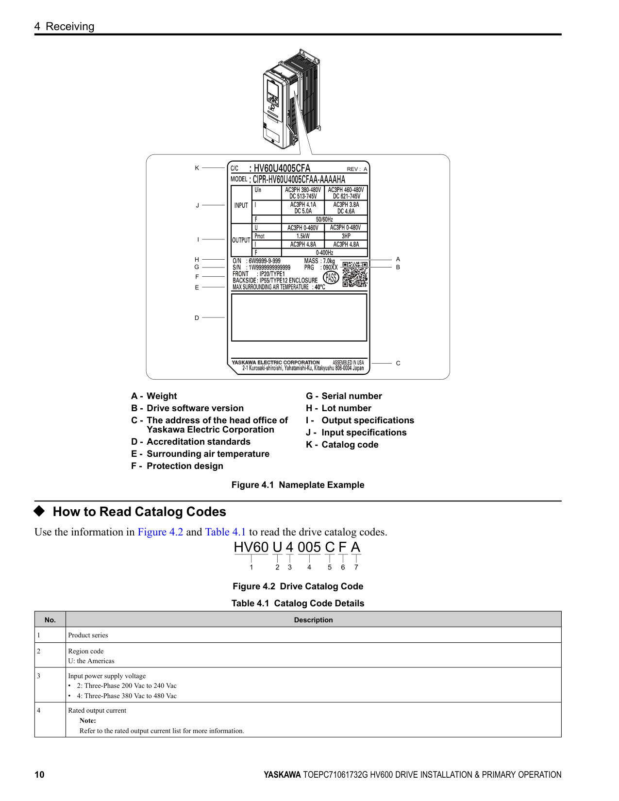
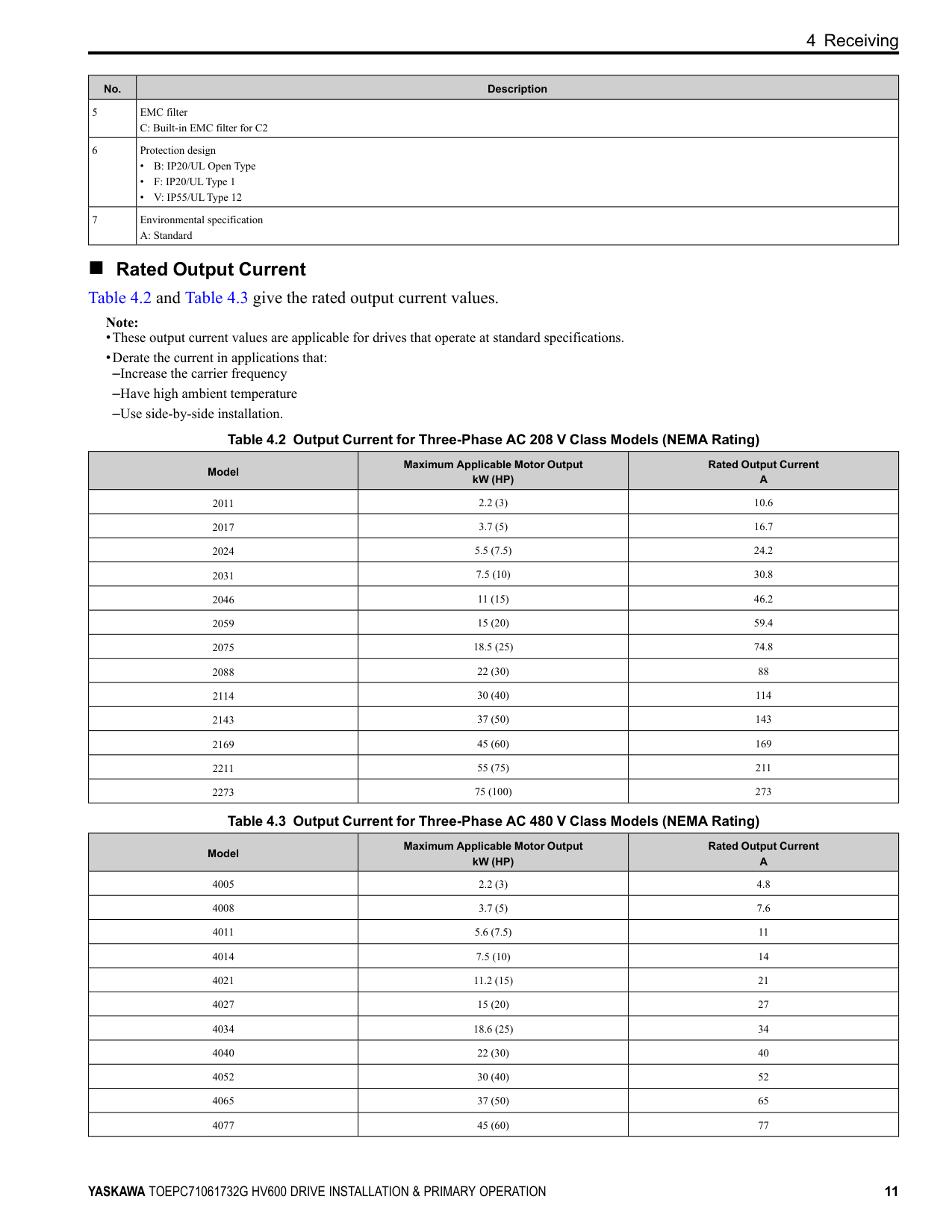
◆ How to Read Catalog Codes Use the information in Figure 4.2 and Table 4.1 to read the drive catalog codes.
Figure 4.2 Drive Catalog Code Table 4.1 Catalog Code Details
|No.|Description| |---|---|
|1|Product series| |2|Region code U: the Americas| |3|Input power supply voltage
• 2: Three-Phase 200 Vac to 240 Vac
• 4: Three-Phase 380 Vac to 480 Vac
| |4|Rated output current Note: Refer to the rated output current list for more information.|
4 Receiving
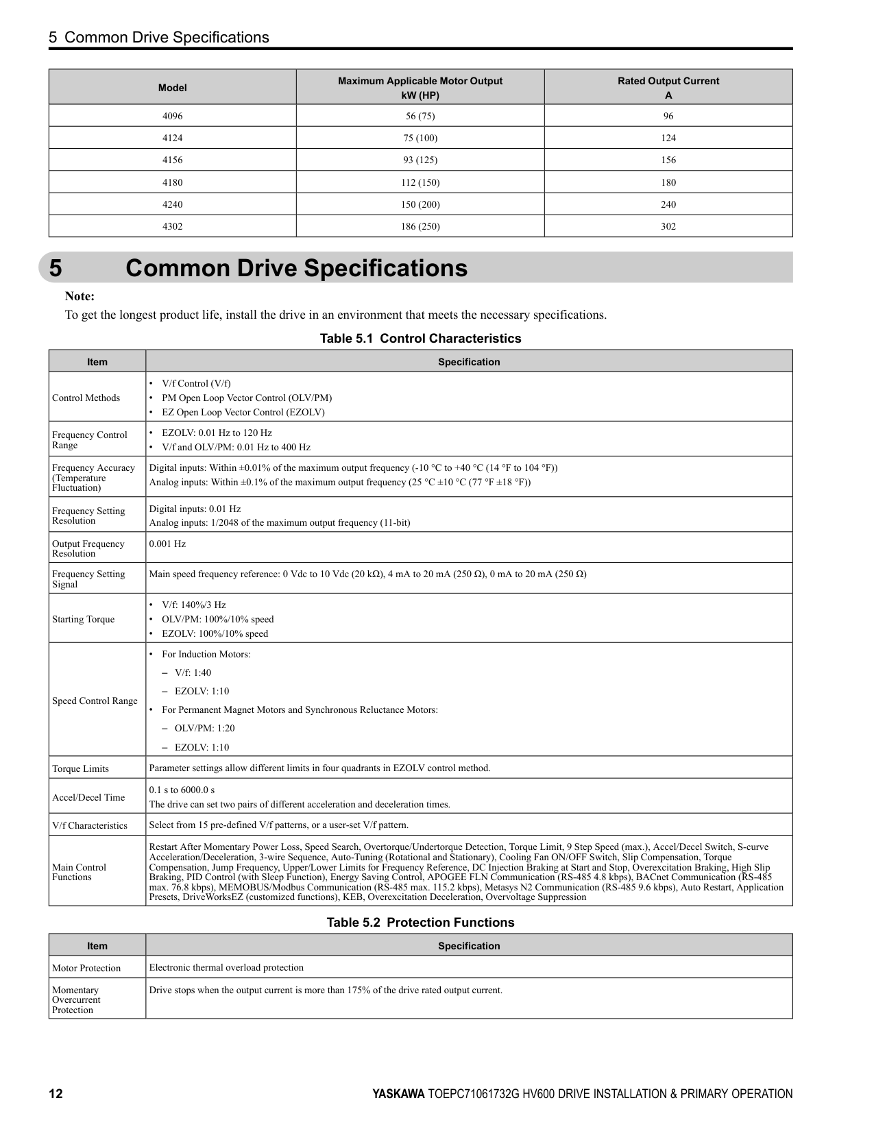
|No.|Description| |---|---| |5|EMC filter C: Built-in EMC filter for C2| |6|Protection design
• B: IP20/UL Open Type
• F: IP20/ULType 1
• V: IP55/ULType 12
| |7|Environmental specification A: Standard|
■ Rated Output Current Table 4.2 and Table 4.3 give the rated output current values.
Note:
|Model|Maximum Applicable Motor Output kW (HP)|Rated Output Current A| |---|---|---| |2011|2.2 (3)|10.6| |2017|3.7 (5)|16.7| |2024|5.5 (7.5)|24.2| |2031|7.5 (10)|30.8| |2046|11 (15)|46.2| |2059|15 (20)|59.4| |2075|18.5 (25)|74.8|
|2088|22 (30)|88| |2114|30 (40)|114| |2143|37 (50)|143| |2169|45 (60)|169| |2211|55 (75)|211| |2273|75 (100)|273|
|Model|Maximum Applicable Motor Output kW (HP)|Rated Output Current A| |---|---|---| |4005|2.2 (3)|4.8| |4008|3.7 (5)|7.6| |4011|5.6 (7.5)|11| |4014|7.5 (10)|14| |4021|11.2 (15)|21| |4027|15 (20)|27| |4034|18.6 (25)|34| |4040|22 (30)|40| |4052|30 (40)|52| |4065|37 (50)|65| |4077|45 (60)|77|
5 Common Drive Specifications
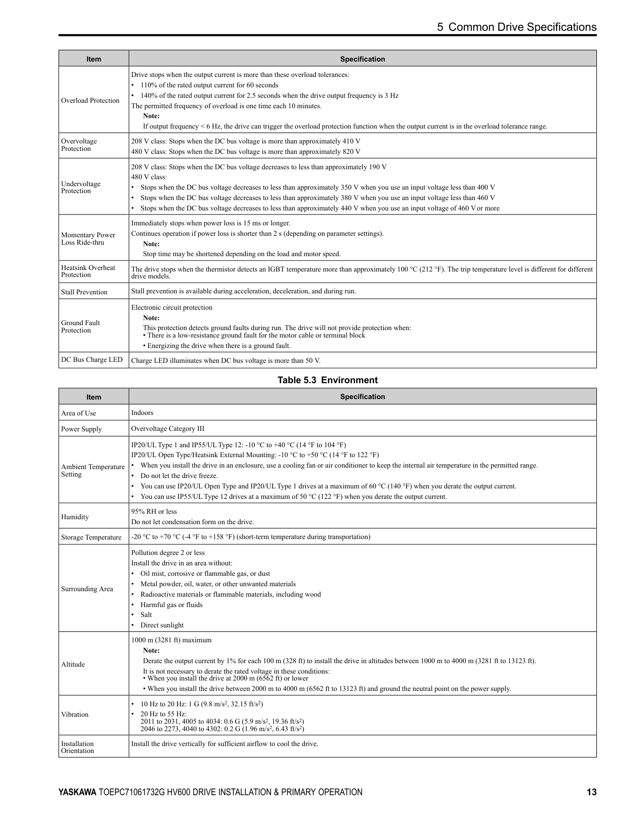
|Model|Maximum Applicable Motor Output kW (HP)|Rated Output Current A| |---|---|---| |4096|56 (75)|96| |4124|75 (100)|124| |4156|93 (125)|156| |4180|112 (150)|180| |4240|150 (200)|240| |4302|186 (250)|302|
#### 5 Common Drive Specifications
Note: To get the longest product life, install the drive in an environment that meets the necessary specifications.
Table 5.1 Control Characteristics
|Item|Specification| |---|---| |Control Methods|• V/f Control (V/f)
• PM Open Loop Vector Control (OLV/PM)
• EZ Open Loop Vector Control (EZOLV)
| |Frequency Control Range|• EZOLV: 0.01 Hz to 120 Hz
• V/f and OLV/PM: 0.01 Hz to 400 Hz
| |Frequency Accuracy (Temperature Fluctuation)|Digital inputs: Within ±0.01% of the maximum output frequency (-10 °C to +40 °C (14 °F to 104 °F)) Analog inputs: Within ±0.1% of the maximum output frequency (25 °C ±10 °C (77 °F ±18 °F))| |Frequency Setting Resolution|Digital inputs: 0.01 Hz Analog inputs: 1/2048 of the maximum output frequency (11-bit)| |Output Frequency Resolution|0.001 Hz| |Frequency Setting Signal|Main speed frequency reference: 0 Vdc to 10 Vdc (20 kΩ), 4 mA to 20 mA (250 Ω), 0 mA to 20 mA (250 Ω)| |Starting Torque|• V/f: 140%/3 Hz
• OLV/PM: 100%/10% speed
• EZOLV: 100%/10% speed
| |Speed Control Range|• For Induction Motors:
– V/f: 1:40
– EZOLV: 1:10
• For Permanent Magnet Motors and Synchronous Reluctance Motors:
– OLV/PM: 1:20
– EZOLV: 1:10
| |Torque Limits|Parameter settings allow different limits in four quadrants in EZOLV control method.| |Accel/Decel Time|0.1 s to 6000.0 s The drive can set two pairs of different acceleration and deceleration times.| |V/f Characteristics|Select from 15 pre-defined V/f patterns, or a user-set V/f pattern.| |Main Control Functions|Restart After Momentary Power Loss, Speed Search, Overtorque/Undertorque Detection, Torque Limit, 9 Step Speed (max.), Accel/Decel Switch, S-curve Acceleration/Deceleration, 3-wire Sequence, Auto-Tuning (Rotational and Stationary), Cooling Fan ON/OFF Switch, Slip Compensation, Torque Compensation, Jump Frequency, Upper/Lower Limits for Frequency Reference, DC Injection Braking at Start and Stop, Overexcitation Braking, High Slip Braking, PID Control (with Sleep Function), Energy Saving Control, APOGEE FLN Communication (RS-485 4.8 kbps), BACnet Communication (RS-485 max. 76.8 kbps), MEMOBUS/Modbus Communication (RS-485 max. 115.2 kbps), Metasys N2 Communication (RS-485 9.6 kbps), Auto Restart, Application Presets, DriveWorksEZ (customized functions), KEB, Overexcitation Deceleration, Overvoltage Suppression|
Table 5.2 Protection Functions
|Item|Specification| |---|---| |Motor Protection|Electronic thermal overload protection| |Momentary Overcurrent Protection|Drive stops when the output current is more than 175% of the drive rated output current.|
5 Common Drive Specifications
|Item|Specification| |---|---| |Overload Protection|Drive stops when the output current is more than these overload tolerances:
• 110% of the rated output current for 60 seconds
• 140% of the rated output current for 2.5 seconds when the drive output frequency is 3 Hz The permitted frequency of overload is one time each 10 minutes.
Note: If output frequency < 6 Hz, the drive can trigger the overload protection function when the output current is in the overload tolerance range.| |Overvoltage Protection|208 V class: Stops when the DC bus voltage is more than approximately 410 V 480 V class: Stops when the DC bus voltage is more than approximately 820 V| |Undervoltage Protection|208 V class: Stops when the DC bus voltage decreases to less than approximately 190 V 480 V class:
• Stops when the DC bus voltage decreases to less than approximately 350 V when you use an input voltage less than 400 V
• Stops when the DC bus voltage decreases to less than approximately 380 V when you use an input voltage less than 460 V
• Stops when the DC bus voltage decreases to less than approximately 440 V when you use an input voltage of 460 Vor more
| |Momentary Power Loss Ride-thru|Immediately stops when power loss is 15 ms or longer. Continues operation if power loss is shorter than 2 s (depending on parameter settings).
Note: Stop time may be shortened depending on the load and motor speed.| |Heatsink Overheat Protection|The drive stops when the thermistor detects an IGBT temperature more than approximately 100 °C (212 °F). The trip temperature level is different for different drive models.| |Stall Prevention|Stall prevention is available during acceleration, deceleration, and during run.| |Ground Fault Protection|Electronic circuit protection Note: This protection detects ground faults during run. The drive will not provide protection when:
• There is a low-resistance ground fault for the motor cable or terminal block
• Energizing the drive when there is a ground fault.
| |DC Bus Charge LED|Charge LED illuminates when DC bus voltage is more than 50 V.|
Table 5.3 Environment
|Item|Specification|
|---|---| |Area of Use|Indoors| |Power Supply|Overvoltage Category III| |Ambient Temperature Setting|IP20/ULType 1 and IP55/ULType 12: -10 °C to +40 °C (14 °F to 104 °F) IP20/UL Open Type/Heatsink External Mounting: -10 °C to +50 °C (14 °F to 122 °F)
• When you install the drive in an enclosure, use a cooling fan or air conditioner to keep the internal air temperature in the permitted range.
• Do not let the drive freeze.
• You can use IP20/UL Open Type and IP20/ULType 1 drives at a maximum of 60 °C (140 °F) when you derate the output current.
• You can use IP55/ULType 12 drives at a maximum of 50 °C (122 °F) when you derate the output current.
| |Humidity|95% RH or less Do not let condensation form on the drive.| |Storage Temperature|-20 °C to +70 °C (-4 °F to +158 °F) (short-term temperature during transportation)| |Surrounding Area|Pollution degree 2 or less Install the drive in an area without:
• Oil mist, corrosive or flammable gas, or dust
• Metal powder, oil, water, or other unwanted materials
• Radioactive materials or flammable materials, including wood
• Harmful gas or fluids
• Salt
• Direct sunlight
| |Altitude|1000 m (3281 ft) maximum Note: Derate the output current by 1% for each 100 m (328 ft) to install the drive in altitudes between 1000 m to 4000 m (3281 ft to 13123 ft). It is not necessary to derate the rated voltage in these conditions:
• When you install the drive at 2000 m (6562 ft) or lower
• When you install the drive between 2000 m to 4000 m (6562 ft to 13123 ft) and ground the neutral point on the power supply.
| |Vibration|• 10 Hz to 20 Hz: 1 G (9.8 m/s2, 32.15 ft/s2)
• 20 Hz to 55 Hz: 2011 to 2031, 4005 to 4034: 0.6 G (5.9 m/s2, 19.36 ft/s2) 2046 to 2273, 4040 to 4302: 0.2 G (1.96 m/s2, 6.43 ft/s2)
| |Installation Orientation|Install the drive vertically for sufficient airflow to cool the drive.|
############## Table 5.4 Certifications and Standard Compliance
|Item|Specification| |---|---| |UL/cUL|UL 508C *1| |CE Low Voltage Directive
2014/35/EU|IEC/EN 61800-5-1| |CE EMC Directive 2014/30/EU|EN 61800-3| |CE Machinery Directive
2006/42/EC|• IEC/EN 61800-5-2 (SIL3)
• IEC/EN 62061 (SIL3)
• EN ISO 13849-1:2015 (PL e, Cat.3)
| |RoHS Directive 2011/65/EU|-| |WEEE Directive 2012/19/EU|-|
*1 Models 2143xV, 2169xV, and 4156xVare compatible with UL61800-5-1.
Table 5.5 Enclosure Ratings
|Item|Specification| |---|---| |Protection Design|IP20/UL Open Type IP20/ULType 1 IP55/ULType 12
Note: Install a UL Type 1 kit on an IP20/UL Open Type drive to convert the drive to an IP20/ULType 1.|
◆ Area of Use Install this product in a location with Overvoltage Category III and pollution degree 2 or less.
■ Ambient Temperature Setting Maintain the ambient temperature within the following ranges according to the enclosure type.
#### 6 Mechanical Installation
This section gives information about the standard environment for correct installation.
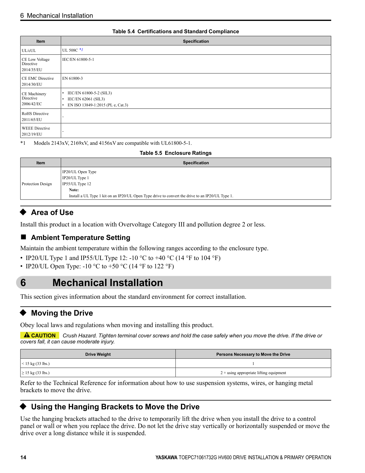
◆ Moving the Drive Obey local laws and regulations when moving and installing this product.
CAUTION Crush Hazard. Tighten terminal cover screws and hold the case safely when you move the drive. If the drive or covers fall, it can cause moderate injury.
|Drive Weight|Persons Necessary to Move the Drive| |---|---| |< 15 kg (33 lbs.)|1| |≥ 15 kg (33 lbs.)|2 + using appropriate lifting equipment|
Refer to the Technical Reference for information about how to use suspension systems, wires, or hanging metal brackets to move the drive.
##### ◆ Using the Hanging Brackets to Move the Drive
Use the hanging brackets attached to the drive to temporarily lift the drive when you install the drive to a control panel or wall or when you replace the drive. Do not let the drive stay vertically or horizontally suspended or move the drive over a long distance while it is suspended.
Before you install the drive, make sure that you read these precautions:
WARNING Crush Hazard. Before you hang the drive vertically, use screws to correctly attach the drive front cover and other drive components. If you do not secure the front cover, it can fall and cause minor injury.
WARNING Crush Hazard. When you use a crane or hoist to lift the drive during installation or removal, prevent more than 1.96 m/s2 (0.2 G) vibration or impact. Too much vibration or impact can cause serious injury or death from falling equipment.
WARNING Crush Hazard. When you lift the drive during installation or removal, do not try to turn the drive over and do not ignore the hanging drive. If you move a hanging drive too much or if you ignore it, the drive can fall and cause serious injury or death.
WARNING Crush Hazard. When you install the drive, do not hold the front cover. Install the drive with holding the heatsink. If you hold the front cover, the cover will come off and the drive will fall, then it can cause injury.
◆ Installation Position and Distance Install the drive vertically for sufficient airflow to cool the drive.
A - Vertical installation B - Horizontal installation Figure 6.1 Installation Position
##### ■ Single Drive Installation
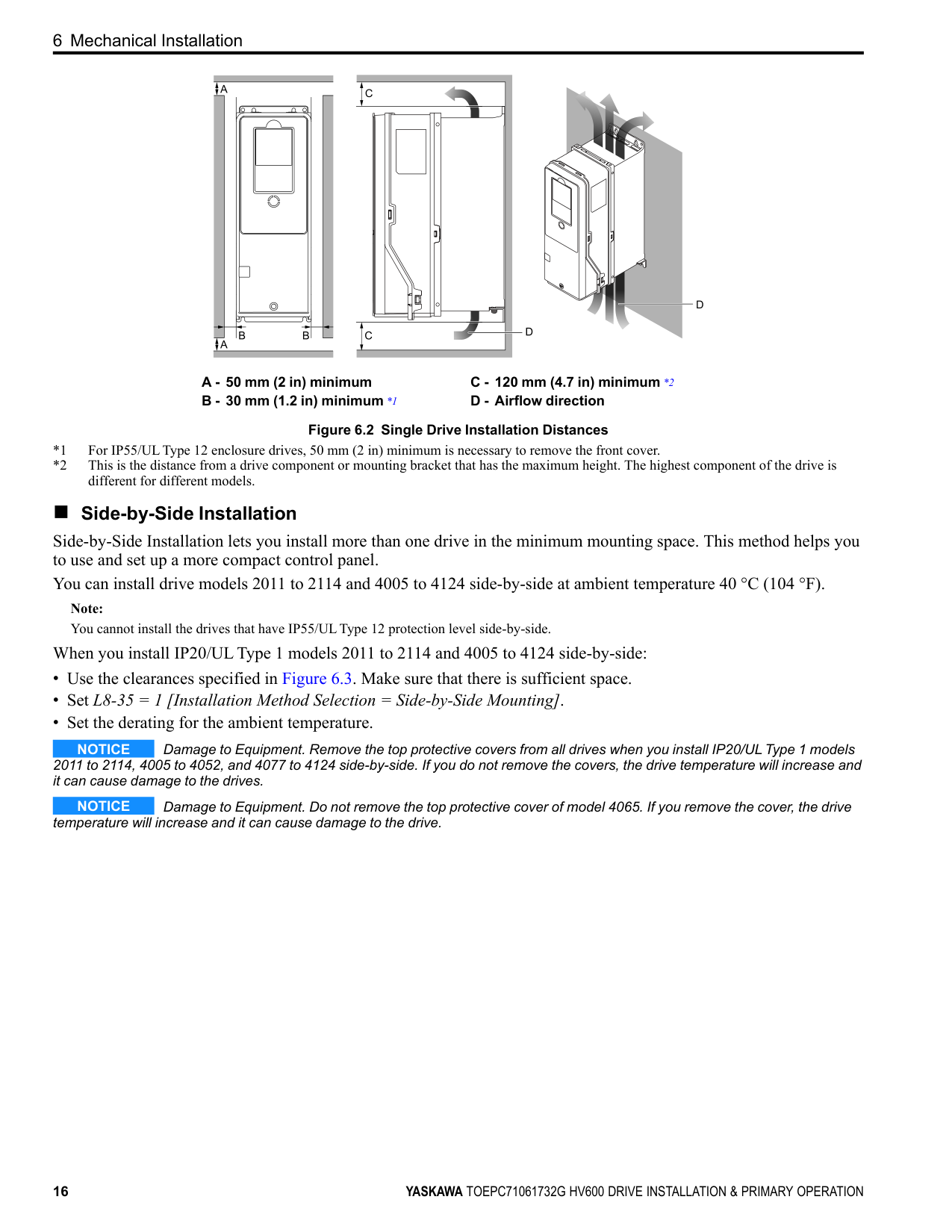
Use the clearances specified in Figure 6.2 to install the drive. Make sure that there is sufficient space for wiring and airflow.
NOTICE Damage to Equipment. Remove the top protective cover from the drive when you install IP20/UL Type 1 models 2011 to 2169, 4005 to 4052, and 4077 to 4156 in an enclosure or when you install the drive with the heatsink external to the enclosure. If you do not remove the cover, the drive temperature will increase and it can cause damage to the drive.
NOTICE Damage to Equipment. Do not remove the top protective cover of model 4065. If you remove the cover, the drive temperature will increase and it can cause damage to the drive.
############## Note:
When you install models 2011 to 2169 and 4005 to 4156 in an enclosure or when you install the drive with the heatsink external to the enclosure, set L8-35 = 0 [Installation Method Selection = IP20/UL Open Type].
| | | |---|---| | | |
| | | |---|---| | | |
A - 50 mm (2 in) minimum B - 30 mm (1.2 in) minimum *1
C - 120 mm (4.7 in) minimum *2 D - Airflow direction
Figure 6.2 Single Drive Installation Distances
different for different models. ■ Side-by-Side Installation Side-by-Side Installation lets you install more than one drive in the minimum mounting space. This method helps you to use and set up a more compact control panel. You can install drive models 2011 to 2114 and 4005 to 4124 side-by-side at ambient temperature 40 °C (104 °F).
Note: You cannot install the drives that have IP55/ULType 12 protection level side-by-side.
When you install IP20/ULType 1 models 2011 to 2114 and 4005 to 4124 side-by-side:
NOTICE Damage to Equipment. Remove the top protective covers from all drives when you install IP20/UL Type 1 models 2011 to 2114, 4005 to 4052, and 4077 to 4124 side-by-side. If you do not remove the covers, the drive temperature will increase and it can cause damage to the drives.
NOTICE Damage to Equipment. Do not remove the top protective cover of model 4065. If you remove the cover, the drive temperature will increase and it can cause damage to the drive.
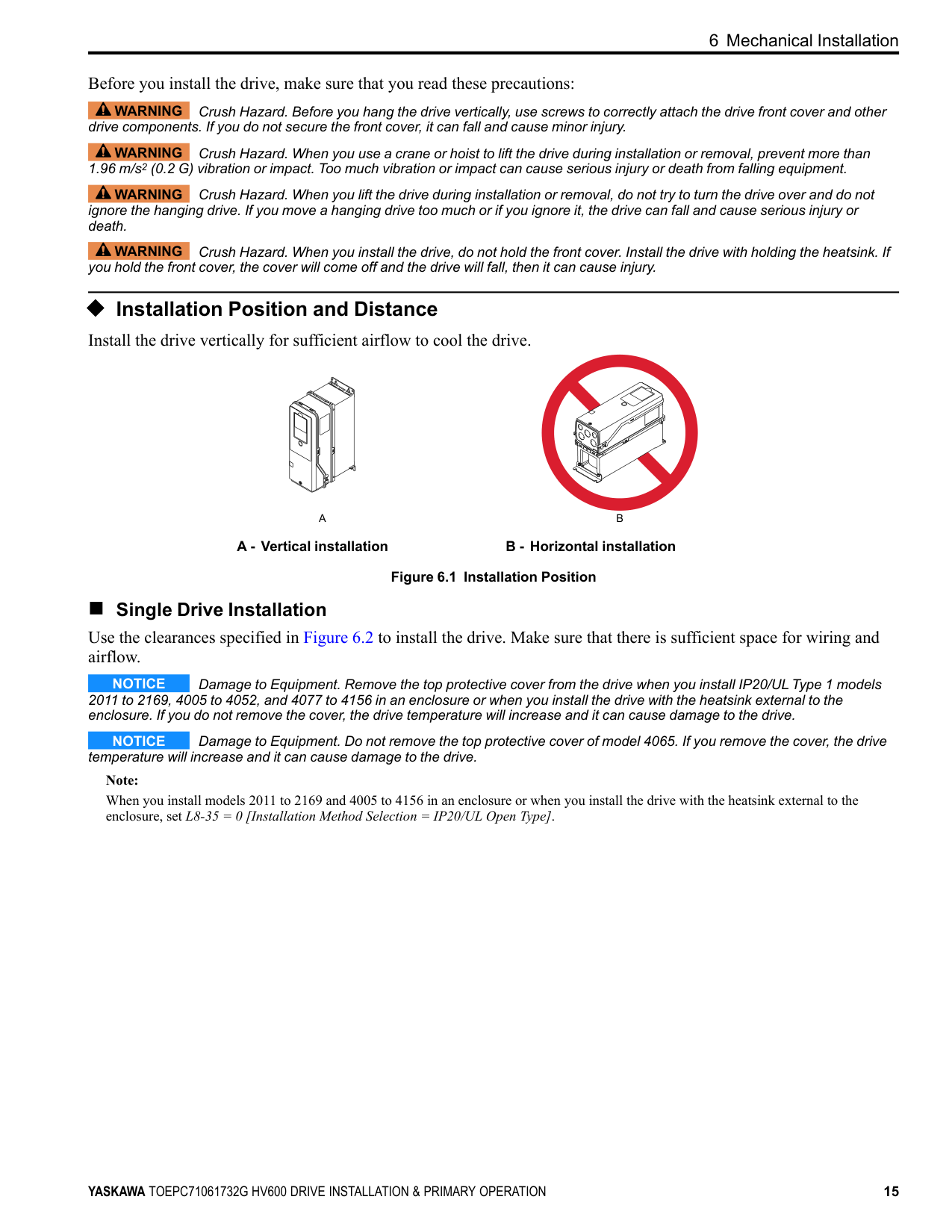
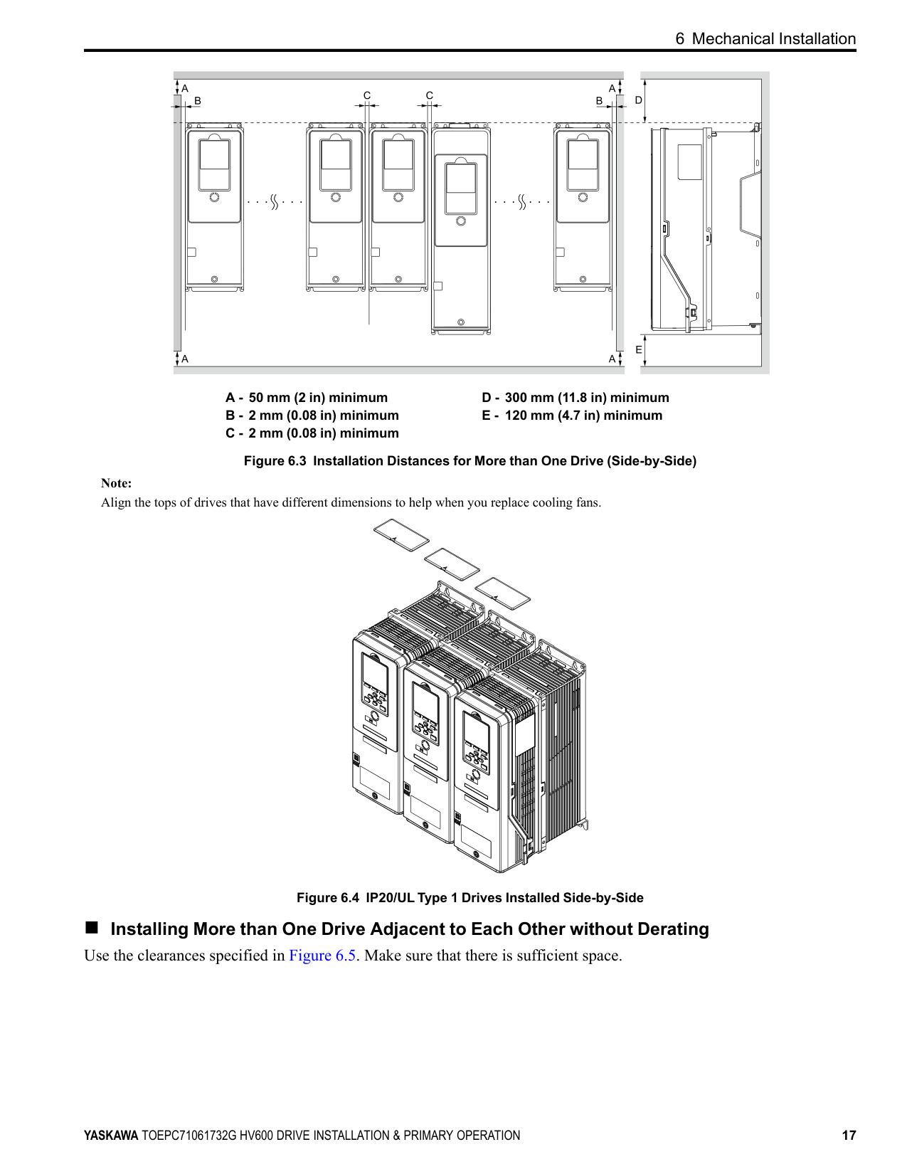
Figure 6.3 Installation Distances for More than One Drive (Side-by-Side)
Note: Align the tops of drives that have different dimensions to help when you replace cooling fans.
| | | |---|---| | | |
| | | | |---|---|---| | | | |
| | | |---|---| | | |
| | | |---|---| | | |
Figure 6.4 IP20/UL Type 1 Drives Installed Side-by-Side
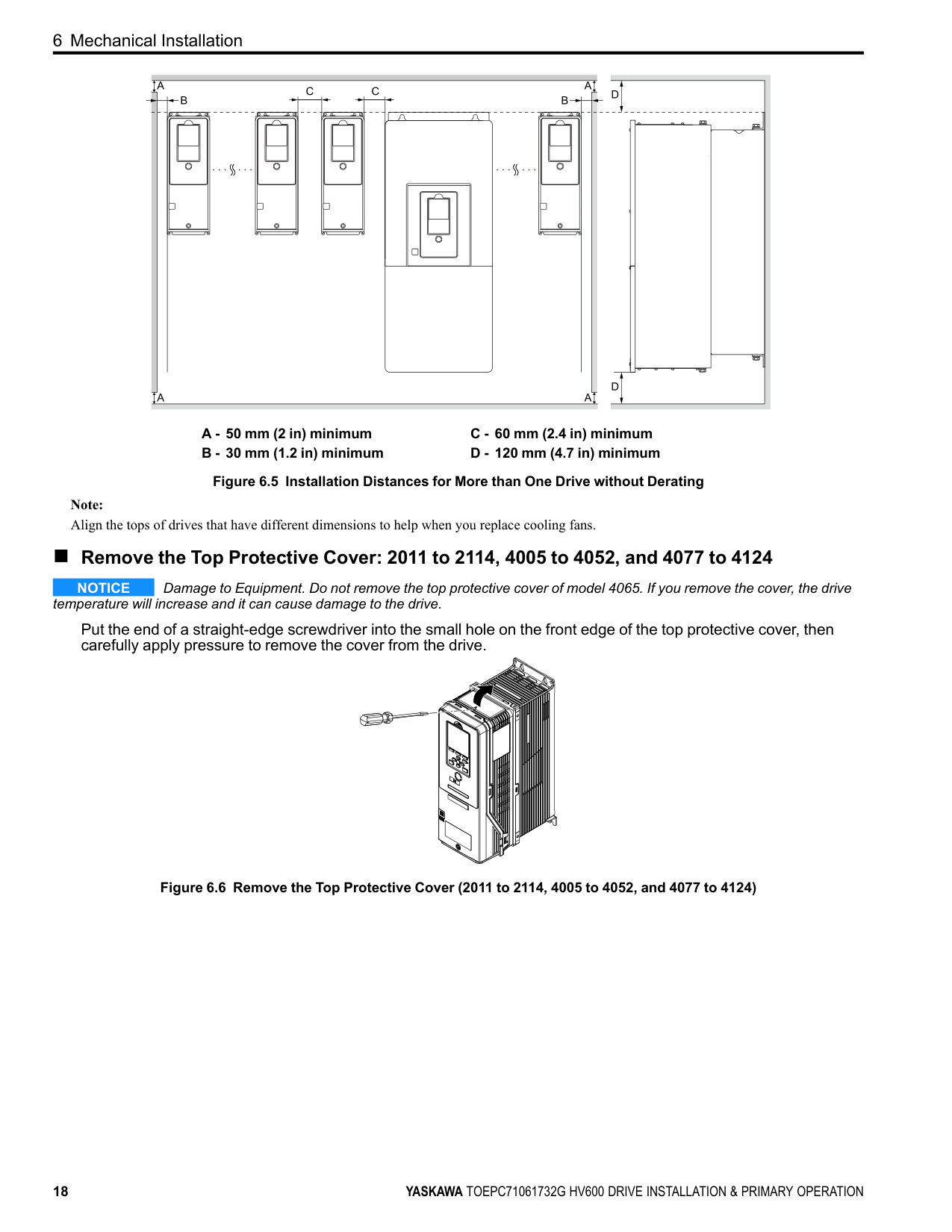
##### ■ Installing More than One Drive Adjacent to Each Other without Derating Use the clearances specified in Figure 6.5. Make sure that there is sufficient space.
| | | | | | |---|---|---|---|---| | | | | | | | | | | | |
A - 50 mm (2 in) minimum B - 30 mm (1.2 in) minimum
C - 60 mm (2.4 in) minimum D - 120 mm (4.7 in) minimum
Figure 6.5 Installation Distances for More than One Drive without Derating
Note: Align the tops of drives that have different dimensions to help when you replace cooling fans.
##### ■ Remove the Top Protective Cover: 2011 to 2114, 4005 to 4052, and 4077 to 4124
NOTICE Damage to Equipment. Do not remove the top protective cover of model 4065. If you remove the cover, the drive temperature will increase and it can cause damage to the drive.
Put the end of a straight-edge screwdriver into the small hole on the front edge of the top protective cover, then carefully apply pressure to remove the cover from the drive.
| | | |---|---| | | |
| | | |---|---| | | |
| | | |---|---| | | |
Figure 6.6 Remove the Top Protective Cover (2011 to 2114, 4005 to 4052, and 4077 to 4124)
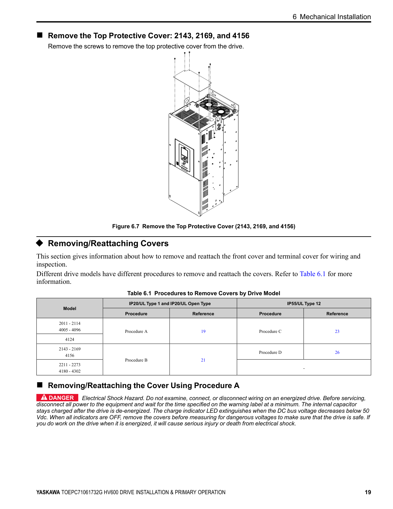
##### ■ Remove the Top Protective Cover: 2143, 2169, and 4156
Remove the screws to remove the top protective cover from the drive.
Figure 6.7 Remove the Top Protective Cover (2143, 2169, and 4156)
◆ Removing/Reattaching Covers This section gives information about how to remove and reattach the front cover and terminal cover for wiring and inspection. Different drive models have different procedures to remove and reattach the covers. Refer to Table 6.1 for more information.
Table 6.1 Procedures to Remove Covers by Drive Model
|Model|IP20/UL Type 1 and IP20/UL Open Type|IP20/UL Type 1 and IP20/UL Open Type|IP55/UL Type 12|IP55/UL Type 12| |---|---|---|---|---| |Model|Procedure|Reference|Procedure|Reference| |2011 - 2114 4005 - 4096|Procedure A|19|Procedure C|23| |4124|Procedure A|19|Procedure C|23| |2143 - 2169 4156|Procedure B|21|Procedure D|26| |2211 - 2273 4180 - 4302|Procedure B|21|-|-|
##### ■ Removing/Reattaching the Cover Using Procedure A
DANGER Electrical Shock Hazard. Do not examine, connect, or disconnect wiring on an energized drive. Before servicing, disconnect all power to the equipment and wait for the time specified on the warning label at a minimum. The internal capacitor stays charged after the drive is de-energized. The charge indicator LED extinguishes when the DC bus voltage decreases below 50 Vdc. When all indicators are OFF, remove the covers before measuring for dangerous voltages to make sure that the drive is safe. If you do work on the drive when it is energized, it will cause serious injury or death from electrical shock.
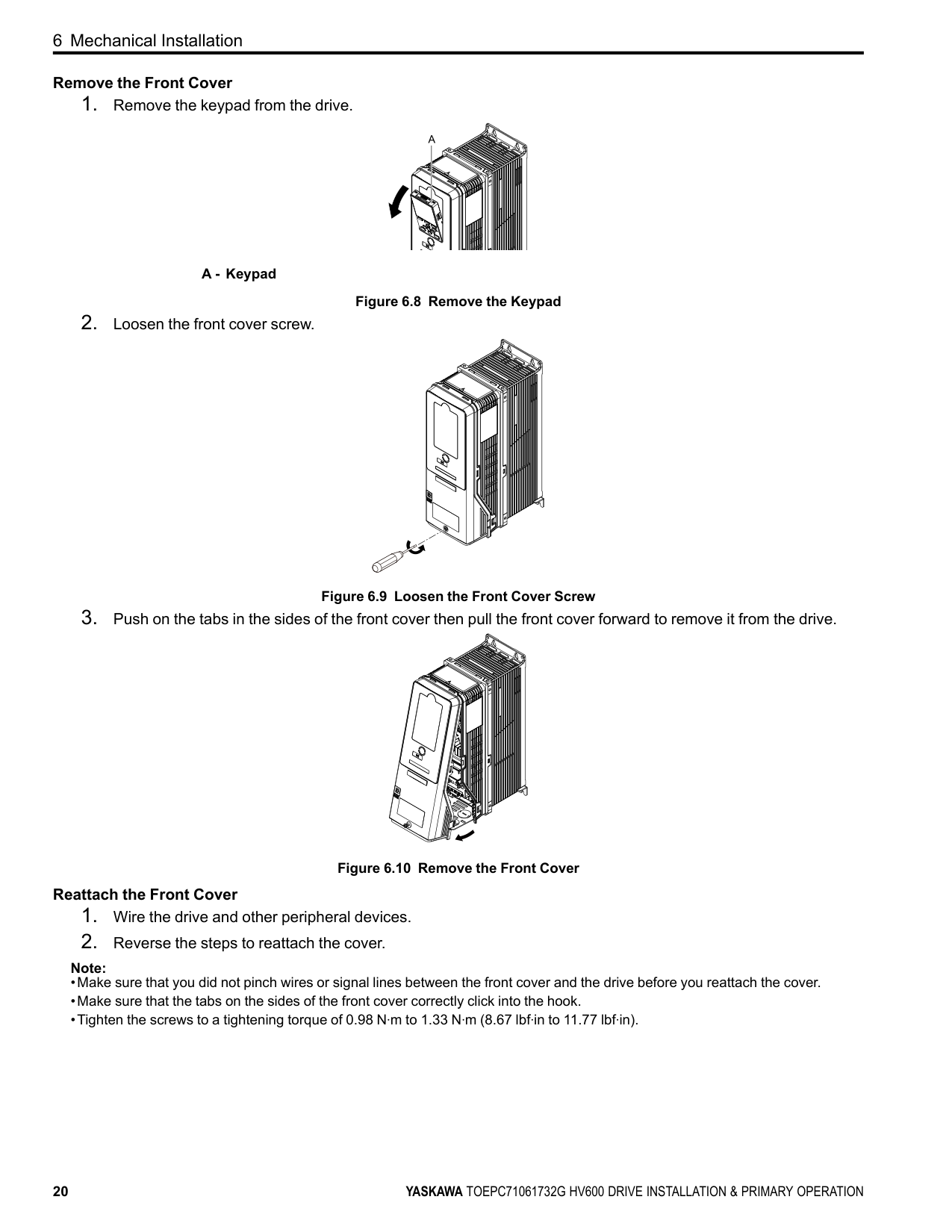
############# Remove the Front Cover
A - Keypad
Figure 6.8 Remove the Keypad
############# Reattach the Front Cover
Note:
| | | |---|---| | | |
| | | |---|---| | | |
Figure 6.11 Reattach the Front Cover
##### ■ Removing/Reattaching the Cover Using Procedure B
DANGER Electrical Shock Hazard. Do not examine, connect, or disconnect wiring on an energized drive. Before servicing, disconnect all power to the equipment and wait for the time specified on the warning label at a minimum. The internal capacitor stays charged after the drive is de-energized. The charge indicator LED extinguishes when the DC bus voltage decreases below 50 Vdc. When all indicators are OFF, remove the covers before measuring for dangerous voltages to make sure that the drive is safe. If you do work on the drive when it is energized, it will cause serious injury or death from electrical shock.
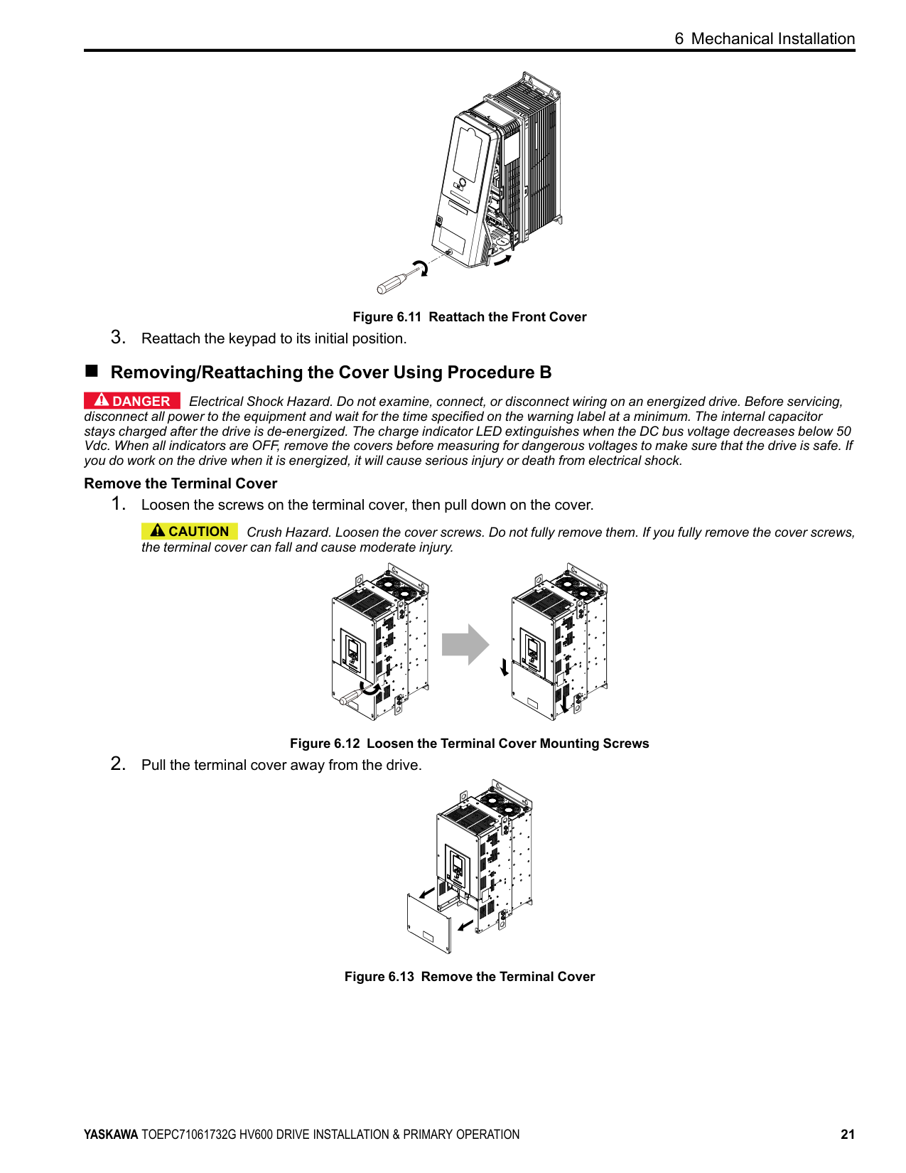
############# Remove the Terminal Cover
CAUTION Crush Hazard. Loosen the cover screws. Do not fully remove them. If you fully remove the cover screws, the terminal cover can fall and cause moderate injury.
Figure 6.12 Loosen the Terminal Cover Mounting Screws
Figure 6.13 Remove the Terminal Cover
| | | | |---|---|---| | | | |
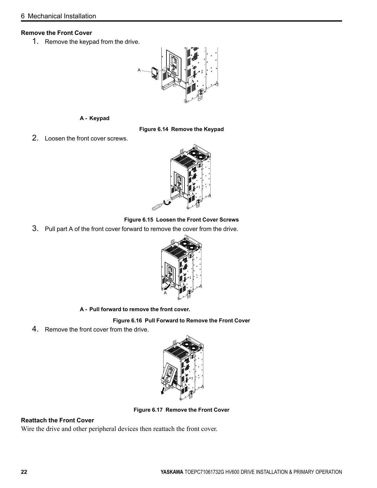
############# Remove the Front Cover
A - Keypad
Figure 6.14 Remove the Keypad
Figure 6.15 Loosen the Front Cover Screws
A - Pull forward to remove the front cover. Figure 6.16 Pull Forward to Remove the Front Cover
| | | |---|---| | | |
| | | |---|---| | | |
| | | |---|---| | | |
Figure 6.17 Remove the Front Cover
############ Reattach the Front Cover Wire the drive and other peripheral devices then reattach the front cover.
######## 1. Move the front cover to connect the hooks at the top of the front cover to the drive.
| | |
|---|---| | | |
| | | |---|---| | | |
A - Hooks
Figure 6.18 Reattach the Front Cover
######## 2. Move the front cover while pushing on the hooks on the left and right sides of the front cover until it clicks intoposition.
Note: Make sure that you did not pinch wires or signal lines between the front cover and the drive before you reattach the cover.
Figure 6.19 Reattach the Front Cover
Wire the drive and other peripheral devices then reattach the terminal cover. Note:
| | | |---|---| | | |
Figure 6.20 Reattach the Terminal Cover
##### ■ Removing/Reattaching the Cover Using Procedure C
DANGER Electrical Shock Hazard. Do not examine, connect, or disconnect wiring on an energized drive. Before servicing, disconnect all power to the equipment and wait for the time specified on the warning label at a minimum. The internal capacitor stays charged after the drive is de-energized. The charge indicator LED extinguishes when the DC bus voltage decreases below 50 Vdc. When all indicators are OFF, remove the covers before measuring for dangerous voltages to make sure that the drive is safe. If you do work on the drive when it is energized, it will cause serious injury or death from electrical shock.
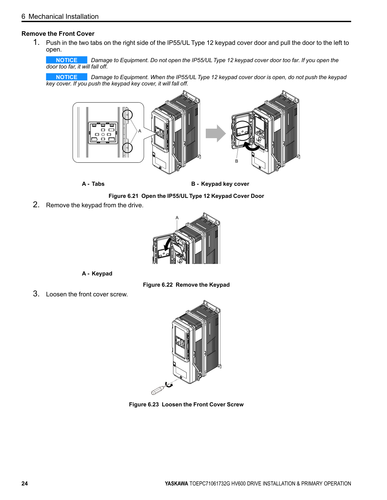
############# Remove the Front Cover
NOTICE Damage to Equipment. Do not open the IP55/UL Type 12 keypad cover door too far. If you open the door too far, it will fall off.
NOTICE Damage to Equipment. When the IP55/UL Type 12 keypad cover door is open, do not push the keypad key cover. If you push the keypad key cover, it will fall off.
A - Tabs B - Keypad key cover Figure 6.21 Open the IP55/UL Type 12 Keypad Cover Door
A - Keypad
Figure 6.22 Remove the Keypad
| | | | |---|---|---| | | | |
Figure 6.23 Loosen the Front Cover Screw
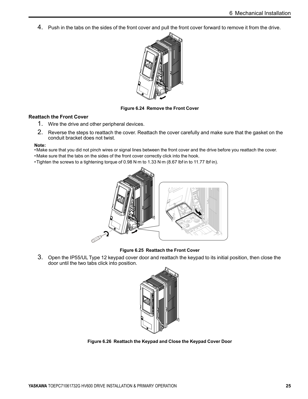
Figure 6.24 Remove the Front Cover Reattach the Front Cover
conduit bracket does not twist. Note:
Figure 6.25 Reattach the Front Cover
door until the two tabs click into position.
Figure 6.26 Reattach the Keypad and Close the Keypad Cover Door
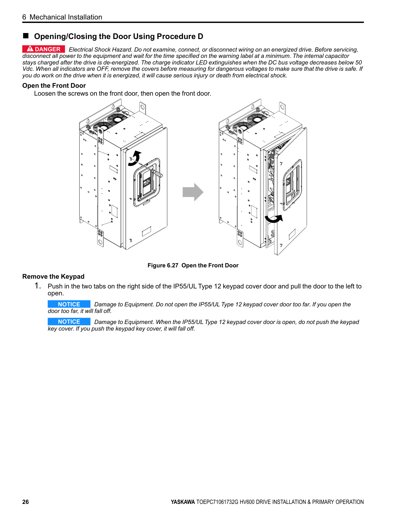
##### ■ Opening/Closing the Door Using Procedure D
DANGER Electrical Shock Hazard. Do not examine, connect, or disconnect wiring on an energized drive. Before servicing, disconnect all power to the equipment and wait for the time specified on the warning label at a minimum. The internal capacitor stays charged after the drive is de-energized. The charge indicator LED extinguishes when the DC bus voltage decreases below 50 Vdc. When all indicators are OFF, remove the covers before measuring for dangerous voltages to make sure that the drive is safe. If you do work on the drive when it is energized, it will cause serious injury or death from electrical shock.
############# Open the Front Door
Loosen the screws on the front door, then open the front door.
Figure 6.27 Open the Front Door Remove the Keypad
NOTICE Damage to Equipment. Do not open the IP55/UL Type 12 keypad cover door too far. If you open the door too far, it will fall off.
NOTICE Damage to Equipment. When the IP55/UL Type 12 keypad cover door is open, do not push the keypad key cover. If you push the keypad key cover, it will fall off.
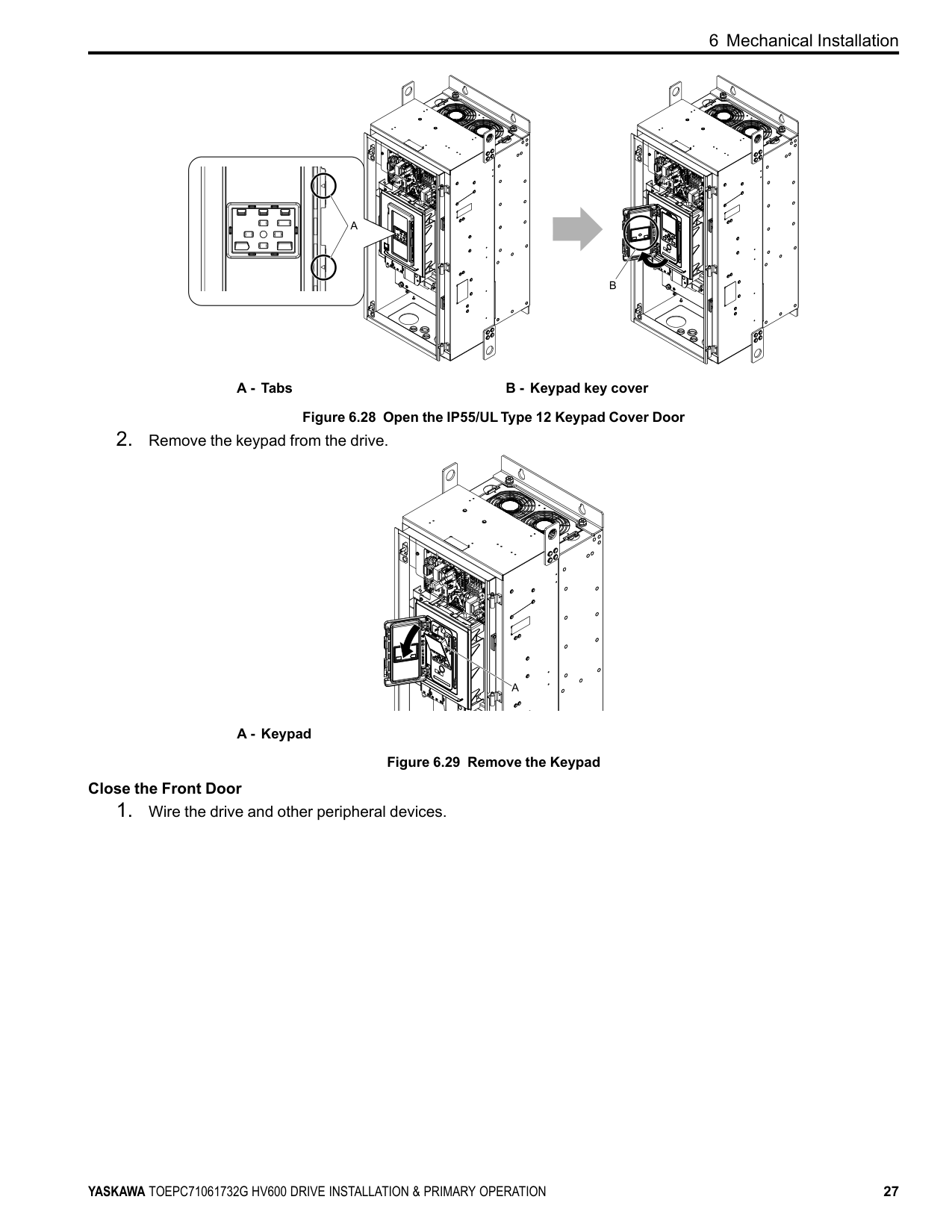
A - Tabs B - Keypad key cover Figure 6.28 Open the IP55/UL Type 12 Keypad Cover Door
A - Keypad
Figure 6.29 Remove the Keypad Close the Front Door
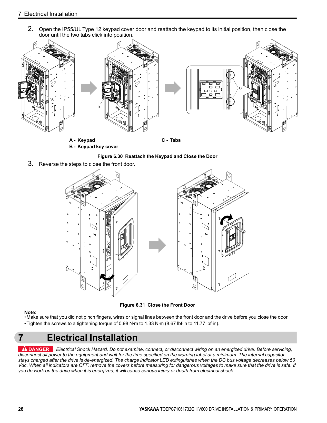
A - Keypad B - Keypad key cover
C - Tabs
Figure 6.30 Reattach the Keypad and Close the Door
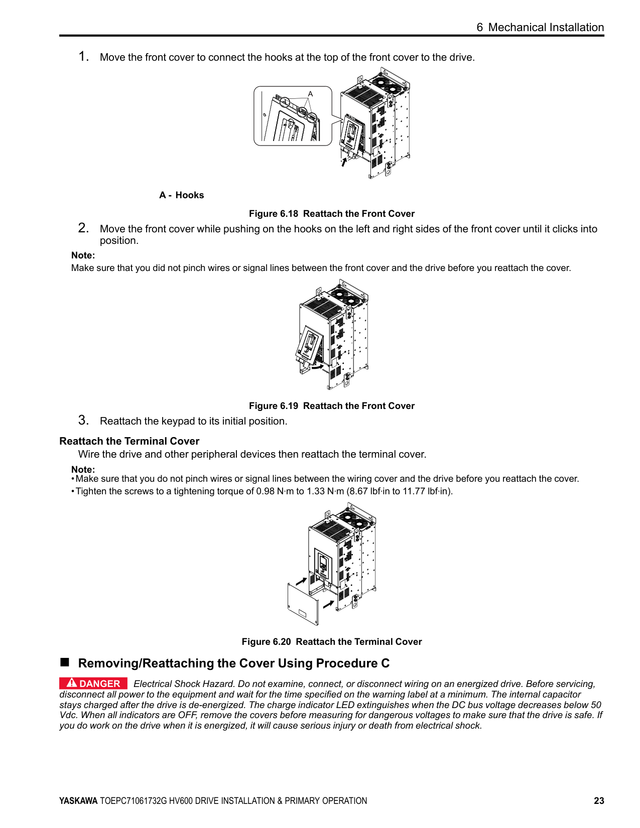
Figure 6.31 Close the Front Door Note:
#### 7 Electrical Installation
DANGER Electrical Shock Hazard. Do not examine, connect, or disconnect wiring on an energized drive. Before servicing, disconnect all power to the equipment and wait for the time specified on the warning label at a minimum. The internal capacitor stays charged after the drive is de-energized. The charge indicator LED extinguishes when the DC bus voltage decreases below 50 Vdc. When all indicators are OFF, remove the covers before measuring for dangerous voltages to make sure that the drive is safe. If you do work on the drive when it is energized, it will cause serious injury or death from electrical shock.
WARNING Electrical Shock Hazard. De-energize the drive and wait 5 minutes minimum until the Charge LED turns off. Remove the front cover and terminal cover to do work on wiring, circuit boards, and other parts. Use terminals for their correct function only. Incorrect wiring, incorrect ground connections, and incorrect repair of protective covers can cause death or serious injury.
WARNING Electrical Shock Hazard. Correctly ground the drive before you turn on the EMC filter switch. If you touch electrical equipment that is not grounded, it can cause serious injury or death.
WARNING Electrical Shock Hazard. Use the terminals for the drive only for their intended purpose. Refer to the technical manual for more information about the I/O terminals. Wiring and grounding incorrectly or modifying the cover may damage the equipment or cause injury.
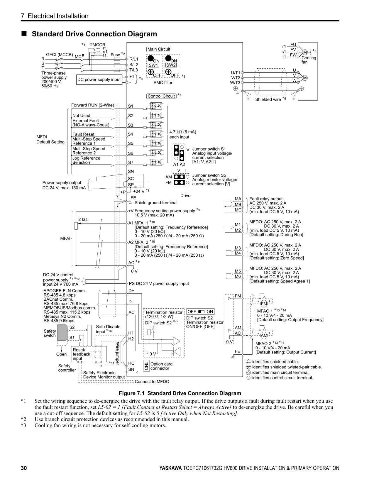
##### ◆ Standard Connection Diagram
WARNING Sudden Movement Hazard. Set the MFDI parameters before you close control circuit switches. Incorrect Run/ Stop circuit sequence settings can cause serious injury or death from moving equipment.
WARNING Sudden Movement Hazard. Correctly wire the start/stop and safety circuits before you energize the drive. If you momentarily close a digital input terminal, it can start a drive that is programmed for 3-Wire control and cause serious injury or death from moving equipment.
WARNING Sudden Movement Hazard. When you use a 3-Wire sequence, set A1-03 = 3330 [Initialize Parameters = 3-Wire Initialization] and make sure that b1-17 = 0 [Run Command at Power Up = Disregard Existing RUN Command]. If you do not correctly set the drive parameters for 3-Wire operation before you energize the drive, the motor can suddenly rotate in reverse when you energize the drive.
WARNING Sudden Movement Hazard. Check the I/O signals and the external sequences for the drive before you set the Application Preset function. When you set the Application Preset function (A1-06 ≠ 0), it changes the I/O terminal functions for the drive and it can cause equipment to operate unusually. This can cause serious injury or death.
WARNING Fire Hazard. Install sufficient branch circuit short circuit protection as specified by applicable codes and this manual. The drive is suitable for circuits that supply not more than 100,000 RMS symmetrical amperes, 240 Vac maximum (208 V Class), 480 Vac maximum (480 V Class). Incorrect branch circuit short circuit protection can cause serious injury or death.
NOTICE When the input voltage is 440 V or higher or the wiring distance is longer than 100 m (328 ft), make sure that the motor insulation voltage is sufficient or use an inverter-duty motor or vector-duty motor with reinforced insulation. Motor winding and insulation failure can occur.
############## Note:
Do not connect the AC control circuit ground to the drive enclosure. Incorrect ground wiring can cause the control circuit to operate incorrectly.
##### ■ Standard Drive Connection Diagram
| | | |---|---| | | |
| | | | |---|---|---| | | | | | | | | | | | |
############## Figure 7.1 Standard Drive Connection Diagram
WARNING Fire Hazard. Only connect factory-recommended devices or circuits to drive terminals - and +1. Do not
connect AC power to these terminals. Incorrect wiring can cause damage to the drive and serious injury or death from fire.
NOTICE Damage to Equipment. Do not close the circuit between terminals SP-SN. If you close the circuits between terminals SC-SP and terminals SC-SN at the same time, it will cause damage to the drive.
NOTICE Damage to Equipment. Do not close the circuit between terminals SC-SN. If you close the circuits between terminals SC-SP and terminals SC-SN at the same time, it will cause damage to the drive.
NOTICE Damage to Equipment. Do not close the circuit between terminals SC-SP. If you close the circuits between terminals SC-SP and terminals SC-SN at the same time, it will cause damage to the drive.
NOTICE Damage to Equipment. Do not install a jumper between terminals +V and AC. A closed circuit between these terminals will cause damage to the drive.
NOTICE Connect terminals PS and AC correctly for the 24 V power supply. If you connect the wires to the incorrect terminals, it will cause damage to the drive.
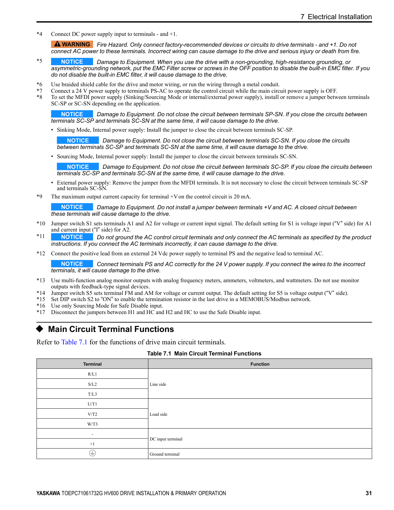
◆ Main Circuit Terminal Functions Refer to Table 7.1 for the functions of drive main circuit terminals.
Table 7.1 Main Circuit Terminal Functions
|Terminal|Function| |---|---| |R/L1|Line side| |S/L2|Line side| |T/L3|Line side| |U/T1|Load side| |V/T2|Load side| |W/T3|Load side| |-|DC input terminal| |+1|DC input terminal| | |Ground terminal|
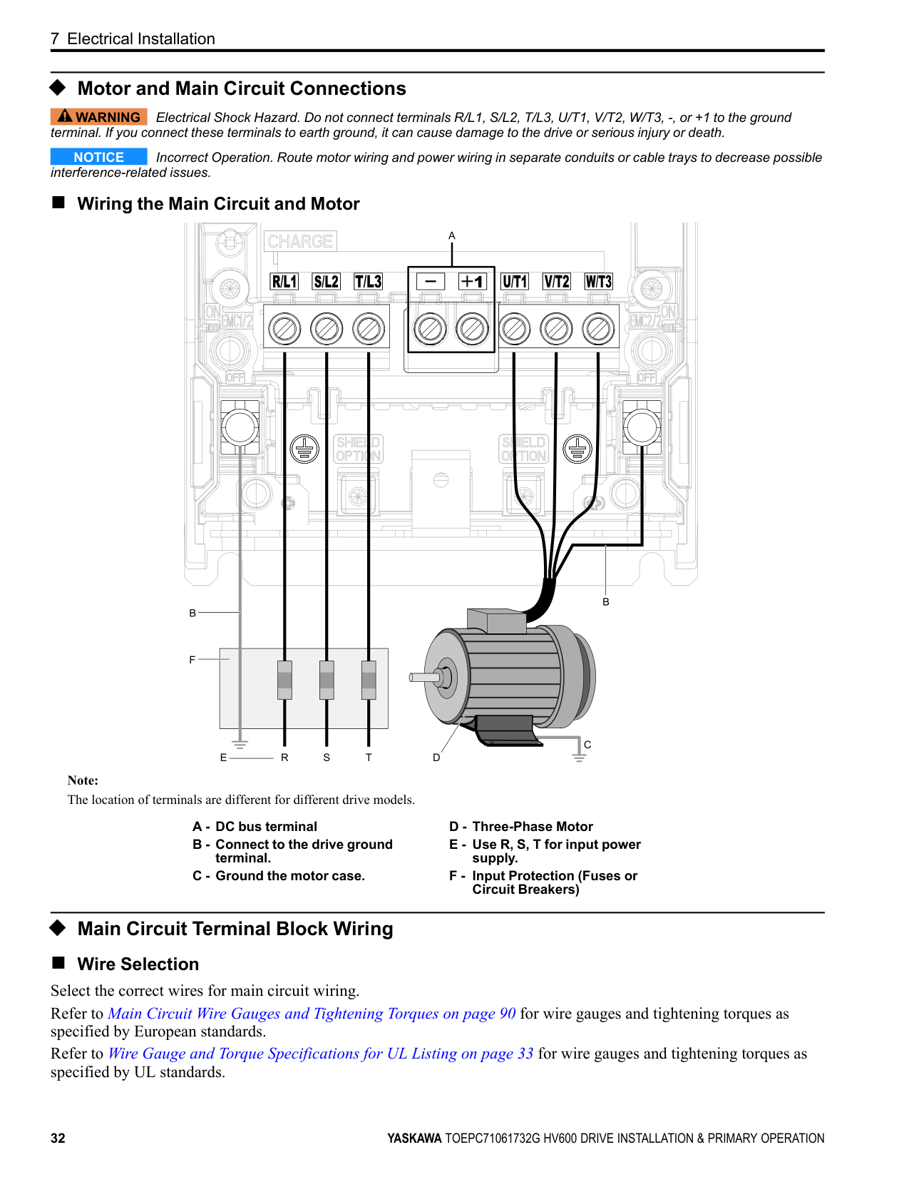
##### ◆ Motor and Main Circuit Connections
WARNING Electrical Shock Hazard. Do not connect terminals R/L1, S/L2, T/L3, U/T1, V/T2, W/T3, -, or +1 to the ground terminal. If you connect these terminals to earth ground, it can cause damage to the drive or serious injury or death.
NOTICE Incorrect Operation. Route motor wiring and power wiring in separate conduits or cable trays to decrease possible interference-related issues.
##### ■ Wiring the Main Circuit and Motor
| | | | |---|---|---| | | | | | | | |
| | | | |---|---|---| | | | |
Note: The location of terminals are different for different drive models.
##### ◆ Main Circuit Terminal Block Wiring
■ Wire Selection Select the correct wires for main circuit wiring. Refer to Main Circuit Wire Gauges and Tightening Torques on page 90 for wire gauges and tightening torques as specified by European standards. Refer to Wire Gauge and Torque Specifications for UL Listing on page 33 for wire gauges and tightening torques as specified by UL standards.
############# Wire Selection Precautions
WARNING Electrical Shock Hazard. Make sure that the protective ground wire complies with technical standards and local safety regulations. The IEC/EN 61800-5-1:2007 standard specifies that you must wire the power supply to automatically deenergize when the protective ground wire disconnects. You can also connect a protective ground wire that has a minimum crosssectional area of 10mm2 (copper wire) or 16 mm2 (aluminum wire). For drive models on which you cannot use a protective ground wire of 10 mm2 or more, install two protective ground wires that have the same cross-sectional area. If you do not obey the standards and regulations, it can cause serious injury or death. The leakage current of the drive will be more than 3.5 mA.
Think about line voltage drop before you select wire gauges. Select wire gauges that drop the voltage by 2% or less of the rated voltage. Increase the wire gauge and the cable length when the risk of voltage drop increases. Calculate line voltage drop with this formula:
Line voltage drop (V) = × wire resistance (Ω/km) × wiring distance (m) × motor rated current (A) × 10-3. Precautions during Wiring Use terminals +1 and - to connect a regenerative converter or regenerative unit. Wire Gauge and Torque Specifications for UL Listing
WARNING Electrical Shock Hazard. Make sure that the protective ground wire complies with technical standards and local safety regulations. The IEC/EN 61800-5-1:2007 standard specifies that you must wire the power supply to automatically deenergize when the protective ground wire disconnects. You can also connect a protective ground wire that has a minimum crosssectional area of 10mm2 (copper wire) or 16 mm2 (aluminum wire). For drive models on which you cannot use a protective ground wire of 10 mm2 or more, install two protective ground wires that have the same cross-sectional area. If you do not obey the standards and regulations, it can cause serious injury or death. The leakage current of the drive will be more than 3.5 mA.
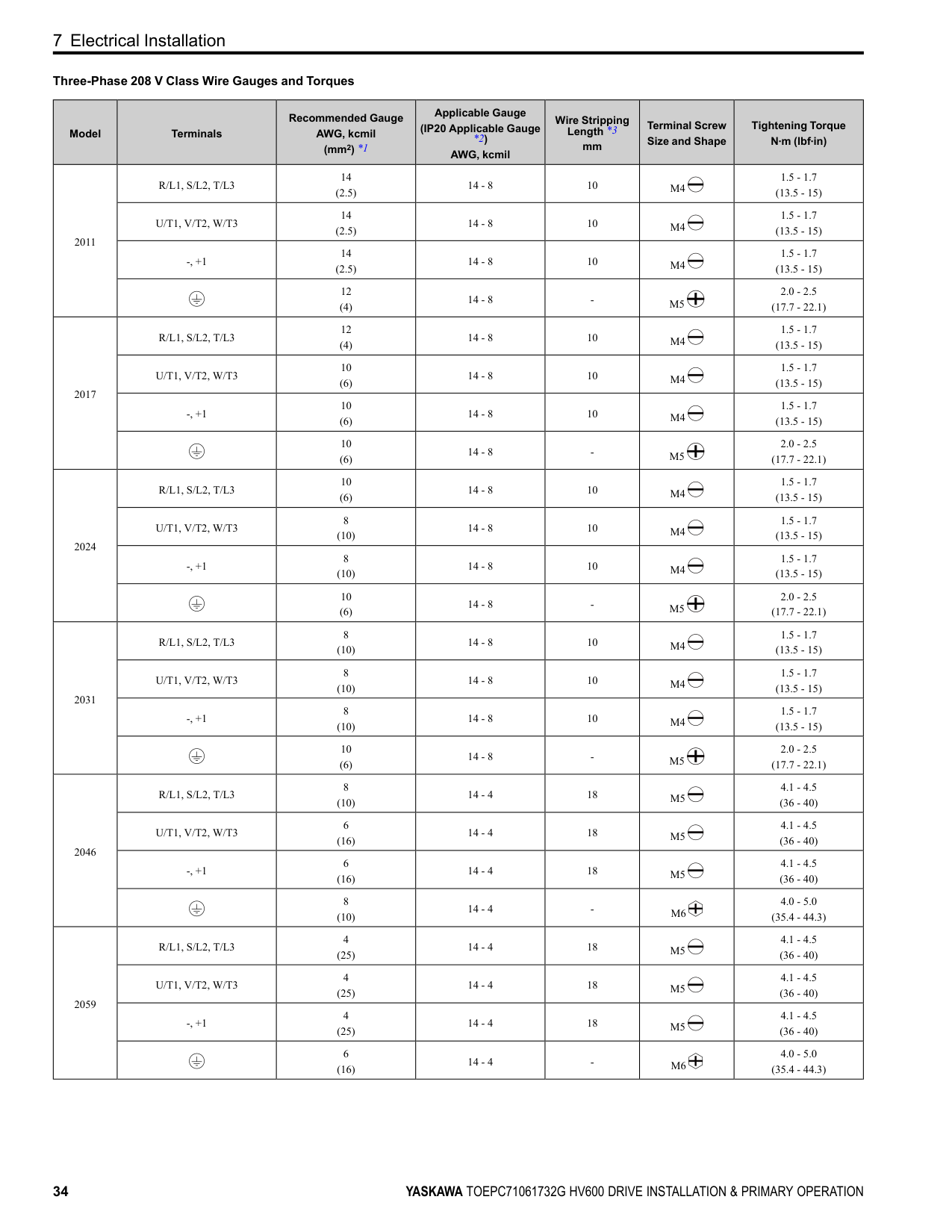
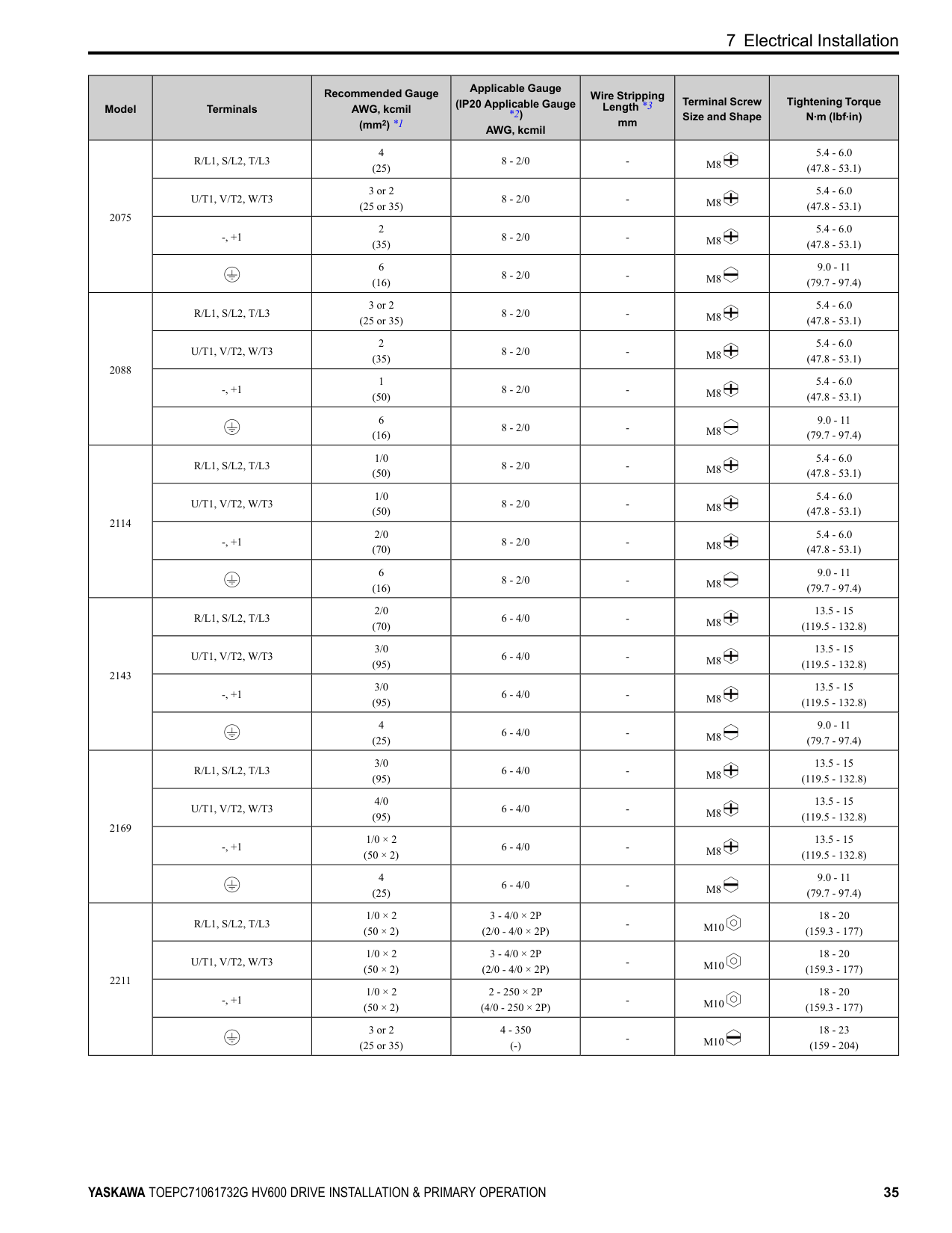
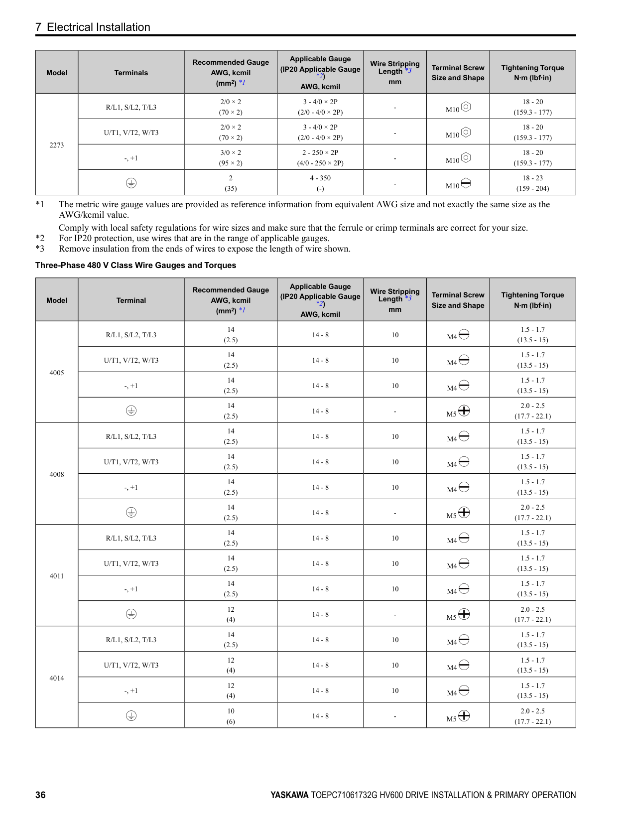
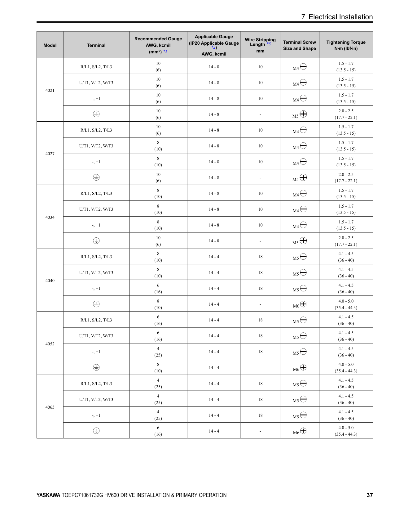
Refer to Three-Phase 208 V Class Wire Gauges and Torques on page 34 and Three-Phase 480 V Class Wire Gauges and Torques on page 36 for the recommended wire gauges and tightening torques of the main circuit terminals.
Note: The recommended wires for the main circuit are 600 V, Class 2 vinyl-insulated wires with a drive continuous maximum allowable temperature of 75 °C (167 °F). Assume these conditions:
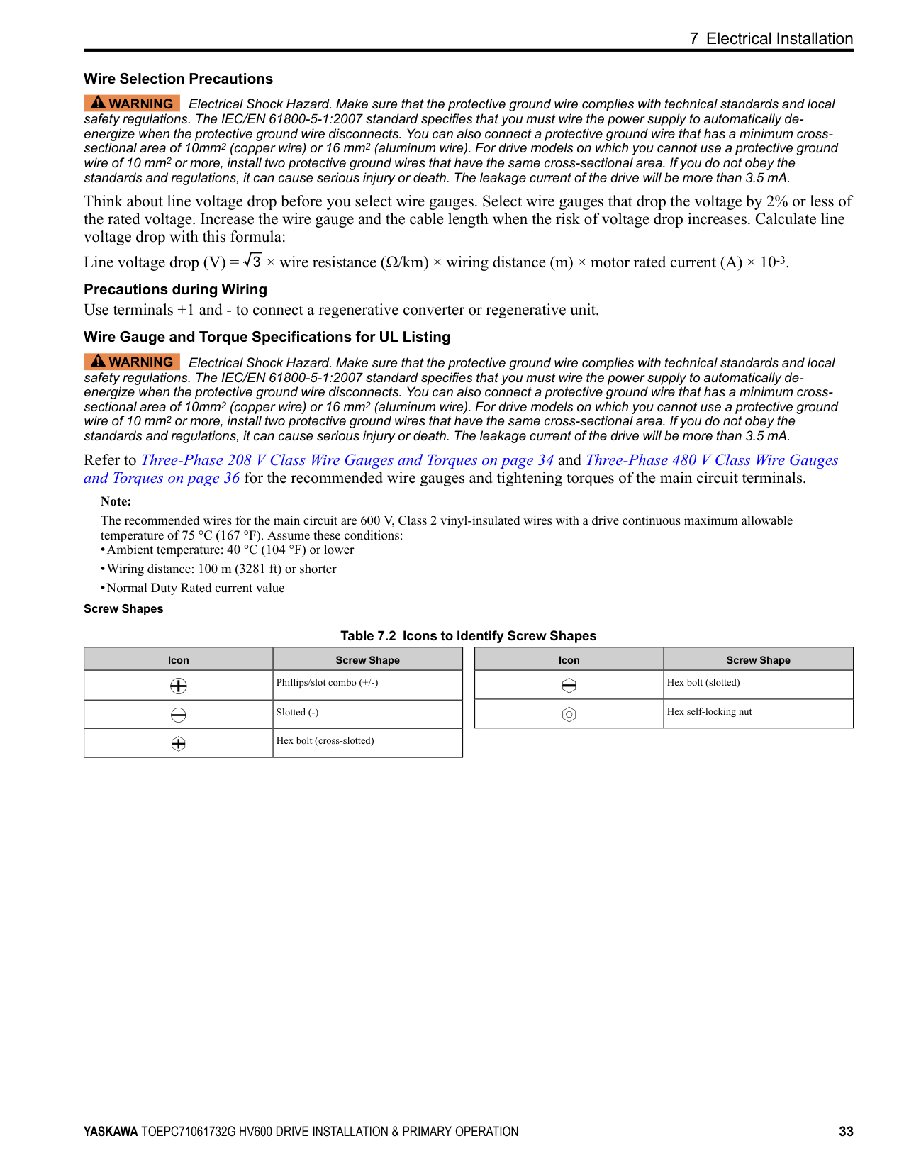
Screw Shapes
############## Table 7.2 Icons to Identify Screw Shapes
|Icon|Screw Shape| |---|---| | |Phillips/slot combo (+/-)| | |Slotted (-)| | |Hex bolt (cross-slotted)|
|Icon|Screw Shape| |---|---| | |Hex bolt (slotted)| | |Hex self-locking nut|
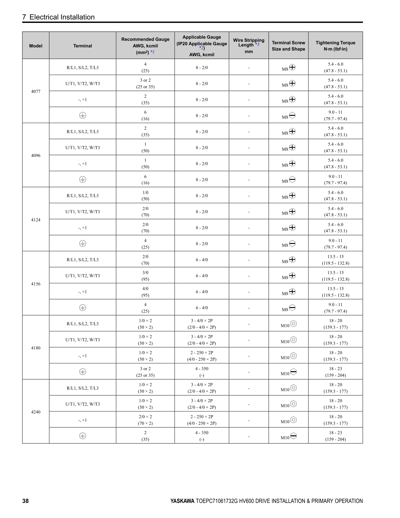
################ Three-Phase 208 V Class Wire Gauges and Torques
|Model|Terminals|Recommended Gauge AWG, kcmil (mm2) *1|Applicable Gauge (IP20 Applicable Gauge *2) AWG, kcmil|Wire Stripping Length *3
mm|Terminal Screw Size and Shape|Tightening Torque N∙m (lbf∙in)| |---|---|---|---|---|---|---| |2011|R/L1, S/L2, T/L3|14 (2.5)|14 - 8|10|M4|1.5 - 1.7 (13.5 - 15)| |2011|U/T1, V/T2, W/T3|14 (2.5)|14 - 8|10|M4|1.5 - 1.7 (13.5 - 15)| |2011|-, +1|14 (2.5)|14 - 8|10|M4|1.5 - 1.7 (13.5 - 15)| |2011| |12 (4)|14 - 8|-|M5|2.0 - 2.5 (17.7 - 22.1)| |2017|R/L1, S/L2, T/L3|12 (4)|14 - 8|10|M4|1.5 - 1.7 (13.5 - 15)| |2017|U/T1, V/T2, W/T3|10 (6)|14 - 8|10|M4|1.5 - 1.7 (13.5 - 15)| |2017|-, +1|10 (6)|14 - 8|10|M4|1.5 - 1.7 (13.5 - 15)| |2017| |10 (6)|14 - 8|-|M5|2.0 - 2.5 (17.7 - 22.1)| |2024|R/L1, S/L2, T/L3|10 (6)|14 - 8|10|M4|1.5 - 1.7 (13.5 - 15)| |2024|U/T1, V/T2, W/T3|8 (10)|14 - 8|10|M4|1.5 - 1.7 (13.5 - 15)| |2024|-, +1|8 (10)|14 - 8|10|M4|1.5 - 1.7 (13.5 - 15)| |2024| |10 (6)|14 - 8|-|M5|2.0 - 2.5 (17.7 - 22.1)| |2031|R/L1, S/L2, T/L3|8 (10)|14 - 8|10|M4|1.5 - 1.7 (13.5 - 15)| |2031|U/T1, V/T2, W/T3|8 (10)|14 - 8|10|M4|1.5 - 1.7 (13.5 - 15)| |2031|-, +1|8 (10)|14 - 8|10|M4|1.5 - 1.7 (13.5 - 15)|
|2031| |10 (6)|14 - 8|-|M5|2.0 - 2.5 (17.7 - 22.1)| |2046|R/L1, S/L2, T/L3|8 (10)|14 - 4|18|M5|4.1 - 4.5 (36 - 40)| |2046|U/T1, V/T2, W/T3|6 (16)|14 - 4|18|M5|4.1 - 4.5 (36 - 40)| |2046|-, +1|6 (16)|14 - 4|18|M5|4.1 - 4.5 (36 - 40)| |2046| |8 (10)|14 - 4|-|M6|4.0 - 5.0 (35.4 - 44.3)| |2059|R/L1, S/L2, T/L3|4 (25)|14 - 4|18|M5|4.1 - 4.5 (36 - 40)| |2059|U/T1, V/T2, W/T3|4 (25)|14 - 4|18|M5|4.1 - 4.5 (36 - 40)| |2059|-, +1|4 (25)|14 - 4|18|M5|4.1 - 4.5 (36 - 40)| |2059| |6 (16)|14 - 4|-|M6|4.0 - 5.0 (35.4 - 44.3)|
|Model|Terminals|Recommended Gauge AWG, kcmil (mm2) *1|Applicable Gauge (IP20 Applicable Gauge *2) AWG, kcmil|Wire Stripping Length *3
mm|Terminal Screw Size and Shape|Tightening Torque N∙m (lbf∙in)| |---|---|---|---|---|---|---| |2075|R/L1, S/L2, T/L3|4 (25)|8 - 2/0|-|M8|5.4 - 6.0 (47.8 - 53.1)| |2075|U/T1, V/T2, W/T3|3 or 2 (25 or 35)|8 - 2/0|-|M8|5.4 - 6.0 (47.8 - 53.1)| |2075|-, +1|2 (35)|8 - 2/0|-|M8|5.4 - 6.0 (47.8 - 53.1)| |2075| |6 (16)|8 - 2/0|-|M8|9.0 - 11 (79.7 - 97.4)| |2088|R/L1, S/L2, T/L3|3 or 2 (25 or 35)|8 - 2/0|-|M8|5.4 - 6.0 (47.8 - 53.1)| |2088|U/T1, V/T2, W/T3|2 (35)|8 - 2/0|-|M8|5.4 - 6.0 (47.8 - 53.1)| |2088|-, +1|1 (50)|8 - 2/0|-|M8|5.4 - 6.0 (47.8 - 53.1)| |2088| |6 (16)|8 - 2/0|-|M8|9.0 - 11 (79.7 - 97.4)| |2114|R/L1, S/L2, T/L3|1/0 (50)|8 - 2/0|-|M8|5.4 - 6.0 (47.8 - 53.1)| |2114|U/T1, V/T2, W/T3|1/0 (50)|8 - 2/0|-|M8|5.4 - 6.0 (47.8 - 53.1)| |2114|-, +1|2/0 (70)|8 - 2/0|-|M8|5.4 - 6.0 (47.8 - 53.1)| |2114| |6 (16)|8 - 2/0|-|M8|9.0 - 11 (79.7 - 97.4)| |2143|R/L1, S/L2, T/L3|2/0 (70)|6 - 4/0|-|M8|13.5 - 15 (119.5 - 132.8)| |2143|U/T1, V/T2, W/T3|3/0 (95)|6 - 4/0|-|M8|13.5 - 15 (119.5 - 132.8)| |2143|-, +1|3/0 (95)|6 - 4/0|-|M8|13.5 - 15 (119.5 - 132.8)| |2143| |4 (25)|6 - 4/0|-|M8|9.0 - 11 (79.7 - 97.4)| |2169|R/L1, S/L2, T/L3|3/0 (95)|6 - 4/0|-|M8|13.5 - 15 (119.5 - 132.8)| |2169|U/T1, V/T2, W/T3|4/0 (95)|6 - 4/0|-|M8|13.5 - 15 (119.5 - 132.8)| |2169|-, +1|1/0 × 2 (50 × 2)|6 - 4/0|-|M8|13.5 - 15 (119.5 - 132.8)| |2169| |4 (25)|6 - 4/0|-|M8|9.0 - 11 (79.7 - 97.4)| |2211|R/L1, S/L2, T/L3|1/0 × 2 (50 × 2)|3 - 4/0 × 2P (2/0 - 4/0 × 2P)|-|M10|18 - 20 (159.3 - 177)| |2211|U/T1, V/T2, W/T3|1/0 × 2 (50 × 2)|3 - 4/0 × 2P (2/0 - 4/0 × 2P)|-|M10|18 - 20 (159.3 - 177)| |2211|-, +1|1/0 × 2 (50 × 2)|2 - 250 × 2P (4/0 - 250 × 2P)|-|M10|18 - 20 (159.3 - 177)| |2211| |3 or 2 (25 or 35)|4 - 350 (-)|-|M10|18 - 23 (159 - 204)|
|Model|Terminals|Recommended Gauge AWG, kcmil (mm2) *1|Applicable Gauge (IP20 Applicable Gauge *2) AWG, kcmil|Wire Stripping Length *3
mm|Terminal Screw Size and Shape|Tightening Torque N∙m (lbf∙in)| |---|---|---|---|---|---|---|
|2273|R/L1, S/L2, T/L3|2/0 × 2 (70 × 2)|3 - 4/0 × 2P (2/0 - 4/0 × 2P)|-|M10|18 - 20 (159.3 - 177)| |2273|U/T1, V/T2, W/T3|2/0 × 2 (70 × 2)|3 - 4/0 × 2P (2/0 - 4/0 × 2P)|-|M10|18 - 20 (159.3 - 177)| |2273|-, +1|3/0 × 2 (95 × 2)|2 - 250 × 2P (4/0 - 250 × 2P)|-|M10|18 - 20 (159.3 - 177)| |2273| |2 (35)|4 - 350 (-)|-|M10|18 - 23 (159 - 204)|
|Model|Terminal|Recommended Gauge AWG, kcmil (mm2) *1|Applicable Gauge (IP20 Applicable Gauge *2) AWG, kcmil|Wire Stripping Length *3
mm|Terminal Screw Size and Shape|Tightening Torque N∙m (lbf∙in)| |---|---|---|---|---|---|---| |4005|R/L1, S/L2, T/L3|14 (2.5)|14 - 8|10|M4|1.5 - 1.7 (13.5 - 15)| |4005|U/T1, V/T2, W/T3|14 (2.5)|14 - 8|10|M4|1.5 - 1.7 (13.5 - 15)| |4005|-, +1|14 (2.5)|14 - 8|10|M4|1.5 - 1.7 (13.5 - 15)| |4005| |14 (2.5)|14 - 8|-|M5|2.0 - 2.5 (17.7 - 22.1)| |4008|R/L1, S/L2, T/L3|14 (2.5)|14 - 8|10|M4|1.5 - 1.7 (13.5 - 15)| |4008|U/T1, V/T2, W/T3|14 (2.5)|14 - 8|10|M4|1.5 - 1.7 (13.5 - 15)| |4008|-, +1|14 (2.5)|14 - 8|10|M4|1.5 - 1.7 (13.5 - 15)| |4008| |14 (2.5)|14 - 8|-|M5|2.0 - 2.5 (17.7 - 22.1)| |4011|R/L1, S/L2, T/L3|14 (2.5)|14 - 8|10|M4|1.5 - 1.7 (13.5 - 15)| |4011|U/T1, V/T2, W/T3|14 (2.5)|14 - 8|10|M4|1.5 - 1.7 (13.5 - 15)| |4011|-, +1|14 (2.5)|14 - 8|10|M4|1.5 - 1.7 (13.5 - 15)| |4011| |12 (4)|14 - 8|-|M5|2.0 - 2.5 (17.7 - 22.1)| |4014|R/L1, S/L2, T/L3|14 (2.5)|14 - 8|10|M4|1.5 - 1.7 (13.5 - 15)| |4014|U/T1, V/T2, W/T3|12 (4)|14 - 8|10|M4|1.5 - 1.7 (13.5 - 15)| |4014|-, +1|12 (4)|14 - 8|10|M4|1.5 - 1.7 (13.5 - 15)| |4014| |10 (6)|14 - 8|-|M5|2.0 - 2.5 (17.7 - 22.1)|
|Model|Terminal|Recommended Gauge AWG, kcmil (mm2) *1|Applicable Gauge (IP20 Applicable Gauge *2) AWG, kcmil|Wire Stripping Length *3
mm|Terminal Screw Size and Shape|Tightening Torque N∙m (lbf∙in)| |---|---|---|---|---|---|---| |4021|R/L1, S/L2, T/L3|10 (6)|14 - 8|10|M4|1.5 - 1.7 (13.5 - 15)| |4021|U/T1, V/T2, W/T3|10 (6)|14 - 8|10|M4|1.5 - 1.7 (13.5 - 15)| |4021|-, +1|10 (6)|14 - 8|10|M4|1.5 - 1.7 (13.5 - 15)| |4021| |10 (6)|14 - 8|-|M5|2.0 - 2.5 (17.7 - 22.1)| |4027|R/L1, S/L2, T/L3|10 (6)|14 - 8|10|M4|1.5 - 1.7 (13.5 - 15)| |4027|U/T1, V/T2, W/T3|8 (10)|14 - 8|10|M4|1.5 - 1.7 (13.5 - 15)| |4027|-, +1|8 (10)|14 - 8|10|M4|1.5 - 1.7 (13.5 - 15)| |4027| |10 (6)|14 - 8|-|M5|2.0 - 2.5 (17.7 - 22.1)|
|4034|R/L1, S/L2, T/L3|8 (10)|14 - 8|10|M4|1.5 - 1.7 (13.5 - 15)| |4034|U/T1, V/T2, W/T3|8 (10)|14 - 8|10|M4|1.5 - 1.7 (13.5 - 15)| |4034|-, +1|8 (10)|14 - 8|10|M4|1.5 - 1.7 (13.5 - 15)| |4034| |10 (6)|14 - 8|-|M5|2.0 - 2.5 (17.7 - 22.1)| |4040|R/L1, S/L2, T/L3|8 (10)|14 - 4|18|M5|4.1 - 4.5 (36 - 40)| |4040|U/T1, V/T2, W/T3|8 (10)|14 - 4|18|M5|4.1 - 4.5 (36 - 40)| |4040|-, +1|6 (16)|14 - 4|18|M5|4.1 - 4.5 (36 - 40)| |4040| |8 (10)|14 - 4|-|M6|4.0 - 5.0 (35.4 - 44.3)| |4052|R/L1, S/L2, T/L3|6 (16)|14 - 4|18|M5|4.1 - 4.5 (36 - 40)| |4052|U/T1, V/T2, W/T3|6 (16)|14 - 4|18|M5|4.1 - 4.5 (36 - 40)| |4052|-, +1|4 (25)|14 - 4|18|M5|4.1 - 4.5 (36 - 40)| |4052| |8 (10)|14 - 4|-|M6|4.0 - 5.0 (35.4 - 44.3)| |4065|R/L1, S/L2, T/L3|4 (25)|14 - 4|18|M5|4.1 - 4.5 (36 - 40)| |4065|U/T1, V/T2, W/T3|4 (25)|14 - 4|18|M5|4.1 - 4.5 (36 - 40)| |4065|-, +1|4 (25)|14 - 4|18|M5|4.1 - 4.5 (36 - 40)| |4065| |6 (16)|14 - 4|-|M6|4.0 - 5.0 (35.4 - 44.3)|
|Model|Terminal|Recommended Gauge AWG, kcmil (mm2) *1|Applicable Gauge (IP20 Applicable Gauge *2) AWG, kcmil|Wire Stripping Length *3
mm|Terminal Screw Size and Shape|Tightening Torque N∙m (lbf∙in)| |---|---|---|---|---|---|---| |4077|R/L1, S/L2, T/L3|4 (25)|8 - 2/0|-|M8|5.4 - 6.0 (47.8 - 53.1)| |4077|U/T1, V/T2, W/T3|3 or 2 (25 or 35)|8 - 2/0|-|M8|5.4 - 6.0 (47.8 - 53.1)| |4077|-, +1|2 (35)|8 - 2/0|-|M8|5.4 - 6.0 (47.8 - 53.1)| |4077| |6 (16)|8 - 2/0|-|M8|9.0 - 11 (79.7 - 97.4)| |4096|R/L1, S/L2, T/L3|2 (35)|8 - 2/0|-|M8|5.4 - 6.0 (47.8 - 53.1)| |4096|U/T1, V/T2, W/T3|1 (50)|8 - 2/0|-|M8|5.4 - 6.0 (47.8 - 53.1)| |4096|-, +1|1 (50)|8 - 2/0|-|M8|5.4 - 6.0 (47.8 - 53.1)| |4096| |6 (16)|8 - 2/0|-|M8|9.0 - 11 (79.7 - 97.4)| |4124|R/L1, S/L2, T/L3|1/0 (50)|8 - 2/0|-|M8|5.4 - 6.0 (47.8 - 53.1)| |4124|U/T1, V/T2, W/T3|2/0 (70)|8 - 2/0|-|M8|5.4 - 6.0 (47.8 - 53.1)| |4124|-, +1|2/0 (70)|8 - 2/0|-|M8|5.4 - 6.0 (47.8 - 53.1)| |4124| |4 (25)|8 - 2/0|-|M8|9.0 - 11 (79.7 - 97.4)| |4156|R/L1, S/L2, T/L3|2/0 (70)|6 - 4/0|-|M8|13.5 - 15 (119.5 - 132.8)| |4156|U/T1, V/T2, W/T3|3/0 (95)|6 - 4/0|-|M8|13.5 - 15 (119.5 - 132.8)| |4156|-, +1|4/0 (95)|6 - 4/0|-|M8|13.5 - 15 (119.5 - 132.8)| |4156| |4 (25)|6 - 4/0|-|M8|9.0 - 11 (79.7 - 97.4)| |4180|R/L1, S/L2, T/L3|1/0 × 2 (50 × 2)|3 - 4/0 × 2P (2/0 - 4/0 × 2P)|-|M10|18 - 20 (159.3 - 177)| |4180|U/T1, V/T2, W/T3|1/0 × 2 (50 × 2)|3 - 4/0 × 2P (2/0 - 4/0 × 2P)|-|M10|18 - 20 (159.3 - 177)| |4180|-, +1|1/0 × 2 (50 × 2)|2 - 250 × 2P (4/0 - 250 × 2P)|-|M10|18 - 20 (159.3 - 177)| |4180| |3 or 2 (25 or 35)|4 - 350 (-)|-|M10|18 - 23 (159 - 204)| |4240|R/L1, S/L2, T/L3|1/0 × 2 (50 × 2)|3 - 4/0 × 2P (2/0 - 4/0 × 2P)|-|M10|18 - 20 (159.3 - 177)|
|4240|U/T1, V/T2, W/T3|1/0 × 2 (50 × 2)|3 - 4/0 × 2P (2/0 - 4/0 × 2P)|-|M10|18 - 20 (159.3 - 177)| |4240|-, +1|2/0 × 2 (70 × 2)|2 - 250 × 2P (4/0 - 250 × 2P)|-|M10|18 - 20 (159.3 - 177)| |4240| |2 (35)|4 - 350 (-)|-|M10|18 - 23 (159 - 204)|
|Model|Terminal|Recommended Gauge AWG, kcmil (mm2) *1|Applicable Gauge (IP20 Applicable Gauge *2) AWG, kcmil|Wire Stripping Length *3
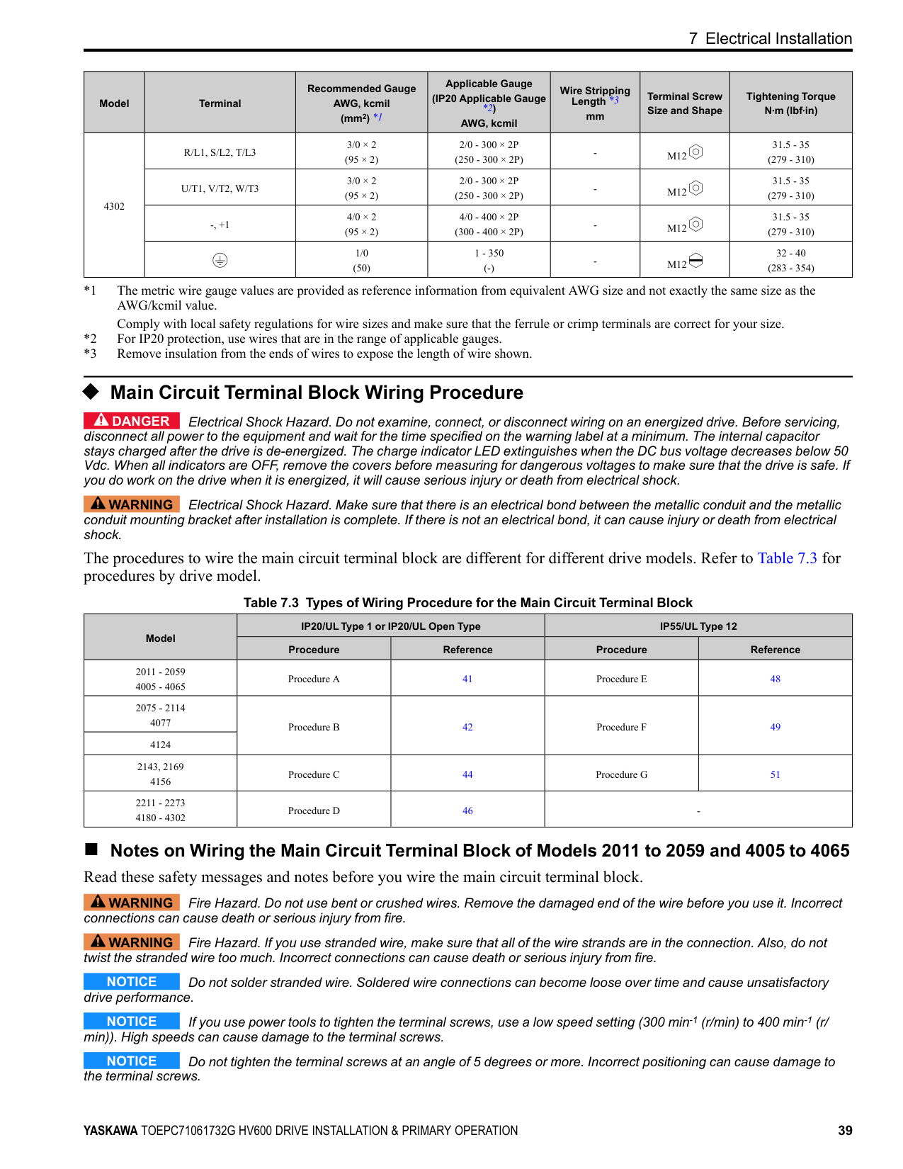
mm|Terminal Screw Size and Shape|Tightening Torque N∙m (lbf∙in)| |---|---|---|---|---|---|---| |4302|R/L1, S/L2, T/L3|3/0 × 2 (95 × 2)|2/0 - 300 × 2P (250 - 300 × 2P)|-|M12|31.5 - 35 (279 - 310)| |4302|U/T1, V/T2, W/T3|3/0 × 2 (95 × 2)|2/0 - 300 × 2P (250 - 300 × 2P)|-|M12|31.5 - 35 (279 - 310)| |4302|-, +1|4/0 × 2 (95 × 2)|4/0 - 400 × 2P (300 - 400 × 2P)|-|M12|31.5 - 35 (279 - 310)| |4302| |1/0 (50)|1 - 350 (-)|-|M12|32 - 40 (283 - 354)|
##### ◆ Main Circuit Terminal Block Wiring Procedure
DANGER Electrical Shock Hazard. Do not examine, connect, or disconnect wiring on an energized drive. Before servicing, disconnect all power to the equipment and wait for the time specified on the warning label at a minimum. The internal capacitor stays charged after the drive is de-energized. The charge indicator LED extinguishes when the DC bus voltage decreases below 50 Vdc. When all indicators are OFF, remove the covers before measuring for dangerous voltages to make sure that the drive is safe. If you do work on the drive when it is energized, it will cause serious injury or death from electrical shock.
WARNING Electrical Shock Hazard. Make sure that there is an electrical bond between the metallic conduit and the metallic conduit mounting bracket after installation is complete. If there is not an electrical bond, it can cause injury or death from electrical shock.
The procedures to wire the main circuit terminal block are different for different drive models. Refer to Table 7.3 for procedures by drive model.
Table 7.3 Types of Wiring Procedure for the Main Circuit Terminal Block
|Model|IP20/UL Type 1 or IP20/UL Open Type|IP20/UL Type 1 or IP20/UL Open Type|IP55/UL Type 12|IP55/UL Type 12| |---|---|---|---|---| |Model|Procedure|Reference|Procedure|Reference| |2011 - 2059 4005 - 4065|Procedure A|41|Procedure E|48| |2075 - 2114 4077|Procedure B|42|Procedure F|49| |4124|Procedure B|42|Procedure F|49| |2143, 2169 4156|Procedure C|44|Procedure G|51| |2211 - 2273 4180 - 4302|Procedure D|46|-|-|
##### ■ Notes on Wiring the Main Circuit Terminal Block of Models 2011 to 2059 and 4005 to 4065 Read these safety messages and notes before you wire the main circuit terminal block.
WARNING Fire Hazard. Do not use bent or crushed wires. Remove the damaged end of the wire before you use it. Incorrect connections can cause death or serious injury from fire.
WARNING Fire Hazard. If you use stranded wire, make sure that all of the wire strands are in the connection. Also, do not twist the stranded wire too much. Incorrect connections can cause death or serious injury from fire.
NOTICE Do not solder stranded wire. Soldered wire connections can become loose over time and cause unsatisfactory drive performance.
NOTICE If you use power tools to tighten the terminal screws, use a low speed setting (300 min-1 (r/min) to 400 min-1 (r/ min)). High speeds can cause damage to the terminal screws.
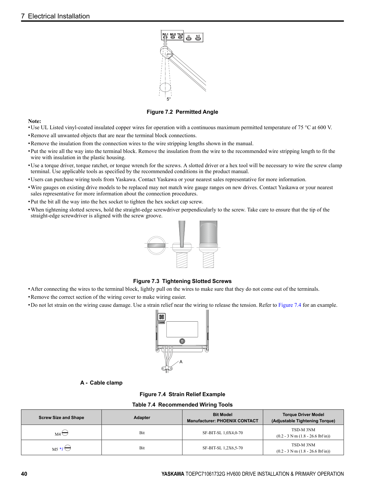
NOTICE Do not tighten the terminal screws at an angle of 5 degrees or more. Incorrect positioning can cause damage to the terminal screws.
Figure 7.2 Permitted Angle Note:
Figure 7.3 Tightening Slotted Screws
A - Cable clamp
Figure 7.4 Strain Relief Example Table 7.4 Recommended Wiring Tools
|Screw Size and Shape|Adapter|Bit Model Manufacturer: PHOENIX CONTACT|Torque Driver Model (Adjustable Tightening Torque)| |---|---|---|---| |M4|Bit|SF-BIT-SL 1,0X4,0-70|TSD-M 3NM (0.2 - 3 N∙m (1.8 - 26.6 lbf∙in))| |M5 *1|Bit|SF-BIT-SL 1,2X6,5-70|TSD-M 3NM (0.2 - 3 N∙m (1.8 - 26.6 lbf∙in))|
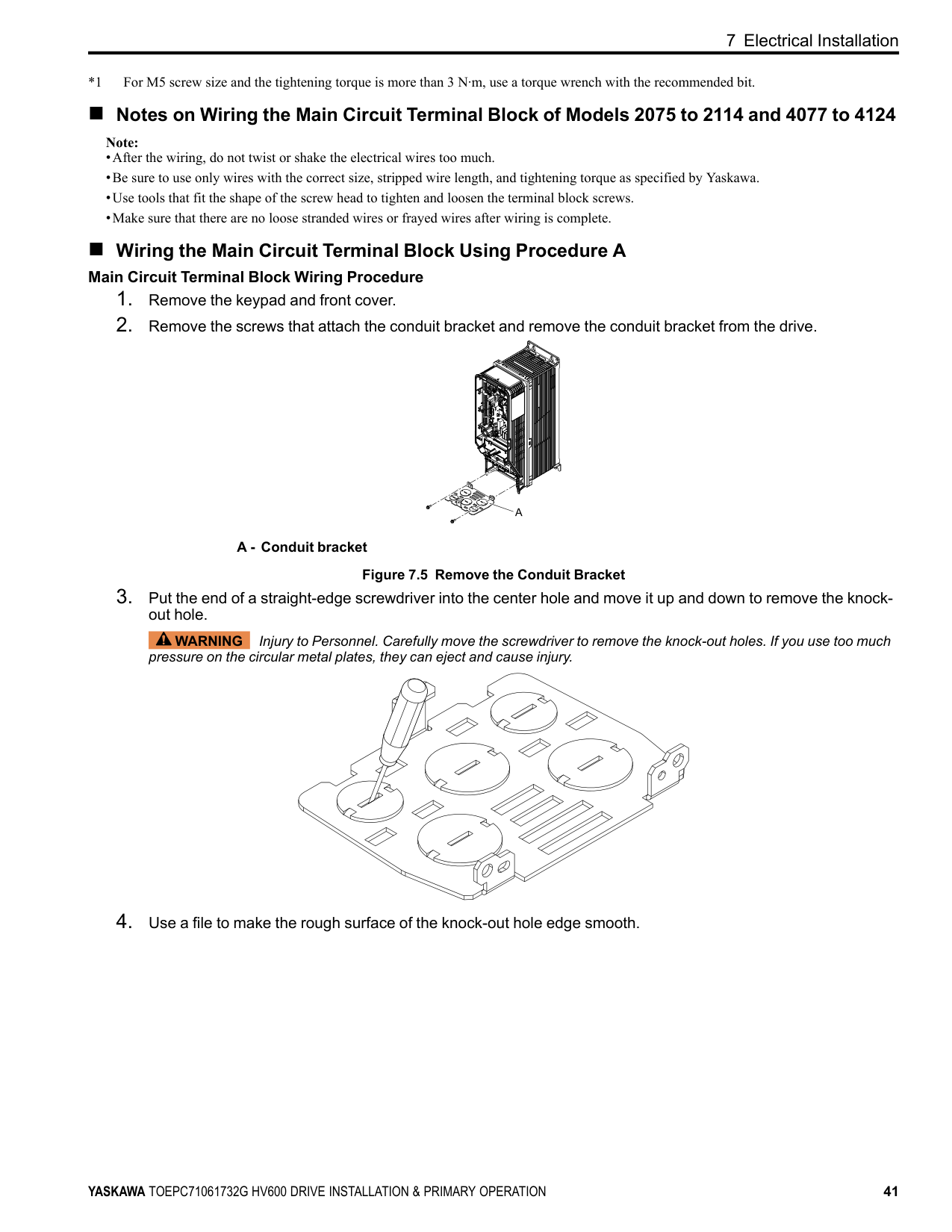
*1 For M5 screw size and the tightening torque is more than 3 N∙m, use a torque wrench with the recommended bit.
##### ■ Notes on Wiring the Main Circuit Terminal Block of Models 2075 to 2114 and 4077 to 4124
Note:
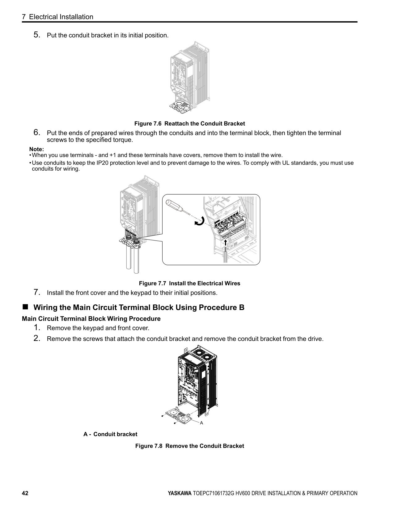
##### ■ Wiring the Main Circuit Terminal Block Using Procedure A
############# Main Circuit Terminal Block Wiring Procedure
A - Conduit bracket Figure 7.5 Remove the Conduit Bracket
WARNING Injury to Personnel. Carefully move the screwdriver to remove the knock-out holes. If you use too much pressure on the circular metal plates, they can eject and cause injury.
Figure 7.6 Reattach the Conduit Bracket
Note:
Figure 7.7 Install the Electrical Wires
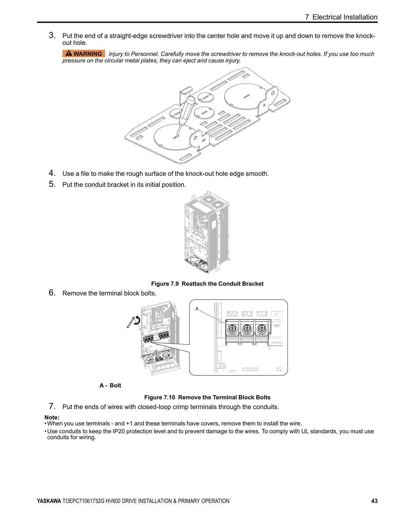
##### ■ Wiring the Main Circuit Terminal Block Using Procedure B
############# Main Circuit Terminal Block Wiring Procedure
| | | |---|---| | | |
| | | |---|---| | | |
| | | |---|---| | | |
A - Conduit bracket Figure 7.8 Remove the Conduit Bracket
WARNING Injury to Personnel. Carefully move the screwdriver to remove the knock-out holes. If you use too much pressure on the circular metal plates, they can eject and cause injury.
Figure 7.9 Reattach the Conduit Bracket
A - Bolt
Figure 7.10 Remove the Terminal Block Bolts
| | | | |---|---|---| | | | | | | | | | | | |
| | |---| | |
| | | |---|---| | | |
| | | |---|---|
| | | |---|---| | | |
| | |---| | |
| | |---| | |
| | |---|
| |
| | |---| | |
| | |---| | |
| | |---| | |
| | |---| | |
| | | |---|---| | | |
| | | | | | | | | | | | | | | | | | |---|---|---|---|---|---|---|---|---|---|---|---|---|---|---|---|---| | | | | | | | | | | | | | | | | | | | | | | | | | | | | | | | | | | | |
| | | | | | | | |---|---|---|---|---|---|---| | | | | | | | | | | | | | | | |
| | |
|---|---|
| | | | |---|---|---|
| | | |---|---|
| | | |---|---|
| | | |---|---| | | |
| | | |---|---| | | |
| | | |---|---| | | |
| | | |---|---| | | |
Note:
| | |---| | |
| | | |---|---| | | |
| | | | | | | | | | | | | | | | | | |---|---|---|---|---|---|---|---|---|---|---|---|---|---|---|---|---| | | | | | | | | | | | | | | | | | | | | | | | | | | | | | | | | | | | |
| | | | | | | | |---|---|---|---|---|---|---| | | | | | | | | | | | | | | | |
############ 7 Electrical Installation
| | | | |---|---|---|
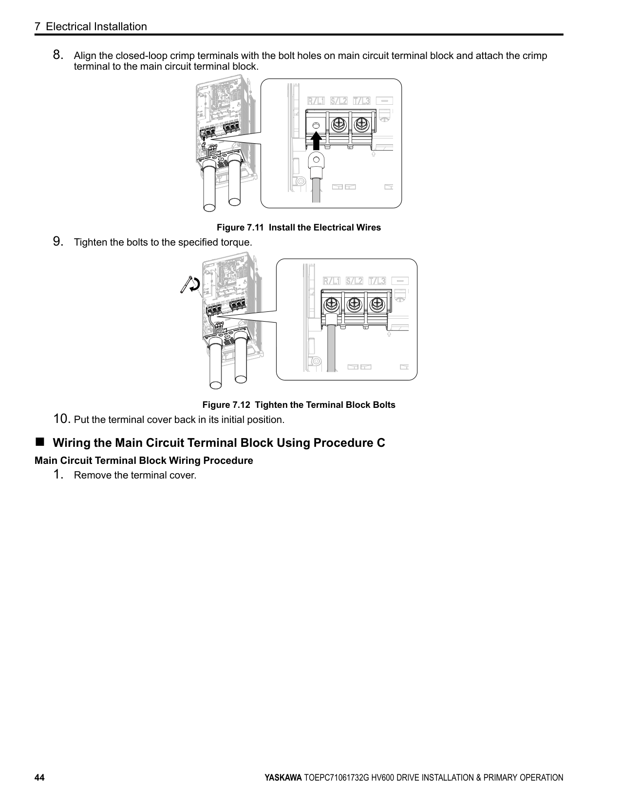
Figure 7.11 Install the Electrical Wires
Figure 7.12 Tighten the Terminal Block Bolts
| | | |---|---|
| | | |---|---| | | |
| | |---| | |
| | |---| | |
| | |---| | |
| | | | |---|---|---| | | | | | | | |
| | |---| | |
| | | | | | | | | | | | | | | | | | |---|---|---|---|---|---|---|---|---|---|---|---|---|---|---|---|---| | | | | | | | | | | | | | | | | | | | | | | | | | | | | | | | | | | | |
| | | | | | | | |---|---|---|---|---|---|---|
| | | | | | | | | | | | | | | |
| | | | |---|---|---|
| | | |---|---|
| | | | |---|---|---| | | | |
| | | |---|---| | | |
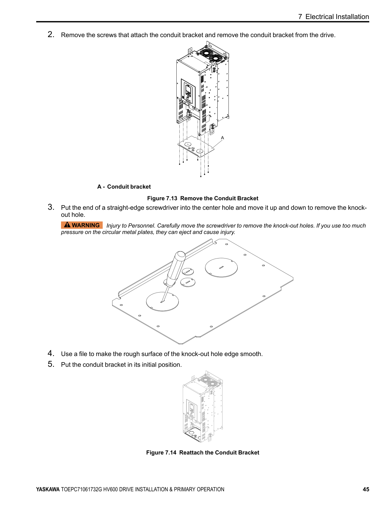
##### ■ Wiring the Main Circuit Terminal Block Using Procedure C
############# Main Circuit Terminal Block Wiring Procedure
A - Conduit bracket Figure 7.13 Remove the Conduit Bracket
WARNING Injury to Personnel. Carefully move the screwdriver to remove the knock-out holes. If you use too much pressure on the circular metal plates, they can eject and cause injury.
| | |
|---|---| | | |
| | | |---|---| | | |
Figure 7.14 Reattach the Conduit Bracket
| | |---| | |
############ 7 Electrical Installation
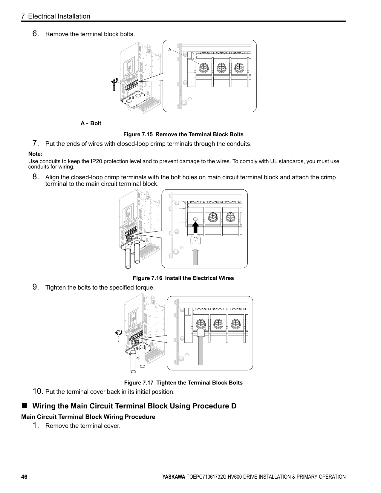
A - Bolt
Figure 7.15 Remove the Terminal Block Bolts
Note:
Use conduits to keep the IP20 protection level and to prevent damage to the wires. To comply with UL standards, you must use conduits for wiring.
Figure 7.16 Install the Electrical Wires
Figure 7.17 Tighten the Terminal Block Bolts
| | | |---|---| | | |
| | | |---|---| | | |
| | | |---|---| | | |
| | | | |---|---|---| | | | |
| | | |---|---| | | |
| | | |---|---| | | |
| | | |---|---| | | |
| | | |---|---| | | |
| | |
|---|---| | | |
| | | |---|---| | | | | | | | | | | | | | | | | | | | | | | | |
| | |---| | |
| | |---| | |
| | |---| | |
| | |---| | |
| | |---| | |
| | |---| | |
| | | |---|---| | | |
| | | |---|---| | | |
| | | |---|---| | | |
| | | |---|---| | | |
| | | | |---|---|---| | | | |
| | | | |---|---|---| | | | |
##### ■ Wiring the Main Circuit Terminal Block Using Procedure D
############# Main Circuit Terminal Block Wiring Procedure
| | | | |---|---|---| | | | |
| | | | |---|---|---| | | | |
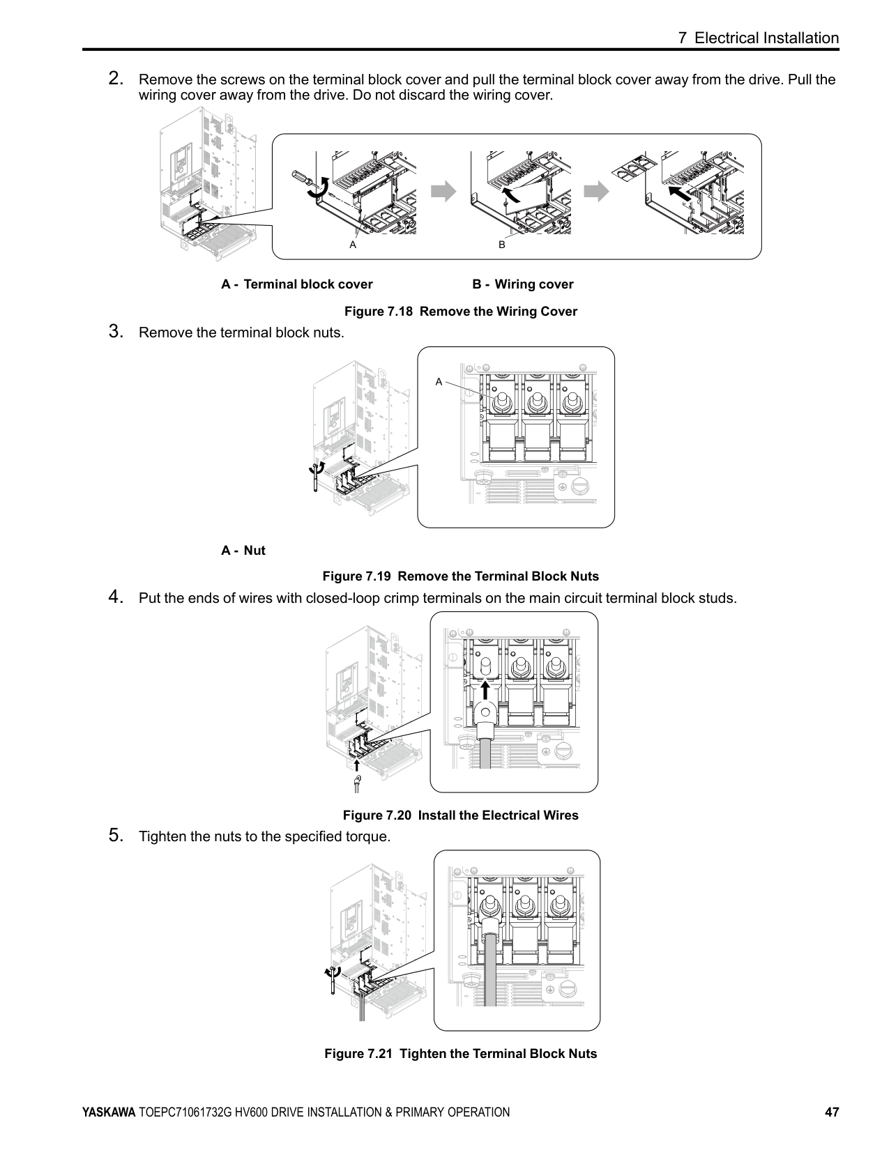
A - Terminal block cover B - Wiring cover Figure 7.18 Remove the Wiring Cover
A - Nut
Figure 7.19 Remove the Terminal Block Nuts
Figure 7.20 Install the Electrical Wires
| | | | |---|---|---| | | | |
| | | | |---|---|---| | | | |
| | | | |---|---|---| | | | |
| | | |---|---| | | |
| | | |---|---| | | |
Figure 7.21 Tighten the Terminal Block Nuts
############ 7 Electrical Installation
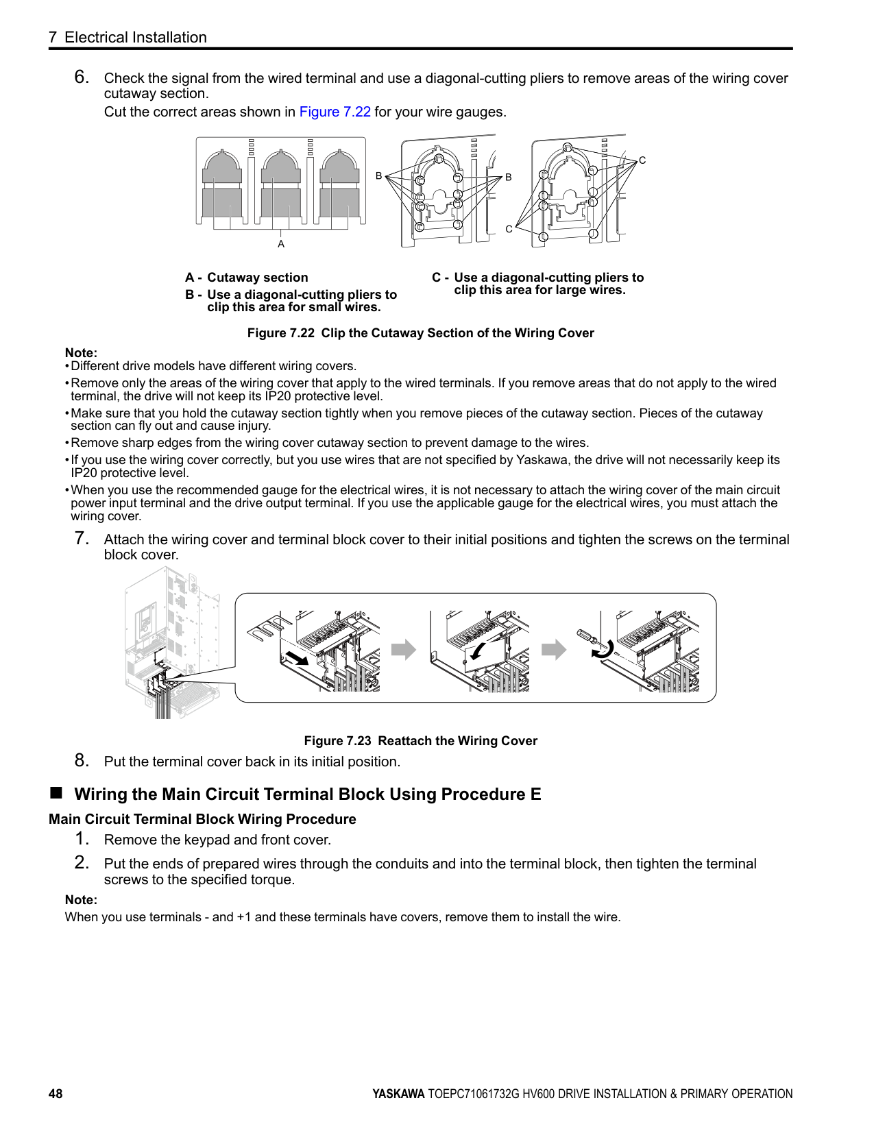
A - Cutaway section B - Use a diagonal-cutting pliers to
clip this area for small wires.
C - Use a diagonal-cutting pliers to clip this area for large wires.
Figure 7.22 Clip the Cutaway Section of the Wiring Cover Note:
Figure 7.23 Reattach the Wiring Cover
##### ■ Wiring the Main Circuit Terminal Block Using Procedure E
############# Main Circuit Terminal Block Wiring Procedure
Note: When you use terminals - and +1 and these terminals have covers, remove them to install the wire.
Figure 7.24 Install the Electrical Wires
Note:
| | | |---|---| | | | | | |
A - Rubber grommets
| | | | |---|---|---| | | | | | | | | | | | |
| | |---| | |
| | | |---|---|
| | |
| | | |---|---|
| | |---| | |
##### ■ Wiring the Main Circuit Terminal Block Using Procedure F
| | |---| | |
| | | |---|---| | | |
############# Main Circuit Terminal Block Wiring Procedure
| | | | | | | | |---|---|---|---|---|---|---| | | | | | | | | | | | | | | | |
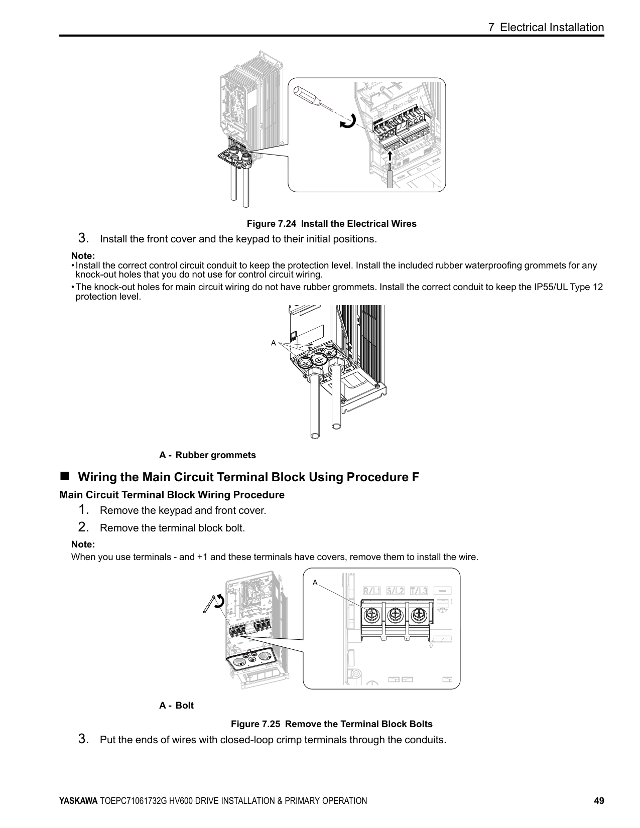
Note: When you use terminals - and +1 and these terminals have covers, remove them to install the wire.
A - Bolt
Figure 7.25 Remove the Terminal Block Bolts
| | | |---|---|
| | | | |---|---|---|
| | | |---|---| | | |
| | | |---|---| | | |
| | | |---|---| | | |
| | |---| | |
| | |---| | |
| | |---| | |
| | |---| | |
| | | | | | | | | | | | | | | | | | |---|---|---|---|---|---|---|---|---|---|---|---|---|---|---|---|---| | | | | | | | | | | | | | | | | | | | | | | | | | | | | | | | | | | | |
| | | |---|---|
| | | |---|---|
| | |---| | |
| | | |---|---| | | |
| | | | | | | | | | | | | | | | | | |---|---|---|---|---|---|---|---|---|---|---|---|---|---|---|---|---| | | | | | | | | | | | | | | | | | | | | | | | | | | | | | | | | | | | |
| | | | | | | | |---|---|---|---|---|---|---| | | | | | | | | | | | | | | | |
############ 7 Electrical Installation
| | | |---|---|
| | | | |---|---|---|
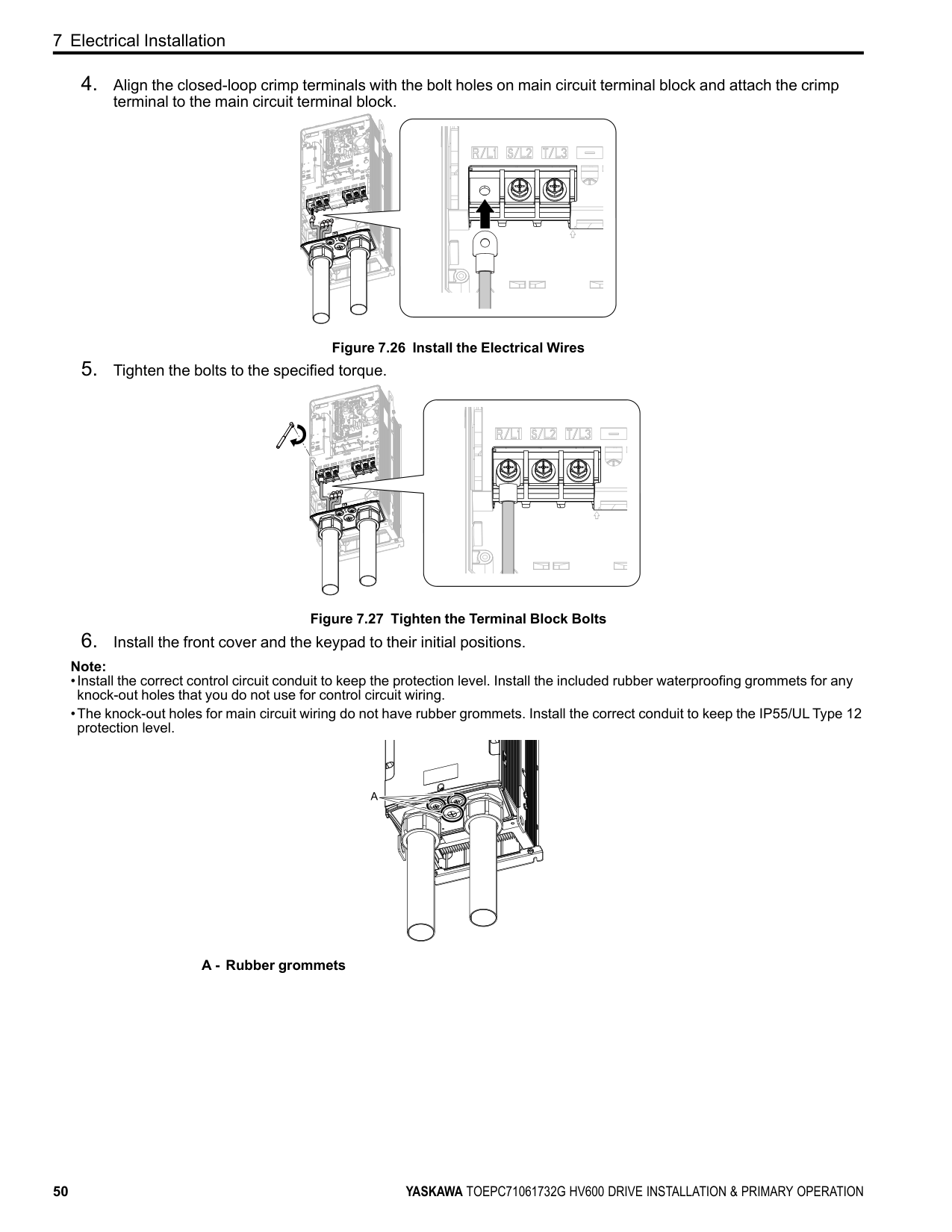
terminal to the main circuit terminal block.
| | |---| | |
| | | | | | | | |---|---|---|---|---|---|---| | | | | | | | | | | | | | | | |
| | | |---|---|
| | | | |---|---|---|
Figure 7.26 Install the Electrical Wires
| | | | |---|---|---|
| | |---| | |
| | |---| | |
| | |---| | |
| | | | | | | | | | | | | | | | | | |---|---|---|---|---|---|---|---|---|---|---|---|---|---|---|---|---| | | | | | | | | | | | | | | | | | | | | | | | | | | | | | | | | | | | |
| | | | | |---|---|---|---| | | | | |
Figure 7.27 Tighten the Terminal Block Bolts
Note:
############## A - Rubber grommets
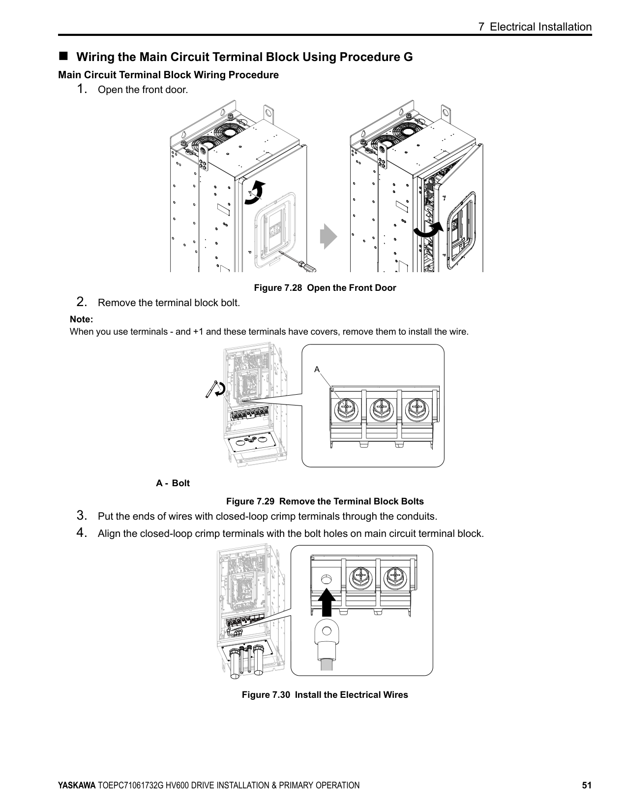
##### ■ Wiring the Main Circuit Terminal Block Using Procedure G
############# Main Circuit Terminal Block Wiring Procedure
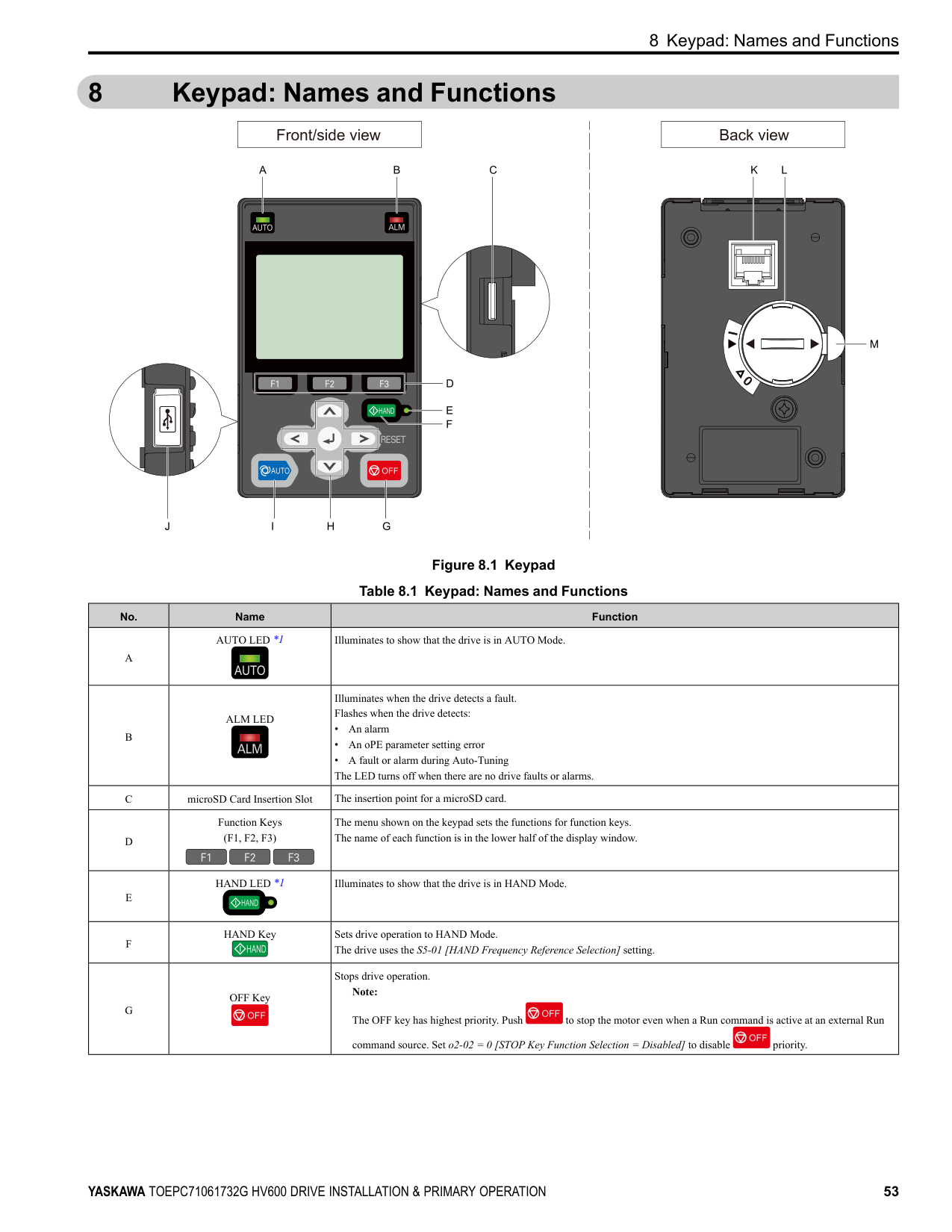
Figure 7.28 Open the Front Door
Note: When you use terminals - and +1 and these terminals have covers, remove them to install the wire.
A - Bolt
Figure 7.29 Remove the Terminal Block Bolts
| | | |---|---| | | | | | |
Figure 7.30 Install the Electrical Wires
############ 7 Electrical Installation
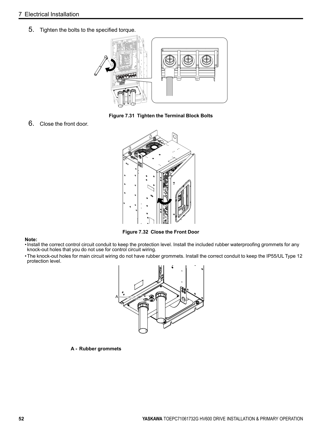
Figure 7.31 Tighten the Terminal Block Bolts
Figure 7.32 Close the Front Door Note:
############## A - Rubber grommets
#### 8 Keypad: Names and Functions
| | | | |---|---|---| | | | |
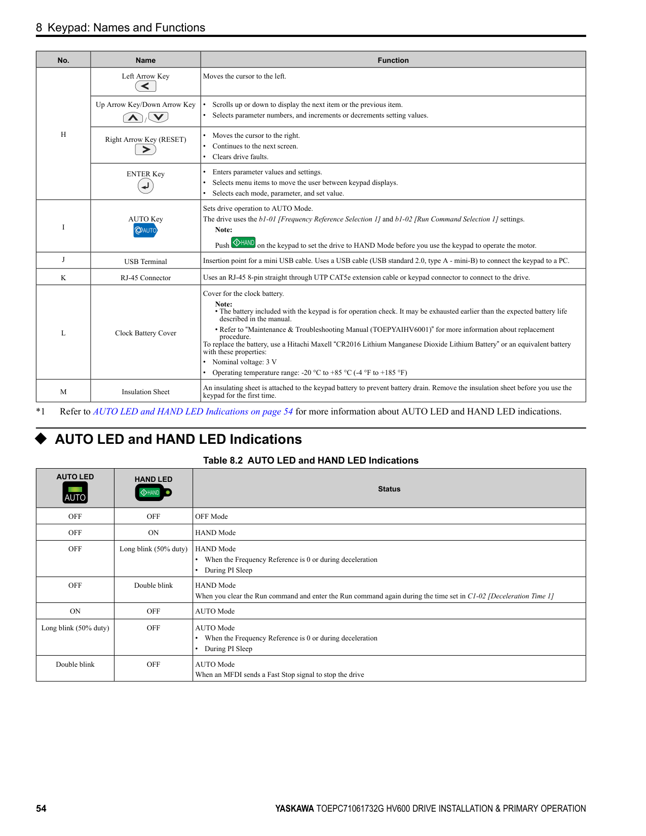
Figure 8.1 Keypad Table 8.1 Keypad: Names and Functions
|No.|Name|Function| |---|---|---| |A|AUTO LED *1|Illuminates to show that the drive is in AUTO Mode.| |B|ALM LED|Illuminates when the drive detects a fault. Flashes when the drive detects:
• An alarm
• An oPE parameter setting error
• A fault or alarm during Auto-Tuning The LED turns off when there are no drive faults or alarms.
| |C|microSD Card Insertion Slot|The insertion point for a microSD card.| |D|Function Keys (F1, F2, F3)|The menu shown on the keypad sets the functions for function keys. The name of each function is in the lower half of the display window.| |E|HAND LED *1|Illuminates to show that the drive is in HAND Mode.| |F|HAND Key|Sets drive operation to HAND Mode. The drive uses the S5-01 [HAND Frequency Reference Selection] setting.| |G|OFF Key|Stops drive operation. Note: The OFF key has highest priority. Push to stop the motor even when a Run command is active at an external Run command source. Set o2-02 0 [STOP Key Function Selection Disabled] to disable priority.|
|No.|Name|Function| |---|---|---| |H|Left Arrow Key|Moves the cursor to the left.| |H|Up Arrow Key/Down Arrow Key /|• Scrolls up or down to display the next item or the previous item.
• Selects parameter numbers, and increments or decrements setting values.
| |H|Right Arrow Key (RESET)|• Moves the cursor to the right.
• Continues to the next screen.
• Clears drive faults.
| |H|ENTER Key|• Enters parameter values and settings.
• Selects menu items to move the user between keypad displays.
• Selects each mode, parameter, and set value.
| |I|AUTO Key|Sets drive operation to AUTO Mode. The drive uses the b1-01 [Frequency Reference Selection 1] and b1-02 [Run Command Selection 1] settings.
Note: Push on the keypad to set the drive to HAND Mode before you use the keypad to operate the motor.| |J|USB Terminal|Insertion point for a mini USB cable. Uses a USB cable (USB standard 2.0, type A - mini-B) to connect the keypad to a PC.| |K|RJ-45 Connector|Uses an RJ-45 8-pin straight through UTP CAT5e extension cable or keypad connector to connect to the drive.| |L|Clock Battery Cover|Cover for the clock battery.
Note:
• The battery included with the keypad is for operation check. It may be exhausted earlier than the expected battery life described in the manual.
• Refer to “Maintenance & Troubleshooting Manual (TOEPYAIHV6001)” for more information about replacement procedure. To replace the battery, use a Hitachi Maxell “CR2016 Lithium Manganese Dioxide Lithium Battery” or an equivalent battery with these properties:
• Nominal voltage: 3 V
• Operating temperature range: -20 °C to +85 °C (-4 °F to +185 °F)
| |M|Insulation Sheet|An insulating sheet is attached to the keypad battery to prevent battery drain. Remove the insulation sheet before you use the keypad for the first time.|
*1 Refer to AUTO LED and HAND LED Indications on page 54 for more information about AUTO LED and HAND LED indications.
##### ◆ AUTO LED and HAND LED Indications
Table 8.2 AUTO LED and HAND LED Indications
|AUTO LED|HAND LED|Status| |---|---|---|
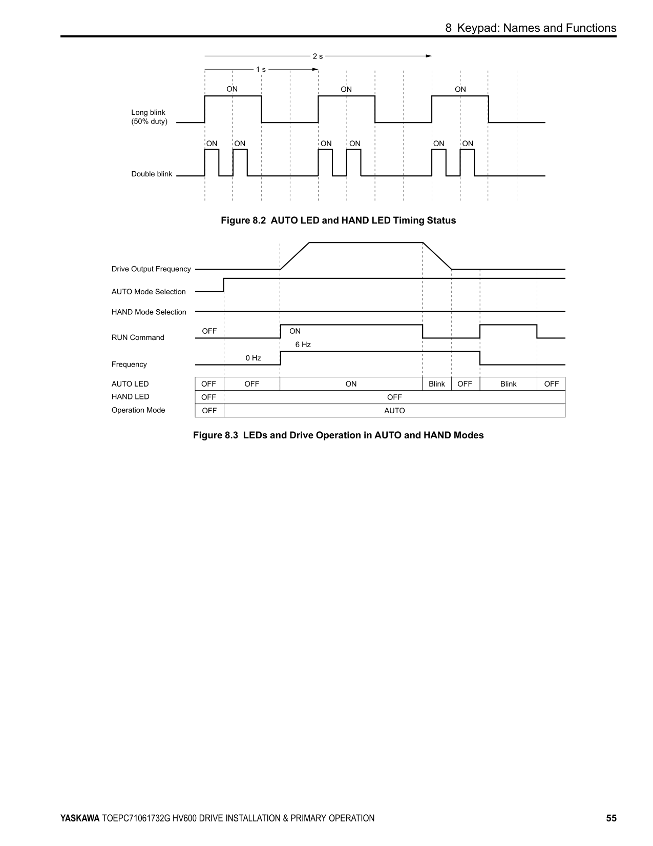
|OFF|OFF|OFF Mode| |OFF|ON|HAND Mode| |OFF|Long blink (50% duty)|HAND Mode
• When the Frequency Reference is 0 or during deceleration
• During PI Sleep
| |OFF|Double blink|HAND Mode When you clear the Run command and enter the Run command again during the time set in C1-02 [Deceleration Time 1]| |ON|OFF|AUTO Mode| |Long blink (50% duty)|OFF|AUTO Mode
• When the Frequency Reference is 0 or during deceleration
• During PI Sleep
| |Double blink|OFF|AUTO Mode When an MFDI sends a Fast Stop signal to stop the drive|
Figure 8.2 AUTO LED and HAND LED Timing Status
Figure 8.3 LEDs and Drive Operation in AUTO and HAND Modes
##### ◆ Keypad Mode and Menu Displays
| | |---| | | | | | | | |
| | |---| | | | |
| | |---| | | | |
| | |---| | | | |
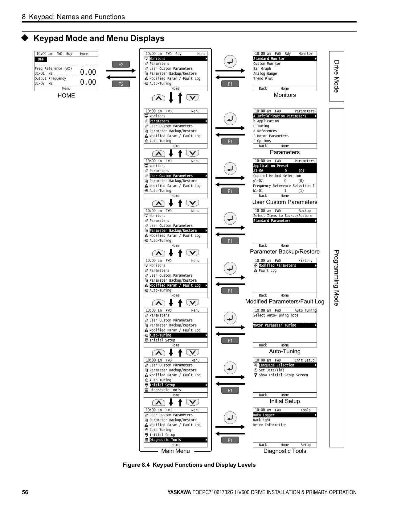
| | |---| | | | |
| | |---| | | | |
| | |---| | | | |
| | |---| | | | |
| | |---| | | | |
| | |---| | | | |
| | |---| | | | |
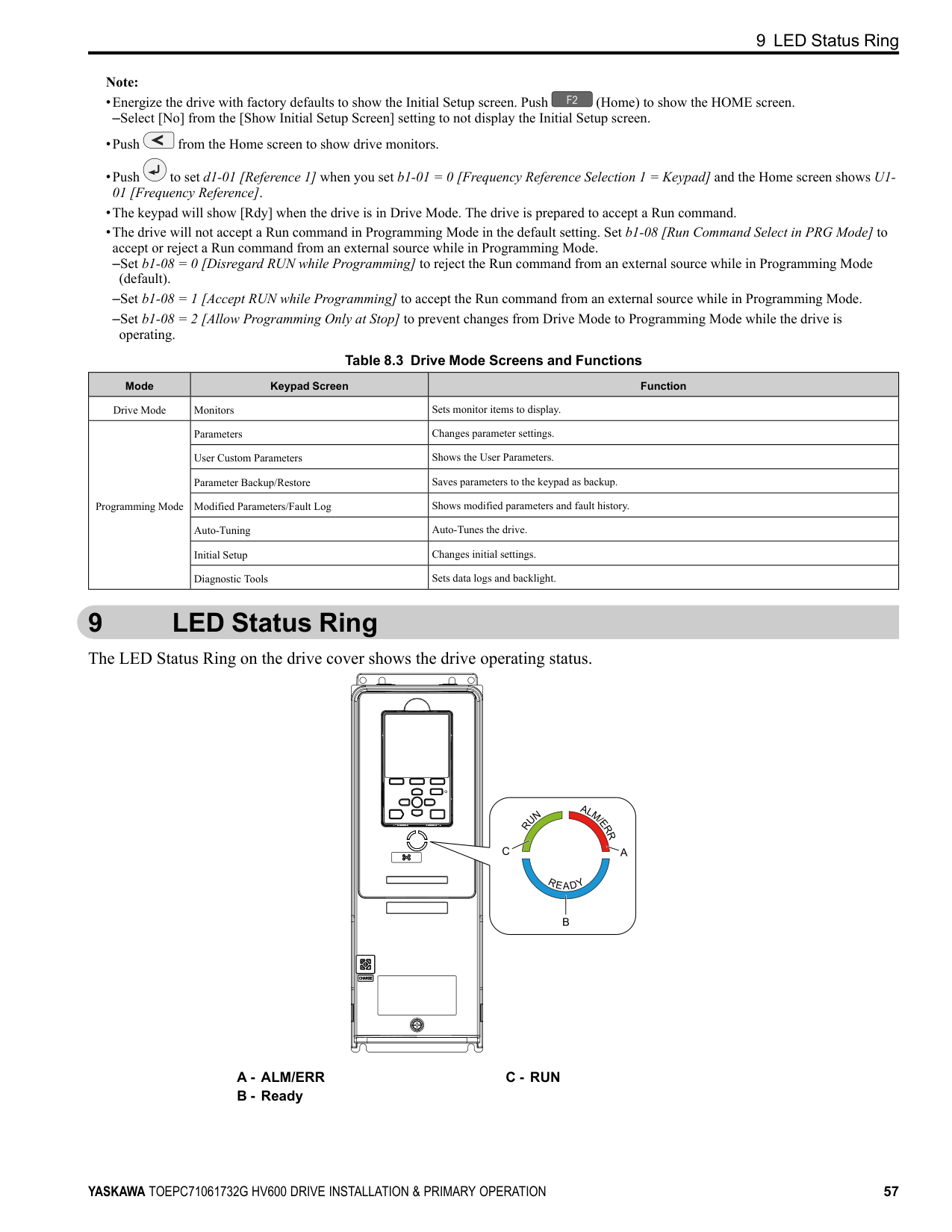
| | |---| | | | |
| | |---| | | | |
| | |---| | | | |
| | |---| | | | |
Figure 8.4 Keypad Functions and Display Levels
9 LED Status Ring
Note:
–Select [No] from the [Show Initial Setup Screen] setting to not display the Initial Setup screen.
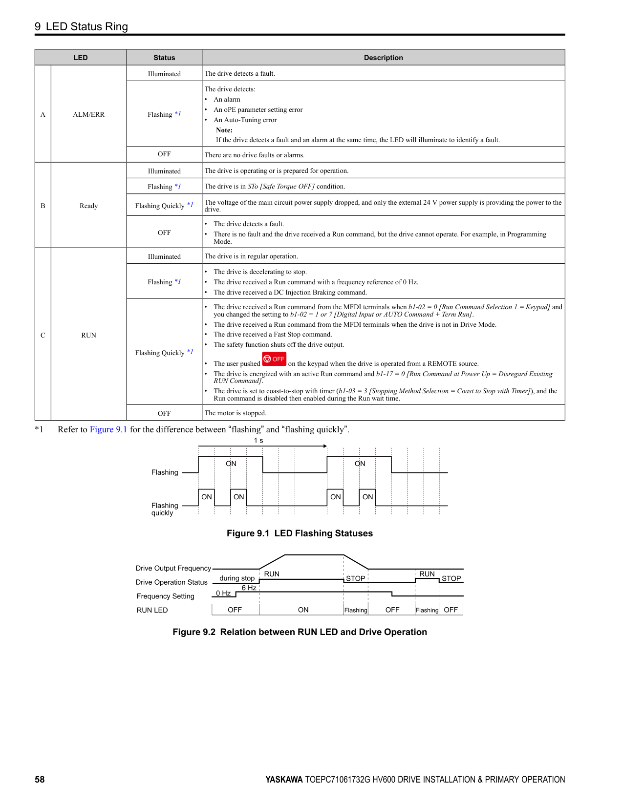
Table 8.3 Drive Mode Screens and Functions
|Mode|Keypad Screen|Function| |---|---|---| |Drive Mode|Monitors|Sets monitor items to display.| |Programming Mode|Parameters|Changes parameter settings.| |Programming Mode|User Custom Parameters|Shows the User Parameters.| |Programming Mode|Parameter Backup/Restore|Saves parameters to the keypad as backup.| |Programming Mode|Modified Parameters/Fault Log|Shows modified parameters and fault history.| |Programming Mode|Auto-Tuning|Auto-Tunes the drive.| |Programming Mode|Initial Setup|Changes initial settings.| |Programming Mode|Diagnostic Tools|Sets data logs and backlight.|
#### 9 LED Status Ring
The LED Status Ring on the drive cover shows the drive operating status.
C - RUN
9 LED Status Ring
|LED|LED|Status|Description| |---|---|---|---| |A|ALM/ERR|Illuminated|The drive detects a fault.| |A|ALM/ERR|Flashing *1|The drive detects:
• An alarm
• An oPE parameter setting error
• An Auto-Tuning error Note: If the drive detects a fault and an alarm at the same time, the LED will illuminate to identify a fault.
| |A|ALM/ERR|OFF|There are no drive faults or alarms.| |B|Ready|Illuminated|The drive is operating or is prepared for operation.| |B|Ready|Flashing *1|The drive is in STo [Safe Torque OFF] condition.| |B|Ready|Flashing Quickly *1|The voltage of the main circuit power supply dropped, and only the external 24 V power supply is providing the power to the drive.| |B|Ready|OFF|• The drive detects a fault.
• There is no fault and the drive received a Run command, but the drive cannot operate. For example, in Programming Mode.
| |C|RUN|Illuminated|The drive is in regular operation.|
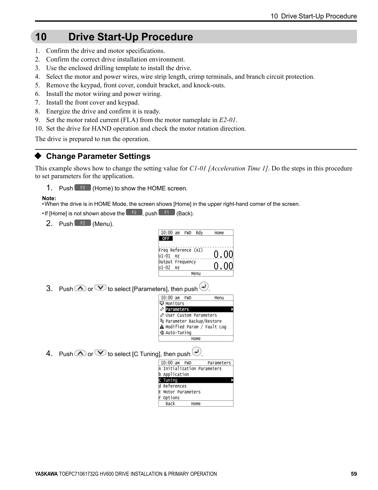
|C|RUN|Flashing *1|• The drive is decelerating to stop.
• The drive received a Run command with a frequency reference of 0 Hz.
• The drive received a DC Injection Braking command.
| |C|RUN|Flashing Quickly *1|• The drive received a Run command from the MFDI terminals when b1-02 0 [Run Command Selection 1 Keypad] and you changed the setting to b1-02 1 or 7 [Digital Input or AUTO Command + Term Run].
• The drive received a Run command from the MFDI terminals when the drive is not in Drive Mode.
• The drive received a Fast Stop command.
• The safety function shuts off the drive output.
• The user pushed on the keypad when the drive is operated from a REMOTE source.
• The drive is energized with an active Run command and b1-17 = 0 [Run Command at Power Up = Disregard Existing RUN Command].
• The drive is set to coast-to-stop with timer (b1-03 = 3 [Stopping Method Selection = Coast to Stop with Timer]), and the Run command is disabled then enabled during the Run wait time.
| |C|RUN|OFF|The motor is stopped.|
*1 Refer to Figure 9.1 for the difference between “flashing” and “flashing quickly”.
| | | | | | | | | | | | | | | | | | |---|---|---|---|---|---|---|---|---|---|---|---|---|---|---|---|---| | | | | | | | | | | | | | | | | | | | | | | | | | | | | | | | | | | | | | | | | | | | | | | | | | | | | | | | | | | | | | | | | | | | | | | | |
Figure 9.1 LED Flashing Statuses
Figure 9.2 Relation between RUN LED and Drive Operation
#### 10 Drive Start-Up Procedure
##### ◆ Change Parameter Settings
This example shows how to change the setting value for C1-01 [Acceleration Time 1]. Do the steps in this procedure to set parameters for the application.
Note:
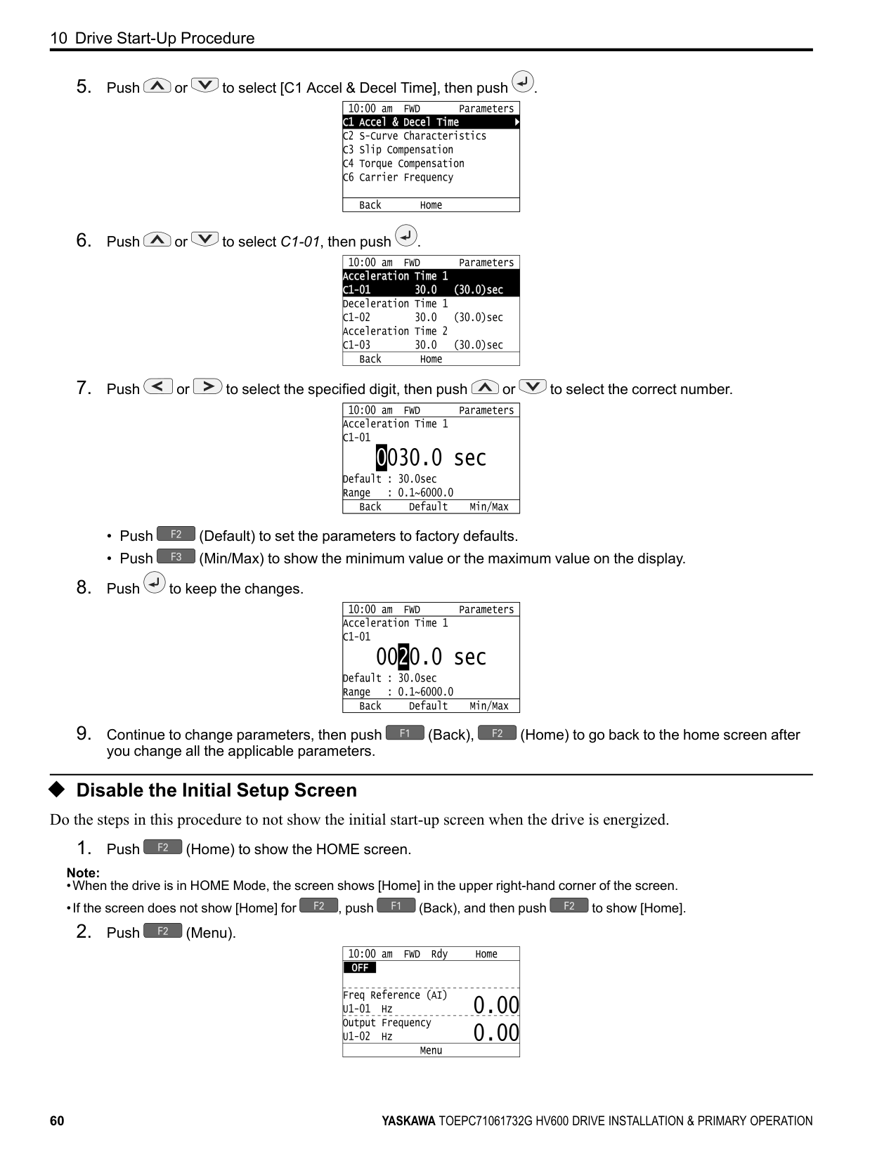
| | |---| | | | | | | | |
| | |---| | | | |
| | |---| | | | |
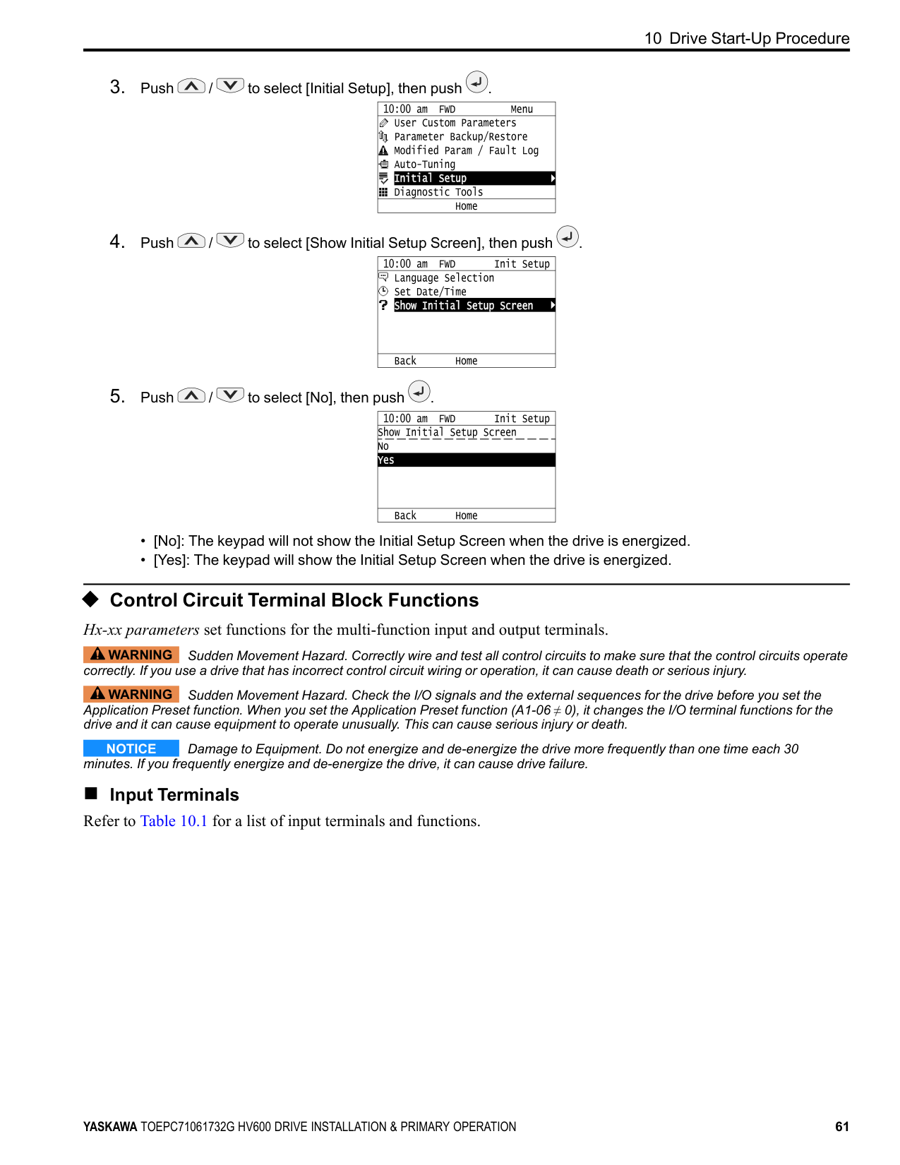
| | |---| | | | |
| | |---| | | | |
| | |---| | | | |
| | |---| | | | |
###### ◆ Disable the Initial Setup Screen Do the steps in this procedure to not show the initial start-up screen when the drive is energized.
Note:
| | |---| | | | |
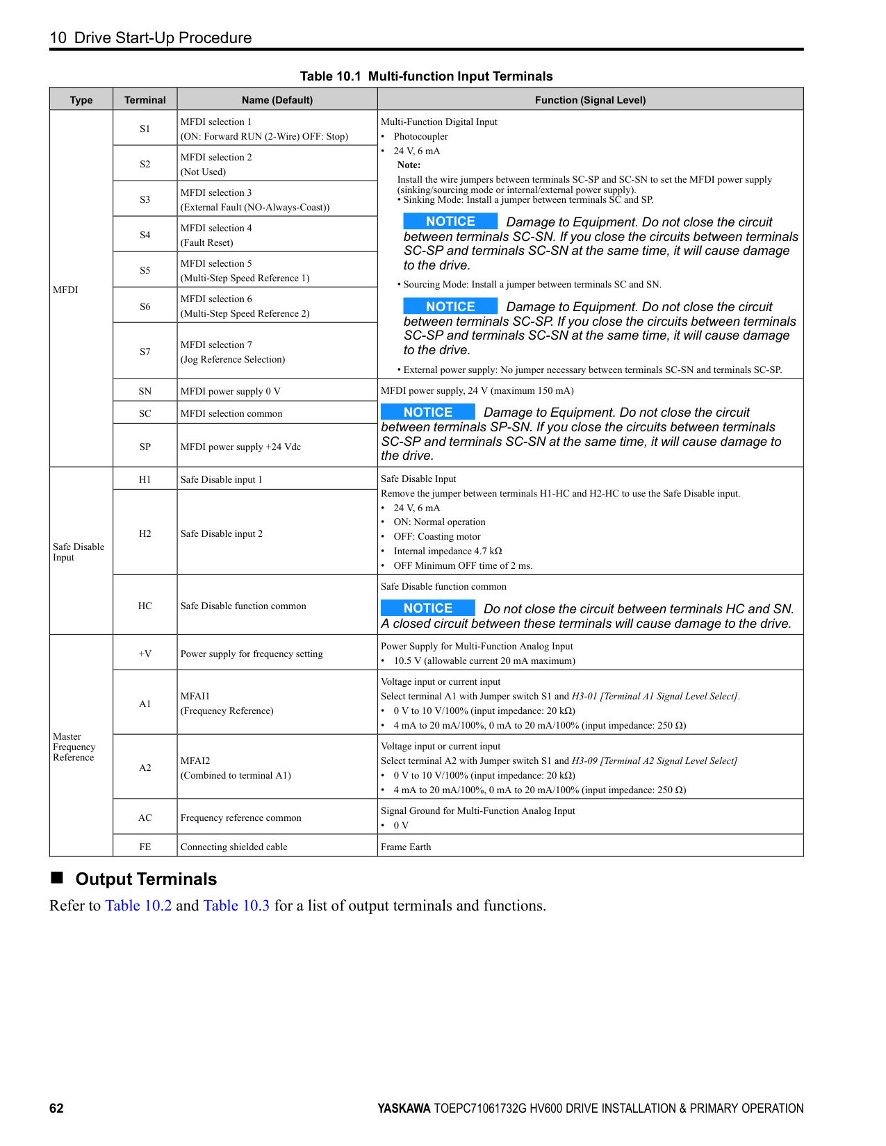
| | | |
| | |---| | | | |
| | |---| | | | |
◆ Control Circuit Terminal Block Functions Hx-xx parameters set functions for the multi-function input and output terminals.
WARNING Sudden Movement Hazard. Correctly wire and test all control circuits to make sure that the control circuits operate correctly. If you use a drive that has incorrect control circuit wiring or operation, it can cause death or serious injury.
WARNING Sudden Movement Hazard. Check the I/O signals and the external sequences for the drive before you set the Application Preset function. When you set the Application Preset function (A1-06 ≠ 0), it changes the I/O terminal functions for the drive and it can cause equipment to operate unusually. This can cause serious injury or death.
NOTICE Damage to Equipment. Do not energize and de-energize the drive more frequently than one time each 30 minutes. If you frequently energize and de-energize the drive, it can cause drive failure.
■ Input Terminals Refer to Table 10.1 for a list of input terminals and functions.
Table 10.1 Multi-function Input Terminals
|Type|Terminal|Name (Default)|Function (Signal Level)| |---|---|---|---| |MFDI|S1|MFDI selection 1 (ON: Forward RUN (2-Wire) OFF: Stop)|Multi-Function Digital Input
• Photocoupler
• 24 V, 6 mA Note: Install the wire jumpers between terminals SC-SP and SC-SN to set the MFDI power supply (sinking/sourcing mode or internal/external power supply).
• Sinking Mode: Install a jumper between terminals SC and SP.
NOTICE Damage to Equipment. Do not close the circuit between terminals SC-SN. If you close the circuits between terminals SC-SP and terminals SC-SN at the same time, it will cause damage to the drive.
• Sourcing Mode: Install a jumper between terminals SC and SN.
NOTICE Damage to Equipment. Do not close the circuit between terminals SC-SP. If you close the circuits between terminals SC-SP and terminals SC-SN at the same time, it will cause damage to the drive.
• External power supply: No jumper necessary between terminals SC-SN and terminals SC-SP.
| |MFDI|S2|MFDI selection 2 (Not Used)|Multi-Function Digital Input
• Photocoupler
• 24 V, 6 mA Note: Install the wire jumpers between terminals SC-SP and SC-SN to set the MFDI power supply (sinking/sourcing mode or internal/external power supply).
• Sinking Mode: Install a jumper between terminals SC and SP.
NOTICE Damage to Equipment. Do not close the circuit between terminals SC-SN. If you close the circuits between terminals SC-SP and terminals SC-SN at the same time, it will cause damage to the drive.
• Sourcing Mode: Install a jumper between terminals SC and SN.
NOTICE Damage to Equipment. Do not close the circuit between terminals SC-SP. If you close the circuits between terminals SC-SP and terminals SC-SN at the same time, it will cause damage to the drive.
• External power supply: No jumper necessary between terminals SC-SN and terminals SC-SP.
|
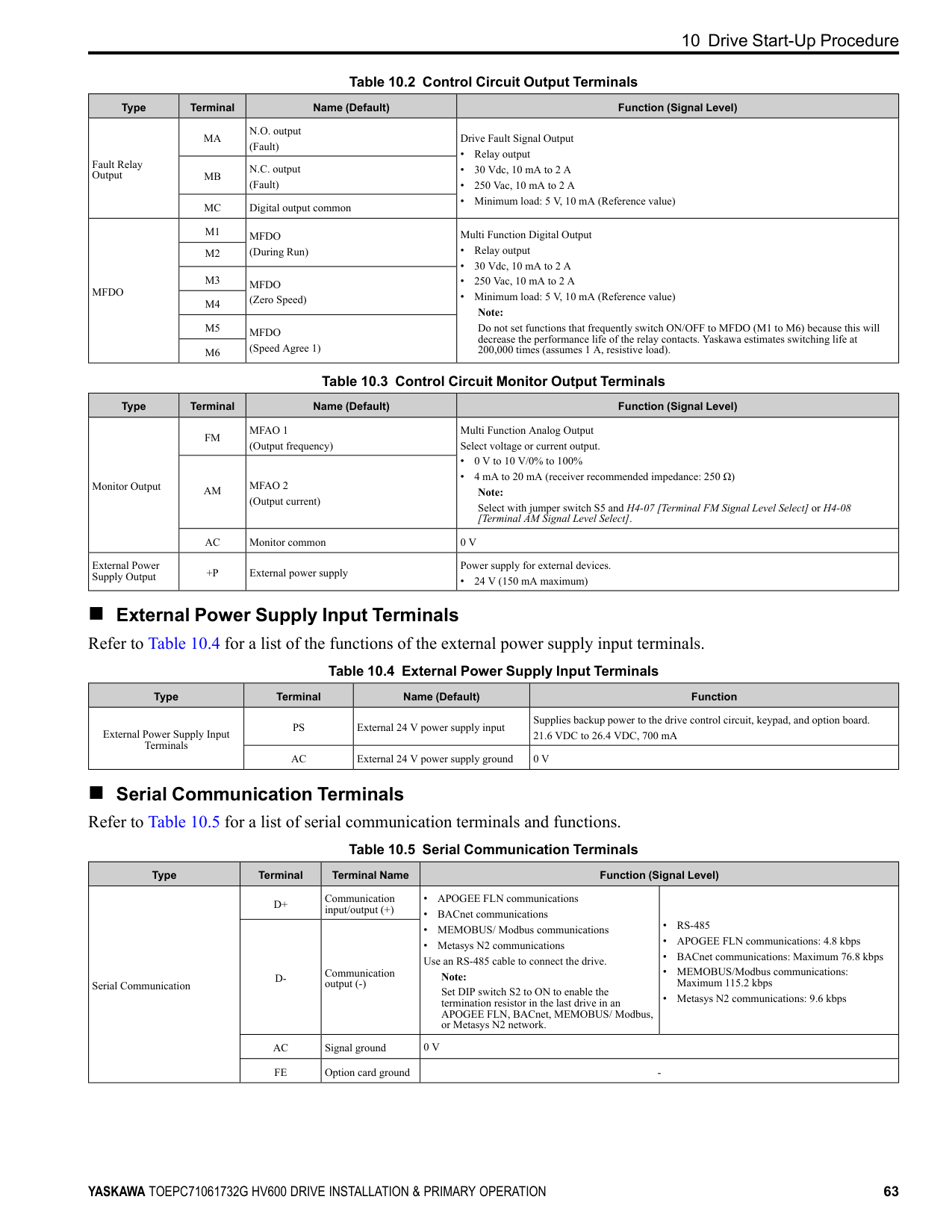
|MFDI|S3|MFDI selection 3 (External Fault (NO-Always-Coast))|Multi-Function Digital Input
• Photocoupler
• 24 V, 6 mA Note: Install the wire jumpers between terminals SC-SP and SC-SN to set the MFDI power supply (sinking/sourcing mode or internal/external power supply).
• Sinking Mode: Install a jumper between terminals SC and SP.
NOTICE Damage to Equipment. Do not close the circuit between terminals SC-SN. If you close the circuits between terminals SC-SP and terminals SC-SN at the same time, it will cause damage to the drive.
• Sourcing Mode: Install a jumper between terminals SC and SN.
NOTICE Damage to Equipment. Do not close the circuit between terminals SC-SP. If you close the circuits between terminals SC-SP and terminals SC-SN at the same time, it will cause damage to the drive.
• External power supply: No jumper necessary between terminals SC-SN and terminals SC-SP.
| |MFDI|S4|MFDI selection 4 (Fault Reset)|Multi-Function Digital Input
• Photocoupler
• 24 V, 6 mA Note: Install the wire jumpers between terminals SC-SP and SC-SN to set the MFDI power supply (sinking/sourcing mode or internal/external power supply).
• Sinking Mode: Install a jumper between terminals SC and SP.
NOTICE Damage to Equipment. Do not close the circuit between terminals SC-SN. If you close the circuits between terminals SC-SP and terminals SC-SN at the same time, it will cause damage to the drive.
• Sourcing Mode: Install a jumper between terminals SC and SN.
NOTICE Damage to Equipment. Do not close the circuit between terminals SC-SP. If you close the circuits between terminals SC-SP and terminals SC-SN at the same time, it will cause damage to the drive.
• External power supply: No jumper necessary between terminals SC-SN and terminals SC-SP.
| |MFDI|S5|MFDI selection 5 (Multi-Step Speed Reference 1)|Multi-Function Digital Input
• Photocoupler
• 24 V, 6 mA Note: Install the wire jumpers between terminals SC-SP and SC-SN to set the MFDI power supply (sinking/sourcing mode or internal/external power supply).
• Sinking Mode: Install a jumper between terminals SC and SP.
NOTICE Damage to Equipment. Do not close the circuit between terminals SC-SN. If you close the circuits between terminals SC-SP and terminals SC-SN at the same time, it will cause damage to the drive.
• Sourcing Mode: Install a jumper between terminals SC and SN.
NOTICE Damage to Equipment. Do not close the circuit between terminals SC-SP. If you close the circuits between terminals SC-SP and terminals SC-SN at the same time, it will cause damage to the drive.
• External power supply: No jumper necessary between terminals SC-SN and terminals SC-SP.
| |MFDI|S6|MFDI selection 6 (Multi-Step Speed Reference 2)|Multi-Function Digital Input
• Photocoupler
• 24 V, 6 mA Note: Install the wire jumpers between terminals SC-SP and SC-SN to set the MFDI power supply (sinking/sourcing mode or internal/external power supply).
• Sinking Mode: Install a jumper between terminals SC and SP.
NOTICE Damage to Equipment. Do not close the circuit between terminals SC-SN. If you close the circuits between terminals SC-SP and terminals SC-SN at the same time, it will cause damage to the drive.
• Sourcing Mode: Install a jumper between terminals SC and SN.
NOTICE Damage to Equipment. Do not close the circuit between terminals SC-SP. If you close the circuits between terminals SC-SP and terminals SC-SN at the same time, it will cause damage to the drive.
• External power supply: No jumper necessary between terminals SC-SN and terminals SC-SP.
| |MFDI|S7|MFDI selection 7 (Jog Reference Selection)|Multi-Function Digital Input
• Photocoupler
• 24 V, 6 mA Note: Install the wire jumpers between terminals SC-SP and SC-SN to set the MFDI power supply (sinking/sourcing mode or internal/external power supply).
• Sinking Mode: Install a jumper between terminals SC and SP.
NOTICE Damage to Equipment. Do not close the circuit between terminals SC-SN. If you close the circuits between terminals SC-SP and terminals SC-SN at the same time, it will cause damage to the drive.
• Sourcing Mode: Install a jumper between terminals SC and SN.
NOTICE Damage to Equipment. Do not close the circuit between terminals SC-SP. If you close the circuits between terminals SC-SP and terminals SC-SN at the same time, it will cause damage to the drive.
• External power supply: No jumper necessary between terminals SC-SN and terminals SC-SP.
| |MFDI|SN|MFDI power supply 0 V|MFDI power supply, 24 V (maximum 150 mA)
NOTICE Damage to Equipment. Do not close the circuit between terminals SP-SN. If you close the circuits between terminals SC-SP and terminals SC-SN at the same time, it will cause damage to the drive.| |MFDI|SC|MFDI selection common|MFDI power supply, 24 V (maximum 150 mA)
NOTICE Damage to Equipment. Do not close the circuit between terminals SP-SN. If you close the circuits between terminals SC-SP and terminals SC-SN at the same time, it will cause damage to the drive.| |MFDI|SP|MFDI power supply +24 Vdc|MFDI power supply, 24 V (maximum 150 mA)
NOTICE Damage to Equipment. Do not close the circuit between terminals SP-SN. If you close the circuits between terminals SC-SP and terminals SC-SN at the same time, it will cause damage to the drive.| |Safe Disable Input|H1|Safe Disable input 1|Safe Disable Input Remove the jumper between terminals H1-HC and H2-HC to use the Safe Disable input.
• 24 V, 6 mA
• ON: Normal operation
• OFF: Coasting motor
• Internal impedance 4.7 kΩ
• OFF Minimum OFF time of 2 ms.
| |Safe Disable Input|H2|Safe Disable input 2|Safe Disable Input Remove the jumper between terminals H1-HC and H2-HC to use the Safe Disable input.
• 24 V, 6 mA
• ON: Normal operation
• OFF: Coasting motor
• Internal impedance 4.7 kΩ
• OFF Minimum OFF time of 2 ms.
| |Safe Disable Input|HC|Safe Disable function common|Safe Disable function common
NOTICE Do not close the circuit between terminals HC and SN. A closed circuit between these terminals will cause damage to the drive.| |Master Frequency Reference|+V|Power supply for frequency setting|Power Supply for Multi-Function Analog Input
• 10.5 V (allowable current 20 mA maximum)| |Master Frequency Reference|A1|MFAI1 (Frequency Reference)|Voltage input or current input Select terminal A1 with Jumper switch S1 and H3-01 [Terminal A1 Signal Level Select].
• 0 V to 10 V/100% (input impedance: 20 kΩ)
• 4 mA to 20 mA/100%, 0 mA to 20 mA/100% (input impedance: 250 Ω)
| |Master Frequency Reference|A2|MFAI2 (Combined to terminal A1)|Voltage input or current input Select terminal A2 with Jumper switch S1 and H3-09 [Terminal A2 Signal Level Select]
• 0 V to 10 V/100% (input impedance: 20 kΩ)
• 4 mA to 20 mA/100%, 0 mA to 20 mA/100% (input impedance: 250 Ω)
| |Master Frequency Reference|AC|Frequency reference common|Signal Ground for Multi-Function Analog Input
• 0 V| |Master Frequency Reference|FE|Connecting shielded cable|Frame Earth|
■ Output Terminals Refer to Table 10.2 and Table 10.3 for a list of output terminals and functions.
Table 10.2 Control Circuit Output Terminals
|Type|Terminal|Name (Default)|Function (Signal Level)| |---|---|---|---| |Fault Relay Output|MA|N.O. output (Fault)|Drive Fault Signal Output
• Relay output
• 30 Vdc, 10 mA to 2 A
• 250 Vac, 10 mA to 2 A
• Minimum load: 5 V, 10 mA (Reference value)
| |Fault Relay Output|MB|N.C. output (Fault)|Drive Fault Signal Output
• Relay output
• 30 Vdc, 10 mA to 2 A
• 250 Vac, 10 mA to 2 A
• Minimum load: 5 V, 10 mA (Reference value)
| |Fault Relay Output|MC|Digital output common|Drive Fault Signal Output
• Relay output
• 30 Vdc, 10 mA to 2 A
• 250 Vac, 10 mA to 2 A
• Minimum load: 5 V, 10 mA (Reference value)
| |MFDO|M1|MFDO (During Run)|Multi Function Digital Output
• Relay output
• 30 Vdc, 10 mA to 2 A
• 250 Vac, 10 mA to 2 A
• Minimum load: 5 V, 10 mA (Reference value) Note:
Do not set functions that frequently switch ON/OFF to MFDO (M1 to M6) because this will decrease the performance life of the relay contacts. Yaskawa estimates switching life at 200,000 times (assumes 1 A, resistive load).| |MFDO|M2|MFDO (During Run)|Multi Function Digital Output
• Relay output
• 30 Vdc, 10 mA to 2 A
• 250 Vac, 10 mA to 2 A
• Minimum load: 5 V, 10 mA (Reference value) Note:
Do not set functions that frequently switch ON/OFF to MFDO (M1 to M6) because this will decrease the performance life of the relay contacts. Yaskawa estimates switching life at 200,000 times (assumes 1 A, resistive load).| |MFDO|M3|MFDO (Zero Speed)|Multi Function Digital Output
• Relay output
• 30 Vdc, 10 mA to 2 A
• 250 Vac, 10 mA to 2 A
• Minimum load: 5 V, 10 mA (Reference value) Note:
Do not set functions that frequently switch ON/OFF to MFDO (M1 to M6) because this will decrease the performance life of the relay contacts. Yaskawa estimates switching life at 200,000 times (assumes 1 A, resistive load).| |MFDO|M4|MFDO (Zero Speed)|Multi Function Digital Output
• Relay output
• 30 Vdc, 10 mA to 2 A
• 250 Vac, 10 mA to 2 A
• Minimum load: 5 V, 10 mA (Reference value) Note:
Do not set functions that frequently switch ON/OFF to MFDO (M1 to M6) because this will decrease the performance life of the relay contacts. Yaskawa estimates switching life at 200,000 times (assumes 1 A, resistive load).| |MFDO|M5|MFDO (Speed Agree 1)|Multi Function Digital Output
• Relay output
• 30 Vdc, 10 mA to 2 A
• 250 Vac, 10 mA to 2 A
• Minimum load: 5 V, 10 mA (Reference value) Note:
Do not set functions that frequently switch ON/OFF to MFDO (M1 to M6) because this will decrease the performance life of the relay contacts. Yaskawa estimates switching life at 200,000 times (assumes 1 A, resistive load).| |MFDO|M6|MFDO (Speed Agree 1)|Multi Function Digital Output
• Relay output
• 30 Vdc, 10 mA to 2 A
• 250 Vac, 10 mA to 2 A
• Minimum load: 5 V, 10 mA (Reference value) Note:
Do not set functions that frequently switch ON/OFF to MFDO (M1 to M6) because this will decrease the performance life of the relay contacts. Yaskawa estimates switching life at 200,000 times (assumes 1 A, resistive load).|
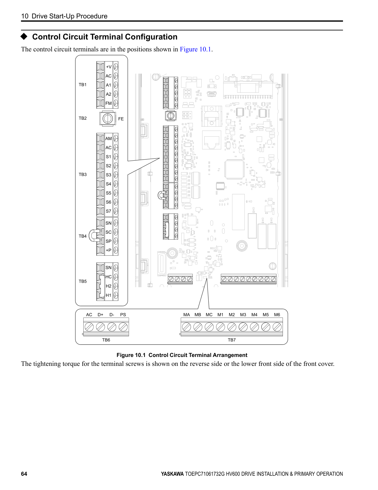
Table 10.4 External Power Supply Input Terminals
■ Serial Communication Terminals
|Type|Terminal|Name (Default)|Function (Signal Level)| |---|---|---|---| |Monitor Output|FM|MFAO 1 (Output frequency)|Multi Function Analog Output Select voltage or current output.
• 0 V to 10 V/0% to 100%
• 4 mA to 20 mA (receiver recommended impedance: 250 Ω) Note:
Select with jumper switch S5 and H4-07 [Terminal FM Signal Level Select] or H4-08 [Terminal AM Signal Level Select].| |Monitor Output|AM|MFAO 2 (Output current)|Multi Function Analog Output Select voltage or current output.
• 0 V to 10 V/0% to 100%
• 4 mA to 20 mA (receiver recommended impedance: 250 Ω) Note:
Select with jumper switch S5 and H4-07 [Terminal FM Signal Level Select] or H4-08 [Terminal AM Signal Level Select].| |Monitor Output|AC|Monitor common|0 V| |External Power Supply Output|+P|External power supply|Power supply for external devices.
• 24 V (150 mA maximum)|
|Type|Terminal|Name (Default)|Function| |---|---|---|---| |External Power Supply Input Terminals|PS|External 24 V power supply input|Supplies backup power to the drive control circuit, keypad, and option board. 21.6 VDC to 26.4 VDC, 700 mA| |External Power Supply Input Terminals|AC|External 24 V power supply ground|0 V|
|Type|Terminal|Terminal Name|Function (Signal Level)|Function (Signal Level)| |---|---|---|---|---| |Serial Communication|D+|Communication input/output (+)|• APOGEE FLN communications
• BACnet communications
• MEMOBUS/ Modbus communications
• Metasys N2 communications Use an RS-485 cable to connect the drive.
Note:
Set DIP switch S2 to ON to enable the termination resistor in the last drive in an APOGEE FLN, BACnet, MEMOBUS/ Modbus, or Metasys N2 network.|• RS-485
• APOGEE FLN communications: 4.8 kbps
• BACnet communications: Maximum 76.8 kbps
• MEMOBUS/Modbus communications: Maximum 115.2 kbps
• Metasys N2 communications: 9.6 kbps
| |Serial Communication|D-|Communication output (-)|• APOGEE FLN communications
• BACnet communications
• MEMOBUS/ Modbus communications
• Metasys N2 communications Use an RS-485 cable to connect the drive.
Note:
Set DIP switch S2 to ON to enable the termination resistor in the last drive in an APOGEE FLN, BACnet, MEMOBUS/ Modbus, or Metasys N2 network.|• RS-485
• APOGEE FLN communications: 4.8 kbps
• BACnet communications: Maximum 76.8 kbps
• MEMOBUS/Modbus communications: Maximum 115.2 kbps
• Metasys N2 communications: 9.6 kbps
| |Serial Communication|AC|Signal ground|0 V|0 V| |Serial Communication|FE|Option card ground|-|-|
◆ Control Circuit Terminal Configuration The control circuit terminals are in the positions shown in Figure 10.1.
| | | | | | |---|---|---|---|---| | | | | | |
| | | | | |

|---|---|---|---|---|
| | | | |---|---|---|
| | | |---|---| | | |
| | | |---|---| | | |
| | | |---|---| | | |
| | | | | | |---|---|---|---|---| | | | | | | | | | | | |
| | | | | | |---|---|---|---|---| | | | | | | | | | | | |
| | | |---|---| | | |
| | | | |---|---|---|
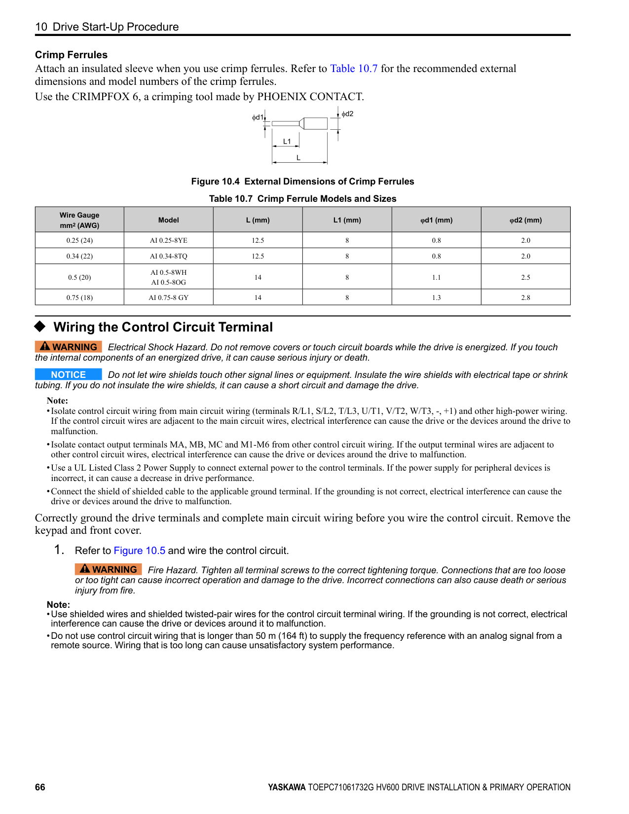
| | | |---|---| | | |
| | | | | |---|---|---|---| | | | | |
| | | | | | |---|---|---|---|---|
| | |---| | | | |
| | | | |---|---|---|
| | |---| | |
| | | |---|---| | | |
| | | | |---|---|---|
| | | |
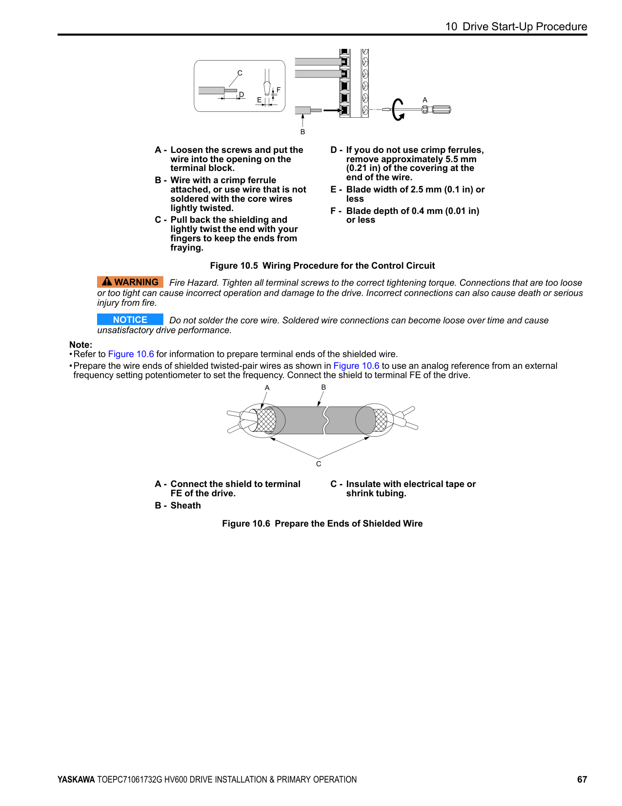
|---|---|---|
| | | | |---|---|---|
| | | | |---|---|---|
| | | |---|---| | | | | | | | | | | | |
| | | |---|---| | | |
| | | | |---|---|---|
| | | | |---|---|---|
| | | |---|---| | | |
| | |---| | | | |
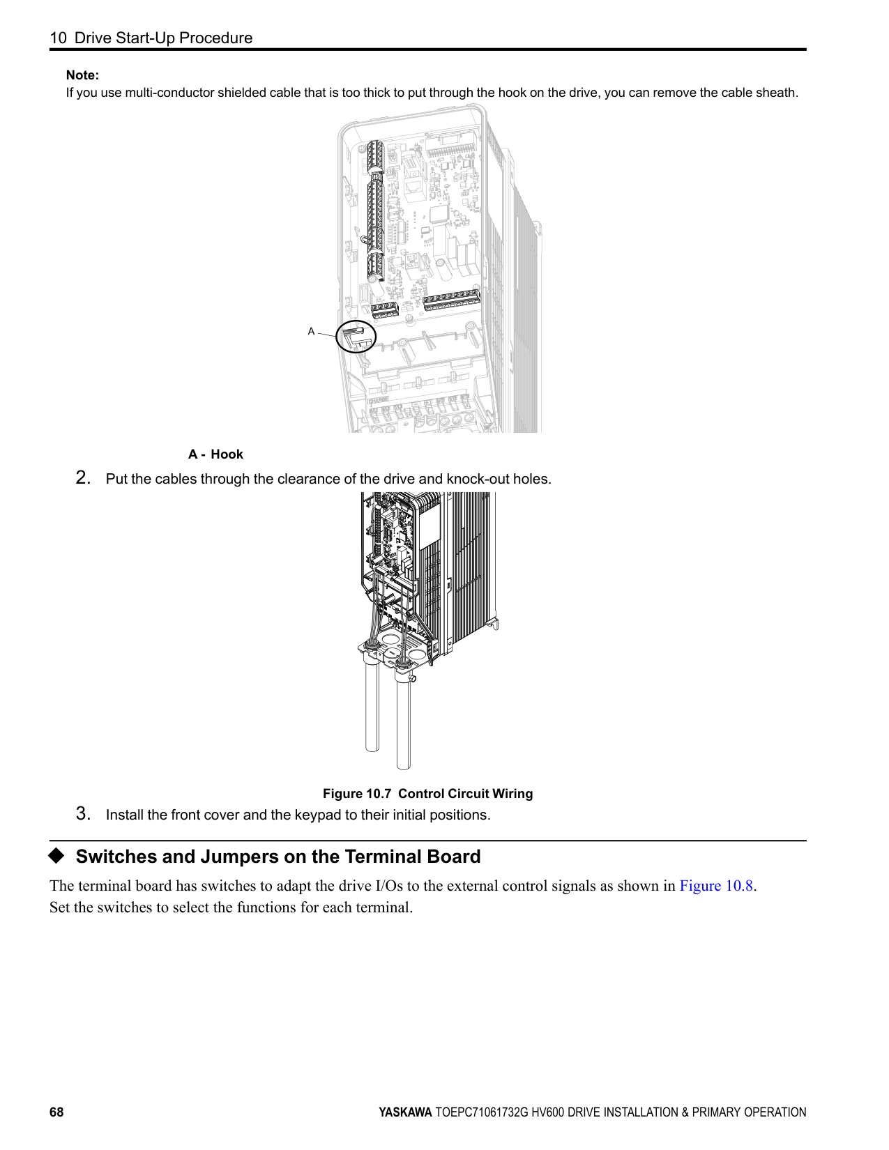
| | | |
| | | | |---|---|---| | | | | | | | |
| | |---| | | | | | | | |
| | |---| | | | | | | | | | | | |
Figure 10.1 Control Circuit Terminal Arrangement
The tightening torque for the terminal screws is shown on the reverse side or the lower front side of the front cover.
| | | | |---|---|---| | | | |
Figure 10.2 Tightening Torque Display Location (Reverse Side of Front Cover)
Figure 10.3 Tightening Torque Display Location (Lower Front Side of Front Cover)
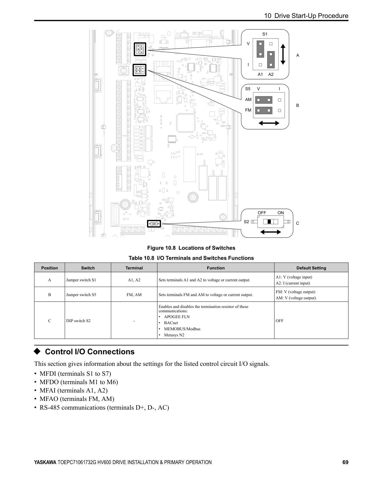
##### ■ Control Circuit Wire Gauges and Tightening Torques
Use the tables in this section to select the correct wires. Use shielded wire to wire the control circuit terminal block. Use crimp ferrules on the wire ends to make the wiring procedure easier and more reliable.
Table 10.6 Control Circuit Wire Gauges and Tightening Torques
|Terminal Block|Terminal|Screw Size|Tightening Torque N∙m (lbf∙in)|Bare Wire|Bare Wire|Crimp Ferrule|Crimp Ferrule| |---|---|---|---|---|---|---|---| |Terminal Block|Terminal|Screw Size|Tightening Torque N∙m (lbf∙in)|Recommended Gauge
mm2 (AWG)|Applicable Gauge mm2 (AWG)|Recommended Gauge
mm2 (AWG)|Applicable Gauge mm2 (AWG)| |TB1|+V, AC, A1, A2, FM|M3|0.5 - 0.6 (4.4 - 5.3)|0.75 (18)|Stranded wire: 0.25 - 1.5 (24 - 16) Solid wire: 0.25 - 1.5 (24 - 16)|0.75 (18)|0.25 - 1.5 (24 - 16)| |TB3|AM, AC, S1 - S7|M3|0.5 - 0.6 (4.4 - 5.3)|0.75 (18)|Stranded wire: 0.25 - 1.5 (24 - 16) Solid wire: 0.25 - 1.5 (24 - 16)|0.75 (18)|0.25 - 1.5 (24 - 16)| |TB4|SN, SC, SP, +P|M3|0.5 - 0.6 (4.4 - 5.3)|0.75 (18)|Stranded wire: 0.25 - 1.5 (24 - 16) Solid wire: 0.25 - 1.5 (24 - 16)|0.75 (18)|0.25 - 1.5 (24 - 16)| |TB5|SN, HC, H1, H2|M3|0.5 - 0.6 (4.4 - 5.3)|0.75 (18)|Stranded wire: 0.25 - 1.5 (24 - 16) Solid wire: 0.25 - 1.5 (24 - 16)|0.75 (18)|0.25 - 1.5 (24 - 16)| |TB6|AC, D+, D-, PS|M3|0.5 - 0.6 (4.4 - 5.3)|0.75 (18)|Stranded wire: 0.25 - 1.5 (24 - 16) Solid wire: 0.25 - 1.5 (24 - 16)|0.75 (18)|0.25 - 1.5 (24 - 16)| |TB7|MA, MB, MC, M1 - M6|M3|0.5 - 0.6 (4.4 - 5.3)|0.75 (18)|Stranded wire: 0.25 - 1.5 (24 - 16) Solid wire: 0.25 - 1.5 (24 - 16)|0.75 (18)|0.25 - 1.5 (24 - 16)| |TB2|FE|M3|1.0 - 1.2 (8.85 - 10.62)|0.75 (18)|Stranded wire: 0.12 - 0.75 (26 - 18) Solid wire: 0.2 - 1.5 (26 - 16)|0.75 (18)|0.25 - 1.5 (24 - 16)|
Crimp Ferrules Attach an insulated sleeve when you use crimp ferrules. Refer to Table 10.7 for the recommended external dimensions and model numbers of the crimp ferrules. Use the CRIMPFOX 6, a crimping tool made by PHOENIX CONTACT.
Figure 10.4 External Dimensions of Crimp Ferrules Table 10.7 Crimp Ferrule Models and Sizes
|Wire Gauge mm2 (AWG)|Model|L (mm)|L1 (mm)|φd1 (mm)|φd2 (mm)| |---|---|---|---|---|---| |0.25 (24)|AI 0.25-8YE|12.5|8|0.8|2.0| |0.34 (22)|AI 0.34-8TQ|12.5|8|0.8|2.0| |0.5 (20)|AI 0.5-8WH AI 0.5-8OG|14|8|1.1|2.5| |0.75 (18)|AI 0.75-8 GY|14|8|1.3|2.8|
##### ◆ Wiring the Control Circuit Terminal
WARNING Electrical Shock Hazard. Do not remove covers or touch circuit boards while the drive is energized. If you touch the internal components of an energized drive, it can cause serious injury or death.
NOTICE Do not let wire shields touch other signal lines or equipment. Insulate the wire shields with electrical tape or shrink tubing. If you do not insulate the wire shields, it can cause a short circuit and damage the drive.
############## Note:
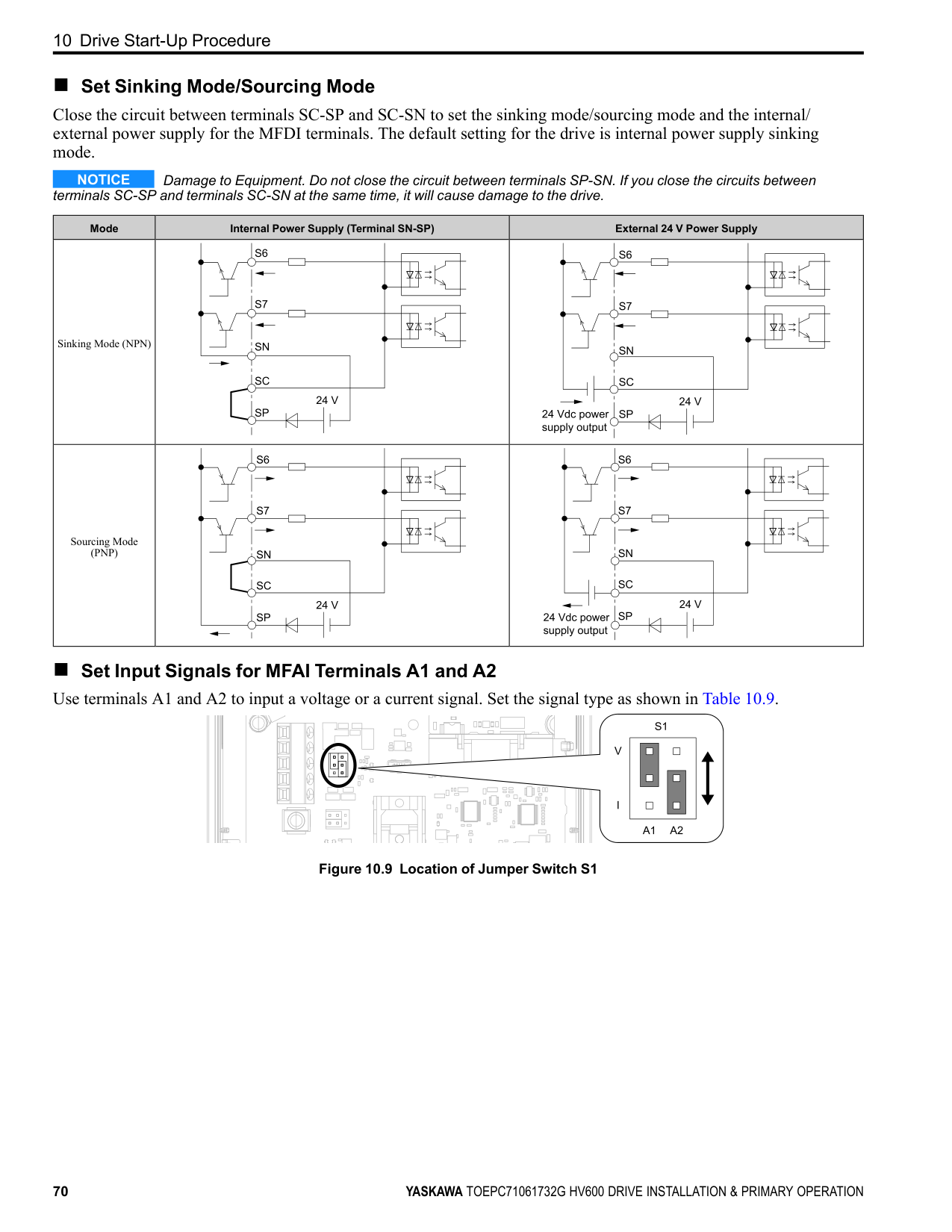
Correctly ground the drive terminals and complete main circuit wiring before you wire the control circuit. Remove the keypad and front cover.
WARNING Fire Hazard. Tighten all terminal screws to the correct tightening torque. Connections that are too loose or too tight can cause incorrect operation and damage to the drive. Incorrect connections can also cause death or serious injury from fire.
############## Note:
Figure 10.5 Wiring Procedure for the Control Circuit
WARNING Fire Hazard. Tighten all terminal screws to the correct tightening torque. Connections that are too loose or too tight can cause incorrect operation and damage to the drive. Incorrect connections can also cause death or serious injury from fire.
NOTICE Do not solder the core wire. Soldered wire connections can become loose over time and cause unsatisfactory drive performance.
############## Note:
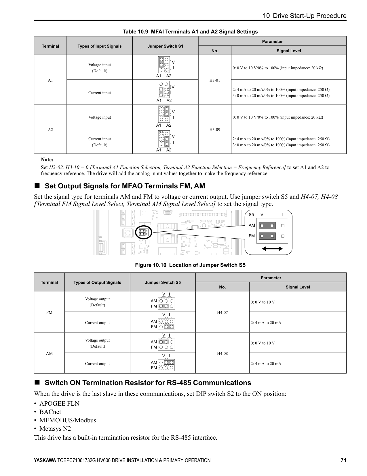
C - Insulate with electrical tape or shrink tubing.
Figure 10.6 Prepare the Ends of Shielded Wire
Note: If you use multi-conductor shielded cable that is too thick to put through the hook on the drive, you can remove the cable sheath.
A - Hook
Figure 10.7 Control Circuit Wiring
◆ Switches and Jumpers on the Terminal Board The terminal board has switches to adapt the drive I/Os to the external control signals as shown in Figure 10.8. Set the switches to select the functions for each terminal.
| | | | | | |---|---|---|---|---| | | | | | |
10 Drive Start-Up Procedure
| | | | |---|---|---|
| | | | | | |---|---|---|---|---| | | | | | | | | | | | |
| | | | |---|---|---|
| | | |---|---| | | |
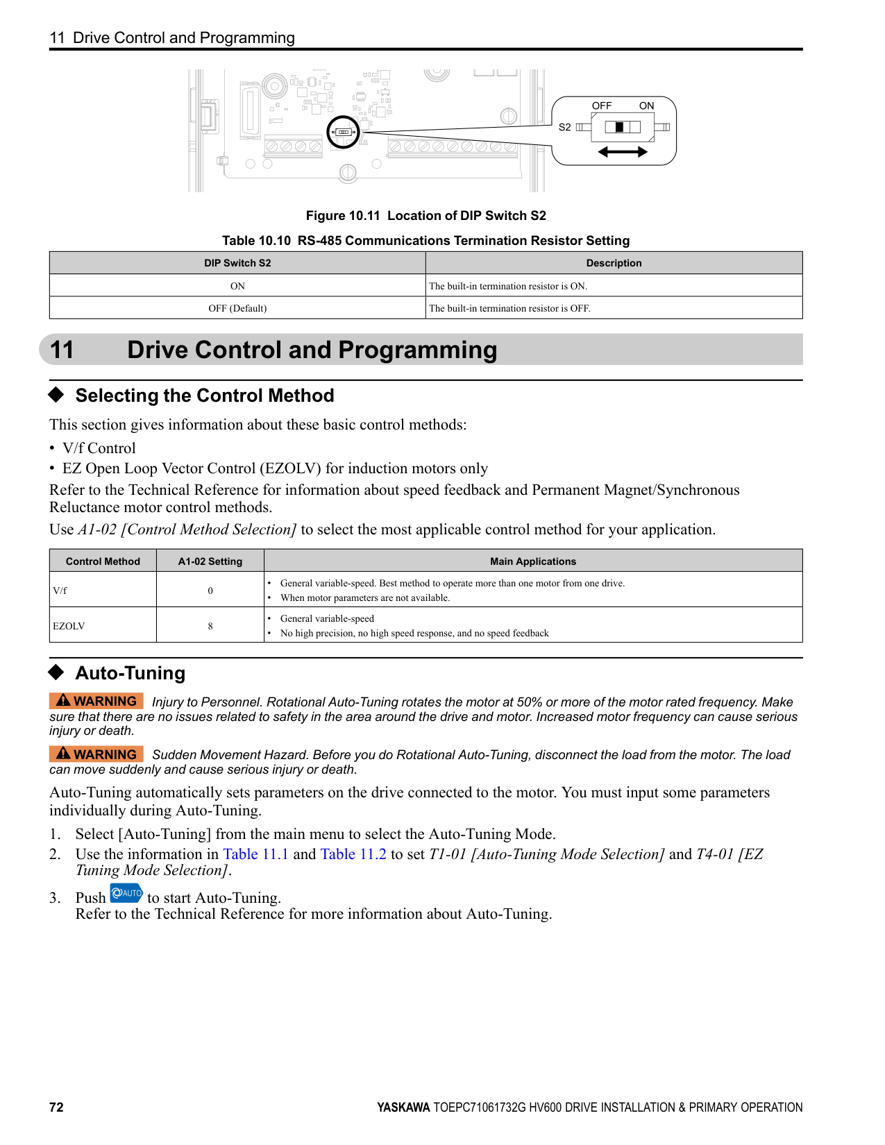
| | | | |---|---|---|
| | | | |---|---|---|
| | | | |---|---|---|
| | | | |---|---|---|
| | | | |---|---|---|
| | | |---|---| | | |
| | | |---|---| | | |
| | |---| | | | |
| | | | | |---|---|---|---| | | | | |
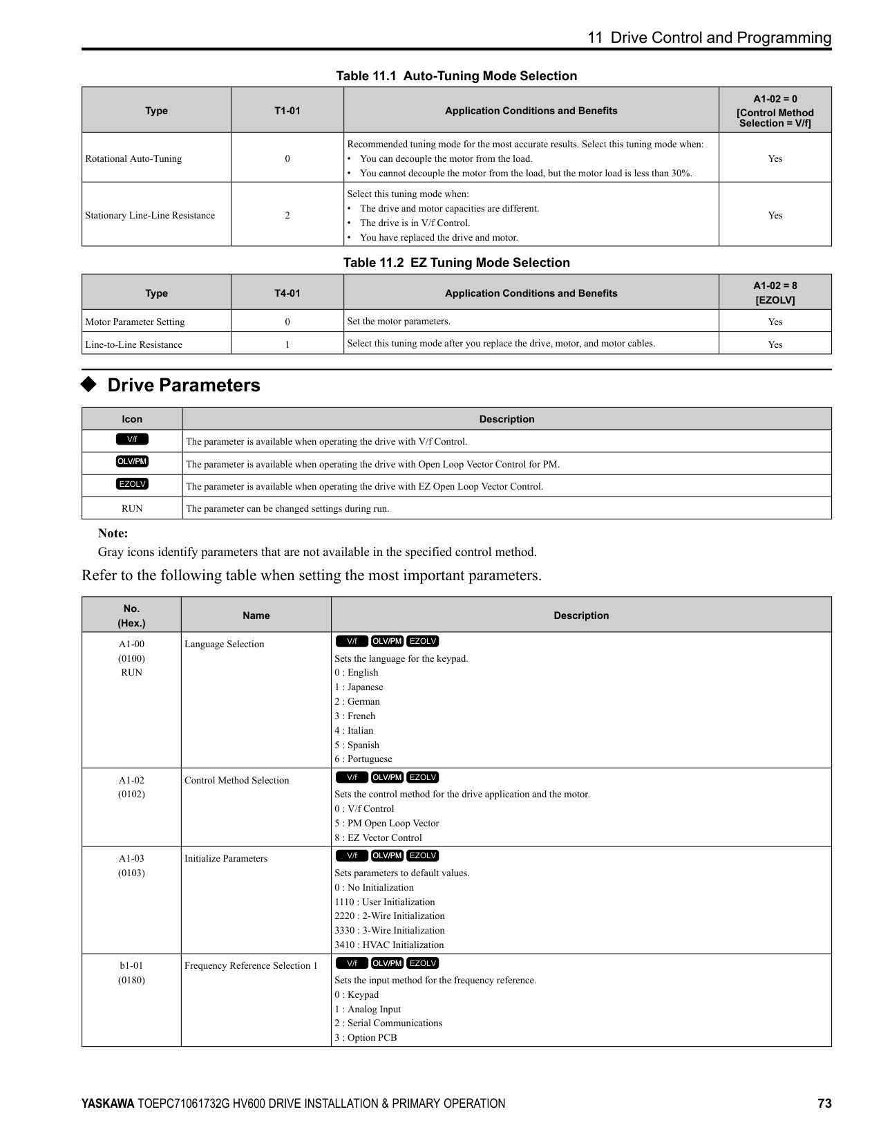
| | | |---|---| | | | | | | | | | | | |
| | | |---|---| | | |
| | | | |---|---|---|
| | | | |---|---|---|
| | | |---|---| | | |
| | |---| | | | | | | | |
| | | | |---|---|---| | | | | | | | |
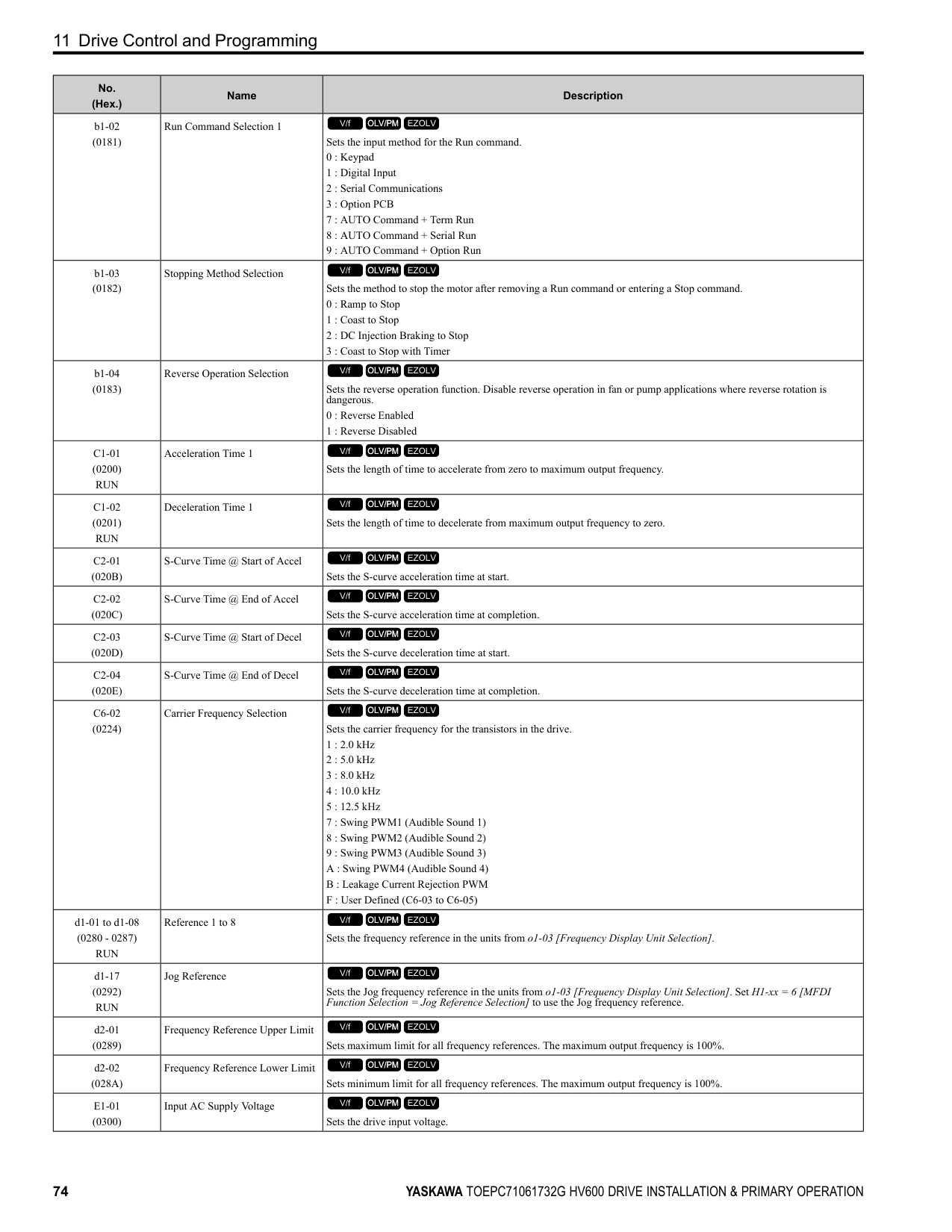
| | |---| | | | | | | | |
| | | | | | | | |---|---|---|---|---|---|---| | | | | | | | | | | | | | | | |
Figure 10.8 Locations of Switches Table 10.8 I/O Terminals and Switches Functions
Position Switch Terminal Function Default Setting
A1: V (voltage input) A2: I (current input)
FM: V (voltage output) AM: V (voltage output)
Enables and disables the termination resistor of these communications:
OFF
##### ◆ Control I/O Connections This section gives information
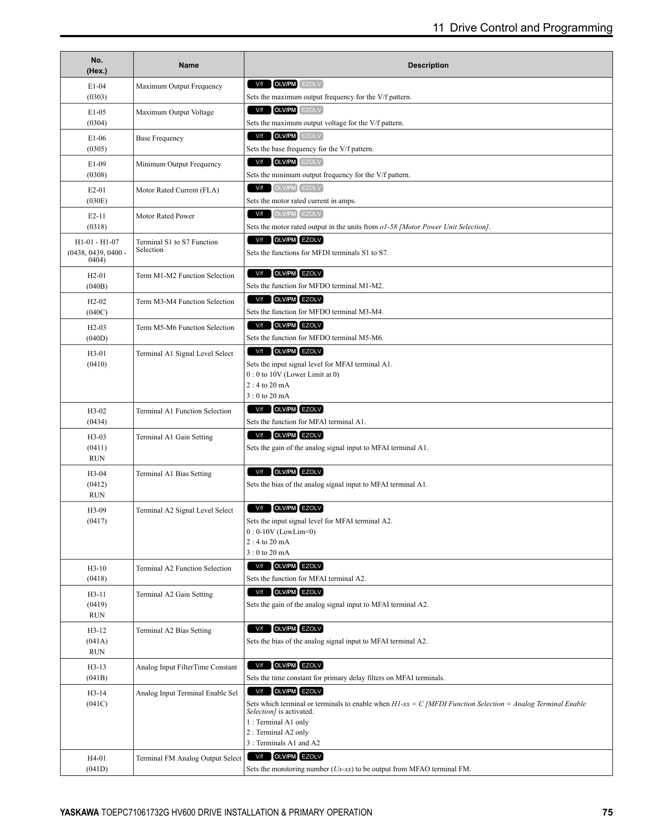
circuit I/O signals.
| |about the settings for the listed control| | |---|---|---| | | | |
##### ■ Set Sinking Mode/Sourcing Mode
Close the circuit between terminals SC-SP and SC-SN to set the sinking mode/sourcing mode and the internal/ external power supply for the MFDI terminals. The default setting for the drive is internal power supply sinking mode.
NOTICE Damage to Equipment. Do not close the circuit between terminals SP-SN. If you close the circuits between terminals SC-SP and terminals SC-SN at the same time, it will cause damage to the drive.
Mode Internal Power Supply (Terminal SN-SP) External 24 V Power Supply
Sinking Mode (NPN)
Sourcing Mode (PNP)
■ Set Input Signals for MFAI Terminals A1 and A2 Use terminals A1 and A2 to input a voltage or a current signal. Set the signal type as shown in Table 10.9.
| | | | | | |---|---|---|---|---| | | | | | |
| | | | |---|---|---|
| | | | | | |---|---|---|---|---| | | | | | |
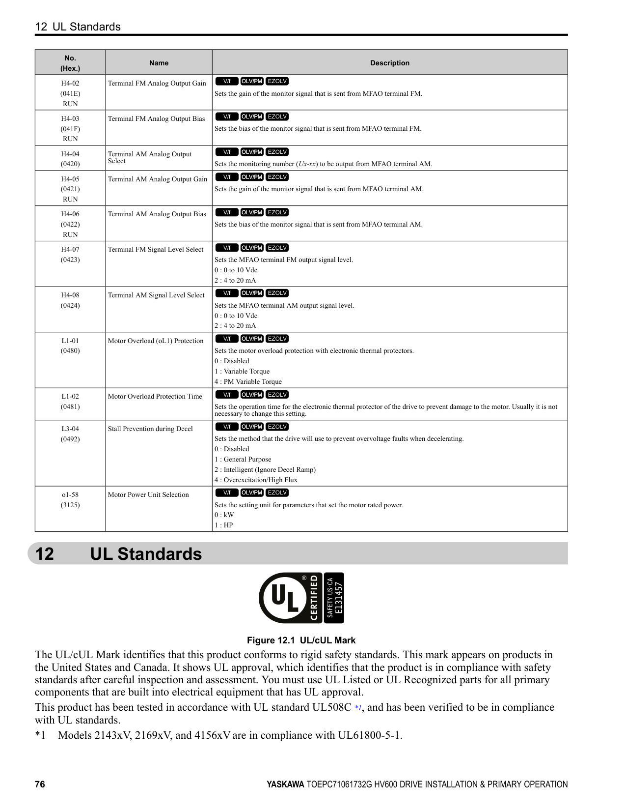
| | | | | |
| | | |---|---| | | |
| | | |---|---| | | |
| | | |---|---| | | |
| | | | |---|---|---|
| | | |---|---| | | |
| | | | | |---|---|---|---| | | | | |
|10.9| |---|
Figure
Location of Jumper Switch S1
| |
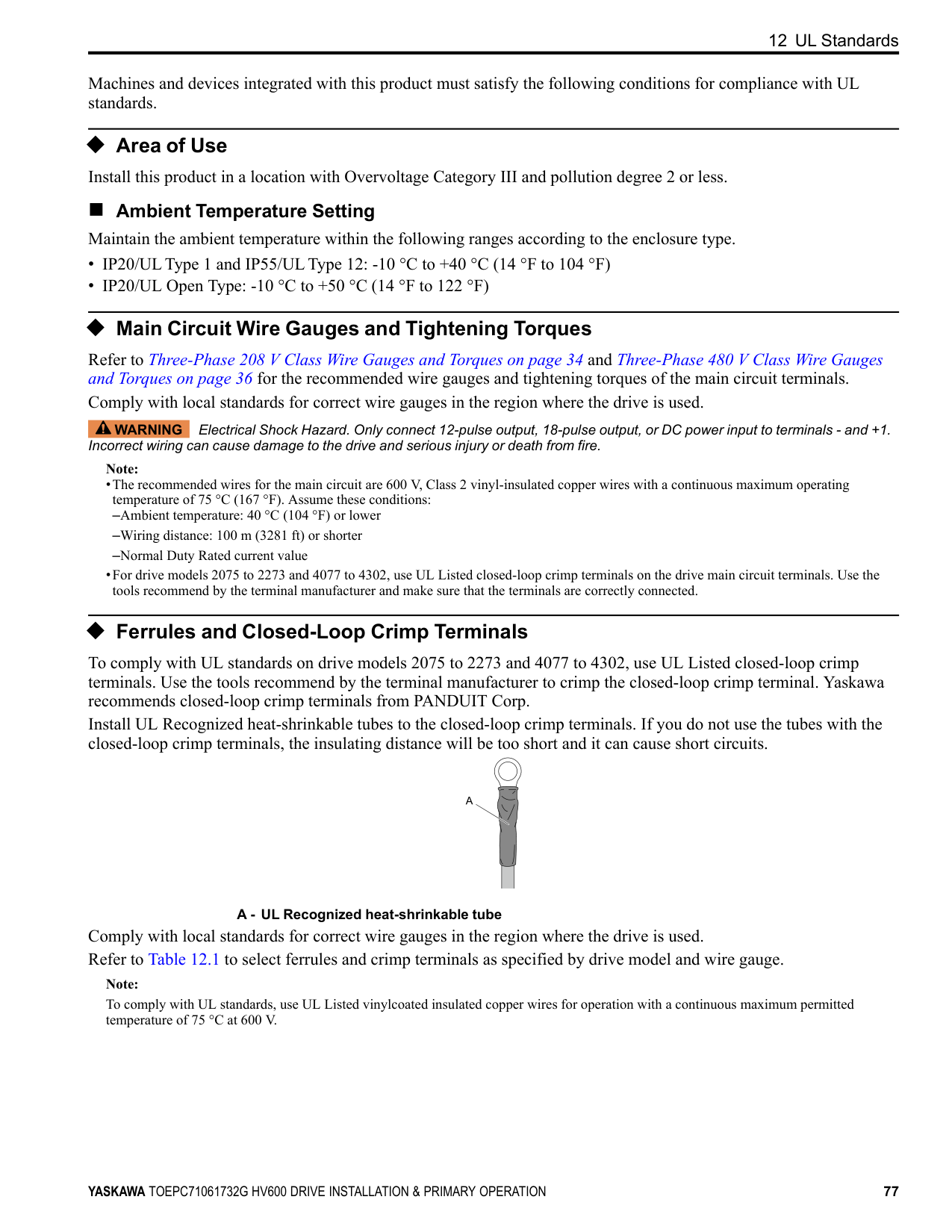
|---| | | | |
| | | | |---|---|---|
| | | | |---|---|---|
| | | | |---|---|---|
| | | | |---|---|---|
| | | | |---|---|---|
| | | |---|---| | | | | | | | | | | | |
| | | |---|---| | | |
| | | | |---|---|---|
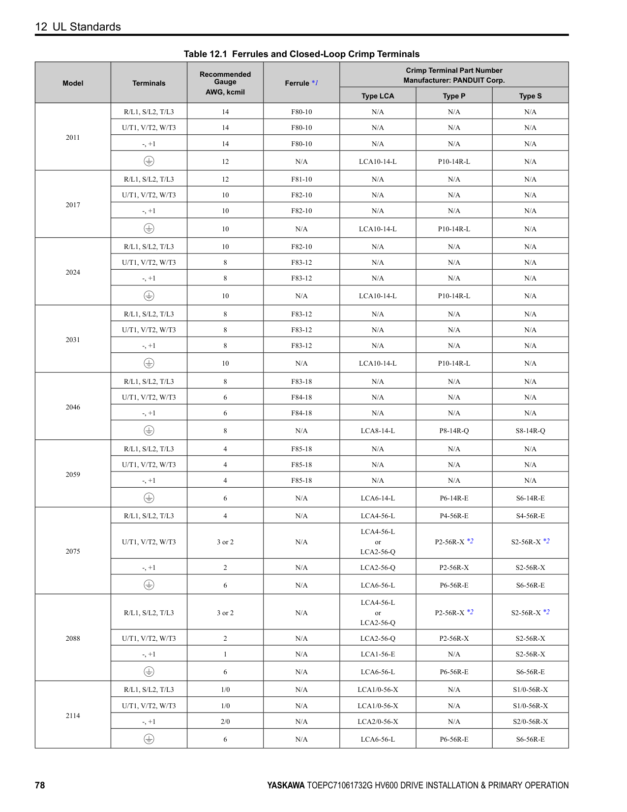
| | | | |---|---|---|
| | | |---|---| | | |
70 YASKAWA TOEPC71061732G HV600 DRIVE INSTALLATION & PRIMARY OPERATION
| | | | |---|---|---| | | | | | | | |
10 Drive Start-Up Procedure
Table 10.9 MFAI Terminals A1 and A2 Signal Settings
|Terminal|Types of Input Signals|Jumper Switch S1|Parameter|Parameter| |---|---|---|---|---| |Terminal|Types of Input Signals|Jumper Switch S1|No.|Signal Level| |A1|Voltage input (Default)| |H3-01|0: 0 V to 10 V/0% to 100% (input impedance: 20 kΩ)| |A1|Current input| |H3-01|2: 4 mA to 20 mA/0% to 100% (input impedance: 250 Ω)
3: 0 mA to 20 mA/0% to 100% (input impedance: 250 Ω)
| |A2|Voltage input| |H3-09|0: 0 V to 10 V/0% to 100% (input impedance: 20 kΩ)| |A2|Current input (Default)| |H3-09|2: 4 mA to 20 mA/0% to 100% (input impedance: 250 Ω)
3: 0 mA to 20 mA/0% to 100% (input impedance: 250 Ω)
|
Note:
Set H3-02, H3-10 = 0 [Terminal A1 Function Selection, Terminal A2 Function Selection = Frequency Reference] to set A1 and A2 to frequency reference. The drive will add the analog input values together to make the frequency reference.
| | | | | | |---|---|---|---|---| | | | | | |
##### ■ Set Output Signals for MFAO Terminals FM, AM Set the signal type for terminals
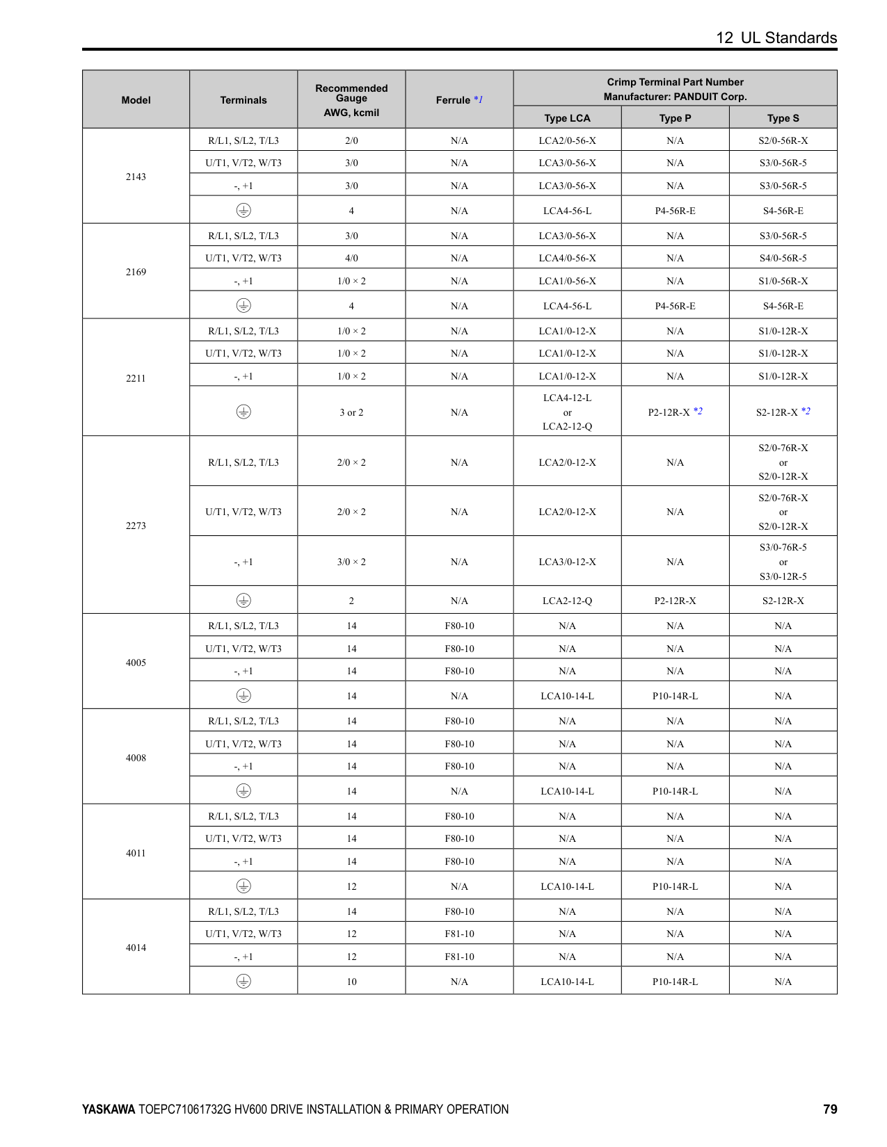
and FM to voltage or current output. Use jumper switch S5 and H4-07, H4-08 [Terminal FM Signal Level Select, Terminal AM Signal Level Select] to set the signal type.
|M| | | |---|---|---|
| | | |---|---| | | |
| | | |---|---| | | |
| | | |---|---| | | |
| | | | | | |---|---|---|---|---| | | | | | | | | | | | |
| | | |---|---| | | |
| | | |---|---| | | |
| | | | | |---|---|---|---| | | | | |
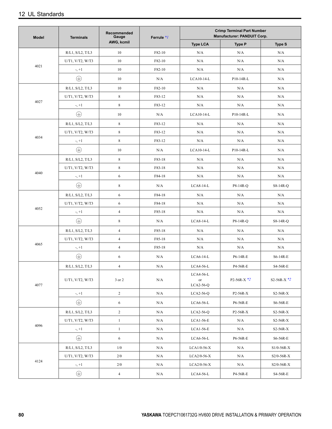
| | |---| | | | |
| | | | |---|---|---|
Figure 10.10 Location of Jumper Switch S5
| | | | |---|---|---|
Terminal Types of Output Signals Jumper Switch S5
| | | |---|---|
Parameter No. Signal Level
FM
Voltage output (Default)
H4-07
0: 0 V to 10 V
Current output 2: 4 mA to 20 mA
AM
| | | |---|---| | | |
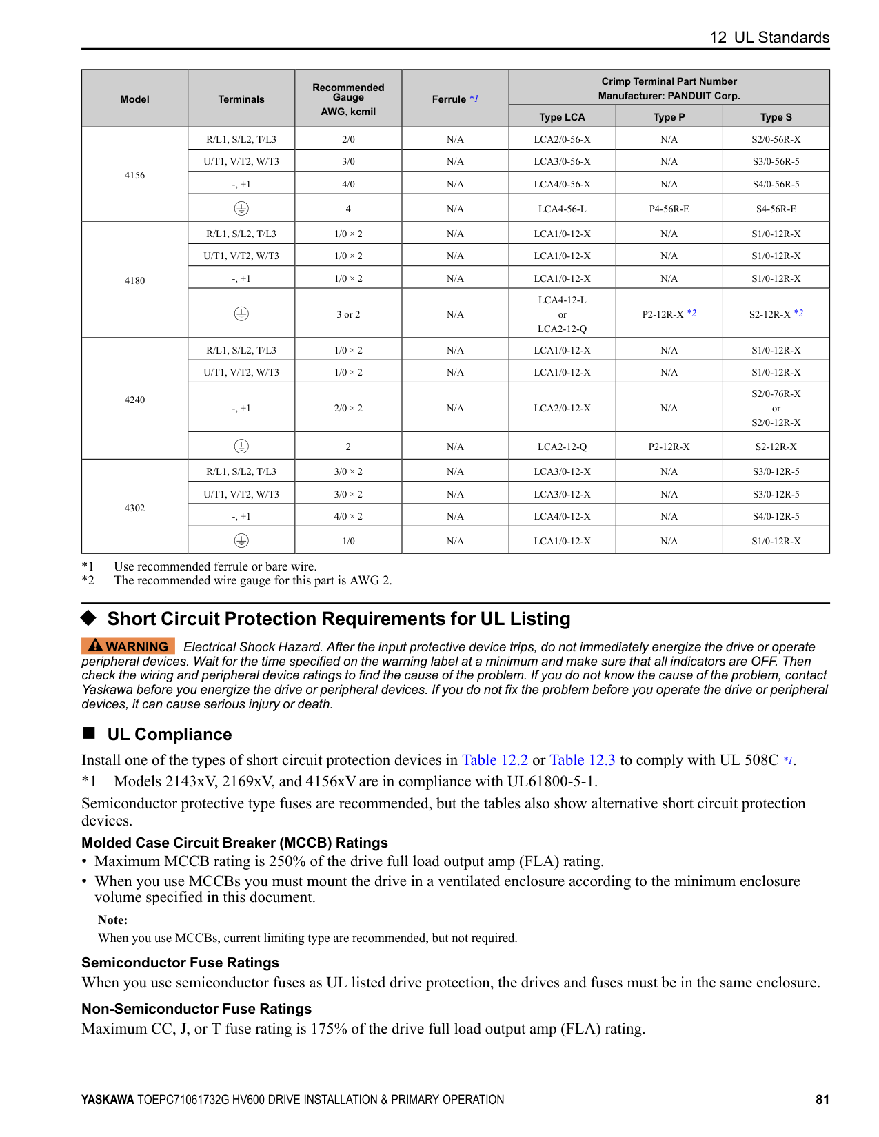
| | | | | | | | |
Voltage output (Default)
0: 0 V to 10 V
H4-08
| | | | |---|---|---|
Current output 2: 4 mA to 20 mA
■ Switch ON Termination Resistor for RS-485 Communications When the drive is the last slave in these communications, set DIP switch S2 to the ON position:
| | | | |---|---|---| | | | | | | | |
| | | | |---|---|---| | | | |
| | | | |---|---|---| | | | |
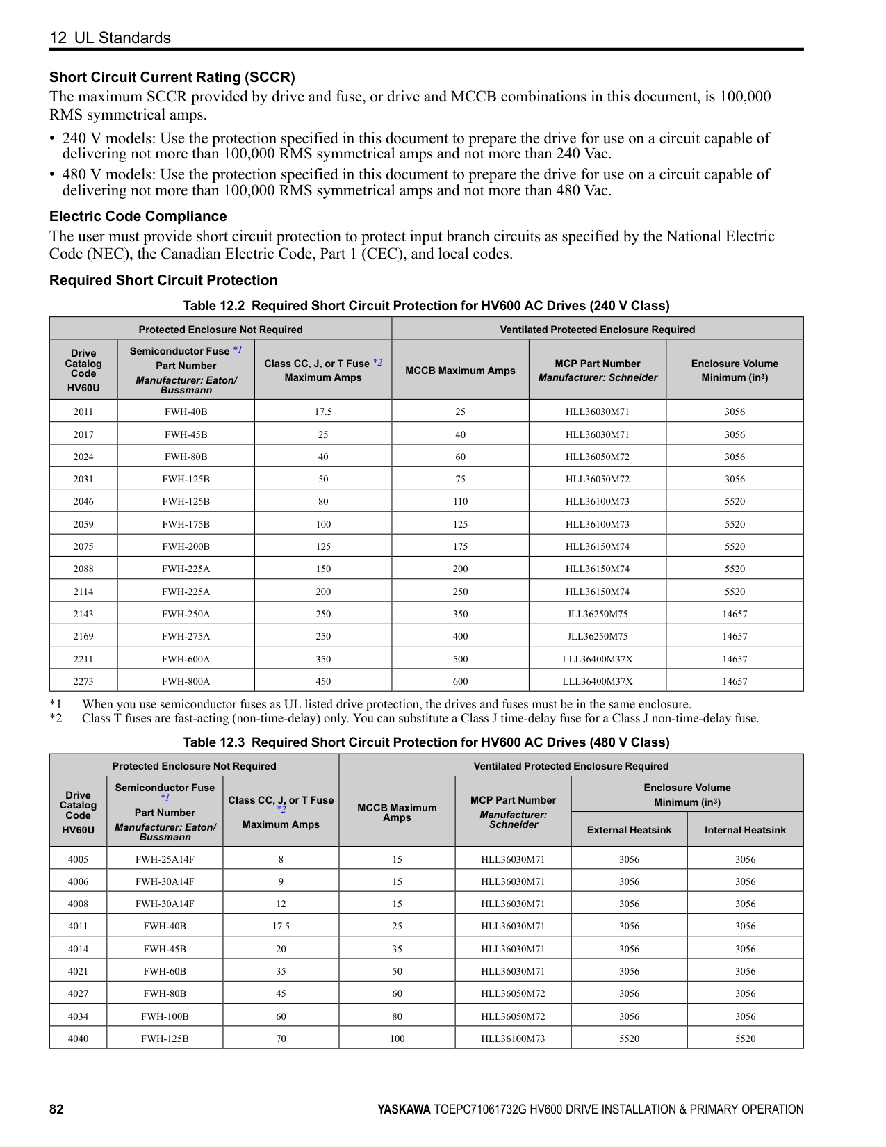
| | | | |---|---|---|
| | | | |---|---|---|
| | | |---|---| | | |
| | |---| | | | | | | | |
| | | | |---|---|---| | | | | | | | |
| | |---| | | | | | | | |
| | | | | | | | |---|---|---|---|---|---|---| | | | | | | | | | | | | | | | |
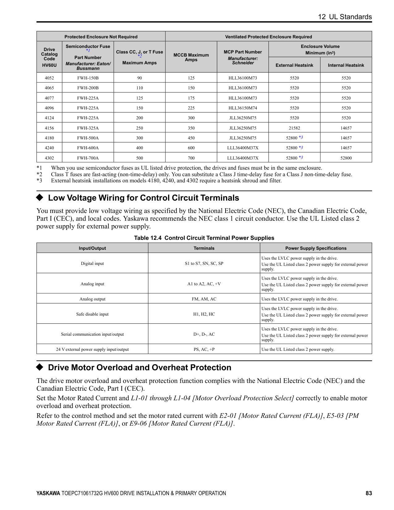
############## Figure 10.11 Location of DIP Switch S2 Table 10.10 RS-485 Communications Termination Resistor Setting
| | | | |---|---|---| | | | |
| | | | |---|---|---| | | | |
################# DIP Switch S2 Description
ON The built-in termination resistor is ON. OFF (Default) The built-in termination resistor is OFF.
#### 11 Drive Control and Programming
◆ Selecting the Control Method This section gives information about these basic control methods:
|on|rol (EZOLV) for induction motors only| | |---|---|---| |on| | |
Refer to the Technical Reference for information about speed feedback and Permanent Magnet/Synchronous Reluctance motor control methods. Use A1-02 [Control Method Selection] to select the most applicable control method for your application.
Control Method A1-02 Setting Main Applications
V/f 0
EZOLV 8
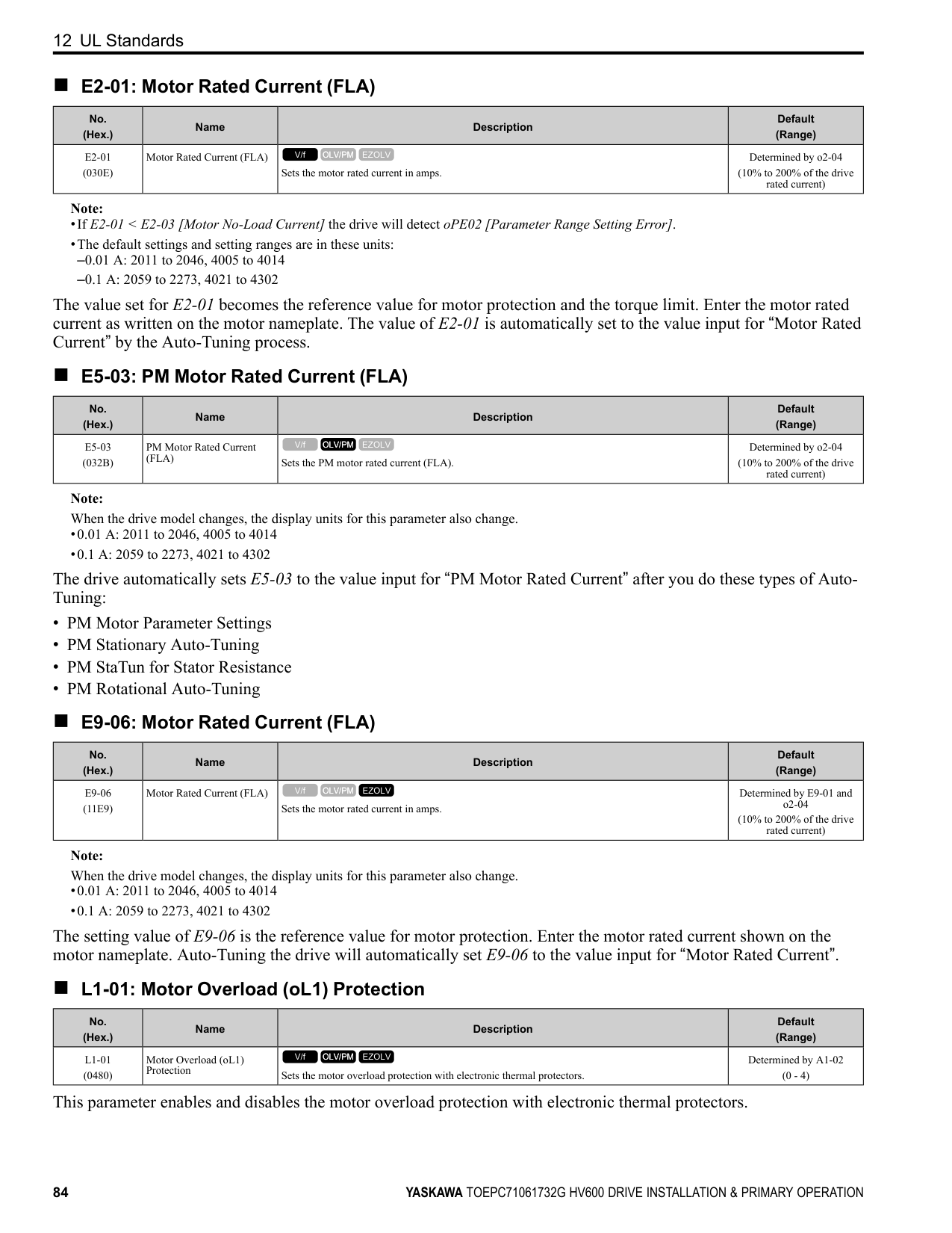
##### ◆ Auto-Tuning
WARNING Injury to Personnel. Rotational Auto-Tuning rotates the motor at 50% or more of the motor rated frequency. Make sure that there are no issues related to safety in the area around the drive and motor. Increased motor frequency can cause serious injury or death.
WARNING Sudden Movement Hazard. Before you do Rotational Auto-Tuning, disconnect the load from the motor. The load can move suddenly and cause serious injury or death.
Auto-Tuning automatically sets parameters on the drive connected to the motor. You must input some parameters individually during Auto-Tuning.
Table 11.1 Auto-Tuning Mode Selection
|Type|T1-01|Application Conditions and Benefits|A1-02 = 0 [Control Method Selection = V/f]| |---|---|---|---| |Rotational Auto-Tuning|0|Recommended tuning mode for the most accurate results. Select this tuning mode when:
• You can decouple the motor from the load.
• You cannot decouple the motor from the load, but the motor load is less than 30%.
|Yes| |Stationary Line-Line Resistance|2|Select this tuning mode when:
• The drive and motor capacities are different.
• The drive is in V/f Control.
• You have replaced the drive and motor.
|Yes|
Table 11.2 EZ Tuning Mode Selection
|Type|T4-01|Application Conditions and Benefits|A1-02 = 8 [EZOLV]| |---|---|---|---| |Motor Parameter Setting|0|Set the motor parameters.|Yes| |Line-to-Line Resistance|1|Select this tuning mode after you replace the drive, motor, and motor cables.|Yes|
##### ◆ Drive Parameters
|Icon|Description| |---|---| |V/f|The parameter is available when operating the drive with V/f Control.| |OLV/PM|The parameter is available when operating the drive with Open Loop Vector Control for PM.| |EZOLV|The parameter is available when operating the drive with EZ Open Loop Vector Control.| |RUN|The parameter can be changed settings during run.|
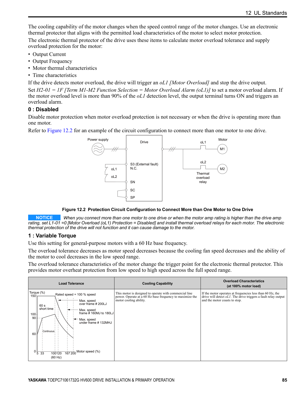
Note: Gray icons identify parameters that are not available in the specified control method.
Refer to the following table when setting the most important parameters.
|No. (Hex.)|Name|Description| |---|---|---| |A1-00 (0100) RUN|Language Selection|Sets the language for the keypad.
0 : English
1 : Japanese
2 : German
3 : French
4 : Italian
5 : Spanish
6 : Portuguese
V/f OLV/PM EZOLV
| |A1-02 (0102)|Control Method Selection|Sets the control method for the drive application and the motor. 0 : V/f Control 5 : PM Open Loop Vector 8 : EZ Vector Control
V/f OLV/PM EZOLV
| |A1-03 (0103)|Initialize Parameters|Sets parameters to default values. 0 : No Initialization 1110 : User Initialization 2220 : 2-Wire Initialization 3330 : 3-Wire Initialization 3410 : HVAC Initialization
V/f OLV/PM EZOLV
| |b1-01 (0180)|Frequency Reference Selection 1|Sets the input method for the frequency reference.
0 : Keypad
1 : Analog Input
2 : Serial Communications
3 : Option PCB
V/f OLV/PM EZOLV
|
|No. (Hex.)|Name|Description| |---|---|---| |b1-02 (0181)|Run Command Selection 1|Sets the input method for the Run command.
0 : Keypad
1 : Digital Input
2 : Serial Communications
3 : Option PCB
7 : AUTO Command Term Run
8 : AUTO Command Serial Run
9 : AUTO Command Option Run
V/f OLV/PM EZOLV
| |b1-03 (0182)|Stopping Method Selection|Sets the method to stop the motor after removing a Run command or entering a Stop command.
0 : Ramp to Stop
1 : Coast to Stop
2 : DC Injection Braking to Stop
3 : Coast to Stop with Timer
V/f OLV/PM EZOLV
| |b1-04 (0183)|Reverse Operation Selection|Sets the reverse operation function. Disable reverse operation in fan or pump applications where reverse rotation is dangerous.
0 : Reverse Enabled
1 : Reverse Disabled
V/f OLV/PM EZOLV
| |C1-01 (0200) RUN|Acceleration Time 1|Sets the length of time to accelerate from zero to maximum output frequency.
V/f OLV/PM EZOLV
| |C1-02 (0201) RUN|Deceleration Time 1|Sets the length of time to decelerate from maximum output frequency to zero.
V/f OLV/PM EZOLV
| |C2-01 (020B)|S-Curve Time @ Start of Accel|Sets the S-curve acceleration time at start.
V/f OLV/PM EZOLV
| |C2-02 (020C)|S-Curve Time @ End of Accel|Sets the S-curve acceleration time at completion.
V/f OLV/PM EZOLV
| |C2-03 (020D)|S-Curve Time @ Start of Decel|Sets the S-curve deceleration time at start.
V/f OLV/PM EZOLV
| |C2-04 (020E)|S-Curve Time @ End of Decel|Sets the S-curve deceleration time at completion.
V/f OLV/PM EZOLV
| |C6-02 (0224)|Carrier Frequency Selection|Sets the carrier frequency for the transistors in the drive.
1 : 2.0 kHz
2 : 5.0 kHz
3 : 8.0 kHz
4 : 10.0 kHz
5 : 12.5 kHz
7 : Swing PWM1 (Audible Sound 1)
8 : Swing PWM2 (Audible Sound 2)
9 : Swing PWM3 (Audible Sound 3)
A : Swing PWM4 (Audible Sound 4)
B : Leakage Current Rejection PWM F : User Defined (C6-03 to C6-05)
V/f OLV/PM EZOLV
| |d1-01 to d1-08 (0280 - 0287) RUN|Reference 1 to 8|Sets the frequency reference in the units from o1-03 [Frequency Display Unit Selection].
V/f OLV/PM EZOLV
| |d1-17 (0292) RUN|Jog Reference|Sets the Jog frequency reference in the units from o1-03 [Frequency Display Unit Selection]. Set H1-xx = 6 [MFDI Function Selection = Jog Reference Selection] to use the Jog frequency reference.
V/f OLV/PM EZOLV
| |d2-01 (0289)|Frequency Reference Upper Limit|Sets maximum limit for all frequency references. The maximum output frequency is 100%.
V/f OLV/PM EZOLV
| |d2-02 (028A)|Frequency Reference Lower Limit|Sets minimum limit for all frequency references. The maximum output frequency is 100%.
V/f OLV/PM EZOLV
| |E1-01 (0300)|Input AC Supply Voltage|Sets the drive input voltage.
V/f OLV/PM EZOLV
|
|No. (Hex.)|Name|Description| |---|---|---| |E1-04 (0303)|Maximum Output Frequency|Sets the maximum output frequency for the V/f pattern.
V/f OLV/PM EZOLV
| |E1-05 (0304)|Maximum Output Voltage|Sets the maximum output voltage for the V/f pattern.
V/f OLV/PM EZOLV
| |E1-06 (0305)|Base Frequency|Sets the base frequency for the V/f pattern.
V/f OLV/PM EZOLV
| |E1-09 (0308)|Minimum Output Frequency|Sets the minimum output frequency for the V/f pattern.
V/f OLV/PM EZOLV
| |E2-01 (030E)|Motor Rated Current (FLA)|Sets the motor rated current in amps.
V/f OLV/PM EZOLV
| |E2-11 (0318)|Motor Rated Power|Sets the motor rated output in the units from o1-58 [Motor Power Unit Selection].
V/f OLV/PM EZOLV
|
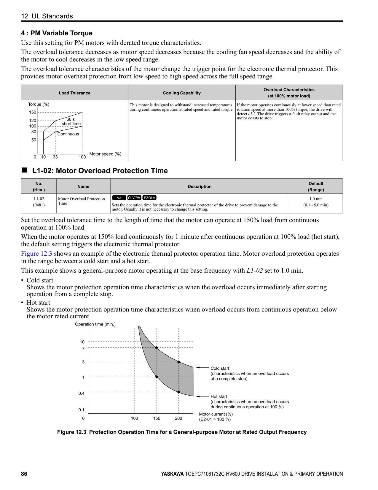
|H1-01 - H1-07 (0438, 0439, 0400 0404)|Terminal S1 to S7 Function Selection|Sets the functions for MFDI terminals S1 to S7.
V/f OLV/PM EZOLV
| |H2-01 (040B)|Term M1-M2 Function Selection|Sets the function for MFDO terminal M1-M2.
V/f OLV/PM EZOLV
| |H2-02 (040C)|Term M3-M4 Function Selection|Sets the function for MFDO terminal M3-M4.
V/f OLV/PM EZOLV
| |H2-03 (040D)|Term M5-M6 Function Selection|Sets the function for MFDO terminal M5-M6.
V/f OLV/PM EZOLV
| |H3-01 (0410)|Terminal A1 Signal Level Select|Sets the input signal level for MFAI terminal A1. 0 : 0 to 10V (Lower Limit at 0)
2 : 4 to 20 mA
3 : 0 to 20 mA
V/f OLV/PM EZOLV
| |H3-02 (0434)|Terminal A1 Function Selection|Sets the function for MFAI terminal A1.
V/f OLV/PM EZOLV
| |H3-03 (0411) RUN|Terminal A1 Gain Setting|Sets the gain of the analog signal input to MFAI terminal A1.
V/f OLV/PM EZOLV
| |H3-04 (0412) RUN|Terminal A1 Bias Setting|Sets the bias of the analog signal input to MFAI terminal A1.
V/f OLV/PM EZOLV
| |H3-09 (0417)|Terminal A2 Signal Level Select|Sets the input signal level for MFAI terminal A2. 0 : 0-10V (LowLim=0)
2 : 4 to 20 mA
3 : 0 to 20 mA
V/f OLV/PM EZOLV
| |H3-10 (0418)|Terminal A2 Function Selection|Sets the function for MFAI terminal A2.
V/f OLV/PM EZOLV
| |H3-11 (0419) RUN|Terminal A2 Gain Setting|Sets the gain of the analog signal input to MFAI terminal A2.
V/f OLV/PM EZOLV
| |H3-12 (041A) RUN|Terminal A2 Bias Setting|Sets the bias of the analog signal input to MFAI terminal A2.
V/f OLV/PM EZOLV
| |H3-13 (041B)|Analog Input FilterTime Constant|Sets the time constant for primary delay filters on MFAI terminals.
V/f OLV/PM EZOLV
| |H3-14 (041C)|Analog Input Terminal Enable Sel|Sets which terminal or terminals to enable when H1-xx = C [MFDI Function Selection = Analog Terminal Enable Selection] is activated.
1 : Terminal A1 only
2 : Terminal A2 only
3 : Terminals A1 and A2
V/f OLV/PM EZOLV
| |H4-01 (041D)|Terminal FM Analog Output Select|Sets the monitoring number (Ux-xx) to be output from MFAO terminal FM.
V/f OLV/PM EZOLV
|
|No. (Hex.)|Name|Description| |---|---|---| |H4-02 (041E) RUN|Terminal FM Analog Output Gain|Sets the gain of the monitor signal that is sent from MFAO terminal FM.
V/f OLV/PM EZOLV
| |H4-03 (041F) RUN|Terminal FM Analog Output Bias|Sets the bias of the monitor signal that is sent from MFAO terminal FM.
V/f OLV/PM EZOLV
| |H4-04 (0420)|Terminal AM Analog Output Select|Sets the monitoring number (Ux-xx) to be output from MFAO terminal AM.
V/f OLV/PM EZOLV
| |H4-05 (0421) RUN|Terminal AM Analog Output Gain|Sets the gain of the monitor signal that is sent from MFAO terminal AM.
V/f OLV/PM EZOLV
| |H4-06 (0422) RUN|Terminal AM Analog Output Bias|Sets the bias of the monitor signal that is sent from MFAO terminal AM.
V/f OLV/PM EZOLV
| |H4-07 (0423)|Terminal FM Signal Level Select|Sets the MFAO terminal FM output signal level. 0 : 0 to 10 Vdc 2 : 4 to 20 mA
V/f OLV/PM EZOLV
| |H4-08 (0424)|Terminal AM Signal Level Select|Sets the MFAO terminal AM output signal level. 0 : 0 to 10 Vdc 2 : 4 to 20 mA
V/f OLV/PM EZOLV
| |L1-01 (0480)|Motor Overload (oL1) Protection|Sets the motor overload protection with electronic thermal protectors.
0 : Disabled
1 : Variable Torque 4 : PM Variable Torque
V/f OLV/PM EZOLV
| |L1-02 (0481)|Motor Overload Protection Time|Sets the operation time for the electronic thermal protector of the drive to prevent damage to the motor. Usually it is not necessary to change this setting.
V/f OLV/PM EZOLV
| |L3-04 (0492)|Stall Prevention during Decel|Sets the method that the drive will use to prevent overvoltage faults when decelerating.
0 : Disabled
1 : General Purpose
2 : Intelligent (Ignore Decel Ramp) 4 : Overexcitation/High Flux
V/f OLV/PM EZOLV
| |o1-58 (3125)|Motor Power Unit Selection|Sets the setting unit for parameters that set the motor rated power.
0 : kW
1 : HP
V/f OLV/PM EZOLV
|
#### 12 UL Standards
Figure 12.1 UL/cUL Mark
The UL/cUL Mark identifies that this product conforms to rigid safety standards. This mark appears on products in the United States and Canada. It shows UL approval, which identifies that the product is in compliance with safety standards after careful inspection and assessment. You must use UL Listed or UL Recognized parts for all primary components that are built into electrical equipment that has UL approval.
This product has been tested in accordance with UL standard UL508C *1, and has been verified to be in compliance with UL standards.
*1 Models 2143xV, 2169xV, and 4156xVare in compliance with UL61800-5-1.
Machines and devices integrated with this product must satisfy the following conditions for compliance with UL standards.
◆ Area of Use Install this product in a location with Overvoltage Category III and pollution degree 2 or less.
■ Ambient Temperature Setting Maintain the ambient temperature within the following ranges according to the enclosure type.
◆ Main Circuit Wire Gauges and Tightening Torques Refer to Three-Phase 208 V Class Wire Gauges and Torques on page 34 and Three-Phase 480 V Class Wire Gauges and Torques on page 36 for the recommended wire gauges and tightening torques of the main circuit terminals. Comply with local standards for correct wire gauges in the region where the drive is used.
WARNING Electrical Shock Hazard. Only connect 12-pulse output, 18-pulse output, or DC power input to terminals - and +1. Incorrect wiring can cause damage to the drive and serious injury or death from fire.
############## Note:
◆ Ferrules and Closed-Loop Crimp Terminals To comply with UL standards on drive models 2075 to 2273 and 4077 to 4302, use UL Listed closed-loop crimp terminals. Use the tools recommend by the terminal manufacturer to crimp the closed-loop crimp terminal. Yaskawa recommends closed-loop crimp terminals from PANDUIT Corp. Install UL Recognized heat-shrinkable tubes to the closed-loop crimp terminals. If you do not use the tubes with the closed-loop crimp terminals, the insulating distance will be too short and it can cause short circuits.
A - UL Recognized heat-shrinkable tube Comply with local standards for correct wire gauges in the region where the drive is used. Refer to Table 12.1 to select ferrules and crimp terminals as specified by drive model and wire gauge.
Note:
To comply with UL standards, use UL Listed vinylcoated insulated copper wires for operation with a continuous maximum permitted temperature of 75 °C at 600 V.
############## Table 12.1 Ferrules and Closed-Loop Crimp Terminals
|Model|Terminals|Recommended Gauge
AWG, kcmil|Ferrule *1|Crimp Terminal Part Number Manufacturer: PANDUIT Corp.|Crimp Terminal Part Number Manufacturer: PANDUIT Corp.|Crimp Terminal Part Number Manufacturer: PANDUIT Corp.| |---|---|---|---|---|---|---| |Model|Terminals|Recommended Gauge
AWG, kcmil|Ferrule *1|Type LCA|Type P|Type S| |2011|R/L1, S/L2, T/L3|14|F80-10|N/A|N/A|N/A|
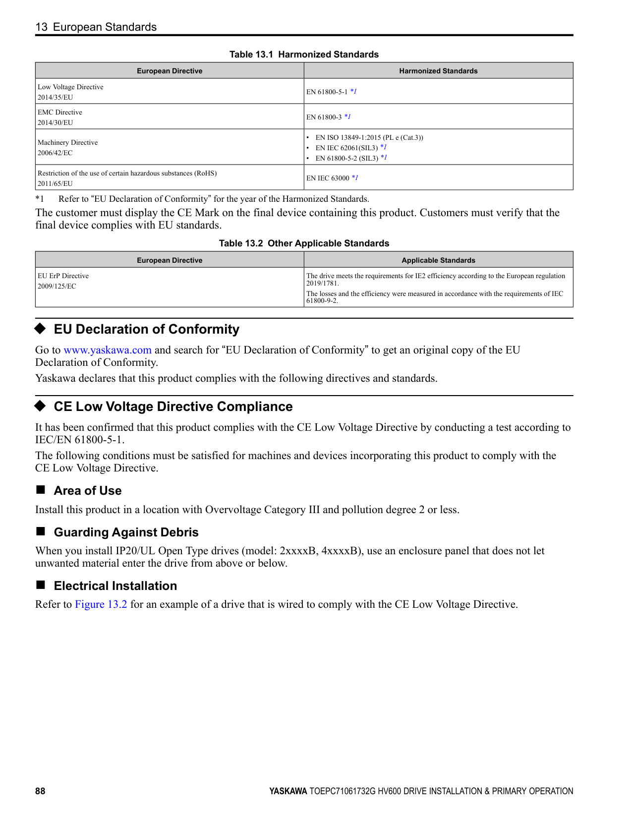
|2011|U/T1, V/T2, W/T3|14|F80-10|N/A|N/A|N/A| |2011|-, +1|14|F80-10|N/A|N/A|N/A| |2011| |12|N/A|LCA10-14-L|P10-14R-L|N/A| |2017|R/L1, S/L2, T/L3|12|F81-10|N/A|N/A|N/A| |2017|U/T1, V/T2, W/T3|10|F82-10|N/A|N/A|N/A| |2017|-, +1|10|F82-10|N/A|N/A|N/A| |2017| |10|N/A|LCA10-14-L|P10-14R-L|N/A| |2024|R/L1, S/L2, T/L3|10|F82-10|N/A|N/A|N/A| |2024|U/T1, V/T2, W/T3|8|F83-12|N/A|N/A|N/A| |2024|-, +1|8|F83-12|N/A|N/A|N/A| |2024| |10|N/A|LCA10-14-L|P10-14R-L|N/A| |2031|R/L1, S/L2, T/L3|8|F83-12|N/A|N/A|N/A| |2031|U/T1, V/T2, W/T3|8|F83-12|N/A|N/A|N/A| |2031|-, +1|8|F83-12|N/A|N/A|N/A| |2031| |10|N/A|LCA10-14-L|P10-14R-L|N/A| |2046|R/L1, S/L2, T/L3|8|F83-18|N/A|N/A|N/A| |2046|U/T1, V/T2, W/T3|6|F84-18|N/A|N/A|N/A| |2046|-, +1|6|F84-18|N/A|N/A|N/A| |2046| |8|N/A|LCA8-14-L|P8-14R-Q|S8-14R-Q| |2059|R/L1, S/L2, T/L3|4|F85-18|N/A|N/A|N/A| |2059|U/T1, V/T2, W/T3|4|F85-18|N/A|N/A|N/A| |2059|-, +1|4|F85-18|N/A|N/A|N/A| |2059| |6|N/A|LCA6-14-L|P6-14R-E|S6-14R-E| |2075|R/L1, S/L2, T/L3|4|N/A|LCA4-56-L|P4-56R-E|S4-56R-E| |2075|U/T1, V/T2, W/T3|3 or 2|N/A|LCA4-56-L or LCA2-56-Q|P2-56R-X *2|S2-56R-X *2| |2075|-, +1|2|N/A|LCA2-56-Q|P2-56R-X|S2-56R-X| |2075| |6|N/A|LCA6-56-L|P6-56R-E|S6-56R-E| |2088|R/L1, S/L2, T/L3
|3 or 2|N/A|LCA4-56-L or LCA2-56-Q|P2-56R-X *2|S2-56R-X *2| |2088|U/T1, V/T2, W/T3|2|N/A|LCA2-56-Q|P2-56R-X|S2-56R-X| |2088|-, +1|1|N/A|LCA1-56-E|N/A|S2-56R-X| |2088| |6|N/A|LCA6-56-L|P6-56R-E|S6-56R-E| |2114|R/L1, S/L2, T/L3|1/0|N/A|LCA1/0-56-X|N/A|S1/0-56R-X| |2114|U/T1, V/T2, W/T3|1/0|N/A|LCA1/0-56-X|N/A|S1/0-56R-X| |2114|-, +1|2/0|N/A|LCA2/0-56-X|N/A|S2/0-56R-X| |2114| |6|N/A|LCA6-56-L|P6-56R-E|S6-56R-E|
|Model|Terminals|Recommended Gauge
AWG, kcmil|Ferrule *1|Crimp Terminal Part Number Manufacturer: PANDUIT Corp.|Crimp Terminal Part Number Manufacturer: PANDUIT Corp.|Crimp Terminal Part Number Manufacturer: PANDUIT Corp.| |---|---|---|---|---|---|---| |Model|Terminals|Recommended Gauge
AWG, kcmil|Ferrule *1|Type LCA|Type P|Type S| |2143|R/L1, S/L2, T/L3|2/0|N/A|LCA2/0-56-X|N/A|S2/0-56R-X|
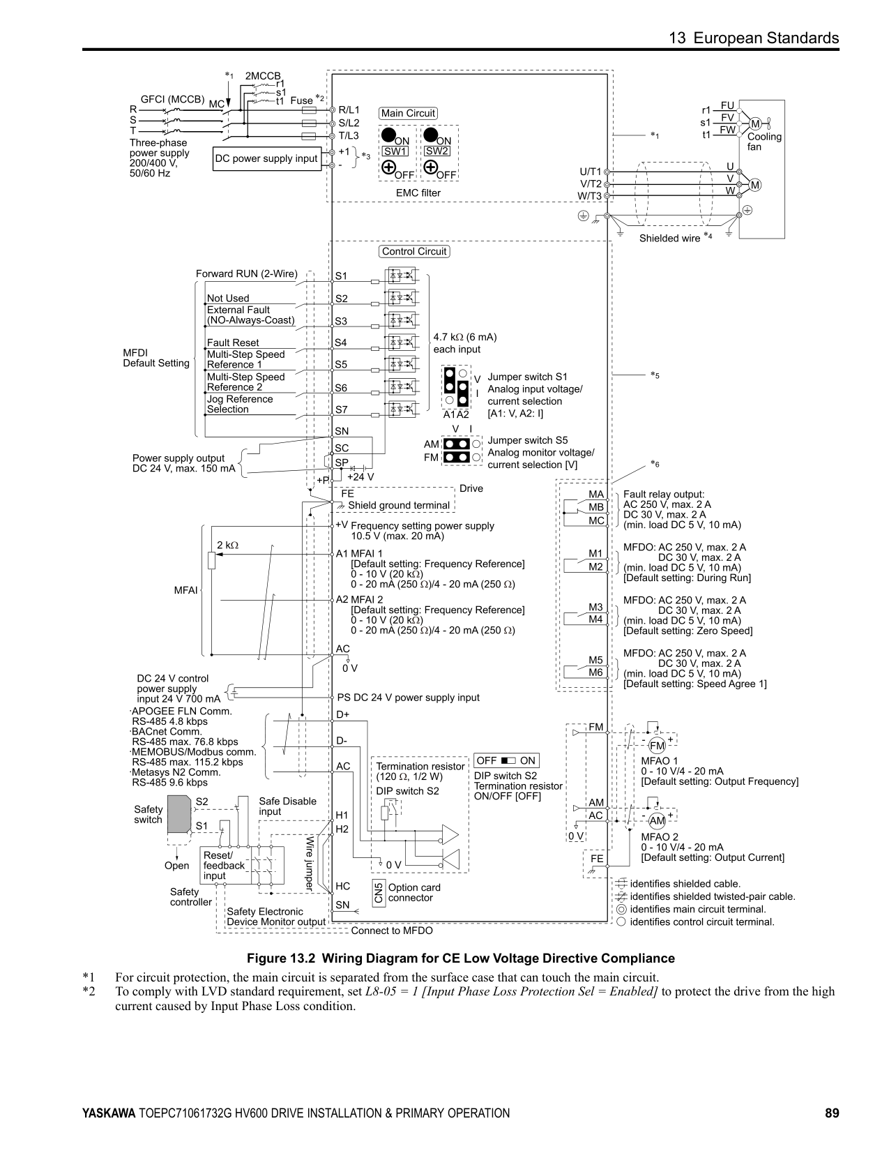
|2143|U/T1, V/T2, W/T3|3/0|N/A|LCA3/0-56-X|N/A|S3/0-56R-5| |2143|-, +1|3/0|N/A|LCA3/0-56-X|N/A|S3/0-56R-5| |2143| |4|N/A|LCA4-56-L|P4-56R-E|S4-56R-E| |2169|R/L1, S/L2, T/L3|3/0|N/A|LCA3/0-56-X|N/A|S3/0-56R-5| |2169|U/T1, V/T2, W/T3|4/0|N/A|LCA4/0-56-X|N/A|S4/0-56R-5| |2169|-, +1|1/0 × 2|N/A|LCA1/0-56-X|N/A|S1/0-56R-X| |2169| |4|N/A|LCA4-56-L|P4-56R-E|S4-56R-E| |2211|R/L1, S/L2, T/L3|1/0 × 2|N/A|LCA1/0-12-X|N/A|S1/0-12R-X| |2211|U/T1, V/T2, W/T3|1/0 × 2|N/A|LCA1/0-12-X|N/A|S1/0-12R-X| |2211|-, +1|1/0 × 2|N/A|LCA1/0-12-X|N/A|S1/0-12R-X| |2211| |3 or 2|N/A|LCA4-12-L or LCA2-12-Q|P2-12R-X *2|S2-12R-X *2| |2273|R/L1, S/L2, T/L3
|2/0 × 2|N/A|LCA2/0-12-X|N/A|S2/0-76R-X or S2/0-12R-X| |2273|U/T1, V/T2, W/T3|2/0 × 2|N/A|LCA2/0-12-X|N/A|S2/0-76R-X or S2/0-12R-X| |2273|-, +1|3/0 × 2|N/A|LCA3/0-12-X|N/A|S3/0-76R-5 or S3/0-12R-5| |2273| |2|N/A|LCA2-12-Q|P2-12R-X|S2-12R-X| |4005|R/L1, S/L2, T/L3|14|F80-10|N/A|N/A|N/A| |4005|U/T1, V/T2, W/T3|14|F80-10|N/A|N/A|N/A| |4005|-, +1|14|F80-10|N/A|N/A|N/A| |4005| |14|N/A|LCA10-14-L|P10-14R-L|N/A| |4008|R/L1, S/L2, T/L3|14|F80-10|N/A|N/A|N/A| |4008|U/T1, V/T2, W/T3|14|F80-10|N/A|N/A|N/A| |4008|-, +1|14|F80-10|N/A|N/A|N/A| |4008| |14|N/A|LCA10-14-L|P10-14R-L|N/A| |4011|R/L1, S/L2, T/L3|14|F80-10|N/A|N/A|N/A| |4011|U/T1, V/T2, W/T3|14|F80-10|N/A|N/A|N/A| |4011|-, +1|14|F80-10|N/A|N/A|N/A| |4011| |12|N/A|LCA10-14-L|P10-14R-L|N/A| |4014|R/L1, S/L2, T/L3|14|F80-10|N/A|N/A|N/A| |4014|U/T1, V/T2, W/T3|12|F81-10|N/A|N/A|N/A| |4014|-, +1|12|F81-10|N/A|N/A|N/A| |4014| |10|N/A|LCA10-14-L|P10-14R-L|N/A|
|Model|Terminals|Recommended Gauge
AWG, kcmil|Ferrule *1|Crimp Terminal Part Number Manufacturer: PANDUIT Corp.|Crimp Terminal Part Number Manufacturer: PANDUIT Corp.|Crimp Terminal Part Number Manufacturer: PANDUIT Corp.| |---|---|---|---|---|---|---| |Model|Terminals|Recommended Gauge
AWG, kcmil|Ferrule *1|Type LCA|Type P|Type S| |4021|R/L1, S/L2, T/L3|10|F82-10|N/A|N/A|N/A| |4021|U/T1, V/T2, W/T3|10|F82-10|N/A|N/A|N/A| |4021|-, +1|10|F82-10|N/A|N/A|N/A| |4021| |10|N/A|LCA10-14-L|P10-14R-L|N/A| |4027|R/L1, S/L2, T/L3|10|F82-10|N/A|N/A|N/A|
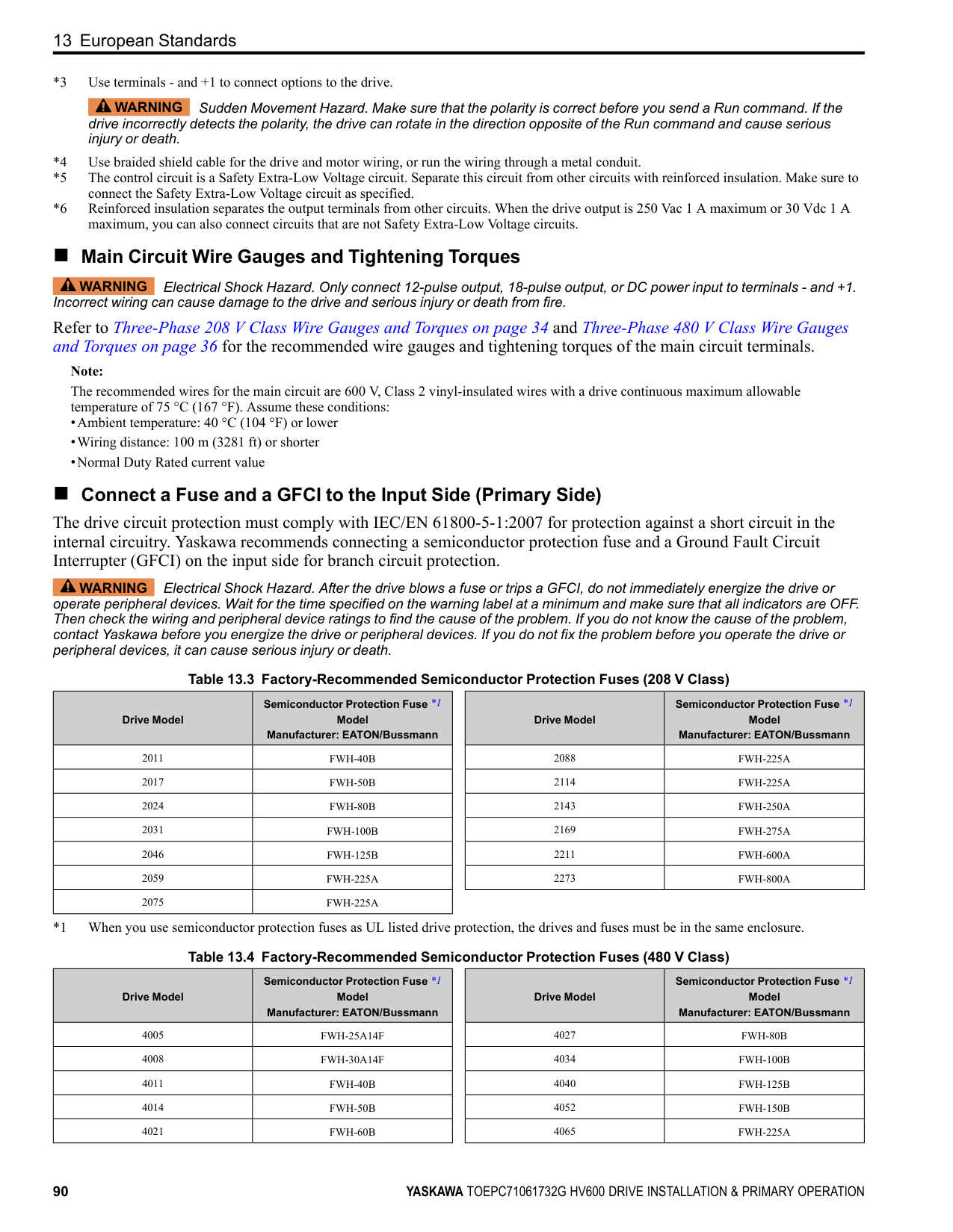
|4027|U/T1, V/T2, W/T3|8|F83-12|N/A|N/A|N/A| |4027|-, +1|8|F83-12|N/A|N/A|N/A| |4027| |10|N/A|LCA10-14-L|P10-14R-L|N/A| |4034|R/L1, S/L2, T/L3|8|F83-12|N/A|N/A|N/A| |4034|U/T1, V/T2, W/T3|8|F83-12|N/A|N/A|N/A| |4034|-, +1|8|F83-12|N/A|N/A|N/A| |4034| |10|N/A|LCA10-14-L|P10-14R-L|N/A| |4040|R/L1, S/L2, T/L3|8|F83-18|N/A|N/A|N/A| |4040|U/T1, V/T2, W/T3|8|F83-18|N/A|N/A|N/A| |4040|-, +1|6|F84-18|N/A|N/A|N/A| |4040| |8|N/A|LCA8-14-L|P8-14R-Q|S8-14R-Q| |4052|R/L1, S/L2, T/L3|6|F84-18|N/A|N/A|N/A| |4052|U/T1, V/T2, W/T3|6|F84-18|N/A|N/A|N/A| |4052|-, +1|4|F85-18|N/A|N/A|N/A| |4052| |8|N/A|LCA8-14-L|P8-14R-Q|S8-14R-Q| |4065|R/L1, S/L2, T/L3|4|F85-18|N/A|N/A|N/A| |4065|U/T1, V/T2, W/T3|4|F85-18|N/A|N/A|N/A| |4065|-, +1|4|F85-18|N/A|N/A|N/A| |4065| |6|N/A|LCA6-14-L|P6-14R-E|S6-14R-E| |4077|R/L1, S/L2, T/L3
|4|N/A|LCA4-56-L|P4-56R-E|S4-56R-E| |4077|U/T1, V/T2, W/T3|3 or 2|N/A|LCA4-56-L or LCA2-56-Q|P2-56R-X *2|S2-56R-X *2| |4077|-, +1|2|N/A|LCA2-56-Q|P2-56R-X|S2-56R-X| |4077| |6|N/A|LCA6-56-L|P6-56R-E|S6-56R-E| |4096|R/L1, S/L2, T/L3|2|N/A|LCA2-56-Q|P2-56R-X|S2-56R-X| |4096|U/T1, V/T2, W/T3|1|N/A|LCA1-56-E|N/A|S2-56R-X| |4096|-, +1|1|N/A|LCA1-56-E|N/A|S2-56R-X| |4096| |6|N/A|LCA6-56-L|P6-56R-E|S6-56R-E| |4124|R/L1, S/L2, T/L3|1/0|N/A|LCA1/0-56-X|N/A|S1/0-56R-X| |4124|U/T1, V/T2, W/T3|2/0|N/A|LCA2/0-56-X|N/A|S2/0-56R-X| |4124|-, +1|2/0|N/A|LCA2/0-56-X|N/A|S2/0-56R-X| |4124| |4|N/A|LCA4-56-L|P4-56R-E|S4-56R-E|
|Model|Terminals|Recommended Gauge
AWG, kcmil|Ferrule *1|Crimp Terminal Part Number Manufacturer: PANDUIT Corp.|Crimp Terminal Part Number Manufacturer: PANDUIT Corp.|Crimp Terminal Part Number Manufacturer: PANDUIT Corp.| |---|---|---|---|---|---|---| |Model|Terminals|Recommended Gauge
AWG, kcmil|Ferrule *1|Type LCA|Type P|Type S| |4156|R/L1, S/L2, T/L3|2/0|N/A|LCA2/0-56-X|N/A|S2/0-56R-X| |4156|U/T1, V/T2, W/T3|3/0|N/A|LCA3/0-56-X|N/A|S3/0-56R-5| |4156|-, +1|4/0|N/A|LCA4/0-56-X|N/A|S4/0-56R-5| |4156| |4|N/A|LCA4-56-L|P4-56R-E|S4-56R-E| |4180|R/L1, S/L2, T/L3|1/0 × 2|N/A|LCA1/0-12-X|N/A|S1/0-12R-X|
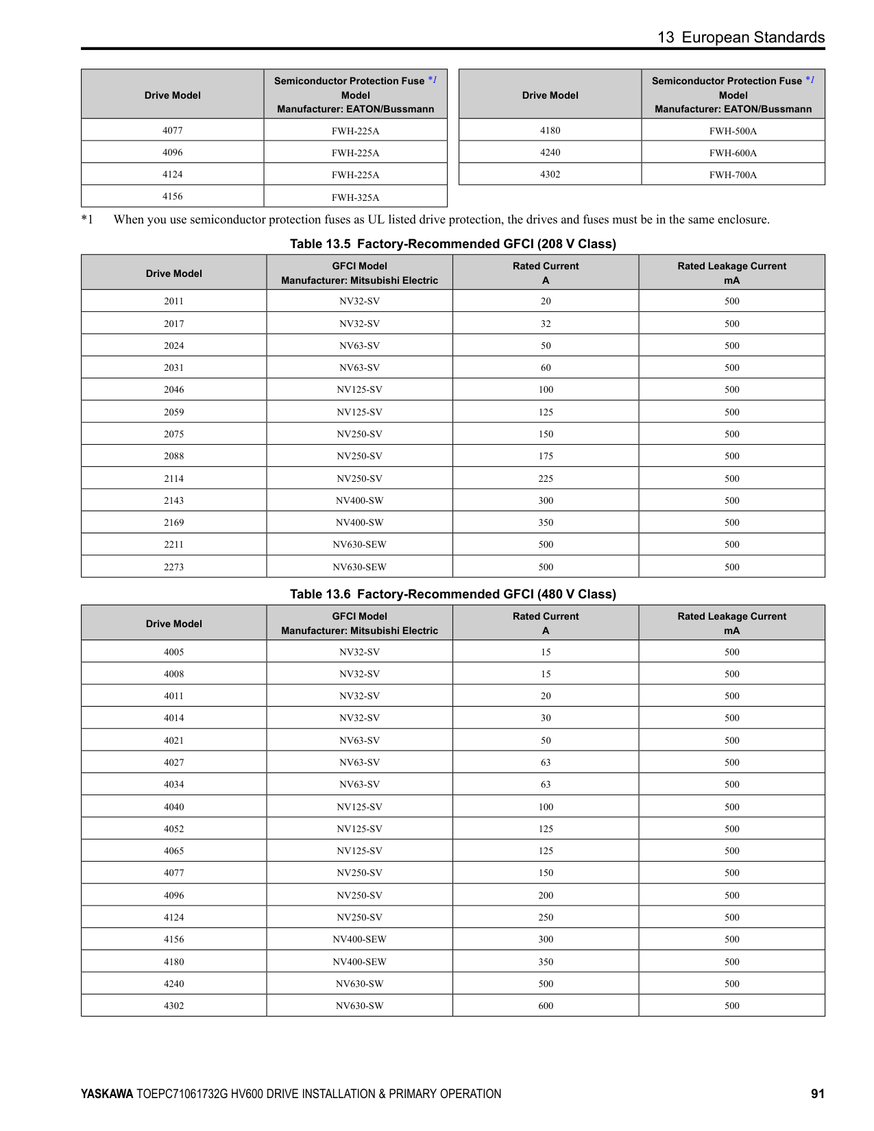
|4180|U/T1, V/T2, W/T3|1/0 × 2|N/A|LCA1/0-12-X|N/A|S1/0-12R-X| |4180|-, +1|1/0 × 2|N/A|LCA1/0-12-X|N/A|S1/0-12R-X| |4180| |3 or 2|N/A|LCA4-12-L or LCA2-12-Q|P2-12R-X *2|S2-12R-X *2| |4240|R/L1, S/L2, T/L3
|1/0 × 2|N/A|LCA1/0-12-X|N/A|S1/0-12R-X| |4240|U/T1, V/T2, W/T3|1/0 × 2|N/A|LCA1/0-12-X|N/A|S1/0-12R-X| |4240|-, +1|2/0 × 2|N/A|LCA2/0-12-X|N/A|S2/0-76R-X or S2/0-12R-X| |4240| |2|N/A|LCA2-12-Q|P2-12R-X|S2-12R-X| |4302|R/L1, S/L2, T/L3|3/0 × 2|N/A|LCA3/0-12-X|N/A|S3/0-12R-5| |4302|U/T1, V/T2, W/T3|3/0 × 2|N/A|LCA3/0-12-X|N/A|S3/0-12R-5| |4302|-, +1|4/0 × 2|N/A|LCA4/0-12-X|N/A|S4/0-12R-5| |4302| |1/0|N/A|LCA1/0-12-X|N/A|S1/0-12R-X|
##### ◆ Short Circuit Protection Requirements for UL Listing
WARNING Electrical Shock Hazard. After the input protective device trips, do not immediately energize the drive or operate peripheral devices. Wait for the time specified on the warning label at a minimum and make sure that all indicators are OFF. Then check the wiring and peripheral device ratings to find the cause of the problem. If you do not know the cause of the problem, contact Yaskawa before you energize the drive or peripheral devices. If you do not fix the problem before you operate the drive or peripheral devices, it can cause serious injury or death.
■ UL Compliance Install one of the types of short circuit protection devices in Table 12.2 or Table 12.3 to comply with UL 508C *1.
*1 Models 2143xV, 2169xV, and 4156xVare in compliance with UL61800-5-1. Semiconductor protective type fuses are recommended, but the tables also show alternative short circuit protection devices. Molded Case Circuit Breaker (MCCB) Ratings
Note: When you use MCCBs, current limiting type are recommended, but not required.
Semiconductor Fuse Ratings When you use semiconductor fuses as UL listed drive protection, the drives and fuses must be in the same enclosure.
Non-Semiconductor Fuse Ratings Maximum CC, J, or T fuse rating is 175% of the drive full load output amp (FLA) rating.
Short Circuit Current Rating (SCCR) The maximum SCCR provided by drive and fuse, or drive and MCCB combinations in this document, is 100,000 RMS symmetrical amps.
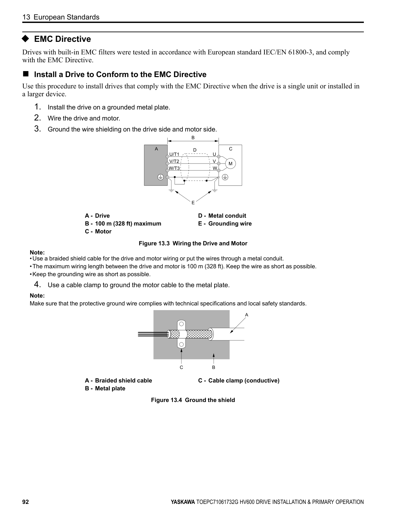
delivering not more than 100,000 RMS symmetrical amps and not more than 480 Vac. Electric Code Compliance The user must provide short circuit protection to protect input branch circuits as specified by the National Electric Code (NEC), the Canadian Electric Code, Part 1 (CEC), and local codes.
Required Short Circuit Protection
|Protected Enclosure Not Required|Protected Enclosure Not Required|Protected Enclosure Not Required|Ventilated Protected Enclosure Required|Ventilated Protected Enclosure Required|Ventilated Protected Enclosure Required| |---|---|---|---|---|---| |Drive Catalog Code
HV60U|Semiconductor Fuse *1 Part Number Manufacturer: Eaton/ Bussmann|Class CC, J, or T Fuse *2 Maximum Amps|MCCB Maximum Amps|MCP Part Number Manufacturer: Schneider|Enclosure Volume Minimum (in3)| |2011|FWH‐40B|17.5|25|HLL36030M71|3056| |2017|FWH‐45B|25|40|HLL36030M71|3056| |2024|FWH‐80B|40|60|HLL36050M72|3056| |2031|FWH‐125B|50|75|HLL36050M72|3056| |2046|FWH‐125B|80|110|HLL36100M73|5520| |2059|FWH‐175B|100|125|HLL36100M73|5520| |2075|FWH‐200B|125|175|HLL36150M74|5520| |2088|FWH‐225A|150|200|HLL36150M74|5520| |2114|FWH‐225A|200|250|HLL36150M74|5520| |2143|FWH‐250A|250|350|JLL36250M75|14657| |2169|FWH‐275A|250|400|JLL36250M75|14657| |2211|FWH‐600A|350|500|LLL36400M37X|14657| |2273|FWH‐800A|450|600|LLL36400M37X|14657|
|Protected Enclosure Not Required|Protected Enclosure Not Required|Protected Enclosure Not Required|Ventilated Protected Enclosure Required|Ventilated Protected Enclosure Required|Ventilated Protected Enclosure Required|Ventilated Protected Enclosure Required| |---|---|---|---|---|---|---| |Drive Catalog Code
HV60U|Semiconductor Fuse *1
Part Number Manufacturer: Eaton/ Bussmann|Class CC, J, or T Fuse *2
Maximum Amps|MCCB Maximum Amps|MCP Part Number Manufacturer: Schneider|Enclosure Volume Minimum (in3)|Enclosure Volume Minimum (in3)| |Drive Catalog Code
HV60U|Semiconductor Fuse *1
Part Number Manufacturer: Eaton/ Bussmann|Class CC, J, or T Fuse *2
Maximum Amps|MCCB Maximum Amps|MCP Part Number Manufacturer: Schneider|External Heatsink|Internal Heatsink| |4005|FWH‐25A14F|8|15|HLL36030M71|3056|3056| |4006|FWH‐30A14F|9|15|HLL36030M71|3056|3056| |4008|FWH‐30A14F|12|15|HLL36030M71|3056|3056| |4011|FWH‐40B|17.5|25|HLL36030M71|3056|3056| |4014|FWH‐45B|20|35|HLL36030M71|3056|3056| |4021|FWH‐60B|35|50|HLL36030M71|3056|3056|
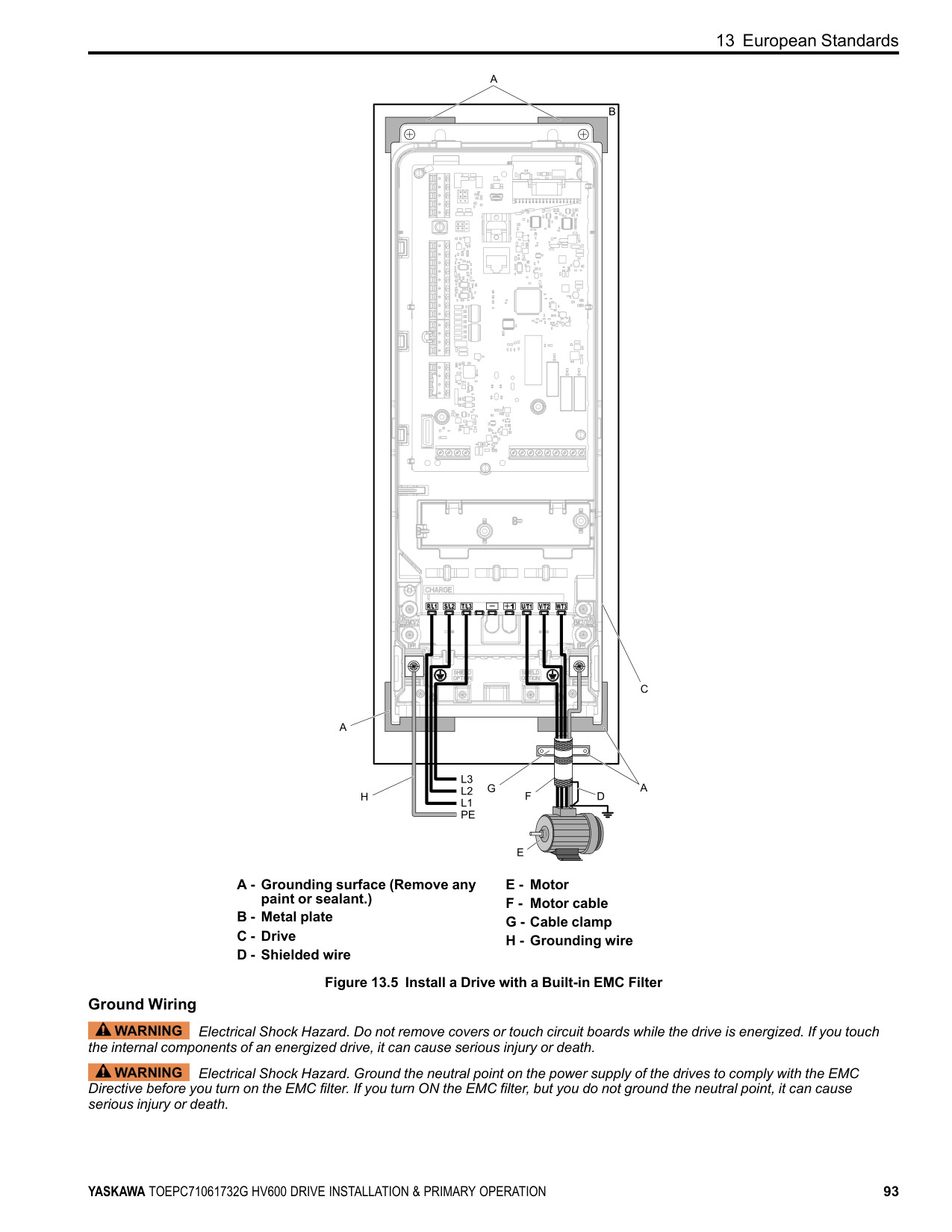
|4027|FWH‐80B|45|60|HLL36050M72|3056|3056| |4034|FWH‐100B|60|80|HLL36050M72|3056|3056| |4040|FWH‐125B|70|100|HLL36100M73|5520|5520|
|Protected Enclosure Not Required|Protected Enclosure Not Required|Protected Enclosure Not Required|Ventilated Protected Enclosure Required|Ventilated Protected Enclosure Required|Ventilated Protected Enclosure Required|Ventilated Protected Enclosure Required| |---|---|---|---|---|---|---| |Drive Catalog Code
HV60U|Semiconductor Fuse *1
Part Number Manufacturer: Eaton/ Bussmann|Class CC, J, or T Fuse *2
Maximum Amps|MCCB Maximum Amps|MCP Part Number Manufacturer: Schneider|Enclosure Volume Minimum (in3)|Enclosure Volume Minimum (in3)| |Drive Catalog Code
HV60U|Semiconductor Fuse *1
Part Number Manufacturer: Eaton/ Bussmann|Class CC, J, or T Fuse *2
Maximum Amps|MCCB Maximum Amps|MCP Part Number Manufacturer: Schneider|External Heatsink|Internal Heatsink| |4052|FWH‐150B|90|125|HLL36100M73|5520|5520| |4065|FWH‐200B|110|150|HLL36100M73|5520|5520| |4077|FWH‐225A|125|175|HLL36100M73|5520|5520| |4096|FWH‐225A|150|225|HLL36150M74|5520|5520| |4124|FWH‐225A|200|300|JLL36250M75|5520|5520| |4156|FWH‐325A|250|350|JLL36250M75|21582|14657| |4180|FWH‐500A|300|450|JLL36250M75|52800 *3|14657| |4240|FWH‐600A|400|600|LLL36400M37X|52800 *3|14657| |4302|FWH‐700A|500|700|LLL36400M37X|52800 *3|52800|
##### ◆ Low Voltage Wiring for Control Circuit Terminals
You must provide low voltage wiring as specified by the National Electric Code (NEC), the Canadian Electric Code, Part I (CEC), and local codes. Yaskawa recommends the NEC class 1 circuit conductor. Use the UL Listed class 2 power supply for external power supply.
Table 12.4 Control Circuit Terminal Power Supplies
|Input/Output|Terminals|Power Supply Specifications| |---|---|---| |Digital input|S1 to S7, SN, SC, SP|Uses the LVLC power supply in the drive. Use the UL Listed class 2 power supply for external power supply.| |Analog input|A1 to A2, AC, +V|Uses the LVLC power supply in the drive. Use the UL Listed class 2 power supply for external power supply.| |Analog output|FM, AM, AC|Uses the LVLC power supply in the drive.| |Safe disable input|H1, H2, HC|Uses the LVLC power supply in the drive. Use the UL Listed class 2 power supply for external power supply.| |Serial communication input/output|D+, D-, AC|Uses the LVLC power supply in the drive. Use the UL Listed class 2 power supply for external power supply.| |24 Vexternal power supply input/output|PS, AC, +P|Use the UL Listed class 2 power supply.|
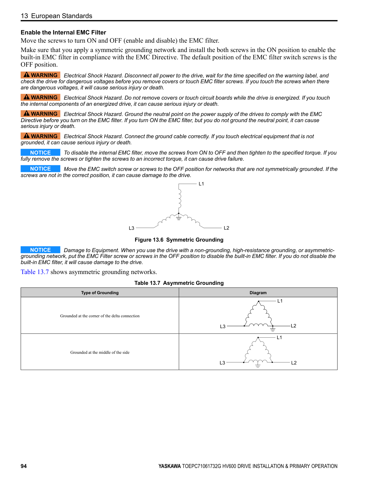
◆ Drive Motor Overload and Overheat Protection The drive motor overload and overheat protection function complies with the National Electric Code (NEC) and the Canadian Electric Code, Part I (CEC). Set the Motor Rated Current and L1-01 through L1-04 [Motor Overload Protection Select] correctly to enable motor overload and overheat protection. Refer to the control method and set the motor rated current with E2-01 [Motor Rated Current (FLA)], E5-03 [PM Motor Rated Current (FLA)], or E9-06 [Motor Rated Current (FLA)].
##### ■ E2-01: Motor Rated Current (FLA)
|No. (Hex.)|Name|Description|Default (Range)| |---|---|---|---| |E2-01 (030E)|Motor Rated Current (FLA)|Sets the motor rated current in amps.
V/f OLV/PM EZOLV
|Determined by o2-04 (10% to 200% of the drive rated current)|
############## Note:
The value set for E2-01 becomes the reference value for motor protection and the torque limit. Enter the motor rated current as written on the motor nameplate. The value of E2-01 is automatically set to the value input for “Motor Rated Current” by the Auto-Tuning process.
##### ■ E5-03: PM Motor Rated Current (FLA)
|No. (Hex.)|Name|Description|Default (Range)| |---|---|---|---| |E5-03 (032B)|PM Motor Rated Current (FLA)|Sets the PM motor rated current (FLA).
V/f OLV/PM EZOLV
|Determined by o2-04 (10% to 200% of the drive rated current)|
Note: When the drive model changes, the display units for this parameter also change.
The drive automatically sets E5-03 to the value input for “PM Motor Rated Current” after you do these types of AutoTuning:
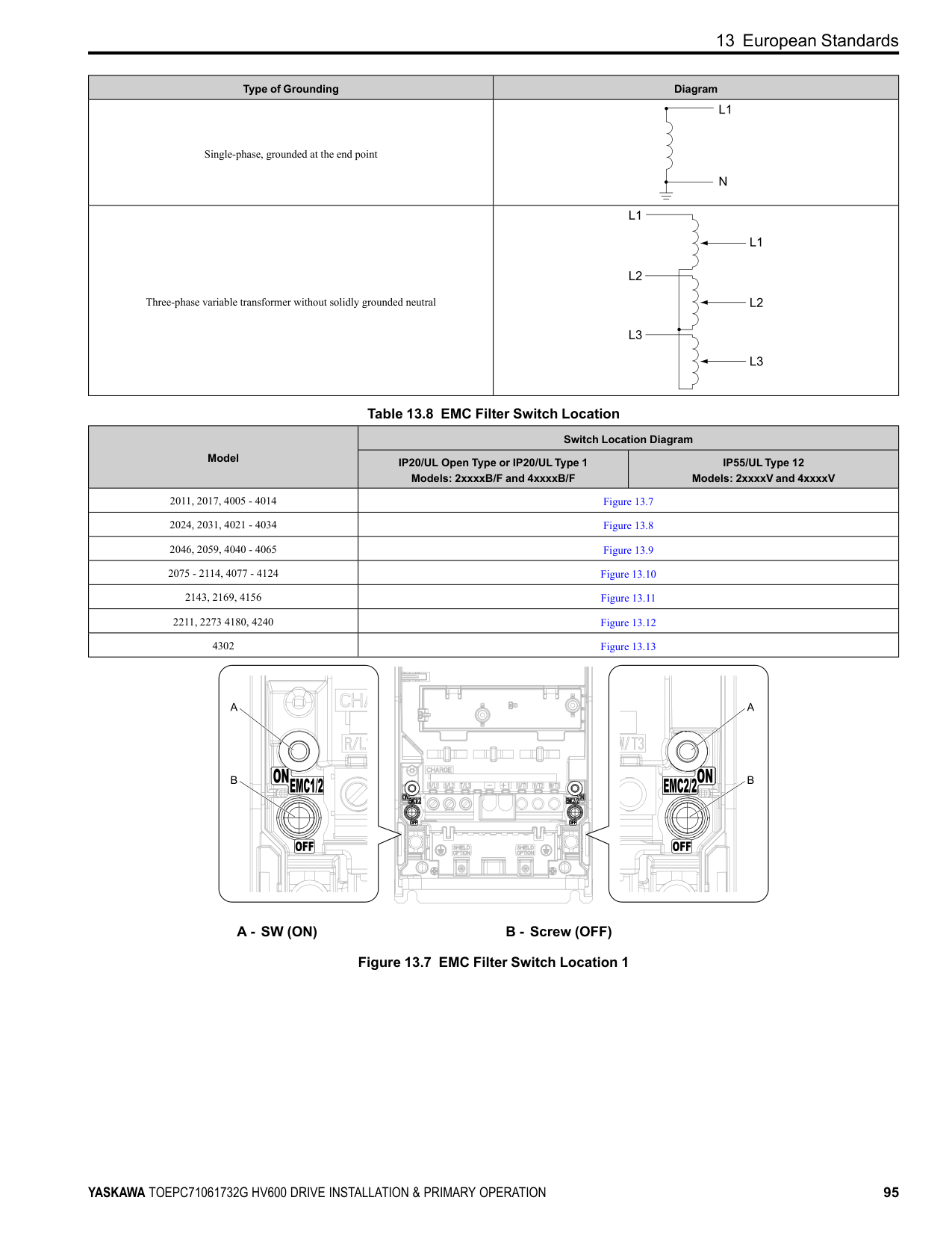
##### ■ E9-06: Motor Rated Current (FLA)
|No. (Hex.)|Name|Description|Default (Range)| |---|---|---|---| |E9-06 (11E9)|Motor Rated Current (FLA)|Sets the motor rated current in amps.
V/f OLV/PM EZOLV
|Determined by E9-01 and o2-04
(10% to 200% of the drive rated current)|
Note: When the drive model changes, the display units for this parameter also change.
The setting value of E9-06 is the reference value for motor protection. Enter the motor rated current shown on the motor nameplate. Auto-Tuning the drive will automatically set E9-06 to the value input for “Motor Rated Current”.
##### ■ L1-01: Motor Overload (oL1) Protection
|No. (Hex.)|Name|Description|Default (Range)| |---|---|---|---| |L1-01 (0480)|Motor Overload (oL1) Protection|Sets the motor overload protection with electronic thermal protectors.
V/f OLV/PM EZOLV
|Determined by A1-02 (0 - 4)|
This parameter enables and disables the motor overload protection with electronic thermal protectors.
The cooling capability of the motor changes when the speed control range of the motor changes. Use an electronic thermal protector that aligns with the permitted load characteristics of the motor to select motor protection. The electronic thermal protector of the drive uses these items to calculate motor overload tolerance and supply overload protection for the motor:
########### 0 : Disabled
Disable motor protection when motor overload protection is not necessary or when the drive is operating more than one motor. Refer to Figure 12.2 for an example of the circuit configuration to connect more than one motor to one drive.
Figure 12.2 Protection Circuit Configuration to Connect More than One Motor to One Drive
NOTICE When you connect more than one motor to one drive or when the motor amp rating is higher than the drive amp rating, set L1-01 =0 [Motor Overload (oL1) Protection = Disabled] and install thermal overload relays for each motor. The electronic thermal protection of the drive will not function and it can cause damage to the motor.
############ 1 : Variable TorqueUse this setting for general-purpose motors with a 60 Hz base frequency.
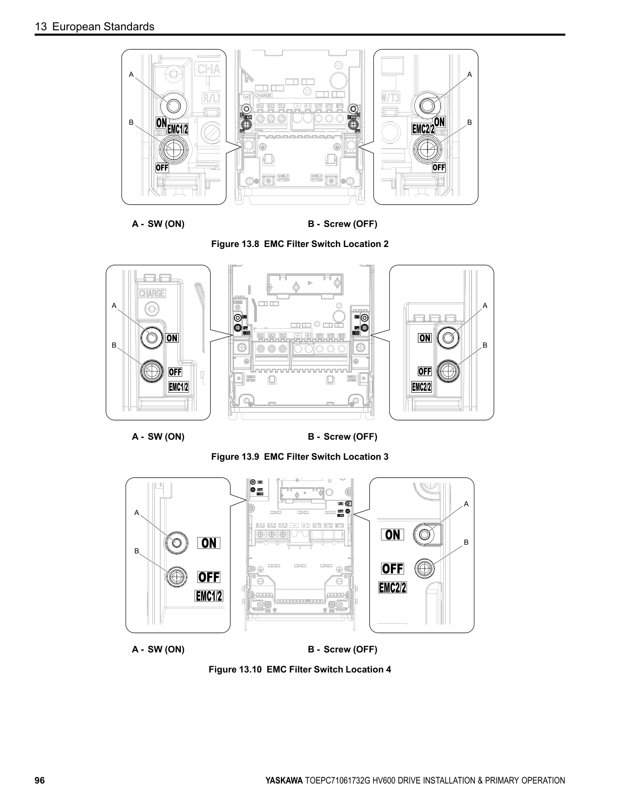
The overload tolerance decreases as motor speed decreases because the cooling fan speed decreases and the ability of the motor to cool decreases in the low speed range. The overload tolerance characteristics of the motor change the trigger point for the electronic thermal protector. This provides motor overheat protection from low speed to high speed across the full speed range.
|Load Tolerance|Cooling Capability|Overload Characteristics (at 100% motor load)| |---|---|---| | |This motor is designed to operate with commercial line power. Operate at a 60 Hz base frequency to maximize the motor cooling ability.|If the motor operates at frequencies less than 60 Hz, the drive will detect oL1. The drive triggers a fault relay output and the motor coasts to stop.|
The overload tolerance decreases as motor speed decreases because the cooling fan speed decreases and the ability of the motor to cool decreases in the low speed range. The overload tolerance characteristics of the motor change the trigger point for the electronic thermal protector. This provides motor overheat protection from low speed to high speed across the full speed range.
|Load Tolerance|Cooling Capability|Overload Characteristics (at 100% motor load)| |---|---|---| | |This motor is designed to withstand increased temperatures during continuous operation at rated speed and rated torque.|If the motor operates continuously at lower speed than rated rotation speed at more than 100% torque, the drive will detect oL1. The drive triggers a fault relay output and the motor coasts to stop.|
##### ■ L1-02: Motor Overload Protection Time
|No. (Hex.)|Name|Description|Default (Range)| |---|---|---|---| |L1-02 (0481)|Motor Overload Protection Time|Sets the operation time for the electronic thermal protector of the drive to prevent damage to the motor. Usually it is not necessary to change this setting.
V/f OLV/PM EZOLV
|1.0 min (0.1 - 5.0 min)|
Set the overload tolerance time to the length of time that the motor can operate at 150% load from continuous operation at 100% load. When the motor operates at 150% load continuously for 1 minute after continuous operation at 100% load (hot start), the default setting triggers the electronic thermal protector. Figure 12.3 shows an example of the electronic thermal protector operation time. Motor overload protection operates in the range between a cold start and a hot start. This example shows a general-purpose motor operating at the base frequency with L1-02 set to 1.0 min.
| | | | | |---|---|---|---| | | | | | | | | | | | | | | | | | | | | | | | | |
Figure 12.3 Protection Operation Time for a General-purpose Motor at Rated Output Frequency
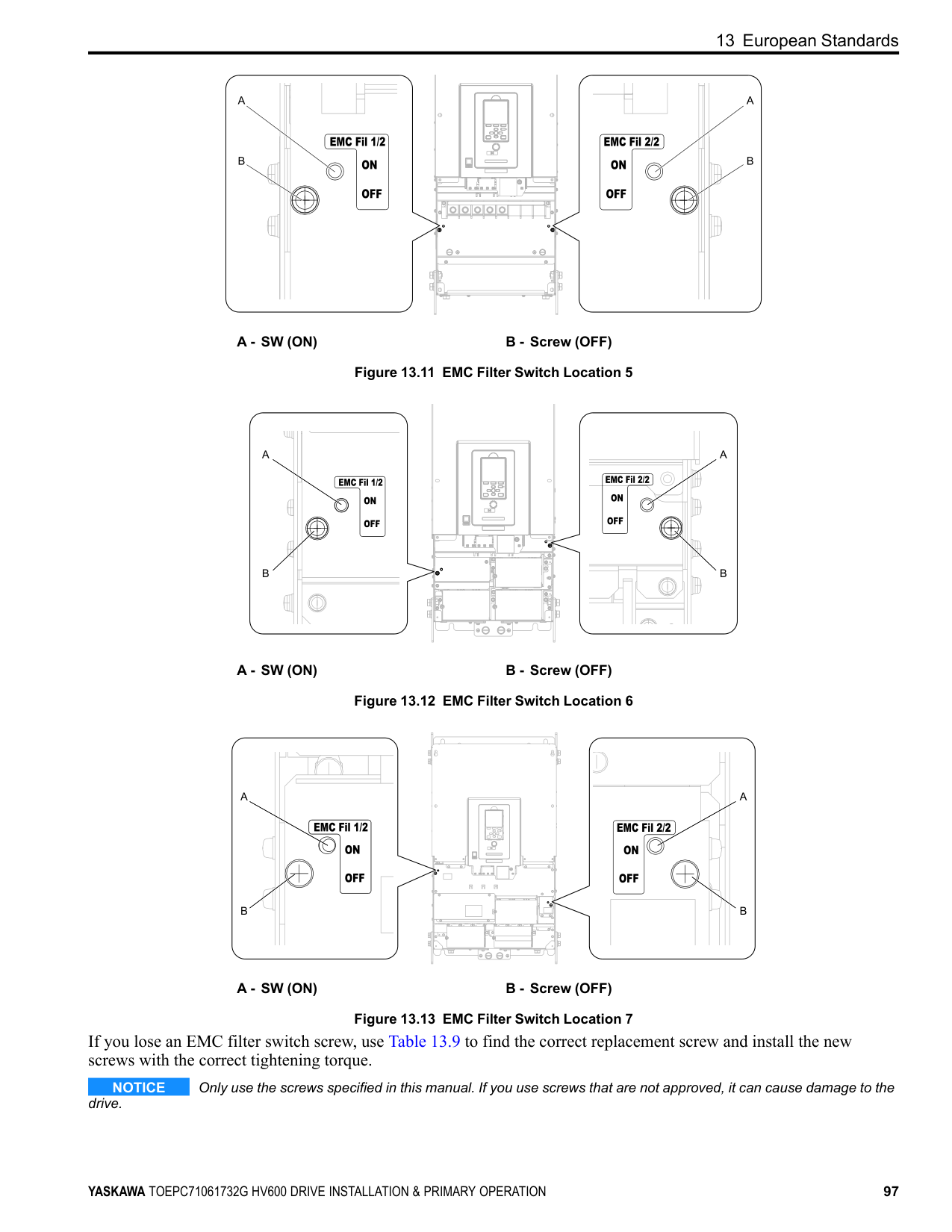
##### ■ L1-03: Motor Thermistor oH Alarm Select
|No. (Hex.)|Name|Description|Default (Range)| |---|---|---|---| |L1-03 (0482)|Motor Thermistor oH Alarm Select|Sets drive operation when the PTC input signal entered into the drive is at the oH3 [Motor Overheat (PTC Input)] detection level.
V/f OLV/PM EZOLV
|3 (0 - 3)|
The drive ramps the motor to stop in the deceleration time. Fault relay output terminal MA-MC turns ON and MBMC turns OFF.
The output turns OFF and the motor coasts to stop. Fault relay output terminal MA-MC turns ON, and MB-MC turns OFF.
The drive stops the motor in the deceleration time set in C1-09 [Fast Stop Time]. Fault relay output terminal MA-MC turns ON, and MB-MC turns OFF.
##### ■ L1-04: Motor Thermistor oH Fault Select
|No. (Hex.)|Name|Description|Default (Range)| |---|---|---|---| |L1-04 (0483)|Motor Thermistor oH Fault Select|Sets the drive operation when the PTC input signal to the drive is at the oH4 [Motor Overheat Fault (PTC Input)] detection level.
V/f OLV/PM EZOLV
|1 (0 - 2)|
########### 0 : Ramp to Stop
The drive ramps the motor to stop in the deceleration time. Fault relay output terminal MA-MC turns ON, and MBMC turns OFF.
########### 1 : Coast to Stop
The output turns OFF and the motor coasts to stop. Fault relay output terminal MA-MC turns ON, and MB-MC turns OFF.
########### 2 : Fast Stop (Use C1-09)
The drive stops the motor in the deceleration time set in C1-09 [Fast Stop Time]. Fault relay output terminal MA-MC turns ON, and MB-MC turns OFF.
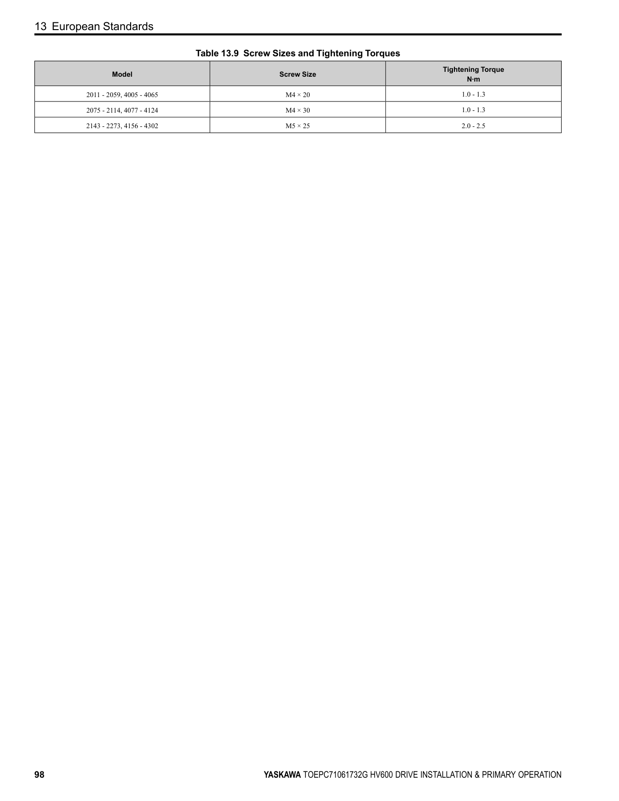
#### 13 European Standards
Figure 13.1 CE Mark The CE Mark identifies that the product meets environmental and safety standards in the European Union. Products manufactured, sold, or imported in the European Union must display the CE Mark. European Union standards include standards for electrical appliances (Low Voltage Directive), standards for electrical noise (EMC Directive), and standards for machinery (Machinery Directive). This product displays the CE Mark in accordance with the Low Voltage Directive, the EMC Directive, and the Machinery Directive.
*1 Refer to “EU Declaration of Conformity” for the year of the Harmonized Standards. The customer must display the CE Mark on the final device containing this product. Customers must verify that the final device complies with EU standards.
|European Directive|Harmonized Standards| |---|---| |Low Voltage Directive 2014/35/EU|EN 61800-5-1 *1| |EMC Directive 2014/30/EU|EN 61800-3 *1| |Machinery Directive 2006/42/EC|• EN ISO 13849-1:2015 (PL e (Cat.3))
• EN IEC 62061(SIL3) *1
• EN 61800-5-2 (SIL3) *1
| |Restriction of the use of certain hazardous substances (RoHS) 2011/65/EU|EN IEC 63000 *1|
|European Directive|Applicable Standards| |---|---| |EU ErP Directive 2009/125/EC|The drive meets the requirements for IE2 efficiency according to the European regulation 2019/1781.
The losses and the efficiency were measured in accordance with the requirements of IEC 61800-9-2.|
◆ EU Declaration of Conformity Go to www.yaskawa.com and search for “EU Declaration of Conformity” to get an original copy of the EU Declaration of Conformity. Yaskawa declares that this product complies with the following directives and standards.
◆ CE Low Voltage Directive Compliance It has been confirmed that this product complies with the CE Low Voltage Directive by conducting a test according to IEC/EN 61800-5-1. The following conditions must be satisfied for machines and devices incorporating this product to comply with the CE Low Voltage Directive.
When you install IP20/UL Open Type drives (model: 2xxxxB, 4xxxxB), use an enclosure panel that does not let unwanted material enter the drive from above or below.
| | | |---|---| | | |
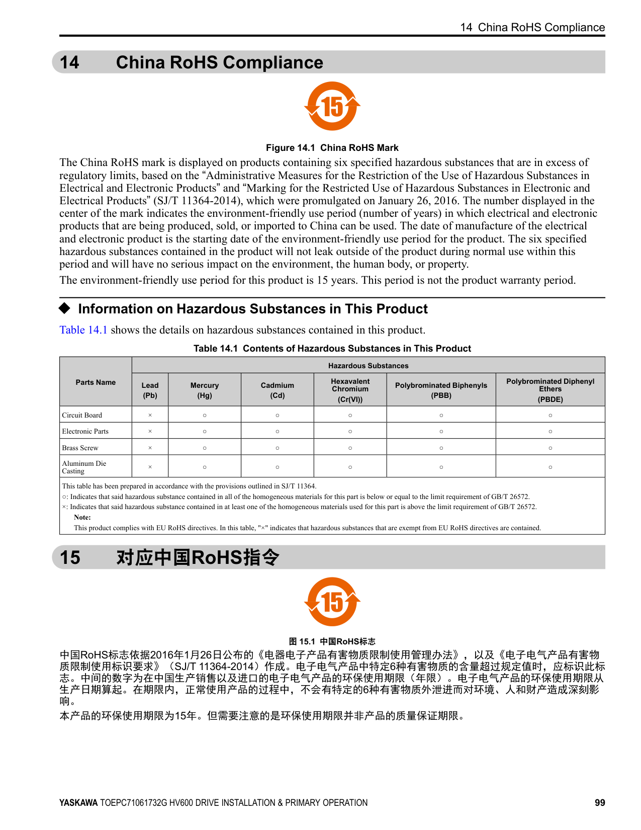
############## Figure 13.2 Wiring Diagram for CE Low Voltage Directive Compliance
WARNING Sudden Movement Hazard. Make sure that the polarity is correct before you send a Run command. If the drive incorrectly detects the polarity, the drive can rotate in the direction opposite of the Run command and cause serious injury or death.
##### ■ Main Circuit Wire Gauges and Tightening Torques
WARNING Electrical Shock Hazard. Only connect 12-pulse output, 18-pulse output, or DC power input to terminals - and +1. Incorrect wiring can cause damage to the drive and serious injury or death from fire. Refer to Three-Phase 208 V Class Wire Gauges and Torques on page 34 and Three-Phase 480 V Class Wire Gauges and Torques on page 36 for the recommended wire gauges and tightening torques of the main circuit terminals.
Note: The recommended wires for the main circuit are 600 V, Class 2 vinyl-insulated wires with a drive continuous maximum allowable temperature of 75 °C (167 °F). Assume these conditions:
##### ■ Connect a Fuse and a GFCI to the Input Side (Primary Side)
The drive circuit protection must comply with IEC/EN 61800-5-1:2007 for protection against a short circuit in the internal circuitry. Yaskawa recommends connecting a semiconductor protection fuse and a Ground Fault Circuit Interrupter (GFCI) on the input side for branch circuit protection.
WARNING Electrical Shock Hazard. After the drive blows a fuse or trips a GFCI, do not immediately energize the drive or operate peripheral devices. Wait for the time specified on the warning label at a minimum and make sure that all indicators are OFF. Then check the wiring and peripheral device ratings to find the cause of the problem. If you do not know the cause of the problem, contact Yaskawa before you energize the drive or peripheral devices. If you do not fix the problem before you operate the drive or peripheral devices, it can cause serious injury or death.
############## Table 13.3 Factory-Recommended Semiconductor Protection Fuses (208 V Class)
|Drive Model|Semiconductor Protection Fuse *1 Model Manufacturer: EATON/Bussmann| |---|---| |2011|FWH-40B| |2017|FWH-50B| |2024|FWH-80B| |2031|FWH-100B|
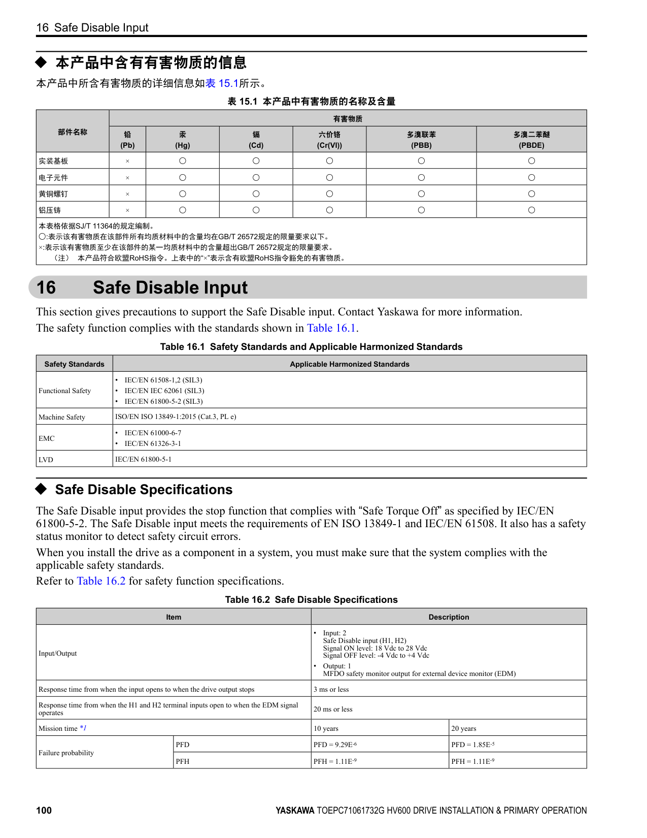
|2046|FWH-125B| |2059|FWH-225A| |2075|FWH-225A|
|Drive Model|Semiconductor Protection Fuse *1 Model Manufacturer: EATON/Bussmann| |---|---| |2088|FWH-225A| |2114|FWH-225A| |2143|FWH-250A| |2169|FWH-275A| |2211|FWH-600A| |2273|FWH-800A|
*1 When you use semiconductor protection fuses as UL listed drive protection, the drives and fuses must be in the same enclosure.
############## Table 13.4 Factory-Recommended Semiconductor Protection Fuses (480 V Class)
|Drive Model|Semiconductor Protection Fuse *1 Model Manufacturer: EATON/Bussmann| |---|---| |4005|FWH-25A14F| |4008|FWH-30A14F| |4011|FWH-40B| |4014|FWH-50B| |4021|FWH-60B|
|Drive Model|Semiconductor Protection Fuse *1 Model Manufacturer: EATON/Bussmann| |---|---| |4027|FWH-80B| |4034|FWH-100B| |4040|FWH-125B| |4052|FWH-150B| |4065|FWH-225A|
|Drive Model|Semiconductor Protection Fuse *1 Model Manufacturer: EATON/Bussmann| |---|---| |4077|FWH-225A| |4096|FWH-225A|
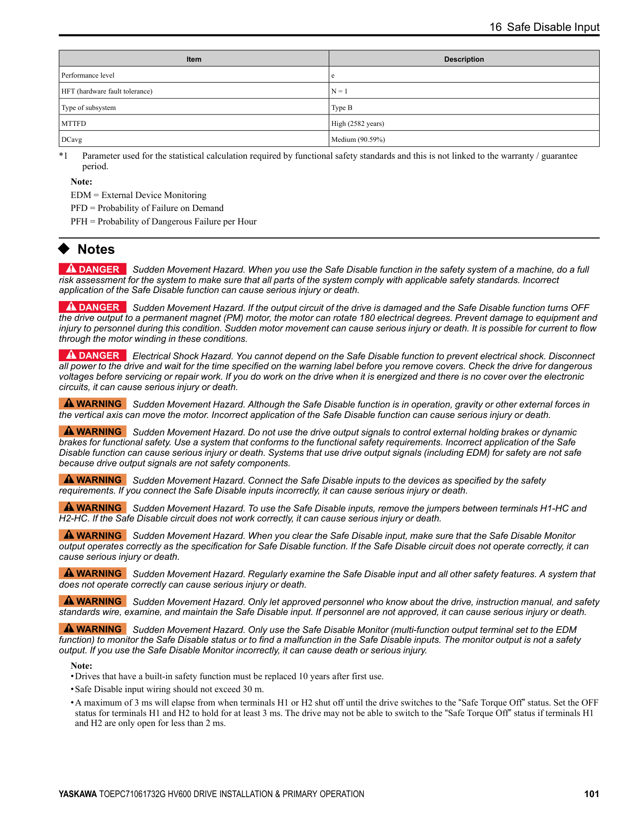
|4124|FWH-225A| |4156|FWH-325A|
|Drive Model|Semiconductor Protection Fuse *1 Model Manufacturer: EATON/Bussmann| |---|---| |4180|FWH-500A| |4240|FWH-600A| |4302|FWH-700A|
*1 When you use semiconductor protection fuses as UL listed drive protection, the drives and fuses must be in the same enclosure.
|Drive Model|GFCI Model Manufacturer: Mitsubishi Electric|Rated Current A|Rated Leakage Current mA| |---|---|---|---| |2011|NV32-SV|20|500| |2017|NV32-SV|32|500| |2024|NV63-SV|50|500| |2031|NV63-SV|60|500| |2046|NV125-SV|100|500| |2059|NV125-SV|125|500| |2075|NV250-SV|150|500| |2088|NV250-SV|175|500| |2114|NV250-SV|225|500| |2143|NV400-SW|300|500| |2169|NV400-SW|350|500| |2211|NV630-SEW|500|500| |2273|NV630-SEW|500|500|
|Drive Model|GFCI Model Manufacturer: Mitsubishi Electric|Rated Current A|Rated Leakage Current mA| |---|---|---|---| |4005|NV32-SV|15|500| |4008|NV32-SV|15|500| |4011|NV32-SV|20|500| |4014|NV32-SV|30|500| |4021|NV63-SV|50|500|
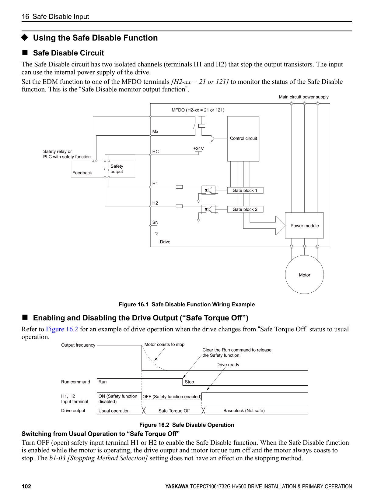
|4027|NV63-SV|63|500| |4034|NV63-SV|63|500| |4040|NV125-SV|100|500| |4052|NV125-SV|125|500| |4065|NV125-SV|125|500| |4077|NV250-SV|150|500| |4096|NV250-SV|200|500| |4124|NV250-SV|250|500| |4156|NV400-SEW|300|500| |4180|NV400-SEW|350|500| |4240|NV630-SW|500|500| |4302|NV630-SW|600|500|
##### ◆ EMC Directive
Drives with built-in EMC filters were tested in accordance with European standard IEC/EN 61800-3, and comply with the EMC Directive.
##### ■ Install a Drive to Conform to the EMC Directive
Use this procedure to install drives that comply with the EMC Directive when the drive is a single unit or installed in a larger device.
D - Metal conduit E - Grounding wire
Figure 13.3 Wiring the Drive and Motor Note:
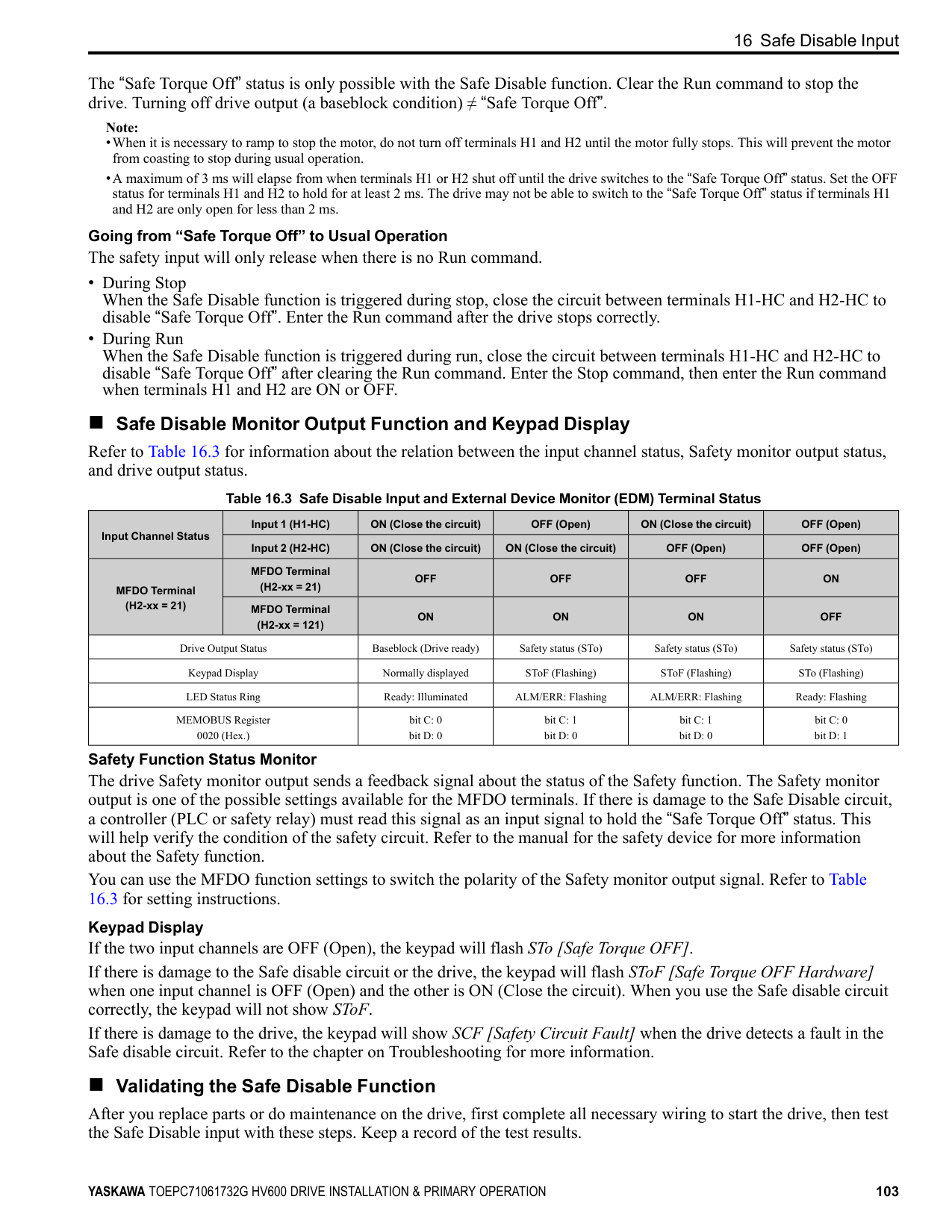
Note: Make sure that the protective ground wire complies with technical specifications and local safety standards.
C - Cable clamp (conductive)
Figure 13.4 Ground the shield
| | | |---|---| | | |
| | | |---|---| | | |
| | | |---|---| | | |
| | | |---|---| | | |
| | | |---|---| | | |
| | |---| | |
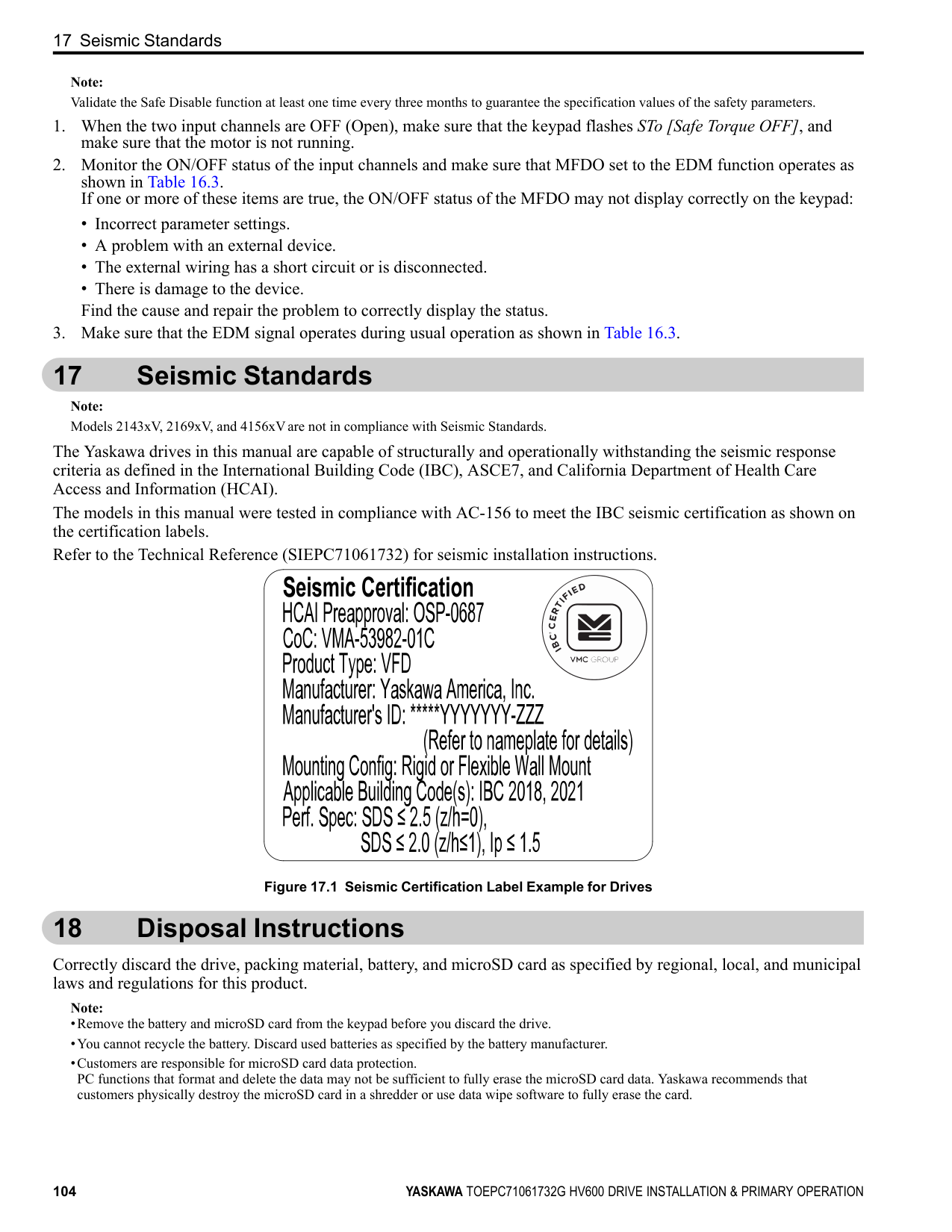
| | |---| | |
| | | | | | | | |---|---|---|---|---|---|---|
| | | | | | | | | |---|---|---|---|---|---|---|---| | | | | | | | | |
| | | | | | | | |---|---|---|---|---|---|---| | | | | | | | |
Figure 13.5 Install a Drive with a Built-in EMC Filter Ground Wiring
WARNING Electrical Shock Hazard. Do not remove covers or touch circuit boards while the drive is energized. If you touch the internal components of an energized drive, it can cause serious injury or death.
WARNING Electrical Shock Hazard. Ground the neutral point on the power supply of the drives to comply with the EMC Directive before you turn on the EMC filter. If you turn ON the EMC filter, but you do not ground the neutral point, it can cause serious injury or death.
Enable the Internal EMC Filter Move the screws to turn ON and OFF (enable and disable) the EMC filter.
Make sure that you apply a symmetric grounding network and install the both screws in the ON position to enable the built-in EMC filter in compliance with the EMC Directive. The default position of the EMC filter switch screws is the OFF position.
WARNING Electrical Shock Hazard. Disconnect all power to the drive, wait for the time specified on the warning label, and check the drive for dangerous voltages before you remove covers or touch EMC filter screws. If you touch the screws when there are dangerous voltages, it will cause serious injury or death.
WARNING Electrical Shock Hazard. Do not remove covers or touch circuit boards while the drive is energized. If you touch the internal components of an energized drive, it can cause serious injury or death.
WARNING Electrical Shock Hazard. Ground the neutral point on the power supply of the drives to comply with the EMC Directive before you turn on the EMC filter. If you turn ON the EMC filter, but you do not ground the neutral point, it can cause serious injury or death.
WARNING Electrical Shock Hazard. Connect the ground cable correctly. If you touch electrical equipment that is not grounded, it can cause serious injury or death.
NOTICE To disable the internal EMC filter, move the screws from ON to OFF and then tighten to the specified torque. If you fully remove the screws or tighten the screws to an incorrect torque, it can cause drive failure.
NOTICE Move the EMC switch screw or screws to the OFF position for networks that are not symmetrically grounded. If the screws are not in the correct position, it can cause damage to the drive.
############## Figure 13.6 Symmetric Grounding
NOTICE Damage to Equipment. When you use the drive with a non-grounding, high-resistance grounding, or asymmetricgrounding network, put the EMC Filter screw or screws in the OFF position to disable the built-in EMC filter. If you do not disable the built-in EMC filter, it will cause damage to the drive.
Table 13.7 shows asymmetric grounding networks.
Table 13.7 Asymmetric Grounding
|Type of Grounding|Diagram| |---|---| |Grounded at the corner of the delta connection| | |Grounded at the middle of the side| |
| | |---| | |
| | | | |---|---|---| | | | | | | | | | | | |
13 European Standards
Type of Grounding Diagram
Single-phase, grounded at the end point
| | | | | |---|---|---|---| | | | | | | | | | |
| | |---| | |
| | | |---|---| | | |
| | | | |---|---|---| | | | | | | | |
| | | |---|---| | | |
| | | |---|---| | | |
| | | |---|---| | | | | | |
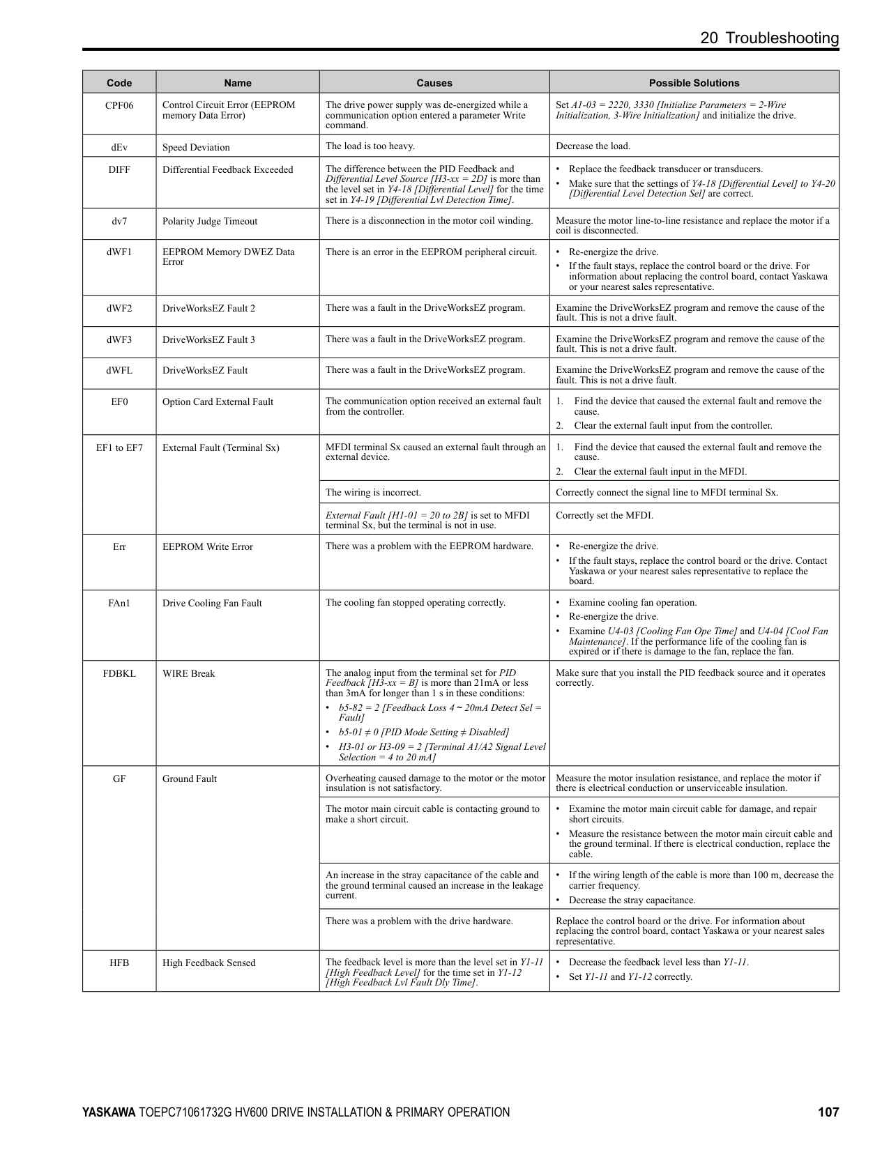
Three-phase variable transformer without solidly grounded neutral
| | | | | |---|---|---|---|
| | | |---|---|
| | | |---|---| | | | | | |
| | | | |---|---|---| | | | | | | | | | | | | | | | |
| | | |---|---| | | | | | |
| | | | |---|---|---| | | | | | | | | | | | | | | | |
| | | |---|---|
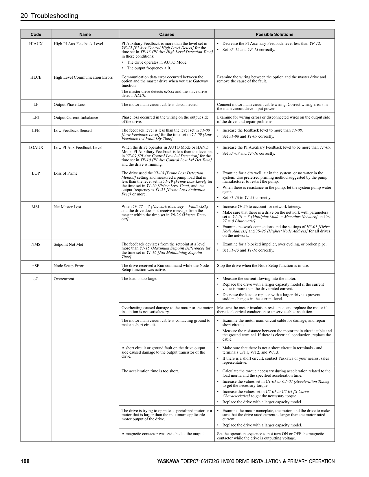
| | |
| | | |---|---| | | |
############## Table 13.8 EMC Filter Switch Location
| | | |---|---|
Model
Switch Location Diagram IP20/UL Open Type or IP20/UL Type 1 Models: 2xxxxB/F and 4xxxxB/F
IP55/UL Type 12 Models: 2xxxxV and 4xxxxV
2011, 2017, 4005 - 4014 Figure 13.7 2024, 2031, 4021 - 4034 Figure 13.8 2046, 2059, 4040 - 4065 Figure 13.9 2075 - 2114, 4077 - 4124 Figure 13.10
| | | |---|---| | | |
| | | |---|---| | | |
2143, 2169, 4156 Figure 13.11 2211, 2273 4180, 4240 Figure 13.12 4302 Figure 13.13
| | | |---|---| | | |
| | | |---|---|
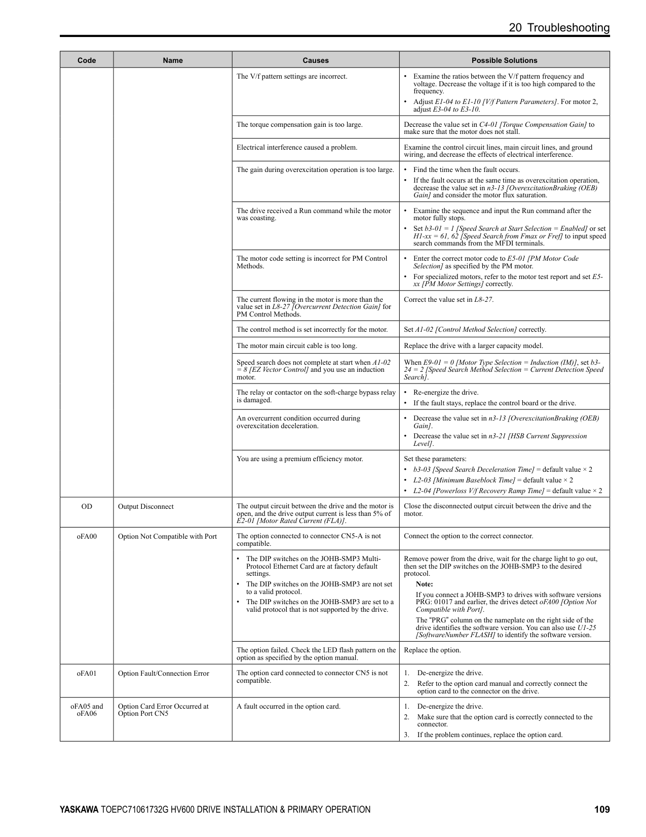
| | |
| | | |---|---| | | |
| | | | |---|---|---| | | | |
| | | | |---|---|---| | | | | | | | |
| | | | | |---|---|---|---| | | | | | | | | | |
############## A - SW (ON) B - Screw (OFF) Figure 13.7 EMC Filter Switch Location 1
| | | |---|---| | | |
A - SW (ON) B - Screw (OFF) Figure 13.8
|EMC|EMC|EMC| |---|---|---| | | | | | | | |
Filter Switch Location 2
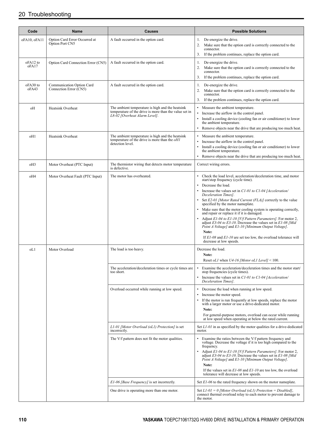
| | | | |---|---|---| | | | |
| | | |---|---| | | |
A - SW (ON) B - Screw (OFF) Figure 13.9 EMC Filter Switch Location 3
| | | |---|---|
| | | |---|---| | | |
| | | |---|---|
| | | |---|---|
| | | |---|---|
A - SW (ON) B - Screw (OFF) Figure 13.10 EMC Filter Switch Location 4
| | | |---|---| | | |
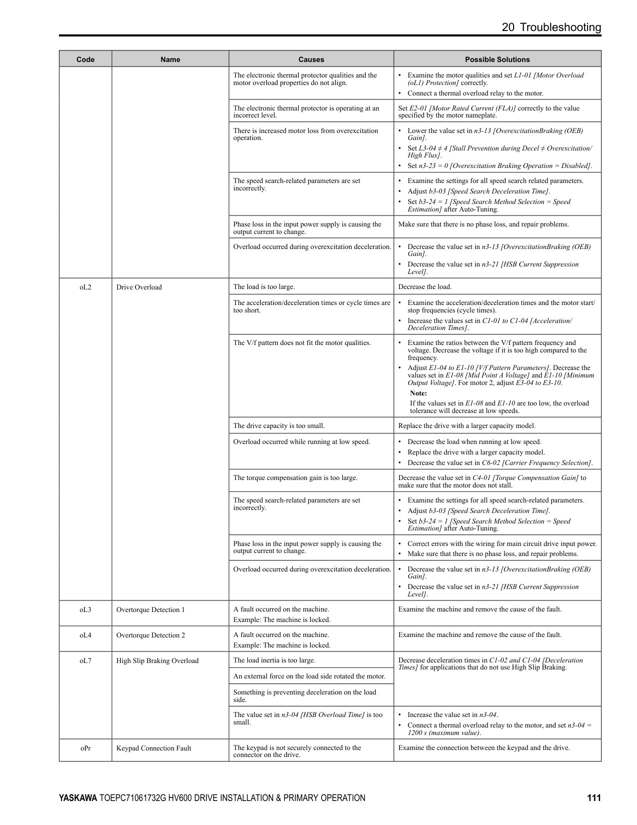
| | | |---|---| | | |
13 European Standards
| | | |---|---| | | |
A - SW (ON) B - Screw (OFF)
A - SW (ON) B - Screw (OFF)
A - SW (ON) B - Screw (OFF)
If you lose an EMC filter switch screw, use Table 13.9 to find the correct replacement screw and install the new screws with the correct tightening torque.
NOTICE Only use the screws specified in this manual. If you use screws that are not approved, it can cause damage to the drive.
############## Table 13.9 Screw Sizes and Tightening Torques
|Model|Screw Size|Tightening Torque N∙m| |---|---|---| |2011 - 2059, 4005 - 4065|M4 × 20|1.0 - 1.3| |2075 - 2114, 4077 - 4124|M4 × 30|1.0 - 1.3| |2143 - 2273, 4156 - 4302|M5 × 25|2.0 - 2.5|
14 China RoHS Compliance
#### 14 China RoHS Compliance
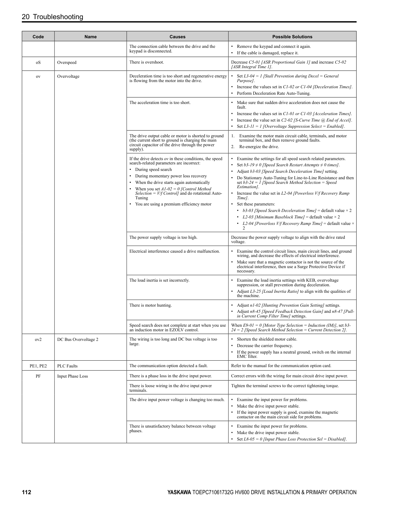
15
Figure 14.1 China RoHS Mark The China RoHS mark is displayed on products containing six specified hazardous substances that are in excess of regulatory limits, based on the “Administrative Measures for the Restriction of the Use of Hazardous Substances in Electrical and Electronic Products” and “Marking for the Restricted Use of Hazardous Substances in Electronic and Electrical Products” (SJ/T 11364-2014), which were promulgated on January 26, 2016. The number displayed in the center of the mark indicates the environment-friendly use period (number of years) in which electrical and electronic products that are being produced, sold, or imported to China can be used. The date of manufacture of the electrical and electronic product is the starting date of the environment-friendly use period for the product. The six specified hazardous substances contained in the product will not leak outside of the product during normal use within this period and will have no serious impact on the environment, the human body, or property. The environment-friendly use period for this product is 15 years. This period is not the product warranty period.
◆ Information on Hazardous Substances in This Product Table 14.1 shows the details on hazardous substances contained in this product.
Table 14.1 Contents of Hazardous Substances in This Product
|Parts Name|Hazardous Substances|Hazardous Substances|Hazardous Substances|Hazardous Substances|Hazardous Substances|Hazardous Substances| |---|---|---|---|---|---|---| |Parts Name|Lead (Pb)|Mercury (Hg)|Cadmium (Cd)|Hexavalent Chromium
(Cr(VI))|Polybrominated Biphenyls (PBB)|Polybrominated Diphenyl Ethers (PBDE)| |Circuit Board|×|○|○|○|○|○| |Electronic Parts|×|○|○|○|○|○| |Brass Screw|×|○|○|○|○|○| |Aluminum Die Casting|×|○|○|○|○|○| |This table has been prepared in accordance with the provisions outlined in SJ/T 11364.
○: Indicates that said hazardous substance contained in all of the homogeneous materials for this part is below or equal to the limit requirement of GB/T 26572. ×: Indicates that said hazardous substance contained in at least one of the homogeneous materials used for this part is above the limit requirement of GB/T 26572.
Note: This product complies with EU RoHS directives. In this table, "×" indicates that hazardous substances that are exempt from EU RoHS directives are contained.|This table has been prepared in accordance with the provisions outlined in SJ/T 11364.
○: Indicates that said hazardous substance contained in all of the homogeneous materials for this part is below or equal to the limit requirement of GB/T 26572. ×: Indicates that said hazardous substance contained in at least one of the homogeneous materials used for this part is above the limit requirement of GB/T 26572.
Note: This product complies with EU RoHS directives. In this table, "×" indicates that hazardous substances that are exempt from EU RoHS directives are contained.|
15 对应中国RoHS指令
15
图 15.1 中国RoHS标志 中国RoHS标志依据2016年1月26日公布的《电器电子产品有害物质限制使用管理办法》,以及《电子电气产品有害物 质限制使用标识要求》(SJ/T 11364-2014)作成。电子电气产品中特定6种有害物质的含量超过规定值时,应标识此标 志。中间的数字为在中国生产销售以及进口的电子电气产品的环保使用期限(年限)。电子电气产品的环保使用期限从 生产日期算起。在期限内,正常使用产品的过程中,不会有特定的6种有害物质外泄进而对环境、人和财产造成深刻影 响。 本产品的环保使用期限为15年。但需要注意的是环保使用期限并非产品的质量保证期限。
◆ 本产品中含有有害物质的信息
本产品中所含有害物质的详细信息如表 15.1所示。
表 15.1 本产品中有害物质的名称及含量
|部件名称|有害物质|有害物质|有害物质|有害物质|有害物质|有害物质| |---|---|---|---|---|---|---| |部件名称|铅 (Pb)|汞 (Hg)|镉 (Cd)|六价铬 (Cr(VI))|多溴联苯 (PBB)|多溴二苯醚 (PBDE)| |实装基板|×|○|○|○|○|○| |电子元件|×|○|○|○|○|○| |黄铜螺钉|×|○|○|○|○|○| |铝压铸|×|○|○|○|○|○| |本表格依据SJ/T 11364的规定编制。
○:表示该有害物质在该部件所有均质材料中的含量均在GB/T 26572规定的限量要求以下。 ×:表示该有害物质至少在该部件的某一均质材料中的含量超出GB/T 26572规定的限量要求。
(注) 本产品符合欧盟RoHS指令。上表中的“×”表示含有欧盟RoHS指令豁免的有害物质。|本表格依据SJ/T 11364的规定编制。
○:表示该有害物质在该部件所有均质材料中的含量均在GB/T 26572规定的限量要求以下。 ×:表示该有害物质至少在该部件的某一均质材料中的含量超出GB/T 26572规定的限量要求。
(注) 本产品符合欧盟RoHS指令。上表中的“×”表示含有欧盟RoHS指令豁免的有害物质。|本表格依据SJ/T 11364的规定编制。
○:表示该有害物质在该部件所有均质材料中的含量均在GB/T 26572规定的限量要求以下。 ×:表示该有害物质至少在该部件的某一均质材料中的含量超出GB/T 26572规定的限量要求。
(注) 本产品符合欧盟RoHS指令。上表中的“×”表示含有欧盟RoHS指令豁免的有害物质。|本表格依据SJ/T 11364的规定编制。
○:表示该有害物质在该部件所有均质材料中的含量均在GB/T 26572规定的限量要求以下。 ×:表示该有害物质至少在该部件的某一均质材料中的含量超出GB/T 26572规定的限量要求。
(注) 本产品符合欧盟RoHS指令。上表中的“×”表示含有欧盟RoHS指令豁免的有害物质。|本表格依据SJ/T 11364的规定编制。
○:表示该有害物质在该部件所有均质材料中的含量均在GB/T 26572规定的限量要求以下。 ×:表示该有害物质至少在该部件的某一均质材料中的含量超出GB/T 26572规定的限量要求。
(注) 本产品符合欧盟RoHS指令。上表中的“×”表示含有欧盟RoHS指令豁免的有害物质。|本表格依据SJ/T 11364的规定编制。
○:表示该有害物质在该部件所有均质材料中的含量均在GB/T 26572规定的限量要求以下。 ×:表示该有害物质至少在该部件的某一均质材料中的含量超出GB/T 26572规定的限量要求。
(注) 本产品符合欧盟RoHS指令。上表中的“×”表示含有欧盟RoHS指令豁免的有害物质。|本表格依据SJ/T 11364的规定编制。
○:表示该有害物质在该部件所有均质材料中的含量均在GB/T 26572规定的限量要求以下。 ×:表示该有害物质至少在该部件的某一均质材料中的含量超出GB/T 26572规定的限量要求。
(注) 本产品符合欧盟RoHS指令。上表中的“×”表示含有欧盟RoHS指令豁免的有害物质。|
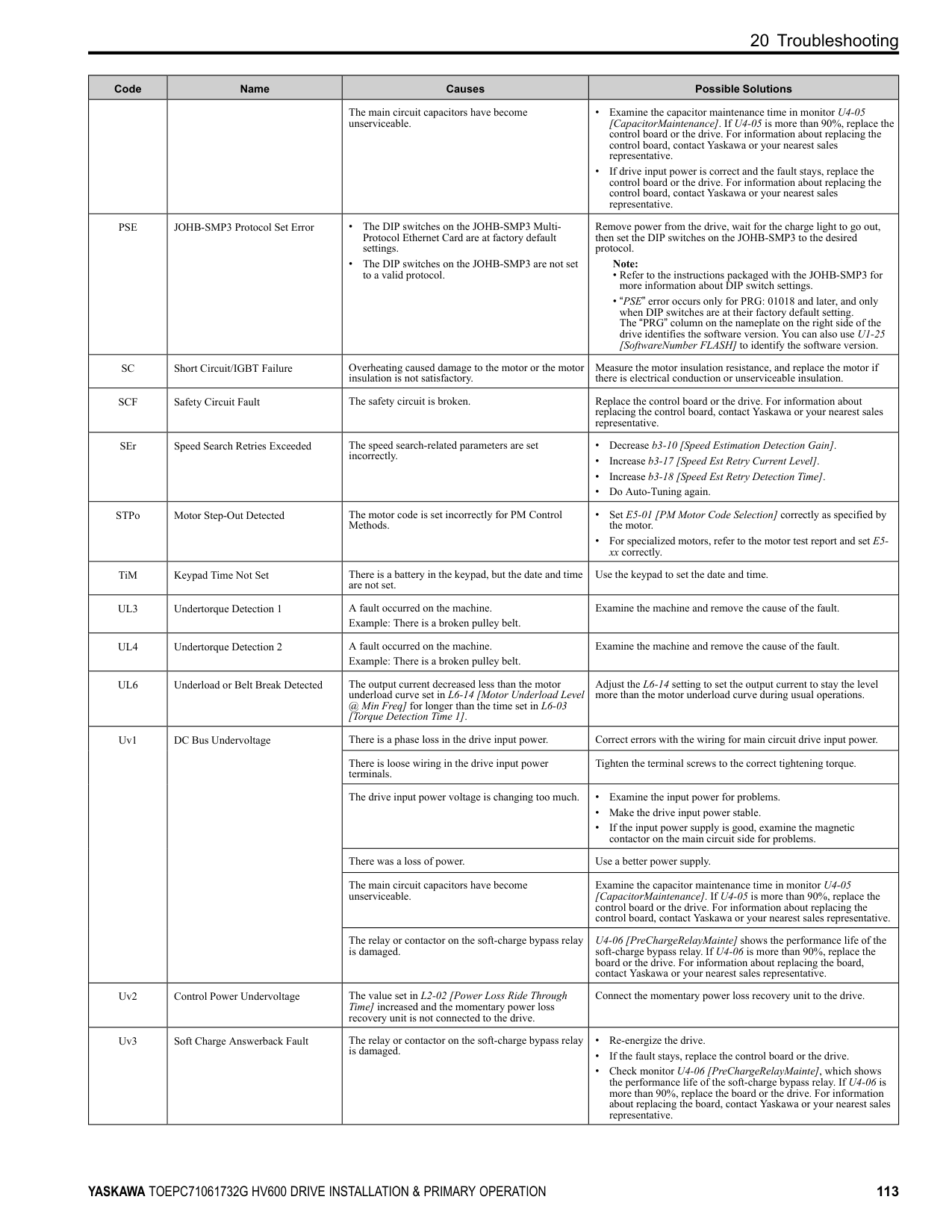
#### 16 Safe Disable Input
This section gives precautions to support the Safe Disable input. Contact Yaskawa for more information. The safety function complies with the standards shown in Table 16.1.
Table 16.1 Safety Standards and Applicable Harmonized Standards
|Safety Standards|Applicable Harmonized Standards| |---|---| |Functional Safety|• IEC/EN 61508-1,2 (SIL3)
• IEC/EN IEC 62061 (SIL3)
• IEC/EN 61800-5-2 (SIL3)
| |Machine Safety|ISO/EN ISO 13849-1:2015 (Cat.3, PL e)| |EMC|• IEC/EN 61000-6-7
• IEC/EN 61326-3-1
| |LVD|IEC/EN 61800-5-1|
◆ Safe Disable Specifications The Safe Disable input provides the stop function that complies with “Safe Torque Off” as specified by IEC/EN 61800-5-2. The Safe Disable input meets the requirements of EN ISO 13849-1 and IEC/EN 61508. It also has a safety status monitor to detect safety circuit errors. When you install the drive as a component in a system, you must make sure that the system complies with the applicable safety standards. Refer to Table 16.2 for safety function specifications.
Table 16.2 Safe Disable Specifications
|Item|Item|Description|Description| |---|---|---|---| |Input/Output|Input/Output|• Input: 2 Safe Disable input (H1, H2) Signal ON level: 18 Vdc to 28 Vdc Signal OFF level: -4 Vdc to +4 Vdc
• Output: 1 MFDO safety monitor output for external device monitor (EDM)
|• Input: 2 Safe Disable input (H1, H2) Signal ON level: 18 Vdc to 28 Vdc Signal OFF level: -4 Vdc to +4 Vdc
• Output: 1 MFDO safety monitor output for external device monitor (EDM)
| |Response time from when the input opens to when the drive output stops|Response time from when the input opens to when the drive output stops|3 ms or less|3 ms or less| |Response time from when the H1 and H2 terminal inputs open to when the EDM signal operates|Response time from when the H1 and H2 terminal inputs open to when the EDM signal operates|20 ms or less|20 ms or less| |Mission time *1|Mission time *1|10 years|20 years| |Failure probability|PFD|PFD = 9.29E-6|PFD = 1.85E-5| |Failure probability|PFH|PFH = 1.11E-9|PFH = 1.11E-9|
|Item|Description| |---|---| |Performance level|e| |HFT (hardware fault tolerance)|N 1| |Type of subsystem|Type B| |MTTFD|High (2582 years)| |DCavg|Medium (90.59%)|
*1 Parameter used for the statistical calculation required by functional safety standards and this is not linked to the warranty / guarantee
period. Note: EDM External Device Monitoring PFD = Probability of Failure on Demand PFH = Probability of Dangerous Failure per Hour
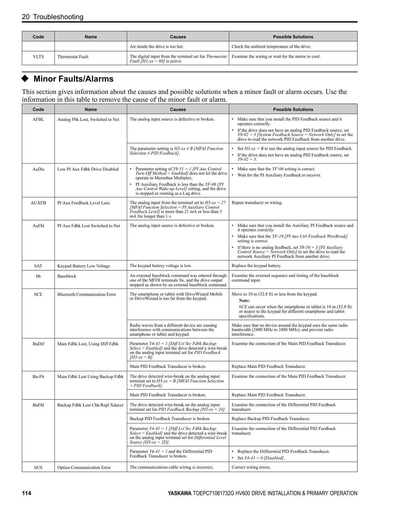
##### ◆ Notes
DANGER Sudden Movement Hazard. When you use the Safe Disable function in the safety system of a machine, do a full risk assessment for the system to make sure that all parts of the system comply with applicable safety standards. Incorrect application of the Safe Disable function can cause serious injury or death.
DANGER Sudden Movement Hazard. If the output circuit of the drive is damaged and the Safe Disable function turns OFF
the drive output to a permanent magnet (PM) motor, the motor can rotate 180 electrical degrees. Prevent damage to equipment and injury to personnel during this condition. Sudden motor movement can cause serious injury or death. It is possible for current to flow through the motor winding in these conditions.
DANGER Electrical Shock Hazard. You cannot depend on the Safe Disable function to prevent electrical shock. Disconnect all power to the drive and wait for the time specified on the warning label before you remove covers. Check the drive for dangerous voltages before servicing or repair work. If you do work on the drive when it is energized and there is no cover over the electronic circuits, it can cause serious injury or death.
WARNING Sudden Movement Hazard. Although the Safe Disable function is in operation, gravity or other external forces in the vertical axis can move the motor. Incorrect application of the Safe Disable function can cause serious injury or death.
WARNING Sudden Movement Hazard. Do not use the drive output signals to control external holding brakes or dynamic brakes for functional safety. Use a system that conforms to the functional safety requirements. Incorrect application of the Safe Disable function can cause serious injury or death. Systems that use drive output signals (including EDM) for safety are not safe because drive output signals are not safety components.
WARNING Sudden Movement Hazard. Connect the Safe Disable inputs to the devices as specified by the safety requirements. If you connect the Safe Disable inputs incorrectly, it can cause serious injury or death.
WARNING Sudden Movement Hazard. To use the Safe Disable inputs, remove the jumpers between terminals H1-HC and H2-HC. If the Safe Disable circuit does not work correctly, it can cause serious injury or death.
WARNING Sudden Movement Hazard. When you clear the Safe Disable input, make sure that the Safe Disable Monitor output operates correctly as the specification for Safe Disable function. If the Safe Disable circuit does not operate correctly, it can cause serious injury or death.
WARNING Sudden Movement Hazard. Regularly examine the Safe Disable input and all other safety features. A system that does not operate correctly can cause serious injury or death.
WARNING Sudden Movement Hazard. Only let approved personnel who know about the drive, instruction manual, and safety standards wire, examine, and maintain the Safe Disable input. If personnel are not approved, it can cause serious injury or death.
WARNING Sudden Movement Hazard. Only use the Safe Disable Monitor (multi-function output terminal set to the EDM function) to monitor the Safe Disable status or to find a malfunction in the Safe Disable inputs. The monitor output is not a safety output. If you use the Safe Disable Monitor incorrectly, it can cause death or serious injury.
############## Note:
##### ◆ Using the Safe Disable Function
■ Safe Disable Circuit The Safe Disable circuit has two isolated channels (terminals H1 and H2) that stop the output transistors. The input can use the internal power supply of the drive. Set the EDM function to one of the MFDO terminals [H2-xx = 21 or 121] to monitor the status of the Safe Disable function. This is the “Safe Disable monitor output function”.
Figure 16.1 Safe Disable Function Wiring Example
##### ■ Enabling and Disabling the Drive Output (“Safe Torque Off”)
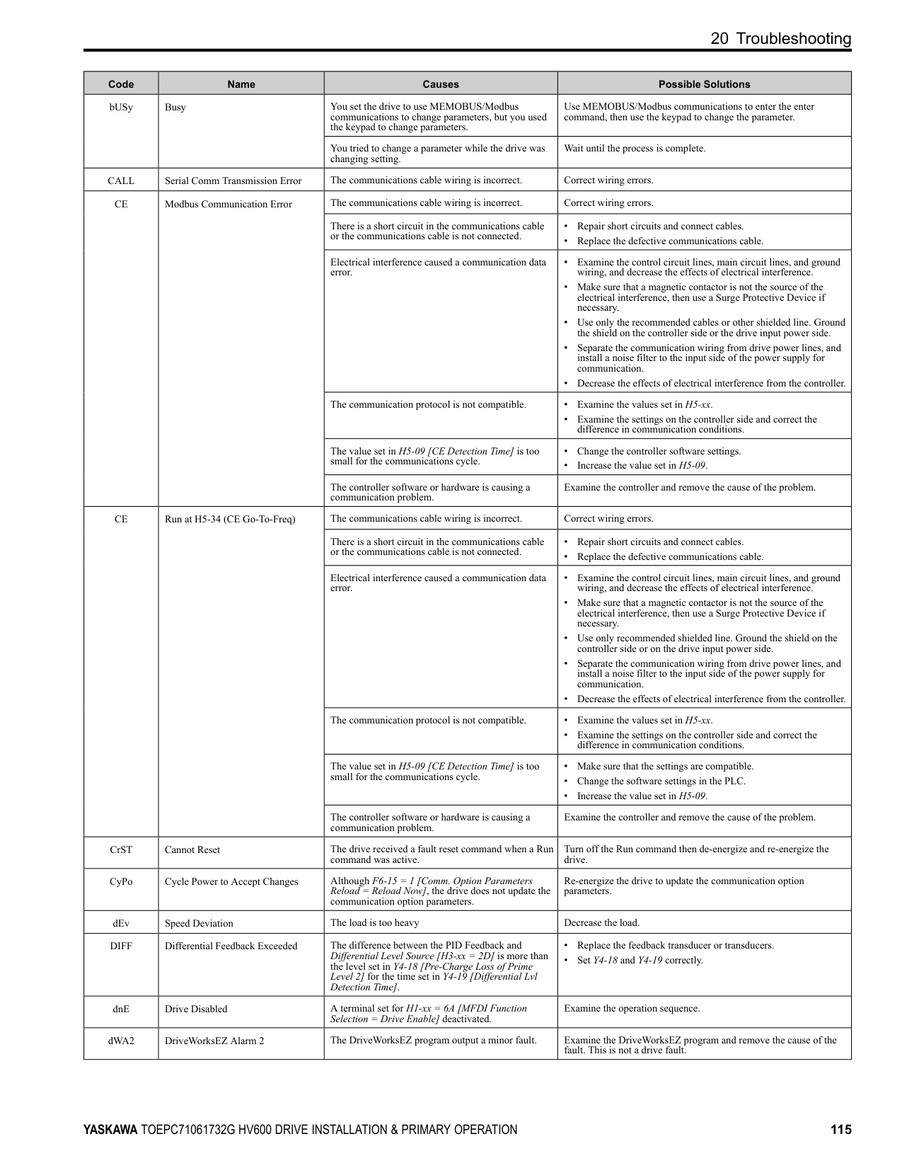
Refer to Figure 16.2 for an example of drive operation when the drive changes from “Safe Torque Off” status to usual operation.
Figure 16.2 Safe Disable Operation Switching from Usual Operation to “Safe Torque Off” Turn OFF (open) safety input terminal H1 or H2 to enable the Safe Disable function. When the Safe Disable function is enabled while the motor is operating, the drive output and motor torque turn off and the motor always coasts to stop. The b1-03 [Stopping Method Selection] setting does not have an effect on the stopping method.
The “Safe Torque Off” status is only possible with the Safe Disable function. Clear the Run command to stop the drive. Turning off drive output (a baseblock condition) ≠ “Safe Torque Off”.
Note:
Going from “Safe Torque Off” to Usual Operation The safety input will only release when there is no Run command.
##### ■ Safe Disable Monitor Output Function and Keypad Display
Refer to Table 16.3 for information about the relation between the input channel status, Safety monitor output status, and drive output status.
Table 16.3 Safe Disable Input and External Device Monitor (EDM) Terminal Status
|Input Channel Status|Input 1 (H1-HC)|ON (Close the circuit)|OFF (Open)|ON (Close the circuit)|OFF (Open)| |---|---|---|---|---|---| |Input Channel Status|Input 2 (H2-HC)|ON (Close the circuit)|ON (Close the circuit)|OFF (Open)|OFF (Open)| |MFDO Terminal (H2-xx = 21)|MFDO Terminal (H2-xx = 21)|OFF|OFF|OFF|ON| |MFDO Terminal (H2-xx = 21)|MFDO Terminal (H2-xx = 121)|ON|ON|ON|OFF| |Drive Output Status|Drive Output Status|Baseblock (Drive ready)|Safety status (STo)|Safety status (STo)|Safety status (STo)| |Keypad Display|Keypad Display|Normally displayed|SToF (Flashing)|SToF (Flashing)|STo (Flashing)| |LED Status Ring|LED Status Ring|Ready: Illuminated|ALM/ERR: Flashing|ALM/ERR: Flashing|Ready: Flashing| |MEMOBUS Register 0020 (Hex.)|MEMOBUS Register 0020 (Hex.)|bit C: 0 bit D: 0|bit C: 1 bit D: 0|bit C: 1 bit D: 0|bit C: 0 bit D: 1|
Safety Function Status Monitor The drive Safety monitor output sends a feedback signal about the status of the Safety function. The Safety monitor output is one of the possible settings available for the MFDO terminals. If there is damage to the Safe Disable circuit, a controller (PLC or safety relay) must read this signal as an input signal to hold the “Safe Torque Off” status. This will help verify the condition of the safety circuit. Refer to the manual for the safety device for more information about the Safety function. You can use the MFDO function settings to switch the polarity of the Safety monitor output signal. Refer to Table 16.3 for setting instructions. Keypad Display If the two input channels are OFF (Open), the keypad will flash STo [Safe Torque OFF]. If there is damage to the Safe disable circuit or the drive, the keypad will flash SToF [Safe Torque OFF Hardware] when one input channel is OFF (Open) and the other is ON (Close the circuit). When you use the Safe disable circuit correctly, the keypad will not show SToF. If there is damage to the drive, the keypad will show SCF [Safety Circuit Fault] when the drive detects a fault in the Safe disable circuit. Refer to the chapter on Troubleshooting for more information.
##### ■ Validating the Safe Disable Function
After you replace parts or do maintenance on the drive, first complete all necessary wiring to start the drive, then test the Safe Disable input with these steps. Keep a record of the test results.
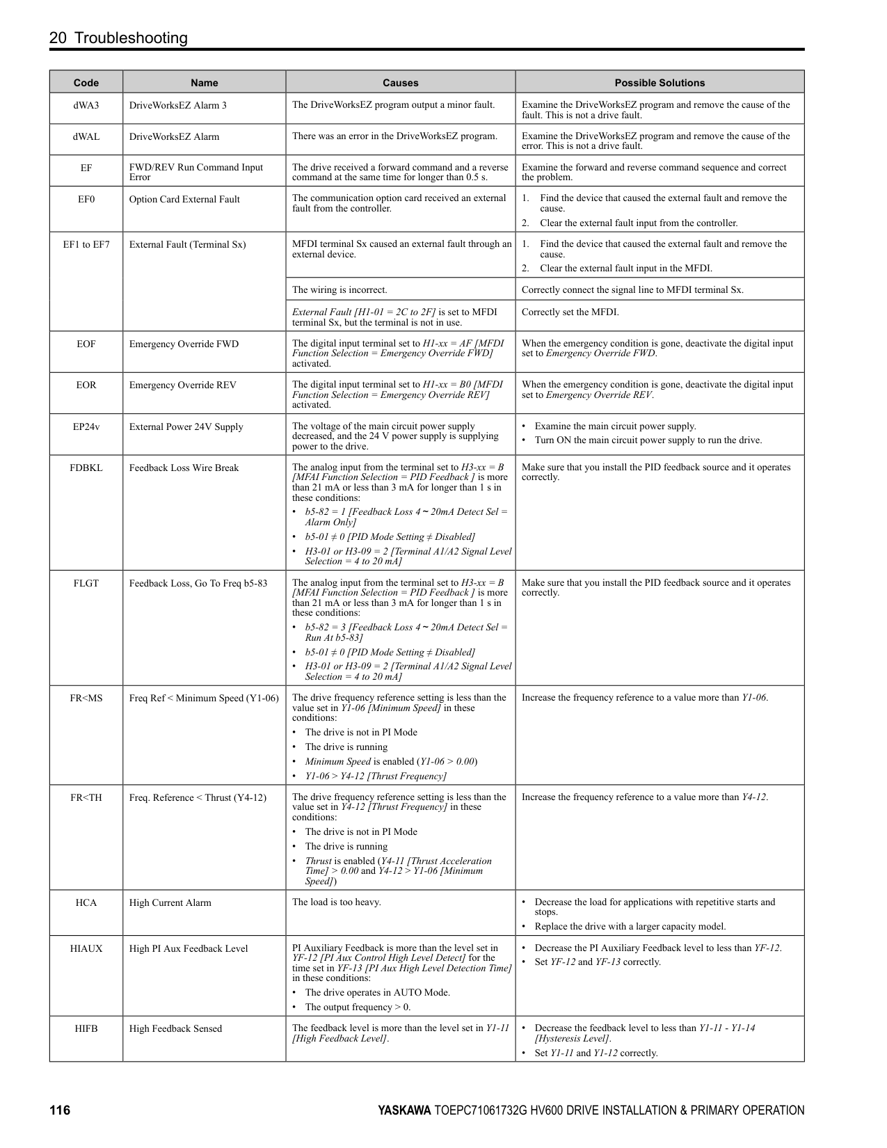
Note: Validate the Safe Disable function at least one time every three months to guarantee the specification values of the safety parameters.
#### 17 Seismic Standards
Note: Models 2143xV, 2169xV, and 4156xVare not in compliance with Seismic Standards.
The Yaskawa drives in this manual are capable of structurally and operationally withstanding the seismic response criteria as defined in the International Building Code (IBC), ASCE7, and California Department of Health Care Access and Information (HCAI). The models in this manual were tested in compliance with AC-156 to meet the IBC seismic certification as shown on the certification labels. Refer to the Technical Reference (SIEPC71061732) for seismic installation instructions.
Figure 17.1 Seismic Certification Label Example for Drives
#### 18 Disposal Instructions
Correctly discard the drive, packing material, battery, and microSD card as specified by regional, local, and municipal laws and regulations for this product.
Note:
19 Maintenance
##### ◆ WEEE Directive
The wheelie bin symbol on this product, its manual, or its packaging identifies that you must recycle it at the end of its product life. You must discard the product at an applicable collection point for electrical and electronic equipment (EEE). Do not discard the product with usual waste.
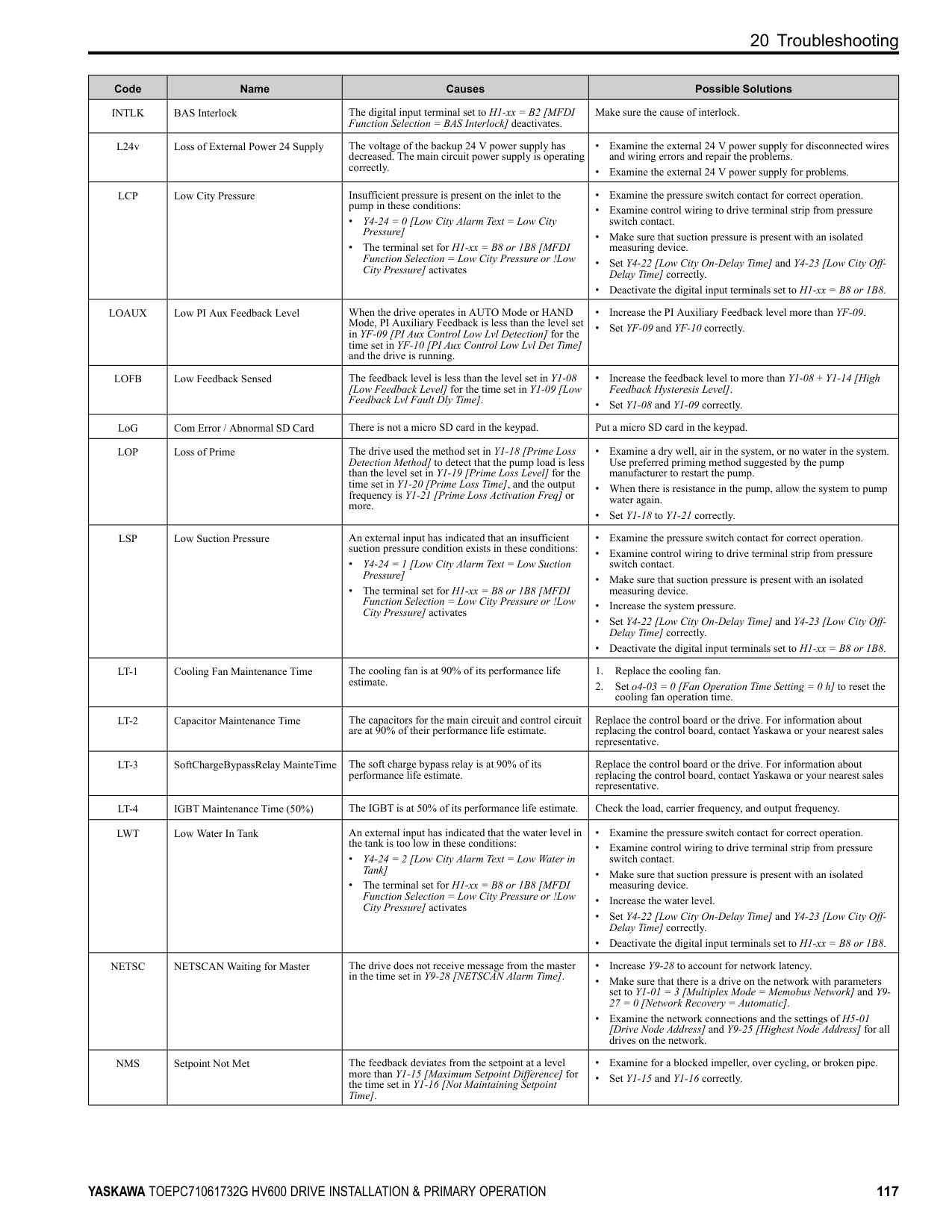
#### 19 Maintenance
Refer to the Maintenance & Troubleshooting Manual (TOEPYAIHV6001) for more information. Only let authorized persons do maintenance, examine, or replace components on the drive. Read this manual carefully and know all the precautions and safety information before installing, wiring, repairing, or examining the drive or replacing components. Examine and maintain the drive and peripheral devices regularly to extend the life of the drive and decrease performance deterioration, decrease early wear, and decrease drive failures. Regular examinations and maintenance will also decrease system downtime. Refer to the Technical Reference (SIEPC71061732) for more information about maintenance and examinations. Examine the drive one time each year at a minimum. The operating conditions, environmental conditions, and use conditions will have an effect on the examination frequency for connected equipment. Examine the drive more frequently if you use the drive in bad conditions or in these conditions:
The drive has Maintenance Monitors that monitor component wear and give warnings when the performance life estimate is approaching. When you use the maintenance monitors, you remove the need to shut down all system components when you have problems. Refer to these monitors:
You can set alarm notifications to inform you about the maintenance periods for specific drive components. Refer to these Maintenance setting parameters:
#### 20 Troubleshooting
Refer to the Maintenance & Troubleshooting Manual (TOEPYAIHV6001) for more information. If the drive or motor do not operate correctly, look at the drive keypad for fault and alarm information.
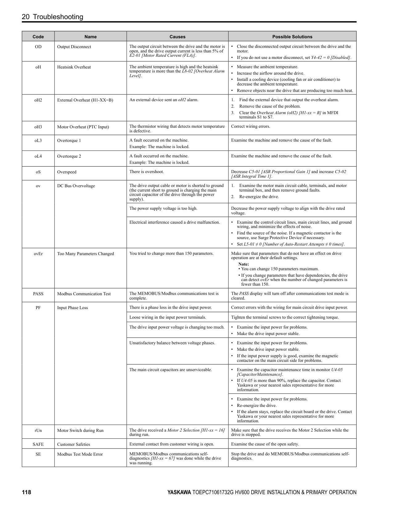
##### ◆ Fault Reset
##### ◆ Fault
This section gives information about some of the causes and possible solutions of faults. You must use the Fault Reset operation to remove the fault before you can operate the drive. Use the information in this table to remove the cause of the fault.
|Code|Name|Causes|Possible Solutions| |---|---|---|---| |AUXFB|PI Aux Feedback Level Loss|The analog input from the terminal set for PI Auxiliary Control Feedback Level [H3-xx = 27] is more than 21 mA or less than 3 mA for longer than 1 s.|Repair transducer or wiring.| |bAT|Keypad Battery Low Voltage|The keypad battery voltage is low.|Replace the keypad battery.| |bCE|Bluetooth Communication Fault|The smartphone or tablet with DriveWizard Mobile or DriveWizard installed is too far from the keypad.|Use the smartphone or tablet 10 m (32.8 ft) or nearer to the keypad. Note: bCE can occur when the smartphone or tablet is 10 m (32.8 ft) or nearer to the keypad depending on the specifications of the smartphone or tablet.| |bCE|Bluetooth Communication Fault|Radio waves from a different device are causing interference with communications between the smartphone or tablet and keypad.|Make sure that no device around the keypad uses the same radio bandwidth (2400 MHz to 2480 MHz), and prevent radio interference.| |bUS|Option Communication Error|The drive did not receive a signal from the controller.|Correct wiring errors.| |CE|Modbus Communication Error|The communications cable wiring is incorrect.|Correct wiring errors.| |CoF|Current Offset Fault|The drive starts operation while the induced voltage stays in the motor (during coasting to a stop or after fast deceleration).|• Make a sequence that does not restart operation when induced voltage stays in the motor.
• Set b3-01 = 1 [Speed Search at Start Selection = Enabled].
• Use Speed Search from Fmax or Fref [H1-xx = 61, 62] to do a speed search through one of the external terminals.
Note:
When controlling the PM motor, External Speed Search commands 1 and 2 operate the same.| |CPF00 to CPF03, CPF07 to CPF08, CPF11 to CPF14, CPF16 to CPF24, and CPF26 to CPF39|Control Circuit Error|A drive hardware problem occurred.|• Re-energize the drive.
• If the fault stays, replace the control board or the drive. For information about replacing the control board, contact Yaskawa or your nearest sales representative.
|
|Code|Name|Causes|Possible Solutions| |---|---|---|---| |CPF06|Control Circuit Error (EEPROM memory Data Error)|The drive power supply was de-energized while a communication option entered a parameter Write command.|Set A1-03 2220, 3330 [Initialize Parameters 2-Wire Initialization, 3-Wire Initialization] and initialize the drive.| |dEv|Speed Deviation|The load is too heavy.|Decrease the load.| |DIFF|Differential Feedback Exceeded|The difference between the PID Feedback and Differential Level Source [H3-xx 2D] is more than the level set in Y4-18 [Differential Level] for the time set in Y4-19 [Differential Lvl Detection Time].|• Replace the feedback transducer or transducers.
• Make sure that the settings of Y4-18 [Differential Level] to Y4-20 [Differential Level Detection Sel] are correct.
| |dv7|Polarity Judge Timeout|There is a disconnection in the motor coil winding.|Measure the motor line-to-line resistance and replace the motor if a coil is disconnected.| |dWF1|EEPROM Memory DWEZ Data Error|There is an error in the EEPROM peripheral circuit.|• Re-energize the drive.
• If the fault stays, replace the control board or the drive. For information about replacing the control board, contact Yaskawa or your nearest sales representative.
| |dWF2|DriveWorksEZ Fault 2|There was a fault in the DriveWorksEZ program.|Examine the DriveWorksEZ program and remove the cause of the fault. This is not a drive fault.| |dWF3|DriveWorksEZ Fault 3|There was a fault in the DriveWorksEZ program.|Examine the DriveWorksEZ program and remove the cause of the fault. This is not a drive fault.| |dWFL|DriveWorksEZ Fault|There was a fault in the DriveWorksEZ program.|Examine the DriveWorksEZ program and remove the cause of the fault. This is not a drive fault.| |EF0|Option Card External Fault|The communication option received an external fault from the controller.|1. Find the device that caused the external fault and remove the cause.
2. Clear the external fault input from the controller.
| |EF1 to EF7|External Fault (Terminal Sx)|MFDI terminal Sx caused an external fault through an external device.|1. Find the device that caused the external fault and remove the cause.
2. Clear the external fault input in the MFDI.
| |EF1 to EF7|External Fault (Terminal Sx)|The wiring is incorrect.|Correctly connect the signal line to MFDI terminal Sx.| |EF1 to EF7|External Fault (Terminal Sx)|External Fault [H1-01 20 to 2B] is set to MFDI terminal Sx, but the terminal is not in use.|Correctly set the MFDI.|
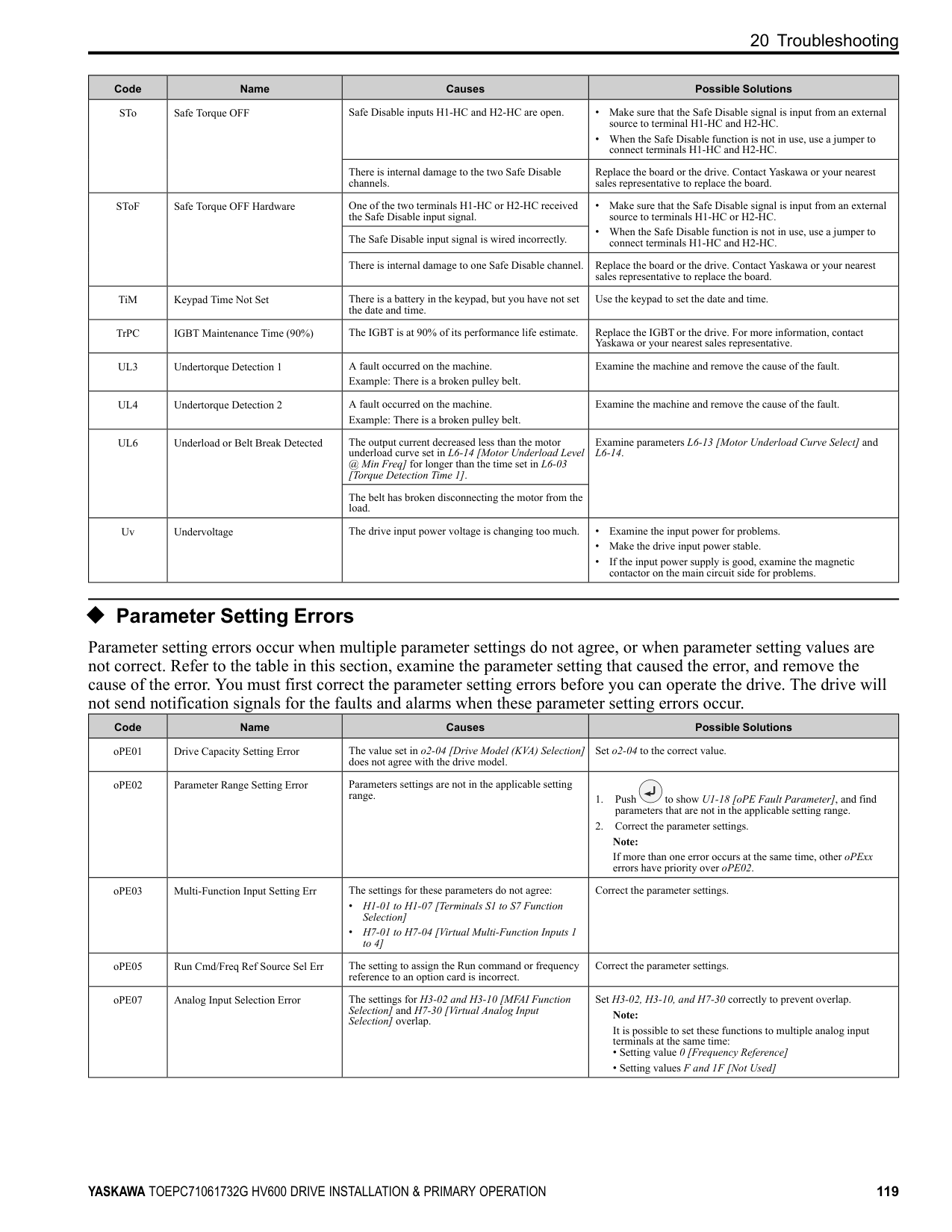
|Err|EEPROM Write Error|There was a problem with the EEPROM hardware.|• Re-energize the drive.
• If the fault stays, replace the control board or the drive. Contact Yaskawa or your nearest sales representative to replace the board.
| |FAn1|Drive Cooling Fan Fault|The cooling fan stopped operating correctly.|• Examine cooling fan operation.
• Re-energize the drive.
• Examine U4-03 [Cooling Fan Ope Time] and U4-04 [Cool Fan Maintenance]. If the performance life of the cooling fan is expired or if there is damage to the fan, replace the fan.
| |FDBKL|WIRE Break|The analog input from the terminal set for PID Feedback [H3-xx B] is more than 21mA or less than 3mA for longer than 1 s in these conditions:
• b5-82 2 [Feedback Loss 4~20mA Detect Sel Fault]
• b5-01 ≠ 0 [PID Mode Setting ≠ Disabled]
• H3-01 or H3-09 2 [Terminal A1/A2 Signal Level Selection 4 to 20 mA]
|Make sure that you install the PID feedback source and it operates correctly.| |GF|Ground Fault|Overheating caused damage to the motor or the motor insulation is not satisfactory.|Measure the motor insulation resistance, and replace the motor if there is electrical conduction or unserviceable insulation.| |GF|Ground Fault|The motor main circuit cable is contacting ground to make a short circuit.|• Examine the motor main circuit cable for damage, and repair short circuits.
• Measure the resistance between the motor main circuit cable and the ground terminal. If there is electrical conduction, replace the cable.
| |GF|Ground Fault|An increase in the stray capacitance of the cable and the ground terminal caused an increase in the leakage current.|• If the wiring length of the cable is more than 100 m, decrease the carrier frequency.
• Decrease the stray capacitance.
| |GF|Ground Fault|There was a problem with the drive hardware.|Replace the control board or the drive. For information about replacing the control board, contact Yaskawa or your nearest sales representative.| |HFB|High Feedback Sensed|The feedback level is more than the level set in Y1-11 [High Feedback Level] for the time set in Y1-12 [High Feedback Lvl Fault Dly Time].|• Decrease the feedback level less than Y1-11.
• Set Y1-11 and Y1-12 correctly.
|
|Code|Name|Causes|Possible Solutions| |---|---|---|---| |HIAUX|High PI Aux Feedback Level|PI Auxiliary Feedback is more than the level set in YF-12 [PI Aux Control High Level Detect] for the time set in YF-13 [PI Aux High Level Detection Time] in these conditions:
• The drive operates in AUTO Mode.
• The output frequency > 0.
|• Decrease the PI Auxiliary Feedback level less than YF-12.
• Set YF-12 and YF-13 correctly.
| |HLCE|High Level Communication Errors|Communication data error occurred between the option and the master drive when you use Gateway function.
The master drive detects oFxxx and the slave drive detects HLCE.|Examine the wiring between the option and the master drive and remove the cause of the fault.| |LF|Output Phase Loss|The motor main circuit cable is disconnected.|Connect motor main circuit cable wiring. Correct wiring errors in the main circuit drive input power.| |LF2|Output Current Imbalance|Phase loss occurred in the wiring on the output side of the drive.|Examine for wiring errors or disconnected wires on the output side of the drive, and repair problems.| |LFB|Low Feedback Sensed|The feedback level is less than the level set in Y1-08 [Low Feedback Level] for the time set in Y1-09 [Low Feedback Lvl Fault Dly Time].|• Increase the feedback level to more than Y1-08.
• Set Y1-08 and Y1-09 correctly.
| |LOAUX|Low PI Aux Feedback Level|When the drive operates in AUTO Mode or HAND Mode, PI Auxiliary Feedback is less than the level set in YF-09 [PI Aux Control Low Lvl Detection] for the time set in YF-10 [PI Aux Control Low Lvl Det Time] and the drive is running.|• Increase the PI Auxiliary Feedback level to be more than YF-09.
• Set YF-09 and YF-10 correctly.
| |LOP|Loss of Prime|The drive used the Y1-18 [Prime Loss Detection Method] setting and measured a pump load that is less than the level set in Y1-19 [Prime Loss Level] for the time set in Y1-20 [Prime Loss Time], and the output frequency is Y1-21 [Prime Loss Activation Freq] or more.|• Examine for a dry well, air in the system, or no water in the system. Use preferred priming method suggested by the pump manufacturer to restart the pump.
• When there is resistance in the pump, let the system pump water again.
• Set Y1-18 to Y1-21 correctly.
| |MSL|Net Master Lost|When Y9-27 3 [Network Recovery Fault MSL] and the drive does not receive message from the master within the time set in Y9-26 [Master Timeout].|• Increase Y9-26 to account for network latency.
• Make sure that there is a drive on the network with parameters set to Y1-01 3 [Multiplex Mode Memobus Network] and Y927 0 [Automatic].
• Examine network connections and the settings of H5-01 [Drive Node Address] and Y9-25 [Highest Node Address] for all drives on the network.
| |NMS|Setpoint Not Met|The feedback deviates from the setpoint at a level more than Y1-15 [Maximum Setpoint Difference] for the time set in Y1-16 [Not Maintaining Setpoint Time].|• Examine for a blocked impeller, over cycling, or broken pipe.
• Set Y1-15 and Y1-16 correctly.
| |nSE|Node Setup Error|The drive received a Run command while the Node Setup function was active.|Stop the drive when the Node Setup function is in use.| |oC|Overcurrent|The load is too large.|• Measure the current flowing into the motor.
• Replace the drive with a larger capacity model if the current value is more than the drive rated current.
• Decrease the load or replace with a larger drive to prevent sudden changes in the current level.
| |oC|Overcurrent|Overheating caused damage to the motor or the motor insulation is not satisfactory.|Measure the motor insulation resistance, and replace the motor if there is electrical conduction or unserviceable insulation.| |oC|Overcurrent|The motor main circuit cable is contacting ground to make a short circuit.|• Examine the motor main circuit cable for damage, and repair short circuits.
• Measure the resistance between the motor main circuit cable and the ground terminal. If there is electrical conduction, replace the cable.
| |oC|Overcurrent|A short circuit or ground fault on the drive output side caused damage to the output transistor of the drive.|• Make sure that there is not a short circuit in terminals - and terminals U/T1, V/T2, and W/T3.
• If there is a short circuit, contact Yaskawa or your nearest sales representative.
| |oC|Overcurrent|The acceleration time is too short.|• Calculate the torque necessary during acceleration related to the load inertia and the specified acceleration time.
• Increase the values set in C1-01 or C1-03 [Acceleration Times] to get the necessary torque.
• Increase the values set in C2-01 to C2-04 [S-Curve Characteristics] to get the necessary torque.
• Replace the drive with a larger capacity model.
| |oC|Overcurrent|The drive is trying to operate a specialized motor or a motor that is larger than the maximum applicable motor output of the drive.|• Examine the motor nameplate, the motor, and the drive to make sure that the drive rated current is larger than the motor rated current.
• Replace the drive with a larger capacity model.
| |oC|Overcurrent|A magnetic contactor was switched at the output.|Set the operation sequence to not turn ON or OFF the magnetic contactor while the drive is outputting voltage.|
|Code|Name|Causes|Possible Solutions| |---|---|---|---| | | |The V/f pattern settings are incorrect.|• Examine the ratios between the V/f pattern frequency and voltage. Decrease the voltage if it is too high compared to the frequency.
• Adjust E1-04 to E1-10 [V/f Pattern Parameters]. For motor 2, adjust E3-04 to E3-10.
| | | |The torque compensation gain is too large.|Decrease the value set in C4-01 [Torque Compensation Gain] to make sure that the motor does not stall.| | | |Electrical interference caused a problem.|Examine the control circuit lines, main circuit lines, and ground wiring, and decrease the effects of electrical interference.| | | |The gain during overexcitation operation is too large.|• Find the time when the fault occurs.
• If the fault occurs at the same time as overexcitation operation, decrease the value set in n3-13 [OverexcitationBraking (OEB) Gain] and consider the motor flux saturation.
| | | |The drive received a Run command while the motor was coasting.|• Examine the sequence and input the Run command after the motor fully stops.
• Set b3-01 1 [Speed Search at Start Selection Enabled] or set H1-xx 61, 62 [Speed Search from Fmax or Fref] to input speed search commands from the MFDI terminals.
| | | |The motor code setting is incorrect for PM Control Methods.|• Enter the correct motor code to E5-01 [PM Motor Code Selection] as specified by the PM motor.
• For specialized motors, refer to the motor test report and set E5xx [PM Motor Settings] correctly.
| | | |The current flowing in the motor is more than the value set in L8-27 [Overcurrent Detection Gain] for PM Control Methods.|Correct the value set in L8-27.| | | |The control method is set incorrectly for the motor.|Set A1-02 [Control Method Selection] correctly.|
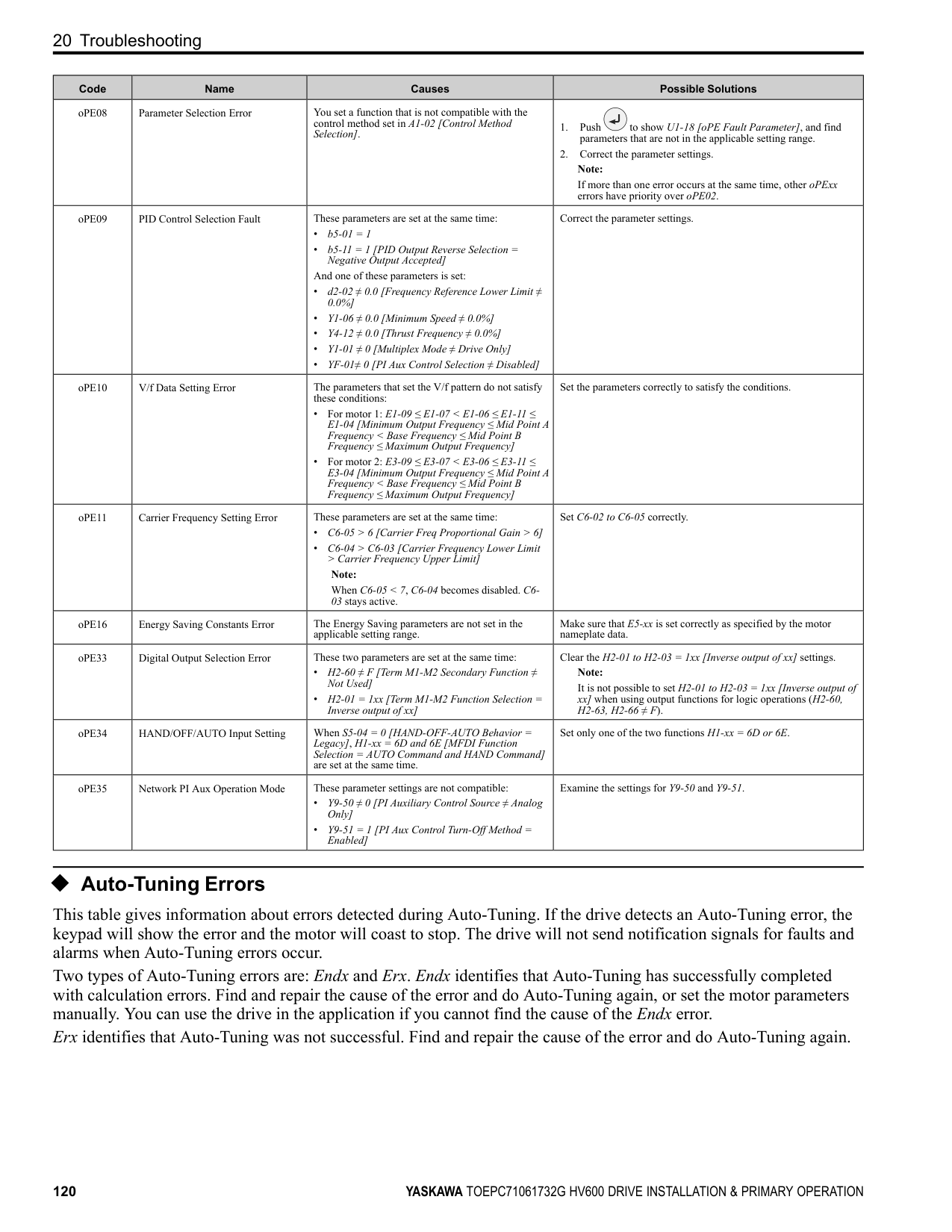
| | |The motor main circuit cable is too long.|Replace the drive with a larger capacity model.| | | |Speed search does not complete at start when A1-02
= 8 [EZ Vector Control] and you use an induction motor.|When E9-01 0 [Motor Type Selection Induction (IM)], set b324 2 [Speed Search Method Selection Current Detection Speed Search].| | | |The relay or contactor on the soft-charge bypass relay is damaged.|• Re-energize the drive.
• If the fault stays, replace the control board or the drive.
| | | |An overcurrent condition occurred during overexcitation deceleration.|• Decrease the value set in n3-13 [OverexcitationBraking (OEB) Gain].
• Decrease the value set in n3-21 [HSB Current Suppression Level].
| | | |You are using a premium efficiency motor.|Set these parameters:
• b3-03 [Speed Search Deceleration Time] default value × 2
• L2-03 [Minimum Baseblock Time] default value × 2
• L2-04 [Powerloss V/f Recovery Ramp Time] default value × 2
| |OD|Output Disconnect|The output circuit between the drive and the motor is open, and the drive output current is less than 5% of E2-01 [Motor Rated Current (FLA)].|Close the disconnected output circuit between the drive and the motor.| |oFA00|Option Not Compatible with Port|The option connected to connector CN5-A is not compatible.|Connect the option to the correct connector.| |oFA00|Option Not Compatible with Port|• The DIP switches on the JOHB-SMP3 MultiProtocol Ethernet Card are at factory default settings.
• The DIP switches on the JOHB-SMP3 are not set to a valid protocol.
• The DIP switches on the JOHB-SMP3 are set to a valid protocol that is not supported by the drive.
|Remove power from the drive, wait for the charge light to go out, then set the DIP switches on the JOHB-SMP3 to the desired protocol.
Note:
If you connect a JOHB-SMP3 to drives with software versions PRG: 01017 and earlier, the drives detect oFA00 [Option Not Compatible with Port].
The “PRG” column on the nameplate on the right side of the drive identifies the software version. You can also use U1-25 [SoftwareNumber FLASH] to identify the software version.| |oFA00|Option Not Compatible with Port|The option failed. Check the LED flash pattern on the option as specified by the option manual.|Replace the option.| |oFA01|Option Fault/Connection Error|The option card connected to connector CN5 is not compatible.|1. De-energize the drive.
2. Refer to the option card manual and correctly connect the option card to the connector on the drive.
| |oFA05 and
oFA06
|Option Card Error Occurred at Option Port CN5|A fault occurred in the option card.|1. De-energize the drive.
2. Make sure that the option card is correctly connected to the connector.
3. If the problem continues, replace the option card.
|
|Code|Name|Causes|Possible Solutions| |---|---|---|---| |oFA10, oFA11|Option Card Error Occurred at Option Port CN5|A fault occurred in the option card.|1. De-energize the drive.
2. Make sure that the option card is correctly connected to the connector.
3. If the problem continues, replace the option card.
| |oFA12 to oFA17|Option Card Connection Error (CN5)|A fault occurred in the option card.|1. De-energize the drive.
2. Make sure that the option card is correctly connected to the connector.
3. If the problem continues, replace the option card.
| |oFA30 to oFA43|Communication Option Card Connection Error (CN5)|A fault occurred in the option card.|1. De-energize the drive.
2. Make sure that the option card is correctly connected to the connector.
3. If the problem continues, replace the option card.
| |oH|Heatsink Overheat|The ambient temperature is high and the heatsink temperature of the drive is more than the value set in L8-02 [Overheat Alarm Level].|• Measure the ambient temperature.
• Increase the airflow in the control panel.
• Install a cooling device (cooling fan or air conditioner) to lower the ambient temperature.
• Remove objects near the drive that are producing too much heat.
| |oH1|Heatsink Overheat|The ambient temperature is high and the heatsink temperature of the drive is more than the oH1 detection level.|• Measure the ambient temperature.
• Increase the airflow in the control panel.
• Install a cooling device (cooling fan or air conditioner) to lower the ambient temperature.
• Remove objects near the drive that are producing too much heat.
| |oH3|Motor Overheat (PTC Input)|The thermistor wiring that detects motor temperature is defective.|Correct wiring errors.| |oH4|Motor Overheat Fault (PTC Input)|The motor has overheated.|• Check the load level, acceleration/deceleration time, and motor start/stop frequency (cycle time).
• Decrease the load.
• Increase the values set in C1-01 to C1-04 [Acceleration/ Deceleration Times].
• Set E2-01 [Motor Rated Current (FLA)] correctly to the value specified by the motor nameplate.
• Make sure that the motor cooling system is operating correctly, and repair or replace it if it is damaged.
• Adjust E1-04 to E1-10 [V/f Pattern Parameters]. For motor 2, adjust E3-04 to E3-10. Decrease the values set in E1-08 [Mid Point A Voltage] and E1-10 [Minimum Output Voltage].
Note:
If E1-08 and E1-10 are set too low, the overload tolerance will decrease at low speeds.| |oL1|Motor Overload|The load is too heavy.|Decrease the load. Note: Reset oL1 when U4-16 [Motor oL1 Level] < 100.| |oL1|Motor Overload|The acceleration/deceleration times or cycle times are too short.|• Examine the acceleration/deceleration times and the motor start/ stop frequencies (cycle times).
• Increase the values set in C1-01 to C1-04 [Acceleration/ Deceleration Times].
| |oL1|Motor Overload|Overload occurred while running at low speed.|• Decrease the load when running at low speed.
• Increase the motor speed.
• If the motor is run frequently at low speeds, replace the motor with a larger motor or use a drive-dedicated motor.
Note:
For general-purpose motors, overload can occur while running at low speed when operating at below the rated current.| |oL1|Motor Overload|L1-01 [Motor Overload (oL1) Protection] is set incorrectly.|Set L1-01 in as specified by the motor qualities for a drive-dedicated motor.| |oL1|Motor Overload|The V/f pattern does not fit the motor qualities.|• Examine the ratios between the V/f pattern frequency and voltage. Decrease the voltage if it is too high compared to the frequency.
• Adjust E1-04 to E1-10 [V/f Pattern Parameters]. For motor 2, adjust E3-04 to E3-10. Decrease the values set in E1-08 [Mid Point A Voltage] and E1-10 [Minimum Output Voltage].
Note:
If the values set in E1-08 and E1-10 are too low, the overload tolerance will decrease at low speeds.| |oL1|Motor Overload|E1-06 [Base Frequency] is set incorrectly.|Set E1-06 to the rated frequency shown on the motor nameplate.| |oL1|Motor Overload|One drive is operating more than one motor.|Set L1-01 0 [Motor Overload (oL1) Protection Disabled], connect thermal overload relay to each motor to prevent damage to the motor.|
|Code|Name|Causes|Possible Solutions| |---|---|---|---| | | |The electronic thermal protector qualities and the motor overload properties do not align.|• Examine the motor qualities and set L1-01 [Motor Overload (oL1) Protection] correctly.
• Connect a thermal overload relay to the motor.
| | | |The electronic thermal protector is operating at an incorrect level.|Set E2-01 [Motor Rated Current (FLA)] correctly to the value specified by the motor nameplate.| | | |There is increased motor loss from overexcitation operation.|• Lower the value set in n3-13 [OverexcitationBraking (OEB) Gain].
• Set L3-04 ≠ 4 [Stall Prevention during Decel ≠ Overexcitation/ High Flux].
• Set n3-23 0 [Overexcitation Braking Operation Disabled].
| | | |The speed search-related parameters are set incorrectly.|• Examine the settings for all speed search related parameters.
• Adjust b3-03 [Speed Search Deceleration Time].
• Set b3-24 1 [Speed Search Method Selection Speed Estimation] after Auto-Tuning.
| | | |Phase loss in the input power supply is causing the output current to change.|Make sure that there is no phase loss, and repair problems.| | | |Overload occurred during overexcitation deceleration.|• Decrease the value set in n3-13 [OverexcitationBraking (OEB) Gain].
• Decrease the value set in n3-21 [HSB Current Suppression Level].
| |oL2|Drive Overload|The load is too large.|Decrease the load.| |oL2|Drive Overload|The acceleration/deceleration times or cycle times are too short.|• Examine the acceleration/deceleration times and the motor start/ stop frequencies (cycle times).
• Increase the values set in C1-01 to C1-04 [Acceleration/ Deceleration Times].
|
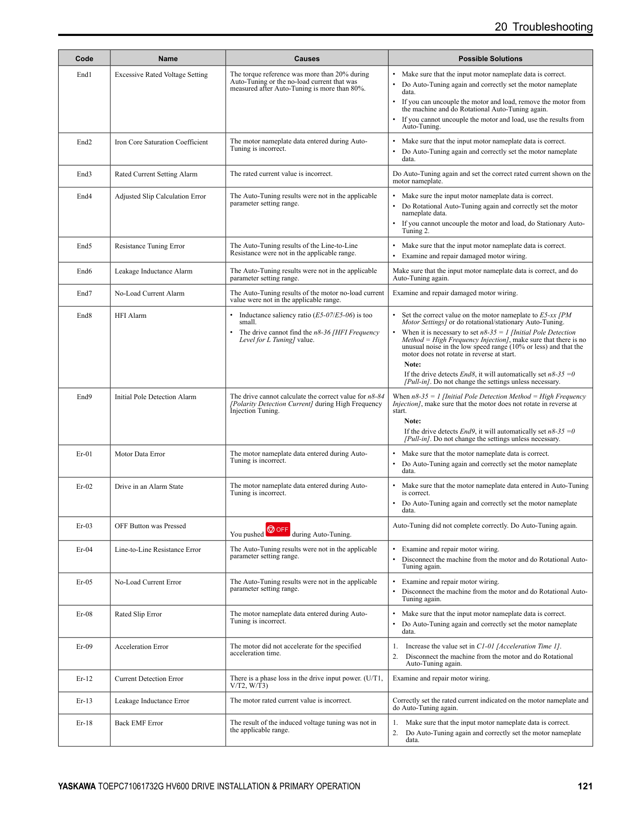
|oL2|Drive Overload|The V/f pattern does not fit the motor qualities.|• Examine the ratios between the V/f pattern frequency and voltage. Decrease the voltage if it is too high compared to the frequency.
• Adjust E1-04 to E1-10 [V/f Pattern Parameters]. Decrease the values set in E1-08 [Mid Point A Voltage] and E1-10 [Minimum Output Voltage]. For motor 2, adjust E3-04 to E3-10.
Note:
If the values set in E1-08 and E1-10 are too low, the overload tolerance will decrease at low speeds.| |oL2|Drive Overload|The drive capacity is too small.|Replace the drive with a larger capacity model.| |oL2|Drive Overload|Overload occurred while running at low speed.|• Decrease the load when running at low speed.
• Replace the drive with a larger capacity model.
• Decrease the value set in C6-02 [Carrier Frequency Selection].
| |oL2|Drive Overload|The torque compensation gain is too large.|Decrease the value set in C4-01 [Torque Compensation Gain] to make sure that the motor does not stall.| |oL2|Drive Overload|The speed search-related parameters are set incorrectly.|• Examine the settings for all speed search-related parameters.
• Adjust b3-03 [Speed Search Deceleration Time].
• Set b3-24 1 [Speed Search Method Selection Speed Estimation] after Auto-Tuning.
| |oL2|Drive Overload|Phase loss in the input power supply is causing the output current to change.|• Correct errors with the wiring for main circuit drive input power.
• Make sure that there is no phase loss, and repair problems.
| |oL2|Drive Overload|Overload occurred during overexcitation deceleration.|• Decrease the value set in n3-13 [OverexcitationBraking (OEB) Gain].
• Decrease the value set in n3-21 [HSB Current Suppression Level].
| |oL3|Overtorque Detection 1|A fault occurred on the machine. Example: The machine is locked.|Examine the machine and remove the cause of the fault.| |oL4|Overtorque Detection 2|A fault occurred on the machine. Example: The machine is locked.|Examine the machine and remove the cause of the fault.| |oL7|High Slip Braking Overload|The load inertia is too large.|Decrease deceleration times in C1-02 and C1-04 [Deceleration Times] for applications that do not use High Slip Braking.| |oL7|High Slip Braking Overload|An external force on the load side rotated the motor.|Decrease deceleration times in C1-02 and C1-04 [Deceleration Times] for applications that do not use High Slip Braking.| |oL7|High Slip Braking Overload|Something is preventing deceleration on the load side.|Decrease deceleration times in C1-02 and C1-04 [Deceleration Times] for applications that do not use High Slip Braking.| |oL7|High Slip Braking Overload|The value set in n3-04 [HSB Overload Time] is too small.|• Increase the value set in n3-04.
• Connect a thermal overload relay to the motor, and set n3-04 1200 s (maximum value).
| |oPr|Keypad Connection Fault|The keypad is not securely connected to the connector on the drive.|Examine the connection between the keypad and the drive.|
|Code|Name|Causes|Possible Solutions| |---|---|---|---| | | |The connection cable between the drive and the keypad is disconnected.|• Remove the keypad and connect it again.
• If the cable is damaged, replace it.
| |oS|Overspeed|There is overshoot.|Decrease C5-01 [ASR Proportional Gain 1] and increase C5-02 [ASR Integral Time 1].| |ov|Overvoltage|Deceleration time is too short and regenerative energy is flowing from the motor into the drive.|• Set L3-04 1 [Stall Prevention during Decel General Purpose].
• Increase the values set in C1-02 or C1-04 [Deceleration Times].
• Perform Deceleration Rate Auto-Tuning.
| |ov|Overvoltage|The acceleration time is too short.|• Make sure that sudden drive acceleration does not cause the fault.
• Increase the values set in C1-01 or C1-03 [Acceleration Times].
• Increase the value set in C2-02 [S-Curve Time @ End of Accel].
• Set L3-11 1 [Overvoltage Suppression Select Enabled].
| |ov|Overvoltage|The drive output cable or motor is shorted to ground (the current short to ground is charging the main circuit capacitor of the drive through the power supply).|1. Examine the motor main circuit cable, terminals, and motor terminal box, and then remove ground faults.
2. Re-energize the drive.
| |ov|Overvoltage|If the drive detects ov in these conditions, the speed search-related parameters are incorrect:
• During speed search
• During momentary power loss recovery
• When the drive starts again automatically
• When you set A1-02 0 [Control Method Selection V/f Control] and do rotational AutoTuning
• You are using a premium efficiency motor
|• Examine the settings for all speed search related parameters.
• Set b3-19 ≠ 0 [Speed Search Restart Attempts ≠ 0 times].
• Adjust b3-03 [Speed Search Deceleration Time] setting.
• Do Stationary Auto-Tuning for Line-to-Line Resistance and then set b3-24 1 [Speed Search Method Selection Speed Estimation].
• Increase the value set in L2-04 [Powerloss V/f Recovery Ramp Time].
• Set these parameters:
• b3-03 [Speed Search Deceleration Time] default value × 2
• L2-03 [Minimum Baseblock Time] default value × 2
• L2-04 [Powerloss V/f Recovery Ramp Time] default value × 2
| |ov|Overvoltage|The power supply voltage is too high.|Decrease the power supply voltage to align with the drive rated voltage.| |ov|Overvoltage|Electrical interference caused a drive malfunction.|• Examine the control circuit lines, main circuit lines, and ground wiring, and decrease the effects of electrical interference.
• Make sure that a magnetic contactor is not the source of the electrical interference, then use a Surge Protective Device if necessary.
| |ov|Overvoltage|The load inertia is set incorrectly.|• Examine the load inertia settings with KEB, overvoltage suppression, or stall prevention during deceleration.
• Adjust L3-25 [Load Inertia Ratio] to align with the qualities of the machine.
| |ov|Overvoltage|There is motor hunting.|• Adjust n1-02 [Hunting Prevention Gain Setting] settings.
• Adjust n8-45 [Speed Feedback Detection Gain] and n8-47 [Pullin Current Comp Filter Time] settings.
| |ov|Overvoltage|Speed search does not complete at start when you use an induction motor in EZOLV control.|When E9-01 0 [Motor Type Selection Induction (IM)], set b324 2 [Speed Search Method Selection Current Detection 2].| |ov2|DC Bus Overvoltage 2|The wiring is too long and DC bus voltage is too large.|• Shorten the shielded motor cable.
• Decrease the carrier frequency.
• If the power supply has a neutral ground, switch on the internal EMC filter.
| |PE1, PE2|PLC Faults|The communication option detected a fault.|Refer to the manual for the communication option card.| |PF|Input Phase Loss|There is a phase loss in the drive input power.|Correct errors with the wiring for main circuit drive input power.| |PF|Input Phase Loss|There is loose wiring in the drive input power terminals.|Tighten the terminal screws to the correct tightening torque.| |PF|Input Phase Loss|The drive input power voltage is changing too much.|• Examine the input power for problems.
• Make the drive input power stable.
• If the input power supply is good, examine the magnetic contactor on the main circuit side for problems.
| |PF|Input Phase Loss|There is unsatisfactory balance between voltage phases.|• Examine the input power for problems.
• Make the drive input power stable.
• Set L8-05 0 [Input Phase Loss Protection Sel Disabled].
|
|Code|Name|Causes|Possible Solutions| |---|---|---|---| | | |The main circuit capacitors have become unserviceable.|• Examine the capacitor maintenance time in monitor U4-05 [CapacitorMaintenance]. If U4-05 is more than 90%, replace the control board or the drive. For information about replacing the control board, contact Yaskawa or your nearest sales representative.
• If drive input power is correct and the fault stays, replace the control board or the drive. For information about replacing the control board, contact Yaskawa or your nearest sales representative.
| |PSE|JOHB-SMP3 Protocol Set Error|• The DIP switches on the JOHB-SMP3 MultiProtocol Ethernet Card are at factory default settings.
• The DIP switches on the JOHB-SMP3 are not set to a valid protocol.
|Remove power from the drive, wait for the charge light to go out, then set the DIP switches on the JOHB-SMP3 to the desired protocol.
Note:
• Refer to the instructions packaged with the JOHB-SMP3 for more information about DIP switch settings.
• “PSE” error occurs only for PRG: 01018 and later, and only when DIP switches are at their factory default setting. The “PRG” column on the nameplate on the right side of the drive identifies the software version. You can also use U1-25 [SoftwareNumber FLASH] to identify the software version.
|
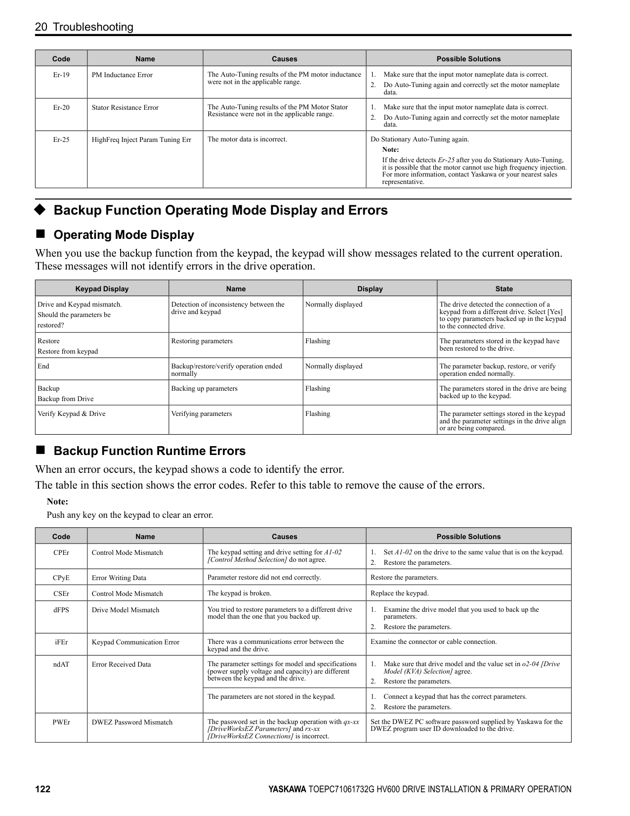
|SC|Short Circuit/IGBT Failure|Overheating caused damage to the motor or the motor insulation is not satisfactory.|Measure the motor insulation resistance, and replace the motor if there is electrical conduction or unserviceable insulation.| |SCF|Safety Circuit Fault|The safety circuit is broken.|Replace the control board or the drive. For information about replacing the control board, contact Yaskawa or your nearest sales representative.| |SEr|Speed Search Retries Exceeded|The speed search-related parameters are set incorrectly.|• Decrease b3-10 [Speed Estimation Detection Gain].
• Increase b3-17 [Speed Est Retry Current Level].
• Increase b3-18 [Speed Est Retry Detection Time].
• Do Auto-Tuning again.
| |STPo|Motor Step-Out Detected|The motor code is set incorrectly for PM Control Methods.|• Set E5-01 [PM Motor Code Selection] correctly as specified by the motor.
• For specialized motors, refer to the motor test report and set E5xx correctly.
| |TiM|Keypad Time Not Set|There is a battery in the keypad, but the date and time are not set.|Use the keypad to set the date and time.| |UL3|Undertorque Detection 1|A fault occurred on the machine. Example: There is a broken pulley belt.|Examine the machine and remove the cause of the fault.| |UL4|Undertorque Detection 2|A fault occurred on the machine. Example: There is a broken pulley belt.|Examine the machine and remove the cause of the fault.| |UL6|Underload or Belt Break Detected|The output current decreased less than the motor underload curve set in L6-14 [Motor Underload Level @ Min Freq] for longer than the time set in L6-03 [Torque Detection Time 1].|Adjust the L6-14 setting to set the output current to stay the level more than the motor underload curve during usual operations.| |Uv1|DC Bus Undervoltage|There is a phase loss in the drive input power.|Correct errors with the wiring for main circuit drive input power.| |Uv1|DC Bus Undervoltage|There is loose wiring in the drive input power terminals.|Tighten the terminal screws to the correct tightening torque.| |Uv1|DC Bus Undervoltage|The drive input power voltage is changing too much.|• Examine the input power for problems.
• Make the drive input power stable.
• If the input power supply is good, examine the magnetic contactor on the main circuit side for problems.
| |Uv1|DC Bus Undervoltage|There was a loss of power.|Use a better power supply.| |Uv1|DC Bus Undervoltage|The main circuit capacitors have become unserviceable.|Examine the capacitor maintenance time in monitor U4-05 [CapacitorMaintenance]. If U4-05 is more than 90%, replace the control board or the drive. For information about replacing the control board, contact Yaskawa or your nearest sales representative.| |Uv1|DC Bus Undervoltage|The relay or contactor on the soft-charge bypass relay is damaged.|U4-06 [PreChargeRelayMainte] shows the performance life of the soft-charge bypass relay. If U4-06 is more than 90%, replace the board or the drive. For information about replacing the board, contact Yaskawa or your nearest sales representative.| |Uv2|Control Power Undervoltage|The value set in L2-02 [Power Loss Ride Through Time] increased and the momentary power loss recovery unit is not connected to the drive.|Connect the momentary power loss recovery unit to the drive.| |Uv3|Soft Charge Answerback Fault|The relay or contactor on the soft-charge bypass relay is damaged.|• Re-energize the drive.
• If the fault stays, replace the control board or the drive.
• Check monitor U4-06 [PreChargeRelayMainte], which shows the performance life of the soft-charge bypass relay. If U4-06 is more than 90%, replace the board or the drive. For information about replacing the board, contact Yaskawa or your nearest sales representative.
|
|Code|Name|Causes|Possible Solutions| |---|---|---|---| | | |Air inside the drive is too hot.|Check the ambient temperature of the drive.| |VLTS|Thermostat Fault|The digital input from the terminal set for Thermostat Fault [H1-xx = 88] is active.|Examine the wiring or wait for the motor to cool.|
##### ◆ Minor Faults/Alarms
This section gives information about the causes and possible solutions when a minor fault or alarm occurs. Use the information in this table to remove the cause of the minor fault or alarm.
|Code|Name|Causes|Possible Solutions| |---|---|---|---| |AFBL|Analog Fbk Lost, Switched to Net|The analog input source is defective or broken.|• Make sure that you install the PID Feedback source and it operates correctly.
• If the drive does not have an analog PID Feedback source, set Y9-02 = 3 [System Feedback Source = Network Only] to set the drive to read the network PID Feedback from another drive.
| |AFBL|Analog Fbk Lost, Switched to Net|The parameter setting is H3-xx ≠ B [MFAI Function Selection ≠ PID Feedback].|• Set H3-xx = B to use the analog input source for PID Feedback.
• If the drive does not have an analog PID Feedback source, set Y9-02 = 3.
| |AuDis|Low PI Aux Fdbk Drive Disabled|• Parameter setting of Y9-51 = 1 [PI Aux Control Turn-Off Method = Enabled] does not let the drive operate in Memobus Multiplex.
• PI Auxiliary Feedback is less than the YF-06 [PI Aux Control Wake-up Level] setting, and the drive is stopped or running as a Lag drive.
|• Make sure that the YF-06 setting is correct.
• Wait for the PI Auxiliary Feedback to recover.
| |AUXFB|PI Aux Feedback Level Loss|The analog input from the terminal set to H3-xx = 27 [MFAI Function Selection = PI Auxiliary Control Feedback Level] is more than 21 mA or less than 3 mA for longer than 1 s.|Repair transducer or wiring.| |AuFbl|PI Aux Fdbk Lost Switched to Net|The analog input source is defective or broken.|• Make sure that you install the Auxiliary PI Feedback source and it operates correctly.
• Make sure that the YF-19 [PI Aux Ctrl Feedback WireBreak] setting is correct.
• If there is no analog feedback, set Y9-50 = 3 [PI Auxiliary Control Source = Network Only] to set the drive to read the network Auxiliary PI Feedback from another drive.
| |bAT|Keypad Battery Low Voltage|The keypad battery voltage is low.|Replace the keypad battery.| |bb|Baseblock|An external baseblock command was entered through one of the MFDI terminals Sx, and the drive output stopped as shown by an external baseblock command.|Examine the external sequence and timing of the baseblock command input.| |bCE|Bluetooth Communication Error|The smartphone or tablet with DriveWizard Mobile or DriveWizard is too far from the keypad.|Move to 10 m (32.8 ft) or less from the keypad. Note: bCE can occur when the smartphone or tablet is 10 m (32.8 ft) or nearer to the keypad for different smartphone and tablet specifications.| |bCE|Bluetooth Communication Error|Radio waves from a different device are causing interference with communications between the smartphone or tablet and keypad.|Make sure that no device around the keypad uses the same radio bandwidth (2400 MHz to 2480 MHz), and prevent radio interference.| |BuDif|Main Fdbk Lost, Using Diff Fdbk|Parameter Y4-41 = 1 [Diff Lvl Src Fdbk Backup Select = Enabled] and the drive detected a wire-break on the analog input terminal set for PID Feedback [H3-xx = B].|Examine the connection of the Main PID Feedback Transducer.| |BuDif|Main Fdbk Lost, Using Diff Fdbk|Main PID Feedback Transducer is broken.|Replace Main PID Feedback Transducer.|
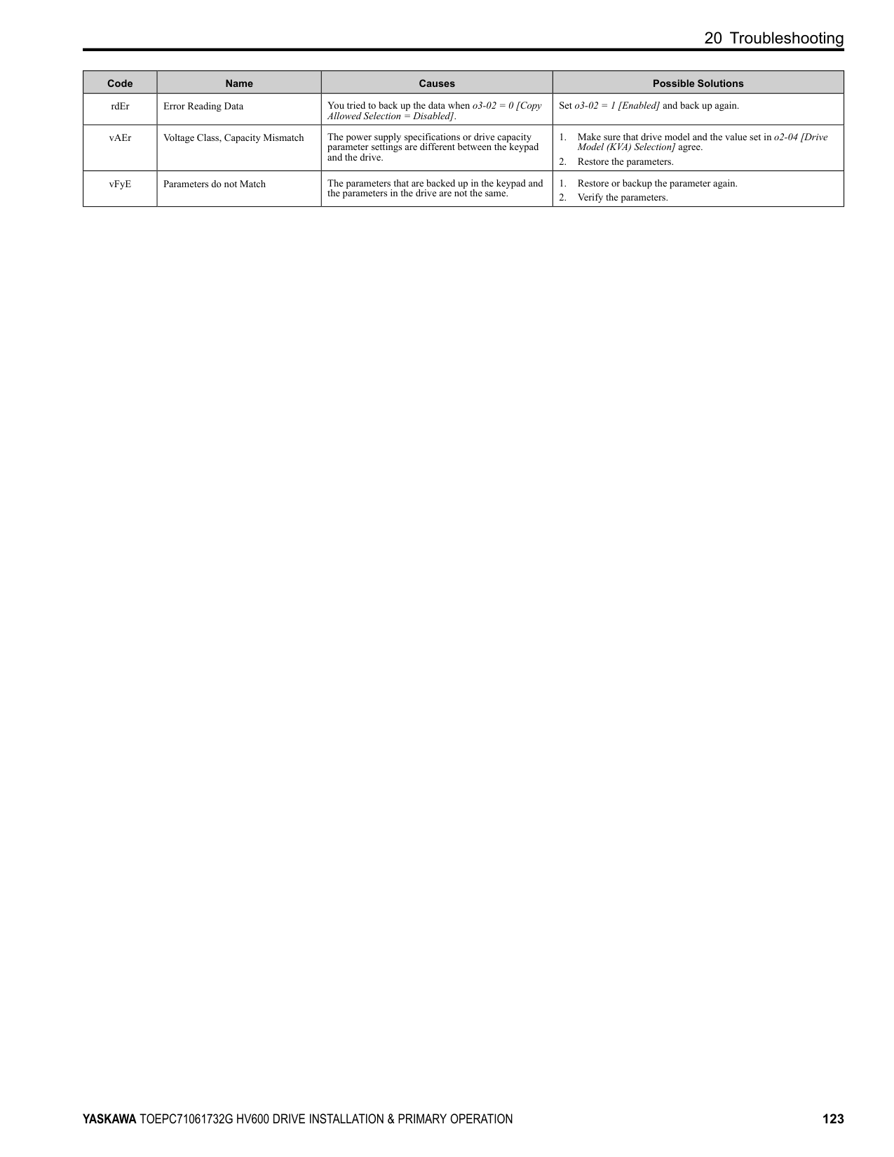
|Bu-Fb|Main Fdbk Lost Using Backup Fdbk|The drive detected wire-break on the analog input terminal set to H3-xx = B [MFAI Function Selection
= PID Feedback].|Examine the connection of the Main PID Feedback Transducer.| |Bu-Fb|Main Fdbk Lost Using Backup Fdbk|Main PID Feedback Transducer is broken.|Replace Main PID Feedback Transducer.| |BuFbl|Backup Fdbk Lost Chk/Repl Xducer|The drive detected wire-break on the analog input terminal set for PID Feedback Backup [H3-xx = 24].|Examine the connection of the Differential PID Feedback transducer.| |BuFbl|Backup Fdbk Lost Chk/Repl Xducer|Backup PID Feedback Transducer is broken.|Replace Backup PID Feedback Transducer.| |BuFbl|Backup Fdbk Lost Chk/Repl Xducer|Parameter Y4-41 = 1 [Diff Lvl Src Fdbk Backup Select = Enabled] and the drive detected a wire-break on the analog input terminal set for Differential Level Source [H3-xx = 2D].|Examine the connection of the Differential PID Feedback transducer.| |BuFbl|Backup Fdbk Lost Chk/Repl Xducer|Parameter Y4-41 = 1 and the Differential PID Feedback Transducer is broken.|• Replace the Differential PID Feedback Transducer.
• Set Y4-41 = 0 [Disabled].
| |bUS|Option Communication Error|The communications cable wiring is incorrect.|Correct wiring errors.|
|Code|Name|Causes|Possible Solutions| |---|---|---|---| |bUSy|Busy|You set the drive to use MEMOBUS/Modbus communications to change parameters, but you used the keypad to change parameters.|Use MEMOBUS/Modbus communications to enter the enter command, then use the keypad to change the parameter.| |bUSy|Busy|You tried to change a parameter while the drive was changing setting.|Wait until the process is complete.| |CALL|Serial Comm Transmission Error|The communications cable wiring is incorrect.|Correct wiring errors.| |CE|Modbus Communication Error|The communications cable wiring is incorrect.|Correct wiring errors.| |CE|Modbus Communication Error|There is a short circuit in the communications cable or the communications cable is not connected.|• Repair short circuits and connect cables.
• Replace the defective communications cable.
| |CE|Modbus Communication Error|Electrical interference caused a communication data error.|• Examine the control circuit lines, main circuit lines, and ground wiring, and decrease the effects of electrical interference.
• Make sure that a magnetic contactor is not the source of the electrical interference, then use a Surge Protective Device if necessary.
• Use only the recommended cables or other shielded line. Ground the shield on the controller side or the drive input power side.
• Separate the communication wiring from drive power lines, and install a noise filter to the input side of the power supply for communication.
• Decrease the effects of electrical interference from the controller.
| |CE|Modbus Communication Error|The communication protocol is not compatible.|• Examine the values set in H5-xx.
• Examine the settings on the controller side and correct the difference in communication conditions.
| |CE|Modbus Communication Error|The value set in H5-09 [CE Detection Time] is too small for the communications cycle.|• Change the controller software settings.
• Increase the value set in H5-09.
| |CE|Modbus Communication Error|The controller software or hardware is causing a communication problem.|Examine the controller and remove the cause of the problem.| |CE|Run at H5-34 (CE Go-To-Freq)|The communications cable wiring is incorrect.|Correct wiring errors.| |CE|Run at H5-34 (CE Go-To-Freq)|There is a short circuit in the communications cable or the communications cable is not connected.|• Repair short circuits and connect cables.
• Replace the defective communications cable.
| |CE|Run at H5-34 (CE Go-To-Freq)|Electrical interference caused a communication data error.|• Examine the control circuit lines, main circuit lines, and ground wiring, and decrease the effects of electrical interference.
• Make sure that a magnetic contactor is not the source of the electrical interference, then use a Surge Protective Device if necessary.
• Use only recommended shielded line. Ground the shield on the controller side or on the drive input power side.
• Separate the communication wiring from drive power lines, and install a noise filter to the input side of the power supply for communication.
• Decrease the effects of electrical interference from the controller.
| |CE|Run at H5-34 (CE Go-To-Freq)|The communication protocol is not compatible.|• Examine the values set in H5-xx.
• Examine the settings on the controller side and correct the difference in communication conditions.
| |CE|Run at H5-34 (CE Go-To-Freq)|The value set in H5-09 [CE Detection Time] is too small for the communications cycle.|• Make sure that the settings are compatible.
• Change the software settings in the PLC.
• Increase the value set in H5-09.
| |CE|Run at H5-34 (CE Go-To-Freq)|The controller software or hardware is causing a communication problem.|Examine the controller and remove the cause of the problem.| |CrST|Cannot Reset|The drive received a fault reset command when a Run command was active.|Turn off the Run command then de-energize and re-energize the drive.| |CyPo|Cycle Power to Accept Changes|Although F6-15 1 [Comm. Option Parameters Reload = Reload Now], the drive does not update the communication option parameters.|Re-energize the drive to update the communication option parameters.| |dEv|Speed Deviation|The load is too heavy|Decrease the load.| |DIFF|Differential Feedback Exceeded|The difference between the PID Feedback and Differential Level Source [H3-xx 2D] is more than the level set in Y4-18 [Pre-Charge Loss of Prime Level 2] for the time set in Y4-19 [Differential Lvl Detection Time].|• Replace the feedback transducer or transducers.
• Set Y4-18 and Y4-19 correctly.
| |dnE|Drive Disabled|A terminal set for H1-xx 6A [MFDI Function Selection Drive Enable] deactivated.|Examine the operation sequence.| |dWA2|DriveWorksEZ Alarm 2|The DriveWorksEZ program output a minor fault.|Examine the DriveWorksEZ program and remove the cause of the fault. This is not a drive fault.|
|Code|Name|Causes|Possible Solutions| |---|---|---|---| |dWA3|DriveWorksEZ Alarm 3|The DriveWorksEZ program output a minor fault.|Examine the DriveWorksEZ program and remove the cause of the fault. This is not a drive fault.| |dWAL|DriveWorksEZ Alarm|There was an error in the DriveWorksEZ program.|Examine the DriveWorksEZ program and remove the cause of the error. This is not a drive fault.| |EF|FWD/REV Run Command Input Error|The drive received a forward command and a reverse command at the same time for longer than 0.5 s.|Examine the forward and reverse command sequence and correct the problem.| |EF0|Option Card External Fault|The communication option card received an external fault from the controller.|1. Find the device that caused the external fault and remove the cause.
2. Clear the external fault input from the controller.
| |EF1 to EF7|External Fault (Terminal Sx)|MFDI terminal Sx caused an external fault through an external device.|1. Find the device that caused the external fault and remove the cause.
2. Clear the external fault input in the MFDI.
|
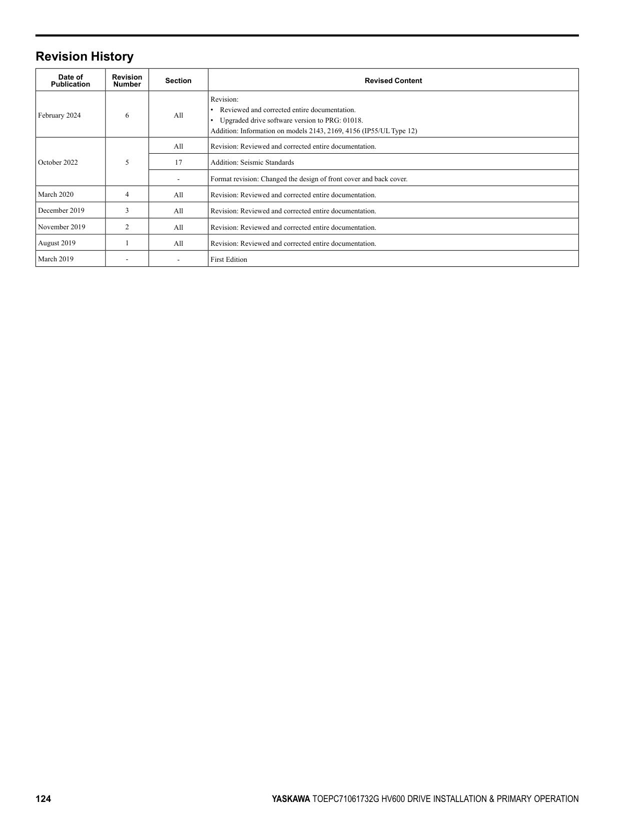
|EF1 to EF7|External Fault (Terminal Sx)|The wiring is incorrect.|Correctly connect the signal line to MFDI terminal Sx.| |EF1 to EF7|External Fault (Terminal Sx)|External Fault [H1-01 2C to 2F] is set to MFDI terminal Sx, but the terminal is not in use.|Correctly set the MFDI.| |EOF|Emergency Override FWD|The digital input terminal set to H1-xx AF [MFDI Function Selection Emergency Override FWD] activated.|When the emergency condition is gone, deactivate the digital input set to Emergency Override FWD.| |EOR|Emergency Override REV|The digital input terminal set to H1-xx B0 [MFDI Function Selection Emergency Override REV] activated.|When the emergency condition is gone, deactivate the digital input set to Emergency Override REV.| |EP24v|External Power 24V Supply|The voltage of the main circuit power supply decreased, and the 24 V power supply is supplying power to the drive.|• Examine the main circuit power supply.
• Turn ON the main circuit power supply to run the drive.
| |FDBKL|Feedback Loss Wire Break|The analog input from the terminal set to H3-xx B [MFAI Function Selection PID Feedback ] is more than 21 mA or less than 3 mA for longer than 1 s in these conditions:
• b5-82 1 [Feedback Loss 4~20mA Detect Sel Alarm Only]
• b5-01 ≠ 0 [PID Mode Setting ≠ Disabled]
• H3-01 or H3-09 2 [Terminal A1/A2 Signal Level Selection 4 to 20 mA]
|Make sure that you install the PID feedback source and it operates correctly.| |FLGT|Feedback Loss, Go To Freq b5-83|The analog input from the terminal set to H3-xx B [MFAI Function Selection PID Feedback ] is more than 21 mA or less than 3 mA for longer than 1 s in these conditions:
• b5-82 3 [Feedback Loss 4~20mA Detect Sel Run At b5-83]
• b5-01 ≠ 0 [PID Mode Setting ≠ Disabled]
• H3-01 or H3-09 2 [Terminal A1/A2 Signal Level Selection 4 to 20 mA]
|Make sure that you install the PID feedback source and it operates correctly.| |FR
• The drive is not in PI Mode
• The drive is running
• Minimum Speed is enabled (Y1-06 > 0.00)
• Y1-06 > Y4-12 [Thrust Frequency]
|Increase the frequency reference to a value more than Y1-06.| |FR
• The drive is not in PI Mode
• The drive is running
• Thrust is enabled (Y4-11 [Thrust Acceleration Time] > 0.00 and Y4-12 > Y1-06 [Minimum Speed])
|Increase the frequency reference to a value more than Y4-12.| |HCA|High Current Alarm|The load is too heavy.|• Decrease the load for applications with repetitive starts and stops.
• Replace the drive with a larger capacity model.
| |HIAUX|High PI Aux Feedback Level|PI Auxiliary Feedback is more than the level set in YF-12 [PI Aux Control High Level Detect] for the time set in YF-13 [PI Aux High Level Detection Time] in these conditions:
• The drive operates in AUTO Mode.
• The output frequency > 0.
|• Decrease the PI Auxiliary Feedback level to less than YF-12.
• Set YF-12 and YF-13 correctly.
| |HIFB|High Feedback Sensed|The feedback level is more than the level set in Y1-11 [High Feedback Level].|• Decrease the feedback level to less than Y1-11 - Y1-14 [Hysteresis Level].
• Set Y1-11 and Y1-12 correctly.
|
|Code|Name|Causes|Possible Solutions| |---|---|---|---| |INTLK|BAS Interlock|The digital input terminal set to H1-xx B2 [MFDI Function Selection BAS Interlock] deactivates.|Make sure the cause of interlock.| |L24v|Loss of External Power 24 Supply|The voltage of the backup 24 V power supply has decreased. The main circuit power supply is operating correctly.|• Examine the external 24 V power supply for disconnected wires and wiring errors and repair the problems.
• Examine the external 24 V power supply for problems.
| |LCP|Low City Pressure|Insufficient pressure is present on the inlet to the pump in these conditions:
• Y4-24 0 [Low City Alarm Text Low City Pressure]
• The terminal set for H1-xx B8 or 1B8 [MFDI Function Selection Low City Pressure or !Low City Pressure] activates
|• Examine the pressure switch contact for correct operation.
• Examine control wiring to drive terminal strip from pressure switch contact.
• Make sure that suction pressure is present with an isolated measuring device.
• Set Y4-22 [Low City On-Delay Time] and Y4-23 [Low City OffDelay Time] correctly.
• Deactivate the digital input terminals set to H1-xx B8 or 1B8.
| |LOAUX|Low PI Aux Feedback Level|When the drive operates in AUTO Mode or HAND Mode, PI Auxiliary Feedback is less than the level set in YF-09 [PI Aux Control Low Lvl Detection] for the time set in YF-10 [PI Aux Control Low Lvl Det Time] and the drive is running.|• Increase the PI Auxiliary Feedback level more than YF-09.
• Set YF-09 and YF-10 correctly.
| |LOFB|Low Feedback Sensed|The feedback level is less than the level set in Y1-08 [Low Feedback Level] for the time set in Y1-09 [Low Feedback Lvl Fault Dly Time].|• Increase the feedback level to more than Y1-08 + Y1-14 [High Feedback Hysteresis Level].
• Set Y1-08 and Y1-09 correctly.
| |LoG|Com Error / Abnormal SD Card|There is not a micro SD card in the keypad.|Put a micro SD card in the keypad.| |LOP|Loss of Prime|The drive used the method set in Y1-18 [Prime Loss Detection Method] to detect that the pump load is less than the level set in Y1-19 [Prime Loss Level] for the time set in Y1-20 [Prime Loss Time], and the output frequency is Y1-21 [Prime Loss Activation Freq] or more.|• Examine a dry well, air in the system, or no water in the system. Use preferred priming method suggested by the pump manufacturer to restart the pump.
• When there is resistance in the pump, allow the system to pump water again.
• Set Y1-18 to Y1-21 correctly.
| |LSP|Low Suction Pressure|An external input has indicated that an insufficient suction pressure condition exists in these conditions:
• Y4-24 1 [Low City Alarm Text Low Suction Pressure]
• The terminal set for H1-xx B8 or 1B8 [MFDI Function Selection Low City Pressure or !Low City Pressure] activates
|• Examine the pressure switch contact for correct operation.
• Examine control wiring to drive terminal strip from pressure switch contact.
• Make sure that suction pressure is present with an isolated measuring device.
• Increase the system pressure.
• Set Y4-22 [Low City On-Delay Time] and Y4-23 [Low City OffDelay Time] correctly.
• Deactivate the digital input terminals set to H1-xx B8 or 1B8.
| |LT-1|Cooling Fan Maintenance Time|The cooling fan is at 90% of its performance life estimate.|1. Replace the cooling fan.
2. Set o4-03 0 [Fan Operation Time Setting 0 h] to reset the cooling fan operation time.
| |LT-2|Capacitor Maintenance Time|The capacitors for the main circuit and control circuit are at 90% of their performance life estimate.|Replace the control board or the drive. For information about replacing the control board, contact Yaskawa or your nearest sales representative.| |LT-3|SoftChargeBypassRelay MainteTime|The soft charge bypass relay is at 90% of its performance life estimate.|Replace the control board or the drive. For information about replacing the control board, contact Yaskawa or your nearest sales representative.| |LT-4|IGBT Maintenance Time (50%)|The IGBT is at 50% of its performance life estimate.|Check the load, carrier frequency, and output frequency.| |LWT|Low Water In Tank|An external input has indicated that the water level in the tank is too low in these conditions:
• Y4-24 2 [Low City Alarm Text Low Water in Tank]
• The terminal set for H1-xx B8 or 1B8 [MFDI Function Selection Low City Pressure or !Low City Pressure] activates
|• Examine the pressure switch contact for correct operation.
• Examine control wiring to drive terminal strip from pressure switch contact.
• Make sure that suction pressure is present with an isolated measuring device.
• Increase the water level.
• Set Y4-22 [Low City On-Delay Time] and Y4-23 [Low City OffDelay Time] correctly.
• Deactivate the digital input terminals set to H1-xx B8 or 1B8.
| |NETSC|NETSCAN Waiting for Master|The drive does not receive message from the master in the time set in Y9-28 [NETSCAN Alarm Time].|• Increase Y9-28 to account for network latency.
• Make sure that there is a drive on the network with parameters set to Y1-01 3 [Multiplex Mode Memobus Network] and Y927 0 [Network Recovery Automatic].
• Examine the network connections and the settings of H5-01 [Drive Node Address] and Y9-25 [Highest Node Address] for all drives on the network.
| |NMS|Setpoint Not Met|The feedback deviates from the setpoint at a level more than Y1-15 [Maximum Setpoint Difference] for the time set in Y1-16 [Not Maintaining Setpoint Time].|• Examine for a blocked impeller, over cycling, or broken pipe.
• Set Y1-15 and Y1-16 correctly.
|
|Code|Name|Causes|Possible Solutions| |---|---|---|---| |OD|Output Disconnect|The output circuit between the drive and the motor is open, and the drive output current is less than 5% of E2-01 [Motor Rated Current (FLA)].|• Close the disconnected output circuit between the drive and the motor.
• If you do not use a motor disconnect, set Y4-42 0 [Disabled].
| |oH|Heatsink Overheat|The ambient temperature is high and the heatsink temperature is more than the L8-02 [Overheat Alarm Level].|• Measure the ambient temperature.
• Increase the airflow around the drive.
• Install a cooling device (cooling fan or air conditioner) to decrease the ambient temperature.
• Remove objects near the drive that are producing too much heat.
| |oH2|External Overheat (H1-XX=B)|An external device sent an oH2 alarm.|1. Find the external device that output the overheat alarm.
2. Remove the cause of the problem.
3. Clear the Overheat Alarm (oH2) [H1-xx B] in MFDI terminals S1 to S7.
| |oH3|Motor Overheat (PTC Input)|The thermistor wiring that detects motor temperature is defective.|Correct wiring errors.| |oL3|Overtorque 1|A fault occurred on the machine. Example: The machine is locked.|Examine the machine and remove the cause of the fault.| |oL4|Overtorque 2|A fault occurred on the machine. Example: The machine is locked.|Examine the machine and remove the cause of the fault.|

|oS|Overspeed|There is overshoot.|Decrease C5-01 [ASR Proportional Gain 1] and increase C5-02 [ASR Integral Time 1].| |ov|DC Bus Overvoltage|The drive output cable or motor is shorted to ground (the current short to ground is charging the main circuit capacitor of the drive through the power supply).|1. Examine the motor main circuit cable, terminals, and motor terminal box, and then remove ground faults.
2. Re-energize the drive.
| |ov|DC Bus Overvoltage|The power supply voltage is too high.|Decrease the power supply voltage to align with the drive rated voltage.| |ov|DC Bus Overvoltage|Electrical interference caused a drive malfunction.|• Examine the control circuit lines, main circuit lines, and ground wiring, and minimize the effects of noise.
• Find the source of the noise. If a magnetic contactor is the source, use Surge Protective Device if necessary.
• Set L5-01 ≠ 0 [Number of Auto-Restart Attempts ≠ 0 times].
| |ovEr|Too Many Parameters Changed|You tried to change more than 150 parameters.|Make sure that parameters that do not have an effect on drive operation are at their default settings.
Note:
• You can change 150 parameters maximum.
• If you change parameters that have dependencies, the drive can detect ovEr when the number of changed parameters is fewer than 150.
| |PASS|Modbus Communication Test|The MEMOBUS/Modbus communications test is complete.|The PASS display will turn off after communications test mode is cleared.| |PF|Input Phase Loss|There is a phase loss in the drive input power.|Correct errors with the wiring for main circuit drive input power.| |PF|Input Phase Loss|Loose wiring in the input power terminals.|Tighten the terminal screws to the correct tightening torque.| |PF|Input Phase Loss|The drive input power voltage is changing too much.|• Examine the input power for problems.
• Make the drive input power stable.
| |PF|Input Phase Loss|Unsatisfactory balance between voltage phases.|• Examine the input power for problems.
• Make the drive input power stable.
• If the input power supply is good, examine the magnetic contactor on the main circuit side for problems.
| |PF|Input Phase Loss|The main circuit capacitors are unserviceable.|• Examine the capacitor maintenance time in monitor U4-05 [CapacitorMaintenance].
• If U4-05 is more than 90%, replace the capacitor. Contact Yaskawa or your nearest sales representative for more information.
| |PF|Input Phase Loss|The main circuit capacitors are unserviceable.|• Examine the input power for problems.
• Re-energize the drive.
• If the alarm stays, replace the circuit board or the drive. Contact Yaskawa or your nearest sales representative for more information.
| |rUn|Motor Switch during Run|The drive received a Motor 2 Selection [H1-xx 16] during run.|Make sure that the drive receives the Motor 2 Selection while the drive is stopped.| |SAFE|Customer Safeties|External contact from customer wiring is open.|Examine the cause of the open safety.| |SE|Modbus Test Mode Error|MEMOBUS/Modbus communications selfdiagnostics [H1-xx 67] was done while the drive was running.|Stop the drive and do MEMOBUS/Modbus communications selfdiagnostics.|
|Code|Name|Causes|Possible Solutions| |---|---|---|---| |STo|Safe Torque OFF|Safe Disable inputs H1-HC and H2-HC are open.|• Make sure that the Safe Disable signal is input from an external source to terminal H1-HC and H2-HC.
• When the Safe Disable function is not in use, use a jumper to connect terminals H1-HC and H2-HC.
| |STo|Safe Torque OFF|There is internal damage to the two Safe Disable channels.|Replace the board or the drive. Contact Yaskawa or your nearest sales representative to replace the board.| |SToF|Safe Torque OFF Hardware|One of the two terminals H1-HC or H2-HC received the Safe Disable input signal.|• Make sure that the Safe Disable signal is input from an external source to terminals H1-HC or H2-HC.
• When the Safe Disable function is not in use, use a jumper to connect terminals H1-HC and H2-HC.
| |SToF|Safe Torque OFF Hardware|The Safe Disable input signal is wired incorrectly.|• Make sure that the Safe Disable signal is input from an external source to terminals H1-HC or H2-HC.
• When the Safe Disable function is not in use, use a jumper to connect terminals H1-HC and H2-HC.
| |SToF|Safe Torque OFF Hardware|There is internal damage to one Safe Disable channel.|Replace the board or the drive. Contact Yaskawa or your nearest sales representative to replace the board.| |TiM|Keypad Time Not Set|There is a battery in the keypad, but you have not set the date and time.|Use the keypad to set the date and time.| |TrPC|IGBT Maintenance Time (90%)|The IGBT is at 90% of its performance life estimate.|Replace the IGBT or the drive. For more information, contact Yaskawa or your nearest sales representative.| |UL3|Undertorque Detection 1|A fault occurred on the machine. Example: There is a broken pulley belt.|Examine the machine and remove the cause of the fault.| |UL4|Undertorque Detection 2|A fault occurred on the machine. Example: There is a broken pulley belt.|Examine the machine and remove the cause of the fault.| |UL6|Underload or Belt Break Detected|The output current decreased less than the motor underload curve set in L6-14 [Motor Underload Level @ Min Freq] for longer than the time set in L6-03 [Torque Detection Time 1].|Examine parameters L6-13 [Motor Underload Curve Select] and L6-14.| |UL6|Underload or Belt Break Detected|The belt has broken disconnecting the motor from the load.|Examine parameters L6-13 [Motor Underload Curve Select] and L6-14.| |Uv|Undervoltage|The drive input power voltage is changing too much.|• Examine the input power for problems.
• Make the drive input power stable.
• If the input power supply is good, examine the magnetic contactor on the main circuit side for problems.
|
##### ◆ Parameter Setting Errors
Parameter setting errors occur when multiple parameter settings do not agree, or when parameter setting values are not correct. Refer to the table in this section, examine the parameter setting that caused the error, and remove the cause of the error. You must first correct the parameter setting errors before you can operate the drive. The drive will not send notification signals for the faults and alarms when these parameter setting errors occur.
|Code|Name|Causes|Possible Solutions| |---|---|---|---| |oPE01|Drive Capacity Setting Error|The value set in o2-04 [Drive Model (KVA) Selection] does not agree with the drive model.|Set o2-04 to the correct value.| |oPE02|Parameter Range Setting Error|Parameters settings are not in the applicable setting range.|1. Push to show U1-18 [oPE Fault Parameter], and find parameters that are not in the applicable setting range.
2. Correct the parameter settings. Note:
If more than one error occurs at the same time, other oPExx errors have priority over oPE02.
|
|oPE03|Multi-Function Input Setting Err|The settings for these parameters do not agree:
• H1-01 to H1-07 [Terminals S1 to S7 Function Selection]
• H7-01 to H7-04 [Virtual Multi-Function Inputs 1 to 4]
|Correct the parameter settings.| |oPE05|Run Cmd/Freq Ref Source Sel Err|The setting to assign the Run command or frequency reference to an option card is incorrect.|Correct the parameter settings.| |oPE07|Analog Input Selection Error|The settings for H3-02 and H3-10 [MFAI Function Selection] and H7-30 [Virtual Analog Input Selection] overlap.|Set H3-02, H3-10, and H7-30 correctly to prevent overlap.
Note:
It is possible to set these functions to multiple analog input terminals at the same time:
• Setting value 0 [Frequency Reference]
• Setting values F and 1F [Not Used]
|
|Code|Name|Causes|Possible Solutions| |---|---|---|---| |oPE08|Parameter Selection Error|You set a function that is not compatible with the control method set in A1-02 [Control Method Selection].|1. Push to show U1-18 [oPE Fault Parameter], and find parameters that are not in the applicable setting range.
2. Correct the parameter settings. Note:
If more than one error occurs at the same time, other oPExx errors have priority over oPE02.
| |oPE09|PID Control Selection Fault|These parameters are set at the same time:
• b5-01 = 1
• b5-11 = 1 [PID Output Reverse Selection = Negative Output Accepted]
And one of these parameters is set:
• d2-02 ≠ 0.0 [Frequency Reference Lower Limit ≠ 0.0%]
• Y1-06 ≠ 0.0 [Minimum Speed ≠ 0.0%]
• Y4-12 ≠ 0.0 [Thrust Frequency ≠ 0.0%]
• Y1-01 ≠ 0 [Multiplex Mode ≠ Drive Only]
• YF-01≠ 0 [PI Aux Control Selection ≠ Disabled]
|Correct the parameter settings.| |oPE10|V/f Data Setting Error|The parameters that set the V/f pattern do not satisfy these conditions:
• For motor 1: E1-09 ≤ E1-07 < E1-06 ≤ E1-11 ≤ E1-04 [Minimum Output Frequency ≤ Mid Point A Frequency < Base Frequency ≤ Mid Point B Frequency ≤ Maximum Output Frequency]
• For motor 2: E3-09 ≤ E3-07 < E3-06 ≤ E3-11 ≤ E3-04 [Minimum Output Frequency ≤ Mid Point A Frequency < Base Frequency ≤ Mid Point B Frequency ≤ Maximum Output Frequency]
|Set the parameters correctly to satisfy the conditions.| |oPE11|Carrier Frequency Setting Error|These parameters are set at the same time:
• C6-05 > 6 [Carrier Freq Proportional Gain > 6]
• C6-04 > C6-03 [Carrier Frequency Lower Limit > Carrier Frequency Upper Limit]
Note: When C6-05 < 7, C6-04 becomes disabled. C603 stays active.|Set C6-02 to C6-05 correctly.| |oPE16|Energy Saving Constants Error|The Energy Saving parameters are not set in the applicable setting range.|Make sure that E5-xx is set correctly as specified by the motor nameplate data.| |oPE33|Digital Output Selection Error|These two parameters are set at the same time:
• H2-60 ≠ F [Term M1-M2 Secondary Function ≠ Not Used]
• H2-01 = 1xx [Term M1-M2 Function Selection = Inverse output of xx]
|Clear the H2-01 to H2-03 = 1xx [Inverse output of xx] settings. Note: It is not possible to set H2-01 to H2-03 = 1xx [Inverse output of xx] when using output functions for logic operations (H2-60, H2-63, H2-66 ≠ F).| |oPE34|HAND/OFF/AUTO Input Setting|When S5-04 = 0 [HAND-OFF-AUTO Behavior = Legacy], H1-xx = 6D and 6E [MFDI Function Selection = AUTO Command and HAND Command] are set at the same time.|Set only one of the two functions H1-xx = 6D or 6E.| |oPE35|Network PI Aux Operation Mode|These parameter settings are not compatible:
• Y9-50 ≠ 0 [PI Auxiliary Control Source ≠ Analog Only]
• Y9-51 = 1 [PI Aux Control Turn-Off Method = Enabled]
|Examine the settings for Y9-50 and Y9-51.|
##### ◆ Auto-Tuning Errors
This table gives information about errors detected during Auto-Tuning. If the drive detects an Auto-Tuning error, the keypad will show the error and the motor will coast to stop. The drive will not send notification signals for faults and alarms when Auto-Tuning errors occur.
Two types of Auto-Tuning errors are: Endx and Erx. Endx identifies that Auto-Tuning has successfully completed with calculation errors. Find and repair the cause of the error and do Auto-Tuning again, or set the motor parameters manually. You can use the drive in the application if you cannot find the cause of the Endx error. Erx identifies that Auto-Tuning was not successful. Find and repair the cause of the error and do Auto-Tuning again.
|Code|Name|Causes|Possible Solutions| |---|---|---|---| |End1|Excessive Rated Voltage Setting|The torque reference was more than 20% during Auto-Tuning or the no-load current that was measured after Auto-Tuning is more than 80%.|• Make sure that the input motor nameplate data is correct.
• Do Auto-Tuning again and correctly set the motor nameplate data.
• If you can uncouple the motor and load, remove the motor from the machine and do Rotational Auto-Tuning again.
• If you cannot uncouple the motor and load, use the results from Auto-Tuning.
| |End2|Iron Core Saturation Coefficient|The motor nameplate data entered during AutoTuning is incorrect.|• Make sure that the input motor nameplate data is correct.
• Do Auto-Tuning again and correctly set the motor nameplate data.
| |End3|Rated Current Setting Alarm|The rated current value is incorrect.|Do Auto-Tuning again and set the correct rated current shown on the motor nameplate.| |End4|Adjusted Slip Calculation Error|The Auto-Tuning results were not in the applicable parameter setting range.|• Make sure the input motor nameplate data is correct.
• Do Rotational Auto-Tuning again and correctly set the motor nameplate data.
• If you cannot uncouple the motor and load, do Stationary AutoTuning 2.
| |End5|Resistance Tuning Error|The Auto-Tuning results of the Line-to-Line Resistance were not in the applicable range.|• Make sure that the input motor nameplate data is correct.
• Examine and repair damaged motor wiring.
| |End6|Leakage Inductance Alarm|The Auto-Tuning results were not in the applicable parameter setting range.|Make sure that the input motor nameplate data is correct, and do Auto-Tuning again.| |End7|No-Load Current Alarm|The Auto-Tuning results of the motor no-load current value were not in the applicable range.|Examine and repair damaged motor wiring.| |End8|HFI Alarm|• Inductance saliency ratio (E5-07/E5-06) is too small.
• The drive cannot find the n8-36 [HFI Frequency Level for L Tuning] value.
|• Set the correct value on the motor nameplate to E5-xx [PM Motor Settings] or do rotational/stationary Auto-Tuning.
• When it is necessary to set n8-35 1 [Initial Pole Detection Method High Frequency Injection], make sure that there is no unusual noise in the low speed range (10% or less) and that the motor does not rotate in reverse at start.
Note: If the drive detects End8, it will automatically set n8-35 =0 [Pull-in]. Do not change the settings unless necessary.| |End9|Initial Pole Detection Alarm|The drive cannot calculate the correct value for n8-84 [Polarity Detection Current] during High Frequency Injection Tuning.|When n8-35 1 [Initial Pole Detection Method High Frequency Injection], make sure that the motor does not rotate in reverse at start.
Note: If the drive detects End9, it will automatically set n8-35 =0 [Pull-in]. Do not change the settings unless necessary.| |Er-01|Motor Data Error|The motor nameplate data entered during AutoTuning is incorrect.|• Make sure that the motor nameplate data is correct.
• Do Auto-Tuning again and correctly set the motor nameplate data.
| |Er-02|Drive in an Alarm State|The motor nameplate data entered during AutoTuning is incorrect.|• Make sure that the motor nameplate data entered in Auto-Tuning is correct.
• Do Auto-Tuning again and correctly set the motor nameplate data.
| |Er-03|OFF Button was Pressed|You pushed during Auto-Tuning.
|Auto-Tuning did not complete correctly. Do Auto-Tuning again.| |Er-04|Line-to-Line Resistance Error|The Auto-Tuning results were not in the applicable parameter setting range.|• Examine and repair motor wiring.
• Disconnect the machine from the motor and do Rotational AutoTuning again.
| |Er-05|No-Load Current Error|The Auto-Tuning results were not in the applicable parameter setting range.|• Examine and repair motor wiring.
• Disconnect the machine from the motor and do Rotational AutoTuning again.
| |Er-08|Rated Slip Error|The motor nameplate data entered during AutoTuning is incorrect.|• Make sure that the input motor nameplate data is correct.
• Do Auto-Tuning again and correctly set the motor nameplate data.
| |Er-09|Acceleration Error|The motor did not accelerate for the specified acceleration time.|1. Increase the value set in C1-01 [Acceleration Time 1].
2. Disconnect the machine from the motor and do Rotational Auto-Tuning again.
| |Er-12|Current Detection Error|There is a phase loss in the drive input power. (U/T1, V/T2, W/T3)|Examine and repair motor wiring.| |Er-13|Leakage Inductance Error|The motor rated current value is incorrect.|Correctly set the rated current indicated on the motor nameplate and do Auto-Tuning again.| |Er-18|Back EMF Error|The result of the induced voltage tuning was not in the applicable range.|1. Make sure that the input motor nameplate data is correct.
2. Do Auto-Tuning again and correctly set the motor nameplate data.
|
|Code|Name|Causes|Possible Solutions| |---|---|---|---| |Er-19|PM Inductance Error|The Auto-Tuning results of the PM motor inductance were not in the applicable range.|1. Make sure that the input motor nameplate data is correct.
2. Do Auto-Tuning again and correctly set the motor nameplate data.
| |Er-20|Stator Resistance Error|The Auto-Tuning results of the PM Motor Stator Resistance were not in the applicable range.|1. Make sure that the input motor nameplate data is correct.
2. Do Auto-Tuning again and correctly set the motor nameplate data.
| |Er-25|HighFreq Inject Param Tuning Err|The motor data is incorrect.|Do Stationary Auto-Tuning again.
Note:
If the drive detects Er-25 after you do Stationary Auto-Tuning, it is possible that the motor cannot use high frequency injection. For more information, contact Yaskawa or your nearest sales representative.|
##### ◆ Backup Function Operating Mode Display and Errors
##### ■ Operating Mode Display
When you use the backup function from the keypad, the keypad will show messages related to the current operation. These messages will not identify errors in the drive operation.
|Keypad Display|Name|Display|State| |---|---|---|---| |Drive and Keypad mismatch. Should the parameters be restored?|Detection of inconsistency between the drive and keypad|Normally displayed|The drive detected the connection of a keypad from a different drive. Select [Yes] to copy parameters backed up in the keypad to the connected drive.| |Restore Restore from keypad|Restoring parameters|Flashing|The parameters stored in the keypad have been restored to the drive.| |End|Backup/restore/verify operation ended normally|Normally displayed|The parameter backup, restore, or verify operation ended normally.| |Backup Backup from Drive|Backing up parameters|Flashing|The parameters stored in the drive are being backed up to the keypad.| |Verify Keypad & Drive|Verifying parameters|Flashing|The parameter settings stored in the keypad and the parameter settings in the drive align or are being compared.|
###### ■ Backup Function Runtime ErrorsWhen an error occurs, the keypad shows a code to identify the error.The table in this section shows the error codes. Refer to this table to remove the cause of the errors.
Note: Push any key on the keypad to clear an error.
|Code|Name|Causes|Possible Solutions| |---|---|---|---| |CPEr|Control Mode Mismatch|The keypad setting and drive setting for A1-02 [Control Method Selection] do not agree.|1. Set A1-02 on the drive to the same value that is on the keypad.
2. Restore the parameters.
| |CPyE|Error Writing Data|Parameter restore did not end correctly.|Restore the parameters.| |CSEr|Control Mode Mismatch|The keypad is broken.|Replace the keypad.| |dFPS|Drive Model Mismatch|You tried to restore parameters to a different drive model than the one that you backed up.|1. Examine the drive model that you used to back up the parameters.
2. Restore the parameters.
| |iFEr|Keypad Communication Error|There was a communications error between the keypad and the drive.|Examine the connector or cable connection.| |ndAT|Error Received Data|The parameter settings for model and specifications (power supply voltage and capacity) are different between the keypad and the drive.|1. Make sure that drive model and the value set in o2-04 [Drive Model (KVA) Selection] agree.
2. Restore the parameters.
| |ndAT|Error Received Data|The parameters are not stored in the keypad.|1. Connect a keypad that has the correct parameters.
2. Restore the parameters.
| |PWEr|DWEZ Password Mismatch|The password set in the backup operation with qx-xx [DriveWorksEZ Parameters] and rx-xx [DriveWorksEZ Connections] is incorrect.|Set the DWEZ PC software password supplied by Yaskawa for the DWEZ program user ID downloaded to the drive.|
|Code|Name|Causes|Possible Solutions| |---|---|---|---| |rdEr|Error Reading Data|You tried to back up the data when o3-02 0 [Copy Allowed Selection = Disabled].|Set o3-02 1 [Enabled] and back up again.| |vAEr|Voltage Class, Capacity Mismatch|The power supply specifications or drive capacity parameter settings are different between the keypad and the drive.|1. Make sure that drive model and the value set in o2-04 [Drive Model (KVA) Selection] agree.
2. Restore the parameters.
| |vFyE|Parameters do not Match|The parameters that are backed up in the keypad and the parameters in the drive are not the same.|1. Restore or backup the parameter again.
2. Verify the parameters.
|
######### Revision History
|Date of Publication|Revision Number|Section|Revised Content| |---|---|---|---| |February 2024|6|All|Revision:
• Reviewed and corrected entire documentation.
• Upgraded drive software version to PRG: 01018. Addition: Information on models 2143, 2169, 4156 (IP55/ULType 12)
| |October 2022|5|All|Revision: Reviewed and corrected entire documentation.| |October 2022|5|17|Addition: Seismic Standards| |October 2022|5|-|Format revision: Changed the design of front cover and back cover.| |March 2020|4|All|Revision: Reviewed and corrected entire documentation.| |December 2019|3|All|Revision: Reviewed and corrected entire documentation.| |November 2019|2|All|Revision: Reviewed and corrected entire documentation.| |August 2019|1|All|Revision: Reviewed and corrected entire documentation.| |March 2019|-|-|First Edition|
##### HV600 DRIVE INSTALLATION & PRIMARY OPERATION
YASKAWA AMERICA, INC. 2121, Norman Drive South, Waukegan, IL 60085, U.S.A.
+1-800-YASKAWA (927-5292) www.yaskawa.com
DRIVE CENTER (INVERTER PLANT) 2-13-1, Nishimiyaichi, Yukuhashi, Fukuoka, 824-8511, Japan Phone: +81-930-25-2548 www.yaskawa.co.jp
YASKAWA EUROPE GmbH Philipp-Reis-Str. 6, 65795 Hattersheim am Main, Germany Phone: +49-6196-569-300 E-mail: support@yaskawa.eu.com www.yaskawa.eu.com
YASKAWA ELÉTRICO DO BRASIL LTDA. 777, Avenida Piraporinha, Diadema, São Paulo, 09950-000, Brasil Phone: +55-11-3585-1100 www.yaskawa.com.br
In the event that the end user of this product is to be the military and said product is to be employed in any weapons systems or the manufacture thereof, the export will fall under the relevant regulations as stipulated in the Foreign Exchange and Foreign Trade Regulations. Therefore, be sure to follow all procedures and submit all relevant documentation according to any and all rules, regulations and laws that may apply. Specifications are subject to change without notice for ongoing product modifications and improvements. Original instructions. © 2019 YASKAWA Electric Corporation
TOEPC71061732 Revision: G <6>-0 February 2024 Published in Japan
23-2-25_YAI*TOEPC71061732*