
Ask AI
— answers from the official manualAnswers from the official manual.
Common questions
Common Questions
30 totalWhat is the LSo fault code and how do I fix it?
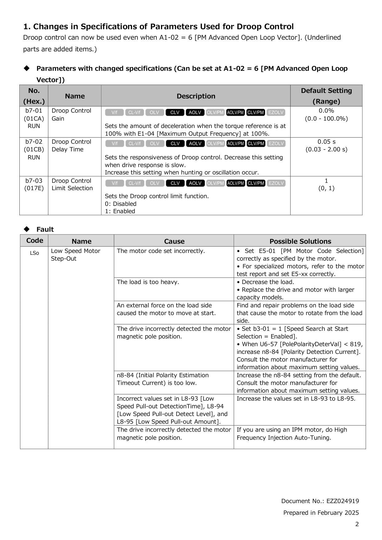
LSo stands for Low Speed Motor Step-Out and is detected when the drive detects step-out while running at low speed. Possible causes include an incorrectly set motor code, a load that is too heavy, or the drive incorrectly detecting the motor magnetic pole position. Solutions include setting E5-01 correctly, decreasing the load, setting b3-01 = 1 to enable Speed Search at Start, or performing High Frequency Injection Auto-Tuning for IPM motors. Do a Fault Reset to clear the fault after resolving the root cause. (Page 2)
What software version is required for the GA800 to use the features described in this supplemental manual?
This supplemental manual applies to GA800 drives running software version S9022 or later. You can check the software version on the nameplate affixed to the side of the product, or by viewing monitor parameter U1-25. (Page 1)
Can droop control be used with PM Advanced Open Loop Vector control mode?
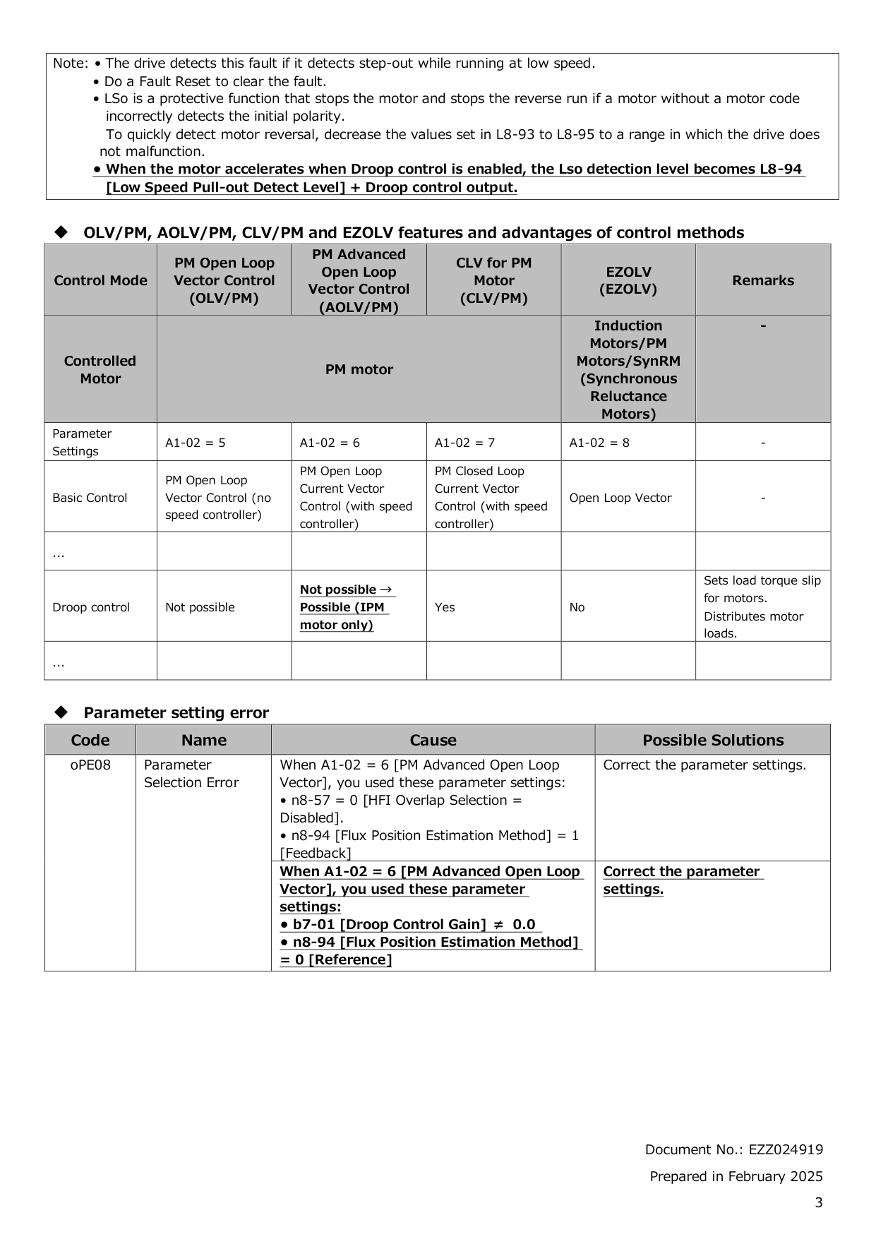
Yes, droop control can now be used when A1-02 = 6 [PM Advanced Open Loop Vector], which is a change from previous specifications. Key droop control parameters include b7-01 [Droop Control Gain], b7-02 [Droop Control Delay Time], and b7-03 [Droop Control Limit Selection]. Note that when the motor accelerates with Droop control enabled, the LSo detection level becomes L8-94 [Low Speed Pull-out Detect Level] plus the Droop control output. (Page 2)
What does the oPE08 parameter selection error mean and how do I resolve it?
The oPE08 error indicates a Parameter Selection Error caused by incompatible parameter settings when A1-02 = 6 [PM Advanced Open Loop Vector]. This occurs either when n8-57 = 0 and n8-94 = 1 [Feedback] are used together, or when b7-01 [Droop Control Gain] is not 0.0 and n8-94 = 0 [Reference] at the same time. The solution is to correct the conflicting parameter settings. (Page 3)
What communication protocols are supported by the JOHB-SMP3 option card?
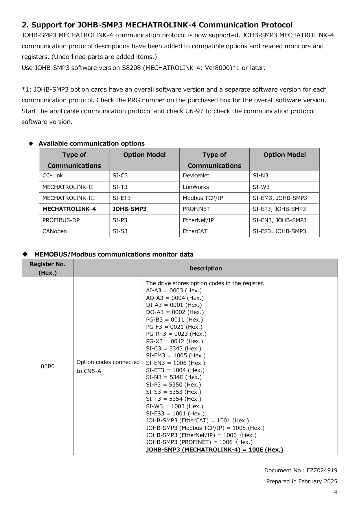
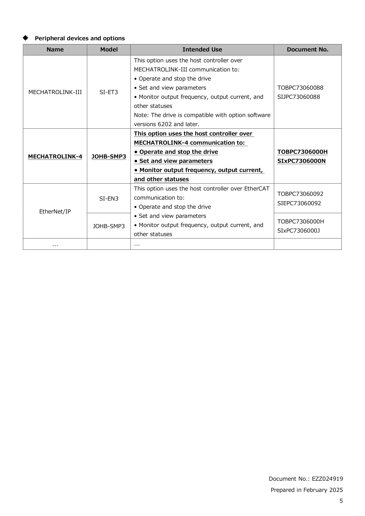
The JOHB-SMP3 option card supports multiple communication protocols including MECHATROLINK-4, Modbus TCP/IP, PROFINET, EtherNet/IP, and EtherCAT. To use MECHATROLINK-4 communication, JOHB-SMP3 software version S8208 (MECHATROLINK-4: Ver8000) or later is required. You can check the communication protocol software version by starting the applicable protocol and checking monitor U6-97. (Page 4)
How do I set the MECHATROLINK station address for the JOHB-SMP3 option?
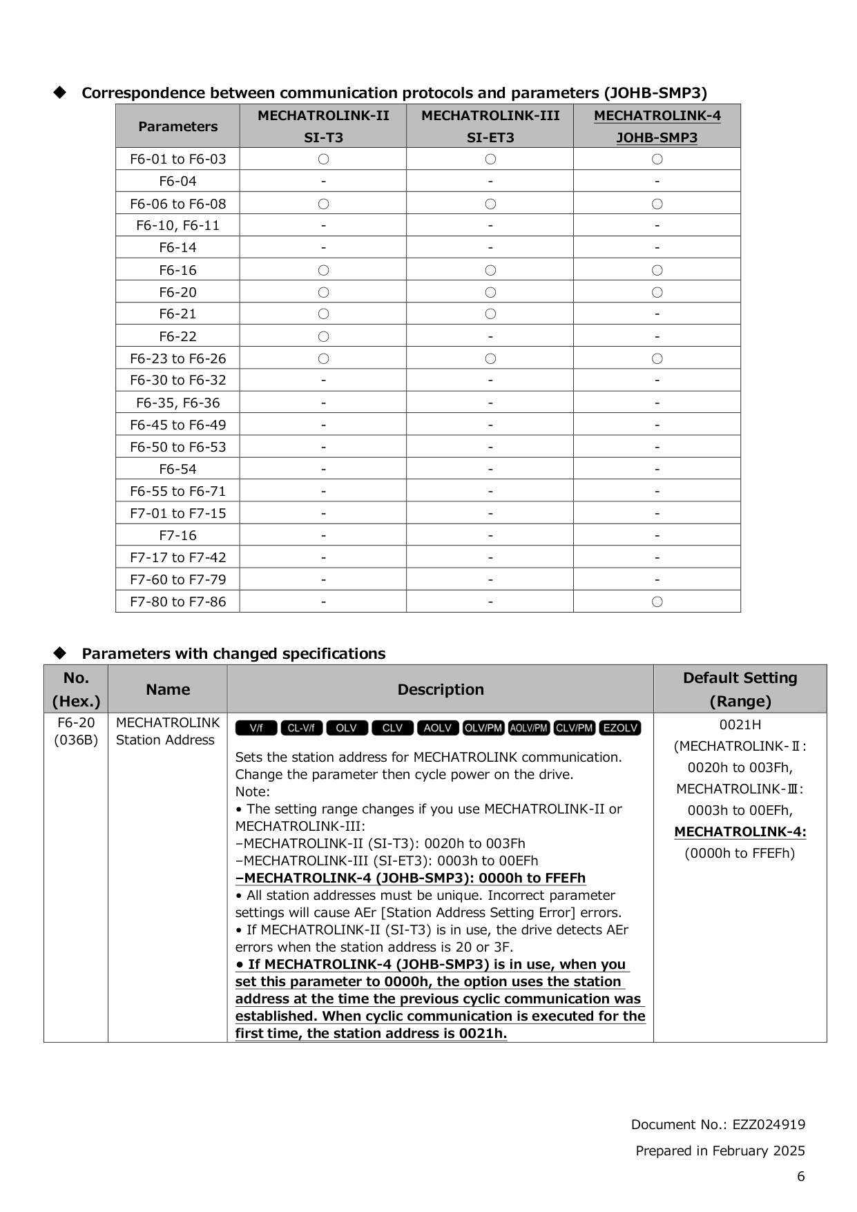
The station address for MECHATROLINK communication is set using parameter F6-20, and you must cycle power on the drive after changing the parameter for it to take effect. For MECHATROLINK-4 (JOHB-SMP3), the valid range is 0000h to FFEFh, with a default of 0021h. If set to 0000h, the option uses the station address from when the previous cyclic communication was established; on first use, it defaults to 0021h. All station addresses must be unique, as incorrect settings will cause AEr [Station Address Setting Error] errors. (Page 6)
Show 24 more questions
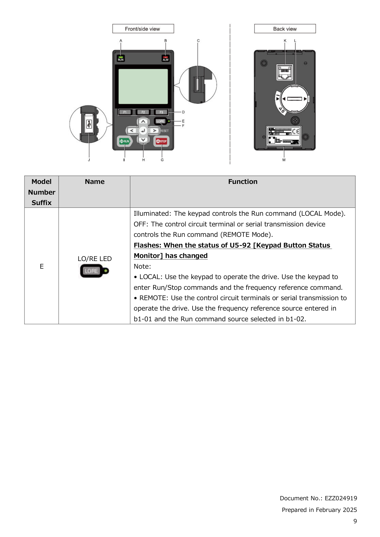
What is the Keypad Button Status Monitor and how does it work?
Is it safe to use the Keypad Button Status Monitor (U5-92) to operate and stop the drive?
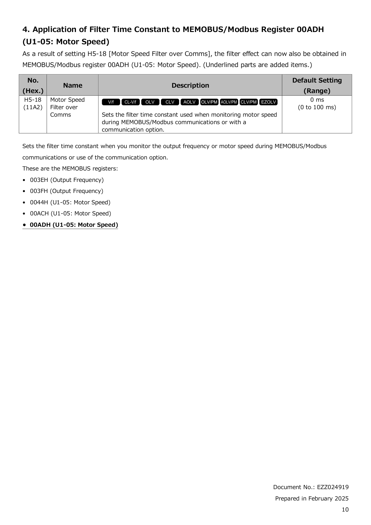
How do I apply a filter to motor speed readings over MEMOBUS/Modbus communications?
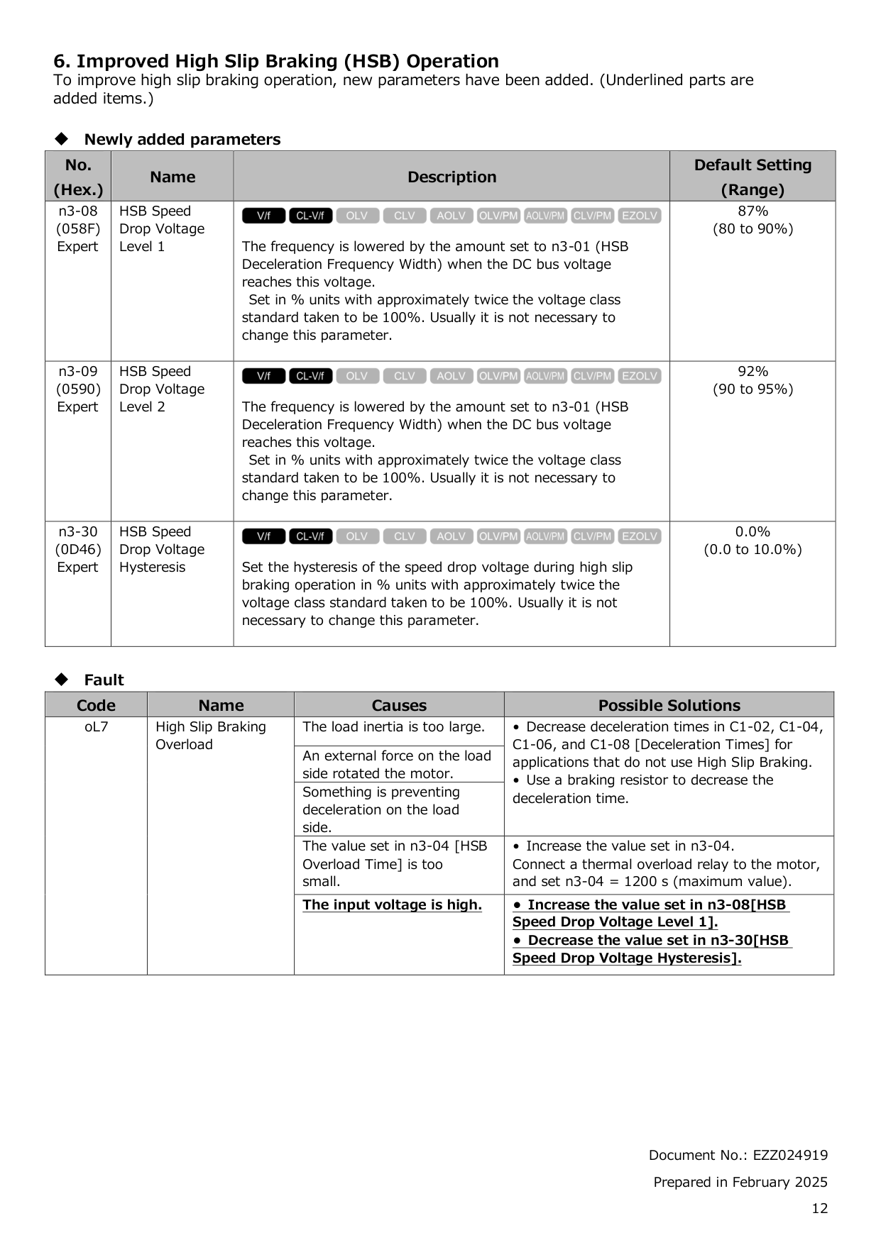
What causes the oL7 High Slip Braking Overload fault and how can I fix it?
What should I do if I receive a 'LSo' fault code?
How do I resolve an 'oPE08' parameter setting error?
What communication protocols does Ga800 support?
How can the filter time constant be applied during communications?
What are some common causes of a 'High Slip Braking Overload' fault?
How does Droop Control work in specific control modes?
What parameters need to be set for improved high slip braking operation?
How do I prevent host controller programs or DriveWorksEZ operations from triggering drive safety risks?
How do I monitor frequency and speed during MEMOBUS communications?
How do I set the access level to 'Expert Level' on my GA800 drive?
What steps do I follow to initialize the parameters of my GA800 drive?
How do I change the control method for my GA800 drive?
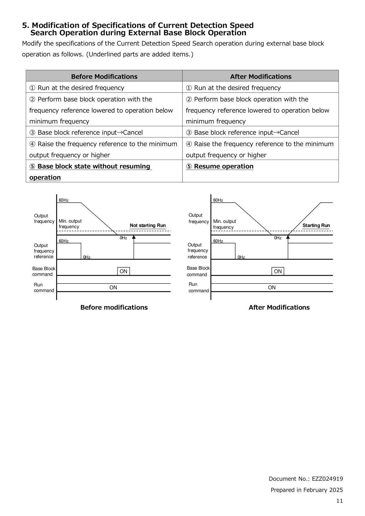
What is the procedure for bi-directional speed search on my GA800 drive?
How do I enable DC injection braking for my GA800 drive?
How do I set up frequency reference input from an analog source for my GA800 drive?
How do I enable DC injection braking at start-up for my GA800 drive?
How do I configure the station address for MECHATROLINK-4?
How do I set up digital input reading protection against noise for my GA800 drive?
What steps are necessary for tuning the drive's acceleration and deceleration times?
How do I set up an auto-tuning procedure for my GA800 drive?
Full Manual
644 pages


GA800 Drive
##### AC Drive for Industrial Applications
#### Programming
############ Catalog Code: GA80Uxxxxxxxx 240 V: 1 to 150 HP 480 V: 1 to 600 HP


Get the DriveWizard® Mobile Commissioning App
https://www.yaskawa.com/dwm
########## This Page Intentionally Blank
Table of Contents
######### i. Preface and General Precautions. . . . . . . . . . . . . . . . . . . . . . . . . . . . . . . . . . 9
######### 1. Parameter List . . . . . . . . . . . . . . . . . . . . . . . . . . . . . . . . . . . . . . . . . . . . . . . . 15
1.15 r: DWEZ Connection 1-20 . . . . . . . . . . . . . . . . . . . . . . . . . . . . . . . . . . . . . . . . . . . . . . 107
######### 2. Parameter Details. . . . . . . . . . . . . . . . . . . . . . . . . . . . . . . . . . . . . . . . . . . . . . . . 173
############# 2.12 T: Auto-Tuning. . . . . . . . . . . . . . . . . . . . . . . . . . . . . . . . . . . . . . . . . . . . . . . . . . . . . . . . 532
######### 3. Keypad Use and Test Run . . . . . . . . . . . . . . . . . . . . . . . . . . . . . . . . . . . . . . . . . 541
######### 4. Mechanical & Electrical Installation. . . . . . . . . . . . . . . . . . . . . . . . . . . . . . . . . . 609
######### Index . . . . . . . . . . . . . . . . . . . . . . . . . . . . . . . . . . . . . . . . . . . . . . . . . . . . . . . . . . . . . 637 Revision History . . . . . . . . . . . . . . . . . . . . . . . . . . . . . . . . . . . . . . . . . . . . . . . . . . . . 643
i
Preface and General Precautions
This chapter gives information about important safety precautions for the use of this product. Failure to obey these precautions can cause serious injury or death, or damage to the product or related devices and systems. Yaskawa must not be held responsible for any injury or equipment damage as a result of the failure to observe these precautions and instructions.
i.1 Document Use
####### i.1 Document Use
This document is for user operation and programming of installed Yaskawa GA800 drives. It is intended for use by those familiar with programming and modifying variable frequency drives. This document does not contain information to support of Yaskawa GA800 drives. For more information about the GA800 drive, refer to the GA800 Technical Manual (SIEPC*****). Yaskawa Technical Support
####### i.2 Using the Product Safely
######## ◆ Explanation of Signal Words
|WARNING| |---| |Read and understand this manual before you install, operate, or do maintenance on the drive. Install the drive as specified by this manual and local codes.
The symbols in this section identify safety messages in this manual. If you do not obey these safety messages, the hazards can cause serious injury, death, or damage to the products and related equipment and systems.|
These identifier words categorize and emphasize important safety precautions in these instructions.
|DANGER| |---| |This signal word identifies a hazard that will cause serious injury or death if you do not prevent it.|
|WARNING| |---| |This signal word identifies a hazard that can cause death or serious injuries if you do not prevent it.|
|CAUTION| |---| |Identifies a hazardous situation, which, if not avoided, can cause minor or moderate injury.|
|NOTICE| |---| |This signal word identifies a property damage message that is not related to personal injury.|
######## ◆ General Safety
|General Precautions| |---| |• Some figures in the instructions include options and drives without covers or safety shields to more clearly show the inside of the drive. Replace covers and shields before operation. Use options and drives only as specified by the instructions.
• The figures in this manual are examples only. All figures do not apply to all products included in this manual.
• Yaskawa can change the products, specifications, and content of the instructions without notice to make the product and/or the instructions better.
• If you damage or lose these instructions, contact a Yaskawa representative or the nearest Yaskawa sales office on the rear cover of the manual, and tell them the document number on the front cover to order new copies.
|
|DANGER| |---| |Do not ignore the safety messages in this manual. If you ignore the safety messages in this manual, it will cause serious injury or death. The manufacturer is not responsible for injuries or damage to equipment.
Electrical Shock Hazard
Do not examine, connect, or disconnect wiring on an energized drive. Before servicing, disconnect all power to the equipment and wait for the time specified on the warning label at a minimum. The internal capacitor stays charged after the drive is de-energized. The charge indicator LED extinguishes when the DC bus voltage decreases below 50 Vdc. When all indicators are OFF, remove the covers before measuring for dangerous voltages to make sure that the drive is safe.
If you do work on the drive when it is energized, it will cause serious injury or death from electrical shock. The drive has internal capacitors that stay charged after you de-energize the drive.|
|WARNING| |---| |Crush Hazard Test the system to make sure that the drive operates safely after you wire the drive and set parameters. If you do not test the system, it can cause damage to equipment or serious injury or death.
Sudden Movement Hazard Before you do a test run, make sure that the setting values for virtual input and output function parameters are correct. Virtual input and output functions can have different default settings and operation than wired input and output functions. Incorrect function settings can cause serious injury or death.
Remove all personnel and objects from the area around the drive, motor, and machine and attach covers, couplings, shaft keys, and machine loads before you energize the drive. If personnel are too close or if there are missing parts, it can cause serious injury or death.
Examine the I/O signals and internal sequence with the engineer who made the DriveWorksEZ program before you operate the drive.
If you do not know how the drive will operate, it can cause serious injury or death. When you use DriveWorksEZ to make custom programming, the drive I/O terminal functions change from factory settings and the drive will not operate as written in this manual.
Electrical Shock Hazard Do not modify the drive body or drive circuitry. Modifications to drive body and circuitry can cause serious injury or death, will cause damage to the drive, and will void the warranty. Yaskawa is not responsible for modifications of the product made by the user. Only let approved personnel install, wire, maintain, examine, replace parts, and repair the drive. If personnel are not approved, it can cause serious injury or death. Do not remove covers or touch circuit boards while the drive is energized. If you touch the internal components of an energized drive, it can cause serious injury or death.
After the drive blows a fuse or trips a GFCI, do not immediately energize the drive or operate peripheral devices. Wait for the time specified on the warning label at a minimum and make sure that all indicators are OFF. Then check the wiring and peripheral device ratings to find the cause of the problem. If you do not know the cause of the problem, contact Yaskawa before you energize the drive or peripheral devices. If you do not fix the problem before you operate the drive or peripheral devices, it can cause serious injury or death.
Fire Hazard Do not use the main circuit power supply (Overvoltage Category III) at incorrect voltages. Operate the drive in the specification range of the input voltage on the drive nameplate. Voltages that are higher than the permitted nameplate tolerance can cause damage to the drive.
Install sufficient branch circuit short circuit protection as specified by applicable codes and this manual. The drive is suited for circuits that supply not more than 100,000 RMS symmetrical amperes, 240 Vac maximum (200 V Class), 480 Vac maximum (400 V Class). Incorrect branch circuit short circuit protection can cause serious injury or death.
|
|CAUTION| |---| |Crush Hazard Tighten terminal cover screws and hold the case safely when you move the drive. If the drive or covers fall, it can cause moderate injury.|
|NOTICE| |---| |Use an inverter-duty motor or vector-duty motor with reinforced insulation and windings applicable for use with an AC drive.
If the motor does not have the correct insulation, it can cause a short circuit or ground fault from insulation deterioration.
When you touch the drive and circuit boards, make sure that you observe correct electrostatic discharge (ESD) procedures. If you do not follow procedures, it can cause ESD damage to the drive circuitry. Do not do a withstand voltage test or use a Megger insulation tester on the drive. These tests can cause damage to the drive. Do not operate a drive or connected equipment that has damaged or missing parts. You can cause damage to the drive and connected equipment.
Do not use steam or other disinfectants to fumigate wood for packaging the drive. Use alternative methods, for example heat treatment, before you package the components.
Gas from wood packaging fumigated with halogen disinfectants, for example fluorine, chlorine, bromine, iodine or DOP gas (phthalic acid ester), can cause damage to the drive.|
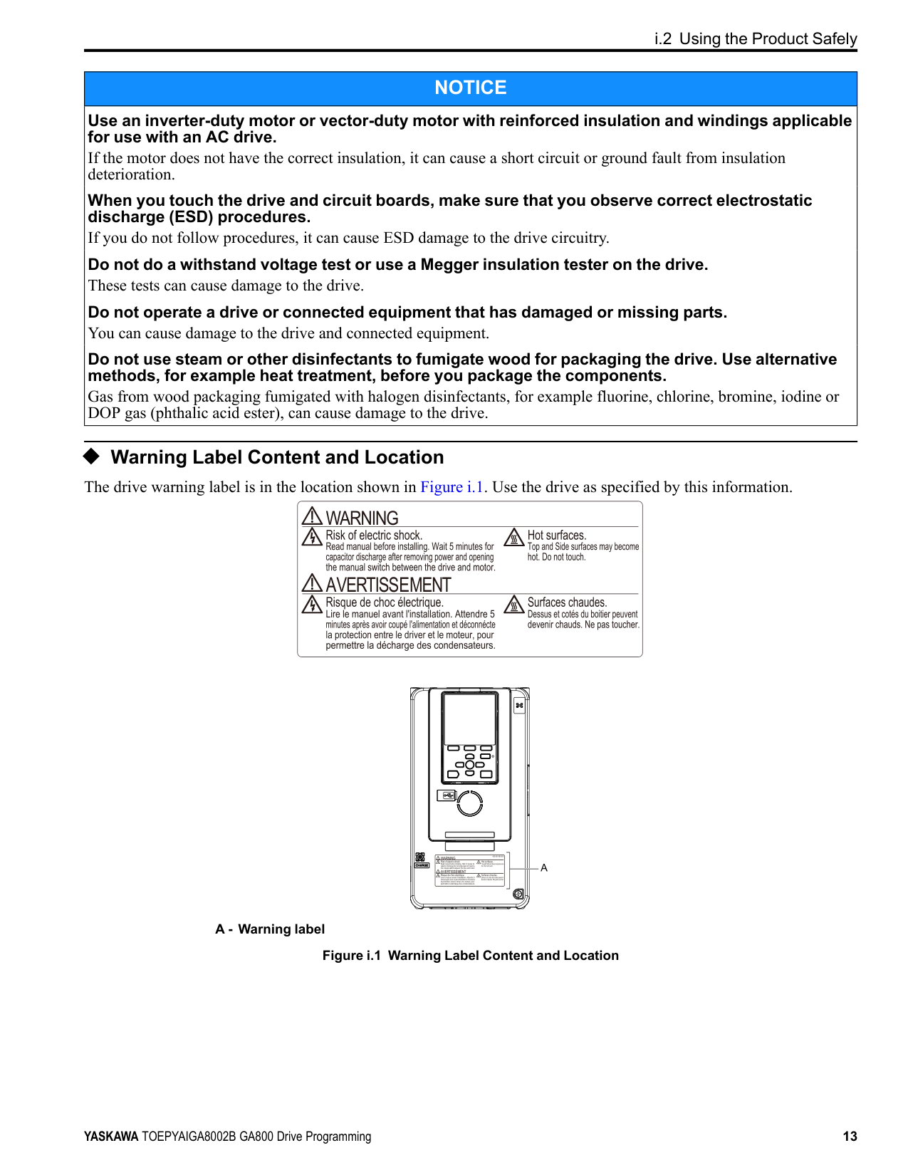
◆ Warning Label Content and Location The drive warning label is in the location shown in Figure i.1. Use the drive as specified by this information.
| | | |---|---| | | |
A - Warning label
Figure i.1 Warning Label Content and Location
1
Parameter List
####### 1.1 Section Safety
|DANGER
| |---| |Do not ignore the safety messages in this manual. If you ignore the safety messages in this manual, it will cause serious injury or death. The manufacturer is not responsible for injuries or damage to equipment.|
1.2 How to Read the Parameter List
####### 1.2 How to Read the Parameter List
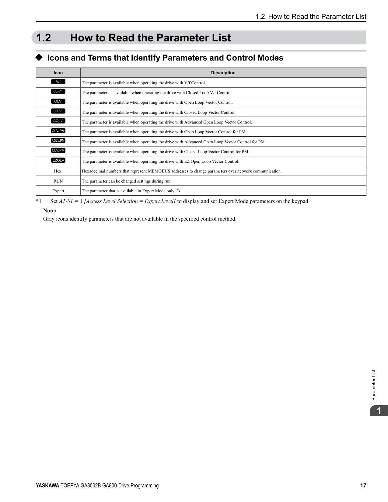
######## ◆ Icons and Terms that Identify Parameters and Control Modes
|Icon|Description| |---|---| |V/f|The parameter is available when operating the drive with V/f Control.| |CL-V/f|The parameters is available when operating the drive with Closed Loop V/f Control.| |OLV|The parameter is available when operating the drive with Open Loop Vector Control.| |CLV|The parameter is available when operating the drive with Closed Loop Vector Control.| |AOLV|The parameter is available when operating the drive with Advanced Open Loop Vector Control.| |OLV/PM|The parameter is available when operating the drive with Open Loop Vector Control for PM.| |AOLV/PM|The parameter is available when operating the drive with Advanced Open Loop Vector Control for PM.| |CLV/PM|The parameter is available when operating the drive with Closed Loop Vector Control for PM.| |EZOLV|The parameter is available when operating the drive with EZ Open Loop Vector Control.| |Hex.|Hexadecimal numbers that represent MEMOBUS addresses to change parameters over network communication.| |RUN|The parameter can be changed settings during run.| |Expert|The parameter that is available in Expert Mode only. *1|
*1 Set A1-01 = 3 [Access Level Selection = Expert Level] to display and set Expert Mode parameters on the keypad. Note: Gray icons identify parameters that are not available in the specified control method.
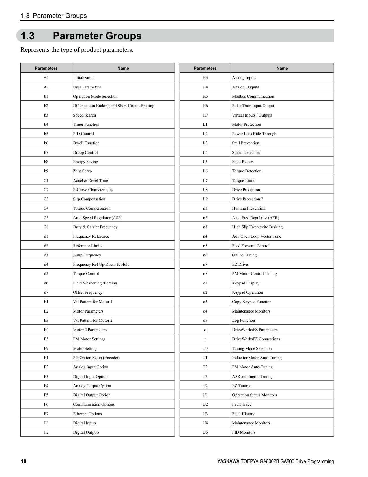
####### 1.3 Parameter Groups
Represents the type of product parameters.
|Parameters|Name| |---|---| |A1|Initialization| |A2|User Parameters| |b1|Operation Mode Selection| |b2|DC Injection Braking and Short Circuit Braking| |b3|Speed Search| |b4|Timer Function| |b5|PID Control| |b6|Dwell Function| |b7|Droop Control| |b8|Energy Saving| |b9|Zero Servo| |C1|Accel & Decel Time|
|C2|S-Curve Characteristics| |C3|Slip Compensation| |C4|Torque Compensation| |C5|Auto Speed Regulator (ASR)| |C6|Duty & Carrier Frequency| |d1|Frequency Reference| |d2|Reference Limits| |d3|Jump Frequency| |d4|Frequency Ref Up/Down & Hold| |d5|Torque Control| |d6|Field Weakening /Forcing| |d7|Offset Frequency| |E1|V/f Pattern for Motor 1| |E2|Motor Parameters| |E3|V/f Pattern for Motor 2| |E4|Motor 2 Parameters| |E5|PM Motor Settings| |E9|Motor Setting| |F1|PG Option Setup (Encoder)| |F2|Analog Input Option| |F3|Digital Input Option| |F4|Analog Output Option| |F5|Digital Output Option| |F6|Communication Options| |F7|Ethernet Options| |H1|Digital Inputs| |H2|Digital Outputs|
|Parameters|Name| |---|---| |H3|Analog Inputs| |H4|Analog Outputs| |H5|Modbus Communication| |H6|Pulse Train Input/Output| |H7|Virtual Inputs / Outputs| |L1|Motor Protection| |L2|Power Loss Ride Through| |L3|Stall Prevention| |L4|Speed Detection| |L5|Fault Restart| |L6|Torque Detection|
|L7|Torque Limit| |L8|Drive Protection| |L9|Drive Protection 2| |n1|Hunting Prevention| |n2|Auto Freq Regulator (AFR)| |n3|High Slip/Overexcite Braking| |n4|Adv Open Loop Vector Tune| |n5|Feed Forward Control| |n6|Online Tuning| |n7|EZ Drive| |n8|PM Motor Control Tuning| |o1|Keypad Display| |o2|Keypad Operation| |o3|Copy Keypad Function| |o4|Maintenance Monitors| |o5|Log Function| |q|DriveWorksEZ Parameters| |r|DriveWorksEZ Connections| |T0|Tuning Mode Selection| |T1|InductionMotor Auto-Tuning| |T2|PM Motor Auto-Tuning| |T3|ASR and Inertia Tuning| |T4|EZ Tuning| |U1|Operation Status Monitors| |U2|Fault Trace| |U3|Fault History| |U4|Maintenance Monitors| |U5|PID Monitors|
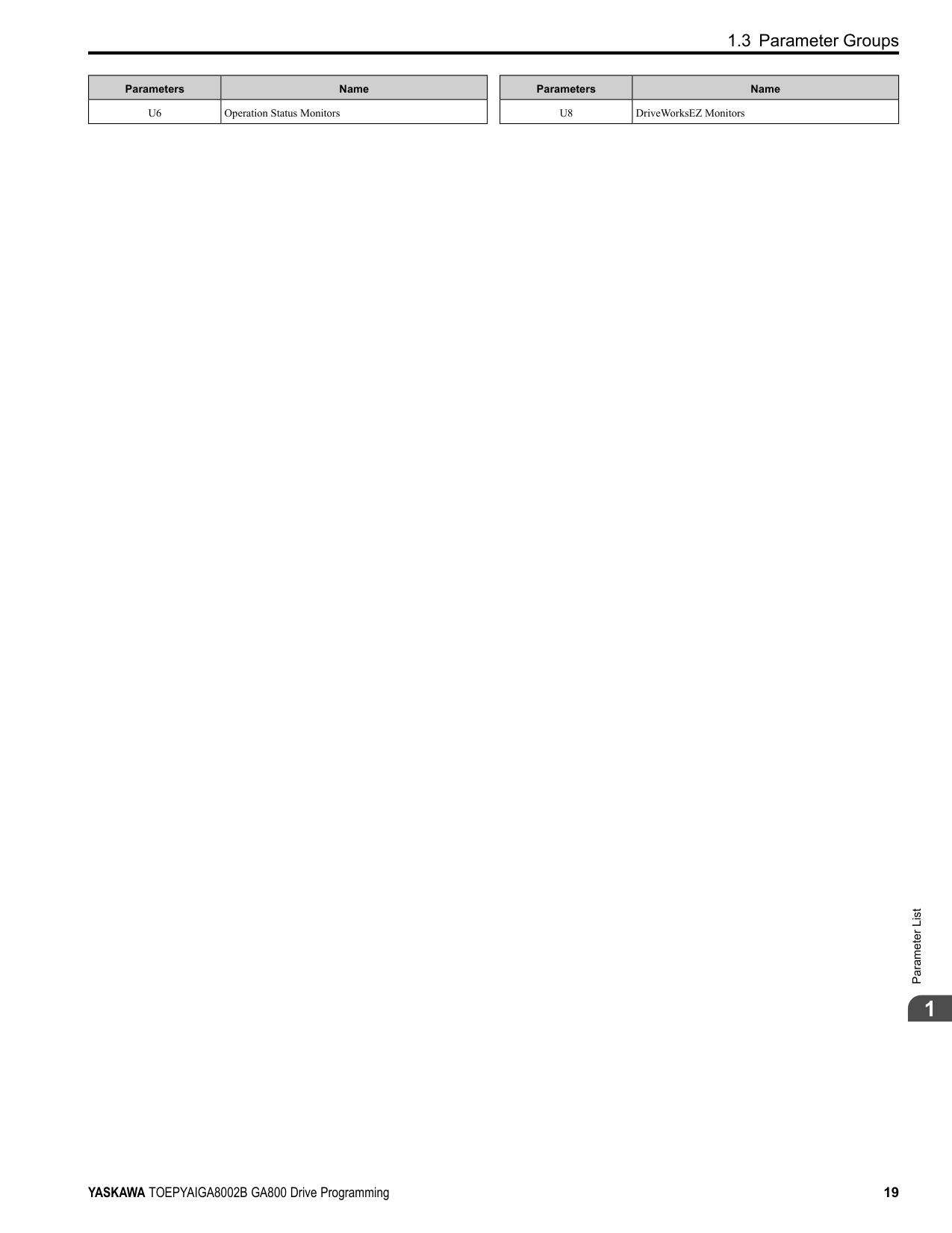
############### 1.3 Parameter Groups
|Parameters|Name| |---|---| |U6|Operation Status Monitors|
|Parameters|Name| |---|---| |U8|DriveWorksEZ Monitors|

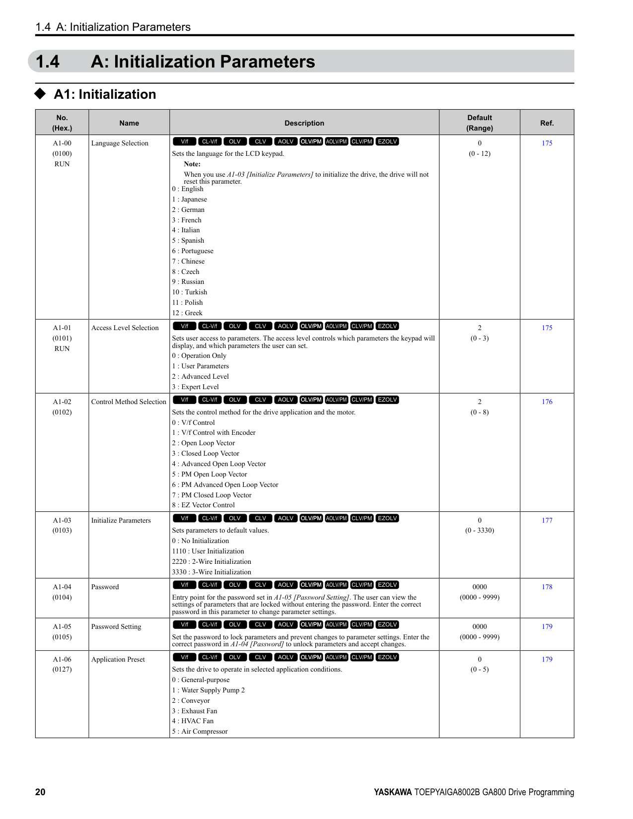
####### 1.4 A: Initialization Parameters
◆ A1: Initialization
|No. (Hex.)|Name|Description|Default (Range)|Ref.| |---|---|---|---|---| |A1-00 (0100) RUN|Language Selection|Sets the language for the LCD keypad.
Note:
When you use A1-03 [Initialize Parameters] to initialize the drive, the drive will not reset this parameter.
0 : English
1 : Japanese
2 : German
3 : French
4 : Italian
5 : Spanish
6 : Portuguese
7 : Chinese
8 : Czech
9 : Russian
10 : Turkish
11 : Polish
12 : Greek
V/f CL-V/f OLV CLV AOLV OLV/PM AOLV/PM CLV/PM EZOLV
|0 (0 - 12)|175| |A1-01 (0101) RUN|Access Level Selection|Sets user access to parameters. The access level controls which parameters the keypad will display, and which parameters the user can set.
0 : Operation Only
1 : User Parameters
2 : Advanced Level
3 : Expert Level
V/f CL-V/f OLV CLV AOLV OLV/PM AOLV/PM CLV/PM EZOLV
|2 (0 - 3)|175| |A1-02 (0102)|Control Method Selection|Sets the control method for the drive application and the motor.
0 : V/f Control
1 : V/f Control with Encoder
2 : Open Loop Vector
3 : Closed Loop Vector
4 : Advanced Open Loop Vector
5 : PM Open Loop Vector
6 : PM Advanced Open Loop Vector
7 : PM Closed Loop Vector
8 : EZ Vector Control
V/f CL-V/f OLV CLV AOLV OLV/PM AOLV/PM CLV/PM EZOLV
|2 (0 - 8)|176| |A1-03 (0103)|Initialize Parameters|Sets parameters to default values. 0 : No Initialization 1110 : User Initialization 2220 : 2-Wire Initialization 3330 : 3-Wire Initialization
V/f CL-V/f OLV CLV AOLV OLV/PM AOLV/PM CLV/PM EZOLV
|0 (0 - 3330)|177| |A1-04 (0104)|Password|Entry point for the password set in A1-05 [Password Setting]. The user can view the settings of parameters that are locked without entering the password. Enter the correct password in this parameter to change parameter settings.
V/f CL-V/f OLV CLV AOLV OLV/PM AOLV/PM CLV/PM EZOLV
|0000 (0000 - 9999)|178| |A1-05 (0105)|Password Setting|Set the password to lock parameters and prevent changes to parameter settings. Enter the correct password in A1-04 [Password] to unlock parameters and accept changes.
V/f CL-V/f OLV CLV AOLV OLV/PM AOLV/PM CLV/PM EZOLV
|0000 (0000 - 9999)|179| |A1-06 (0127)|Application Preset|Sets the drive to operate in selected application conditions.
0 : General-purpose
1 : Water Supply Pump 2
2 : Conveyor
3 : Exhaust Fan
4 : HVAC Fan
5 : Air Compressor
V/f CL-V/f OLV CLV AOLV OLV/PM AOLV/PM CLV/PM EZOLV
|0 (0 - 5)|179|
1.4 A: Initialization Parameters
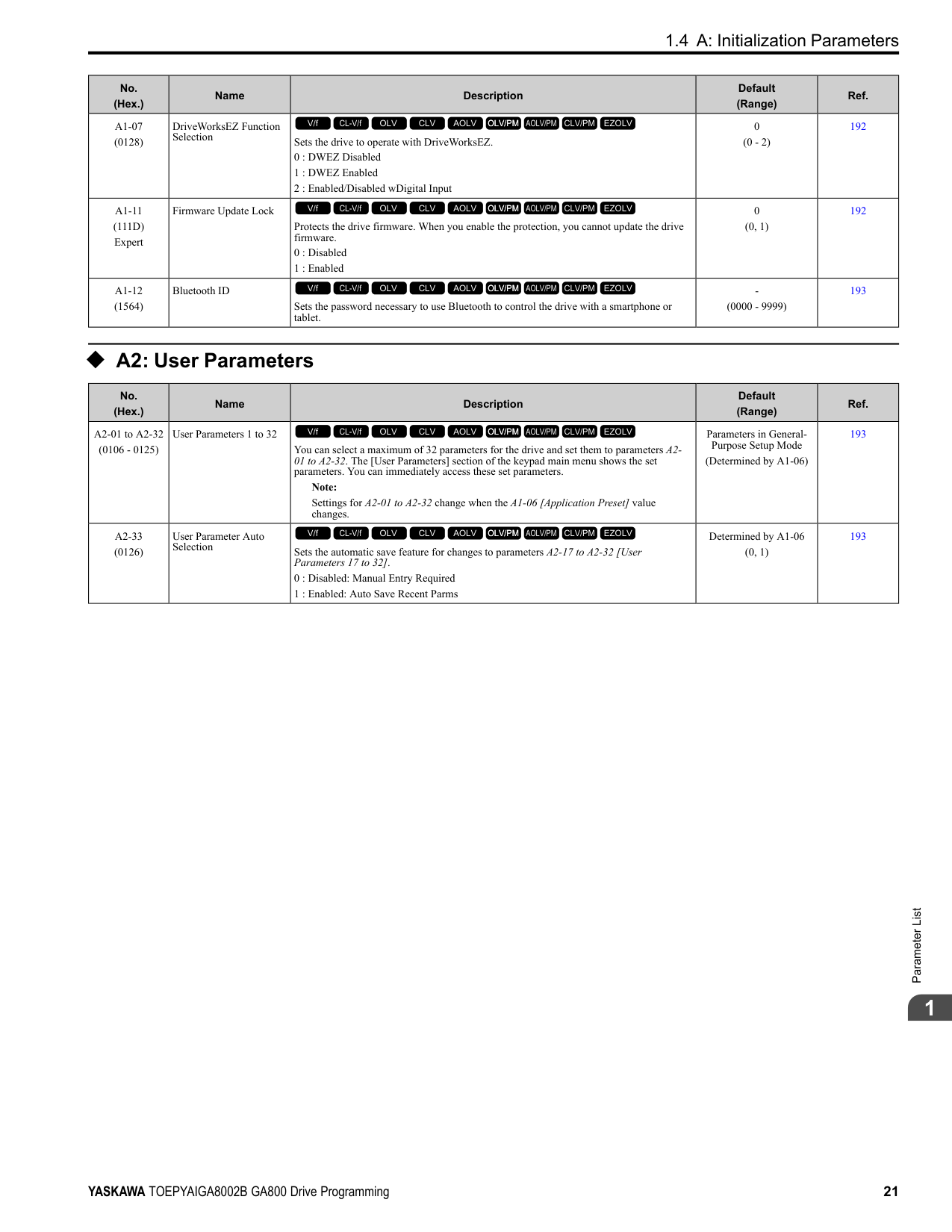
|No. (Hex.)|Name|Description|Default (Range)|Ref.| |---|---|---|---|---| |A1-07 (0128)|DriveWorksEZ Function Selection|Sets the drive to operate with DriveWorksEZ.
0 : DWEZ Disabled
1 : DWEZ Enabled
2 : Enabled/Disabled wDigital Input
V/f CL-V/f OLV CLV AOLV OLV/PM AOLV/PM CLV/PM EZOLV
|0 (0 - 2)|192| |A1-11 (111D) Expert|Firmware Update Lock|Protects the drive firmware. When you enable the protection, you cannot update the drive firmware.
0 : Disabled
1 : Enabled
V/f CL-V/f OLV CLV AOLV OLV/PM AOLV/PM CLV/PM EZOLV
|0 (0, 1)|192| |A1-12 (1564)|Bluetooth ID|Sets the password necessary to use Bluetooth to control the drive with a smartphone or tablet.
V/f CL-V/f OLV CLV AOLV OLV/PM AOLV/PM CLV/PM EZOLV
|(0000 - 9999)|193|
######## ◆ A2: User Parameters
|No. (Hex.)|Name|Description|Default (Range)|Ref.| |---|---|---|---|---| |A2-01 to A2-32 (0106 - 0125)|User Parameters 1 to 32|You can select a maximum of 32 parameters for the drive and set them to parameters A201 to A2-32. The [User Parameters] section of the keypad main menu shows the set parameters. You can immediately access these set parameters.
Note:
Settings for A2-01 to A2-32 change when the A1-06 [Application Preset] value changes.
V/f CL-V/f OLV CLV AOLV OLV/PM AOLV/PM CLV/PM EZOLV
|Parameters in GeneralPurpose Setup Mode
(Determined by A1-06)|193| |A2-33 (0126)|User Parameter Auto Selection|Sets the automatic save feature for changes to parameters A2-17 to A2-32 [User Parameters 17 to 32].
0 : Disabled: Manual Entry Required
1 : Enabled: Auto Save Recent Parms
V/f CL-V/f OLV CLV AOLV OLV/PM AOLV/PM CLV/PM EZOLV
|Determined by A1-06 (0, 1)|193|
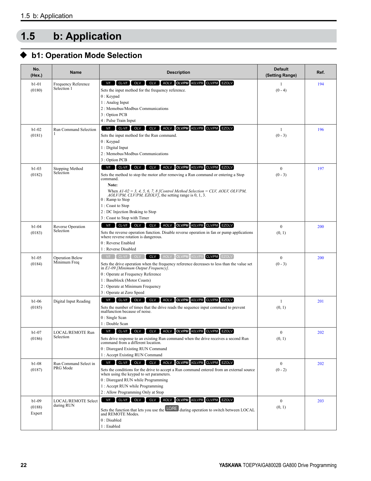
####### 1.5 b: Application
◆ b1: Operation Mode Selection
|No. (Hex.)|Name|Description|Default (Setting Range)|Ref.| |---|---|---|---|---| |b1-01 (0180)|Frequency Reference Selection 1|Sets the input method for the frequency reference.
0 : Keypad
1 : Analog Input
2 : Memobus/Modbus Communications
3 : Option PCB
4 : Pulse Train Input
V/f CL-V/f OLV CLV AOLV OLV/PM AOLV/PM CLV/PM EZOLV
|1 (0 - 4)|194|
|b1-02 (0181)|Run Command Selection 1|Sets the input method for the Run command.
0 : Keypad
1 : Digital Input
2 : Memobus/Modbus Communications
3 : Option PCB
V/f CL-V/f OLV CLV AOLV OLV/PM AOLV/PM CLV/PM EZOLV
|1 (0 - 3)|196| |b1-03 (0182)|Stopping Method Selection|Sets the method to stop the motor after removing a Run command or entering a Stop command.
Note: When A1-02 = 3, 4, 5, 6, 7, 8 [Control Method Selection = CLV, AOLV, OLV/PM, AOLV/PM, CLV/PM, EZOLV], the setting range is 0, 1, 3.
0 : Ramp to Stop
1 : Coast to Stop
2 : DC Injection Braking to Stop
3 : Coast to Stop with Timer
V/f CL-V/f OLV CLV AOLV OLV/PM AOLV/PM CLV/PM EZOLV
|0 (0 - 3)|197| |b1-04 (0183)|Reverse Operation Selection|Sets the reverse operation function. Disable reverse operation in fan or pump applications where reverse rotation is dangerous.
0 : Reverse Enabled
1 : Reverse Disabled
V/f CL-V/f OLV CLV AOLV OLV/PM AOLV/PM CLV/PM EZOLV
|0 (0, 1)|200| |b1-05 (0184)|Operation Below Minimum Freq|Sets the drive operation when the frequency reference decreases to less than the value set in E1-09 [Minimum Output Frequency].
0 : Operate at Frequency Reference
1 : Baseblock (Motor Coasts)
2 : Operate at Minimum Frequency
3 : Operate at Zero Speed
V/f CL-V/f OLV CLV AOLV OLV/PM AOLV/PM CLV/PM EZOLV
|0 (0 - 3)|200| |b1-06 (0185)|Digital Input Reading|Sets the number of times that the drive reads the sequence input command to prevent malfunction because of noise.
0 : Single Scan
1 : Double Scan
V/f CL-V/f OLV CLV AOLV OLV/PM AOLV/PM CLV/PM EZOLV
|1 (0, 1)|201| |b1-07 (0186)|LOCAL/REMOTE Run Selection|Sets drive response to an existing Run command when the drive receives a second Run command from a different location.
0 : Disregard Existing RUN Command
1 : Accept Existing RUN Command
V/f CL-V/f OLV CLV AOLV OLV/PM AOLV/PM CLV/PM EZOLV
|0 (0, 1)|202| |b1-08 (0187)|Run Command Select in PRG Mode|Sets the conditions for the drive to accept a Run command entered from an external source when using the keypad to set parameters.
0 : Disregard RUN while Programming
1 : Accept RUN while Programming
2 : Allow Programming Only at Stop
V/f CL-V/f OLV CLV AOLV OLV/PM AOLV/PM CLV/PM EZOLV
|0 (0 - 2)|202| |b1-09 (0188) Expert|LOCAL/REMOTE Select during RUN|Sets the function that lets you use the during operation to switch between LOCAL and REMOTE Modes.
0 : Disabled
1 : Enabled
V/f CL-V/f OLV CLV AOLV OLV/PM AOLV/PM CLV/PM EZOLV
|0 (0, 1)|203|
|No. (Hex.)|Name|Description|Default (Setting Range)|Ref.| |---|---|---|---|---| |b1-14 (01C3)|Phase Order Selection|Sets the phase order for output terminals U/T1, V/T2, and W/T3. This parameter can align the Forward Run command from the drive and the forward direction of the motor without changing wiring.
0 : Standard
1 : Switch Phase Order
V/f CL-V/f OLV CLV AOLV OLV/PM AOLV/PM CLV/PM EZOLV
|0 (0, 1)|203| |b1-15 (01C4)|Frequency Reference Selection 2|Sets the input method for frequency reference 2.
0 : Keypad
1 : Analog Input
2 : Memobus/Modbus Communications
3 : Option PCB
4 : Pulse Train Input
V/f CL-V/f OLV CLV AOLV OLV/PM AOLV/PM CLV/PM EZOLV
|0 (0 - 4)|203| |b1-16 (01C5)|Run Command Selection 2|Sets the input method for Run Command 2 when the user switches the control circuit terminals ON/OFF to change the Run command source.
0 : Keypad
1 : Digital Input
2 : Memobus/Modbus Communications
3 : Option PCB
V/f CL-V/f OLV CLV AOLV OLV/PM AOLV/PM CLV/PM EZOLV
|0 (0 - 3)|205| |b1-17 (01C6)|Run Command at Power Up|Sets drive response when energizing a drive that has an external Run command. Set this parameter in applications where energizing or de-energizing the drive enables the Run command.
0 : Disregard Existing RUN Command
1 : Accept Existing RUN Command
V/f CL-V/f OLV CLV AOLV OLV/PM AOLV/PM CLV/PM EZOLV
|0 (0, 1)|206| |b1-21 (0748) Expert|CLV Start Selection|Sets the conditions for the drive to accept a Run command when A1-02 = 3, 7 [Control Method Selection = CLV, CLV/PM]. Usually it is not necessary to change this setting.
0 : Reject RUN if b2-01
V/f CL-V/f OLV CLV AOLV OLV/PM AOLV/PM CLV/PM EZOLV
|0 (0, 1)|206| |b1-35 (1117) Expert|Digital Input Deadband Time|Sets the deadband time for MFDIs.
V/f CL-V/f OLV CLV AOLV OLV/PM AOLV/PM CLV/PM EZOLV
|0.0 ms (0.0 to 100.0 ms)|207|
######## ◆ b2: DC Injection Braking and Short Circuit Braking
|No. (Hex.)|Name|Description|Default (Range)|Ref.| |---|---|---|---|---| |b2-01 (0189)|DC Injection/Zero SpeedThreshold|Sets the frequency to start DC Injection Braking, Short Circuit Braking, and Zero Servo. Note: This parameter is available when b1-03 = 0 [Stopping Method Selection = Ramp to Stop].
V/f CL-V/f OLV CLV AOLV OLV/PM AOLV/PM CLV/PM EZOLV
|Determined by A1-02 (0.0 - 10.0 Hz)|207| |b2-02 (018A)|DC Injection Braking Current|Sets the DC Injection Braking current as a percentage of the drive rated current.
V/f CL-V/f OLV CLV AOLV OLV/PM AOLV/PM CLV/PM EZOLV
|50% (0 - 100%)|208| |b2-03 (018B)|DC Inject Braking Time at Start|Sets the DC Injection Braking Time at stop. Sets the time of Zero Speed Control at start when A1-02 = 3, 7 [Control Method Selection = CLV, CLV/PM].
V/f CL-V/f OLV CLV AOLV OLV/PM AOLV/PM CLV/PM EZOLV
|A1-02 = 4: 0.03 s Other than A1-02 = 4: 0.00 s (0.00 - 10.00 s)|208| |b2-04 (018C)|DC Inject Braking Time at Stop|Sets the DC Injection Braking Time at stop. Sets the time of Zero Speed Control at stop when A1-02 = 3, 7 [Control Method Selection = CLV, CLV/PM].
V/f CL-V/f OLV CLV AOLV OLV/PM AOLV/PM CLV/PM EZOLV
|Determined by A1-02 (0.00 - 10.00 s)|209| |b2-08 (0190)|Magnetic Flux Compensation Value|Sets how much current the drive injects when DC Injection Braking at Start starts (Initial Excitation) as a percentage of E2-03 [Motor No-Load Current].
V/f CL-V/f OLV CLV AOLV OLV/PM AOLV/PM CLV/PM EZOLV
|0% (0 - 1000%)|209| |b2-12 (01BA)|Short Circuit Brake Time @ Start|Sets the Short Circuit Braking time at start.
V/f CL-V/f OLV CLV AOLV OLV/PM AOLV/PM CLV/PM EZOLV
|0.00 s (0.00 - 25.50 s)|209|
|No. (Hex.)|Name|Description|Default (Range)|Ref.| |---|---|---|---|---| |b2-13 (01BB)|Short Circuit Brake Time @ Stop|Sets the Short Circuit Braking time at stop.
V/f CL-V/f OLV CLV AOLV OLV/PM AOLV/PM CLV/PM EZOLV
|A1-02 8: 0.00 s Other than A1-02 8: 0.50 s (0.00 - 25.50 s)|210| |b2-18 (0177)|Short Circuit Braking Current|Sets the Short Circuit Braking Current as a percentage of the motor rated current.
Note:
Parameter A1-02 [Control Method Selection] selects which parameter is the motor rated current.
• A1-02 = 5, 6 [OLV/PM, AOLV/PM]: E5-03 [PM Motor Rated Current (FLA)]
• A1-02 8 [EZOLV]: E9-06 [Motor Rated Current (FLA)]
V/f CL-V/f OLV CLV AOLV OLV/PM AOLV/PM CLV/PM EZOLV
|100.0% (0.0 - 200.0%)|210|
######## ◆ b3: Speed Search
|No. (Hex.)|Name|Description|Default (Range)|Ref.| |---|---|---|---|---|

|b3-01 (0191)|Speed Search at Start Selection|Sets the Speed Search at Start function where the drive will perform Speed Search with each Run command.
0 : Disabled
1 : Enabled
V/f CL-V/f OLV CLV AOLV OLV/PM AOLV/PM CLV/PM EZOLV
|Determined by A1-02 (0, 1)|214| |b3-02 (0192)|SpeedSearch Deactivation Current|Sets the current level that stops Speed Search as a percentage of the drive rated output current. Usually it is not necessary to change this setting.
V/f CL-V/f OLV CLV AOLV OLV/PM AOLV/PM CLV/PM EZOLV
|Determined by A1-02 (0 - 200%)|214| |b3-03 (0193)|Speed Search Deceleration Time|Sets the deceleration time during Speed Search operation. Set the length of time to decelerate from the maximum output frequency to the minimum output frequency.
Note:
When A1-02 8 [Control Method Selection EZOLV], this parameter takes effect only in Expert Mode.
V/f CL-V/f OLV CLV AOLV OLV/PM AOLV/PM CLV/PM EZOLV
|2.0 s (0.1 - 10.0 s)|214| |b3-04 (0194)|V/f Gain during Speed Search|Sets the ratio used to reduce the V/f during searches to reduce the output current during speed searches.
V/f CL-V/f OLV CLV AOLV OLV/PM AOLV/PM CLV/PM EZOLV
|Determined by o2-04 (10 - 100)|215| |b3-05 (0195)|Speed Search Delay Time|Sets the Speed Search delay time to activate a magnetic contactor installed between the drive and motor.
V/f CL-V/f OLV CLV AOLV OLV/PM AOLV/PM CLV/PM EZOLV
|0.2 s (0.0 - 100.0 s)|215| |b3-06 (0196) Expert|Speed Estimation Current Level 1|Sets the level of current that flows to the motor during Speed Estimation Speed Search as a coefficient of the motor rated current. Usually it is not necessary to change this setting.
V/f CL-V/f OLV CLV AOLV OLV/PM AOLV/PM CLV/PM EZOLV
|Determined by o2-04 (0.0 - 2.0)|215| |b3-07 (0197) Expert|Speed Estimation Current Level 2|Sets the level of current that flows to the motor during Speed Estimation Speed Search as a coefficient of E2-03 [Motor No-Load Current] or E4-03 [Motor 2 Rated No-Load Current]. Usually it is not necessary to change this setting.
V/f CL-V/f OLV CLV AOLV OLV/PM AOLV/PM CLV/PM EZOLV
|1.0 (0.0 - 3.0)|215| |b3-08 (0198)|Speed Estimation ACR P Gain|Sets the proportional gain for the automatic current regulator during Speed Estimation Speed Search. Also adjusts speed search responsiveness. Usually it is not necessary to change this setting.
V/f CL-V/f OLV CLV AOLV OLV/PM AOLV/PM CLV/PM EZOLV
|Determined by A1-02 and o2-04
(0.00 - 6.00)|215| |b3-09 (0199)|Speed Estimation ACR I Time|Sets the integral time for the automatic current regulator during Speed Estimation Speed Search. Also adjusts speed search responsiveness. Usually it is not necessary to change this setting.
V/f CL-V/f OLV CLV AOLV OLV/PM AOLV/PM CLV/PM EZOLV
|Determined by A1-02 when A1-02 ≠ 5
20.0 when A1-02 = 5 (0.0 - 1000.0 ms)|216| |b3-10 (019A) Expert|Speed Estimation Detection Gain|Sets the gain to correct estimated frequencies from Speed Estimation Speed Search.
V/f CL-V/f OLV CLV AOLV OLV/PM AOLV/PM CLV/PM EZOLV
|1.05 (1.00 - 1.20)|216|
|No. (Hex.)|Name|Description|Default (Range)|Ref.| |---|---|---|---|---| |b3-14 (019E)|Bi-directional Speed Search|Sets the direction of Speed Search to the direction of the frequency reference or in the motor rotation direction as detected by the drive.
0 : Disabled
1 : Enabled Note:
• Refer to page 125 for information about the initial value of b3-14 [Bi-directional Speed Search] that applies when you set these parameters:
–A1-02 0, 2, 8 [Control Method Selection V/f, OLV, EZOLV]
–E9-01 0 [Motor Type Selection Induction (IM)]
–b3-24 = 1 [Speed Search Method Selection = Speed Estimation Speed Search]
• The initial value of b3-14 is 0 when you set these parameters:
–A1-02 = 0, 2, 8
–E9-01 0
–b3-24 2 [Current Detection 2]
• Refer to page 125 for information about the initial value of b3-14 that applies when you set these parameters:
–A1-02 = 1, 4, 8 [CL-V/f, AOLV, EZOLV]
–E9-01 1, 2 [Permanent Magnet (PM), Synchronous Reluctance (SynRM)]
• When you change A1-02, b3-24, and E9-01, also set b3-14.
V/f CL-V/f OLV CLV AOLV OLV/PM AOLV/PM CLV/PM EZOLV
|Determined by A1-02 and b3-24 (0, 1)|216| |b3-17 (01F0) Expert|Speed Est Retry Current Level|Sets the current level for the search retry function in Speed Estimation Speed Search as a percentage where drive rated current is a setting value of 100%.
V/f CL-V/f OLV CLV AOLV OLV/PM AOLV/PM CLV/PM EZOLV
|150% (0 - 200%)|216| |b3-18 (01F1) Expert|Speed Est Retry Detection Time|Sets the length of time that the drive will wait to retry Speed Estimation Speed Search when too much current flow stopped the Speed Search.
V/f CL-V/f OLV CLV AOLV OLV/PM AOLV/PM CLV/PM EZOLV
|0.10 s (0.00 - 1.00 s)|217| |b3-19 (01F2)|Speed Search Restart Attempts|Sets the number of times to restart Speed Search if Speed Search does not complete.
V/f CL-V/f OLV CLV AOLV OLV/PM AOLV/PM CLV/PM EZOLV
|3 times (0 - 10 times)|217| |b3-24 (01C0)|Speed Search Method Selection|Sets the Speed Search method when you start the motor or when you return power after a momentary power loss.
Note:
• The default setting is different for different control methods.
–A1-02 = 0, 2 [Control Method Selection = V/f, OLV]: 2
–A1-02 = 1 [CL-V/f]: 1
–A1-02 = 8 [EZOLV] and E9-01 = 0 [Motor Type Selection = Induction (IM)]: 2
–A1-02 = 8 and E9-01 ≠ 0: 1
• Set b3-24 = 1. If b3-24 = 2, the drive will detect oPE08 [Parameter Selection Error].
V/f CL-V/f OLV CLV AOLV OLV/PM AOLV/PM CLV/PM EZOLV
|2 (1, 2)|217| |b3-25 (01C8) Expert|Speed Search Wait Time|Sets the length of time the drive will wait to start the Speed Search Retry function.
V/f CL-V/f OLV CLV AOLV OLV/PM AOLV/PM CLV/PM EZOLV
|0.5 s (0.0 - 30.0 s)|217| |b3-26 (01C7) Expert|Direction Determination Level|Sets the level to find the motor rotation direction. Increase the value if the drive cannot find the direction.
V/f CL-V/f OLV CLV AOLV OLV/PM AOLV/PM CLV/PM EZOLV
|1000 (40 to 60000)|218| |b3-27 (01C9) Expert|Speed Search RUN/BB Priority|Sets the conditions necessary to start Speed Search.
0 : SS Only if RUN Applied Before BB
1 : SS Regardless of RUN/BB Sequence
V/f CL-V/f OLV CLV AOLV OLV/PM AOLV/PM CLV/PM EZOLV
|0 (0, 1)|218| |b3-29 (077C) Expert|Speed Search Back-EMF Threshold|Sets the induced voltage for motors that use Speed Search. The drive will start Speed Search when the motor induced voltage level is the same as the setting value. Usually it is not necessary to change this setting.
V/f CL-V/f OLV CLV AOLV OLV/PM AOLV/PM CLV/PM EZOLV
|10% (0 - 10%)|218| |b3-31 (0BC0) Expert|Spd Search Current Reference Lvl|Sets the current level that decreases the output current during Current Detection Speed Search.
V/f CL-V/f OLV CLV AOLV OLV/PM AOLV/PM CLV/PM EZOLV
|1.50 (1.50 - 3.50)|218| |b3-32 (0BC1) Expert|Spd Search Current Complete Lvl|Sets the current level that completes Speed Search.
V/f CL-V/f OLV CLV AOLV OLV/PM AOLV/PM CLV/PM EZOLV
|1.20 (0.00 - 1.49)|218| |b3-33 (0B3F) Expert|Speed Search during Uv Selection|Sets the function that starts Speed Search at start-up if the drive detects a Uv [Undervoltage] when it receives a Run command.
0 : Disabled
1 : Enabled
V/f CL-V/f OLV CLV AOLV OLV/PM AOLV/PM CLV/PM EZOLV
|1 (0, 1)|219|
|No. (Hex.)|Name|Description|Default (Range)|Ref.| |---|---|---|---|---| |b3-35 (0BC3) Expert|Low Back EMF Detection Level|Sets the Low Back EMF Detection Level. Usually it is not necessary to change this setting.
V/f CL-V/f OLV CLV AOLV OLV/PM AOLV/PM CLV/PM EZOLV
|10% (5 - 50%)|219| |b3-36 (0BC4) Expert|High Back EMF Detection Level|Sets the voltage level for Speed Search restart. Usually it is not necessary to change this setting.
V/f CL-V/f OLV CLV AOLV OLV/PM AOLV/PM CLV/PM EZOLV
|0.970 (0.500 - 1.000)|219| |b3-54 (3123)|Search Time|Sets the length of time that the drive will run Speed Search.
V/f CL-V/f OLV CLV AOLV OLV/PM AOLV/PM CLV/PM EZOLV
|400 ms (10 - 2000 ms)|219| |b3-55 (3124) Expert|Current Increment Time|Sets the length of time that the drive will increase the current from zero current to the setting value of b3-06 [Speed Estimation Current Level 1].
V/f CL-V/f OLV CLV AOLV OLV/PM AOLV/PM CLV/PM EZOLV
|10 ms (10 - 2000 ms)|219| |b3-56 (3126)|InverseRotationSearch WaitTime|Sets the wait time until the drive starts inverse rotation search after it completes forward search when you do inverse rotation search during Current Detection Speed Search.
V/f CL-V/f OLV CLV AOLV OLV/PM AOLV/PM CLV/PM EZOLV
|Determined by o2-04 (0.1 - 5.0 s)|220| |b3-61 (1B96) Expert|Init Magnet Pole Estimation Gain|Adjusts the Initial Pole Detection response gain when A1-02 = 6 [Control Method Selection = AOLV/PM]. Set b3-61 > 0.0 for a general IPM motor.
The drive sets this value automatically when High Frequency Injection Tuning completes correctly.
Note:
• It is available when n8-35 = 1 [Initial Pole Detection Method = High Frequency Injection].
• To adjust the Initial Pole Detection response gain when A1-02 = 5, 7 [OLV/PM, CLV/ PM], set n8-41 [HFI P Gain].
V/f CL-V/f OLV CLV AOLV OLV/PM AOLV/PM CLV/PM EZOLV
|5.0 (-20.0 - +20.0)|220|
######## ◆ b4: Timer Function
|No. (Hex.)|Name|Description|Default (Range)|Ref.| |---|---|---|---|---|
|b4-01 (01A3)|Timer Function ONDelay Time|Sets the ON-delay time for the timer input.
V/f CL-V/f OLV CLV AOLV OLV/PM AOLV/PM CLV/PM EZOLV
|0.0 s (0.0 - 3000.0 s)|221| |b4-02 (01A4)|Timer Function OFFDelay Time|Sets the OFF-delay time for the timer input.
V/f CL-V/f OLV CLV AOLV OLV/PM AOLV/PM CLV/PM EZOLV
|0.0 s (0.0 - 3000.0 s)|221| |b4-03 (0B30) Expert|Terminal M1-M2 ONDelay Time|Sets the delay time until the contact is turned ON after the function set with H2-01 turns ON.
V/f CL-V/f OLV CLV AOLV OLV/PM AOLV/PM CLV/PM EZOLV
|0 ms (0 - 65000 ms)|221| |b4-04 (0B31) Expert|Terminal M1-M2 OFFDelay Time|Sets the delay time to deactivate the contact after the function set in H2-01 deactivates.
V/f CL-V/f OLV CLV AOLV OLV/PM AOLV/PM CLV/PM EZOLV
|0 ms (0 - 65000 ms)|221| |b4-05 (0B32) Expert|Terminal M3-M4 ONDelay Time|Sets the delay time to activate the contact after the function set in H2-02 activates.
V/f CL-V/f OLV CLV AOLV OLV/PM AOLV/PM CLV/PM EZOLV
|0 ms (0 - 65000 ms)|221| |b4-06 (0B33) Expert|Terminal M3-M4 OFFDelay Time|Sets the delay time to deactivate the contact after the function set in H2-02 deactivates.
V/f CL-V/f OLV CLV AOLV OLV/PM AOLV/PM CLV/PM EZOLV
|0 ms (0 - 65000 ms)|221| |b4-07 (0B34) Expert|Terminal M5-M6 ONDelay Time|Sets the delay time to activate the contact after the function set in H2-03 activates.
V/f CL-V/f OLV CLV AOLV OLV/PM AOLV/PM CLV/PM EZOLV
|0 ms (0 - 65000 ms)|222| |b4-08 (0B35) Expert|Terminal M5-M6 OFFDelay Time|Sets the delay time to deactivate the contact after the function set in H2-03 deactivates.
V/f CL-V/f OLV CLV AOLV OLV/PM AOLV/PM CLV/PM EZOLV
|0 ms (0 - 65000 ms)|222|
######## ◆ b5: PID Control
|No. (Hex.)|Name|Description|Default (Range)|Ref.| |---|---|---|---|---| |b5-01 (01A5)|PID Mode Setting|Sets the type of PID control.
0 : Disabled
1 : Standard
2 : Standard (D on feedback)
3 : Fref + PID Trim
4 : Fref + PID Trim (D on feedback)
5 : Same as 7series & prior, b5-01=1
6 : Same as 7series & prior, b5-01=2
7 : Same as 7series & prior, b5-01=3
8 : Same as 7series & prior, b5-01=4 Note: Use settings 5 to 8 when the drive is a replacement for a previous generation drive.
V/f CL-V/f OLV CLV AOLV OLV/PM AOLV/PM CLV/PM EZOLV
|0 (0 - 8)|227| |b5-02 (01A6) RUN|Proportional Gain (P)|Sets the proportional gain (P) that is applied to PID input.
V/f CL-V/f OLV CLV AOLV OLV/PM AOLV/PM CLV/PM EZOLV
|1.00 (0.00 - 25.00)|228| |b5-03 (01A7) RUN|Integral Time (I)|Sets the integral time (I) that is applied to PID input.
V/f CL-V/f OLV CLV AOLV OLV/PM AOLV/PM CLV/PM EZOLV
|1.0 s (0.0 - 360.0 s)|228| |b5-04 (01A8) RUN|Integral Limit|Sets the upper limit for integral control (I) as a percentage of the Maximum Output Frequency.
Note:
Parameter A1-02 [Control Method Selection] selects which parameter is the maximum output frequency.
• A1-02 ≠ 8 [EZOLV]: E1-04 [Maximum Output Frequency]
• A1-02 8: E9-02 [Maximum Speed]
V/f CL-V/f OLV CLV AOLV OLV/PM AOLV/PM CLV/PM EZOLV
|100.0% (0.0 - 100.0%)|228| |b5-05 (01A9) RUN|Derivative Time (D)|Sets the derivative time (D) for PID control. This parameter adjusts system responsiveness.
V/f CL-V/f OLV CLV AOLV OLV/PM AOLV/PM CLV/PM EZOLV
|0.00 s (0.00 - 10.00 s)|229| |b5-06 (01AA) RUN|PID Output Limit|Sets the maximum possible output from the PID controller as a percentage of the Maximum Output Frequency.
Note:
Parameter A1-02 [Control Method Selection] selects which parameter is the maximum output frequency.
• A1-02 ≠ 8 [EZOLV]: E1-04 [Maximum Output Frequency]
• A1-02 8: E9-02 [Maximum Speed]
V/f CL-V/f OLV CLV AOLV OLV/PM AOLV/PM CLV/PM EZOLV
|100.0% (0.0 - 100.0%)|229| |b5-07 (01AB) RUN|PID Offset Adjustment|Sets the offset for the PID control output as a percentage of the Maximum Output Frequency.
Note:
Parameter A1-02 [Control Method Selection] selects which parameter is the maximum output frequency.
• A1-02 ≠ 8 [EZOLV]: E1-04 [Maximum Output Frequency]
• A1-02 8: E9-02 [Maximum Speed]
V/f CL-V/f OLV CLV AOLV OLV/PM AOLV/PM CLV/PM EZOLV
|0.0% (-100.0 - +100.0%)|229| |b5-08 (01AC) RUN Expert|PID Primary Delay Time Constant|Sets the primary delay time constant for the PID control output. Usually it is not necessary to change this setting.
V/f CL-V/f OLV CLV AOLV OLV/PM AOLV/PM CLV/PM EZOLV
|0.00 s (0.00 - 10.00 s)|229| |b5-09 (01AD)|PID Output Level Selection|Sets the polarity of the PID output.
0 : Normal Output (Direct Acting)
1 : Reverse Output (Reverse Acting)
V/f CL-V/f OLV CLV AOLV OLV/PM AOLV/PM CLV/PM EZOLV
|0 (0, 1)|229| |b5-10 (01AE) RUN|PID Output Gain Setting|Sets the amount of gain to apply to the PID output.
V/f CL-V/f OLV CLV AOLV OLV/PM AOLV/PM CLV/PM EZOLV
|1.00 (0.00 - 25.00)|229|
|No. (Hex.)|Name|Description|Default (Range)|Ref.| |---|---|---|---|---| |b5-11 (01AF)|PID Output Reverse Selection|Sets the function that enables and disables reverse motor rotation for negative PID control output.
0 : Lower Limit is Zero
1 : Negative Output Accepted
V/f CL-V/f OLV CLV AOLV OLV/PM AOLV/PM CLV/PM EZOLV
|0 (0, 1)|230| |b5-12 (01B0)|Feedback Loss Detection Select|Sets the drive response to PID Feedback Low/High. Sets drive operation after the drive detects PID feedback Low/High.
0 : Digital Out Only, Always Detect
1 : Alarm + Digital Out, Always Det
2 : Fault + Digital Out, Always Det
3 : Digital Out Only, @ PID Enable
4 : Alarm + Digital Out, @PID Enable
5 : Fault + Digital Out, @PID Enable
V/f CL-V/f OLV CLV AOLV OLV/PM AOLV/PM CLV/PM EZOLV
|0 (0 - 5)|230| |b5-13 (01B1)|PID Feedback Loss Detection Lvl|Sets the level that triggers PID Feedback Loss [FbL] detection as a percentage of the Maximum Output Frequency.
Note:
Parameter A1-02 [Control Method Selection] selects which parameter is the maximum output frequency.
• A1-02 ≠ 8 [EZOLV]: E1-04 [Maximum Output Frequency]
• A1-02 = 8: E9-02 [Maximum Speed]
V/f CL-V/f OLV CLV AOLV OLV/PM AOLV/PM CLV/PM EZOLV
|0% (0 - 100%)|231| |b5-14 (01B2)|PID Feedback Loss Detection Time|Sets the length of time that PID Feedback must be less than b5-13 [PID Feedback Loss Detection Lvl] to detect PID Feedback Loss [FbL].
V/f CL-V/f OLV CLV AOLV OLV/PM AOLV/PM CLV/PM EZOLV
|1.0 s (0.0 - 25.5 s)|231| |b5-15 (01B3)|PID Sleep Function Start Level|Sets the output level that triggers the PID Sleep function.
V/f CL-V/f OLV CLV AOLV OLV/PM AOLV/PM CLV/PM EZOLV
|Determined by A1-02 (0.0 - 590.0)|231| |b5-16 (01B4)|PID Sleep Delay Time|Sets a delay time to start or stop the PID Sleep function.
V/f CL-V/f OLV CLV AOLV OLV/PM AOLV/PM CLV/PM EZOLV
|0.0 s (0.0 - 25.5 s)|231| |b5-17 (01B5) RUN|PID Accel/Decel Time|Raises or lowers the PID setpoint using the acceleration and deceleration times set to the drive. This is a soft-starter for the PID setpoint.
V/f CL-V/f OLV CLV AOLV OLV/PM AOLV/PM CLV/PM EZOLV
|0.0 s (0.0 - 6000.0 s)|231| |b5-18 (01DC)|b5-19 PID Setpoint Selection|Sets the function that enables and disables b5-19 [PID Setpoint Value].
0 : Disabled
1 : Enabled
V/f CL-V/f OLV CLV AOLV OLV/PM AOLV/PM CLV/PM EZOLV
|0 (0, 1)|232| |b5-19 (01DD) RUN|PID Setpoint Value|Sets the PID setpoint when b5-18 = 1 [b5-19 PID Setpoint Selection = Enabled].
V/f CL-V/f OLV CLV AOLV OLV/PM AOLV/PM CLV/PM EZOLV
|0.00% (0.00 - 100.00%)|232| |b5-20 (01E2)|PID Unit Selection|Sets the number of digits to set and show the PID setpoint.
0 : 0.01Hz units
1 : 0.01% units
2 : rev/min
3 : User Units
V/f CL-V/f OLV CLV AOLV OLV/PM AOLV/PM CLV/PM EZOLV
|1 (0 - 3)|232| |b5-34 (019F) RUN|PID Output Lower Limit Level|Sets the output lower limit for the PID control as a percentage of the Maximum Output Frequency.
Note:
Parameter A1-02 [Control Method Selection] selects which parameter is the maximum output frequency.
• A1-02 ≠ 8 [EZOLV]: E1-04 [Maximum Output Frequency]
• A1-02 = 8: E9-02 [Maximum Speed]
V/f CL-V/f OLV CLV AOLV OLV/PM AOLV/PM CLV/PM EZOLV
|0.0% (-100.0 - +100.0%)|232| |b5-35 (01A0) RUN|PID Input Limit Level|Sets the output upper limit for the PID control as a percentage of the Maximum Output Frequency.
Note:
Parameter A1-02 [Control Method Selection] selects which parameter is the maximum output frequency.
• A1-02 ≠ 8 [EZOLV]: E1-04 [Maximum Output Frequency]
• A1-02 = 8: E9-02 [Maximum Speed]
V/f CL-V/f OLV CLV AOLV OLV/PM AOLV/PM CLV/PM EZOLV
|1000.0% (0.0 - 1000.0%)|233|
|No. (Hex.)|Name|Description|Default (Range)|Ref.| |---|---|---|---|---| |b5-36 (01A1)|PID High Feedback Detection Lvl|Sets the level that triggers Excessive PID Feedback [FbH] as a percentage of the Maximum Output Frequency.
Note:
Parameter A1-02 [Control Method Selection] selects which parameter is the maximum output frequency.
• A1-02 ≠ 8 [EZOLV]: E1-04 [Maximum Output Frequency]
• A1-02 8: E9-02 [Maximum Speed]
V/f CL-V/f OLV CLV AOLV OLV/PM AOLV/PM CLV/PM EZOLV
|100% (0 - 100%)|233| |b5-37 (01A2)|PID High Feedback Detection Time|Sets the length of time that the PID feedback signal must be more than the level set in b536 [PID Feedback High Detection Lvl] to cause Excessive PID Feedback [FbH].
V/f CL-V/f OLV CLV AOLV OLV/PM AOLV/PM CLV/PM EZOLV
|1.0 s (0.0 - 25.5 s)|233| |b5-38 (01FE)|PID User Unit Display Scaling|Sets the value that the drive sets or shows as the PID setpoint when at the maximum output frequency.
V/f CL-V/f OLV CLV AOLV OLV/PM AOLV/PM CLV/PM EZOLV
|Determined by b5-20 (1 - 60000)|233| |b5-39 (01FF)|PID User Unit Display Digits|Sets the number of digits to set and show the PID setpoint.
0 : No Decimal Places (XXXXX)
1 : One Decimal Places (XXXX.X)
2 : Two Decimal Places (XXX.XX)
3 : Three Decimal Places (XX.XXX)
V/f CL-V/f OLV CLV AOLV OLV/PM AOLV/PM CLV/PM EZOLV
|Determined by b5-20 (0 - 3)|233| |b5-40 (017F)|Frequency Reference Monitor @PID|Sets the contents for monitor U1-01 [Frequency Reference] in PID control.
0 : U1-01 Includes PID Output
1 : U1-01 Excludes PID Output
V/f CL-V/f OLV CLV AOLV OLV/PM AOLV/PM CLV/PM EZOLV
|0 (0, 1)|234| |b5-47 (017D)|PID Trim Mode Output Reverse Sel|Sets reverse motor rotation when the PID control output is negative.
0 : Lower Limit is Zero
1 : Negative Output Accepted
V/f CL-V/f OLV CLV AOLV OLV/PM AOLV/PM CLV/PM EZOLV
|1 (0, 1)|234| |b5-53 (0B8F) RUN|PID Integrator Ramp Limit|Sets the responsiveness of PID control when the PID feedback changes quickly.
V/f CL-V/f OLV CLV AOLV OLV/PM AOLV/PM CLV/PM EZOLV
|0.0 Hz (0.0 - 10.0 Hz)|234| |b5-55 (0BE1)|PID Feedback Monitor Selection|Sets the monitor (Ux-xx) used as the PID Feedback. Set the x-xx part of the Ux-xx [Monitor].
V/f CL-V/f OLV CLV AOLV OLV/PM AOLV/PM CLV/PM EZOLV
|000 (000 - 999)|234| |b5-56 (0BE2)|PID Feedback Monitor Gain|Sets the gain for the monitor set in b5-55 [PID Feedback Monitor Selection].
V/f CL-V/f OLV CLV AOLV OLV/PM AOLV/PM CLV/PM EZOLV
|1.00 (0.00 - 10.00)|235| |b5-57 (11DD)|PID Feedback Monitor Bias|Sets the bias for the monitor specified in b5-55 [PID Feedback Monitor Selection].
V/f CL-V/f OLV CLV AOLV OLV/PM AOLV/PM CLV/PM EZOLV
|0.00 (-10.00 - +10.00)|235| |b5-58 to b5-60: (1182 - 1184) RUN|PID Setpoints 2 to 4|Sets the PID setpoint when H1-xx = 3E or 3F [MFDI Function Selection = PID Setpoint Selection 1/2]. This value is a percentage of the maximum output frequency.
Note:
Parameter A1-02 [Control Method Selection] selects which parameter is the maximum output frequency.
• A1-02 ≠ 8 [EZOLV]: E1-04 [Maximum Output Frequency]
• A1-02 = 8: E9-02 [Maximum Speed]
V/f CL-V/f OLV CLV AOLV OLV/PM AOLV/PM CLV/PM EZOLV
|0.00% (0.00 - 100.00%)|235| |b5-61 (119A)|PID Trim Mode Lower Limit Sel|Sets the function that adjusts the PID output in relation to the frequency reference.
0 : Disabled
1 : Enabled
V/f CL-V/f OLV CLV AOLV OLV/PM AOLV/PM CLV/PM EZOLV
|0 (0, 1)|235| |b5-62 (119B)|PID Trim Mode Lower Limit Value|Sets the PID Trim Mode Lower Limit Value as a percentage of the maximum output frequency.
Note:
Parameter A1-02 [Control Method Selection] selects which parameter is the maximum output frequency.
• A1-02 ≠ 8 [EZOLV]: E1-04 [Maximum Output Frequency]
• A1-02 = 8: E9-02 [Maximum Speed]
V/f CL-V/f OLV CLV AOLV OLV/PM AOLV/PM CLV/PM EZOLV
|0.00% (0.00 - 100.00%)|236| |b5-63 (119C)|PID Differential FB Monitor Sel|Selects the monitor (Ux-xx) used as the PID Differential Feedback. Set the x-xx part of the Ux-xx [Monitor].
V/f CL-V/f OLV CLV AOLV OLV/PM AOLV/PM CLV/PM EZOLV
|000 (000 - 999)|236| |b5-64 (119D)|PID Differential FB Monitor Gain|Sets the gain for the monitor specified in b5-63 [PID Differential FB Monitor Sel].
V/f CL-V/f OLV CLV AOLV OLV/PM AOLV/PM CLV/PM EZOLV
|1.00 (0.00 - 10.00)|236|
|No. (Hex.)|Name|Description|Default (Range)|Ref.| |---|---|---|---|---| |b5-65 (119F)|PID Differential FB Monitor Bias|Sets the bias for the monitor specified in b5-63 [PID Differential FB Monitor Sel].
V/f CL-V/f OLV CLV AOLV OLV/PM AOLV/PM CLV/PM EZOLV
|0.00 (-10.00 - +10.00)|236| |b5-66 (11DE)|PID Feedback Monitor Level|Sets the signal level for the monitor specified in b5-55 [PID Feedback Monitor Selection].
0 : Absolute
1 : Bi-directional (+/-)
V/f CL-V/f OLV CLV AOLV OLV/PM AOLV/PM CLV/PM EZOLV
|0 (0, 1)|236| |b5-67 (11DF)|PID Differential FB Monitor Lvl|Sets the signal level for the monitor specified in b5-63 [PID Differential FB Monitor Sel].
0 : Absolute
1 : Bi-directional (+/-)
V/f CL-V/f OLV CLV AOLV OLV/PM AOLV/PM CLV/PM EZOLV
|0 (0, 1)|236| |b5-89 (0B89) RUN|Sleep Method Selection|Sets sleep and wake up operation when using PID.
0 : Standard
1 : EZ Sleep/Wake-up
V/f CL-V/f OLV CLV AOLV OLV/PM AOLV/PM CLV/PM EZOLV
|0 (0, 1)|236| |b5-90 (0B90)|EZ Sleep Unit|Sets the measurement units for b5-91 [EZ Sleep Minimum Speed] and b5-92 [EZ Sleep Level].
0 : 0.1Hz units
1 : rev/min
V/f CL-V/f OLV CLV AOLV OLV/PM AOLV/PM CLV/PM EZOLV
|0 (0, 1)|237| |b5-91 (0B91) RUN|EZ Sleep Minimum Speed|Sets the minimum speed for the EZ Sleep/Wakeup function. This parameter uses the largest value from b5-91, b5-34 [PID Output Lower Limit Level], and d2-02 [Frequency Reference Lower Limit].
V/f CL-V/f OLV CLV AOLV OLV/PM AOLV/PM CLV/PM EZOLV
|0.0 Hz or 0 min-1 (r/min) (0.0 to 590.0 Hz or 0 to 35400 min-1 (r/min))|237| |b5-92 (0B92) RUN|EZ Sleep Level|Sets the value that the output frequency or motor speed must be less than for longer than b5-93 [EZ Sleep Time] to enter Sleep Mode.
V/f CL-V/f OLV CLV AOLV OLV/PM AOLV/PM CLV/PM EZOLV
|0.0 Hz or 0 min-1 (r/min) (0.0 to 590.0 Hz or 0 to 35400 min-1 (r/min))|237| |b5-93 (0B93) RUN|EZ Sleep Time|Sets the length of time that the output frequency or motor speed must be less than b5-92 [EZ Sleep Level] to enter Sleep Mode.
V/f CL-V/f OLV CLV AOLV OLV/PM AOLV/PM CLV/PM EZOLV
|5.0 s (0.0 - 1000.0 s)|237| |b5-94 (0B94) RUN|EZ Sleep Wake-up Level|Sets the level at which the drive resumes operation when exiting Sleep Mode.
V/f CL-V/f OLV CLV AOLV OLV/PM AOLV/PM CLV/PM EZOLV
|0.00% (0.00 - 600.00%)|237| |b5-95 (0B95)|EZ Sleep Wake-up Mode|Sets the wake-up mode to use when exiting Sleep Mode.
0 : Absolute
1 : Setpoint Delta
V/f CL-V/f OLV CLV AOLV OLV/PM AOLV/PM CLV/PM EZOLV
|0 (0, 1)|238| |b5-96 (0B96) RUN|EZ Sleep Wake-up Time|Sets the EZ Wake-up time.
V/f CL-V/f OLV CLV AOLV OLV/PM AOLV/PM CLV/PM EZOLV
|1.0 s (0.0 - 1000.0 s)|238|
######## ◆ b6: Dwell Function
|No. (Hex.)|Name|Description|Default (Range)|Ref.| |---|---|---|---|---| |b6-01 (01B6)|Dwell Reference at Start|Sets the output frequency that the drive will hold momentarily when the motor starts.
V/f CL-V/f OLV CLV AOLV OLV/PM AOLV/PM CLV/PM EZOLV
|0.0 (Determined by A1-02)|238| |b6-02 (01B7)|Dwell Time at Start|Sets the length of time that the drive will hold the output frequency when the motor starts.
V/f CL-V/f OLV CLV AOLV OLV/PM AOLV/PM CLV/PM EZOLV
|0.0 s (0.0 - 10.0 s)|239| |b6-03 (01B8)|Dwell Reference at Stop|Sets the output frequency that the drive will hold momentarily when ramping to stop the motor.
V/f CL-V/f OLV CLV AOLV OLV/PM AOLV/PM CLV/PM EZOLV
|0.0 (Determined by A1-02)|239| |b6-04 (01B9)|Dwell Time at Stop|Sets the length of time for the drive to hold the output frequency when ramping to stop the motor.
V/f CL-V/f OLV CLV AOLV OLV/PM AOLV/PM CLV/PM EZOLV
|0.0 s (0.0 - 10.0 s)|239|
|No. (Hex.)|Name|Description|Default (Range)|Ref.| |---|---|---|---|---| |b7-01 (01CA) RUN|Droop Control Gain|Sets the amount of deceleration when the torque reference is at 100% as a percentage of E1-04 [Maximum Output Frequency].
V/f CL-V/f OLV CLV AOLV OLV/PM AOLV/PM CLV/PM EZOLV
|0.0% (0.0 - 100.0%)|240| |b7-02 (01CB) RUN|Droop Control Delay Time|Sets the responsiveness of Droop control. Decrease this setting when drive response is slow. Increase this setting when hunting or oscillation occur.
V/f CL-V/f OLV CLV AOLV OLV/PM AOLV/PM CLV/PM EZOLV
|0.05 s (0.03 - 2.00 s)|240| |b7-03 (017E)|Droop Control Limit Selection|Sets the Droop control limit function.
0 : Disabled
1 : Enabled
V/f CL-V/f OLV CLV AOLV OLV/PM AOLV/PM CLV/PM EZOLV
|1 (0, 1)|240|
|No. (Hex.)|Name|Description|Default (Range)|Ref.| |---|---|---|---|---| |b8-01 (01CC)|Energy Saving Control Selection|Sets the Energy-saving control function.
0 : Disabled
1 : Enabled
2 : Automatic Optimization Note:
Setting 2 is available only when A1-02 = 6, 7 [Control Method Selection = AOLV/PM, CLV/PM] and in Expert Mode.
V/f CL-V/f OLV CLV AOLV OLV/PM AOLV/PM CLV/PM EZOLV
|0 (0 - 2)|240| |b8-02 (01CD) RUN Expert|Energy Saving Gain|Sets the gain for Energy-saving control.
V/f CL-V/f OLV CLV AOLV OLV/PM AOLV/PM CLV/PM EZOLV
|Determined by A1-02 (0.0 - 10.0)|241| |b8-03 (01CE) RUN Expert|Energy Saving Filter Time|Sets the responsiveness for Energy-saving control.
V/f CL-V/f OLV CLV AOLV OLV/PM AOLV/PM CLV/PM EZOLV
|Determined by A1-02, C6-01 and o2-04
(0.00 - 10.00 s)|241| |b8-04 (01CF) Expert|Energy Saving Coefficient Value|Sets the Energy-saving control coefficient to maintain maximum motor efficiency. The default setting is for Yaskawa motors.
V/f CL-V/f OLV CLV AOLV OLV/PM AOLV/PM CLV/PM EZOLV
|Determined by C6-01, E2-11, and o2-04
(0.00 - 655.00)|241| |b8-05 (01D0) Expert|Power Detection Filter Time|Sets the time constant to measure output power.
V/f CL-V/f OLV CLV AOLV OLV/PM AOLV/PM CLV/PM EZOLV
|20 ms (0 - 2000 ms)|241| |b8-06 (01D1) Expert|Search Operation Voltage Limit|Sets the voltage limit for Search Operation as a percentage of the motor rated voltage.
V/f CL-V/f OLV CLV AOLV OLV/PM AOLV/PM CLV/PM EZOLV
|0% (0 - 100%)|241| |b8-16 (01F8) Expert|PM E-Save Coefficient Ki|Sets torque linearity. This parameter uses the Ki value from the motor nameplate. Usually it is not necessary to change this setting.
V/f CL-V/f OLV CLV AOLV OLV/PM AOLV/PM CLV/PM EZOLV
|1.00 (0.00 - 3.00)|242| |b8-17 (01F9) Expert|PM E-Save Coefficient Kt|Sets torque linearity. This parameter uses the Kt value from the motor nameplate. Usually it is not necessary to change this setting.
V/f CL-V/f OLV CLV AOLV OLV/PM AOLV/PM CLV/PM EZOLV
|1.00 (0.00 - 3.00)|242| |b8-18 (01FA) Expert|E-Save d-axis Current FilterTime|Sets the d-axis current reference filter time constant.
V/f CL-V/f OLV CLV AOLV OLV/PM AOLV/PM CLV/PM EZOLV
|0.100 s (0.000 - 5.000 s)|242| |b8-19 (0B40) Expert|E-Save Search Frequency|Sets the frequency of Energy-saving control search operations. Usually it is not necessary to change this setting.
V/f CL-V/f OLV CLV AOLV OLV/PM AOLV/PM CLV/PM EZOLV
|Determined by A1-02 (10 - 300 Hz)|242| |b8-20 (0B41) Expert|E-Save Search Width|Sets the amplitude of Energy-saving control search operations.
V/f CL-V/f OLV CLV AOLV OLV/PM AOLV/PM CLV/PM EZOLV
|1.0 degrees (0.1 - 5.0 degrees)|243|
|No. (Hex.)|Name|Description|Default (Range)|Ref.| |---|---|---|---|---| |b8-21 (0B42) Expert|PM E-Save Search Gain|Sets the gain of Energy-saving control search operations.
V/f CL-V/f OLV CLV AOLV OLV/PM AOLV/PM CLV/PM EZOLV
|0.3Hz (0.1 - 20.0 Hz)|243| |b8-22 (0B43) Expert|PM E-Save Search LPF Cutoff Freq|Sets the frequency of the filter used to extract the high-efficiency phase from search operations. Usually it is not necessary to change this setting.
V/f CL-V/f OLV CLV AOLV OLV/PM AOLV/PM CLV/PM EZOLV
|10.0 Hz (1.0 - 30.0 Hz)|243| |b8-23 (0B44) Expert|PM E-Save Search Limit|Sets the search operations output limit. Usually it is not necessary to change this setting.
V/f CL-V/f OLV CLV AOLV OLV/PM AOLV/PM CLV/PM EZOLV
|15.0 degrees (0.0 - 30.0 degrees)|243| |b8-24 (0B45) Expert|PM E-Save High Freq ACR Gain|Sets the gain for high-frequency current control.
V/f CL-V/f OLV CLV AOLV OLV/PM AOLV/PM CLV/PM EZOLV
|200.0 Hz (100.0 - 1000.0 Hz)|243| |b8-25 (0B46) Expert|PM E-Save Search Start Level|Sets the start level for search operations.
V/f CL-V/f OLV CLV AOLV OLV/PM AOLV/PM CLV/PM EZOLV
|10.0% (0.0 - 100.0%)|243| |b8-26 (0B47) Expert|PM E-Save Power Setpoint|Sets a value to increase torque accuracy.
V/f CL-V/f OLV CLV AOLV OLV/PM AOLV/PM CLV/PM EZOLV
|0.0% (-10.0 - +10.0%)|244| |b8-28 (0B8B) Expert|Over Excitation Action Selection|Sets the function for excitation operation.
0 : Disabled
1 : Enabled
V/f CL-V/f OLV CLV AOLV OLV/PM AOLV/PM CLV/PM EZOLV
|0 (0, 1)|244| |b8-29 (0B8C)|Energy Saving Priority Selection|Sets the priority of drive response between changes to the load or Energy-saving control. Enable this to prioritize energy-saving control. Disable this to prioritize tracking related to fast load changes, and prevent motor stall.
0 : Priority: Drive Response
1 : Priority: Energy Savings
V/f CL-V/f OLV CLV AOLV OLV/PM AOLV/PM CLV/PM EZOLV
|0 (0, 1)|244| |b8-50 (0B0D)|Standby Mode Selection|Sets the Standby Mode function.
0 : Disabled
1 : Enabled
V/f CL-V/f OLV CLV AOLV OLV/PM AOLV/PM CLV/PM EZOLV
|0 (0, 1)|244| |b8-51 (0B01)|Standby Mode Wait Time|Sets the delay time before turning off the electromagnetic contactor after the drive stops.
V/f CL-V/f OLV CLV AOLV OLV/PM AOLV/PM CLV/PM EZOLV
|600 s (0 - 6000 s)|245|
######## ◆ b9: Zero Servo
|No. (Hex.)|Name|Description|Default (Range)|Ref.| |---|---|---|---|---| |b9-01 (01DA)|Zero Servo Gain|Sets the responsiveness for the Zero Servo function.
V/f CL-V/f OLV CLV AOLV OLV/PM AOLV/PM CLV/PM EZOLV
|5 (0 - 100)|246| |b9-02 (01DB)|Zero Servo Completion Window|Sets the range to trigger an output terminal set for “Zero Servo Complete” during Zero Servo operation. Be sure to set the deviation from the Zero Servo start position.
V/f CL-V/f OLV CLV AOLV OLV/PM AOLV/PM CLV/PM EZOLV
|10 (0 - 16383)|246|
####### 1.6 C: Tuning
|No. (Hex.)|Name|Description|Default (Range)|Ref.| |---|---|---|---|---| |C1-01 (0200) RUN|Acceleration Time 1|Sets the length of time to accelerate from zero to maximum output frequency.
V/f CL-V/f OLV CLV AOLV OLV/PM AOLV/PM CLV/PM EZOLV
|10.0 s (0.0 - 6000.0 s)|249| |C1-02 (0201) RUN|Deceleration Time 1|Sets the length of time to decelerate from maximum output frequency to zero.
V/f CL-V/f OLV CLV AOLV OLV/PM AOLV/PM CLV/PM EZOLV
|10.0 s (0.0 - 6000.0 s)|249| |C1-03 (0202) RUN|Acceleration Time 2|Sets the length of time to accelerate from zero to maximum output frequency.
V/f CL-V/f OLV CLV AOLV OLV/PM AOLV/PM CLV/PM EZOLV
|10.0 s (0.0 - 6000.0 s)|249| |C1-04 (0203) RUN|Deceleration Time 2|Sets the length of time to decelerate from maximum output frequency to zero.
V/f CL-V/f OLV CLV AOLV OLV/PM AOLV/PM CLV/PM EZOLV
|10.0 s (0.0 - 6000.0 s)|249| |C1-05 (0204) RUN|Acceleration Time 3|Sets the length of time to accelerate from zero to maximum output frequency.
V/f CL-V/f OLV CLV AOLV OLV/PM AOLV/PM CLV/PM EZOLV
|10.0 s (0.0 - 6000.0 s)|249| |C1-06 (0205) RUN|Deceleration Time 3|Sets the length of time to decelerate from maximum output frequency to zero.
V/f CL-V/f OLV CLV AOLV OLV/PM AOLV/PM CLV/PM EZOLV
|10.0 s (0.0 - 6000.0 s)|249| |C1-07 (0206) RUN|Acceleration Time 4|Sets the length of time to accelerate from zero to maximum output frequency.
V/f CL-V/f OLV CLV AOLV OLV/PM AOLV/PM CLV/PM EZOLV
|10.0 s (0.0 - 6000.0 s)|250| |C1-08 (0207) RUN|Deceleration Time 4|Sets the length of time to decelerate from maximum output frequency to zero.
V/f CL-V/f OLV CLV AOLV OLV/PM AOLV/PM CLV/PM EZOLV
|10.0 s (0.0 - 6000.0 s)|250| |C1-09 (0208) RUN|Fast Stop Time|Sets the length of time that the drive will decelerate to zero for a Fast Stop.
Note:
• Decelerating too quickly can cause an ov [Overvoltage] fault that shuts off the drive while the motor to coasts to a stop. Set a Fast Stop time in C1-09 that prevents motor coasting and makes sure that the motor stops quickly and safely.
• When L2-29 = 0 [Kinetic Energy Backup Method = Single Drive KEB Ride-Thru 1] and you do KEB Auto-Tuning, the drive will automatically set C1-09. If you must not change the Fast Stop time, do not do KEB Tuning.
V/f CL-V/f OLV CLV AOLV OLV/PM AOLV/PM CLV/PM EZOLV
|10.0 s (0.0 - 6000.0 s)|250| |C1-10 (0209)|Accel/Decel Time Setting Units|Sets the setting units for C1-01 to C1-08 [Accel/Decel Times 1 to 4], C1-09 [Fast Stop Time], L2-06 [Kinetic Energy Backup Decel Time], and L2-07 [Kinetic Energy Backup Accel Time].
0 : 0.01 s (0.00 to 600.00 s)
1 : 0.1 s (0.0 to 6000.0 s)
V/f CL-V/f OLV CLV AOLV OLV/PM AOLV/PM CLV/PM EZOLV
|1 (0, 1)|250| |C1-11 (020A)|Accel/Decel Time Switching Frequency|Sets the frequency at which the drive will automatically change acceleration and deceleration times.
V/f CL-V/f OLV CLV AOLV OLV/PM AOLV/PM CLV/PM EZOLV
|Determined by A1-02 (0.0 - 590.0 Hz)|251| |C1-14 (0264) RUN|Accel/Decel Rate Frequency|Sets the base frequency used to calculate acceleration and deceleration rates.
V/f CL-V/f OLV CLV AOLV OLV/PM AOLV/PM CLV/PM EZOLV
|0.0 Hz (0.0 - 590.0 Hz)|251|
|No. (Hex.)|Name|Description|Default (Range)|Ref.| |---|---|---|---|---| |C2-01 (020B)|S-Curve Time @ Start of Accel|Sets the S-curve acceleration time at start.
V/f CL-V/f OLV CLV AOLV OLV/PM AOLV/PM CLV/PM EZOLV
|Determined by A1-02 (0.00 - 10.00 s)|253| |C2-02 (020C)|S-Curve Time @ End of Accel|Sets the S-curve acceleration time at completion.
V/f CL-V/f OLV CLV AOLV OLV/PM AOLV/PM CLV/PM EZOLV
|0.20 s (0.00 - 10.00 s)|253|
ParameterList
1
|No. (Hex.)|Name|Description|Default (Range)|Ref.| |---|---|---|---|---|
|C2-03 (020D)|S-Curve Time @ Start of Decel|Sets the S-curve deceleration time at start.
V/f CL-V/f OLV CLV AOLV OLV/PM AOLV/PM CLV/PM EZOLV
|0.20 s (0.00 - 10.00 s)|253| |C2-04 (020E)|S-Curve Time @ End of Decel|Sets the S-curve deceleration time at completion.
V/f CL-V/f OLV CLV AOLV OLV/PM AOLV/PM CLV/PM EZOLV
|0.00 s (0.00 - 10.00 s)|253|
######## ◆ C3: Slip Compensation
|No. (Hex.)|Name|Description|Default (Range)|Ref.| |---|---|---|---|---| |C3-01 (020F) RUN|Slip Compensation Gain|Sets the gain for the slip compensation function. Usually it is not necessary to change this setting.
Note: Correctly set these parameters before changing the slip compensation gain:
• E2-01 [Motor Rated Current (FLA)]
• E2-02 [Motor Rated Slip]
• E2-03 [Motor No-Load Current]
V/f CL-V/f OLV CLV AOLV OLV/PM AOLV/PM CLV/PM EZOLV
|Determined by A1-02 (0.0 - 2.5)|254| |C3-02 (0210) RUN|Slip Compensation Delay Time|Sets the slip compensation delay time when speed is unstable or when the slip compensation response is too slow. Usually it is not necessary to change this setting.
V/f CL-V/f OLV CLV AOLV OLV/PM AOLV/PM CLV/PM EZOLV
|Determined by A1-02 (0 - 10000 ms)|254| |C3-03 (0211)|Slip Compensation Limit|Sets the upper limit for the slip compensation function as a percentage of the motor rated slip.
V/f CL-V/f OLV CLV AOLV OLV/PM AOLV/PM CLV/PM EZOLV
|200% (0 - 250%)|254| |C3-04 (0212)|Slip Compensation at Regen|Sets the slip compensation function during regenerative operation.
0 : Disabled
1 : Enabled Above 6Hz
2 : Enabled Above C3-15
V/f CL-V/f OLV CLV AOLV OLV/PM AOLV/PM CLV/PM EZOLV
|0 (0 - 2)|255| |C3-05 (0213)|Output Voltage Limit Selection|Sets the automatic reduction of motor magnetic flux when the output voltage is saturated.
0 : Disabled
1 : Enabled
V/f CL-V/f OLV CLV AOLV OLV/PM AOLV/PM CLV/PM EZOLV
|0 (0, 1)|255| |C3-16 (0261) Expert|Vout Modulation Limit Start Lvl|Sets the modulation factor that starts the output voltage limit operation when C3-05 1 [Output Voltage Limit Selection Enabled].
V/f CL-V/f OLV CLV AOLV OLV/PM AOLV/PM CLV/PM EZOLV
|90.0% (70.0 - 90.0%)|256| |C3-17 (0262) Expert|Vout Modulation Limit Max Level|Sets the modulation factor used with C3-18 [Output Voltage Limit Level] for the output voltage limit operation when C3-05 1 [Output Voltage Limit Selection Enabled].
V/f CL-V/f OLV CLV AOLV OLV/PM AOLV/PM CLV/PM EZOLV
|100.0% (85.0 - 100.0%)|256| |C3-18 (0263) Expert|Output Voltage Limit Level|Sets the maximum drop width of the voltage reference when C3-05 = 1 [Output Voltage Limit Selection Enabled].
V/f CL-V/f OLV CLV AOLV OLV/PM AOLV/PM CLV/PM EZOLV
|90.0% (50.0 - 100.0%)|256| |C3-21 (033E) RUN|Motor 2 Slip Compensation Gain|Sets the gain for the motor 2 slip compensation function. Usually it is not necessary to change this setting.
Note: Correctly set these parameters before changing the slip compensation gain:
• E4-01 [Motor 2 Rated Current]
• E4-02 [Motor 2 Rated Slip]
• E4-03 [Motor 2 Rated No-Load Current]
V/f CL-V/f OLV CLV AOLV OLV/PM AOLV/PM CLV/PM EZOLV
|Determined by E3-01 (0.0 - 2.5)|256| |C3-22 (0241) RUN|Motor 2 Slip Comp Delay Time|Sets the slip compensation delay time for motor 2 when speed is unstable or when the slip compensation response is too slow. Usually it is not necessary to change this setting.
V/f CL-V/f OLV CLV AOLV OLV/PM AOLV/PM CLV/PM EZOLV
|Determined by E3-01 (0 - 10000 ms)|256| |C3-23 (0242)|Motor 2 Slip Compensation Limit|Sets the upper limit for the slip compensation function as a percentage of the motor 2 rated slip.
V/f CL-V/f OLV CLV AOLV OLV/PM AOLV/PM CLV/PM EZOLV
|200% (0 - 250%)|256|
|No. (Hex.)|Name|Description|Default (Range)|Ref.| |---|---|---|---|---| |C3-24 (0243)|Motor 2 Slip Comp during Regen|Sets the slip compensation during regenerative operation function for motor 2.
0 : Disabled
1 : Enabled Above 6Hz
2 : Enabled Above C3-15
V/f CL-V/f OLV CLV AOLV OLV/PM AOLV/PM CLV/PM EZOLV
|0 (0 - 2)|257| |C3-28 (1B5B) Expert|Adaptive Slip Control Mode|Sets the slip compensation function mode.
0 : Normal
1 : Advanced
V/f CL-V/f OLV CLV AOLV OLV/PM AOLV/PM CLV/PM EZOLV
|0 (0, 1)|257|
######## ◆ C4: Torque Compensation
|No. (Hex.)|Name|Description|Default (Range)|Ref.| |---|---|---|---|---| |C4-01 (0215) RUN|Torque Compensation Gain|Sets the gain for the torque compensation function. Use this parameter value for motor 1 when operating multiple motors.
Note:
If A1-02 8 [Control Method Selection EZOLV], you cannot change the setting while the drive is running.
V/f CL-V/f OLV CLV AOLV OLV/PM AOLV/PM CLV/PM EZOLV
|Determined by A1-02 (0.00 - 2.50)|258| |C4-02 (0216) RUN|Torque Compensation Delay Time|Sets the torque compensation delay time. Usually it is not necessary to change this setting.
Note:
If A1-02 8 [Control Method Selection EZOLV], you cannot change the setting while the drive is running.
V/f CL-V/f OLV CLV AOLV OLV/PM AOLV/PM CLV/PM EZOLV
|Determined by A1-02 (0 - 60000 ms)|258| |C4-03 (0217)|Torque Compensation @ FWD Start|Set the amount of torque reference for forward start as a percentage of the motor rated torque.
V/f CL-V/f OLV CLV AOLV OLV/PM AOLV/PM CLV/PM EZOLV
|0.0% (0.0 - 200.0%)|258| |C4-04 (0218)|Torque Compensation @ REV Start|Sets the amount of torque reference for reverse start as a percentage of the motor rated torque.
V/f CL-V/f OLV CLV AOLV OLV/PM AOLV/PM CLV/PM EZOLV
|0.0% (-200.0 - 0.0%)|259| |C4-05 (0219)|Torque Compensation Time|Sets the starting torque constant to use with C4-03 and C4-04 [Torque Compensation @ FWD/REV Start].
V/f CL-V/f OLV CLV AOLV OLV/PM AOLV/PM CLV/PM EZOLV
|10 ms (0 - 200 ms)|259| |C4-06 (021A)|Motor 2 Torque Comp Delay Time|Sets the value if ov [Overvoltage] occurs with sudden changes in the load, at the end of acceleration, or at the start of deceleration.
V/f CL-V/f OLV CLV AOLV OLV/PM AOLV/PM CLV/PM EZOLV
|150 ms (0 - 10000 ms)|259| |C4-07 (0341) RUN|Motor 2 Torque Compensation Gain|Sets the gain for motor 2 torque compensation function when using the Motor Switch function.
V/f CL-V/f OLV CLV AOLV OLV/PM AOLV/PM CLV/PM EZOLV
|1.00 (0.00 - 2.50)|259| |C4-19 (0B8D) Expert|Torque Ripple Suppress Min Freq|Adjust this if slow oscillation occurs at low speeds. Increase this parameter in 1.0 Hz increments when current ripples and torque ripples occur during low-speed operation. Set this parameter to 0.0 to disable the function if increasing the value does not fix the problem. Usually it is not necessary to change this setting.
V/f CL-V/f OLV CLV AOLV OLV/PM AOLV/PM CLV/PM EZOLV
|0.1 Hz (0.0 - 10.0 Hz)|259| |C4-20 (0BCB) Expert|Voltage Compensation Adjust 1|Sets voltage precision compensation. Usually it is not necessary to change this setting.
V/f CL-V/f OLV CLV AOLV OLV/PM AOLV/PM CLV/PM EZOLV
|120 (0 - 200)|260| |C4-21 (0BCC) Expert|Voltage Compensation Adjust 2|Sets voltage precision compensation. Usually it is not necessary to change this setting.
V/f CL-V/f OLV CLV AOLV OLV/PM AOLV/PM CLV/PM EZOLV
|5 (0 - 10)|260| |C4-23 (1583) RUN Expert|Current Control Gain|Current control gain. Usually it is not necessary to change this parameter.
V/f CL-V/f OLV CLV AOLV OLV/PM AOLV/PM CLV/PM EZOLV
|1.00 (0.50 - 2.50)|260|
######## ◆ C5: Auto Speed Regulator (ASR)
|No. (Hex.)|Name|Description|Default (Range)|Ref.| |---|---|---|---|---| |C5-01 (021B) RUN|ASR Proportional Gain 1|Sets the gain to adjust ASR response.
V/f CL-V/f OLV CLV AOLV OLV/PM AOLV/PM CLV/PM EZOLV
|Determined by A1-02 (0.00 - 300.00)|264| |C5-02 (021C) RUN|ASR Integral Time 1|Sets the ASR integral time.
V/f CL-V/f OLV CLV AOLV OLV/PM AOLV/PM CLV/PM EZOLV
|Determined by A1-02 (0.000 - 60.000 s)|264| |C5-03 (021D) RUN|ASR Proportional Gain 2|Sets the gain to adjust ASR response.
V/f CL-V/f OLV CLV AOLV OLV/PM AOLV/PM CLV/PM EZOLV
|Determined by A1-02 (0.00 - 300.00)|264| |C5-04 (021E) RUN|ASR Integral Time 2|Sets the ASR integral time.
V/f CL-V/f OLV CLV AOLV OLV/PM AOLV/PM CLV/PM EZOLV
|Determined by A1-02 (0.000 - 60.000 s)|264| |C5-05 (021F)|ASR Limit|Set the ASR output limit as a percentage of E1-04 [Maximum Output Frequency].
V/f CL-V/f OLV CLV AOLV OLV/PM AOLV/PM CLV/PM EZOLV
|5.0% (0.0 - 20.0%)|265| |C5-06 (0220)|ASR Delay Time|Sets the filter time constant of the torque reference output from the speed loop. Usually it is not necessary to change this setting.
V/f CL-V/f OLV CLV AOLV OLV/PM AOLV/PM CLV/PM EZOLV
|Determined by A1-02 (0.000 - 0.500 s)|265| |C5-07 (0221)|ASR Gain Switchover Frequency|Sets the frequency where the drive will switch between these parameters:
C5-01 and C5-03 [ASR Proportional Gain 1/2]
C5-02 and C5-04 [ASR Integral Time 1/2]
V/f CL-V/f OLV CLV AOLV OLV/PM AOLV/PM CLV/PM EZOLV
|Determined by A1-02 (Determined by A1-02)|265| |C5-08 (0222)|ASR Integral Limit|Set the upper limit of the ASR integral amount as a percentage of the rated load.
V/f CL-V/f OLV CLV AOLV OLV/PM AOLV/PM CLV/PM EZOLV
|400% (0 - 400%)|265| |C5-12 (0386)|Integral Operation @ Accel/Decel|Sets ASR integral operation during acceleration and deceleration.
0 : Disabled
1 : Enabled
V/f CL-V/f OLV CLV AOLV OLV/PM AOLV/PM CLV/PM EZOLV
|0 (0, 1)|265| |C5-17 (0276) Expert|Motor Inertia|Sets the motor inertia.
Note:
The default settings and the display units for setting ranges are different for different drive models.
• 0.0001 kgm2 units (setting range: 0.0001 kgm2 to 6.0000 kgm2): 2004 to 2021, 4002 to 4012
• 0.001 kgm2 units (setting range: 0.001 kgm2 to 60.000 kgm2): 2030 to 2211, 4018 to 4103
• 0.01 kgm2 units (setting range: 0.01 kgm2 to 600.00 kgm2): 2257 to 2415, 4140 to 4720
V/f CL-V/f OLV CLV AOLV OLV/PM AOLV/PM CLV/PM EZOLV
|Determined by o2-04, C6-01, and E5-01
(0.0001 - 600.00 kgm2)|266| |C5-18 (0277) Expert|Load Inertia Ratio|Sets the load inertia ratio for the motor inertia.
V/f CL-V/f OLV CLV AOLV OLV/PM AOLV/PM CLV/PM EZOLV
|1.0 (0.0 - 6000.0)|266| |C5-21 (0356) RUN|Motor 2 ASR Proportional Gain 1|Sets the gain to adjust ASR response for motor 2.
V/f CL-V/f OLV CLV AOLV OLV/PM AOLV/PM CLV/PM EZOLV
|Determined by E3-01 (0.00 - 300.00)|266| |C5-22 (0357) RUN|Motor 2 ASR Integral Time 1|Sets the ASR integral time for motor 2.
V/f CL-V/f OLV CLV AOLV OLV/PM AOLV/PM CLV/PM EZOLV
|Determined by E3-01 (0.000 - 60.000 s)|266| |C5-23 (0358) RUN|Motor 2 ASR Proportional Gain 2|Sets the gain to adjust ASR response for motor 2.
V/f CL-V/f OLV CLV AOLV OLV/PM AOLV/PM CLV/PM EZOLV
|Determined by E3-01 (0.00 - 300.00)|267| |C5-24 (0359) RUN|Motor 2 ASR Integral Time 2|Sets the ASR integral time for motor 2.
V/f CL-V/f OLV CLV AOLV OLV/PM AOLV/PM CLV/PM EZOLV
|Determined by E3-01 (0.000 - 60.000 s)|267| |C5-25 (035A)|Motor 2 ASR Limit|Set the motor 2 ASR output limit as a percentage of E1-04 [Maximum Output Frequency].
V/f CL-V/f OLV CLV AOLV OLV/PM AOLV/PM CLV/PM EZOLV
|5.0% (0.0 - 20.0%)|267| |C5-26 (035B)|Motor 2 ASR Delay Time|Sets the motor 2 filter time constant of the torque reference output from the speed loop. Usually it is not necessary to change this setting.
V/f CL-V/f OLV CLV AOLV OLV/PM AOLV/PM CLV/PM EZOLV
|Determined by E3-01 (0.000 - 0.500 s)|267|
|No. (Hex.)|Name|Description|Default (Range)|Ref.| |---|---|---|---|---| |C5-27 (035C)|Motor 2 ASR Gain Switchover Freq|Sets the frequency where the drive will switch between these parameters:
C5-21 and C5-23 [Motor 2 ASR Proportional Gain 1/2]
C5-22 and C5-24 [Motor 2 ASR Integral Time 1/2]
V/f CL-V/f OLV CLV AOLV OLV/PM AOLV/PM CLV/PM EZOLV
|0.0 (0.0 - 400.0)|267| |C5-28 (035D)|Motor 2 ASR Integral Limit|Set the upper limit of the motor 2 ASR integral amount as a percentage of the rated load.
V/f CL-V/f OLV CLV AOLV OLV/PM AOLV/PM CLV/PM EZOLV
|400% (0 - 400%)|268| |C5-29 (0B18) Expert|Speed Control Response|Sets the level of speed control responsiveness. Usually it is not necessary to change this setting.
0 : Standard
1 : High Performance 1
V/f CL-V/f OLV CLV AOLV OLV/PM AOLV/PM CLV/PM EZOLV
|0 (0, 1)|268| |C5-32 (0361)|Motor 2 Integral Oper at Acc/Dec|Sets ASR integral operation during acceleration and deceleration for motor 2.
0 : Disabled
1 : Enabled
V/f CL-V/f OLV CLV AOLV OLV/PM AOLV/PM CLV/PM EZOLV
|0 (0, 1)|268| |C5-37 (0278) Expert|Motor 2 Inertia|Sets the motor inertia for motor 2.
Note:
The default settings and the display units for setting ranges are different for different drive models.
• 0.0001 kgm2 units (setting range: 0.0001 kgm2 to 6.0000 kgm2): 2004 to 2021, 4002 to 4012
• 0.001 kgm2 units (setting range: 0.001 kgm2 to 60.000 kgm2): 2030 to 2211, 4018 to 4103
• 0.01 kgm2 units (setting range: 0.01 kgm2 to 600.00 kgm2): 2257 to 2415, 4140 to 4720
V/f CL-V/f OLV CLV AOLV OLV/PM AOLV/PM CLV/PM EZOLV
|Determined by o2-04, C6-01
(0.0001 - 600.00 kgm2)|268| |C5-38 (0279) Expert|Motor 2 Load Inertia Ratio|Sets the load inertia ratio for the motor 2 inertia.
V/f CL-V/f OLV CLV AOLV OLV/PM AOLV/PM CLV/PM EZOLV
|1.0 (0.0 - 6000.0)|269| |C5-39 (030D)|ASR Primary Delay Time Const 2|Sets the filter time constant used when the torque reference is output from ASR. Usually it is not necessary to change this parameter.
V/f CL-V/f OLV CLV AOLV OLV/PM AOLV/PM CLV/PM EZOLV
|0.000 s (0.000 - 0.500 s)|269| |C5-50 (0B14) Expert|Notch Filter Frequency|Sets the machine resonance frequency. Note: Set C5-50 = 0 [0 Hz] to disable the notch filter.
V/f CL-V/f OLV CLV AOLV OLV/PM AOLV/PM CLV/PM EZOLV
|0 Hz (0, or 2 to 100 Hz)|269| |C5-51 (0B15) Expert|Notch Filter Bandwidth|Sets the notch width of the notch filter. Note: Set C5-50 = 0 [Notch Filter Frequency = 0 Hz] to disable the notch filter.
V/f CL-V/f OLV CLV AOLV OLV/PM AOLV/PM CLV/PM EZOLV
|1.0 (0.5 - 5.0)|269|
######## ◆ C6: Duty & Carrier Frequency
|No. (Hex.)|Name|Description|Default (Range)|Ref.| |---|---|---|---|---|
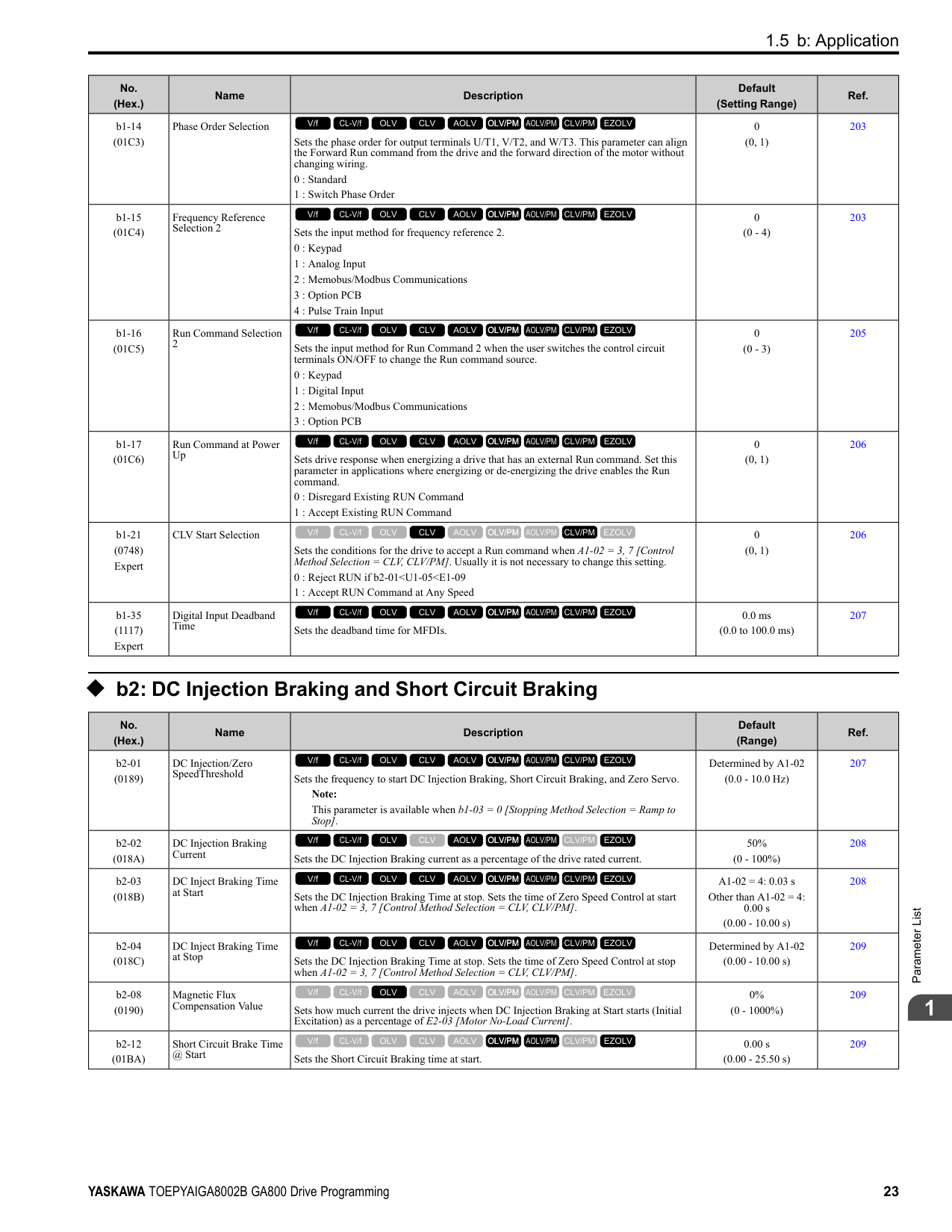
|C6-01 (0223)|Normal / Heavy Duty Selection|Sets the drive duty rating.
0 : Heavy Duty Rating
1 : Normal Duty Rating
V/f CL-V/f OLV CLV AOLV OLV/PM AOLV/PM CLV/PM EZOLV
|1 (0, 1)|269| |C6-02 (0224)|Carrier Frequency Selection|Sets the carrier frequency for the transistors in the drive.
1 : 2.0 kHz
2 : 5.0 kHz (4.0 kHz AOLV/PM)
3 : 8.0 kHz (6.0 kHz AOLV/PM)
4 : 10.0 kHz (8.0 kHz AOLV/PM)
5 : 12.5 kHz (10.0 kHz AOLV/PM)
6 : 15.0 kHz (12.0 kHz AOLV/PM)
7 : Swing PWM1 (Audible Sound 1)
8 : Swing PWM2 (Audible Sound 2)
9 : Swing PWM3 (Audible Sound 3) A : Swing PWM4 (Audible Sound 4) F : User Defined (C6-03 to C6-05)
Note: The carrier frequency for Swing PWM 1 to 4 is equivalent to 2.0 kHz.
V/f CL-V/f OLV CLV AOLV OLV/PM AOLV/PM CLV/PM EZOLV
|Determined by A1-02, C6-01, and o2-04
(Determined by A1-02)|270| |C6-03 (0225)|Carrier Frequency Upper Limit|Sets the upper limit of the carrier frequency. Set C6-02 F [Carrier Frequency Selection User Defined (C6-03 to C6-05)] to set this parameter.
V/f CL-V/f OLV CLV AOLV OLV/PM AOLV/PM CLV/PM EZOLV
|Determined by C6-02 (1.0 - 15.0 kHz)|271| |C6-04 (0226)|Carrier Frequency Lower Limit|Sets the lower limit of the carrier frequency. Set C6-02 F [Carrier Frequency Selection User Defined (C6-03 to C6-05)] to set this parameter.
V/f CL-V/f OLV CLV AOLV OLV/PM AOLV/PM CLV/PM EZOLV
|Determined by C6-02 (1.0 - 15.0 kHz)|272| |C6-05 (0227)|Carrier Freq Proportional Gain|Sets the proportional gain for the carrier frequency. Set C6-02 F [Carrier Frequency Selection = User Defined (C6-03 to C6-05)] to set this parameter.
V/f CL-V/f OLV CLV AOLV OLV/PM AOLV/PM CLV/PM EZOLV
|Determined by C6-02 (0 - 99)|272| |C6-09 (022B)|Carrier Freq at Rotational Tune|Sets the Auto-Tuning carrier frequency. Usually it is not necessary to change this setting.
0 : 5kHz
1 : use C6-03
V/f CL-V/f OLV CLV AOLV OLV/PM AOLV/PM CLV/PM EZOLV
|0 (0, 1)|272|
####### 1.7 d: Reference Settings
◆ d1: Frequency Reference
|No. (Hex.)|Name|Description|Default (Range)|Ref.| |---|---|---|---|---| |d1-01 (0280) RUN|Reference 1|Sets the frequency reference in the units from o1-03 [Frequency Display Unit Selection.
Note:
When A1-02 = 6, 7 [Control Method Selection = AOLV/PM, CLV/PM], the drive changes o1-03 = 1 [0.01% (100% = E1-04)].
V/f CL-V/f OLV CLV AOLV OLV/PM AOLV/PM CLV/PM EZOLV
|0.00 Hz (0.00 - 590.00 Hz)|276| |d1-02 (0281) RUN|Reference 2|Sets the frequency reference in the units from o1-03 [Frequency Display Unit Selection].
Note:
When A1-02 = 6, 7 [Control Method Selection = AOLV/PM, CLV/PM], the drive changes o1-03 = 1 [0.01% (100% = E1-04)].
V/f CL-V/f OLV CLV AOLV OLV/PM AOLV/PM CLV/PM EZOLV
|0.00 Hz (0.00 - 590.00 Hz)|277| |d1-03 (0282) RUN|Reference 3|Sets the frequency reference in the units from o1-03 [Frequency Display Unit Selection].
Note:
When A1-02 = 6, 7 [Control Method Selection = AOLV/PM, CLV/PM], the drive changes o1-03 = 1 [0.01% (100% = E1-04)].
V/f CL-V/f OLV CLV AOLV OLV/PM AOLV/PM CLV/PM EZOLV
|0.00 Hz (0.00 - 590.00 Hz)|277| |d1-04 (0283) RUN|Reference 4|Sets the frequency reference in the units from o1-03 [Frequency Display Unit Selection].
Note:
When A1-02 = 6, 7 [Control Method Selection = AOLV/PM, CLV/PM], the drive changes o1-03 = 1 [0.01% (100% = E1-04)].
V/f CL-V/f OLV CLV AOLV OLV/PM AOLV/PM CLV/PM EZOLV
|0.00 Hz (0.00 - 590.00 Hz)|277| |d1-05 (0284) RUN|Reference 5|Sets the frequency reference in the units from o1-03 [Frequency Display Unit Selection].
Note:
When A1-02 = 6, 7 [Control Method Selection = AOLV/PM, CLV/PM], the drive changes o1-03 = 1 [0.01% (100% = E1-04)].
V/f CL-V/f OLV CLV AOLV OLV/PM AOLV/PM CLV/PM EZOLV
|0.00 Hz (0.00 - 590.00 Hz)|277| |d1-06 (0285) RUN|Reference 6|Sets the frequency reference in the units from o1-03 [Frequency Display Unit Selection].
Note:
When A1-02 = 6, 7 [Control Method Selection = AOLV/PM, CLV/PM], the drive changes o1-03 = 1 [0.01% (100% = E1-04)].
V/f CL-V/f OLV CLV AOLV OLV/PM AOLV/PM CLV/PM EZOLV
|0.00 Hz (0.00 - 590.00 Hz)|277| |d1-07 (0286) RUN|Reference 7|Sets the frequency reference in the units from o1-03 [Frequency Display Unit Selection].
Note:
When A1-02 = 6, 7 [Control Method Selection = AOLV/PM, CLV/PM], the drive changes o1-03 = 1 [0.01% (100% = E1-04)].
V/f CL-V/f OLV CLV AOLV OLV/PM AOLV/PM CLV/PM EZOLV
|0.00 Hz (0.00 - 590.00 Hz)|278| |d1-08 (0287) RUN|Reference 8|Sets the frequency reference in the units from o1-03 [Frequency Display Unit Selection].
Note:
When A1-02 = 6, 7 [Control Method Selection = AOLV/PM, CLV/PM], the drive changes o1-03 = 1 [0.01% (100% = E1-04)].
V/f CL-V/f OLV CLV AOLV OLV/PM AOLV/PM CLV/PM EZOLV
|0.00 Hz (0.00 - 590.00 Hz)|278| |d1-09 (0288) RUN|Reference 9|Sets the frequency reference in the units from o1-03 [Frequency Display Unit Selection].
Note:
When A1-02 = 6, 7 [Control Method Selection = AOLV/PM, CLV/PM], the drive changes o1-03 1 [0.01% (100% E1-04)].
V/f CL-V/f OLV CLV AOLV OLV/PM AOLV/PM CLV/PM EZOLV
|0.00 Hz (0.00 - 590.00 Hz)|278| |d1-10 (028B) RUN|Reference 10|Sets the frequency reference in the units from o1-03 [Frequency Display Unit Selection].
Note:
When A1-02 6, 7 [Control Method Selection AOLV/PM, CLV/PM], the drive changes o1-03 1 [0.01% (100% E1-04)].
V/f CL-V/f OLV CLV AOLV OLV/PM AOLV/PM CLV/PM EZOLV
|0.00 Hz (0.00 - 590.00 Hz)|278| |d1-11 (028C) RUN|Reference 11|Sets the frequency reference in the units from o1-03 [Frequency Display Unit Selection].
Note:
When A1-02 6, 7 [Control Method Selection AOLV/PM, CLV/PM], the drive changes o1-03 1 [0.01% (100% E1-04)].
V/f CL-V/f OLV CLV AOLV OLV/PM AOLV/PM CLV/PM EZOLV
|0.00 Hz (0.00 - 590.00 Hz)|279|
|No. (Hex.)|Name|Description|Default (Range)|Ref.| |---|---|---|---|---| |d1-12 (028D) RUN|Reference 12|Sets the frequency reference in the units from o1-03 [Frequency Display Unit Selection].
Note:
When A1-02 = 6, 7 [Control Method Selection = AOLV/PM, CLV/PM], the drive changes o1-03 1 [0.01% (100% E1-04)].
V/f CL-V/f OLV CLV AOLV OLV/PM AOLV/PM CLV/PM EZOLV
|0.00 Hz (0.00 - 590.00 Hz)|279| |d1-13 (028E) RUN|Reference 13|Sets the frequency reference in the units from o1-03 [Frequency Display Unit Selection].
Note:
When A1-02 = 6, 7 [Control Method Selection = AOLV/PM, CLV/PM], the drive changes o1-03 = 1 [0.01% (100% = E1-04)].
V/f CL-V/f OLV CLV AOLV OLV/PM AOLV/PM CLV/PM EZOLV
|0.00 Hz (0.00 - 590.00 Hz)|279| |d1-14 (028F) RUN|Reference 14|Sets the frequency reference in the units from o1-03 [Frequency Display Unit Selection].
Note:
When A1-02 = 6, 7 [Control Method Selection = AOLV/PM, CLV/PM], the drive changes o1-03 = 1 [0.01% (100% = E1-04)].
V/f CL-V/f OLV CLV AOLV OLV/PM AOLV/PM CLV/PM EZOLV
|0.00 Hz (0.00 - 590.00 Hz)|279| |d1-15 (0290) RUN|Reference 15|Sets the frequency reference in the units from o1-03 [Frequency Display Unit Selection].
Note:
When A1-02 = 6, 7 [Control Method Selection = AOLV/PM, CLV/PM], the drive changes o1-03 = 1 [0.01% (100% = E1-04)].
V/f CL-V/f OLV CLV AOLV OLV/PM AOLV/PM CLV/PM EZOLV
|0.00 Hz (0.00 - 590.00 Hz)|279| |d1-16 (0291) RUN|Reference 16|Sets the frequency reference in the units from o1-03 [Frequency Display Unit Selection].
Note:
When A1-02 = 6, 7 [Control Method Selection = AOLV/PM, CLV/PM], the drive changes o1-03 = 1 [0.01% (100% = E1-04)].
V/f CL-V/f OLV CLV AOLV OLV/PM AOLV/PM CLV/PM EZOLV
|0.00 Hz (0.00 - 590.00 Hz)|280| |d1-17 (0292) RUN|Jog Reference|Sets the Jog frequency reference in the units from o1-03 [Frequency Display Unit Selection]. Set H1-xx = 6 [MFDI Function Select = Jog Reference Selection] to use the Jog frequency reference.
Note: When A1-02 = 6, 7 [Control Method Selection = AOLV/PM, CLV/PM], the drive sets o1-03 = 1 [0.01% (100% = E1-04)].
V/f CL-V/f OLV CLV AOLV OLV/PM AOLV/PM CLV/PM EZOLV
|6.00 Hz (0.00 - 590.00 Hz)|280|
######## ◆ d2: Reference Limits
|No. (Hex.)|Name|Description|Default (Range)|Ref.| |---|---|---|---|---| |d2-01 (0289)|Frequency Reference Upper Limit|Sets maximum limit for all frequency references. The maximum output frequency is 100%.
Note:
Parameter A1-02 [Control Method Selection] selects which parameter is the maximum output frequency.
• A1-02 ≠ 8 [EZOLV]: E1-04 [Maximum Output Frequency]
• A1-02 = 8: E9-02 [Motor Max Revolutions]
V/f CL-V/f OLV CLV AOLV OLV/PM AOLV/PM CLV/PM EZOLV
|100.0% (0.0 - 110.0%)|280|
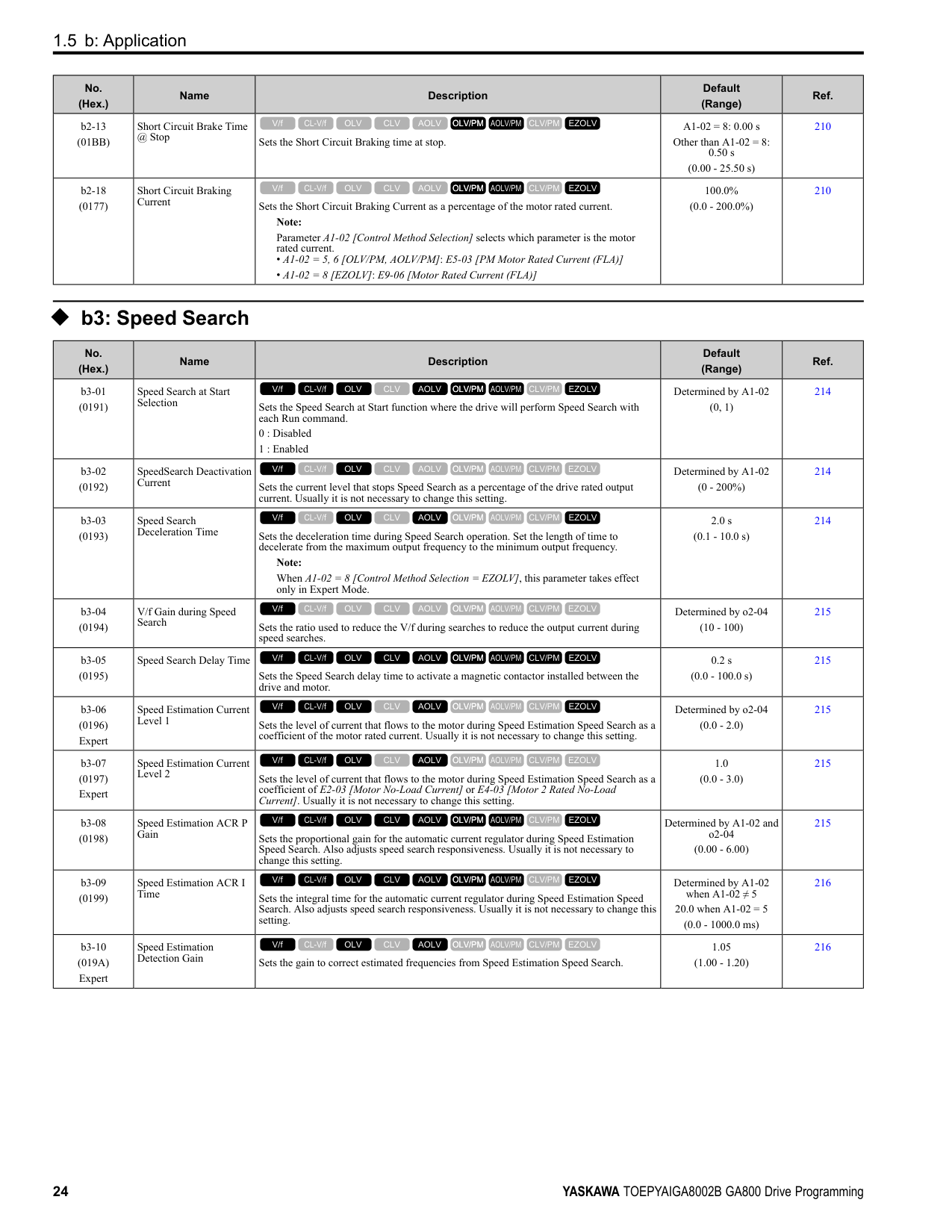
|d2-02 (028A)|Frequency Reference Lower Limit|Sets minimum limit for all frequency references. The maximum output frequency is 100%.
Note:
Parameter A1-02 [Control Method Selection] selects which parameter is the maximum output frequency.
• A1-02 ≠ 8 [EZOLV]: E1-04 [Maximum Output Frequency]
• A1-02 = 8: E9-02 [Motor Max Revolutions]
V/f CL-V/f OLV CLV AOLV OLV/PM AOLV/PM CLV/PM EZOLV
|0.0% (0.0 - 110.0%)|281| |d2-03 (0293)|Analog Frequency Ref Lower Limit|Sets the lower limit for the master frequency reference (the first frequency of the multistep speed reference) as a percentage. The maximum output frequency is 100%.
Note:
Parameter A1-02 [Control Method Selection] selects which parameter is the maximum output frequency.
• A1-02 ≠ 8: E1-04 [Maximum Output Frequency]
• A1-02 = 8: E9-02 [Maximum Speed]
V/f CL-V/f OLV CLV AOLV OLV/PM AOLV/PM CLV/PM EZOLV
|0.0% (0.0 - 110.0%)|281|
|No. (Hex.)|Name|Description|Default (Range)|Ref.| |---|---|---|---|---| |d3-01 (0294)|Jump Frequency 1|Sets the median value of the frequency band that the drive will avoid.
V/f CL-V/f OLV CLV AOLV OLV/PM AOLV/PM CLV/PM EZOLV
|0.0 Hz (Determined by A1-02)|282| |d3-02 (0295)|Jump Frequency 2|Sets the median value of the frequency band that the drive will avoid.
V/f CL-V/f OLV CLV AOLV OLV/PM AOLV/PM CLV/PM EZOLV
|0.0 Hz (Determined by A1-02)|282| |d3-03 (0296)|Jump Frequency 3|Sets the median value of the frequency band that the drive will avoid.
V/f CL-V/f OLV CLV AOLV OLV/PM AOLV/PM CLV/PM EZOLV
|0.0 Hz (Determined by A1-02)|282| |d3-04 (0297)|Jump Frequency Width|Sets the width of the frequency band that the drive will avoid.
V/f CL-V/f OLV CLV AOLV OLV/PM AOLV/PM CLV/PM EZOLV
|1.0 Hz (Determined by A1-02)|282|
|No. (Hex.)|Name|Description|Default (Range)|Ref.| |---|---|---|---|---| |d4-01 (0298)|Freq Reference Hold Selection|Sets the function that saves the frequency reference or the frequency bias (Up/Down 2) after a Stop command or when de-energizing the drive.
Set H1-xx [MFDI Function Selection] to one of these values to enable this parameter:
• A [Accel/Decel Ramp Hold]
• 10/11 [Up/Down Command]
• 75/76 [Up/Down 2 Command]
0 : Disabled
1 : Enabled
V/f CL-V/f OLV CLV AOLV OLV/PM AOLV/PM CLV/PM EZOLV
|0 (0, 1)|282| |d4-03 (02AA) RUN|Up/Down 2 Bias Step Frequency|Sets the bias that the Up/Down 2 function adds to or subtracts from the frequency reference.
V/f CL-V/f OLV CLV AOLV OLV/PM AOLV/PM CLV/PM EZOLV
|0.00 Hz (0.00 - 99.99 Hz)|284| |d4-04 (02AB) RUN|Up/Down 2 Ramp Selection|Sets the acceleration and deceleration times for the Up/Down 2 function to apply the bias to the frequency reference.
0 : Use Selected Accel/Decel Time
1 : Use Accel/Decel Time 4
V/f CL-V/f OLV CLV AOLV OLV/PM AOLV/PM CLV/PM EZOLV
|0 (0, 1)|285| |d4-05 (02AC) RUN|Up/Down 2 Bias Mode Selection|Sets the function that saves the bias value to the drive when you open or close the two Up/ Down 2 Commands [H1-xx = 75, 76]. Set d4-03 [Up/Down 2 Bias Step Frequency] = 0.00 before you set this parameter.
0 : Hold when Neither Up/Down Closed
1 : Reset when Neither Both Closed
V/f CL-V/f OLV CLV AOLV OLV/PM AOLV/PM CLV/PM EZOLV
|0 (0, 1)|285| |d4-06 (02AD)|Frequency Ref Bias (Up/ Down 2)|Saves the bias value from the Up/Down 2 Command where the Maximum Output Frequency is 100%.
Note:
Parameter A1-02 [Control Method Selection] selects which parameter is the maximum output frequency.
• A1-02 ≠ 8 [EZOLV]: E1-04 [Maximum Output Frequency]
• A1-02 = 8: E9-02 [Maximum Speed]
V/f CL-V/f OLV CLV AOLV OLV/PM AOLV/PM CLV/PM EZOLV
|0.0% (-99.9 - +100.0%)|286| |d4-07 (02AE) RUN|Analog Freq Ref Fluctuate Limit|If the frequency reference changes for more than the level set to this parameter, then the bias value will be held. The value is set as a percentage of the Maximum Output Frequency.
Note:
Parameter A1-02 [Control Method Selection] selects which parameter is the maximum output frequency.
• A1-02 ≠ 8 [EZOLV]: E1-04 [Maximum Output Frequency]
• A1-02 = 8: E9-02 [Maximum Speed]
V/f CL-V/f OLV CLV AOLV OLV/PM AOLV/PM CLV/PM EZOLV
|1.0% (0.1 - 100.0%)|286| |d4-08 (02AF) RUN|Up/Down 2 Bias Upper Limit|Sets the upper limit of the Up/Down 2 bias as a percentage of the Maximum Output Frequency.
Note:
Parameter A1-02 [Control Method Selection] selects which parameter is the maximum output frequency.
• A1-02 ≠ 8 [EZOLV]: E1-04 [Maximum Output Frequency]
• A1-02 8: E9-02 [Maximum Speed]
V/f CL-V/f OLV CLV AOLV OLV/PM AOLV/PM CLV/PM EZOLV
|100.0% (0.0 - 100.0%)|286|
|No. (Hex.)|Name|Description|Default (Range)|Ref.| |---|---|---|---|---| |d4-09 (02B0) RUN|Up/Down 2 Bias Lower Limit|Sets the lower limit of the Up/Down 2 bias as a percentage of the Maximum Output Frequency.
Note:
Parameter A1-02 [Control Method Selection] selects which parameter is the maximum output frequency.
• A1-02 ≠ 8 [EZOLV]: E1-04 [Maximum Output Frequency]
• A1-02 8: E9-02 [Maximum Speed]
V/f CL-V/f OLV CLV AOLV OLV/PM AOLV/PM CLV/PM EZOLV
|0.0% (-99.9 - 0.0%)|287| |d4-10 (02B6)|Up/Down Freq Lower Limit Select|Sets the lower frequency limit for the Up/Down function.
0 : Greater of d2-02 or Analog
1 : d2-02
V/f CL-V/f OLV CLV AOLV OLV/PM AOLV/PM CLV/PM EZOLV
|0 (0, 1)|287|
|No. (Hex.)|Name|Description|Default (Range)|Ref.| |---|---|---|---|---| |d5-01 (029A)|Torque Control Selection|Sets the drive for torque control or speed control.
0 : Speed Control
1 : Torque Control
V/f CL-V/f OLV CLV AOLV OLV/PM AOLV/PM CLV/PM EZOLV
|0 (0, 1)|291| |d5-02 (029B)|Torque Reference Delay Time|Sets the primary delay time constant for the torque reference filter.
V/f CL-V/f OLV CLV AOLV OLV/PM AOLV/PM CLV/PM EZOLV
|Determined by A1-02 (0 - 1000 ms)|291| |d5-03 (029C)|Speed Limit Selection|Sets the torque control speed limit method.
1 : Active Frequency Reference
2 : d5-04 Setting
V/f CL-V/f OLV CLV AOLV OLV/PM AOLV/PM CLV/PM EZOLV
|1 (1, 2)|291|
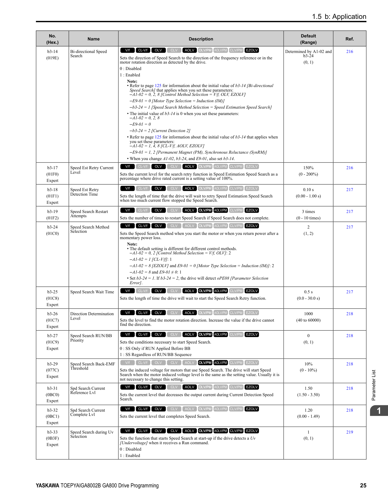
|d5-04 (029D)|Speed Limit|Sets the speed limit during Torque Control as a percentage of E1-04 [Maximum Output Frequency]. Set d5-03 2 [Speed Limit Selection d5-04 Setting] before you set this parameter.
V/f CL-V/f OLV CLV AOLV OLV/PM AOLV/PM CLV/PM EZOLV
|0% (-120 - +120%)|292| |d5-05 (029E)|Speed Limit Bias|Sets the speed limit bias value as a percentage of E1-04 [Maximum Output Frequency].
V/f CL-V/f OLV CLV AOLV OLV/PM AOLV/PM CLV/PM EZOLV
|10% (0 - 120%)|292| |d5-06 (029F)|Speed/Torque Changeover Time|Sets the delay time to switch between Speed Control and Torque Control. Set H1-xx = 71 [MFDI Function Selection = Torque Control] before you set this parameter.
V/f CL-V/f OLV CLV AOLV OLV/PM AOLV/PM CLV/PM EZOLV
|0 ms (0 - 1000 ms)|292| |d5-08 (02B5)|Uni-directional Speed Limit Bias|Sets the direction of the speed limit reference to which Speed Limit Bias [d5-05] applies.
0 : Disabled
1 : Enabled
V/f CL-V/f OLV CLV AOLV OLV/PM AOLV/PM CLV/PM EZOLV
|1 (0, 1)|292|
|No. (Hex.)|Name|Description|Default (Range)|Ref.| |---|---|---|---|---| |d6-01 (02A0)|Field Weakening Level|Sets the drive output voltage as a percentage of E1-05 [Maximum Output Voltage] when H1-xx 63 [Field Weakening] is activated.
V/f CL-V/f OLV CLV AOLV OLV/PM AOLV/PM CLV/PM EZOLV
|80% (0 - 100%)|293| |d6-02 (02A1)|Field Weakening Frequency Limit|Sets the minimum output frequency to start field weakening.
V/f CL-V/f OLV CLV AOLV OLV/PM AOLV/PM CLV/PM EZOLV
|0.0 Hz (0.0 - 590.0 Hz)|293| |d6-03 (02A2)|Field Forcing Selection|Sets the field forcing function.
0 : Disabled
1 : Enabled
V/f CL-V/f OLV CLV AOLV OLV/PM AOLV/PM CLV/PM EZOLV
|0 (0, 1)|293| |d6-06 (02A5)|Field Forcing Limit|Sets the limit value for field forcing to increase the motor excitation current reference as a percentage of E2-03 [Motor No-Load Current]. Usually it is not necessary to change this setting.
V/f CL-V/f OLV CLV AOLV OLV/PM AOLV/PM CLV/PM EZOLV
|400% (100 - 400%)|293|
######## ◆ d7: Offset Frequency
|No. (Hex.)|Name|Description|Default (Range)|Ref.| |---|---|---|---|---| |d7-01 (02B2) RUN|Offset Frequency 1|Uses H1-xx = 44 [MFDI Function Select = Add Offset Frequency 1 (d7-01)] as a percentage of the Maximum Output Frequency to add or subtract the set frequency to/from the frequency reference.
Note:
Parameter A1-02 [Control Method Selection] selects which parameter is the maximum output frequency.
• A1-02 ≠ 8 [EZOLV]: E1-04 [Maximum Output Frequency]
• A1-02 = 8: E9-02 [Maximum Speed]
V/f CL-V/f OLV CLV AOLV OLV/PM AOLV/PM CLV/PM EZOLV
|0.0% (-100.0 - +100.0%)|294| |d7-02 (02B3) RUN|Offset Frequency 2|Uses H1-xx 45 [MFDI Function Select Add Offset Frequency 2 (d7-02)] as a percentage of the Maximum Output Frequency to add or subtract the set frequency to/from the frequency reference.
Note:
Parameter A1-02 [Control Method Selection] selects which parameter is the maximum output frequency.
• A1-02 ≠ 8 [EZOLV]: E1-04 [Maximum Output Frequency]
• A1-02 = 8: E9-02 [Maximum Speed]
V/f CL-V/f OLV CLV AOLV OLV/PM AOLV/PM CLV/PM EZOLV
|0.0% (-100.0 - +100.0%)|294| |d7-03 (02B4) RUN|Offset Frequency 3|Uses H1-xx 46 [MFDI Function Select Add Offset Frequency 3 (d7-03)] as a percentage of the Maximum Output Frequency to add or subtract the set frequency to/from the frequency reference.
Note:
Parameter A1-02 [Control Method Selection] selects which parameter is the maximum output frequency.
• A1-02 ≠ 8 [EZOLV]: E1-04 [Maximum Output Frequency]
• A1-02 8: E9-02 [Maximum Speed]
V/f CL-V/f OLV CLV AOLV OLV/PM AOLV/PM CLV/PM EZOLV
|0.0% (-100.0 - +100.0%)|294|
####### 1.8 E: Motor Parameters
|No. (Hex.)|Name|Description|Default (Range)|Ref.| |---|---|---|---|---| |E1-01 (0300)|Input AC Supply Voltage|Sets the drive input voltage. NOTICE: Set parameter E1-01 to align with the drive input voltage (not motor voltage). If this parameter is incorrect, the protective functions of the drive will not operate correctly and it can cause damage to the drive.
V/f CL-V/f OLV CLV AOLV OLV/PM AOLV/PM CLV/PM EZOLV
|200 V Class: 240 V, 400 V: 480 V
(200 V Class: 155 to 255 V, 400 V Class: 310 to 510 V)|296| |E1-03 (0302)|V/f Pattern Selection|Sets the V/f pattern for the drive and motor. You can use one of the preset patterns or you can make a custom pattern.
0 : Const Trq, 50Hz base, 50Hz max
1 : Const Trq, 60Hz base, 60Hz max
2 : Const Trq, 50Hz base, 60Hz max
3 : Const Trq, 60Hz base, 72Hz max
4 : VT, 50Hz, 65% Vmid reduction
5 : VT, 50Hz, 50% Vmid reduction
6 : VT, 60 Hz, 65% Vmid reduction
7 : VT, 60Hz, 50% Vmid reduction
8 : High Trq, 50Hz, 25% Vmin boost
9 : High Trq, 50Hz, 65% Vmin boost
A : High Trq, 60Hz, 25% Vmin boost
B : High Trq, 60Hz, 65% Vmin boost
C : High Freq, 60Hz base, 90Hz max
D : High Freq, 60Hz base, 120Hz max
E : High Freq, 60Hz base, 180Hz max
F : Custom Note:
• When A1-02 = 2 [Control Method Selection = OLV], settings 0 to E are not available.
• Set the correct V/f pattern for the application and operation area. An incorrect V/f pattern can decrease motor torque and increase current from overexcitation.
V/f CL-V/f OLV CLV AOLV OLV/PM AOLV/PM CLV/PM EZOLV
|F (Determined by A1-02)|296| |E1-04 (0303)|Maximum Output Frequency|Sets the maximum output frequency for the V/f pattern.
V/f CL-V/f OLV CLV AOLV OLV/PM AOLV/PM CLV/PM EZOLV
|Determined by A1-02 and E5-01
(Determined by A1-02 and E5-01)|301| |E1-05 (0304)|Maximum Output Voltage|Sets the maximum output voltage for the V/f pattern.
V/f CL-V/f OLV CLV AOLV OLV/PM AOLV/PM CLV/PM EZOLV
|200 V Class: 230.0 V, 400 V: 460.0 V
(200 V Class: 0.0 - 255.0 V, 400 V Class: 0.0 510.0 V)|302| |E1-06 (0305)|Base Frequency|Sets the base frequency for the V/f pattern.
V/f CL-V/f OLV CLV AOLV OLV/PM AOLV/PM CLV/PM EZOLV
|Determined by A1-02 and E5-01
(0.0 - E1-04)|302| |E1-07 (0306)|Mid Point A Frequency|Sets a middle output frequency for the V/f pattern.
V/f CL-V/f OLV CLV AOLV OLV/PM AOLV/PM CLV/PM EZOLV
|Determined by A1-02 (0.0 - E1-04)|302| |E1-08 (0307)|Mid Point AVoltage|Sets a middle output voltage for the V/f pattern.
V/f CL-V/f OLV CLV AOLV OLV/PM AOLV/PM CLV/PM EZOLV
|Determined by A1-02, C6-01 and o2-04
(200 V Class: 0.0 - 255.0 V, 400 V Class: 0.0 - 510.0 V)|302| |E1-09 (0308)|Minimum Output Frequency|Sets the minimum output frequency for the V/f pattern.
V/f CL-V/f OLV CLV AOLV OLV/PM AOLV/PM CLV/PM EZOLV
|Determined by A1-02 and E5-01
(Determined by A1-02, E1-04, and E5-01)|302| |E1-10 (0309)|Minimum Output Voltage|Sets the minimum output voltage for the V/f pattern.
V/f CL-V/f OLV CLV AOLV OLV/PM AOLV/PM CLV/PM EZOLV
|Determined by A1-02 (200 V Class: 0.0 to 255.0 V, 400 V Class: 0.0 to 510.0 V)|302| |E1-11 (030A) Expert|Mid Point B Frequency|Sets a middle output frequency for the V/f pattern.
V/f CL-V/f OLV CLV AOLV OLV/PM AOLV/PM CLV/PM EZOLV
|0.0 Hz (0.0 - E1-04)|302|
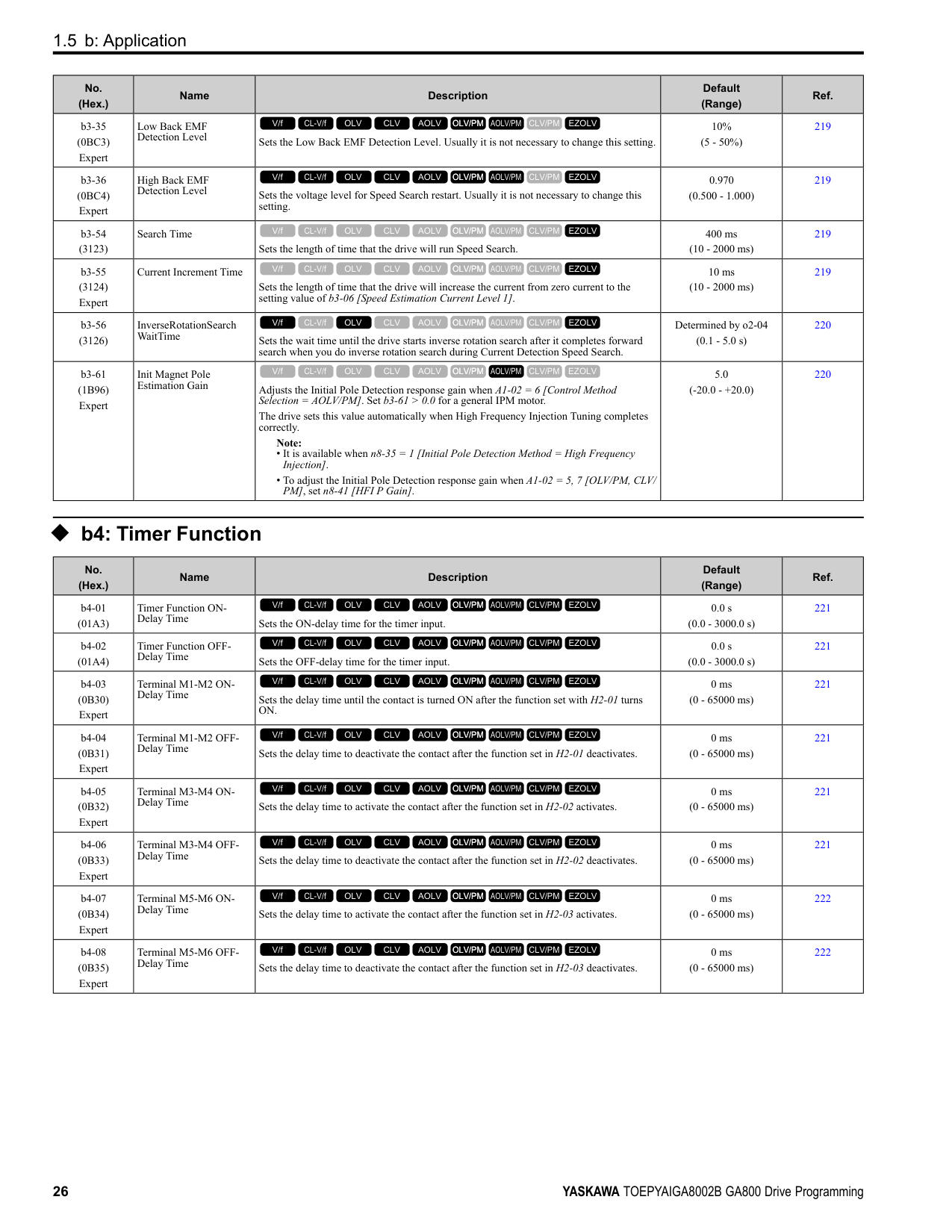
|No. (Hex.)|Name|Description|Default (Range)|Ref.| |---|---|---|---|---| |E1-12 (030B) Expert|Mid Point B Voltage|Sets a middle point voltage for the V/f pattern.
V/f CL-V/f OLV CLV AOLV OLV/PM AOLV/PM CLV/PM EZOLV
|0.0 V (200 V Class: 0.0 to 255.0 V, 400 V Class: 0.0 to 510.0 V)|303| |E1-13 (030C) Expert|Base Voltage|Sets the base voltage for the V/f pattern.
V/f CL-V/f OLV CLV AOLV OLV/PM AOLV/PM CLV/PM EZOLV
|0.0 V (200 V Class: 0.0 - 255.0 V,400 V Class: 0.0 510.0 V)|303|
######## ◆ E2: Motor Parameters
|No. (Hex.)|Name|Description|Default (Range)|Ref.| |---|---|---|---|---| |E2-01 (030E)|Motor Rated Current (FLA)|Sets the motor rated current in amps.
V/f CL-V/f OLV CLV AOLV OLV/PM AOLV/PM CLV/PM EZOLV
|Determined by o2-04, C6-01
(10% to 200% of the drive rated current)|303| |E2-02 (030F)|Motor Rated Slip|Sets motor rated slip.
V/f CL-V/f OLV CLV AOLV OLV/PM AOLV/PM CLV/PM EZOLV
|Determined by o2-04, C6-01
(0.000 - 20.000 Hz)|303| |E2-03 (0310)|Motor No-Load Current|Sets the no-load current for the motor in amps when operating at the rated frequency and the no-load voltage.
V/f CL-V/f OLV CLV AOLV OLV/PM AOLV/PM CLV/PM EZOLV
|Determined by o2-04, C6-01
(0 to E2-01)|304| |E2-04 (0311)|Motor Pole Count|Sets the number of motor poles.
Note:
• When A1-02 = 0, 1, 3 [Control Method Selection = V/f, CL-V/f, CLV], the maximum value is 120.
• When A1-02 = 2, 4 [OLV, AOLV], the maximum value is 48.
V/f CL-V/f OLV CLV AOLV OLV/PM AOLV/PM CLV/PM EZOLV
|4 (2 - 120)|304| |E2-05 (0312)|Motor Line-to-Line Resistance|Sets the line-to-line resistance for the motor stator windings.
V/f CL-V/f OLV CLV AOLV OLV/PM AOLV/PM CLV/PM EZOLV
|Determined by o2-04, C6-01
(0.000 - 65.000 Ω)|304| |E2-06 (0313)|Motor Leakage Inductance|Sets the voltage drop from motor leakage inductance when the motor is operating at the rated frequency and rated current. This value is a percentage of Motor Rated Voltage.
V/f CL-V/f OLV CLV AOLV OLV/PM AOLV/PM CLV/PM EZOLV
|Determined by o2-04, C6-01
(0.0 - 60.0%)|305| |E2-07 (0314)|Motor Saturation Coefficient 1|Sets the motor iron-core saturation coefficient at 50% of the magnetic flux.
V/f CL-V/f OLV CLV AOLV OLV/PM AOLV/PM CLV/PM EZOLV
|0.50 (0.00 - 0.50)|305| |E2-08 (0315)|Motor Saturation Coefficient 2|Sets the motor iron-core saturation coefficient at 75% of the magnetic flux.
V/f CL-V/f OLV CLV AOLV OLV/PM AOLV/PM CLV/PM EZOLV
|0.75 (E2-07 - 0.75)|305| |E2-09 (0316) Expert|Motor Mechanical Loss|Sets the mechanical loss of the motor. It is set as a percentage of E2-11 [Motor Rated Power]. Usually it is not necessary to change this setting.
V/f CL-V/f OLV CLV AOLV OLV/PM AOLV/PM CLV/PM EZOLV
|0.0% (0.0 - 10.0%)|305| |E2-10 (0317)|Motor Iron Loss|Sets the motor iron loss.
V/f CL-V/f OLV CLV AOLV OLV/PM AOLV/PM CLV/PM EZOLV
|Determined by o2-04, C6-01
(0 - 65535 W)|305| |E2-11 (0318)|Motor Rated Power|Sets the motor rated output in the units from o1-58 [Motor Power Unit Selection].
V/f CL-V/f OLV CLV AOLV OLV/PM AOLV/PM CLV/PM EZOLV
|Determined by o2-04, C6-01
(0.00 - 650.00 HP)|305|
|No. (Hex.)|Name|Description|Default (Range)|Ref.| |---|---|---|---|---| |E3-01 (0319)|Motor 2 Control Mode Selection|Sets the control method for motor 2.
Note:
When you change this setting, the drive will set all parameters that are dependent on this parameter to their default settings.
0 : V/f Control
1 : V/f Control with Encoder
2 : Open Loop Vector
3 : Closed Loop Vector
V/f CL-V/f OLV CLV AOLV OLV/PM AOLV/PM CLV/PM EZOLV
|0 (0 - 3)|306| |E3-04 (031A)|Motor 2 Maximum Output Frequency|Set the maximum output frequency for the motor 2 V/f pattern.
V/f CL-V/f OLV CLV AOLV OLV/PM AOLV/PM CLV/PM EZOLV
|Determined by E3-01 (40.0 - 590.0 Hz)|306| |E3-05 (031B)|Motor 2 Maximum Output Voltage|Sets the maximum output voltage for the motor 2 V/f pattern.
V/f CL-V/f OLV CLV AOLV OLV/PM AOLV/PM CLV/PM EZOLV
|Determined by E3-01 (200 V Class: 0.0 - 255.0 V, 400 V Class: 0.0 - 510.0 V)|307| |E3-06 (031C)|Motor 2 Base Frequency|Sets the base frequency for the motor 2 V/f pattern.
V/f CL-V/f OLV CLV AOLV OLV/PM AOLV/PM CLV/PM EZOLV
|Determined by E3-01 (0.0 - E3-04)|307| |E3-07 (031D)|Motor 2 Mid Point A Frequency|Sets a middle output frequency for the motor 2 V/f pattern.
V/f CL-V/f OLV CLV AOLV OLV/PM AOLV/PM CLV/PM EZOLV
|Determined by E3-01 (0.0 - E3-04)|307| |E3-08 (031E)|Motor 2 Mid Point A Voltage|Sets a middle output voltage for the motor 2 V/f pattern.
V/f CL-V/f OLV CLV AOLV OLV/PM AOLV/PM CLV/PM EZOLV
|Determined by E3-01 (200 V Class: 0.0 - 255.0 V, 400 V Class: 0.0 - 510.0 V)|307| |E3-09 (031F)|Motor 2 Minimum Output Frequency|Sets the minimum output frequency for the motor 2 V/f pattern.
V/f CL-V/f OLV CLV AOLV OLV/PM AOLV/PM CLV/PM EZOLV
|Determined by E3-01 (0.0 - E3-04)|307| |E3-10 (0320)|Motor 2 Minimum Output Voltage|Sets the minimum output voltage for the motor 2 V/f pattern.
V/f CL-V/f OLV CLV AOLV OLV/PM AOLV/PM CLV/PM EZOLV
|Determined by E3-01 (200 V Class: 0.0 - 255.0 V, 400 V Class: 0.0 - 510.0 V)|307| |E3-11 (0345) Expert|Motor 2 Mid Point B Frequency|Sets a middle output frequency for the motor 2 V/f pattern. Set this parameter to adjust the V/f pattern for the constant output range. Usually it is not necessary to change this parameter.
V/f CL-V/f OLV CLV AOLV OLV/PM AOLV/PM CLV/PM EZOLV
|0.0 Hz (0.0 - E3-04)|307| |E3-12 (0346) Expert|Motor 2 Mid Point B Voltage|Sets a middle output voltage for the motor 2 V/f pattern. Set this parameter to adjust the V/ f pattern for the constant output range. Usually it is not necessary to change this parameter.
V/f CL-V/f OLV CLV AOLV OLV/PM AOLV/PM CLV/PM EZOLV
|0.0 V (200 V Class: 0.0 to 255.0 V, 400 V Class: 0.0 to 510.0 V)|308| |E3-13 (0347) Expert|Motor 2 Base Voltage|Sets the base voltage for the motor 2 V/f pattern. Set this parameter to adjust the V/f pattern for the constant output range. Usually it is not necessary to change this parameter.
V/f CL-V/f OLV CLV AOLV OLV/PM AOLV/PM CLV/PM EZOLV
|0.0 V (200 V Class: 0.0 to 255.0 V, 400 V Class: 0.0 to 510.0 V)|308|
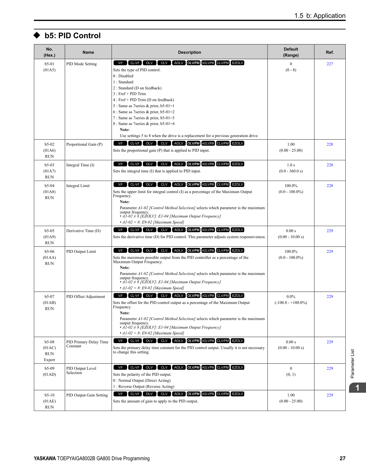
|No. (Hex.)|Name|Description|Default (Range)|Ref.| |---|---|---|---|---| |E4-01 (0321)|Motor 2 Rated Current|Sets the motor rated current for motor 2 in amps.
V/f CL-V/f OLV CLV AOLV OLV/PM AOLV/PM CLV/PM EZOLV
|Determined by o2-04, C6-01
(10% to 200% of the drive rated current)|308| |E4-02 (0322)|Motor 2 Rated Slip|Sets the motor rated slip for motor 2.
V/f CL-V/f OLV CLV AOLV OLV/PM AOLV/PM CLV/PM EZOLV
|Determined by o2-04, C6-01
(0.000 - 20.000 Hz)|308| |E4-03 (0323)|Motor 2 Rated No-Load Current|Sets the no-load current for motor 2 in amps when operating at the rated frequency and the no-load voltage.
V/f CL-V/f OLV CLV AOLV OLV/PM AOLV/PM CLV/PM EZOLV
|Determined by o2-04, C6-01
(Less than 0 - E4-01)|309| |E4-04 (0324)|Motor 2 Motor Poles|Sets the number of poles for motor 2.
V/f CL-V/f OLV CLV AOLV OLV/PM AOLV/PM CLV/PM EZOLV
|4 (2 - 120)|309|
|No. (Hex.)|Name|Description|Default (Range)|Ref.| |---|---|---|---|---| |E4-05 (0325)|Motor 2 Line-to-Line Resistance|Sets the line-to-line resistance for the motor 2 stator windings.
V/f CL-V/f OLV CLV AOLV OLV/PM AOLV/PM CLV/PM EZOLV
|Determined by o2-04, C6-01
(0.000 - 65.000 Ω)|309| |E4-06 (0326)|Motor 2 Leakage Inductance|Sets the voltage drop from motor 2 leakage inductance as a percentage of Motor Rated Voltage when motor 2 operates at the rated frequency and rated current.
V/f CL-V/f OLV CLV AOLV OLV/PM AOLV/PM CLV/PM EZOLV
|Determined by o2-04, C6-01
(0.0 - 60.0%)|309| |E4-07 (0343)|Motor 2 Saturation Coefficient 1|Sets the motor 2 iron-core saturation coefficient at 50% of the magnetic flux.
V/f CL-V/f OLV CLV AOLV OLV/PM AOLV/PM CLV/PM EZOLV
|0.50 (0.00 - 0.50)|310| |E4-08 (0344)|Motor 2 Saturation Coefficient 2|Sets the motor 2 iron-core saturation coefficient at 75% of the magnetic flux.
V/f CL-V/f OLV CLV AOLV OLV/PM AOLV/PM CLV/PM EZOLV
|0.75 (E4-07 - 0.75)|310| |E4-09 (033F) Expert|Motor 2 Mechanical Loss|Sets the mechanical loss of motor 2. It is set as a percentage of E4-11 [Motor 2 Rated Power]. Usually it is not necessary to change this setting.
V/f CL-V/f OLV CLV AOLV OLV/PM AOLV/PM CLV/PM EZOLV
|0.0% (0.0 - 10.0%)|310| |E4-10 (0340)|Motor 2 Iron Loss|Sets the motor iron loss for motor 2.
V/f CL-V/f OLV CLV AOLV OLV/PM AOLV/PM CLV/PM EZOLV
|Determined by o2-04, C6-01
(0 - 65535 W)|310| |E4-11 (0327)|Motor 2 Rated Power|Sets the motor rated power in the units from o1-58 [Motor Power Unit Selection].
V/f CL-V/f OLV CLV AOLV OLV/PM AOLV/PM CLV/PM EZOLV
|Determined by o2-04, C6-01
(0.00 - 650.00 HP)|310|
######## ◆ E5: PM Motor Settings
|No. (Hex.)|Name|Description|Default (Range)|Ref.| |---|---|---|---|---| |E5-01 (0329)|PM Motor Code Selection|Sets the motor code for Yaskawa PM motors. The drive uses the motor code to set some parameters to their correct settings automatically.
V/f CL-V/f OLV CLV AOLV OLV/PM AOLV/PM CLV/PM EZOLV
|FFFF (0000 - FFFF)|311| |E5-02 (032A)|PM Motor Rated Power|Sets the PM motor rated output in the units set in o1-58 [Motor Power Unit Selection].
V/f CL-V/f OLV CLV AOLV OLV/PM AOLV/PM CLV/PM EZOLV
|Determined by o2-04, C6-01
(0.10 - 650.00 HP)|311| |E5-03 (032B)|PM Motor Rated Current (FLA)|Sets the PM motor rated current (FLA).
V/f CL-V/f OLV CLV AOLV OLV/PM AOLV/PM CLV/PM EZOLV
|Determined by o2-04, C6-01
(10% to 200% of the drive rated current)|311| |E5-04 (032C)|PM Motor Pole Count|Sets the number of PM motor poles.
Note:
• When A1-02 = 7 [Control Method Selection = CLV/PM], the maximum value is 120.
• When A1-02 = 5, 6 or 8 [OLV/PM, AOLV/PM or EZOLV], the maximum value is 48.
V/f CL-V/f OLV CLV AOLV OLV/PM AOLV/PM CLV/PM EZOLV
|4 (2 - 120)|311| |E5-05 (032D)|PM Motor Resistance (ohms/phase)|Sets the resistance per phase of the PM motors. Set 50% of the line-to-line resistance.
V/f CL-V/f OLV CLV AOLV OLV/PM AOLV/PM CLV/PM EZOLV
|0.100 Ω (0.000 - 65.000 Ω)|312| |E5-06 (032E)|PM d-axis Inductance (mH/phase)|Sets the PM motor d-axis inductance.
V/f CL-V/f OLV CLV AOLV OLV/PM AOLV/PM CLV/PM EZOLV
|1.00 mH (0.00 - 300.00 mH)|312| |E5-07 (032F)|PM q-axis Inductance (mH/phase)|Sets the PM motor q-axis inductance.
V/f CL-V/f OLV CLV AOLV OLV/PM AOLV/PM CLV/PM EZOLV
|1.00 mH (0.00 - 600.00 mH)|312| |E5-09 (0331)|PM Back-EMF Vpeak (mV/(rad/s))|Sets the peak value of PM motor induced voltage.
V/f CL-V/f OLV CLV AOLV OLV/PM AOLV/PM CLV/PM EZOLV
|0.0 mV/(rad/s) (0.0 - 2000.0 mV/(rad/s))|312| |E5-11 (0333)|Encoder Z-Pulse Offset|Sets the encoder Z-pulse offset.
V/f CL-V/f OLV CLV AOLV OLV/PM AOLV/PM CLV/PM EZOLV
|0.0 degrees (-180.0 - +180.0 degrees)|313| |E5-24 (0353)|PM Back-EMF L-LVrms (mV/rpm)|Sets the RMS value for PM motor line voltage.
V/f CL-V/f OLV CLV AOLV OLV/PM AOLV/PM CLV/PM EZOLV
|0.1 mV/min-1 (0.0 - 6500.0 mV/min-1)|313| |E5-25 (035E) Expert|Polarity Estimation Timeout|Sets the function that switches polarity for initial polarity estimation. Usually it is not necessary to change this setting.
0 : Disabled
1 : Enabled
V/f CL-V/f OLV CLV AOLV OLV/PM AOLV/PM CLV/PM EZOLV
|0 (0, 1)|313|
######## ◆ E9: Motor Setting
|No. (Hex.)|Name|Description|Default (Range)|Ref.| |---|---|---|---|---| |E9-01 (11E4)|Motor Type Selection|Sets the type of motor.
0 : Induction (IM)
1 : Permanent Magnet (PM)
2 : Synchronous Reluctance (SynRM)
V/f CL-V/f OLV CLV AOLV OLV/PM AOLV/PM CLV/PM EZOLV
|0 (0 to 2)|313| |E9-02 (11E5)|Maximum Speed|Sets the maximum speed of the motor.
V/f CL-V/f OLV CLV AOLV OLV/PM AOLV/PM CLV/PM EZOLV
|Determined by E9-01 (40.0 - 120.0 Hz)|314|
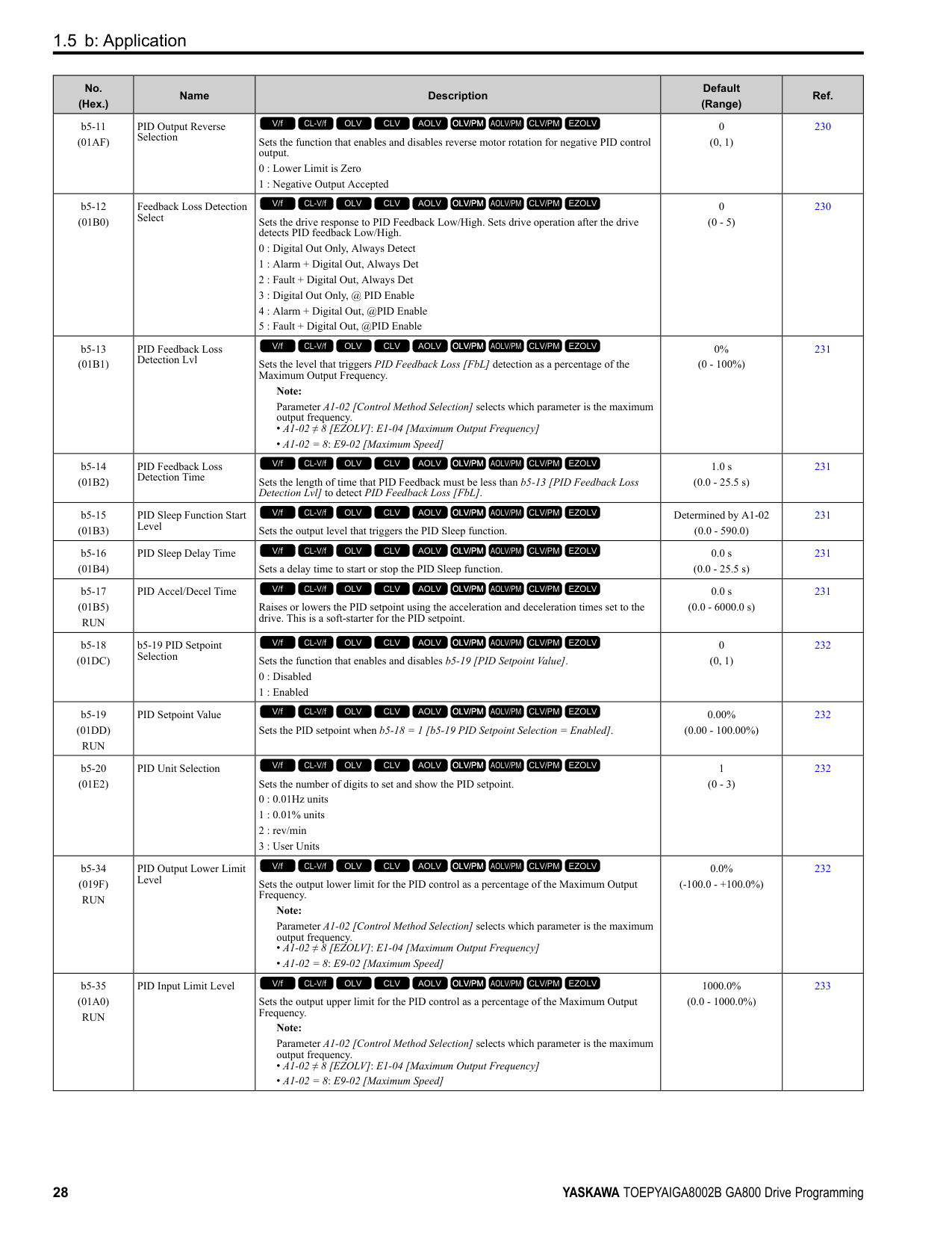
|E9-03 (11E6)|Rated Speed|Sets the rated rotation speed of the motor.
V/f CL-V/f OLV CLV AOLV OLV/PM AOLV/PM CLV/PM EZOLV
|Determined by E9-01 (100 - 7200 min-1)|314| |E9-04 (11E7)|Base Frequency|Sets the rated frequency of the motor.
V/f CL-V/f OLV CLV AOLV OLV/PM AOLV/PM CLV/PM EZOLV
|Determined by E9-01 (40.0 - 120.0 Hz)|314| |E9-05 (11E8)|Base Voltage|Sets the rated voltage of the motor.
V/f CL-V/f OLV CLV AOLV OLV/PM AOLV/PM CLV/PM EZOLV
|200 V Class: 230.0 V, 400 V: 460.0 V
(200 V Class: 0.0 - 255.0 V,400 V Class: 0.0 510.0 V)|314| |E9-06 (11E9)|Motor Rated Current (FLA)|Sets the motor rated current in amps.
V/f CL-V/f OLV CLV AOLV OLV/PM AOLV/PM CLV/PM EZOLV
|Determined by E9-01 and o2-04
(10% to 200% of the drive rated current)|314| |E9-07 (11EA)|Motor Rated Power|Sets the motor rated power in the units from o1-58 [Motor Power Unit Selection].
V/f CL-V/f OLV CLV AOLV OLV/PM AOLV/PM CLV/PM EZOLV
|Determined by E9-02 and o2-04
(0.00 - 650.00 HP)|315| |E9-08 (11EB)|Motor Pole Count|Sets the number of motor poles.
V/f CL-V/f OLV CLV AOLV OLV/PM AOLV/PM CLV/PM EZOLV
|4 (2 to 120)|315| |E9-09 (11EC)|Motor Rated Slip|Sets the motor rated slip.
V/f CL-V/f OLV CLV AOLV OLV/PM AOLV/PM CLV/PM EZOLV
|0.000 Hz (0.000 - 20.000 Hz)|315| |E9-10 (11ED)|Motor Line-to-Line Resistance|Sets the line-to-line resistance for the motor stator windings.
V/f CL-V/f OLV CLV AOLV OLV/PM AOLV/PM CLV/PM EZOLV
|Determined by o2-04 (0.000 - 65.000 Ω)|315|
####### 1.9 F: Options
|No. (Hex.)|Name|Description|Default (Range)|Ref.| |---|---|---|---|---| |F1-01 (0380)|Encoder 1 Pulse Count (PPR)|Sets the number of output pulses for each motor revolution.
V/f CL-V/f OLV CLV AOLV OLV/PM AOLV/PM CLV/PM EZOLV
|1024 ppr (1 - 60000 ppr)|317| |F1-02 (0381)|Encoder Signal Loss Detect Sel|Sets the method to stop the motor or let the motor continue operating when the drive detects PGo [Encoder (PG) Feedback Loss].
0 : Ramp to Stop
1 : Coast to Stop
2 : Fast Stop (Use C1-09)
3 : Alarm Only
4 : No Alarm Display
V/f CL-V/f OLV CLV AOLV OLV/PM AOLV/PM CLV/PM EZOLV
|1 (0 - 4)|317| |F1-03 (0382)|Overspeed Detection Selection|Sets the method to stop the motor or let the motor continue operating when the drive detects oS [Overspeed].
0 : Ramp to Stop
1 : Coast to Stop
2 : Fast Stop (Use C1-09)
3 : Alarm Only
V/f CL-V/f OLV CLV AOLV OLV/PM AOLV/PM CLV/PM EZOLV
|1 (0 - 3)|317| |F1-04 (0383)|Speed Deviation Detection Select|Sets the method to stop the motor or let the motor continue operating when the drive detects dEv [Speed Deviation].
0 : Ramp to Stop
1 : Coast to Stop
2 : Fast Stop (Use C1-09)
3 : Alarm Only
V/f CL-V/f OLV CLV AOLV OLV/PM AOLV/PM CLV/PM EZOLV
|3 (0 - 3)|318| |F1-05 (0384)|Encoder 1 Rotation Selection|Sets the output sequence for the A and B pulses from the encoder, assuming that the motor is operating in the forward direction.
0 : Pulse A leads in FWD Direction
1 : Pulse B leads in FWD Direction
V/f CL-V/f OLV CLV AOLV OLV/PM AOLV/PM CLV/PM EZOLV
|Determined by A1-02 (0, 1)|318| |F1-06 (0385)|Encoder 1 Pulse Monitor Scaling|Sets the ratio between the pulse input and the pulse output of the encoder as a 3-digit number. The first digit is the numerator and the second and third digits set the denominator.
The dividing ratio = (1 + x)/yz when the setting value is a 3-digit value (xyz).
V/f CL-V/f OLV CLV AOLV OLV/PM AOLV/PM CLV/PM EZOLV
|001 (001 - 032, 102 - 132 (1 1/32))|319| |F1-08 (0387)|Overspeed Detection Level|Sets the detection level of oS [Overspeed] as a percentage when the maximum output frequency is 100%.
Note:
Parameter A1-02 [Control Method Selection] selects which parameter is the maximum output frequency.
• A1-02 ≠ 8 [EZOLV]: E1-04 [Maximum Output Frequency]
• A1-02 = 8: E9-02 [Maximum Speed]
V/f CL-V/f OLV CLV AOLV OLV/PM AOLV/PM CLV/PM EZOLV
|115% (0 - 120%)|319| |F1-09 (0388)|Overspeed Detection Delay Time|Sets the length of time that the speed feedback must be more than the F1-08 level to cause oS [Overspeed].
V/f CL-V/f OLV CLV AOLV OLV/PM AOLV/PM CLV/PM EZOLV
|Determined by A1-02 (0.0 - 2.0 s)|319| |F1-10 (0389)|Speed Deviation Detection Level|Sets the detection level of dEv [Speed Deviation] as a percentage when the maximum output frequency is 100%.
Note:
Parameter A1-02 [Control Method Selection] selects which parameter is the maximum output frequency.
• A1-02 ≠ 8 [EZOLV]: E1-04 [Maximum Output Frequency]
• A1-02 = 8: E9-02 [Maximum Speed]
V/f CL-V/f OLV CLV AOLV OLV/PM AOLV/PM CLV/PM EZOLV
|10% (0 - 50%)|319| |F1-11 (038A)|Speed Deviation Detect DelayTime|Sets the length of time that the difference between the frequency reference and speed feedback must be more than the level in F1-10 to cause dEv [Speed Deviation].
V/f CL-V/f OLV CLV AOLV OLV/PM AOLV/PM CLV/PM EZOLV
|0.5 s (0.0 - 10.0 s)|319| |F1-12 (038B)|Encoder 1 Gear Teeth 1|Sets the number of gear teeth on the motor side. This parameter and F1-13 [Encoder 1 Gear Teeth 2] set the gear ratio between the motor and encoder.
V/f CL-V/f OLV CLV AOLV OLV/PM AOLV/PM CLV/PM EZOLV
|0 (0 - 1000)|319|
|No. (Hex.)|Name|Description|Default (Range)|Ref.| |---|---|---|---|---| |F1-13 (038C)|Encoder 2 Gear Teeth 1|Sets the number of gear teeth on the load side. This parameter and F1-12 [Encoder 1 Gear Teeth 1] set the gear ratio between the motor and encoder.
V/f CL-V/f OLV CLV AOLV OLV/PM AOLV/PM CLV/PM EZOLV
|0 (0 - 1000)|320| |F1-14 (038D)|Encoder Open-Circuit Detect Time|Sets the length of time that the drive must not receive a pulse signal to cause PGo [Encoder (PG) Feedback Loss].
Note:
Motor speed and load conditions can cause ov [Overvoltage] and oC [Overcurrent] faults.
V/f CL-V/f OLV CLV AOLV OLV/PM AOLV/PM CLV/PM EZOLV
|2.0 s (0.0 - 10.0 s)|320| |F1-18 (03AD)|Deviation 3 Detection Selection|Sets the number of rotations necessary to detect conditions that invert the torque reference and rate of acceleration and cause dv3 [Inversion Detection].
V/f CL-V/f OLV CLV AOLV OLV/PM AOLV/PM CLV/PM EZOLV
|10 (0 - 10)|320| |F1-19 (03AE)|Deviation 4 Detection Selection|Sets the number of pulses necessary to cause dv4 [Inversion Prevention Detection].
V/f CL-V/f OLV CLV AOLV OLV/PM AOLV/PM CLV/PM EZOLV
|128 (0 - 5000)|320| |F1-20 (03B4)|Encoder 1 PCB Disconnect Detect|Sets the function that enables and disables detection of a disconnected encoder connection cable to cause PGoH [Encoder (PG) Hardware Fault].
0 : No
1 : Yes
V/f CL-V/f OLV CLV AOLV OLV/PM AOLV/PM CLV/PM EZOLV
|1 (0, 1)|321| |F1-21 (03BC)|Encoder 1 Signal Selection|Sets the number of channels for the signal to the encoder option card.
0 : A Pulse Detection
1 : AB Pulse Detection
V/f CL-V/f OLV CLV AOLV OLV/PM AOLV/PM CLV/PM EZOLV
|0 (0, 1)|321| |F1-30 (03AA)|Motor 2 Encoder PCB Port Select|Sets the drive port to install the motor 2 encoder option card.
0 : CN5-C
1 : CN5-B
V/f CL-V/f OLV CLV AOLV OLV/PM AOLV/PM CLV/PM EZOLV
|1 (0, 1)|321| |F1-31 (03B0)|Encoder 2 Pulse Count (PPR)|Sets the number of output pulses for each motor revolution for motor 2.
V/f CL-V/f OLV CLV AOLV OLV/PM AOLV/PM CLV/PM EZOLV
|1024 ppr (1 - 60000 ppr)|321| |F1-32 (03B1)|Encoder 2 Rotation Selection|Sets the output sequence for the A and B pulses from the encoder for motor 2. This parameter assumes that the motor is operating in the forward direction.
0 : Pulse A leads in FWD Direction
1 : Pulse B leads in FWD Direction
V/f CL-V/f OLV CLV AOLV OLV/PM AOLV/PM CLV/PM EZOLV
|0 (0, 1)|321| |F1-33 (03B2)|Encoder 2 Gear Teeth 1|Sets the number of gear teeth on the motor side for motor 2. This parameter and F1-34 [Encoder 2 Gear Teeth 2] set the gear ratio between the motor and encoder.
V/f CL-V/f OLV CLV AOLV OLV/PM AOLV/PM CLV/PM EZOLV
|0 (0 - 1000)|322|
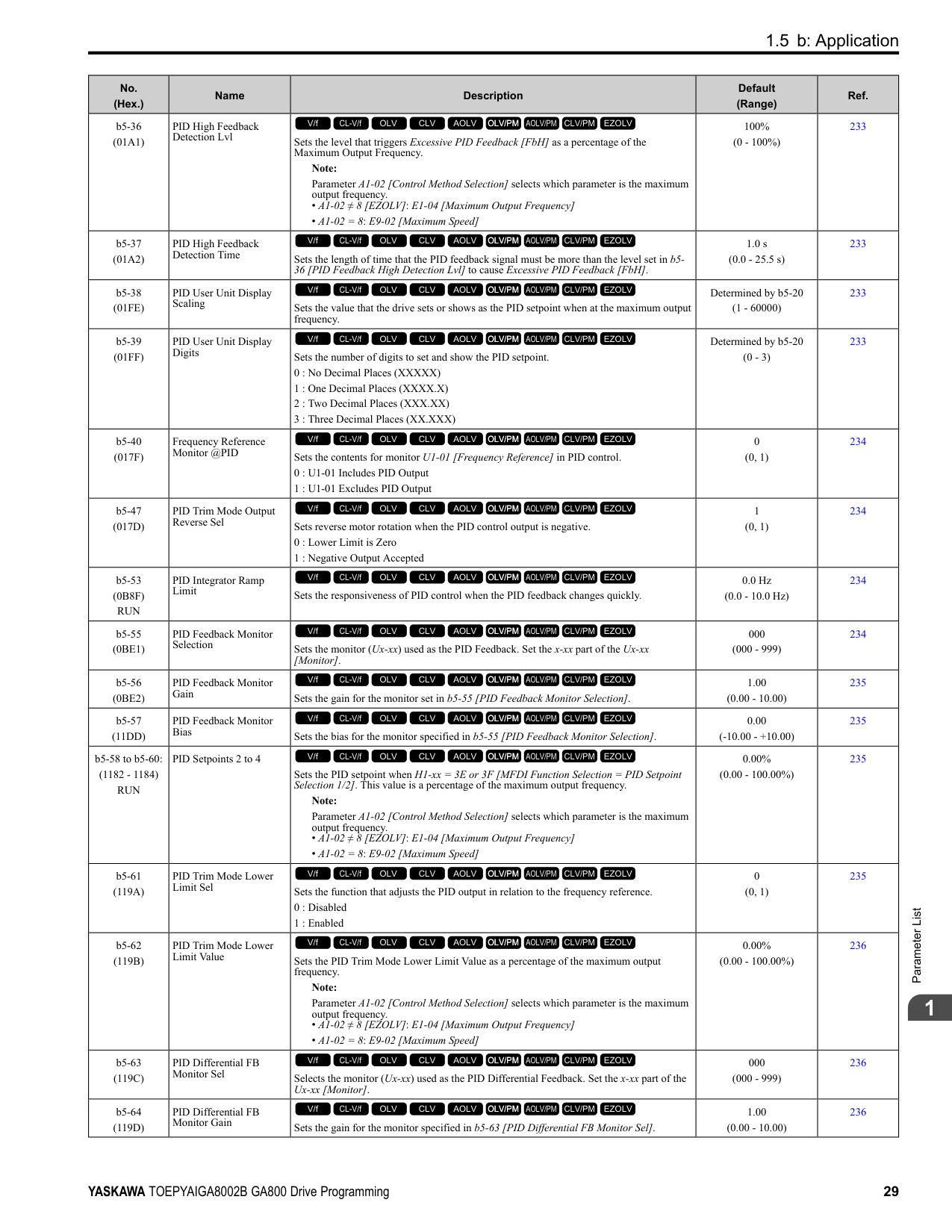
|F1-34 (03B3)|Encoder 2 Gear Teeth 2|Sets the number of gear teeth on the load side for motor 2. This parameter and F1-33 [Encoder 2 Gear Teeth 1] set the gear ratio between the motor and encoder.
V/f CL-V/f OLV CLV AOLV OLV/PM AOLV/PM CLV/PM EZOLV
|0 (0 - 1000)|322| |F1-35 (03BE)|Encoder 2 Pulse Monitor Scaling|Sets the ratio between the pulse input and the pulse output of the encoder as a 3-digit number for motor 2. The first digit is the numerator and the second and third digits set the denominator.
The dividing ratio = (1 + x)/yz when the setting value is a 3-digit value (xyz).
V/f CL-V/f OLV CLV AOLV OLV/PM AOLV/PM CLV/PM EZOLV
|001 (001 - 032, 102 - 132 (1 1/32))|322| |F1-36 (03B5)|Encoder 2 PCB Disconnect Detect|Sets the function that enables and disables detection of a disconnected encoder connection cable to cause PGoH [Encoder (PG) Hardware Fault] for motor 2.
0 : Disabled
1 : Enabled
V/f CL-V/f OLV CLV AOLV OLV/PM AOLV/PM CLV/PM EZOLV
|1 (0, 1)|322| |F1-37 (03BD)|Encoder 2 Signal Selection|Sets the number of channels for the signal to the encoder option card for motor 2.
0 : A Pulse Detection
1 : AB Pulse Detection
V/f CL-V/f OLV CLV AOLV OLV/PM AOLV/PM CLV/PM EZOLV
|0 (0, 1)|322| |F1-50 (03D2)|PG-F3 Option Encoder Type|Sets the type of encoder connected to the PG-F3 option.
0 : EnDat Sin/Cos
1 : EnDat Serial Only
2 : HIPERFACE
V/f CL-V/f OLV CLV AOLV OLV/PM AOLV/PM CLV/PM EZOLV
|0 (0 - 2)|323|
|No. (Hex.)|Name|Description|Default (Range)|Ref.| |---|---|---|---|---| |F1-51 (03D3)|PG-F3 PGoH Detection Level|The drive will detect PGoH [Encoder (PG) Hardware Fault] if the value of this parameter is smaller than the value of .
Note: This function is enabled when F1-20 = 1 [Encoder 1 PCB Disconnect Detect = Enabled].
V/f CL-V/f OLV CLV AOLV OLV/PM AOLV/PM CLV/PM EZOLV
|80% (1 - 100%)|323| |F1-52 (03D4)|Serial Encoder Comm Speed|Sets the communication speed between the PG-F3 option and the serial encoder.
0 : 1M/9600bps
1 : 500k/19200bps
2 : 1M/38400bps
V/f CL-V/f OLV CLV AOLV OLV/PM AOLV/PM CLV/PM EZOLV
|0 (0 - 2)|323|
|No. (Hex.)|Name|Description|Default (Range)|Ref.| |---|---|---|---|---| |F2-01 (038F)|Analog Input Function Selection|Sets the input method for the analog reference used with AI-A3.
0 : 3 Independent Channels
1 : 3 Channels Added Together
V/f CL-V/f OLV CLV AOLV OLV/PM AOLV/PM CLV/PM EZOLV
|0 (0, 1)|323| |F2-02 (0368) RUN|Analog Input Option Card Gain|Sets the analog reference gain as a percentage when the maximum output frequency is 100%.
Note:
• Set F2-01 = 1 [Analog Input Function Selection = 3 Channels Added Together] to enable this function.
• Parameter A1-02 [Control Method Selection] selects which parameter is the maximum output frequency.
–A1-02 ≠ 8 [EZOLV]: E1-04 [Maximum Output Frequency]
–A1-02 = 8: E9-02 [Maximum Speed]
V/f CL-V/f OLV CLV AOLV OLV/PM AOLV/PM CLV/PM EZOLV
|100.0% (-999.9 - +999.9%)|325| |F2-03 (0369) RUN|Analog Input Option Card Bias|Sets the analog reference bias as a percentage when the maximum output frequency is 100%.
Note:
• Set F2-01 = 1 [Analog Input Function Selection = 3 Channels Added Together] to enable this function.
• Parameter A1-02 [Control Method Selection] selects which parameter is the maximum output frequency.
–A1-02 ≠ 8 [EZOLV]: E1-04 [Maximum Output Frequency]
–A1-02 8: E9-02 [Maximum Speed]
V/f CL-V/f OLV CLV AOLV OLV/PM AOLV/PM CLV/PM EZOLV
|0.0% (-999.9 - +999.9%)|325|
|No. (Hex.)|Name|Description|Default (Range)|Ref.| |---|---|---|---|---| |F3-01 (0390)|Digital Input Function Selection|Sets the data format of digital input signals. This parameter is enabled when o1-03 = 0 or 1 [Frequency Display Unit Selection = 0.01 Hz or 0.01% (100% = E1-04)].
Note:
When o1-03 = 2 or 3 [Revolutions Per Minute (RPM) or User Units (o1-10 & o1-11)], the input signal will be BCD. The o1-03 value sets the setting units.
0 : BCD, 1% units
1 : BCD, 0.1% units
2 : BCD, 0.01% units
3 : BCD, 1 Hz units
4 : BCD, 0.1 Hz units
5 : BCD, 0.01 Hz units
6 : BCD (5-digit), 0.02 Hz
7 : Binary input
8 : Multi-Function Digital Input
V/f CL-V/f OLV CLV AOLV OLV/PM AOLV/PM CLV/PM EZOLV
|8 (0 - 8)|326| |F3-03 (03B9)|Digital Input Data Length Select|Sets the number of bits to set the frequency reference with DI-A3.
0 : 8-bit
1 : 12-bit
2 : 16-bit
V/f CL-V/f OLV CLV AOLV OLV/PM AOLV/PM CLV/PM EZOLV
|2 (0 - 2)|326|
|No. (Hex.)|Name|Description|Default (Range)|Ref.| |---|---|---|---|---| |F3-10 (0BE3) Expert|Terminal D0 Function Selection|Sets the function for terminal D0 of the DI-A3 option when F3-01 8 [Digital Input Function Selection Multi-Function Digital Input].
V/f CL-V/f OLV CLV AOLV OLV/PM AOLV/PM CLV/PM EZOLV
|F (1 - 19F)|327| |F3-11 (0BE4) Expert|Terminal D1 Function Selection|Sets the function for terminal D1 of the DI-A3 option when F3-01 8 [Digital Input Function Selection Multi-Function Digital Input].
V/f CL-V/f OLV CLV AOLV OLV/PM AOLV/PM CLV/PM EZOLV
|F (1 - 19F)|327| |F3-12 (0BE5) Expert|Terminal D2 Function Selection|Sets the function for terminal D2 of the DI-A3 option when F3-01 8 [Digital Input Function Selection Multi-Function Digital Input].
V/f CL-V/f OLV CLV AOLV OLV/PM AOLV/PM CLV/PM EZOLV
|F (1 - 19F)|328| |F3-13 (0BE6) Expert|Terminal D3 Function Selection|Sets the function for terminal D3 of the DI-A3 option when F3-01 = 8 [Digital Input Function Selection Multi-Function Digital Input].
V/f CL-V/f OLV CLV AOLV OLV/PM AOLV/PM CLV/PM EZOLV
|F (1 - 19F)|328| |F3-14 (0BE7) Expert|Terminal D4 Function Selection|Sets the function for terminal D4 of the DI-A3 option when F3-01 8 [Digital Input Function Selection = Multi-Function Digital Input].
V/f CL-V/f OLV CLV AOLV OLV/PM AOLV/PM CLV/PM EZOLV
|F (1 - 19F)|328| |F3-15 (0BE8) Expert|Terminal D5 Function Selection|Sets the function for terminal D5 of the DI-A3 option when F3-01 = 8 [Digital Input Function Selection Multi-Function Digital Input].
V/f CL-V/f OLV CLV AOLV OLV/PM AOLV/PM CLV/PM EZOLV
|F (1 - 19F)|328| |F3-16 (0BE9) Expert|Terminal D6 Function Selection|Sets the function for terminal D6 of the DI-A3 option when F3-01 8 [Digital Input Function Selection = Multi-Function Digital Input].
V/f CL-V/f OLV CLV AOLV OLV/PM AOLV/PM CLV/PM EZOLV
|F (1 - 19F)|328| |F3-17 (0BEA) Expert|Terminal D7 Function Selection|Sets the function for terminal D7 of the DI-A3 option when F3-01 = 8 [Digital Input Function Selection Multi-Function Digital Input].
V/f CL-V/f OLV CLV AOLV OLV/PM AOLV/PM CLV/PM EZOLV
|F (1 - 19F)|328| |F3-18 (0BEB) Expert|Terminal D8 Function Selection|Sets the function for terminal D8 of the DI-A3 option when F3-01 8 [Digital Input Function Selection = Multi-Function Digital Input].
V/f CL-V/f OLV CLV AOLV OLV/PM AOLV/PM CLV/PM EZOLV
|F (1 - 19F)|328| |F3-19 (0BEC) Expert|Terminal D9 Function Selection|Sets the function for terminal D9 of the DI-A3 option when F3-01 = 8 [Digital Input Function Selection Multi-Function Digital Input].
V/f CL-V/f OLV CLV AOLV OLV/PM AOLV/PM CLV/PM EZOLV
|F (1 - 19F)|329|
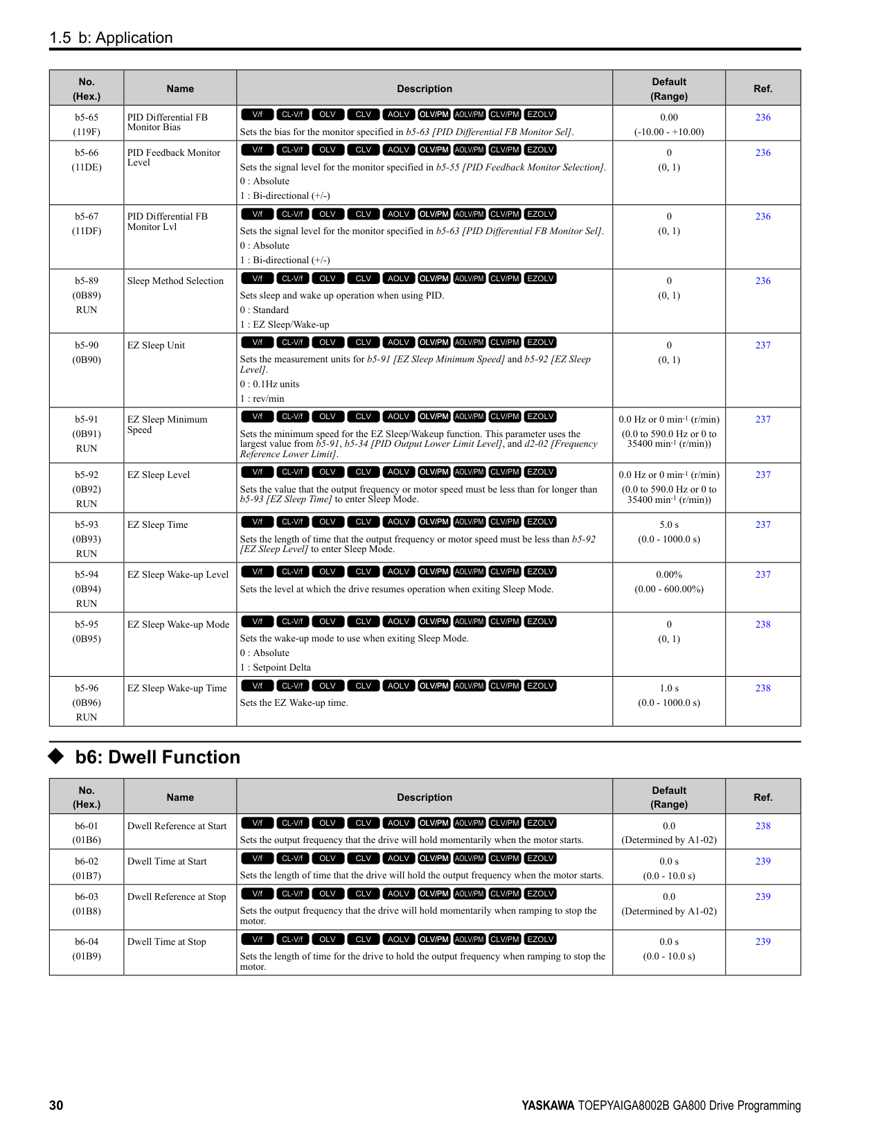
|F3-20 (0BED) Expert|Terminal DA Function Selection|Sets the function for terminal DA of the DI-A3 option when F3-01 8 [Digital Input Function Selection = Multi-Function Digital Input].
V/f CL-V/f OLV CLV AOLV OLV/PM AOLV/PM CLV/PM EZOLV
|F (1 - 19F)|329| |F3-21 (0BEE) Expert|Terminal DB Function Selection|Sets the function for terminal DB of the DI-A3 option when F3-01 = 8 [Digital Input Function Selection Multi-Function Digital Input].
V/f CL-V/f OLV CLV AOLV OLV/PM AOLV/PM CLV/PM EZOLV
|F (1 - 19F)|329| |F3-22 (0BEF) Expert|Terminal DC Function Selection|Sets the function for terminal DC of the DI-A3 option when F3-01 8 [Digital Input Function Selection = Multi-Function Digital Input].
V/f CL-V/f OLV CLV AOLV OLV/PM AOLV/PM CLV/PM EZOLV
|F (1 - 19F)|329| |F3-23 (0BF0) Expert|Terminal DD Function Selection|Sets the function for terminal DD of the DI-A3 option when F3-01 = 8 [Digital Input Function Selection Multi-Function Digital Input].
V/f CL-V/f OLV CLV AOLV OLV/PM AOLV/PM CLV/PM EZOLV
|F (1 - 19F)|329| |F3-24 (0BF1) Expert|Terminal DE Function Selection|Sets the function for terminal DE of the DI-A3 option when F3-01 = 8 [Digital Input Function Selection = Multi-Function Digital Input].
V/f CL-V/f OLV CLV AOLV OLV/PM AOLV/PM CLV/PM EZOLV
|F (1 - 19F)|329| |F3-25 (0BF2) Expert|Terminal DF Function Selection|Sets the function for terminal DF of the DI-A3 option when F3-01 = 8 [Digital Input Function Selection = Multi-Function Digital Input].
V/f CL-V/f OLV CLV AOLV OLV/PM AOLV/PM CLV/PM EZOLV
|F (1 - 19F)|329|
|No. (Hex.)|Name|Description|Default (Range)|Ref.| |---|---|---|---|---| |F4-01 (0391)|Terminal V1 Function Selection|Sets the monitor signal output from terminal V1. Set the x-xx part of the Ux-xx [Monitor]. For example, set F4-01 = 102 to monitor U1-02 [Output Frequency].
V/f CL-V/f OLV CLV AOLV OLV/PM AOLV/PM CLV/PM EZOLV
|102 (000 - 999)|330| |F4-02 (0392) RUN|Terminal V1 Gain|Sets the gain of the monitor signal that is sent from terminal V1. Sets the analog signal output level from the terminal V1 at 10 Vor 20 mA as 100% when an output for monitoring items is 100%.
V/f CL-V/f OLV CLV AOLV OLV/PM AOLV/PM CLV/PM EZOLV
|100.0% (-999.9 - +999.9%)|330| |F4-03 (0393)|Terminal V2 Function Selection|Sets the monitor signal output from terminal V2. Set the x-xx part of the Ux-xx [Monitor]. For example, set F4-03 103 to monitor U1-03 [Output Current].
V/f CL-V/f OLV CLV AOLV OLV/PM AOLV/PM CLV/PM EZOLV
|103 (000 - 999)|331| |F4-04 (0394) RUN|Terminal V2 Gain|Sets the gain of the monitor signal that is sent from terminal V2. Sets the analog signal output level from terminal V2 at 10 Vor 20 mA as 100% when an output for monitoring items is 100%.
V/f CL-V/f OLV CLV AOLV OLV/PM AOLV/PM CLV/PM EZOLV
|50.0% (-999.9 - +999.9%)|331| |F4-05 (0395) RUN|Terminal V1 Bias|Sets the bias of the monitor signal that is sent from terminal V1. When an output for monitoring items is 0%, this parameter sets the analog signal output level from the V1 terminal as a percentage of 10 Vor 20 mA.
V/f CL-V/f OLV CLV AOLV OLV/PM AOLV/PM CLV/PM EZOLV
|0.0% (-999.9 - +999.9%)|331| |F4-06 (0396) RUN|Terminal V2 Bias|Sets the bias of the monitor signal that is sent from terminal V2. Set the level of the analog signal sent from the V2 terminal at 10 Vor 20 mA as 100% when an output for monitoring items is 0%.
V/f CL-V/f OLV CLV AOLV OLV/PM AOLV/PM CLV/PM EZOLV
|0.0% (-999.9 - +999.9%)|331| |F4-07 (0397)|Terminal V1 Signal Level|Sets the output signal level for terminal V1.
0 : 0 to 10 V
1 : -10 to 10 V
V/f CL-V/f OLV CLV AOLV OLV/PM AOLV/PM CLV/PM EZOLV
|0 (0, 1)|332| |F4-08 (0398)|Terminal V2 Signal Level|Sets the output signal level for terminal V2.
0 : 0 to 10 V
1 : -10 to 10 V
V/f CL-V/f OLV CLV AOLV OLV/PM AOLV/PM CLV/PM EZOLV
|0 (0, 1)|332|
|No. (Hex.)|Name|Description|Default (Range)|Ref.| |---|---|---|---|---| |F5-01 (0399)|Terminal P1-PC Function Select|Sets the function of terminal P1-PC on the DO-A3 option. Set F5-09 2 [DO-A3 Output Mode Selection = Programmable (F5-01 to F5-08)] to enable this function.
V/f CL-V/f OLV CLV AOLV OLV/PM AOLV/PM CLV/PM EZOLV
|0 (0 - 1A7)|333| |F5-02 (039A)|Terminal P2-PC Function Select|Sets the function of terminal P2-PC on the DO-A3 option. Set F5-09 = 2 [DO-A3 Output Mode Selection = Programmable (F5-01 to F5-08)] to enable this function.
V/f CL-V/f OLV CLV AOLV OLV/PM AOLV/PM CLV/PM EZOLV
|1 (0 - 1A7)|333| |F5-03 (039B)|Terminal P3-PC Function Select|Sets the function of terminal P3-PC on the DO-A3 option. Set F5-09 = 2 [DO-A3 Output Mode Selection = Programmable (F5-01 to F5-08)] to enable this function.
V/f CL-V/f OLV CLV AOLV OLV/PM AOLV/PM CLV/PM EZOLV
|2 (0 - 1A7)|334| |F5-04 (039C)|Terminal P4-PC Function Select|Sets the function of terminal P4-PC on the DO-A3 option. Set F5-09 = 2 [DO-A3 Output Mode Selection = Programmable (F5-01 to F5-08)] to enable this function.
V/f CL-V/f OLV CLV AOLV OLV/PM AOLV/PM CLV/PM EZOLV
|4 (0 - 1A7)|334| |F5-05 (039D)|Terminal P5-PC Function Select|Sets the function of terminal P5-PC on the DO-A3 option. Set F5-09 = 2 [DO-A3 Output Mode Selection = Programmable (F5-01 to F5-08)] to enable this function.
V/f CL-V/f OLV CLV AOLV OLV/PM AOLV/PM CLV/PM EZOLV
|6 (0 - 1A7)|334| |F5-06 (039E)|Terminal P6-PC Function Select|Sets the function of terminal P6-PC on the DO-A3 option. Set F5-09 = 2 [DO-A3 Output Mode Selection = Programmable (F5-01 to F5-08)] to enable this function.
V/f CL-V/f OLV CLV AOLV OLV/PM AOLV/PM CLV/PM EZOLV
|37 (0 - 1A7)|334| |F5-07 (039F)|Terminal M1-M2 Function Select|Sets the function of terminal M3-M2 on the DO-A3 option. Set F5-09 = 2 [DO-A3 Output Mode Selection = Programmable (F5-01 to F5-08)] to enable this function.
V/f CL-V/f OLV CLV AOLV OLV/PM AOLV/PM CLV/PM EZOLV
|F (0 - 1A7)|334|
|No. (Hex.)|Name|Description|Default (Range)|Ref.| |---|---|---|---|---| |F5-08 (03A0)|Terminal M3-M4 Function Select|Sets the function of terminal M3-M4 on the DO-A3 option. Set F5-09 2 [DO-A3 Output Mode Selection Programmable (F5-01 to F5-08)] to enable this function.
V/f CL-V/f OLV CLV AOLV OLV/PM AOLV/PM CLV/PM EZOLV
|F (0 - 1A7)|334| |F5-09 (03A1)|DO-A3 Output Mode Selection|Sets the output mode of signals from the DO-A3 option.
0 : Predefined Individual Outputs
1 : Binary Output
2 : Programmable (F5-01 to F5-08)
V/f CL-V/f OLV CLV AOLV OLV/PM AOLV/PM CLV/PM EZOLV
|0 (0 - 2)|334|
######## ◆ F6: Communication Options
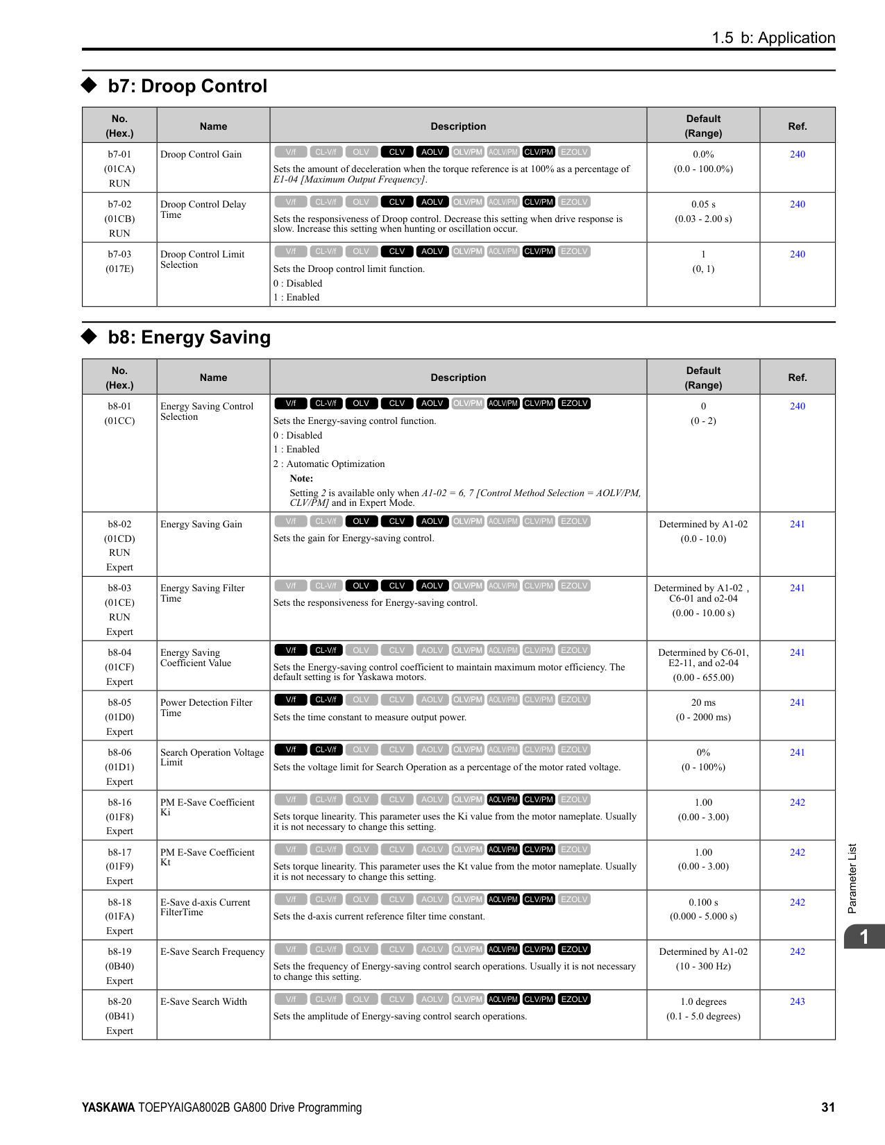
|No. (Hex.)|Name|Description|Default (Range)|Ref.| |---|---|---|---|---| |F6-01 (03A2)|Communication Error Selection|Sets the method to stop the motor or let the motor continue operating when the drive detects a bUS [Option Communication Error].
0 : Ramp to Stop
1 : Coast to Stop
2 : Fast Stop
3 : Alarm Only
4 : Alarm (Run at d1-04)
5 : Alarm - Ramp Stop
V/f CL-V/f OLV CLV AOLV OLV/PM AOLV/PM CLV/PM EZOLV
|1 (0 - 5)|340| |F6-02 (03A3)|Comm External Fault (EF0) Detect|Sets the conditions at which EF0 [Option Card External Fault] is detected.
0 : Always Detected
1 : Detected during RUN Only
V/f CL-V/f OLV CLV AOLV OLV/PM AOLV/PM CLV/PM EZOLV
|0 (0, 1)|341| |F6-03 (03A4)|Comm External Fault (EF0) Select|Sets the method to stop the motor or let the motor continue operating when the drive detects an EF0 [Option Card External Fault].
0 : Ramp to Stop
1 : Coast to Stop
2 : Fast Stop (Use C1-09)
3 : Alarm Only
V/f CL-V/f OLV CLV AOLV OLV/PM AOLV/PM CLV/PM EZOLV
|1 (0 - 3)|341| |F6-04 (03A5)|bUS Error Detection Time|Sets the delay time for the drive to detect bUS [Option Communication Error]. Note: When you install an option card in the drive, the parameter value changes to 0.0 s.
V/f CL-V/f OLV CLV AOLV OLV/PM AOLV/PM CLV/PM EZOLV
|2.0 s (0.0 - 5.0 s)|341| |F6-06 (03A7)|Torque Reference/Limit by Comm|Sets the function that enables and disables the torque reference and torque limit received from the communication option.
0 : Disabled
1 : Enabled
V/f CL-V/f OLV CLV AOLV OLV/PM AOLV/PM CLV/PM EZOLV
|0 (0, 1)|341| |F6-07 (03A8)|Multi-Step Ref @ NetRef/ComRef|Sets the function that enables and disables the multi-step speed reference when the freqency reference source is NetRef or ComRef (communication option card or MEMOBUS/Modbus communications).
0 : Disable Multi-Step References
1 : Enable Multi-Step References
V/f CL-V/f OLV CLV AOLV OLV/PM AOLV/PM CLV/PM EZOLV
|0 (0, 1)|342| |F6-08 (036A)|Comm Parameter Reset @Initialize|Sets the function to initialize F6-xx and F7-xx parameters when the drive is initialized with A1-03 [Initialize Parameters].
0 : No Reset - Parameters Retained
1 : Reset Back to Factory Default
V/f CL-V/f OLV CLV AOLV OLV/PM AOLV/PM CLV/PM EZOLV
|0 (0, 1)|342| |F6-10 (03B6)|CC-Link Node Address|Sets the node address for CC-Link communication. Restart the drive after you change the parameter setting.
Note:
Be sure to set a node address that is different than all other node addresses. Do not set this parameter to 0. Incorrect parameter settings will cause AEr [Station Address Setting Error] errors and the L.ERR LED on the option will come on.
V/f CL-V/f OLV CLV AOLV OLV/PM AOLV/PM CLV/PM EZOLV
|0 (0 - 64)|342|
|No. (Hex.)|Name|Description|Default (Range)|Ref.| |---|---|---|---|---| |F6-11 (03B7)|CC-Link Communication Speed|Sets the communication speed for CC-Link communication. Restart the drive after you change the parameter setting.
0 : 156 kbps
1 : 625 kbps
2 : 2.5 Mbps
3 : 5 Mbps
4 : 10 Mbps
V/f CL-V/f OLV CLV AOLV OLV/PM AOLV/PM CLV/PM EZOLV
|0 (0 - 4)|342| |F6-14 (03BB)|BUS Error Auto Reset|Sets the automatic reset function for bUS [Option Communication Errors].
0 : Disabled
1 : Enabled
V/f CL-V/f OLV CLV AOLV OLV/PM AOLV/PM CLV/PM EZOLV
|0 (0, 1)|343| |F6-15 (0B5B)|Comm. Option Parameters Reload|Sets the update method when you change F6-xx, F7-xx [Communication Options].
0 : Reload at Next Power Cycle
1 : Reload Now
2 : Cancel Reload Request
V/f CL-V/f OLV CLV AOLV OLV/PM AOLV/PM CLV/PM EZOLV
|0 (0 - 2)|343| |F6-16 (0B8A)|Gateway Mode|Sets the gateway mode operation and the number of connected slave drives.
0 : Disabled
1 : Enabled: 1 Slave Drives
2 : Enabled: 2 Slave Drives
3 : Enabled: 3 Slave Drives
4 : Enabled: 4 Slave Drives
V/f CL-V/f OLV CLV AOLV OLV/PM AOLV/PM CLV/PM EZOLV
|0 (0 to 4)|343| |F6-20 (036B)|MECHATROLINK Station Address|Sets the station address for MECHATROLINK communication. Restart the drive after you change the parameter setting.
Note:
• The setting range changes if using MECHATROLINK-II or MECHATROLINK-III:
–MECHATROLINK-II (SI-T3) range: 20 - 3F
–MECHATROLINK-III (SI-ET3) range: 03 - EF
• Be sure to set a node address that is different than all other node addresses. Incorrect parameter settings will cause AEr [Station Address Setting Error] errors and the L. ERR LED on the option will come on.
• When the station addressis 20 or 3F, the drive detects AEr errors.
V/f CL-V/f OLV CLV AOLV OLV/PM AOLV/PM CLV/PM EZOLV
|0021h (MECHATROLINK-II: 0020h - 003Fh, MECHATROLINK-III: 0003h - 00EFh)|343| |F6-21 (036C)|MECHATROLINK Frame Size|Sets the frame size for MECHATROLINK communication. Restart the drive after you change the parameter setting.
0 : 32byte (M-2) / 64byte (M-3)
1 : 17byte (M-2) / 32byte (M-3)
V/f CL-V/f OLV CLV AOLV OLV/PM AOLV/PM CLV/PM EZOLV
|0 (0, 1)|344| |F6-22 (036D)|MECHATROLINK Link Speed|Sets the communications speed for MECHATROLINK-II. Restart the drive after you change the parameter setting.
Note: This parameter is only available with the MECHATROLINK-II option.
0 : 10 Mbps
1 : 4 Mbps
V/f CL-V/f OLV CLV AOLV OLV/PM AOLV/PM CLV/PM EZOLV
|0 (0, 1)|344| |F6-23 (036E)|MECHATROLINK Monitor Select (E)|Sets the MEMOBUS register used for the monitor functions of INV_CTL (drive operation control command) and INV_I/O (drive I/O control command). Restart the drive after you change the parameter setting.
V/f CL-V/f OLV CLV AOLV OLV/PM AOLV/PM CLV/PM EZOLV
|0000h (0000h - FFFFh)|344| |F6-24 (036F)|MECHATROLINK Monitor Select (F)|Sets the MEMOBUS register used for the monitor functions of INV_CTL (drive operation control command) and INV_I/O (drive I/O control command). Restart the drive after you change the parameter setting.
V/f CL-V/f OLV CLV AOLV OLV/PM AOLV/PM CLV/PM EZOLV
|0000h (0000h - FFFFh)|344| |F6-25 (03C9)|MECHATROLINK Watchdog Error Sel|Sets the method to stop the motor or let the motor continue operating when the drive detects an E5 [MECHATROLINK Watchdog Timer Err].
0 : Ramp to Stop
1 : Coast to Stop
2 : Fast Stop (Use C1-09)
3 : Alarm Only
V/f CL-V/f OLV CLV AOLV OLV/PM AOLV/PM CLV/PM EZOLV
|1 (0 - 3)|344| |F6-26 (03CA)|MECHATROLINK Allowable No of Err|Sets the number of times that the option must detect a bUS alarm to cause a bUS [Option Communication Error].
V/f CL-V/f OLV CLV AOLV OLV/PM AOLV/PM CLV/PM EZOLV
|2 (2 - 10 times)|345|
|No. (Hex.)|Name|Description|Default (Range)|Ref.| |---|---|---|---|---| |F6-30 (03CB)|PROFIBUS-DP Node Address|Sets the node address for PROFIBUS-DP communication. Restart the drive after you change the parameter setting.
Note:
Be sure to set an address that is different than all other node addresses. Do not set this parameter to 0.
V/f CL-V/f OLV CLV AOLV OLV/PM AOLV/PM CLV/PM EZOLV
|0 (0 - 125)|345| |F6-31 (03CC)|PROFIBUS-DP Clear Mode Selection|Sets what the drive will do after it receives the Clear Mode command.
0 : Reset
1 : Hold Previous State
V/f CL-V/f OLV CLV AOLV OLV/PM AOLV/PM CLV/PM EZOLV
|0 (0, 1)|345| |F6-32 (03CD)|PROFIBUS-DP Data Format Select|Sets the data format of PROFIBUS-DP communication. Restart the drive after you change the parameter setting.
0 : PPO Type
1 : Conventional
2 : PPO (bit0)
3 : PPO (Enter)
4 : Conventional (Enter)
5 : PPO (bit0, Enter)
V/f CL-V/f OLV CLV AOLV OLV/PM AOLV/PM CLV/PM EZOLV
|0 (0 - 5)|345| |F6-35 (03D0)|CANopen Node ID Selection|Sets the node address for CANopen communication. Restart the drive after you change the parameter setting.
Note:
Be sure to set an address that is different than all other node addresses. Do not set this parameter to 0. Incorrect parameter settings will cause AEr [Station Address Setting Error] errors and the L.ERR LED on the option will come on.
V/f CL-V/f OLV CLV AOLV OLV/PM AOLV/PM CLV/PM EZOLV
|0 (0 - 126)|346| |F6-36 (03D1)|CANopen Communication Speed|Sets the CANopen communications speed. Restart the drive after you change the parameter setting.
0 : Detect Automatically
1 : 10 kbps
2 : 20 kbps
3 : 50 kbps
4 : 125 kbps
5 : 250 kbps
6 : 500 kbps
7 : 800 kbps
8 : 1 Mbps
V/f CL-V/f OLV CLV AOLV OLV/PM AOLV/PM CLV/PM EZOLV
|6 (0 - 8)|346| |F6-45 (02FB)|BACnet Node Address|Sets the node address for BACnet communication.
Note:
Be sure to set an address that is different than all other node addresses. Do not set this parameter to 0.
V/f CL-V/f OLV CLV AOLV OLV/PM AOLV/PM CLV/PM EZOLV
|1 (0 - 127)|346| |F6-46 (02FC)|BACnet Baud Rate|Sets the BACnet communications speed.
0 : 1200 bps
1 : 2400 bps
2 : 4800 bps
3 : 9600 bps
4 : 19.2 kbps
5 : 38.4 kbps
6 : 57.6 kbps
7 : 76.8 kbps
8 : 115.2 kbps
V/f CL-V/f OLV CLV AOLV OLV/PM AOLV/PM CLV/PM EZOLV
|3 (0 - 8)|346| |F6-47 (02FD)|Rx to Tx Wait Time|Sets the wait time for the drive to receive and send BACnet communication.
V/f CL-V/f OLV CLV AOLV OLV/PM AOLV/PM CLV/PM EZOLV
|5 ms (5 - 65 ms)|347| |F6-48 (02FE)|BACnet Device Object Identifier0|Sets the last word of BACnet communication addresses.
V/f CL-V/f OLV CLV AOLV OLV/PM AOLV/PM CLV/PM EZOLV
|0 (0 - FFFF)|347| |F6-49 (02FF)|BACnet Device Object Identifier1|Sets the last word of BACnet communication addresses.
V/f CL-V/f OLV CLV AOLV OLV/PM AOLV/PM CLV/PM EZOLV
|0 (0 - 3F)|347|
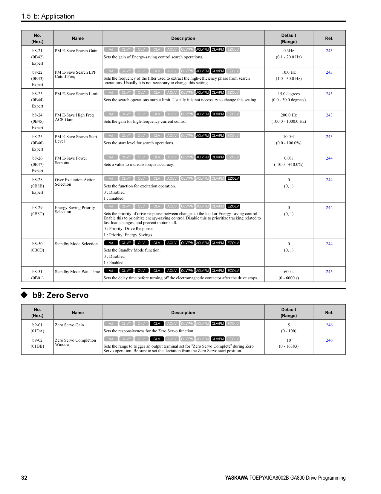
|No. (Hex.)|Name|Description|Default (Range)|Ref.| |---|---|---|---|---| |F6-50 (03C1)|DeviceNet MAC Address|Sets the MAC address for DeviceNet communication. Restart the drive after you change the parameter setting.
Note:
Be sure to set a MAC address that is different than all other node addresses. Do not set this parameter to 0. Incorrect parameter settings will cause AEr [Station Address Setting Error] errors and the MS LED on the option will flash.
V/f CL-V/f OLV CLV AOLV OLV/PM AOLV/PM CLV/PM EZOLV
|64 (0 - 64)|347| |F6-51 (03C2)|DeviceNet Baud Rate|Sets the DeviceNet communications speed. Restart the drive after you change the parameter setting.
0 : 125 kbps
1 : 250 kbps
2 : 500 kbps
3 : Adjustable from Network
4 : Detect Automatically
V/f CL-V/f OLV CLV AOLV OLV/PM AOLV/PM CLV/PM EZOLV
|4 (0 - 4)|347| |F6-52 (03C3)|DeviceNet PCA Setting|Sets the format of data that the DeviceNet communication master sends to the drive.
V/f CL-V/f OLV CLV AOLV OLV/PM AOLV/PM CLV/PM EZOLV
|21 (0 - 255)|347| |F6-53 (03C4)|DeviceNet PPA Setting|Sets the format of data that the drive sends to the DeviceNet communication master.
V/f CL-V/f OLV CLV AOLV OLV/PM AOLV/PM CLV/PM EZOLV
|71 (0 - 255)|348| |F6-54 (03C5)|DeviceNet Idle Fault Detection|Sets the function to detect EF0 [Option Card External Fault] when the drive does not receive data from the DeviceNet master.
0 : Enabled
1 : Disabled, No Fault Detection
2 : Vendor Specific
3 : RUN Forward
4 : Reverse run
V/f CL-V/f OLV CLV AOLV OLV/PM AOLV/PM CLV/PM EZOLV
|0 (0 - 4)|348| |F6-55 (03C6)|DeviceNet Baud Rate Monitor|Sets the function to see the actual DeviceNet communications speed using the keypad. This parameter functions as a monitor only.
0 : 125 kbps
1 : 250 kbps
2 : 500 kbps
V/f CL-V/f OLV CLV AOLV OLV/PM AOLV/PM CLV/PM EZOLV
|0 (0 - 2)|348| |F6-56 (03D7)|DeviceNet Speed Scaling|Sets the speed scale for DeviceNet communication.
V/f CL-V/f OLV CLV AOLV OLV/PM AOLV/PM CLV/PM EZOLV
|0 (-15 - +15)|348| |F6-57 (03D8)|DeviceNet Current Scaling|Sets the current scale of the DeviceNet communication master.
V/f CL-V/f OLV CLV AOLV OLV/PM AOLV/PM CLV/PM EZOLV
|0 (-15 - +15)|348| |F6-58 (03D9)|DeviceNet Torque Scaling|Sets the torque scale of the DeviceNet communication master.
V/f CL-V/f OLV CLV AOLV OLV/PM AOLV/PM CLV/PM EZOLV
|0 (-15 - +15)|348| |F6-59 (03DA)|DeviceNet Power Scaling|Sets the power scale of the DeviceNet communication master.
V/f CL-V/f OLV CLV AOLV OLV/PM AOLV/PM CLV/PM EZOLV
|0 (-15 - +15)|349| |F6-60 (03DB)|DeviceNet Voltage Scaling|Sets the voltage scale of the DeviceNet communication master.
V/f CL-V/f OLV CLV AOLV OLV/PM AOLV/PM CLV/PM EZOLV
|0 (-15 - +15)|349| |F6-61 (03DC)|DeviceNet Time Scaling|Sets the time scale of the DeviceNet communication master.
V/f CL-V/f OLV CLV AOLV OLV/PM AOLV/PM CLV/PM EZOLV
|0 (-15 - +15)|349| |F6-62 (03DD)|DeviceNet Heartbeat Interval|Sets the heartbeat for DeviceNet communication. Set this parameter to 0 to disable the heartbeat function.
V/f CL-V/f OLV CLV AOLV OLV/PM AOLV/PM CLV/PM EZOLV
|0 (0 - 10)|349| |F6-63 (03DE)|DeviceNet Network MAC ID|Sets the function to see the actual DeviceNet MAC address using the keypad. This parameter functions as a monitor only.
V/f CL-V/f OLV CLV AOLV OLV/PM AOLV/PM CLV/PM EZOLV
|63 (0 - 63)|349| |F6-64 to F6-67 (03DF - 03E2)|Dynamic Out Assembly 109 Param 1 to 4|Sets Configurable Outputs 1 to 4 written to the MEMOBUS register.
V/f CL-V/f OLV CLV AOLV OLV/PM AOLV/PM CLV/PM EZOLV
|0000h (0000h - FFFFh)|349| |F6-68 to F6-71 (03E3, 03E4, 03C7, and 03C8)|Dynamic In Assembly 159 Param 1 to 4|Sets Configurable Inputs 1 to 4 written to the MEMOBUS register.
V/f CL-V/f OLV CLV AOLV OLV/PM AOLV/PM CLV/PM EZOLV
|0000h (0000h - FFFFh)|349| |F6-72 (081B)|PowerLink Node Address|Sets the node ID for PowerLink communication.
Note:
Be sure to set an address that is different than all other node addresses. Do not set this parameter to 0.
V/f CL-V/f OLV CLV AOLV OLV/PM AOLV/PM CLV/PM EZOLV
|0 (0 - 255)|349|
######## ◆ F7: Ethernet Options
|No. (Hex.)|Name|Description|Default (Range)|Ref.| |---|---|---|---|---| |F7-01 (03E5)|IPAddress 1|Sets the first octet of the IP Address for the device that is connecting to the network. Restart the drive after you change this parameter.
Note: When F7-13 = 0 [Address Mode at Startup = Static]:
• Use parameters F7-01 to F7-04 [IPAddress 4] to set the IPAddress. Be sure to set a different IP address for each drive on the network.
• Also set parameters F7-01 to F7-12.
V/f CL-V/f OLV CLV AOLV OLV/PM AOLV/PM CLV/PM EZOLV
|192 (0 - 255)|350| |F7-02 (03E6)|IPAddress 2|Sets the second octet of the IP Address for the device that is connecting to the network. Restart the drive after you change this parameter.
Note: When F7-13 0 [Address Mode at Startup Static]:
• Use parameters F7-01 to F7-04 [IPAddress 4] to set the IPAddress. Be sure to set a different IP address for each drive on the network.
• Also set parameters F7-01 to F7-12.
V/f CL-V/f OLV CLV AOLV OLV/PM AOLV/PM CLV/PM EZOLV
|168 (0 - 255)|350| |F7-03 (03E7)|IPAddress 3|Sets the third octet of the IPAddress for the device that is connecting to the network. Restart the drive after you change this parameter.
Note: When F7-13 0 [Address Mode at Startup Static]:
• Use parameters F7-01 to F7-04 [IPAddress 4] to set the IPAddress. Be sure to set a different IP address for each drive on the network.
• Also set parameters F7-01 to F7-12.
V/f CL-V/f OLV CLV AOLV OLV/PM AOLV/PM CLV/PM EZOLV
|1 (0 - 255)|350| |F7-04 (03E8)|IPAddress 4|Sets the fourth octet of the IP Address for the device that is connecting to the network. Restart the drive after you change this parameter.
Note: When F7-13 0 [Address Mode at Startup Static]:
• Use parameters F7-01 to F7-04 [IPAddress 4] to set the IPAddress. Be sure to set a different IP address for each drive on the network.
• Also set parameters F7-01 to F7-12.
V/f CL-V/f OLV CLV AOLV OLV/PM AOLV/PM CLV/PM EZOLV
|20 (0 - 255)|350| |F7-05 (03E9)|Subnet Mask 1|Sets the first octet of the subnet mask of the connected network. Note: Set this parameter when F7-13 0 [Address Mode at Startup Static].
V/f CL-V/f OLV CLV AOLV OLV/PM AOLV/PM CLV/PM EZOLV
|255 (0 - 255)|350| |F7-06 (03EA)|Subnet Mask 2|Sets the second octet of the subnet mask of the connected network. Note: Set this parameter when F7-13 = 0 [Address Mode at Startup = Static].
V/f CL-V/f OLV CLV AOLV OLV/PM AOLV/PM CLV/PM EZOLV
|255 (0 - 255)|351| |F7-07 (03EB)|Subnet Mask 3|Sets the third octet of the subnet mask of the connected network. Note: Set this parameter when F7-13 = 0 [Address Mode at Startup = Static].
V/f CL-V/f OLV CLV AOLV OLV/PM AOLV/PM CLV/PM EZOLV
|255 (0 - 255)|351| |F7-08 (03EC)|Subnet Mask 4|Sets the fourth octet of the subnet mask of the connected network. Note: Set this parameter when F7-13 = 0 [Address Mode at Startup = Static].
V/f CL-V/f OLV CLV AOLV OLV/PM AOLV/PM CLV/PM EZOLV
|0 (0 - 255)|351| |F7-09 (03ED)|Gateway Address 1|Sets the first octet of the gateway address of the connected network. Note: Set this parameter when F7-13 = 0 [Address Mode at Startup = Static].
V/f CL-V/f OLV CLV AOLV OLV/PM AOLV/PM CLV/PM EZOLV
|192 (0 - 255)|351| |F7-10 (03EE)|Gateway Address 2|Sets the second octet of the gateway address of the connected network. Note: Set this parameter when F7-13 = 0 [Address Mode at Startup = Static].
V/f CL-V/f OLV CLV AOLV OLV/PM AOLV/PM CLV/PM EZOLV
|168 (0 - 255)|351| |F7-11 (03EF)|Gateway Address 3|Sets the third octet of the gateway address of the connected network. Note: Set this parameter when F7-13 = 0 [Address Mode at Startup = Static].
V/f CL-V/f OLV CLV AOLV OLV/PM AOLV/PM CLV/PM EZOLV
|1 (0 - 255)|351|
|No. (Hex.)|Name|Description|Default (Range)|Ref.| |---|---|---|---|---| |F7-12 (03F0)|Gateway Address 4|Sets the fourth octet of the gateway address of the connected network. Note: Set this parameter when F7-13 = 0 [Address Mode at Startup = Static].
V/f CL-V/f OLV CLV AOLV OLV/PM AOLV/PM CLV/PM EZOLV
|1 (0 - 255)|352| |F7-13 (03F1)|Address Mode at Startup|Sets the method to set option card IP addresses.
0 : Static
1 : BOOTP
2 : DHCP Note:
• The following setting values are available when using the PROFINET communication option card (SI-EP3).
–0: Static
–2: DHCP
• When F7-13 = 0, set parameters F7-01 to F7-12 [IPAddress 1 to Gateway Address 4] to set the IP Address. Be sure to set a different IP address for each drive on the network.
V/f CL-V/f OLV CLV AOLV OLV/PM AOLV/PM CLV/PM EZOLV
|2 (0 - 2)|352|
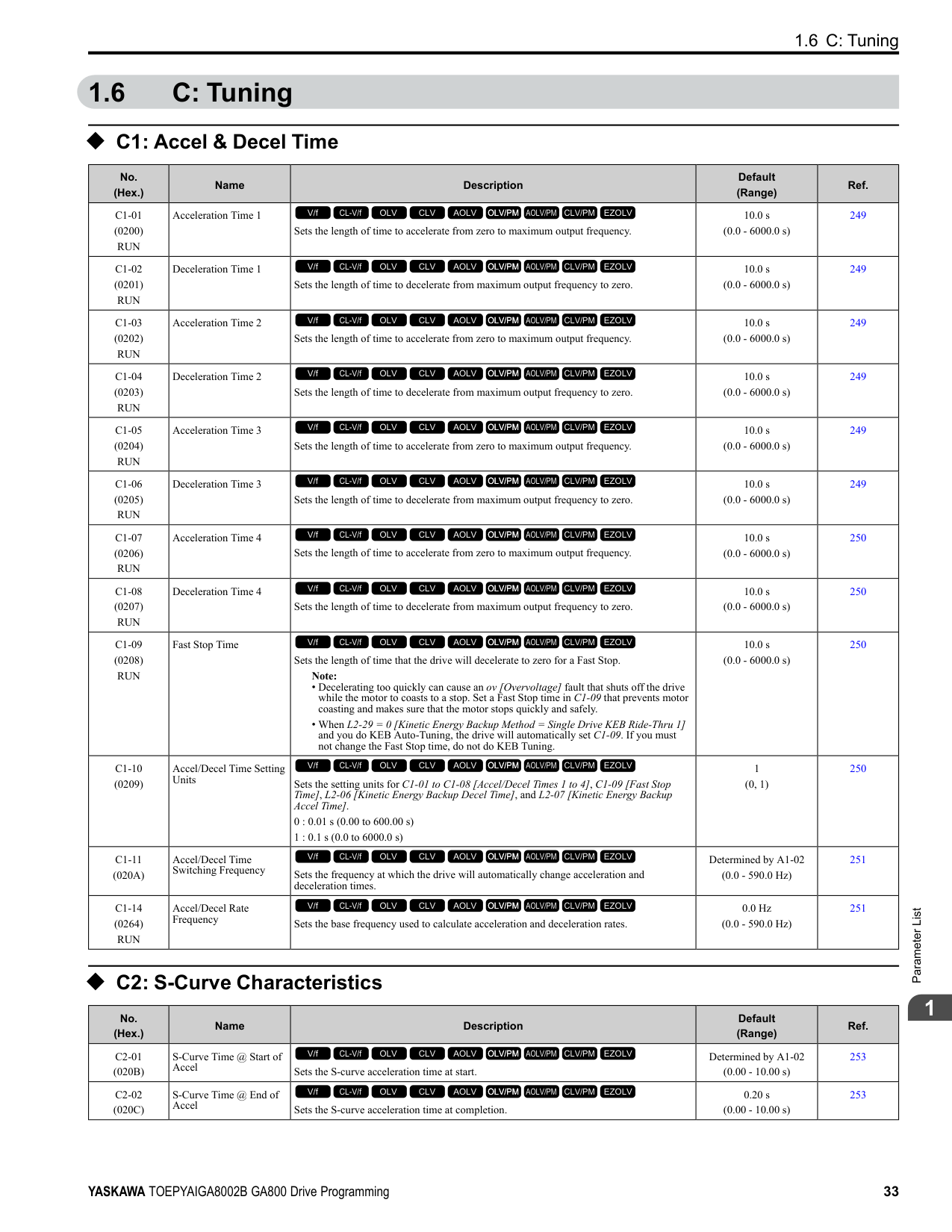
|F7-14 (03F2)|Duplex Mode Selection|Sets the duplex mode setting method.
0 : Half/Half
1 : Auto/Auto
2 : Full/Full
3 : Half/Auto
4 : Half/Full
5 : Auto/Half
6 : Auto/Full
7 : Full/Half
8 : Full/Auto
V/f CL-V/f OLV CLV AOLV OLV/PM AOLV/PM CLV/PM EZOLV
|1 (0 - 8)|352| |F7-15 (03F3)|Communication Speed Selection|Sets the communications speed. 10 : 10/10 Mbps
100 : 100/100 Mbps
101 : 10/100 Mbps
102 : 100/10 Mbps
V/f CL-V/f OLV CLV AOLV OLV/PM AOLV/PM CLV/PM EZOLV
|10 (10, 100 - 102)|352| |F7-16 (03F4)|Timeout Value|Sets the detection time for a communications timeout. Note: Set this parameter to 0.0 to disable the connection timeout function.
V/f CL-V/f OLV CLV AOLV OLV/PM AOLV/PM CLV/PM EZOLV
|0.0 s (0.0 - 30.0 s)|353| |F7-17 (03F5)|EtherNet/IP Speed Scaling Factor|Sets the scaling factor for the speed monitor in the EtherNet/IP Class ID 2AH Object.
V/f CL-V/f OLV CLV AOLV OLV/PM AOLV/PM CLV/PM EZOLV
|0 (-15 - +15)|353| |F7-18 (03F6)|EtherNet/IP Current Scale Factor|Sets the scaling factor for the output current monitor in the EtherNet/IP Class ID 2AH Object.
V/f CL-V/f OLV CLV AOLV OLV/PM AOLV/PM CLV/PM EZOLV
|0 (-15 - +15)|353| |F7-19 (03F7)|EtherNet/IP Torque Scale Factor|Sets the scaling factor for the torque monitor in the EtherNet/IP Class ID 2AH Object.
V/f CL-V/f OLV CLV AOLV OLV/PM AOLV/PM CLV/PM EZOLV
|0 (-15 - +15)|353| |F7-20 (03F8)|EtherNet/IP Power Scaling Factor|Sets the scaling factor for the power monitor in the EtherNet/IP Class ID 2AH Object.
V/f CL-V/f OLV CLV AOLV OLV/PM AOLV/PM CLV/PM EZOLV
|0 (-15 - +15)|353| |F7-21 (03F9)|EtherNet/IP Voltage Scale Factor|Sets the scaling factor for the voltage monitor in the EtherNet/IP Class ID 2AH Object.
V/f CL-V/f OLV CLV AOLV OLV/PM AOLV/PM CLV/PM EZOLV
|0 (-15 - +15)|353| |F7-22 (03FA)|EtherNet/IP Time Scaling|Sets the scaling factor for the time monitor in the EtherNet/IP Class ID 2AH Object.
V/f CL-V/f OLV CLV AOLV OLV/PM AOLV/PM CLV/PM EZOLV
|0 (-15 - +15)|353| |F7-23 - F7-27 (03FB - 03FF) F7-28- F7-32 (0370 - 0374)|Dynamic Out Param 1 to 10 for CommCard|Sets Output Assembly 116. The drive writes the values from Output Assembly 116 to the MEMOBUS/Modbus address register that is stored for each parameter. The drive will not write the values from Output Assembly 116 to the registers when the MEMOBUS/Modbus address is 0.
V/f CL-V/f OLV CLV AOLV OLV/PM AOLV/PM CLV/PM EZOLV
|0|354| |F7-33 - F7-42 (0375 - 037E)|Dynamic In Param 1 to 10 for CommCard|Sets Input Assembly 166. The drive sends the values from the MEMOBUS/Modbus address registers stored for each parameter to Input Assembly 166. The drive returns the default register value for the option card when the MEMOBUS/Modbus address is 0 and the value sent to Input Assembly 166 is not defined.
V/f CL-V/f OLV CLV AOLV OLV/PM AOLV/PM CLV/PM EZOLV
|0|354| |F7-60 (0780)|PZD1 Write (Control Word)|Sets the MEMOBUS/Modbus address for PZD1 (PPO output). PZD1 (PPO output) functions as the STW when F7-60 = 0, 1, or 2.
V/f CL-V/f OLV CLV AOLV OLV/PM AOLV/PM CLV/PM EZOLV
|0|354|
|No. (Hex.)|Name|Description|Default (Range)|Ref.| |---|---|---|---|---| |F7-61 (0781)|PZD2 Write (Frequency Reference)|Sets the MEMOBUS/Modbus address for PZD2 (PPO output). PZD2 (PPO output) functions as the HSW when F7-61 0, 1, or 2.
V/f CL-V/f OLV CLV AOLV OLV/PM AOLV/PM CLV/PM EZOLV
|0|354| |F7-62 (0782)|PZD3 Write|Sets the MEMOBUS/Modbus address for PZD3 (PPO output). A value of 0, 1, or 2 will disable the PZD3 (PPO output) write operation to the MEMOBUS/Modbus register.
V/f CL-V/f OLV CLV AOLV OLV/PM AOLV/PM CLV/PM EZOLV
|0|354| |F7-63 (0783)|PZD4 Write|Sets the MEMOBUS/Modbus address for PZD4 (PPO output). A value of 0, 1, or 2 will disable the PZD4 (PPO output) write operation to the MEMOBUS/Modbus register.
V/f CL-V/f OLV CLV AOLV OLV/PM AOLV/PM CLV/PM EZOLV
|0|354| |F7-64 (0784)|PZD5 Write|Sets the MEMOBUS/Modbus address for PZD5 (PPO output). A value of 0, 1, or 2 will disable the PZD5 (PPO output) write operation to the MEMOBUS/Modbus register.
V/f CL-V/f OLV CLV AOLV OLV/PM AOLV/PM CLV/PM EZOLV
|0|354| |F7-65 (0785)|PZD6 Write|Sets the MEMOBUS/Modbus address for PZD6 (PPO output). A value of 0, 1, or 2 will disable the PZD6 (PPO output) write operation to the MEMOBUS/Modbus register.
V/f CL-V/f OLV CLV AOLV OLV/PM AOLV/PM CLV/PM EZOLV
|0|355| |F7-66 (0786)|PZD7 Write|Sets the MEMOBUS/Modbus address for PZD7 (PPO output). A value of 0, 1, or 2 will disable the PZD7 (PPO output) write operation to the MEMOBUS/Modbus register.
V/f CL-V/f OLV CLV AOLV OLV/PM AOLV/PM CLV/PM EZOLV
|0|355| |F7-67 (0787)|PZD8 Write|Sets the MEMOBUS/Modbus address for PZD8 (PPO output). A value of 0, 1, or 2 will disable the PZD8 (PPO output) write operation to the MEMOBUS/Modbus register.
V/f CL-V/f OLV CLV AOLV OLV/PM AOLV/PM CLV/PM EZOLV
|0|355| |F7-68 (0788)|PZD9 Write|Sets the MEMOBUS/Modbus address for PZD9 (PPO output). A value of 0, 1, or 2 will disable the PZD9 (PPO output) write operation to the MEMOBUS/Modbus register.
V/f CL-V/f OLV CLV AOLV OLV/PM AOLV/PM CLV/PM EZOLV
|0|355| |F7-69 (0789)|PZD10 Write|Sets the MEMOBUS/Modbus address for PZD10 (PPO output). A value of 0, 1, or 2 will disable the PZD10 (PPO output) write operation to the MEMOBUS/Modbus register.
V/f CL-V/f OLV CLV AOLV OLV/PM AOLV/PM CLV/PM EZOLV
|0|355| |F7-70 (078A)|PZD1 Read (Status Word)|Sets the MEMOBUS/Modbus address for PZD1 (PPO Read). PZD1 (PPO input) functions as the ZSW when F7-70 = 0.
V/f CL-V/f OLV CLV AOLV OLV/PM AOLV/PM CLV/PM EZOLV
|0|355| |F7-71 (078B)|PZD2 Read (Output Frequency)|Sets the MEMOBUS/Modbus address for PZD2 (PPO Read). PZD2 (PPO input) functions as the HIW when F7-71 = 0.
V/f CL-V/f OLV CLV AOLV OLV/PM AOLV/PM CLV/PM EZOLV
|0|355| |F7-72 (078C)|PZD3 Read|Sets the MEMOBUS/Modbus address for PZD3 (PPO Read). A value of 0 will disable the PZD3 (PPO Read) load operation from the MEMOBUS/Modbus register.
V/f CL-V/f OLV CLV AOLV OLV/PM AOLV/PM CLV/PM EZOLV
|0|355| |F7-73 (078D)|PZD4 Read|Sets the MEMOBUS/Modbus address for PZD4 (PPO Read). A value of 0 will disable the PZD4 (PPO Read) load operation from the MEMOBUS/Modbus register.
V/f CL-V/f OLV CLV AOLV OLV/PM AOLV/PM CLV/PM EZOLV
|0|356| |F7-74 (078E)|PZD5 Read|Sets the MEMOBUS/Modbus address for PZD5 (PPO Read). A value of 0 will disable the PZD5 (PPO Read) load operation from the MEMOBUS/Modbus register.
V/f CL-V/f OLV CLV AOLV OLV/PM AOLV/PM CLV/PM EZOLV
|0|356| |F7-75 (078F)|PZD6 Read|Sets the MEMOBUS/Modbus address for PZD6 (PPO Read). A value of 0 will disable the PZD6 (PPO Read) load operation from the MEMOBUS/Modbus register.
V/f CL-V/f OLV CLV AOLV OLV/PM AOLV/PM CLV/PM EZOLV
|0|356| |F7-76 (0790)|PZD7 Read|Sets the MEMOBUS/Modbus address for PZD7 (PPO Read). A value of 0 will disable the PZD7 (PPO input) load operation from the MEMOBUS/Modbus register.
V/f CL-V/f OLV CLV AOLV OLV/PM AOLV/PM CLV/PM EZOLV
|0|356| |F7-77 (0791)|PZD8 Read|Sets the MEMOBUS/Modbus address for PZD8 (PPO Read). A value of 0 will disable the PZD8 (PPO Read) load operation from the MEMOBUS/Modbus register.
V/f CL-V/f OLV CLV AOLV OLV/PM AOLV/PM CLV/PM EZOLV
|0|356| |F7-78 (0792)|PZD9 Read|Sets the MEMOBUS/Modbus address for PZD9 (PPO Read). A value of 0 will disable the PZD9 (PPO Read) load operation from the MEMOBUS/Modbus register.
V/f CL-V/f OLV CLV AOLV OLV/PM AOLV/PM CLV/PM EZOLV
|0|356| |F7-79 (0793)|PZD10 Read|Sets the MEMOBUS/Modbus address for PZD10 (PPO Read). A value of 0 will disable the PZD10 (PPO Read) load operation from the MEMOBUS/Modbus register.
V/f CL-V/f OLV CLV AOLV OLV/PM AOLV/PM CLV/PM EZOLV
|0|356|
####### 1.10 H: Terminal Functions
◆ H1: Digital Inputs
|No. (Hex.)|Name|Description|Default (Range)|Ref.|
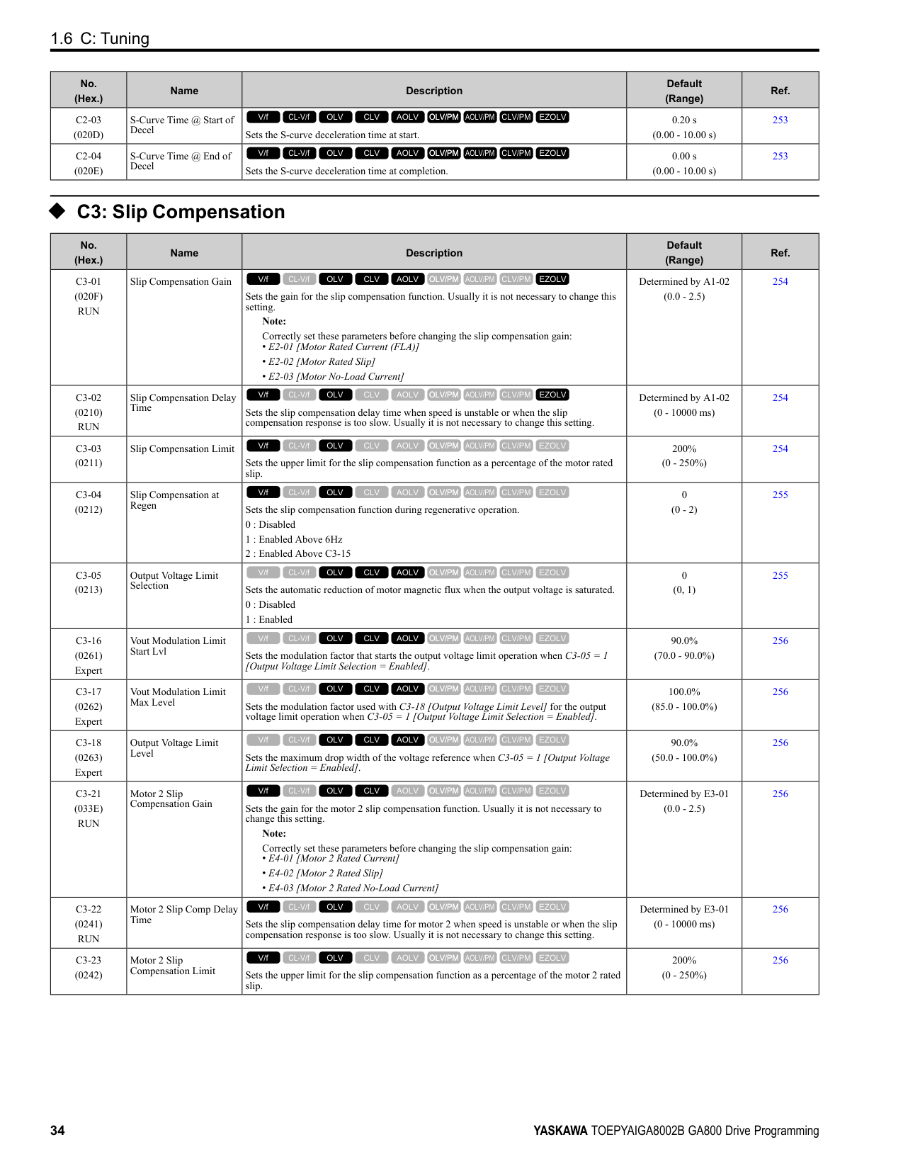
|---|---|---|---|---| |H1-01 (0438)|Terminal S1 Function Selection|Sets the function for MFDI terminal S1. Note: The default setting is F when the drive is initialized for 3-Wire Initialization [A1-03 = 3330].
V/f CL-V/f OLV CLV AOLV OLV/PM AOLV/PM CLV/PM EZOLV
|40 (1 - 1FF)|358| |H1-02 (0439)|Terminal S2 Function Selection|Sets the function for MFDI terminal S2. Note: The default setting is F when the drive is initialized for 3-Wire Initialization [A1-03 = 3330].
V/f CL-V/f OLV CLV AOLV OLV/PM AOLV/PM CLV/PM EZOLV
|41 (1 - 1FF)|358| |H1-03 (0400)|Terminal S3 Function Selection|Sets the function for MFDI terminal S3.
V/f CL-V/f OLV CLV AOLV OLV/PM AOLV/PM CLV/PM EZOLV
|24 (0 - 1FF)|358| |H1-04 (0401)|Terminal S4 Function Selection|Sets the function for MFDI terminal S4.
V/f CL-V/f OLV CLV AOLV OLV/PM AOLV/PM CLV/PM EZOLV
|14 (0 - 1FF)|358| |H1-05 (0402)|Terminal S5 Function Selection|Sets the function for MFDI terminal S5. Note: The default setting is 0 when the drive is initialized for 3-Wire Initialization [A1-03 = 3330].
V/f CL-V/f OLV CLV AOLV OLV/PM AOLV/PM CLV/PM EZOLV
|3 (0 - 1FF)|358| |H1-06 (0403)|Terminal S6 Function Selection|Sets the function for MFDI terminal S6.
Note:
When you initialize the drive for 3-Wire Initialization [A1-03 = 3330], the default setting is 3.
V/f CL-V/f OLV CLV AOLV OLV/PM AOLV/PM CLV/PM EZOLV
|4 (0 - 1FF)|359| |H1-07 (0404)|Terminal S7 Function Selection|Sets the function for MFDI terminal S7.
Note:
When you initialize the drive for 3-Wire Initialization [A1-03 = 3330], the default setting is 4.
V/f CL-V/f OLV CLV AOLV OLV/PM AOLV/PM CLV/PM EZOLV
|6 (0 - 1FF)|359| |H1-08 (0405)|Terminal S8 Function Selection|Sets the function for MFDI terminal S8.
V/f CL-V/f OLV CLV AOLV OLV/PM AOLV/PM CLV/PM EZOLV
|8 (0 - 1FF)|359| |H1-21 (0B70)|Terminal S1 Function Selection 2|Sets the second function for MFDI terminal S1.
V/f CL-V/f OLV CLV AOLV OLV/PM AOLV/PM CLV/PM EZOLV
|F (1 - 19F)|359| |H1-22 (0B71)|Terminal S2 Function Select 2|Sets the second function for MFDI terminal S2.
V/f CL-V/f OLV CLV AOLV OLV/PM AOLV/PM CLV/PM EZOLV
|F (1 - 19F)|359| |H1-23 (0B72)|Terminal S3 Function Selection 2|Sets the second function for MFDI terminal S3.
V/f CL-V/f OLV CLV AOLV OLV/PM AOLV/PM CLV/PM EZOLV
|F (1 - 19F)|359| |H1-24 (0B73)|Terminal S4 Function Selection 2|Sets the second function for MFDI terminal S4.
V/f CL-V/f OLV CLV AOLV OLV/PM AOLV/PM CLV/PM EZOLV
|F (1 - 19F)|360| |H1-25 (0B74)|Terminal S5 Function Selection 2|Sets the second function for MFDI terminal S5.
V/f CL-V/f OLV CLV AOLV OLV/PM AOLV/PM CLV/PM EZOLV
|F (1 - 19F)|360| |H1-26 (0B75)|Terminal S6 Function Selection 2|Sets the second function for MFDI terminal S6.
V/f CL-V/f OLV CLV AOLV OLV/PM AOLV/PM CLV/PM EZOLV
|F (1 - 19F)|360| |H1-27 (0B76)|Terminal S7 Function Selection 2|Sets the second function for MFDI terminal S7.
V/f CL-V/f OLV CLV AOLV OLV/PM AOLV/PM CLV/PM EZOLV
|F (1 - 19F)|360| |H1-28 (0B77)|Terminal S8 Function Selection 2|Sets the second function for MFDI terminal S8.
V/f CL-V/f OLV CLV AOLV OLV/PM AOLV/PM CLV/PM EZOLV
|F (1 - 19F)|360| |H1-40 (0B54)|Mbus Reg 15C0h bit0 Input Func|Selects MFDI function assigned to bit 0 of the MEMOBUS register 15C0 (Hex.).
V/f CL-V/f OLV CLV AOLV OLV/PM AOLV/PM CLV/PM EZOLV
|F (1 - 19F)|361| |H1-41 (0B55)|Mbus Reg 15C0h bit1 Input Func|Selects MFDI function assigned to bit 1 of the MEMOBUS register 15C0 (Hex.).
V/f CL-V/f OLV CLV AOLV OLV/PM AOLV/PM CLV/PM EZOLV
|F (1 - 19F)|361| |H1-42 (0B56)|Mbus Reg 15C0h bit2 Input Func|Selects MFDI function assigned to bit 2 of the MEMOBUS register 15C0 (Hex.).
V/f CL-V/f OLV CLV AOLV OLV/PM AOLV/PM CLV/PM EZOLV
|F (1 - 19F)|361|
######## ■ H1-xx: MFDI Setting Values
|Setting Value|Function|Description|Ref.| |---|---|---|---| |0|3-Wire Sequence|Sets the direction of motor rotation for 3-wire sequence.
V/f CL-V/f OLV CLV AOLV OLV/PM AOLV/PM CLV/PM EZOLV
|361| |1|LOCAL/REMOTE Selection|Sets drive control for the keypad (LOCAL) or an external source (REMOTE). ON : LOCAL OFF : REMOTE
V/f CL-V/f OLV CLV AOLV OLV/PM AOLV/PM CLV/PM EZOLV
|362| |2|External Reference 1/2 Selection|Sets the drive to use Run command source 1/2 or Reference command source 1/2 when in REMOTE Mode. ON : b1-15 = [Frequency Reference Selection 2], b1-16 [Run Command Selection 2] OFF : b1-01 = [Frequency Reference Selection 1], b1-02 [Run Command Selection 1]
V/f CL-V/f OLV CLV AOLV OLV/PM AOLV/PM CLV/PM EZOLV
|362| |3|Multi-Step Speed Reference 1|Uses speed references d1-01 to d1-16 to set a multi-step speed reference.
V/f CL-V/f OLV CLV AOLV OLV/PM AOLV/PM CLV/PM EZOLV
|362| |4|Multi-Step Speed Reference 2|Uses speed references d1-01 to d1-16 to set a multi-step speed reference.
V/f CL-V/f OLV CLV AOLV OLV/PM AOLV/PM CLV/PM EZOLV
|363| |5|Multi-Step Speed Reference 3|Uses speed references d1-01 to d1-16 to set a multi-step speed reference.
V/f CL-V/f OLV CLV AOLV OLV/PM AOLV/PM CLV/PM EZOLV
|363| |6|Jog Reference Selection|Sets the drive to use the JOG Frequency Reference (JOG command) set in d1-17. The JOG Frequency Reference (JOG command) overrides Frequency References 1 to 16 (d1-01 to d1-16).
V/f CL-V/f OLV CLV AOLV OLV/PM AOLV/PM CLV/PM EZOLV
|363| |7|Accel/Decel Time Selection 1|Sets the drive to use Acceleration/Deceleration Time 1 [C1-01, C1-02] or Acceleration/Deceleration Time 2 [C1-03, C1-04].
V/f CL-V/f OLV CLV AOLV OLV/PM AOLV/PM CLV/PM EZOLV
|363| |8|Baseblock Command (N. O.)|Sets the command that stops drive output and coasts the motor to stop when the input is ON. ON : Baseblock (drive output stop) OFF : Normal operation
V/f CL-V/f OLV CLV AOLV OLV/PM AOLV/PM CLV/PM EZOLV
|363| |9|Baseblock Command (N. C.)|Sets the command that stops drive output and coasts the motor to stop when the input terminal is OFF. ON : Normal operation OFF : Baseblock (drive output stop)
V/f CL-V/f OLV CLV AOLV OLV/PM AOLV/PM CLV/PM EZOLV
|364| |A|Accel/Decel Ramp Hold|Momentarily pauses motor acceleration and deceleration when the terminal is turned ON, retains the output frequency that was stored in the drive at the time of the pause, and restarts motor operation.
V/f CL-V/f OLV CLV AOLV OLV/PM AOLV/PM CLV/PM EZOLV
|364| |B|Overheat Alarm (oH2)|Sets the drive to display an oH2 [Drive Overheat Warning] alarm when the input terminal is ON. The alarm does not have an effect on drive operation.
V/f CL-V/f OLV CLV AOLV OLV/PM AOLV/PM CLV/PM EZOLV
|364| |C|Analog Terminal Enable Selection|Sets the command that enables or disables the terminals selected in H3-14 [Analog Input Terminal Enable Sel]. ON : Input to the terminal selected with H3-14 is enabled OFF : Input to the terminal selected with H3-14 is disabled
V/f CL-V/f OLV CLV AOLV OLV/PM AOLV/PM CLV/PM EZOLV
|364| |D|Ignore Speed Fdbk (V/f w/o Enc)|Sets the command to disable speed feedback control and run the drive in V/f control or use speed feedback from the encoder.
ON : Speed feedback control disable (V/f Control) OFF : Speed feedback control enable (Closed Loop V/f Control)
V/f CL-V/f OLV CLV AOLV OLV/PM AOLV/PM CLV/PM EZOLV
|364| |E|ASR Integral Reset|Sets the command to reset the integral value and use PI control or P control for the speed control loop. ON : P control OFF : PI control
V/f CL-V/f OLV CLV AOLV OLV/PM AOLV/PM CLV/PM EZOLV
|364| |F|Not Used|Use this setting for unused terminals or to use terminals in through mode.
V/f CL-V/f OLV CLV AOLV OLV/PM AOLV/PM CLV/PM EZOLV
|365|
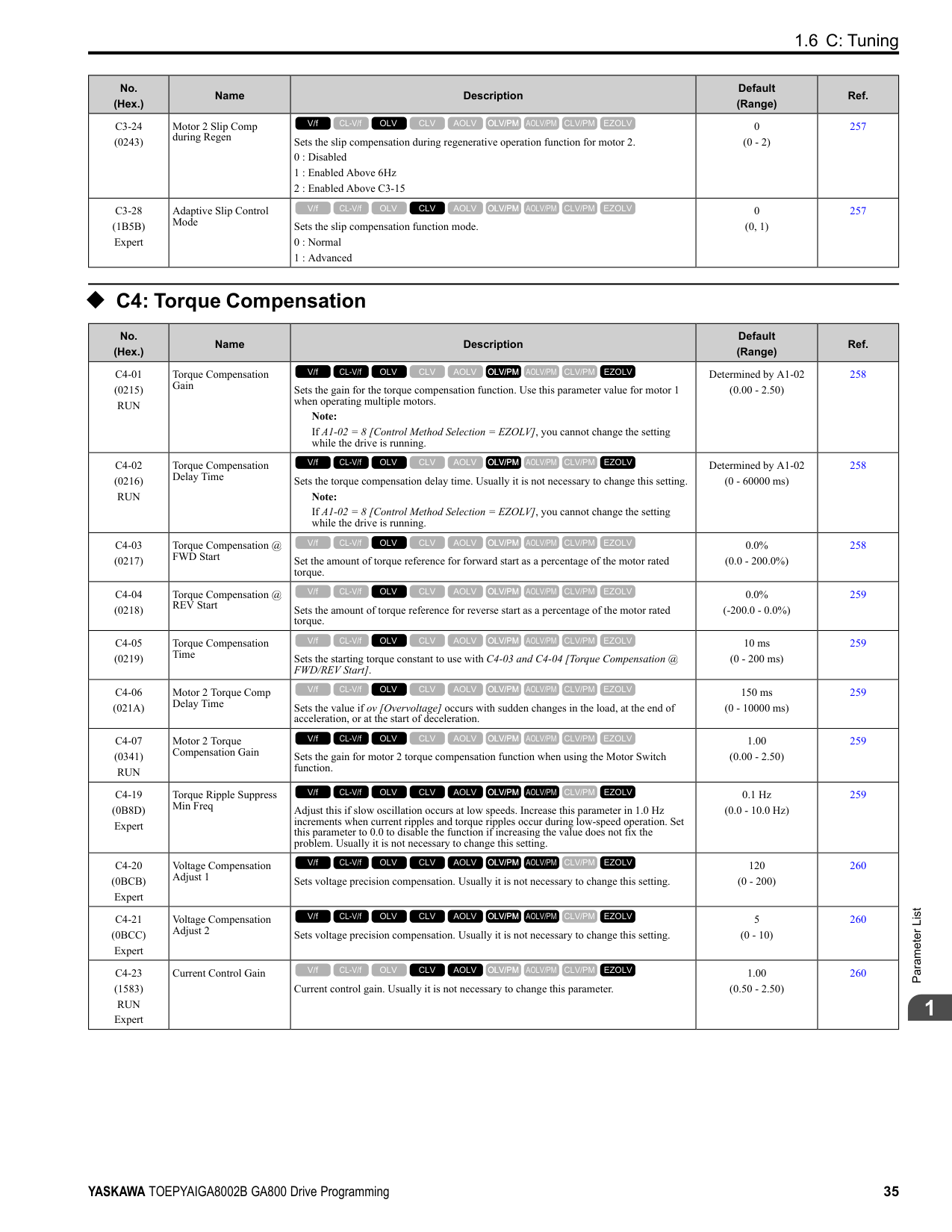
|10|Up Command|Sets the command to use a push button switch to increase the drive frequency reference. You must also set Setting 11 [Down Command].
ON : Increases the frequency reference. OFF : Holds the current frequency reference.
V/f CL-V/f OLV CLV AOLV OLV/PM AOLV/PM CLV/PM EZOLV
|365|
|Setting Value|Function|Description|Ref.| |---|---|---|---| |11|Down Command|Sets the command to use a push button switch to decrease the drive frequency reference. You must also set Setting 10 [Up Command].
ON : Decreases the frequency reference. OFF : Holds the current frequency reference.
V/f CL-V/f OLV CLV AOLV OLV/PM AOLV/PM CLV/PM EZOLV
|366| |12|Forward Jog|Sets the command to operate the motor in the forward direction at the Jog Frequency set in d1-17 [Jog Reference].
V/f CL-V/f OLV CLV AOLV OLV/PM AOLV/PM CLV/PM EZOLV
|367| |13|Reverse Jog|Sets the command to operate the motor in reverse at the Jog Frequency set in d1-17 [Jog Reference].
V/f CL-V/f OLV CLV AOLV OLV/PM AOLV/PM CLV/PM EZOLV
|367| |14|Fault Reset Procedure|Sets the command to reset the current fault when the Run command is inactive.
Note:
The drive ignores the fault reset command when the Run command is active. Remove the Run command before trying to reset a fault.
V/f CL-V/f OLV CLV AOLV OLV/PM AOLV/PM CLV/PM EZOLV
|368| |15|Fast Stop (N.O.)|Sets the command to ramp to stop in the deceleration time set in C1-09 [Fast Stop Time] when the input terminal is activated while the drive is operating.
V/f CL-V/f OLV CLV AOLV OLV/PM AOLV/PM CLV/PM EZOLV
|368| |16|Motor 2 Selection|Sets the command for the drive to operate motor 1 or motor 2. Stop the motors before switching. ON : Operate motor 2 OFF : Operate motor 1
V/f CL-V/f OLV CLV AOLV OLV/PM AOLV/PM CLV/PM EZOLV
|368| |17|Fast Stop (N.C.)|Sets the command to ramp to stop in the deceleration time set in C1-09 [Fast Stop Time] when the input terminal is activated while the drive is operating.
V/f CL-V/f OLV CLV AOLV OLV/PM AOLV/PM CLV/PM EZOLV
|369| |18|Timer Function|Sets the command to start the timer function. Use this setting with Timer Output [H2-xx = 12].
V/f CL-V/f OLV CLV AOLV OLV/PM AOLV/PM CLV/PM EZOLV
|369| |19|PID Disable|Sets the command to disable PID control when b5-01 = 1 to 8 [PID Mode Setting = Enabled]. ON : PID control disabled OFF : PID control enabled
V/f CL-V/f OLV CLV AOLV OLV/PM AOLV/PM CLV/PM EZOLV
|370| |1A|Accel/Decel Time Selection 2|Set this function and H1-xx = 7[Accel/Decel Time Selection 1] together. Sets the drive to use Acceleration/ Deceleration Time 3 [C1-05, C1-06] or Acceleration/Deceleration Time 4 [C1-07, C1-08].
V/f CL-V/f OLV CLV AOLV OLV/PM AOLV/PM CLV/PM EZOLV
|370| |1B|Programming Lockout|Sets the command to prevent parameter changes when the terminal is OFF. ON : Programming Lockout OFF : Parameter Write Prohibit
V/f CL-V/f OLV CLV AOLV OLV/PM AOLV/PM CLV/PM EZOLV
|370| |1E|Reference Sample Hold|Sets the command to sample the frequency reference at terminals A1, A2, or A3 and hold the frequency reference at that frequency.
V/f CL-V/f OLV CLV AOLV OLV/PM AOLV/PM CLV/PM EZOLV
|370| |20 to 2F|External fault|Sets a command to stop the drive when a failure or fault occurs on an external device.
20 : External Fault (NO-Always-Ramp)
21 : External Fault (NC-Always-Ramp)
22 : External Fault (NO-@Run-Ramp)
23 : External Fault (NC-@Run-Ramp)
24 : External Fault (NO-Always-Coast)
25 : External Fault (NC-Always-Coast)
26 : External Fault (NO-@Run-Coast)
27 : External Fault (NC-@Run-Coast)
28 : External Fault (NO-Always-FStop)
29 : External Fault (NC-Always-FStop)
2A : External Fault (NO-@Run-FStop)
2B : External Fault (NC-@Run-FStop)
2C : External Fault (NO-Always-Alarm)
2D : External Fault (NC-Always-Alarm)
2E : External Fault (NO-@Run-Alarm)
2F : External Fault (NC-@Run-Alarm)
V/f CL-V/f OLV CLV AOLV OLV/PM AOLV/PM CLV/PM EZOLV
|371| |30|PID Integrator Reset|Sets the command to reset and hold the PID control integral to 0 when the terminal is ON.
V/f CL-V/f OLV CLV AOLV OLV/PM AOLV/PM CLV/PM EZOLV
|371| |31|PID Integrator Hold|Sets the command to hold the integral value of the PID control while the terminal is activated.
V/f CL-V/f OLV CLV AOLV OLV/PM AOLV/PM CLV/PM EZOLV
|372|
|Setting Value|Function|Description|Ref.| |---|---|---|---| |32|Multi-Step Speed Reference 4|Uses speed references d1-01 to d1-16 to set a multi-step speed reference.
V/f CL-V/f OLV CLV AOLV OLV/PM AOLV/PM CLV/PM EZOLV
|372| |34|PID Soft Starter Disable|Sets the PID soft starter function. ON : No OFF : Yes
V/f CL-V/f OLV CLV AOLV OLV/PM AOLV/PM CLV/PM EZOLV
|372| |35|PID Input (Error) Invert|Sets the command to turn the terminal ON and OFF to switch the PID input level (polarity).
V/f CL-V/f OLV CLV AOLV OLV/PM AOLV/PM CLV/PM EZOLV
|372| |3E|PID Setpoint Selection 1|Set this function and H1-xx = 3F [PID Setpoint Selection 2] together. Sets the function to switch the PID setpoint to b5-58 to b5-60 [PID Setpoint 2 to 4].
V/f CL-V/f OLV CLV AOLV OLV/PM AOLV/PM CLV/PM EZOLV
|372| |3F|PID Setpoint Selection 2|Set this function and H1-xx = 3E [PID Setpoint Selection 1] at the same time. Sets the function to switch the PID setpoint to b5-58 to b5-60 [PID Setpoint 2 to 4].
V/f CL-V/f OLV CLV AOLV OLV/PM AOLV/PM CLV/PM EZOLV
|372| |40|Forward RUN (2-Wire)|Sets the Forward Run command for 2-wire sequence 1. Set this function and H1-xx = 41 [Reverse Run Command (2Wire Seq)] at the same time.
ON : Forward Run OFF : Run Stop
Note:
• If you activate the Forward Run command terminal and the Reverse Run command terminal, the drive will detect minor fault/alarm EF [FWD/REV Run Command Input Error] and the motor will ramp to stop.
• Initialize the drive with a 2-wire sequence to set the Forward Run command to terminal S1.
• This function will not operate at the same time as H1-xx = 42, 43 [Run Command/FWD/REV Command (2-Wire Seq 2)].
V/f CL-V/f OLV CLV AOLV OLV/PM AOLV/PM CLV/PM EZOLV
|373| |41|Reverse RUN (2-Wire)|Sets the Forward Run command for 2-wire sequence 1. Set this function and H1-xx = 40 [Forward Run Command (2Wire Seq)] at the same time.
ON : Reverse Run OFF : Run Stop
Note:
• If you activate the Forward Run command terminal and the Reverse Run command terminal, the drive will detect minor fault/alarm EF [FWD/REV Run Command Input Error] and the motor will ramp to stop.
• Initialize the drive with a 2-wire sequence to set the Reverse Run command to terminal S2.
• This function will not operate at the same time as H1-xx = 42, 43 [Run Command/FWD/REV Command (2-Wire Seq 2)].
V/f CL-V/f OLV CLV AOLV OLV/PM AOLV/PM CLV/PM EZOLV
|373| |42|Run Command (2-Wire Sequence 2)|Sets the Run command for 2-wire sequence 2. Set this function and H1-xx = 43 [FWD/REV Command (2-Wire Seq 2)] at the same time.
ON : Run OFF : Stop
Note: This function will not operate at the same time as H1-xx = 40, 41 [Forward/Reverse Run Command (2-Wire Seq)].
V/f CL-V/f OLV CLV AOLV OLV/PM AOLV/PM CLV/PM EZOLV
|373| |43|FWD/REV (2-Wire Sequence 2)|Sets the direction of motor rotation for 2-wire sequence 2. Set this function and H1-xx = 42 [Run Command (2-Wire Sequence 2)] together.
ON : Reverse run OFF : Forward run
Note: This function will not operate at the same time as H1-xx = 40, 41 [Forward/Reverse Run Command (2-Wire Seq)].
V/f CL-V/f OLV CLV AOLV OLV/PM AOLV/PM CLV/PM EZOLV
|374| |44|Offset Frequency 1|Sets the function to add the offset frequency set in d7-01 [Offset Frequency 1] to the frequency reference when the terminal activates.
V/f CL-V/f OLV CLV AOLV OLV/PM AOLV/PM CLV/PM EZOLV
|374| |45|Offset Frequency 2|Sets the function to add the offset frequency set in d7-02 [Offset Frequency 2] to the frequency reference when the terminal activates.
V/f CL-V/f OLV CLV AOLV OLV/PM AOLV/PM CLV/PM EZOLV
|374| |46|Offset Frequency 3|Sets the function to add the offset frequency set in d7-03 [Offset Frequency 3] to the frequency reference when the terminal activates.
V/f CL-V/f OLV CLV AOLV OLV/PM AOLV/PM CLV/PM EZOLV
|374| |47|Node Setup (CANopen)|Sets the function in CANopen communications to start the Node Setup function to set the drive node address from the host controller.
V/f CL-V/f OLV CLV AOLV OLV/PM AOLV/PM CLV/PM EZOLV
|374|
|Setting Value|Function|Description|Ref.| |---|---|---|---| |60|DC Injection Braking Command|Sets the command to use DC Injection Braking to stop the motor. Note: When A1-02 8 [Control Method Selection EZOLV], this function is available only when you use a PM motor.
V/f CL-V/f OLV CLV AOLV OLV/PM AOLV/PM CLV/PM EZOLV
|374|
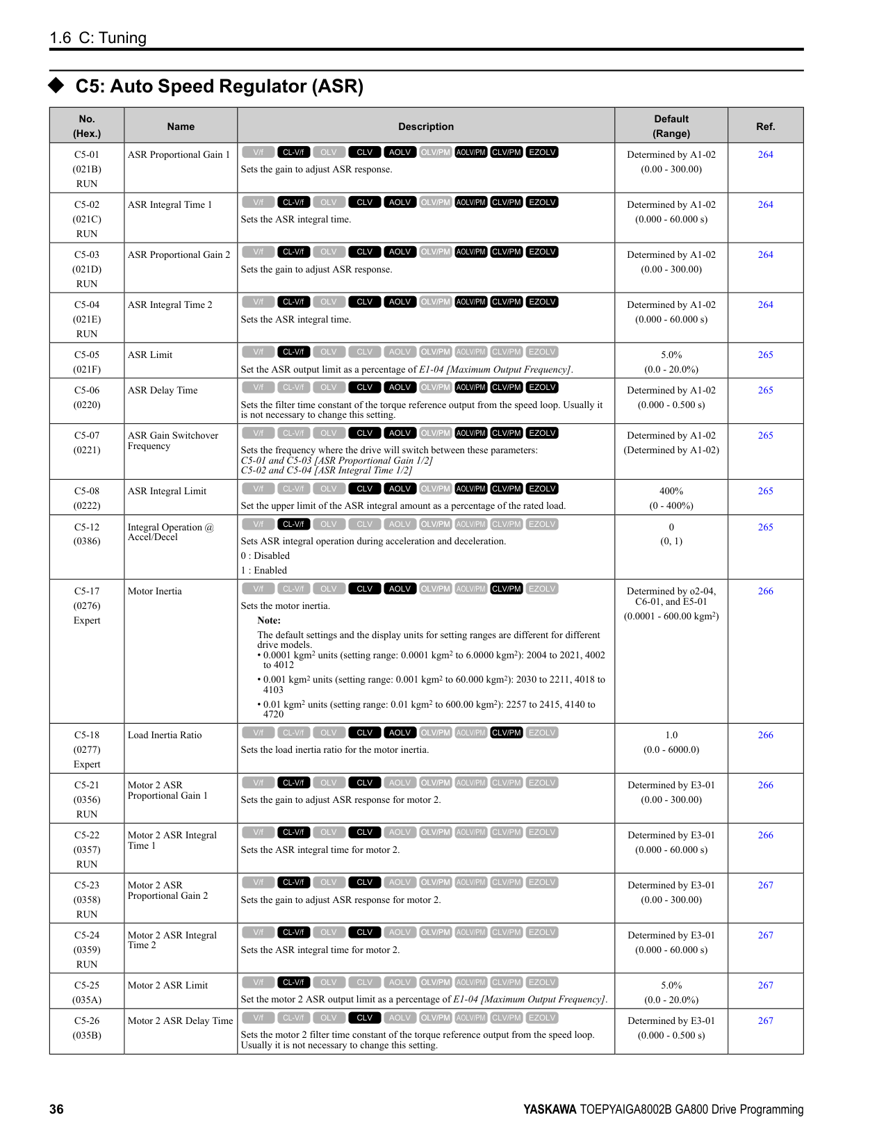
|61|Speed Search from Fmax|Sets the function to start speed search using an external reference although b3-01 = 0 [Speed Search Selection at Start
= Disabled]. Note: The drive will detect oPE03 [Multi-Function Input Setting Err] when H1-xx = 61 and 62 are set at the same time.
V/f CL-V/f OLV CLV AOLV OLV/PM AOLV/PM CLV/PM EZOLV
|375| |62|Speed Search from Fref|Sets the function to use an external reference to start speed search although b3-01 = 0 [Speed Search Selection at Start
= Disabled]. Note: The drive will detect oPE03 [Multi-Function Input Setting Err] when H1-xx = 61 and 62 are set at the same time.
V/f CL-V/f OLV CLV AOLV OLV/PM AOLV/PM CLV/PM EZOLV
|375| |63|Field Weakening|Sets the function to send the Field Weakening Level and Field Weakening Frequency Limit commands set in d6-01 [Field Weakening Level] and d6-02 [Field Weakening Frequency Limit] when the input terminal is activated.
V/f CL-V/f OLV CLV AOLV OLV/PM AOLV/PM CLV/PM EZOLV
|375| |65|KEB Ride-Thru 1 Activate (N.C.)|Sets operation of the KEB1 function through the KEB Ride-Thru 1 (N.C.). ON : Normal operation OFF : Deceleration during momentary power loss
V/f CL-V/f OLV CLV AOLV OLV/PM AOLV/PM CLV/PM EZOLV
|375| |66|KEB Ride-Thru 1 Activate (N.O.)|Sets operation of the KEB1 function through the KEB Ride-Thru 1 (N.O.). ON : Deceleration during momentary power loss OFF : Normal operation
V/f CL-V/f OLV CLV AOLV OLV/PM AOLV/PM CLV/PM EZOLV
|376| |67|Communications Test Mode|Set the function for the drive to self-test RS-485 serial communications operation.
V/f CL-V/f OLV CLV AOLV OLV/PM AOLV/PM CLV/PM EZOLV
|376| |68|High Slip Braking|Sets the command to use high-slip braking to stop the motor.
V/f CL-V/f OLV CLV AOLV OLV/PM AOLV/PM CLV/PM EZOLV
|376| |6A|Drive Enable|Sets the function to show dnE [Drive Enabled] on the keypad and ignore Run commands when the terminal is OFF.
V/f CL-V/f OLV CLV AOLV OLV/PM AOLV/PM CLV/PM EZOLV
|376| |71|Torque Control|Sets the function to switch between torque control and speed control. ON : Torque Control OFF : Speed Control
V/f CL-V/f OLV CLV AOLV OLV/PM AOLV/PM CLV/PM EZOLV
|376| |72|Zero Servo|Sets the function to hold a stopped motor.
V/f CL-V/f OLV CLV AOLV OLV/PM AOLV/PM CLV/PM EZOLV
|377| |75|Up 2 Command|Sets the function to increase the frequency reference bias value to accelerate the motor when the terminal is activated. Set this function and H1-xx = 76 [Down 2 Command] together.
Note:
When you use this function, use d4-08 and d4-09 [Up/Down 2 Bias Upper Limit/Lower Limit] to set the optimal bias limit value.
V/f CL-V/f OLV CLV AOLV OLV/PM AOLV/PM CLV/PM EZOLV
|377| |76|Down 2 Command|Sets the function to decrease the frequency reference bias value to decelerate the motor when the terminal is activated. Set this function and H1-xx 75 [Up 2 Command] at the same time.
Note:
When you use this function, use d4-08 and d4-09 [Up/Down 2 Bias Upper Limit/Lower Limit] to set the optimal bias limit value.
V/f CL-V/f OLV CLV AOLV OLV/PM AOLV/PM CLV/PM EZOLV
|378| |77|ASR Gain (C5-03) Select|Sets the function to switch the ASR proportional gain set in C5-01 [ASR Proportional Gain 1] and C5-03 [ASR Proportional Gain 2].
ON : C5-03 OFF : C5-01
V/f CL-V/f OLV CLV AOLV OLV/PM AOLV/PM CLV/PM EZOLV
|379| |78|Analog TorqueRef Polarity Invert|Sets the rotation direction of the external torque reference. ON : External torque reference reverse direction OFF : External torque reference forward direction
V/f CL-V/f OLV CLV AOLV OLV/PM AOLV/PM CLV/PM EZOLV
|379| |7A|KEB Ride-Thru 2 Activate (N.C.)|Sets operation of the KEB2 function through the KEB Ride-Thru 2 (N.C.). ON : Normal operation OFF : Deceleration during momentary power loss
V/f CL-V/f OLV CLV AOLV OLV/PM AOLV/PM CLV/PM EZOLV
|379|
|Setting Value|Function|Description|Ref.| |---|---|---|---| |7B|KEB Ride-Thru 2 Activate (N.O.)|Sets operation of the KEB2 function through the KEB Ride-Thru 2 (N.O.). ON : Deceleration during momentary power loss OFF : Normal operation
V/f CL-V/f OLV CLV AOLV OLV/PM AOLV/PM CLV/PM EZOLV
|379| |7C|Short Circuit Braking (N. O.)|Sets operation of Short Circuit Braking (N.O.). ON : Short Circuit Braking is enabled. OFF : Normal operation
Note: When A1-02 = 8 [Control Method Selection = EZOLV], this function is available only when you use a PM motor.
V/f CL-V/f OLV CLV AOLV OLV/PM AOLV/PM CLV/PM EZOLV
|380| |7D|Short Circuit Braking (N. C.)|Sets operation of Short Circuit Braking (N.C.). ON : Normal operation OFF : Short Circuit Braking is enabled.
Note: When A1-02 = 8 [Control Method Selection = EZOLV], this function is available only when you use a PM motor.
V/f CL-V/f OLV CLV AOLV OLV/PM AOLV/PM CLV/PM EZOLV
|380| |7E|Reverse Rotation Identifier|Sets the rotation direction of the motor when in Simple Closed Loop V/f Control method and F1-21, F1-37 = 0 [Encoder Option Function Selection = A pulse detection], or when in Closed Loop V/f Control method.
ON : Reverse run OFF : Forward run
V/f CL-V/f OLV CLV AOLV OLV/PM AOLV/PM CLV/PM EZOLV
|380| |90 - 97|DWEZ Digital Inputs 1 to 8|Sets digital inputs used with DriveWorksEZ. Refer to the DriveWorksEZ online manual for more information.
V/f CL-V/f OLV CLV AOLV OLV/PM AOLV/PM CLV/PM EZOLV
|380| |9F|DWEZ Disable|Sets operation of the DriveWorksEZ program saved in the drive. ON : No OFF : Yes
Note: Set A1-07 = 2 [DriveWorksEZ Function Selection = Digital input] to enable this function.
V/f CL-V/f OLV CLV AOLV OLV/PM AOLV/PM CLV/PM EZOLV
|380| |101 to 19F|Inverse Inputs of 1 to 9F|Sets the function of the selected MFDI to operate inversely. To select the function, enter “1xx”, where the “xx” is the function setting value.
Note: You cannot use inverse input for all functions. Refer to Table 2.55 for more information.|381|
######## ◆ H2: Digital Outputs
|No. (Hex.)|Name|Description|Default (Range)|Ref.| |---|---|---|---|---| |H2-01 (040B)|Term M1-M2 Function Selection|Sets the function for MFDO terminal M1-M2.
Note:
Set this parameter to F when the terminal is not being used or to use the terminal in through mode.
V/f CL-V/f OLV CLV AOLV OLV/PM AOLV/PM CLV/PM EZOLV
|0 (0 - 1FF)|383| |H2-02 (040C)|Term M3-M4 Function Selection|Sets the function for MFDO terminal M3-M4.
Note:
Set this parameter to F when the terminal is not being used or to use the terminal in through mode.
V/f CL-V/f OLV CLV AOLV OLV/PM AOLV/PM CLV/PM EZOLV
|1 (0 - 1FF)|383| |H2-03 (040D)|Term M5-M6 Function Selection|Sets the function for MFDO terminal M5-M6.
Note:
Set this parameter to F when the terminal is not being used or to use the terminal in through mode.
V/f CL-V/f OLV CLV AOLV OLV/PM AOLV/PM CLV/PM EZOLV
|2 (0 - 1FF)|383| |H2-06 (0437)|Watt Hour Output Unit Selection|Sets the unit for the output signal when H2-01 to H2-03 = 39 [MFDO Function Selection
= Watt Hour Pulse Output].
0 : 0.1 kWh units
1 : 1 kWh units
2 : 10 kWh units
3 : 100 kWh units
4 : 1000 kWh units
V/f CL-V/f OLV CLV AOLV OLV/PM AOLV/PM CLV/PM EZOLV
|0 (0 - 4)|384|
|No. (Hex.)|Name|Description|Default (Range)|Ref.| |---|---|---|---|---| |H2-07 (0B3A)|Modbus Register 1 Address Select|Sets the address of the MEMOBUS/Modbus register output to the MFDO terminal.
V/f CL-V/f OLV CLV AOLV OLV/PM AOLV/PM CLV/PM EZOLV
|0001 (0001 - 1FFF)|384| |H2-08 (0B3B)|Modbus Register 1 Bit Select|Sets the bit of the MEMOBUS/Modbus register output to the MFDO terminal.
V/f CL-V/f OLV CLV AOLV OLV/PM AOLV/PM CLV/PM EZOLV
|0000 (0000 - FFFF)|384|
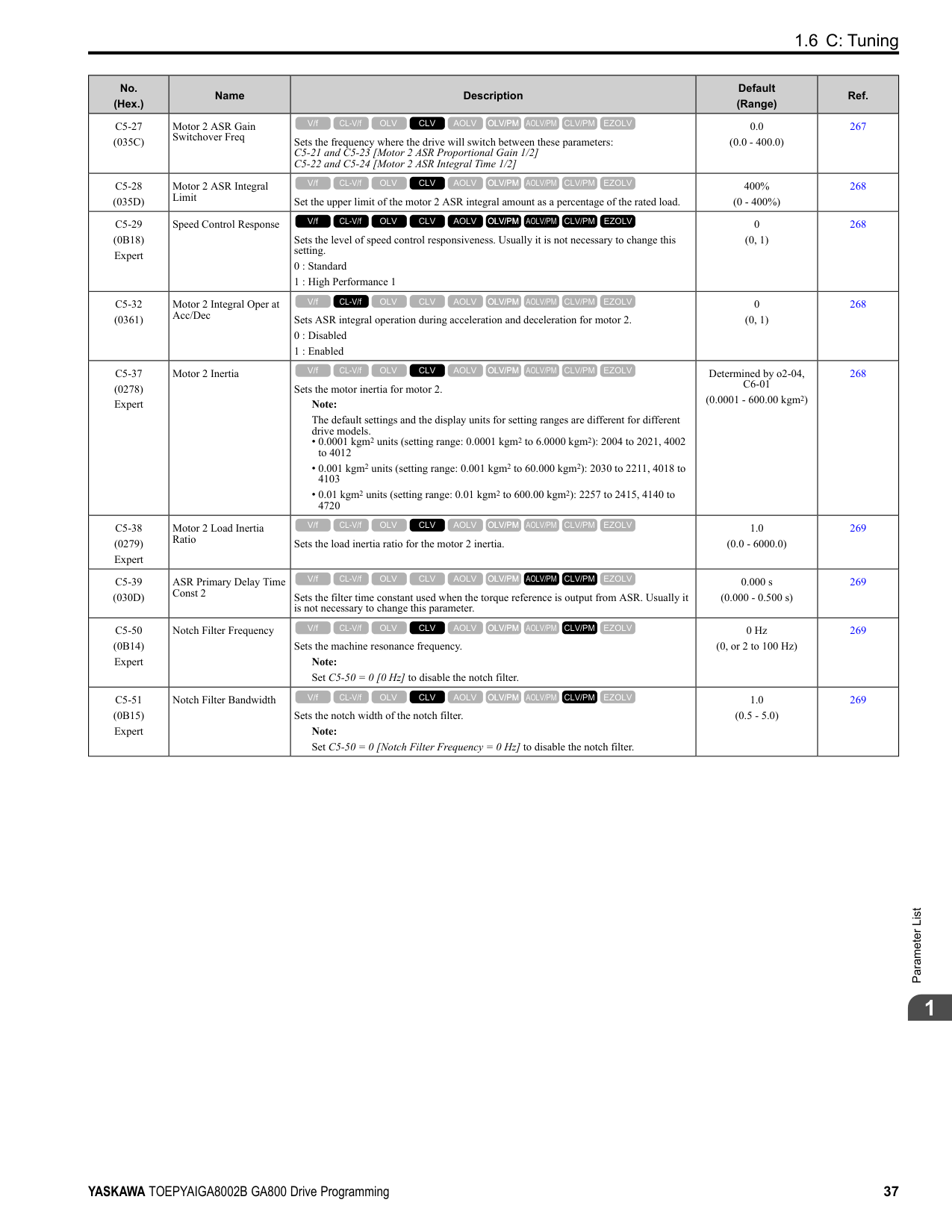
|H2-09 (0B3C)|Modbus Register 2 Address Select|Sets the address of the MEMOBUS/Modbus register output to the MFDO terminal.
V/f CL-V/f OLV CLV AOLV OLV/PM AOLV/PM CLV/PM EZOLV
|0001 (0001 - 1FFF)|384| |H2-10 (0B3D)|Modbus Register 2 Bit Select|Sets the bit of the MEMOBUS/Modbus register output to the MFDO terminal.
V/f CL-V/f OLV CLV AOLV OLV/PM AOLV/PM CLV/PM EZOLV
|0000 (0000 - FFFF)|385| |H2-20 (1540)|Comparator 1 Monitor Selection|Sets the monitor number for comparator 1. Set the x-xx part of the Ux-xx [Monitor]. For example, set H2-20 102 to monitor U1-02 [Output Frequency].
V/f CL-V/f OLV CLV AOLV OLV/PM AOLV/PM CLV/PM EZOLV
|102 (000 - 999)|385| |H2-21 (1541)|Comparator 1 Lower Limit|Sets the lower limit detection level for comparator 1 when the full scale analog output for the monitor selected in H2-20 [Comparator 1 Monitor Selection] is the 100% value.
V/f CL-V/f OLV CLV AOLV OLV/PM AOLV/PM CLV/PM EZOLV
|0.0% (0.0 - 300.0%)|385| |H2-22 (1542)|Comparator 1 Upper Limit|Sets the upper limit detection level for comparator 1 when the full scale analog output for the monitor selected in H2-20 [Comparator 1 Monitor Selection] is the 100% value.
V/f CL-V/f OLV CLV AOLV OLV/PM AOLV/PM CLV/PM EZOLV
|0.0% (0.0 - 300.0%)|385| |H2-23 (1543)|Comparator 1 Hysteresis|Sets the hysteresis level for comparator 1 as a percentage of the full scale analog output for the monitor selected in H2-20 [Comparator 1 Monitor Selection].
V/f CL-V/f OLV CLV AOLV OLV/PM AOLV/PM CLV/PM EZOLV
|0.0% (0.0 - 10.0%)|385| |H2-24 (1544)|Comparator 1 On-Delay Time|Sets the on-delay time for comparator 1.
V/f CL-V/f OLV CLV AOLV OLV/PM AOLV/PM CLV/PM EZOLV
|0.0 s (0.0 - 600.0 s)|385| |H2-25 (1545)|Comparator 1 Off-Delay Time|Sets the off-delay time for comparator 1.
V/f CL-V/f OLV CLV AOLV OLV/PM AOLV/PM CLV/PM EZOLV
|0.0 s (0.0 - 600.0 s)|386| |H2-26 (1546)|Comparator 2 Monitor Selection|Sets the monitor number for comparator 2. Set the x-xx part of the Ux-xx [Monitor]. For example, set H2-26 = 103 to monitor U1-03 [Output Current].
V/f CL-V/f OLV CLV AOLV OLV/PM AOLV/PM CLV/PM EZOLV
|103 (000 - 999)|386| |H2-27 (1547)|Comparator 2 Lower Limit|Sets the lower limit detection level for comparator 2 as a percentage of the full scale analog output for the monitor selected in H2-26 [Comparator 2 Monitor Selection].
V/f CL-V/f OLV CLV AOLV OLV/PM AOLV/PM CLV/PM EZOLV
|0.0% (0.0 - 300.0%)|386| |H2-28 (1548)|Comparator 2 Upper Limit|Sets the upper limit detection level for comparator 2 as a percentage of the full scale analog output for the monitor selected in H2-26 [Comparator 2 Monitor Selection].
V/f CL-V/f OLV CLV AOLV OLV/PM AOLV/PM CLV/PM EZOLV
|0.0% (0.0 - 300.0%)|386| |H2-29 (1549)|Comparator 2 Hysteresis|Sets the hysteresis level for comparator 2 as a percentage of the full scale analog output for the monitor selected in H2-26 [Comparator 2 Monitor Selection].
V/f CL-V/f OLV CLV AOLV OLV/PM AOLV/PM CLV/PM EZOLV
|0.0% (0.0 - 10.0%)|386| |H2-30 (154A)|Comparator 2 On-Delay Time|Sets the on-delay time for comparator 2.
V/f CL-V/f OLV CLV AOLV OLV/PM AOLV/PM CLV/PM EZOLV
|0.0 s (0.0 - 600.0 s)|386| |H2-31 (154B)|Comparator 2 Off-Delay Time|Sets the off-delay time for comparator 2.
V/f CL-V/f OLV CLV AOLV OLV/PM AOLV/PM CLV/PM EZOLV
|0.0 s (0.0 - 600.0 s)|387| |H2-32 (159A)|Comparator 1 Filter Time|Sets the time constant that is applied to the primary delay filter used for the analog output of the monitor selected with H2-20 [Comparator 1 Monitor Selection].
V/f CL-V/f OLV CLV AOLV OLV/PM AOLV/PM CLV/PM EZOLV
|0.0s (0.0 - 10.0 s)|387| |H2-33 (159B)|Comparator1 Protection Selection|Sets drive operation when it detects CP1 [Comparator1 Limit Fault].
0 : Ramp to Stop
1 : Coast to Stop
2 : Fast Stop (Use C1-09)
3 : Alarm Only
4 : Digital Output Only
V/f CL-V/f OLV CLV AOLV OLV/PM AOLV/PM CLV/PM EZOLV
|4 (0 - 4)|387| |H2-34 (159C)|Comparator 2 Filter Time|Sets the time constant that is applied to the primary delay filter used for the analog output of the monitor selected with H2-26 [Comparator 2 Monitor Selection].
V/f CL-V/f OLV CLV AOLV OLV/PM AOLV/PM CLV/PM EZOLV
|0.0s (0.0 - 10.0 s)|387| |H2-35 (159D)|Comparator2 Protection Selection|Sets drive operation when it detects CP2 [Comparator2 Limit Fault].
0 : Ramp to Stop
1 : Coast to Stop
2 : Fast Stop (Use C1-09)
3 : Alarm Only
4 : Digital Output Only
V/f CL-V/f OLV CLV AOLV OLV/PM AOLV/PM CLV/PM EZOLV
|4 (0 - 4)|387|
|No. (Hex.)|Name|Description|Default (Range)|Ref.| |---|---|---|---|---| |H2-36 (159E)|Comparator 1 Ineffective Time|Sets the length of time that CP1 [Comparator1 Limit Fault] is disabled.
V/f CL-V/f OLV CLV AOLV OLV/PM AOLV/PM CLV/PM EZOLV
|0.0 s (0.0 - 1000.0 s)|388| |H2-37 (159F)|Comparator 2 Ineffective Time|Sets the length of time that CP2 [Comparator2 Limit Fault] is disabled.
V/f CL-V/f OLV CLV AOLV OLV/PM AOLV/PM CLV/PM EZOLV
|0.0 s (0.0 - 1000.0 s)|388| |H2-40 (0B58)|Mbus Reg 15E0h bit0 Output Func|Sets the MFDO for bit 0 of MEMOBUS register 15E0 (Hex.).
V/f CL-V/f OLV CLV AOLV OLV/PM AOLV/PM CLV/PM EZOLV
|F (0 - 1FF)|388| |H2-41 (0B59)|Mbus Reg 15E0h bit1 Output Func|Sets the MFDO for bit 1 of MEMOBUS register 15E0 (Hex.).
V/f CL-V/f OLV CLV AOLV OLV/PM AOLV/PM CLV/PM EZOLV
|F (0 - 1FF)|388| |H2-42 (0B5A)|Mbus Reg 15E0h bit2 Output Func|Sets the MFDO for bit 2 of MEMOBUS register 15E0 (Hex.).
V/f CL-V/f OLV CLV AOLV OLV/PM AOLV/PM CLV/PM EZOLV
|F (0 - 1FF)|388| |H2-60 (1B46) Expert|Term M1-M2 Secondary Function|Sets the second function for terminal M1-M2. Outputs the logical calculation results of the terminals assigned to functions by H2-01 [Term M1-M2 Function Selection].
V/f CL-V/f OLV CLV AOLV OLV/PM AOLV/PM CLV/PM EZOLV
|F (0 - FF)|389| |H2-61 (1B47) Expert|Terminal M1-M2 Logical Operation|Sets the logical operation for the functions set in H2-01 [Term M1-M2 Function Selection] and H2-60 [Term M1-M2 Secondary Function].
V/f CL-V/f OLV CLV AOLV OLV/PM AOLV/PM CLV/PM EZOLV
|0 (0 - 8)|389| |H2-62 (1B48) Expert|Terminal M1-M2 Delay Time|Sets the minimum on time used to output the logical calculation results from terminal M1M2.
V/f CL-V/f OLV CLV AOLV OLV/PM AOLV/PM CLV/PM EZOLV
|0.1 s (0.0 - 25.0 s)|389| |H2-63 (1B49) Expert|Term M3-M4 Secondary Function|Sets the second function for terminal M3-M4. Outputs the logical calculation results of the terminals assigned to functions by H2-02 [Term M3-M4 Function Selection].
V/f CL-V/f OLV CLV AOLV OLV/PM AOLV/PM CLV/PM EZOLV
|F (0 - FF)|389| |H2-64 (1B4A) Expert|Terminal M3-M4 Logical Operation|Sets the logical operation for the functions set in H2-02 [Term M3-M4 Function Selection] and H2-63 [Term M3-M4 Secondary Function].
V/f CL-V/f OLV CLV AOLV OLV/PM AOLV/PM CLV/PM EZOLV
|0 (0 - 8)|389| |H2-65 (1B4B) Expert|Terminal M3-M4 Delay Time|Sets the minimum on time used to output the logical calculation results from terminal M3M4.
V/f CL-V/f OLV CLV AOLV OLV/PM AOLV/PM CLV/PM EZOLV
|0.1 s (0.0 - 25.0 s)|389| |H2-66 (1B4C) Expert|Term M5-M6 Secondary Function|Sets the second function for terminal M5-M6. Outputs the logical calculation results of the terminals assigned to functions by H2-03 [Terminal M5-M6 Function Select].
V/f CL-V/f OLV CLV AOLV OLV/PM AOLV/PM CLV/PM EZOLV
|F (0 - FF)|389| |H2-67 (1B4D) Expert|Terminal M5-M6 Logical Operation|Sets the logical operation for the functions set in H2-03 [Term M5-M6 Function Selection] and H2-66 [Term M5-M6 Secondary Function].
V/f CL-V/f OLV CLV AOLV OLV/PM AOLV/PM CLV/PM EZOLV
|0 (0 - 8)|390| |H2-68 (1B4E) Expert|Terminal M5-M6 Delay Time|Sets the minimum on time used to output the logical calculation results from terminal M5M6.
V/f CL-V/f OLV CLV AOLV OLV/PM AOLV/PM CLV/PM EZOLV
|0.1 s (0.0 - 25.0 s)|390|
######## ■ H2-xx: MFDO Setting Values
|Setting Value|Function|Description|Ref.| |---|---|---|---|
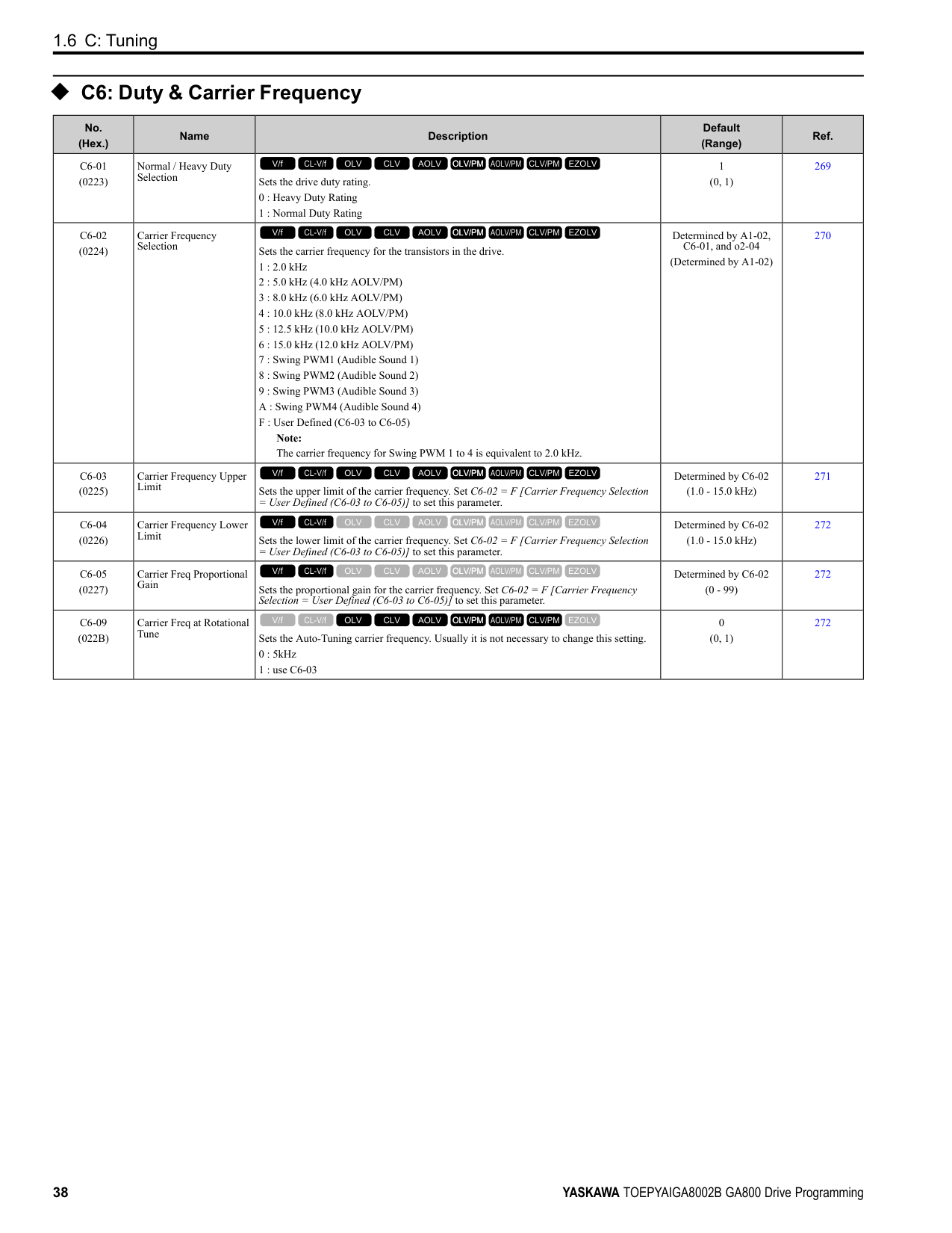
|0|During Run|The terminal activates when the Run command is input and when the drive is outputting voltage. ON : Drive is running OFF : Drive is stopping
V/f CL-V/f OLV CLV AOLV OLV/PM AOLV/PM CLV/PM EZOLV
|390| |1|Zero Speed|The terminal activates when the output frequency < E1-09 [Minimum Output Frequency] or b2-01 [DC Injection/Zero SpeedThreshold].
Note: Parameter A1-02 [Control Method Selection] selects which parameter is the reference.
|A1-02 Setting|Control method selection|Parameter Used as the Reference| |---|---|---| |0|V/f|E1-09| |1|CL-V/f|E1-09| |2|OLV|b2-01| |3|CLV|E1-09| |4|AOLV|E1-09| |5|OLV/PM|E1-09| |6|AOLV/PM|E1-09| |7|CLV/PM|b2-01| |8|EZOLV|E1-09|
ON : Output frequency < value of E1-09 or b2-01. OFF : Output frequency ≥ value of E1-09 or b2-01.
V/f CL-V/f OLV CLV AOLV OLV/PM AOLV/PM CLV/PM EZOLV
|390| |2|Speed Agree 1|The terminal turns on when the output frequency is in the range of the frequency reference ± L4-02 [Speed Agree Detection Width].
Note:
• The detection function operates in the two motor rotation directions.
• The drive outputs the motor speed status when A1-02 = 3, 7 [CLV, CLV/PM]. It also outputs the motor speed status when A1-02 = 4 and n4-72 = 1.
ON : The output frequency is in the range of “frequency reference ± L4-02”. OFF : The output frequency does not align with the frequency reference although the drive is running.
V/f CL-V/f OLV CLV AOLV OLV/PM AOLV/PM CLV/PM EZOLV
|391| |3|User-Set Speed Agree 1|The terminal activates when the output frequency is in the range of L4-01 [Speed Agree Detection Level] ± L4-02 [Speed Agree Detection Width] and in the range of the frequency reference ± L4-02.
Note:
• The detection function operates in the two motor rotation directions. The drive uses the L4-01 value as the forward/reverse detection level.
• The drive outputs the motor speed status when A1-02 = 3, 7 [CLV, CLV/PM]. It also outputs the motor speed status when A1-02 = 4 and n4-72 = 1.
ON : The output frequency is in the range of “L4-01 ± L4-02” and the range of frequency reference ± L4-02. OFF : The output frequency is not in the range of “L4-01 ± L4-02” or the range of frequency reference ± L4-02.
V/f CL-V/f OLV CLV AOLV OLV/PM AOLV/PM CLV/PM EZOLV
|392| |4|Frequency Detection 1|The terminal deactivates when the output frequency > L4-01 [Speed Agree Detection Level] + L4-02 [Speed Agree Detection Width]. After the terminal turns off, the terminal continues to remain off until the output frequency reaches the level set with L4-01.
Note:
• The detection function operates in the two motor rotation directions. The drive uses the L4-01 value as the forward/reverse detection level.
• The drive outputs the motor speed status when A1-02 = 3, 7 [CLV, CLV/PM]. It also outputs the motor speed status when A1-02 = 4 and n4-72 = 1.
ON : The output frequency is less than the value of L4-01 or does not exceed the value of L4-01 + L4-02. OFF : The output frequency > L4-01 + L4-02.
V/f CL-V/f OLV CLV AOLV OLV/PM AOLV/PM CLV/PM EZOLV
|392| |5|Frequency Detection 2|The terminal activates when the output frequency is higher than the value of L4-01 [Speed Agree Detection Level]. After the terminal activates, the terminal stays activated until the output frequency = L4-01 - L4-02.
Note:
• The detection function operates in the two motor rotation directions. The drive uses the L4-01 value as the forward/reverse detection level.
• The drive outputs the motor speed status when A1-02 = 3, 7 [CLV, CLV/PM]. It also outputs the motor speed status when A1-02 = 4 and n4-72 = 1.
ON : The output frequency is higher than the value of L4-01. OFF : The output frequency < “L4-01 - L4-02”, or ≤ L4-01.
V/f CL-V/f OLV CLV AOLV OLV/PM AOLV/PM CLV/PM EZOLV
|393|
|Setting Value|Function|Description|Ref.| |---|---|---|---| |6|Drive ready|The terminal activates when the drive is ready and running.
V/f CL-V/f OLV CLV AOLV OLV/PM AOLV/PM CLV/PM EZOLV
|393| |7|DC Bus Undervoltage|The terminal activates when the DC bus voltage or control circuit power supply is less than the voltage set with L2-05 [Undervoltage Detection Lvl (Uv1)]. The terminal also turns on when there is a fault with the DC bus voltage.
ON : The DC bus voltage is less than the setting value of L2-05. OFF : The DC bus voltage is more than the setting value of L2-05.
V/f CL-V/f OLV CLV AOLV OLV/PM AOLV/PM CLV/PM EZOLV
|393| |8|During Baseblock (N.O.)|The terminal turns on during baseblock. When the drive is in baseblock, the drive output transistor stops switching and does not make DC bus voltage.
ON : During baseblock OFF : The drive is not in baseblock.
V/f CL-V/f OLV CLV AOLV OLV/PM AOLV/PM CLV/PM EZOLV
|394| |9|Frequency Reference from Keypad|Shows the selected frequency reference source. ON : The keypad is the frequency reference source. OFF : Parameter b1-01 or b1-15 [Frequency Reference Selection 1 or 2] is the frequency reference source.
V/f CL-V/f OLV CLV AOLV OLV/PM AOLV/PM CLV/PM EZOLV
|394| |A|Run Command Source|Shows the selected Run command source. ON : The keypad is the Run command source. OFF : Parameter b1-02 or b1-16 [Run Command Selection 1 or 2] is the Run command source.
V/f CL-V/f OLV CLV AOLV OLV/PM AOLV/PM CLV/PM EZOLV
|394| |B|Torque Detection 1 (N. O.)|The terminal activates when the drive detects overtorque or undertorque. ON : The output current/torque > L6-02 [Torque Detection Level 1], or < L6-02 for longer than the time set with L6-03 [Torque Detection Time 1].
V/f CL-V/f OLV CLV AOLV OLV/PM AOLV/PM CLV/PM EZOLV
|394| |C|Frequency Reference Loss|The terminal activates when the drive detects a loss of frequency reference.
V/f CL-V/f OLV CLV AOLV OLV/PM AOLV/PM CLV/PM EZOLV
|394| |D|Braking Resistor Fault|The terminal activates when the mounting-type braking resistor is overheating or when there is a braking transistor fault.
V/f CL-V/f OLV CLV AOLV OLV/PM AOLV/PM CLV/PM EZOLV
|394| |E|Fault|The terminal activates when the drive detects a fault. Note: The terminal will not activate for CPF00 and CPF01 [Control Circuit Error] faults.
V/f CL-V/f OLV CLV AOLV OLV/PM AOLV/PM CLV/PM EZOLV
|395| |F|Not Used|Use this setting for unused terminals or to use terminals in through mode. Also use this setting as the PLC contact output via MEMOBUS/Modbus or the communication option. This signal does not function if signals from the PLC are not configured.
V/f CL-V/f OLV CLV AOLV OLV/PM AOLV/PM CLV/PM EZOLV
|395| |10|Alarm|The terminal turns on when the drive detects a minor fault.
V/f CL-V/f OLV CLV AOLV OLV/PM AOLV/PM CLV/PM EZOLV
|395| |11|Fault Reset Command Active|The terminal turns on when the drive receives the Reset command from the control circuit terminal, serial communications, or the communication option.
V/f CL-V/f OLV CLV AOLV OLV/PM AOLV/PM CLV/PM EZOLV
|395| |12|Timer Output|Use this setting when the drive uses the timer function as an output terminal.
V/f CL-V/f OLV CLV AOLV OLV/PM AOLV/PM CLV/PM EZOLV
|395| |13|Speed Agree 2|The terminal activates when the output frequency is in the range of the frequency reference ± L4-04 [Speed Agree Detection Width (+/-)].
Note:
• The detection function operates in the two motor rotation directions.
• The drive outputs the motor speed status when A1-02 3, 7 [Control Method Selection CLV, CLV/PM].
ON : The output frequency is in the range of “frequency reference ± L4-04”. OFF : The output frequency is not in the range of “frequency reference ± L4-04”.
V/f CL-V/f OLV CLV AOLV OLV/PM AOLV/PM CLV/PM EZOLV
|395| |14|User-Set Speed Agree 2|The terminal activates when the output frequency is in the range of L4-03 [Speed Agree Detection Level (+/-)] ± L4-04 [Speed Agree Detection Width (+/-)] and in the range of the frequency reference ± L4-04.
Note:
• The detection level set in L4-03 is a signed value. The drive will only detect in one direction.
• The drive outputs the motor speed status when A1-02 3, 7 [Control Method Selection CLV, CLV/PM].
ON : The output frequency is in the range of “L4-03 ± L4-04” and the range of frequency reference ± L4-04. OFF : The output frequency is not in the range of “L4-03 ± L4-04” or the range of frequency reference ± L4-04.
V/f CL-V/f OLV CLV AOLV OLV/PM AOLV/PM CLV/PM EZOLV
|396|
|Setting Value|Function|Description|Ref.| |---|---|---|---| |15|Frequency Detection 3|The terminal deactivates when the output frequency is higher than the value of “L4-03 [Speed Agree Detection Level (+/-)] L4-04 [Speed Agree Detection Width (+/-)]”. After the terminal deactivates, the terminal stays off until the output frequency is at the value of L4-03.
Note:
• The detection level set in L4-03 is a signed value. The drive will only detect in one direction.
• The drive outputs the motor speed status when A1-02 3, 7 [Control Method Selection CLV, CLV/PM].
ON : The output frequency is less than the value of L4-03 or it is not higher than the value of L4-03 + L4-04. OFF : The output frequency is higher than the value of L4-03 + L4-04.
V/f CL-V/f OLV CLV AOLV OLV/PM AOLV/PM CLV/PM EZOLV
|396| |16|Frequency Detection 4|The terminal activates when the output frequency is higher than the value of L4-03 [Speed Agree Detection Level (+/-)]. After the terminal activates, the terminal stays on until the output frequency is at the value of L4-03 - L4-04.
Note:
• The detection level set in L4-03 is a signed value. The drive will only detect in one direction.
• The drive outputs the motor speed status when A1-02 = 3, 7 [Control Method Selection = CLV, CLV/PM].
ON : The output frequency is higher than the value of L4-03. OFF : The output frequency is less than the value of “L4-03 - L4-04”, or it is not higher than the value of L4-03.
V/f CL-V/f OLV CLV AOLV OLV/PM AOLV/PM CLV/PM EZOLV
|397|
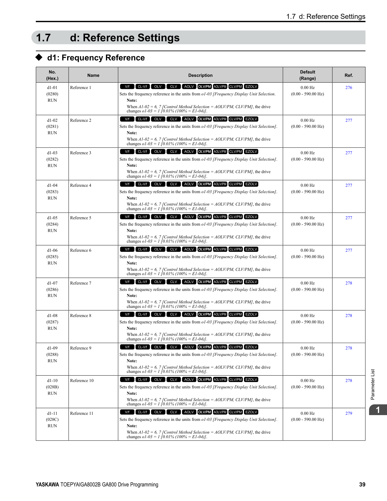
|17|Torque Detection 1 (N.C.)|The terminal deactivates when the drive detects overtorque or undertorque. OFF : The output current/torque is more than the torque value set with L6-02 [Torque Detection Level 1], or the level is less than the torque value set with L6-02 [Torque Detection Level 1] for longer than the time set with L6-03 [Torque Detection Time 1].
V/f CL-V/f OLV CLV AOLV OLV/PM AOLV/PM CLV/PM EZOLV
|397| |18|Torque Detection 2 (N. O.)|The terminal activates when the drive detects overtorque or undertorque. ON : The output current/torque is more than the torque value set with L6-05 [Torque Detection Level 2], or the level is less than the torque value set with L6-05 [Torque Detection Level 2] for longer than the time set with L6-06 [Torque Detection Time 2].
V/f CL-V/f OLV CLV AOLV OLV/PM AOLV/PM CLV/PM EZOLV
|398| |19|Torque Detection 2 (N.C.)|The terminal deactivates when the drive detects overtorque or undertorque. OFF : The output current/torque is more than the torque value set with L6-05 [Torque Detection Level 2], or the level is less than the torque value set with L6-05 [Torque Detection Level 2] for longer than the time set with L6-06 [Torque Detection Time 2].
V/f CL-V/f OLV CLV AOLV OLV/PM AOLV/PM CLV/PM EZOLV
|398| |1A|During reverse|The terminal activates when the motor operates in the reverse direction. ON : The motor is operating in the reverse direction. OFF : The motor is operating in the forward direction or the motor stopped.
V/f CL-V/f OLV CLV AOLV OLV/PM AOLV/PM CLV/PM EZOLV
|398| |1B|During Baseblock (N.C.)|The terminal deactivates during baseblock. When the drive is in baseblock, the drive output transistor stops switching and does not make DC bus voltage. ON : The drive is not in baseblock. OFF : During baseblock
V/f CL-V/f OLV CLV AOLV OLV/PM AOLV/PM CLV/PM EZOLV
|398| |1C|Motor 2 Selected|The terminal activates when motor 2 is selected. ON : Motor 2 Selection OFF : Motor 1 Selection
V/f CL-V/f OLV CLV AOLV OLV/PM AOLV/PM CLV/PM EZOLV
|399| |1D|During Regeneration|The terminal activates on when the motor is regenerating. ON : Motor is regenerating. OFF : Motor is operating or stopped.
V/f CL-V/f OLV CLV AOLV OLV/PM AOLV/PM CLV/PM EZOLV
|399| |1E|Executing Auto-Restart|The terminal activates when the Auto Restart function is trying to restart after a fault.
V/f CL-V/f OLV CLV AOLV OLV/PM AOLV/PM CLV/PM EZOLV
|399| |1F|Motor Overload Alarm (oL1)|The terminal activates when the electronic thermal protection value of the motor overload protective function is a minimum of 90% of the detection level.
V/f CL-V/f OLV CLV AOLV OLV/PM AOLV/PM CLV/PM EZOLV
|399| |20|Drive Overheat PreAlarm (oH)|The terminal activates when the drive heatsink temperature is at the level set with L8-02 [Overheat Alarm Level].
V/f CL-V/f OLV CLV AOLV OLV/PM AOLV/PM CLV/PM EZOLV
|399| |21|Safe Torque OFF|The terminal activates (safety stop state) when the safety circuit and safety diagnosis circuit are operating correctly and when terminals H1-HC and H2-HC are OFF (Open).
ON : Safety stop state OFF : Safety circuit fault or RUN/READY
V/f CL-V/f OLV CLV AOLV OLV/PM AOLV/PM CLV/PM EZOLV
|399| |22|Mechanical Weakening Detection|The terminal activates when the drive detects mechanical weakening.
V/f CL-V/f OLV CLV AOLV OLV/PM AOLV/PM CLV/PM EZOLV
|400|
|Setting Value|Function|Description|Ref.| |---|---|---|---| |2F|Maintenance Notification|The terminal activates when drive components are at their estimated maintenance period. Tells the user about the maintenance period for these items:
• IGBT
• Cooling fan
• Capacitor
• Soft charge bypass relay
V/f CL-V/f OLV CLV AOLV OLV/PM AOLV/PM CLV/PM EZOLV
|400| |30|During Torque Limit|The terminal activates when the torque reference is the torque limit set with L7 parameters, H3-02, H3-06, or H3-10 [MFAI Function Selection].
V/f CL-V/f OLV CLV AOLV OLV/PM AOLV/PM CLV/PM EZOLV
|400| |31|During Speed Limit|The terminal activates when the speed limit is active.
V/f CL-V/f OLV CLV AOLV OLV/PM AOLV/PM CLV/PM EZOLV
|400| |32|In Speed Limit During Trq Ctrl|The motor accelerates in the forward direction or the reverse direction after enabling torque control and the externally input torque reference is disproportionate to the load. The output terminal activates when this speed is not higher than a constant speed and the motor speed is at the speed limit. This does not include operation when the drive is stopped.
V/f CL-V/f OLV CLV AOLV OLV/PM AOLV/PM CLV/PM EZOLV
|400| |33|Zero Servo Complete|The terminal activates when positioning in the range set with b9-02 [Zero Servo Completion Window] completes after sending the Zero-Servo command.
V/f CL-V/f OLV CLV AOLV OLV/PM AOLV/PM CLV/PM EZOLV
|401| |37|During Frequency Output|The terminal activates when the drive outputs frequency. ON : The drive outputs frequency. OFF : The drive does not output frequency.
V/f CL-V/f OLV CLV AOLV OLV/PM AOLV/PM CLV/PM EZOLV
|401| |38|Drive Enabled|This terminal activates when the H1-xx = 6A [Drive Enable] terminal activates.
V/f CL-V/f OLV CLV AOLV OLV/PM AOLV/PM CLV/PM EZOLV
|401| |39|Watt Hour Pulse Output|Outputs the pulse that shows the watt hours.
V/f CL-V/f OLV CLV AOLV OLV/PM AOLV/PM CLV/PM EZOLV
|401| |3C|LOCAL Control Selected|The terminal activates when the Run command source or frequency reference source is LOCAL. ON : LOCAL OFF : REMOTE
V/f CL-V/f OLV CLV AOLV OLV/PM AOLV/PM CLV/PM EZOLV
|401| |3D|During Speed Search|The terminal activates when the drive is doing speed search.
V/f CL-V/f OLV CLV AOLV OLV/PM AOLV/PM CLV/PM EZOLV
|402| |3E|PID Feedback Low|The terminal activates when the drive detects FbL [PID Feedback Loss].
V/f CL-V/f OLV CLV AOLV OLV/PM AOLV/PM CLV/PM EZOLV
|402| |3F|PID Feedback High|The terminal activates when the drive detects FbH [Excessive PID Feedback].
V/f CL-V/f OLV CLV AOLV OLV/PM AOLV/PM CLV/PM EZOLV
|402| |4A|During KEB Ride-Thru|The activates during KEB Ride-Thru.
V/f CL-V/f OLV CLV AOLV OLV/PM AOLV/PM CLV/PM EZOLV
|402| |4B|During Short Circuit Braking|The terminal activates during Short Circuit Braking. Note: When A1-02 8 [Control Method Selection EZOLV], this function is available when you use a PM motor.
V/f CL-V/f OLV CLV AOLV OLV/PM AOLV/PM CLV/PM EZOLV
|402| |4C|During Fast Stop|The terminal activates when the fast stop is in operation.
V/f CL-V/f OLV CLV AOLV OLV/PM AOLV/PM CLV/PM EZOLV
|402| |4D|oH Pre-Alarm Time Limit|The terminal activates when L8-03 = 4 [Overheat Pre-Alarm Selection = Operate at Reduced Speed (L8-19)] and oH [Heatsink Overheat] does not clear after the drive decreases the frequency for 10 cycles.
V/f CL-V/f OLV CLV AOLV OLV/PM AOLV/PM CLV/PM EZOLV
|403| |4E|Braking Transistor Fault (rr)|The terminal activates when the internal braking transistor overheats and the drive detects an rr [Dynamic Braking Transistor Fault] fault.
V/f CL-V/f OLV CLV AOLV OLV/PM AOLV/PM CLV/PM EZOLV
|403| |4F|Braking Resistor Overheat (rH)|The terminal activates when the braking resistor overheats and the drive detects an rH [Braking Resistor Overheat] fault.
V/f CL-V/f OLV CLV AOLV OLV/PM AOLV/PM CLV/PM EZOLV
|403| |60|Internal Cooling Fan Failure|The terminal activates when the drive detects a cooling fan failure in the drive.
V/f CL-V/f OLV CLV AOLV OLV/PM AOLV/PM CLV/PM EZOLV
|403| |61|Pole Position Detection Complete|The terminal activates when drive receives a Run command and the drive detects the motor magnetic pole position of the PM motor.
V/f CL-V/f OLV CLV AOLV OLV/PM AOLV/PM CLV/PM EZOLV
|403|
|Setting Value|Function|Description|Ref.| |---|---|---|---| |62|Modbus Reg 1 Status Satisfied|The terminal activates when the bit specified by H2-08 [Modbus Register 1 Bit Select] for the MEMOBUS register address set with H2-07 [Modbus Register 1 Address Select] activates.
V/f CL-V/f OLV CLV AOLV OLV/PM AOLV/PM CLV/PM EZOLV
|403| |63|Modbus Reg 2 Status Satisfied|The terminal activates when the bit specified by H2-10 [Modbus Register 2 Bit Select] for the MEMOBUS register address set with H2-09 [Modbus Register 2 Address Select] activates.
V/f CL-V/f OLV CLV AOLV OLV/PM AOLV/PM CLV/PM EZOLV
|403|
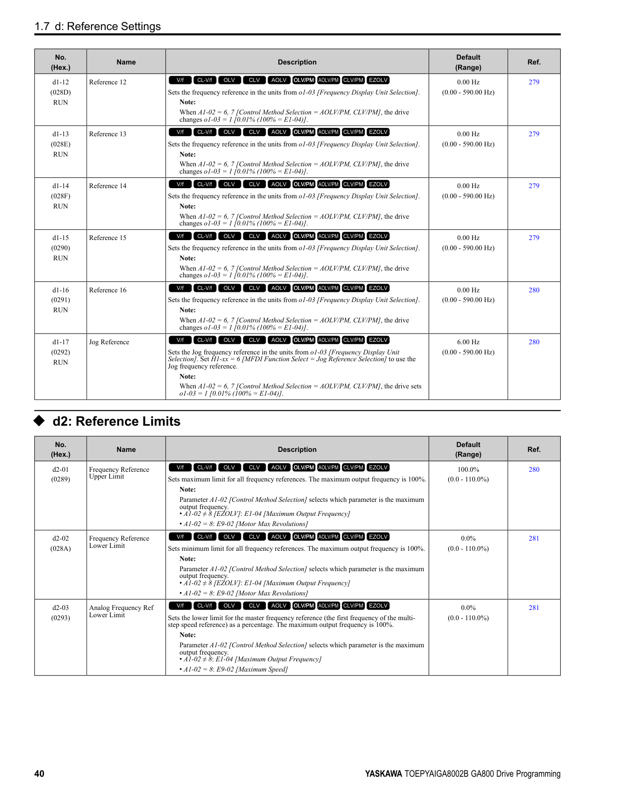
|65|Standby Output|The terminal deactivates after the drive stops operating and after the time set with b8-51 [Standby Mode Wait Time]. ON : The Run command turns on and the magnetic contactor on the input side turns on. OFF : The Run command turns off and the drive stops operating. Then, the magnetic contactor on the input side turns off after the time set in b8-51 [Standby Mode Wait Time] elapses.
V/f CL-V/f OLV CLV AOLV OLV/PM AOLV/PM CLV/PM EZOLV
|403| |66|Comparator1|The terminal activates if the monitor value set with H2-20 [Comparator 1 Monitor Selection] is in range of the values of H2-21 [Comparator 1 Lower Limit] and H2-22 [Comparator 1 Upper Limit] for the time set in H2-24 [Comparator 1 On-Delay Time].
V/f CL-V/f OLV CLV AOLV OLV/PM AOLV/PM CLV/PM EZOLV
|404| |67|Comparator2|The terminal activates if the monitor value set with H2-26 [Comparator 2 Monitor Selection] is not in the range of the values of H2-27 [Comparator 2 Lower Limit] and H2-28 [Comparator 2 Upper Limit] for the time set in H2-30 [Comparator 2 On-Delay Time].
V/f CL-V/f OLV CLV AOLV OLV/PM AOLV/PM CLV/PM EZOLV
|404| |69|External Power 24V Supply|The terminal activates when there is an external 24V power supply between terminals PS-AC. ON : An external 24V power supply supplies power. OFF : An external 24V power supply does not supply power.
V/f CL-V/f OLV CLV AOLV OLV/PM AOLV/PM CLV/PM EZOLV
|405| |6A|Data Logger Error|The terminal activates when the drive detects LoG [Com Error / Abnormal SD card].
V/f CL-V/f OLV CLV AOLV OLV/PM AOLV/PM CLV/PM EZOLV
|405| |90 to 93|DWEZ Digital Outputs 1 to 4|Sets the DriveWorksEZ digital output. Refer to the DriveWorksEZ online manual for more information.
V/f CL-V/f OLV CLV AOLV OLV/PM AOLV/PM CLV/PM EZOLV
|405| |A0 to A7|DWEZ Extended Digital Outputs 1 to 8|Sets the digital output for the DriveWorksEZ DO-A3 option card. Refer to the DriveWorksEZ online manual for more information.
V/f CL-V/f OLV CLV AOLV OLV/PM AOLV/PM CLV/PM EZOLV
|405| |100 to 1A7|Inverse Outputs of 0 to A7|Causes inverse output of the function for the selected MFDO. Uses the last two digits of 1xx to select which function to inversely output.
V/f CL-V/f OLV CLV AOLV OLV/PM AOLV/PM CLV/PM EZOLV
|405|
######## ◆ H3: Analog Inputs
|No. (Hex.)|Name|Description|Default (Range)|Ref.| |---|---|---|---|---| |H3-01 (0410)|Terminal A1 Signal Level Select|Sets the input signal level for MFAI terminal A1.
0 : 0 to 10V (Lower Limit at 0)
1 : -10 to +10V (Bipolar Reference)
2 : 4 to 20 mA
3 : 0 to 20 mA
V/f CL-V/f OLV CLV AOLV OLV/PM AOLV/PM CLV/PM EZOLV
|0 (0 - 3)|408| |H3-02 (0434)|Terminal A1 Function Selection|Sets the function for MFAI terminal A1.
V/f CL-V/f OLV CLV AOLV OLV/PM AOLV/PM CLV/PM EZOLV
|0 (0 - 32)|408| |H3-03 (0411) RUN|Terminal A1 Gain Setting|Sets the gain of the analog signal input to MFAI terminal A1.
V/f CL-V/f OLV CLV AOLV OLV/PM AOLV/PM CLV/PM EZOLV
|100.0% (-999.9 - +999.9%)|408| |H3-04 (0412) RUN|Terminal A1 Bias Setting|Sets the bias of the analog signal input to MFAI terminal A1.
V/f CL-V/f OLV CLV AOLV OLV/PM AOLV/PM CLV/PM EZOLV
|0.0% (-999.9 - +999.9%)|409| |H3-05 (0413)|Terminal A3 Signal Level Select|Sets the input signal level for MFAI terminal A3.
0 : 0 to 10V (Lower Limit at 0)
1 : -10 to +10V (Bipolar Reference)
2 : 4 to 20 mA
3 : 0 to 20 mA
V/f CL-V/f OLV CLV AOLV OLV/PM AOLV/PM CLV/PM EZOLV
|0 (0 - 3)|409| |H3-06 (0414)|Terminal A3 Function Selection|Sets the function for MFAI terminal A3.
V/f CL-V/f OLV CLV AOLV OLV/PM AOLV/PM CLV/PM EZOLV
|2 (0 - 32)|409|
|No. (Hex.)|Name|Description|Default (Range)|Ref.| |---|---|---|---|---| |H3-07 (0415) RUN|Terminal A3 Gain Setting|Sets the gain of the analog signal input to MFAI terminal A3.
V/f CL-V/f OLV CLV AOLV OLV/PM AOLV/PM CLV/PM EZOLV
|100.0% (-999.9 - +999.9%)|410| |H3-08 (0416) RUN|Terminal A3 Bias Setting|Sets the bias of the analog signal input to MFAI terminal A3.
V/f CL-V/f OLV CLV AOLV OLV/PM AOLV/PM CLV/PM EZOLV
|0.0% (-999.9 - +999.9%)|410| |H3-09 (0417)|Terminal A2 Signal Level Select|Sets the input signal level for MFAI terminal A2.
0 : 0-10V (LowLim=0)
1 : -10 to +10V (Bipolar Reference)
2 : 4 to 20 mA
3 : 0 to 20 mA
V/f CL-V/f OLV CLV AOLV OLV/PM AOLV/PM CLV/PM EZOLV
|2 (0 - 3)|410| |H3-10 (0418)|Terminal A2 Function Selection|Sets the function for MFAI terminal A2.
V/f CL-V/f OLV CLV AOLV OLV/PM AOLV/PM CLV/PM EZOLV
|0 (0 - 32)|410| |H3-11 (0419) RUN|Terminal A2 Gain Setting|Sets the gain of the analog signal input to MFAI terminal A2.
V/f CL-V/f OLV CLV AOLV OLV/PM AOLV/PM CLV/PM EZOLV
|100.0% (-999.9 - +999.9%)|411| |H3-12 (041A) RUN|Terminal A2 Bias Setting|Sets the bias of the analog signal input to MFAI terminal A2.
V/f CL-V/f OLV CLV AOLV OLV/PM AOLV/PM CLV/PM EZOLV
|0.0% (-999.9 - +999.9%)|411| |H3-13 (041B)|Analog Input FilterTime Constant|Sets the time constant for primary delay filters on MFAI terminals.
V/f CL-V/f OLV CLV AOLV OLV/PM AOLV/PM CLV/PM EZOLV
|0.03 s (0.00 - 2.00 s)|411| |H3-14 (041C)|Analog Input Terminal Enable Sel|Sets the enabled terminal or terminals when H1-xx = C [MFDI Function Select = Analog Terminal Enable Selection] is ON.
1 : Terminal A1 only
2 : Terminal A2 only
3 : Terminals A1 and A2
4 : Terminal A3 only
5 : Terminals A1 and A3
6 : Terminals A2 and A3
7 : Terminals A1, A2, and A3
V/f CL-V/f OLV CLV AOLV OLV/PM AOLV/PM CLV/PM EZOLV
|7 (1 - 7)|411| |H3-16 (02F0)|Terminal A1 Offset|Sets the offset level for analog signals input to terminal A1. Usually it is not necessary to change this setting.
V/f CL-V/f OLV CLV AOLV OLV/PM AOLV/PM CLV/PM EZOLV
|0 (-500 - +500)|412| |H3-17 (02F1)|Terminal A2 Offset|Sets the offset level for analog signals input to terminal A2. Usually it is not necessary to change this setting.
V/f CL-V/f OLV CLV AOLV OLV/PM AOLV/PM CLV/PM EZOLV
|0 (-500 - +500)|412| |H3-18 (02F2)|Terminal A3 Offset|Sets the offset level for analog signals input to terminal A3. Usually it is not necessary to change this setting.
V/f CL-V/f OLV CLV AOLV OLV/PM AOLV/PM CLV/PM EZOLV
|0 (-500 - +500)|412| |H3-40 (0B5C)|Mbus Reg 15C1h Input Function|Sets the MEMOBUS AI1 function.
V/f CL-V/f OLV CLV AOLV OLV/PM AOLV/PM CLV/PM EZOLV
|F (4 - 2F)|412| |H3-41 (0B5F)|Mbus Reg 15C2h Input Function|Sets the MEMOBUS AI2 function.
V/f CL-V/f OLV CLV AOLV OLV/PM AOLV/PM CLV/PM EZOLV
|F (4 - 2F)|412| |H3-42 (0B62)|Mbus Reg 15C3h Input Function|Sets the MEMOBUS AI3 function.
V/f CL-V/f OLV CLV AOLV OLV/PM AOLV/PM CLV/PM EZOLV
|F (4 - 2F)|413| |H3-43 (117F)|Mbus Reg Inputs FilterTime Const|Sets the time constant to apply a primary delay filter to the MEMOBUS analog input terminal.
V/f CL-V/f OLV CLV AOLV OLV/PM AOLV/PM CLV/PM EZOLV
|0.00 s (0.00 - 2.00 s)|413|
######## ■ H3-xx: MFAI Setting Values
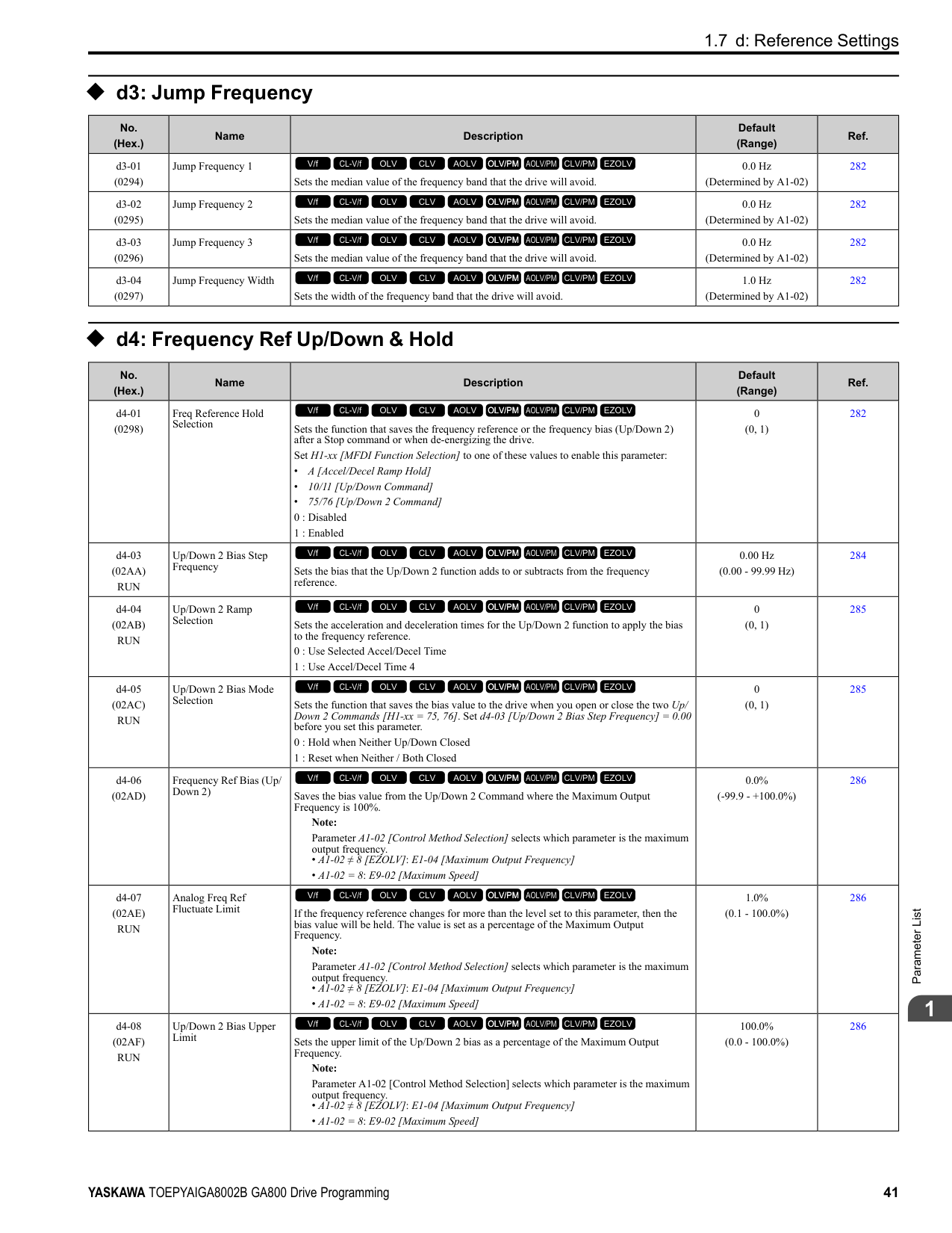
|Setting Value|Function|Description|Ref.| |---|---|---|---| |0|Frequency Reference|The input value from the MFAI terminal set with this function becomes the master frequency reference.
V/f CL-V/f OLV CLV AOLV OLV/PM AOLV/PM CLV/PM EZOLV
|413| |1|Frequency Gain|The drive multiplies the analog frequency reference with the input value from the MFAI set with this function.
V/f CL-V/f OLV CLV AOLV OLV/PM AOLV/PM CLV/PM EZOLV
|413|
|Setting Value|Function|Description|Ref.| |---|---|---|---| |2|Auxiliary Frequency Reference 1|Sets Reference 2 through multi-step speed reference to enable the command reference (Auxiliary Frequency Reference 1) from the analog input terminal set here. This value is a percentage where the Maximum Output Frequency setting is a setting value of 100%.
Note: Parameter A1-02 [Control Method Selection] selects which parameter is the maximum output frequency.
• A1-02 ≠ 8 [EZOLV]: E1-04 [Maximum Output Frequency]
• A1-02 = 8: E9-02 [Maximum Speed]
V/f CL-V/f OLV CLV AOLV OLV/PM AOLV/PM CLV/PM EZOLV
|413| |3|Auxiliary Frequency Reference 2|Sets Reference 3 through multi-step speed reference to enable the command reference (Auxiliary Frequency Reference 2) from the analog input terminal set here. This value is a percentage where the Maximum Output Frequency setting is a setting value of 100%.
Note: Parameter A1-02 [Control Method Selection] selects which parameter is the maximum output frequency.
• A1-02 ≠ 8 [EZOLV]: E1-04 [Maximum Output Frequency]
• A1-02 = 8: E9-02 [Maximum Speed]
V/f CL-V/f OLV CLV AOLV OLV/PM AOLV/PM CLV/PM EZOLV
|414| |4|Output Voltage Bias|Set this parameter to input a bias signal and amplify the output voltage.
V/f CL-V/f OLV CLV AOLV OLV/PM AOLV/PM CLV/PM EZOLV
|414| |5|Accel/Decel Time Gain|Enters a signal to adjust the gain used for C1-01 to C1-08 [Acceleration/Deceleration Times 1 to 4] and C1-09 [Fast Stop Time] when the full scale analog signal (10 Vor 20 mA) is 100%.
V/f CL-V/f OLV CLV AOLV OLV/PM AOLV/PM CLV/PM EZOLV
|414| |6|DC Injection Braking Current|Enters a signal to adjust the current level used for DC Injection Braking when the drive rated output current is 100%.
V/f CL-V/f OLV CLV AOLV OLV/PM AOLV/PM CLV/PM EZOLV
|414| |7|Torque Detection Level|Enters a signal to adjust the overtorque/undertorque detection level. Note: Use this function with L6-01 [Torque Detection Selection 1]. This parameter functions as an alternative to L6-02 [Torque Detection Level 1].
V/f CL-V/f OLV CLV AOLV OLV/PM AOLV/PM CLV/PM EZOLV
|415| |8|Stall Prevent Level During Run|Enters a signal to adjust the stall prevention level during run if the drive rated current is 100%.
V/f CL-V/f OLV CLV AOLV OLV/PM AOLV/PM CLV/PM EZOLV
|415| |9|Output Frequency Lower Limit|Enters a signal to adjust the output frequency lower limit level as a percentage of the maximum output frequency. Note: Parameter A1-02 [Control Method Selection] selects which parameter is the maximum output frequency.
• A1-02 ≠ 8 [EZOLV]: E1-04 [Maximum Output Frequency]
• A1-02 = 8: E9-02 [Maximum Speed]
V/f CL-V/f OLV CLV AOLV OLV/PM AOLV/PM CLV/PM EZOLV
|415| |B|PID Feedback|Enter the PID feedback value as a percentage of the maximum output frequency. Note: Parameter A1-02 [Control Method Selection] selects which parameter is the maximum output frequency.
• A1-02 ≠ 8 [EZOLV]: E1-04 [Maximum Output Frequency]
• A1-02 = 8: E9-02 [Maximum Speed]
V/f CL-V/f OLV CLV AOLV OLV/PM AOLV/PM CLV/PM EZOLV
|415| |C|PID Setpoint|Enters the PID setpoint as a percentage of the maximum output frequency. Note: Parameter A1-02 [Control Method Selection] selects which parameter is the maximum output frequency.
• A1-02 ≠ 8 [EZOLV]: E1-04 [Maximum Output Frequency]
• A1-02 = 8: E9-02 [Maximum Speed]
V/f CL-V/f OLV CLV AOLV OLV/PM AOLV/PM CLV/PM EZOLV
|416| |D|Frequency Bias|Enters the bias value added to the frequency reference as a percentage of the maximum output frequency. Note: Parameter A1-02 [Control Method Selection] selects which parameter is the maximum output frequency.
• A1-02 ≠ 8 [EZOLV]: E1-04 [Maximum Output Frequency]
• A1-02 = 8: E9-02 [Maximum Speed]
V/f CL-V/f OLV CLV AOLV OLV/PM AOLV/PM CLV/PM EZOLV
|416| |E|Motor Temperature (PTC Input)|Uses the motor Positive Temperature Coefficient (PTC) thermistor to prevent heat damage to the motor as a percentage of the current value when the 10 Vanalog signal is input.
V/f CL-V/f OLV CLV AOLV OLV/PM AOLV/PM CLV/PM EZOLV
|416| |F|Not Used|Use this setting for unused terminals or to use terminals in through mode.
V/f CL-V/f OLV CLV AOLV OLV/PM AOLV/PM CLV/PM EZOLV
|416| |10|Forward Torque Limit|Enters the forward torque limit if the motor rated torque is 100%.
V/f CL-V/f OLV CLV AOLV OLV/PM AOLV/PM CLV/PM EZOLV
|416| |11|Reverse Torque Limit|Enters the load torque limit if the motor rated torque is 100%.
V/f CL-V/f OLV CLV AOLV OLV/PM AOLV/PM CLV/PM EZOLV
|417|
|Setting Value|Function|Description|Ref.| |---|---|---|---| |12|Regenerative Torque Limit|Enters the regenerative torque limit if the motor rated torque is 100%.
V/f CL-V/f OLV CLV AOLV OLV/PM AOLV/PM CLV/PM EZOLV
|418| |13|Torque Reference / Torque Limit|Enters the torque reference if the motor rated torque is 100%. This setting is the torque limit for speed control.
V/f CL-V/f OLV CLV AOLV OLV/PM AOLV/PM CLV/PM EZOLV
|418| |14|Torque Compensation|Enters the torque compensation value if the motor rated torque is 100%.
V/f CL-V/f OLV CLV AOLV OLV/PM AOLV/PM CLV/PM EZOLV
|418| |15|General Torque Limit|Enters the torque limit that is the same for all quadrants for forward, reverse, and regenerative operation if the motor rated torque is 100%.
V/f CL-V/f OLV CLV AOLV OLV/PM AOLV/PM CLV/PM EZOLV
|418| |16|Differential PID Feedback|Enters the PID differential feedback value if the full scale analog signal (10 Vor 20 mA) is 100%.
V/f CL-V/f OLV CLV AOLV OLV/PM AOLV/PM CLV/PM EZOLV
|418| |1F|Not Used|Use this setting for unused terminals or to use terminals in through mode.
V/f CL-V/f OLV CLV AOLV OLV/PM AOLV/PM CLV/PM EZOLV
|418| |30|DWEZ Analog Input 1|Use with DriveWorksEZ. Refer to the DriveWorksEZ online manual for more information.
V/f CL-V/f OLV CLV AOLV OLV/PM AOLV/PM CLV/PM EZOLV
|418| |31|DWEZ Analog Input 2|Use with DriveWorksEZ. Refer to the DriveWorksEZ online manual for more information.
V/f CL-V/f OLV CLV AOLV OLV/PM AOLV/PM CLV/PM EZOLV
|418| |32|DWEZ Analog Input 3|Use with DriveWorksEZ. Refer to the DriveWorksEZ online manual for more information.
V/f CL-V/f OLV CLV AOLV OLV/PM AOLV/PM CLV/PM EZOLV
|419|
######## ◆ H4: Analog Outputs
|No. (Hex.)|Name|Description|Default (Range)|Ref.|
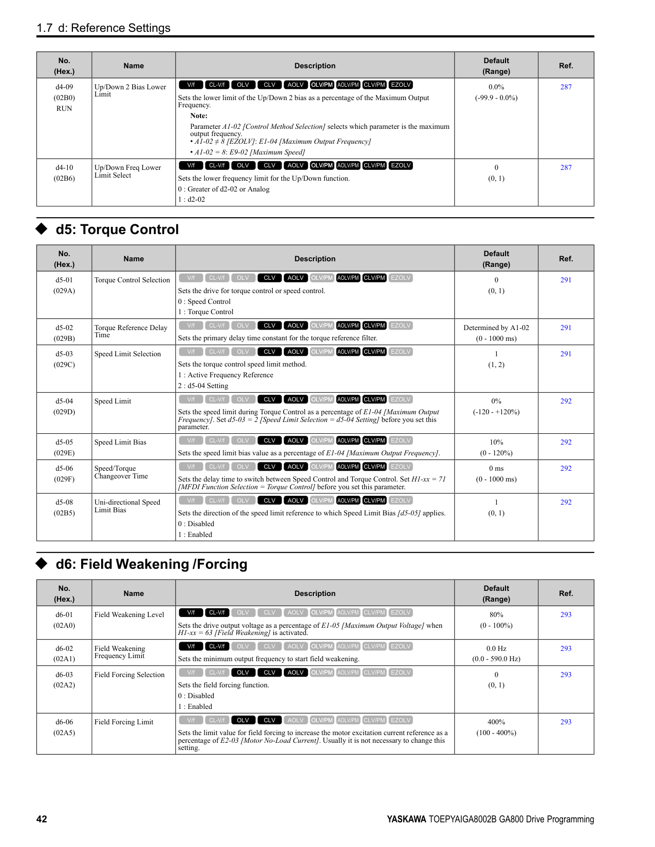
|---|---|---|---|---| |H4-01 (041D)|Terminal FM Analog Output Select|Sets the monitor number to send from MFAO terminal FM. Set the x-xx part of the Ux-xx [Monitor]. For example, set H4-01 = 102 to monitor U1-02 [Output Frequency].
V/f CL-V/f OLV CLV AOLV OLV/PM AOLV/PM CLV/PM EZOLV
|102 (000 - 999)|420| |H4-02 (041E) RUN|Terminal FM Analog Output Gain|Sets the gain of the monitor signal that is sent from MFAO terminal FM. Sets the analog signal output level from the terminal FM at 10 Vor 20 mA as 100% when an output for monitoring items is 100%.
V/f CL-V/f OLV CLV AOLV OLV/PM AOLV/PM CLV/PM EZOLV
|100.0% (-999.9 - +999.9%)|420| |H4-03 (041F) RUN|Terminal FM Analog Output Bias|Sets the bias of the monitor signal that is sent from MFAO terminal FM. Set the level of the analog signal sent from terminal FM at 10 Vor 20 mA as 100% when an output for monitoring items is 0%.
V/f CL-V/f OLV CLV AOLV OLV/PM AOLV/PM CLV/PM EZOLV
|0.0% (-999.9 - +999.9%)|421| |H4-04 (0420)|Terminal AM Analog Output Select|Sets the monitoring number to be output from the MFAO terminal AM. Set the x-xx part of the Ux-xx [Monitor]. For example, set H4-04 = 103 to monitor U1-03 [Output Current].
V/f CL-V/f OLV CLV AOLV OLV/PM AOLV/PM CLV/PM EZOLV
|103 (000 - 999)|421| |H4-05 (0421) RUN|Terminal AM Analog Output Gain|Sets the gain of the monitor signal that is sent from MFAO terminal AM. When an output for monitoring items is 0%, this parameter sets the analog signal output level from the AM terminal at 10 Vor 20 mA as 100%.
V/f CL-V/f OLV CLV AOLV OLV/PM AOLV/PM CLV/PM EZOLV
|50.0% (-999.9 - +999.9%)|421| |H4-06 (0422) RUN|Terminal AM Analog Output Bias|Sets the bias of the monitor signal that is sent from MFAO terminal AM. When an output for monitoring items is 0%, this parameter sets the analog signal output level from the AM terminal at 10 Vor 20 mA as 0%.
V/f CL-V/f OLV CLV AOLV OLV/PM AOLV/PM CLV/PM EZOLV
|0.0% (-999.9 - +999.9%)|421| |H4-07 (0423)|Terminal FM Signal Level Select|Sets the MFAO terminal FM output signal level.
Note:
Set jumper S5 on the control circuit terminal block accordingly when changing these parameters.
0 : 0 to 10 Vdc
1 : -10 to +10 Vdc
2 : 4 to 20 mA
V/f CL-V/f OLV CLV AOLV OLV/PM AOLV/PM CLV/PM EZOLV
|0 (0 - 2)|421|
|No. (Hex.)|Name|Description|Default (Range)|Ref.| |---|---|---|---|---| |H4-08 (0424)|Terminal AM Signal Level Select|Sets the MFAO terminal AM output signal level.
Note:
Set jumper S5 on the control circuit terminal block accordingly when changing these parameters.
0 : 0 to 10 Vdc
1 : -10 to +10 Vdc
2 : 4 to 20 mA
V/f CL-V/f OLV CLV AOLV OLV/PM AOLV/PM CLV/PM EZOLV
|0 (0 - 2)|422| |H4-20 (0B53)|Analog Power Monitor 100% Level|Sets the level at 10 V when U1-08 [Output Power] is set for analog output.
V/f CL-V/f OLV CLV AOLV OLV/PM AOLV/PM CLV/PM EZOLV
|0.00 kW (0.00 - 650.00 kW)|422|
######## ◆ H5: Modbus Communication
|No. (Hex.)|Name|Description|Default (Range)|Ref.| |---|---|---|---|---| |H5-01 (0425)|Drive Node Address|Sets the communication slave address for drives.
Note:
• Restart the drive after changing the parameter setting.
• Setting 0 will not let the drive respond to MEMOBUS/Modbus communications.
V/f CL-V/f OLV CLV AOLV OLV/PM AOLV/PM CLV/PM EZOLV
|1FH (0 - FFH)|422| |H5-02 (0426)|Communication Speed Selection|Sets the communications speed for MEMOBUS/Modbus communications. Note: Restart the drive after changing the parameter setting.
0 : 1200 bps
1 : 2400 bps
2 : 4800 bps
3 : 9600 bps
4 : 19200 bps
5 : 38400 bps
6 : 57600 bps
7 : 76800 bps
8 : 115200 bps
V/f CL-V/f OLV CLV AOLV OLV/PM AOLV/PM CLV/PM EZOLV
|3 (0 - 8)|423| |H5-03 (0427)|Communication Parity Selection|Sets the communications parity used for MEMOBUS/Modbus communications. Note: Restart the drive after changing the parameter setting.
0 : No parity
1 : Even parity
2 : Odd parity
V/f CL-V/f OLV CLV AOLV OLV/PM AOLV/PM CLV/PM EZOLV
|0 (0 - 2)|423| |H5-04 (0428)|Communication Error Stop Method|Sets the motor Stopping Method when the drive detects CE [Modbus Communication Error] issues.
0 : Ramp to Stop
1 : Coast to Stop
2 : Fast Stop (Use C1-09)
3 : Alarm Only
V/f CL-V/f OLV CLV AOLV OLV/PM AOLV/PM CLV/PM EZOLV
|3 (0 - 3)|423| |H5-05 (0429)|Comm Fault Detection Selection|Sets the function that detects CE [Modbus Communication Error] issues during MEMOBUS/Modbus communications.
0 : Disabled
1 : Enabled
V/f CL-V/f OLV CLV AOLV OLV/PM AOLV/PM CLV/PM EZOLV
|1 (0, 1)|424| |H5-06 (042A)|Drive Transmit Wait Time|Sets the time to wait to send a response message after the drive receives a command message from the master.
Note: Restart the drive after changing the parameter setting.
V/f CL-V/f OLV CLV AOLV OLV/PM AOLV/PM CLV/PM EZOLV
|5 ms (0 - 65 ms)|424| |H5-09 (0435)|CE Detection Time|Sets the detection time for CE [Modbus Communication Error] issues when communication stops.
V/f CL-V/f OLV CLV AOLV OLV/PM AOLV/PM CLV/PM EZOLV
|2.0 s (0.0 - 10.0 s)|424|
|No. (Hex.)|Name|Description|Default (Range)|Ref.| |---|---|---|---|---| |H5-10 (0436)|Modbus Register 0025H Unit Sel|Sets the unit of measure used for the MEMOBUS/Modbus communications monitor register 0025H (output voltage reference monitor).
0 : 0.1 V units
1 : 1 V units
V/f CL-V/f OLV CLV AOLV OLV/PM AOLV/PM CLV/PM EZOLV
|0 (0, 1)|424| |H5-11 (043C)|Comm ENTER Command Mode|Sets the function to make the Enter command necessary to change parameters through MEMOBUS/Modbus communications.
0 : ENTER Command Required
1 : ENTER Command Not Required
V/f CL-V/f OLV CLV AOLV OLV/PM AOLV/PM CLV/PM EZOLV
|0 (0, 1)|424| |H5-12 (043D)|Run Command Method Selection|Sets the input method for the Run command when b1-02 = 2 [Run Command Selection 1 = Memobus/Modbus Communications] or b1-16 = 2 [Run Command Selection 2 = Memobus/Modbus Communications].
0 : FWD/Stop, REV/Stop
1 : Run/Stop, FWD/REV
V/f CL-V/f OLV CLV AOLV OLV/PM AOLV/PM CLV/PM EZOLV
|0 (0, 1)|425| |H5-17 (11A1) Expert|ENTER command response @CPU BUSY|Sets operation when the EEPROM write command is sent without EEPROM write available. Usually it is not necessary to change this setting.
0 : Ignore Command(No ROM/RAM Write)
1 : Write to RAM Only
V/f CL-V/f OLV CLV AOLV OLV/PM AOLV/PM CLV/PM EZOLV
|0 (0, 1)|425| |H5-18 (11A2)|Motor Speed Filter over Comms|Sets the filter time constant used when monitoring motor speed during MEMOBUS/ Modbus communications or with a communication option.
V/f CL-V/f OLV CLV AOLV OLV/PM AOLV/PM CLV/PM EZOLV
|0 ms (0 - 100 ms)|425| |H5-20 (0B57)|Communication Parameters Reload|Sets the function to immediately enable updated MEMOBUS/Modbus communications parameters.
0 : Reload at Next Power Cycle
1 : Reload Now
V/f CL-V/f OLV CLV AOLV OLV/PM AOLV/PM CLV/PM EZOLV
|0 (0, 1)|425| |H5-22 (11CF)|Speed Search from MODBUS|Enables the MEMOBUS/Modbus communication register Speed Search function (bit0 of 15DFH).
0 : Disabled
1 : Enabled
V/f CL-V/f OLV CLV AOLV OLV/PM AOLV/PM CLV/PM EZOLV
|0 (0, 1)|426| |H5-25 (1589) RUN|Function 5A Register 1 Selection|Returns the contents of the specified MEMOBUS/Modbus communications register when responding to the master device.
V/f CL-V/f OLV CLV AOLV OLV/PM AOLV/PM CLV/PM EZOLV
|0044H (U1-05) (0000H - FFFFH)|426| |H5-26 (158A) RUN|Function 5A Register 2 Selection|Returns the contents of the specified MEMOBUS/Modbus communications register when responding to the master device.
V/f CL-V/f OLV CLV AOLV OLV/PM AOLV/PM CLV/PM EZOLV
|0045H (U1-06) (0000H - FFFFH)|426| |H5-27 (158B) RUN|Function 5A Register 3 Selection|Returns the contents of the specified MEMOBUS/Modbus communications register when responding to the master device.
V/f CL-V/f OLV CLV AOLV OLV/PM AOLV/PM CLV/PM EZOLV
|0042H (U1-03) (0000H - FFFFH)|426| |H5-28 (158C) RUN|Function 5A Register 4 Selection|Returns the contents of the specified MEMOBUS/Modbus communications register when responding to the master device.
V/f CL-V/f OLV CLV AOLV OLV/PM AOLV/PM CLV/PM EZOLV
|0049H (U1-10) (0000H - FFFFH)|426|
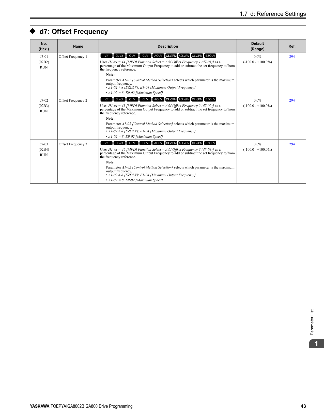
######## ◆ H6: Pulse Train Input/Output
|No. (Hex.)|Name|Description|Default (Range)|Ref.| |---|---|---|---|---| |H6-01 (042C)|Terminal RP Pulse Train Function|Sets the function for pulse train input terminal RP.
0 : Frequency Reference
1 : PID Feedback Value
2 : PID Setpoint
3 : Speed Feedback (V/F Control)
V/f CL-V/f OLV CLV AOLV OLV/PM AOLV/PM CLV/PM EZOLV
|0 (0 - 3)|427| |H6-02 (042D) RUN|Terminal RP Frequency Scaling|Sets the frequency of the pulse train input signal used when the item selected with H6-01 [Terminal RP Pulse Train Function] is input at 100%.
V/f CL-V/f OLV CLV AOLV OLV/PM AOLV/PM CLV/PM EZOLV
|1440 Hz (100 - 32000 Hz)|428|
|No. (Hex.)|Name|Description|Default (Range)|Ref.| |---|---|---|---|---| |H6-03 (042E) RUN|Terminal RP Function Gain|Sets the gain used when the function in H6-01 [Terminal RP Pulse Train Function] is input to terminal RP.
V/f CL-V/f OLV CLV AOLV OLV/PM AOLV/PM CLV/PM EZOLV
|100.0% (0.0 - 1000.0%)|428| |H6-04 (042F) RUN|Terminal RP Function Bias|Sets the bias used when the function in H6-01 [Terminal RP Pulse Train Function] is input to terminal RP. Sets a value at the time when the pulse train is 0 Hz.
V/f CL-V/f OLV CLV AOLV OLV/PM AOLV/PM CLV/PM EZOLV
|0.0% (-100.0 - 100.0%)|428| |H6-05 (0430) RUN|Terminal RP Filter Time|Sets the time constant for the pulse train input primary delay filters.
V/f CL-V/f OLV CLV AOLV OLV/PM AOLV/PM CLV/PM EZOLV
|0.10 s (0.00 - 2.00 s)|429| |H6-06 (0431) RUN|Terminal MP Monitor Selection|Sets a function for pulse train monitor output terminal MP. Sets the “x-xx” part of the Ux-xx monitor.
V/f CL-V/f OLV CLV AOLV OLV/PM AOLV/PM CLV/PM EZOLV
|102
(000, 031, 101, 102, 105, 116, 501, 502, 801 - 809, 821 - 825, 831 - 839, 851 - 855)|429| |H6-07 (0432) RUN|Terminal MP Frequency Scaling|Sets the frequency of the pulse train output signal used when the monitor set with H6-06 [Terminal MP Monitor Selection] is 100%.
V/f CL-V/f OLV CLV AOLV OLV/PM AOLV/PM CLV/PM EZOLV
|1440 Hz (0 - 32000 Hz)|430| |H6-08 (043F)|Terminal RP Minimum Frequency|Sets the minimum frequency of the pulse train signal that terminal RP can detect.
V/f CL-V/f OLV CLV AOLV OLV/PM AOLV/PM CLV/PM EZOLV
|0.5 Hz (0.1 - 1000.0 Hz)|430| |H6-09 (156E)|Voltage Phase Sync MP Selection|Set whether to output the pulse synchronized with drive output voltage phase from the pulse train monitor output terminal MP. This parameter is only enabled when H6-06 102 [Terminal MP Monitor Selection = Output Frequency] and H6-07 = 0 [Terminal MP Frequency Scaling 0 Hz].
0 : Disabled
1 : Enabled
V/f CL-V/f OLV CLV AOLV OLV/PM AOLV/PM CLV/PM EZOLV
|0 (0, 1)|430|
######## ◆ H7: Virtual MFIO selection
|No. (Hex.)|Name|Description|Default (Range)|Ref.| |---|---|---|---|---| |H7-00 (116F) Expert|Virtual MFIO selection|Sets the function to enable and disable the virtual I/O function. Set this parameter to 1 to operate the virtual I/O function.
0 : No
1 : Yes
V/f CL-V/f OLV CLV AOLV OLV/PM AOLV/PM CLV/PM EZOLV
|0 (0, 1)|431| |H7-01 (1185) Expert|Virtual Multi-Function Input 1|Sets the function that enters the virtual input set in H7-10 [Virtual Multi-Function Output 1].
Note:
Settings 1B [Programming Lockout] and 11B [!Programming Lockout] are not available.
V/f CL-V/f OLV CLV AOLV OLV/PM AOLV/PM CLV/PM EZOLV
|F (1 - 19F)|431| |H7-02 (1186) Expert|Virtual Multi-Function Input 2|Sets the function that enters the virtual input set in H7-12 [Virtual Multi-Function Output 2].
Note:
Settings 1B [Programming Lockout] and 11B [!Programming Lockout] are not available.
V/f CL-V/f OLV CLV AOLV OLV/PM AOLV/PM CLV/PM EZOLV
|F (1 - 19F)|431| |H7-03 (1187) Expert|Virtual Multi-Function Input 3|Sets the function that enters the virtual input set in H7-14 [Virtual Multi-Function Output 3].
Note:
Settings 1B [Programming Lockout] and 11B [!Programming Lockout] are not available.
V/f CL-V/f OLV CLV AOLV OLV/PM AOLV/PM CLV/PM EZOLV
|F (1 - 19F)|431| |H7-04 (1188) Expert|Virtual Multi-Function Input 4|Sets the function that enters the virtual input set in H7-16 [Virtual Multi-Function Output 4].
Note:
Settings 1B [Programming Lockout] and 11B [!Programming Lockout] are not available.
V/f CL-V/f OLV CLV AOLV OLV/PM AOLV/PM CLV/PM EZOLV
|F (1 - 19F)|432| |H7-10 (11A4) Expert|Virtual Multi-Function Output 1|Sets the function for virtual digital output 1.
V/f CL-V/f OLV CLV AOLV OLV/PM AOLV/PM CLV/PM EZOLV
|F (0 - 1A7)|432|
|No. (Hex.)|Name|Description|Default (Range)|Ref.| |---|---|---|---|---| |H7-11 (11A5) Expert|Virtual Output 1 Delay Time|Sets the minimum ON time for virtual digital output 1.
V/f CL-V/f OLV CLV AOLV OLV/PM AOLV/PM CLV/PM EZOLV
|0.1 s (0.0 - 25.0 s)|432| |H7-12 (11A6) Expert|Virtual Multi-Function Output 2|Sets the function for virtual digital output 2.
V/f CL-V/f OLV CLV AOLV OLV/PM AOLV/PM CLV/PM EZOLV
|F (0 - 1A7)|432| |H7-13 (11A7) Expert|Virtual Output 2 Delay Time|Sets the minimum ON time for virtual digital output 2.
V/f CL-V/f OLV CLV AOLV OLV/PM AOLV/PM CLV/PM EZOLV
|0.1 s (0.0 - 25.0 s)|432| |H7-14 (11A8) Expert|Virtual Multi-Function Output 3|Sets the function for virtual digital output 3.
V/f CL-V/f OLV CLV AOLV OLV/PM AOLV/PM CLV/PM EZOLV
|F (0 - 1A7)|432| |H7-15 (11A9) Expert|Virtual Output 3 Delay Time|Sets the minimum ON time for virtual digital output 3.
V/f CL-V/f OLV CLV AOLV OLV/PM AOLV/PM CLV/PM EZOLV
|0.1 s (0.0 - 25.0 s)|432| |H7-16 (11AA) Expert|Virtual Multi-Function Output 4|Sets the function for virtual digital output 4.
V/f CL-V/f OLV CLV AOLV OLV/PM AOLV/PM CLV/PM EZOLV
|F (0 - 1A7)|433| |H7-17 (11AB) Expert|Virtual Output 4 Delay Time|Sets the minimum ON time for virtual digital output 4.
V/f CL-V/f OLV CLV AOLV OLV/PM AOLV/PM CLV/PM EZOLV
|0.1 s (0.0 - 25.0 s)|433|
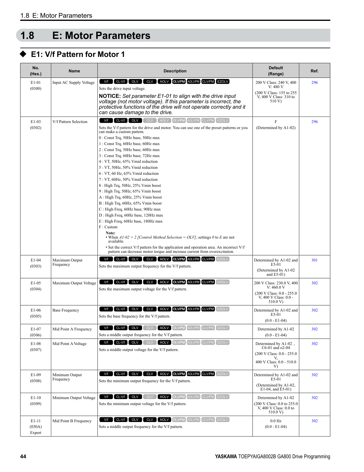
|H7-30 (1177) Expert|Virtual Analog Input Selection|Sets the virtual analog input function.
V/f CL-V/f OLV CLV AOLV OLV/PM AOLV/PM CLV/PM EZOLV
|F (0 - 32)|433| |H7-31 (1178) RUN Expert|Virtual Analog Input Gain|Sets the virtual analog input gain.
V/f CL-V/f OLV CLV AOLV OLV/PM AOLV/PM CLV/PM EZOLV
|100.0% (-999.9 - 999.9%)|433| |H7-32 (1179) RUN Expert|Virtual Analog Input Bias|Sets the virtual analog input bias.
V/f CL-V/f OLV CLV AOLV OLV/PM AOLV/PM CLV/PM EZOLV
|0.0% (-999.9 - 999.9%)|433| |H7-40 (1163)|Virtual Analog Out Signal Select|Sets the signal level of the virtual analog output.
0 : 0 to 100% (Absolute Value)
1 : -100 to 100%
2 : 0 to 100% (Lower Limit at 0)
V/f CL-V/f OLV CLV AOLV OLV/PM AOLV/PM CLV/PM EZOLV
|0 (0 - 2)|433| |H7-41 (1164)|Virtual Analog Output Function|Sets the monitor to be output from the virtual analog output. Set the x-xx part of the Ux-xx [Monitor]. For example, set H7-41 = 102 to monitor U1-02 [Output Frequency].
V/f CL-V/f OLV CLV AOLV OLV/PM AOLV/PM CLV/PM EZOLV
|102 (0 - 999)|433| |H7-42 (1165)|Virtual Analog Output FilterTime|Sets the time constant for a primary filter of the virtual analog output.
V/f CL-V/f OLV CLV AOLV OLV/PM AOLV/PM CLV/PM EZOLV
|0.00 s (0.00 - 2.00 s)|434|
####### 1.11 L: Protection Functions
◆ L1: Motor Protection
|No. (Hex.)|Name|Description|Default (Range)|Ref.| |---|---|---|---|---| |L1-01 (0480)|Motor Overload (oL1) Protection|Sets the motor overload protection with electronic thermal protectors.
0 : Disabled
1 : Variable Torque
2 : Constant Torque 10:1 Speed Range
3 : Constant Torque 100:1 SpeedRange
4 : PM Variable Torque
5 : PM Constant Torque
6 : Variable Torque (50Hz) Note:
When only one motor is connected to a drive, set L1-01 = 1 to 6 [Enabled]. External thermal relays are not necessary in these conditions.
V/f CL-V/f OLV CLV AOLV OLV/PM AOLV/PM CLV/PM EZOLV
|Determined by A1-02 (0 - 6)|436| |L1-02 (0481)|Motor Overload Protection Time|Sets the operation time for the electronic thermal protector of the drive to prevent damage to the motor. Usually it is not necessary to change this setting.
V/f CL-V/f OLV CLV AOLV OLV/PM AOLV/PM CLV/PM EZOLV
|1.0 min (0.1 - 5.0 min)|439| |L1-03 (0482)|Motor Thermistor oH Alarm Select|Sets drive operation when the PTC input signal entered into the drive is at the oH3 [Motor Overheat Alarm] detection level.
0 : Ramp to Stop
1 : Coast to Stop
2 : Fast Stop (Use C1-09)
3 : Alarm Only
V/f CL-V/f OLV CLV AOLV OLV/PM AOLV/PM CLV/PM EZOLV
|3 (0 - 3)|440| |L1-04 (0483)|Motor Thermistor oH Fault Select|Sets the drive operation when the PTC input signal to the drive is at the oH4 [Motor Overheat Fault (PTC Input)] detection level.
0 : Ramp to Stop
1 : Coast to Stop
2 : Fast Stop (Use C1-09)
V/f CL-V/f OLV CLV AOLV OLV/PM AOLV/PM CLV/PM EZOLV
|1 (0 - 2)|440| |L1-05 (0484)|Motor Thermistor Filter Time|Sets the primary delay time constant for the PTC input signal entered to the drive. This parameter prevents accidental motor overheat faults.
V/f CL-V/f OLV CLV AOLV OLV/PM AOLV/PM CLV/PM EZOLV
|0.20 s (0.00 - 10.00 s)|440| |L1-08 (1103)|oL1 Current Level|Sets the reference current for the motor 1 thermal overload detection. When the current level > 0.0 A, you cannot set this value < 10% of drive rated current.
V/f CL-V/f OLV CLV AOLV OLV/PM AOLV/PM CLV/PM EZOLV
|0.0 A (0.0 A or 10% to 150% of the drive rated current)|440| |L1-09 (1104)|oL1 Current Level for Motor 2|Sets the reference current for the motor 2 thermal overload detection. When the current level > 0.0 A, you cannot set this value < 10% of drive rated current.
V/f CL-V/f OLV CLV AOLV OLV/PM AOLV/PM CLV/PM EZOLV
|0.0 A
(0.0 A or 10 to150% of the drive rated current)|441| |L1-13 (046D)|Motor Overload Memory Selection|Sets the function that keeps the current electronic thermal protector value when the drive stops receiving power.
0 : Disabled
1 : Enabled
V/f CL-V/f OLV CLV AOLV OLV/PM AOLV/PM CLV/PM EZOLV
|1 (0, 1)|441|
######## ◆ L2: Power Loss Ride Through
|No. (Hex.)|Name|Description|Default (Range)|Ref.| |---|---|---|---|---| |L2-01 (0485)|Power Loss Ride Through Select|Sets the drive operation after a momentary power loss.
0 : Disabled
1 : Enabled
2 : Enabled while CPU Power Active
3 : Kinetic Energy Backup: L2-02
4 : Kinetic Energy Backup: CPU Power
5 : Kinetic Energy Backup: DecelStop
V/f CL-V/f OLV CLV AOLV OLV/PM AOLV/PM CLV/PM EZOLV
|0 (0 - 5)|447| |L2-02 (0486)|Power Loss Ride Through Time|Sets the maximum time that the drive will wait until trying to restart after power loss.
V/f CL-V/f OLV CLV AOLV OLV/PM AOLV/PM CLV/PM EZOLV
|Determined by o2-04, C6-01
(0.0 - 25.5 s)|448| |L2-03 (0487)|Minimum Baseblock Time|Sets the minimum time to continue the drive output block (baseblock) after a baseblock.
V/f CL-V/f OLV CLV AOLV OLV/PM AOLV/PM CLV/PM EZOLV
|Determined by o2-04, C6-01
(0.1 - 5.0 s)|448| |L2-04 (0488)|Powerloss V/f Recovery Ramp Time|Sets the time for the drive output voltage to go back to correct voltage after completing speed searches.
V/f CL-V/f OLV CLV AOLV OLV/PM AOLV/PM CLV/PM EZOLV
|Determined by o2-04, C6-01
(0.0 - 5.0 s)|448| |L2-05 (0489)|Undervoltage Detection Lvl (Uv1)|Sets the voltage at which a Uv1 [DC Bus Undervoltage] fault is triggered or at which the KEB function is activated. Usually it is not necessary to change this setting.
NOTICE: Damage to Equipment. When you set this parameter
to a value lower than the default, you must install an AC reactor on the input side of the power supply. If you do not install an AC reactor, it will cause damage to the drive circuitry.
V/f CL-V/f OLV CLV AOLV OLV/PM AOLV/PM CLV/PM EZOLV
|Determined by o2-04 and E1-01
(200 V Class: 150 - 210 V, 400 V Class: 300 - 420 V)|449| |L2-06 (048A) Expert|Kinetic Energy Backup Decel Time|Sets the deceleration time during KEB operation used to decrease the maximum output frequency to 0.
Note: When L2-29 1, 2, or 3 [Kinetic Energy Backup Method Single Drive KEB RideThru 2, System KEB Ride-Thru 1, or System KEB Ride-Thru 2] and you do KEB AutoTuning, the drive will automatically set this value.
V/f CL-V/f OLV CLV AOLV OLV/PM AOLV/PM CLV/PM EZOLV
|0.0 s (0.0 - 6000.0 s)|449| |L2-07 (048B) Expert|Kinetic Energy Backup Accel Time|Sets the acceleration time to return the frequency to the frequency reference before a power loss after canceling KEB operation.
V/f CL-V/f OLV CLV AOLV OLV/PM AOLV/PM CLV/PM EZOLV
|0.0 s (0.0 - 6000.0 s)|449| |L2-08 (048C) Expert|Frequency Gain at KEB Start|Sets the quantity of output frequency reduction used when KEB operation starts as a percentage of the motor rated slip before starting KEB operation.
V/f CL-V/f OLV CLV AOLV OLV/PM AOLV/PM CLV/PM EZOLV
|100% (0 - 300%)|450| |L2-09 (048D) Expert|KEB Minimum Frequency Level|Sets the quantity of output frequency reduction used as a percentage of E2-02 [Motor Rated Slip] when KEB operation starts.
V/f CL-V/f OLV CLV AOLV OLV/PM AOLV/PM CLV/PM EZOLV
|20% (0 - 100%)|450| |L2-10 (048E) Expert|Minimum KEB Time|Sets the minimum length of time to operate the KEB after the drive detects a momentary power loss.
V/f CL-V/f OLV CLV AOLV OLV/PM AOLV/PM CLV/PM EZOLV
|50 ms (0 - 25500 ms)|450| |L2-11 (0461) Expert|KEB DC Bus Voltage Setpoint|Sets the target value that controls the DC bus voltage to a constant level in Single Drive KEB Ride-Thru 2. Sets the DC bus voltage level that completes the KEB operation for all other KEB methods.
V/f CL-V/f OLV CLV AOLV OLV/PM AOLV/PM CLV/PM EZOLV
|Determined by E1-01 (Determined by E1-01)|451| |L2-29 (0475) Expert|Kinetic Energy Backup Method|Sets the KEB function operation mode.
0 : Single Drive KEB Ride-Thru 1
1 : Single Drive KEB Ride-Thru 2
2 : System KEB Ride-Thru 1
3 : System KEB Ride-Thru 2
V/f CL-V/f OLV CLV AOLV OLV/PM AOLV/PM CLV/PM EZOLV
|0 (0 - 3)|451|
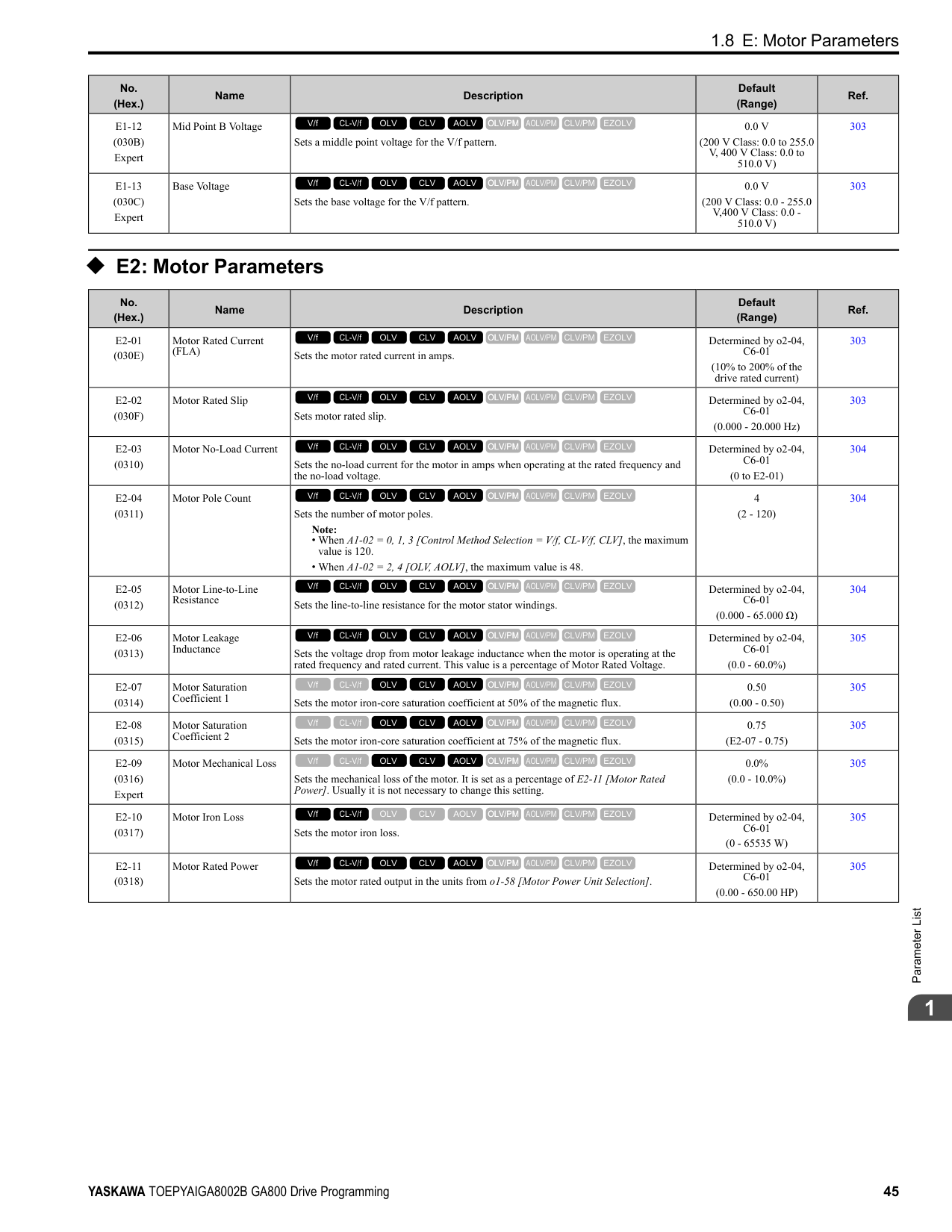
|No. (Hex.)|Name|Description|Default (Range)|Ref.| |---|---|---|---|---| |L2-30 (045E) Expert|KEB Zero Speed Operation|Sets the operation when the output frequency decreases below the zero level (DC braking injection starting frequency) during KEB deceleration when L2-01 3 to 5 [Power Loss Ride Through Select = Kinetic Energy Backup: L2-02, Kinetic Energy Backup: CPU Power, or Kinetic Energy Backup: DecelStop].
0 : Baseblock
1 : DC Injection Braking
V/f CL-V/f OLV CLV AOLV OLV/PM AOLV/PM CLV/PM EZOLV
|0 (0, 1)|451| |L2-31 (045D) Expert|KEB Start Voltage Offset Level|Sets the KEB start voltage offset.
V/f CL-V/f OLV CLV AOLV OLV/PM AOLV/PM CLV/PM EZOLV
|Determined by A1-02 (200 V Class: 0 - 100 V,400 V Class: 0 - 200 V)|452|
######## ◆ L3: Stall Prevention
|No. (Hex.)|Name|Description|Default (Range)|Ref.| |---|---|---|---|---| |L3-01 (048F)|Stall Prevention during Accel|Sets the method of the Stall Prevention During Acceleration.
0 : Disabled
1 : Enabled
2 : Intelligent (Ignore Decel Ramp)
3 : Current Limit Acceleration
V/f CL-V/f OLV CLV AOLV OLV/PM AOLV/PM CLV/PM EZOLV
|1 (0 to 3)|452| |L3-02 (0490)|Stall Prevent Level during Accel|Sets the output current level to activate the Stall Prevention function during acceleration as a percentage of the drive rated output current.
Note: The upper limit of the setting range changes when C6-01 [Normal / Heavy Duty Selection] changes.
• 150% when C6-01 0 [Heavy Duty Rating].
• 110% when C6-01 1 [Normal Duty Rating].
V/f CL-V/f OLV CLV AOLV OLV/PM AOLV/PM CLV/PM EZOLV
|Determined by C6-01 and L8-38
(0 - 150%)|454| |L3-03 (0491)|Stall Prevent Limit during Accel|Sets the lower limit for the stall prevention level used in the constant output range as a percentage of the drive rated output current.
V/f CL-V/f OLV CLV AOLV OLV/PM AOLV/PM CLV/PM EZOLV
|50% (0 - 100%)|454| |L3-04 (0492)|Stall Prevention during Decel|Sets the method that the drive will use to prevent overvoltage faults when decelerating.
Note:
1. To connect a dynamic braking option (braking resistor or braking resistor unit) to the drive, set this parameter to 0 or 3. Parameter values 1, 2, 4, and 5 will enable Stall Prevention function during deceleration, and the dynamic braking option will not function.
2. The setting range changes when the A1-02 [Control Method Selection] value changes:
• When A1-02 = 5 [OLV/PM], the setting range is 0 to 2.
• When A1-02 6, 7, 8 [AOLV/PM, CLV/PM, EZOLV], the setting range is 0, 1.
0 : No
1 : General Purpose
2 : Intelligent (Ignore Decel Ramp)
3 : General Purpose w/ DB resistor
4 : Overexcitation/High Flux
5 : Overexcitation/High Flux 2
V/f CL-V/f OLV CLV AOLV OLV/PM AOLV/PM CLV/PM EZOLV
|1 (Determined by A1-02)|455| |L3-05 (0493)|Stall Prevention during RUN|Sets the function to enable and disable Stall Prevention During Run.
Note:
1. An output frequency lower than 6 Hz will disable Stall Prevention during Run. The L3-05 and L3-06 [Stall Prevent Level during Run] settings do not have an effect.
2. The setting range changes when the A1-02 [Control Method] value changes:
• A1-02 = 0, 1, 5 [V/f, CL-V/f, OLV/PM]: 0 to 2
• A1-02 =8[EZOLV]: 0, 3
0 : Disabled
1 : Deceleration Time 1 (C1-02)
2 : Deceleration Time 2 (C1-04)
3 : Intelligent (Ignore Decel Ramp)
V/f CL-V/f OLV CLV AOLV OLV/PM AOLV/PM CLV/PM EZOLV
|2 (0 - Determined by A102)|456|
|No. (Hex.)|Name|Description|Default (Range)|Ref.| |---|---|---|---|---| |L3-06 (0494)|Stall Prevent Level during Run|Sets the output current level to enable the Stall Prevention function during operation as a percentage of the drive rated output current.
Note:
• This parameter is applicable when L3-05 1, 2 [Stall Prevention during RUN Deceleration Time 1 (C1-02), Deceleration Time 2 (C1-04)].
• The upper limit of the setting range changes when C6-01 [Normal Heavy Duty Selection] changes.
–150% when C6-01 0 [Heavy Duty Rating 1 (HD1) for Constant Torque Applications].
–110% when C6-01 = 1 [Normal Duty Rating 1 (ND1) for Variable Torque Applications].
V/f CL-V/f OLV CLV AOLV OLV/PM AOLV/PM CLV/PM EZOLV
|Determined by C6-01 and L8-38
(5 - 150%)|457| |L3-11 (04C7)|Overvoltage Suppression Select|Sets the overvoltage suppression function.
0 : Disabled
1 : Enabled
V/f CL-V/f OLV CLV AOLV OLV/PM AOLV/PM CLV/PM EZOLV
|0 (0, 1)|458| |L3-17 (0462)|DC Bus Regulation Level|Sets the target value for the DC bus voltage when the overvoltage suppression function and the Decel Stall Prevention function (Intelligent Stall Prevention) are active.
V/f CL-V/f OLV CLV AOLV OLV/PM AOLV/PM CLV/PM EZOLV
|200 V Class: 375 V, 400 V: 750 V
(200 V Class: 150 to 400 V, 400 V Class: 300 to 800 V)|458| |L3-20 (0465) Expert|DC Bus Voltage Adjustment Gain|Sets the proportional gain used to control the DC bus voltage.
V/f CL-V/f OLV CLV AOLV OLV/PM AOLV/PM CLV/PM EZOLV
|Determined by A1-02 (0.00 - 5.00)|458| |L3-21 (0466) Expert|OVSuppression Accel/ Decel P Gain|Sets the proportional gain to calculate acceleration and deceleration rates.
V/f CL-V/f OLV CLV AOLV OLV/PM AOLV/PM CLV/PM EZOLV
|Determined by A1-02 (0.10 - 10.00)|458| |L3-22 (04F9)|PM Stall Prevention Decel Time|Sets the momentary deceleration time that the drive will use when it tries to accelerate a PM motor and detected motor stalls. This function is applicable when L3-01 = 1 [Stall Prevent Select duringAccel = General Purpose].
V/f CL-V/f OLV CLV AOLV OLV/PM AOLV/PM CLV/PM EZOLV
|0.0 s (0.0 - 6000.0 s)|459| |L3-23 (04FD)|Stall P Reduction at Constant HP|Sets the function to automatically decrease the Stall Prevention Level during Run for constant output ranges.
0 : Disabled
1 : Automatic Reduction @ CHP Region
V/f CL-V/f OLV CLV AOLV OLV/PM AOLV/PM CLV/PM EZOLV
|0 (0, 1)|459| |L3-24 (046E) Expert|Motor Accel Time @ Rated Torque|Sets the motor acceleration time to reach the maximum frequency at the motor rated torque for stopped single-drive motors.
V/f CL-V/f OLV CLV AOLV OLV/PM AOLV/PM CLV/PM EZOLV
|Determined by o2-04, C6-01, E2-11, and E5-01
(0.001 - 10.000 s)|459| |L3-25 (046F) Expert|Load Inertia Ratio|Sets the ratio between motor inertia and machine inertia.
V/f CL-V/f OLV CLV AOLV OLV/PM AOLV/PM CLV/PM EZOLV
|1.0 (0.1 - 1000.0)|460| |L3-26 (0455) Expert|Additional DC Bus Capacitors|Sets the capacity for external main circuit capacitors. Usually it is not necessary to change this setting. Sets this parameter when you use the KEB Ride-Thru function.
V/f CL-V/f OLV CLV AOLV OLV/PM AOLV/PM CLV/PM EZOLV
|0 μF (0 to 65000 μF)|460| |L3-27 (0456)|Stall Prevention Detection Time|Sets a delay time between reaching the Stall Prevention level and starting the Stall Prevention function.
V/f CL-V/f OLV CLV AOLV OLV/PM AOLV/PM CLV/PM EZOLV
|50 ms (0 - 5000 ms)|460| |L3-34 (016F) Expert|Torque Limit Delay Time|Sets the filter time constant that returns the torque limit to its initial value when KEB operation operates in Single Drive KEB Ride-Thru mode.
V/f CL-V/f OLV CLV AOLV OLV/PM AOLV/PM CLV/PM EZOLV
|Determined by A1-02 (0.000 - 1.000 s)|460| |L3-35 (0747) Expert|Speed Agree Width for Auto Decel|Sets the width for speed agreement when L3-04 = 2 [Decel Stall Prevention Selection = Automatic Decel Reduction]. Usually it is not necessary to change this setting.
V/f CL-V/f OLV CLV AOLV OLV/PM AOLV/PM CLV/PM EZOLV
|0.00 Hz (0.00 - 1.00 Hz)|461| |L3-36 (11D0)|Current Suppression Gain@Accel|Sets the gain to suppress current and motor speed hunting during operation when L3-01 = 3 [Stall Prevention during Accel = Current Limit Method]. Usually it is not necessary to change this setting.
V/f CL-V/f OLV CLV AOLV OLV/PM AOLV/PM CLV/PM EZOLV
|Determined by A1-02 (0.0 - 100.0)|461| |L3-37 (11D1) Expert|Current Limit P Gain @ Accel|Suppresses current hunting during acceleration. Usually it is not necessary to change this setting.
V/f CL-V/f OLV CLV AOLV OLV/PM AOLV/PM CLV/PM EZOLV
|5 ms (0 - 100 ms)|461| |L3-38 (11D2) Expert|Current Limit I Time @ Accel|Suppresses current hunting and overshooting that occurs when the drive stalls during acceleration. Usually it is not necessary to change this setting.
V/f CL-V/f OLV CLV AOLV OLV/PM AOLV/PM CLV/PM EZOLV
|10.0 (0.0 - 100.0)|461|
|No. (Hex.)|Name|Description|Default (Range)|Ref.| |---|---|---|---|---| |L3-39 (11D3)|Current Limit Filter Time @Accel|Sets the time constant to adjust the acceleration rate when L3-01 3 [Stall Prevention during Accel Current Limit Method]. Usually it is not necessary to change this setting.
V/f CL-V/f OLV CLV AOLV OLV/PM AOLV/PM CLV/PM EZOLV
|100.0 ms (1.0 - 1000.0 ms)|461| |L3-40 (11D4)|Current Limit S-Curve @ Acc/Dec|Sets the function to enable and disable the best S-curve characteristic used for currentlimited acceleration.
0 : Disabled
1 : Enabled
V/f CL-V/f OLV CLV AOLV OLV/PM AOLV/PM CLV/PM EZOLV
|0 (0, 1)|462|
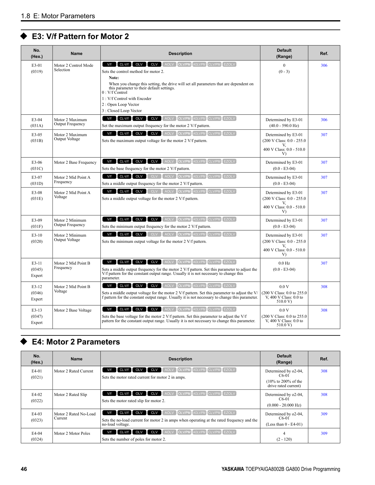
|No. (Hex.)|Name|Description|Default (Range)|Ref.| |---|---|---|---|---| |L4-01 (0499)|Speed Agree Detection Level|Sets the level to detect speed agree or motor speed. Sets the level to detect speed agree or motor speed when H2-01 to H2-03 2, 3, 4, 5 [MFDO Function Selection Speed Agree 1, User-set Speed Agree 1, Frequency Detection 1, Frequency Detection 2].
V/f CL-V/f OLV CLV AOLV OLV/PM AOLV/PM CLV/PM EZOLV
|Determined by A1-02 (Determined by A1-02)|462| |L4-02 (049A)|Speed Agree Detection Width|Sets the width to detect speed agree or motor speed. Sets the width to detect speed agree or motor speed when H2-01 to H2-03 2, 3, 4, 5 [MFDO Function Selection Speed Agree 1, User-set Speed Agree 1, Frequency Detection 1, Frequency Detection 2].
V/f CL-V/f OLV CLV AOLV OLV/PM AOLV/PM CLV/PM EZOLV
|Determined by A1-02 (Determined by A1-02)|462| |L4-03 (049B)|Speed Agree Detection Level (+/-)|Sets the level to detect speed agree or motor speed. Sets the speed agree detection level or motor speed detection level when H2-01 to H2-03 13, 14, 15, 16 [MFDO Function Selection Speed Agree 2, User-set Speed Agree 2, Frequency Detection 3, Frequency Detection 4].
V/f CL-V/f OLV CLV AOLV OLV/PM AOLV/PM CLV/PM EZOLV
|Determined by A1-02 (Determined by A1-02)|462| |L4-04 (049C)|Speed Agree Detection Width (+/-)|Sets the width to detect speed agree or motor speed. Sets the width to detect speed agree or motor speed when H2-01 to H2-03 = 13, 14, 15, 16 [MFDO Function Selection = Speed Agree 2, User-set Speed Agree 2, Frequency Detection 3, Frequency Detection 4].
V/f CL-V/f OLV CLV AOLV OLV/PM AOLV/PM CLV/PM EZOLV
|Determined by A1-02 (Determined by A1-02)|462| |L4-05 (049D)|Fref Loss Detection Selection|Sets the operation when the drive detects a loss of frequency reference.
0 : Stop
1 : Run at (L4-06 x Last Reference)
V/f CL-V/f OLV CLV AOLV OLV/PM AOLV/PM CLV/PM EZOLV
|0 (0, 1)|463| |L4-06 (04C2)|Frequency Reference @Loss of Ref|Sets the frequency reference as a percentage to continue drive operation after it detects a frequency reference loss. The value is a percentage of the frequency reference before the drive detected the loss.
V/f CL-V/f OLV CLV AOLV OLV/PM AOLV/PM CLV/PM EZOLV
|80.0% (0.0 - 100.0%)|463| |L4-07 (0470)|Speed Agree Detection Selection|Sets the condition that activates speed detection.
0 : No Detection during Baseblock
1 : Detection Always Enabled
V/f CL-V/f OLV CLV AOLV OLV/PM AOLV/PM CLV/PM EZOLV
|0 (0, 1)|463|
|No. (Hex.)|Name|Description|Default (Range)|Ref.| |---|---|---|---|---| |L5-01 (049E)|Number of Auto-Restart Attempts|Sets the number of times that the drive will try to restart.
V/f CL-V/f OLV CLV AOLV OLV/PM AOLV/PM CLV/PM EZOLV
|0 (0 - 10 times)|464| |L5-02 (049F)|Fault Contact at Restart Select|Sets the function that sends signals to the MFDO terminal set for Fault [H2-xx = E] while the drive is automatically restarting.
0 : Active Only when Not Restarting
1 : Always Active
V/f CL-V/f OLV CLV AOLV OLV/PM AOLV/PM CLV/PM EZOLV
|0 (0, 1)|464| |L5-03 (04A0)|Continuous Method Max Restart T|Sets the time for which the drive will try to restart. If the drive cannot restart inthe time set in L5-03, the drive detects a fault. This is available when L5-05 = 0 [Auto-Restart Method = Continuous/Immediate Attempts].
V/f CL-V/f OLV CLV AOLV OLV/PM AOLV/PM CLV/PM EZOLV
|10.0 s (0.5 - 180.0 s)|464|
|No. (Hex.)|Name|Description|Default (Range)|Ref.| |---|---|---|---|---| |L5-04 (046C)|Interval Method Restart Time|Sets the time interval between each Auto Restart attempt. This function is enabled when L5-05 1 [Auto Restart Operation Selection Use L5-04 Time].
V/f CL-V/f OLV CLV AOLV OLV/PM AOLV/PM CLV/PM EZOLV
|10.0 s (0.5 - 600.0 s)|464| |L5-05 (0467)|Auto-Restart Method|Sets the count method for the Auto Restart operation.
0 : Continuous/Immediate Attempts
1 : Interval/Attempt after L5-04 sec
V/f CL-V/f OLV CLV AOLV OLV/PM AOLV/PM CLV/PM EZOLV
|0 (0, 1)|465| |L5-07 (0B2A)|Fault Reset Enable Select Grp1|Use these 4 digits to set the Auto Restart function for oL1 to oL4. From left to right, the digits set oL1, oL2, oL3, and oL4, in order.
0000 : Disabled
0001 : Enabled (—/—/—/oL4)
0010 : Enabled (—/—/oL3/—)
0011 : Enabled (—/—/oL3/oL4)
0100 : Enabled (—/oL2/—/—)
0101 : Enabled (—/oL2/—/oL4)
0110 : Enabled (—/oL2/oL3/—)
0111 : Enabled (—/oL2/oL3/oL4)
1000 : Enabled (oL1/—/—/—)
1001 : Enabled (oL1/—/—/oL4)
1010 : Enabled (oL1/—/oL3/—)
1011 : Enabled (oL1/—/oL3/oL4)
1100 : Enabled (oL1/oL2/—/—)
1101 : Enabled (oL1/oL2/—/oL4)
1110 : Enabled (oL1/oL2/oL3/—)
1111 : Enabled (oL1/oL2/oL3/oL4)
V/f CL-V/f OLV CLV AOLV OLV/PM AOLV/PM CLV/PM EZOLV
|1111 (0000 - 1111)|465| |L5-08 (0B2B)|Fault Reset Enable Select Grp2|Use these 4 digits to set the Auto Restart function for Uv1, ov, oH1, and GF. From left to right, the digits set Uv1, ov, oH1, and GF, in order.
0000 : Disabled
0001 : Enabled (—/–/—/GF)
0010 : Enabled (—/–/oH1/–)
0011 : Enabled (—/–/oH1/GF)
0100 : Enabled (—/ov/—/–)
0101 : Enabled (—/ov/—/GF)
0110 : Enabled (—/ov/oH1/–)
0111 : Enabled (—/ov/oH1/GF)
1000 : Enabled (Uv1/–/—/–)
1001 : Enabled (Uv1/–/—/GF)
1010 : Enabled (Uv1/–/oH1/–)
1011 : Enabled (Uv1/–/oH1/GF)
1100 : Enabled (Uv1/ov/—/–)
1101 : Enabled (Uv1/ov/—/GF)
1110 : Enabled (Uv1/ov/oH1/–)
1111 : Enabled (Uv1/ov/oH1/GF)
V/f CL-V/f OLV CLV AOLV OLV/PM AOLV/PM CLV/PM EZOLV
|1111 (0000 - 1111)|465|
######## ◆ L6: Torque Detection
|No. (Hex.)|Name|Description|Default (Range)|Ref.| |---|---|---|---|---| |L6-01 (04A1)|Torque Detection Selection 1|Sets the speed range that detects overtorque and undertorque and the operation of drives (operation status) after detection.
0 : Disabled
1 : oL @ Speed Agree - Alarm only
2 : oL @ RUN - Alarm only
3 : oL @ Speed Agree - Fault
4 : oL @ RUN - Fault
5 : UL @ Speed Agree - Alarm only
6 : UL @ RUN - Alarm only
7 : UL @ Speed Agree - Fault
8 : UL @ RUN - Fault
V/f CL-V/f OLV CLV AOLV OLV/PM AOLV/PM CLV/PM EZOLV
|0 (0 - 8)|468| |L6-02 (04A2)|Torque Detection Level 1|Sets the detection level for Overtorque/Undertorque Detection 1. In V/f control, drive rated output current = 100% value. In vector control, motor rated torque = 100% value.
V/f CL-V/f OLV CLV AOLV OLV/PM AOLV/PM CLV/PM EZOLV
|150% (0 - 300%)|469| |L6-03 (04A3)|Torque Detection Time 1|Sets the detection time for Overtorque/Undertorque Detection 1.
V/f CL-V/f OLV CLV AOLV OLV/PM AOLV/PM CLV/PM EZOLV
|0.1 s (0.0 - 10.0 s)|469| |L6-04 (04A4)|Torque Detection Selection 2|Sets the speed range that detects overtorque and undertorque and the operation of drives (operation status) after detection.
0 : Disabled
1 : oL @ Speed Agree - Alarm only
2 : oL @ RUN - Alarm only
3 : oL @ Speed Agree - Fault
4 : oL @ RUN - Fault
5 : UL @ Speed Agree - Alarm only
6 : UL @ RUN - Alarm only
7 : UL @ Speed Agree - Fault
8 : UL @ RUN - Fault
V/f CL-V/f OLV CLV AOLV OLV/PM AOLV/PM CLV/PM EZOLV
|0 (0 - 8)|469| |L6-05 (04A5)|Torque Detection Level 2|Sets the detection level for Overtorque/Undertorque Detection 2. In V/f control, drive rated output current 100% value. In vector control, motor rated torque 100% value.
V/f CL-V/f OLV CLV AOLV OLV/PM AOLV/PM CLV/PM EZOLV
|150% (0 - 300%)|470| |L6-06 (04A6)|Torque Detection Time 2|Sets the detection time for Overtorque/Undertorque Detection 2.
V/f CL-V/f OLV CLV AOLV OLV/PM AOLV/PM CLV/PM EZOLV
|0.1 s (0.0 - 10.0 s)|470| |L6-07 (04E5)|Torque Detection Filter Time|Sets the time constant for a primary filter to the torque reference or to the output current used to detect overtorque/undertorque.
V/f CL-V/f OLV CLV AOLV OLV/PM AOLV/PM CLV/PM EZOLV
|0 ms (0 - 1000 ms)|470|
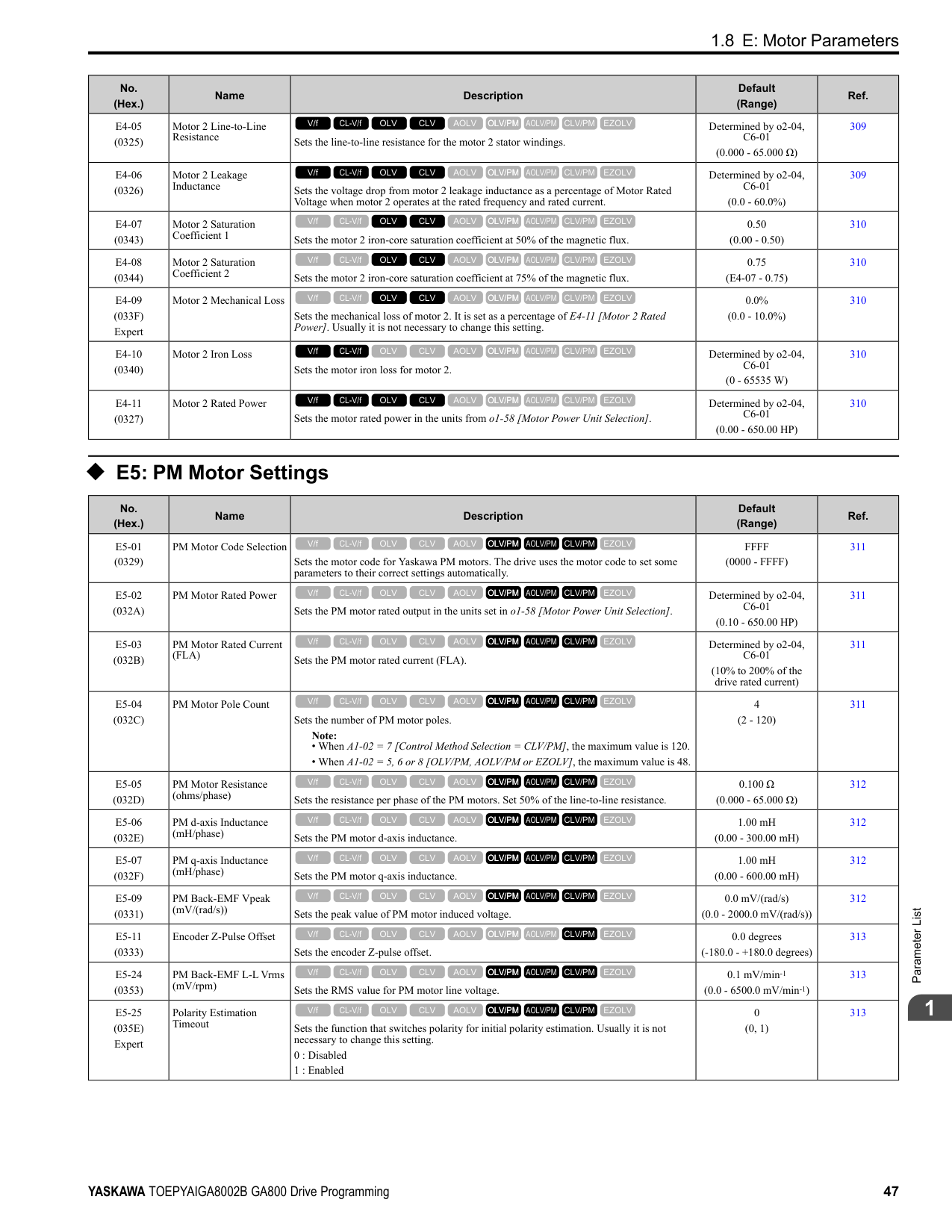
|L6-08 (0468)|Mechanical Fatigue Detect Select|Sets the speed where the drive detects mechanical deterioration and how the drive operates (operation status) after detection.
0 : Disabled
1 : oL5 @ Speed > L6-09 - Alarm
2 : oL5 @ lSpeedl > L6-09 - Alarm
3 : oL5 @ Speed > L6-09 - Fault
4 : oL5 @ lSpeedl > L6-09 - Fault
5 : UL5 @ Speed < L6-09 - Alarm
6 : UL5 @ lSpeedl < L6-09 - Alarm
7 : UL5 @ Speed < L6-09 - Fault
8 : UL5 @ lSpeedl < L6-09 - Fault
V/f CL-V/f OLV CLV AOLV OLV/PM AOLV/PM CLV/PM EZOLV
|0 (0 - 8)|470| |L6-09 (0469)|Mech Fatigue Detect Speed Level|Sets the speed level where the drive will operate the mechanical deterioration detection function, as a percentage of the Maximum Output Frequency.
Note:
Parameter A1-02 [Control Method Selection] selects which parameter is the maximum output frequency.
• A1-02 ≠ 8 [EZOLV]: E1-04 [Maximum Output Frequency]
• A1-02 = 8: E9-02 [Maximum Speed]
V/f CL-V/f OLV CLV AOLV OLV/PM AOLV/PM CLV/PM EZOLV
|110.0% (-110.0 - 110.0%)|471|
|No. (Hex.)|Name|Description|Default (Range)|Ref.| |---|---|---|---|---| |L6-10 (046A)|Mech Fatigue Detect Delay Time|Sets the time for mechanical deterioration detection.
V/f CL-V/f OLV CLV AOLV OLV/PM AOLV/PM CLV/PM EZOLV
|0.1 s (0.0 - 10.0 s)|471| |L6-11 (046B)|Mech Fatigue Hold Off Time|Sets the time that the drive will start mechanical deterioration detection triggered by the cumulative operation time of the drive.
V/f CL-V/f OLV CLV AOLV OLV/PM AOLV/PM CLV/PM EZOLV
|0 h (0 - 65535 h)|471|
|No. (Hex.)|Name|Description|Default (Range)|Ref.| |---|---|---|---|---| |L7-01 (04A7) RUN|Forward Torque Limit|Sets the torque limit value for forward motoring as a percentage, where motor rated torque is the 100% value.
V/f CL-V/f OLV CLV AOLV OLV/PM AOLV/PM CLV/PM EZOLV
|200% (0 - 300%)|472| |L7-02 (04A8) RUN|Reverse Torque Limit|Sets the torque limit value for reversed motoring as a percentage, where motor rated torque is the 100% value.
V/f CL-V/f OLV CLV AOLV OLV/PM AOLV/PM CLV/PM EZOLV
|200% (0 - 300%)|473| |L7-03 (04A9) RUN|Forward Regenerative Trq Limit|Sets the torque limit value for forward regenerative conditions as a percentage of the motor rated torque.
V/f CL-V/f OLV CLV AOLV OLV/PM AOLV/PM CLV/PM EZOLV
|200% (0 - 300%)|473| |L7-04 (04AA) RUN|Reverse Regenerative Trq Limit|Sets the torque limit value for reversed regenerative conditions as a percentage of the motor rated torque.
V/f CL-V/f OLV CLV AOLV OLV/PM AOLV/PM CLV/PM EZOLV
|200% (0 - 300%)|473| |L7-06 (04AC)|Torque Limit Integral Time|Sets the integral time constant for the torque limit function.
V/f CL-V/f OLV CLV AOLV OLV/PM AOLV/PM CLV/PM EZOLV
|200 ms (5 - 10000 ms)|473| |L7-07 (04C9)|Torque Limit during Accel/Decel|Sets the torque limit function during acceleration and deceleration.
0 : Proportional only
1 : Proportional & Integral control
V/f CL-V/f OLV CLV AOLV OLV/PM AOLV/PM CLV/PM EZOLV
|0 (0, 1)|474| |L7-16 (044D)|Torque Limit Process at Start|Assigns a time filter to allow the torque limit to build at start.
0 : Disabled
1 : Enabled
V/f CL-V/f OLV CLV AOLV OLV/PM AOLV/PM CLV/PM EZOLV
|1 (0, 1)|474| |L7-35 (1B57) Expert|Low Freq Regen Torque Limit Lvl|Sets the torque limit used during low-speed regeneration. Usually it is not necessary to change this setting.
V/f CL-V/f OLV CLV AOLV OLV/PM AOLV/PM CLV/PM EZOLV
|50.0% (0.0 - 200.0%)|474| |L7-36 (1B58) Expert|Regen Torque Limit Derate Freq|Sets the frequency width at which L7-35 [Low Freq Regen Torque Limit Lvl] operates.
V/f CL-V/f OLV CLV AOLV OLV/PM AOLV/PM CLV/PM EZOLV
|6.0 Hz (0.0 - 30.0 Hz)|475|
|No. (Hex.)|Name|Description|Default (Range)|Ref.| |---|---|---|---|---| |L8-01 (04AD)|3% ERF DB Resistor Protection|Sets the function to enable braking resistor protection with a Yaskawa ERF series braking resistor (3% ED) installed on the heatsink.
0 : Disabled
1 : Enabled
V/f CL-V/f OLV CLV AOLV OLV/PM AOLV/PM CLV/PM EZOLV
|0 (0, 1)|475| |L8-02 (04AE)|Overheat Alarm Level|Sets the oH detection level in temperature.
V/f CL-V/f OLV CLV AOLV OLV/PM AOLV/PM CLV/PM EZOLV
|Determined by o2-04, C6-01
(50 - 150 °C)|475| |L8-03 (04AF)|Overheat Pre-Alarm Selection|Sets the operation of drives when an oH alarm is detected.
0 : Ramp to Stop
1 : Coast to Stop
2 : Fast Stop (Use C1-09)
3 : Alarm Only
4 : Operate at Reduced Speed (L8-19)
V/f CL-V/f OLV CLV AOLV OLV/PM AOLV/PM CLV/PM EZOLV
|3 (0 - 4)|475|
|No. (Hex.)|Name|Description|Default (Range)|Ref.| |---|---|---|---|---| |L8-05 (04B1)|Input Phase Loss Protection Sel|Sets the function to enable and disable input phase loss detection.
0 : Disabled
1 : Enabled
V/f CL-V/f OLV CLV AOLV OLV/PM AOLV/PM CLV/PM EZOLV
|1 (0, 1)|476| |L8-07 (04B3)|Output Phase Loss Protection Sel|Sets the function to enable and disable output phase loss detection. The drive starts output phase loss detection when the output current decreases to less than 5% of the drive rated current.
Note: The drive can incorrectly start output phase loss detection in these conditions:
• The motor rated current is very small compared to the drive rating.
• The drive is operating a PM motor with a small load.
0 : Disabled
1 : Fault when one phase is lost
2 : Fault when two phases are lost
V/f CL-V/f OLV CLV AOLV OLV/PM AOLV/PM CLV/PM EZOLV
|1 (0 - 2)|477| |L8-09 (04B5)|Output Ground Fault Detection|Sets the function to enable and disable ground fault protection.
0 : Disabled
1 : Enabled
V/f CL-V/f OLV CLV AOLV OLV/PM AOLV/PM CLV/PM EZOLV
|Determined by o2-04 (0, 1)|477| |L8-10 (04B6)|Heatsink Fan Operation Selection|Sets operation of the heatsink cooling fan.
0 : During Run, w/ L8-11 Off-Delay
1 : Always On
2 : On when Drive Temp Reaches L8-64
V/f CL-V/f OLV CLV AOLV OLV/PM AOLV/PM CLV/PM EZOLV
|0 (0 - 2)|477| |L8-11 (04B7)|Heatsink Fan Off-Delay Time|Sets the length of time that the drive will wait before it stops the cooling fan after it cancels the Run command when L8-10 = 0 [Heatsink Cooling Fan Ope Select = Dur Run (OffDly)].
V/f CL-V/f OLV CLV AOLV OLV/PM AOLV/PM CLV/PM EZOLV
|60 s (0 - 300 s)|478| |L8-12 (04B8)|Ambient Temperature Setting|Sets the ambient temperature of the drive installation area.
V/f CL-V/f OLV CLV AOLV OLV/PM AOLV/PM CLV/PM EZOLV
|40 °C (-10 - +50 °C)|478|
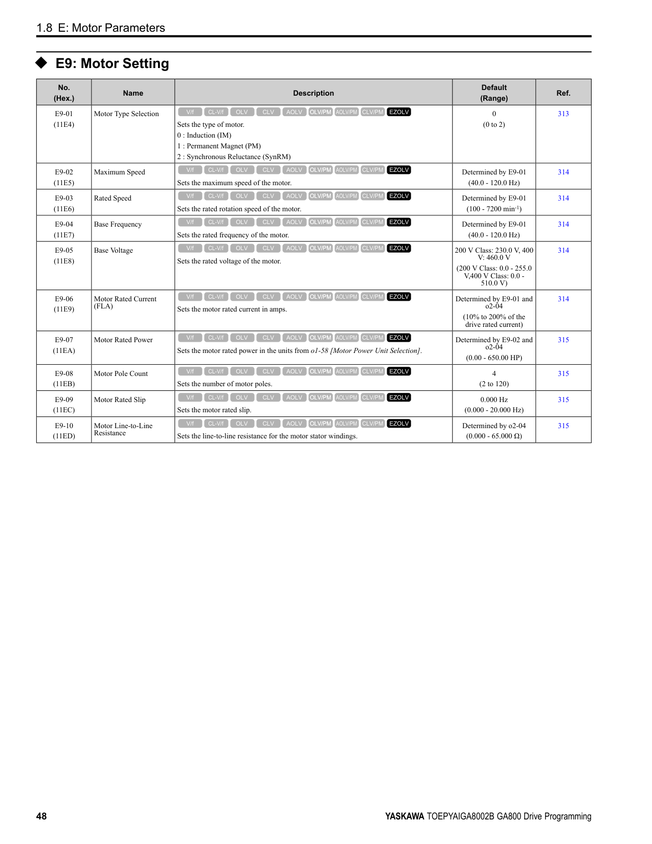
|L8-15 (04BB)|Drive oL2 @ Low Speed Protection|Sets the function to decrease drive overload at low speeds to prevent damage to the main circuit transistor during low speed operation (at 6 Hz or slower) to prevent oL2 [Drive Overloaded].
Note:
Contact Yaskawa or your nearest sales representative before disabling this function at low speeds. If you frequently operate drives with high output current in low speed ranges, it can cause heat stress and decrease the life span of drive IGBTs.
0 : Disabled (No Additional Derate)
1 : Enabled (Reduced oL2 Level)
V/f CL-V/f OLV CLV AOLV OLV/PM AOLV/PM CLV/PM EZOLV
|1 (0, 1)|478| |L8-18 (04BE)|Software Current Limit Selection|Set the software current limit selection function to prevent damage to the main circuit transistor caused by too much current.
0 : Disabled
1 : Enabled
V/f CL-V/f OLV CLV AOLV OLV/PM AOLV/PM CLV/PM EZOLV
|0 (0, 1)|478| |L8-19 (04BF)|Freq Reduction @ oH Pre-Alarm|Sets the ratio at which the drive derates the frequency reference during an oH alarm.
V/f CL-V/f OLV CLV AOLV OLV/PM AOLV/PM CLV/PM EZOLV
|0.8 (0.1 - 0.9)|478| |L8-20 (04C0) Expert|Control Fault & Step Out Detect|Sets operation after the drive detects a CF fault when A1-02 = 4 [Control Method Selection = Advanced Open Loop Vector].
0 : Disabled
1 : CF/STPo Detection Enabled
2 : CF ALM/Stop
V/f CL-V/f OLV CLV AOLV OLV/PM AOLV/PM CLV/PM EZOLV
|1 (0 - 2)|479| |L8-27 (04DD)|Overcurrent Detection Gain|Sets the PM motor overcurrent detection level as a percentage of the motor rated current value.
Note:
Parameter A1-02 [Control Method Selection] selects which parameter is the motor rated current.
• A1-02 ≠ 8 [EZOLV]: E5-03 [Motor Rated Current (FLA)]
• A1-02 = 8: E9-06 [Motor Rated Current (FLA)]
V/f CL-V/f OLV CLV AOLV OLV/PM AOLV/PM CLV/PM EZOLV
|300.0% (0.0 - 1000.0%)|479| |L8-29 (04DF)|Output Unbalance Detection Sel|Sets the function to detect LF2.
0 : Disabled
1 : Enabled
V/f CL-V/f OLV CLV AOLV OLV/PM AOLV/PM CLV/PM EZOLV
|1 (0, 1)|479|
|No. (Hex.)|Name|Description|Default (Range)|Ref.| |---|---|---|---|---| |L8-31 (04E1)|LF2 Detection Time|Sets the LF2 [Output Current Imbalance] detection time.
V/f CL-V/f OLV CLV AOLV OLV/PM AOLV/PM CLV/PM EZOLV
|3 (1 – 100)|479| |L8-35 (04EC)|Installation Method Selection|Sets the type of drive installation.
0 : IP20/OpenChassis Enc/Ex Heatsink
1 : Side-by-Side Mounting
2 : IP20/NEMAType 1/IP55
3 : Finless
V/f CL-V/f OLV CLV AOLV OLV/PM AOLV/PM CLV/PM EZOLV
|Determined by the drive (0 - 3)|480| |L8-38 (04EF)|Carrier Frequency Reduction|Sets the carrier frequency reduction function. The drive reduces the carrier frequency when the output current is more than a specified level.
0 : Disabled
1 : Enabled below 6 Hz
2 : Enabled for All Speeds
V/f CL-V/f OLV CLV AOLV OLV/PM AOLV/PM CLV/PM EZOLV
|Determined by A1-02, C6-01 and o2-04
(0 - 2)|480| |L8-40 (04F1)|Carrier Freq Reduction Off-Delay|Sets the length of time until the automatically reduced carrier frequency returns to the condition before the reduction.
V/f CL-V/f OLV CLV AOLV OLV/PM AOLV/PM CLV/PM EZOLV
|Determined by A1-02 (0.00 - 2.00 s)|481| |L8-41 (04F2)|High Current Alarm Selection|Sets the function to cause an HCA [Current Alarm] when the output current is more than 150% of the drive rated current.
0 : Disabled
1 : Enabled
V/f CL-V/f OLV CLV AOLV OLV/PM AOLV/PM CLV/PM EZOLV
|0 (0, 1)|481| |L8-51 (0471) Expert|STPo I Detection Level|Sets the STPo [Motor Step-Out Detected] detection level as a percentage of the motor rated current.
Note:
Parameter A1-02 [Control Method Selection] selects which parameter is the motor rated current.
• A1-02 = 5 [OLV/PM]: E5-03 [PM Motor Rated Current (FLA)]
• A1-02 = 8 [EZOLV]: E9-06 [Motor Rated Current (FLA)]
V/f CL-V/f OLV CLV AOLV OLV/PM AOLV/PM CLV/PM EZOLV
|0.0% (0.0 - 300.0%)|481| |L8-52 (0472) Expert|STPo Integration Level|Sets the detection level for STPo [Motor Step-Out Detected] related to the ACR integral value.
V/f CL-V/f OLV CLV AOLV OLV/PM AOLV/PM CLV/PM EZOLV
|1.0 (0.1 - 2.0)|481| |L8-53 (0473) Expert|STPo Integration Time|Sets the length of time until the drive detects STPo after it is more than the value of L8-51 [STPo I Detection Level].
V/f CL-V/f OLV CLV AOLV OLV/PM AOLV/PM CLV/PM EZOLV
|1.0 s (1.0 - 10.0 s)|481| |L8-54 (0474) Expert|STPo Id Diff Detection|Sets the Id deviation detection function for STPo [Motor Step-Out Detected].
0 : Disabled
1 : Enabled
V/f CL-V/f OLV CLV AOLV OLV/PM AOLV/PM CLV/PM EZOLV
|1 (0, 1)|482| |L8-55 (045F)|Internal DB TransistorProtection|Sets the protection function for the internal braking transistor.
0 : Disable
1 : Protection Enabled
V/f CL-V/f OLV CLV AOLV OLV/PM AOLV/PM CLV/PM EZOLV
|1 (0, 1)|482| |L8-56 (047D) Expert|Stall P @ Accel Activation Time|Sets the length time that the acceleration stall prevention function can continue to operate before the drive detects an STPo [Motor Step-Out Detected].
V/f CL-V/f OLV CLV AOLV OLV/PM AOLV/PM CLV/PM EZOLV
|5000 ms (100 - 5000 ms)|482| |L8-57 (047E) Expert|Stall Prevention Retry Counts|Sets the number of times the acceleration stall prevention function can operate until speeds agree before the drive detects an STPo [Motor Step-Out Detected].
V/f CL-V/f OLV CLV AOLV OLV/PM AOLV/PM CLV/PM EZOLV
|10 (1 - 10 times)|482| |L8-90 (0175) Expert|STPo Detection Level (Low Speed)|Sets the detection level that the control fault must be equal to or more than to cause an STPo [Motor Step-Out Detected].
V/f CL-V/f OLV CLV AOLV OLV/PM AOLV/PM CLV/PM EZOLV
|Determined by A1-02 (0 - 5000 times)|482| |L8-93 (073C) Expert|Low Speed Pull-out DetectionTime|Sets the length of time the drive will wait to start baseblock after detecting LSo [Low Speed Motor Step-Out].
V/f CL-V/f OLV CLV AOLV OLV/PM AOLV/PM CLV/PM EZOLV
|1.0 s (0.0 - 10.0 s)|483|
|No. (Hex.)|Name|Description|Default (Range)|Ref.| |---|---|---|---|---| |L8-94 (073D) Expert|Low Speed Pull-out Detect Level|Sets the detection level for LSo [Low Speed Motor Step-Out] as a percentage of E1-04 [Maximum Output Frequency].
V/f CL-V/f OLV CLV AOLV OLV/PM AOLV/PM CLV/PM EZOLV
|3% (0 - 10%)|483| |L8-95 (077F) Expert|Low Speed Pull-out Amount|Sets the average count of LSo [Low Speed Motor Step-Out] detections.
V/f CL-V/f OLV CLV AOLV OLV/PM AOLV/PM CLV/PM EZOLV
|10 (1 - 50 times)|483|
######## ◆ L9: Drive Protection 2
|No. (Hex.)|Name|Description|Default (Range)|Ref.| |---|---|---|---|---| |L9-16 (11DC) Expert|FAn1 Detect Time|Sets the detection time for FAn1 [Drive Cooling Fan Fault]. Yaskawa recommends that you do not change this parameter value.
V/f CL-V/f OLV CLV AOLV OLV/PM AOLV/PM CLV/PM EZOLV
|4.0 s (0.0 - 30.0 s)|483|
####### 1.12 n: Special Adjustment
◆ n1: Hunting Prevention
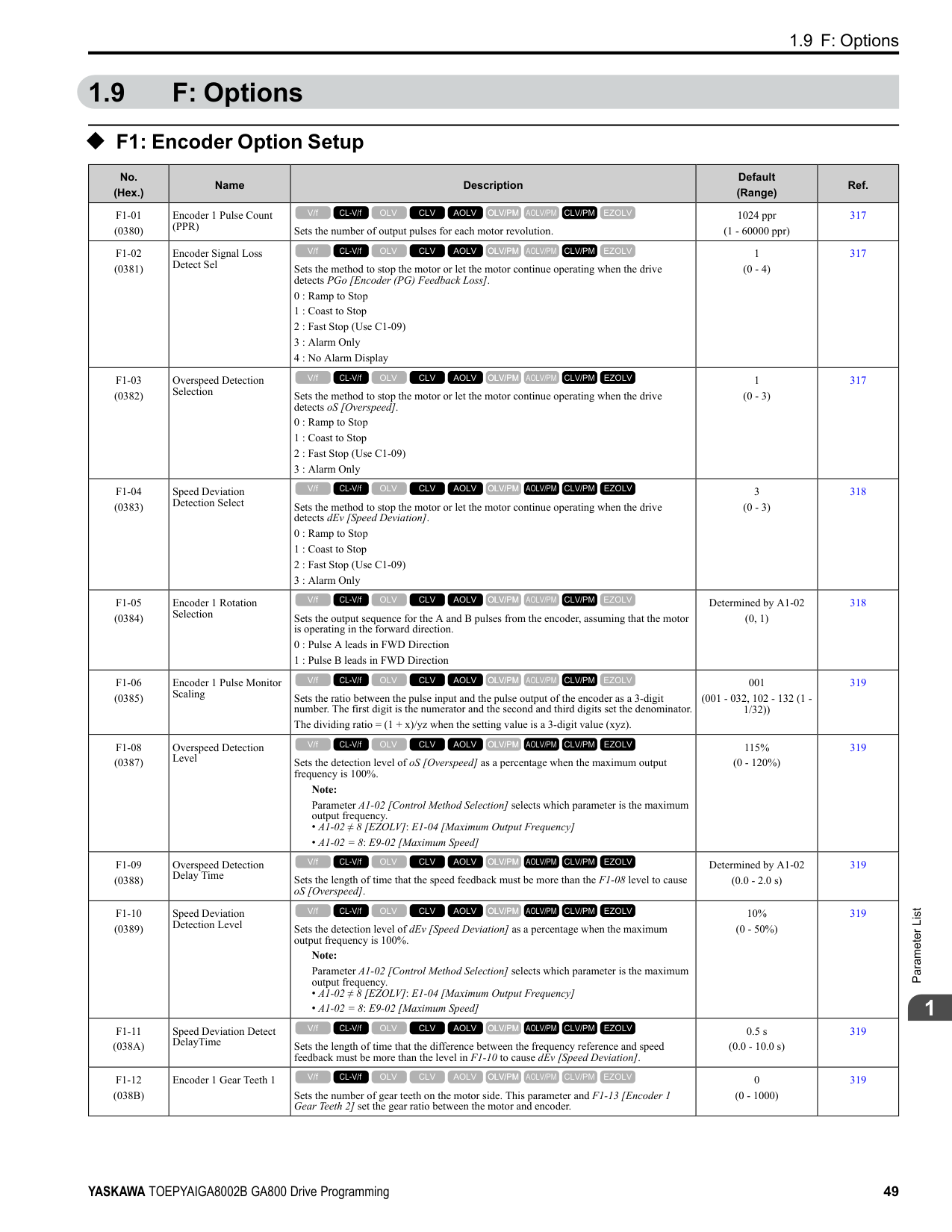
|No. (Hex.)|Name|Description|Default (Range)|Ref.| |---|---|---|---|---| |n1-01 (0580)|Hunting Prevention Selection|Sets the function to prevent hunting.
0 : Disabled
1 : Enabled (Normal)
2 : Enabled (High Carrier Frequency)
V/f CL-V/f OLV CLV AOLV OLV/PM AOLV/PM CLV/PM EZOLV
|Determined by o2-04 (0 to 2)|484| |n1-02 (0581) Expert|Hunting Prevention Gain Setting|Sets the performance of the hunting prevention function. Usually it is not necessary to change this parameter.
V/f CL-V/f OLV CLV AOLV OLV/PM AOLV/PM CLV/PM EZOLV
|1.00 (0.00 - 2.50)|484| |n1-03 (0582) Expert|Hunting Prevention Time Constant|Sets the primary delay time constant of the hunting prevention function. Usually it is not necessary to change this parameter.
V/f CL-V/f OLV CLV AOLV OLV/PM AOLV/PM CLV/PM EZOLV
|Determined by o2-04 (0 - 500 ms)|484| |n1-05 (0530) Expert|Hunting Prevent Gain in Reverse|Sets the performance of the hunting prevention function. This parameter adjusts Reverse run. Usually it is not necessary to change this parameter.
V/f CL-V/f OLV CLV AOLV OLV/PM AOLV/PM CLV/PM EZOLV
|0.00 (0.00 - 2.50)|485| |n1-08 (1105) Expert|Current Detection Method|Sets how the drive decreases the motor vibration that is caused by leakage current. Usually it is not necessary to change this parameter.
0 : 2-Phases
1 : 3-Phases
V/f CL-V/f OLV CLV AOLV OLV/PM AOLV/PM CLV/PM EZOLV
|0 (0, 1)|485| |n1-13 (1B59) Expert|DC Bus Stabilization Control|Sets the oscillation suppression function for the DC bus voltage.
0 : Disabled
1 : Enabled
V/f CL-V/f OLV CLV AOLV OLV/PM AOLV/PM CLV/PM EZOLV
|0 (0, 1)|485| |n1-14 (1B5A) Expert|DC Bus Stabilization Time|Adjusts the responsiveness of the oscillation suppression function for the DC bus voltage. Set n1-13 = 1 [DC Bus Stabilization Control = Enabled] to enable this parameter.
V/f CL-V/f OLV CLV AOLV OLV/PM AOLV/PM CLV/PM EZOLV
|100.0 ms (50.0 - 500.0 ms)|485| |n1-15 (0BF8) Expert|PWM Voltage Offset Calibration|Sets the calibration method that the drive uses to decrease torque/current ripple.
0 : No Calibration
1 : One Time Calibrate at Next Start
2 : Calibrate Every Time at Start
V/f CL-V/f OLV CLV AOLV OLV/PM AOLV/PM CLV/PM EZOLV
|Determined by A1-02 (0 - 2)|485| |n1-16 (0BFB) Expert|Hunting Prevention High Fc Gain|Sets the gain for the hunting prevention function. This parameter functions best with a high carrier frequency. Usually it is not necessary to change this parameter.
V/f CL-V/f OLV CLV AOLV OLV/PM AOLV/PM CLV/PM EZOLV
|Determined by o2-04 (0.00 - 2.50)|486| |n1-17 (0BFC) Expert|Hunting Prevent High Fc Filter|Sets the responsiveness of the hunting prevention function. Usually it is not necessary to change this parameter.
V/f CL-V/f OLV CLV AOLV OLV/PM AOLV/PM CLV/PM EZOLV
|500 ms (0 - 1000 ms)|486| |n1-20 (1588) Expert|Voltage Calibration Duration|Sets the calibration time at start. Usually it is not necessary to change this parameter.
V/f CL-V/f OLV CLV AOLV OLV/PM AOLV/PM CLV/PM EZOLV
|50 ms (10 - 500 ms)|486|
|No. (Hex.)|Name|Description|Default (Range)|Ref.| |---|---|---|---|---| |n2-01 (0584)|Automatic Freq Regulator Gain|Sets the gain of the AFR function as a magnification value. Usually it is not necessary to change this setting.
V/f CL-V/f OLV CLV AOLV OLV/PM AOLV/PM CLV/PM EZOLV
|1.00 (0.00 - 10.00)|486| |n2-02 (0585)|Automatic Freq Regulator Time 1|Sets the time constant that sets the rate of change for the AFR function. Usually it is not necessary to change this setting.
V/f CL-V/f OLV CLV AOLV OLV/PM AOLV/PM CLV/PM EZOLV
|50 ms (0 - 2000 ms)|487| |n2-03 (0586)|Automatic Freq Regulator Time 2|Sets the time constant that sets the speed difference of the AFR function. Use this parameter for speed searches or regeneration. Usually it is not necessary to change this setting.
V/f CL-V/f OLV CLV AOLV OLV/PM AOLV/PM CLV/PM EZOLV
|750 ms (0 - 2000 ms)|487|
|No. (Hex.)|Name|Description|Default (Range)|Ref.| |---|---|---|---|---| |n3-01 (0588) Expert|HSB Deceleration Frequency Width|Sets the amount by which the output frequency is to be lowered during high-slip braking, as a percentage of E1-04 [Maximum Output Frequency], which represents the 100% value.
V/f CL-V/f OLV CLV AOLV OLV/PM AOLV/PM CLV/PM EZOLV
|5% (1 - 20%)|489| |n3-02 (0589) Expert|HSB Current Limit Level|Sets the maximum current output during high-slip braking as a percentage of E2-01 [Motor Rated Current (FLA)]. Also set the current suppression to prevent exceeding drive overload tolerance.
Note: The upper limit of the setting range changes when the setting for C6-01 [Normal Heavy Duty Selection] changes.
• 150% when C6-01 = 0 [Heavy Duty Rating 1 (HD1) for Constant Torque Applications].
• 110% when C6-01 = 1 [Normal Duty Rating 1 (ND1) for Variable Torque Applications].
V/f CL-V/f OLV CLV AOLV OLV/PM AOLV/PM CLV/PM EZOLV
|Determined by C6-01, L8-38
(0 - 150%)|489| |n3-03 (058A) Expert|HSB Dwell Time at Stop|Sets the dwell time, a length of time when high-slip braking is ending and during which the motor speed decreases and runs at a stable speed. For a set length of time, the drive will hold the actual output frequency at the minimum output frequency set in E1-09.
V/f CL-V/f OLV CLV AOLV OLV/PM AOLV/PM CLV/PM EZOLV
|1.0 s (0.0 - 10.0 s)|489| |n3-04 (058B) Expert|HSB Overload Time|Sets the time used to detect oL7 [High Slip Braking Overload], which occurs when the output frequency does not change during high-slip braking. Usually it is not necessary to change this parameter.
V/f CL-V/f OLV CLV AOLV OLV/PM AOLV/PM CLV/PM EZOLV
|40 s (30 - 1200 s)|489| |n3-13 (0531)|OverexcitationBraking (OEB) Gain|Sets the gain value that the drive multiplies by the V/f pattern output value during overexcitation deceleration to calculate the overexcitation level.
V/f CL-V/f OLV CLV AOLV OLV/PM AOLV/PM CLV/PM EZOLV
|1.10 (1.00 - 1.40)|490| |n3-14 (0532) Expert|OEB High Frequency Injection|Sets the function that injects harmonic signals during overexcitation deceleration.
0 : Disabled
1 : Enabled
V/f CL-V/f OLV CLV AOLV OLV/PM AOLV/PM CLV/PM EZOLV
|0 (0, 1)|490| |n3-21 (0579)|HSB Current Suppression Level|Sets the upper limit of the current that is suppressed at the time of overexcitation deceleration as a percentage of the drive rated current.
V/f CL-V/f OLV CLV AOLV OLV/PM AOLV/PM CLV/PM EZOLV
|100% (0 - 150%)|490| |n3-23 (057B)|Overexcitation Braking Operation|Sets the direction of motor rotation where the drive will enable overexcitation.
0 : Disabled
1 : Enabled Only when Rotating FWD
2 : Enabled Only when Rotating REV
V/f CL-V/f OLV CLV AOLV OLV/PM AOLV/PM CLV/PM EZOLV
|0 (0 - 2)|490|
######## ◆ n4: Adv Open Loop Vector Tune
|No. (Hex.)|Name|Description|Default (Range)|Ref.|
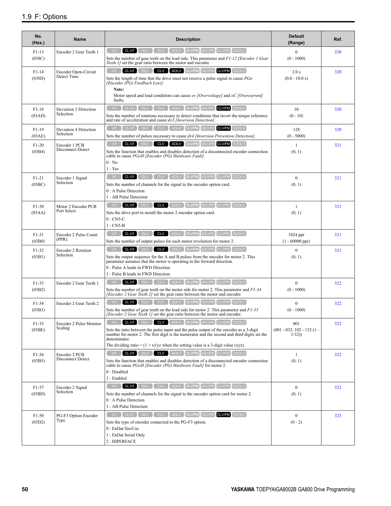
|---|---|---|---|---| |n4-60 (1B80)|Motoring Low Speed Comp Gain|Sets a compensation gain to improve the control qualities for motoring loads in the low speed range.
V/f CL-V/f OLV CLV AOLV OLV/PM AOLV/PM CLV/PM EZOLV
|100.0% (50.0 - 200.0%)|491| |n4-61 (1B81)|Low Speed Comp Frequency Level|Sets a frequency at which the settings n4-60 [Motoring Low Speed Comp Gain] and n4-62
[Regen Low Speed Comp Gain] are enabled. When the output frequency < n4-61, the drive adjusts the torque to agree with the settings for n4-60 and n4-62. Usually it is not necessary to change this setting.
V/f CL-V/f OLV CLV AOLV OLV/PM AOLV/PM CLV/PM EZOLV
|6.00 Hz (0.50 - 12.00 Hz)|491| |n4-62 (1B82)|Regen Low Speed Comp Gain|Sets a compensation gain to improve the control qualities for regenerative loads in the low speed range.
V/f CL-V/f OLV CLV AOLV OLV/PM AOLV/PM CLV/PM EZOLV
|100.0 (50.0 - 500.0)|491| |n4-63 (1B83)|Speed EstimateResponse@High Freq|Sets the responsiveness of the speed estimation in high speed ranges, where the output frequency is ≥ n4-67 [Estimate Gain Switchover Freq].
V/f CL-V/f OLV CLV AOLV OLV/PM AOLV/PM CLV/PM EZOLV
|60.0 (0.1 - 300.0)|491| |n4-64 (1B84)|Speed Estimate Response@Low Freq|Sets the responsiveness of the speed estimation in low speed ranges, where 0 ≤ the output frequency, which is < n4-67 [Estimate Gain Switchover Freq].
V/f CL-V/f OLV CLV AOLV OLV/PM AOLV/PM CLV/PM EZOLV
|60.0 (0.1 - 300.0)|492| |n4-65 (1B85)|Flux Estimate Response@High Freq|Sets the responsiveness of the magnetic flux estimation in high speed ranges, where the output frequency is ≥ n4-67 [Estimate Gain Switchover Freq]. Usually it is not necessary to change this setting.
V/f CL-V/f OLV CLV AOLV OLV/PM AOLV/PM CLV/PM EZOLV
|1.00 (0.50 - 3.00)|492| |n4-66 (1B86)|Flux Estimate Response @Low Freq|Sets the responsiveness of the magnetic flux estimation in low speed ranges, where 0 ≤ the output frequency, which is < n4-67 [Estimate Gain Switchover Freq]. Usually it is not necessary to change this setting.
V/f CL-V/f OLV CLV AOLV OLV/PM AOLV/PM CLV/PM EZOLV
|1.50 (0.50 - 3.00)|492| |n4-67 (1B87)|Estimate Gain Switchover Freq|Sets the switching frequency for estimation gain for these parameters:
n4-63 [Speed EstimateResponse@High Freq]
n4-64 [Speed Estimate Response@Low Freq]
n4-65 [Flux Estimate Response@High Freq]
n4-66 [Flux Estimate Response @Low Freq] Usually it is not necessary to change this setting.
V/f CL-V/f OLV CLV AOLV OLV/PM AOLV/PM CLV/PM EZOLV
|6.00 Hz (0.00 - E1-04 setting)|492| |n4-68 (1B88)|Speed Estimation Filter Time|Sets the primary delay time constant for the speed estimation value. Usually it is not necessary to change this setting.
V/f CL-V/f OLV CLV AOLV OLV/PM AOLV/PM CLV/PM EZOLV
|0.001 s (0.001 - 0.010 s)|492| |n4-69 (1B89)|Flux Control Response|Unifies control of magnetic flux to make motor vibrations more stable.
V/f CL-V/f OLV CLV AOLV OLV/PM AOLV/PM CLV/PM EZOLV
|1.00 (0.00 - 60.00)|493| |n4-70 (1B8A)|Speed Command Comp @ Low Freq|Sets the function to make the drive more stable when operating at low speeds. Usually it is not necessary to change this setting.
V/f CL-V/f OLV CLV AOLV OLV/PM AOLV/PM CLV/PM EZOLV
|1.00 Hz (0.00 - 6.00 Hz)|493| |n4-71 (1B8B) Expert|Flux Estimation Method|Sets the flux estimation method. Usually it is not necessary to change this setting.
0 : Method 1
1 : Method 2
V/f CL-V/f OLV CLV AOLV OLV/PM AOLV/PM CLV/PM EZOLV
|0 (0, 1)|493| |n4-72 (1B8C)|Speed Feedback Mode|Sets the requirement for an encoder option when A1-02 = 4 [Control Method Selection = Advanced Open Loop Vector].
0 : Without Encoder
1 : With Encoder
V/f CL-V/f OLV CLV AOLV OLV/PM AOLV/PM CLV/PM EZOLV
|0 (0, 1)|493| |n4-73 (1B8D)|PGo Recovery Selection|Sets the restart mode to Without Encoder Mode or the With Encoder Mode when an encoder is disconnected.
0 : Without Encoder
1 : With Encoder
V/f CL-V/f OLV CLV AOLV OLV/PM AOLV/PM CLV/PM EZOLV
|0 (0, 1)|493| |n4-74 (1B8E)|Limit of Flux Loop|Sets the control level for flux loop control output.
V/f CL-V/f OLV CLV AOLV OLV/PM AOLV/PM CLV/PM EZOLV
|250% (100 - 500%)|494|
|No. (Hex.)|Name|Description|Default (Range)|Ref.| |---|---|---|---|---| |n5-01 (05B0)|Feed Forward Control Selection|Sets the feed forward function.
0 : Disabled
1 : Enabled
V/f CL-V/f OLV CLV AOLV OLV/PM AOLV/PM CLV/PM EZOLV
|0 (0, 1)|495| |n5-02 (05B1)|Motor Inertia Acceleration Time|Sets the length of time for the motor to accelerate from the stopped to the maximum frequency with a single motor at the rated torque. Inertia Tuning automatically sets the motor acceleration time.
V/f CL-V/f OLV CLV AOLV OLV/PM AOLV/PM CLV/PM EZOLV
|Determined by C6-01, E5-01, and o2-04 (0.001 - 10.000 s)|495| |n5-03 (05B2)|Feed Forward Control Gain|Sets the ratio between load inertia and motor inertia. Inertia Tuning automatically sets the Feedforward Control Gain value.
V/f CL-V/f OLV CLV AOLV OLV/PM AOLV/PM CLV/PM EZOLV
|1.00 (0.00 - 100.00)|496| |n5-04 (05B3) RUN Expert|Speed Response Frequency|Sets the response frequency for the speed reference. Usually it is not necessary to change this parameter.
V/f CL-V/f OLV CLV AOLV OLV/PM AOLV/PM CLV/PM EZOLV
|Determined by A1-02 (0.00 - 500.00 Hz)|497|
|No. (Hex.)|Name|Description|Default (Range)|Ref.| |---|---|---|---|---| |n6-01 (0570)|Online Tuning Selection|Sets the type of motor data that Online Tuning uses for OLV control.
0 : Disabled
1 : Line-to-Line Resistance Tuning
2 : Voltage Correction Tuning
V/f CL-V/f OLV CLV AOLV OLV/PM AOLV/PM CLV/PM EZOLV
|0 (0 - 2)|497| |n6-05 (05C7) Expert|Online Tuning Gain|Sets the compensation gain when n6-01 = 2 [Online Tuning Selection = Voltage Correction Tuning]. Usually it is not necessary to change this parameter.
V/f CL-V/f OLV CLV AOLV OLV/PM AOLV/PM CLV/PM EZOLV
|1.0 (0.1 - 50.0)|497| |n6-11 (1B56) Expert|Online Resistance Tuning|Sets the responsiveness for online resistor tuning. Set this parameter to approximately 1.000 to enable the function. The function is disabled when the value is 0.000.
V/f CL-V/f OLV CLV AOLV OLV/PM AOLV/PM CLV/PM EZOLV
|0.000 (0.000 - 1.000)|497|
|No. (Hex.)|Name|Description|Default (Range)|Ref.| |---|---|---|---|---| |n7-01 (3111) Expert|Damping Gain for Low Frequency|Sets the oscillation suppression gain for the low speed range.
V/f CL-V/f OLV CLV AOLV OLV/PM AOLV/PM CLV/PM EZOLV
|1.0 (0.1 - 10.0)|498| |n7-05 (3115) Expert|Response Gain for Load Changes|Sets the response gain related to changes in the load.
V/f CL-V/f OLV CLV AOLV OLV/PM AOLV/PM CLV/PM EZOLV
|100 (10 - 1000)|498|
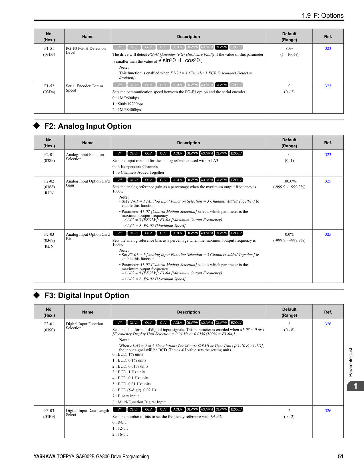
|n7-07 (3117) Expert|Speed Calculation Gain1|Sets the speed calculation gain during usual operation. Usually it is not necessary to change this setting.
V/f CL-V/f OLV CLV AOLV OLV/PM AOLV/PM CLV/PM EZOLV
|15.0 Hz (1.0 - 50.0 Hz)|498| |n7-08 (3118) Expert|Speed Calculation Gain2|Sets the speed calculation gain during a speed search.
V/f CL-V/f OLV CLV AOLV OLV/PM AOLV/PM CLV/PM EZOLV
|25.0 Hz (1.0 - 50.0 Hz)|498| |n7-10 (311A) Expert|Pull-in Current Switching Speed|Parameter n8-51 [Pull-in Current @ Acceleration], is in effect when the output frequency is ≤ n7-10, where the speed is set as a percentage of rated speed.
Note:
• The value set in n8-51 [Pull-in Current @ Acceleration] is enabled for speeds that are not higher than n7-10 during deceleration. The value set in b8-01 [Energy Saving Control Selection] is enabled for speeds higher than n7-10.
• If there is a large quantity of oscillation when you operate in the low speed range, increase the setting value.
• When it is most important to save energy in the low speed range, decrease the setting value.
V/f CL-V/f OLV CLV AOLV OLV/PM AOLV/PM CLV/PM EZOLV
|10.0% (0.0 - 100.0%)|498|
|No. (Hex.)|Name|Description|Default (Range)|Ref.| |---|---|---|---|---| |n7-11 (311B) Expert|Pull-in Current Switch Hysteresis Band|Sets the hysteresis level for Switching Speed set in n7-10 [Pull-in Current Switching Speed]. When the speed is lower than n7-10 n7-11 during acceleration, the drive enables pull-in current.
Note:
• The value set in n8-51 [Pull-in Current @ Acceleration] is enabled for speeds that are not higher than n7-10 + n7-11 during acceleration. The value set in b8-01 [Energy Saving Control Selection] is enabled for speeds higher than n7-10 + n7-11.
• If there is a large quantity of oscillation when you operate in the low speed range, increase the setting value.
• When it is most important to save energy in the low speed range, decrease the setting value.
V/f CL-V/f OLV CLV AOLV OLV/PM AOLV/PM CLV/PM EZOLV
|5.0% (1.0 - 20.0%)|499| |n7-13 (311D) Expert|Pull-in Current Switching Time|Sets a time to enable the pull-in current commands.
V/f CL-V/f OLV CLV AOLV OLV/PM AOLV/PM CLV/PM EZOLV
|100 ms (0 - 1000 ms)|499| |n7-17 (3122)|Resistance TemperatureCorrection|Sets the function to adjust for changes in the motor resistance value caused by changes in the temperature.
0 : Invalid
1 : Valid (Only 1 time)
2 : Valid (Every time)
V/f CL-V/f OLV CLV AOLV OLV/PM AOLV/PM CLV/PM EZOLV
|1 (0 to 2)|499|
######## ◆ n8: PM Motor Control Tuning
|No. (Hex.)|Name|Description|Default (Range)|Ref.| |---|---|---|---|---| |n8-01 (0540)|Pole Position Detection Current|Sets, as a percentage, the Initial Rotor Position Estimated Current, taking the E5-03 [Motor Rated Current (FLA)] as the 100% value. Usually it is not necessary to change this setting.
V/f CL-V/f OLV CLV AOLV OLV/PM AOLV/PM CLV/PM EZOLV
|50% (0 - 100%)|499| |n8-02 (0541) Expert|Pole Alignment Current Level|Sets the current at the time of polar attraction as a percentage of E5-03 [Motor Rated Current (FLA)]. Usually it is not necessary to change this setting.
V/f CL-V/f OLV CLV AOLV OLV/PM AOLV/PM CLV/PM EZOLV
|80% (0 - 150%)|500| |n8-03 (0542)|Pole Position Detection Time|Sets the length of the Current Starting Time, which is used for Z Pulse Offset Tuning. Usually it is not necessary to change this setting.
V/f CL-V/f OLV CLV AOLV OLV/PM AOLV/PM CLV/PM EZOLV
|1.5 s (1.5 - 5.0 s)|500| |n8-04 (0543) Expert|Pole Alignment Time|Sets the length of the Polar Attraction Time, which is used for Z Pulse Offset Tuning. Usually it is not necessary to change this setting.
V/f CL-V/f OLV CLV AOLV OLV/PM AOLV/PM CLV/PM EZOLV
|1.5 s (1.5 - 5.0 s)|500| |n8-11 (054A)|Observer Calculation Gain 2|Sets the gain for speed estimation. Usually it is not necessary to change this setting.
V/f CL-V/f OLV CLV AOLV OLV/PM AOLV/PM CLV/PM EZOLV
|Determined by n8-72 (0.0 - 1000.0)|500| |n8-14 (054D) Expert|Polarity Compensation Gain 3|Sets the gain for speed estimation. Usually it is not necessary to change this setting.
V/f CL-V/f OLV CLV AOLV OLV/PM AOLV/PM CLV/PM EZOLV
|1.000 (0.000 - 10.000)|500| |n8-15 (054E) Expert|Polarity Compensation Gain 4|Sets the gain for speed estimation. Usually it is not necessary to change this setting.
V/f CL-V/f OLV CLV AOLV OLV/PM AOLV/PM CLV/PM EZOLV
|0.500 (0.000 - 10.000)|501| |n8-21 (0554) Expert|Motor Back-EMF (Ke) Gain|Sets the gain for speed estimation. Usually it is not necessary to change this setting.
V/f CL-V/f OLV CLV AOLV OLV/PM AOLV/PM CLV/PM EZOLV
|0.90 (0.80 - 1.00)|501| |n8-23 (0556) Expert|ACR q Gain @PoleEst|Sets the proportional gain for current regulator q-axis control when the drive estimates the initial pole. Usually it is not necessary to change this setting.
V/f CL-V/f OLV CLV AOLV OLV/PM AOLV/PM CLV/PM EZOLV
|0 (0 - 2000)|501| |n8-24 (0557) Expert|ACR q Integral Time @PoleEst|Sets the integral time for current regulator q-axis control when the drive estimates the initial pole. Usually it is not necessary to change this setting.
V/f CL-V/f OLV CLV AOLV OLV/PM AOLV/PM CLV/PM EZOLV
|0.0 ms (0.0 - 100.0 ms)|501| |n8-25 (0558) Expert|ACR q Limit @PoleEst|Sets the q-axis limit of the current regulator when the drive estimates the initial pole. Usually it is not necessary to change this setting.
V/f CL-V/f OLV CLV AOLV OLV/PM AOLV/PM CLV/PM EZOLV
|0% (0 - 150%)|501| |n8-26 (0559) Expert|ACR d Gain @PoleEst|Sets the proportional gain for current regulator d-axis control when the drive estimates the initial pole. Usually it is not necessary to change this setting.
V/f CL-V/f OLV CLV AOLV OLV/PM AOLV/PM CLV/PM EZOLV
|500 (0 - 2000)|501|
|No. (Hex.)|Name|Description|Default (Range)|Ref.| |---|---|---|---|---| |n8-27 (055A) Expert|ACR d Integral Time @PoleEst|Sets the integral time for current regulator d-axis control when the drive estimates the initial pole. Usually it is not necessary to change this setting.
V/f CL-V/f OLV CLV AOLV OLV/PM AOLV/PM CLV/PM EZOLV
|0.0 ms (0.0 - 100.0 ms)|501| |n8-28 (055B) Expert|ACR d Lim @PoleEst|Sets the d-axis limit of the current regulator when the drive estimates the initial pole. Usually it is not necessary to change this setting.
V/f CL-V/f OLV CLV AOLV OLV/PM AOLV/PM CLV/PM EZOLV
|100% (0 - 150%)|502| |n8-35 (0562)|Initial Pole Detection Method|Sets how the drive detects the position of the rotor at start.
Note:
• When you operate an SPM motor, set n8-35 = 0. When you operate an IPM motor, you can set n8-35 0 to 2.
• When you set n8-35 = 1, doHigh Frequency Injection Auto-Tuning.
0 : Pull-in
1 : High Frequency Injection
2 : Pulse Injection
V/f CL-V/f OLV CLV AOLV OLV/PM AOLV/PM CLV/PM EZOLV
|Determined by A1-02 (0 - 2)|502| |n8-36 (0563)|HFI Frequency Level for LTuning|Sets the injection frequency for high frequency injection.
Note:
• Set n8-35 = 1 [Initial Pole Detection Method = High Frequency Injection] or n8-57
= 1 [HFI Overlap Selection = Enabled] to enable this parameter.
• The drive automatically calculates this value when High Frequency Injection AutoTuning completes successfully.
V/f CL-V/f OLV CLV AOLV OLV/PM AOLV/PM CLV/PM EZOLV
|500 Hz (200 - 1000 Hz)|502| |n8-37 (0564) Expert|HFI Voltage Amplitude Level|Sets the high frequency injection amplitude as a percentage where 200 V = 100% for 200 V class drives and 400 V = 100% for a 400 V class drives. Usually it is not necessary to change this setting.
Note:
• Set n8-35 = 1 [Initial Pole Detection Method = High Frequency Injection] or n8-57
= 1 [HFI Overlap Selection = Enabled] to enable this parameter.
• The drive automatically calculates this value when High Frequency Injection AutoTuning completes successfully.
V/f CL-V/f OLV CLV AOLV OLV/PM AOLV/PM CLV/PM EZOLV
|20.0% (0.0 - 50.0%)|502| |n8-39 (0566)|PM Phase Compensation Gain|Sets the low-pass filter shut-off frequency for high frequency injection.
Note:
• Set n8-35 = 1 [Initial Pole Detection Method = High Frequency Injection] or n8-57
= 1 [HFI Overlap Selection = Enabled] to enable this parameter.
• The drive automatically calculates this value when High Frequency Injection AutoTuning completes successfully.
V/f CL-V/f OLV CLV AOLV OLV/PM AOLV/PM CLV/PM EZOLV
|250 Hz (0 - 1000 Hz)|503| |n8-41 (0568) Expert|HFI P Gain|Sets the response gain for the high frequency injection speed estimation.
V/f CL-V/f OLV CLV AOLV OLV/PM AOLV/PM CLV/PM EZOLV
|2.5 (-10.0 - +10.0)|503| |n8-42 (0569) Expert|HFI I Time|Sets the integral time constant for the high frequency injection speed estimation. Usually it is not necessary to change this setting.
V/f CL-V/f OLV CLV AOLV OLV/PM AOLV/PM CLV/PM EZOLV
|0.10 s (0.00 - 9.99 s)|503| |n8-45 (0538)|Speed Feedback Detection Gain|Sets the internal speed feedback detection reduction unit gain as a magnification value. Usually it is not necessary to change this setting.
V/f CL-V/f OLV CLV AOLV OLV/PM AOLV/PM CLV/PM EZOLV
|0.80 (0.00 - 10.00)|503| |n8-46 (0539) Expert|PM Phase Compensation Gain|Sets the gain to compensate for phase differences. Usually it is not necessary to change this setting.
V/f CL-V/f OLV CLV AOLV OLV/PM AOLV/PM CLV/PM EZOLV
|0.3 (0.0 - 10.0)|503|
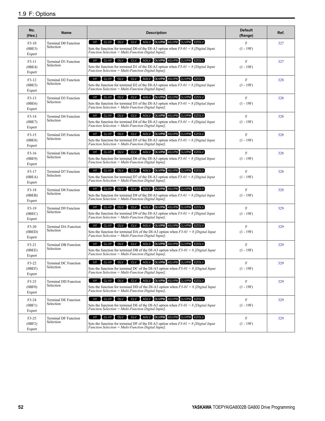
|n8-47 (053A)|Pull-in Current Comp Filter Time|Sets the time constant the drive uses to align the pull-in current reference value with the actual current value. Usually it is not necessary to change this setting.
V/f CL-V/f OLV CLV AOLV OLV/PM AOLV/PM CLV/PM EZOLV
|5.0 s (0.0 - 100.0 s)|504| |n8-48 (053B)|Pull-in/Light Load Id Current|On the basis that parameter E5-03 [Motor Rated Current (FLA)] is the 100% value, this parameter sets the d-axis current that flows to the motor during run at constant speed as a percentage.
V/f CL-V/f OLV CLV AOLV OLV/PM AOLV/PM CLV/PM EZOLV
|30% (0 - 200%)|504| |n8-49 (053C)|Heavy Load Id Current|Sets the d-axis current to that the drive will supply to the motor to run it at a constant speed with a heavy load. Considers E5-03 [PM Motor Rated Current (FLA)] to be 100%. Usually it is not necessary to change this setting.
V/f CL-V/f OLV CLV AOLV OLV/PM AOLV/PM CLV/PM EZOLV
|Determined by E5-01 (-200.0 - +200.0%)|504| |n8-50 (053D)|Medium Load Iq Level (High)|Sets the load current level to start high efficiency control as a percentage of E5-03 [PM Motor Rated Current (FLA)]. Usually it is not necessary to change this setting.
V/f CL-V/f OLV CLV AOLV OLV/PM AOLV/PM CLV/PM EZOLV
|80% (50 - 255%)|504|
|No. (Hex.)|Name|Description|Default (Range)|Ref.| |---|---|---|---|---| |n8-51 (053E)|Pull-in Current @ Acceleration|Sets the pull-in current allowed to flow during acceleration/deceleration as a percentage of the motor rated current.
Note:
Parameter A1-02 [Control Method Selection] selects which parameter is the motor rated current.
• A1-02 5 [OLV/PM]: E5-03 [Motor Rated Current (FLA)]
• A1-02 8 [EZOLV]: E9-06 [Motor Rated Current (FLA)]
V/f CL-V/f OLV CLV AOLV OLV/PM AOLV/PM CLV/PM EZOLV
|Determined by A1-02 (0 - 200%)|504| |n8-52 (053F) Expert|ACR P Gain|Sets the proportional gain of the current regulator. Usually it is not necessary to change this setting.
V/f CL-V/f OLV CLV AOLV OLV/PM AOLV/PM CLV/PM EZOLV
|10.0 (-100.0 - 100.0)|505| |n8-54 (056D) Expert|Voltage Error Compensation Time|Sets the time constant that the drive uses when adjusting for voltage errors.
V/f CL-V/f OLV CLV AOLV OLV/PM AOLV/PM CLV/PM EZOLV
|1.00 s (0.00 - 10.00 s)|505| |n8-55 (056E)|Motor to Load Inertia Ratio|Sets the ratio between motor inertia and machine inertia.
0 : Below 1:10
1 : Between 1:10 and 1:30
2 : Between 1:30 and 1:50
3 : Beyond 1:50
V/f CL-V/f OLV CLV AOLV OLV/PM AOLV/PM CLV/PM EZOLV
|0 (0 - 3)|505| |n8-56 (056F) Expert|PM High Performance Selection|Sets the high efficiency control method for IPM motor. Usually it is not necessary to change this setting.
0 : Disabled
1 : Enabled (Vd)
2 : Enabled (Vd & Vq)
V/f CL-V/f OLV CLV AOLV OLV/PM AOLV/PM CLV/PM EZOLV
|1 (0 - 2)|506| |n8-57 (0574)|HFI Overlap Selection|Sets the function that detects motor speed with high frequency injection. Note: When you set n8-57 = 1, doHigh Frequency Injection Auto-Tuning.
0 : Disabled
1 : Enabled
V/f CL-V/f OLV CLV AOLV OLV/PM AOLV/PM CLV/PM EZOLV
|0 (0, 1)|506| |n8-62 (057D) Expert|Output Voltage Limit Level|Sets the output voltage limit to prevent saturation of the output voltage. Usually it is not necessary to change this parameter.
Note:
• When A1-02 = 7, 8 [Control Method Selection = CLV/PM, EZOLV], this parameter is available in Expert Mode.
• When A1-02 = 8, the default setting is
–200 V Class: 230.0 V
–400 V Class: 460.0 V
V/f CL-V/f OLV CLV AOLV OLV/PM AOLV/PM CLV/PM EZOLV
|200 V Class: 200.0 V, 400 V Class: 400.0 V
(200 V Class: 0.0 to 240.0 V, 400 V Class: 0.0 to 480.0 V)|506| |n8-63 (057E) Expert|Output Voltage Limit P Gain|Sets the proportional gain for output voltage control. Usually it is not necessary to change this setting.
V/f CL-V/f OLV CLV AOLV OLV/PM AOLV/PM CLV/PM EZOLV
|1.00 (0.00 - 100.00)|506| |n8-64 (057F) Expert|Output Voltage Limit I Time|Sets the integral time for output voltage control. Usually it is not necessary to change this setting.
V/f CL-V/f OLV CLV AOLV OLV/PM AOLV/PM CLV/PM EZOLV
|0.040 s (0.000 - 5.000 s)|507| |n8-65 (065C) Expert|Speed Fdbk Gain @ oV Suppression|Sets the gain of internal speed feedback detection suppression while the overvoltage suppression function is operating as a magnification value. Usually it is not necessary to change this parameter.
V/f CL-V/f OLV CLV AOLV OLV/PM AOLV/PM CLV/PM EZOLV
|1.50 (0.00 - 10.00)|507| |n8-66 (0235) Expert|Output Voltage Limit Filter Time|Sets the filter time constant for output voltage control. Usually it is not necessary to change this setting.
V/f CL-V/f OLV CLV AOLV OLV/PM AOLV/PM CLV/PM EZOLV
|0.020 s (0.000 - 5.000 s)|507| |n8-69 (065D) Expert|Speed Observer Control P Gain|Sets the gain that the drive uses for speed estimation. Usually it is not necessary to change this setting.
V/f CL-V/f OLV CLV AOLV OLV/PM AOLV/PM CLV/PM EZOLV
|1.00 (0.00 - 20.00)|507| |n8-70 (065E) Expert|Speed Observer Control I Time|Sets the speed estimator integral time constant. It is available when n8-72 = 1 [Speed Estimation Method Select = Method 2]. Usually it is not necessary to change this setting.
V/f CL-V/f OLV CLV AOLV OLV/PM AOLV/PM CLV/PM EZOLV
|0.0 s (0.0 - 100.0 s)|507| |n8-71 (065F) Expert|Speed Observer Control D Gain|Set the speed estimator differential gain. It is available when n8-72 = 1 [Speed Estimation Method Select = Method 2]. Usually it is not necessary to change this setting.
V/f CL-V/f OLV CLV AOLV OLV/PM AOLV/PM CLV/PM EZOLV
|5.00 (0.00 - 50.00)|507|
|No. (Hex.)|Name|Description|Default (Range)|Ref.| |---|---|---|---|---| |n8-72 (0655) Expert|Speed Estimation Method Select|Selects the speed estimation method. Usually it is not necessary to change this setting.
0 : Method 1
1 : Method 2
V/f CL-V/f OLV CLV AOLV OLV/PM AOLV/PM CLV/PM EZOLV
|1 (0, 1)|507| |n8-73 (0656) Expert|Observer Mode SwitchOver Speed|Sets the speed level for pull-in current control at motor start as a percentage of E1-06 [Base Frequency]. Usually it is not necessary to change this setting.
V/f CL-V/f OLV CLV AOLV OLV/PM AOLV/PM CLV/PM EZOLV
|10% (0 - 100%)|508| |n8-74 (05C3)|Light Load Iq Level|Set n8-48 [Pull-in/Light Load Id Current] to the percentage of load current (q-axis current) that you will apply, where E5-03 [Motor Rated Current (FLA)] = a setting value of 100%.
V/f CL-V/f OLV CLV AOLV OLV/PM AOLV/PM CLV/PM EZOLV
|30% (0 - 255%)|508| |n8-75 (05C4)|Medium Load Iq Level (low)|Set n8-78 [Medium Load Id Current] to the percentage of load current (q-axis current) that you will apply, where E5-03 [Motor Rated Current (FLA)] = a setting value of 100%.
V/f CL-V/f OLV CLV AOLV OLV/PM AOLV/PM CLV/PM EZOLV
|50% (0 - 255%)|508| |n8-76 (05CD) Expert|Id Switching Filter Time|Sets the filter time constant for d-axis current reference. Usually it is not necessary to change this setting.
V/f CL-V/f OLV CLV AOLV OLV/PM AOLV/PM CLV/PM EZOLV
|200 ms (0 - 5000 ms)|508| |n8-77 (05CE)|Heavy Load Iq Level|Set n8-49 [Heavy Load Id Current] to the percentage of load current (q-axis current) that you will apply, where E5-03 [Motor Rated Current (FLA)] = a setting value of 100%.
V/f CL-V/f OLV CLV AOLV OLV/PM AOLV/PM CLV/PM EZOLV
|90% (0 - 255%)|508| |n8-78 (05F4)|Medium Load Id Current|Sets the level of the pull-in current for mid-range loads.
V/f CL-V/f OLV CLV AOLV OLV/PM AOLV/PM CLV/PM EZOLV
|0% (-200 - +200%)|508| |n8-79 (05FE)|Pull-in Current @ Deceleration|Sets the pull-in current that can flow during deceleration as a percentage of the E5-03 [PM Motor Rated Current (FLA)].
Note: When n8-79 = 0, the drive will use the value set in n8-51 [Pull-in Current @ Acceleration].
V/f CL-V/f OLV CLV AOLV OLV/PM AOLV/PM CLV/PM EZOLV
|50% (0 - 200%)|509| |n8-84 (02D3) Expert|Polarity Detection Current|Sets the current for processing an estimation of the initial motor magnetic pole as a percentage, where E5-03 [PM Motor Rated Current] is the 100% value.
V/f CL-V/f OLV CLV AOLV OLV/PM AOLV/PM CLV/PM EZOLV
|100% (0 - 150%)|509| |n8-94 (012D) Expert|Flux Position Estimation Method|Sets the criteria that the drive uses to find changes in speed or load. Usually it is not necessary to change this setting.
0 : Softstarter
1 : Speed Feedback
V/f CL-V/f OLV CLV AOLV OLV/PM AOLV/PM CLV/PM EZOLV
|Determined by d5-01 (0, 1)|509| |n8-95 (012E) Expert|Flux Position Est Filter Time|Sets the time constant of the filter used for the recognition criteria value for speed and load changes. Usually it is not necessary to change this setting.
V/f CL-V/f OLV CLV AOLV OLV/PM AOLV/PM CLV/PM EZOLV
|30 ms (0 - 100 ms)|509|
####### 1.13 o: Keypad-Related Settings
◆ o1: Keypad Display
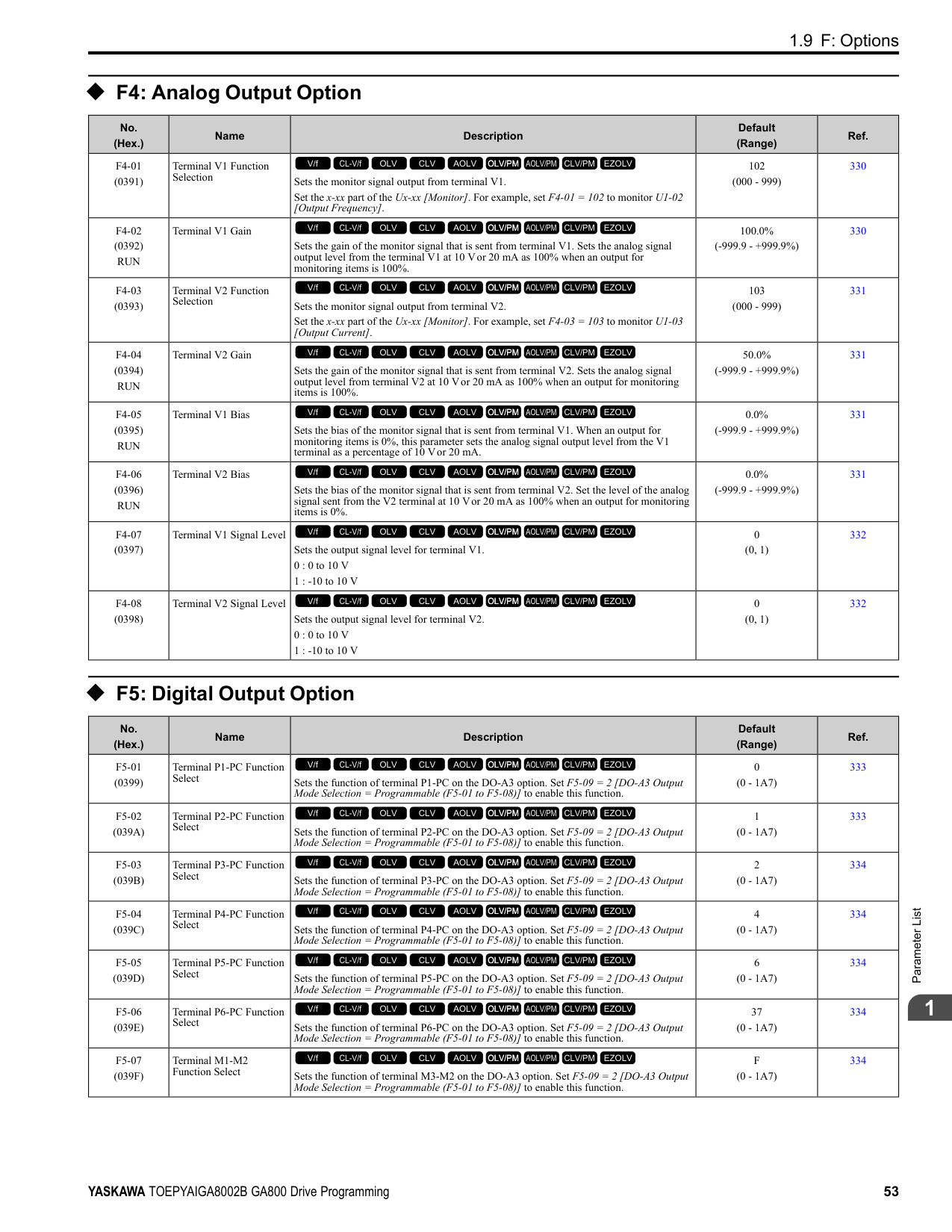
|No. (Hex.)|Name|Description|Default (Range)|Ref.| |---|---|---|---|---| |o1-01 (0500) RUN|User Monitor Selection|Sets the U monitor for the Drive Mode. This parameter is only available when you use an LED keypad.
V/f CL-V/f OLV CLV AOLV OLV/PM AOLV/PM CLV/PM EZOLV
|106 (104 - 855)|511| |o1-02 (0501) RUN|Monitor Selection at Power-up|Sets the monitor item that the keypad screen shows after energizing the drive. Refer to “U: Monitors” for information about the monitor items that the keypad screen can show. This parameter is only available when you use an LED keypad.
1 : Frequency Reference (U1-01)
2 : Direction
3 : Output Frequency (U1-02)
4 : Output Current (U1-03)
5 : User Monitor (o1-01)
V/f CL-V/f OLV CLV AOLV OLV/PM AOLV/PM CLV/PM EZOLV
|1 (1 - 5)|511| |o1-03 (0502)|Frequency Display Unit Selection|Sets the display units for the frequency reference and output frequency.
0 : 0.01Hz units
1 : 0.01% units
2 : min-1 (r/min) unit
3 : User Units
V/f CL-V/f OLV CLV AOLV OLV/PM AOLV/PM CLV/PM EZOLV
|Determined by A1-02 (0 - 3)|511| |o1-04 (0503)|V/f Pattern Display Unit|Sets the setting unit for parameters that set the V/f pattern frequency.
0 : Hz
1 : min-1 (r/min) unit
V/f CL-V/f OLV CLV AOLV OLV/PM AOLV/PM CLV/PM EZOLV
|Determined by A1-02 (0, 1)|512| |o1-05 (0504) RUN|LCD Contrast Adjustment|Sets the contrast of the LCD display on the keypad.
V/f CL-V/f OLV CLV AOLV OLV/PM AOLV/PM CLV/PM EZOLV
|5 (0 - 10)|513| |o1-10 (0520)|User Units Maximum Value|Sets the value that the drive shows as the maximum output frequency.
V/f CL-V/f OLV CLV AOLV OLV/PM AOLV/PM CLV/PM EZOLV
|Determined by o1-03 (1 - 60000)|513| |o1-11 (0521)|User Units Decimal Position|Sets the number of decimal places for frequency reference and monitor values.
0 : No Decimal Places (XXXXX)
1 : One Decimal Places (XXXX.X)
2 : Two Decimal Places (XXX.XX)
3 : Three Decimal Places (XX.XXX)
V/f CL-V/f OLV CLV AOLV OLV/PM AOLV/PM CLV/PM EZOLV
|Determined by o1-03 (0 - 3)|513| |o1-24 to o1-35: (11AD - 11B8) RUN|Custom Monitor 1 to 12|Sets a maximum of 12 monitors as user monitors. This parameter is only available when using an LCD keypad.
V/f CL-V/f OLV CLV AOLV OLV/PM AOLV/PM CLV/PM EZOLV
|o1-24: 101
o1-25: 102
o1-26: 103
o1-27 to o1-35: 0 (0, 101 - 999)|513| |o1-36 (11B9) RUN|LCD Backlight Brightness|Sets the intensity of the LCD keypad backlight.
V/f CL-V/f OLV CLV AOLV OLV/PM AOLV/PM CLV/PM EZOLV
|5 (1 - 5)|514| |o1-37 (11BA) RUN|LCD Backlight ON/OFF Selection|Sets the automatic shut off function for the LCD backlight.
0 : OFF
1 : ON
V/f CL-V/f OLV CLV AOLV OLV/PM AOLV/PM CLV/PM EZOLV
|1 (0, 1)|514| |o1-38 (11BB) RUN|LCD Backlight Off-Delay|Sets the time until the LCD backlight automatically turns off.
V/f CL-V/f OLV CLV AOLV OLV/PM AOLV/PM CLV/PM EZOLV
|60 s (10 - 300 s)|514| |o1-39 (11BC) RUN|Show Initial Setup Screen|Sets the function to show the LCD keypad initial setup screen each time the drive is energized. This parameter is only available when using an LCD keypad.
0 : No
1 : Yes
V/f CL-V/f OLV CLV AOLV OLV/PM AOLV/PM CLV/PM EZOLV
|1 (0, 1)|514|
|No. (Hex.)|Name|Description|Default (Range)|Ref.| |---|---|---|---|---| |o1-40 (11BD) RUN|Home Screen Display Selection|Sets the monitor display mode for the Home screen. This parameter is only available when using an LCD keypad.
0 : Custom Monitor
1 : Bar Graph
2 : Analog Gauge
3 : Trend Plot
V/f CL-V/f OLV CLV AOLV OLV/PM AOLV/PM CLV/PM EZOLV
|0 (0 - 3)|515| |o1-41 (11C1) RUN|1st Monitor Area Selection|Sets the horizontal range used to display the monitor set in o1-24 [Custom Monitor 1] as a bar graph. This parameter is only available when using an LCD keypad.
0 : +/- Area ( - o1-42 ~ o1-42 )
1 : + Area ( 0 ~ o1-42 )
2 : - Area ( - o1-42 ~ 0 )
V/f CL-V/f OLV CLV AOLV OLV/PM AOLV/PM CLV/PM EZOLV
|0 (0 - 2)|515| |o1-42 (11C2) RUN|1st Monitor Area Setting|Sets the horizontal axis value used to display the monitor set in o1-24 [Custom Monitor 1] as a bar graph. This parameter is only available when using an LCD keypad.
V/f CL-V/f OLV CLV AOLV OLV/PM AOLV/PM CLV/PM EZOLV
|100.0% (0.0 - 100.0%)|515| |o1-43 (11C3) RUN|2nd Monitor Area Selection|Selects the horizontal range used to display the monitor set in o1-25 [Custom Monitor 2] as a bar graph. This parameter is only available when using an LCD keypad.
0 : +/- Area ( - o1-44 ~ o1-44 )
1 : + Area ( 0 ~ o1-44 )
2 : - Area ( - o1-44 ~ 0 )
V/f CL-V/f OLV CLV AOLV OLV/PM AOLV/PM CLV/PM EZOLV
|0 (0 - 2)|515| |o1-44 (11C4) RUN|2nd Monitor Area Setting|Sets the horizontal axis value used to display the monitor set in o1-25 [Custom Monitor 2] as a bar graph. This parameter is only available when using an LCD keypad.
V/f CL-V/f OLV CLV AOLV OLV/PM AOLV/PM CLV/PM EZOLV
|100.0% (0.0 - 100.0%)|516| |o1-45 (11C5) RUN|3rd Monitor Area Selection|Sets the horizontal range used to display the monitor set in o1-26 [Custom Monitor 3] as a bar graph. This parameter is only available when using an LCD keypad.
0 : +/- Area ( - o1-46 ~ o1-46 )
1 : + Area ( 0 ~ o1-46 )
2 : - Area ( - o1-46 ~ 0 )
V/f CL-V/f OLV CLV AOLV OLV/PM AOLV/PM CLV/PM EZOLV
|0 (0 - 2)|516| |o1-46 (11C6) RUN|3rd Monitor Area Setting|Sets the horizontal axis value used to display the monitor set in o1-26 [Custom Monitor 3] as a bar graph. This parameter is only available when using an LCD keypad.
V/f CL-V/f OLV CLV AOLV OLV/PM AOLV/PM CLV/PM EZOLV
|100.0% (0.0 - 100.0%)|516| |o1-47 (11C7) RUN|Trend Plot 1 Scale Minimum Value|Sets the horizontal axis minimum value used to display the monitor set in o1-24 [Custom Monitor 1] as a trend plot. This parameter is only available when using an LCD keypad.
V/f CL-V/f OLV CLV AOLV OLV/PM AOLV/PM CLV/PM EZOLV
|-100.0% (-300.0 - +300.0%)|516| |o1-48 (11C8) RUN|Trend Plot 1 Scale Maximum Value|Sets the horizontal axis maximum value used to display the monitor set in o1-24 [Custom Monitor 1] as a trend plot. This parameter is only available when using an LCD keypad.
V/f CL-V/f OLV CLV AOLV OLV/PM AOLV/PM CLV/PM EZOLV
|100.0% (-300.0 - +300.0%)|516| |o1-49 (11C9) RUN|Trend Plot 2 Scale Minimum Value|Sets the horizontal axis minimum value used to display the monitor set in o1-25 [Custom Monitor 2] as a trend plot. This parameter is only available when using an LCD keypad.
V/f CL-V/f OLV CLV AOLV OLV/PM AOLV/PM CLV/PM EZOLV
|-100.0% (-300.0 - +300.0%)|516| |o1-50 (11CA) RUN|Trend Plot 2 Scale Maximum Value|Sets the horizontal axis maximum value used to display the monitor set in o1-25 [Custom Monitor 2] as a trend plot. This parameter is only available when using an LCD keypad.
V/f CL-V/f OLV CLV AOLV OLV/PM AOLV/PM CLV/PM EZOLV
|100.0% (-300.0 - +300.0%)|516| |o1-51 (11CB) RUN|Trend Plot Time Scale Setting|Sets the time scale (horizontal axis) to display the trend plot. When you change this setting, the drive automatically adjusts the data sampling time. This parameter is only available when using an LCD keypad.
V/f CL-V/f OLV CLV AOLV OLV/PM AOLV/PM CLV/PM EZOLV
|300 s (1 - 3600 s)|517| |o1-55 (11EE) RUN|Analog Gauge Area Selection|Sets the range used to display the monitor set in o1-24 [Custom Monitor 1] as an analog gauge. This parameter is only available when using an LCD keypad.
0 : +/- Area ( - o1-56 ~ o1-56 )
1 : + Area ( 0 ~ o1-56 )
V/f CL-V/f OLV CLV AOLV OLV/PM AOLV/PM CLV/PM EZOLV
|1 (0, 1)|517|
|No. (Hex.)|Name|Description|Default (Range)|Ref.| |---|---|---|---|---| |o1-56 (11EF) RUN|Analog Gauge Area Setting|Sets the value used to display the monitor set in o1-24 [Custom Monitor 1] as an analog meter. This parameter is only available when using an LCD keypad.
V/f CL-V/f OLV CLV AOLV OLV/PM AOLV/PM CLV/PM EZOLV
|100.0% (0.0 - 100.0%)|517| |o1-58 (3125)|Motor Power Unit Selection|Sets the setting unit for parameters that set the motor rated power.
0 : kW
1 : HP
V/f CL-V/f OLV CLV AOLV OLV/PM AOLV/PM CLV/PM EZOLV
|1 (0, 1)|517|
######## ◆ o2: Keypad Operation
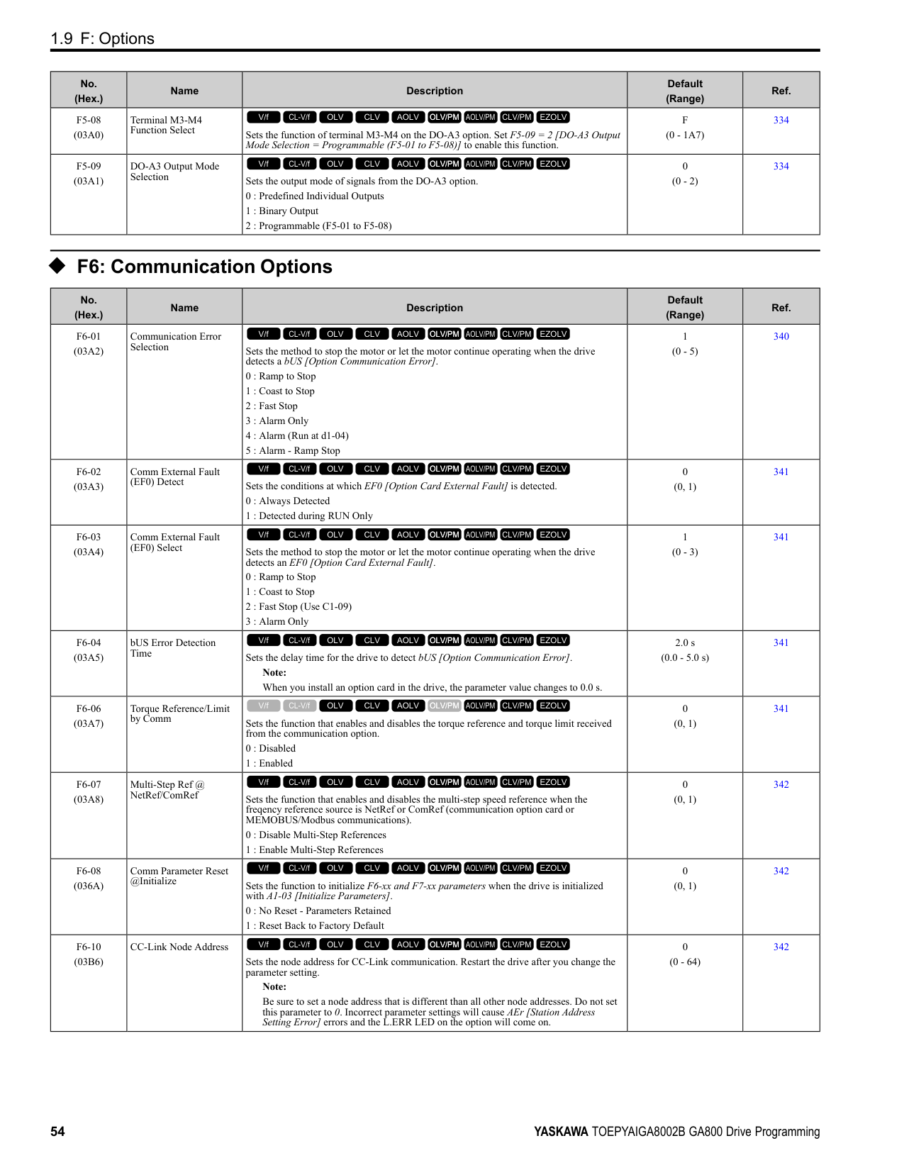
|No. (Hex.)|Name|Description|Default (Range)|Ref.| |---|---|---|---|---| |o2-01 (0505)|LO/RE Key Function Selection|Sets the function that lets you use to switch between LOCAL and REMOTE Modes.
0 : Disabled
1 : Enabled
V/f CL-V/f OLV CLV AOLV OLV/PM AOLV/PM CLV/PM EZOLV
|1 (0, 1)|517| |o2-02 (0506)|STOP Key Function Selection|Sets the function to stop the drive with the button on the keypad when the Run command source for the drive is REMOTE (external) and not assigned to the keypad.
0 : Disabled
1 : Enabled
V/f CL-V/f OLV CLV AOLV OLV/PM AOLV/PM CLV/PM EZOLV
|1 (0, 1)|518| |o2-03 (0507)|User Parameter Default Value|Sets the function to keep the settings of changed parameters as user parameter defaults to use during initialization.
0 : No change
1 : Set defaults
2 : Clear all
V/f CL-V/f OLV CLV AOLV OLV/PM AOLV/PM CLV/PM EZOLV
|0 (0 - 2)|518| |o2-04 (0508)|Drive Model (KVA) Selection|Sets the Drive Model code. Set this parameter after replacing the control board.
V/f CL-V/f OLV CLV AOLV OLV/PM AOLV/PM CLV/PM EZOLV
|Determined by the drive (-)|519| |o2-05 (0509)|Home Mode Freq Ref Entry Mode|Sets the function that makes it necessary to push the to change the frequency reference value with the keypad when in Drive Mode.
0 : ENTER Key Required
1 : Immediate / MOP-style
V/f CL-V/f OLV CLV AOLV OLV/PM AOLV/PM CLV/PM EZOLV
|0 (0, 1)|520| |o2-06 (050A)|Keypad Disconnect Detection|Sets the function that stops the drive if you disconnect the keypad connection cable from the drive or if you damage the cable while the keypad is the Run command source.
0 : Disabled
1 : Enabled
V/f CL-V/f OLV CLV AOLV OLV/PM AOLV/PM CLV/PM EZOLV
|1 (0, 1)|520| |o2-07 (0527)|Keypad RUN Direction @ Power-up|Sets the direction of motor rotation when the drive is energized and the keypad is the Run command source.
0 : Forward
1 : Reverse
V/f CL-V/f OLV CLV AOLV OLV/PM AOLV/PM CLV/PM EZOLV
|0 (0, 1)|520| |o2-09 (050D)|Reserved|-|-|520| |o2-23 (11F8) RUN|External 24V Powerloss Detection|Sets the function to give a warning when the backup external 24 V power supply turns off when the main circuit power supply is in operation.
0 : Disabled
1 : Enabled
V/f CL-V/f OLV CLV AOLV OLV/PM AOLV/PM CLV/PM EZOLV
|0 (0, 1)|521| |o2-24 (11FE)|LED Light Function Selection|Sets the function to show the LED status rings and keypad LED lamps.
Note:
When you use A1-03 [Initialize Parameters] to initialize the drive, the drive will not reset this parameter.
0 : Enable Status Ring & Keypad LED
1 : LED Status Ring Disable
2 : Keypad LED Light Disable
V/f CL-V/f OLV CLV AOLV OLV/PM AOLV/PM CLV/PM EZOLV
|2 (0 - 2)|521|
|No. (Hex.)|Name|Description|Default (Range)|Ref.| |---|---|---|---|---| |o2-26 (1563)|Alarm display at ext. 24V power|When you connect a backup external 24 V power supply, this parameter sets the function to trigger an alarm when the main circuit power supply voltage decreases.
Note: The drive will not run when it is operating from one 24-Vexternal power supply.
0 : No
1 : Yes
V/f CL-V/f OLV CLV AOLV OLV/PM AOLV/PM CLV/PM EZOLV
|1 (0, 1)|521| |o2-27 (1565)|bCE Detection Selection|Sets drive operation if the Bluetooth device is disconnected when you operate the drive in Bluetooth Mode.
0 : Ramp to Stop
1 : Coast to Stop
2 : Fast Stop (Use C1-09)
3 : Alarm Only
4 : No Alarm Display
V/f CL-V/f OLV CLV AOLV OLV/PM AOLV/PM CLV/PM EZOLV
|3 (0 - 4)|521|
######## ◆ o3: Copy Keypad Function
|No. (Hex.)|Name|Description|Default (Range)|Ref.| |---|---|---|---|---| |o3-01 (0515)|Copy Keypad Function Selection|Sets the function that saves and copies drive parameters to a different drive with the keypad.
0 : Copy Select
1 : Backup (drive → keypad)
2 : Restore (keypad → drive)
3 : Verify (check for mismatch)
4 : Erase (backup data of keypad)
V/f CL-V/f OLV CLV AOLV OLV/PM AOLV/PM CLV/PM EZOLV
|0 (0 - 4)|522| |o3-02 (0516)|Copy Allowed Selection|Sets the copy function when o3-01 1 [Copy Keypad Function Selection Backup (drive
→ keypad)].
0 : Disabled
1 : Enabled
V/f CL-V/f OLV CLV AOLV OLV/PM AOLV/PM CLV/PM EZOLV
|0 (0, 1)|522| |o3-04 (0B3E)|Select Backup/Restore Location|Sets the storage location for drive parameters when you back up and restore parameters. This parameter is only available when using an LCD keypad.
0 : Memory Location 1
1 : Memory Location 2
2 : Memory Location 3
3 : Memory Location 4
V/f CL-V/f OLV CLV AOLV OLV/PM AOLV/PM CLV/PM EZOLV
|0 (0 - 3)|522| |o3-05 (0BDA)|Select Items to Backup/ Restore|Sets which parameters are backed up, restored, and referenced. This parameter is only available when using an LCD keypad.
0 : Standard Parameters
1 : Standard DWEZ Parameters
V/f CL-V/f OLV CLV AOLV OLV/PM AOLV/PM CLV/PM EZOLV
|1 (0, 1)|522| |o3-06 (0BDE)|Auto Parameter Backup Selection|Sets the function that automatically backs up parameters. This parameter is only available when using an LCD keypad.
0 : Disabled
1 : Enabled
V/f CL-V/f OLV CLV AOLV OLV/PM AOLV/PM CLV/PM EZOLV
|1 (0, 1)|523| |o3-07 (0BDF)|Auto Parameter Backup Interval|Sets the interval at which the automatic parameter backup function saves parameters from the drive to the keypad.
Note: This parameter is only available when using an LCD keypad.
0 : Every 10 minutes
1 : Every 30 minutes
2 : Every 60 minutes
3 : Every 12 hours
V/f CL-V/f OLV CLV AOLV OLV/PM AOLV/PM CLV/PM EZOLV
|1 (0 - 3)|523|
|No. (Hex.)|Name|Description|Default (Range)|Ref.| |---|---|---|---|---| |o4-01 (050B)|Elapsed Operating Time Setting|Sets the initial value of the cumulative drive operation time in 10-hour units.
V/f CL-V/f OLV CLV AOLV OLV/PM AOLV/PM CLV/PM EZOLV
|0 h (0 - 9999 h)|523| |o4-02 (050C)|Elapsed Operating Time Selection|Sets the condition that counts the cumulative operation time.
0 : U4-01 Shows Total Power-up Time
1 : U4-01 Shows Total RUN Time
V/f CL-V/f OLV CLV AOLV OLV/PM AOLV/PM CLV/PM EZOLV
|0 (0, 1)|524| |o4-03 (050E)|Fan Operation Time Setting|Sets the value from which to start the cumulative drive cooling fan operation time in 10hour units.
V/f CL-V/f OLV CLV AOLV OLV/PM AOLV/PM CLV/PM EZOLV
|0 h (0 - 9999 h)|524| |o4-05 (051D)|Capacitor Maintenance Setting|Sets the U4-05 [CapacitorMaintenance] monitor value.
V/f CL-V/f OLV CLV AOLV OLV/PM AOLV/PM CLV/PM EZOLV
|0% (0 - 150%)|524|
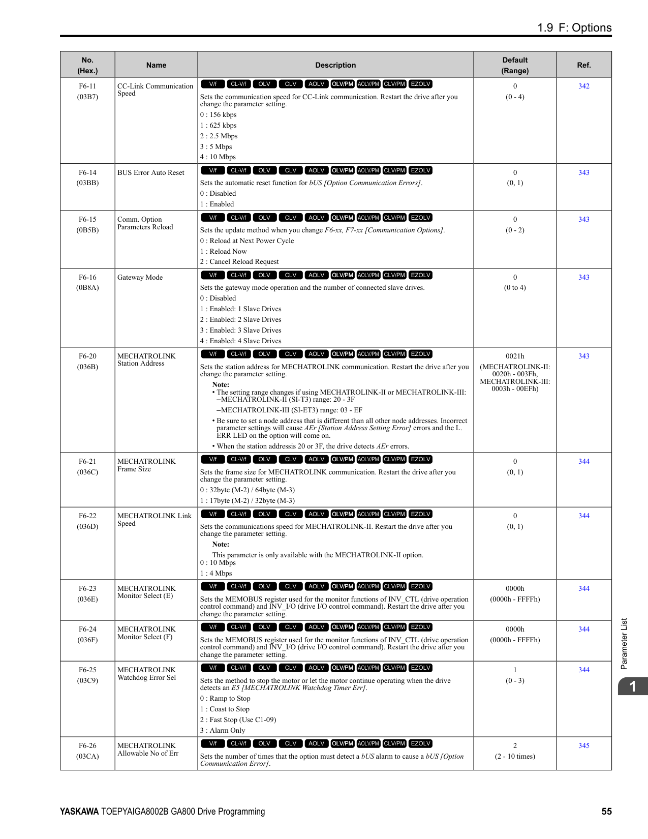
|o4-07 (0523)|Softcharge Relay Maintenance Set|Sets the U4-06 [PreChargeRelayMainte] monitor value.
V/f CL-V/f OLV CLV AOLV OLV/PM AOLV/PM CLV/PM EZOLV
|0% (0 - 150%)|524| |o4-09 (0525)|IGBT Maintenance Setting|Sets the U4-07 [IGBT Maintenance] monitor value.
V/f CL-V/f OLV CLV AOLV OLV/PM AOLV/PM CLV/PM EZOLV
|0% (0 - 150%)|524| |o4-11 (0510)|Fault Trace/History Init (U2/U3)|Resets the records of Monitors U2-xx [Fault Trace] and U3-xx [Fault History].
0 : Disabled
1 : Enabled
V/f CL-V/f OLV CLV AOLV OLV/PM AOLV/PM CLV/PM EZOLV
|0 (0, 1)|525| |o4-12 (0512)|kWh Monitor Initialization|Resets the monitor values for U4-10 [kWh, Lower 4 Digits] and U4-11 [kWh, Upper 5 Digits].
0 : No Reset
1 : Reset
V/f CL-V/f OLV CLV AOLV OLV/PM AOLV/PM CLV/PM EZOLV
|0 (0, 1)|525| |o4-13 (0528)|RUN Command Counter @ Initialize|Resets the monitor values for U4-02 [Num of Run Commands], U4-24 [Number of Runs (Low)], and U4-25 [Number of Runs (High)].
0 : No Reset
1 : Reset
V/f CL-V/f OLV CLV AOLV OLV/PM AOLV/PM CLV/PM EZOLV
|0 (0, 1)|525| |o4-22 (154F) RUN|Time Format|Sets the time display format. This parameter is only available when using an LCD keypad.
0 : 24 Hour Clock
1 : 12 Hour Clock
2 : 12 Hour JP Clock
V/f CL-V/f OLV CLV AOLV OLV/PM AOLV/PM CLV/PM EZOLV
|1 (0 - 2)|525| |o4-23 (1550) RUN|Date Format|Sets the date display format. This parameter is only available when using an LCD keypad.
0 : YYYY/MM/DD
1 : DD/MM/YYYY
2 : MM/DD/YYYY
V/f CL-V/f OLV CLV AOLV OLV/PM AOLV/PM CLV/PM EZOLV
|2 (0 - 2)|526| |o4-24 (310F) RUN|bAT Detection Selection|Sets operation when the drive detects bAT [Keypad Battery Low Voltage] and TiM [Keypad Time Not Set].
0 : Disable
1 : Enable (Alarm Detected)
2 : Enable (Fault Detected)
V/f CL-V/f OLV CLV AOLV OLV/PM AOLV/PM CLV/PM EZOLV
|0 (0 - 2)|526|
|No. (Hex.)|Name|Description|Default (Range)|Ref.| |---|---|---|---|---| |o5-01 (1551) RUN|Log Start/Stop Selection|Sets the data log function. This parameter is only available when using an LCD keypad.
0 : OFF
1 : ON
V/f CL-V/f OLV CLV AOLV OLV/PM AOLV/PM CLV/PM EZOLV
|0 (0 - 1)|529| |o5-02 (1552) RUN|Log Sampling Interval|Sets the data log sampling cycle. This parameter is only available when using an LCD keypad.
V/f CL-V/f OLV CLV AOLV OLV/PM AOLV/PM CLV/PM EZOLV
|100 ms (100 - 60000 ms)|529|
|No. (Hex.)|Name|Description|Default (Range)|Ref.| |---|---|---|---|---| |o5-03 (1553) RUN|Log Monitor Data 1|Sets the data log monitor. This parameter is only available when using an LCD keypad.
V/f CL-V/f OLV CLV AOLV OLV/PM AOLV/PM CLV/PM EZOLV
|101 (000, 101 - 999)|529| |o5-04 (1554) RUN|Log Monitor Data 2|Sets the data log monitor. This parameter is only available when using an LCD keypad.
V/f CL-V/f OLV CLV AOLV OLV/PM AOLV/PM CLV/PM EZOLV
|102 (000, 101 - 999)|529| |o5-05 (1555) RUN|Log Monitor Data 3|Sets the data log monitor. This parameter is only available when using an LCD keypad.
V/f CL-V/f OLV CLV AOLV OLV/PM AOLV/PM CLV/PM EZOLV
|103 (000, 101 - 999)|530| |o5-06 (1556) RUN|Log Monitor Data 4|Sets the data log monitor. This parameter is only available when using an LCD keypad.
V/f CL-V/f OLV CLV AOLV OLV/PM AOLV/PM CLV/PM EZOLV
|107 (000, 101 - 999)|530| |o5-07 (1557) RUN|Log Monitor Data 5|Sets the data log monitor. This parameter is only available when using an LCD keypad.
V/f CL-V/f OLV CLV AOLV OLV/PM AOLV/PM CLV/PM EZOLV
|108 (000, 101 - 999)|530| |o5-08 (1558) RUN|Log Monitor Data 6|Sets the data log monitor. This parameter is only available when using an LCD keypad.
V/f CL-V/f OLV CLV AOLV OLV/PM AOLV/PM CLV/PM EZOLV
|V/f, OLV/PM: 0, CL-V/f, OLV, CLV, AOLV, AOLV/PM, CLV/PM, EZOLV: 105
(000, 101 - 999)|530| |o5-09 (1559) RUN|Log Monitor Data 7|Sets the data log monitor. This parameter is only available when using an LCD keypad.
V/f CL-V/f OLV CLV AOLV OLV/PM AOLV/PM CLV/PM EZOLV
|110 (000, 101 - 999)|530| |o5-10 (155A) RUN|Log Monitor Data 8|Sets the data log monitor. This parameter is only available when using an LCD keypad.
V/f CL-V/f OLV CLV AOLV OLV/PM AOLV/PM CLV/PM EZOLV
|112 (000, 101 - 999)|531| |o5-11 (155B) RUN|Log Monitor Data 9|Sets the data log monitor. This parameter is only available when using an LCD keypad.
V/f CL-V/f OLV CLV AOLV OLV/PM AOLV/PM CLV/PM EZOLV
|000 (000, 101 - 999)|531| |o5-12 (155C) RUN|Log Monitor Data 10|Sets the data log monitor. This parameter is only available when using an LCD keypad.
V/f CL-V/f OLV CLV AOLV OLV/PM AOLV/PM CLV/PM EZOLV
|000 (000, 101 - 999)|531|
####### 1.14 q: DriveWorksEZ Parameters
◆ q1-01 to q8-40: Reserved for DriveWorksEZ
|No. (Hex.)|Name|Description|Default (Range)| |---|---|---|---| |q1-01 to q8-40 (1600 - 17E7)|Reserved for DriveWorksEZ|Refer to “DriveWorksEZ Operation Manual”.
V/f CL-V/f OLV CLV AOLV OLV/PM AOLV/PM CLV/PM EZOLV
|These parameters are reserved for use with DriveWorksEZ.|
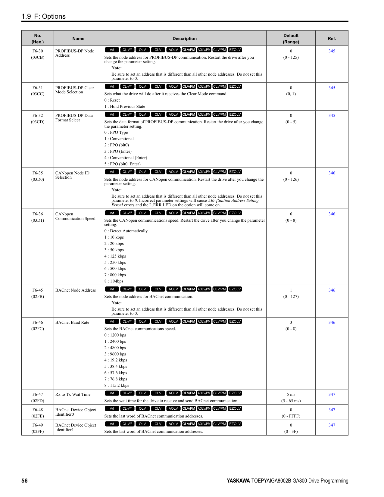
1.15 r: DWEZ Connection 1-20
####### 1.15 r: DWEZ Connection 1-20
◆ r1-01 to r1-40: DriveWorksEZ Connection Parameters 1 to 20 (Upper / Lower)
|No. (Hex.)|Name|Description|Default (Range)| |---|---|---|---| |r1-01 to r1-40: (1840 - 1867)|DriveWorksEZ Connection Parameters 1 to 20 (Upper / Lower)|DriveWorksEZ Connection Parameters 1 to 20 (Upper / Lower)
V/f CL-V/f OLV CLV AOLV OLV/PM AOLV/PM CLV/PM EZOLV
|0 (0 - FFFFH)|
1.16 T: Motor Tuning ◆ T0: Tuning Mode Selection
|No. (Hex.)|Name|Description|Default (Range)|Ref.| |---|---|---|---|---| |T0-00 (1197)|Tuning Mode Selection|Sets the type of Auto-Tuning.
0 : Motor Parameter Tuning
1 : Control Tuning
V/f CL-V/f OLV CLV AOLV OLV/PM AOLV/PM CLV/PM EZOLV
|0 (0, 1)|532|
◆ T1: Induction Motor Auto-Tuning
|No. (Hex.)|Name|Description|Default (Range)|Ref.| |---|---|---|---|---| |T1-00 (0700)|Motor 1/Motor 2 Selection|Sets which motor to tune when motor 1/2 switching is enabled. You can only use the keypad to set this parameter. You cannot use external input terminals to set it.
Note:
This parameter is available when H1-xx 16 [Motor 2 Selection]. The keypad will not show this parameter when H1-xx ≠ 16.
1 : Motor 1 (sets E1-xx, E2-xx)
2 : Motor 2 (sets E3-xx, E4-xx)
V/f CL-V/f OLV CLV AOLV OLV/PM AOLV/PM CLV/PM EZOLV
|1 (1, 2)|532| |T1-01 (0701)|Tuning Mode Selection|Sets the type of Auto-Tuning.
0 : Rotational Auto-Tuning
1 : Stationary Auto-Tuning 1
2 : Stationary Line-Line Resistance
V/f CL-V/f OLV CLV AOLV OLV/PM AOLV/PM CLV/PM EZOLV
|Determined by A1-02 (Determined by A1-02)|533| |T1-02 (0702)|Motor Rated Power|Uses the units set in o1-58 [Motor Power Unit Selection] to set the motor rated output power.
V/f CL-V/f OLV CLV AOLV OLV/PM AOLV/PM CLV/PM EZOLV
|Determined by o2-04, C6-01
(0.00 - 650.00 HP)|533| |T1-03 (0703)|Motor Rated Voltage|Sets the rated voltage (V) of the motor. Enter the base speed voltage for constant output motors.
V/f CL-V/f OLV CLV AOLV OLV/PM AOLV/PM CLV/PM EZOLV
|Determined by o2-04, C6-01
(200 V Class: 0.0 - 255.5 V, 400 V Class: 0.0 511.0 V)|533| |T1-04 (0704)|Motor Rated Current|Sets the rated current (A) of the motor.
V/f CL-V/f OLV CLV AOLV OLV/PM AOLV/PM CLV/PM EZOLV
|Determined by o2-04 (10% to 200% of the drive rated current)|533| |T1-05 (0705)|Motor Base Frequency|Sets the base frequency (Hz) of the motor.
V/f CL-V/f OLV CLV AOLV OLV/PM AOLV/PM CLV/PM EZOLV
|60.0 Hz (0.0 - 590.0 Hz)|533| |T1-06 (0706)|Number of Motor Poles|Sets the number of motor poles.
V/f CL-V/f OLV CLV AOLV OLV/PM AOLV/PM CLV/PM EZOLV
|4 (2 to 120)|534| |T1-07 (0707)|Motor Base Speed|Sets the motor base speed for Auto-Tuning (min-1 (r/min)).
V/f CL-V/f OLV CLV AOLV OLV/PM AOLV/PM CLV/PM EZOLV
|1750 min-1 (r/min) (0 - 35400 min-1 (r/min))|534| |T1-08 (0708)|Encoder Pulse Count (PPR)|Sets the number of PG (pulse generator, encoder) pulses.
V/f CL-V/f OLV CLV AOLV OLV/PM AOLV/PM CLV/PM EZOLV
|1024 ppr (0 - 60,000 ppr)|534| |T1-09 (0709)|Motor No-Load Current|Sets the no-load current of the motor.
V/f CL-V/f OLV CLV AOLV OLV/PM AOLV/PM CLV/PM EZOLV
|(0A - T1-04; max. of 2999.9)|534| |T1-10 (070A)|Motor Rated Slip Frequency|Sets motor rated slip.
V/f CL-V/f OLV CLV AOLV OLV/PM AOLV/PM CLV/PM EZOLV
|(0.000 - 20.000 Hz)|534| |T1-11 (070B)|Motor Iron Loss|Sets the iron loss for calculating the energy-saving coefficient.
V/f CL-V/f OLV CLV AOLV OLV/PM AOLV/PM CLV/PM EZOLV
|Determined by E2-11 or E4-11
(0 - 65535 W)|534|
|No. (Hex.)|Name|Description|Default (Range)|Ref.| |---|---|---|---|---| |T1-12 (0BDB)|Test Mode Selection|Sets the function to enable Test Mode after Stationary Auto-Tuning. When you can operate the motor with a light load attached after Stationary Auto-Tuning is complete, enable this parameter.
Note:
You must first set T1-10 [Motor Rated Slip Frequency] = 0 Hz to enable this parameter.
0 : No
1 : Yes
V/f CL-V/f OLV CLV AOLV OLV/PM AOLV/PM CLV/PM EZOLV
|0 (0, 1)|535| |T1-13 (0BDC)|No-load voltage|Sets the no-load voltage of the motor. If you know the no-load voltage at the rated speed in a test report, set that voltage value. If you do not know the no-load voltage, do not change from the initial value.
Note:
• To get the same qualities as a Yaskawa 1000-series drive or previous models, set this parameter = T1-03 [Motor Rated Voltage] value.
• The default value is different for different models.
–2004 - 2008, 4002 - 4004: T1-03 × 0.85
–2010 - 2415, 4005 - 4302: T1-03 × 0.90
–4371- 4720: T1-03 × 0.95
V/f CL-V/f OLV CLV AOLV OLV/PM AOLV/PM CLV/PM EZOLV
|T1-03 × 0.85 (200 V Class: 0.0 - 255.0 V, 400 V Class: 0.0 510.0 V)|535|
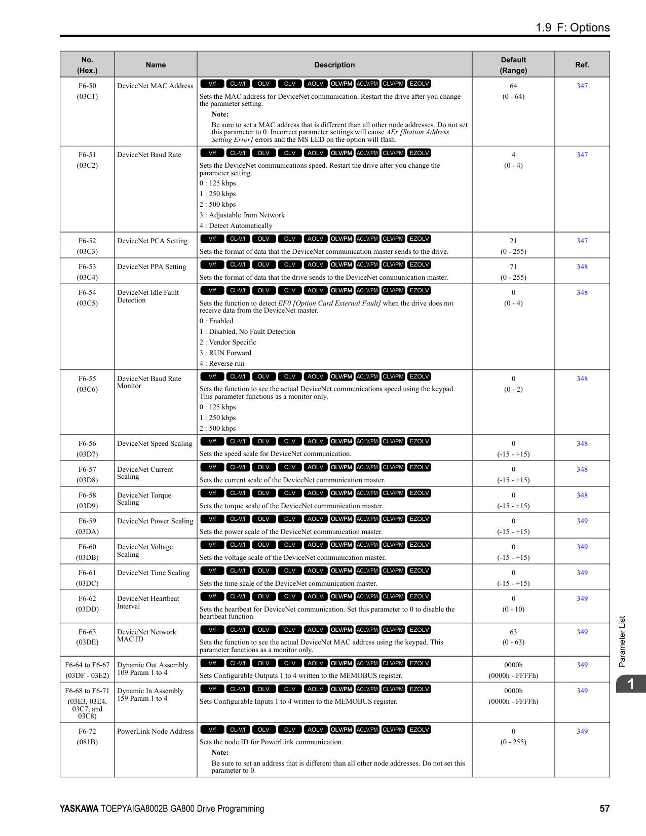
######## ◆ T2: PM Motor Auto-Tuning
|No. (Hex.)|Name|Description|Default (Range)|Ref.| |---|---|---|---|---| |T2-01 (0750)|PM Auto-Tuning Selection|Sets the type of Auto-Tuning for PM motors.
0 : Manual Entry w/ Motor Data Sheet
1 : Stationary (Ld, Lq, R)
2 : Stationary (R Only)
3 : Z-Pulse Offset (Pole Position)
4 : Rotational (Ld, Lq, R, back-EMF)
5 : High Frequency Injection
V/f CL-V/f OLV CLV AOLV OLV/PM AOLV/PM CLV/PM EZOLV
|0 (Determined by A1-02)|535| |T2-02 (0751)|PM Motor Code Selection|If the drive is operating a Yaskawa PM motor from the SMRA, SSR1, or SST4 series, enter the PM motor code in accordance with the rotation speed and motor output.
V/f CL-V/f OLV CLV AOLV OLV/PM AOLV/PM CLV/PM EZOLV
|FFFF (0000 - FFFF)|536| |T2-03 (0752)|PM Motor Type|Sets the type of PM motor the drive will operate.
0 : IPM motor
1 : SPM motor
V/f CL-V/f OLV CLV AOLV OLV/PM AOLV/PM CLV/PM EZOLV
|1 (0, 1)|536| |T2-04 (0730)|PM Motor Rated Power|Uses the units set in o1-58 [Motor Power Unit Selection] to set the PM motor rated output power.
V/f CL-V/f OLV CLV AOLV OLV/PM AOLV/PM CLV/PM EZOLV
|Determined by o2-04, C6-01
(0.00 - 650.00 HP)|536| |T2-05 (0732)|PM Motor Rated Voltage|Sets the rated voltage (V) of the motor.
V/f CL-V/f OLV CLV AOLV OLV/PM AOLV/PM CLV/PM EZOLV
|200 V Class: 230.0 V, 400 V: 460.0 V
(200 V Class: 0.0 - 255.0 V, 400 V Class: 0.0 510.0 V)|536| |T2-06 (0733)|PM Motor Rated Current|Sets the rated current (A) of the motor.
V/f CL-V/f OLV CLV AOLV OLV/PM AOLV/PM CLV/PM EZOLV
|Determined by o2-04 (10% to 200% of the drive rated current)|536| |T2-07 (0753)|PM Motor Base Frequency|Sets the base frequency (Hz) of the motor.
V/f CL-V/f OLV CLV AOLV OLV/PM AOLV/PM CLV/PM EZOLV
|60.0 Hz (0.0 - 590.0 Hz)|536| |T2-08 (0734)|Number of PM Motor Poles|Sets the number of motor poles.
V/f CL-V/f OLV CLV AOLV OLV/PM AOLV/PM CLV/PM EZOLV
|4 (2 - 48)|537| |T2-09 (0731)|PM Motor Base Speed|Sets the motor base speed (min-1 (r/min)).
V/f CL-V/f OLV CLV AOLV OLV/PM AOLV/PM CLV/PM EZOLV
|1750 min-1 (r/min) (0 - 34500 min-1 (r/min))|537| |T2-10 (0754)|PM Motor Stator Resistance|Sets the stator resistance for each motor phase. Note: This parameter does not set line-to-line resistance.
V/f CL-V/f OLV CLV AOLV OLV/PM AOLV/PM CLV/PM EZOLV
|Determined by T2-02 (0.000 - 65.000 Ω)|537| |T2-11 (0735)|PM Motor d-Axis Inductance|Sets the d-axis inductance of the motor on a per phase basis.
V/f CL-V/f OLV CLV AOLV OLV/PM AOLV/PM CLV/PM EZOLV
|Determined by T2-02 (0.00 - 600.00 mH)|537|
|No. (Hex.)|Name|Description|Default (Range)|Ref.| |---|---|---|---|---| |T2-12 (0736)|PM Motor q-Axis Inductance|Sets the q-Axis inductance of the motor on a per phase basis.
V/f CL-V/f OLV CLV AOLV OLV/PM AOLV/PM CLV/PM EZOLV
|Determined by T2-02 (0.00 - 600.00 mH)|537| |T2-13 (0755)|Back-EMF Units Selection|Sets the units that the drive uses to set the induced voltage constant.
0 : mV/(rev/min)
1 : mV/(rad/sec)
V/f CL-V/f OLV CLV AOLV OLV/PM AOLV/PM CLV/PM EZOLV
|0 (0, 1)|537| |T2-14 (0737)|Back-EMF Voltage Constant (Ke)|Sets the motor induced voltage constant (Ke).
V/f CL-V/f OLV CLV AOLV OLV/PM AOLV/PM CLV/PM EZOLV
|Determined by T2-13 (0.0 - 2000.0)|537| |T2-15 (0756)|Pull-In Current Level|Sets the level of the pull-in current as a percentage of E5-03 [PM Motor Rated Current (FLA)]. Usually it is not necessary to change this setting.
V/f CL-V/f OLV CLV AOLV OLV/PM AOLV/PM CLV/PM EZOLV
|30% (0 - 120%)|538| |T2-16 (0738)|Encoder Pulse Count (PPR)|Sets the number of PG (pulse generator, encoder) pulses.
V/f CL-V/f OLV CLV AOLV OLV/PM AOLV/PM CLV/PM EZOLV
|1024 ppr (1 - 15000 ppr)|538| |T2-17 (0757)|Encoder Z-Pulse Offset|Sets the encoder Z-pulse offset (Δθ) (pulse generator, encoder) that is listed on the motor nameplate.
V/f CL-V/f OLV CLV AOLV OLV/PM AOLV/PM CLV/PM EZOLV
|0.0 ° (-180.0 - +180.0°)|538|
######## ◆ T3: ASR and Inertia Tuning
|No. (Hex.)|Name|Description|Default (Range)|Ref.| |---|---|---|---|---| |T3-00 (1198)|Control Loop Tuning Selection|Sets the type of Control Auto-Tuning.
0 : Inertia Tuning
1 : ASR (Speed Regulator)
2 : Deceleration Rate Tuning
3 : KEB Tuning Note:
Settings 0 and 1 are available only when A1-02 3, 7 [Control Method Selection CLV, CLV/PM].
V/f CL-V/f OLV CLV AOLV OLV/PM AOLV/PM CLV/PM EZOLV
|0 (0 - 3)|538| |T3-01 (0760)|Test Signal Frequency|Sets the frequency of the test signal applied to the motor during Inertia Tuning. Usually it is not necessary to change this setting.
V/f CL-V/f OLV CLV AOLV OLV/PM AOLV/PM CLV/PM EZOLV
|3.0 Hz (0.1 - 20.0 Hz)|538| |T3-02 (0761)|Test Signal Amplitude|Sets the amplitude of the test signal applied to the motor during Inertia Tuning. Usually it is not necessary to change this setting.
V/f CL-V/f OLV CLV AOLV OLV/PM AOLV/PM CLV/PM EZOLV
|0.5 rad (0.1 - 10.0 rad)|538| |T3-03 (0762)|Motor Inertia|Sets the inertia of the motor. This value uses the test signal response to calculate the load inertia.
Note:
The display units for the default setting and setting range are different for different models:
• 0.0001 kgm2 units (setting range: 0.0001 kgm2 to 6.0000 kgm2): 2004 to 2021, 4002 to 4012
• 0.001 kgm2 units (setting range: 0.001 kgm2 to 60.000 kgm2): 2030 to 2211, 4018 to 4103
• 0.01 kgm2 units (setting range: 0.01 kgm2 to 600.00 kgm2): 2257 to 2415, 4140 to 4720
V/f CL-V/f OLV CLV AOLV OLV/PM AOLV/PM CLV/PM EZOLV
|Determined by o2-04, C6-01, and E5-01
(0.0001 - 600.00 kgm2)|539| |T3-04 (0763)|System Response Frequency|This parameter uses the load inertia value from the Inertia Tuning process to automatically calculate and set C5-01 [ASR Proportional Gain 1].
V/f CL-V/f OLV CLV AOLV OLV/PM AOLV/PM CLV/PM EZOLV
|10.0 Hz (0.1 - 50.0 Hz)|539|
######## ◆ T4: EZ Tuning
|No. (Hex.)|Name|Description|Default (Range)|Ref.| |---|---|---|---|---|
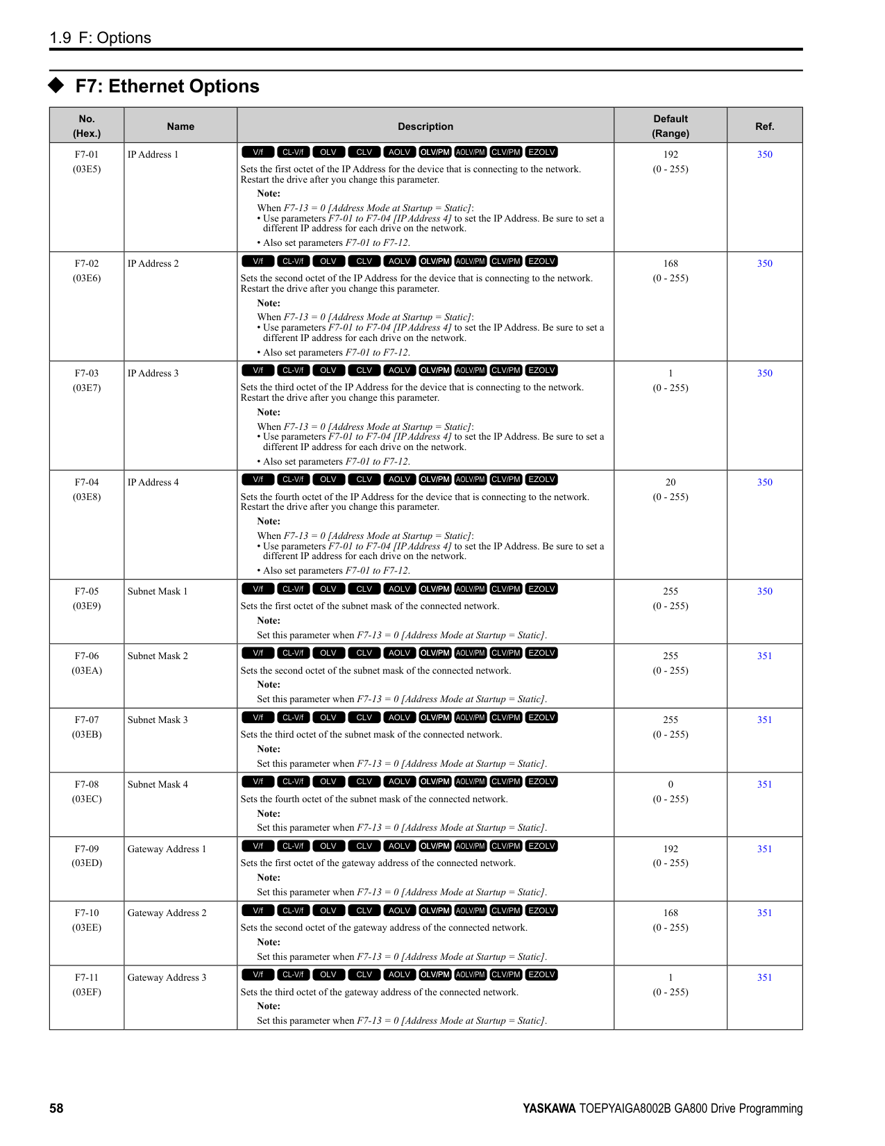
|T4-01 (3130)|EZ Tuning Mode Selection|Sets the type of Auto-Tuning for EZOLV control.
0 : Motor Parameter Setting
1 : Line-to-Line Resistance
V/f CL-V/f OLV CLV AOLV OLV/PM AOLV/PM CLV/PM EZOLV
|0 (0, 1)|539| |T4-02 (3131)|Motor Type Selection|Sets the type of motor.
0 : Induction (IM)
1 : Permanent Magnet (PM)
2 : Synchronous Reluctance (SynRM)
V/f CL-V/f OLV CLV AOLV OLV/PM AOLV/PM CLV/PM EZOLV
|0 (0, 1, 2)|540| |T4-04 (3133)|Motor Rated Revolutions|Sets rated rotation speed (min-1) of the motor.
V/f CL-V/f OLV CLV AOLV OLV/PM AOLV/PM CLV/PM EZOLV
|((40 Hz to 120 Hz) × 60 × 2/E9-08)|540| |T4-05 (3134)|Motor Rated Frequency|Sets the rated frequency (Hz) of the motor.
V/f CL-V/f OLV CLV AOLV OLV/PM AOLV/PM CLV/PM EZOLV
|Determined by E9-01 and o2-04
(40.0 - 120.0 Hz)|540| |T4-06 (3135)|Motor Rated Voltage|Sets the rated voltage (V) of the motor.
V/f CL-V/f OLV CLV AOLV OLV/PM AOLV/PM CLV/PM EZOLV
|200 V Class: 230.0 V, 400 V: 460.0 V
(200 V Class: 0.0 - 255.0 V,400 V Class: 0.0 510.0 V)|540| |T4-07 (3136)|Motor Rated Current|Sets the rated current (A) of the motor.
V/f CL-V/f OLV CLV AOLV OLV/PM AOLV/PM CLV/PM EZOLV
|Determined by o2-04, C6-01
(10% to 200% of the drive rated current)|540| |T4-08 (3137)|Motor Rated Capacity|Sets the motor rated power in the units set in o1-58 [Motor Power Unit Selection].
V/f CL-V/f OLV CLV AOLV OLV/PM AOLV/PM CLV/PM EZOLV
|Determined by E9-10 (0.10 - 650.00 HP)|540| |T4-09 (3138)|Number of Poles|Sets the number of motor poles.
V/f CL-V/f OLV CLV AOLV OLV/PM AOLV/PM CLV/PM EZOLV
|Determined by E9-01 (2 - 48)|540|
####### 1.17 U: Monitors
|No. (Hex.)|Name|Description|MFAO Signal Level| |---|---|---|---| |U1-01 (0040)|Frequency reference|Shows the actual frequency reference value. Parameter o1-03 [Keypad Display Unit Selection] sets the display units.
Unit: 0.01 Hz
V/f CL-V/f OLV CLV AOLV OLV/PM AOLV/PM CLV/PM EZOLV
|10 V = Maximum frequency (-10 V to +10 V)| |U1-02 (0041)|Output Frequency|Shows the actual output frequency. Parameter o1-03 [Keypad Display Unit Selection] sets the display units.
Unit: 0.01 Hz
V/f CL-V/f OLV CLV AOLV OLV/PM AOLV/PM CLV/PM EZOLV
|10 V = Maximum frequency (-10 V to +10 V)| |U1-03 (0042)|Output Current|Shows the actual output current. The keypad shows the value of U1-03 in amperes (A). When looking at the monitor through MEMOBUS/Modbus communications, the current is “8192 = drive rated current (A).” Calculate the current from the monitor value that is in at MEMOBUS/Modbus communications using “Numerals being displayed / 8192 × drive rated current (A).” Unit: Determined by the drive model.
• 0.01 A: 2004 to 2042, 4002 to 4023
• 0.1 A: 2056 to 2415, 4031 to 4720
V/f CL-V/f OLV CLV AOLV OLV/PM AOLV/PM CLV/PM EZOLV
|10 V = Drive rated current| |U1-04 (0043)|Control Method|Shows the drive control method.
0 : V/f Control
1 : V/f Control with Encoder
2 : Open Loop Vector
3 : Closed Loop Vector
4 : Advanced Open Loop Vector
5 : PM Open Loop Vector
6 : PM Advanced Open Loop Vector
7 : PM Closed Loop Vector
8 : EZ Vector Control
V/f CL-V/f OLV CLV AOLV OLV/PM AOLV/PM CLV/PM EZOLV
|No signal output available| |U1-05 (0044)|Motor Speed|Shows the actual detected motor speed. Parameter o1-03 [Keypad Display Unit Selection] sets the display units. Unit: 0.01 Hz
V/f CL-V/f OLV CLV AOLV OLV/PM AOLV/PM CLV/PM EZOLV
|10 V = Maximum frequency (-10 V to +10 V)| |U1-06 (0045)|Output Voltage Ref|Shows the output voltage reference. Unit: 0.1 V
V/f CL-V/f OLV CLV AOLV OLV/PM AOLV/PM CLV/PM EZOLV
|200 V class: 10 V = 200 Vrms
400 V class: 10 V = 400 Vrms| |U1-07 (0046)|DC Bus Voltage|Shows the DC bus voltage. Unit: 1 V
V/f CL-V/f OLV CLV AOLV OLV/PM AOLV/PM CLV/PM EZOLV
|200 V class: 10 V = 400 V 400 V class: 10 V = 800 V| |U1-08 (0047)|Output Power|Shows the internally-calculated output power. Changing the setting of A1-02 [Control Method Selection] also changes the signal level of the analog output.
• A1-02 = 0, 1: Drive capacity (kW)
• A1-02 = 2, 3, 4: Motor Rated Power [E2-11] (kW)
• A1-02 = 5, 6, 7: PM Motor Rated Power [E5-02] (kW)
• A1-02 = 8: Motor Rated Power [E9-07] (kW) Unit: The display units are different for different models:
• 0.01 kW: 2004 to 2042, 4002 to 4023
• 0.1 kW: 2056 to 2415, 4031 to 4720
V/f CL-V/f OLV CLV AOLV OLV/PM AOLV/PM CLV/PM EZOLV
|10 V: Drive capacity (motor rated power) kW (-10 V to +10 V)| |U1-09 (0048)|Torque Reference|Shows the internal torque reference value. Unit: 0.1%
V/f CL-V/f OLV CLV AOLV OLV/PM AOLV/PM CLV/PM EZOLV
|10 V = Motor rated torque (-10 V to +10 V)|
|No. (Hex.)|Name|Description|MFAO Signal Level| |---|---|---|---| |U1-10 (0049)|Input Terminal Status|Shows the status of the MFDI terminal where 1 (ON) and 0 (OFF). For example, U1-10 shows “00000011” when terminals S1 and S2 are ON.
bit 0 : Terminal S1 (MFDI 1)
bit 1 : Terminal S2 (MFDI 2)
bit 2 : Terminal S3 (MFDI 3)
bit 3 : Terminal S4 (MFDI 4)
bit 4 : Terminal S5 (MFDI 5)
bit 5 : Terminal S6 (MFDI 6)
bit 6 : Terminal S7 (MFDI 7)
bit 7 : Terminal S8 (MFDI 8)
V/f CL-V/f OLV CLV AOLV OLV/PM AOLV/PM CLV/PM EZOLV
|No signal output available| |U1-11 (004A)|Output Terminal Status|Shows the status of the MFDO terminal where 1 = (ON) and 0 = (OFF). For example, U1-11 shows “00000011” when terminals M1 and M3 are ON.
Note: When H2-xx = 100 to 19F [Inverse Output of Function], the value before inversion is displayed.
bit 0 : Terminals M1-M2
bit 1 : Terminals M3-M4
bit 2 : Terminals M5-M6
bit 3 : Not used (normal value of 0).
bit 4 : Not used (normal value of 0).
bit 5 : Not used (normal value of 0).
bit 6 : Not used (normal value of 0).
bit 7 : Fault relay MA/MB-MC
V/f CL-V/f OLV CLV AOLV OLV/PM AOLV/PM CLV/PM EZOLV
|No signal output available| |U1-12 (004B)|Drive Status|Shows drive status where 1 = (ON) and 0 = (OFF). For example, U1-12 shows “00000101” during run with the Reverse Run command.
bit 0 : During Run
bit 1 : During zero-speed
bit 2 : During reverse
bit 3 : During fault reset signal input
bit 4 : During speed agreement
bit 5 : Drive ready
bit 6 : During minor fault detection
bit 7 : During fault detection
V/f CL-V/f OLV CLV AOLV OLV/PM AOLV/PM CLV/PM EZOLV
|No signal output available| |U1-13 (004E)|Terminal A1 Level|Shows the signal level of terminal A1. Unit: 0.1%
V/f CL-V/f OLV CLV AOLV OLV/PM AOLV/PM CLV/PM EZOLV
|10 V = 100% (-10 V to +10 V)| |U1-14 (004F)|Terminal A2 Level|Shows the signal level of terminal A2. Unit: 0.1%
V/f CL-V/f OLV CLV AOLV OLV/PM AOLV/PM CLV/PM EZOLV
|10 V = 100% (-10 V to +10 V)| |U1-15 (0050)|Terminal A3 Level|Shows the signal level of terminal A3. Unit: 0.1%
V/f CL-V/f OLV CLV AOLV OLV/PM AOLV/PM CLV/PM EZOLV
|0 V = 100% (-10 V to +10 V)| |U1-16 (0053)|SFS Output Frequency|Shows the output frequency after soft start. Shows the frequency with acceleration and deceleration times and S-curves. Parameter o1-03 [Keypad Display Unit Selection] sets the display units.
Unit: 0.01 Hz
V/f CL-V/f OLV CLV AOLV OLV/PM AOLV/PM CLV/PM EZOLV
|10 V = Maximum frequency (-10 V to +10 V)| |U1-17 (0058)|DI-A3 Input Status|Shows the reference value input from DI-A3 option. Shows the input signal for DI-A3 in hexadecimal as set in F3-01 [Digital Input Function Selection]. 3FFFF: Set (1 bit) + Sign (1 bit) + 16 bit
V/f CL-V/f OLV CLV AOLV OLV/PM AOLV/PM CLV/PM EZOLV
|No signal output available| |U1-18 (0061)|oPE Fault Parameter|Shows the parameter number that caused the oPE02 [Parameter Range Setting Error] or oPE08 [Parameter Selection Error].
V/f CL-V/f OLV CLV AOLV OLV/PM AOLV/PM CLV/PM EZOLV
|No signal output available|
|No. (Hex.)|Name|Description|MFAO Signal Level|
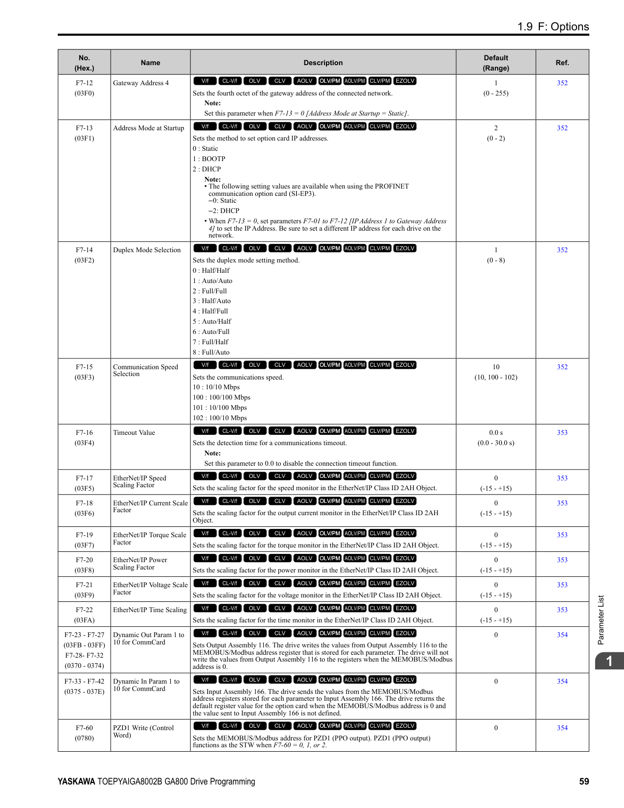
|---|---|---|---| |U1-19 (0066)|MEMOBUS/Modbus Error Code|Shows the contents of the MEMOBUS/Modbus communication error where 1 (error) and 0 (no error).
For example, U1-19 shows “00000001” when a CRC error occurs.
bit 0 : CRC Error
bit 1 : Data Length Error
bit 2 : Not used (normal value of 0).
bit 3 : Parity Error
bit 4 : Overrun Error
bit 5 : Framing Error
bit 6 : Timed Out
bit 7 : Not used (normal value of 0).
V/f CL-V/f OLV CLV AOLV OLV/PM AOLV/PM CLV/PM EZOLV
|No signal output available| |U1-21 (0077)|AI-A3 Term V1 Level|Shows the analog reference of terminal V1 on analog input option card AI-A3. Unit: 0.1%
V/f CL-V/f OLV CLV AOLV OLV/PM AOLV/PM CLV/PM EZOLV
|10 V = 100% (-10 V to +10 V)| |U1-22 (072A)|AI-A3 Term V2 Level|Shows the analog reference of terminal V2 on analog input option card AI-A3. Unit: 0.1%
V/f CL-V/f OLV CLV AOLV OLV/PM AOLV/PM CLV/PM EZOLV
|10 V = 100% (-10 V to +10 V)| |U1-23 (072B)|AI-A3 Term V3 Level|Shows the analog reference of terminal V3 on analog input option card AI-A3. Unit: 0.1%
V/f CL-V/f OLV CLV AOLV OLV/PM AOLV/PM CLV/PM EZOLV
|10 V = 100% (-10 V to +10 V)| |U1-24 (007D)|Input Pulse Monitor|Shows the frequency to pulse train input terminal RP. Unit: 1 Hz
V/f CL-V/f OLV CLV AOLV OLV/PM AOLV/PM CLV/PM EZOLV
|Determined by H6-02| |U1-25 (004D)|SoftwareNumber Flash|Shows the FLASH ID.
V/f CL-V/f OLV CLV AOLV OLV/PM AOLV/PM CLV/PM EZOLV
|No signal output available| |U1-26 (005B)|SoftwareNumber ROM|Shows the ROM ID.
V/f CL-V/f OLV CLV AOLV OLV/PM AOLV/PM CLV/PM EZOLV
|No signal output available| |U1-50 (1199) Expert|Virtual Analog Input|Shows the virtual analog input value.
V/f CL-V/f OLV CLV AOLV OLV/PM AOLV/PM CLV/PM EZOLV
|Determined by H7-40| |U1-91 (154E) Expert|Output Voltage|Shows the drive internal output voltage reference. Unit: 0.1 V
V/f CL-V/f OLV CLV AOLV OLV/PM AOLV/PM CLV/PM EZOLV
|200 V class: 10 V = 200 Vrms
400 V class: 10 V = 400 Vrms|
######## ◆ U2: Fault Trace
|No. (Hex.)|Name|Description|MFAO Signal Level| |---|---|---|---| |U2-01 (0080)|Current Fault|Shows the fault that the drive has when viewing the monitor.
V/f CL-V/f OLV CLV AOLV OLV/PM AOLV/PM CLV/PM EZOLV
|No signal output available| |U2-02 (0081)|Previous Fault|Shows the fault that occurred most recently.
V/f CL-V/f OLV CLV AOLV OLV/PM AOLV/PM CLV/PM EZOLV
|No signal output available| |U2-03 (0082)|Freq Reference@Fault|Shows the frequency reference at the fault that occurred most recently. Use U1-01 [Frequency Reference] to monitor the actual frequency reference value. Unit: 0.01 Hz
V/f CL-V/f OLV CLV AOLV OLV/PM AOLV/PM CLV/PM EZOLV
|No signal output available| |U2-04 (0083)|Output Freq @ Fault|Shows the output frequency at the fault that occurred most recently. Use U1-02 [Output Frequency] to monitor the actual output frequency. Unit: 0.01 Hz
V/f CL-V/f OLV CLV AOLV OLV/PM AOLV/PM CLV/PM EZOLV
|No signal output available|
|No. (Hex.)|Name|Description|MFAO Signal Level| |---|---|---|---| |U2-05 (0084)|Output Current@Fault|Shows the output current at the fault that occurred most recently. Use U1-03 [Output Current] to monitor the actual output current. The keypad shows the value of U103 in amperes (A).
When looking at the monitor through MEMOBUS/Modbus communications, the current is “8192 drive rated current (A)”. Calculate the current from the monitor value that is in at MEMOBUS/ Modbus communications using “Numerals being displayed / 8192 × drive rated current (A)”.
Unit: Determined by the drive model.
• 0.01 A: 2004 to 2042, 4002 to 4023
• 0.1 A: 2056 to 2415, 4031 to 4720
V/f CL-V/f OLV CLV AOLV OLV/PM AOLV/PM CLV/PM EZOLV
|No signal output available| |U2-06 (0085)|Motor Speed @ Fault|Shows the motor speed at the fault that occurred most recently. Use U1-05 [Motor Speed] to monitor the actual motor speed. Unit: 0.01 Hz
V/f CL-V/f OLV CLV AOLV OLV/PM AOLV/PM CLV/PM EZOLV
|No signal output available| |U2-07 (0086)|Output Voltage@Fault|Shows the output voltage reference at the fault that occurred most recently. Use U1-06 [Output Voltage Ref] to monitor the actual output voltage reference. Unit: 0.1 V
V/f CL-V/f OLV CLV AOLV OLV/PM AOLV/PM CLV/PM EZOLV
|No signal output available| |U2-08 (0087)|DC Bus Voltage@Fault|Shows the DC bus voltage at the fault that occurred most recently. Use U1-07 [DC Bus Voltage] to monitor the actual DC bus voltage. Unit: 1 V
V/f CL-V/f OLV CLV AOLV OLV/PM AOLV/PM CLV/PM EZOLV
|No signal output available| |U2-09 (0088)|Output Power @ Fault|Shows the output power at the fault that occurred most recently. Use U1-08 [Output Power] to monitor the actual output power. Unit: 0.1 kW
V/f CL-V/f OLV CLV AOLV OLV/PM AOLV/PM CLV/PM EZOLV
|No signal output available| |U2-10 (0089)|Torque Ref @ Fault|Shows the torque reference at the fault that occurred most recently as a percentage of the motor rated torque.
Use U1-09 [Torque Reference] to monitor the actual torque reference. Unit: 0.1%
V/f CL-V/f OLV CLV AOLV OLV/PM AOLV/PM CLV/PM EZOLV
|No signal output available| |U2-11 (008A)|Input Terminal Status @ Fault|Shows the status of the MFDI terminals at the most recent fault where 1 = (ON) and 0 = (OFF). For example, U2-11 shows “00000011” when terminals S1 and S2 are ON. Use U1-10 [Input Terminal Status] to monitor the actual MFDI terminal status.
bit 0 : Terminal S1
bit 1 : Terminal S2
bit 2 : Terminal S3
bit 3 : Terminal S4
bit 4 : Terminal S5
bit 5 : Terminal S6
bit 6 : Terminal S7
bit 7 : Terminal S8
V/f CL-V/f OLV CLV AOLV OLV/PM AOLV/PM CLV/PM EZOLV
|No signal output available| |U2-12 (008B)|Output Terminal Status @ Fault|Shows the status of the MFDO terminals at the most recent fault where 1 = (ON) and 0 = (OFF). For example, U2-12 shows “00000011” when terminals M1 and M3 are ON. Use U1-11 [Output Terminal Status] to monitor the actual MFDO terminal status.
bit 0 : Terminals M1-M2
bit 1 : Terminals M3-M4
bit 2 : Terminals M5-M6
bit 3 : Not used (normal value of 0).
bit 4 : Not used (normal value of 0).
bit 5 : Not used (normal value of 0).
bit 6 : Not used (normal value of 0).
bit 7 : Fault relay MA/MB-MC
V/f CL-V/f OLV CLV AOLV OLV/PM AOLV/PM CLV/PM EZOLV
|No signal output available|
|No. (Hex.)|Name|Description|MFAO Signal Level| |---|---|---|---| |U2-13 (008C)|Operation Status @ Fault|Shows the status of the MFDO terminals at the most recent fault where 1 (ON) and 0 (OFF). For example, U2-13 shows “00000001” during run. Use U1-12 [Drive Status] to monitor the actual MFDO terminal status.
bit 0 : During Run
bit 1 : During zero-speed
bit 2 : During reverse
bit 3 : During fault reset signal input
bit 4 : During speed agreement
bit 5 : Drive ready
bit 6 : During minor fault detection
bit 7 : During fault detection
V/f CL-V/f OLV CLV AOLV OLV/PM AOLV/PM CLV/PM EZOLV
|No signal output available| |U2-14 (008D)|Elapsed Time @ Fault|Shows the cumulative operation time of the drive at the fault that occurred most recently. Use U4-01 [Cumulative Ope Time] to monitor the actual cumulative operation time. Unit: 1 h
V/f CL-V/f OLV CLV AOLV OLV/PM AOLV/PM CLV/PM EZOLV
|No signal output available| |U2-15 (07E0)|SFS Output @ Fault|Shows the output frequency after soft start at the fault that occurred most recently. Use U1-16 [SFS Output Frequency] to monitor the actual output frequency after soft start. Unit: 0.01 Hz
V/f CL-V/f OLV CLV AOLV OLV/PM AOLV/PM CLV/PM EZOLV
|No signal output available| |U2-16 (07E1)|q-Axis Current@Fault|Shows the q-axis current of the motor at the fault that occurred most recently. Use U6-01 [Iq Secondary Current] to monitor the actual q-Axis current of the motor. Unit: 0.1 %
V/f CL-V/f OLV CLV AOLV OLV/PM AOLV/PM CLV/PM EZOLV
|No signal output available| |U2-17 (07E2)|d-Axis Current@Fault|Shows the d-axis current of the motor at the fault that occurred most recently. Use U6-02 [Id ExcitationCurrent] to monitor the actual d-Axis current of the motor. Unit: 0.1 %
V/f CL-V/f OLV CLV AOLV OLV/PM AOLV/PM CLV/PM EZOLV
|No signal output available| |U2-19 (07E4)|ControlDeviation@Flt|Shows the amount of control axis deviation (Δθ) at the fault that occurred most recently. Use U6-10 [ContAxisDeviation Δθ] to monitor the actual amount of control axis deviation (Δθ). Unit: 0.1 °
V/f CL-V/f OLV CLV AOLV OLV/PM AOLV/PM CLV/PM EZOLV
|No signal output available|
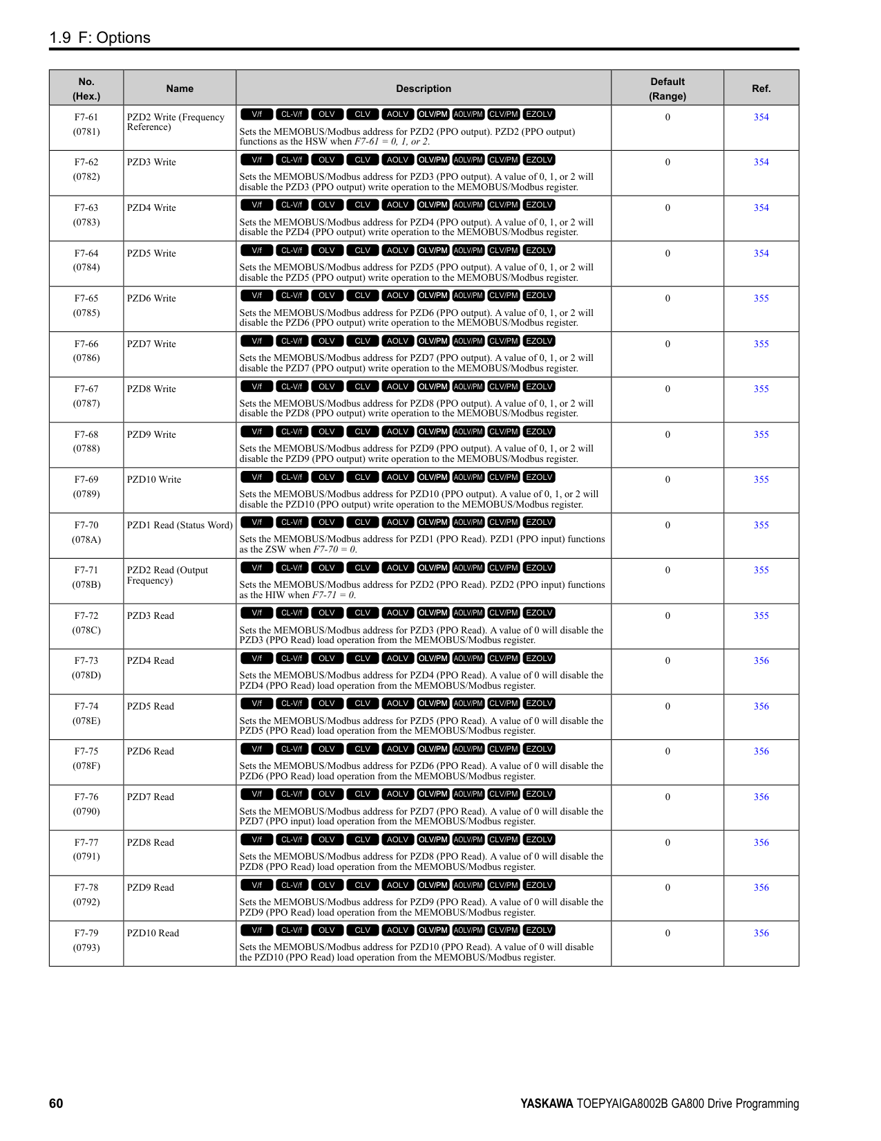
|U2-20 (008E)|Heatsink Temp @Fault|Shows the heatsink temperature at the fault that occurred most recently. Use U4-08 [Heatsink Temperature] to monitor the actual temperature of the heatsink. Unit: 1 °C
V/f CL-V/f OLV CLV AOLV OLV/PM AOLV/PM CLV/PM EZOLV
|No signal output available| |U2-21 (1166) Expert|STPo Detect @ Fault|Monitors conditions to detect STPo [Motor Step-Out Detected] faults. The bit for each condition is displayed as ON or OFF.
bit 0 : Excessive current
bit 1 : Induced voltage deviation
bit 2 : d-axis current deviation
bit 3 : Motor lock at startup
bit 4 : Acceleration stall continue
bit 5 : Acceleration stall repeat
bit 6 : Not used (normal value of 0).
bit 7 : Not used (normal value of 0).
V/f CL-V/f OLV CLV AOLV OLV/PM AOLV/PM CLV/PM EZOLV
|No signal output available|
######## ◆ U3: Fault History
|No. (Hex.)|Name|Description|MFAO Signal Level| |---|---|---|---| |U3-01 to U3-04 (0090 - 0093) (0800 - 0803)|1st to 4th MostRecent Fault|Shows the fault history of the first to fourth most recent faults.
Note:
The drive saves the U3-01 to U3-04 [1st to 4th MostRecent Fault] fault histories to two types of registers at the same time for the MEMOBUS/Modbus communications.
V/f CL-V/f OLV CLV AOLV OLV/PM AOLV/PM CLV/PM EZOLV
|No signal output available| |U3-05 to U3-10 (0804 - 0809)|5th to 10th MostRecent Fault|Shows the fault history of the fifth to tenth most recent faults.
V/f CL-V/f OLV CLV AOLV OLV/PM AOLV/PM CLV/PM EZOLV
|No signal output available|
|No. (Hex.)|Name|Description|MFAO Signal Level| |---|---|---|---| |U3-11 to U3-14 (0094 - 0097) (080A - 080D)|ElapsedTime@1st to 4thFault|Shows the cumulative operation time when the first to fourth most recent faults occurred. Unit: 1 h
Note:
The drive saves the U3-11 to U3-14 [ElapsedTime@1st to 4thFault] the cumulative operation time to two types of registers at the same time for the MEMOBUS/Modbus communications.
V/f CL-V/f OLV CLV AOLV OLV/PM AOLV/PM CLV/PM EZOLV
|No signal output available| |U3-15 to U3-20 (080E - 0813)|ElapsedTime@5th to 10thFault|Shows the cumulative operation time when the fifth to tenth most recent faults occurred. Unit: 1 h
V/f CL-V/f OLV CLV AOLV OLV/PM AOLV/PM CLV/PM EZOLV
|No signal output available|
######## ◆ U4: Maintenance Monitors
|No. (Hex.)|Name|Description|MFAO Signal Level| |---|---|---|---| |U4-01 (004C)|Cumulative Ope Time|Shows the cumulative operation time of the drive. Use parameter o4-01 [Elapsed Operating Time Setting] to reset this monitor. Use parameter o4-02 [Elapsed Operating Time Selection] to select the cumulative operation times from:
• The time from when the drive is energized until it is de-energized.
• The time at which the Run command is turned ON.
The maximum value that the monitor will show is 99999. After this value is more than 99999, the drive automatically resets it and starts to count from 0 again.
Unit: 1 h
Note:
The MEMOBUS/Modbus communication data is shown in 10 h units. Use register 0099H for data in 1 h units.
V/f CL-V/f OLV CLV AOLV OLV/PM AOLV/PM CLV/PM EZOLV
|10 V: 99999 h| |U4-02 (0075)|Num of Run Commands|Shows how many times that the drive has received a Run command. Use parameter o4-13 [RUN Command Counter @ Initialize] to reset this monitor. The maximum value that the monitor will show is 65535. After this value is more than 65535, the drive automatically resets it and starts to count from 0 again. Unit: 1
V/f CL-V/f OLV CLV AOLV OLV/PM AOLV/PM CLV/PM EZOLV
|10 V: 65535 times| |U4-03 (0067)|Cooling Fan Ope Time|Shows the cumulative operation time of the cooling fans. Use parameter o4-03 [Fan Operation Time Setting] to reset this monitor. The maximum value that the monitor will show is 99999. After this value is more than 99999, the drive automatically resets it and starts to count from 0 again. Unit: 1 h
Note:
The MEMOBUS/Modbus communication data is shown in 10 h units. Use register 009BH for data in 1 h units.
V/f CL-V/f OLV CLV AOLV OLV/PM AOLV/PM CLV/PM EZOLV
|10 V: 99999 h| |U4-04 (007E)|Cool Fan Maintenance|Shows the cumulative operation time of the cooling fans as a percentage of the replacement life of the cooling fans.
Use parameter o4-03 [Fan Operation Time Setting] to reset this monitor. Unit: 1%
Note: Replace the cooling fans when this monitor is 90%.
V/f CL-V/f OLV CLV AOLV OLV/PM AOLV/PM CLV/PM EZOLV
|10 V: 100%| |U4-05 (007C)|CapacitorMaintenance|Shows the operation time of the electrolytic capacitors for the main circuit and control circuit as a percentage of the replacement life of the electrolytic capacitors.
Use parameter o4-05 [Capacitor Maintenance Setting] to reset this monitor. Unit: 1%
Note: Replace the electrolytic capacitor when this monitor is 90%.
V/f CL-V/f OLV CLV AOLV OLV/PM AOLV/PM CLV/PM EZOLV
|10 V: 100%| |U4-06 (07D6)|PreChargeRelayMainte|Shows the operation time of the soft charge bypass relay as a percentage of the replacement life of the soft charge bypass relay.
Use parameter o4-07 [Softcharge Relay Maintenance Set] to reset this monitor. Unit: 1%
Note: Replace the drive when this monitor is 90%.
V/f CL-V/f OLV CLV AOLV OLV/PM AOLV/PM CLV/PM EZOLV
|10 V: 100%|
|No. (Hex.)|Name|Description|MFAO Signal Level| |---|---|---|---| |U4-07 (07D7)|IGBT Maintenance|Shows the operation time of the IGBTs as a percentage of the replacement life of the IGBTs. Set parameter o4-09 [IGBT Maintenance Setting] to reset this monitor. Unit: 1%
Note: Replace the drive when this monitor is 90%.
V/f CL-V/f OLV CLV AOLV OLV/PM AOLV/PM CLV/PM EZOLV
|10 V: 100%| |U4-08 (0068)|Heatsink Temperature|Shows the heatsink temperature of the drive. Unit: 1 °C
V/f CL-V/f OLV CLV AOLV OLV/PM AOLV/PM CLV/PM EZOLV
|10 V: 100 °C| |U4-09 (005E)|LED Check|Turns on the LED Status Ring and all of the keypad LEDs to make sure that the LEDs operate correctly.
Note:
A damaged LED Status Ring board will prevent an accurate estimate of the internal status of the drive. Do not use only the LED Status Ring to estimate the status of the drive and motors.
1. Set o2-24 = 0 [LED Light Function Selection = Enable Status Ring & Keypad LED].
2. Push with U4-09 shown on the keypad. All LEDs on the keypad and LED Status Ring will turn on.
Note: When Safety input 2 CH is open (STo), READY will flash.
V/f CL-V/f OLV CLV AOLV OLV/PM AOLV/PM CLV/PM EZOLV
|No signal output available| |U4-10 (005C)|kWh, Lower 4 Digits|Displays the lower 4 digits of the watt hour value for the drive. Unit: 1 kWh
Note:
The watt hour is displayed in 9 digits. Monitor U4-11 [kWh, Upper 5 Digits] shows the upper 5 digits and U4-10 shows the lower 4 digits.
Example for 12345678.9 kWh:
U4-10: 678.9 kWh
U4-11: 12345 MWh
V/f CL-V/f OLV CLV AOLV OLV/PM AOLV/PM CLV/PM EZOLV
|No signal output available| |U4-11 (005D)|kWh, Upper 5 Digits|Shows the upper 5 digits of the watt hour value for the drive. Unit: 1 MWh Note:
Monitor U4-11 shows the upper 5 digits and U4-10 [kWh, Lower 4 Digits] shows the lower 4 digits.
Example for 12345678.9 kWh:
U4-10: 678.9 kWh
U4-11: 12345 MWh
V/f CL-V/f OLV CLV AOLV OLV/PM AOLV/PM CLV/PM EZOLV
|No signal output available| |U4-13 (07CF)|Peak Hold Current|Shows the hold value of the peak value (rms) for the drive output current. Use U4-14 [PeakHold Output Freq] to show the drive output frequency at the time that the drive holds the output current. The drive will hold the peak hold current at the next start up and restart of the power supply. The drive keeps the held value during baseblock (during stop). The keypad shows the value of U4-13 in amperes (A). When looking at the monitor through MEMOBUS/Modbus communications, the current is “8192 drive rated current (A).” Calculate the current from the monitor value that is in at MEMOBUS/Modbus communications using “Numerals being displayed / 8192 × drive rated current (A). Unit: Determined by the drive model.
• 0.01 A: 2004 to 2042, 4002 to 4023
• 0.1 A: 2056 to 2415, 4031 to 4720
V/f CL-V/f OLV CLV AOLV OLV/PM AOLV/PM CLV/PM EZOLV
|No signal output available| |U4-14 (07D0)|PeakHold Output Freq|Displays the output frequency at which the peak value (rms) of the drive output current is held. The peak hold current can be monitored by U4-13 [Peak Hold Current]. The peak hold output frequency will be cleared at the next startup and restart of the power supply. The drive keeps the value that was under hold during baseblock (during stop). Unit: 0.01 Hz
V/f CL-V/f OLV CLV AOLV OLV/PM AOLV/PM CLV/PM EZOLV
|No signal output available| |U4-16 (07D8)|Motor oL1 Level|Shows the integrated value of oL1 [Motor Overload] as a percentage of oL1 detection level. Unit: 0.1%
V/f CL-V/f OLV CLV AOLV OLV/PM AOLV/PM CLV/PM EZOLV
|10 V: 100%|
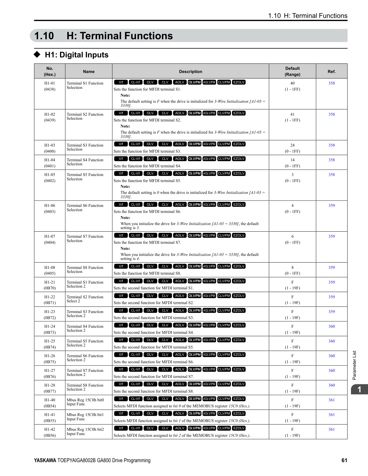
|No. (Hex.)|Name|Description|MFAO Signal Level| |---|---|---|---| |U4-18 (07DA)|Reference Source|Shows the selected frequency reference source. The keypad shows the frequency reference source as “XY-nn” as specified by these rules: X: External Reference 1/2 Selection [H1-xx = 2] selection status
• 1: b1-01 [Frequency Reference Selection 1]
• 2: b1-15 [Frequency Reference Selection 2] Y-nn: Frequency reference source
• 0-01: Keypad (d1-01 [Reference 1])
• 1-00: Analog input (unassigned)
• 1-01: MFAI terminal A1
• 1-02: MFAI terminal A2
• 1-03: MFAI terminal A3
• 2-02 to 2-17: Multi-step speed reference (d1-02 to d1-17 [Reference 2 to 16, Jog Reference])
• 3-01: MEMOBUS/Modbus communications
• 4-01: Communication option card
• 5-01: Pulse train input
• 7-01: DriveWorksEZ
• 9-01: Up/Down command
V/f CL-V/f OLV CLV AOLV OLV/PM AOLV/PM CLV/PM EZOLV
|No signal output available| |U4-19 (07DB)|Modbus FreqRef (dec)|Shows the frequency reference sent to the drive from the MEMOBUS/Modbus communications as a decimal.
Unit: 0.01%
V/f CL-V/f OLV CLV AOLV OLV/PM AOLV/PM CLV/PM EZOLV
|10 V = Maximum frequency (-10 V to +10 V)| |U4-20 (07DC)|Option Freq Ref(dec)|Shows the frequency reference sent to the drive from the communication option as a decimal.
V/f CL-V/f OLV CLV AOLV OLV/PM AOLV/PM CLV/PM EZOLV
|10 V = Maximum frequency (-10 V to +10 V)| |U4-21 (07DD)|Run Command Source|Shows the selected Run command source. The keypad shows the Run command source as “XY-nn” as specified by these rules:
X: External Reference 1/2 Selection [H1-xx = 2] selection status
• 1: b1-02 [Run Command Selection 1]
• 2: b1-16 [Run Command Selection 2]
Y: Run command source
• 0: Keypad
• 1: Control circuit terminal
• 3: MEMOBUS/Modbus communications
• 4: Communication option card
• 7: DriveWorksEZ nn: Run command limit status data
• 00: No limit status.
• 01: The Run command was left ON when the drive stopped in the Programming Mode.
• 02: The Run command was left ON when switching from LOCAL Mode to REMOTE Mode.
• 03: The Run command is in standby after the drive was energized until the soft charge bypass contactor turns ON.
Note:
The drive will detect Uv1 [DC Bus Undervoltage] or Uv [Undervoltage] if the soft charge bypass contactor does not turn ON after 10 s.
• 04: Restart after run stop is prohibited.
• 05: Fast stop has been executed using the MFDI terminal. Or, the motor has ramped to stop by pressing the STOP key on the keypad.
• 06: b1-17 = 0 [Run Command at Power Up = Disregard Existing RUN Command] is set.
• 07: During baseblock while coast to stop with timer.
• 08: Frequency reference is below E1-09 [Minimum Output Frequency] during baseblock.
• 09: Waiting for the Enter command from PLC.
V/f CL-V/f OLV CLV AOLV OLV/PM AOLV/PM CLV/PM EZOLV
|No signal output The keypad shows the Run command source as "XY-nn" as specified by these rules: available|
|No. (Hex.)|Name|Description|MFAO Signal Level| |---|---|---|---| |U4-22 (07DE)|Modbus CmdData (hex)|Shows the operation signal (register 0001H) sent to the drive from MEMOBUS/Modbus communications as a 4-digit hexadecimal number (zero suppress). The keypad shows the operation signal as specified by these rules:
bit 0 : Forward run/Stop
bit 1 : Reverse run/Stop
bit 2 : External fault
bit 3 : Fault Reset
bit 4 : Multi-function input 1
bit 5 : Multi-function input 2
bit 6 : Multi-function input 3
bit 7 : Multi-function input 4
bit 8 : Multi-function input 5
bit 9 : Multi-function input 6
bit A : Multi-function input 7
bit B : Multi-function input 8
bit C : Not used (normal value of 0).
bit D : Not used (normal value of 0).
bit E : Not used (normal value of 0).
bit F : Not used (normal value of 0).
V/f CL-V/f OLV CLV AOLV OLV/PM AOLV/PM CLV/PM EZOLV
|No signal output available| |U4-23 (07DF)|Option CmdData (hex)|Shows the operation signal (register 0001H) sent to the drive from MEMOBUS/Modbus communications as a 4-digit hexadecimal number. The keypad shows the operation signal as specified by these rules:
bit 0 : Forward run/Stop
bit 1 : Reverse run/Stop
bit 2 : External fault
bit 3 : Fault Reset
bit 4 : Multi-function input 1
bit 5 : Multi-function input 2
bit 6 : Multi-function input 3
bit 7 : Multi-function input 4
bit 8 : Multi-function input 5
bit 9 : Multi-function input 6
bit A : Multi-function input 7
bit B : Multi-function input 8
bit C : Not used (normal value of 0).
bit D : Not used (normal value of 0).
bit E : Not used (normal value of 0).
bit F : Not used (normal value of 0).
V/f CL-V/f OLV CLV AOLV OLV/PM AOLV/PM CLV/PM EZOLV
|No signal output available| |U4-24 (07E6)|Number of Runs (Low)|Shows the lower 4 digits of the drive run count.
Note:
The drive run count appears as an 8-digit number. Monitor U4-25 [Number of Runs(High)] shows the upper 4 digits and U4-24 shows the lower 4 digits.
V/f CL-V/f OLV CLV AOLV OLV/PM AOLV/PM CLV/PM EZOLV
|No signal output available| |U4-25 (07E7)|Number of Runs(High)|Shows the lower 4 digits of the drive run count. Note: The drive run count appears as an 8-digit number. Monitor U4-25 shows the upper 4 digits and U4-24 [Number of Runs (Low)] shows the lower 4 digits.
V/f CL-V/f OLV CLV AOLV OLV/PM AOLV/PM CLV/PM EZOLV
|No signal output available| |U4-52 (1592)|Torque Ref from Comm|Displays the torque reference given to the drive via a serial communication option card or via MEMOBUS/Modbus communications as a decimal number.
Unit: 0.1%
V/f CL-V/f OLV CLV AOLV OLV/PM AOLV/PM CLV/PM EZOLV
|10 V = 100% (-10 V to +10 V)|
|No. (Hex.)|Name|Description|MFAO Signal Level| |---|---|---|---| |U5-01 (0057)|PID Feedback|Shows the PID control feedback value. Parameter b5-20 [PID Unit Selection] sets the display units. Unit: 0.01%
V/f CL-V/f OLV CLV AOLV OLV/PM AOLV/PM CLV/PM EZOLV
|10 V = Maximum frequency (-10 V to +10 V)| |U5-02 (0063)|PID Input|Shows the change between the PID setpoint and PID feedback (the quantity of PID input) as a percentage of the maximum output frequency.
Unit: 0.01%
V/f CL-V/f OLV CLV AOLV OLV/PM AOLV/PM CLV/PM EZOLV
|10 V = Maximum frequency (-10 V to +10 V)| |U5-03 (0064)|PID Output|Shows the PID control output as a percentage of the maximum output frequency. Unit: 0.01%
V/f CL-V/f OLV CLV AOLV OLV/PM AOLV/PM CLV/PM EZOLV
|10 V Maximum frequency (-10 V to +10 V)| |U5-04 (0065)|PID Setpoint|Shows the PID setpoint. Parameter b5-20 [PID Unit Selection] sets the display units. Unit: 0.01%
V/f CL-V/f OLV CLV AOLV OLV/PM AOLV/PM CLV/PM EZOLV
|10 V Maximum frequency (-10 V to +10 V)| |U5-05 (07D2)|PID DifferentialFdbk|Shows the PID differential feedback value as a percentage of the maximum output frequency. This monitor is available after you set H3-02, H3-10, or H3-06 = 16 [MFAI Function Selection = Differential PID Feedback]. Unit: 0.01%
V/f CL-V/f OLV CLV AOLV OLV/PM AOLV/PM CLV/PM EZOLV
|10 V Maximum frequency (-10 V to +10 V)| |U5-06 (07D3)|PID Fdbk-Diff PID Fdbk|Shows the difference from calculating U5-05 - U5-01 [PID DifferentialFdbk] - [PID Feedback]. Unit: 0.01%
Note:
U5-01 [PID Feedback] = U5-06 when H3-02, H3-10, or H3-06 ≠ 16 [MFAI Function Selection ≠ Differential PID Feedback].
V/f CL-V/f OLV CLV AOLV OLV/PM AOLV/PM CLV/PM EZOLV
|10 V Maximum frequency (-10 V to +10 V)| |U5-21 (0872) Expert|Energy Save Coeff Ki|Shows the energy-saving coefficient Ki value for PM. Unit: 0.01
V/f CL-V/f OLV CLV AOLV OLV/PM AOLV/PM CLV/PM EZOLV
|No signal output available| |U5-22 (0873) Expert|Energy Save Coeff Kt|Shows the energy-saving coefficient Kt value for PM. Unit: 0.01
V/f CL-V/f OLV CLV AOLV OLV/PM AOLV/PM CLV/PM EZOLV
|No signal output available| |U5-99 (1599)|PID Setpoint Command|Shows the PID setpoint command. Parameter b5-20 [PID Unit Selection] sets the display units. Unit: 0.01%
V/f CL-V/f OLV CLV AOLV OLV/PM AOLV/PM CLV/PM EZOLV
|10 V = Maximum frequency (-10 V to +10 V)|
|No. (Hex.)|Name|Description|MFAO Signal Level| |---|---|---|---| |U6-01 (0051)|Iq Secondary Current|Shows the value calculated for the motor secondary current (q axis) as a percentage of the motor rated secondary current.
Unit: 0.1%
V/f CL-V/f OLV CLV AOLV OLV/PM AOLV/PM CLV/PM EZOLV
|10 V Motor secondary rated current (-10 V to +10 V)| |U6-02 (0052)|Id ExcitationCurrent|Shows the value calculated for the motor excitation current (d axis) as a percentage of the motor rated secondary current.
Unit: 0.1%
V/f CL-V/f OLV CLV AOLV OLV/PM AOLV/PM CLV/PM EZOLV
|10 V Motor secondary rated current (-10 V to +10 V)| |U6-03 (0054)|ASR Input|Shows the ASR input value as a percentage of the maximum frequency. Unit: 0.01%
V/f CL-V/f OLV CLV AOLV OLV/PM AOLV/PM CLV/PM EZOLV
|10 V Maximum frequency (-10 V to +10 V)| |U6-04 (0055)|ASR Output|Shows the ASR output value as a percentage of the motor rated secondary current. Unit: 0.01%
V/f CL-V/f OLV CLV AOLV OLV/PM AOLV/PM CLV/PM EZOLV
|10 V = Motor secondary rated current (-10 V to +10 V)| |U6-05 (0059)|OutputVoltageRef: Vq|Shows the drive internal voltage reference for motor secondary current control (q axis). Unit: 0.1 V
V/f CL-V/f OLV CLV AOLV OLV/PM AOLV/PM CLV/PM EZOLV
|200 V class: 10 V = 200 Vrms
400 V class: 10 V = 400 Vrms
(-10 V to +10 V)|
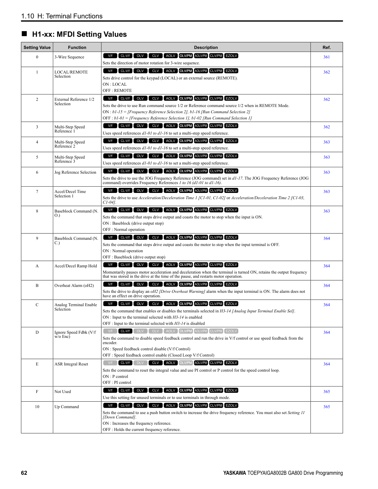
|No. (Hex.)|Name|Description|MFAO Signal Level| |---|---|---|---| |U6-06 (005A)|OutputVoltageRef: Vd|Shows the drive internal voltage reference for motor excitation current control (d axis). Unit: 0.1 V
V/f CL-V/f OLV CLV AOLV OLV/PM AOLV/PM CLV/PM EZOLV
|200 V class: 10 V 200 Vrms
400 V class: 10 V 400 Vrms
(-10 V to +10 V)| |U6-07 (005F) Expert|q-Axis ACR Output|Shows the output value for current control related to motor secondary current (q axis). Unit: 0.1%
V/f CL-V/f OLV CLV AOLV OLV/PM AOLV/PM CLV/PM EZOLV
|200 V class: 10 V 200 Vrms
400 V class: 10 V 400 Vrms
(-10 V to +10 V)| |U6-08 (0060) Expert|d-Axis ACR Output|Shows the output value for current control related to motor excitation current (d axis). Unit: 0.1%
V/f CL-V/f OLV CLV AOLV OLV/PM AOLV/PM CLV/PM EZOLV
|200 V class: 10 V 200 Vrms
400 V class: 10 V 400 Vrms
(-10 V to +10 V)| |U6-09 (07C0) Expert|AdvPhase Compen Δθcmp|Displays the data on forward phase compensation for the calculation results of the amount of control axis deviation.
Unit: 1 °
V/f CL-V/f OLV CLV AOLV OLV/PM AOLV/PM CLV/PM EZOLV
|10 V: 180 ° (-10 V to +10 V)| |U6-10 (07C1) Expert|ContAxisDeviation Δθ|Shows the deviation between the γδ-Axis used for motor control and the dq-Axis. Unit: 0.1 °
V/f CL-V/f OLV CLV AOLV OLV/PM AOLV/PM CLV/PM EZOLV
|10 V: 180 ° (-10 V to +10 V)| |U6-13 (07CA) Expert|MagPolePosition(Enc)|Shows the value of the flux position detection. Unit: 0.1 °
V/f CL-V/f OLV CLV AOLV OLV/PM AOLV/PM CLV/PM EZOLV
|10 V: 180° (-10 V to +10 V)| |U6-14 (07CB) Expert|MagPolePosition(Obs)|Shows the value of the flux position estimation. Unit: 0.1 °
V/f CL-V/f OLV CLV AOLV OLV/PM AOLV/PM CLV/PM EZOLV
|10 V: 180 ° (-10 V to +10 V)| |U6-17 (07D1) Expert|Energy Save Coeff|Shows the total time of direction of motor rotation detections for Speed Estimation Speed Searches. This value adjusts b3-26 [Direction Determination Level].
Note: Upper limit is +32767 and lower limit is -32767.
V/f CL-V/f OLV CLV AOLV OLV/PM AOLV/PM CLV/PM EZOLV
|No signal output available| |U6-18 (07CD)|Enc 1 Pulse Counter|Shows the number of pulses for speed detection (PG1). Unit: 1 pulse
V/f CL-V/f OLV CLV AOLV OLV/PM AOLV/PM CLV/PM EZOLV
|10 V: 65536| |U6-19 (07E5)|Enc 2 Pulse Counter|Shows the number of pulses for speed detection (PG2). Unit: 1 pulse
V/f CL-V/f OLV CLV AOLV OLV/PM AOLV/PM CLV/PM EZOLV
|10 V: 65536| |U6-20 (07D4)|UP/DOWN 2 Bias Value|Shows the bias value used to adjust the frequency reference. Unit: 0.1%
V/f CL-V/f OLV CLV AOLV OLV/PM AOLV/PM CLV/PM EZOLV
|10 V: Maximum Frequency| |U6-21 (07D5)|Offset Frequency|Shows the total value of d7-01 to d7-03 [Offset Frequency 1 to 3] selected with Add Offset Frequency 1 to 3 [H1-xx = 44 to 46].
Unit: 0.1%
V/f CL-V/f OLV CLV AOLV OLV/PM AOLV/PM CLV/PM EZOLV
|10 V: Maximum Frequency| |U6-22 (0062)|ZeroServo Pulse Move|Shows the distance that the rotor moved from its last position when Zero Servo is available. The value shown in this monitor = 4 X [No. of PG pulses].
Unit: 1 pulse
V/f CL-V/f OLV CLV AOLV OLV/PM AOLV/PM CLV/PM EZOLV
|10 V = Number of pulses per revolution (-10 V to +10 V)| |U6-25 (006B) Expert|ASR Output Level|Shows the primary delay filter input value of the ASR (speed control loop). Unit: 0.01%
V/f CL-V/f OLV CLV AOLV OLV/PM AOLV/PM CLV/PM EZOLV
|10 V = Motor secondary rated current (-10 V to +10 V)| |U6-26 (006C) Expert|Feed Fwd Cont Output|Shows the Feed Forward control output. Unit: 0.01%
V/f CL-V/f OLV CLV AOLV OLV/PM AOLV/PM CLV/PM EZOLV
|10 V = Motor secondary rated current (-10 V to +10 V)| |U6-27 (006D) Expert|FeedFwd Estimate Spd|Shows the feed forward estimated speed. Unit: 0.01%
V/f CL-V/f OLV CLV AOLV OLV/PM AOLV/PM CLV/PM EZOLV
|10 V = Maximum frequency (-10 V to +10 V)|
|No. (Hex.)|Name|Description|MFAO Signal Level| |---|---|---|---| |U6-31 (007B)|TorqueDetect Monitor|Monitors the torque reference or the output current after applying the filter set to L6-07 [Torque Detection Filter Time].
Unit: 0.1%
V/f CL-V/f OLV CLV AOLV OLV/PM AOLV/PM CLV/PM EZOLV
|10 V:100%| |U6-36 (0720) Expert|Comm Errors-Host|Shows the number of inter-CPU communication errors. De-energizing the drive sets this number to 0.
V/f CL-V/f OLV CLV AOLV OLV/PM AOLV/PM CLV/PM EZOLV
|No signal output available| |U6-37 (0721) Expert|Comm Errors-Sensor|Shows the number of inter-CPU communication errors. De-energizing the drive sets this number to 0.
V/f CL-V/f OLV CLV AOLV OLV/PM AOLV/PM CLV/PM EZOLV
|No signal output available| |U6-48 (072E) Expert|ASIC Comm Errors|Counts the number of inter-ASIC communication errors detected by the ASIC. This count is reset to 0 when the power to the drive is turned off.
V/f CL-V/f OLV CLV AOLV OLV/PM AOLV/PM CLV/PM EZOLV
|No signal output available| |U6-57 (07C4)|PolePolarityDeterVal|Shows the change from the integrated current when finding the polarity. Unit: 1
Note: If the change from the integrated current is less than 819, increase n8-84 [Polarity Detection Current]. U6-57 = 8192 is equivalent to the motor rated current.
V/f CL-V/f OLV CLV AOLV OLV/PM AOLV/PM CLV/PM EZOLV
|No signal output available| |U6-80 to U6-83 (07B0 - 07B3)|Option IPAddress 1 to 4|Shows the currently available local IP Address.
• U6-80: 1st octet
• U6-81: 2nd octet
• U6-82: 3rd octet
• U6-83: 4th octet
V/f CL-V/f OLV CLV AOLV OLV/PM AOLV/PM CLV/PM EZOLV
|No signal output available| |U6-84 to U6-87 (07B4 - 07B7)|Online Subnets 1 to 4|Shows the currently available subnet mask.
• U6-84: 1st octet
• U6-85: 2nd octet
• U6-86: 3rd octet
• U6-87: 4th octet
V/f CL-V/f OLV CLV AOLV OLV/PM AOLV/PM CLV/PM EZOLV
|No signal output available| |U6-88 to U6-91 (07B8, 07B9, 07F0, 07F1)|Online Gateways 1 to 4|Shows the currently available gateway address.
• U6-88: 1st octet
• U6-89: 2nd octet
• U6-90: 3rd octet
• U6-91: 4th octet
V/f CL-V/f OLV CLV AOLV OLV/PM AOLV/PM CLV/PM EZOLV
|No signal output available| |U6-92 (07F2)|Online Speed|Shows the currently available communications speed. 10: 10 Mbps 100: 100 Mbps
V/f CL-V/f OLV CLV AOLV OLV/PM AOLV/PM CLV/PM EZOLV
|No signal output available| |U6-93 (07F3)|Online Duplex|Shows the currently available Duplex setting.
V/f CL-V/f OLV CLV AOLV OLV/PM AOLV/PM CLV/PM EZOLV
|No signal output available| |U6-98 (07F8)|First Fault|Shows the contents of the most recent communication options fault (DeviceNet, Modbus TCP/IP, EtherNet/IP).
V/f CL-V/f OLV CLV AOLV OLV/PM AOLV/PM CLV/PM EZOLV
|No signal output available| |U6-99 (07F9)|Current Fault|Shows the contents of current fault from communication options (DeviceNet, Modbus TCP/IP, EtherNet/IP).
V/f CL-V/f OLV CLV AOLV OLV/PM AOLV/PM CLV/PM EZOLV
|No signal output available|
######## ◆ U8: DriveWorksEZ Monitors
|No. (Hex.)|Name|Description|MFAO Signal Level| |---|---|---|---| |U8-01 to U8-10 (1950 - 1959)|DWEZ Monitors 1 to 10|Shows DriveWorks EZ Monitors 1 to 10. Unit: 0.01%
V/f CL-V/f OLV CLV AOLV OLV/PM AOLV/PM CLV/PM EZOLV
|10 V = 100%|
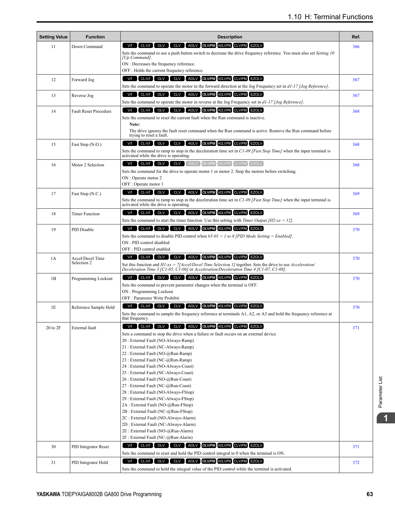
|U8-11 (195A)|DWEZ Version 1|Displays the upper three digits of the user ID. When you open the setting screen by clicking the setting button on the PC tool title bar, the user ID can be confirmed with the ID display of the primary user.
V/f CL-V/f OLV CLV AOLV OLV/PM AOLV/PM CLV/PM EZOLV
|No signal output available| |U8-12 (195B)|DWEZ Version 2|Displays the lower five digits of the user ID. When you open the setting screen by clicking the setting button on the PC tool title bar, the user ID can be confirmed with the ID display of the primary user.
V/f CL-V/f OLV CLV AOLV OLV/PM AOLV/PM CLV/PM EZOLV
|No signal output available| |U8-13 (195C)|DWEZ Version 3|Displays the software ID.
V/f CL-V/f OLV CLV AOLV OLV/PM AOLV/PM CLV/PM EZOLV
|No signal output available| |U8-18 (1961)|DWEZ Platform Ver|Shows the DriveWorksEZ platform version.
V/f CL-V/f OLV CLV AOLV OLV/PM AOLV/PM CLV/PM EZOLV
|No signal output available| |U8-21 to U8-25 (1964 - 1968)|DWEZ Monitors 21 to 25|Shows DriveWorks EZ Monitors 21 to 25. Unit: 0.01%
V/f CL-V/f OLV CLV AOLV OLV/PM AOLV/PM CLV/PM EZOLV
|10 V 100%| |U8-31 to U8-40 (196E - 1977)|DWEZ Monitors 31 to 40|Shows DriveWorks EZ Monitors 31 to 40. Unit: 0.01%
V/f CL-V/f OLV CLV AOLV OLV/PM AOLV/PM CLV/PM EZOLV
|10 V 100%| |U8-51 to U8-55 (1982 - 1986)|DWEZ Monitors 51 to 55|Shows DriveWorks EZ Monitors 51 to 55. Unit: 0.01%
V/f CL-V/f OLV CLV AOLV OLV/PM AOLV/PM CLV/PM EZOLV
|10 V 100%|
####### 1.18 Parameters that Change from the Default Settings with A1-02 [Control Method Selection]
The values for the parameters in these tables change when A1-02 changes. Changing the setting for A1-02 will change the default settings.
######## ◆ A1-02 = 0 to 4 [Induction Motor Control Methods]
|No.|Name|Range|Unit|Control Method (A1-02 Setting)|Control Method (A1-02 Setting)|Control Method (A1-02 Setting)|Control Method (A1-02 Setting)|Control Method (A1-02 Setting)| |---|---|---|---|---|---|---|---|---| |No.|Name|Range|Unit|V/f (0)|CL-V/f (1)|OLV (2)|CLV (3)|AOLV (4)| |b2-01|DC Injection/Zero SpeedThreshold|0.0 - 10.0|0.1 Hz|0.5|0.5|0.5|0.5|0.5| |b2-04|DC Inject Braking Time at Stop|0.00 - 10.00|0.01 s|0.50|0.50|0.50|0.50|0.50| |b3-01|Speed Search at Start Selection|0 - 1|1|0|1|0|-|0| |b3-02|SpeedSearch Deactivation Current|0 - 200|1%|120|-|100|-|-| |b3-08|Speed Estimation ACR P Gain|0.00 - 6.00|0.01|0.50 *1|0.50 *1|0.50 *1|0.50 *1|0.50 *1| |b3-09|Speed Estimation ACR I Time|0.0 - 1000.0|0.1 ms|2.0|2.0|2.0|2.0|2.0| |b3-14|Bi-directional Speed Search|0 - 1|1|0|0|0|-|1| |b5-15|PID Sleep Function Start Level|0.0 - 400.0|0.1 Hz|0.0|0.0|0.0|0.0|0.0| |b6-01|Dwell Reference at Start|0.0 - 400.0|0.1 Hz|0.0|0.0|0.0|0.0|0.0| |b6-03|Dwell Reference at Stop|0.0 - 400.0|0.1 Hz|0.0|0.0|0.0|0.0|0.0| |b8-02|Energy Saving Gain|0.0 - 10.0|0.1|-|-|0.7|1.0|1.0| |b8-03|Energy Saving Filter Time|0.00 - 10.00|0.01 s|-|-|0.50 *2|0.01 *2|0.01 *2| |b8-19|E-Save Search Injection Freq|10 - 300|1 Hz|-|-|-|-|-| |C1-11|Accel/Decel Time Switchover Freq|0.0 - 400.0|0.1 Hz|0.0|0.0|0.0|0.0|0.0| |C2-01|S-Curve Time @ Start of Accel|0.00 - 10.00|0.01 s|0.20|0.20|0.20|0.20|0.20| |C3-01|Slip Compensation Gain|0.0 - 2.5|0.1|0.0|-|1.0|1.0|0.0| |C3-02|Slip Compensation Delay Time|0 - 10000|1 ms|2000|-|200|-|-| |C4-01|Torque Compensation Gain|0.00 - 2.50|0.01|1.00|1.00|1.00|-|-| |C4-02|Torque Compensation Delay Time|0 - 60000|1 ms|200|200|20|-|-| |C5-01|ASR Proportional Gain 1|0.00 - 300.00|0.01|-|0.20|-|20.00|10.00| |C5-02|ASR Integral Time 1|0.000 - 60.000|0.001 s|-|0.200|-|0.500|0.500| |C5-03|ASR Proportional Gain 2|0.00 - 300.00|0.01|-|0.02|-|20.00|20.00| |C5-04|ASR Integral Time 2|0.000 - 60.000|0.001 s|-|0.050|-|0.500|0.500|
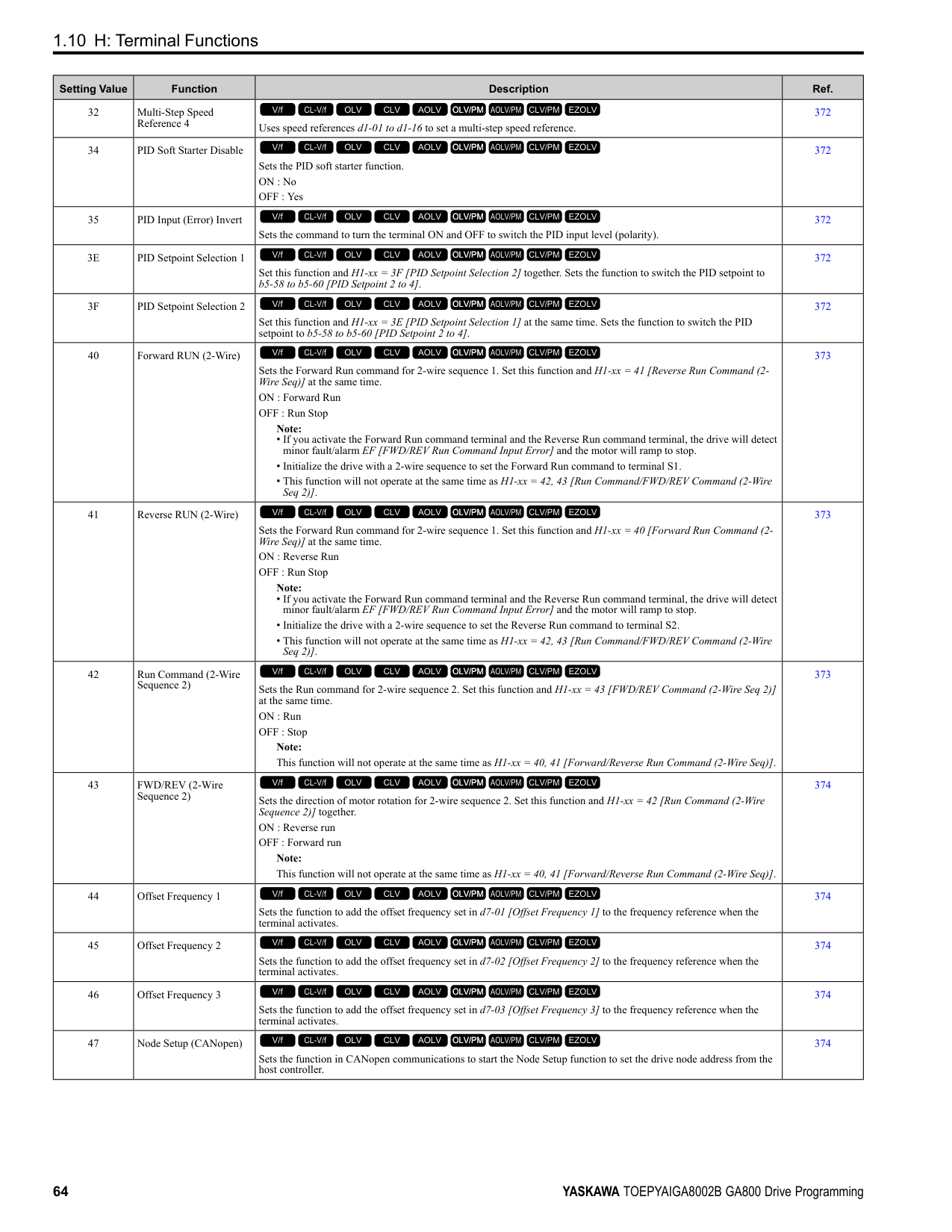
|No.|Name|Range|Unit|Control Method (A1-02 Setting)|Control Method (A1-02 Setting)|Control Method (A1-02 Setting)|Control Method (A1-02 Setting)|Control Method (A1-02 Setting)| |---|---|---|---|---|---|---|---|---| |No.|Name|Range|Unit|V/f (0)|CL-V/f (1)|OLV (2)|CLV (3)|AOLV (4)| |C5-06|ASR Delay Time|0.000 - 0.500|0.001 s|-|-|-|0.004|0.004| |C5-07|ASR Gain Switchover Frequency|0.0 - 400.0|0.1 Hz|-|-|-|0.0|0.0| |C6-02|Carrier Frequency Selection|1 - F|1|1 *3|1 *3|1 *3|1|1| |d3-01|Jump Frequency 1|0.0 - 400.0|0.1 Hz|0.0|0.0|0.0|0.0|0.0| |d3-02|Jump Frequency 2|0.0 - 400.0|0.1 Hz|0.0|0.0|0.0|0.0|0.0| |d3-03|Jump Frequency 3|0.0 - 400.0|0.1 Hz|0.0|0.0|0.0|0.0|0.0| |d3-04|Jump Frequency Width|0.0 - 20.0|0.1 Hz|1.0|1.0|1.0|1.0|1.0| |d5-02|Torque Reference Delay Time|0 - 1000|1 ms|-|-|-|0|0| |E1-04|Maximum Output Frequency|40.0 - 400.0 *3 *4|0.1 Hz|60.0 *5|60.0 *5|60.0|60.0|60.0| |E1-05|Maximum Output Voltage|0.0 - 255.0 *6|0.1 V|200.0 *5|200.0 *5|200.0|200.0|200.0| |E1-06|Base Frequency|0.0 - 400.0 *4|0.1 Hz|60.0 *5|60.0 *5|60.0|60.0|60.0| |E1-07|Mid Point A Frequency|0.0 - 400.0 *4|0.1 Hz|3.0 *5|3.0 *5|3.0|-|0.0| |E1-08|Mid Point A Voltage|0.0 - 255.0 *6|0.1 V|15.0 *5|15.0 *5|11.0|-|0.0| |E1-09|Minimum Output Frequency|0.0 - 400.0 *4|0.1 Hz|1.5 *5|1.5 *5|0.5|0.0|0.0| |E1-10|Minimum Output Voltage|0.0 - 255.0 *6|0.1 V|9.0 *5|9.0 *5|2.0|-|0.0| |F1-01|Encoder 1 Pulse Count (PPR)|0 - 60000|1 ppr|-|600|-|600|600| |F1-05|Encoder 1 Rotation Selection|0 - 1|1|-|0|-|0|0| |F1-09|Overspeed Detection Delay Time|0.0 - 2.0|0.1 s|-|1.0|-|0.0|0.1| |L1-01|Motor Overload (oL1) Protection|0 - 6|1|1|1|1|1|1| |L2-31|KEB Start Voltage Offset Level|0 - 100 *6|1 V|0|0|0|0|0| |L3-05|Stall Prevention during RUN|0 - 3|1|2|2|-|-|-| |L3-20|DC Bus Voltage Adjustment Gain|0.00 - 5.00|0.01|1.00|1.00|0.30|0.30|0.30| |L3-21|OVSuppression Accel/Decel P Gain|0.10 - 10.00|0.01|1.00|1.00|1.00|1.00|1.00| |L3-36|Current Suppression Gain@Accel|0.0 - 100.0|0.1|10.0|10.0|20.0|-|-| |L4-01|Speed Agree Detection Level|0.0 - 400.0 *7|0.1|0.0 Hz|0.0 Hz|0.0 Hz|0.0 Hz|0.0 Hz| |L4-02|Speed Agree Detection Width|0.0 - 20.0|0.1|2.0 Hz|2.0 Hz|2.0 Hz|2.0 Hz|2.0 Hz| |L4-03|Speed Agree Detection Level (+/-)|-400.0 - +400.0 *8|0.1|0.0 Hz|0.0 Hz|0.0 Hz|0.0 Hz|0.0 Hz| |L4-04|Speed Agree Detection Width (+/-)|0.0 - 20.0|0.1|2.0 Hz|2.0 Hz|2.0 Hz|2.0 Hz|2.0 Hz|
|No.|Name|Range|Unit|Control Method (A1-02 Setting)|Control Method (A1-02 Setting)|Control Method (A1-02 Setting)|Control Method (A1-02 Setting)|Control Method (A1-02 Setting)| |---|---|---|---|---|---|---|---|---| |No.|Name|Range|Unit|V/f (0)|CL-V/f (1)|OLV (2)|CLV (3)|AOLV (4)| |L8-38|Carrier Frequency Reduction|0 - 2|1|*3|*3|*3|*3|-| |L8-40|Carrier Freq Reduction OffDelay|0.00 - 2.00|0.01 s|0.50|0.50|0.50|0.50|-| |L8-90|STPo Detection Level (Low Speed)|0 - 5000|1|-|-|-|-|-| |n1-15|PWM Voltage Offset Calibration|0 - 2|1|1|1|1|1|2| |n5-04|Speed Response Frequency|0.00 - 500.00|0.01 Hz|-|-|-|50.00|50.00|
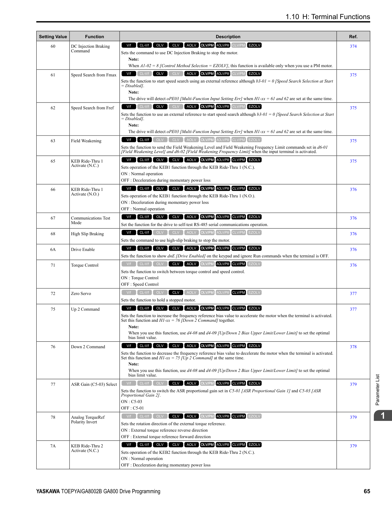
|n8-35|Initial Pole Detection Method|0 - 2|1|-|-|-|-|-| |n8-51|Pull-in Current @ Acceleration|0 - 200|1%|-|-|-|-|-| |o1-03|Frequency Display Unit Selection|0 - 3|1|0|0|0|0|0| |o1-04|V/f Pattern Display Unit|0 - 1|1|-|-|-|0|0|
######## ◆ A1-02 = 5 to 8 [Control Method for PM Motors and EZ Vector Control]
|No.|Name|Range|Unit|Control Method (A1-02 Setting)|Control Method (A1-02 Setting)|Control Method (A1-02 Setting)|Control Method (A1-02 Setting)| |---|---|---|---|---|---|---|---| |No.|Name|Range|Unit|OLV/PM (5)|AOLV/PM (6)|CLV/PM (7)|EZOLV (8)| |b2-01|DC Injection/Zero SpeedThreshold|0.0 - 10.0|0.1|0.5 Hz|1.0%|0.5%|0.5 Hz| |b2-04|DC Inject Braking Time at Stop|0.00 - 10.00|0.01 s|0.00|0.00|0.00|0.00| |b3-01|Speed Search at Start Selection|0 - 1|1|0|0|-|0| |b3-02|SpeedSearch Deactivation Current|0 - 200|1%|-|-|-|-| |b3-08|Speed Estimation ACR P Gain|0.00 - 6.00|0.01|0.50 *1|0.50 *1|-|0.60 *2| |b3-09|Speed Estimation ACR I Time|0.0 - 1000.0|0.1 ms|2.0|4.0|-|10.0| |b3-14|Bi-directional Speed Search|0 - 1|1|-|-|-|0| |b5-15|PID Sleep Function Start Level|0.0 - 400.0 *3|0.1|0.0 Hz|0.0%|0.0%|0.0 Hz| |b6-01|Dwell Reference at Start|0.0 - 400.0 *3|0.1|0.0 Hz|0.0%|0.0%|0.0 Hz|
|No.|Name|Range|Unit|Control Method (A1-02 Setting)|Control Method (A1-02 Setting)|Control Method (A1-02 Setting)|Control Method (A1-02 Setting)| |---|---|---|---|---|---|---|---| |No.|Name|Range|Unit|OLV/PM (5)|AOLV/PM (6)|CLV/PM (7)|EZOLV (8)| |b6-03|Dwell Reference at Stop|0.0 - 400.0 *3|0.1|0.0 Hz|0.0%|0.0%|0.0 Hz| |b8-02|Energy Saving Gain|0.0 - 10.0|0.1|-|-|-|-|
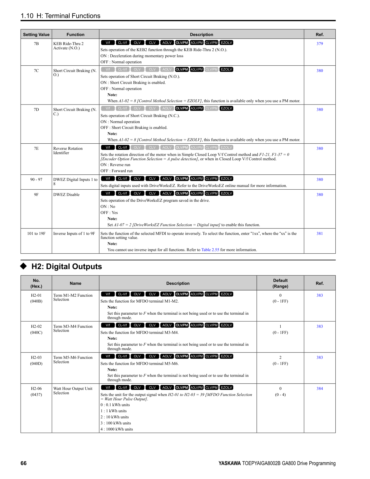
|b8-03|Energy Saving Filter Time|0.00 - 10.00|0.01 s|-|-|-|-| |b8-19|E-Save Search Injection Freq|10 - 300|1 Hz|-|100|100|20| |C1-11|Accel/Decel Time Switchover Freq|0.0 - 400.0 *3|0.1|0.0 Hz|0.0%|0.0%|0.0 Hz| |C2-01|S-Curve Time @ Start of Accel|0.00 - 10.00|0.01 s|1.00|0.20|0.20|1.00| |C3-01|Slip Compensation Gain|0.0 - 2.5|0.1|-|-|-|0.0| |C3-02|Slip Compensation Delay Time|0 - 10000|1 ms|-|-|-|200| |C4-01|Torque Compensation Gain|0.00 - 2.50|0.01|0.00|-|-|0.00| |C4-02|Torque Compensation Delay Time|0 - 60000|1 ms|100|-|-|200| |C5-01|ASR Proportional Gain 1|0.00 - 300.00|0.01|-|10.00|20.00|10.00| |C5-02|ASR Integral Time 1|0.000 - 60.000|0.001 s|-|0.500|0.500|0.500| |C5-03|ASR Proportional Gain 2|0.00 - 300.00|0.01|-|10.00|20.00|10.00| |C5-04|ASR Integral Time 2|0.000 - 60.000|0.001 s|-|0.500|0.500|0.500| |C5-06|ASR Delay Time|0.000 - 0.500|0.001 s|-|0.016|0.004|0.004| |C5-07|ASR Gain Switchover Frequency|0.0 - 400.0 *3|0.1|-|0.0%|0.0%|0.0 Hz| |C6-02|Carrier Frequency Selection|1 - F|1|2|2|2|2| |d3-01|Jump Frequency 1|0.0 - 400.0 *3|0.1|0.0 Hz|0.0%|0.0%|0.0 Hz| |d3-02|Jump Frequency 2|0.0 - 400.0 *3|0.1|0.0 Hz|0.0%|0.0%|0.0 Hz| |d3-03|Jump Frequency 3|0.0 - 400.0 *3|0.1|0.0 Hz|0.0%|0.0%|0.0 Hz| |d3-04|Jump Frequency Width|0.0 - 20.0 *4|0.1|1.0 Hz|1.0%|1.0%|1.0 Hz| |d5-02|Torque Reference Delay Time|0 - 1000|1 ms|-|0|0|-| |E1-04|Maximum Output Frequency|40.0 - 400.0 *5|0.1 Hz|Determined by E5-01|Determined by E5-01|Determined by E5-01|-| |E1-05|Maximum Output Voltage|0.0 - 255.0 *6|0.1 V|Determined by E5-01|Determined by E5-01|Determined by E5-01|-| |E1-06|Base Frequency|0.0 - 400.0|0.1 Hz|Determined by E5-01|Determined by E5-01|Determined by E5-01|-| |E1-07|Mid Point A Frequency|0.0 - 400.0|0.1 Hz|-|-|-|-| |E1-08|Mid Point AVoltage|0.0 - 255.0 *6|0.1 V|-|-|-|-| |E1-09|Minimum Output Frequency|0.0 - 400.0|0.1 Hz|Determined by E5-01|Determined by E5-01|Determined by E5-01|-| |E1-10|Minimum Output Voltage|0.0 - 255.0 *6|0.1 V|-|-|-|-| |F1-01|Encoder 1 Pulse Count (PPR)|0 - 60000|1 ppr|-|-|1024|-| |F1-05|Encoder 1 Rotation Selection|0 - 1|1|-|-|1|-| |F1-09|Overspeed Detection Delay Time|0.0 - 2.0|0.1 s|-|0.0|0.0|0.0| |L1-01|Motor Overload (oL1) Protection|0 - 6|1|4|4|5|1|
|No.|Name|Range|Unit|Control Method (A1-02 Setting)|Control Method (A1-02 Setting)|Control Method (A1-02 Setting)|Control Method (A1-02 Setting)| |---|---|---|---|---|---|---|---| |No.|Name|Range|Unit|OLV/PM (5)|AOLV/PM (6)|CLV/PM (7)|EZOLV (8)| |L2-31|KEB Start Voltage Offset Level|0 - 100 *6|1 V|50|50|50|50| |L3-05|Stall Prevention during RUN|0 - 3|1|1|-|-|3| |L3-20|DC Bus Voltage Adjustment Gain|0.00 - 5.00|0.01|0.65|0.65|0.65|0.65| |L3-21|OVSuppression Accel/ Decel P Gain|0.10 - 10.00|0.01|1.00|1.00|1.00|1.00| |L3-36|Current Suppression Gain@Accel|0.0 - 100.0|0.1|-|-|-|-| |L4-01|Speed Agree Detection Level|0.0 - 400.0 *3|0.1|0.0 Hz|0.0%|0.0%|0.0 Hz|
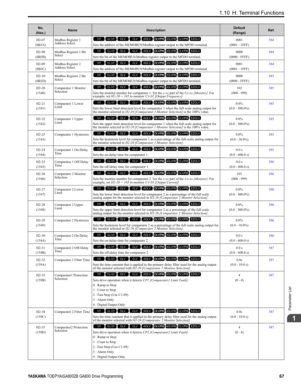
|L4-02|Speed Agree Detection Width|0.0 - 20.0 *4|0.1|2.0 Hz|4.0%|4.0%|2.0 Hz| |L4-03|Speed Agree Detection Level(+/-)|-400.0 - +400.0 *7|0.1|0.0 Hz|0.0%|0.0%|0.0 Hz| |L4-04|Speed Agree Detection Width(+/-)|0.0 - 20.0 *4|0.1|2.0 Hz|4.0%|4.0%|2.0 Hz| |L8-38|Carrier Frequency Reduction|0 - 2|1|0|-|0|0| |L8-40|Carrier Freq Reduction Off-Delay|0.00 - 2.00|0.01 s|0.00|-|0.00|0.00| |L8-90|STPo Detection Level (Low Speed)|0 - 5000|1|0|80|-|0| |n1-15|PWM Voltage Offset Calibration|0 - 2|1|1|1|1|1| |n5-04|Speed Response Frequency|0.00 - 500.00|0.01 Hz|-|20.00|50.00|-| |n8-35|Initial Pole Detection Method|0 - 2|1|0|1|1|-| |n8-51|Pull-in Current @ Acceleration|0 - 200|1%|50%|-|-|80%| |o1-03|Frequency Display Unit Selection|0 - 3|1|2|2|2|0 *8| |o1-04|V/f Pattern Display Unit|0 - 1|1|-|1|1|0 *8|
• 2138 - 2415, 4089 - 4720: 0.30
ParameterList
####### 1.19 Parameters that Change from the Default Settings withE3-01 [Motor 2 Control Mode Selection]
The values for the parameters in these tables depend on the values for parameter E3-01. When you change the setting for E3-01, the default settings will change.
|No.|Name|Range|Unit|Motor 2 Control Method (setting value of E3-01)|Motor 2 Control Method (setting value of E3-01)|Motor 2 Control Method (setting value of E3-01)|Motor 2 Control Method (setting value of E3-01)| |---|---|---|---|---|---|---|---|
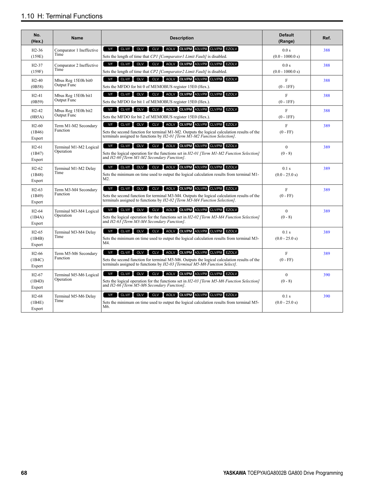
|No.|Name|Range|Unit|V/f (0)|CL-V/f (1)|OLV (2)|CLV (3)| |C3-21|Motor 2 Slip Compensation Gain|0.0 - 2.50|0.1|0.0|-|1.0|1.0| |C3-22|Motor 2 Slip Comp Delay Time|0 - 10000|1 ms|2000|-|200|-| |C5-21|Motor 2 ASR Proportional Gain 1 (P)|0.00 - 300.00|0.01|-|0.20|-|20.00| |C5-22|Motor 2 ASR Integral Time 1 (I)|0.000 - 10.000|0.001 s|-|0.200|-|0.500| |C5-23|Motor 2 ASR Proportional Gain 2 (P)|0.00 - 300.00|0.01|-|0.02|-|20.00| |C5-24|Motor 2 ASR Integral Time 2 (I)|0.000 - 10.000|0.001 s|-|0.050|-|0.500| |C5-26|Motor 2 ASR Delay Time|0.000 - 0.500|0.001 s|-|-|-|0.004| |E3-04|Motor 2 Maximum Output Frequency|40.0 - 590.0|0.1 Hz|60.0|60.0|60.0|60.0| |E3-05|Motor 2 Maximum Output Voltage|0.0 - 255.0
*1|0.1 V|200.0|200.0|200.0|200.0| |E3-06|Motor 2 Base Frequency|0.0 - 590.0|0.1 Hz|60.0|60.0|60.0|60.0| |E3-07|Motor 2 Mid Point A Frequency|0.0 - 590.0|0.1 Hz|3.0|3.0|3.0|-| |E3-08|Motor 2 Mid Point A Voltage|0.0 - 255.0
*1|0.1 V|15.0|15.0|11.0|-| |E3-09|Motor 2 Minimum Output Frequency|0.0 - 590.0|0.1 Hz|1.5|1.5|0.5|0.0| |E3-10|Motor 2 Minimum Output Voltage|0.0 - 255.0
*1|0.1 V|9.0|9.0|2.0|-| |E3-11|Motor 2 Mid Point B Frequency|0.0 - 590.0|Determined by o1-04|0.0|0.0|0.0|0.0| |E3-12|Motor 2 Mid Point B Voltage|0.0 - 255.0
*1|0.1 V|0.0|0.0|0.0|0.0| |E3-13|Motor 2 Base Voltage|0.0 - 255.0
*1|0.1 V|0.0|0.0|0.0|0.0|
####### 1.20 Parameters Changed by E1-03 [V/f Pattern Selection]
The values for parameters A1-02 [Control Method Selection] and E1-03 [V/f Pattern Selection] changes the default settings for the parameters in these tables:
Table 1.1 Parameters Changed by E1-03 (2004 to 2021 and 4002 to 4012)
|No.|Unit|Setting Value|Setting Value|Setting Value|Setting Value|Setting Value|Setting Value|Setting Value|Setting Value|Setting Value|Setting Value|Setting Value|Setting Value|Setting Value|Setting Value|Setting Value|Setting Value|Control Method (A1-02 Setting)|Control Method (A1-02 Setting)|Control Method (A1-02 Setting)|Control Method (A1-02 Setting)|Control Method (A1-02 Setting)| |---|---|---|---|---|---|---|---|---|---|---|---|---|---|---|---|---|---|---|---|---|---|---| |E103|Unit|0|1|2|3|4|5|6|7|8|9|A|B|C|D|E|F|OLV (2)|CLV (3)|OLV/ PM (5)|AOLV/PM
(6)|CLV/ PM (7)| |E1-04|Hz|50.0|60.0|60.0|72.0|50.0|50.0|60.0|60.0|50.0|50.0|60.0|60.0|90.0|120.0|180.0|60.0 *1|60.0|60.0|*2|*2|*2| |E1-05 *3|V|230.0|230.0|230.0|230.0|230.0|230.0|230.0|230.0|230.0|230.0|230.0|230.0|230.0|230.0|230.0|230.0 *1|230.0|230.0|*2|*2|*2| |E1-06|Hz|50.0|60.0|50.0|60.0|50.0|50.0|60.0|60.0|50.0|50.0|60.0|60.0|60.0|60.0|60.0|60.0 *1|60.0|60.0|*2|*2|*2| |E1-07|Hz|2.5|3.0|3.0|3.0|25.0|25.0|30.0|30.0|2.5|2.5|3.0|3.0|3.0|3.0|3.0|3.0 *1|3.0|0.0|-|-|-| |E1-08 *3|V|17.3|17.3|17.3|17.3|40.3|57.5|40.3|57.5|21.9|27.6|21.9|27.6|17.3|17.3|17.3|17.3 *1|13.8|0.0|-|-|-| |E1-09|Hz|1.3|1.5|1.5|1.5|1.3|1.3|1.5|1.5|1.3|1.3|1.5|1.5|1.5|1.5|1.5|1.5 *1|0.5|0.0|*2|*2|0.0| |E1-10 *3|V|10.4|10.4|10.4|10.4|9.2|10.4|9.2|10.4|12.7|15.0|12.7|17.3|10.4|10.4|10.4|10.2 *1|2.9|0.0|-|-|-|
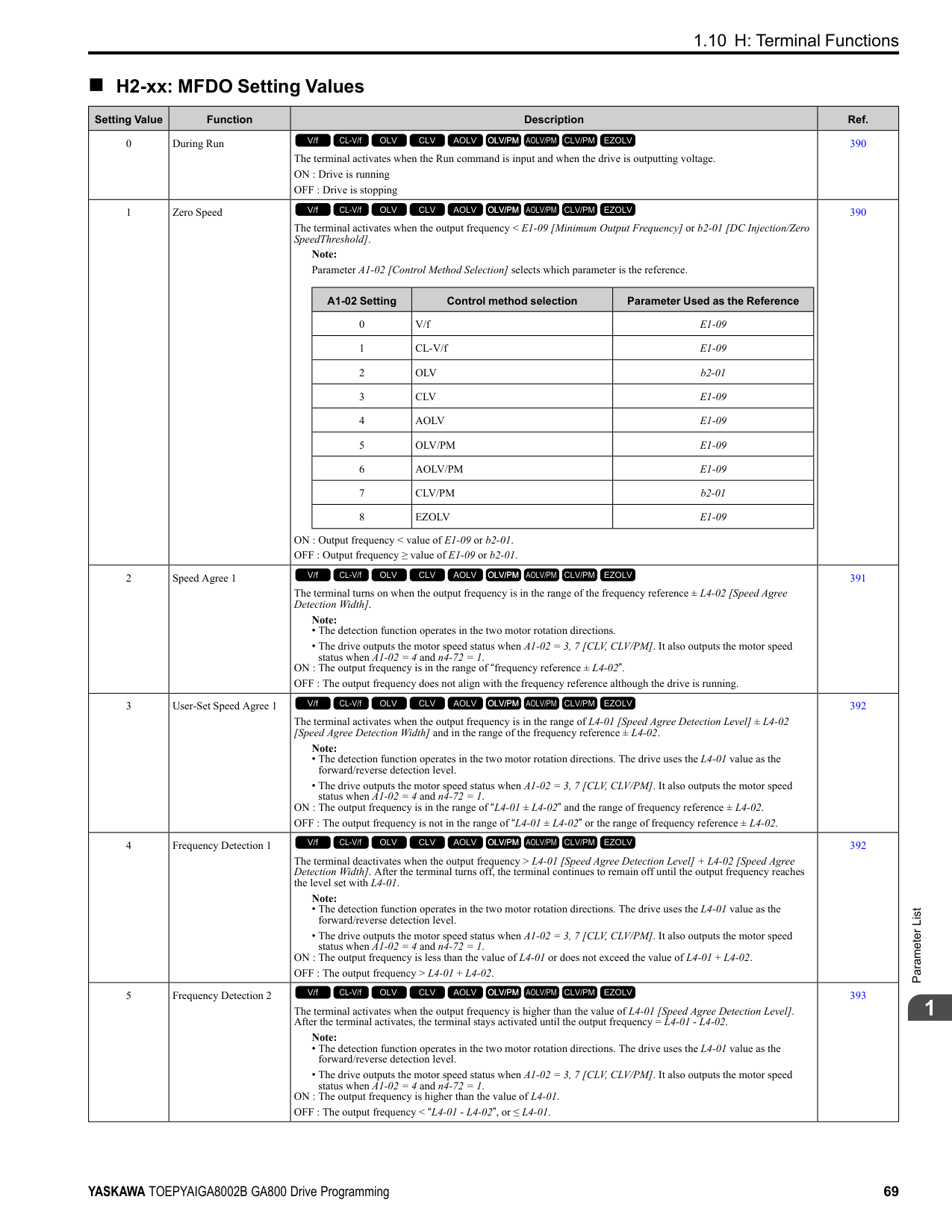
|No.|Unit|Setting Value|Setting Value|Setting Value|Setting Value|Setting Value|Setting Value|Setting Value|Setting Value|Setting Value|Setting Value|Setting Value|Setting Value|Setting Value|Setting Value|Setting Value|Setting Value|Control Method (A1-02 Setting)|Control Method (A1-02 Setting)|Control Method (A1-02 Setting)|Control Method (A1-02 Setting)|Control Method (A1-02 Setting)| |---|---|---|---|---|---|---|---|---|---|---|---|---|---|---|---|---|---|---|---|---|---|---| |E103|Unit|0|1|2|3|4|5|6|7|8|9|A|B|C|D|E|F|OLV (2)|CLV (3)|OLV/ PM (5)|AOLV/PM
(6)|CLV/ PM (7)| |E1-04|Hz|50.0|60.0|60.0|72.0|50.0|50.0|60.0|60.0|50.0|50.0|60.0|60.0|90.0|120.0|180.0|60.0 *1|60.0|60.0|*2|*2|*2| |E1-05 *3|V|230.0|230.0|230.0|230.0|230.0|230.0|230.0|230.0|230.0|230.0|230.0|230.0|230.0|230.0|230.0|230.0 *1|230.0|230.0|*2|*2|*2| |E1-06|Hz|50.0|60.0|50.0|60.0|50.0|50.0|60.0|60.0|50.0|50.0|60.0|60.0|60.0|60.0|60.0|60.0 *1|60.0|60.0|*2|*2|*2| |E1-07|Hz|2.5|3.0|3.0|3.0|25.0|25.0|30.0|30.0|2.5|2.5|3.0|3.0|3.0|3.0|3.0|3.0 *1|3.0|0.0|-|-|-| |E1-08 *3|V|16.1|16.1|16.1|16.1|40.3|57.5|40.3|57.5|20.7|26.5|20.7|26.5|16.1|16.1|16.1|16.1 *1|12.7|0.0|-|-|-| |E1-09|Hz|1.3|1.5|1.5|1.5|1.3|1.3|1.5|1.5|1.3|1.3|1.5|1.5|1.5|1.5|1.5|1.5 *1|0.5|0.0|*2|*2|0.0| |E1-10 *3|V|8.1|8.1|8.1|8.1|6.9|8.1|6.9|8.1|10.4|12.7|10.4|15.0|8.1|8.1|8.1|8.1 *1|2.3|0.0|-|-|-|
ParameterList
1
################# Table 1.3 Parameters Changed by E1-03 (2257 to 2415 and 4140 to 4720)
|No.|Unit|Setting Value|Setting Value|Setting Value|Setting Value|Setting Value|Setting Value|Setting Value|Setting Value|Setting Value|Setting Value|Setting Value|Setting Value|Setting Value|Setting Value|Setting Value|Setting Value|Control Method (A1-02 Setting)|Control Method (A1-02 Setting)|Control Method (A1-02 Setting)|Control Method (A1-02 Setting)|Control Method (A1-02 Setting)| |---|---|---|---|---|---|---|---|---|---|---|---|---|---|---|---|---|---|---|---|---|---|---| |E103|Unit|0|1|2|3|4|5|6|7|8|9|A|B|C|D|E|F|OLV (2)|CLV (3)|OLV/ PM (5)|AOLV/PM
(6)|CLV/ PM (7)| |E1-04|Hz|50.0|60.0|60.0|72.0|50.0|50.0|60.0|60.0|50.0|50.0|60.0|60.0|90.0|120.0|180.0|60.0 *1|60.0|60.0|*2|*2|*2| |E1-05 *3|V|230.0|230.0|230.0|230.0|230.0|230.0|230.0|230.0|230.0|230.0|230.0|230.0|230.0|230.0|230.0|230.0 *1|230.0|230.0|*2|*2|*2| |E1-06|Hz|50.0|60.0|50.0|60.0|50.0|50.0|60.0|60.0|50.0|50.0|60.0|60.0|60.0|60.0|60.0|60.0 *1|60.0|60.0|*2|*2|*2| |E1-07|Hz|2.5|3.0|3.0|3.0|25.0|25.0|30.0|30.0|2.5|2.5|3.0|3.0|3.0|3.0|3.0|3.0 *1|3.0|0.0|-|-|-| |E1-08 *3|V|13.8|13.8|13.8|13.8|40.3|57.5|40.3|57.5|17.3|23.0|17.3|23.0|13.8|13.8|13.8|13.8 *1|12.7|0.0|-|-|-| |E1-09|Hz|1.3|1.5|1.5|1.5|1.3|1.3|1.5|1.5|1.3|1.3|1.5|1.5|1.5|1.5|1.5|1.5 *1|0.5|0.0|*2|*2|0.0| |E1-10 *3|V|6.9|6.9|6.9|6.9|5.8|6.9|5.8|6.9|8.1|10.4|8.1|12.7|6.9|6.9|6.9|6.9 *1|2.3|0.0|-|-|-|
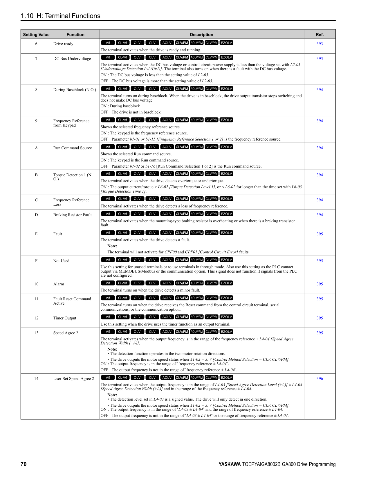
####### 1.21 Defaults by Drive Model and Duty Rating ND/HD
The values for the parameters in these tables depend on the values for parameters o2-04 and C6-01. Changing the settings for o2-04 and C6-01 will change the default settings.
######## ◆ 200 V class
|No. *1|Name|Unit|Default|Default|Default|Default|Default|Default|Default|Default| |---|---|---|---|---|---|---|---|---|---|---| |-|Drive Model|-|2004|2004|2006|2006|2008|2008|2010|2010| |C6-01|Normal / Heavy Duty Selection|-|HD|ND|HD|ND|HD|ND|HD|ND| |C6-01|Normal / Heavy Duty Selection|-|0|1|0|1|0|1|0|1| |o2-04|Drive Model (KVA) Selection|Hex.|62|62|63|63|64|64|65|65| |E2-11 (E4-11, E502)|Motor Rated Power|HP (kW)|0.75 (0.55)|1 (0.75)|1 (0.75)|1.5 (1.1)|1.5 (1.1)|2 (1.5)|2 (1.5)|3 (2.2)| |b3-04|V/f Gain during Speed Search|%|100|100|100|100|100|100|100|100| |b3-06|Speed Estimation Current Level 1|-|1|1|0.5|0.5|0.5|0.5|0.5|0.5| |b3-08|Speed Estimation ACR P Gain|-|0.5|0.5|0.5|0.5|0.5|0.5|0.5|0.5| |b3-26|Direction Determination Level|-|1000|1000|1000|1000|1000|1000|1000|1000| |b8-03|Energy Saving Filter Time|s|0.50|0.50|0.50|0.50|0.50|0.50|0.50|0.50| |b8-04|Energy Saving Coefficient Value|-|288.2|223.7|223.7|196.6|196.6|169.4|169.4|156.8| |C5-17 (C5-37)|Motor Inertia|kgm2|0.0015|0.0028|0.0028|0.0068|0.0068|0.0068|0.0068|0.0088| |C6-02|Carrier Frequency Selection|-|1|7|1|7|1|7|1|7| |E2-01 (E4-01)|Motor Rated Current (FLA)|A|1.9|3.3|3.3|4.9|4.9|6.2|6.2|8.5| |E2-02 (E4-02)|Motor Rated Slip|Hz|2.9|2.5|2.5|2.6|2.6|2.6|2.6|2.9| |E2-03 (E4-03)|Motor NoLoad Current|A|1.2|1.8|1.8|2.3|2.3|2.8|2.8|3| |E2-05 (E4-05)|Motor Line-toLine Resistance|Ω|9.842|5.156|5.156|3.577|3.577|1.997|1.997|1.601| |E2-06 (E4-06)|Motor Leakage Inductance|%|18.2|13.8|13.8|18.5|18.5|18.5|18.5|18.4| |E2-10 (E4-10)|Motor Iron Loss|W|14|26|26|38|38|53|53|77| |E5-01|PM Motor Code Selection|-|FFFF|FFFF|FFFF|FFFF|FFFF|FFFF|FFFF|FFFF| |L2-02|Power Loss Ride Through Time|s|0.1|0.1|0.2|0.2|0.3|0.3|0.3|0.3| |L2-03|Minimum Baseblock Time|s|0.2|0.3|0.3|0.4|0.4|0.4|0.4|0.5|
ParameterList
1
|No. *1|Name|Unit|Default|Default|Default|Default|Default|Default|Default|Default| |---|---|---|---|---|---|---|---|---|---|---| |-|Drive Model|-|2004|2004|2006|2006|2008|2008|2010|2010| |C6-01|Normal / Heavy Duty Selection|-|HD|ND|HD|ND|HD|ND|HD|ND| |C6-01|Normal / Heavy Duty Selection|-|0|1|0|1|0|1|0|1| |o2-04|Drive Model (KVA) Selection|Hex.|62|62|63|63|64|64|65|65|
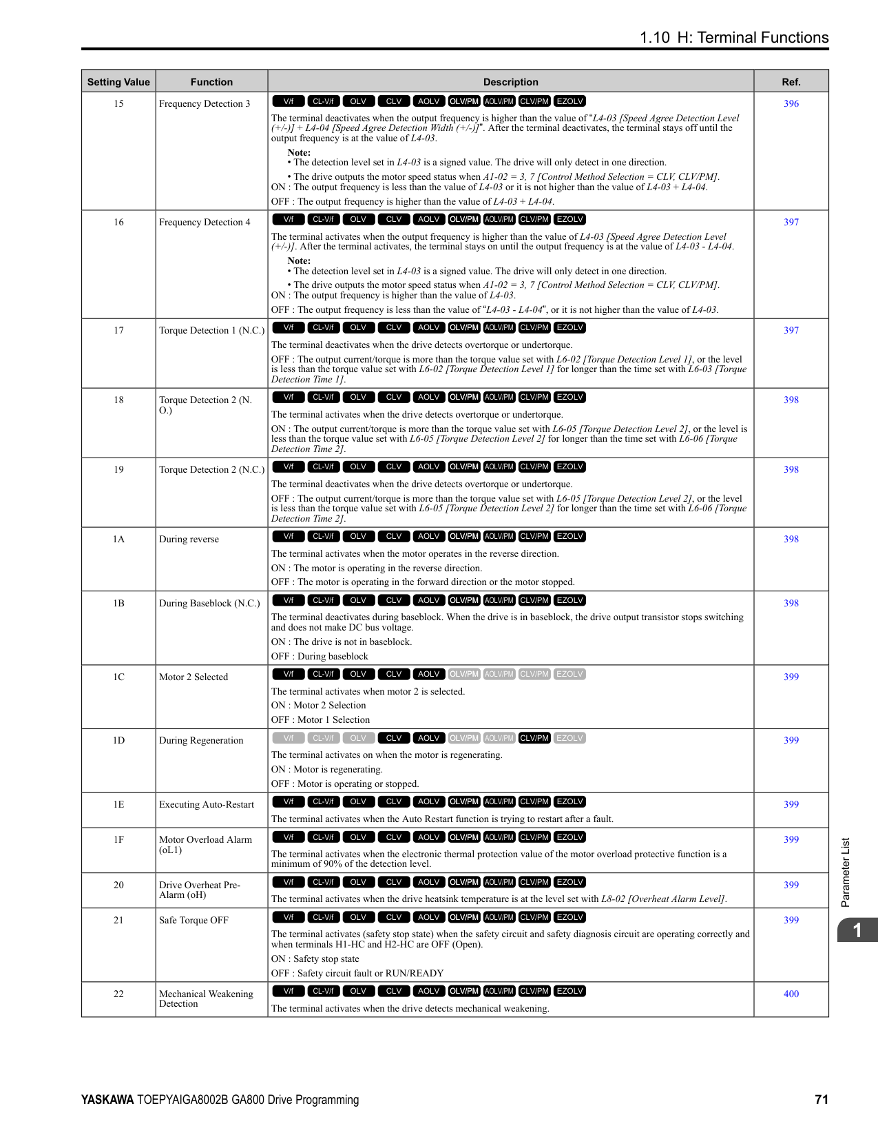
|E2-11 (E4-11, E502)|Motor Rated Power|HP (kW)|0.75 (0.55)|1 (0.75)|1 (0.75)|1.5 (1.1)|1.5 (1.1)|2 (1.5)|2 (1.5)|3 (2.2)| |L2-04|Powerloss V/f Recovery Ramp Time|s|0.3|0.3|0.3|0.3|0.3|0.3|0.3|0.3| |L2-05|Undervoltage Detection Lvl (Uv1)|-|190|190|190|190|190|190|190|190| |L3-24|Motor Accel Time for Inertia Cal|s|0.178|0.142|0.142|0.142|0.142|0.166|0.166|0.145| |L8-02|Overheat Alarm Level|°C|115|115|115|115|115|115|115|115| |L8-09|Output Ground Fault Detection|-|1|1|1|1|1|1|1|1| |L8-38|Carrier Frequency Reduction|-|2|2|2|2|2|2|2|2| |n1-01|Hunting Prevention Selection|-|1|1|1|1|1|1|1|1| |n1-03|Hunting Prevention Time Constant|ms|10|10|10|10|10|10|10|10| |n5-02|Motor Inertia Acceleration Time|s|0.178|0.142|0.142|0.142|0.142|0.166|0.166|0.145|
################## *1 Parameters within parentheses are for motor 2.
|No. *1|Name|Unit|Default|Default|Default|Default|Default|Default|Default|Default| |---|---|---|---|---|---|---|---|---|---|---| |-|Drive Model|-|2012|2012|2018|2018|2021|2021|2030|2030| |C6-01|Normal / Heavy Duty Selection|-|HD|ND|HD|ND|HD|ND|HD|ND| |C6-01|Normal / Heavy Duty Selection|-|0|1|0|1|0|1|0|1| |o2-04|Drive Model (KVA) Selection|Hex.|66|66|67|67|68|68|6A|6A| |E2-11 (E4-11, E502)|Motor Rated Power|HP (kW)|3 (2.2)|4 (3.0)|4 (3.0)|5 (3.7)|5 (3.7)|7.5 (5.5)|7.5 (5.5)|10 (7.5)| |b3-04|V/f Gain during Speed Search|%|100|100|100|100|100|100|100|100| |b3-06|Speed Estimation Current Level 1|-|0.5|0.5|0.5|0.5|0.5|0.5|0.5|0.5| |b3-08|Speed Estimation ACR P Gain|-|0.5|0.5|0.5|0.5|0.5|0.5|0.5|0.5| |b3-26|Direction Determination Level|-|1000|1000|1000|1000|1000|1000|1000|1000| |b8-03|Energy Saving Filter Time|s|0.50|0.50|0.50|0.50|0.50|0.50|0.50|0.50| |b8-04|Energy Saving Coefficient Value|-|156.8|136.4|136.4|122.9|122.9|94.75|94.75|72.69|
|No. *1|Name|Unit|Default|Default|Default|Default|Default|Default|Default|Default| |---|---|---|---|---|---|---|---|---|---|---| |-|Drive Model|-|2012|2012|2018|2018|2021|2021|2030|2030| |C6-01|Normal / Heavy Duty Selection|-|HD|ND|HD|ND|HD|ND|HD|ND| |C6-01|Normal / Heavy Duty Selection|-|0|1|0|1|0|1|0|1| |o2-04|Drive Model (KVA) Selection|Hex.|66|66|67|67|68|68|6A|6A| |E2-11 (E4-11, E502)|Motor Rated Power|HP (kW)|3 (2.2)|4 (3.0)|4 (3.0)|5 (3.7)|5 (3.7)|7.5 (5.5)|7.5 (5.5)|10 (7.5)| |C5-17 (C5-37)|Motor Inertia|kgm2|0.0088|0.0158|0.0158|0.0158|0.0158|0.0255|0.026|0.037| |C6-02|Carrier Frequency Selection|-|1|7|1|7|1|7|1|7| |E2-01 (E4-01)|Motor Rated Current (FLA)|A|8.5|11.4|11.4|14|14|19.6|19.6|26.6| |E2-02 (E4-02)|Motor Rated Slip|Hz|2.9|2.7|2.7|2.73|2.73|1.5|1.5|1.3| |E2-03 (E4-03)|Motor NoLoad Current|A|3|3.7|3.7|4.5|4.5|5.1|5.1|8| |E2-05 (E4-05)|Motor Line-toLine Resistance|Ω|1.601|1.034|1.034|0.771|0.771|0.399|0.399|0.288|
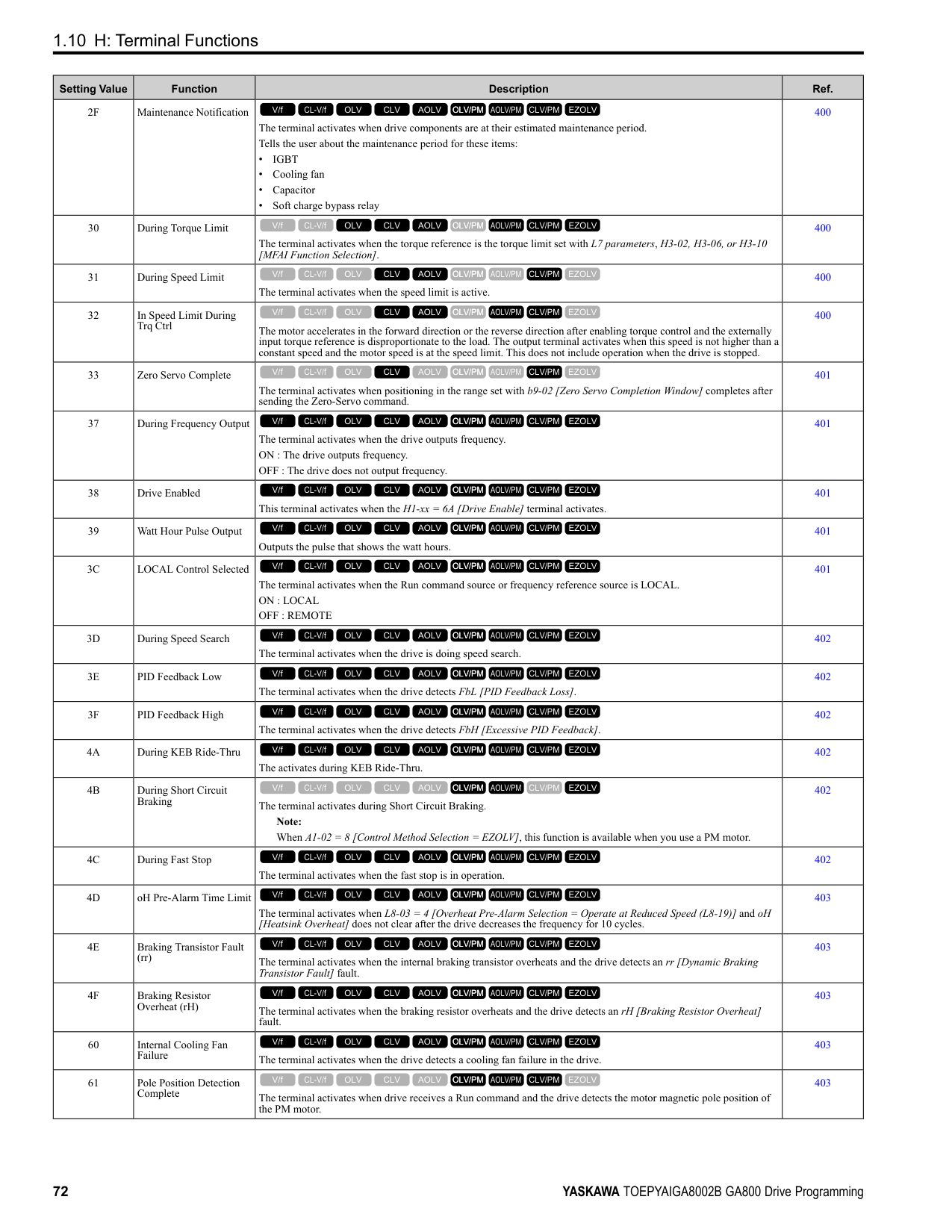
|E2-06 (E4-06)|Motor Leakage Inductance|%|18.4|19|19|19.6|19.6|18.2|18.2|15.5| |E2-10 (E4-10)|Motor Iron Loss|W|77|91|91|112|112|172|172|262| |E5-01|PM Motor Code Selection|-|FFFF|FFFF|FFFF|FFFF|FFFF|FFFF|FFFF|FFFF| |L2-02|Power Loss Ride Through Time|s|0.5|0.5|1|1|1|1|1|1| |L2-03|Minimum Baseblock Time|s|0.5|0.5|0.5|0.6|0.6|0.7|0.7|0.8| |L2-04|Powerloss V/f Recovery Ramp Time|s|0.3|0.3|0.3|0.3|0.3|0.3|0.3|0.3| |L2-05|Undervoltage Detection Lvl (Uv1)|-|190|190|190|190|190|190|190|190| |L3-24|Motor Accel Time for Inertia Cal|s|0.145|0.145|0.145|0.154|0.154|0.168|0.168|0.175| |L8-02|Overheat Alarm Level|°C|124|124|110|110|110|110|110|110| |L8-09|Output Ground Fault Detection|-|1|1|1|1|1|1|1|1| |L8-38|Carrier Frequency Reduction|-|2|2|2|2|2|2|2|2| |n1-01|Hunting Prevention Selection|-|1|1|1|1|1|1|1|1| |n1-03|Hunting Prevention Time Constant|ms|10|10|10|10|10|10|10|10| |n5-02|Motor Inertia Acceleration Time|s|0.145|0.145|0.145|0.154|0.154|0.168|0.168|0.175|
ParameterList
######## 1
|No.|Name|Unit|Default|Default|Default|Default|Default|Default|Default|Default| |---|---|---|---|---|---|---|---|---|---|---| |-|Drive Model|-|2042|2042|2056|2056|2070|2070|2082|2082| |C6-01|Normal / Heavy Duty Selection|-|HD|ND|HD|ND|HD|ND|HD|ND| |C6-01|Normal / Heavy Duty Selection|-|0|1|0|1|0|1|0|1| |o2-04|Drive Model (KVA) Selection|Hex.|6B|6B|6D|6D|6E|6E|6F|6F| |E2-11 (E4-11, E502)|Motor Rated Power|HP (kW)|10 (7.5)|15 (11)|15 (11)|20 (15)|20 (15)|25 (18.5)|25 (18.5)|30 (22)| |b3-04|V/f Gain during Speed Search|%|100|100|100|100|100|100|100|100| |b3-06|Speed Estimation Current Level 1|-|0.5|0.5|0.5|0.5|0.5|0.5|0.5|0.5| |b3-08|Speed Estimation ACR P Gain|-|0.5|0.5|0.5|0.5|0.5|0.5|0.5|0.5| |b3-26|Direction Determination Level|-|1000|1000|1000|1000|1000|1000|1000|1000| |b8-03|Energy Saving Filter Time|s|0.50|0.50|0.50|0.50|0.50|0.50|0.50|0.50| |b8-04|Energy Saving Coefficient Value|-|72.69|70.44|70.44|63.13|63.13|57.87|57.87|51.79| |C5-17 (C5-37)|Motor Inertia|kgm2|0.037|0.053|0.053|0.076|0.076|0.138|0.138|0.165| |C6-02|Carrier Frequency Selection|-|1|7|1|7|1|7|1|7| |E2-01 (E4-01)|Motor Rated Current (FLA)|A|26.6|39.7|39.7|53|53|65.8|65.8|77.2| |E2-02 (E4-02)|Motor Rated Slip|Hz|1.3|1.7|1.7|1.6|1.6|1.67|1.67|1.7| |E2-03 (E4-03)|Motor NoLoad Current|A|8|11.2|11.2|15.2|15.2|15.7|15.7|18.5| |E2-05 (E4-05)|Motor Line-toLine Resistance|Ω|0.288|0.23|0.23|0.138|0.138|0.101|0.101|0.079|
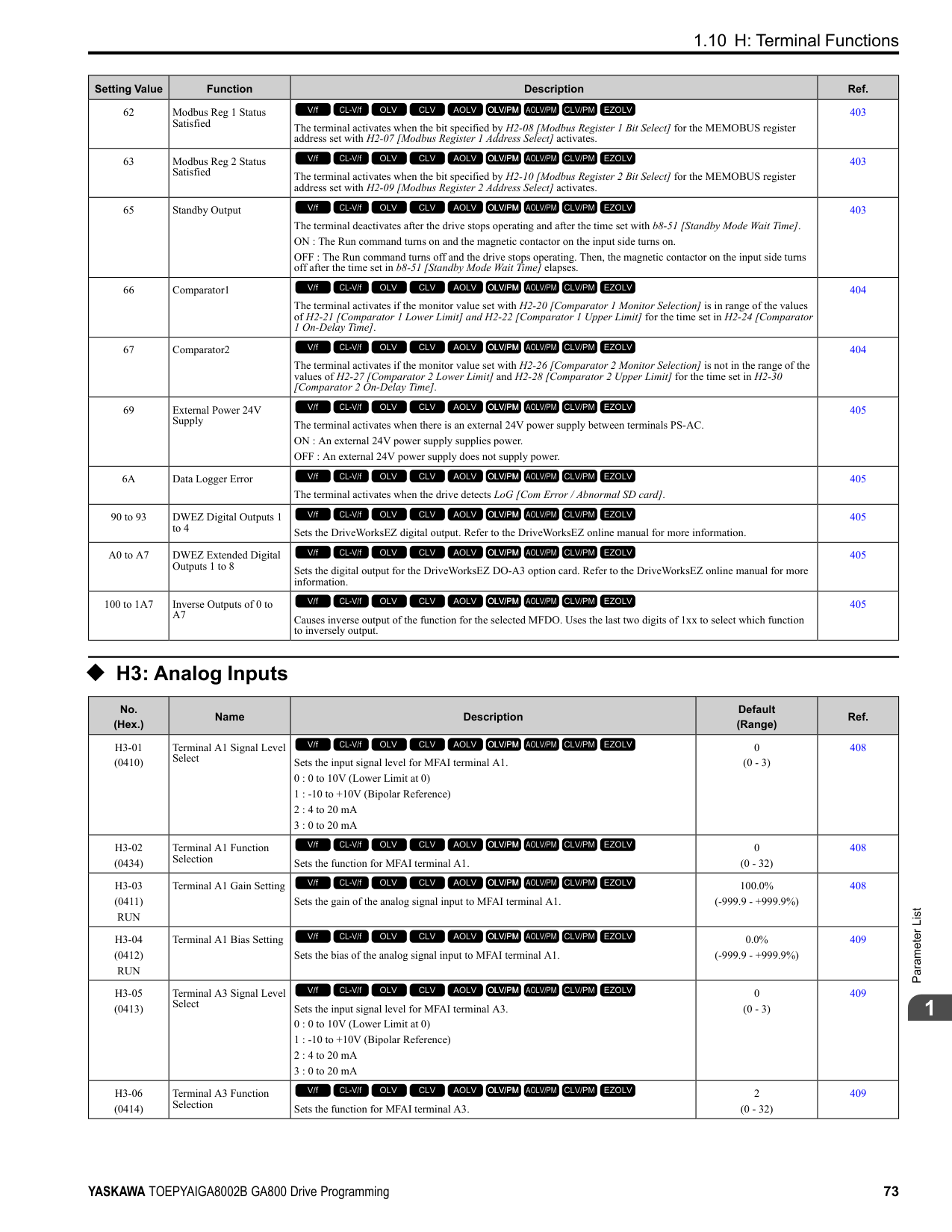
|E2-06 (E4-06)|Motor Leakage Inductance|%|15.5|19.5|19.5|17.2|17.2|15.7|20.1|19.5| |E2-10 (E4-10)|Motor Iron Loss|W|262|245|245|272|272|505|505|538| |E5-01|PM Motor Code Selection|-|FFFF|FFFF|FFFF|FFFF|FFFF|FFFF|FFFF|FFFF| |L2-02|Power Loss Ride Through Time|s|1|1|2|2|2|2|2|2| |L2-03|Minimum Baseblock Time|s|0.8|0.9|0.9|1|1|1|1|1| |L2-04|Powerloss V/f Recovery Ramp Time|s|0.3|0.3|0.3|0.6|0.6|0.6|0.6|0.6| |L2-05|Undervoltage Detection Lvl (Uv1)|-|190|190|190|190|190|190|190|190| |L3-24|Motor Accel Time for Inertia Cal|s|0.175|0.265|0.265|0.244|0.244|0.317|0.317|0.355| |L8-02|Overheat Alarm Level|°C|110|110|115|115|120|120|133|130|
|No.|Name|Unit|Default|Default|Default|Default|Default|Default|Default|Default| |---|---|---|---|---|---|---|---|---|---|---| |-|Drive Model|-|2042|2042|2056|2056|2070|2070|2082|2082| |C6-01|Normal / Heavy Duty Selection|-|HD|ND|HD|ND|HD|ND|HD|ND| |C6-01|Normal / Heavy Duty Selection|-|0|1|0|1|0|1|0|1| |o2-04|Drive Model (KVA) Selection|Hex.|6B|6B|6D|6D|6E|6E|6F|6F| |E2-11 (E4-11, E502)|Motor Rated Power|HP (kW)|10 (7.5)|15 (11)|15 (11)|20 (15)|20 (15)|25 (18.5)|25 (18.5)|30 (22)| |L8-09|Output Ground Fault Detection|-|1|1|1|1|1|1|1|1| |L8-38|Carrier Frequency Reduction|-|2|2|2|2|2|2|2|2| |n1-01|Hunting Prevention Selection|-|1|1|2|2|2|2|2|2| |n1-03|Hunting Prevention Time Constant|ms|10|10|10|10|10|10|10|10| |n5-02|Motor Inertia Acceleration Time|s|0.175|0.265|0.265|0.244|0.244|0.317|0.317|0.355|
################## *1 Parameters within parentheses are for motor 2.
|No. *1|Name|Unit|Default|Default|Default|Default|Default|Default|Default|Default| |---|---|---|---|---|---|---|---|---|---|---| |-|Drive Model|-|2110|2110|2138|2138|2169|2169|2211|2211| |C6-01|Normal / Heavy Duty Selection|-|HD|ND|HD|ND|HD|ND|HD|ND| |C6-01|Normal / Heavy Duty Selection|-|0|1|0|1|0|1|0|1| |o2-04|Drive Model (KVA) Selection|Hex.|70|70|72|72|73|73|74|74| |E2-11 (E4-11, E502)|Motor Rated Power|HP (kW)|30 (22)|40 (30)|40 (30)|50 (37)|50 (37)|60 (45)|60 (45)|75 (55)| |b3-04|V/f Gain during Speed Search|%|100|80|80|80|80|80|80|80| |b3-06|Speed Estimation Current Level 1|-|0.5|0.5|0.5|0.5|0.5|0.5|0.5|0.5| |b3-08|Speed Estimation ACR P Gain|-|0.5|0.5|0.5|0.5|0.5|0.5|0.5|0.5| |b3-26|Direction Determination Level|-|1000|1000|1000|1000|1000|1000|1000|1000| |b8-03|Energy Saving Filter Time|s|0.50|0.50|0.50|0.50|0.50|0.50|0.50|2.00| |b8-04|Energy Saving Coefficient Value|-|51.79|46.27|46.27|38.16|38.16|35.78|35.78|31.35| |C5-17 (C5-37)|Motor Inertia|kgm2|0.165|0.220|0.220|0.273|0.273|0.333|0.333|0.490| |C6-02|Carrier Frequency Selection|-|1|7|1|7|1|7|1|7|
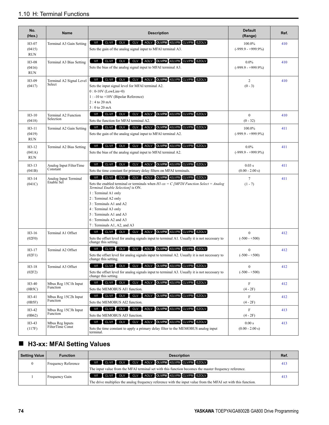
|E2-01 (E4-01)|Motor Rated Current (FLA)|A|77.2|105|105|131|131|160|160|190| |E2-02 (E4-02)|Motor Rated Slip|Hz|1.7|1.8|1.8|1.33|1.33|1.6|1.6|1.43|
|No. *1|Name|Unit|Default|Default|Default|Default|Default|Default|Default|Default| |---|---|---|---|---|---|---|---|---|---|---| |-|Drive Model|-|2110|2110|2138|2138|2169|2169|2211|2211| |C6-01|Normal / Heavy Duty Selection|-|HD|ND|HD|ND|HD|ND|HD|ND| |C6-01|Normal / Heavy Duty Selection|-|0|1|0|1|0|1|0|1| |o2-04|Drive Model (KVA) Selection|Hex.|70|70|72|72|73|73|74|74| |E2-11 (E4-11, E502)|Motor Rated Power|HP (kW)|30 (22)|40 (30)|40 (30)|50 (37)|50 (37)|60 (45)|60 (45)|75 (55)| |E2-03 (E4-03)|Motor NoLoad Current|A|18.5|21.9|21.9|38.2|38.2|44|44|45.6| |E2-05 (E4-05)|Motor Line-toLine Resistance|Ω|0.079|0.064|0.064|0.039|0.039|0.03|0.03|0.022| |E2-06 (E4-06)|Motor Leakage Inductance|%|19.5|20.8|20.8|18.8|18.8|20.2|20.2|20.5| |E2-10 (E4-10)|Motor Iron Loss|W|538|699|699|823|823|852|852|960| |E5-01|PM Motor Code Selection|-|FFFF|FFFF|FFFF|FFFF|FFFF|FFFF|FFFF|FFFF| |L2-02|Power Loss Ride Through Time|s|2|2|2|2|2|2|2|2| |L2-03|Minimum Baseblock Time|s|1|1.1|1.1|1.1|1.1|1.2|1.2|1.3| |L2-04|Powerloss V/f Recovery Ramp Time|s|0.6|0.6|0.6|0.6|0.6|1|1|1| |L2-05|Undervoltage Detection Lvl (Uv1)|-|190|190|190|190|190|190|190|190| |L3-24|Motor Accel Time for Inertia Cal|s|0.355|0.323|0.323|0.32|0.32|0.387|0.387|0.317| |L8-02|Overheat Alarm Level|°C|105|105|115|115|105|105|105|105| |L8-09|Output Ground Fault Detection|-|1|1|1|1|1|1|1|1| |L8-38|Carrier Frequency Reduction|-|2|2|2|2|2|2|2|2| |n1-01|Hunting Prevention Selection|-|2|2|2|2|2|2|2|2| |n1-03|Hunting Prevention Time Constant|ms|10|10|10|10|10|10|10|10| |n5-02|Motor Inertia Acceleration Time|s|0.355|0.323|0.323|0.32|0.32|0.387|0.387|0.317|
################## *1 Parameters within parentheses are for motor 2.
|No.|Name|Unit|Default|Default|Default|Default|Default|Default|Default|Default| |---|---|---|---|---|---|---|---|---|---|---| |-|Drive Model|-|2257|2257|2313|2313|2360|2360|2415|2415| |C6-01|Normal / Heavy Duty Selection|-|HD|ND|HD|ND|HD|ND|HD|ND| |C6-01|Normal / Heavy Duty Selection|-|0|1|0|1|0|1|0|1| |o2-04|Drive Model (KVA) Selection|Hex.|75|75|76|76|77|77|78|78| |E2-11 (E4-11, E502)|Motor Rated Power|HP (kW)|75 (55)|100 (75)|100 (75)|125 (90)|125 (90)|150 (110)|150 (110)|150 (110)| |b3-04|V/f Gain during Speed Search|%|80|80|80|80|80|80|80|80| |b3-06|Speed Estimation Current Level 1|-|0.5|0.7|0.7|0.7|0.7|0.7|0.7|0.7| |b3-08|Speed Estimation ACR P Gain|-|0.5|0.5|0.5|0.5|0.5|0.5|0.5|0.5| |b3-26|Direction Determination Level|-|1000|1000|1000|1000|1000|1000|1000|1000|
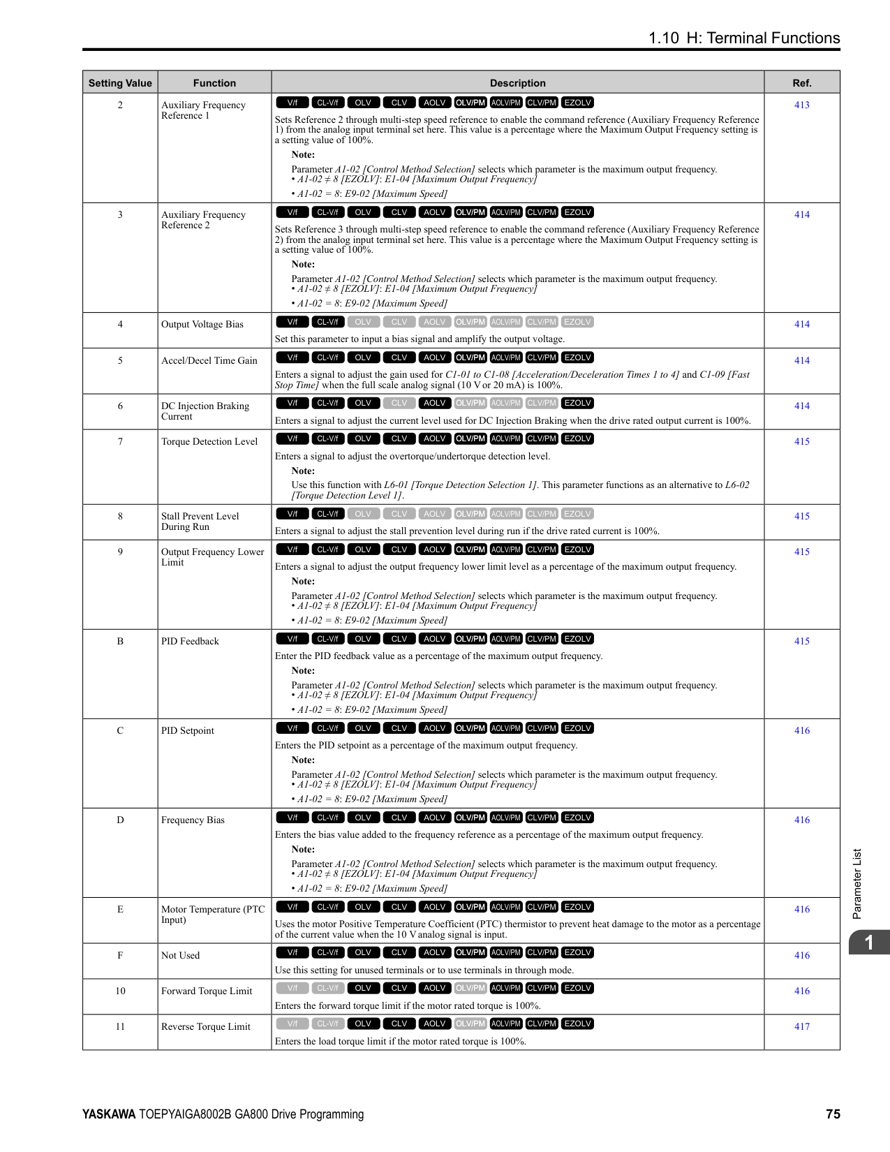
|b8-03|Energy Saving Filter Time|s|2.00|2.00|2.00|2.00|2.00|2.00|2.00|2.00| |b8-04|Energy Saving Coefficient Value|-|31.35|23.1|23.1|20.65|20.65|18.12|18.12|18.12| |C5-17 (C5-37)|Motor Inertia|kgm2|0.49|0.90|0.90|1.10|1.10|1.90|1.90|1.90| |C6-02|Carrier Frequency Selection|-|1|7|1|7|1|7|1|7| |E2-01 (E4-01)|Motor Rated Current (FLA)|A|190|260|260|260|260|260|260|260| |E2-02 (E4-02)|Motor Rated Slip|Hz|1.43|1.39|1.39|1.39|1.39|1.39|1.39|1.39| |E2-03 (E4-03)|Motor NoLoad Current|A|45.6|72|72|72|72|72|72|72| |E2-05 (E4-05)|Motor Line-toLine Resistance|Ω|0.022|0.023|0.023|0.023|0.023|0.023|0.023|0.023| |E2-06 (E4-06)|Motor Leakage Inductance|%|20.5|20|20|20|20|20|20|20| |E2-10 (E4-10)|Motor Iron Loss|W|960|1200|1200|1200|1200|1200|1200|1200| |E5-01|PM Motor Code Selection|-|FFFF|FFFF|FFFF|FFFF|FFFF|FFFF|FFFF|FFFF| |L2-02|Power Loss Ride Through Time|s|2|2|2|2|2|2|2|2| |L2-03|Minimum Baseblock Time|s|1.3|1.5|1.5|1.5|1.5|1.7|1.7|1.7| |L2-04|Powerloss V/f Recovery Ramp Time|s|1|1|1|1|1|1|1|1| |L2-05|Undervoltage Detection Lvl (Uv1)|-|190|190|190|190|190|190|190|190| |L3-24|Motor Accel Time for Inertia Cal|s|0.317|0.533|0.533|0.592|0.592|0.646|0.646|0.646| |L8-02|Overheat Alarm Level|°C|105|105|105|105|105|105|105|105|
|No.|Name|Unit|Default|Default|Default|Default|Default|Default|Default|Default| |---|---|---|---|---|---|---|---|---|---|---| |-|Drive Model|-|2257|2257|2313|2313|2360|2360|2415|2415| |C6-01|Normal / Heavy Duty Selection|-|HD|ND|HD|ND|HD|ND|HD|ND| |C6-01|Normal / Heavy Duty Selection|-|0|1|0|1|0|1|0|1| |o2-04|Drive Model (KVA) Selection|Hex.|75|75|76|76|77|77|78|78| |E2-11 (E4-11, E502)|Motor Rated Power|HP (kW)|75 (55)|100 (75)|100 (75)|125 (90)|125 (90)|150 (110)|150 (110)|150 (110)| |L8-09|Output Ground Fault Detection|-|1|1|1|1|1|1|1|1| |L8-38|Carrier Frequency Reduction|-|2|2|2|2|2|2|2|2| |n1-01|Hunting Prevention Selection|-|2|2|2|2|2|2|2|2| |n1-03|Hunting Prevention Time Constant|ms|10|10|10|10|100|100|100|100| |n5-02|Motor Inertia Acceleration Time|s|0.317|0.533|0.533|0.592|0.592|0.646|0.646|0.646|
######## ◆ 400 V Class
|No.|Name|Unit|Default|Default|Default|Default|Default|Default|Default|Default| |---|---|---|---|---|---|---|---|---|---|---| |-|Drive Model|-|4002|4002|4004|4004|4005|4005|4007|4007| |C6-01|Normal / Heavy Duty Selection|-|HD|ND|HD|ND|HD|ND|HD|ND|
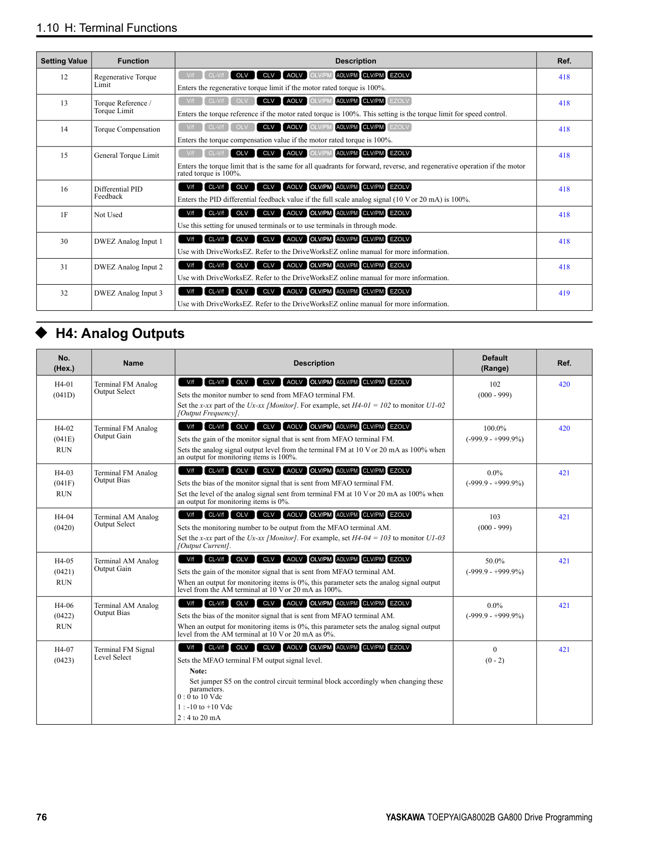
|C6-01|Normal / Heavy Duty Selection|-|0|1|0|1|0|1|0|1| |o2-04|Drive Model (KVA) Selection|Hex.|92|92|93|93|94|94|95|95| |E2-11 (E4-11, E502)|Motor Rated Power|HP (kW)|0.75 (0.4)|1 (0.75)|1.5 (1.1)|2 (1.5)|2 (1.5)|3 (2.2)|3 (2.2)|4 (3.0)| |b3-04|V/f Gain during Speed Search|%|100|100|100|100|100|100|100|100| |b3-06|Speed Estimation Current Level 1|-|0.5|0.5|0.5|0.5|0.5|0.5|0.5|0.5| |b3-08|Speed Estimation ACR P Gain|-|0.5|0.5|0.5|0.5|0.5|0.5|0.5|0.5| |b3-26|Direction Determination Level|-|1000|1000|1000|1000|1000|1000|1000|1000| |b8-03|Energy Saving Filter Time|s|0.50|0.50|0.50|0.50|0.50|0.50|0.50|0.50| |b8-04|Energy Saving Coefficient Value|-|576.4|447.4|447.4|338.8|338.8|313.6|313.6|265.7| |C5-17 (C5-37)|Motor Inertia|kgm2|0.0015|0.0028|0.0028|0.0068|0.0068|0.0088|0.0088|0.0158| |C6-02|Carrier Frequency Selection|-|1|7|1|7|1|7|1|7| |E2-01 (E4-01)|Motor Rated Current (FLA)|A|1|1.6|1.6|3.1|3.1|4.2|4.2|5.7|
|No.|Name|Unit|Default|Default|Default|Default|Default|Default|Default|Default| |---|---|---|---|---|---|---|---|---|---|---| |-|Drive Model|-|4002|4002|4004|4004|4005|4005|4007|4007| |C6-01|Normal / Heavy Duty Selection|-|HD|ND|HD|ND|HD|ND|HD|ND| |C6-01|Normal / Heavy Duty Selection|-|0|1|0|1|0|1|0|1| |o2-04|Drive Model (KVA) Selection|Hex.|92|92|93|93|94|94|95|95| |E2-11 (E4-11, E502)|Motor Rated Power|HP (kW)|0.75 (0.4)|1 (0.75)|1.5 (1.1)|2 (1.5)|2 (1.5)|3 (2.2)|3 (2.2)|4 (3.0)| |E2-02 (E4-02)|Motor Rated Slip|Hz|2.9|2.6|2.6|2.5|2.5|3|3|2.7| |E2-03 (E4-03)|Motor NoLoad Current|A|0.6|0.8|0.8|1.4|1.4|1.5|1.5|1.9| |E2-05 (E4-05)|Motor Line-toLine Resistance|Ω|38.198|22.459|22.459|10.1|10.1|6.495|6.495|4.360| |E2-06 (E4-06)|Motor Leakage Inductance|%|18.2|14.3|14.3|18.3|18.3|18.7|18.7|19| |E2-10 (E4-10)|Motor Iron Loss|W|14|26|26|53|53|77|77|105| |E5-01|PM Motor Code Selection|-|FFFF|FFFF|FFFF|FFFF|FFFF|FFFF|FFFF|FFFF| |L2-02|Power Loss Ride Through Time|s|0.1|0.1|0.2|0.2|0.3|0.3|0.5|0.5| |L2-03|Minimum Baseblock Time|s|0.2|0.3|0.3|0.4|0.4|0.5|0.5|0.5| |L2-04|Powerloss V/f Recovery Ramp Time|s|0.3|0.3|0.3|0.3|0.3|0.3|0.3|0.3| |L2-05|Undervoltage Detection Lvl (Uv1)|-|380|380|380|380|380|380|380|380| |L3-24|Motor Accel Time for Inertia Cal|s|0.178|0.142|0.142|0.166|0.166|0.145|0.145|0.145| |L8-02|Overheat Alarm Level|°C|100|100|105|105|112|112|100|100| |L8-09|Output Ground Fault Detection|-|1|1|1|1|1|1|1|1| |L8-38|Carrier Frequency Reduction|-|2|2|2|2|2|2|2|2| |n1-01|Hunting Prevention Selection|-|1|1|1|1|1|1|1|1| |n1-03|Hunting Prevention Time Constant|ms|10|10|10|10|10|10|10|10| |n5-02|Motor Inertia Acceleration Time|s|0.178|0.142|0.142|0.166|0.166|0.145|0.145|0.145|
ParameterList
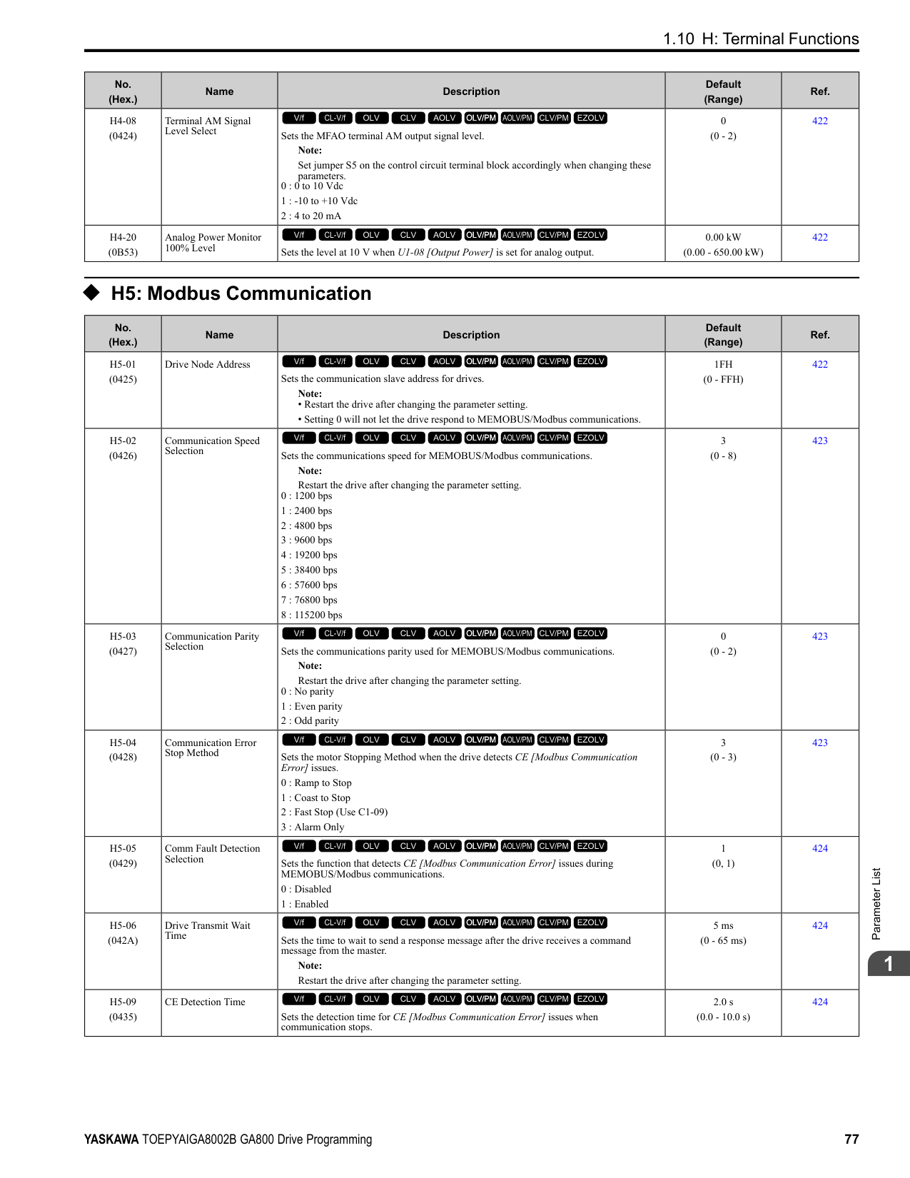
|No.|Name|Unit|Default|Default|Default|Default|Default|Default|Default|Default| |---|---|---|---|---|---|---|---|---|---|---| |-|Drive Model|-|4009|4009|4012|4012|4018|4018|4023|4023| |C6-01|Normal / Heavy Duty Selection|-|HD|ND|HD|ND|HD|ND|HD|ND| |C6-01|Normal / Heavy Duty Selection|-|0|1|0|1|0|1|0|1| |o2-04|Drive Model (KVA) Selection|Hex.|96|96|97|97|99|99|9A|9A| |E2-11 (E4-11, E502)|Motor Rated Power|HP (kW)|4 (3.0)|5 (4.0)|5 (4.0)|7.5 (5.5)|7.5 (5.5)|10 (7.5)|10 (7.5)|15 (11)| |b3-04|V/f Gain during Speed Search|%|100|100|100|100|100|100|100|100| |b3-06|Speed Estimation Current Level 1|-|0.5|0.5|0.5|0.5|0.5|0.5|0.5|0.5| |b3-08|Speed Estimation ACR P Gain|-|0.5|0.5|0.5|0.5|0.5|0.5|0.5|0.5| |b3-26|Direction Determination Level|-|1000|1000|1000|1000|1000|1000|1000|1000| |b8-03|Energy Saving Filter Time|s|0.50|0.50|0.50|0.50|0.50|0.50|0.50|0.50| |b8-04|Energy Saving Coefficient Value|-|265.7|245.8|245.8|189.5|189.5|145.38|145.38|140.88| |C5-17 (C5-37)|Motor Inertia|kgm2|0.0158|0.0158|0.0158|0.0255|0.026|0.037|0.037|0.053| |C6-02|Carrier Frequency Selection|-|1|7|1|7|1|7|1|7| |E2-01 (E4-01)|Motor Rated Current (FLA)|A|5.7|7|7|9.8|9.8|13.3|13.3|19.9| |E2-02 (E4-02)|Motor Rated Slip|Hz|2.7|2.7|2.7|1.5|1.5|1.3|1.3|1.7| |E2-03 (E4-03)|Motor NoLoad Current|A|1.9|2.3|2.3|2.6|2.6|4|4|5.6| |E2-05 (E4-05)|Motor Line-toLine Resistance|Ω|4.360|3.333|3.333|1.595|1.595|1.152|1.152|0.922| |E2-06 (E4-06)|Motor Leakage Inductance|%|19|19.3|19.3|18.2|18.2|15.5|15.5|19.6| |E2-10 (E4-10)|Motor Iron Loss|W|105|130|130|193|193|263|263|385| |E5-01|PM Motor Code Selection|-|FFFF|FFFF|FFFF|FFFF|FFFF|FFFF|FFFF|FFFF| |L2-02|Power Loss Ride Through Time|s|0.5|0.5|0.5|0.5|0.8|0.8|1|1| |L2-03|Minimum Baseblock Time|s|0.5|0.6|0.6|0.7|0.7|0.8|0.8|0.9| |L2-04|Powerloss V/f Recovery Ramp Time|s|0.3|0.3|0.3|0.3|0.3|0.3|0.3|0.3| |L2-05|Undervoltage Detection Lvl (Uv1)|-|380|380|380|380|380|380|380|380| |L3-24|Motor Accel Time for Inertia Cal|s|0.145|0.154|0.154|0.168|0.168|0.175|0.175|0.265| |L8-02|Overheat Alarm Level|°C|100|100|100|100|105|105|105|105|
|No.|Name|Unit|Default|Default|Default|Default|Default|Default|Default|Default| |---|---|---|---|---|---|---|---|---|---|---| |-|Drive Model|-|4009|4009|4012|4012|4018|4018|4023|4023| |C6-01|Normal / Heavy Duty Selection|-|HD|ND|HD|ND|HD|ND|HD|ND| |C6-01|Normal / Heavy Duty Selection|-|0|1|0|1|0|1|0|1| |o2-04|Drive Model (KVA) Selection|Hex.|96|96|97|97|99|99|9A|9A| |E2-11 (E4-11, E502)|Motor Rated Power|HP (kW)|4 (3.0)|5 (4.0)|5 (4.0)|7.5 (5.5)|7.5 (5.5)|10 (7.5)|10 (7.5)|15 (11)| |L8-09|Output Ground Fault Detection|-|1|1|1|1|1|1|1|1| |L8-38|Carrier Frequency Reduction|-|2|2|2|2|2|2|2|2|
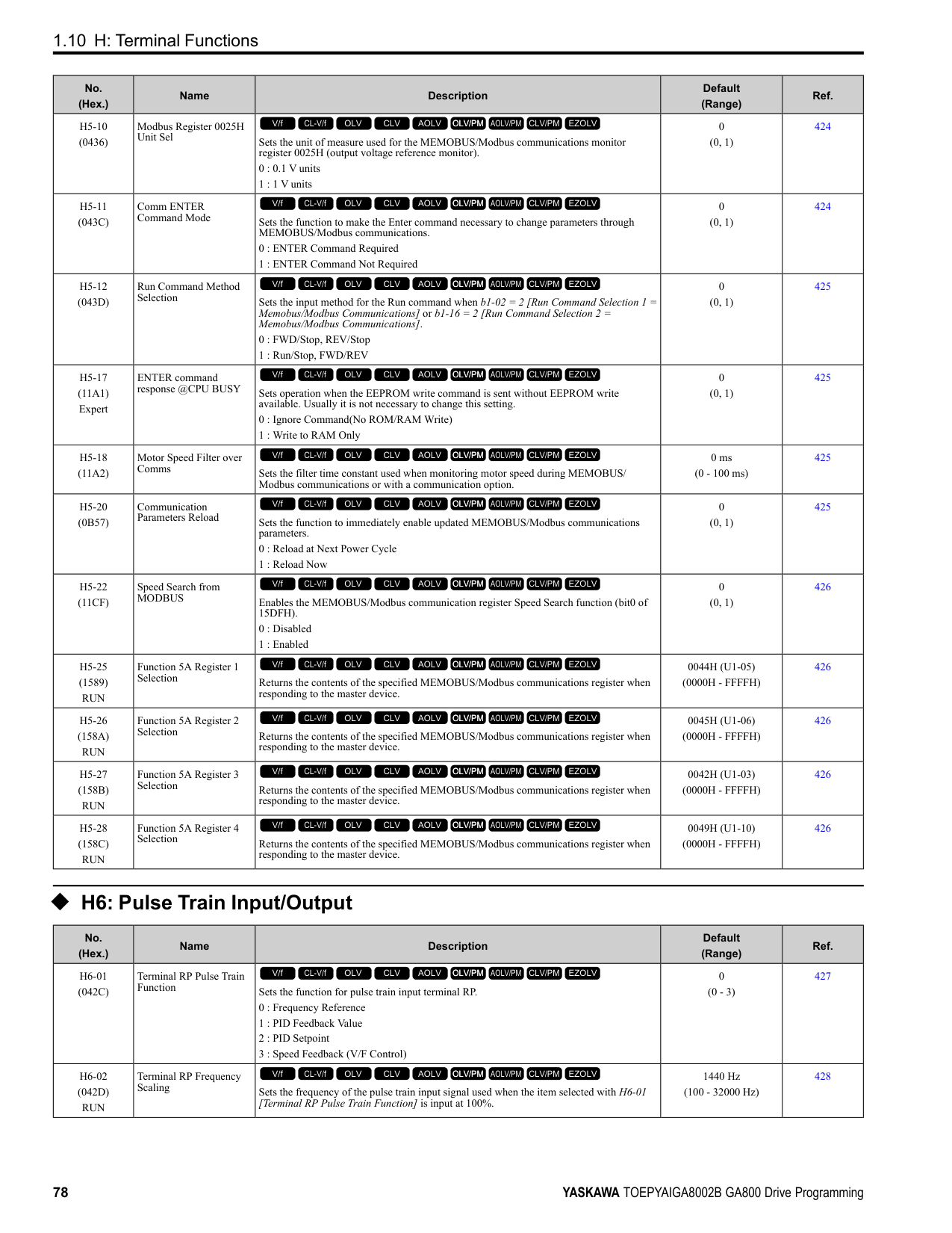
|n1-01|Hunting Prevention Selection|-|1|1|1|1|1|1|1|1| |n1-03|Hunting Prevention Time Constant|ms|10|10|10|10|10|10|10|10| |n5-02|Motor Inertia Acceleration Time|s|0.145|0.154|0.154|0.168|0.168|0.175|0.175|0.265|
################## *1 Parameters within parentheses are for motor 2.
|No.|Name|Unit|Default|Default|Default|Default|Default|Default|Default|Default| |---|---|---|---|---|---|---|---|---|---|---| |-|Drive Model|-|4031|4031|4038|4038|4044|4044|4060|4060| |C6-01|Normal / Heavy Duty Selection|-|HD|ND|HD|ND|HD|ND|HD|ND| |C6-01|Normal / Heavy Duty Selection|-|0|1|0|1|0|1|0|1| |o2-04|Drive Model (KVA) Selection|Hex.|9C|9C|9D|9D|9E|9E| | | |E2-11 (E4-11, E502)|Motor Rated Power|HP (kW)|15 (11)|20 (15)|20 (15)|25 (18.5)|25 (18.5)|30 (22)|30 (22)|40 (30)| |b3-04|V/f Gain during Speed Search|%|100|100|100|100|100|100|100|100| |b3-06|Speed Estimation Current Level 1|-|0.5|0.5|0.5|0.5|0.5|0.5|0.5|0.5| |b3-08|Speed Estimation ACR P Gain|-|0.5|0.5|0.5|0.5|0.5|0.5|0.5|0.5| |b3-26|Direction Determination Level|-|1000|1000|1000|1000|1000|1000|1000|1000| |b8-03|Energy Saving Filter Time|s|0.50|0.50|0.50|0.50|0.50|0.50|0.50|0.50| |b8-04|Energy Saving Coefficient Value|-|140.88|126.26|126.26|115.74|115.74|103.58|103.58|92.54| |C5-17 (C5-37)|Motor Inertia|kgm2|0.053|0.076|0.076|0.138|0.138|0.165|0.165|0.220| |C6-02|Carrier Frequency Selection|-|1|7|1|7|1|7|1|7| |E2-01 (E4-01)|Motor Rated Current (FLA)|A|19.9|26.5|26.5|32.9|32.9|38.6|38.6|52.3| |E2-02 (E4-02)|Motor Rated Slip|Hz|1.7|1.6|1.6|1.67|1.67|1.7|1.7|1.8|
|No.|Name|Unit|Default|Default|Default|Default|Default|Default|Default|Default| |---|---|---|---|---|---|---|---|---|---|---| |-|Drive Model|-|4031|4031|4038|4038|4044|4044|4060|4060| |C6-01|Normal / Heavy Duty Selection|-|HD|ND|HD|ND|HD|ND|HD|ND| |C6-01|Normal / Heavy Duty Selection|-|0|1|0|1|0|1|0|1| |o2-04|Drive Model (KVA) Selection|Hex.|9C|9C|9D|9D|9E|9E| | | |E2-11 (E4-11, E502)|Motor Rated Power|HP (kW)|15 (11)|20 (15)|20 (15)|25 (18.5)|25 (18.5)|30 (22)|30 (22)|40 (30)| |E2-03 (E4-03)|Motor NoLoad Current|A|5.6|7.6|7.6|7.8|7.8|9.2|9.2|10.9| |E2-05 (E4-05)|Motor Line-toLine Resistance|Ω|0.922|0.55|0.55|0.403|0.403|0.316|0.316|0.269| |E2-06 (E4-06)|Motor Leakage Inductance|%|19.6|17.2|17.2|20.1|20.1|23.5|23.5|20.7| |E2-10 (E4-10)|Motor Iron Loss|W|385|440|440|508|508|586|586|750| |E5-01|PM Motor Code Selection|-|FFFF|FFFF|FFFF|FFFF|FFFF|FFFF|FFFF|FFFF| |L2-02|Power Loss Ride Through Time|s|2|2|2|2|2|2|2|2| |L2-03|Minimum Baseblock Time|s|0.9|1|1|1|1|1|1|1.1| |L2-04|Powerloss V/f Recovery Ramp Time|s|0.3|0.6|0.6|0.6|0.6|0.6|0.6|0.6| |L2-05|Undervoltage Detection Lvl (Uv1)|-|380|380|380|380|380|380|380|380|
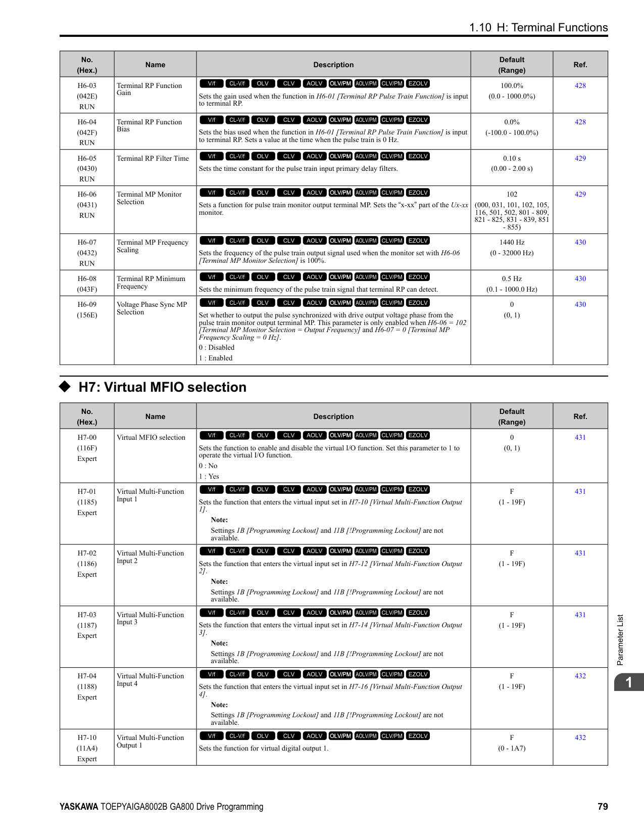
|L3-24|Motor Accel Time for Inertia Cal|s|0.265|0.244|0.244|0.317|0.317|0.355|0.355|0.323| |L8-02|Overheat Alarm Level|°C|115|115|120|120|120|120|130|137| |L8-09|Output Ground Fault Detection|-|1|1|1|1|1|1|1|1| |L8-38|Carrier Frequency Reduction|-|2|2|2|2|2|2|2|2| |n1-01|Hunting Prevention Selection|-|2|2|2|2|2|2|2|2| |n1-03|Hunting Prevention Time Constant|ms|10|10|10|10|10|10|10|10| |n5-02|Motor Inertia Acceleration Time|s|0.265|0.244|0.244|0.317|0.317|0.355|0.355|0.323|
################## *1 Parameters within parentheses are for motor 2.
|No.|Name|Unit|Default|Default|Default|Default|Default|Default|Default|Default| |---|---|---|---|---|---|---|---|---|---|---| |-|Drive Model|-|4075|4075|4089|4089|4103|4103|4140|4140| |C6-01|Normal / Heavy Duty Selection|-|HD|ND|HD|ND|HD|ND|HD|ND| |C6-01|Normal / Heavy Duty Selection|-|0|1|0|1|0|1|0|1| |o2-04|Drive Model (KVA) Selection|Hex.|A1|A1|A2|A2|A3|A3|A4|A4| |E2-11 (E4-11, E502)|Motor Rated Power|HP (kW)|40 (30)|50 (37)|50 (37)|60 (45)|60 (45)|75 (55)|75 (55)|100 (75)| |b3-04|V/f Gain during Speed Search|%|100|100|100|100|100|80|80|60| |b3-06|Speed Estimation Current Level 1|-|0.5|0.5|0.5|0.5|0.5|0.5|0.5|0.7| |b3-08|Speed Estimation ACR P Gain|-|0.5|0.5|0.5|0.5|0.5|0.5|0.5|0.8| |b3-26|Direction Determination Level|-|1000|1000|1000|1000|1000|1000|1000|1000| |b8-03|Energy Saving Filter Time|s|0.50|0.50|0.50|0.50|0.50|2.00|2.00|2.00| |b8-04|Energy Saving Coefficient Value|-|92.54|76.32|76.32|71.56|71.56|67.2|67.2|46.2| |C5-17 (C5-37)|Motor Inertia|kgm2|0.220|0.273|0.273|0.333|0.333|0.490|0.49|0.90| |C6-02|Carrier Frequency Selection|-|1|7|1|7|1|7|1|7| |E2-01 (E4-01)|Motor Rated Current (FLA)|A|52.3|65.6|65.6|79.7|79.7|95|95|130| |E2-02 (E4-02)|Motor Rated Slip|Hz|1.8|1.33|1.33|1.6|1.6|1.46|1.46|1.39| |E2-03 (E4-03)|Motor NoLoad Current|A|10.9|19.1|19.1|22|22|24|24|36| |E2-05 (E4-05)|Motor Line-toLine Resistance|Ω|0.269|0.155|0.155|0.122|0.122|0.088|0.088|0.092| |E2-06 (E4-06)|Motor Leakage Inductance|%|20.7|18.8|18.8|19.9|19.9|20|20|20| |E2-10 (E4-10)|Motor Iron Loss|W|750|925|925|1125|1125|1260|1260|1600| |E5-01|PM Motor Code Selection|-|FFFF|FFFF|FFFF|FFFF|FFFF|FFFF|FFFF|FFFF| |L2-02|Power Loss Ride Through Time|s|2|2|2|2|2|2|2|2| |L2-03|Minimum Baseblock Time|s|1.1|1.1|1.1|1.2|1.2|1.2|1.2|1.3| |L2-04|Powerloss V/f Recovery Ramp Time|s|0.6|0.6|0.6|0.6|0.6|1|1|1| |L2-05|Undervoltage Detection Lvl (Uv1)|-|380|380|380|380|380|380|380|380| |L3-24|Motor Accel Time for Inertia Cal|s|0.323|0.32|0.32|0.387|0.387|0.317|0.317|0.533| |L8-02|Overheat Alarm Level|°C|120|120|115|115|126|120|120|120|
|No.|Name|Unit|Default|Default|Default|Default|Default|Default|Default|Default|
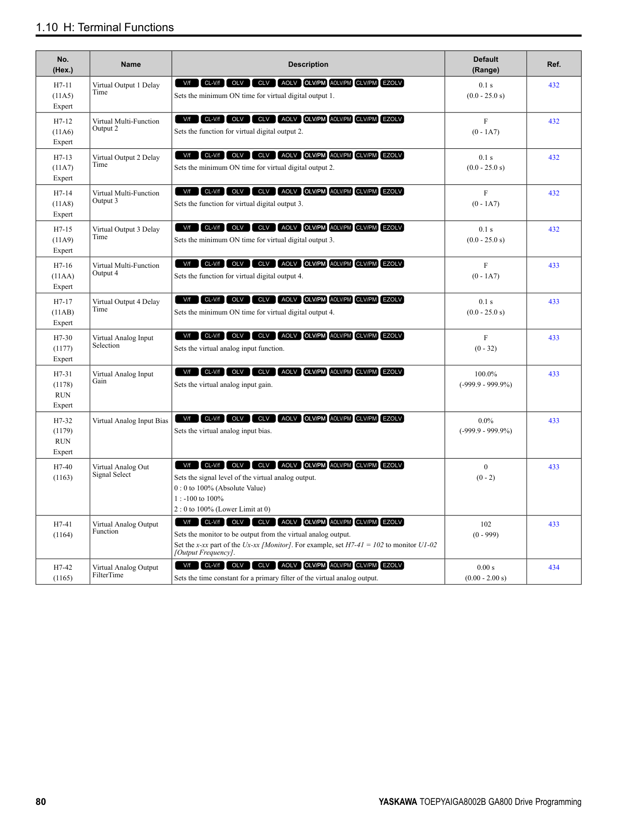
|---|---|---|---|---|---|---|---|---|---|---| |-|Drive Model|-|4075|4075|4089|4089|4103|4103|4140|4140| |C6-01|Normal / Heavy Duty Selection|-|HD|ND|HD|ND|HD|ND|HD|ND| |C6-01|Normal / Heavy Duty Selection|-|0|1|0|1|0|1|0|1| |o2-04|Drive Model (KVA) Selection|Hex.|A1|A1|A2|A2|A3|A3|A4|A4| |E2-11 (E4-11, E502)|Motor Rated Power|HP (kW)|40 (30)|50 (37)|50 (37)|60 (45)|60 (45)|75 (55)|75 (55)|100 (75)| |L8-09|Output Ground Fault Detection|-|1|1|1|1|1|1|1|1| |L8-38|Carrier Frequency Reduction|-|2|2|2|2|2|2|2|2| |n1-01|Hunting Prevention Selection|-|2|2|2|2|2|2|2|2| |n1-03|Hunting Prevention Time Constant|ms|10|10|10|10|10|10|30|30| |n5-02|Motor Inertia Acceleration Time|s|0.323|0.32|0.32|0.387|0.387|0.317|0.317|0.533|
################## *1 Parameters within parentheses are for motor 2.
|No.|Name|Unit|Default|Default|Default|Default|Default|Default|Default|Default| |---|---|---|---|---|---|---|---|---|---|---| |-|Drive Model|-|4168|4168|4208|4208|4250|4250|4302|4302| |C6-01|Normal / Heavy Duty Selection|-|HD|ND|HD|ND|HD|ND|HD|ND| |C6-01|Normal / Heavy Duty Selection|-|0|1|0|1|0|1|0|1| |o2-04|Drive Model (KVA) Selection|Hex.|A5|A5|A6|A6|A7|A7|A8|A8| |E2-11 (E4-11, E502)|Motor Rated Power|HP (kW)|100 (75)|125 (90)|125 (90)|150 (110)|150 (110)|175 (132)|175 (132)|200 (160)| |b3-04|V/f Gain during Speed Search|%|60|60|60|60|60|60|60|60| |b3-06|Speed Estimation Current Level 1|-|0.7|0.7|0.7|0.7|0.7|0.7|0.7|0.7| |b3-08|Speed Estimation ACR P Gain|-|0.8|0.8|0.8|0.8|0.8|0.8|0.8|0.8| |b3-26|Direction Determination Level|-|1000|1000|1000|1000|1000|1000|1000|1000| |b8-03|Energy Saving Filter Time|s|2.00|2.00|2.00|2.00|2.00|2.00|2.00|2.00| |b8-04|Energy Saving Coefficient Value|-|46.2|38.91|38.91|36.23|36.23|32.79|32.79|30.13| |C5-17 (C5-37)|Motor Inertia|kgm2|0.90|1.10|1.10|1.90|1.90|2.10|2.10|3.30| |C6-02|Carrier Frequency Selection|-|1|7|1|7|1|7|1|7| |E2-01 (E4-01)|Motor Rated Current (FLA)|A|130|156|156|190|190|223|223|270| |E2-02 (E4-02)|Motor Rated Slip|Hz|1.39|1.4|1.4|1.4|1.4|1.38|1.38|1.35|
|No.|Name|Unit|Default|Default|Default|Default|Default|Default|Default|Default| |---|---|---|---|---|---|---|---|---|---|---| |-|Drive Model|-|4168|4168|4208|4208|4250|4250|4302|4302| |C6-01|Normal / Heavy Duty Selection|-|HD|ND|HD|ND|HD|ND|HD|ND| |C6-01|Normal / Heavy Duty Selection|-|0|1|0|1|0|1|0|1| |o2-04|Drive Model (KVA) Selection|Hex.|A5|A5|A6|A6|A7|A7|A8|A8| |E2-11 (E4-11, E502)|Motor Rated Power|HP (kW)|100 (75)|125 (90)|125 (90)|150 (110)|150 (110)|175 (132)|175 (132)|200 (160)| |E2-03 (E4-03)|Motor NoLoad Current|A|36|40|40|49|49|58|58|70|
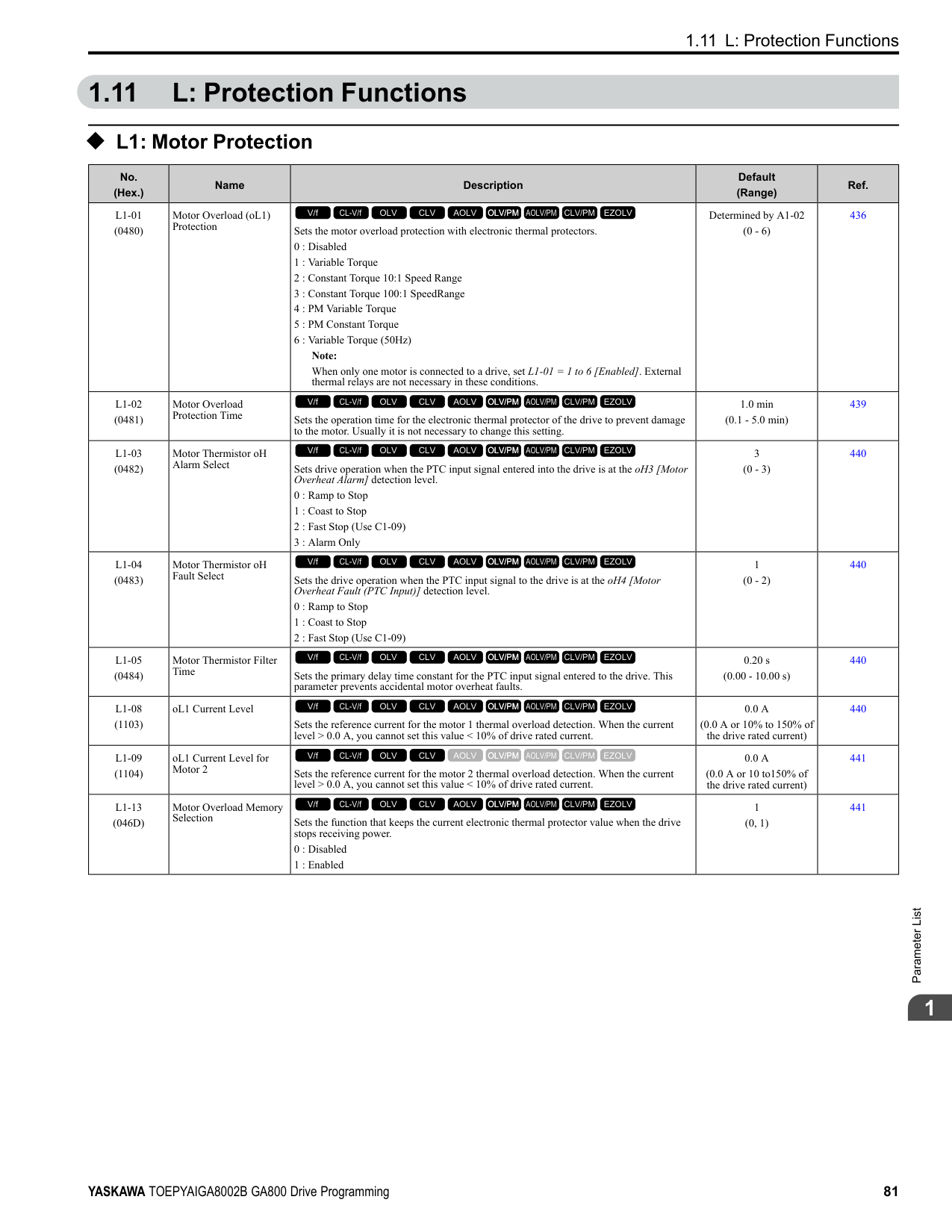
|E2-05 (E4-05)|Motor Line-toLine Resistance|Ω|0.092|0.056|0.056|0.046|0.046|0.035|0.035|0.029| |E2-06 (E4-06)|Motor Leakage Inductance|%|20|20|20|20|20|20|20|20| |E2-10 (E4-10)|Motor Iron Loss|W|1600|1760|1760|2150|2150|2350|2350|2850| |E5-01|PM Motor Code Selection|-|FFFF|FFFF|FFFF|FFFF|FFFF|FFFF|FFFF|FFFF| |L2-02|Power Loss Ride Through Time|s|2|2|2|2|2|2|2|2| |L2-03|Minimum Baseblock Time|s|1.3|1.5|1.5|1.7|1.7|1.7|1.7|1.8| |L2-04|Powerloss V/f Recovery Ramp Time|s|1|1|1|1|1|1|1|1| |L2-05|Undervoltage Detection Lvl (Uv1)|-|380|380|380|380|380|380|380|380| |L3-24|Motor Accel Time for Inertia Cal|s|0.533|0.592|0.592|0.646|0.646|0.673|0.673|0.777| |L8-02|Overheat Alarm Level|°C|110|110|105|105|120|120|120|120| |L8-09|Output Ground Fault Detection|-|1|1|1|1|1|1|1|1| |L8-38|Carrier Frequency Reduction|-|2|2|2|2|2|2|2|2| |n1-01|Hunting Prevention Selection|-|2|2|2|2|2|2|2|2| |n1-03|Hunting Prevention Time Constant|ms|30|30|30|30|30|30|30|30| |n5-02|Motor Inertia Acceleration Time|s|0.533|0.592|0.592|0.646|0.646|0.673|0.673|0.777|
*1 Parameters within parentheses are for motor 2.
ParameterList
|No.|Name|Unit|Default|Default|Default|Default|Default|Default|Default|Default| |---|---|---|---|---|---|---|---|---|---|---| |-|Drive Model|-|4371|4371|4414|4414|4477|4477|4568|4568| |C6-01|Normal / Heavy Duty Selection|-|HD|ND|HD|ND|HD|ND|HD|ND| |C6-01|Normal / Heavy Duty Selection|-|0|1|0|1|0|1|0|1| |o2-04|Drive Model (KVA) Selection|Hex.|A9|A9|AA|AA|AC|AC|AD|AD| |E2-11 (E4-11, E502)|Motor Rated Power|HP (kW)|200 (160)|250 (200)|250 (200)|300 (220)|300 (220)|335 (250)|335 (250)|400 (315)| |b3-04|V/f Gain during Speed Search|%|60|60|60|60|60|60|60|60| |b3-06|Speed Estimation Current Level 1|-|0.7|0.7|0.7|0.7|0.7|0.7|0.7|0.7| |b3-08|Speed Estimation ACR P Gain|-|0.8|0.8|0.8|0.8|0.8|0.8|0.8|0.8| |b3-26|Direction Determination Level|-|1000|1000|1000|1000|1000|1000|1000|1000| |b8-03|Energy Saving Filter Time|s|2.00|2.00|2.00|2.00|2.00|2.00|2.00|2.00| |b8-04|Energy Saving Coefficient Value|-|30.13|30.57|30.57|27.13|27.13|21.76|21.76|21.76| |C5-17 (C5-37)|Motor Inertia|kgm2|3.30|3.60|3.60|4.10|4.10|6.50|6.50|11.00| |C6-02|Carrier Frequency Selection|-|1|7|1|7|1|7|1|7| |E2-01 (E4-01)|Motor Rated Current (FLA)|A|270|310|310|370|370|500|500|500| |E2-02 (E4-02)|Motor Rated Slip|Hz|1.35|1.3|1.3|1.3|1.3|1.25|1.25|1.25| |E2-03 (E4-03)|Motor NoLoad Current|A|70|81|81|96|96|130|130|130| |E2-05 (E4-05)|Motor Line-toLine Resistance|Ω|0.029|0.025|0.025|0.02|0.02|0.014|0.014|0.014| |E2-06 (E4-06)|Motor Leakage Inductance|%|20|20|20|20|20|20|20|20| |E2-10 (E4-10)|Motor Iron Loss|W|2850|3200|3200|3700|3700|4700|4700|4700|
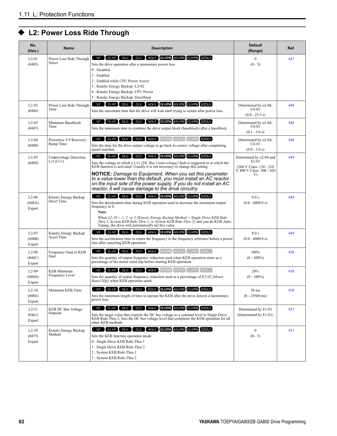
|E5-01|PM Motor Code Selection|-|FFFF|FFFF|FFFF|FFFF|FFFF|FFFF|FFFF|FFFF| |L2-02|Power Loss Ride Through Time|s|2|2|2|2|2|2|2|2| |L2-03|Minimum Baseblock Time|s|1.8|1.9|1.9|2|2|2.1|2.1|2.1| |L2-04|Powerloss V/f Recovery Ramp Time|s|1|1|1.8|1.8|1.8|2|2|2| |L2-05|Undervoltage Detection Lvl (Uv1)|-|380|380|380|380|380|380|380|380| |L3-24|Motor Accel Time for Inertia Cal|s|0.777|0.864|0.864|0.91|0.91|1.392|1.392|1.392| |L8-02|Overheat Alarm Level|°C|125|125|125|125|110|110|125|115|
|No.|Name|Unit|Default|Default|Default|Default|Default|Default|Default|Default| |---|---|---|---|---|---|---|---|---|---|---| |-|Drive Model|-|4371|4371|4414|4414|4477|4477|4568|4568| |C6-01|Normal / Heavy Duty Selection|-|HD|ND|HD|ND|HD|ND|HD|ND| |C6-01|Normal / Heavy Duty Selection|-|0|1|0|1|0|1|0|1| |o2-04|Drive Model (KVA) Selection|Hex.|A9|A9|AA|AA|AC|AC|AD|AD| |E2-11 (E4-11, E502)|Motor Rated Power|HP (kW)|200 (160)|250 (200)|250 (200)|300 (220)|300 (220)|335 (250)|335 (250)|400 (315)| |L8-09|Output Ground Fault Detection|-|1|1|1|1|1|1|1|1| |L8-38|Carrier Frequency Reduction|-|2|2|2|2|2|2|2|2| |n1-01|Hunting Prevention Selection|-|2|2|2|2|2|2|2|2| |n1-03|Hunting Prevention Time Constant|ms|30|30|100|100|100|100|100|100| |n5-02|Motor Inertia Acceleration Time|s|0.777|0.864|0.864|0.91|0.91|1.392|1.392|1.392|
################## *1 Parameters within parentheses are for motor 2.
|No.|Name|Unit|Default|Default|Default|Default| |---|---|---|---|---|---|---| |-|Drive Model|-|4605|4605|4720|4720| |C6-01|Normal / Heavy Duty Selection|-|HD|ND|HD|ND| |C6-01|Normal / Heavy Duty Selection|-|0|1|0|1| |o2-04|Drive Model (KVA) Selection|Hex.|AE|AE|AF|AF| |E2-11 (E4-11, E5-02)|Motor Rated Power|HP (kW)|400 (315)|450 (355)|400 (315)|500 (370)| |b3-04|V/f Gain during Speed Search|%|60|60|60|60| |b3-06|Speed Estimation Current Level 1|-|0.7|0.7|0.7|0.7| |b3-08|Speed Estimation ACR P Gain|-|0.8|0.8|0.8|0.8| |b3-26|Direction Determination Level|-|1000|1000|1000|1000| |b8-03|Energy Saving Filter Time|s|2.00|2.00|2.00|2.00| |b8-04|Energy Saving Coefficient Value|-|21.76|23.84|21.76|23.84| |C5-17 (C5-37)|Motor Inertia|kgm2|11.00|12.00|11.00|12.00| |C6-02|Carrier Frequency Selection|-|1|7|1|7| |E2-01 (E4-01)|Motor Rated Current (FLA)|A|500|650|500|650| |E2-02 (E4-02)|Motor Rated Slip|Hz|1.25|1|1.25|1|
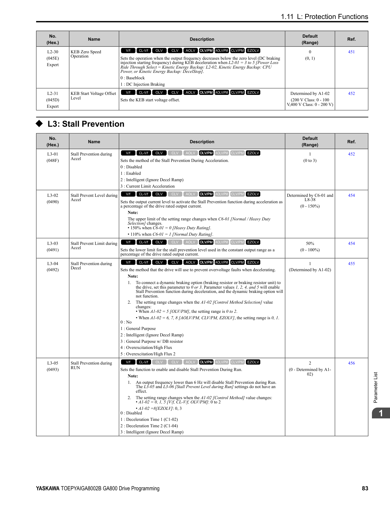
|E2-03 (E4-03)|Motor No-Load Current|A|130|130|130|130| |E2-05 (E4-05)|Motor Line-to-Line Resistance|Ω|0.014|0.012|0.014|0.012|
|No.|Name|Unit|Default|Default|Default|Default| |---|---|---|---|---|---|---| |-|Drive Model|-|4605|4605|4720|4720| |C6-01|Normal / Heavy Duty Selection|-|HD|ND|HD|ND| |C6-01|Normal / Heavy Duty Selection|-|0|1|0|1| |o2-04|Drive Model (KVA) Selection|Hex.|AE|AE|AF|AF| |E2-11 (E4-11, E5-02)|Motor Rated Power|HP (kW)|400 (315)|450 (355)|400 (315)|500 (370)| |E2-06 (E4-06)|Motor Leakage Inductance|%|20|20|20|20| |E2-10 (E4-10)|Motor Iron Loss|W|4700|5560|4700|5560| |E5-01|PM Motor Code Selection|-|FFFF|FFFF|FFFF|FFFF| |L2-02|Power Loss Ride Through Time|s|2|2|2|2| |L2-03|Minimum Baseblock Time|s|2.1|2.3|2.1|2.3| |L2-04|Powerloss V/f Recovery Ramp Time|s|2|2.2|2|2.2| |L2-05|Undervoltage Detection Lvl (Uv1)|-|380|380|380|380| |L3-24|Motor Accel Time for Inertia Cal|s|1.392|1.667|1.392|1.667| |L8-02|Overheat Alarm Level|°C|133|133|125|125| |L8-09|Output Ground Fault Detection|-|1|1|1|1| |L8-38|Carrier Frequency Reduction|-|2|2|2|2| |n1-01|Hunting Prevention Selection|-|2|2|2|2| |n1-03|Hunting Prevention Time Constant|ms|100|100|100|100| |n5-02|Motor Inertia Acceleration Time|s|1.392|1.667|1.392|1.667|
################## *1 Parameters within parentheses are for motor 2.
####### 1.22 Parameters Changed by PM Motor Code Selection
Note: The motor codes listed in these tables are the only correct setting values.
######## ◆ Yaskawa SMRA Series SPM Motors
|No.|Name|Unit|Motor Code (setting value of E5-01)|Motor Code (setting value of E5-01)|Motor Code (setting value of E5-01)|Motor Code (setting value of E5-01)|Motor Code (setting value of E5-01)| |---|---|---|---|---|---|---|---| |E5-01|PM Motor Code Selection|-|0002|0003|0005|0006|0008|
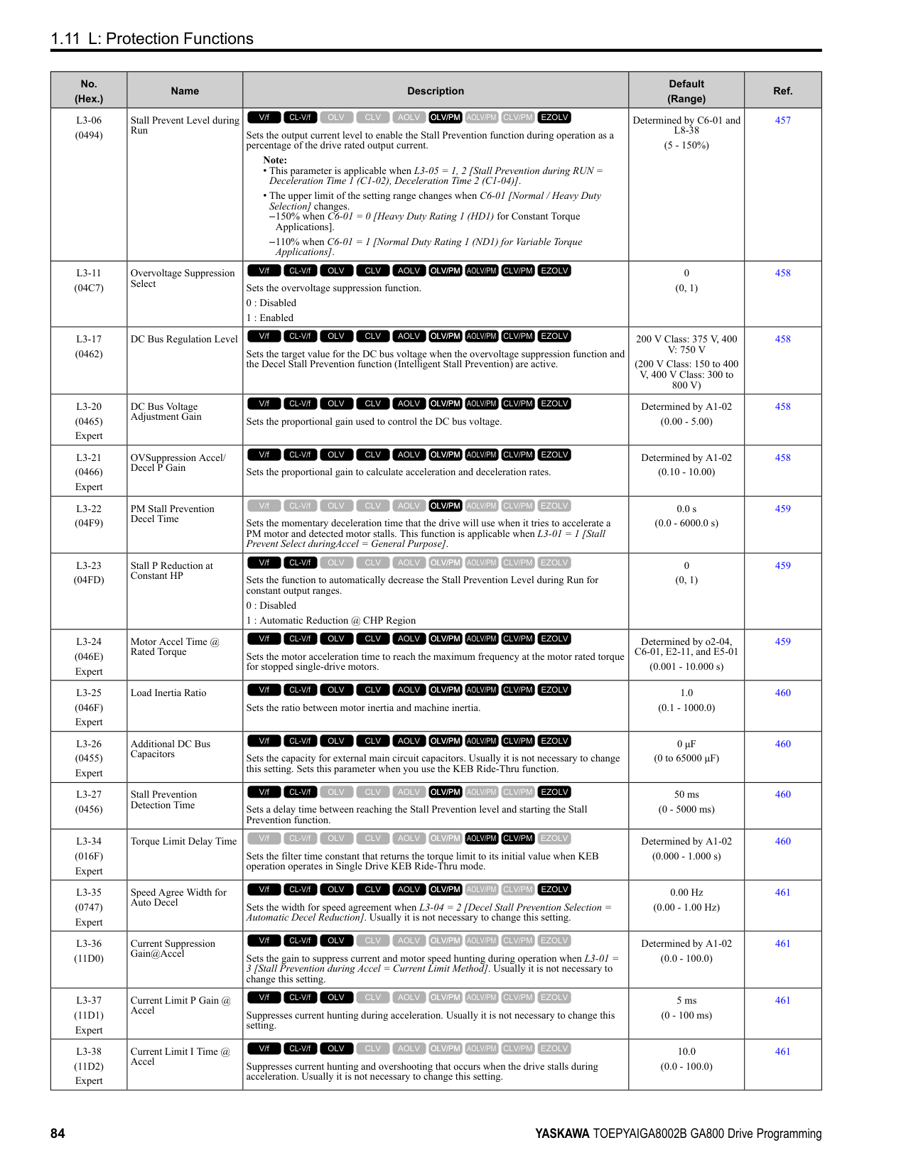
|E5-01|Voltage Class|V|200|200|200|200|200| |E5-01|Capacity|kW|0.4|0.75|1.5|2.2|3.7| |E5-01|Motor Rotation Speed|min-1|1800|1800|1800|1800|1800| |E5-02|PM Motor Rated Power|kW|0.4|0.75|1.5|2.2|3.7| |E5-03|PM Motor Rated Current (FLA)|A|2.1|4.0|6.9|10.8|17.4| |E5-04|PM Motor Pole Count|-|8|8|8|8|8| |E5-05|PM Motor Resistance (ohms/ phase)|Ω|2.47|1.02|0.679|0.291|0.169| |E5-06|PM d-axis Inductance (mH/ phase)|mH|12.7|4.8|3.9|3.6|2.5| |E5-07|PM q-axis Inductance (mH/ phase)|mH|12.7|4.8|3.9|3.6|2.5| |E5-09|PM Back-EMF Vpeak (mV/ (rad/s))|mVs/rad|0|0|0|0|0| |E5-24|PM Back-EMF L-L Vrms (mV/rpm)|mV/min-1|62.0|64.1|73.4|69.6|72.2| |E1-04|Maximum Output Frequency|Hz|120|120|120|120|120| |E1-05|Maximum Output Voltage|V|200.0|200.0|200.0|200.0|200.0| |E1-06|Base Frequency|Hz|120|120|120|120|120| |E1-09|Minimum Output Frequency|Hz|6|6|6|6|6| |C5-17|Motor Inertia|kgm2|0.0007|0.0014|0.0021|0.0032|0.0046| |L3-24|Motor Accel Time @ Rated Torque|s|0.064|0.066|0.049|0.051|0.044| |n5-02|Motor Inertia Acceleration Time|s|0.064|0.066|0.049|0.051|0.044| |n8-49|Heavy Load Id Current|%|0|0|0|0|0|
|No.|Name|Unit|Motor Code (setting value of E5-01)|Motor Code (setting value of E5-01)|Motor Code (setting value of E5-01)|Motor Code (setting value of E5-01)| |---|---|---|---|---|---|---| |E5-01|PM Motor Code Selection|-|0103|0105|0106|0108| |E5-01|Voltage Class|V|200|200|200|200| |E5-01|Capacity|kW|0.75|1.5|2.2|3.7| |E5-01|Motor Rotation Speed|min-1|3600|3600|3600|3600| |E5-02|PM Motor Rated Power|kW|0.75|1.5|2.2|3.7| |E5-03|PM Motor Rated Current (FLA)|A|4.1|8.0|10.5|16.5| |E5-04|PM Motor Pole Count|-|8|8|8|8| |E5-05|PM Motor Resistance (ohms/ phase)|Ω|0.538|0.20|0.15|0.097| |E5-06|PM d-axis Inductance (mH/ phase)|mH|3.2|1.3|1.1|1.1| |E5-07|PM q-axis Inductance (mH/ phase)|mH|3.2|1.3|1.1|1.1|
|No.|Name|Unit|Motor Code (setting value of E5-01)|Motor Code (setting value of E5-01)|Motor Code (setting value of E5-01)|Motor Code (setting value of E5-01)| |---|---|---|---|---|---|---| |E5-09|PM Back-EMF Vpeak (mV/ (rad/s))|mVs/rad|0|0|0|0| |E5-24|PM Back-EMF L-L Vrms (mV/rpm)|mV/min-1|32.4|32.7|36.7|39.7| |E1-04|Maximum Output Frequency|Hz|240|240|240|240| |E1-05|Maximum Output Voltage|V|200.0|200.0|200.0|200.0| |E1-06|Base Frequency|Hz|240|240|240|240|
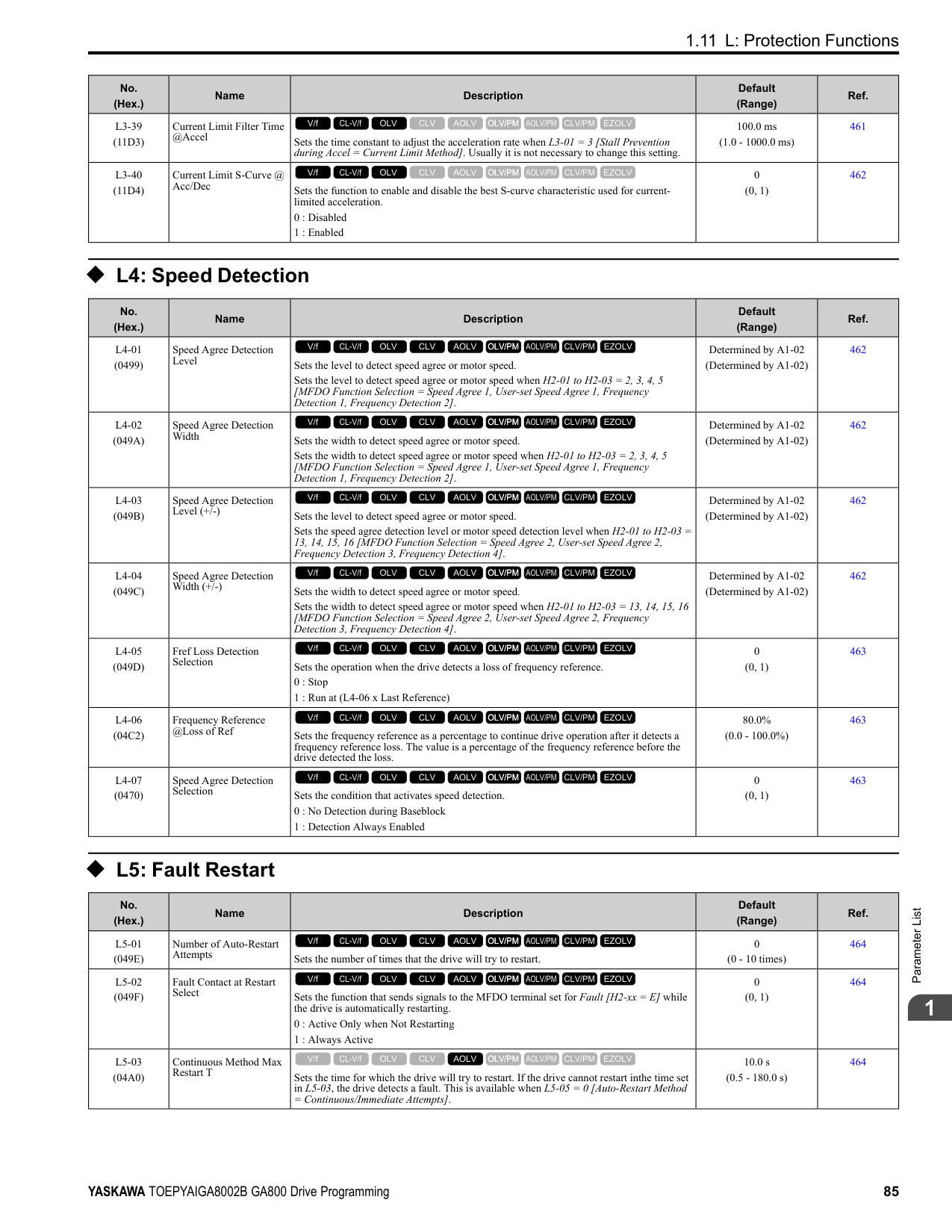
|E1-09|Minimum Output Frequency|Hz|12|12|12|12| |C5-17|Motor Inertia|kgm2|0.0007|0.0014|0.0021|0.0032| |L3-24|Motor Accel Time @ Rated Torque|s|0.137|0.132|0.132|0.122| |n5-02|Motor Inertia Acceleration Time|s|0.137|0.132|0.132|0.122| |n8-49|Heavy Load Id Current|%|0|0|0|0|
######## ◆ Yaskawa SSR1 Series IPM Motors (Derated Torque)
################# Table 1.6 SSR1 Series Motor Code Setting for Specification of 200 V at 1750 min-1 (r/min)
|No.|Name|Unit|Motor Code (setting value of E5-01)|Motor Code (setting value of E5-01)|Motor Code (setting value of E5-01)|Motor Code (setting value of E5-01)|Motor Code (setting value of E5-01)|Motor Code (setting value of E5-01)|Motor Code (setting value of E5-01)|Motor Code (setting value of E5-01)| |---|---|---|---|---|---|---|---|---|---|---| |E5-01|PM Motor Code Selection|-|1202|1203|1205|1206|1208|120A|120B|120D| |E5-01|Voltage Class|V|200|200|200|200|200|200|200|200| |E5-01|Capacity|kW|0.4|0.75|1.5|2.2|3.7|5.5|7.5|11| |E5-01|Motor Rotation Speed|min-1|1750|1750|1750|1750|1750|1750|1750|1750| |E5-02|PM Motor Rated Power|kW|0.4|0.75|1.5|2.2|3.7|5.5|7.5|11.0| |E5-03|PM Motor Rated Current (FLA)|A|1.77|3.13|5.73|8.44|13.96|20.63|28.13|41.4| |E5-04|PM Motor Pole Count|-|6|6|6|6|6|6|6|6| |E5-05|PM Motor Resistance (ohms/phase)|Ω|8.233|2.284|1.470|0.827|0.455|0.246|0.198|0.094| |E5-06|PM d-axis Inductance (mH/phase)|mH|54.84|23.02|17.22|8.61|7.20|4.86|4.15|3.40| |E5-07|PM q-axis Inductance (mH/phase)|mH|64.10|29.89|20.41|13.50|10.02|7.43|5.91|3.91| |E5-09|PM Back-EMF Vpeak (mV/(rad/s))|mVs/rad|223.7|220.3|240.8|238.0|238.7|239.6|258.2|239.3| |E5-24|PM Back-EMF L-L Vrms (mV/rpm)|mV/min-1|0.0|0.0|0.0|0.0|0.0|0.0|0.0|0.0| |E1-04|Maximum Output Frequency|Hz|87.5|87.5|87.5|87.5|87.5|87.5|87.5|87.5| |E1-05|Maximum Output Voltage|V|190.0|190.0|190.0|190.0|190.0|190.0|190.0|190.0| |E1-06|Base Frequency|Hz|87.5|87.5|87.5|87.5|87.5|87.5|87.5|87.5| |E1-09|Minimum Output Frequency|Hz|4.4|4.4|4.4|4.4|4.4|4.4|4.4|4.4| |C5-17|Motor Inertia|kgm2|0.0011|0.0017|0.0023|0.0043|0.0083|0.014|0.017|0.027| |L3-24 *1|Motor Accel Time @ Rated Torque|s|0.092|0.076|0.051|0.066|0.075|0.083|0.077|0.084| |n5-02|Motor Inertia Acceleration Time|s|0.092|0.076|0.051|0.066|0.075|0.083|0.077|0.084| |n8-49|Heavy Load Id Current|%|-7.6|-11.5|-9.1|-19.0|-18.7|-23.4|-18.5|-10.9|
################# Table 1.7 SSR1 Series Motor Code Setting for Specification of 200 V at 1750 min-1 (r/min)
|No.|Name|Unit|Motor Code (setting value of E5-01)|Motor Code (setting value of E5-01)|Motor Code (setting value of E5-01)|Motor Code (setting value of E5-01)|Motor Code (setting value of E5-01)|Motor Code (setting value of E5-01)|Motor Code (setting value of E5-01)|Motor Code (setting value of E5-01)| |---|---|---|---|---|---|---|---|---|---|---|
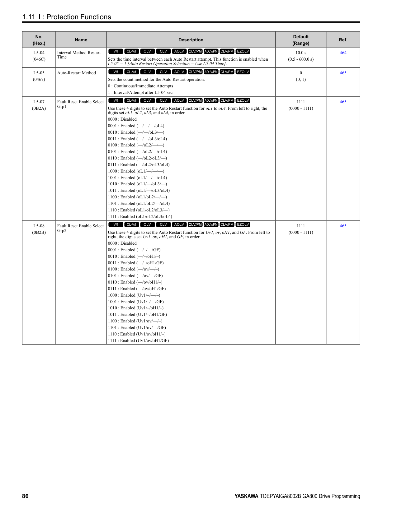
|E5-01|PM Motor Code Selection|-|120E|120F|1210|1212|1213|1214|1215|1216| |E5-01|Voltage Class|V|200|200|200|200|200|200|200|200| |E5-01|Capacity|kW|15|18|22|30|37|45|55|75| |E5-01|Motor Rotation Speed|min-1|1750|1750|1750|1750|1750|1750|1750|1750| |E5-02|PM Motor Rated Power|kW|15.00|18.50|22.00|30.00|37.00|45.00|55.00|75.00| |E5-03|PM Motor Rated Current (FLA)|A|55.4|68.2|80.6|105.2|131.3|153.1|185.4|257.3| |E5-04|PM Motor Pole Count|-|6|6|6|6|6|6|6|6| |E5-05|PM Motor Resistance (ohms/phase)|Ω|0.066|0.051|0.037|0.030|0.020|0.014|0.012|0.006| |E5-06|PM d-axis Inductance (mH/phase)|mH|2.45|2.18|1.71|1.35|0.99|0.83|0.79|0.44| |E5-07|PM q-axis Inductance (mH/phase)|mH|3.11|2.55|2.05|1.82|1.28|1.01|0.97|0.56| |E5-09|PM Back-EMF Vpeak (mV/(rad/s))|mVs/rad|248.1|253.6|250.0|280.9|264.2|280.4|311.9|268.0| |E5-24|PM Back-EMF L-L Vrms (mV/rpm)|mV/min-1|0.0|0.0|0.0|0.0|0.0|0.0|0.0|0.0| |E1-04|Maximum Output Frequency|Hz|87.5|87.5|87.5|87.5|87.5|87.5|87.5|87.5| |E1-05|Maximum Output Voltage|V|190.0|190.0|190.0|190.0|190.0|190.0|190.0|190.0| |E1-06|Base Frequency|Hz|87.5|87.5|87.5|87.5|87.5|87.5|87.5|87.5| |E1-09|Minimum Output Frequency|Hz|4.4|4.4|4.4|4.4|4.4|4.4|4.4|4.4| |C5-17|Motor Inertia|kgm2|0.046|0.055|0.064|0.116|0.140|0.259|0.31|0.42| |L3-24 *1|Motor Accel Time @ Rated Torque|s|0.102|0.101|0.098|0.130|0.127|0.193|0.191|0.187| |n5-02|Motor Inertia Acceleration Time|s|0.102|0.101|0.098|0.130|0.127|0.193|0.191|0.187| |n8-49|Heavy Load Id Current|%|-16.5|-11.3|-12.8|-16.8|-15.6|-10.7|-9.6|-13.3|
*1 The default setting changes when the setting for o2-04 [Drive Model Selection] changes.
################# Table 1.8 SSR1 Series Motor Code Setting for Specification of 400 V at 1750 min-1 (r/min)
|No.|Name|Unit|Motor Code (setting value of E5-01)|Motor Code (setting value of E5-01)|Motor Code (setting value of E5-01)|Motor Code (setting value of E5-01)|Motor Code (setting value of E5-01)|Motor Code (setting value of E5-01)|Motor Code (setting value of E5-01)|Motor Code (setting value of E5-01)| |---|---|---|---|---|---|---|---|---|---|---| |E5-01|PM Motor Code Selection|-|1232|1233|1235|1236|1238|123A|123B|123D| |E5-01|Voltage Class|V|400|400|400|400|400|400|400|400| |E5-01|Capacity|kW|0.4|0.75|1.5|2.2|3.7|5.5|7.5|11| |E5-01|Motor Rotation Speed|min-1|1750|1750|1750|1750|1750|1750|1750|1750| |E5-02|PM Motor Rated Power|kW|0.4|0.75|1.5|2.2|3.7|5.5|7.5|11.0| |E5-03|PM Motor Rated Current (FLA)|A|0.89|1.56|2.81|4.27|7.08|10.31|13.65|20.7| |E5-04|PM Motor Pole Count|-|6|6|6|6|6|6|6|6| |E5-05|PM Motor Resistance (ohms/phase)|Ω|25.370|9.136|6.010|3.297|1.798|0.982|0.786|0.349| |E5-06|PM d-axis Inductance (mH/phase)|mH|169.00|92.08|67.71|34.40|32.93|22.7|16.49|13.17| |E5-07|PM q-axis Inductance (mH/phase)|mH|197.50|119.56|81.71|54.00|37.70|26.80|23.46|15.60| |E5-09|PM Back-EMF Vpeak (mV/(rad/s))|mVs/rad|392.6|440.6|478.3|466.3|478.8|478.1|520.0|481.5|
|No.|Name|Unit|Motor Code (setting value of E5-01)|Motor Code (setting value of E5-01)|Motor Code (setting value of E5-01)|Motor Code (setting value of E5-01)|Motor Code (setting value of E5-01)|Motor Code (setting value of E5-01)|Motor Code (setting value of E5-01)|Motor Code (setting value of E5-01)|
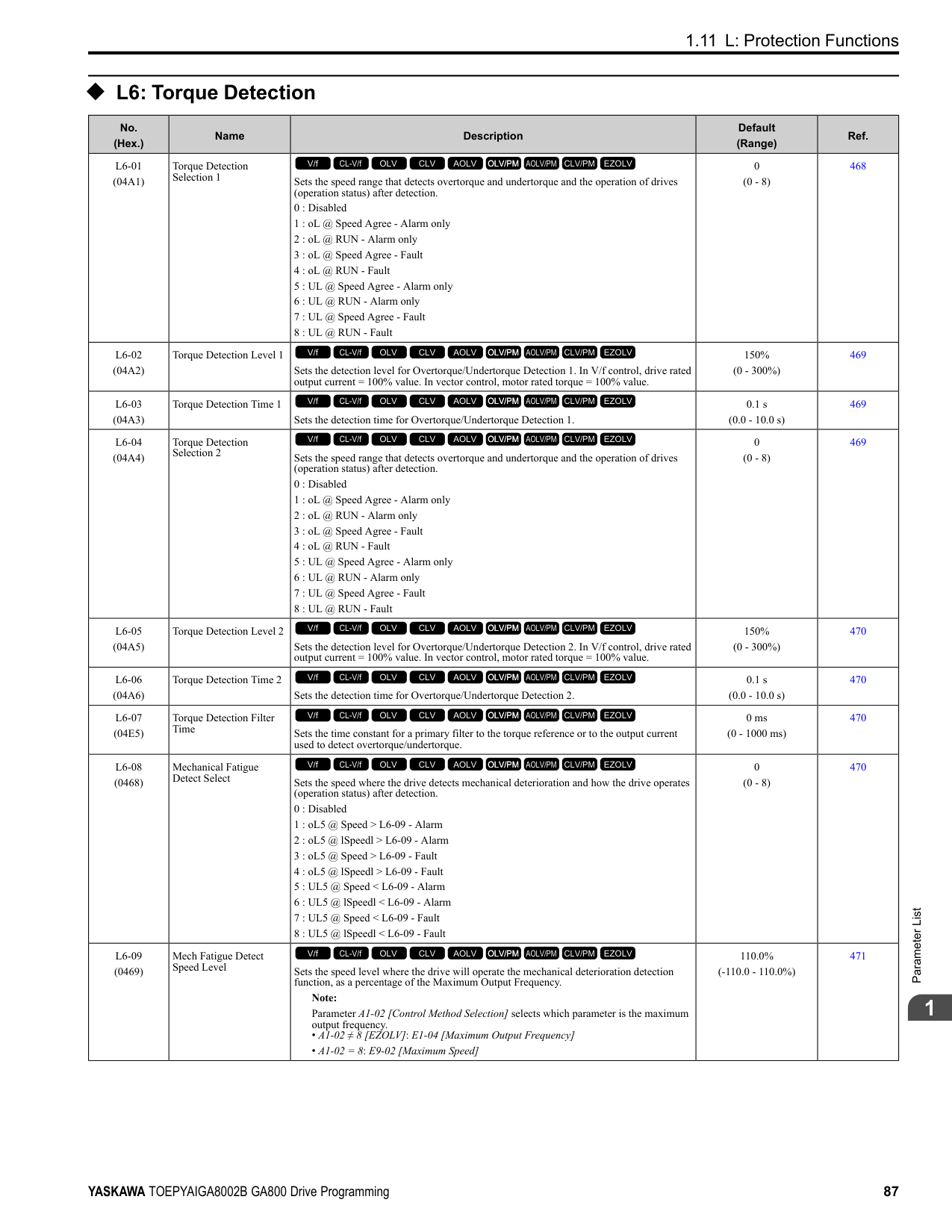
|---|---|---|---|---|---|---|---|---|---|---| |E5-24|PM Back-EMF L-L Vrms (mV/rpm)|mV/min-1|0.0|0.0|0.0|0.0|0.0|0.0|0.0|0.0| |E1-04|Maximum Output Frequency|Hz|87.5|87.5|87.5|87.5|87.5|87.5|87.5|87.5| |E1-05|Maximum Output Voltage|V|380.0|380.0|380.0|380.0|380.0|380.0|380.0|380.0| |E1-06|Base Frequency|Hz|87.5|87.5|87.5|87.5|87.5|87.5|87.5|87.5| |E1-09|Minimum Output Frequency|Hz|4.4|4.4|4.4|4.4|4.4|4.4|4.4|4.4| |C5-17|Motor Inertia|kgm2|0.0011|0.0017|0.0023|0.0043|0.0083|0.014|0.017|0.027| |L3-24 *1|Motor Accel Time @ Rated Torque|s|0.092|0.076|0.051|0.066|0.075|0.083|0.077|0.084| |n5-02|Motor Inertia Acceleration Time|s|0.092|0.076|0.051|0.066|0.075|0.083|0.077|0.084| |n8-49|Heavy Load Id Current|%|-8.6|-11.5|-10.3|-19.8|-8.5|-11.0|-18.6|-12.5|
|No.|Name|Unit|Motor Code (setting value of E5-01)|Motor Code (setting value of E5-01)|Motor Code (setting value of E5-01)|Motor Code (setting value of E5-01)|Motor Code (setting value of E5-01)|Motor Code (setting value of E5-01)|Motor Code (setting value of E5-01)|Motor Code (setting value of E5-01)| |---|---|---|---|---|---|---|---|---|---|---| |E5-01|PM Motor Code Selection|-|123E|123F|1240|1242|1243|1244|1245|1246| |E5-01|Voltage Class|V|400|400|400|400|400|400|400|400| |E5-01|Capacity|kW|15|18|22|30|37|45|55|75| |E5-01|Motor Rotation Speed|min-1|1750|1750|1750|1750|1750|1750|1750|1750| |E5-02|PM Motor Rated Power|kW|15|18.50|22.00|30.00|37.00|45.00|55.00|75.00| |E5-03|PM Motor Rated Current (FLA)|A|27.5|33.4|39.8|52.0|65.8|77.5|92.7|126.6| |E5-04|PM Motor Pole Count|-|6|6|6|6|6|6|6|6| |E5-05|PM Motor Resistance (ohms/phase)|Ω|0.272|0.207|0.148|0.235|0.079|0.054|0.049|0.029| |E5-06|PM d-axis Inductance (mH/phase)|mH|10.30|8.72|6.81|5.4|4.08|3.36|3.16|2.12| |E5-07|PM q-axis Inductance (mH/phase)|mH|12.77|11.22|8.47|7.26|5.12|3.94|3.88|2.61| |E5-09|PM Back-EMF Vpeak (mV/(rad/s))|mVs/rad|498.8|509.5|503.9|561.7|528.5|558.1|623.8|594.5| |E5-24|PM Back-EMF L-L Vrms (mV/rpm)|mV/min-1|0.0|0.0|0.0|0.0|0.0|0.0|0.0|0.0| |E1-04|Maximum Output Frequency|Hz|87.5|87.5|87.5|87.5|87.5|87.5|87.5|87.5| |E1-05|Maximum Output Voltage|V|380.0|380.0|380.0|380.0|380.0|380.0|380.0|380.0| |E1-06|Base Frequency|Hz|87.5|87.5|87.5|87.5|87.5|87.5|87.5|87.5| |E1-09|Minimum Output Frequency|Hz|4.4|4.4|4.4|4.4|4.4|4.4|4.4|4.4| |C5-17|Motor Inertia|kgm2|0.046|0.055|0.064|0.116|0.140|0.259|0.31|0.42| |L3-24 *1|Motor Accel Time @ Rated Torque|s|0.102|0.101|0.098|0.130|0.127|0.193|0.191|0.187| |n5-02|Motor Inertia Acceleration Time|s|0.102|0.101|0.098|0.130|0.127|0.193|0.191|0.187| |n8-49|Heavy Load Id Current|%|-15.5|-17.9|-15.1|-16.8|-14.1|-8.8|-9.6|-10.3|
################# Table 1.10 SSR1 Series Motor Code Setting for Specification of 400 V at 1750 min-1 (r/min)
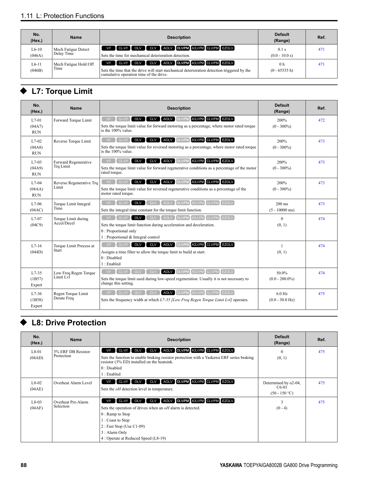
|No.|Name|Unit|Motor Code (setting value of E5-01)|Motor Code (setting value of E5-01)|Motor Code (setting value of E5-01)|Motor Code (setting value of E5-01)| |---|---|---|---|---|---|---| |E5-01|PM Motor Code Selection|-|1247|1248|1249|124A| |E5-01|Voltage Class|V|400|400|400|400| |E5-01|Capacity|kW|90|110|132|160| |E5-01|Motor Rotation Speed|min-1|1750|1750|1750|1750| |E5-02|PM Motor Rated Power|kW|90.00|110.00|132.00|160.00| |E5-03|PM Motor Rated Current (FLA)|A|160.4|183.3|222.9|267.7| |E5-04|PM Motor Pole Count|-|6|6|6|6| |E5-05|PM Motor Resistance (ohms/phase)|Ω|0.019|0.017|0.012|0.008| |E5-06|PM d-axis Inductance (mH/phase)|mH|1.54|1.44|1.21|0.97| |E5-07|PM q-axis Inductance (mH/phase)|mH|2.06|2.21|1.46|1.28| |E5-09|PM Back-EMF Vpeak (mV/(rad/s))|mVs/rad|524.1|583.7|563.6|601.2| |E5-24|PM Back-EMF L-LVrms (mV/rpm)|mV/min-1|0.0|0.0|0.0|0.0| |E1-04|Maximum Output Frequency|Hz|87.5|87.5|87.5|87.5| |E1-05|Maximum Output Voltage|V|380.0|380.0|380.0|380.0| |E1-06|Base Frequency|Hz|87.5|87.5|87.5|87.5| |E1-09|Minimum Output Frequency|Hz|4.4|4.4|4.4|4.4| |C5-17|Motor Inertia|kgm2|0.56|0.83|0.96|1.61| |L3-24 *1|Motor Accel Time @ Rated Torque|s|0.208|0.254|0.243|0.338| |n5-02|Motor Inertia Acceleration Time|s|0.208|0.254|0.243|0.338| |n8-49|Heavy Load Id Current|%|-17.0|-21.7|-10.9|-13.2|
*1 The default setting changes when the setting for o2-04 [Drive Model Selection] changes.
################# Table 1.11 SSR1 Series Motor Code Setting for Specification of 200 V at 1450 min-1 (r/min)
|No.|Name|Unit|Motor Code (setting value of E5-01)|Motor Code (setting value of E5-01)|Motor Code (setting value of E5-01)|Motor Code (setting value of E5-01)|Motor Code (setting value of E5-01)|Motor Code (setting value of E5-01)|Motor Code (setting value of E5-01)|Motor Code (setting value of E5-01)| |---|---|---|---|---|---|---|---|---|---|---| |E5-01|PM Motor Code Selection|-|1302|1303|1305|1306|1308|130A|130B|130D| |E5-01|Voltage Class|V|200|200|200|200|200|200|200|200| |E5-01|Capacity|kW|0.4|0.75|1.5|2.2|3.7|5.5|7.5|11| |E5-01|Motor Rotation Speed|min-1|1450|1450|1450|1450|1450|1450|1450|1450| |E5-02|PM Motor Rated Power|kW|0.4|0.75|1.5|2.2|3.7|5.5|7.5|11.0| |E5-03|PM Motor Rated Current (FLA)|A|1.88|3.13|5.63|8.33|14.17|20.63|27.71|39.6| |E5-04|PM Motor Pole Count|-|6|6|6|6|6|6|6|6| |E5-05|PM Motor Resistance (ohms/phase)|Ω|3.190|1.940|1.206|0.665|0.341|0.252|0.184|0.099| |E5-06|PM d-axis Inductance (mH/phase)|mH|32.15|26.12|14.72|12.27|8.27|6.49|6.91|4.07| |E5-07|PM q-axis Inductance (mH/phase)|mH|41.74|34.30|20.15|14.77|9.81|7.74|7.66|4.65| |E5-09|PM Back-EMF Vpeak (mV/(rad/s))|mVs/rad|264.3|269.6|284.3|287.1|284.5|298.0|335.0|303.9| |E5-24|PM Back-EMF L-L Vrms (mV/rpm)|mV/min-1|0.0|0.0|0.0|0.0|0.0|0.0|0.0|0.0|
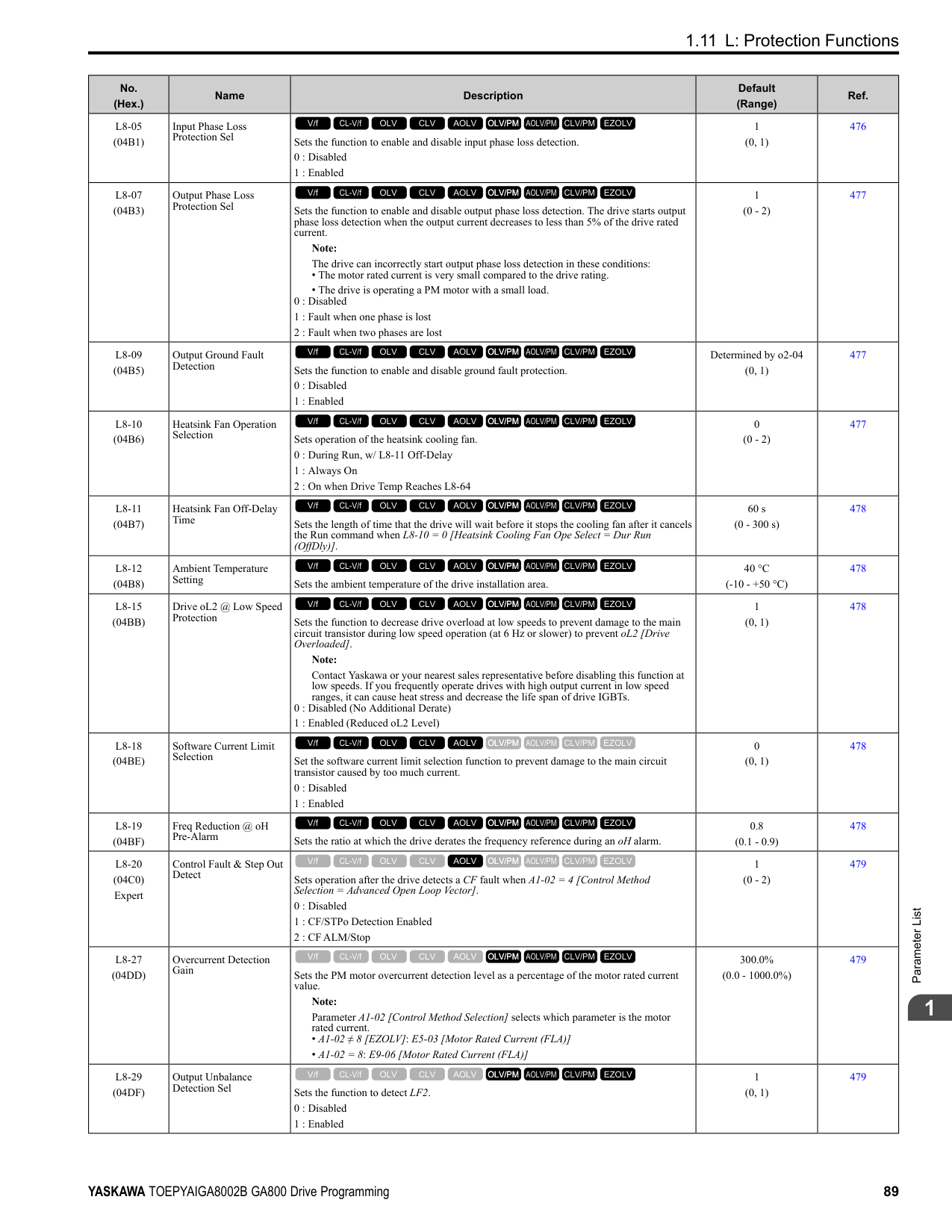
|E1-04|Maximum Output Frequency|Hz|72.5|72.5|72.5|72.5|72.5|72.5|72.5|72.5| |E1-05|Maximum Output Voltage|V|190.0|190.0|190.0|190.0|190.0|190.0|190.0|190.0| |E1-06|Base Frequency|Hz|72.5|72.5|72.5|72.5|72.5|72.5|72.5|72.5|
|No.|Name|Unit|Motor Code (setting value of E5-01)|Motor Code (setting value of E5-01)|Motor Code (setting value of E5-01)|Motor Code (setting value of E5-01)|Motor Code (setting value of E5-01)|Motor Code (setting value of E5-01)|Motor Code (setting value of E5-01)|Motor Code (setting value of E5-01)| |---|---|---|---|---|---|---|---|---|---|---| |E1-09|Minimum Output Frequency|Hz|3.6|3.6|3.6|3.6|3.6|3.6|3.6|3.6| |C5-17|Motor Inertia|kgm2|0.0017|0.0023|0.0043|0.0083|0.0136|0.017|0.027|0.046| |L3-24 *1|Motor Accel Time @ Rated Torque|s|0.098|0.071|0.066|0.087|0.085|0.072|0.084|0.096| |n5-02|Motor Inertia Acceleration Time|s|0.098|0.071|0.066|0.087|0.085|0.072|0.084|0.096| |n8-49|Heavy Load Id Current|%|-6.6|-10.9|-13.5|-9.0|-9.5|-10.1|-6.0|-9.3|
################## *1 The default setting changes when the setting for o2-04 [Drive Model Selection] changes.
*1 The default setting changes when the setting for o2-04 [Drive Model Selection] changes.
|No.|Name|Unit|Motor Code (setting value of E5-01)|Motor Code (setting value of E5-01)|Motor Code (setting value of E5-01)|Motor Code (setting value of E5-01)|Motor Code (setting value of E5-01)|Motor Code (setting value of E5-01)|Motor Code (setting value of E5-01)| |---|---|---|---|---|---|---|---|---|---| |E5-01|PM Motor Code Selection|-|130E|130F|1310|1312|1313|1314|1315| |E5-01|Voltage Class|V|200|200|200|200|200|200|200| |E5-01|Capacity|kW|15|18|22|30|37|45|55| |E5-01|Motor Rotation Speed|min-1|1450|1450|1450|1450|1450|1450|1450| |E5-02|PM Motor Rated Power|kW|15.00|18.50|22.00|30.00|37.00|45.00|55.00| |E5-03|PM Motor Rated Current (FLA)|A|55.5|65.6|75.1|105.2|126.0|153.1|186.5| |E5-04|PM Motor Pole Count|-|6|6|6|6|6|6|6| |E5-05|PM Motor Resistance (ohms/phase)|Ω|0.075|0.057|0.041|0.034|0.023|0.015|0.012| |E5-06|PM d-axis Inductance (mH/ phase)|mH|3.29|2.53|1.98|1.75|1.48|1.04|0.87| |E5-07|PM q-axis Inductance (mH/ phase)|mH|3.84|3.01|2.60|2.17|1.70|1.31|1.10| |E5-09|PM Back-EMF Vpeak (mV/(rad/s))|mVs/rad|311.2|300.9|327.7|354.2|369.6|351.6|374.7| |E5-24|PM Back-EMF L-L Vrms (mV/rpm)|mV/min-1|0.0|0.0|0.0|0.0|0.0|0.0|0.0| |E1-04|Maximum Output Frequency|Hz|72.5|72.5|72.5|72.5|72.5|72.5|72.5| |E1-05|Maximum Output Voltage|V|190.0|190.0|190.0|190.0|190.0|190.0|190.0| |E1-06|Base Frequency|Hz|72.5|72.5|72.5|72.5|72.5|72.5|72.5| |E1-09|Minimum Output Frequency|Hz|3.6|3.6|3.6|3.6|3.6|3.6|3.6| |C5-17|Motor Inertia|kgm2|0.055|0.064|0.116|0.140|0.259|0.312|0.42|
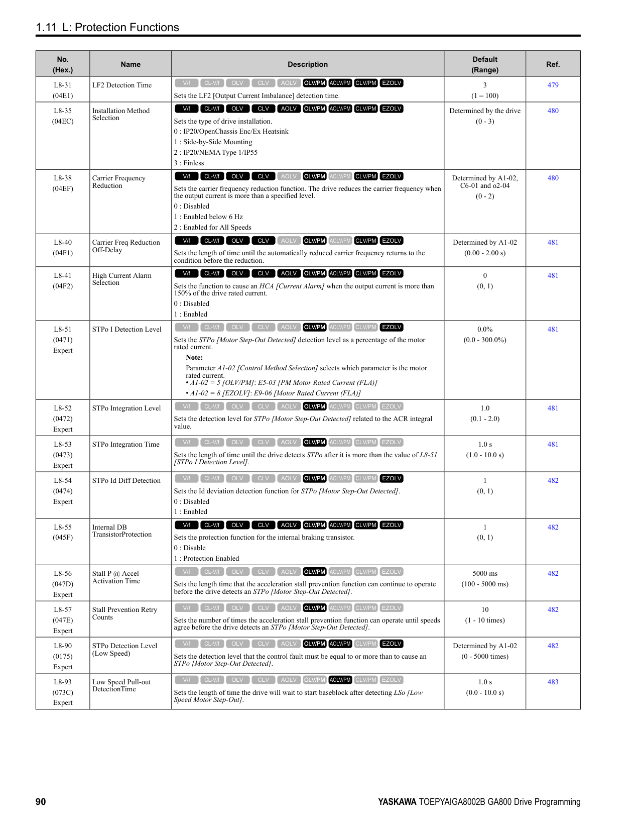
|L3-24 *1|Motor Accel Time @ Rated Torque|s|0.085|0.080|0.122|0.108|0.161|0.160|0.175| |n5-02|Motor Inertia Acceleration Time|s|0.085|0.080|0.122|0.108|0.161|0.160|0.175| |n8-49|Heavy Load Id Current|%|-10.7|-13.2|-15.7|-11.5|-7.0|-11.8|-10.2|
|No.|Name|Unit|Motor Code (setting value of E5-01)|Motor Code (setting value of E5-01)|Motor Code (setting value of E5-01)|Motor Code (setting value of E5-01)|Motor Code (setting value of E5-01)|Motor Code (setting value of E5-01)|Motor Code (setting value of E5-01)|Motor Code (setting value of E5-01)| |---|---|---|---|---|---|---|---|---|---|---| |E5-01|PM Motor Code Selection|-|1332|1333|1335|1336|1338|133A|133B|133D| |E5-01|Voltage Class|V|400|400|400|400|400|400|400|400| |E5-01|Capacity|kW|0.4|0.75|1.5|2.2|3.7|5.5|7.5|11| |E5-01|Motor Rotation Speed|min-1|1450|1450|1450|1450|1450|1450|1450|1450| |E5-02|PM Motor Rated Power|kW|0.4|0.75|1.5|2.2|3.7|5.5|7.5|11.0|
|No.|Name|Unit|Motor Code (setting value of E5-01)|Motor Code (setting value of E5-01)|Motor Code (setting value of E5-01)|Motor Code (setting value of E5-01)|Motor Code (setting value of E5-01)|Motor Code (setting value of E5-01)|Motor Code (setting value of E5-01)|Motor Code (setting value of E5-01)| |---|---|---|---|---|---|---|---|---|---|---| |E5-03|PM Motor Rated Current (FLA)|A|0.94|1.56|2.81|4.27|6.98|10.21|13.85|19.5| |E5-04|PM Motor Pole Count|-|6|6|6|6|6|6|6|6| |E5-05|PM Motor Resistance (ohms/phase)|Ω|12.760|7.421|4.825|2.656|1.353|0.999|0.713|0.393| |E5-06|PM d-axis Inductance (mH/phase)|mH|128.60|85.11|58.87|46.42|31.73|26.20|27.06|15.51| |E5-07|PM q-axis Inductance (mH/phase)|mH|166.96|113.19|80.59|60.32|40.45|30.94|33.45|19.63| |E5-09|PM Back-EMF Vpeak (mV/(rad/s))|mVs/rad|528.6|544.2|568.5|572.8|562.9|587.6|670.1|612.7| |E5-24|PM Back-EMF L-L Vrms (mV/rpm)|mV/min-1|0.0|0.0|0.0|0.0|0.0|0.0|0.0|0.0| |E1-04|Maximum Output Frequency|Hz|72.5|72.5|72.5|72.5|72.5|72.5|72.5|72.5| |E1-05|Maximum Output Voltage|V|380.0|380.0|380.0|380.0|380.0|380.0|380.0|380.0| |E1-06|Base Frequency|Hz|72.5|72.5|72.5|72.5|72.5|72.5|72.5|72.5| |E1-09|Minimum Output Frequency|Hz|3.6|3.6|3.6|3.6|3.6|3.6|3.6|3.6| |C5-17|Motor Inertia|kgm2|0.0017|0.0023|0.0043|0.0083|0.0136|0.017|0.027|0.046| |L3-24 *1|Motor Accel Time @ Rated Torque|s|0.098|0.071|0.066|0.087|0.085|0.072|0.084|0.096| |n5-02|Motor Inertia Acceleration Time|s|0.098|0.071|0.066|0.087|0.085|0.072|0.084|0.096| |n8-49|Heavy Load Id Current|%|-6.6|-9.2|-13.5|-12.1|-13.7|-10.1|-12.2|-15.5|
*1 The default setting changes when the setting for o2-04 [Drive Model Selection] changes.
################# Table 1.14 SSR1 Series Motor Code Setting for Specification of 400 V at 1450 min-1 (r/min)
|No.|Name|Unit|Motor Code (setting value of E5-01)|Motor Code (setting value of E5-01)|Motor Code (setting value of E5-01)|Motor Code (setting value of E5-01)|Motor Code (setting value of E5-01)|Motor Code (setting value of E5-01)|Motor Code (setting value of E5-01)| |---|---|---|---|---|---|---|---|---|---| |E5-01|PM Motor Code Selection|-|133E|133F|1340|1342|1343|1344|1345| |E5-01|Voltage Class|V|400|400|400|400|400|400|400| |E5-01|Capacity|kW|15|18|22|30|37|45|55|
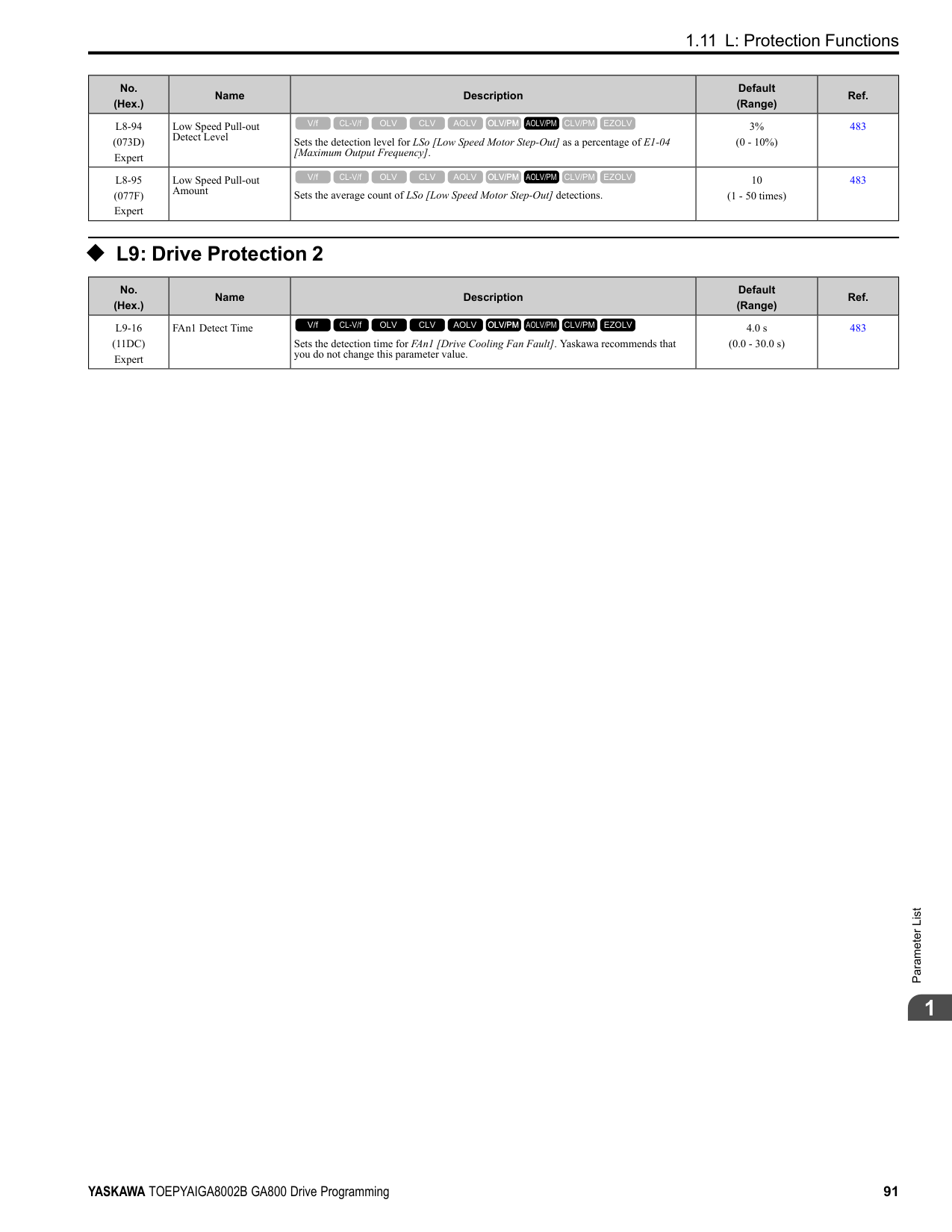
|E5-01|Motor Rotation Speed|min-1|1450|1450|1450|1450|1450|1450|1450| |E5-02|PM Motor Rated Power|kW|15|18.50|22.00|30.00|37.00|45.00|55.00| |E5-03|PM Motor Rated Current (FLA)|A|27.4|32.9|37.6|52.5|63.2|76.4|96.1| |E5-04|PM Motor Pole Count|-|6|6|6|6|6|6|6| |E5-05|PM Motor Resistance (ohms/phase)|Ω|0.295|0.223|0.164|0.137|0.093|0.059|0.048| |E5-06|PM d-axis Inductance (mH/ phase)|mH|12.65|9.87|7.90|7.01|5.93|4.17|3.11| |E5-07|PM q-axis Inductance (mH/ phase)|mH|15.87|12.40|10.38|8.68|6.79|5.22|4.55| |E5-09|PM Back-EMF Vpeak (mV/(rad/s))|mVs/rad|624.6|610.4|655.4|708.4|739.2|703.0|747.1| |E5-24|PM Back-EMF L-L Vrms (mV/rpm)|mV/min-1|0.0|0.0|0.0|0.0|0.0|0.0|0.0| |E1-04|Maximum Output Frequency|Hz|72.5|72.5|72.5|72.5|72.5|72.5|72.5| |E1-05|Maximum Output Voltage|V|380.0|380.0|380.0|380.0|380.0|380.0|380.0| |E1-06|Base Frequency|Hz|72.5|72.5|72.5|72.5|72.5|72.5|72.5| |E1-09|Minimum Output Frequency|Hz|3.6|3.6|3.6|3.6|3.6|3.6|3.6| |C5-17|Motor Inertia|kgm2|0.055|0.064|0.116|0.140|0.259|0.312|0.42|
|No.|Name|Unit|Motor Code (setting value of E5-01)|Motor Code (setting value of E5-01)|Motor Code (setting value of E5-01)|Motor Code (setting value of E5-01)|Motor Code (setting value of E5-01)|Motor Code (setting value of E5-01)|Motor Code (setting value of E5-01)| |---|---|---|---|---|---|---|---|---|---| |L3-24 *1|Motor Accel Time @ Rated Torque|s|0.085|0.080|0.122|0.108|0.161|0.160|0.175| |n5-02|Motor Inertia Acceleration Time|s|0.085|0.080|0.122|0.108|0.161|0.160|0.175| |n8-49|Heavy Load Id Current|%|-15.1|-16.0|-15.7|-11.5|-6.8|-11.5|-14.8|
|No.|Name|Unit|Motor Code (setting value of E5-01)|Motor Code (setting value of E5-01)|Motor Code (setting value of E5-01)|Motor Code (setting value of E5-01)| |---|---|---|---|---|---|---| |E5-01|PM Motor Code Selection|-|1346|1347|1348|1349| |E5-01|Voltage Class|V|400|400|400|400| |E5-01|Capacity|kW|75|90|110|132| |E5-01|Motor Rotation Speed|min-1|1450|1450|1450|1450| |E5-02|PM Motor Rated Power|kW|75.00|90.00|110.00|132.00| |E5-03|PM Motor Rated Current (FLA)|A|124.0|153.1|186.5|226.0| |E5-04|PM Motor Pole Count|-|6|6|6|6| |E5-05|PM Motor Resistance (ohms/phase)|Ω|0.028|0.024|0.015|0.011| |E5-06|PM d-axis Inductance (mH/phase)|mH|2.32|2.20|1.45|1.23| |E5-07|PM q-axis Inductance (mH/phase)|mH|2.97|3.23|1.88|1.67| |E5-09|PM Back-EMF Vpeak (mV/(rad/s))|mVs/rad|639.3|708.0|640.7|677.0| |E5-24|PM Back-EMF L-LVrms (mV/rpm)|mV/min-1|0.0|0.0|0.0|0.0| |E1-04|Maximum Output Frequency|Hz|72.5|72.5|72.5|72.5|
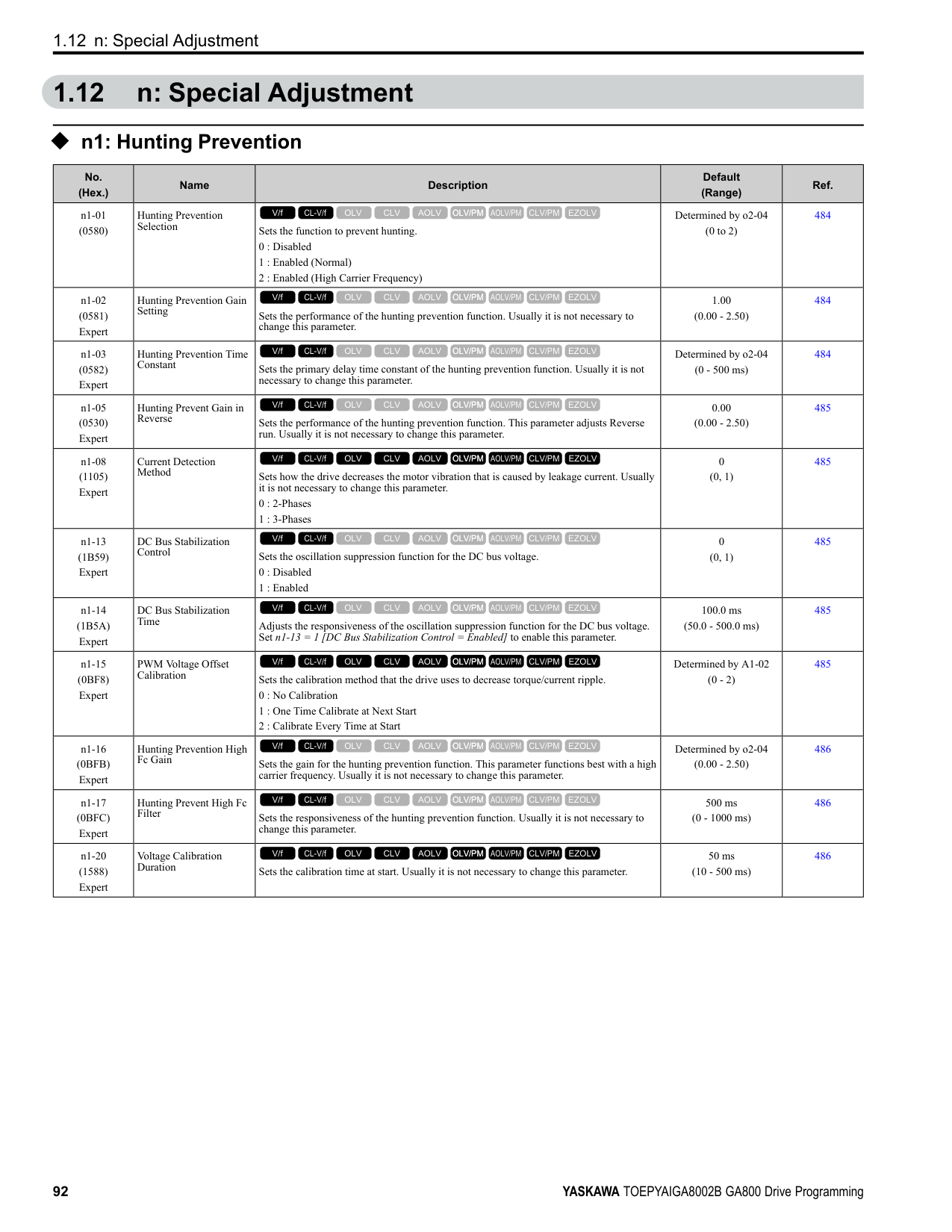
|E1-05|Maximum Output Voltage|V|380.0|380.0|380.0|380.0| |E1-06|Base Frequency|Hz|72.5|72.5|72.5|72.5| |E1-09|Minimum Output Frequency|Hz|3.6|3.6|3.6|3.6| |C5-17|Motor Inertia|kgm2|0.56|0.83|0.96|1.61| |L3-24 *1|Motor Accel Time @ Rated Torque|s|0.171|0.213|0.201|0.281| |n5-02|Motor Inertia Acceleration Time|s|0.171|0.213|0.201|0.281| |n8-49|Heavy Load Id Current|%|-15.8|-19.6|-14.9|-15.1|
|No.|Name|Unit|Motor Code (setting value of E5-01)|Motor Code (setting value of E5-01)|Motor Code (setting value of E5-01)|Motor Code (setting value of E5-01)|Motor Code (setting value of E5-01)|Motor Code (setting value of E5-01)|Motor Code (setting value of E5-01)|Motor Code (setting value of E5-01)| |---|---|---|---|---|---|---|---|---|---|---| |E5-01|PM Motor Code Selection|-|1402|1403|1405|1406|1408|140A|140B|140D| |E5-01|Voltage Class|V|200|200|200|200|200|200|200|200| |E5-01|Capacity|kW|0.4|0.75|1.5|2.2|3.7|5.5|7.5|11| |E5-01|Motor Rotation Speed|min-1|1150|1150|1150|1150|1150|1150|1150|1150| |E5-02|PM Motor Rated Power|kW|0.4|0.75|1.5|2.2|3.7|5.5|7.5|11.0| |E5-03|PM Motor Rated Current (FLA)|A|1.88|3.02|6.00|8.85|14.27|20.21|26.67|39.9| |E5-04|PM Motor Pole Count|-|6|6|6|6|6|6|6|6| |E5-05|PM Motor Resistance (ohms/phase)|Ω|4.832|2.704|1.114|0.511|0.412|0.303|0.165|0.113| |E5-06|PM d-axis Inductance (mH/phase)|mH|48.68|32.31|19.22|12.15|7.94|11.13|6.59|4.96| |E5-07|PM q-axis Inductance (mH/phase)|mH|63.21|40.24|24.38|15.35|11.86|14.06|8.55|6.12|
|No.|Name|Unit|Motor Code (setting value of E5-01)|Motor Code (setting value of E5-01)|Motor Code (setting value of E5-01)|Motor Code (setting value of E5-01)|Motor Code (setting value of E5-01)|Motor Code (setting value of E5-01)|Motor Code (setting value of E5-01)|Motor Code (setting value of E5-01)| |---|---|---|---|---|---|---|---|---|---|---| |E5-09|PM Back-EMF Vpeak (mV/(rad/s))|mVs/rad|320.4|327.1|364.4|344.4|357.5|430.8|391.5|384.4| |E5-24|PM Back-EMF L-L Vrms (mV/rpm)|mV/min-1|0.0|0.0|0.0|0.0|0.0|0.0|0.0|0.0| |E1-04|Maximum Output Frequency|Hz|57.5|57.5|57.5|57.5|57.5|57.5|57.5|57.5| |E1-05|Maximum Output Voltage|V|190.0|190.0|190.0|190.0|190.0|190.0|190.0|190.0| |E1-06|Base Frequency|Hz|57.5|57.5|57.5|57.5|57.5|57.5|57.5|57.5| |E1-09|Minimum Output Frequency|Hz|2.9|2.9|2.9|2.9|2.9|2.9|2.9|2.9| |C5-17|Motor Inertia|kgm2|0.0017|0.0023|0.0083|0.0136|0.0171|0.027|0.046|0.055| |L3-24 *1|Motor Accel Time @ Rated Torque|s|0.062|0.044|0.080|0.090|0.067|0.072|0.088|0.073| |n5-02|Motor Inertia Acceleration Time|s|0.062|0.044|0.080|0.090|0.067|0.072|0.088|0.073| |n8-49|Heavy Load Id Current|%|-8.8|-9.9|-9.3|-10.0|-17.7|-12.3|-15.3|-13.9|
|No.|Name|Unit|Motor Code (setting value of E5-01)|Motor Code (setting value of E5-01)|Motor Code (setting value of E5-01)|Motor Code (setting value of E5-01)|Motor Code (setting value of E5-01)|Motor Code (setting value of E5-01)|
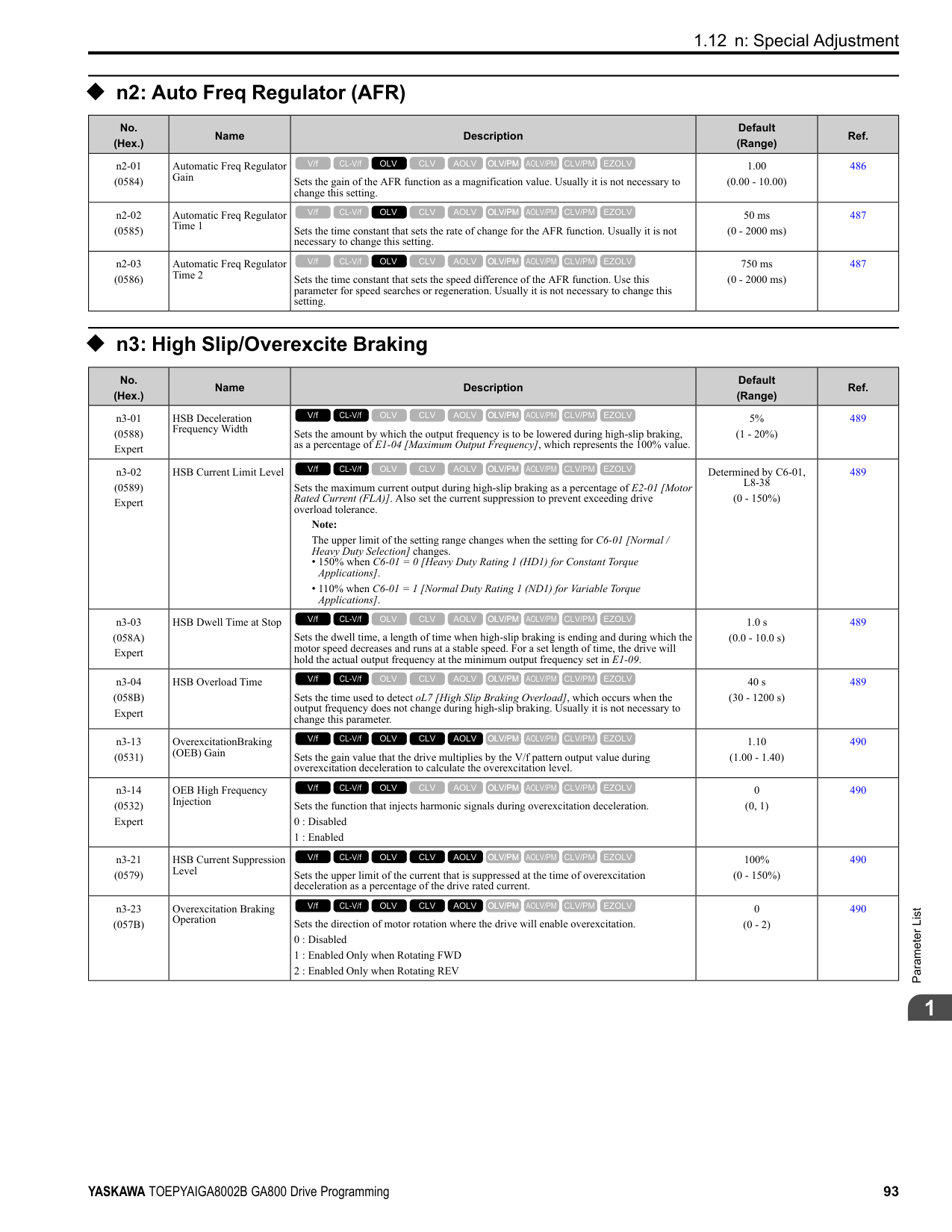
|---|---|---|---|---|---|---|---|---| |E5-01|PM Motor Code Selection|-|140E|140F|1410|1412|1413|1414| |E5-01|Voltage Class|V|200|200|200|200|200|200| |E5-01|Capacity|kW|15|18|22|30|37|45| |E5-01|Motor Rotation Speed|min-1|1150|1150|1150|1150|1150|1150| |E5-02|PM Motor Rated Power|kW|15|18.50|22.00|30.00|37.00|45.00| |E5-03|PM Motor Rated Current (FLA)|A|55.6|63.5|74.4|104.2|129.6|154.2| |E5-04|PM Motor Pole Count|-|6|6|6|6|6|6| |E5-05|PM Motor Resistance (ohms/ phase)|Ω|0.084|0.066|0.048|0.035|0.023|0.016| |E5-06|PM d-axis Inductance (mH/ phase)|mH|3.83|3.33|2.38|2.04|1.53|1.16| |E5-07|PM q-axis Inductance (mH/ phase)|mH|4.65|4.50|3.15|2.86|2.27|1.54| |E5-09|PM Back-EMF Vpeak (mV/ (rad/s))|mVs/rad|372.1|421.3|410.9|436.1|428.8|433.3| |E5-24|PM Back-EMF L-LVrms (mV/rpm)|mV/min-1|0.0|0.0|0.0|0.0|0.0|0.0| |E1-04|Maximum Output Frequency|Hz|57.5|57.5|57.5|57.5|57.5|57.5| |E1-05|Maximum Output Voltage|V|190.0|190.0|190.0|190.0|190.0|190.0| |E1-06|Base Frequency|Hz|57.5|57.5|57.5|57.5|57.5|57.5| |E1-09|Minimum Output Frequency|Hz|2.9|2.9|2.9|2.9|2.9|2.9| |C5-17|Motor Inertia|kgm2|0.064|0.116|0.140|0.259|0.312|0.418| |L3-24 *1|Motor Accel Time @ Rated Torque|s|0.062|0.091|0.092|0.125|0.122|0.135| |n5-02|Motor Inertia Acceleration Time|s|0.062|0.091|0.092|0.125|0.122|0.135| |n8-49|Heavy Load Id Current|%|-14.4|-17.9|-15.9|-17.9|-20.1|-13.7|
ParameterList
######## 1
Table 1.18 SSR1 Series Motor Code Setting for Specification of 400 V at 1150 min-1 (r/min)
|No.|Name|Unit|Motor Code (setting value of E5-01)|Motor Code (setting value of E5-01)|Motor Code (setting value of E5-01)|Motor Code (setting value of E5-01)|Motor Code (setting value of E5-01)|Motor Code (setting value of E5-01)|Motor Code (setting value of E5-01)|Motor Code (setting value of E5-01)| |---|---|---|---|---|---|---|---|---|---|---| |E5-01|PM Motor Code Selection|-|1432|1433|1435|1436|1438|143A|143B|143D| |E5-01|Voltage Class|V|400|400|400|400|400|400|400|400| |E5-01|Capacity|kW|0.4|0.75|1.5|2.2|3.7|5.5|7.5|11| |E5-01|Motor Rotation Speed|min-1|1150|1150|1150|1150|1150|1150|1150|1150| |E5-02|PM Motor Rated Power|kW|0.4|0.75|1.5|2.2|3.7|5.5|7.5|11.0| |E5-03|PM Motor Rated Current (FLA)|A|0.94|1.51|3.00|4.43|7.08|10.10|13.33|19.9| |E5-04|PM Motor Pole Count|-|6|6|6|6|6|6|6|6| |E5-05|PM Motor Resistance (ohms/phase)|Ω|19.320|10.800|4.456|2.044|1.483|1.215|0.660|0.443| |E5-06|PM d-axis Inductance (mH/phase)|mH|194.70|129.20|76.88|48.60|37.58|44.54|26.36|19.10| |E5-07|PM q-axis Inductance (mH/phase)|mH|252.84|160.90|97.52|61.40|47.65|56.26|34.20|24.67| |E5-09|PM Back-EMF Vpeak (mV/(rad/s))|mVs/rad|640.9|654.1|728.8|688.9|702.0|861.5|783.0|762.2|
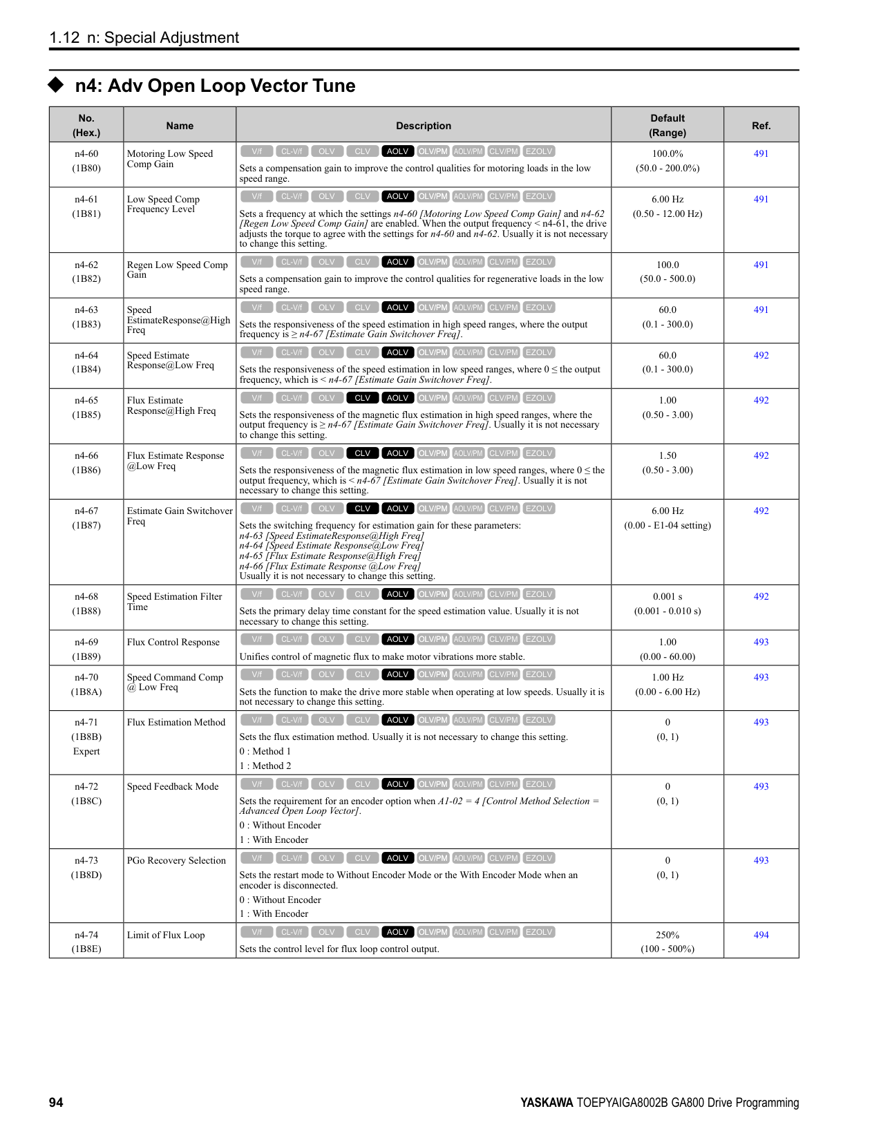
|E5-24|PM Back-EMF L-L Vrms (mV/rpm)|mV/min|0.0|0.0|0.0|0.0|0.0|0.0|0.0|0.0| |E1-04|Maximum Output Frequency|Hz|57.5|57.5|57.5|57.5|57.5|57.5|57.5|57.5| |E1-05|Maximum Output Voltage|V|380.0|380.0|380.0|380.0|380.0|380.0|380.0|380.0| |E1-06|Base Frequency|Hz|57.5|57.5|57.5|57.5|57.5|57.5|57.5|57.5| |E1-09|Minimum Output Frequency|Hz|2.9|2.9|2.9|2.9|2.9|2.9|2.9|2.9| |C5-17|Motor Inertia|kgm2|0.0017|0.0023|0.0083|0.0136|0.0171|0.027|0.046|0.055| |L3-24 *1|Motor Accel Time @ Rated Torque|s|0.062|0.044|0.080|0.090|0.067|0.072|0.088|0.073| |n5-02|Motor Inertia Acceleration Time|s|0.062|0.044|0.080|0.090|0.067|0.072|0.088|0.073| |n8-49|Heavy Load Id Current|%|-8.8|-9.9|-9.3|-10.0|-12.8|-12.3|-15.3|-16.7|
|No.|Name|Unit|Motor Code (setting value of E5-01)|Motor Code (setting value of E5-01)|Motor Code (setting value of E5-01)|Motor Code (setting value of E5-01)|Motor Code (setting value of E5-01)|Motor Code (setting value of E5-01)| |---|---|---|---|---|---|---|---|---| |E5-01|PM Motor Code Selection|-|143E|143F|1440|1442|1443|1444| |E5-01|Voltage Class|V|400|400|400|400|400|400| |E5-01|Capacity|kW|15|18|22|30|37|45| |E5-01|Motor Rotation Speed|min-1|1150|1150|1150|1150|1150|1150| |E5-02|PM Motor Rated Power|kW|15|18.50|22.00|30.00|37.00|45.00| |E5-03|PM Motor Rated Current (FLA)|A|27.8|31.8|37.2|52.1|64.8|76.6| |E5-04|PM Motor Pole Count|-|6|6|6|6|6|6| |E5-05|PM Motor Resistance (ohms/ phase)|Ω|0.331|0.264|0.192|0.140|0.093|0.063| |E5-06|PM d-axis Inductance (mH/ phase)|mH|15.09|13.32|9.52|8.16|6.13|4.63| |E5-07|PM q-axis Inductance (mH/ phase)|mH|18.56|18.00|12.60|11.40|9.10|6.15| |E5-09|PM Back-EMF Vpeak (mV/ (rad/s))|mVs/rad|749.6|842.7|821.8|872.3|857.7|866.6| |E5-24|PM Back-EMF L-LVrms (mV/rpm)|mV/min-1|0.0|0.0|0.0|0.0|0.0|0.0|
|No.|Name|Unit|Motor Code (setting value of E5-01)|Motor Code (setting value of E5-01)|Motor Code (setting value of E5-01)|Motor Code (setting value of E5-01)|Motor Code (setting value of E5-01)|Motor Code (setting value of E5-01)| |---|---|---|---|---|---|---|---|---| |E1-04|Maximum Output Frequency|Hz|57.5|57.5|57.5|57.5|57.5|57.5| |E1-05|Maximum Output Voltage|V|380.0|380.0|380.0|380.0|380.0|380.0| |E1-06|Base Frequency|Hz|57.5|57.5|57.5|57.5|57.5|57.5| |E1-09|Minimum Output Frequency|Hz|2.9|2.9|2.9|2.9|2.9|2.9| |C5-17|Motor Inertia|kgm2|0.064|0.116|0.140|0.259|0.312|0.418| |L3-24 *1|Motor Accel Time @ Rated Torque|s|0.062|0.091|0.092|0.125|0.122|0.135| |n5-02|Motor Inertia Acceleration Time|s|0.062|0.091|0.092|0.125|0.122|0.135| |n8-49|Heavy Load Id Current|%|-14.9|-17.9|-15.9|-17.7|-20.1|-13.8|
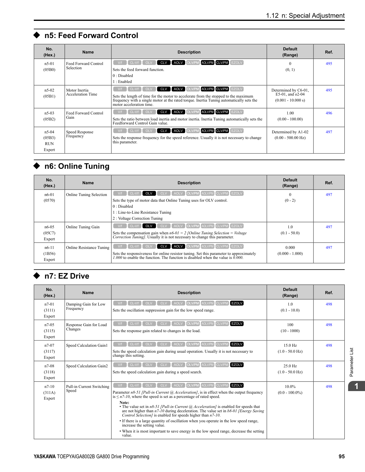
*1 The default setting changes when the setting for o2-04 [Drive Model Selection] changes.
################# Table 1.20 SSR1 Series Motor Code Setting for Specification of 400 V at 1150 min-1 (r/min)
|No.|Name|Unit|Motor Code (setting value of E5-01)|Motor Code (setting value of E5-01)|Motor Code (setting value of E5-01)|Motor Code (setting value of E5-01)| |---|---|---|---|---|---|---| |E5-01|PM Motor Code Selection|-|1445|1446|1447|1448| |E5-01|Voltage Class|V|400|400|400|400| |E5-01|Capacity|kW|55|75|90|110| |E5-01|Motor Rotation Speed|min-1|1150|1150|1150|1150| |E5-02|PM Motor Rated Power|kW|55.00|75.00|90.00|110.00| |E5-03|PM Motor Rated Current (FLA)|A|92.0|127.1|150.5|185.4| |E5-04|PM Motor Pole Count|-|6|6|6|6| |E5-05|PM Motor Resistance (ohms/ phase)|Ω|0.051|0.033|0.027|0.015| |E5-06|PM d-axis Inductance (mH/ phase)|mH|3.96|3.03|2.60|1.89| |E5-07|PM q-axis Inductance (mH/ phase)|mH|5.00|5.14|3.28|2.33| |E5-09|PM Back-EMF Vpeak (mV/(rad/ s))|mVs/rad|854.0|823.1|853.4|829.2| |E5-24|PM Back-EMF L-LVrms (mV/ rpm)|mV/min-1|0.0|0.0|0.0|0.0| |E1-04|Maximum Output Frequency|Hz|57.5|57.5|57.5|57.5| |E1-05|Maximum Output Voltage|V|380.0|380.0|380.0|380.0| |E1-06|Base Frequency|Hz|57.5|57.5|57.5|57.5| |E1-09|Minimum Output Frequency|Hz|2.9|2.9|2.9|2.9| |C5-17|Motor Inertia|kgm2|0.56|0.83|0.96|1.61| |L3-24 *1|Motor Accel Time @ Rated Torque|s|0.147|0.161|0.154|0.212| |n5-02|Motor Inertia Acceleration Time|s|0.147|0.161|0.154|0.212| |n8-49|Heavy Load Id Current|%|-12.5|-28.8|-13.3|-11.6|
*1 The default setting changes when the setting for o2-04 [Drive Model Selection] changes.
ParameterList
######## 1
######## ◆ Yaskawa SST4 Series IPM Motors (Constant Torque)
Table 1.21 SST4 series motor code setting for specification of 200 V at 1750 min-1 (r/min)
|No.|Name|Unit|Motor Code (setting value of E5-01)|Motor Code (setting value of E5-01)|Motor Code (setting value of E5-01)|Motor Code (setting value of E5-01)|Motor Code (setting value of E5-01)|Motor Code (setting value of E5-01)|Motor Code (setting value of E5-01)|Motor Code (setting value of E5-01)| |---|---|---|---|---|---|---|---|---|---|---| |E5-01|PM Motor Code Selection|-|2202|2203|2205|2206|2208|220A|220B|220D| |E5-01|Voltage Class|V|200|200|200|200|200|200|200|200|
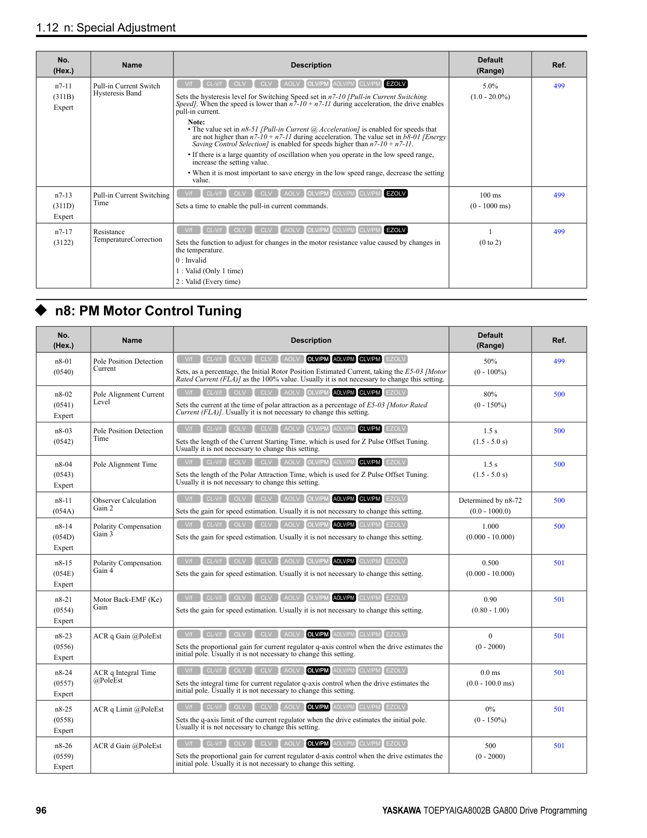
|E5-01|Capacity|kW|0.4|0.75|1.5|2.2|3.7|5.5|7.5|11| |E5-01|Motor Rotation Speed|min-1|1750|1750|1750|1750|1750|1750|1750|1750| |E5-02|PM Motor Rated Power (kW)|kW|0.4|0.75|1.5|2.2|3.7|5.5|7.5|11.0| |E5-03|PM Motor Rated Current (FLA)|A|1.77|3.54|6.56|8.96|14.79|20.94|29.58|41.1| |E5-04|PM Motor Pole Count|-|6|6|6|6|6|6|6|6| |E5-05|PM Motor Resistance (ohms/phase)|Ω|2.247|1.132|0.774|0.479|0.242|0.275|0.161|0.111| |E5-06|PM d-axis Inductance (mH/phase)|mH|22.32|12.38|8.90|7.39|5.06|5.82|3.86|3.59| |E5-07|PM q-axis Inductance (mH/phase)|mH|32.50|15.72|11.96|9.63|6.42|6.74|4.66|4.32| |E5-09|PM Motor Induced Voltage Constant 1 (Ke)|mVs/rad|215.2|203.9|219.3|230.6|235.1|251.7|235.7|252.0| |E5-24|PM Motor Induced Voltage Constant 2 (Ke)|mV/min-1|0.0|0.0|0.0|0.0|0.0|0.0|0.0|0.0| |E1-04|Maximum Output Frequency|Hz|87.5|87.5|87.5|87.5|87.5|87.5|87.5|87.5| |E1-05|Maximum Output Voltage|V|190.0|190.0|190.0|190.0|190.0|190.0|190.0|190.0| |E1-06|Base Frequency|Hz|87.5|87.5|87.5|87.5|87.5|87.5|87.5|87.5| |E1-09|Minimum Output Frequency|Hz|4.4|4.4|4.4|4.4|4.4|4.4|4.4|4.4| |C5-17|Motor Inertia|kgm2|0.0016|0.0022|0.0042|0.0081|0.0133|0.013|0.017|0.027| |L3-24 *1|Motor Accel Time for Inertia Cal|s|0.134|0.099|0.094|0.124|0.121|0.081|0.075|0.082| |n5-02|Motor Inertia Acceleration Time|s|0.134|0.099|0.094|0.124|0.121|0.081|0.075|0.082| |n8-49|d-Axis Cur forHighEfficiencyCont|%|-9.3|-6.4|-10.0|-9.9|-9.7|-8.4|-11.5|-13.1|
|No.|Name|Unit|Motor Code (setting value of E5-01)|Motor Code (setting value of E5-01)|Motor Code (setting value of E5-01)|Motor Code (setting value of E5-01)|Motor Code (setting value of E5-01)|Motor Code (setting value of E5-01)|Motor Code (setting value of E5-01)|Motor Code (setting value of E5-01)| |---|---|---|---|---|---|---|---|---|---|---| |E5-01|PM Motor Code Selection|-|220E|220F|2210|2212|2213|2214|2215|2216| |E5-01|Voltage Class|V|200|200|200|200|200|200|200|200| |E5-01|Capacity|kW|15|18|22|30|37|45|55|75| |E5-01|Motor Rotation Speed|min-1|1750|1750|1750|1750|1750|1750|1750|1750| |E5-02|PM Motor Rated Power|kW|15|18.50|22.00|30.00|37.00|45.00|55.00|75.00| |E5-03|PM Motor Rated Current (FLA)|A|54.2|68.2|78.6|104.2|129.2|153.1|205.2|260.4| |E5-04|PM Motor Pole Count|-|6|6|6|6|6|6|6|6| |E5-05|PM Motor Resistance (ohms/phase)|Ω|0.071|0.049|0.040|0.030|0.020|0.013|0.009|0.006| |E5-06|PM d-axis Inductance (mH/phase)|mH|2.67|1.98|1.69|1.31|0.88|0.77|0.55|0.40| |E5-07|PM q-axis Inductance (mH/phase)|mH|3.10|2.41|2.12|1.61|1.14|1.04|0.69|0.50|
|No.|Name|Unit|Motor Code (setting value of E5-01)|Motor Code (setting value of E5-01)|Motor Code (setting value of E5-01)|Motor Code (setting value of E5-01)|Motor Code (setting value of E5-01)|Motor Code (setting value of E5-01)|Motor Code (setting value of E5-01)|Motor Code (setting value of E5-01)| |---|---|---|---|---|---|---|---|---|---|---| |E5-09|PM Back-EMF Vpeak (mV/(rad/s))|mVs/rad|253.7|244.6|256.3|283.1|266.3|260.0|261.5|259.3| |E5-24|PM Back-EMF L-L Vrms (mV/rpm)|mV/min-1|0.0|0.0|0.0|0.0|0.0|0.0|0.0|0.0| |E1-04|Maximum Output Frequency|Hz|87.5|87.5|87.5|87.5|87.5|87.5|87.5|87.5|
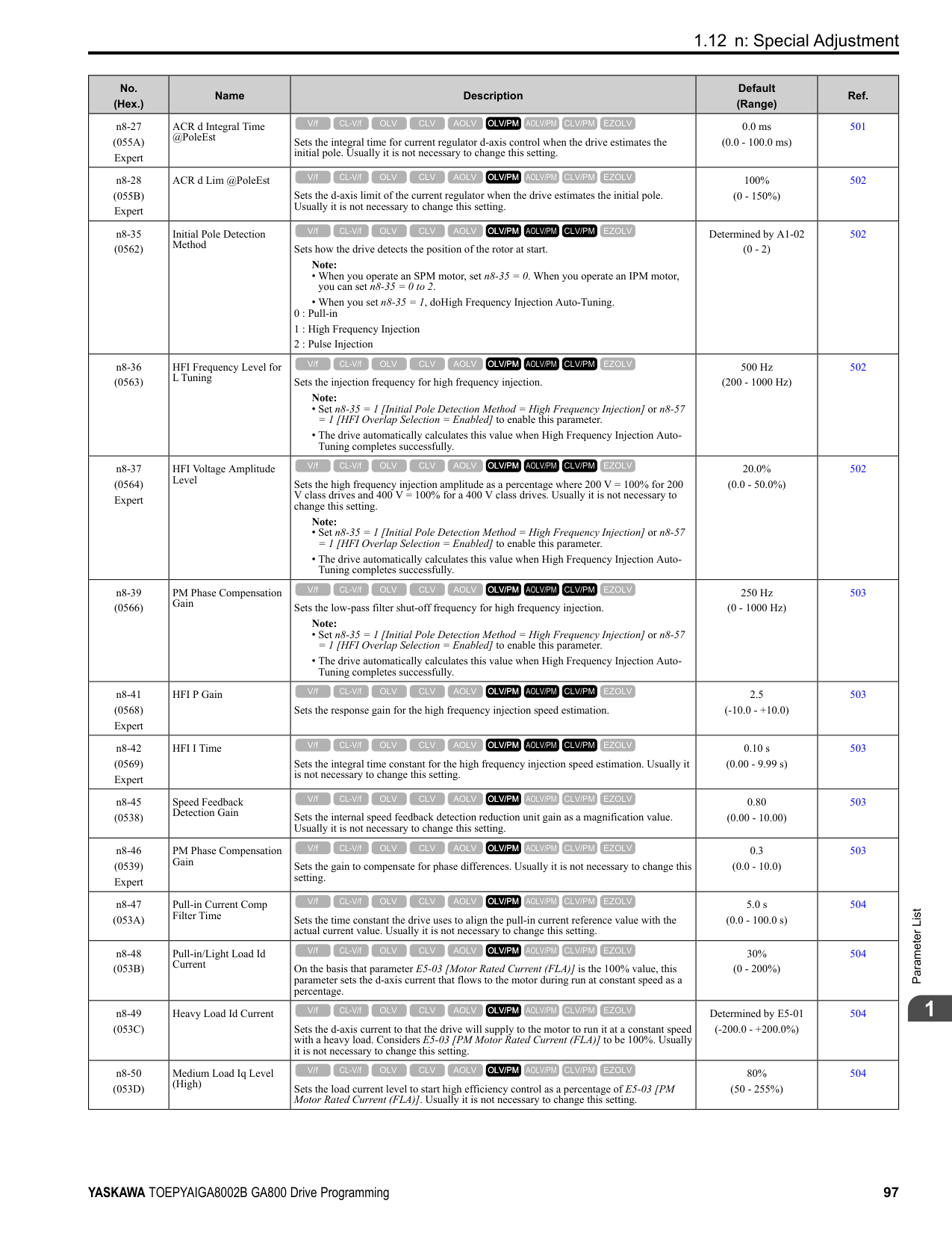
|E1-05|Maximum Output Voltage|V|190.0|190.0|190.0|190.0|190.0|190.0|190.0|190.0| |E1-06|Base Frequency|Hz|87.5|87.5|87.5|87.5|87.5|87.5|87.5|87.5| |E1-09|Minimum Output Frequency|Hz|4.4|4.4|4.4|4.4|4.4|4.4|4.4|4.4| |C5-17|Motor Inertia|kgm2|0.044|0.054|0.063|0.113|0.137|0.252|0.30|0.41| |L3-24 *1|Motor Accel Time @ Rated Torque|s|0.099|0.098|0.096|0.126|0.124|0.188|0.186|0.184| |n5-02|Motor Inertia Acceleration Time|s|0.099|0.098|0.096|0.126|0.124|0.188|0.186|0.184| |n8-49|Heavy Load Id Current|%|-10.9|-14.3|-15.1|-11.3|-14.1|-18.8|-11.4|-12.2|
*1 The default setting changes when the setting for o2-04 [Drive Model Selection] changes.
################# Table 1.23 SST4 Series Motor Code Setting for Specification of 400 V at 1750 min-1 (r/min)
|No.|Name|Unit|Motor Code (setting value of E5-01)|Motor Code (setting value of E5-01)|Motor Code (setting value of E5-01)|Motor Code (setting value of E5-01)|Motor Code (setting value of E5-01)|Motor Code (setting value of E5-01)|Motor Code (setting value of E5-01)|Motor Code (setting value of E5-01)| |---|---|---|---|---|---|---|---|---|---|---| |E5-01|PM Motor Code Selection|-|2232|2233|2235|2236|2238|223A|223B|223D| |E5-01|Voltage Class|V|400|400|400|400|400|400|400|400| |E5-01|Capacity|kW|0.4|0.75|1.5|2.2|3.7|5.5|7.5|11| |E5-01|Motor Rotation Speed|min-1|1750|1750|1750|1750|1750|1750|1750|1750| |E5-02|PM Motor Rated Power|kW|0.4|0.75|1.5|2.2|3.7|5.5|7.5|11.0| |E5-03|PM Motor Rated Current (FLA)|A|0.92|1.77|3.33|4.48|7.50|10.42|14.27|20.5| |E5-04|PM Motor Pole Count|-|6|6|6|6|6|6|6|6| |E5-05|PM Motor Resistance (ohms/phase)|Ω|8.935|4.570|3.096|1.906|0.972|1.103|0.630|0.429| |E5-06|PM d-axis Inductance (mH/phase)|mH|80.14|48.04|35.60|30.31|20.03|23.41|14.86|14.34| |E5-07|PM q-axis Inductance (mH/phase)|mH|110.76|64.88|47.84|38.36|24.97|28.70|17.25|17.25| |E5-09|PM Back-EMF Vpeak (mV/(rad/s))|mVs/rad|416.5|399.4|438.5|475.5|463.7|485.8|470.4|513.4| |E5-24|PM Back-EMF L-L Vrms (mV/rpm)|mV/min-1|0.0|0.0|0.0|0.0|0.0|0.0|0.0|0.0| |E1-04|Maximum Output Frequency|Hz|87.5|87.5|87.5|87.5|87.5|87.5|87.5|87.5| |E1-05|Maximum Output Voltage|V|380.0|380.0|380.0|380.0|380.0|380.0|380.0|380.0| |E1-06|Base Frequency|Hz|87.5|87.5|87.5|87.5|87.5|87.5|87.5|87.5| |E1-09|Minimum Output Frequency|Hz|4.4|4.4|4.4|4.4|4.4|4.4|4.4|4.4| |C5-17|Motor Inertia|kgm2|0.0016|0.0022|0.0042|0.0081|0.0133|0.013|0.017|0.027| |L3-24 *1|Motor Accel Time @ Rated Torque|s|0.134|0.099|0.094|0.124|0.121|0.081|0.075|0.082| |n5-02|Motor Inertia Acceleration Time|s|0.134|0.099|0.094|0.124|0.121|0.081|0.075|0.082| |n8-49|Heavy Load Id Current|%|-7.5|-8.5|-9.8|-8.2|-9.1|-13.1|-9.2|-12.4|
*1 The default setting changes when the setting for o2-04 [Drive Model Selection] changes.
ParameterList
######## 1
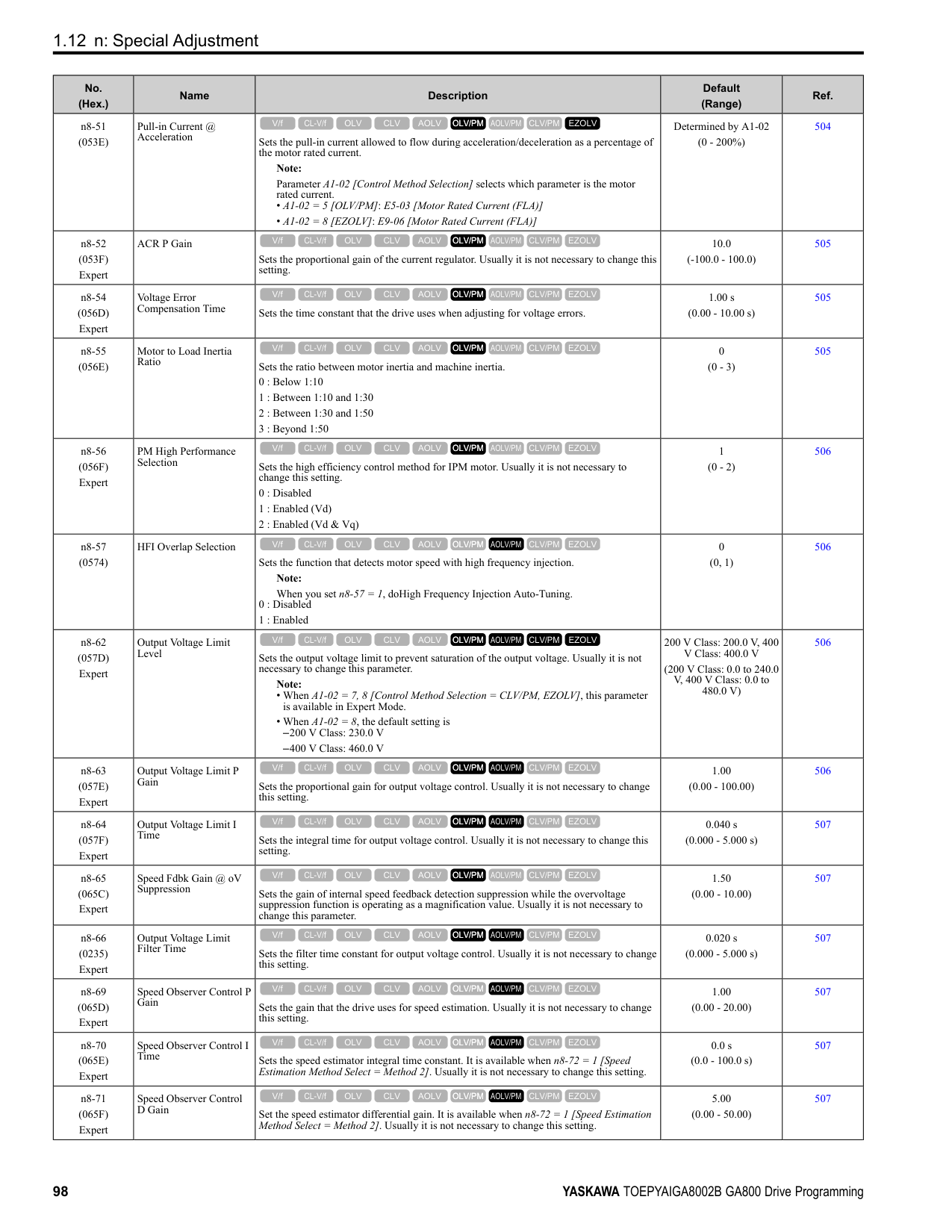
Table 1.24 SST4 Series Motor Code Setting for Specification of 400 V at 1750 min-1 (r/min)
|No.|Name|Unit|Motor Code (setting value of E5-01)|Motor Code (setting value of E5-01)|Motor Code (setting value of E5-01)|Motor Code (setting value of E5-01)|Motor Code (setting value of E5-01)|Motor Code (setting value of E5-01)|Motor Code (setting value of E5-01)|Motor Code (setting value of E5-01)| |---|---|---|---|---|---|---|---|---|---|---| |E5-01|PM Motor Code Selection|-|223E|223F|2240|2242|2243|2244|2245|2246| |E5-01|Voltage Class|V|400|400|400|400|400|400|400|400| |E5-01|Capacity|kW|15|18|22|30|37|45|55|75| |E5-01|Motor Rotation Speed|min-1|1750|1750|1750|1750|1750|1750|1750|1750| |E5-02|PM Motor Rated Power|kW|15|18.50|22.00|30.00|37.00|45.00|55.00|75.00| |E5-03|PM Motor Rated Current (FLA)|A|26.4|34.2|38.8|52.2|65.4|77.6|99.3|130.2| |E5-04|PM Motor Pole Count|-|6|6|6|6|6|6|6|6| |E5-05|PM Motor Resistance (ohms/phase)|Ω|0.275|0.196|0.160|0.120|0.077|0.052|0.036|0.023| |E5-06|PM d-axis Inductance (mH/phase)|mH|9.99|7.92|6.82|5.24|3.57|2.98|1.59|1.59| |E5-07|PM q-axis Inductance (mH/phase)|mH|12.37|9.64|8.51|6.44|4.65|3.75|2.78|1.97| |E5-09|PM Back-EMF Vpeak (mV/(rad/s))|mVs/rad|505.3|489.2|509.5|566.2|531.6|530.6|515.2|515.2| |E5-24|PM Back-EMF L-L Vrms (mV/rpm)|mV/min|0.0|0.0|0.0|0.0|0.0|0.0|0.0|0.0| |E1-04|Maximum Output Frequency|Hz|87.5|87.5|87.5|87.5|87.5|87.5|87.5|87.5| |E1-05|Maximum Output Voltage|V|380.0|380.0|380.0|380.0|380.0|380.0|380.0|380.0| |E1-06|Base Frequency|Hz|87.5|87.5|87.5|87.5|87.5|87.5|87.5|87.5| |E1-09|Minimum Output Frequency|Hz|4.4|4.4|4.4|4.4|4.4|4.4|4.4|4.4| |C5-17|Motor Inertia|kgm2|0.044|0.054|0.063|0.113|0.137|0.252|0.30|0.41| |L3-24 *1|Motor Accel Time @ Rated Torque|s|0.099|0.098|0.096|0.126|0.124|0.188|0.186|0.184| |n5-02|Motor Inertia Acceleration Time|s|0.099|0.098|0.096|0.126|0.124|0.188|0.186|0.184| |n8-49|Heavy Load Id Current|%|-15.1|-14.3|-15.3|-11.3|-14.5|-13.2|-22.6|-11.9|
|No.|Name|Unit|Motor Code (setting value of E5-01)|Motor Code (setting value of E5-01)|Motor Code (setting value of E5-01)|Motor Code (setting value of E5-01)|Motor Code (setting value of E5-01)|Motor Code (setting value of E5-01)|Motor Code (setting value of E5-01)| |---|---|---|---|---|---|---|---|---|---| |E5-01|PM Motor Code Selection|-|2247|2248|2249|224A|224C|224D|224E| |E5-01|Voltage Class|V|400|400|400|400|400|400|400| |E5-01|Capacity|kW|90|110|132|160|200|220|300| |E5-01|Motor Rotation Speed|min-1|1750|1750|1750|1750|1750|1750|1750| |E5-02|PM Motor Rated Power|kW|90.00|110.00|132.00|160.00|200.00|250.00|300.00| |E5-03|PM Motor Rated Current (FLA)|A|153.1|184.4|229.2|269.8|346.9|421.9|520.8| |E5-04|PM Motor Pole Count|-|6|6|6|6|6|6|6| |E5-05|PM Motor Resistance (ohms/phase)|Ω|0.019|0.017|0.012|0.008|0.005|0.004|0.002| |E5-06|PM d-axis Inductance (mH/ phase)|mH|1.51|1.43|1.13|0.96|0.65|0.67|0.40| |E5-07|PM q-axis Inductance (mH/ phase)|mH|1.76|1.92|1.54|1.26|0.88|0.74|0.52|
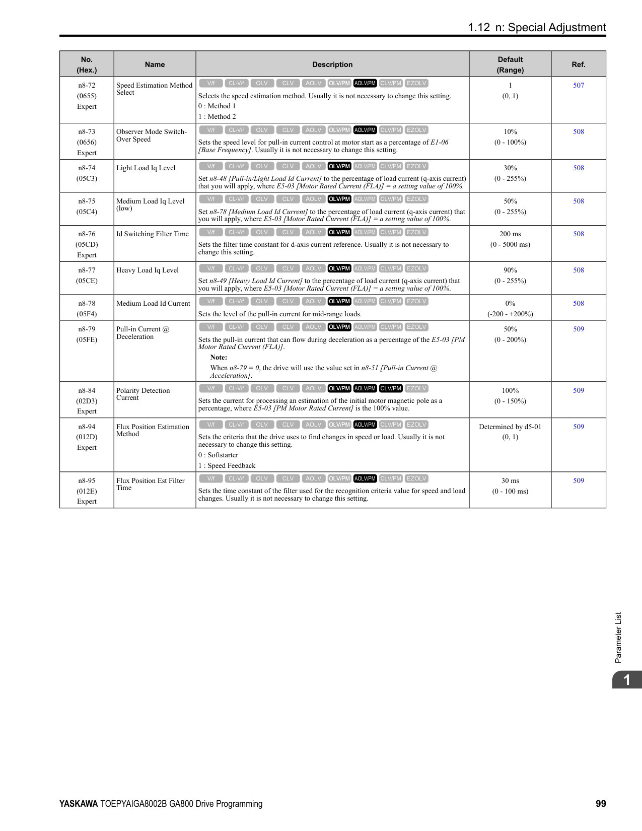
|E5-09|PM Back-EMF Vpeak (mV/(rad/s))|mVs/rad|538.3|590.9|548.2|603.9|556.8|593.1|495.4| |E5-24|PM Back-EMF L-L Vrms (mV/rpm)|mV/min-1|0.0|0.0|0.0|0.0|0.0|0.0|0.0|
|No.|Name|Unit|Motor Code (setting value of E5-01)|Motor Code (setting value of E5-01)|Motor Code (setting value of E5-01)|Motor Code (setting value of E5-01)|Motor Code (setting value of E5-01)|Motor Code (setting value of E5-01)|Motor Code (setting value of E5-01)| |---|---|---|---|---|---|---|---|---|---| |E1-04|Maximum Output Frequency|Hz|87.5|87.5|87.5|87.5|87.5|87.5|87.5| |E1-05|Maximum Output Voltage|V|380.0|380.0|380.0|380.0|380.0|380.0|380.0| |E1-06|Base Frequency|Hz|87.5|87.5|87.5|87.5|87.5|87.5|87.5| |E1-09|Minimum Output Frequency|Hz|4.4|4.4|4.4|4.4|4.4|4.4|4.4| |C5-17|Motor Inertia|kgm2|0.55|0.82|0.96|1.60|1.95|2.82|3.70| |L3-24 *1|Motor Accel Time @ Rated Torque|s|0.205|0.250|0.244|0.336|0.327|0.379|0.414| |n5-02|Motor Inertia Acceleration Time|s|0.205|0.250|0.244|0.336|0.327|0.379|0.414| |n8-49|Heavy Load Id Current|%|-8.6|-14.8|-17.5|-12.5|-14.7|-5.1|-16.3|
*1 The default setting changes when the setting for o2-04 [Drive Model Selection] changes.
################# Table 1.26 SST4 Series Motor Code Setting for Specification of 200 V at 1450 min-1 (r/min)
|No.|Name|Unit|Motor Code (setting value of E5-01)|Motor Code (setting value of E5-01)|Motor Code (setting value of E5-01)|Motor Code (setting value of E5-01)|Motor Code (setting value of E5-01)|Motor Code (setting value of E5-01)|Motor Code (setting value of E5-01)|Motor Code (setting value of E5-01)| |---|---|---|---|---|---|---|---|---|---|---| |E5-01|PM Motor Code Selection|-|2302|2303|2305|2306|2308|230A|230B|230D| |E5-01|Voltage Class|V|200|200|200|200|200|200|200|200| |E5-01|Capacity|kW|0.4|0.75|1.5|2.2|3.7|5.5|7.5|11| |E5-01|Motor Rotation Speed|min-1|1450|1450|1450|1450|1450|1450|1450|1450| |E5-02|PM Motor Rated Power|kW|0.4|0.75|1.5|2.2|3.7|5.5|7.5|11.0| |E5-03|PM Motor Rated Current (FLA)|A|1.77|3.33|5.94|9.48|14.17|20.42|27.92|39.6| |E5-04|PM Motor Pole Count|-|6|6|6|6|6|6|6|6| |E5-05|PM Motor Resistance (ohms/phase)|Ω|3.154|1.835|0.681|0.308|0.405|0.278|0.180|0.098| |E5-06|PM d-axis Inductance (mH/phase)|mH|28.46|19.46|10.00|6.88|8.15|5.77|6.32|3.34| |E5-07|PM q-axis Inductance (mH/phase)|mH|39.29|25.89|15.20|9.25|10.76|8.60|8.80|4.61| |E5-09|PM Back-EMF Vpeak (mV/(rad/s))|mVs/rad|268.8|256.9|271.9|260.2|286.8|314.9|300.8|292.3| |E5-24|PM Back-EMF L-L Vrms (mV/rpm)|mV/min-1|0.0|0.0|0.0|0.0|0.0|0.0|0.0|0.0| |E1-04|Maximum Output Frequency|Hz|72.5|72.5|72.5|72.5|72.5|72.5|72.5|72.5| |E1-05|Maximum Output Voltage|V|190.0|190.0|190.0|190.0|190.0|190.0|190.0|190.0| |E1-06|Base Frequency|Hz|72.5|72.5|72.5|72.5|72.5|72.5|72.5|72.5| |E1-09|Minimum Output Frequency|Hz|3.6|3.6|3.6|3.6|3.6|3.6|3.6|3.6| |C5-17|Motor Inertia|kgm2|0.0016|0.0022|0.0081|0.0133|0.0133|0.017|0.027|0.044| |L3-24 *1|Motor Accel Time @ Rated Torque|s|0.092|0.068|0.125|0.139|0.083|0.070|0.082|0.092| |n5-02|Motor Inertia Acceleration Time|s|0.092|0.068|0.125|0.139|0.083|0.070|0.082|0.092| |n8-49|Heavy Load Id Current|%|-7.5|-9.4|-13.9|-10.0|-15.0|-17.9|-22.7|-20.5|
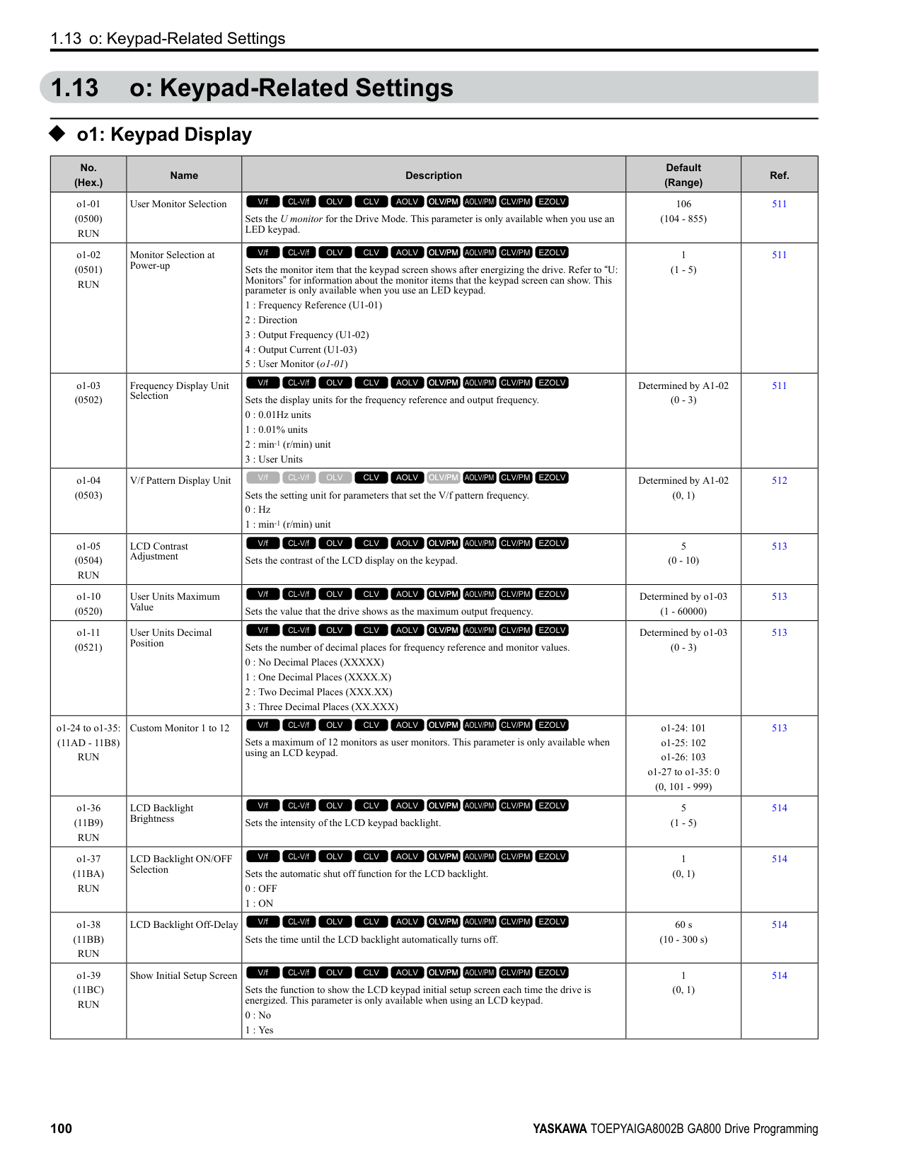
*1 The default setting changes when the setting for o2-04 [Drive Model Selection] changes.
ParameterList
######## 1
Table 1.27 SST4 Series Motor Code Setting for Specification of 200 V at 1450 min-1 (r/min)
|No.|Name|Unit|Motor Code (setting value of E5-01)|Motor Code (setting value of E5-01)|Motor Code (setting value of E5-01)|Motor Code (setting value of E5-01)|Motor Code (setting value of E5-01)|Motor Code (setting value of E5-01)|Motor Code (setting value of E5-01)|Motor Code (setting value of E5-01)| |---|---|---|---|---|---|---|---|---|---|---| |E5-01|PM Motor Code Selection|-|230E|230F|2310|2312|2313|2314|2315|2316| |E5-01|Voltage Class|V|200|200|200|200|200|200|200|200| |E5-01|Capacity|kW|15|18|22|30|37|45|55|75| |E5-01|Motor Rotation Speed|min-1|1450|1450|1450|1450|1450|1450|1450|1450| |E5-02|PM Motor Rated Power|kW|15.0|18.50|22.00|30.00|37.00|45.00|55.00|75.00| |E5-03|PM Motor Rated Current (FLA)|A|54.2|68.3|75.2|102.0|131.3|160.4|191.7|257.3| |E5-04|PM Motor Pole Count|-|6|6|6|6|6|6|6|6| |E5-05|PM Motor Resistance (ohms/phase)|Ω|0.073|0.055|0.048|0.034|0.023|0.016|0.012|0.007| |E5-06|PM d-axis Inductance (mH/phase)|mH|2.94|2.23|2.08|1.67|1.39|0.94|0.82|0.56| |E5-07|PM q-axis Inductance (mH/phase)|mH|3.65|2.85|2.66|2.04|1.73|1.22|1.06|0.76| |E5-09|PM Back-EMF Vpeak (mV/(rad/s))|mVs/rad|305.1|297.6|355.8|355.4|324.0|302.4|337.2|323.4| |E5-24|PM Back-EMF L-L Vrms (mV/rpm)|mV/min|0.0|0.0|0.0|0.0|0.0|0.0|0.0|0.0| |E1-04|Maximum Output Frequency|Hz|72.5|72.5|72.5|72.5|72.5|72.5|72.5|72.5| |E1-05|Maximum Output Voltage|V|190.0|190.0|190.0|190.0|190.0|190.0|190.0|190.0| |E1-06|Base Frequency|Hz|72.5|72.5|72.5|72.5|72.5|72.5|72.5|72.5| |E1-09|Minimum Output Frequency|Hz|3.6|3.6|3.6|3.6|3.6|3.6|3.6|3.6| |C5-17|Motor Inertia|kgm2|0.054|0.063|0.113|0.137|0.252|0.304|0.41|0.55| |L3-24 *1|Motor Accel Time @ Rated Torque|s|0.083|0.079|0.118|0.105|0.157|0.156|0.172|0.169| |n5-02|Motor Inertia Acceleration Time|s|0.083|0.079|0.118|0.105|0.157|0.156|0.172|0.169| |n8-49|Heavy Load Id Current|%|-14.6|-16.4|-11.8|-10.5|-14.5|-17.4|-13.8|-17.5|
|No.|Name|Unit|Motor Code (setting value of E5-01)|Motor Code (setting value of E5-01)|Motor Code (setting value of E5-01)|Motor Code (setting value of E5-01)|Motor Code (setting value of E5-01)|Motor Code (setting value of E5-01)|Motor Code (setting value of E5-01)|Motor Code (setting value of E5-01)| |---|---|---|---|---|---|---|---|---|---|---| |E5-01|PM Motor Code Selection|-|2332|2333|2335|2336|2338|233A|233B|233D| |E5-01|Voltage Class|V|400|400|400|400|400|400|400|400| |E5-01|Capacity|kW|0.4|0.75|1.5|2.2|3.7|5.5|7.5|11|
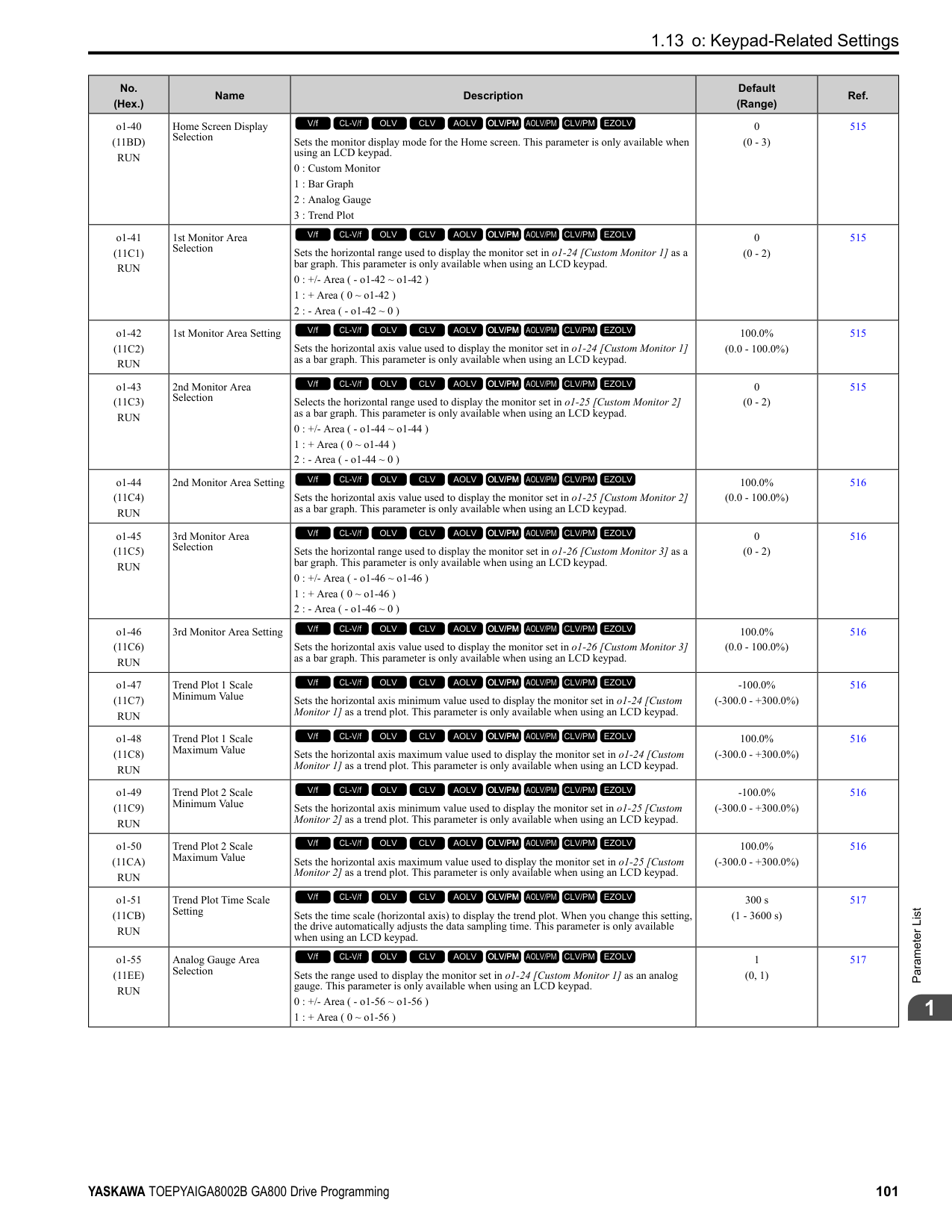
|E5-01|Motor Rotation Speed|min-1|1450|1450|1450|1450|1450|1450|1450|1450| |E5-02|PM Motor Rated Power|kW|0.4|0.75|1.5|2.2|3.7|5.5|7.5|11.0| |E5-03|PM Motor Rated Current (FLA)|A|0.91|1.67|3.02|4.74|7.08|10.21|13.96|20.5| |E5-04|PM Motor Pole Count|-|6|6|6|6|6|6|6|6| |E5-05|PM Motor Resistance (ohms/phase)|Ω|12.616|7.340|2.724|1.232|1.509|1.112|0.720|0.393| |E5-06|PM d-axis Inductance (mH/phase)|mH|113.84|77.84|40.00|27.52|31.73|23.09|25.28|13.36| |E5-07|PM q-axis Inductance (mH/phase)|mH|157.16|103.56|60.80|37.00|40.88|34.39|35.20|18.44| |E5-09|PM Back-EMF Vpeak (mV/(rad/s))|mVs/rad|490.8|513.8|543.7|520.3|580.8|602.7|601.5|584.6|
################# Table 1.29 SST4 Series Motor Code Setting for Specification of 400 V at 1450 min-1 (r/min)
|No.|Name|Unit|Motor Code (setting value of E5-01)|Motor Code (setting value of E5-01)|Motor Code (setting value of E5-01)|Motor Code (setting value of E5-01)|Motor Code (setting value of E5-01)|Motor Code (setting value of E5-01)|Motor Code (setting value of E5-01)|Motor Code (setting value of E5-01)| |---|---|---|---|---|---|---|---|---|---|---| |E5-01|PM Motor Code Selection|-|233E|233F|2340|2342|2343|2344|2345|2346| |E5-01|Voltage Class|V|400|400|400|400|400|400|400|400| |E5-01|Capacity|kW|15|18|22|30|37|45|55|75| |E5-01|Motor Rotation Speed|min-1|1450|1450|1450|1450|1450|1450|1450|1450| |E5-02|PM Motor Rated Power|kW|15|18.50|22.00|30.00|37.00|45.00|55.00|75.00| |E5-03|PM Motor Rated Current (FLA)|A|27.1|34.2|37.6|50.9|65.4|80.2|96.1|129.2| |E5-04|PM Motor Pole Count|-|6|6|6|6|6|6|6|6| |E5-05|PM Motor Resistance (ohms/phase)|Ω|0.291|0.220|0.192|0.136|0.091|0.064|0.048|0.028| |E5-06|PM d-axis Inductance (mH/phase)|mH|11.77|8.94|8.32|6.68|5.30|3.76|3.09|2.24| |E5-07|PM q-axis Inductance (mH/phase)|mH|14.60|11.40|10.64|8.16|6.80|4.88|4.75|3.03| |E5-09|PM Back-EMF Vpeak (mV/(rad/s))|mVs/rad|610.3|595.2|711.6|710.8|652.7|604.8|669.1|646.8| |E5-24|PM Back-EMF L-L Vrms (mV/rpm)|mV/min-1|0.0|0.0|0.0|0.0|0.0|0.0|0.0|0.0| |E1-04|Maximum Output Frequency|Hz|72.5|72.5|72.5|72.5|72.5|72.5|72.5|72.5| |E1-05|Maximum Output Voltage|V|380.0|380.0|380.0|380.0|380.0|380.0|380.0|380.0| |E1-06|Base Frequency|Hz|72.5|72.5|72.5|72.5|72.5|72.5|72.5|72.5| |E1-09|Minimum Output Frequency|Hz|3.6|3.6|3.6|3.6|3.6|3.6|3.6|3.6| |C5-17|Motor Inertia|kgm2|0.054|0.063|0.113|0.137|0.252|0.304|0.41|0.55| |L3-24 *1|Motor Accel Time @ Rated Torque|s|0.083|0.079|0.118|0.105|0.157|0.156|0.172|0.169| |n5-02|Motor Inertia Acceleration Time|s|0.083|0.079|0.118|0.105|0.157|0.156|0.172|0.169| |n8-49|Heavy Load Id Current|%|-14.5|-16.1|-11.8|-10.5|-15.6|-17.4|-21.7|-17.3|
Table 1.30 SST4 Series Motor Code Setting for Specification of 400 V at 1450 min-1 (r/min)
|No.|Name|Unit|Motor Code (setting value of E5-01)|Motor Code (setting value of E5-01)|Motor Code (setting value of E5-01)|Motor Code (setting value of E5-01)|Motor Code (setting value of E5-01)|Motor Code (setting value of E5-01)| |---|---|---|---|---|---|---|---|---| |E5-01|PM Motor Code Selection|-|2347|2348|2349|234A|234C|234D| |E5-01|Voltage Class|V|400|400|400|400|400|400|
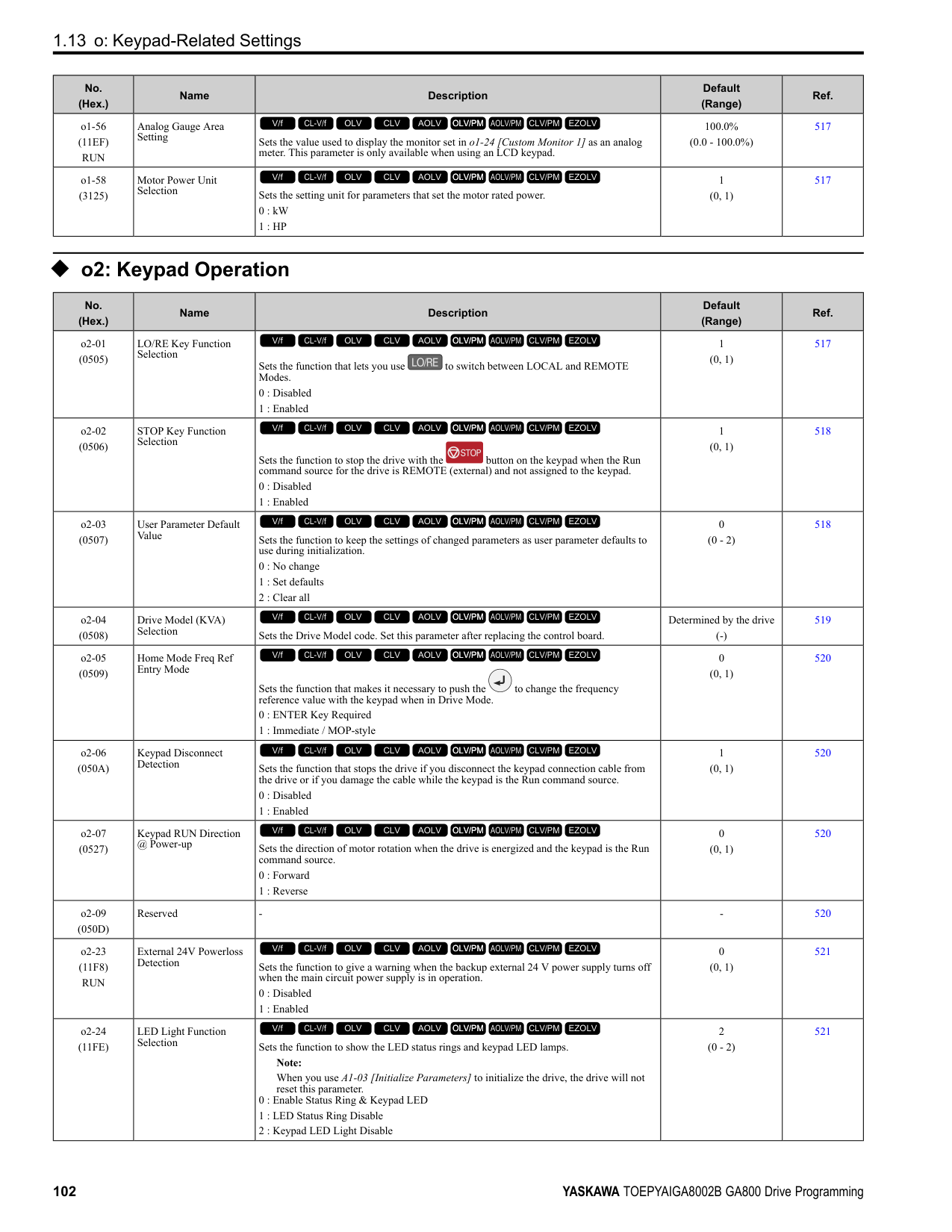
|E5-01|Capacity|kW|90|110|132|160|200|250| |E5-01|Motor Rotation Speed|min-1|1450|1450|1450|1450|1450|1450| |E5-02|PM Motor Rated Power|kW|90.00|110.00|132.00|160.00|200.00|250.00| |E5-03|PM Motor Rated Current (FLA)|A|153.1|191.7|226.0|268.8|331.3|422.9| |E5-04|PM Motor Pole Count|-|6|6|6|6|6|6| |E5-05|PM Motor Resistance (ohms/phase)|Ω|0.024|0.015|0.011|0.007|0.006|0.003| |E5-06|PM d-axis Inductance (mH/phase)|mH|2.20|1.34|1.23|0.92|0.84|0.61| |E5-07|PM q-axis Inductance (mH/phase)|mH|3.23|2.16|1.67|1.30|1.25|0.89| |E5-09|PM Back-EMF Vpeak (mV/(rad/s))|mVs/rad|708.0|637.8|677.0|661.7|687.1|655.9| |E5-24|PM Back-EMF L-L Vrms (mV/rpm)|mV/min-1|0.0|0.0|0.0|0.0|0|0.0| |E1-04|Maximum Output Frequency|Hz|72.5|72.5|72.5|72.5|72.5|72.5| |E1-05|Maximum Output Voltage|V|380.0|380.0|380.0|380.0|380.0|380.0| |E1-06|Base Frequency|Hz|72.5|72.5|72.5|72.5|72.5|72.5| |E1-09|Minimum Output Frequency|Hz|3.6|3.6|3.6|3.6|3.6|3.6| |C5-17|Motor Inertia|kgm2|0.82|0.96|1.60|1.95|2.82|3.70| |L3-24 *1|Motor Accel Time @ Rated Torque|s|0.210|0.201|0.279|0.281|0.325|0.341| |n5-02|Motor Inertia Acceleration Time|s|0.210|0.201|0.279|0.281|0.325|0.341| |n8-49|Heavy Load Id Current|%|-19.6|-24.1|-15.1|-17.0|-19.8|-19.3|
|No.|Name|Unit|Motor Code (setting value of E5-01)|Motor Code (setting value of E5-01)|Motor Code (setting value of E5-01)|Motor Code (setting value of E5-01)|Motor Code (setting value of E5-01)|Motor Code (setting value of E5-01)|Motor Code (setting value of E5-01)|Motor Code (setting value of E5-01)| |---|---|---|---|---|---|---|---|---|---|---| |E5-01|PM Motor Code Selection|-|2402|2403|2405|2406|2408|240A|240B|240D| |E5-01|Voltage Class|V|200|200|200|200|200|200|200|200| |E5-01|Capacity|kW|0.4|0.75|1.5|2.2|3.7|5.5|7.5|11| |E5-01|Motor Rotation Speed|min-1|1150|1150|1150|1150|1150|1150|1150|1150| |E5-02|PM Motor Rated Power|kW|0.4|0.75|1.5|2.2|3.7|5.5|7.5|11.0| |E5-03|PM Motor Rated Current (FLA)|A|1.77|3.44|5.94|9.17|14.79|20.21|27.40|39.0| |E5-04|PM Motor Pole Count|-|6|6|6|6|6|6|6|6| |E5-05|PM Motor Resistance (ohms/phase)|Ω|2.680|1.520|1.071|0.542|0.362|0.295|0.162|0.115| |E5-06|PM d-axis Inductance (mH/phase)|mH|30.55|15.29|17.48|11.98|8.60|9.54|5.31|4.44| |E5-07|PM q-axis Inductance (mH/phase)|mH|42.71|24.28|22.51|15.51|10.69|13.84|8.26|5.68| |E5-09|PM Back-EMF Vpeak (mV/(rad/s))|mVs/rad|313.1|313.1|345.3|342.9|363.8|384.3|379.9|370.2|
################# Table 1.32 SST4 Series Motor Code Setting for Specification of 200 V at 1150 min-1 (r/min)
|No.|Name|Unit|Motor Code (setting value of E5-01)|Motor Code (setting value of E5-01)|Motor Code (setting value of E5-01)|Motor Code (setting value of E5-01)|Motor Code (setting value of E5-01)|Motor Code (setting value of E5-01)|Motor Code (setting value of E5-01)|Motor Code (setting value of E5-01)| |---|---|---|---|---|---|---|---|---|---|---|
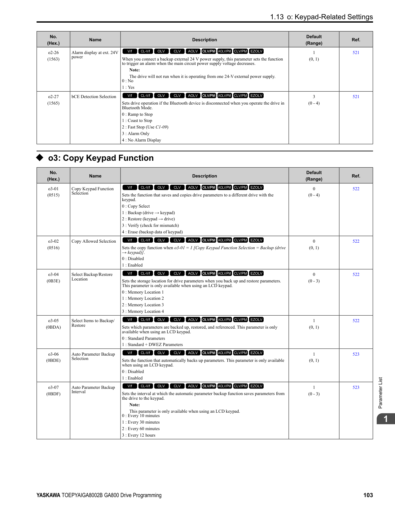
|E5-01|PM Motor Code Selection|-|240E|240F|2410|2412|2413|2414|2415|2416| |E5-01|Voltage Class|V|200|200|200|200|200|200|200|200| |E5-01|Capacity|kW|15|18|22|30|37|45|55|75| |E5-01|Motor Rotation Speed|min-1|1150|1150|1150|1150|1150|1150|1150|1150| |E5-02|PM Motor Rated Power|kW|15|18.50|22.00|30.00|37.00|45.00|55.00|75.00| |E5-03|PM Motor Rated Current (FLA)|A|55.9|65.4|77.0|103.5|126.0|153.1|188.5|260.4| |E5-04|PM Motor Pole Count|-|6|6|6|6|6|6|6|6| |E5-05|PM Motor Resistance (ohms/phase)|Ω|0.083|0.065|0.052|0.035|0.026|0.019|0.013|0.009| |E5-06|PM d-axis Inductance (mH/phase)|mH|3.50|2.92|2.55|2.03|1.59|1.24|0.98|0.70| |E5-07|PM q-axis Inductance (mH/phase)|mH|4.23|3.79|3.22|2.46|1.92|1.64|1.37|0.97| |E5-09|PM Back-EMF Vpeak (mV/(rad/s))|mVs/rad|364.5|404.5|445.1|444.4|447.3|470.8|422.4|418.3| |E5-24|PM Back-EMF L-L Vrms (mV/rpm)|mV/min-1|0.0|0.0|0.0|0.0|0.0|0.0|0.0|0.0| |E1-04|Maximum Output Frequency|Hz|57.5|57.5|57.5|57.5|57.5|57.5|57.5|57.5| |E1-05|Maximum Output Voltage|V|190.0|190.0|190.0|190.0|190.0|190.0|190.0|190.0| |E1-06|Base Frequency|Hz|57.5|57.5|57.5|57.5|57.5|57.5|57.5|57.5| |E1-09|Minimum Output Frequency|Hz|2.9|2.9|2.9|2.9|2.9|2.9|2.9|2.9| |C5-17|Motor Inertia|kgm2|0.063|0.113|0.137|0.252|0.304|0.410|0.55|0.82| |L3-24 *1|Motor Accel Time @ Rated Torque|s|0.061|0.089|0.090|0.122|0.119|0.132|0.145|0.159| |n5-02|Motor Inertia Acceleration Time|s|0.061|0.089|0.090|0.122|0.119|0.132|0.145|0.159| |n8-49|Heavy Load Id Current|%|-13.7|-15.2|-10.9|-9.8|-9.3|-11.5|-17.7|-17.1|
Table 1.33 SST4 Series Motor Code Setting for Specification of 400 V at 1150 min-1 (r/min)
|No.|Name|Unit|Motor Code (setting value of E5-01)|Motor Code (setting value of E5-01)|Motor Code (setting value of E5-01)|Motor Code (setting value of E5-01)|Motor Code (setting value of E5-01)|Motor Code (setting value of E5-01)|Motor Code (setting value of E5-01)| |---|---|---|---|---|---|---|---|---|---| |E5-01|PM Motor Code Selection|-|2432|2433|2435|2436|2438|243A|243B| |E5-01|Voltage Class|V|400|400|400|400|400|400|400| |E5-01|Capacity|kW|0.4|0.75|1.5|2.2|3.7|5.5|7.5| |E5-01|Motor Rotation Speed|min|1150|1150|1150|1150|1150|1150|1150| |E5-02|PM Motor Rated Power|kW|0.4|0.75|1.5|2.2|3.7|5.5|7.5| |E5-03|PM Motor Rated Current (FLA)|A|0.89|1.72|3.02|4.58|7.40|10.21|13.75| |E5-04|PM Motor Pole Count|-|6|6|6|6|6|6|6| |E5-05|PM Motor Resistance (ohms/phase)|Ω|10.720|6.080|4.336|2.143|1.428|1.199|0.648| |E5-06|PM d-axis Inductance (mH/phase)|mH|122.20|61.16|70.24|46.20|33.87|41.67|21.24| |E5-07|PM q-axis Inductance (mH/phase)|mH|170.80|97.12|90.04|60.28|42.98|69.15|33.04| |E5-09|PM Back-EMF Vpeak (mV/(rad/s))|mVs/rad|626.1|626.1|703.1|727.6|699.0|861.5|759.7| |E5-24|PM Back-EMF L-L Vrms (mV/rpm)|mV/min-1|0.0|0.0|0.0|0.0|0.0|0.0|0.0| |E1-04|Maximum Output Frequency|Hz|57.5|57.5|57.5|57.5|57.5|57.5|57.5| |E1-05|Maximum Output Voltage|V|380.0|380.0|380.0|380.0|380.0|380.0|380.0| |E1-06|Base Frequency|Hz|57.5|57.5|57.5|57.5|57.5|57.5|57.5| |E1-09|Minimum Output Frequency|Hz|2.9|2.9|2.9|2.9|2.9|2.9|2.9|
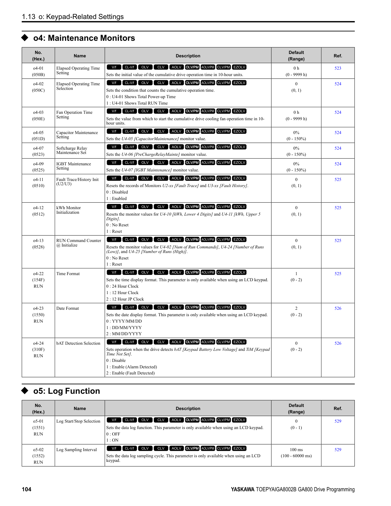
|C5-17|Motor Inertia|kgm2|0.0022|0.0042|0.0081|0.0133|0.0168|0.027|0.044| |L3-24 *1|Motor Accel Time @ Rated Torque|s|0.080|0.081|0.078|0.088|0.066|0.070|0.085| |n5-02|Motor Inertia Acceleration Time|s|0.080|0.081|0.078|0.088|0.066|0.070|0.085| |n8-49|Heavy Load Id Current|%|-8.4|-11.0|-9.9|-9.0|-11.4|-23.2|-22.1|
|No.|Name|Unit|Motor Code (setting value of E5-01)|Motor Code (setting value of E5-01)|Motor Code (setting value of E5-01)|Motor Code (setting value of E5-01)|Motor Code (setting value of E5-01)|Motor Code (setting value of E5-01)|Motor Code (setting value of E5-01)| |---|---|---|---|---|---|---|---|---|---| |E5-01|PM Motor Code Selection|-|243D|243E|243F|2440|2442|2443|2444| |E5-01|Voltage Class|V|400|400|400|400|400|400|400| |E5-01|Capacity|kW|11|15|18|22|30|37|45| |E5-01|Motor Rotation Speed|min-1|1150|1150|1150|1150|1150|1150|1150| |E5-02|PM Motor Rated Power|kW|11.0|15|18.50|22.00|30.00|37.00|45.00| |E5-03|PM Motor Rated Current (FLA)|A|19.5|27.7|32.7|39.2|51.8|63.0|76.6| |E5-04|PM Motor Pole Count|-|6|6|6|6|6|6|6| |E5-05|PM Motor Resistance (ohms/phase)|Ω|0.460|0.325|0.260|0.209|0.140|0.106|0.076| |E5-06|PM d-axis Inductance (mH/phase)|mH|17.76|12.83|11.68|10.09|8.12|6.43|4.96| |E5-07|PM q-axis Inductance (mH/phase)|mH|22.72|17.19|15.16|16.25|9.84|7.71|6.56| |E5-09|PM Back-EMF Vpeak (mV/(rad/s))|mVs/rad|740.4|716.6|809.1|786.2|888.8|857.7|941.6|
|No.|Name|Unit|Motor Code (setting value of E5-01)|Motor Code (setting value of E5-01)|Motor Code (setting value of E5-01)|Motor Code (setting value of E5-01)|Motor Code (setting value of E5-01)|Motor Code (setting value of E5-01)|Motor Code (setting value of E5-01)| |---|---|---|---|---|---|---|---|---|---| |E5-24|PM Back-EMF L-L Vrms (mV/rpm)|mV/min-1|0.0|0.0|0.0|0.0|0.0|0.0|0.0| |E1-04|Maximum Output Frequency|Hz|57.5|57.5|57.5|57.5|57.5|57.5|57.5| |E1-05|Maximum Output Voltage|V|380.0|380.0|380.0|380.0|380.0|380.0|380.0| |E1-06|Base Frequency|Hz|57.5|57.5|57.5|57.5|57.5|57.5|57.5| |E1-09|Minimum Output Frequency|Hz|2.9|2.9|2.9|2.9|2.9|2.9|2.9| |C5-17|Motor Inertia|kgm2|0.054|0.063|0.113|0.137|0.252|0.304|0.410| |L3-24 *1|Motor Accel Time @ Rated Torque|s|0.071|0.061|0.089|0.090|0.122|0.119|0.132| |n5-02|Motor Inertia Acceleration Time|s|0.071|0.061|0.089|0.090|0.122|0.119|0.132| |n8-49|Heavy Load Id Current|%|-16.7|-20.2|-15.2|-27.7|-9.8|-10.2|-11.5|
*1 The default setting changes when the setting for o2-04 [Drive Model Selection] changes.
################# Table 1.35 SST4 Series Motor Code Setting for Specification of 400 V at 1150 min-1 (r/min)
|No.|Name|Unit|Motor Code (setting value of E5-01)|Motor Code (setting value of E5-01)|Motor Code (setting value of E5-01)|Motor Code (setting value of E5-01)|Motor Code (setting value of E5-01)|Motor Code (setting value of E5-01)|Motor Code (setting value of E5-01)|
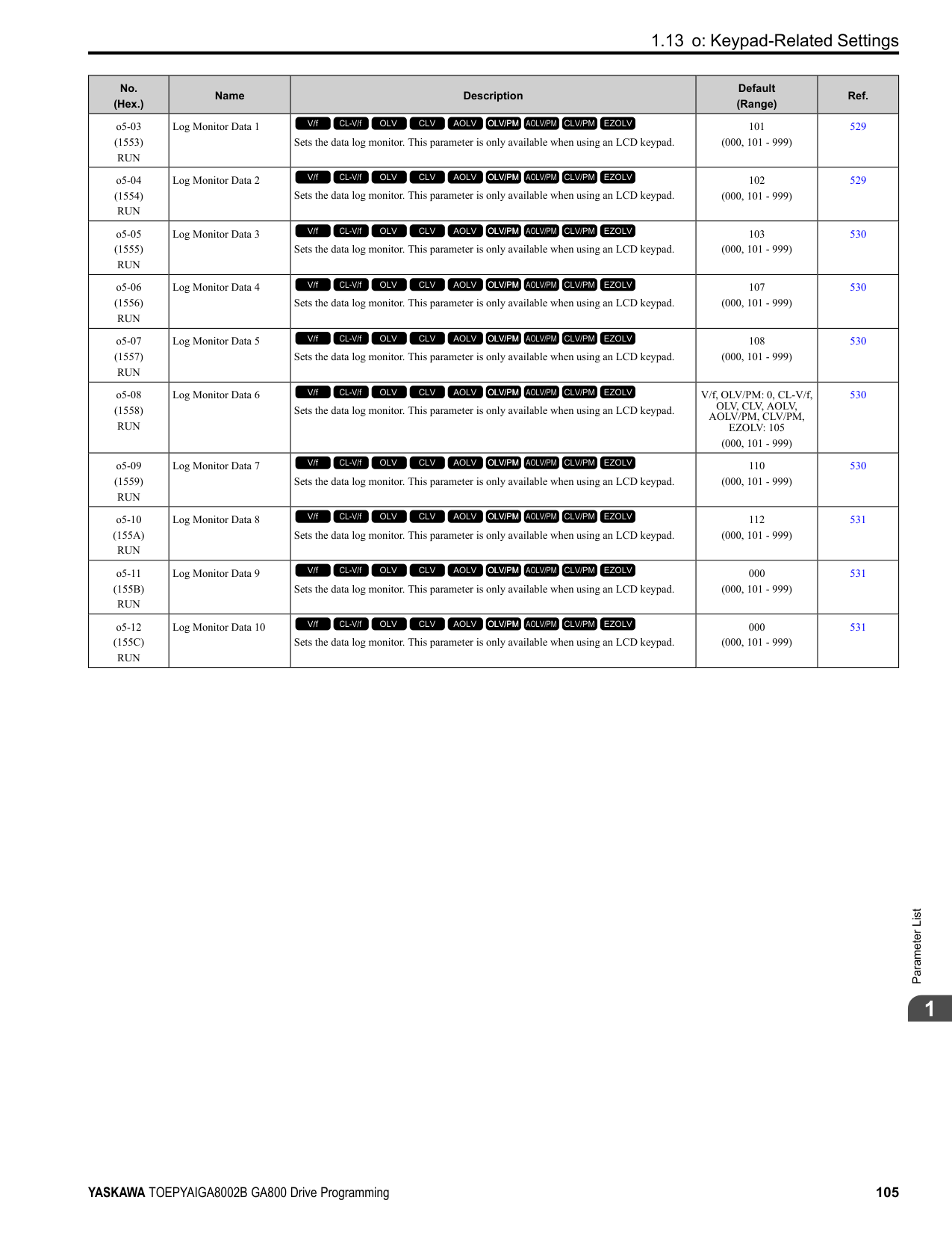
|---|---|---|---|---|---|---|---|---|---| |E5-01|PM Motor Code Selection|-|2445|2446|2447|2448|2449|244A|244C| |E5-01|Voltage Class|V|400|400|400|400|400|400|400| |E5-01|Capacity|kW|55|75|90|110|132|160|200| |E5-01|Motor Rotation Speed|min-1|1150|1150|1150|1150|1150|1150|1150| |E5-02|PM Motor Rated Power|kW|55.00|75.00|90.00|110.00|132.00|160.00|200.00| |E5-03|PM Motor Rated Current (FLA)|A|93.1|128.1|153.1|186.5|221.9|269.8|336.5| |E5-04|PM Motor Pole Count|-|6|6|6|6|6|6|6| |E5-05|PM Motor Resistance (ohms/phase)|Ω|0.051|0.032|0.026|0.015|0.012|0.009|0.007| |E5-06|PM d-axis Inductance (mH/phase)|mH|3.99|2.97|2.44|1.87|1.49|1.41|1.22| |E5-07|PM q-axis Inductance (mH/phase)|mH|5.39|3.90|3.23|2.46|2.08|1.88|1.51| |E5-09|PM Back-EMF Vpeak (mV/(rad/s))|mVs/rad|853.8|829.6|835.6|833.4|848.6|889.1|915.0| |E5-24|PM Back-EMF L-L Vrms (mV/rpm)|mV/min-1|0.0|0.0|0.0|0.0|0.0|0.0|0.0| |E1-04|Maximum Output Frequency|Hz|57.5|57.5|57.5|57.5|57.5|57.5|57.5| |E1-05|Maximum Output Voltage|V|380.0|380.0|380.0|380.0|380.0|380.0|380.0| |E1-06|Base Frequency|Hz|57.5|57.5|57.5|57.5|57.5|57.5|57.5| |E1-09|Minimum Output Frequency|Hz|2.9|2.9|2.9|2.9|2.9|2.9|2.9| |C5-17|Motor Inertia|kgm2|0.55|0.82|0.96|1.60|1.95|2.82|3.70| |L3-24 *1|Motor Accel Time @ Rated Torque|s|0.145|0.159|0.155|0.211|0.214|0.256|0.268| |n5-02|Motor Inertia Acceleration Time|s|0.145|0.159|0.155|0.211|0.214|0.256|0.268| |n8-49|Heavy Load Id Current|%|-15.9|-15.7|-15.7|-14.7|-16.5|-14.1|-10.3|
2
Parameter Details
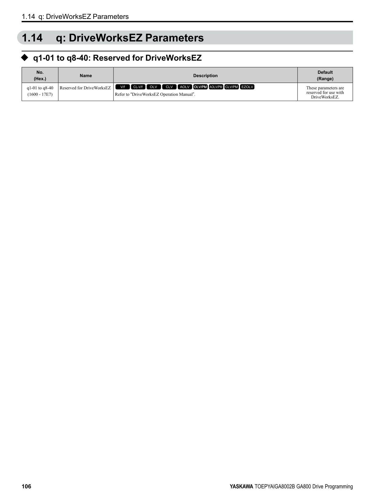
####### 2.1 Section Safety
|DANGER
| |---| |Do not ignore the safety messages in this manual. If you ignore the safety messages in this manual, it will cause serious injury or death. The manufacturer is not responsible for injuries or damage to equipment.|
####### 2.2 A: Initialization Parameters
A parameters [Initialization Parameters] set the operating environment and operating conditions for the drive.
◆ A1: Initialization A1 parameters set the operating environment and operating conditions for the drive. For example, these parameters set the keypad language, the control method, and the parameter access level for the drive.
######## ■ A1-00: Language Selection
|No. (Hex.)|Name|Description|Default (Range)| |---|---|---|---| |A1-00 (0100) RUN|Language Selection|Sets the language for the LCD keypad.
V/f CL-V/f OLV CLV AOLV OLV/PM AOLV/PM CLV/PM EZOLV
|0 (0 - 12)|
Note: When you initialize the drive with parameter A1-03 [Initialize Parameters], the drive will not reset this parameter.
######## ■ A1-01: Access Level Selection
|No. (Hex.)|Name|Description|Default (Range)|
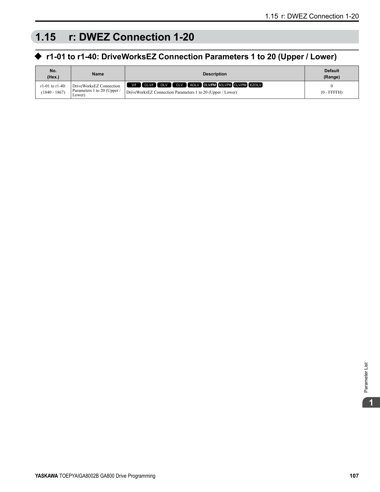
|---|---|---|---| |A1-01 (0101) RUN|Access Level Selection|Sets user access to parameters. The access level controls which parameters the keypad will display, and which parameters the user can set.
V/f CL-V/f OLV CLV AOLV OLV/PM AOLV/PM CLV/PM EZOLV
|2 (0 - 3)|
ParameterDetails
2
Table 2.1 Access Level and Available Keypad Screens
|Mode|Keypad Screen|A1-01 [Access Level Selection] Setting|A1-01 [Access Level Selection] Setting|A1-01 [Access Level Selection] Setting|A1-01 [Access Level Selection] Setting| |---|---|---|---|---|---| |Mode|Keypad Screen|0|1|2|3| |Drive Mode|Monitors|Yes|Yes|Yes|Yes| |Programming Mode|Parameters|Yes|Yes|Yes|Yes| |Programming Mode|User Custom Parameters|No|Yes|Yes|Yes| |Programming Mode|Parameter Backup/Restore|No|No|Yes|Yes| |Programming Mode|Modified Parameters/Fault Log|No|No|Yes|Yes| |Programming Mode|Auto-Tuning|No|No|Yes|Yes| |Programming Mode|Initial Setup Screen|No|No|Yes|Yes| |Programming Mode|Diagnostic Tools|No|No|Yes|Yes|
Note:
######## ■ A1-02: Control Method Selection
|No. (Hex.)|Name|Description|Default (Range)| |---|---|---|---| |A1-02 (0102)|Control Method Selection|Sets the control method for the drive application and the motor.
V/f CL-V/f OLV CLV AOLV OLV/PM AOLV/PM CLV/PM EZOLV
|2 (0 - 8)|
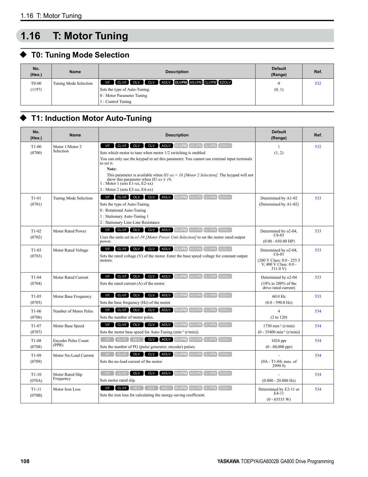
Note: When you change the A1-02 setting, the parameter values specified by A1-02 are changed to their default values.
Sets the control method for the drive application and the motor.
Use this control method for general variable-speed control applications in which high-precision speed control is necessary. In this control method, a feedback signal from the motor is not necessary to have high torque response and high torque when operating at low speeds. The speed control range is 1:120.
• High-precision torque control. A speed feedback signal from the motor is necessary for this control method. The speed control range is 1:1500.
############## 4 : Advanced Open Loop Vector
This is a control method for induction motors. Use this control method for applications in which high-precision speed control is necessary. This control method has high speed and torque response and high torque when operating at low speeds. The speed control range is 1:200.
############## 5 : PM Open Loop Vector
The drive controls an IPM motor or SPM motor in this control method. Use this control method for general variablespeed control applications in which a high level of responsiveness or high-precision speed control are not necessary. The speed control range is 1:20.
############## 6 : PM Advanced Open Loop Vector
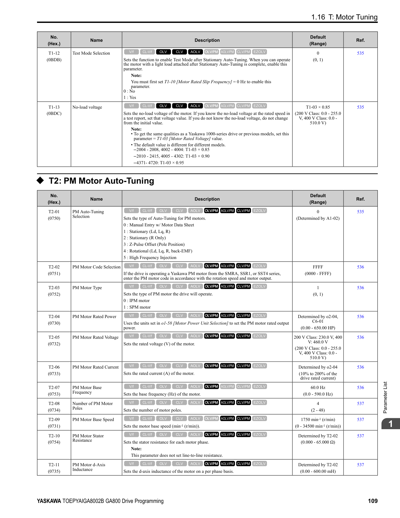
The drive can control an IPM motor in this control method. Use this control method for general variable-speed control applications in which high-precision speed control and torque limit are necessary. The speed control range is 1:20. The speed control range is 1:100 when n8-57 = 1 [HFI Overlap Selection = Enabled].
############## 7 : PM Closed Loop Vector
The drive controls a PM motor in this control method. Use this control method for constant torque applications in which high-precision control with a PM motor is necessary. Also use this control method for general variable-speed control applications in which high torque response and high-precision torque control are necessary. A speed feedback signal from the motor is necessary for this control method. The speed control range is 1:1500.
############## 8 : EZ Vector Control
The drive controls SynRM (Synchronous Reluctance Motors) in this control method. This control method uses an easier procedure to operate motors with more efficiency. Use this control method for derating torque applications. For example, fans and pumps.
######## ■ A1-03: Initialize Parameters
|No. (Hex.)|Name|Description|Default (Range)| |---|---|---|---| |A1-03 (0103)|Initialize Parameters|Sets parameters to default values.
V/f CL-V/f OLV CLV AOLV OLV/PM AOLV/PM CLV/PM EZOLV
|0 (0 - 3330)|
################# Note:
Sets parameters to the values set by the user as user settings. Set o2-03 = 1 [User Parameter Default Value = Set defaults] to save the user settings.
You can save the parameter settings that were adjusted for the test run as user-set default values to the drive. When you make changes to the parameter values after you save the settings as User Parameter Settings, the drive will set the parameters to the User Parameter Setting value when you initialize with A1-03 = 1110. Follow this procedure to save User Parameter setting values, and to do a User Initialization.
2220 : 2-Wire Initialization Sets MFDI terminal S1 to Forward Run and terminal S2 to Reverse Run, and resets all parameters to default settings.
ParameterDetails
######## 2
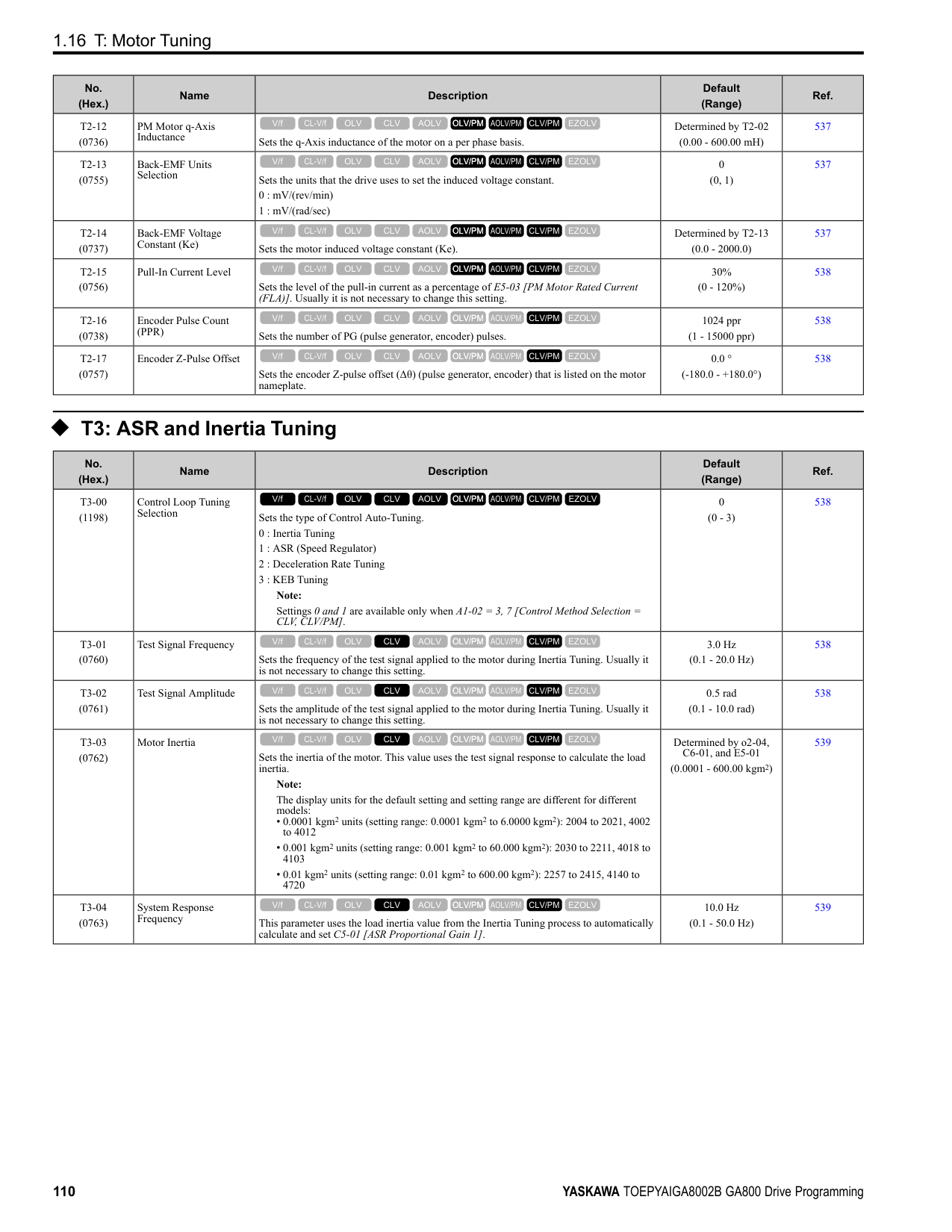
3330 : 3-Wire Initialization Sets MFDI terminal S1 to Run, terminal S2 to Stop, and terminal S5 to FWD/REV, and resets all parameters to default settings. The drive will not initialize the parameters in Table 2.2 when A1-03 = 2220, 3330.
Table 2.2 Parameters that are not Initialized Using a 2-Wire Sequence or a 3-Wire Sequence
|No.|Name| |---|---| |A1-00|Language Selection| |A1-02|Control Method Selection| |A1-07|DriveWorksEZ Function Selection| |E1-03|V/f Pattern Selection| |E5-01|PM Motor Code Selection| |E5-02|PM Motor Rated Power (kW)| |E5-03|Motor Rated Current (FLA)| |E5-04|PM Motor Pole Count| |E5-05|PM Motor Resistance (ohms/phase)| |E5-06|PM d-axis Inductance (mH/phase)| |E5-07|PM q-axis Inductance (mH/phase)| |E5-09|PM Back-EMF Vpeak (mV/(rad/s))| |E5-11|Encoder Z-Pulse Offset| |E5-24|PM Back-EMF L-LVrms (mV/rpm)| |E5-25|Polarity Estimation Timeout| |F6-08|Comm Parameter Reset @Initialize| |F6-xx/F7-xx|Communication Option Parameters Set F6-08 = 1 [Comm Parameter Reset @Initialize = Reset Back to Factory Default] to initialize communication option card parameters.| |L8-35|Installation Method Selection| |o2-04|Drive Model (KVA) Selection| |o2-24|LED Light Function Selection| |q1-xx - q8-xx|DriveWorksEZ Parameters| |r1-xx|DWEZ Connection 1-20|
Note:
######## ■ A1-04: Password
|No. (Hex.)|Name|Description|Default (Range)| |---|---|---|---| |A1-04 (0104)|Password|Entry point for the password set in A1-05 [Password Setting]. The user can view the settings of parameters that are locked without entering the password. Enter the correct password in this parameter to change parameter settings.
V/f CL-V/f OLV CLV AOLV OLV/PM AOLV/PM CLV/PM EZOLV
|0000 (0000 - 9999)|
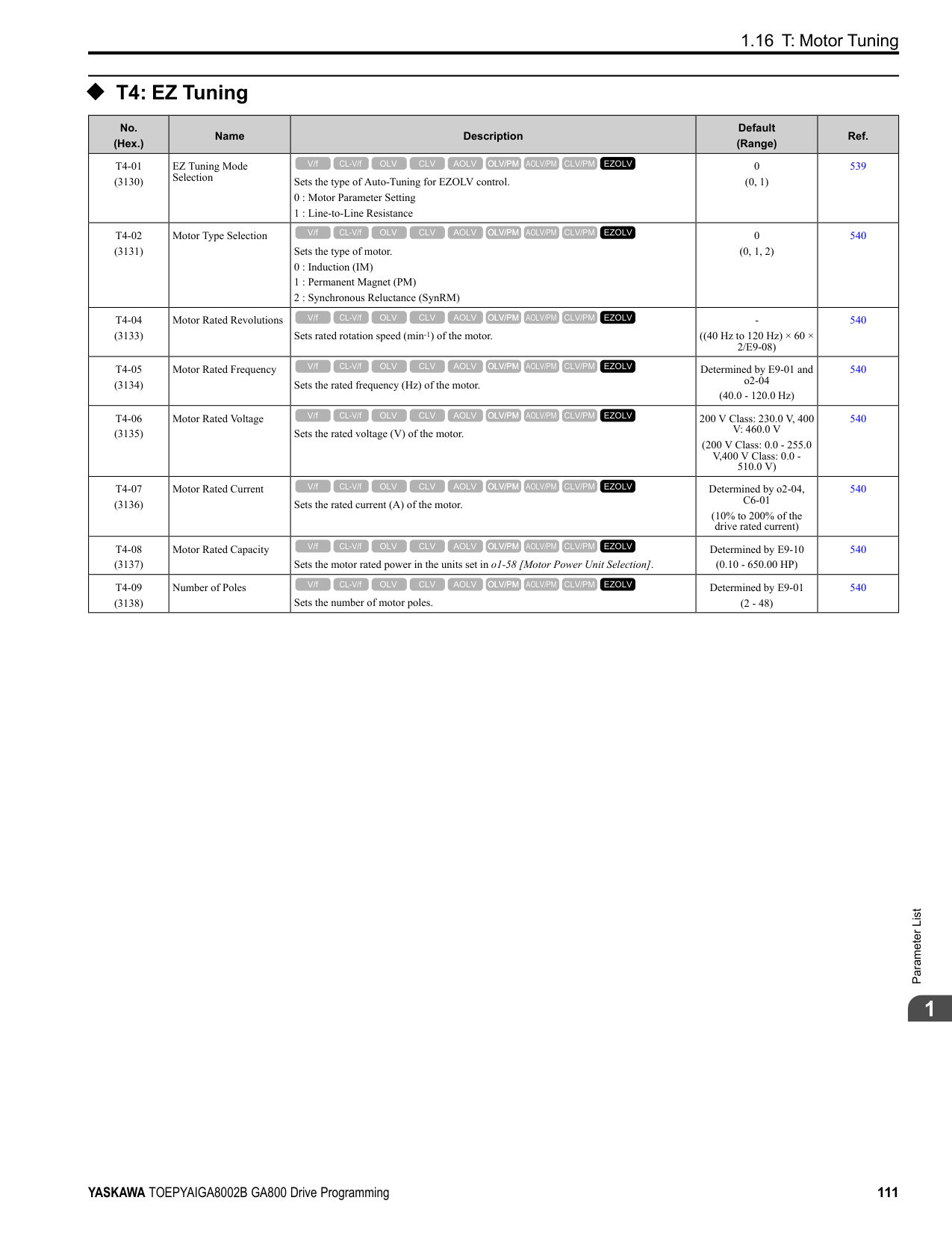
If the password entered in A1-04 does not agree with the password setting in A1-05, you cannot change these parameters:
04 and push . Enter the Password to Unlock Parameters Use this procedure to unlock parameter settings. Set the password in A1-05 [Password Setting], and show the Parameter Setting Mode screen on the keypad. This procedure verifies the password, and makes sure that the parameter settings are unlocked.
Push (Back) until the keypad shows the Parameter Setup Mode screen.
######## ■ A1-05: Password Setting
|No. (Hex.)|Name|Description|Default (Range)| |---|---|---|---| |A1-05 (0105)|Password Setting|Set the password to lock parameters and prevent changes to parameter settings. Enter the correct password in A1-04 [Password] to unlock parameters and accept changes.
V/f CL-V/f OLV CLV AOLV OLV/PM AOLV/PM CLV/PM EZOLV
|0000 (0000 - 9999)|
This parameter can lock these parameter settings:
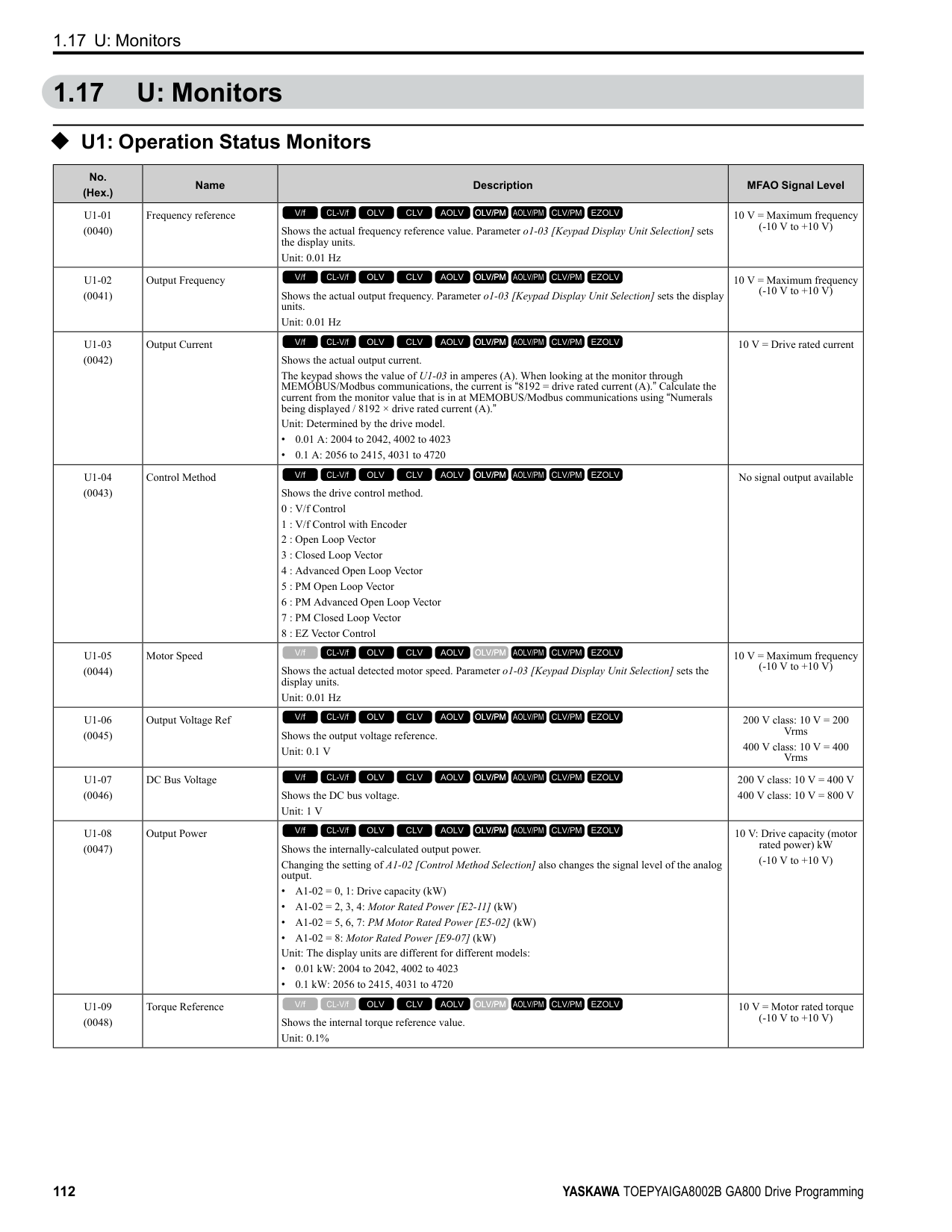
######## ■ A1-06: Application Preset
WARNING! Sudden Movement Hazard. Check the I/O signals and the external sequences for the drive before you set the Application Preset function. When you set the Application Preset function (A1-06 ≠ 0), it changes the I/O terminal functions for the drive and it can cause equipment to operate unusually. This can cause serious injury or death.
ParameterDetails
######## 2
|No. (Hex.)|Name|Description|Default (Range)| |---|---|---|---| |A1-06 (0127)|Application Preset|Sets the drive to operate in selected application conditions.
V/f CL-V/f OLV CLV AOLV OLV/PM AOLV/PM CLV/PM EZOLV
|0 (0 - 5)|
The drive software contains the application presets shown below. Set A1-06 to align with the application to let the drive automatically set the best parameter settings for the selected application. The drive saves parameters frequently used for the application in parameters A2-01 to A2-16 [User Parameters 1 to 16] for easy configuration and reference in [User Custom Parameters] in the main menu.
Table 2.3 Parameters Saved as User Parameters with the General-purpose Preset
|User Parameter No.|Parameter No. Saved|Name| |---|---|---| |A2-01|A1-02|Control Method Selection| |A2-02|b1-01|Frequency Reference Selection 1| |A2-03|b1-02|Run Command Selection 1| |A2-04|b1-03|Stopping Method Selection| |A2-05|C1-01|Acceleration Time 1|
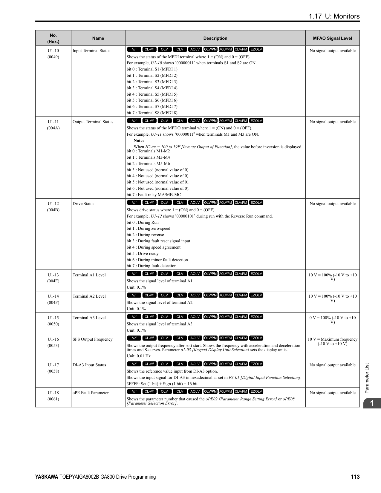
|A2-06|C1-02|Deceleration Time 1| |A2-07|C6-01|Normal / Heavy Duty Selection| |A2-08|C6-02|Carrier Frequency Selection| |A2-09|d1-01|Reference 1| |A2-10|d1-02|Reference 2| |A2-11|d1-03|Reference 3| |A2-12|d1-04|Reference 4| |A2-13|d1-17|Jog Reference| |A2-14|E1-01|Input AC Supply Voltage| |A2-15|E1-03|V/f Pattern Selection| |A2-16|E1-04|Maximum Output Frequency| |A2-17|E1-05|Maximum Output Voltage| |A2-18|E1-06|Base Frequency| |A2-19|E1-09|Minimum Output Frequency| |A2-20|E1-13|Base Voltage| |A2-21|E2-01|Motor Rated Current (FLA)| |A2-22|E2-04|Motor Pole Count| |A2-23|E2-11|Motor Rated Power|
|User Parameter No.|Parameter No. Saved|Name| |---|---|---| |A2-24|H4-02|Terminal FM Analog Output Gain| |A2-25|L1-01|Motor Overload (oL1) Protection| |A2-26|L3-04|Stall Prevention during Decel|
Table 2.4 Best Parameter Settings for Water Supply Pump Applications
The drive saves the parameters in Table 2.5 as user parameters.
Table 2.5 Parameters Saved as User Parameters with the Water Supply Pump Preset
|No.|Name|Optimal Value| |---|---|---| |A1-02|Control Method Selection|0: V/f Control| |b1-04|Reverse Operation Selection|1: Reverse Disabled|
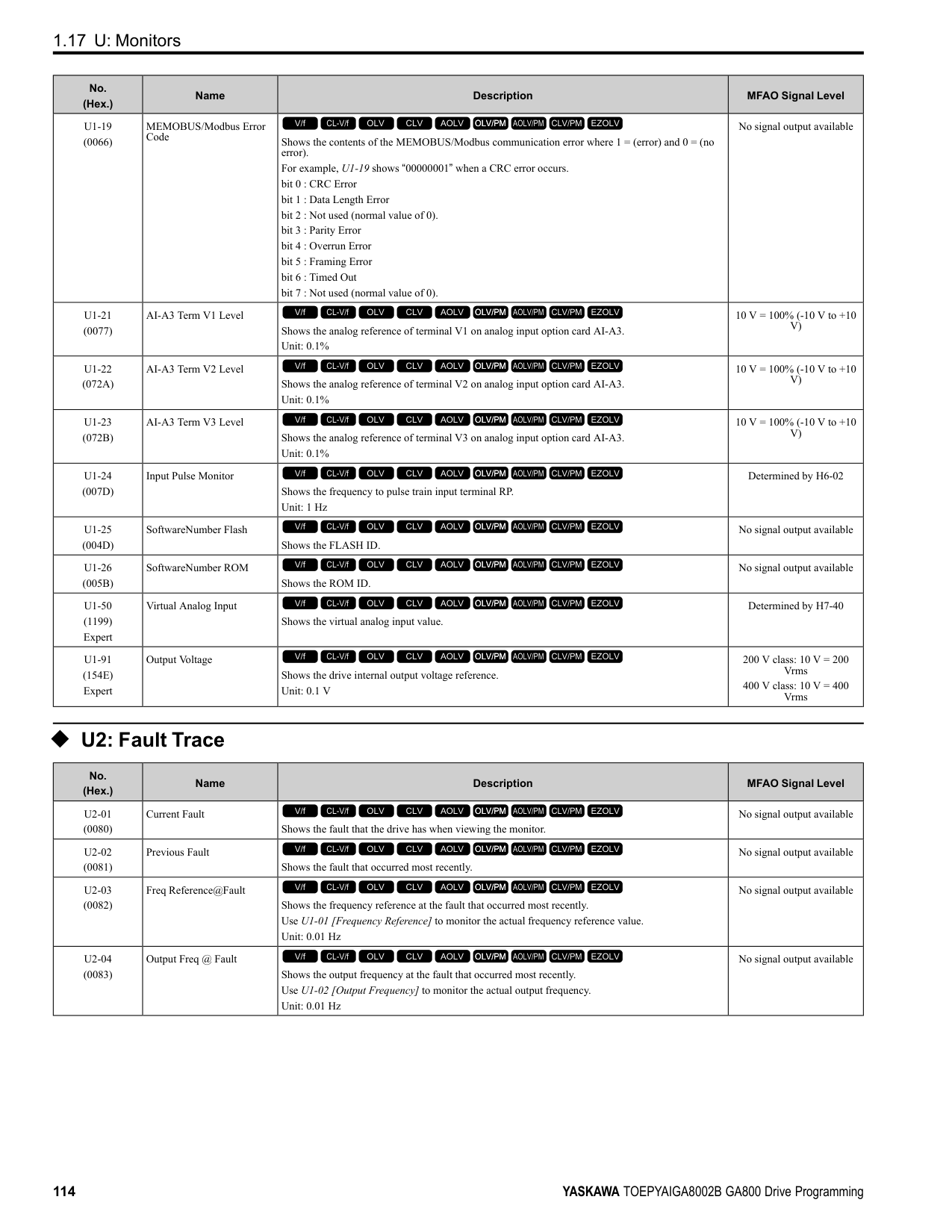
|C1-01|Acceleration Time 1|1.0 s| |C1-02|Deceleration Time 1|1.0 s| |C6-01|Normal Heavy Duty Selection|1: Normal Duty Rating| |E1-03|V/f Pattern Selection|F: Custom| |E1-07|Mid Point A Frequency|30.0 Hz| |E1-08|Mid Point AVoltage|50.0 V| |L2-01|Power Loss Ride Through Select|1: Enabled| |L3-04|Stall Prevention during Decel|1: Enabled|
|User Parameter No.|Parameter No. Saved|Name| |---|---|---| |A2-01|b1-01|Frequency Reference Selection 1| |A2-02|b1-02|Run Command Selection 1| |A2-03|b1-04|Reverse Operation Selection| |A2-04|C1-01|Acceleration Time 1| |A2-05|C1-02|Deceleration Time 1| |A2-06|E1-03|V/f Pattern Selection| |A2-07|E1-07|Mid Point A Frequency| |A2-08|E1-08|Mid Point AVoltage| |A2-09|E2-01|Motor Rated Current (FLA)| |A2-10|H1-05|Terminal S5 Function Selection| |A2-11|H1-06|Terminal S6 Function Selection| |A2-12|H1-07|Terminal S7 Function Selection| |A2-13|L5-01|Number of Auto-Restart Attempts|
ParameterDetails
Table 2.6 Best Parameter Settings for Conveyor Applications
|No.|Name|Optimal Value| |---|---|---| |A1-02|Control Method Selection|0: V/f Control| |C1-01|Acceleration Time 1|3.0 s| |C1-02|Deceleration Time 1|3.0 s|
The drive saves the parameters in Table 2.7 as user parameters.
Table 2.7 Parameters Saved as User Parameters with the Conveyor Preset
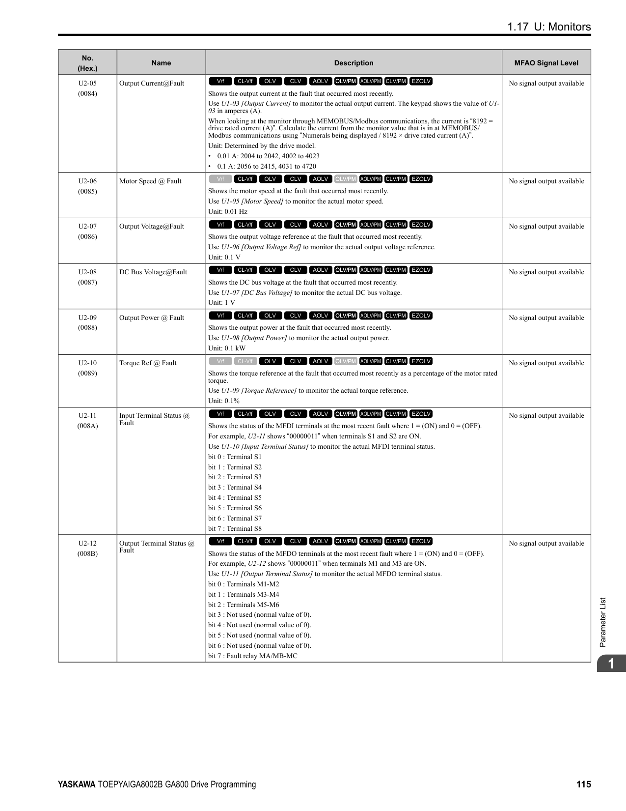
|User Parameter No.|Parameter No. Saved|Name| |---|---|---| |A2-01|A1-02|Control Method Selection| |A2-02|b1-01|Frequency Reference Selection 1| |A2-03|b1-02|Run Command Selection 1| |A2-04|C1-01|Acceleration Time 1| |A2-05|C1-02|Deceleration Time 1| |A2-06|E2-01|Motor Rated Current (FLA)| |A2-07|L3-04|Stall Prevention during Decel|
3 : Exhaust Fan The drive automatically sets the parameters in Table 2.8 for an exhaust fan application.
Table 2.8 Best Parameter Settings for Exhaust Fan Applications
|No.|Name|Optimal Value| |---|---|---| |A1-02|Control Method Selection|0: V/f Control| |b1-04|Reverse Operation Selection|1: Reverse Disabled| |C6-01|Normal / Heavy Duty Selection|1: Normal Duty Rating| |E1-03|V/f Pattern Selection|F: Custom| |E1-07|Mid Point A Frequency|30.0 Hz| |E1-08|Mid Point AVoltage|50.0 V| |L2-01|Power Loss Ride Through Select|1: Enabled| |L3-04|Stall Prevention during Decel|1: Enabled|
The drive saves the parameters in Table 2.9 as user parameters.
Table 2.9 Parameters Saved as User Parameters with the Exhaust Fan Preset
|User Parameter No.|Parameter No. Saved|Name| |---|---|---| |A2-01|b1-01|Frequency Reference Selection 1| |A2-02|b1-02|Run Command Selection 1| |A2-03|b1-04|Reverse Operation Selection| |A2-04|b3-01|Speed Search at Start Selection| |A2-05|C1-01|Acceleration Time 1| |A2-06|C1-02|Deceleration Time 1| |A2-07|E1-03|V/f Pattern Selection| |A2-08|E1-07|Mid Point A Frequency| |A2-09|E1-08|Mid Point AVoltage|
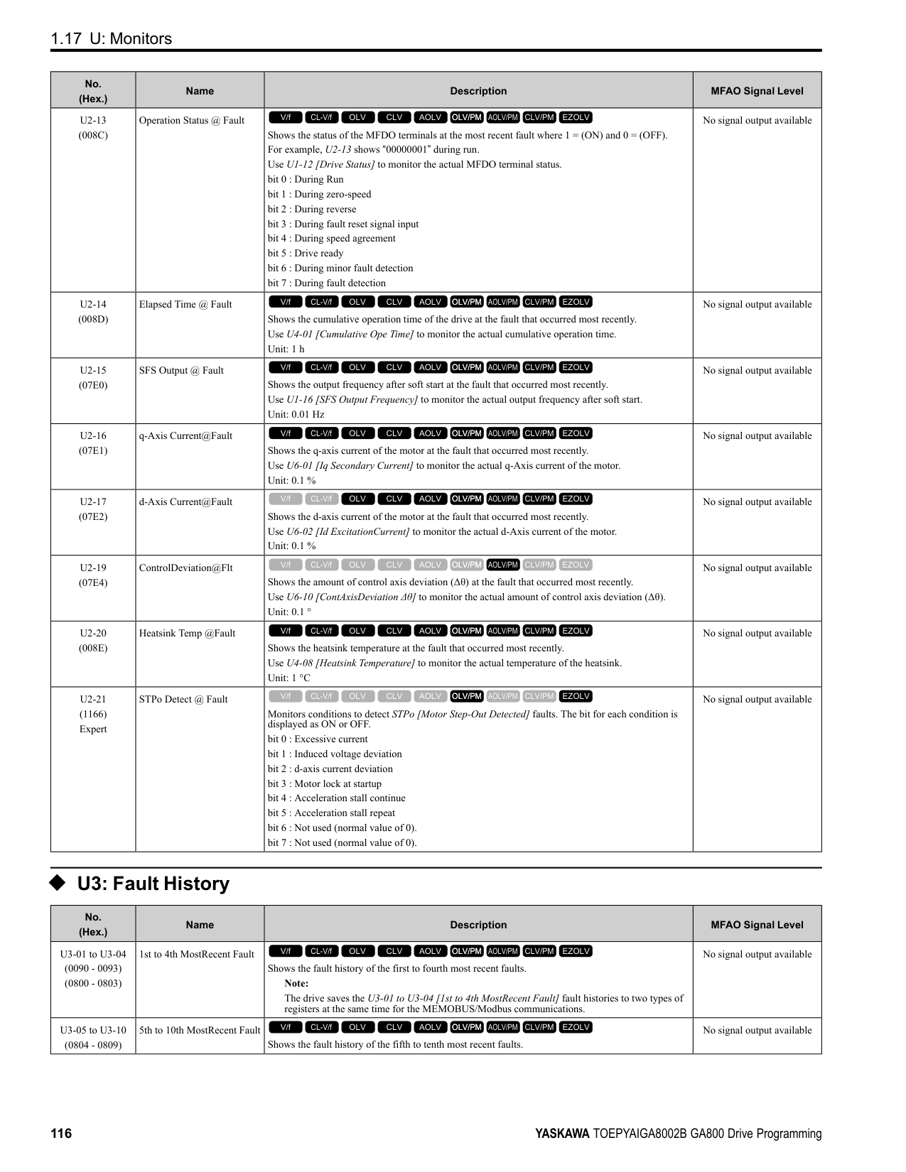
|A2-10|E2-01|Motor Rated Current (FLA)| |A2-11|H1-05|Terminal S5 Function Selection| |A2-12|H1-06|Terminal S6 Function Selection| |A2-13|H1-07|Terminal S7 Function Selection| |A2-14|L5-01|Number of Auto-Restart Attempts|
Table 2.10 Best Parameter Settings for HVAC Applications
The drive saves the parameters in Table 2.11 as user parameters.
5 : Air Compressor The drive automatically sets the parameters in Table 2.12 for an air compressor application.
|No.|Name|Optimal Value| |---|---|---| |A1-02|Control Method Selection|0: V/f Control| |b1-04|Reverse Operation Selection|1: Reverse Disabled| |b1-17|Run Command at Power Up|1: Accept Existing RUN Command| |C6-01|Normal Heavy Duty Selection|1: Normal Duty Rating| |C6-02|Carrier Frequency Selection|3: 8.0 kHz| |H2-03|Terminal M5-M6 Function Selection|39: Watt Hour Pulse Output| |L2-01|Power Loss Ride Through Select|2: Enabled while CPU Power Active| |L8-03|Overheat Pre-Alarm Selection|4: Operate at Reduced Speed (L8-19)| |L8-38|Carrier Frequency Reduction|2: Enabled for All Speeds|
|User Parameter No.|Parameter No. Saved|Name| |---|---|---| |A2-01|b1-01|Frequency Reference Selection 1| |A2-02|b1-02|Run Command Selection 1| |A2-03|b1-03|Stopping Method Selection| |A2-04|b1-04|Reverse Operation Selection| |A2-05|C1-01|Acceleration Time 1|
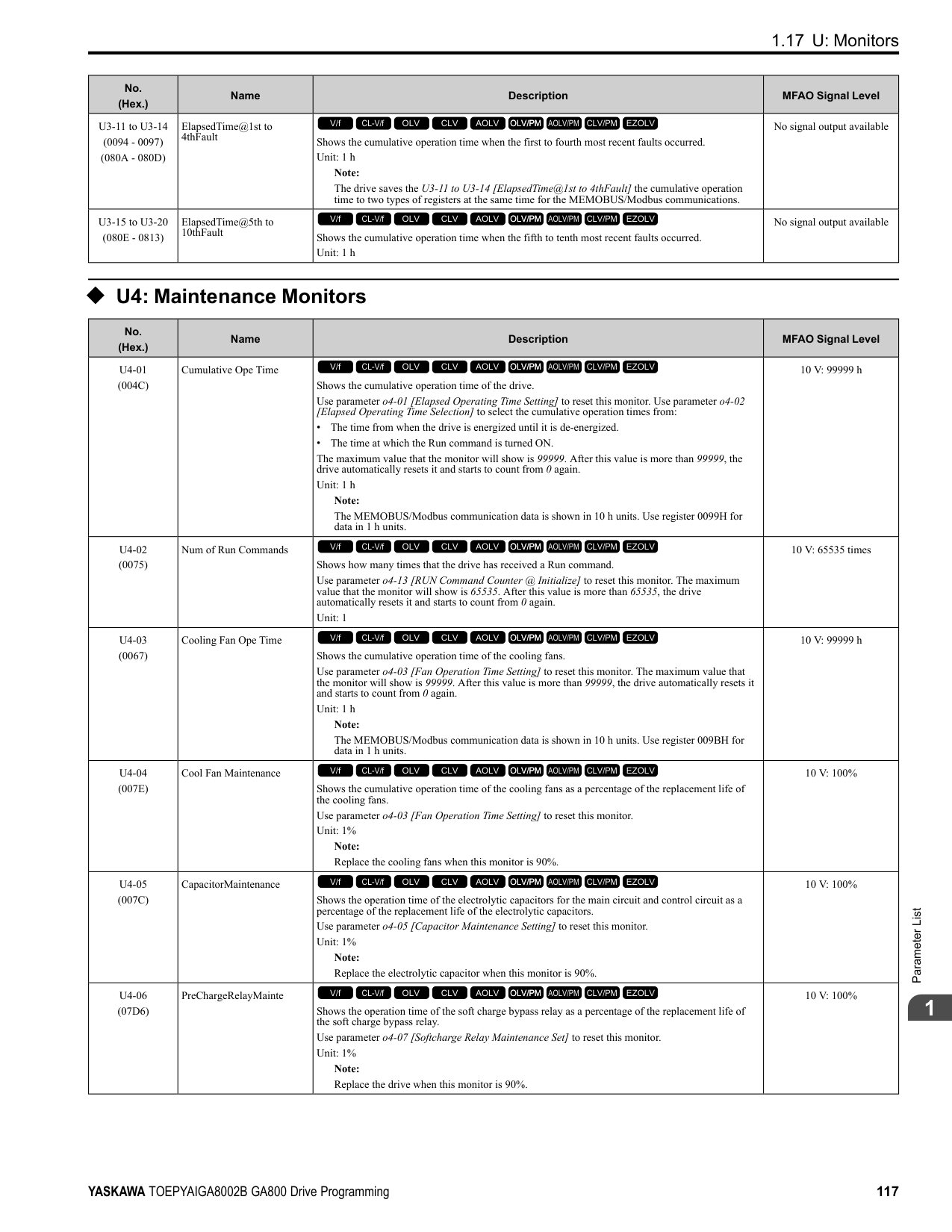
|A2-06|C1-02|Deceleration Time 1| |A2-07|C6-02|Carrier Frequency Selection| |A2-08|d2-01|Frequency Reference Upper Limit| |A2-09|d2-02|Frequency Reference Lower Limit| |A2-10|E1-03|V/f Pattern Selection| |A2-11|E1-04|Maximum Output Frequency| |A2-12|E2-01|Motor Rated Current (FLA)| |A2-13|H3-11|Terminal A2 Gain Setting| |A2-14|H3-12|Terminal A2 Bias Setting| |A2-15|L2-01|Power Loss Ride Through Select| |A2-16|o4-12|kWh Monitor Initialization|
ParameterDetails
|No.|Name|Optimal Value| |---|---|---| |A1-02|Control Method Selection|0: V/f Control| |b1-04|Reverse Operation Selection|1: Reverse Disabled| |C1-01|Acceleration Time 1|5.0 s| |C1-02|Deceleration Time 1|5.0 s| |C6-01|Normal Heavy Duty Selection|0: Heavy Duty Rating| |E1-03|V/f Pattern Selection|F: Custom|
The drive saves the parameters in Table 2.13 as user parameters.
Table 2.13 Parameters Saved as User Parameters with the Air Compressor Preset
|User Parameter No.|Parameter No. Saved|Name| |---|---|---| |A2-01|b1-01|Frequency Reference Selection 1| |A2-02|b1-02|Run Command Selection 1| |A2-03|b1-04|Reverse Operation Selection| |A2-04|C1-01|Acceleration Time 1| |A2-05|C1-02|Deceleration Time 1| |A2-06|E1-03|V/f Pattern Selection| |A2-07|E1-07|Mid Point A Frequency| |A2-08|E1-08|Mid Point AVoltage| |A2-09|E2-01|Motor Rated Current (FLA)|
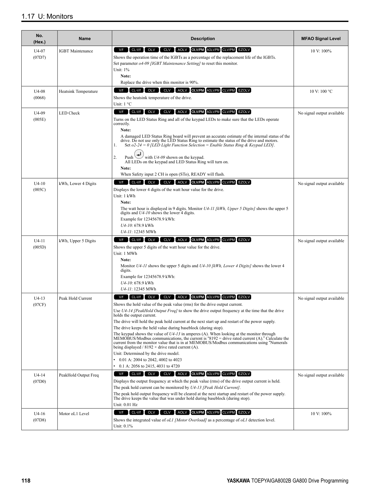
■ Notes for Elevator Applications When using the drive for elevator applications, read the safety descriptions and precautions, and safely and correctly use the device. Conditions to Open and Close the Brake Set L4-07 = 0 [Speed Agree Detection Selection = No Detection during Baseblock] to open and close the holding brake. When L4-07 = 1 [Detection Always Enabled], the output frequency increases when you input the Run command although the external baseblock command is input. Because of this, speed detection operates and will open the brake signal.
• Set Related Parameters Table 2.14 shows examples of parameter settings to use the MFDO terminal (M1-M2) as the holding brake open and close signal.
Table 2.14 Holding Brake Open and Close Signal Setting Example
|Brake Open and Close Signal|Brake Open and Close Signal|Brake Open and Close Level Adjust|Brake Open and Close Level Adjust|Applicable Control Methods (A1-02 Setting Value)|Applicable Control Methods (A1-02 Setting Value)|Applicable Control Methods (A1-02 Setting Value)|Applicable Control Methods (A1-02 Setting Value)|Applicable Control Methods (A1-02 Setting Value)| |---|---|---|---|---|---|---|---|---| |Signal Name|Parameter Settings|Signal Name|Parameter Settings|V/f (0)|OLV (2)|CLV (3)|AOLV (4)|CLV/PM (7) *1| |Frequency (FOUT) Detection 2|L4-07 0|Speed Agree Detection Level|L4-01 1.0 Hz to 3.0 Hz
*2|x|x|-|x|-| |Frequency (FOUT) Detection 2|H2-01 5|Speed Agree Detection Width|L4-02 0.0 Hz to 0.5 Hz
*3|x|x|-|x|-| |During Frequency Output|H2-01 37|DC Injection/Zero Speed Threshold|b2-01 0.1 Hz to 0.5 Hz|-|-|x|-|x|
Figure 2.1 Frequency Detection 2
Sequence Circuit Configuration Use these conditions to set the circuit for the open/close sequence of the holding brake:
Figure 2.2 Sequence Circuit Configuration Diagram
Time Chart Figure 2.3 shows the open/close sequence of the holding brake.
Figure 2.3 Holding Brake Open and Close Sequence Time Chart (V/f, CL-V/f, OLV)
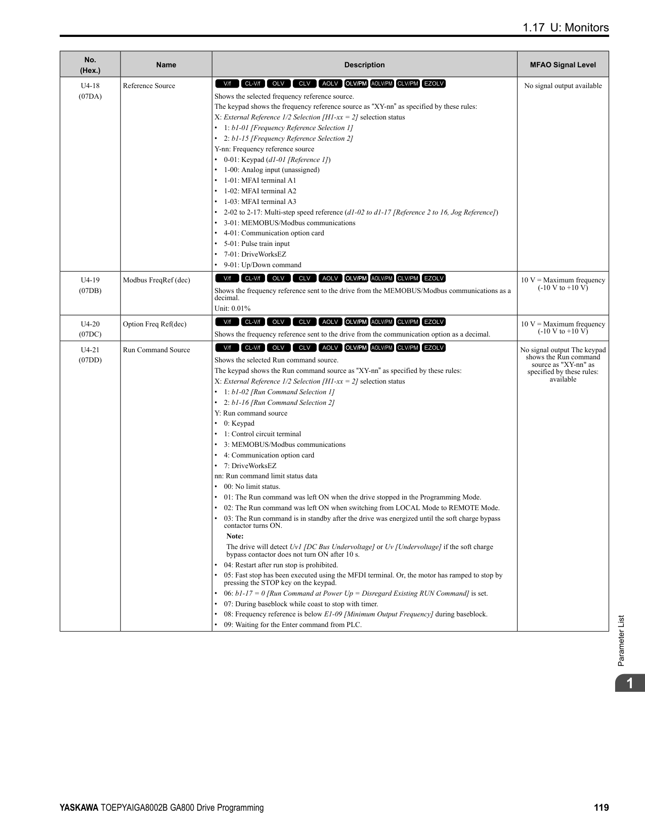
Figure 2.4 Holding Brake Open and Close Sequence Time Chart (CLV, CLV/PM)
############### *1 Start braking from the higher set frequency between b2-01 [DC Injection/Zero SpeedThreshold] or E1-09[Minimum Output Frequency].
Notes on when Using Other Functions
|Function|Notes| |---|---| |Decel stall prevention function|When you connect a braking resistor to discharge the regenerative power to the drive, set L3-04 = 0 [Stall Prevention during Decel = Disabled].
Note:
If L3-04 = 1 [General Purpose], it is possible that the drive will not stop in the set deceleration time. Do not change the default settings of these related parameters:
• L3-01 = 1 [Stall Prevention during Accel = Enabled]
• L3-05 = 1 [Stall Prevention during RUN = Deceleration Time 1 (C1-02)]
| |Auto-Tuning for Induction Motors|• When A1-02 = 2, 3, 4 [Control Method Selection = Open Loop Vector, Closed Loop Vector, Advanced Open Loop Vector], Auto-Tune the motor before you operate the drive.
• Disconnect the drive from the motor to do Rotational Auto-Tuning.
• Auto-Tuning runs automatically for approximately 1 minute. Do not do Auto-Tuning with the motor engaged in the elevator system. Note:
• If you cannot disconnect the motor from the machine, do Stationary Auto-Tuning. During this time, the drive automatically measures the necessary motor data. If the motor test report or the motor nameplate is not available, use Stationary Auto-Tuning. Do Stationary Auto-Tuning for Line-to-Line Resistance for better torque characteristics at low speeds in the V/f Control mode.
• When you do Stationary Auto-Tuning, the drive energizes the motor and the motor stays stopped.
• To Auto-Tune a specialized motor, for example a wound motor, prepare a motor test report before Auto-Tuning and make sure that the motor parameter E2-xx is not too different than the value in the test report.
| |Auto-Tuning for PM Motors|You must set the motor data in the drive to run a PM motor.
• When you use a PM motor recommended by Yaskawa Input the motor code in E5-01. E5 and other related motor parameters will be automatically set to the optimal values.
• When you use a non-Yaskawa PM motor Do Auto-Tuning.
– When the motor nameplate or motor test report is available, enter the PM motor parameters directly with PM Motor Parameter Settings.
– If the motor nameplate or motor test report is not available, and the motor cannot rotate, do PM Stationary Auto-Tuning.
– If the motor nameplate or motor test report is not available, and the motor can rotate, do PM Rotational Auto-Tuning.
– When you replace an encoder, make sure that the motor can rotate and do Z Pulse Offset Tuning or PM Rotational Auto-Tuning. Note:
• Use in Closed Loop Vector Control for PM mode.
• When you do Auto-Tuning or replace the encoder, make sure that the motor can rotate.
• Set the Encoder Z-Pulse Offset.
• Refer to Closed Loop Vector Control for induction motors for information about the signal to use and the adjustment method.
| |Braking Resistor Overheat Protection|When you use a braking resistor other than the optional Yaskawa braking resistor unit (LKEB-series), this function uses the thermal overload relay to detect braking resistor overheat. Load a sequence program that turns OFF the drive input power supply when the braking resistor overheats.
Note: Refer to 617 when you load the sequence circuit.| |Continuous operation function|Do not use the momentary power loss continuous operation function and the Auto Restart function. If you use these functions, there is a risk that the motor will coast to a stop if the brake is open when there is a momentary power loss and the drive is operating or if there is a fault.
Set the these parameters:
• L2-01 = 0 [Power Loss Ride Through Select = Disabled]
• L5-01 = 0 [Number of Auto-Restart Attempts = 0]
| |Torque limit function|The motor rated torque sets the value for L7-01 to L7-04 [Torque Limit]. If there will not be sufficient torque during start up, replace the drive with a larger capacity drive and set the torque limit between 200% and 300%. The L7-01 to L7-04 default setting is 200%.|
|Function|Notes| |---|---| |I/O phase loss protection, overtorque detection function|To stop a fall because of motor phase loss, set these parameters.
• L8-05 1 [Input Phase Loss Protection Sel Enabled]
• L8-07 1 [Output Phase Loss Protection Sel Fault when one phase is lost]
• L6-01, L6-04 1 to 8 [Torque Detection Selection 1/2 oL @ Speed Agree - Alarm only to UL @ RUN - Fault]
• L6-02, L6-05 [Torque Detection Level 1/2]
• L6-03, L6-06 [Torque Detection Time 1/2] Note: Use precautions, for example fall detection, on the machine side.
| |External baseblock command|• If you enter the external baseblock signal set in H1-01 to H1-08 8 or 9 [Terminal S1 to S8 Function Selection Baseblock Command] during run, the motor immediately coasts to stop. When you enter a baseblock command while the motor is operating, make sure that it is necessary.
• When you use an external baseblock command for the fast stop and operation start up interlocks, load the sequence to lock the holding brake when you enter the external baseblock command.
• If you enter the external baseblock command and then immediately remove it, the drive will not output the voltage in the time set in L2-03 [Minimum Baseblock Time]. Do not use an external baseblock command for applications that have frequent Run/Stop commands.
| |Acceleration and deceleration times|If you set the acceleration and deceleration times for the drive side too short and you do not add the mechanical operation delay time of the holding brake, the holding brake could operate late, or there could be overcurrent at start up, the brake could grind, or the motor could roll back when it stops. In these conditions, use Dwell Reference at Start/Time and DC Injection Braking at Stop to adjust the holding brake timing.| |Electromagnetic contactor on the drive output side|Usually you must not install the electromagnetic contactor between the drive and motor. When you must install an electromagnetic contactor to use one drive to switchover more than one motor, follow these precautions:
• Load a sequence that opens and closes the electromagnetic contactor when these two conditions are satisfied at the same time, unless there is an emergency:
– The holding brake is fully closed
– The drive terminals for H2-xx 8 or 1B [MFDO Function Selection During Baseblock] are activated
• If you open and close the electromagnetic contactor during motor control or during DC Injection Braking (or zero speed control), the surge voltage and the motor direct input current can cause the drive to detect faults.
• When you use an electromagnetic contactor between the drive and motor, set L8-07 1 or 2 [Output Phase Loss Protection Sel Fault when one phase is lost, Fault when two phases are lost].
|
Adjustments Relating to Control When there is oscillation, rollback, or other control problems, adjust the parameters as specified by the control method. V/f Control and Closed Loop V/f Control on page 187 shows only the frequently adjusted parameters.
Note:
Torque and speed response for high-resistance and high-slip motors are slow. Adjust the torque and speed response to increase them. Low impedance (low-slip) motors will hunt and oscillate. Adjust the torque and speed response to increase them.
V/f Control and Closed Loop V/f Control While in V/f Control, do not use C3-01 [Slip Compensation Gain]. While in Closed Loop V/f Control, continue to use default settings for C5-01 to C5-05 [ASR Parameters]. Significantly altering the default settings will likely cause oscillation.
Table 2.15 Adjustment of Drive Control (V/f Control and Closed Loop V/f Control Methods)
|Adjustment description|Parameter Number|Possible Solutions|Default|Recommended Setting| |---|---|---|---|---| |• Prevent hunting and oscillation at middle-range speeds (10 Hz to 40 Hz)|n1-02 [Hunting Prevention Gain Setting]|• If the torque is not sufficient with heavy loads, decrease the setting.
• If there is hunting or oscillation with light loads, increase the setting.
|1.00|0.50 - 2.00| |• Increasing motor excitation sound
• Hunting and oscillation suppression at low speeds and middle-range speeds
|C6-02 [Carrier Frequency Selection]|• If there is a loud motor excitation sound, increase the setting value.
• If there is hunting or oscillation at low speeds or middle-range speeds, decrease the setting value.
|*1|1 - F| |• Increase torque at low speeds (10 Hz or lower)
• Prevent hunting and oscillation
|C4-01 [Torque Compensation Gain]|• If the torque is not sufficient at low speeds, increase the setting value.
• If there is hunting or oscillation with light loads, decrease the setting value.
|1.00|0.50 - 1.50|
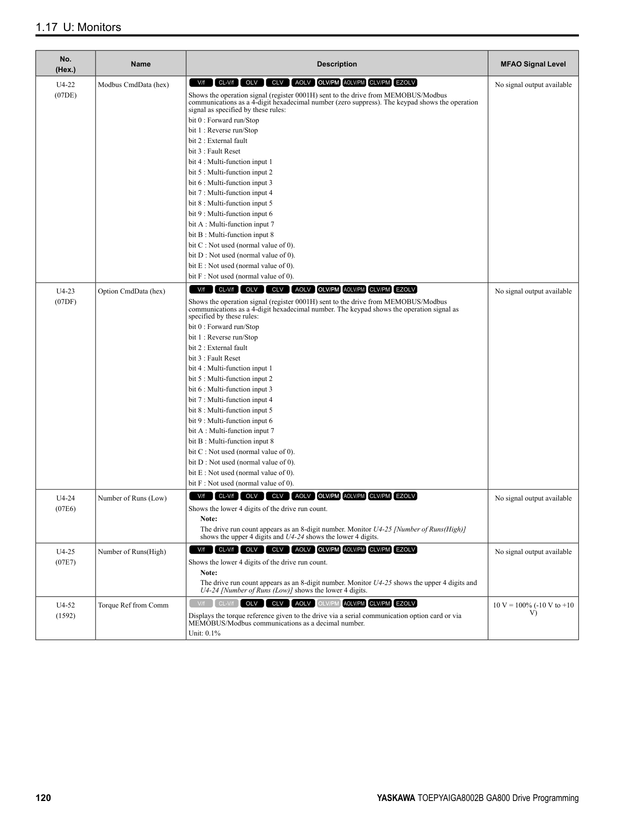
|Adjustment description|Parameter Number|Possible Solutions|Default|Recommended Setting| |---|---|---|---|---| |• Increase torque at low speeds
• Prevent shock during start up
|E1-08 [Mid Point AVoltage]|• If the torque is not sufficient at low speeds, increase the setting value.
• If there is a large shock during start up, decrease the setting value.
|15.0 V *2 *3|13.0 V to 16.0 V *3| |• Increase torque at low speeds
• Prevent shock during start up
|E1-10 [Minimum Output Voltage]|• If the torque is not sufficient at low speeds, increase the setting value.
• If there is a large shock during start up, decrease the setting value.
|9.0 V *2 *3|7.0 V to 10.0 V *3|
Open Loop Vector Control Method Do not adjust parameter C4-01 [Torque Compensation Gain]. Keep this parameter at its default setting. If you cannot get speed accuracy during regeneration, set C3-04 = 1 [Slip Compensation at Regen = Enabled Above 6Hz]. If you cannot get speed accuracy at high speeds, set C3-05 = 1 [Output Voltage Limit Selection = Enabled].
Table 2.16 Adjustment of Drive Control (Open Loop Vector Control Method)
|Adjustment description|Parameter Number|Possible Solutions|Default|Recommended Setting| |---|---|---|---|---| |• Torque, increase speed response
• Prevent hunting and oscillation at middle-range speeds (10 Hz to 40 Hz)
|n2-01 [Automatic Freq Regulator Gain]|• If torque and speed response are slow, decrease the setting value.
• If there is hunting or oscillation, increase the setting value.
|1.00|0.50 - 2.00| |• Torque, increase speed response
• Prevent hunting and oscillation
|C4-02 [Torque Compensation Delay Time] *1|• If torque and speed response are slow, decrease the setting value.
• If there is hunting or oscillation, increase the setting value.
|20 ms|20 ms to 100 ms| |• Increase speed response
• Increase speed stability
|C3-02 [Slip Compensation Delay Time]|• When speed response is slow, decrease the setting value.
• If speed is not stable, increase the setting value.
|200 ms|100 ms to 500 ms| |• Improve speed accuracy|C3-01 [Slip Compensation Gain]|• If speed is too slow, increase the setting value.
• If speed is too fast, decrease the setting value.
|1.0|0.5 - 1.5| |• Increasing motor excitation sound
• Prevent hunting and oscillation at low-range speeds (10 Hz to or lower)
|C6-02 [Carrier Frequency Selection]|• If there is a loud motor excitation sound, increase the setting value.
• If there is hunting or oscillation at low speeds, decrease the setting value.
|*2|1 - F| |• Increase torque and speed response at low speeds
• Prevent shock during start up
|E1-08 [Mid Point AVoltage]|• If the torque and speed response are slow, increase the setting value.
• If there is a large shock during start up, decrease the setting value.
|11.0 V *3|12.0 V to 13.0 V *3| |• Increase torque and speed response at low speeds
• Prevent shock during start up
|E1-10 [Minimum Output Voltage]|• If the torque and speed response are slow, increase the setting value.
• If there is a large shock during start up, decrease the setting value.
|2.0 V *3|2.0 V to 3.0 V *3|
################# Table 2.17 Adjustment of Drive Control (Closed Loop Vector Control Method)
|Adjustment description|Parameter Number|Possible Solutions|Default|Recommended Setting| |---|---|---|---|---| |• Torque, increase speed response
• Prevent hunting and oscillation
|C5-01 [ASR Proportional Gain 1]|• If the torque and speed response are slow, increase the setting value.
• If there is hunting or oscillation, decrease the setting value.
|20.00|10.00 - 50.00| |• Torque, increase speed response
• Prevent hunting and oscillation
|C5-03 [ASR Proportional Gain 2]|• If the torque and speed response are slow, increase the setting value.
• If there is hunting or oscillation, decrease the setting value.
|20.00|10.00 - 50.00| |• Torque, increase speed response
• Prevent hunting and oscillation
|C5-02 [ASR Integral Time 1]|• If torque and speed response are slow, decrease the setting value.
• If there is hunting or oscillation, increase the setting value.
|0.500 s|0.300 s to 1.000 s| |• Torque, increase speed response
• Prevent hunting and oscillation
|C5-04 [ASR Integral Time 2]|• If torque and speed response are slow, decrease the setting value.
• If there is hunting or oscillation, increase the setting value.
|0.500 s|0.300 s to 1.000 s|
|Adjustment description|Parameter Number|Possible Solutions|Default|Recommended Setting|
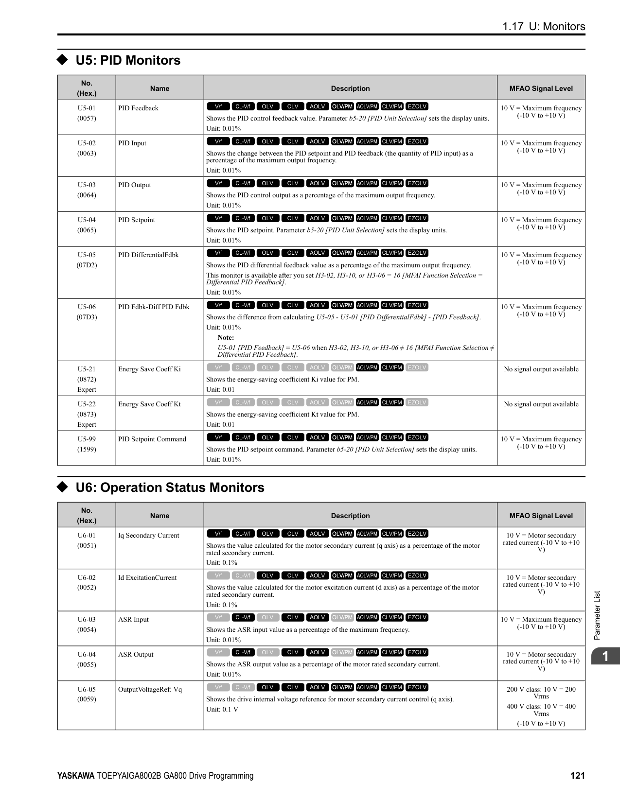
|---|---|---|---|---| |Change the ASR proportional gain and ASR integral time in accordance with the output frequency.|C5-07 [ASR Gain Switchover Frequency]|If you cannot establish ASR proportional gain or integral time for low speed or high speed, switch as specified by the output frequency.|0.0 Hz (Do not switch)|0.0 Hz to Maximum frequency| |• Prevent hunting and oscillation|C5-06 [ASR Delay Time]|• If there is unsatisfactory machine rigidity and oscillation is possible, increase the setting value.|0.004 s|0.004 s to 0.020 s|
################ Elevator Start/Stop and Accel/Decel Time Shock Reduction S-Curve Characteristics, Accel & Decel Time
|Adjustment Parameter|Name| |---|---| |C1-01, C1-03, C1-05, C1-07|Acceleration Time 1 to 4| |C1-02, C1-04, C1-06, C1-08|Deceleration Time 1 to 4| |C2-01|S-Curve Time @ Start of Accel| |C2-02|S-Curve Time @ End of Accel| |C2-03|S-Curve Time @ Start of Decel| |C2-04|S-Curve Time @ End of Decel|
Figure 2.5 S-curve Characteristics, Accel & Decel Time Note:
################ Dwell Function at Start
|Adjustment Parameter|Name| |---|---| |b6-01|Dwell Reference at Start| |b6-02|Dwell Time at Start| |H2-xx = 5|Frequency Detection 2|
Figure 2.6 Dwell Function at Start Note:
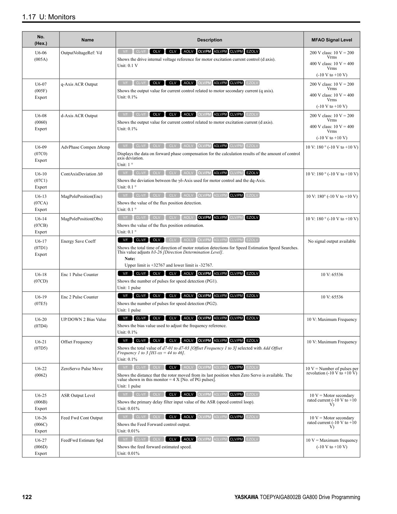
DC Injection Braking at Stop, Zero Speed Control Function
Note:
If you disconnect a drive when it is controlling the motor or during DC Injection Braking (Zero speed level), a voltage surge can trigger a fault. When you use an electromagnetic contactor between the drive and motor, set L8-07 = 1 or 2 [Output Phase Loss Protection Sel = Fault when one phase is lost, Fault when two phases are lost]. If it necessary to disconnect the motor and drive when you stop the elevator, fully close the holding brake and disconnect the drive during baseblock (that is, while the baseblock signal is ON). This does not apply for emergency conditions.
|Adjustment Parameter|Name| |---|---| |b2-01|DC Injection/Zero SpeedThreshold| |b2-02|DC Injection Braking Current| |b2-04|DC Inject Braking Time at Stop| |H2-xx 5|Frequency Detection 2|
Figure 2.7 DC Injection Braking at Stop, Zero Speed Control Function Note:
Torque Compensation (Torque Bias)
############### This function enters the torque compensation (torque bias) signal that matches a set load from the MFAI terminal in Closed Loop Vector Control to decrease the overshoot when you open and close the brake. You must detect the load
############### and motoring/regeneration on the machine side before you use the function. If there is a polarity error, shock can increase.
|Item|Description| |---|---| |Sequence Circuit Configuration| | |Time chart: Increase|Enter the analog signal as the torque compensation (torque bias) signal as specified by the load quantity before drive operation until drive operation completes. The default setting is 10 V/100% torque.
Enter a positive polarity during a motoring load, and enter a negative polarity during a regenerative load.| |Time chart: Decrease|Enter the analog signal as the torque compensation (torque bias) signal as specified by the load quantity before drive operation until drive operation completes. The default setting is 10 V/100% torque.
Enter a negative polarity during a motoring load, and enter a positive polarity during a regenerative load.|
################# Note:
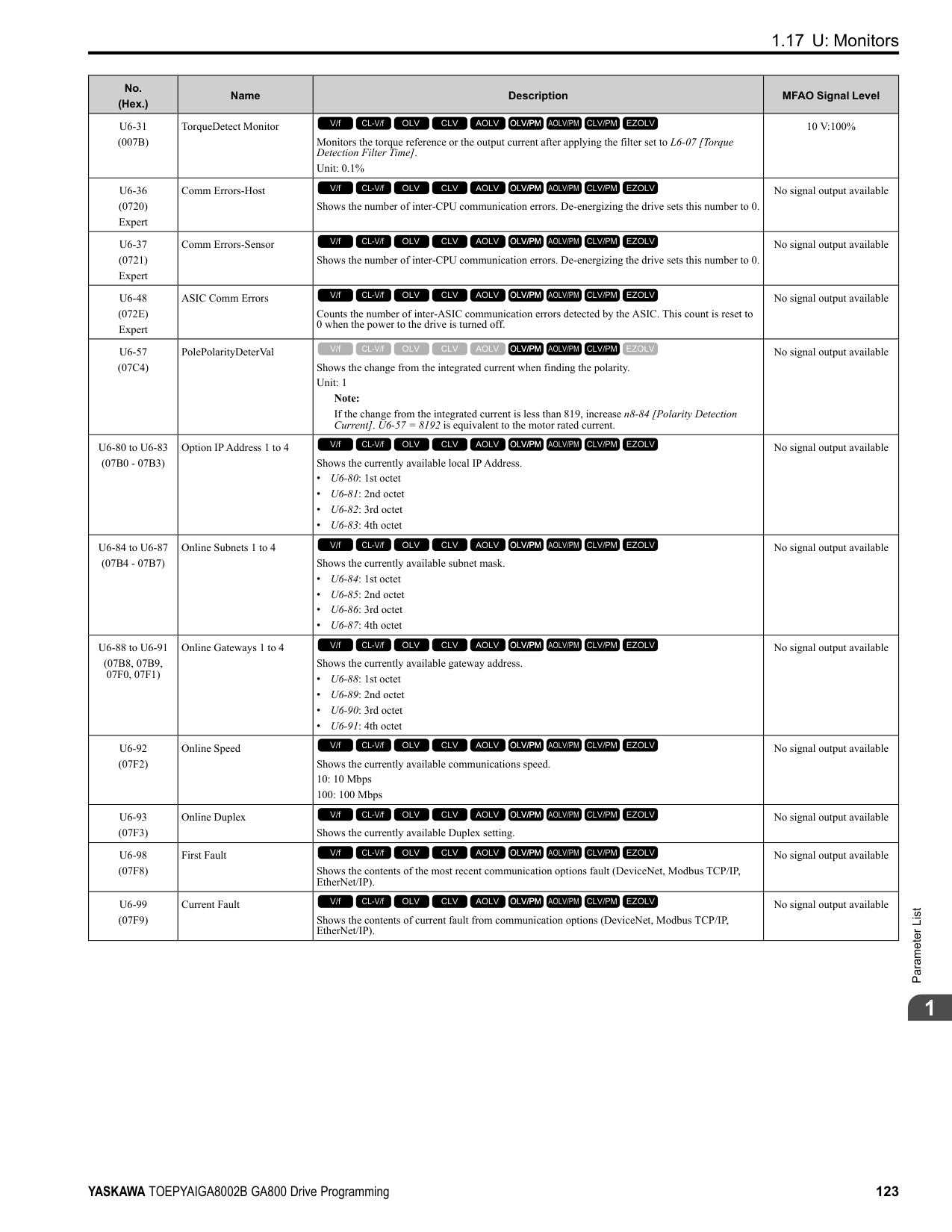
Startup Current Check When you do a test run, set L8-41 =1 [High Current Alarm Selection = Enabled] and use U4-13 [Peak Hold Current] and a clamp ammeter with the machine under load and not under load to check the motor current during start up. If the motor torque is not sufficient during start up or if the timing between the motor and the holding brake is unsatisfactory and causes the motor to lock, a large quantity of current will flow. In these conditions, adjust the parameters again and decrease the load to decrease the current to less than 150%. If the current flow is more than 150% of the drive rated current, the heat stress on the IGBTs will decrease the service life of drive parts. To decrease the effects of heat stress, decrease the carrier frequency of the drive to 2.0 kHz to 2.5 kHz for applications where low audible noise is not necessary. Overvoltage Suppression Function
The overvoltage suppression function is designed to prevent an overvoltage trip in a situation in which a braking resistor is not used with a regenerative load. If the overvoltage suppression function is enabled, the regeneration torque reference within the drive is automatically controlled during regeneration.
Note:
######## ■ A1-07: DriveWorksEZ Function Selection
|No. (Hex.)|Name|Description|Default (Range)| |---|---|---|---| |A1-07 (0128)|DriveWorksEZ Function Selection|Sets the drive to operate with DriveWorksEZ.
V/f CL-V/f OLV CLV AOLV OLV/PM AOLV/PM CLV/PM EZOLV
|0 (0 - 2)|
DriveWorksEZ is a simple visual programming tool that lets you connect function blocks to customize the drive and add PLC functions.
Note:
Set H1-xx = 9F [MFDI Function Select = DWEZ Disable]. Deactivate the digital input to enable programs made with DriveWorksEZ and activate the terminal to disable the programs.
######## ■ A1-11: Firmware Update Lock
|No. (Hex.)|Name|Description|Default (Range)| |---|---|---|---| |A1-11 (111D) Expert|Firmware Update Lock|Protects the drive firmware. When you enable the protection, you cannot update the drive firmware.
V/f CL-V/f OLV CLV AOLV OLV/PM AOLV/PM CLV/PM EZOLV
|0 (0, 1)|
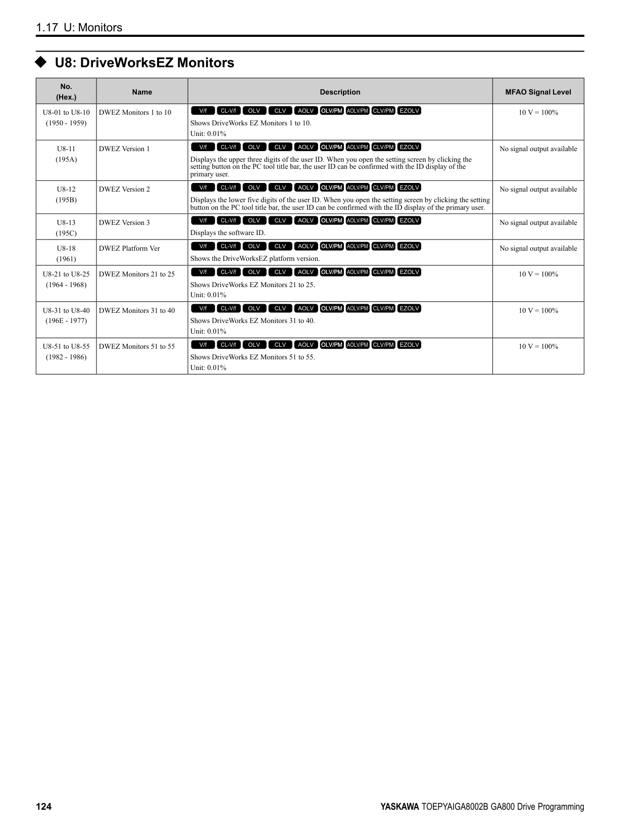
######## ■ A1-12: Bluetooth ID
|No. (Hex.)|Name|Description|Default (Range)| |---|---|---|---| |A1-12 (1564)|Bluetooth ID|Sets the password necessary to use Bluetooth to control the drive with a smartphone or tablet.
V/f CL-V/f OLV CLV AOLV OLV/PM AOLV/PM CLV/PM EZOLV
|(0000 - 9999)|
◆ A2: User Parameters
You can register frequently used parameters and recently changed parameters here to access them quickly. You can show the registered parameters in [User Custom Parameters] in the main menu.
######## ■ A2-01 to A2-32: User Parameters 1 to 32
|No. (Hex.)|Name|Description|Default (Range)| |---|---|---|---| |A2-01 to A2-32 (0106 - 0125)|User Parameters 1 to 32|You can select a maximum of 32 parameters for the drive and set them to parameters A2-01 to A2-32. The [User Parameters] section of the keypad main menu shows the set parameters. You can immediately access these set parameters.
V/f CL-V/f OLV CLV AOLV OLV/PM AOLV/PM CLV/PM EZOLV
|Parameters in GeneralPurpose Setup Mode
(Determined by A1-06)|
################# Note:
The drive saves these parameters to A2-01 to A2-32.
• The drive automatically saves changed parameters to A2-17 to A2-32.
Note:
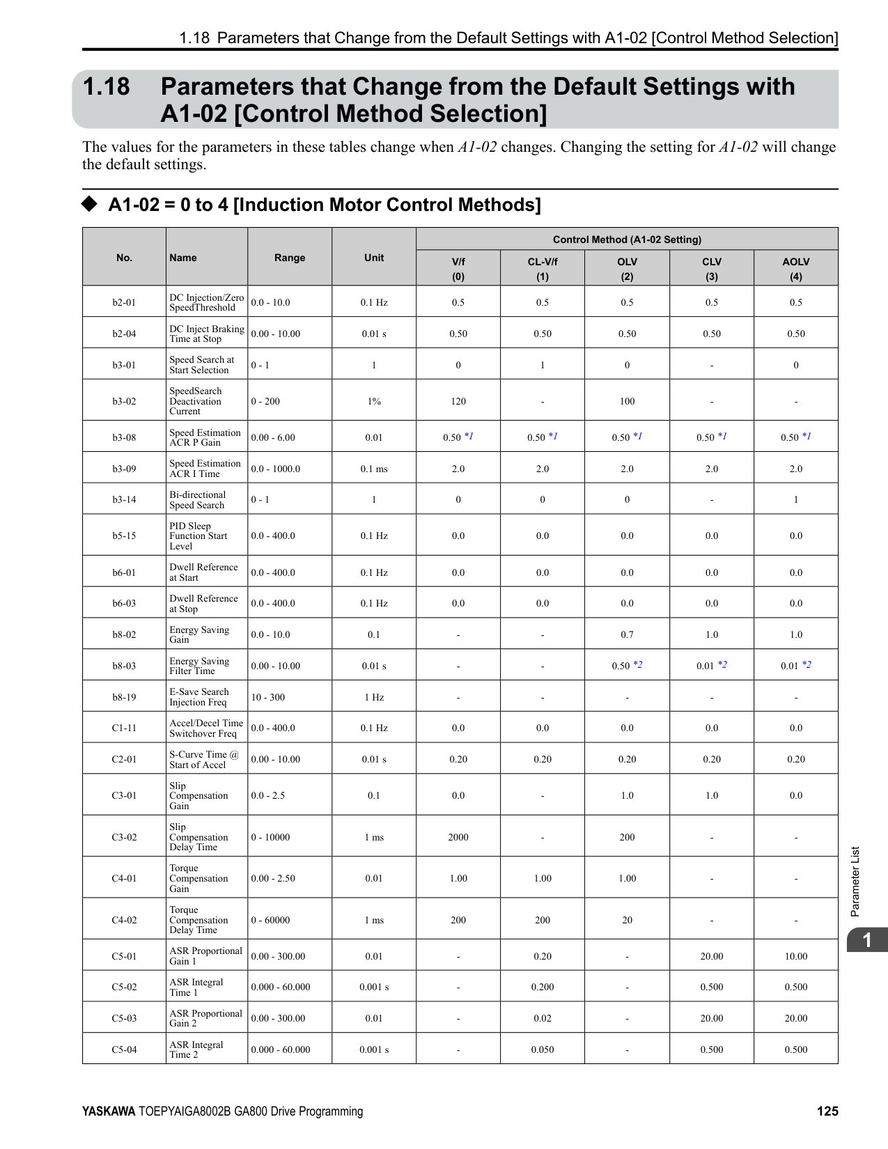
######## ■ A2-33: User Parameter Auto Selection
|No. (Hex.)|Name|Description|Default (Range)| |---|---|---|---| |A2-33 (0126)|User Parameter Auto Selection|Sets the automatic save feature for changes to parameters A2-17 to A2-32 [User Parameters 17 to 32].
V/f CL-V/f OLV CLV AOLV OLV/PM AOLV/PM CLV/PM EZOLV
|Determined by A1-06 (0, 1)|
The drive automatically registers changed parameter A2-17 to A2-32. The drive automatically saves the most recently changed parameter to A2-17, and saves a maximum of 16 parameters. After the drive registers 16 parameters, when you save a new parameter, the drive will remove a parameter from the User Parameter list to make space for the new parameter. The drive removes parameters with First In, First Out. You can show the registered parameters in [User Custom Parameters] in the main menu.
ParameterDetails
Note:
In General-Purpose Setup Mode, the drive registers parameters starting with A2-27 because the drive registers parameters A2-26 and lower by default.
####### 2.3 b: Application
b parameters set the following functions.
◆ b1: Operation Mode Selection b1 parameters set the operation mode for the drive.
######## ■ b1-01: Frequency Reference Selection 1
|No. (Hex.)|Name|Description|Default (Setting Range)|
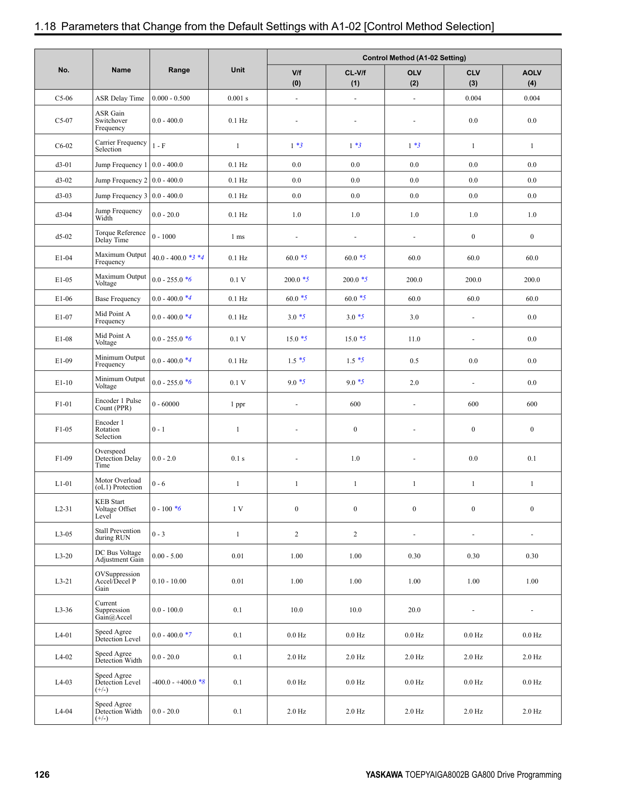
|---|---|---|---| |b1-01 (0180)|Frequency Reference Selection 1|Sets the input method for the frequency reference.
V/f CL-V/f OLV CLV AOLV OLV/PM AOLV/PM CLV/PM EZOLV
|1 (0 - 4)|
################# Note:
• Voltage Input Refer to Table 2.18 to use a voltage signal input to one of the MFAI terminals.
Table 2.18 Frequency Reference Voltage Input
|Terminal|Terminal Signal Level|Parameter Settings|Parameter Settings|Parameter Settings|Parameter Settings|Note| |---|---|---|---|---|---|---| |Terminal|Terminal Signal Level|Signal Level Selection|Function Selection|Gain|Bias|Note| |A1|0 - 10 V|H3-01 0|H3-02 0 [Frequency Bias]|H3-03|H3-04|Set DIP switch S1-1 to “V” for voltage input.| |A1|-10 - +10 V|H3-01 1|H3-02 0 [Frequency Bias]|H3-03|H3-04|Set DIP switch S1-1 to “V” for voltage input.| |A2|0 - 10 V|H3-09 0|H3-10 0 [Frequency Bias]|H3-11|H3-12|Set DIP switch S1-2 to “V” for voltage input.| |A2|-10 - +10 V|H3-09 1|H3-10 0 [Frequency Bias]|H3-11|H3-12|Set DIP switch S1-2 to “V” for voltage input.| |A3|0 - 10 V|H3-05 0|H3-06 0 [Frequency Bias]|H3-07|H3-08|Set DIP switch S1-3 to “V” for voltage input.
Set DIP switch S4 to “AI” for analog input.| |A3|-10 - +10 V|H3-05 1|H3-06 0 [Frequency Bias]|H3-07|H3-08|Set DIP switch S1-3 to “V” for voltage input.
Set DIP switch S4 to “AI” for analog input.|
| | | | |---|---|---| | | | | | | | |
| | | | |---|---|---| | | | | | | | |
################# Figure 2.8 Example of Setting the Frequency Reference with a Voltage Signal to Terminal A1
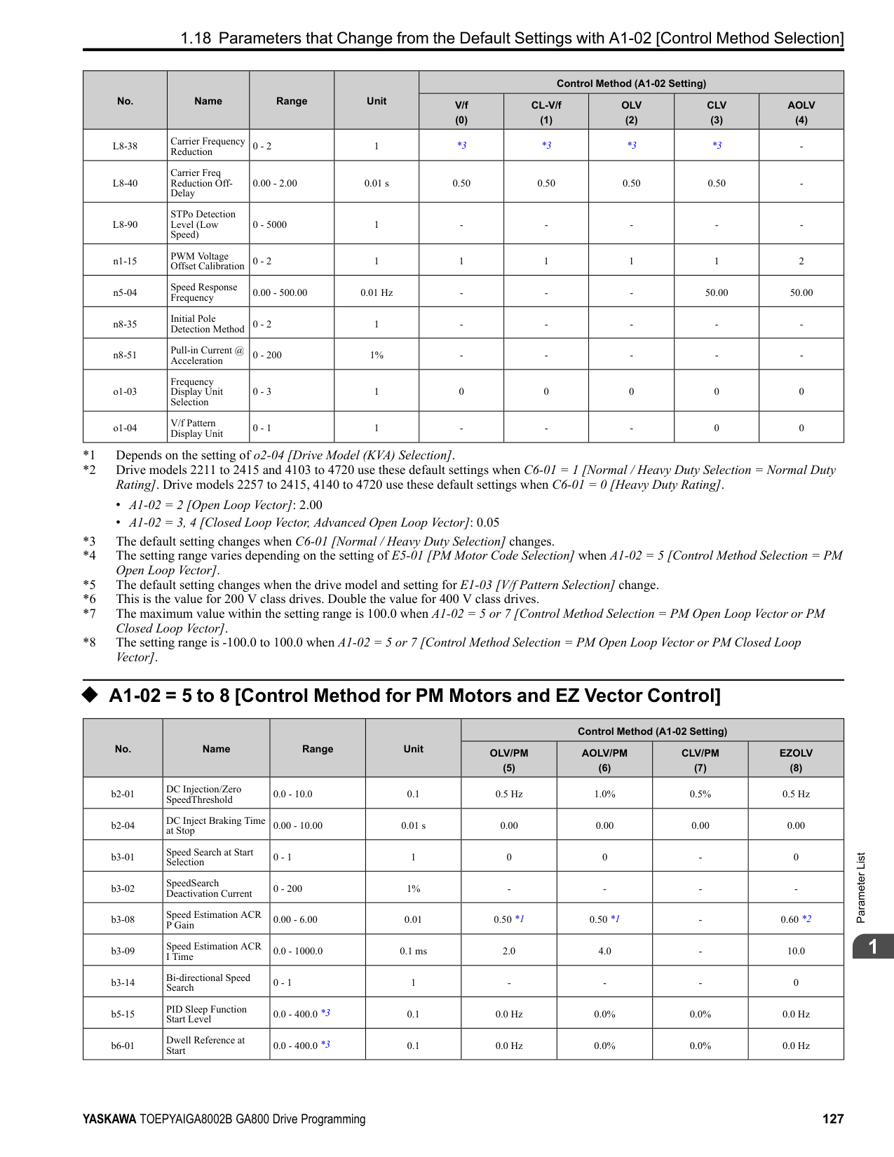
Note: You can also use this diagram to wire terminals A2 and A3.
• Current Input Refer to Table 2.19 to use a current signal input to one of the MFAI terminals.
Table 2.19 Frequency Reference Current Input
|Terminal|Signal Level|Parameter Settings|Parameter Settings|Parameter Settings|Parameter Settings|Note| |---|---|---|---|---|---|---| |Terminal|Signal Level|Signal Level Selection|Function Selection|Gain|Bias|Note| |A1|4 mA to 20 mA|H3-01 2|H3-02 0 [Frequency Bias]|H3-03|H3-04|Set DIP switch S1-1 to “I” for current input.| |A1|0 - 20 mA|H3-01 3|H3-02 0 [Frequency Bias]|H3-03|H3-04|Set DIP switch S1-1 to “I” for current input.| |A2|4 mA to 20 mA|H3-09 2|H3-10 0 [Frequency Bias]|H3-11|H3-12|Set DIP switch S1-2 to “I” for current input.| |A2|0 - 20 mA|H3-09 3|H3-10 0 [Frequency Bias]|H3-11|H3-12|Set DIP switch S1-2 to “I” for current input.| |A3|4 mA to 20 mA|H3-05 2|H3-06 0 [Frequency Bias]|H3-07|H3-08|Set DIP switch S1-3 to “I” for current input.
Set DIP switch S4 to “AI” for analog input.| |A3|0 - 20 mA|H3-05 3|H3-06 0 [Frequency Bias]|H3-07|H3-08|Set DIP switch S1-3 to “I” for current input.
Set DIP switch S4 to “AI” for analog input.|
| | | | |---|---|---| | | | | | | | |
Figure 2.9 Example of Setting the Frequency Reference with a Current Signal to Terminal A2
Note: You can also use this diagram to wire terminals A1 and A3.
Changing between Master and Auxiliary Frequency References Use the multi-step speed reference function to change the frequency reference input between terminals A1, A2, and A3. 2 : Memobus/Modbus Communications
ParameterDetails
######## 2
Use MEMOBUS/Modbus communications to enter the frequency reference.
Note: If b1-01 = 3 but no connected option card, then oPE05 [Run Cmd/Freq Ref Source Sel Err] will flash on the keypad.
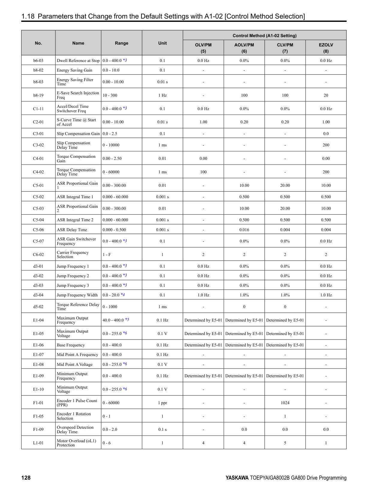
######## ■ b1-02: Run Command Selection 1
|No. (Hex.)|Name|Description|Default (Range)| |---|---|---|---| |b1-02 (0181)|Run Command Selection 1|Sets the input method for the Run command.
V/f CL-V/f OLV CLV AOLV OLV/PM AOLV/PM CLV/PM EZOLV
|1 (0 - 3)|
Note:
The on the keypad is on while keypad is the Run command source.
Use the control circuit terminals to enter the Run command. Select the input method for the Run command with an H1-xx parameter. Set H1-xx = 0, 40 to 43 [3-Wire Sequence, Run Command (2-Wire Sequence)]. The default setting is 2-wire sequence
Note: If b1-02 = 3 but no connected option card, then oPE05 [Run Cmd/Freq Ref Source Sel Err] will flash on the keypad.
######## ■ b1-03: Stopping Method Selection
|No. (Hex.)|Name|Description|Default (Range)| |---|---|---|---| |b1-03 (0182)|Stopping Method Selection|Sets the method to stop the motor after removing a Run command or entering a Stop command.
V/f CL-V/f OLV CLV AOLV OLV/PM AOLV/PM CLV/PM EZOLV
|0 (0 - 3)|
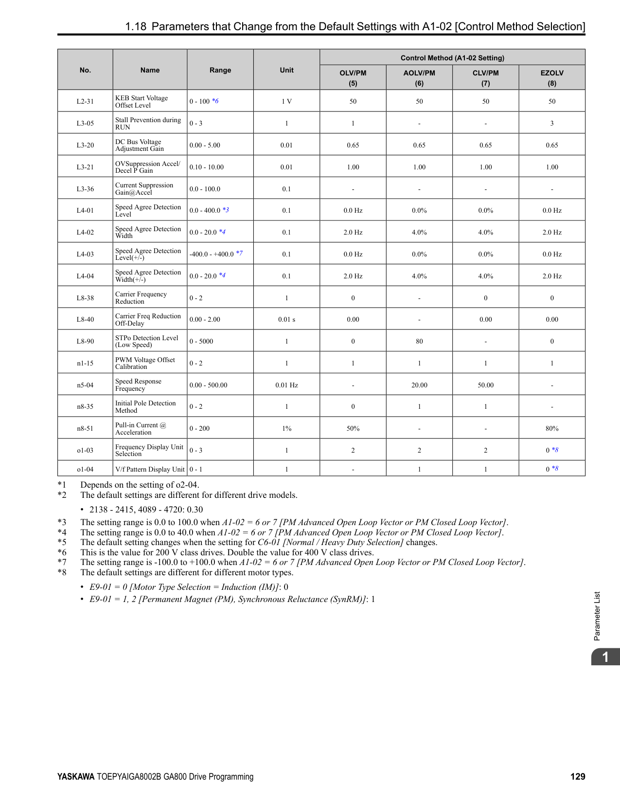
Note: When A1-02 = 3, 4, 5, 6, 7, 8 [Control Method Selection = CLV, AOLV, OLV/PM, AOLV/PM, CLV/PM, EZOLV], the setting range is 0, 1, 3.
Select the applicable stopping method for the application from these four options: 0 : Ramp to Stop When you enter the Stop command or turn OFF the Run command, the drive ramps the motor to stop. The drive ramps the motor to stop as specified by the deceleration time. The default setting for the deceleration time is C1-02 [Deceleration Time 1]. The actual deceleration time changes as the load conditions change (for example, mechanical loss and inertia). If the output frequency is less than or equal to the value set in b2-01 [DC Injection/Zero SpeedThreshold] during deceleration, the drive will do DC Injection Braking, Zero Speed Control, or Short Circuit Braking, as specified by the control method.
Figure 2.10 Ramp to Stop with V/f, AOLV, CL-V/f, and OLV Control Methods
Note: When b2-01 ≤ E1-09 [Minimum Output Frequency], the drive will start DC Injection Braking from the frequency set in E1-09.
Figure 2.11 Ramp to Stop with OLV/PM, AOLV/PM, and EZOLV Control Methods
Note: When b2-01 ≤ E1-09, the drive will start Short Circuit Braking from the frequency set in E1-09. If b2-01 = 0 Hz and E1-09 = 0 Hz, the drive will not do Short Circuit Braking.
| | | | |---|---|---| | | | |
| | | | | |---|---|---|---| | | | | |
ParameterDetails
######## 2
Parameter b2-01 sets the frequency to start Zero Speed Control at stop. When the output frequency is less than or equal to the value set in b2-01 during deceleration, the drive will do Zero Speed Control for the time set in b2-04.
| | | | |---|---|---| | | | |
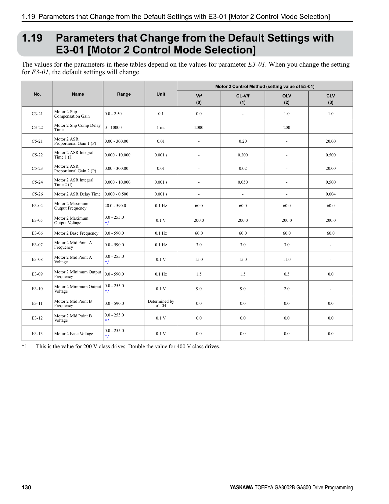
Figure 2.12 Ramp to Stop in CLV and CLV/PM Control Methods
Note: When b2-01 ≤ E1-09, the drive will start Zero Speed Control from the frequency set in E1-09.
############## 1 : Coast to Stop
When you enter the Stop command or turn OFF the Run command, the drive turns OFF the output and coasts the motor to stop. Load conditions will have an effect on the deceleration rate as the motor coasts to stop (for example, mechanical loss and inertia).
| | | |---|---| | | | | | | | | | | | |
Figure 2.13 Coast to Stop Note:
The drive ignores the Run command for the time set in L2-03 [Minimum Baseblock Time] when the Stop command is entered or when the Run command is switched OFF. Do not enter the Run command until the motor comes to a complete stop. Use DC Injection or Speed Search to restart the motor before it stops.
############## 2 : DC Injection Braking to Stop
When you enter the Stop command or turn OFF the Run command, the drive turns OFF the output for the time set in L2-03. The drive waits for the minimum baseblock time and then injects the amount of DC current into the motor set in b2-02 [DC Injection Braking Current] to stop the motor with DC current.
DC Injection Braking stops the motor more quickly than coast to stop. Note: If A1-02 3, 4, 5, 6, or 7, DC Injection Braking to Stop is not available.
| | | |---|---| | | |
Figure 2.14 DC Injection Braking to Stop The value set in b2-04 and the output frequency when the drive receives the Stop command determine the DC Injection Braking time. The drive calculates the DC Injection Braking time as in Figure 2.15.
Figure 2.15 DC Injection Braking Time and Output Frequency
Note: If the drive detects oC [Overcurrent] when it uses DC Injection Braking to stop the motor, set L2-03 to a high value that will not trigger oC.
3 : Coast to Stop with Timer When you enter the Stop command or turn OFF the Run command, the drive turns OFF the output and coasts the motor to stop. The drive ignores the Run command until the “Run wait time t” is expired. To start the drive again, enter the Run command after the “Run wait time t” is expired.
Figure 2.16 Coast to Stop with Timer The active deceleration time and the output frequency when drive receives the Stop command determine the length of “Run wait time t”.
ParameterDetails
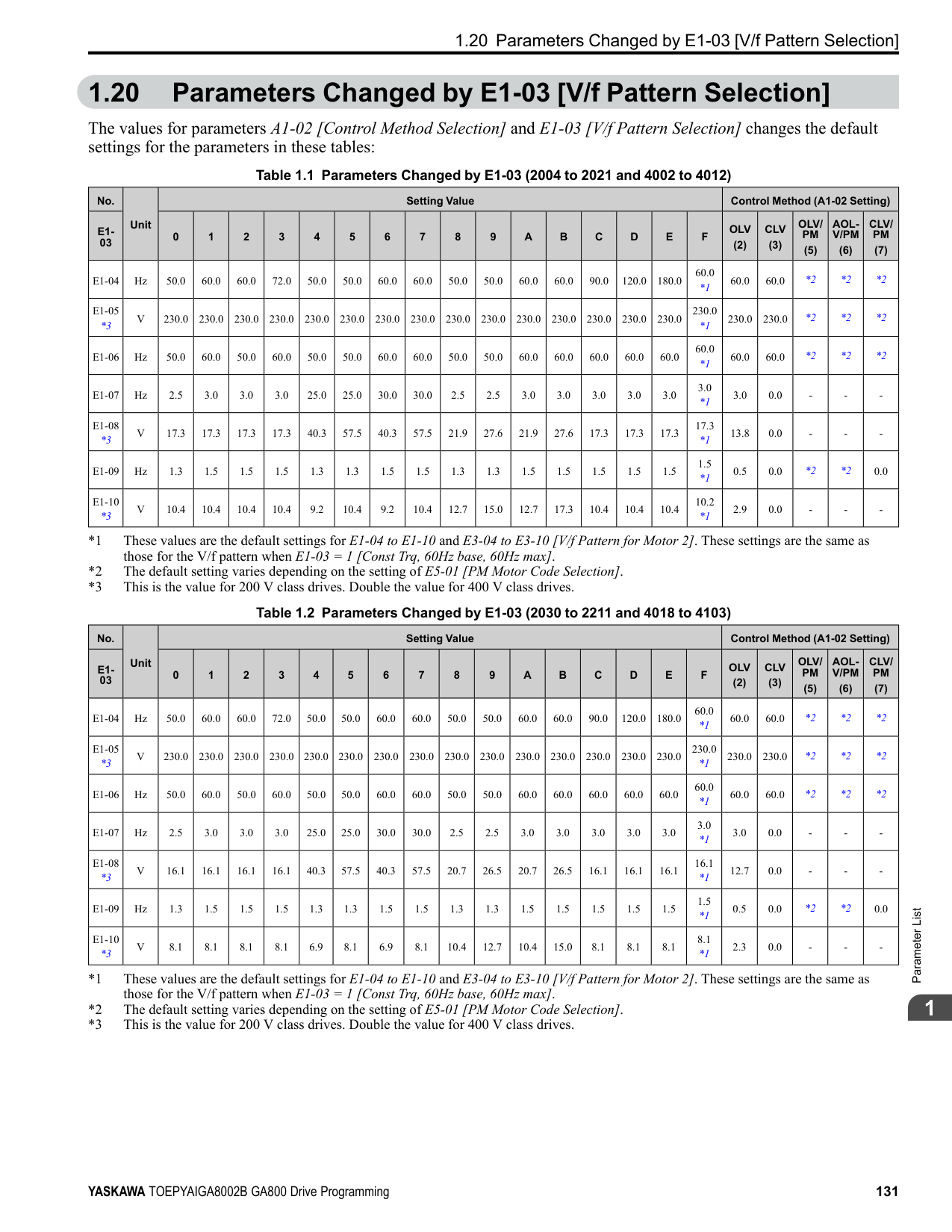
######## 2
When reverse operation is prohibited, the drive will not accept a Reverse operation command. 0 : Reverse Enabled The drive will accept a Reverse operation command. 1 : Reverse Disabled The drive will not accept a Reverse operation command.
When the frequency reference is less than the value set in E1-09, the drive will continue to operate the motor as specified by the frequency reference. If the motor speed is less than or equal to the value set in b2-01 [DC Injection/Zero SpeedThreshold] when you enter the Stop command (or deactivate the Run command), the drive will do Zero Speed Control for the time set in b2-04 [DC Inject Braking Time at Stop] and then turn OFF its output.
Figure 2.18 Operate at the Frequency Reference
|No. (Hex.)|Name|Description|Default (Range)| |---|---|---|---| |b1-04 (0183)|Reverse Operation Selection|Sets the reverse operation function. Disable reverse operation in fan or pump applications where reverse rotation is dangerous.
V/f CL-V/f OLV CLV AOLV OLV/PM AOLV/PM CLV/PM EZOLV
|0 (0, 1)|
|No. (Hex.)|Name|Description|Default (Range)| |---|---|---|---| |b1-05 (0184)|Operation Below Minimum Freq|Sets the drive operation when the frequency reference decreases to less than the value set in E1-09 [Minimum Output Frequency].
V/f CL-V/f OLV CLV AOLV OLV/PM AOLV/PM CLV/PM EZOLV
|0 (0 - 3)|
If the frequency reference is less than the value set in E1-09, the drive stops motor voltage output and the motor coasts to stop. If the motor speed is less than or equal to the value set in b2-01, the drive will do Zero Speed Control for the time set in b2-04.
Figure 2.19 Coast to Stop
############## 2 : Operate at Minimum Frequency
The drive operates the motor at the minimum frequency reference set in E1-09 when the frequency reference falls below the value set in E1-09 and the Run command is still enabled. The drive decelerates the motor when the Stop command is entered (or when the Run command is switched OFF). If the motor speed falls below or is equal to the value set in b2-01, then the drive will perform Zero Speed Control for the time set in b2-04.
Figure 2.20 Operate at Minimum Frequency
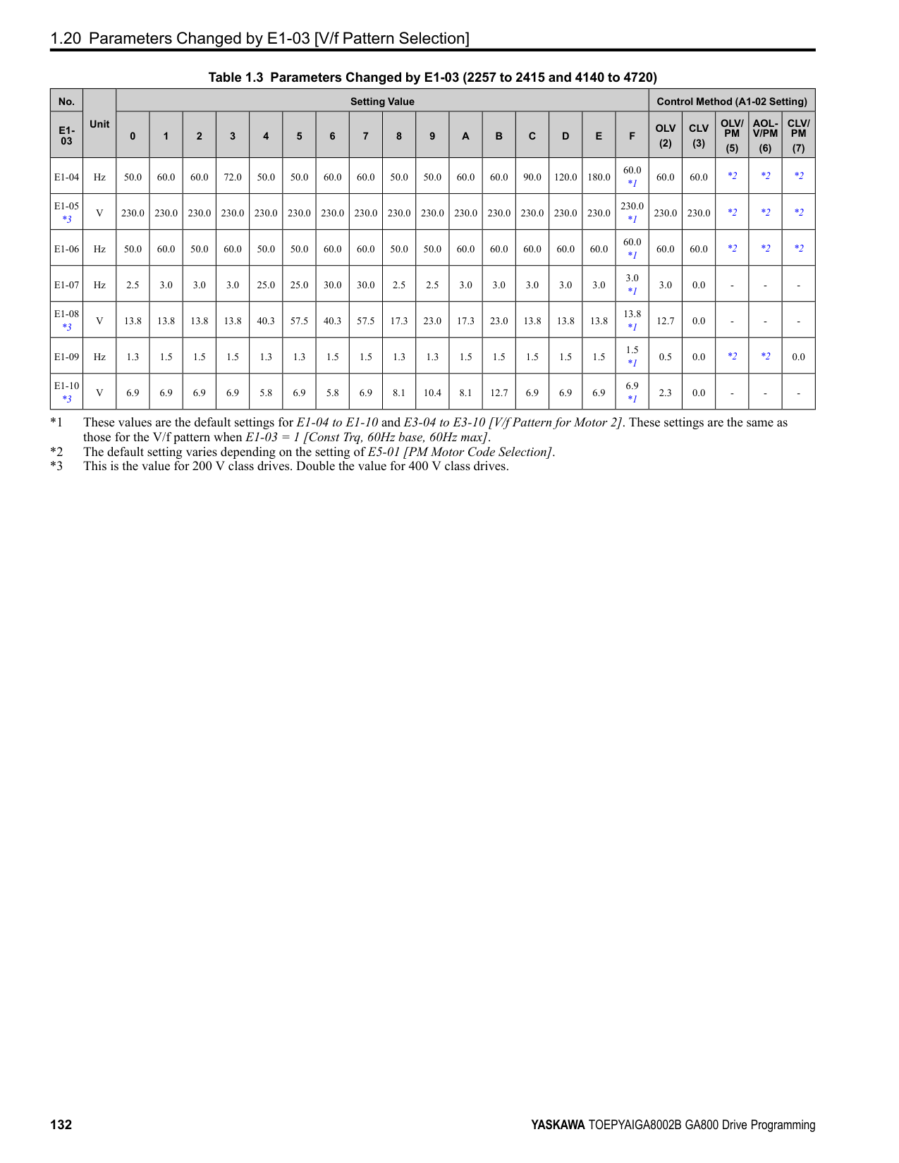
############### 3 : Operate at Zero SpeedThe drive performs Zero Speed Control when the frequency reference falls below the value set in E1-09.
When you enter the Stop command (or when you turn OFF the Run command), the drive does Zero Speed Control again for the time set in b2-04.
Figure 2.21 Operate at Zero Speed
######## ■ b1-06: Digital Input Reading
|No. (Hex.)|Name|Description|Default (Range)| |---|---|---|---| |b1-06 (0185)|Digital Input Reading|Sets the number of times that the drive reads the sequence input command to prevent malfunction because of noise.
V/f CL-V/f OLV CLV AOLV OLV/PM AOLV/PM CLV/PM EZOLV
|1 (0, 1)|
0 : Single Scan The drive reads the terminal status one time. The drive immediately reads all changes to the terminal status. This setting lets the drive quickly respond to changes in the sequence, but noise can cause malfunction. 1 : Double Scan
ParameterDetails
######## 2
The drive reads the terminal status two times. The drive reads all changes to the terminal status two times to make sure that the reading is the same. The drive responds slower than when it reads the sequence one time, but this setting prevents malfunction because of noise.
######## ■ b1-07: LOCAL/REMOTE Run Selection
|No. (Hex.)|Name|Description|Default (Range)| |---|---|---|---| |b1-07 (0186)|LOCAL/REMOTE Run Selection|Sets drive response to an existing Run command when the drive receives a second Run command from a different location.
V/f CL-V/f OLV CLV AOLV OLV/PM AOLV/PM CLV/PM EZOLV
|0 (0, 1)|
This parameter interlocks the drive to help prevent accidents that can occur if the motor starts to rotate because the Run command source changed.
To switch the RUN command source, push on the keypad or set H1-xx = 1, 2 [MFDI Function Selection = LOCAL/REMOTE Selection, External Reference 1/2 Selection] and activate/deactivate the terminal.
When the drive is operating the motor, turn OFF the Run command to stop the motor. Enter the Run command again to start operation.
If a Run command is enabled when you switch between Run command sources, the drive will start to operate the motor or continue to operate the motor. WARNING! Sudden Movement Hazard. When you use a 3-Wire sequence, set A1-03 = 3330 [Initialize Parameters = 3-Wire
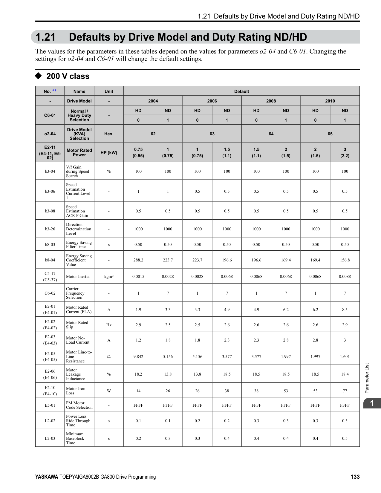
Initialization] and make sure that b1-17 = 0 [Run Command at Power Up = Disregard Existing RUN Command] (default). If you do not correctly set the drive parameters for 3-Wire operation before you energize the drive, the motor can suddenly rotate in reverse when you energize the drive.
######## ■ b1-08: Run Command Select in PRG Mode
|No. (Hex.)|Name|Description|Default (Range)| |---|---|---|---| |b1-08 (0187)|Run Command Select in PRG Mode|Sets the conditions for the drive to accept a Run command entered from an external source when using the keypad to set parameters.
V/f CL-V/f OLV CLV AOLV OLV/PM AOLV/PM CLV/PM EZOLV
|0 (0 - 2)|
This parameter helps prevent accidents that can occur if the motor starts to rotate because the drive received a Run command from an external source while the user is programming the drive. You can also set the drive to not show the Programming Mode when a Run command is active.
Note: Refer to this table for Drive Mode and Programming Mode functions.
|Mode|Keypad Screen|Function| |---|---|---| |Drive Mode|Monitors|Sets monitor display.| |Programming Mode|Parameters|Changes parameter settings.| |Programming Mode|User Custom Parameters|Shows the User Parameters.| |Programming Mode|Parameter Backup/Restore|Saves parameters to the keypad as backup.| |Programming Mode|Modified Parameters/Fault Log|Shows modified parameters and fault history.| |Programming Mode|Auto-Tuning|Auto-Tunes the drive.| |Programming Mode|Initial Setup|Changes initial settings.| |Programming Mode|Diagnostic Tools|Sets data logs and backlight.|
The drive does not let the user enter Programming Mode when the drive is operating. The drive does not show the Programming Mode when a Run command is active.
######## ■ b1-09: LOCAL/REMOTE Select during RUN
|No. (Hex.)|Name|Description|Default (Range)| |---|---|---|---| |b1-09 (0188) Expert|LOCAL/REMOTE Select during RUN|Sets the function that lets you use the during operation to switch between LOCAL and REMOTE Modes.
V/f CL-V/f OLV CLV AOLV OLV/PM AOLV/PM CLV/PM EZOLV
|0 (0, 1)|
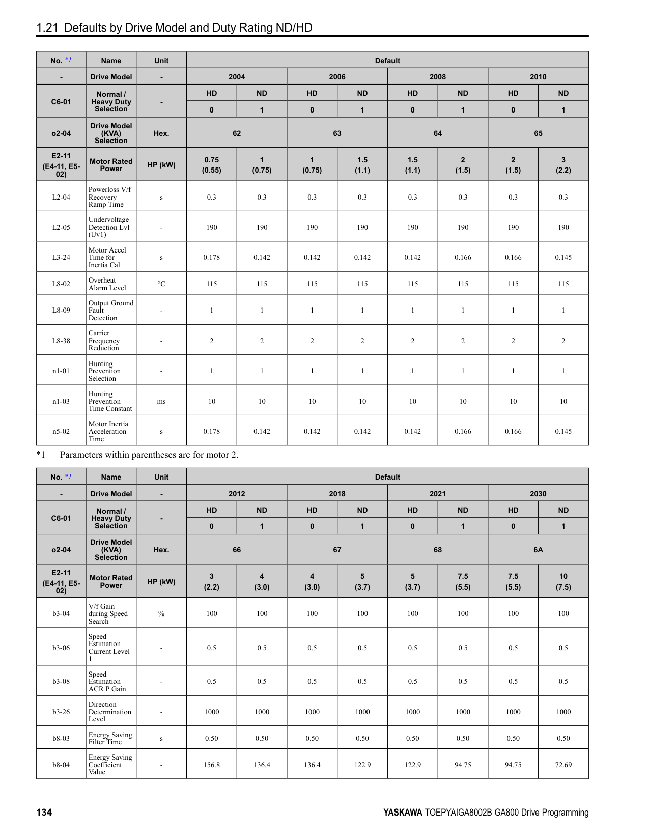
0 : Disabled 1 : Enabled
When you switch the operation mode from REMOTE to LOCAL during run, the drive writes this REMOTE operation status to the keypad:
######## ■ b1-14: Phase Order Selection
|No. (Hex.)|Name|Description|Default (Range)| |---|---|---|---| |b1-14 (01C3)|Phase Order Selection|Sets the phase order for output terminals U/T1, V/T2, and W/T3. This parameter can align the Forward Run command from the drive and the forward direction of the motor without changing wiring.
V/f CL-V/f OLV CLV AOLV OLV/PM AOLV/PM CLV/PM EZOLV
|0 (0, 1)|
######## ■ b1-15: Frequency Reference Selection 2
|No. (Hex.)|Name|Description|Default (Range)| |---|---|---|---| |b1-15 (01C4)|Frequency Reference Selection 2|Sets the input method for frequency reference 2.
V/f CL-V/f OLV CLV AOLV OLV/PM AOLV/PM CLV/PM EZOLV
|0 (0 - 4)|
This parameter is enabled when H1-xx = 2 [MFDI Function Selection = External Reference 1/2 Selection] is activated. Note:
will flash. Check the setting for the frequency reference input and enter a value more than or equal to E1-09. 0 : Keypad Use the keypad to enter the frequency reference. Use and on the keypad to change the frequency reference.
ParameterDetails
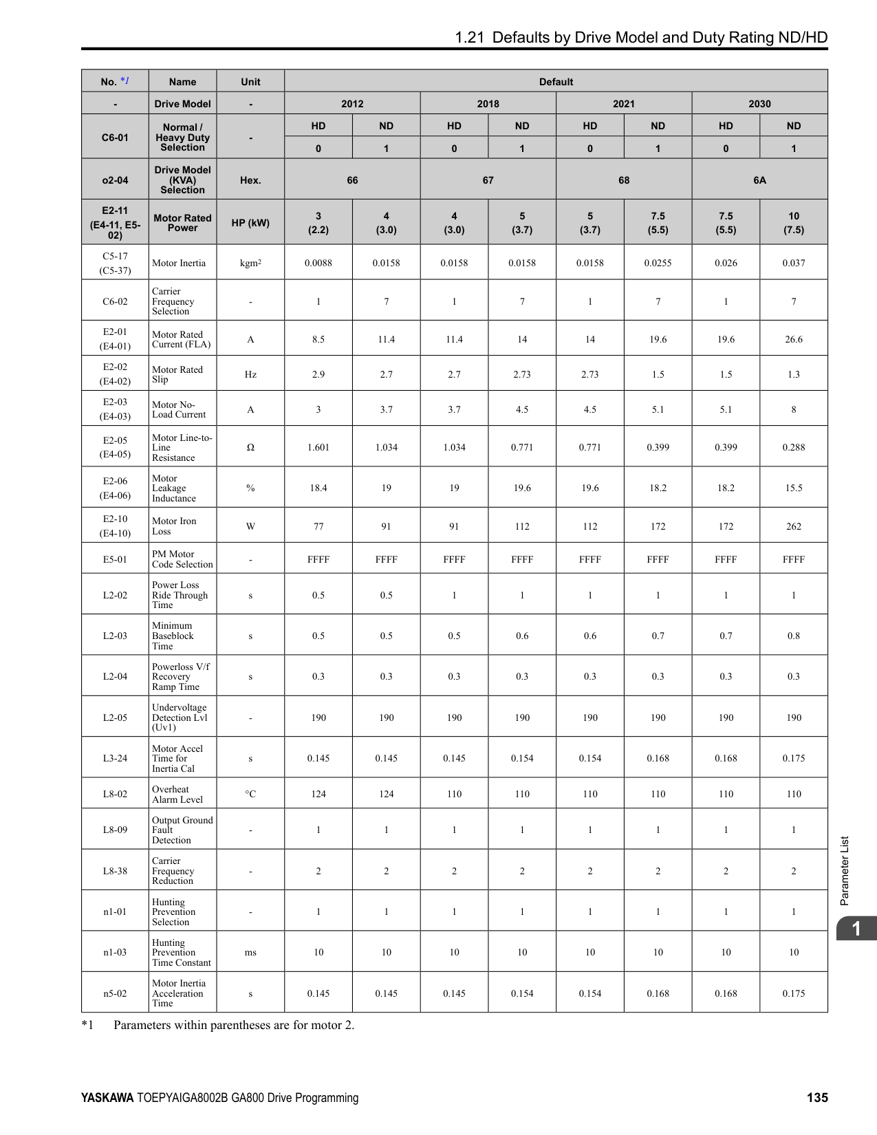
######## 2
Table 2.20 Frequency Reference Voltage Input
Figure 2.22 Example of Setting the Frequency Reference with a Voltage Signal to Terminal A1
Note: You can also use this diagram to wire terminals A2 and A3.
|Terminal|Terminal Signal Level|Parameter Settings|Parameter Settings|Parameter Settings|Parameter Settings|Note| |---|---|---|---|---|---|---| |Terminal|Terminal Signal Level|Signal Level Selection|Function Selection|Gain|Bias|Note| |A1|0 - 10 V|H3-01 = 0|H3-02 = 0 [Frequency Reference]|H3-03|H3-04|Set DIP switch S1-1 to “V” for voltage input.| |A1|-10 - +10 V|H3-01 = 1|H3-02 = 0 [Frequency Reference]|H3-03|H3-04|Set DIP switch S1-1 to “V” for voltage input.| |A2|0 - 10 V|H3-09 = 0|H3-10 = 0 [Frequency Reference]|H3-11|H3-12|Set DIP switch S1-2 to “V” for voltage input.| |A2|-10 - +10 V|H3-09 = 1|H3-10 = 0 [Frequency Reference]|H3-11|H3-12|Set DIP switch S1-2 to “V” for voltage input.| |A3|0 - 10 V|H3-05 = 0|H3-06 = 0 [Frequency Reference]|H3-07|H3-08|Set DIP switch S1-3 to “V” for voltage input. Set DIP switch S4 to “AI” for analog input.| |A3|-10 - +10 V|H3-05 = 1|H3-06 = 0 [Frequency Reference]|H3-07|H3-08|Set DIP switch S1-3 to “V” for voltage input. Set DIP switch S4 to “AI” for analog input.|
| | | | |---|---|---| | | | | | | | |
| | | | |---|---|---| | | | | | | | |
Table 2.21 Frequency Reference Current Input

|Terminal|Signal Level|Parameter Settings|Parameter Settings|Parameter Settings|Parameter Settings|Note| |---|---|---|---|---|---|---| |Terminal|Signal Level|Signal Level Selection|Function Selection|Gain|Bias|Note| |A1|4 mA to 20 mA|H3-01 = 2|H3-02 = 0 [Frequency Reference]|H3-03|H3-04|Set DIP switch S1-1 to “I” for current input.| |A1|0 - 20 mA|H3-01 = 3|H3-02 = 0 [Frequency Reference]|H3-03|H3-04|Set DIP switch S1-1 to “I” for current input.| |A2|4 mA to 20 mA|H3-09 = 2|H3-10 = 0 [Frequency Reference]|H3-11|H3-12|Set DIP switch S1-2 to “I” for current input.| |A2|0 - 20 mA|H3-09 = 3|H3-10 = 0 [Frequency Reference]|H3-11|H3-12|Set DIP switch S1-2 to “I” for current input.| |A3|4 mA to 20 mA|H3-05 = 2|H3-06 = 0 [Frequency Reference]|H3-07|H3-08|Set DIP switch S1-3 to “I” for current input. Set DIP switch S4 to “AI” for analog input.| |A3|0 - 20 mA|H3-05 = 3|H3-06 = 0 [Frequency Reference]|H3-07|H3-08|Set DIP switch S1-3 to “I” for current input. Set DIP switch S4 to “AI” for analog input.|
| | | | |---|---|---| | | | | | | | |
################# Figure 2.23 Example of Setting the Frequency Reference with a Current Signal to Terminal A2
Note: You can also use this diagram to wire terminals A1 and A3.
Changing between Master and Auxiliary Frequency References Use the multi-step speed reference function to change the frequency reference input between terminals A1, A2, and A3.
Note: If b1-15 = 3 but no option card is connected, then oPE03 [Multi-Function Input Setting Err] will flash on the keypad.
######## ■ b1-16: Run Command Selection 2
|No. (Hex.)|Name|Description|Default (Range)| |---|---|---|---| |b1-16 (01C5)|Run Command Selection 2|Sets the input method for Run Command 2 when the user switches the control circuit terminals ON/ OFF to change the Run command source.
V/f CL-V/f OLV CLV AOLV OLV/PM AOLV/PM CLV/PM EZOLV
|0 (0 - 3)|
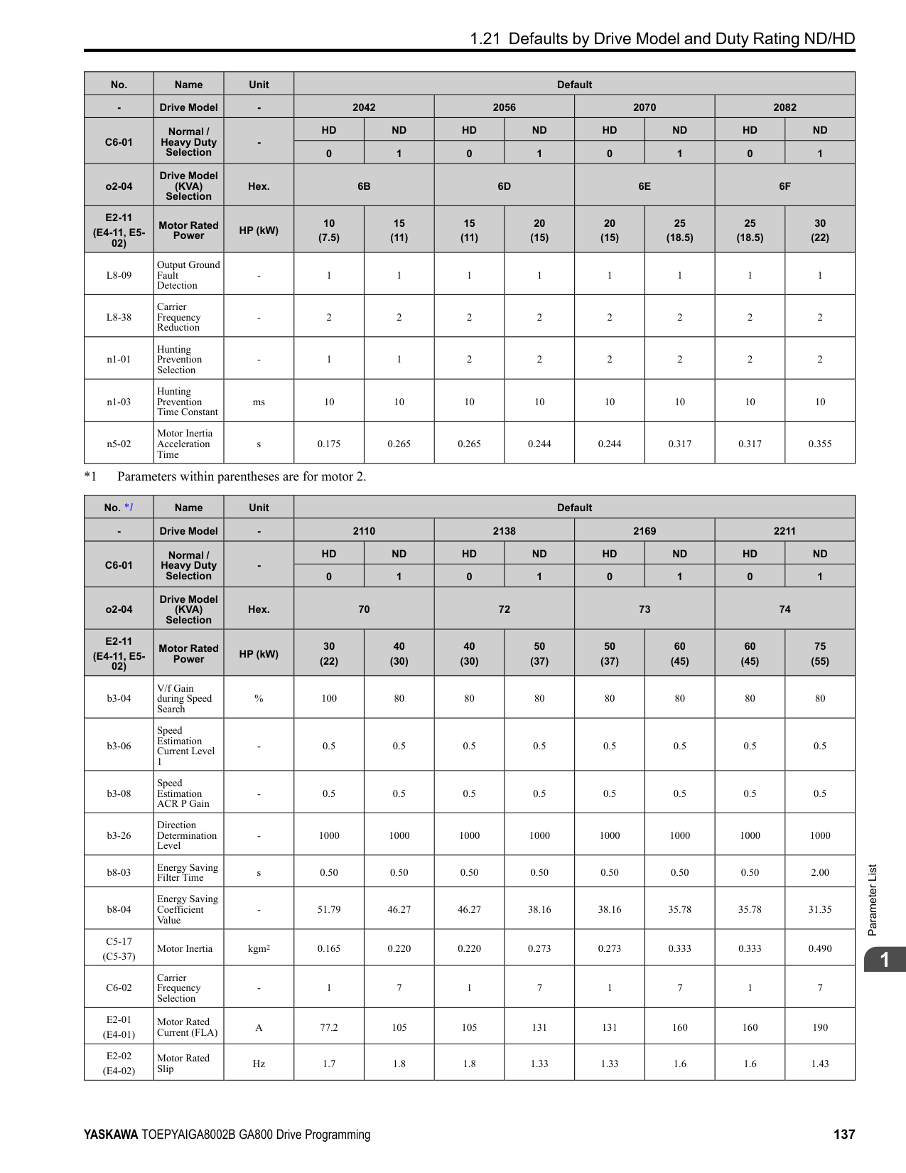
Activate H1-xx = 2 [MFDI Function Selection = External Reference 1/2 Selection] to enable this parameter.
Note:
The is on while the keypad is the Run command source.
ParameterDetails
######## 2
Use the control circuit terminals to enter the Run command. Select the input method for the Run command with an
Note: If b1-16 = 3 but no option card is connected, then oPE03 [Multi-Function Input Setting Err] will flash on the keypad.
######## ■ b1-17: Run Command at Power Up
|No. (Hex.)|Name|Description|Default (Range)| |---|---|---|---| |b1-17 (01C6)|Run Command at Power Up|Sets drive response when energizing a drive that has an external Run command. Set this parameter in applications where energizing or de-energizing the drive enables the Run command.
V/f CL-V/f OLV CLV AOLV OLV/PM AOLV/PM CLV/PM EZOLV
|0 (0, 1)|
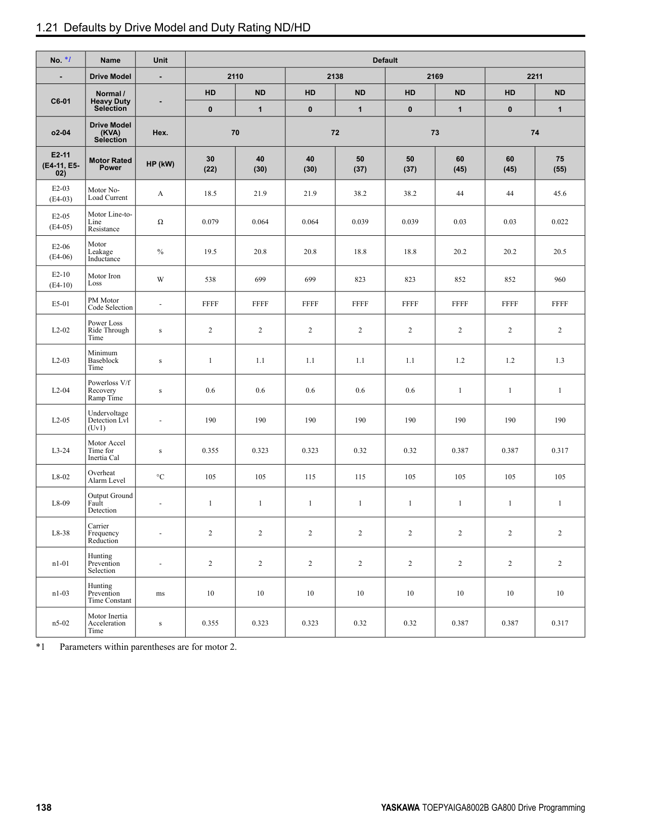
############## 0 : Disregard Existing RUN Command
The drive does not start to operate the application when the power is switched ON, even when there is an existing Run command. Enter the Run command again to operate the application.
Note:
When you energize the drive, on the keypad will flash quickly if the Run command is already enabled from an external source.
############### 1 : Accept Existing RUN CommandWhen there is an existing Run command, the drive starts to operate the application when the power is switched ON.
WARNING! Sudden Movement Hazard. When you use a 3-Wire sequence, set A1-03 = 3330 [Initialize Parameters = 3-Wire
Initialization] and make sure that b1-17 = 0 [Run Command at Power Up = Disregard Existing RUN Command] (default). If you do not correctly set the drive parameters for 3-Wire operation before you energize the drive, the motor can suddenly rotate in reverse when you energize the drive.
######## ■ b1-21: CLV Start Selection
|No. (Hex.)|Name|Description|Default (Range)| |---|---|---|---| |b1-21 (0748) Expert|CLV Start Selection|Sets the conditions for the drive to accept a Run command when A1-02 3, 7 [Control Method Selection CLV, CLV/PM]. Usually it is not necessary to change this setting.
V/f CL-V/f OLV CLV AOLV OLV/PM AOLV/PM CLV/PM EZOLV
|0 (0, 1)|
######## ■ b1-35: Digital Input Deadband Time
|No. (Hex.)|Name|Description|Default (Range)| |---|---|---|---| |b1-35 (1117) Expert|Digital Input Deadband Time|Sets the deadband time for MFDIs.
V/f CL-V/f OLV CLV AOLV OLV/PM AOLV/PM CLV/PM EZOLV
|0.0 ms (0.0 to 100.0 ms)|
When the on/off time for MFDIs is longer than the time set in b1-35, the drive activates the MFDI. Set this parameter to prevent malfunctions caused by relay chattering for applications in which relays send input to MFDI terminals.
◆ b2: DC Injection Braking and Short Circuit Braking b2 parameters set the DC Injection Braking and Short Circuit Braking functions.
######## ■ b2-01: DC Injection/Zero SpeedThreshold
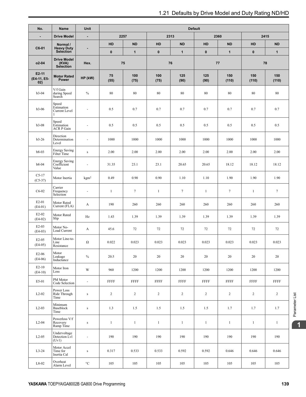
|No. (Hex.)|Name|Description|Default (Range)| |---|---|---|---| |b2-01 (0189)|DC Injection/Zero SpeedThreshold|Sets the frequency to start DC Injection Braking, Short Circuit Braking, and Zero Servo.
V/f CL-V/f OLV CLV AOLV OLV/PM AOLV/PM CLV/PM EZOLV
|Determined by A1-02 (0.0 - 10.0 Hz)|
Note: This parameter is available when b1-03 = 0 [Stopping Method Selection = Ramp to Stop].
When the control method selected in A1-02 [Control Method Selection] changes, the b2-01 function changes.
ParameterDetails
|Parameter Settings|Function of b2-01| |---|---| |A1-02 0, 1, 2 [V/f, CL-V/f, OLV]|b2-01 sets the frequency to start DC Injection Braking at stop. When the output frequency is less than or equal to the value set in b2-01, the drive will inject the quantity of DC current set in b2-02 [DC Injection Braking Current] into the motor for the time set in b2-04 [DC Inject Braking Time at Stop].
Figure 2.24 DC Injection Braking at Stop Note:
When b2-01 ≤ E1-09 [Minimum Output Frequency], the drive will start DC Injection Braking from the frequency set in E1-09.| |A1-02 4 [AOLV] and n4-72 0 [Speed Feedback Mode Without Encoder]|b2-01 sets the frequency to start DC Injection Braking at stop. When the output frequency is less than or equal to the value set in b2-01, the drive will inject the quantity of DC current set in b2-02 [DC Injection Braking Current] into the motor for the time set in b2-04 [DC Inject Braking Time at Stop].
Figure 2.24 DC Injection Braking at Stop Note:
When b2-01 ≤ E1-09 [Minimum Output Frequency], the drive will start DC Injection Braking from the frequency set in E1-09.| |A1-02 5, 6, 8 [OLV/PM, AOLV/PM, EZOLV]|b2-01 sets the frequency to start Short Circuit Braking at stop. When the output frequency is less than or equal to the value set in b2-01, the drive will do Short Circuit Braking for the time set in b2-13 [Short Circuit Brake Time @ Stop]. When b2-04 > 0.00 s, the drive will complete Short Circuit Braking, then do DC Injection Braking for the time set in b2-04.
Figure 2.25 Short Circuit Braking at Stop
Note: When b2-01 ≤ E1-09, the drive will start Short Circuit Braking from the frequency set in E1-09. If b2-01 and E1-09 0 Hz, the drive will not do Short Circuit Braking.| |A1-02 = 3, 7 [CLV, CLV/PM]|b2-01 sets the frequency to start Zero Speed Control at stop. When the output frequency is less than or equal to the value set in b2-01, the drive will do Zero Speed Control for the time set in b2-04.
Figure 2.26 Zero Speed Control at Stop
Note: When b2-01 ≤ E1-09, the drive will start Zero Speed Control from the frequency set in E1-09.| |A1-02 4 [AOLV] and n4-72 1 [With Encoder]|b2-01 sets the frequency to start Zero Speed Control at stop. When the output frequency is less than or equal to the value set in b2-01, the drive will do Zero Speed Control for the time set in b2-04.
Figure 2.26 Zero Speed Control at Stop
Note: When b2-01 ≤ E1-09, the drive will start Zero Speed Control from the frequency set in E1-09.|
######## ■ b2-02: DC Injection Braking Current
|No. (Hex.)|Name|Description|Default (Range)| |---|---|---|---| |b2-02 (018A)|DC Injection Braking Current|Sets the DC Injection Braking current as a percentage of the drive rated current.
V/f CL-V/f OLV CLV AOLV OLV/PM AOLV/PM CLV/PM EZOLV
|50% (0 - 100%)|
When the DC Injection Braking current is more than 50%, the drive decreases the carrier frequency to 1 kHz. The motor rated current determines how much DC Injection Braking current that the drive can use. The DC Injection Braking current level has an effect on the strength of the magnetic field that locks the motor shaft.
Note: When A1-02 4 [Control Method Selection AOLV] and n4-72 1 [Speed Feedback Mode With Encoder], the drive ignores the b2-02 setting and does initial excitation.
######## ■ b2-03: DC Inject Braking Time at Start
|No. (Hex.)|Name|Description|Default (Range)| |---|---|---|---| |b2-03 (018B)|DC Inject Braking Time at Start|Sets the DC Injection Braking Time at stop. Sets the time of Zero Speed Control at start when A1-02 3, 7 [Control Method Selection CLV, CLV/PM].
V/f CL-V/f OLV CLV AOLV OLV/PM AOLV/PM CLV/PM EZOLV
|A1-02 4: 0.03 s Other than A1-02 4: 0.00 s (0.00 - 10.00 s)|
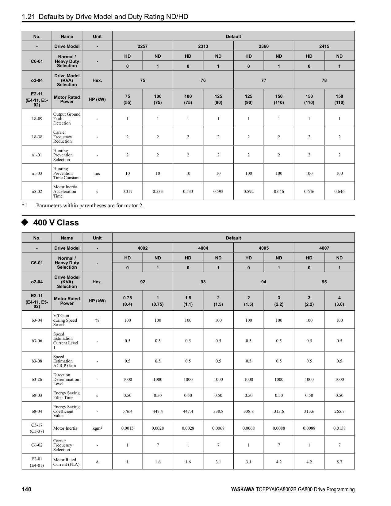
This function stops then restarts a coasting motor and increases motor flux to make high starting torque (a process called initial excitation). Set this parameter to 0.00 to disable the function.
Note:
######## ■ b2-04: DC Inject Braking Time at Stop
|No. (Hex.)|Name|Description|Default (Range)| |---|---|---|---| |b2-04 (018C)|DC Inject Braking Time at Stop|Sets the DC Injection Braking Time at stop. Sets the time of Zero Speed Control at stop when A1-02
= 3, 7 [Control Method Selection = CLV, CLV/PM].
V/f CL-V/f OLV CLV AOLV OLV/PM AOLV/PM CLV/PM EZOLV
|Determined by A1-02 (0.00 - 10.00 s)|
This function fully stops a motor with a large inertia during deceleration and will not let the inertia continue to rotate the motor. Set this parameter to 0.00 to disable the function. When a longer time is required to stop the motor, increase the value.
Note: Sets the time of Zero Speed Control at stop when A1-02 = 4 [AOLV] and n4-72 = 1 [Speed Feedback Mode = With Encoder].
######## ■ b2-08: Magnetic Flux Compensation Value
|No. (Hex.)|Name|Description|Default (Range)| |---|---|---|---| |b2-08 (0190)|Magnetic Flux Compensation Value|Sets how much current the drive injects when DC Injection Braking at Start starts (Initial Excitation) as a percentage of E2-03 [Motor No-Load Current].
V/f CL-V/f OLV CLV AOLV OLV/PM AOLV/PM CLV/PM EZOLV
|0% (0 - 1000%)|
This parameter is effective when you start a high-capacity motor (a motor with a large secondary circuit time constant). This function can quickly increase motor flux to make high starting torque (a process called initial excitation).
The current level for DC Injection Braking at start changes linearly from the setting of b2-08 to the setting of b2-03 as shown in Figure 2.27.
Figure 2.27 DC Current Level during DC Injection Braking at Start Note:
ParameterDetails
######## ■ b2-12: Short Circuit Brake Time @ Start
|No. (Hex.)|Name|Description|Default (Range)|
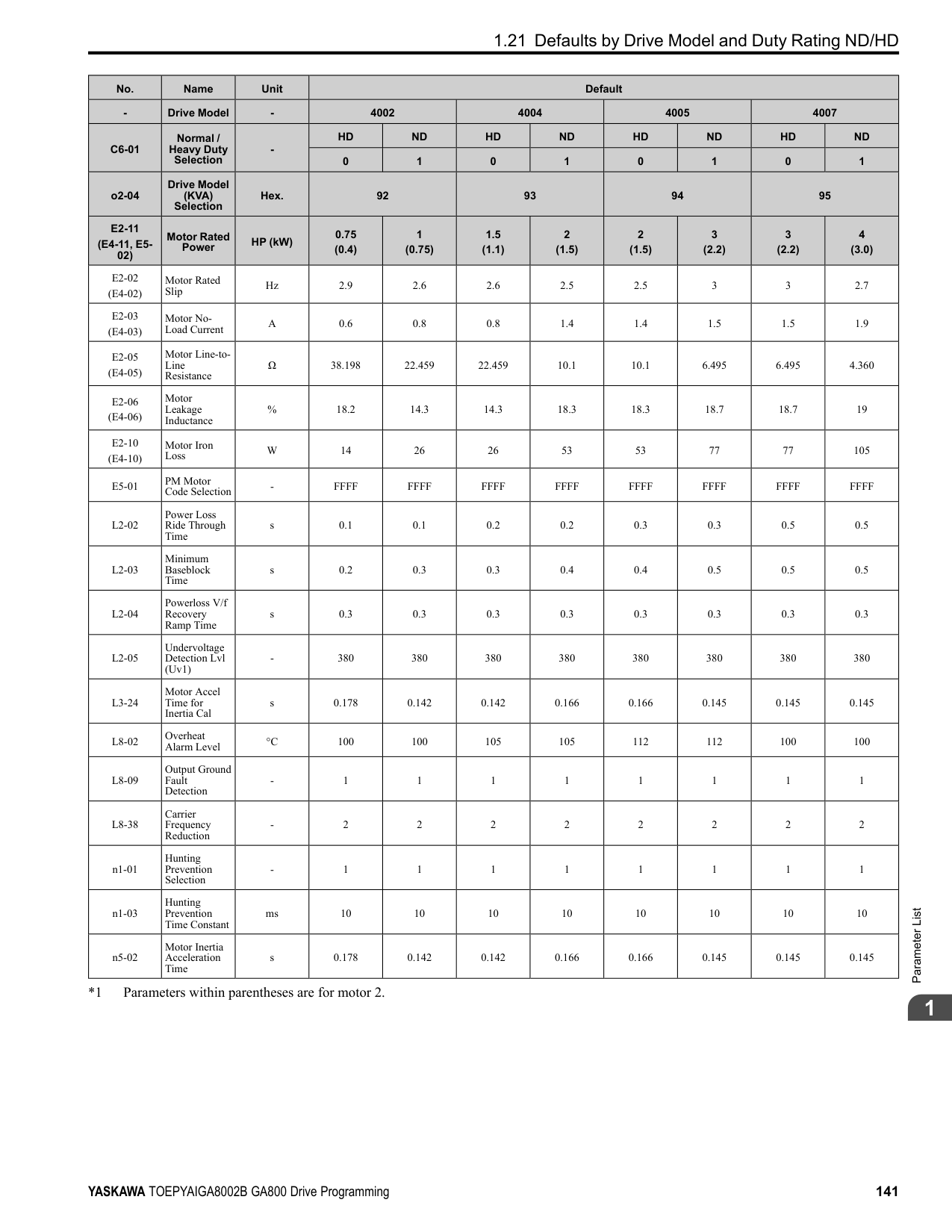
|---|---|---|---| |b2-12 (01BA)|Short Circuit Brake Time @ Start|Sets the Short Circuit Braking time at start.
V/f CL-V/f OLV CLV AOLV OLV/PM AOLV/PM CLV/PM EZOLV
|0.00 s (0.00 - 25.50 s)|
This function stops and restarts a coasting PM motor. The drive short circuits all the three motor phases to make braking torque in the motor. Set this parameter to 0.00 to disable the function.
Note:
######## ■ b2-13: Short Circuit Brake Time @ Stop
|No. (Hex.)|Name|Description|Default (Range)| |---|---|---|---| |b2-13 (01BB)|Short Circuit Brake Time @ Stop|Sets the Short Circuit Braking time at stop.
V/f CL-V/f OLV CLV AOLV OLV/PM AOLV/PM CLV/PM EZOLV
|A1-02 = 8: 0.00 s Other than A1-02 = 8: 0.50 s (0.00 - 25.50 s)|
This function fully stops a PM motor with a large inertia during deceleration and will not let the inertia continue to rotate the motor. Short Circuit Braking operates for the time set in b2-13 when output frequency is less than the value set in b2-01 [DC Injection/Zero SpeedThreshold] or E1-09 [Minimum Output Frequency]. Set this parameter to 0.00 to disable the function.
Note: Motor speed and load conditions can make it necessary to install a dynamic braking option on the drive.
######## ■ b2-18: Short Circuit Braking Current
|No. (Hex.)|Name|Description|Default (Range)| |---|---|---|---| |b2-18 (0177)|Short Circuit Braking Current|Sets the Short Circuit Braking Current as a percentage of the motor rated current.
V/f CL-V/f OLV CLV AOLV OLV/PM AOLV/PM CLV/PM EZOLV
|100.0% (0.0 - 200.0%)|
The Short Circuit Braking current cannot be higher than the drive rated current, although a higher current level can be set using b2-18. The maximum rated current is 120% when the drive is set for Normal Duty (C6-01 = 1 [Normal Duty Rating]). The maximum rated current is 150% when the drive is set for Heavy Duty (C6-01 = 0 [Heavy Duty Rating]).
######## ◆ b3: Speed Search
The Speed Search function detects the actual speed of a coasting motor, then restarts the motor before the motor stops. Use Speed Search in these conditions:
For example, the drive output turns off and the motor coasts when there is a momentary loss of power. After you return power, the drive does Speed Search on the coasting motor, and restarts the motor from the detected speed. When you use a PM motor, enable b3-01 [Speed Search at Start Selection]. There are two types of Speed Search for induction motors: Current Detection and Speed Estimation. Use parameter b3-24 [Speed Search Method Selection] to select the type of Speed Search. Parameter settings are different for different types of Speed Search. For details, refer to Table 2.22.
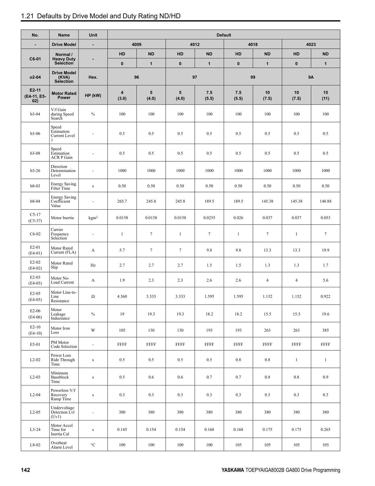
Table 2.22 Speed Search and Related Parameters
|Parameters|Speed Estimation|Current Detection 2| |---|---|---| |Parameters|b3-24 = 1|b3-24 = 2| |b3-01 [Speed Search at Start Selection]|x|x| |b3-03 [Speed Search Deceleration Time]|-|x| |b3-05 [Speed Search Delay Time]|x|x|
|Parameters|Speed Estimation|Current Detection 2| |---|---|---| |Parameters|b3-24 = 1|b3-24 = 2| |b3-06 [Speed Estimation Current Level 1]|x|-| |b3-07 [Speed Estimation Current Level 2]|x|-| |b3-08 [Speed Estimation ACR P Gain]|x|-| |b3-09 [Speed Estimation ACR I Time]|x|-| |b3-10 [Speed Estimation Detection Gain]|x|-| |b3-14 [Bi-directional Speed Search]|x|○| |b3-17 [Speed Est Retry Current Level]|x|x| |b3-18 [Speed Est Retry Detection Time]|x|x| |b3-19 [Speed Search Restart Attempts]|x|x| |b3-24 [Speed Search Method Selection]|x (1)|x (2)| |b3-25 [Speed Search Wait Time]|x|x| |b3-26 [Direction Determination Level]|x|-| |b3-27 [Speed Search RUN/BB Priority]|x|x| |b3-29 [Speed Search Back-EMF Threshold]|-|-| |b3-31 [Spd Search Current Reference Lvl]|-|x| |b3-32 [Spd Search Current Complete Lvl]|-|x| |b3-33 [Speed Search during Uv Selection]|x|x| |b3-35 [Low Back EMF Detection Level]|x|x| |b3-36 [High Back EMF Detection Level]|x|x| |b3-54 [Search Time]|-|-| |b3-55 [Current Increment Time]|-|-| |b3-56 [InverseRotationSearch WaitTime]|-|x|
################# Note:
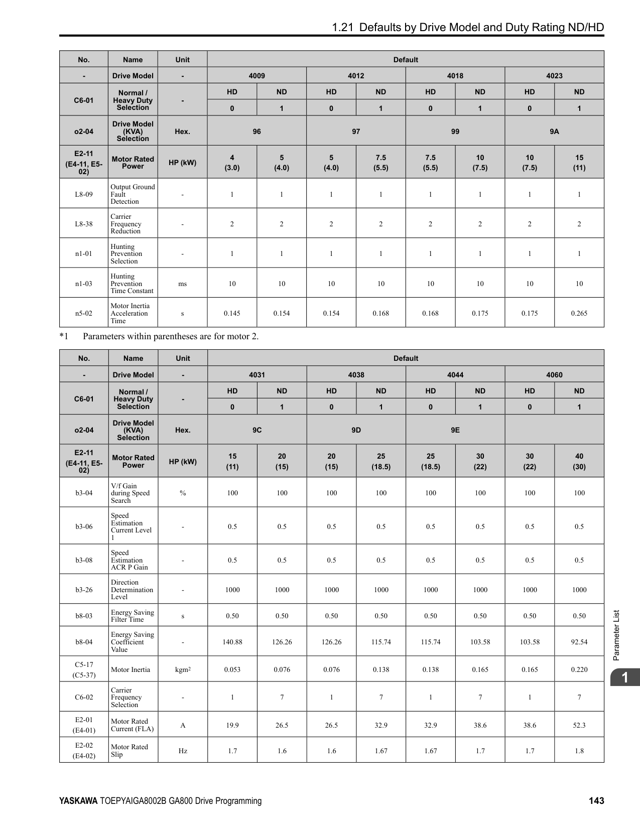
■ Current Detection 2 Use this Speed Search function with induction motors. Set b3-24 = 2 [Speed Search Method Selection = Current Detection 2]. Current Detection Speed Search injects current into the motor to detect the speed of an induction motor. Speed Search increases the output voltage for the time set in L2-04 [Powerloss V/f Recovery Ramp Time], starting from the maximum output frequency or the frequency reference.
ParameterDetails
Figure 2.28 Current Detection 2 after a Momentary Power Loss Note:
Once power is restored, the drive will not execute Speed Search until the time set in b3-05 [Speed Search Delay Time] has passed. Thus, the drive will not always start Speed Search although the time set in L2-03 [Minimum Baseblock Time] is expired.
If you enter the Run command at the same time as Speed Search, the drive will not do Speed Search until the time set in L2-03 is expired. When the value set in L2-03 < b3-05, the drive will use the wait time set in b3-05.
Figure 2.29 Speed Search Selection at Start (Current Detection Type)
WARNING! Sudden Movement Hazard. Do not do Current Detection Speed Search with light loads or a stopped motor. If you do Auto-Tuning in these conditions, the motor can suddenly accelerate and cause serious injury or death.
################# Note:
■ Speed Estimation Use this Speed Search function with induction motors. Set b3-24 = 1 [Speed Search Method Selection = Speed
Estimation]. This function uses less current and has a shorter search time than other functions. This function lets you do Speed Search when the motor is rotating in reverse. When you return power after a power loss, the motor will not suddenly accelerate.
Note: You cannot do Speed Estimation Speed Search in these conditions:
Speed Estimation Speed Search uses these two steps to estimate the motor speed:
Figure 2.30 Speed Search after Baseblock Note:
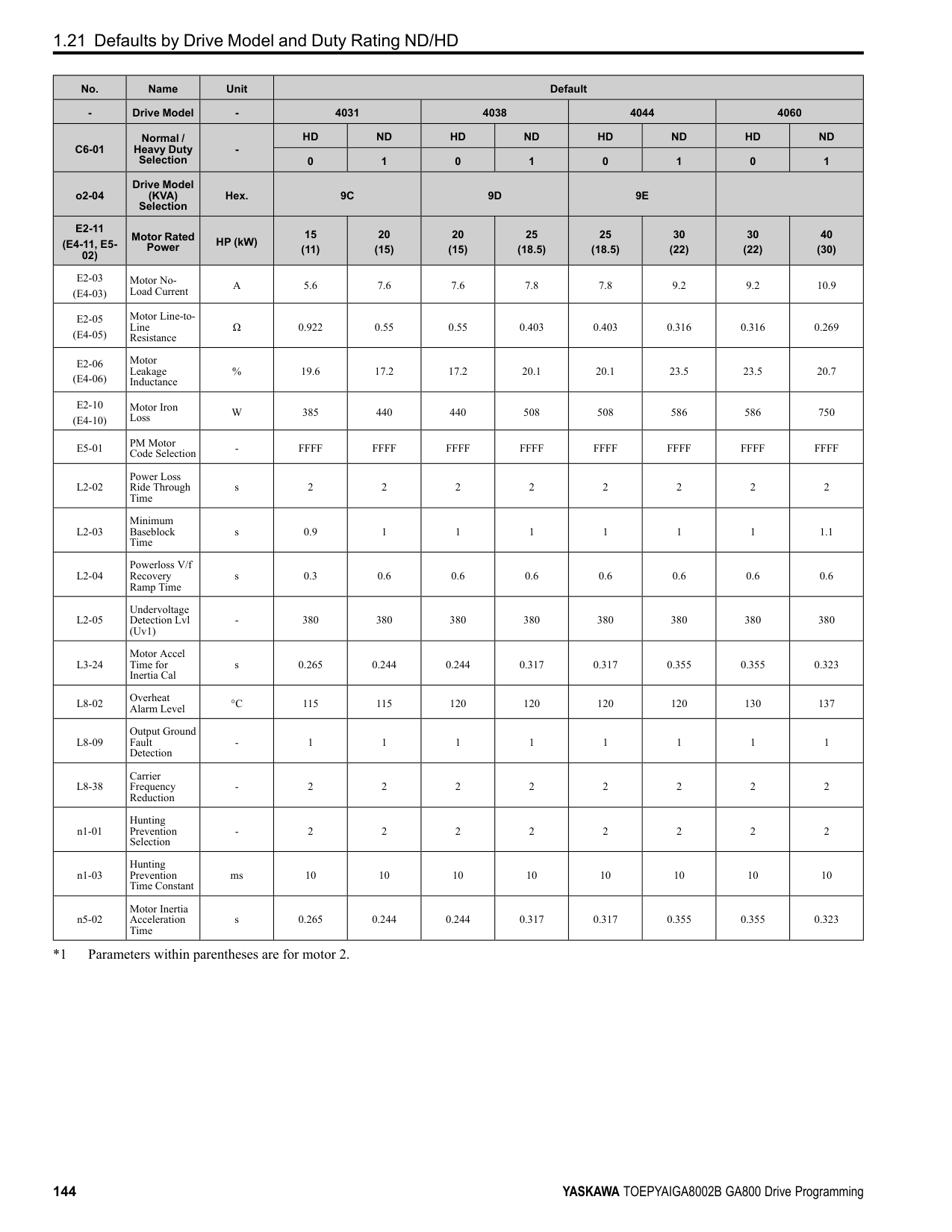
After you return power, the drive waits for the time set in b3-05. When power loss is longer than the time set in L2-03, the drive will start Speed Search when the time set in b3-05 is expired after the power recovery.
Figure 2.31 Speed Search Selection at Start
Note: Set the lower limit of the delay time to b3-05 for when Speed Search starts.
■ Speed Search and Operation Conditions These conditions apply to Speed Search operation. When A1-02 = 0, 1, 2 [Control Method Selection = V/f Control, V/ f Control with Encoder, Open Loop Vector], set b3-24 [Speed Search Method Selection] before you do Speed Search.
ParameterDetails
######## 2
Set Speed Search to H1-xx to do the function externally. You cannot set external Speed Search 1 and 2 at the same time.
Table 2.23 Execute Speed Search via the Digital Input Terminals
|H1-xx Setting|Name|Current Detection 2|Speed Estimation| |---|---|---|---| |61|Speed Search from Fmax|ON: Speed Search starts from E1-04 [Maximum Output Frequency].|External Speed Search commands 1 and 2 work the same.
The drive estimates the motor speed, then starts Speed Search from the estimated speed.| |62|Speed Search from Fref|ON: Speed Search starts from the frequency reference immediately before you input the Speed Search command.|External Speed Search commands 1 and 2 work the same.
The drive estimates the motor speed, then starts Speed Search from the estimated speed.|
######## ■ b3-01: Speed Search at Start Selection
|No. (Hex.)|Name|Description|Default (Range)| |---|---|---|---| |b3-01 (0191)|Speed Search at Start Selection|Sets the Speed Search at Start function where the drive will perform Speed Search with each Run command.
V/f CL-V/f OLV CLV AOLV OLV/PM AOLV/PM CLV/PM EZOLV
|Determined by A1-02 (0, 1)|

When the Run command is enabled and the Speed Search from Fmax or Fref [H1-xx = 61, 62] is input from a multifunction input terminal, the drive will do Speed Search and start to operate the motor.
######## ■ b3-02: SpeedSearch Deactivation Current
|No. (Hex.)|Name|Description|Default (Range)| |---|---|---|---| |b3-02 (0192)|SpeedSearch Deactivation Current|Sets the current level that stops Speed Search as a percentage of the drive rated output current. Usually it is not necessary to change this setting.
V/f CL-V/f OLV CLV AOLV OLV/PM AOLV/PM CLV/PM EZOLV
|Determined by A1-02 (0 - 200%)|
If the drive cannot restart the motor, decrease this setting.
######## ■ b3-03: Speed Search Deceleration Time
|No. (Hex.)|Name|Description|Default (Range)| |---|---|---|---| |b3-03 (0193)|Speed Search Deceleration Time|Sets the deceleration time during Speed Search operation. Set the length of time to decelerate from the maximum output frequency to the minimum output frequency.
V/f CL-V/f OLV CLV AOLV OLV/PM AOLV/PM CLV/PM EZOLV
|2.0 s (0.1 - 10.0 s)|
This is the output frequency deceleration time used by Current Detection Speed Search and by the Current Injection Method of Speed Estimation Speed Search.
Note:
Use the this formula to calculate the output voltage during Speed Search: Output voltage during Speed Search = Configured V/f × b3-04 When the current detection search operates correctly, this configuration is not necessary.
When you use a magnetic contactor between the drive and motor, you must close the contactor before the drive will do Speed Search. This parameter sets a delay time to activate the magnetic contactor.
When the speed estimation value is the minimum output frequency, increase this setting. You can do this when the motor coasts at a high speed while the drive estimates the speed during Speed Estimation Speed Search. The limit of the output current during speed search is automatically the drive rated current.
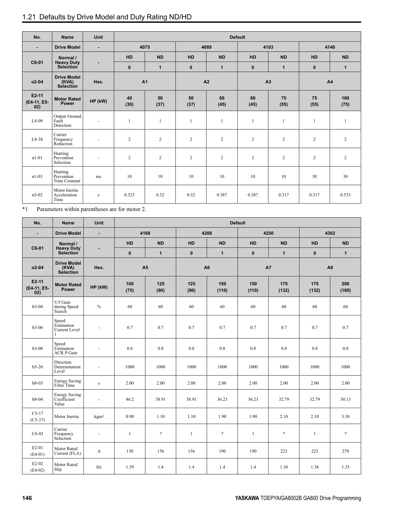
Note: When the drive cannot accurately estimate the speed after you adjust this parameter, use Current Detection Speed Search.
During Speed Estimation Speed Searches, when the speed estimation value aligns with the minimum output frequency, increase the setting value in 0.1-unit increments. The limit of the output current during speed search is automatically the drive rated current.
|No. (Hex.)|Name|Description|Default (Range)| |---|---|---|---| |b3-04 (0194)|V/f Gain during Speed Search|Sets the ratio used to reduce the V/f during searches to reduce the output current during speed searches.
V/f CL-V/f OLV CLV AOLV OLV/PM AOLV/PM CLV/PM EZOLV
|Determined by o2-04 (10 - 100)|
|No. (Hex.)|Name|Description|Default (Range)| |---|---|---|---| |b3-05 (0195)|Speed Search Delay Time|Sets the Speed Search delay time to activate a magnetic contactor installed between the drive and motor.
V/f CL-V/f OLV CLV AOLV OLV/PM AOLV/PM CLV/PM EZOLV
|0.2 s (0.0 - 100.0 s)|
|No. (Hex.)|Name|Description|Default (Range)| |---|---|---|---| |b3-06 (0196) Expert|Speed Estimation Current Level 1|Sets the level of current that flows to the motor during Speed Estimation Speed Search as a coefficient of the motor rated current. Usually it is not necessary to change this setting.
V/f CL-V/f OLV CLV AOLV OLV/PM AOLV/PM CLV/PM EZOLV
|Determined by o2-04 (0.0 - 2.0)|
|No. (Hex.)|Name|Description|Default (Range)| |---|---|---|---| |b3-07 (0197) Expert|Speed Estimation Current Level 2|Sets the level of current that flows to the motor during Speed Estimation Speed Search as a coefficient of E2-03 [Motor No-Load Current] or E4-03 [Motor 2 Rated No-Load Current]. Usually it is not necessary to change this setting.
V/f CL-V/f OLV CLV AOLV OLV/PM AOLV/PM CLV/PM EZOLV
|1.0 (0.0 - 3.0)|
|No. (Hex.)|Name|Description|Default (Range)| |---|---|---|---| |b3-08 (0198)|Speed Estimation ACR P Gain|Sets the proportional gain for the automatic current regulator during Speed Estimation Speed Search. Also adjusts speed search responsiveness. Usually it is not necessary to change this setting.
V/f CL-V/f OLV CLV AOLV OLV/PM AOLV/PM CLV/PM EZOLV
|Determined by A1-02 and o2-04
(0.00 - 6.00)|
ParameterDetails
######## 2
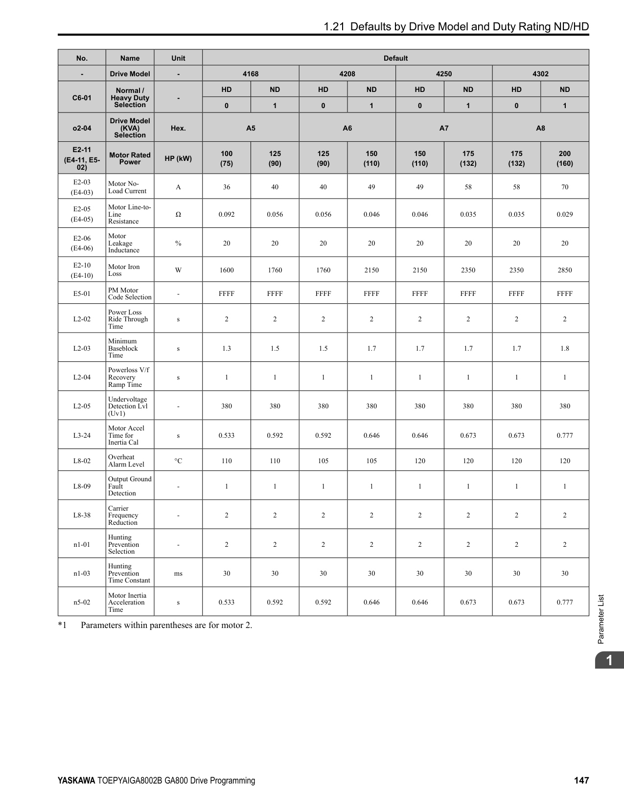
If the drive detects ov [DC Bus Overvoltage] when you restart the motor, increase the setting value.
|No. (Hex.)|Name|Description|Default (Range)| |---|---|---|---| |b3-09 (0199)|Speed Estimation ACR I Time|Sets the integral time for the automatic current regulator during Speed Estimation Speed Search. Also adjusts speed search responsiveness. Usually it is not necessary to change this setting.
V/f CL-V/f OLV CLV AOLV OLV/PM AOLV/PM CLV/PM EZOLV
|Determined by A1-02 when A1-02 ≠ 5
20.0 when A1-02 = 5 (0.0 - 1000.0 ms)|
|No. (Hex.)|Name|Description|Default (Range)| |---|---|---|---| |b3-10 (019A) Expert|Speed Estimation Detection Gain|Sets the gain to correct estimated frequencies from Speed Estimation Speed Search.
V/f CL-V/f OLV CLV AOLV OLV/PM AOLV/PM CLV/PM EZOLV
|1.05 (1.00 - 1.20)|
|No. (Hex.)|Name|Description|Default (Range)| |---|---|---|---| |b3-14 (019E)|Bi-directional Speed Search|Sets the direction of Speed Search to the direction of the frequency reference or in the motor rotation direction as detected by the drive.
V/f CL-V/f OLV CLV AOLV OLV/PM AOLV/PM CLV/PM EZOLV
|Determined by A1-02 and b3-24 (0, 1)|
################# Note:
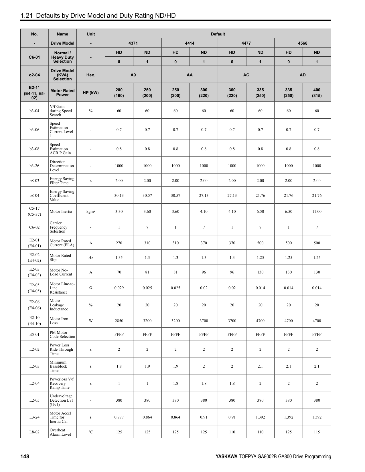
0 : Disabled The drive uses the frequency reference to detect the direction of motor rotation. 1 : Enabled The drive detects the direction of motor rotation during Speed Search.
######## ■ b3-17: Speed Est Retry Current Level
|No. (Hex.)|Name|Description|Default (Range)| |---|---|---|---| |b3-17 (01F0) Expert|Speed Est Retry Current Level|Sets the current level for the search retry function in Speed Estimation Speed Search as a percentage where drive rated current is a setting value of 100%.
V/f CL-V/f OLV CLV AOLV OLV/PM AOLV/PM CLV/PM EZOLV
|150% (0 - 200%)|
When a large quantity of current flows during Speed Estimation Speed Search, the drive temporarily stops operation to prevent overvoltage and overcurrent. When the current is at the level set in b3-17, the drive tries speed search again.
######## ■ b3-18: Speed Est Retry Detection Time
|No. (Hex.)|Name|Description|Default (Range)| |---|---|---|---| |b3-18 (01F1) Expert|Speed Est Retry Detection Time|Sets the length of time that the drive will wait to retry Speed Estimation Speed Search when too much current flow stopped the Speed Search.
V/f CL-V/f OLV CLV AOLV OLV/PM AOLV/PM CLV/PM EZOLV
|0.10 s (0.00 - 1.00 s)|
When the current is more than the level set in b3-17 [Speed Est Retry Current Level] during the time set in b3-18, the drive tries speed search again.
######## ■ b3-19: Speed Search Restart Attempts
|No. (Hex.)|Name|Description|Default (Range)| |---|---|---|---| |b3-19 (01F2)|Speed Search Restart Attempts|Sets the number of times to restart Speed Search if Speed Search does not complete.
V/f CL-V/f OLV CLV AOLV OLV/PM AOLV/PM CLV/PM EZOLV
|3 times (0 - 10 times)|
If the drive does the number of Speed Search restarts set in this parameter, it will trigger an SEr [Speed Search Retries Exceeded] error.
######## ■ b3-24: Speed Search Method Selection
|No. (Hex.)|Name|Description|Default (Range)| |---|---|---|---| |b3-24 (01C0)|Speed Search Method Selection|Sets the Speed Search method when you start the motor or when you return power after a momentary power loss.
V/f CL-V/f OLV CLV AOLV OLV/PM AOLV/PM CLV/PM EZOLV
|2 (1, 2)|
################# Note:
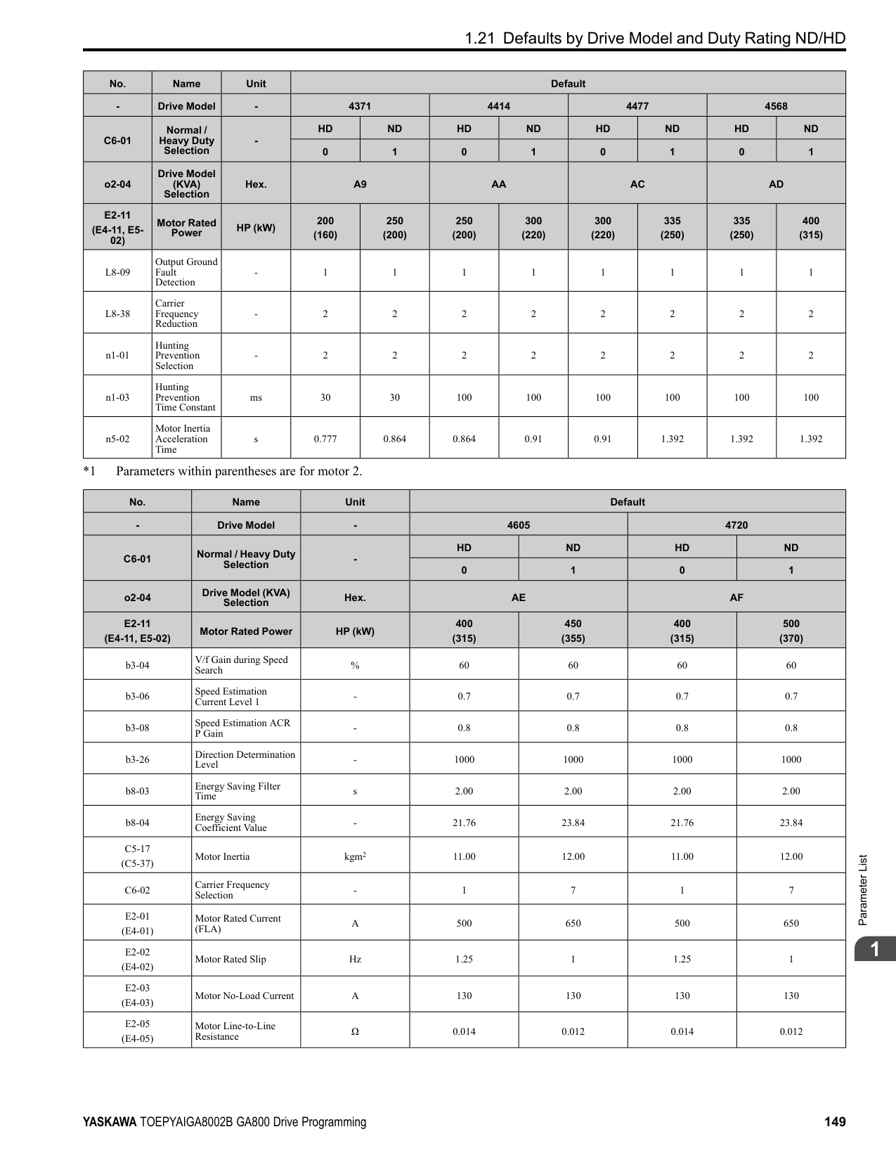
Set b3-01 = 1 [Speed Search at Start Selection = Enabled] to do Speed Search at start. Set L2-01 = 1 [Power Loss Ride Through Select = Enabled for L2-02 Time] to do Speed Search after you restore power after a momentary power loss.
If there is not sufficient residual voltage, then the drive will inject DC current into the motor to estimate the motor speed.
######## ■ b3-25: Speed Search Wait Time
|No. (Hex.)|Name|Description|Default (Range)| |---|---|---|---| |b3-25 (01C8) Expert|Speed Search Wait Time|Sets the length of time the drive will wait to start the Speed Search Retry function.
V/f CL-V/f OLV CLV AOLV OLV/PM AOLV/PM CLV/PM EZOLV
|0.5 s (0.0 - 30.0 s)|
If the drive detects these faults during speed search, increase the setting value:
ParameterDetails
######## 2
|No. (Hex.)|Name|Description|Default (Range)|
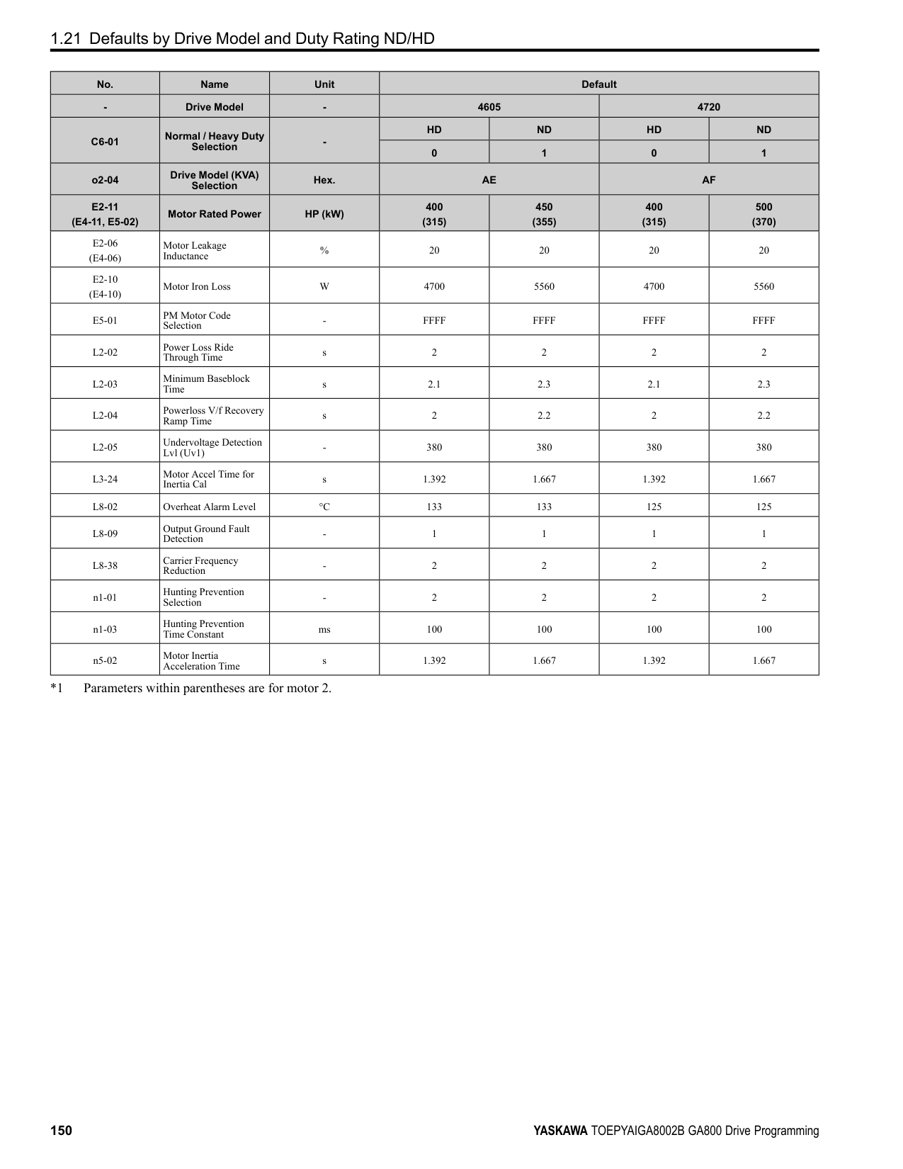
|---|---|---|---| |b3-26 (01C7) Expert|Direction Determination Level|Sets the level to find the motor rotation direction. Increase the value if the drive cannot find the direction.
V/f CL-V/f OLV CLV AOLV OLV/PM AOLV/PM CLV/PM EZOLV
|1000 (40 to 60000)|
|No. (Hex.)|Name|Description|Default (Range)| |---|---|---|---| |b3-27 (01C9) Expert|Speed Search RUN/BB Priority|Sets the conditions necessary to start Speed Search.
V/f CL-V/f OLV CLV AOLV OLV/PM AOLV/PM CLV/PM EZOLV
|0 (0, 1)|
Executes Speed Search from Fmax or Fref [H1-xx = 61/62] for initial speed searches or from the MFDI terminal. 0 : SS Only if RUN Applied Before BB 1 : SS Regardless of RUN/BB Sequence
######## ■ b3-29: Speed Search Back-EMF Threshold
|No. (Hex.)|Name|Description|Default (Range)| |---|---|---|---| |b3-29 (077C) Expert|Speed Search Back-EMF Threshold|Sets the induced voltage for motors that use Speed Search. The drive will start Speed Search when the motor induced voltage level is the same as the setting value. Usually it is not necessary to change this setting.
V/f CL-V/f OLV CLV AOLV OLV/PM AOLV/PM CLV/PM EZOLV
|10% (0 - 10%)|
To make adjustments, gradually decrease the setting value. If you decrease the setting value too much, speed search will not operate correctly.
######## ■ b3-31: Spd Search Current Reference Lvl
|No. (Hex.)|Name|Description|Default (Range)| |---|---|---|---| |b3-31 (0BC0) Expert|Spd Search Current Reference Lvl|Sets the current level that decreases the output current during Current Detection Speed Search.
V/f CL-V/f OLV CLV AOLV OLV/PM AOLV/PM CLV/PM EZOLV
|1.50 (1.50 - 3.50)|
Set this parameter as a ratio of E2-03 [Motor No-Load Current]. The setting is a ratio with respect to 30% of the motor rated current when E2-03 ≤ E2-01 [Motor Rated Current] × 0.3.
Note: The setting is a ratio with respect to E9-06 [Motor Rated Current (FLA)] × 0.5 when A1-02 = 8 [Control Method Selection = EZOLV].
######## ■ b3-32: Spd Search Current Complete Lvl
|No. (Hex.)|Name|Description|Default (Range)| |---|---|---|---| |b3-32 (0BC1) Expert|Spd Search Current Complete Lvl|Sets the current level that completes Speed Search.
V/f CL-V/f OLV CLV AOLV OLV/PM AOLV/PM CLV/PM EZOLV
|1.20 (0.00 - 1.49)|
The Current Detection Speed Search gradually decreases the output frequency to search for the motor speed when the output current is equal to or less than Speed Search Current Complete Level. Set this parameter as a ratio of E2-03 [Motor No-Load Current]. The setting is a ratio with respect to 30% of the motor rated current when E2-03 ≤ E2-01 [Motor Rated Current] × 0.3.
Note: The setting is a ratio with respect to E9-06 [Motor Rated Current (FLA)] × 0.5 when A1-02 8 [Control Method Selection EZOLV].
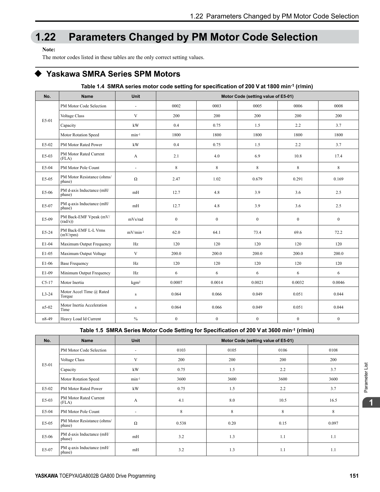
######## ■ b3-33: Speed Search during Uv Selection
|No. (Hex.)|Name|Description|Default (Range)| |---|---|---|---| |b3-33 (0B3F) Expert|Speed Search during Uv Selection|Sets the function that starts Speed Search at start-up if the drive detects a Uv [Undervoltage] when it receives a Run command.
V/f CL-V/f OLV CLV AOLV OLV/PM AOLV/PM CLV/PM EZOLV
|1 (0, 1)|
Set these three parameters as shown to enable b3-33:
The drives wait for Speed Search to prevent failure when the induced voltage for the motor during coasting to a stop is larger than the voltage the drive can output. The drive will not restart the motor (Speed Search) if induced voltage ≥ supply voltage × b3-36 after a Run command is entered. The drive will restart the motor when induced voltage < supply voltage × b3-36. For example, if the setting value is 0.83 and the voltage does not decrease to the induced voltage at approximately 183 V when the power supply voltage is 220 V, the drive will not restart.
|No. (Hex.)|Name|Description|Default (Range)| |---|---|---|---| |b3-35 (0BC3) Expert|Low Back EMF Detection Level|Sets the Low Back EMF Detection Level. Usually it is not necessary to change this setting.
V/f CL-V/f OLV CLV AOLV OLV/PM AOLV/PM CLV/PM EZOLV
|10% (5 - 50%)|
|No. (Hex.)|Name|Description|Default (Range)| |---|---|---|---| |b3-36 (0BC4) Expert|High Back EMF Detection Level|Sets the voltage level for Speed Search restart. Usually it is not necessary to change this setting.
V/f CL-V/f OLV CLV AOLV OLV/PM AOLV/PM CLV/PM EZOLV
|0.970 (0.500 - 1.000)|
|No. (Hex.)|Name|Description|Default (Range)| |---|---|---|---| |b3-54 (3123)|Search Time|Sets the length of time that the drive will run Speed Search.
V/f CL-V/f OLV CLV AOLV OLV/PM AOLV/PM CLV/PM EZOLV
|400 ms (10 - 2000 ms)|
If you set this parameter too low, Speed Search will not operate correctly. If the drive detects oC [Overcurrent] immediately after Speed Search Starts:
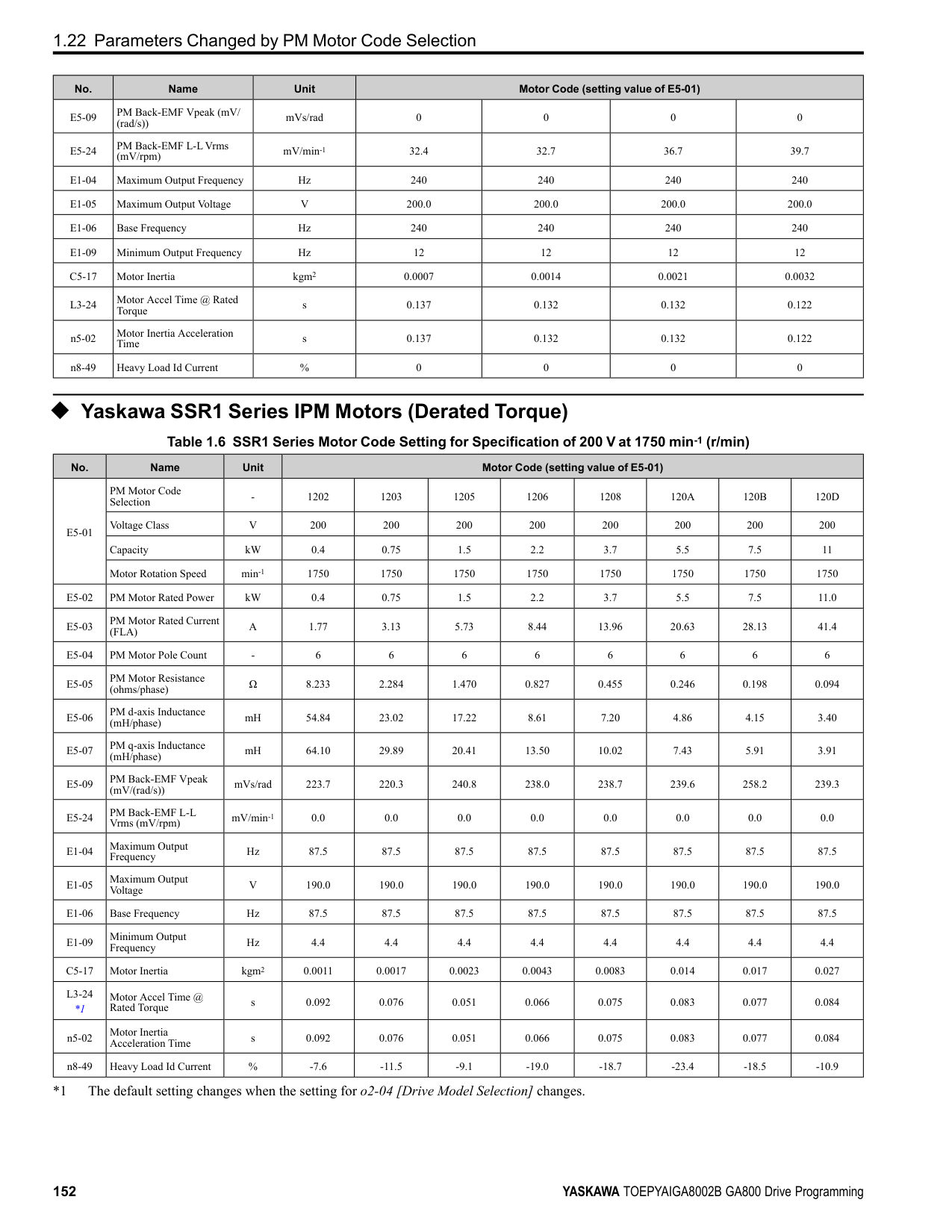
######## ■ b3-55: Current Increment Time
|No. (Hex.)|Name|Description|Default (Range)| |---|---|---|---| |b3-55 (3124) Expert|Current Increment Time|Sets the length of time that the drive will increase the current from zero current to the setting value of b3-06 [Speed Estimation Current Level 1].
V/f CL-V/f OLV CLV AOLV OLV/PM AOLV/PM CLV/PM EZOLV
|10 ms (10 - 2000 ms)|
ParameterDetails
######## 2
Gradually increase the setting value when a large quantity of current flows after speed search starts. If you set this value too high, speed search will not operate correctly.
|No. (Hex.)|Name|Description|Default (Range)| |---|---|---|---| |b3-56 (3126)|InverseRotationSearch WaitTime|Sets the wait time until the drive starts inverse rotation search after it completes forward search when you do inverse rotation search during Current Detection Speed Search.
V/f CL-V/f OLV CLV AOLV OLV/PM AOLV/PM CLV/PM EZOLV
|Determined by o2-04 (0.1 - 5.0 s)|
|No. (Hex.)|Name|Description|Default (Range)| |---|---|---|---| |b3-61 (1B96) Expert|Init Magnet Pole Estimation Gain|Adjusts the Initial Pole Detection response gain when A1-02 = 6 [Control Method Selection = AOLV/ PM]. Set b3-61 > 0.0 for a general IPM motor.
V/f CL-V/f OLV CLV AOLV OLV/PM AOLV/PM CLV/PM EZOLV
|5.0 (-20.0 - +20.0)|
Use this when n8-35 = 1 [Initial Pole Detection Method = High Frequency Injection]. Adjusts the response gain for Initial Pole Detection. Specify a positive value for an ordinary motor. The drive sets this value automatically when High Frequency Injection Tuning completes correctly.
######## ◆ b4: Timer Function
The drive uses timers to delay activating and deactivating MFDO terminals. Timers prevent sensors and switches from making chattering noise. There are two types of timers:
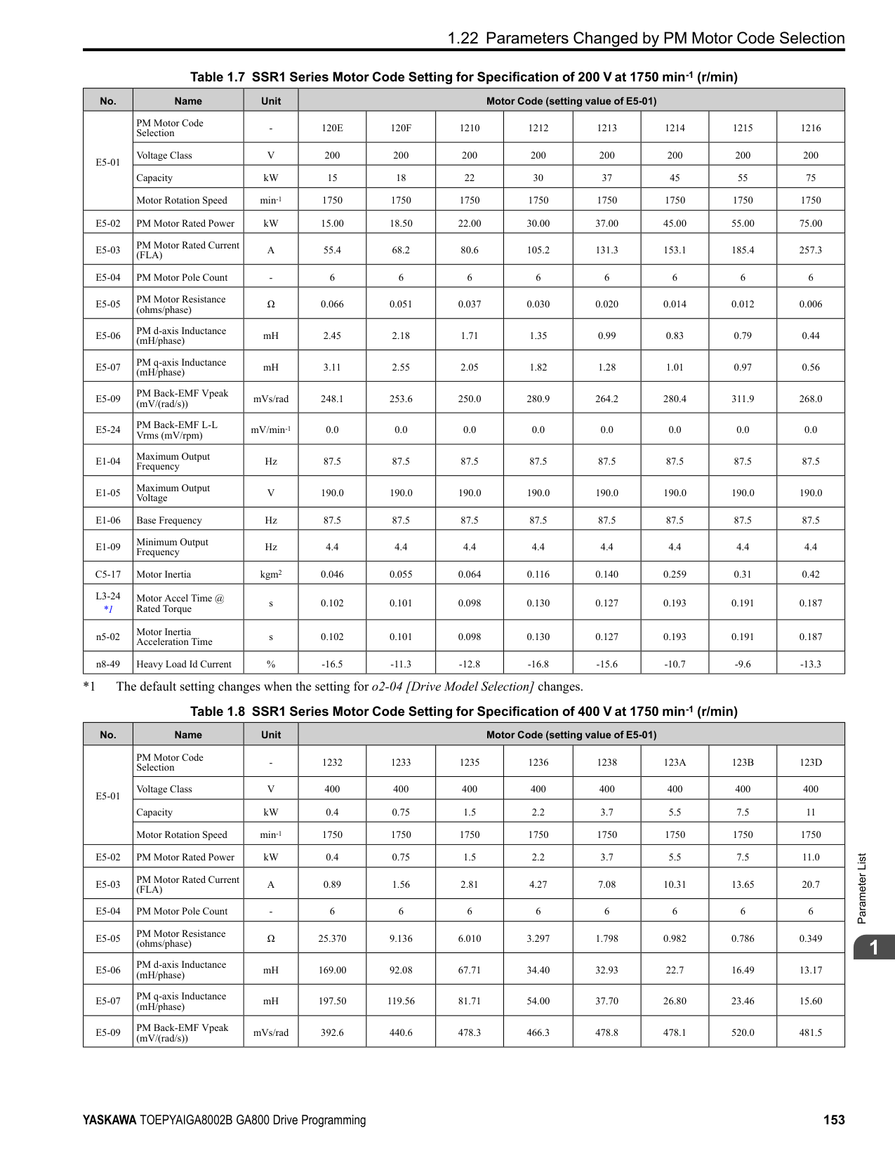
######## ■ Timer Function Operation
Figure 2.32 Example of Timer Function Operation
################# Figure 2.33 Example of How the Timer Function Works with H2-01 Terminals
Note: When the terminal is triggered, it continues for a minimum of 100 ms. The on/off-delay time of MFDO terminal does not have an effect.
|No. (Hex.)|Name|Description|Default (Range)| |---|---|---|---| |b4-01 (01A3)|Timer Function ON-Delay Time|Sets the ON-delay time for the timer input.
V/f CL-V/f OLV CLV AOLV OLV/PM AOLV/PM CLV/PM EZOLV
|0.0 s (0.0 - 3000.0 s)|
|No. (Hex.)|Name|Description|Default (Range)| |---|---|---|---| |b4-02 (01A4)|Timer Function OFF-Delay Time|Sets the OFF-delay time for the timer input.
V/f CL-V/f OLV CLV AOLV OLV/PM AOLV/PM CLV/PM EZOLV
|0.0 s (0.0 - 3000.0 s)|
|No. (Hex.)|Name|Description|Default (Range)| |---|---|---|---| |b4-03 (0B30) Expert|Terminal M1-M2 ON-Delay Time|Sets the delay time until the contact is turned ON after the function set with H2-01 turns ON.
V/f CL-V/f OLV CLV AOLV OLV/PM AOLV/PM CLV/PM EZOLV
|0 ms (0 - 65000 ms)|
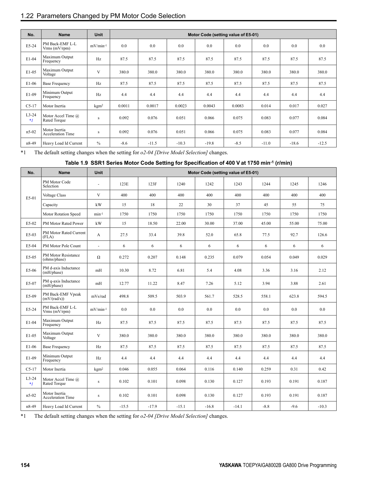
|No. (Hex.)|Name|Description|Default (Range)| |---|---|---|---| |b4-04 (0B31) Expert|Terminal M1-M2 OFF-Delay Time|Sets the delay time to deactivate the contact after the function set in H2-01 deactivates.
V/f CL-V/f OLV CLV AOLV OLV/PM AOLV/PM CLV/PM EZOLV
|0 ms (0 - 65000 ms)|
|No. (Hex.)|Name|Description|Default (Range)| |---|---|---|---| |b4-05 (0B32) Expert|Terminal M3-M4 ON-Delay Time|Sets the delay time to activate the contact after the function set in H2-02 activates.
V/f CL-V/f OLV CLV AOLV OLV/PM AOLV/PM CLV/PM EZOLV
|0 ms (0 - 65000 ms)|
|No. (Hex.)|Name|Description|Default (Range)| |---|---|---|---| |b4-06 (0B33) Expert|Terminal M3-M4 OFF-Delay Time|Sets the delay time to deactivate the contact after the function set in H2-02 deactivates.
V/f CL-V/f OLV CLV AOLV OLV/PM AOLV/PM CLV/PM EZOLV
|0 ms (0 - 65000 ms)|
ParameterDetails
######## 2
######## ■ b4-07: Terminal M5-M6 ON-Delay Time
|No. (Hex.)|Name|Description|Default (Range)| |---|---|---|---| |b4-07 (0B34) Expert|Terminal M5-M6 ON-Delay Time|Sets the delay time to activate the contact after the function set in H2-03 activates.
V/f CL-V/f OLV CLV AOLV OLV/PM AOLV/PM CLV/PM EZOLV
|0 ms (0 - 65000 ms)|
|No. (Hex.)|Name|Description|Default (Range)| |---|---|---|---| |b4-08 (0B35) Expert|Terminal M5-M6 OFF-Delay Time|Sets the delay time to deactivate the contact after the function set in H2-03 deactivates.
V/f CL-V/f OLV CLV AOLV OLV/PM AOLV/PM CLV/PM EZOLV
|0 ms (0 - 65000 ms)|
######## ◆ b5: PID Control
The drive has a PID control function. You can control drive output to adjust the proportional gain, integral time, and derivative time that has an effect on the bias between the target value and the feedback value to align the target value with the detected value. Use this function to adjust the drive output to accurately match the flow, pressure, and temperature in the application match the target value. Use a combination of these controls to increase the performance:
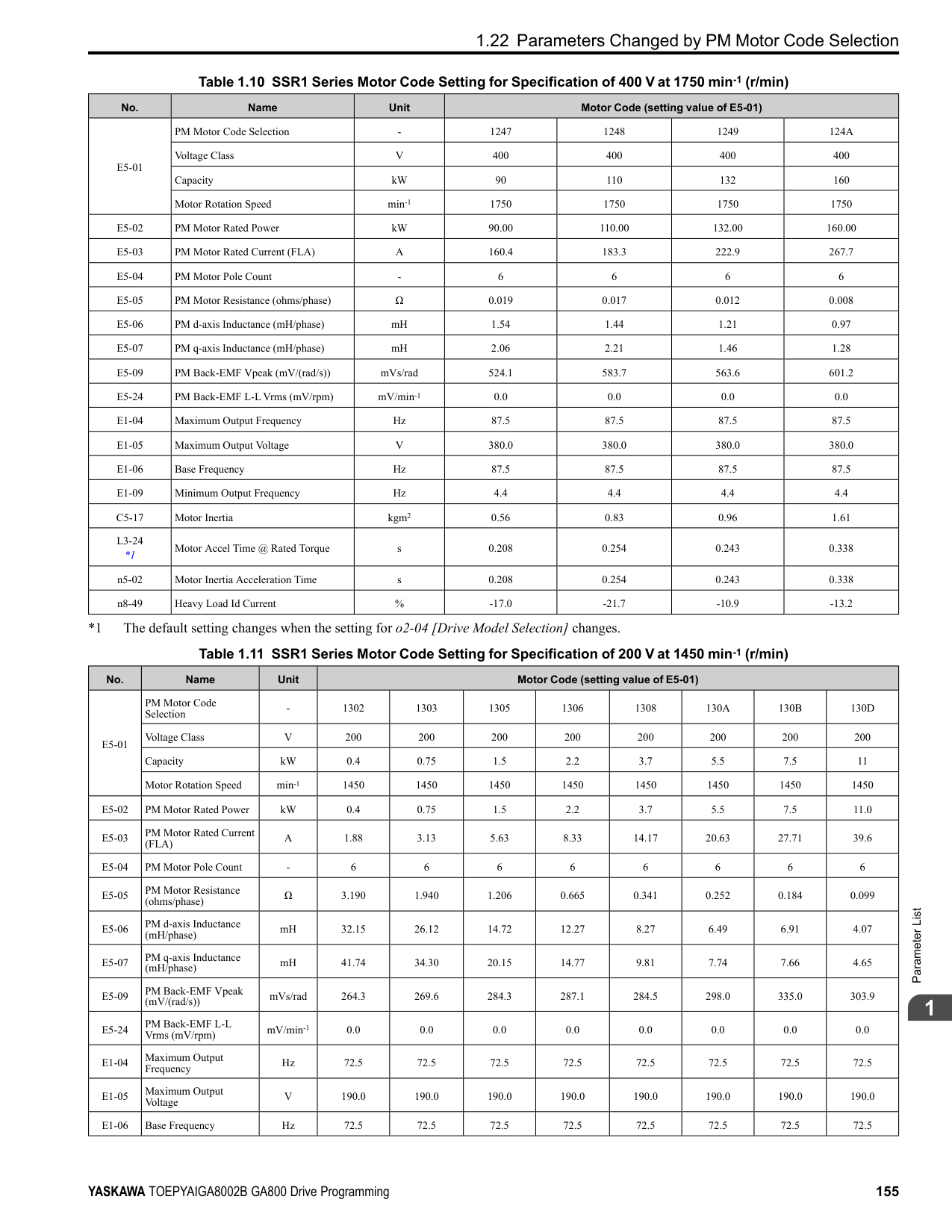
Note:
######## ■ PID Control Operation
| | | |---|---| | | | | | |
Figure 2.34 PID Control Operation
Table 2.24 PID Control Applications
When b5-01 = 1 or 2 [Standard or Standard (D on feedback)], the frequency reference set in b1-01 [Frequency Reference Selection 1] or b1-15 [Frequency Reference Selection 2] will be the PID setpoint, or the one of the values shown in Table 2.25 will be the PID setpoint. When b5-01 = 3 or 4 [Fref + PID Trim or Fref + PID Trim (D on feedback)], one of the inputs in Table 2.25 will be the PID setpoint.
Table 2.25 Input Methods for the PID Setpoint
Note: If you set two inputs for the PID setpoint, it will trigger operation error oPE07 [Analog Input Selection Error].
|Application|Control Content|Sensors Used| |---|---|---| |Speed Control|• The drive uses a feedback signal for the machine speed, and adjusts that speed to align with the target value.
• The drive uses speed data from other machinery as the target value to do synchronous control. The drive then adds that target value to the feedback from the machine it is operating to align its speed with the other machinery.
|Tacho generator| |Pressure control|The drive uses feedback from the actual pressure to hold constant pressure.|Pressure sensor|
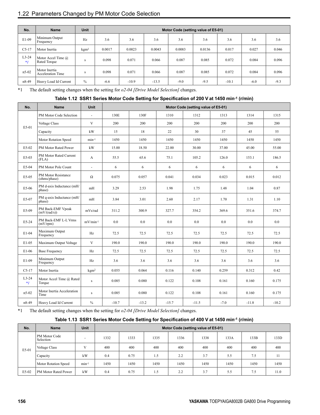
|Flow control|The drive uses feedback from the actual flow to hold constant flow.|Flow rate sensor| |Temperature control|The drive uses feedback from the actual temperature to control a fan and hold constant temperature.|Thermocoupler, thermistor|
|Input Methods for the PID Setpoint|Setting Value| |---|---| |Multi-function analog input terminal A1|Set H3-02 = C [Terminal A1 Function Selection = PID Setpoint].| |Multi-function analog input terminal A2|Set H3-10 [Terminal A2 Function Selection] = C.| |Multi-function analog input terminal A3|Set H3-06 [Terminal A3 Function Selection] = C.| |MEMOBUS/Modbus register 0006H|Sets MEMOBUS/Modbus register 000FH (Control Selection Setting) bit 1 to 1 (PID setpoint input). Enters the PID setpoint to MEMOBUS/Modbus register 0006H (PID Target, 0.01% units, signed).| |Pulse train input terminal RP|Set H6-01 = 2 [Terminal RP Pulse Train Function = PID Setpoint Value].| |b5-19 [PID Setpoint Value]|Set b5-18 = 1 [b5-19 PID Setpoint Selection = Enabled]. Enters the PID setpoint to b5-19.|
You can use two methods to input the PID feedback value to the drive. One method uses a single feedback signal for usual PID control. The other method uses two signals. The difference between those signals sets the deviation.
Table 2.26 PID Feedback Input Method
|PID Feedback Input Method|Setting Value| |---|---| |Multi-function analog input terminal A1|Set H3-02 = B [PID Feedback].| |Multi-function analog input terminal A2|Set H3-10 = B.| |Multi-function analog input terminal A3|Set H3-06 = B.| |Pulse train input terminal RP|Set H6-01 = 1 [PID feedback value].|
ParameterDetails
######## 2
Use Table 2.27 to select how the second feedback value is input to the drive. The drive calculates the deviation of the second feedback value. Set H3-02, H3-06, or H3-10 = 16 [Terminal A1/A3/A2 Function Selection = Differential PID Feedback] to enable the second feedback signal used to calculated the deviation.
Table 2.27 PID Differential Feedback Input Method
|PID Differential Feedback Input Method|Setting Value| |---|---| |Multi-function analog input terminal A1|Set H3-02 16 [Differential PID Feedback].|
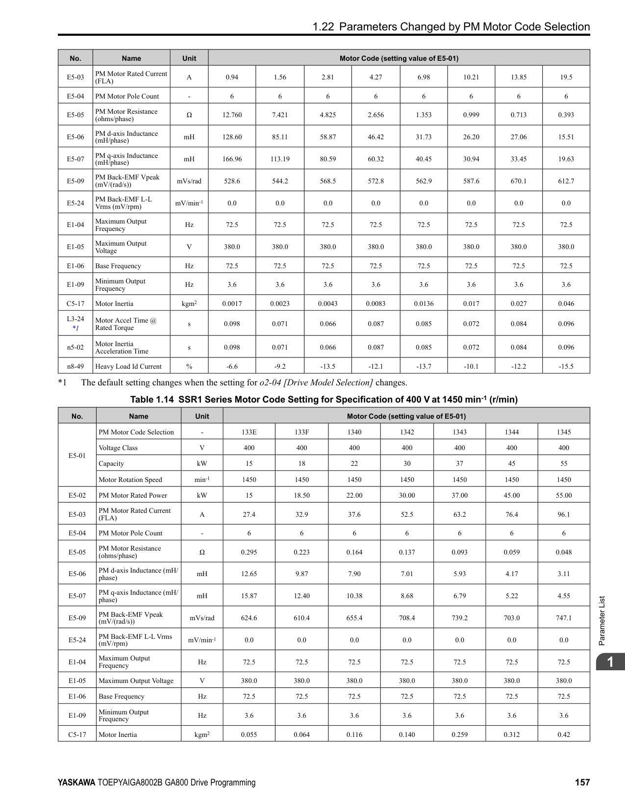
|Multi-function analog input terminal A2|Set H3-10 16.| |Multi-function analog input terminal A3|Set H3-06 16.|
Note: If you set more than one of H3-02, H3-06, and H3-10 to 16, the drive will detect oPE07 [Analog Input Selection Error].
######## ■ PID Control Block Diagram
| | | |---|---| | | |
| | | |---|---| | | |
| | | |---|---| | | |
| | | |---|---| | | |
| | | |---|---| | | |
| | | |---|---| | | | | | |
| | | |---|---| | | |
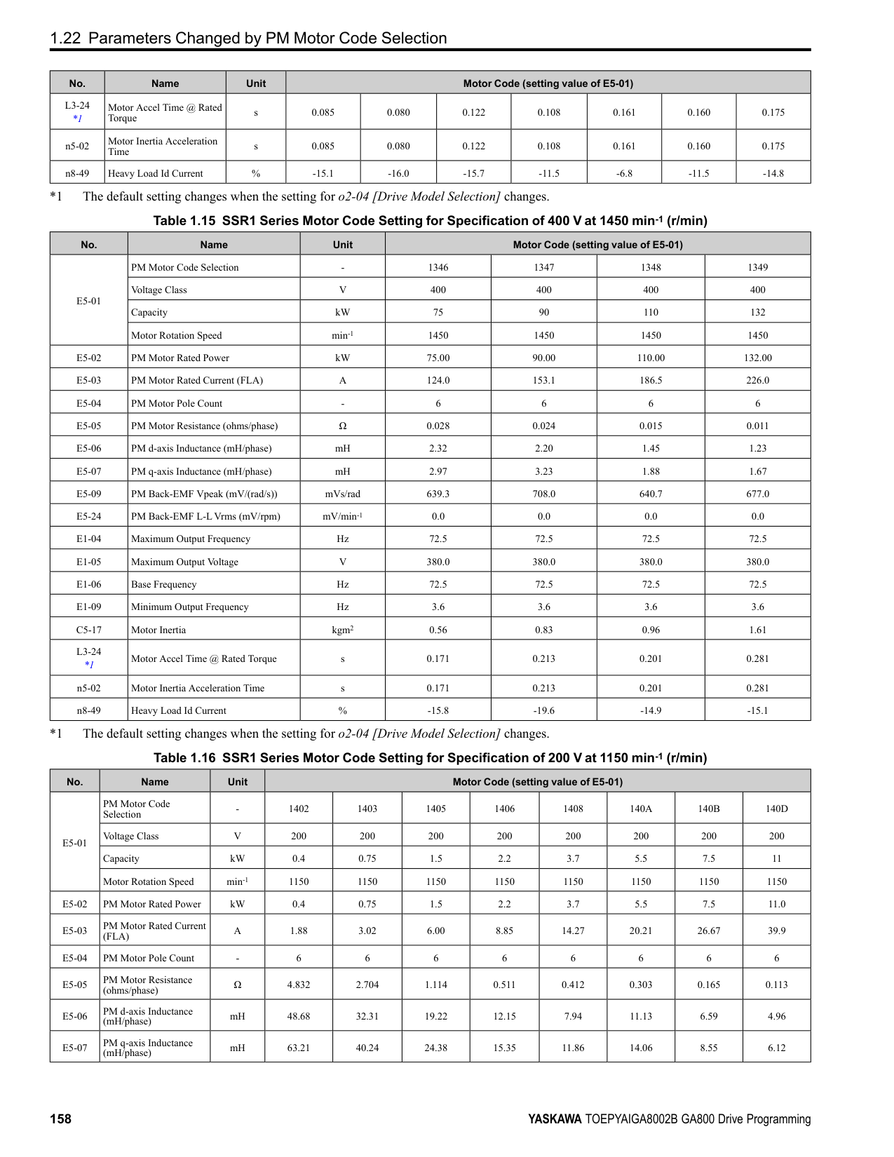
| | | |---|---| | | |
| | | |---|---| | | |
| | | |---|---| | | |
| | | |---|---| | | |
| | | |---|---| | | |
| | | |---|---| | | |
| | | |---|---| | | |
| | | |---|---| | | |
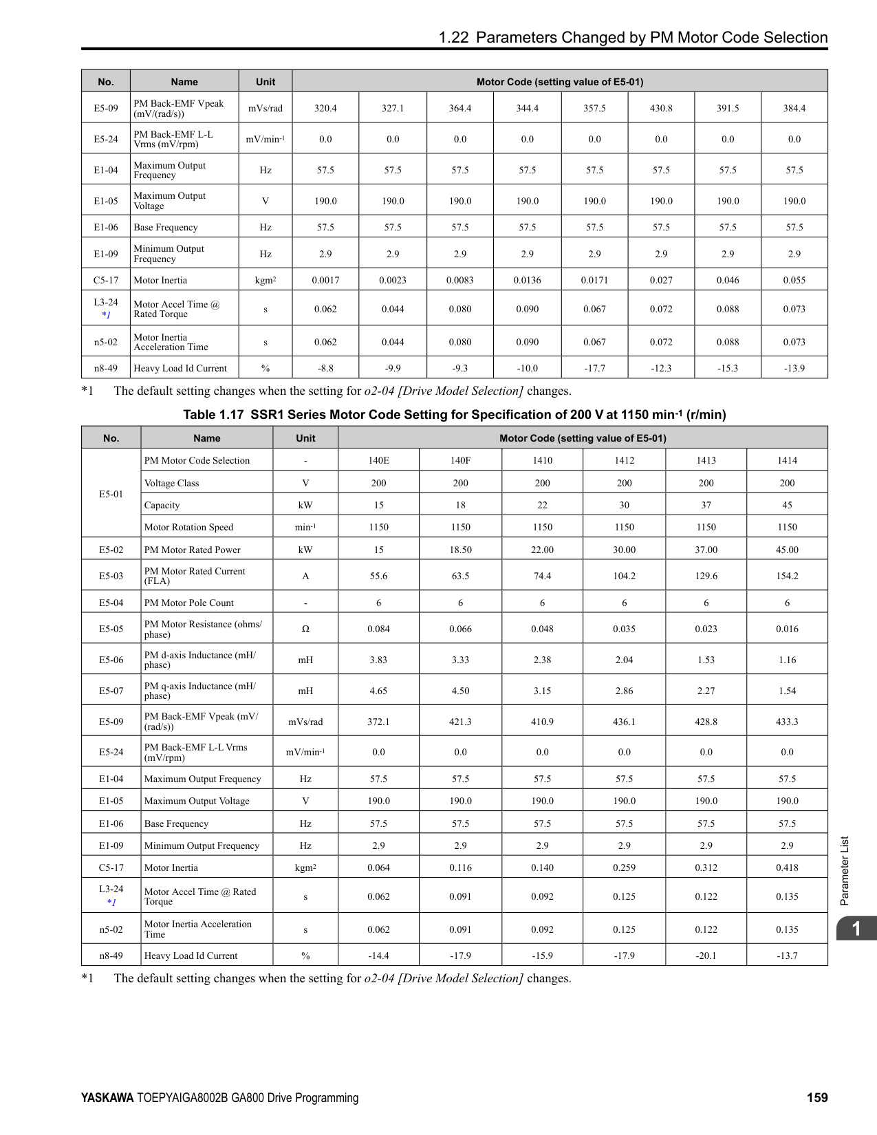
| | | |---|---| | | |
| | | |---|---| | | |
| | | | |---|---|---| | | | |
| | | |---|---| | | |
Figure 2.35 PID Block Diagram
######### ■ PID Feedback Loss DetectionThe PID feedback loss detection function detects broken sensors and defective wiring between the drive and sensors.
Use the PID feedback loss detection function when you use PID control. If the feedback signal is too low, the motor can suddenly accelerate to the maximum output frequency. This function prevents such risks to the load. The drive uses two methods to detect feedback loss:
• PID Feedback Loss [FbL] Set these parameters for the PID feedback loss detection function. The drive detects feedback loss when the feedback value is less than the value in b5-13 for longer than the time in b5-14.
• Excessive PID Feedback [FbH] Set these parameters to set how the drive detects a feedback level that is too high. The drive detects too much PID feedback when the feedback value is more than the value in b5-36 for longer than the time in b5-37.
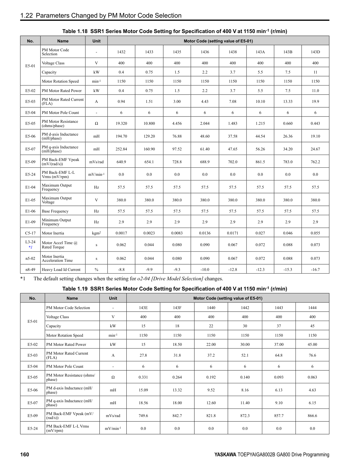
Figure 2.36 Time Chart for PID Feedback Loss Detection Time
■ PID Sleep PID sleep stops drive operation when the PID output or the frequency reference is less than b5-15 [PID Sleep Function Start Level]. This function shuts off drive output after the motor decelerates to the set frequency.
The drive will automatically restart the motor when the PID output or the frequency reference is more than the b5-15 value for the time set in b5-16 [PID Sleep Delay Time].
Figure 2.37 PID Sleep Time Chart Note:
■ Fine-Tuning PID Fine-tune the following parameter settings to have PID control eliminate problems with overshoot and oscillation.
ParameterDetails
######## 2
|Purpose|Procedure|Results| |---|---|---| |Prevent overshoot.|• Set b5-05 [Derivative Time (D)] to a smaller value.
• Set b5-03 [Integral Time (I)] to a larger value.
| | |Quickly stabilize control.|• Set b5-05 [Derivative Time (D)] to a larger value.
• Set b5-03 [Integral Time (I)] to a smaller value.
| | |Prevent long-cycle oscillations.|Set b5-03 [Integral Time (I)] to a larger value.| | |Prevent short-cycle oscillations.|• Set b5-05 [Derivative Time (D)] to a smaller value.
• If you set b5-05 = 0.00 [Derivative Time (D) = disabling D control] and it does not stop oscillation, then set b5-02 [Proportional Gain (P)] to a smaller value or set b5-08 [PID Primary Delay Time Constant] to a larger value.
| |
Note:
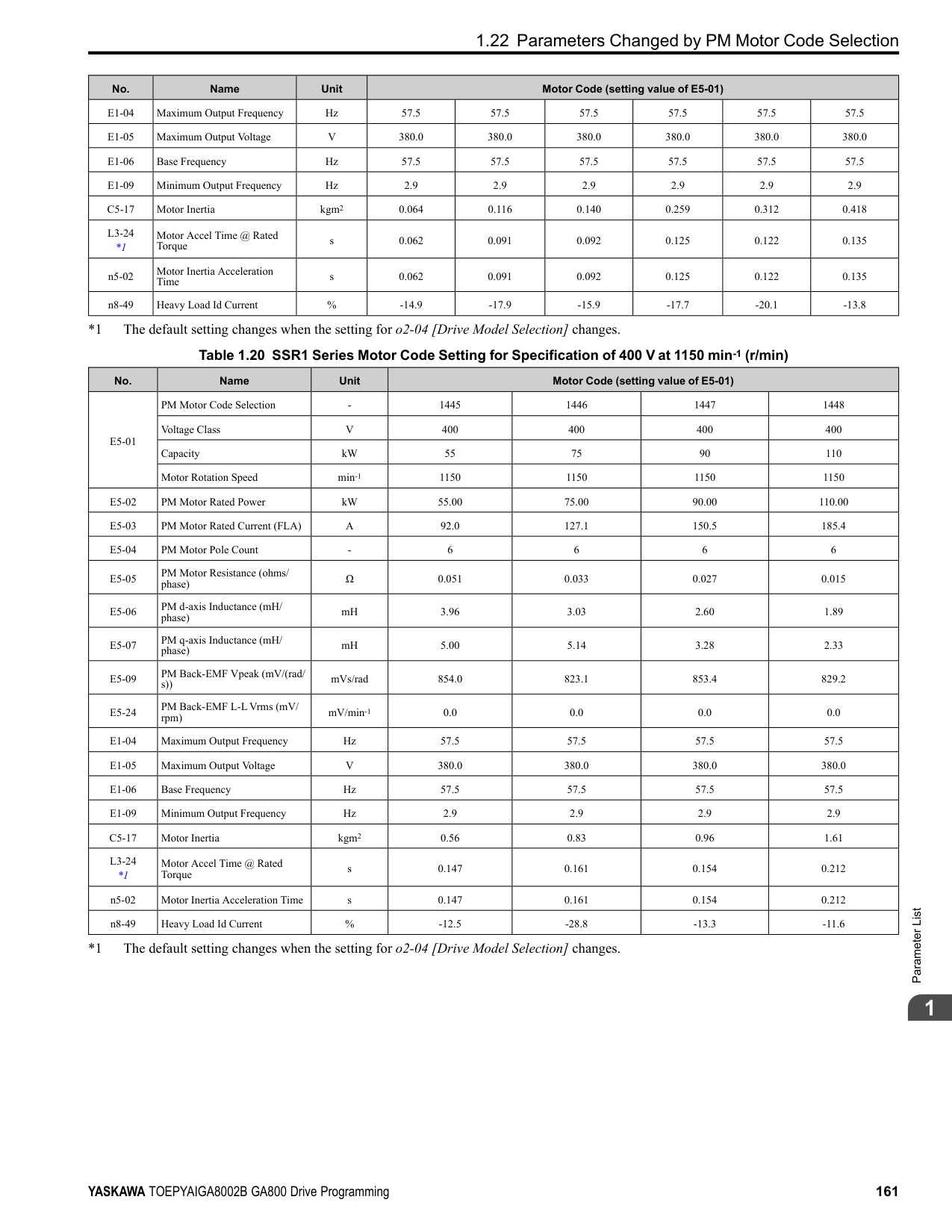
|Configuration Parameter|Description| |---|---| |b5-90 [EZ Sleep Unit]|Sets the unit of measure for b5-92 [EZ Sleep Level]. When b5-90 0 [0.1Hz units], the setting range of b5-91 [EZ Minimum Speed] is 0.0 to 590.0 Hz. When b5-90 1 [rev/min], the setting range is 0 to 35400 min-1 (r/ min).
Note: When you change b5-90, the value of b5-92 is not automatically updated.| |b5-91 [EZ Minimum Speed]|This parameter sets the lower limit for PID output. The drive uses the largest value of b5-91, b5-34 [PID Output Lower Limit], and d2-02 [Frequency Reference Lower Limit] to internally set the lower limit of PID output. The b5-89 setting does not have an effect.| |b5-92 [EZ Sleep Level]|When the output frequency or motor speed is less than the value of b5-92 for longer than the value of b5-93 [EZ Sleep Time], the drive does to sleep.| |b5-95 0 [EZ Wake-up Mode Absolute]|When the PID feedback is less than the value of b5-94 [EZ Wake-up Level] for longer than the time set in b5-96 [EZ Sleep Wake-up Time], the drive restarts operation from sleep.| |b5-95 1 [EZ Wake-up Mode Setpiont Delta]|When the PID feedback is less than the value set as the PID setpoint value minus b5-94 for the time set in b5-96, the drive restarts operation from sleep.|
Figure 2.38 EZ Sleep/Wake-up Operation: PID Output is Normal and b5-92 = 0.0 Hz
######## ■ b5-01: PID Mode Setting
|No. (Hex.)|Name|Description|Default (Range)| |---|---|---|---| |b5-01 (01A5)|PID Mode Setting|Sets the type of PID control.
V/f CL-V/f OLV CLV AOLV OLV/PM AOLV/PM CLV/PM EZOLV
|0 (0 - 8)|
Enables PID control. The drive performs D control on the difference between the feedback value and the PID setpoint output via U5-02 [PID Input].
Enables PID control. The drive adds the frequency reference to the PID output. The drive performs D control on the difference between the feedback value and the PID setpoint output via U5-02 [PID Input].
ParameterDetails
######## 2
Enables PID control. The drive adds the frequency reference to the PID output. The drive performs D control on the feedback output via U5-06 [PID Fdbk-Diff PID Fdbk].
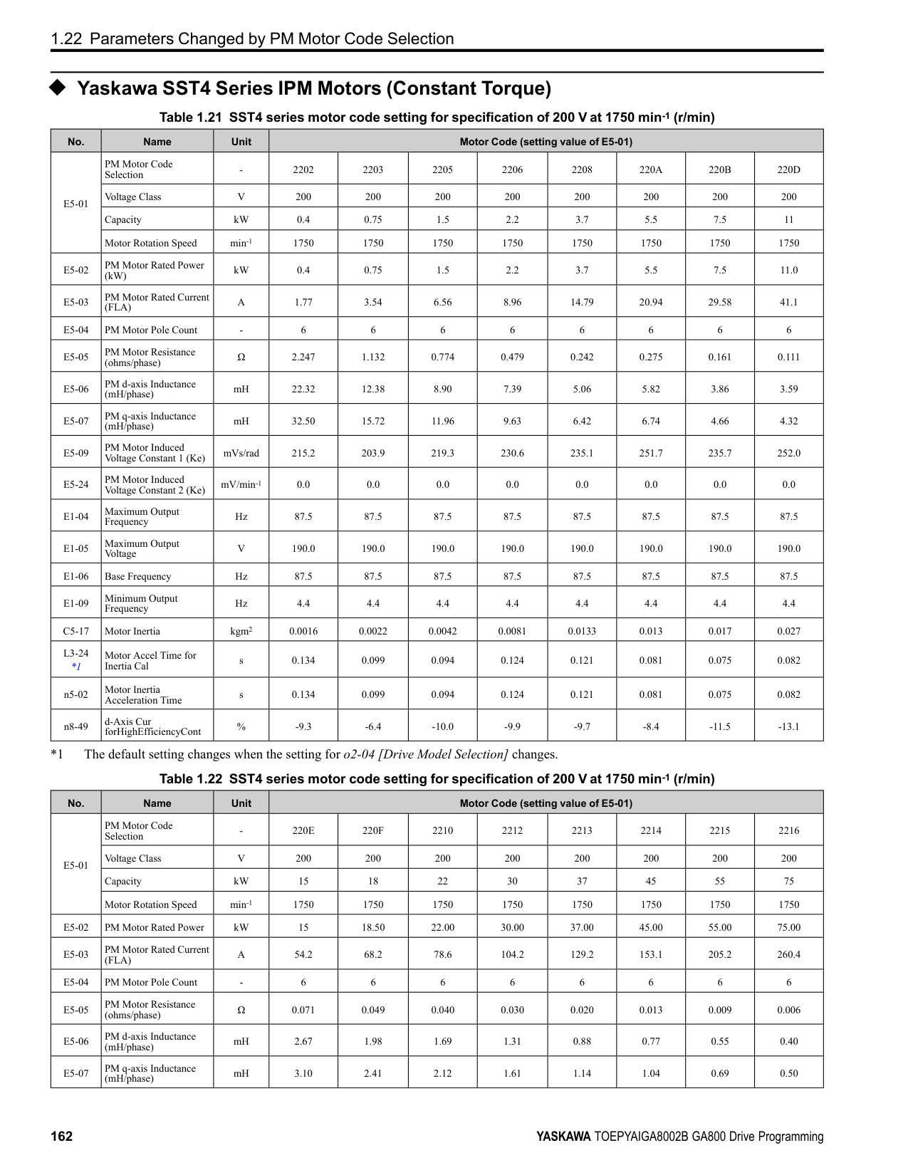
######## ■ b5-02: Proportional Gain (P)
|No. (Hex.)|Name|Description|Default (Range)| |---|---|---|---| |b5-02 (01A6) RUN|Proportional Gain (P)|Sets the proportional gain (P) that is applied to PID input.
V/f CL-V/f OLV CLV AOLV OLV/PM AOLV/PM CLV/PM EZOLV
|1.00 (0.00 - 25.00)|
Larger values decrease errors, but can cause oscillations. Smaller values let too much offset between the setpoint and feedback.
■ b5-03: Integral Time (I)
Set a short integral time in b5-03 to remove the offset more quickly. If the integral time is too short, overshoot or oscillation can occur.
|No. (Hex.)|Name|Description|Default (Range)| |---|---|---|---| |b5-03 (01A7) RUN|Integral Time (I)|Sets the integral time (I) that is applied to PID input.
V/f CL-V/f OLV CLV AOLV OLV/PM AOLV/PM CLV/PM EZOLV
|1.0 s (0.0 - 360.0 s)|
Figure 2.39 Integral Time and Deviation
######## ■ b5-04: Integral Limit
|No. (Hex.)|Name|Description|Default (Range)| |---|---|---|---| |b5-04 (01A8) RUN|Integral Limit|Sets the upper limit for integral control (I) as a percentage of the Maximum Output Frequency.
V/f CL-V/f OLV CLV AOLV OLV/PM AOLV/PM CLV/PM EZOLV
|100.0% (0.0 - 100.0%)|
Applications with loads that quickly change will cause the output of the PID function to oscillate. Set this parameter to a low value to prevent oscillation, mechanical loss, and motor speed loss.
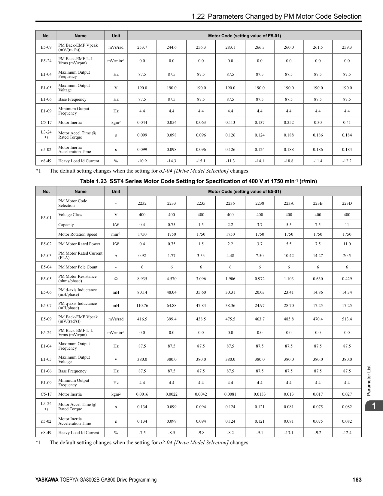
When you increase the time setting, it will increase controller responsiveness, but it can also cause vibration. When you decrease the time setting, it will suppress overshoot and decrease controller responsiveness. Set b5-05 = 0.00 to disable D control.
Prevents resonance if there is a large quantity of mechanical friction or if rigidity is unsatisfactory. Set the value larger than the resonant frequency cycle. A value that is too large will decrease drive responsiveness.
|No. (Hex.)|Name|Description|Default (Range)| |---|---|---|---| |b5-05 (01A9) RUN|Derivative Time (D)|Sets the derivative time (D) for PID control. This parameter adjusts system responsiveness.
V/f CL-V/f OLV CLV AOLV OLV/PM AOLV/PM CLV/PM EZOLV
|0.00 s (0.00 - 10.00 s)|
|No. (Hex.)|Name|Description|Default (Range)| |---|---|---|---| |b5-06 (01AA) RUN|PID Output Limit|Sets the maximum possible output from the PID controller as a percentage of the Maximum Output Frequency.
V/f CL-V/f OLV CLV AOLV OLV/PM AOLV/PM CLV/PM EZOLV
|100.0% (0.0 - 100.0%)|
|No. (Hex.)|Name|Description|Default (Range)| |---|---|---|---| |b5-07 (01AB) RUN|PID Offset Adjustment|Sets the offset for the PID control output as a percentage of the Maximum Output Frequency.
V/f CL-V/f OLV CLV AOLV OLV/PM AOLV/PM CLV/PM EZOLV
|0.0% (-100.0 - +100.0%)|
|No. (Hex.)|Name|Description|Default (Range)| |---|---|---|---| |b5-08 (01AC) RUN Expert|PID Primary Delay Time Constant|Sets the primary delay time constant for the PID control output. Usually it is not necessary to change this setting.
V/f CL-V/f OLV CLV AOLV OLV/PM AOLV/PM CLV/PM EZOLV
|0.00 s (0.00 - 10.00 s)|
|No. (Hex.)|Name|Description|Default (Range)| |---|---|---|---| |b5-09 (01AD)|PID Output Level Selection|Sets the polarity of the PID output.
V/f CL-V/f OLV CLV AOLV OLV/PM AOLV/PM CLV/PM EZOLV
|0 (0, 1)|
Use this parameter in applications that decrease the drive output frequency when you increase the PID setpoint. 0 : Normal Output (Direct Acting) A positive PID input increases the PID output (direct acting). 1 : Reverse Output (Reverse Acting) A positive PID input decreases the PID output (reverse acting).
######## ■ b5-10: PID Output Gain Setting
|No. (Hex.)|Name|Description|Default (Range)| |---|---|---|---|
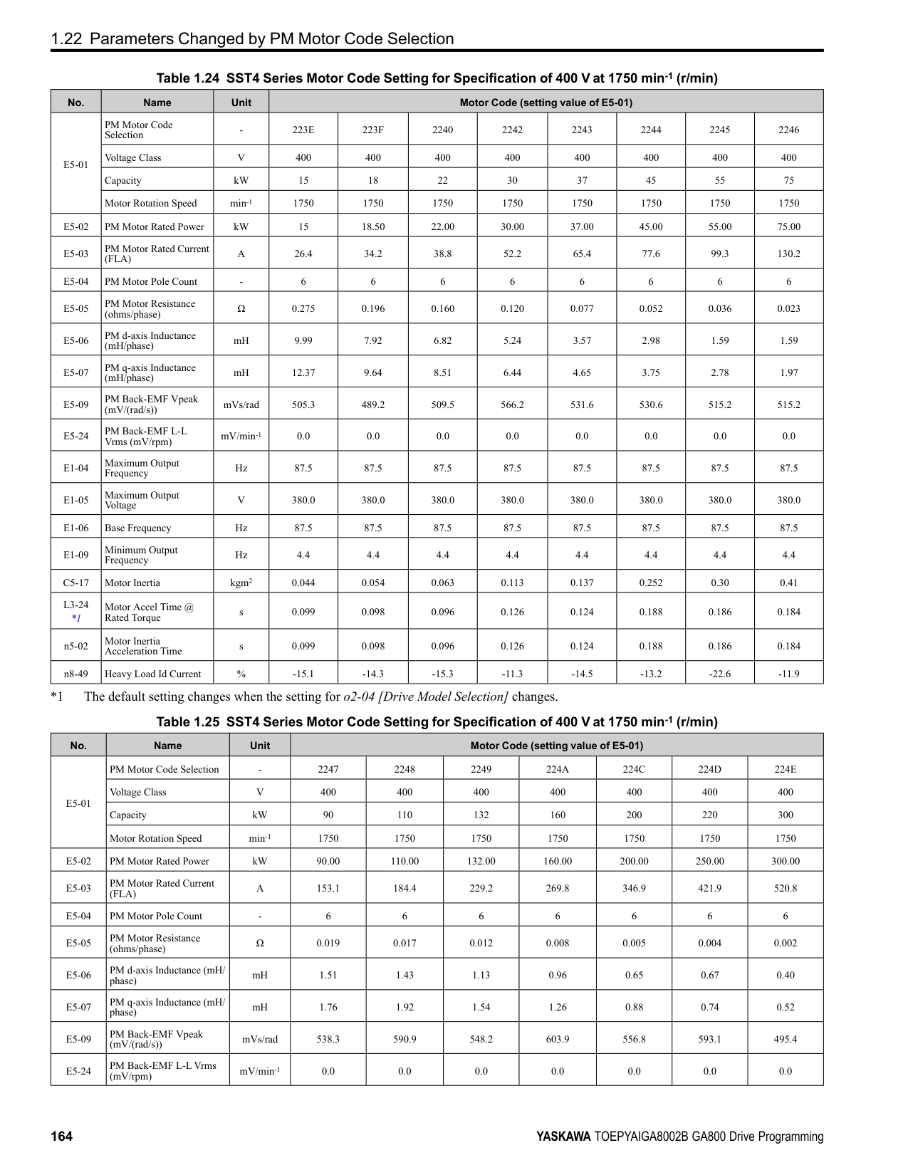
|b5-10 (01AE) RUN|PID Output Gain Setting|Sets the amount of gain to apply to the PID output.
V/f CL-V/f OLV CLV AOLV OLV/PM AOLV/PM CLV/PM EZOLV
|1.00 (0.00 - 25.00)|
ParameterDetails
######## 2
Applies a gain to the PID output and can help when b5-01 = 3 or 4 [PID Mode Setting = Fref + PID Trim, Fref + PID Trim (D on feedback)].
######## ■ b5-11: PID Output Reverse Selection
|No. (Hex.)|Name|Description|Default (Range)| |---|---|---|---| |b5-11 (01AF)|PID Output Reverse Selection|Sets the function that enables and disables reverse motor rotation for negative PID control output.
V/f CL-V/f OLV CLV AOLV OLV/PM AOLV/PM CLV/PM EZOLV
|0 (0, 1)|
This parameter is disabled when b5-01 = 3, 4 [PID Mode Setting = Fref + PID Trim, Fref + PID Trim (D on feedback)]. There is no limit for PID output (PID output can be positive or negative). Operates the same as setting “1: Enabled: Negative lower limit”. 0 : Lower Limit is Zero When PID output is negative, PID output is limited to 0 and drive output is shut off. 1 : Negative Output Accepted When the PID output is negative, the motor will rotate in reverse. When b1-04 = 1 [Reverse Operation Selection = Reverse Disabled], the lower limit is 0.
######## ■ b5-12: Feedback Loss Detection Select
|No. (Hex.)|Name|Description|Default (Range)| |---|---|---|---| |b5-12 (01B0)|Feedback Loss Detection Select|Sets the drive response to PID Feedback Low/High. Sets drive operation after the drive detects PID feedback Low/High.
V/f CL-V/f OLV CLV AOLV OLV/PM AOLV/PM CLV/PM EZOLV
|0 (0 - 5)|
############## 0 : Digital Out Only, Always Detect
The MFDO terminal set for PID Feedback Low or PID Feedback High [H2-01 to H2-03 = 3E, 3F] activates. When the drive detects Feedback Low/High, the keypad will not show a minor fault/alarm and the drive will continue operation.
When the feedback signal is less than the level set in b5-13 [PID Feedback Loss Detection Lvl] for longer than the time set in b5-14 [PID Feedback Loss Detection Time], the MFDO terminal set for a PID Feedback Low activates. When the feedback signal is more than the level set in b5-36 [PID High Feedback Detection Lvl] for longer than the time set in b5-37 [PID High Feedback Detection Time] the MFDO terminal set for a PID Feedback High activates. When the feedback value is not in the detection range, the drive resets the MFDO.
############## 1 : Alarm + Digital Out, Always Det
The drive detects FbL [PID Feedback Loss] and FbH [Excessive PID Feedback]. The MFDO terminal set for PID Feedback Low or PID Feedback High [H2-01 to H2-03 = 3E, 3F] activates. The output terminal set for Alarm [H2-
When the feedback signal is less than the level set in b5-13 for longer than the time set in b5-14, the MFDO terminal set for a PID Feedback Low activates. When the feedback signal is less than the level set in b5-36 for longer than the time set in b5-37, the MFDO terminal set for a PID Feedback High activates. When the feedback value is not in the detection range, the drive resets the MFDO.
The drive detects FbL and FbH. Fault relay output terminal MA-MC activates, MB-MC turns OFF, and the motor coasts to stop.
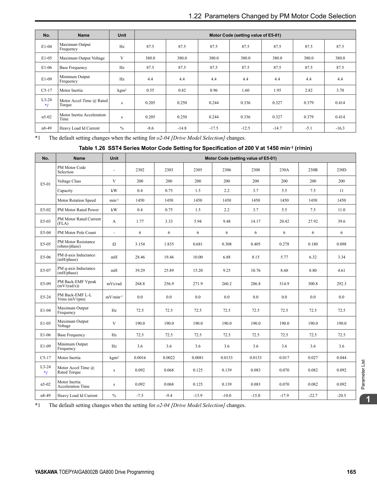
When the feedback signal is less than the level set in b5-13 for the time set in b5-14, the drive detects FbL. When the feedback signal is less than the level set in b5-36 for the time set in b5-37, the drive detects FbH.
The MFDO terminal set for PID Feedback Low or PID Feedback High activates. The keypad will not show a minor fault/alarm. The drive continues operation. When the MFDI terminal set to PID Disable [H1-xx = 19] activates, the drive disables fault detection.
4 : Alarm + Digital Out, @PID Enable The drive detects FbL and FbH. The MFDO terminal set for PID Feedback Low or PID Feedback High activates. The output terminal set for Alarm [H2-01 to H2-03 = 10] activates and the drive continues operation. When the MFDI terminal set to PID Disable [H1-xx = 19] activates, the drive disables fault detection. 5 : Fault + Digital Out, @PID Enable The drive detects FbL and FbH. Fault relay output terminal MA-MC activates, MB-MC turns OFF, and the drive coasts to stop. When the MFDI terminal set to PID Disable [H1-xx = 19] activates, the drive disables fault detection.
The drive detects PID Feedback Loss [FbL] when the feedback signal decreases to less than the level set in b5-13 for longer than the time set in b5-14 [PID Feedback Loss Detection Time].
The drive goes into Sleep mode when the PID output or frequency reference is less than b5-15 for longer than the time set to b5-16 [PID Sleep Delay Time]. The drive continues operation when the PID output or frequency reference is more than b5-15 for longer than the time set to b5-16.
|No. (Hex.)|Name|Description|Default (Range)| |---|---|---|---| |b5-13 (01B1)|PID Feedback Loss Detection Lvl|Sets the level that triggers PID Feedback Loss [FbL] detection as a percentage of the Maximum Output Frequency.
V/f CL-V/f OLV CLV AOLV OLV/PM AOLV/PM CLV/PM EZOLV
|0% (0 - 100%)|
|No. (Hex.)|Name|Description|Default (Range)| |---|---|---|---| |b5-14 (01B2)|PID Feedback Loss Detection Time|Sets the length of time that PID Feedback must be less than b5-13 [PID Feedback Loss Detection Lvl] to detect PID Feedback Loss [FbL].
V/f CL-V/f OLV CLV AOLV OLV/PM AOLV/PM CLV/PM EZOLV
|1.0 s (0.0 - 25.5 s)|
|No. (Hex.)|Name|Description|Default (Range)| |---|---|---|---| |b5-15 (01B3)|PID Sleep Function Start Level|Sets the output level that triggers the PID Sleep function.
V/f CL-V/f OLV CLV AOLV OLV/PM AOLV/PM CLV/PM EZOLV
|Determined by A1-02 (0.0 - 590.0)|
|No. (Hex.)|Name|Description|Default (Range)| |---|---|---|---| |b5-16 (01B4)|PID Sleep Delay Time|Sets a delay time to start or stop the PID Sleep function.
V/f CL-V/f OLV CLV AOLV OLV/PM AOLV/PM CLV/PM EZOLV
|0.0 s (0.0 - 25.5 s)|

|No. (Hex.)|Name|Description|Default (Range)| |---|---|---|---| |b5-17 (01B5) RUN|PID Accel/Decel Time|Raises or lowers the PID setpoint using the acceleration and deceleration times set to the drive. This is a soft-starter for the PID setpoint.
V/f CL-V/f OLV CLV AOLV OLV/PM AOLV/PM CLV/PM EZOLV
|0.0 s (0.0 - 6000.0 s)|
The drive usually uses the acceleration and deceleration times set in C1-xx [Accel and Decel Times], but when PID control is enabled, the drive applies C1-xx after PID output. If you frequently change the PID setpoint, the drive responsiveness decreases. When resonance with PID control causes hunting, overshoot, or undershoot, set b5-17 for longer acceleration and deceleration times. Decrease C1-xx until hunting stops, then use b5-17 to check the acceleration and deceleration. To enable and disable the setting in b5-17 through an MFDI terminal, set PID Soft Starter Disable [H1-xx = 34].
ParameterDetails
######## 2
0 : Disabled The drive does not use the value set in b5-19 as the PID setpoint. 1 : Enabled The drive uses the value set in b5-19 as the PID setpoint.
|No. (Hex.)|Name|Description|Default (Range)| |---|---|---|---| |b5-18 (01DC)|b5-19 PID Setpoint Selection|Sets the function that enables and disables b5-19 [PID Setpoint Value].
V/f CL-V/f OLV CLV AOLV OLV/PM AOLV/PM CLV/PM EZOLV
|0 (0, 1)|
|No. (Hex.)|Name|Description|Default (Range)| |---|---|---|---| |b5-19 (01DD) RUN|PID Setpoint Value|Sets the PID setpoint when b5-18 = 1 [b5-19 PID Setpoint Selection = Enabled].
V/f CL-V/f OLV CLV AOLV OLV/PM AOLV/PM CLV/PM EZOLV
|0.00% (0.00 - 100.00%)|
|No. (Hex.)|Name|Description|Default (Range)| |---|---|---|---| |b5-20 (01E2)|PID Unit Selection|Sets the number of digits to set and show the PID setpoint.
V/f CL-V/f OLV CLV AOLV OLV/PM AOLV/PM CLV/PM EZOLV
|1 (0 - 3)|
Set the units for these parameters and monitors:
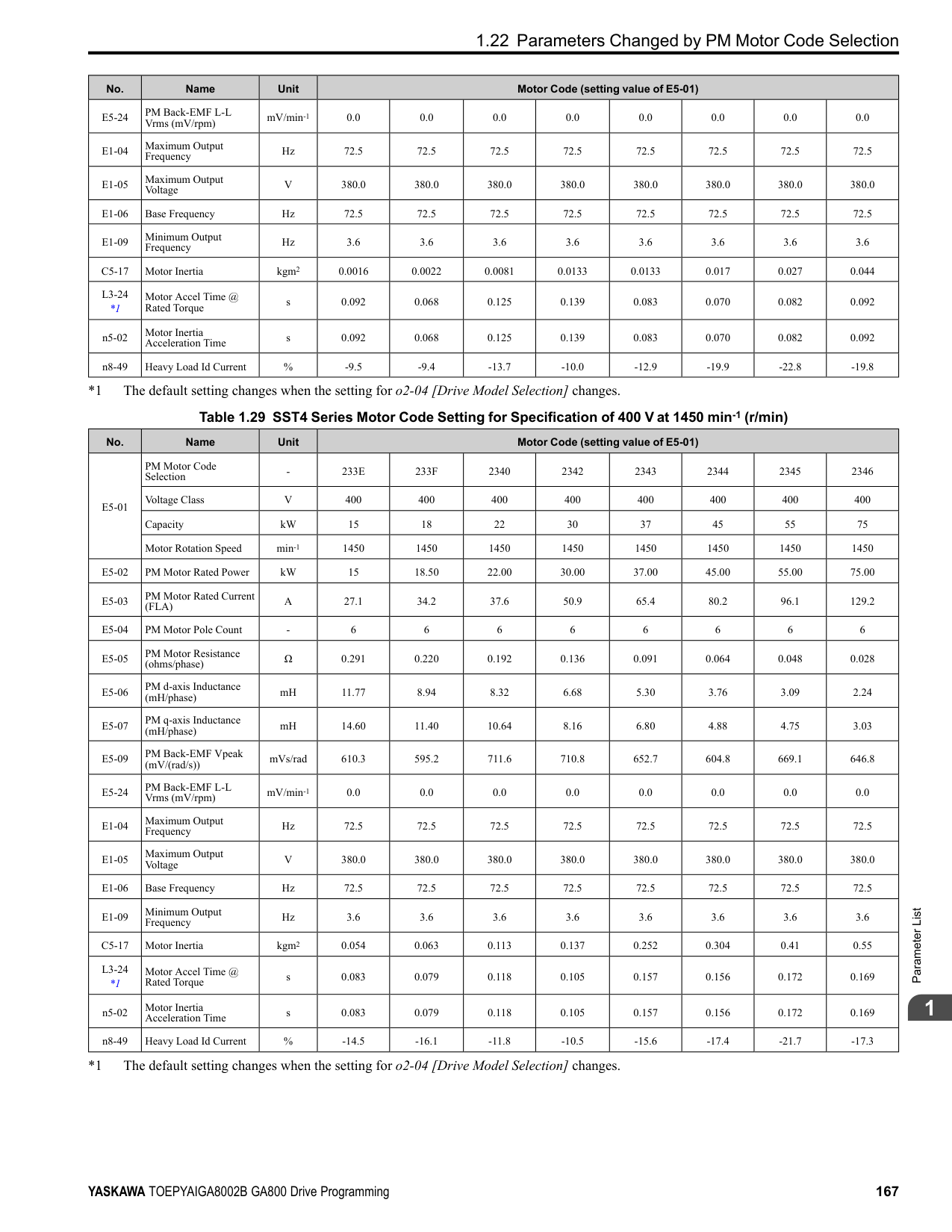
The drive uses the units set in b5-38 [PID User Unit Display Scaling] and b5-39 [PID User Unit Display Digits] to show the PID setpoint in U5-01, U5-04, U5-06 [PID Feedback, PID Setpoint, PID Fdbk-Diff PID Fdbk].
######## ■ b5-34: PID Output Lower Limit Level
|No. (Hex.)|Name|Description|Default (Range)| |---|---|---|---| |b5-34 (019F) RUN|PID Output Lower Limit Level|Sets the output lower limit for the PID control as a percentage of the Maximum Output Frequency.
V/f CL-V/f OLV CLV AOLV OLV/PM AOLV/PM CLV/PM EZOLV
|0.0% (-100.0 - +100.0%)|
Use a lower limit to keep PID control output from dropping below a fixed level. Set this parameter to 0.0% to disable this function.
A large input value for PID control makes a high output. The drive applies this limit to the negative and positive domains.
When the feedback signal increases to more than the level set in b5-36 for the time set in b5-37 [PID High Feedback Detection Time], the drive will detect Excessive PID Feedback [FbH].
The drive uses this parameter and b5-39 [PID Setpoint Display Digits] together. When b5-20 = 3 [PID Unit Selection = User Units], the drive applies user-set PID setpoint and display units to these parameters and monitors:
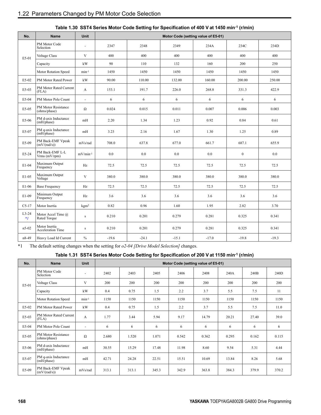
■ b5-39: PID User Unit Display Digits
The drive uses this parameter and b5-38 [PID Setpoint User Display] together. When b5-20 = 3 [PID Unit Selection = User Units], the drive applies user-set PID setpoint and display units to these parameters and monitors:
|No. (Hex.)|Name|Description|Default (Range)| |---|---|---|---| |b5-35 (01A0) RUN|PID Input Limit Level|Sets the output upper limit for the PID control as a percentage of the Maximum Output Frequency.
V/f CL-V/f OLV CLV AOLV OLV/PM AOLV/PM CLV/PM EZOLV
|1000.0% (0.0 - 1000.0%)|
|No. (Hex.)|Name|Description|Default (Range)| |---|---|---|---| |b5-36 (01A1)|PID High Feedback Detection Lvl|Sets the level that triggers Excessive PID Feedback [FbH] as a percentage of the Maximum Output Frequency.
V/f CL-V/f OLV CLV AOLV OLV/PM AOLV/PM CLV/PM EZOLV
|100% (0 - 100%)|
|No. (Hex.)|Name|Description|Default (Range)| |---|---|---|---| |b5-37 (01A2)|PID High Feedback Detection Time|Sets the length of time that the PID feedback signal must be more than the level set in b5-36 [PID Feedback High Detection Lvl] to cause Excessive PID Feedback [FbH].
V/f CL-V/f OLV CLV AOLV OLV/PM AOLV/PM CLV/PM EZOLV
|1.0 s (0.0 - 25.5 s)|
|No. (Hex.)|Name|Description|Default (Range)| |---|---|---|---| |b5-38 (01FE)|PID User Unit Display Scaling|Sets the value that the drive sets or shows as the PID setpoint when at the maximum output frequency.
V/f CL-V/f OLV CLV AOLV OLV/PM AOLV/PM CLV/PM EZOLV
|Determined by b5-20 (1 - 60000)|
|No. (Hex.)|Name|Description|Default (Range)| |---|---|---|---| |b5-39 (01FF)|PID User Unit Display Digits|Sets the number of digits to set and show the PID setpoint.
V/f CL-V/f OLV CLV AOLV OLV/PM AOLV/PM CLV/PM EZOLV
|Determined by b5-20 (0 - 3)|
ParameterDetails
######## 2
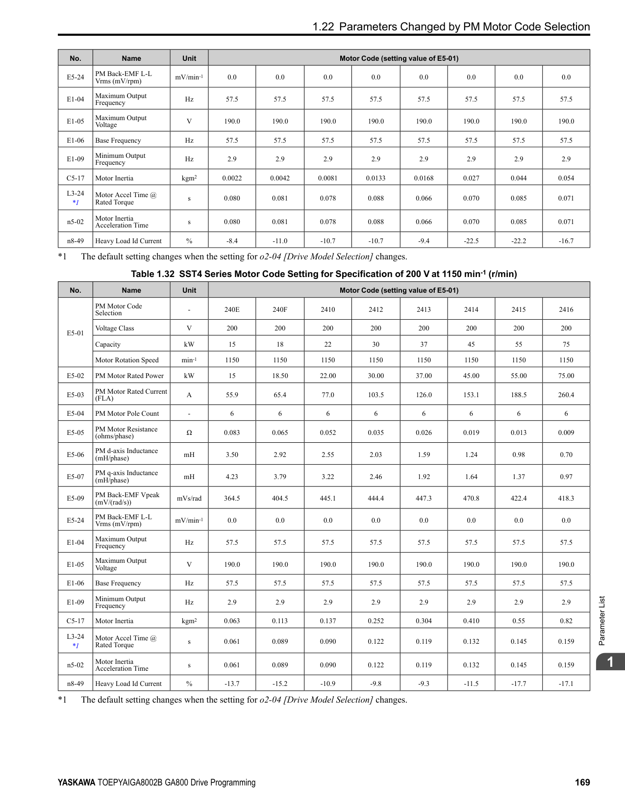
######## ■ b5-40: Frequency Reference Monitor @PID
|No. (Hex.)|Name|Description|Default (Range)| |---|---|---|---| |b5-40 (017F)|Frequency Reference Monitor @PID|Sets the contents for monitor U1-01 [Frequency Reference] in PID control.
V/f CL-V/f OLV CLV AOLV OLV/PM AOLV/PM CLV/PM EZOLV
|0 (0, 1)|
######## ■ b5-47: PID Trim Mode Output Reverse Sel
|No. (Hex.)|Name|Description|Default (Range)| |---|---|---|---| |b5-47 (017D)|PID Trim Mode Output Reverse Sel|Sets reverse motor rotation when the PID control output is negative.
V/f CL-V/f OLV CLV AOLV OLV/PM AOLV/PM CLV/PM EZOLV
|1 (0, 1)|
This parameter is enabled when b5-01 = 3 or 4 [PID Mode Setting = Fref + PID Trim, Fref + PID Trim (D on feedback)]. 0 : Lower Limit is Zero When PID output is negative, PID output is limited to 0 and drive output is shut off. 1 : Negative Output Accepted When the PID output is negative, the motor will rotate in reverse.
######## ■ b5-53: PID Integrator Ramp Limit
|No. (Hex.)|Name|Description|Default (Range)| |---|---|---|---| |b5-53 (0B8F) RUN|PID Integrator Ramp Limit|Sets the responsiveness of PID control when the PID feedback changes quickly.
V/f CL-V/f OLV CLV AOLV OLV/PM AOLV/PM CLV/PM EZOLV
|0.0 Hz (0.0 - 10.0 Hz)|
Note:
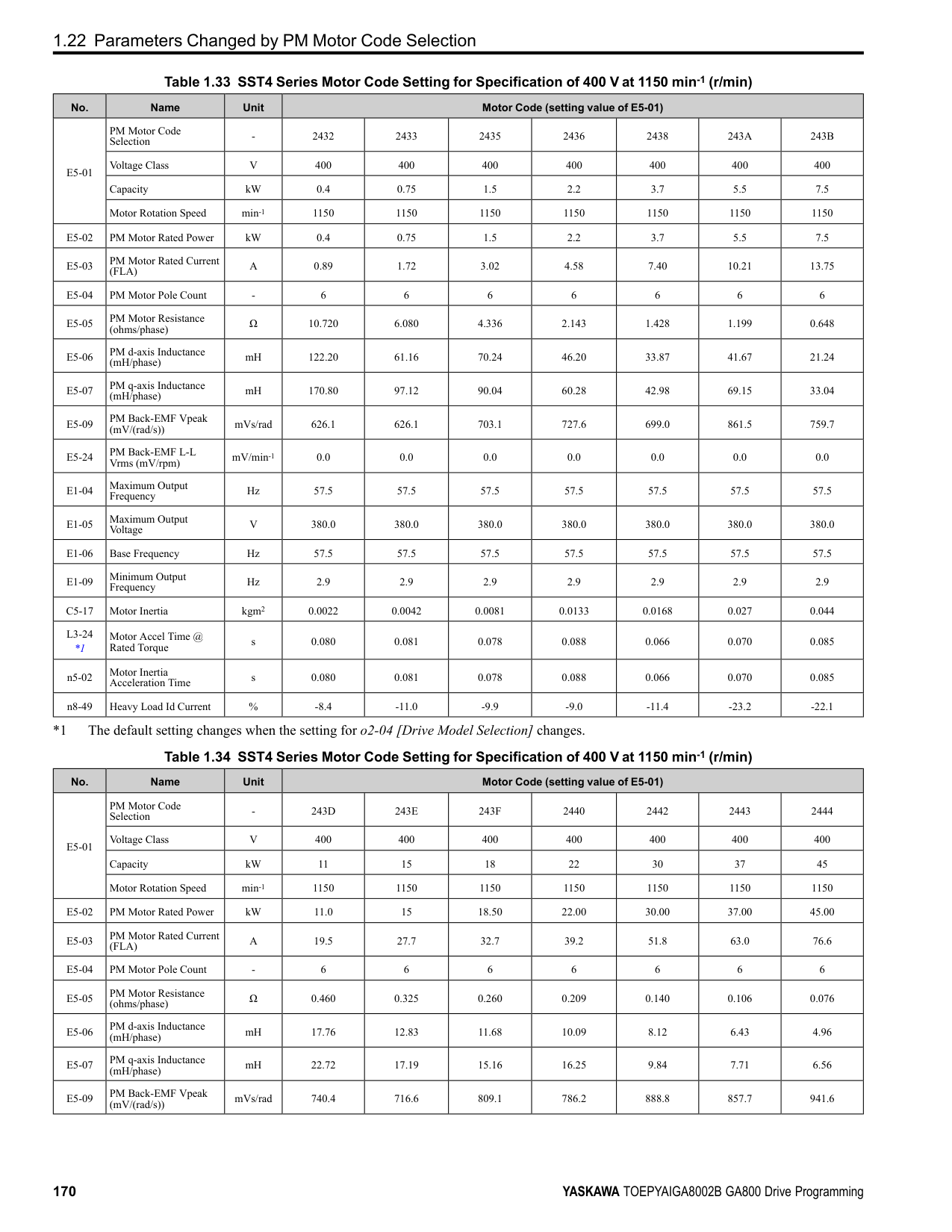
######## ■ b5-55: PID Feedback Monitor Selection
|No. (Hex.)|Name|Description|Default (Range)| |---|---|---|---| |b5-55 (0BE1)|PID Feedback Monitor Selection|Sets the monitor (Ux-xx) used as the PID Feedback. Set the x-xx part of the Ux-xx [Monitor].
V/f CL-V/f OLV CLV AOLV OLV/PM AOLV/PM CLV/PM EZOLV
|000 (000 - 999)|
################# Note:
Table 2.28 shows how the different MFDI H1-xx values (3E and 3F) have an effect on the PID setpoint value.
Table 2.28 Switching of MFDI and PID Setpoint Value
|No. (Hex.)|Name|Description|Default (Range)| |---|---|---|---| |b5-56 (0BE2)|PID Feedback Monitor Gain|Sets the gain for the monitor set in b5-55 [PID Feedback Monitor Selection].
V/f CL-V/f OLV CLV AOLV OLV/PM AOLV/PM CLV/PM EZOLV
|1.00 (0.00 - 10.00)|
|No. (Hex.)|Name|Description|Default (Range)| |---|---|---|---| |b5-57 (11DD)|PID Feedback Monitor Bias|Sets the bias for the monitor specified in b5-55 [PID Feedback Monitor Selection].
V/f CL-V/f OLV CLV AOLV OLV/PM AOLV/PM CLV/PM EZOLV
|0.00 (-10.00 - +10.00)|
|No. (Hex.)|Name|Description|Default (Range)| |---|---|---|---| |b5-58 to b5-60: (1182 - 1184) RUN|PID Setpoints 2 to 4|Sets the PID setpoint when H1-xx = 3E or 3F [MFDI Function Selection = PID Setpoint Selection 1/ 2]. This value is a percentage of the maximum output frequency.
V/f CL-V/f OLV CLV AOLV OLV/PM AOLV/PM CLV/PM EZOLV
|0.00% (0.00 - 100.00%)|
|H1-xx = 3E|H1-xx = 3F|PID Setpoint Value| |---|---|---| |OFF|OFF|No switch|

|ON|OFF|b5-58 [PID Setpoint2]| |OFF|ON|b5-59 [PID Setpoint3]| |ON|ON|b5-60 [PID Setpoint4]|
|No. (Hex.)|Name|Description|Default (Range)| |---|---|---|---| |b5-61 (119A)|PID Trim Mode Lower Limit Sel|Sets the function that adjusts the PID output in relation to the frequency reference.
V/f CL-V/f OLV CLV AOLV OLV/PM AOLV/PM CLV/PM EZOLV
|0 (0, 1)|
Adjusts the PID output in relation to the frequency reference. The setting value of b5-62 [PID Trim Mode Lower Limit Value] sets the lower limit of the post-adjustment value. The maximum output frequency sets the upper limit.
Note:
U5-03 [PID Output], Fref [Frequency Reference], and Fmax [Maximum Output Frequency]
*1 Lower limit = b5-62, Upper limit = Maximum output frequency
ParameterDetails
######## 2
Note: Set b5-01 = 3, 4, 7, or 8 to enable this parameter.
Note:

|No. (Hex.)|Name|Description|Default (Range)| |---|---|---|---| |b5-62 (119B)|PID Trim Mode Lower Limit Value|Sets the PID Trim Mode Lower Limit Value as a percentage of the maximum output frequency.
V/f CL-V/f OLV CLV AOLV OLV/PM AOLV/PM CLV/PM EZOLV
|0.00% (0.00 - 100.00%)|
|No. (Hex.)|Name|Description|Default (Range)| |---|---|---|---| |b5-63 (119C)|PID Differential FB Monitor Sel|Selects the monitor (Ux-xx) used as the PID Differential Feedback. Set the x-xx part of the Ux-xx [Monitor].
V/f CL-V/f OLV CLV AOLV OLV/PM AOLV/PM CLV/PM EZOLV
|000 (000 - 999)|
|No. (Hex.)|Name|Description|Default (Range)| |---|---|---|---| |b5-64 (119D)|PID Differential FB Monitor Gain|Sets the gain for the monitor specified in b5-63 [PID Differential FB Monitor Sel].
V/f CL-V/f OLV CLV AOLV OLV/PM AOLV/PM CLV/PM EZOLV
|1.00 (0.00 - 10.00)|
|No. (Hex.)|Name|Description|Default (Range)| |---|---|---|---| |b5-65 (119F)|PID Differential FB Monitor Bias|Sets the bias for the monitor specified in b5-63 [PID Differential FB Monitor Sel].
V/f CL-V/f OLV CLV AOLV OLV/PM AOLV/PM CLV/PM EZOLV
|0.00 (-10.00 - +10.00)|
|No. (Hex.)|Name|Description|Default (Range)| |---|---|---|---| |b5-66 (11DE)|PID Feedback Monitor Level|Sets the signal level for the monitor specified in b5-55 [PID Feedback Monitor Selection].
V/f CL-V/f OLV CLV AOLV OLV/PM AOLV/PM CLV/PM EZOLV
|0 (0, 1)|
######## ■ b5-67: PID Differential FB Monitor Lvl
|No. (Hex.)|Name|Description|Default (Range)| |---|---|---|---| |b5-67 (11DF)|PID Differential FB Monitor Lvl|Sets the signal level for the monitor specified in b5-63 [PID Differential FB Monitor Sel].
V/f CL-V/f OLV CLV AOLV OLV/PM AOLV/PM CLV/PM EZOLV
|0 (0, 1)|
0 : Absolute 1 : Bi-directional (+/-)
######## ■ b5-89: Sleep Method Selection
|No. (Hex.)|Name|Description|Default (Range)| |---|---|---|---| |b5-89 (0B89) RUN|Sleep Method Selection|Sets sleep and wake up operation when using PID.
V/f CL-V/f OLV CLV AOLV OLV/PM AOLV/PM CLV/PM EZOLV
|0 (0, 1)|
0 : Standard 1 : EZ Sleep/Wake-up
0 : 0.1Hz units 1 : rev/min
Note: The value of b5-90 [EZ Sleep Unit] sets the units. When b5-90 changes, this parameter does not automatically update. Set this parameter again after you change b5-90 is changed.
Note: When b5-90 [EZ Sleep Unit] changes, this parameter does not automatically update. Set this parameter again after you change b5-90.
|No. (Hex.)|Name|Description|Default (Range)| |---|---|---|---| |b5-90 (0B90)|EZ Sleep Unit|Sets the measurement units for b5-91 [EZ Sleep Minimum Speed] and b5-92 [EZ Sleep Level].
V/f CL-V/f OLV CLV AOLV OLV/PM AOLV/PM CLV/PM EZOLV
|0 (0, 1)|
|No. (Hex.)|Name|Description|Default (Range)| |---|---|---|---| |b5-91 (0B91) RUN|EZ Sleep Minimum Speed|Sets the minimum speed for the EZ Sleep/Wakeup function. This parameter uses the largest value from b5-91, b5-34 [PID Output Lower Limit Level], and d2-02 [Frequency Reference Lower Limit].
V/f CL-V/f OLV CLV AOLV OLV/PM AOLV/PM CLV/PM EZOLV
|0.0 Hz or 0 min-1 (r/min) (0.0 to 590.0 Hz or 0 to 35400 min-1 (r/min))|
|No. (Hex.)|Name|Description|Default (Range)| |---|---|---|---| |b5-92 (0B92) RUN|EZ Sleep Level|Sets the value that the output frequency or motor speed must be less than for longer than b5-93 [EZ Sleep Time] to enter Sleep Mode.
V/f CL-V/f OLV CLV AOLV OLV/PM AOLV/PM CLV/PM EZOLV
|0.0 Hz or 0 min-1 (r/min) (0.0 to 590.0 Hz or 0 to 35400 min-1 (r/min))|
|No. (Hex.)|Name|Description|Default (Range)|
|---|---|---|---| |b5-93 (0B93) RUN|EZ Sleep Time|Sets the length of time that the output frequency or motor speed must be less than b5-92 [EZ Sleep Level] to enter Sleep Mode.
V/f CL-V/f OLV CLV AOLV OLV/PM AOLV/PM CLV/PM EZOLV
|5.0 s (0.0 - 1000.0 s)|
|No. (Hex.)|Name|Description|Default (Range)| |---|---|---|---| |b5-94 (0B94) RUN|EZ Sleep Wake-up Level|Sets the level at which the drive resumes operation when exiting Sleep Mode.
V/f CL-V/f OLV CLV AOLV OLV/PM AOLV/PM CLV/PM EZOLV
|0.00% (0.00 - 600.00%)|
Note: The values of b5-20 [PID Unit Selection], b5-38 [PID User Unit Display Scaling], and b5-39 [PID User Unit Display Digits] set the units. When b5-20, b5-38, and b5-39 change, this parameter does not automatically update. Set this parameter again after you change b5-20, b5-38, and b5-39 are changed.
ParameterDetails
######## 2
When b5-09 = 0, and the PID feedback is less than the value of “PID setpoint value - b5-94” for a time longer than the value of b5-96, the drive will exit sleep and start operation again. When b5-09 = 1, and the PID feedback is more than the value of “PID setpoint value + b5-94” for a time longer than the setting value of b5-96, the drive will exit sleep and start operation again.
######## ■ b5-95: EZ Sleep Wake-up Mode
|No. (Hex.)|Name|Description|Default (Range)| |---|---|---|---| |b5-95 (0B95)|EZ Sleep Wake-up Mode|Sets the wake-up mode to use when exiting Sleep Mode.
V/f CL-V/f OLV CLV AOLV OLV/PM AOLV/PM CLV/PM EZOLV
|0 (0, 1)|
0 : Absolute 1 : Setpoint Delta
######## ■ b5-96: EZ Sleep Wake-up Time
|No. (Hex.)|Name|Description|Default (Range)| |---|---|---|---| |b5-96 (0B96) RUN|EZ Sleep Wake-up Time|Sets the EZ Wake-up time.
V/f CL-V/f OLV CLV AOLV OLV/PM AOLV/PM CLV/PM EZOLV
|1.0 s (0.0 - 1000.0 s)|
When the PID feedback is less than the value of b5-94 [EZ Sleep Wake-up Level] continuously for the time set in b596, the drive will exit sleep and start operation again.
◆ b6: Dwell Function The Dwell function momentarily holds the output frequency at start and stop. This prevents motor speed loss when you start and stop heavy loads. The Dwell function is also enabled when backlash on the machine side causes sudden movement at the start of acceleration and deceleration. At the start of acceleration, the drive uses the output frequency and acceleration time set for the Dwell function to automatically operate at low speed to minimize the effects of backlash. Then, the drive can accelerate again. The Dwell function operates the same for deceleration. For conveyor applications, the Dwell function also lets the drive interlock the output frequency and a delay time for the holding brake on the load side. The Dwell function momentarily stops during acceleration to prevent a PM motor from stepping out. Figure 2.40 shows how the Dwell function works.
Note: When you use the Dwell function at stop, set b1-03 0 [Stopping Method Selection Ramp to Stop].
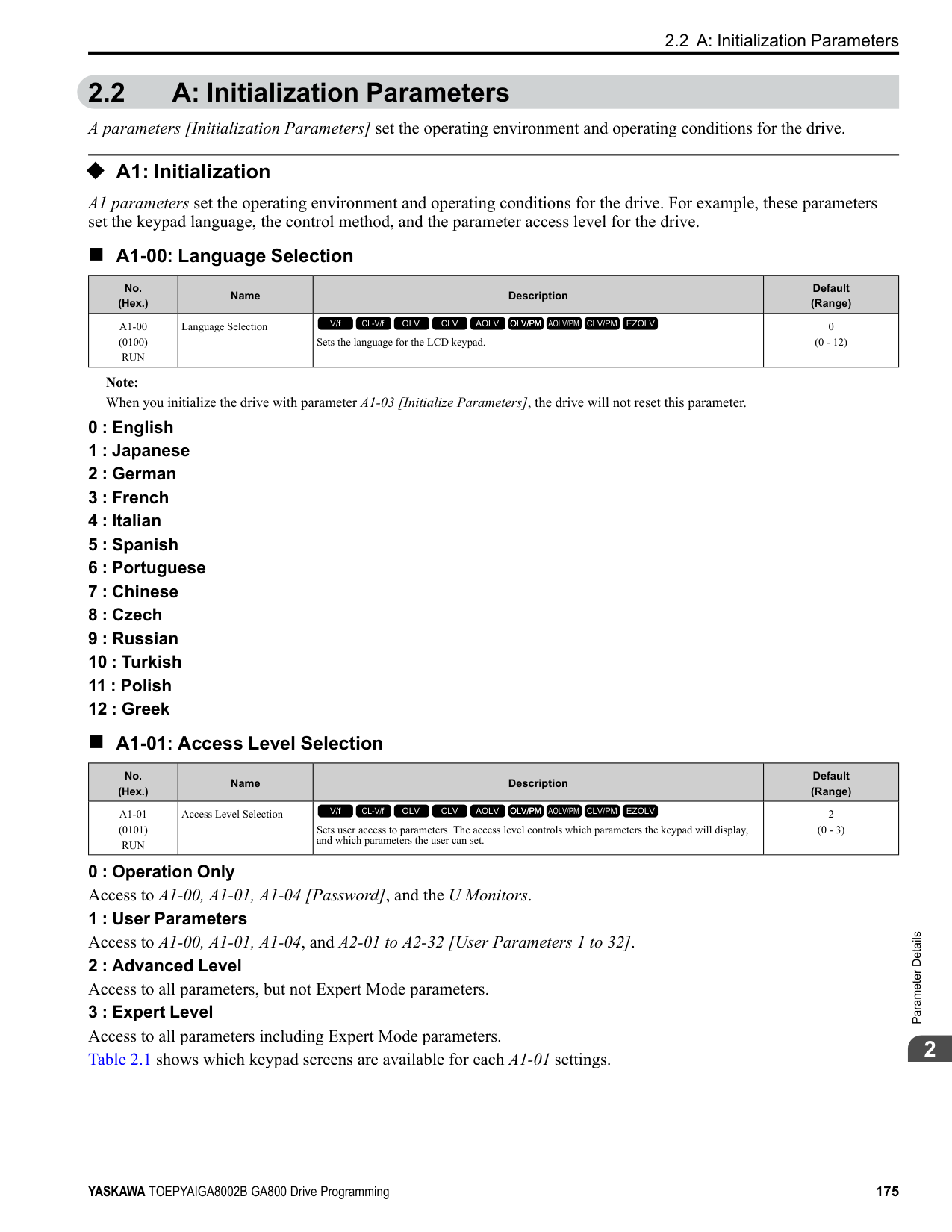
Figure 2.40 Time Chart for the Dwell Function at Start/Stop
######## ■ b6-01: Dwell Reference at Start
|No. (Hex.)|Name|Description|Default (Range)| |---|---|---|---| |b6-01 (01B6)|Dwell Reference at Start|Sets the output frequency that the drive will hold momentarily when the motor starts.
V/f CL-V/f OLV CLV AOLV OLV/PM AOLV/PM CLV/PM EZOLV
|0.0 (Determined by A1-02)|
When the drive accelerates to the output frequency set in b6-01, it holds that frequency for the time set in b6-02 [Dwell Time at Start], and starts to accelerate again.
When the drive decelerates to the output frequency set in b6-03, it holds that frequency for the time set in b6-04 [Dwell Time at Stop] and starts to decelerate again.
|No. (Hex.)|Name|Description|Default (Range)| |---|---|---|---| |b6-02 (01B7)|Dwell Time at Start|Sets the length of time that the drive will hold the output frequency when the motor starts.
V/f CL-V/f OLV CLV AOLV OLV/PM AOLV/PM CLV/PM EZOLV
|0.0 s (0.0 - 10.0 s)|
|No. (Hex.)|Name|Description|Default (Range)| |---|---|---|---| |b6-03 (01B8)|Dwell Reference at Stop|Sets the output frequency that the drive will hold momentarily when ramping to stop the motor.
V/f CL-V/f OLV CLV AOLV OLV/PM AOLV/PM CLV/PM EZOLV
|0.0 (Determined by A1-02)|
|No. (Hex.)|Name|Description|Default (Range)| |---|---|---|---| |b6-04 (01B9)|Dwell Time at Stop|Sets the length of time for the drive to hold the output frequency when ramping to stop the motor.
V/f CL-V/f OLV CLV AOLV OLV/PM AOLV/PM CLV/PM EZOLV
|0.0 s (0.0 - 10.0 s)|
◆ b7: Droop Control Droop control automatically balances the load level between two motors that operate the same load. Droop control decreases motor speed as the load changes. You must enable the Droop control function for each motor it is operating. To decrease motor speed, the Droop control function decreases the speed reference when an increase in the load increases the torque reference. To increase motor speed, the Droop control function increases the speed reference when a decrease in the load decreases the torque reference. The Droop control function adjusts motor speed as the torque reference changes to balance the load between the motors.
Note: When you use Droop control, set n5-01 = 0 [Feed Forward Control Selection = Disabled].
################# Figure 2.41 Droop Control Application
ParameterDetails
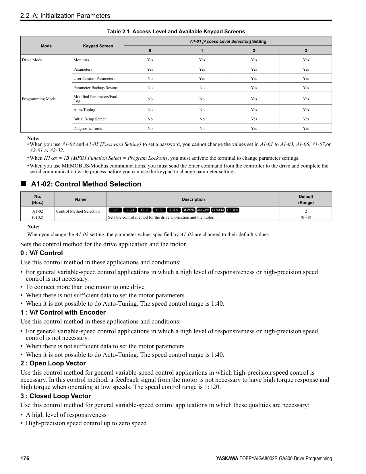
######## ■ b7-01: Droop Control Gain
|No. (Hex.)|Name|Description|Default (Range)| |---|---|---|---| |b7-01 (01CA) RUN|Droop Control Gain|Sets the amount of deceleration when the torque reference is at 100% as a percentage of E1-04 [Maximum Output Frequency].
V/f CL-V/f OLV CLV AOLV OLV/PM AOLV/PM CLV/PM EZOLV
|0.0% (0.0 - 100.0%)|
To disable Droop control, set this parameter to 0.0%.
|No. (Hex.)|Name|Description|Default (Range)| |---|---|---|---| |b7-02 (01CB) RUN|Droop Control Delay Time|Sets the responsiveness of Droop control. Decrease this setting when drive response is slow. Increase this setting when hunting or oscillation occur.
V/f CL-V/f OLV CLV AOLV OLV/PM AOLV/PM CLV/PM EZOLV
|0.05 s (0.03 - 2.00 s)|
|No. (Hex.)|Name|Description|Default (Range)| |---|---|---|---| |b7-03 (017E)|Droop Control Limit Selection|Sets the Droop control limit function.
V/f CL-V/f OLV CLV AOLV OLV/PM AOLV/PM CLV/PM EZOLV
|1 (0, 1)|
0 : Disabled 1 : Enabled
◆ b8: Energy Saving Energy-saving control improves overall system operating efficiency by operating the motor at its most efficient level. Set b8-01 and the following parameters according to the control mode and the motor.
######## ■ b8-01: Energy Saving Control Selection
|No. (Hex.)|Name|Description|Default (Range)| |---|---|---|---|
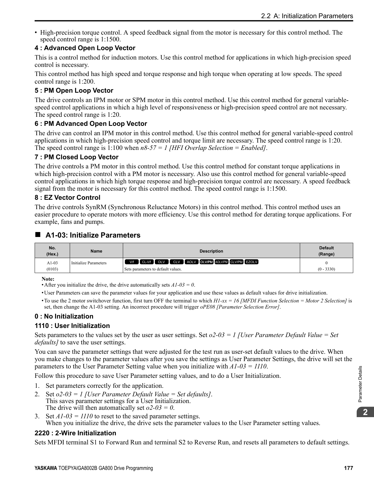
|b8-01 (01CC)|Energy Saving Control Selection|Sets the Energy-saving control function.
V/f CL-V/f OLV CLV AOLV OLV/PM AOLV/PM CLV/PM EZOLV
|0 (0 - 2)|
############## 1 : Enabled 2 : Automatic Optimization
Note: Setting 2 is available only when A1-02 = 6, 7 [Control Method Selection = AOLV/PM, CLV/PM] and in Expert Mode.
######## ■ b8-02: Energy Saving Gain
|No. (Hex.)|Name|Description|Default (Range)| |---|---|---|---| |b8-02 (01CD) RUN Expert|Energy Saving Gain|Sets the gain for Energy-saving control.
V/f CL-V/f OLV CLV AOLV OLV/PM AOLV/PM CLV/PM EZOLV
|Determined by A1-02 (0.0 - 10.0)|
Increase the setting value to increase energy saving. If the setting value is too large, the motor will stall.
######## ■ b8-03: Energy Saving Filter Time
|No. (Hex.)|Name|Description|Default (Range)| |---|---|---|---| |b8-03 (01CE) RUN Expert|Energy Saving Filter Time|Sets the responsiveness for Energy-saving control.
V/f CL-V/f OLV CLV AOLV OLV/PM AOLV/PM CLV/PM EZOLV
|Determined by A1-02,C601 and o2-04
(0.00 - 10.00 s)|
Decrease the setting value to increase responsiveness. If the setting value is too low, operation will not be stable.
######## ■ b8-04: Energy Saving Coefficient Value
|No. (Hex.)|Name|Description|Default (Range)| |---|---|---|---| |b8-04 (01CF) Expert|Energy Saving Coefficient Value|Sets the Energy-saving control coefficient to maintain maximum motor efficiency. The default setting is for Yaskawa motors.
V/f CL-V/f OLV CLV AOLV OLV/PM AOLV/PM CLV/PM EZOLV
|Determined by C6-01, E211, and o2-04
(0.00 - 655.00)|
When you use a motor from a different manufacturer, increase the setting value in 5% increments to find the minimum value for U1-08 [Output Power] at light loads. When you decrease the setting value, it decreases the output voltage and decreases power consumption. If the setting value is too low, the motor will stall.
Note: When you do Rotational Auto-Tuning, the drive will automatically set the energy-saving coefficient.
######## ■ b8-05: Power Detection Filter Time
|No. (Hex.)|Name|Description|Default (Range)|
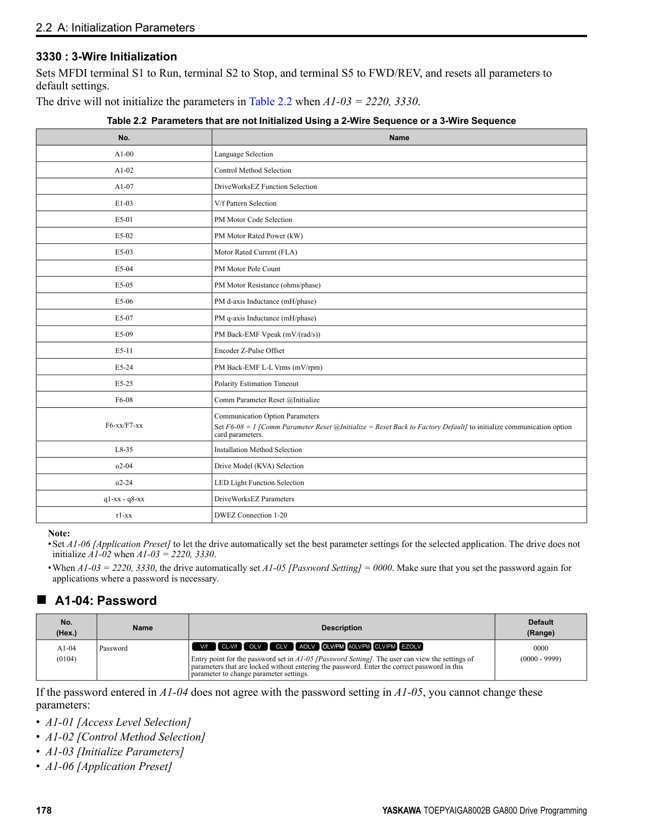
|---|---|---|---| |b8-05 (01D0) Expert|Power Detection Filter Time|Sets the time constant to measure output power.
V/f CL-V/f OLV CLV AOLV OLV/PM AOLV/PM CLV/PM EZOLV
|20 ms (0 - 2000 ms)|
Decrease the setting value to increase responsiveness to load changes. If you set the value too low during operation at light loads, motor speed is not stable.
ParameterDetails
######## ■ b8-06: Search Operation Voltage Limit
|No. (Hex.)|Name|Description|Default (Range)| |---|---|---|---| |b8-06 (01D1) Expert|Search Operation Voltage Limit|Sets the voltage limit for Search Operation as a percentage of the motor rated voltage.
V/f CL-V/f OLV CLV AOLV OLV/PM AOLV/PM CLV/PM EZOLV
|0% (0 - 100%)|
The Search Operation changes the output voltage in small increments to find a setpoint at which the drive can use minimum power to operate. Set this parameter to 0 to disable Search Operation. This will not disable Energy-saving control. If the setting value is too low, the motor will stall when loads suddenly increase.
When b8-16 = 1.00 (default), the drive will automatically calculate and control the energy-saving coefficient. If the motor nameplate has a description for “Ki”, set this parameter to the Ki value. Do this procedure to prevent oscillation when you set b8-01 = 1 [Energy Saving Control Selection = Enabled].
When E5-01 = 1xxx, 2xxx [PM Motor Code Selection = Yaskawa SSR1 or SST4 series IPM motor], the drive automatically calculates the energy-saving coefficient Kt and uses that value to control operation. Do this procedure to prevent oscillation when you set b8-01 = 1 [Energy Saving Control Selection = Enabled].
|No. (Hex.)|Name|Description|Default (Range)| |---|---|---|---| |b8-16 (01F8) Expert|PM E-Save Coefficient Ki|Sets torque linearity. This parameter uses the Ki value from the motor nameplate. Usually it is not necessary to change this setting.
V/f CL-V/f OLV CLV AOLV OLV/PM AOLV/PM CLV/PM EZOLV
|1.00 (0.00 - 3.00)|
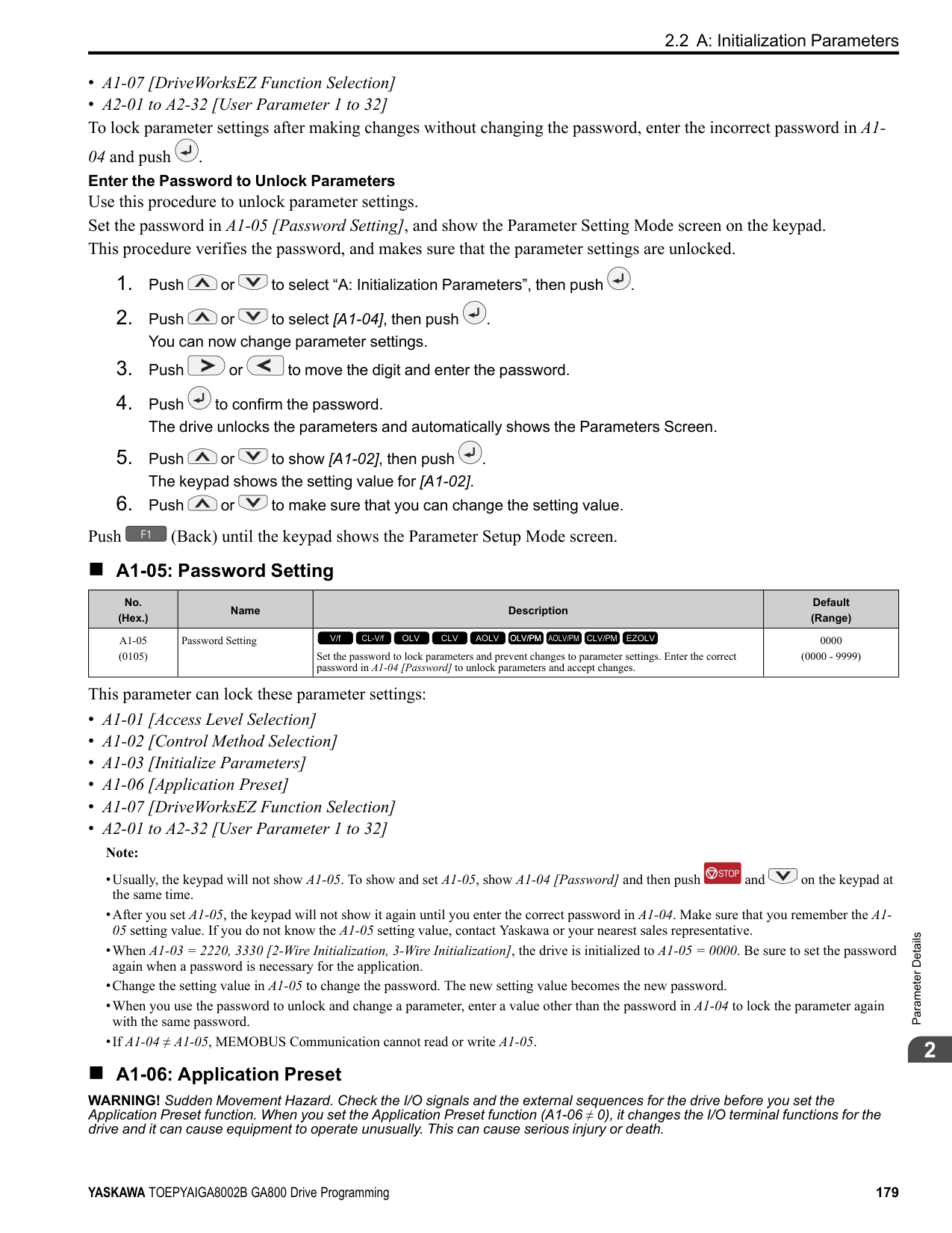
|No. (Hex.)|Name|Description|Default (Range)| |---|---|---|---| |b8-17 (01F9) Expert|PM E-Save Coefficient Kt|Sets torque linearity. This parameter uses the Kt value from the motor nameplate. Usually it is not necessary to change this setting.
V/f CL-V/f OLV CLV AOLV OLV/PM AOLV/PM CLV/PM EZOLV
|1.00 (0.00 - 3.00)|
|No. (Hex.)|Name|Description|Default (Range)| |---|---|---|---| |b8-18 (01FA) Expert|E-Save d-axis Current FilterTime|Sets the d-axis current reference filter time constant.
V/f CL-V/f OLV CLV AOLV OLV/PM AOLV/PM CLV/PM EZOLV
|0.100 s (0.000 - 5.000 s)|
|No. (Hex.)|Name|Description|Default (Range)| |---|---|---|---| |b8-19 (0B40) Expert|E-Save Search Frequency|Sets the frequency of Energy-saving control search operations. Usually it is not necessary to change this setting.
V/f CL-V/f OLV CLV AOLV OLV/PM AOLV/PM CLV/PM EZOLV
|Determined by A1-02 (10 - 300 Hz)|
################# Note:
An increase in the value can make the operational efficiency better. However, if the load inertia is small, it may be necessary to adjust the value to prevent machine vibration.
Note:
When you decrease the value of C5-01 [ASR Proportional Gain 1], also decrease the value of b8-21 to keep the correct ratio.
When the motor characteristics are correct, increase this value to make the motor more efficient.
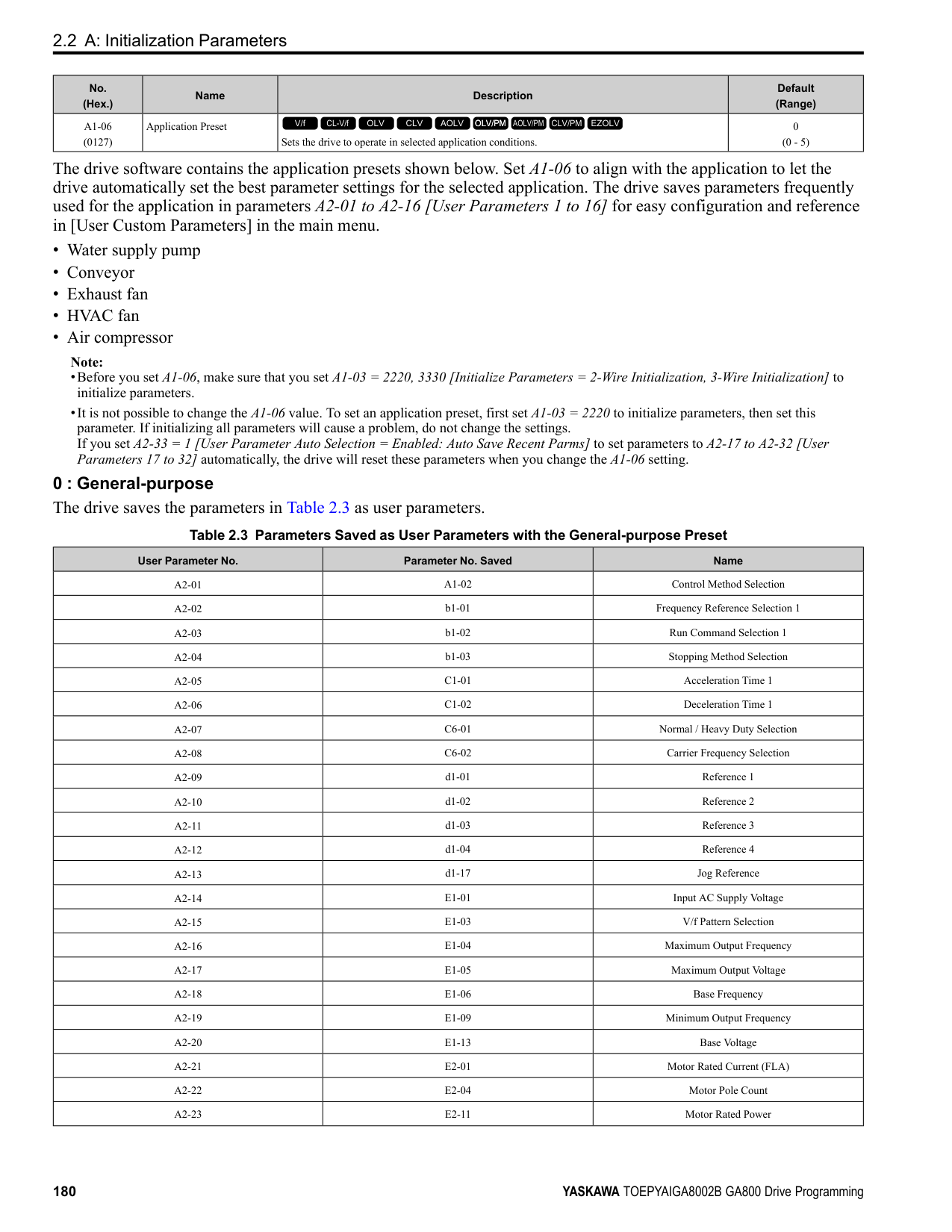
Note: If the drive detects oC [Overcurrent], decrease the value.
|No. (Hex.)|Name|Description|Default (Range)| |---|---|---|---| |b8-20 (0B41) Expert|E-Save Search Width|Sets the amplitude of Energy-saving control search operations.
V/f CL-V/f OLV CLV AOLV OLV/PM AOLV/PM CLV/PM EZOLV
|1.0 degrees (0.1 - 5.0 degrees)|
|No. (Hex.)|Name|Description|Default (Range)| |---|---|---|---| |b8-21 (0B42) Expert|PM E-Save Search Gain|Sets the gain of Energy-saving control search operations.
V/f CL-V/f OLV CLV AOLV OLV/PM AOLV/PM CLV/PM EZOLV
|0.3Hz (0.1 - 20.0 Hz)|
|No. (Hex.)|Name|Description|Default (Range)| |---|---|---|---| |b8-22 (0B43) Expert|PM E-Save Search LPF Cutoff Freq|Sets the frequency of the filter used to extract the high-efficiency phase from search operations. Usually it is not necessary to change this setting.
V/f CL-V/f OLV CLV AOLV OLV/PM AOLV/PM CLV/PM EZOLV
|10.0 Hz (1.0 - 30.0 Hz)|
|No. (Hex.)|Name|Description|Default (Range)| |---|---|---|---| |b8-23 (0B44) Expert|PM E-Save Search Limit|Sets the search operations output limit. Usually it is not necessary to change this setting.
V/f CL-V/f OLV CLV AOLV OLV/PM AOLV/PM CLV/PM EZOLV
|15.0 degrees (0.0 - 30.0 degrees)|
|No. (Hex.)|Name|Description|Default (Range)| |---|---|---|---| |b8-24 (0B45) Expert|PM E-Save High Freq ACR Gain|Sets the gain for high-frequency current control.
V/f CL-V/f OLV CLV AOLV OLV/PM AOLV/PM CLV/PM EZOLV
|200.0 Hz (100.0 - 1000.0 Hz)|
ParameterDetails
|No. (Hex.)|Name|Description|Default (Range)| |---|---|---|---| |b8-25 (0B46) Expert|PM E-Save Search Start Level|Sets the start level for search operations.
V/f CL-V/f OLV CLV AOLV OLV/PM AOLV/PM CLV/PM EZOLV
|10.0% (0.0 - 100.0%)|
If there is vibration in the machine, increase the value.
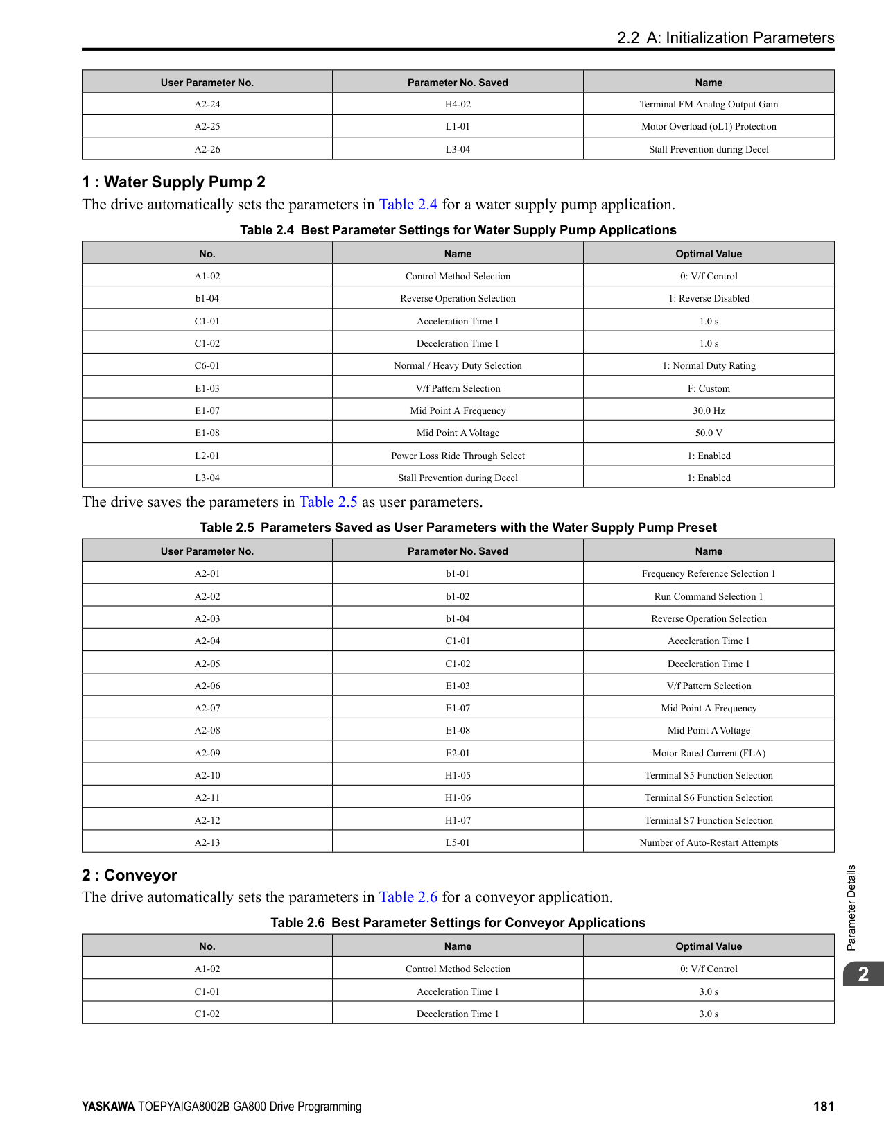
|No. (Hex.)|Name|Description|Default (Range)| |---|---|---|---| |b8-26 (0B47) Expert|PM E-Save Power Setpoint|Sets a value to increase torque accuracy.
V/f CL-V/f OLV CLV AOLV OLV/PM AOLV/PM CLV/PM EZOLV
|0.0% (-10.0 - +10.0%)|
|No. (Hex.)|Name|Description|Default (Range)| |---|---|---|---| |b8-28 (0B8B) Expert|Over Excitation Action Selection|Sets the function for excitation operation.
V/f CL-V/f OLV CLV AOLV OLV/PM AOLV/PM CLV/PM EZOLV
|0 (0, 1)|
When operation is not stable at low speeds, set this parameter to 1 to enable the function. 0 : Disabled 1 : Enabled
######## ■ b8-29: Energy Saving Priority Selection
|No. (Hex.)|Name|Description|Default (Range)| |---|---|---|---| |b8-29 (0B8C)|Energy Saving Priority Selection|Sets the priority of drive response between changes to the load or Energy-saving control. Enable this to prioritize energy-saving control. Disable this to prioritize tracking related to fast load changes, and prevent motor stall.
V/f CL-V/f OLV CLV AOLV OLV/PM AOLV/PM CLV/PM EZOLV
|0 (0, 1)|
Enable this parameter when there are small changes in the load. It is possible that the motor cannot respond correctly to changes in the load.
0 : Priority: Drive Response 1 : Priority: Energy Savings
######## ■ b8-50: Standby Mode Selection
|No. (Hex.)|Name|Description|Default (Range)| |---|---|---|---| |b8-50 (0B0D)|Standby Mode Selection|Sets the Standby Mode function.
V/f CL-V/f OLV CLV AOLV OLV/PM AOLV/PM CLV/PM EZOLV
|0 (0, 1)|
Standby Mode waits for the drive to stop, uses the relay output of an MFDO terminal to shut off the input side electromagnetic contactor (MC), then shuts off the main circuit power supply.
Note: These conditions are also necessary for Standby Mode:
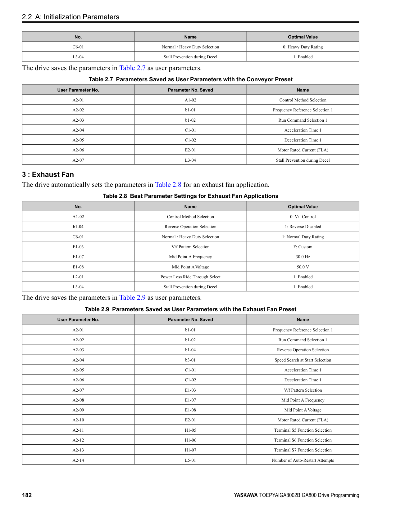
A - Drive B - MFDO Terminal
C - External 24 V power supply
######## ■ b8-51: Standby Mode Wait Time
|No. (Hex.)|Name|Description|Default (Range)| |---|---|---|---| |b8-51 (0B01)|Standby Mode Wait Time|Sets the delay time before turning off the electromagnetic contactor after the drive stops.
V/f CL-V/f OLV CLV AOLV OLV/PM AOLV/PM CLV/PM EZOLV
|600 s (0 - 6000 s)|
◆ b9: Zero Servo Zero Servo is a position control function that stops and holds the motor shaft. The drive safeties the stopped motor and an external force will not move the motor. When you enable the Zero Servo function, the drive will save the home position. The drive can correct the motor position and put the motor into the home position when the load rotates the motor. To enable Zero Servo, set H1-xx = 72 [MFDI Function Selection = Zero Servo]. The drive starts Zero Servo when the MFDI terminal set for Zero Servo [H1-xx = 72] activates and the motor speed decreases to less than the value set in b2-01 [DC Injection/Zero SpeedThreshold]. The drive stops and holds the motor in the Zero Servo start position.
When Zero Servo is enabled, the drive will hold the motor in position when the frequency reference increases to more than the value set in b2-01. When Zero Servo is enabled, the drive will hold the motor in position when the frequency reference increases to more than the value set in b2-01.
Note: Zero Servo is available when A1-02 = 3, 7 [Control Method Selection = Closed Loop Vector, PM Closed Loop Vector].
Figure 2.43 Zero Servo Time Chart Monitor U6-22 [ZeroServoPulse Move] shows the difference between the position of the motor shaft and the Zero Servo start position when Zero Servo is enabled. To find the difference, divide the number of pulses shown in U6-22 by 4. When the position of the motor shaft is in the range of “Zero Servo start position ± b9-02 [Zero Servo Completion Window]”, the drive will activate an MFDO set for Zero Servo Complete [H2-xx = 33]. NOTICE: Do not let the Zero Servo function hold 100% load for long periods of time. When the application must use Zero Servo to hold 100% load for long periods, operate in less than 50% of the drive rated output current or use a larger capacity drive. If Zero Servo holds the load for too long in 50% or more of the drive rated output current, it will cause damage to the drive.
ParameterDetails
######## 2
######## ■ b9-01: Zero Servo Gain
|No. (Hex.)|Name|Description|Default (Range)| |---|---|---|---| |b9-01 (01DA)|Zero Servo Gain|Sets the responsiveness for the Zero Servo function.
V/f CL-V/f OLV CLV AOLV OLV/PM AOLV/PM CLV/PM EZOLV
|5 (0 - 100)|
If the drive is not responsive, or if there is too much deviation from the Zero Servo start point when you increase the load, increase this setting. If oscillation or hunting occurs, decrease this setting.
Note:
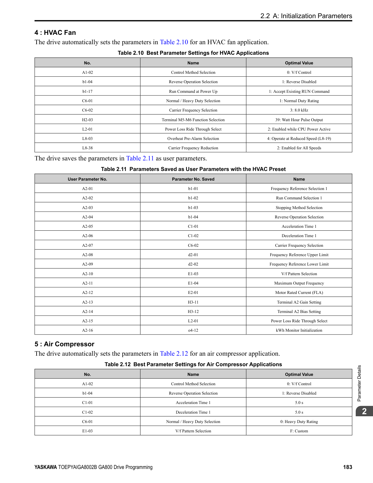
######## ■ b9-02: Zero Servo Completion Window
|No. (Hex.)|Name|Description|Default (Range)| |---|---|---|---| |b9-02 (01DB)|Zero Servo Completion Window|Sets the range to trigger an output terminal set for “Zero Servo Complete” during Zero Servo operation. Be sure to set the deviation from the Zero Servo start position.
V/f CL-V/f OLV CLV AOLV OLV/PM AOLV/PM CLV/PM EZOLV
|10 (0 - 16383)|
When the position of the motor shaft is in the range of “Zero Servo start position ± b9-02”, the drive will activate a MFDO set for Zero Servo Complete [H2-xx = 33].
####### 2.4 C: Tuning
C parameters adjust drive operation, including:
◆ C1: Accel & Decel Time You can set four different acceleration and deceleration time pairs in the drive. When you activate and deactivate H1xx = 7, 16, 1A [MFDI Function Select = Accel/Decel Time Selection 1, Motor 2 Selection, Accel/Decel Time Selection 2], you can switch acceleration and deceleration times during run. Acceleration time parameters always set the time to accelerate from 0 Hz to E1-04 [Maximum Output Frequency]. Deceleration time parameters always set the time to decelerate from E1-04 to 0 Hz. C1-01 [Acceleration Time 1] and C1-02 [Deceleration Time 1] are the default active accel/decel settings.
|Parameter|Range| |---|---| |C1-01 [Acceleration Time 1]|0.0 to 6000.0 s| |C1-02 [Deceleration Time 1]|0.0 to 6000.0 s| |C1-03 [Acceleration Time 2]|0.0 to 6000.0 s| |C1-04 [Deceleration Time 2]|0.0 to 6000.0 s| |C1-05 [Acceleration Time 3]|0.0 to 6000.0 s| |C1-06 [Deceleration Time 3]|0.0 to 6000.0 s| |C1-07 [Acceleration Time 4]|0.0 to 6000.0 s| |C1-08 [Deceleration Time 4]|0.0 to 6000.0 s|
Note: The setting range for acceleration and deceleration times is 0.00 to 600.00 s when C1-10 = 0 [Accel/Decel Time Setting Units = 0.01 s (0.00 to 600.00 s)].
■ Use MFDIs to Switch Acceleration Times Table 2.29 shows the different acceleration and deceleration times.
Table 2.29 Accel/Decel Times and Active Parameters
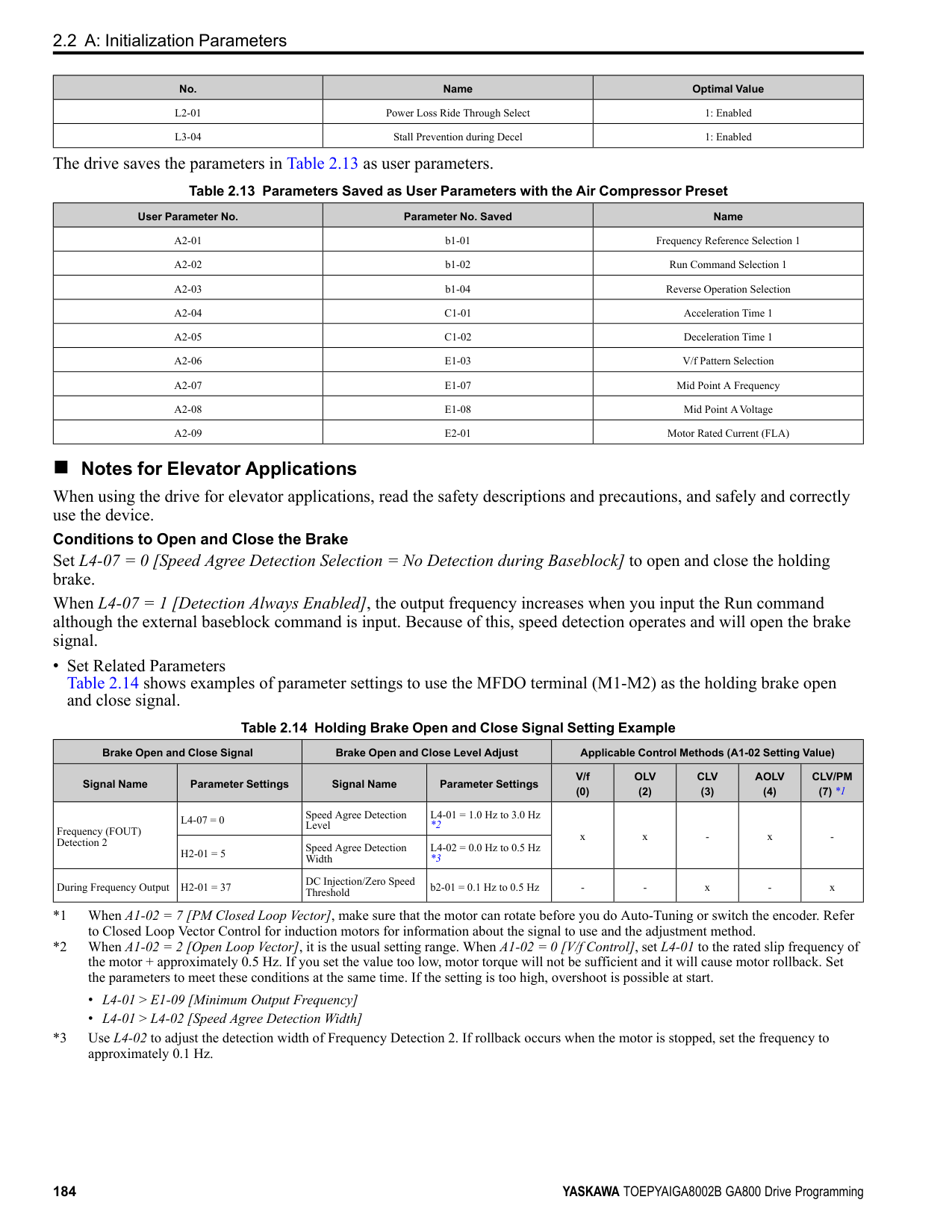
|H1-xx = 7 [Accel/Decel Time Selection 1]|H1-xx = 1A [Accel/Decel Time Selection 2]|Active Parameter|Active Parameter| |---|---|---|---| |H1-xx = 7 [Accel/Decel Time Selection 1]|H1-xx = 1A [Accel/Decel Time Selection 2]|Acceleration Time|Deceleration Time| |OFF|OFF|C1-01 [Acceleration Time 1]|C1-02 [Deceleration Time 1]| |ON|OFF|C1-03 [Acceleration Time 2]|C1-04 [Deceleration Time 2]| |OFF|ON|C1-05 [Acceleration Time 3]|C1-06 [Deceleration Time 3]| |ON|ON|C1-07 [Acceleration Time 4]|C1-08 [Deceleration Time 4]|
Figure 2.44 shows an operation example to change acceleration and deceleration times. It is necessary to set b1-03 = 0 [Stopping Method Selection = Ramp to Stop] for this example.
ParameterDetails
2
Figure 2.44 Timing Diagram of Acceleration and Deceleration Times
######## ■ Use Motor Selection to Switch Acceleration and Deceleration Times
When you set H1-xx = 16 [MFDI Function Selection = Motor 2 Selection], you can activate and deactivate the input terminal to switch between motor 1 and motor 2.
Note: You cannot use the Motor 2 Selection function with PM motors.
Table 2.30 shows the possible acceleration and deceleration time combinations when you use the Motor 2 Selection function.
Table 2.30 Motor Selection and Acceleration and Deceleration Times
|H1-xx = 7 [Accel/Decel Time Selection 1]|H1-xx = 16 [Motor 2 Selection]|H1-xx = 16 [Motor 2 Selection]|H1-xx = 16 [Motor 2 Selection]|H1-xx = 16 [Motor 2 Selection]| |---|---|---|---|---| |H1-xx = 7 [Accel/Decel Time Selection 1]|Motor 2 Selection: OFF|Motor 2 Selection: OFF|Motor 2 Selection: ON|Motor 2 Selection: ON| |H1-xx = 7 [Accel/Decel Time Selection 1]|Acceleration Time|Deceleration Time|Acceleration Time|Deceleration Time| |OFF|C1-01|C1-02|C1-05|C1-06| |ON|C1-03|C1-04|C1-07|C1-08|
######## ■ Use Output Frequency Level to Switch Acceleration and Deceleration Times
The drive can use output frequency to automatically switch between different acceleration and deceleration times. When the output frequency = C1-11 [Accel/Decel Time Switchover Freq], the drive automatically switches the acceleration and deceleration times. Set C1-11 = 0.0 Hz to disable this function.
Note:
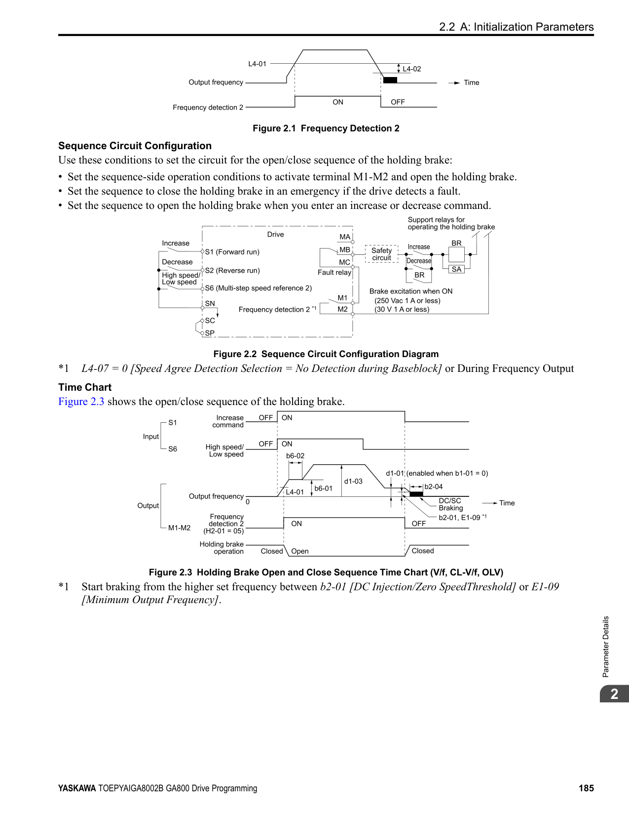
################# Figure 2.45 Accel/Decel Time Switching Frequency
######## ■ C1-01: Acceleration Time 1
|No. (Hex.)|Name|Description|Default (Range)| |---|---|---|---| |C1-01 (0200) RUN|Acceleration Time 1|Sets the length of time to accelerate from zero to maximum output frequency.
V/f CL-V/f OLV CLV AOLV OLV/PM AOLV/PM CLV/PM EZOLV
|10.0 s (0.0 - 6000.0 s)|
Note: When C1-10 = 0 [Accel/Decel Time Setting Units = 0.01 s (0.00 to 600.00 s)], the setting range is 0.00 to 600.00 s.
######## ■ C1-02: Deceleration Time 1
|No. (Hex.)|Name|Description|Default (Range)| |---|---|---|---| |C1-02 (0201) RUN|Deceleration Time 1|Sets the length of time to decelerate from maximum output frequency to zero.
V/f CL-V/f OLV CLV AOLV OLV/PM AOLV/PM CLV/PM EZOLV
|10.0 s (0.0 - 6000.0 s)|
Note: When C1-10 = 0 [Accel/Decel Time Setting Units = 0.01 s (0.00 to 600.00 s)], the setting range is 0.00 to 600.00 s.
######## ■ C1-03: Acceleration Time 2
|No. (Hex.)|Name|Description|Default (Range)| |---|---|---|---| |C1-03 (0202) RUN|Acceleration Time 2|Sets the length of time to accelerate from zero to maximum output frequency.
V/f CL-V/f OLV CLV AOLV OLV/PM AOLV/PM CLV/PM EZOLV
|10.0 s (0.0 - 6000.0 s)|
Note: When C1-10 = 0 [Accel/Decel Time Setting Units = 0.01 s (0.00 to 600.00 s)], the setting range is 0.00 to 600.00 s.
######## ■ C1-04: Deceleration Time 2
|No. (Hex.)|Name|Description|Default (Range)| |---|---|---|---| |C1-04 (0203) RUN|Deceleration Time 2|Sets the length of time to decelerate from maximum output frequency to zero.
V/f CL-V/f OLV CLV AOLV OLV/PM AOLV/PM CLV/PM EZOLV
|10.0 s (0.0 - 6000.0 s)|
Note: When C1-10 = 0 [Accel/Decel Time Setting Units = 0.01 s (0.00 to 600.00 s)], the setting range is 0.00 to 600.00 s.
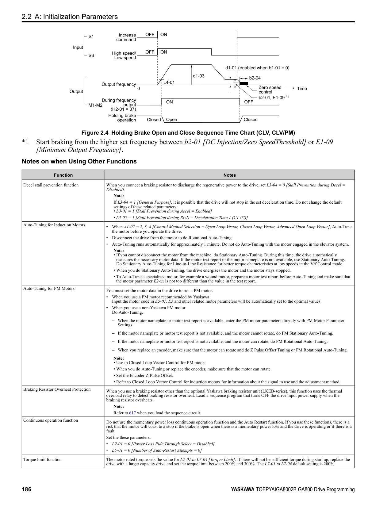
######## ■ C1-05: Acceleration Time 3
|No. (Hex.)|Name|Description|Default (Range)| |---|---|---|---| |C1-05 (0204) RUN|Acceleration Time 3|Sets the length of time to accelerate from zero to maximum output frequency.
V/f CL-V/f OLV CLV AOLV OLV/PM AOLV/PM CLV/PM EZOLV
|10.0 s (0.0 - 6000.0 s)|
Note: When C1-10 = 0 [Accel/Decel Time Setting Units = 0.01 s (0.00 to 600.00 s)], the setting range is 0.00 to 600.00 s.
######## ■ C1-06: Deceleration Time 3
|No. (Hex.)|Name|Description|Default (Range)| |---|---|---|---| |C1-06 (0205) RUN|Deceleration Time 3|Sets the length of time to decelerate from maximum output frequency to zero.
V/f CL-V/f OLV CLV AOLV OLV/PM AOLV/PM CLV/PM EZOLV
|10.0 s (0.0 - 6000.0 s)|
Note: When C1-10 = 0 [Accel/Decel Time Setting Units = 0.01 s (0.00 to 600.00 s)], the setting range is 0.00 to 600.00 s.
ParameterDetails
######## 2
######## ■ C1-07: Acceleration Time 4
|No. (Hex.)|Name|Description|Default (Range)| |---|---|---|---| |C1-07 (0206) RUN|Acceleration Time 4|Sets the length of time to accelerate from zero to maximum output frequency.
V/f CL-V/f OLV CLV AOLV OLV/PM AOLV/PM CLV/PM EZOLV
|10.0 s (0.0 - 6000.0 s)|
Note: When C1-10 = 0 [Accel/Decel Time Setting Units = 0.01 s (0.00 to 600.00 s)], the setting range is 0.00 to 600.00 s.
######## ■ C1-08: Deceleration Time 4
|No. (Hex.)|Name|Description|Default (Range)| |---|---|---|---| |C1-08 (0207) RUN|Deceleration Time 4|Sets the length of time to decelerate from maximum output frequency to zero.
V/f CL-V/f OLV CLV AOLV OLV/PM AOLV/PM CLV/PM EZOLV
|10.0 s (0.0 - 6000.0 s)|
Note: When C1-10 = 0 [Accel/Decel Time Setting Units = 0.01 s (0.00 to 600.00 s)], the setting range is 0.00 to 600.00 s.
######## ■ C1-09: Fast Stop Time
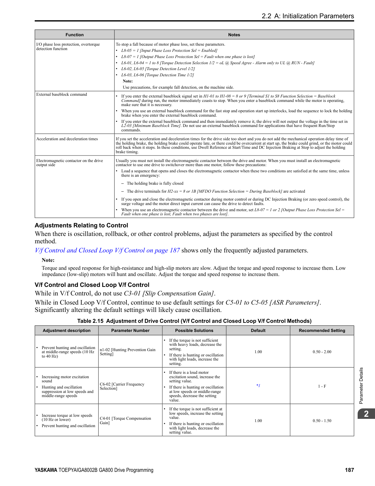
|No. (Hex.)|Name|Description|Default (Range)| |---|---|---|---| |C1-09 (0208) RUN|Fast Stop Time|Sets the length of time that the drive will decelerate to zero for a Fast Stop.
V/f CL-V/f OLV CLV AOLV OLV/PM AOLV/PM CLV/PM EZOLV
|10.0 s (0.0 - 6000.0 s)|
################# Note:
automatically set C1-09. If you must not change the Fast Stop time, do not do KEB Auto-Tuning. The Fast Stop function will be triggered in the following circumstances.
Set H1-xx = 15, 17 [MFDI Function Select = Fast Stop (N.O.), Fast Stop (N.C.)]. When the Fast Stop command is input, the Fast Stop operation will be triggered at the deceleration time set to C1-09. The drive cannot be restarted after initiating a Fast Stop operation until deceleration is complete. Complete deceleration and cycle the Run command to clear the Fast Stop input. The terminal set for H2-xx = 4C [MFDO Function Select = During Fast Stop] will be ON during Fast Stop.
Note:
Decelerating too quickly can cause an ov [Overvoltage] fault that shuts off the drive while the motor to coasts to a stop. Set a Fast Stop time in C1-09 that prevents motor coasting and makes sure that the motor stops quickly and safely.
######## ■ C1-10: Accel/Decel Time Setting Units
|No. (Hex.)|Name|Description|Default (Range)| |---|---|---|---| |C1-10 (0209)|Accel/Decel Time Setting Units|Sets the setting units for C1-01 to C1-08 [Accel/Decel Times 1 to 4], C1-09 [Fast Stop Time], L2-06 [Kinetic Energy Backup Decel Time], and L2-07 [Kinetic Energy Backup Accel Time].
V/f CL-V/f OLV CLV AOLV OLV/PM AOLV/PM CLV/PM EZOLV
|1 (0, 1)|
• C1-01 to C1-09
• L2-06 • L2-07 When one of those parameters is set to a value between 600.1 s and 1000.0 s, you can set C1-10 = 0, but the time will change to 600.00 s. 1 : 0.1 s (0.0 to 6000.0 s) Sets acceleration and deceleration times in 0.1 s units. The setting range is 0.0 to 6000.0 s.
######## ■ C1-11: Accel/Decel Time Switchover Freq
|No. (Hex.)|Name|Description|Default (Range)| |---|---|---|---| |C1-11 (020A)|Accel/Decel Time Switching Frequency|Sets the frequency at which the drive will automatically change acceleration and deceleration times.
V/f CL-V/f OLV CLV AOLV OLV/PM AOLV/PM CLV/PM EZOLV
|Determined by A1-02 (0.0 - 590.0 Hz)|
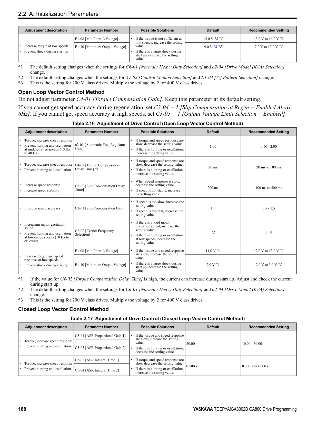
When output frequency get C1-11 value, the drive automatically switches the acceleration and deceleration times. Set this parameter to 0.0 to disable this function.
Figure 2.46 Accel/Decel Time Switching Frequency Table 2.31 lists the possible combinations of acceleration and deceleration time switchover frequencies and the acceleration times for the Motor 2 Selection function.
Table 2.31 Motor and Acceleration and Deceleration Time Combination
|C1-11|Motor 1|Motor 1|Motor 2|Motor 2| |---|---|---|---|---| |C1-11|Acceleration Time|Deceleration Time|Acceleration Time|Deceleration Time| |Less than the setting value|C1-07 [Acceleration Time 4]|C1-08 [Deceleration Time 4]|C1-07 [Acceleration Time 4]|C1-08 [Deceleration Time 4]| |Equal to or more than the setting value|C1-01 [Acceleration Time 1]|C1-02 [Deceleration Time 1]|C1-05 [Acceleration Time 3]|C1-06 [Deceleration Time 3]|
######## ■ C1-14: Accel/Decel Rate Frequency
|No. (Hex.)|Name|Description|Default (Range)| |---|---|---|---| |C1-14 (0264) RUN|Accel/Decel Rate Frequency|Sets the base frequency used to calculate acceleration and deceleration rates.
V/f CL-V/f OLV CLV AOLV OLV/PM AOLV/PM CLV/PM EZOLV
|0.0 Hz (0.0 - 590.0 Hz)|
The acceleration and deceleration rates set in C1-01 to C1-09 [Acceleration/Deceleration Times 1 to 4, Fast Stop Time] will change when the value of C1-14 changes.
• When C1-14 = 0.0 Hz
ParameterDetails
Figure 2.47 Example 1: Acceleration/Deceleration Rate (When C1-14 = 0 Hz, E1-04 = 60 Hz, and the Frequency Reference is 60 Hz)
• When C1-14 ≠ 0.0 Hz
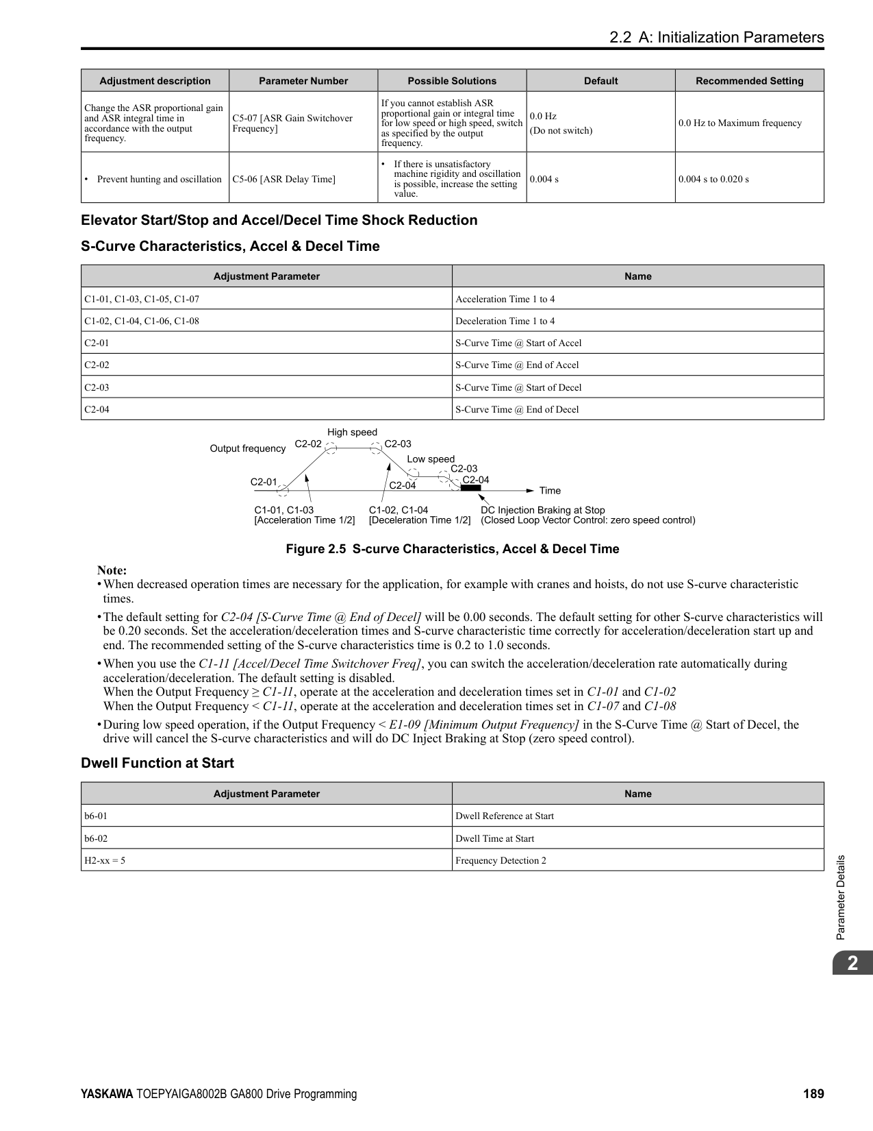
◆ C2: S-Curve Characteristics Use S-curve characteristics to smooth acceleration and deceleration and to minimize abrupt shock to the load.
Set S-curve characteristic time during acceleration/deceleration at start and acceleration/deceleration at stop. The following figure explains how S-curves are applied.
Figure 2.50 S-Curve Timing Diagram - Forward/Reverse Operation Note:
|No. (Hex.)|Name|Description|Default (Range)| |---|---|---|---| |C2-01 (020B)|S-Curve Time @ Start of Accel|Sets the S-curve acceleration time at start.
V/f CL-V/f OLV CLV AOLV OLV/PM AOLV/PM CLV/PM EZOLV
|Determined by A1-02 (0.00 - 10.00 s)|
|No. (Hex.)|Name|Description|Default (Range)| |---|---|---|---| |C2-02 (020C)|S-Curve Time @ End of Accel|Sets the S-curve acceleration time at completion.
V/f CL-V/f OLV CLV AOLV OLV/PM AOLV/PM CLV/PM EZOLV
|0.20 s (0.00 - 10.00 s)|
|No. (Hex.)|Name|Description|Default (Range)| |---|---|---|---| |C2-03 (020D)|S-Curve Time @ Start of Decel|Sets the S-curve deceleration time at start.
V/f CL-V/f OLV CLV AOLV OLV/PM AOLV/PM CLV/PM EZOLV
|0.20 s (0.00 - 10.00 s)|
|No. (Hex.)|Name|Description|Default (Range)| |---|---|---|---| |C2-04 (020E)|S-Curve Time @ End of Decel|Sets the S-curve deceleration time at completion.
V/f CL-V/f OLV CLV AOLV OLV/PM AOLV/PM CLV/PM EZOLV
|0.00 s (0.00 - 10.00 s)|
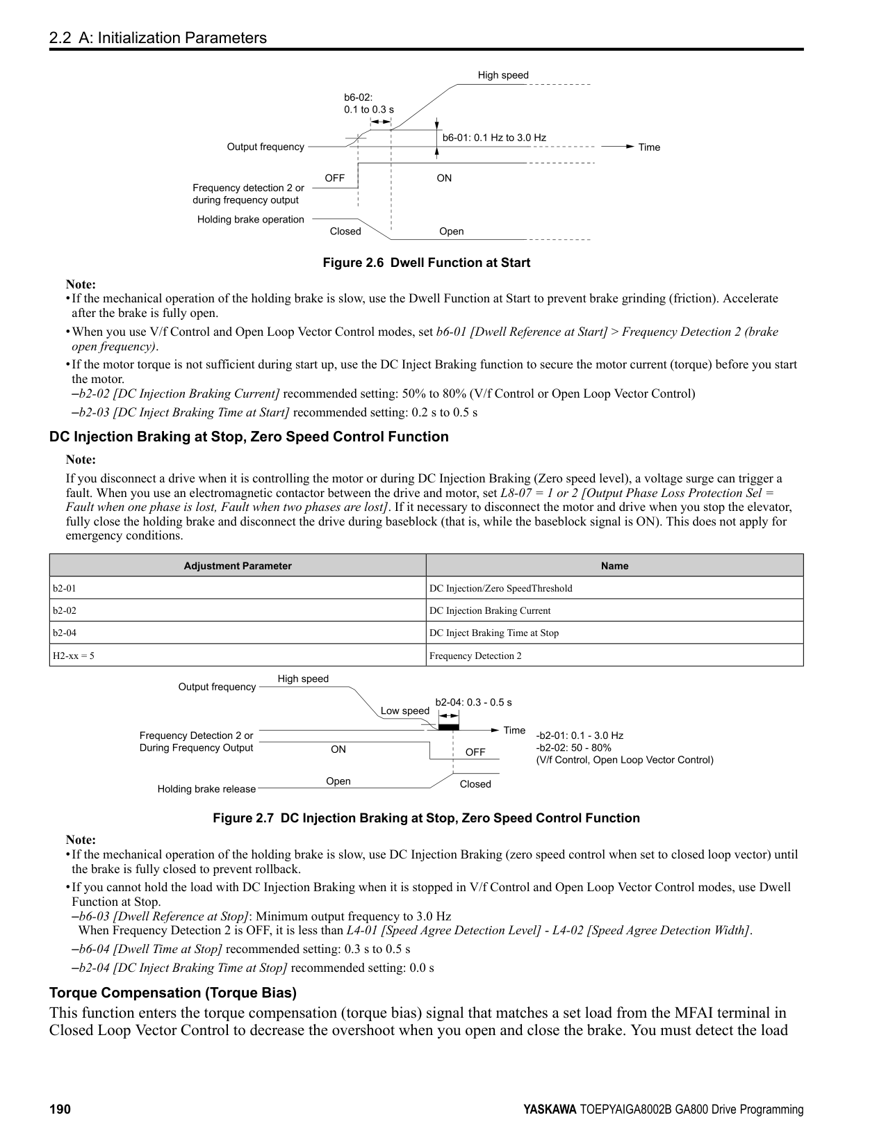
ParameterDetails
######## ◆ C3: Slip Compensation
The Slip Compensation function improves the speed accuracy of an induction motor. As loads on induction motors increase, motor slip increases and motor speed decreases. By adjusting the output frequency in accordance with the motor load, it compensates the slip and makes the motor speed equal to the frequency reference.
######## ■ C3-01: Slip Compensation Gain
|No. (Hex.)|Name|Description|Default (Range)| |---|---|---|---| |C3-01 (020F) RUN|Slip Compensation Gain|Sets the gain for the slip compensation function. Usually it is not necessary to change this setting.
V/f CL-V/f OLV CLV AOLV OLV/PM AOLV/PM CLV/PM EZOLV
|Determined by A1-02 (0.0 - 2.5)|
Note:
Use these settings to adjust this parameter as necessary:
######## ■ C3-02: Slip Compensation Delay Time
|No. (Hex.)|Name|Description|Default (Range)| |---|---|---|---| |C3-02 (0210) RUN|Slip Compensation Delay Time|Sets the slip compensation delay time when speed is unstable or when the slip compensation response is too slow. Usually it is not necessary to change this setting.
V/f CL-V/f OLV CLV AOLV OLV/PM AOLV/PM CLV/PM EZOLV
|Determined by A1-02 (0 - 10000 ms)|
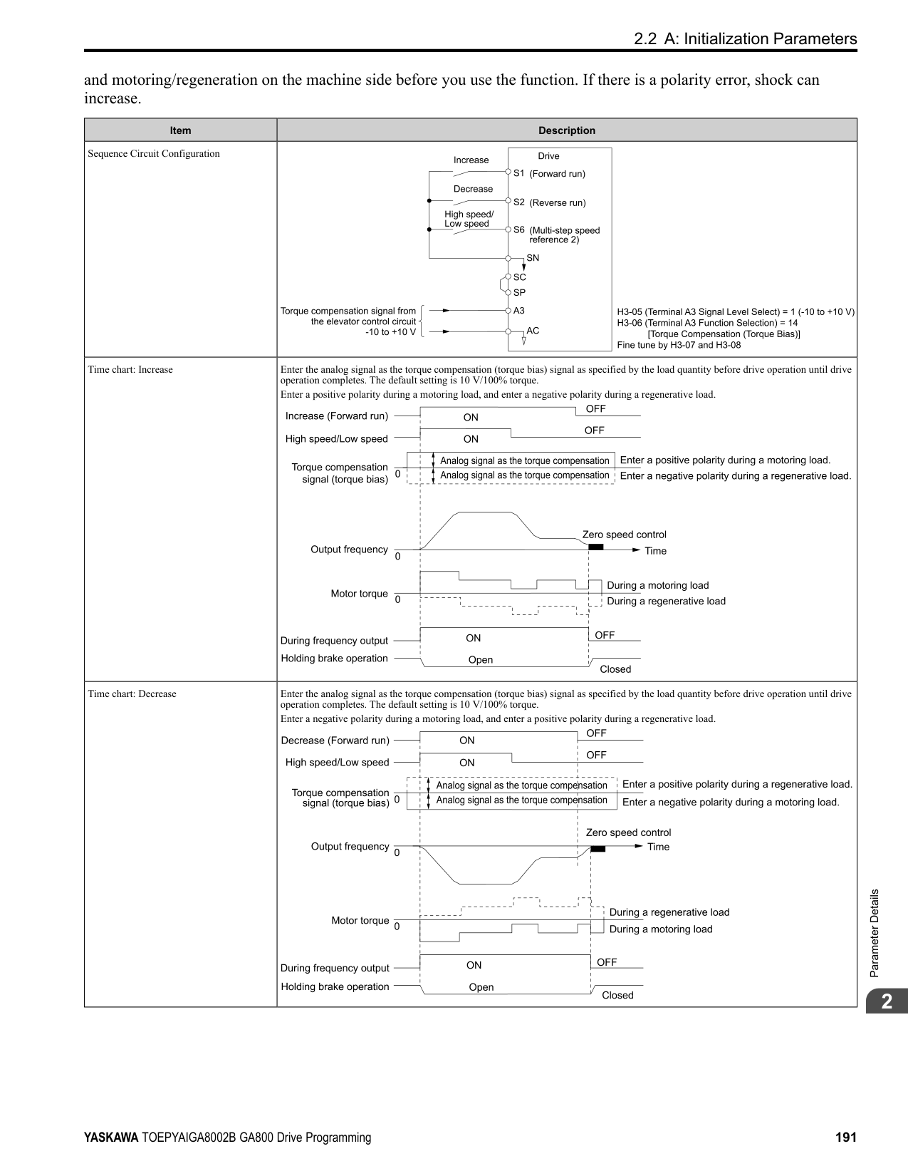
Use these settings to adjust this parameter as necessary:
######## ■ C3-03: Slip Compensation Limit
|No. (Hex.)|Name|Description|Default (Range)| |---|---|---|---| |C3-03 (0211)|Slip Compensation Limit|Sets the upper limit for the slip compensation function as a percentage of the motor rated slip.
V/f CL-V/f OLV CLV AOLV OLV/PM AOLV/PM CLV/PM EZOLV
|200% (0 - 250%)|
If you increase the value of C3-01 [Slip Compensation Gain] and the motor speed is slow, use this parameter. The drive uses this parameter when the slip is at the upper limit of slip compensation. Make sure that you measure the motor speed when you increase this parameter value. Set this parameter to make the frequency reference and the slip compensation limit less than the permitted range of the machine. The slip compensation limit is constant in the constant torque range (frequency reference ≤ E1-06 [Base Frequency]). In the constant output range where the frequency reference > E1-06, the slip compensation limit increases with the C3-03 value and the output frequency as shown in Figure 2.51.
Figure 2.51 Slip Compensation Limit
######## ■ C3-04: Slip Compensation at Regen
|No. (Hex.)|Name|Description|Default (Range)| |---|---|---|---| |C3-04 (0212)|Slip Compensation at Regen|Sets the slip compensation function during regenerative operation.
V/f CL-V/f OLV CLV AOLV OLV/PM AOLV/PM CLV/PM EZOLV
|0 (0 - 2)|
If you apply a regenerative load when slip compensation function during regeneration is active, the quantity of regeneration can increase immediately. In this condition, it is necessary to use a dynamic braking option (braking resistor or braking resistor unit).
The load and operation status (regenerative operation) can cause the motor speed to be higher or lower than the frequency reference.
Slip compensation function is enabled during regeneration. Slip compensation is disabled at output frequencies of 6 Hz or less.
The drive uses E2-02 [Motor Rated Slip] to automatically calculate the frequency range where it will disable slip compensation function during regenerative operation. Slip compensation is enabled at frequencies as low as 2 Hz.
######## ■ C3-05: Output Voltage Limit Selection
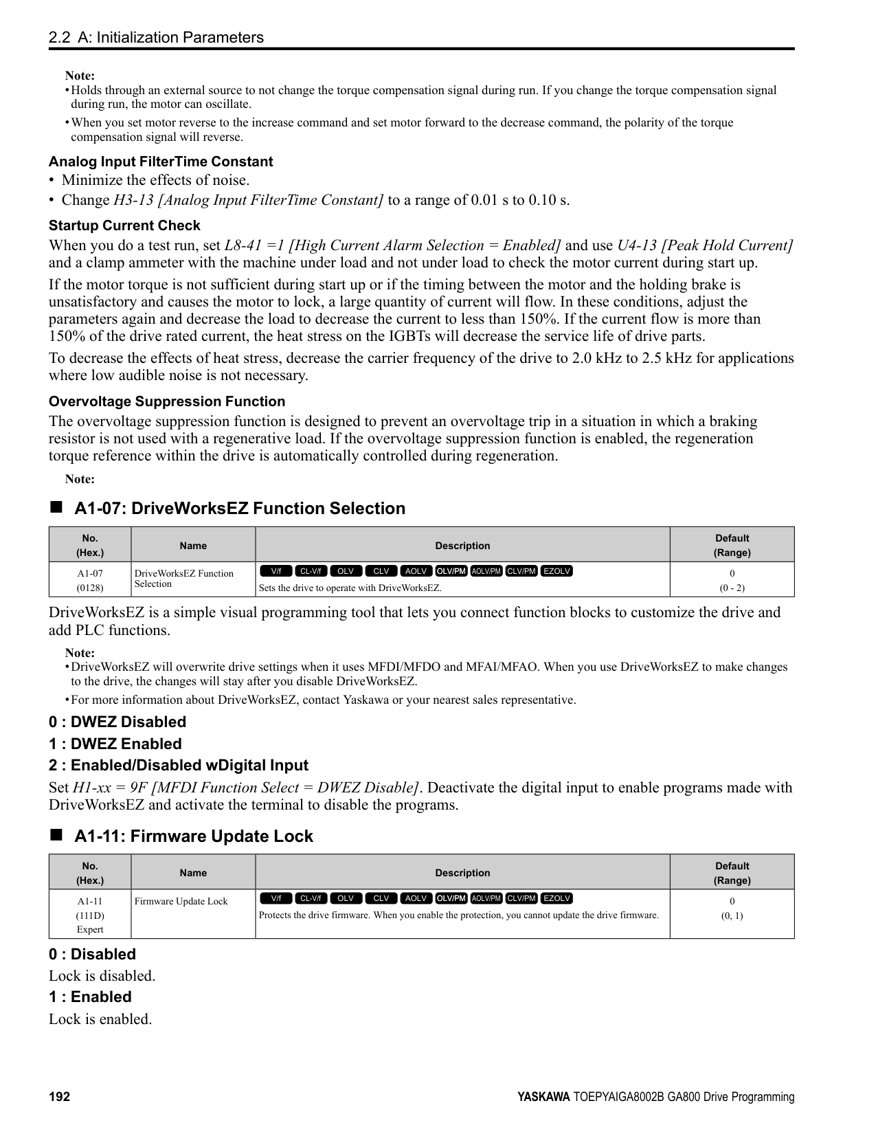
|No. (Hex.)|Name|Description|Default (Range)| |---|---|---|---| |C3-05 (0213)|Output Voltage Limit Selection|Sets the automatic reduction of motor magnetic flux when the output voltage is saturated.
V/f CL-V/f OLV CLV AOLV OLV/PM AOLV/PM CLV/PM EZOLV
|0 (0, 1)|
The drive will decrease flux and increase current to compensate torque when voltage is saturated. Make sure that the drive has sufficient output current capacity before you enable this parameter. When this parameter = 1 [Enabled], the output current will increase by 10% at a maximum (at rated load) before it is enabled. Enable this parameter to increase speed precision when you move heavy loads at high speeds in these conditions:
When you enable this parameter, if the power supply voltage is much less than the motor rated voltage, torque control will not be accurate.
ParameterDetails
######## 2
|No. (Hex.)|Name|Description|Default (Range)| |---|---|---|---| |C3-16 (0261) Expert|Vout Modulation Limit Start Lvl|Sets the modulation factor that starts the output voltage limit operation when C3-05 = 1 [Output Voltage Limit Selection = Enabled].
V/f CL-V/f OLV CLV AOLV OLV/PM AOLV/PM CLV/PM EZOLV
|90.0% (70.0 - 90.0%)|
|No. (Hex.)|Name|Description|Default (Range)| |---|---|---|---| |C3-17 (0262) Expert|Vout Modulation Limit Max Level|Sets the modulation factor used with C3-18 [Output Voltage Limit Level] for the output voltage limit operation when C3-05 = 1 [Output Voltage Limit Selection = Enabled].
V/f CL-V/f OLV CLV AOLV OLV/PM AOLV/PM CLV/PM EZOLV
|100.0% (85.0 - 100.0%)|
|No. (Hex.)|Name|Description|Default (Range)| |---|---|---|---|
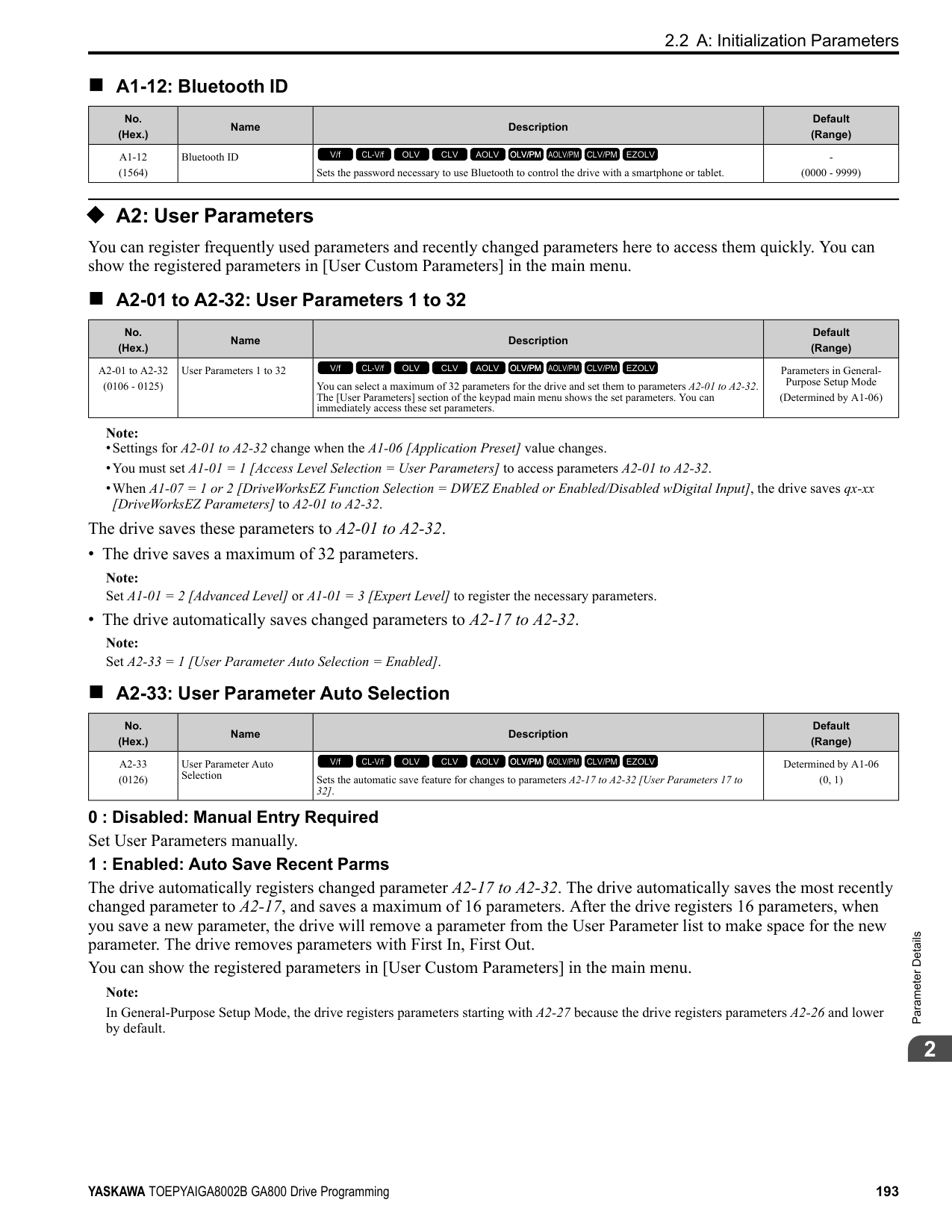
|C3-18 (0263) Expert|Output Voltage Limit Level|Sets the maximum drop width of the voltage reference when C3-05 = 1 [Output Voltage Limit Selection = Enabled].
V/f CL-V/f OLV CLV AOLV OLV/PM AOLV/PM CLV/PM EZOLV
|90.0% (50.0 - 100.0%)|
|No. (Hex.)|Name|Description|Default (Range)| |---|---|---|---| |C3-21 (033E) RUN|Motor 2 Slip Compensation Gain|Sets the gain for the motor 2 slip compensation function. Usually it is not necessary to change this setting.
V/f CL-V/f OLV CLV AOLV OLV/PM AOLV/PM CLV/PM EZOLV
|Determined by E3-01 (0.0 - 2.5)|
Note: Correctly set these parameters before changing the slip compensation gain:
Use these settings to adjust this parameter as necessary:
######## ■ C3-22: Motor 2 Slip Comp Delay Time
|No. (Hex.)|Name|Description|Default (Range)| |---|---|---|---| |C3-22 (0241) RUN|Motor 2 Slip Comp Delay Time|Sets the slip compensation delay time for motor 2 when speed is unstable or when the slip compensation response is too slow. Usually it is not necessary to change this setting.
V/f CL-V/f OLV CLV AOLV OLV/PM AOLV/PM CLV/PM EZOLV
|Determined by E3-01 (0 - 10000 ms)|
Use these settings to adjust this parameter as necessary:
######## ■ C3-23: Motor 2 Slip Compensation Limit
|No. (Hex.)|Name|Description|Default (Range)| |---|---|---|---| |C3-23 (0242)|Motor 2 Slip Compensation Limit|Sets the upper limit for the slip compensation function as a percentage of the motor 2 rated slip.
V/f CL-V/f OLV CLV AOLV OLV/PM AOLV/PM CLV/PM EZOLV
|200% (0 - 250%)|
If you increase the value of C3-21 [Motor 2 Slip Compensation Gain] and the motor speed is slow, use this parameter. The drive uses this parameter when the slip is at the upper limit of slip compensation. Make sure that you measure the motor speed when you increase this parameter value. Set this parameter to make the frequency reference and the slip compensation limit less than the permitted range of the machine. The slip compensation limit is constant in the constant torque range (frequency reference ≤ E3-06 [Motor 2 Base Frequency]). In the constant power range where the frequency reference > E3-06, the slip compensation limit increases with the C3-23 value and the output frequency as shown in Figure 2.52.
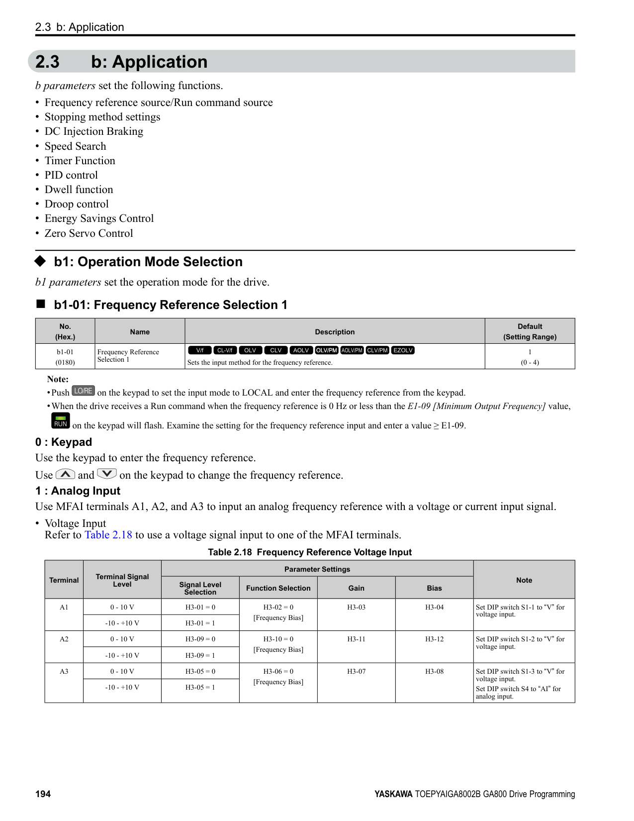
Figure 2.52 Motor 2 Slip Compensation Limit
######## ■ C3-24: Motor 2 Slip Comp during Regen
|No. (Hex.)|Name|Description|Default (Range)| |---|---|---|---| |C3-24 (0243)|Motor 2 Slip Comp during Regen|Sets the slip compensation during regenerative operation function for motor 2.
V/f CL-V/f OLV CLV AOLV OLV/PM AOLV/PM CLV/PM EZOLV
|0 (0 - 2)|
If you enable the slip compensation function during regeneration, the quantity of regeneration can increase immediately. In this condition, it is necessary to use a dynamic braking option (braking resistor or braking resistor unit).
The load and operation status (regenerative operation) can cause the motor speed to be higher or lower than the frequency reference.
The slip compensation function is enabled during regeneration. Slip compensation is disabled at output frequencies of 6 Hz or less.
The drive uses E2-02 [Motor Rated Slip] to automatically calculate the frequency range where it will disable slip compensation function during regeneration. Slip compensation is enabled at frequencies as low as 2 Hz.
######## ■ C3-28: Adaptive Slip Control Mode
|No. (Hex.)|Name|Description|Default (Range)| |---|---|---|---| |C3-28 (1B5B) Expert|Adaptive Slip Control Mode|Sets the slip compensation function mode.
V/f CL-V/f OLV CLV AOLV OLV/PM AOLV/PM CLV/PM EZOLV
|0 (0, 1)|
Set C3-28 = 0 for better torque precision. If the torque precision does is not better, set C3-28 = 1 and increase the value of n4-65 [Flux Estimate Response@High Freq] or n4-66 [Flux Estimate Response @Low Freq] in 0.1-unit increments. Then, you must do Rotational AutoTuning.
ParameterDetails
######## 2
◆ C4: Torque Compensation Torque compensation is a function that increases voltage to increase output torque as compensation for insufficient torque production at start-up or low-speed operation. Voltage drops due to motor winding resistance cause torque generating voltage to decrease, which causes insufficient torque. If the main circuit cable connecting the drive and motor is long, this can also cause insufficient torque due to voltage drops.
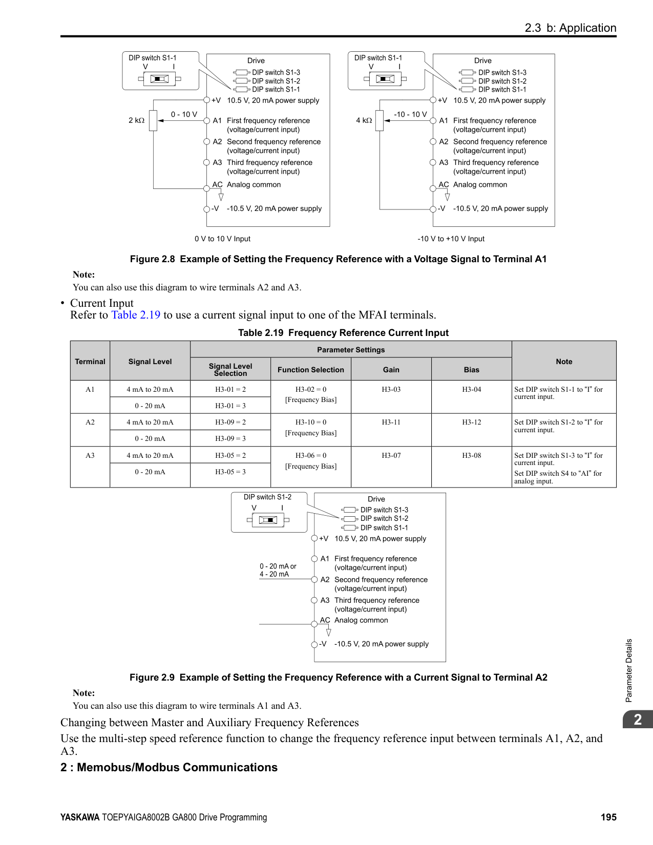
Note: Set the motor parameters and V/f pattern properly before setting C4 parameters.
######## ■ C4-01: Torque Compensation Gain
|No. (Hex.)|Name|Description|Default (Range)| |---|---|---|---| |C4-01 (0215) RUN|Torque Compensation Gain|Sets the gain for the torque compensation function. Use this parameter value for motor 1 when operating multiple motors.
V/f CL-V/f OLV CLV AOLV OLV/PM AOLV/PM CLV/PM EZOLV
|Determined by A1-02 (0.00 - 2.50)|
Adjust the setting in these control methods and conditions:
|A1-02 [Control Method Selection]|Status|Adjustment| |---|---|---| |0 [V/f Control] 1 [V/f Control with Encoder] 8 [EZ Vector Control]|Torque is not sufficient during low-speed operation of 10 Hz or less.|Increase the setting in 0.05-unit increments.| |0 [V/f Control] 1 [V/f Control with Encoder] 8 [EZ Vector Control]|There is vibration in the motor when operating the drive with a light load.|Decrease the setting in 0.05-unit decrements.| |0 [V/f Control] 1 [V/f Control with Encoder] 8 [EZ Vector Control]|The cable between the drive and motor is too long.|Increase the setting in 0.05-unit increments.|
Note:
######## ■ C4-02: Torque Compensation Delay Time
|No. (Hex.)|Name|Description|Default (Range)| |---|---|---|---| |C4-02 (0216) RUN|Torque Compensation Delay Time|Sets the torque compensation delay time. Usually it is not necessary to change this setting.
V/f CL-V/f OLV CLV AOLV OLV/PM AOLV/PM CLV/PM EZOLV
|Determined by A1-02 (0 - 60000 ms)|
Note: If A1-02 = 8 [Control Method Selection = EZOLV], you cannot change the setting while the drive is running.
Set this parameter in these conditions:
######## ■ C4-03: Torque Compensation @ FWD Start
|No. (Hex.)|Name|Description|Default (Range)| |---|---|---|---| |C4-03 (0217)|Torque Compensation @ FWD Start|Set the amount of torque reference for forward start as a percentage of the motor rated torque.
V/f CL-V/f OLV CLV AOLV OLV/PM AOLV/PM CLV/PM EZOLV
|0.0% (0.0 - 200.0%)|
The torque compensation function is performed using the time constant set in C4-05 [Torque Compensation Time]. This is available only when you start the motor with the forward command. Set this parameter to 0.0 to disable this function.
The drive uses the time constant set in C4-05 [Torque Compensation Time] to do the torque compensation function. This is available only when you start the motor with the reverse Run command.
Sets the time constant used during Speed Search or during regenerative operation when ov occurs. Adjust this parameter in the following circumstances.
• Gradually reduce the setting in 10 ms increments and check the performance to improve motor torque speed response when ov occurs.
Note:
■ C4-07: Motor 2 Torque Compensation Gain
In V/f Control or CL-V/f Control, adjust the value in 0.05 unit increments for these conditions:
|No. (Hex.)|Name|Description|Default (Range)| |---|---|---|---| |C4-04 (0218)|Torque Compensation @ REV Start|Sets the amount of torque reference for reverse start as a percentage of the motor rated torque.
V/f CL-V/f OLV CLV AOLV OLV/PM AOLV/PM CLV/PM EZOLV
|0.0% (-200.0 - 0.0%)|
|No. (Hex.)|Name|Description|Default (Range)|
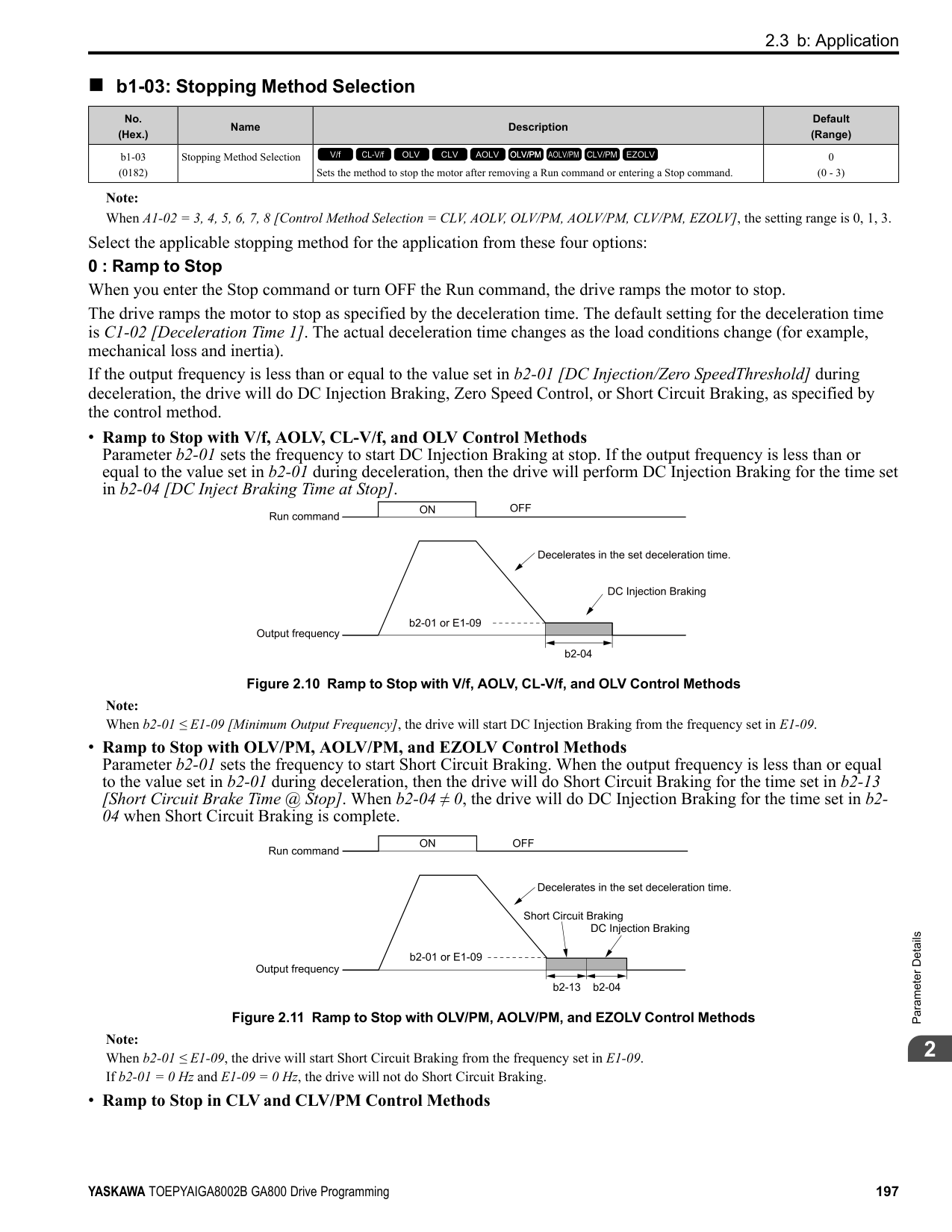
|---|---|---|---| |C4-05 (0219)|Torque Compensation Time|Sets the starting torque constant to use with C4-03 and C4-04 [Torque Compensation @ FWD/REV Start].
V/f CL-V/f OLV CLV AOLV OLV/PM AOLV/PM CLV/PM EZOLV
|10 ms (0 - 200 ms)|
|No. (Hex.)|Name|Description|Default (Range)| |---|---|---|---| |C4-06 (021A)|Motor 2 Torque Comp Delay Time|Sets the value if ov [Overvoltage] occurs with sudden changes in the load, at the end of acceleration, or at the start of deceleration.
V/f CL-V/f OLV CLV AOLV OLV/PM AOLV/PM CLV/PM EZOLV
|150 ms (0 - 10000 ms)|
|No. (Hex.)|Name|Description|Default (Range)| |---|---|---|---| |C4-07 (0341) RUN|Motor 2 Torque Compensation Gain|Sets the gain for motor 2 torque compensation function when using the Motor Switch function.
V/f CL-V/f OLV CLV AOLV OLV/PM AOLV/PM CLV/PM EZOLV
|1.00 (0.00 - 2.50)|
################# Note:
######## ■ C4-19: Torque Ripple Suppress Min Freq
|No. (Hex.)|Name|Description|Default (Range)| |---|---|---|---| |C4-19 (0B8D) Expert|Torque Ripple Suppress Min Freq|Adjust this if slow oscillation occurs at low speeds. Increase this parameter in 1.0 Hz increments when current ripples and torque ripples occur during low-speed operation. Set this parameter to 0.0 to disable the function if increasing the value does not fix the problem. Usually it is not necessary to change this setting.
V/f CL-V/f OLV CLV AOLV OLV/PM AOLV/PM CLV/PM EZOLV
|0.1 Hz (0.0 - 10.0 Hz)|
ParameterDetails
######## 2
Note: Set C4-20 [Voltage Compensation Adjust 1] ≠ 0 to enable this parameter.
Note:
■ C4-21: Voltage Compensation Adjust 2
Note:
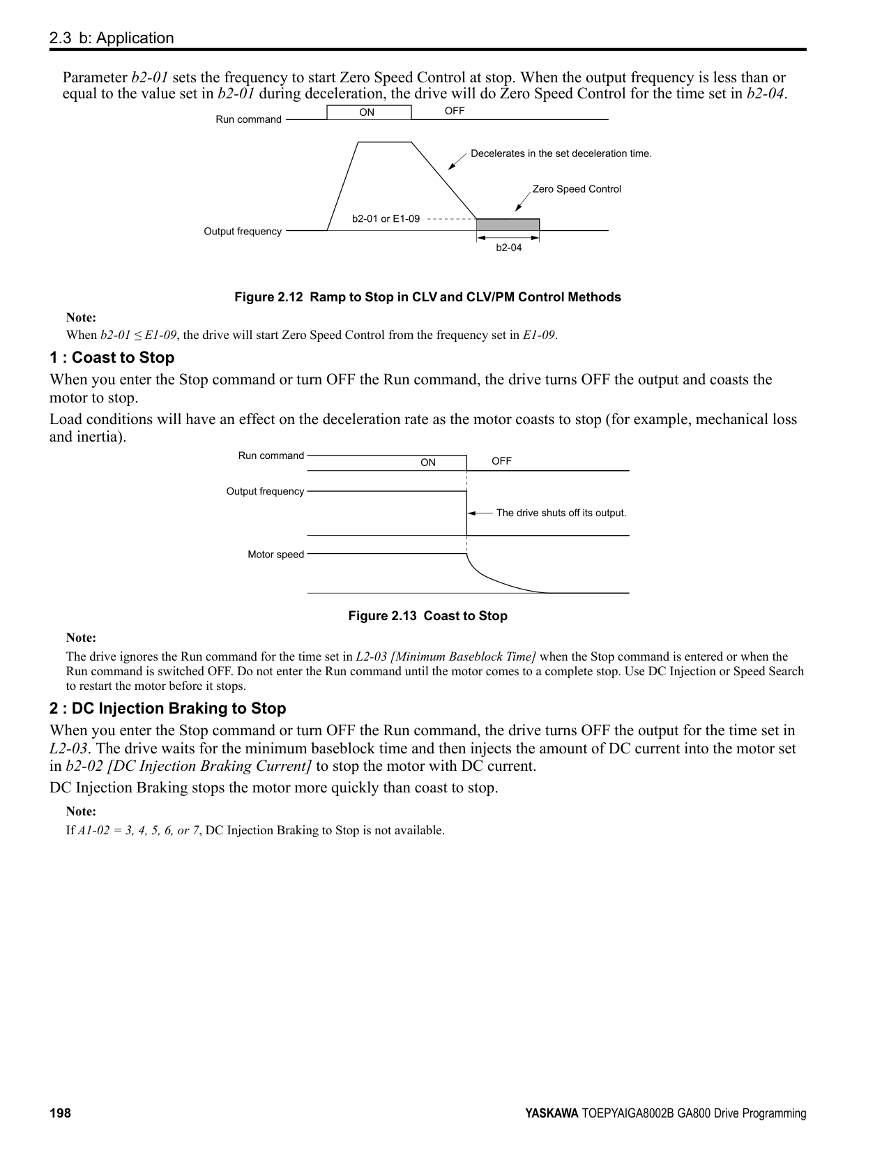
|No. (Hex.)|Name|Description|Default (Range)| |---|---|---|---| |C4-20 (0BCB) Expert|Voltage Compensation Adjust 1|Sets voltage precision compensation. Usually it is not necessary to change this setting.
V/f CL-V/f OLV CLV AOLV OLV/PM AOLV/PM CLV/PM EZOLV
|120 (0 - 200)|
|No. (Hex.)|Name|Description|Default (Range)| |---|---|---|---| |C4-21 (0BCC) Expert|Voltage Compensation Adjust 2|Sets voltage precision compensation. Usually it is not necessary to change this setting.
V/f CL-V/f OLV CLV AOLV OLV/PM AOLV/PM CLV/PM EZOLV
|5 (0 - 10)|
|No. (Hex.)|Name|Description|Default (Range)| |---|---|---|---| |C4-23 (1583) RUN Expert|Current Control Gain|Current control gain. Usually it is not necessary to change this parameter.
V/f CL-V/f OLV CLV AOLV OLV/PM AOLV/PM CLV/PM EZOLV
|1.00 (0.50 - 2.50)|
######## ◆ C5: Auto Speed Regulator (ASR)
The ASR adjusts the output frequency or torque reference to decrease the difference between frequency reference and motor speed. The control method sets the parameter that you must adjust.
|A1-02 [Control Method Selection]|Targets of Adjustment| |---|---| |1: Closed Loop V/f Control (CL-V/f)|Output Frequency| |• 3: Closed Loop Vector Control (CLV)
• 4: Advanced Open Loop Vector Control (AOLV)
• 6: PM Advanced Open Loop Vector Control (AOLV/PM)
• 7: PM Closed Loop Vector Control (CLV/PM)
• 8: EZ Vector Control (EZOLV)
|Torque Reference|
The speed control block diagrams of the respective control methods are shown in Figure 2.53 and Figure 2.54.
| | | |---|---| | | |
| | | |---|---| | | |
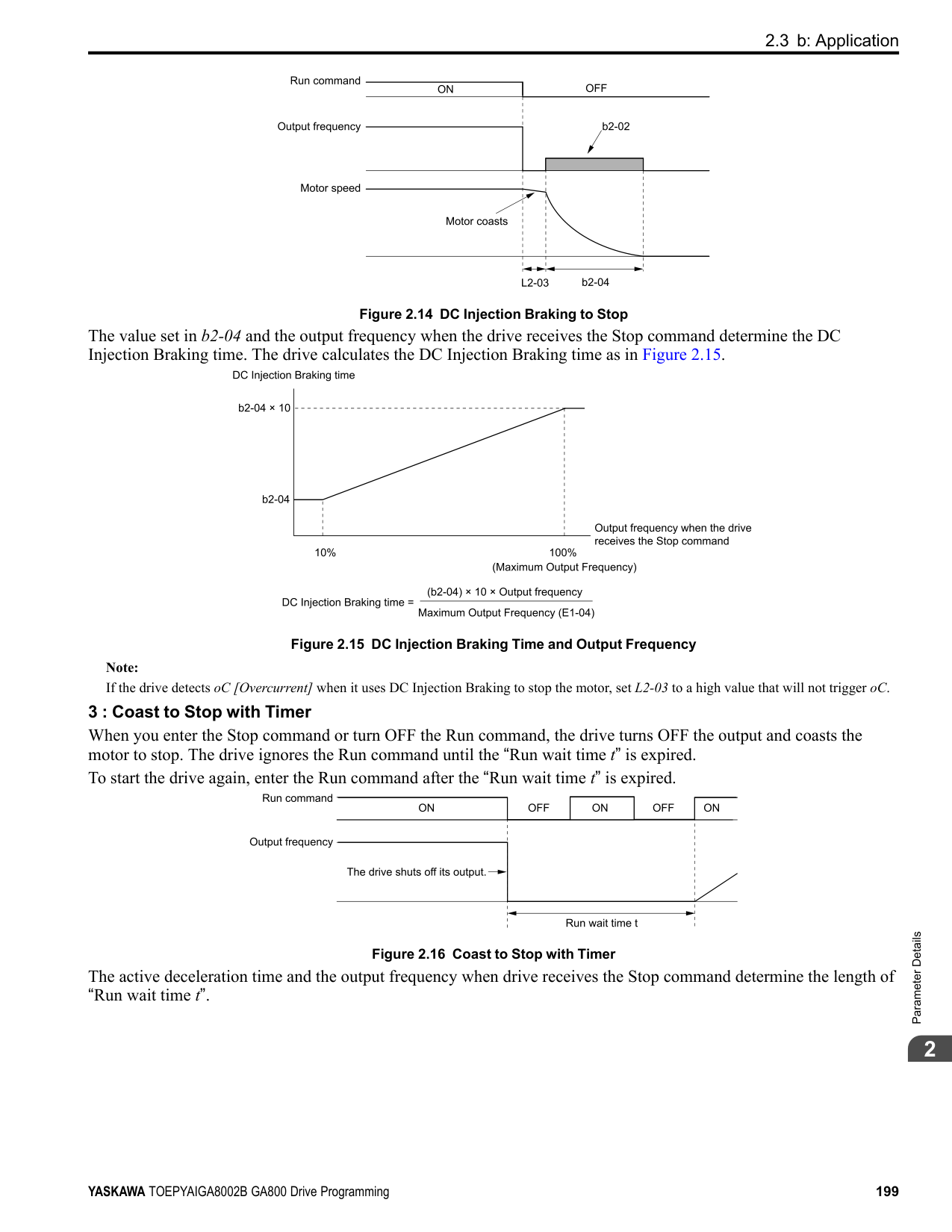
Figure 2.53 Speed Control Block Diagram for CL-V/f
| | | |---|---| | | |
################# Figure 2.54 Speed Control Block Diagrams for CLV, AOLV, CLV/PM, AOLV/PM, and EZOLV
Note: The detected speed is the speed estimation value when configured such that A1-02 = 4, 6, or 8 [Control Method Selection = AOLV, AOLV/ PM, or EZOLV].
######## ■ Before You Adjust ASR Parameters
######## ■ ASR Adjustment Procedure for CL-V/fDo this procedure to adjust ASR parameters:
Figure 2.55 ASR Gain and Integral Time Adjustment
Note:
######## ■ ASR Adjustment Procedure for CLV, AOLV, AOLV/PM, CLV/PM, and EZOLV Do this procedure to adjust ASR parameters:
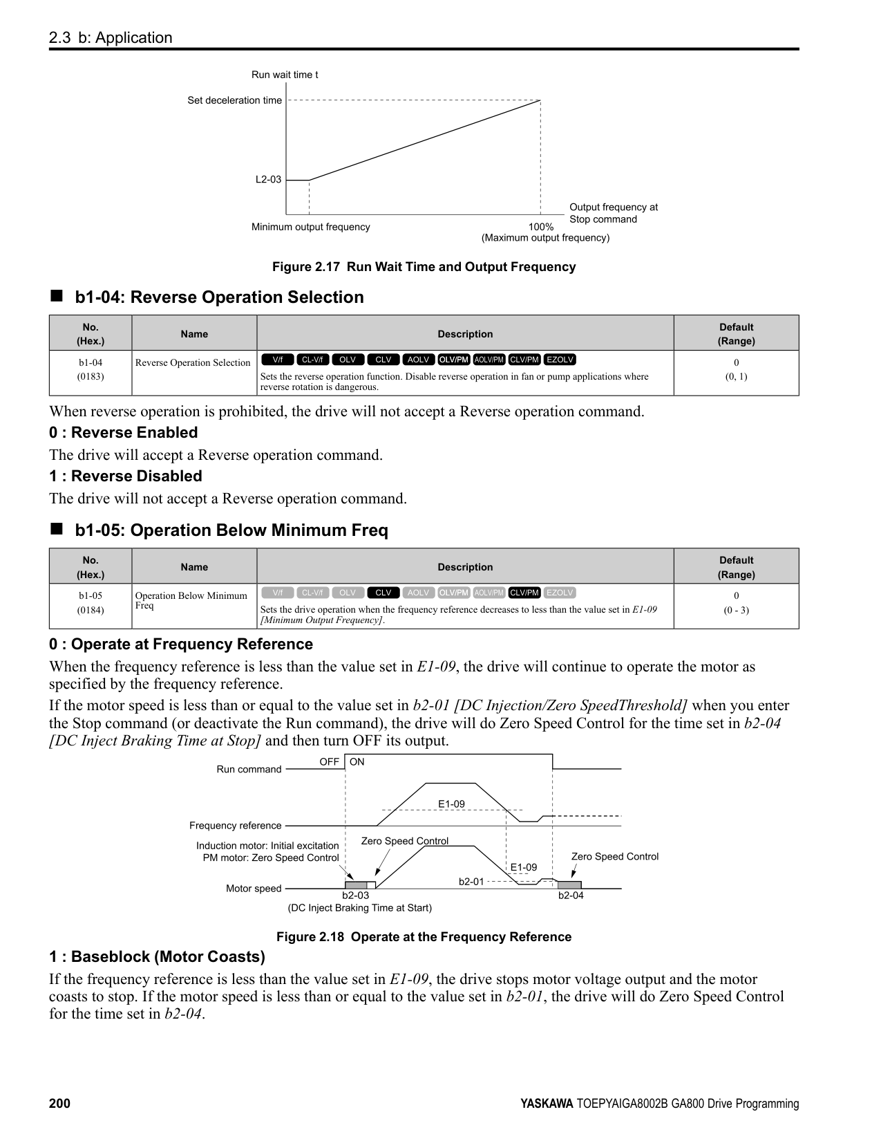
ParameterDetails
######## 2
Figure 2.56 Low-speed/High-speed Gain Settings
Note:
######## ■ Use MFDI Switch for Proportional Gain
Note: If A1-02 = 1 [Control Method Selection = V/f Control with Encoder], you cannot use this function.
You can use the input terminals set for ASR Gain (C5-03) Select [H1-xx = 77] to switch the proportional gains set with C5-01 and C5-03. When the configured input terminal is deactivated, the proportional gain set for C5-01 is selected. When the terminal is activated, the proportional gain set for C5-03 is selected. The proportional gain changes linearly over the time set in C5-02 [ASR Integral Time 1]. The signals from this MFDI are more important than C5-07 [ASR Gain Switchover Frequency].
Figure 2.57 Proportional Gain through Multi-function Digital Input Switch
■ Speed Waveform Monitoring Method To make small adjustments of ASR parameters, monitor the speed waveforms when you make the adjustments. Table
Table 2.32 Example Settings of MFAO Terminals to Monitor Speed Waveforms
|No.|Name|Setting Value|Description| |---|---|---|---| |H4-01|Terminal FM Analog Output Select|116|Lets you use terminal FM to monitor U1-16 [SFS Output Frequency].|
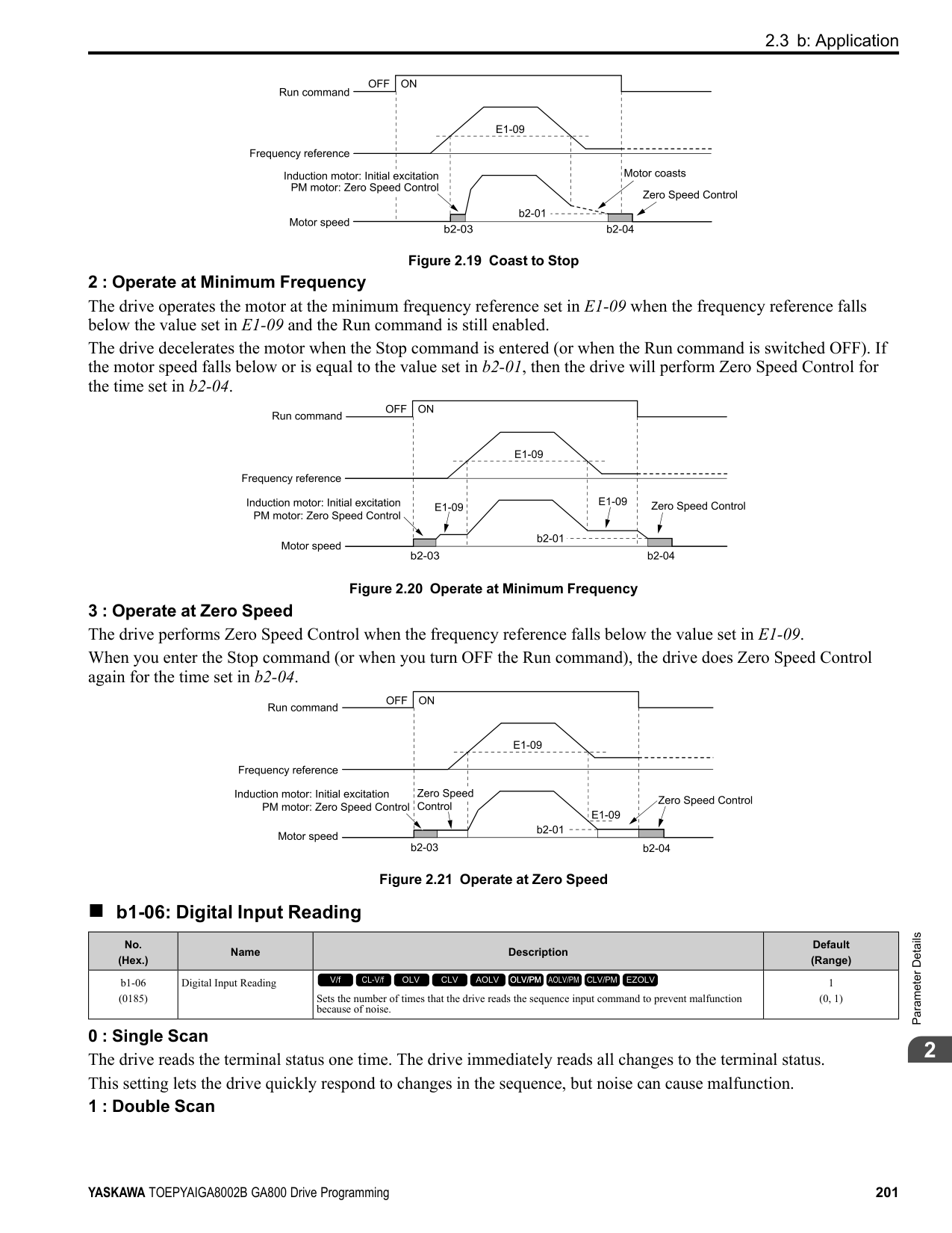
|H4-02|Terminal FM Analog Output Gain|100.0%|Lets you use terminal FM to monitor U1-16 [SFS Output Frequency].| |H4-03|Terminal FM Analog Output Bias|0.0%|Lets you use terminal FM to monitor U1-16 [SFS Output Frequency].| |H4-04|Terminal AM Analog Output Select|105|Lets you use the terminal AM to monitor U1-05 [Motor Speed].| |H4-05|Terminal AM Analog Output Gain|50.0%|Lets you use the terminal AM to monitor U1-05 [Motor Speed].| |H4-06|Terminal AM Analog Output Bias|0.0%|Lets you use the terminal AM to monitor U1-05 [Motor Speed].| |H4-07|Terminal FM Signal Level Select|1|Lets you monitor in a -10 to +10 V range.| |H4-08|Terminal AM Signal Level Select|1|Lets you monitor in a -10 to +10 V range.|
These settings cause this MFAO configuration. The MFAO common is terminal AC:
######## ■ Adjust ASR Parameters
Use Table 2.33 to adjust ASR. The table shows the parameters for motor 1. To operate motor 2, set the motor 2 parameters in the same method.
Note: When adjusting the proportional gain and integral time, adjust the proportional gain first.
################# Table 2.33 ASR Response and Possible Solutions
|Problem|Problem|Possible Solutions| |---|---|---| |Speed response is slow.| |• Increase C5-01/C5-03 [ASR Proportional Gain].
• Decrease C5-02/C5-04 [ASR Integral Time].
| |Overshoot or undershoot occurs at the end of acceleration or deceleration.| |• Decrease C5-01/C5-03.
• Increase C5-02/C5-04.
| |Vibration and oscillation occur at constant speed.| |• Decrease C5-01/C5-03.
• Increase C5-02/C5-04.
• Increase C5-06 [ASR Delay Time].
| |Speed accuracy is unsatisfactory when you operate a motor that has a large quantity of rated slip in Closed Loop V/f Control.| |• Check the pulse number set to F1-01 [Encoder 1 Pulse Count (PPR)] and the gear ratio set to F1-12 [Encoder 1 Gear Teeth 1] and F1-13 [Encoder 1 Gear Teeth 2].
• Make sure that you correctly set the pulse signal from the encoder.
• Check U6-04 [ASR Output] to make sure that the ASR operates at its output limit set to C5-05 [ASR Limit]. If the ASR is at the output limit, increase C5-05.
|
ParameterDetails
######## 2
|Problem|Problem|Possible Solutions| |---|---|---| |If C5-12 1 or C5-32 1 [Enabled] in Closed Loop V/f Control, over/undershoot occurs when you change speeds.|-|• Decrease C5-01/C5-03.
• Increase C5-02/C5-04.
• Decrease the value set to C5-05.
| |Oscillation at low speed and response is too slow at high speed.
Oscillation at high speed and response is too slow at low speed.|-|• Closed Loop V/f Control Mode: Use C5-03 and C5-04 at maximum speed and C5-01 and C5-02 at minimum speed to set different ASR settings.
• Closed Loop Vector Control, PM Advanced Open Loop Vector Control, and PM Closed Loop Vector Control: Use C5-01 to C5-04 to set the best ASR settings for high and low speed. Use C5-07 [ASR Gain Switchover Frequency] to switch the ASR proportional gain and ASR integral time as specified by the output frequency.
|
######## ■ C5-01: ASR Proportional Gain 1
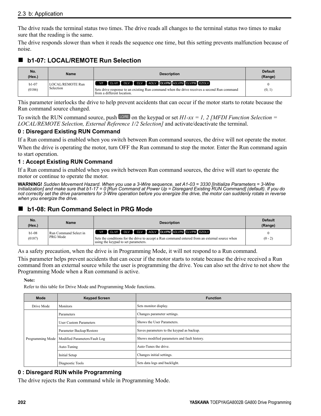
|No. (Hex.)|Name|Description|Default (Range)| |---|---|---|---| |C5-01 (021B) RUN|ASR Proportional Gain 1|Sets the gain to adjust ASR response.
V/f CL-V/f OLV CLV AOLV OLV/PM AOLV/PM CLV/PM EZOLV
|Determined by A1-02 (0.00 - 300.00)|
A higher gain provides a higher speed response. Usually, the gain increases with larger loads. Too much gain will cause vibration.
Note:
######## ■ C5-02: ASR Integral Time 1
|No. (Hex.)|Name|Description|Default (Range)| |---|---|---|---| |C5-02 (021C) RUN|ASR Integral Time 1|Sets the ASR integral time.
V/f CL-V/f OLV CLV AOLV OLV/PM AOLV/PM CLV/PM EZOLV
|Determined by A1-02 (0.000 - 60.000 s)|
When you increase the integral time, the responsiveness will decrease. An integral time that is too short can cause oscillation.
######## ■ C5-03: ASR Proportional Gain 2
|No. (Hex.)|Name|Description|Default (Range)| |---|---|---|---| |C5-03 (021D) RUN|ASR Proportional Gain 2|Sets the gain to adjust ASR response.
V/f CL-V/f OLV CLV AOLV OLV/PM AOLV/PM CLV/PM EZOLV
|Determined by A1-02 (0.00 - 300.00)|
A higher gain provides a higher speed response. Usually, the gain increases with larger loads. Too much gain will cause vibration.
######## ■ C5-04: ASR Integral Time 2
|No. (Hex.)|Name|Description|Default (Range)| |---|---|---|---| |C5-04 (021E) RUN|ASR Integral Time 2|Sets the ASR integral time.
V/f CL-V/f OLV CLV AOLV OLV/PM AOLV/PM CLV/PM EZOLV
|Determined by A1-02 (0.000 - 60.000 s)|
When you increase the integral time, the responsiveness will decrease. An integral time that is too short can cause oscillation.
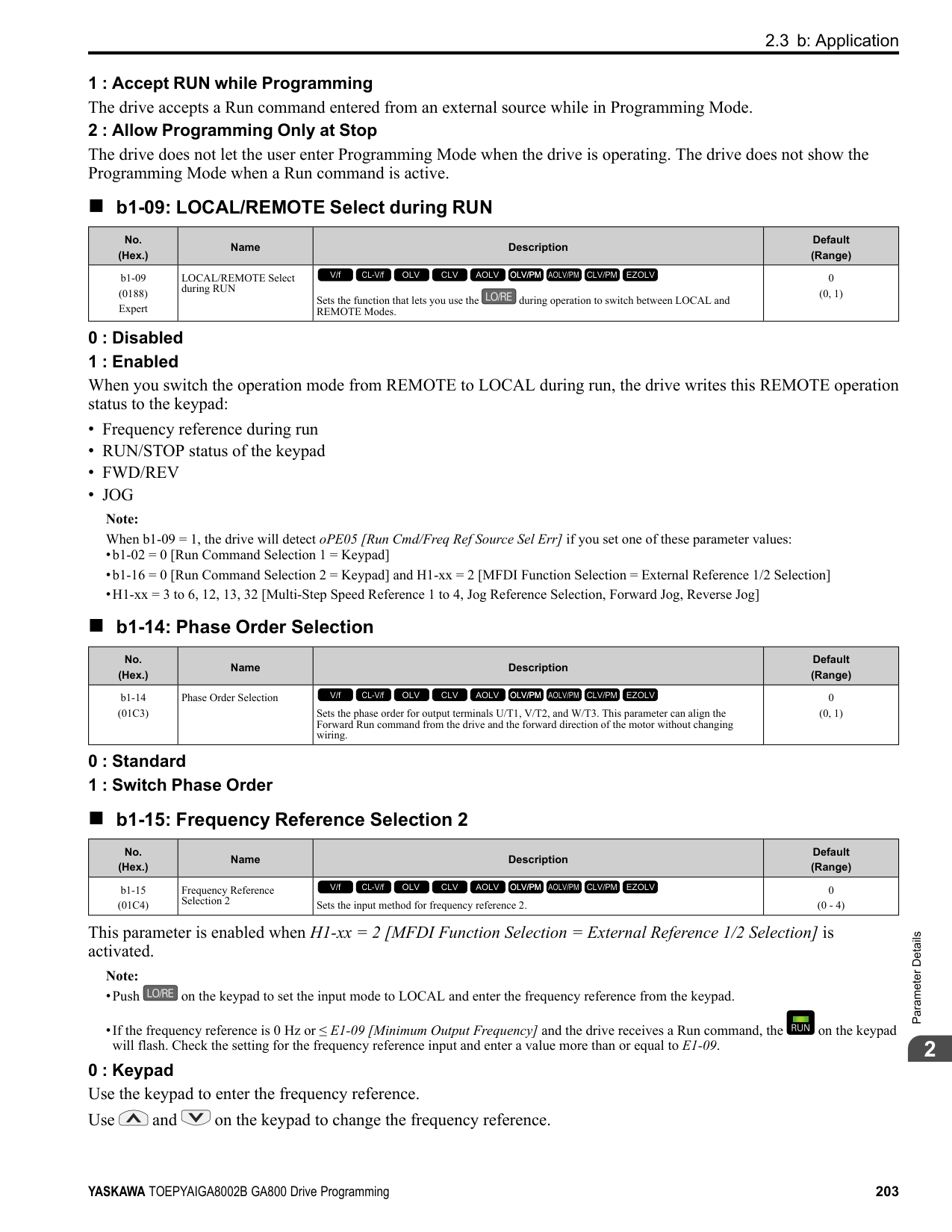
If the motor rated slip is high, it is necessary to increase the setting for correct motor speed control. Use U6-04 [ASR Output] to make sure that ASR is operating at the limit set in this parameter. When ASR is operating at the limit, correctly set the PG signal and these parameters before you make changes to C5-05.
If you have a load with low rigidity or if oscillation is a problem, decrease C5-01 in 2-unit decrements or decrease C5-06 in 0.001-unit decrements.
Switching the proportional gain and integral time in the low or high speed range can help operation become stable. A good switching point is 80% of the frequency where oscillation occurs or at 80% of the maximum output frequency.
Note: An MFDI set for H1-xx 77 [MFDI Function Selection ASR Gain (C5-03) Select] will have priority over the ASR gain switching frequency.
|No. (Hex.)|Name|Description|Default (Range)| |---|---|---|---| |C5-05 (021F)|ASR Limit|Set the ASR output limit as a percentage of E1-04 [Maximum Output Frequency].
V/f CL-V/f OLV CLV AOLV OLV/PM AOLV/PM CLV/PM EZOLV
|5.0% (0.0 - 20.0%)|
|No. (Hex.)|Name|Description|Default (Range)| |---|---|---|---| |C5-06 (0220)|ASR Delay Time|Sets the filter time constant of the torque reference output from the speed loop. Usually it is not necessary to change this setting.
V/f CL-V/f OLV CLV AOLV OLV/PM AOLV/PM CLV/PM EZOLV
|Determined by A1-02 (0.000 - 0.500 s)|
|No. (Hex.)|Name|Description|Default (Range)| |---|---|---|---| |C5-07 (0221)|ASR Gain Switchover Frequency|Sets the frequency where the drive will switch between these parameters:
C5-01 and C5-03 [ASR Proportional Gain 1/2]
C5-02 and C5-04 [ASR Integral Time 1/2]
V/f CL-V/f OLV CLV AOLV OLV/PM AOLV/PM CLV/PM EZOLV
|Determined by A1-02 (Determined by A1-02)|
|No. (Hex.)|Name|Description|Default (Range)| |---|---|---|---| |C5-08 (0222)|ASR Integral Limit|Set the upper limit of the ASR integral amount as a percentage of the rated load.
V/f CL-V/f OLV CLV AOLV OLV/PM AOLV/PM CLV/PM EZOLV
|400% (0 - 400%)|
|No. (Hex.)|Name|Description|Default (Range)|
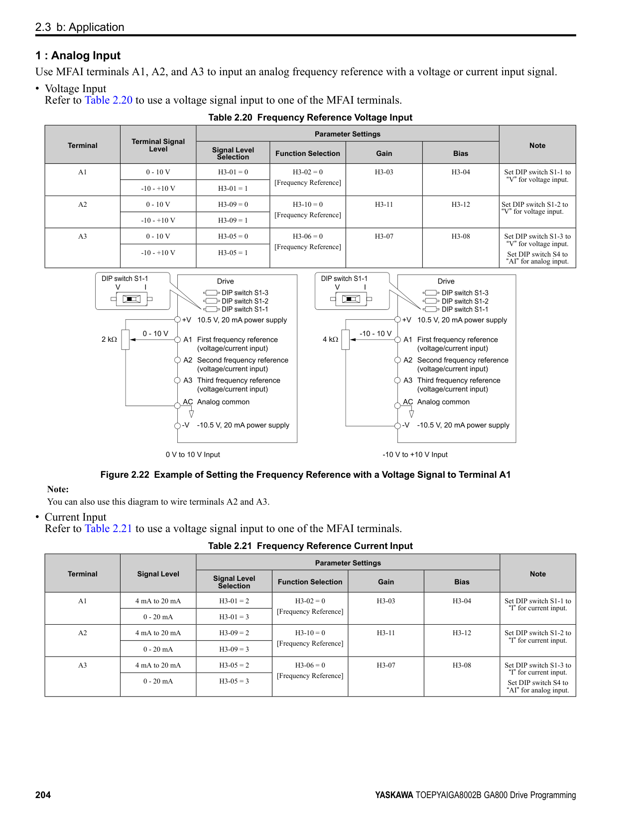
|---|---|---|---| |C5-12 (0386)|Integral Operation @ Accel/ Decel|Sets ASR integral operation during acceleration and deceleration.
V/f CL-V/f OLV CLV AOLV OLV/PM AOLV/PM CLV/PM EZOLV
|0 (0, 1)|
When it is necessary for the motor speed to be as near the frequency reference as possible during acceleration or deceleration, set this parameter to 1.
Note:
If you enable integral control, overshoot or undershoot can occur when acceleration or deceleration complete. If there are problems with overshooting and undershooting, set this parameter to 0.
############## 0 : Disabled
ParameterDetails
######## 2
Integral operation is always enabled during constant speed. The drive will not enable integral operation during acceleration or deceleration.
######## ■ C5-17: Motor Inertia
|No. (Hex.)|Name|Description|Default (Range)| |---|---|---|---| |C5-17 (0276) Expert|Motor Inertia|Sets the motor inertia.
V/f CL-V/f OLV CLV AOLV OLV/PM AOLV/PM CLV/PM EZOLV
|Determined by o2-04, C601, and E5-01
(0.0001 - 600.00 kgm2)|
Note: The default settings and the display units for setting ranges are different for different drive models.
■ C5-18: Load Inertia Ratio
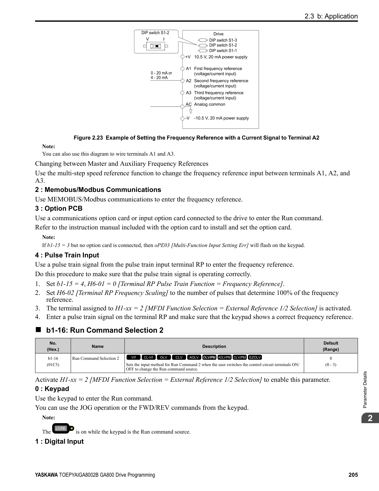
|No. (Hex.)|Name|Description|Default (Range)| |---|---|---|---| |C5-18 (0277) Expert|Load Inertia Ratio|Sets the load inertia ratio for the motor inertia.
V/f CL-V/f OLV CLV AOLV OLV/PM AOLV/PM CLV/PM EZOLV
|1.0 (0.0 - 6000.0)|
######## ■ C5-21: Motor 2 ASR Proportional Gain 1
|No. (Hex.)|Name|Description|Default (Range)| |---|---|---|---| |C5-21 (0356) RUN|Motor 2 ASR Proportional Gain 1|Sets the gain to adjust ASR response for motor 2.
V/f CL-V/f OLV CLV AOLV OLV/PM AOLV/PM CLV/PM EZOLV
|Determined by E3-01 (0.00 - 300.00)|
A higher gain provides a higher speed response. Usually, the gain increases with larger loads. Too much gain will cause vibration.
Note:
######## ■ C5-22: Motor 2 ASR Integral Time 1
|No. (Hex.)|Name|Description|Default (Range)| |---|---|---|---| |C5-22 (0357) RUN|Motor 2 ASR Integral Time 1|Sets the ASR integral time for motor 2.
V/f CL-V/f OLV CLV AOLV OLV/PM AOLV/PM CLV/PM EZOLV
|Determined by E3-01 (0.000 - 60.000 s)|
When you increase the integral time, the responsiveness will decrease. An integral time that is too short can cause oscillation.
Note: The drive usually sets Motor 2 ASR with C5-21 [Motor 2 ASR Proportional Gain 1] and C5-22. You can also use C5-24 [Motor 2 ASR Integral Time 2] instead of C5-22 when the speed is less than or equal to the frequency set in C5-27 [Motor 2 ASR Gain Switchover Freq].
######## ■ C5-23: Motor 2 ASR Proportional Gain 2
|No. (Hex.)|Name|Description|Default (Range)| |---|---|---|---| |C5-23 (0358) RUN|Motor 2 ASR Proportional Gain 2|Sets the gain to adjust ASR response for motor 2.
V/f CL-V/f OLV CLV AOLV OLV/PM AOLV/PM CLV/PM EZOLV
|Determined by E3-01 (0.00 - 300.00)|
A higher gain provides a higher speed response. Usually, the gain increases with larger loads. Too much gain causes vibration.
######## ■ C5-24: Motor 2 ASR Integral Time 2
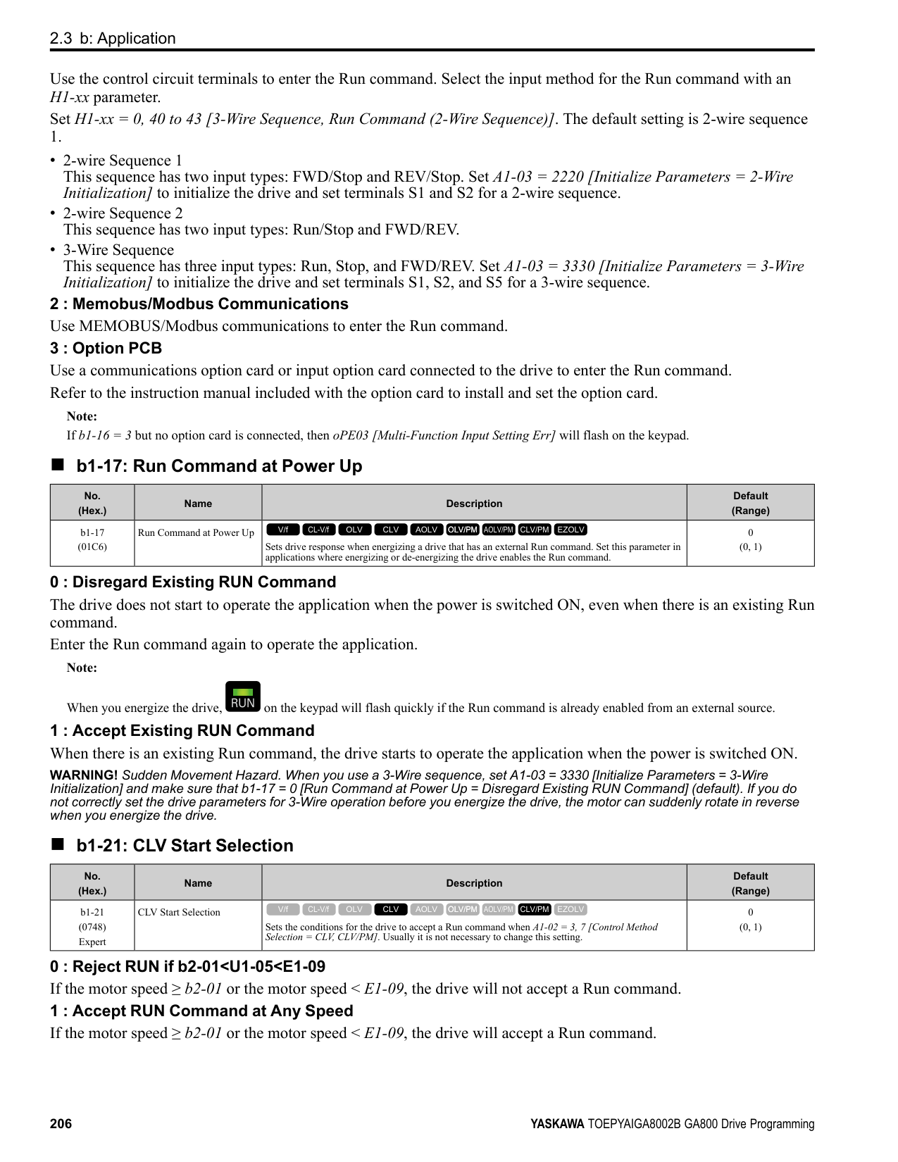
|No. (Hex.)|Name|Description|Default (Range)| |---|---|---|---| |C5-24 (0359) RUN|Motor 2 ASR Integral Time 2|Sets the ASR integral time for motor 2.
V/f CL-V/f OLV CLV AOLV OLV/PM AOLV/PM CLV/PM EZOLV
|Determined by E3-01 (0.000 - 60.000 s)|
When you increase the integral time, the responsiveness will decrease. An integral time that is too short can cause oscillation.
Note:
The drive usually sets Motor 2 ASR with C5-21 [Motor 2 ASR Proportional Gain 1] and C5-22 [Motor 2 ASR Integral Time 1]. You can also use C5-24 [Motor 2 ASR Integral Time 2] instead of C5-22 when the speed is less than or equal to the frequency set in C5-27 [Motor 2 ASR Gain Switchover Freq].
######## ■ C5-25: Motor 2 ASR Limit
|No. (Hex.)|Name|Description|Default (Range)| |---|---|---|---| |C5-25 (035A)|Motor 2 ASR Limit|Set the motor 2 ASR output limit as a percentage of E1-04 [Maximum Output Frequency].
V/f CL-V/f OLV CLV AOLV OLV/PM AOLV/PM CLV/PM EZOLV
|5.0% (0.0 - 20.0%)|
If the motor rated slip is high, it is necessary to increase the setting for correct motor speed control. Use U6-04 [ASR Output] to make sure that ASR is operating at the limit set in this parameter. When ASR is operating at the limit, correctly set the PG signal and these parameters before you make changes to C5-25.
######## ■ C5-26: Motor 2 ASR Delay Time
|No. (Hex.)|Name|Description|Default (Range)| |---|---|---|---| |C5-26 (035B)|Motor 2 ASR Delay Time|Sets the motor 2 filter time constant of the torque reference output from the speed loop. Usually it is not necessary to change this setting.
V/f CL-V/f OLV CLV AOLV OLV/PM AOLV/PM CLV/PM EZOLV
|Determined by E3-01 (0.000 - 0.500 s)|
If you have a load with low rigidity or if oscillation is a problem, decrease C5-21 in 2-unit decrements or decrease C5-26 in 0.001-unit decrements.
######## ■ C5-27: Motor 2 ASR Gain Switchover Freq
|No. (Hex.)|Name|Description|Default (Range)| |---|---|---|---| |C5-27 (035C)|Motor 2 ASR Gain Switchover Freq|Sets the frequency where the drive will switch between these parameters:
C5-21 and C5-23 [Motor 2 ASR Proportional Gain 1/2]
C5-22 and C5-24 [Motor 2 ASR Integral Time 1/2]
V/f CL-V/f OLV CLV AOLV OLV/PM AOLV/PM CLV/PM EZOLV
|0.0 (0.0 - 400.0)|
Switching the proportional gain and integral time in the low or high speed range can help operation become stable. A good switching point is 80% of the frequency where oscillation occurs or at 80% of the maximum output frequency.
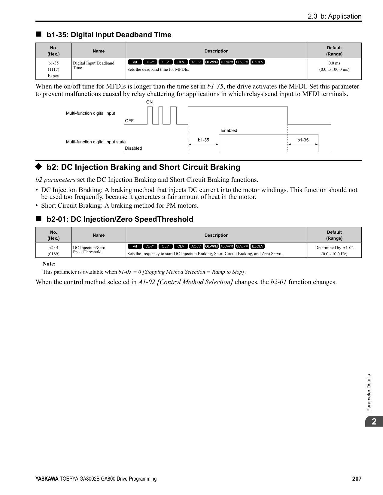
ParameterDetails
######## 2
################# Note:
An MFDI set for H1-xx = 77 [MFDI Function Selection = ASR Gain (C5-03) Select] will have priority over the ASR gain switching frequency.
|No. (Hex.)|Name|Description|Default (Range)| |---|---|---|---| |C5-28 (035D)|Motor 2 ASR Integral Limit|Set the upper limit of the motor 2 ASR integral amount as a percentage of the rated load.
V/f CL-V/f OLV CLV AOLV OLV/PM AOLV/PM CLV/PM EZOLV
|400% (0 - 400%)|
|No. (Hex.)|Name|Description|Default (Range)| |---|---|---|---| |C5-29 (0B18) Expert|Speed Control Response|Sets the level of speed control responsiveness. Usually it is not necessary to change this setting.
V/f CL-V/f OLV CLV AOLV OLV/PM AOLV/PM CLV/PM EZOLV
|0 (0, 1)|
If a high level of speed control responsiveness is necessary, set C5-29 = 1,then adjust the speed control (ASR) parameter.
0 : Standard 1 : High Performance 1
######## ■ C5-32: Motor 2 Integral Oper at Acc/Dec
|No. (Hex.)|Name|Description|Default (Range)| |---|---|---|---| |C5-32 (0361)|Motor 2 Integral Oper at Acc/Dec|Sets ASR integral operation during acceleration and deceleration for motor 2.
V/f CL-V/f OLV CLV AOLV OLV/PM AOLV/PM CLV/PM EZOLV
|0 (0, 1)|
When it is necessary for the motor speed to be as near the frequency reference as possible during acceleration or deceleration, set this parameter to 1.
Note: If you enable integral control, overshoot or undershoot can occur when acceleration or deceleration complete. If there are problems with overshooting and undershooting, set this parameter to 0.
Integral operation is not enabled during acceleration or deceleration. Integral operation is always enabled during constant speed.
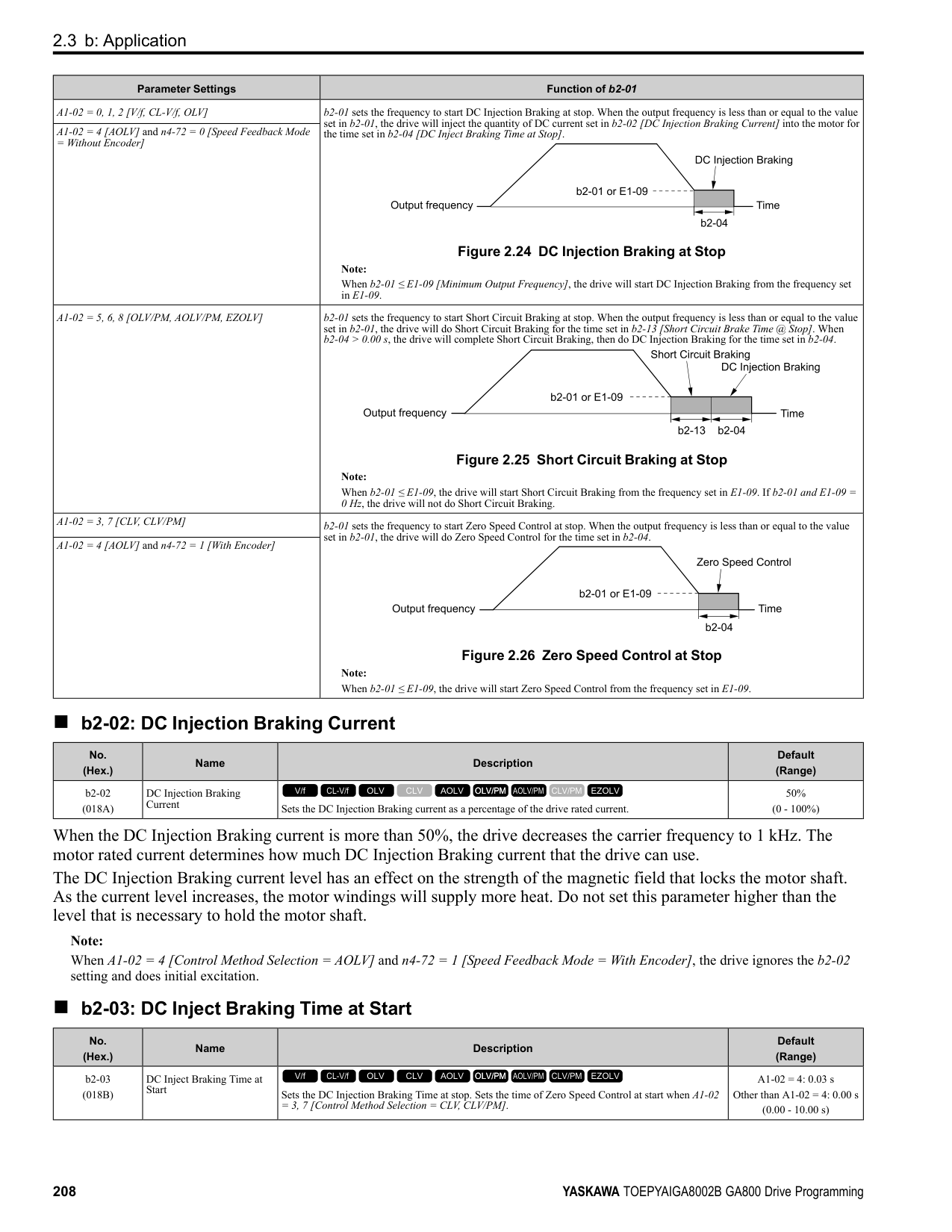
######## ■ C5-37: Motor 2 Inertia
|No. (Hex.)|Name|Description|Default (Range)| |---|---|---|---| |C5-37 (0278) Expert|Motor 2 Inertia|Sets the motor inertia for motor 2.
V/f CL-V/f OLV CLV AOLV OLV/PM AOLV/PM CLV/PM EZOLV
|Determined by o2-04, C6-01 (0.0001 - 600.00 kgm2)|
Note: The default settings and the display units for setting ranges are different for different drive models.
The drive automatically sets C5-37 to the value of [Motor Inertia] when you do Inertia Tuning or ASR Tuning.
######## ■ C5-38: Motor 2 Load Inertia Ratio
|No. (Hex.)|Name|Description|Default (Range)| |---|---|---|---| |C5-38 (0279) Expert|Motor 2 Load Inertia Ratio|Sets the load inertia ratio for the motor 2 inertia.
V/f CL-V/f OLV CLV AOLV OLV/PM AOLV/PM CLV/PM EZOLV
|1.0 (0.0 - 6000.0)|
The drive automatically sets C5-38 to the value of [Load Inertia Ratio] when you do Inertia Tuning or ASR Tuning.
######## ■ C5-39: ASR Primary Delay Time Const 2
|No. (Hex.)|Name|Description|Default (Range)| |---|---|---|---| |C5-39 (030D)|ASR Primary Delay Time Const 2|Sets the filter time constant used when the torque reference is output from ASR. Usually it is not necessary to change this parameter.
V/f CL-V/f OLV CLV AOLV OLV/PM AOLV/PM CLV/PM EZOLV
|0.000 s (0.000 - 0.500 s)|
If you have a load with low rigidity or if oscillation is a problem, increase this setting in 0.01 unit increments.
######## ■ C5-50: Notch Filter Frequency
|No. (Hex.)|Name|Description|Default (Range)| |---|---|---|---| |C5-50 (0B14) Expert|Notch Filter Frequency|Sets the machine resonance frequency.
V/f CL-V/f OLV CLV AOLV OLV/PM AOLV/PM CLV/PM EZOLV
|0 Hz (0, or 2 to 100 Hz)|
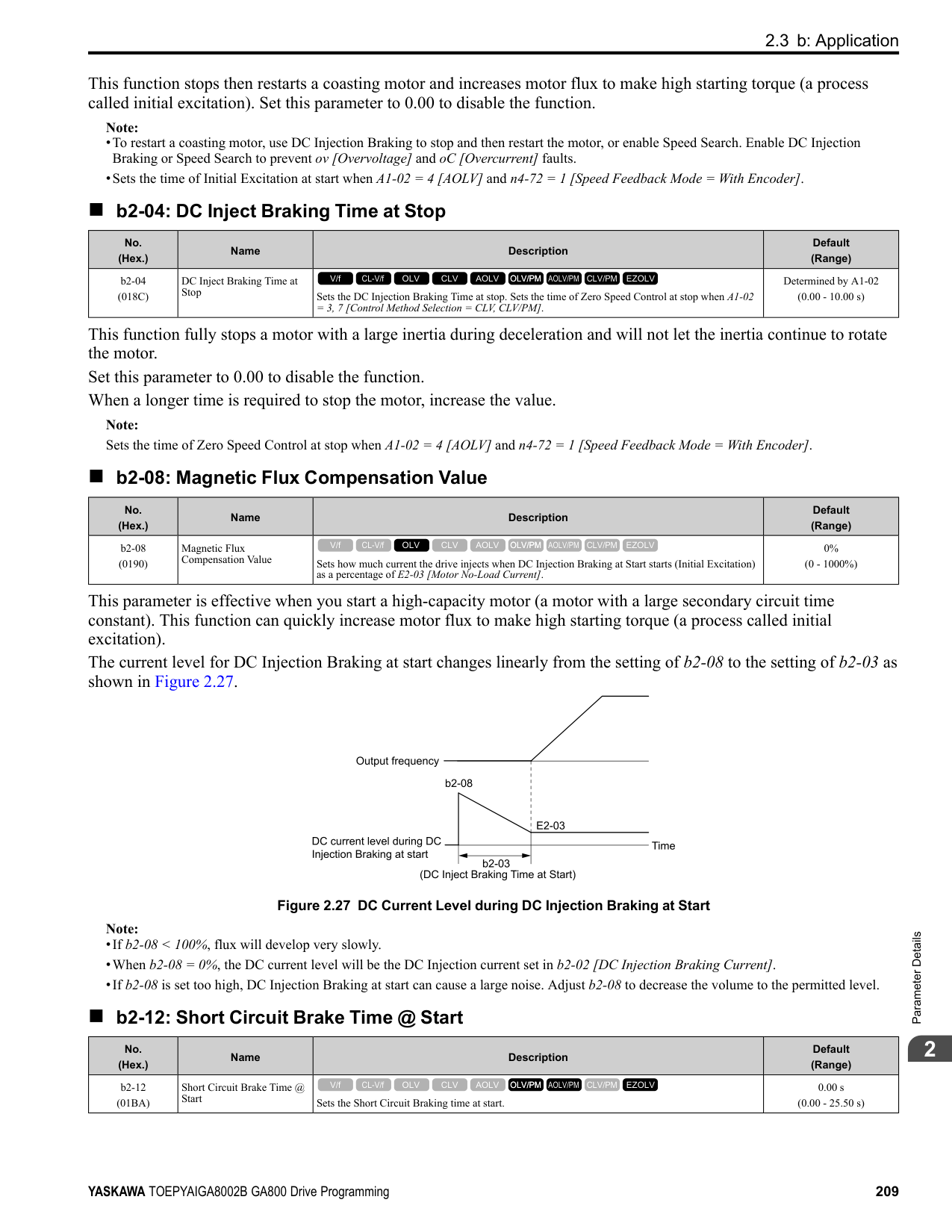
Machine resonance can cause high-frequency noise and vibration during operation. A notch filter can help prevent the noise and vibration. Notch filters set the resonant frequency of the machine to remove specific vibrational frequency components caused by machine resonance.
Note:
######## ■ C5-51: Notch Filter Bandwidth
|No. (Hex.)|Name|Description|Default (Range)| |---|---|---|---| |C5-51 (0B15) Expert|Notch Filter Bandwidth|Sets the notch width of the notch filter.
V/f CL-V/f OLV CLV AOLV OLV/PM AOLV/PM CLV/PM EZOLV
|1.0 (0.5 - 5.0)|
Note: Set C5-50 = 0 [Notch Filter Frequency = 0 Hz] to disable the notch filter.
◆ C6: Duty & Carrier Frequency C6 parameters are used to set the selection of drive duty rating, selection of carrier frequency, and upper and lower limits of carrier frequencies.
######## ■ C6-01: Normal / Heavy Duty Selection
|No. (Hex.)|Name|Description|Default (Range)| |---|---|---|---| |C6-01 (0223)|Normal / Heavy Duty Selection|Sets the drive duty rating.
V/f CL-V/f OLV CLV AOLV OLV/PM AOLV/PM CLV/PM EZOLV
|1 (0, 1)|
ParameterDetails
######## 2
The overload tolerance is 110% of the rated output current for 60 seconds. There are two types of load ratings for this product depending on the load characteristics of the application: Heavy Duty Rating (HD) and Normal Duty Rating (ND). The drive rated output current, overload tolerance, and acceleration stall prevention level change when the duty rating changes. Set the drive to agree with the duty rating of the selected drive capacity. In HD, the tolerance is 150% overload for 60 seconds. In ND, the tolerance is 110% overload for 60 seconds. The rated output current for ND drives is higher than the rated output current for HD drives. Refer to “Model Specifications (200 V Class)” and “Model Specifications (400 V Class)” for more information about rated output current.
Table 2.34 Differences between Heavy Duty Rating and Normal Duty Rating
|Item|Heavy Duty Rating (HD)|Normal Duty Rating (ND)| |---|---|---| |C6-01 Setting|0|1|
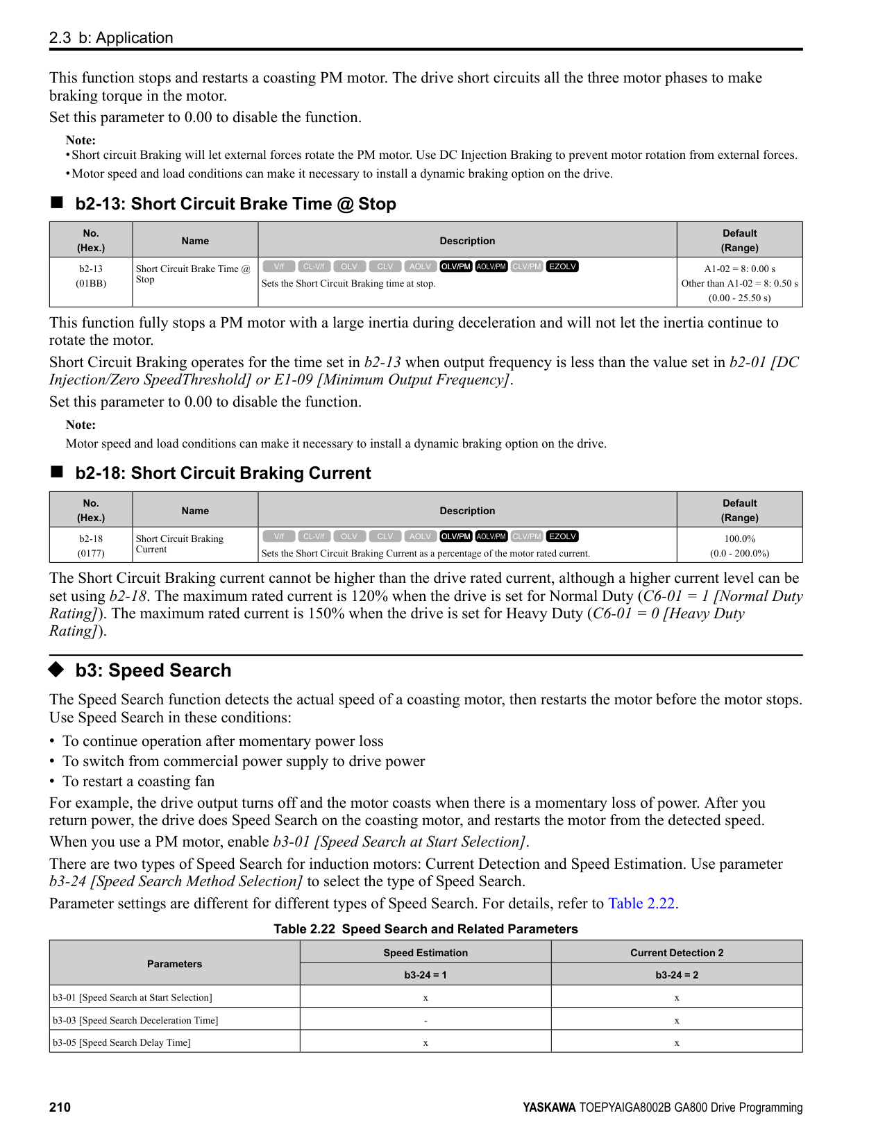
|Load Characteristics| | | |Application|A high overload tolerance is necessary during start up, acceleration, deceleration, and equivalent conditions.
• Extruder
• Conveyor
• Constant torque or high overload capacity are necessary.
|Overload tolerance is not necessary.
• Fan
• Pump
• Blower
| |Overload Tolerance|150% - 60 seconds|110% - 60 seconds| |Stall Prevent Level during Accel|150%|110%| |Stall Prevent Level during Run|150%|110%| |Carrier Frequency|2 kHz|2 kHz Swing-PWM|
Note:
######## ■ C6-02: Carrier Frequency Selection
|No. (Hex.)|Name|Description|Default (Range)| |---|---|---|---| |C6-02 (0224)|Carrier Frequency Selection|Sets the carrier frequency for the transistors in the drive.
V/f CL-V/f OLV CLV AOLV OLV/PM AOLV/PM CLV/PM EZOLV
|Determined by A1-02, C601, and o2-04
(Determined by A1-02)|
Changes to the switching frequency will decrease audible noise and decrease leakage current. Note: Increasing the carrier frequency to more than the default setting will automatically decrease the drive current rating.
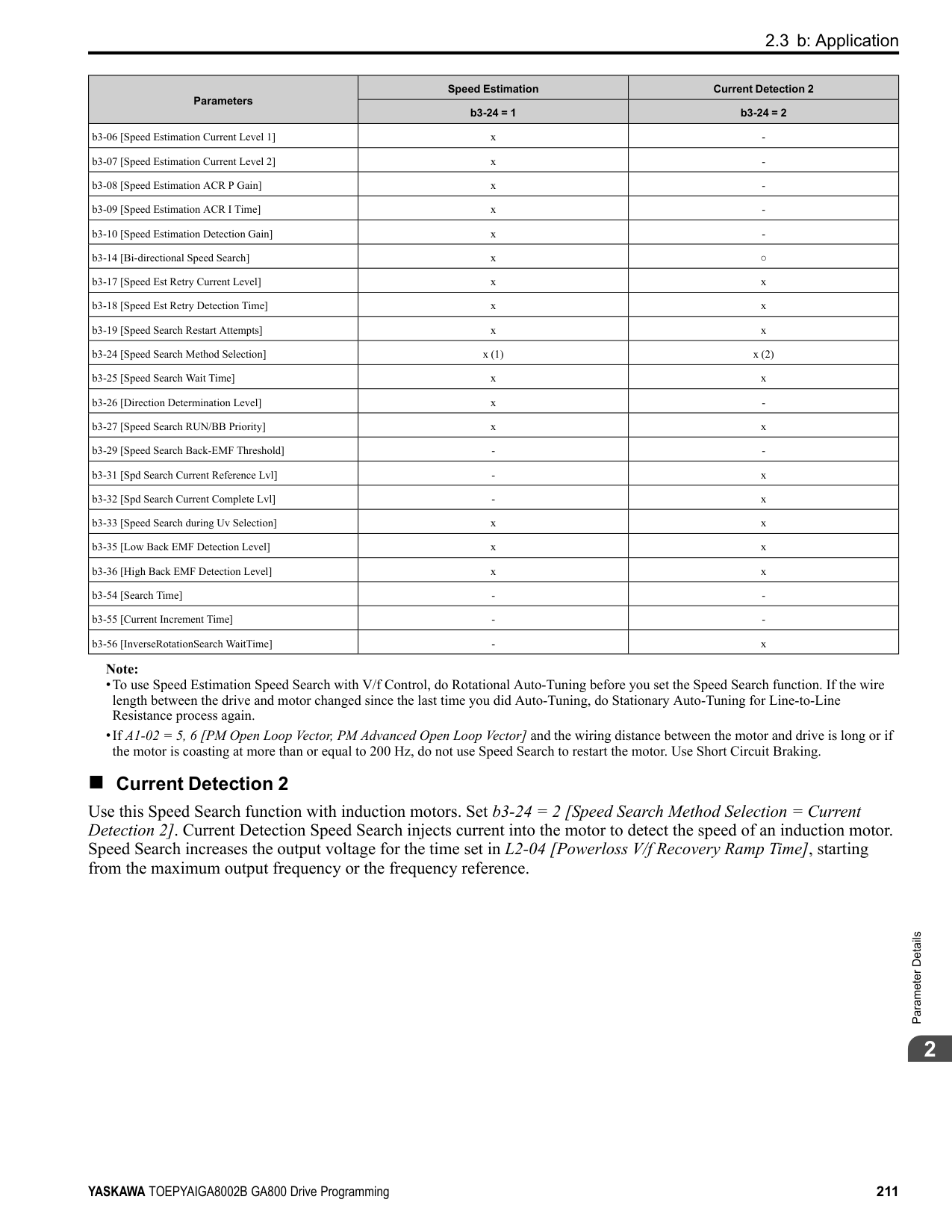
################# Note:
|Symptom|Remedy| |---|---| |Speed and torque are not stable at low speed.|Decrease the carrier frequency.| |Speed and torque are not stable at low speed.|Decrease the carrier frequency.| |Too much leakage current from the drive.|Decrease the carrier frequency.| |Wiring between the drive and motor is too long.|Decrease the carrier frequency.
Note:
If the motor cable is too long, it can be necessary to decrease the carrier frequency. Refer to Table 2.36 for the wiring distance and decrease the carrier frequency.| |Audible motor noise is too loud.|Increase the carrier frequency. Use Swing PWM.
Note:
The default carrier frequency in ND is Swing PWM 1 (C6-02 = 7), with a 2 kHz base. You can increase the carrier frequency in Normal Duty mode, but this will also decrease the drive rated current.|
################# Table 2.36 Wiring Distance
|Wiring Distance|Up to 50 m|Up to 100 m|Greater than 100 m| |---|---|---|---| |C6-02 [Carrier Frequency Selection]|1 to F (up to 15 kHz)|1 to 2 (up to 5 kHz), 7|1 (up to 2 kHz), 7|
Note: When A1-02 = 5 or 6 [Control Method Selection = OLV/PM or AOLV/PM], the maximum cable length is 100 m (328 ft).
######## ■ C6-03: Carrier Frequency Upper Limit
|No. (Hex.)|Name|Description|Default (Range)| |---|---|---|---| |C6-03 (0225)|Carrier Frequency Upper Limit|Sets the upper limit of the carrier frequency. Set C6-02 F [Carrier Frequency Selection User Defined (C6-03 to C6-05)] to set this parameter.
V/f CL-V/f OLV CLV AOLV OLV/PM AOLV/PM CLV/PM EZOLV
|Determined by C6-02 (1.0 - 15.0 kHz)|
Setting a Fixed User-Defined Carrier Frequency When you cannot use C6-02 to set a carrier frequency between set selectable values, you can set the value in C6-03. The carrier frequency will be fixed to the value set to C6-03. When A1-02 = 0, 1 [Control Method Selection = V/f, CL-V/f], set C6-03 = C6-04 [Carrier Frequency Lower Limit] to fix the carrier frequency. Setting a Variable Carrier Frequency to Agree with the Output Frequency
ParameterDetails
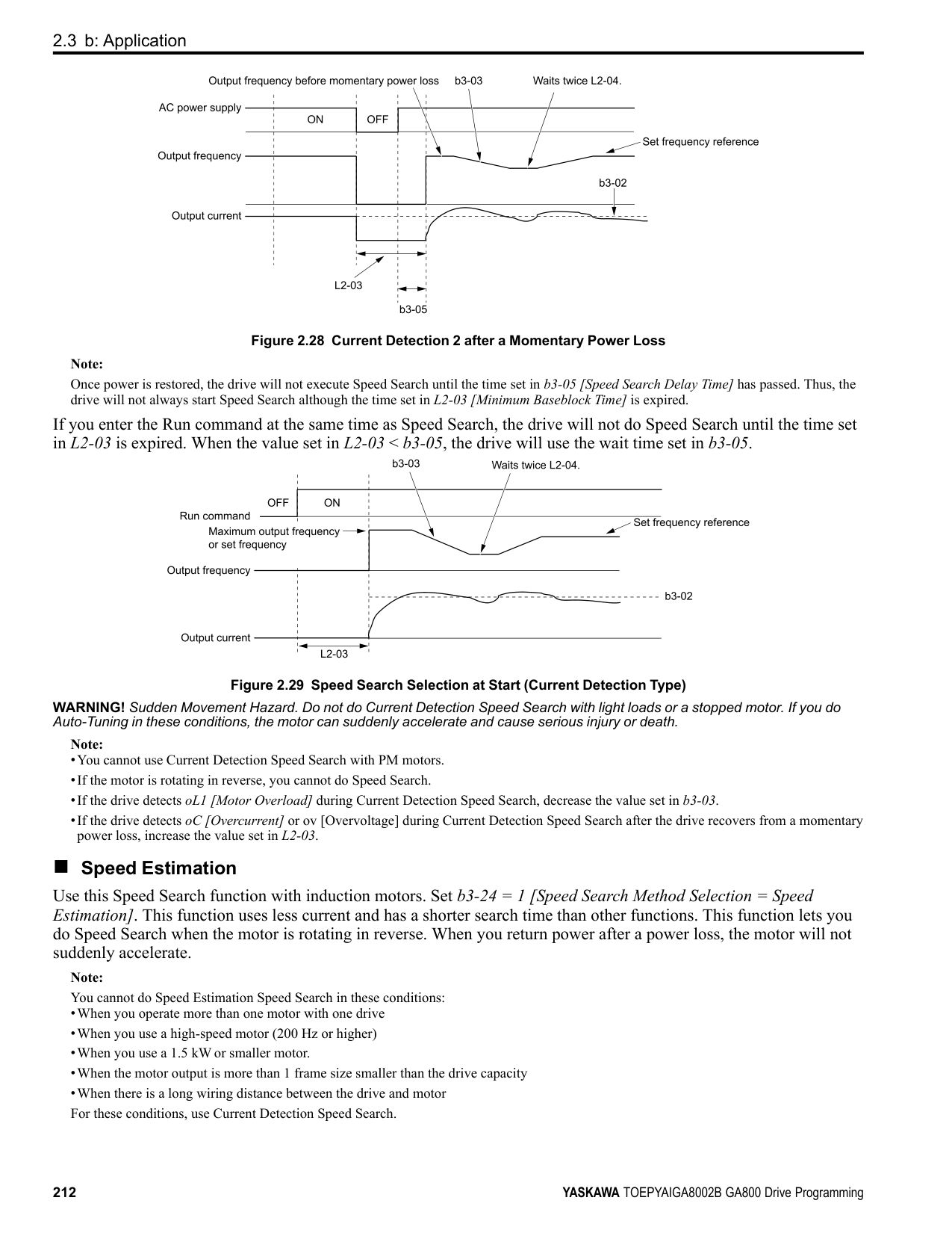
When A1-02 = 0, 1, set C6-03, C6-04, and C6-05 [Carrier Freq Proportional Gain] as shown in Figure 2.58 to make the carrier frequency change linearly with the output frequency.
Figure 2.58 Setting a Variable Carrier Frequency to Agree with the Output Frequency Note:
######## ■ C6-04: Carrier Frequency Lower Limit
|No. (Hex.)|Name|Description|Default (Range)| |---|---|---|---| |C6-04 (0226)|Carrier Frequency Lower Limit|Sets the lower limit of the carrier frequency. Set C6-02 F [Carrier Frequency Selection User Defined (C6-03 to C6-05)] to set this parameter.
V/f CL-V/f OLV CLV AOLV OLV/PM AOLV/PM CLV/PM EZOLV
|Determined by C6-02 (1.0 - 15.0 kHz)|
Set C6-03 [Carrier Frequency Upper Limit], C6-04, and C6-05 [Carrier Freq Proportional Gain] to make the carrier frequency change linearly with the output frequency.
Note: The drive detects oPE11 [Carrier Frequency Setting Error] when these conditions are correct at the same time:
■ C6-05: Carrier Freq Proportional Gain
Set C6-03 [Carrier Frequency Upper Limit], C6-04 [Carrier Frequency Lower Limit], and C6-05 to make the carrier frequency change linearly with the output frequency. ■ C6-09: Carrier Freq at Rotational Tune
If you set C6-09 = 0 for a high-frequency or low-impedance motor, it can cause oC [Overcurrent]. To prevent oC, set the carrier frequency to a high value and set C6-09 = 1 before you do Auto-Tuning. The procedure to set the carrier frequency when the A1-02 [Control Method Selection] setting changes.
|No. (Hex.)|Name|Description|Default (Range)| |---|---|---|---| |C6-05 (0227)|Carrier Freq Proportional Gain|Sets the proportional gain for the carrier frequency. Set C6-02 = F [Carrier Frequency Selection = User Defined (C6-03 to C6-05)] to set this parameter.
V/f CL-V/f OLV CLV AOLV OLV/PM AOLV/PM CLV/PM EZOLV
|Determined by C6-02 (0 - 99)|
|No. (Hex.)|Name|Description|Default (Range)|
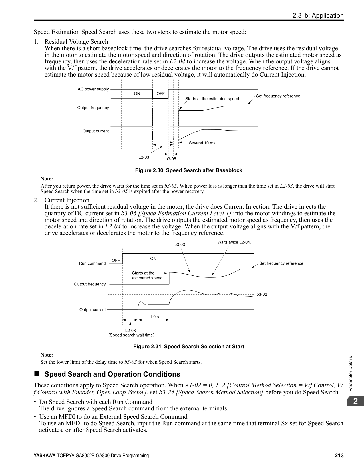
|---|---|---|---| |C6-09 (022B)|Carrier Freq at Rotational Tune|Sets the Auto-Tuning carrier frequency. Usually it is not necessary to change this setting.
V/f CL-V/f OLV CLV AOLV OLV/PM AOLV/PM CLV/PM EZOLV
|0 (0, 1)|
################## Note: When A1-02 = 5, 6, 7 [Control Method Selection = OLV/PM, AOLV/PM, CLV/PM], the carrier frequency is as specified in C6-02.
####### 2.5 d: References
d parameters [References] set the frequency reference input method and dead band range. They also set torque control, field weakening, and field forcing functions. WARNING! Sudden Movement Hazard. Use fast stop circuits to safely and quickly stop the drive. After you wire the fast stop circuits, you must check their operation. Test the operation of the fast stop function before you use the drive. If you do not test the fast stop circuit before you operate the drive, it can cause serious injury or death.
◆ d1: Frequency Reference Figure 2.59 shows the frequency reference input method, command source selection method and priority descriptions.
| | | |---|---| | | |
| | | |---|---| | | |
| | | |---|---| | | |
| | | |---|---| | | |
| | | |---|---| | | | | | | | | | | | |
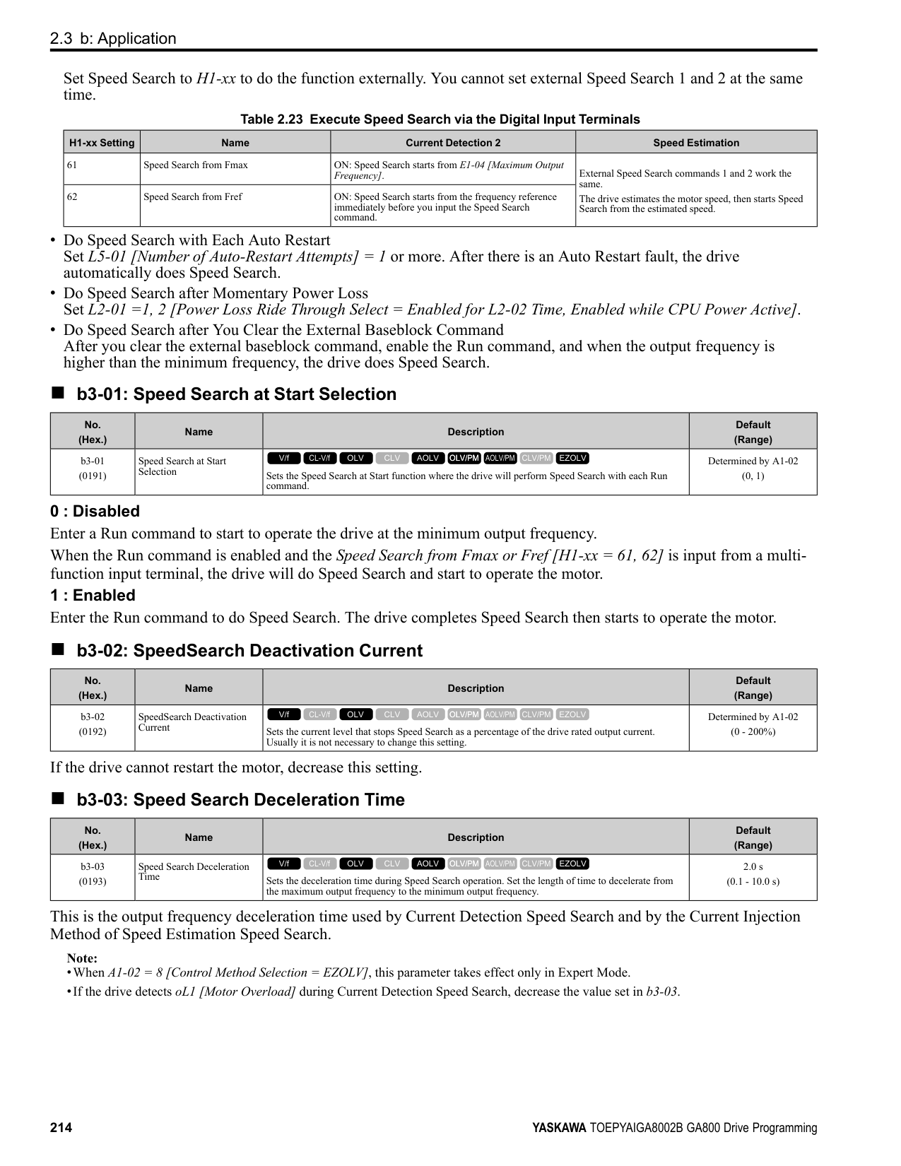
| | |
Figure 2.59 Frequency Reference Setting Hierarchy
######## ■ Multi-Step Speed Operation
The drive has a multi-step speed operation function that can set many frequency references in advance. Set frequency references in d1-xx parameters. You can select the set frequency references with MFDI signals from an external source. Activate and deactivate the digital input to select the frequency reference to change the motor speed in steps. You can use the 16-step frequency reference and one Jog Frequency Reference (JOG command) to switch the speed to the maximum 17-step speeds.
Note:
######## ■ Setting Procedures for Multi-step Speed Operation
Use an Analog Input as Reference 1 and 2 This section gives information about the procedures to set these examples:
|Procedure|Configuration Parameter|Task Contents| |---|---|---| |1|Reference 1|1. Set b1-01 1 [Frequency Reference Selection 1 Analog Input].
2. Set H3-02 0 [Terminal A1 Function Selection Frequency Reference].
3. Set H3-01 1 [Terminal A1 Signal Level Select -10 to +10V (Bipolar Reference)].
| |2|Reference 2|1. Set H3-06 2 [Terminal A3 Function Selection Auxiliary Frequency Reference 1].
2. Set H3-05 1 [Terminal A3 Signal Level Select -10 to +10V (Bipolar Reference)].
| |3|Signal type of analog input|Set DIP switches S1-1 and S1-3 on the control circuit board to the V-side (voltage). Note: Set this before you energize the drive.| |4|Reference 3|Set the value of d1-03 [Reference 3].| |5|Reference 4|Set the value of d1-04 [Reference 4].| |6|Reference 5|Set the value of d1-05 [Reference 5].| |7|Jog Reference|Set d1-17 [Jog Reference] to the jog speed.| |8|External digital input (3 inputs)|Set the Multi-Step Speed Reference 1 to 3 [H1-xx 3, 4, 5] to one of the MFDI terminals S1 to S8.| |9|JOG command|Set the Jog Reference Selection [H1-xx 6] to one of the MFDI terminals S1 to S8.|
Use the Maximum 17-Step Speed with All Digital Inputs This section is the procedure to set the 17-step speeds (17 types of frequency references) without an analog input.
|Procedure|Configuration Parameter|Task Contents| |---|---|---| |1|Reference 1|1. Set b1-01 = 0 [Frequency Reference Selection 1 = Keypad].
2. Set the value of d1-01 [Reference 1].
|
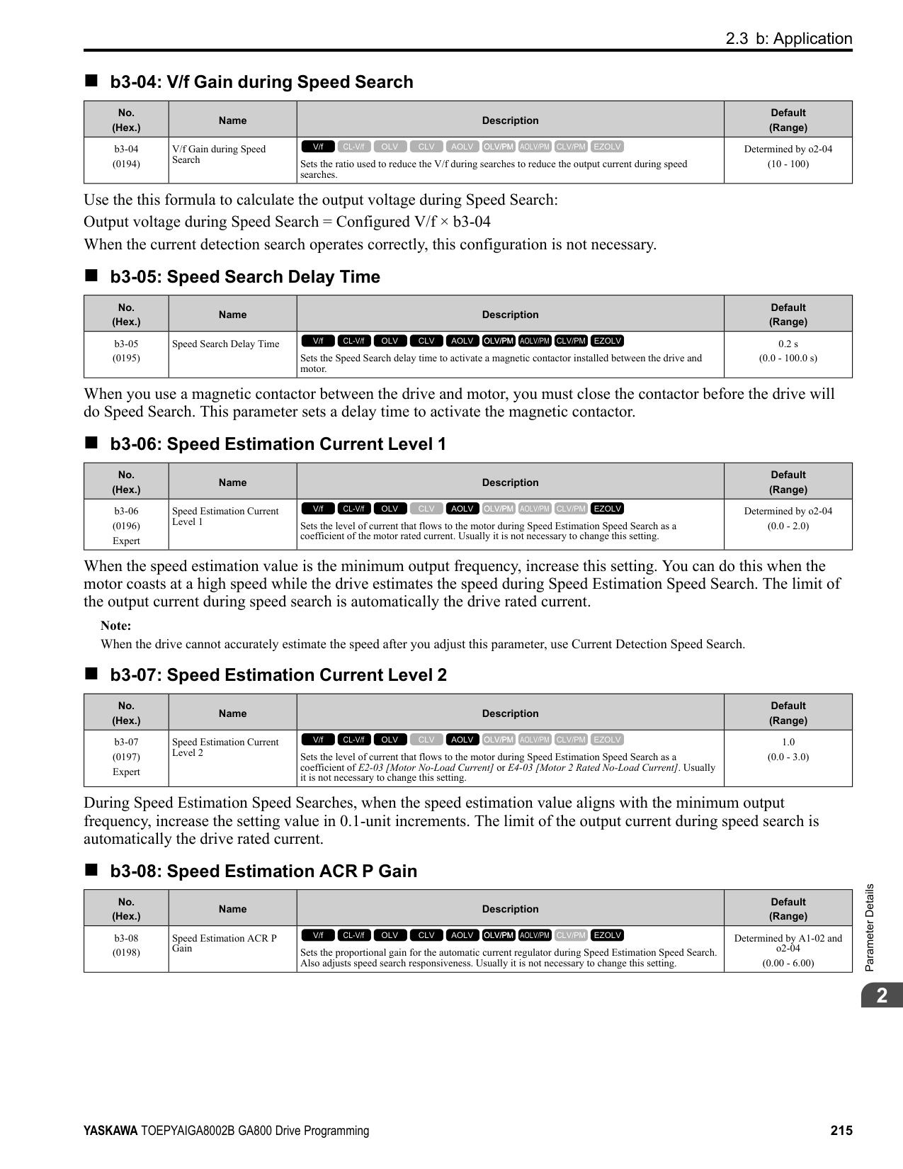
|2|Reference 2|1. Set H3-06 = F [Terminal A3 Function Selection = Not Used], and disables the analog reference.
2. Set the value of d1-02 [Reference 2].
| |3|Reference 3|1. Set H3-10 = F [Terminal A2 Function Selection = Not Used], and disables the analog reference.
2. Set the value of d1-03 [Reference 3].
| |4|Reference 4|Set the value of d1-04 [Reference 4].| |5|Reference 5 to 16|Sets the values of d1-05 to d1-16 [Reference 5 to 16].| |6|Jog Reference|Set d1-17 [Jog Reference] to the jog speed.| |7|External digital input (4 inputs)|Set Multi-Step Speed Reference 1 to 4 [H1-xx = 3, 4, 5, 32] to one of the MFDI terminals S1 to S8.| |8|JOG command|Set the Jog Reference Selection [H1-xx = 6] to one of the MFDI terminals S1 to S8.|
Multi-step Speed Operation Combinations Refer to Table 2.37 and Figure 2.60 for information about multi-step speed reference combinations. The selected frequency reference changes when the combination of digital input signals from an external source changes.
Table 2.37 Multi-step Speed Reference and MFDI Terminal Combinations
|Related Parameters|Multi-Step Speed Reference 1
H1-xx = 3|Multi-Step Speed Reference 2
H1-xx = 4|Multi-Step Speed Reference 3
H1-xx = 5|Multi-Step Speed Reference 4
H1-xx = 32|Jog Reference H1-xx = 6| |---|---|---|---|---|---| |Reference 1 (set in b1-01)|OFF|OFF|OFF|OFF|OFF| |Reference 2 (d1-02 or terminals A1, A2, A3)|ON|OFF|OFF|OFF|OFF| |Reference 3 (d1-03 or terminals A1, A2, A3)|OFF|ON|OFF|OFF|OFF| |Reference 4 (d1-04)|ON|ON|OFF|OFF|OFF| |Reference 5 (d1-05)|OFF|OFF|ON|OFF|OFF| |Reference 6 (d1-06)|ON|OFF|ON|OFF|OFF| |Reference 7 (d1-07)|OFF|ON|ON|OFF|OFF| |Reference 8 (d1-08)|ON|ON|ON|OFF|OFF| |Reference 9 (d1-09)|OFF|OFF|OFF|ON|OFF| |Reference 10 (d1-10)|ON|OFF|OFF|ON|OFF|
|Related Parameters|Multi-Step Speed Reference 1
H1-xx = 3|Multi-Step Speed Reference 2
H1-xx = 4|Multi-Step Speed Reference 3
H1-xx = 5|Multi-Step Speed Reference 4
H1-xx = 32|Jog Reference H1-xx = 6| |---|---|---|---|---|---| |Reference 11 (d1-11)|OFF|ON|OFF|ON|OFF| |Reference 12 (d1-12)|ON|ON|OFF|ON|OFF| |Reference 13 (d1-13)|OFF|OFF|ON|ON|OFF| |Reference 14 (d1-14)|ON|OFF|ON|ON|OFF| |Reference 15 (d1-15)|OFF|ON|ON|ON|OFF| |Reference 16 (d1-16)|ON|ON|ON|ON|OFF| |Jog Reference (d1-17) *1|-|-|-|-|ON|
*1 The Jog Frequency Reference (JOG command) overrides all other frequency references.
Figure 2.60 Time Chart for Multi-step Speed Reference/JOG Reference
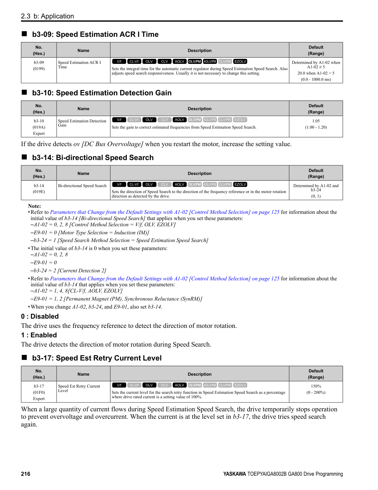
######## ■ d1-01: Reference 1
|No. (Hex.)|Name|Description|Default (Range)| |---|---|---|---| |d1-01 (0280) RUN|Reference 1|Sets the frequency reference in the units from o1-03 [Frequency Display Unit Selection.
V/f CL-V/f OLV CLV AOLV OLV/PM AOLV/PM CLV/PM EZOLV
|0.00 Hz (0.00 - 590.00 Hz)|
################# Note:
Note:
Note:
Note:
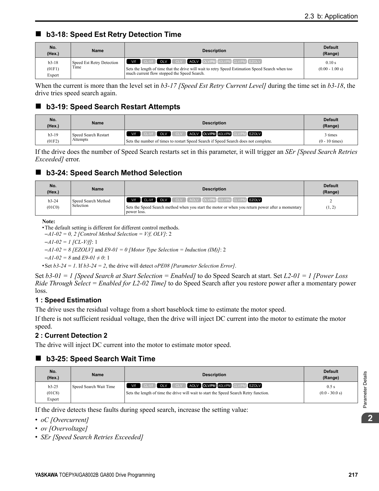
Note:
|No. (Hex.)|Name|Description|Default (Range)| |---|---|---|---| |d1-02 (0281) RUN|Reference 2|Sets the frequency reference in the units from o1-03 [Frequency Display Unit Selection].
V/f CL-V/f OLV CLV AOLV OLV/PM AOLV/PM CLV/PM EZOLV
|0.00 Hz (0.00 - 590.00 Hz)|
|No. (Hex.)|Name|Description|Default (Range)| |---|---|---|---| |d1-03 (0282) RUN|Reference 3|Sets the frequency reference in the units from o1-03 [Frequency Display Unit Selection].
V/f CL-V/f OLV CLV AOLV OLV/PM AOLV/PM CLV/PM EZOLV
|0.00 Hz (0.00 - 590.00 Hz)|
|No. (Hex.)|Name|Description|Default (Range)| |---|---|---|---| |d1-04 (0283) RUN|Reference 4|Sets the frequency reference in the units from o1-03 [Frequency Display Unit Selection].
V/f CL-V/f OLV CLV AOLV OLV/PM AOLV/PM CLV/PM EZOLV
|0.00 Hz (0.00 - 590.00 Hz)|
|No. (Hex.)|Name|Description|Default (Range)| |---|---|---|---| |d1-05 (0284) RUN|Reference 5|Sets the frequency reference in the units from o1-03 [Frequency Display Unit Selection].
V/f CL-V/f OLV CLV AOLV OLV/PM AOLV/PM CLV/PM EZOLV
|0.00 Hz (0.00 - 590.00 Hz)|
|No. (Hex.)|Name|Description|Default (Range)| |---|---|---|---| |d1-06 (0285) RUN|Reference 6|Sets the frequency reference in the units from o1-03 [Frequency Display Unit Selection].
V/f CL-V/f OLV CLV AOLV OLV/PM AOLV/PM CLV/PM EZOLV
|0.00 Hz (0.00 - 590.00 Hz)|
ParameterDetails
######## 2
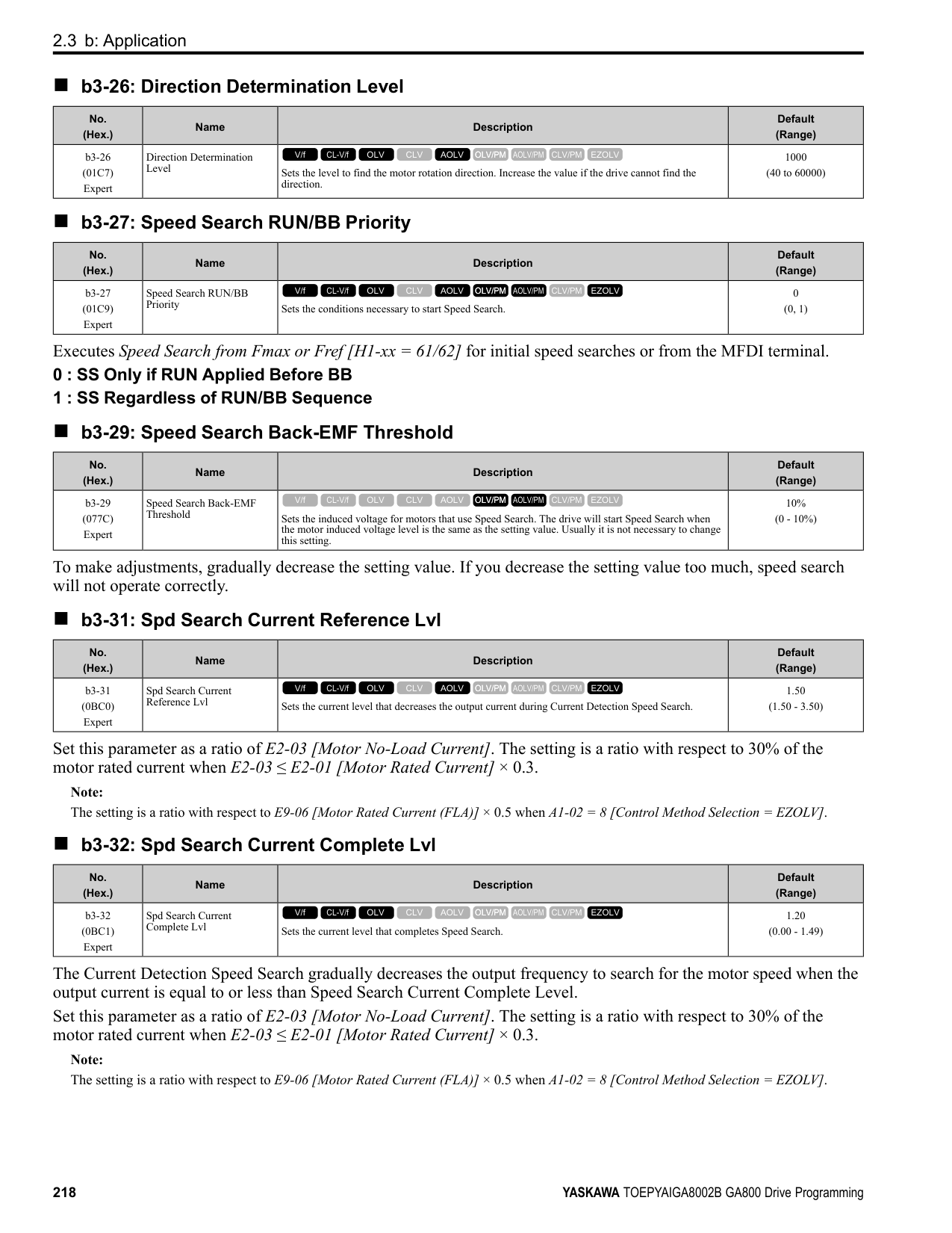
######## ■ d1-07: Reference 7
|No. (Hex.)|Name|Description|Default (Range)| |---|---|---|---| |d1-07 (0286) RUN|Reference 7|Sets the frequency reference in the units from o1-03 [Frequency Display Unit Selection].
V/f CL-V/f OLV CLV AOLV OLV/PM AOLV/PM CLV/PM EZOLV
|0.00 Hz (0.00 - 590.00 Hz)|
Note:
######## ■ d1-08: Reference 8
|No. (Hex.)|Name|Description|Default (Range)| |---|---|---|---| |d1-08 (0287) RUN|Reference 8|Sets the frequency reference in the units from o1-03 [Frequency Display Unit Selection].
V/f CL-V/f OLV CLV AOLV OLV/PM AOLV/PM CLV/PM EZOLV
|0.00 Hz (0.00 - 590.00 Hz)|
Note:
######## ■ d1-09: Reference 9
|No. (Hex.)|Name|Description|Default (Range)| |---|---|---|---| |d1-09 (0288) RUN|Reference 9|Sets the frequency reference in the units from o1-03 [Frequency Display Unit Selection].
V/f CL-V/f OLV CLV AOLV OLV/PM AOLV/PM CLV/PM EZOLV
|0.00 Hz (0.00 - 590.00 Hz)|
Note:
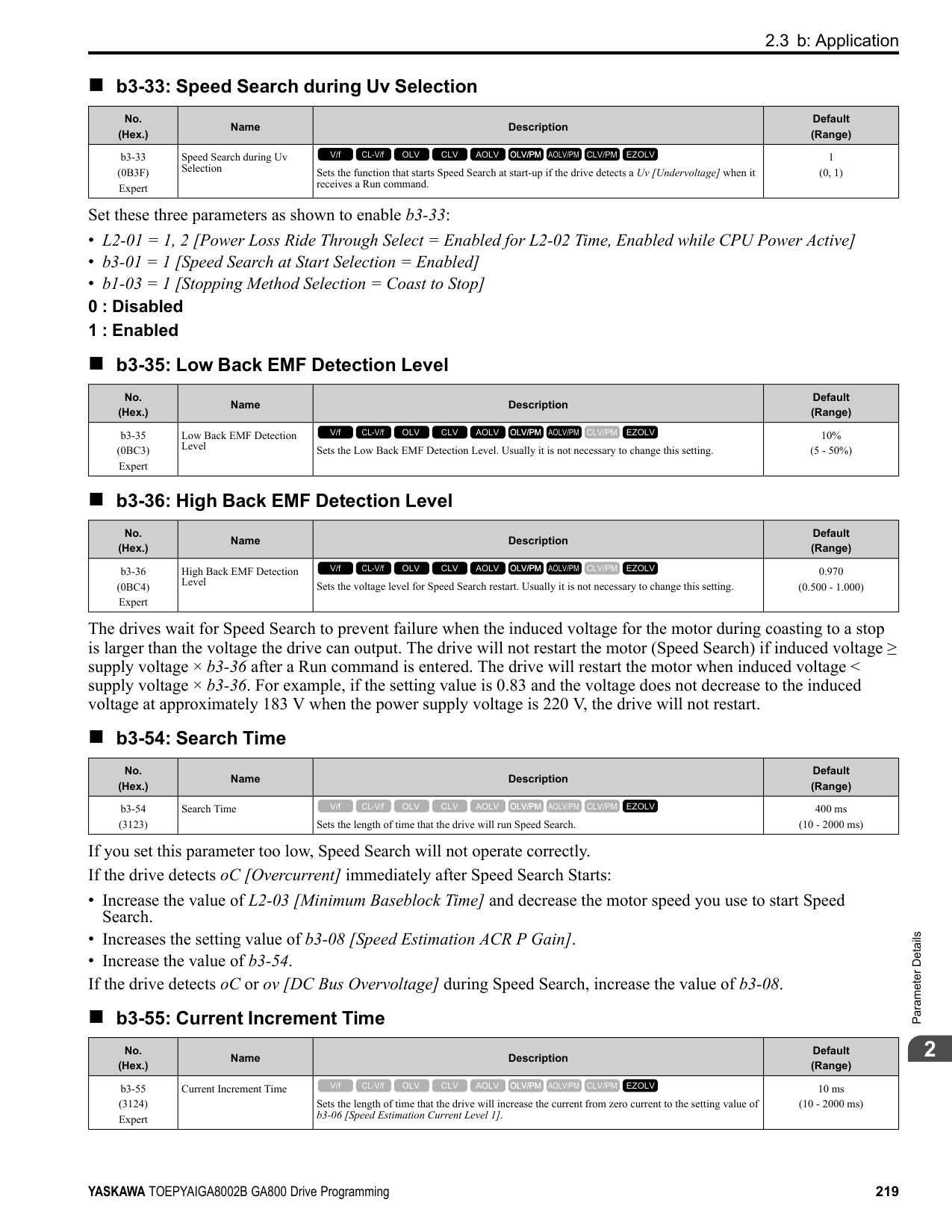
######## ■ d1-10: Reference 10
|No. (Hex.)|Name|Description|Default (Range)| |---|---|---|---| |d1-10 (028B) RUN|Reference 10|Sets the frequency reference in the units from o1-03 [Frequency Display Unit Selection].
V/f CL-V/f OLV CLV AOLV OLV/PM AOLV/PM CLV/PM EZOLV
|0.00 Hz (0.00 - 590.00 Hz)|
################# Note:
Note:
Note:
Note:
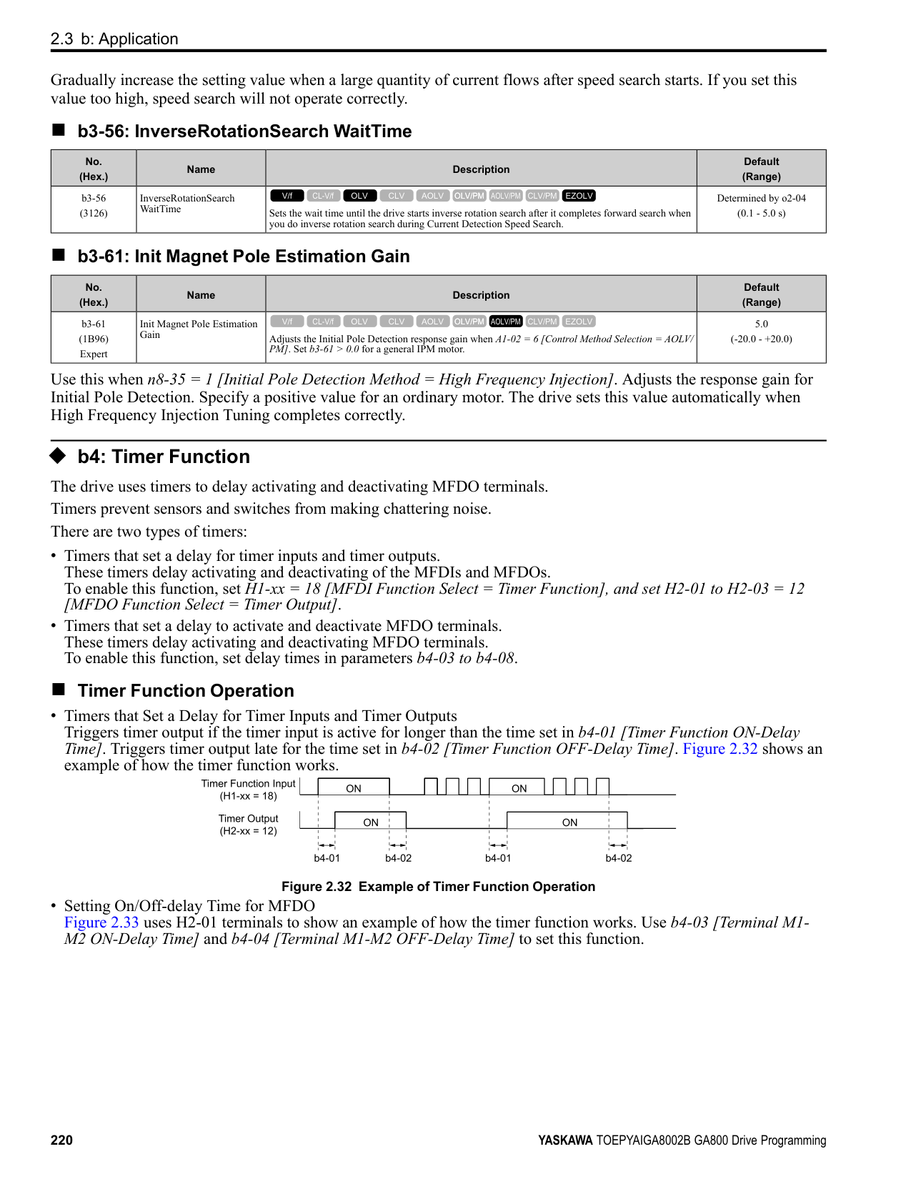
Note:
|No. (Hex.)|Name|Description|Default (Range)| |---|---|---|---| |d1-11 (028C) RUN|Reference 11|Sets the frequency reference in the units from o1-03 [Frequency Display Unit Selection].
V/f CL-V/f OLV CLV AOLV OLV/PM AOLV/PM CLV/PM EZOLV
|0.00 Hz (0.00 - 590.00 Hz)|
|No. (Hex.)|Name|Description|Default (Range)| |---|---|---|---| |d1-12 (028D) RUN|Reference 12|Sets the frequency reference in the units from o1-03 [Frequency Display Unit Selection].
V/f CL-V/f OLV CLV AOLV OLV/PM AOLV/PM CLV/PM EZOLV
|0.00 Hz (0.00 - 590.00 Hz)|
|No. (Hex.)|Name|Description|Default (Range)| |---|---|---|---| |d1-13 (028E) RUN|Reference 13|Sets the frequency reference in the units from o1-03 [Frequency Display Unit Selection].
V/f CL-V/f OLV CLV AOLV OLV/PM AOLV/PM CLV/PM EZOLV
|0.00 Hz (0.00 - 590.00 Hz)|
|No. (Hex.)|Name|Description|Default (Range)| |---|---|---|---| |d1-14 (028F) RUN|Reference 14|Sets the frequency reference in the units from o1-03 [Frequency Display Unit Selection].
V/f CL-V/f OLV CLV AOLV OLV/PM AOLV/PM CLV/PM EZOLV
|0.00 Hz (0.00 - 590.00 Hz)|
|No. (Hex.)|Name|Description|Default (Range)| |---|---|---|---| |d1-15 (0290) RUN|Reference 15|Sets the frequency reference in the units from o1-03 [Frequency Display Unit Selection].
V/f CL-V/f OLV CLV AOLV OLV/PM AOLV/PM CLV/PM EZOLV
|0.00 Hz (0.00 - 590.00 Hz)|
ParameterDetails
######## 2
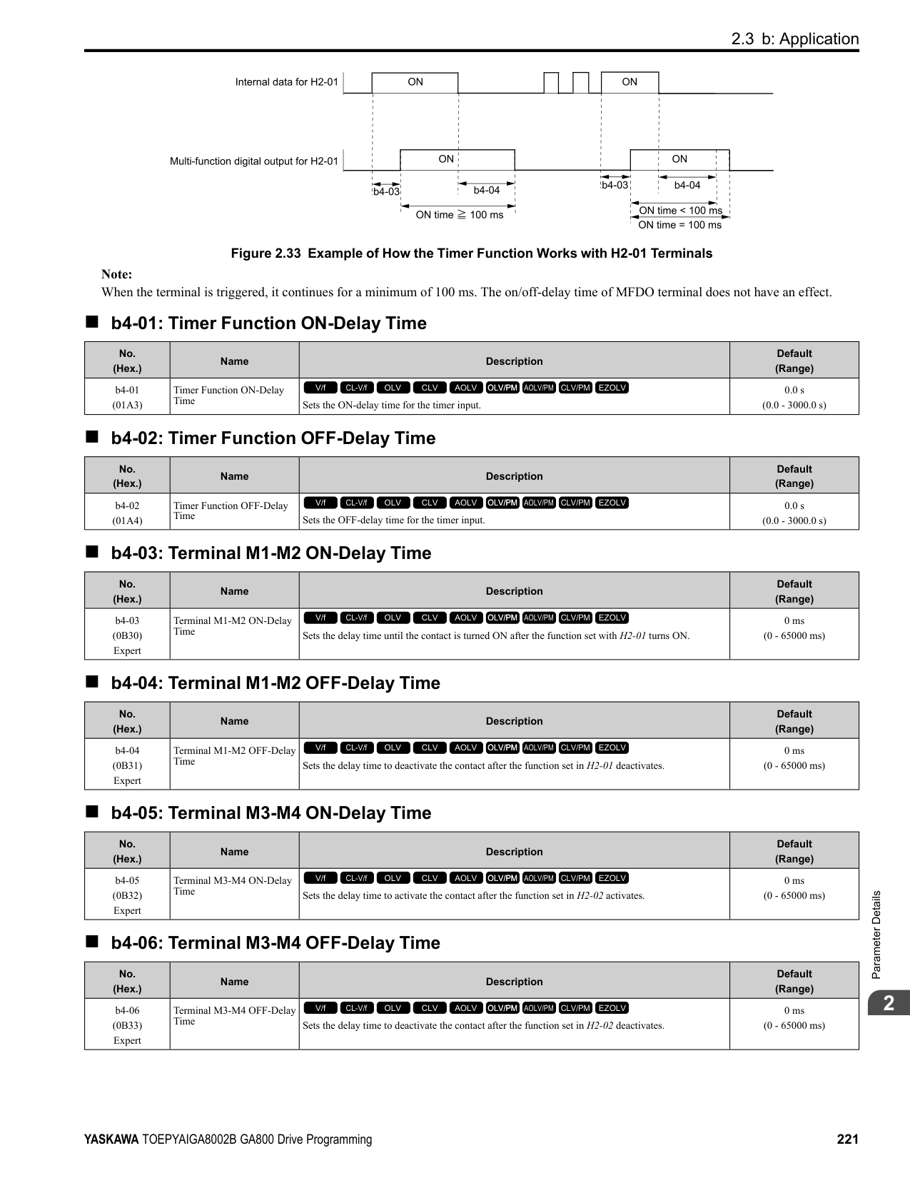
######## ■ d1-16: Reference 16
|No. (Hex.)|Name|Description|Default (Range)| |---|---|---|---| |d1-16 (0291) RUN|Reference 16|Sets the frequency reference in the units from o1-03 [Frequency Display Unit Selection].
V/f CL-V/f OLV CLV AOLV OLV/PM AOLV/PM CLV/PM EZOLV
|0.00 Hz (0.00 - 590.00 Hz)|
Note:
######## ■ d1-17: Jog Reference
|No. (Hex.)|Name|Description|Default (Range)| |---|---|---|---| |d1-17 (0292) RUN|Jog Reference|Sets the Jog frequency reference in the units from o1-03 [Frequency Display Unit Selection]. Set H1xx = 6 [MFDI Function Select = Jog Reference Selection] to use the Jog frequency reference.
V/f CL-V/f OLV CLV AOLV OLV/PM AOLV/PM CLV/PM EZOLV
|6.00 Hz (0.00 - 590.00 Hz)|
################# Note:
◆ d2: Reference Limits d2 parameters set the upper and lower frequency limits to control the motor speed. Apply these parameters to for example, run the motor at low-speed due to mechanical strength concerns, or if the motor should not be run at low speed because of lubrication issues with the gears and bearings. The upper frequency limit is set in d2-01 [Frequency Reference Upper Limit] and the lower limit is set in d2-02 [Frequency Reference Lower Limit].
Figure 2.61 Upper and Lower Frequency Limits
######## ■ d2-01: Frequency Reference Upper Limit
|No. (Hex.)|Name|Description|Default (Range)| |---|---|---|---| |d2-01 (0289)|Frequency Reference Upper Limit|Sets maximum limit for all frequency references. The maximum output frequency is 100%.
V/f CL-V/f OLV CLV AOLV OLV/PM AOLV/PM CLV/PM EZOLV
|100.0% (0.0 - 110.0%)|
When the frequency reference is more than the value set in d2-01 the drive will continue to operate at the value set in d2-01.
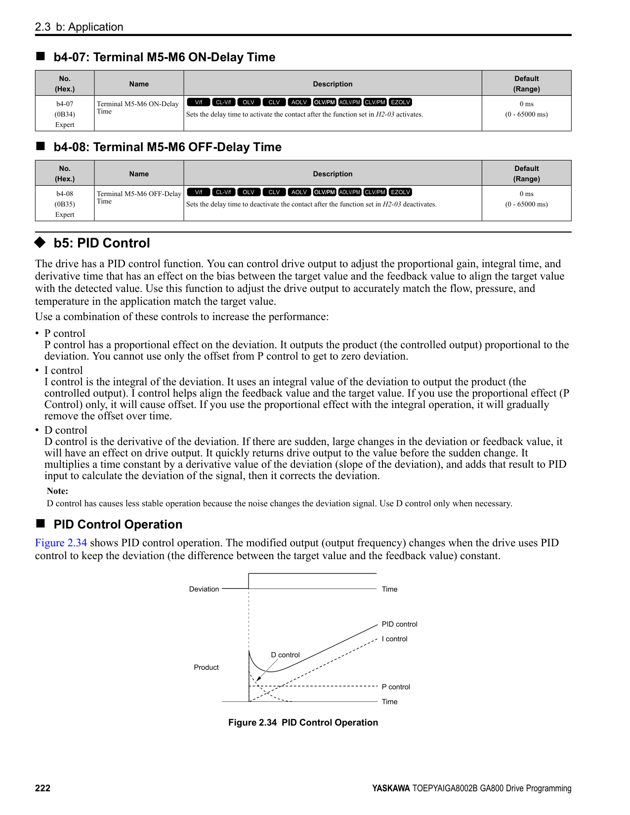
######## ■ d2-02: Frequency Reference Lower Limit
|No. (Hex.)|Name|Description|Default (Range)| |---|---|---|---| |d2-02 (028A)|Frequency Reference Lower Limit|Sets minimum limit for all frequency references. The maximum output frequency is 100%.
V/f CL-V/f OLV CLV AOLV OLV/PM AOLV/PM CLV/PM EZOLV
|0.0% (0.0 - 110.0%)|
When the frequency reference is less than the value set in d2-02, the drive will continue to operate at the value set in d2-02. The motor will accelerate to the d2-02 value after the drive receives a Run command and a lower frequency reference than d2-02 has been entered.
######## ■ d2-03: Analog Frequency Ref Lower Limit
|No. (Hex.)|Name|Description|Default (Range)| |---|---|---|---| |d2-03 (0293)|Analog Frequency Ref Lower Limit|Sets the lower limit for the master frequency reference (the first frequency of the multi-step speed reference) as a percentage. The maximum output frequency is 100%.
V/f CL-V/f OLV CLV AOLV OLV/PM AOLV/PM CLV/PM EZOLV
|0.0% (0.0 - 110.0%)|
This parameter does not change the lower limit of Jog reference, frequency reference for multi-step speed operation, or the auxiliary frequency reference. The drive operates at the value set in d2-03 when the frequency reference decreases to less than the value set in d2-03.
Note:
When lower limits are set to parameters d2-02 [Frequency Reference Lower Limit] and d2-03, the drive uses the larger value as the lower limit.
◆ d3: Jump Frequency The Jump frequency is a function that sets the dead band to a specified frequency band. If a machine that operated at constant speed is operated with variable speed, it can make resonance. To operate the machine without resonance from the natural frequency of the machinery mechanical system, use a frequency band jump. You can program the drive to have three different Jump frequencies. Set d3-01 to d3-03 [Jump Frequencies] to the median value for the jumped frequency and set d3-04 [Jump Frequency Width] to the Jump frequency width. When you input a frequency reference that is the same as or near the Jump frequency width, the frequency reference changes automatically. The drive accelerates or decelerates the motor smoothly until the frequency reference is not in the range of the Jump frequency band. The drive will use the active accel/decel time to go through the specified dead band range. If the frequency reference is not in the range of the Jump frequency band, switch to constant speed operation.
Figure 2.62 Jump Frequency
ParameterDetails
######## 2
######## ■ d3-01: Jump Frequency 1
|No. (Hex.)|Name|Description|Default (Range)| |---|---|---|---| |d3-01 (0294)|Jump Frequency 1|Sets the median value of the frequency band that the drive will avoid.
V/f CL-V/f OLV CLV AOLV OLV/PM AOLV/PM CLV/PM EZOLV
|0.0 Hz (Determined by A1-02)|
Note: Set this parameter to 0.0 Hz to disable the Jump frequency.
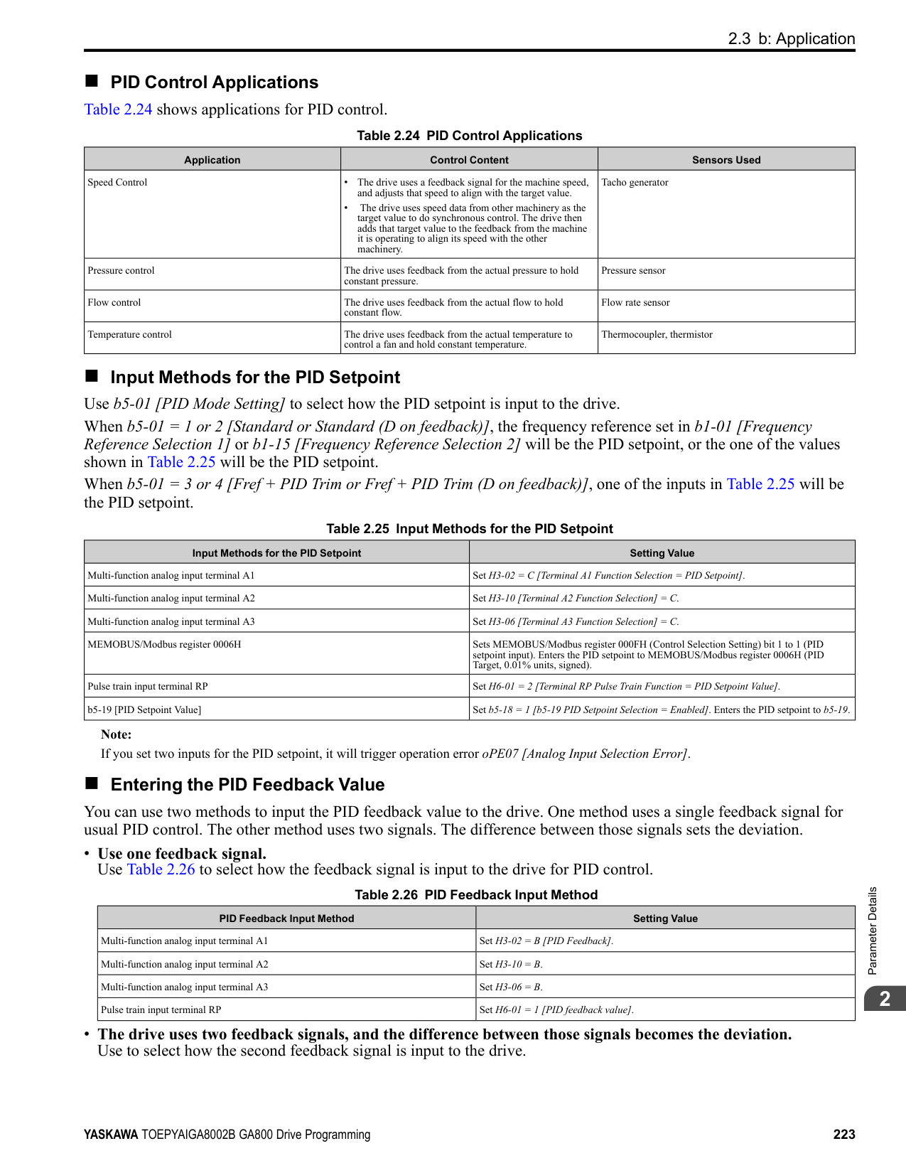
######## ■ d3-02: Jump Frequency 2
|No. (Hex.)|Name|Description|Default (Range)| |---|---|---|---| |d3-02 (0295)|Jump Frequency 2|Sets the median value of the frequency band that the drive will avoid.
V/f CL-V/f OLV CLV AOLV OLV/PM AOLV/PM CLV/PM EZOLV
|0.0 Hz (Determined by A1-02)|
Note: Set this parameter to 0.0 Hz to disable the Jump frequency.
######## ■ d3-03: Jump Frequency 3
|No. (Hex.)|Name|Description|Default (Range)| |---|---|---|---| |d3-03 (0296)|Jump Frequency 3|Sets the median value of the frequency band that the drive will avoid.
V/f CL-V/f OLV CLV AOLV OLV/PM AOLV/PM CLV/PM EZOLV
|0.0 Hz (Determined by A1-02)|
Note: Set this parameter to 0.0 Hz to disable the Jump frequency.
######## ■ d3-04: Jump Frequency Width
|No. (Hex.)|Name|Description|Default (Range)| |---|---|---|---| |d3-04 (0297)|Jump Frequency Width|Sets the width of the frequency band that the drive will avoid.
V/f CL-V/f OLV CLV AOLV OLV/PM AOLV/PM CLV/PM EZOLV
|1.0 Hz (Determined by A1-02)|
◆ d4: Frequency Ref Up/Down & Hold The d4 parameters set the Frequency Reference Hold function and Up/Down and Up/Down 2 commands.
######## ■ d4-01: Freq Reference Hold Selection
|No. (Hex.)|Name|Description|Default (Range)| |---|---|---|---| |d4-01 (0298)|Freq Reference Hold Selection|Sets the function that saves the frequency reference or the frequency bias (Up/Down 2) after a Stop command or when de-energizing the drive.
V/f CL-V/f OLV CLV AOLV OLV/PM AOLV/PM CLV/PM EZOLV
|0 (0, 1)|
Set H1-xx [MFDI Function Selection] to one of these values to enable this parameter:

############## 1 : Enabled
Note:
When you energize the drive, continuously enable the MFDI terminal set for Accel/Decel Ramp Hold [H1-xx = A]. If the digital input does not activate, the drive will clear the hold value and set it to 0 Hz.
Figure 2.63 Frequency Reference Hold with Accel/Decel Hold Function
ParameterDetails
######## 2
Figure 2.64 Up/Down 2 Example with Reference from Keypad and d4-01 = 1 • Up/Down 2 Command with Frequency Reference from Input Sources Other Than the Keypad
When a Run command is active and you release the Up/Down 2 command for longer than 5 s, the drive will save the bias value in d4-06 [Frequency Ref Bias (Up/Down 2)]. The drive saves the frequency reference + d4-06 as a frequency reference value. The drive will use the new value as the frequency reference when it restarts.
Figure 2.65 Up/Down 2 Example with Other Reference than Keypad and d4-01 = 1 Note:
To use the combination of the frequency reference hold function and the Up/Down 2 function, configure the Up/Down 2 upper limit [d4-08] and lower limit [d4-09] correctly.
Remove the Saved Frequency Reference Value The procedure to remove the saved frequency reference value is different for different functions. Use these methods to remove the value:
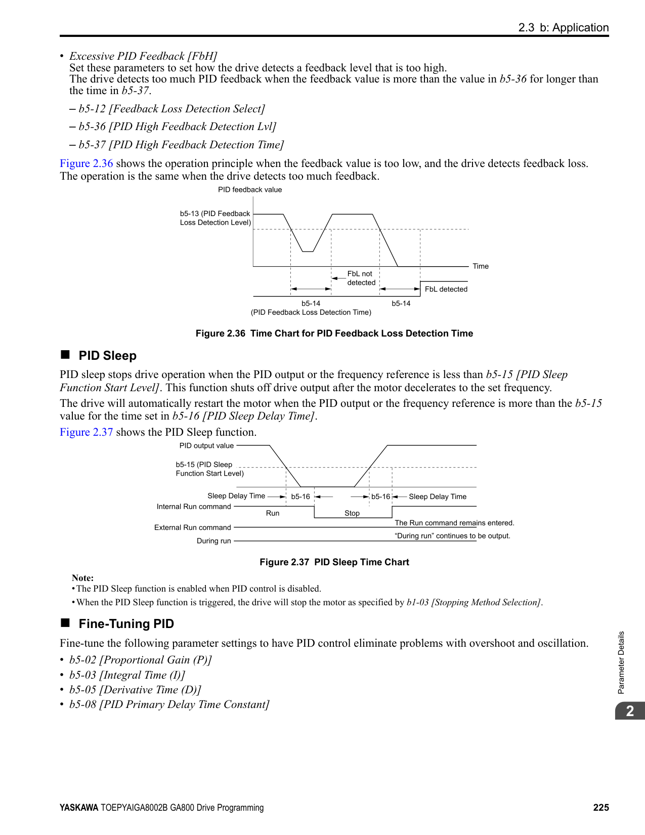
The operation is different for different setting values:
|No. (Hex.)|Name|Description|Default (Range)| |---|---|---|---| |d4-03 (02AA) RUN|Up/Down 2 Bias Step Frequency|Sets the bias that the Up/Down 2 function adds to or subtracts from the frequency reference.
V/f CL-V/f OLV CLV AOLV OLV/PM AOLV/PM CLV/PM EZOLV
|0.00 Hz (0.00 - 99.99 Hz)|
When the Up/Down 2 Command [H1-xx = 75, 76] is active, the drive uses the accel/decel times set in d4-04 [Up/ Down 2 Ramp Selection] to increase or decrease the bias value.
Figure 2.66 Up/Down 2 Bias when d4-03 = 0.00 Hz
• Setting d4-03 ≠ 0.00 Hz When the Up/Down 2 Command [H1-xx = 75, 76] is active, the drive increases or decreases the bias in steps for the value set in d4-03. The drive uses the acceleration and deceleration times set in d4-04.
Figure 2.67 Up/Down 2 Bias when d4-03 ≠ 0.00 Hz
######## ■ d4-04: Up/Down 2 Ramp Selection
|No. (Hex.)|Name|Description|Default (Range)| |---|---|---|---| |d4-04 (02AB) RUN|Up/Down 2 Ramp Selection|Sets the acceleration and deceleration times for the Up/Down 2 function to apply the bias to the frequency reference.
V/f CL-V/f OLV CLV AOLV OLV/PM AOLV/PM CLV/PM EZOLV
|0 (0, 1)|
0 : Use Selected Accel/Decel Time Use the active acceleration and deceleration times to increase or decrease the bias. 1 : Use Accel/Decel Time 4 Use C1-07 [Acceleration Time 4] and C1-08 [Deceleration Time 4] to increase or decrease the bias.
######## ■ d4-05: Up/Down 2 Bias Mode Selection
|No. (Hex.)|Name|Description|Default (Range)| |---|---|---|---| |d4-05 (02AC) RUN|Up/Down 2 Bias Mode Selection|Sets the function that saves the bias value to the drive when you open or close the two Up/Down 2 Commands [H1-xx = 75, 76]. Set d4-03 [Up/Down 2 Bias Step Frequency] = 0.00 before you set this parameter.
V/f CL-V/f OLV CLV AOLV OLV/PM AOLV/PM CLV/PM EZOLV
|0 (0, 1)|
0 : Hold when Neither Up/Down Closed When the two MFDI terminals set for Up/Down 2 Command [H1-xx = 75, 76] activate or deactivate, the drive will hold the bias value. 1 : Reset when Neither / Both Closed
When the two MFDI terminals set for Up/Down 2 Command [H1-xx = 75, 76] activate or deactivate, the drive will reset the bias value to 0. The drive will use the acceleration and deceleration times set in d4-04 [Up/Down 2 Ramp Selection] to accelerate and decelerate the motor to the selected output frequency.
ParameterDetails
######## 2
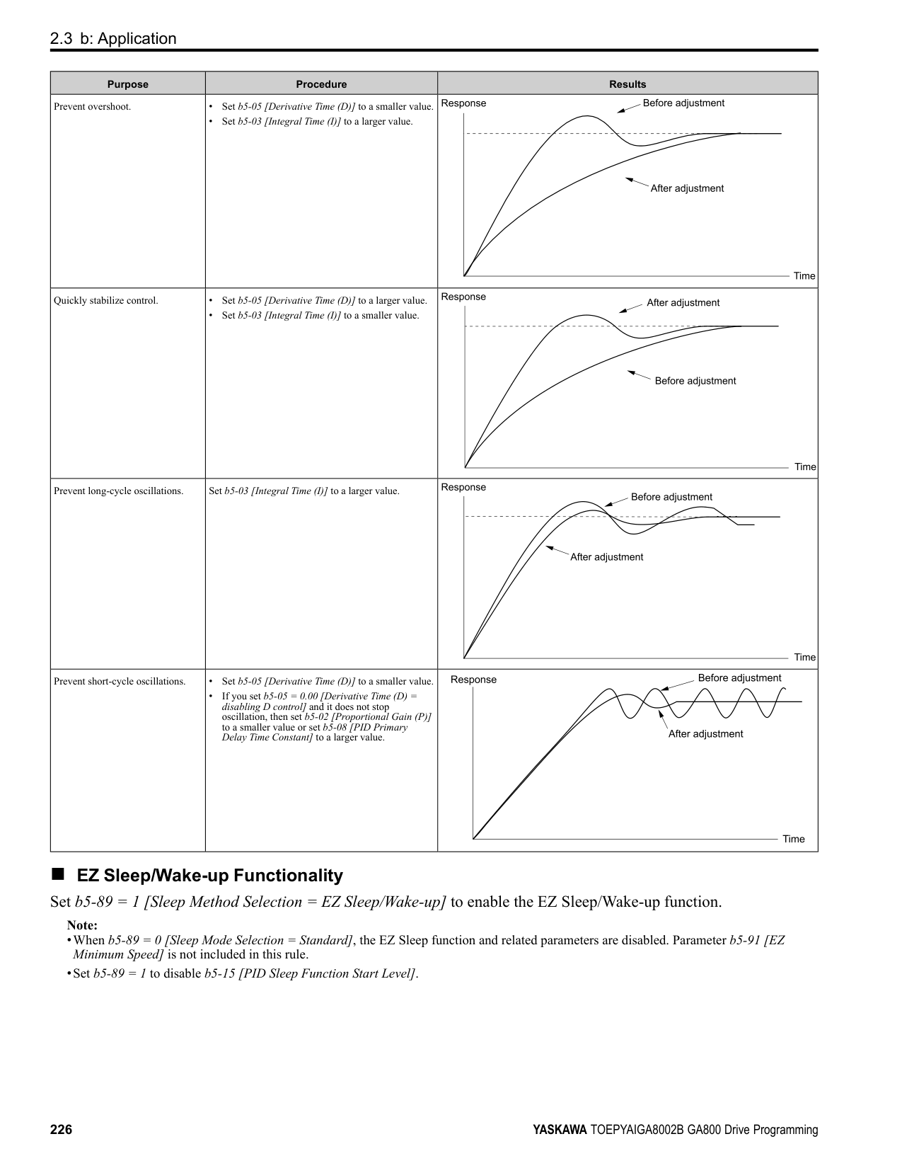
######## ■ d4-06: Frequency Ref Bias (Up/Down 2)
|No. (Hex.)|Name|Description|Default (Range)| |---|---|---|---| |d4-06 (02AD)|Frequency Ref Bias (Up/ Down 2)|Saves the bias value from the Up/Down 2 Command where the Maximum Output Frequency is 100%.
V/f CL-V/f OLV CLV AOLV OLV/PM AOLV/PM CLV/PM EZOLV
|0.0% (-99.9 - +100.0%)|
The Up/Down 2 function setting changes the function of d4-06: Note: When the keypad sets the frequency reference, you do not usually use parameter d4-06.
Conditions that Reset or Disable d4-06 The drive resets and disables the bias value in these conditions:
######## ■ d4-07: Analog Freq Ref Fluctuate Limit
|No. (Hex.)|Name|Description|Default (Range)| |---|---|---|---| |d4-07 (02AE) RUN|Analog Freq Ref Fluctuate Limit|If the frequency reference changes for more than the level set to this parameter, then the bias value will be held. The value is set as a percentage of the Maximum Output Frequency.
V/f CL-V/f OLV CLV AOLV OLV/PM AOLV/PM CLV/PM EZOLV
|1.0% (0.1 - 100.0%)|
Handles frequency reference changes while Up/Down 2 Command [H1-xx = 75, 76] is activated. When the frequency reference changes for more than the level set in d4-07, the drive will hold the bias value, and the drive will accelerate or decelerate to the frequency reference. When the drive is at the frequency reference, it releases the bias hold and the bias follows the Up/Down 2 input commands. This parameter is applicable only when an analog or pulse input sets the frequency reference.
######## ■ d4-08: Up/Down 2 Bias Upper Limit
|No. (Hex.)|Name|Description|Default (Range)| |---|---|---|---| |d4-08 (02AF) RUN|Up/Down 2 Bias Upper Limit|Sets the upper limit of the Up/Down 2 bias as a percentage of the Maximum Output Frequency.
V/f CL-V/f OLV CLV AOLV OLV/PM AOLV/PM CLV/PM EZOLV
|100.0% (0.0 - 100.0%)|
The drive saves the set bias upper limit in d4-06 [Frequency Ref Bias (Up/Down 2)]. Set d4-08 an applicable value before you use the Up/Down 2 function.
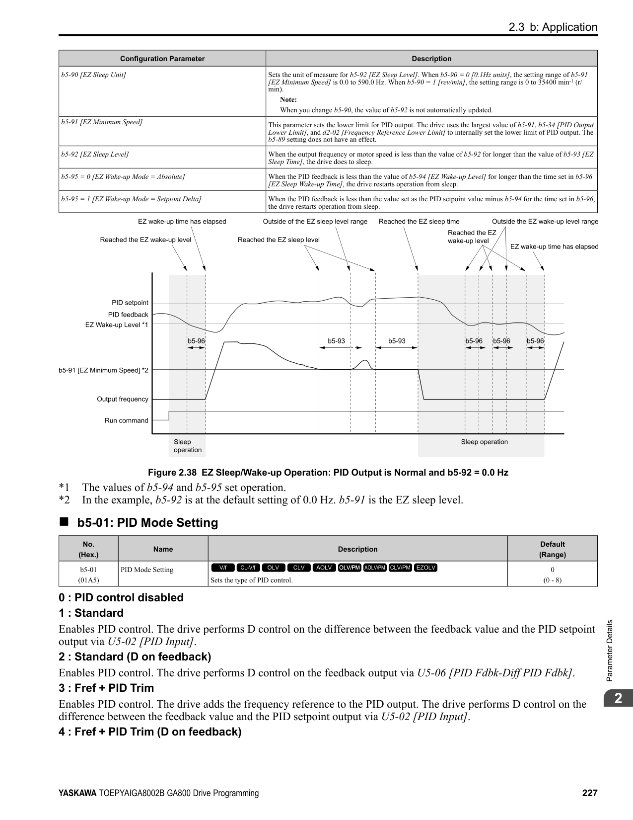
Note:
When d4-01 1 [Freq Reference Hold Selection Enabled] and b1-01 0 [Frequency Reference Selection 1 Keypad], the drive will add the bias value to the frequency reference when it does not receive an Up/Down 2 command for 5 s. Then the drive will reset the value to 0 at which time you can increase the bias to the limit set in d4-08 again.
######## ■ d4-09: Up/Down 2 Bias Lower Limit
|No. (Hex.)|Name|Description|Default (Range)| |---|---|---|---| |d4-09 (02B0) RUN|Up/Down 2 Bias Lower Limit|Sets the lower limit of the Up/Down 2 bias as a percentage of the Maximum Output Frequency.
V/f CL-V/f OLV CLV AOLV OLV/PM AOLV/PM CLV/PM EZOLV
|0.0% (-99.9 - 0.0%)|
The drive saves the set bias lower limit in d4-06 [Frequency Ref Bias (Up/Down 2)]. Set d4-09 to an applicable value before you use the Up/Down 2 function.
Note: When d4-01 = 1 [Freq Reference Hold Selection = Enabled] and b1-01 = 0 [Frequency Reference Selection 1 = Keypad], the drive will add the bias value to the frequency reference when it does not receive an Up/Down 2 command for 5 s. Then the drive will reset the value to 0. If you increase the bias with the Up 2 command and d4-09 0, you cannot use a Down 2 command to decrease the frequency reference. To decrease speed in this condition, set a negative lower limit in d4-09.
######## ■ d4-10: Up/Down Freq Lower Limit Select
|No. (Hex.)|Name|Description|Default (Range)| |---|---|---|---| |d4-10 (02B6)|Up/Down Freq Lower Limit Select|Sets the lower frequency limit for the Up/Down function.
V/f CL-V/f OLV CLV AOLV OLV/PM AOLV/PM CLV/PM EZOLV
|0 (0, 1)|
############## 0 : Greater of d2-02 or Analog
The higher value between d2-02 [Frequency Reference Lower Limit] and an analog input programmed for Frequency Reference [H3-02, H3-06, H3-10 = 0] sets the lower frequency reference limit.
Note: When you use External Reference 1/2 Selection [H1-xx = 2] to switch between the Up/Down function and an analog input as the reference source, the analog value becomes the lower reference limit when the Up/Down command is active. Set d4-10 = 1 to isolate the Up/Down function and the analog input value.
############### 1 : d2-02You can only use d2-02 to set the lower limit of the frequency reference.
◆ d5: Torque Control d5 parameters set the Torque Control function. The Torque Control function controls the output torque of the motor. You can use Torque Control for roller drives, winders, unwinders, conveyors and other machines that use tension control and push/pull applications. When there is no more material and the machine suddenly has no load, the drive uses Torque Control and the speed limit function to keep the rotation speed of the motor from increasing. Set A1-02 [Control Method Selection] to one of these values to use Torque Control:
■ Torque Control Operation Figure 2.68 shows the operation principle of Torque Control.
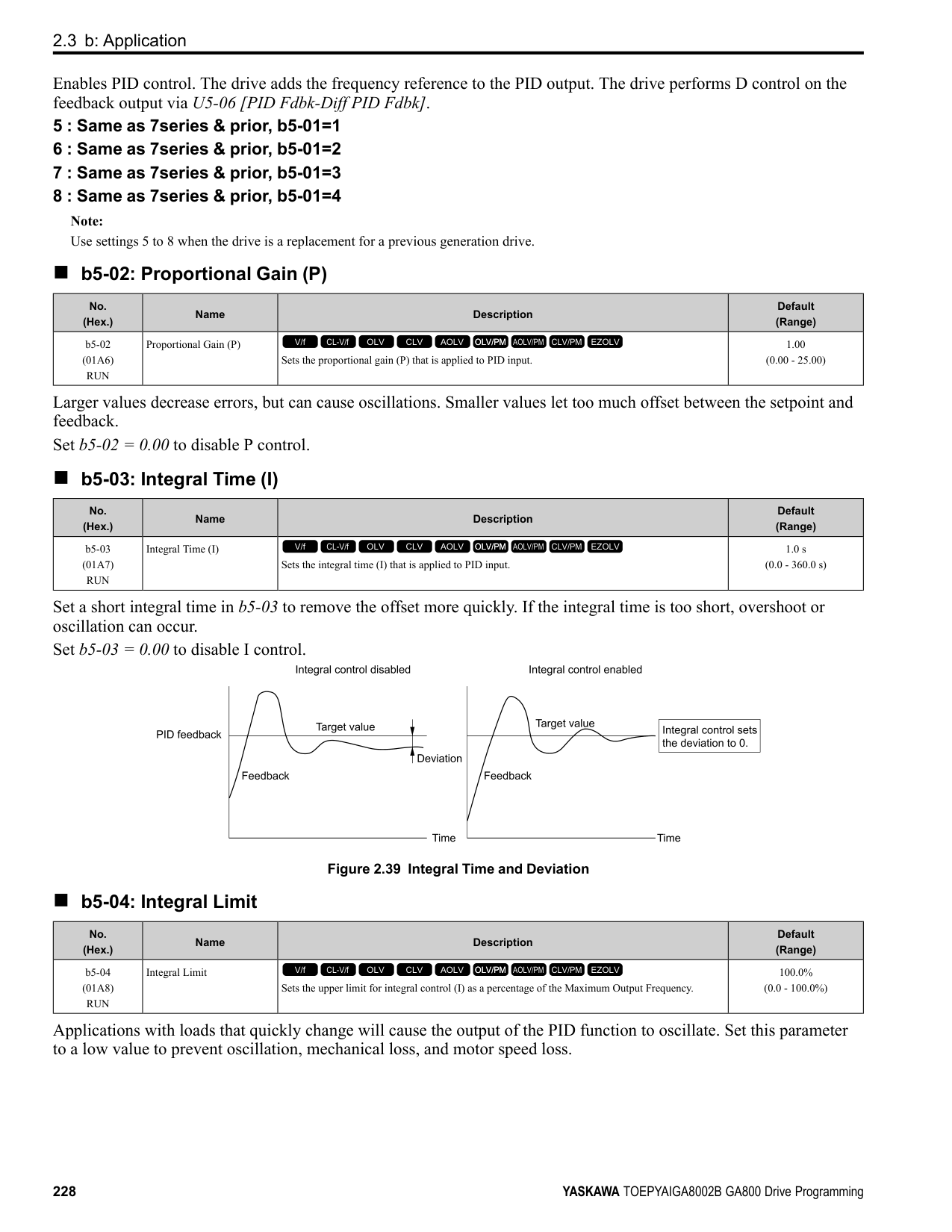
ParameterDetails
######## 2
Figure 2.68 Torque Control Block Diagram The externally input torque reference is the target value for the motor output torque. If the motor output torque and load torque are not balanced during Torque Control, the motor accelerates or decelerates. To prevent operation beyond the speed limit, the drive corrects the external torque reference if the motor speed reaches the speed limit. The speed limit, speed feedback, and the speed limit bias are the values that calculate the compensation value. When an external torque compensation value is input, the drive adds that value to the speed limit compensated torque reference value. The values L7-01 to L7-04 [Torque Limit] limit the resulting torque reference. The drive uses the value as the internal torque reference. You can use U1-09 [Torque Reference] to monitor the calculated torque reference. The torque limit values set in L7-01 to L7-04 are most important. Although you can set a higher external torque reference from an external source, the motor will not operate a torque output higher than the values set in L701 to L7-04.
######## ■ Setting the Torque Reference, Speed Limit, and Torque Compensation Values Torque Control Input Value Selection Table 2.38 lists the method for torque control input signals.
Table 2.38 The Method for Torque Control Input Signals
|Configuration Parameter|Signal Input Method|Parameter Settings|Notes| |---|---|---|---| |Torque Reference|Drive analog input terminals A1, A2, A3|H3-02, H3-10, H3-06 = 13 [MFAI Function Select= Torque Reference / Torque Limit] *1|The level of the set input signal must align with the polarity of the external signals.| |Torque Reference|Analog reference option cards AI-A3|• F2-01 = 0 [Analog Input Function Selection = 3 Independent Channels]
• H3-02, H3-10, and H3-06 = 13 *1
|H3-02, H3-10, or H3-06 settings are enabled for the option card input terminal. The level of the set input signal must align with the polarity of the external signals.| |Torque Reference|MEMOBUS register 0004H|• b1-01 = 2 [Frequency Reference Selection 1 = Memobus/Modbus Communications]
• When register bit 2 of 000FH = 1, the torque reference and torque limit from register 0004H is enabled.
|-| |Torque Reference|Communication option card|• b1-01 = 3 [Option PCB]
• F6-06 = 1 [Torque Reference/Limit by Comm = Enabled]
Refer to the communication option card manual for more information about the torque reference setting.|-| |Speed Limit|Frequency Reference Selection (Reference source selected with b1-01)|d5-03 = 1 [Speed Limit Selection = Active Frequency Reference]
The drive gets the speed limit from the frequency reference source input in b1-01 or b1-15 [Frequency Reference Selection 2].
*1|The drive applies the settings in C1-01 to C1-08 [Acceleration/Deceleration Times] and C2-01 to C2-04 [S-Curve Time @ Start/
End of Accel/Decel] to the speed limit.| |Speed Limit|d5-04 [Speed Limit]|d5-03 = 2 [d5-04 Setting]|-|
|Configuration Parameter|Signal Input Method|Parameter Settings|Notes| |---|---|---|---| |Torque Compensation|Drive analog input terminals A1, A2, A3|H3-02, H3-10, or H3-06 14 [Torque Compensation] *1|The level of the set input signal must align with the polarity of the external signals.| |Torque Compensation|Analog reference option cards AI-A3|• F2-01 0
• H3-02, H3-10, or H3-06 14 *1
|H3-02, H3-10, or H3-06 settings are enabled for the option card input terminal. The level of the set input signal must align with the polarity of the external signals.| |Torque Compensation|MEMOBUS register 0005H|• b1-01 2
• When register bit 3 of 000FH 1, the torque reference and torque limit from register 0005H is enabled.
|-| |Torque Compensation|Communication option card|b1-01 3
Refer to the communication option card manual for more information about the torque reference setting.|-|
*1 Sets analog input terminals A1, A2, and A3 to supply the speed limit, torque reference, or torque compensation. If you set the same
function to A1 to A3 terminals with H3-02, H3-10, or H3-06, the drive will detect oPE07 [Analog Input Selection Error]. Input Signal Polarity
The positive and negative torque references set the motor rotation direction. The direction of the Run command does not set it. The positive and negative torque reference signals and the direction of the Run command have an effect on the internal torque reference.
Table 2.39 Torque Control Signal Polarity
|Run Command Direction|Torque Reference Signal Polarity|Direction of Motor Rotation|Polarity of the Internal Torque Reference [U1-09]| |---|---|---|---| |Forward run|+ (Positive)|Forward direction|(Positive)| |Forward run|- (Negative)|Reverse direction|- (Negative)| |Reverse run|+ (Positive)|Reverse direction|- (Negative)| |Reverse run|- (Negative)|Forward direction|(Positive)|
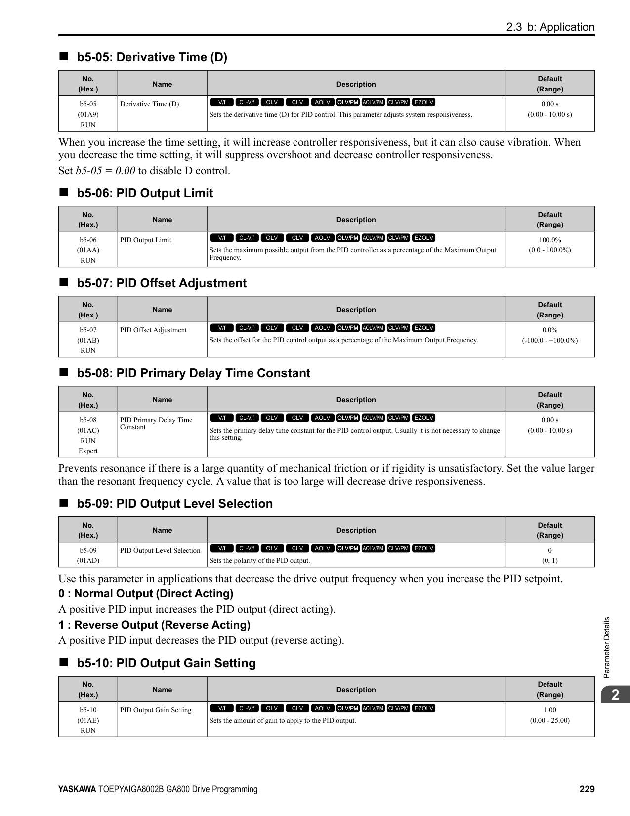
Note: For Yaskawa motors, the forward run direction is counterclockwise direction when seen from the load shaft.
When you use analog inputs, you can get negative input values with these methods:
xx = 78]. When you use MEMOBUS/Modbus communication or a communication option card, set the positive or negative signed torque reference. When the level of the analog signal input is 0 V to 10 Vor 4 mA to 20 mA, the torque reference is the forward direction. To reverse the polarity of the torque reference, use one of these two methods:
■ Speed Limit and Speed Limit Bias The drive reads the speed limit setting from the input selected in d5-03 [Speed Limit Selection]. You can use d5-05 [Speed Limit Bias] to add a bias to this speed. Parameter d5-08 [Uni-directional Speed Limit Bias] sets how the drive applies bias to the speed limit. Table 2.40 shows the relation between these settings:
Table 2.40 Speed Limit, Speed Bias and Speed Limit Priority Selection
| |Operating Conditions|Operating Conditions|Operating Conditions|Operating Conditions|Operating Conditions|Operating Conditions|Operating Conditions|Operating Conditions| |---|---|---|---|---|---|---|---|---| |Run command|Forward|Reverse|Forward|Reverse|Forward|Reverse|Forward|Reverse| |Torque reference direction|+ (Positive)|(Positive)|- (Negative)|- (Negative)|- (Negative)|- (Negative)|+ (Positive)|+ (Positive)|
ParameterDetails
######## 2
| |Operating Conditions|Operating Conditions|Operating Conditions|Operating Conditions|Operating Conditions|Operating Conditions|Operating Conditions|Operating Conditions| |---|---|---|---|---|---|---|---|---| |Speed limit direction|(Positive)|- (Negative)|- (Negative)|+ (Positive)|+ (Positive)|- (Negative)|- (Negative)|(Positive)| |Direction of motor rotation|Forward|Forward|Reverse|Reverse|Forward|Forward|Reverse|Reverse| |Generated torque (d5-08 0 [Disabled])
*1| | | | | | | | | |Generated torque
(d5-08 = 1 [Enabled]) *1| | | | | | | | | |Application example| | | | | | | | |
*1 The C5 parameter set the Δn value.
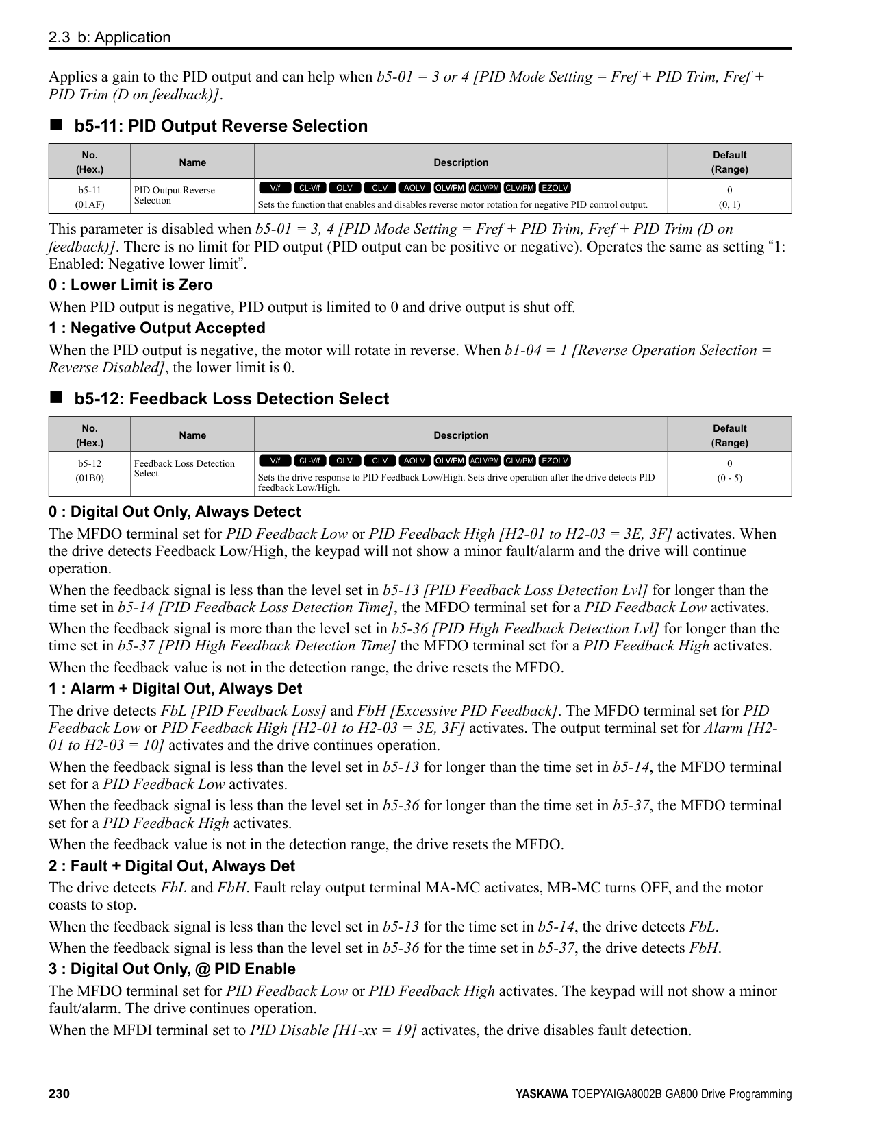
######## ■ Show Speed Limit Operation
When the motor is at the speed limit or more than the speed limit, the drive sends a signal to the PLC or other such control devices to tell you that an error has occurred. To enable this function, set an MFDO function [H2-01 to H2-
######## ■ Switch Between Torque Control and Speed Control
Use a digital input to switch Torque Control and Speed Control. To enable this function, set H1-xx = 71 [MFDI Function Select = Torque Control] to enable this function.
When you switch from Speed Control to Torque Control, the torque limit becomes the torque reference and the speed reference becomes the speed limit. When you switch from Torque Control to Speed Control, the torque reference becomes the torque limit and the speed limit becomes the speed reference. When you must use a delay time to switch between Speed Control and Torque Control, set d5-06 [Speed/Torque Changeover Time]. During this switch delay time, the drive keeps the reference value of the Torque Control and Speed Control when the switch signal was input. Change the reference values from an external control device during this delay time.
Note:
Figure 2.69 Speed/Torque Control Switching Time
######## ■ d5-01: Torque Control Selection
|No. (Hex.)|Name|Description|Default (Range)| |---|---|---|---| |d5-01 (029A)|Torque Control Selection|Sets the drive for torque control or speed control.
V/f CL-V/f OLV CLV AOLV OLV/PM AOLV/PM CLV/PM EZOLV
|0 (0, 1)|
Enables Speed Control. The drive controls the speed as specified by C5-01 to C5-07 [Speed Control (ASR) Setting Parameters].
Also use this setting when you use H1-xx = 71 [MFDI Function Select = Torque Control] to change between Speed Control and Torque Control.
######## ■ d5-02: Torque Reference Delay Time
|No. (Hex.)|Name|Description|Default (Range)| |---|---|---|---| |d5-02 (029B)|Torque Reference Delay Time|Sets the primary delay time constant for the torque reference filter.
V/f CL-V/f OLV CLV AOLV OLV/PM AOLV/PM CLV/PM EZOLV
|Determined by A1-02 (0 - 1000 ms)|
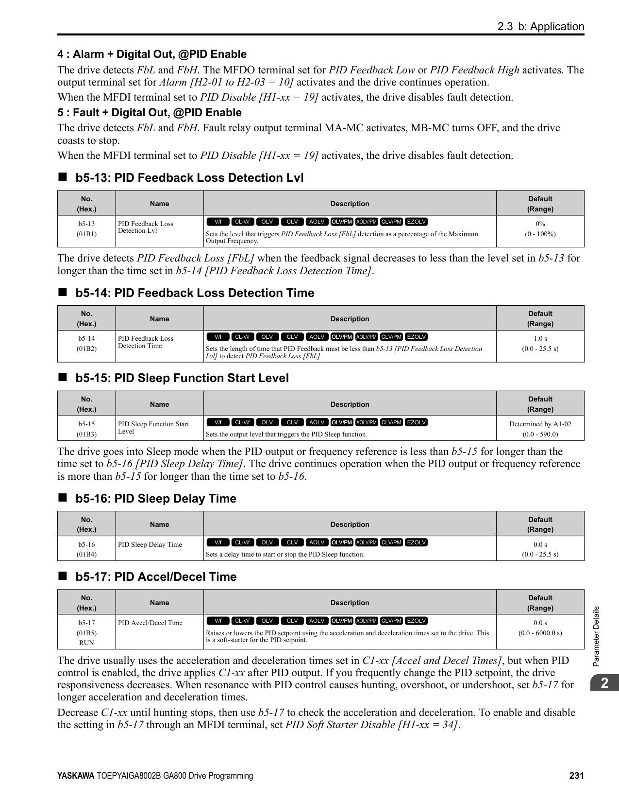
This parameter applies a primary delay filter to the torque reference signal to stop oscillation caused by a torque reference signal that is not stable. This also helps remove electrical interference from the torque reference signal and helps adjust the responsiveness between host controllers. If oscillation occurs during Torque Control, increase the setting value. If the setting value is too high, responsiveness becomes unsatisfactory.
######## ■ d5-03: Speed Limit Selection
|No. (Hex.)|Name|Description|Default (Range)| |---|---|---|---| |d5-03 (029C)|Speed Limit Selection|Sets the torque control speed limit method.
V/f CL-V/f OLV CLV AOLV OLV/PM AOLV/PM CLV/PM EZOLV
|1 (1, 2)|
The enabled frequency reference set in b1-01 [Frequency Reference Selection 1] or b1-15 [Frequency Reference Selection 2] will be the speed limit. The drive applies the values set in C1-01 to C1-08 [Acceleration/Deceleration Times 1 to 4] and C2-01 to C2-04 [S-Curve Time @ Start/End of Accel] as speed limits.
ParameterDetails
######## 2
######## ■ d5-04: Speed Limit
|No. (Hex.)|Name|Description|Default (Range)| |---|---|---|---| |d5-04 (029D)|Speed Limit|Sets the speed limit during Torque Control as a percentage of E1-04 [Maximum Output Frequency]. Set d5-03 = 2 [Speed Limit Selection = d5-04 Setting] before you set this parameter.
V/f CL-V/f OLV CLV AOLV OLV/PM AOLV/PM CLV/PM EZOLV
|0% (-120 - +120%)|
The speed limit is a positive value when it is in the same direction as the Run command. The speed limit is a negative value when it is in the opposite direction of the Run command.
######## ■ d5-05: Speed Limit Bias
|No. (Hex.)|Name|Description|Default (Range)| |---|---|---|---| |d5-05 (029E)|Speed Limit Bias|Sets the speed limit bias value as a percentage of E1-04 [Maximum Output Frequency].
V/f CL-V/f OLV CLV AOLV OLV/PM AOLV/PM CLV/PM EZOLV
|10% (0 - 120%)|
Adjusts the margin for the speed limit.
######## ■ d5-06: Speed/Torque Changeover Time
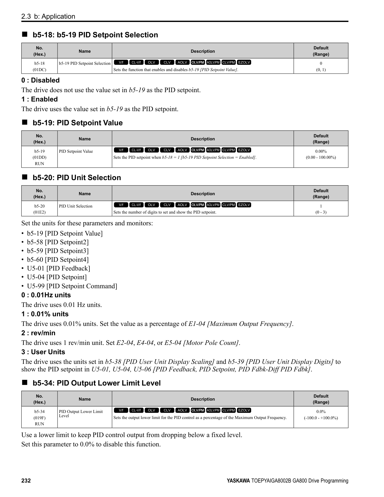
|No. (Hex.)|Name|Description|Default (Range)| |---|---|---|---| |d5-06 (029F)|Speed/Torque Changeover Time|Sets the delay time to switch between Speed Control and Torque Control. Set H1-xx = 71 [MFDI Function Selection = Torque Control] before you set this parameter.
V/f CL-V/f OLV CLV AOLV OLV/PM AOLV/PM CLV/PM EZOLV
|0 ms (0 - 1000 ms)|
The analog input (torque reference, speed limit value) holds at the value when the drive switched between Speed and Torque Control in the time of the Speed/Torque Changeover Timer. During this time, prepare to switch to an external source.
######## ■ d5-08: Uni-directional Speed Limit Bias
|No. (Hex.)|Name|Description|Default (Range)| |---|---|---|---| |d5-08 (02B5)|Uni-directional Speed Limit Bias|Sets the direction of the speed limit reference to which Speed Limit Bias [d5-05] applies.
V/f CL-V/f OLV CLV AOLV OLV/PM AOLV/PM CLV/PM EZOLV
|1 (0, 1)|
0 : Disabled The drive applies the speed limit bias in the speed limit direction and the opposite direction. 1 : Enabled The drive applies the speed limit bias in the opposite direction of the speed limit only.
◆ d6: Field Weakening /Forcing d6 parameters set the field weakening and field forcing functions.
The field weakening function decreases the energy consumption of the motor. It decreases the output voltage of the drive to a set level. The function decreases the motor excitation current inversely proportional to speed in a constant output range, and does not let the induced voltage of the motor become more than the power supply voltage. To enable this function, set Field Weakening [H1-xx = 63] ON.
Note:
Use the Field Weakening function in constant light-load applications. To control the energy consumption of the motor for other load conditions, use the b8 parameters [Energy Saving].
The Field Forcing function adjusts the delaying influence of the motor time constant when the drive changes the excitation current reference and it also increases motor responsiveness. This function uses a high motor excitation current reference for drive start-up only to help develop actual motor excitation current. Enable the Field Forcing function to increase motor responsiveness.
Note: You cannot use Field Forcing during DC Injection Braking.
Make sure that these two conditions are correct to enable the Field Weakening command:
|No. (Hex.)|Name|Description|Default (Range)| |---|---|---|---|
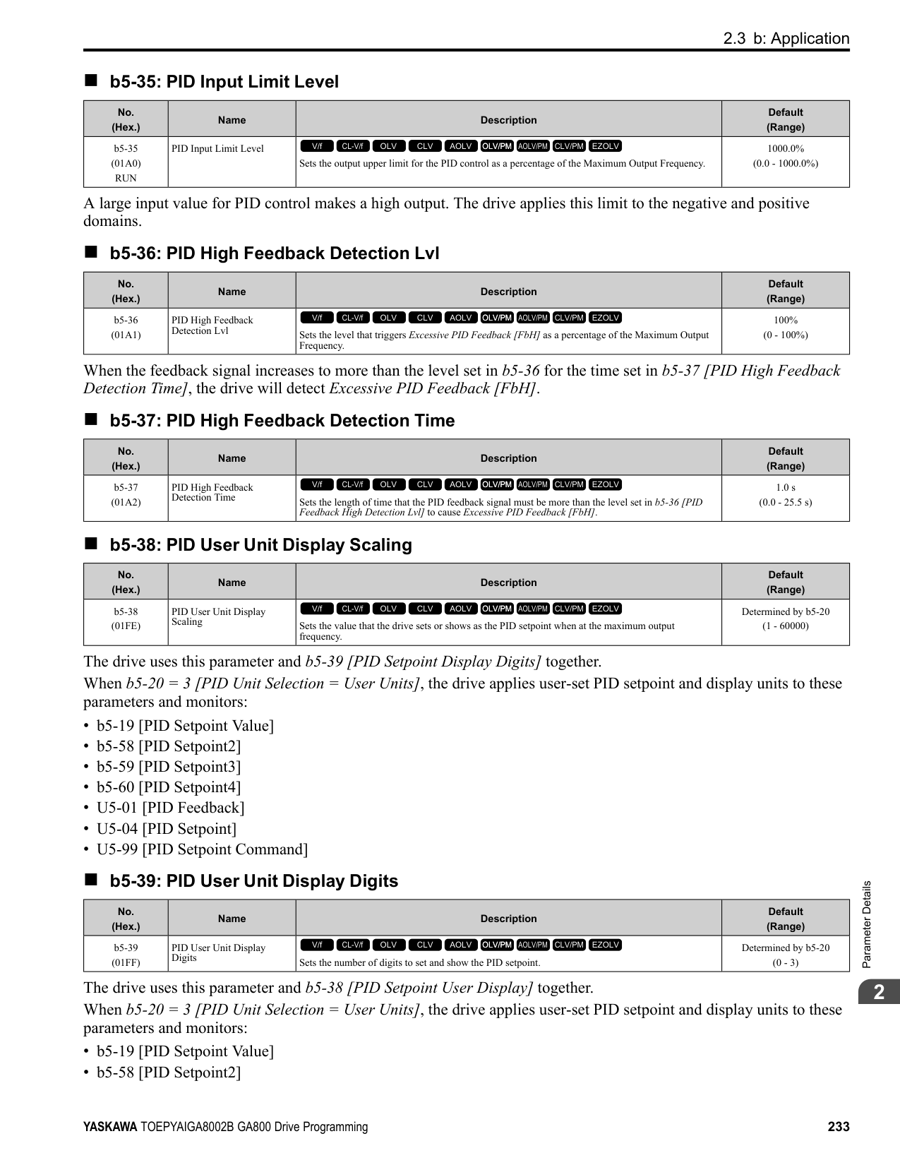
|d6-01 (02A0)|Field Weakening Level|Sets the drive output voltage as a percentage of E1-05 [Maximum Output Voltage] when H1-xx = 63 [Field Weakening] is activated.
V/f CL-V/f OLV CLV AOLV OLV/PM AOLV/PM CLV/PM EZOLV
|80% (0 - 100%)|
|No. (Hex.)|Name|Description|Default (Range)| |---|---|---|---| |d6-02 (02A1)|Field Weakening Frequency Limit|Sets the minimum output frequency to start field weakening.
V/f CL-V/f OLV CLV AOLV OLV/PM AOLV/PM CLV/PM EZOLV
|0.0 Hz (0.0 - 590.0 Hz)|
|No. (Hex.)|Name|Description|Default (Range)| |---|---|---|---| |d6-03 (02A2)|Field Forcing Selection|Sets the field forcing function.
V/f CL-V/f OLV CLV AOLV OLV/PM AOLV/PM CLV/PM EZOLV
|0 (0, 1)|
0 : Disabled 1 : Enabled
######## ■ d6-06: Field Forcing Limit
|No. (Hex.)|Name|Description|Default (Range)| |---|---|---|---| |d6-06 (02A5)|Field Forcing Limit|Sets the limit value for field forcing to increase the motor excitation current reference as a percentage of E2-03 [Motor No-Load Current]. Usually it is not necessary to change this setting.
V/f CL-V/f OLV CLV AOLV OLV/PM AOLV/PM CLV/PM EZOLV
|400% (100 - 400%)|
Note: You cannot use Field Forcing during DC Injection Braking.
◆ d7: Offset Frequency The drive will use 3 digital signal inputs, to add or subtract the set frequency (Offset frequency) to/from the frequency reference and correct the speed. The drive uses the terminal set in H1-xx = 44 to 46 [MFDI Function Select = Add Offset Frequency 1 to 3] to set the Offset frequency. When you close more than one input at the same time, the drive adds the selected offset values together. Figure 2.70 shows the Offset frequency function:
| | | |---|---| | | |
Figure 2.70 Offset Frequency Operation
|No. (Hex.)|Name|Description|Default (Range)| |---|---|---|---| |d7-01 (02B2) RUN|Offset Frequency 1|Uses H1-xx = 44 [MFDI Function Select = Add Offset Frequency 1 (d7-01)] as a percentage of the Maximum Output Frequency to add or subtract the set frequency to/from the frequency reference.
V/f CL-V/f OLV CLV AOLV OLV/PM AOLV/PM CLV/PM EZOLV
|0.0% (-100.0 - +100.0%)|
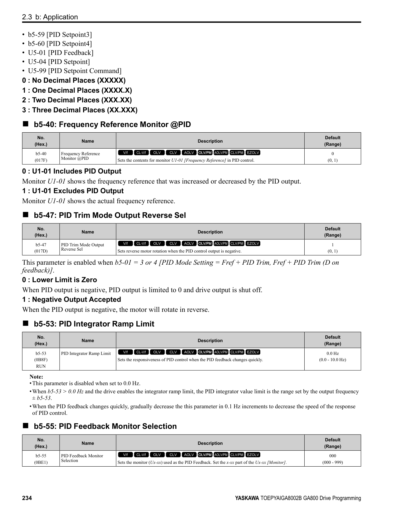
|No. (Hex.)|Name|Description|Default (Range)| |---|---|---|---| |d7-02 (02B3) RUN|Offset Frequency 2|Uses H1-xx = 45 [MFDI Function Select = Add Offset Frequency 2 (d7-02)] as a percentage of the Maximum Output Frequency to add or subtract the set frequency to/from the frequency reference.
V/f CL-V/f OLV CLV AOLV OLV/PM AOLV/PM CLV/PM EZOLV
|0.0% (-100.0 - +100.0%)|
|No. (Hex.)|Name|Description|Default (Range)| |---|---|---|---| |d7-03 (02B4) RUN|Offset Frequency 3|Uses H1-xx = 46 [MFDI Function Select = Add Offset Frequency 3 (d7-03)] as a percentage of the Maximum Output Frequency to add or subtract the set frequency to/from the frequency reference.
V/f CL-V/f OLV CLV AOLV OLV/PM AOLV/PM CLV/PM EZOLV
|0.0% (-100.0 - +100.0%)|
####### 2.6 E: Motor Parameters
E parameters cover drive input voltage, V/f pattern, and motor parameters.
◆ E1: V/f Pattern for Motor 1 E1 parameters are used to set the drive input voltage and motor V/f characteristics. To switch drive operation from one motor to another motor, set the V/f characteristics for motor 1.
■ V/f Pattern Settings The drive uses a V/f pattern to adjust the output voltage relative to the frequency reference. This product has been preconfigured with 15 voltage/frequency (V/f) patterns. Use E1-03 [V/f Pattern Selection] to select the V/f pattern that is appropriate for the application. Additionally, one custom V/f pattern is available. Set E1-03 = F [Custom] and then manually set parameters E1-04 to E1-10.
Table 2.41 Predefined V/f Patterns
|Setting Value|Specification|Characteristic|Application| |---|---|---|---| |0|VT, 50Hz|Constant torque|For general purpose applications. This pattern is used when the load torque is constant without any rotation speed such as that used for linear conveyor systems.| |1|VT, 60 Hz|Constant torque|For general purpose applications. This pattern is used when the load torque is constant without any rotation speed such as that used for linear conveyor systems.| |2|Const Trq, 50Hz base, 60Hz max|Constant torque|For general purpose applications. This pattern is used when the load torque is constant without any rotation speed such as that used for linear conveyor systems.| |3|Const Trq, 60 Hz base, 72 Hz max|Constant torque|For general purpose applications. This pattern is used when the load torque is constant without any rotation speed such as that used for linear conveyor systems.| |4|VT, 50 Hz, 65% Vmid reduction|Derated Torque Characteristics|This pattern is used for torque loads proportional to 2 or 3 times the rotation speed, such as is the case with fans and pumps.| |5|VT, 50 Hz, 50% Vmid reduction|Derated Torque Characteristics|This pattern is used for torque loads proportional to 2 or 3 times the rotation speed, such as is the case with fans and pumps.| |6|VT, 60 Hz, 65% Vmid reduction|Derated Torque Characteristics|This pattern is used for torque loads proportional to 2 or 3 times the rotation speed, such as is the case with fans and pumps.| |7|VT, 60 Hz, 50% Vmid reduction|Derated Torque Characteristics|This pattern is used for torque loads proportional to 2 or 3 times the rotation speed, such as is the case with fans and pumps.| |8|High Trq, 50 Hz, 25% Vmin Boost|High starting torque|This pattern is used when strong torque is required during startup.| |9|High Trq, 50 Hz, 65% Vmin Boost|High starting torque|This pattern is used when strong torque is required during startup.| |A|High Trq, 60 Hz, 25% Vmin Boost|High starting torque|This pattern is used when strong torque is required during startup.| |B|High Trq, 60 Hz, 65% Vmin Boost|High starting torque|This pattern is used when strong torque is required during startup.| |C|Const Trq, 60 Hz base, 90 Hz max|Constant output|This pattern is used to rotate motors at greater than 60 Hz. Output voltage is constant when operating at greater than 60 Hz.| |D|Const Trq, 60 Hz base, 120 Hz max|Constant output|This pattern is used to rotate motors at greater than 60 Hz. Output voltage is constant when operating at greater than 60 Hz.| |E|Const Trq, 60 Hz base, 180 Hz max|Constant output|This pattern is used to rotate motors at greater than 60 Hz. Output voltage is constant when operating at greater than 60 Hz.| |F|V/f Pattern Selection|Constant torque|Enables a custom V/f pattern by changing E1-04 to E1-13 [V/f Pattern for Motor 1]. The default settings for E1-04 to E1-13 are the same as Setting Value 1 [Const Trq, 60Hz base, 60Hz max].|
Note: Be aware of the following points when manually setting V/f patterns.
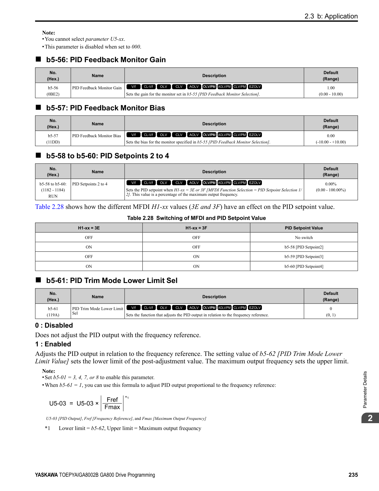
Figure 2.71 V/f Pattern
######## ■ E1-01: Input AC Supply Voltage
|No. (Hex.)|Name|Description|Default (Range)| |---|---|---|---| |E1-01 (0300)|Input AC Supply Voltage|Sets the drive input voltage.
V/f CL-V/f OLV CLV AOLV OLV/PM AOLV/PM CLV/PM EZOLV
|200 V Class: 240 V, 400 V: 480 V
(200 V Class: 155 to 255 V, 400 V Class: 310 to 510 V)|
NOTICE: Set parameter E1-01 to align with the drive input voltage (not motor voltage). If this parameter is incorrect, the protective functions of the drive will not operate correctly and it can cause damage to the drive.
Values Related to the Drive Input Voltage The value set in E1-01 is the base value that the drive uses for the motor protective functions in Table 2.42. With a 400 V class drive, the detection level changes for some motor protective functions.
Table 2.42 Values Related to the Drive Input Voltage
|Voltage|E1-01 Setting|Approximate Values|Approximate Values|Approximate Values|Approximate Values|Approximate Values| |---|---|---|---|---|---|---| |Voltage|E1-01 Setting|ov Detection Level|BTR Operation Level (rr Detection Level) *1|L2-05 [Undervoltage Detection Lvl (Uv1)]|L2-11 [KEB DC Bus Voltage Setpoint]|L3-17 [DC Bus Regulation Level]| |200 V class|All settings|410 V|394 V|190 V|260 V|375 V| |400 V class|Setting value ≥ 400 V|820 V|788 V|380 V|500 V|750 V| |400 V class|Setting value < 400 V|820 V|788 V|350 V|460 V|750 V|
*1 This is the protection function enabled in drives with built-in braking transistors. These values show the level that will trigger the built-in braking transistor. Refer to “YASKAWA AC Drive 72060001 Series Option Braking Unit and Braking Resistor Unit Installation Manual (TOBPC72060001)” for more information.
######## ■ E1-03: V/f Pattern Selection
|No. (Hex.)|Name|Description|Default (Range)| |---|---|---|---| |E1-03 (0302)|V/f Pattern Selection|Sets the V/f pattern for the drive and motor. You can use one of the preset patterns or you can make a custom pattern.
V/f CL-V/f OLV CLV AOLV OLV/PM AOLV/PM CLV/PM EZOLV
|F (Determined by A1-02)|
################# Note:
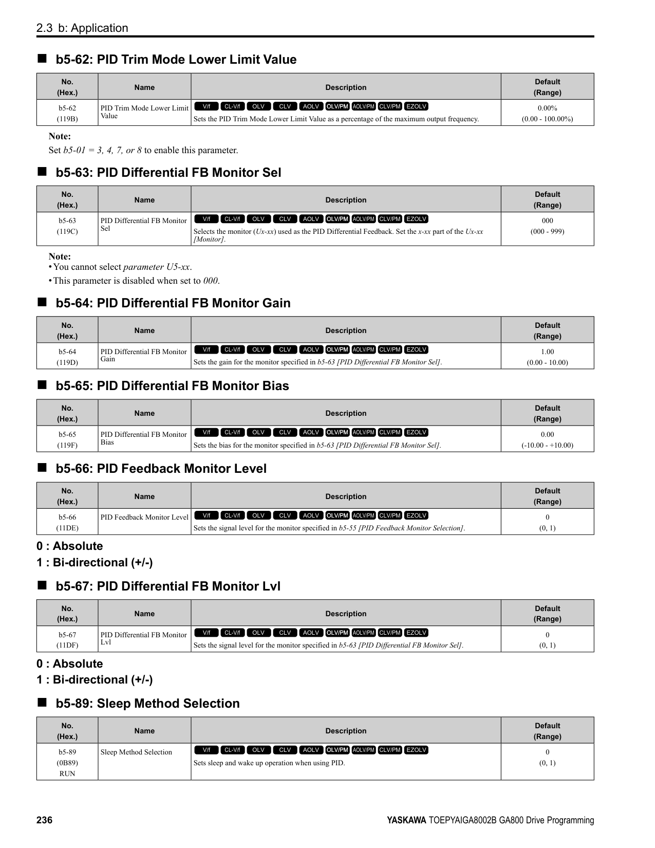
############## 0 : Const Trq, 50Hz base, 50Hz max
Use this constant torque pattern for general applications. This pattern is used when the load torque is constant without any rotation speed such as that used for linear conveyor systems.
Note: The voltage values in the figures are for 200 V class drives. Multiply the values by 2 for 400 V class drives.
|HD: 2004 - 2021, 4002 - 4012 ND: 2004 - 2018, 4002 - 4009|HD: 2030 - 2211, 4018 - 4103 ND: 2021 - 2169, 4012 - 4089|HD: 2257 - 2415, 4140 - 4720 ND: 2211 - 2415, 4103 - 4720| |---|---|---| | | | |
############## 1 : Const Trq, 60Hz base, 60Hz max
Use this constant torque pattern for general applications. This pattern is used when the load torque is constant without any rotation speed such as that used for linear conveyor systems.
Note: The voltage values in the figures are for 200 V class drives. Multiply the values by 2 for 400 V class drives.
|HD: 2004 - 2021, 4002 - 4012 ND: 2004 - 2018, 4002 - 4009|HD: 2030 - 2211, 4018 - 4103 ND: 2021 - 2169, 4012 - 4089|HD: 2257 - 2415, 4140 - 4720 ND: 2211 - 2415, 4103 - 4720| |---|---|---| | | | |
############## 2 : Const Trq, 50Hz base, 60Hz max
Use this constant torque pattern for general applications. This pattern is used when the load torque is constant without any rotation speed such as that used for linear conveyor systems.
Note: The voltage values in the figures are for 200 V class drives. Multiply the values by 2 for 400 V class drives.
|HD: 2004 - 2021, 4002 - 4012 ND: 2004 - 2018, 4002 - 4009|HD: 2030 - 2211, 4018 - 4103 ND: 2021 - 2169, 4012 - 4089|HD: 2257 - 2415, 4140 - 4720 ND: 2211 - 2415, 4103 - 4720| |---|---|---| | | | |
ParameterDetails
######## 2
############## 3 : Const Trq, 60 Hz base, 72 Hz max
Use this constant torque pattern for general applications. This pattern is used when the load torque is constant without any rotation speed such as that used for linear conveyor systems.
Note: The voltage values in the figures are for 200 V class drives. Multiply the values by 2 for 400 V class drives.
|HD: 2004 - 2021, 4002 - 4012 ND: 2004 - 2018, 4002 - 4009|HD: 2030 - 2211, 4018 - 4103 ND: 2021 - 2169, 4012 - 4089|HD: 2257 - 2415, 4140 - 4720 ND: 2211 - 2415, 4103 - 4720| |---|---|---| | | | |
############## 4 : VT, 50Hz, 65% Vmid reduction
Use this derated torque pattern for torque loads proportional to three times the rotation speed. For example, fans and pumps.
Note: The voltage values in the figures are for 200 V class drives. Multiply the values by 2 for 400 V class drives.
|HD: 2004 - 2021, 4002 - 4012 ND: 2004 - 2018, 4002 - 4009|HD: 2030 - 2211, 4018 - 4103 ND: 2021 - 2169, 4012 - 4089|HD: 2257 - 2415, 4140 - 4720 ND: 2211 - 2415, 4103 - 4720| |---|---|---| | | | |
############## 5 : VT, 50Hz, 50% Vmid reduction
Use this derated torque pattern for torque loads proportional to two times the rotation speed. For example, fans and pumps.
Note: The voltage values in the figures are for 200 V class drives. Multiply the values by 2 for 400 V class drives.
|HD: 2004 - 2021, 4002 - 4012 ND: 2004 - 2018, 4002 - 4009|HD: 2030 - 2211, 4018 - 4103 ND: 2021 - 2169, 4012 - 4089|HD: 2257 - 2415, 4140 - 4720 ND: 2211 - 2415, 4103 - 4720| |---|---|---| | | | |
############## 6 : VT, 60 Hz, 65% Vmid reduction
Use this derated torque pattern for torque loads proportional to three times the rotation speed. For example, fans and pumps.
|HD: 2004 - 2021, 4002 - 4012 ND: 2004 - 2018, 4002 - 4009|HD: 2030 - 2211, 4018 - 4103 ND: 2021 - 2169, 4012 - 4089|HD: 2257 - 2415, 4140 - 4720 ND: 2211 - 2415, 4103 - 4720| |---|---|---| | | | |
############## 7 : VT, 60Hz, 50% Vmid reduction
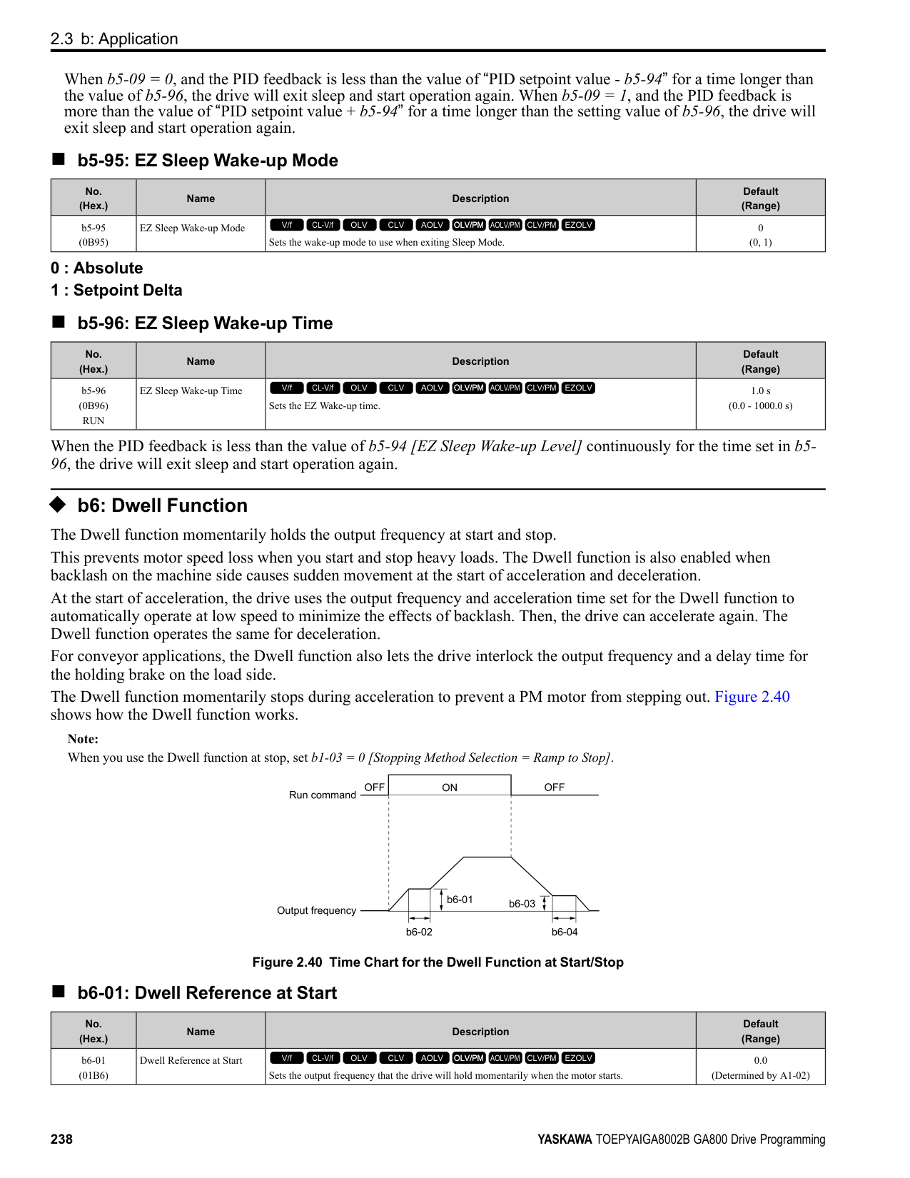
Use this derated torque pattern for torque loads proportional to two times the rotation speed. For example, fans and pumps.
Note: The voltage values in the figures are for 200 V class drives. Multiply the values by 2 for 400 V class drives.
|HD: 2004 - 2021, 4002 - 4012 ND: 2004 - 2018, 4002 - 4009|HD: 2030 - 2211, 4018 - 4103 ND: 2021 - 2169, 4012 - 4089|HD: 2257 - 2415, 4140 - 4720 ND: 2211 - 2415, 4103 - 4720| |---|---|---| | | | |
############### 8 : High Trq, 50Hz, 25% Vmin boostUse this pattern when moderate torque is necessary during start up.Select this pattern only in these conditions:
|HD: 2004 - 2021, 4002 - 4012 ND: 2004 - 2018, 4002 - 4009|HD: 2030 - 2211, 4018 - 4103 ND: 2021 - 2169, 4012 - 4089|HD: 2257 - 2415, 4140 - 4720 ND: 2211 - 2415, 4103 - 4720| |---|---|---| | | | |
Note:
ParameterDetails
######## 2
|HD: 2004 - 2021, 4002 - 4012 ND: 2004 - 2018, 4002 - 4009|HD: 2030 - 2211, 4018 - 4103 ND: 2021 - 2169, 4012 - 4089|HD: 2257 - 2415, 4140 - 4720 ND: 2211 - 2415, 4103 - 4720| |---|---|---| | | | |
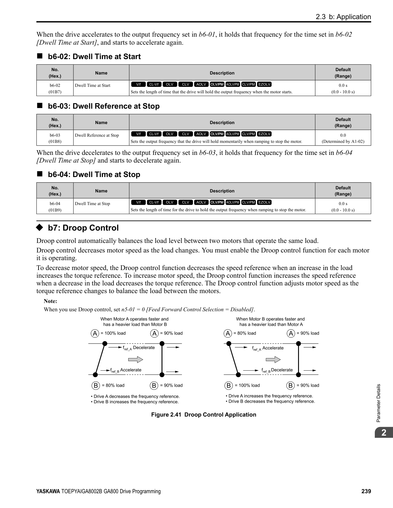
|HD: 2004 - 2021, 4002 - 4012 ND: 2004 - 2018, 4002 - 4009|HD: 2030 - 2211, 4018 - 4103 ND: 2021 - 2169, 4012 - 4089|HD: 2257 - 2415, 4140 - 4720 ND: 2211 - 2415, 4103 - 4720| |---|---|---| | | | |
|HD: 2004 - 2021, 4002 - 4012 ND: 2004 - 2018, 4002 - 4009|HD: 2030 - 2211, 4018 - 4103 ND: 2021 - 2169, 4012 - 4089|HD: 2257 - 2415, 4140 - 4720 ND: 2211 - 2415, 4103 - 4720| |---|---|---| | | | |
Use this constant output pattern to rotate motors at more than 60 Hz. Output voltage is constant when you operate at more than 60 Hz.
Note: The voltage values in the figures are for 200 V class drives. Multiply the values by 2 for 400 V class drives.
Use this constant output pattern to rotate motors at more than 60 Hz. Output voltage is constant when you operate at more than 60 Hz.
Note: The voltage values in the figures are for 200 V class drives. Multiply the values by 2 for 400 V class drives.
|HD: 2004 - 2021, 4002 - 4012 ND: 2004 - 2018, 4002 - 4009|HD: 2030 - 2211, 4018 - 4103 ND: 2021 - 2169, 4012 - 4089|HD: 2257 - 2415, 4140 - 4720 ND: 2211 - 2415, 4103 - 4720| |---|---|---| | | | |
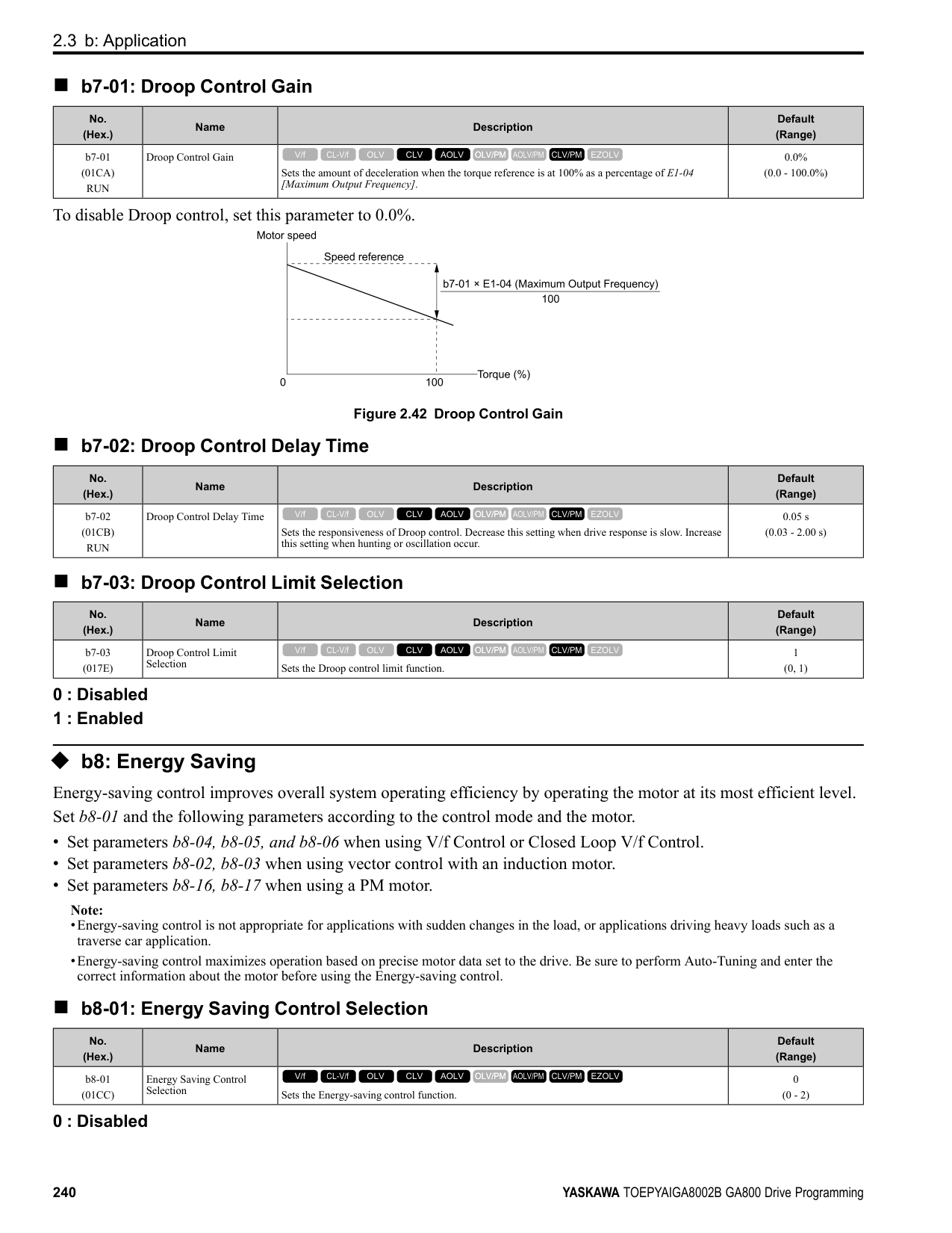
|HD: 2004 - 2021, 4002 - 4012 ND: 2004 - 2018, 4002 - 4009|HD: 2030 - 2211, 4018 - 4103 ND: 2021 - 2169, 4012 - 4089|HD: 2257 - 2415, 4140 - 4720 ND: 2211 - 2415, 4103 - 4720| |---|---|---| | | | |
ParameterDetails
######## ■ E1-04: Maximum Output Frequency
|No. (Hex.)|Name|Description|Default (Range)| |---|---|---|---| |E1-04 (0303)|Maximum Output Frequency|Sets the maximum output frequency for the V/f pattern.
V/f CL-V/f OLV CLV AOLV OLV/PM AOLV/PM CLV/PM EZOLV
|Determined by A1-02 and E5-01
(Determined by A1-02 and E5-01)|
Note: Default setting is determined by A1-02 [Control Method Selection], C6-01 [Normal / Heavy Duty Selection], and o2-04 [Drive Model Selection].
|No. (Hex.)|Name|Description|Default (Range)| |---|---|---|---| |E1-05 (0304)|Maximum Output Voltage|Sets the maximum output voltage for the V/f pattern.
V/f CL-V/f OLV CLV AOLV OLV/PM AOLV/PM CLV/PM EZOLV
|200 V Class: 230.0 V, 400 V: 460.0 V
(200 V Class: 0.0 - 255.0 V, 400 V Class: 0.0 - 510.0 V)|
|No. (Hex.)|Name|Description|Default (Range)| |---|---|---|---| |E1-06 (0305)|Base Frequency|Sets the base frequency for the V/f pattern.
V/f CL-V/f OLV CLV AOLV OLV/PM AOLV/PM CLV/PM EZOLV
|Determined by A1-02 and E5-01
(0.0 - E1-04)|
|No. (Hex.)|Name|Description|Default (Range)| |---|---|---|---| |E1-07 (0306)|Mid Point A Frequency|Sets a middle output frequency for the V/f pattern.
V/f CL-V/f OLV CLV AOLV OLV/PM AOLV/PM CLV/PM EZOLV
|Determined by A1-02 (0.0 - E1-04)|
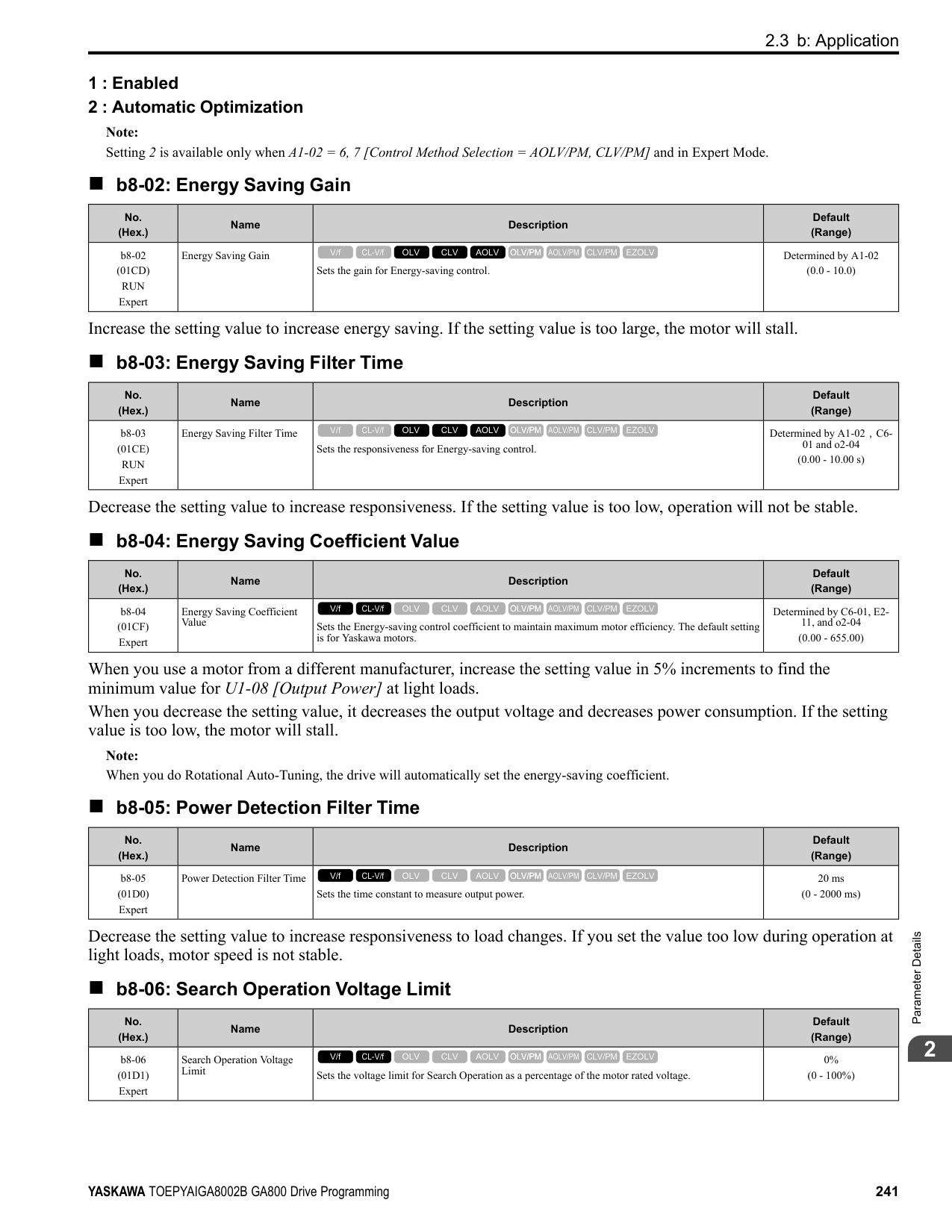
|No. (Hex.)|Name|Description|Default (Range)| |---|---|---|---| |E1-08 (0307)|Mid Point AVoltage|Sets a middle output voltage for the V/f pattern.
V/f CL-V/f OLV CLV AOLV OLV/PM AOLV/PM CLV/PM EZOLV
|Determined by A1-02,C601 and o2-04
(200 V Class: 0.0 - 255.0 V, 400 V Class: 0.0 - 510.0 V)|
|No. (Hex.)|Name|Description|Default (Range)| |---|---|---|---| |E1-09 (0308)|Minimum Output Frequency|Sets the minimum output frequency for the V/f pattern.
V/f CL-V/f OLV CLV AOLV OLV/PM AOLV/PM CLV/PM EZOLV
|Determined by A1-02 and E5-01
(Determined by A1-02, E104, and E5-01)|
|No. (Hex.)|Name|Description|Default (Range)| |---|---|---|---| |E1-10 (0309)|Minimum Output Voltage|Sets the minimum output voltage for the V/f pattern.
V/f CL-V/f OLV CLV AOLV OLV/PM AOLV/PM CLV/PM EZOLV
|Determined by A1-02
(200 V Class: 0.0 to 255.0 V, 400 V Class: 0.0 to 510.0 V)|
|No. (Hex.)|Name|Description|Default (Range)| |---|---|---|---| |E1-11 (030A) Expert|Mid Point B Frequency|Sets a middle output frequency for the V/f pattern.
V/f CL-V/f OLV CLV AOLV OLV/PM AOLV/PM CLV/PM EZOLV
|0.0 Hz (0.0 - E1-04)|
Note: Set this parameter to 0.0 to disable the function.
######## ■ E1-12: Mid Point B Voltage
|No. (Hex.)|Name|Description|Default (Range)| |---|---|---|---| |E1-12 (030B) Expert|Mid Point B Voltage|Sets a middle point voltage for the V/f pattern.
V/f CL-V/f OLV CLV AOLV OLV/PM AOLV/PM CLV/PM EZOLV
|0.0 V
(200 V Class: 0.0 to 255.0 V, 400 V Class: 0.0 to 510.0 V)|
Note: Set this parameter to 0.0 to disable the function.
######## ■ E1-13: Base Voltage
|No. (Hex.)|Name|Description|Default (Range)| |---|---|---|---| |E1-13 (030C) Expert|Base Voltage|Sets the base voltage for the V/f pattern.
V/f CL-V/f OLV CLV AOLV OLV/PM AOLV/PM CLV/PM EZOLV
|0.0 V (200 V Class: 0.0 - 255.0 V,400 V Class: 0.0 - 510.0 V)|
################# Note:
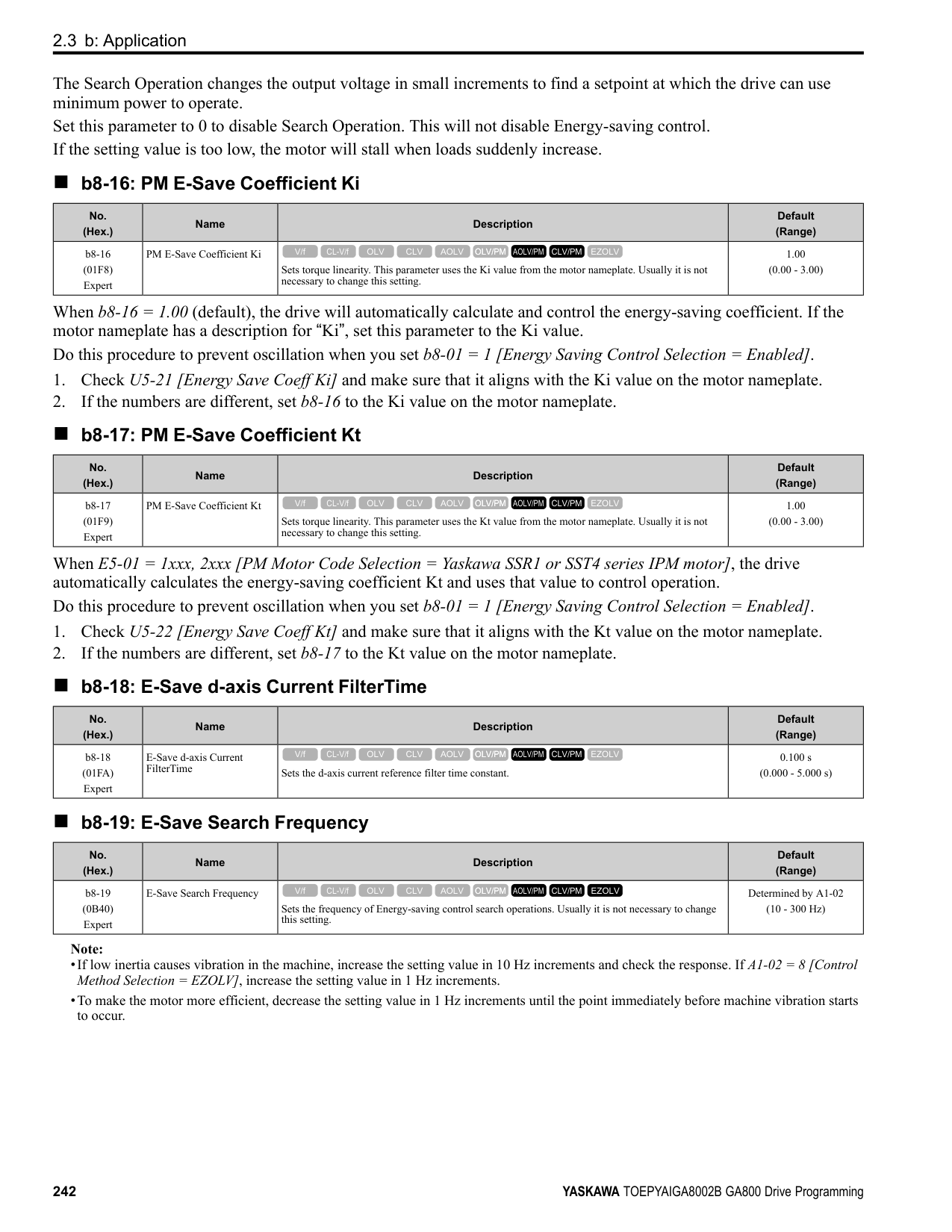
◆ E2: Motor Parameters E2 parameters [Motor Parameters] are used to set induction motor data. To switch drive operation from one motor to another motor, configure the first motor (motor 1). Performing Auto-Tuning automatically sets the E2 parameters to the optimal values. If Auto-Tuning cannot be performed, set the E2 parameters manually.
Note: If A1-02 [Control Method Selection] is set to the following control modes, the keypad does not display E2-xx.
######## ■ E2-01: Motor Rated Current (FLA)
|No. (Hex.)|Name|Description|Default (Range)| |---|---|---|---| |E2-01 (030E)|Motor Rated Current (FLA)|Sets the motor rated current in amps.
V/f CL-V/f OLV CLV AOLV OLV/PM AOLV/PM CLV/PM EZOLV
|Determined by o2-04, C6-01 (10% to 200% of the drive rated current)|
Note:
The value set for E2-01 becomes the reference value for motor protection, the torque limit, and torque control. Enter the motor rated current shown on the motor nameplate. Auto-Tuning the drive will automatically set E2-01 to the value input for “Motor Rated Current”.
######## ■ E2-02: Motor Rated Slip
ParameterDetails
|No. (Hex.)|Name|Description|Default (Range)| |---|---|---|---| |E2-02 (030F)|Motor Rated Slip|Sets motor rated slip.
V/f CL-V/f OLV CLV AOLV OLV/PM AOLV/PM CLV/PM EZOLV
|Determined by o2-04, C6-01 (0.000 - 20.000 Hz)|
This parameter value becomes the base slip compensation value. The drive automatically sets this parameter during Auto-Tuning. When you cannot do Auto-Tuning, calculate the motor rated slip with the information on the motor nameplate and this formula: E2-02 = f - (n × p) / 120
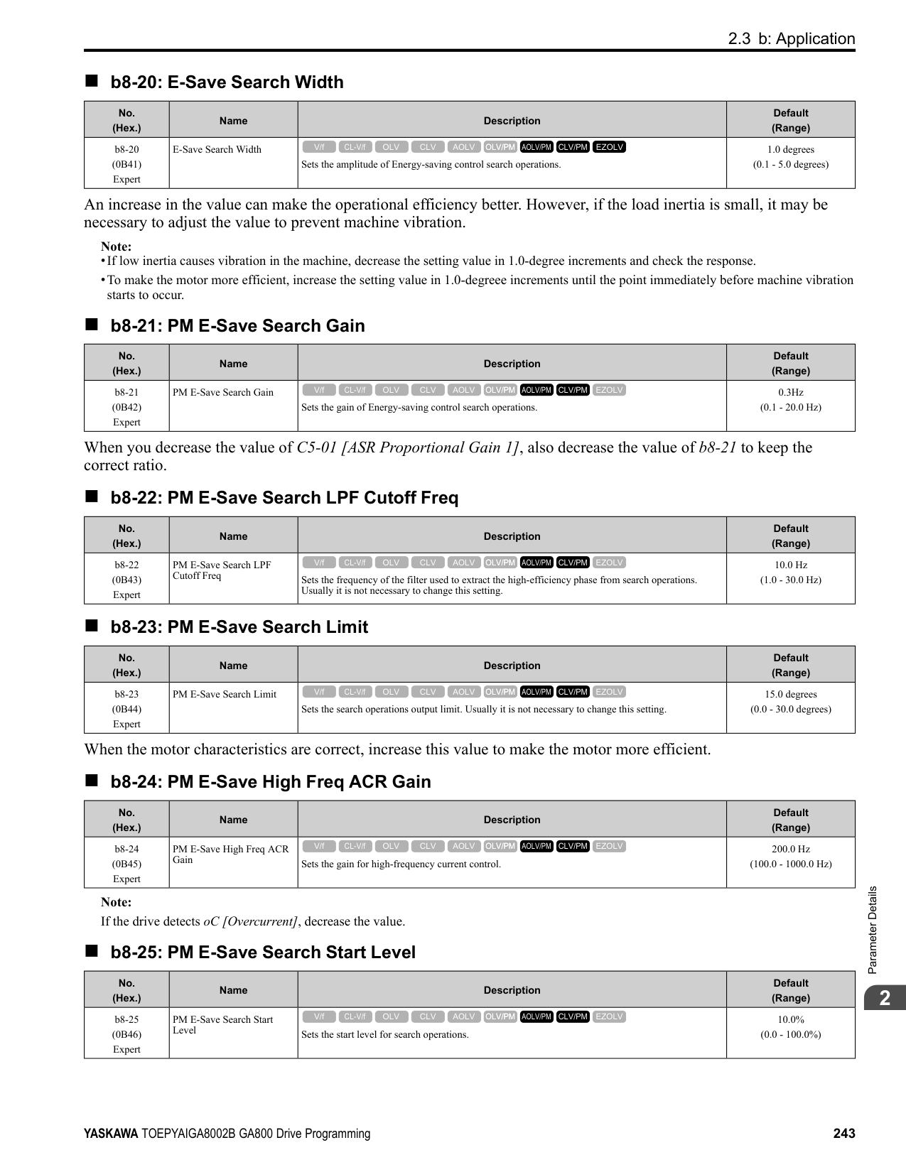
######## ■ E2-03: Motor No-Load Current
|No. (Hex.)|Name|Description|Default (Range)| |---|---|---|---| |E2-03 (0310)|Motor No-Load Current|Sets the no-load current for the motor in amps when operating at the rated frequency and the no-load voltage.
V/f CL-V/f OLV CLV AOLV OLV/PM AOLV/PM CLV/PM EZOLV
|Determined by o2-04, C6-01 (0 to E2-01)|
Note: The default settings and setting ranges are in these units:
The drive automatically sets this parameter during Auto-Tuning. When you cannot do Auto-Tuning, you can also use the motor no-load current on the motor test report to enter this value manually. Contact the motor manufacturer to receive a copy of the motor test report.
Note: The default setting of the no-load current is for operation with a 4-pole motor recommended by Yaskawa.
######## ■ E2-04: Motor Pole Count
|No. (Hex.)|Name|Description|Default (Range)| |---|---|---|---| |E2-04 (0311)|Motor Pole Count|Sets the number of motor poles.
V/f CL-V/f OLV CLV AOLV OLV/PM AOLV/PM CLV/PM EZOLV
|4 (2 - 120)|
Note:
Auto-Tuning automatically sets this parameter to the value of [Number of Motor Poles].
######## ■ E2-05: Motor Line-to-Line Resistance
|No. (Hex.)|Name|Description|Default (Range)| |---|---|---|---|
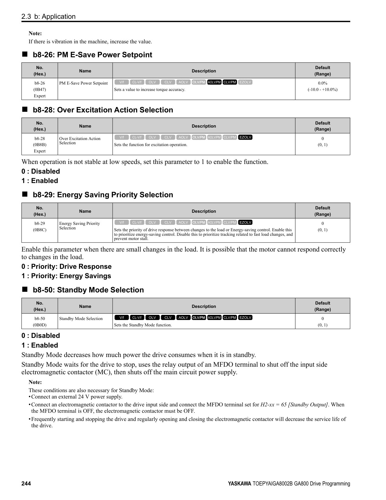
|E2-05 (0312)|Motor Line-to-Line Resistance|Sets the line-to-line resistance for the motor stator windings.
V/f CL-V/f OLV CLV AOLV OLV/PM AOLV/PM CLV/PM EZOLV
|Determined by o2-04, C6-01 (0.000 - 65.000 Ω)|
Note: This value is the motor line-to-line resistance. Do not set this parameter with the single-phase resistance.
Auto-Tuning automatically sets this parameter. If you cannot do Auto-Tuning, use the test report from the motor manufacturer to configure the settings. You can calculate the motor line-to-line resistance with one of these formulas:
• E-type insulation: [the resistance value (Ω) shown on the test report at 75 °C] × 0.92 • B-type insulation: [the resistance value (Ω) shown on the test report at 75 °C] × 0.92 • F-type insulation: [the resistance value (Ω) shown on the test report at 115 °C] × 0.87
The drive automatically sets this parameter during Auto-Tuning. Note: The motor nameplate does not usually show the quantity of voltage drop. If you do not know the value of the motor leakage inductance, contact the motor manufacturer to receive a copy of the motor test report.
The drive uses this coefficient when it operates with constant output. The drive uses this coefficient when it operates the motor in the constant output range.
The drive uses this coefficient when it operates with constant output. The drive uses this coefficient when it operates the motor in the constant output range.
Adjust this parameter in these conditions. The drive adds the configured mechanical loss to the torque reference value as a torque compensation value:
|No. (Hex.)|Name|Description|Default (Range)| |---|---|---|---| |E2-06 (0313)|Motor Leakage Inductance|Sets the voltage drop from motor leakage inductance when the motor is operating at the rated frequency and rated current. This value is a percentage of Motor Rated Voltage.
V/f CL-V/f OLV CLV AOLV OLV/PM AOLV/PM CLV/PM EZOLV
|Determined by o2-04, C6-01 (0.0 - 60.0%)|
|No. (Hex.)|Name|Description|Default (Range)| |---|---|---|---| |E2-07 (0314)|Motor Saturation Coefficient 1|Sets the motor iron-core saturation coefficient at 50% of the magnetic flux.
V/f CL-V/f OLV CLV AOLV OLV/PM AOLV/PM CLV/PM EZOLV
|0.50 (0.00 - 0.50)|
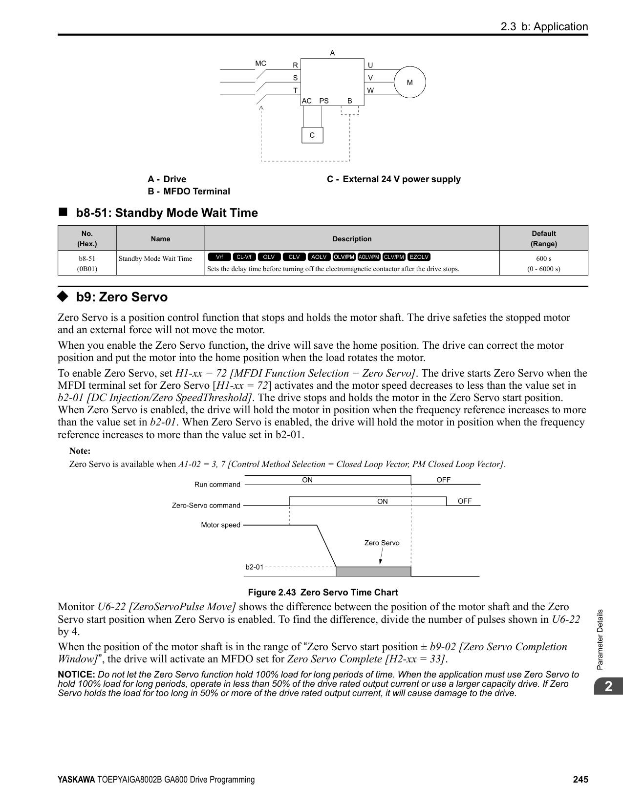
|No. (Hex.)|Name|Description|Default (Range)| |---|---|---|---| |E2-08 (0315)|Motor Saturation Coefficient 2|Sets the motor iron-core saturation coefficient at 75% of the magnetic flux.
V/f CL-V/f OLV CLV AOLV OLV/PM AOLV/PM CLV/PM EZOLV
|0.75 (E2-07 - 0.75)|
|No. (Hex.)|Name|Description|Default (Range)| |---|---|---|---| |E2-09 (0316) Expert|Motor Mechanical Loss|Sets the mechanical loss of the motor. It is set as a percentage of E2-11 [Motor Rated Power]. Usually it is not necessary to change this setting.
V/f CL-V/f OLV CLV AOLV OLV/PM AOLV/PM CLV/PM EZOLV
|0.0% (0.0 - 10.0%)|
|No. (Hex.)|Name|Description|Default (Range)| |---|---|---|---| |E2-10 (0317)|Motor Iron Loss|Sets the motor iron loss.
V/f CL-V/f OLV CLV AOLV OLV/PM AOLV/PM CLV/PM EZOLV
|Determined by o2-04, C6-01 (0 - 65535 W)|
|No. (Hex.)|Name|Description|Default (Range)| |---|---|---|---| |E2-11 (0318)|Motor Rated Power|Sets the motor rated output in the units from o1-58 [Motor Power Unit Selection].
V/f CL-V/f OLV CLV AOLV OLV/PM AOLV/PM CLV/PM EZOLV
|Determined by o2-04, C6-01 (0.00 - 650.00 HP)|
The drive automatically sets this parameter to the value input for “Motor Rated Power” during Auto-Tuning.
ParameterDetails
######## 2
######## ◆ E3: V/f Pattern for Motor 2
V/f preset patterns equivalent to those set with E1-03 [V/f Pattern Selection] are not available for E3 parameters. Use E3-04 [Motor 2 Maximum Output Frequency] to E3-10 [Motor 2 Minimum Output Voltage] to manually set the V/f pattern.
######## ■ Notes on Manually Setting V/f Patterns
Figure 2.72 Motor 2 V/f Pattern Diagram
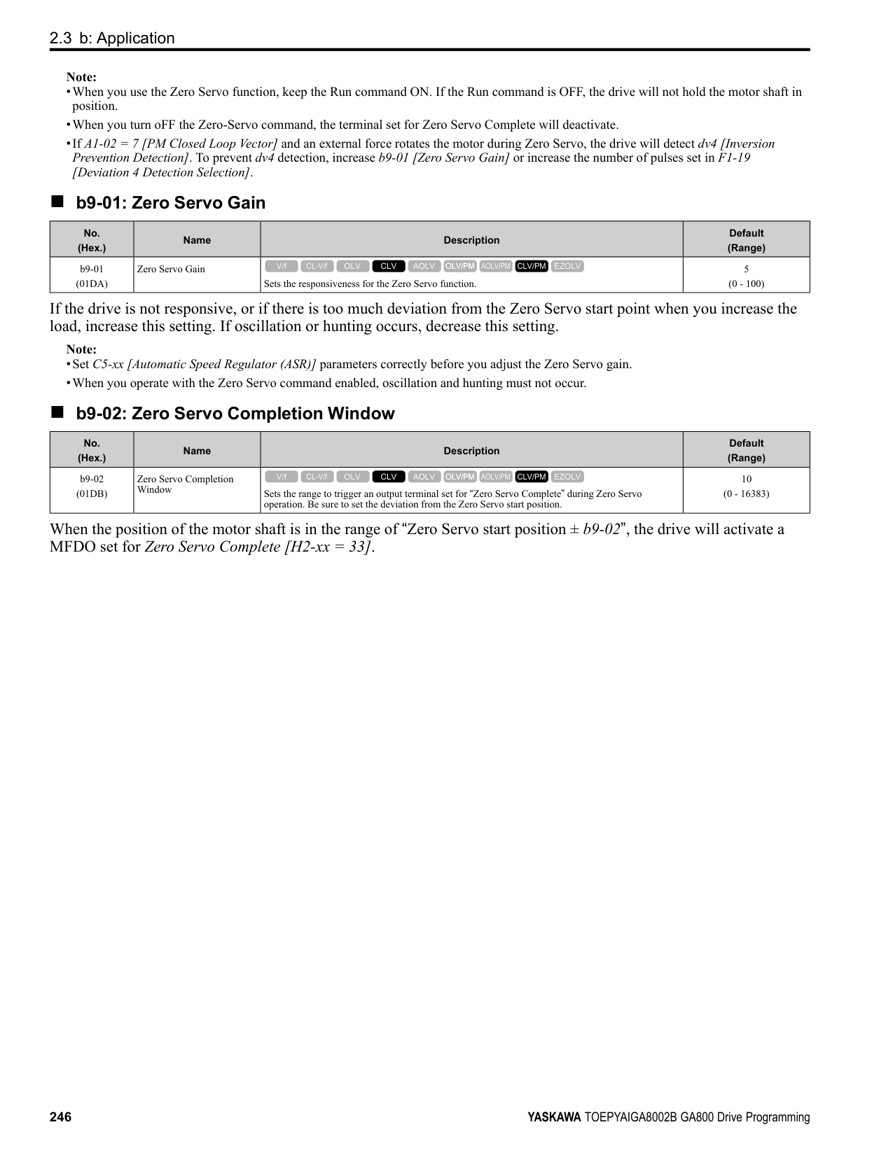
######## ■ E3-01: Motor 2 Control Mode Selection
|No. (Hex.)|Name|Description|Default (Range)| |---|---|---|---| |E3-01 (0319)|Motor 2 Control Mode Selection|Sets the control method for motor 2.
V/f CL-V/f OLV CLV AOLV OLV/PM AOLV/PM CLV/PM EZOLV
|0 (0 - 3)|
################# Note:
######## ■ E3-04: Motor 2 Maximum Output Frequency
|No. (Hex.)|Name|Description|Default (Range)| |---|---|---|---| |E3-04 (031A)|Motor 2 Maximum Output Frequency|Set the maximum output frequency for the motor 2 V/f pattern.
V/f CL-V/f OLV CLV AOLV OLV/PM AOLV/PM CLV/PM EZOLV
|Determined by E3-01 (40.0 - 590.0 Hz)|
|No. (Hex.)|Name|Description|Default (Range)| |---|---|---|---| |E3-05 (031B)|Motor 2 Maximum Output Voltage|Sets the maximum output voltage for the motor 2 V/f pattern.
V/f CL-V/f OLV CLV AOLV OLV/PM AOLV/PM CLV/PM EZOLV
|Determined by E3-01
(200 V Class: 0.0 - 255.0 V, 400 V Class: 0.0 - 510.0 V)|
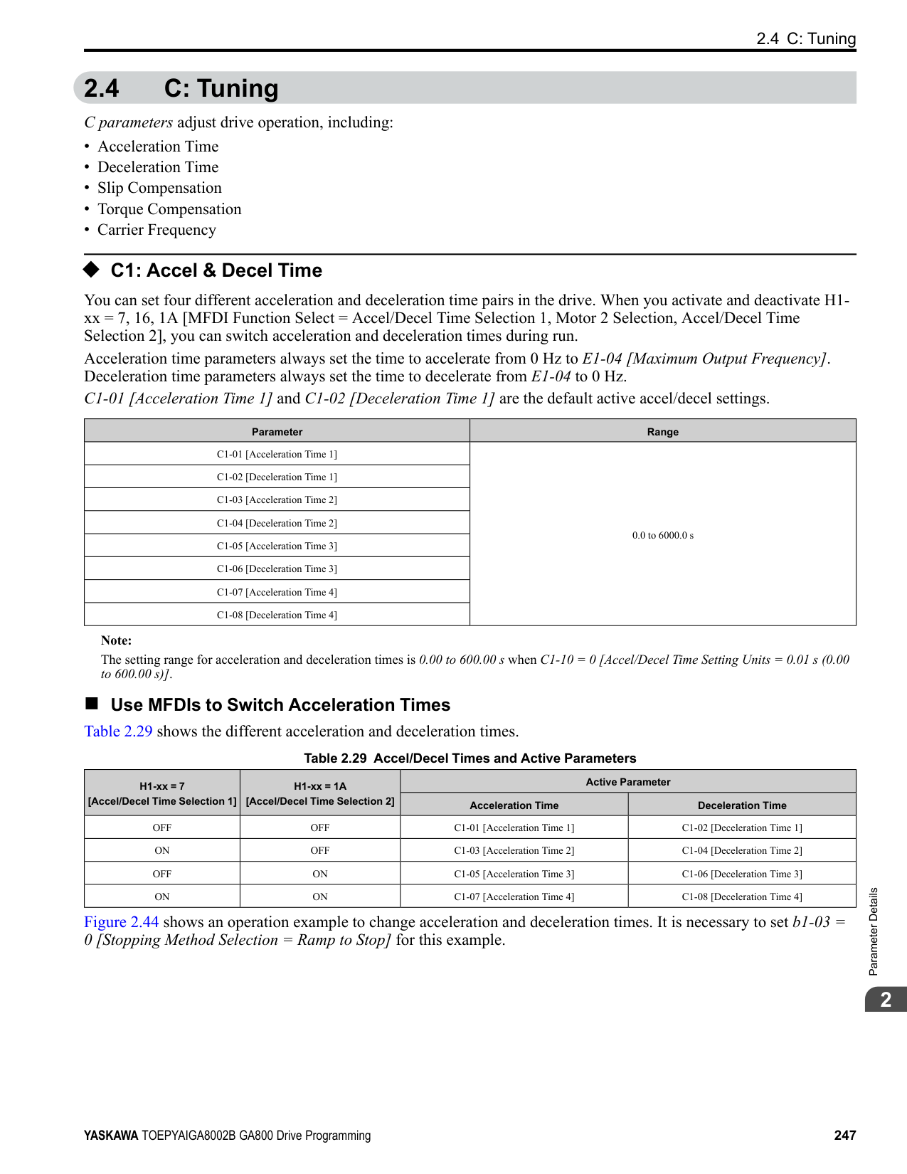
|No. (Hex.)|Name|Description|Default (Range)| |---|---|---|---| |E3-06 (031C)|Motor 2 Base Frequency|Sets the base frequency for the motor 2 V/f pattern.
V/f CL-V/f OLV CLV AOLV OLV/PM AOLV/PM CLV/PM EZOLV
|Determined by E3-01 (0.0 - E3-04)|
|No. (Hex.)|Name|Description|Default (Range)| |---|---|---|---| |E3-07 (031D)|Motor 2 Mid Point A Frequency|Sets a middle output frequency for the motor 2 V/f pattern.
V/f CL-V/f OLV CLV AOLV OLV/PM AOLV/PM CLV/PM EZOLV
|Determined by E3-01 (0.0 - E3-04)|
|No. (Hex.)|Name|Description|Default (Range)| |---|---|---|---| |E3-08 (031E)|Motor 2 Mid Point AVoltage|Sets a middle output voltage for the motor 2 V/f pattern.
V/f CL-V/f OLV CLV AOLV OLV/PM AOLV/PM CLV/PM EZOLV
|Determined by E3-01
(200 V Class: 0.0 - 255.0 V, 400 V Class: 0.0 - 510.0 V)|
|No. (Hex.)|Name|Description|Default (Range)| |---|---|---|---| |E3-09 (031F)|Motor 2 Minimum Output Frequency|Sets the minimum output frequency for the motor 2 V/f pattern.
V/f CL-V/f OLV CLV AOLV OLV/PM AOLV/PM CLV/PM EZOLV
|Determined by E3-01 (0.0 - E3-04)|
|No. (Hex.)|Name|Description|Default (Range)| |---|---|---|---| |E3-10 (0320)|Motor 2 Minimum Output Voltage|Sets the minimum output voltage for the motor 2 V/f pattern.
V/f CL-V/f OLV CLV AOLV OLV/PM AOLV/PM CLV/PM EZOLV
|Determined by E3-01
(200 V Class: 0.0 - 255.0 V, 400 V Class: 0.0 - 510.0 V)|
|No. (Hex.)|Name|Description|Default (Range)| |---|---|---|---| |E3-11 (0345) Expert|Motor 2 Mid Point B Frequency|Sets a middle output frequency for the motor 2 V/f pattern. Set this parameter to adjust the V/f pattern for the constant output range. Usually it is not necessary to change this parameter.
V/f CL-V/f OLV CLV AOLV OLV/PM AOLV/PM CLV/PM EZOLV
|0.0 Hz (0.0 - E3-04)|
################# Note:
ParameterDetails
######## 2
######## ■ E3-12: Motor 2 Mid Point B Voltage
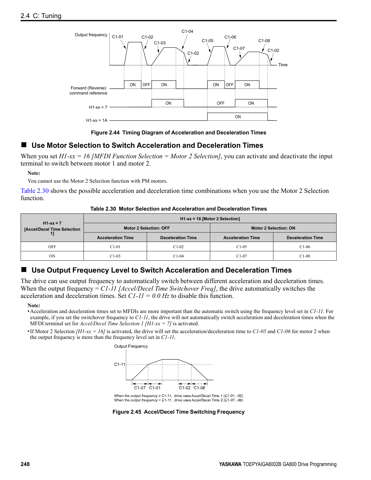
|No. (Hex.)|Name|Description|Default (Range)| |---|---|---|---| |E3-12 (0346) Expert|Motor 2 Mid Point B Voltage|Sets a middle output voltage for the motor 2 V/f pattern. Set this parameter to adjust the V/f pattern for the constant output range. Usually it is not necessary to change this parameter.
V/f CL-V/f OLV CLV AOLV OLV/PM AOLV/PM CLV/PM EZOLV
|0.0 V
(200 V Class: 0.0 to 255.0 V, 400 V Class: 0.0 to 510.0 V)|
Note:
######## ■ E3-13: Motor 2 Base Voltage
|No. (Hex.)|Name|Description|Default (Range)| |---|---|---|---| |E3-13 (0347) Expert|Motor 2 Base Voltage|Sets the base voltage for the motor 2 V/f pattern. Set this parameter to adjust the V/f pattern for the constant output range. Usually it is not necessary to change this parameter.
V/f CL-V/f OLV CLV AOLV OLV/PM AOLV/PM CLV/PM EZOLV
|0.0 V
(200 V Class: 0.0 to 255.0 V, 400 V Class: 0.0 to 510.0 V)|
################# Note:
######## ◆ E4: Motor 2 Parameters
Auto-Tuning automatically sets the E4 parameters to the best values for the application. If you cannot do AutoTuning, set the E4 parameters manually.
Note: E3-xx and E4-xx are available when H1-xx = 16 [MFDI Function Select = Motor 2 Selection].
######## ■ E4-01: Motor 2 Rated Current
|No. (Hex.)|Name|Description|Default (Range)| |---|---|---|---| |E4-01 (0321)|Motor 2 Rated Current|Sets the motor rated current for motor 2 in amps.
V/f CL-V/f OLV CLV AOLV OLV/PM AOLV/PM CLV/PM EZOLV
|Determined by o2-04, C6-01 (10% to 200% of the drive rated current)|
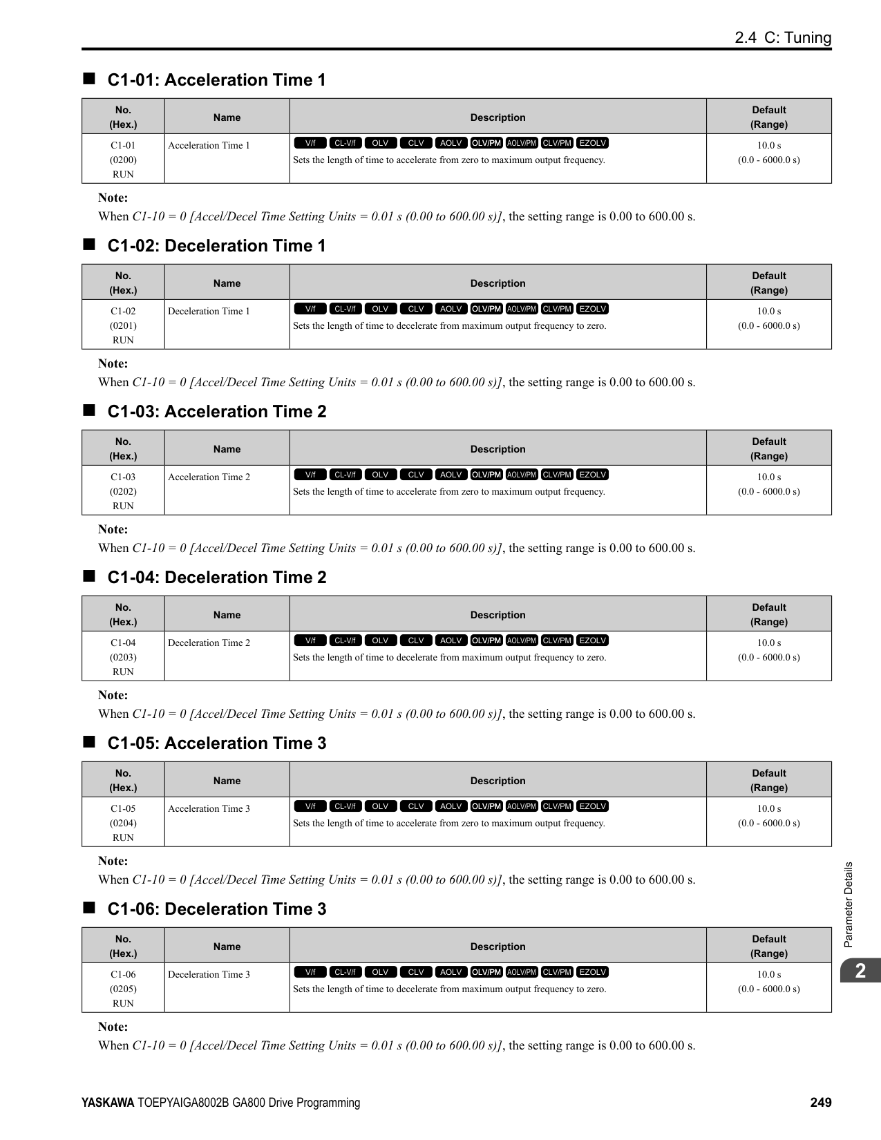
################# Note:
The value set for E4-01 becomes the reference value for motor protection, the torque limit, and torque control. Enter the motor rated current written on the motor nameplate. Auto-Tuning automatically sets the value of E4-01 to the value input for [Motor Rated Current].
######## ■ E4-02: Motor 2 Rated Slip
|No. (Hex.)|Name|Description|Default (Range)| |---|---|---|---| |E4-02 (0322)|Motor 2 Rated Slip|Sets the motor rated slip for motor 2.
V/f CL-V/f OLV CLV AOLV OLV/PM AOLV/PM CLV/PM EZOLV
|Determined by o2-04, C6-01 (0.000 - 20.000 Hz)|
The value set in E4-02 becomes the base slip compensation value. The drive sets this parameter during Rotational Auto-Tuning and Stationary Auto-Tuning. If you cannot do Auto-Tuning, use the information written on the motor nameplate and this formula to calculate the motor rated slip:
E4-02 = f - (n × p) / 120
######## ■ E4-03: Motor 2 Rated No-Load Current
|No. (Hex.)|Name|Description|Default (Range)| |---|---|---|---| |E4-03 (0323)|Motor 2 Rated No-Load Current|Sets the no-load current for motor 2 in amps when operating at the rated frequency and the no-load voltage.
V/f CL-V/f OLV CLV AOLV OLV/PM AOLV/PM CLV/PM EZOLV
|Determined by o2-04, C6-01 (Less than 0 - E4-01)|
Note: When the drive model changes, the display units for this parameter also change.
You can also manually enter the motor no-load current shown on the motor test report to E4-03. Contact the motor manufacturer to receive a copy of the motor test report.
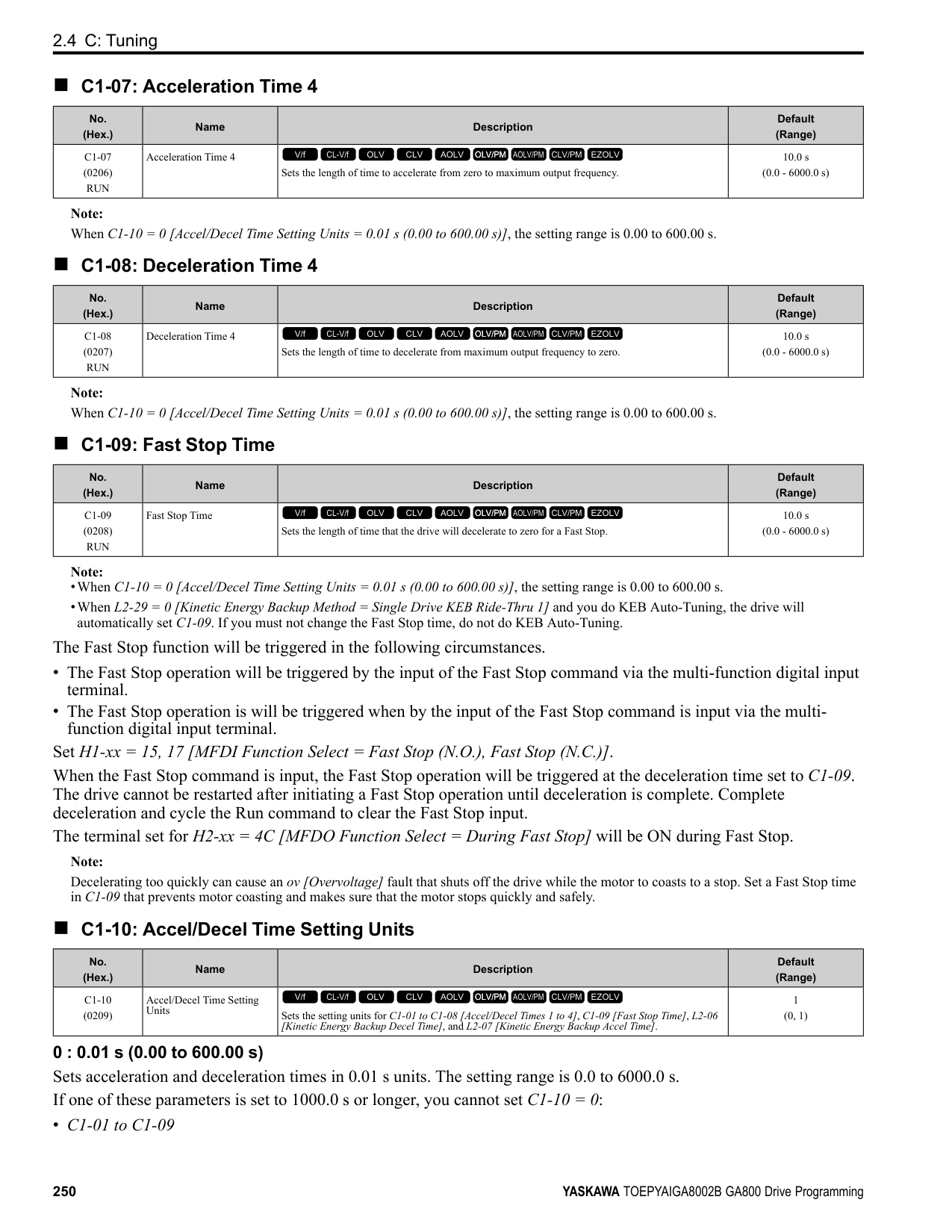
Note: The default setting of the no-load current is for a 4-pole motor recommended by Yaskawa.
######## ■ E4-04: Motor 2 Motor Poles
|No. (Hex.)|Name|Description|Default (Range)| |---|---|---|---| |E4-04 (0324)|Motor 2 Motor Poles|Sets the number of poles for motor 2.
V/f CL-V/f OLV CLV AOLV OLV/PM AOLV/PM CLV/PM EZOLV
|4 (2 - 120)|
Auto-Tuning automatically sets E4-04 to the value input for [Number of Motor Poles].
######## ■ E4-05: Motor 2 Line-to-Line Resistance
|No. (Hex.)|Name|Description|Default (Range)| |---|---|---|---| |E4-05 (0325)|Motor 2 Line-to-Line Resistance|Sets the line-to-line resistance for the motor 2 stator windings.
V/f CL-V/f OLV CLV AOLV OLV/PM AOLV/PM CLV/PM EZOLV
|Determined by o2-04, C6-01 (0.000 - 65.000 Ω)|
Note: This value is the line-to-line resistance for motor 2. Do not use the single-phase resistance to set this parameter.
The drive automatically calculates this value when Auto-Tuning completes successfully. If you cannot do AutoTuning, get the test report from the motor manufacturer. To calculate the motor line-to-line resistance, use the information shown on the motor nameplate with one of these formulas:
• E-type insulation: the resistance value (Ω) shown on the test report at 75 °C × 0.92 • B-type insulation: the resistance value (Ω) shown on the test report at 75 °C × 0.92 • F-type insulation: the resistance value (Ω) shown on the test report at 115 °C × 0.87
######## ■ E4-06: Motor 2 Leakage Inductance
|No. (Hex.)|Name|Description|Default (Range)| |---|---|---|---| |E4-06 (0326)|Motor 2 Leakage Inductance|Sets the voltage drop from motor 2 leakage inductance as a percentage of Motor Rated Voltage when motor 2 operates at the rated frequency and rated current.
V/f CL-V/f OLV CLV AOLV OLV/PM AOLV/PM CLV/PM EZOLV
|Determined by o2-04, C6-01 (0.0 - 60.0%)|
The drive sets this parameter during Rotational Auto-Tuning and Stationary Auto-Tuning.
Note:
You cannot usually find the quantity of voltage drop on the motor nameplate. If you do not know the value of the motor 2 leakage inductance, get the test report from the motor manufacturer.
ParameterDetails
######## 2
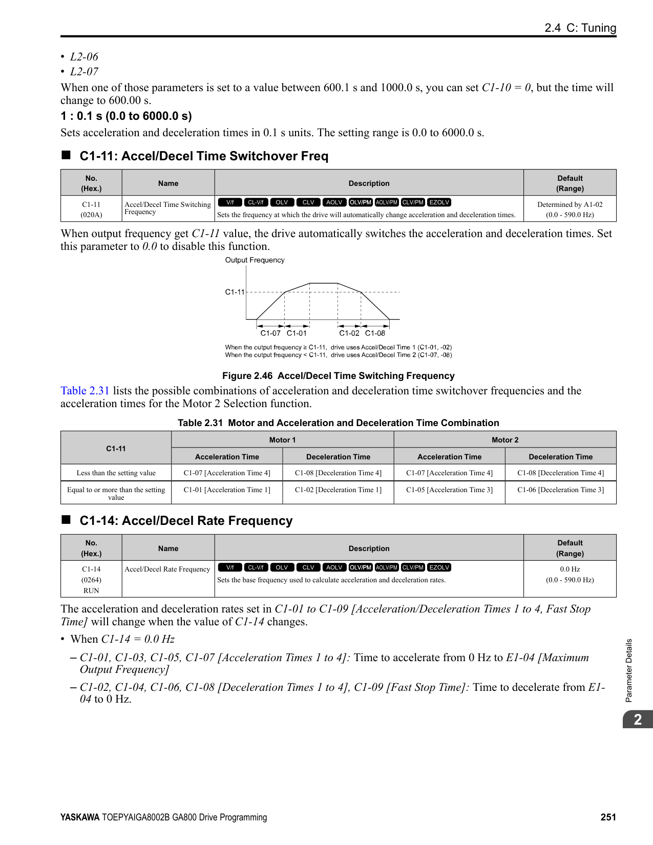
The drive sets this parameter during Rotational Auto-Tuning. The drive uses this value when it operates the motor in the constant output range.
The drive sets this parameter during Rotational Auto-Tuning. The drive uses this value when it operates the motor in the constant output range.
Adjust this parameter in these conditions. The drive adds the configured mechanical loss to the torque reference value as a torque compensation value:
|No. (Hex.)|Name|Description|Default (Range)| |---|---|---|---| |E4-07 (0343)|Motor 2 Saturation Coefficient 1|Sets the motor 2 iron-core saturation coefficient at 50% of the magnetic flux.
V/f CL-V/f OLV CLV AOLV OLV/PM AOLV/PM CLV/PM EZOLV
|0.50 (0.00 - 0.50)|
|No. (Hex.)|Name|Description|Default (Range)| |---|---|---|---| |E4-08 (0344)|Motor 2 Saturation Coefficient 2|Sets the motor 2 iron-core saturation coefficient at 75% of the magnetic flux.
V/f CL-V/f OLV CLV AOLV OLV/PM AOLV/PM CLV/PM EZOLV
|0.75 (E4-07 - 0.75)|
|No. (Hex.)|Name|Description|Default (Range)| |---|---|---|---| |E4-09 (033F) Expert|Motor 2 Mechanical Loss|Sets the mechanical loss of motor 2. It is set as a percentage of E4-11 [Motor 2 Rated Power]. Usually it is not necessary to change this setting.
V/f CL-V/f OLV CLV AOLV OLV/PM AOLV/PM CLV/PM EZOLV
|0.0% (0.0 - 10.0%)|
|No. (Hex.)|Name|Description|Default (Range)| |---|---|---|---| |E4-10 (0340)|Motor 2 Iron Loss|Sets the motor iron loss for motor 2.
V/f CL-V/f OLV CLV AOLV OLV/PM AOLV/PM CLV/PM EZOLV
|Determined by o2-04, C6-01 (0 - 65535 W)|
|No. (Hex.)|Name|Description|Default (Range)| |---|---|---|---|
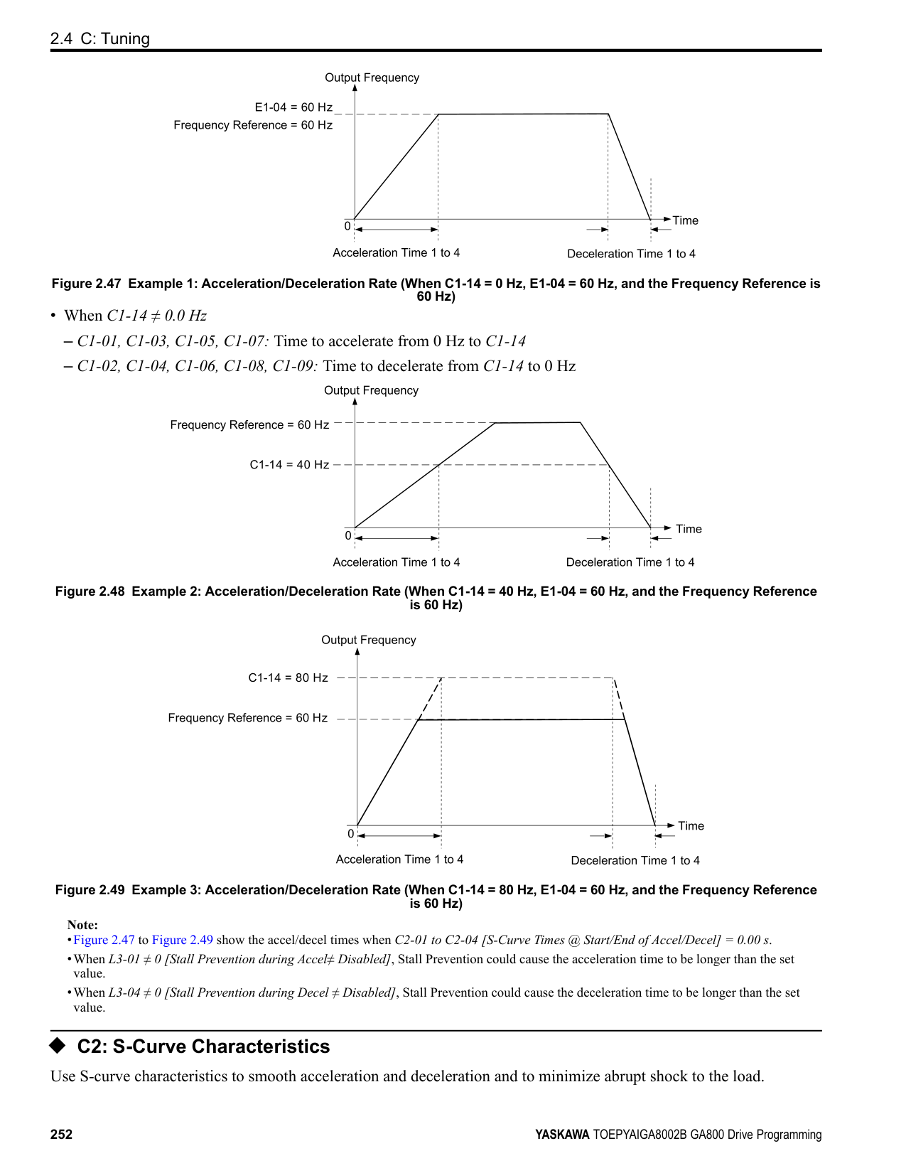
|E4-11 (0327)|Motor 2 Rated Power|Sets the motor rated power in the units from o1-58 [Motor Power Unit Selection].
V/f CL-V/f OLV CLV AOLV OLV/PM AOLV/PM CLV/PM EZOLV
|Determined by o2-04, C6-01 (0.00 - 650.00 HP)|
Auto-Tuning automatically sets this parameter to the value input for [Motor Rated Power].
######## ◆ E5: PM Motor Settings
Set E5-01 to the motor code when using PM motors recommended by Yaskawa. E5 and other related motor parameters will be automatically set to the optimal values. Perform Auto-Tuning for all other PM motors. If information from motor nameplates or test reports is available, the
Note:
Note:
Figure 2.73 PM Motor Code
The drive will automatically set this parameter the next time you do Auto-Tuning.
Note: When the drive model changes, the display units for this parameter also change.
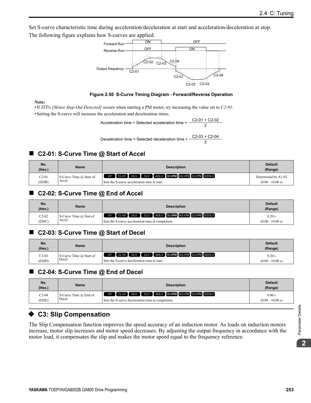
|No. (Hex.)|Name|Description|Default (Range)| |---|---|---|---| |E5-01 (0329)|PM Motor Code Selection|Sets the motor code for Yaskawa PM motors. The drive uses the motor code to set some parameters to their correct settings automatically.
V/f CL-V/f OLV CLV AOLV OLV/PM AOLV/PM CLV/PM EZOLV
|FFFF (0000 - FFFF)|
|No. (Hex.)|Name|Description|Default (Range)| |---|---|---|---| |E5-02 (032A)|PM Motor Rated Power|Sets the PM motor rated output in the units set in o1-58 [Motor Power Unit Selection].
V/f CL-V/f OLV CLV AOLV OLV/PM AOLV/PM CLV/PM EZOLV
|Determined by o2-04, C6-01 (0.10 - 650.00 HP)|
|No. (Hex.)|Name|Description|Default (Range)| |---|---|---|---| |E5-03 (032B)|PM Motor Rated Current (FLA)|Sets the PM motor rated current (FLA).
V/f CL-V/f OLV CLV AOLV OLV/PM AOLV/PM CLV/PM EZOLV
|Determined by o2-04, C6-01 (10% to 200% of the drive rated current)|
|No. (Hex.)|Name|Description|Default (Range)| |---|---|---|---| |E5-04 (032C)|PM Motor Pole Count|Sets the number of PM motor poles.
V/f CL-V/f OLV CLV AOLV OLV/PM AOLV/PM CLV/PM EZOLV
|4 (2 - 120)|
ParameterDetails
######## 2
################# Note:
These types of Auto-Tuning will automatically set this parameter to the value of [Number of Motor Poles]:
######## ■ E5-05: PM Motor Resistance (ohms/phase)
|No. (Hex.)|Name|Description|Default (Range)| |---|---|---|---| |E5-05 (032D)|PM Motor Resistance (ohms/ phase)|Sets the resistance per phase of the PM motors. Set 50% of the line-to-line resistance.
V/f CL-V/f OLV CLV AOLV OLV/PM AOLV/PM CLV/PM EZOLV
|0.100 Ω (0.000 - 65.000 Ω)|
PM motor Auto-Tuning automatically sets this parameter to the value of [PM Motor Stator Resistance]. Note: Do not change the setting calculated by Auto-Tuning unless it is necessary.
######## ■ E5-06: PM d-axis Inductance (mH/phase)
|No. (Hex.)|Name|Description|Default (Range)| |---|---|---|---| |E5-06 (032E)|PM d-axis Inductance (mH/ phase)|Sets the PM motor d-axis inductance.
V/f CL-V/f OLV CLV AOLV OLV/PM AOLV/PM CLV/PM EZOLV
|1.00 mH (0.00 - 300.00 mH)|
PM motor Auto-Tuning automatically sets this parameter to the value of [PM Motor d-Axis Inductance]. Note: Do not change the setting calculated by Auto-Tuning unless it is necessary.
######## ■ E5-07: PM q-axis Inductance (mH/phase)
|No. (Hex.)|Name|Description|Default (Range)| |---|---|---|---| |E5-07 (032F)|PM q-axis Inductance (mH/ phase)|Sets the PM motor q-axis inductance.
V/f CL-V/f OLV CLV AOLV OLV/PM AOLV/PM CLV/PM EZOLV
|1.00 mH (0.00 - 600.00 mH)|
PM motor Auto-Tuning automatically sets this parameter to the value of [PM Motor q-Axis Inductance]. Note: Do not change the setting calculated by Auto-Tuning unless it is necessary.
######## ■ E5-09: PM Back-EMF Vpeak (mV/(rad/s))
|No. (Hex.)|Name|Description|Default (Range)| |---|---|---|---| |E5-09 (0331)|PM Back-EMF Vpeak (mV/ (rad/s))|Sets the peak value of PM motor induced voltage.
V/f CL-V/f OLV CLV AOLV OLV/PM AOLV/PM CLV/PM EZOLV
|0.0 mV/(rad/s) (0.0 - 2000.0 mV/(rad/s))|
Set this parameter when you use an IPM motor with derated torque (SSR1-series) or an IPM motor with constant torque (SST4-series). PM motor Auto-Tuning automatically sets this parameter to the value of [Back-EMF Voltage Constant (Ke)]. When E5-01 = FFFF, only set E5-09 or E5-24 [PM Back-EMF L-L Vrms (mV/rpm)] as the induced voltage constant.
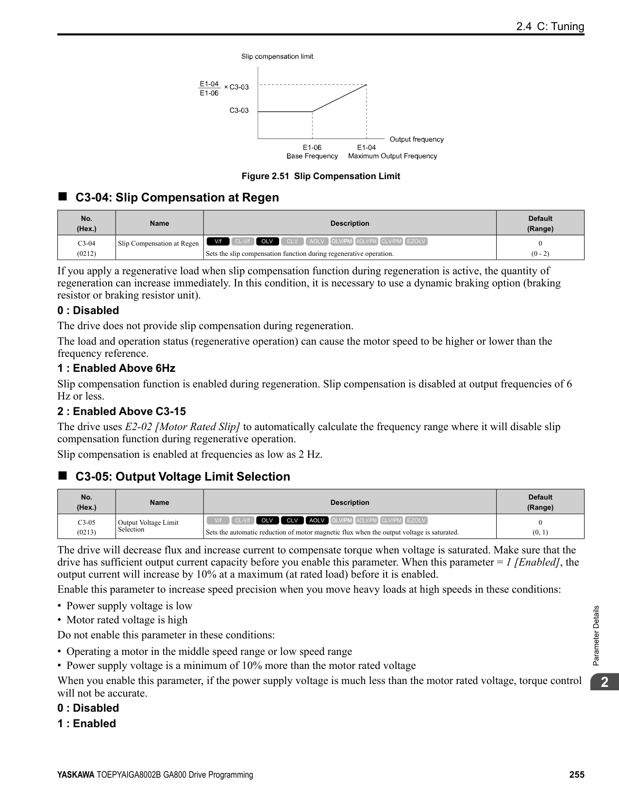
Note: When you set this parameter, also set E5-24 = 0.0. The drive will detect oPE08 [Parameter Selection Error] in these conditions:
######## ■ E5-11: Encoder Z-Pulse Offset
|No. (Hex.)|Name|Description|Default (Range)| |---|---|---|---| |E5-11 (0333)|Encoder Z-Pulse Offset|Sets the encoder Z-pulse offset.
V/f CL-V/f OLV CLV AOLV OLV/PM AOLV/PM CLV/PM EZOLV
|0.0 degrees (-180.0 - +180.0 degrees)|
The drive uses the PM motor parameter settings and PM Stationary Auto-Tuning to set E5-11 to the value input for “Encoder Z-Pulse Offset” automatically. The drive uses Z Pulse Offset Tuning or the Rotational Auto-Tuning to set E5-11.
######## ■ E5-24: PM Back-EMF L-LVrms (mV/rpm)
|No. (Hex.)|Name|Description|Default (Range)| |---|---|---|---| |E5-24 (0353)|PM Back-EMF L-LVrms (mV/rpm)|Sets the RMS value for PM motor line voltage.
V/f CL-V/f OLV CLV AOLV OLV/PM AOLV/PM CLV/PM EZOLV
|0.1 mV/min-1 (0.0 - 6500.0 mV/min-1)|
Set this parameter when you use an SPM motor (SMRA-Series Pico motor). PM motor Auto-Tuning automatically sets this parameter to the value of [Back-EMF Voltage Constant (Ke)]. When E5-01 = FFFF, only set E5-09 [PM Back-EMF Vpeak (mV/(rad/s))] or E5-24 as the induced voltage constant.
Note: When you set this parameter, also set E5-09 = 0.0. The drive will detect oPE08 [Parameter Selection Error] in these conditions:
######## ■ E5-25: Polarity Estimation Timeout
|No. (Hex.)|Name|Description|Default (Range)| |---|---|---|---| |E5-25 (035E) Expert|Polarity Estimation Timeout|Sets the function that switches polarity for initial polarity estimation. Usually it is not necessary to change this setting.
V/f CL-V/f OLV CLV AOLV OLV/PM AOLV/PM CLV/PM EZOLV
|0 (0, 1)|
When “Sd = 1” is shown on the motor nameplate or test report for Yaskawa motors, set this parameter to 1. 0 : Disabled 1 : Enabled
◆ E9: Motor Setting E9 parameters set SynRM motors. Set these parameters to derate torque applications when a high level of responsiveness and accurate speed control are not necessary. Auto-Tuning the drive will automatically set the E9 parameters. If you cannot do EZ Tuning, you can also manually set the E9 parameters.
######## ■ E9-01: Motor Type Selection
|No. (Hex.)|Name|Description|Default (Range)| |---|---|---|---| |E9-01 (11E4)|Motor Type Selection|Sets the type of motor.
V/f CL-V/f OLV CLV AOLV OLV/PM AOLV/PM CLV/PM EZOLV
|0 (0 to 2)|
EZ Tuning automatically sets this parameter to the value of [Motor Type Selection]. 0 : Induction (IM) 1 : Permanent Magnet (PM) 2 : Synchronous Reluctance (SynRM)
ParameterDetails
######## 2
######## ■ E9-02: Maximum Speed
|No. (Hex.)|Name|Description|Default (Range)| |---|---|---|---| |E9-02 (11E5)|Maximum Speed|Sets the maximum speed of the motor.
V/f CL-V/f OLV CLV AOLV OLV/PM AOLV/PM CLV/PM EZOLV
|Determined by E9-01 (40.0 - 120.0 Hz)|
Note: The unit of measure changes when the setting of o1-04 [V/f Pattern Display Unit].
EZ Tuning automatically sets this parameter to the value of [Motor Max Revolutions].
######## ■ E9-03: Rated Speed
|No. (Hex.)|Name|Description|Default (Range)| |---|---|---|---| |E9-03 (11E6)|Rated Speed|Sets the rated rotation speed of the motor.
V/f CL-V/f OLV CLV AOLV OLV/PM AOLV/PM CLV/PM EZOLV
|Determined by E9-01 (100 - 7200 min-1)|
EZ Tuning automatically sets this parameter to the value of [Rated Speed]. Note: Set E9-01 0 [Motor Type Selection Induction (IM)] before you set this parameter.
######## ■ E9-04: Base Frequency
|No. (Hex.)|Name|Description|Default (Range)| |---|---|---|---| |E9-04 (11E7)|Base Frequency|Sets the rated frequency of the motor.
V/f CL-V/f OLV CLV AOLV OLV/PM AOLV/PM CLV/PM EZOLV
|Determined by E9-01 (40.0 - 120.0 Hz)|
Note: The unit of measure changes when the setting of o1-04 [V/f Pattern Display Unit].
EZ Tuning automatically sets this parameter to the value of [Base Frequency].
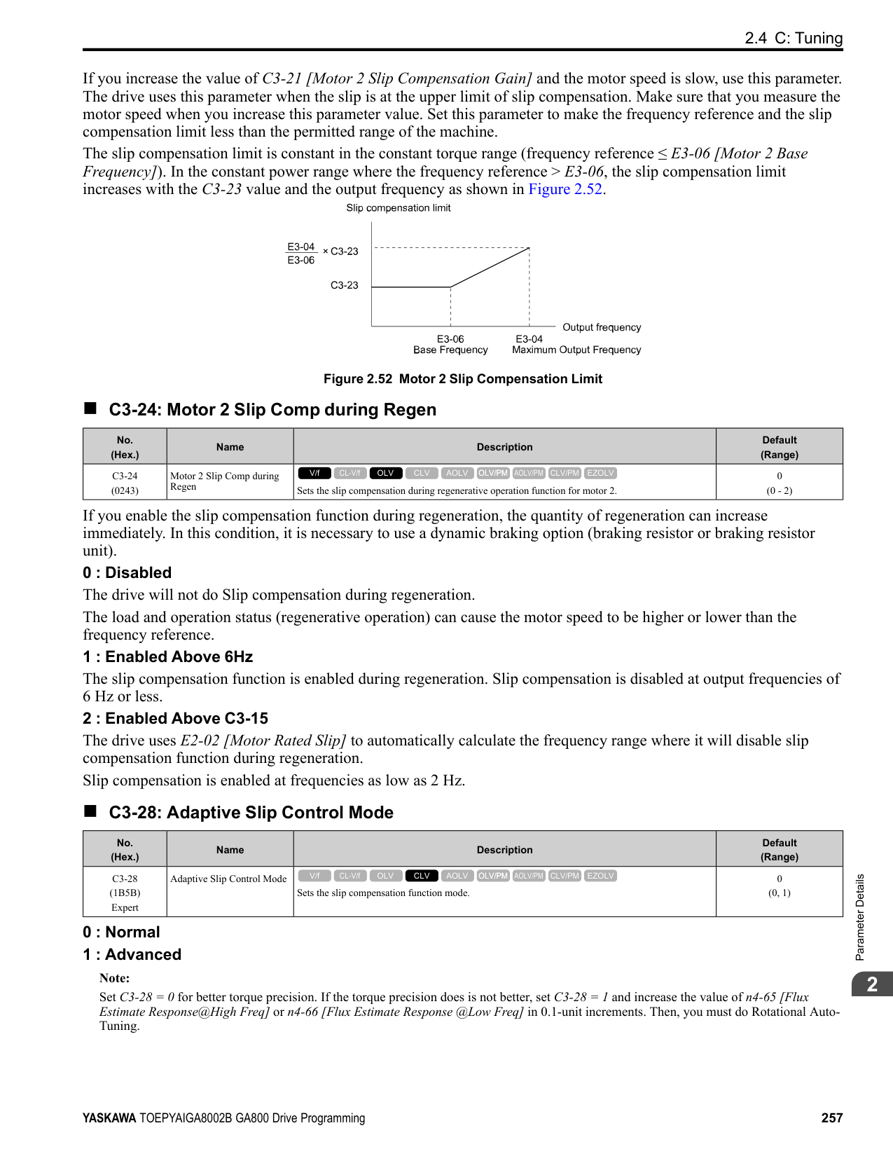
######## ■ E9-05: Base Voltage
|No. (Hex.)|Name|Description|Default (Range)| |---|---|---|---| |E9-05 (11E8)|Base Voltage|Sets the rated voltage of the motor.
V/f CL-V/f OLV CLV AOLV OLV/PM AOLV/PM CLV/PM EZOLV
|200 V Class: 230.0 V, 400 V: 460.0 V
(200 V Class: 0.0 - 255.0 V,400 V Class: 0.0 - 510.0 V)|
EZ Tuning automatically sets this parameter to the value of [Base Voltage].
######## ■ E9-06: Motor Rated Current (FLA)
|No. (Hex.)|Name|Description|Default (Range)| |---|---|---|---| |E9-06 (11E9)|Motor Rated Current (FLA)|Sets the motor rated current in amps.
V/f CL-V/f OLV CLV AOLV OLV/PM AOLV/PM CLV/PM EZOLV
|Determined by E9-01 and o2-04
(10% to 200% of the drive rated current)|
Note: When the drive model changes, the display units for this parameter also change.
The value set for E9-06 becomes the reference value for motor protection. Enter the motor rated current shown on the motor nameplate. Auto-Tuning the drive will automatically set E9-06 to the value input for “Motor Rated Current”.
######## ■ E9-07: Motor Rated Power
|No. (Hex.)|Name|Description|Default (Range)| |---|---|---|---| |E9-07 (11EA)|Motor Rated Power|Sets the motor rated power in the units from o1-58 [Motor Power Unit Selection].
V/f CL-V/f OLV CLV AOLV OLV/PM AOLV/PM CLV/PM EZOLV
|Determined by E9-02 and o2-04
(0.00 - 650.00 HP)|
Auto-Tuning automatically sets this parameter to the value of [Motor Rated Power (kW)].
######## ■ E9-08: Motor Pole Count
|No. (Hex.)|Name|Description|Default (Range)| |---|---|---|---| |E9-08 (11EB)|Motor Pole Count|Sets the number of motor poles.
V/f CL-V/f OLV CLV AOLV OLV/PM AOLV/PM CLV/PM EZOLV
|4 (2 to 120)|
Auto-Tuning automatically sets this parameter to the value of [Number of Motor Poles].
######## ■ E9-09: Motor Rated Slip
|No. (Hex.)|Name|Description|Default (Range)| |---|---|---|---| |E9-09 (11EC)|Motor Rated Slip|Sets the motor rated slip.
V/f CL-V/f OLV CLV AOLV OLV/PM AOLV/PM CLV/PM EZOLV
|0.000 Hz (0.000 - 20.000 Hz)|
The setting value of this parameter is the slip compensation reference value. The drive uses the setting values of E9-03, E9-04, and E9-08 to calculate this parameter. When Motor Rated Slip = 0, Auto-Tuning automatically sets this parameter to the value of [Motor Rated Slip].
Note: Set E9-01 = 0 [Motor Type Selection = Induction (IM)] before you set this parameter.
######## ■ E9-10: Motor Line-to-Line Resistance
|No. (Hex.)|Name|Description|Default (Range)| |---|---|---|---| |E9-10 (11ED)|Motor Line-to-Line Resistance|Sets the line-to-line resistance for the motor stator windings.
V/f CL-V/f OLV CLV AOLV OLV/PM AOLV/PM CLV/PM EZOLV
|Determined by o2-04 (0.000 - 65.000 Ω)|
Note: This value is the motor line-to-line resistance. Do not set this parameter with the single-phase resistance.
Stationary Auto-Tuning automatically sets this parameter. If you cannot do Stationary Auto-Tuning, use the test report from the motor manufacturer. You can calculate the motor line-to-line resistance with one of these formulas:
• E-type insulation: the resistance value (Ω) shown on the test report at 75 °C × 0.92 • B-type insulation: the resistance value (Ω) shown on the test report at 75 °C × 0.92 • F-type insulation: the resistance value (Ω) shown on the test report at 115 °C × 0.87
ParameterDetails
######## 2
####### 2.7 F: Options
######## ◆ F1: Encoder Option Setup
F1 parameters are used to set the operation of and protective function for the encoder option card. The following table lists the setting parameters available for each option card. Refer to the instruction manual packaged with the encoder option card for more information on installing, wiring, and setting the encoder option cards. WARNING! Sudden Movement Hazard. Do test runs and examine the drive to make sure that the command references are correct. If you set the command reference incorrectly, it can cause damage to the drive or serious injury or death. WARNING! Sudden Movement Hazard. Make sure that the host controller circuitry has correct safety design that will let you keep control of the motor if the drive loses speed feedback. If you do not have control of the motor, it can cause serious injury or death.
################# Table 2.43 Encoder Option Card Setting Parameters
|Setting Parameter|Encoder Option Card|Encoder Option Card|Encoder Option Card|Encoder Option Card| |---|---|---|---|---|
|Setting Parameter|PG-B3|PG-X3|PG-F3|PG-RT3| |F1-01|x|x|x|-| |F1-02|x|x|x|x| |F1-03|x|x|x|x| |F1-04|x|x|x|x| |F1-05|x|x|x|x| |F1-06|x|x|x|-| |F1-08|x|x|x|x| |F1-09|x|x|x|x| |F1-10|x|x|x|x| |F1-11|x|x|x|x| |F1-12 *1|x|x|-|-| |F1-13 *1|x|x|-|-| |F1-14|x|x|x|x| |F1-18|x|x|x|x| |F1-19|x|x|x|x| |F1-20|-|x|x|-| |F1-21|x|x|-|-| |F1-30|x|x|-|-| |F1-31 *2|x|x|-|-| |F1-32 *2|x|x|-|-| |F1-33 *1 *2|x|x|-|-| |F1-34 *1 *2|x|x|-|-| |F1-35 *2|x|x|-|-| |F1-36|-|x|-|-| |F1-37 *2|x|x|-|-| |F1-50|-|-|x|-| |F1-51|-|-|x|-|
|Setting Parameter|Encoder Option Card|Encoder Option Card|Encoder Option Card|Encoder Option Card| |---|---|---|---|---| |Setting Parameter|PG-B3|PG-X3|PG-F3|PG-RT3| |F1-52|-|-|x|-| |Number of cards that can be installed in a drive|2|2|1|1|
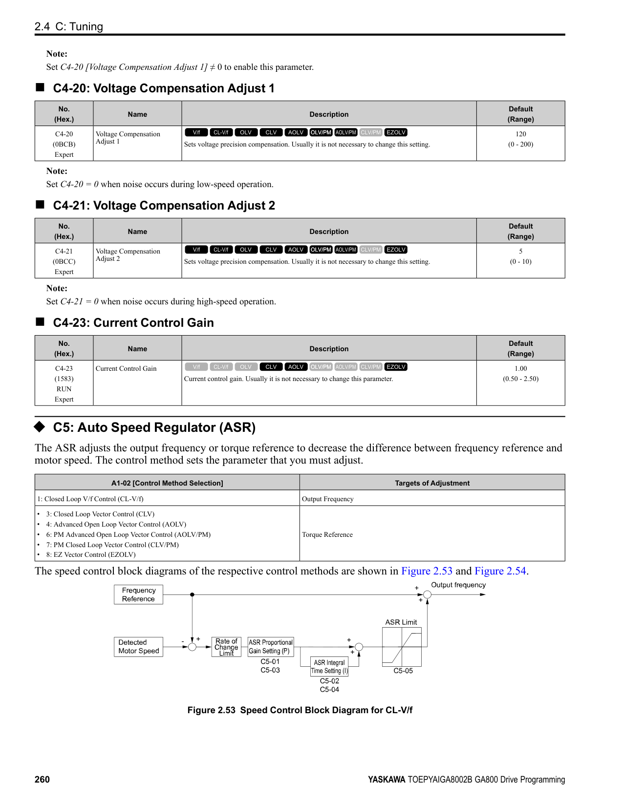
|No. (Hex.)|Name|Description|Default (Range)| |---|---|---|---| |F1-01 (0380)|Encoder 1 Pulse Count (PPR)|Sets the number of output pulses for each motor revolution.
V/f CL-V/f OLV CLV AOLV OLV/PM AOLV/PM CLV/PM EZOLV
|1024 ppr (1 - 60000 ppr)|
|No. (Hex.)|Name|Description|Default (Range)| |---|---|---|---| |F1-02 (0381)|Encoder Signal Loss Detect Sel|Sets the method to stop the motor or let the motor continue operating when the drive detects PGo [Encoder (PG) Feedback Loss].
V/f CL-V/f OLV CLV AOLV OLV/PM AOLV/PM CLV/PM EZOLV
|1 (0 - 4)|
If the drive does not detect ouput pulses from the encoder for the time set in F1-14 [Encoder Open-Circuit Detect Time], it will trigger PGo.
Note:
############## 0 : Ramp to Stop
The drive ramps the motor to stop in the deceleration time. Fault relay output terminal MA-MC turns ON, and MBMC turns OFF.
############## 1 : Coast to Stop
The output turns off and the motor coasts to stop. Fault relay output terminal MA-MC turns ON, and MB-MC turns OFF.
############## 2 : Fast Stop (Use C1-09)
The drive stops the motor in the deceleration time set in C1-09 [Fast Stop Time]. Fault relay output terminal MA-MC turns ON, and MB-MC turns OFF.
############## 3 : Alarm Only
The keypad shows PGo and the drive continues operation. Only use this setting in special conditions to prevent damage to the motor and machinery. The output terminal set for Alarm [H2-01 to H2-03 = 10] activates.
############## 4 : No Alarm Display
The drive continues operation and does not show PGo on the keypad. Only use this setting in special conditions to prevent damage to the motor and machinery.
######## ■ F1-03: Overspeed Detection Selection
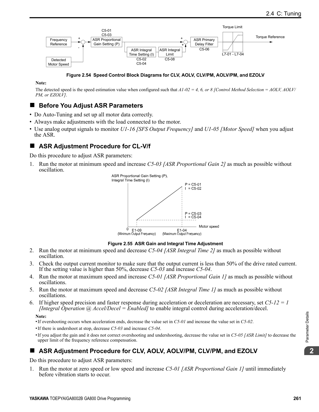
|No. (Hex.)|Name|Description|Default (Range)| |---|---|---|---| |F1-03 (0382)|Overspeed Detection Selection|Sets the method to stop the motor or let the motor continue operating when the drive detects oS [Overspeed].
V/f CL-V/f OLV CLV AOLV OLV/PM AOLV/PM CLV/PM EZOLV
|1 (0 - 3)|
When the motor speed is more than the value set in F1-08 [Overspeed Detection Level] for longer than the time set in F1-09 [Overspeed Detection Delay Time], the drive will detect oS. 0 : Ramp to Stop
ParameterDetails
######## 2
The drive ramps the motor to stop in the deceleration time. Fault relay output terminal MA-MC turns ON, and MBMC turns OFF.
############## 1 : Coast to Stop
The output turns off and the motor coasts to stop. Fault relay output terminal MA-MC turns ON, and MB-MC turns OFF.
############## 2 : Fast Stop (Use C1-09)
The drive stops the motor in the deceleration time set in C1-09 [Fast Stop Time]. Fault relay output terminal MA-MC turns ON, and MB-MC turns OFF.
############## 3 : Alarm Only
The keypad shows oS and the drive continues operation. Only use this setting in special conditions to prevent damage to the motor and machinery. The output terminal set for Alarm [H2-01 to H2-03 = 10] activates.
Note:
When A1-02 = 6 [Control Method Selection = AOLV/PM], the drive will automatically set F1-03 = 1 [Coast to Stop]. You cannot change this value.
######## ■ F1-04: Speed Deviation Detection Select
|No. (Hex.)|Name|Description|Default (Range)| |---|---|---|---| |F1-04 (0383)|Speed Deviation Detection Select|Sets the method to stop the motor or let the motor continue operating when the drive detects dEv [Speed Deviation].
V/f CL-V/f OLV CLV AOLV OLV/PM AOLV/PM CLV/PM EZOLV
|3 (0 - 3)|
When the difference between the frequency reference and the motor speed is more than the value set in F1-10 [Speed Deviation Detection Level] for longer than the time set in F1-11 [Speed Deviation Detect DelayTime], the drive will detect dEv.
The drive ramps the motor to stop in the deceleration time. Fault relay output terminal MA-MC turns ON, and MBMC turns OFF.
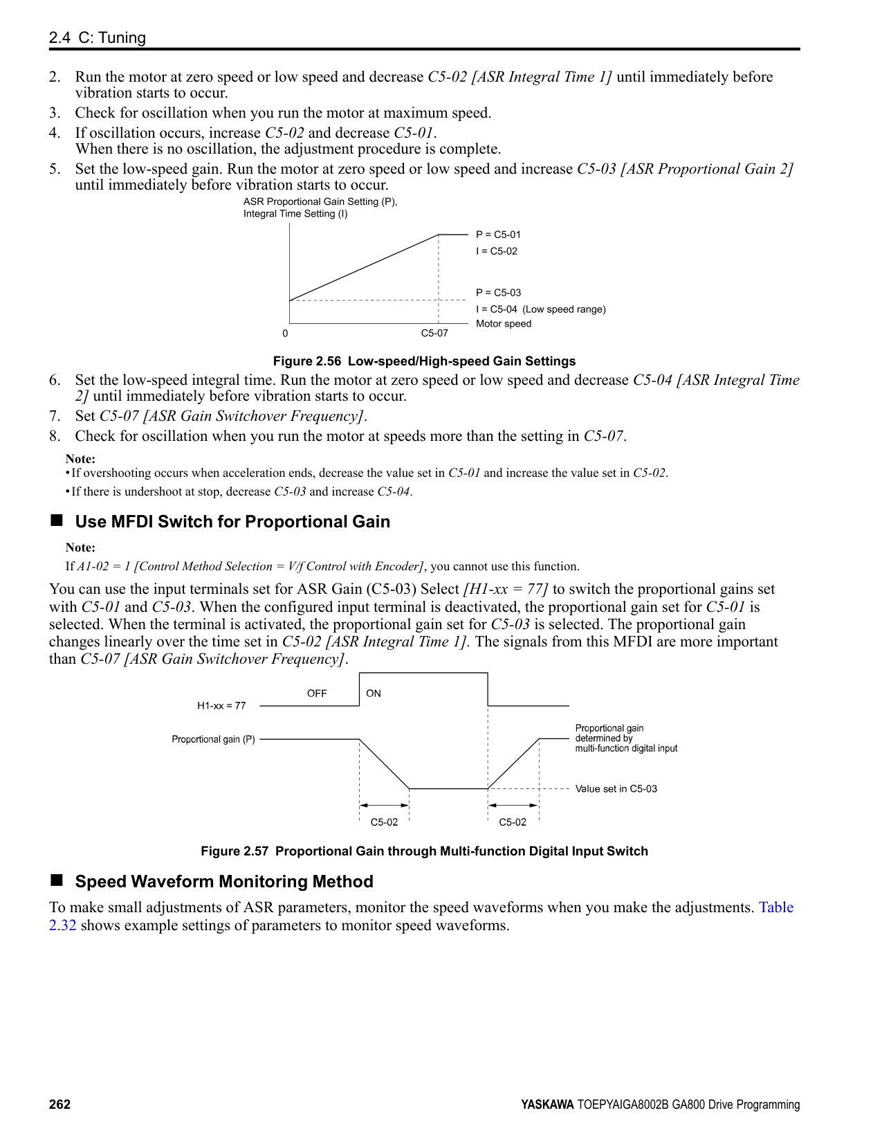
The output turns off and the motor coasts to stop. Fault relay output terminal MA-MC turns ON, and MB-MC turns OFF.
The drive stops the motor in the deceleration time set in C1-09 [Fast Stop Time]. Fault relay output terminal MA-MC turns ON, and MB-MC turns OFF.
The keypad shows dEv and the drive continues operation. Only use this setting in special conditions to prevent damage to the motor and machinery. The output terminal set for Alarm [H2-01 to H2-03 = 10] activates.
######## ■ F1-05: Encoder 1 Rotation Selection
|No. (Hex.)|Name|Description|Default (Range)| |---|---|---|---| |F1-05 (0384)|Encoder 1 Rotation Selection|Sets the output sequence for the A and B pulses from the encoder, assuming that the motor is operating in the forward direction.
V/f CL-V/f OLV CLV AOLV OLV/PM AOLV/PM CLV/PM EZOLV
|Determined by A1-02 (0, 1)|
Refer to the option card installation manual for more information about how to set the encoder pulse output sequence and make sure that it is correct.
######## ■ F1-06: Encoder 1 Pulse Monitor Scaling
|No. (Hex.)|Name|Description|Default (Range)| |---|---|---|---| |F1-06 (0385)|Encoder 1 Pulse Monitor Scaling|Sets the ratio between the pulse input and the pulse output of the encoder as a 3-digit number. The first digit is the numerator and the second and third digits set the denominator.
V/f CL-V/f OLV CLV AOLV OLV/PM AOLV/PM CLV/PM EZOLV
|001 (001 - 032, 102 - 132 (1 - 1/ 32))|
When the setting value is a 3-digit value (xyz), the dividing ratio is (1 + x)/yz For example, when F1-06 = 032, the dividing ratio is 1/32.
Note: When you use a single-pulse encoder, the dividing ratio for the monitor signal is 1:1
######## ■ F1-08: Overspeed Detection Level
|No. (Hex.)|Name|Description|Default (Range)| |---|---|---|---|
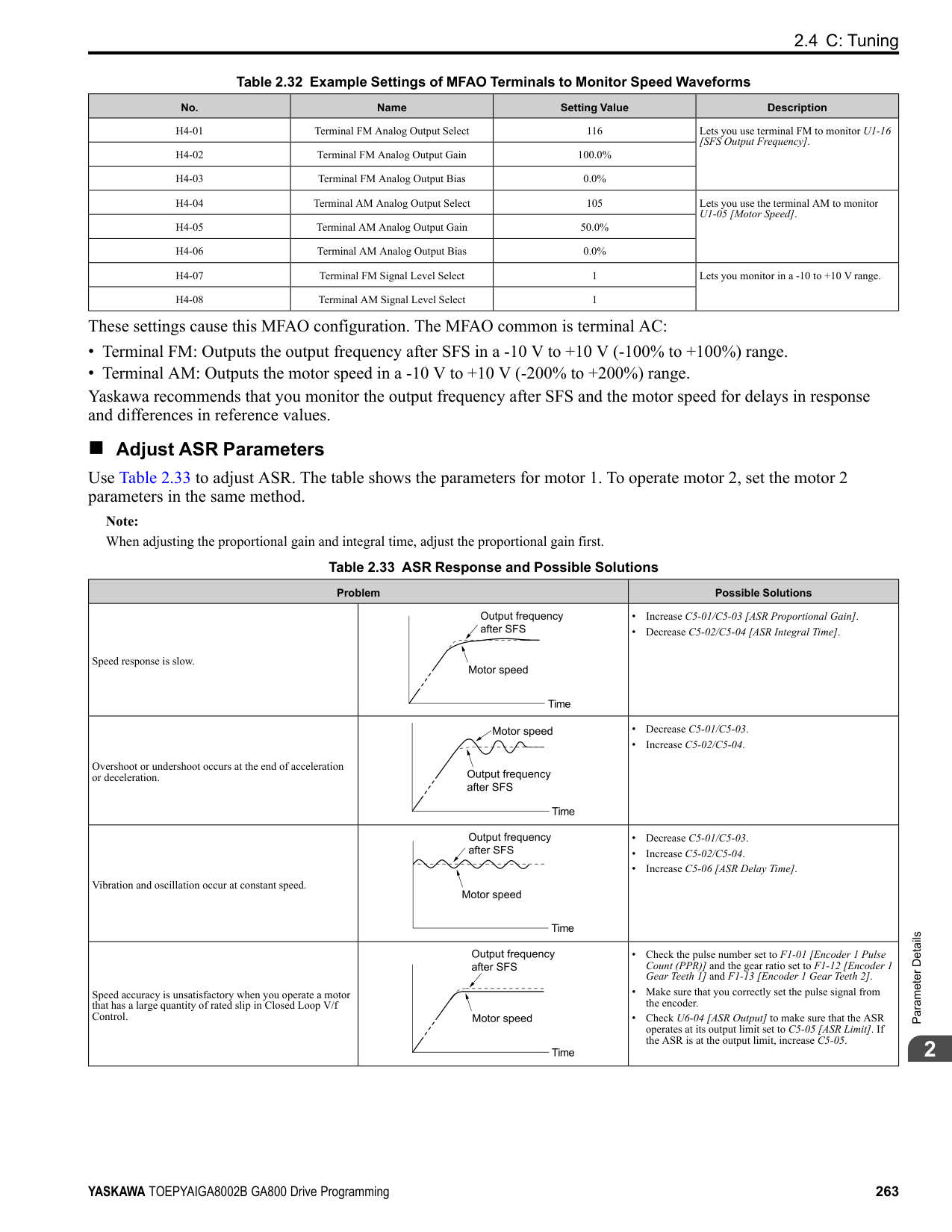
|F1-08 (0387)|Overspeed Detection Level|Sets the detection level of oS [Overspeed] as a percentage when the maximum output frequency is 100%.
V/f CL-V/f OLV CLV AOLV OLV/PM AOLV/PM CLV/PM EZOLV
|115% (0 - 120%)|
When the motor speed is more than the value set in F1-08 for longer than the time set in F1-09 [Overspeed Detection Delay Time], the drive will detect oS.
######## ■ F1-09: Overspeed Detection Delay Time
|No. (Hex.)|Name|Description|Default (Range)| |---|---|---|---| |F1-09 (0388)|Overspeed Detection Delay Time|Sets the length of time that the speed feedback must be more than the F1-08 level to cause oS [Overspeed].
V/f CL-V/f OLV CLV AOLV OLV/PM AOLV/PM CLV/PM EZOLV
|Determined by A1-02 (0.0 - 2.0 s)|
When the motor speed is more than the value set in F1-08 [Overspeed Detection Level] for longer than the time set in F1-09, the drive will detect oS.
######## ■ F1-10: Speed Deviation Detection Level
|No. (Hex.)|Name|Description|Default (Range)| |---|---|---|---| |F1-10 (0389)|Speed Deviation Detection Level|Sets the detection level of dEv [Speed Deviation] as a percentage when the maximum output frequency is 100%.
V/f CL-V/f OLV CLV AOLV OLV/PM AOLV/PM CLV/PM EZOLV
|10% (0 - 50%)|
When the speed deviation between the frequency reference and the actual motor speed is more than the value set in F1-10 for longer than the time set in F1-11 [Speed Deviation Detect DelayTime], the drive will detect dEv.
######## ■ F1-11: Speed Deviation Detect DelayTime
|No. (Hex.)|Name|Description|Default (Range)| |---|---|---|---| |F1-11 (038A)|Speed Deviation Detect DelayTime|Sets the length of time that the difference between the frequency reference and speed feedback must be more than the level in F1-10 to cause dEv [Speed Deviation].
V/f CL-V/f OLV CLV AOLV OLV/PM AOLV/PM CLV/PM EZOLV
|0.5 s (0.0 - 10.0 s)|
When the speed deviation between the frequency reference and the actual motor speed is more than the value set in F1-10 [Speed Deviation Detection Level] for longer than the time set in F1-11, the drive will detect dEv.
######## ■ F1-12: Encoder 1 Gear Teeth 1
|No. (Hex.)|Name|Description|Default (Range)| |---|---|---|---| |F1-12 (038B)|Encoder 1 Gear Teeth 1|Sets the number of gear teeth on the motor side. This parameter and F1-13 [Encoder 1 Gear Teeth 2] set the gear ratio between the motor and encoder.
V/f CL-V/f OLV CLV AOLV OLV/PM AOLV/PM CLV/PM EZOLV
|0 (0 - 1000)|
ParameterDetails
######## 2
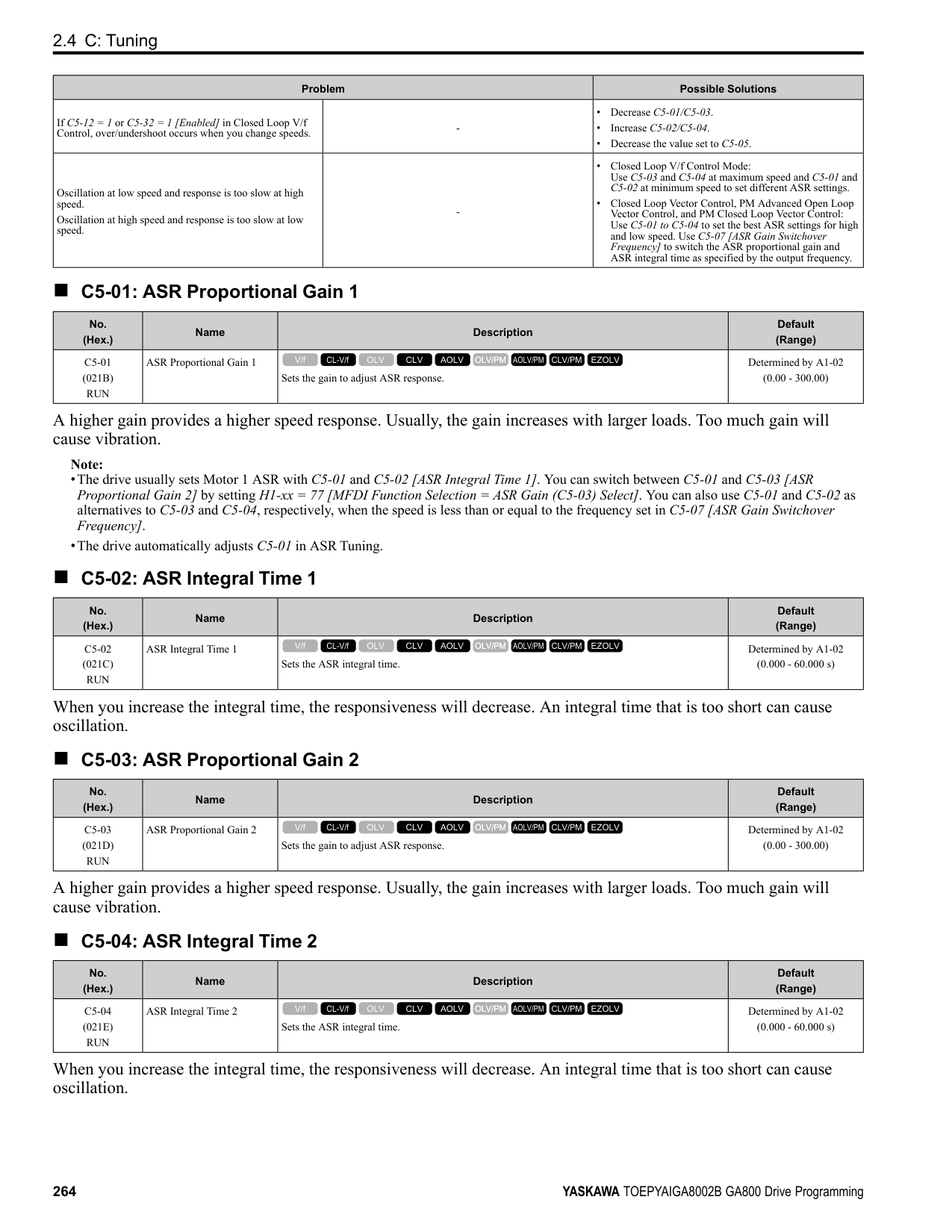
After you set the number of gear teeth, the drive uses this formula to calculate the motor speed:
Note: When F1-12 = 0 or F1-13 = 0, the gear ratio is 1.
######## ■ F1-13: Encoder 1 Gear Teeth 2
|No. (Hex.)|Name|Description|Default (Range)| |---|---|---|---| |F1-13 (038C)|Encoder 2 Gear Teeth 1|Sets the number of gear teeth on the load side. This parameter and F1-12 [Encoder 1 Gear Teeth 1] set the gear ratio between the motor and encoder.
V/f CL-V/f OLV CLV AOLV OLV/PM AOLV/PM CLV/PM EZOLV
|0 (0 - 1000)|
After you set the number of gear teeth, the drive uses this formula to calculate the motor speed:
Note: When F1-12 = 0 or F1-13 = 0, the gear ratio is 1.
######## ■ F1-14: Encoder Open-Circuit Detect Time
|No. (Hex.)|Name|Description|Default (Range)| |---|---|---|---| |F1-14 (038D)|Encoder Open-Circuit Detect Time|Sets the length of time that the drive must not receive a pulse signal to cause PGo [Encoder (PG) Feedback Loss].
V/f CL-V/f OLV CLV AOLV OLV/PM AOLV/PM CLV/PM EZOLV
|2.0 s (0.0 - 10.0 s)|
If the drive does not detect output pulses from the encoder for longer than the time set in F1-14, the drive will detect PGo.
Note: Motor speed and load conditions can cause ov [Overvoltage] and oC [Overcurrent] faults.
######## ■ F1-18: Deviation 3 Detection Selection
|No. (Hex.)|Name|Description|Default (Range)| |---|---|---|---| |F1-18 (03AD)|Deviation 3 Detection Selection|Sets the number of rotations necessary to detect conditions that invert the torque reference and rate of acceleration and cause dv3 [Inversion Detection].
V/f CL-V/f OLV CLV AOLV OLV/PM AOLV/PM CLV/PM EZOLV
|10 (0 - 10)|
When the drive detects these two conditions at the same time for the number of times set in F1-18, the drive will detect dv3.
Note:
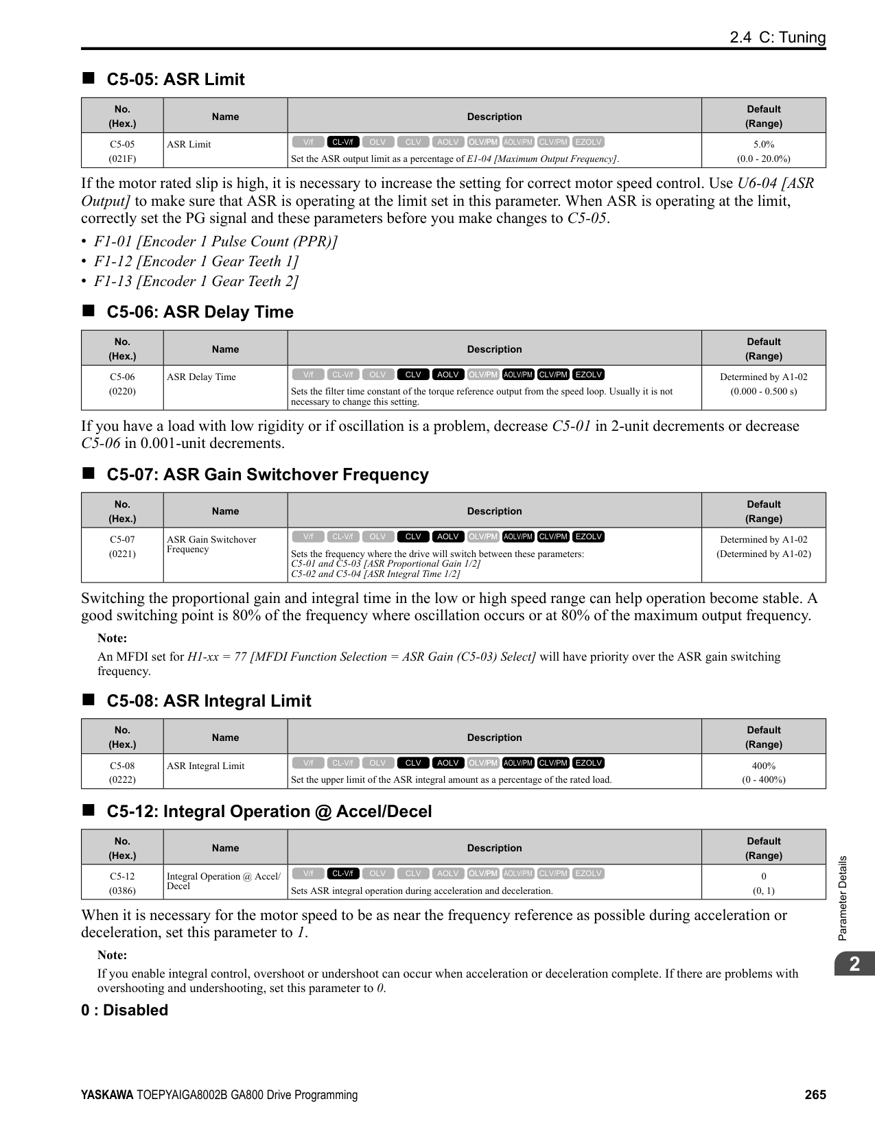
######## ■ F1-19: Deviation 4 Detection Selection
|No. (Hex.)|Name|Description|Default (Range)| |---|---|---|---| |F1-19 (03AE)|Deviation 4 Detection Selection|Sets the number of pulses necessary to cause dv4 [Inversion Prevention Detection].
V/f CL-V/f OLV CLV AOLV OLV/PM AOLV/PM CLV/PM EZOLV
|128 (0 - 5000)|
The drive detects a dv4 [Inversion Prevention Detection] faultwhen the pulses in a reverse direction to the speed reference are input for longer than the time set in F1-19.
################# Note:
= 0.
######## ■ F1-20: Encoder 1 PCB Disconnect Detect
|No. (Hex.)|Name|Description|Default (Range)| |---|---|---|---| |F1-20 (03B4)|Encoder 1 PCB Disconnect Detect|Sets the function that enables and disables detection of a disconnected encoder connection cable to cause PGoH [Encoder (PG) Hardware Fault].
V/f CL-V/f OLV CLV AOLV OLV/PM AOLV/PM CLV/PM EZOLV
|1 (0, 1)|
0 : Disabled 1 : Enabled
######## ■ F1-21: Encoder 1 Signal Selection
|No. (Hex.)|Name|Description|Default (Range)| |---|---|---|---| |F1-21 (03BC)|Encoder 1 Signal Selection|Sets the number of channels for the signal to the encoder option card.
V/f CL-V/f OLV CLV AOLV OLV/PM AOLV/PM CLV/PM EZOLV
|0 (0, 1)|
0 : A Pulse Detection 1 : AB Pulse Detection
0 : CN5-C One option card receives the speed feedback signals from motor 1 and motor 2. 1 : CN5-B Two option cards receive the speed feedback signals from motor 1 and motor 2.
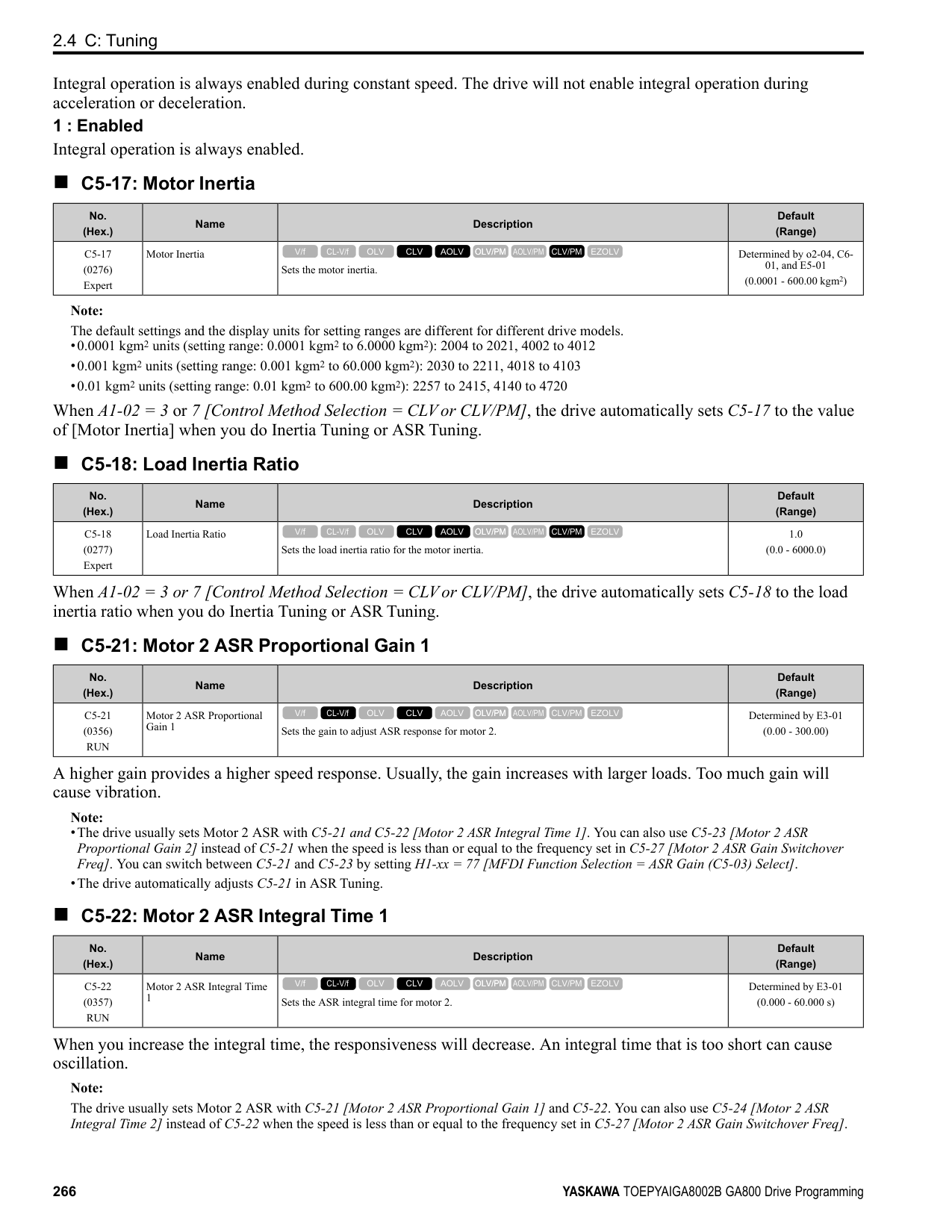
|No. (Hex.)|Name|Description|Default (Range)| |---|---|---|---| |F1-30 (03AA)|Motor 2 Encoder PCB Port Select|Sets the drive port to install the motor 2 encoder option card.
V/f CL-V/f OLV CLV AOLV OLV/PM AOLV/PM CLV/PM EZOLV
|1 (0, 1)|
|No. (Hex.)|Name|Description|Default (Range)| |---|---|---|---| |F1-31 (03B0)|Encoder 2 Pulse Count (PPR)|Sets the number of output pulses for each motor revolution for motor 2.
V/f CL-V/f OLV CLV AOLV OLV/PM AOLV/PM CLV/PM EZOLV
|1024 ppr (1 - 60000 ppr)|
|No. (Hex.)|Name|Description|Default (Range)| |---|---|---|---| |F1-32 (03B1)|Encoder 2 Rotation Selection|Sets the output sequence for the A and B pulses from the encoder for motor 2. This parameter assumes that the motor is operating in the forward direction.
V/f CL-V/f OLV CLV AOLV OLV/PM AOLV/PM CLV/PM EZOLV
|0 (0, 1)|
Refer to the option card installation manual for more information about how to set the encoder pulse output sequence and make sure that it is correct.
0 : Pulse A leads in FWD Direction 1 : Pulse B leads in FWD Direction
ParameterDetails
######## 2
######## ■ F1-33: Encoder 2 Gear Teeth 1
|No. (Hex.)|Name|Description|Default (Range)| |---|---|---|---| |F1-33 (03B2)|Encoder 2 Gear Teeth 1|Sets the number of gear teeth on the motor side for motor 2. This parameter and F1-34 [Encoder 2 Gear Teeth 2] set the gear ratio between the motor and encoder.
V/f CL-V/f OLV CLV AOLV OLV/PM AOLV/PM CLV/PM EZOLV
|0 (0 - 1000)|
After you set the number of gear teeth, the drive uses this formula to calculate the motor speed:
Note: When F1-33 = 0 or F1-34 = 0, the gear ratio is 1.
######## ■ F1-34: Encoder 2 Gear Teeth 2
|No. (Hex.)|Name|Description|Default (Range)|
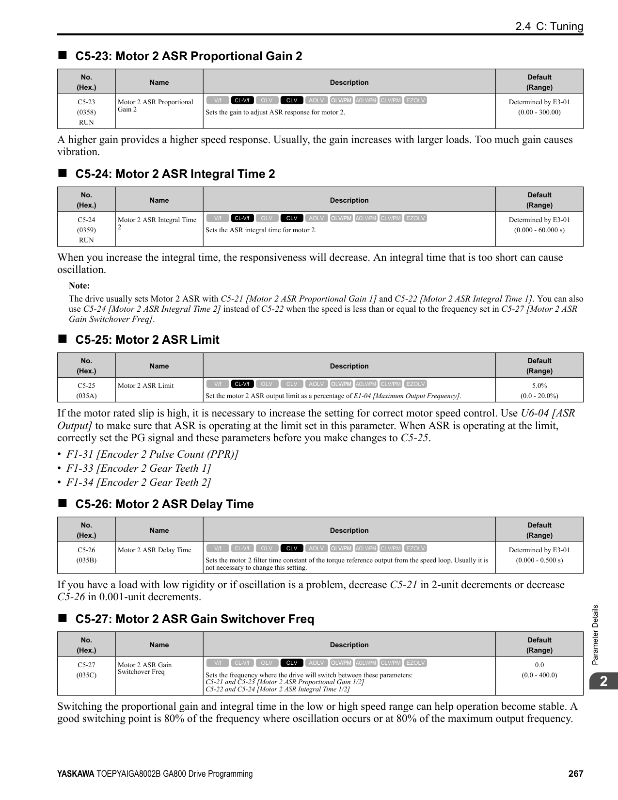
|---|---|---|---| |F1-34 (03B3)|Encoder 2 Gear Teeth 2|Sets the number of gear teeth on the load side for motor 2. This parameter and F1-33 [Encoder 2 Gear Teeth 1] set the gear ratio between the motor and encoder.
V/f CL-V/f OLV CLV AOLV OLV/PM AOLV/PM CLV/PM EZOLV
|0 (0 - 1000)|
After you set the number of gear teeth, the drive uses this formula to calculate the motor speed:
Note: When F1-33 = 0 or F1-34 = 0, the gear ratio is 1.
######## ■ F1-35: Encoder 2 Pulse Monitor Scaling
|No. (Hex.)|Name|Description|Default (Range)| |---|---|---|---| |F1-35 (03BE)|Encoder 2 Pulse Monitor Scaling|Sets the ratio between the pulse input and the pulse output of the encoder as a 3-digit number for motor 2. The first digit is the numerator and the second and third digits set the denominator.
V/f CL-V/f OLV CLV AOLV OLV/PM AOLV/PM CLV/PM EZOLV
|001 (001 - 032, 102 - 132 (1 - 1/ 32))|
When the setting value is a 3-digit value (xyz), the dividing ratio is (1 + x)/yz. For example, when F1-35 = 032, the dividing ratio is 1/32.
Note: For a single-pulse encoder, the dividing ratio for the monitor signal is 1:1.
######## ■ F1-36: Encoder 2 PCB Disconnect Detect
|No. (Hex.)|Name|Description|Default (Range)| |---|---|---|---| |F1-36 (03B5)|Encoder 2 PCB Disconnect Detect|Sets the function that enables and disables detection of a disconnected encoder connection cable to cause PGoH [Encoder (PG) Hardware Fault] for motor 2.
V/f CL-V/f OLV CLV AOLV OLV/PM AOLV/PM CLV/PM EZOLV
|1 (0, 1)|
######## ■ F1-37: Encoder 2 Signal Selection
|No. (Hex.)|Name|Description|Default (Range)| |---|---|---|---| |F1-37 (03BD)|Encoder 2 Signal Selection|Sets the number of channels for the signal to the encoder option card for motor 2.
V/f CL-V/f OLV CLV AOLV OLV/PM AOLV/PM CLV/PM EZOLV
|0 (0, 1)|
0 : A Pulse Detection 1 : AB Pulse Detection
######## ■ F1-50: PG-F3 Option Encoder Type
|No. (Hex.)|Name|Description|Default (Range)|
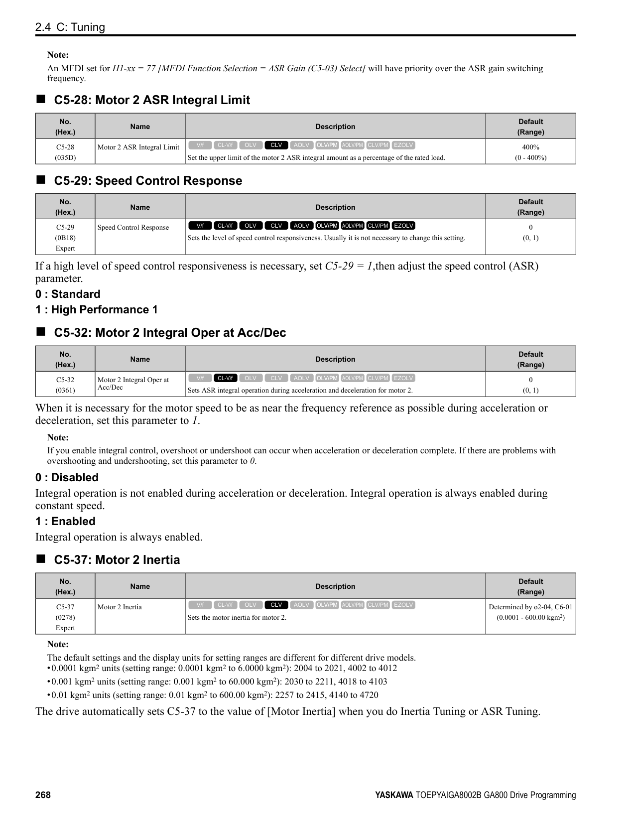
|---|---|---|---| |F1-50 (03D2)|PG-F3 Option Encoder Type|Sets the type of encoder connected to the PG-F3 option.
V/f CL-V/f OLV CLV AOLV OLV/PM AOLV/PM CLV/PM EZOLV
|0 (0 - 2)|
0 : EnDat Sin/Cos 1 : EnDat Serial Only 2 : HIPERFACE
######## ■ F1-51: PG-F3 PGoH Detection Level
|No. (Hex.)|Name|Description|Default (Range)| |---|---|---|---| |F1-51 (03D3)|PG-F3 PGoH Detection Level|The drive will detect PGoH [Encoder (PG) Hardware Fault] if the value of this parameter is smaller than the value of .
V/f CL-V/f OLV CLV AOLV OLV/PM AOLV/PM CLV/PM EZOLV
|80% (1 - 100%)|
The drive will detect PGoH if the value of this parameter is smaller than the value of . Regarding the expression , Sin θ is the single-track (phase B) output from the encoder and Cos θ is the single-track (phase A) output from the encoder.
Note: This function is enabled when F1-20 = 1 [Encoder 1 PCB Disconnect Detect = Enabled].
######## ■ F1-52: Serial Encoder Comm Speed
|No. (Hex.)|Name|Description|Default (Range)| |---|---|---|---| |F1-52 (03D4)|Serial Encoder Comm Speed|Sets the communication speed between the PG-F3 option and the serial encoder.
V/f CL-V/f OLV CLV AOLV OLV/PM AOLV/PM CLV/PM EZOLV
|0 (0 - 2)|
Note: This function is enabled when F1-50 1 or 2 [PG-F3 Option Encoder Type EnDat Serial Only or HIPERFACE].
◆ F2: Analog Input Option F2 parameters set the operation of the drive when you use analog input option card AI-A3. The AI-A3 card has 3 input terminals that accept voltages of -10 V to +10 V (20 kΩ) or currents of 4 mA to 20 mA (250 Ω). Install the AIA3 card to enable setting very accurate analog references with high resolution. Refer to the AI-A3 option manual for more information about how to install, wire, and set the AI-A3 card. WARNING! Sudden Movement Hazard. Do test runs and examine the drive to make sure that the command references are correct. If you set the command reference incorrectly, it can cause damage to the drive or serious injury or death.
######## ■ F2-01: Analog Input Function Selection
|No. (Hex.)|Name|Description|Default (Range)| |---|---|---|---| |F2-01 (038F)|Analog Input Function Selection|Sets the input method for the analog reference used with AI-A3.
V/f CL-V/f OLV CLV AOLV OLV/PM AOLV/PM CLV/PM EZOLV
|0 (0, 1)|
Note: When the AI-A3 card is not mounted in the drive, analog input terminals A1 to A3 on the drive are always enabled. The setting of this parameter does not have an effect. 0 : 3 Independent Channels
ParameterDetails
######## 2
Note:
Figure 2.74 Analog Input Reference Individual Input Block Diagram 1 : 3 Channels Added Together Set b1-01 = 3 [Option PCB] to set addition input. You can input the frequency reference directly. The sum value when you add the input from terminals V1 to V3 becomes the frequency reference. Set F2-01 = 1 to use the AI-A3 card as addition input.
| | | |---|---| | | |
| | | |---|---| | | |
| | | |---|---| | | |
| | | |---|---| | | |
| | |
|---|---| | | | | | |
| | | |---|---| | | |
| | | |---|---| | | |
| | | |---|---| | | |
Figure 2.75 Analog Input Reference Addition Input Block Diagram Use F2-02 and F2-03 to Adjust the Input Status When the bias set in F2-03 is 0%, the gain in F2-02 and the addition input value set the ratio (%) of the maximum output frequency output as the frequency reference.
Note: A voltage input of 10 Vor a current input of 20 mA is the 100% value for each channel.
The bias set in F2-03 sets the ratio (%) of the maximum output frequency output as the frequency reference when the addition input value is 0%.
Note: A voltage input of 0 Vor a current input of 4 mA is the 0% value for each channel.
######## ■ F2-02: Analog Input Option Card Gain
|No. (Hex.)|Name|Description|Default (Range)| |---|---|---|---| |F2-02 (0368) RUN|Analog Input Option Card Gain|Sets the analog reference gain as a percentage when the maximum output frequency is 100%.
V/f CL-V/f OLV CLV AOLV OLV/PM AOLV/PM CLV/PM EZOLV
|100.0% (-999.9 - +999.9%)|
Note: Set F2-01 = 1 [Analog Input Function Selection = 3 Channels Added Together] to enable this function.
######## ■ F2-03: Analog Input Option Card Bias
|No. (Hex.)|Name|Description|Default (Range)| |---|---|---|---| |F2-03 (0369) RUN|Analog Input Option Card Bias|Sets the analog reference bias as a percentage when the maximum output frequency is 100%.
V/f CL-V/f OLV CLV AOLV OLV/PM AOLV/PM CLV/PM EZOLV
|0.0% (-999.9 - +999.9%)|
################# Note:
◆ F3: Digital Input Option F3 parameters set the type of input signal to use with digital input option card DI-A3. Use these digital inputs to set the frequency reference when you install the DI-A3 card in a drive. Set b1-01 = 3 [Frequency Reference Selection 1 = Option PCB] to use this card as the frequency reference input. The input signal is isolated input of 24 Vdc and 8 mA.
WARNING! Sudden Movement Hazard. Do test runs and examine the drive to make sure that the command references are correct. If you set the command reference incorrectly, it can cause damage to the drive or serious injury or death.
■ MFDI for DI-A3
Use F3-10 to F3-25 [Terminal D0 Function Selection to Terminal DF Function Selection] to set the function for the DI-A3 terminals.
ParameterDetails
######## 2
################# Note:
######## ■ F3-01: Digital Input Function Selection
|No. (Hex.)|Name|Description|Default (Range)| |---|---|---|---| |F3-01 (0390)|Digital Input Function Selection|Sets the data format of digital input signals. This parameter is enabled when o1-03 = 0 or 1 [Frequency Display Unit Selection = 0.01 Hz or 0.01% (100% = E1-04)].
V/f CL-V/f OLV CLV AOLV OLV/PM AOLV/PM CLV/PM EZOLV
|8 (0 - 8)|
################# Note:
The input signal type is BCD when o1-03 = 2 or 3 [Revolutions Per Minute (RPM) or User Units (o1-10 & o1-11)]. The o1-03 value sets the setting units.
######## ■ F3-03: Digital Input Data Length Select
|No. (Hex.)|Name|Description|Default (Range)| |---|---|---|---| |F3-03 (03B9)|Digital Input Data Length Select|Sets the number of bits to set the frequency reference with DI-A3.
V/f CL-V/f OLV CLV AOLV OLV/PM AOLV/PM CLV/PM EZOLV
|2 (0 - 2)|
################# Table 2.44 DI-A3 Terminal Function Selection
|Terminal Block|Terminal Name|BCD, Signed [F3-01 = 0 to 5]|BCD, Signed [F3-01 = 0 to 5]|BCD, Signed [F3-01 = 0 to 5]|BCD, Signed [F3-01 = 0 to 5]|BCD, Signed [F3-01 = 0 to 5]|BCD, Signed [F3-01 = 0 to 5]|BCD, Unsigned [F3-01 = 6] *1|BCD, Unsigned [F3-01 = 6] *1|Binary, Signed [F3-01 = 7]|Binary, Signed [F3-01 = 7]|Binary, Signed [F3-01 = 7]| |---|---|---|---|---|---|---|---|---|---|---|---|---| |Terminal Block|Terminal Name|8-bit [F3-03 = 0]|8-bit [F3-03 = 0]|12-bit [F3-03 = 1]|12-bit [F3-03 = 1]|16-bit [F3-03 = 2]|16-bit [F3-03 = 2]|16-bit [F3-03 = 2]|16-bit [F3-03 = 2]|8-bit [F3-03 = 0]|12-bit [F3-03 = 1]|16-bit [F3-03 = 2]| |TB2|D0|1 digit (0 9)|1|1 digit (0 9)|1|1 digit (0 9)|1|1 digit (0, 2, 4, 6, 8)|2|bit 0|bit 0|bit 0| |TB2|D1|1 digit (0 9)|2|1 digit (0 9)|2|1 digit (0 9)|2|1 digit (0, 2, 4, 6, 8)|4|bit 1|bit 1|bit 1| |TB2|D2|1 digit (0 9)|4|1 digit (0 9)|4|1 digit (0 9)|4|1 digit (0, 2, 4, 6, 8)|8|bit 2|bit 2|bit 2| |TB2|D3|1 digit (0 9)|8|1 digit (0 9)|8|1 digit (0 9)|8|2 digits (0 9)|1|bit 3|bit 3|bit 3| |TB2|D4|2 digits (0 -
15) *2|1|2 digits (0 9)|1|2 digits (0 9)|1|2 digits (0 9)|2|bit 4|bit 4|bit 4| |TB2|D5|2 digits (0 -
15) *2|2|2 digits (0 9)|2|2 digits (0 9)|2|2 digits (0 9)|4|bit 5|bit 5|bit 5| |TB2|D6|2 digits (0 -
15) *2|4|2 digits (0 9)|4|2 digits (0 9)|4|2 digits (0 9)|8|bit 6|bit 6|bit 6| |TB2|D7|2 digits (0 -
15) *2|8|2 digits (0 9)|8|2 digits (0 9)|8|3 digits (0 9)|1|bit 7|bit 7|bit 7| |TB3|D8|-|-|3 digits (0 -
15) *2|1|3 digits (0 9)|-|3 digits (0 9)|2|-|bit 8|bit 8| |TB3|D9|-|-|3 digits (0 -
15) *2|2|3 digits (0 9)|-|3 digits (0 9)|4|-|bit 9|bit 9| |TB3|DA|-|-|3 digits (0 -
15) *2|4|3 digits (0 9)|-|3 digits (0 9)|8|-|bit 10|bit 10| |TB3|DB|-|-|3 digits (0 -
15) *2|8|3 digits (0 9)|-|4 digits (0 9)|1|-|bit 11|bit 11| |TB3|DC|-|-|-|-|4 digits (0 -
15) *2|-|4 digits (0 9)|2|-|-|bit 12| |TB3|DD|-|-|-|-|4 digits (0 -
15) *2|-|4 digits (0 9)|4|-|-|bit 13| |TB3|DE|-|-|-|-|4 digits (0 -
15) *2|-|4 digits (0 9)|8|-|-|bit 14| |TB3|DF|-|-|-|-|4 digits (0 -
15) *2|-|5 digits (0 3)|1|-|-|bit 15| |TB1|SI|SIGN (encoded) signal 0: Forward run, 1: Reverse run|SIGN (encoded) signal 0: Forward run, 1: Reverse run|SIGN (encoded) signal 0: Forward run, 1: Reverse run|SIGN (encoded) signal 0: Forward run, 1: Reverse run|SIGN (encoded) signal 0: Forward run, 1: Reverse run|SIGN (encoded) signal 0: Forward run, 1: Reverse run|5 digits (0 3)|2|SIGN (encoded) signal 0: Forward run, 1: Reverse run|SIGN (encoded) signal 0: Forward run, 1: Reverse run|SIGN (encoded) signal 0: Forward run, 1: Reverse run| |TB1|SE|SET (loaded) signal 1: Loads the value set for D0 to DF and SI.|SET (loaded) signal 1: Loads the value set for D0 to DF and SI.|SET (loaded) signal 1: Loads the value set for D0 to DF and SI.|SET (loaded) signal 1: Loads the value set for D0 to DF and SI.|SET (loaded) signal 1: Loads the value set for D0 to DF and SI.|SET (loaded) signal 1: Loads the value set for D0 to DF and SI.|SET (loaded) signal 1: Loads the value set for D0 to DF and SI.|SET (loaded) signal 1: Loads the value set for D0 to DF and SI.|SET (loaded) signal 1: Loads the value set for D0 to DF and SI.|SET (loaded) signal 1: Loads the value set for D0 to DF and SI.|SET (loaded) signal 1: Loads the value set for D0 to DF and SI.| |TB1|SP|Internal power supply: 24 V ± 5%|Internal power supply: 24 V ± 5%|Internal power supply: 24 V ± 5%|Internal power supply: 24 V ± 5%|Internal power supply: 24 V ± 5%|Internal power supply: 24 V ± 5%|Internal power supply: 24 V ± 5%|Internal power supply: 24 V ± 5%|Internal power supply: 24 V ± 5%|Internal power supply: 24 V ± 5%|Internal power supply: 24 V ± 5%| |TB1|SC|Input signal common|Input signal common|Input signal common|Input signal common|Input signal common|Input signal common|Input signal common|Input signal common|Input signal common|Input signal common|Input signal common| |TB1|SN|Internal power supply common: 0 V|Internal power supply common: 0 V|Internal power supply common: 0 V|Internal power supply common: 0 V|Internal power supply common: 0 V|Internal power supply common: 0 V|Internal power supply common: 0 V|Internal power supply common: 0 V|Internal power supply common: 0 V|Internal power supply common: 0 V|Internal power supply common: 0 V| |TB1|SD|Cable sheath connection terminal (ungrounded)|Cable sheath connection terminal (ungrounded)|Cable sheath connection terminal (ungrounded)|Cable sheath connection terminal (ungrounded)|Cable sheath connection terminal (ungrounded)|Cable sheath connection terminal (ungrounded)|Cable sheath connection terminal (ungrounded)|Cable sheath connection terminal (ungrounded)|Cable sheath connection terminal (ungrounded)|Cable sheath connection terminal (ungrounded)|Cable sheath connection terminal (ungrounded)| |TB1|FE|Cable sheath connection terminal (grounded)|Cable sheath connection terminal (grounded)|Cable sheath connection terminal (grounded)|Cable sheath connection terminal (grounded)|Cable sheath connection terminal (grounded)|Cable sheath connection terminal (grounded)|Cable sheath connection terminal (grounded)|Cable sheath connection terminal (grounded)|Cable sheath connection terminal (grounded)|Cable sheath connection terminal (grounded)|Cable sheath connection terminal (grounded)|
|No. (Hex.)|Name|Description|Default (Range)| |---|---|---|---| |F3-10 (0BE3) Expert|Terminal D0 Function Selection|Sets the function for terminal D0 of the DI-A3 option when F3-01 8 [Digital Input Function Selection = Multi-Function Digital Input].
V/f CL-V/f OLV CLV AOLV OLV/PM AOLV/PM CLV/PM EZOLV
|F (1 - 19F)|
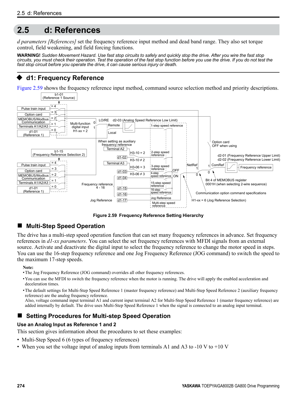
|No. (Hex.)|Name|Description|Default (Range)| |---|---|---|---| |F3-11 (0BE4) Expert|Terminal D1 Function Selection|Sets the function for terminal D1 of the DI-A3 option when F3-01 8 [Digital Input Function Selection = Multi-Function Digital Input].
V/f CL-V/f OLV CLV AOLV OLV/PM AOLV/PM CLV/PM EZOLV
|F (1 - 19F)|
ParameterDetails
######## 2
|No. (Hex.)|Name|Description|Default (Range)| |---|---|---|---| |F3-12 (0BE5) Expert|Terminal D2 Function Selection|Sets the function for terminal D2 of the DI-A3 option when F3-01 = 8 [Digital Input Function Selection = Multi-Function Digital Input].
V/f CL-V/f OLV CLV AOLV OLV/PM AOLV/PM CLV/PM EZOLV
|F (1 - 19F)|
|No. (Hex.)|Name|Description|Default (Range)| |---|---|---|---| |F3-13 (0BE6) Expert|Terminal D3 Function Selection|Sets the function for terminal D3 of the DI-A3 option when F3-01 = 8 [Digital Input Function Selection = Multi-Function Digital Input].
V/f CL-V/f OLV CLV AOLV OLV/PM AOLV/PM CLV/PM EZOLV
|F (1 - 19F)|
|No. (Hex.)|Name|Description|Default (Range)| |---|---|---|---| |F3-14 (0BE7) Expert|Terminal D4 Function Selection|Sets the function for terminal D4 of the DI-A3 option when F3-01 = 8 [Digital Input Function Selection = Multi-Function Digital Input].
V/f CL-V/f OLV CLV AOLV OLV/PM AOLV/PM CLV/PM EZOLV
|F (1 - 19F)|
|No. (Hex.)|Name|Description|Default (Range)| |---|---|---|---| |F3-15 (0BE8) Expert|Terminal D5 Function Selection|Sets the function for terminal D5 of the DI-A3 option when F3-01 8 [Digital Input Function Selection = Multi-Function Digital Input].
V/f CL-V/f OLV CLV AOLV OLV/PM AOLV/PM CLV/PM EZOLV
|F (1 - 19F)|
|No. (Hex.)|Name|Description|Default (Range)| |---|---|---|---|
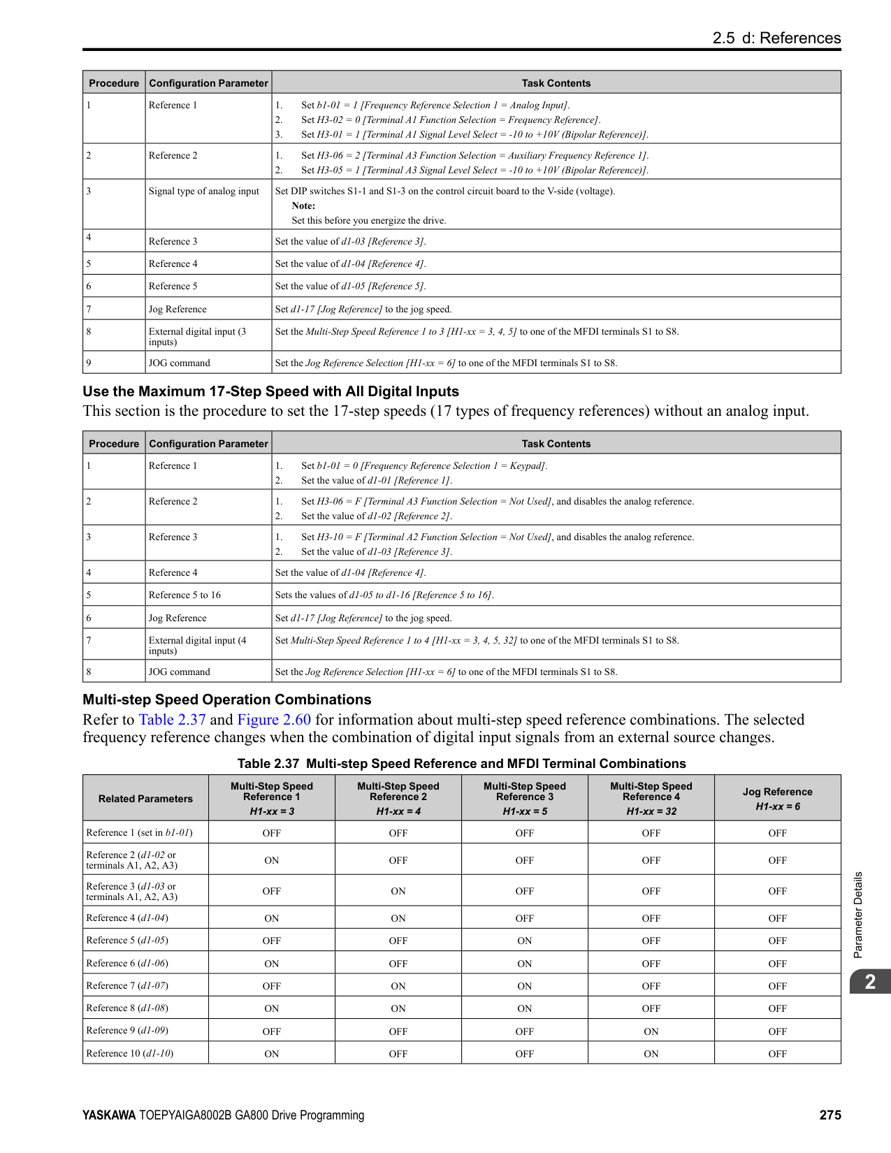
|F3-16 (0BE9) Expert|Terminal D6 Function Selection|Sets the function for terminal D6 of the DI-A3 option when F3-01 8 [Digital Input Function Selection = Multi-Function Digital Input].
V/f CL-V/f OLV CLV AOLV OLV/PM AOLV/PM CLV/PM EZOLV
|F (1 - 19F)|
|No. (Hex.)|Name|Description|Default (Range)| |---|---|---|---| |F3-17 (0BEA) Expert|Terminal D7 Function Selection|Sets the function for terminal D7 of the DI-A3 option when F3-01 = 8 [Digital Input Function Selection = Multi-Function Digital Input].
V/f CL-V/f OLV CLV AOLV OLV/PM AOLV/PM CLV/PM EZOLV
|F (1 - 19F)|
|No. (Hex.)|Name|Description|Default (Range)| |---|---|---|---| |F3-18 (0BEB) Expert|Terminal D8 Function Selection|Sets the function for terminal D8 of the DI-A3 option when F3-01 = 8 [Digital Input Function Selection = Multi-Function Digital Input].
V/f CL-V/f OLV CLV AOLV OLV/PM AOLV/PM CLV/PM EZOLV
|F (1 - 19F)|
|No. (Hex.)|Name|Description|Default (Range)| |---|---|---|---| |F3-19 (0BEC) Expert|Terminal D9 Function Selection|Sets the function for terminal D9 of the DI-A3 option when F3-01 = 8 [Digital Input Function Selection = Multi-Function Digital Input].
V/f CL-V/f OLV CLV AOLV OLV/PM AOLV/PM CLV/PM EZOLV
|F (1 - 19F)|
|No. (Hex.)|Name|Description|Default (Range)| |---|---|---|---| |F3-20 (0BED) Expert|Terminal DA Function Selection|Sets the function for terminal DA of the DI-A3 option when F3-01 = 8 [Digital Input Function Selection = Multi-Function Digital Input].
V/f CL-V/f OLV CLV AOLV OLV/PM AOLV/PM CLV/PM EZOLV
|F (1 - 19F)|
|No. (Hex.)|Name|Description|Default (Range)| |---|---|---|---| |F3-21 (0BEE) Expert|Terminal DB Function Selection|Sets the function for terminal DB of the DI-A3 option when F3-01 = 8 [Digital Input Function Selection = Multi-Function Digital Input].
V/f CL-V/f OLV CLV AOLV OLV/PM AOLV/PM CLV/PM EZOLV
|F (1 - 19F)|
|No. (Hex.)|Name|Description|Default (Range)| |---|---|---|---| |F3-22 (0BEF) Expert|Terminal DC Function Selection|Sets the function for terminal DC of the DI-A3 option when F3-01 8 [Digital Input Function Selection = Multi-Function Digital Input].
V/f CL-V/f OLV CLV AOLV OLV/PM AOLV/PM CLV/PM EZOLV
|F (1 - 19F)|
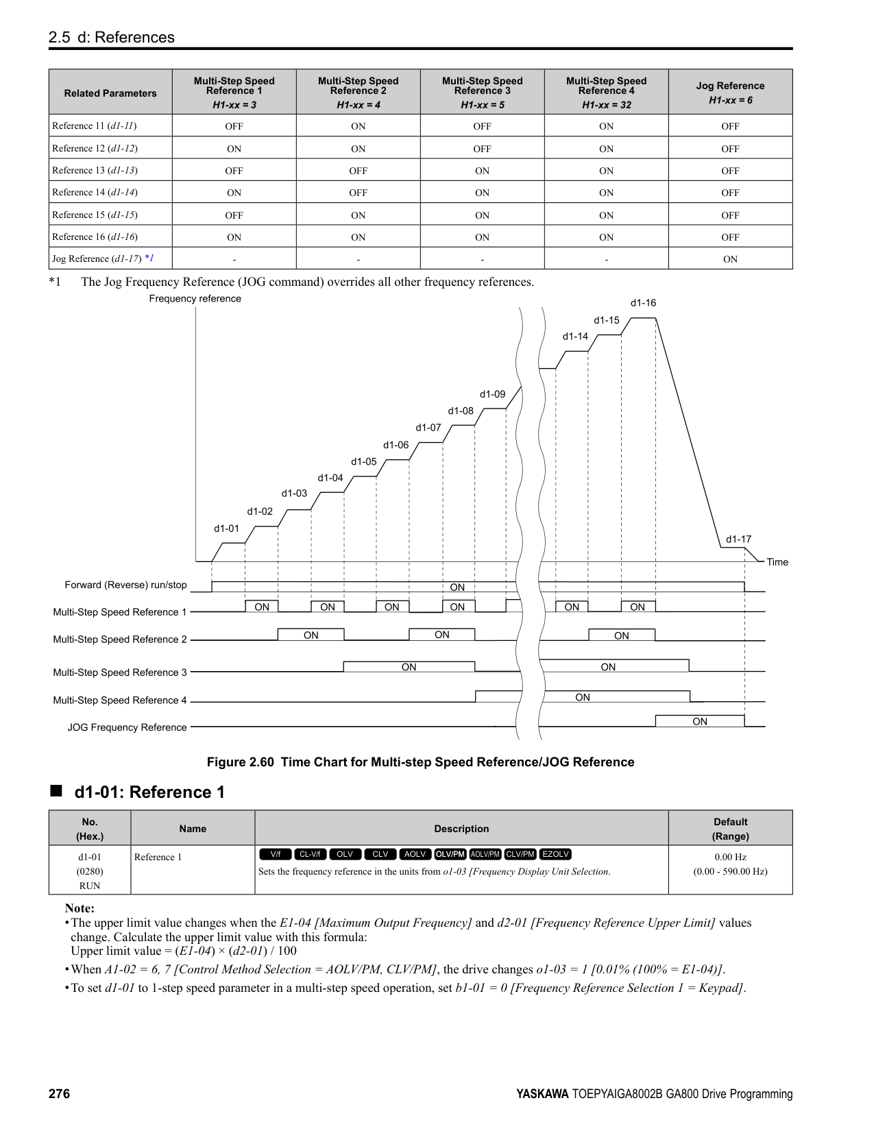
|No. (Hex.)|Name|Description|Default (Range)| |---|---|---|---| |F3-23 (0BF0) Expert|Terminal DD Function Selection|Sets the function for terminal DD of the DI-A3 option when F3-01 8 [Digital Input Function Selection = Multi-Function Digital Input].
V/f CL-V/f OLV CLV AOLV OLV/PM AOLV/PM CLV/PM EZOLV
|F (1 - 19F)|
|No. (Hex.)|Name|Description|Default (Range)| |---|---|---|---| |F3-24 (0BF1) Expert|Terminal DE Function Selection|Sets the function for terminal DE of the DI-A3 option when F3-01 = 8 [Digital Input Function Selection = Multi-Function Digital Input].
V/f CL-V/f OLV CLV AOLV OLV/PM AOLV/PM CLV/PM EZOLV
|F (1 - 19F)|
|No. (Hex.)|Name|Description|Default (Range)| |---|---|---|---| |F3-25 (0BF2) Expert|Terminal DF Function Selection|Sets the function for terminal DF of the DI-A3 option when F3-01 = 8 [Digital Input Function Selection = Multi-Function Digital Input].
V/f CL-V/f OLV CLV AOLV OLV/PM AOLV/PM CLV/PM EZOLV
|F (1 - 19F)|
ParameterDetails
◆ F4: Analog Monitor Option F4 parameters set drive operation when you use analog monitor option card AO-A3. The AO-A3 card has 2 output terminals (terminals V1 and V2) for signals with an Output resolution of 11 bits (1/2048) + encoding and that have an
######## 2
output voltage range of -10 V to +10 V. Install the AO-A3 card to a drive to output analog signals that monitor the output status of the drive (output frequency and output current). Refer to the AO-A3 card manual for more information about how to install, wire, and set the AO-A3 card. Use the U monitor number to set the monitor data to be output from terminals V1 and V2 on the AO-A3 card. Enter the last three digits of Ux-xx as the setting value.
######## ■ F4-01: Terminal V1 Function Selection
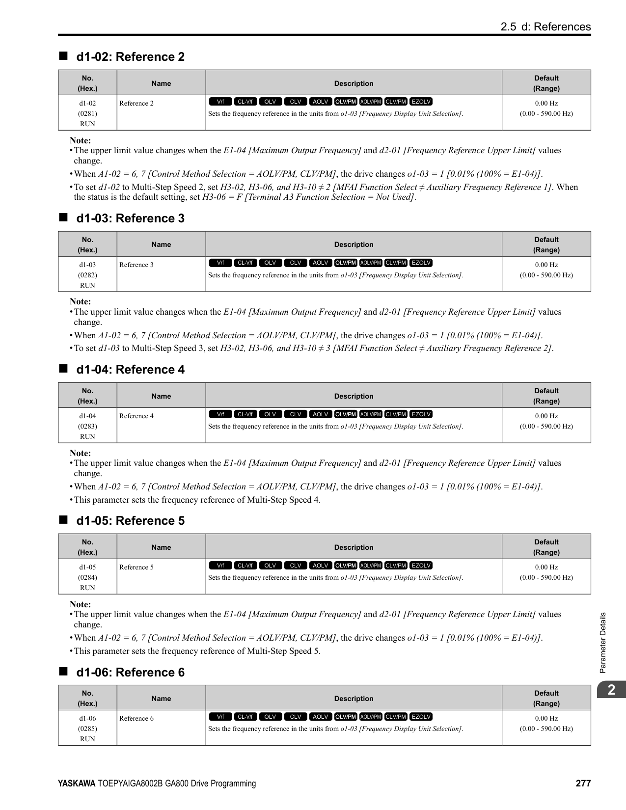
|No. (Hex.)|Name|Description|Default (Range)| |---|---|---|---| |F4-01 (0391)|Terminal V1 Function Selection|Sets the monitor signal output from terminal V1.
V/f CL-V/f OLV CLV AOLV OLV/PM AOLV/PM CLV/PM EZOLV
|102 (000 - 999)|
Set the x-xx part of the Ux-xx [Monitors] to set monitor data to output from the option card. For example, set F4-01 = 102 to monitor U1-02 [Output Frequency].
Note:
######## ■ F4-02: Terminal V1 Gain
|No. (Hex.)|Name|Description|Default (Range)| |---|---|---|---| |F4-02 (0392) RUN|Terminal V1 Gain|Sets the gain of the monitor signal that is sent from terminal V1. Sets the analog signal output level from the terminal V1 at 10 Vor 20 mA as 100% when an output for monitoring items is 100%.
V/f CL-V/f OLV CLV AOLV OLV/PM AOLV/PM CLV/PM EZOLV
|100.0% (-999.9 - +999.9%)|
The maximum output voltage output from terminal V1 is ±10 V. Use F4-07 [Terminal V1 Signal Level] to set the signal level. Example settings:
When you use these settings, and the monitored output voltage is at 100% (drive rated current), the output voltage of terminal V1 is 5 V (50% of 10 V). The output current is 200% of the drive rated current when terminal V1 outputs a maximum voltage of 10 V.
######## ■ F4-03: Terminal V2 Function Selection
|No. (Hex.)|Name|Description|Default (Range)| |---|---|---|---| |F4-03 (0393)|Terminal V2 Function Selection|Sets the monitor signal output from terminal V2.
V/f CL-V/f OLV CLV AOLV OLV/PM AOLV/PM CLV/PM EZOLV
|103 (000 - 999)|
Set the x-xx part of the Ux-xx [Monitors] to set monitor data to output from the option card. For example, set F4-03 = 103 to monitor U1-03 [Output Current].
Note:
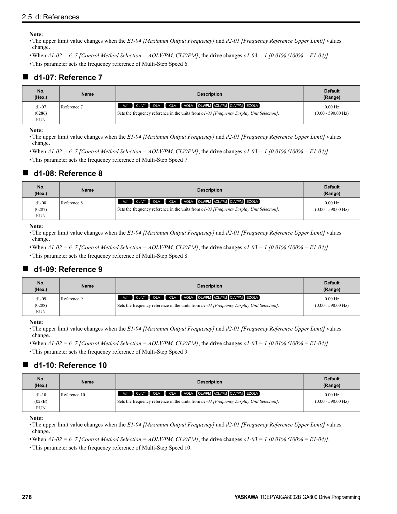
######## ■ F4-04: Terminal V2 Gain
|No. (Hex.)|Name|Description|Default (Range)| |---|---|---|---| |F4-04 (0394) RUN|Terminal V2 Gain|Sets the gain of the monitor signal that is sent from terminal V2. Sets the analog signal output level from terminal V2 at 10 Vor 20 mA as 100% when an output for monitoring items is 100%.
V/f CL-V/f OLV CLV AOLV OLV/PM AOLV/PM CLV/PM EZOLV
|50.0% (-999.9 - +999.9%)|
The maximum output voltage output from terminal V2 is ±10 V. Use F4-08 [Terminal V2 Signal Level] to set the signal level. Example settings:
When you use these settings, and the monitored output voltage is at 100% (drive rated current), the output voltage of terminal V2 is 5 V (50% of 10 V). The output current is 200% of the drive rated current when terminal V2 outputs a maximum voltage of 10 V.
######## ■ F4-05: Terminal V1 Bias
|No. (Hex.)|Name|Description|Default (Range)| |---|---|---|---| |F4-05 (0395) RUN|Terminal V1 Bias|Sets the bias of the monitor signal that is sent from terminal V1. When an output for monitoring items is 0%, this parameter sets the analog signal output level from the V1 terminal as a percentage of 10 Vor 20 mA.
V/f CL-V/f OLV CLV AOLV OLV/PM AOLV/PM CLV/PM EZOLV
|0.0% (-999.9 - +999.9%)|
The maximum output voltage output from terminal V1 is ±10 V. Use F4-07 [Terminal V1 Signal Level] to set the signal level.
######## ■ F4-06: Terminal V2 Bias
|No. (Hex.)|Name|Description|Default (Range)| |---|---|---|---| |F4-06 (0396) RUN|Terminal V2 Bias|Sets the bias of the monitor signal that is sent from terminal V2. Set the level of the analog signal sent from the V2 terminal at 10 Vor 20 mA as 100% when an output for monitoring items is 0%.
V/f CL-V/f OLV CLV AOLV OLV/PM AOLV/PM CLV/PM EZOLV
|0.0% (-999.9 - +999.9%)|
The maximum output voltage output from terminal V2 is ±10 V. Use F4-08 [Terminal V2 Signal Level] to set the signal level.
ParameterDetails
######## ■ F4-07: Terminal V1 Signal Level
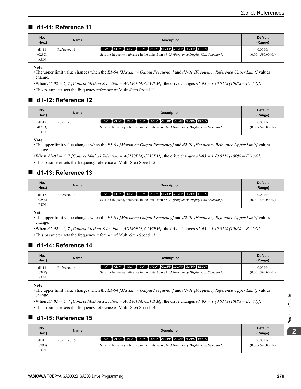
|No. (Hex.)|Name|Description|Default (Range)| |---|---|---|---| |F4-07 (0397)|Terminal V1 Signal Level|Sets the output signal level for terminal V1.
V/f CL-V/f OLV CLV AOLV OLV/PM AOLV/PM CLV/PM EZOLV
|0 (0, 1)|
0 : 0 to 10 V 1 : -10 to 10 V
######## ■ F4-08: Terminal V2 Signal Level
|No. (Hex.)|Name|Description|Default (Range)| |---|---|---|---| |F4-08 (0398)|Terminal V2 Signal Level|Sets the output signal level for terminal V2.
V/f CL-V/f OLV CLV AOLV OLV/PM AOLV/PM CLV/PM EZOLV
|0 (0, 1)|
0 : 0 to 10 V 1 : -10 to 10 V
######## ◆ F5: Digital Output Option
Table 2.45 Details of F5-09 and the DO-A3 Terminal Output
|DO-A3 Terminal Block|DO-A3 Terminal Name|F5-09 = 0 [Predefined Individual Outputs] (Default)|F5-09 = 1 [Binary Output]|F5-09 = 2 [Programmable (F501 to F5-08)]| |---|---|---|---|---| |TB1|M1-M2|Zero speed detection in progress|During run|Depending on the setting of F5-07 [Terminal M1-M2 Function Select]| |TB1|M3-M4|During speed agreement|Minor fault (excluding bb [Baseblock])|Depending on the setting of F5-08 [Terminal M3-M4 Function Select]| |TB2|P1-PC|oC [Overcurrent], GF [Ground Fault]|Coded output Note: Refer to Table 2.46 for details.|Depending on the setting of F5-01 [Terminal P1-PC Function Select]| |TB2|P2-PC|ov [Overvoltage]|Coded output Note: Refer to Table 2.46 for details.|Depending on the setting of F5-02 [Terminal P2-PC Function Select]| |TB2|P3-PC|oL2 [Drive Overload] or oH2 [Heatsink Overheat]|Coded output Note: Refer to Table 2.46 for details.|Depending on the setting of F5-03 [Terminal P3-PC Function Select]| |TB2|P4-PC|Not used|Coded output Note: Refer to Table 2.46 for details.|Depending on the setting of F5-04 [Terminal P4-PC Function Select]| |TB2|P5-PC|oS [Overspeed]|Zero speed detection in progress|Depending on the setting of F5-05 [Terminal P5-PC Function Select]| |TB2|P6-PC|oH, oH1 [Heatsink Overheat] or oL1 [Motor Overload]|During speed agreement|Depending on the setting of F5-06 [Terminal P6-PC Function Select]|

Table 2.46 Binary Output [F5-09 = 1]
|Coded Output (Binary)|Description|DO-A3 Terminal Block TB2|DO-A3 Terminal Block TB2|DO-A3 Terminal Block TB2|DO-A3 Terminal Block TB2| |---|---|---|---|---|---| |Coded Output (Binary)|Description|Terminal P1-PC|Terminal P2-PC|Terminal P3-PC|Terminal P4-PC| |0|No fault|0|0|0|0| |1|oC [Overcurrent], GF [Ground Fault]|1|0|0|0| |2|ov [Overvoltage]|0|1|0|0| |3|oL2 [Drive Overloaded]|1|1|0|0|
|Coded Output (Binary)|Description|DO-A3 Terminal Block TB2|DO-A3 Terminal Block TB2|DO-A3 Terminal Block TB2|DO-A3 Terminal Block TB2| |---|---|---|---|---|---| |Coded Output (Binary)|Description|Terminal P1-PC|Terminal P2-PC|Terminal P3-PC|Terminal P4-PC| |4|oH, oH1 [Heatsink Overheat]|0|0|1|0| |5|oS [Overspeed]|1|0|1|0| |6|Not used|0|1|1|0| |7|rr [Dynamic Braking Transistor Fault], rH [Braking Resistor Overheat]|1|1|1|0| |8|External fault [EF1 to EF8]|0|0|0|1| |9|CPFxx, oFAxx, oFbxx, oFCxx [Drive Hardware Fault] *1|1|0|0|1| |A|oL1 [Motor Overload]|0|1|0|1| |B|Not used|1|1|0|1| |C|Uv1, Uv2 [Undervoltage], Uv3 [Soft Charge Answerback Fault]|0|0|1|1| |D|dEv [Speed Deviation]|1|0|1|1| |E|PGo [Encoder (PG) Feedback Loss]|0|1|1|1| |F|Not used|1|1|1|1|
*1 The “xx” characters are different for different faults.
Refer to “H2: Multi-function Digital Output” for more information about the functions that output from the terminals when F5-09 = 2 [DO-A3 Output Mode Selection = Programmable (F5-01 to F5-08)]. Use F5-01 to F5-08 to set the output items.
|No.|Name|Setting Range|Default| |---|---|---|---| |F5-01|Terminal P1-PC Function Select|0 - 192|0: During Run| |F5-02|Terminal P2-PC Function Select|0 - 192|1: Zero Speed|
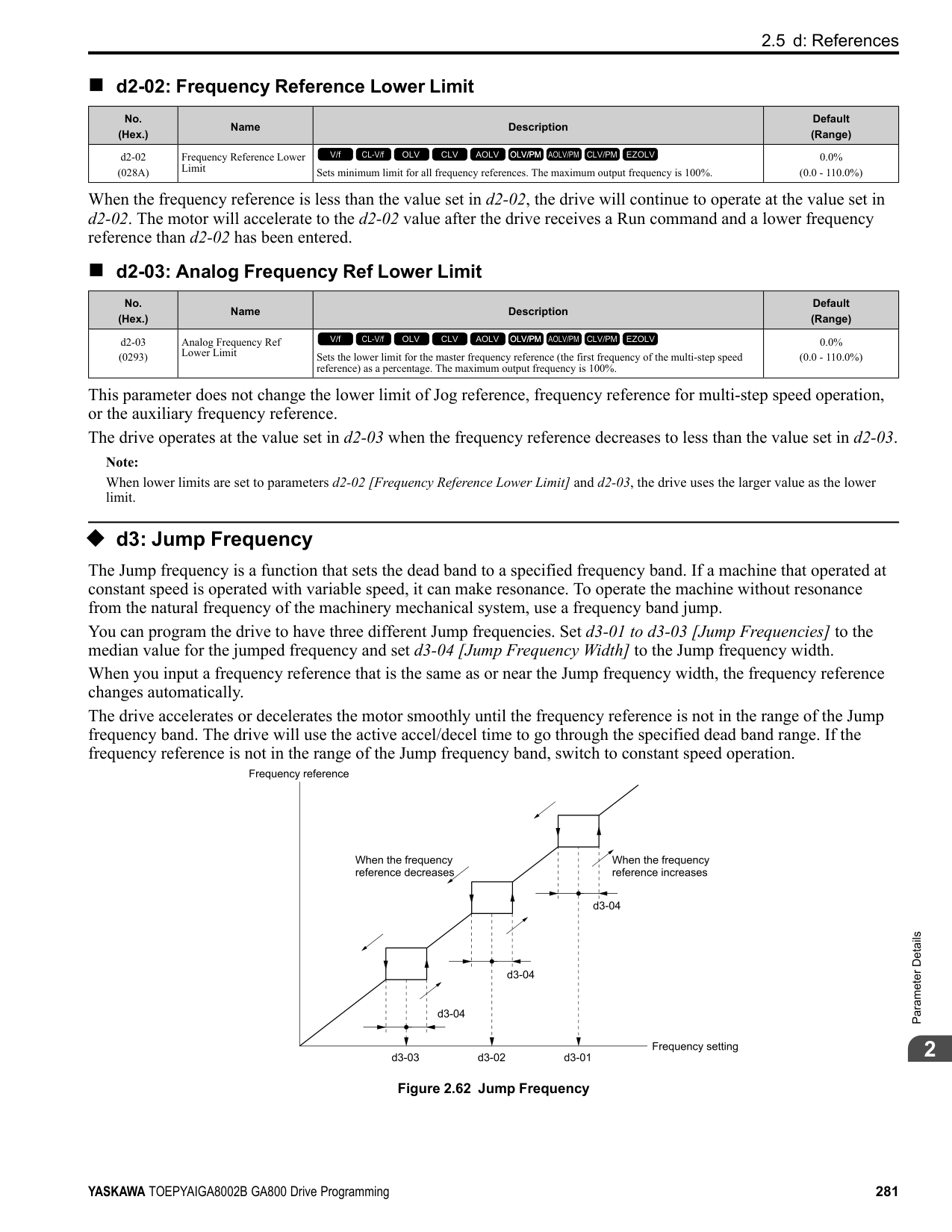
|F5-03|Terminal P3-PC Function Select|0 - 192|2: Speed Agree 1| |F5-04|Terminal P4-PC Function Select|0 - 192|4: Frequency Detection 1| |F5-05|Terminal P5-PC Function Select|0 - 192|6: Drive Ready| |F5-06|Terminal P6-PC Function Select|0 - 192|37: During Frequency Output| |F5-07|Terminal M1-M2 Function Select|0 - 192|F: Not Used| |F5-08|Terminal M3-M4 Function Select|0 - 192|F: Not Used|
|No. (Hex.)|Name|Description|Default (Range)| |---|---|---|---| |F5-01 (0399)|Terminal P1-PC Function Select|Sets the function of terminal P1-PC on the DO-A3 option. Set F5-09 = 2 [DO-A3 Output Mode Selection Programmable (F5-01 to F5-08)] to enable this function.
V/f CL-V/f OLV CLV AOLV OLV/PM AOLV/PM CLV/PM EZOLV
|0 (0 - 1A7)|
ParameterDetails
|No. (Hex.)|Name|Description|Default (Range)| |---|---|---|---| |F5-02 (039A)|Terminal P2-PC Function Select|Sets the function of terminal P2-PC on the DO-A3 option. Set F5-09 = 2 [DO-A3 Output Mode Selection = Programmable (F5-01 to F5-08)] to enable this function.
V/f CL-V/f OLV CLV AOLV OLV/PM AOLV/PM CLV/PM EZOLV
|1 (0 - 1A7)|
|No. (Hex.)|Name|Description|Default (Range)| |---|---|---|---| |F5-03 (039B)|Terminal P3-PC Function Select|Sets the function of terminal P3-PC on the DO-A3 option. Set F5-09 = 2 [DO-A3 Output Mode Selection = Programmable (F5-01 to F5-08)] to enable this function.
V/f CL-V/f OLV CLV AOLV OLV/PM AOLV/PM CLV/PM EZOLV
|2 (0 - 1A7)|
|No. (Hex.)|Name|Description|Default (Range)| |---|---|---|---| |F5-04 (039C)|Terminal P4-PC Function Select|Sets the function of terminal P4-PC on the DO-A3 option. Set F5-09 = 2 [DO-A3 Output Mode Selection = Programmable (F5-01 to F5-08)] to enable this function.
V/f CL-V/f OLV CLV AOLV OLV/PM AOLV/PM CLV/PM EZOLV
|4 (0 - 1A7)|
|No. (Hex.)|Name|Description|Default (Range)| |---|---|---|---| |F5-05 (039D)|Terminal P5-PC Function Select|Sets the function of terminal P5-PC on the DO-A3 option. Set F5-09 = 2 [DO-A3 Output Mode Selection = Programmable (F5-01 to F5-08)] to enable this function.
V/f CL-V/f OLV CLV AOLV OLV/PM AOLV/PM CLV/PM EZOLV
|6 (0 - 1A7)|
|No. (Hex.)|Name|Description|Default (Range)| |---|---|---|---| |F5-06 (039E)|Terminal P6-PC Function Select|Sets the function of terminal P6-PC on the DO-A3 option. Set F5-09 2 [DO-A3 Output Mode Selection = Programmable (F5-01 to F5-08)] to enable this function.
V/f CL-V/f OLV CLV AOLV OLV/PM AOLV/PM CLV/PM EZOLV
|37 (0 - 1A7)|
|No. (Hex.)|Name|Description|Default (Range)| |---|---|---|---| |F5-07 (039F)|Terminal M1-M2 Function Select|Sets the function of terminal M3-M2 on the DO-A3 option. Set F5-09 = 2 [DO-A3 Output Mode Selection = Programmable (F5-01 to F5-08)] to enable this function.
V/f CL-V/f OLV CLV AOLV OLV/PM AOLV/PM CLV/PM EZOLV
|F (0 - 1A7)|
|No. (Hex.)|Name|Description|Default (Range)| |---|---|---|---| |F5-08 (03A0)|Terminal M3-M4 Function Select|Sets the function of terminal M3-M4 on the DO-A3 option. Set F5-09 = 2 [DO-A3 Output Mode Selection = Programmable (F5-01 to F5-08)] to enable this function.
V/f CL-V/f OLV CLV AOLV OLV/PM AOLV/PM CLV/PM EZOLV
|F (0 - 1A7)|
|No. (Hex.)|Name|Description|Default (Range)| |---|---|---|---| |F5-09 (03A1)|DO-A3 Output Mode Selection|Sets the output mode of signals from the DO-A3 option.
V/f CL-V/f OLV CLV AOLV OLV/PM AOLV/PM CLV/PM EZOLV
|0 (0 - 2)|
Refer to Table 2.45 for more information. 0 : Predefined Individual Outputs 1 : Binary Output 2 : Programmable (F5-01 to F5-08)
◆ F6, F7: Communication Options and Ethernet Options F6 and F7 parameters are used to set the basic communication settings and method of fault detection for the communication option card. The communication option card parameters include common option card parameters and communication protocol-specific parameters. The following table lists the parameters that need to be set for each communication option card. Refer to the technical manual for each communication option card for more information on installing, wiring, and configuring the details needed before starting communication. WARNING! Sudden Movement Hazard. Do test runs and examine the drive to make sure that the command references are correct. If you set the command reference incorrectly, it can cause damage to the drive or serious injury or death. Table 2.47 Correspondence Between Communication Protocols and Parameters (SI-C3, SI-T3, SI-ET3, SI-P3, SI-S3, and SIES3)
|Parameter|CC-Link SI-C3|MECHATROLINK-II SI-T3|MECHATROLINK-III SI-ET3|PROFIBUS-DP SI-P3|CANopen SI-S3|EtherCAT SI-ES3| |---|---|---|---|---|---|---| |F6-01 to F6-03|x|x|x|x|x|x| |F6-04|x|-|-|-|-|-| |F6-06 to F6-08|x|x|x|x|x|x| |F6-10, F6-11|x|-|-|-|-|-| |F6-14|x|x|x|x|x|x| |F6-16|x|x|x|x|x|x| |F6-20, F6-21|-|x|x|-|-|-| |F6-22|-|x|-|-|-|-| |F6-23 to F6-26|-|x|x|-|-|-| |F6-30 to F6-32|-|-|-|x|-|-| |F6-35, F6-36|-|-|-|-|x|-| |F6-45 to F6-49|-|-|-|-|-|-| |F6-50 to F6-71|-|-|-|-|-|-| |F7-01 to F7-15|-|-|-|-|-|-|
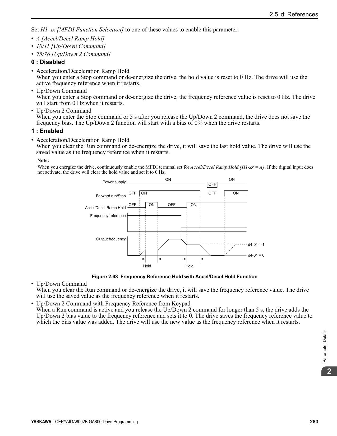
|F7-16|-|-|-|-|-|-| |F7-17 to F7-42|-|-|-|-|-|-| |F7-60 to F7-79|-|-|-|x|-|-|
Table 2.48 Correspondence Between Communication Protocols and Parameters (SI-B3, SI-N3, SI-W3, SI-EM3, SI-EP3, and SI-EN3)
|Parameter|DeviceNet SI-N3|LonWorks SI-W3|Modbus TCP/IP SI-EM3|PROFINET SI-EP3|EtherNet/IP SI-EN3| |---|---|---|---|---|---| |F6-01 to F6-03|x|x|x|x|x| |F6-04|-|-|-|-|-| |F6-06 to F6-08|x|x|x|x|x| |F6-10, F6-11|-|-|-|-|-| |F6-14|x|x|x|x|x| |F6-16|x|x|x|x|x| |F6-20, F6-21|-|-|-|-|-| |F6-22|-|-|-|-|-| |F6-23 to F6-26|-|-|-|-|-| |F6-30 to F6-32|-|-|-|-|-| |F6-35, F6-36|-|-|-|-|-| |F6-45 to F6-49|-|-|-|-|-|
|Parameter|DeviceNet SI-N3|LonWorks SI-W3|Modbus TCP/IP SI-EM3|PROFINET SI-EP3|EtherNet/IP SI-EN3| |---|---|---|---|---|---| |F6-50 to F6-71|x|-|-|-|-| |F7-01 to F7-15|-|-|x|x|x| |F7-16|-|-|x|-|-| |F7-17 to F7-42|-|-|-|x|x| |F7-60 to F7-79|-|-|-|-|-|
######## ■ Gateway Mode
Note: When you use Gateway Mode, do not install the communication option in slave drives. If you install a communication option in a slave drive, the drive commands and responses will not synchronize.
In gateway mode, you can use one communication option to communicate with more than one drive. You can use one communication option to connect a maximum of five drives to the field bus communications. Refer to Figure 2.76 for more information. When you install a communication option on the master drive, you can use the RS-485 communication card to transmit data and slave drives without a communication option can receive it.
| | |---| | |
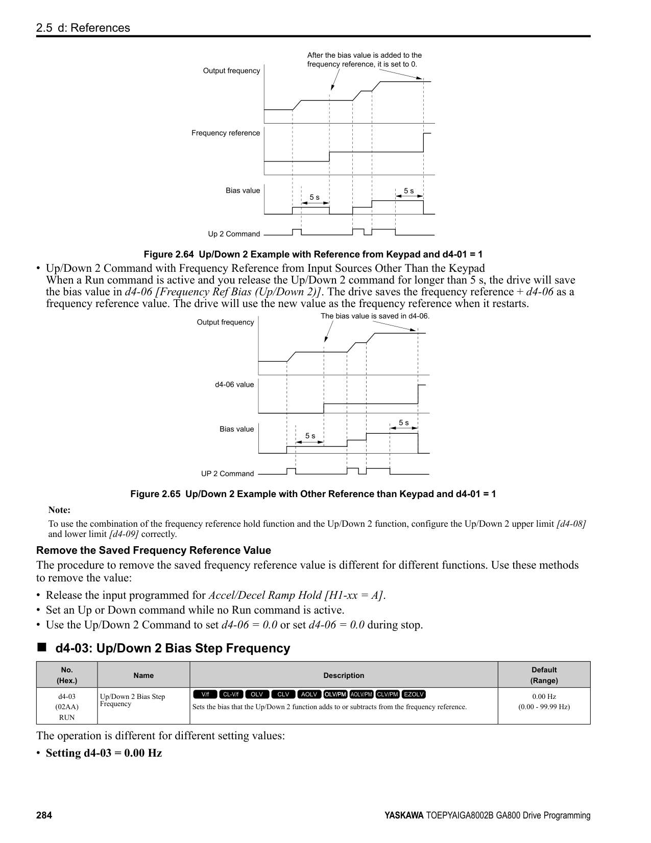
| | |---| | |
| | |---| | |
| | |---| | |
| | |---| | |
Figure 2.76 Connection Examples in Gateway Mode Table 2.49 Specification
|Item|Specification| |---|---| |Applicable options|All the options that support the MEMOBUS access function (for example, PROFIBUS-DP, PROFINET, EtherNet/IP, EtherCAT, etc.)| |Number of connected drives|Maximum: 5 units| |Communication Specifications|MEMOBUS/Modbus (RTUmode) communications| |Commands/responses|The controller can send this data to each drive (Drive 0 to Drive 4):
• Control commands: Run commands and frequency references
• Control responses: Output frequency and drive status (during run, faults)
• Read and write parameters
• Read monitors
| |Synchronous control|Not supported|
Note:
WARNING! Injury to Personnel. Separately prepare safety protection equipment and systems, for example fast stop switches. If the motor does not stop correctly from the disconnection of communications cable or electrical interference, it can cause serious injury.
Configuring Gateway Mode Table 2.50 shows sample settings to connect 4 slave drives:
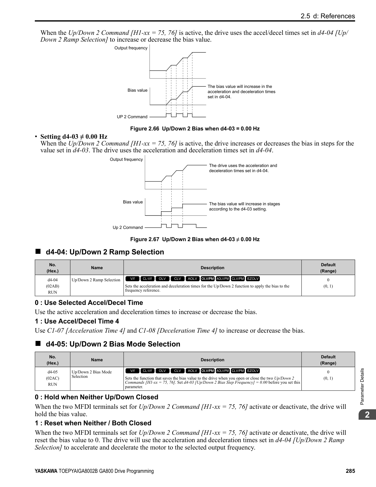
################# Table 2.50 Sample Settings for Using Gateway Mode
| |F6-16 [Gateway Mode]|H5-01
[Drive Node Address] *1|H5-02
[Communication Speed Selection]
H5-03
[Communication Parity Selection]|H5-06 [Drive Transmit Wait Time]|H5-09 [CE Detection Time]|b1-01 [Frequency Reference Selection 1]|b1-02 [Run Command Selection 1]| |---|---|---|---|---|---|---|---| |Drive 0 (Master Drive)|1 - 4 *2|1F (Default)|*5|5 ms (factory default) *6|≥ 2.0 s *7|3 [Option PCB]|3 [Option PCB]| |Drive 1 (Slave drive)|0|01 *3 *4|*5|5 ms (factory default) *6|≥ 0.9 s *7|2 [Memobus/Modbus Communications] *8|2 [Memobus/Modbus Communications] *8| |Drive 2 (Slave drive)|0|02 *3 *4|*5|5 ms (factory default) *6|≥ 0.9 s *7|2 [Memobus/Modbus Communications] *8|2 [Memobus/Modbus Communications] *8| |Drive 3 (Slave drive)|0|03 *3 *4|*5|5 ms (factory default) *6|≥ 0.9 s *7|2 [Memobus/Modbus Communications] *8|2 [Memobus/Modbus Communications] *8| |Drive 4 (Slave drive)|0|04 *3 *4|*5|5 ms (factory default) *6|≥ 0.9 s *7|2 [Memobus/Modbus Communications] *8|2 [Memobus/Modbus Communications] *8|
An Overview of Gateway Mode When in gateway mode, the drive operates as shown in Table 2.51.
| | |---| | |
A - Controller B - Communication Option
C - Master Drive (Drive 0) D - Slave Drives (Drives 1 to 4)
|Controller to Communication Option Card|Communication Option Card to Master Drive (Drive 0)|Master Drive (Drive 0) to Slave Drives (Drives 1 to 4)| |---|---|---| |• The controller and card communicate in the format of each field bus communications protocol.
• Drive 0 sends commands and monitors through normal field bus communications.
• The special registers of Drive 0 use read and write to send commands to and monitor Drives 1 to 4.
|Field bus communication data is written to and read from the special registers of Drive 0.|• Uses MEMOBUS communications .
• Drive 0 sends data from its special registers to Drives 1 to 4.
|
Operations at the Time of Communication Error
|Communication Error|Error Codes|Operation| |---|---|---| |From controller to communication option|bUS|• Master drive Detects bUS [Option Communication Error] and operates as specified by F6-01 [Communication Error Selection].
• Slave drive Detects CE [Modbus Communication Error] and operates as specified by H5-04 [Communication Error Stop Method].
Note:
• After error detection, each drive can continue the operation specified by the last received command if the F6-01 and H5-04 settings agree. Because the controller cannot stop the operation, you must supply a stopping method, for example an emergency stop switch.
• If you set H5-05 0 [Comm Fault Detection Selection Disabled], the drive will not detect CE. The H5-04 setting does not have an effect.
| |From communication option to master drive|oFAxx|• Master drive Detects oFAxx and coasts to stop.
• Slave drive Detects hLCE [High Level Communication Errors] and coasts to stop.
| |From master drive to slave drive|CE|The master drive stops communicating with the slave drive in these conditions: Reset the fault to restart communication. The slave drive detects CE after H5-09 [CE Detection Time] is expired. Then it operates in as specified with H5-04 [Communication Error Stop Method].
• A message error occurred in the send data from the slave drive 10 consecutive times.
• Response from the slave drive timed out 10 consecutive times.
|
Special Register for Gateway Mode
|Register No. (Hex.)|Description|Description|Description| |---|---|---|---| |15C5|Command Source Update|Command Source Update|This flag enables command updates.| |15C5|bit 0|Drive 1 Update Command Enabled|To input the Run command and frequency reference at the same time, change the bit value from 0 to 1 after you write all commands.| |15C5|bit 1|Drive 2 Update Command Enabled| | |15C5|bit 2|Drive 3 Update Command Enabled| | |15C5|bit 3|Drive 4 Update Command Enabled| | |15C5|bit 4|Update Register Access Command Enabled| | |15C5|bit 5 - F|Region Code| | |15C6|Run Command (Drive 1)|Run Command (Drive 1)| | |15C6|bit 0|H5-12 = 0: FWD/Stop
0 = Stop
1 = Forward run
| | |15C6|bit 0|H5-12 = 1: Run/Stop
0 = Stop
1 = Run
| | |15C6|bit 1|H5-12 = 0: REV/Stop
0 = Stop
1 = Reverse run
| | |15C6|bit 1|H5-12 = 1: FWD/REV
0 = Forward run
1 = Reverse run
| | |15C6|bit 2|External fault| | |15C6|bit 3|Fault Reset Procedure| | |15C6|bit 4|ComRef| | |15C6|bit 5|ComCtrl| | |15C6|bit 6 - F|Region Code| | |15C7|Frequency Reference (Drive 1)|Frequency Reference (Drive 1)|The unit of measure changes when o1-03 changes.| |15C8|Run Command (Drive 2)|Run Command (Drive 2)| | |15C9|Frequency Reference (Drive 2)|Frequency Reference (Drive 2)| | |15CA|Run Command (Drive 3)|Run Command (Drive 3)| |
|Register No. (Hex.)|Description|Description|Description| |---|---|---|---| |15CB|Frequency Reference (Drive 3)|Frequency Reference (Drive 3)| | |15CC|Run Command (Drive 4)|Run Command (Drive 4)| |
|15CD|Frequency Reference (Drive 4)|Frequency Reference (Drive 4)| | |15CE|Slave Address for Reg. Access Read/Write|Slave Address for Reg. Access Read/Write| | |15CE|bit 0
bit 1
bit 2
bit 3
|Slave address
0: Broadcast Messages (MEMOBUS)
1: Drive 1
2: Drive 2
3: Drive 3
4: Drive 4
5: Broadcast Messages (Run command and frequency reference)
|When bit 0 to 3 0, access is enabled for broadcast messages only. When bit 0 to 3 5, access is enabled for Run command and frequency reference broadcast messages only. Drive 0 is excluded.| |15CE|bit 4|0: Read, 1: Write| | |15CE|bit 5 - F|Region Code| | |15CF|Register No.|Register No.| | |15D0|Data (write register)|Data (write register)| |
################# Table 2.53 Monitor Data
|Register No. (Hex.)|Description|Description|Description| |---|---|---|---| |15E7|Drive Status (Drive 1)|Drive Status (Drive 1)| | |15E7|bit 0|During Run| | |15E7|bit 1|During Reverse Run| | |15E7|bit 2|Drive ready| | |15E7|bit 3|Faults| | |15E7|bit 4|Frequency Command Setting Fault|1: Upper/Lower Limit Fault| |15E7|bit 5|No response from slave|1: Response timed out.| |15E7|bit 6|Communication Error|1: The drive detected a fault from a slave.| |15E7|bit 7|No response from slave 10 consecutive attempts.|1: Timeout occurred 10 consecutive times.| |15E7|bit 8|Communication fault has occurred 10 consecutive times.|1: A fault occurred from a slave 10 consecutive times.| |15E7|bit 9|Receive broadcast command while drive is running|1: The drive operates as specified by the broadcast message command.| |15E7|bit A|Communication error with master drive|1: The slave cannot communicate with the master because of a communication error.| |15E7|bit B D|Region Code| | |15E7|bit E|ComRef status| | |15E7|bit F|ComCtrl status| | |15E8|Output frequency or frequency reference (Drive Status bit 4: ON) (Drive 1)
Drive Status Bit 4 = 0 [Output Frequency]
Drive Status Bit 4 = 1 [Frequency Reference]
|Output frequency or frequency reference (Drive Status bit 4: ON) (Drive 1)
Drive Status Bit 4 = 0 [Output Frequency]
Drive Status Bit 4 = 1 [Frequency Reference]
|The unit of measure changes when o1-03 changes.| |15E9|Drive Status (Drive 2)|Drive Status (Drive 2)| | |15EA|Output frequency or frequency reference (Drive Status bit 4: ON) (Drive 2)|Output frequency or frequency reference (Drive Status bit 4: ON) (Drive 2)| | |15EB|Drive Status (Drive 3)|Drive Status (Drive 3)| | |15EC|Output frequency or frequency reference (Drive Status bit 4: ON) (Drive 3)|Output frequency or frequency reference (Drive Status bit 4: ON) (Drive 3)| | |15ED|Drive Status (Drive 4)|Drive Status (Drive 4)| | |15EE|Output frequency or frequency reference (Drive Status bit 4: ON) (Drive 4)|Output frequency or frequency reference (Drive Status bit 4: ON) (Drive 4)| |
|Register No. (Hex.)|Description|Description|Description| |---|---|---|---| |15EF|Slave Address for Reg. Access + During MEMOBUS process & ErrCode|Slave Address for Reg. Access + During MEMOBUS process & ErrCode| | |15EF|bit 0
bit 1
bit 2
bit 3
bit 4
bit 5
bit 6
bit 7
|00H: MEMOBUS communication complete 02H: Register number not registered
21H: Upper/Lower Limit Fault
22H: Writing Mode Error
23H: Write performed during Uv
24H: Write performed while writing parameter settings FFH: MEMOBUS communication in process
|Note:
If you change the access command before the MEMOBUS/Modbus access completion flag turns on, the drive will not execute the command from before.| |15EF|bit 8
bit 9
bit A
bit B
|Slave address
0: MEMOBUS command ignored
1: Drive 1
2: Drive 2
3: Drive 3
4: Drive 4
5: Broadcast Messages (Run command and frequency reference)
| |
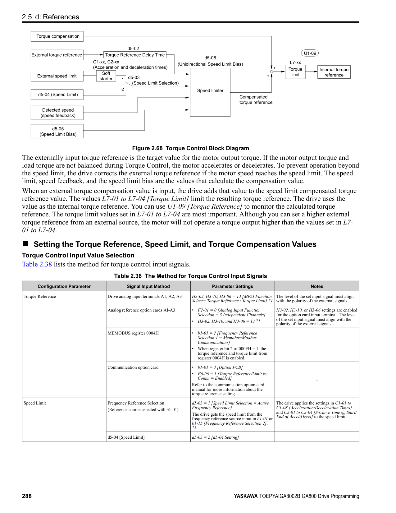
|15EF|bit C - F|Region Code| | |15F0|Register No.|Register No.| | |15F1|Data (write register)|Data (write register)| |
######## ■ F6-01: Communication Error Selection
|No. (Hex.)|Name|Description|Default (Range)| |---|---|---|---| |F6-01 (03A2)|Communication Error Selection|Sets the method to stop the motor or let the motor continue operating when the drive detects a bUS [Option Communication Error].
V/f CL-V/f OLV CLV AOLV OLV/PM AOLV/PM CLV/PM EZOLV
|1 (0 - 5)|
The drive ramps the motor to stop in the deceleration time. Fault relay output terminal MA-MC turns ON, and MBMC turns OFF.
The output turns off and the motor coasts to stop. Fault relay output terminal MA-MC turns ON, and MB-MC turns OFF.
The drive stops the motor in the deceleration time set in C1-09 [Fast Stop Time]. Fault relay output terminal MA-MC turns ON, and MB-MC turns OFF.
Note: Separately prepare safety protection equipment and systems, for example fast stop switches.
The output terminal set for Alarm [H2-01 to H2-03 = 10] activates.
Note: Separately prepare safety protection equipment and systems, for example fast stop switches.
######## ■ F6-02: Comm External Fault (EF0) Detect
|No. (Hex.)|Name|Description|Default (Range)| |---|---|---|---| |F6-02 (03A3)|Comm External Fault (EF0) Detect|Sets the conditions at which EF0 [Option Card External Fault] is detected.
V/f CL-V/f OLV CLV AOLV OLV/PM AOLV/PM CLV/PM EZOLV
|0 (0, 1)|
0 : Always Detected 1 : Detected during RUN Only
######## ■ F6-03: Comm External Fault (EF0) Select
|No. (Hex.)|Name|Description|Default (Range)| |---|---|---|---| |F6-03 (03A4)|Comm External Fault (EF0) Select|Sets the method to stop the motor or let the motor continue operating when the drive detects an EF0 [Option Card External Fault].
V/f CL-V/f OLV CLV AOLV OLV/PM AOLV/PM CLV/PM EZOLV
|1 (0 - 3)|
The drive ramps the motor to stop in the deceleration time. Fault relay output terminal MA-MC turns ON, and MBMC turns OFF.
The output turns off and the motor coasts to stop. Fault relay output terminal MA-MC turns ON, and MB-MC turns OFF.
The drive stops the motor in the deceleration time set in C1-09 [Fast Stop Time]. Fault relay output terminal MA-MC turns ON, and MB-MC turns OFF.
Note: Separately prepare safety protection equipment and systems, for example fast stop switches.
The output terminal set for Alarm [H2-01 to H2-03 = 10] activates.
######## ■ F6-04: bUS Error Detection Time
|No. (Hex.)|Name|Description|Default (Range)| |---|---|---|---| |F6-04 (03A5)|bUS Error Detection Time|Sets the delay time for the drive to detect bUS [Option Communication Error].
V/f CL-V/f OLV CLV AOLV OLV/PM AOLV/PM CLV/PM EZOLV
|2.0 s (0.0 - 5.0 s)|
Note: When you install an option card in the drive, the parameter value changes to 0.0 s.
######## ■ F6-06: Torque Reference/Limit by Comm
|No. (Hex.)|Name|Description|Default (Range)|
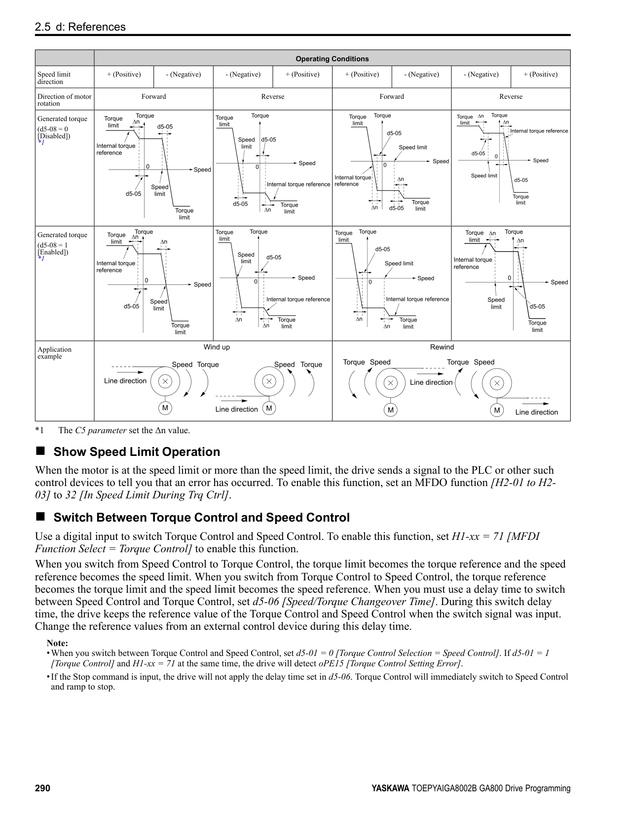
|---|---|---|---| |F6-06 (03A7)|Torque Reference/Limit by Comm|Sets the function that enables and disables the torque reference and torque limit received from the communication option.
V/f CL-V/f OLV CLV AOLV OLV/PM AOLV/PM CLV/PM EZOLV
|0 (0, 1)|
0 : Disabled 1 : Enabled
ParameterDetails
######## ■ F6-07: Multi-Step Ref @ NetRef/ComRef
|No. (Hex.)|Name|Description|Default (Range)| |---|---|---|---| |F6-07 (03A8)|Multi-Step Ref @ NetRef/ ComRef|Sets the function that enables and disables the multi-step speed reference when the freqency reference source is NetRef or ComRef (communication option card or MEMOBUS/Modbus communications).
V/f CL-V/f OLV CLV AOLV OLV/PM AOLV/PM CLV/PM EZOLV
|0 (0, 1)|
When NetRef or ComRef are the frequency reference source, the multi-step speed reference (2-step speed to 16-step speed references) and the Jog Frequency Reference (JOG command) are disabled.
When NetRef or ComRef are the frequency reference source, the multi-step speed reference (2-step speed through 16step speed references) and the Jog Frequency Reference (JOG command) are enabled, and you can change the frequency reference.
######## ■ F6-08: Comm Parameter Reset @Initialize
|No. (Hex.)|Name|Description|Default (Range)| |---|---|---|---| |F6-08 (036A)|Comm Parameter Reset @Initialize|Sets the function to initialize F6-xx and F7-xx parameters when the drive is initialized with A1-03 [Initialize Parameters].
V/f CL-V/f OLV CLV AOLV OLV/PM AOLV/PM CLV/PM EZOLV
|0 (0, 1)|
############## 0 : No Reset - Parameters Retained 1 : Reset Back to Factory Default
Note: When you use A1-03 to initialize the drive, this setting will not change.
######## ■ F6-10: CC-Link Node Address
|No. (Hex.)|Name|Description|Default (Range)| |---|---|---|---| |F6-10 (03B6)|CC-Link Node Address|Sets the node address for CC-Link communication. Restart the drive after you change the parameter setting.
V/f CL-V/f OLV CLV AOLV OLV/PM AOLV/PM CLV/PM EZOLV
|0 (0 - 64)|
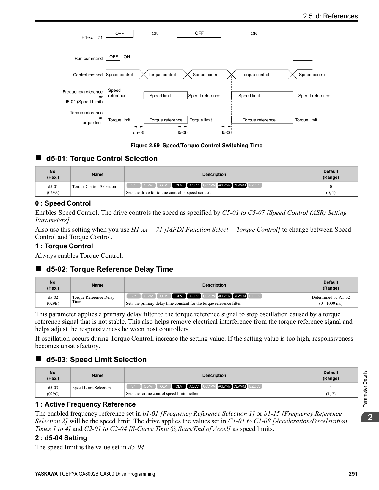
Note:
Be sure to set a node address that is different than all other node addresses. Do not set this parameter to 0. Incorrect parameter settings will cause AEr [Station Address Setting Error] errors and the L.ERR LED on the option will come on.
When the only drive is connected, you can connect a maximum of 42 nodes. Follow these rules to connect devices that are not drives:
######## ■ F6-11: CC-Link Communication Speed
|No. (Hex.)|Name|Description|Default (Range)| |---|---|---|---| |F6-11 (03B7)|CC-Link Communication Speed|Sets the communication speed for CC-Link communication. Restart the drive after you change the parameter setting.
V/f CL-V/f OLV CLV AOLV OLV/PM AOLV/PM CLV/PM EZOLV
|0 (0 - 4)|
0 : 156 kbps 1 : 625 kbps 2 : 2.5 Mbps
3 : 5 Mbps 4 : 10 Mbps
######## ■ F6-14: BUS Error Auto Reset
|No. (Hex.)|Name|Description|Default (Range)| |---|---|---|---| |F6-14 (03BB)|BUS Error Auto Reset|Sets the automatic reset function for bUS [Option Communication Errors].
V/f CL-V/f OLV CLV AOLV OLV/PM AOLV/PM CLV/PM EZOLV
|0 (0, 1)|
0 : Disabled 1 : Enabled
######## ■ F6-15: Comm. Option Parameters Reload
|No. (Hex.)|Name|Description|Default (Range)| |---|---|---|---| |F6-15 (0B5B)|Comm. Option Parameters Reload|Sets the update method when you change F6-xx, F7-xx [Communication Options].
V/f CL-V/f OLV CLV AOLV OLV/PM AOLV/PM CLV/PM EZOLV
|0 (0 - 2)|
Note:
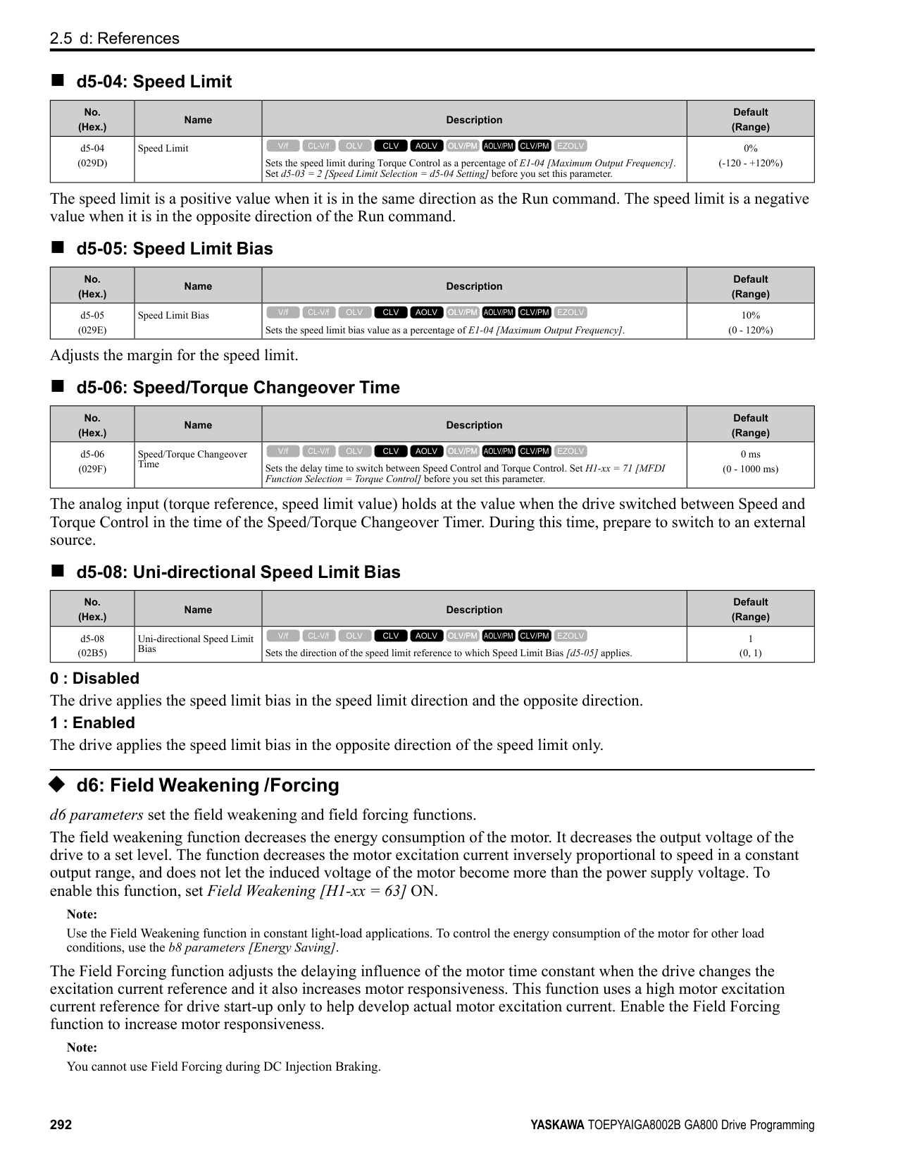
######## ■ F6-16: Gateway Mode
|No. (Hex.)|Name|Description|Default (Range)| |---|---|---|---| |F6-16 (0B8A)|Gateway Mode|Sets the gateway mode operation and the number of connected slave drives.
V/f CL-V/f OLV CLV AOLV OLV/PM AOLV/PM CLV/PM EZOLV
|0 (0 to 4)|
######## ■ F6-20: MECHATROLINK Station Address
|No. (Hex.)|Name|Description|Default (Range)| |---|---|---|---| |F6-20 (036B)|MECHATROLINK Station Address|Sets the station address for MECHATROLINK communication. Restart the drive after you change the parameter setting.
V/f CL-V/f OLV CLV AOLV OLV/PM AOLV/PM CLV/PM EZOLV
|0021h (MECHATROLINK-II: 0020h - 003Fh, MECHATROLINK-III: 0003h - 00EFh)|
################# Note:
ParameterDetails
######## 2
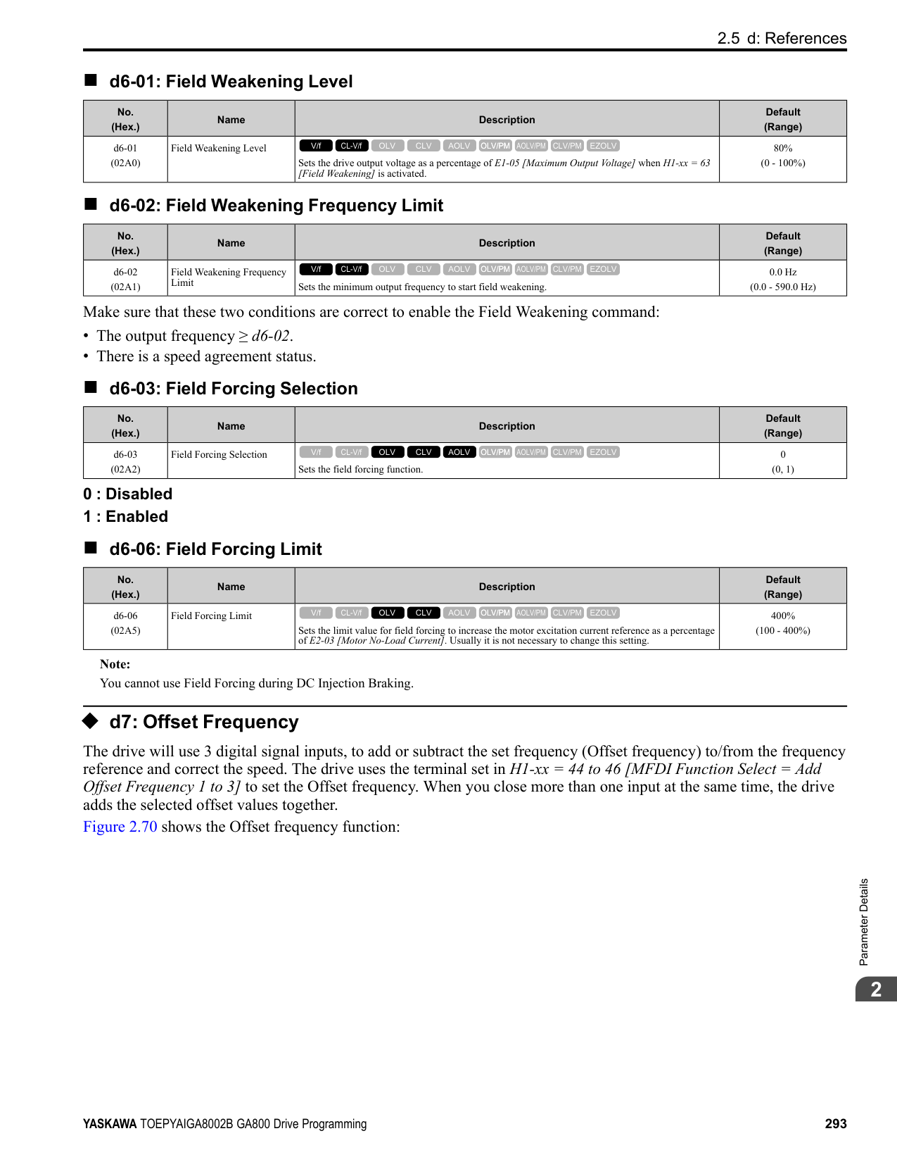
######## ■ F6-21: MECHATROLINK Frame Size
|No. (Hex.)|Name|Description|Default (Range)| |---|---|---|---| |F6-21 (036C)|MECHATROLINK Frame Size|Sets the frame size for MECHATROLINK communication. Restart the drive after you change the parameter setting.
V/f CL-V/f OLV CLV AOLV OLV/PM AOLV/PM CLV/PM EZOLV
|0 (0, 1)|
0 : 32byte (M-2) / 64byte (M-3) 1 : 17byte (M-2) / 32byte (M-3)
######## ■ F6-22: MECHATROLINK Link Speed
|No. (Hex.)|Name|Description|Default (Range)| |---|---|---|---| |F6-22 (036D)|MECHATROLINK Link Speed|Sets the communications speed for MECHATROLINK-II. Restart the drive after you change the parameter setting.
V/f CL-V/f OLV CLV AOLV OLV/PM AOLV/PM CLV/PM EZOLV
|0 (0, 1)|
Note: This parameter is only available with the MECHATROLINK-II option.
0 : 10 Mbps 1 : 4 Mbps
######## ■ F6-23: MECHATROLINK Monitor Select (E)
|No. (Hex.)|Name|Description|Default (Range)| |---|---|---|---| |F6-23 (036E)|MECHATROLINK Monitor Select (E)|Sets the MEMOBUS register used for the monitor functions of INV_CTL (drive operation control command) and INV_I/O (drive I/O control command). Restart the drive after you change the parameter setting.
V/f CL-V/f OLV CLV AOLV OLV/PM AOLV/PM CLV/PM EZOLV
|0000h (0000h - FFFFh)|
To enable the MEMOBUS register set in F6-23, set SEL_MON2/1 to 0EH or set SEL_MON 3/4 and SEL_MON 5/6 to 0EH. Bytes of the response data enable the MEMOBUS register content that was set in F6-23.
######## ■ F6-24: MECHATROLINK Monitor Select (F)
|No. (Hex.)|Name|Description|Default (Range)| |---|---|---|---| |F6-24 (036F)|MECHATROLINK Monitor Select (F)|Sets the MEMOBUS register used for the monitor functions of INV_CTL (drive operation control command) and INV_I/O (drive I/O control command). Restart the drive after you change the parameter setting.
V/f CL-V/f OLV CLV AOLV OLV/PM AOLV/PM CLV/PM EZOLV
|0000h (0000h - FFFFh)|
To enable the MEMOBUS register set in F6-24, set SEL_MON2/1 to 0FH or set SEL_MON3/4 and SEL_MON 5/6 to 0FH. Bytes of the response data enable the MEMOBUS register content that was set F6-24.
######## ■ F6-25: MECHATROLINK Watchdog Error Sel
|No. (Hex.)|Name|Description|Default (Range)|
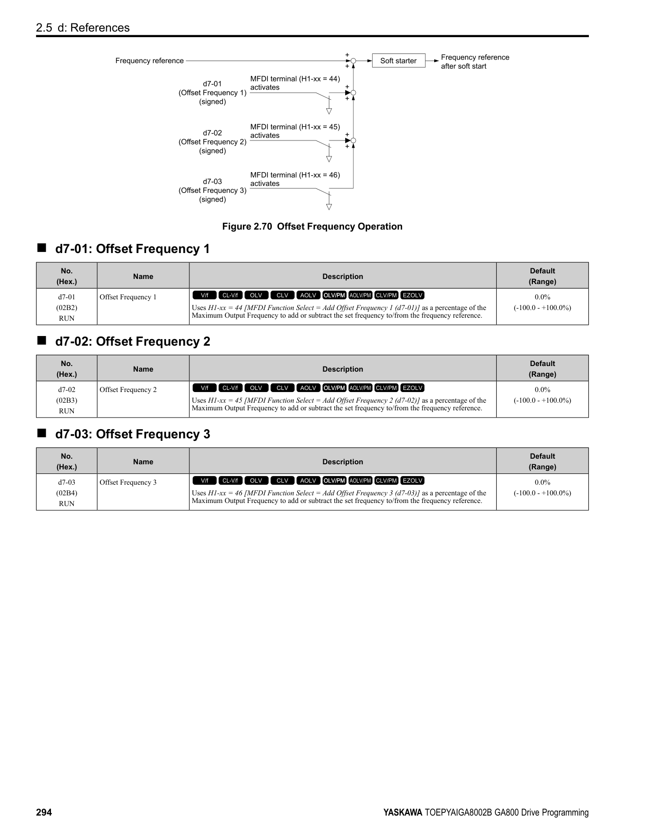
|---|---|---|---| |F6-25 (03C9)|MECHATROLINK Watchdog Error Sel|Sets the method to stop the motor or let the motor continue operating when the drive detects an E5 [MECHATROLINK Watchdog Timer Err].
V/f CL-V/f OLV CLV AOLV OLV/PM AOLV/PM CLV/PM EZOLV
|1 (0 - 3)|
The drive ramps the motor to stop in the deceleration time. Fault relay output terminal MA-MC turns ON, and MBMC turns OFF.
The output turns off and the motor coasts to stop. Fault relay output terminal MA-MC turns ON, and MB-MC turns OFF.
The drive stops the motor in the deceleration time set in C1-09 [Fast Stop Time]. Fault relay output terminal MA-MC turns ON, and MB-MC turns OFF. 3 : Alarm Only The keypad shows E5, and the drive continues to operate.
Note: Separately prepare safety protection equipment and systems, for example fast stop switches.
The output terminal set for Alarm [H2-01 to H2-03 = 10] activates.
Note:
|No. (Hex.)|Name|Description|Default (Range)| |---|---|---|---| |F6-26 (03CA)|MECHATROLINK Allowable No of Err|Sets the number of times that the option must detect a bUS alarm to cause a bUS [Option Communication Error].
V/f CL-V/f OLV CLV AOLV OLV/PM AOLV/PM CLV/PM EZOLV
|2 (2 - 10 times)|
|No. (Hex.)|Name|Description|Default (Range)| |---|---|---|---| |F6-30 (03CB)|PROFIBUS-DP Node Address|Sets the node address for PROFIBUS-DP communication. Restart the drive after you change the parameter setting.
V/f CL-V/f OLV CLV AOLV OLV/PM AOLV/PM CLV/PM EZOLV
|0 (0 - 125)|
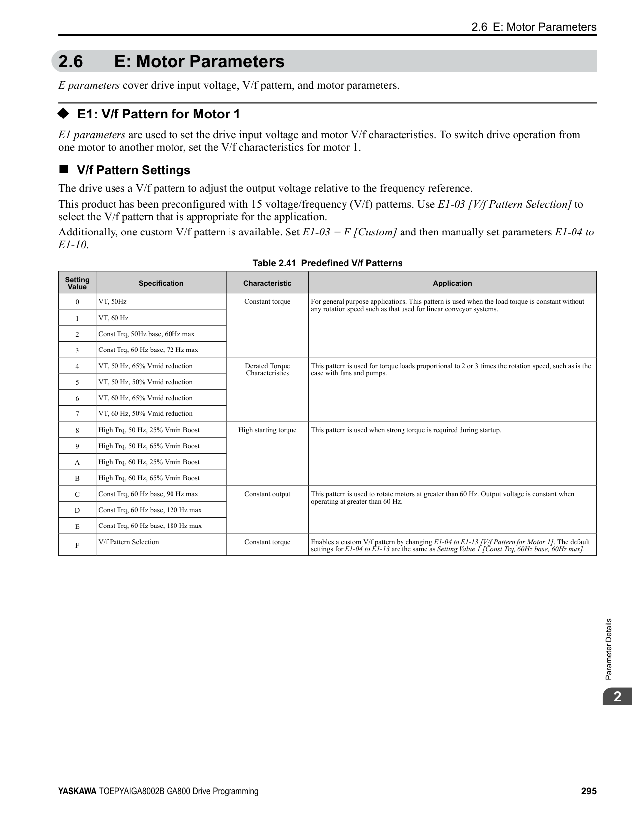
|No. (Hex.)|Name|Description|Default (Range)| |---|---|---|---| |F6-31 (03CC)|PROFIBUS-DP Clear Mode Selection|Sets what the drive will do after it receives the Clear Mode command.
V/f CL-V/f OLV CLV AOLV OLV/PM AOLV/PM CLV/PM EZOLV
|0 (0, 1)|
0 : Reset Resets drive settings, for example frequency reference and I/O settings. 1 : Hold Previous State The drive keeps the same status as before it received the command.
######## ■ F6-32: PROFIBUS-DP Data Format Select
|No. (Hex.)|Name|Description|Default (Range)| |---|---|---|---| |F6-32 (03CD)|PROFIBUS-DP Data Format Select|Sets the data format of PROFIBUS-DP communication. Restart the drive after you change the parameter setting.
V/f CL-V/f OLV CLV AOLV OLV/PM AOLV/PM CLV/PM EZOLV
|0 (0 - 5)|
Note: The H5-11 [Comm ENTER Command Mode] setting makes the RAM enter command necessary or not necessary to write parameters over network communication. When F6-32 = 0, 1, or 2, the H5-11 setting does not have an effect. The RAM enter command is always necessary to write parameters.
This function operates when bit 0 and bit 4 in the register STW have values of 1 (operate). Refer to the PROFIBUSDP communication manual for more information.
ParameterDetails
######## 2
############## 5 : PPO (bit0, Enter)
This function operates when bit 0 and bit 4 in the register STW have values of 1 (operate). Refer to the PROFIBUSDP communication manual for more information.
######## ■ F6-35: CANopen Node ID Selection
|No. (Hex.)|Name|Description|Default (Range)| |---|---|---|---| |F6-35 (03D0)|CANopen Node ID Selection|Sets the node address for CANopen communication. Restart the drive after you change the parameter setting.
V/f CL-V/f OLV CLV AOLV OLV/PM AOLV/PM CLV/PM EZOLV
|0 (0 - 126)|
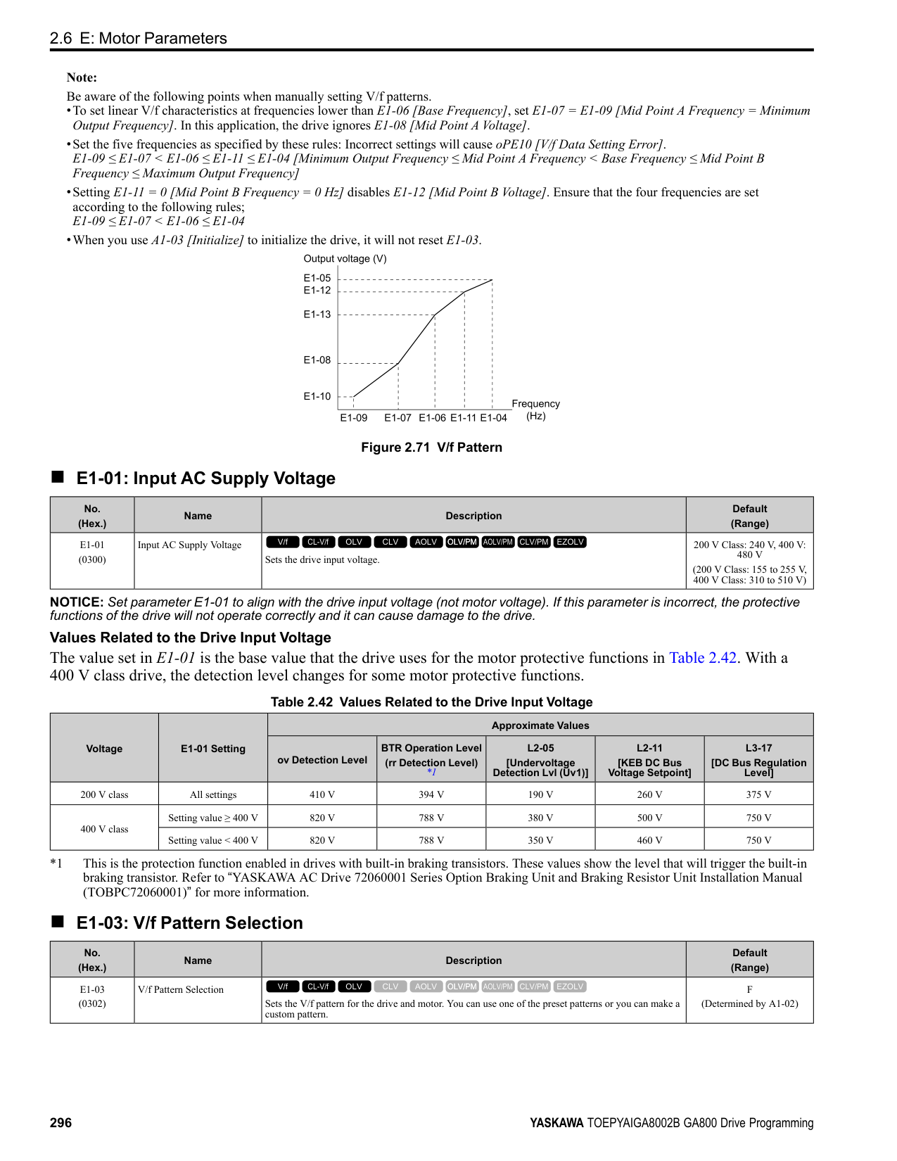
Note: Be sure to set an address that is different than all other node addresses. Do not set this parameter to 0. Incorrect parameter settings will cause AEr [Station Address Setting Error] errors and the L.ERR LED on the option will come on.
######## ■ F6-36: CANopen Communication Speed
|No. (Hex.)|Name|Description|Default (Range)| |---|---|---|---| |F6-36 (03D1)|CANopen Communication Speed|Sets the CANopen communications speed. Restart the drive after you change the parameter setting.
V/f CL-V/f OLV CLV AOLV OLV/PM AOLV/PM CLV/PM EZOLV
|6 (0 - 8)|
|No. (Hex.)|Name|Description|Default (Range)| |---|---|---|---| |F6-45 (02FB)|BACnet Node Address|Sets the node address for BACnet communication.
V/f CL-V/f OLV CLV AOLV OLV/PM AOLV/PM CLV/PM EZOLV
|1 (0 - 127)|
|No. (Hex.)|Name|Description|Default (Range)| |---|---|---|---| |F6-46 (02FC)|BACnet Baud Rate|Sets the BACnet communications speed.
V/f CL-V/f OLV CLV AOLV OLV/PM AOLV/PM CLV/PM EZOLV
|3 (0 - 8)|
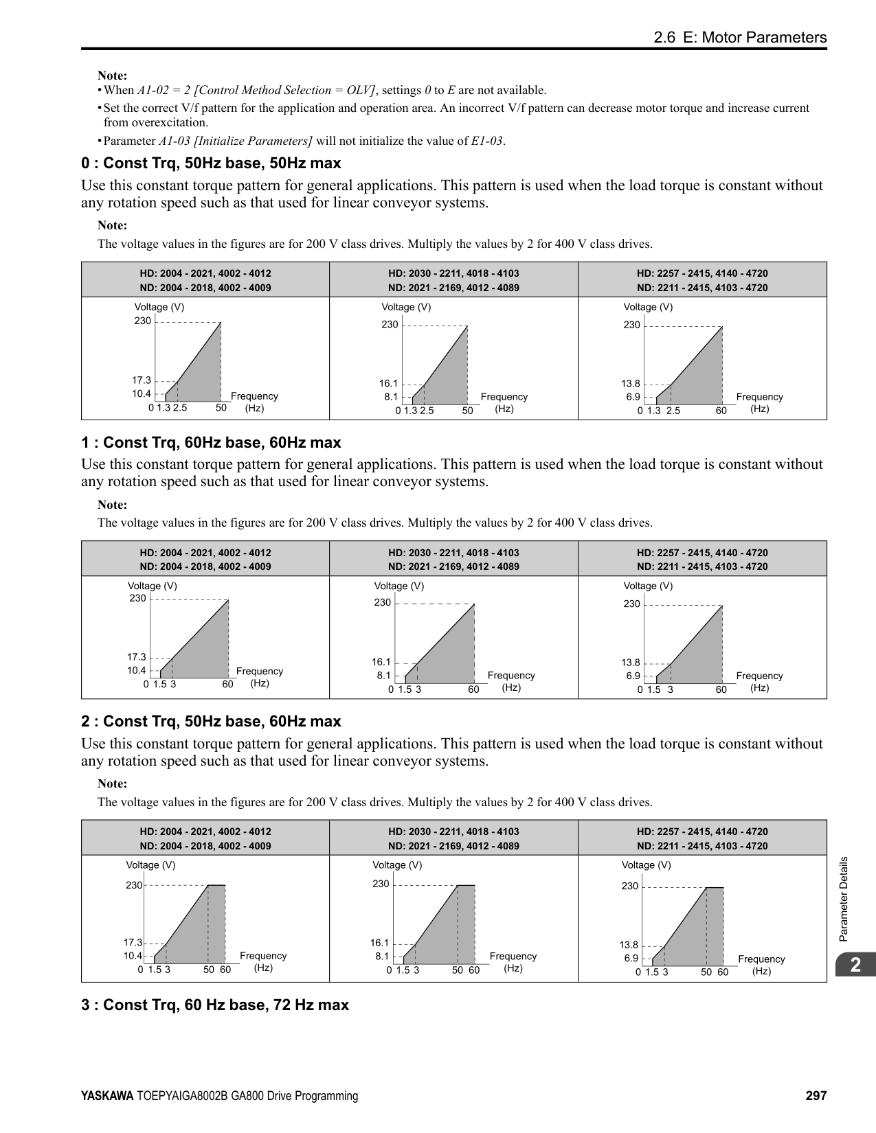
Note: Be sure to set a MAC address that is different than all other node addresses. Do not set this parameter to 0. Incorrect parameter settings will cause AEr [Station Address Setting Error] errors and the MS LED on the option will flash.
|No. (Hex.)|Name|Description|Default (Range)| |---|---|---|---| |F6-47 (02FD)|Rx to Tx Wait Time|Sets the wait time for the drive to receive and send BACnet communication.
V/f CL-V/f OLV CLV AOLV OLV/PM AOLV/PM CLV/PM EZOLV
|5 ms (5 - 65 ms)|
|No. (Hex.)|Name|Description|Default (Range)| |---|---|---|---| |F6-48 (02FE)|BACnet Device Object Identifier0|Sets the last word of BACnet communication addresses.
V/f CL-V/f OLV CLV AOLV OLV/PM AOLV/PM CLV/PM EZOLV
|0 (0 - FFFF)|
|No. (Hex.)|Name|Description|Default (Range)| |---|---|---|---| |F6-49 (02FF)|BACnet Device Object Identifier1|Sets the last word of BACnet communication addresses.
V/f CL-V/f OLV CLV AOLV OLV/PM AOLV/PM CLV/PM EZOLV
|0 (0 - 3F)|
|No. (Hex.)|Name|Description|Default (Range)| |---|---|---|---| |F6-50 (03C1)|DeviceNet MAC Address|Sets the MAC address for DeviceNet communication. Restart the drive after you change the parameter setting.
V/f CL-V/f OLV CLV AOLV OLV/PM AOLV/PM CLV/PM EZOLV
|64 (0 - 64)|
|No. (Hex.)|Name|Description|Default (Range)| |---|---|---|---| |F6-51 (03C2)|DeviceNet Baud Rate|Sets the DeviceNet communications speed. Restart the drive after you change the parameter setting.
V/f CL-V/f OLV CLV AOLV OLV/PM AOLV/PM CLV/PM EZOLV
|4 (0 - 4)|
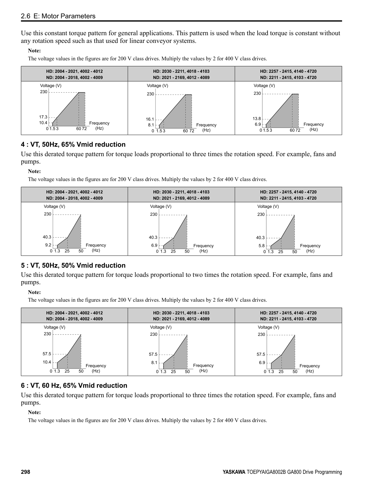
######## ■ F6-52: DeviceNet PCA Setting
|No. (Hex.)|Name|Description|Default (Range)| |---|---|---|---| |F6-52 (03C3)|DeviceNet PCA Setting|Sets the format of data that the DeviceNet communication master sends to the drive.
V/f CL-V/f OLV CLV AOLV OLV/PM AOLV/PM CLV/PM EZOLV
|21 (0 - 255)|
Note: If F6-52 [DeviceNet PCA Setting] and F6-53 [DeviceNet PPA Setting] are not correct, the value is reset to default.
ParameterDetails
######## 2
######## ■ F6-53: DeviceNet PPA Setting
|No. (Hex.)|Name|Description|Default (Range)| |---|---|---|---| |F6-53 (03C4)|DeviceNet PPA Setting|Sets the format of data that the drive sends to the DeviceNet communication master.
V/f CL-V/f OLV CLV AOLV OLV/PM AOLV/PM CLV/PM EZOLV
|71 (0 - 255)|
Note: If F6-52 [DeviceNet PCA Setting] and F6-53 [DeviceNet PPA Setting] are not correct, the value is reset to default.
######## ■ F6-54: DeviceNet Idle Fault Detection
|No. (Hex.)|Name|Description|Default (Range)| |---|---|---|---| |F6-54 (03C5)|DeviceNet Idle Fault Detection|Sets the function to detect EF0 [Option Card External Fault] when the drive does not receive data from the DeviceNet master.
V/f CL-V/f OLV CLV AOLV OLV/PM AOLV/PM CLV/PM EZOLV
|0 (0 - 4)|
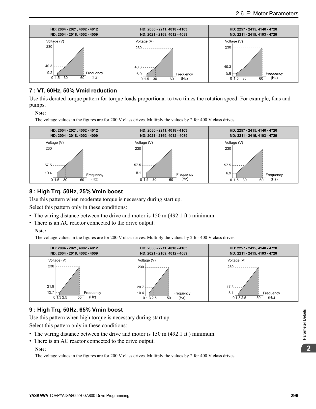
|No. (Hex.)|Name|Description|Default (Range)| |---|---|---|---| |F6-55 (03C6)|DeviceNet Baud Rate Monitor|Sets the function to see the actual DeviceNet communications speed using the keypad. This parameter functions as a monitor only.
V/f CL-V/f OLV CLV AOLV OLV/PM AOLV/PM CLV/PM EZOLV
|0 (0 - 2)|
|No. (Hex.)|Name|Description|Default (Range)| |---|---|---|---| |F6-56 (03D7)|DeviceNet Speed Scaling|Sets the speed scale for DeviceNet communication.
V/f CL-V/f OLV CLV AOLV OLV/PM AOLV/PM CLV/PM EZOLV
|0 (-15 - +15)|
|No. (Hex.)|Name|Description|Default (Range)| |---|---|---|---| |F6-57 (03D8)|DeviceNet Current Scaling|Sets the current scale of the DeviceNet communication master.
V/f CL-V/f OLV CLV AOLV OLV/PM AOLV/PM CLV/PM EZOLV
|0 (-15 - +15)|
|No. (Hex.)|Name|Description|Default (Range)| |---|---|---|---| |F6-58 (03D9)|DeviceNet Torque Scaling|Sets the torque scale of the DeviceNet communication master.
V/f CL-V/f OLV CLV AOLV OLV/PM AOLV/PM CLV/PM EZOLV
|0 (-15 - +15)|
|No. (Hex.)|Name|Description|Default (Range)| |---|---|---|---| |F6-59 (03DA)|DeviceNet Power Scaling|Sets the power scale of the DeviceNet communication master.
V/f CL-V/f OLV CLV AOLV OLV/PM AOLV/PM CLV/PM EZOLV
|0 (-15 - +15)|
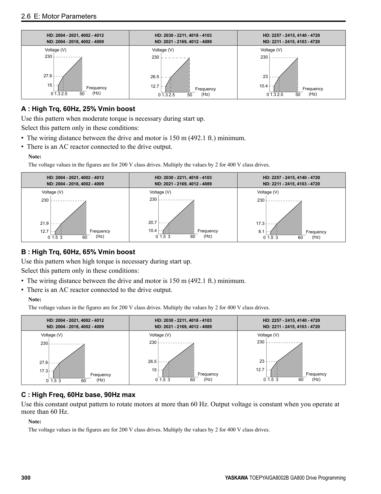
|No. (Hex.)|Name|Description|Default (Range)| |---|---|---|---| |F6-60 (03DB)|DeviceNet Voltage Scaling|Sets the voltage scale of the DeviceNet communication master.
V/f CL-V/f OLV CLV AOLV OLV/PM AOLV/PM CLV/PM EZOLV
|0 (-15 - +15)|
|No. (Hex.)|Name|Description|Default (Range)| |---|---|---|---| |F6-61 (03DC)|DeviceNet Time Scaling|Sets the time scale of the DeviceNet communication master.
V/f CL-V/f OLV CLV AOLV OLV/PM AOLV/PM CLV/PM EZOLV
|0 (-15 - +15)|
|No. (Hex.)|Name|Description|Default (Range)| |---|---|---|---| |F6-62 (03DD)|DeviceNet Heartbeat Interval|Sets the heartbeat for DeviceNet communication. Set this parameter to 0 to disable the heartbeat function.
V/f CL-V/f OLV CLV AOLV OLV/PM AOLV/PM CLV/PM EZOLV
|0 (0 - 10)|
|No. (Hex.)|Name|Description|Default (Range)| |---|---|---|---| |F6-63 (03DE)|DeviceNet Network MAC ID|Sets the function to see the actual DeviceNet MAC address using the keypad. This parameter functions as a monitor only.
V/f CL-V/f OLV CLV AOLV OLV/PM AOLV/PM CLV/PM EZOLV
|63 (0 - 63)|
|No. (Hex.)|Name|Description|Default (Range)| |---|---|---|---| |F6-64 to F6-67 (03DF - 03E2)|Dynamic Out Assembly 109 Param 1 to 4|Sets Configurable Outputs 1 to 4 written to the MEMOBUS register.
V/f CL-V/f OLV CLV AOLV OLV/PM AOLV/PM CLV/PM EZOLV
|0000h (0000h - FFFFh)|
|No. (Hex.)|Name|Description|Default (Range)| |---|---|---|---| |F6-68 to F6-71 (03E3, 03E4, 03C7, and 03C8)|Dynamic In Assembly 159 Param 1 to 4|Sets Configurable Inputs 1 to 4 written to the MEMOBUS register.
V/f CL-V/f OLV CLV AOLV OLV/PM AOLV/PM CLV/PM EZOLV
|0000h (0000h - FFFFh)|
ParameterDetails
|No. (Hex.)|Name|Description|Default (Range)| |---|---|---|---| |F6-72 (081B)|PowerLink Node Address|Sets the node ID for PowerLink communication.
V/f CL-V/f OLV CLV AOLV OLV/PM AOLV/PM CLV/PM EZOLV
|0 (0 - 255)|
######## ■ F7-01: IPAddress 1
|No. (Hex.)|Name|Description|Default (Range)|
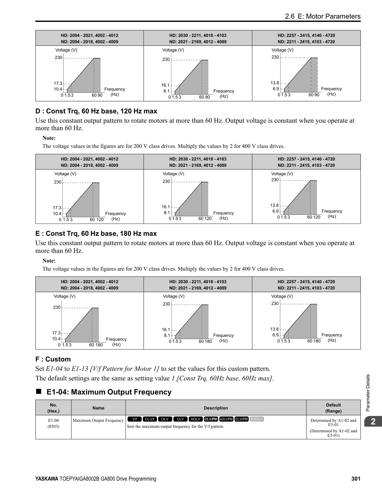
|---|---|---|---| |F7-01 (03E5)|IPAddress 1|Sets the first octet of the IPAddress for the device that is connecting to the network. Restart the drive after you change this parameter.
V/f CL-V/f OLV CLV AOLV OLV/PM AOLV/PM CLV/PM EZOLV
|192 (0 - 255)|
Note: When F7-13 = 0 [Address Mode at Startup = Static]:
######## ■ F7-02: IPAddress 2
|No. (Hex.)|Name|Description|Default (Range)| |---|---|---|---| |F7-02 (03E6)|IPAddress 2|Sets the second octet of the IPAddress for the device that is connecting to the network. Restart the drive after you change this parameter.
V/f CL-V/f OLV CLV AOLV OLV/PM AOLV/PM CLV/PM EZOLV
|168 (0 - 255)|
Note: When F7-13 0 [Address Mode at Startup Static]:
######## ■ F7-03: IPAddress 3
|No. (Hex.)|Name|Description|Default (Range)| |---|---|---|---| |F7-03 (03E7)|IPAddress 3|Sets the third octet of the IPAddress for the device that is connecting to the network. Restart the drive after you change this parameter.
V/f CL-V/f OLV CLV AOLV OLV/PM AOLV/PM CLV/PM EZOLV
|1 (0 - 255)|
Note: When F7-13 = 0 [Address Mode at Startup = Static]:
######## ■ F7-04: IPAddress 4
|No. (Hex.)|Name|Description|Default (Range)| |---|---|---|---| |F7-04 (03E8)|IPAddress 4|Sets the fourth octet of the IPAddress for the device that is connecting to the network. Restart the drive after you change this parameter.
V/f CL-V/f OLV CLV AOLV OLV/PM AOLV/PM CLV/PM EZOLV
|20 (0 - 255)|
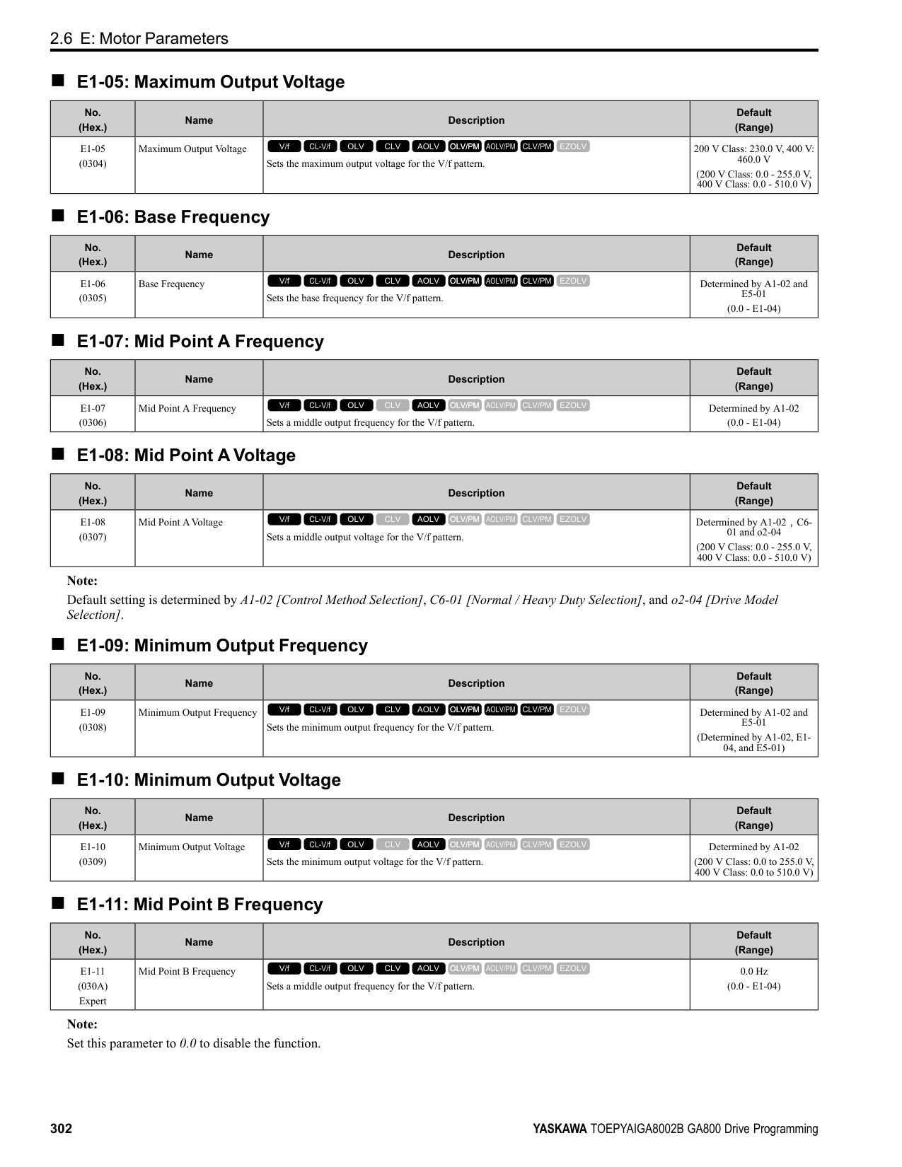
Note: When F7-13 = 0 [Address Mode at Startup = Static]:
######## ■ F7-05: Subnet Mask 1
|No. (Hex.)|Name|Description|Default (Range)| |---|---|---|---| |F7-05 (03E9)|Subnet Mask 1|Sets the first octet of the subnet mask of the connected network.
V/f CL-V/f OLV CLV AOLV OLV/PM AOLV/PM CLV/PM EZOLV
|255 (0 - 255)|
Note: Set this parameter when F7-13 = 0 [Address Mode at Startup = Static].
######## ■ F7-06: Subnet Mask 2
|No. (Hex.)|Name|Description|Default (Range)| |---|---|---|---| |F7-06 (03EA)|Subnet Mask 2|Sets the second octet of the subnet mask of the connected network.
V/f CL-V/f OLV CLV AOLV OLV/PM AOLV/PM CLV/PM EZOLV
|255 (0 - 255)|
Note: Set this parameter when F7-13 = 0 [Address Mode at Startup = Static].
######## ■ F7-07: Subnet Mask 3
|No. (Hex.)|Name|Description|Default (Range)| |---|---|---|---| |F7-07 (03EB)|Subnet Mask 3|Sets the third octet of the subnet mask of the connected network.
V/f CL-V/f OLV CLV AOLV OLV/PM AOLV/PM CLV/PM EZOLV
|255 (0 - 255)|
Note: Set this parameter when F7-13 = 0 [Address Mode at Startup = Static].
######## ■ F7-08: Subnet Mask 4
|No. (Hex.)|Name|Description|Default (Range)| |---|---|---|---| |F7-08 (03EC)|Subnet Mask 4|Sets the fourth octet of the subnet mask of the connected network.
V/f CL-V/f OLV CLV AOLV OLV/PM AOLV/PM CLV/PM EZOLV
|0 (0 - 255)|
Note: Set this parameter when F7-13 = 0 [Address Mode at Startup = Static].
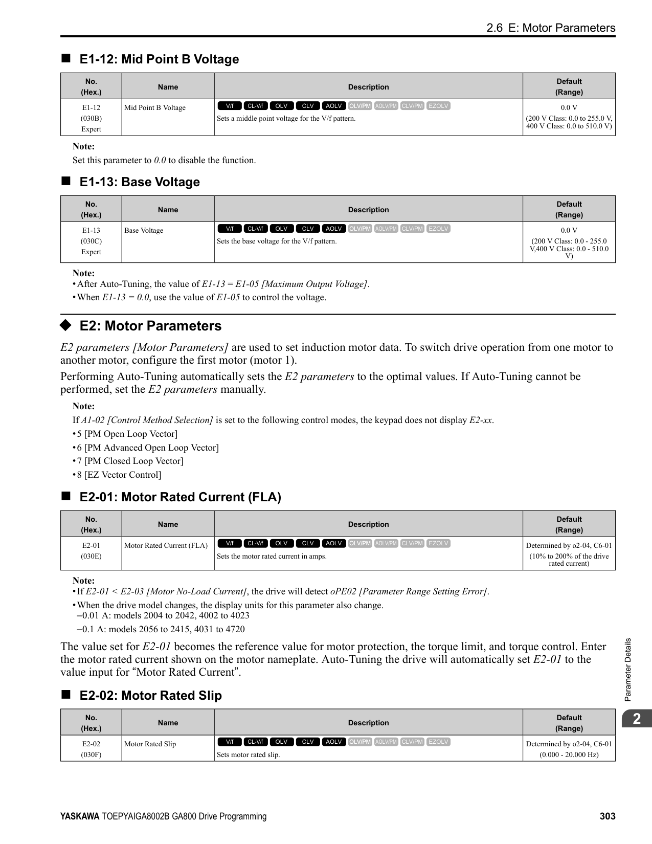
######## ■ F7-09: Gateway Address 1
|No. (Hex.)|Name|Description|Default (Range)| |---|---|---|---| |F7-09 (03ED)|Gateway Address 1|Sets the first octet of the gateway address of the connected network.
V/f CL-V/f OLV CLV AOLV OLV/PM AOLV/PM CLV/PM EZOLV
|192 (0 - 255)|
Note: Set this parameter when F7-13 = 0 [Address Mode at Startup = Static].
######## ■ F7-10: Gateway Address 2
|No. (Hex.)|Name|Description|Default (Range)| |---|---|---|---| |F7-10 (03EE)|Gateway Address 2|Sets the second octet of the gateway address of the connected network.
V/f CL-V/f OLV CLV AOLV OLV/PM AOLV/PM CLV/PM EZOLV
|168 (0 - 255)|
Note: Set this parameter when F7-13 = 0 [Address Mode at Startup = Static].
######## ■ F7-11: Gateway Address 3
|No. (Hex.)|Name|Description|Default (Range)| |---|---|---|---| |F7-11 (03EF)|Gateway Address 3|Sets the third octet of the gateway address of the connected network.
V/f CL-V/f OLV CLV AOLV OLV/PM AOLV/PM CLV/PM EZOLV
|1 (0 - 255)|
ParameterDetails
Note: Set this parameter when F7-13 = 0 [Address Mode at Startup = Static].
######## ■ F7-12: Gateway Address 4
|No. (Hex.)|Name|Description|Default (Range)| |---|---|---|---| |F7-12 (03F0)|Gateway Address 4|Sets the fourth octet of the gateway address of the connected network.
V/f CL-V/f OLV CLV AOLV OLV/PM AOLV/PM CLV/PM EZOLV
|1 (0 - 255)|
Note: Set this parameter when F7-13 = 0 [Address Mode at Startup = Static].
######## ■ F7-13: Address Mode at Startup
|No. (Hex.)|Name|Description|Default (Range)|
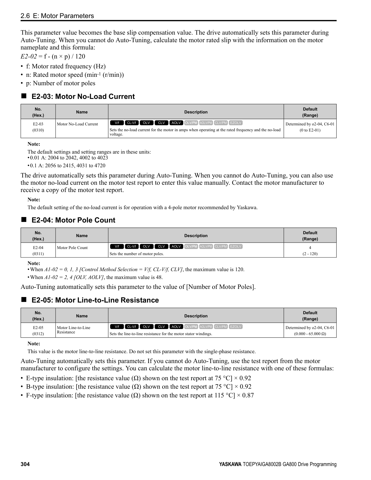
|---|---|---|---| |F7-13 (03F1)|Address Mode at Startup|Sets the method to set option card IP addresses.
V/f CL-V/f OLV CLV AOLV OLV/PM AOLV/PM CLV/PM EZOLV
|2 (0 - 2)|
############## 0 : Static 1 : BOOTP 2 : DHCP Note:
######## ■ F7-14: Duplex Mode Selection
|No. (Hex.)|Name|Description|Default (Range)| |---|---|---|---| |F7-14 (03F2)|Duplex Mode Selection|Sets the duplex mode setting method.
V/f CL-V/f OLV CLV AOLV OLV/PM AOLV/PM CLV/PM EZOLV
|1 (0 - 8)|
######## ■ F7-15: Communication Speed Selection
|No. (Hex.)|Name|Description|Default (Range)| |---|---|---|---| |F7-15 (03F3)|Communication Speed Selection|Sets the communications speed.
V/f CL-V/f OLV CLV AOLV OLV/PM AOLV/PM CLV/PM EZOLV
|10 (10, 100 - 102)|
############## 10 : 10/10 Mbps 100 : 100/100 Mbps 101 : 10/100 Mbps 102 : 100/10 Mbps
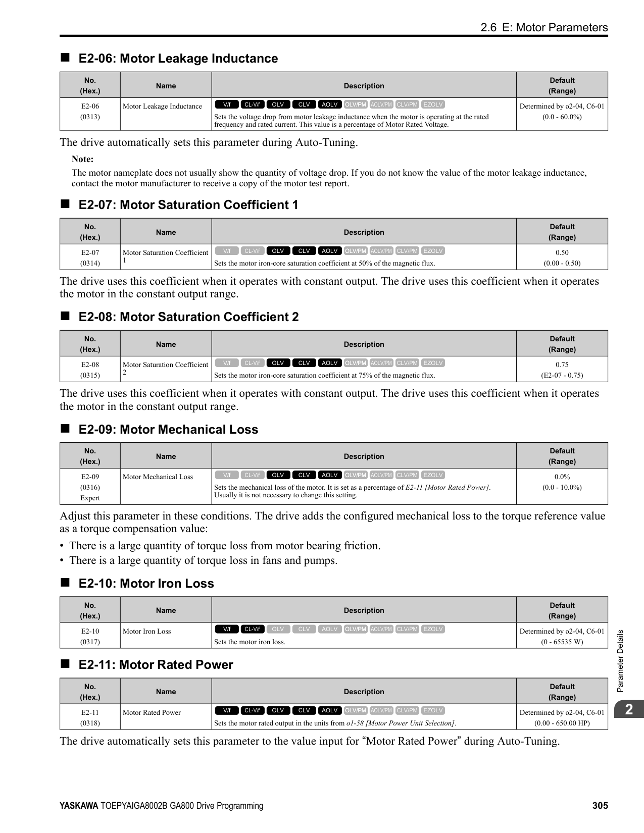
Note: Set this parameter when F7-14 = 0 or 2 [Duplex Mode Selection = Half/Half or Full/Full].
Note: Set this parameter to 0.0 to disable the connection timeout function.
|No. (Hex.)|Name|Description|Default (Range)| |---|---|---|---| |F7-16 (03F4)|Timeout Value|Sets the detection time for a communications timeout.
V/f CL-V/f OLV CLV AOLV OLV/PM AOLV/PM CLV/PM EZOLV
|0.0 s (0.0 - 30.0 s)|
|No. (Hex.)|Name|Description|Default (Range)| |---|---|---|---| |F7-17 (03F5)|EtherNet/IP Speed Scaling Factor|Sets the scaling factor for the speed monitor in the EtherNet/IP Class ID 2AH Object.
V/f CL-V/f OLV CLV AOLV OLV/PM AOLV/PM CLV/PM EZOLV
|0 (-15 - +15)|
|No. (Hex.)|Name|Description|Default (Range)| |---|---|---|---| |F7-18 (03F6)|EtherNet/IP Current Scale Factor|Sets the scaling factor for the output current monitor in the EtherNet/IP Class ID 2AH Object.
V/f CL-V/f OLV CLV AOLV OLV/PM AOLV/PM CLV/PM EZOLV
|0 (-15 - +15)|
|No. (Hex.)|Name|Description|Default (Range)| |---|---|---|---| |F7-19 (03F7)|EtherNet/IP Torque Scale Factor|Sets the scaling factor for the torque monitor in the EtherNet/IP Class ID 2AH Object.
V/f CL-V/f OLV CLV AOLV OLV/PM AOLV/PM CLV/PM EZOLV
|0 (-15 - +15)|
|No. (Hex.)|Name|Description|Default (Range)| |---|---|---|---| |F7-20 (03F8)|EtherNet/IP Power Scaling Factor|Sets the scaling factor for the power monitor in the EtherNet/IP Class ID 2AH Object.
V/f CL-V/f OLV CLV AOLV OLV/PM AOLV/PM CLV/PM EZOLV
|0 (-15 - +15)|
|No. (Hex.)|Name|Description|Default (Range)| |---|---|---|---| |F7-21 (03F9)|EtherNet/IP Voltage Scale Factor|Sets the scaling factor for the voltage monitor in the EtherNet/IP Class ID 2AH Object.
V/f CL-V/f OLV CLV AOLV OLV/PM AOLV/PM CLV/PM EZOLV
|0 (-15 - +15)|
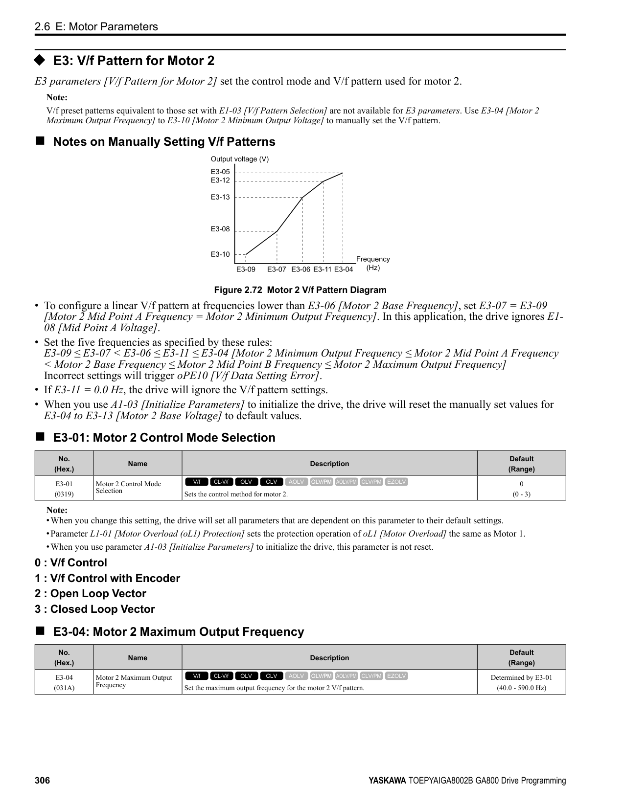
ParameterDetails
|No. (Hex.)|Name|Description|Default (Range)| |---|---|---|---| |F7-22 (03FA)|EtherNet/IP Time Scaling|Sets the scaling factor for the time monitor in the EtherNet/IP Class ID 2AH Object.
V/f CL-V/f OLV CLV AOLV OLV/PM AOLV/PM CLV/PM EZOLV
|0 (-15 - +15)|
|No. (Hex.)|Name|Description|Default (Range)| |---|---|---|---| |F7-23 - F7-27 (03FB - 03FF) F7-28- F7-32 (0370 - 0374)|Dynamic Out Param 1 to 10 for CommCard|Sets Output Assembly 116. The drive writes the values from Output Assembly 116 to the MEMOBUS/Modbus address register that is stored for each parameter. The drive will not write the values from Output Assembly 116 to the registers when the MEMOBUS/Modbus address is 0.
V/f CL-V/f OLV CLV AOLV OLV/PM AOLV/PM CLV/PM EZOLV
|0|
|No. (Hex.)|Name|Description|Default (Range)| |---|---|---|---| |F7-33 - F7-42 (0375 - 037E)|Dynamic In Param 1 to 10 for CommCard|Sets Input Assembly 166. The drive sends the values from the MEMOBUS/Modbus address registers stored for each parameter to Input Assembly 166. The drive returns the default register value for the option card when the MEMOBUS/Modbus address is 0 and the value sent to Input Assembly 166 is not defined.
V/f CL-V/f OLV CLV AOLV OLV/PM AOLV/PM CLV/PM EZOLV
|0|
|No. (Hex.)|Name|Description|Default (Range)| |---|---|---|---| |F7-60 (0780)|PZD1 Write (Control Word)|Sets the MEMOBUS/Modbus address for PZD1 (PPO output). PZD1 (PPO output) functions as the STW when F7-60 = 0, 1, or 2.
V/f CL-V/f OLV CLV AOLV OLV/PM AOLV/PM CLV/PM EZOLV
|0|
|No. (Hex.)|Name|Description|Default (Range)| |---|---|---|---| |F7-61 (0781)|PZD2 Write (Frequency Reference)|Sets the MEMOBUS/Modbus address for PZD2 (PPO output). PZD2 (PPO output) functions as the HSW when F7-61 0, 1, or 2.
V/f CL-V/f OLV CLV AOLV OLV/PM AOLV/PM CLV/PM EZOLV
|0|
|No. (Hex.)|Name|Description|Default (Range)| |---|---|---|---| |F7-62 (0782)|PZD3 Write|Sets the MEMOBUS/Modbus address for PZD3 (PPO output). A value of 0, 1, or 2 will disable the PZD3 (PPO output) write operation to the MEMOBUS/Modbus register.
V/f CL-V/f OLV CLV AOLV OLV/PM AOLV/PM CLV/PM EZOLV
|0|
|No. (Hex.)|Name|Description|Default (Range)| |---|---|---|---| |F7-63 (0783)|PZD4 Write|Sets the MEMOBUS/Modbus address for PZD4 (PPO output). A value of 0, 1, or 2 will disable the PZD4 (PPO output) write operation to the MEMOBUS/Modbus register.
V/f CL-V/f OLV CLV AOLV OLV/PM AOLV/PM CLV/PM EZOLV
|0|
|No. (Hex.)|Name|Description|Default (Range)| |---|---|---|---| |F7-64 (0784)|PZD5 Write|Sets the MEMOBUS/Modbus address for PZD5 (PPO output). A value of 0, 1, or 2 will disable the PZD5 (PPO output) write operation to the MEMOBUS/Modbus register.
V/f CL-V/f OLV CLV AOLV OLV/PM AOLV/PM CLV/PM EZOLV
|0|
|No. (Hex.)|Name|Description|Default (Range)| |---|---|---|---| |F7-65 (0785)|PZD6 Write|Sets the MEMOBUS/Modbus address for PZD6 (PPO output). A value of 0, 1, or 2 will disable the PZD6 (PPO output) write operation to the MEMOBUS/Modbus register.
V/f CL-V/f OLV CLV AOLV OLV/PM AOLV/PM CLV/PM EZOLV
|0|
|No. (Hex.)|Name|Description|Default (Range)| |---|---|---|---| |F7-66 (0786)|PZD7 Write|Sets the MEMOBUS/Modbus address for PZD7 (PPO output). A value of 0, 1, or 2 will disable the PZD7 (PPO output) write operation to the MEMOBUS/Modbus register.
V/f CL-V/f OLV CLV AOLV OLV/PM AOLV/PM CLV/PM EZOLV
|0|
|No. (Hex.)|Name|Description|Default (Range)| |---|---|---|---| |F7-67 (0787)|PZD8 Write|Sets the MEMOBUS/Modbus address for PZD8 (PPO output). A value of 0, 1, or 2 will disable the PZD8 (PPO output) write operation to the MEMOBUS/Modbus register.
V/f CL-V/f OLV CLV AOLV OLV/PM AOLV/PM CLV/PM EZOLV
|0|
|No. (Hex.)|Name|Description|Default (Range)| |---|---|---|---| |F7-68 (0788)|PZD9 Write|Sets the MEMOBUS/Modbus address for PZD9 (PPO output). A value of 0, 1, or 2 will disable the PZD9 (PPO output) write operation to the MEMOBUS/Modbus register.
V/f CL-V/f OLV CLV AOLV OLV/PM AOLV/PM CLV/PM EZOLV
|0|
|No. (Hex.)|Name|Description|Default (Range)|
|---|---|---|---| |F7-69 (0789)|PZD10 Write|Sets the MEMOBUS/Modbus address for PZD10 (PPO output). A value of 0, 1, or 2 will disable the PZD10 (PPO output) write operation to the MEMOBUS/Modbus register.
V/f CL-V/f OLV CLV AOLV OLV/PM AOLV/PM CLV/PM EZOLV
|0|
|No. (Hex.)|Name|Description|Default (Range)| |---|---|---|---| |F7-70 (078A)|PZD1 Read (Status Word)|Sets the MEMOBUS/Modbus address for PZD1 (PPO Read). PZD1 (PPO input) functions as the ZSW when F7-70 = 0.
V/f CL-V/f OLV CLV AOLV OLV/PM AOLV/PM CLV/PM EZOLV
|0|
|No. (Hex.)|Name|Description|Default (Range)| |---|---|---|---| |F7-71 (078B)|PZD2 Read (Output Frequency)|Sets the MEMOBUS/Modbus address for PZD2 (PPO Read). PZD2 (PPO input) functions as the HIW when F7-71 0.
V/f CL-V/f OLV CLV AOLV OLV/PM AOLV/PM CLV/PM EZOLV
|0|
ParameterDetails
|No. (Hex.)|Name|Description|Default (Range)| |---|---|---|---| |F7-72 (078C)|PZD3 Read|Sets the MEMOBUS/Modbus address for PZD3 (PPO Read). A value of 0 will disable the PZD3 (PPO Read) load operation from the MEMOBUS/Modbus register.
V/f CL-V/f OLV CLV AOLV OLV/PM AOLV/PM CLV/PM EZOLV
|0|
|No. (Hex.)|Name|Description|Default (Range)| |---|---|---|---| |F7-73 (078D)|PZD4 Read|Sets the MEMOBUS/Modbus address for PZD4 (PPO Read). A value of 0 will disable the PZD4 (PPO Read) load operation from the MEMOBUS/Modbus register.
V/f CL-V/f OLV CLV AOLV OLV/PM AOLV/PM CLV/PM EZOLV
|0|
|No. (Hex.)|Name|Description|Default (Range)| |---|---|---|---| |F7-74 (078E)|PZD5 Read|Sets the MEMOBUS/Modbus address for PZD5 (PPO Read). A value of 0 will disable the PZD5 (PPO Read) load operation from the MEMOBUS/Modbus register.
V/f CL-V/f OLV CLV AOLV OLV/PM AOLV/PM CLV/PM EZOLV
|0|
|No. (Hex.)|Name|Description|Default (Range)| |---|---|---|---|
|F7-75 (078F)|PZD6 Read|Sets the MEMOBUS/Modbus address for PZD6 (PPO Read). A value of 0 will disable the PZD6 (PPO Read) load operation from the MEMOBUS/Modbus register.
V/f CL-V/f OLV CLV AOLV OLV/PM AOLV/PM CLV/PM EZOLV
|0|
|No. (Hex.)|Name|Description|Default (Range)| |---|---|---|---| |F7-76 (0790)|PZD7 Read|Sets the MEMOBUS/Modbus address for PZD7 (PPO Read). A value of 0 will disable the PZD7 (PPO input) load operation from the MEMOBUS/Modbus register.
V/f CL-V/f OLV CLV AOLV OLV/PM AOLV/PM CLV/PM EZOLV
|0|
|No. (Hex.)|Name|Description|Default (Range)| |---|---|---|---| |F7-77 (0791)|PZD8 Read|Sets the MEMOBUS/Modbus address for PZD8 (PPO Read). A value of 0 will disable the PZD8 (PPO Read) load operation from the MEMOBUS/Modbus register.
V/f CL-V/f OLV CLV AOLV OLV/PM AOLV/PM CLV/PM EZOLV
|0|
|No. (Hex.)|Name|Description|Default (Range)| |---|---|---|---| |F7-78 (0792)|PZD9 Read|Sets the MEMOBUS/Modbus address for PZD9 (PPO Read). A value of 0 will disable the PZD9 (PPO Read) load operation from the MEMOBUS/Modbus register.
V/f CL-V/f OLV CLV AOLV OLV/PM AOLV/PM CLV/PM EZOLV
|0|
|No. (Hex.)|Name|Description|Default (Range)| |---|---|---|---| |F7-79 (0793)|PZD10 Read|Sets the MEMOBUS/Modbus address for PZD10 (PPO Read). A value of 0 will disable the PZD10 (PPO Read) load operation from the MEMOBUS/Modbus register.
V/f CL-V/f OLV CLV AOLV OLV/PM AOLV/PM CLV/PM EZOLV
|0|
####### 2.8 H: Terminal Functions
H parameters are used to assign functions to external input and output terminals.
◆ H1: Digital Inputs H1 Parameters set the MFDI terminal functions.
■ H1-01 to H1-08 Terminal S1 to S8 Function Selection The drive has 8 MFDI terminals. Refer to Table 2.54 for drive default settings and functions.
Table 2.54 MFDI Default Settings and Functions
|No.|Name|Default|Function| |---|---|---|---| |H1-01|Terminal S1 Function Selection|40 (F) *1|Forward RUN (2-Wire)| |H1-02|Terminal S2 Function Selection|41 (F) *1|Reverse RUN (2-Wire)| |H1-03|Terminal S3 Function Selection|24|External Fault (NO-Always-Coast)| |H1-04|Terminal S4 Function Selection|14|Fault Reset| |H1-05|Terminal S5 Function Selection|3 (0) *1|Multi-Step Speed Reference 1| |H1-06|Terminal S6 Function Selection|4 (3) *1|Multi-Step Speed Reference 2| |H1-07|Terminal S7 Function Selection|6 (4) *1|Jog Reference Selection|
|H1-08|Terminal S8 Function Selection|8|Baseblock Command (N.O.)|
*1 The value in parentheses identifies the default setting when you set A1-03 = 3330 [Initialize Parameters = 3-Wire Initialization]. Refer to Table 2.55 the and use H1-xx [MFDI Function Select] to set the function.
################# Table 2.55 MFDI Setting Values
|Setting Value|Function|Reference| |---|---|---| |0 *1|3-Wire Sequence|361| |1|LOCAL/REMOTE Selection|362| |2|External Reference 1/2 Selection|362| |3|Multi-Step Speed Reference 1|362| |4|Multi-Step Speed Reference 2|363| |5|Multi-Step Speed Reference 3|363| |6|Jog Reference Selection|363| |7|Accel/Decel Time Selection 1|363| |8 *1|Baseblock Command (N.O.)|363| |9 *1|Baseblock Command (N.C.)|364| |A|Accel/Decel Ramp Hold|364| |B|Overheat Alarm (oH2)|364| |C|Analog Terminal Enable Selection|364| |D|Ignore Speed Fdbk (V/f w/o Enc)|364| |E|ASR Integral Reset|364| |F|Not Used|365| |10|Up Command|365| |11|Down Command|366| |12 *1|Forward Jog|367| |13 *1|Reverse Jog|367| |14|Fault Reset Procedure|368|
|Setting Value|Function|Reference| |---|---|---| |15 *1|Fast Stop (N.O.)|368| |16|Motor 2 Selection|368| |17 *1|Fast Stop (N.C.)|369| |18|Timer Function|369| |19|PID Disable|370| |1A|Accel/Decel Time Selection 2|370| |1B|Programming Lockout|370| |1E|Reference Sample Hold|370|
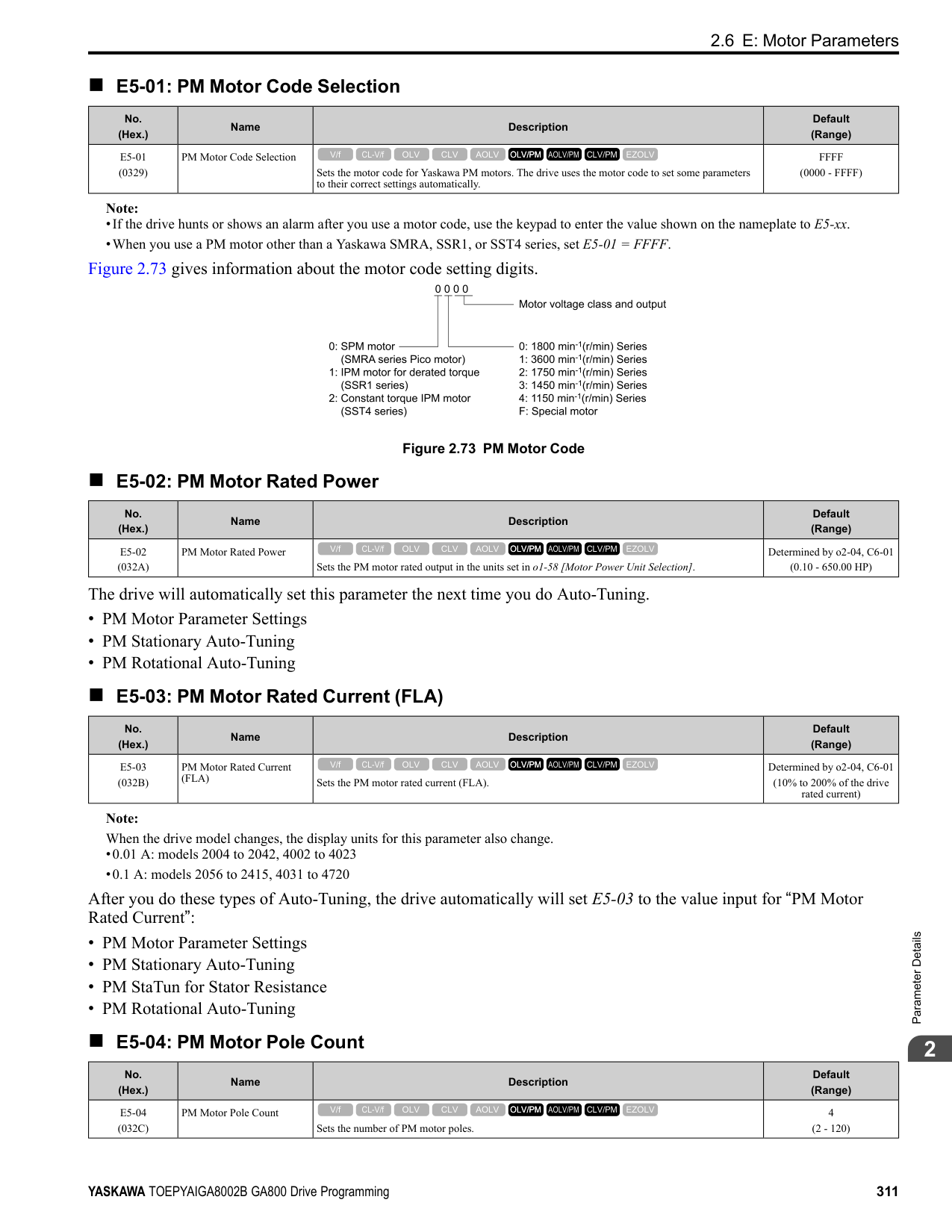
|20 to 2F *1|External Fault|371| |30|PID Integrator Reset|371| |31|PID Integrator Hold|372| |32|Multi-Step Speed Reference 4|372| |34|PID Soft Starter Disable|372| |35|PID Input (Error) Invert|372| |3E|PID Setpoint Selection 1|372| |3F|PID Setpoint Selection 2|372| |40 *1|Forward RUN (2-Wire)|373| |41 *1|Reverse RUN (2-Wire)|373| |42 *1|Run Command (2-Wire Sequence 2)|373| |43 *1|FWD/REV (2-Wire Sequence 2)|374| |44|Add Offset Frequency 1 (d7-01)|374|
ParameterDetails
|Setting Value|Function|Reference| |---|---|---| |45|Add Offset Frequency 2 (d7-02)|374| |46|Add Offset Frequency 3 (d7-03)|374| |47|Node Setup (CANopen)|374| |60|DC Injection Braking Command|374| |61|Speed Search from Fmax|375| |62|Speed Search from Fref|375| |63|Field Weakening|375| |65 *1|KEB Ride-Thru 1 Activate (N.C.)|375| |66 *1|KEB Ride-Thru 1 Activate (N.O.)|376| |67|Communications Test Mode|376| |68|High Slip Braking (HSB) Activate|376| |6A|Drive Enable|376| |71|Torque Control|376| |72|Zero Servo|377|
*1 Inverse input is not available.
|Setting Value|Function|Reference| |---|---|---| |75|Up 2 Command|377| |76|Down 2 Command|378| |77|ASR Gain (C5-03) Select|379|
|78|Analog TorqueRef Polarity Invert|379| |7A *1|KEB Ride-Thru 2 Activate (N.C.)|379| |7B *1|KEB Ride-Thru 2 Activate (N.O.)|379| |7C *1|Short Circuit Braking (N.O.)|380| |7D *1|Short Circuit Braking (N.C.)|380| |7E|Reverse Rotation Identifier|380| |90 to 97 *1|DWEZ Digital Inputs 1 to 8|380| |9F|DWEZ Disable|380| |101 to 19F|Inverse Inputs of 1 to 9F Sets the function of the selected MFDI to operate inversely. To select the function for inverse input, enter two digits 01 to 9F for the “xx” in ”1xx”.|381|
Note: The default setting is F when the drive is initialized for 3-Wire Initialization [A1-03 = 3330].
Note: The default setting is F when the drive is initialized for 3-Wire Initialization [A1-03 = 3330].
|No. (Hex.)|Name|Description|Default (Range)| |---|---|---|---| |H1-01 (0438)|Terminal S1 Function Selection|Sets the function for MFDI terminal S1.
V/f CL-V/f OLV CLV AOLV OLV/PM AOLV/PM CLV/PM EZOLV
|40 (1 - 1FF)|
|No. (Hex.)|Name|Description|Default (Range)| |---|---|---|---| |H1-02 (0439)|Terminal S2 Function Selection|Sets the function for MFDI terminal S2.
V/f CL-V/f OLV CLV AOLV OLV/PM AOLV/PM CLV/PM EZOLV
|41 (1 - 1FF)|
|No. (Hex.)|Name|Description|Default (Range)| |---|---|---|---| |H1-03 (0400)|Terminal S3 Function Selection|Sets the function for MFDI terminal S3.
V/f CL-V/f OLV CLV AOLV OLV/PM AOLV/PM CLV/PM EZOLV
|24 (0 - 1FF)|
|No. (Hex.)|Name|Description|Default (Range)| |---|---|---|---| |H1-04 (0401)|Terminal S4 Function Selection|Sets the function for MFDI terminal S4.
V/f CL-V/f OLV CLV AOLV OLV/PM AOLV/PM CLV/PM EZOLV
|14 (0 - 1FF)|
|No. (Hex.)|Name|Description|Default (Range)| |---|---|---|---| |H1-05 (0402)|Terminal S5 Function Selection|Sets the function for MFDI terminal S5.
V/f CL-V/f OLV CLV AOLV OLV/PM AOLV/PM CLV/PM EZOLV
|3 (0 - 1FF)|
When you initialize the drive for 3-Wire Initialization [A1-03 = 3330], the default setting is 0.
Note: When you initialize the drive for 3-Wire Initialization [A1-03 = 3330], the default setting is 3.
Note: When you initialize the drive for 3-Wire Initialization [A1-03 = 3330], the default setting is 4.
■ H1-22: Terminal S2 Function Select 2
When MFDI terminal S2 activates, it will operate the function set to H1-02 [Terminal S2 Function Selection] and the
■ H1-23: Terminal S3 Function Select 2
When MFDI terminal S3 activates, it will operate the function set to H1-03 [Terminal S3 Function Selection] and the
|No. (Hex.)|Name|Description|Default (Range)|
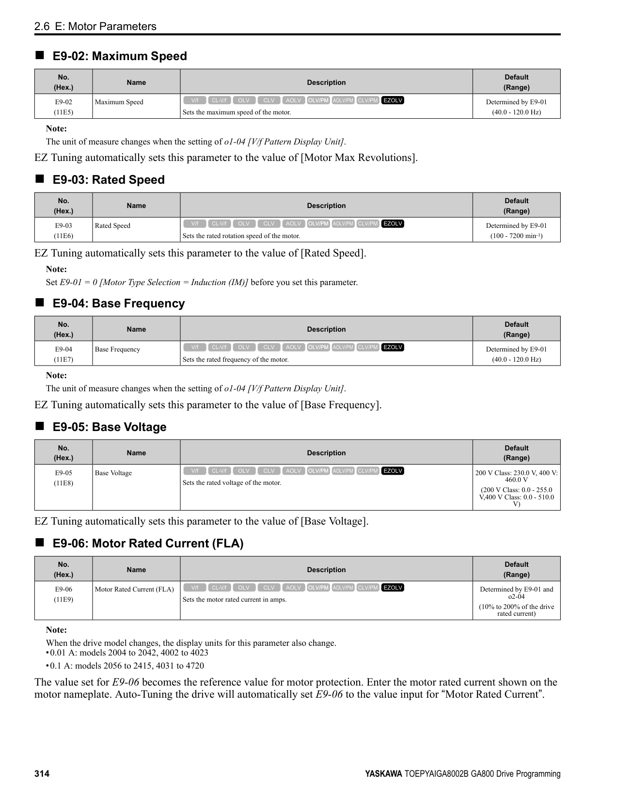
|---|---|---|---| |H1-06 (0403)|Terminal S6 Function Selection|Sets the function for MFDI terminal S6.
V/f CL-V/f OLV CLV AOLV OLV/PM AOLV/PM CLV/PM EZOLV
|4 (0 - 1FF)|
|No. (Hex.)|Name|Description|Default (Range)| |---|---|---|---| |H1-07 (0404)|Terminal S7 Function Selection|Sets the function for MFDI terminal S7.
V/f CL-V/f OLV CLV AOLV OLV/PM AOLV/PM CLV/PM EZOLV
|6 (0 - 1FF)|
|No. (Hex.)|Name|Description|Default (Range)| |---|---|---|---| |H1-08 (0405)|Terminal S8 Function Selection|Sets the function for MFDI terminal S8.
V/f CL-V/f OLV CLV AOLV OLV/PM AOLV/PM CLV/PM EZOLV
|8 (0 - 1FF)|
|No. (Hex.)|Name|Description|Default (Range)| |---|---|---|---| |H1-21 (0B70)|Terminal S1 Function Selection 2|Sets the second function for MFDI terminal S1.
V/f CL-V/f OLV CLV AOLV OLV/PM AOLV/PM CLV/PM EZOLV
|F (1 - 19F)|
|No. (Hex.)|Name|Description|Default (Range)| |---|---|---|---| |H1-22 (0B71)|Terminal S2 Function Select 2|Sets the second function for MFDI terminal S2.
V/f CL-V/f OLV CLV AOLV OLV/PM AOLV/PM CLV/PM EZOLV
|F (1 - 19F)|
|No. (Hex.)|Name|Description|Default (Range)| |---|---|---|---| |H1-23 (0B72)|Terminal S3 Function Selection 2|Sets the second function for MFDI terminal S3.
V/f CL-V/f OLV CLV AOLV OLV/PM AOLV/PM CLV/PM EZOLV
|F (1 - 19F)|
ParameterDetails
######## 2
######## ■ H1-24: Terminal S4 Function Selection 2
|No. (Hex.)|Name|Description|Default (Range)| |---|---|---|---| |H1-24 (0B73)|Terminal S4 Function Selection 2|Sets the second function for MFDI terminal S4.
V/f CL-V/f OLV CLV AOLV OLV/PM AOLV/PM CLV/PM EZOLV
|F (1 - 19F)|
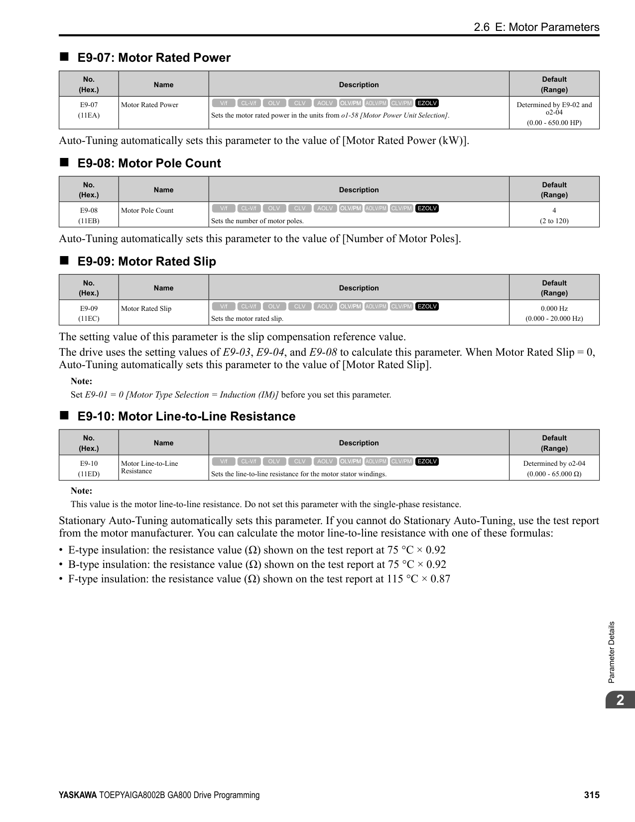
■ H1-25: Terminal S5 Function Select 2
When MFDI terminal S5 activates, it will operate the function set to H1-05 [Terminal S5 Function Selection] and the
When MFDI terminal S6 activates, it will operate the function set to H1-06 [Terminal S6 Function Selection] and the function set to H1-26 at the same time. When the setting value is F, the function is disabled.
When MFDI terminal S7 activates, it will operate the function set to H1-07 [Terminal S7 Function Selection] and the function set to H1-27 at the same time. When the setting value is F, the function is disabled.
|No. (Hex.)|Name|Description|Default (Range)| |---|---|---|---| |H1-25 (0B74)|Terminal S5 Function Selection 2|Sets the second function for MFDI terminal S5.
V/f CL-V/f OLV CLV AOLV OLV/PM AOLV/PM CLV/PM EZOLV
|F (1 - 19F)|
|No. (Hex.)|Name|Description|Default (Range)| |---|---|---|---| |H1-26 (0B75)|Terminal S6 Function Selection 2|Sets the second function for MFDI terminal S6.
V/f CL-V/f OLV CLV AOLV OLV/PM AOLV/PM CLV/PM EZOLV
|F (1 - 19F)|
|No. (Hex.)|Name|Description|Default (Range)| |---|---|---|---| |H1-27 (0B76)|Terminal S7 Function Selection 2|Sets the second function for MFDI terminal S7.
V/f CL-V/f OLV CLV AOLV OLV/PM AOLV/PM CLV/PM EZOLV
|F (1 - 19F)|
|No. (Hex.)|Name|Description|Default (Range)| |---|---|---|---| |H1-28 (0B77)|Terminal S8 Function Selection 2|Sets the second function for MFDI terminal S8.
V/f CL-V/f OLV CLV AOLV OLV/PM AOLV/PM CLV/PM EZOLV
|F (1 - 19F)|
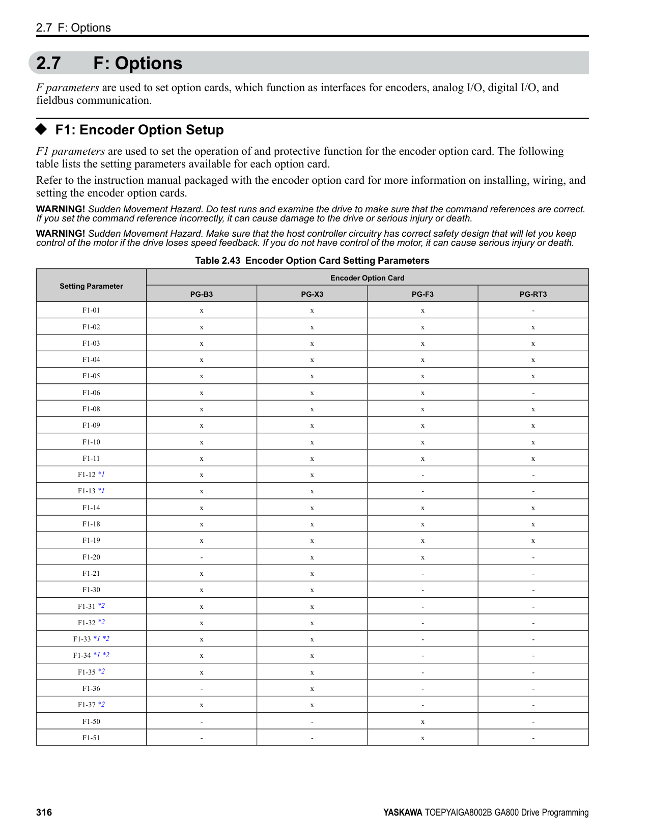
■ MEMOBUS/Modbus MFDI 1 to 3 Function Selection You can set the function for the MFDI to MEMOBUS register bit 0 to 2 of [15C0(Hex.)]. Use H1-40 to H1-42 [Extend MFDI Function Selection] to select the function.
|No. (Hex.)|Name|Description|Default (Range)| |---|---|---|---| |H1-40 (0B54)|Mbus Reg 15C0h bit0 Input Func|Selects MFDI function assigned to bit 0 of the MEMOBUS register 15C0 (Hex.).
V/f CL-V/f OLV CLV AOLV OLV/PM AOLV/PM CLV/PM EZOLV
|F (1 - 19F)|
|No. (Hex.)|Name|Description|Default (Range)| |---|---|---|---| |H1-41 (0B55)|Mbus Reg 15C0h bit1 Input Func|Selects MFDI function assigned to bit 1 of the MEMOBUS register 15C0 (Hex.).
V/f CL-V/f OLV CLV AOLV OLV/PM AOLV/PM CLV/PM EZOLV
|F (1 - 19F)|
|No. (Hex.)|Name|Description|Default (Range)| |---|---|---|---| |H1-42 (0B56)|Mbus Reg 15C0h bit2 Input Func|Selects MFDI function assigned to bit 2 of the MEMOBUS register 15C0 (Hex.).
V/f CL-V/f OLV CLV AOLV OLV/PM AOLV/PM CLV/PM EZOLV
|F (1 - 19F)|
######## ◆ Multi-Function Digital Input Setting Values Selects a function set with H1-01 to H1-08.
######## ■ 0: 3-Wire Sequence
|Setting Value|Function|Description| |---|---|---| |0|3-Wire Sequence|Sets the direction of motor rotation for 3-wire sequence.
V/f CL-V/f OLV CLV AOLV OLV/PM AOLV/PM CLV/PM EZOLV
|
If the 3-wire sequence is set to a terminal that is not MFDI terminals S1 and S2, these terminals will be the input terminals for Forward run/Reverse run command. The drive will automatically set terminal S1 to Run command (RUN) and terminal S2 to Stop command (STOP).
When terminal S1 (Run command) activates for 1 ms minimum, the drive rotates the motor. When terminal S2 (Stop command) deactivates, the drive stops. When terminal Sx that is set in 3-wire sequence deactivates, the drive operates in the forward direction, and when it activates, the drive operates in the reverse direction. WARNING! Sudden Movement Hazard. Set the MFDI parameters before you close control circuit switches. Incorrect Run/Stop circuit sequence settings can cause serious injury or death from moving equipment. WARNING! Sudden Movement Hazard. When you use a 3-Wire sequence, set A1-03 = 3330 [Initialize Parameters = 3-Wire
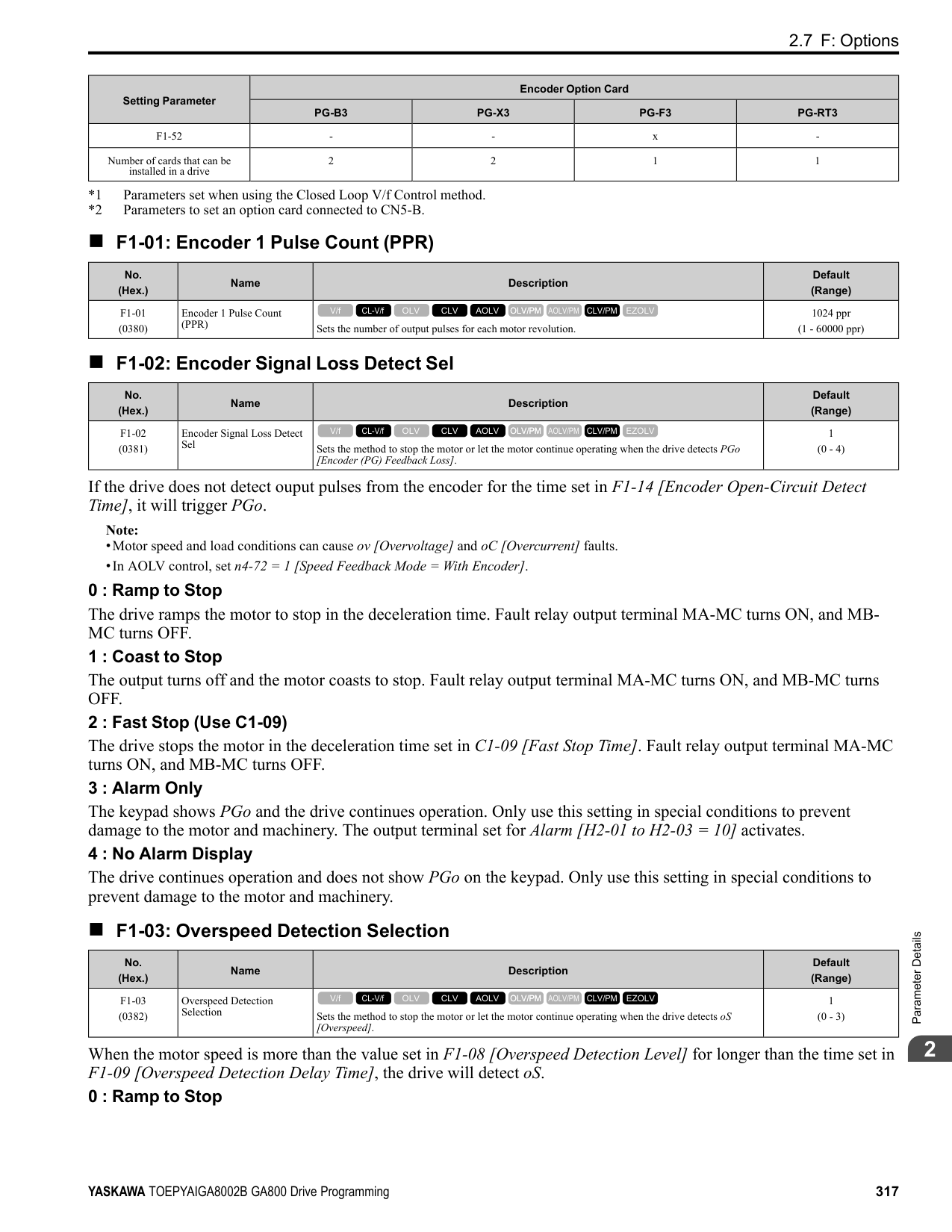
Initialization] and make sure that b1-17 = 0 [Run Command at Power Up = Disregard Existing RUN Command] (default). If you do not correctly set the drive parameters for 3-Wire operation before you energize the drive, the motor can suddenly rotate in reverse when you energize the drive.
| | | |---|---| | | |
ParameterDetails
######## 2
################# Figure 2.77 3-Wire Sequence Wiring Example
.
Figure 2.78 3-Wire Sequence Time Chart Note:
the drive is energized, the protective function activates and the flashes quickly. When the application allows Run, set b1-17 = 1 [Accept Existing RUN Command].
######## ■ 1: LOCAL/REMOTE Selection
|Setting Value|Function|Description| |---|---|---| |1|LOCAL/REMOTE Selection|Sets drive control for the keypad (LOCAL) or an external source (REMOTE).
V/f CL-V/f OLV CLV AOLV OLV/PM AOLV/PM CLV/PM EZOLV
|
Note:
######## ■ 2: External Reference 1/2 Selection
|Setting Value|Function|Description| |---|---|---|
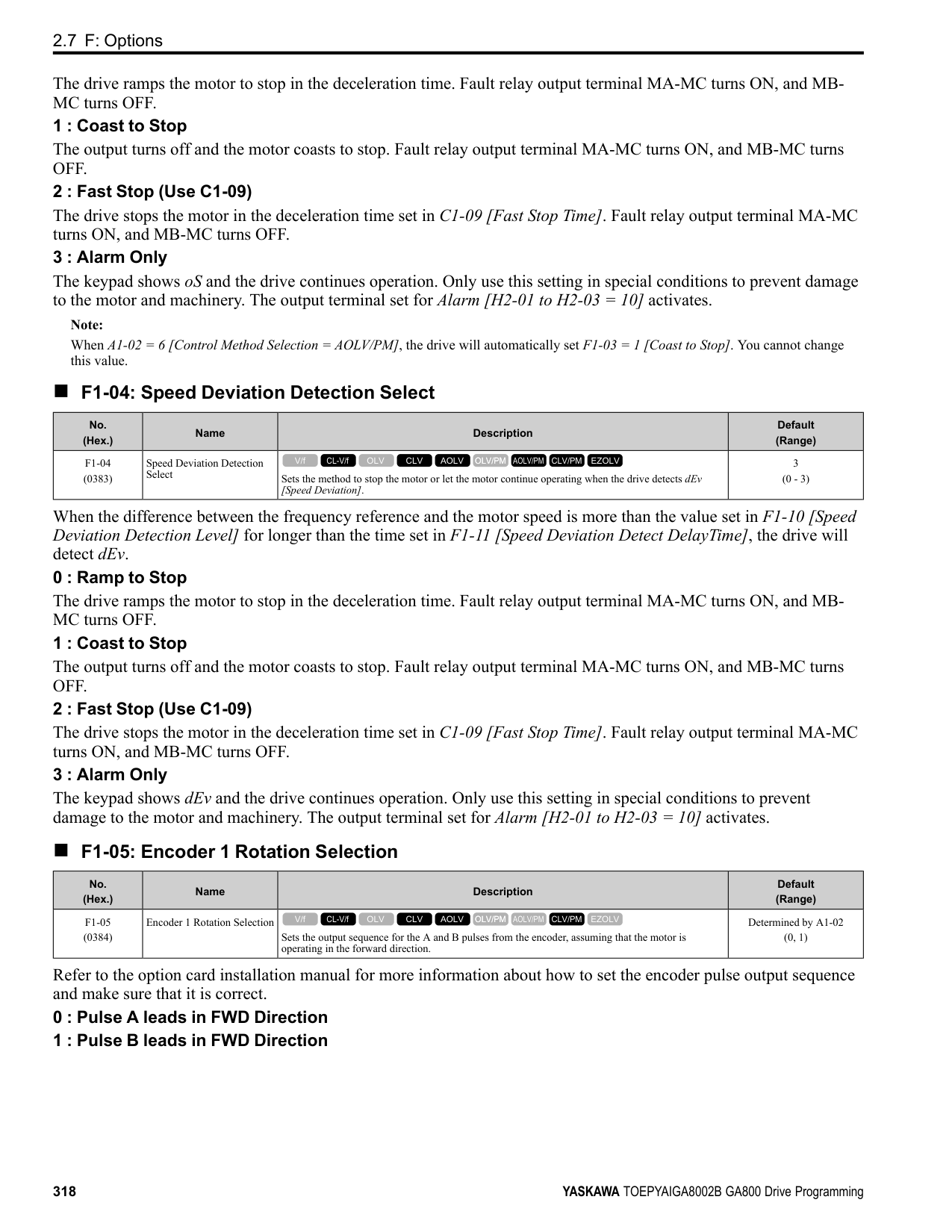
|2|External Reference 1/2 Selection|Sets the drive to use Run command source 1/2 or Reference command source 1/2 when in REMOTE Mode.
V/f CL-V/f OLV CLV AOLV OLV/PM AOLV/PM CLV/PM EZOLV
|
Note: When the drive is receiving a Run command, you cannot switch between reference sources.
ON : b1-15 = [Frequency Reference Selection 2], b1-16 [Run Command Selection 2] OFF : b1-01 = [Frequency Reference Selection 1], b1-02 [Run Command Selection 1]
######## ■ 3: Multi-Step Speed Reference 1
|Setting Value|Function|Description| |---|---|---| |3|Multi-Step Speed Reference 1|Uses speed references d1-01 to d1-16 to set a multi-step speed reference.
V/f CL-V/f OLV CLV AOLV OLV/PM AOLV/PM CLV/PM EZOLV
|
Refer to “Setting Procedures for Multi-step Speed Operation” in “d: Reference Settings” for more information.
Note: Refer to “Setting Procedures for Multi-step Speed Operation” in “d: Reference Settings” for more information.
Note: Refer to “Setting Procedures for Multi-step Speed Operation” in “d: Reference Settings” for more information.
Note: Refer to “C1: Accel & Decel Time” for more information.
|Setting Value|Function|Description| |---|---|---| |4|Multi-Step Speed Reference 2|Uses speed references d1-01 to d1-16 to set a multi-step speed reference.
V/f CL-V/f OLV CLV AOLV OLV/PM AOLV/PM CLV/PM EZOLV
|
|Setting Value|Function|Description| |---|---|---| |5|Multi-Step Speed Reference 3|Uses speed references d1-01 to d1-16 to set a multi-step speed reference.
V/f CL-V/f OLV CLV AOLV OLV/PM AOLV/PM CLV/PM EZOLV
|
|Setting Value|Function|Description| |---|---|---| |6|Jog Reference Selection|Sets the drive to use the JOG Frequency Reference (JOG command) set in d1-17. The JOG Frequency Reference (JOG command) overrides Frequency References 1 to 16 (d1-01 to d1-16).
V/f CL-V/f OLV CLV AOLV OLV/PM AOLV/PM CLV/PM EZOLV
|
|Setting Value|Function|Description| |---|---|---| |7|Accel/Decel Time Selection 1|Sets the drive to use Acceleration/Deceleration Time 1 [C1-01, C1-02] or Acceleration/Deceleration Time 2 [C1-03, C1-04].
V/f CL-V/f OLV CLV AOLV OLV/PM AOLV/PM CLV/PM EZOLV
|
|Setting Value|Function|Description| |---|---|---| |8|Baseblock Command (N.O.)|Sets the command that stops drive output and coasts the motor to stop when the input is ON.
V/f CL-V/f OLV CLV AOLV OLV/PM AOLV/PM CLV/PM EZOLV
|
The keypad flashes bb [Baseblock]. If you cancel the baseblock command when the Run command is active, the drive will restart the motor and use the speed search function.
############## Figure 2.79 Baseblock Command Time Chart ON : Baseblock (drive output stop) OFF : Normal operation
ParameterDetails
######## 2
######## ■ 9: Baseblock Command (N.C.)
|Setting Value|Function|Description| |---|---|---| |9|Baseblock Command (N.C.)|Sets the command that stops drive output and coasts the motor to stop when the input terminal is OFF.
V/f CL-V/f OLV CLV AOLV OLV/PM AOLV/PM CLV/PM EZOLV
|
The keypad flashes bb [Baseblock]. If you cancel the baseblock command when the Run command is active, the drive will restart the motor and use the speed search function.
ON : Normal operation OFF : Baseblock (drive output stop)
If the terminal is deactivated, the drive restarts acceleration and deceleration. When the acceleration/deceleration ramp hold terminal is activated and d4-01 = 1 [Freq Reference Retention Select = Enabled], the drive will store the output frequency in memory. While the acceleration/deceleration ramp hold command is activated, the drive will always restart the motor at this output frequency.
Note: Refer to “d4-01: Freq Reference Retention Select” for more information.
ON : Terminal selected with H3-14 is enabled OFF : Terminal selected with H3-14 is disabled
ON : Speed feedback control disable (V/f Control) OFF : Speed feedback control enable (Closed Loop V/f Control)
|Setting Value|Function|Description| |---|---|---| |A|Accel/Decel Ramp Hold|Momentarily pauses motor acceleration and deceleration when the terminal is turned ON, retains the output frequency that was stored in the drive at the time of the pause, and restarts motor operation.
V/f CL-V/f OLV CLV AOLV OLV/PM AOLV/PM CLV/PM EZOLV
|
|Setting Value|Function|Description| |---|---|---| |B|Overheat Alarm (oH2)|Sets the drive to display an oH2 [Drive Overheat Warning] alarm when the input terminal is ON. The alarm does not have an effect on drive operation.
V/f CL-V/f OLV CLV AOLV OLV/PM AOLV/PM CLV/PM EZOLV
|
|Setting Value|Function|Description| |---|---|---| |C|Analog Terminal Enable Selection|Sets the command that enables or disables the terminals selected in H3-14 [Analog Input Terminal Enable Sel].
V/f CL-V/f OLV CLV AOLV OLV/PM AOLV/PM CLV/PM EZOLV
|
|Setting Value|Function|Description| |---|---|---| |D|Ignore Speed Fdbk (V/f w/o Enc)|Sets the command to disable speed feedback control and run the drive in V/f control or use speed feedback from the encoder.
V/f CL-V/f OLV CLV AOLV OLV/PM AOLV/PM CLV/PM EZOLV
|
|Setting Value|Function|Description| |---|---|---| |E|ASR Integral Reset|Sets the command to reset the integral value and use PI control or P control for the speed control loop.
V/f CL-V/f OLV CLV AOLV OLV/PM AOLV/PM CLV/PM EZOLV
|
ON : P control OFF : PI control
######## ■ F: Not Used
|Setting Value|Function|Description| |---|---|---| |F|Not Used|Use this setting for unused terminals or to use terminals in through mode.
V/f CL-V/f OLV CLV AOLV OLV/PM AOLV/PM CLV/PM EZOLV
|
Through Mode uses the signal input to the terminal as a digital input for the upper sequence through a communication option or MEMOBUS/Modbus communications. This input signal does not have an effect on drive operation.
######## ■ 10: Up Command
|Setting Value|Function|Description| |---|---|---| |10|Up Command|Sets the command to use a push button switch to increase the drive frequency reference. You must also set Setting 11 [Down Command].
V/f CL-V/f OLV CLV AOLV OLV/PM AOLV/PM CLV/PM EZOLV
|
ON : Increases the frequency reference. OFF : Holds the current frequency reference.
Note:
When you enter the UP command, the frequency reference increases. When you enter the Down command, the frequency reference decreases. The Up and Down commands have priority over all other frequency references. When you enable the Up/Down command, the drive will ignore these frequency references:
Table 2.56 Up Command and Down Command
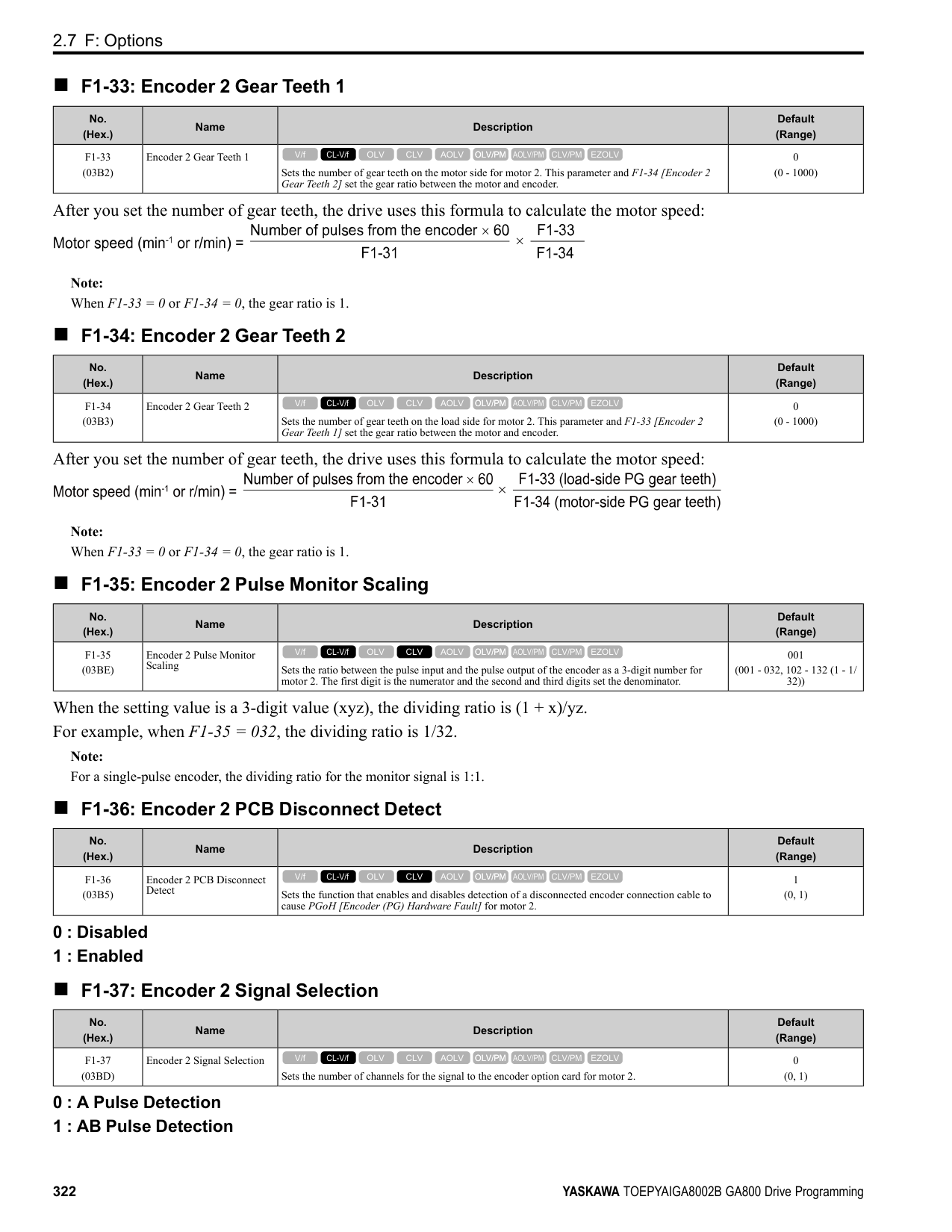
|Command status|Command status|Drive operation| |---|---|---| |Up command (10)|Down command (11)|Drive operation| |OFF|OFF|Keeps the current frequency reference.| |ON|OFF|Increases the frequency reference.| |OFF|ON|Decreases the frequency reference.| |ON|ON|Keeps the current frequency reference.|
Combine Frequency Reference Hold Functions and Up/Down Commands
ParameterDetails
######## 2
Note: Refer to “d4-01 [Freq Reference Hold Selection]” for more information.
Combine Upper/Lower Limits of the Frequency Reference and the Up/Down Commands Set the upper limit value of the frequency reference to d2-01 [Frequency Reference Upper Limit]. Use an analog input or d2-02 [Frequency Reference Lower Limit] to set the lower limit value of the frequency reference. The configurable values change when the setting for d4-10 [Up/Down Freq Lower Limit Select] changes. When you input a Run command, these are the lower limits of the frequency reference:
Figure 2.80 shows an example of how Up/Down command operates. In this example, the lower limit value of the frequency reference is set in d2-02. Figure 2.80 shows the time chart when Freq Reference Retention Select [d4-01] is enabled and disabled.
Figure 2.80 Up/Down Command Time Chart
######## ■ 11: Down Command
|Setting Value|Function|Description| |---|---|---| |11|Down Command|Sets the command to use a push button switch to decrease the drive frequency reference. You must also set Setting 10 [Up Command].
V/f CL-V/f OLV CLV AOLV OLV/PM AOLV/PM CLV/PM EZOLV
|
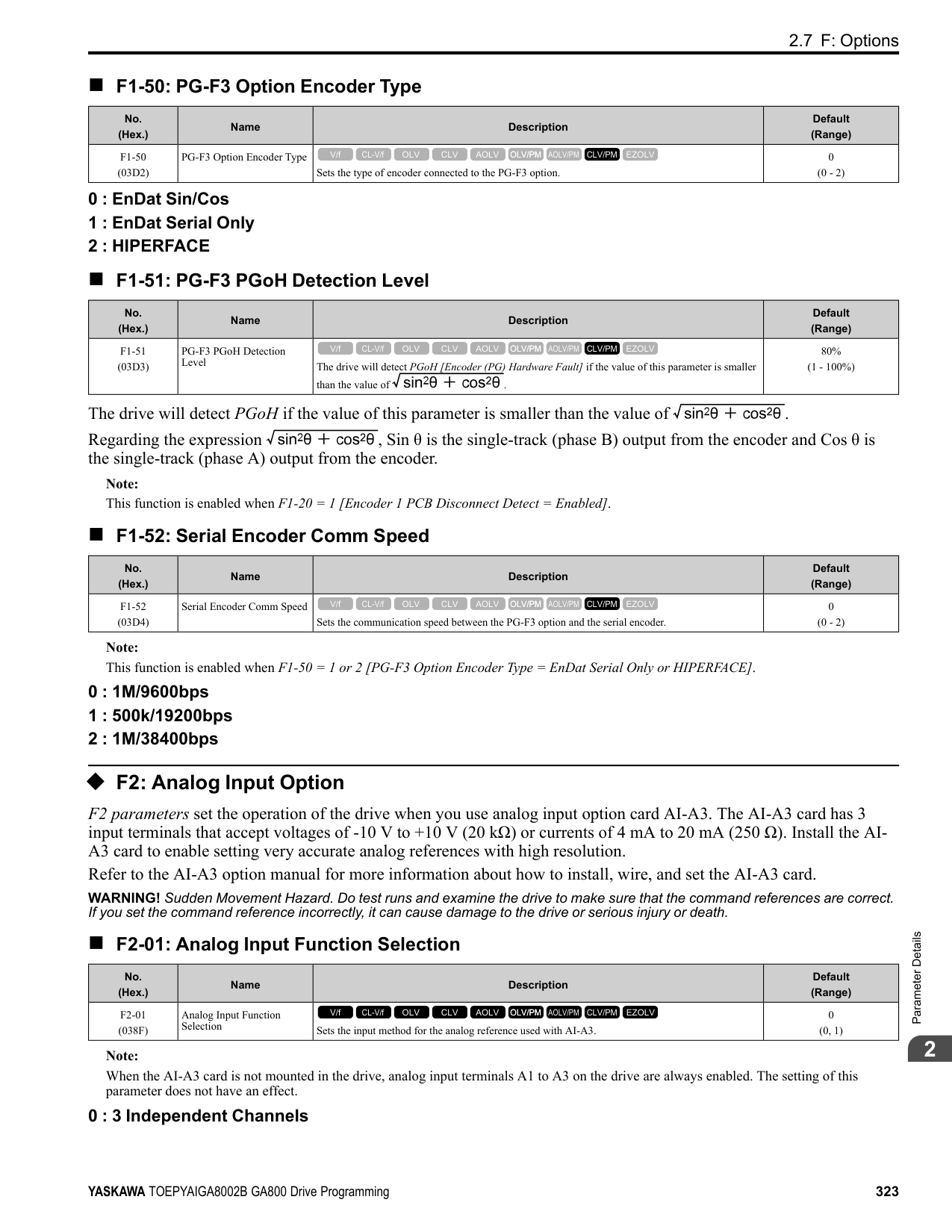
ON : Decreases the frequency reference. OFF : Holds the current frequency reference.
################# Note:
When you enter the UP command, the frequency reference increases. When you enter the Down command, the frequency reference decreases. The Up and Down commands have priority over all other frequency references. When you enable the Up/Down command, the drive will ignore these frequency references:
######## ■ 12: Forward Jog
|Setting Value|Function|Description| |---|---|---| |12|Forward Jog|Sets the command to operate the motor in the forward direction at the Jog Frequency set in d1-17 [Jog Reference].
V/f CL-V/f OLV CLV AOLV OLV/PM AOLV/PM CLV/PM EZOLV
|
Note:
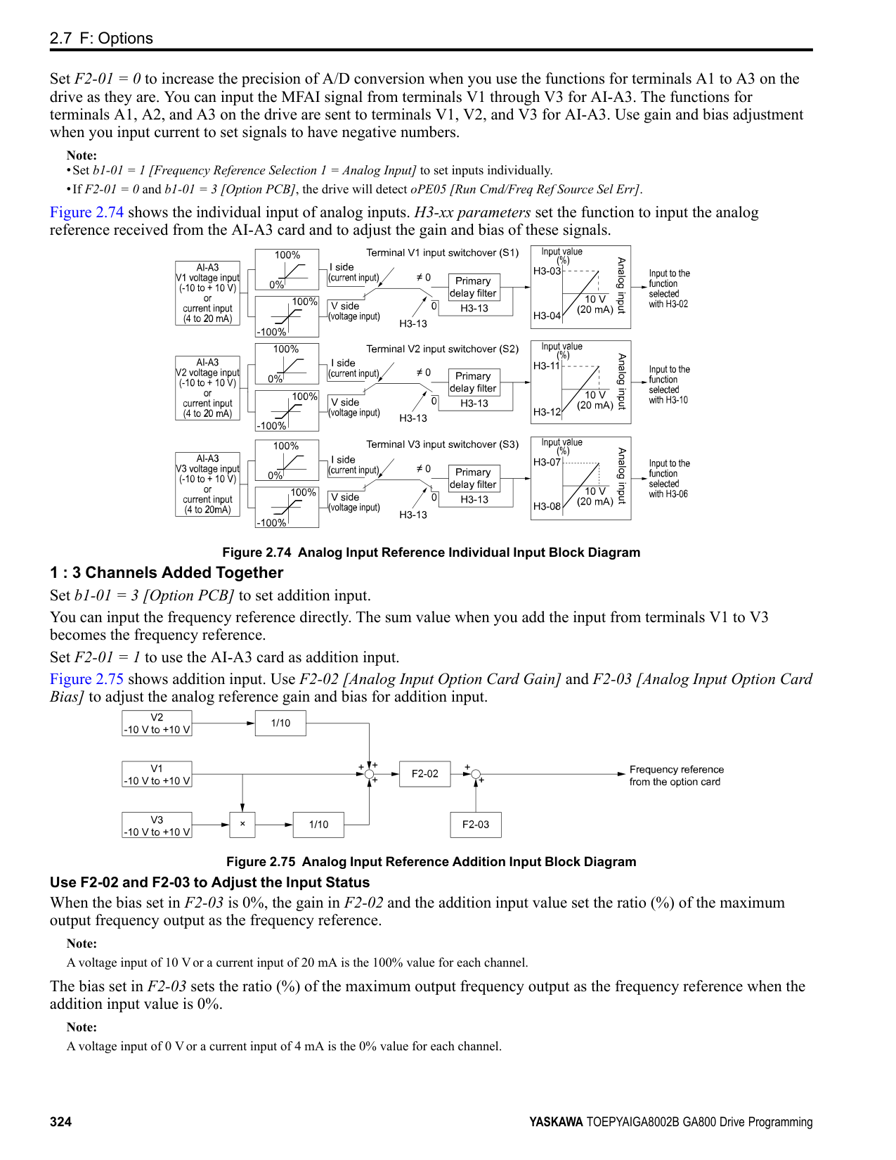
Figure 2.81 JOG Operation Pattern
######## ■ 13: Reverse Jog
|Setting Value|Function|Description| |---|---|---| |13|Reverse Jog|Sets the command to operate the motor in reverse at the Jog Frequency set in d1-17 [Jog Reference].
V/f CL-V/f OLV CLV AOLV OLV/PM AOLV/PM CLV/PM EZOLV
|
################# Note:
ParameterDetails
######## 2
######## ■ 14: Fault Reset
|Setting Value|Function|Description| |---|---|---| |14|Fault Reset Procedure|Sets the command to reset the current fault when the Run command is inactive.
V/f CL-V/f OLV CLV AOLV OLV/PM AOLV/PM CLV/PM EZOLV
|
If the drive detects a fault, the drive will activate the fault relay output, turn off the output, and the motor will coast to stop. If the drive detects a fault for which you can set the stopping method, apply the appropriate Stopping Method. Then push (RESET) on the keypad to turn the Run command OFF, or activate the fault reset terminal to reset the fault.
Note: The drive ignores the fault reset command when the Run command is active. Remove the Run command before trying to reset a fault.
######## ■ 15: Fast Stop (N.O.)
|Setting Value|Function|Description| |---|---|---| |15|Fast Stop (N.O.)|Sets the command to ramp to stop in the deceleration time set in C1-09 [Fast Stop Time] when the input terminal is activated while the drive is operating.
V/f CL-V/f OLV CLV AOLV OLV/PM AOLV/PM CLV/PM EZOLV
|
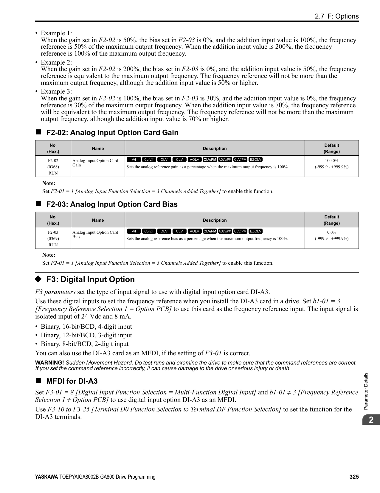
If you cancel the fast stop input, the drive will not restart the motor until you meet these conditions:
Note:
######## ■ 16: Motor 2 Selection
|Setting Value|Function|Description| |---|---|---| |16|Motor 2 Selection|Sets the command for the drive to operate motor 1 or motor 2. Stop the motors before switching.
V/f CL-V/f OLV CLV AOLV OLV/PM AOLV/PM CLV/PM EZOLV
|
You can use an external input to switch operation between two induction motors. The drive will save the control methods, V/f patterns, and motor parameters for the two motors.
ON : Selects motor 2 OFF : Selects motor 1
When you select motor 2, the drive will switch to motor 2 parameters.
Table 2.57 Parameters that Switch between Motor 1 and Motor 2
|Parameter|Motor 2 Selection|Motor 2 Selection| |---|---|---| |Parameter|OFF (Motor 1)|ON (Motor 2)| |C1-xx [Accel & Decel Time]|C1-01 to C1-04|C1-05 to C1-08| |C3-xx [Slip Compensation]|C3-01 to C3-04|C3-21 to C3-24| |C4-xx [Torque Compensation]|C4-01|C4-07|
|Parameter|Motor 2 Selection|Motor 2 Selection| |---|---|---| |Parameter|OFF (Motor 1)|ON (Motor 2)| |C5-xx [Automatic Speed Regulator (ASR)]|C5-01 to C5-08, C5-12, C5-17, C5-18|C5-21 to C5-28, C5-32, C5-37, C5-38| |E1-xx, E3-xx [V/f Patterns]
E2-xx, E-4xx [Motor Parameters]
|E1-xx, E2-xx|E3-xx, E4-xx|
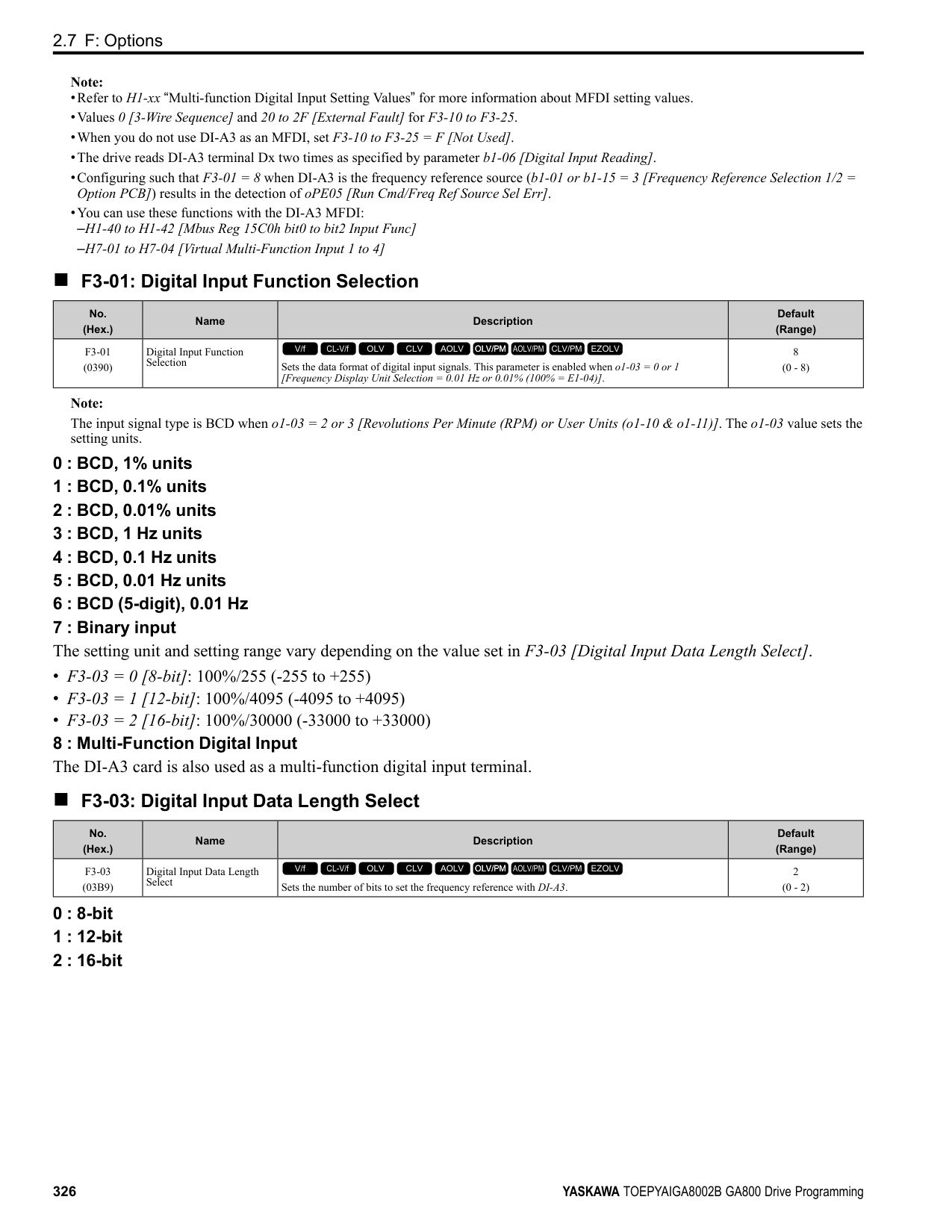
|F1-xx [Number of PG pulses per Revolution]|F1-01 to F1-21|F1-02 to F1-04, F1-08 to F1-11, F1-14, F1-31 to F1-37|
################# Note:
######## ■ 17: Fast Stop (N.C.)
|Setting Value|Function|Description| |---|---|---| |17|Fast Stop (N.C.)|Sets the command to ramp to stop in the deceleration time set in C1-09 [Fast Stop Time] when the input terminal is activated while the drive is operating.
V/f CL-V/f OLV CLV AOLV OLV/PM AOLV/PM CLV/PM EZOLV
|
If you cancel the fast stop input, the drive will not restart the motor until you meet these conditions:
Note:
Figure 2.82 shows an example of how fast stop operates.
Figure 2.82 Fast Stop Time Chart
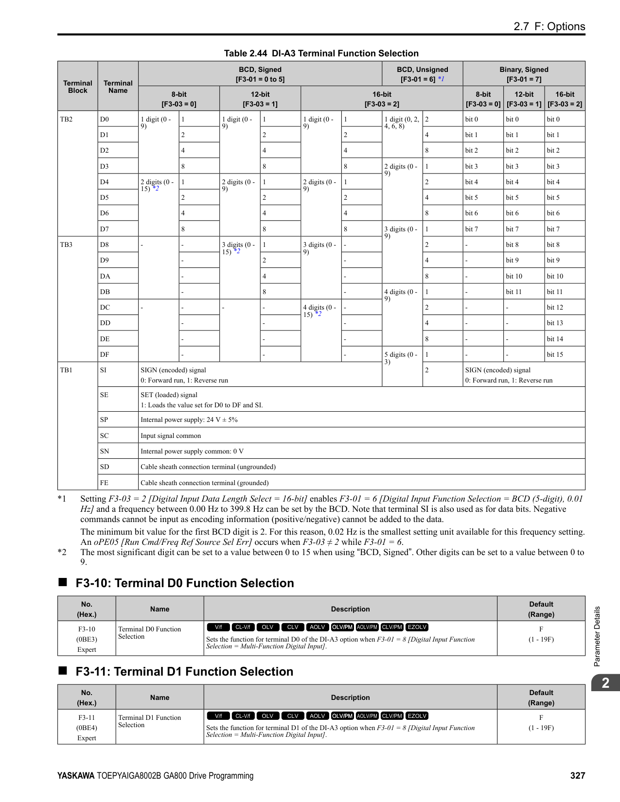
######## ■ 18: Timer Function
|Setting Value|Function|Description| |---|---|---| |18|Timer Function|Sets the command to start the timer function. Use this setting with Timer Output [H2-xx 12].
V/f CL-V/f OLV CLV AOLV OLV/PM AOLV/PM CLV/PM EZOLV
|
ParameterDetails
######## 2
Note: Refer to “b4: Timer Function” for more information.
######## ■ 19: PID Disable
|Setting Value|Function|Description| |---|---|---| |19|PID Disable|Sets the command to disable PID control when b5-01 = 1 to 8 [PID Mode Setting = Enabled].
V/f CL-V/f OLV CLV AOLV OLV/PM AOLV/PM CLV/PM EZOLV
|
ON : PID control disabled OFF : PID control enabled
######## ■ 1A: Accel/Decel Time Selection 2
|Setting Value|Function|Description| |---|---|---| |1A|Accel/Decel Time Selection 2|Set this function and H1-xx = 7[Accel/Decel Time Selection 1] together. Sets the drive to use Acceleration/Deceleration Time 3 [C105, C1-06] or Acceleration/Deceleration Time 4 [C1-07, C1-08].
V/f CL-V/f OLV CLV AOLV OLV/PM AOLV/PM CLV/PM EZOLV
|
Note: Refer to “C1: Accel & Decel Time” for more information.
######## ■ 1B: Programming Lockout
|Setting Value|Function|Description| |---|---|---| |1B|Programming Lockout|Sets the command to prevent parameter changes when the terminal is OFF.
V/f CL-V/f OLV CLV AOLV OLV/PM AOLV/PM CLV/PM EZOLV
|
You can continue to view parameter setting values when the terminal is OFF [Parameters Cannot be Edited]. ON : Program Lockout OFF : Parameter Write Prohibit
######## ■ 1E: Reference Sample Hold
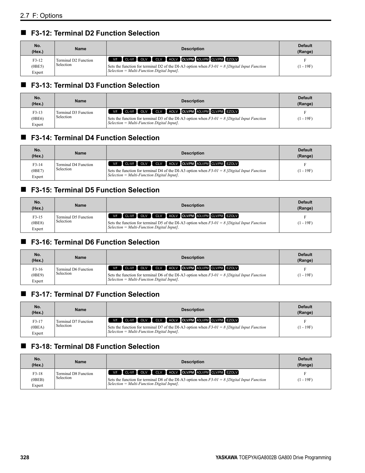
|Setting Value|Function|Description| |---|---|---| |1E|Reference Sample Hold|Sets the command to sample the frequency reference at terminals A1, A2, or A3 and hold the frequency reference at that frequency.
V/f CL-V/f OLV CLV AOLV OLV/PM AOLV/PM CLV/PM EZOLV
|
When the terminal is active for 100 ms, this function reads a sample of the analog frequency reference and holds that sample. When you input the sample/hold command again, the function reads a sample of the analog frequency reference again and holds that sample. When you turn off the power, the drive erases the saved analog frequency and resets the frequency reference to 0. Figure 2.83 shows an example of how the function operates.
Figure 2.83 Reference Sample Hold
You cannot set the Reference Sample Hold function at the same time as these functions:
■ 20 to 2F: External Fault
If an external fault is input to the drive, the keypad will show EFx [External Fault (Terminal Sx)], where x is the number of the terminal (terminal Sx) to which the external fault signal is assigned. For example, when an external fault signal is input to terminal S3, the keypad will show EF3. Use these conditions to select the value to set in H1-xx:
|Setting Value|Function|Description| |---|---|---| |20 to 2F|External fault|Sets a command to stop the drive when a failure or fault occurs on an external device.
V/f CL-V/f OLV CLV AOLV OLV/PM AOLV/PM CLV/PM EZOLV
|
Table 2.58 Stopping Methods for External Fault
|Setting|Signal Input Method from Peripheral Devices *1|Signal Input Method from Peripheral Devices *1|External Fault Detection Method *2|External Fault Detection Method *2|Stopping Method|Stopping Method|Stopping Method|Stopping Method| |---|---|---|---|---|---|---|---|---| |Setting|N.O.|N.C.|Always Detected|Detected during RUN Only|Ramp to Stop (Fault)|Coast to Stop (Fault)|Fast Stop (Fault)|Continuous Operation (Alarm Only)| |20|x|-|x|-|x|-|-|-| |21|-|x|x|-|x|-|-|-| |22|x|-|-|x|x|-|-|-| |23|-|x|-|x|x|-|-|-| |24|x|-|x|-|-|x|-|-|
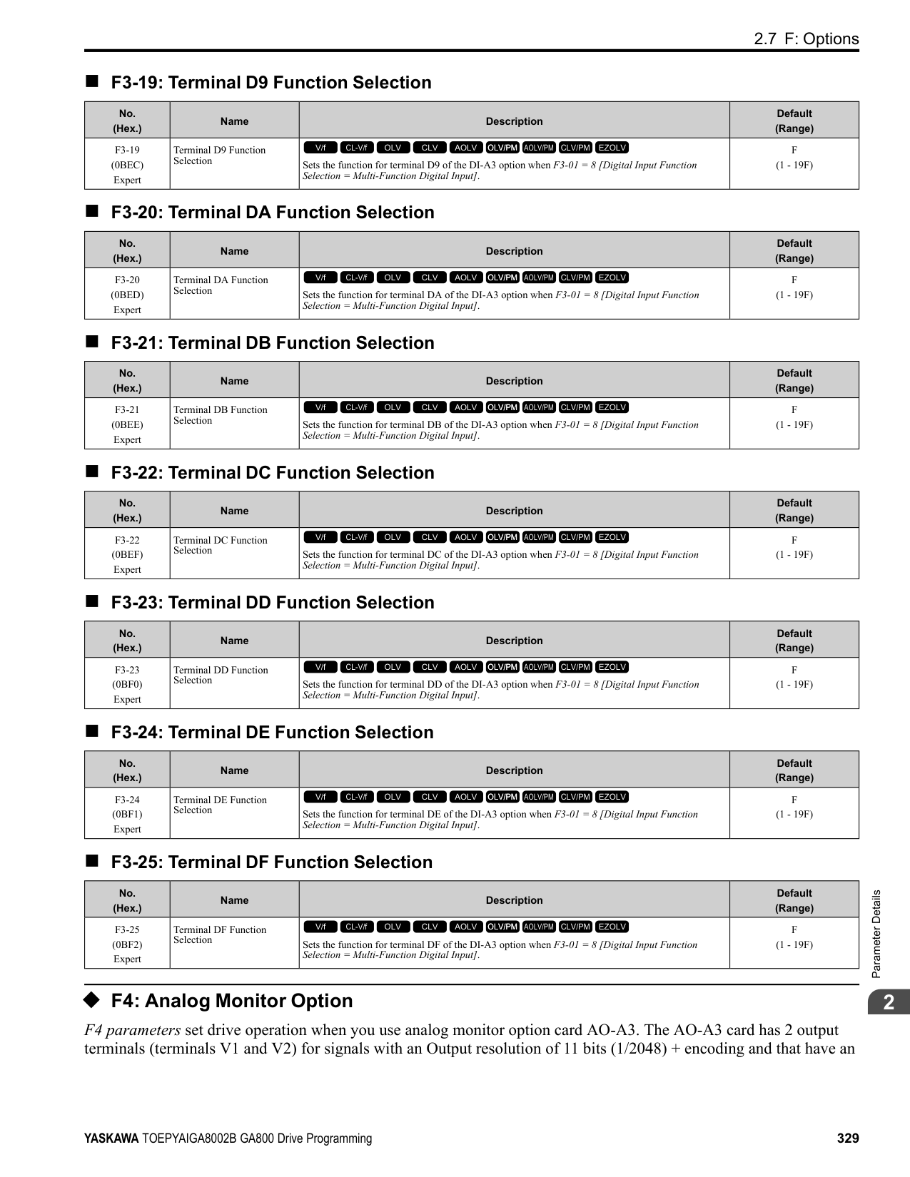
|25|-|x|x|-|-|x|-|-| |26|x|-|-|x|-|x|-|-| |27|-|x|-|x|-|x|-|-| |28|x|-|x|-|-|-|x|-| |29|-|x|x|-|-|-|x|-| |2A|x|-|-|x|-|-|x|-| |2B|-|x|-|x|-|-|x|-| |2C|x|-|x|-|-|-|-|x| |2D|-|x|x|-|-|-|-|x| |2E|x|-|-|x|-|-|-|x| |2F|-|x|-|x|-|-|-|x|
######## ■ 30: PID Integrator Reset
|Setting Value|Function|Description| |---|---|---| |30|PID Integrator Reset|Sets the command to reset and hold the PID control integral to 0 when the terminal is ON.
V/f CL-V/f OLV CLV AOLV OLV/PM AOLV/PM CLV/PM EZOLV
|
Note: Refer to “PID control block diagram” for more information.
ParameterDetails
######## 2
######## ■ 31: PID Integrator Hold
|Setting Value|Function|Description| |---|---|---| |31|PID Integrator Hold|Sets the command to hold the integral value of the PID control while the terminal is activated.
V/f CL-V/f OLV CLV AOLV OLV/PM AOLV/PM CLV/PM EZOLV
|
When you turn off the input terminal, PID control restarts the integral. Note: Refer to “PID control block diagram” for more information.
######## ■ 32: Multi-Step Speed Reference 4
|Setting Value|Function|Description|
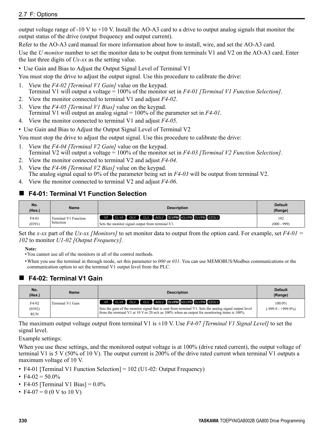
|---|---|---| |32|Multi-Step Speed Reference 4|Uses speed references d1-01 to d1-16 to set a multi-step speed reference.
V/f CL-V/f OLV CLV AOLV OLV/PM AOLV/PM CLV/PM EZOLV
|
Note: Refer to "Setting Procedures for Multi-step Speed Operation” in “d: Reference Settings” for more information.
######## ■ 34: PID Soft Starter Disable
|Setting Value|Function|Description| |---|---|---| |34|PID Soft Starter Disable|Sets the PID soft starter function.
V/f CL-V/f OLV CLV AOLV OLV/PM AOLV/PM CLV/PM EZOLV
|
ON : Disabled Disables b5-17 [PID Accel/Decel Time]. OFF : Enabled Enables b5-17 [PID Accel/Decel Time].
Note: Refer to “PID control block diagram” for more information.
######## ■ 35: PID Input (Error) Invert
|Setting Value|Function|Description| |---|---|---| |35|PID Input (Error) Invert|Sets the command to turn the terminal ON and OFF to switch the PID input level (polarity).
V/f CL-V/f OLV CLV AOLV OLV/PM AOLV/PM CLV/PM EZOLV
|
Note: Refer to “PID control block diagram” for more information.
######## ■ 3E: PID Setpoint Selection 1
|Setting Value|Function|Description| |---|---|---| |3E|PID Setpoint Selection 1|Set this function and H1-xx 3F [PID Setpoint Selection 2] together. Sets the function to switch the PID setpoint to b5-58 to b5-60 [PID Setpoint 2 to 4].
V/f CL-V/f OLV CLV AOLV OLV/PM AOLV/PM CLV/PM EZOLV
|
Refer to “b5-58 to b5-60: PID Setpoint 2 to 4” for more information.
######## ■ 3F: PID Setpoint Selection 2
|Setting Value|Function|Description| |---|---|---| |3F|PID Setpoint Selection 2|Set this function and H1-xx 3E [PID Setpoint Selection 1] at the same time. Sets the function to switch the PID setpoint to b5-58 to b5-60 [PID Setpoint 2 to 4].
V/f CL-V/f OLV CLV AOLV OLV/PM AOLV/PM CLV/PM EZOLV
|
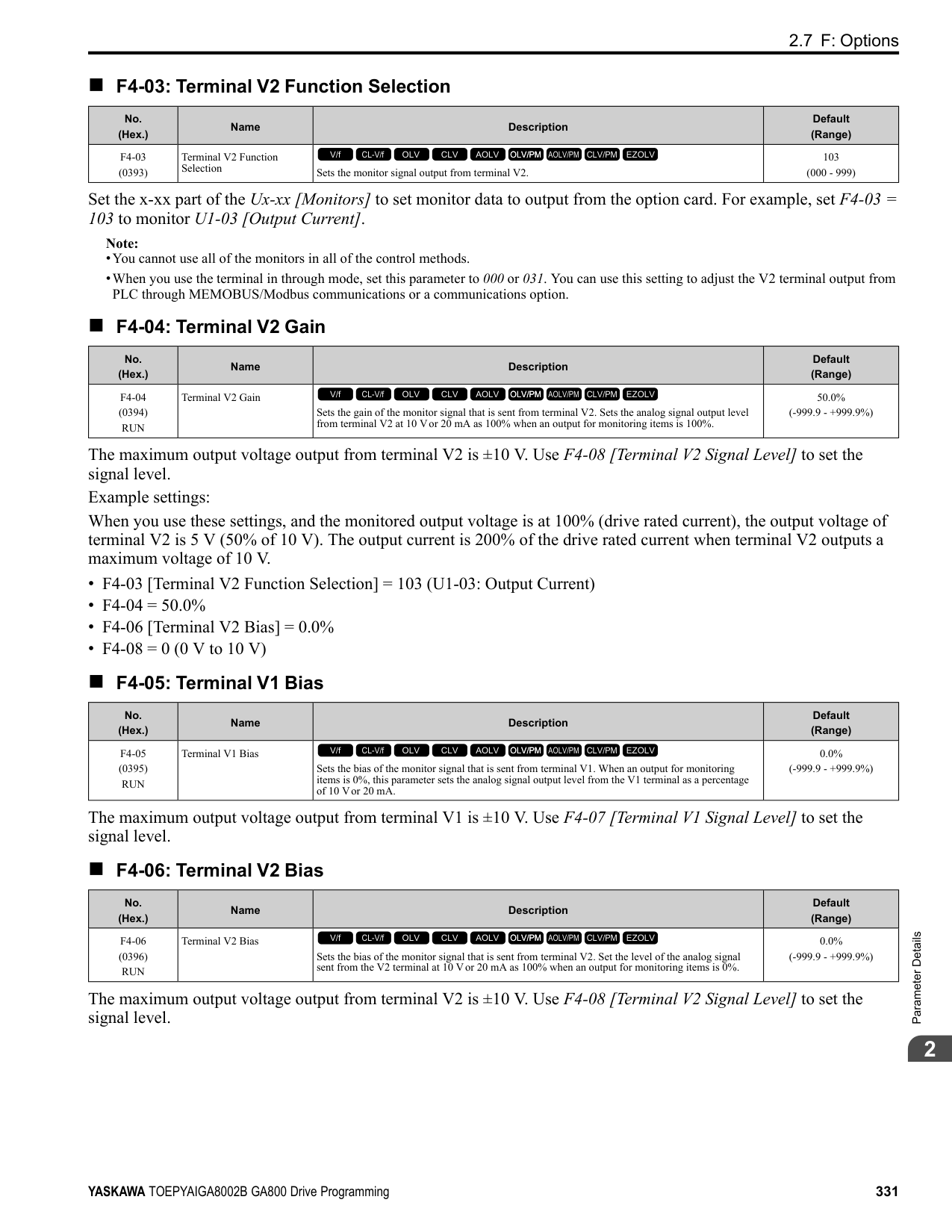
Refer to “b5-58 to b5-60: PID Setpoint 2 to 4” for more information.
######## ■ 40: Forward RUN (2-Wire)
|Setting Value|Function|Description| |---|---|---| |40|Forward RUN (2-Wire)|Sets the Forward Run command for 2-wire sequence 1. Set this function and H1-xx = 41 [Reverse Run Command (2-Wire Seq)] at the same time.
V/f CL-V/f OLV CLV AOLV OLV/PM AOLV/PM CLV/PM EZOLV
|
ON : Forward Run OFF : Run Stop
Note:
Figure 2.84 2-Wire Sequence Wiring Example
######## ■ 41: Reverse RUN (2-Wire)
|Setting Value|Function|Description| |---|---|---| |41|Reverse RUN (2-Wire)|Sets the Forward Run command for 2-wire sequence 1. Set this function and H1-xx = 40 [Forward Run Command (2-Wire Seq)] at the same time.
V/f CL-V/f OLV CLV AOLV OLV/PM AOLV/PM CLV/PM EZOLV
|
ON : Reverse Run OFF : Run Stop
Note:
######## ■ 42: Run Command (2-Wire Sequence 2)
|Setting Value|Function|Description| |---|---|---| |42|Run Command (2-Wire Sequence 2)|Sets the Run command for 2-wire sequence 2. Set this function and H1-xx = 43 [FWD/REV Command (2-Wire Seq 2)] at the same time.
V/f CL-V/f OLV CLV AOLV OLV/PM AOLV/PM CLV/PM EZOLV
|
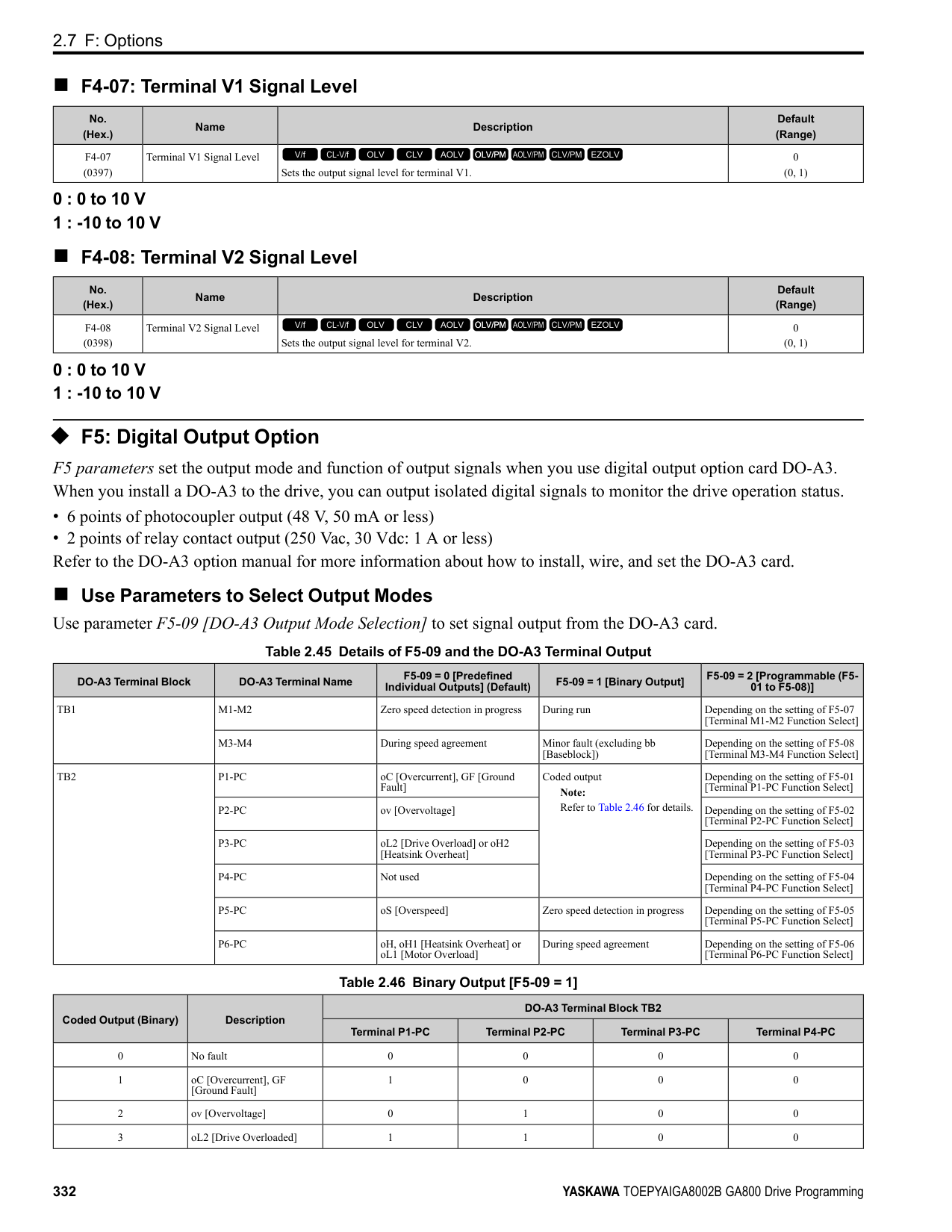
############## ON : Run OFF : Stop
Note: This function will not operate at the same time as H1-xx = 40, 41 [Forward/Reverse Run Command (2-Wire Seq)].
ParameterDetails
######## 2
ON : Reverse OFF : Forward
Note:
Note: Refer to “d7: Offset Frequency” for more information.
Note: Refer to “d7: Offset Frequency” for more information.
Note: Refer to “d7: Offset Frequency” for more information.
|Setting Value|Function|Description| |---|---|---| |43|FWD/REV (2-Wire Sequence 2)|Sets the direction of motor rotation for 2-wire sequence 2. Set this function and H1-xx = 42 [Run Command (2-Wire Sequence 2)] together.
V/f CL-V/f OLV CLV AOLV OLV/PM AOLV/PM CLV/PM EZOLV
|
|Setting Value|Function|Description| |---|---|---|
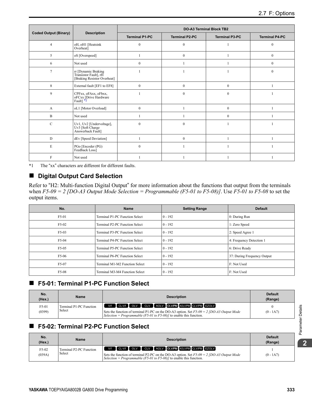
|44|Offset Frequency 1|Sets the function to add the offset frequency set in d7-01 [Offset Frequency 1] to the frequency reference when the terminal activates.
V/f CL-V/f OLV CLV AOLV OLV/PM AOLV/PM CLV/PM EZOLV
|
|Setting Value|Function|Description| |---|---|---| |45|Offset Frequency 2|Sets the function to add the offset frequency set in d7-02 [Offset Frequency 2] to the frequency reference when the terminal activates.
V/f CL-V/f OLV CLV AOLV OLV/PM AOLV/PM CLV/PM EZOLV
|
|Setting Value|Function|Description| |---|---|---| |46|Offset Frequency 3|Sets the function to add the offset frequency set in d7-03 [Offset Frequency 3] to the frequency reference when the terminal activates.
V/f CL-V/f OLV CLV AOLV OLV/PM AOLV/PM CLV/PM EZOLV
|
|Setting Value|Function|Description| |---|---|---| |47|Node Setup (CANopen)|Sets the function in CANopen communications to start the Node Setup function to set the drive node address from the host controller.
V/f CL-V/f OLV CLV AOLV OLV/PM AOLV/PM CLV/PM EZOLV
|
|Setting Value|Function|Description| |---|---|---| |60|DC Injection Braking Command|Sets the command to use DC Injection Braking to stop the motor.
V/f CL-V/f OLV CLV AOLV OLV/PM AOLV/PM CLV/PM EZOLV
|
If you input the Run command or JOG command, it will cancel DC Injection Braking. Figure 2.85 shows the time chart of the DC Injection Braking function.
Figure 2.85 DC Injection Braking Time Chart Note:
######## ■ 61: Speed Search from Fmax
|Setting Value|Function|Description| |---|---|---| |61|Speed Search from Fmax|Sets the function to start speed search using an external reference although b3-01 = 0 [Speed Search Selection at Start = Disabled].
V/f CL-V/f OLV CLV AOLV OLV/PM AOLV/PM CLV/PM EZOLV
|
When the terminal is turned ON for b3-24 = 2 [Speed Search Method Selection = Current Detection 2], the drive starts speed search from the maximum output frequency.
Note:
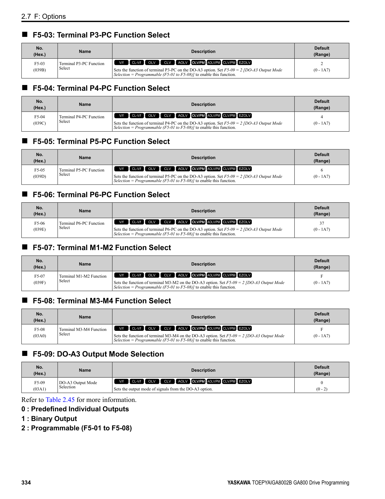
######## ■ 62: Speed Search from Fref
|Setting Value|Function|Description| |---|---|---| |62|Speed Search from Fref|Sets the function to use an external reference to start speed search although b3-01 = 0 [Speed Search Selection at Start = Disabled].
V/f CL-V/f OLV CLV AOLV OLV/PM AOLV/PM CLV/PM EZOLV
|
When the terminal is turned ON for b3-24 = 2 [Speed Search Method Selection = Current Detection 2], the drive starts speed search from the frequency reference.
Note:
######## ■ 63: Field Weakening
|Setting Value|Function|Description| |---|---|---| |63|Field Weakening|Sets the function to send the Field Weakening Level and Field Weakening Frequency Limit commands set in d6-01[Field Weakening Level] and d6-02 [Field Weakening Frequency Limit] when the input terminal is activated.
V/f CL-V/f OLV CLV AOLV OLV/PM AOLV/PM CLV/PM EZOLV
|
Note: Refer to “d6: Field Weak & Field Force” for more information.
######## ■ 65: KEB Ride-Thru 1 Activate (N.C.)
|Setting Value|Function|Description| |---|---|---| |65|KEB Ride-Thru 1 Activate (N.C.)|Sets operation of the KEB1 function through the KEB Ride-Thru 1 (N.C.).
V/f CL-V/f OLV CLV AOLV OLV/PM AOLV/PM CLV/PM EZOLV
|
ON : Normal operation OFF : Deceleration during momentary power loss
When you enable KEB Ride-Thru 1, set L2-29 [KEB Method Selection]. The drive operates with the selected KEB method.
ParameterDetails
######## 2
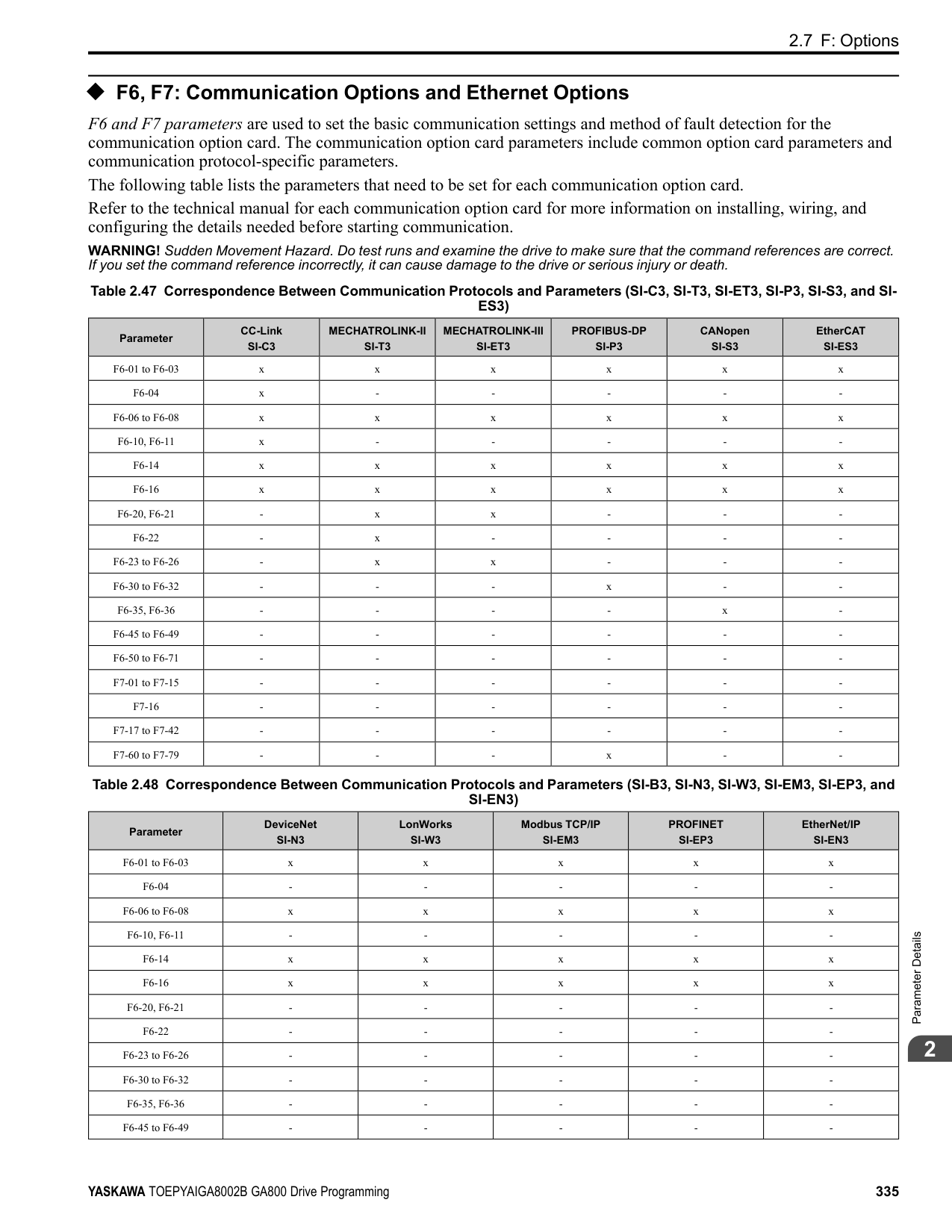
################# Note:
######## ■ 66: KEB Ride-Thru 1 Activate (N.O.)
|Setting Value|Function|Description| |---|---|---| |66|KEB Ride-Thru 1 Activate (N.O.)|Sets operation of the KEB1 function through the KEB Ride-Thru 1 (N.O.).
V/f CL-V/f OLV CLV AOLV OLV/PM AOLV/PM CLV/PM EZOLV
|
ON : Deceleration during momentary power loss OFF : Normal operation
When you enable KEB Ride-Thru 1, set L2-29 [KEB Method Selection]. The drive operates with the selected KEB method.
Note:
######## ■ 67: Communications Test Mode
|Setting Value|Function|Description| |---|---|---| |67|Communications Test Mode|Set the function for the drive to self-test RS-485 serial communications operation.
V/f CL-V/f OLV CLV AOLV OLV/PM AOLV/PM CLV/PM EZOLV
|
The Self-Diagnostics function connects the transmission terminal of the control terminal block to the reception terminal. The function transmits the data that the drive sent to make sure that the drive can communicate correctly.
Note: Refer to MEMOBUS/Modbus communications “Self-Diagnostics” for the self-diagnostics procedure.
######## ■ 68: High Slip Braking (HSB) Activate
|Setting Value|Function|Description| |---|---|---| |68|High Slip Braking|Sets the command to use high-slip braking to stop the motor.
V/f CL-V/f OLV CLV AOLV OLV/PM AOLV/PM CLV/PM EZOLV
|
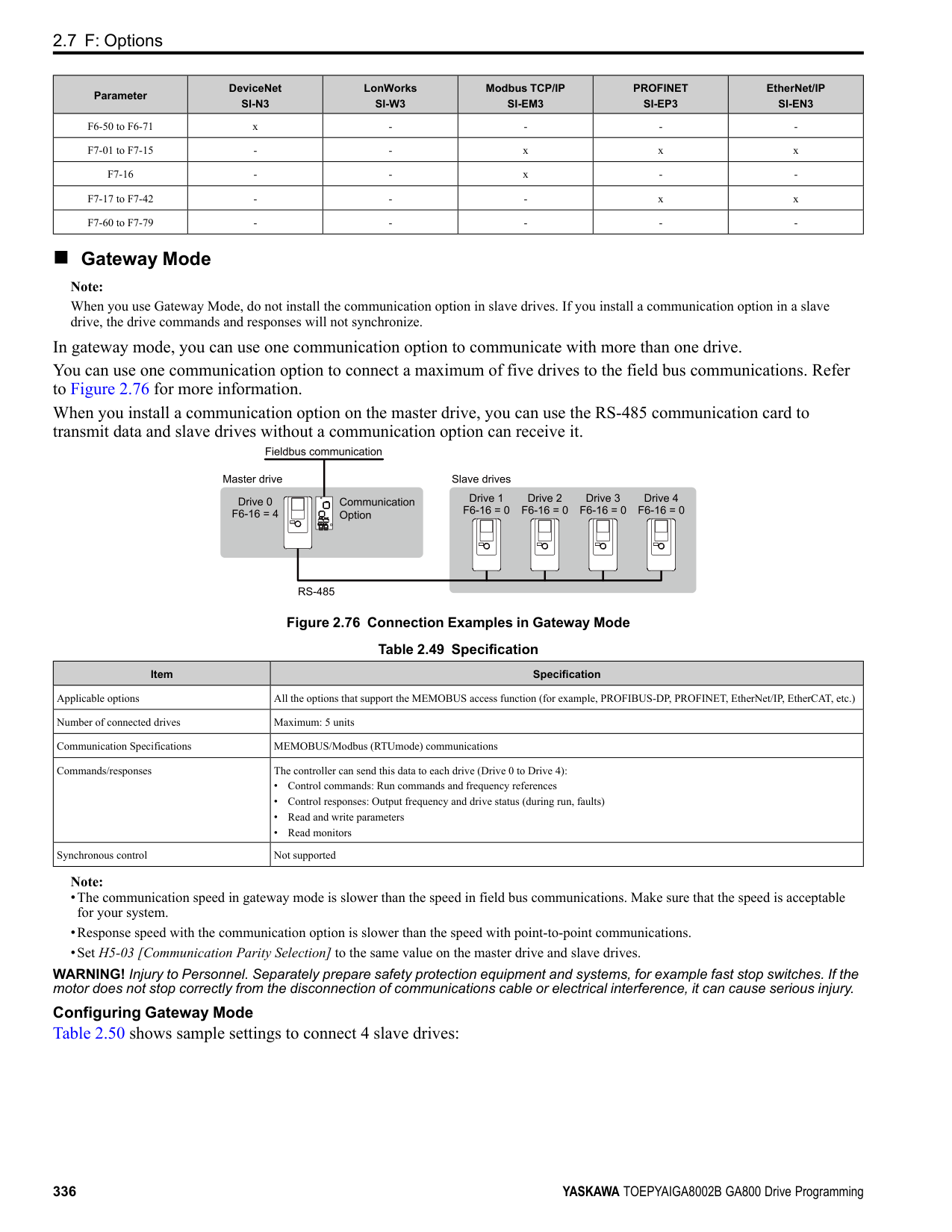
Note:
######## ■ 6A: Drive Enable
|Setting Value|Function|Description| |---|---|---| |6A|Drive Enable|Sets the function to show dnE [Drive Enabled] on the keypad and ignore Run commands when the terminal is OFF.
V/f CL-V/f OLV CLV AOLV OLV/PM AOLV/PM CLV/PM EZOLV
|
If you input the Run command before you turn ON the Drive Enable terminal, you must input the Run command again to operate the drive. When the terminal set for Drive Enable is turned OFF when the drive is operating, the drive will use the stopping method set in b1-03 [Stopping Method Selection] to stop the motor.
ON : Run command is accepted. OFF : Run command is disabled. When the drive is running, it stops according to b1-03 setting.
######## ■ 71: Torque Control
|Setting Value|Function|Description| |---|---|---| |71|Torque Control|Sets the function to switch between torque control and speed control.
V/f CL-V/f OLV CLV AOLV OLV/PM AOLV/PM CLV/PM EZOLV
|
ON : Torque control
OFF : Speed control Note: When this function is enabled, set d5-01 = 0 [Torque Control Selection = Speed Control].
Input the Speed/Torque Control Switchover Time Use parameter d5-06 [Speed/Torque Changeover Time] to set the length of time, in milliseconds, that the drive will wait to switch between speed and torque control. When the speed/torque control switchover signal changes in the time set in d5-06, the three analog inputs will keep their present value. Complete the signal switchover with an external source in this time.
Note: Refer to “Switch Speed Control and Torque Control” for more information.
######## ■ 72: Zero Servo
|Setting Value|Function|Description| |---|---|---| |72|Zero Servo|Sets the function to hold a stopped motor.
V/f CL-V/f OLV CLV AOLV OLV/PM AOLV/PM CLV/PM EZOLV
|
This function will hold a stopped motor if an external force is applied or an analog reference is offset.
Note:
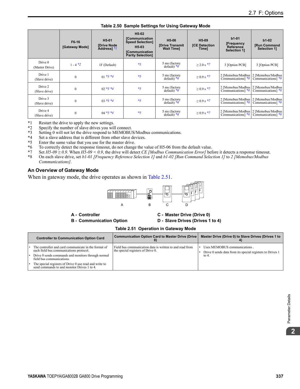
######## ■ 75: Up 2 Command
|Setting Value|Function|Description| |---|---|---| |75|Up 2 Command|Sets the function to increase the frequency reference bias value to accelerate the motor when the terminal is activated. Set this function and H1-xx 76 [Down 2 Command] together.
V/f CL-V/f OLV CLV AOLV OLV/PM AOLV/PM CLV/PM EZOLV
|
When you activate the terminal set for Up2 Command, the bias will increase. When you activate the terminal set for Down 2 Command, the bias will decrease. When you activate or deactivate the two commands, the drive will hold the frequency reference. Table 2.59 gives information about the relation between operation of the Up/Down 2 Command and d4-01, d4-03, d4-05.
Note:
ParameterDetails
######## 2
Table 2.59 Up 2 Command, Down 2 Command
|Function|Frequency Reference Source|d4-03|d4-05|d4-01|Operation|Storing the Frequency Reference or Frequency Bias| |---|---|---|---|---|---|---| |1|Multi-step speed reference|0.00|0|0|• When the Up 2 Command is active, the drive accelerates the motor (increases the bias value).
• When the Down 2 Command is active, the drive decelerates the motor (decreases the bias value)
• When the Up 2 Command and Down 2 Command are not active and when the Up 2 Command and Down 2 Command are active, the drive holds the output frequency (holds the bias value).
• When the frequency changes, it will reset the bias.
• For all other statuses, the drive will follow the frequency reference.
|Not stored.| |2|Multi-step speed reference|0.00|0|1|• When the Up 2 Command is active, the drive accelerates the motor (increases the bias value).
• When the Down 2 Command is active, the drive decelerates the motor (decreases the bias value)
• When the Up 2 Command and Down 2 Command are not active and when the Up 2 Command and Down 2 Command are active, the drive holds the output frequency (holds the bias value).
• When the frequency changes, it will reset the bias.
• For all other statuses, the drive will follow the frequency reference.
|When the bias value and frequency reference are constant for 5 seconds after the frequency reference hold starts, the drive will add the bias value to the enabled frequency reference, then reset.| |3|Multi-step speed reference|0.00|1|-|• When the Up 2 Command is active, the drive accelerates the motor.
• When the Down 2 Command is active, the drive decelerates the motor.
• For all other statuses, the drive will follow the frequency reference.
|Not stored.| |4|Multi-step speed reference|> 0|-|0|• When the Up 2 Command is active, the drive accelerates the motor to “Frequency Reference + d4-03” (the bias value will increase to the value set in d4-03)
• When the Down 2 Command is active, the drive decelerates the motor to “Frequency Reference d4-03” (the bias value will decrease to the value set in d4-03).
• When the Up 2 Command and Down 2 Command are not active and when the Up 2 Command and Down 2 Command are active, the drive holds the output frequency (holds the bias value).
• When the frequency changes, it will reset the bias.
• For all other statuses, the drive will follow the frequency reference.
|Not stored.| |5|Multi-step speed reference|> 0|-|1|• When the Up 2 Command is active, the drive accelerates the motor to “Frequency Reference + d4-03” (the bias value will increase to the value set in d4-03)
• When the Down 2 Command is active, the drive decelerates the motor to “Frequency Reference d4-03” (the bias value will decrease to the value set in d4-03).
• When the Up 2 Command and Down 2 Command are not active and when the Up 2 Command and Down 2 Command are active, the drive holds the output frequency (holds the bias value).
• When the frequency changes, it will reset the bias.
• For all other statuses, the drive will follow the frequency reference.
|When the bias value and frequency reference are constant for 5 seconds after the frequency reference hold starts, the drive will add the bias value to the enabled frequency reference, then reset.| |6|Others (Analog input, transmission)|0|0|0|• When the Up 2 Command is active, the drive accelerates the motor (increases the bias value).
• When the Down 2 Command is active, the drive decelerates the motor (decreases the bias value)
• When the Up 2 Command and Down 2 Command are not active and when the Up 2 Command and Down 2 Command are active, the drive holds the output frequency (holds the bias value).
• During acceleration or deceleration, when the frequency reference increases or decreases more than d4-07, the drive holds the bias value until the output frequency and the actual frequency reference agree (speed agreement).
|Not stored.| |7|Others (Analog input, transmission)|0|0|1|• When the Up 2 Command is active, the drive accelerates the motor (increases the bias value).
• When the Down 2 Command is active, the drive decelerates the motor (decreases the bias value)
• When the Up 2 Command and Down 2 Command are not active and when the Up 2 Command and Down 2 Command are active, the drive holds the output frequency (holds the bias value).
• During acceleration or deceleration, when the frequency reference increases or decreases more than d4-07, the drive holds the bias value until the output frequency and the actual frequency reference agree (speed agreement).
|When the bias value is constant for 5 seconds after the frequency reference hold starts, the drive will store the bias value in d4-06. You cannot rewrite the frequency reference is not possible. The drive will store only the bias value.| |8|Others (Analog input, transmission)|0|1|-|• When the Up 2 Command is active, the drive accelerates the motor (increases the bias value).
• When the Down 2 Command is active, the drive decelerates the motor (decreases the bias value)
• For all other statuses, the drive will follow the frequency reference.
|Not stored.| |9|Others (Analog input, transmission)|> 0|-|0|• When the Up 2 Command is active, the drive accelerates the motor to “Frequency Reference + d4-03” (the bias value will increase to the value set in d4-03)
• When the Down 2 Command is active, the drive decelerates the motor to “Frequency Reference d4-03” (the bias value will decrease to the value set in d4-03).
• During acceleration or deceleration, when the frequency reference increases or decreases more than d4-07, the drive holds the bias value until the output frequency and the actual frequency reference agree (speed agreement).
|Not stored.| |10|Others (Analog input, transmission)|> 0|-|1|• When the Up 2 Command is active, the drive accelerates the motor to “Frequency Reference + d4-03” (the bias value will increase to the value set in d4-03)
• When the Down 2 Command is active, the drive decelerates the motor to “Frequency Reference d4-03” (the bias value will decrease to the value set in d4-03).
• During acceleration or deceleration, when the frequency reference increases or decreases more than d4-07, the drive holds the bias value until the output frequency and the actual frequency reference agree (speed agreement).
|When the bias value is constant for 5 seconds after the frequency reference hold starts, the drive will store the bias value in d4-06. You cannot rewrite the frequency reference is not possible. The drive will store only the bias value.|
######## ■ 76: Down 2 Command
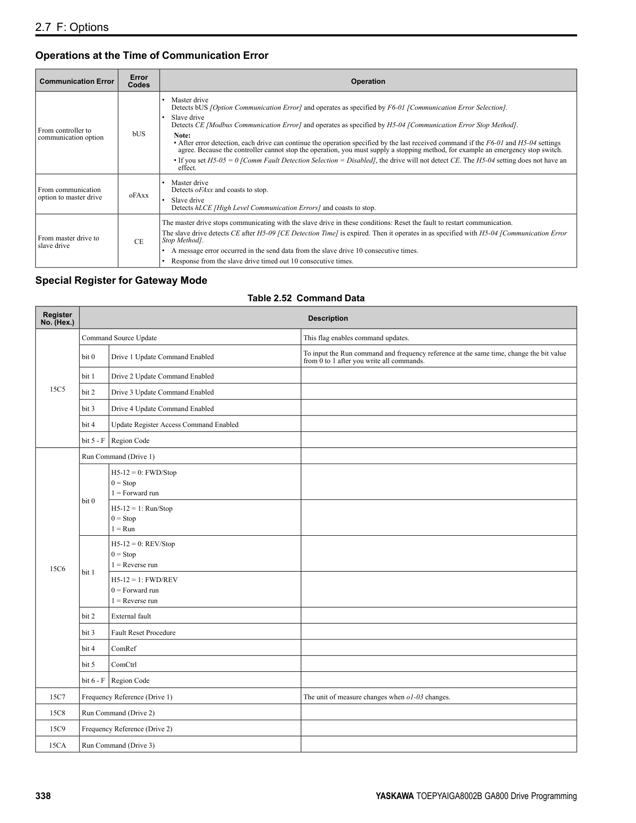
|Setting Value|Function|Description| |---|---|---| |76|Down 2 Command|Sets the function to decrease the frequency reference bias value to decelerate the motor when the terminal is activated. Set this function and H1-xx = 75 [Up 2 Command] at the same time.
V/f CL-V/f OLV CLV AOLV OLV/PM AOLV/PM CLV/PM EZOLV
|
When you activate the terminal set for Up2 Command, the bias will increase. When you activate the terminal set for Down 2 Command, the bias will decrease. When you activate or deactivate the two commands, the drive will hold the frequency reference.
Note:
######## ■ 77: ASR Gain (C5-03) Select
|Setting Value|Function|Description| |---|---|---| |77|ASR Gain (C5-03) Select|Sets the function to switch the ASR proportional gain set in C5-01 [ASR Proportional Gain 1] and C5-03 [ASR Proportional Gain 2].
V/f CL-V/f OLV CLV AOLV OLV/PM AOLV/PM CLV/PM EZOLV
|
ON : C5-03 Switches the proportional gain to C5-03 [ASR Proportional Gain 2]. OFF : C5-01 Switches the proportional gain to C5-01 [ASR Proportional Gain 1].
Note: Refer to “C5: Automatic Speed Regulator (ASR)” for more information.
######## ■ 78: Analog TorqueRef Polarity Invert
|Setting Value|Function|Description| |---|---|---| |78|Analog TorqueRef Polarity Invert|Sets the rotation direction of the external torque reference.
V/f CL-V/f OLV CLV AOLV OLV/PM AOLV/PM CLV/PM EZOLV
|
ON : External torque reference reverse direction OFF : External torque reference forward direction
######## ■ 7A: KEB Ride-Thru 2 Activate (N.C.)
|Setting Value|Function|Description| |---|---|---| |7A|KEB Ride-Thru 2 Activate (N.C.)|Sets operation of the KEB2 function through the KEB Ride-Thru 2 (N.C.).
V/f CL-V/f OLV CLV AOLV OLV/PM AOLV/PM CLV/PM EZOLV
|
ON : Normal operation OFF : Deceleration during momentary power loss When KEB Ride-Thru 2 is input, the drive will use Single Drive KEB Ride-Thru 2 for KEB operation. The L2-29 [KEB Method Selection] setting will not have an effect.
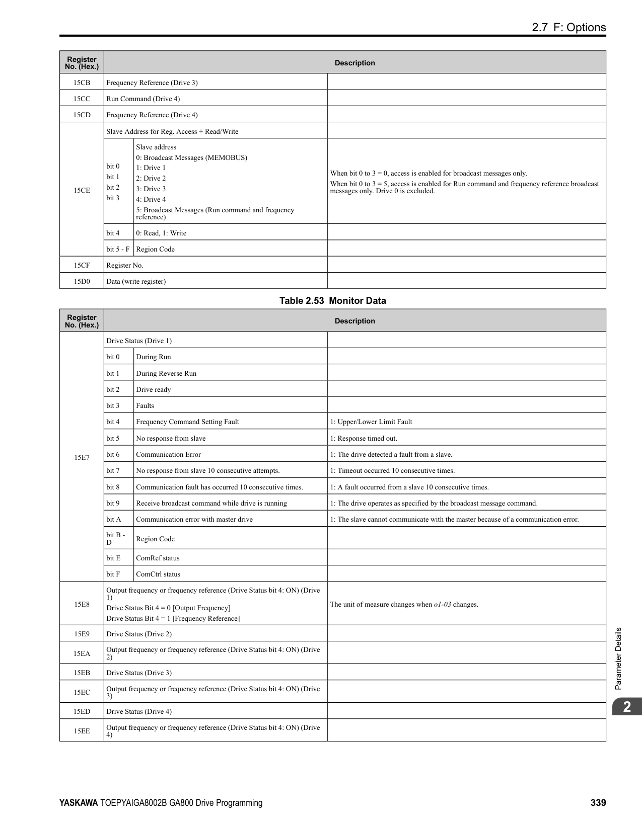
Note:
######## ■ 7B: KEB Ride-Thru 2 Activate (N.O.)
|Setting Value|Function|Description| |---|---|---| |7B|KEB Ride-Thru 2 Activate (N.O.)|Sets operation of the KEB2 function through the KEB Ride-Thru 2 (N.O.).
V/f CL-V/f OLV CLV AOLV OLV/PM AOLV/PM CLV/PM EZOLV
|
ON : Deceleration during momentary power loss OFF : Normal operation When KEB Ride-Thru 2 is input, the drive will use Single Drive KEB Ride-Thru 2 for KEB operation. The L2-29 [KEB Method Selection] setting will not have an effect.
Note:
ParameterDetails
######## 2
######## ■ 7C: Short Circuit Braking (N.O.)
|Setting Value|Function|Description| |---|---|---| |7C|Short Circuit Braking (N.O.)|Sets operation of Short Circuit Braking (N.O.).
V/f CL-V/f OLV CLV AOLV OLV/PM AOLV/PM CLV/PM EZOLV
|
The drive will short circuit the three phases of a PM motor to cause braking torque in the spinning motor.
Note:
######## ■ 7D: Short Circuit Braking (N.C.)
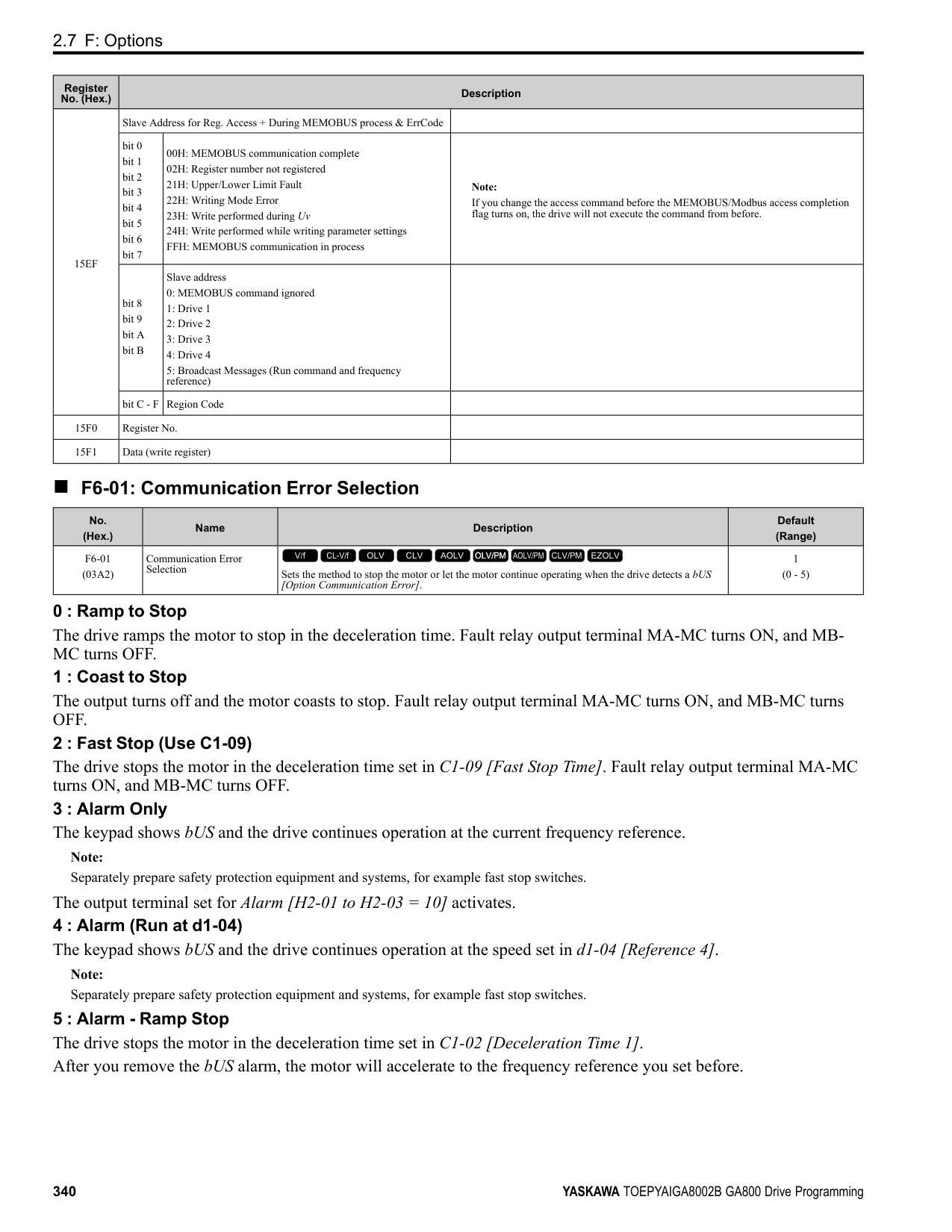
|Setting Value|Function|Description| |---|---|---| |7D|Short Circuit Braking (N.C.)|Sets operation of Short Circuit Braking (N.C.).
V/f CL-V/f OLV CLV AOLV OLV/PM AOLV/PM CLV/PM EZOLV
|
The drive will short circuit the three phases of a PM motor to cause braking torque in the spinning motor.
Note:
######## ■ 7E: Reverse Rotation Identifier
|Setting Value|Function|Description| |---|---|---| |7E|Reverse Rotation Identifier|Sets the rotation direction of the motor when in Simple Closed Loop V/f Control method and F1-21, F1-37 = 0 [Encoder Option Function Selection = A pulse detection], or when in Closed Loop V/f Control method.
V/f CL-V/f OLV CLV AOLV OLV/PM AOLV/PM CLV/PM EZOLV
|
ON : Reverse run The drive knows that the motor is rotating in reverse . OFF : Forward run The drive knows that the motor is rotating forward .
######## ■ 90 to 97: DriveWorksEZ Digital Inputs 1 to 8
|Setting Value|Function|Description| |---|---|---| |90 - 97|DWEZ Digital Inputs 1 to 8|Sets digital inputs used with DriveWorksEZ. Refer to the DriveWorksEZ online manual for more information.
V/f CL-V/f OLV CLV AOLV OLV/PM AOLV/PM CLV/PM EZOLV
|
Note: You cannot set values 90 to 97 for inverse output.
######## ■ 9F: DWEZ Disable
|Setting Value|Function|Description| |---|---|---| |9F|DWEZ Disable|Sets operation of the DriveWorksEZ program saved in the drive.
V/f CL-V/f OLV CLV AOLV OLV/PM AOLV/PM CLV/PM EZOLV
|
Note: Set A1-07 = 2 [DriveWorksEZ Function Selection = Digital input] to use this function.
############## ON : Disabled OFF : Enabled
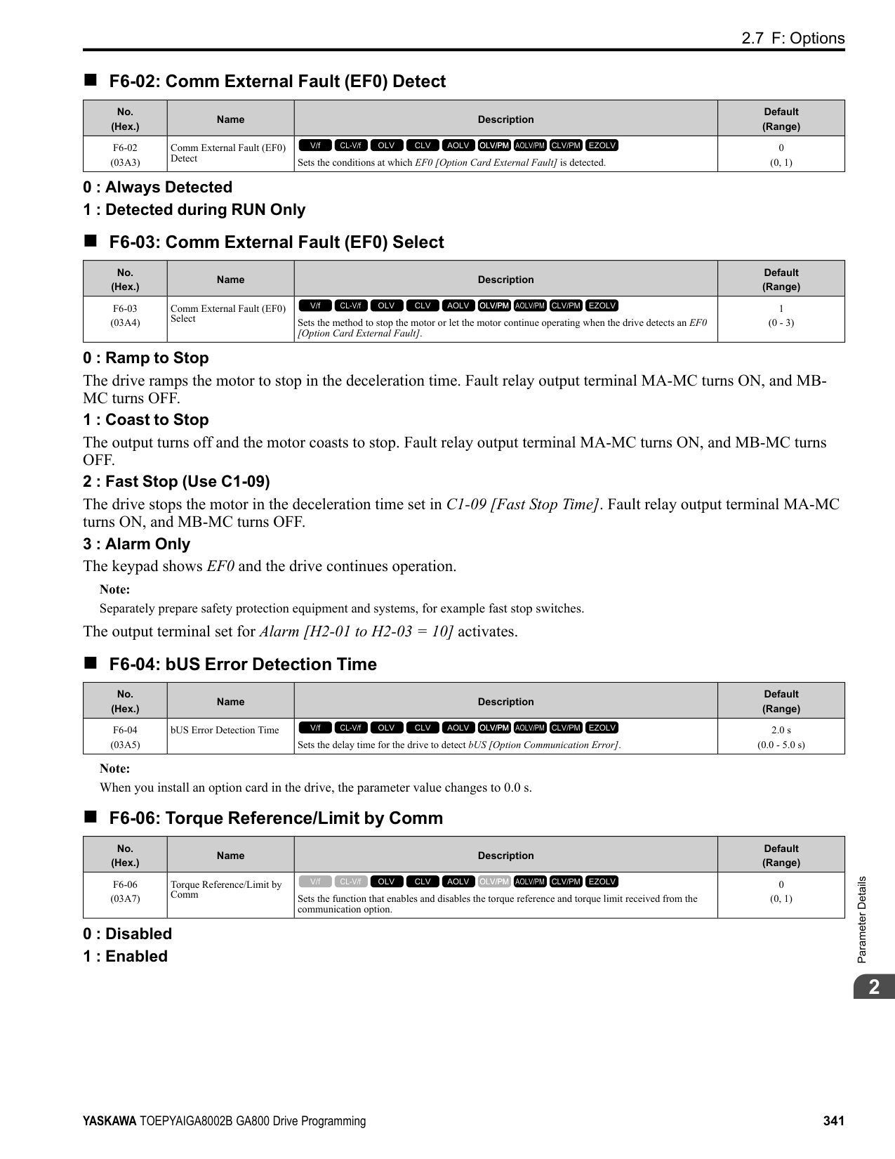
######## ■ 101 to 19F: Inverse Input of 1 to 9F
|Setting Value|Function|Description| |---|---|---| |101 to 19F|Inverse Inputs of 1 to 9F|Sets the function of the selected MFDI to operate inversely. To select the function, enter “1xx”, where the “xx” is the function setting value.|
For example, to use the inverse input of E [ASR Integral Reset], set H1-xx = 10E. Note: You cannot use inverse input for all functions. Refer to Table 2.55 for more information.
◆ H2: Digital Outputs H2 parameters set the MFDO terminal functions.
■ H2-01 to H2-03 Terminal M1-M2, M3-M4, M5-M6 Function Selection The drive has three MFDO terminals. Table 2.60 shows the default function settings for the terminals.
Table 2.60 MFDO Terminals Default Function Settings
|No.|Name|Default|Function| |---|---|---|---| |H2-01|Term M1-M2 Function Selection|0|During Run| |H2-02|Term M3-M4 Function Selection|1|Zero Speed| |H2-03|Term M5-M6 Function Selection|2|Speed Agree 1|
Refer to Table 2.61 to set H2-xx [MFDO Function Selection].
Table 2.61 MFDO Setting Value
|Setting Value|Function|Reference| |---|---|---| |0|During Run|390| |1|Zero Speed|390| |2|Speed Agree 1|391| |3|User-Set Speed Agree 1|392| |4|Frequency Detection 1|392| |5|Frequency Detection 2|393| |6|Drive ready|393| |7|DC Bus Undervoltage|393| |8|During Baseblock (N.O.)|394| |9|Frequency Reference from Keypad|394| |A|Run Command from Keypad|394| |B|Torque Detection 1 (N.O.)|394| |C|Frequency Reference Loss|394| |D|Braking Resistor Fault|394|
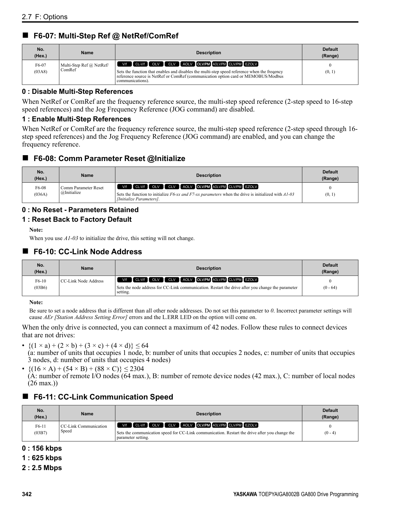
|E|Fault|395| |F *1|Not Used|395| |10|Alarm|395| |11|Fault Reset Command Active|395| |12|Timer Output|395| |13|Speed Agree 2|395| |14|User-Set Speed Agree 2|396| |15|Frequency Detection 3|396| |16|Frequency Detection 4|397|
|Setting Value|Function|Reference| |---|---|---| |17|Torque Detection 1 (N.C.)|397| |18|Torque Detection 2 (N.O.)|398| |19|Torque Detection 2 (N.C.)|398| |1A|During reverse|398| |1B|During Baseblock (N.C.)|398| |1C|Motor 2 Selected|399| |1D|During Regeneration|399| |1E|Executing Auto-Restart|399| |1F|Motor Overload Alarm (oL1)|399| |20|Drive Overheat Pre-Alarm (oH)|399| |21|Safe Torque OFF|399| |22|Mechanical Weakening Detection|400| |2F|Maintenance Notification|400| |30|During Torque Limit|400| |31|During Speed Limit|400| |32|In Speed Limit During Trq Ctrl|400| |33|Zero Servo Complete|401| |37|During Frequency Output|401| |38|Drive Enabled|401| |39|Watt Hour Pulse Output|401| |3C|LOCAL Control Selected|401| |3D|During Speed Search|402| |3E|PID Feedback Low|402|
ParameterDetails
######## 2
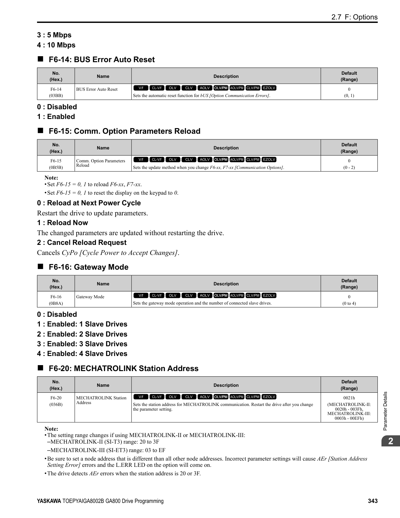
|Setting Value|Function|Reference| |---|---|---| |3F|PID Feedback High|402| |4A|During KEB Ride-Thru|402| |4B|During Short Circuit Braking|402| |4C|During Fast Stop|402| |4D|oH Pre-Alarm Reduction Limit|403| |4E *2|Braking Transistor Fault (rr)|403| |4F *2|Braking Resistor Overheat (rH)|403| |60|Internal Cooling Fan Failure|403| |61|Pole Position Detection Complete|403| |62|Modbus Reg 1 Status Satisfied|403| |63|Modbus Reg 2 Status Satisfied|403|
|Setting Value|Function|Reference| |---|---|---| |65|Standby Output|403| |66|Comparator1|404| |67|Comparator2|404| |69|External Power 24V Supply|405| |6A|Data Logger Error|405| |90 - 93|DWEZ Digital Outputs 1 to 4|405| |A0 to A7|DWEZ Extended Digital Outputs 1 to 8|405| |100 to 1A7|Inverse Outputs of 0 to A7 Sets an inverse output of the function for the MFDO. Put a 1 at the front of the function setting to set inverse output. For example, set 138 for inverse output of 38 [Drive Enabled].|405|
■ Extend MFDO1 to MFDO3 Function Selection You can set MFDO functions to bit 0 to bit 2 [MEMOBUS MFDO1 to 3] of MEMOBUS register 15E0 (Hex.). Use
Figure 2.86 Functional Block Diagram of MEMOBUS Multi-function Output Table 2.62 MEMOBUS MFDO Registers
|Register No. (Hex.)|Name|Name| |---|---|---| |15E0|bit0|MEMOBUS MFDO 1| |15E0|bit1|MEMOBUS MFDO 2|
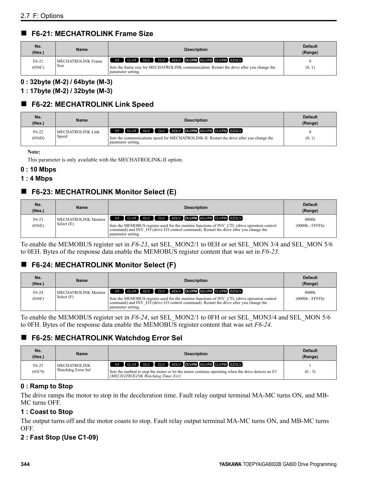
|15E0|bit2|MEMOBUS MFDO 3|
Note:
■ Output of Logical Operation Results of MFDO This enables the logical operation results of two MFDOs to be output to one MFDO terminal. Use H2-60, H2-63, and H2-66 [Term M1-M2 Secondary Function to Term M5-M6 Secondary Function] to set the function of the output signal for which logical operations are performed. Use H2-61, H2-64, H2-67 [Term M1-M2 Logical Operation to Term M5-M6 Logical Operation] to set the logical operation.
Figure 2.87 Functional Block Diagram of Logical Operation Output for MFDO 1
Table 2.63 MFDO Logical Operation Table
|Logical Operation Selection|Logical Operation Expression|Logical Operation Notation| |---|---|---| |H2-61, H2-64, H2-67|Logical Operation Expression|Logical Operation Notation| |0|A=B=1| | |1|A=1 or B=1| | |2|A=0 or B=0| | |3|A=B=0| | |4|A=B|A=B| |5|A != B| | |6|AND(A, )| | |7|OR(A, )| | |8|-|On|
Note:
######## ◆ H2 MFDO Parameters
######## ■ H2-01: Term M1-M2 Function Selection
|No. (Hex.)|Name|Description|Default (Range)| |---|---|---|---| |H2-01 (040B)|Term M1-M2 Function Selection|Sets the function for MFDO terminal M1-M2.
V/f CL-V/f OLV CLV AOLV OLV/PM AOLV/PM CLV/PM EZOLV
|0 (0 - 1FF)|
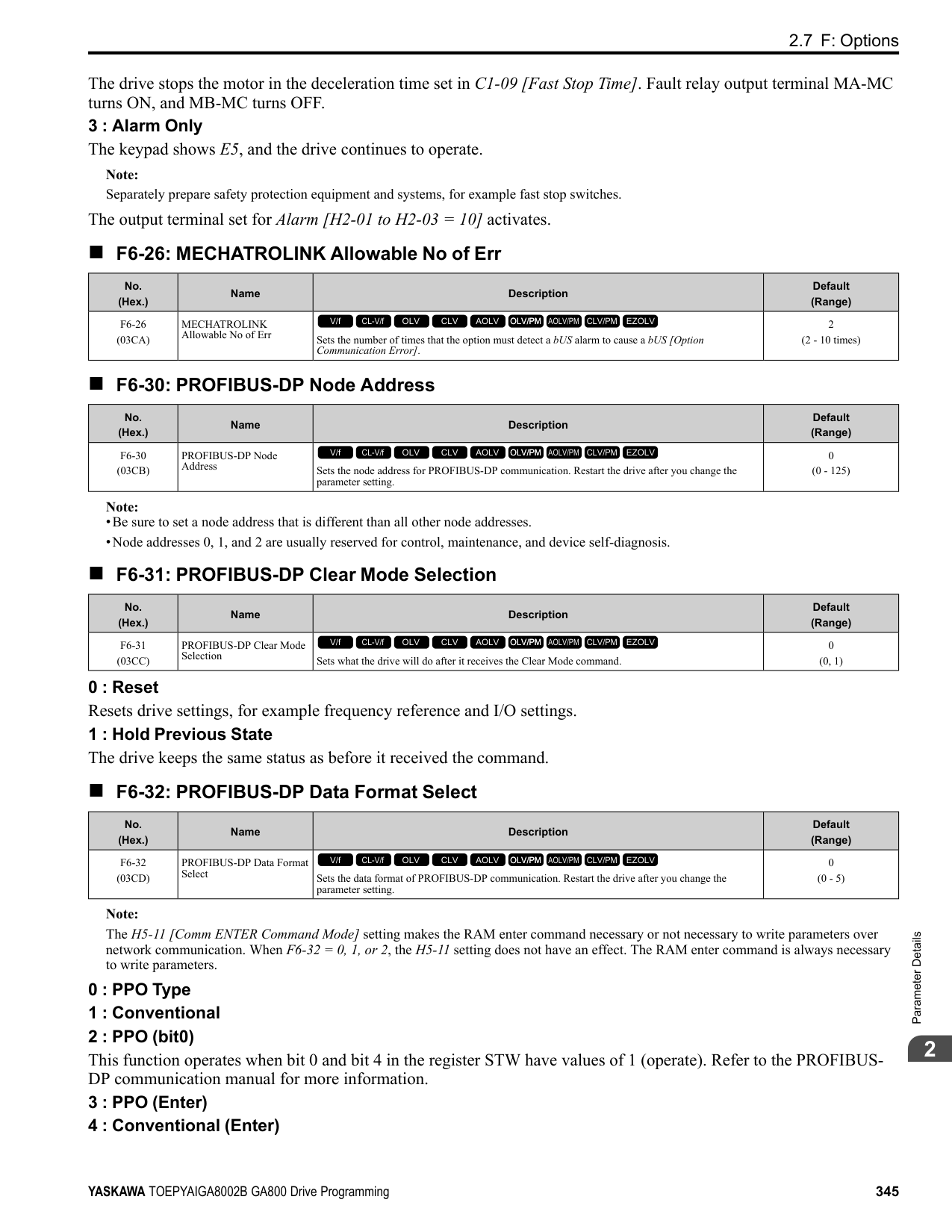
Note: Set this parameter to F when the terminal is not being used or to use the terminal in through mode.
######## ■ H2-02: Term M3-M4 Function Selection
|No. (Hex.)|Name|Description|Default (Range)| |---|---|---|---| |H2-02 (040C)|Term M3-M4 Function Selection|Sets the function for MFDO terminal M3-M4.
V/f CL-V/f OLV CLV AOLV OLV/PM AOLV/PM CLV/PM EZOLV
|1 (0 - 1FF)|
Note: Set this parameter to F when not using the terminal or to use the terminal in through mode.
######## ■ H2-03: Term M5-M6 Function Selection
|No. (Hex.)|Name|Description|Default (Range)| |---|---|---|---| |H2-03 (040D)|Term M5-M6 Function Selection|Sets the function for MFDO terminal M5-M6.
V/f CL-V/f OLV CLV AOLV OLV/PM AOLV/PM CLV/PM EZOLV
|2 (0 - 1FF)|
Note: Set this parameter to F when not using the terminal or to use the terminal in through mode.
ParameterDetails
######## 2
######## ■ H2-06: Watt Hour Output Unit Selection
|No. (Hex.)|Name|Description|Default (Range)| |---|---|---|---| |H2-06 (0437)|Watt Hour Output Unit Selection|Sets the unit for the output signal when H2-01 to H2-03 = 39 [MFDO Function Selection = Watt Hour Pulse Output].
V/f CL-V/f OLV CLV AOLV OLV/PM AOLV/PM CLV/PM EZOLV
|0 (0 - 4)|
This output is input to the Watt hour meter or PLC through a 200 ms pulse signal. This parameter sets the kWh unit for each pulse output.
Figure 2.88 Example MFDO when Configured for Watt Hours Note:
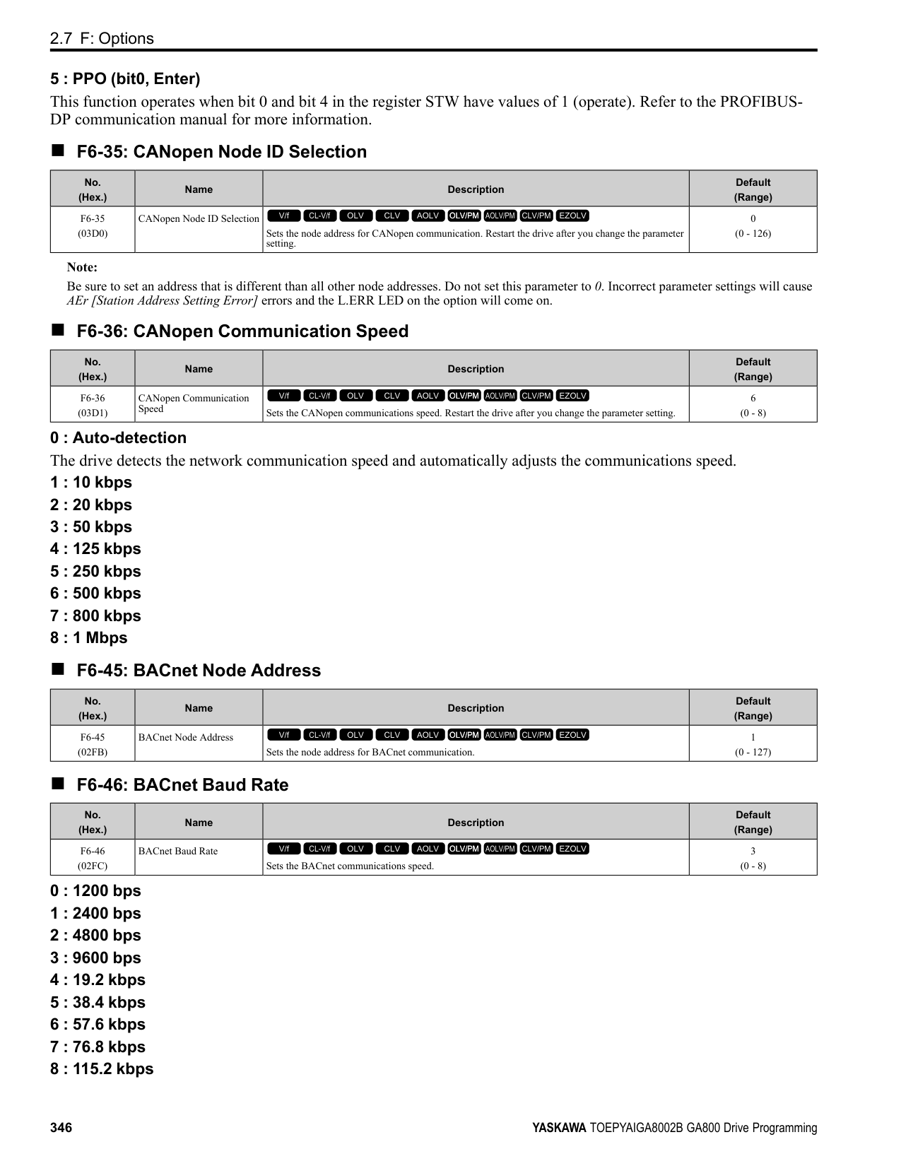
######## ■ H2-07: Modbus Register 1 Address Select
|No. (Hex.)|Name|Description|Default (Range)| |---|---|---|---| |H2-07 (0B3A)|Modbus Register 1 Address Select|Sets the address of the MEMOBUS/Modbus register output to the MFDO terminal.
V/f CL-V/f OLV CLV AOLV OLV/PM AOLV/PM CLV/PM EZOLV
|0001 (0001 - 1FFF)|
Sets the address of the register that is output to Modbus Reg 1 Status Satisfied [H2-01 to H2-03 = 62] and uses the bit in H2-08 [Modbus Register 1 Bit Select].
######## ■ H2-08: Modbus Register 1 Bit Select
|No. (Hex.)|Name|Description|Default (Range)| |---|---|---|---| |H2-08 (0B3B)|Modbus Register 1 Bit Select|Sets the bit of the MEMOBUS/Modbus register output to the MFDO terminal.
V/f CL-V/f OLV CLV AOLV OLV/PM AOLV/PM CLV/PM EZOLV
|0000 (0000 - FFFF)|
Sets the bit of the register that is output to Modbus Reg 1 Status Satisfied [H2-01 to H2-03 = 62] and uses the address in H2-07 [Modbus Register 1 Address Select].
######## ■ H2-09: Modbus Register 2 Address Select
|No. (Hex.)|Name|Description|Default (Range)| |---|---|---|---| |H2-09 (0B3C)|Modbus Register 2 Address Select|Sets the address of the MEMOBUS/Modbus register output to the MFDO terminal.
V/f CL-V/f OLV CLV AOLV OLV/PM AOLV/PM CLV/PM EZOLV
|0001 (0001 - 1FFF)|
Sets H2-09 with the address of the register that is output to Modbus Reg 2 Status Satisfied [H2-01 to H2-03 = 63] and uses the bit in H2-10 [Modbus Register 2 Bit Select].
######## ■ H2-10: Modbus Register 2 Bit Select
|No. (Hex.)|Name|Description|Default (Range)| |---|---|---|---| |H2-10 (0B3D)|Modbus Register 2 Bit Select|Sets the bit of the MEMOBUS/Modbus register output to the MFDO terminal.
V/f CL-V/f OLV CLV AOLV OLV/PM AOLV/PM CLV/PM EZOLV
|0000 (0000 - FFFF)|
Sets the bit of the register that is output to Modbus Reg 2 Status Satisfied [H2-01 to H2-03 = 63] and uses the address in H2-09.
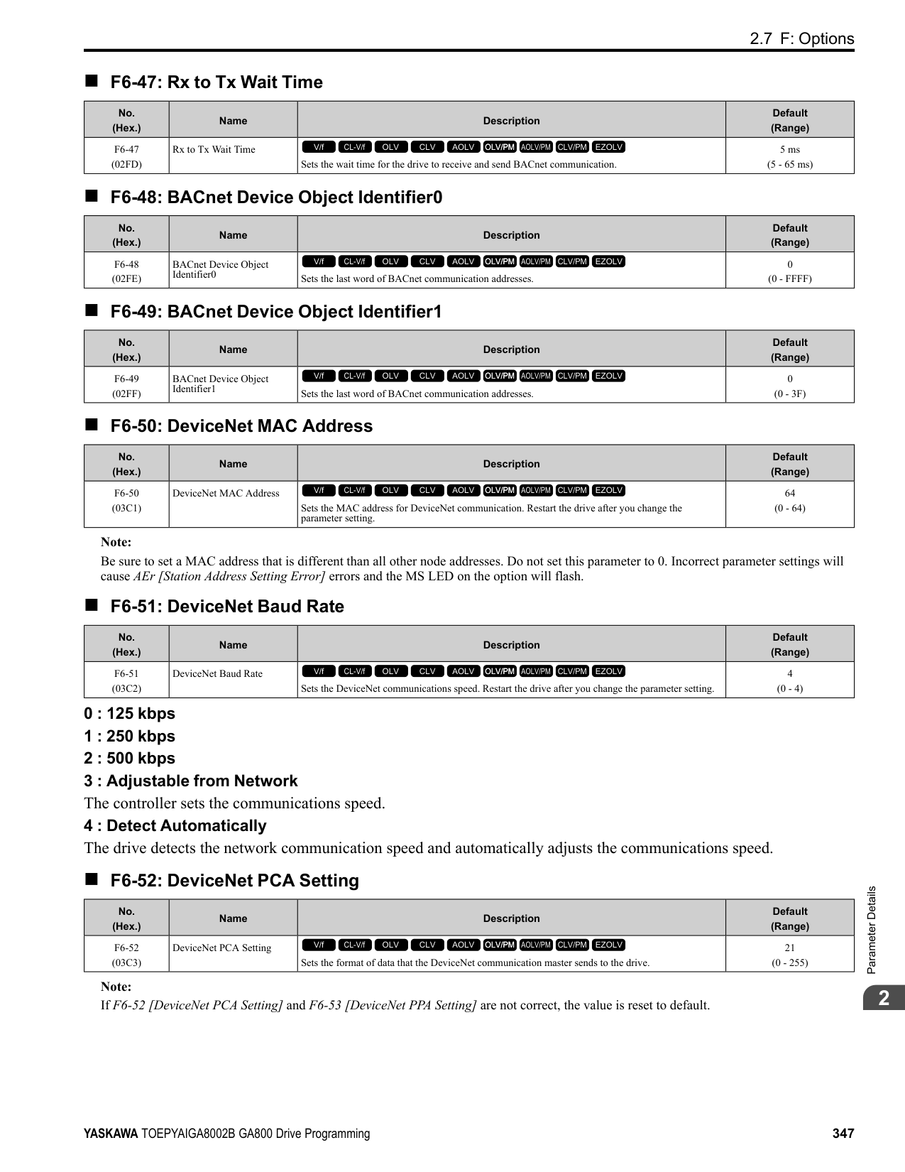
######## ■ H2-20: Comparator 1 Monitor Selection
|No. (Hex.)|Name|Description|Default (Range)| |---|---|---|---| |H2-20 (1540)|Comparator 1 Monitor Selection|Sets the monitor number for comparator 1. Set the x-xx part of the Ux-xx [Monitor]. For example, set H2-20 = 102 to monitor U1-02 [Output Frequency].
V/f CL-V/f OLV CLV AOLV OLV/PM AOLV/PM CLV/PM EZOLV
|102 (000 - 999)|
Note:
######## ■ H2-21: Comparator 1 Lower Limit
|No. (Hex.)|Name|Description|Default (Range)| |---|---|---|---| |H2-21 (1541)|Comparator 1 Lower Limit|Sets the lower limit detection level for comparator 1 when the full scale analog output for the monitor selected in H2-20 [Comparator 1 Monitor Selection] is the 100% value.
V/f CL-V/f OLV CLV AOLV OLV/PM AOLV/PM CLV/PM EZOLV
|0.0% (0.0 - 300.0%)|
Note: For information on the comparator function, refer to 66: Comparator1 on page 404 and 67: Comparator2 on page 404.
######## ■ H2-22: Comparator 1 Upper Limit
|No. (Hex.)|Name|Description|Default (Range)| |---|---|---|---| |H2-22 (1542)|Comparator 1 Upper Limit|Sets the upper limit detection level for comparator 1 when the full scale analog output for the monitor selected in H2-20 [Comparator 1 Monitor Selection] is the 100% value.
V/f CL-V/f OLV CLV AOLV OLV/PM AOLV/PM CLV/PM EZOLV
|0.0% (0.0 - 300.0%)|
Note: For information on the comparator function, refer to 66: Comparator1 on page 404 and 67: Comparator2 on page 404.
######## ■ H2-23: Comparator 1 Hysteresis
|No. (Hex.)|Name|Description|Default (Range)| |---|---|---|---| |H2-23 (1543)|Comparator 1 Hysteresis|Sets the hysteresis level for comparator 1 as a percentage of the full scale analog output for the monitor selected in H2-20 [Comparator 1 Monitor Selection].
V/f CL-V/f OLV CLV AOLV OLV/PM AOLV/PM CLV/PM EZOLV
|0.0% (0.0 - 10.0%)|
Note: For information on the comparator function, refer to 66: Comparator1 on page 404 and 67: Comparator2 on page 404.
######## ■ H2-24: Comparator 1 On-Delay Time
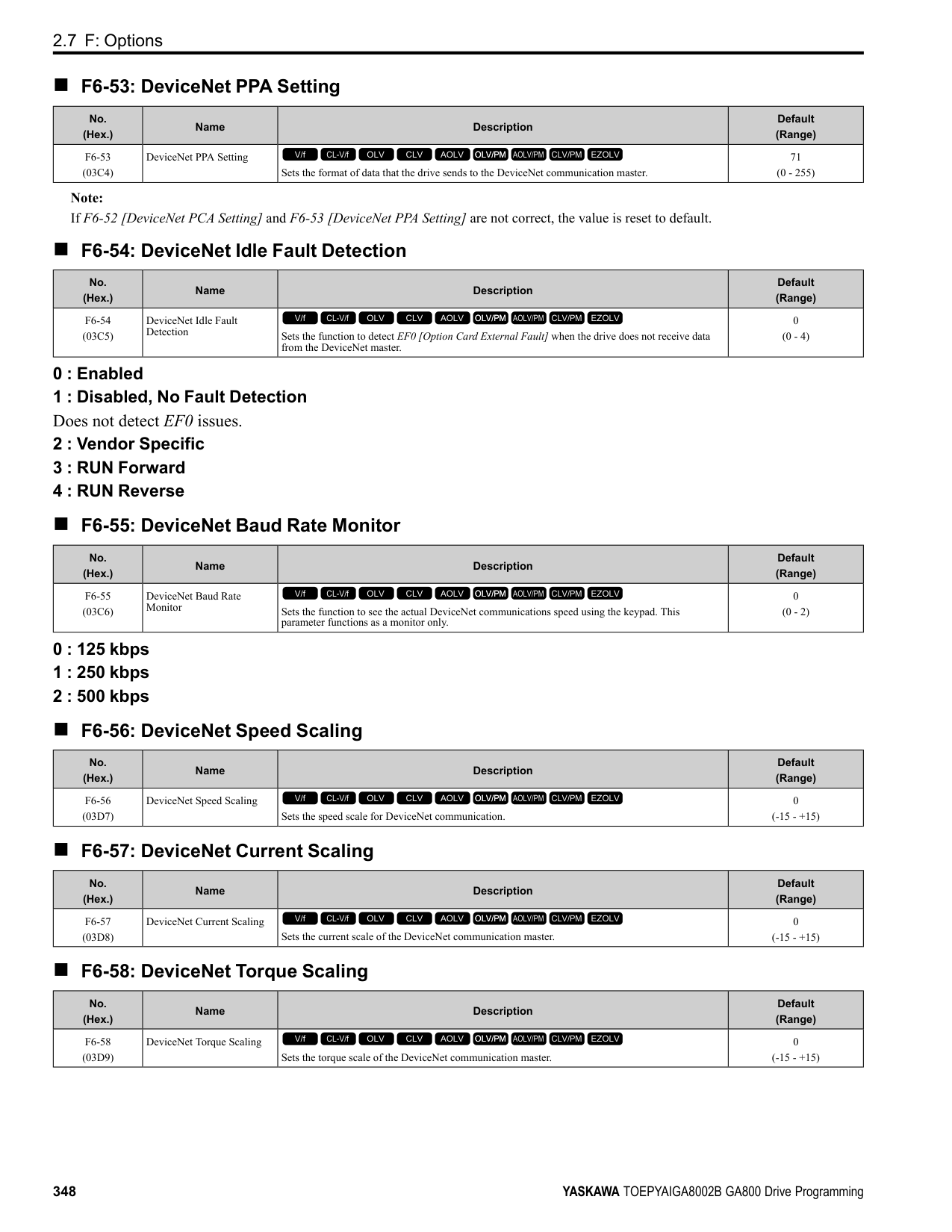
|No. (Hex.)|Name|Description|Default (Range)| |---|---|---|---| |H2-24 (1544)|Comparator 1 On-Delay Time|Sets the on-delay time for comparator 1.
V/f CL-V/f OLV CLV AOLV OLV/PM AOLV/PM CLV/PM EZOLV
|0.0 s (0.0 - 600.0 s)|
Note: For information on the comparator function, refer to 66: Comparator1 on page 404 and 67: Comparator2 on page 404.
ParameterDetails
######## 2
######## ■ H2-25: Comparator 1 Off-Delay Time
|No. (Hex.)|Name|Description|Default (Range)| |---|---|---|---| |H2-25 (1545)|Comparator 1 Off-Delay Time|Sets the off-delay time for comparator 1.
V/f CL-V/f OLV CLV AOLV OLV/PM AOLV/PM CLV/PM EZOLV
|0.0 s (0.0 - 600.0 s)|
Note: For information on the comparator function, refer to 66: Comparator1 on page 404 and 67: Comparator2 on page 404.
######## ■ H2-26: Comparator 2 Monitor Selection
|No. (Hex.)|Name|Description|Default (Range)| |---|---|---|---| |H2-26 (1546)|Comparator 2 Monitor Selection|Sets the monitor number for comparator 2. Set the x-xx part of the Ux-xx [Monitor]. For example, set H2-26 = 103 to monitor U1-03 [Output Current].
V/f CL-V/f OLV CLV AOLV OLV/PM AOLV/PM CLV/PM EZOLV
|103 (000 - 999)|
Note:
######## ■ H2-27: Comparator 2 Lower Limit
|No. (Hex.)|Name|Description|Default (Range)| |---|---|---|---| |H2-27 (1547)|Comparator 2 Lower Limit|Sets the lower limit detection level for comparator 2 as a percentage of the full scale analog output for the monitor selected in H2-26 [Comparator 2 Monitor Selection].
V/f CL-V/f OLV CLV AOLV OLV/PM AOLV/PM CLV/PM EZOLV
|0.0% (0.0 - 300.0%)|
Note: For information on the comparator function, refer to 66: Comparator1 on page 404 and 67: Comparator2 on page 404.
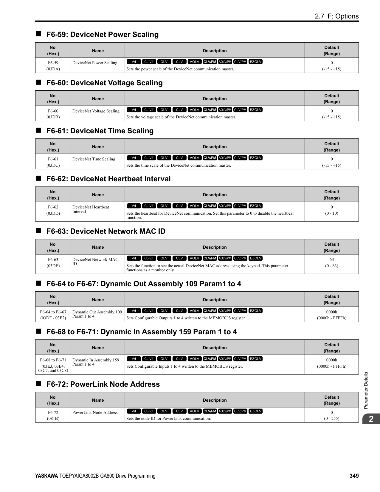
######## ■ H2-28: Comparator 2 Upper Limit
|No. (Hex.)|Name|Description|Default (Range)| |---|---|---|---| |H2-28 (1548)|Comparator 2 Upper Limit|Sets the upper limit detection level for comparator 2 as a percentage of the full scale analog output for the monitor selected in H2-26 [Comparator 2 Monitor Selection].
V/f CL-V/f OLV CLV AOLV OLV/PM AOLV/PM CLV/PM EZOLV
|0.0% (0.0 - 300.0%)|
Note: For information on the comparator function, refer to 66: Comparator1 on page 404 and 67: Comparator2 on page 404.
######## ■ H2-29: Comparator 2 Hysteresis
|No. (Hex.)|Name|Description|Default (Range)| |---|---|---|---| |H2-29 (1549)|Comparator 2 Hysteresis|Sets the hysteresis level for comparator 2 as a percentage of the full scale analog output for the monitor selected in H2-26 [Comparator 2 Monitor Selection].
V/f CL-V/f OLV CLV AOLV OLV/PM AOLV/PM CLV/PM EZOLV
|0.0% (0.0 - 10.0%)|
Note: For information on the comparator function, refer to 66: Comparator1 on page 404 and 67: Comparator2 on page 404.
######## ■ H2-30: Comparator 2 On-Delay Time
|No. (Hex.)|Name|Description|Default (Range)| |---|---|---|---| |H2-30 (154A)|Comparator 2 On-Delay Time|Sets the on-delay time for comparator 2.
V/f CL-V/f OLV CLV AOLV OLV/PM AOLV/PM CLV/PM EZOLV
|0.0 s (0.0 - 600.0 s)|
Note: For information on the comparator function, refer to 66: Comparator1 on page 404 and 67: Comparator2 on page 404.
######## ■ H2-31: Comparator 2 Off-Delay Time
|No. (Hex.)|Name|Description|Default (Range)| |---|---|---|---| |H2-31 (154B)|Comparator 2 Off-Delay Time|Sets the off-delay time for comparator 2.
V/f CL-V/f OLV CLV AOLV OLV/PM AOLV/PM CLV/PM EZOLV
|0.0 s (0.0 - 600.0 s)|
Note: For information on the comparator function, refer to 66: Comparator1 on page 404 and 67: Comparator2 on page 404.
######## ■ H2-32: Comparator 1 Filter Time
|No. (Hex.)|Name|Description|Default (Range)| |---|---|---|---| |H2-32 (159A)|Comparator 1 Filter Time|Sets the time constant that is applied to the primary delay filter used for the analog output of the monitor selected with H2-20 [Comparator 1 Monitor Selection].
V/f CL-V/f OLV CLV AOLV OLV/PM AOLV/PM CLV/PM EZOLV
|0.0s (0.0 - 10.0 s)|
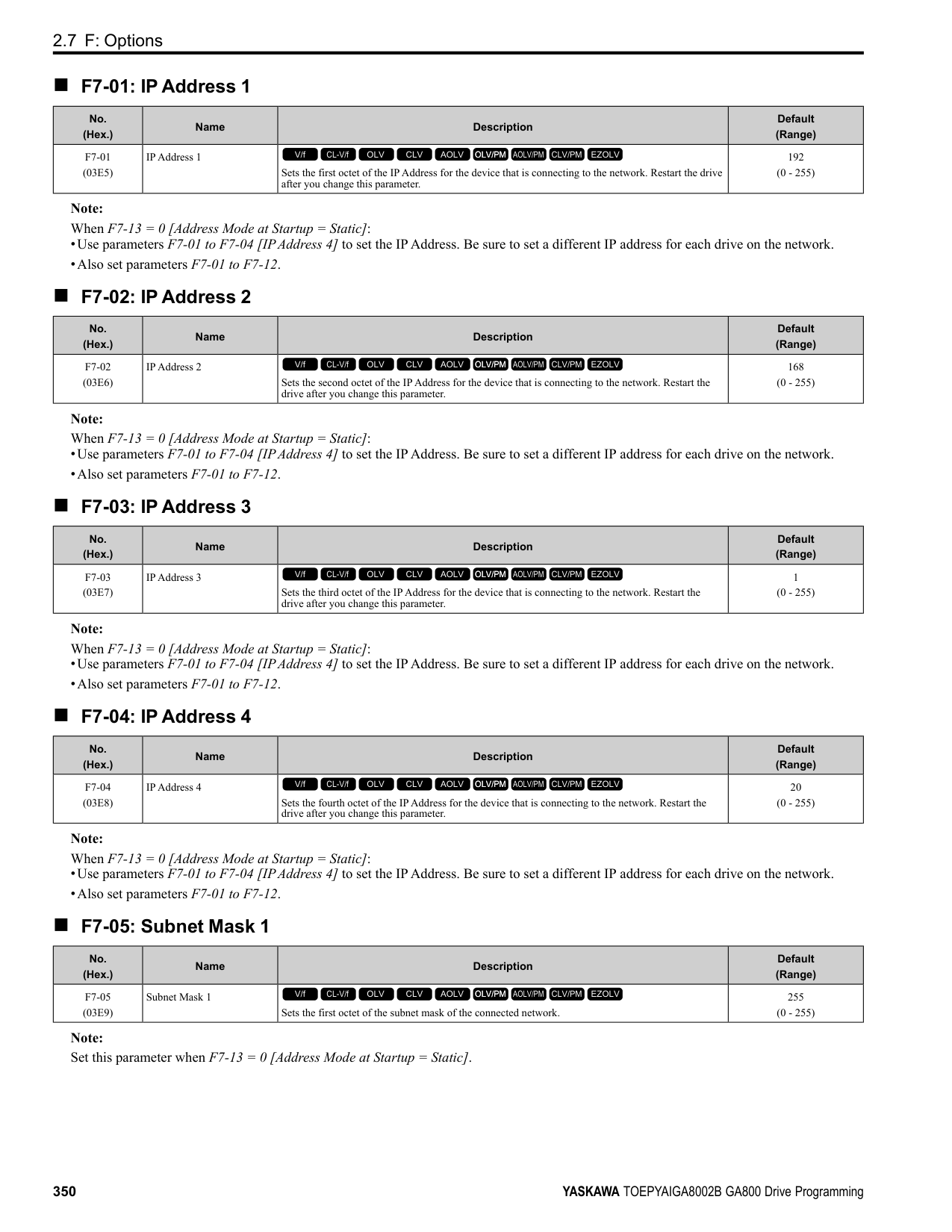
Note: For information on the comparator function, refer to 66: Comparator1 on page 404 and 67: Comparator2 on page 404.
######## ■ H2-33: Comparator1 Protection Selection
|No. (Hex.)|Name|Description|Default (Range)| |---|---|---|---| |H2-33 (159B)|Comparator1 Protection Selection|Sets drive operation when it detects CP1 [Comparator1 Limit Fault].
V/f CL-V/f OLV CLV AOLV OLV/PM AOLV/PM CLV/PM EZOLV
|4 (0 - 4)|
The drive ramps the motor to stop in the deceleration time. Fault relay output terminal MA-MC turns ON, and MBMC turns OFF.
The output turns off and the motor coasts to stop. Fault relay output terminal MA-MC turns ON, and MB-MC turns OFF.
The drive stops the motor in the deceleration time set in C1-09 [Fast Stop Time]. Fault relay output terminal MA-MC turns ON, and MB-MC turns OFF.
Note: The output terminal set for Alarm [H2-01 to H2-03 10] activates.
|No. (Hex.)|Name|Description|Default (Range)| |---|---|---|---| |H2-34 (159C)|Comparator 2 Filter Time|Sets the time constant that is applied to the primary delay filter used for the analog output of the monitor selected with H2-26 [Comparator 2 Monitor Selection].
V/f CL-V/f OLV CLV AOLV OLV/PM AOLV/PM CLV/PM EZOLV
|0.0s (0.0 - 10.0 s)|
|No. (Hex.)|Name|Description|Default (Range)| |---|---|---|---| |H2-35 (159D)|Comparator2 Protection Selection|Sets drive operation when it detects CP2 [Comparator2 Limit Fault].
V/f CL-V/f OLV CLV AOLV OLV/PM AOLV/PM CLV/PM EZOLV
|4 (0 - 4)|
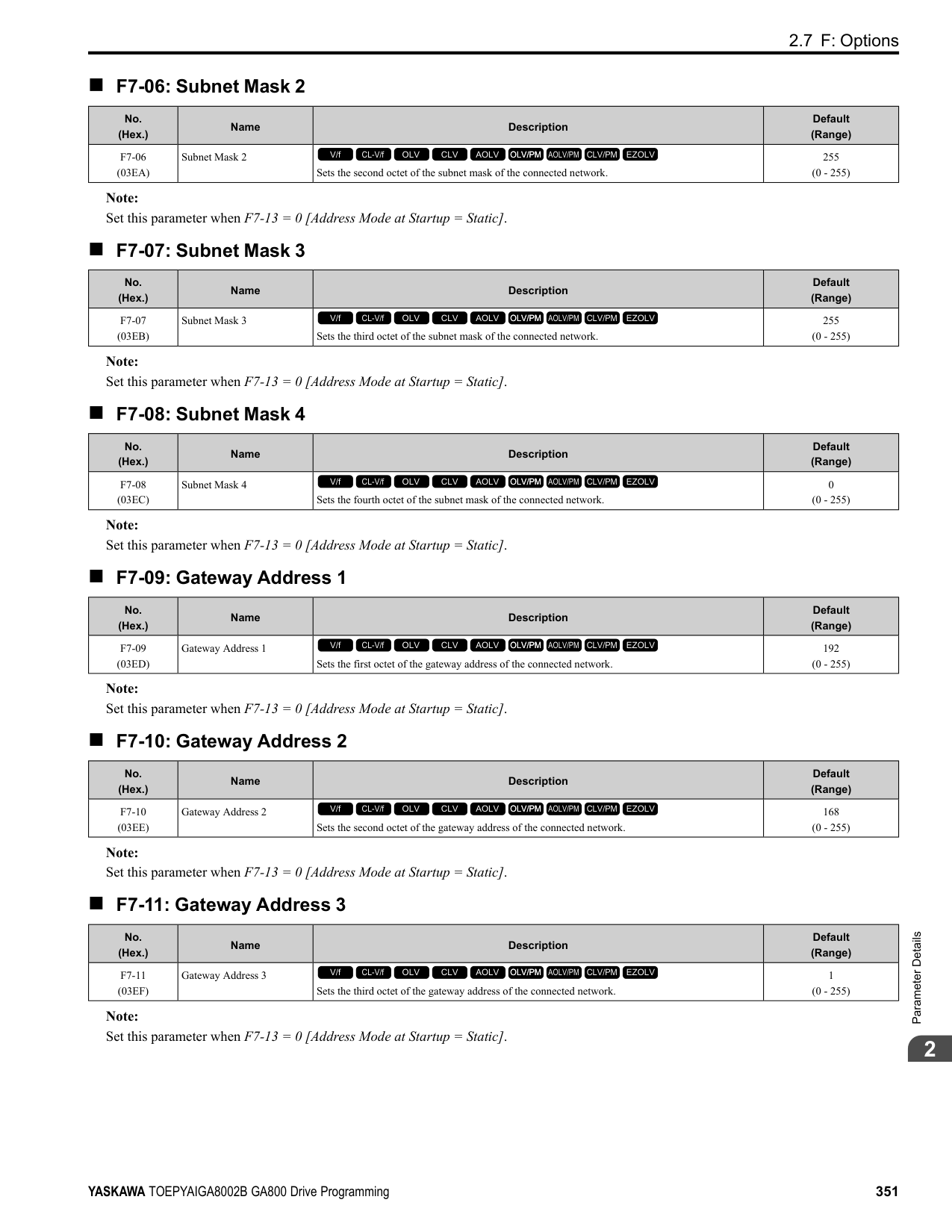
0 : Ramp to Stop
ParameterDetails
######## 2
The drive ramps the motor to stop in the deceleration time. Fault relay output terminal MA-MC turns ON, and MBMC turns OFF.
The output turns off and the motor coasts to stop. Fault relay output terminal MA-MC turns ON, and MB-MC turns OFF.
The drive stops the motor in the deceleration time set in C1-09 [Fast Stop Time]. Fault relay output terminal MA-MC turns ON, and MB-MC turns OFF.
Note: The output terminal set for Alarm [H2-01 to H2-03 = 10] activates.
Note:
Note:
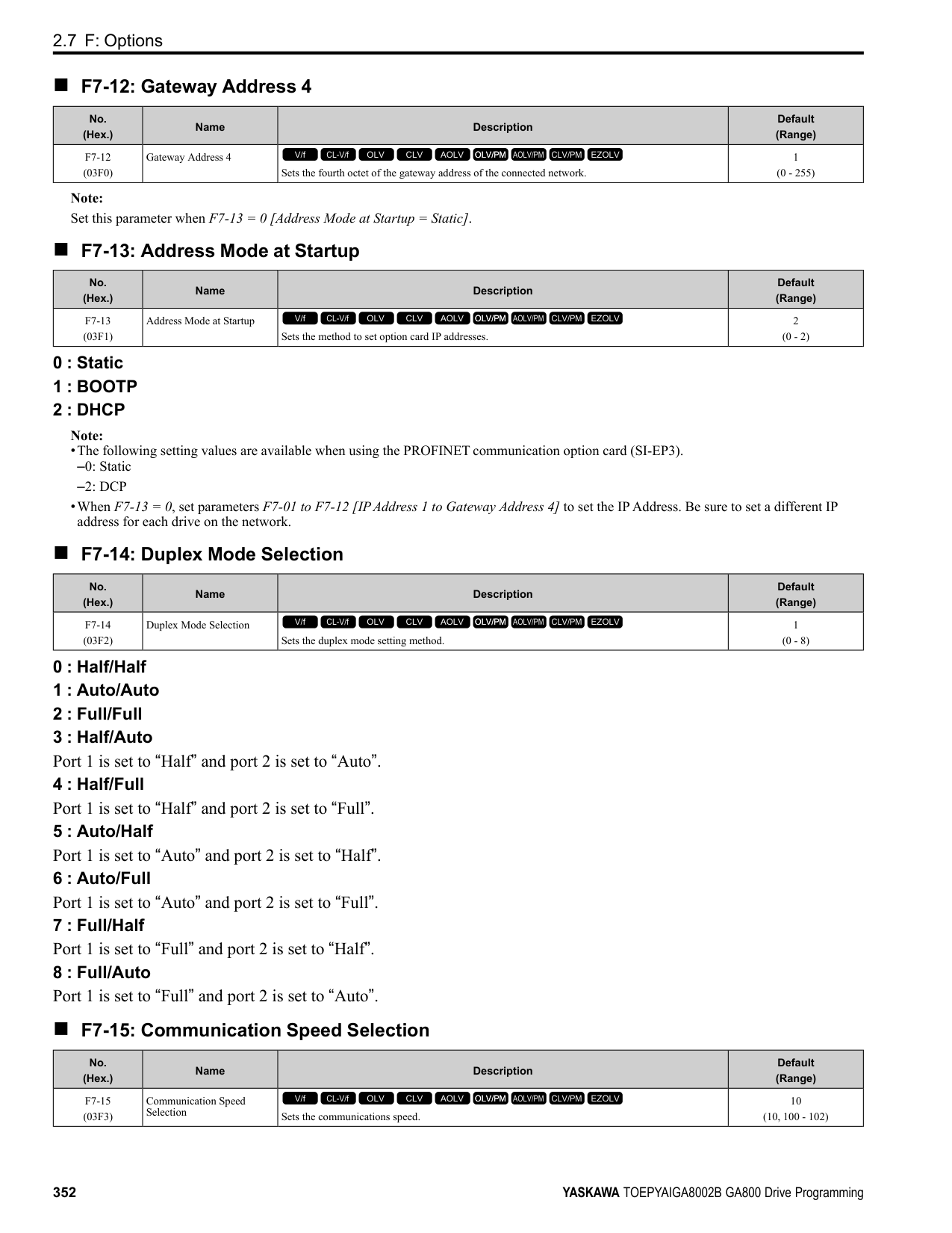
|No. (Hex.)|Name|Description|Default (Range)| |---|---|---|---| |H2-36 (159E)|Comparator 1 Ineffective Time|Sets the length of time that CP1 [Comparator1 Limit Fault] is disabled.
V/f CL-V/f OLV CLV AOLV OLV/PM AOLV/PM CLV/PM EZOLV
|0.0 s (0.0 - 1000.0 s)|
|No. (Hex.)|Name|Description|Default (Range)| |---|---|---|---| |H2-37 (159F)|Comparator 2 Ineffective Time|Sets the length of time that CP2 [Comparator2 Limit Fault] is disabled.
V/f CL-V/f OLV CLV AOLV OLV/PM AOLV/PM CLV/PM EZOLV
|0.0 s (0.0 - 1000.0 s)|
|No. (Hex.)|Name|Description|Default (Range)| |---|---|---|---| |H2-40 (0B58)|Mbus Reg 15E0h bit0 Output Func|Sets the MFDO for bit 0 of MEMOBUS register 15E0 (Hex.).
V/f CL-V/f OLV CLV AOLV OLV/PM AOLV/PM CLV/PM EZOLV
|F (0 - 1FF)|
|No. (Hex.)|Name|Description|Default (Range)| |---|---|---|---| |H2-41 (0B59)|Mbus Reg 15E0h bit1 Output Func|Sets the MFDO for bit 1 of MEMOBUS register 15E0 (Hex.).
V/f CL-V/f OLV CLV AOLV OLV/PM AOLV/PM CLV/PM EZOLV
|F (0 - 1FF)|
|No. (Hex.)|Name|Description|Default (Range)| |---|---|---|---| |H2-42 (0B5A)|Mbus Reg 15E0h bit2 Output Func|Sets the MFDO for bit 2 of MEMOBUS register 15E0 (Hex.).
V/f CL-V/f OLV CLV AOLV OLV/PM AOLV/PM CLV/PM EZOLV
|F (0 - 1FF)|
Note:
Refer to Output of Logical Operation Results of MFDO on page 382 for more information about the relation between parameter settings and logical operations.
Note:
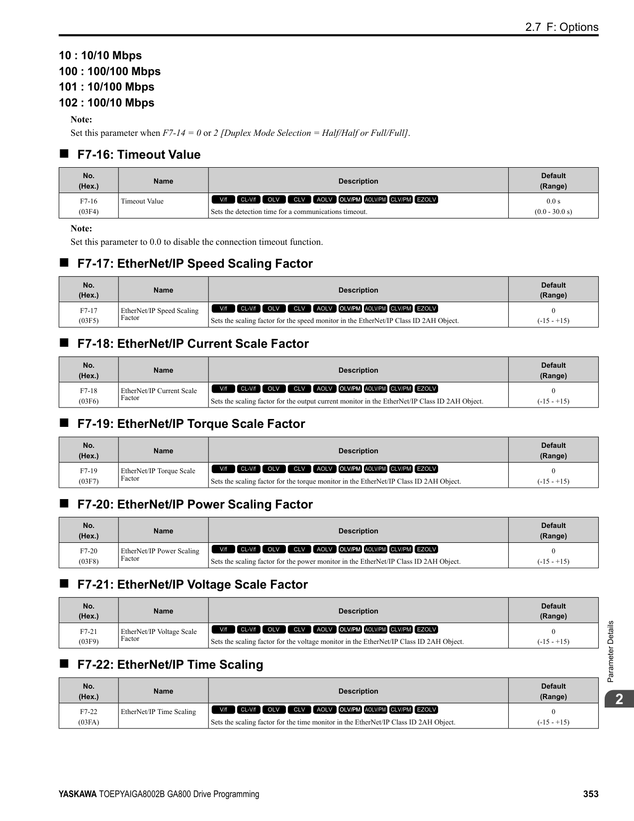
Refer to Output of Logical Operation Results of MFDO on page 382 for more information about the relation between parameter settings and logical operations.
|No. (Hex.)|Name|Description|Default (Range)| |---|---|---|---| |H2-60 (1B46) Expert|Term M1-M2 Secondary Function|Sets the second function for terminal M1-M2. Outputs the logical calculation results of the terminals assigned to functions by H2-01 [Term M1-M2 Function Selection].
V/f CL-V/f OLV CLV AOLV OLV/PM AOLV/PM CLV/PM EZOLV
|F (0 - FF)|
|No. (Hex.)|Name|Description|Default (Range)| |---|---|---|---| |H2-61 (1B47) Expert|Terminal M1-M2 Logical Operation|Sets the logical operation for the functions set in H2-01 [Term M1-M2 Function Selection] and H260 [Term M1-M2 Secondary Function].
V/f CL-V/f OLV CLV AOLV OLV/PM AOLV/PM CLV/PM EZOLV
|0 (0 - 8)|
|No. (Hex.)|Name|Description|Default (Range)| |---|---|---|---| |H2-62 (1B48) Expert|Terminal M1-M2 Delay Time|Sets the minimum on time used to output the logical calculation results from terminal M1-M2.
V/f CL-V/f OLV CLV AOLV OLV/PM AOLV/PM CLV/PM EZOLV
|0.1 s (0.0 - 25.0 s)|
|No. (Hex.)|Name|Description|Default (Range)| |---|---|---|---| |H2-63 (1B49) Expert|Term M3-M4 Secondary Function|Sets the second function for terminal M3-M4. Outputs the logical calculation results of the terminals assigned to functions by H2-02 [Term M3-M4 Function Selection].
V/f CL-V/f OLV CLV AOLV OLV/PM AOLV/PM CLV/PM EZOLV
|F (0 - FF)|
|No. (Hex.)|Name|Description|Default (Range)| |---|---|---|---| |H2-64 (1B4A) Expert|Terminal M3-M4 Logical Operation|Sets the logical operation for the functions set in H2-02 [Term M3-M4 Function Selection] and H263 [Term M3-M4 Secondary Function].
V/f CL-V/f OLV CLV AOLV OLV/PM AOLV/PM CLV/PM EZOLV
|0 (0 - 8)|
|No. (Hex.)|Name|Description|Default (Range)| |---|---|---|---| |H2-65 (1B4B) Expert|Terminal M3-M4 Delay Time|Sets the minimum on time used to output the logical calculation results from terminal M3-M4.
V/f CL-V/f OLV CLV AOLV OLV/PM AOLV/PM CLV/PM EZOLV
|0.1 s (0.0 - 25.0 s)|
|No. (Hex.)|Name|Description|Default (Range)| |---|---|---|---| |H2-66 (1B4C) Expert|Term M5-M6 Secondary Function|Sets the second function for terminal M5-M6. Outputs the logical calculation results of the terminals assigned to functions by H2-03 [Terminal M5-M6 Function Select].
V/f CL-V/f OLV CLV AOLV OLV/PM AOLV/PM CLV/PM EZOLV
|F (0 - FF)|
ParameterDetails
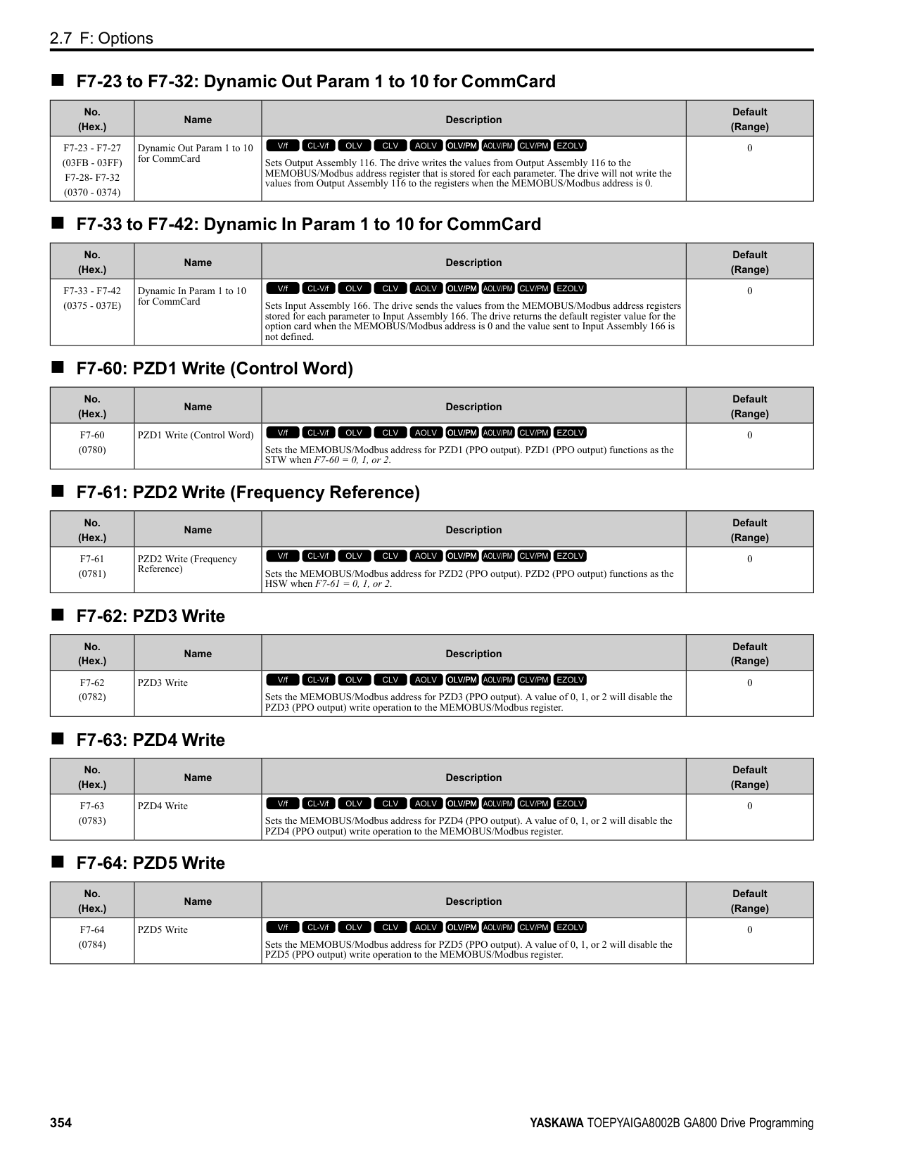
######## 2
######## ■ H2-67: Terminal M5-M6 Logical Operation
|No. (Hex.)|Name|Description|Default (Range)| |---|---|---|---| |H2-67 (1B4D) Expert|Terminal M5-M6 Logical Operation|Sets the logical operation for the functions set in H2-03 [Term M5-M6 Function Selection] and H266 [Term M5-M6 Secondary Function].
V/f CL-V/f OLV CLV AOLV OLV/PM AOLV/PM CLV/PM EZOLV
|0 (0 - 8)|
Note: Refer to Output of Logical Operation Results of MFDO on page 382 for more information about the relation between parameter settings and logical operations.
######## ■ H2-68: Terminal M5-M6 Delay Time
|No. (Hex.)|Name|Description|Default (Range)| |---|---|---|---| |H2-68 (1B4E) Expert|Terminal M5-M6 Delay Time|Sets the minimum on time used to output the logical calculation results from terminal M5-M6.
V/f CL-V/f OLV CLV AOLV OLV/PM AOLV/PM CLV/PM EZOLV
|0.1 s (0.0 - 25.0 s)|
◆ MFDO Setting Value Selects the function configured to a MFDO.
######## ■ 0: During Run
|Setting Value|Function|Description| |---|---|---| |0|During Run|The terminal activates when the Run command is input and when the drive is outputting voltage.
V/f CL-V/f OLV CLV AOLV OLV/PM AOLV/PM CLV/PM EZOLV
|
Figure 2.89 Drive Running Time Chart
ON : Drive is running The drive is receiving a Run command or outputting voltage. OFF : Drive is stopping Drive is stopped.
######## ■ 1: Zero Speed
|Setting Value|Function|Description| |---|---|---| |1|Zero Speed|The terminal activates when the output frequency < E1-09 [Minimum Output Frequency] or b2-01 [DC Injection/Zero SpeedThreshold].
V/f CL-V/f OLV CLV AOLV OLV/PM AOLV/PM CLV/PM EZOLV
|
Parameter A1-02 [Control Method Selection] selects which parameter is the reference.
|A1-02 Setting|Control method selection|Parameter Used as the Reference|
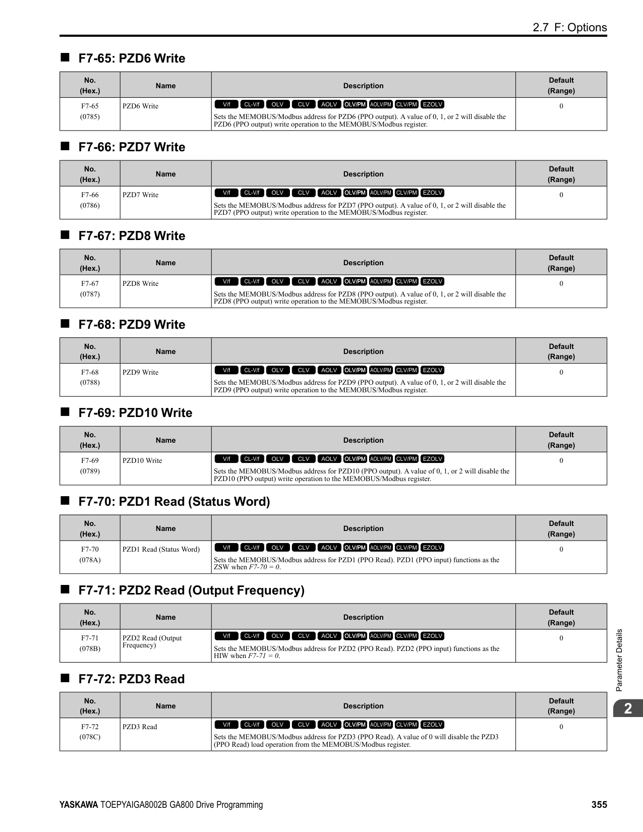
|---|---|---| |0|V/f Control|E1-09| |1|V/f Control with Encoder|E1-09| |2|Open Loop Vector|b2-01| |3|Closed Loop Vector|E1-09| |4|Advanced OpenLoop Vector Control|E1-09| |5|PM Open Loop Vector|E1-09| |6|PM Advanced Open Loop Vector|E1-09| |7|PM Closed Loop Vector Control|b2-01| |8|EZ Open Loop Vector Control|E1-09|
Figure 2.90 Zero Speed Time Chart ON : Output frequency < value of E1-09 or b2-01. OFF : Output frequency ≥ value of E1-09 or b2-01.
######## ■ 2: Speed Agree 1
|Setting Value|Function|Description| |---|---|---| |2|Speed Agree 1|The terminal turns on when the output frequency is in the range of the frequency reference ± L4-02 [Speed Agree Detection Width].
V/f CL-V/f OLV CLV AOLV OLV/PM AOLV/PM CLV/PM EZOLV
|
################# Note:
ParameterDetails
############## Figure 2.91 Speed Agree 1 Time Chart ON : The output frequency is in the range of “frequency reference ± L4-02”. OFF : The output frequency does not align with the frequency reference although the drive is running.
######## ■ 3: User-Set Speed Agree 1
|Setting Value|Function|Description| |---|---|---| |3|User-Set Speed Agree 1|The terminal activates when the output frequency is in the range of L4-01 [Speed Agree Detection Level] ± L4-02 [Speed Agree Detection Width] and in the range of the frequency reference ± L4-02.
V/f CL-V/f OLV CLV AOLV OLV/PM AOLV/PM CLV/PM EZOLV
|
################# Note:
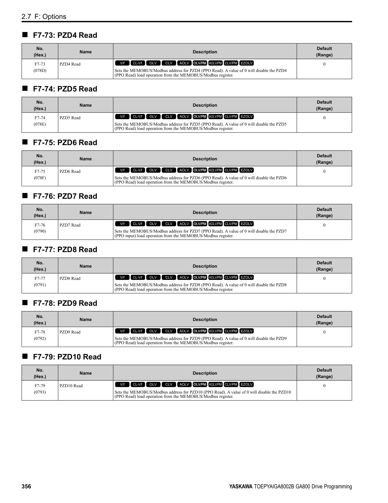
ON : The output frequency is in the range of “L4-01 ± L4-02” and the range of frequency reference ± L4-02.
OFF : The output frequency is not in the range of “L4-01 ± L4-02” or the range of frequency reference ± L4-02.
Figure 2.92 User-Defined Speed Agree 1 Time Chart
######## ■ 4: Frequency Detection 1
|Setting Value|Function|Description| |---|---|---| |4|Frequency Detection 1|The terminal deactivates when the output frequency > L4-01 [Speed Agree Detection Level] + L4-02 [Speed Agree Detection Width]. After the terminal turns off, the terminal continues to remain off until the output frequency reaches the level set with L4-01.
V/f CL-V/f OLV CLV AOLV OLV/PM AOLV/PM CLV/PM EZOLV
|
################# Note:
ON : The output frequency is less than the value of L4-01 or does not exceed the value of L4-01 + L4-
Figure 2.93 Frequency Detection 1 Time Chart
Figure 2.93 shows the result of the configuration when L4-07 = 1 [Speed Agree Detection Selection = Detection Always Enabled]. The default setting of L4-07 is 0 [No detection during baseblock]. When the speed agreement detection selection is “No Detection during Baseblock”, the terminal is deactivated when the drive output stops.
######## ■ 5: Frequency Detection 2
|Setting Value|Function|Description| |---|---|---| |5|Frequency Detection 2|The terminal activates when the output frequency is higher than the value of L4-01 [Speed Agree Detection Level]. After the terminal activates, the terminal stays activated until the output frequency L4-01 - L4-02.
V/f CL-V/f OLV CLV AOLV OLV/PM AOLV/PM CLV/PM EZOLV
|
Note:
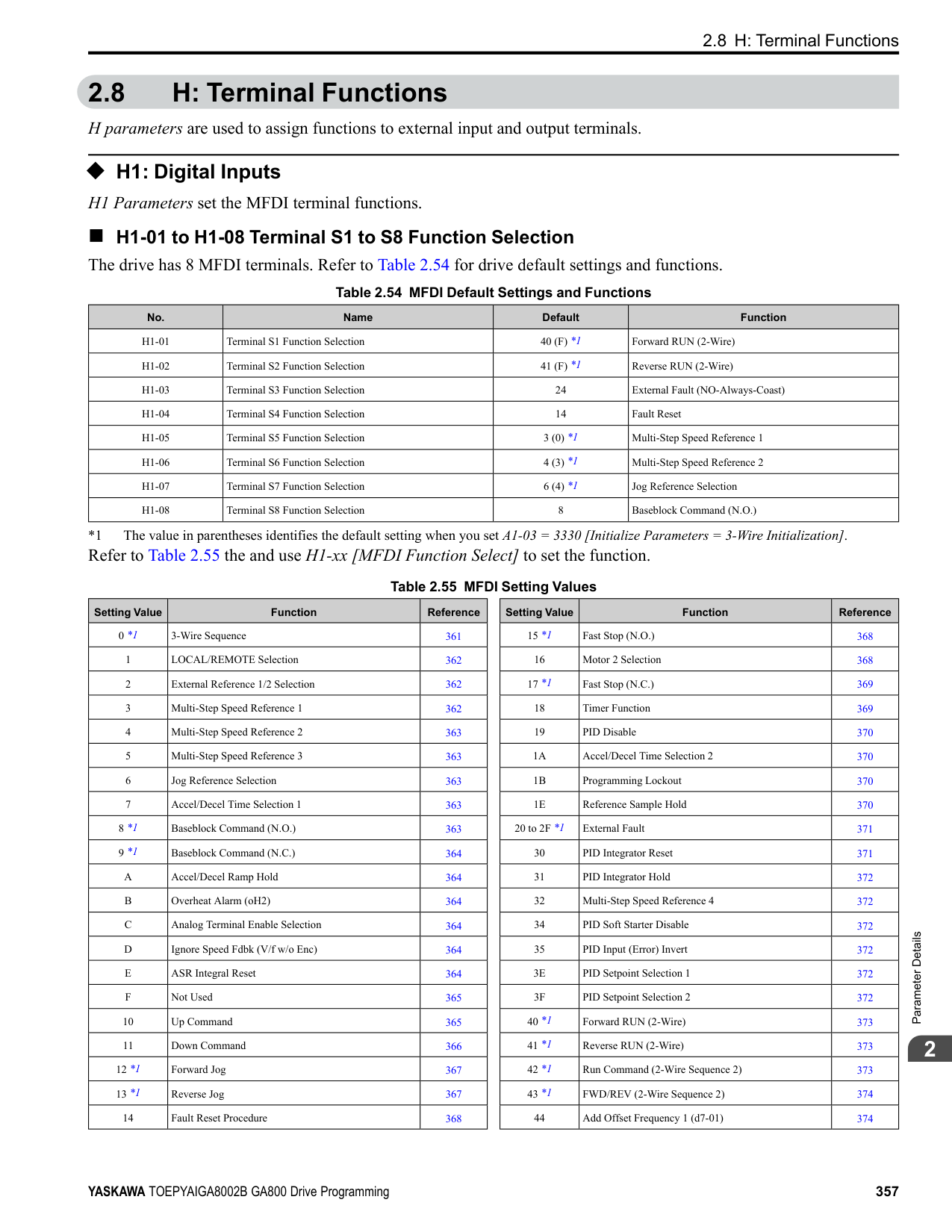
72 = 1. ON : The output frequency is higher than the value of L4-01. OFF : The output frequency < “L4-01 - L4-02”, or ≤ L4-01.
Figure 2.94 Frequency Detection 2 Time Chart
######## ■ 6: Drive ready
|Setting Value|Function|Description| |---|---|---| |6|Drive ready|The terminal activates when the drive is ready and running.
V/f CL-V/f OLV CLV AOLV OLV/PM AOLV/PM CLV/PM EZOLV
|
The terminal deactivates in these conditions:
######## ■ 7: DC Bus Undervoltage
|Setting Value|Function|Description| |---|---|---| |7|DC Bus Undervoltage|The terminal activates when the DC bus voltage or control circuit power supply is less than the voltage set with L2-05 [Undervoltage Detection Lvl (Uv1)]. The terminal also turns on when there is a fault with the DC bus voltage.
V/f CL-V/f OLV CLV AOLV OLV/PM AOLV/PM CLV/PM EZOLV
|
ParameterDetails
ON : The DC bus voltage is less than the setting value of L2-05. OFF : The DC bus voltage is more than the setting value of L2-05.
ON : During baseblock OFF : The drive is not in baseblock.
ON : The keypad is the frequency reference source.
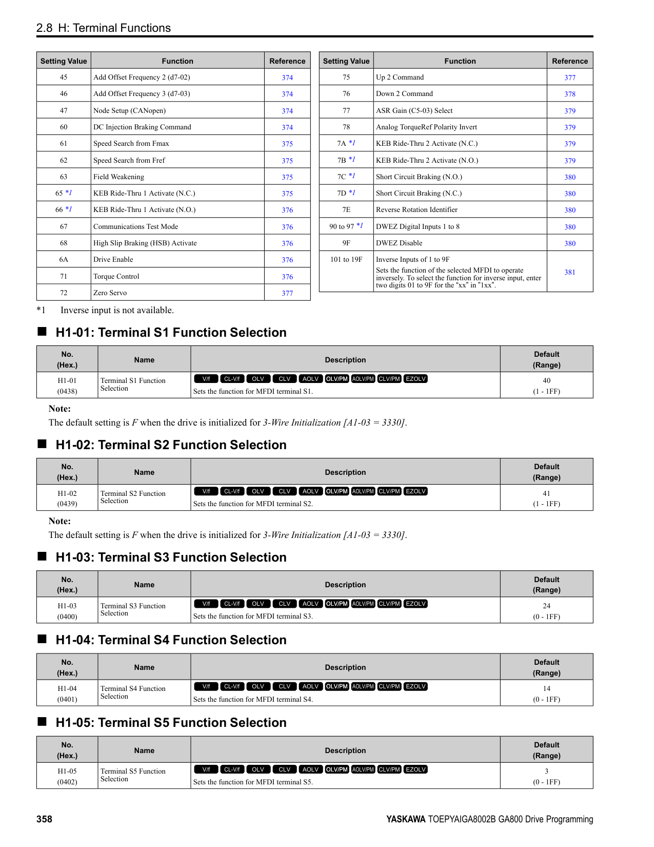
■ A: Run Command from Keypad
ON : The keypad is the Run command source.
ON : The output current/torque is more than the torque value set with L6-02 [Torque Detection Level
Note:
Note: Refer to “L4-05: Fref Loss Detection Selection” for more information.
|Setting Value|Function|Description| |---|---|---| |8|During Baseblock (N.O.)|The terminal turns on during baseblock. When the drive is in baseblock, the drive output transistor stops switching and does not make DC bus voltage.
V/f CL-V/f OLV CLV AOLV OLV/PM AOLV/PM CLV/PM EZOLV
|
|Setting Value|Function|Description| |---|---|---| |9|Frequency Reference from Keypad|Shows the selected frequency reference source.
V/f CL-V/f OLV CLV AOLV OLV/PM AOLV/PM CLV/PM EZOLV
|
|Setting Value|Function|Description|
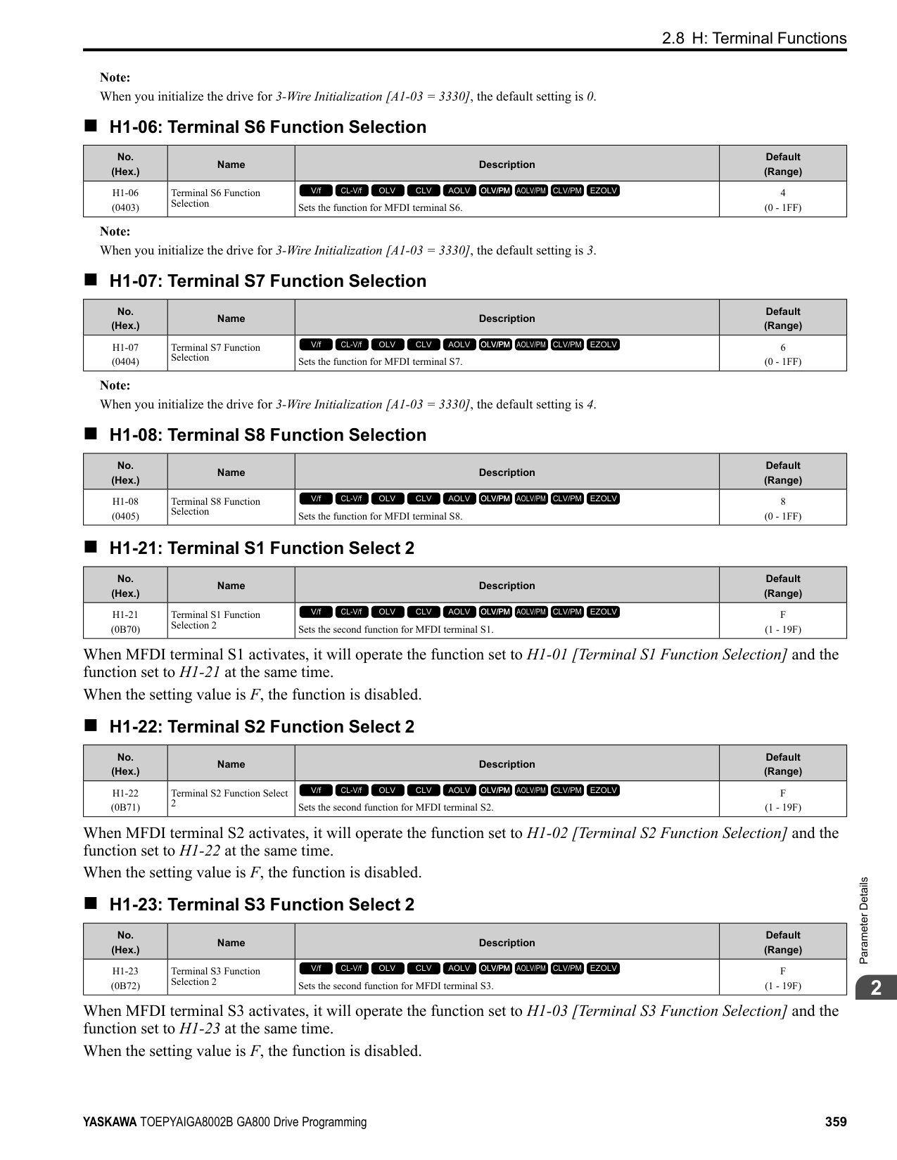
|---|---|---| |A|Run Command Source|Shows the selected Run command source.
V/f CL-V/f OLV CLV AOLV OLV/PM AOLV/PM CLV/PM EZOLV
|
|Setting Value|Function|Description| |---|---|---| |B|Torque Detection 1 (N.O.)|The terminal activates when the drive detects overtorque or undertorque.
V/f CL-V/f OLV CLV AOLV OLV/PM AOLV/PM CLV/PM EZOLV
|
|Setting Value|Function|Description| |---|---|---| |C|Frequency Reference Loss|The terminal activates when the drive detects a loss of frequency reference.
V/f CL-V/f OLV CLV AOLV OLV/PM AOLV/PM CLV/PM EZOLV
|
|Setting Value|Function|Description| |---|---|---| |D|Braking Resistor Fault|The terminal activates when the mounting-type braking resistor is overheating or when there is a braking transistor fault.
V/f CL-V/f OLV CLV AOLV OLV/PM AOLV/PM CLV/PM EZOLV
|
Note: The terminal will not activate for CPF00 and CPF01 [Control Circuit Error] faults.
Note: Refer to “b4: Timer Function” for more information.
|Setting Value|Function|Description| |---|---|---| |E|Fault|The terminal activates when the drive detects a fault.
V/f CL-V/f OLV CLV AOLV OLV/PM AOLV/PM CLV/PM EZOLV
|
|Setting Value|Function|Description| |---|---|---| |F|Not Used|Use this setting for unused terminals or to use terminals in through mode. Also use this setting as the PLC contact output via MEMOBUS/Modbus or the communication option. This signal does not function if signals from the PLC are not configured.
V/f CL-V/f OLV CLV AOLV OLV/PM AOLV/PM CLV/PM EZOLV
|
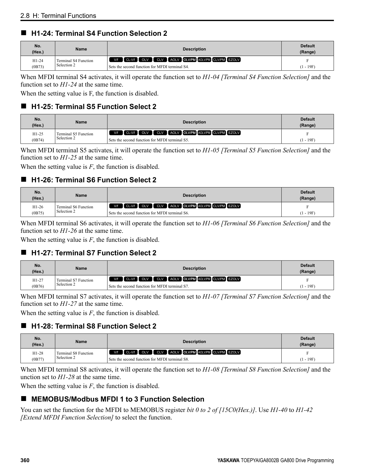
|Setting Value|Function|Description| |---|---|---| |10|Alarm|The terminal turns on when the drive detects a minor fault.
V/f CL-V/f OLV CLV AOLV OLV/PM AOLV/PM CLV/PM EZOLV
|
|Setting Value|Function|Description| |---|---|---| |11|Fault Reset Command Active|The terminal turns on when the drive receives the Reset command from the control circuit terminal, serial communications, or the communication option.
V/f CL-V/f OLV CLV AOLV OLV/PM AOLV/PM CLV/PM EZOLV
|
|Setting Value|Function|Description| |---|---|---| |12|Timer Output|Use this setting when the drive uses the timer function as an output terminal.
V/f CL-V/f OLV CLV AOLV OLV/PM AOLV/PM CLV/PM EZOLV
|
|Setting Value|Function|Description| |---|---|---| |13|Speed Agree 2|The terminal activates when the output frequency is in the range of the frequency reference ± L4-04 [Speed Agree Detection Width (+/-)].
V/f CL-V/f OLV CLV AOLV OLV/PM AOLV/PM CLV/PM EZOLV
|
################# Note:
ParameterDetails
Figure 2.95 Speed Agree 2 Time Chart
######## ■ 14: User-Set Speed Agree 2
|Setting Value|Function|Description| |---|---|---| |14|User-Set Speed Agree 2|The terminal activates when the output frequency is in the range of L4-03 [Speed Agree Detection Level (+/-)] ± L4-04 [Speed Agree Detection Width (+/-)] and in the range of the frequency reference ± L4-04.
V/f CL-V/f OLV CLV AOLV OLV/PM AOLV/PM CLV/PM EZOLV
|
################# Note:
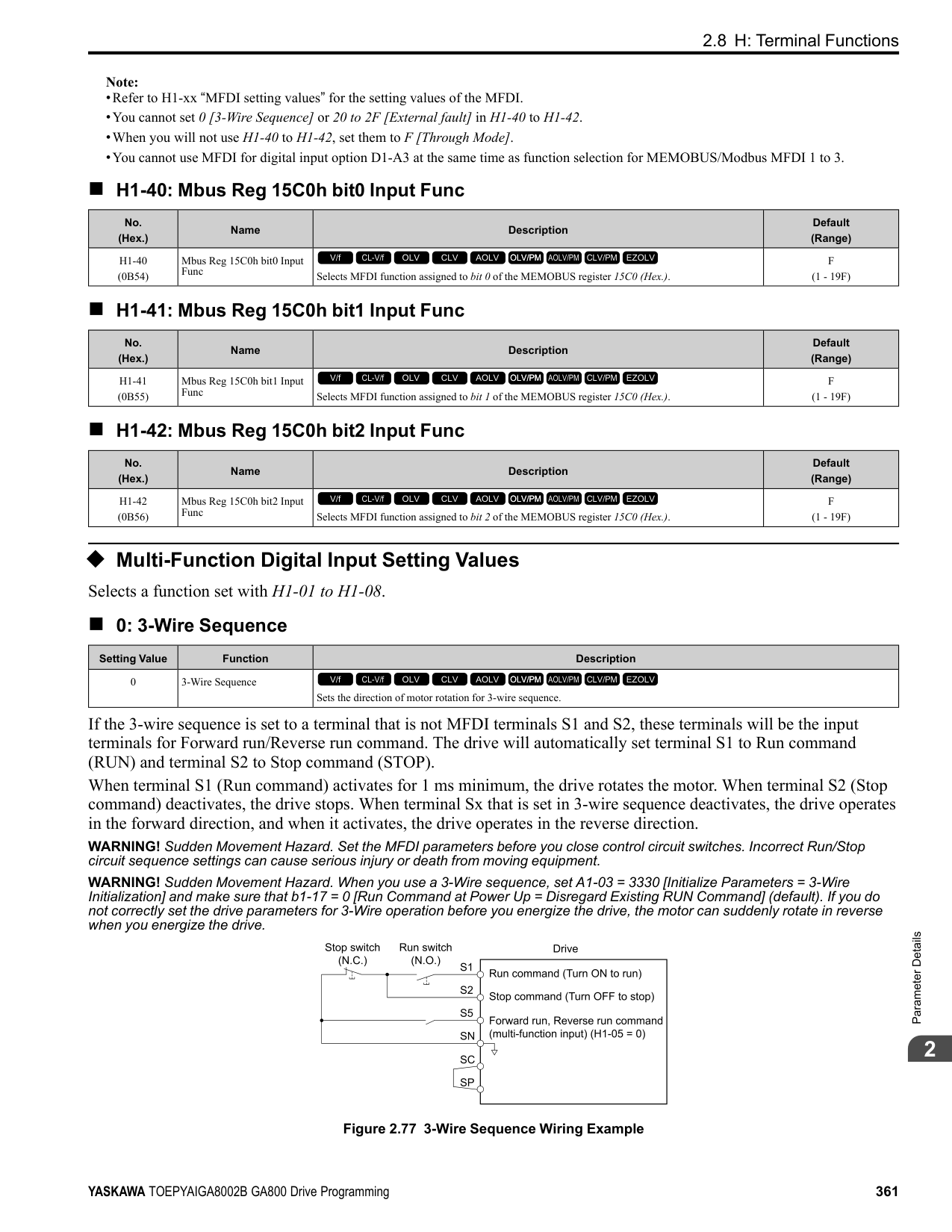
ON : The output frequency is in the range of “L4-03 ± L4-04” and the range of frequency reference ± L4-04.
OFF : The output frequency is not in the range of “L4-03 ± L4-04” or the range of frequency reference ± L4-04.
Figure 2.96 Example of User-set Speed Agree 2 (L4-03 Is Positive)
######## ■ 15: Frequency Detection 3
|Setting Value|Function|Description| |---|---|---| |15|Frequency Detection 3|The terminal deactivates when the output frequency is higher than the value of “L4-03 [Speed Agree Detection Level (+/-)] + L4-04 [Speed Agree Detection Width (+/-)]”. After the terminal deactivates, the terminal stays off until the output frequency is at the value of L4-03.
V/f CL-V/f OLV CLV AOLV OLV/PM AOLV/PM CLV/PM EZOLV
|
################# Note:
############## ON : The output frequency is less than the value of L4-03 or is not higher than the value of L4-03 + L4-04.
############## OFF : The output frequency is higher than the value of L4-03 + L4-04.
################# Figure 2.97 Example of Frequency Detection 3 (value of L4-03 Is Positive)
Note: Figure 2.97 shows the time chart when L4-07 = 1 [Speed Agree Detection Selection = Detection Always Enabled]. The default setting of L407 is 0 [No detection during baseblock]. When the speed agreement detection selection is “No Detection during Baseblock”, the terminal is deactivated when the drive output stops.
######## ■ 16: Frequency Detection 4
|Setting Value|Function|Description| |---|---|---| |16|Frequency Detection 4|The terminal activates when the output frequency is higher than the value of L4-03 [Speed Agree Detection Level (+/-)]. After the terminal activates, the terminal stays on until the output frequency is at the value of L4-03 - L4-04.
V/f CL-V/f OLV CLV AOLV OLV/PM AOLV/PM CLV/PM EZOLV
|
Note:
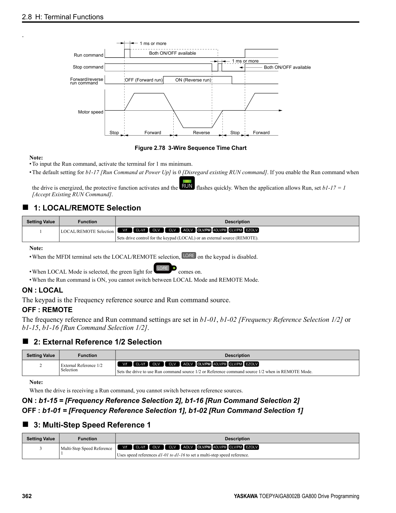
Figure 2.98 Example of Frequency Detection 4 (value of L4-03 Is Positive)
######## ■ 17: Torque Detection 1 (N.C.)
|Setting Value|Function|Description| |---|---|---| |17|Torque Detection 1 (N.C.)|The terminal deactivates when the drive detects overtorque or undertorque.
V/f CL-V/f OLV CLV AOLV OLV/PM AOLV/PM CLV/PM EZOLV
|
Use the L6 [Torque Detection] parameters to set torque detection. OFF : The output current/torque is more than the torque value set with L6-02 [Torque Detection Level 1], or the level is less than the torque value set with L6-02 for longer than the time set with L603 [Torque Detection Time 1].
Note:
ParameterDetails
######## 2
######## ■ 18: Torque Detection 2 (N.O.)
|Setting Value|Function|Description| |---|---|---| |18|Torque Detection 2 (N.O.)|The terminal activates when the drive detects overtorque or undertorque.
V/f CL-V/f OLV CLV AOLV OLV/PM AOLV/PM CLV/PM EZOLV
|
Use the L6 [Torque Detection] parameters to set torque detection. ON : The output current/torque is more than the torque value set with L6-05 [Torque Detection Level 2], or the level is less than the torque value set with L6-05 for longer than the time set with L6-06 [Torque Detection Time 2].
Note:
######## ■ 19: Torque Detection 2 (N.C.)
|Setting Value|Function|Description| |---|---|---| |19|Torque Detection 2 (N.C.)|The terminal deactivates when the drive detects overtorque or undertorque.
V/f CL-V/f OLV CLV AOLV OLV/PM AOLV/PM CLV/PM EZOLV
|
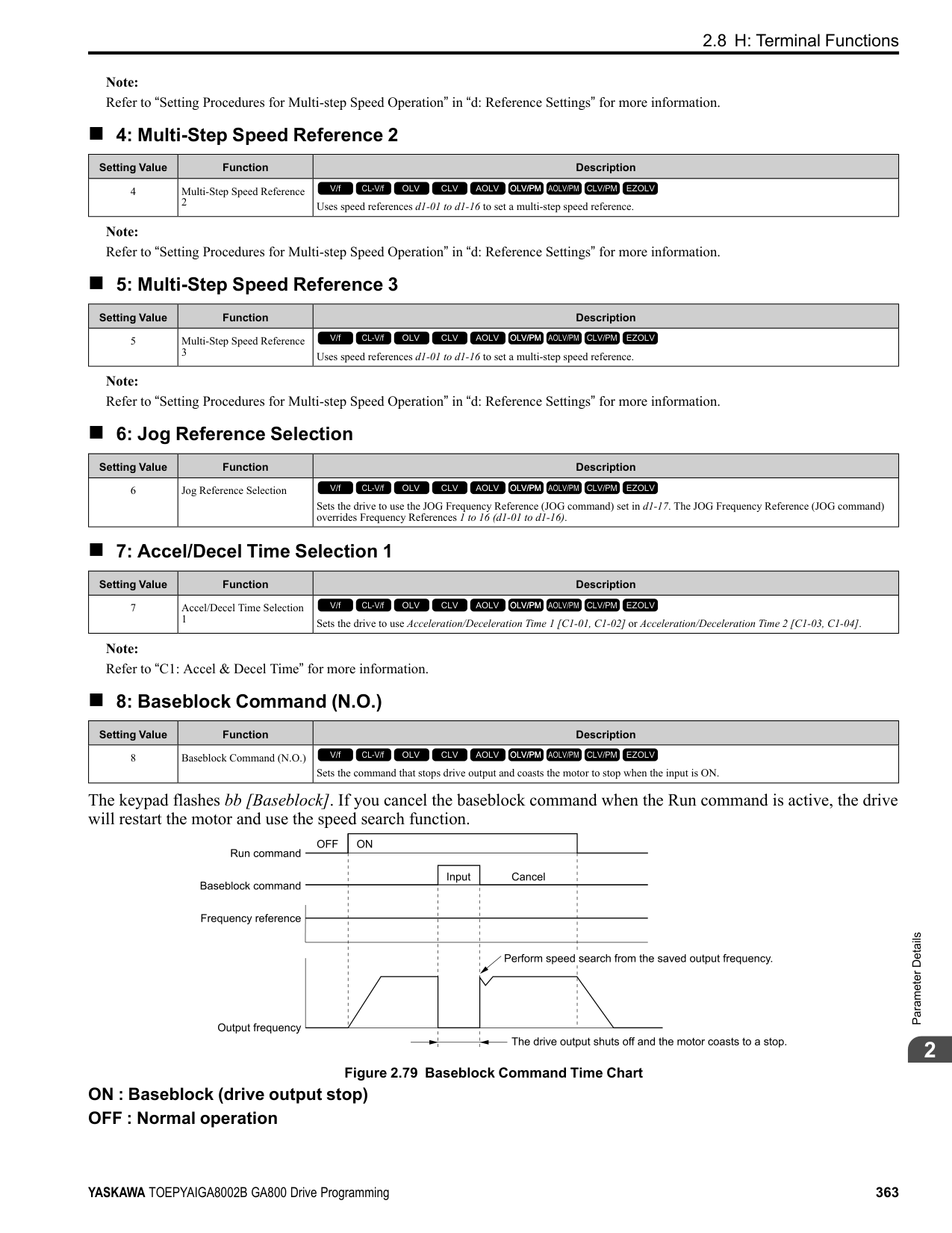
Use the L6 [Torque Detection] parameters to set torque detection. OFF : The output current/torque is more than the torque value set with L6-05 [Torque Detection Level 2], or the level is less than the torque value set with L6-05 for longer than the time set with L6-
Note:
######## ■ 1A: During Reverse
|Setting Value|Function|Description| |---|---|---| |1A|During reverse|The terminal activates when the motor operates in the reverse direction.
V/f CL-V/f OLV CLV AOLV OLV/PM AOLV/PM CLV/PM EZOLV
|
############## ON : The motor is operating in the reverse direction. OFF : The motor is operating in the forward direction or the motor stopped.
Figure 2.99 Reverse Operation Output Time Chart
######## ■ 1B: During Baseblock (N.C.)
|Setting Value|Function|Description| |---|---|---| |1B|During Baseblock (N.C.)|The terminal deactivates during baseblock. When the drive is in baseblock, the drive output transistor stops switching and does not make DC bus voltage.
V/f CL-V/f OLV CLV AOLV OLV/PM AOLV/PM CLV/PM EZOLV
|
ON : The drive is not in baseblock.
OFF : During baseblock
######## ■ 1C: Motor 2 Selected
|Setting Value|Function|Description| |---|---|---| |1C|Motor 2 Selected|The terminal activates when motor 2 is selected.
V/f CL-V/f OLV CLV AOLV OLV/PM AOLV/PM CLV/PM EZOLV
|
ON : Motor 2 Selection OFF : Motor 1 Selection
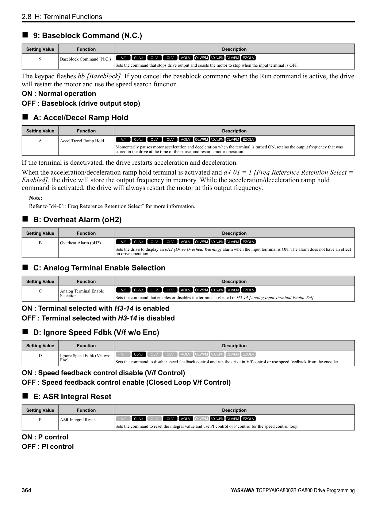
######## ■ 1D: During Regeneration
|Setting Value|Function|Description| |---|---|---| |1D|During Regeneration|The terminal activates on when the motor is regenerating.
V/f CL-V/f OLV CLV AOLV OLV/PM AOLV/PM CLV/PM EZOLV
|
ON : Motor is regenerating. OFF : Motor is operating or stopped.
######## ■ 1E: Executing Auto-Restart
|Setting Value|Function|Description| |---|---|---| |1E|Executing Auto-Restart|The terminal activates when the Auto Restart function is trying to restart after a fault.
V/f CL-V/f OLV CLV AOLV OLV/PM AOLV/PM CLV/PM EZOLV
|
The terminal deactivates when the Auto Restart function automatically resets a fault. The terminal turns off when the Auto Restart function detects the fault again since Auto Restart function cannot function any longer due to number of attempts set with L5-01 [Number of Auto Restart Attempts] being reached.
Note: Refer to "L5: Auto-Restart" for more information.
######## ■ 1F: Motor Overload Alarm (oL1)
|Setting Value|Function|Description| |---|---|---| |1F|Motor Overload Alarm (oL1)|The terminal activates when the electronic thermal protection value of the motor overload protective function is a minimum of 90% of the detection level.
V/f CL-V/f OLV CLV AOLV OLV/PM AOLV/PM CLV/PM EZOLV
|
Note: Refer to “L1-01: Motor Overload (oL1) Protection” for more information.
######## ■ 20: Drive Overheat Pre-Alarm (oH)
|Setting Value|Function|Description| |---|---|---| |20|Drive Overheat Pre-Alarm (oH)|The terminal activates when the drive heatsink temperature is at the level set with L8-02 [Overheat Alarm Level].
V/f CL-V/f OLV CLV AOLV OLV/PM AOLV/PM CLV/PM EZOLV
|
Note: Refer to “L8-02: Overheat Alarm Level” for more information.
######## ■ 21: Safe Torque OFF
|Setting Value|Function|Description|
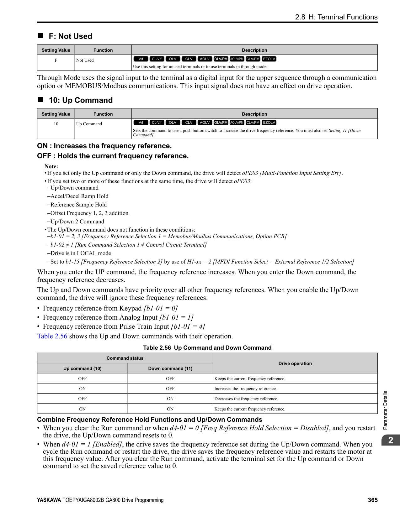
|---|---|---| |21|Safe Torque OFF|The terminal activates (safety stop state) when the safety circuit and safety diagnosis circuit are operating correctly and when terminals H1-HC and H2-HC are OFF (Open).
V/f CL-V/f OLV CLV AOLV OLV/PM AOLV/PM CLV/PM EZOLV
|
Note: EDM = External Device Monitor
ON : Safety stop state Terminals H1-HC and H2-HC are OFF (Open) (safety stop state).
ParameterDetails
######## 2
OFF : Safety circuit fault or RUN/READY Terminal H1-HC or terminal H2-HC is OFF (Open) (safety circuit fault), or the two terminals are ON or have short circuited (RUN/READY).
######## ■ 22: Mechanical Weakening Detection
|Setting Value|Function|Description| |---|---|---| |22|Mechanical Weakening Detection|The terminal activates when the drive detects mechanical weakening.
V/f CL-V/f OLV CLV AOLV OLV/PM AOLV/PM CLV/PM EZOLV
|
Note: Refer to “Mechanical Weakening Detection Function” for more information.
######## ■ 2F: Maintenance Notification
|Setting Value|Function|Description| |---|---|---| |2F|Maintenance Notification|The terminal activates when drive components are at their estimated maintenance period.
V/f CL-V/f OLV CLV AOLV OLV/PM AOLV/PM CLV/PM EZOLV
|
Tells the user about the maintenance period for these items:
######## ■ 30: During Torque Limit
|Setting Value|Function|Description| |---|---|---|
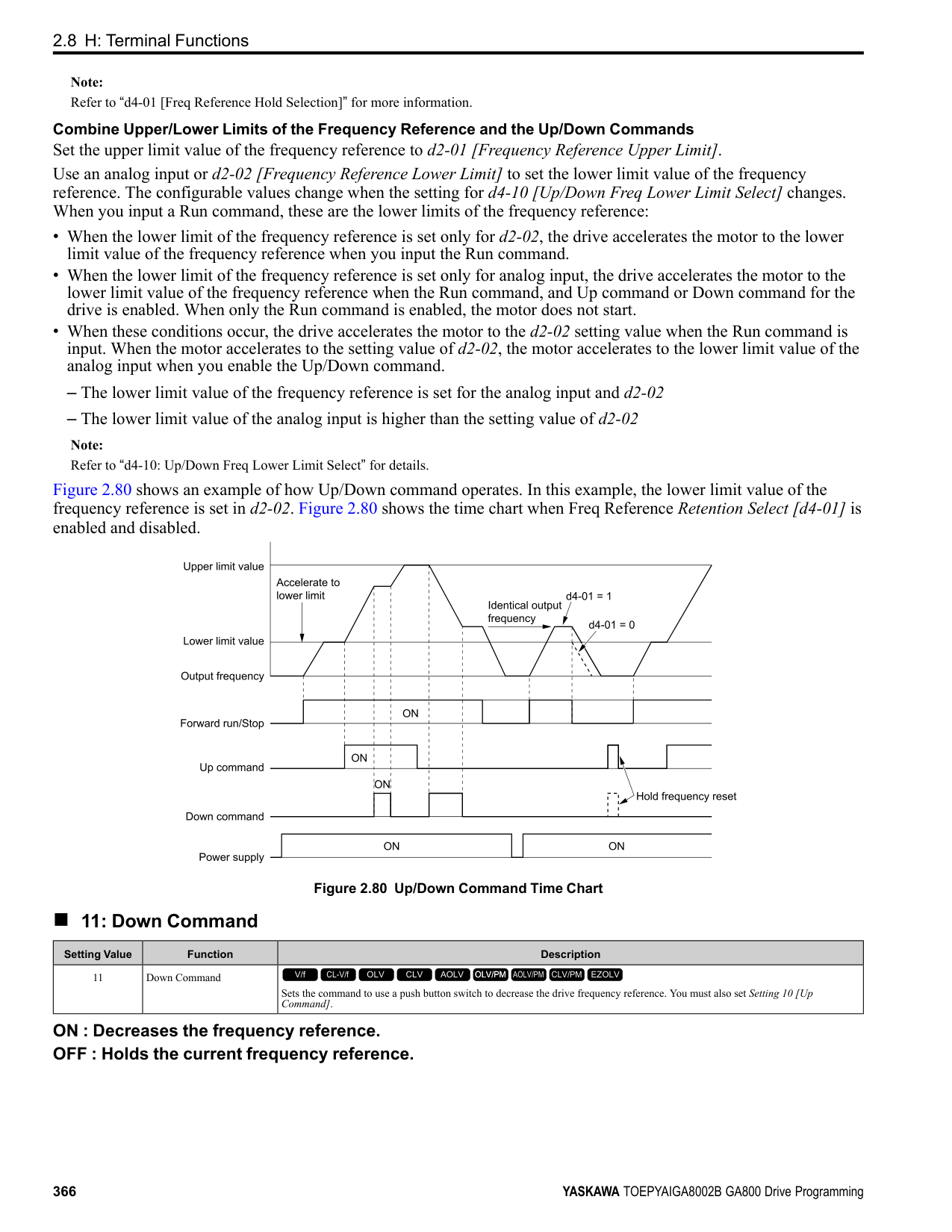
|30|During Torque Limit|The terminal activates when the torque reference is the torque limit set with L7 parameters, H3-02, H3-06, or H3-10 [MFAI Function Selection].
V/f CL-V/f OLV CLV AOLV OLV/PM AOLV/PM CLV/PM EZOLV
|
Note: Refer to “L7: Torque Limit” for more information.
######## ■ 31: During Speed Limit
|Setting Value|Function|Description| |---|---|---| |31|During Speed Limit|The terminal activates when the speed limit is active.
V/f CL-V/f OLV CLV AOLV OLV/PM AOLV/PM CLV/PM EZOLV
|
The speed limit activates and the terminal activates in these conditions:
######## ■ 32: In Speed Limit During Trq Ctrl
|Setting Value|Function|Description| |---|---|---| |32|In Speed Limit During Trq Ctrl|The motor accelerates in the forward direction or the reverse direction after enabling torque control and the externally input torque reference is disproportionate to the load. The output terminal activates when this speed is not higher than a constant speed and the motor speed is at the speed limit. This does not include operation when the drive is stopped.
V/f CL-V/f OLV CLV AOLV OLV/PM AOLV/PM CLV/PM EZOLV
|
Note: Refer to “d5-03: Speed Limit Selection” for more information.
Note: Refer to “b9: Zero Servo” for more information.
ON : The drive outputs frequency. OFF : The drive does not output frequency.
Note: The terminal deactivates in these conditions:
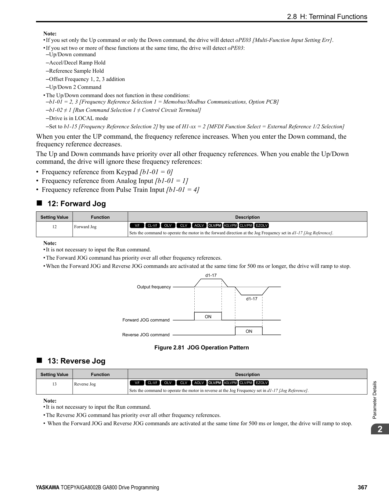
Figure 2.100 Active Frequency Output Time Chart
Note: Refer to “H2-06: Watt Hour Output Unit Selection” for more information.
|Setting Value|Function|Description| |---|---|---| |33|Zero Servo Complete|The terminal activates when positioning in the range set with b9-02 [Zero Servo Completion Window] completes after sending the Zero-Servo command.
V/f CL-V/f OLV CLV AOLV OLV/PM AOLV/PM CLV/PM EZOLV
|
|Setting Value|Function|Description| |---|---|---| |37|During Frequency Output|The terminal activates when the drive outputs frequency.
V/f CL-V/f OLV CLV AOLV OLV/PM AOLV/PM CLV/PM EZOLV
|
|Setting Value|Function|Description| |---|---|---| |38|Drive Enabled|This terminal activates when the H1-xx = 6A [Drive Enable] terminal activates.
V/f CL-V/f OLV CLV AOLV OLV/PM AOLV/PM CLV/PM EZOLV
|
|Setting Value|Function|Description| |---|---|---| |39|Watt Hour Pulse Output|Outputs the pulse that shows the watt hours.
V/f CL-V/f OLV CLV AOLV OLV/PM AOLV/PM CLV/PM EZOLV
|
|Setting Value|Function|Description| |---|---|---| |3C|LOCAL Control Selected|The terminal activates when the Run command source or frequency reference source is LOCAL.
V/f CL-V/f OLV CLV AOLV OLV/PM AOLV/PM CLV/PM EZOLV
|
ON : LOCAL The keypad is the Run command source or the frequency reference source. OFF : REMOTE
ParameterDetails
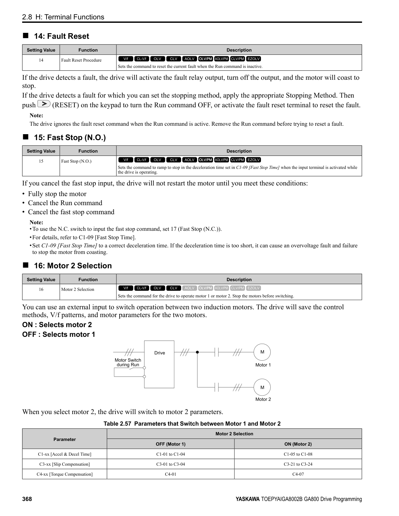
######## 2
The Run command source or frequency reference source is an external source set with b1-01 [Frequency Reference
######## ■ 3D: During Speed Search
|Setting Value|Function|Description| |---|---|---| |3D|During Speed Search|The terminal activates when the drive is doing speed search.
V/f CL-V/f OLV CLV AOLV OLV/PM AOLV/PM CLV/PM EZOLV
|
Note: Refer to “b3: Speed Search” for more information.
######## ■ 3E: PID Feedback Low
|Setting Value|Function|Description| |---|---|---| |3E|PID Feedback Low|The terminal activates when the drive detects FbL [PID Feedback Loss].
V/f CL-V/f OLV CLV AOLV OLV/PM AOLV/PM CLV/PM EZOLV
|
The drive detects FbL [PID Feedback Loss] when the PID feedback value < b5-13 [PID Feedback Loss Detection Lvl] for longer than the time set in b5-14 [PID Feedback Loss Detection Time].
Note: Refer to “PID Feedback Loss Detection” for more information.
######## ■ 3F: PID Feedback High
|Setting Value|Function|Description| |---|---|---| |3F|PID Feedback High|The terminal activates when the drive detects FbH [Excessive PID Feedback].
V/f CL-V/f OLV CLV AOLV OLV/PM AOLV/PM CLV/PM EZOLV
|
The drive detects FbH [Excessive PID Feedback] when the PID feedback value > b5-36 [PID High Feedback Detection Lvl] for longer than the time set in b5-37 [PID High Feedback Detection Time].
Note: Refer to “PID Feedback Loss Detection” for more information.
######## ■ 4A: During KEB Ride-Thru
|Setting Value|Function|Description|
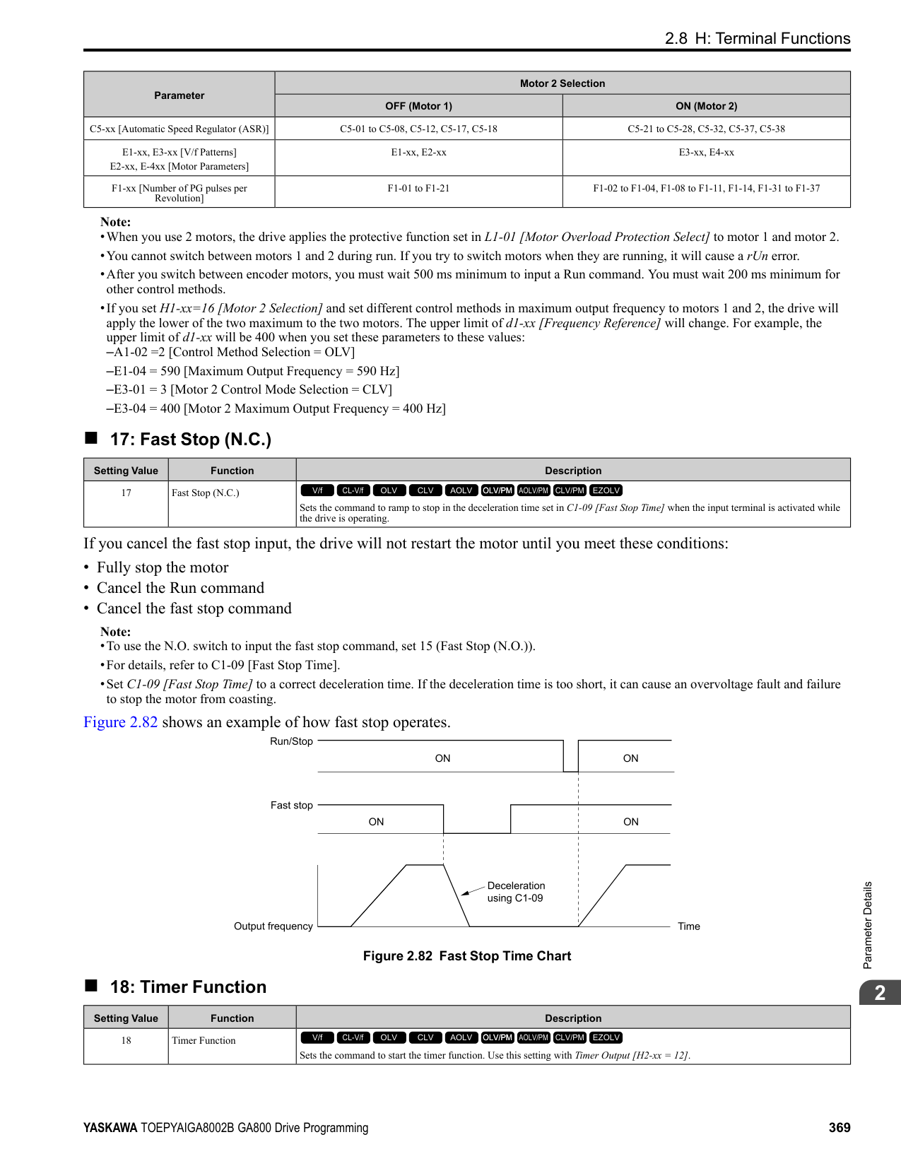
|---|---|---| |4A|During KEB Ride-Thru|The activates during KEB Ride-Thru.
V/f CL-V/f OLV CLV AOLV OLV/PM AOLV/PM CLV/PM EZOLV
|
Note: Refer to “KEB Ride-Thru function” for more information.
######## ■ 4B: During Short Circuit Braking
|Setting Value|Function|Description| |---|---|---| |4B|During Short Circuit Braking|The terminal activates during Short Circuit Braking.
V/f CL-V/f OLV CLV AOLV OLV/PM AOLV/PM CLV/PM EZOLV
|
Note:
######## ■ 4C: During Fast Stop
|Setting Value|Function|Description| |---|---|---| |4C|During Fast Stop|The terminal activates when the fast stop is in operation.
V/f CL-V/f OLV CLV AOLV OLV/PM AOLV/PM CLV/PM EZOLV
|
Note: Refer to “L8-03: Overheat Pre-Alarm Selection” for more information.
The braking resistor overheats when the deceleration time is short and there is too much motor regeneration energy.
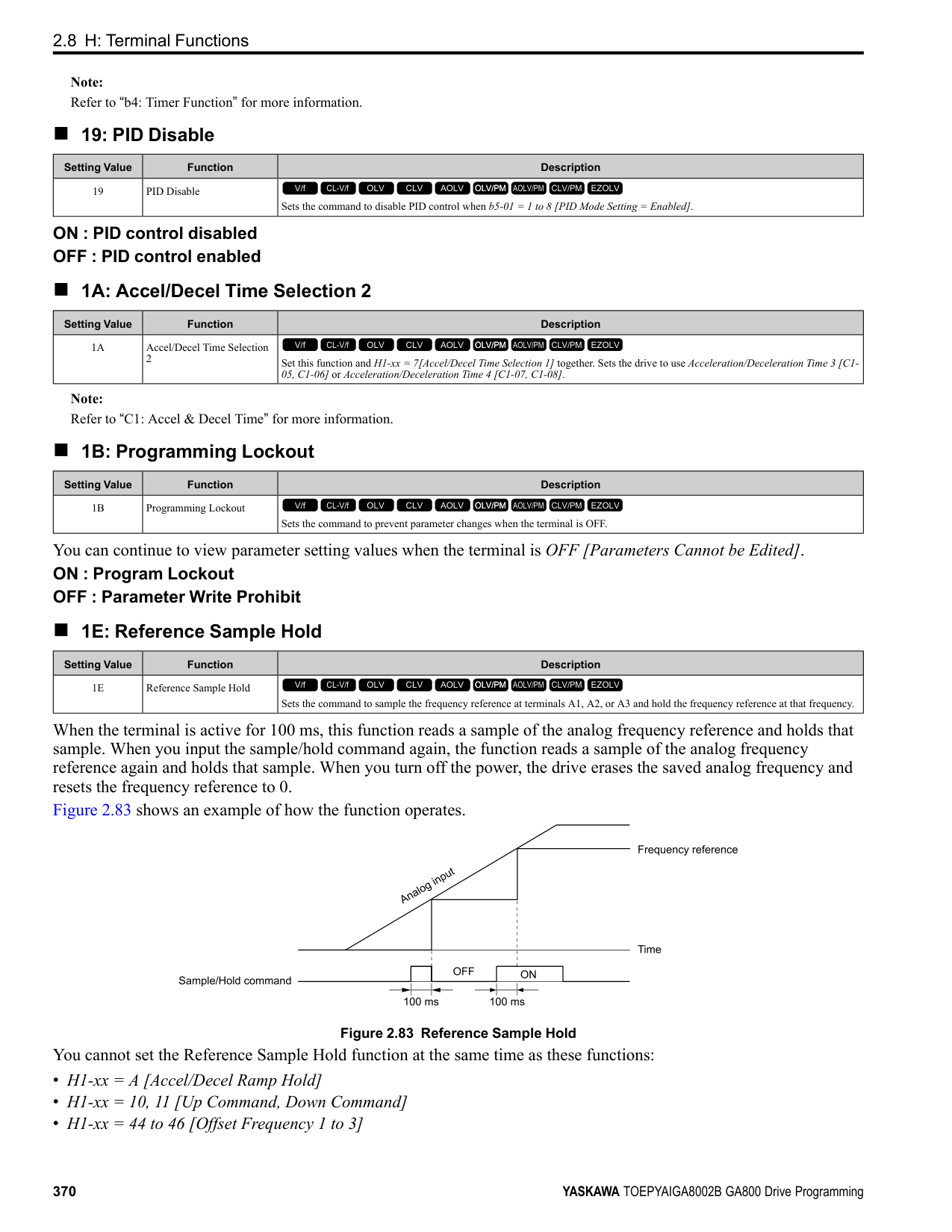
|Setting Value|Function|Description| |---|---|---| |4D|oH Pre-Alarm Time Limit|The terminal activates when L8-03 = 4 [Overheat Pre-Alarm Selection = Operate at Reduced Speed (L8-19)] and oH [Heatsink Overheat] does not clear after the drive decreases the frequency for 10 cycles.
V/f CL-V/f OLV CLV AOLV OLV/PM AOLV/PM CLV/PM EZOLV
|
|Setting Value|Function|Description| |---|---|---| |4E|Braking Transistor Fault (rr)|The terminal activates when the internal braking transistor overheats and the drive detects an rr [Dynamic Braking Transistor Fault] fault.
V/f CL-V/f OLV CLV AOLV OLV/PM AOLV/PM CLV/PM EZOLV
|
|Setting Value|Function|Description| |---|---|---| |4F|Braking Resistor Overheat (rH)|The terminal activates when the braking resistor overheats and the drive detects an rH [Braking Resistor Overheat] fault.
V/f CL-V/f OLV CLV AOLV OLV/PM AOLV/PM CLV/PM EZOLV
|
|Setting Value|Function|Description| |---|---|---| |60|Internal Cooling Fan Failure|The terminal activates when the drive detects a cooling fan failure in the drive.
V/f CL-V/f OLV CLV AOLV OLV/PM AOLV/PM CLV/PM EZOLV
|
|Setting Value|Function|Description| |---|---|---| |61|Pole Position Detection Complete|The terminal activates when drive receives a Run command and the drive detects the motor magnetic pole position of the PM motor.
V/f CL-V/f OLV CLV AOLV OLV/PM AOLV/PM CLV/PM EZOLV
|
|Setting Value|Function|Description| |---|---|---| |62|Modbus Reg 1 Status Satisfied|The terminal activates when the bit specified by H2-08 [Modbus Register 1 Bit Select] for the MEMOBUS register address set with H2-07 [Modbus Register 1 Address Select] activates.
V/f CL-V/f OLV CLV AOLV OLV/PM AOLV/PM CLV/PM EZOLV
|
|Setting Value|Function|Description| |---|---|---| |63|Modbus Reg 2 Status Satisfied|The terminal activates when the bit specified by H2-10 [Modbus Register 2 Bit Select] for the MEMOBUS register address set with H2-09 [Modbus Register 2 Address Select] activates.
V/f CL-V/f OLV CLV AOLV OLV/PM AOLV/PM CLV/PM EZOLV
|
|Setting Value|Function|Description| |---|---|---| |65|Standby Output|The terminal deactivates after the drive stops operating and after the time set with b8-51 [Standby Mode Wait Time].
V/f CL-V/f OLV CLV AOLV OLV/PM AOLV/PM CLV/PM EZOLV
|
ParameterDetails
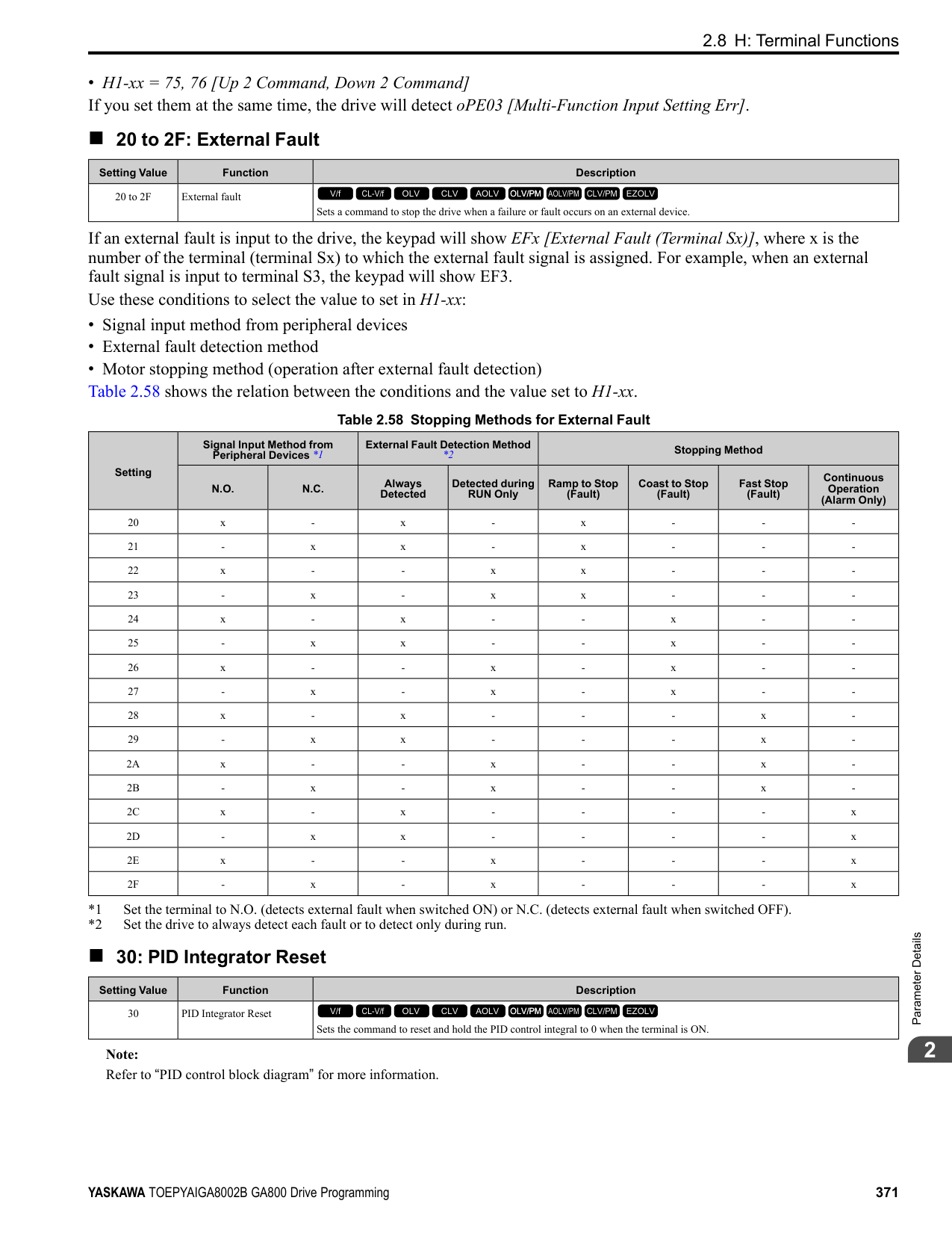
######## 2
ON : The Run command turns on and the magnetic contactor on the input side turns on. OFF : The Run command turns off and the drive stops operating. Then, the magnetic contactor on the input side turns off after the time set with b8-51 [Standby Mode Wait Time] elapses.
######## ■ 66: Comparator1
|Setting Value|Function|Description| |---|---|---| |66|Comparator1|The terminal activates if the monitor value set with H2-20 [Comparator 1 Monitor Selection] is in range of the values of H2-21 [Comparator 1 Lower Limit] and H2-22 [Comparator 1 Upper Limit] for the time set in H2-24 [Comparator 1 On-Delay Time].
V/f CL-V/f OLV CLV AOLV OLV/PM AOLV/PM CLV/PM EZOLV
|
A - H2-24 [Comparator 1 On-Delay Time]
B - H2-25
[Comparator 1 Off-Delay Time] Figure 2.101 Comparator 1 Output Time Chart
Note: The drive compares the monitors set with H2-20 as absolute values.
######## ■ 67: Comparator2
|Setting Value|Function|Description| |---|---|---| |67|Comparator2|The terminal activates if the monitor value set with H2-26 [Comparator 2 Monitor Selection] is not in the range of the values of H227 [Comparator 2 Lower Limit] and H2-28 [Comparator 2 Upper Limit] for the time set in H2-30 [Comparator 2 On-Delay Time].
V/f CL-V/f OLV CLV AOLV OLV/PM AOLV/PM CLV/PM EZOLV
|
A - H2-30 [Comparator 2 On-Delay Time]
B - H2-31
[Comparator 2 Off-Delay Time] Figure 2.102 Comparator 2 Output Time Chart
Note: The drive compares the monitors set with H2-26 as absolute values.
ON : An external 24V power supply supplies power. OFF : An external 24V power supply does not supply power.
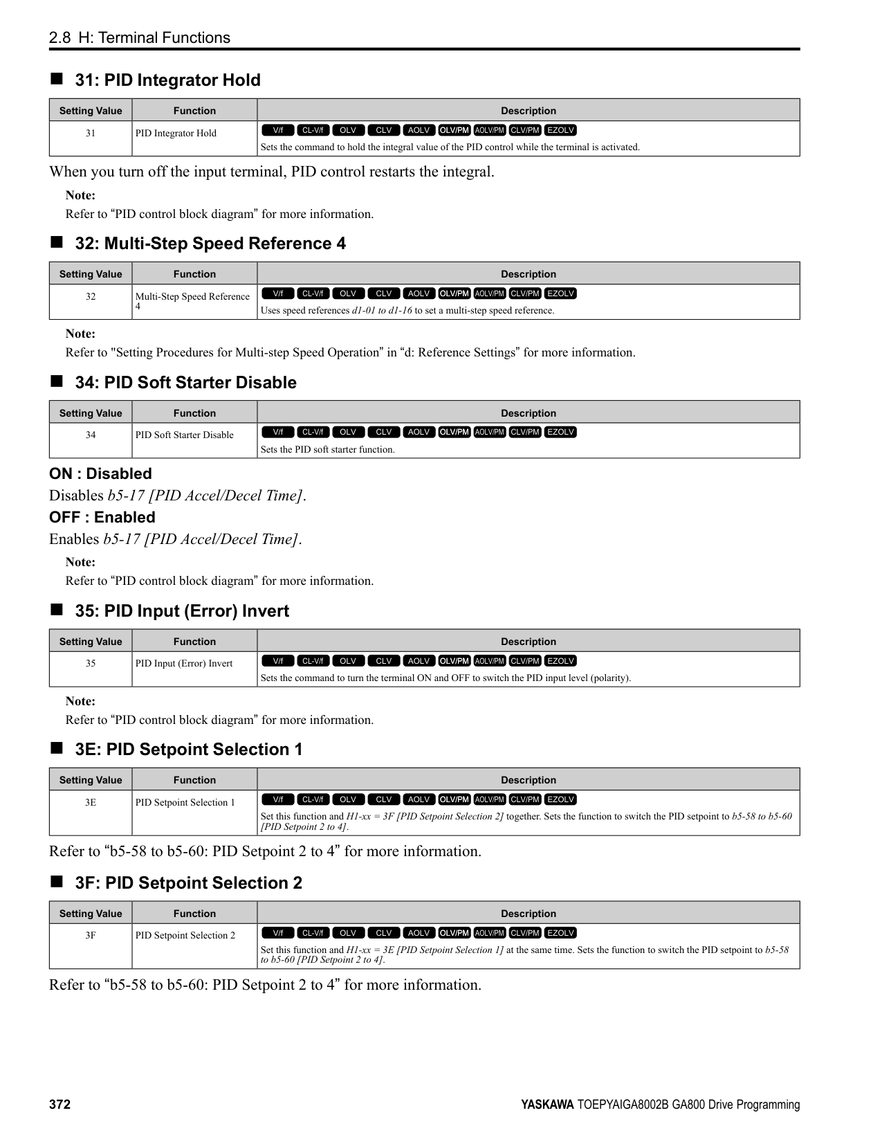
|Setting Value|Function|Description| |---|---|---| |69|External Power 24V Supply|The terminal activates when there is an external 24V power supply between terminals PS-AC.
V/f CL-V/f OLV CLV AOLV OLV/PM AOLV/PM CLV/PM EZOLV
|
|Setting Value|Function|Description| |---|---|---| |6A|Data Logger Error|The terminal activates when the drive detects LoG [Com Error / Abnormal SD card].
V/f CL-V/f OLV CLV AOLV OLV/PM AOLV/PM CLV/PM EZOLV
|
|Setting Value|Function|Description| |---|---|---| |90 to 93|DWEZ Digital Outputs 1 to 4|Sets the DriveWorksEZ digital output. Refer to the DriveWorksEZ online manual for more information.
V/f CL-V/f OLV CLV AOLV OLV/PM AOLV/PM CLV/PM EZOLV
|
|Setting Value|Function|Description| |---|---|---| |A0 to A7|DWEZ Extended Digital Outputs 1 to 8|Sets the digital output for the DriveWorksEZ DO-A3 option card. Refer to the DriveWorksEZ online manual for more information.
V/f CL-V/f OLV CLV AOLV OLV/PM AOLV/PM CLV/PM EZOLV
|
|Setting Value|Function|Description| |---|---|---| |100 to 1A7|Inverse Outputs of 0 to A7|Causes inverse output of the function for the selected MFDO. Uses the last two digits of 1xx to select which function to inversely output.
V/f CL-V/f OLV CLV AOLV OLV/PM AOLV/PM CLV/PM EZOLV
|
For example, set H2-xx = 10E for the inverse output of E [Fault].
######## ◆ H3: Analog Inputs
WARNING! Sudden Movement Hazard. Do test runs and examine the drive to make sure that the command references are correct. If you set the command reference incorrectly, it can cause damage to the drive or serious injury or death.
ParameterDetails
######## 2
Drives have three analog input terminals, terminals A1, A2, and A3. H3 parameters select the functions set to these analog input terminals and adjust signal levels. Table 2.64 shows the functions that you can set to analog input terminals. Use H3-02, H3-06, and H3-10 [MFAI Function Selection] to set functions.
Table 2.64 MFAI Setting Values
|Setting Value|Function|Ref.|
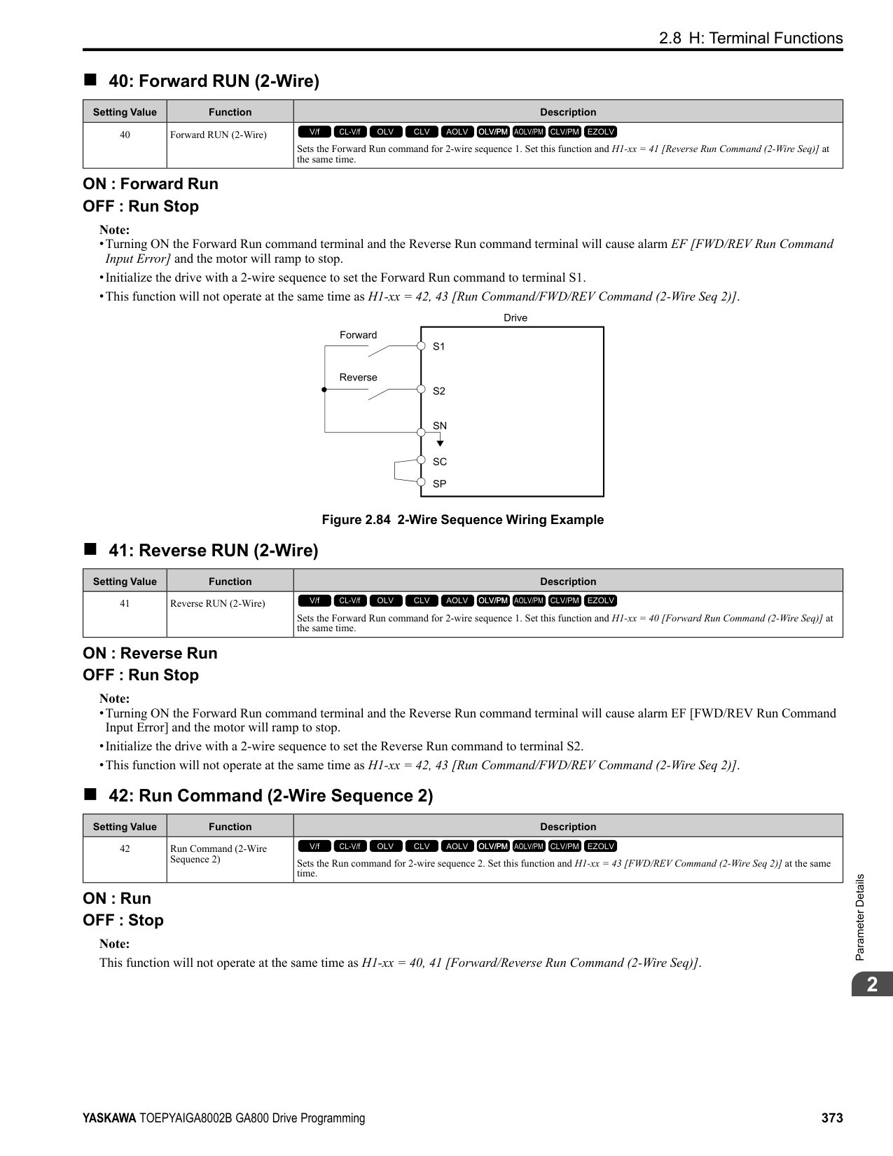
|---|---|---| |0|Frequency Reference|413| |1|Frequency Gain|413| |2|Auxiliary Frequency Reference 1|413| |3|Auxiliary Frequency Reference 2|414| |4|Output Voltage Bias|414| |5|Accel/Decel Time Gain|414| |6|DC Injection Braking Current|414| |7|Torque Detection Level|415| |8|Stall Prevent Level During Run|415| |9|Output Frequency Lower Limit|415| |B|PID Feedback|415| |C|PID Setpoint|416| |D|Frequency Bias|416|
|Setting Value|Function|Ref.| |---|---|---| |E|Motor Temperature (PTC Input)|416| |F|Not Used|416| |10|Forward Torque Limit|416| |11|Reverse Torque Limit|417| |12|Regenerative Torque Limit|418| |13|Torque Reference / Torque Limit|418| |14|Torque Compensation|418| |15|General Torque Limit|418| |16|Differential PID Feedback|418| |1F|Not Used|418| |30|DWEZ Analog Input 1|418| |31|DWEZ Analog Input 2|418| |32|DWEZ Analog Input 3|419|
Note: All analog input scaling uses gain and bias for adjustment. Set the gain and bias values correctly.
|Example Analog Input Settings|Setting of Terminal A1|Frequency Reference| |---|---|---| |Frequency reference with the gain setting adjusted|• H3-02 0 [Terminal A1 Function Selection = Frequency Reference]
• H3-03: 200.0 [Terminal A1 Gain Setting 200%]
• H3-04 0.0 [Terminal A1 Bias Setting 0.0%]
|• When you input a 10 V signal, the frequency reference will be 200%.
• When you input a 5 V signal, the frequency reference will be 100%.
When you input a 5 Vor more signal, E1-04 [Maximum Output Frequency] will limit the drive output and the frequency reference will be 100%.| |Frequency reference with the negative number bias set|• H3-02 = 0 [Frequency Reference]
• H3-03 = 100.0 [100.0%]
• H3-04 = -25.0 [-25.0%]
|• When you input a 0 V signal, the frequency reference will be -25%.
• When H3-01 = 0 [Terminal A1 Signal Level Select = 0 to 10V (Lower Limit at 0)]:
– When you input a 0 V to 2 V signal, the frequency reference will be 0%.
– When you input a 2 V to 10 V signal, the frequency reference will be 0% to 100%.
• When H3-01 = 1 [-10 to +10V (Bipolar Reference)]:
– When you input a 0 V to 2 V signal, it enables signals of positive and negative polarities and the motor rotates in reverse.|
■ MEMOBUS/Modbus Multi-Function AI1 to 3 Function Selection Let the MFAI function be assigned to MEMOBUS/Modbus register 15C1 to 15C3 (Hex.) [Mbus Reg 15C1h through 15C3h Input Function]. Use H3-40 to H3-42 [Mbus Reg 15C1h through 15C3h Input Function] to set the function and use H3-43 [Mbus Reg Inputs FilterTime Const] to set the input filter.
Table 2.65 MEMOBUS Multi-Function AI Command Register
|Register No. (Hex.)|Name|Range *1|Parameter| |---|---|---|---| |15C1|Mbus Reg 15C1h Input Function|-32767 to 32767|H3-40| |15C2|Mbus Reg 15C2h Input Function|-32767 to 32767|H3-41| |15C3|Mbus Reg 15C3h Input Function|-32767 to 32767|H3-42|
*1 Set as 100% = 4096.
ParameterDetails
######## 2
################# Figure 2.103 Functional Block Diagram for MEMOBUS Multi-Function AI Command 1
################# Note:
|H3-xx Setting Value|Function| |---|---| |0|Frequency Reference| |1|Frequency Gain| |2|Auxiliary Frequency Reference 1| |3|Auxiliary Frequency Reference 2| |30|DWEZ Analog Input 1| |31|DWEZ Analog Input 2| |32|DWEZ Analog Input 3|
######## ◆ H3: MFAI Parameters
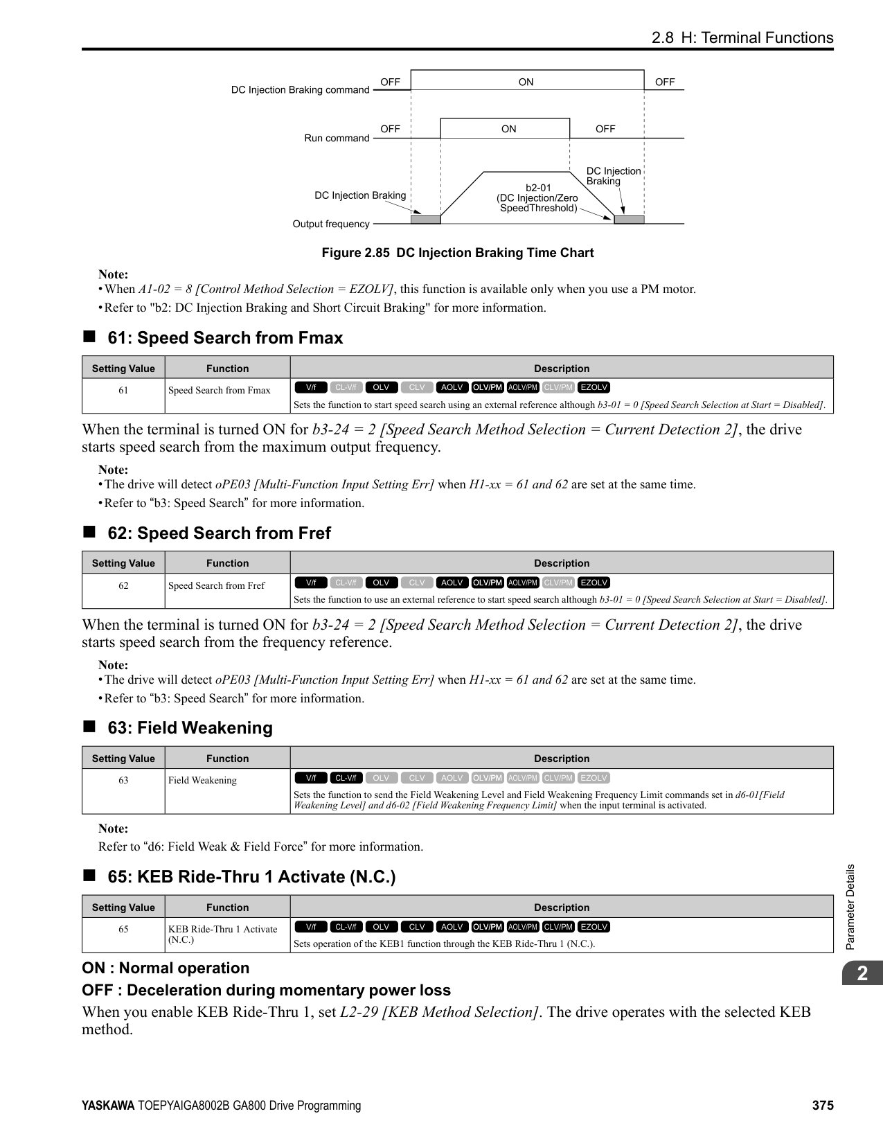
The voltage signal is 0 Vdc to 10 Vdc. The minimum input level limit is 0%. The drive will read a negative input signal caused by gain and bias settings as 0%.
The voltage signal is -10 Vdc to 10 Vdc. This setting enables positive and negative polarity signals. When the drive uses this setting as the frequency reference, a Forward Run command will run the motor in reverse and a Reverse Run command will run the motor forward. The gain and bias settings will cause the signal to be a negative number.
The current signal is 4 mA to 20 mA. The minimum input level limit is 0%. The drive will read a negative input signal caused by gain and bias settings as 0%.
The current signal is 0 mA to 20 mA. The minimum input level limit is 0%. The drive will read a negative input signal caused by gain and bias settings as 0%.
Note:
When H3-01 = 0, 1, set DIP switch S1-1 to the V side (voltage). When H3-01 = 2, 3, set DIP switch S1-1 to the I side (current). The default setting is the V side (voltage).
|No. (Hex.)|Name|Description|Default (Range)| |---|---|---|---| |H3-01 (0410)|Terminal A1 Signal Level Select|Sets the input signal level for MFAI terminal A1.
V/f CL-V/f OLV CLV AOLV OLV/PM AOLV/PM CLV/PM EZOLV
|0 (0 - 3)|
|No. (Hex.)|Name|Description|Default (Range)| |---|---|---|---| |H3-02 (0434)|Terminal A1 Function Selection|Sets the function for MFAI terminal A1.
V/f CL-V/f OLV CLV AOLV OLV/PM AOLV/PM CLV/PM EZOLV
|0 (0 - 32)|
|No. (Hex.)|Name|Description|Default (Range)| |---|---|---|---| |H3-03 (0411) RUN|Terminal A1 Gain Setting|Sets the gain of the analog signal input to MFAI terminal A1.
V/f CL-V/f OLV CLV AOLV OLV/PM AOLV/PM CLV/PM EZOLV
|100.0% (-999.9 - +999.9%)|
This parameter sets the quantity of reference for the function set for terminal A1 as a percentage when 10 V (or 20 mA) is input. Use this parameter and H3-04 [Terminal A1 Bias Setting] to adjust the characteristics of the analog input signal to terminal A1.
######## ■ H3-04: Terminal A1 Bias Setting
|No. (Hex.)|Name|Description|Default (Range)| |---|---|---|---| |H3-04 (0412) RUN|Terminal A1 Bias Setting|Sets the bias of the analog signal input to MFAI terminal A1.
V/f CL-V/f OLV CLV AOLV OLV/PM AOLV/PM CLV/PM EZOLV
|0.0% (-999.9 - +999.9%)|
This parameter sets the bias for the function set for terminal A1 as a percentage when 0 V (4 mA or 0 mA) is input. Use this parameter and H3-03 [Terminal A1 Gain Setting] to adjust the characteristics of the analog input signal to terminal A1.
######## ■ H3-05: Terminal A3 Signal Level Select
|No. (Hex.)|Name|Description|Default (Range)| |---|---|---|---| |H3-05 (0413)|Terminal A3 Signal Level Select|Sets the input signal level for MFAI terminal A3.
V/f CL-V/f OLV CLV AOLV OLV/PM AOLV/PM CLV/PM EZOLV
|0 (0 - 3)|
############## 0 : 0-10V (LowLim=0)
The voltage signal is 0 Vdc to 10 Vdc. The minimum input level limit is 0%. The drive will read a negative input signal caused by gain and bias settings as 0%.
############## 1 : -10 to +10V (Bipolar Reference)
The voltage signal is -10 Vdc to 10 Vdc. This setting enables positive and negative polarity signals. When the drive uses this setting as the frequency reference, a Forward Run command will run the motor in reverse and a Reverse Run command will run the motor forward. The gain and bias settings will cause the signal to be a negative number.
############## 2 : 4 to 20 mA
The current signal is 4 mA to 20 mA. The minimum input level limit is 0%. The drive will read a negative input signal caused by gain and bias settings as 0%.
############## 3 : 0 to 20 mA
The current signal is 0 mA to 20 mA. The minimum input level limit is 0%. The drive will read a negative input signal caused by gain and bias settings as 0%.
Note:
When H3-05 0, 1, set DIP switch S1-3 to the V side (voltage). When H3-05 2, 3, set DIP switch S1-3 to the I side (current). The default setting is the V side (voltage).
######## ■ H3-06: Terminal A3 Function Selection
|No. (Hex.)|Name|Description|Default (Range)| |---|---|---|---| |H3-06 (0414)|Terminal A3 Function Selection|Sets the function for MFAI terminal A3.
V/f CL-V/f OLV CLV AOLV OLV/PM AOLV/PM CLV/PM EZOLV
|2 (0 - 32)|
Note: When terminal A3 is the PTC input terminal:
ParameterDetails
######## 2
######## ■ H3-07: Terminal A3 Gain Setting
|No. (Hex.)|Name|Description|Default (Range)| |---|---|---|---| |H3-07 (0415) RUN|Terminal A3 Gain Setting|Sets the gain of the analog signal input to MFAI terminal A3.
V/f CL-V/f OLV CLV AOLV OLV/PM AOLV/PM CLV/PM EZOLV
|100.0% (-999.9 - +999.9%)|
When 10 V (or 20 mA) is input, this parameter sets the reference quantity for the function set for terminal A3 as a percentage. Use this parameter and H3-08 [Terminal A3 Bias Setting] to adjust the characteristics of the analog input signal to terminal A3.
######## ■ H3-08: Terminal A3 Bias Setting
|No. (Hex.)|Name|Description|Default (Range)| |---|---|---|---| |H3-08 (0416) RUN|Terminal A3 Bias Setting|Sets the bias of the analog signal input to MFAI terminal A3.
V/f CL-V/f OLV CLV AOLV OLV/PM AOLV/PM CLV/PM EZOLV
|0.0% (-999.9 - +999.9%)|
When 0 V (4 mA or 0 mA) is input, this parameter sets the bias for the function set for terminal A3 as a percentage. Use this parameter and H3-07 [Terminal A3 Gain Setting] to adjust the characteristics of the analog input signal to terminal A3.
######## ■ H3-09: Terminal A2 Signal Level Select
|No. (Hex.)|Name|Description|Default (Range)| |---|---|---|---| |H3-09 (0417)|Terminal A2 Signal Level Select|Sets the input signal level for MFAI terminal A2.
V/f CL-V/f OLV CLV AOLV OLV/PM AOLV/PM CLV/PM EZOLV
|2 (0 - 3)|
############## 0 : 0-10V (LowLim=0)
The voltage signal is 0 Vdc to 10 Vdc. The minimum input level is limited to 0%, so that a negative input signal due to gain and bias settings will be read as 0%.
############## 1 : -10 to +10V (Bipolar Reference)
The voltage signal is -10 Vdc to 10 Vdc. Signals of both positive and negative polarities are enabled. When this setting is used as the frequency reference, the motor runs reverse when the Forward run command is input, or runs forward when the Reverse run signal is input, while the signal is a negative number due to gain and bias.
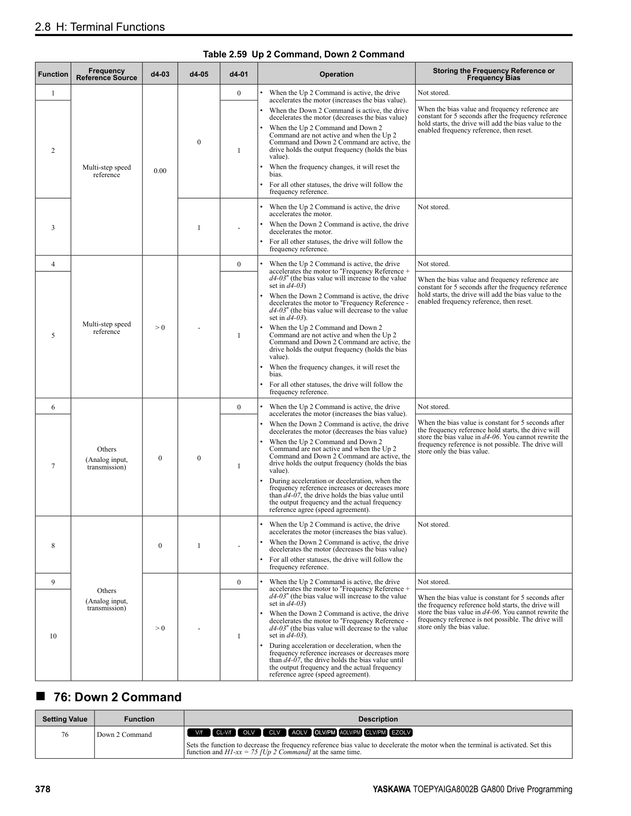
############## 2 : 4 to 20 mA
The current signal is 4 mA to 20 mA. The minimum input level is limited to 0%, so that a negative input signal due to gain and bias settings will be read as 0%.
############## 3 : 0 to 20 mA
The current signal is 0 mA to 20 mA. The minimum input level is limited to 0%, so that a negative input signal due to gain and bias settings will be read as 0%.
Note: When H3-09 = 0, 1, set DIP switch S1-2 to the V side (voltage). When H3-09 = 2, 3, set DIP switch S1-2 to the I side (current). The default setting is the I side (current).
######## ■ H3-10: Terminal A2 Function Selection
|No. (Hex.)|Name|Description|Default (Range)| |---|---|---|---| |H3-10 (0418)|Terminal A2 Function Selection|Sets the function for MFAI terminal A2.
V/f CL-V/f OLV CLV AOLV OLV/PM AOLV/PM CLV/PM EZOLV
|0 (0 - 32)|
######## ■ H3-11: Terminal A2 Gain Setting
|No. (Hex.)|Name|Description|Default (Range)| |---|---|---|---| |H3-11 (0419) RUN|Terminal A2 Gain Setting|Sets the gain of the analog signal input to MFAI terminal A2.
V/f CL-V/f OLV CLV AOLV OLV/PM AOLV/PM CLV/PM EZOLV
|100.0% (-999.9 - +999.9%)|
When 10 V (or 20 mA) is input, this parameter sets the reference quantity for the function set for terminal A2 as a percentage. Use this parameter and H3-12 [Terminal A2 Bias Setting] to adjust the characteristics of the analog input signal to terminal A2.
######## ■ H3-12: Terminal A2 Bias Setting
|No. (Hex.)|Name|Description|Default (Range)| |---|---|---|---| |H3-12 (041A) RUN|Terminal A2 Bias Setting|Sets the bias of the analog signal input to MFAI terminal A2.
V/f CL-V/f OLV CLV AOLV OLV/PM AOLV/PM CLV/PM EZOLV
|0.0% (-999.9 - +999.9%)|
When 0 V (4 mA or 0 mA) is input, this parameter sets the bias for the function set for terminal A2 as a percentage. Use this parameter and H3-11 [Terminal A2 Gain Setting] to adjust the characteristics of the analog input signal to terminal A2.
######## ■ H3-13: Analog Input FilterTime Constant
|No. (Hex.)|Name|Description|Default (Range)| |---|---|---|---| |H3-13 (041B)|Analog Input FilterTime Constant|Sets the time constant for primary delay filters on MFAI terminals.
V/f CL-V/f OLV CLV AOLV OLV/PM AOLV/PM CLV/PM EZOLV
|0.03 s (0.00 - 2.00 s)|
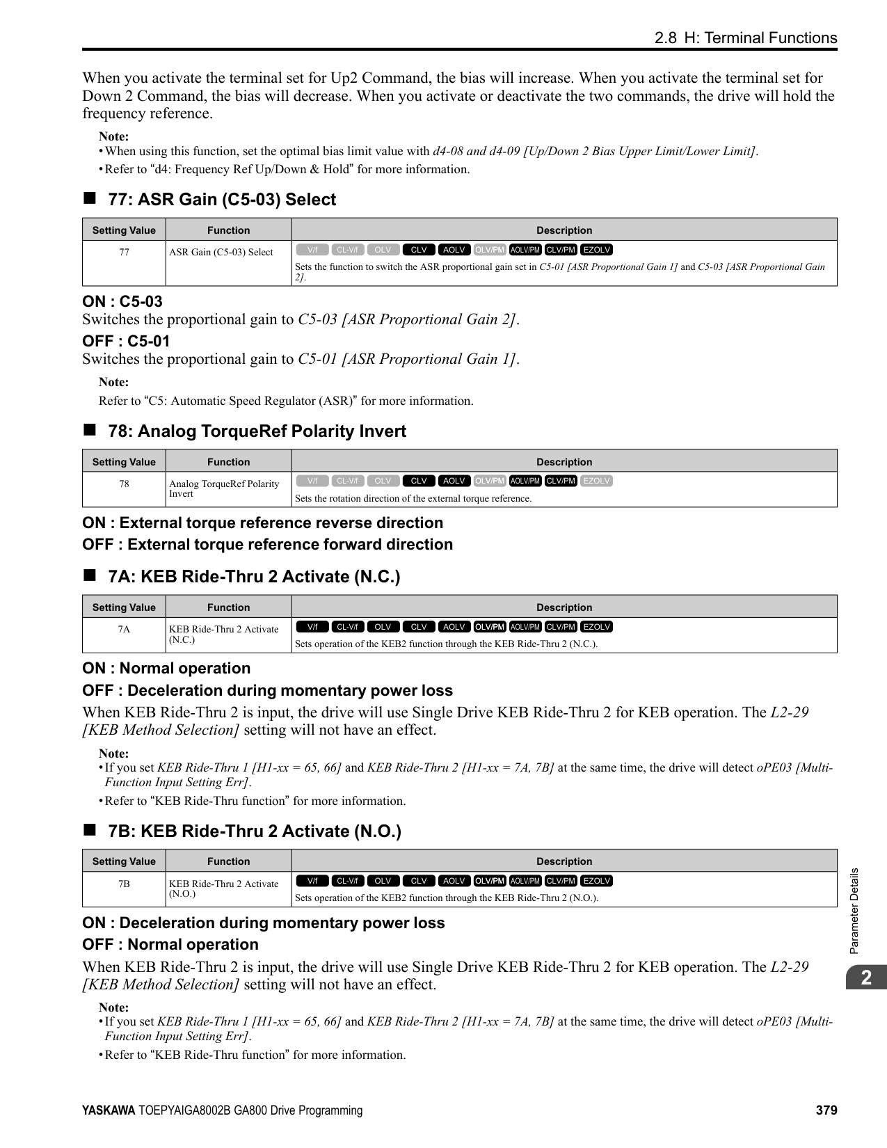
Apply the primary delay filter to the analog input to enable an analog input signal without the use of high-frequency noise components. An analog input filter prevents irregular drive control. Drive operation becomes more stable as the programmed time becomes longer, but it also becomes less responsive to quickly changing analog signals.
######## ■ H3-14: Analog Input Terminal Enable Sel
|No. (Hex.)|Name|Description|Default (Range)| |---|---|---|---| |H3-14 (041C)|Analog Input Terminal Enable Sel|Sets the enabled terminal or terminals when H1-xx = C [MFDI Function Select = Analog Terminal Enable Selection] is ON.
V/f CL-V/f OLV CLV AOLV OLV/PM AOLV/PM CLV/PM EZOLV
|7 (1 - 7)|
Input signals do not have an effect on terminals not set as targets.
ParameterDetails
######## 2
######## ■ H3-16: Terminal A1 Offset
|No. (Hex.)|Name|Description|Default (Range)| |---|---|---|---| |H3-16 (02F0)|Terminal A1 Offset|Sets the offset level for analog signals input to terminal A1. Usually it is not necessary to change this setting.
V/f CL-V/f OLV CLV AOLV OLV/PM AOLV/PM CLV/PM EZOLV
|0 (-500 - +500)|
Adds the offset value for the analog input value. For voltage input, this parameter will set the offset when a signal of 0 V is input. For current input, this parameter will set the offset when a signal of 4 mA [H3-01= 2] or 0 mA [H3-01 = 3] is input.
######## ■ H3-17: Terminal A2 Offset
|No. (Hex.)|Name|Description|Default (Range)| |---|---|---|---|
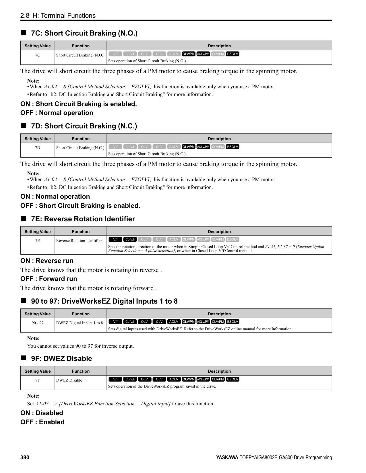
|H3-17 (02F1)|Terminal A2 Offset|Sets the offset level for analog signals input to terminal A2. Usually it is not necessary to change this setting.
V/f CL-V/f OLV CLV AOLV OLV/PM AOLV/PM CLV/PM EZOLV
|0 (-500 - +500)|
Adds the offset value for the analog input value. For voltage input, this parameter will set the offset when a signal of 0 V is input. For current input, this parameter will set the offset when a signal of 4 mA [H3-09 = 2] or 0 mA [H3-09 =
######## ■ H3-18: Terminal A3 Offset
|No. (Hex.)|Name|Description|Default (Range)| |---|---|---|---| |H3-18 (02F2)|Terminal A3 Offset|Sets the offset level for analog signals input to terminal A3. Usually it is not necessary to change this setting.
V/f CL-V/f OLV CLV AOLV OLV/PM AOLV/PM CLV/PM EZOLV
|0 (-500 - +500)|
Adds the offset value for the analog input value. For voltage input, this parameter will set the offset when a signal of 0 V is input. For current input, this parameter will set the offset when a signal of 4 mA [H3-05 = 2] or 0 mA [H3-05 =
######## ■ H3-40: Mbus Reg 15C1h Input Function
|No. (Hex.)|Name|Description|Default (Range)| |---|---|---|---| |H3-40 (0B5C)|Mbus Reg 15C1h Input Function|Sets the MEMOBUS AI1 function.
V/f CL-V/f OLV CLV AOLV OLV/PM AOLV/PM CLV/PM EZOLV
|F (4 - 2F)|
You can use the MFAI function from MEMOBUS/Modbus communications. Use this parameter to set the function. Sets the input for the function in MEMOBUS/Modbus register 15C1. Refer to H3-xx “MFAI Setting Values” for the setting values.
######## ■ H3-41: Mbus Reg 15C2h Input Function
|No. (Hex.)|Name|Description|Default (Range)| |---|---|---|---| |H3-41 (0B5F)|Mbus Reg 15C2h Input Function|Sets the MEMOBUS AI2 function.
V/f CL-V/f OLV CLV AOLV OLV/PM AOLV/PM CLV/PM EZOLV
|F (4 - 2F)|
You can use the MFAI function from MEMOBUS/Modbus communications. Use this parameter to set the function. Sets the input for the function in MEMOBUS/Modbus register 15C2. Refer to H3-xx “MFAI Setting Values” for the setting values.
######## ■ H3-42: Mbus Reg 15C3h Input Function
|No. (Hex.)|Name|Description|Default (Range)| |---|---|---|---|
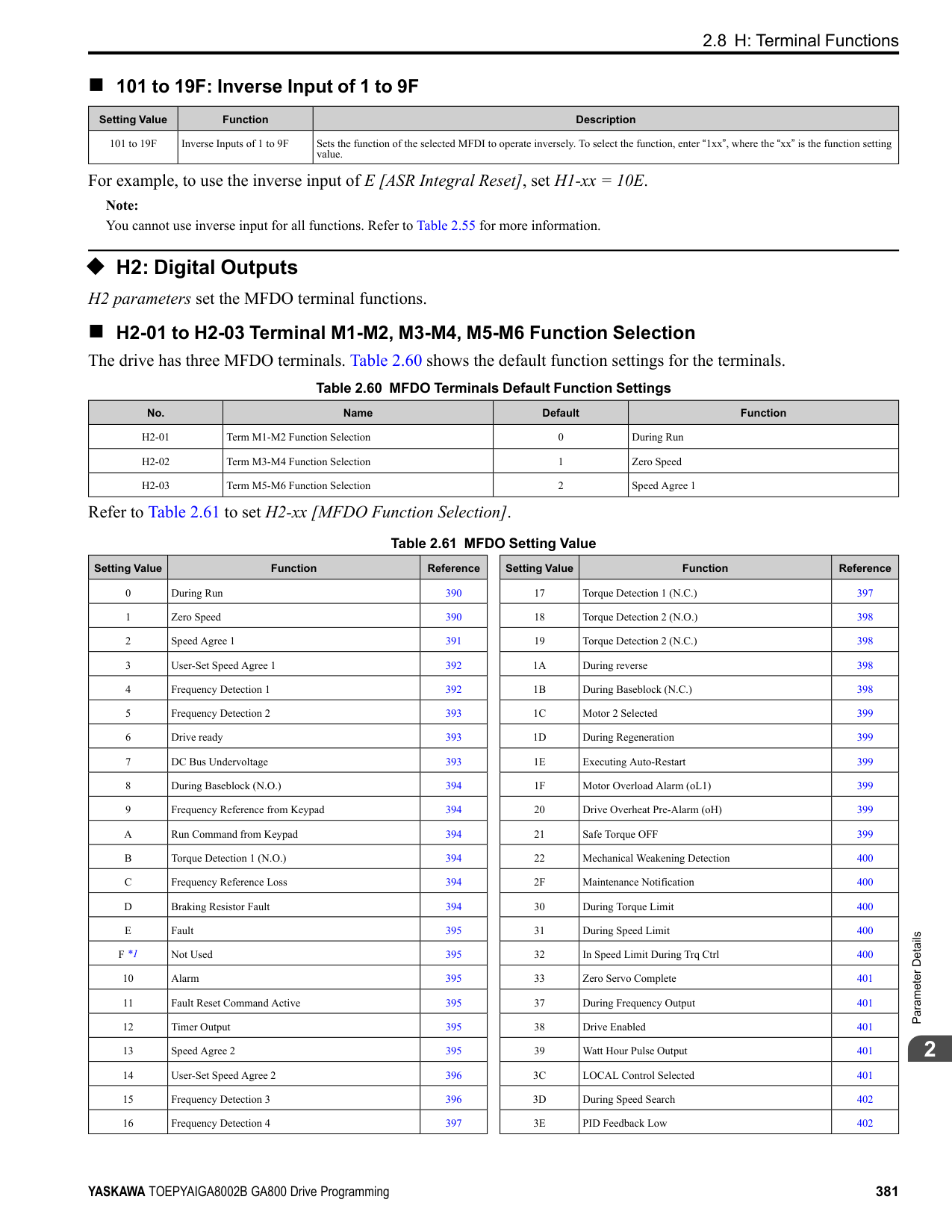
|H3-42 (0B62)|Mbus Reg 15C3h Input Function|Sets the MEMOBUS AI3 function.
V/f CL-V/f OLV CLV AOLV OLV/PM AOLV/PM CLV/PM EZOLV
|F (4 - 2F)|
You can use the MFAI function from MEMOBUS/Modbus communications. Use this parameter to set the function. Sets the input for the function in MEMOBUS/Modbus register 15C3. Refer to H3-xx “MFAI Setting Values” for the setting values.
######## ■ H3-43: Mbus Reg Inputs FilterTime Const
|No. (Hex.)|Name|Description|Default (Range)| |---|---|---|---| |H3-43 (117F)|Mbus Reg Inputs FilterTime Const|Sets the time constant to apply a primary delay filter to the MEMOBUS analog input terminal.
V/f CL-V/f OLV CLV AOLV OLV/PM AOLV/PM CLV/PM EZOLV
|0.00 s (0.00 - 2.00 s)|
◆ Multi-Function Analog Input Terminal Settings This section gives information about the functions set with H3-02, H3-06, and H3-10.
######## ■ 0: Frequency Reference
|Setting Value|Function|Description| |---|---|---| |0|Frequency Reference|The input value from the MFAI terminal set with this function becomes the master frequency reference.
V/f CL-V/f OLV CLV AOLV OLV/PM AOLV/PM CLV/PM EZOLV
|
• You can copy the configuration to more than one of the analog input terminals A1 through A3. When you set more
than one analog input terminal with the master frequency reference, the sum value becomes the frequency bias. • If you use this function to set the analog input value as the master frequency reference, set b1-01 = 1 [Frequency
Reference Selection 1 = Analog Input]. This setting value is the default value for terminals A1 and A2.
• The frequency reference is the sum of the input values for terminals A1 and A2 when they are used at the same time. For example, when a 20% bias is input to terminal A2 while a frequency reference of 50% is input from terminal A1, the calculated frequency reference will be 70% of the maximum output frequency.
######## ■ 1: Frequency Gain
|Setting Value|Function|Description| |---|---|---| |1|Frequency Gain|The drive multiplies the analog frequency reference with the input value from the MFAI set with this function.
V/f CL-V/f OLV CLV AOLV OLV/PM AOLV/PM CLV/PM EZOLV
|
Example: When you set frequency gain for terminal A2
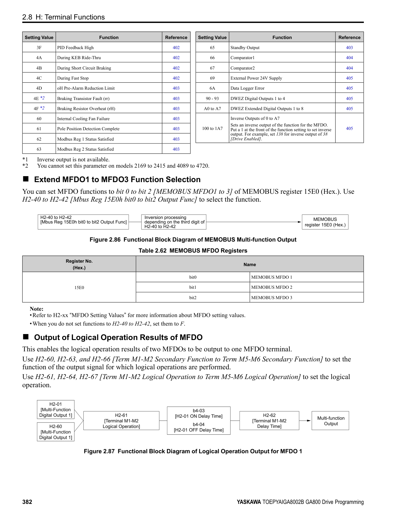
######## ■ 2: Auxiliary Frequency Reference 1
|Setting Value|Function|Description| |---|---|---| |2|Auxiliary Frequency Reference 1|Sets Reference 2 through multi-step speed reference to enable the command reference (Auxiliary Frequency Reference 1) from the analog input terminal set here. This value is a percentage where the Maximum Output Frequency setting is a setting value of 100%.
V/f CL-V/f OLV CLV AOLV OLV/PM AOLV/PM CLV/PM EZOLV
|
ParameterDetails
######## 2
The gain (%) for the MFAI terminals A1, A2, and A3 is 100% of the voltage class standard, which is 200 V for 200 V class drives and 400 V for 400 V class drives. The bias (%) for MFAI terminals A1, A2, and A3 is 100% of the voltage configured for E1-05 [Maximum Output Voltage].
Note: The gain for each terminal A1, A2, and A3 is configured independently with H3-03 [Terminal A1 Gain Setting], H3-11 [Terminal A2 Gain Setting], and H3-07 [Terminal A3 Gain Setting]. The bias for each terminal A1, A2, and A3 is configured independently with H3-04 [Terminal A1 Bias Setting], H3-12 [Terminal A2 Bias Setting], and H3-08 [Terminal A3 Bias Setting].
Figure 2.104 Output Voltage Bias through Analog Input
When you enable C1-01 [Acceleration Time 1], the acceleration time is: Acceleration Time 1 = Setting value of C1-01 × acceleration and deceleration time gain / 100
Figure 2.105 Acceleration/Deceleration Time Gain through Analog Input
|Setting Value|Function|Description| |---|---|---| |3|Auxiliary Frequency Reference 2|Sets Reference 3 through multi-step speed reference to enable the command reference (Auxiliary Frequency Reference 2) from the analog input terminal set here. This value is a percentage where the Maximum Output Frequency setting is a setting value of 100%.
V/f CL-V/f OLV CLV AOLV OLV/PM AOLV/PM CLV/PM EZOLV
|
|Setting Value|Function|Description| |---|---|---| |4|Output Voltage Bias|Set this parameter to input a bias signal and amplify the output voltage.
V/f CL-V/f OLV CLV AOLV OLV/PM AOLV/PM CLV/PM EZOLV
|
|Setting Value|Function|Description| |---|---|---|
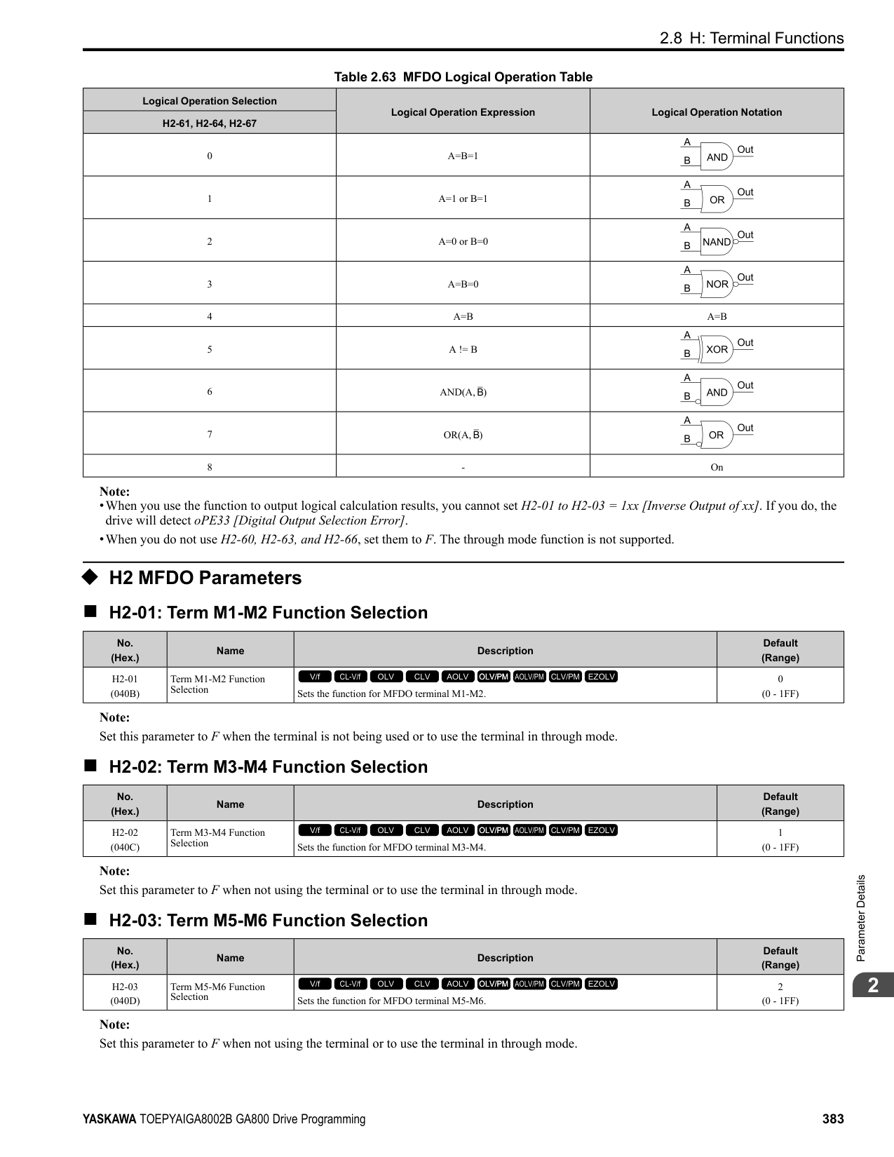
|5|Accel/Decel Time Gain|Enters a signal to adjust the gain used for C1-01 to C1-08 [Acceleration/Deceleration Times 1 to 4] and C1-09 [Fast Stop Time] when the full scale analog signal (10 Vor 20 mA) is 100%.
V/f CL-V/f OLV CLV AOLV OLV/PM AOLV/PM CLV/PM EZOLV
|
|Setting Value|Function|Description| |---|---|---| |6|DC Injection Braking Current|Enters a signal to adjust the current level used for DC Injection Braking when the drive rated output current is 100%.
V/f CL-V/f OLV CLV AOLV OLV/PM AOLV/PM CLV/PM EZOLV
|
Note: When you set this function, it will disable the setting value of b2-02 [DC Injection Braking Current].
Figure 2.106 DC Injection Braking Current through Analog Input
When A1-02 = 0, 1, 5 [Control Method Selection = V/f, CL-V/f, OLV/PM], the drive rated current is 100%. When A102 = 2, 3, 4, 6, 7, 8 [OLV, CLV, AOLV, AOLV/PM, CLV/PM, EZOLV], the motor rated torque is 100%.
Note: Use this function with L6-01 [Torque Detection Selection 1]. This parameter functions as an alternative to L6-02 [Torque Detection Level 1].
Note: The Stall Prevent Level During Run is based on the smaller of these two values:
Figure 2.107 Stall Prevention Level during Run with Analog Input
|Setting Value|Function|Description| |---|---|---| |7|Torque Detection Level|Enters a signal to adjust the overtorque/undertorque detection level.
V/f CL-V/f OLV CLV AOLV OLV/PM AOLV/PM CLV/PM EZOLV
|
|Setting Value|Function|Description| |---|---|---| |8|Stall Prevent Level During Run|Enters a signal to adjust the stall prevention level during run if the drive rated current is 100%.
V/f CL-V/f OLV CLV AOLV OLV/PM AOLV/PM CLV/PM EZOLV
|
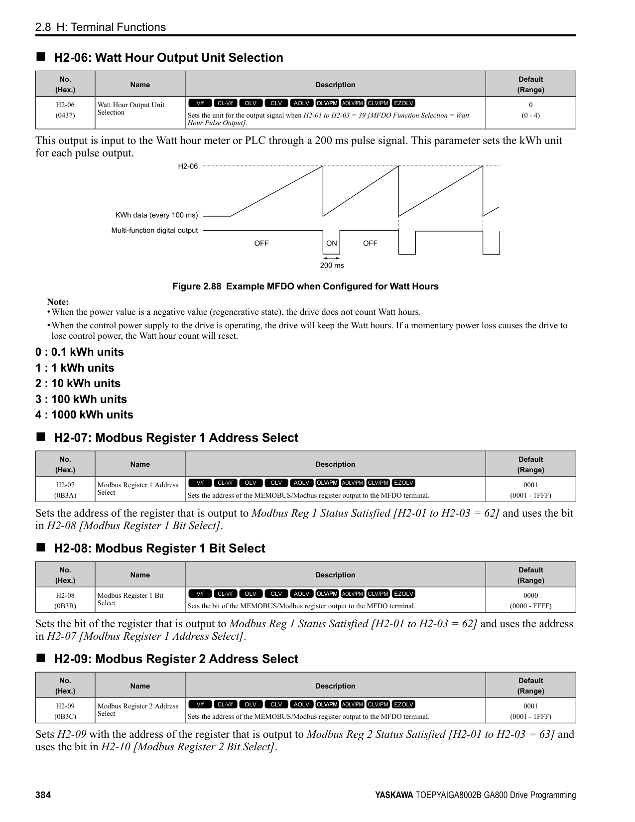
|Setting Value|Function|Description| |---|---|---| |9|Output Frequency Lower Limit|Enters a signal to adjust the output frequency lower limit level as a percentage of the maximum output frequency.
V/f CL-V/f OLV CLV AOLV OLV/PM AOLV/PM CLV/PM EZOLV
|
|Setting Value|Function|Description| |---|---|---| |B|PID Feedback|Enter the PID feedback value as a percentage of the maximum output frequency.
V/f CL-V/f OLV CLV AOLV OLV/PM AOLV/PM CLV/PM EZOLV
|
ParameterDetails
######## 2
When you use this function, set b5-01 = 1 to 8 [PID Mode Setting = Enabled].
######## ■ C: PID Setpoint
|Setting Value|Function|Description| |---|---|---| |C|PID Setpoint|Enters the PID setpoint as a percentage of the maximum output frequency.
V/f CL-V/f OLV CLV AOLV OLV/PM AOLV/PM CLV/PM EZOLV
|
When you use this function, set b5-01 = 1 to 8 [PID Mode Setting = Enabled]. Note: Configuring this function disables the frequency reference set with b1-01 [Frequency Reference Selection 1].
######## ■ D: Frequency Bias
|Setting Value|Function|Description| |---|---|---| |D|Frequency Bias|Enters the bias value added to the frequency reference as a percentage of the maximum output frequency.
V/f CL-V/f OLV CLV AOLV OLV/PM AOLV/PM CLV/PM EZOLV
|
The drive adds the input value from the MFAI terminal set with this function to the frequency reference as the bias value.
Note:
When you select d1-01 to d1-16 or d1-17 [Reference 1 to 16 or JOG Frequency Reference] as the frequency reference, it will disable this function.
######## ■ E: Motor Temperature (PTC Input)
|Setting Value|Function|Description| |---|---|---|
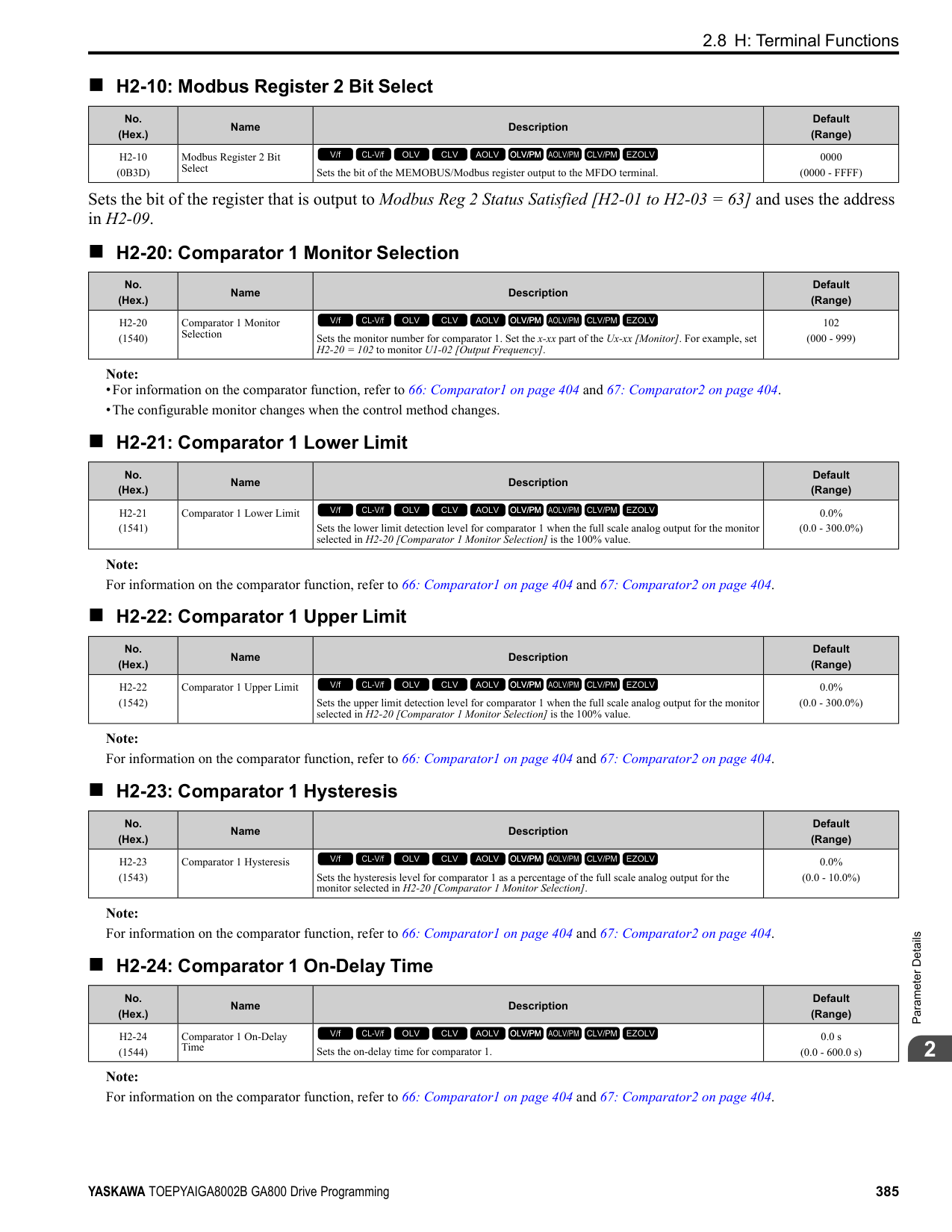
|E|Motor Temperature (PTC Input)|Uses the motor Positive Temperature Coefficient (PTC) thermistor to prevent heat damage to the motor as a percentage of the current value when the 10 Vanalog signal is input.
V/f CL-V/f OLV CLV AOLV OLV/PM AOLV/PM CLV/PM EZOLV
|
######## ■ F: Not Used
|Setting Value|Function|Description| |---|---|---| |F|Not Used|Use this setting for unused terminals or to use terminals in through mode.
V/f CL-V/f OLV CLV AOLV OLV/PM AOLV/PM CLV/PM EZOLV
|
When you set a terminal that is not in use to F, you can use the signal input to the terminal as PLC analog signal input through MEMOBUS/Modbus communications or the communication option. This input signal does not have an effect on drive operation. This functions the same as setting 1F (Through Mode).
######## ■ 10: Forward Torque Limit
|Setting Value|Function|Description| |---|---|---| |10|Forward Torque Limit|Enters the forward torque limit if the motor rated torque is 100%.
V/f CL-V/f OLV CLV AOLV OLV/PM AOLV/PM CLV/PM EZOLV
|
WARNING! Sudden Movement Hazard. Set correct torque limits for applications, for example elevator applications. If you set torque limits incorrectly, motor torque that is not sufficient can cause damage to equipment and cause serious injury or death.
Torque Limit Configuration Method Use one of these methods to set torque limits:
• Use a communication option to set all four torque limit quadrants together.
Figure 2.108 Torque Limits and Analog Input Setting Parameters Note:
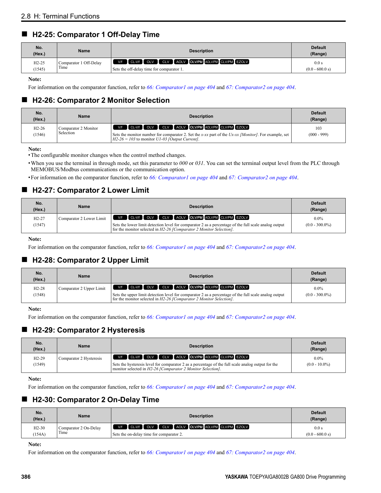
Figure 2.109 Torque Limits from Parameters and Analog Inputs
######## ■ 11: Reverse Torque Limit
|Setting Value|Function|Description| |---|---|---| |11|Reverse Torque Limit|Enters the load torque limit if the motor rated torque is 100%.
V/f CL-V/f OLV CLV AOLV OLV/PM AOLV/PM CLV/PM EZOLV
|
Note: When you use L7-01 to L7-04 and analog inputs to set torque limits for the same quadrant, it will enable the lower torque limit.
ParameterDetails
######## 2
Note: When you use L7-01 to L7-04 and analog inputs to set torque limits for the same quadrant, it will enable the lower torque limit.
Note: When you use L7-01 to L7-04 and analog inputs to set torque limits for the same quadrant, it will enable the lower torque limit.
When you set a terminal that you do not use to 1F, you can use the signal that is input to that terminal as the PLC analog signal input from MEMOBUS/Modbus communications or the communication option. This input signal does not have an effect on drive operation. This signal functions the same as F (Through Mode).
|Setting Value|Function|Description|
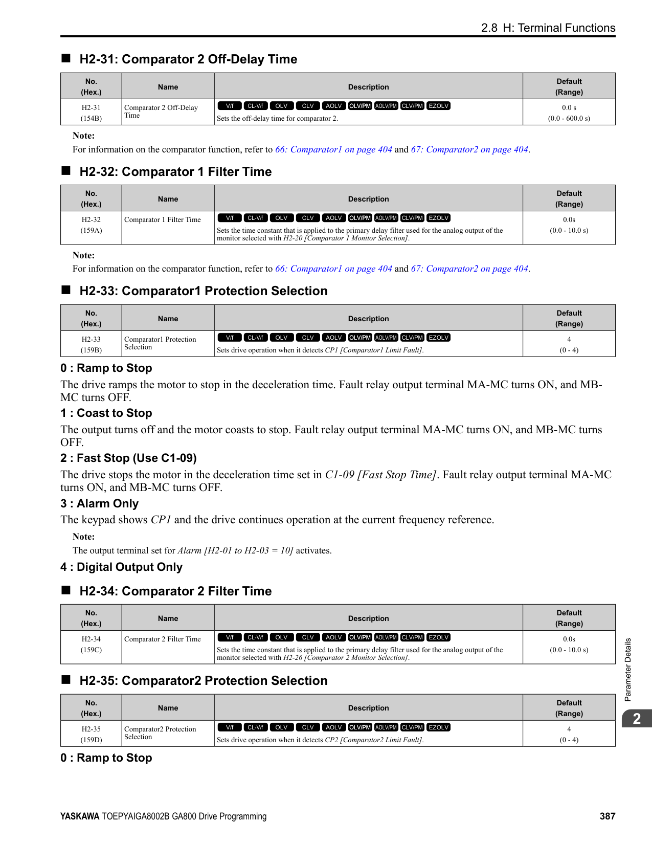
|---|---|---| |12|Regenerative Torque Limit|Enters the regenerative torque limit if the motor rated torque is 100%.
V/f CL-V/f OLV CLV AOLV OLV/PM AOLV/PM CLV/PM EZOLV
|
|Setting Value|Function|Description| |---|---|---| |13|Torque Reference / Torque Limit|Enters the torque reference if the motor rated torque is 100%. This setting is the torque limit for speed control.
V/f CL-V/f OLV CLV AOLV OLV/PM AOLV/PM CLV/PM EZOLV
|
|Setting Value|Function|Description| |---|---|---| |14|Torque Compensation|Enters the torque compensation value if the motor rated torque is 100%.
V/f CL-V/f OLV CLV AOLV OLV/PM AOLV/PM CLV/PM EZOLV
|
|Setting Value|Function|Description| |---|---|---| |15|General Torque Limit|Enters the torque limit that is the same for all quadrants for forward, reverse, and regenerative operation if the motor rated torque is 100%.
V/f CL-V/f OLV CLV AOLV OLV/PM AOLV/PM CLV/PM EZOLV
|
|Setting Value|Function|Description| |---|---|---| |16|Differential PID Feedback|Enters the PID differential feedback value if the full scale analog signal (10 Vor 20 mA) is 100%.
V/f CL-V/f OLV CLV AOLV OLV/PM AOLV/PM CLV/PM EZOLV
|
|Setting Value|Function|Description| |---|---|---| |1F|Not Used|Use this setting for unused terminals or to use terminals in through mode.
V/f CL-V/f OLV CLV AOLV OLV/PM AOLV/PM CLV/PM EZOLV
|
|Setting Value|Function|Description| |---|---|---| |30|DWEZ Analog Input 1|Use with DriveWorksEZ. Refer to the DriveWorksEZ online manual for more information.
V/f CL-V/f OLV CLV AOLV OLV/PM AOLV/PM CLV/PM EZOLV
|
|Setting Value|Function|Description| |---|---|---| |31|DWEZ Analog Input 2|Use with DriveWorksEZ. Refer to the DriveWorksEZ online manual for more information.
V/f CL-V/f OLV CLV AOLV OLV/PM AOLV/PM CLV/PM EZOLV
|
######## ■ 32: DWEZ Analog Input 3
|Setting Value|Function|Description|
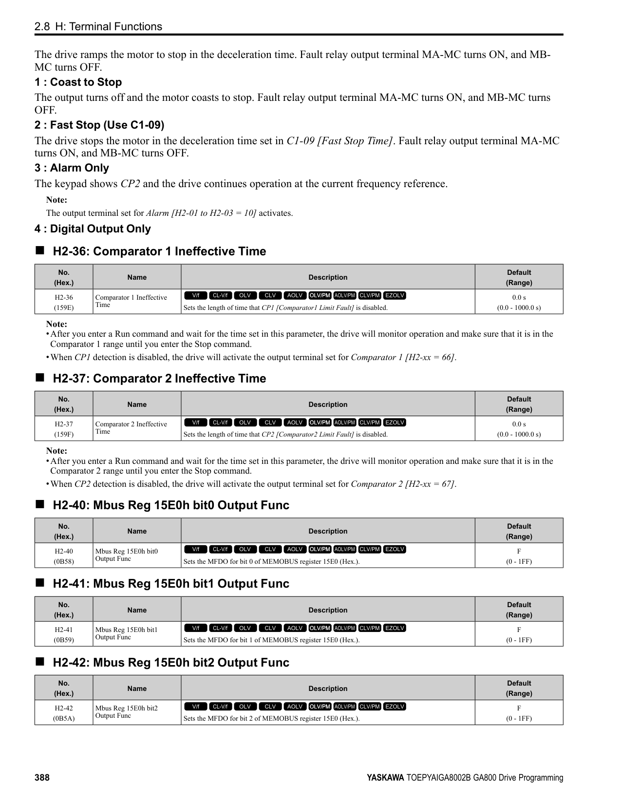
|---|---|---| |32|DWEZ Analog Input 3|Use with DriveWorksEZ. Refer to the DriveWorksEZ online manual for more information.
V/f CL-V/f OLV CLV AOLV OLV/PM AOLV/PM CLV/PM EZOLV
|
◆ H4: Analog Outputs H4 parameters set the drive analog monitors. These parameters select monitor parameters, adjust gain and bias, and select output signal levels.
■ Calibrate Meters Connected to MFAO Terminals FM and AM To calibrate the meters connected to terminals FM and AM, use these parameters:
Set these parameters where the output voltage of 10 Vand output current of 20 mA are 100% of the signal level. Use jumper switch S5 and H4-07 [Terminal FM Signal Level Select] or H4-08 [Terminal AM Signal Level Select] to select the voltage output and current output.
|No.|Name|Range|Default| |---|---|---|---| |H4-02|Terminal FM Analog Output Gain|-999.9 - +999.9%|100.0%| |H4-03|Terminal FM Analog Output Bias|-999.9 - +999.9%|0.0%| |H4-05|Terminal AM Analog Output Gain|-999.9 - +999.9%|50.0%| |H4-06|Terminal AM Analog Output Bias|-999.9 - +999.9%|0.0%| |H4-07|Terminal FM Signal Level Select|0: 0 to 10 Vdc
1: -10 to +10 Vdc
2: 4 to 20 mA
|0| |H4-08|Terminal AM Signal Level Select|0: 0 to 10 Vdc
1: -10 to +10 Vdc
2: 4 to 20 mA
|0|
Figure 2.110 and Figure 2.111 show the gain and bias.
Figure 2.110 Analog Output Gain/Bias Configuration Example 1 For example, when the parameter value set to analog output is 0, and a 3 V signal is output to terminal FM, H4-03 [Terminal FM Analog Output Bias] is set to 30%.
ParameterDetails
######## 2
Figure 2.111 Analog Output Gain/Bias Configuration Example 2
Calibrate Terminal FM Stop the drive to calibrate meters. Use this procedure to calibrate:
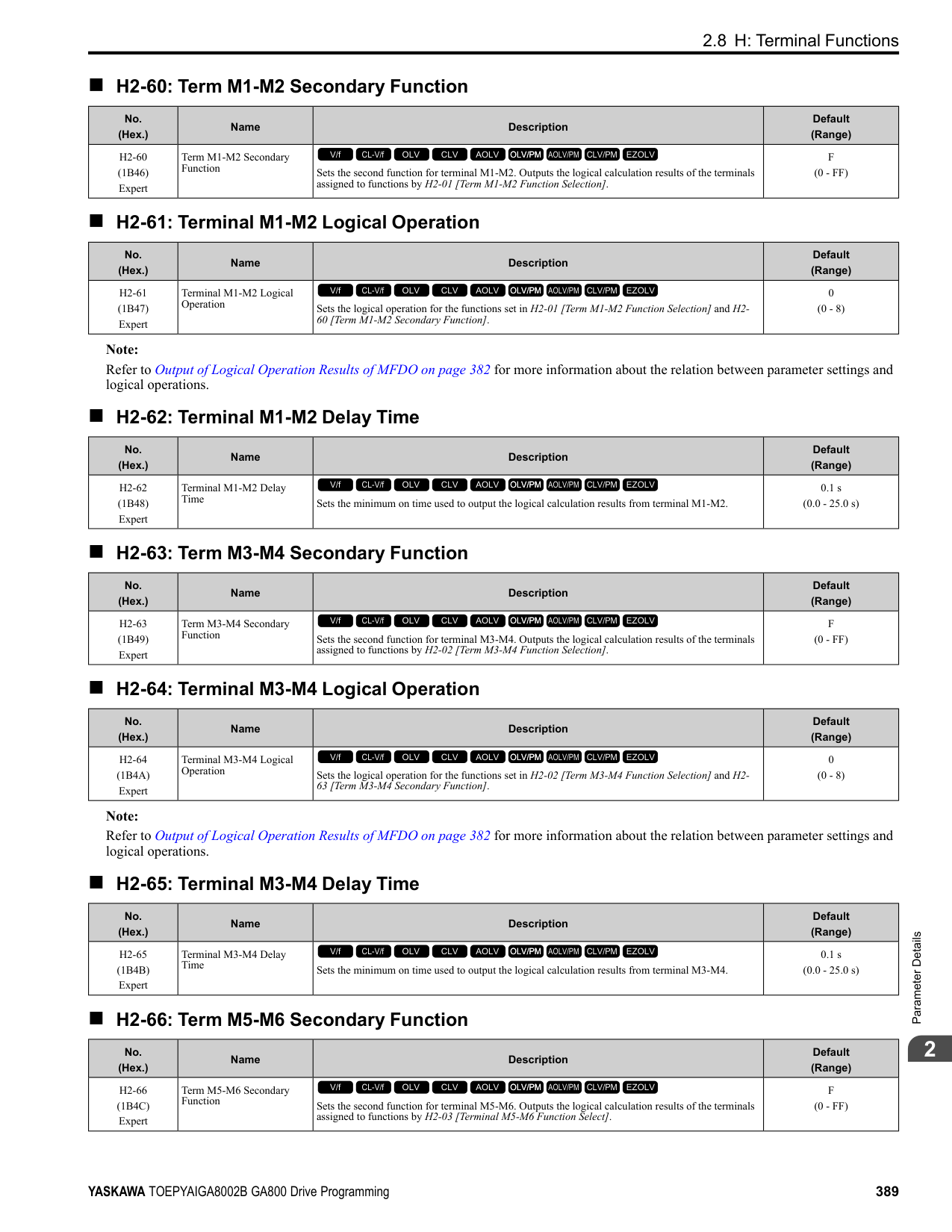
Calibrate Terminal AM Stop the drive to calibrate meters. Use this procedure to calibrate:
######## ■ H4-01: Terminal FM Analog Output Select
|No. (Hex.)|Name|Description|Default (Range)| |---|---|---|---| |H4-01 (041D)|Terminal FM Analog Output Select|Sets the monitor number to send from MFAO terminal FM.
V/f CL-V/f OLV CLV AOLV OLV/PM AOLV/PM CLV/PM EZOLV
|102 (000 - 999)|
Set the x-xx part of the Ux-xx [Monitor]. For example, set H4-01 = 102 to monitor U1-02 [Output Frequency].
Note:
######## ■ H4-02: Terminal FM Analog Output Gain
|No. (Hex.)|Name|Description|Default (Range)| |---|---|---|---| |H4-02 (041E) RUN|Terminal FM Analog Output Gain|Sets the gain of the monitor signal that is sent from MFAO terminal FM.
V/f CL-V/f OLV CLV AOLV OLV/PM AOLV/PM CLV/PM EZOLV
|100.0% (-999.9 - +999.9%)|
The analog signal output from the FM terminal is a maximum of ±10 V (or 20 mA). Select the signal level with H4-
######## ■ H4-03: Terminal FM Analog Output Bias
|No. (Hex.)|Name|Description|Default (Range)| |---|---|---|---| |H4-03 (041F) RUN|Terminal FM Analog Output Bias|Sets the bias of the monitor signal that is sent from MFAO terminal FM.
V/f CL-V/f OLV CLV AOLV OLV/PM AOLV/PM CLV/PM EZOLV
|0.0% (-999.9 - +999.9%)|
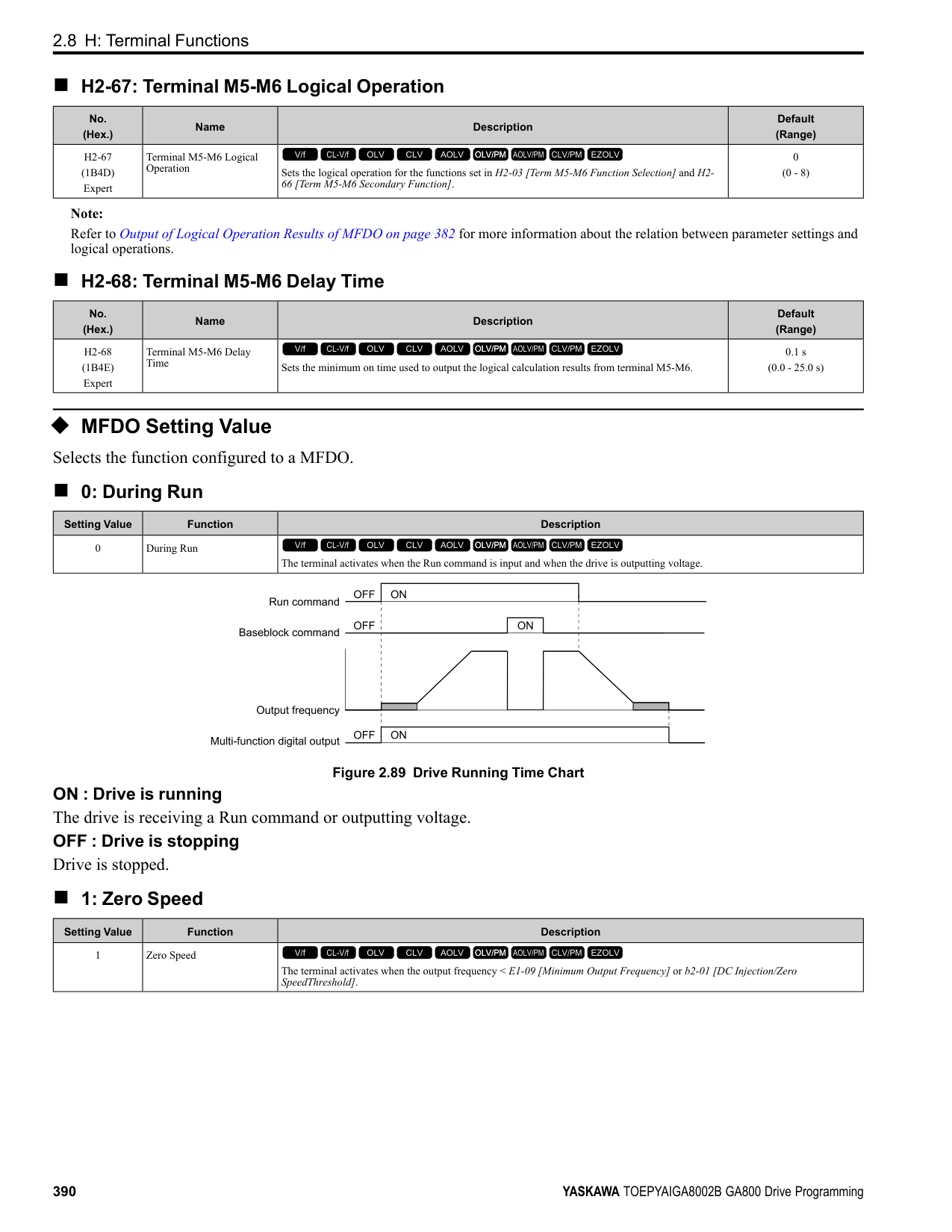
The analog signal output from the FM terminal is a maximum of ±10 V (or 20 mA). Select the signal level with H4-
■ H4-04: Terminal AM Analog Output Select
Set the x-xx part of the Ux-xx [Monitor]. For example, set H4-04 = 103 to monitor U1-03 [Output Current].
Note:
■ H4-05: Terminal AM Analog Output Gain
The analog signal output from the AM terminal is a maximum of ±10 V (or 20 mA). Select the signal level with H4-
|No. (Hex.)|Name|Description|Default (Range)| |---|---|---|---| |H4-04 (0420)|Terminal AM Analog Output Select|Sets the monitoring number to be output from the MFAO terminal AM.
V/f CL-V/f OLV CLV AOLV OLV/PM AOLV/PM CLV/PM EZOLV
|103 (000 - 999)|
|No. (Hex.)|Name|Description|Default (Range)| |---|---|---|---| |H4-05 (0421) RUN|Terminal AM Analog Output Gain|Sets the gain of the monitor signal that is sent from MFAO terminal AM.
V/f CL-V/f OLV CLV AOLV OLV/PM AOLV/PM CLV/PM EZOLV
|50.0% (-999.9 - +999.9%)|
When the output current of a monitoring item is 100% (drive rated current) in these examples, the voltage of AM terminal outputs at 5 V (50% of 10 V). Subsequently, the output current at the time the AM terminal outputs a maximum voltage of 10 V will be 200% of the drive rated current.
######## ■ H4-06: Terminal AM Analog Output Bias
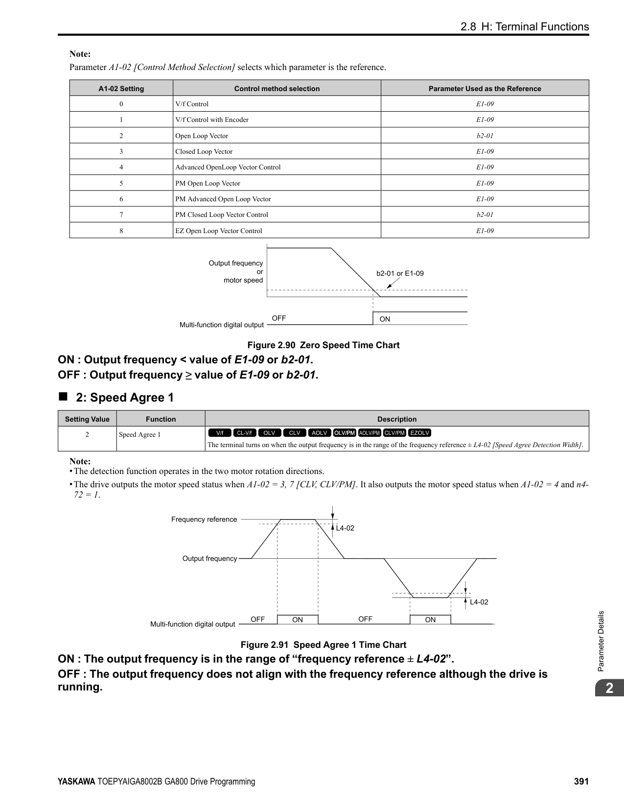
|No. (Hex.)|Name|Description|Default (Range)| |---|---|---|---| |H4-06 (0422) RUN|Terminal AM Analog Output Bias|Sets the bias of the monitor signal that is sent from MFAO terminal AM.
V/f CL-V/f OLV CLV AOLV OLV/PM AOLV/PM CLV/PM EZOLV
|0.0% (-999.9 - +999.9%)|
The analog signal output from the AM terminal is a maximum of ±10 V (or 20 mA). Select the signal level with H408 [Terminal AM Signal Level Select].
######## ■ H4-07: Terminal FM Signal Level Select
|No. (Hex.)|Name|Description|Default (Range)| |---|---|---|---| |H4-07 (0423)|Terminal FM Signal Level Select|Sets the MFAO terminal FM output signal level.
V/f CL-V/f OLV CLV AOLV OLV/PM AOLV/PM CLV/PM EZOLV
|0 (0 - 2)|
ParameterDetails
######## 2
Note: Set jumper S5 on the control circuit terminal block accordingly when changing these parameters.
0 : 0-10 VDC 1 : -10 +10 VDC 2 : 4-20 mA
######## ■ H4-08: Terminal AM Signal Level Select
|No. (Hex.)|Name|Description|Default (Range)| |---|---|---|---| |H4-08 (0424)|Terminal AM Signal Level Select|Sets the MFAO terminal AM output signal level.
V/f CL-V/f OLV CLV AOLV OLV/PM AOLV/PM CLV/PM EZOLV
|0 (0 - 2)|
Note: Set jumper S5 on the terminal board to the correct position after changing this parameter.
######## ■ H4-20: Analog Power Monitor 100% Level
|No. (Hex.)|Name|Description|Default (Range)| |---|---|---|---| |H4-20 (0B53)|Analog Power Monitor 100% Level|Sets the level at 10 V when U1-08 [Output Power] is set for analog output.
V/f CL-V/f OLV CLV AOLV OLV/PM AOLV/PM CLV/PM EZOLV
|0.00 kW (0.00 - 650.00 kW)|
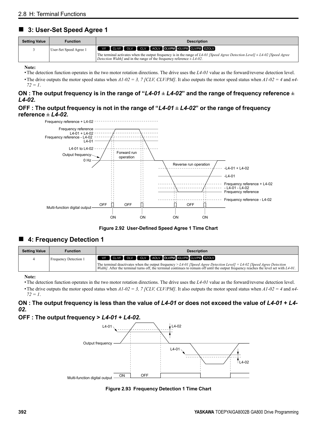
Note:
•When H4-20 = 0.00 kW, the output power monitor 10 V level = motor rated power. The setting changes when the A1-02 [Control Method Selection] value changes:
◆ H5: Memobus/Modbus Communication
You can use the MEMOBUS/Modbus protocol over the RS-485 port (terminals D+ and D-) in the drive to use serial communication with programmable controllers (PLC).
######## ■ H5-01: Drive Node Address
|No. (Hex.)|Name|Description|Default (Range)| |---|---|---|---| |H5-01 (0425)|Drive Node Address|Sets the communication slave address for drives.
V/f CL-V/f OLV CLV AOLV OLV/PM AOLV/PM CLV/PM EZOLV
|1FH (0 - FFH)|
################# Note:
######## ■ H5-02: Communication Speed Selection
|No. (Hex.)|Name|Description|Default (Range)| |---|---|---|---| |H5-02 (0426)|Communication Speed Selection|Sets the communications speed for MEMOBUS/Modbus communications.
V/f CL-V/f OLV CLV AOLV OLV/PM AOLV/PM CLV/PM EZOLV
|3 (0 - 8)|
Note: Restart the drive after you change the parameter setting.
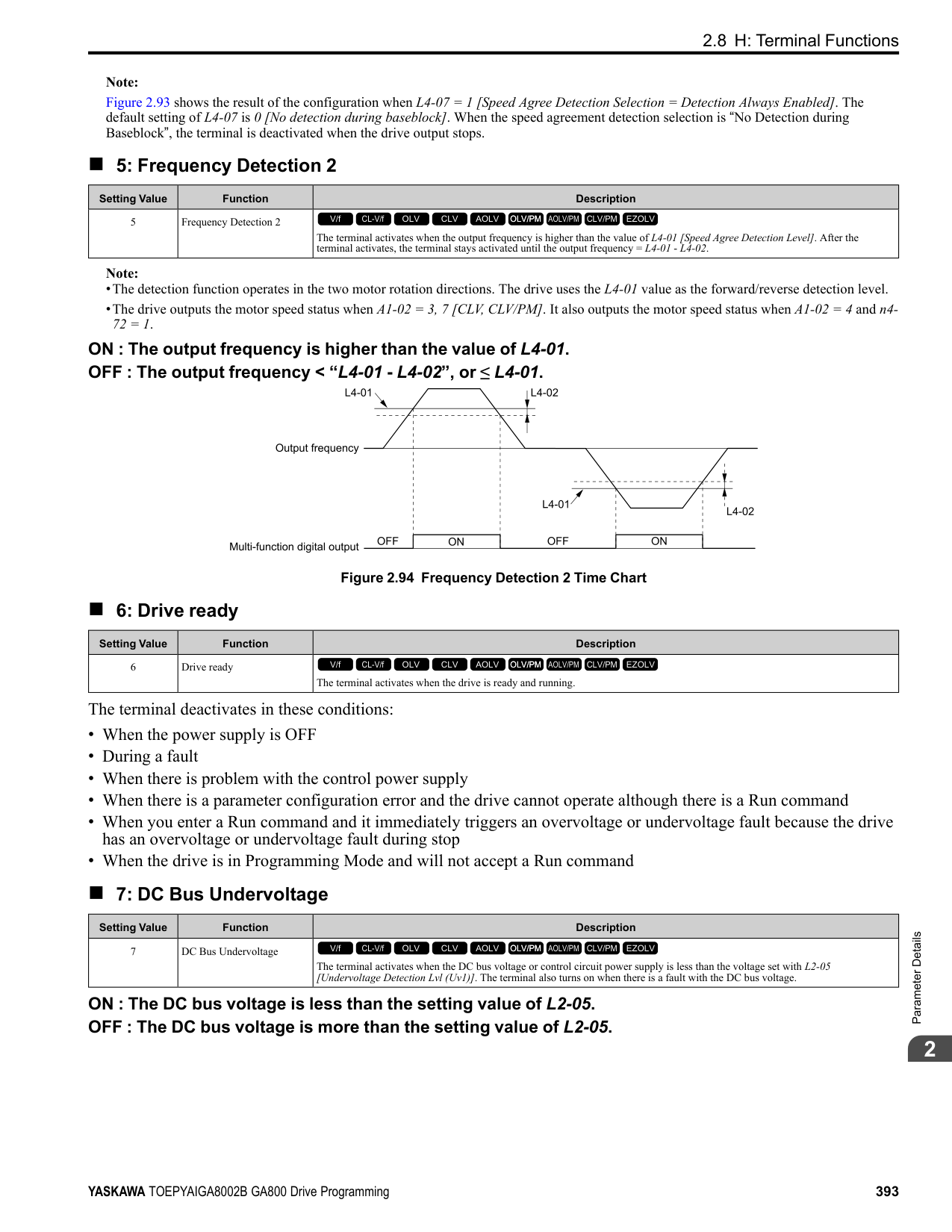
######## ■ H5-03: Communication Parity Selection
|No. (Hex.)|Name|Description|Default (Range)| |---|---|---|---| |H5-03 (0427)|Communication Parity Selection|Sets the communications parity used for MEMOBUS/Modbus communications.
V/f CL-V/f OLV CLV AOLV OLV/PM AOLV/PM CLV/PM EZOLV
|0 (0 - 2)|
Note: Restart the drive after you change the parameter setting.
0 : No parity 1 : Even parity 2 : Odd parity
######## ■ H5-04: Communication Error Stop Method
|No. (Hex.)|Name|Description|Default (Range)| |---|---|---|---| |H5-04 (0428)|Communication Error Stop Method|Sets the motor Stopping Method when the drive detects CE [Modbus Communication Error] issues.
V/f CL-V/f OLV CLV AOLV OLV/PM AOLV/PM CLV/PM EZOLV
|3 (0 - 3)|
############## 0 : Ramp to Stop
The drive ramps the motor to stop in the deceleration time. Fault relay output terminal MA-MC turns ON, and MBMC turns OFF.
############## 1 : Coast to Stop
The output turns off and the motor coasts to stop. Fault relay output terminal MA-MC turns ON, and MB-MC turns OFF.
############## 2 : Fast Stop (Use C1-09)
The drive stops the motor in the deceleration time set in C1-09 [Fast Stop Time]. Fault relay output terminal MA-MC turns ON, and MB-MC turns OFF.
############## 3 : Alarm Only
The keypad shows CE and the drive continues operation. The output terminal set for Alarm [H2-01 to H2-03 = 10] activates.
ParameterDetails
######## 2
######## ■ H5-05: Comm Fault Detection Selection
|No. (Hex.)|Name|Description|Default (Range)| |---|---|---|---| |H5-05 (0429)|Comm Fault Detection Selection|Sets the function that detects CE [Modbus Communication Error] issues during MEMOBUS/ Modbus communications.
V/f CL-V/f OLV CLV AOLV OLV/PM AOLV/PM CLV/PM EZOLV
|1 (0, 1)|
If the drive does not receive data from the master during the time set in H5-09 [CE Detection Time], it will detect a CE error. 0 : Disabled Does not detect CE. The drive continues operation. 1 : Enabled Detects CE. If the drive detects CE, it will operate as specified by the setting of H5-04 [Communication Error Stop Method].
######## ■ H5-06: Drive Transmit Wait Time
|No. (Hex.)|Name|Description|Default (Range)| |---|---|---|---| |H5-06 (042A)|Drive Transmit Wait Time|Sets the time to wait to send a response message after the drive receives a command message from the master.
V/f CL-V/f OLV CLV AOLV OLV/PM AOLV/PM CLV/PM EZOLV
|5 ms (0 - 65 ms)|
Figure 2.112 Drive Transmit Wait Time
|No. (Hex.)|Name|Description|Default (Range)| |---|---|---|---| |H5-09 (0435)|CE Detection Time|Sets the detection time for CE [Modbus Communication Error] issues when communication stops.
V/f CL-V/f OLV CLV AOLV OLV/PM AOLV/PM CLV/PM EZOLV
|2.0 s (0.0 - 10.0 s)|
|No. (Hex.)|Name|Description|Default (Range)|
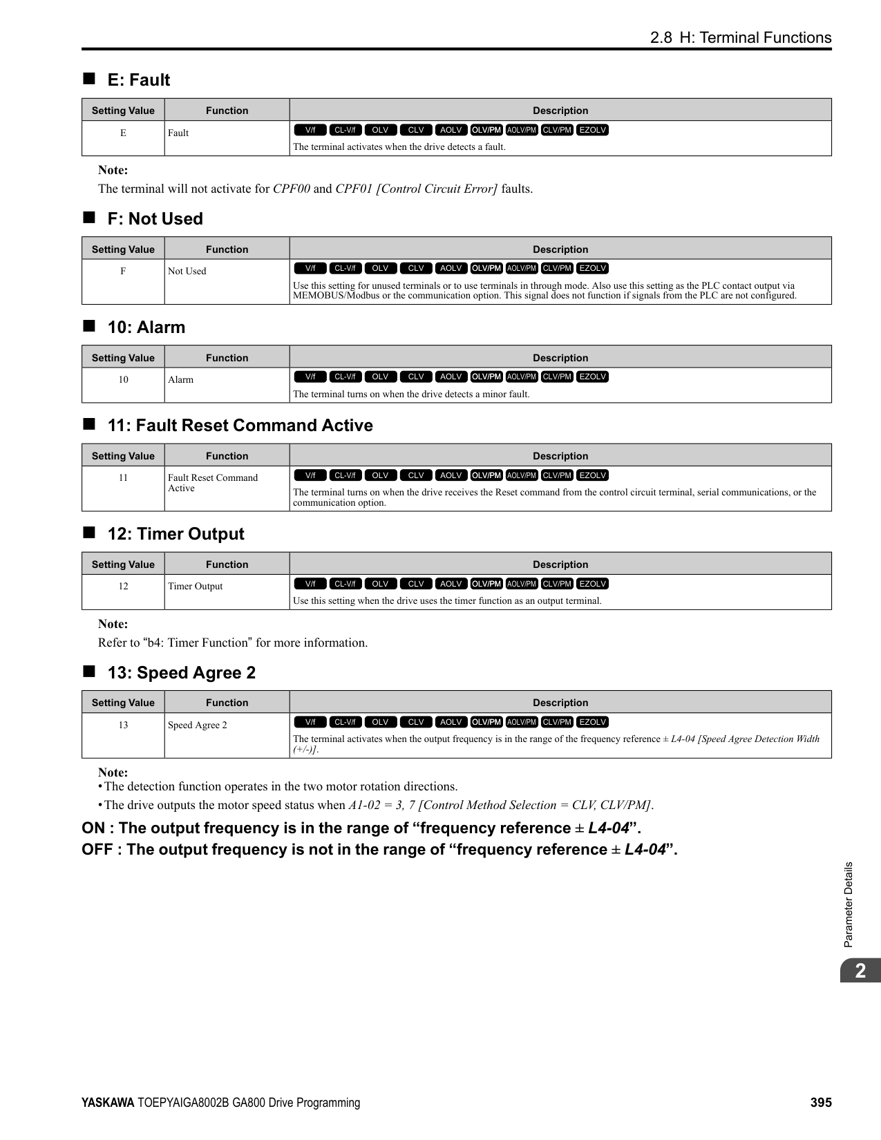
|---|---|---|---| |H5-10 (0436)|Modbus Register 0025H Unit Sel|Sets the unit of measure used for the MEMOBUS/Modbus communications monitor register 0025H (output voltage reference monitor).
V/f CL-V/f OLV CLV AOLV OLV/PM AOLV/PM CLV/PM EZOLV
|0 (0, 1)|
|No. (Hex.)|Name|Description|Default (Range)| |---|---|---|---| |H5-11 (043C)|Comm ENTER Command Mode|Sets the function to make the Enter command necessary to change parameters through MEMOBUS/ Modbus communications.
V/f CL-V/f OLV CLV AOLV OLV/PM AOLV/PM CLV/PM EZOLV
|0 (0, 1)|
You must use the Enter command to enable changes to parameters. Make all parameter changes then input the Enter command. 1 : ENTER Command Not Required It is not necessary to input the Enter command to change parameters.
######## ■ H5-12: Run Command Method Selection
|No. (Hex.)|Name|Description|Default (Range)| |---|---|---|---| |H5-12 (043D)|Run Command Method Selection|Sets the input method for the Run command when b1-02 = 2 [Run Command Selection 1 = Memobus/Modbus Communications] or b1-16 = 2 [Run Command Selection 2 = Memobus/Modbus Communications].
V/f CL-V/f OLV CLV AOLV OLV/PM AOLV/PM CLV/PM EZOLV
|0 (0, 1)|
The drive uses bit 0 in command data 0001H of the MEMOBUS register in the motor Run command (bit 0 = 1) and the stop command (bit 0 = 0). The drive uses bit 1 in the direction of motor rotation command (Forward run (bit1 = 0) or Reverse run (bit 1 = 1)).
######## ■ H5-17: ENTER command response @CPU BUSY
|No. (Hex.)|Name|Description|Default (Range)| |---|---|---|---| |H5-17 (11A1) Expert|ENTER command response @CPU BUSY|Sets operation when the EEPROM write command is sent without EEPROM write available. Usually it is not necessary to change this setting.
V/f CL-V/f OLV CLV AOLV OLV/PM AOLV/PM CLV/PM EZOLV
|0 (0, 1)|
0 : Ignore Command(No ROM/RAM Write) 1 : Write to RAM Only
######## ■ H5-18: Motor Speed Filter over Comms
|No. (Hex.)|Name|Description|Default (Range)| |---|---|---|---| |H5-18 (11A2)|Motor Speed Filter over Comms|Sets the filter time constant used when monitoring motor speed during MEMOBUS/Modbus communications or with a communication option.
V/f CL-V/f OLV CLV AOLV OLV/PM AOLV/PM CLV/PM EZOLV
|0 ms (0 - 100 ms)|
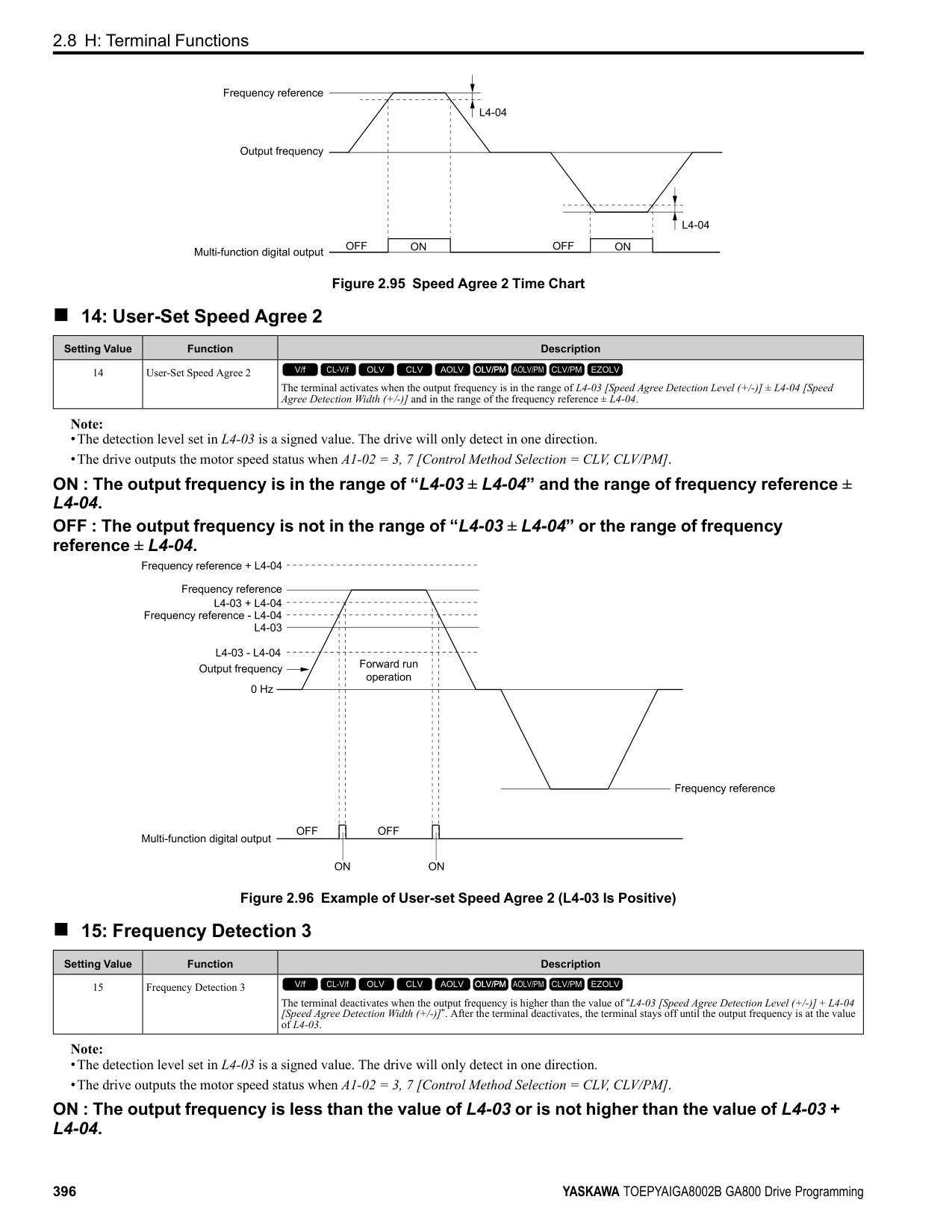
Sets the filter time constant when you monitor the output frequency or motor speed during MEMOBUS/Modbus communications or use of the communication option. These are the MEMOBUS registers:
######## ■ H5-20: Communication Parameters Reload
|No. (Hex.)|Name|Description|Default (Range)| |---|---|---|---| |H5-20 (0B57)|Communication Parameters Reload|Sets the function to immediately enable updated MEMOBUS/Modbus communications parameters.
V/f CL-V/f OLV CLV AOLV OLV/PM AOLV/PM CLV/PM EZOLV
|0 (0, 1)|
0 : Reload at Next Power Cycle 1 : Reload Now
ParameterDetails
######## 2
################# Note:
######## ■ H5-22: Speed Search from MODBUS
|No. (Hex.)|Name|Description|Default (Range)| |---|---|---|---| |H5-22 (11CF)|Speed Search from MODBUS|Enables the MEMOBUS/Modbus communication register Speed Search function (bit0 of 15DFH).
V/f CL-V/f OLV CLV AOLV OLV/PM AOLV/PM CLV/PM EZOLV
|0 (0, 1)|
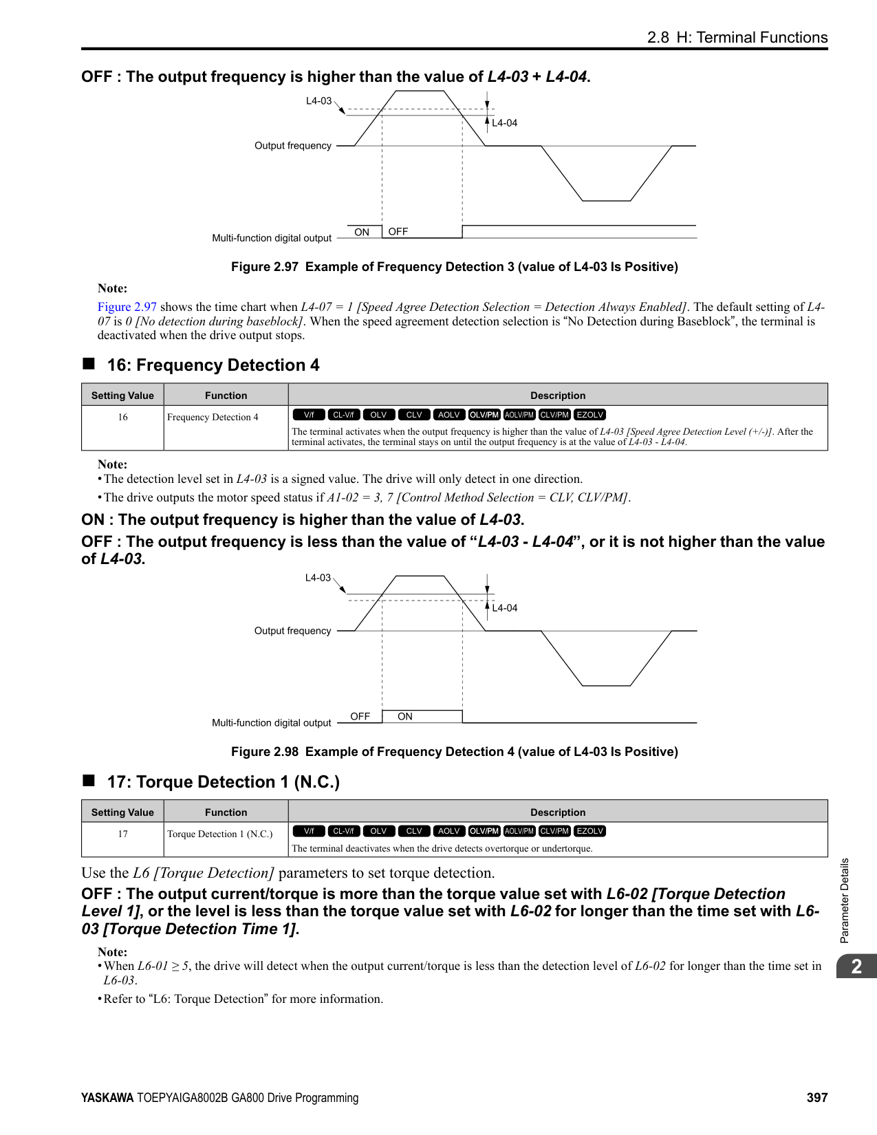
|No. (Hex.)|Name|Description|Default (Range)| |---|---|---|---| |H5-25 (1589) RUN|Function 5A Register 1 Selection|Returns the contents of the specified MEMOBUS/Modbus communications register when responding to the master device.
V/f CL-V/f OLV CLV AOLV OLV/PM AOLV/PM CLV/PM EZOLV
|0044H (U1-05) (0000H - FFFFH)|
|No. (Hex.)|Name|Description|Default (Range)| |---|---|---|---| |H5-26 (158A) RUN|Function 5A Register 2 Selection|Returns the contents of the specified MEMOBUS/Modbus communications register when responding to the master device.
V/f CL-V/f OLV CLV AOLV OLV/PM AOLV/PM CLV/PM EZOLV
|0045H (U1-06) (0000H - FFFFH)|
|No. (Hex.)|Name|Description|Default (Range)| |---|---|---|---| |H5-27 (158B) RUN|Function 5A Register 3 Selection|Returns the contents of the specified MEMOBUS/Modbus communications register when responding to the master device.
V/f CL-V/f OLV CLV AOLV OLV/PM AOLV/PM CLV/PM EZOLV
|0042H (U1-03) (0000H - FFFFH)|
|No. (Hex.)|Name|Description|Default (Range)| |---|---|---|---| |H5-28 (158C) RUN|Function 5A Register 4 Selection|Returns the contents of the specified MEMOBUS/Modbus communications register when responding to the master device.
V/f CL-V/f OLV CLV AOLV OLV/PM AOLV/PM CLV/PM EZOLV
|0049H (U1-10) (0000H - FFFFH)|
######## ◆ H6: Pulse Train Input/Output
A pulse train signal with a maximum single pulse of 32 kHz can be input to the drive input terminal RP. You can use the pulse train signal as the frequency reference, PID feedback value, PID setpoint value, and speed feedback for V/f Control mode.
A pulse train signal with a maximum frequency of 32 kHz can be output from the drive output terminal MP as the monitor value. Sinking mode and sourcing mode are supported.
Figure 2.113 Pulse Train Input Block Diagram
######## ■ H6-01: Terminal RP Pulse Train Function
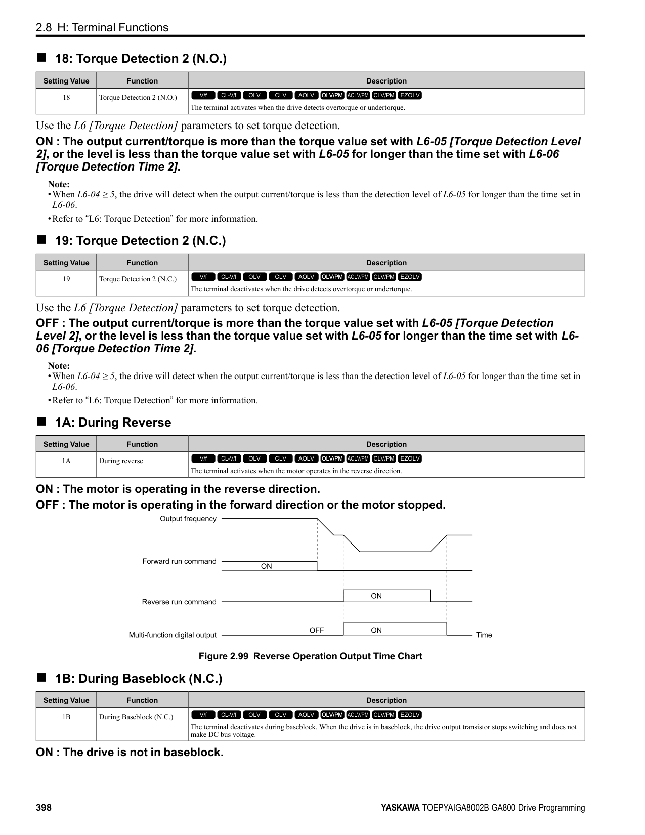
|No. (Hex.)|Name|Description|Default (Range)| |---|---|---|---| |H6-01 (042C)|Terminal RP Pulse Train Function|Sets the function for pulse train input terminal RP.
V/f CL-V/f OLV CLV AOLV OLV/PM AOLV/PM CLV/PM EZOLV
|0 (0 - 3)|
When b1-01 [Frequency Reference Selection 1] or b1-15 [Frequency Reference Selection 2] = 4 [Pulse Train Input], the drive inputs the frequency reference received from terminal RP.
Use motor speed feedback for better speed control precision. The drive compares the frequency reference to the motor speed feedback received from the encoder, and uses the ASR function to compensates for motor slip. You cannot use input terminal RP used for the simple encoder to detect the direction of motor rotation. Use a different method to detect motor rotation. Use these methods to detect the direction of motor rotation.
Figure 2.114 shows speed control in Simple Closed Loop V/f Mode.
ParameterDetails
| | | |---|---| | | |
| | | |---|---| | | | | | | | | |
Figure 2.114 Simple Closed Loop Speed Control Block Diagram Enable Simple Closed Loop V/f Mode
Note:
|No. (Hex.)|Name|Description|Default (Range)| |---|---|---|---| |H6-02 (042D) RUN|Terminal RP Frequency Scaling|Sets the frequency of the pulse train input signal used when the item selected with H6-01 [Terminal RP Pulse Train Function] is input at 100%.
V/f CL-V/f OLV CLV AOLV OLV/PM AOLV/PM CLV/PM EZOLV
|1440 Hz (100 - 32000 Hz)|
|No. (Hex.)|Name|Description|Default (Range)| |---|---|---|---| |H6-03 (042E) RUN|Terminal RP Function Gain|Sets the gain used when the function in H6-01 [Terminal RP Pulse Train Function] is input to terminal RP.
V/f CL-V/f OLV CLV AOLV OLV/PM AOLV/PM CLV/PM EZOLV
|100.0% (0.0 - 1000.0%)|
|No. (Hex.)|Name|Description|Default (Range)| |---|---|---|---| |H6-04 (042F) RUN|Terminal RP Function Bias|Sets the bias used when the function in H6-01 [Terminal RP Pulse Train Function] is input to terminal RP. Sets a value at the time when the pulse train is 0 Hz.
V/f CL-V/f OLV CLV AOLV OLV/PM AOLV/PM CLV/PM EZOLV
|0.0% (-100.0 - 100.0%)|
|No. (Hex.)|Name|Description|Default (Range)| |---|---|---|---| |H6-05 (0430) RUN|Terminal RP Filter Time|Sets the time constant for the pulse train input primary delay filters.
V/f CL-V/f OLV CLV AOLV OLV/PM AOLV/PM CLV/PM EZOLV
|0.10 s (0.00 - 2.00 s)|
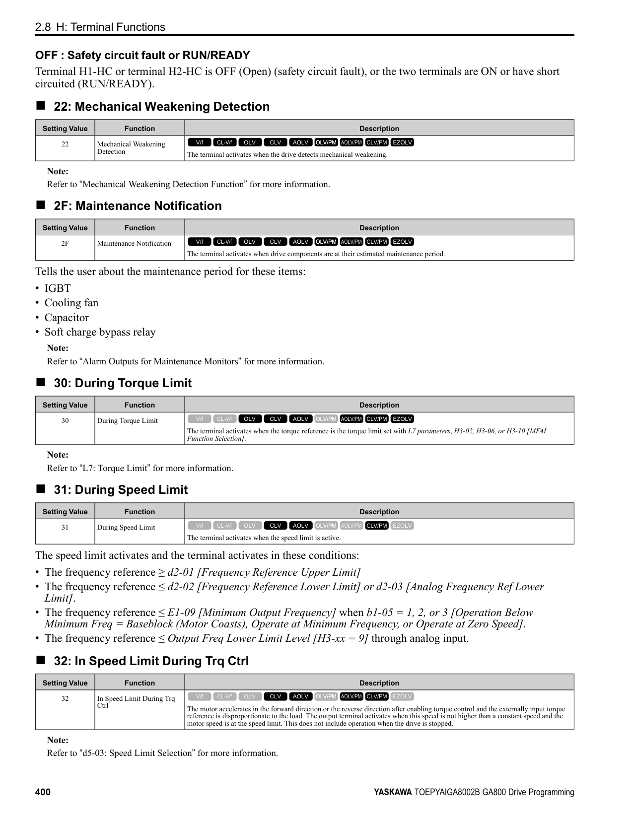
|No. (Hex.)|Name|Description|Default (Range)| |---|---|---|---| |H6-06 (0431) RUN|Terminal MP Monitor Selection|Sets a function for pulse train monitor output terminal MP. Sets the “x-xx” part of the Ux-xx monitor.
V/f CL-V/f OLV CLV AOLV OLV/PM AOLV/PM CLV/PM EZOLV
|102
(000, 031, 101, 102, 105, 116, 501, 502, 801 - 809, 821 - 825, 831 - 839, 851 855)|
Note: To use in through mode or when terminal MP is not used, set this parameter to 000 or 031.
When you use the pulse train monitor, make sure that you connect peripheral devices as specified by these load conditions: Incorrect connections can make the characteristics not sufficient or cause mechanical damage.
• Use the pulse train monitor as the sourcing output.
|Output Voltage VRL(V)|Load Impedance (kΩ)| |---|---| |5 Vor more|1.5 kΩ or more| |8 Vor more|4.0 kΩ or more| |10 Vor more|10 kΩ or more|
Figure 2.115 Circuit Diagram When Used as the Sourcing Output
• Use the pulse train monitor as the sinking input
|External Power Supply (V)|12 VDC ± 10%, 15 VDC ± 10%| |---|---| |Sinking current (mA)|16 mA or less|
ParameterDetails
Figure 2.116 Circuit Diagram When Used as the Sinking Input
######## ■ H6-07: Terminal MP Frequency Scaling
|No. (Hex.)|Name|Description|Default (Range)| |---|---|---|---| |H6-07 (0432) RUN|Terminal MP Frequency Scaling|Sets the frequency of the pulse train output signal used when the monitor set with H6-06 [Terminal MP Monitor Selection] is 100%.
V/f CL-V/f OLV CLV AOLV OLV/PM AOLV/PM CLV/PM EZOLV
|1440 Hz (0 - 32000 Hz)|
When H6-06 = 102 [Terminal MP Monitor Selection = Output Frequency] and H6-07 = 0, the pulse train output terminal MP outputs the same frequency as the drive output frequency.
######## ■ H6-08: Terminal RP Minimum Frequency
|No. (Hex.)|Name|Description|Default (Range)| |---|---|---|---| |H6-08 (043F)|Terminal RP Minimum Frequency|Sets the minimum frequency of the pulse train signal that terminal RP can detect.
V/f CL-V/f OLV CLV AOLV OLV/PM AOLV/PM CLV/PM EZOLV
|0.5 Hz (0.1 - 1000.0 Hz)|
|No. (Hex.)|Name|Description|Default (Range)| |---|---|---|---| |H6-09 (156E)|Voltage Phase Sync MP Selection|Set whether to output the pulse synchronized with drive output voltage phase from the pulse train monitor output terminal MP. This parameter is only enabled when H6-06 = 102 [Terminal MP Monitor Selection = Output Frequency] and H6-07 = 0 [Terminal MP Frequency Scaling = 0 Hz].
V/f CL-V/f OLV CLV AOLV OLV/PM AOLV/PM CLV/PM EZOLV
|0 (0, 1)|
function parameters are correct. Virtual input and output functions can have different default settings and operation than wired input and output functions. Incorrect function settings can cause serious injury or death.
################# Figure 2.117 Virtual Analog I/O Functional Block Diagram
H7-10 [Virtual Multi-Function Output 1]
H7-11 [Virtual Output 1 Delay Time]
H7-01 [Virtual Multi-Function Input 1]
Figure 2.118 Virtual Digital I/O Functional Block Diagram Note:
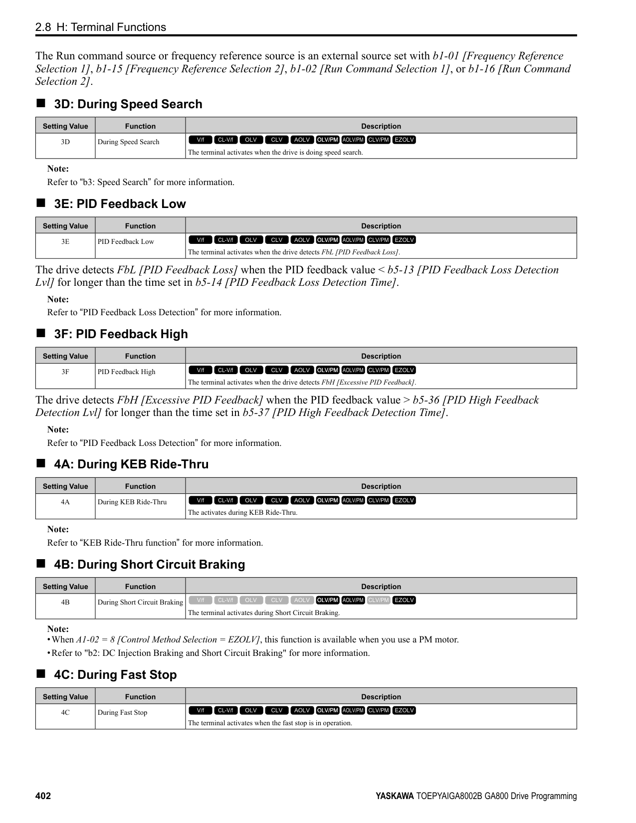
######## ■ H7-00: Virtual MFIO selection
|No. (Hex.)|Name|Description|Default (Range)| |---|---|---|---| |H7-00 (116F) Expert|Virtual MFIO selection|Sets the function to enable and disable the virtual I/O function. Set this parameter to 1 to operate the virtual I/O function.
V/f CL-V/f OLV CLV AOLV OLV/PM AOLV/PM CLV/PM EZOLV
|0 (0, 1)|
0 : Disabled 1 : Enabled
######## ■ H7-01: Virtual Multi-Function Input 1
|No. (Hex.)|Name|Description|Default (Range)| |---|---|---|---| |H7-01 (1185) Expert|Virtual Multi-Function Input 1|Sets the function that enters the virtual input set in H7-10 [Virtual Multi-Function Output 1].
V/f CL-V/f OLV CLV AOLV OLV/PM AOLV/PM CLV/PM EZOLV
|F (1 - 19F)|
Note: Settings 1B [Programming Lockout] and 11B [!Programming Lockout] are not available.
######## ■ H7-02: Virtual Multi-Function Input 2
|No. (Hex.)|Name|Description|Default (Range)| |---|---|---|---| |H7-02 (1186) Expert|Virtual Multi-Function Input 2|Sets the function that enters the virtual input set in H7-12 [Virtual Multi-Function Output 2].
V/f CL-V/f OLV CLV AOLV OLV/PM AOLV/PM CLV/PM EZOLV
|F (1 - 19F)|
Note: Settings 1B [Programming Lockout] and 11B [!Programming Lockout] are not available.
######## ■ H7-03: Virtual Multi-Function Input 3
|No. (Hex.)|Name|Description|Default (Range)| |---|---|---|---| |H7-03 (1187) Expert|Virtual Multi-Function Input 3|Sets the function that enters the virtual input set in H7-14 [Virtual Multi-Function Output 3].
V/f CL-V/f OLV CLV AOLV OLV/PM AOLV/PM CLV/PM EZOLV
|F (1 - 19F)|
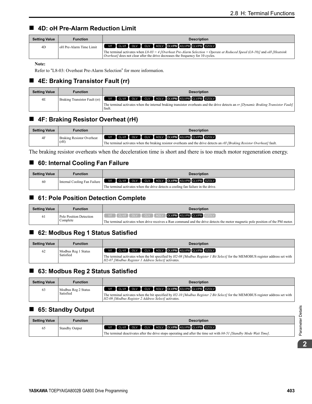
Note: Settings 1B [Programming Lockout] and 11B [!Programming Lockout] are not available.
ParameterDetails
######## 2
######## ■ H7-04: Virtual Multi-Function Input 4
|No. (Hex.)|Name|Description|Default (Range)| |---|---|---|---| |H7-04 (1188) Expert|Virtual Multi-Function Input 4|Sets the function that enters the virtual input set in H7-16 [Virtual Multi-Function Output 4].
V/f CL-V/f OLV CLV AOLV OLV/PM AOLV/PM CLV/PM EZOLV
|F (1 - 19F)|
Note: Settings 1B [Programming Lockout] and 11B [!Programming Lockout] are not available.
|No. (Hex.)|Name|Description|Default (Range)| |---|---|---|---| |H7-10 (11A4) Expert|Virtual Multi-Function Output 1|Sets the function for virtual digital output 1.
V/f CL-V/f OLV CLV AOLV OLV/PM AOLV/PM CLV/PM EZOLV
|F (0 - 1A7)|
|No. (Hex.)|Name|Description|Default (Range)| |---|---|---|---| |H7-11 (11A5) Expert|Virtual Output 1 Delay Time|Sets the minimum ON time for virtual digital output 1.
V/f CL-V/f OLV CLV AOLV OLV/PM AOLV/PM CLV/PM EZOLV
|0.1 s (0.0 - 25.0 s)|
|No. (Hex.)|Name|Description|Default (Range)| |---|---|---|---| |H7-12 (11A6) Expert|Virtual Multi-Function Output 2|Sets the function for virtual digital output 2.
V/f CL-V/f OLV CLV AOLV OLV/PM AOLV/PM CLV/PM EZOLV
|F (0 - 1A7)|
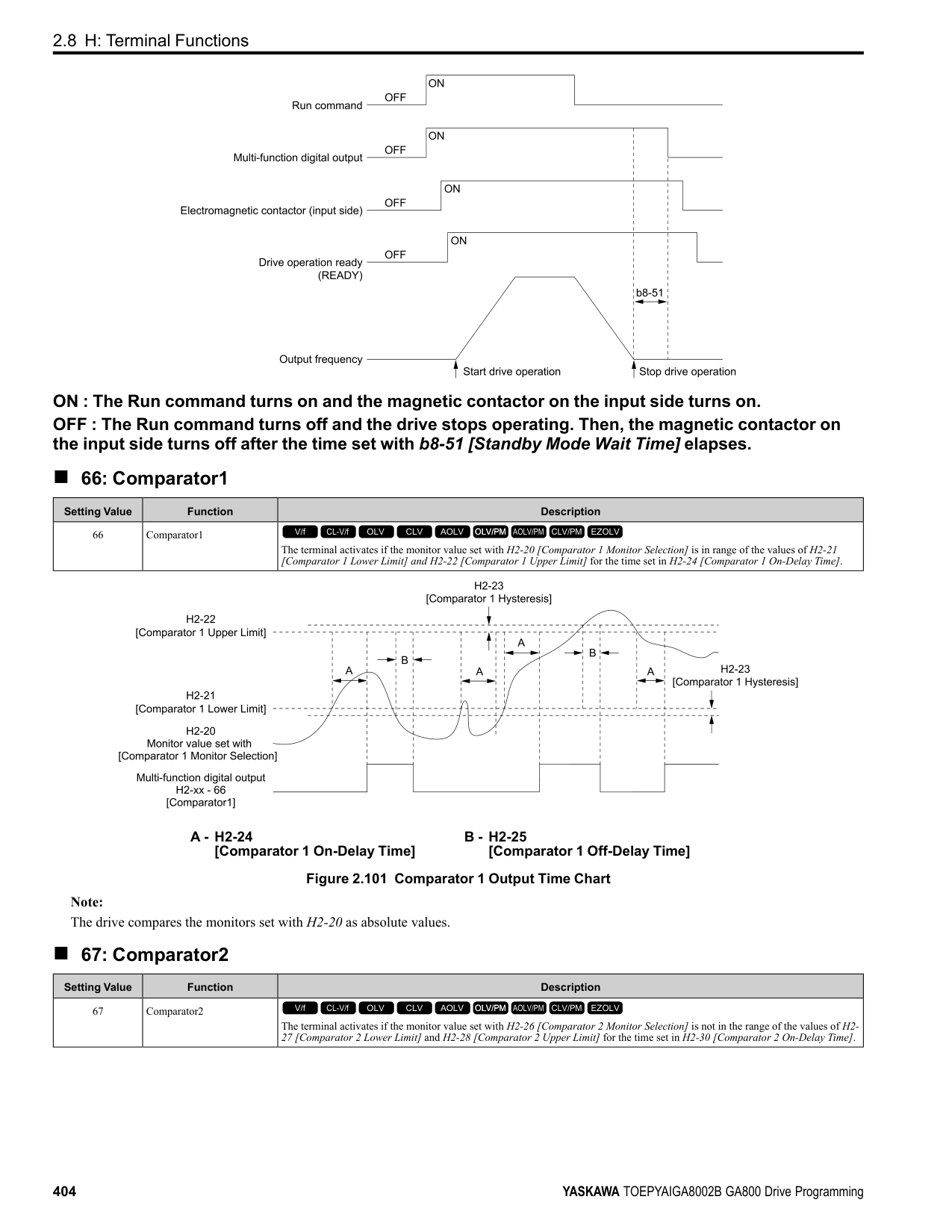
|No. (Hex.)|Name|Description|Default (Range)| |---|---|---|---| |H7-13 (11A7) Expert|Virtual Output 2 Delay Time|Sets the minimum ON time for virtual digital output 2.
V/f CL-V/f OLV CLV AOLV OLV/PM AOLV/PM CLV/PM EZOLV
|0.1 s (0.0 - 25.0 s)|
|No. (Hex.)|Name|Description|Default (Range)| |---|---|---|---| |H7-14 (11A8) Expert|Virtual Multi-Function Output 3|Sets the function for virtual digital output 3.
V/f CL-V/f OLV CLV AOLV OLV/PM AOLV/PM CLV/PM EZOLV
|F (0 - 1A7)|
|No. (Hex.)|Name|Description|Default (Range)| |---|---|---|---| |H7-15 (11A9) Expert|Virtual Output 3 Delay Time|Sets the minimum ON time for virtual digital output 3.
V/f CL-V/f OLV CLV AOLV OLV/PM AOLV/PM CLV/PM EZOLV
|0.1 s (0.0 - 25.0 s)|
|No. (Hex.)|Name|Description|Default (Range)| |---|---|---|---| |H7-16 (11AA) Expert|Virtual Multi-Function Output 4|Sets the function for virtual digital output 4.
V/f CL-V/f OLV CLV AOLV OLV/PM AOLV/PM CLV/PM EZOLV
|F (0 - 1A7)|
|No. (Hex.)|Name|Description|Default (Range)| |---|---|---|---| |H7-17 (11AB) Expert|Virtual Output 4 Delay Time|Sets the minimum ON time for virtual digital output 4.
V/f CL-V/f OLV CLV AOLV OLV/PM AOLV/PM CLV/PM EZOLV
|0.1 s (0.0 - 25.0 s)|
|No. (Hex.)|Name|Description|Default (Range)| |---|---|---|---| |H7-30 (1177) Expert|Virtual Analog Input Selection|Sets the virtual analog input function.
V/f CL-V/f OLV CLV AOLV OLV/PM AOLV/PM CLV/PM EZOLV
|F (0 - 32)|
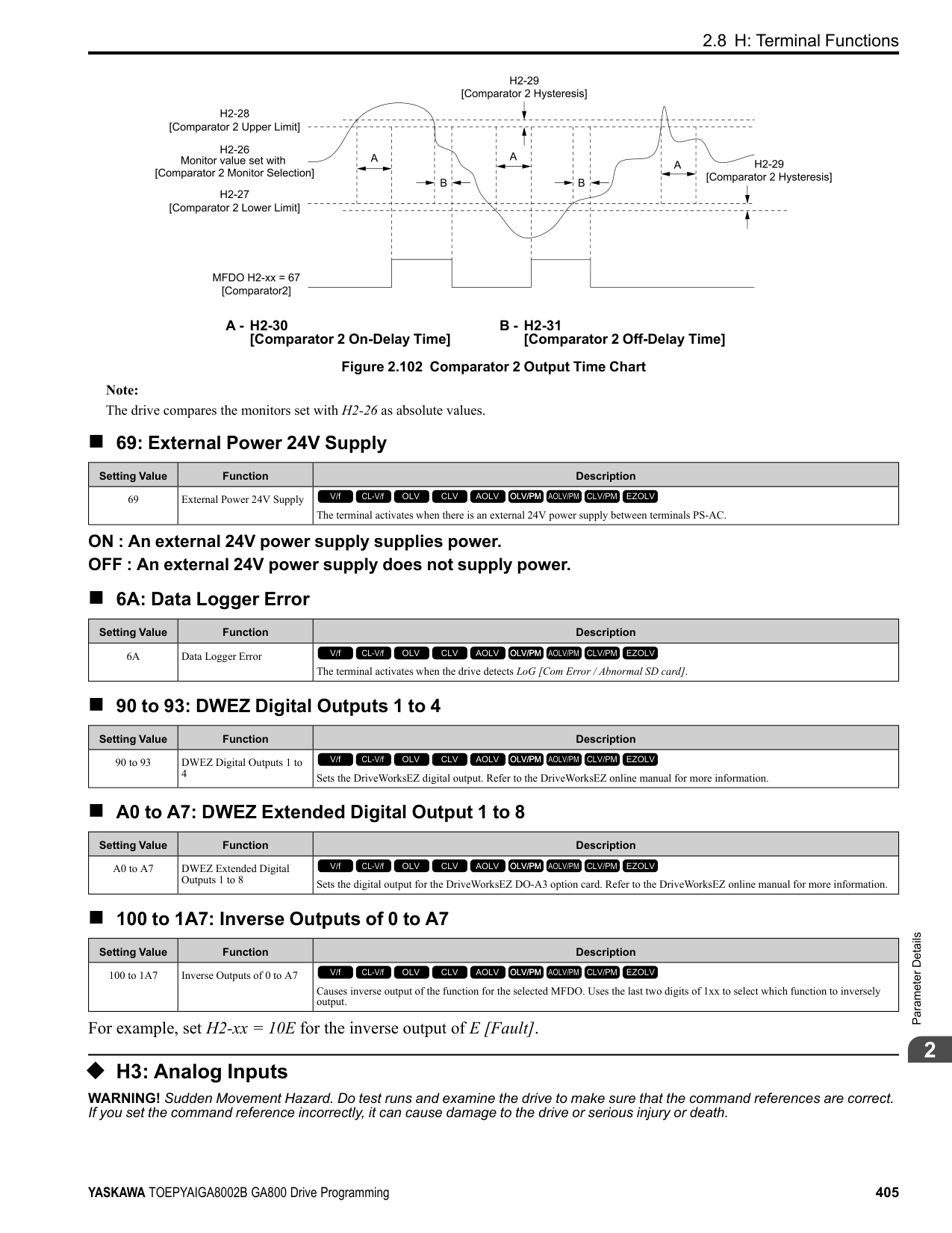
|No. (Hex.)|Name|Description|Default (Range)| |---|---|---|---| |H7-31 (1178) RUN Expert|Virtual Analog Input Gain|Sets the virtual analog input gain.
V/f CL-V/f OLV CLV AOLV OLV/PM AOLV/PM CLV/PM EZOLV
|100.0% (-999.9 - 999.9%)|
|No. (Hex.)|Name|Description|Default (Range)| |---|---|---|---| |H7-32 (1179) RUN Expert|Virtual Analog Input Bias|Sets the virtual analog input bias.
V/f CL-V/f OLV CLV AOLV OLV/PM AOLV/PM CLV/PM EZOLV
|0.0% (-999.9 - 999.9%)|
|No. (Hex.)|Name|Description|Default (Range)| |---|---|---|---| |H7-40 (1163)|Virtual Analog Out Signal Select|Sets the signal level of the virtual analog output.
V/f CL-V/f OLV CLV AOLV OLV/PM AOLV/PM CLV/PM EZOLV
|0 (0 - 2)|
0 : 0 to 100% (Absolute Value) 1 : -100 to 100% 2 : 0 to 100% (Lower Limit at 0)
######## ■ H7-41: Virtual Analog Output Function
|No. (Hex.)|Name|Description|Default (Range)| |---|---|---|---| |H7-41 (1164)|Virtual Analog Output Function|Sets the monitor to be output from the virtual analog output.
V/f CL-V/f OLV CLV AOLV OLV/PM AOLV/PM CLV/PM EZOLV
|102 (0 - 999)|
Set the x-xx part of the Ux-xx [Monitor]. For example, set H7-41 = 102 to monitor U1-02 [Output Frequency].
ParameterDetails
######## 2
######## ■ H7-42: Virtual Analog Output FilterTime
|No. (Hex.)|Name|Description|Default (Range)| |---|---|---|---| |H7-42 (1165)|Virtual Analog Output FilterTime|Sets the time constant for a primary filter of the virtual analog output.
V/f CL-V/f OLV CLV AOLV OLV/PM AOLV/PM CLV/PM EZOLV
|0.00 s (0.00 - 2.00 s)|
####### 2.9 L: Protection Functions
L parameters set the following functions.
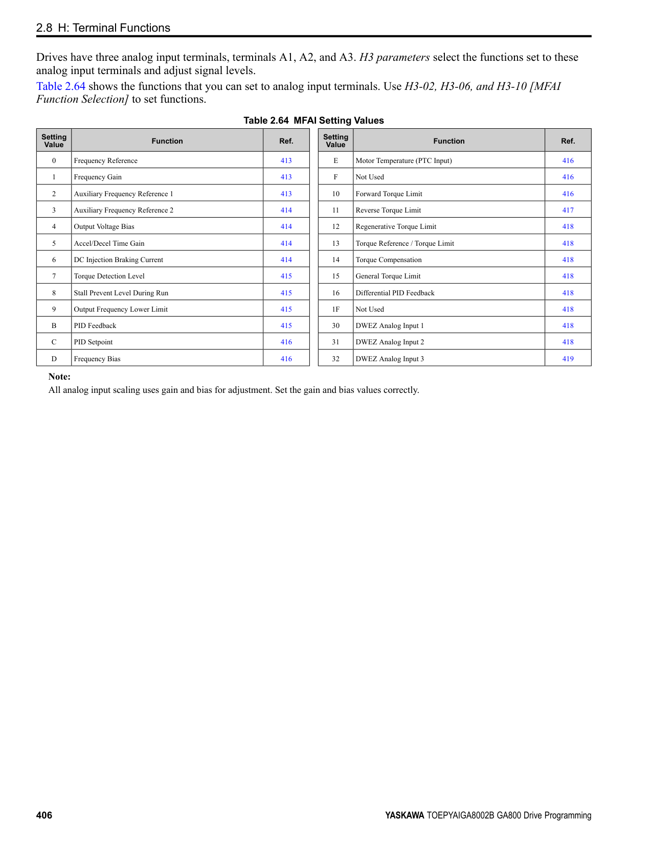
◆ L1: Motor Protection L1 parameters set the motor overload protection function.
■ Motor Protection Using Positive Temperature Coefficient (PTC) Thermistors The temperature resistance characteristics of three PTC thermistors in the motor stator winding protect the motor from overheat. The PTC thermistor must have the characteristics shown in Figure 2.119 for each motor phase.
Figure 2.119 PTC Thermistor Temperature and Resistance When the PTC input signal input to the drive is more than the overload alarm level, the drive detects oH3 [Motor Overheat (PTC Input)]. The drive continues the operation set in L1-03 [Motor Thermistor oH Alarm Select]. By factory default, oH3 flashes on the keypad and the drive continues operation. The overheat fault level triggers an oH4 [Motor Overheat Fault (PTC Input)] fault, and outputs a fault signal. The drive outputs a fault signal, and uses the stop method set in L1-04 [Motor Thermistor oH Fault Select] to stop the motor.
Note: PTC is an acronym for Positive Temperature Coefficient.
Figure 2.120 shows the configuration procedure when you use terminal A3.
ParameterDetails
Figure 2.120 Connect Motor PTC
######## ■ L1-01: Motor Overload (oL1) Protection
|No. (Hex.)|Name|Description|Default (Range)| |---|---|---|---|
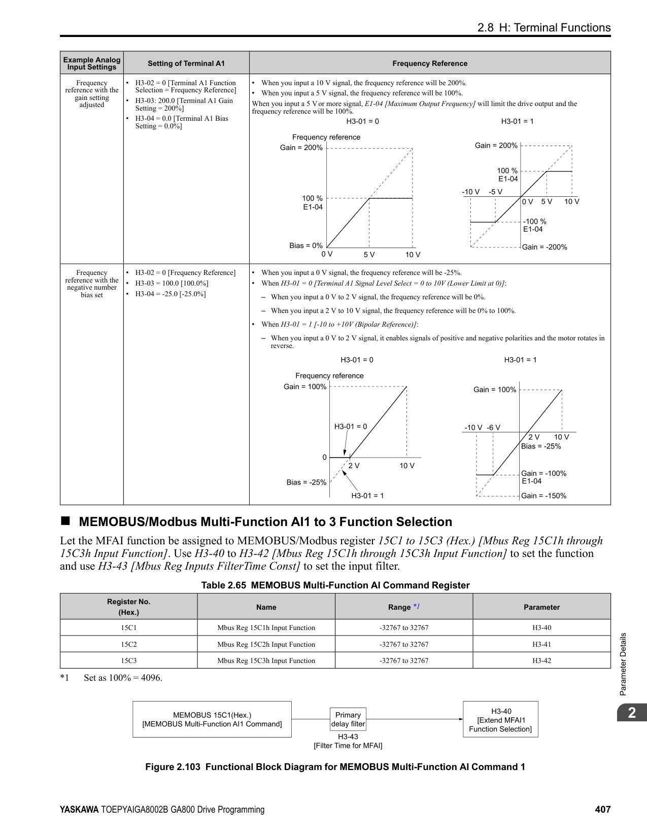
|L1-01 (0480)|Motor Overload (oL1) Protection|Sets the motor overload protection with electronic thermal protectors.
V/f CL-V/f OLV CLV AOLV OLV/PM AOLV/PM CLV/PM EZOLV
|Determined by A1-02 (0 - 6)|
This parameter enables and disables the motor overload protection with electronic thermal protectors. The cooling capability of the motor changes when the speed control range of the motor changes. Use an electronic thermal protector that aligns with the permitted load characteristics of the motor to select motor protection. The electronic thermal protector of the drive uses these items to calculate motor overload tolerance and supply overload protection for the motor:
############## 0 : Disabled
Disable motor protection when motor overload protection is not necessary or when the drive is operating more than one motor.
################# Figure 2.121 Protection Circuit Configuration to Connect More than One Motor to One Drive
NOTICE: When you connect more than one motor to one drive or when the motor amp rating is higher than the drive amp rating, set L1-01 =0 [Motor Overload (oL1) Protection = Disabled] and install thermal overload relays for each motor. The electronic thermal protection of the drive will not function and it can cause damage to the motor.
The overload tolerance decreases as motor speed decreases because the cooling fan speed decreases and the ability of the motor to cool decreases in the low speed range. The overload tolerance characteristics of the motor change the trigger point for the electronic thermal protector. This provides motor overheat protection from low speed to high speed across the full speed range.
|Load Tolerance|Cooling Capability|Overload Characteristics (at 100% motor load)| |---|---|---| | |This motor is designed to operate with commercial line power. Operate at a 60 Hz base frequency to maximize the motor cooling ability.|If the motor operates at frequencies less than 60 Hz, the drive will detect oL1. The drive triggers a fault relay output and the motor coasts to stop.|
The speed control for this motor is 10% to 100% when at 100% load. If the motor operates at slower than 10% speed with 100% load, it will cause motor overload.
|Load Tolerance|Cooling Capability|Overload Characteristics (at 100% motor load)| |---|---|---| | |This motor is designed to withstand increased temperatures during continuous operation in the low speed range (10% base frequency).|The motor operates continuously at 10% to 100% base frequency. Operating slower than 10% speed at 100% load will cause motor overload.|
ParameterDetails

############### 3 : Constant Torque 100:1 SpeedRangeUse this setting for vector motors with a speed range for constant torque of 1:100.
The speed control for this motor is 1% to 100% when at 100% load. If the motor operates at slower than 1% speed with 100% load, it will cause motor overload.
|Load Tolerance|Cooling Capability|Overload Characteristics (at 100% motor load)| |---|---|---| | |This motor is designed to withstand increased temperatures during continuous operation in the low speed range (1% base frequency).|The motor operates continuously at 1% to 100% base frequency. Operating slower than 1% speed at 100% load will cause motor overload.|
############### 4 : PM Variable TorqueUse this setting for PM motors with derated torque characteristics.
The overload tolerance decreases as motor speed decreases because the cooling fan speed decreases and the ability of the motor to cool decreases in the low speed range. The overload tolerance characteristics of the motor change the trigger point for the electronic thermal protector. This provides motor overheat protection from low speed to high speed across the full speed range.
|Load Tolerance|Cooling Capability|Overload Characteristics (at 100% motor load)| |---|---|---| | |This motor is designed to withstand increased temperatures during continuous operation at rated speed and rated torque.|If the motor operates continuously at lower speed than rated rotation speed at more than 100% torque, the drive will detect oL1. The drive triggers a fault relay output and the motor coasts to stop.|
############### 5 : PM Constant TorqueUse this setting with a PM motor for constant torque that has a speed range for constant torque of 1:500.
The speed control for this motor is 0.2% to 100% when at 100% load. If the motor operates at slower than 0.2% speed with 100% load, it will cause motor overload.
|Load Tolerance|Cooling Capability|Overload Characteristics (at 100% motor load)| |---|---|---| | |This motor is designed to withstand increased temperatures during continuous operation in the low speed range (0.2% base frequency).|The motor operates continuously at 0.2% to 100% rated speed. Operating slower than 0.2% speed at 100% load will cause motor overload.|
############### 6 : Variable Torque (50Hz)Use this setting for general-purpose motors with a 50 Hz base frequency.
The overload tolerance decreases as motor speed decreases because the cooling fan speed decreases and the ability of the motor to cool decreases in the low speed range. The overload tolerance characteristics of the motor change the trigger point for the electronic thermal protector. This provides motor overheat protection from low speed to high speed across the full speed range.
|Load Tolerance|Cooling Capability|Overload Characteristics (at 100% motor load)| |---|---|---| | |This motor is designed to operate with commercial line power. Operate at a 50 Hz base frequency to maximize the motor cooling ability.|If the motor operates at frequencies less than commercial line power, the drive will detect oL1. The drive triggers a fault relay output and the motor coasts to stop.|
######## ■ L1-02: Motor Overload Protection Time
|No. (Hex.)|Name|Description|Default (Range)| |---|---|---|---| |L1-02 (0481)|Motor Overload Protection Time|Sets the operation time for the electronic thermal protector of the drive to prevent damage to the motor. Usually it is not necessary to change this setting.
V/f CL-V/f OLV CLV AOLV OLV/PM AOLV/PM CLV/PM EZOLV
|1.0 min (0.1 - 5.0 min)|
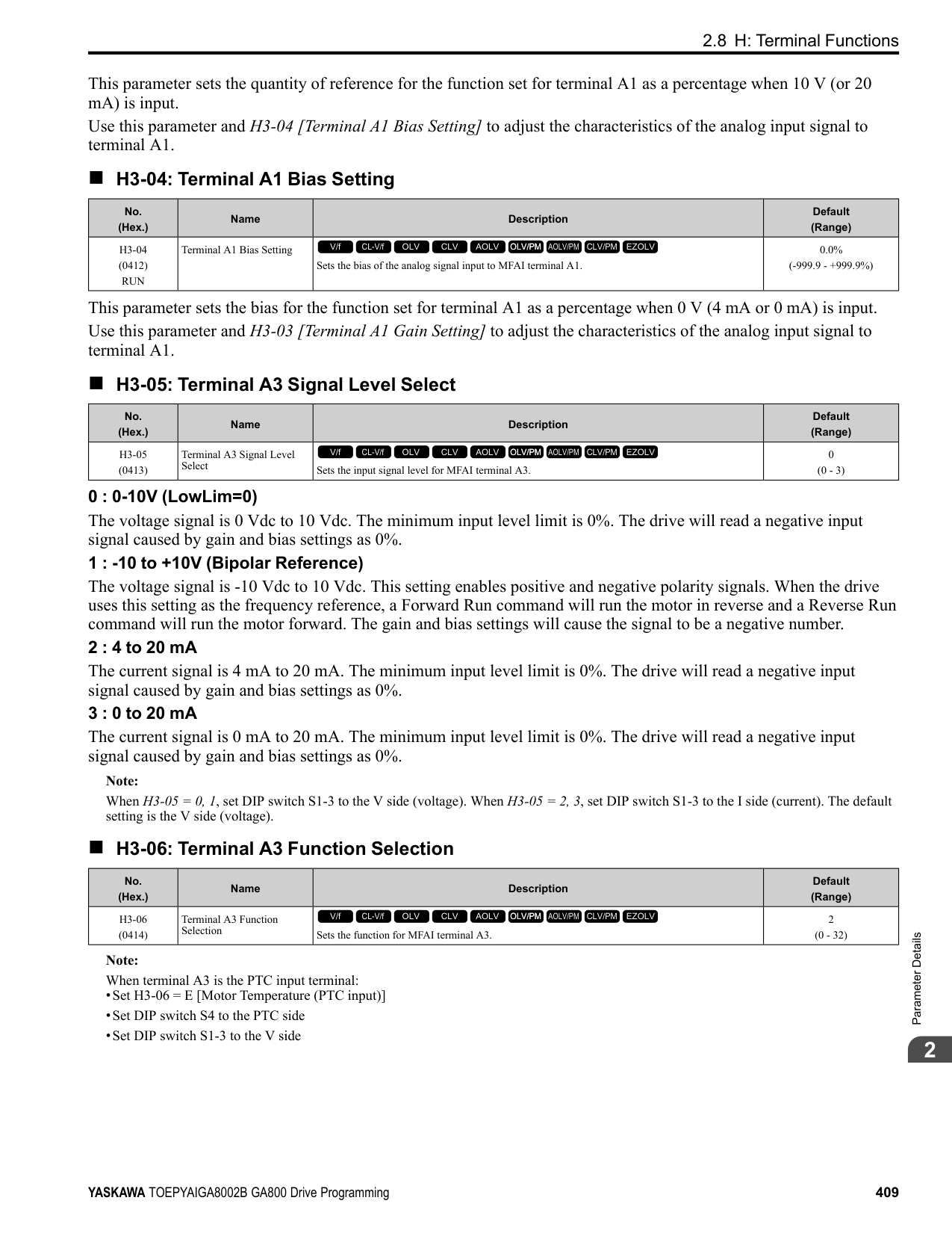
Set the overload tolerance time to the length of time that the motor can operate at 150% load from continuous operation at 100% load. When the motor operates at 150% load continuously for 1 minute after continuous operation at 100% load (hot start), the default setting triggers the electronic thermal protector. Figure 2.122 shows an example of the electronic thermal protector operation time. Motor overload protection operates in the range between a cold start and a hot start. This example shows a general-purpose motor operating at the base frequency with L1-02 set to 1.0 min.
| | | | | |---|---|---|---| | | | | | | | | | | | | | | | | | | | | | | | | |
ParameterDetails
######## 2
Figure 2.122 Protection Operation Time for a General-purpose Motor at Rated Output Frequency
The drive ramps the motor to stop in the deceleration time. Fault relay output terminal MA-MC turns ON and MBMC turns OFF.
The output turns OFF and the motor coasts to stop. Fault relay output terminal MA-MC turns ON, and MB-MC turns OFF.
The drive stops the motor in the deceleration time set in C1-09 [Fast Stop Time]. Fault relay output terminal MA-MC turns ON, and MB-MC turns OFF.
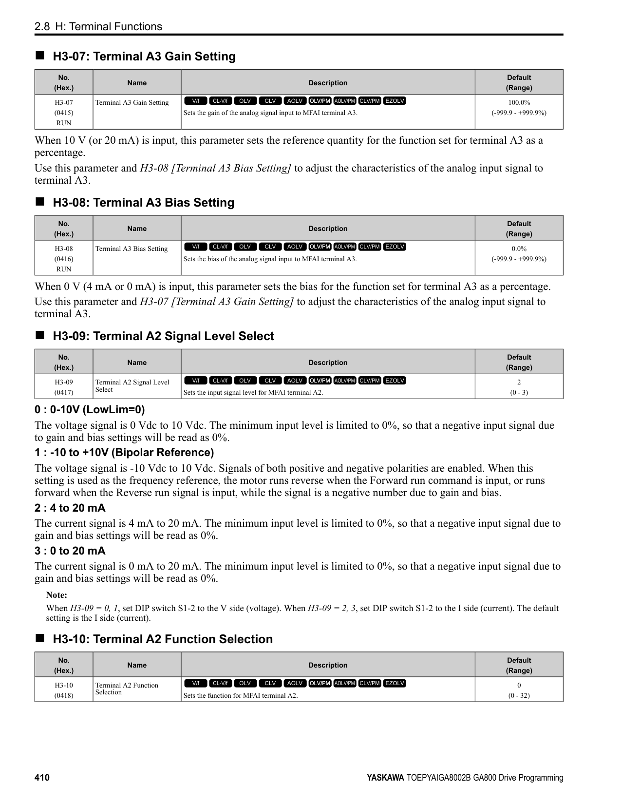
|No. (Hex.)|Name|Description|Default (Range)| |---|---|---|---| |L1-03 (0482)|Motor Thermistor oH Alarm Select|Sets drive operation when the PTC input signal entered into the drive is at the oH3 [Motor Overheat Alarm] detection level.
V/f CL-V/f OLV CLV AOLV OLV/PM AOLV/PM CLV/PM EZOLV
|3 (0 - 3)|
|No. (Hex.)|Name|Description|Default (Range)| |---|---|---|---| |L1-04 (0483)|Motor Thermistor oH Fault Select|Sets the drive operation when the PTC input signal to the drive is at the oH4 [Motor Overheat Fault (PTC Input)] detection level.
V/f CL-V/f OLV CLV AOLV OLV/PM AOLV/PM CLV/PM EZOLV
|1 (0 - 2)|
|No. (Hex.)|Name|Description|Default (Range)| |---|---|---|---| |L1-05 (0484)|Motor Thermistor Filter Time|Sets the primary delay time constant for the PTC input signal entered to the drive. This parameter prevents accidental motor overheat faults.
V/f CL-V/f OLV CLV AOLV OLV/PM AOLV/PM CLV/PM EZOLV
|0.20 s (0.00 - 10.00 s)|
|No. (Hex.)|Name|Description|Default (Range)| |---|---|---|---| |L1-08 (1103)|oL1 Current Level|Sets the reference current for the motor 1 thermal overload detection. When the current level > 0.0 A, you cannot set this value < 10% of drive rated current.
V/f CL-V/f OLV CLV AOLV OLV/PM AOLV/PM CLV/PM EZOLV
|0.0 A (0.0 A or 10% to 150% of the drive rated current)|
When L1-08 = 0.0 A, the drive uses E2-01 [Motor Rated Current (FLA)] to detect the motor overload protection. In PM control mode, the drive uses E5-03 [PM Motor Rated Current (FLA)] to detect the motor overload protection. When L1-08 ≠ 0.0 A, the set value is the reference for motor overload protection.
################# Note:
•Display is in these units:
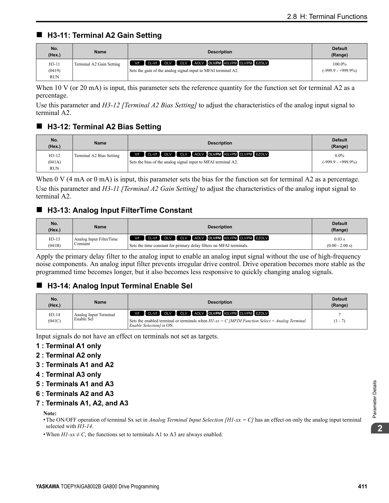
•When the current level > 0.0 A, you cannot set this value < 10% of drive rated current.
######## ■ L1-09: oL1 Current Level for Motor 2
|No. (Hex.)|Name|Description|Default (Range)| |---|---|---|---| |L1-09 (1104)|oL1 Current Level for Motor 2|Sets the reference current for the motor 2 thermal overload detection. When the current level > 0.0 A, you cannot set this value < 10% of drive rated current.
V/f CL-V/f OLV CLV AOLV OLV/PM AOLV/PM CLV/PM EZOLV
|0.0 A (0.0 A or 10 to150% of the drive rated current)|
When L1-09 = 0.0 A, the drive uses E4-01 [Motor 2 Rated Current] to detect the motor overload protection. When L1-09 ≠ 0.0 A, the set value is the reference for motor overload protection.
Note:
•Display is in these units:
•When the current level > 0.0 A, you cannot set this value < 10% of drive rated current.
######## ■ L1-13: Motor Overload Memory Selection
|No. (Hex.)|Name|Description|Default (Range)| |---|---|---|---| |L1-13 (046D)|Motor Overload Memory Selection|Sets the function that keeps the current electronic thermal protector value when the drive stops receiving power.
V/f CL-V/f OLV CLV AOLV OLV/PM AOLV/PM CLV/PM EZOLV
|1 (0, 1)|
0 : Disabled 1 : Enabled Sets if the drive will calculate the motor again when the drive is energized again.
◆ L2: Power Loss Ride Through L2 parameters set the drive operation during momentary power loss and the KEB Ride-Thru function method of operation.
■ KEB Ride-Thru Function KEB is an acronym for Kinetic Energy Backup. If the drive detects a power loss or momentary power loss, it will quickly decelerate the motor. The drive uses regenerative energy from the motor to keep the main circuit operating. When you return power during motor deceleration, the drive returns operation to the status before the power loss. The KEB Ride-Thru function is different than other functions for continuous operation. If the drive detects momentary power loss, the motor will ramp to stop. It will not coast to stop. This function is applicable for applications in which it is necessary to prevent materials from running out, for example control for film and fiber lines. The KEB Ride-Thru function has 4 methods of operation. Parameter L2-29 [Kinetic Energy Backup Method] sets the method. When you use the KEB Ride-Thru function with one drive, set L2-29 = 0, 1 [Single Drive KEB Ride-Thru 1, Single Drive KEB Ride-Thru 2]. If deceleration in coordination with more than one drive is necessary, for example textile machinery line systems, set L2-29 = 2, 3 [System KEB Ride-Thru 1, System KEB Ride-Thru 2].
ParameterDetails
Table 2.66 KEB Ride-Thru Function Operation Method
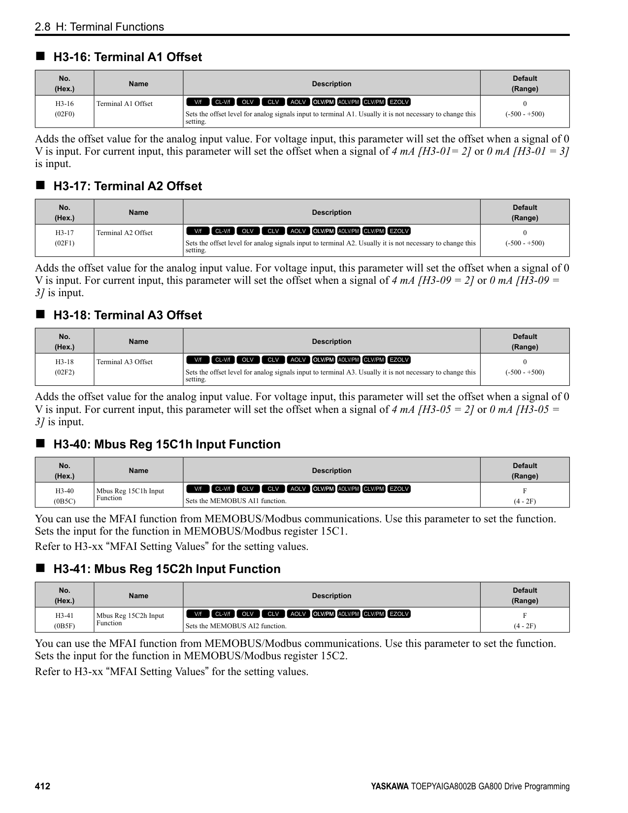
|L2-29|Kinetic Energy Backup Method|Operation|Configuration Precautions| |---|---|---|---| |0|Single Drive KEB Ride-Thru 1|The drive uses regenerative energy from the motor to keep the DC bus voltage at the level set in L2-11 [KEB DC Bus Voltage Setpoint] while it adjusts the rate of deceleration.
The KEB operation continues while the drive adjusts the deceleration rate with the setting of C1-09 [Fast Stop Time].|• Set C1-09 correctly to prevent Uv1 [DC Bus Undervoltage] and ov [Overvoltage].
• If the drive detects Uv1 during the KEB operation, decrease the value set in C1-09.
• If the drive detects ov during the KEB operation, increase the value set in C1-09.
| |1|Single Drive KEB Ride-Thru 2|The drive uses information about the inertia of the connected machinery to find the deceleration rate necessary to keep the DC bus voltage at the level set in parameter L2-11.
The drive uses system inertia to calculate the deceleration time. You cannot adjust this value.|• If the drive detects Uv1 during the KEB operation, increase the setting value of L3-20 [DC Bus Voltage Adjustment Gain] and L3-21 [OVSuppression Accel/Decel P Gain].
• If the drive detects ov during the KEB operation, decrease the setting values of L3-20 and L3-21.
| |2|System KEB RideThru 1|The drive does not monitor the DC bus voltage. The drive decelerates at the KEB deceleration time set in L2-06.
Use L2-06 to set the time necessary to decelerate from the current frequency reference to 0 Hz. More than one drive can decelerate and keep a constant speed ratio between drives.|Use the dynamic braking option with System KEB Ride-Thru 1.| |3|System KEB RideThru 2|The drive uses the KEB deceleration time set in L2-06 to decelerate and it also monitors the DC bus voltage.
If the voltage level increases, the drive momentarily holds the frequency to prevent an ov before it continues to decelerate.|If you cannot use the dynamic braking option, use System KEB RideThru 2.|
######## ■ KEB Ride Thru Start
When L2-01 = 3, 4, 5 [Power Loss Ride Through Select = Kinetic Energy Backup: L2-02, Kinetic Energy Backup: CPU Power, Kinetic Energy Backup: DecelStop], the drive starts the KEB operation immediately after it detects a momentary power loss. When one of these conditions occur, the drive will activate KEB Ride-Thru:
The KEB operation will start as specified in L2-29. Note: If you try to set KEB Ride-Thru 1 and 2 to the MFDI terminals at the same time, it will trigger oPE03 [Multi-Function Input Setting Err].
Figure 2.123 KEB Operation through KEB Ride-Thru Input
■ KEB Ride-Thru End Detection Parameter L2-01 [Power Loss Ride Through Select] and a digital input programmed for KEB set the KEB function end detection. Use the Momentary Power Loss Ride-Thru Time to Cancel KEB Operation shows an example with this configuration:
| | | | |---|---|---| | | | | | | | | | | | |
| | | | |---|---|---| | | | |
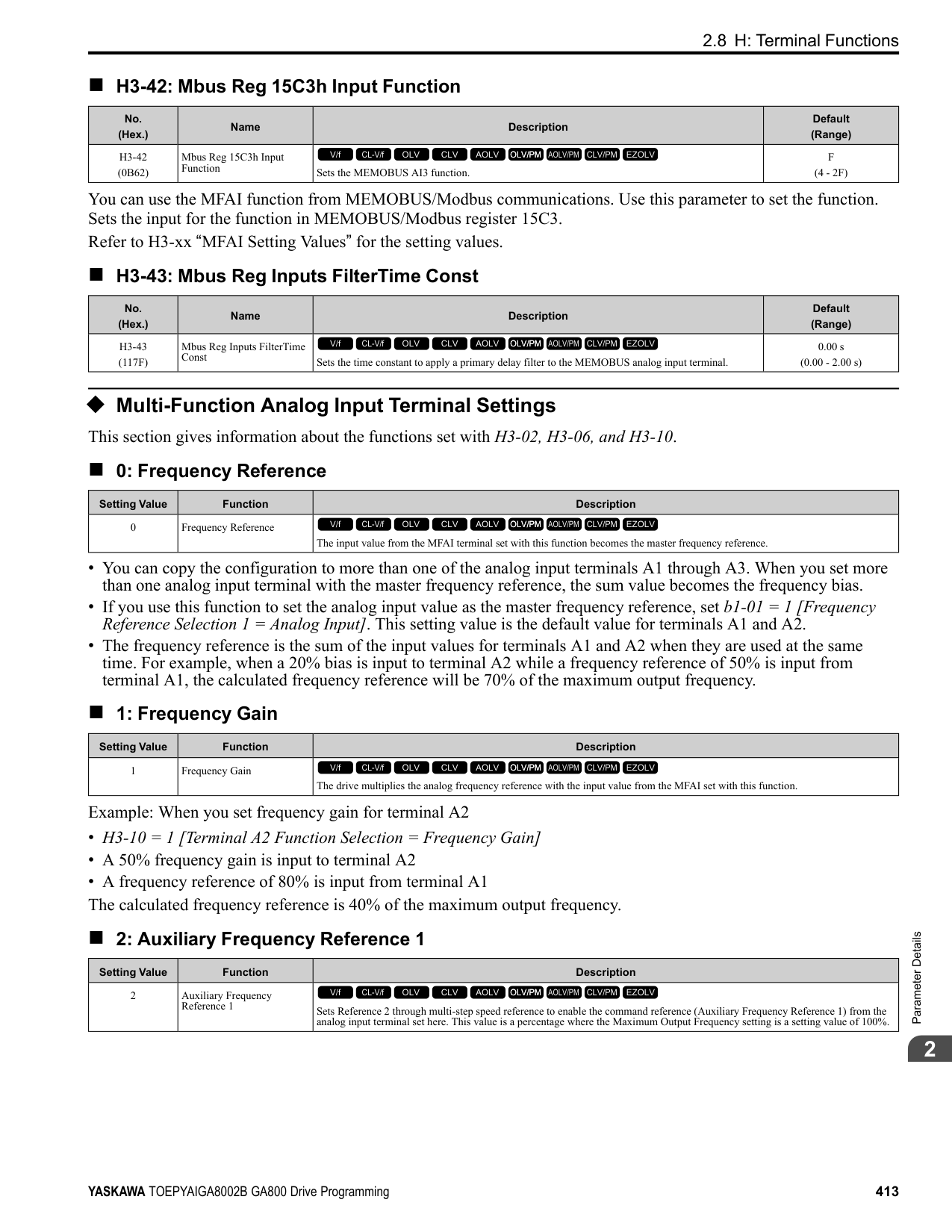
Figure 2.124 Cancel the KEB Operation after the Momentary Power Loss Ride-Thru Time Is Expired without KEB RideThru *1 When L2-07 = 0.00 [Kinetic Energy Backup Accel Time = 0.00 s], the drive accelerates again as specified by the
applicable Acceleration Time [C1-01, C1-03, C1-05, C1-07], and usual operation continues.
Use the Momentary Power Loss Ride-Thru Time and KEB Ride-Thru to Cancel KEB Operation shows an example with this configuration:
Figure 2.125 Use the Momentary Power Loss Ride-Thru Time and KEB Ride-Thru to Cancel KEB Operation *1 When L2-07 = 0.00, the drive accelerates again as specified by the applicable Acceleration Time [C1-01, C1-03,
C1-05, C1-07], and usual operation continues.
Cancel KEB Operation When Restoration of Power Occurs while the Control Power (Power Supply to the Control Board) is Maintained shows an example with this configuration:
Figure 2.126 Cancel KEB Operation without Using the KEB Ride-Thru if Restoration of Power Occurs while the Control Power (Power Supply to the Control Board) is Maintained
*1 When L2-07 = 0.00 s, the drive accelerates again as specified by the applicable Acceleration Time [C1-01, C103, C1-05, C1-07], and usual operation continues.
Use the KEB Ride-Thru to Cancel KEB Operation when Restoration of Power Occurs while the Control Power (Power Supply to the Control Board) is Maintained shows an example with this configuration:
The drive starts deceleration through KEB operation. When the motor decelerates for the time set in L2-10, the drive measures the DC bus voltage and the status of the digital input set for KEB Ride-Thru. When the DC bus voltage is less than the level set in L2-11, or if the digital input set to KEB Ride-Thru is active, deceleration continues. When the DC bus voltage is more than the level set in L2-11, the drive ends KEB operation. The drive accelerates the motor to the frequency reference value before the power loss, and usual operation continues. When the KEB Ride-Thru continues to be input after the time set in L2-02 is expired, the drive uses the KEB Ride-Thru function to continue to decelerate. When you cancel the KEB Ride-Thru, the motor accelerates again, and usual operation continues.
*1 When L2-07 = 0.00 s, the drive accelerates again as specified by the applicable Acceleration Time [C1-01, C103, C1-05, C1-07], and usual operation continues.
KEB Operation when L2-01 = 5 [Kinetic Energy Backup: DecelStop] The drive starts deceleration through KEB operation. If you do not input the Run command, the motor cannot restart. The drive will continue to decelerate until the motor comes to the minimum output frequency or a complete stop. If you return power during deceleration, the drive continues to decelerate.
■ KEB Operation Wiring Example
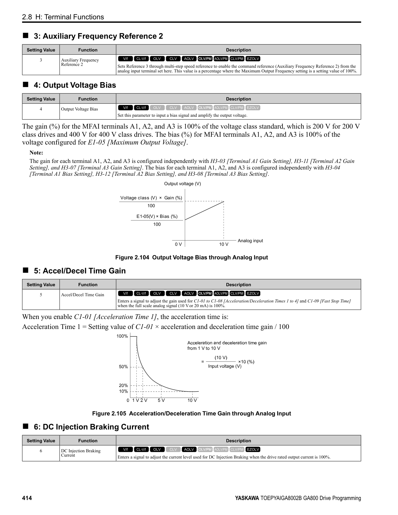
Note:
Figure 2.128 KEB Function Wiring Example
■ Parameters for KEB Ride-Thru Table 2.67 shows the parameters that adjust the KEB Ride-Thru function. Parameter settings are different for the different KEB methods set in L2-29 [Kinetic Energy Backup Method].
Table 2.67 Parameters for KEB Ride-Thru
|No.|Name|Configuring Settings|L2-29 [Kinetic Energy Backup Method]|L2-29 [Kinetic Energy Backup Method]|L2-29 [Kinetic Energy Backup Method]|L2-29 [Kinetic Energy Backup Method]| |---|---|---|---|---|---|---| |No.|Name|Configuring Settings|0|1|2|3| |C1-09|Fast Stop Time|• If ov [Overvoltage] occurs during KEB deceleration, increase the setting value.
• If Uv1 [DC Bus Undervoltage] occurs during KEB deceleration, decrease the setting value.
|x *1|-|-|-| |C2-03|S-Curve Time @ Start of Decel|• If ov occurs immediately after you start KEB deceleration, increase the setting value.
• If Uv1 occurs immediately after you start KEB deceleration, decrease the setting value.
|x|-|x|x| |L2-05|Undervoltage Detection Lvl (Uv1)|If Uv1 occurs immediately after you start KEB deceleration, increase the setting value to detect power loss more quickly.|x|x|x|x| |L2-06|Does KEB Tuning.|• Kinetic Energy Backup Decel Time
• If ov or Uv1 occur during KEB deceleration after KEB Tuning, set L2-06 in these conditions:
– If ov occurs, increase the setting value
– If Uv1 occurs, decrease the setting value.
|-|-|x *2|x *2| |L2-07|Kinetic Energy Backup Accel Time|Sets the acceleration time to return to the frequency reference value before a power loss, after you cancel the KEB operation. When L2-07 = 0, the drive uses the standard acceleration times set in C1-01, C1-03, C1-05, and C1-07 [Acceleration Time].|x|x|x|x| |L2-08|Frequency Gain at KEB Start|• If ov occurs immediately after you start operation, decrease the setting value.
• If Uv1 occurs immediately after you start operation, increase the setting value.
|x|-|x|x| |L2-10|Minimum KEB Time|• With KEB Ride-Thru There is Uv1 because you set a digital input for KEB Ride-Thru and the device that controls the input operated too slowly after power loss.
• Without KEB Ride-Thru If the DC bus voltage overshoots immediately after KEB Ride-Thru starts, increase L2-10 to longer than the overshoot.
|x|x|x|x| |L2-11|KEB DC Bus Voltage Setpoint|• Single Drive KEB Ride-Thru 2 Set to approximately 1.22 x input voltage.
• Single Drive KEB Ride-Thru 1, System KEB Ride-Thru 1, or System KEB RideThru 2 Set to approximately 1.4 x input voltage.
|x|x|x|x| |L3-20|DC Bus Voltage Adjustment Gain|• If ov or Uv1 occurs at the start of deceleration when you use KEB operation, increase this value in 0.1-unit increments.
• If there is torque ripple during deceleration when you use KEB Ride-Thru, decrease the value.
|-|x|-|-|
|No.|Name|Configuring Settings|L2-29 [Kinetic Energy Backup Method]|L2-29 [Kinetic Energy Backup Method]|L2-29 [Kinetic Energy Backup Method]|L2-29 [Kinetic Energy Backup Method]| |---|---|---|---|---|---|---| |No.|Name|Configuring Settings|0|1|2|3| |L3-21|OVSuppression Accel/Decel P Gain|If there is large speed or current ripple, decrease the value in 0.05 unit increments.
Note:
If the setting value is too low, then the drive will have unsatisfactory DC bus voltage control response. The drive can detect ov or Uv1.|-|x|-|-| |L3-24|Motor Accel Time @ Rated Torque|Set the motor acceleration time to the maximum frequency at the motor rated torque.|-|x|-|-| |L3-25|Load Inertia Ratio|Sets the ratio between motor inertia and machine inertia.|-|x *3|-|-|
######## ■ L2-01: Power Loss Ride Through Select
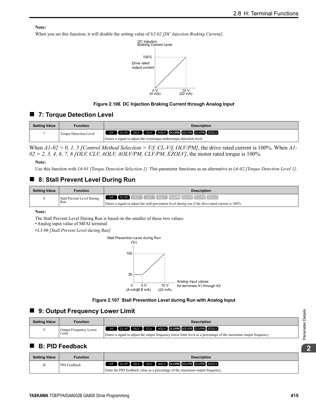
|No. (Hex.)|Name|Description|Default (Range)| |---|---|---|---| |L2-01 (0485)|Power Loss Ride Through Select|Sets the drive operation after a momentary power loss.
V/f CL-V/f OLV CLV AOLV OLV/PM AOLV/PM CLV/PM EZOLV
|0 (0 - 5)|
The drive detects momentary power loss when the drive DC bus voltage is less than the value set in L2-05 [Undervoltage Detection Lvl (Uv1)].
When power returns in the time set in L2-02 [Power Loss Ride Through Time], the drive will restart. If power does not return in the time set in L2-02, the drive will detect Uv1. The drive momentarily turns OFF its output after a power loss. If the power returns in the time set to L2-02, the drive will do Speed Search and try to continue operation. If the DC bus voltage is less than or equal to the Uv1 detection level for the time set in L2-02, the drive will detect Uv1 and output a fault signal.
Note:
When there is a momentary power loss, the drive output will turn OFF. If the power returns and the drive control circuit has power, the drive will do Speed Search and try to continue operation. This will not trigger a Uv1. This function enables longer support for power loss than when L2-01 = 1.
If the drive detects momentary power loss, the drive will use regenerative energy from the motor and ramp to stop. When you return power in the time set in L2-02, the drive will accelerate to the frequency reference value that was used before the power loss. If you do not return power in the time set to L2-02, the drive will detect Uv1 and the drive output will turn OFF. L2-29 [Kinetic Energy Backup Method] sets the type of KEB operation.
The drive decelerates using regenerative energy from the motor until the power returns and then restarts when a momentary power loss is detected. When power is restored during deceleration, the drive accelerates the motor again to the frequency reference value used before the power loss. If the motor comes to a stop before the power returns, the
ParameterDetails
######## 2
drive loses control power and the drive output shuts off. A Uv1 is not triggered when power is restored while power to the CPU in the drive is maintained. L2-29 sets the type of KEB operation.
If the drive detects momentary power loss, the drive will use regenerative energy from the motor and ramp to stop. When you return power to the drive, the drive will continue to decelerate until the motor comes to a full stop. After you return power, the drive will ramp to stop in the set deceleration time. L2-29 sets the type of KEB operation.
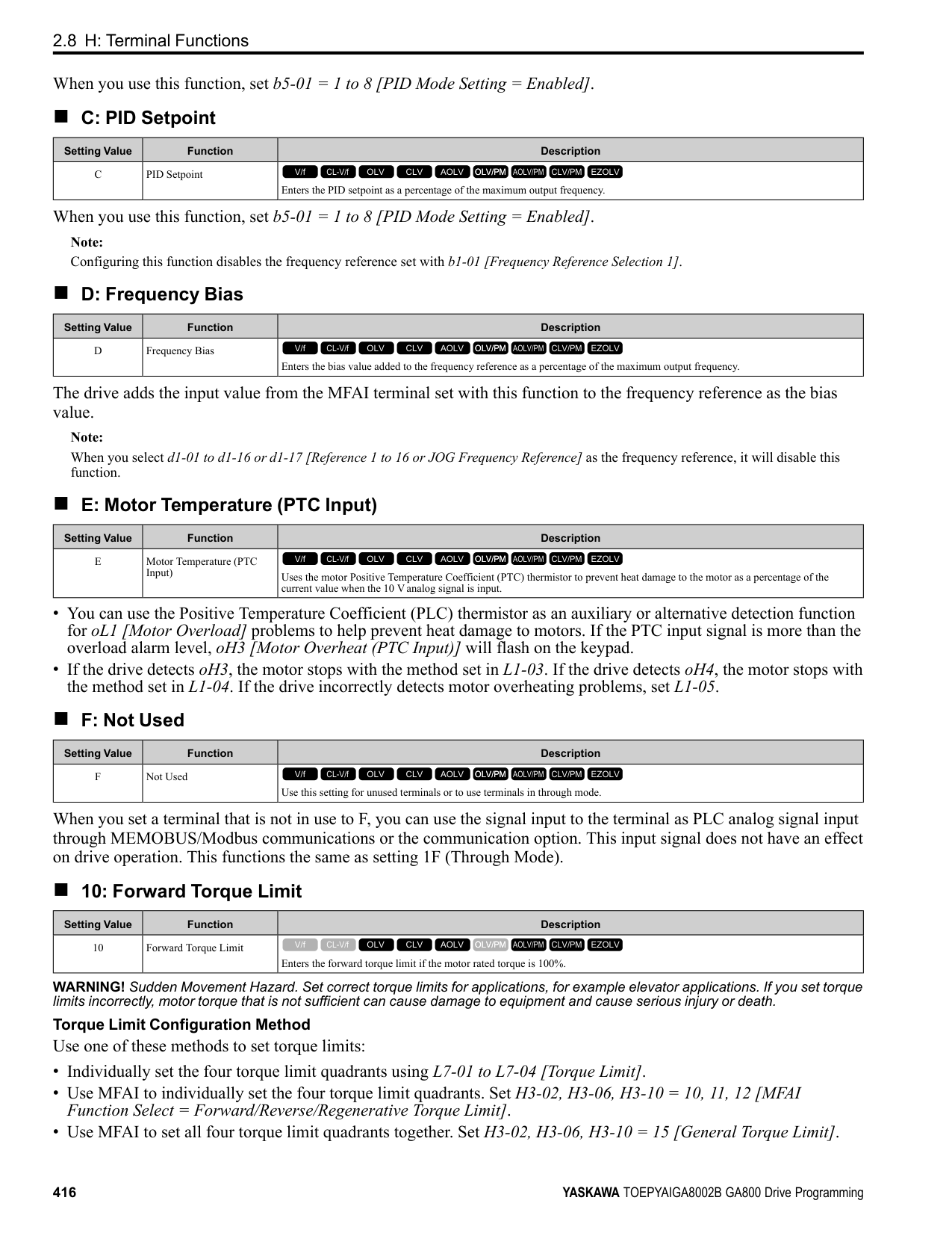
Note: When you set L2-01, make sure that you know these items:
######## ■ L2-02: Power Loss Ride Through Time
|No. (Hex.)|Name|Description|Default (Range)| |---|---|---|---| |L2-02 (0486)|Power Loss Ride Through Time|Sets the maximum time that the drive will wait until trying to restart after power loss.
V/f CL-V/f OLV CLV AOLV OLV/PM AOLV/PM CLV/PM EZOLV
|Determined by o2-04, C6-01 (0.0 - 25.5 s)|
This function is applicable when L2-01 = 1, 3 [Power Loss Ride Through Select = Enabled for L2-02 Time, Kinetic Energy Backup: L2-02]. If power loss operation is longer than the time set in this parameter, the drive will detect Uv1 [DC Bus Undervoltage], turn OFF output, and the motor will coast to stop.
Note:
######## ■ L2-03: Minimum Baseblock Time
|No. (Hex.)|Name|Description|Default (Range)| |---|---|---|---| |L2-03 (0487)|Minimum Baseblock Time|Sets the minimum time to continue the drive output block (baseblock) after a baseblock.
V/f CL-V/f OLV CLV AOLV OLV/PM AOLV/PM CLV/PM EZOLV
|Determined by o2-04, C6-01 (0.1 - 5.0 s)|
Sets the length of time that the drive will wait for the residual voltage in the motor to dissipate in estimation to the secondary circuit time constant of the motor. If oC [Overcurrent] or ov [DC Bus Overvoltage] occur at the start of Speed Search, after power returns, or during DC Injection Braking, increase this setting.
######## ■ L2-04: Powerloss V/f Recovery Ramp Time
|No. (Hex.)|Name|Description|Default (Range)| |---|---|---|---| |L2-04 (0488)|Powerloss V/f Recovery Ramp Time|Sets the time for the drive output voltage to go back to correct voltage after completing speed searches.
V/f CL-V/f OLV CLV AOLV OLV/PM AOLV/PM CLV/PM EZOLV
|Determined by o2-04, C6-01 (0.0 - 5.0 s)|
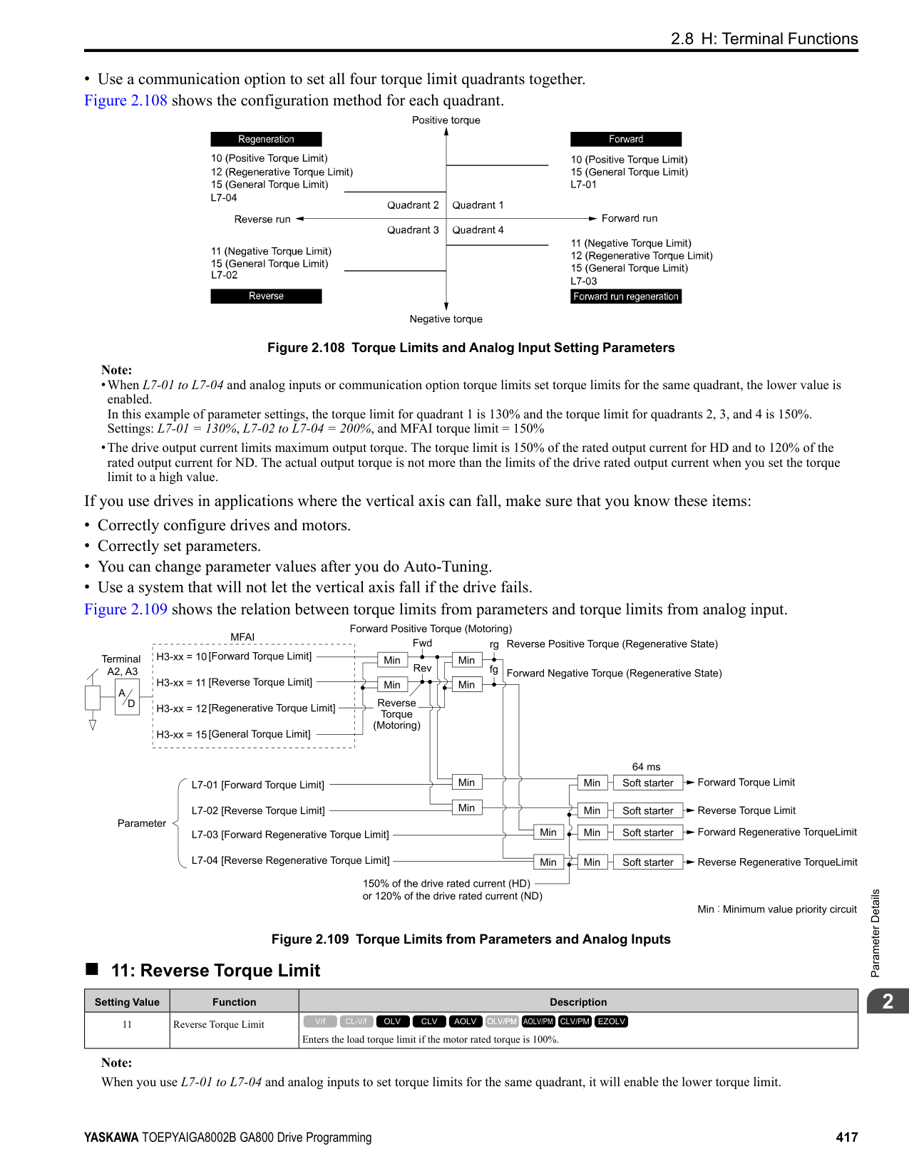
Sets the time for voltage to recover from 0 V to the value set in E1-05 [Maximum Output Voltage].
######## ■ L2-05: Undervoltage Detection Lvl (Uv1)
|No. (Hex.)|Name|Description|Default (Range)| |---|---|---|---| |L2-05 (0489)|Undervoltage Detection Lvl (Uv1)|Sets the voltage at which a Uv1 [DC Bus Undervoltage] fault is triggered or at which the KEB function is activated. Usually it is not necessary to change this setting.
V/f CL-V/f OLV CLV AOLV OLV/PM AOLV/PM CLV/PM EZOLV
|Determined by o2-04 and E1-01
(200 V Class: 150 - 210 V, 400 V Class: 300 - 420 V)|
NOTICE: Damage to Equipment. When you set this parameter to a value lower than the default, you must install an AC reactor on the input side of the power supply. If you do not install an AC reactor, it will cause damage to the drive circuitry.
Note: If the low voltage detection level is near the lower limit value of L2-05, the drive will detect Uv1 during KEB Ride-Thru operation. Do not set the value too low when you use the KEB Ride-Thru function.
######## ■ L2-06: Kinetic Energy Backup Decel Time
|No. (Hex.)|Name|Description|Default (Range)| |---|---|---|---| |L2-06 (048A) Expert|Kinetic Energy Backup Decel Time|Sets the deceleration time during KEB operation used to decrease the maximum output frequency to 0.
V/f CL-V/f OLV CLV AOLV OLV/PM AOLV/PM CLV/PM EZOLV
|0.0 s (0.0 - 6000.0 s)|
Set L2-29 = 2 or 3 [Kinetic Energy Backup Method = System KEB Ride-Thru 1 or System KEB Ride-Thru 2] to enable this function. When L2-29 = 1, 2 , 3 [Kinetic Energy Backup Method = Single Drive KEB Ride-Thru 2, System KEB Ride-Thru 1, System KEB Ride-Thru 2] and you do KEB Auto-Tuning, the drive will automatically set this value. Sets the deceleration time necessary to decelerate from the frequency reference to 0 Hz when the drive detects a momentary power loss. If a Uv1 [DC Bus Undervoltage] fault occurs during KEB operation, decrease the deceleration time. If an ov [Overvoltage] fault occurs, increase the deceleration time.
| | | | |---|---|---| | | | | | | | |
Figure 2.129 Kinetic Energy Backup Decel Time
######## ■ L2-07: Kinetic Energy Backup Accel Time
|No. (Hex.)|Name|Description|Default (Range)| |---|---|---|---| |L2-07 (048B) Expert|Kinetic Energy Backup Accel Time|Sets the acceleration time to return the frequency to the frequency reference before a power loss after canceling KEB operation.
V/f CL-V/f OLV CLV AOLV OLV/PM AOLV/PM CLV/PM EZOLV
|0.0 s (0.0 - 6000.0 s)|
ParameterDetails
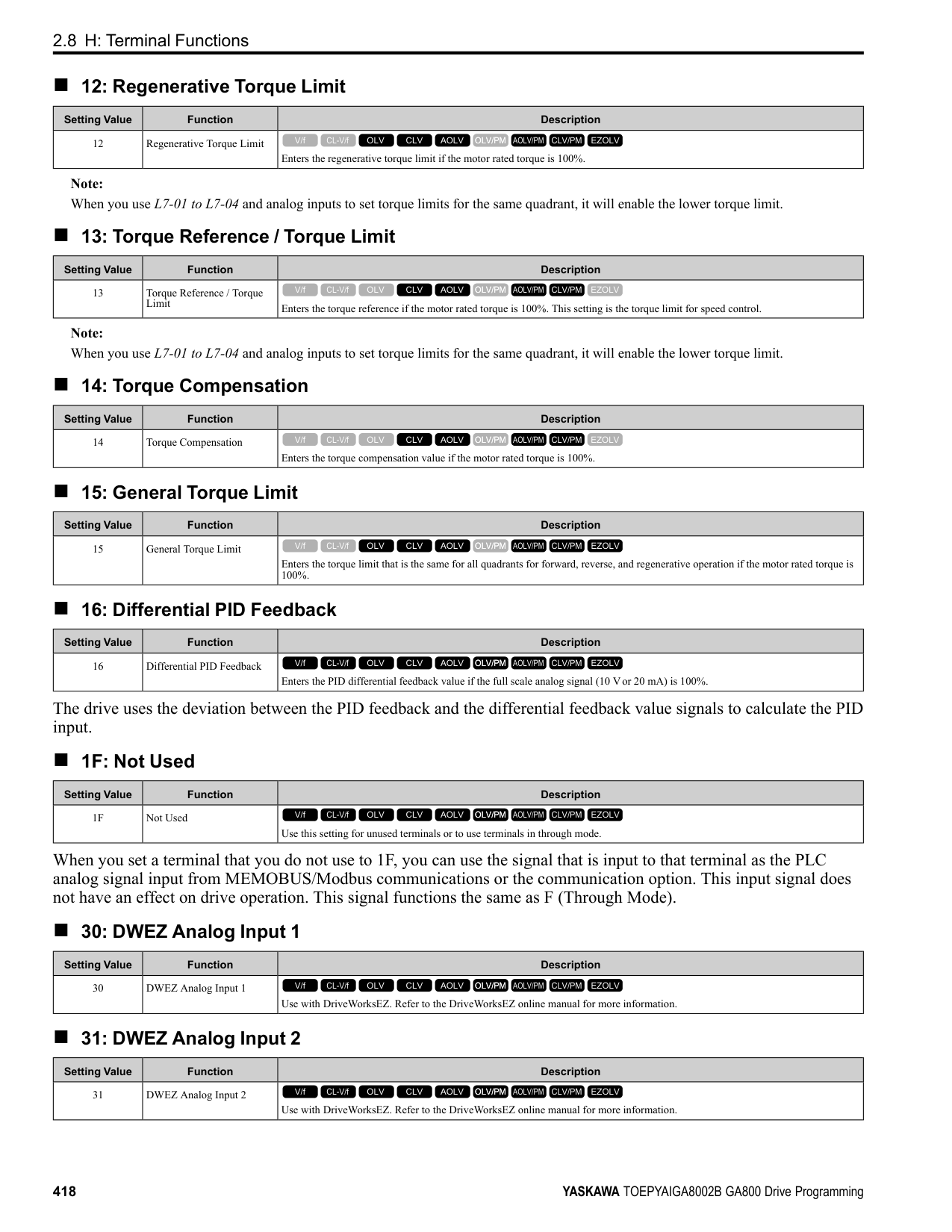
######## 2
Set this parameter to 0.0 to disable the function. The drive uses the acceleration time in C1-01, C1-03, C1-05, and C1-
######## ■ L2-08: Frequency Gain at KEB Start
|No. (Hex.)|Name|Description|Default (Range)| |---|---|---|---| |L2-08 (048C) Expert|Frequency Gain at KEB Start|Sets the quantity of output frequency reduction used when KEB operation starts as a percentage of the motor rated slip before starting KEB operation.
V/f CL-V/f OLV CLV AOLV OLV/PM AOLV/PM CLV/PM EZOLV
|100% (0 - 300%)|
Decreases the output frequency in steps to quickly set the motor to a regenerative condition. Use this formula to calculate the value: Output frequency reduction = Motor rated slip before KEB operation × (L2-08/100) × 2
######## ■ L2-09: KEB Minimum Frequency Level
|No. (Hex.)|Name|Description|Default (Range)| |---|---|---|---| |L2-09 (048D) Expert|KEB Minimum Frequency Level|Sets the quantity of output frequency reduction used as a percentage of E2-02 [Motor Rated Slip] when KEB operation starts.
V/f CL-V/f OLV CLV AOLV OLV/PM AOLV/PM CLV/PM EZOLV
|20% (0 - 100%)|
These conditions set the quantity of decrease:
■ L2-10: Minimum KEB Time
When you return power while KEB is operating, the drive continues KEB operation until the time set in L2-10is expired. When the DC bus voltage is less than the level of L2-05 [Undervoltage Detect Level (Uv1)] in one of these conditions, KEB operation continues until the time set in L2-10 is expired:
|No. (Hex.)|Name|Description|Default (Range)| |---|---|---|---| |L2-10 (048E) Expert|Minimum KEB Time|Sets the minimum length of time to operate the KEB after the drive detects a momentary power loss.
V/f CL-V/f OLV CLV AOLV OLV/PM AOLV/PM CLV/PM EZOLV
|50 ms (0 - 25500 ms)|
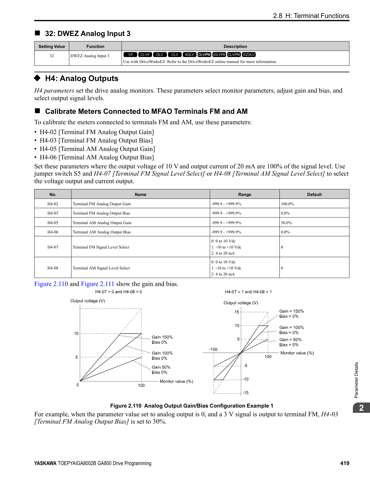
When you input KEB Ride-Thru, KEB operation continues after the time set in L2-10 is expired. When you cancel KEB Ride-Thru, the motor accelerates again. When you do not input KEB Ride-Thru during the time set in L2-10, the drive accelerates to the frequency reference that the drive had before power loss in the applicable acceleration time.
When L2-01 = 3, 4, or 5, and the DC bus voltage is a minimum of the value of L2-11 [DC Bus Vol Setpoint during KEB], the drive accelerates again after the time set in L2-10 is expired. If the DC bus voltage is less than the L2-11 value, KEB operation continues after the time set in L2-10 is expired.
Note:
|No. (Hex.)|Name|Description|Default (Range)| |---|---|---|---| |L2-11 (0461) Expert|KEB DC Bus Voltage Setpoint|Sets the target value that controls the DC bus voltage to a constant level in Single Drive KEB RideThru 2. Sets the DC bus voltage level that completes the KEB operation for all other KEB methods.
V/f CL-V/f OLV CLV AOLV OLV/PM AOLV/PM CLV/PM EZOLV
|Determined by E1-01 (Determined by E1-01)|
|No. (Hex.)|Name|Description|Default (Range)| |---|---|---|---| |L2-29 (0475) Expert|Kinetic Energy Backup Method|Sets the KEB function operation mode.
V/f CL-V/f OLV CLV AOLV OLV/PM AOLV/PM CLV/PM EZOLV
|0 (0 - 3)|
Set L2-01 = 3, 4, or 5 [Momentary Power Loss Ope Select = KEB Mode, KEB Stop Mode, or KEB Decel to Stp] or KEB Ride-Thru 1/2 [H1-xx = 65, 66, 7A, or 7B], to enable the KEB function.
############## 0 : Single Drive KEB Ride-Thru 1
The drive monitors the DC bus voltage and uses regenerative energy from the motor to hold the DC bus voltage at the level set in L2-11 [KEB DC Bus Voltage Setpoint]. The KEB operation continues and the deceleration rate changes as specified by C1-09 [Fast Stop Time].
Note:
############## 1 : Single Drive KEB Ride-Thru 2
The drive does KEB operation and automatically calculates the deceleration rate to make sure that the main circuit electrical energy and main current voltage from motor regenerative energy is equal to L2-11 [DC Bus Vol Setpoint during KEB].
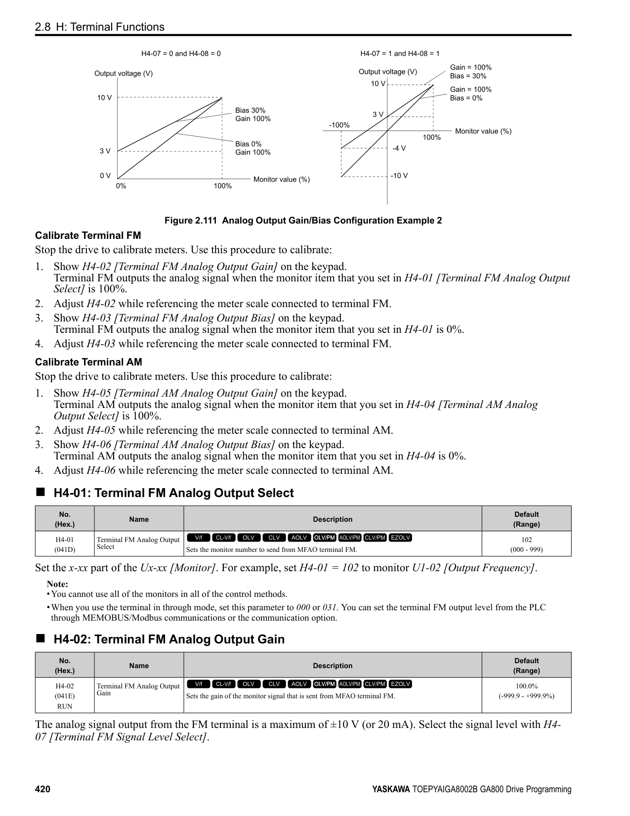
############## 2 : System KEB Ride-Thru 1
The drive does not monitor the DC bus voltage and decelerates as specified by the KEB deceleration time set in L206.
Set L2-06 to the time necessary to decelerate from the frequency reference to 0 Hz when the drive detects a momentary power loss. The drive can decelerate and keep constant deceleration rates for more than one drive.
Note: If you keep constant deceleration rates for more than one drive, it can trigger ov faults. Use the dynamic braking option with System KEB Ride-Thru 1 to prevent ov faults.
############### 3 : System KEB Ride-Thru 2The drive monitors the DC bus voltage and decelerates for the deceleration time set in L2-06.
If the DC bus voltage increases, the drive momentarily holds the frequency to prevent ov while deceleration continues.
Note: When you cannot use a dynamic braking option, use System KEB Ride-Thru.
######## ■ L2-30: KEB Zero Speed Operation
|No. (Hex.)|Name|Description|Default (Range)| |---|---|---|---| |L2-30 (045E) Expert|KEB Zero Speed Operation|Sets the operation when the output frequency decreases below the zero level (DC braking injection starting frequency) during KEB deceleration when L2-01 = 3 to 5 [Power Loss Ride Through Select
= Kinetic Energy Backup: L2-02, Kinetic Energy Backup: CPU Power, or Kinetic Energy Backup: DecelStop].
V/f CL-V/f OLV CLV AOLV OLV/PM AOLV/PM CLV/PM EZOLV
|0 (0, 1)|
ParameterDetails
######## 2
Does DC injection braking and short circuit braking as specified by b2-04 [DC Inject Braking Time at Stop] and b2-
######## ■ L2-31: KEB Start Voltage Offset Level
|No. (Hex.)|Name|Description|Default (Range)| |---|---|---|---| |L2-31 (045D) Expert|KEB Start Voltage Offset Level|Sets the KEB start voltage offset.
V/f CL-V/f OLV CLV AOLV OLV/PM AOLV/PM CLV/PM EZOLV
|Determined by A1-02 (200 V Class: 0 - 100 V,400 V Class: 0 - 200 V)|
The drive uses this formula to calculate the KEB start voltage: KEB start voltage = L2-05 [Undervoltage Detect Level (Uv1)] + L2-31
◆ L3: Stall Prevention L3 parameters set the Stall Prevention function and overvoltage suppression function.
######## ■ Stall Prevention
If the load is too heavy or the acceleration and deceleration times are too short, the motor can slip too much because it cannot work at the same rate as the frequency reference. If the motor stalls during acceleration, current increases as the slip increases to cause an oC [Overcurrent], oL2 [Drive Overload], or oL1 [Motor Overload] and the drive will stop. If the motor stalls during deceleration, too much regenerative power will flow back into the DC bus capacitors, and cause the drive to fault out from ov [Overvoltage] and the drive will stop. The stall prevention function will let the motor get to the set speed without stalling and it is not necessary for you to change the acceleration or deceleration time settings. You can set a separate stall prevention functions for acceleration, operating at constant speeds, and deceleration.
######## ■ Overvoltage Suppression Function
Decreases the regenerative torque limit and increases the output frequency when the DC bus voltage increases to prevent ov. This function can drive loads with cyclic regenerative operation, for example punch presses or other applications with repeated crank movements. When you use this function, set L3-11 = 1 [Overvoltage Suppression Select = Enabled].
The drive adjusts the regenerative torque limit and the output frequency during overvoltage suppression to make sure that the DC bus voltage is not more than the level set in L3-17 [DC Bus Regulation Level]. Set these parameters as necessary when you use the overvoltage suppression function:
######## ■ L3-01: Stall Prevention during Accel
|No. (Hex.)|Name|Description|Default (Range)| |---|---|---|---| |L3-01 (048F)|Stall Prevention during Accel|Sets the method of the Stall Prevention During Acceleration.
V/f CL-V/f OLV CLV AOLV OLV/PM AOLV/PM CLV/PM EZOLV
|1 (0 to 3)|
Note: When A1-02 = 5 [Control Method Selection = OLV/PM], the setting range is 0 and 1.
Stall prevention during acceleration prevents the stalling and stopping of motors when oC [Overcurrent], oL2 [Drive Overloaded], or oL1 [Motor Overload] is detected in cases of significant loads applied during acceleration or sudden acceleration times regarding load inertia are set.
0 : Disabled The Stall Prevention function does not operate during acceleration, and acceleration occurs for the set acceleration time. If the acceleration time is too short, the motor will not fully accelerate during the set time, which causes the drive to detect oL1 or oL2 and the motor to stop. 1 : Enabled Enables the Stall Prevention During Acceleration function. Operation is different for different control methods.
Figure 2.130 Stall Prevention During Acceleration when Using Induction Motors
ParameterDetails
######## 2
Figure 2.131 Stall Prevention During Acceleration Function in OLV/PM
############## 2 : Intelligent (Ignore Decel Ramp)
The drive ignores the acceleration time setting and the drive starts to accelerate in the minimum length of time. The drive automatically adjusts the acceleration rate to make sure that the output current is not more than L3-02.
############## 3 : Current Limit Acceleration
This function uses the L3-02 value to limit the output current and automatically adjusts the acceleration rate. When the load (output current) increases to more than the current limit level during acceleration, the drive automatically adjusts the acceleration rate.
Figure 2.132 Current Limit Acceleration
######## ■ L3-02: Stall Prevent Level during Accel
|No. (Hex.)|Name|Description|Default (Range)| |---|---|---|---| |L3-02 (0490)|Stall Prevent Level during Accel|Sets the output current level to activate the Stall Prevention function during acceleration as a percentage of the drive rated output current.
V/f CL-V/f OLV CLV AOLV OLV/PM AOLV/PM CLV/PM EZOLV
|Determined by C6-01 and L8-38
(0 - 150%)|
Note:
######## ■ L3-03: Stall Prevent Limit during Accel
|No. (Hex.)|Name|Description|Default (Range)| |---|---|---|---| |L3-03 (0491)|Stall Prevent Limit during Accel|Sets the lower limit for the stall prevention level used in the constant output range as a percentage of the drive rated output current.
V/f CL-V/f OLV CLV AOLV OLV/PM AOLV/PM CLV/PM EZOLV
|50% (0 - 100%)|
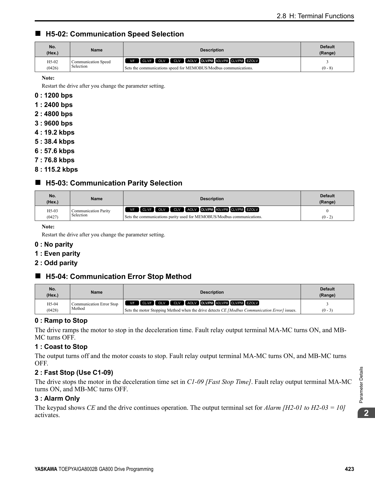
The stall prevention level set in L3-02 [Stall Prevent Level during Accel] is automatically reduced when the motor is running within the constant output range. Parameter L3-03 is the limit value used to prevent the stall prevention level during constant output ranges to fall below the minimum required level.
Note: The function to automatically reduce the stall prevention level does not operate when L3-01 = 3 [Stall Prevention during Accel = Current Limit Method].
| | | |---|---| | | | | | |
Figure 2.133 Stall Prevent Level during Accel/Limit
######## ■ L3-04: Stall Prevention during Decel
|No. (Hex.)|Name|Description|Default (Range)| |---|---|---|---| |L3-04 (0492)|Stall Prevention during Decel|Sets the method that the drive will use to prevent overvoltage faults when decelerating.
V/f CL-V/f OLV CLV AOLV OLV/PM AOLV/PM CLV/PM EZOLV
|1 (Determined by A1-02)|
################# Note:
Stall Prevention during deceleration controls the deceleration as specified by the DC bus voltage and does not let high inertia or fast deceleration cause ov [Overvoltage] faults.
############## 0 : No
The drive decelerates as specified by the deceleration time. If the deceleration time is too short, the drive can detect an ov fault.
Note: If an ov fault occurs, connect a dynamic braking option to the drive. If an ov fault occurs after you connect a dynamic braking option and A102 = 0 or 2 [Control Method Selection = V/f or CLV] and L3-04 = 0, set L3-04 = 3.
############## 1 : General Purpose
The drive decelerates as specified by the deceleration time. When the DC bus voltage is more than the Stall Prevention level, the drive stops deceleration until the DC bus voltage is less than the Stall Prevention Level. The drive then starts to decelerate at the set deceleration time. Frequent use of Stall Prevention will help prevent ov faults when the deceleration time is shorter than the drive can usually accept.
Note:
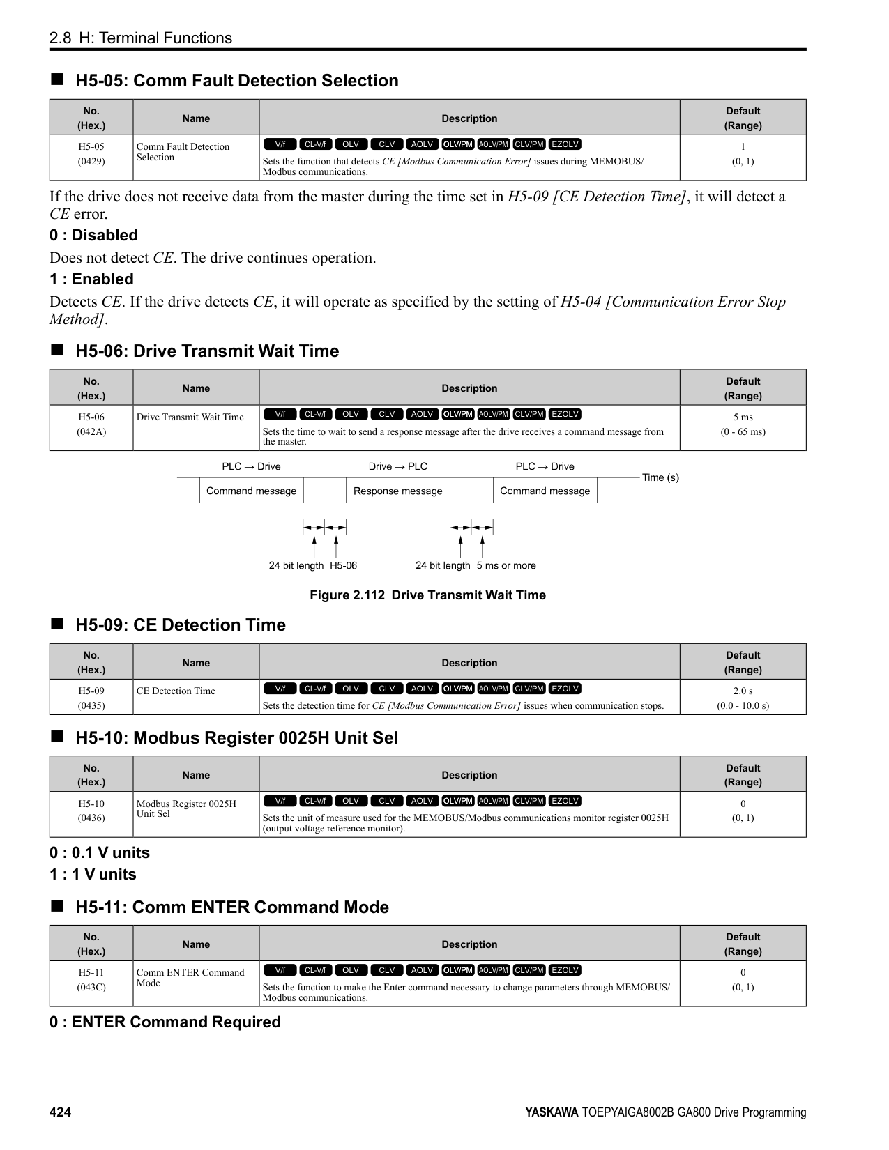
The Decel Stall Prevention function will increase the deceleration time to stop and the deceleration time will be longer than the setting. This function is not applicable for conveyor applications because the precision of the stop position is very important. As an alternative, use a dynamic braking option in these applications.
The input voltage setting of E1-01 [Input AC Supply Voltage] sets the DC bus voltage level for Stall Prevention.
Table 2.68 Stall Prevention Level during Deceleration
|Drive Input Voltage|Stall Prevention Level during Deceleration| |---|---| |200 V class|377 V| |400 V class|754 V|
ParameterDetails
######## 2
Figure 2.134 shows the Stall Prevention during deceleration function.
Figure 2.134 Stall Prevention Operation during Deceleration
############## 2 : Intelligent (Ignore Decel Ramp)
The drive adjusts the deceleration rate to keep the DC bus voltage at the L3-17 [DC Bus Regulation Level] level. This makes the shortest possible deceleration time and will not let the motor stall. The drive ignores the selected deceleration time and the possible deceleration time cannot be less than 1/10 of the set deceleration time. This function uses these parameters to adjust the deceleration rate:
############## 3 : General Purpose w/ DB resistor
A braking resistor is necessary for this setting. The braking resistor and the drive work together for the Stall Prevention during deceleration function.
############### 4 : Overexcitation/High FluxEnables Overexcitation/High Flux and enables a shorter deceleration time than when L3-04 = 0.
Note:
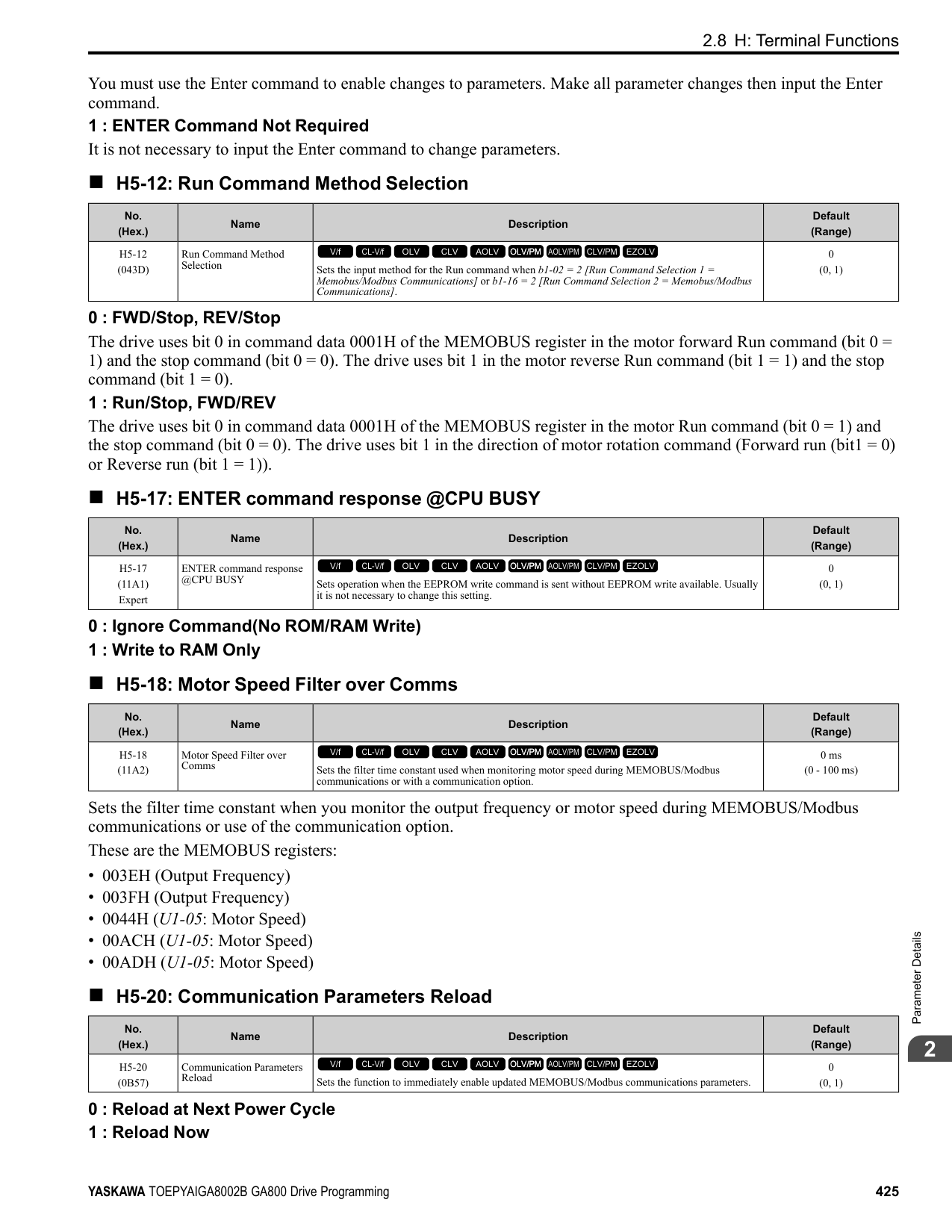
############## 5 : Overexcitation/High Flux 2
Enables Overexcitation/High Flux 2. This function decreases the possible deceleration time more than Overexcitation/ High Flux. The drive decreases motor speed and tries to keep the DC bus voltage at the L3-17 level. If the drive detects oL1, decrease the values set in n3-13 and n3-21. If the drive detects ov, increase the values set in C1-02, C1-04, C1-06, and C1-08 [Deceleration Times].
Note:
######## ■ L3-05: Stall Prevention during RUN
|No. (Hex.)|Name|Description|Default (Range)| |---|---|---|---| |L3-05 (0493)|Stall Prevention during RUN|Sets the function to enable and disable Stall Prevention During Run.
V/f CL-V/f OLV CLV AOLV OLV/PM AOLV/PM CLV/PM EZOLV
|2 (0 - Determined by A1-02)|
Stall Prevention function during run prevents the motor from stalling by automatically reducing the speed when an oL1 [Motor Overload] occurs while the motor is running at constant speed.
Note:
The drive runs at the set frequency reference. A heavy load can cause the drive to detect oC [Overcurrent] or oL1 and stall the motor.
The drive will decelerate for the time set in C1-02 [Deceleration Time 1] when the current is more than the Stall Prevention level set in L3-06. When the current level is less than the “L3-06 setting value - 2%” for 100 ms, the drive accelerates again for the acceleration time applicable at that time until it reaches the set frequency.
This setting functions the same as Setting 1 [Deceleration Time 1 (C1-02)]. When the Stall Prevention function is enabled, the drive decelerates with the value set in C1-04 [Deceleration Time 2].
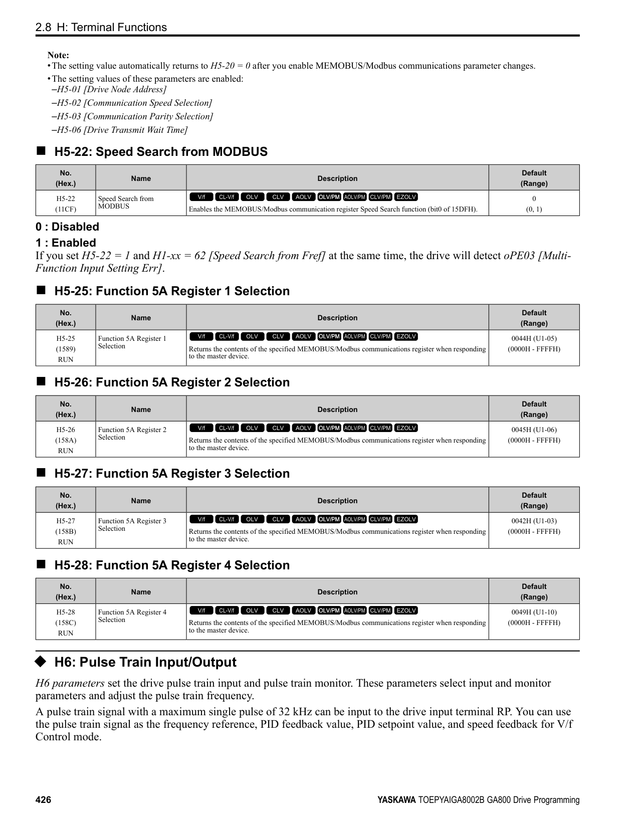
######## ■ L3-06: Stall Prevent Level during Run
|No. (Hex.)|Name|Description|Default (Range)| |---|---|---|---| |L3-06 (0494)|Stall Prevent Level during Run|Sets the output current level to enable the Stall Prevention function during operation as a percentage of the drive rated output current.
V/f CL-V/f OLV CLV AOLV OLV/PM AOLV/PM CLV/PM EZOLV
|Determined by C6-01 and L8-38
(5 - 150%)|
################# Note:
Stall Prevention Level during Run (%)
100
30
Input level of multi-function analog input terminals A1, A2, and A3
0 3 V 10 V
(4 mA)(8.8 mA) (20 mA)
Figure 2.135 Stall Prevention Level during Run with Analog Input
ParameterDetails
######## 2
######## ■ L3-11: Overvoltage Suppression Select
|No. (Hex.)|Name|Description|Default (Range)|
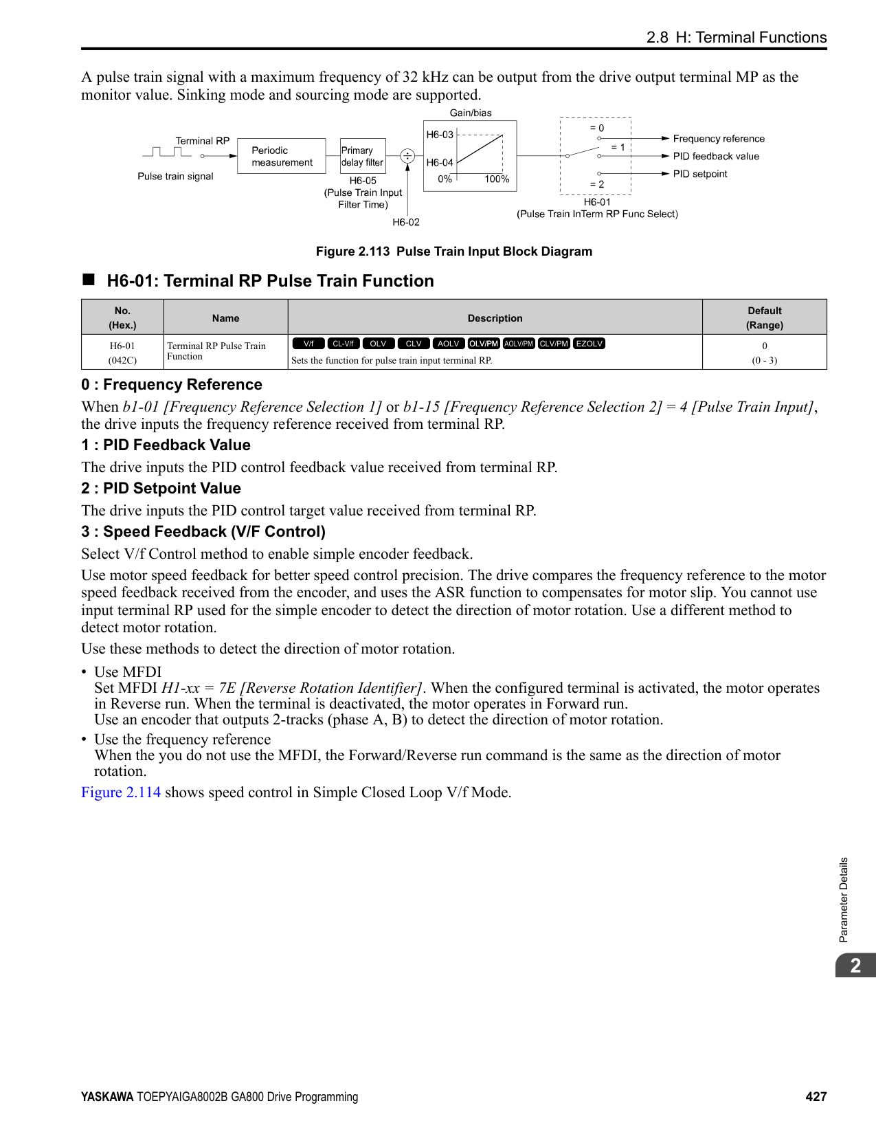
|---|---|---|---| |L3-11 (04C7)|Overvoltage Suppression Select|Sets the overvoltage suppression function.
V/f CL-V/f OLV CLV AOLV OLV/PM AOLV/PM CLV/PM EZOLV
|0 (0, 1)|
0 : Disabled The drive does not adjust the regenerative torque limit or the output frequency. If you apply a regenerative load, the drive can detect an ov [Overvoltage] fault. Use this setting with a dynamic braking option. 1 : Enabled
When a regenerative load increases the DC bus voltage, the drive decreases the regenerative torque limit and increases the output frequency to prevent ov
######## ■ L3-17: DC Bus Regulation Level
|No. (Hex.)|Name|Description|Default (Range)| |---|---|---|---| |L3-17 (0462)|DC Bus Regulation Level|Sets the target value for the DC bus voltage when the overvoltage suppression function and the Decel Stall Prevention function (Intelligent Stall Prevention) are active.
V/f CL-V/f OLV CLV AOLV OLV/PM AOLV/PM CLV/PM EZOLV
|200 V Class: 375 V, 400 V: 750 V
(200 V Class: 150 to 400 V, 400 V Class: 300 to 800 V)|
Note: This value is initialized when E1-01 [Input AC Supply Voltage] is changed.
Sets this parameter for any of the following circumstances.
Set one of these parameters to enable L3-20:
Note:
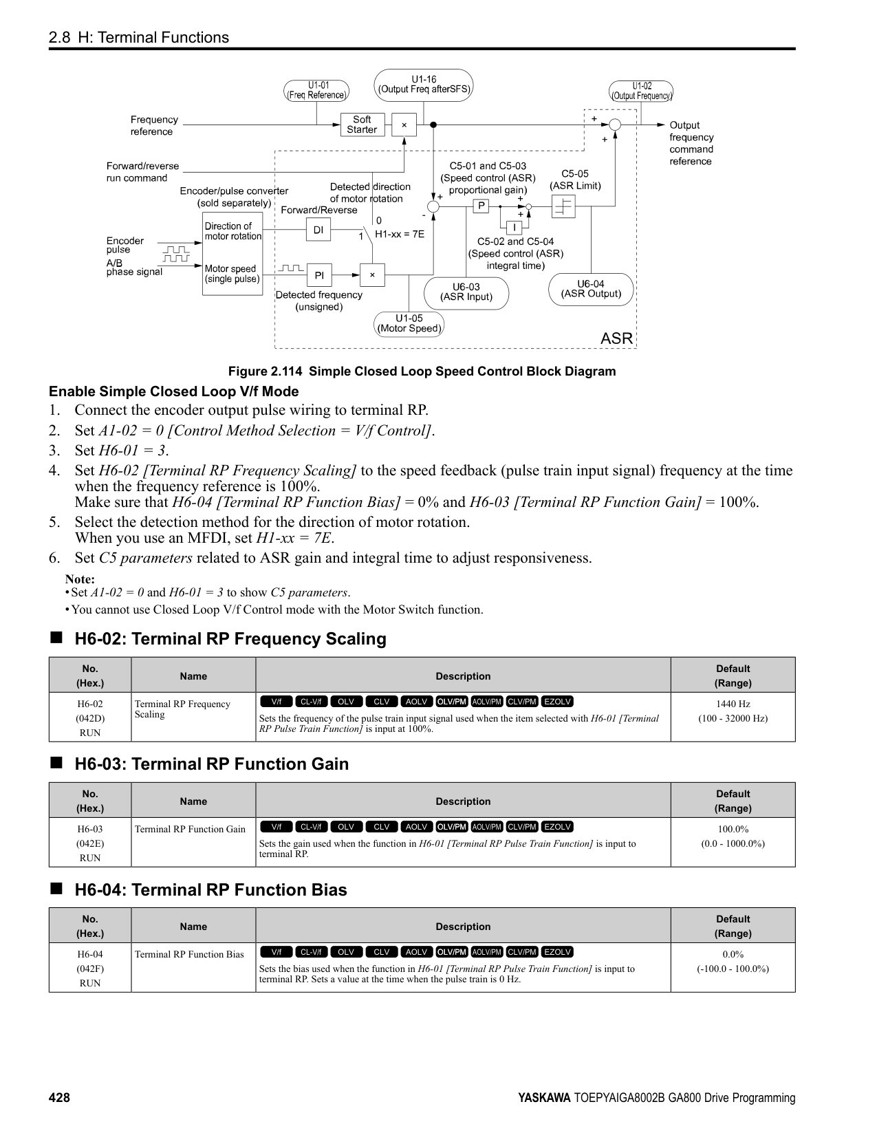
|No. (Hex.)|Name|Description|Default (Range)| |---|---|---|---| |L3-20 (0465) Expert|DC Bus Voltage Adjustment Gain|Sets the proportional gain used to control the DC bus voltage.
V/f CL-V/f OLV CLV AOLV OLV/PM AOLV/PM CLV/PM EZOLV
|Determined by A1-02 (0.00 - 5.00)|
|No. (Hex.)|Name|Description|Default (Range)| |---|---|---|---| |L3-21 (0466) Expert|OVSuppression Accel/Decel P Gain|Sets the proportional gain to calculate acceleration and deceleration rates.
V/f CL-V/f OLV CLV AOLV OLV/PM AOLV/PM CLV/PM EZOLV
|Determined by A1-02 (0.10 - 10.00)|
Note:
######## ■ L3-22: PM Stall Prevention Decel Time
|No. (Hex.)|Name|Description|Default (Range)| |---|---|---|---| |L3-22 (04F9)|PM Stall Prevention Decel Time|Sets the momentary deceleration time that the drive will use when it tries to accelerate a PM motor and detected motor stalls. This function is applicable when L3-01 = 1 [Stall Prevent Select duringAccel = General Purpose].
V/f CL-V/f OLV CLV AOLV OLV/PM AOLV/PM CLV/PM EZOLV
|0.0 s (0.0 - 6000.0 s)|
Set this parameter to 0.0 s to disable this function. The drive will decelerates in the deceleration time applicable at the time when a motor stall occurs.
######## ■ L3-23: Stall P Reduction at Constant HP
|No. (Hex.)|Name|Description|Default (Range)| |---|---|---|---| |L3-23 (04FD)|Stall P Reduction at Constant HP|Sets the function to automatically decrease the Stall Prevention Level during Run for constant output ranges.
V/f CL-V/f OLV CLV AOLV OLV/PM AOLV/PM CLV/PM EZOLV
|0 (0, 1)|
0 : Use L3-06 for Entire Speed Range The drive uses the level set in L3-06 [Stall Prevent Level during Run] through the full speed range. 1 : Automatic Reduction @ CHP Region The drive decreases the Stall Prevention level during run in the constant power range. The lower limit is 40% of the L3-06 value.
######## ■ L3-24: Motor Accel Time @ Rated Torque
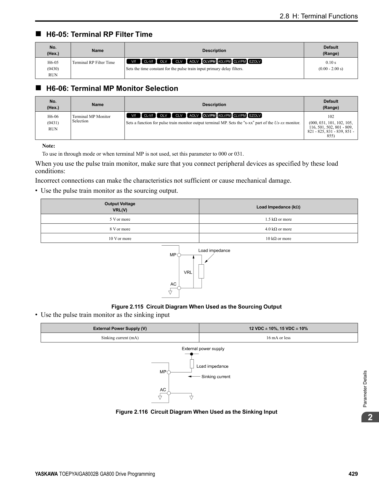
|No. (Hex.)|Name|Description|Default (Range)| |---|---|---|---| |L3-24 (046E) Expert|Motor Accel Time @ Rated Torque|Sets the motor acceleration time to reach the maximum frequency at the motor rated torque for stopped single-drive motors.
V/f CL-V/f OLV CLV AOLV OLV/PM AOLV/PM CLV/PM EZOLV
|Determined by o2-04, C601, E2-11, and E5-01
(0.001 - 10.000 s)|
Set one of these parameters to enable L3-20:
Automatically Adjust Parameters When A1-02 = 3, 7 [Control Method Selection = CLV, CLV/PM], do Inertia Tuning. Parameters are automatically adjusted.
Manually Adjust Parameters Use this formula to find the motor acceleration time:
ParameterDetails
######## 2
PMotor = Motor Rated Power (kW)
Set one of these parameters to enable L3-20:
Note:
Manually Adjust Parameters Use this formula to find the load inertia ratio:
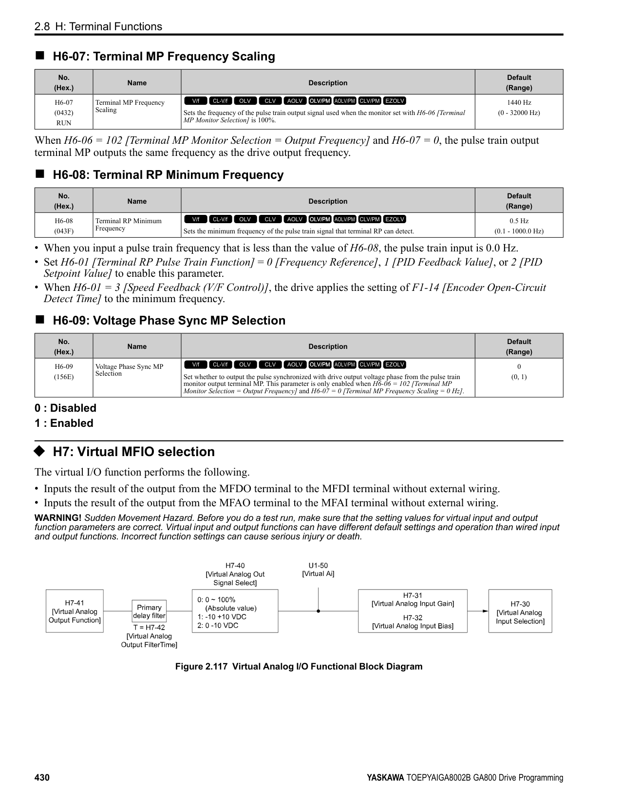
|No. (Hex.)|Name|Description|Default (Range)| |---|---|---|---| |L3-25 (046F) Expert|Load Inertia Ratio|Sets the ratio between motor inertia and machine inertia.
V/f CL-V/f OLV CLV AOLV OLV/PM AOLV/PM CLV/PM EZOLV
|1.0 (0.1 - 1000.0)|
|No. (Hex.)|Name|Description|Default (Range)| |---|---|---|---| |L3-26 (0455) Expert|Additional DC Bus Capacitors|Sets the capacity for external main circuit capacitors. Usually it is not necessary to change this setting. Sets this parameter when you use the KEB Ride-Thru function.
V/f CL-V/f OLV CLV AOLV OLV/PM AOLV/PM CLV/PM EZOLV
|0 μF (0 to 65000 μF)|
|No. (Hex.)|Name|Description|Default (Range)| |---|---|---|---| |L3-27 (0456)|Stall Prevention Detection Time|Sets a delay time between reaching the Stall Prevention level and starting the Stall Prevention function.
V/f CL-V/f OLV CLV AOLV OLV/PM AOLV/PM CLV/PM EZOLV
|50 ms (0 - 5000 ms)|
######## ■ L3-34: Torque Limit Delay Time
|No. (Hex.)|Name|Description|Default (Range)| |---|---|---|---| |L3-34 (016F) Expert|Torque Limit Delay Time|Sets the filter time constant that returns the torque limit to its initial value when KEB operation operates in Single Drive KEB Ride-Thru mode.
V/f CL-V/f OLV CLV AOLV OLV/PM AOLV/PM CLV/PM EZOLV
|Determined by A1-02 (0.000 - 1.000 s)|
When vibration occurs during operation of Single Drive KEB Ride-Thru 2, increase this parameter in 0.010-unit increments.
Note: The Single Drive KEB Ride-Thru 2 mode operates when L2-29 = 1 [KEB Method Selection = Single Drive KEB Ride-Thru 2] and H1-xx = 7A or 7B [Terminal Sx Function Selection = KEB Ride-Thru 2 (N.C./N.O.)].
######## ■ L3-35: Speed Agree Width for Auto Decel
|No. (Hex.)|Name|Description|Default (Range)| |---|---|---|---| |L3-35 (0747) Expert|Speed Agree Width for Auto Decel|Sets the width for speed agreement when L3-04 = 2 [Decel Stall Prevention Selection = Automatic Decel Reduction]. Usually it is not necessary to change this setting.
V/f CL-V/f OLV CLV AOLV OLV/PM AOLV/PM CLV/PM EZOLV
|0.00 Hz (0.00 - 1.00 Hz)|
Set this parameter when hunting occurs while you use a frequency reference through an analog input.
######## ■ L3-36: Current Suppression Gain@Accel
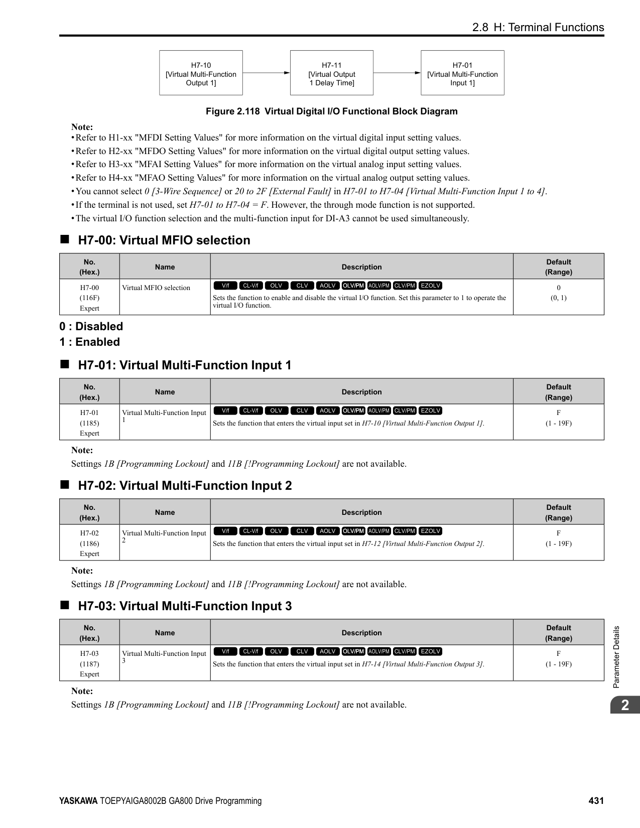
|No. (Hex.)|Name|Description|Default (Range)| |---|---|---|---| |L3-36 (11D0)|Current Suppression Gain@Accel|Sets the gain to suppress current and motor speed hunting during operation when L3-01 = 3 [Stall Prevention during Accel = Current Limit Method]. Usually it is not necessary to change this setting.
V/f CL-V/f OLV CLV AOLV OLV/PM AOLV/PM CLV/PM EZOLV
|Determined by A1-02 (0.0 - 100.0)|
If there is vibration in the output current during acceleration, increase the setting value. Note: Set L3-01 3 [Stall Prevention during Accel Current Limit Method] to enable this function.
######## ■ L3-37: Current Limit P Gain @ Accel
|No. (Hex.)|Name|Description|Default (Range)| |---|---|---|---| |L3-37 (11D1) Expert|Current Limit P Gain @ Accel|Suppresses current hunting during acceleration. Usually it is not necessary to change this setting.
V/f CL-V/f OLV CLV AOLV OLV/PM AOLV/PM CLV/PM EZOLV
|5 ms (0 - 100 ms)|
Note: Set L3-01 = 3 [Stall Prevention during Accel = Current Limit Method] to enable this function.
######## ■ L3-38: Current Limit I Time @ Accel
|No. (Hex.)|Name|Description|Default (Range)| |---|---|---|---| |L3-38 (11D2) Expert|Current Limit I Time @ Accel|Suppresses current hunting and overshooting that occurs when the drive stalls during acceleration. Usually it is not necessary to change this setting.
V/f CL-V/f OLV CLV AOLV OLV/PM AOLV/PM CLV/PM EZOLV
|10.0 (0.0 - 100.0)|
Note: Set L3-01 = 3 [Stall Prevention during Accel = Current Limit Method] to enable this function.
######## ■ L3-39: Current Limit Filter Time @Accel
|No. (Hex.)|Name|Description|Default (Range)| |---|---|---|---| |L3-39 (11D3)|Current Limit Filter Time @Accel|Sets the time constant to adjust the acceleration rate when L3-01 = 3 [Stall Prevention during Accel
= Current Limit Method]. Usually it is not necessary to change this setting.
V/f CL-V/f OLV CLV AOLV OLV/PM AOLV/PM CLV/PM EZOLV
|100.0 ms (1.0 - 1000.0 ms)|
Note: Set L3-01 = 3 [Stall Prevention during Accel = Current Limit Method] to enable this function.
ParameterDetails
######## 2
######## ■ L3-40: Current Limit S-Curve @ Acc/Dec
|No. (Hex.)|Name|Description|Default (Range)|
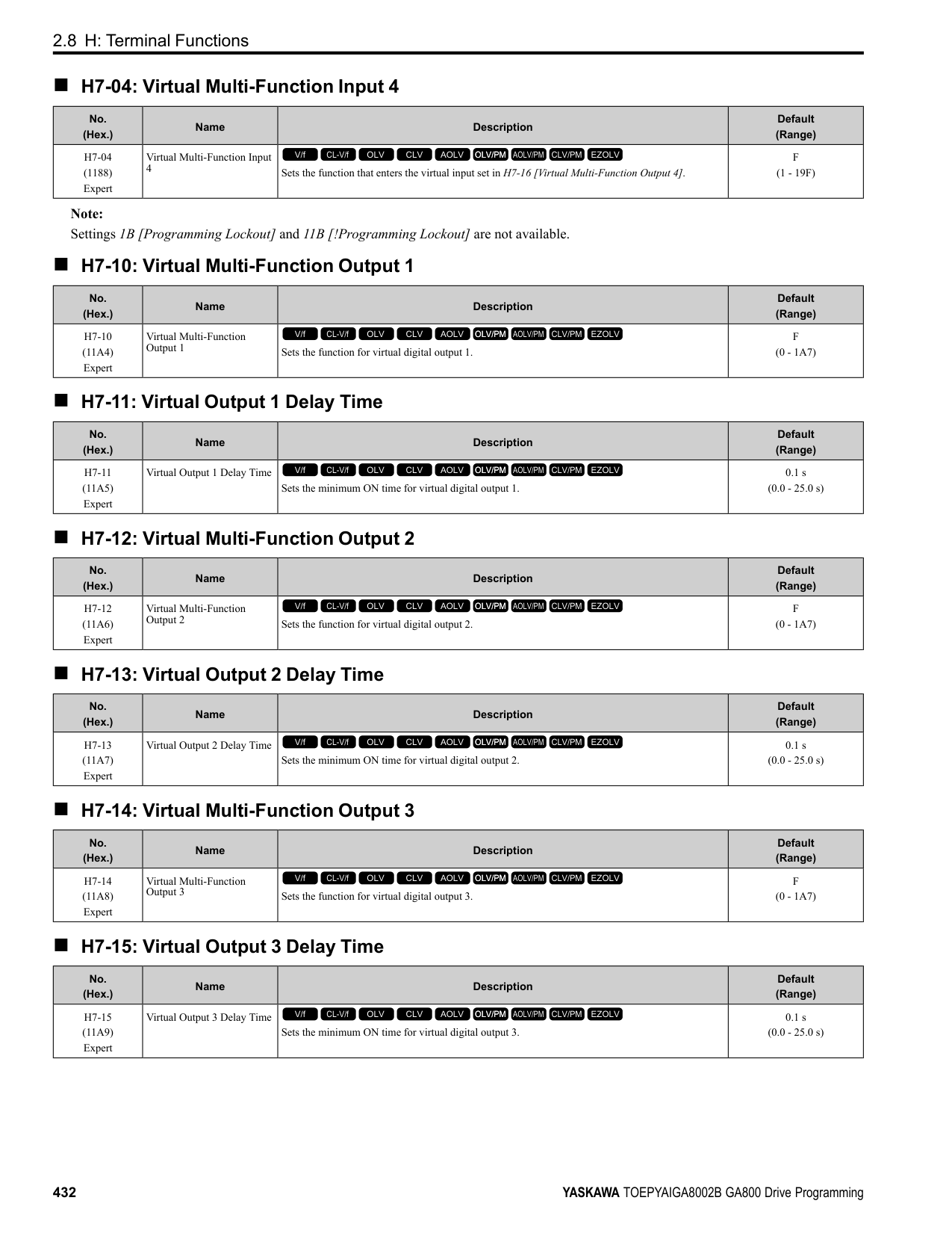
|---|---|---|---| |L3-40 (11D4)|Current Limit S-Curve @ Acc/Dec|Sets the function to enable and disable the best S-curve characteristic used for current-limited acceleration.
V/f CL-V/f OLV CLV AOLV OLV/PM AOLV/PM CLV/PM EZOLV
|0 (0, 1)|
Makes the best motor acceleration rate for start up. If you set this parameter to 1, it will make acceleration smoother, but it can also increase the acceleration time to be longer than the set time. If the drive detects oC [Overcurrent] faults immediately after acceleration starts, set this parameter.
0 : No 1 : Yes
Note: Set L3-01 3 [Stall Prevention during Accel Current Limit Method] to enable this function.
◆ L4: Speed Detection L4 parameters set the output of signals to the MFDO terminals, for example frequency agree and speed detection. The drive detects motor speed in CLVor CLV/PM control methods.
######## ■ L4-01: Speed Agree Detection Level
|No. (Hex.)|Name|Description|Default (Range)| |---|---|---|---| |L4-01 (0499)|Speed Agree Detection Level|Sets the level to detect speed agree or motor speed.
V/f CL-V/f OLV CLV AOLV OLV/PM AOLV/PM CLV/PM EZOLV
|Determined by A1-02 (Determined by A1-02)|
Sets the level to detect speed agree or motor speed when H2-01 to H2-03 = 2, 3, 4, 5 [MFDO Function Select = Speed Agree 1, User-set Speed Agree 1, Frequency Detection 1, Frequency Detection 2].
######## ■ L4-02: Speed Agree Detection Width
|No. (Hex.)|Name|Description|Default (Range)| |---|---|---|---| |L4-02 (049A)|Speed Agree Detection Width|Sets the width to detect speed agree or motor speed.
V/f CL-V/f OLV CLV AOLV OLV/PM AOLV/PM CLV/PM EZOLV
|Determined by A1-02 (Determined by A1-02)|
Sets the width to detect speed agree or motor speed when H2-01 to H2-03 = 2, 3, 4, 5 [MFDO Function Select = Speed Agree 1, User-set Speed Agree 1, Frequency Detection 1, Frequency Detection 2].
######## ■ L4-03: Speed Agree Detection Level (+/-)
|No. (Hex.)|Name|Description|Default (Range)| |---|---|---|---| |L4-03 (049B)|Speed Agree Detection Level (+/-)|Sets the level to detect speed agree or motor speed.
V/f CL-V/f OLV CLV AOLV OLV/PM AOLV/PM CLV/PM EZOLV
|Determined by A1-02 (Determined by A1-02)|
Sets the speed agree detection level or motor speed detection level when H2-01 to H2-03 = 13, 14, 15, 16 [MFDO Function Selection = Speed Agree 2, User-set Speed Agree 2, Frequency Detection 3, Frequency Detection 4].
######## ■ L4-04: Speed Agree Detection Width (+/-)
|No. (Hex.)|Name|Description|Default (Range)|
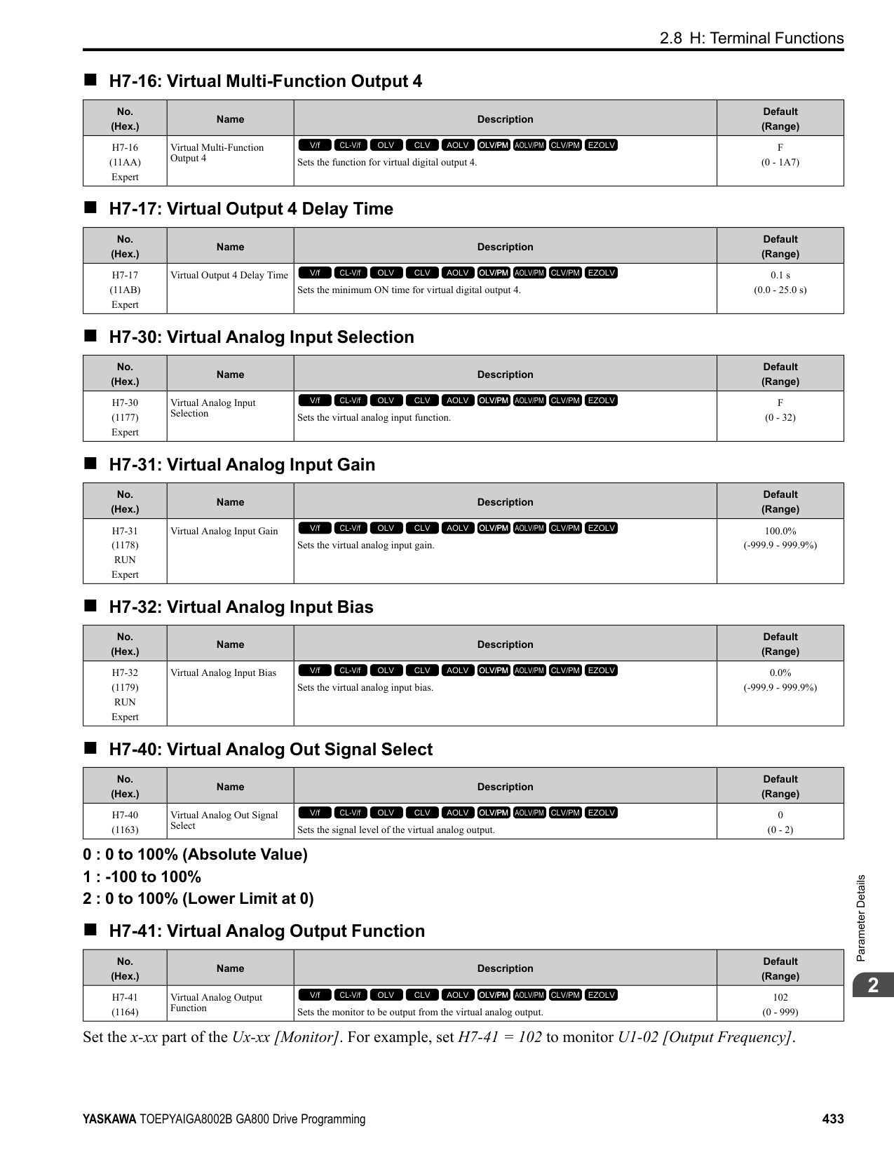
|---|---|---|---| |L4-04 (049C)|Speed Agree Detection Width (+/-)|Sets the width to detect speed agree or motor speed.
V/f CL-V/f OLV CLV AOLV OLV/PM AOLV/PM CLV/PM EZOLV
|Determined by A1-02 (Determined by A1-02)|
Sets the width to detect speed agree or motor speed when H2-01 to H2-03 = 13, 14, 15, 16 [MFDO Function Selection = Speed Agree 2, User-set Speed Agree 2, Frequency Detection 3, Frequency Detection 4].
######## ■ L4-05: Fref Loss Detection Selection
|No. (Hex.)|Name|Description|Default (Range)| |---|---|---|---| |L4-05 (049D)|Fref Loss Detection Selection|Sets the operation when the drive detects a loss of frequency reference.
V/f CL-V/f OLV CLV AOLV OLV/PM AOLV/PM CLV/PM EZOLV
|0 (0, 1)|
Enables the detection of a loss of an analog frequency reference when the frequency reference is input from the MFAI terminals (A1, A2, and A3). Set H2-01 to H2-03 = C [MFDO Function Select = Frequency Reference Loss] to enable this function.
If the frequency reference is less than 10% in 400 ms, the drive detects frequency reference loss.
Figure 2.136 Detection of Frequency Reference Loss
0 : Stop The drive follows the frequency reference and stops the motor. 1 : Run at (L4-06 x Last Reference)
The drive continues to operate at the frequency reference value set in L4-06 [FreqReference at Reference Loss]. When you return the external frequency reference value, the drive continues to operate with the frequency reference.
######## ■ L4-06: Frequency Reference @Loss of Ref
|No. (Hex.)|Name|Description|Default (Range)| |---|---|---|---| |L4-06 (04C2)|Frequency Reference @Loss of Ref|Sets the frequency reference as a percentage to continue drive operation after it detects a frequency reference loss. The value is a percentage of the frequency reference before the drive detected the loss.
V/f CL-V/f OLV CLV AOLV OLV/PM AOLV/PM CLV/PM EZOLV
|80.0% (0.0 - 100.0%)|
Set L4-05 = 1 [FreqReference Loss Detect Select = Run@L4-06PrevRef] to enable this parameter.
######## ■ L4-07: Speed Agree Detection Selection
|No. (Hex.)|Name|Description|Default (Range)| |---|---|---|---| |L4-07 (0470)|Speed Agree Detection Selection|Sets the condition that activates speed detection.
V/f CL-V/f OLV CLV AOLV OLV/PM AOLV/PM CLV/PM EZOLV
|0 (0, 1)|
0 : No Detection during Baseblock Detects the frequency while the drive is operating. When the drive turns off its output, it will not detect frequency. 1 : Detection Always Enabled
◆ L5: Fault Restart The Auto Restart function tries to keep machines operating when the drive detects a transient fault. The drive can do a self-diagnostic check and continue the operation after a fault. If the cause of the fault goes away, the drive does speed search and restarts. It will not stop and the drive will not record a fault history. Use L5-02 [Fault Contact at Restart Select] to select the operation of fault relay signals during Auto Restart operation.
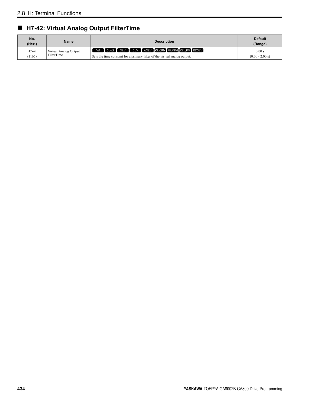
Sets if the drive will do Auto Restart and the number of times the drive will try to do Auto Restart in a set time. If the number of Auto Restart tries is more than the set value during the set time, drive output shuts off and operation stops. If this happens, remove the cause of the fault and manually restart the drive.
The drive can do Auto Restart when these faults occur:
ParameterDetails
######## 2
Note: You can disable Auto Restart for faults if you must not restart the machine after the fault.
################# Table 2.69 List of Faults during which Auto Restart is Available
|Fault|Name|Parameters to Disable Auto Restart| |---|---|---| |GF|Ground Fault|L5-08| |LF|Output Phase Loss|-| |oC|Overcurrent|-| |oH1|Heatsink Overheat|L5-08| |oL1|Motor Overload|L5-07| |oL2|Drive Overload|L5-07| |oL3|Overtorque Detection 1|L5-07| |oL4|Overtorque Detection 2|L5-07|
|Fault|Name|Parameters to Disable Auto Restart| |---|---|---| |ov|Overvoltage|L5-08| |PF|Input Phase Loss|-| |rH|Braking Resistor Overheat|-| |rr|Dynamic Braking Transistor Fault|-| |STPo|Motor Step-Out Detected|-| |Uv1|DC Bus Undervoltage *1|L5-08|
*1 Uv1 is the target for the auto restart process when L2-01 1, 2, 3, or 4 [Power Loss Ride Through Select Enabled for L2-02 Time, Enabled while CPU Power Active, Kinetic Energy Backup: L2-02, or Kinetic Energy Backup: CPU Power].
######## ■ L5-01: Number of Auto-Restart Attempts
|No. (Hex.)|Name|Description|Default (Range)| |---|---|---|---| |L5-01 (049E)|Number of Auto-Restart Attempts|Sets the number of times that the drive will try to restart.
V/f CL-V/f OLV CLV AOLV OLV/PM AOLV/PM CLV/PM EZOLV
|0 (0 - 10 times)|
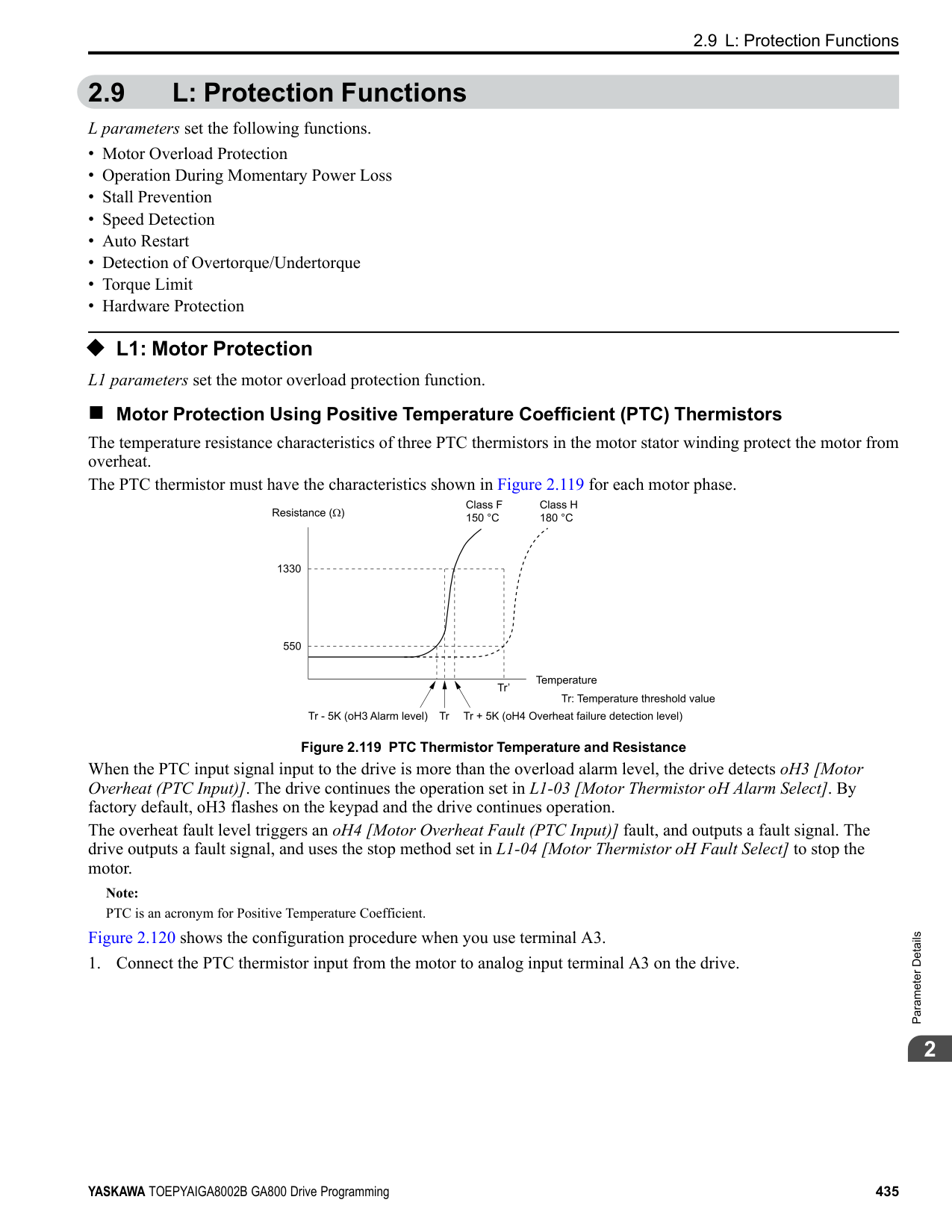
The drive resets the number of Auto Restart attempts to 0 in these conditions:
######## ■ L5-02: Fault Contact at Restart Select
|No. (Hex.)|Name|Description|Default (Range)| |---|---|---|---| |L5-02 (049F)|Fault Contact at Restart Select|Sets the function that sends signals to the MFDO terminal set for Fault [H2-xx = E] while the drive is automatically restarting.
V/f CL-V/f OLV CLV AOLV OLV/PM AOLV/PM CLV/PM EZOLV
|0 (0, 1)|
0 : Active Only when Not Restarting 1 : Always Active
|No. (Hex.)|Name|Description|Default (Range)| |---|---|---|---| |L5-03 (04A0)|Continuous Method Max Restart T|Sets the time for which the drive will try to restart. If the drive cannot restart inthe time set in L5-03, the drive detects a fault. This is available when L5-05 = 0 [Auto-Restart Method = Continuous/ Immediate Attempts].
V/f CL-V/f OLV CLV AOLV OLV/PM AOLV/PM CLV/PM EZOLV
|10.0 s (0.5 - 180.0 s)|
|No. (Hex.)|Name|Description|Default (Range)| |---|---|---|---| |L5-04 (046C)|Interval Method Restart Time|Sets the time interval between each Auto Restart attempt. This function is enabled when L5-05 = 1 [Auto Restart Operation Selection = Use L5-04 Time].
V/f CL-V/f OLV CLV AOLV OLV/PM AOLV/PM CLV/PM EZOLV
|10.0 s (0.5 - 600.0 s)|
######## ■ L5-05: Auto-Restart Method
|No. (Hex.)|Name|Description|Default (Range)| |---|---|---|---| |L5-05 (0467)|Auto-Restart Method|Sets the count method for the Auto Restart operation.
V/f CL-V/f OLV CLV AOLV OLV/PM AOLV/PM CLV/PM EZOLV
|0 (0, 1)|
0 : Continuous/Immediate Attempts Counts the number of successful fault resets through Auto Restart. When this value > L5-01, the drive will send a fault signal and fault code to the keypad and the motor will coast to stop. 1 : Interval/Attempt after L5-04 sec Counts the number of all fault resets (successful and unsuccessful) through Auto Restart. The drive repeats the Auto Restart process in the intervals set in L5-04 [Interval Method Restart Time]. When this value > L5-01, the drive will send a fault signal and fault code to the keypad and the motor will coast to stop.
######## ■ L5-07: Fault Reset Enable Select Grp1
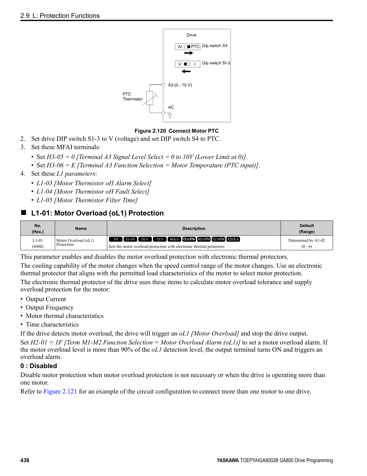
|No. (Hex.)|Name|Description|Default (Range)| |---|---|---|---| |L5-07 (0B2A)|Fault Reset Enable Select Grp1|Use these 4 digits to set the Auto Restart function for oL1 to oL4. From left to right, the digits set oL1, oL2, oL3, and oL4, in order.
V/f CL-V/f OLV CLV AOLV OLV/PM AOLV/PM CLV/PM EZOLV
|1111 (0000 - 1111)|
0000 : Disabled 0001 : Enabled (—/—/—/oL4) 0010 : Enabled (—/—/oL3/—) 0011 : Enabled (—/—/oL3/oL4) 0100 : Enabled (—/oL2/—/—) 0101 : Enabled (—/oL2/—/oL4) 0110 : Enabled (—/oL2/oL3/—) 0111 : Enabled (—/oL2/oL3/oL4) 1000 : Enabled (oL1/—/—/—) 1001 : Enabled (oL1/—/—/oL4) 1010 : Enabled (oL1/—/oL3/—) 1011 : Enabled (oL1/—/oL3/oL4) 1100 : Enabled (oL1/oL2/—/—) 1101 : Enabled (oL1/oL2/—/oL4) 1110 : Enabled (oL1/oL2/oL3/—) 1111 : Enabled (oL1/oL2/oL3/oL4)
| | | |---|---| | | |
| | | |---|---| | | |
| | | |---|---| | | |
| | | |---|---| | | |
Figure 2.137 Setting Digits and Fault Code
######## ■ L5-08: Fault Reset Enable Select Grp2
|No. (Hex.)|Name|Description|Default (Range)| |---|---|---|---| |L5-08 (0B2B)|Fault Reset Enable Select Grp2|Use these 4 digits to set the Auto Restart function for Uv1, ov, oH1, and GF. From left to right, the digits set Uv1, ov, oH1, and GF, in order.
V/f CL-V/f OLV CLV AOLV OLV/PM AOLV/PM CLV/PM EZOLV
|1111 (0000 - 1111)|
0000 : Disabled
ParameterDetails
######## 2
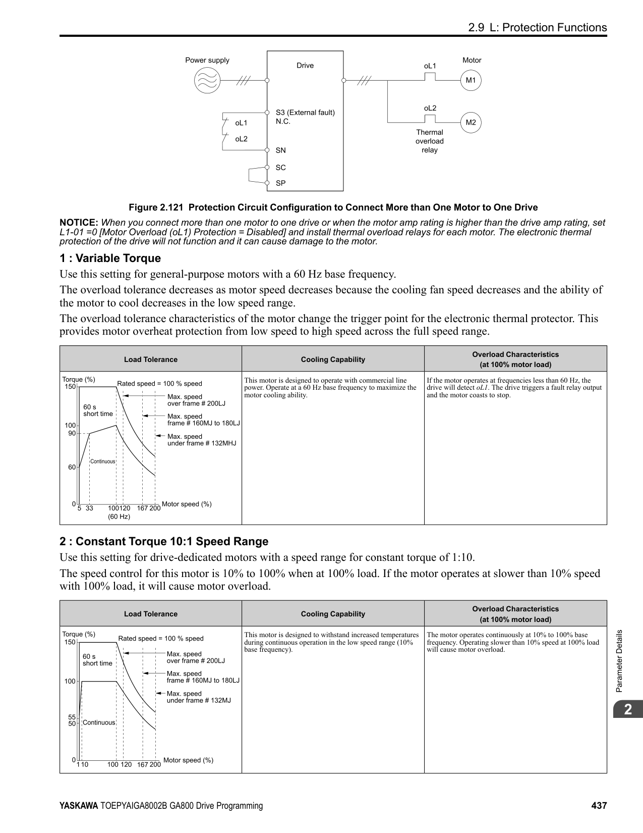
| | | |---|---| | | |
| | | |---|---| | | |
| | | |---|---| | | |
| | | |---|---| | | |
Figure 2.138 Setting Digits and Fault Code
◆ L6: Torque Detection The overtorque/undertorque detection function prevents damage to machinery and loads. Overtorque is the when there is too much load on the machine. If the motor current or output torque is at the overtorque detection level for the overtorque detection time, the drive will output an alarm and turn off the output. Undertorque is the when a load suddenly decreases. When the motor current or output torque is at the undertorque detection level for the undertorque detection time, the drive will outupt an alarm and turn off the output. You can use the undertorque detection function to detect these conditions, for example:
Note:
If there is oC [Overcurrent] or oL1 [Motor Overload], the drive can stop during overtorque conditions. Use torque detection to identify overload conditions before the drive detects oC or oL1 and stops. Use this function to detect issues that occur in the application.
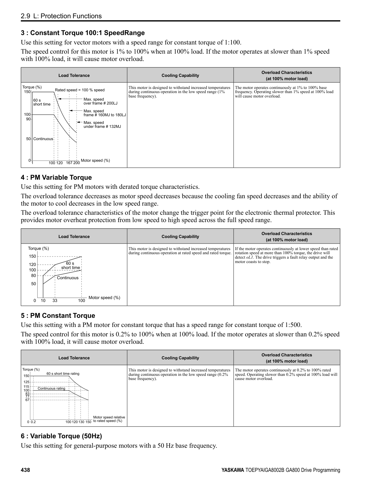
######## ■ Parameter Setting
You can individually set the two overtorque/undertorque detection functions with the drive. Use the information in Table 2.70 to set the parameters.
Table 2.70 Overtorque/Undertorque Detection Parameters
|Configuration Parameter|Overtorque/Undertorque Detection 1|Overtorque/Undertorque Detection 2| |---|---|---| |MFDO Function Select
• Terminals M1-M2
• Terminals M3-M4
• Terminals M5-M6
|H2-01, H2-02, and H2-03 = B N.O.: Activated when detected|H2-01, H2-02, and H2-03 = 18 N.O.: Activated when detected| |MFDO Function Select
• Terminals M1-M2
• Terminals M3-M4
• Terminals M5-M6
|H2-01, H2-02, and H2-03 = 17 N.C.: Disactivated when detected|H2-01, H2-02, and H2-03 = 19 N.C.: Disactivated when detected| |Detection conditions and selection of operation after detection|L6-01|L6-04| |Detection Level|L6-02|L6-05| |Detection Level|Analog Input Terminal *1 H3-xx = 7|-|
|Configuration Parameter|Overtorque/Undertorque Detection 1|Overtorque/Undertorque Detection 2| |---|---|---| |Detection Time|L6-03|L6-06|
*1 You can also use an analog input terminal to supply the torque detection level. To enable this function, set H3-xx = 7 [MFAI Function Selection = Overtorque/Undertorque DetectLvl]. If both L6-02 and H3-xx = 7 are set, the analog input has priority and the setting of L602 is disabled.
You cannot use Overtorque/Undertorque Detection 2 to set the detection level for the analog input terminals. Note: In V/f Control, the drive uses the current level (100% of the drive rated output current) to detect overtorque/undertorque. In vector control, the drive uses the motor torque (100% of the motor rated torque)to detect overtorque/undertorque. When you enable the mechanical weakening detection function, the overtorque/undertorque detection level for all control modes is the current level (100% of the drive rated output current).
■ Time Chart for Detection of Overtorque/Undertorque Overtorque Detection Time Chart When you use Overtorque/Undertorque Detection 1, the drive detects overtorque if the motor current or motor torque is at the detection level set in L6-02 [Torque Detection Level 1] for the time set in L6-03 [Torque Detection Time 1]. Parameter L6-01 [Torque Detection Selection 1] sets the operation after detection. When you use Overtorque/Undertorque Detection 2, set L6-04 [Torque Detection Selection 2], L6-05 [Torque Detection Level 2], and L6-06 [Torque Detection Time 2]. Use H2-01 to H2-03 [MFDO Function Select] to set the terminal that outputs the alarm.
Figure 2.139 Overtorque Detection Time Chart Note:
The drive applies a hysteresis of approximately 10% of the drive rated output current or the motor rated torque to the overtorque/undertorque detection function.
Undertorque Detection Time Chart
Figure 2.140 Undertorque Detection Time Chart Note:
The drive applies a hysteresis of approximately 10% of the drive rated output current or the motor rated torque to the overtorque/undertorque detection function.
ParameterDetails
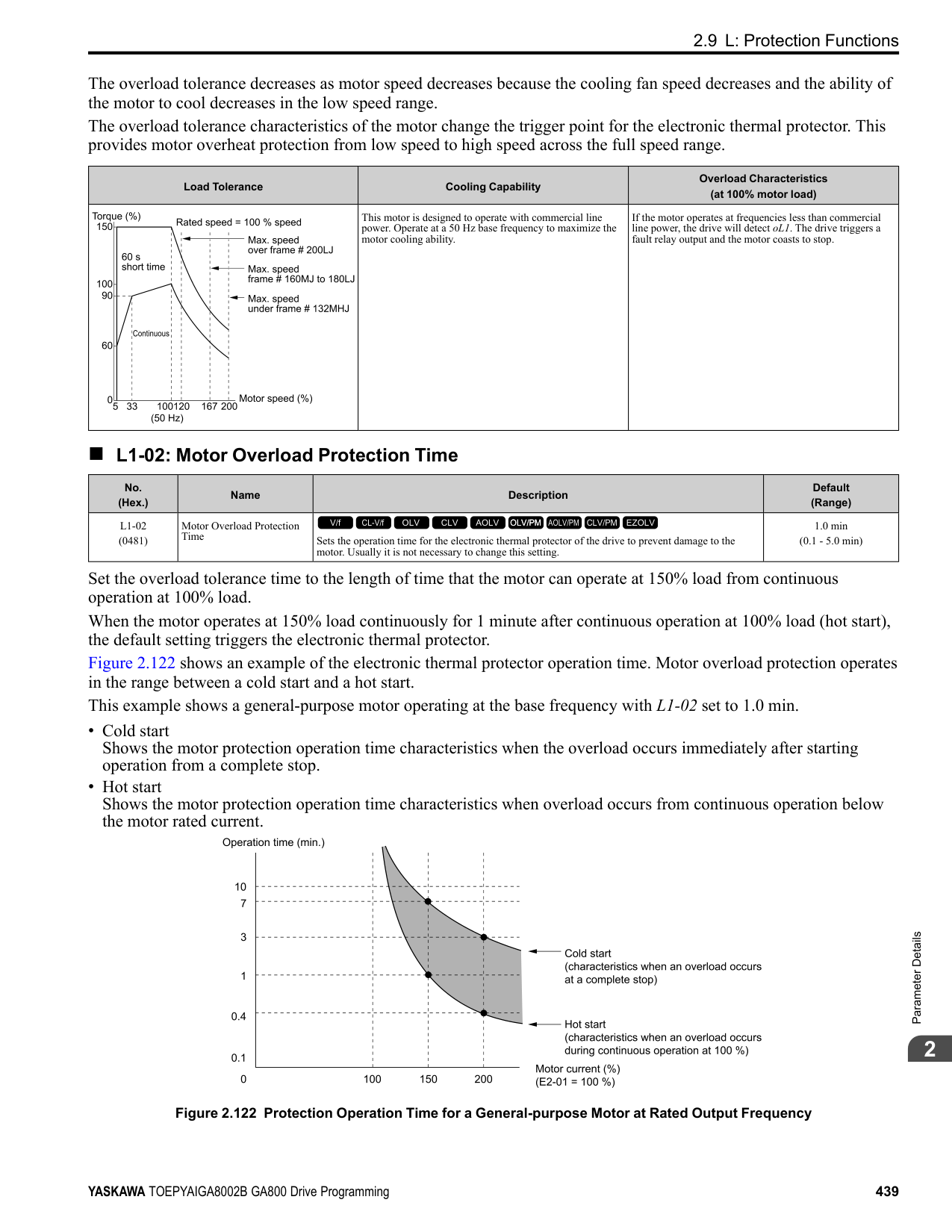
######## 2
######## ■ Mechanical Weakening Detection
The Mechanical Weakening Detection function detects the mechanical weakening of a machine that can cause overtorque or undertorque because of motor speed and total drive operation time. The drive activates the function if the drive total operation time is longer than the time set in L6-11 [Mech Fatigue Hold Off Time]. You can use U4-01 [Cumulative Ope Time] to monitor the total operation time. Parameter Settings The drive detects Mechanical Weakening if overtorque or undertorque occur during the speed range set in L6-08 [Mechanical Fatigue Detect Select] and L6-09 [Mech Fatigue Detect Speed Level] for the length of time set in L6-10 [Mech Fatigue Detect Delay Time]. The drive uses L6-01 to L6-03 [Torque Detection 1 Setting Parameter] to detect oL5 [Mechanical Weakening Detection 1] or UL5 [Mechanical Weakening Detection 2]. Parameter L6-08 sets the operation after detection. Set the terminal that outputs the fault in H2-01 to H2-03 [MFDO Function Select].
Table 2.71 Mechanical Weakening Detection Settings Parameters
|Configuration Parameter|Configuration Parameter|Mechanical Deterioration Detection| |---|---|---| |MFDO Function Select
• Terminals M1-M2
• Terminals M3-M4
• Terminals M5-M6
|MFDO Function Select
• Terminals M1-M2
• Terminals M3-M4
• Terminals M5-M6
|H2-01, H2-02, and H2-03 = 22| |Operation Selection after Detection|Operation Selection after Detection|L6-08| |Detection Start Time|Detection Start Time|L6-11| |Speed Range|Detection Criteria|L6-08| |Speed Range|Detection Level|L6-09| |Speed Range|Detection Time|L6-10| |Overtorque|Detection Criteria|L6-01| |Overtorque|Detection Level|L6-02| |Overtorque|Detection Time|L6-03|
######## ■ L6-01: Torque Detection Selection 1
|No. (Hex.)|Name|Description|Default (Range)| |---|---|---|---| |L6-01 (04A1)|Torque Detection Selection 1|Sets the speed range that detects overtorque and undertorque and the operation of drives (operation status) after detection.
V/f CL-V/f OLV CLV AOLV OLV/PM AOLV/PM CLV/PM EZOLV
|0 (0 - 8)|
The drive detects overtorque if the motor current or output torque is more than the level set in L6-02 [Torque Detection Level 1] for the length of time set in L6-03 [Torque Detection Time 1]. The drive detects undertorque if the motor current or output torque is less than the level set in L6-02 for the length the time set in L6-03.
The drive detects overtorque when the output frequency aligns with the frequency reference. Detection does not occur during acceleration/deceleration. The drive outputs an oL3 [Overtorque Detection 1] and operation continues.
When the Run command is enabled, the drive constantly detects overtorque. The drive outputs an oL3 and operation continues.
The drive detects overtorque when the output frequency aligns with the frequency reference. Detection does not occur during acceleration/deceleration. The drive outputs an oL3 [Overtorque Detection 1] and operation stops.
When the Run command is enabled, the drive constantly detects overtorque. The drive outputs an oL3 and operation stops.
############## 5 : UL @ Speed Agree - Alarm only
The drive detects undertorque when the output frequency aligns with the frequency reference. Detection does not occur during acceleration/deceleration. The drive outputs a UL3 [Undertorque Detection 1] and operation continues.
############## 6 : UL @ RUN - Alarm only
When the Run command is enabled, the drive constantly detects undertorque. The drive outputs a UL3 and operation continues.
############## 7 : UL @ Speed Agree - Fault
The drive detects undertorque when the output frequency aligns with the frequency reference. Detection does not occur during acceleration/deceleration. The drive outputs a UL3 and operation stops.
############## 8 : UL @ RUN - Fault
When the Run command is enabled, the drive constantly detects undertorque. The drive outputs a UL3 and operation stops
Note:
= Overtorque/Undertorque DetectLvl]. If you set L6-02 and H3-x = 7, the analog input is most important and the drive disables L6-02.
|No. (Hex.)|Name|Description|Default (Range)| |---|---|---|---| |L6-02 (04A2)|Torque Detection Level 1|Sets the detection level for Overtorque/Undertorque Detection 1. In V/f control, drive rated output current = 100% value. In vector control, motor rated torque = 100% value.
V/f CL-V/f OLV CLV AOLV OLV/PM AOLV/PM CLV/PM EZOLV
|150% (0 - 300%)|
|No. (Hex.)|Name|Description|Default (Range)|
|---|---|---|---| |L6-03 (04A3)|Torque Detection Time 1|Sets the detection time for Overtorque/Undertorque Detection 1.
V/f CL-V/f OLV CLV AOLV OLV/PM AOLV/PM CLV/PM EZOLV
|0.1 s (0.0 - 10.0 s)|
|No. (Hex.)|Name|Description|Default (Range)| |---|---|---|---| |L6-04 (04A4)|Torque Detection Selection 2|Sets the speed range that detects overtorque and undertorque and the operation of drives (operation status) after detection.
V/f CL-V/f OLV CLV AOLV OLV/PM AOLV/PM CLV/PM EZOLV
|0 (0 - 8)|
The drive detects overtorque if the motor current or output torque is more than the level set in L6-05 [Torque Detection Level 2] for the length of time set in L6-06 [Torque Detection Time 2]. The drive detects undertorque if the motor current or output torque is less than the level set in L6-05 for the length the time set in L6-06.
The drive detects overtorque when the output frequency aligns with the frequency reference. Detection does not occur during acceleration/deceleration. The drive outputs an oL4 [Overtorque Detection 2] and operation continues.
When the Run command is enabled, the drive constantly detects overtorque. The drive outputs an oL4 and operation continues.
ParameterDetails
######## 2
The drive detects overtorque when the output frequency aligns with the frequency reference. Detection does not occur during acceleration/deceleration. The drive outputs an oL4 [Overtorque Detection 2] and operation stops.
############## 4 : oL @ RUN - Fault
When the Run command is enabled, the drive constantly detects overtorque. The drive outputs an oL4 and operation stops.
############## 5 : UL @ Speed Agree - Alarm only
The drive detects undertorque when the output frequency aligns with the frequency reference. Detection does not occur during acceleration/deceleration. The drive outputs a UL4 [Undertorque Detection 2] and operation continues.
############## 6 : UL @ RUN - Alarm only
When the Run command is enabled, the drive constantly detects undertorque. The drive outputs a UL4 and operation continues.
############## 7 : UL @ Speed Agree - Fault
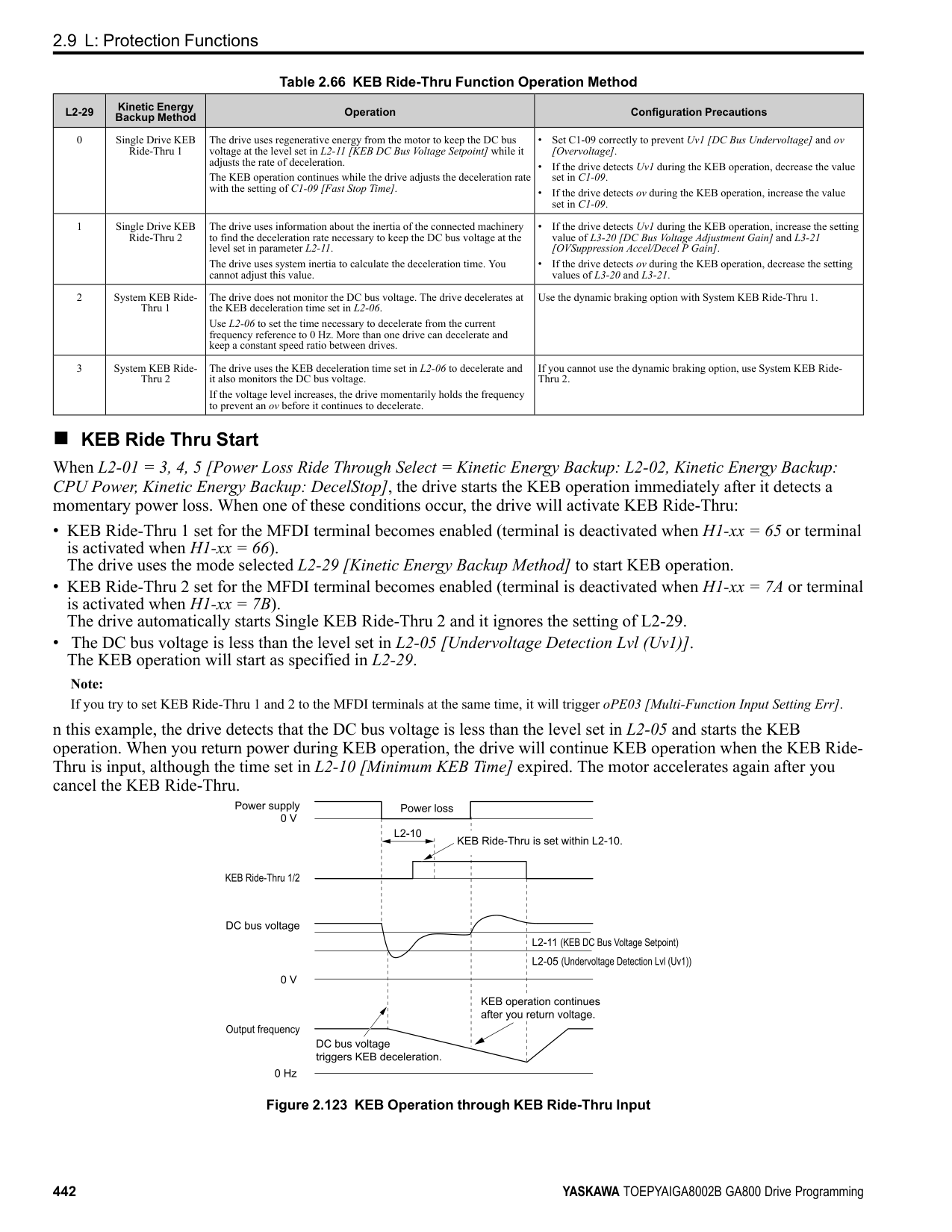
The drive detects undertorque when the output frequency aligns with the frequency reference. Detection does not occur during acceleration/deceleration. The drive outputs a UL4 and operation stops.
############## 8 : UL @ RUN - Fault
When the Run command is enabled, the drive constantly detects undertorque. The drive outputs a UL4 and operation stops
Note: Overtorque/Undertorque Detection 2 cannot set the detection level for the analog input terminal.
|No. (Hex.)|Name|Description|Default (Range)| |---|---|---|---| |L6-05 (04A5)|Torque Detection Level 2|Sets the detection level for Overtorque/Undertorque Detection 2. In V/f control, drive rated output current = 100% value. In vector control, motor rated torque = 100% value.
V/f CL-V/f OLV CLV AOLV OLV/PM AOLV/PM CLV/PM EZOLV
|150% (0 - 300%)|
|No. (Hex.)|Name|Description|Default (Range)| |---|---|---|---| |L6-06 (04A6)|Torque Detection Time 2|Sets the detection time for Overtorque/Undertorque Detection 2.
V/f CL-V/f OLV CLV AOLV OLV/PM AOLV/PM CLV/PM EZOLV
|0.1 s (0.0 - 10.0 s)|
|No. (Hex.)|Name|Description|Default (Range)| |---|---|---|---| |L6-07 (04E5)|Torque Detection Filter Time|Sets the time constant for a primary filter to the torque reference or to the output current used to detect overtorque/undertorque.
V/f CL-V/f OLV CLV AOLV OLV/PM AOLV/PM CLV/PM EZOLV
|0 ms (0 - 1000 ms)|
|No. (Hex.)|Name|Description|Default (Range)| |---|---|---|---| |L6-08 (0468)|Mechanical Fatigue Detect Select|Sets the speed where the drive detects mechanical deterioration and how the drive operates (operation status) after detection.
V/f CL-V/f OLV CLV AOLV OLV/PM AOLV/PM CLV/PM EZOLV
|0 (0 - 8)|
The drive detects mechanical weakening through overtorque or undertorque as specified by the conditions set in L6-
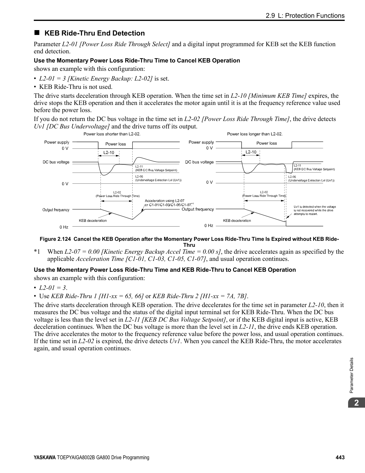
############## 1 : oL5 @ Speed > L6-09 - Alarm
When the speed (signed) ≥ L6-09 [Mech Fatigue Detect Speed Level], the drive detects mechanical weakening. The drive will detect oL5 [Mechanical Weakening Detection 1] and continue operation.
############## 2 : oL5 @ lSpeedl > L6-09 - Alarm
When the speed (absolute value) ≥ L6-09, the drive detects mechanical weakening. The drive will detect oL5 and continue operation.
############## 3 : oL5 @ Speed > L6-09 - Fault
When the speed (signed) ≥ L6-09, the drive detects mechanical weakening. The drive will detect oL5 and stop operation.
############## 4 : oL5 @ lSpeedl > L6-09 - Fault
When the speed (absolute value) ≥ L6-09, the drive detects mechanical weakening. The drive will detect oL5 and stop operation.
############## 5 : UL5 @ Speed < L6-09 - Alarm
When the speed (signed) ≤ L6-09, the drive detects mechanical weakening. The drive will detect UL5 [Mechanical Weakening Detection 2] and continue operation.
############## 6 : UL5 @ lSpeedl < L6-09 - Alarm
When the speed (absolute value) ≤ L6-09, the drive detects mechanical weakening. The drive will detect UL5 and continue operation.
############## 7 : UL5 @ Speed < L6-09 - Fault
When the speed (signed) ≤ L6-09, the drive detects mechanical weakening. The drive will detect UL5 and stop operation.
############## 8 : UL5 @ lSpeedl < L6-09 - Fault
When the speed (absolute value) ≤ L6-09, the drive detects mechanical weakening. The drive will detect UL5 and stop operation.
######## ■ L6-09: Mech Fatigue Detect Speed Level
|No. (Hex.)|Name|Description|Default (Range)| |---|---|---|---| |L6-09 (0469)|Mech Fatigue Detect Speed Level|Sets the speed level where the drive will operate the mechanical deterioration detection function, as a percentage of the Maximum Output Frequency.
V/f CL-V/f OLV CLV AOLV OLV/PM AOLV/PM CLV/PM EZOLV
|110.0% (-110.0 - 110.0%)|
Parameters L6-01 to L6-03 [Torque Detection 1 Settings Parameters] set the overtorque/undertorque detection conditions. When L6-08 = 2, 4, 6, 8 [Mechanical Fatigue Detect Select = Speed : unsigned], the setting value of L6-09 is the absolute value. When L6-09 is set to a negative number, the drive processes this value as a positive number.
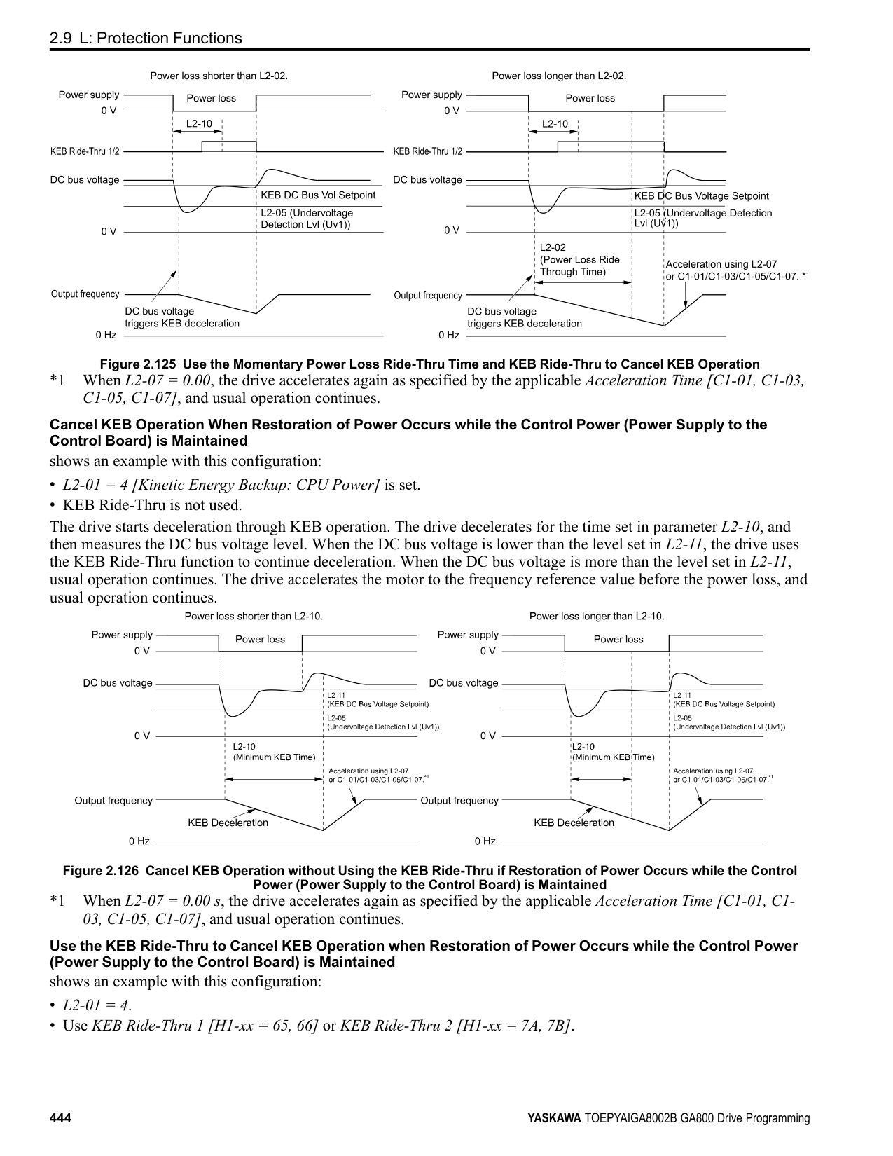
######## ■ L6-10: Mech Fatigue Detect Delay Time
|No. (Hex.)|Name|Description|Default (Range)| |---|---|---|---| |L6-10 (046A)|Mech Fatigue Detect Delay Time|Sets the time for mechanical deterioration detection.
V/f CL-V/f OLV CLV AOLV OLV/PM AOLV/PM CLV/PM EZOLV
|0.1 s (0.0 - 10.0 s)|
ParameterDetails
When the detection conditions set in L6-08 [Mechanical Weakening Detect Ope] continue for the time set in L6-10, the drive will detect mechanical weakening.
######## ■ L6-11: Mech Fatigue Hold Off Time
|No. (Hex.)|Name|Description|Default (Range)| |---|---|---|---| |L6-11 (046B)|Mech Fatigue Hold Off Time|Sets the time that the drive will start mechanical deterioration detection triggered by the cumulative operation time of the drive.
V/f CL-V/f OLV CLV AOLV OLV/PM AOLV/PM CLV/PM EZOLV
|0 h (0 - 65535 h)|
When the total operation time of the drive is more than the value set in L6-11, the drive will detect mechanical weakening. Use U4-01 [Cumulative Ope Time] to monitor the drive total operation time.
######## ◆ L7: Torque Limit
The torque limit function limits the internal torque reference for the drive to limit the quantity of torque generated by the motor to a constant quantity. This function keeps the torque applied to loads and regenerative torque less than a set quantity. This function also prevents damage to machinery and increases the reliability of continuous operation. You can set torque limits individually for the four quadrants, which include torque direction (motoring/regeneration) and direction of motor rotation (forward/reverse). When the torque reference value is at the set torque limit, the MFDO terminal set for During Torque Limit [H2-xx = 30] activates.
Note:
■ Configuring Settings Use one of these methods to set torque limits:
Figure 2.141 Torque Limits and Analog Input Setting Parameters Note:
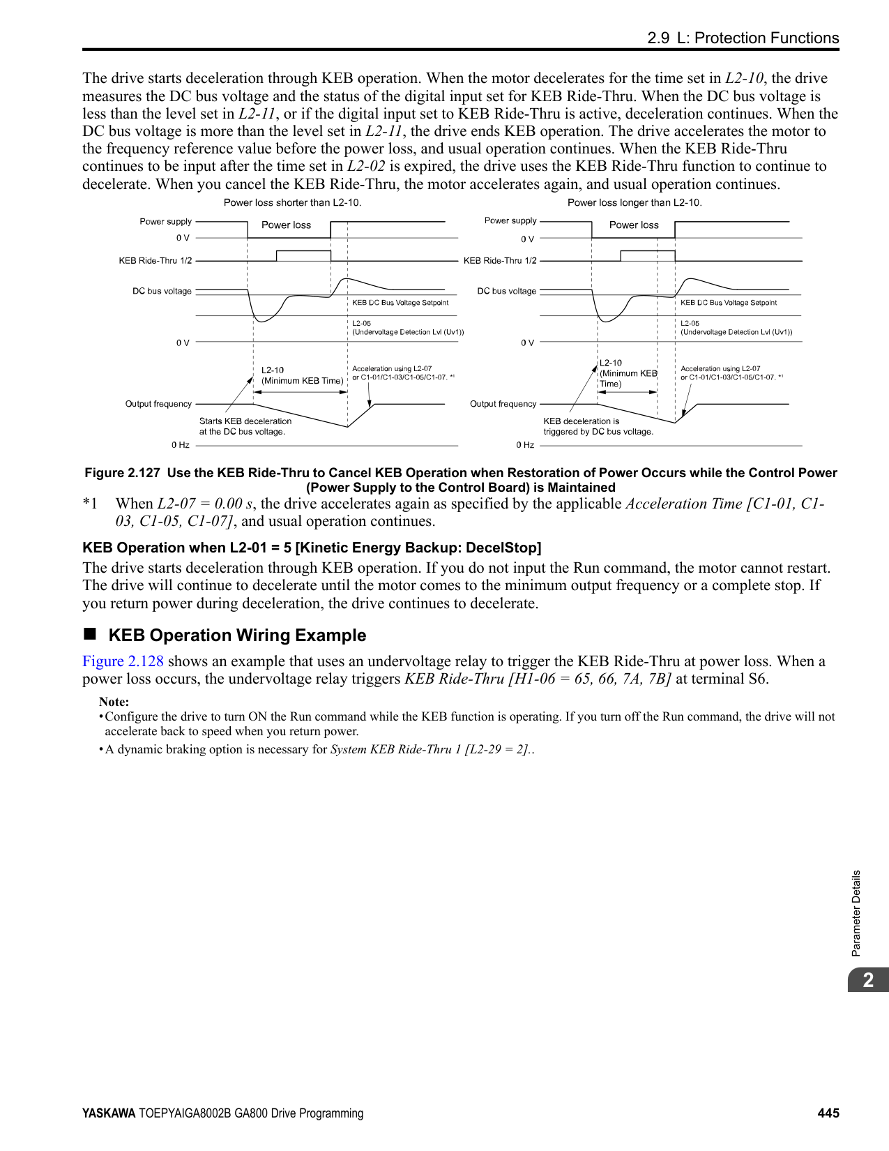
######## ■ L7-01: Forward Torque Limit
|No. (Hex.)|Name|Description|Default (Range)| |---|---|---|---| |L7-01 (04A7) RUN|Forward Torque Limit|Sets the torque limit value for forward motoring as a percentage, where motor rated torque is the 100% value.
V/f CL-V/f OLV CLV AOLV OLV/PM AOLV/PM CLV/PM EZOLV
|200% (0 - 300%)|
################# Note:
######## ■ L7-02: Reverse Torque Limit
|No. (Hex.)|Name|Description|Default (Range)| |---|---|---|---| |L7-02 (04A8) RUN|Reverse Torque Limit|Sets the torque limit value for reversed motoring as a percentage, where motor rated torque is the 100% value.
V/f CL-V/f OLV CLV AOLV OLV/PM AOLV/PM CLV/PM EZOLV
|200% (0 - 300%)|
Note:
######## ■ L7-03: Forward Regenerative Trq Limit
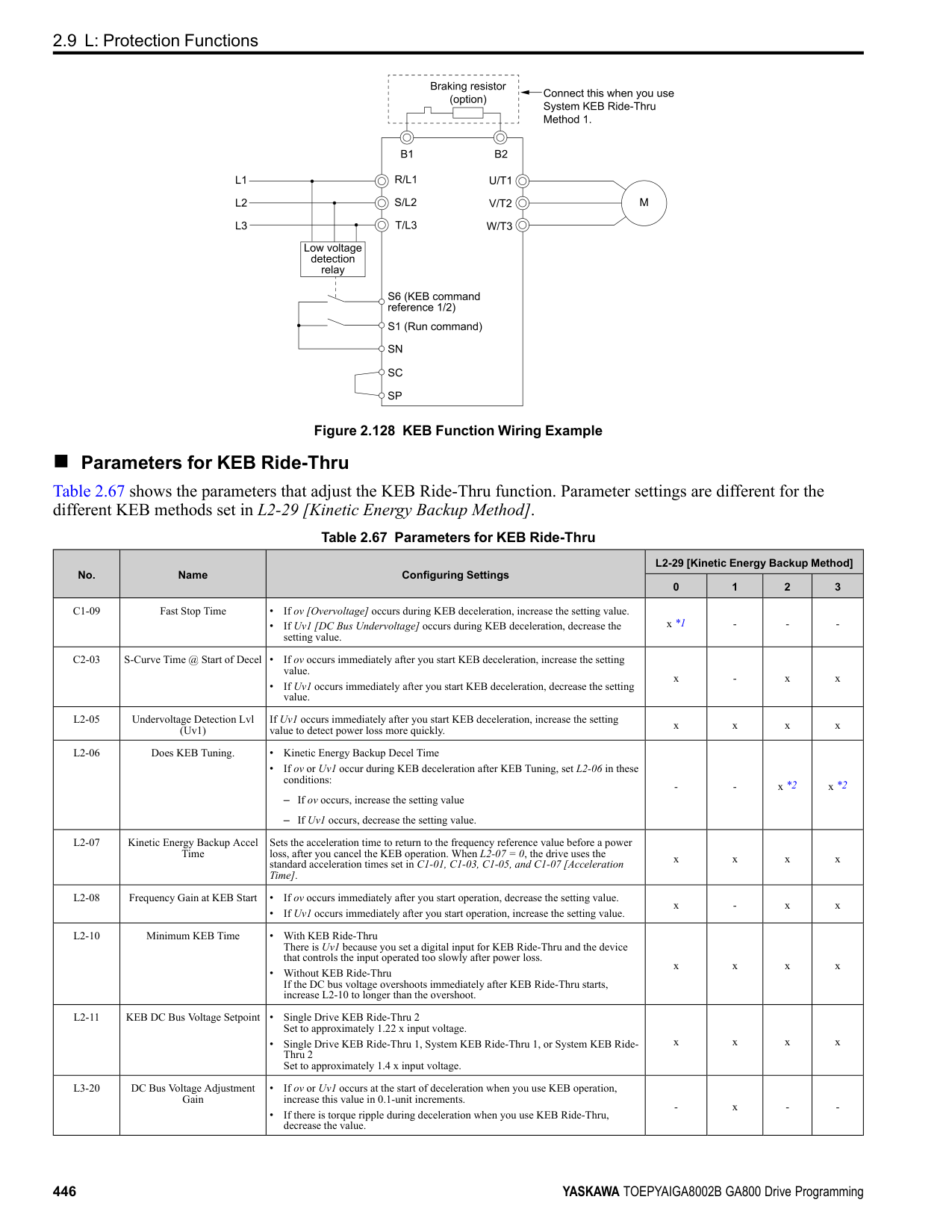
|No. (Hex.)|Name|Description|Default (Range)| |---|---|---|---| |L7-03 (04A9) RUN|Forward Regenerative Trq Limit|Sets the torque limit value for forward regenerative conditions as a percentage of the motor rated torque.
V/f CL-V/f OLV CLV AOLV OLV/PM AOLV/PM CLV/PM EZOLV
|200% (0 - 300%)|
Note:
######## ■ L7-04: Reverse Regenerative Trq Limit
|No. (Hex.)|Name|Description|Default (Range)| |---|---|---|---| |L7-04 (04AA) RUN|Reverse Regenerative Trq Limit|Sets the torque limit value for reversed regenerative conditions as a percentage of the motor rated torque.
V/f CL-V/f OLV CLV AOLV OLV/PM AOLV/PM CLV/PM EZOLV
|200% (0 - 300%)|
Note:
ParameterDetails
######## ■ L7-06: Torque Limit Integral Time
|No. (Hex.)|Name|Description|Default (Range)|
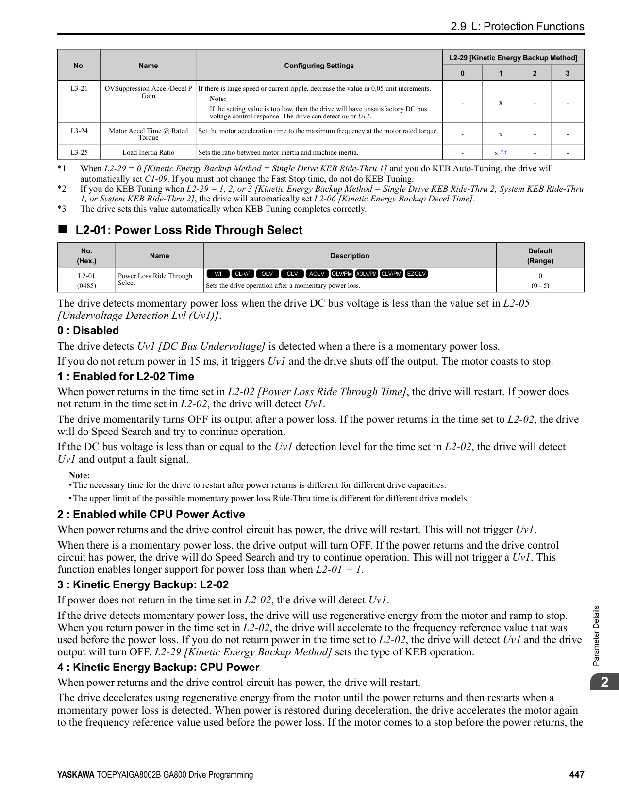
|---|---|---|---| |L7-06 (04AC)|Torque Limit Integral Time|Sets the integral time constant for the torque limit function.
V/f CL-V/f OLV CLV AOLV OLV/PM AOLV/PM CLV/PM EZOLV
|200 ms (5 - 10000 ms)|
Decrease the setting value to increase torque limit responsiveness when you use torque limits and L7-07 = 1 [Torque Limit during Accel/Decel = Proportional & Integral control]. If there is hunting when torque limits are active, increase the setting value.
######## ■ L7-07: Torque Limit during Accel/Decel
|No. (Hex.)|Name|Description|Default (Range)| |---|---|---|---| |L7-07 (04C9)|Torque Limit during Accel/ Decel|Sets the torque limit function during acceleration and deceleration.
V/f CL-V/f OLV CLV AOLV OLV/PM AOLV/PM CLV/PM EZOLV
|0 (0, 1)|
0 : Proportional only The torque limit function works with proportional control during acceleration and deceleration, and switches to integral control at constant speed. Use this setting when quickly reaching the target speed is more important than the torque limit during speed changes. 1 : Proportional & Integral control The torque limit function always uses integral control. Use this setting when a very accurate torque limit is necessary during speed changes, for example in winding machine applications. If you make the torque limit the most important, it can:
######## ■ L7-16: Torque Limit Process at Start
|No. (Hex.)|Name|Description|Default (Range)| |---|---|---|---| |L7-16 (044D)|Torque Limit Process at Start|Assigns a time filter to allow the torque limit to build at start.
V/f CL-V/f OLV CLV AOLV OLV/PM AOLV/PM CLV/PM EZOLV
|1 (0, 1)|
######## ■ L7-35: Low Freq Regen Torque Limit Lvl
|No. (Hex.)|Name|Description|Default (Range)| |---|---|---|---| |L7-35 (1B57) Expert|Low Freq Regen Torque Limit Lvl|Sets the torque limit used during low-speed regeneration. Usually it is not necessary to change this setting.
V/f CL-V/f OLV CLV AOLV OLV/PM AOLV/PM CLV/PM EZOLV
|50.0% (0.0 - 200.0%)|
Reduces the regenerative torque limit to the level set with L7-35 when using low frequencies such that the output frequency is less than L7-36 [Regen Torque Limit Derate Freq]. The drive does not decrease torque limits during ramp to stop operation. Decrease the setting of L7-35 when oC [Overcurrent] issues occur while a regenerative load is input and the speed reference is constant.
Note:
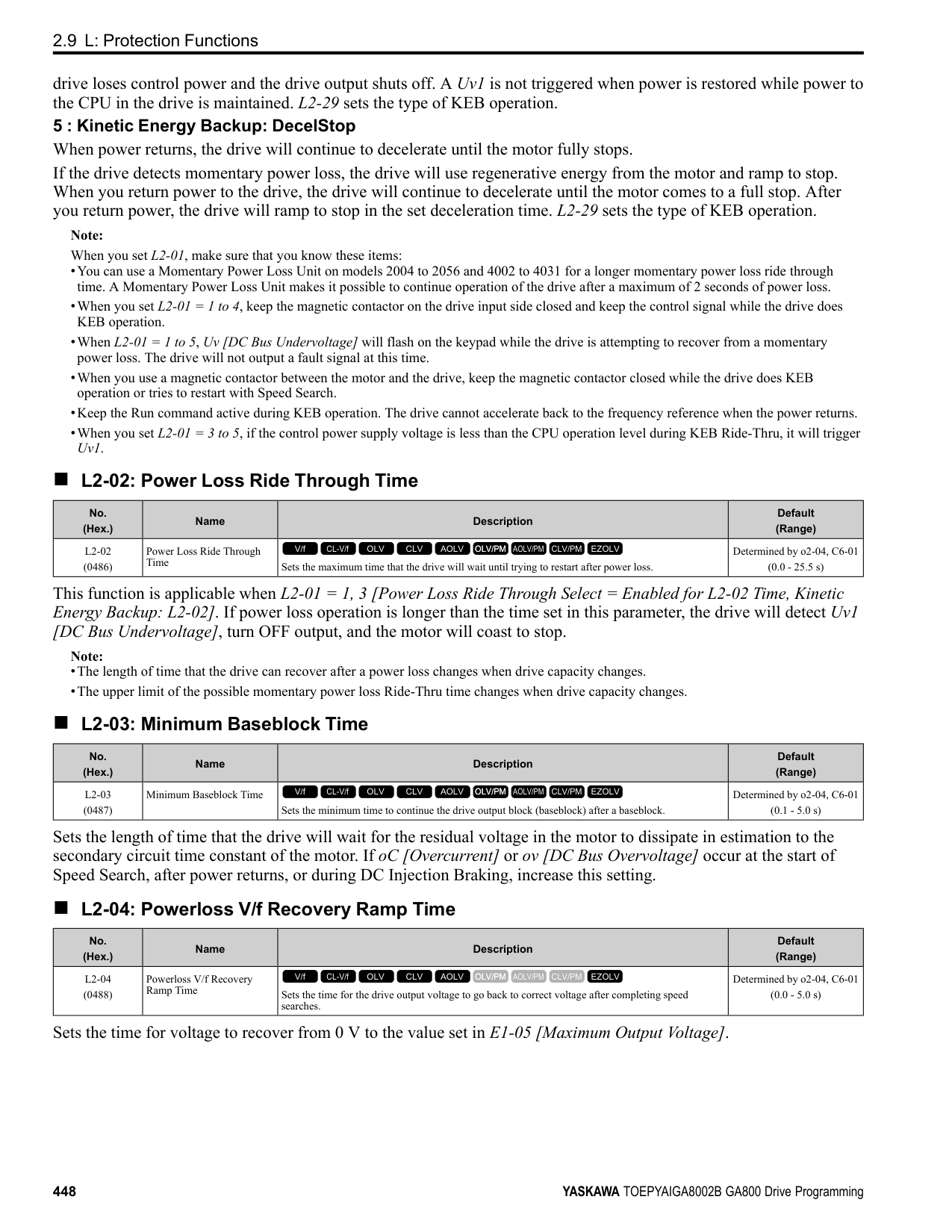
######## ■ L7-36: Regen Torque Limit Derate Freq
|No. (Hex.)|Name|Description|Default (Range)| |---|---|---|---| |L7-36 (1B58) Expert|Regen Torque Limit Derate Freq|Sets the frequency width at which L7-35 [Low Freq Regen Torque Limit Lvl] operates.
V/f CL-V/f OLV CLV AOLV OLV/PM AOLV/PM CLV/PM EZOLV
|6.0 Hz (0.0 - 30.0 Hz)|
If the drive detects oC [Overcurrent] faults when you connect regenerative loads at low speed, increase the setting value. Decreases the torque limit as specified by the setting of L7-35 in a range of 0 ≤ output frequency < L7-36. When the torque limit gradually changes as specified by the output frequency until the output frequency = L7-36, the value changes to the setting of L7-03 [Forward Regenerative Trq Limit] and L7-04 [Reverse Regenerative Trq Limit].
Note: If you increase the setting of L7-36, the motor will rotate at a speed higher than specified when a you input a regenerative load. Do not set the value higher than necessary.
◆ L8: Drive Protection L8 parameters set protective functions that prevent faults such as overheating, phase loss, and ground faults.
######## ■ L8-01: 3% ERF DB Resistor Protection
|No. (Hex.)|Name|Description|Default (Range)| |---|---|---|---| |L8-01 (04AD)|3% ERF DB Resistor Protection|Sets the function to enable braking resistor protection with a Yaskawa ERF series braking resistor (3% ED) installed on the heatsink.
V/f CL-V/f OLV CLV AOLV OLV/PM AOLV/PM CLV/PM EZOLV
|0 (0, 1)|
0 : Disabled Disables braking resistor protection. Use this setting for dynamic braking options that are not Yaskawa ERF series braking resistors. 1 : Enabled Enables protection for Yaskawa ERF series braking resistors.
Note: Set L8-01 = 1 and H2-01 to H2-03 = D [MFDO Function Select = Braking Resistor Fault]. Use a sequence to turn OFF power with MFDO.
######## ■ L8-02: Overheat Alarm Level
|No. (Hex.)|Name|Description|Default (Range)| |---|---|---|---| |L8-02 (04AE)|Overheat Alarm Level|Sets the oH detection level in temperature.
V/f CL-V/f OLV CLV AOLV OLV/PM AOLV/PM CLV/PM EZOLV
|Determined by o2-04, C6-01 (50 - 150 °C)|
If the heatsink temperature is more than the temperature set in this parameter, the drive detects an overheat pre-alarm. To enable this function, set one of H2-01 to H2-03 [MFDO Function Select] to 20 [Drive Overheat Pre-Alarm (oH)]. If the temperature increases to the overheat fault level, the drive will trigger an oH1 [Heatsink Overheat] fault and stop operation.
######## ■ L8-03: Overheat Pre-Alarm Selection
|No. (Hex.)|Name|Description|Default (Range)| |---|---|---|---|
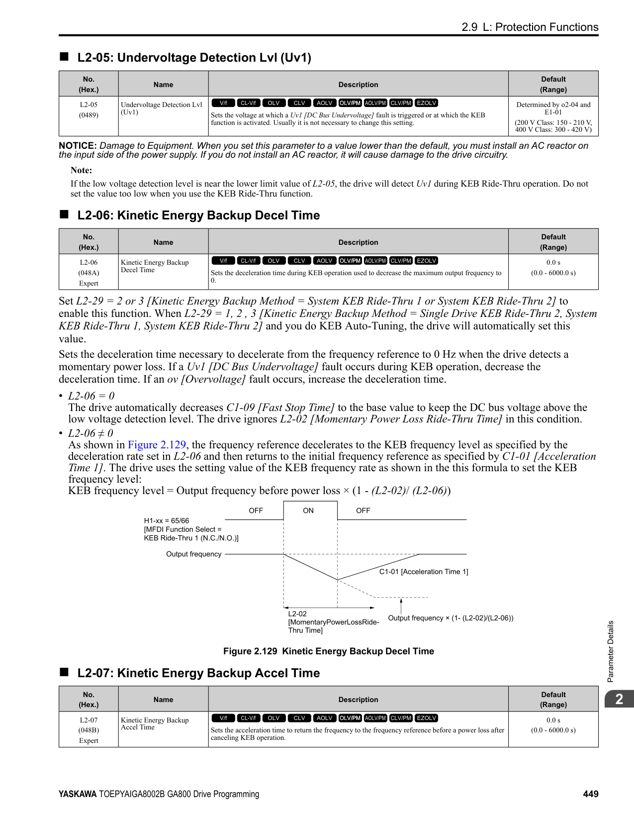
|L8-03 (04AF)|Overheat Pre-Alarm Selection|Sets the operation of drives when an oH alarm is detected.
V/f CL-V/f OLV CLV AOLV OLV/PM AOLV/PM CLV/PM EZOLV
|3 (0 - 4)|
The drive ramps the motor to stop in the deceleration time. Fault relay output terminal MA-MC turns ON, and MBMC turns OFF.
ParameterDetails
######## 2
The output turns off and the motor coasts to stop. Fault relay output terminal MA-MC turns ON, and MB-MC turns OFF.
############## 2 : Fast Stop (Use C1-09)
The drive stops the motor in the deceleration time set in C1-09 [Fast Stop Time]. Fault relay output terminal MA-MC turns ON, and MB-MC turns OFF.
############## 3 : Alarm Only
The keypad shows oH and the drive continues operation. The output terminal set for Alarm [H2-01 to H2-03 = 10] activates.
############## 4 : Operate at Reduced Speed (L8-19)
The drive decelerates to the level set in L8-19 [Freq Reduction @ oH Pre-Alarm] and continues operation. oH flashes on the keypad. oH flashes on the keypad. When the alarm is output, the drive decelerates each 10 seconds. If the drive decelerates 10 times and the alarm continues to be output, the output terminal set for oH Pre-Alarm Reduction Limit [H2-01 to H2-
Figure 2.142 Drive Operation at a Decreased Output Frequency when the Overheat Alarm is Output
######## ■ L8-05: Input Phase Loss Protection Sel
|No. (Hex.)|Name|Description|Default (Range)| |---|---|---|---| |L8-05 (04B1)|Input Phase Loss Protection Sel|Sets the function to enable and disable input phase loss detection.
V/f CL-V/f OLV CLV AOLV OLV/PM AOLV/PM CLV/PM EZOLV
|1 (0, 1)|
0 : Disabled 1 : Enabled The drive measures ripples in DC bus voltage to detect input phase loss. The drive detects phase loss when power supply phase loss occurs or the main circuit capacitor becomes unusable, which causes PF [Input Phase Loss] to show on the keypad. Disable the detection of the input power supply phase loss function in these conditions:
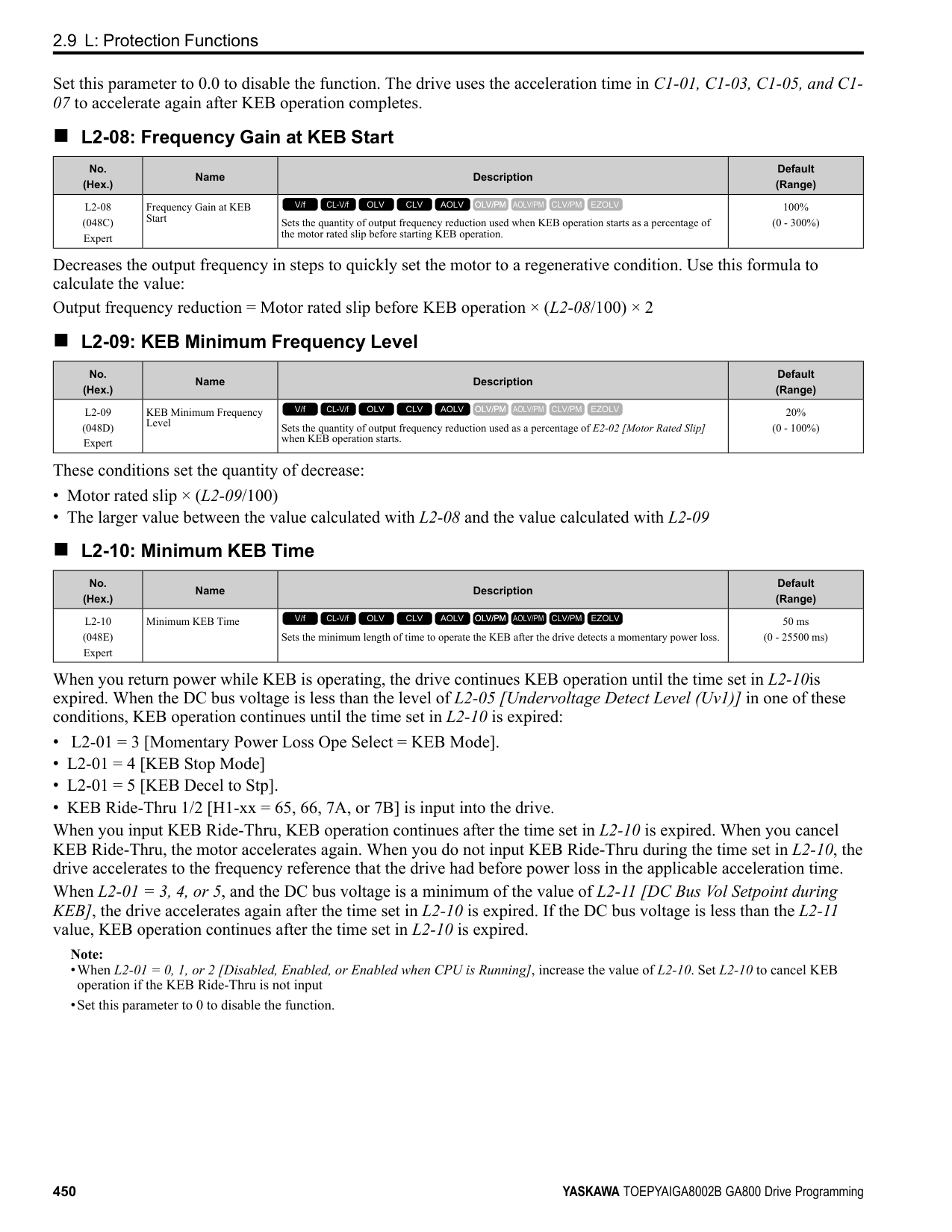
######## ■ L8-07: Output Phase Loss Protection Sel
|No. (Hex.)|Name|Description|Default (Range)| |---|---|---|---| |L8-07 (04B3)|Output Phase Loss Protection Sel|Sets the function to enable and disable output phase loss detection. The drive starts output phase loss detection when the output current decreases to less than 5% of the drive rated current.
V/f CL-V/f OLV CLV AOLV OLV/PM AOLV/PM CLV/PM EZOLV
|1 (0 - 2)|
Note: The drive can incorrectly start output phase loss detection in these conditions:
######## ■ L8-09: Output Ground Fault Detection
|No. (Hex.)|Name|Description|Default (Range)| |---|---|---|---| |L8-09 (04B5)|Output Ground Fault Detection|Sets the function to enable and disable ground fault protection.
V/f CL-V/f OLV CLV AOLV OLV/PM AOLV/PM CLV/PM EZOLV
|Determined by o2-04 (0, 1)|
0 : Disabled The drive will not detect ground faults. 1 : Enabled If there is high leakage current or a ground short circuit in one or two output phases, the drive will detect GF [Ground Fault].
Note: If the ground path impedance is low, oC [Overcurrent], SC [Out Short Circuit or IGBT Fault], or ov [DC Bus Overvoltage] can stop the motor.
######## ■ L8-10: Heatsink Fan Operation Selection
|No. (Hex.)|Name|Description|Default (Range)| |---|---|---|---| |L8-10 (04B6)|Heatsink Fan Operation Selection|Sets operation of the heatsink cooling fan.
V/f CL-V/f OLV CLV AOLV OLV/PM AOLV/PM CLV/PM EZOLV
|0 (0 - 2)|
The fan turns on when you supply power to the drive. When you release the Run command and the delay time set in L8-11 [HeatsinkCoolingFan Off DelayTime] is expired, the fan stops. his setting extends the fan lifetime.
ParameterDetails
######## 2
The drive automatically adjusts the drive rated current to the best value as specified by the set temperature. Set the ambient temperature of the area where you install the drive to a value that is more than the drive rating.
|No. (Hex.)|Name|Description|Default (Range)| |---|---|---|---| |L8-11 (04B7)|Heatsink Fan Off-Delay Time|Sets the length of time that the drive will wait before it stops the cooling fan after it cancels the Run command when L8-10 = 0 [Heatsink Cooling Fan Ope Select = Dur Run (OffDly)].
V/f CL-V/f OLV CLV AOLV OLV/PM AOLV/PM CLV/PM EZOLV
|60 s (0 - 300 s)|
|No. (Hex.)|Name|Description|Default (Range)| |---|---|---|---| |L8-12 (04B8)|Ambient Temperature Setting|Sets the ambient temperature of the drive installation area.
V/f CL-V/f OLV CLV AOLV OLV/PM AOLV/PM CLV/PM EZOLV
|40 °C (-10 - +50 °C)|
|No. (Hex.)|Name|Description|Default (Range)| |---|---|---|---| |L8-15 (04BB)|Drive oL2 @ Low Speed Protection|Sets the function to decrease drive overload at low speeds to prevent damage to the main circuit transistor during low speed operation (at 6 Hz or slower) to prevent oL2 [Drive Overloaded].
V/f CL-V/f OLV CLV AOLV OLV/PM AOLV/PM CLV/PM EZOLV
|1 (0, 1)|
Note: Contact Yaskawa or your nearest sales representative for consultation before disabling this function at low speeds. Frequent operation of drives under conditions of high output current in low speed ranges may shorten the service life of the drive IGBT due to heat stress.
0 : Disabled (No Additional Derate) The drive does not decrease the overload protection level. 1 : Enabled (Reduced oL2 Level) When the drive detects oL2 during low speed operation, it automatically decreases the overload detection level.
######## ■ L8-18: Software Current Limit Selection
|No. (Hex.)|Name|Description|Default (Range)| |---|---|---|---| |L8-18 (04BE)|Software Current Limit Selection|Set the software current limit selection function to prevent damage to the main circuit transistor caused by too much current.
V/f CL-V/f OLV CLV AOLV OLV/PM AOLV/PM CLV/PM EZOLV
|0 (0, 1)|
0 : Disabled When the output current is at the software current limit value, the drive does not restrict the output voltage.
Note: The drive may detect an oC [Overcurrent] when loads are particularly heavy or the acceleration time is particularly short.
1 : Enabled When the output current is at the software current limit value, the drive decreases output voltage to decrease output current. When the output current decreases to the software current limit level, the drive starts usual operation.
######## ■ L8-19: Freq Reduction @ oH Pre-Alarm
|No. (Hex.)|Name|Description|Default (Range)| |---|---|---|---| |L8-19 (04BF)|Freq Reduction @ oH PreAlarm|Sets the ratio at which the drive derates the frequency reference during an oH alarm.
V/f CL-V/f OLV CLV AOLV OLV/PM AOLV/PM CLV/PM EZOLV
|0.8 (0.1 - 0.9)|
When these two conditions are correct, this function is enabled:
######## ■ L8-20: Control Fault & Step Out Detect
|No. (Hex.)|Name|Description|Default (Range)| |---|---|---|---| |L8-20 (04C0) Expert|Control Fault & Step Out Detect|Sets operation after the drive detects a CF fault when A1-02 = 4 [Control Method Selection = Advanced Open Loop Vector].
V/f CL-V/f OLV CLV AOLV OLV/PM AOLV/PM CLV/PM EZOLV
|1 (0 - 2)|
If you enter a Stop command but it cannot stop drive operation, the drive will detect CF. 0 : Disabled 1 : CF/STPo Detection Enabled 2 : CF ALM/Stop The drive stops DC injection braking as specified by the value of b2-03 [DC Inject Braking Time at Start].
Note:
–d5-01 = 1 [Torque Control Selection = Torque Control] –L3-11 = 1 [Overvoltage Suppression Select = Enabled] –Decreased L7-01 to L7-04 [Torque Limit].
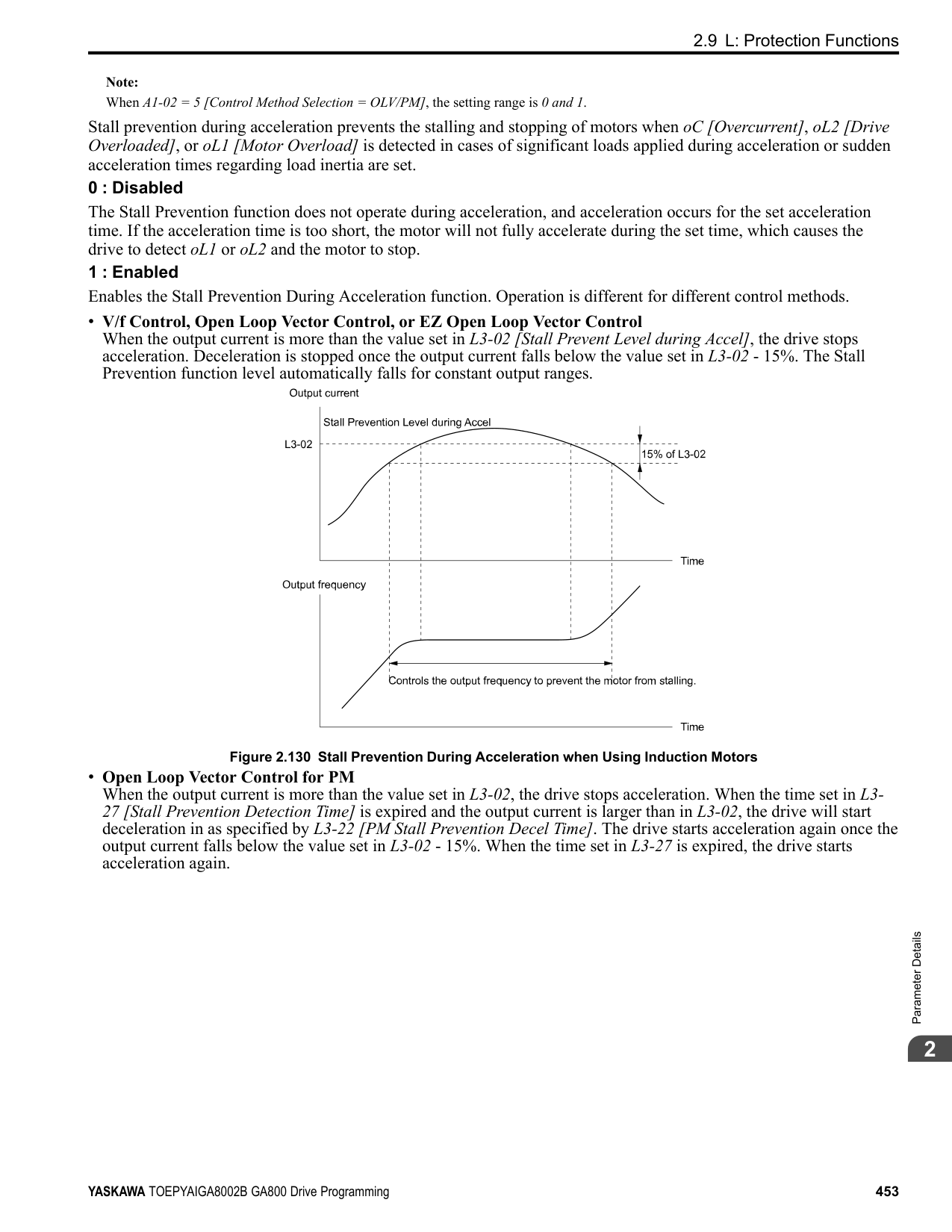
######## ■ L8-27: Overcurrent Detection Gain
|No. (Hex.)|Name|Description|Default (Range)| |---|---|---|---| |L8-27 (04DD)|Overcurrent Detection Gain|Sets the PM motor overcurrent detection level as a percentage of the motor rated current value.
V/f CL-V/f OLV CLV AOLV OLV/PM AOLV/PM CLV/PM EZOLV
|300.0% (0.0 - 1000.0%)|
Note:
######## ■ L8-29: Output Unbalance Detection Sel
|No. (Hex.)|Name|Description|Default (Range)| |---|---|---|---| |L8-29 (04DF)|Output Unbalance Detection Sel|Sets the function to detect LF2.
V/f CL-V/f OLV CLV AOLV OLV/PM AOLV/PM CLV/PM EZOLV
|1 (0, 1)|
This function prevents damage to PM motors. Current unbalance can heat a PM motor and demagnetize the magnets. When the current is unbalanced, the drive will detect LF2 to stop the motor and prevent damage to the motor.
0 : Disabled 1 : Enabled
######## ■ L8-31: LF2 Detection Time
|No. (Hex.)|Name|Description|Default (Range)| |---|---|---|---| |L8-31 (04E1)|LF2 Detection Time|Sets the LF2 [Output Current Imbalance] detection time.
V/f CL-V/f OLV CLV AOLV OLV/PM AOLV/PM CLV/PM EZOLV
|3 (1 – 100)|
ParameterDetails
######## 2
When the output current is unbalanced for longer than the time set in L8-31, the drive detects LF2.
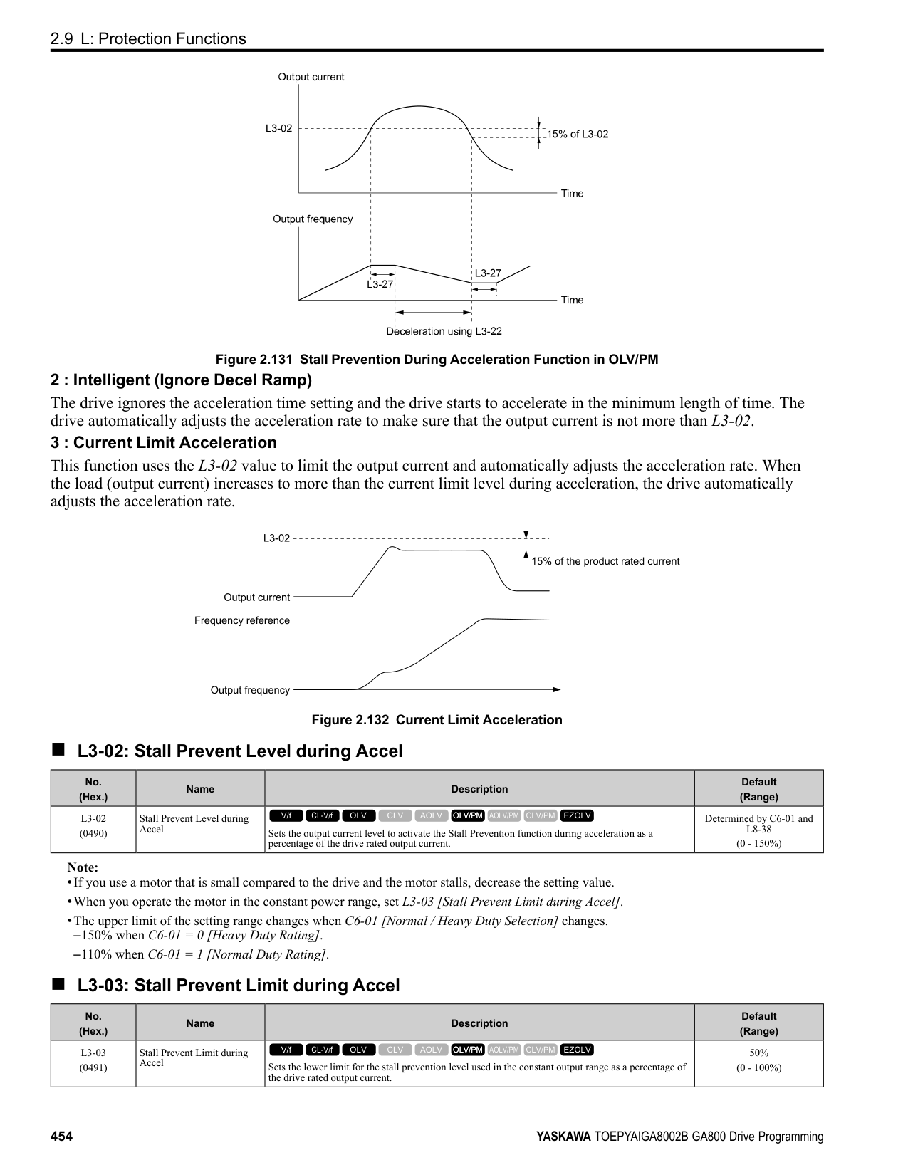
Note:
######## ■ L8-35: Installation Method Selection
|No. (Hex.)|Name|Description|Default (Range)| |---|---|---|---| |L8-35 (04EC)|Installation Method Selection|Sets the type of drive installation.
V/f CL-V/f OLV CLV AOLV OLV/PM AOLV/PM CLV/PM EZOLV
|Determined by the drive (0 - 3)|
################# Note:
The overload protection detection level for the drive is automatically adjusted to the optimal value in accordance with the setting value.
Make sure that there is 30 mm (1.18 in) minimum of space between drives or between the drive and side of the enclosure panel.
######## ■ L8-38: Carrier Frequency Reduction
|No. (Hex.)|Name|Description|Default (Range)|
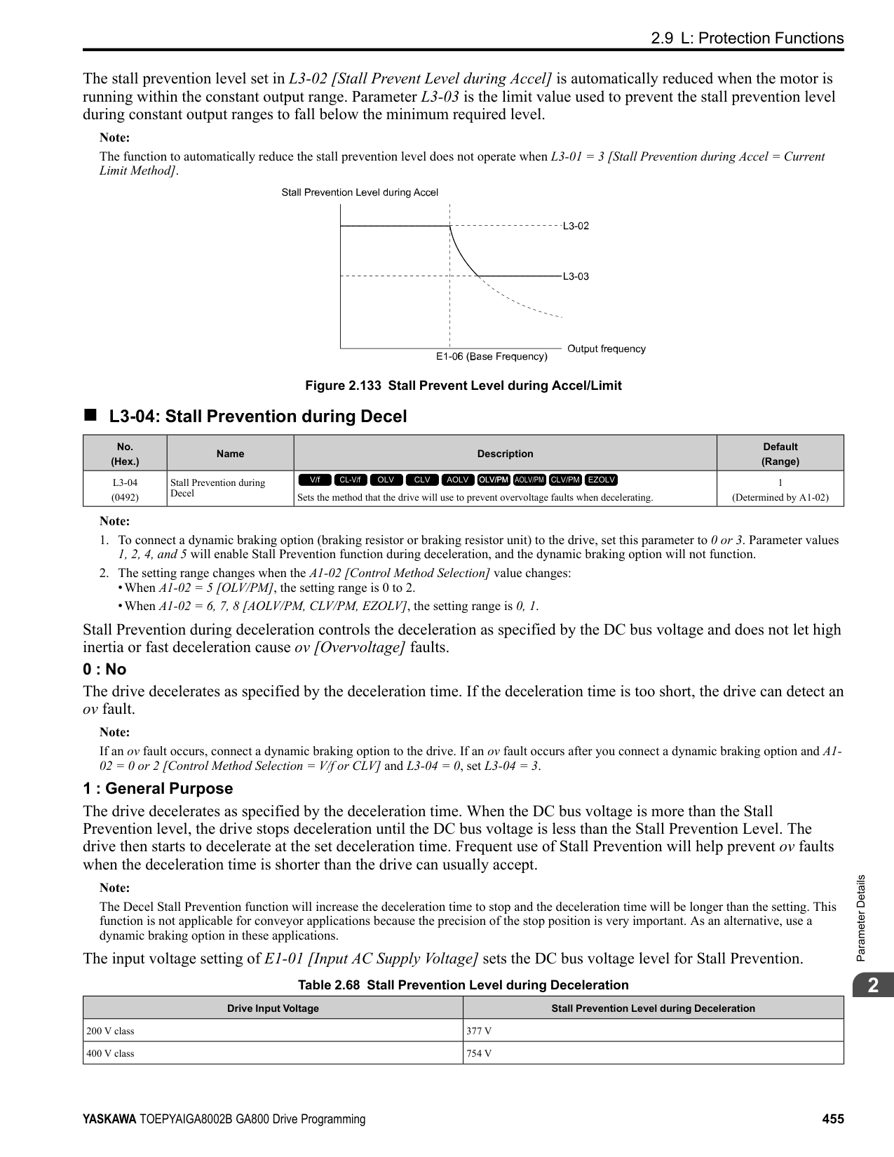
|---|---|---|---| |L8-38 (04EF)|Carrier Frequency Reduction|Sets the carrier frequency reduction function. The drive reduces the carrier frequency when the output current is more than a specified level.
V/f CL-V/f OLV CLV AOLV OLV/PM AOLV/PM CLV/PM EZOLV
|Determined by A1-02, C601 and o2-04
(0 - 2)|
If you decrease the carrier frequency, it increases the overload tolerance. The overload capacity increases temporarily for oL2 [Drive Overloaded] and lets the drive operate through transient load peaks and not trip.
The drive decreases the carrier frequency at speeds less than 6 Hz when the current is more than 100% of the drive rated current. When the current is less than 88% or the output frequency is more than 7 Hz, the drive goes back to the usual carrier frequency.
• Output current is a minimum of 100% of the drive rated current and the frequency reference is less than 6 Hz.
frequency reference is 7 Hz or more. When the drive switches the carrier frequency to the set value, it uses the delay time set in L8-40 [CarrierFreqReduct Off DelayTime] and a hysteresis of 12%.
######## ■ L8-40: Carrier Freq Reduction Off-Delay
|No. (Hex.)|Name|Description|Default (Range)| |---|---|---|---| |L8-40 (04F1)|Carrier Freq Reduction OffDelay|Sets the length of time until the automatically reduced carrier frequency returns to the condition before the reduction.
V/f CL-V/f OLV CLV AOLV OLV/PM AOLV/PM CLV/PM EZOLV
|Determined by A1-02 (0.00 - 2.00 s)|
Set L8-40 ≠ 0.00 to enable the carrier frequency reduction function during start-up. When operation starts, the drive automatically decreases the carrier frequency. When the time set in L8-40 is expired, the carrier frequency returns to the value set in C6-02 [Carrier Frequency Selection]. When L8-38 = 1, 2 [Carrier Frequency Reduction = Enabled], the drive applies L8-40 as the time for the carrier frequency to return to its configured value after it is decreased.
######## ■ L8-41: High Current Alarm Selection
|No. (Hex.)|Name|Description|Default (Range)| |---|---|---|---| |L8-41 (04F2)|High Current Alarm Selection|Sets the function to cause an HCA [Current Alarm] when the output current is more than 150% of the drive rated current.
V/f CL-V/f OLV CLV AOLV OLV/PM AOLV/PM CLV/PM EZOLV
|0 (0, 1)|
0 : Disabled The drive will not detect HCA [Current Alarm]. 1 : Enabled If the output current is more than 150% of the drive rated current, the drive will detect HCA. The MFDO terminal set for an alarm [H2-01 to H2-03 = 10] activates.
######## ■ L8-51: STPo I Detection Level
|No. (Hex.)|Name|Description|Default (Range)| |---|---|---|---| |L8-51 (0471) Expert|STPo I Detection Level|Sets the STPo [Motor Step-Out Detected] detection level as a percentage of the motor rated current.
V/f CL-V/f OLV CLV AOLV OLV/PM AOLV/PM CLV/PM EZOLV
|0.0% (0.0 - 300.0%)|
Note: The detection level is automatically calculated when L8-51 0.
|No. (Hex.)|Name|Description|Default (Range)| |---|---|---|---| |L8-52 (0472) Expert|STPo Integration Level|Sets the detection level for STPo [Motor Step-Out Detected] related to the ACR integral value.
V/f CL-V/f OLV CLV AOLV OLV/PM AOLV/PM CLV/PM EZOLV
|1.0 (0.1 - 2.0)|
|No. (Hex.)|Name|Description|Default (Range)| |---|---|---|---| |L8-53 (0473) Expert|STPo Integration Time|Sets the length of time until the drive detects STPo after it is more than the value of L8-51 [STPo I Detection Level].
V/f CL-V/f OLV CLV AOLV OLV/PM AOLV/PM CLV/PM EZOLV
|1.0 s (1.0 - 10.0 s)|
ParameterDetails
######## 2
######## ■ L8-54: STPo Id Diff Detection
|No. (Hex.)|Name|Description|Default (Range)| |---|---|---|---| |L8-54 (0474) Expert|STPo Id Diff Detection|Sets the Id deviation detection function for STPo [Motor Step-Out Detected].
V/f CL-V/f OLV CLV AOLV OLV/PM AOLV/PM CLV/PM EZOLV
|1 (0, 1)|
0 : Disabled 1 : Enabled
######## ■ L8-55: Internal DB TransistorProtection
|No. (Hex.)|Name|Description|Default (Range)| |---|---|---|---| |L8-55 (045F)|Internal DB TransistorProtection|Sets the protection function for the internal braking transistor.
V/f CL-V/f OLV CLV AOLV OLV/PM AOLV/PM CLV/PM EZOLV
|1 (0, 1)|
• 2004 to 2138 • 4002 to 4168
######## ■ L8-56: Stall P @ Accel Activation Time
|No. (Hex.)|Name|Description|Default (Range)| |---|---|---|---| |L8-56 (047D) Expert|Stall P @ Accel Activation Time|Sets the length time that the acceleration stall prevention function can continue to operate before the drive detects an STPo [Motor Step-Out Detected].
V/f CL-V/f OLV CLV AOLV OLV/PM AOLV/PM CLV/PM EZOLV
|5000 ms (100 - 5000 ms)|
Note: If this value is too small, it can cause incorrect detection of STPo. If this value is too large, the drive will not detect STPo.
######## ■ L8-57: Stall Prevention Retry Counts
|No. (Hex.)|Name|Description|Default (Range)| |---|---|---|---| |L8-57 (047E) Expert|Stall Prevention Retry Counts|Sets the number of times the acceleration stall prevention function can operate until speeds agree before the drive detects an STPo [Motor Step-Out Detected].
V/f CL-V/f OLV CLV AOLV OLV/PM AOLV/PM CLV/PM EZOLV
|10 (1 - 10 times)|
Note: If this value is too small, it can cause incorrect detection of STPo. If this value is too large, the drive will not detect STPo.
######## ■ L8-90: STPo Detection Level (Low Speed)
|No. (Hex.)|Name|Description|Default (Range)| |---|---|---|---| |L8-90 (0175) Expert|STPo Detection Level (Low Speed)|Sets the detection level that the control fault must be equal to or more than to cause an STPo [Motor Step-Out Detected].
V/f CL-V/f OLV CLV AOLV OLV/PM AOLV/PM CLV/PM EZOLV
|Determined by A1-02 (0 - 5000 times)|
This function detects when PM motors are not synchronized. The drive cannot detect when motors are not synchronized because the frequency reference is low during start up and the motor is locked. If fault detection is necessary in these conditions, set the control fault detection level to enable detection of desynchronization because of motor locking. Increase the setting in 5-unit increments.
Set this parameter to 0.0 to disable the function.
◆ L9: Drive Protection 2 L9 parameters are used to configure the protection function used to detect cooling fan faults.
|No. (Hex.)|Name|Description|Default (Range)| |---|---|---|---| |L8-93 (073C) Expert|Low Speed Pull-out DetectionTime|Sets the length of time the drive will wait to start baseblock after detecting LSo [Low Speed Motor Step-Out].
V/f CL-V/f OLV CLV AOLV OLV/PM AOLV/PM CLV/PM EZOLV
|1.0 s (0.0 - 10.0 s)|
|No. (Hex.)|Name|Description|Default (Range)| |---|---|---|---| |L8-94 (073D) Expert|Low Speed Pull-out Detect Level|Sets the detection level for LSo [Low Speed Motor Step-Out] as a percentage of E1-04 [Maximum Output Frequency].
V/f CL-V/f OLV CLV AOLV OLV/PM AOLV/PM CLV/PM EZOLV
|3% (0 - 10%)|
|No. (Hex.)|Name|Description|Default (Range)| |---|---|---|---| |L8-95 (077F) Expert|Low Speed Pull-out Amount|Sets the average count of LSo [Low Speed Motor Step-Out] detections.
V/f CL-V/f OLV CLV AOLV OLV/PM AOLV/PM CLV/PM EZOLV
|10 (1 - 50 times)|
|No. (Hex.)|Name|Description|Default (Range)| |---|---|---|---| |L9-16 (11DC) Expert|FAn1 Detect Time|Sets the detection time for FAn1 [Drive Cooling Fan Fault]. Yaskawa recommends that you do not change this parameter value.
V/f CL-V/f OLV CLV AOLV OLV/PM AOLV/PM CLV/PM EZOLV
|4.0 s (0.0 - 30.0 s)|
ParameterDetails
####### 2.10 n: Special Adjustment
n parameters set these functions:
######## ◆ n1: Hunting Prevention
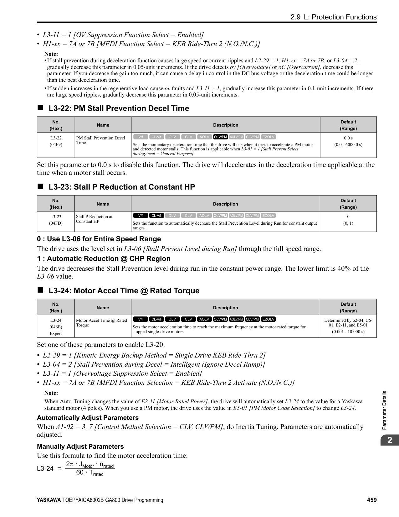
The Hunting Prevention function will not let low inertia or operation with a light load cause hunting. Hunting frequently occurs when you have a high carrier frequency and an output frequency less than 30 Hz.
######## ■ n1-01: Hunting Prevention Selection
|No. (Hex.)|Name|Description|Default (Range)| |---|---|---|---| |n1-01 (0580)|Hunting Prevention Selection|Sets the function to prevent hunting.
V/f CL-V/f OLV CLV AOLV OLV/PM AOLV/PM CLV/PM EZOLV
|Determined by o2-04 (0 to 2)|
When drive response is more important than the decrease of motor vibration, disable this function. If hunting occurs, or if you use a high carrier frequency or SwingPWM, set this parameter to 2 for better hunting prevention. 0 : Disabled 1 : Enabled (Normal) 2 : Enabled (High Carrier Frequency)
######## ■ n1-02: Hunting Prevention Gain Setting
|No. (Hex.)|Name|Description|Default (Range)| |---|---|---|---| |n1-02 (0581) Expert|Hunting Prevention Gain Setting|Sets the performance of the hunting prevention function. Usually it is not necessary to change this parameter.
V/f CL-V/f OLV CLV AOLV OLV/PM AOLV/PM CLV/PM EZOLV
|1.00 (0.00 - 2.50)|
Adjust this parameter in these conditions:
######## ■ n1-03: Hunting Prevention Time Constant
|No. (Hex.)|Name|Description|Default (Range)| |---|---|---|---| |n1-03 (0582) Expert|Hunting Prevention Time Constant|Sets the primary delay time constant of the hunting prevention function. Usually it is not necessary to change this parameter.
V/f CL-V/f OLV CLV AOLV OLV/PM AOLV/PM CLV/PM EZOLV
|Determined by o2-04 (0 - 500 ms)|
Adjust this parameter in these conditions:
######## ■ n1-05: Hunting Prevent Gain in Reverse
|No. (Hex.)|Name|Description|Default (Range)| |---|---|---|---|
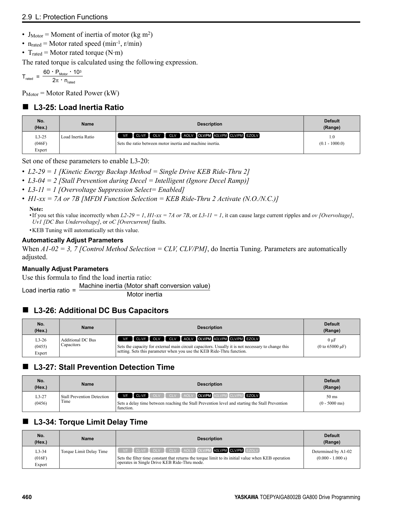
|n1-05 (0530) Expert|Hunting Prevent Gain in Reverse|Sets the performance of the hunting prevention function. This parameter adjusts Reverse run. Usually it is not necessary to change this parameter.
V/f CL-V/f OLV CLV AOLV OLV/PM AOLV/PM CLV/PM EZOLV
|0.00 (0.00 - 2.50)|
Note: When you set this parameter to 0, the value set in n1-02 [Hunting Prevention Gain Setting] is effective when the motor rotates in reverse.
Adjust this parameter in these conditions:
######## ■ n1-08: Current Detection Method
|No. (Hex.)|Name|Description|Default (Range)| |---|---|---|---| |n1-08 (1105) Expert|Current Detection Method|Sets how the drive decreases the motor vibration that is caused by leakage current. Usually it is not necessary to change this parameter.
V/f CL-V/f OLV CLV AOLV OLV/PM AOLV/PM CLV/PM EZOLV
|0 (0, 1)|
############## 0 : 2-Phases 1 : 3-Phases
Note: Set this parameter to 1 to suppress motor vibrations caused by leakage current when the wiring distance is long.
######## ■ n1-13: DC Bus Stabilization Control
|No. (Hex.)|Name|Description|Default (Range)| |---|---|---|---| |n1-13 (1B59) Expert|DC Bus Stabilization Control|Sets the oscillation suppression function for the DC bus voltage.
V/f CL-V/f OLV CLV AOLV OLV/PM AOLV/PM CLV/PM EZOLV
|0 (0, 1)|
0 : Disabled 1 : Enabled
Note: If the DC bus voltage does not become stable with light loads and the drive detects ov [Overvoltage], set this parameter to 1.
######## ■ n1-14: DC Bus Stabilization Time
|No. (Hex.)|Name|Description|Default (Range)| |---|---|---|---| |n1-14 (1B5A) Expert|DC Bus Stabilization Time|Adjusts the responsiveness of the oscillation suppression function for the DC bus voltage. Set n1-13 1 [DC Bus Stabilization Control Enabled] to enable this parameter.
V/f CL-V/f OLV CLV AOLV OLV/PM AOLV/PM CLV/PM EZOLV
|100.0 ms (50.0 - 500.0 ms)|
ParameterDetails
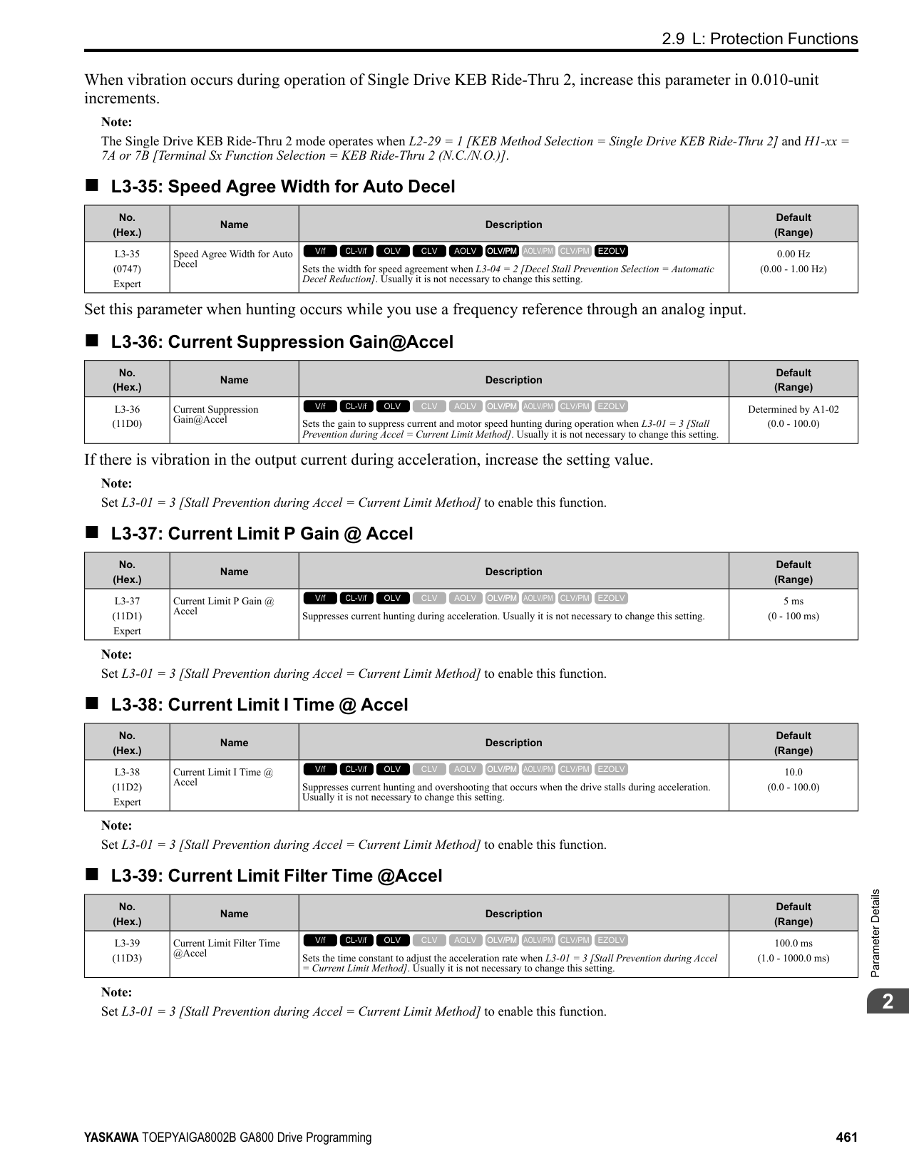
Note: Adjust this parameter in 100 ms increments.
######## ■ n1-15: PWM Voltage Offset Calibration
|No. (Hex.)|Name|Description|Default (Range)| |---|---|---|---| |n1-15 (0BF8) Expert|PWM Voltage Offset Calibration|Sets the calibration method that the drive uses to decrease torque/current ripple.
V/f CL-V/f OLV CLV AOLV OLV/PM AOLV/PM CLV/PM EZOLV
|Determined by A1-02 (0 - 2)|
This calibration function lets the drive suppress the torque ripple of a motor. Usually it is not necessary to change this setting.
0 : No Calibration 1 : One Time Calibrate at Next Start 2 : Calibrate Every Time at Start
Set n1-01 = 2 [Hunting Prevention Selection = Enabled (High Carrier Frequency)] to enable this function. If the motor oscillates, set n1-01 = 2. If that does not have an effect, increase this parameter in 0.2-unit increments.
|No. (Hex.)|Name|Description|Default (Range)| |---|---|---|---| |n1-16 (0BFB) Expert|Hunting Prevention High Fc Gain|Sets the gain for the hunting prevention function. This parameter functions best with a high carrier frequency. Usually it is not necessary to change this parameter.
V/f CL-V/f OLV CLV AOLV OLV/PM AOLV/PM CLV/PM EZOLV
|Determined by o2-04 (0.00 - 2.50)|
|No. (Hex.)|Name|Description|Default (Range)| |---|---|---|---| |n1-17 (0BFC) Expert|Hunting Prevent High Fc Filter|Sets the responsiveness of the hunting prevention function. Usually it is not necessary to change this parameter.
V/f CL-V/f OLV CLV AOLV OLV/PM AOLV/PM CLV/PM EZOLV
|500 ms (0 - 1000 ms)|
|No. (Hex.)|Name|Description|Default (Range)| |---|---|---|---| |n1-20 (1588) Expert|Voltage Calibration Duration|Sets the calibration time at start. Usually it is not necessary to change this parameter.
V/f CL-V/f OLV CLV AOLV OLV/PM AOLV/PM CLV/PM EZOLV
|50 ms (10 - 500 ms)|
######## ◆ n2: Auto Freq Regulator (AFR)
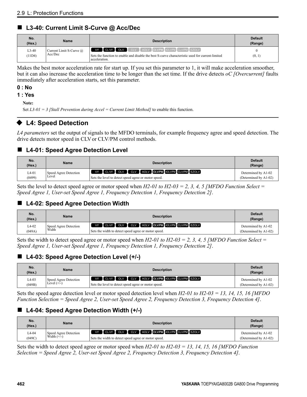
The speed feedback detection reduction function (or AFR: Automatic Frequency Regulator) helps the speed become stable when you suddenly apply or remove a load.
Note: Before you change n2-xx parameters, do one of these procedures:
Adjust this parameter in these conditions:
|No. (Hex.)|Name|Description|Default (Range)| |---|---|---|---| |n2-01 (0584)|Automatic Freq Regulator Gain|Sets the gain of the AFR function as a magnification value. Usually it is not necessary to change this setting.
V/f CL-V/f OLV CLV AOLV OLV/PM AOLV/PM CLV/PM EZOLV
|1.00 (0.00 - 10.00)|
######## ■ n2-02: Automatic Freq Regulator Time 1
|No. (Hex.)|Name|Description|Default (Range)| |---|---|---|---| |n2-02 (0585)|Automatic Freq Regulator Time 1|Sets the time constant that sets the rate of change for the AFR function. Usually it is not necessary to change this setting.
V/f CL-V/f OLV CLV AOLV OLV/PM AOLV/PM CLV/PM EZOLV
|50 ms (0 - 2000 ms)|
Adjust this parameter in these conditions:
• If there is hunting or oscillation with a light load, increase the setting value in 50 ms increments and examine the
response. If the load inertia is large, increase the setting value in 50 ms increments and examine the response. • If torque is not sufficient with a heavy load or if you must increase torque or speed responsiveness, decrease the
setting value in 10 ms increments and examine the response.
Note:
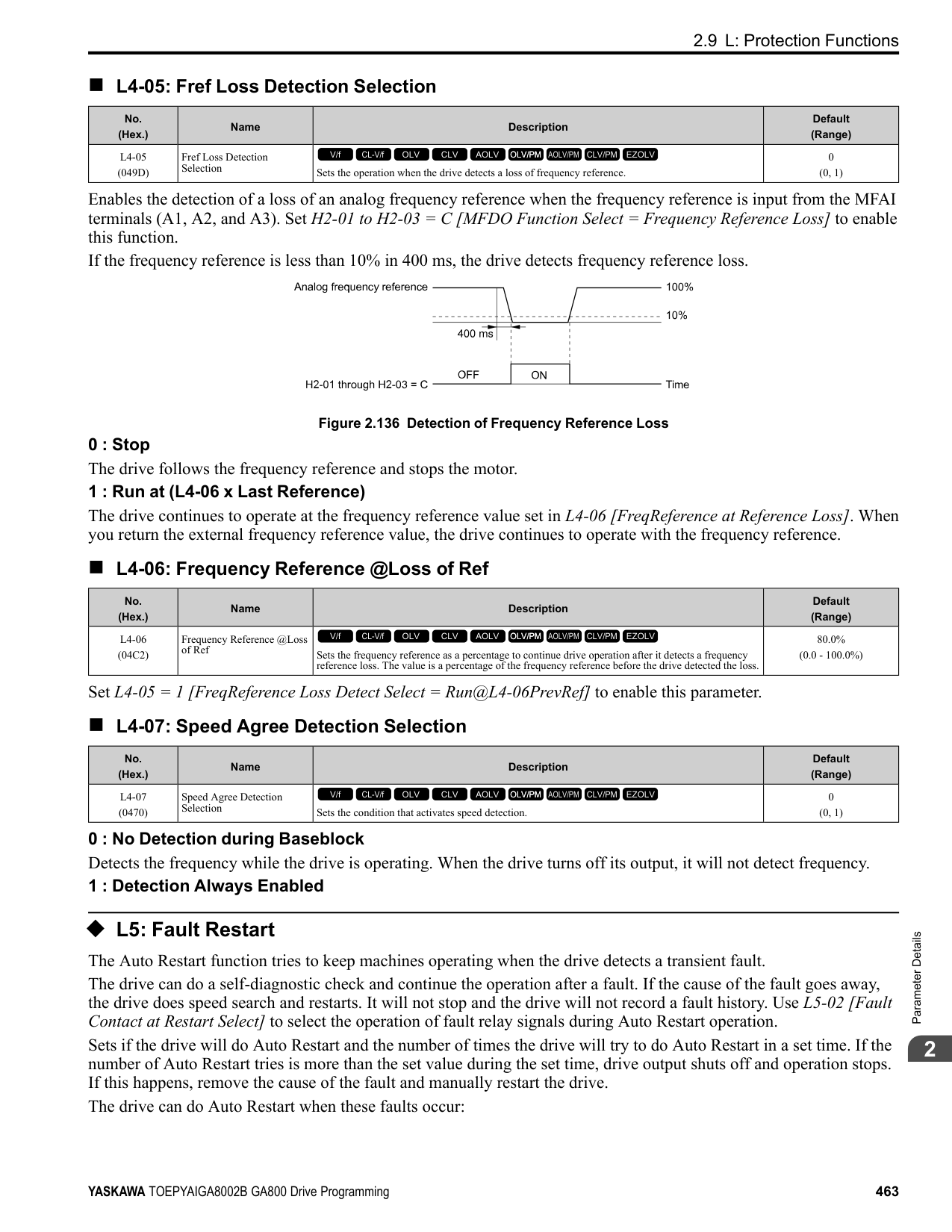
######## ■ n2-03: Automatic Freq Regulator Time 2
|No. (Hex.)|Name|Description|Default (Range)| |---|---|---|---| |n2-03 (0586)|Automatic Freq Regulator Time 2|Sets the time constant that sets the speed difference of the AFR function. Use this parameter for speed searches or regeneration. Usually it is not necessary to change this setting.
V/f CL-V/f OLV CLV AOLV OLV/PM AOLV/PM CLV/PM EZOLV
|750 ms (0 - 2000 ms)|
Adjust this parameter in these conditions:
◆ n3: High Slip Braking (HSB) and Overexcitation Braking n3 parameters configure High Slip Braking and Overexcitation Deceleration.
■ High Slip Braking High slip braking quickly decelerates motors without braking resistors. This lets you stop a motor more quickly than with the ramp to stop processes. This function is best for applications that do not frequently stop the motor, for example the fast stop function for high-inertia loads. Braking starts when the MFDI for High Slip Braking (HSB) Activate [H1-xx = 68] activates.
| | | | |---|---|---| | | | | | | | | | | | | | | | |
Figure 2.143 High Slip Braking Time Chart An induction motor is necessary to use high slip braking. Set A1-02 [Control Method Selection] to one of these values to enable high slip braking:
ParameterDetails
######## 2
Principles of Operation HSB increases motor slip by significantly decreasing the frequency supplied to the motor at the same time that deceleration starts. A large quantity of current flows through the motor to increase the motor loss, and the motor decelerates while the motor windings consume the regenerative energy. The drive keeps the motor current at a constant level during deceleration to prevent overvoltage and do automatic braking and it also keeps a slip level that causes the maximum quantity of deceleration torque. High Slip Braking Precautions
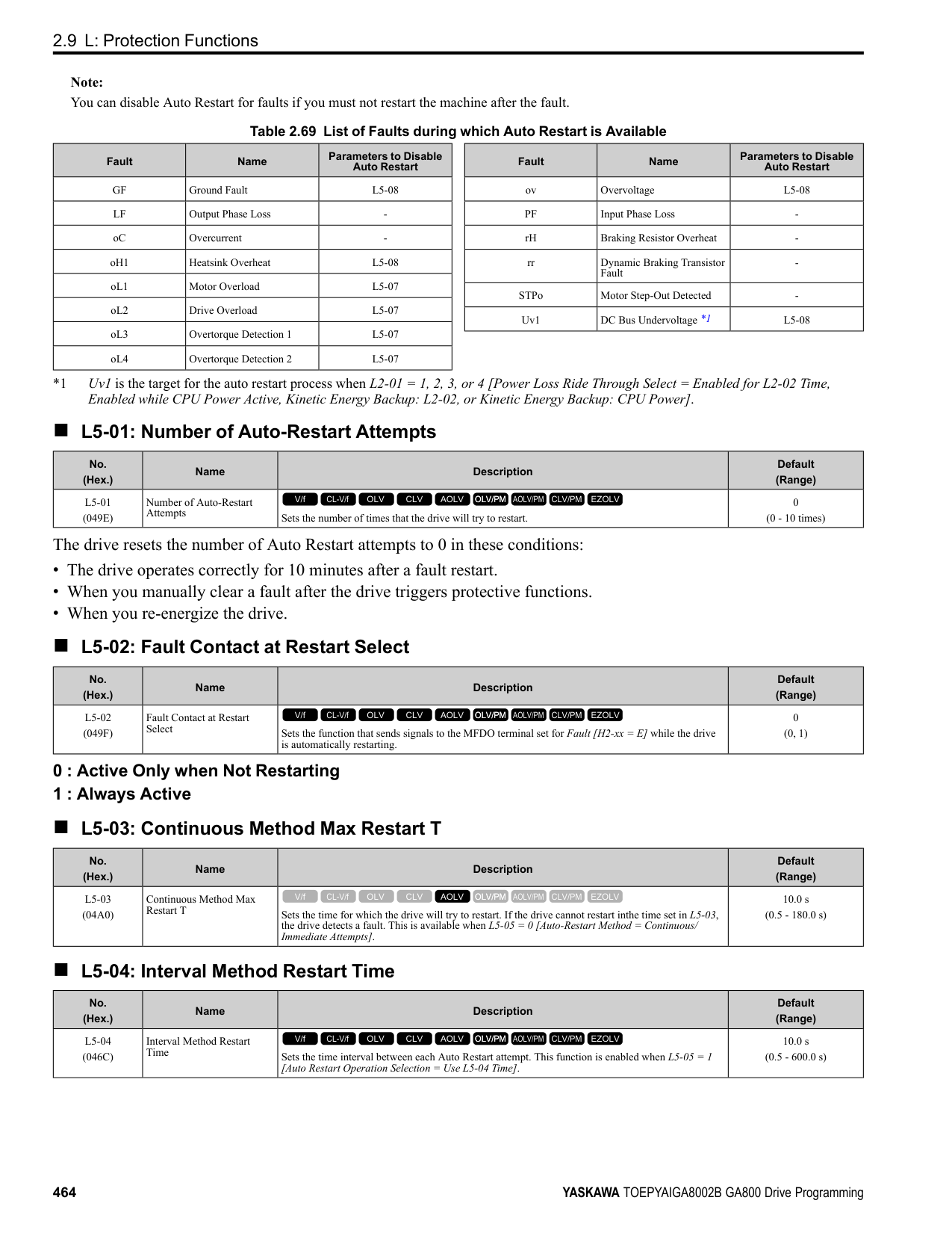
■ Overexcitation Deceleration Overexcitation deceleration quickly decelerates motors without braking resistors. This lets you stop a motor more quickly than with the ramp to stop processes. Overexcitation deceleration increases excitation current during deceleration to cause a large quantity of braking torque through motor overexcitation. You can set the deceleration speed to adjust the deceleration time for overexcitation deceleration. Overexcitation deceleration lets you accelerate the motor again during deceleration. Enter the Run command during overexcitation deceleration to cancel overexcitation deceleration and accelerate the drive to the specified speed. To enable this function, set L3-04 = 4, 5 [Stall Prevention during Decel = Overexcitation/High Flux, Overexcitation/ High Flux 2]. When L3-04 = 4, the motor will decelerate for the deceleration time set in C1-02, C1-04, C1-06, or C1-08. If the drive detects ov [Overvoltage], increase the deceleration time. When L3-04 = 5, the drive uses the value in C1-02, C1-04, C1-06, or C1-08 to decelerate and it adjusts the deceleration rate to keep the DC bus voltage at the level set in L3-17 [DC Bus Regulation Level]. The load inertia and motor characteristics have an effect on the braking time. Notes on Overexcitation Deceleration
braking time. You can use overexcitation deceleration in OLV control and CLV control, but those control methods decrease the precision of torque control and braking efficiency. Use V/f control for the best results.
• The drive disables these functions during braking with Overexcitation Deceleration 2:
######## ■ n3-01: HSB Deceleration Frequency Width
|No. (Hex.)|Name|Description|Default (Range)| |---|---|---|---| |n3-01 (0588) Expert|HSB Deceleration Frequency Width|Sets the amount by which the output frequency is to be lowered during high-slip braking, as a percentage of E1-04 [Maximum Output Frequency], which represents the 100% value.
V/f CL-V/f OLV CLV AOLV OLV/PM AOLV/PM CLV/PM EZOLV
|5% (1 - 20%)|
When you must detect ov [DC Bus Overvoltage] during high-slip braking, set this parameter to a large value.
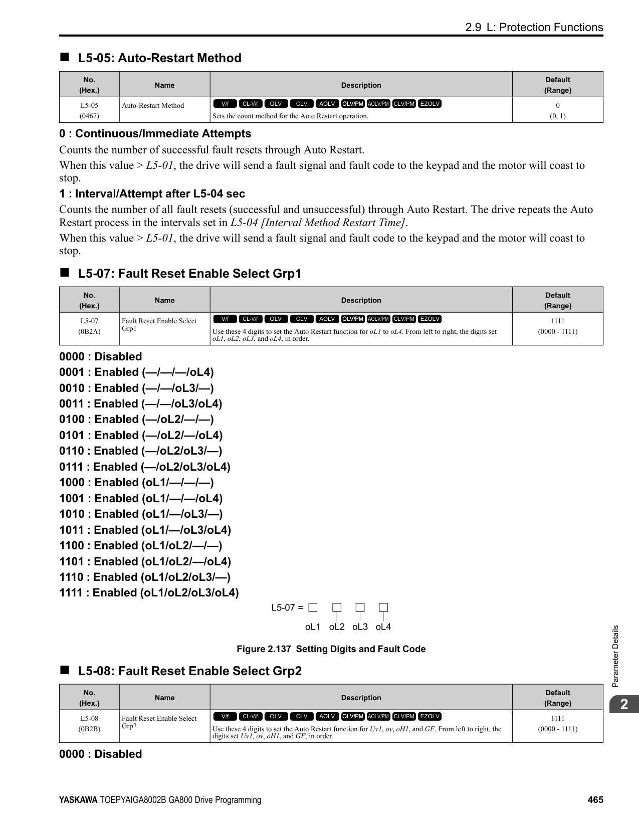
######## ■ n3-02: HSB Current Limit Level
|No. (Hex.)|Name|Description|Default (Range)| |---|---|---|---| |n3-02 (0589) Expert|HSB Current Limit Level|Sets the maximum current output during high-slip braking as a percentage of E2-01 [Motor Rated Current (FLA)]. Also set the current suppression to prevent exceeding drive overload tolerance.
V/f CL-V/f OLV CLV AOLV OLV/PM AOLV/PM CLV/PM EZOLV
|Determined by C6-01, L8-38 (0 - 150%)|
Note: The upper limit of the setting range changes when the setting for C6-01 [Normal / Heavy Duty Selection] changes.
When you decrease the setting value for current suppression, it will make the deceleration time longer.
######## ■ n3-03: HSB Dwell Time at Stop
|No. (Hex.)|Name|Description|Default (Range)| |---|---|---|---| |n3-03 (058A) Expert|HSB Dwell Time at Stop|Sets the dwell time, a length of time when high-slip braking is ending and during which the motor speed decreases and runs at a stable speed. For a set length of time, the drive will hold the actual output frequency at the minimum output frequency set in E1-09.
V/f CL-V/f OLV CLV AOLV OLV/PM AOLV/PM CLV/PM EZOLV
|1.0 s (0.0 - 10.0 s)|
If there is too much inertia or when the motor is coasting to a stop after high-slip braking is complete, increase the setting value. If the setting value is too low, machine inertia can cause the motor to rotate after high-slip braking is complete.
######## ■ n3-04: HSB Overload Time
|No. (Hex.)|Name|Description|Default (Range)| |---|---|---|---| |n3-04 (058B) Expert|HSB Overload Time|Sets the time used to detect oL7 [High Slip Braking Overload], which occurs when the output frequency does not change during high-slip braking. Usually it is not necessary to change this parameter.
V/f CL-V/f OLV CLV AOLV OLV/PM AOLV/PM CLV/PM EZOLV
|40 s (30 - 1200 s)|
If a force on the load side is rotating the motor or if there is too much load inertia connected to the motor, the drive will detect oL7. The current flowing to the motor from the load can overheat the motor and cause burn damage to the motor. Set this parameter to prevent burn damage to the motor.
ParameterDetails
######## 2
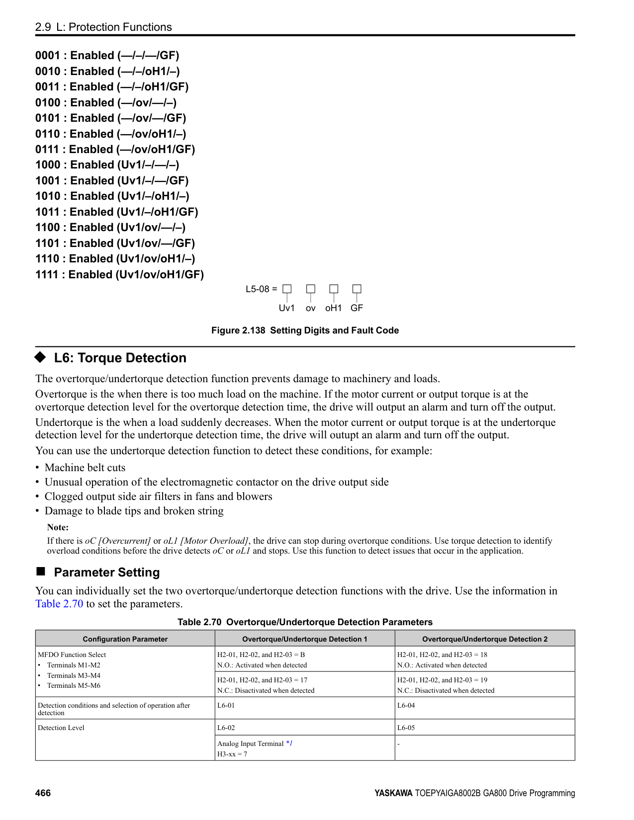
######## ■ n3-13: OverexcitationBraking (OEB) Gain
|No. (Hex.)|Name|Description|Default (Range)| |---|---|---|---| |n3-13 (0531)|OverexcitationBraking (OEB) Gain|Sets the gain value that the drive multiplies by the V/f pattern output value during overexcitation deceleration to calculate the overexcitation level.
V/f CL-V/f OLV CLV AOLV OLV/PM AOLV/PM CLV/PM EZOLV
|1.10 (1.00 - 1.40)|
The V/f pattern output value goes back to its usual level after the motor stops or accelerates again to the frequency reference speed. The best value of this parameter changes when the flux saturation characteristics of the motor change.
######## ■ n3-14: OEB High Frequency Injection
|No. (Hex.)|Name|Description|Default (Range)| |---|---|---|---| |n3-14 (0532) Expert|OEB High Frequency Injection|Sets the function that injects harmonic signals during overexcitation deceleration.
V/f CL-V/f OLV CLV AOLV OLV/PM AOLV/PM CLV/PM EZOLV
|0 (0, 1)|
Enable this parameter to set a shorter deceleration time.
Note:
unwanted, set this parameter to 0 to disable the function. 0 : Disabled 1 : Enabled
The drive injects harmonic signals at the time of overexcitation deceleration. You can decrease the deceleration time because motor loss increases.
######## ■ n3-21: HSB Current Suppression Level
|No. (Hex.)|Name|Description|Default (Range)| |---|---|---|---| |n3-21 (0579)|HSB Current Suppression Level|Sets the upper limit of the current that is suppressed at the time of overexcitation deceleration as a percentage of the drive rated current.
V/f CL-V/f OLV CLV AOLV OLV/PM AOLV/PM CLV/PM EZOLV
|100% (0 - 150%)|
If flux saturation during Overexcitation Deceleration makes the motor current become more than the value set in this parameter, the drive will automatically decrease the overexcitation gain. If oC [Overcurrent], oL1 [Motor Overload], or oL2 [Drive Overloaded] occur during overexcitation deceleration, decrease the setting value. If repetitive or long overexcitation deceleration cause the motor to overheat, decrease the setting value.
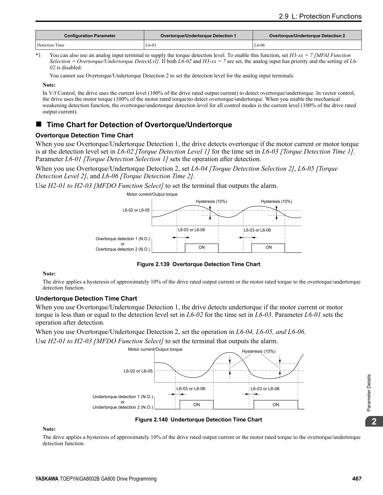
######## ■ n3-23: Overexcitation Braking Operation
|No. (Hex.)|Name|Description|Default (Range)| |---|---|---|---| |n3-23 (057B)|Overexcitation Braking Operation|Sets the direction of motor rotation where the drive will enable overexcitation.
V/f CL-V/f OLV CLV AOLV OLV/PM AOLV/PM CLV/PM EZOLV
|0 (0 - 2)|
############## 1 : Enabled Only when Rotating FWD 2 : Enabled Only when Rotating REV
Note: When n3-23 = 1, 2, the drive enables overexcitation only in the direction of motor rotation in which a regenerative load is applied. Increased motor loss can decrease ov [Overvoltage] faults.
◆ n4: Adv Open Loop Vector Tune The following explains how to make special adjustments for Advanced Open Loop Vector [A1-02 = 4].
Note:
Note:
If you do not apply a regenerative load when you operate at low speeds, do stationary Auto-Tuning for Line-to-Line Resistance only. If this does not make it better, increase the setting value in 5% increments. The recommended setting is 100% to 150%. If you set this parameter too high, the drive will detect CF [Control Fault] at stop.
|No. (Hex.)|Name|Description|Default (Range)|
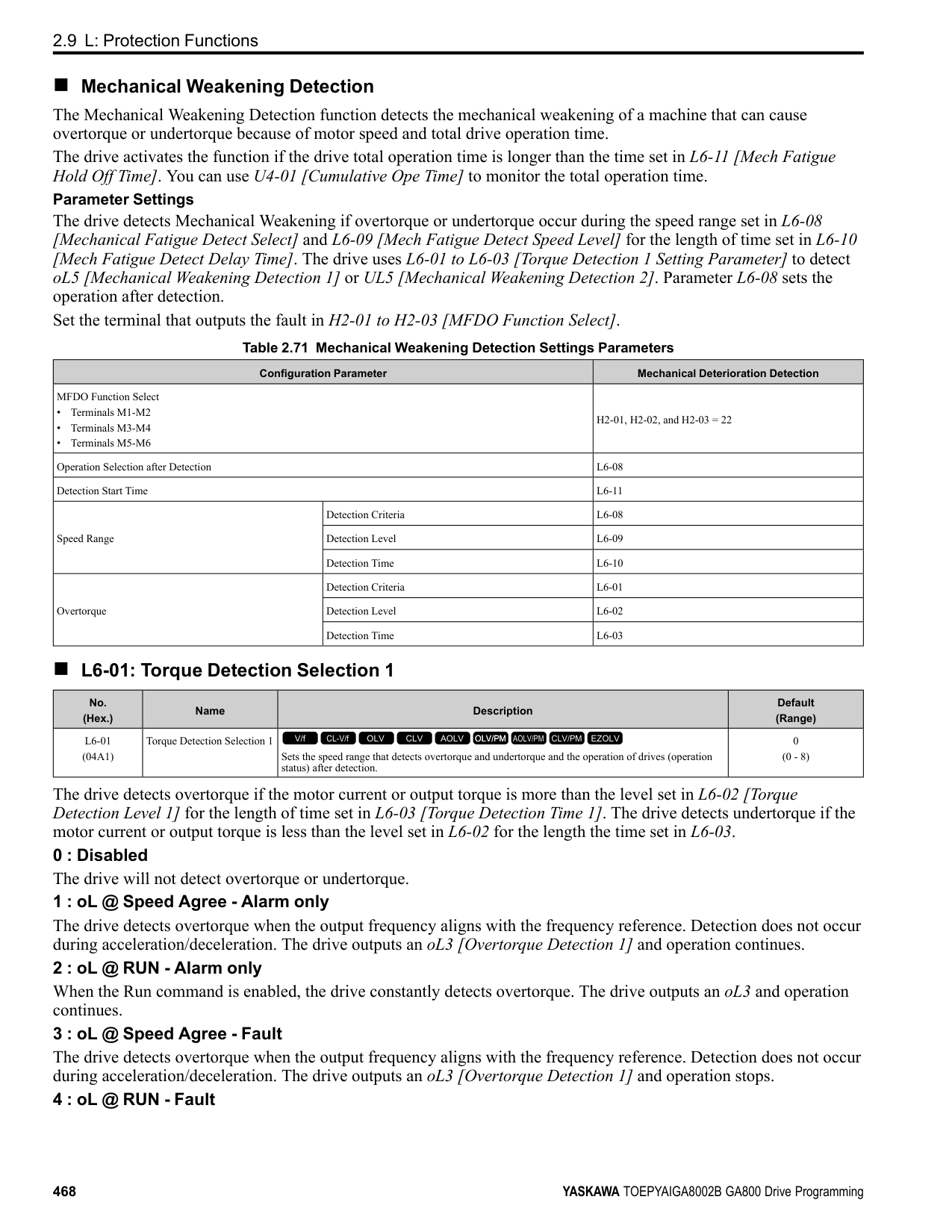
|---|---|---|---| |n4-60 (1B80)|Motoring Low Speed Comp Gain|Sets a compensation gain to improve the control qualities for motoring loads in the low speed range.
V/f CL-V/f OLV CLV AOLV OLV/PM AOLV/PM CLV/PM EZOLV
|100.0% (50.0 - 200.0%)|
|No. (Hex.)|Name|Description|Default (Range)| |---|---|---|---| |n4-61 (1B81)|Low Speed Comp Frequency Level|Sets a frequency at which the settings n4-60 [Motoring Low Speed Comp Gain] and n4-62 [Regen Low Speed Comp Gain] are enabled. When the output frequency < n4-61, the drive adjusts the torque to agree with the settings for n4-60 and n4-62. Usually it is not necessary to change this setting.
V/f CL-V/f OLV CLV AOLV OLV/PM AOLV/PM CLV/PM EZOLV
|6.00 Hz (0.50 - 12.00 Hz)|
|No. (Hex.)|Name|Description|Default (Range)| |---|---|---|---| |n4-62 (1B82)|Regen Low Speed Comp Gain|Sets a compensation gain to improve the control qualities for regenerative loads in the low speed range.
V/f CL-V/f OLV CLV AOLV OLV/PM AOLV/PM CLV/PM EZOLV
|100.0 (50.0 - 500.0)|
|No. (Hex.)|Name|Description|Default (Range)| |---|---|---|---| |n4-63 (1B83)|Speed EstimateResponse@High Freq|Sets the responsiveness of the speed estimation in high speed ranges, where the output frequency is ≥ n4-67 [Estimate Gain Switchover Freq].
V/f CL-V/f OLV CLV AOLV OLV/PM AOLV/PM CLV/PM EZOLV
|60.0 (0.1 - 300.0)|
If better response of speed estimation is necessary, or if the motor oscillates, or if there is a large quantity of torque ripple, increase the setting value in 10.0 unit increments. If this does not make it better, decrease the setting value in 10.0 unit increments.
ParameterDetails
######## 2
Note: Do rotational Auto-Tuning before you adjust n4-63, n4-64 [Speed Estimate Response@Low Freq], n4-65 [Flux Estimate Response@High Freq], and n4-66 [Flux Estimate Response @Low Freq].
######## ■ n4-64: Speed Estimate Response@Low Freq
|No. (Hex.)|Name|Description|Default (Range)| |---|---|---|---| |n4-64 (1B84)|Speed Estimate Response@Low Freq|Sets the responsiveness of the speed estimation in low speed ranges, where 0 ≤ the output frequency, which is < n4-67 [Estimate Gain Switchover Freq].
V/f CL-V/f OLV CLV AOLV OLV/PM AOLV/PM CLV/PM EZOLV
|60.0 (0.1 - 300.0)|
If better response of speed estimation is necessary, or if the motor oscillates, or if there is a large quantity of torque ripple, increase the setting value in 10.0 unit increments.
Note: Do rotational Auto-Tuning before you adjust n4-63 [Speed EstimateResponse@High Freq], n4-64, n4-65 [Flux Estimate Response@High Freq], and n4-66 [Flux Estimate Response @Low Freq].
######## ■ n4-65: Flux Estimate Response@High Freq
|No. (Hex.)|Name|Description|Default (Range)| |---|---|---|---|
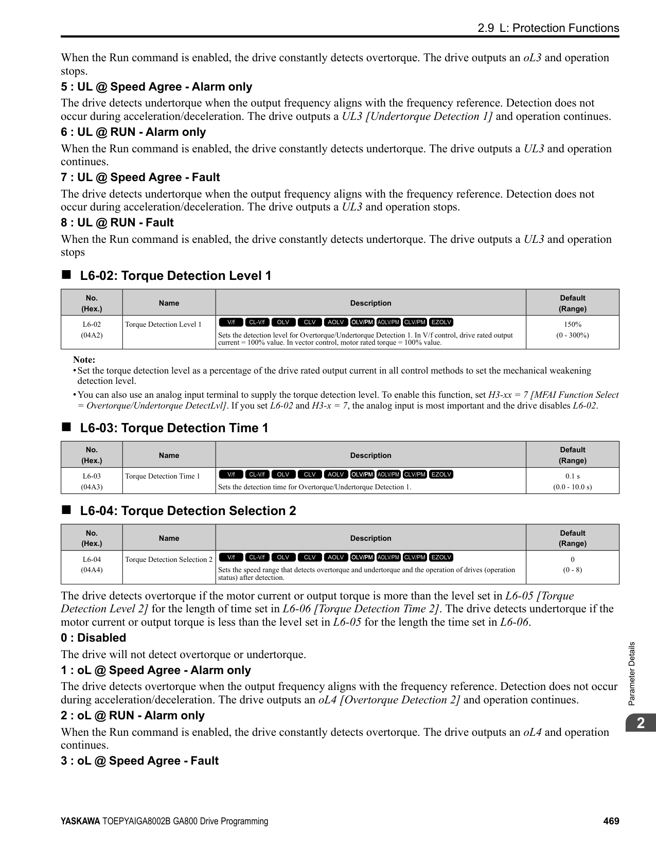
|n4-65 (1B85)|Flux Estimate Response@High Freq|Sets the responsiveness of the magnetic flux estimation in high speed ranges, where the output frequency is ≥ n4-67 [Estimate Gain Switchover Freq]. Usually it is not necessary to change this setting.
V/f CL-V/f OLV CLV AOLV OLV/PM AOLV/PM CLV/PM EZOLV
|1.00 (0.50 - 3.00)|
If the drive detects oS [Overspeed] in no-load conditions, or if the speed does not become stable in the high speed range, increase or decrease the setting value in 0.05 unit increments.
######## ■ n4-66: Flux Estimate Response @Low Freq
|No. (Hex.)|Name|Description|Default (Range)| |---|---|---|---| |n4-66 (1B86)|Flux Estimate Response @Low Freq|Sets the responsiveness of the magnetic flux estimation in low speed ranges, where 0 ≤ the output frequency, which is < n4-67 [Estimate Gain Switchover Freq]. Usually it is not necessary to change this setting.
V/f CL-V/f OLV CLV AOLV OLV/PM AOLV/PM CLV/PM EZOLV
|1.50 (0.50 - 3.00)|
If the drive detects oS [Overspeed] in no-load conditions, or if the speed does not become stable in the low speed range, increase or decrease the setting value in 0.05 unit increments.
######## ■ n4-67: Estimate Gain Switchover Freq
|No. (Hex.)|Name|Description|Default (Range)| |---|---|---|---| |n4-67 (1B87)|Estimate Gain Switchover Freq|Sets the switching frequency for estimation gain for these parameters:
n4-63 [Speed EstimateResponse@High Freq]
n4-64 [Speed Estimate Response@Low Freq]
n4-65 [Flux Estimate Response@High Freq]
n4-66 [Flux Estimate Response @Low Freq] Usually it is not necessary to change this setting.
V/f CL-V/f OLV CLV AOLV OLV/PM AOLV/PM CLV/PM EZOLV
|6.00 Hz (0.00 - E1-04 setting)|
When the output frequency ≥ n4-67, the drive will select n4-63 and n4-65. When the output frequency < n4-67, the drive will select n4-64 and n4-66.
######## ■ n4-68: Speed Estimation Filter Time
|No. (Hex.)|Name|Description|Default (Range)| |---|---|---|---| |n4-68 (1B88)|Speed Estimation Filter Time|Sets the primary delay time constant for the speed estimation value. Usually it is not necessary to change this setting.
V/f CL-V/f OLV CLV AOLV OLV/PM AOLV/PM CLV/PM EZOLV
|0.001 s (0.001 - 0.010 s)|
If the motor speed oscillates in the high speed range, set the value to 0.010 s.
######## ■ n4-69: Flux Control Response
|No. (Hex.)|Name|Description|Default (Range)| |---|---|---|---| |n4-69 (1B89)|Flux Control Response|Unifies control of magnetic flux to make motor vibrations more stable.
V/f CL-V/f OLV CLV AOLV OLV/PM AOLV/PM CLV/PM EZOLV
|1.00 (0.00 - 60.00)|
If step-out occurs when the load changes, decrease the setting value in 1.00 increments. Note: If heavy loads decrease motor speed, increase the setting value in 1.00 increments. If it does not get better, increase n4-74 [Limit of Flux Loop] in 20% increments.
######## ■ n4-70: Speed Command Comp @ Low Freq
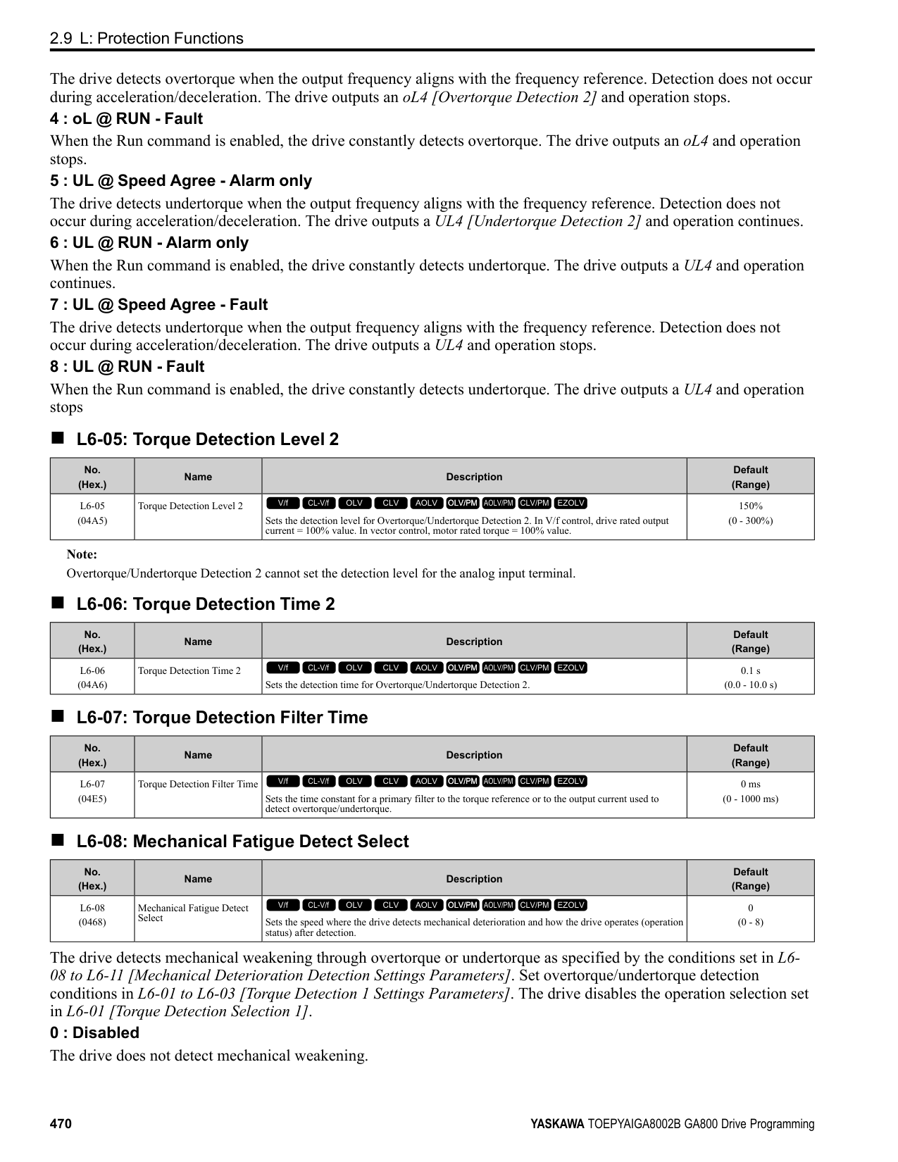
|No. (Hex.)|Name|Description|Default (Range)| |---|---|---|---| |n4-70 (1B8A)|Speed Command Comp @ Low Freq|Sets the function to make the drive more stable when operating at low speeds. Usually it is not necessary to change this setting.
V/f CL-V/f OLV CLV AOLV OLV/PM AOLV/PM CLV/PM EZOLV
|1.00 Hz (0.00 - 6.00 Hz)|
This function makes the control more stable when operating at low speeds. Increase the setting in 0.3 Hz increments at the time of low-speed references with no load.
Note: If you increase this parameter to make the speed references for low speeds more stable, it can make the speed control less accurate.
######## ■ n4-71: Flux Estimation Method
|No. (Hex.)|Name|Description|Default (Range)| |---|---|---|---| |n4-71 (1B8B) Expert|Flux Estimation Method|Sets the flux estimation method. Usually it is not necessary to change this setting.
V/f CL-V/f OLV CLV AOLV OLV/PM AOLV/PM CLV/PM EZOLV
|0 (0, 1)|
0 : Method 1 1 : Method 2
######## ■ n4-72: Speed Feedback Mode
|No. (Hex.)|Name|Description|Default (Range)| |---|---|---|---| |n4-72 (1B8C)|Speed Feedback Mode|Sets the requirement for an encoder option when A1-02 4 [Control Method Selection Advanced Open Loop Vector].
V/f CL-V/f OLV CLV AOLV OLV/PM AOLV/PM CLV/PM EZOLV
|0 (0, 1)|
You can connect a PG-B3 or PG-X3 encoder option in AOLV control. You can use the encoder option for better speed control precision.
Note:
######## ■ n4-73: PGo Recovery Selection
|No. (Hex.)|Name|Description|Default (Range)| |---|---|---|---| |n4-73 (1B8D)|PGo Recovery Selection|Sets the restart mode to Without Encoder Mode or the With Encoder Mode when an encoder is disconnected.
V/f CL-V/f OLV CLV AOLV OLV/PM AOLV/PM CLV/PM EZOLV
|0 (0, 1)|
ParameterDetails
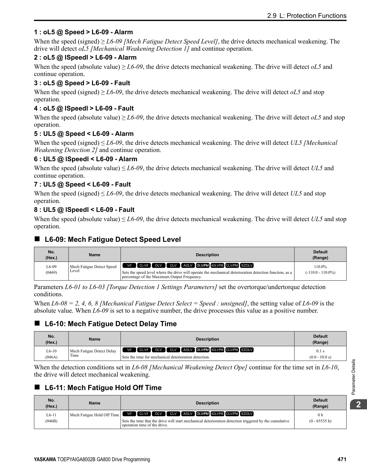
######## 2
Set A1-02 = 4 [Control Method Selection = AOLV] and n4-72 = 1 [Speed Feedback Mode = With Encoder] to use this parameter. Parameter F1-02 [Encoder Signal Loss Detect Sel] sets the drive response when the drive detects a disconnected encoder. This parameter sets the drive to start up in the Without Encoder Mode or With Encoder Mode if the drive detects PGo [Encoder (PG) Feedback Loss].
Note: A PG-B3 encoder option is necessary to use this parameter. When you use a PG-X3 option, it is not necessary to set this parameter. If the drive detects PGo, de-energize the drive and examine the wiring for the encoder.
0 : Without Encoder 1 : With Encoder
######## ■ n4-74: Limit of Flux Loop
|No. (Hex.)|Name|Description|Default (Range)| |---|---|---|---| |n4-74 (1B8E)|Limit of Flux Loop|Sets the control level for flux loop control output.
V/f CL-V/f OLV CLV AOLV OLV/PM AOLV/PM CLV/PM EZOLV
|250% (100 - 500%)|
If the torque is not sufficient because of 100% or more loads, increase the setting value in 20% increments. If the setting is too high, overexcitation could occur and overheat the motor.
######## ◆ n5: Feed Forward Control
Feed forward control increases the responsiveness of acceleration and deceleration as specified by the speed reference.
Increase C5-01 and C5-03 [ASR Proportional Gain] to apply feed forward control to machines that have low rigidity and are possible to have hunting and vibration or to machines that have a large quantity of inertia. When you use this function in CLV control, it also helps prevent overshoot. Refer to Figure 2.144. Refer to Figure 2.145 for more information about parameters related to feed forward control. Set A1-02 [Control Method Selection] to one of these values to enable feed forward control:
################# Figure 2.144 Suppress Overshooting with Feed Forward Control
| | | | |---|---|---| | | | | | | | |
Figure 2.145 Configure Feed Forward Control
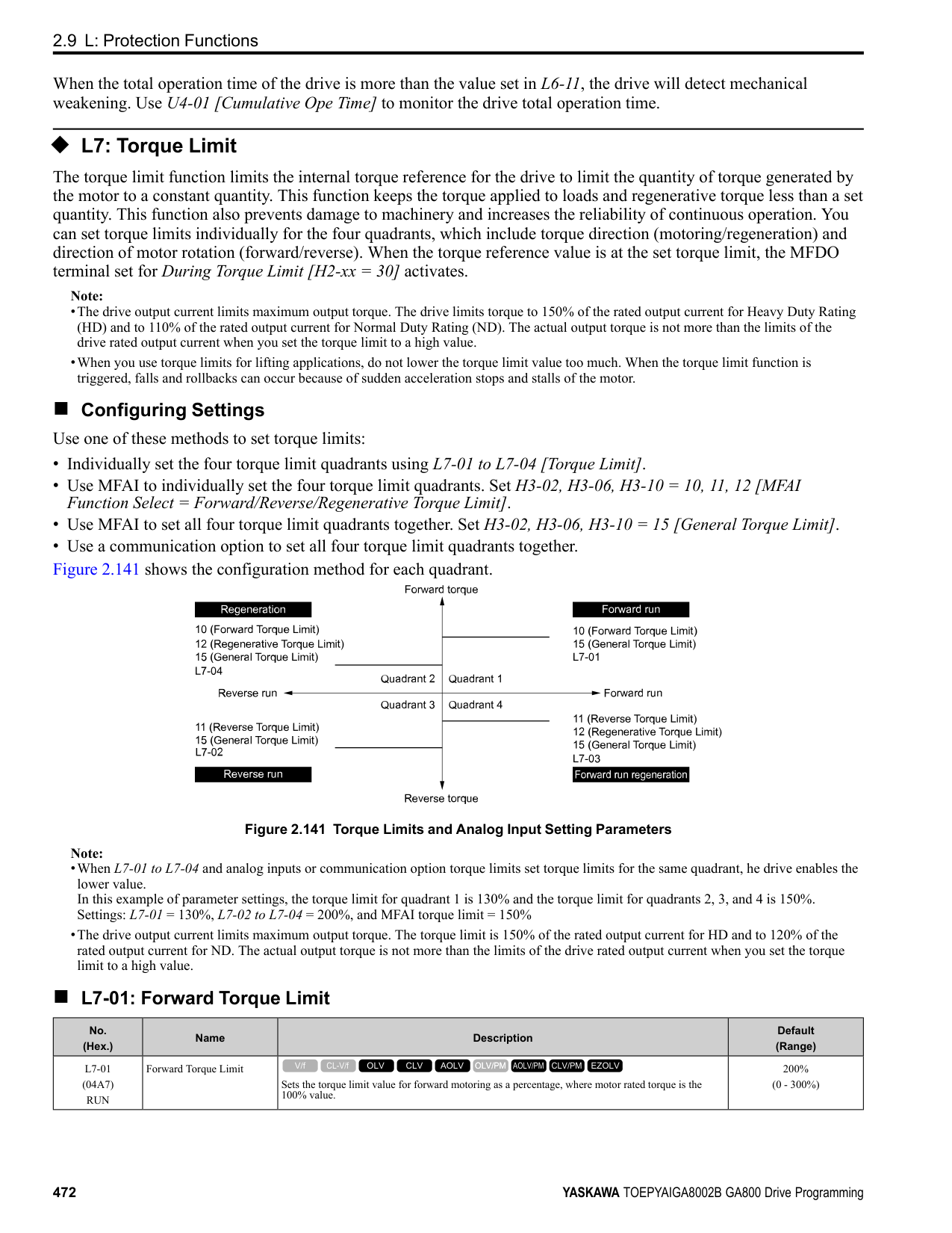
|No. (Hex.)|Name|Description|Default (Range)| |---|---|---|---| |n5-01 (05B0)|Feed Forward Control Selection|Sets the feed forward function.
V/f CL-V/f OLV CLV AOLV OLV/PM AOLV/PM CLV/PM EZOLV
|0 (0, 1)|
0 : Disabled 1 : Enabled
######## ■ n5-02: Motor Inertia Acceleration Time
|No. (Hex.)|Name|Description|Default (Range)| |---|---|---|---| |n5-02 (05B1)|Motor Inertia Acceleration Time|Sets the length of time for the motor to accelerate from the stopped to the maximum frequency with a single motor at the rated torque. Inertia Tuning automatically sets the motor acceleration time.
V/f CL-V/f OLV CLV AOLV OLV/PM AOLV/PM CLV/PM EZOLV
|Determined by C6-01, E501, and o2-04
(0.001 - 10.000 s)|
If you cannot do Inertia Tuning, calculate the motor acceleration time as shown here or measure the motor acceleration time and set n5-02 to this value. Calculate the Motor Acceleration Time Use this formula to find the motor acceleration time:
ParameterDetails
######## 2
Calculate the Motor Acceleration Time Use this procedure to calculate the motor acceleration time:
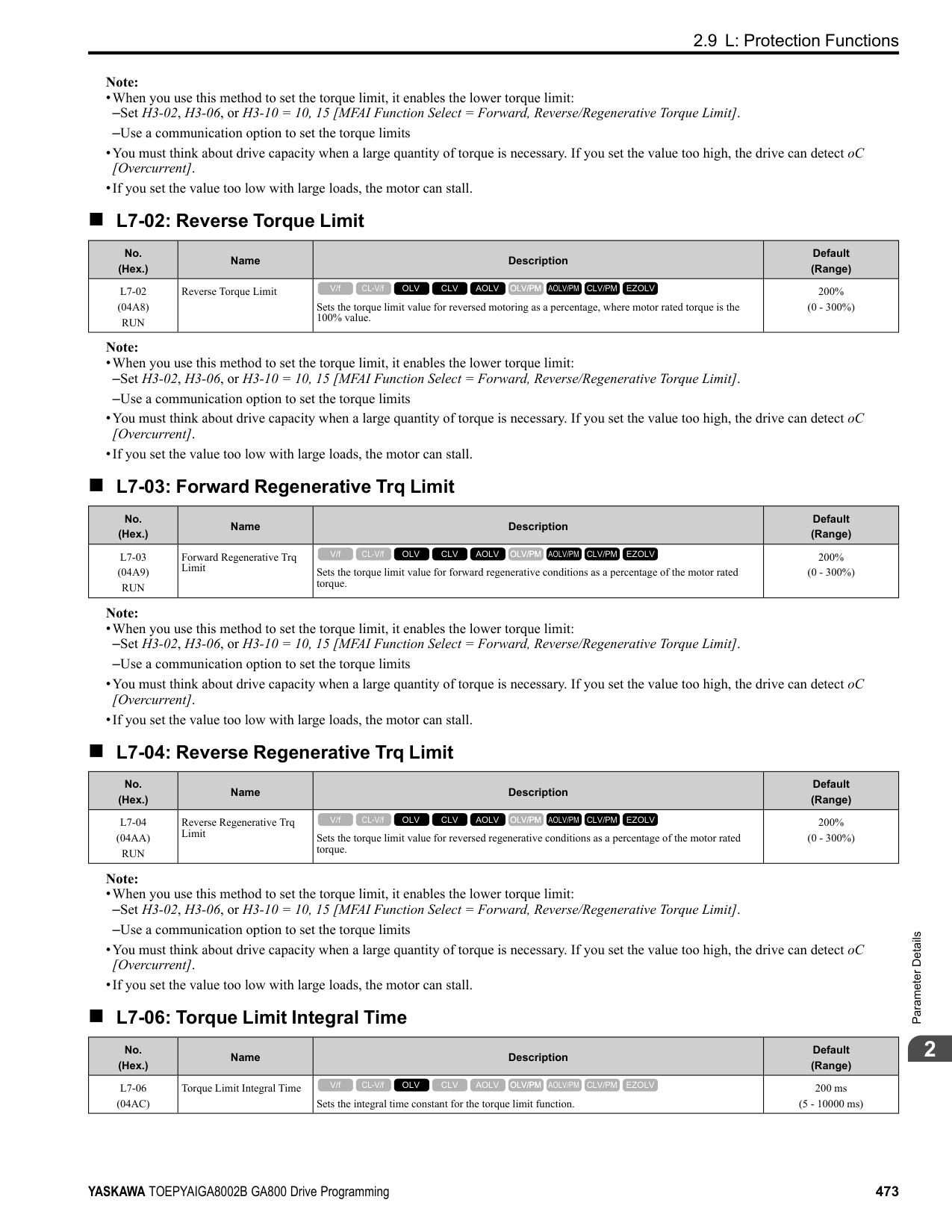
######## ■ n5-03: Feed Forward Control Gain
|No. (Hex.)|Name|Description|Default (Range)| |---|---|---|---| |n5-03 (05B2)|Feed Forward Control Gain|Sets the ratio between load inertia and motor inertia. Inertia Tuning automatically sets the Feedforward Control Gain value.
V/f CL-V/f OLV CLV AOLV OLV/PM AOLV/PM CLV/PM EZOLV
|1.00 (0.00 - 100.00)|
When you cannot do Inertia Tuning, use this procedure to set n5-03: Set n5-02 [Motor Inertia Acceleration Time].
WARNING! Sudden Movement Hazard. Machinery can accelerate suddenly. Do not use this function with machinery that must not accelerate suddenly. Sudden starts can cause serious injury or death.
Reset all of the parameters that you changed to the previous setting values.
################# Note:
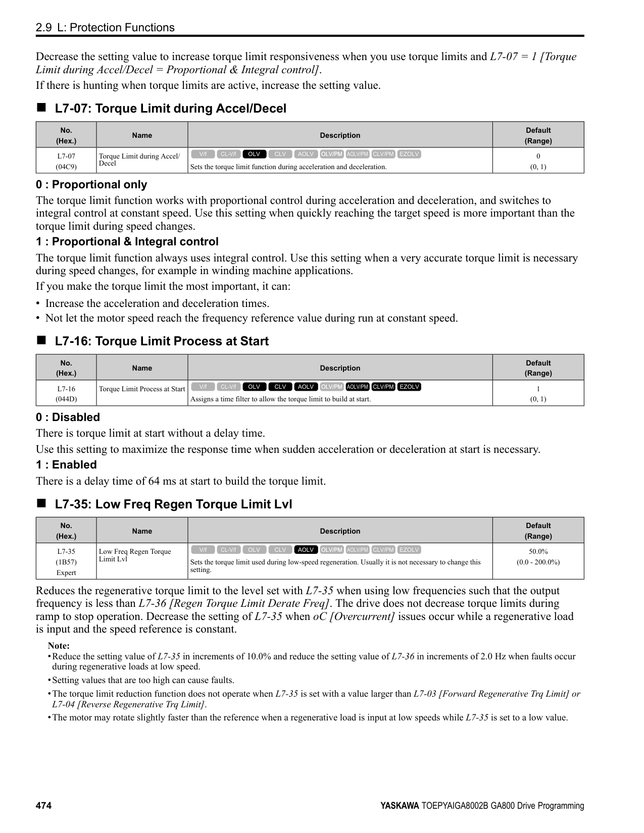
######## ■ n5-04: Speed Response Frequency
|No. (Hex.)|Name|Description|Default (Range)| |---|---|---|---| |n5-04 (05B3) RUN Expert|Speed Response Frequency|Sets the response frequency for the speed reference. Usually it is not necessary to change this parameter.
V/f CL-V/f OLV CLV AOLV OLV/PM AOLV/PM CLV/PM EZOLV
|Determined by A1-02 (0.00 - 500.00 Hz)|
If you set n5-03 [Feed Forward Control Gain] too high, the motor speed will momentarily increase to more than the set frequency.
◆ n6: Online Tuning n6 parameters are used to set the online tuning function for motor line-to-line resistance.
The Online Tuning for motor line-to-line resistance is used to prevent degradation of speed control accuracy due to motor temperature fluctuation and motor stalls due to insufficient torque.
######## ■ n6-01: Online Tuning Selection
|No. (Hex.)|Name|Description|Default (Range)| |---|---|---|---| |n6-01 (0570)|Online Tuning Selection|Sets the type of motor data that Online Tuning uses for OLV control.
V/f CL-V/f OLV CLV AOLV OLV/PM AOLV/PM CLV/PM EZOLV
|0 (0 - 2)|
The drive adjusts the motor line-to-line resistance during run. This procedure is applicable for speed values 6 Hz and less. It also adjusts the motor resistance value to increase the overload capacity in the low speed range.
The drive adjusts the output voltage during run to increase overload tolerance and minimize the effects of high temperatures on speed precision.
Note: Setting 2 is enabled only when b8-01 = 0 [Energy Saving Control Selection = Disabled].
######## ■ n6-05: Online Tuning Gain
|No. (Hex.)|Name|Description|Default (Range)| |---|---|---|---| |n6-05 (05C7) Expert|Online Tuning Gain|Sets the compensation gain when n6-01 = 2 [Online Tuning Selection = Voltage Correction Tuning]. Usually it is not necessary to change this parameter.
V/f CL-V/f OLV CLV AOLV OLV/PM AOLV/PM CLV/PM EZOLV
|1.0 (0.1 - 50.0)|
ParameterDetails
When you use a motor that has a large secondary circuit time constant, decrease the setting value. If the drive detects oL1 [Motor Overload], increase the setting value in 0.1-unit increments.
######## ■ n6-11: Online Resistance Tuning
|No. (Hex.)|Name|Description|Default (Range)| |---|---|---|---| |n6-11 (1B56) Expert|Online Resistance Tuning|Sets the responsiveness for online resistor tuning. Set this parameter to approximately 1.000 to enable the function. The function is disabled when the value is 0.000.
V/f CL-V/f OLV CLV AOLV OLV/PM AOLV/PM CLV/PM EZOLV
|0.000 (0.000 - 1.000)|
◆ n7: EZ Drive The n7 parameters provide special adjustments for EZ Vector Control.
Note:
Note:
To make tracking related to load changes better, increase the setting value in 5-unit increments. If oscillation occurs during load changes, decrease the setting value in 5-unit increments.
Note:
When you increase the setting value, you can do a speed search of a motor rotating at a high frequency. If the setting value is too high, the calculated speed will oscillate and a restart will fail. Decrease the setting value in these conditions.
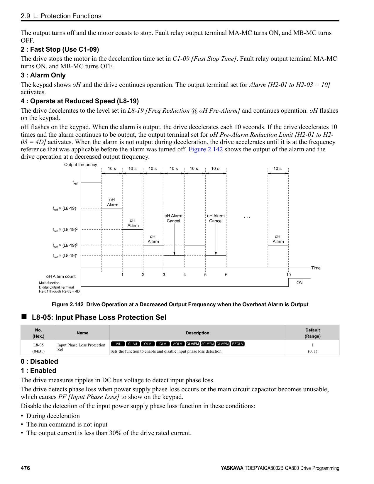
|No. (Hex.)|Name|Description|Default (Range)| |---|---|---|---| |n7-01 (3111) Expert|Damping Gain for Low Frequency|Sets the oscillation suppression gain for the low speed range.
V/f CL-V/f OLV CLV AOLV OLV/PM AOLV/PM CLV/PM EZOLV
|1.0 (0.1 - 10.0)|
|No. (Hex.)|Name|Description|Default (Range)| |---|---|---|---| |n7-05 (3115) Expert|Response Gain for Load Changes|Sets the response gain related to changes in the load.
V/f CL-V/f OLV CLV AOLV OLV/PM AOLV/PM CLV/PM EZOLV
|100 (10 - 1000)|
|No. (Hex.)|Name|Description|Default (Range)| |---|---|---|---| |n7-07 (3117) Expert|Speed Calculation Gain1|Sets the speed calculation gain during usual operation. Usually it is not necessary to change this setting.
V/f CL-V/f OLV CLV AOLV OLV/PM AOLV/PM CLV/PM EZOLV
|15.0 Hz (1.0 - 50.0 Hz)|
|No. (Hex.)|Name|Description|Default (Range)| |---|---|---|---| |n7-08 (3118) Expert|Speed Calculation Gain2|Sets the speed calculation gain during a speed search.
V/f CL-V/f OLV CLV AOLV OLV/PM AOLV/PM CLV/PM EZOLV
|25.0 Hz (1.0 - 50.0 Hz)|
|No. (Hex.)|Name|Description|Default (Range)| |---|---|---|---| |n7-10 (311A) Expert|Pull-in Current Switching Speed|Parameter n8-51 [Pull-in Current @ Acceleration], is in effect when the output frequency is ≤ n7-10, where the speed is set as a percentage of rated speed.
V/f CL-V/f OLV CLV AOLV OLV/PM AOLV/PM CLV/PM EZOLV
|10.0% (0.0 - 100.0%)|
################# Note:
Note:
|No. (Hex.)|Name|Description|Default (Range)| |---|---|---|---| |n7-11 (311B) Expert|Pull-in Current Switch Hysteresis Band|Sets the hysteresis level for Switching Speed set in n7-10 [Pull-in Current Switching Speed]. When the speed is lower than n7-10 + n7-11 during acceleration, the drive enables pull-in current.
V/f CL-V/f OLV CLV AOLV OLV/PM AOLV/PM CLV/PM EZOLV
|5.0% (1.0 - 20.0%)|
|No. (Hex.)|Name|Description|Default (Range)| |---|---|---|---| |n7-13 (311D) Expert|Pull-in Current Switching Time|Sets a time to enable the pull-in current commands.
V/f CL-V/f OLV CLV AOLV OLV/PM AOLV/PM CLV/PM EZOLV
|100 ms (0 - 1000 ms)|
|No. (Hex.)|Name|Description|Default (Range)| |---|---|---|---| |n7-17 (3122)|Resistance TemperatureCorrection|Sets the function to adjust for changes in the motor resistance value caused by changes in the temperature.
V/f CL-V/f OLV CLV AOLV OLV/PM AOLV/PM CLV/PM EZOLV
|1 (0 to 2)|
0 : Invalid 1 : Valid (Only 1 time) 2 : Valid (Every time)
Note:
◆ n8: PM Motor Control Tuning n8 parameters are used to make adjustments when controlling PM motors.
######## ■ n8-01: Pole Position Detection Current
|No. (Hex.)|Name|Description|Default (Range)| |---|---|---|---| |n8-01 (0540)|Pole Position Detection Current|Sets, as a percentage, the Initial Rotor Position Estimated Current, taking the E5-03 [Motor Rated Current (FLA)] as the 100% value. Usually it is not necessary to change this setting.
V/f CL-V/f OLV CLV AOLV OLV/PM AOLV/PM CLV/PM EZOLV
|50% (0 - 100%)|
ParameterDetails
The drive uses the Initial Rotor Position Estimated Current to detect the initial position of rotors. Use the "Si" value on the motor nameplate, if available.
Note: When A1-02 = 7 [CLV/PM], this parameter takes effect only in Expert Mode.
######## ■ n8-02: Pole Alignment Current Level
|No. (Hex.)|Name|Description|Default (Range)| |---|---|---|---| |n8-02 (0541) Expert|Pole Alignment Current Level|Sets the current at the time of polar attraction as a percentage of E5-03 [Motor Rated Current (FLA)]. Usually it is not necessary to change this setting.
V/f CL-V/f OLV CLV AOLV OLV/PM AOLV/PM CLV/PM EZOLV
|80% (0 - 150%)|
The drive uses the polar pull-in current to attract the rotor after it detects the initial rotor position. When you increase the value of n8-02, the starting torque also increases.
Note:
######## ■ n8-03: Pole Position Detection Time
|No. (Hex.)|Name|Description|Default (Range)| |---|---|---|---| |n8-03 (0542)|Pole Position Detection Time|Sets the length of the Current Starting Time, which is used for Z Pulse Offset Tuning. Usually it is not necessary to change this setting.
V/f CL-V/f OLV CLV AOLV OLV/PM AOLV/PM CLV/PM EZOLV
|1.5 s (1.5 - 5.0 s)|
Sets the length of time of pull-in current when the drive detects the motor magnetic pole of the rotors. Note: If the motor oscillates at the time of the polar attraction, increase the value in 0.5 s increments. If the value is too high, the drive can detect oL2 [Drive Overloaded].
######## ■ n8-04: Pole Alignment Time
|No. (Hex.)|Name|Description|Default (Range)| |---|---|---|---| |n8-04 (0543) Expert|Pole Alignment Time|Sets the length of the Polar Attraction Time, which is used for Z Pulse Offset Tuning. Usually it is not necessary to change this setting.
V/f CL-V/f OLV CLV AOLV OLV/PM AOLV/PM CLV/PM EZOLV
|1.5 s (1.5 - 5.0 s)|
Sets the length of time that the pull-in current flows when the drive detects the motor magnetic pole of the rotors.
Note:
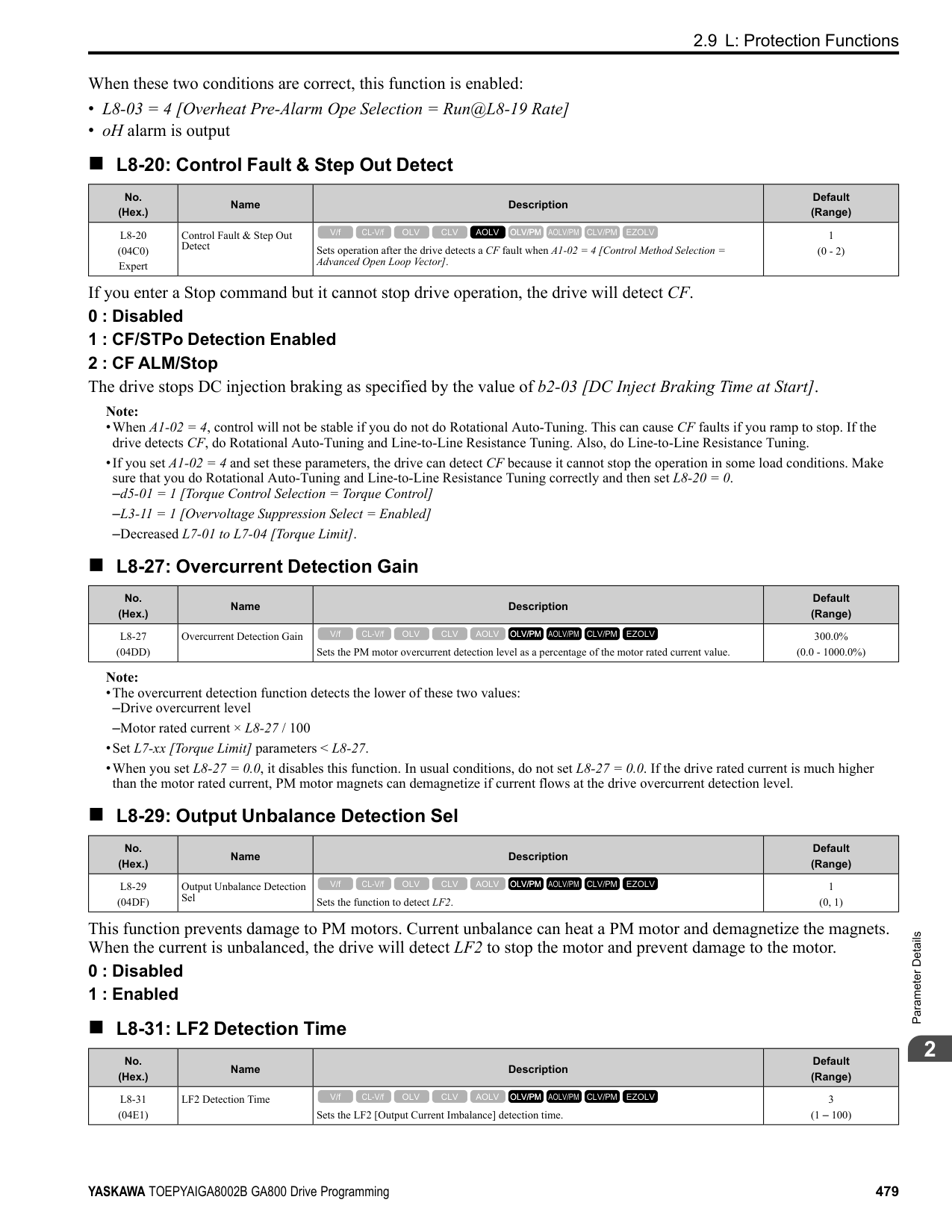
If the motor oscillates at the time of the polar attraction, increase the value in 0.5 s increments. If you set the value too high, the drive will detect oL2 [Drive Overloaded].
######## ■ n8-11: Observer Calculation Gain 2
|No. (Hex.)|Name|Description|Default (Range)| |---|---|---|---| |n8-11 (054A)|Observer Calculation Gain 2|Sets the gain for speed estimation. Usually it is not necessary to change this setting.
V/f CL-V/f OLV CLV AOLV OLV/PM AOLV/PM CLV/PM EZOLV
|Determined by n8-72 (0.0 - 1000.0)|
Note: When n8-72 = 0 [Speed Estimation Method Select = Method 1], the default value is 50.0. When n8-72 = 1 [Method 2], the default value is 150.0.
######## ■ n8-14: Polarity Compensation Gain 3
|No. (Hex.)|Name|Description|Default (Range)| |---|---|---|---| |n8-14 (054D) Expert|Polarity Compensation Gain 3|Sets the gain for speed estimation. Usually it is not necessary to change this setting.
V/f CL-V/f OLV CLV AOLV OLV/PM AOLV/PM CLV/PM EZOLV
|1.000 (0.000 - 10.000)|
|No. (Hex.)|Name|Description|Default (Range)| |---|---|---|---| |n8-15 (054E) Expert|Polarity Compensation Gain 4|Sets the gain for speed estimation. Usually it is not necessary to change this setting.
V/f CL-V/f OLV CLV AOLV OLV/PM AOLV/PM CLV/PM EZOLV
|0.500 (0.000 - 10.000)|
|No. (Hex.)|Name|Description|Default (Range)| |---|---|---|---| |n8-21 (0554) Expert|Motor Back-EMF (Ke) Gain|Sets the gain for speed estimation. Usually it is not necessary to change this setting.
V/f CL-V/f OLV CLV AOLV OLV/PM AOLV/PM CLV/PM EZOLV
|0.90 (0.80 - 1.00)|
|No. (Hex.)|Name|Description|Default (Range)| |---|---|---|---| |n8-23 (0556) Expert|ACR q Gain @PoleEst|Sets the proportional gain for current regulator q-axis control when the drive estimates the initial pole. Usually it is not necessary to change this setting.
V/f CL-V/f OLV CLV AOLV OLV/PM AOLV/PM CLV/PM EZOLV
|0 (0 - 2000)|
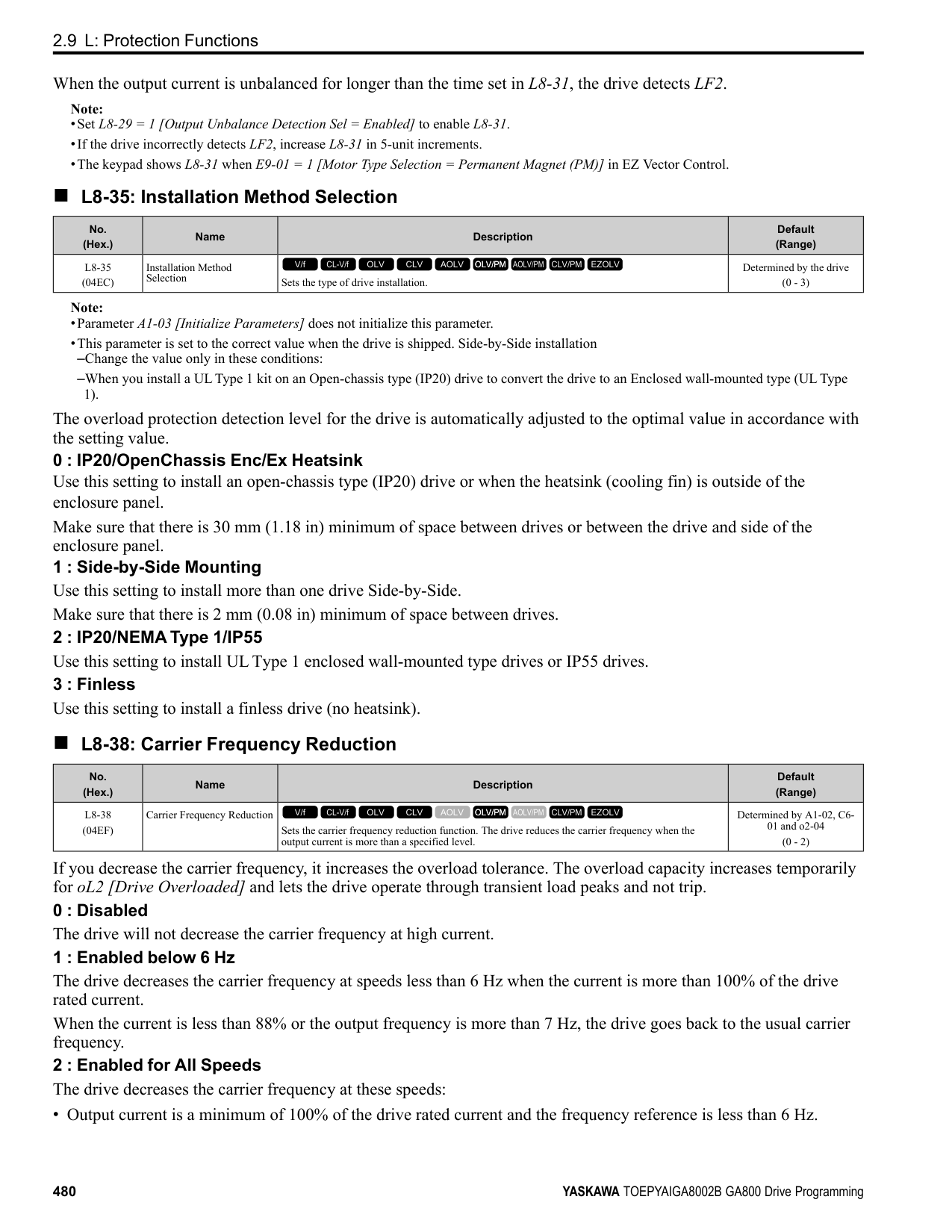
|No. (Hex.)|Name|Description|Default (Range)| |---|---|---|---| |n8-24 (0557) Expert|ACR q Integral Time @PoleEst|Sets the integral time for current regulator q-axis control when the drive estimates the initial pole. Usually it is not necessary to change this setting.
V/f CL-V/f OLV CLV AOLV OLV/PM AOLV/PM CLV/PM EZOLV
|0.0 ms (0.0 - 100.0 ms)|
|No. (Hex.)|Name|Description|Default (Range)| |---|---|---|---| |n8-25 (0558) Expert|ACR q Limit @PoleEst|Sets the q-axis limit of the current regulator when the drive estimates the initial pole. Usually it is not necessary to change this setting.
V/f CL-V/f OLV CLV AOLV OLV/PM AOLV/PM CLV/PM EZOLV
|0% (0 - 150%)|
|No. (Hex.)|Name|Description|Default (Range)| |---|---|---|---| |n8-26 (0559) Expert|ACR d Gain @PoleEst|Sets the proportional gain for current regulator d-axis control when the drive estimates the initial pole. Usually it is not necessary to change this setting.
V/f CL-V/f OLV CLV AOLV OLV/PM AOLV/PM CLV/PM EZOLV
|500 (0 - 2000)|
|No. (Hex.)|Name|Description|Default (Range)| |---|---|---|---| |n8-27 (055A) Expert|ACR d Integral Time @PoleEst|Sets the integral time for current regulator d-axis control when the drive estimates the initial pole. Usually it is not necessary to change this setting.
V/f CL-V/f OLV CLV AOLV OLV/PM AOLV/PM CLV/PM EZOLV
|0.0 ms (0.0 - 100.0 ms)|
ParameterDetails
|No. (Hex.)|Name|Description|Default (Range)| |---|---|---|---| |n8-28 (055B) Expert|ACR d Lim @PoleEst|Sets the d-axis limit of the current regulator when the drive estimates the initial pole. Usually it is not necessary to change this setting.
V/f CL-V/f OLV CLV AOLV OLV/PM AOLV/PM CLV/PM EZOLV
|100% (0 - 150%)|
|No. (Hex.)|Name|Description|Default (Range)| |---|---|---|---| |n8-35 (0562)|Initial Pole Detection Method|Sets how the drive detects the position of the rotor at start.
V/f CL-V/f OLV CLV AOLV OLV/PM AOLV/PM CLV/PM EZOLV
|Determined by A1-02 (0 - 2)|
Note:
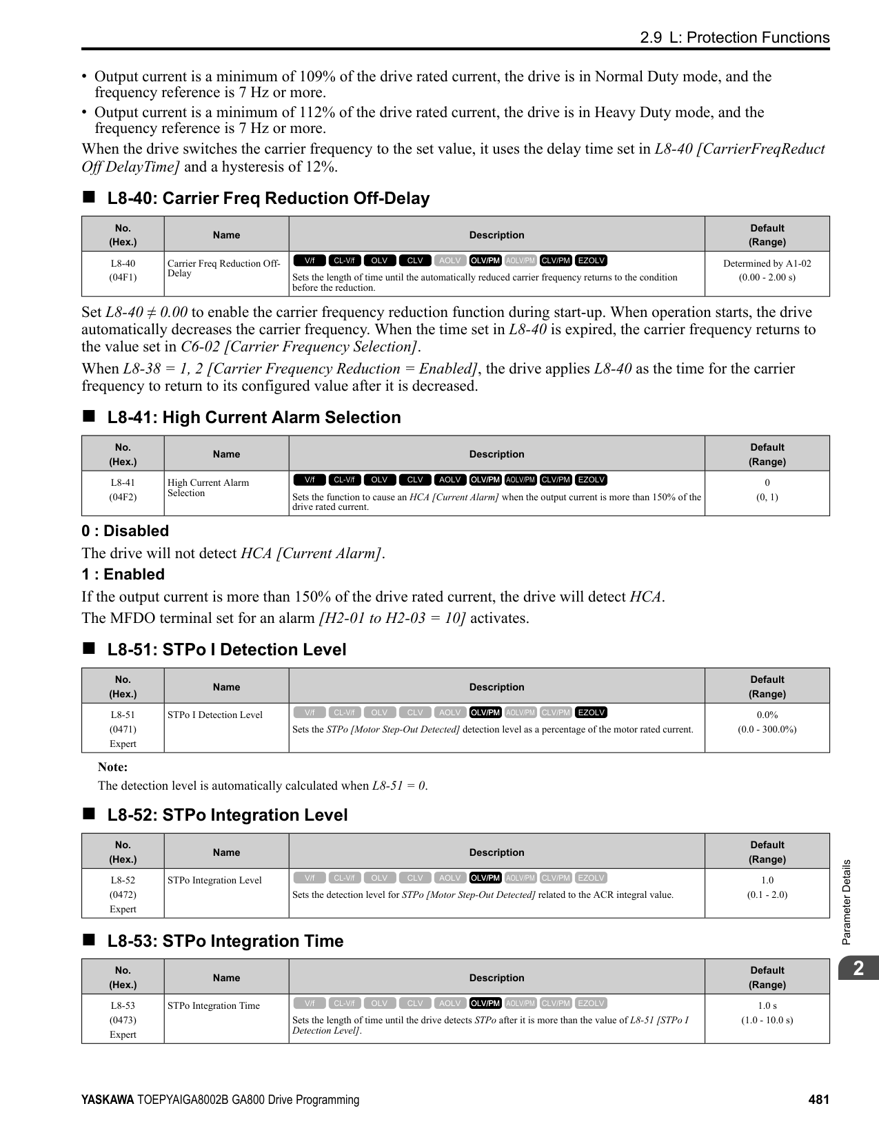
Injects high frequency to detect the rotor position. This setting can cause a loud excitation sound when the motor starts.
Note: When you set this to 1, do High Frequency Injection Auto-Tuning.
######## ■ n8-36: HFI Frequency Level for LTuning
|No. (Hex.)|Name|Description|Default (Range)| |---|---|---|---| |n8-36 (0563)|HFI Frequency Level for L Tuning|Sets the injection frequency for high frequency injection.
V/f CL-V/f OLV CLV AOLV OLV/PM AOLV/PM CLV/PM EZOLV
|500 Hz (200 - 1000 Hz)|
Note:
######## ■ n8-37: HFI Voltage Amplitude Level
|No. (Hex.)|Name|Description|Default (Range)| |---|---|---|---| |n8-37 (0564) Expert|HFI Voltage Amplitude Level|Sets the high frequency injection amplitude as a percentage where 200 V = 100% for 200 V class drives and 400 V 100% for a 400 V class drives. Usually it is not necessary to change this setting.
V/f CL-V/f OLV CLV AOLV OLV/PM AOLV/PM CLV/PM EZOLV
|20.0% (0.0 - 50.0%)|
Note: Set n8-35 = 1 [Initial Pole Detection Method = High Frequency Injection] or n8-57 = 1 [HFI Overlap Selection = Enabled] to enable this parameter.
The drive automatically calculates this value when High Frequency Injection Auto-Tuning completes successfully.
######## ■ n8-39: HFI LPF Cutoff Freq
|No. (Hex.)|Name|Description|Default (Range)| |---|---|---|---|
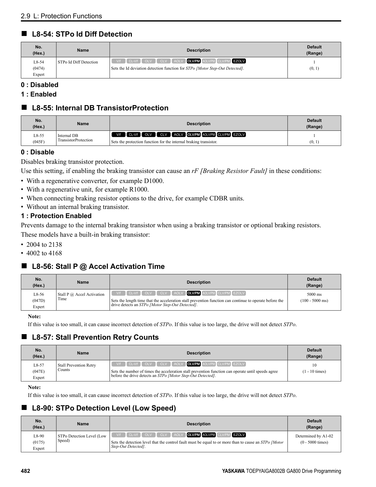
|n8-39 (0566)|PM Phase Compensation Gain|Sets the low-pass filter shut-off frequency for high frequency injection.
V/f CL-V/f OLV CLV AOLV OLV/PM AOLV/PM CLV/PM EZOLV
|250 Hz (0 - 1000 Hz)|
################# Note:
######## ■ n8-41: HFI P Gain
|No. (Hex.)|Name|Description|Default (Range)| |---|---|---|---| |n8-41 (0568) Expert|HFI P Gain|Sets the response gain for the high frequency injection speed estimation.
V/f CL-V/f OLV CLV AOLV OLV/PM AOLV/PM CLV/PM EZOLV
|2.5 (-10.0 - +10.0)|
################# Note:
Configure the setting as follows.
######## ■ n8-42: HFI I Time
|No. (Hex.)|Name|Description|Default (Range)| |---|---|---|---| |n8-42 (0569) Expert|HFI I Time|Sets the integral time constant for the high frequency injection speed estimation. Usually it is not necessary to change this setting.
V/f CL-V/f OLV CLV AOLV OLV/PM AOLV/PM CLV/PM EZOLV
|0.10 s (0.00 - 9.99 s)|
Note: Set n8-35 = 1 [Initial Pole Detection Method = High Frequency Injection] or n8-57 = 1 [HFI Overlap Selection = Enabled] to enable this parameter.
######## ■ n8-45: Speed Feedback Detection Gain
|No. (Hex.)|Name|Description|Default (Range)| |---|---|---|---| |n8-45 (0538)|Speed Feedback Detection Gain|Sets the internal speed feedback detection reduction unit gain as a magnification value. Usually it is not necessary to change this setting.
V/f CL-V/f OLV CLV AOLV OLV/PM AOLV/PM CLV/PM EZOLV
|0.80 (0.00 - 10.00)|
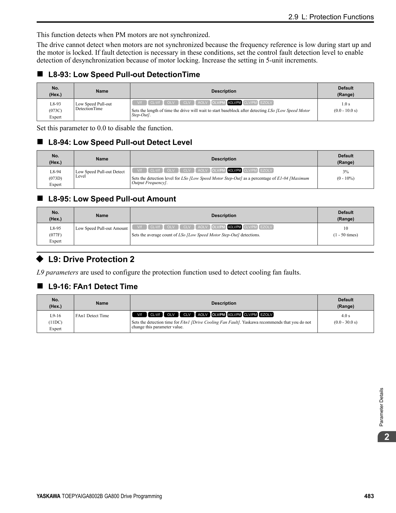
Adjust this parameter in these conditions:
######## ■ n8-46: PM Phase Compensation Gain
|No. (Hex.)|Name|Description|Default (Range)| |---|---|---|---| |n8-46 (0539) Expert|PM Phase Compensation Gain|Sets the gain to compensate for phase differences. Usually it is not necessary to change this setting.
V/f CL-V/f OLV CLV AOLV OLV/PM AOLV/PM CLV/PM EZOLV
|0.3 (0.0 - 10.0)|
If there is vibration in the motor, increase the value. When you must detect oC [Overcurrent] or ov [DC Bus Overvoltage], set this parameter to a low value.
ParameterDetails
######## 2
Adjust this parameter in these conditions:
Adjust in the following situations.
When you use an IPM motor, you can use the reluctance torque of the motor to make the motor more efficient and help conserve energy. When you operate an SPN motor, set this parameter to 0. Adjust this parameter in these conditions:
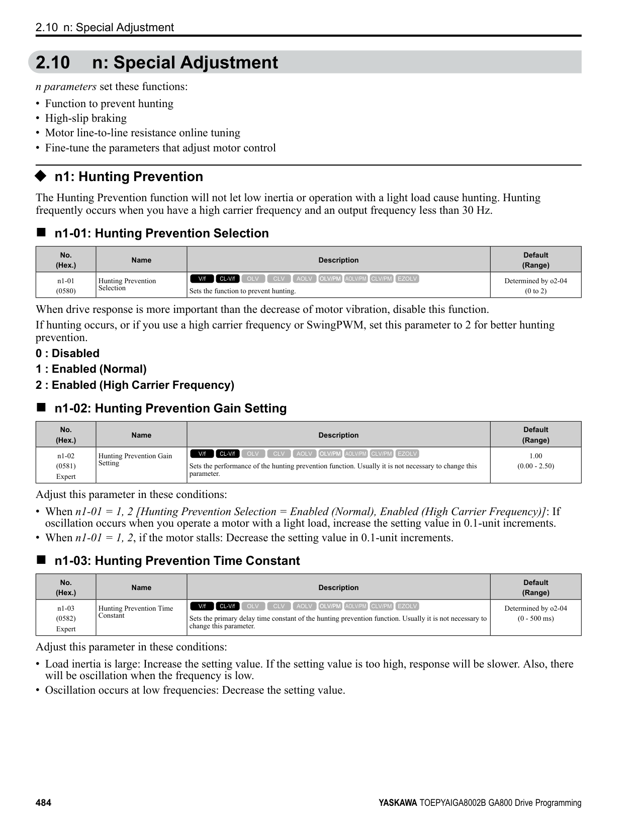
|No. (Hex.)|Name|Description|Default (Range)| |---|---|---|---| |n8-47 (053A)|Pull-in Current Comp Filter Time|Sets the time constant the drive uses to align the pull-in current reference value with the actual current value. Usually it is not necessary to change this setting.
V/f CL-V/f OLV CLV AOLV OLV/PM AOLV/PM CLV/PM EZOLV
|5.0 s (0.0 - 100.0 s)|
|No. (Hex.)|Name|Description|Default (Range)| |---|---|---|---| |n8-48 (053B)|Pull-in/Light Load Id Current|On the basis that parameter E5-03 [Motor Rated Current (FLA)] is the 100% value, this parameter sets the d-axis current that flows to the motor during run at constant speed as a percentage.
V/f CL-V/f OLV CLV AOLV OLV/PM AOLV/PM CLV/PM EZOLV
|30% (0 - 200%)|
|No. (Hex.)|Name|Description|Default (Range)| |---|---|---|---| |n8-49 (053C)|Heavy Load Id Current|Sets the d-axis current to that the drive will supply to the motor to run it at a constant speed with a heavy load. Considers E5-03 [PM Motor Rated Current (FLA)] to be 100%. Usually it is not necessary to change this setting.
V/f CL-V/f OLV CLV AOLV OLV/PM AOLV/PM CLV/PM EZOLV
|Determined by E5-01 (-200.0 - +200.0%)|
|No. (Hex.)|Name|Description|Default (Range)| |---|---|---|---| |n8-50 (053D)|Medium Load Iq Level (High)|Sets the load current level to start high efficiency control as a percentage of E5-03 [PM Motor Rated Current (FLA)]. Usually it is not necessary to change this setting.
V/f CL-V/f OLV CLV AOLV OLV/PM AOLV/PM CLV/PM EZOLV
|80% (50 - 255%)|
|No. (Hex.)|Name|Description|Default (Range)| |---|---|---|---| |n8-51 (053E)|Pull-in Current @ Acceleration|Sets the pull-in current allowed to flow during acceleration/deceleration as a percentage of the motor rated current.
V/f CL-V/f OLV CLV AOLV OLV/PM AOLV/PM CLV/PM EZOLV
|Determined by A1-02 (0 - 200%)|
Adjust in the following situations.
• When the motor does not smoothly because of large loads, increase the setting value in 5% increments.
• If too much current flows during acceleration, decrease the setting value. Note: When A1-02 = 8 [Control Method Selection = EZOLV], this parameter will always be in effect for speed ranges less than n7-10 [Pull-in Current Switching Speed].
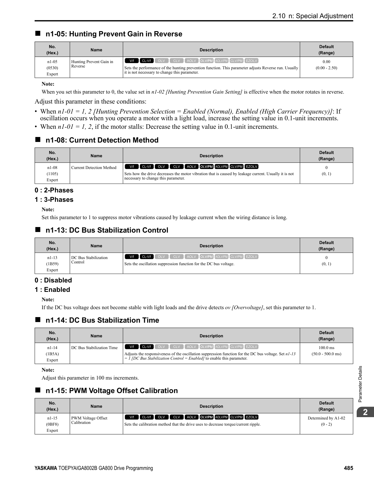
Adjust this parameter in these conditions:
|No. (Hex.)|Name|Description|Default (Range)| |---|---|---|---| |n8-52 (053F) Expert|ACR P Gain|Sets the proportional gain of the current regulator. Usually it is not necessary to change this setting.
V/f CL-V/f OLV CLV AOLV OLV/PM AOLV/PM CLV/PM EZOLV
|10.0 (-100.0 - 100.0)|
|No. (Hex.)|Name|Description|Default (Range)| |---|---|---|---| |n8-54 (056D) Expert|Voltage Error Compensation Time|Sets the time constant that the drive uses when adjusting for voltage errors.
V/f CL-V/f OLV CLV AOLV OLV/PM AOLV/PM CLV/PM EZOLV
|1.00 s (0.00 - 10.00 s)|
|No. (Hex.)|Name|Description|Default (Range)| |---|---|---|---| |n8-55 (056E)|Motor to Load Inertia Ratio|Sets the ratio between motor inertia and machine inertia.
V/f CL-V/f OLV CLV AOLV OLV/PM AOLV/PM CLV/PM EZOLV
|0 (0 - 3)|
Adjust in the following situations.
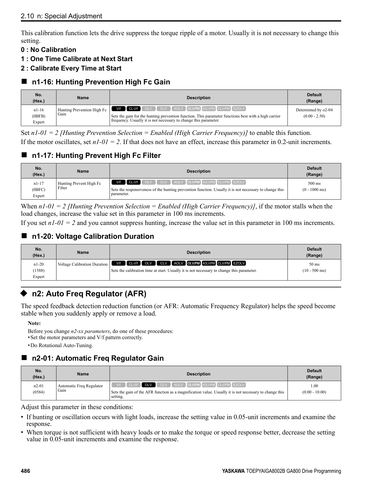
ParameterDetails
######## 2
######## ■ n8-56: PM High Performance Selection
|No. (Hex.)|Name|Description|Default (Range)| |---|---|---|---| |n8-56 (056F) Expert|PM High Performance Selection|Sets the high efficiency control method for IPM motor. Usually it is not necessary to change this setting.
V/f CL-V/f OLV CLV AOLV OLV/PM AOLV/PM CLV/PM EZOLV
|1 (0 - 2)|
######## ■ n8-57: HFI Overlap Selection
|No. (Hex.)|Name|Description|Default (Range)| |---|---|---|---| |n8-57 (0574)|HFI Overlap Selection|Sets the function that detects motor speed with high frequency injection.
V/f CL-V/f OLV CLV AOLV OLV/PM AOLV/PM CLV/PM EZOLV
|0 (0, 1)|
################# Note:
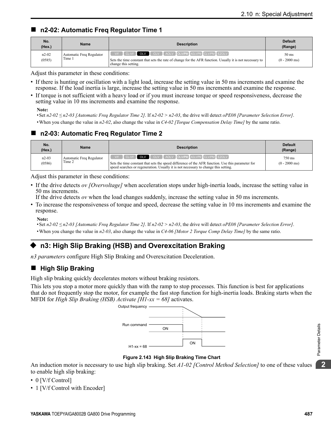
Note: It is not available with an SPM motor.
######## ■ n8-62: Output Voltage Limit Level
|No. (Hex.)|Name|Description|Default (Range)| |---|---|---|---| |n8-62 (057D) Expert|Output Voltage Limit Level|Sets the output voltage limit to prevent saturation of the output voltage. Usually it is not necessary to change this parameter.
V/f CL-V/f OLV CLV AOLV OLV/PM AOLV/PM CLV/PM EZOLV
|200 V Class: 200.0 V, 400 V Class: 400.0 V
(200 V Class: 0.0 to 240.0 V, 400 V Class: 0.0 to 480.0 V)|
Set this parameter lower than the input power supply voltage.
Note:
–200 V Class: 230.0 V –400 V Class: 460.0 V
######## ■ n8-63: Output Voltage Limit P Gain
|No. (Hex.)|Name|Description|Default (Range)| |---|---|---|---| |n8-63 (057E) Expert|Output Voltage Limit P Gain|Sets the proportional gain for output voltage control. Usually it is not necessary to change this setting.
V/f CL-V/f OLV CLV AOLV OLV/PM AOLV/PM CLV/PM EZOLV
|1.00 (0.00 - 100.00)|
Adjust this parameter in these conditions:
|No. (Hex.)|Name|Description|Default (Range)| |---|---|---|---| |n8-64 (057F) Expert|Output Voltage Limit I Time|Sets the integral time for output voltage control. Usually it is not necessary to change this setting.
V/f CL-V/f OLV CLV AOLV OLV/PM AOLV/PM CLV/PM EZOLV
|0.040 s (0.000 - 5.000 s)|
|No. (Hex.)|Name|Description|Default (Range)| |---|---|---|---| |n8-65 (065C) Expert|Speed Fdbk Gain @ oV Suppression|Sets the gain of internal speed feedback detection suppression while the overvoltage suppression function is operating as a magnification value. Usually it is not necessary to change this parameter.
V/f CL-V/f OLV CLV AOLV OLV/PM AOLV/PM CLV/PM EZOLV
|1.50 (0.00 - 10.00)|
|No. (Hex.)|Name|Description|Default (Range)| |---|---|---|---| |n8-66 (0235) Expert|Output Voltage Limit Filter Time|Sets the filter time constant for output voltage control. Usually it is not necessary to change this setting.
V/f CL-V/f OLV CLV AOLV OLV/PM AOLV/PM CLV/PM EZOLV
|0.020 s (0.000 - 5.000 s)|
|No. (Hex.)|Name|Description|Default (Range)| |---|---|---|---| |n8-69 (065D) Expert|Speed Observer Control P Gain|Sets the gain that the drive uses for speed estimation. Usually it is not necessary to change this setting.
V/f CL-V/f OLV CLV AOLV OLV/PM AOLV/PM CLV/PM EZOLV
|1.00 (0.00 - 20.00)|
|No. (Hex.)|Name|Description|Default (Range)| |---|---|---|---| |n8-70 (065E) Expert|Speed Observer Control I Time|Sets the speed estimator integral time constant. It is available when n8-72 = 1 [Speed Estimation Method Select Method 2]. Usually it is not necessary to change this setting.
V/f CL-V/f OLV CLV AOLV OLV/PM AOLV/PM CLV/PM EZOLV
|0.0 s (0.0 - 100.0 s)|
|No. (Hex.)|Name|Description|Default (Range)| |---|---|---|---| |n8-71 (065F) Expert|Speed Observer Control D Gain|Set the speed estimator differential gain. It is available when n8-72 = 1 [Speed Estimation Method Select Method 2]. Usually it is not necessary to change this setting.
V/f CL-V/f OLV CLV AOLV OLV/PM AOLV/PM CLV/PM EZOLV
|5.00 (0.00 - 50.00)|
|No. (Hex.)|Name|Description|Default (Range)| |---|---|---|---| |n8-72 (0655) Expert|Speed Estimation Method Select|Selects the speed estimation method. Usually it is not necessary to change this setting.
V/f CL-V/f OLV CLV AOLV OLV/PM AOLV/PM CLV/PM EZOLV
|1 (0, 1)|
0 : Method 1
ParameterDetails
######## 2
1 : Method 2
Note:
Note:
Note: The change is linear between n8-75 [Medium Load Iq Level (low)] and n8-77 and the level of the pull-in current from n8-78 [Medium Load Id Current] to n8-49 [Heavy Load Id Current].
|No. (Hex.)|Name|Description|Default (Range)| |---|---|---|---| |n8-73 (0656) Expert|Observer Mode Switch-Over Speed|Sets the speed level for pull-in current control at motor start as a percentage of E1-06 [Base Frequency]. Usually it is not necessary to change this setting.
V/f CL-V/f OLV CLV AOLV OLV/PM AOLV/PM CLV/PM EZOLV
|10% (0 - 100%)|
|No. (Hex.)|Name|Description|Default (Range)| |---|---|---|---| |n8-74 (05C3)|Light Load Iq Level|Set n8-48 [Pull-in/Light Load Id Current] to the percentage of load current (q-axis current) that you will apply, where E5-03 [Motor Rated Current (FLA)] = a setting value of 100%.
V/f CL-V/f OLV CLV AOLV OLV/PM AOLV/PM CLV/PM EZOLV
|30% (0 - 255%)|
|No. (Hex.)|Name|Description|Default (Range)| |---|---|---|---| |n8-75 (05C4)|Medium Load Iq Level (low)|Set n8-78 [Medium Load Id Current] to the percentage of load current (q-axis current) that you will apply, where E5-03 [Motor Rated Current (FLA)] = a setting value of 100%.
V/f CL-V/f OLV CLV AOLV OLV/PM AOLV/PM CLV/PM EZOLV
|50% (0 - 255%)|
|No. (Hex.)|Name|Description|Default (Range)| |---|---|---|---| |n8-76 (05CD) Expert|Id Switching Filter Time|Sets the filter time constant for d-axis current reference. Usually it is not necessary to change this setting.
V/f CL-V/f OLV CLV AOLV OLV/PM AOLV/PM CLV/PM EZOLV
|200 ms (0 - 5000 ms)|
|No. (Hex.)|Name|Description|Default (Range)| |---|---|---|---| |n8-77 (05CE)|Heavy Load Iq Level|Set n8-49 [Heavy Load Id Current] to the percentage of load current (q-axis current) that you will apply, where E5-03 [Motor Rated Current (FLA)] = a setting value of 100%.
V/f CL-V/f OLV CLV AOLV OLV/PM AOLV/PM CLV/PM EZOLV
|90% (0 - 255%)|
|No. (Hex.)|Name|Description|Default (Range)| |---|---|---|---| |n8-78 (05F4)|Medium Load Id Current|Sets the level of the pull-in current for mid-range loads.
V/f CL-V/f OLV CLV AOLV OLV/PM AOLV/PM CLV/PM EZOLV
|0% (-200 - +200%)|
######## ■ n8-79: Pull-in Current @ Deceleration
|No. (Hex.)|Name|Description|Default (Range)| |---|---|---|---| |n8-79 (05FE)|Pull-in Current @ Deceleration|Sets the pull-in current that can flow during deceleration as a percentage of the E5-03 [PM Motor Rated Current (FLA)].
V/f CL-V/f OLV CLV AOLV OLV/PM AOLV/PM CLV/PM EZOLV
|50% (0 - 200%)|
If overcurrent occurs during deceleration, slowly decrease the setting in 5% increments. Note: When n8-79 = 0, the drive will use the value set in n8-51 [Pull-in Current @ Acceleration].
######## ■ n8-84: Polarity Detection Current
|No. (Hex.)|Name|Description|Default (Range)| |---|---|---|---| |n8-84 (02D3) Expert|Polarity Detection Current|Sets the current for processing an estimation of the initial motor magnetic pole as a percentage, where E5-03 [PM Motor Rated Current] is the 100% value.
V/f CL-V/f OLV CLV AOLV OLV/PM AOLV/PM CLV/PM EZOLV
|100% (0 - 150%)|
WARNING! Sudden Movement Hazard. Make sure that the polarity is correct before you send a Run command. If the drive incorrectly detects the polarity, the drive can rotate in the direction opposite of the Run command and cause serious injury or death.
If you use a Yaskawa motor and the motor nameplate has an “Si” item, set this parameter to a value equal to or more than "Si x 2". Consult the motor manufacturer to determine the maximum setting values. Find the Polarity of Magnetic Poles At start, the drive estimates the magnetic poles and finds the polarity of the magnetic poles. When A1-02 = 7 [Control Method Selection = CLV/PM], the drive finds the polarity of the magnetic poles only at the first startup. Check monitor U6-57 [PolePolarityDeterVal] to make sure that the drive correctly estimated the polarity of the magnetic poles. The drive automatically calculates n8-84 when High Frequency Injection Auto-Tuning completes successfully.
######## ■ n8-94: Flux Position Estimation Method
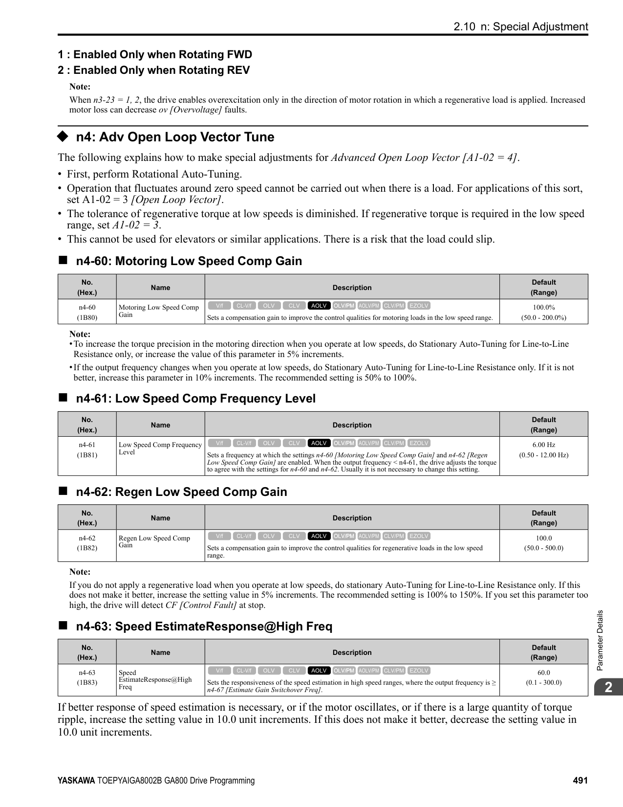
|No. (Hex.)|Name|Description|Default (Range)| |---|---|---|---| |n8-94 (012D) Expert|Flux Position Estimation Method|Sets the criteria that the drive uses to find changes in speed or load. Usually it is not necessary to change this setting.
V/f CL-V/f OLV CLV AOLV OLV/PM AOLV/PM CLV/PM EZOLV
|Determined by d5-01 (0, 1)|
0 : Softstarter 1 : Speed Feedback
Set n8-57 = 1 [HFI Overlap Selection = Enabled] to enable this parameter. Increases the stability when the speed or load suddenly change, for example with rapid acceleration/deceleration or impact loads.
######## ■ n8-95: Flux Position Est Filter Time
|No. (Hex.)|Name|Description|Default (Range)| |---|---|---|---| |n8-95 (012E) Expert|Flux Position Est Filter Time|Sets the time constant of the filter used for the recognition criteria value for speed and load changes. Usually it is not necessary to change this setting.
V/f CL-V/f OLV CLV AOLV OLV/PM AOLV/PM CLV/PM EZOLV
|30 ms (0 - 100 ms)|
Note: Enabled when n8-94 = 1 [Flux Position Estimation Method = Speed Feedback].
ParameterDetails
####### 2.11 o: Keypad-Related Settings
o parameters set keypad functions. Note: You cannot set these parameters with the optional LED keypad.
Table 2.72 Parameters You Cannot Set with the LED Keypad
|No.|Name| |---|---| |o1-05|LCD Contrast Adjustment| |o1-24 to o1-35:|Custom Monitor 1 to 12| |o1-36|LCD Backlight Brightness| |o1-37|LCD Backlight ON/OFF Selection| |o1-38|LCD Backlight Off-Delay| |o1-39|Show Initial Setup Screen| |o1-40|Home Screen Display Selection| |o1-41 to o1-46:|1st to 3rd Monitor Area Selections/Settings| |o1-47 to o1-51:|Trend Plot 1 or 2 Scale Settings| |o1-55 to o1-56:|Analog Gauge Area Selection/Setting| |o2-27|bCE Detection Selection|
|No.|Name|
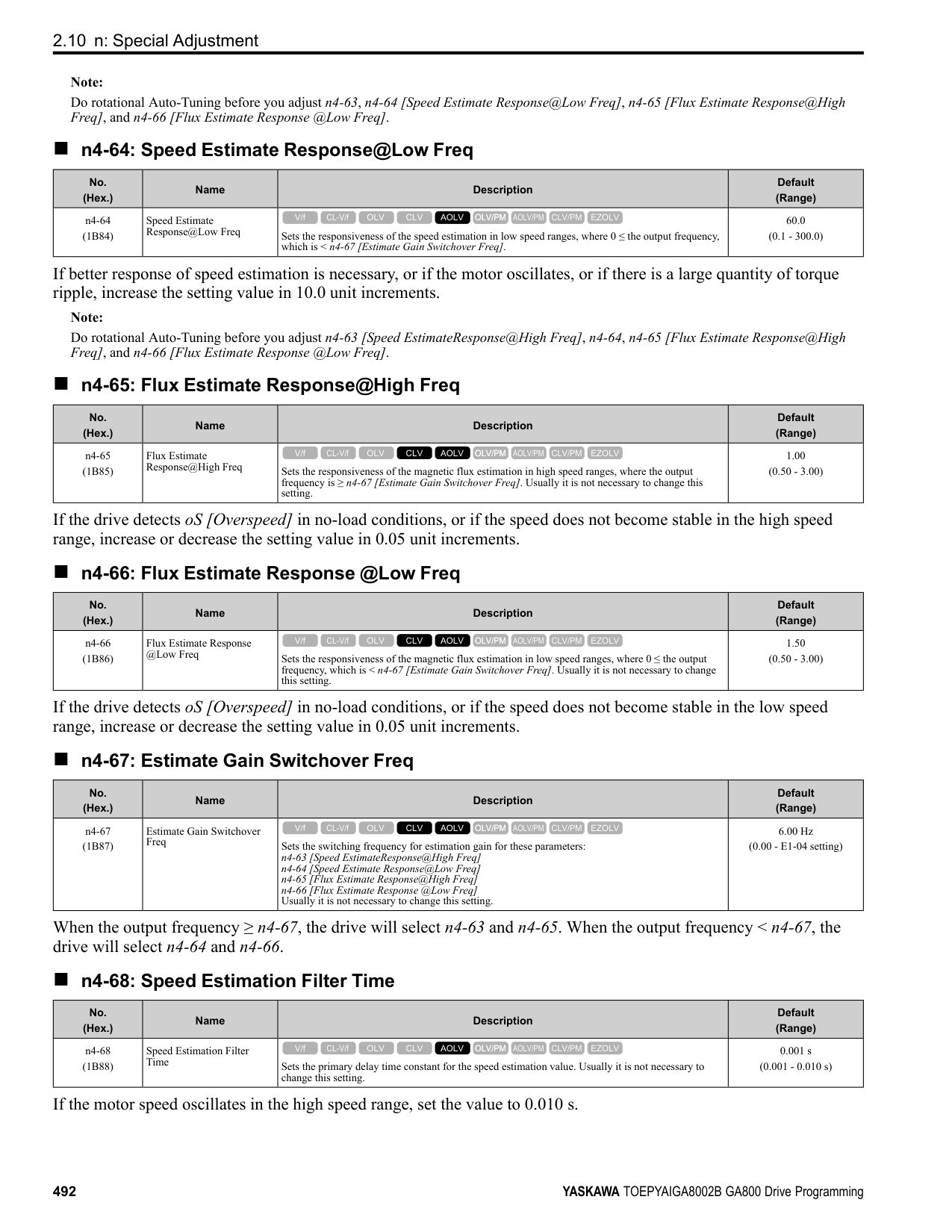
|---|---| |o3-04|Select Backup/Restore Location| |o3-05|Select Items to Backup/Restore| |o3-06|Auto Parameter Backup Selection| |o3-07|Auto Parameter Backup Interval| |o4-22|Time Format| |o4-23|Date Format| |o4-24|bAT Detection Selection| |o5-01|Log Start/Stop Selection| |o5-02|Log Sampling Interval| |o5-03 to o5-12:|Log Monitor Data 1 to 10|
######## ◆ o1: Keypad Display Selection
■ Home Screen Display Format o1-40 [Home Screen Display Selection] changes the display of the monitor shown on the Home screen. You can show numerical values or one of these three displays on the Home screen monitor: Bar Graph Display
C - Select display ranges with o1-42, o1-44, and o1-46.
################ Analog Gauge Display
A - Select Ux-xx [Monitors] with o1-24. B - Configure display regions with o1-
C - Select display ranges with o1-55.
G
F
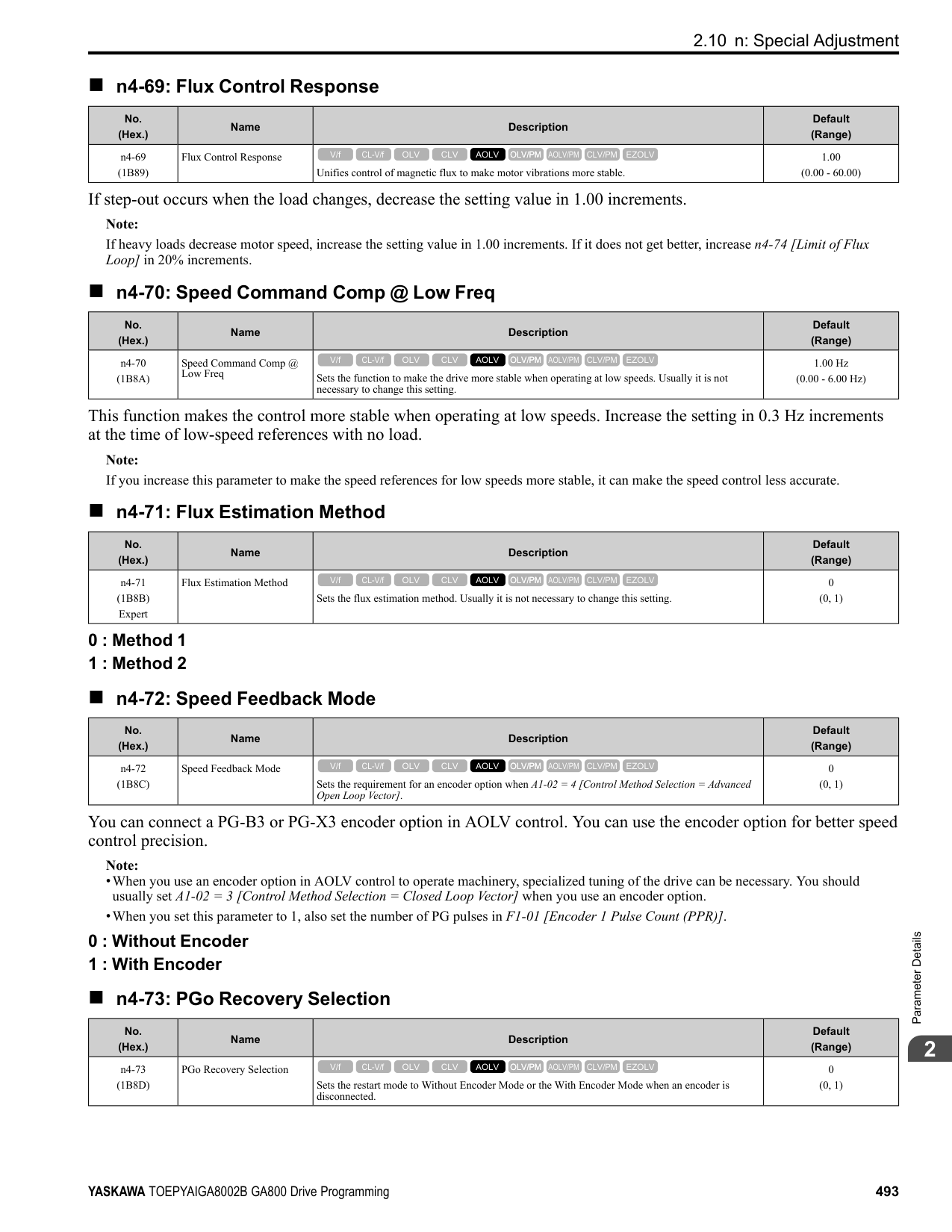
######## ■ o1-01: User Monitor Selection
|No. (Hex.)|Name|Description|Default (Range)| |---|---|---|---| |o1-01 (0500) RUN|User Monitor Selection|Sets the U monitor for the Drive Mode. This parameter is only available when you use an LED keypad.
V/f CL-V/f OLV CLV AOLV OLV/PM AOLV/PM CLV/PM EZOLV
|106 (104 - 855)|
When the drive is in Drive Mode, push on the keypad to cycle through this data: frequency reference → rotational direction → output frequency → output current → o1-01 selection. Set the x-xx part of Ux-xx that is shown in the fifth position in Drive Mode. For example, to show U1-05 [Motor Speed], set o1-01 = 105.
Note: The monitors that you can select are different for different control methods.
######## ■ o1-02: Monitor Selection at Power-up
|No. (Hex.)|Name|Description|Default (Range)| |---|---|---|---| |o1-02 (0501) RUN|Monitor Selection at Powerup|Sets the monitor item that the keypad screen shows after energizing the drive. Refer to “U: Monitors” for information about the monitor items that the keypad screen can show. This parameter is only available when you use an LED keypad.
V/f CL-V/f OLV CLV AOLV OLV/PM AOLV/PM CLV/PM EZOLV
|1 (1 - 5)|
1 : Frequency Reference (U1-01) 2 : Direction 3 : Output Frequency (U1-02) 4 : Output Current (U1-03) 5 : User Monitor (o1-01) Shows the monitor item selected in o1-01 [User Monitor Selection].
ParameterDetails
■ o1-03: Frequency Display Unit Selection
|No. (Hex.)|Name|Description|Default (Range)| |---|---|---|---| |o1-03 (0502)|Frequency Display Unit Selection|Sets the display units for the frequency reference and output frequency.
V/f CL-V/f OLV CLV AOLV OLV/PM AOLV/PM CLV/PM EZOLV
|Determined by A1-02 (0 - 3)|
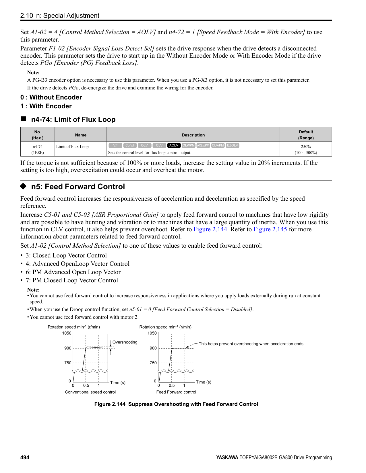
Note:
Note:
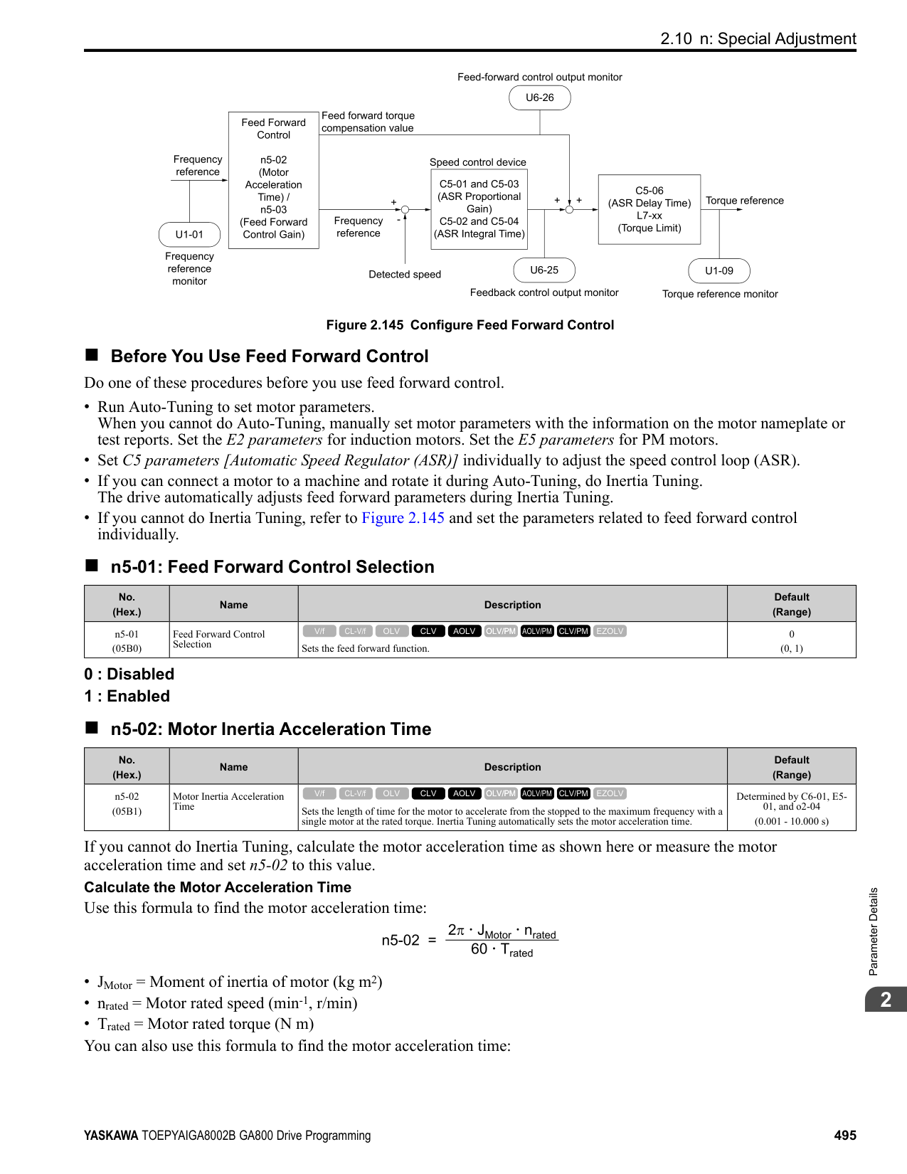
|No. (Hex.)|Name|Description|Default (Range)| |---|---|---|---| |o1-04 (0503)|V/f Pattern Display Unit|Sets the setting unit for parameters that set the V/f pattern frequency.
V/f CL-V/f OLV CLV AOLV OLV/PM AOLV/PM CLV/PM EZOLV
|Determined by A1-02 (0, 1)|
######## ■ o1-05: LCD Contrast Adjustment
|No. (Hex.)|Name|Description|Default (Range)| |---|---|---|---| |o1-05 (0504) RUN|LCD Contrast Adjustment|Sets the contrast of the LCD display on the keypad.
V/f CL-V/f OLV CLV AOLV OLV/PM AOLV/PM CLV/PM EZOLV
|5 (0 - 10)|
When you decrease the setting value, the contrast of the LCD display decreases. When you increase the setting value, the contrast increases.
######## ■ o1-10: User Units Maximum Value
|No. (Hex.)|Name|Description|Default (Range)| |---|---|---|---| |o1-10 (0520)|User Units Maximum Value|Sets the value that the drive shows as the maximum output frequency.
V/f CL-V/f OLV CLV AOLV OLV/PM AOLV/PM CLV/PM EZOLV
|Determined by o1-03 (1 - 60000)|
To display a maximum output frequency of 100.00, set parameters to these values:
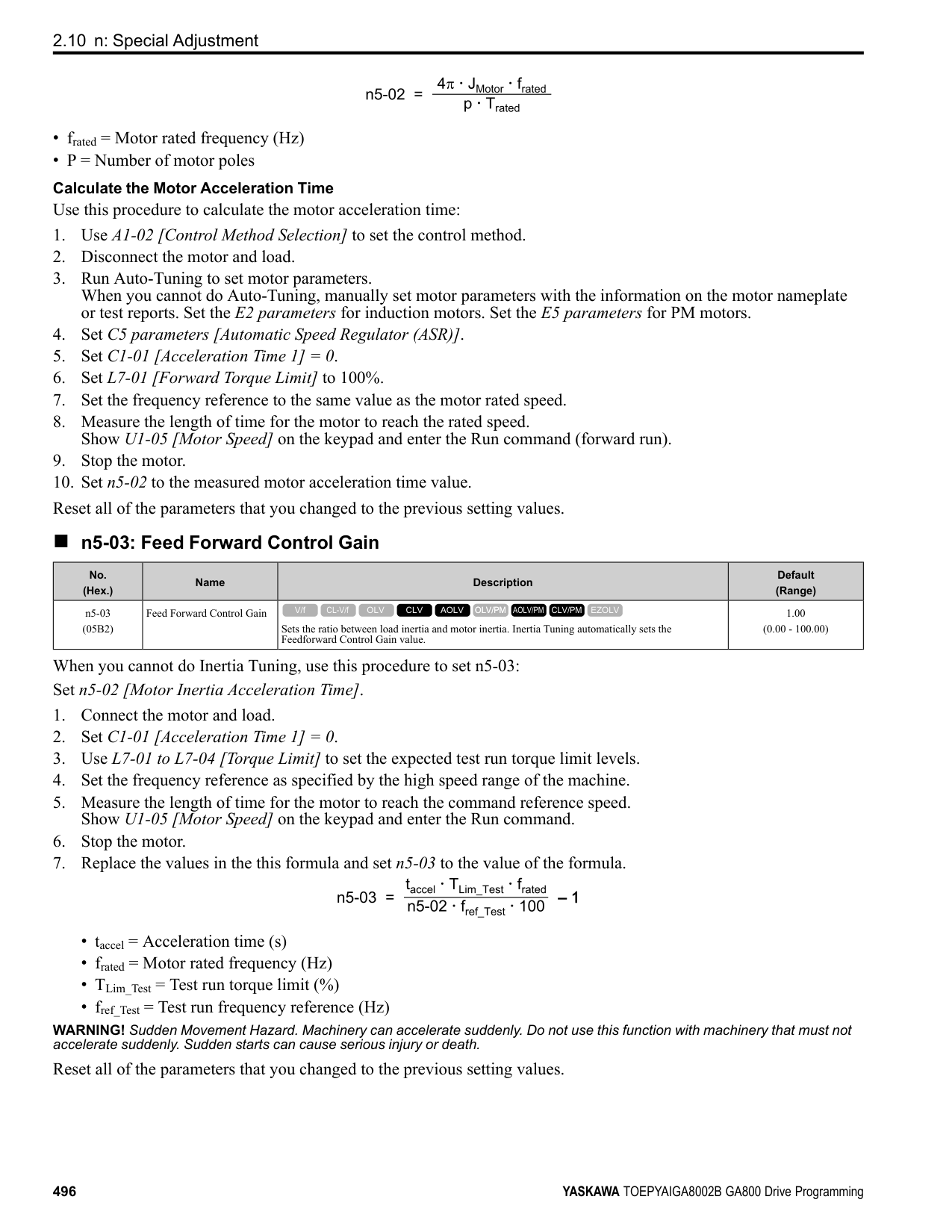
######## ■ o1-11: User Units Decimal Position
|No. (Hex.)|Name|Description|Default (Range)| |---|---|---|---| |o1-11 (0521)|User Units Decimal Position|Sets the number of decimal places for frequency reference and monitor values.
V/f CL-V/f OLV CLV AOLV OLV/PM AOLV/PM CLV/PM EZOLV
|Determined by o1-03 (0 - 3)|
############## 0 : No Decimal Places (XXXXX) 1 : One Decimal Places (XXXX.X) 2 : Two Decimal Places (XXX.XX) 3 : Three Decimal Places (XX.XXX)
Note: Set o1-03 = 3 [Frequency Display Unit Selection = User Units (o1-10 & o1-11)] before you set o1-10 [User Units Maximum Value] and o111.
######## ■ o1-24 to o1-35: Custom Monitor 1 to 12
|No. (Hex.)|Name|Description|Default (Range)| |---|---|---|---| |o1-24 to o1-35: (11AD - 11B8) RUN|Custom Monitor 1 to 12|Sets a maximum of 12 monitors as user monitors. This parameter is only available when using an LCD keypad.
V/f CL-V/f OLV CLV AOLV OLV/PM AOLV/PM CLV/PM EZOLV
|o1-24: 101
o1-25: 102
o1-26: 103
o1-27 to o1-35: 0 (0, 101 - 999)|
These parameters save the monitor items selected by the LCD keypad [Custom Monitor].
ParameterDetails
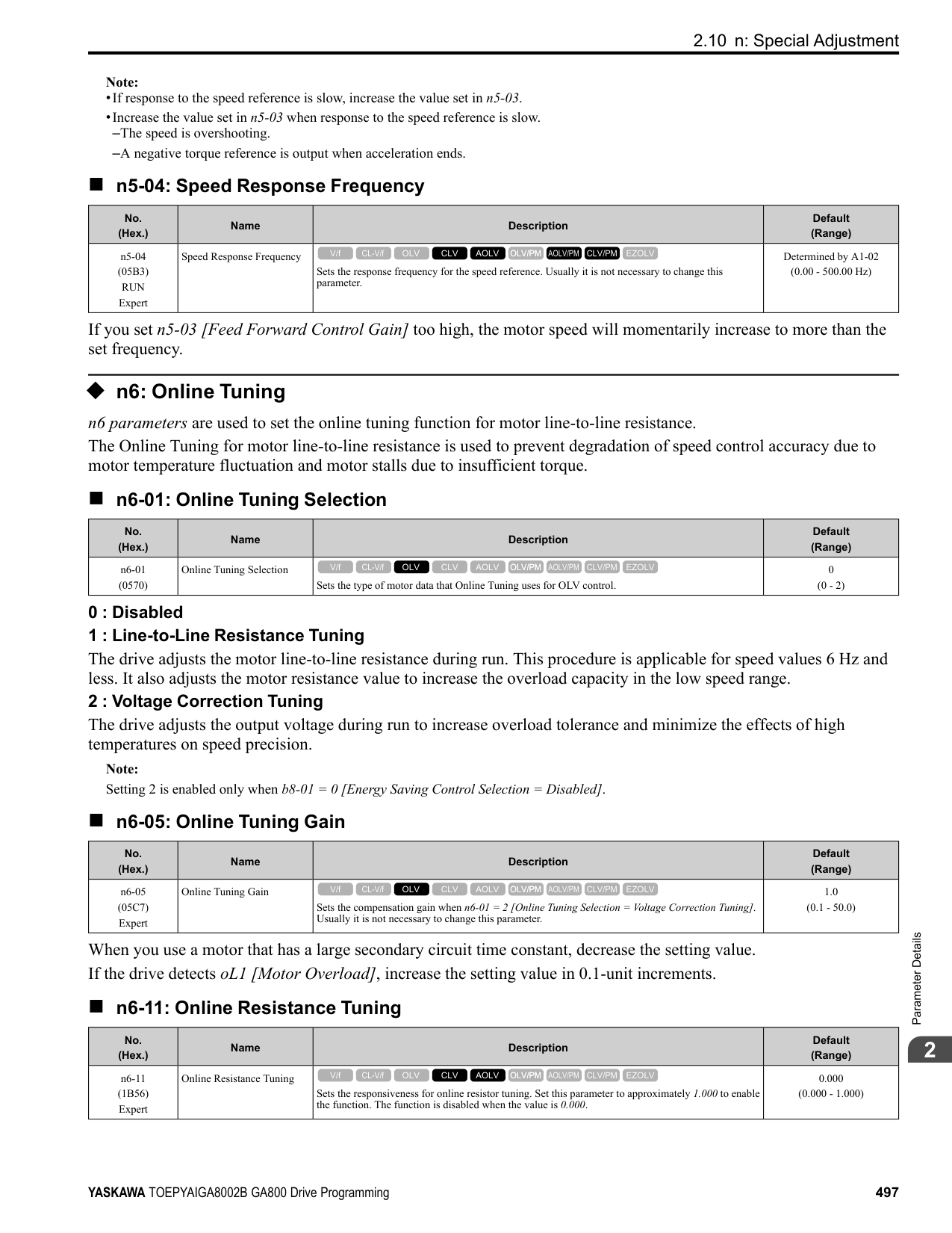
######## ■ o1-36: LCD Backlight Brightness
|No. (Hex.)|Name|Description|Default (Range)| |---|---|---|---| |o1-36 (11B9) RUN|LCD Backlight Brightness|Sets the intensity of the LCD keypad backlight.
V/f CL-V/f OLV CLV AOLV OLV/PM AOLV/PM CLV/PM EZOLV
|5 (1 - 5)|
When you decrease the setting value, the intensity of the backlight decreases.
######## ■ o1-37: LCD Backlight ON/OFF Selection
|No. (Hex.)|Name|Description|Default (Range)| |---|---|---|---| |o1-37 (11BA) RUN|LCD Backlight ON/OFF Selection|Sets the automatic shut off function for the LCD backlight.
V/f CL-V/f OLV CLV AOLV OLV/PM AOLV/PM CLV/PM EZOLV
|1 (0, 1)|
Note: Use o1-36 [LCD backlight adjustment] to adjust the intensity of the LCD backlight.
############## 0 : OFF 1 : ON
Enables the automatic shut off function. The time at which the LCD backlight automatically turns off is configured with o1-38 [Time to turn off LCD backlight].
######## ■ o1-38: LCD Backlight Off-Delay
|No. (Hex.)|Name|Description|Default (Range)| |---|---|---|---| |o1-38 (11BB) RUN|LCD Backlight Off-Delay|Sets the time until the LCD backlight automatically turns off.
V/f CL-V/f OLV CLV AOLV OLV/PM AOLV/PM CLV/PM EZOLV
|60 s (10 - 300 s)|
When the backlight is off, push a key on the keypad to temporarily turn the backlight on. After the backlight turns on, it will turn off automatically after the time set in o1-38 is expired.
######## ■ o1-39: Show Initial Setup Screen
|No. (Hex.)|Name|Description|Default (Range)| |---|---|---|---| |o1-39 (11BC) RUN|Show Initial Setup Screen|Sets the function to show the LCD keypad initial setup screen each time the drive is energized. This parameter is only available when using an LCD keypad.
V/f CL-V/f OLV CLV AOLV OLV/PM AOLV/PM CLV/PM EZOLV
|1 (0, 1)|
The initial setup screen shows a menu where you can select the display language, set the date, time, and other basic settings. When you set this parameter to 0, the drive will not show this screen each time you energize the drive. 0 : No
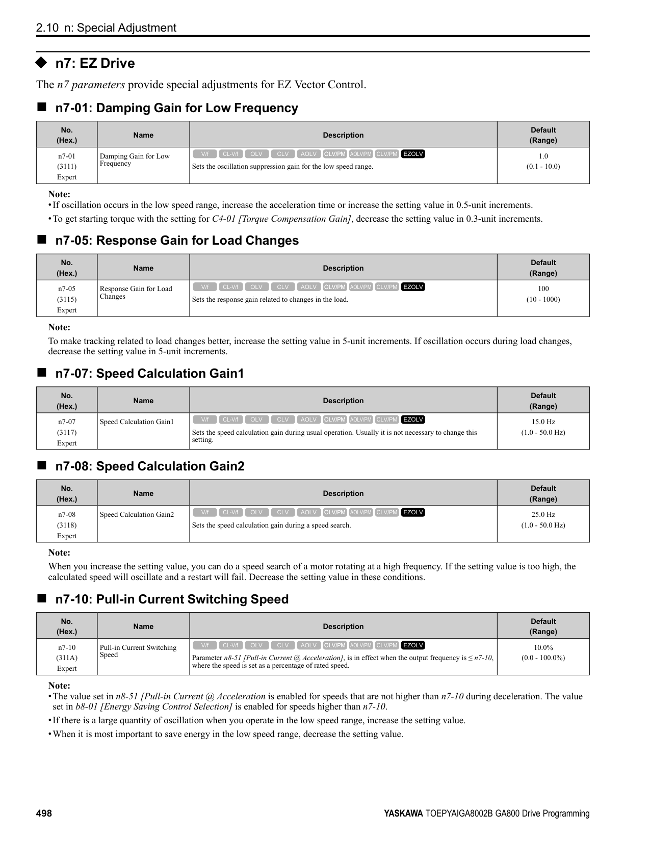
The drive will not show the initial setup display screen each time you energize the drive. The drive will show the Home screen. 1 : Yes
When you input the Run command before you energize the drive or when the you turn on the Run command while the drive shows the initial setup screen, the drive will replace the initial setup screen with the Home screen.
0 : Custom Monitor 1 : Bar Graph 2 : Analog Gauge 3 : Trend Plot
0 : +/- Area ( - o1-42 ~ o1-42 ) 1 : + Area ( 0 ~ o1-42 ) 2 : - Area ( - o1-42 ~ 0 )
|No. (Hex.)|Name|Description|Default (Range)| |---|---|---|---| |o1-40 (11BD) RUN|Home Screen Display Selection|Sets the monitor display mode for the Home screen. This parameter is only available when using an LCD keypad.
V/f CL-V/f OLV CLV AOLV OLV/PM AOLV/PM CLV/PM EZOLV
|0 (0 - 3)|
|No. (Hex.)|Name|Description|Default (Range)| |---|---|---|---| |o1-41 (11C1) RUN|1st Monitor Area Selection|Sets the horizontal range used to display the monitor set in o1-24 [Custom Monitor 1] as a bar graph. This parameter is only available when using an LCD keypad.
V/f CL-V/f OLV CLV AOLV OLV/PM AOLV/PM CLV/PM EZOLV
|0 (0 - 2)|
|No. (Hex.)|Name|Description|Default (Range)| |---|---|---|---| |o1-42 (11C2) RUN|1st Monitor Area Setting|Sets the horizontal axis value used to display the monitor set in o1-24 [Custom Monitor 1] as a bar graph. This parameter is only available when using an LCD keypad.
V/f CL-V/f OLV CLV AOLV OLV/PM AOLV/PM CLV/PM EZOLV
|100.0% (0.0 - 100.0%)|
|No. (Hex.)|Name|Description|Default (Range)| |---|---|---|---| |o1-43 (11C3) RUN|2nd Monitor Area Selection|Selects the horizontal range used to display the monitor set in o1-25 [Custom Monitor 2] as a bar graph. This parameter is only available when using an LCD keypad.
V/f CL-V/f OLV CLV AOLV OLV/PM AOLV/PM CLV/PM EZOLV
|0 (0 - 2)|
ParameterDetails
0 : +/- Area ( - o1-44 ~ o1-44 ) 1 : + Area ( 0 ~ o1-44 ) 2 : - Area ( - o1-44 ~ 0 )
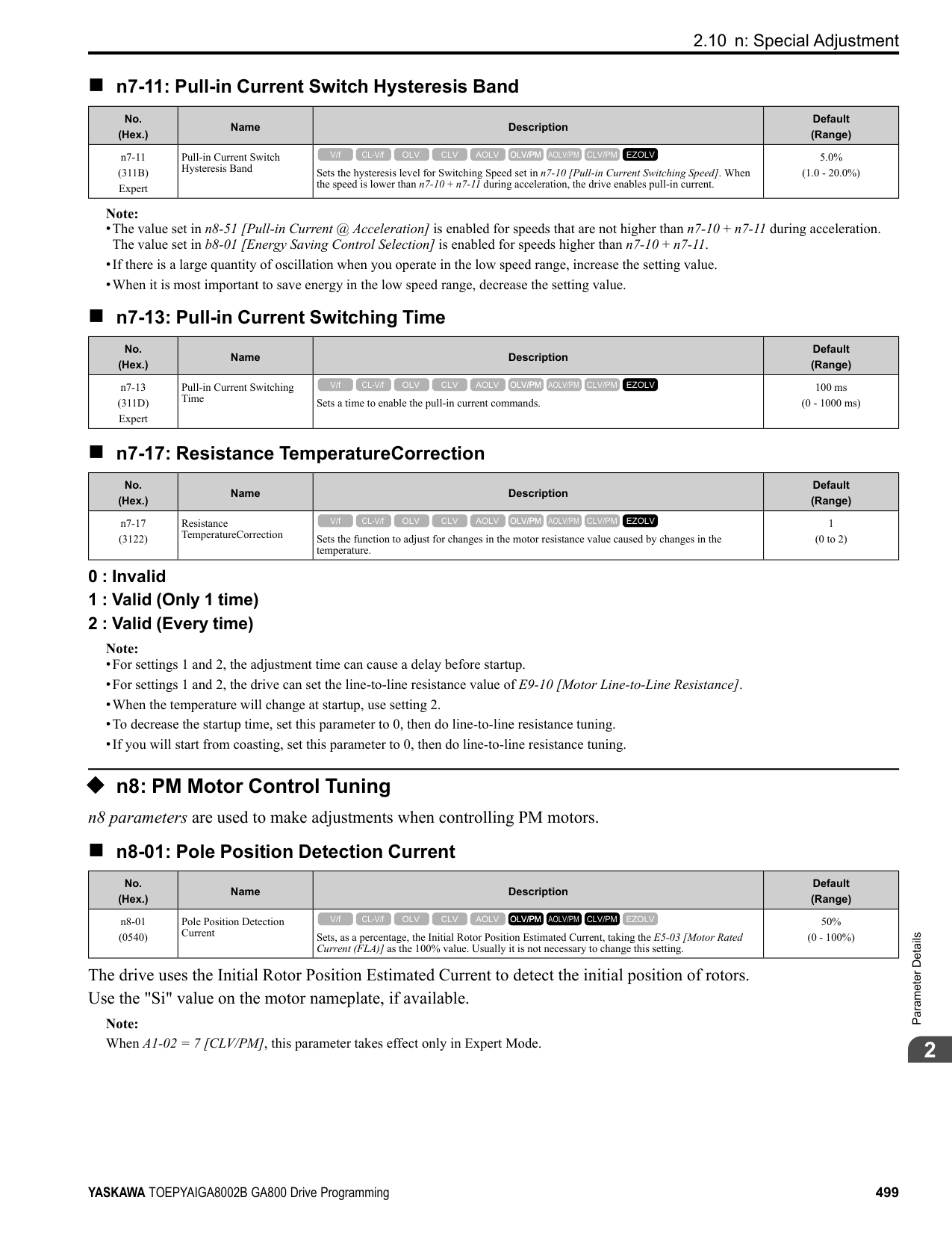
|No. (Hex.)|Name|Description|Default (Range)| |---|---|---|---| |o1-44 (11C4) RUN|2nd Monitor Area Setting|Sets the horizontal axis value used to display the monitor set in o1-25 [Custom Monitor 2] as a bar graph. This parameter is only available when using an LCD keypad.
V/f CL-V/f OLV CLV AOLV OLV/PM AOLV/PM CLV/PM EZOLV
|100.0% (0.0 - 100.0%)|
|No. (Hex.)|Name|Description|Default (Range)| |---|---|---|---| |o1-45 (11C5) RUN|3rd Monitor Area Selection|Sets the horizontal range used to display the monitor set in o1-26 [Custom Monitor 3] as a bar graph. This parameter is only available when using an LCD keypad.
V/f CL-V/f OLV CLV AOLV OLV/PM AOLV/PM CLV/PM EZOLV
|0 (0 - 2)|
|No. (Hex.)|Name|Description|Default (Range)| |---|---|---|---| |o1-46 (11C6) RUN|3rd Monitor Area Setting|Sets the horizontal axis value used to display the monitor set in o1-26 [Custom Monitor 3] as a bar graph. This parameter is only available when using an LCD keypad.
V/f CL-V/f OLV CLV AOLV OLV/PM AOLV/PM CLV/PM EZOLV
|100.0% (0.0 - 100.0%)|
|No. (Hex.)|Name|Description|Default (Range)| |---|---|---|---| |o1-47 (11C7) RUN|Trend Plot 1 Scale Minimum Value|Sets the horizontal axis minimum value used to display the monitor set in o1-24 [Custom Monitor 1] as a trend plot. This parameter is only available when using an LCD keypad.
V/f CL-V/f OLV CLV AOLV OLV/PM AOLV/PM CLV/PM EZOLV
|-100.0% (-300.0 - +300.0%)|
|No. (Hex.)|Name|Description|Default (Range)| |---|---|---|---| |o1-48 (11C8) RUN|Trend Plot 1 Scale Maximum Value|Sets the horizontal axis maximum value used to display the monitor set in o1-24 [Custom Monitor 1] as a trend plot. This parameter is only available when using an LCD keypad.
V/f CL-V/f OLV CLV AOLV OLV/PM AOLV/PM CLV/PM EZOLV
|100.0% (-300.0 - +300.0%)|
|No. (Hex.)|Name|Description|Default (Range)| |---|---|---|---| |o1-49 (11C9) RUN|Trend Plot 2 Scale Minimum Value|Sets the horizontal axis minimum value used to display the monitor set in o1-25 [Custom Monitor 2] as a trend plot. This parameter is only available when using an LCD keypad.
V/f CL-V/f OLV CLV AOLV OLV/PM AOLV/PM CLV/PM EZOLV
|-100.0% (-300.0 - +300.0%)|
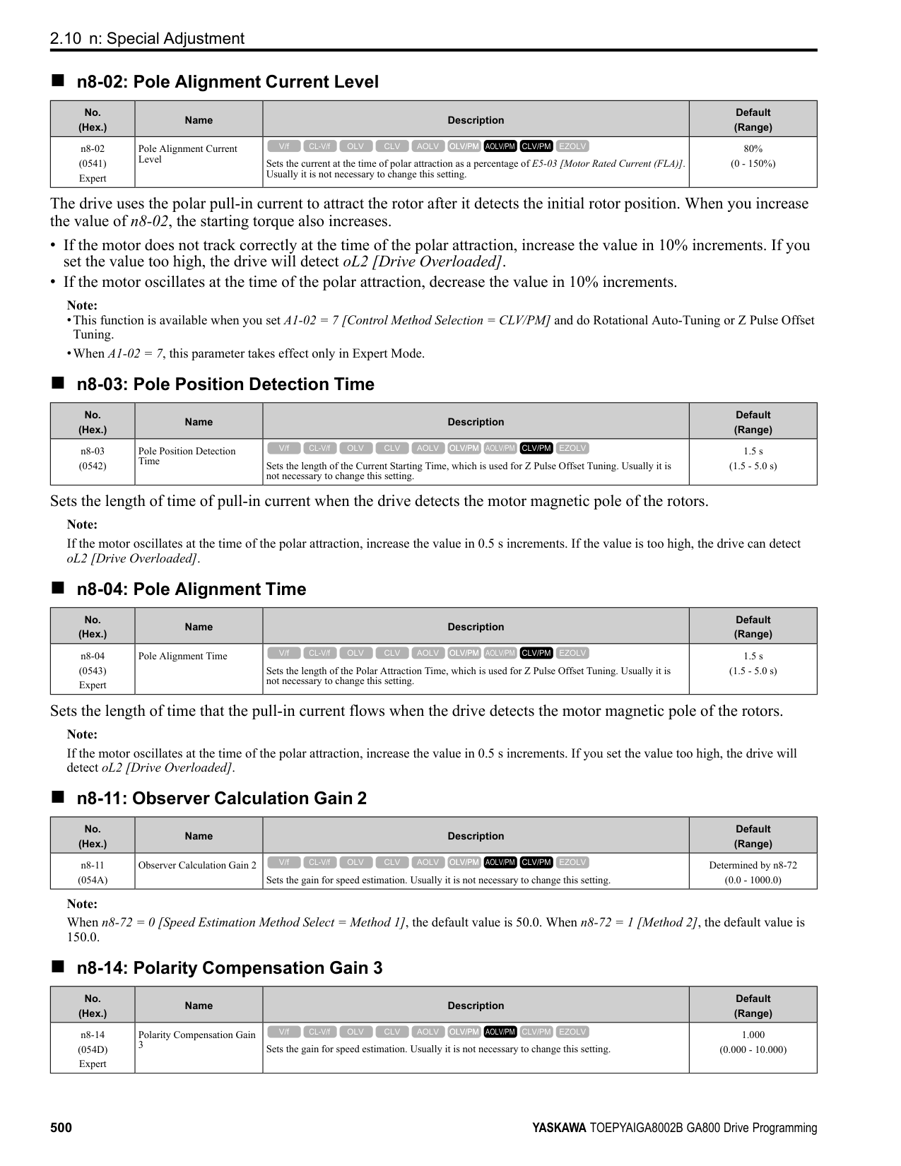
|No. (Hex.)|Name|Description|Default (Range)| |---|---|---|---| |o1-50 (11CA) RUN|Trend Plot 2 Scale Maximum Value|Sets the horizontal axis maximum value used to display the monitor set in o1-25 [Custom Monitor 2] as a trend plot. This parameter is only available when using an LCD keypad.
V/f CL-V/f OLV CLV AOLV OLV/PM AOLV/PM CLV/PM EZOLV
|100.0% (-300.0 - +300.0%)|
|No. (Hex.)|Name|Description|Default (Range)| |---|---|---|---| |o1-51 (11CB) RUN|Trend Plot Time Scale Setting|Sets the time scale (horizontal axis) to display the trend plot. When you change this setting, the drive automatically adjusts the data sampling time. This parameter is only available when using an LCD keypad.
V/f CL-V/f OLV CLV AOLV OLV/PM AOLV/PM CLV/PM EZOLV
|300 s (1 - 3600 s)|
|No. (Hex.)|Name|Description|Default (Range)| |---|---|---|---| |o1-55 (11EE) RUN|Analog Gauge Area Selection|Sets the range used to display the monitor set in o1-24 [Custom Monitor 1] as an analog gauge. This parameter is only available when using an LCD keypad.
V/f CL-V/f OLV CLV AOLV OLV/PM AOLV/PM CLV/PM EZOLV
|1 (0, 1)|
0 : +/- Area ( - o1-56 ~ o1-56 ) 1 : + Area ( 0 ~ o1-56 )
|No. (Hex.)|Name|Description|Default (Range)| |---|---|---|---| |o1-56 (11EF) RUN|Analog Gauge Area Setting|Sets the value used to display the monitor set in o1-24 [Custom Monitor 1] as an analog meter. This parameter is only available when using an LCD keypad.
V/f CL-V/f OLV CLV AOLV OLV/PM AOLV/PM CLV/PM EZOLV
|100.0% (0.0 - 100.0%)|
|No. (Hex.)|Name|Description|Default (Range)| |---|---|---|---| |o1-58 (3125)|Motor Power Unit Selection|Sets the setting unit for parameters that set the motor rated power.
V/f CL-V/f OLV CLV AOLV OLV/PM AOLV/PM CLV/PM EZOLV
|1 (0, 1)|
The drive shows these parameter values in the set units:
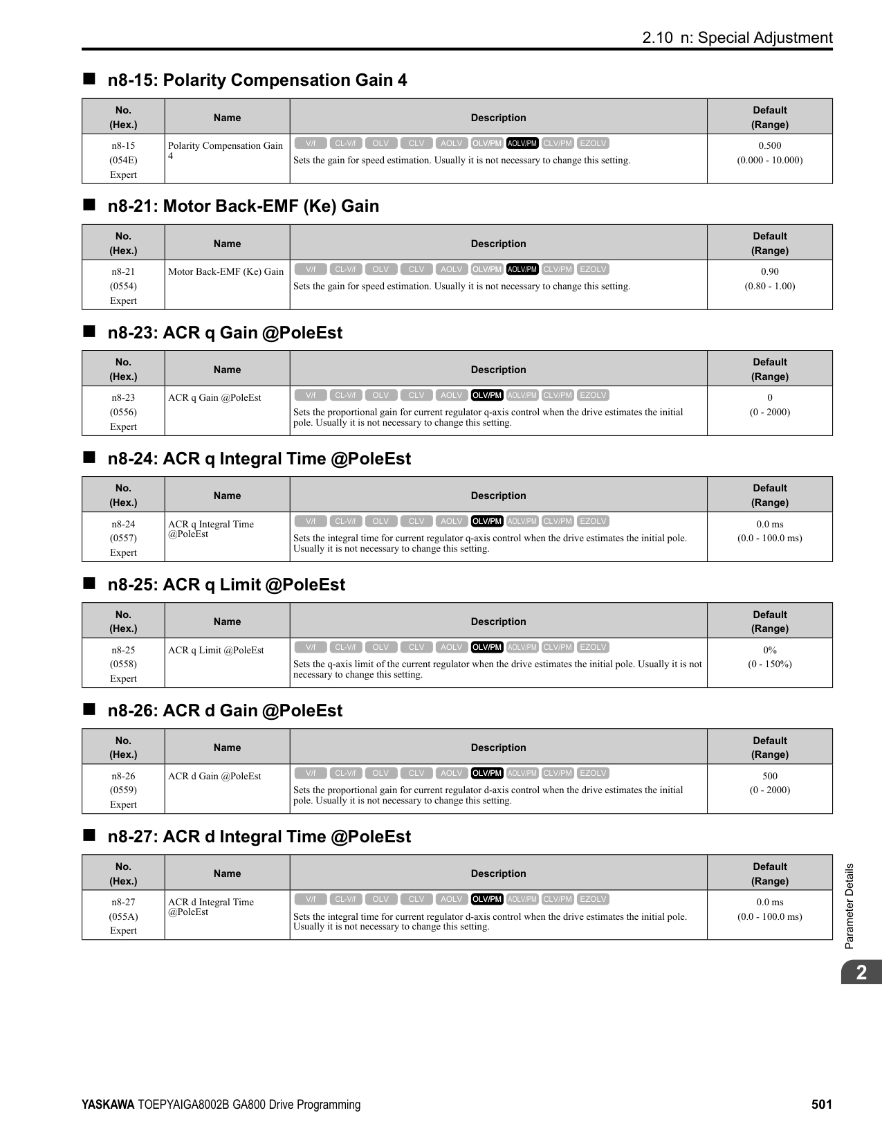
######## ◆ o2: Keypad Operation
######## ■ o2-01: LO/RE Key Function Selection
|No. (Hex.)|Name|Description|Default (Range)| |---|---|---|---| |o2-01 (0505)|LO/RE Key Function Selection|Sets the function that lets you use to switch between LOCAL and REMOTE Modes.
V/f CL-V/f OLV CLV AOLV OLV/PM AOLV/PM CLV/PM EZOLV
|1 (0, 1)|
0 : Disabled
ParameterDetails
######## 2
You cannot use to switch between LOCAL and REMOTE Modes. 1 : Enabled
You can use to switch between LOCAL and REMOTE Modes when the drive is stopped. When LOCAL Mode is selected, on the keypad will come on. WARNING! Sudden Movement Hazard. If you change the control source when b1-07 = 1 [LOCAL/REMOTE Run Selection = Accept Existing RUN Command], the drive can start suddenly. Before you change the control source, remove all personnel from the area around the drive, motor, and load. Sudden starts can cause serious injury or death. WARNING! Sudden Movement Hazard. Fully examine all mechanical and electrical connections before you change o2-01 [LO/RE Key Function Selection] or b1-07 [LOCAL/REMOTE Run Selection]. Sudden starts can cause serious injury or death. If b1-07 = 1 [Accept Existing RUN Command] and there is an active Run command when you switch from LOCAL to REMOTE Mode, the drive can start suddenly.
Table 2.73 Function Settings with o2-01 and b1-07
|Function Selection|LOCAL/REMOTE Run Selection|Switching from LOCAL Mode to REMOTE Mode|Switching from REMOTE Mode to LOCAL Mode| |---|---|---|---| |o2-01 = 0 [Disabled]|b1-07 = 0 [Disregard Existing RUN Command]|The drive will not switch modes.|The drive will not switch modes.| |o2-01 = 0 [Disabled]|b1-07 = 1 [Accept Existing RUN Command]|The drive will not switch modes.|The drive will not switch modes.| |o2-01 = 1 [Enabled]|b1-07 = 0 [Disregard Existing RUN Command]|The drive will not start operating although the Run command is active. When you set Run command to active again, the drive will start to run.|The drive cannot operate because the Run command is not enabled.| |o2-01 = 1 [Enabled]|b1-07 1 [Accept Existing RUN Command]|When the Run command is active, the drive will start to run immediately when the mode switches from LOCAL to REMOTE.|The drive cannot operate because the Run command is not enabled.|
######## ■ o2-02: STOP Key Function Selection
|No. (Hex.)|Name|Description|Default (Range)| |---|---|---|---| |o2-02 (0506)|STOP Key Function Selection|Sets the function to stop the drive with the button on the keypad when the Run command source for the drive is REMOTE (external) and not assigned to the keypad.
V/f CL-V/f OLV CLV AOLV OLV/PM AOLV/PM CLV/PM EZOLV
|1 (0, 1)|
0 : Disabled 1 : Enabled
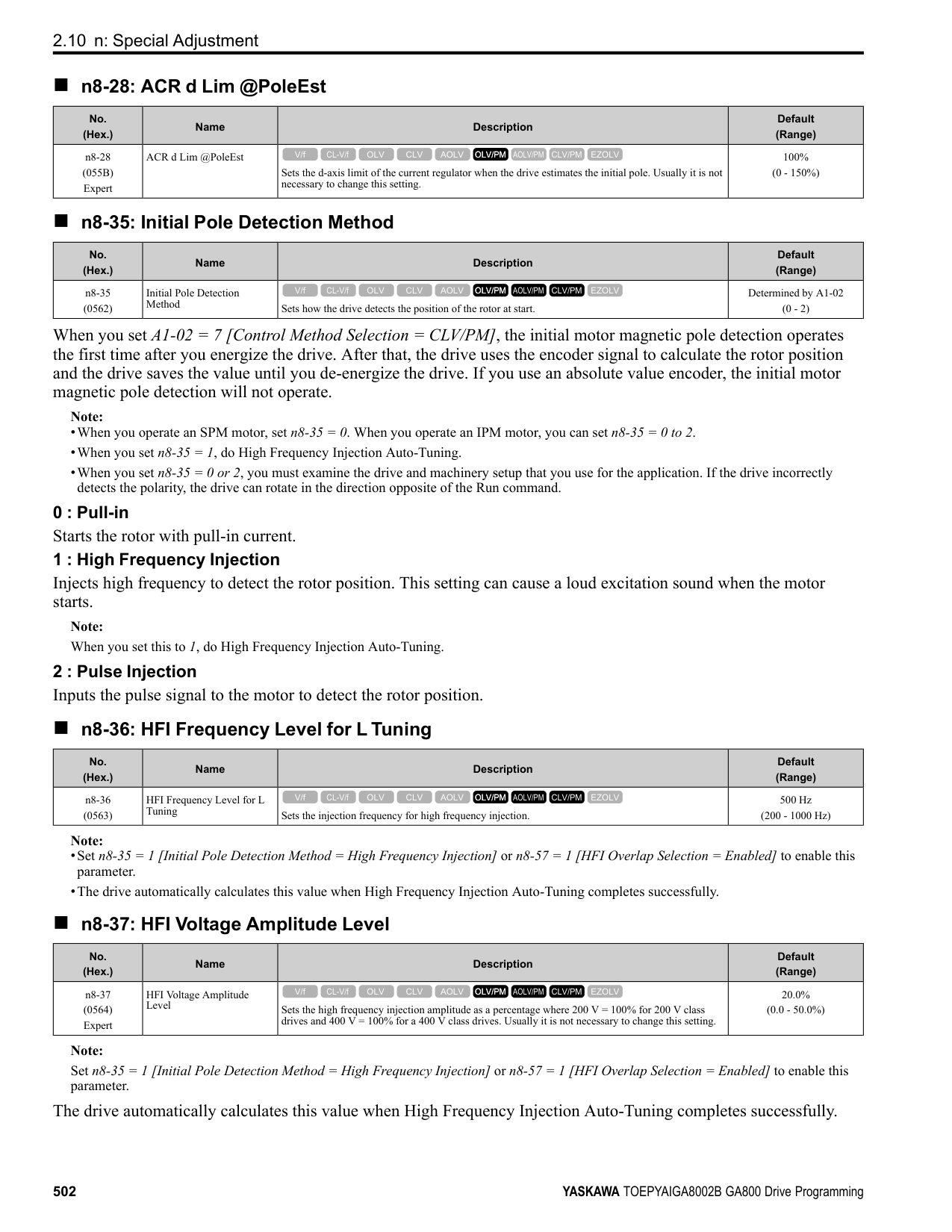
stays enabled when the Run command source has not been assigned to the keypad. To start the drive again after you push to stop operation, turn the external Run command OFF and ON again.
######## ■ o2-03: User Parameter Default Value
|No. (Hex.)|Name|Description|Default (Range)| |---|---|---|---| |o2-03 (0507)|User Parameter Default Value|Sets the function to keep the settings of changed parameters as user parameter defaults to use during initialization.
V/f CL-V/f OLV CLV AOLV OLV/PM AOLV/PM CLV/PM EZOLV
|0 (0 - 2)|
When you set o2-03 = 1 [Set defaults], the drive saves changed parameter settings as user parameter setting values in a part of the memory that is isolated from drive parameters.
Set o2-03 = 1 then push to save the user parameter setting values. After the drive saves the setting value, o2-03 automatically resets to 0.
2 : Clear all Deletes all of the saved user parameter setting values. Set o2-03 = 2 then push to clear the user parameter setting values. The drive will automatically reset o2-03 to 0. If you delete the user parameter setting values, you cannot set A1-03 = 1110 to initialize parameters.
######## ■ o2-04: Drive Model (KVA) Selection
|No. (Hex.)|Name|Description|Default (Range)| |---|---|---|---| |o2-04 (0508)|Drive Model (KVA) Selection|Sets the Drive Model code. Set this parameter after replacing the control board.
V/f CL-V/f OLV CLV AOLV OLV/PM AOLV/PM CLV/PM EZOLV
|Determined by the drive (-)|
NOTICE: Set o2-04 [Drive Model Selection] correctly. If you set this parameter incorrectly, it will decrease drive performance, cause the protection function to operate incorrectly, and cause damage to the drive.
Note: When the setting value of o2-04 changes, related parameter setting values also change. Refer to Defaults by Drive Model and Duty Rating ND/HD on page 133 for more information.
These tables list the relation between o2-04 setting values and drive models.
|o2-04 Setting|Drive Model| |---|---| |62|2004| |63|2006| |64|2008| |65|2010| |66|2012| |67|2018| |68|2021| |6A|2030| |6B|2042|
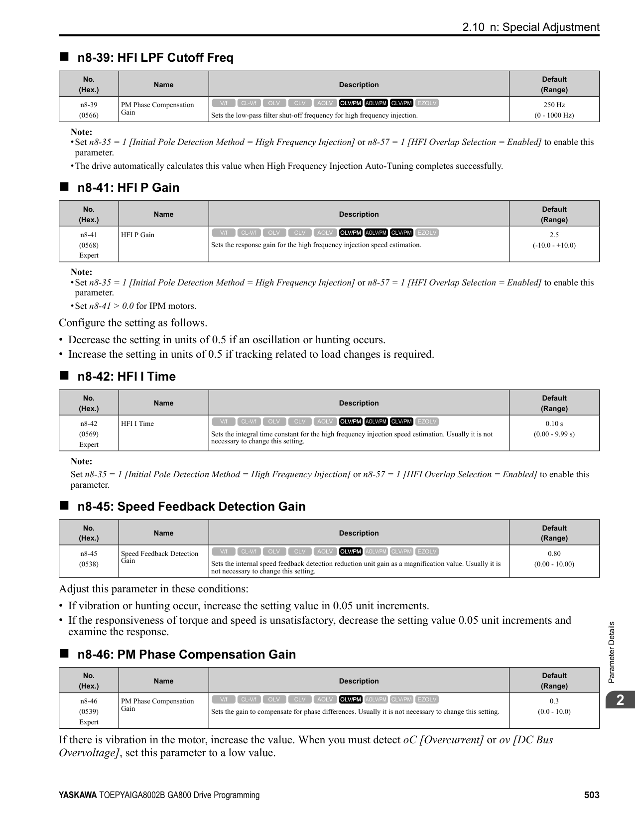
|6D|2056| |6E|2070| |6F|2082| |70|2110| |72|2138| |73|2169| |74|2211| |75|2257| |76|2313| |77|2360| |78|2415| |92|4002| |93|4004| |94|4005|
|o2-04 Setting|Drive Model| |---|---| |95|4007| |96|4009| |97|4012| |99|4018| |9A|4023| |9C|4031| |9D|4038| |9E|4044| |9F|4060| |A1|4075| |A2|4089| |A3|4103| |A4|4140| |A5|4168| |A6|4208| |A7|4250| |A8|4302| |A9|4371| |AA|4414| |AC|4477| |AD|4568| |AE|4605| |AF|4720|
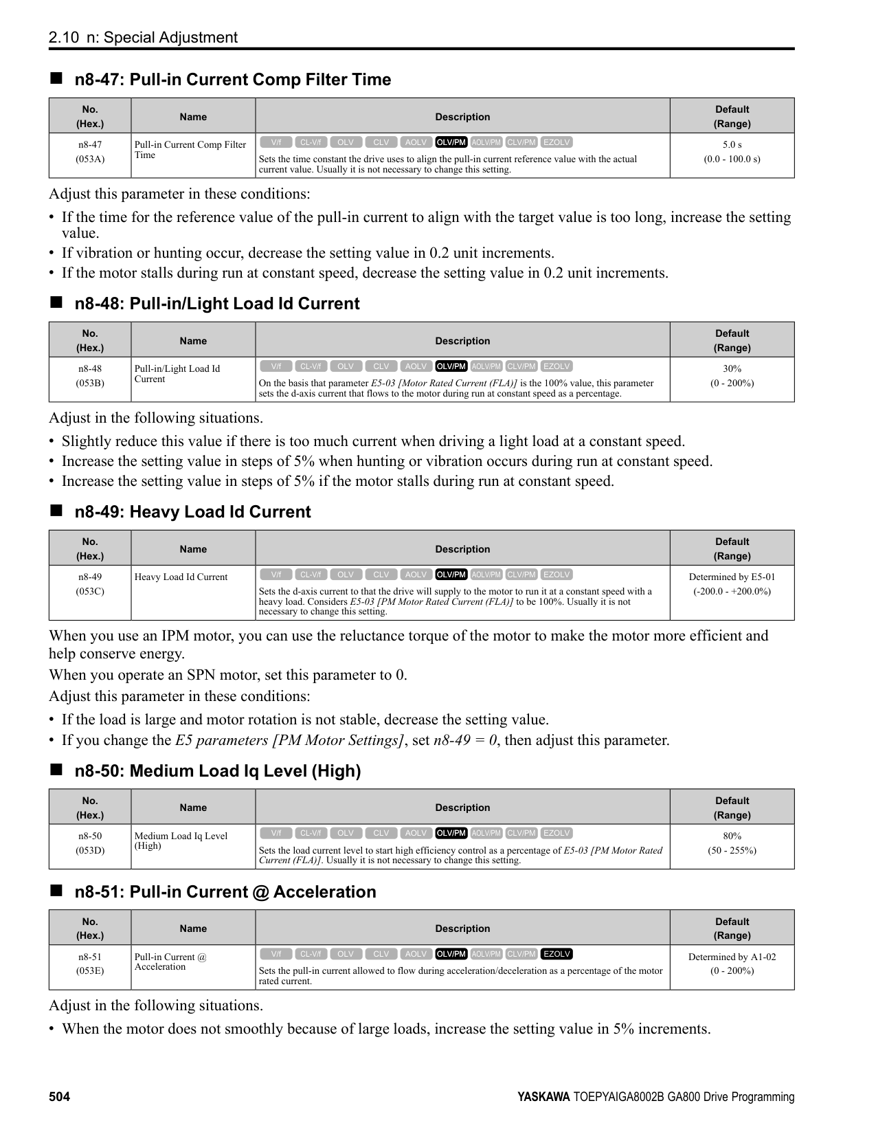
ParameterDetails
######## 2
######## ■ o2-05: Home Mode Freq Ref Entry Mode
|No. (Hex.)|Name|Description|Default (Range)| |---|---|---|---| |o2-05 (0509)|Home Mode Freq Ref Entry Mode|Sets the function that makes it necessary to push the to change the frequency reference value with the keypad when in Drive Mode.
V/f CL-V/f OLV CLV AOLV OLV/PM AOLV/PM CLV/PM EZOLV
|0 (0, 1)|
0 : ENTER Key Required You must push to use the keypad to change the frequency reference value. 1 : Immediate / MOP-style The frequency reference changes when you enter it with the keypad. This then changes the output frequency. It is not necessary to push . The drive keeps the frequency reference for 5 seconds after you use and on the keypad to change the frequency reference value.
######## ■ o2-06: Keypad Disconnect Detection
|No. (Hex.)|Name|Description|Default (Range)| |---|---|---|---| |o2-06 (050A)|Keypad Disconnect Detection|Sets the function that stops the drive if you disconnect the keypad connection cable from the drive or if you damage the cable while the keypad is the Run command source.
V/f CL-V/f OLV CLV AOLV OLV/PM AOLV/PM CLV/PM EZOLV
|1 (0, 1)|
This parameter continues to operate if the keypad installed to the drive becomes disconnected. This parameter is enabled in these conditions:
The drive stops operation, detects oPr [Keypad Connection Fault], and the motor coasts to stop when the drive detects a keypad disconnection.
######## ■ o2-07: Keypad RUN Direction @ Power-up
|No. (Hex.)|Name|Description|Default (Range)| |---|---|---|---| |o2-07 (0527)|Keypad RUN Direction @ Power-up|Sets the direction of motor rotation when the drive is energized and the keypad is the Run command source.
V/f CL-V/f OLV CLV AOLV OLV/PM AOLV/PM CLV/PM EZOLV
|0 (0, 1)|
This parameter is enabled in these conditions:
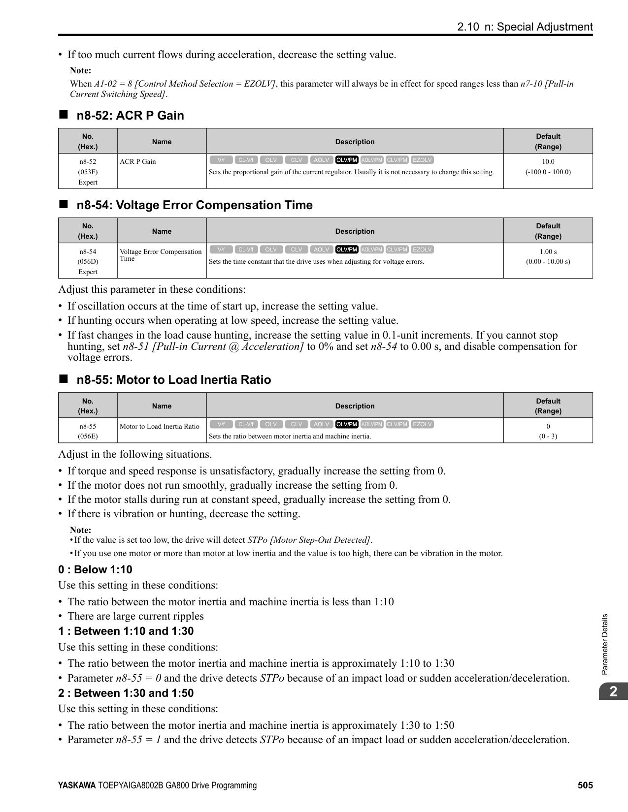
0 : Forward 1 : Reverse
######## ■ o2-09: Region Code
|No. (Hex.)|Name|Description|Default (Range)| |---|---|---|---| |o2-09 (050D)|Reserved|-|-|
######## ■ o2-23: External 24V Powerloss Detection
|No. (Hex.)|Name|Description|Default (Range)| |---|---|---|---| |o2-23 (11F8) RUN|External 24V Powerloss Detection|Sets the function to give a warning when the backup external 24 V power supply turns off when the main circuit power supply is in operation.
V/f CL-V/f OLV CLV AOLV OLV/PM AOLV/PM CLV/PM EZOLV
|0 (0, 1)|
Note: The drive will not run when it is operating from one 24-Vexternal power supply.
0 : Disabled The drive does not detect the loss of the 24-Vexternal power supply. 1 : Enabled
The keypad shows the L24v [Ext. 24-V Power Supply Lost] indicator when the drive detects the loss of the 24-V external power supply.
Note: The minor fault signal is not output from H2-xx = 10 [Multi-Function Digital Out = Minor Fault].
######## ■ o2-24: LED Light Function Selection
|No. (Hex.)|Name|Description|Default (Range)| |---|---|---|---| |o2-24 (11FE)|LED Light Function Selection|Sets the function to show the LED status rings and keypad LED lamps.
V/f CL-V/f OLV CLV AOLV OLV/PM AOLV/PM CLV/PM EZOLV
|2 (0 - 2)|
Note: When you use A1-03 [Initialize Parameters] to initialize the drive, the drive will not reset this parameter.
0 : Enable Status Ring & Keypad LED 1 : LED Status Ring Disable 2 : Keypad LED Light Disable
######## ■ o2-26: Alarm display at ext. 24V power
|No. (Hex.)|Name|Description|Default (Range)| |---|---|---|---| |o2-26 (1563)|Alarm display at ext. 24V power|When you connect a backup external 24 V power supply, this parameter sets the function to trigger an alarm when the main circuit power supply voltage decreases.
V/f CL-V/f OLV CLV AOLV OLV/PM AOLV/PM CLV/PM EZOLV
|1 (0, 1)|
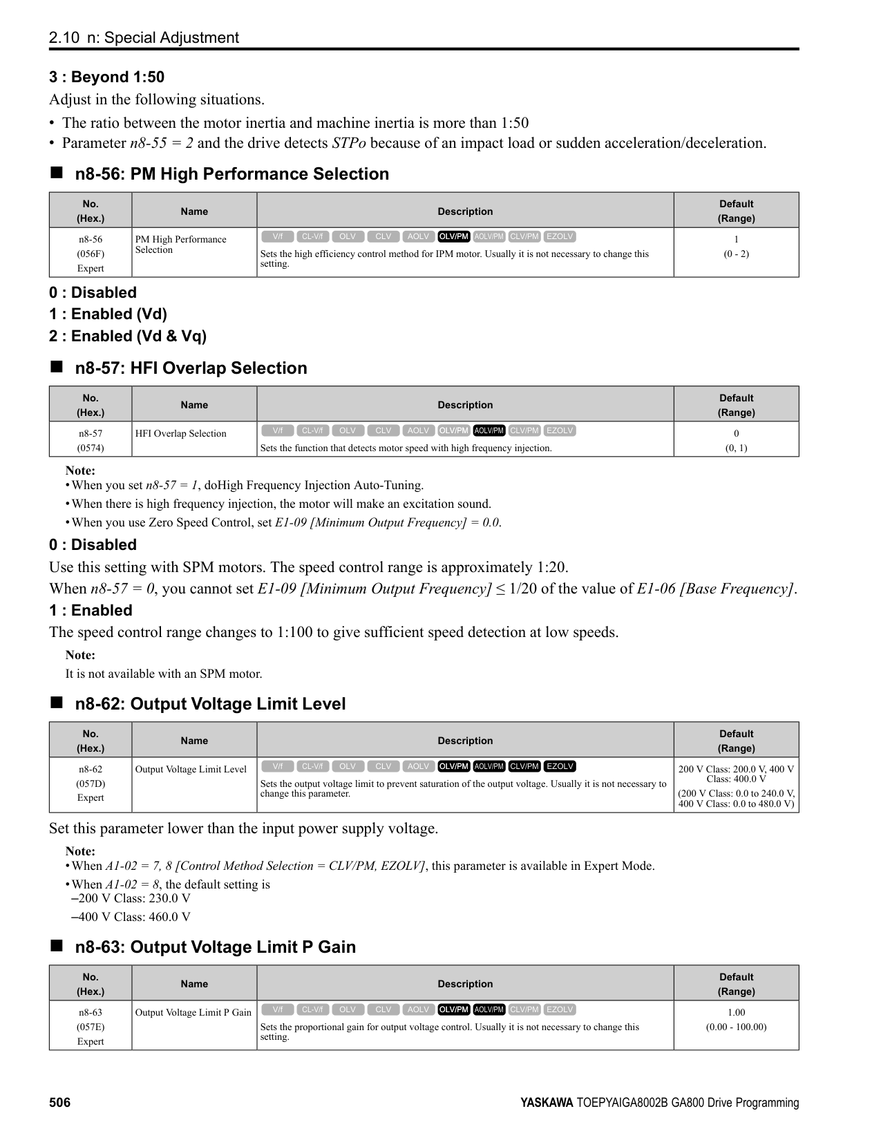
0 : Disabled The drive will not detect EP24v [External Power 24V Supply] if the main circuit power supply voltage decreases. The [Ready] light on the LED Status Ring flashes quickly to identify that drive operation is not possible. 1 : Enabled The drive detects EP24v when the main circuit power supply voltage decreases.
Note: The minor fault signal is not output from H2-xx 10 [MFDO Function Selection Alarm].
######## ■ o2-27: bCE Detection Selection
|No. (Hex.)|Name|Description|Default (Range)| |---|---|---|---| |o2-27 (1565)|bCE Detection Selection|Sets drive operation if the Bluetooth device is disconnected when you operate the drive in Bluetooth Mode.
V/f CL-V/f OLV CLV AOLV OLV/PM AOLV/PM CLV/PM EZOLV
|3 (0 - 4)|
0 : Ramp to Stop 1 : Coast to Stop 2 : Fast Stop (Use C1-09)
ParameterDetails
######## 2
######## ■ o3-01: Copy Keypad Function Selection
|No. (Hex.)|Name|Description|Default (Range)| |---|---|---|---| |o3-01 (0515)|Copy Keypad Function Selection|Sets the function that saves and copies drive parameters to a different drive with the keypad.
V/f CL-V/f OLV CLV AOLV OLV/PM AOLV/PM CLV/PM EZOLV
|0 (0 - 4)|
######## ■ o3-02: Copy Allowed Selection
|No. (Hex.)|Name|Description|Default (Range)| |---|---|---|---|
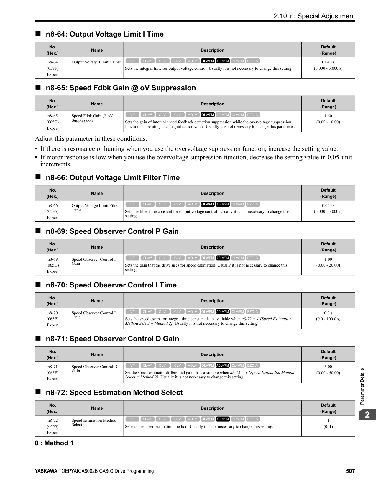
|o3-02 (0516)|Copy Allowed Selection|Sets the copy function when o3-01 = 1 [Copy Keypad Function Selection = Backup (drive → keypad)].
V/f CL-V/f OLV CLV AOLV OLV/PM AOLV/PM CLV/PM EZOLV
|0 (0, 1)|
Note: When you select [Parameter Backup] on the keypad menu screen to do the backup function, the drive automatically sets o3-02 = 1.
0 : Disabled 1 : Enabled
######## ■ o3-04: Select Backup/Restore Location
|No. (Hex.)|Name|Description|Default (Range)| |---|---|---|---| |o3-04 (0B3E)|Select Backup/Restore Location|Sets the storage location for drive parameters when you back up and restore parameters. This parameter is only available when using an LCD keypad.
V/f CL-V/f OLV CLV AOLV OLV/PM AOLV/PM CLV/PM EZOLV
|0 (0 - 3)|
You can use the LCD keypad to make a maximum of 4 parameter backup sets.
######## ■ o3-05: Select Items to Backup/Restore
|No. (Hex.)|Name|Description|Default (Range)| |---|---|---|---| |o3-05 (0BDA)|Select Items to Backup/ Restore|Sets which parameters are backed up, restored, and referenced. This parameter is only available when using an LCD keypad.
V/f CL-V/f OLV CLV AOLV OLV/PM AOLV/PM CLV/PM EZOLV
|1 (0, 1)|
0 : Standard Parameters 1 : Standard + DWEZ Parameters
Note:
######## ■ o3-06: Auto Parameter Backup Selection
|No. (Hex.)|Name|Description|Default (Range)| |---|---|---|---| |o3-06 (0BDE)|Auto Parameter Backup Selection|Sets the function that automatically backs up parameters. This parameter is only available when using an LCD keypad.
V/f CL-V/f OLV CLV AOLV OLV/PM AOLV/PM CLV/PM EZOLV
|1 (0, 1)|
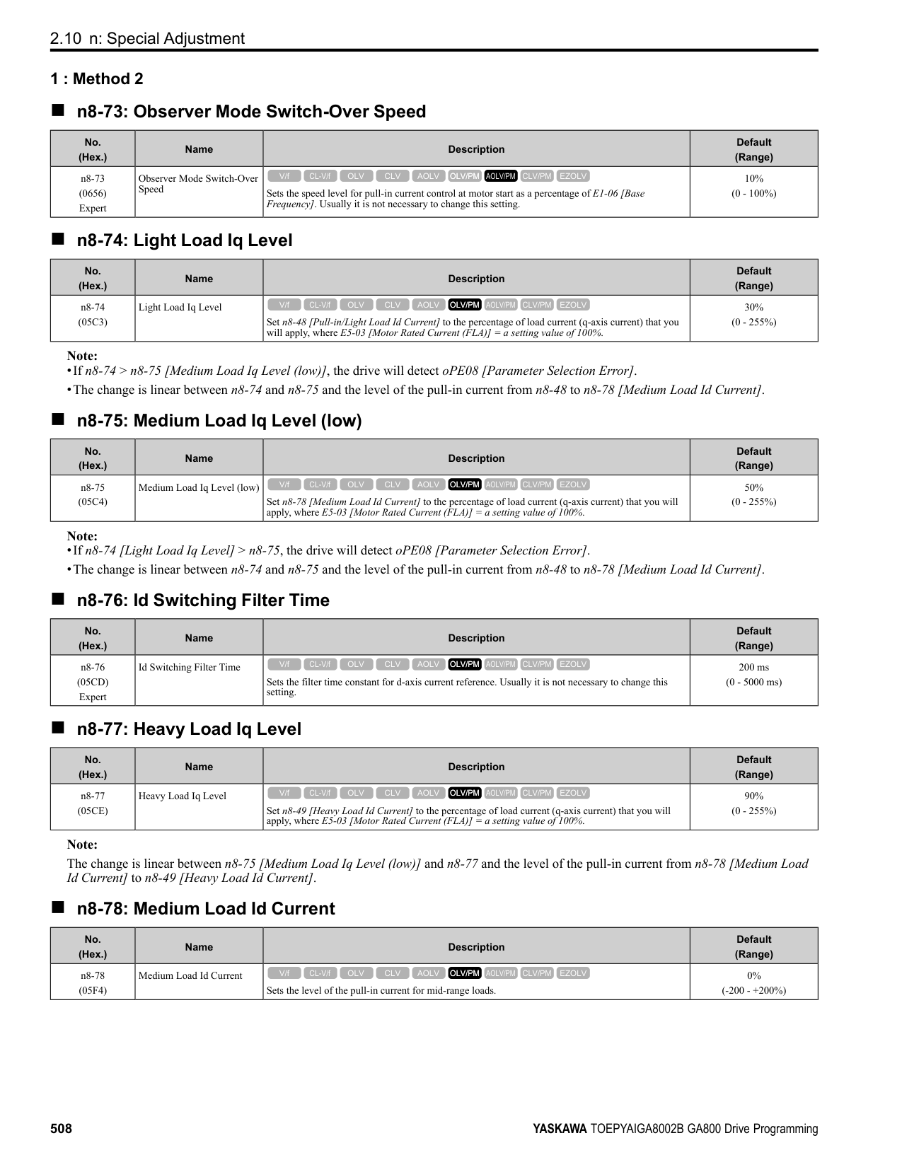
When you connect the drive and keypad, parameters set to the drive are automatically backed up to the keypad as specified by the setting of parameters o3-06 and o3-07.
0 : Disabled 1 : Enabled
Note:
When you replace the LCD keypad then energize the drive, the keypad shows the restore operation screen automatically to restore the drive configuration with the parameters backed up to the LCD keypad. If you connect an LCD keypad that does not have parameter backup data, the keypad will not show the restore operation screen.
######## ■ o3-07: Auto Parameter Backup Interval
|No. (Hex.)|Name|Description|Default (Range)| |---|---|---|---| |o3-07 (0BDF)|Auto Parameter Backup Interval|Sets the interval at which the automatic parameter backup function saves parameters from the drive to the keypad.
V/f CL-V/f OLV CLV AOLV OLV/PM AOLV/PM CLV/PM EZOLV
|1 (0 - 3)|
The drive saves parameter settings to the keypad at these times:
for the auto backup period to pass, then saves those parameters in the keypad. Note:
The drive can write data to the keypad a maximum of 100,000 times. If you write data to the keypad more than 100,000 times, you must replace the keypad.
0 : Every 10 minutes 1 : Every 30 minutes 2 : Every 60 minutes 3 : Every 12 hours
◆ o4: Maintenance Mon Settings o4 parameters set the expected service life to help you know when to replace parts. The drive will show an alarm to tell you when the replacement part interval is near.
######## ■ o4-01: Elapsed Operating Time Setting
|No. (Hex.)|Name|Description|Default (Range)| |---|---|---|---| |o4-01 (050B)|Elapsed Operating Time Setting|Sets the initial value of the cumulative drive operation time in 10-hour units.
V/f CL-V/f OLV CLV AOLV OLV/PM AOLV/PM CLV/PM EZOLV
|0 h (0 - 9999 h)|
When you select o4-01 on the keypad, it will show the current value of U4-01 in units of 10 hours (h). When you change the setting of o4-01 through the monitor, the U4-01 count starts again as specified by the setting of o4-01.
ParameterDetails
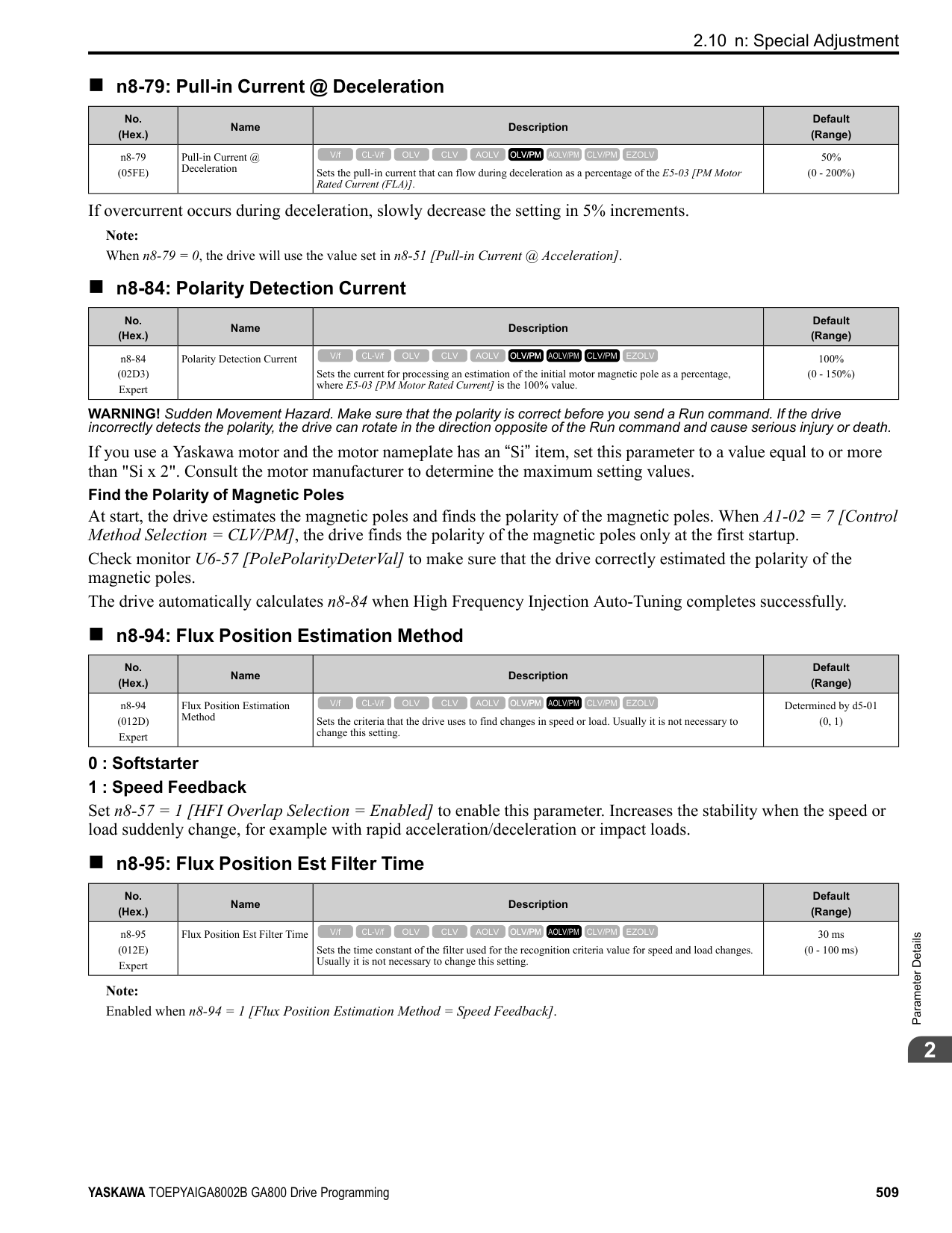
######## 2
Note: Set this parameter in 10-hour (h) units. When o4-01 = 30, U4-01 [Cumulative Ope Time] = 300 h.
######## ■ o4-02: Elapsed Operating Time Selection
|No. (Hex.)|Name|Description|Default (Range)| |---|---|---|---| |o4-02 (050C)|Elapsed Operating Time Selection|Sets the condition that counts the cumulative operation time.
V/f CL-V/f OLV CLV AOLV OLV/PM AOLV/PM CLV/PM EZOLV
|0 (0, 1)|
0 : U4-01 Shows Total Power-up Time Counts the time from when the drive is energized to when it is de-energized. 1 : U4-01 Shows Total RUN Time Counts the time that the drive outputs voltage.
######## ■ o4-03: Fan Operation Time Setting
|No. (Hex.)|Name|Description|Default (Range)| |---|---|---|---| |o4-03 (050E)|Fan Operation Time Setting|Sets the value from which to start the cumulative drive cooling fan operation time in 10-hour units.
V/f CL-V/f OLV CLV AOLV OLV/PM AOLV/PM CLV/PM EZOLV
|0 h (0 - 9999 h)|
Use monitor U4-03 [Cooling Fan Ope Time] to view the total operation time of the cooling fan. When you replace a cooling fan, set o4-03 = 0 to reset U4-03. Select o4-03 on the keypad to show the current value of U4-03 in 10-hour (h) units. If you use the monitor to change o4-03, the recount of U4-03 starts with the o4-03 setting.
Note: The drive sets o4-03 in 10-hour (h) units. When o4-03 = 30, U4-03 [Cooling Fan Ope Time] will show “300 h”.
######## ■ o4-05: Capacitor Maintenance Setting
|No. (Hex.)|Name|Description|Default (Range)| |---|---|---|---| |o4-05 (051D)|Capacitor Maintenance Setting|Sets the U4-05 [CapacitorMaintenance] monitor value.
V/f CL-V/f OLV CLV AOLV OLV/PM AOLV/PM CLV/PM EZOLV
|0% (0 - 150%)|
When you replace a drive, set o4-05 = 0 to reset U4-05. When the o4-05 setting changes, the count of U4-05 starts again as specified by the setting of o4-05. After you complete the configuration, o4-05 automatically resets to 0.
Note: The maintenance period changes for different operating environments.
######## ■ o4-07: Softcharge Relay Maintenance Set
|No. (Hex.)|Name|Description|Default (Range)| |---|---|---|---| |o4-07 (0523)|Softcharge Relay Maintenance Set|Sets the U4-06 [PreChargeRelayMainte] monitor value.
V/f CL-V/f OLV CLV AOLV OLV/PM AOLV/PM CLV/PM EZOLV
|0% (0 - 150%)|
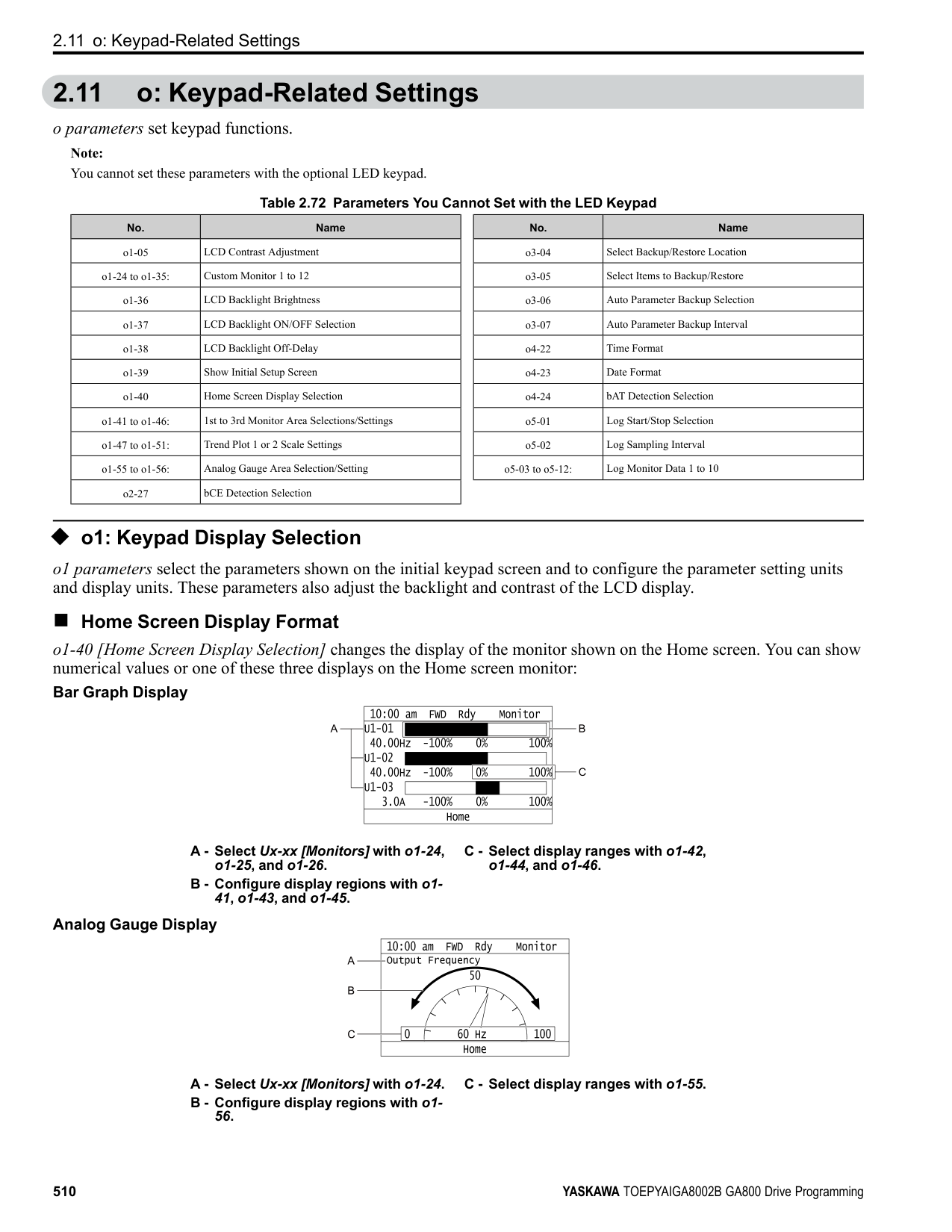
When you replace a drive, set o4-07 = 0 to reset U4-06. When the o4-07 setting changes, the count of U4-06 starts again as specified by the setting of o4-07. After you complete the configuration, o4-07 automatically resets to 0.
Note: The maintenance period changes for different operating environments.
######## ■ o4-09: IGBT Maintenance Setting
|No. (Hex.)|Name|Description|Default (Range)| |---|---|---|---| |o4-09 (0525)|IGBT Maintenance Setting|Sets the U4-07 [IGBT Maintenance] monitor value.
V/f CL-V/f OLV CLV AOLV OLV/PM AOLV/PM CLV/PM EZOLV
|0% (0 - 150%)|
When you replace a drive, set o4-09 = 0 to reset U4-07. When the o4-09 setting changes, the count of U4-07 starts again as specified by the setting of o4-09. After you complete the configuration, o4-09 automatically resets to 0.
The maintenance period changes for different operating environments.
######## ■ o4-11: Fault Trace/History Init (U2/U3)
|No. (Hex.)|Name|Description|Default (Range)| |---|---|---|---| |o4-11 (0510)|Fault Trace/History Init (U2/ U3)|Resets the records of Monitors U2-xx [Fault Trace] and U3-xx [Fault History].
V/f CL-V/f OLV CLV AOLV OLV/PM AOLV/PM CLV/PM EZOLV
|0 (0, 1)|
Note: When you initialize the drive with A1-03 [Initialize Parameters], the drive will not reset the records for U2-xx and U3-xx.
0 : Disabled Keeps the records of Monitors U2-xx and U3-xx. 1 : Enabled Resets the records for Monitors U2-xx and U3-xx. After the reset, the drive automatically resets o4-11 to 0.
######## ■ o4-12: kWh Monitor Initialization
|No. (Hex.)|Name|Description|Default (Range)| |---|---|---|---| |o4-12 (0512)|kWh Monitor Initialization|Resets the monitor values for U4-10 [kWh, Lower 4 Digits] and U4-11 [kWh, Upper 5 Digits].
V/f CL-V/f OLV CLV AOLV OLV/PM AOLV/PM CLV/PM EZOLV
|0 (0, 1)|
Note: When you initialize the drive with A1-03 [Initialize Parameters], the drive will not reset U4-10 and U4-11.
0 : No Reset Keeps the monitor values for U4-10 and U4-11. 1 : Reset Resets the values of U4-10 and U4-11. After the reset, the drive automatically resets o4-12 to 0.
######## ■ o4-13: RUN Command Counter @ Initialize
|No. (Hex.)|Name|Description|Default (Range)| |---|---|---|---| |o4-13 (0528)|RUN Command Counter @ Initialize|Resets the monitor values for U4-02 [Num of Run Commands], U4-24 [Number of Runs (Low)], and U4-25 [Number of Runs (High)].
V/f CL-V/f OLV CLV AOLV OLV/PM AOLV/PM CLV/PM EZOLV
|0 (0, 1)|
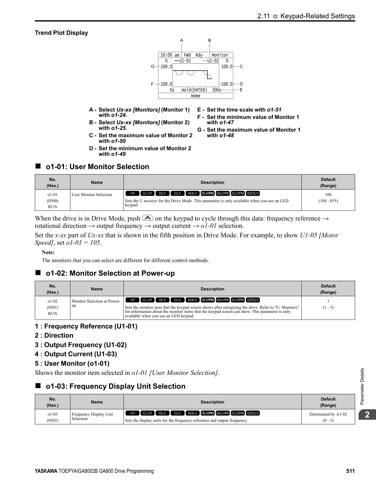
0 : No Reset Keeps the monitor values for U4-02, U4-24, and U4-25. 1 : Reset Resets the values of U4-02, U4-24, and U4-25. After the reset, the drive automatically resets o4-13 to 0.
######## ■ o4-22: Time Format
|No. (Hex.)|Name|Description|Default (Range)| |---|---|---|---| |o4-22 (154F) RUN|Time Format|Sets the time display format. This parameter is only available when using an LCD keypad.
V/f CL-V/f OLV CLV AOLV OLV/PM AOLV/PM CLV/PM EZOLV
|1 (0 - 2)|
Sets the display of the time shown in the upper-left of the LCD keypad screen.
0 : 24 Hour Clock 1 : 12 Hour Clock 2 : 12 Hour JP Clock
ParameterDetails
######## 2
######## ■ o4-23: Date Format
|No. (Hex.)|Name|Description|Default (Range)| |---|---|---|---| |o4-23 (1550) RUN|Date Format|Sets the date display format. This parameter is only available when using an LCD keypad.
V/f CL-V/f OLV CLV AOLV OLV/PM AOLV/PM CLV/PM EZOLV
|2 (0 - 2)|
Sets the date format that the drive uses for the fault history and other records.
############## 0 : YYYY/MM/DD 1 : DD/MM/YYYY 2 : MM/DD/YYYY
Note: The Fault History in the Monitor Mode shows when faults occurred. Refer to Show Fault History on page 573 for more information.
######## ■ o4-24: bAT Detection Selection
|No. (Hex.)|Name|Description|Default (Range)| |---|---|---|---| |o4-24 (310F) RUN|bAT Detection Selection|Sets operation when the drive detects bAT [Keypad Battery Low Voltage] and TiM [Keypad Time Not Set].
V/f CL-V/f OLV CLV AOLV OLV/PM AOLV/PM CLV/PM EZOLV
|0 (0 - 2)|
TiM or bAT shows on the keypad, and operation continues. The output terminal set for Alarm [H2-01 to H2-03 = 10] activates.
The drive output shuts off and the motor coasts to stop. Fault relay output terminal MA-MC activates, and MB-MC deactivates.
◆ o5: Log Function The data log function saves drive status information as a CSV file in the micro SD memory card in the keypad. Monitors Ux-xx are the source of data log information. You can record a maximum of 10 monitors.
Change the LCD keypad screen from the main menu to the Diagnostic Tools screen and select the data log function. Set the number of the monitor to record and the sampling time, then start to record the data log.
Table 2.74 Setting Parameters for Data Log Items
|No.|Name|Default|Data Log Monitors| |---|---|---|---| |o5-03|Log Monitor Data 1|101|U1-01 [Frequency Reference]| |o5-04|Log Monitor Data 2|102|U1-02 [Output Frequency]| |o5-05|Log Monitor Data 3|103|U1-03 [Output Current]| |o5-06|Log Monitor Data 4|107|U1-07 [DC Bus Voltage]| |o5-07|Log Monitor Data 5|108|U1-08 [Output Power]| |o5-08|Log Monitor Data 6|000|Not selected| |o5-09|Log Monitor Data 7|000|Not selected| |o5-10|Log Monitor Data 8|000|Not selected| |o5-11|Log Monitor Data 9|000|Not selected| |o5-12|Log Monitor Data 10|000|Not selected|
|Item|Specification| |---|---| |File storage location|A folder called [Log_File] is created in the root directory of the micro SD card.| |Filename|GLOG0xxx.csv Note: [xxx] identifies a 3-digit decimal number| |Maximum number of files|999 (GLOG0001.csv to GLOG0999.csv)| |Character code|ASCII code| |Line break code|
|Separating character|[ , ] (Commas)| |Header Rows|First Row: Drive information including Drive Model, software version, control method, and sampling time Second Row: Log data information including the monitor number, number decimal points, and unit code|
The [Log_Files] folder is created in the root directory of the micro SD card. This is where the log data is stored as CSV files. Log data files are created in this configuration. The number of rows changes when the number of selected monitors change.
|First row|Drive information| |---|---| |Second row|Log data information| |Third row|Log data 1| |:|Log data 2| |:|Log data 3| |:|:| |Last row|Log data n|
First Row: Drive Information This example shows the data text strings and data generated for the first row of log data. Example of generated data: 00,0012,160107111230,GA800,VSAA09010,2,62,1000,000001
|No.|Item|Number of Characters|Example|Description| |---|---|---|---|---| |1|Attribute|2|00|[00] shows that the record is a drive information record.| |2|File number|4|0012|The [xxx] part of the [GLOG0xxx.csv] filename is a 3-digit decimal number in hexadecimal format. Example filename of [GLOG0018.csv]: 018 (Dec.) = 0012 (Hex.)| |3|Time stamp *1|12|160107111230|Date file was generated ・Date: 20YY/MM/DD ・Time in 24-hour format: HH:MM:SS Example data of [160107111230]: 11:12:30 on January 7, 2016| |4|Model|5|GA800|Drive model information| |5|Software number|9|VSAA09010|Drive software number| |6|Control method|1|2|Setting value (Hex.) of A1-02 [Control Method Selection]| |7|Drive capacity|2|62|Setting value (Hex.) of o2-04 [Drive Model Selection]| |8|Sampling time|5 (maximum)|1000|Setting value (Dec.) of o5-02 [Log Sampling Interval] Unit: ms| |9|Row number|6|000001|Row number (Hex.) in the data log file|
*1 If you do not set the time in the keypad, the text string of [000000000000] is generated to show the time.
ParameterDetails
######## 2
Second Row: Log Data Information This example shows the data text strings and data generated for the second row of log data. Example of generated data:
Table 2.75 Unit Codes
Third and Subsequent Rows: Log Data This example shows the data text strings and data generated for the third row of log data. Example of generated data:
|No.|Item|Number of Characters|Description| |---|---|---|---| |1|Attribute|2|[01] shows that the record is a log data information record.| |2|File number|4|The [xxx] part of the [GLOG0xxx.csv] filename is a 3-digit decimal number in hexadecimal format.| |3|Time stamp|12|Date file was generated| |4|Monitor number 1 *1|4|Monitor number selected by o5-03 [Log Monitor Data 1] Ex.: 0101 (Dec.) for U1-01| |5|Monitor number 1 *2|4|Unit code and number of decimal places used for the monitor selected with o5-03 Example when U1-01 = 30.00 Hz: Number of decimal places = 2, Hz unit code = 01, monitor unit 1 = 0201 (Hex.)| |6|Monitor number 2|4|Monitor number selected by o5-04 [Log Monitor Data 2]| |7|Monitor number 2|4|Unit code and number of decimal places used for the monitor selected with o5-04| |:|:|:|:| |22|Monitor number 10|4|Monitor number selected by o5-12 [Log Monitor Data 1]| |23|Monitor number 10|4|Unit code and number of decimal places used for the monitor selected with o5-12| |24 to 27|Reserved|4|-| |28|File number|6|Row number (Hex.) in the data log file|
|Unit Code (Hex.)|Unit|Unit Code (Hex.)|Unit|Unit Code (Hex.)|Unit|Unit Code (Hex.)|Unit| |---|---|---|---|---|---|---|---| |00|–|08|PPR|10|H|18|0H| |01|Hz|09|kW|11|V|19|–| |02|RPM|0A|Ω|12|us|1A|–| |03|%|0B|ms|13|min|1B|–| |04|VAC|0C|kHz|14|°C|1C|–| |05|VDC|0D|PSI|15|W|1D|–| |06|A|0E|MPM|16|kWH|1E|–| |07|sec|0F|FPM|17|MWH|1F|–|
|No.|Item|Number of Characters|Description| |---|---|---|---| |1|Attribute|2|[02] shows that the record is a monitor data record.| |2|File number|4|The [xxx] part of the [GLOG0xxx.csv] filename is a 3-digit decimal number in hexadecimal format.|
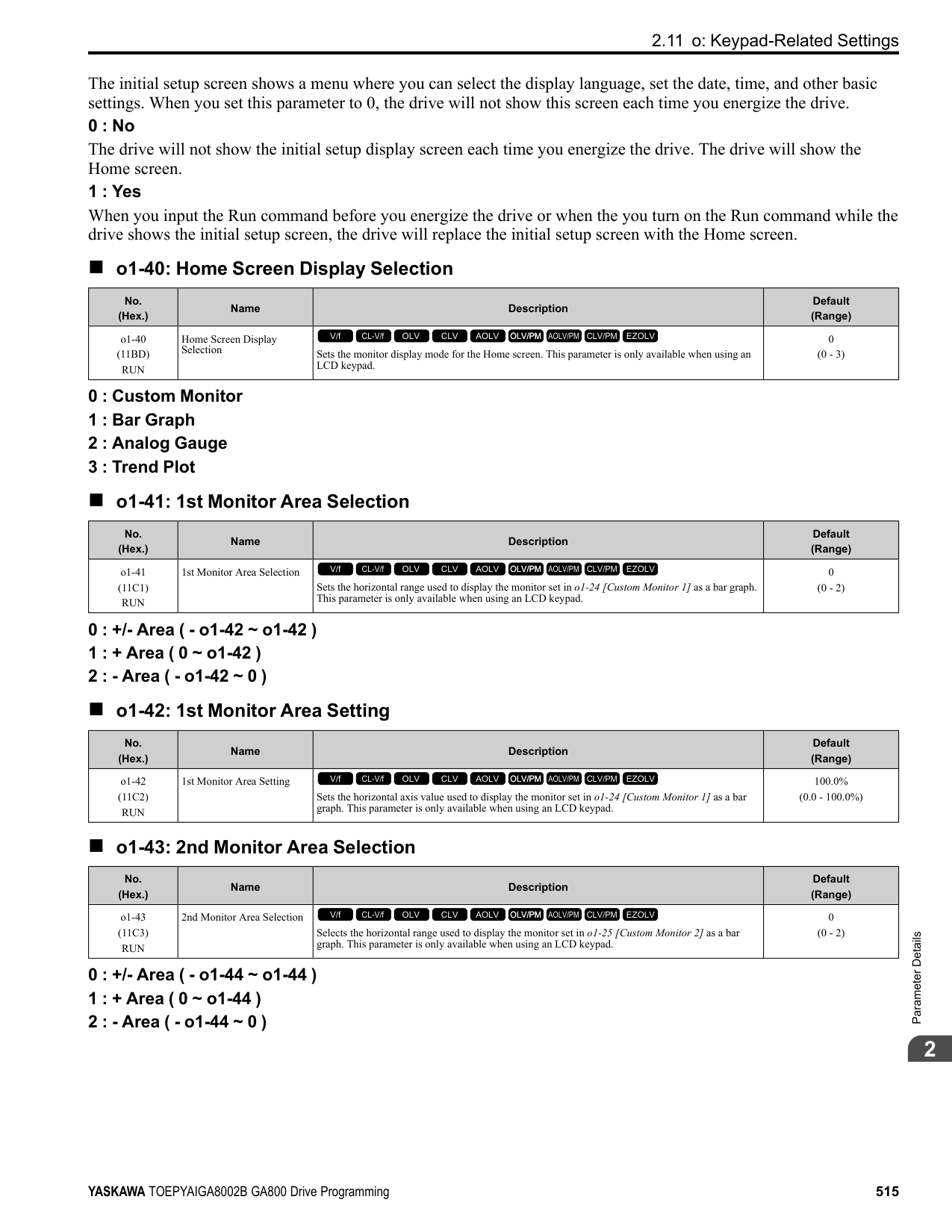
|3|Time stamp|12|Data log data was retrieved (YYMMDDHHMMSS)| |4|Log Monitor Data 1|4|Monitor number selected by o5-03 [Log Monitor Data 1]| |5|Log Monitor Data 2|4|Monitor number selected by o5-04 [Log Monitor Data 2]| |:|:|:|:| |13|Log Monitor Data 10|4|Monitor number selected by o5-12 [Log Monitor Data 10]|
|No.|Item|Number of Characters|Description| |---|---|---|---| |14|Reserved|4|-| |15|Encoding data|4|Encoding data for log monitor data 1 through 10 (Hex.) Bits 0 through 9 show the encoding of log monitor data 1 1 through 10. A bit value of 1 shows that the data represents a negative value. (Log monitor data 1 through 10 is absolute value data without encoding) Example when log monitor data 2, 5, and 8 show negative values: Bits 1, 4, and 7 have values of 1, and the encoding data
0010010010 (Bin.) 0092 (Hex.)| |16|File number|6|Row number (Hex.) in the data log file|
0 : OFF Stops the data log. 1 : ON Starts the data log as specified by the sampling cycle set in o5-02 [Log Sampling Interval].
Note: Sets the number of the U monitor you will log. For example, to show U1-01 [Frequency Reference], set o5-03 = 101. When it is not necessary to set data log monitors, set this parameter to
|No. (Hex.)|Name|Description|Default (Range)| |---|---|---|---| |o5-01 (1551) RUN|Log Start/Stop Selection|Sets the data log function. This parameter is only available when using an LCD keypad.
V/f CL-V/f OLV CLV AOLV OLV/PM AOLV/PM CLV/PM EZOLV
|0 (0 - 1)|
|No. (Hex.)|Name|Description|Default (Range)| |---|---|---|---| |o5-02 (1552) RUN|Log Sampling Interval|Sets the data log sampling cycle. This parameter is only available when using an LCD keypad.
V/f CL-V/f OLV CLV AOLV OLV/PM AOLV/PM CLV/PM EZOLV
|100 ms (100 - 60000 ms)|
|No. (Hex.)|Name|Description|Default (Range)| |---|---|---|---| |o5-03 (1553) RUN|Log Monitor Data 1|Sets the data log monitor. This parameter is only available when using an LCD keypad.
V/f CL-V/f OLV CLV AOLV OLV/PM AOLV/PM CLV/PM EZOLV
|101 (000, 101 - 999)|
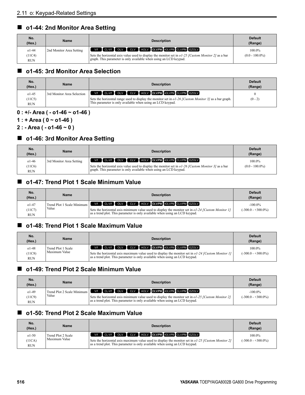
|No. (Hex.)|Name|Description|Default (Range)| |---|---|---|---| |o5-04 (1554) RUN|Log Monitor Data 2|Sets the data log monitor. This parameter is only available when using an LCD keypad.
V/f CL-V/f OLV CLV AOLV OLV/PM AOLV/PM CLV/PM EZOLV
|102 (000, 101 - 999)|
ParameterDetails
Note: Set the U monitor number you will log. For example, to show U1-02 [Output Frequency], set o5-04 = 102. When it is not necessary to set data log monitor, set this parameter to 000.
######## ■ o5-05: Log Monitor Data 3
|No. (Hex.)|Name|Description|Default (Range)| |---|---|---|---| |o5-05 (1555) RUN|Log Monitor Data 3|Sets the data log monitor. This parameter is only available when using an LCD keypad.
V/f CL-V/f OLV CLV AOLV OLV/PM AOLV/PM CLV/PM EZOLV
|103 (000, 101 - 999)|
Note: Sets the number of the U monitor you will log. For example, to show U1-03 [Output Current], set o5-05 103. When it is not necessary to set data log monitors, set this parameter to 000. You cannot select U2 monitor [Fault Trace] or U3 Monitor [Fault History].
######## ■ o5-06: Log Monitor Data 4
|No. (Hex.)|Name|Description|Default (Range)| |---|---|---|---| |o5-06 (1556) RUN|Log Monitor Data 4|Sets the data log monitor. This parameter is only available when using an LCD keypad.
V/f CL-V/f OLV CLV AOLV OLV/PM AOLV/PM CLV/PM EZOLV
|107 (000, 101 - 999)|
Note: Sets the number of the U monitor you will log. For example, to show U1-07 [DC Bus Voltage], set o5-06 = 107. When it is not necessary to set data log monitors, set this parameter to 000. You cannot select U2 monitor [Fault Trace] or U3 Monitor [Fault History].
######## ■ o5-07: Log Monitor Data 5
|No. (Hex.)|Name|Description|Default (Range)| |---|---|---|---| |o5-07 (1557) RUN|Log Monitor Data 5|Sets the data log monitor. This parameter is only available when using an LCD keypad.
V/f CL-V/f OLV CLV AOLV OLV/PM AOLV/PM CLV/PM EZOLV
|108 (000, 101 - 999)|
Note: Sets the number of the U monitor you will log. For example, to show U1-08 [Output Power], set o5-07 = 108. When it is not necessary to set data log monitors, set this parameter to 000. You cannot select U2 monitor [Fault Trace] or U3 Monitor [Fault History].
######## ■ o5-08: Log Monitor Data 6
|No. (Hex.)|Name|Description|Default (Range)| |---|---|---|---| |o5-08 (1558) RUN|Log Monitor Data 6|Sets the data log monitor. This parameter is only available when using an LCD keypad.
V/f CL-V/f OLV CLV AOLV OLV/PM AOLV/PM CLV/PM EZOLV
|V/f, OLV/PM: 0, CL-V/f, OLV, CLV, AOLV, AOLV/ PM, CLV/PM, EZOLV: 105
(000, 101 - 999)|
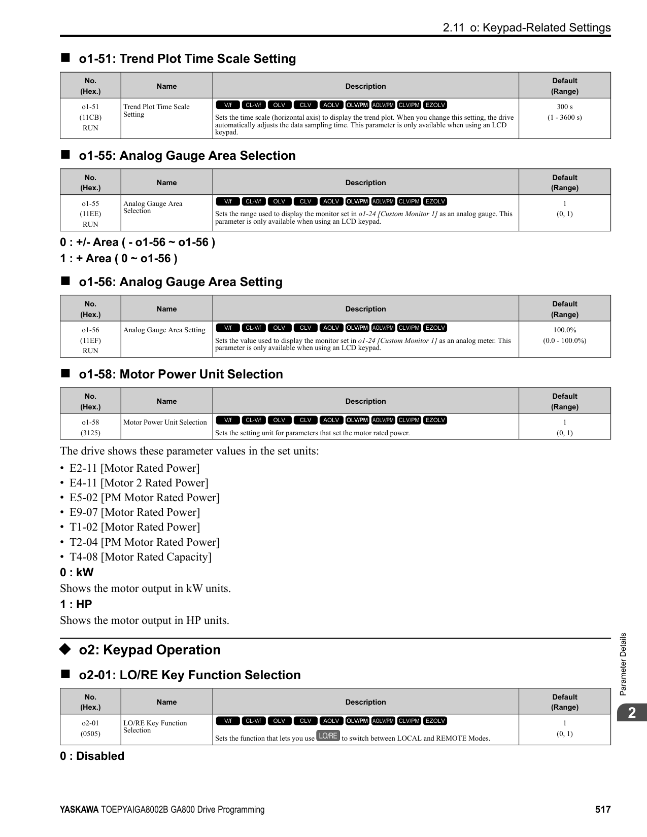
Note: Sets the number of the U monitor you will log. For example, to show U1-01 [Frequency Reference], set o5-08 101. When it is not necessary to set data log monitors, set this parameter to
######## ■ o5-09: Log Monitor Data 7
|No. (Hex.)|Name|Description|Default (Range)| |---|---|---|---| |o5-09 (1559) RUN|Log Monitor Data 7|Sets the data log monitor. This parameter is only available when using an LCD keypad.
V/f CL-V/f OLV CLV AOLV OLV/PM AOLV/PM CLV/PM EZOLV
|110 (000, 101 - 999)|
Note: Set the U monitor number you will log. For example, to show U1-01 [Frequency Reference], set o5-09 = 101. When it is not necessary to set data log monitor, set this parameter to
######## ■ o5-10: Log Monitor Data 8
|No. (Hex.)|Name|Description|Default (Range)| |---|---|---|---| |o5-10 (155A) RUN|Log Monitor Data 8|Sets the data log monitor. This parameter is only available when using an LCD keypad.
V/f CL-V/f OLV CLV AOLV OLV/PM AOLV/PM CLV/PM EZOLV
|112 (000, 101 - 999)|
Note: Sets the number of the U monitor you will log. For example, to show U1-01 [Frequency Reference], set o5-10 101. When it is not necessary to set data log monitors, set this parameter to
######## ■ o5-11: Log Monitor Data 9
|No. (Hex.)|Name|Description|Default (Range)| |---|---|---|---| |o5-11 (155B) RUN|Log Monitor Data 9|Sets the data log monitor. This parameter is only available when using an LCD keypad.
V/f CL-V/f OLV CLV AOLV OLV/PM AOLV/PM CLV/PM EZOLV
|000 (000, 101 - 999)|
Note: Sets the number of the U monitor you will log. For example, to show U1-01 [Frequency Reference], set o5-11 = 101. When it is not necessary to set data log monitors, set this parameter to
######## ■ o5-12: Log Monitor Data 10
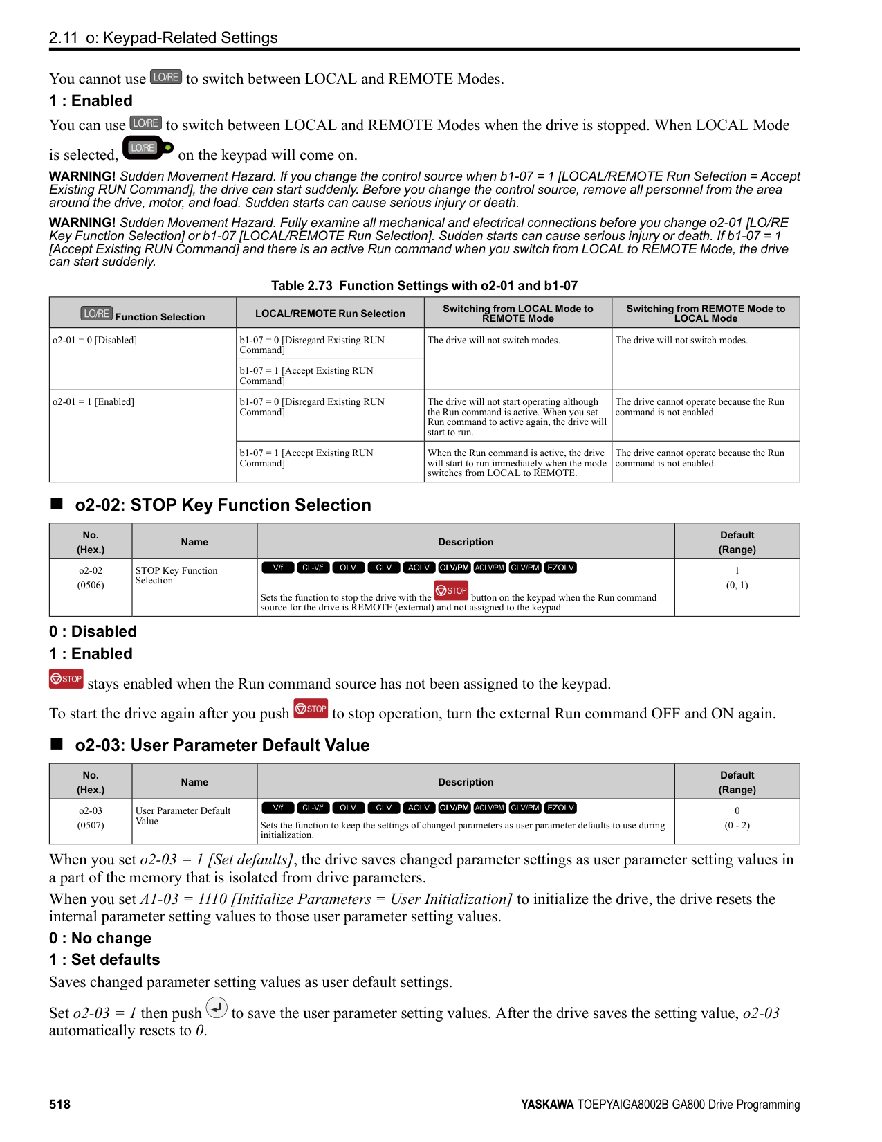
|No. (Hex.)|Name|Description|Default (Range)| |---|---|---|---| |o5-12 (155C) RUN|Log Monitor Data 10|Sets the data log monitor. This parameter is only available when using an LCD keypad.
V/f CL-V/f OLV CLV AOLV OLV/PM AOLV/PM CLV/PM EZOLV
|000 (000, 101 - 999)|
Note: Sets the number of the U monitor you will log. For example, to show U1-01 [Frequency Reference], set o5-12 = 101. When it is not necessary to set data log monitors, set this parameter to
ParameterDetails
####### 2.12 T: Auto-Tuning
Numbers identifying the T parameters are displayed when an LED keypad is used. The names of the parameters are displayed on the LCD screen of the LCD keypad. Set the following.
######## ◆ T0: Tuning Mode Selection
######## ■ T0-00: Tuning Mode Selection
When your control method supports Control Tuning, set T0-00 first. Then, set T1-00 [Motor 1/Motor 2 Selection] to select the motor you will tune. Then, set the tuning mode in T2-01 [PM Auto-Tuning Selection] or T3-00 [Control Loop Tuning Selection].
|No. (Hex.)|Name|Description|Default (Range)| |---|---|---|---| |T0-00 (1197)|Tuning Mode Selection|Sets the type of Auto-Tuning.
V/f CL-V/f OLV CLV AOLV OLV/PM AOLV/PM CLV/PM EZOLV
|0 (0, 1)|
0 : Motor Parameter Tuning 1 : Control Tuning
Note: The available tuning modes are different for different control methods.
◆ T1: Induction Motor Auto-Tuning
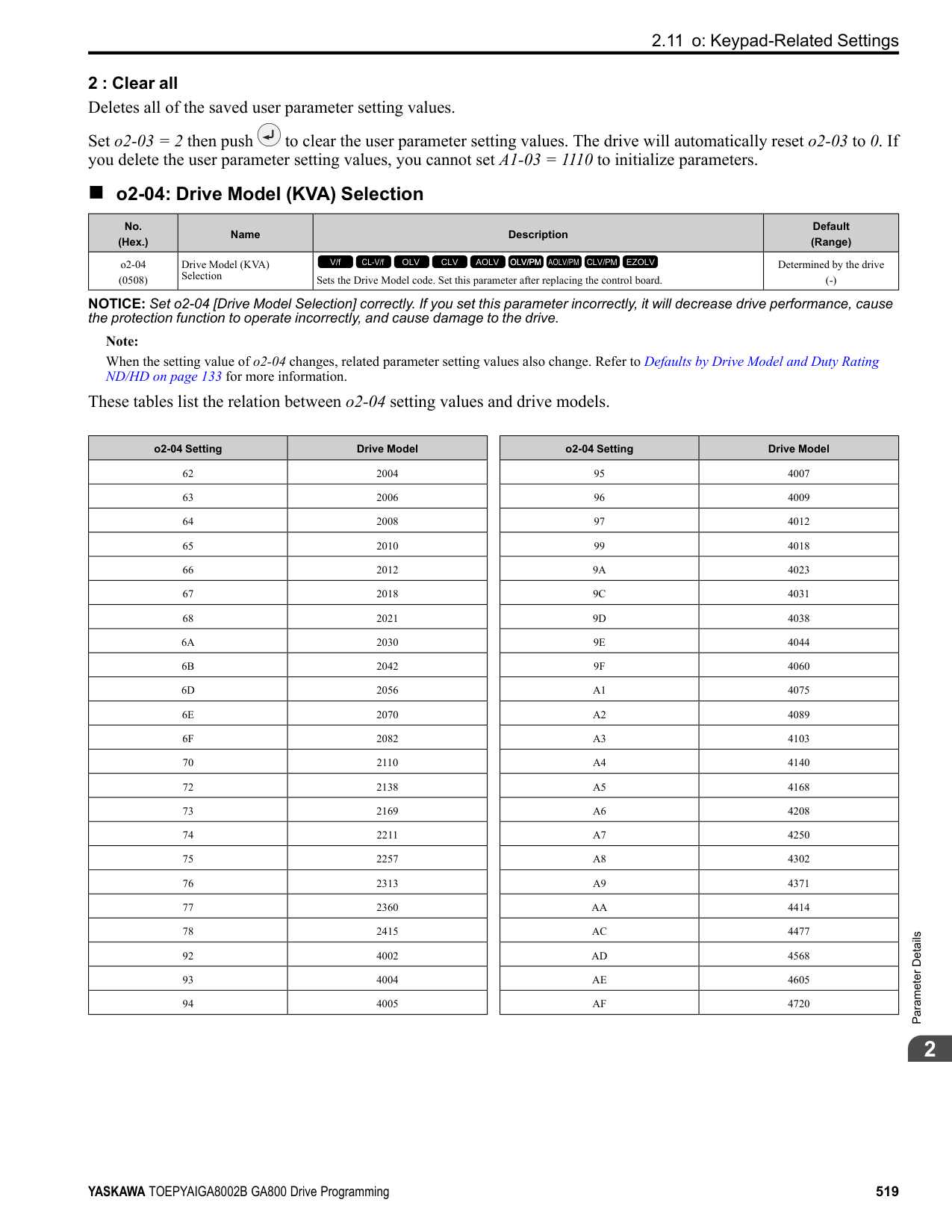
######## ■ T1-00: Motor 1/Motor 2 Selection
|No. (Hex.)|Name|Description|Default (Range)| |---|---|---|---| |T1-00 (0700)|Motor 1/Motor 2 Selection|Sets which motor to tune when motor 1/2 switching is enabled.
V/f CL-V/f OLV CLV AOLV OLV/PM AOLV/PM CLV/PM EZOLV
|1 (1, 2)|
Note: This parameter is available when H1-xx = 16 [Motor 2 Selection]. The keypad will not show this parameter when H1-xx ≠ 16.
Auto-Tuning automatically sets parameters E3-xx and E4-xx for motor 2. Make sure that you connect motor 2 to the drive for Auto-Tuning.
0 : Rotational Auto-Tuning 1 : Stationary Auto-Tuning 1 2 : Stationary Line-Line Resistance
If you do Auto-Tuning on a drive-dedicated motor or a specialized motor for vector control, the voltage or frequency can be lower than that of a general-purpose motor. Always compare the data from the nameplate or test report with the Auto-Tuning results and check for differences. Enter the voltage necessary to operate the motor in no-load conditions at rated speed for better control precision around rated speed. If the motor test report or the motor nameplate is not available, enter approximately 90% of the motor rated voltage. If the drive input power supply voltage is low, enter approximately 90% of the input voltage. When the input power supply voltage is low, the current will increase. Make sure that the main power supply capacity is correct and use a molded-case circuit breaker for the drive.
Set the motor rated current between 50% and 100% of the drive rated current for the best performance. Enter the current at the motor base speed.
|No. (Hex.)|Name|Description|Default (Range)| |---|---|---|---|
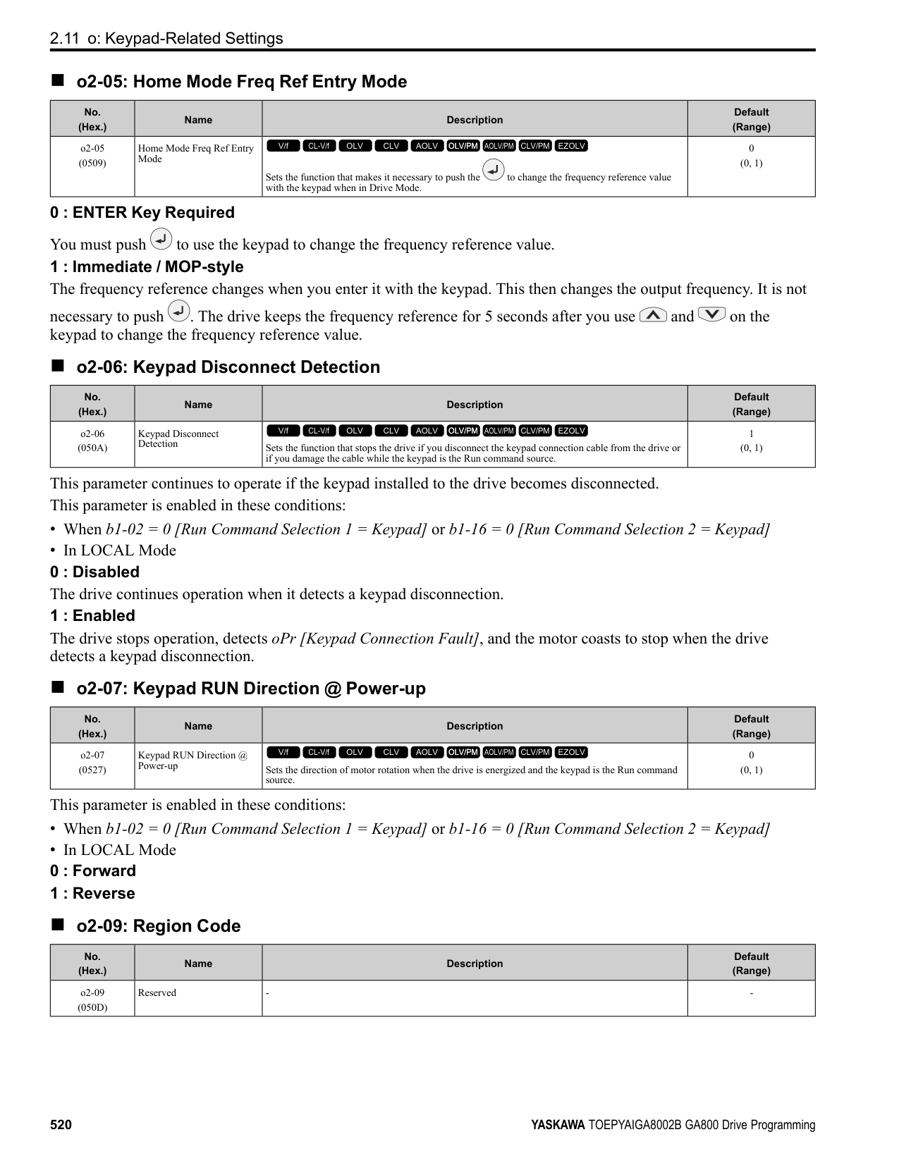
|T1-01 (0701)|Tuning Mode Selection|Sets the type of Auto-Tuning.
V/f CL-V/f OLV CLV AOLV OLV/PM AOLV/PM CLV/PM EZOLV
|Determined by A1-02 (Determined by A1-02)|
|No. (Hex.)|Name|Description|Default (Range)| |---|---|---|---| |T1-02 (0702)|Motor Rated Power|Uses the units set in o1-58 [Motor Power Unit Selection] to set the motor rated output power.
V/f CL-V/f OLV CLV AOLV OLV/PM AOLV/PM CLV/PM EZOLV
|Determined by o2-04, C6-01 (0.00 - 650.00 HP)|
|No. (Hex.)|Name|Description|Default (Range)| |---|---|---|---| |T1-03 (0703)|Motor Rated Voltage|Sets the rated voltage (V) of the motor. Enter the base speed voltage for constant output motors.
V/f CL-V/f OLV CLV AOLV OLV/PM AOLV/PM CLV/PM EZOLV
|Determined by o2-04, C6-01 (200 V Class: 0.0 - 255.5 V, 400 V Class: 0.0 - 511.0 V)|
|No. (Hex.)|Name|Description|Default (Range)| |---|---|---|---| |T1-04 (0704)|Motor Rated Current|Sets the rated current (A) of the motor.
V/f CL-V/f OLV CLV AOLV OLV/PM AOLV/PM CLV/PM EZOLV
|Determined by o2-04 (10% to 200% of the drive rated current)|
|No. (Hex.)|Name|Description|Default (Range)| |---|---|---|---| |T1-05 (0705)|Motor Base Frequency|Sets the base frequency (Hz) of the motor.
V/f CL-V/f OLV CLV AOLV OLV/PM AOLV/PM CLV/PM EZOLV
|60.0 Hz (0.0 - 590.0 Hz)|
ParameterDetails
When Auto-Tuning is carried out, the value of T1-05 is set to E1-04 [Maximum Output Frequency]. If T1-05 < 40 Hz, E1-04 = 40 Hz. If you operate the drive at a speed that is higher than the base frequency, or if you operate in the field weakening range, set E1-04 (E3-04 for motor 2) to the maximum output frequency after you complete Auto-Tuning.
Set the actual number of pulses for one full motor rotation.
|No. (Hex.)|Name|Description|Default (Range)| |---|---|---|---| |T1-06 (0706)|Number of Motor Poles|Sets the number of motor poles.
V/f CL-V/f OLV CLV AOLV OLV/PM AOLV/PM CLV/PM EZOLV
|4 (2 to 120)|
|No. (Hex.)|Name|Description|Default (Range)|
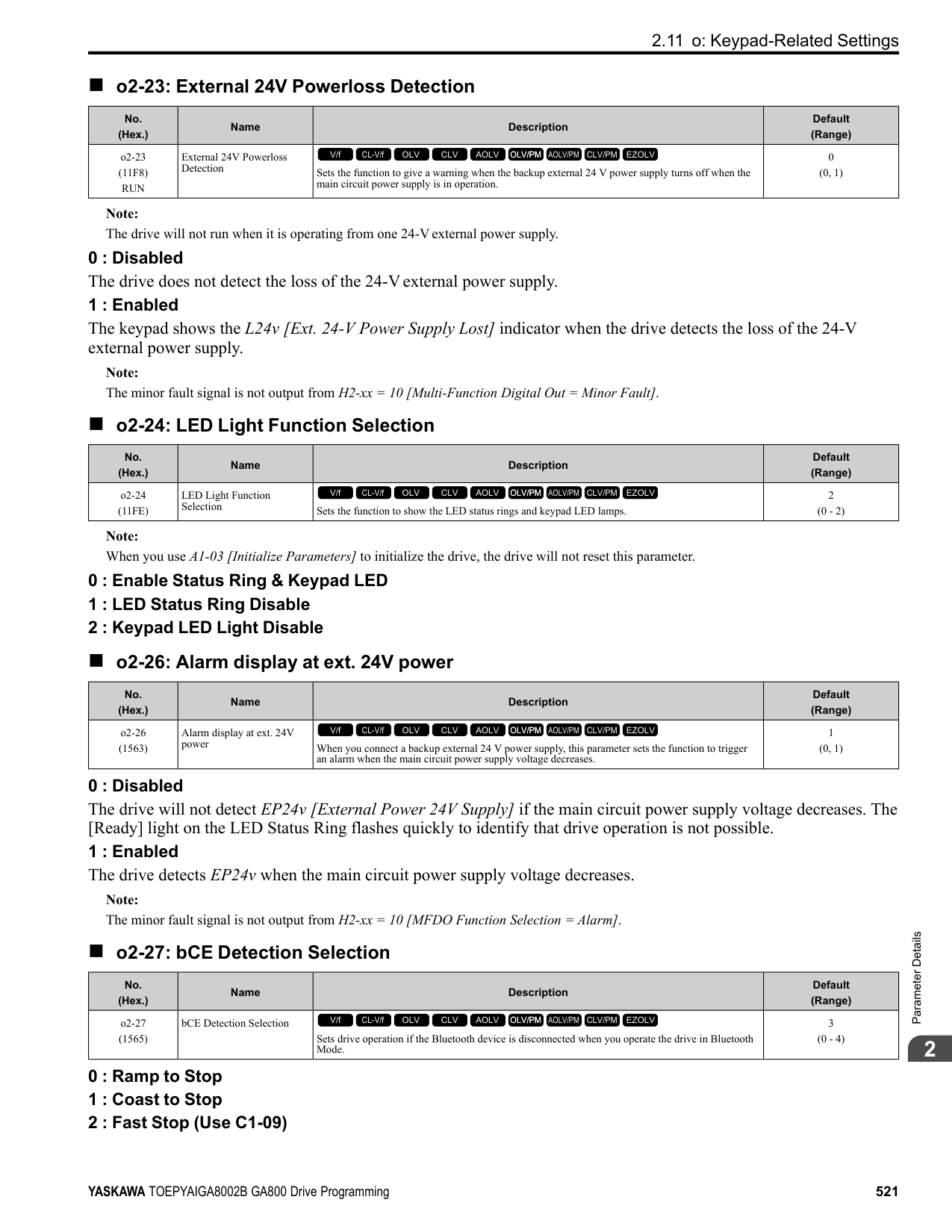
|---|---|---|---| |T1-07 (0707)|Motor Base Speed|Sets the motor base speed for Auto-Tuning (min-1 (r/min)).
V/f CL-V/f OLV CLV AOLV OLV/PM AOLV/PM CLV/PM EZOLV
|1750 min-1 (r/min) (0 - 35400 min-1 (r/min))|
|No. (Hex.)|Name|Description|Default (Range)| |---|---|---|---| |T1-08 (0708)|Encoder Pulse Count (PPR)|Sets the number of PG (pulse generator, encoder) pulses.
V/f CL-V/f OLV CLV AOLV OLV/PM AOLV/PM CLV/PM EZOLV
|1024 ppr (0 - 60,000 ppr)|
|No. (Hex.)|Name|Description|Default (Range)| |---|---|---|---| |T1-09 (0709)|Motor No-Load Current|Sets the no-load current of the motor.
V/f CL-V/f OLV CLV AOLV OLV/PM AOLV/PM CLV/PM EZOLV
|(0A - T1-04; max. of 2999.9)|
Note: The display units are different for different models:
The value shown is the no-load current that is automatically calculated from the values set in T1-02 [Motor Rated Power] and T1-04 [Motor Rated Current]. Set the no-load current shown on the motor test report. If the motor test report is not available, do not change this parameter.
######## ■ T1-10: Motor Rated Slip Frequency
|No. (Hex.)|Name|Description|Default (Range)| |---|---|---|---| |T1-10 (070A)|Motor Rated Slip Frequency|Sets motor rated slip.
V/f CL-V/f OLV CLV AOLV OLV/PM AOLV/PM CLV/PM EZOLV
|(0.000 - 20.000 Hz)|
Shows 0.000 Hz as the default value. Set the rated slip shown on the motor test report. If the motor test report is not available, do not change this parameter.
######## ■ T1-11: Motor Iron Loss
|No. (Hex.)|Name|Description|Default (Range)| |---|---|---|---| |T1-11 (070B)|Motor Iron Loss|Sets the iron loss for calculating the energy-saving coefficient.
V/f CL-V/f OLV CLV AOLV OLV/PM AOLV/PM CLV/PM EZOLV
|Determined by E2-11 or E411
(0 - 65535 W)|
Note: The default setting is different for different motor codes and motor parameter settings.
The value shown is the E2-10 [Motor Iron Loss] or E4-10 [Motor 2 Iron Loss] for the motor output set in T1-02 [Motor Rated Power]. If the motor test report is available, enter the motor iron loss value to T1-11.
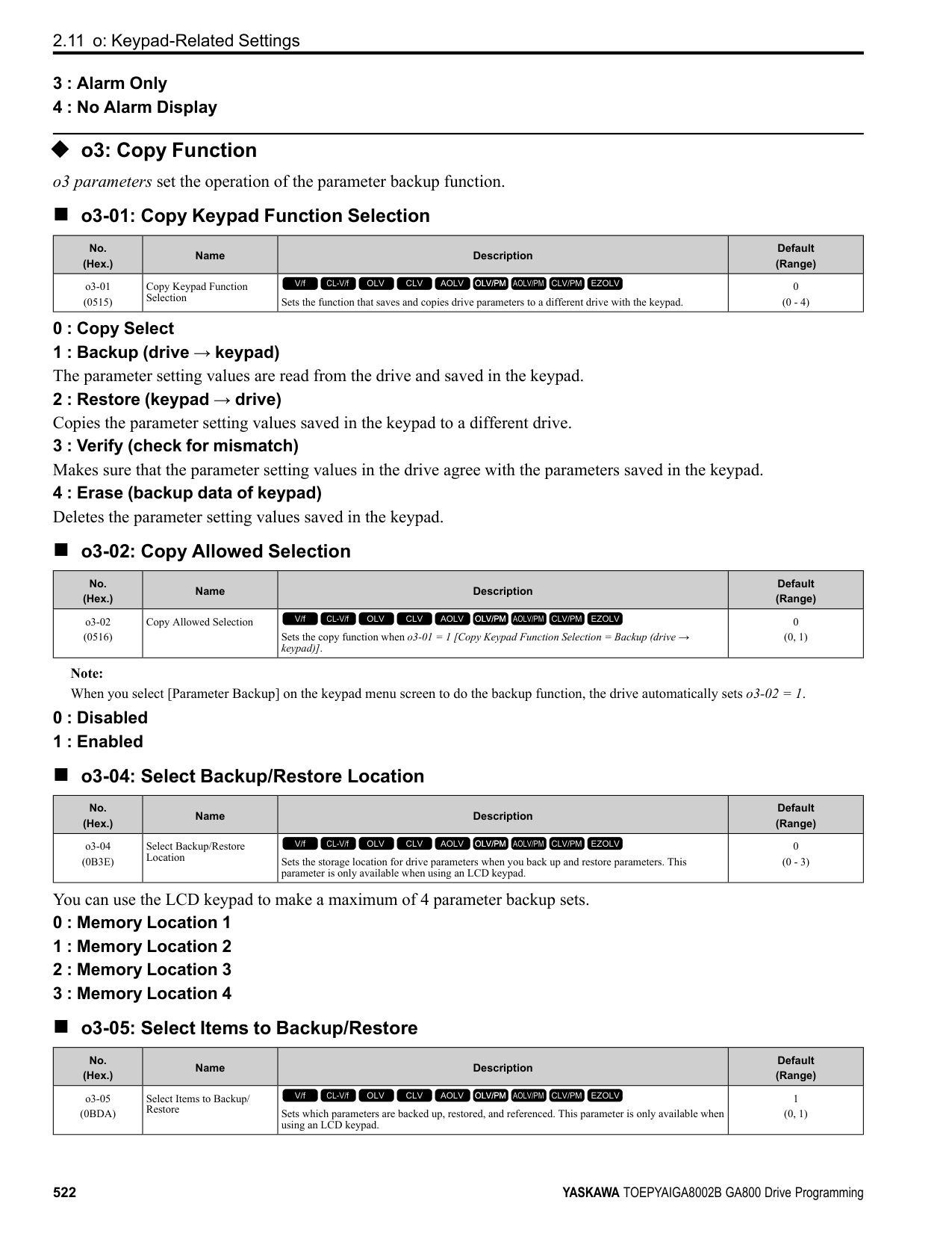
######## ■ T1-12: Test Mode Selection
|No. (Hex.)|Name|Description|Default (Range)| |---|---|---|---| |T1-12 (0BDB)|Test Mode Selection|Sets the function to enable Test Mode after Stationary Auto-Tuning. When you can operate the motor with a light load attached after Stationary Auto-Tuning is complete, enable this parameter.
V/f CL-V/f OLV CLV AOLV OLV/PM AOLV/PM CLV/PM EZOLV
|0 (0, 1)|
0 : No 1 : Yes
After Auto-Tuning, the drive automatically sets E2-02 [Motor Rated Slip] and E2-03 [Motor No-Load Current] when you operate the motor for the first time in Drive Mode.
Note: After Auto-Tuning is complete and you set the drive to Drive Mode, operate the motor in these conditions:
######## ■ T1-13: No-load voltage
|No. (Hex.)|Name|Description|Default (Range)| |---|---|---|---| |T1-13 (0BDC)|No-load voltage|Sets the no-load voltage of the motor. If you know the no-load voltage at the rated speed in a test report, set that voltage value. If you do not know the no-load voltage, do not change from the initial value.
V/f CL-V/f OLV CLV AOLV OLV/PM AOLV/PM CLV/PM EZOLV
|T1-03 × 0.85
(200 V Class: 0.0 - 255.0 V, 400 V Class: 0.0 - 510.0 V)|
################# Note:
–2004 - 2008, 4002 - 4004: T1-03 × 0.85 –2010 - 2415, 4005 - 4302: T1-03 × 0.90 –4371- 4720: T1-03 × 0.95
◆ T2: PM Motor Auto-Tuning T2 parameters set the Auto-Tuning input data for PM motor tuning.
Note: The drive automatically sets these PM motor parameters:
•E1-xx [V/f Pattern for Motor 1] •E5-xx [V/f Pattern for Motor 1] •F1-xx [Encoder Option Setup]
Only when A1-02 = 7 [Control Method Selection = PM Closed Loop Vector]
######## ■ T2-01: PM Auto-Tuning Selection
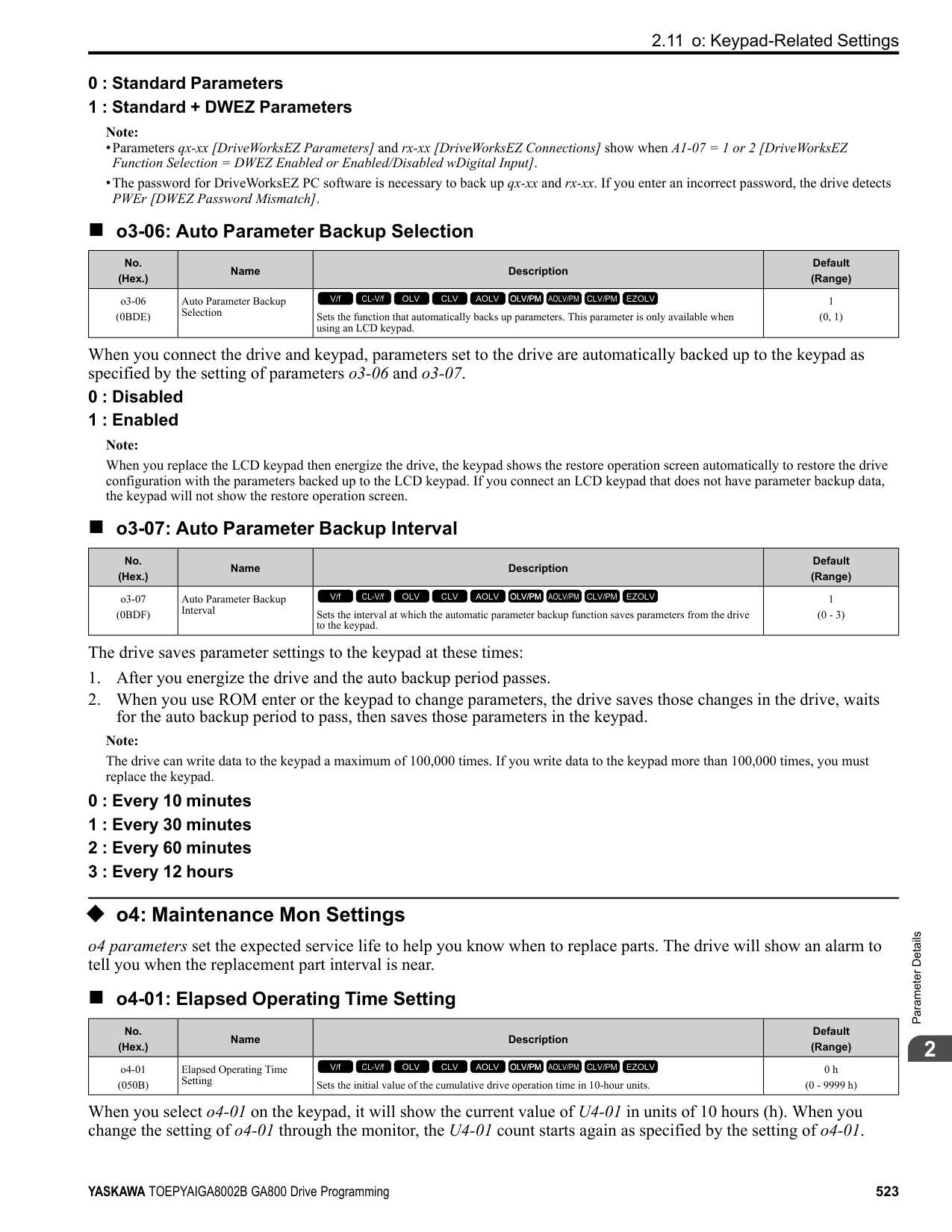
|No. (Hex.)|Name|Description|Default (Range)| |---|---|---|---| |T2-01 (0750)|PM Auto-Tuning Selection|Sets the type of Auto-Tuning for PM motors.
V/f CL-V/f OLV CLV AOLV OLV/PM AOLV/PM CLV/PM EZOLV
|0 (Determined by A1-02)|
################# Note:
Yaskawa recommends Rotational (Ld, Lq, R, back-EMF) for specialized motors. Rotational Auto-Tuning rotates the motor to measure the actual induction voltage constants for more accurate control than Stationary Auto-Tuning.
############## 0 : Manual Entry w/ Motor Data Sheet 1 : Stationary (Ld, Lq, R) 2 : Stationary (R Only) 3 : Z-Pulse Offset (Pole Position)
ParameterDetails
######## 2
######## ■ T2-02: PM Motor Code Selection
|No. (Hex.)|Name|Description|Default (Range)| |---|---|---|---| |T2-02 (0751)|PM Motor Code Selection|If the drive is operating a Yaskawa PM motor from the SMRA, SSR1, or SST4 series, enter the PM motor code in accordance with the rotation speed and motor output.
V/f CL-V/f OLV CLV AOLV OLV/PM AOLV/PM CLV/PM EZOLV
|FFFF (0000 - FFFF)|
Enter the motor code in T2-02 to automatically set parameters T2-03 to T2-14. When you are operating a specialized motor or a non-Yaskawa motor designed, set T2-02 = FFFF and enter the data from the motor nameplate or the motor test report. You can only enter the permitted PM motor codes. Different drive control methods will accept different PM motor codes.
|No. (Hex.)|Name|Description|Default (Range)| |---|---|---|---|
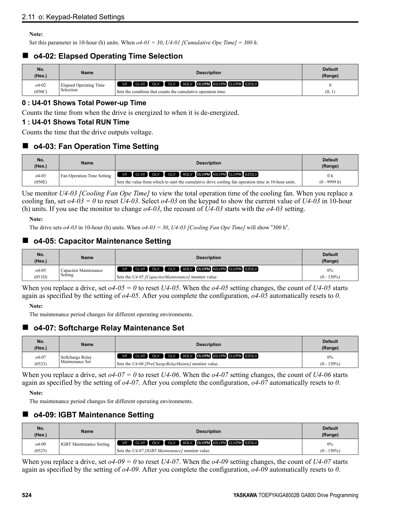
|T2-03 (0752)|PM Motor Type|Sets the type of PM motor the drive will operate.
V/f CL-V/f OLV CLV AOLV OLV/PM AOLV/PM CLV/PM EZOLV
|1 (0, 1)|
|No. (Hex.)|Name|Description|Default (Range)| |---|---|---|---| |T2-04 (0730)|PM Motor Rated Power|Uses the units set in o1-58 [Motor Power Unit Selection] to set the PM motor rated output power.
V/f CL-V/f OLV CLV AOLV OLV/PM AOLV/PM CLV/PM EZOLV
|Determined by o2-04, C6-01 (0.00 - 650.00 HP)|
|No. (Hex.)|Name|Description|Default (Range)| |---|---|---|---| |T2-05 (0732)|PM Motor Rated Voltage|Sets the rated voltage (V) of the motor.
V/f CL-V/f OLV CLV AOLV OLV/PM AOLV/PM CLV/PM EZOLV
|200 V Class: 230.0 V, 400 V: 460.0 V
(200 V Class: 0.0 - 255.0 V, 400 V Class: 0.0 - 510.0 V)|
|No. (Hex.)|Name|Description|Default (Range)| |---|---|---|---| |T2-06 (0733)|PM Motor Rated Current|Sets the rated current (A) of the motor.
V/f CL-V/f OLV CLV AOLV OLV/PM AOLV/PM CLV/PM EZOLV
|Determined by o2-04 (10% to 200% of the drive rated current)|
|No. (Hex.)|Name|Description|Default (Range)| |---|---|---|---| |T2-07 (0753)|PM Motor Base Frequency|Sets the base frequency (Hz) of the motor.
V/f CL-V/f OLV CLV AOLV OLV/PM AOLV/PM CLV/PM EZOLV
|60.0 Hz (0.0 - 590.0 Hz)|
Note: This parameter does not set line-to-line resistance.
|No. (Hex.)|Name|Description|Default (Range)| |---|---|---|---| |T2-08 (0734)|Number of PM Motor Poles|Sets the number of motor poles.
V/f CL-V/f OLV CLV AOLV OLV/PM AOLV/PM CLV/PM EZOLV
|4 (2 - 48)|
|No. (Hex.)|Name|Description|Default (Range)| |---|---|---|---| |T2-09 (0731)|PM Motor Base Speed|Sets the motor base speed (min-1 (r/min)).
V/f CL-V/f OLV CLV AOLV OLV/PM AOLV/PM CLV/PM EZOLV
|1750 min-1 (r/min) (0 - 34500 min-1 (r/min))|
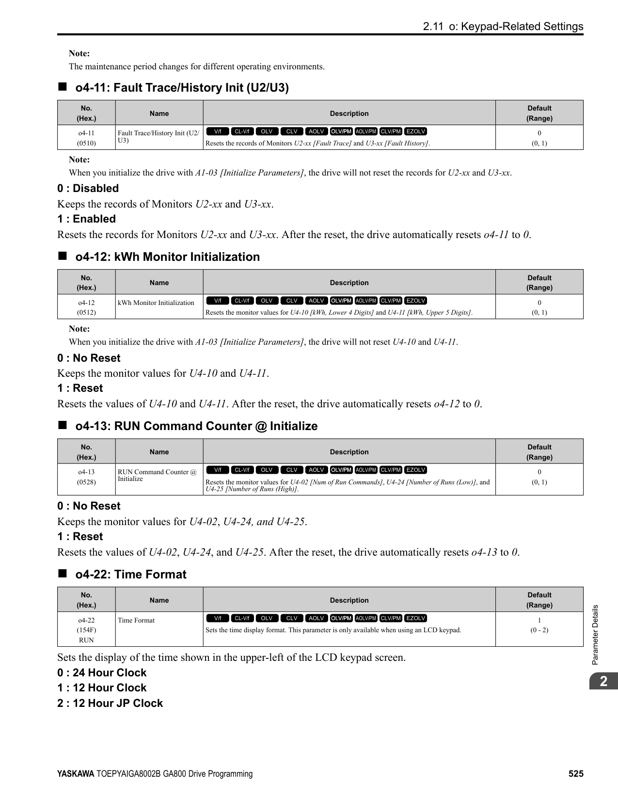
|No. (Hex.)|Name|Description|Default (Range)| |---|---|---|---| |T2-10 (0754)|PM Motor Stator Resistance|Sets the stator resistance for each motor phase.
V/f CL-V/f OLV CLV AOLV OLV/PM AOLV/PM CLV/PM EZOLV
|Determined by T2-02 (0.000 - 65.000 Ω)|
|No. (Hex.)|Name|Description|Default (Range)| |---|---|---|---| |T2-11 (0735)|PM Motor d-Axis Inductance|Sets the d-axis inductance of the motor on a per phase basis.
V/f CL-V/f OLV CLV AOLV OLV/PM AOLV/PM CLV/PM EZOLV
|Determined by T2-02 (0.00 - 600.00 mH)|
|No. (Hex.)|Name|Description|Default (Range)| |---|---|---|---| |T2-12 (0736)|PM Motor q-Axis Inductance|Sets the q-Axis inductance of the motor on a per phase basis.
V/f CL-V/f OLV CLV AOLV OLV/PM AOLV/PM CLV/PM EZOLV
|Determined by T2-02 (0.00 - 600.00 mH)|
|No. (Hex.)|Name|Description|Default (Range)| |---|---|---|---| |T2-13 (0755)|Back-EMF Units Selection|Sets the units that the drive uses to set the induced voltage constant.
V/f CL-V/f OLV CLV AOLV OLV/PM AOLV/PM CLV/PM EZOLV
|0 (0, 1)|
0 : mV/(rev/min) 1 : mV/(rad/s)
Note:
######## ■ T2-14: Back-EMF Voltage Constant (Ke)
|No. (Hex.)|Name|Description|Default (Range)| |---|---|---|---| |T2-14 (0737)|Back-EMF Voltage Constant (Ke)|Sets the motor induced voltage constant (Ke).
V/f CL-V/f OLV CLV AOLV OLV/PM AOLV/PM CLV/PM EZOLV
|Determined by T2-13 (0.0 - 2000.0)|
ParameterDetails
######## 2
######## ■ T2-15: Pull-In Current Level
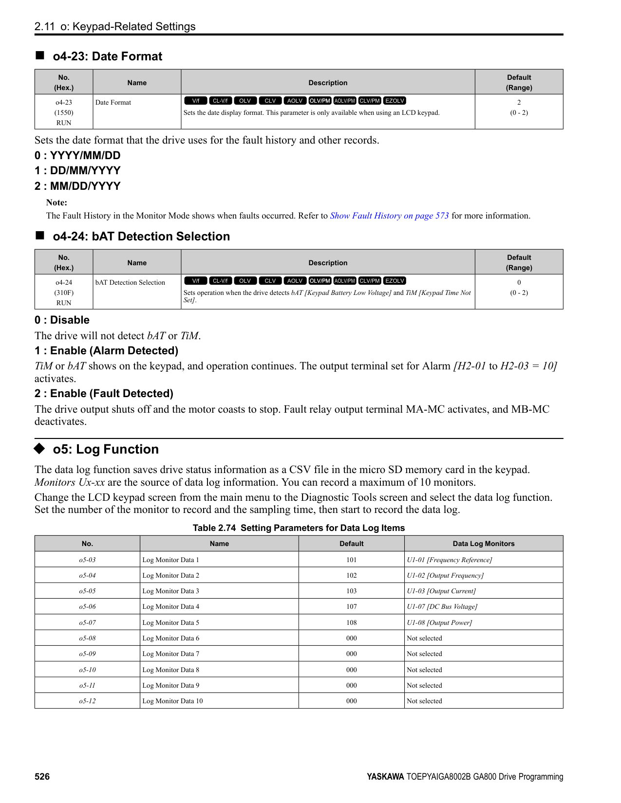
|No. (Hex.)|Name|Description|Default (Range)| |---|---|---|---| |T2-15 (0756)|Pull-In Current Level|Sets the level of the pull-in current as a percentage of E5-03 [PM Motor Rated Current (FLA)]. Usually it is not necessary to change this setting.
V/f CL-V/f OLV CLV AOLV OLV/PM AOLV/PM CLV/PM EZOLV
|30% (0 - 120%)|
If the load inertia is high, increase the setting value.
######## ■ T2-16: Encoder Pulse Count (PPR)
|No. (Hex.)|Name|Description|Default (Range)| |---|---|---|---| |T2-16 (0738)|Encoder Pulse Count (PPR)|Sets the number of PG (pulse generator, encoder) pulses.
V/f CL-V/f OLV CLV AOLV OLV/PM AOLV/PM CLV/PM EZOLV
|1024 ppr (1 - 15000 ppr)|
Set the actual number of pulses for one full motor rotation.
######## ■ T2-17: Encoder Z-Pulse Offset
|No. (Hex.)|Name|Description|Default (Range)| |---|---|---|---| |T2-17 (0757)|Encoder Z-Pulse Offset|Sets the encoder Z-pulse offset (Δθ) (pulse generator, encoder) that is listed on the motor nameplate.
V/f CL-V/f OLV CLV AOLV OLV/PM AOLV/PM CLV/PM EZOLV
|0.0 ° (-180.0 - +180.0°)|
If you do not know the quantity of encoder (pulse generator, encoder) Z-pulse offset, or if you replaced the encoder, do Z Pulse Offset Tuning and correct for the offset (Δθ) from the Z phase.
◆ T3: ASR and Inertia Tuning
######## ■ T3-00: Control Loop Tuning Selection
|No. (Hex.)|Name|Description|Default (Range)| |---|---|---|---| |T3-00 (1198)|Control Loop Tuning Selection|Sets the type of Control Auto-Tuning.
V/f CL-V/f OLV CLV AOLV OLV/PM AOLV/PM CLV/PM EZOLV
|0 (0 - 3)|
############## 0 : Inertia Tuning 1 : ASR (Speed Regulator) 2 : Deceleration Rate Tuning 3 : KEB Tuning
Note: Settings 0 and 1 are available only when A1-02 = 3, 7 [Control Method Selection = CLV, CLV/PM].
######## ■ T3-01: Test Signal Frequency
|No. (Hex.)|Name|Description|Default (Range)|
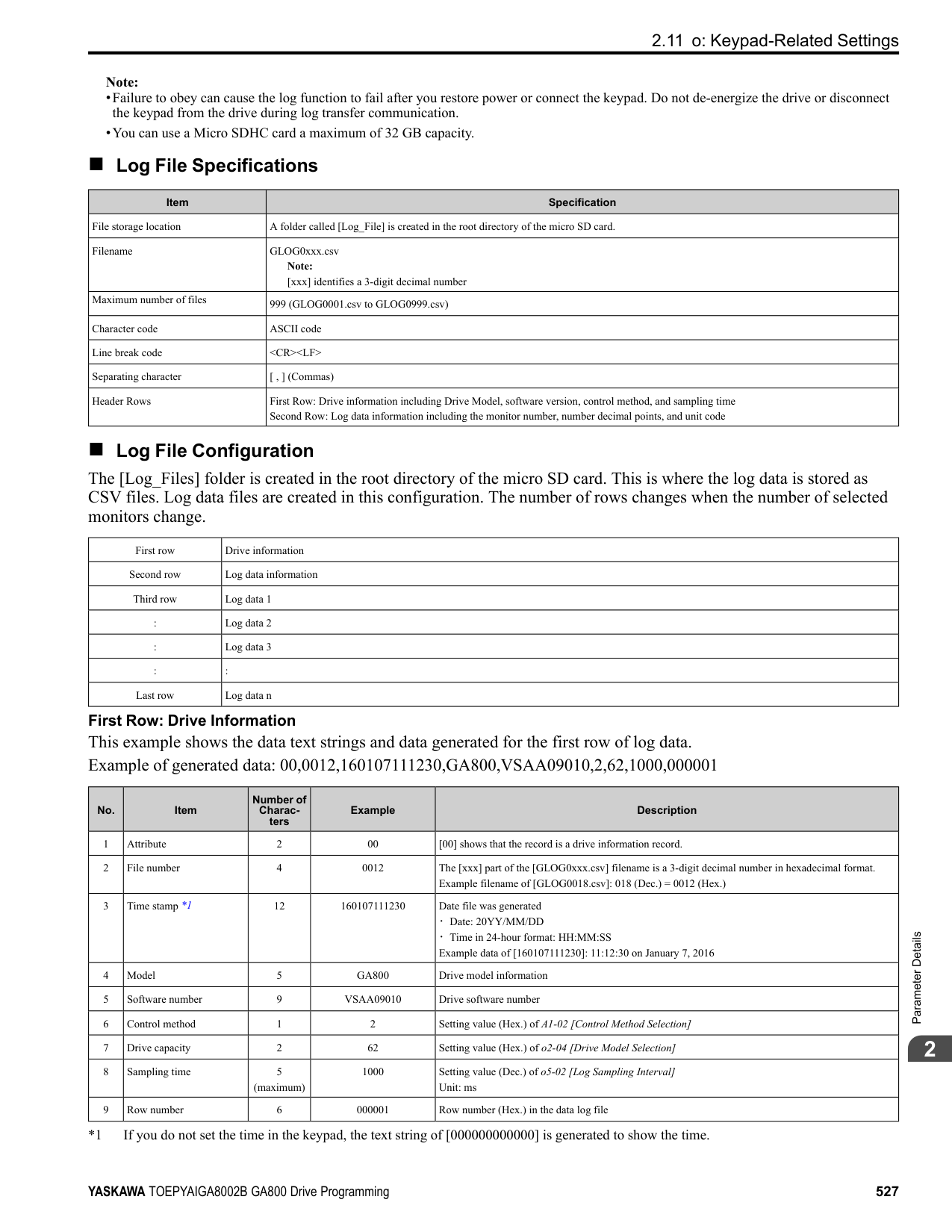
|---|---|---|---| |T3-01 (0760)|Test Signal Frequency|Sets the frequency of the test signal applied to the motor during Inertia Tuning. Usually it is not necessary to change this setting.
V/f CL-V/f OLV CLV AOLV OLV/PM AOLV/PM CLV/PM EZOLV
|3.0 Hz (0.1 - 20.0 Hz)|
If the load inertia is too large and the drive detects a fault after Inertia Tuning, decrease the setting.
######## ■ T3-02: Test Signal Amplitude
|No. (Hex.)|Name|Description|Default (Range)| |---|---|---|---| |T3-02 (0761)|Test Signal Amplitude|Sets the amplitude of the test signal applied to the motor during Inertia Tuning. Usually it is not necessary to change this setting.
V/f CL-V/f OLV CLV AOLV OLV/PM AOLV/PM CLV/PM EZOLV
|0.5 rad (0.1 - 10.0 rad)|
If the load inertia is too large and the drive detects a fault after Inertia Tuning, decrease the setting. If the drive detects a fault when T3-01 [Test Signal Frequency] is set to a low value, adjust this parameter.
######## ■ T3-03: Motor Inertia
|No. (Hex.)|Name|Description|Default (Range)| |---|---|---|---| |T3-03 (0762)|Motor Inertia|Sets the inertia of the motor. This value uses the test signal response to calculate the load inertia.
V/f CL-V/f OLV CLV AOLV OLV/PM AOLV/PM CLV/PM EZOLV
|Determined by o2-04, C601, and E5-01
(0.0001 - 600.00 kgm2)|
The default setting is for a Yaskawa standard motor as shown in the motor inertia table. Actual values will be different when you use induction motors or PM motors.
Note: The display units for the default setting and setting range are different for different models:
######## ■ T3-04: System Response Frequency
|No. (Hex.)|Name|Description|Default (Range)| |---|---|---|---| |T3-04 (0763)|System Response Frequency|This parameter uses the load inertia value from the Inertia Tuning process to automatically calculate and set C5-01 [ASR Proportional Gain 1].
V/f CL-V/f OLV CLV AOLV OLV/PM AOLV/PM CLV/PM EZOLV
|10.0 Hz (0.1 - 50.0 Hz)|
If this input value is too high, it can cause oscillation.
◆ T4: EZ Tuning Use T4 parameters to input the data necessary for motor parameter Auto-Tuning when A1-02 = 8 [Control Method Selection = EZ Vector Control]. These two modes are available:
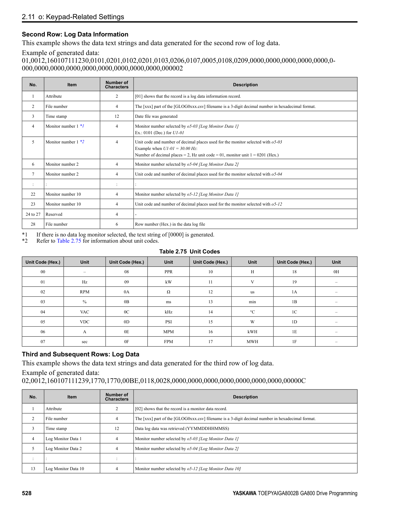
|T4-01 Setting|Operational overview|Items input for tuning|Items tuned| |---|---|---|---| |0|Follow the instructions in the setup wizard on the keypad to manually enter the necessary motor parameters.|• T4-02 [Motor Type Selection]
• T4-03 [Motor Max Revolutions]
• T4-04 [Motor Rated Revolutions]
• T4-05 [Motor Rated Frequency] *1
• T4-06 [Motor Rated Voltage]
• T4-07 [Motor Rated Current]
• T4-08 [Motor Rated Capacity]
• T4-09 [Number of Poles]
|• E9-01 [Motor Type Selection]
• E9-02 [Maximum Speed]
• E9-03 [Rated Speed]
• E9-04 [Base Frequency]
• E9-05 [Base Voltage]
• E9-06 [Motor Rated Current (FLA)]
• E9-07 [Motor Rated Power]
• E9-08 [Motor Pole Count]
• E9-09 [Motor Rated Slip]
• E9-10 [Motor Line-to-Line Resistance]
| |1|Do only line-to-line resistance tuning.|Motor Rated Current|E9-10 [Motor Line-to-Line Resistance]|
*1 When you use a PM motor or a synchronous reluctance motor, it is not necessary to enter the rated frequency. The drive will use the rated rotation speed and number of motor poles to automatically calculate the rated frequency.
######## ■ T4-01: EZ Tuning Mode Selection
|No. (Hex.)|Name|Description|Default (Range)| |---|---|---|---| |T4-01 (3130)|EZ Tuning Mode Selection|Sets the type of Auto-Tuning for EZOLV control.
V/f CL-V/f OLV CLV AOLV OLV/PM AOLV/PM CLV/PM EZOLV
|0 (0, 1)|
0 : Motor Parameter Setting 1 : Line-to-Line Resistance
ParameterDetails
######## 2
######## ■ T4-02: Motor Type Selection
|No. (Hex.)|Name|Description|Default (Range)| |---|---|---|---| |T4-02 (3131)|Motor Type Selection|Sets the type of motor.
V/f CL-V/f OLV CLV AOLV OLV/PM AOLV/PM CLV/PM EZOLV
|0 (0, 1, 2)|
0 : Induction (IM) 1 : Permanent Magnet (PM) 2 : Synchronous Reluctance (SynRM)
Note:
When T4-02 = 1, 2 [Motor Type Selection = PM, SynRM], input is not necessary because it assumes: Motor Rated Revolutions/60 × Number of Motor Poles/2.
Note: The value set here becomes the base value for motor protection, the torque limit, and torque control.
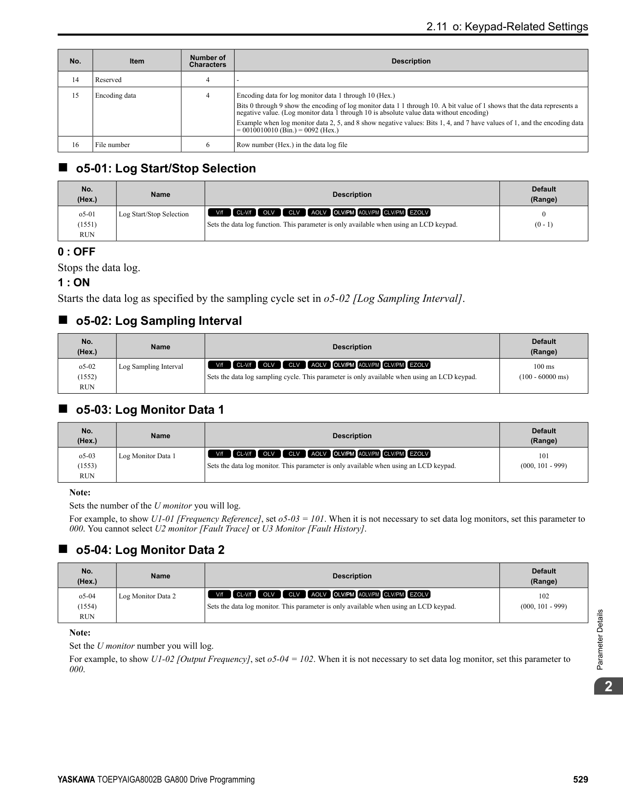
|No. (Hex.)|Name|Description|Default (Range)| |---|---|---|---| |T4-04 (3133)|Motor Rated Revolutions|Sets rated rotation speed (min-1) of the motor.
V/f CL-V/f OLV CLV AOLV OLV/PM AOLV/PM CLV/PM EZOLV
|((40 Hz to 120 Hz) × 60 × 2/ E9-08)|
|No. (Hex.)|Name|Description|Default (Range)| |---|---|---|---| |T4-05 (3134)|Motor Rated Frequency|Sets the rated frequency (Hz) of the motor.
V/f CL-V/f OLV CLV AOLV OLV/PM AOLV/PM CLV/PM EZOLV
|Determined by E9-01 and o2-04
(40.0 - 120.0 Hz)|
|No. (Hex.)|Name|Description|Default (Range)| |---|---|---|---| |T4-06 (3135)|Motor Rated Voltage|Sets the rated voltage (V) of the motor.
V/f CL-V/f OLV CLV AOLV OLV/PM AOLV/PM CLV/PM EZOLV
|200 V Class: 230.0 V, 400 V: 460.0 V
(200 V Class: 0.0 - 255.0 V,400 V Class: 0.0 - 510.0 V)|
|No. (Hex.)|Name|Description|Default (Range)| |---|---|---|---| |T4-07 (3136)|Motor Rated Current|Sets the rated current (A) of the motor.
V/f CL-V/f OLV CLV AOLV OLV/PM AOLV/PM CLV/PM EZOLV
|Determined by o2-04, C6-01 (10% to 200% of the drive rated current)|
|No. (Hex.)|Name|Description|Default (Range)| |---|---|---|---| |T4-08 (3137)|Motor Rated Capacity|Sets the motor rated power in the units set in o1-58 [Motor Power Unit Selection].
V/f CL-V/f OLV CLV AOLV OLV/PM AOLV/PM CLV/PM EZOLV
|Determined by E9-10 (0.10 - 650.00 HP)|
|No. (Hex.)|Name|Description|Default (Range)| |---|---|---|---| |T4-09 (3138)|Number of Poles|Sets the number of motor poles.
V/f CL-V/f OLV CLV AOLV OLV/PM AOLV/PM CLV/PM EZOLV
|Determined by E9-01 (2 - 48)|
3
Keypad Use and Test Run
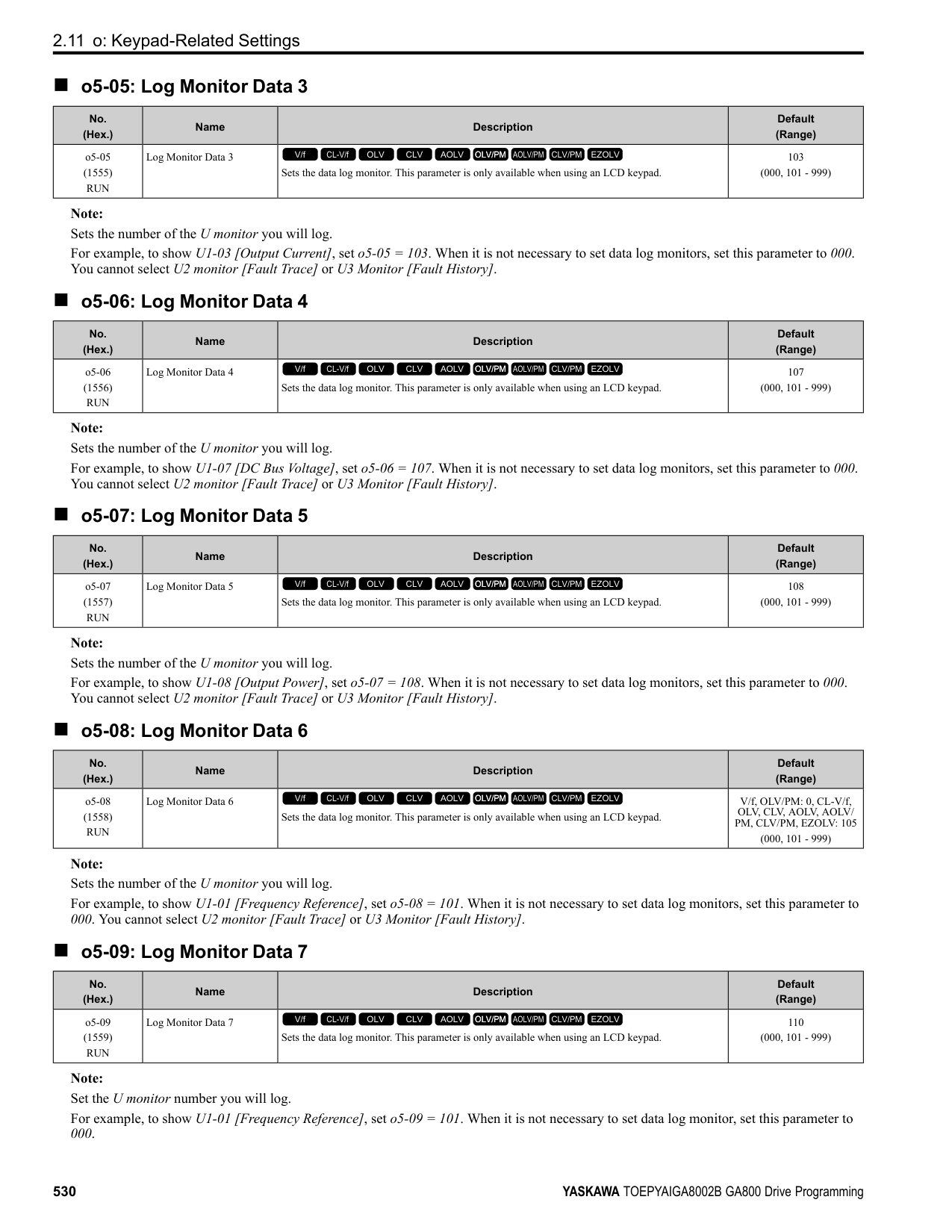
3.1 Section Safety
####### 3.1 Section Safety
|DANGER| |---| |Electrical Shock Hazard
Do not examine, connect, or disconnect wiring on an energized drive. Before servicing, disconnect all power to the equipment and wait for the time specified on the warning label at a minimum. The internal capacitor stays charged after the drive is de-energized. The charge indicator LED extinguishes when the DC bus voltage decreases below 50 Vdc. When all indicators are OFF, remove the covers before measuring for dangerous voltages to make sure that the drive is safe.
If you do work on the drive when it is energized, it will cause serious injury or death from electrical shock. The drive has internal capacitors that stay charged after you de-energize the drive.
|
|WARNING| |---| |Electrical Shock Hazard
Do not operate the drive when covers are missing. Replace covers and shields before you operate the drive. Use the drive only as specified by the instructions.
Some figures in this section include drives without covers or safety shields to more clearly show the inside of the drive. If covers or safety shields are missing from the drive, it can cause serous injury or death.
Do not remove covers or touch circuit boards while the drive is energized. If you touch the internal components of an energized drive, it can cause serious injury or death.|
####### 3.2 Keypad: Names and Functions
| | | | |---|---|---| | | | |
Figure 3.1 Keypad Table 3.1 Keypad: Names and Functions
|No.|Name|Function| |---|---|---| |A|RUN LED|Illuminates to show that the drive is operating the motor. The LED turns OFF when the drive stops. Flashes to show that:
• The drive is decelerating to stop.
• The drive received a Run command but the frequency reference is 0 Hz. Flashes quickly to show that:
• The drive received a Run command from the Multi-Function Digital Input (MFDI) terminals and is switching to REMOTE Mode while the drive is in LOCAL Mode.
• The drive received a Run command from the MFDI terminals when the drive is not in Drive Mode.
• The drive received a Fast Stop command.
• The safety function shuts off the drive output.
• The user pushed on the keypad while the drive is operating in REMOTE Mode.
• The drive is energized with an active Run command and b1-17 = 0 [Run Command at Power Up = Disregard Existing RUN Command].
| |B|ALM LED|Illuminates when the drive detects a fault. Flashes when the drive detects:
• Alarm
• An oPE parameter setting error
• A fault or alarm during Auto-Tuning The light switches off when the drive is in normal operation. There is no fault or alarm.
| |C|microSD Card Insertion Slot|The insertion point for a microSD card.| |D|Function Keys (F1, F2, F3)|The menu shown on the keypad sets the functions for function keys. The name of each function is in the lower half of the display window.| |E|LO/RE LED|Illuminated: The keypad controls the Run command (LOCAL Mode). OFF: The control circuit terminal or serial transmission device controls the Run command (REMOTE Mode).
Note:
• LOCAL: Operated using the keypad. Use the keypad to enter Run/Stop commands and the frequency reference command.
• REMOTE: Operated from the control circuit terminal or serial transmission. Use the frequency reference source entered in b1-01 and the Run command source selected in b1-02.
|
|No.|Name|Function| |---|---|---| |F|LO/RE Selection Key|Switches drive control for the Run command and frequency reference between the keypad (LOCAL) and an external source (REMOTE).
Note:
• Stop operation to enable the LO/RE Selection Key when in Drive Mode. Set o2-01 0 [LO/RE Key Function Selection Disabled] to disable when switching from REMOTE to LOCAL will have a negative effect on system performance.
• The drive will not switch between LOCAL and REMOTE when it is receiving a Run command from an external source.
| |G|STOP Key|Stops drive operation. Note: The STOP key has highest priority. Push to stop the motor even when a Run command (REMOTE Mode) is active at any external Run command source. Set o2-02 0 [STOP Key Function Selection Disabled] to disable the priority in .|
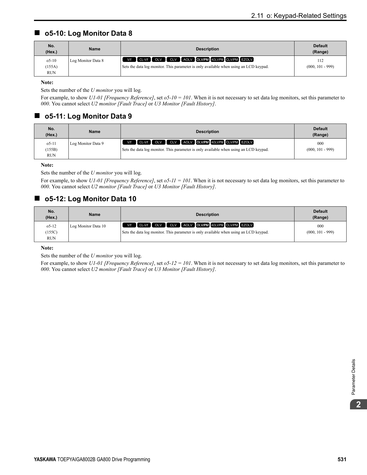
|H|Left Arrow Key|Moves the cursor to the left.| |H|Up Arrow Key/Down Arrow Key
/|• Scrolls up or down to display the next item or the previous item.
• Selects parameter numbers, and increments or decrements setting values.
| |H|Right Arrow Key (RESET)|• Moves the cursor to the right.
• Continues to the next screen.
• Clears drive faults.
| |H|ENTER Key|• Enters parameter values and settings.
• Selects menu items to move the user between keypad displays.
• Selects each mode, parameter, and set value.
| |I|RUN Key|Starts the drive in LOCAL mode. Starts the motor tuning procedure in Auto-Tuning Mode.
Note: Push on the keypad to set the drive to LOCAL Mode before using the keypad to operate the motor.| |J|USB Terminal|Insertion point for a mini USB cable. Uses a USB cable (USB standard 2.0, type A - mini-B) to connect the keypad to a PC.| |K|RJ-45 Connector|Connects to the drive using an RJ-45 8-pin straight through UTP CAT5e extension cable or keypad connector.| |L|Clock Battery Cover|Cover for the clock battery.
Note:
• The battery included with the keypad is for operation check. It may be exhausted earlier than the expected battery life described in the manual.
• Refer to “Maintenance & Troubleshooting Manual (TOEPYAIGA8001)” for details on replacement procedure.
To replace the battery, use a Hitachi Maxell “CR2016 Lithium Manganese Dioxide Lithium Battery” or an equivalent battery with these properties:
• Nominal voltage: 3 V
• Operating temperature range: -20°C to +85°C (-4°F to +185°F)
| |M|Insulation Sheet|An insulating sheet is attached to the keypad battery to prevent battery drain. Remove the insulation sheet before you use the keypad for the first time.| |N|Nameplate|Shows the model, lot number, and FLASH number of the keypad.
Note:
Make sure that you use a keypad with FLASH number 1004 or later. Keypads with FLASH numbers 1003 and earlier will not show characters correctly.|
################## WARNING! Sudden Movement Hazard. If you change the control source when b1-07 = 1 [LOCAL/REMOTE Run Selection = Accept Existing RUN Command], the drive can start suddenly. Before you change the control source, remove all personnel from the area around the drive, motor, and load. Sudden starts can cause serious injury or death.
######## ◆ LCD Display
Figure 3.2 LCD Display Indications Table 3.2 LCD Display Indications and Meanings
|Symbol|Name|Description| |---|---|---| |A|Time display area|Shows the current time. Set the time on the default settings screen.| |B|Forward run/Reverse indication|Shows direction of motor rotation.
• FWD: Shown when set to Forward run.
• REV: Shown when set to Reverse run. Note: In DriveWorksEZ operation, FWD or REV flash.
| |C|Ready|The screen will show Rdy when the drive is ready for operation or when the drive is running.| |D|Mode display area|Shows the name of the current mode or screen.| |E|Frequency reference source indicator|Shows the current frequency reference source.
• KPD: keypad
• AI: analog input terminal (terminals A1 to A3)
• COM: MEMOBUS/Modbus communications
• OPT: option card
• RP: pulse train input terminal (terminal RP)
| |F|Data display area|Shows parameter values, monitor values, and details of the results of operations.| |G|Function keys 1 to 3 (F1 to F3)|The function names shown in this area will change when the selected screen changes. Push one of the function keys to on the keypad to do the function.|
######## ◆ Indicator LEDs and Drive Status
|LED|Display|Drive Status| |---|---|---| |RUN LED|Illuminated|The drive is operating the motor.| |RUN LED|Flashing|• The drive is decelerating to stop.
• The drive received a Run command, but the frequency reference is 0 Hz.
• The drive received a DC Injection Braking command.
| |RUN LED|Flashing Quickly|• The drive received a Run command from the Multi-Function Digital Input (MFDI) terminals and is switching to REMOTE Mode while the drive is in LOCAL Mode.
• The drive received a Run command from an external source, but the drive is not in the Drive Ready (READY) condition.
• The drive received a Fast Stop command.
• The safety function shuts off the drive output.
• The user pushed on the keypad while the drive is operating in REMOTE Mode.
• The drive is energized with an active Run command and b1-17 = 0 [Run Command at Power Up = Disregard Existing RUN Command].
• When b1-03 = 3 [Stopping Method Selection = Coast to Stop with Timer], the Run command is disabled then enabled during the Run wait time.
• The drive received a DC Injection Braking command.
• The voltage of the main circuit power supply decreased, and only the 24 V power supply is supplying power to the drive.
| |RUN LED|OFF|The motor is stopped.| |ALM LED|Illuminated|The drive detects a fault.| |ALM LED|Flashing|The drive detects:
• An alarm
• An oPE parameter setting error
• An Auto-Tuning error Note: The digital characters shown on the keypad will also flash.
| |ALM LED|OFF|There are no drive faults or alarms.| |LO/RE LED|Illuminated|The keypad controls the Run command (LOCAL Mode).| |LO/RE LED|OFF|The control circuit terminal or serial transmission device controls the Run command (REMOTE Mode).|
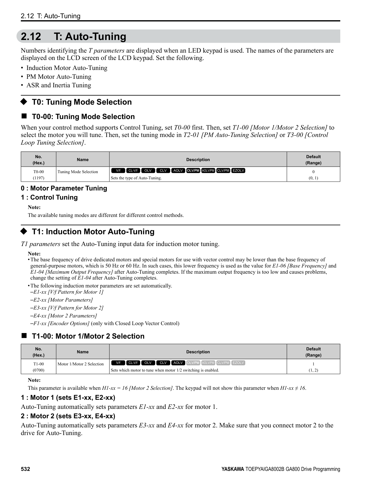
######## ■ LED Flashing Statuses
| | | | | | | | | | | | | | | | | | |---|---|---|---|---|---|---|---|---|---|---|---|---|---|---|---|---| | | | | | | | | | | | | | | | | | | | | | | | | | | | | | | | | | | | | | | | | | | | | | | | | | | | | | | | | | | | | | | | | | | | | | | | |
Figure 3.3 LED Flashing Statuses
/
Figure 3.4 Relation between RUN LED and Drive Operation
######## ◆ Keypad Mode and Menu Displays
| | |---| | | | |
| | |---| | | | |
| | |---| | | | |
| |
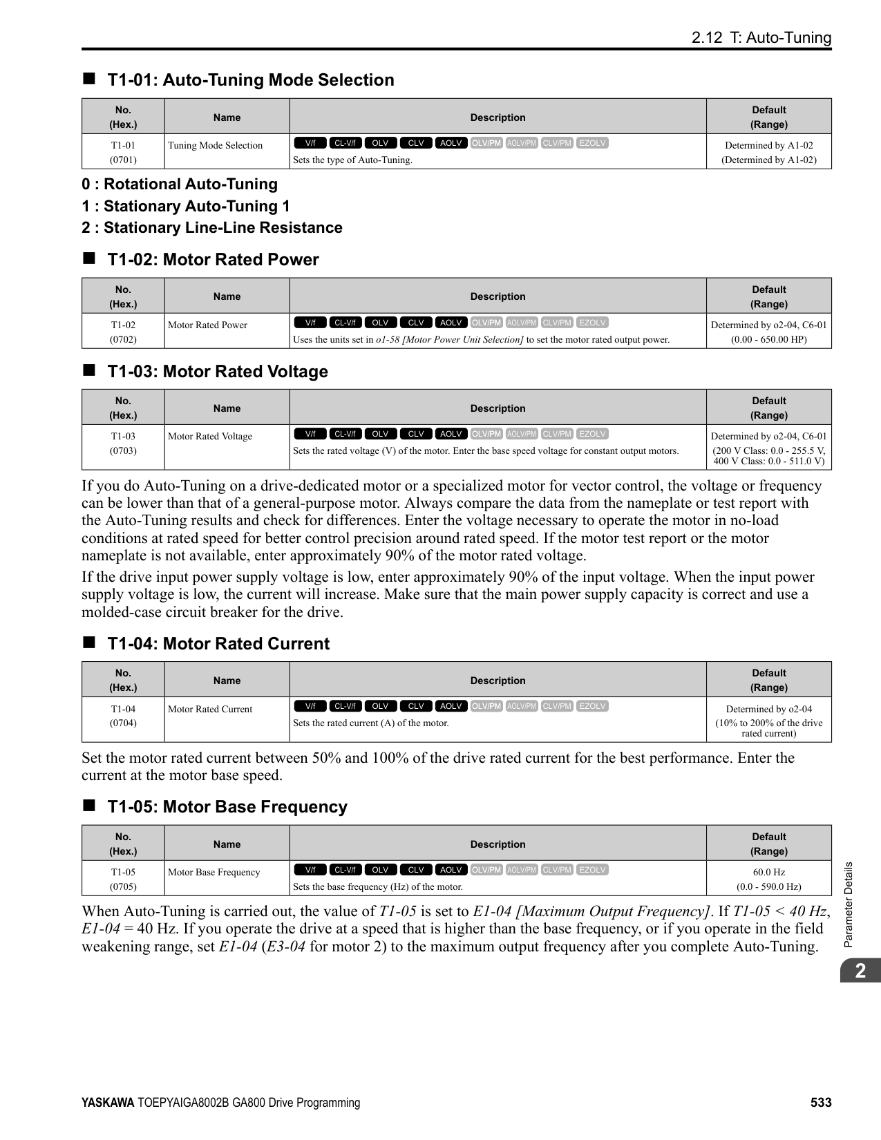
|---| | | | |
| | |---| | | | |
| | |---| | | | |
| | |---| | | | |
| | |---| | | | |
| | |---| | | | |
| | |---| | | | |
| |
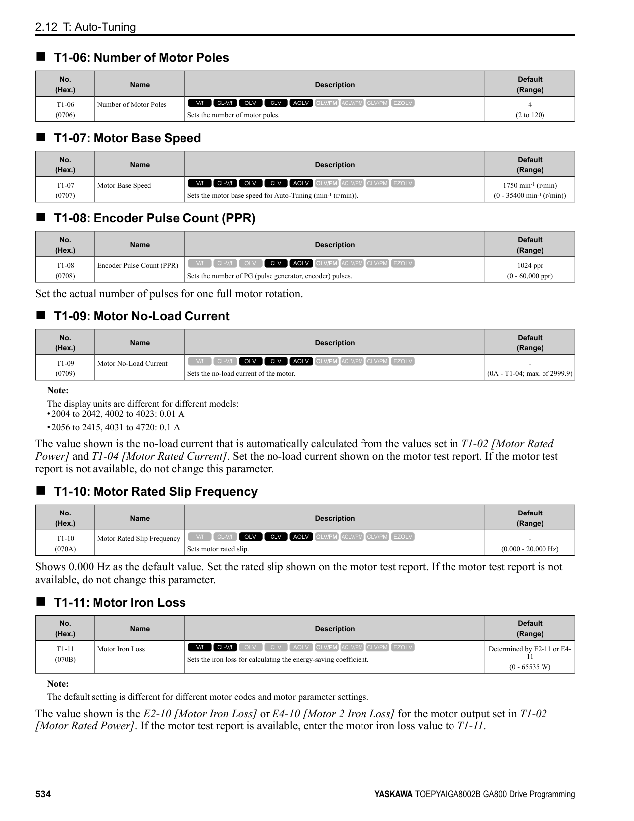
|---| | | | |
| | |---| | | | |
| | |---| | | | |
| | |---| | | | |
Figure 3.5 Keypad Functions and Display Levels
KeypadUseandTestRun
######## 3
################# Note:
–Select [No] from the [Show Initial Setup Screen] setting to not display the Initial Setup screen.
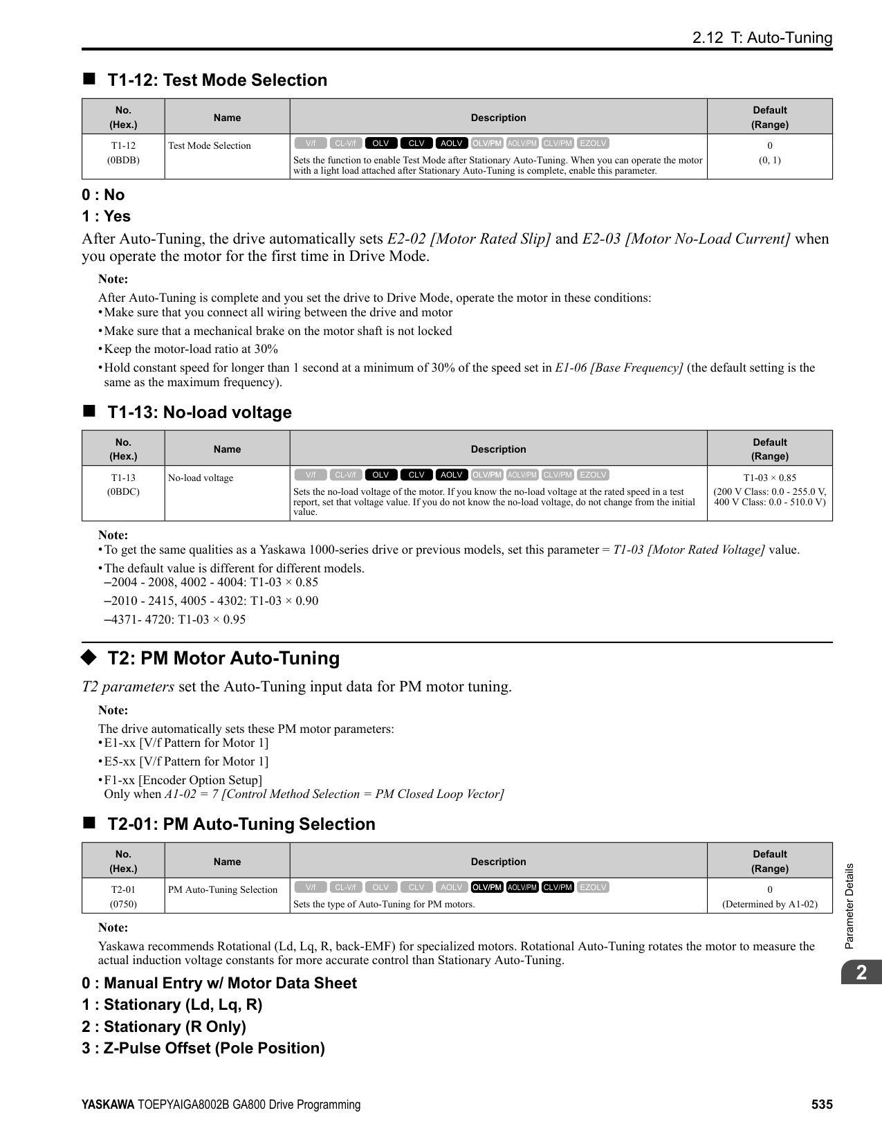
################# Table 3.3 Drive Mode Screens and Functions
|Mode|Keypad Screen|Function| |---|---|---| |Drive Mode|Monitors|Sets monitor items to display.| |Programming Mode|Parameters|Changes parameter settings.| |Programming Mode|User Custom Parameters|Shows the User Parameters.| |Programming Mode|Parameter Backup/Restore|Saves parameters to the keypad as backup.| |Programming Mode|Modified Parameters/Fault Log|Shows modified parameters and fault history.| |Programming Mode|Auto-Tuning|Auto-Tunes the drive.| |Programming Mode|Initial Setup|Changes initial settings.| |Programming Mode|Diagnostic Tools|Sets data logs and backlight.|
3.3 LED Status Ring
####### 3.3 LED Status Ring
The LED Status Ring on the drive cover shows the drive operating status.
| | | |---|---| | | | | | |
A - ALM/ERR B - Ready
C - RUN
|LED|LED|Status|Description| |---|---|---|---| |A|ALM/ERR|Illuminated|The drive detects a fault.| |A|ALM/ERR|Flashing *1|The drive detects:
• An alarm
• An oPE parameter setting error
• An Auto-Tuning error Note: The LED will illuminate to identify a fault if the drive detects a fault and an alarm at the same time.
| |A|ALM/ERR|OFF|There are no drive faults or alarms.| |B|Ready|Illuminated|The drive is operating or is prepared for operation.| |B|Ready|Flashing *1|The drive is in STo [Safe Torque OFF] condition.| |B|Ready|Flashing Quickly *1|The voltage of the main circuit power supply dropped, and only the external 24 V power supply provides the power to the drive.|
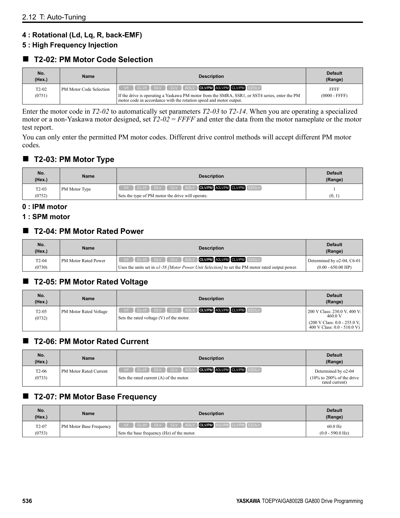
|B|Ready|OFF|• The drive detects a fault.
• There is no fault and the drive received a Run command, but the drive cannot operate. For example, in Programming
Mode or when is flashing.| |C|RUN|Illuminated|The drive is in regular operation.| |C|RUN|Flashing *1|• The drive is decelerating to stop.
• The drive received a Run command with a frequency reference of 0 Hz, but the drive is not set for zero speed control.
• The drive received a DC Injection Braking command.
| |C|RUN|Flashing Quickly *1|• The drive received a Run command from the MFDI terminals and is switching to REMOTE Mode while the drive is in LOCAL Mode.
• The drive received a Run command from the MFDI terminals when the drive is not in Drive Mode.
• The drive received a Fast Stop command.
• The safety function shuts off the drive output.
• The user pushed on the keypad while the drive is operating in REMOTE Mode.
• The drive is energized with an active Run command and b1-17 = 0 [Run Command at Power Up = Disregard Existing RUN Command].
• The drive is set to coast-to-stop with timer (b1-03 = 3 [Stopping Method Selection = Coast to Stop with Timer]), and the Run command is disabled then enabled during the Run wait time.
| |C|RUN|OFF|The motor is stopped.|
*1 Refer to Figure 3.6 for the difference between “flashing” and “flashing quickly”.
KeypadUseandTestRun
3
| | | | | | | | | | | | | | | | | | |---|---|---|---|---|---|---|---|---|---|---|---|---|---|---|---|---| | | | | | | | | | | | | | | | | | | | | | | | | | | | | | | | | | | | | | | | | | | | | | | | | | | | | | | | | | | | | | | | | | | | | | | | |
Figure 3.6 LED Flashing Statuses
/
Figure 3.7 Relation between RUN LED and Drive Operation
####### 3.4 Keypad Operation
Note: Make sure that you use a keypad with FLASH number 1004 or later. Keypads with FLASH numbers 1003 and earlier will not show characters correctly.
######## ◆ Home Screen Display Selection
This section gives information about the functions that you can control from the HOME screen and the content shown on the HOME screen.
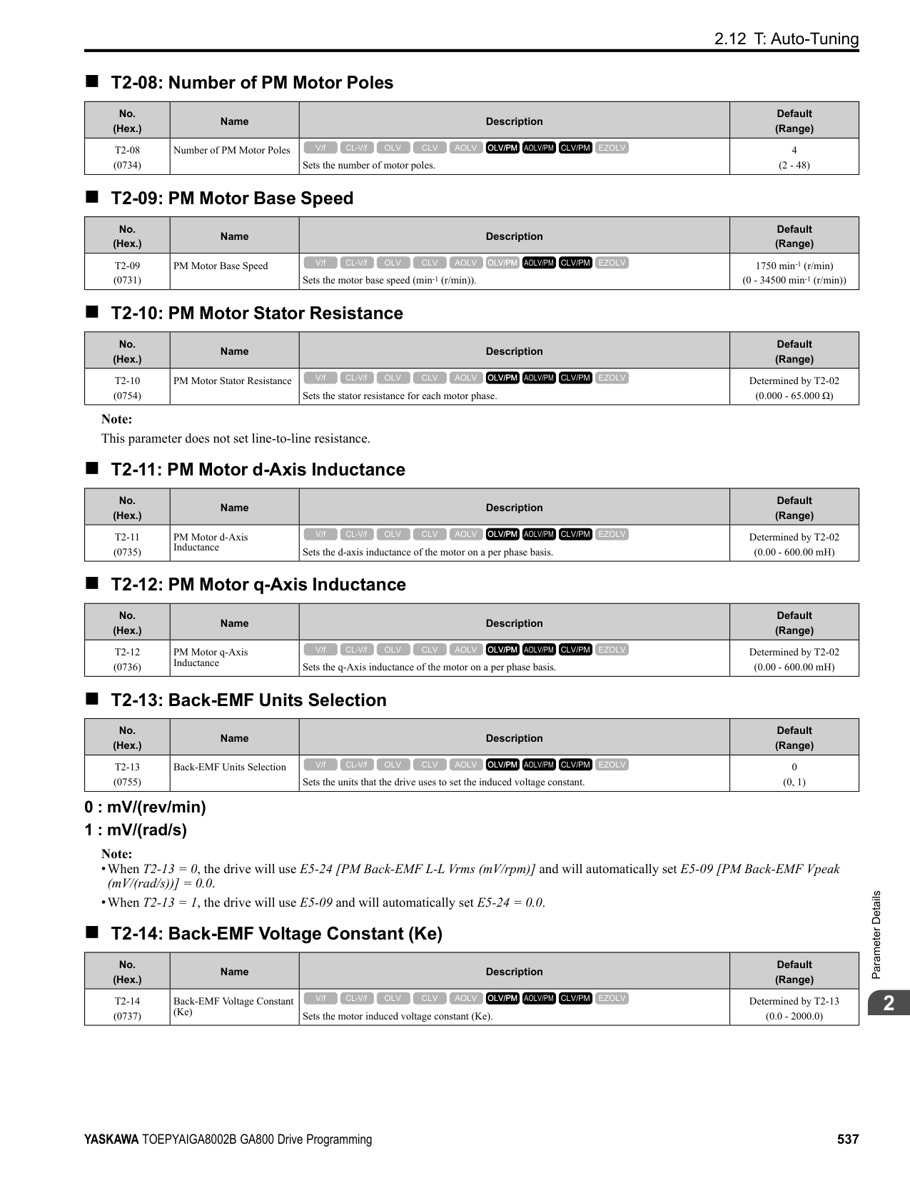
. Push and hold (FWD/REV) to toggle the direction of motor rotation between forward and reverse.
######## ■ Show the Standard Monitor
Push to show the standard monitor (Ux-xx). Push (HOME) to go back to the HOME screen. Note: When a fault, minor fault, or an error occurs, push to show the content of the fault. Push again to show the standard monitor (Uxxx).
######## ■ Change the Frequency Reference Value
KeypadUseandTestRun
3
The HOME screen must show U1-01 [Frequency Reference] or you must set the keypad as the Run command source (REMOTE) to use this function.
■ Show the Main Menu Push to show the main menu. Push (HOME) to go back to the HOME screen.
| | |---| | | | |
◆ Displaying the Monitor This section shows how to show the standard monitor (Ux-xx).
Note:
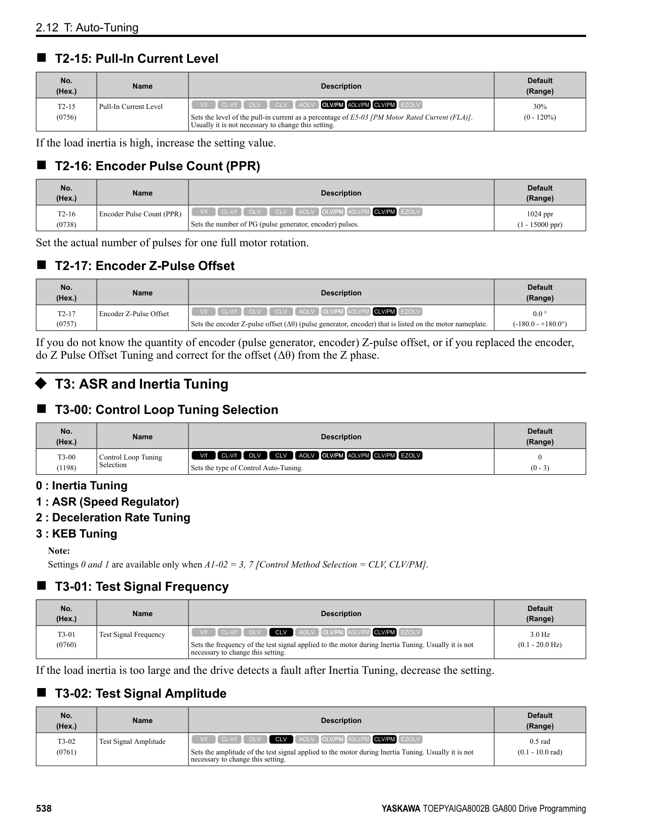
| | |---| | | | |
| | |---| | | | |
| | |---| | | | |
######### ◆ Set Custom Monitors You can select and register a maximum of 12 monitoring items to regularly show on the keypad. This procedure shows how to set the motor speed to [Custom Monitor 1].
Note:
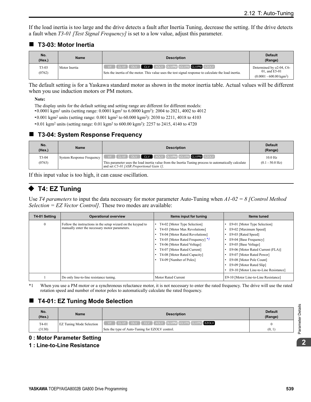
| | |---| | | | |
KeypadUseandTestRun
| | |---| | | | |
| | |---| | | | |
| | |---| | | | |
The configuration procedure is complete.
◆ Show Custom Monitors The procedure in this section shows how to show the registered custom monitors.
Note:
| | |---| | | | |
| | |---| | | | |
The keypad shows the selected monitor as shown in this figure.
◆ Set the Monitors to Show as a Bar Graph The procedure in this section shows how to show the frequency reference monitor as a bar graph.
Note:
| |
|---| | | | |
| | |---| | | | |
KeypadUseandTestRun
| | |---| | | | |
| | | |---|---| | | |
| | | |---|---| | | |
Enter the three digits in “x-xx” part of monitor Ux-xx to identify which monitor to output. For example, to show monitor U1-01 [Frequency Reference], set it to "101" as shown in this figure.
| | |---| | | | |
The configuration procedure is complete.
######## ◆ Show Monitors as Bar Graphs
The procedure in this section shows how to show a specific monitor as a bar graph. You can show a maximum of three.
Note:
| | |---| | | | |
| | |---| | | | |
The screen will show the monitors as shown in this figure.
| | |---| | | | |
◆ Set the Monitors to Show as Analog Gauges The procedure in this section shows how to show the frequency reference monitor as an analog gauge.
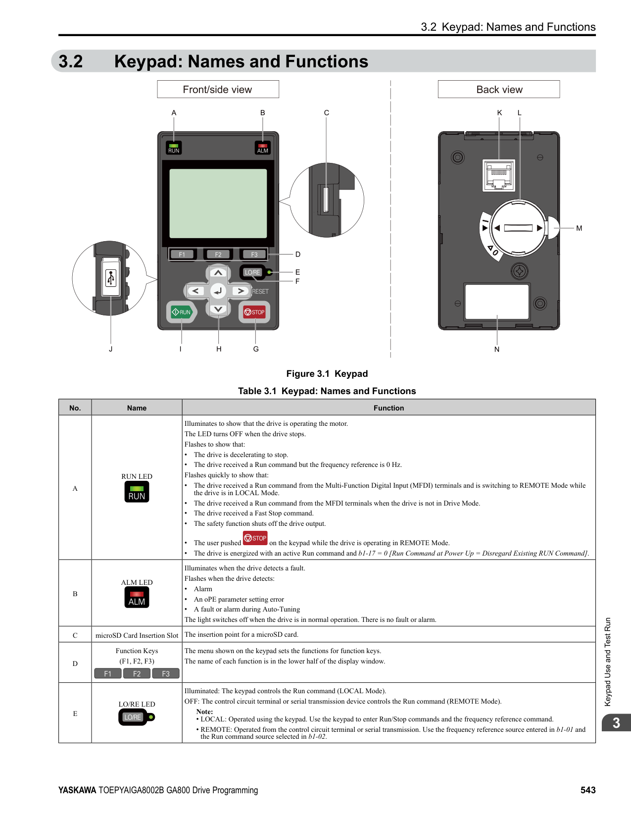
Note:
| | |---| | | | |
| | |---| | | | |
| | | |---|---| | | |
| | | |---|---| | | |
Enter the three digits in “x-xx” part of monitor Ux-xx to identify which monitor to output. For example, to show monitor U1-01 [Frequency Reference], set it to "101" as shown in this figure.
KeypadUseandTestRun
######## 3
The configuration procedure is complete.
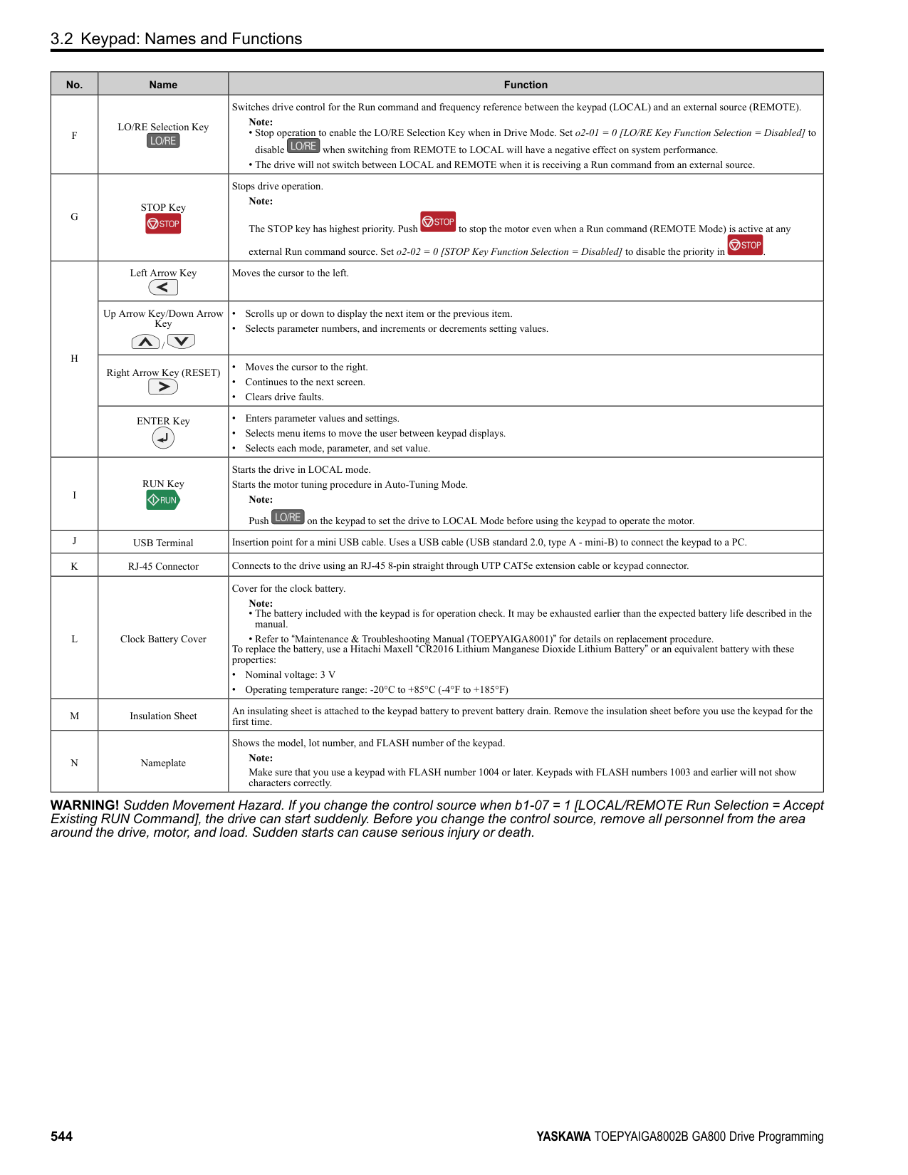
| | |---| | | | |
◆ Display Monitors as an Analog Gauge The following explains how to display the contents selected for a monitor as an analog gauge.
Note:
| | |---| | | | |
| | |---| | | | |
It will be displayed as follows.
| | |---| | | | |
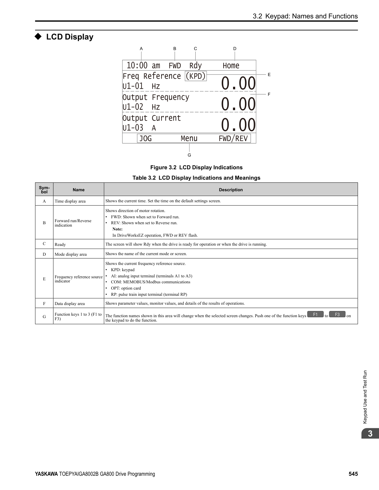
######## ◆ Set Monitoring Items to be Shown as a Trend Plot You must set the items in this figure to display as a trend plot.
D - Trend Plot Time Scale E - Trend Plot 1 Scale Maximum/
Minimum Value
######### ■ Select Monitor Items to Show as a Trend Plot The procedure in this section shows how to show the frequency reference monitor as a trend plot.
Note:
| | |---| | | | |
| | | |---|---| | | |
KeypadUseandTestRun
| | |---|
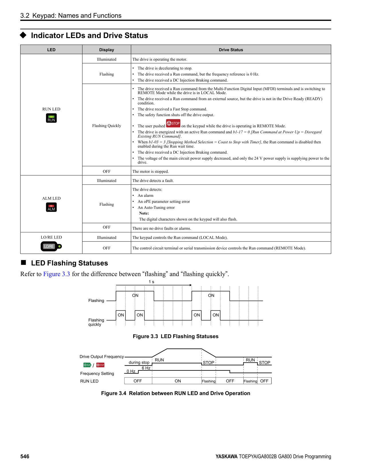
| | | |
When the U parameters are on the display as "Ux-xx", the three digits in "x-xx" identify which monitor to output. For example, to show monitor U1-01 [Frequency Reference], set it to "101" as shown in this figure.
| | | |---|---| | | |
| | | |---|---| | | |
| | |---| | | | |
| | | |---|---| | | |
| |
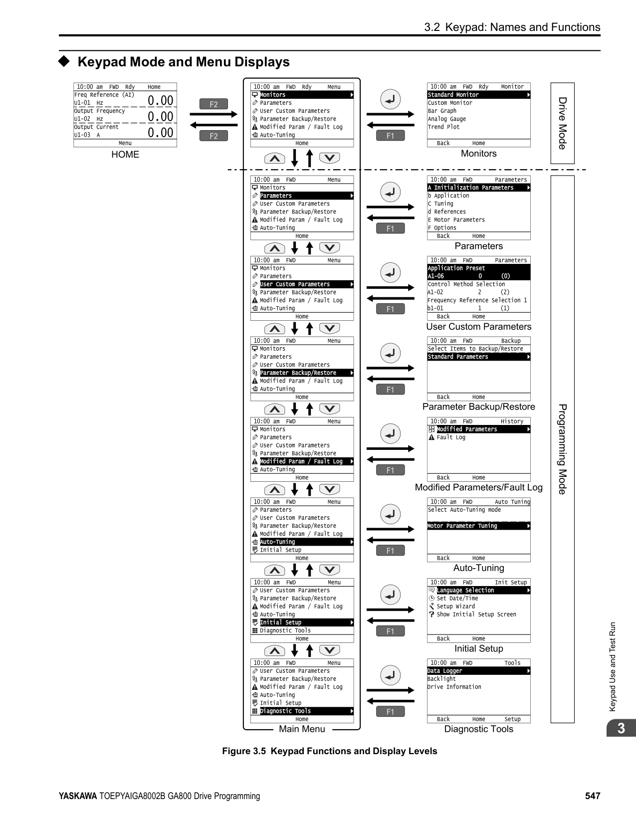
|---| | | | |
| | |---| | | | |
| | | |---|---| | | |
| | |---| | | | |
| | |---| | | | |
######### ■ Set the Time Scale for the Trend Plot Monitor The procedure in this section shows how to set the time scale for the trend plot monitor.
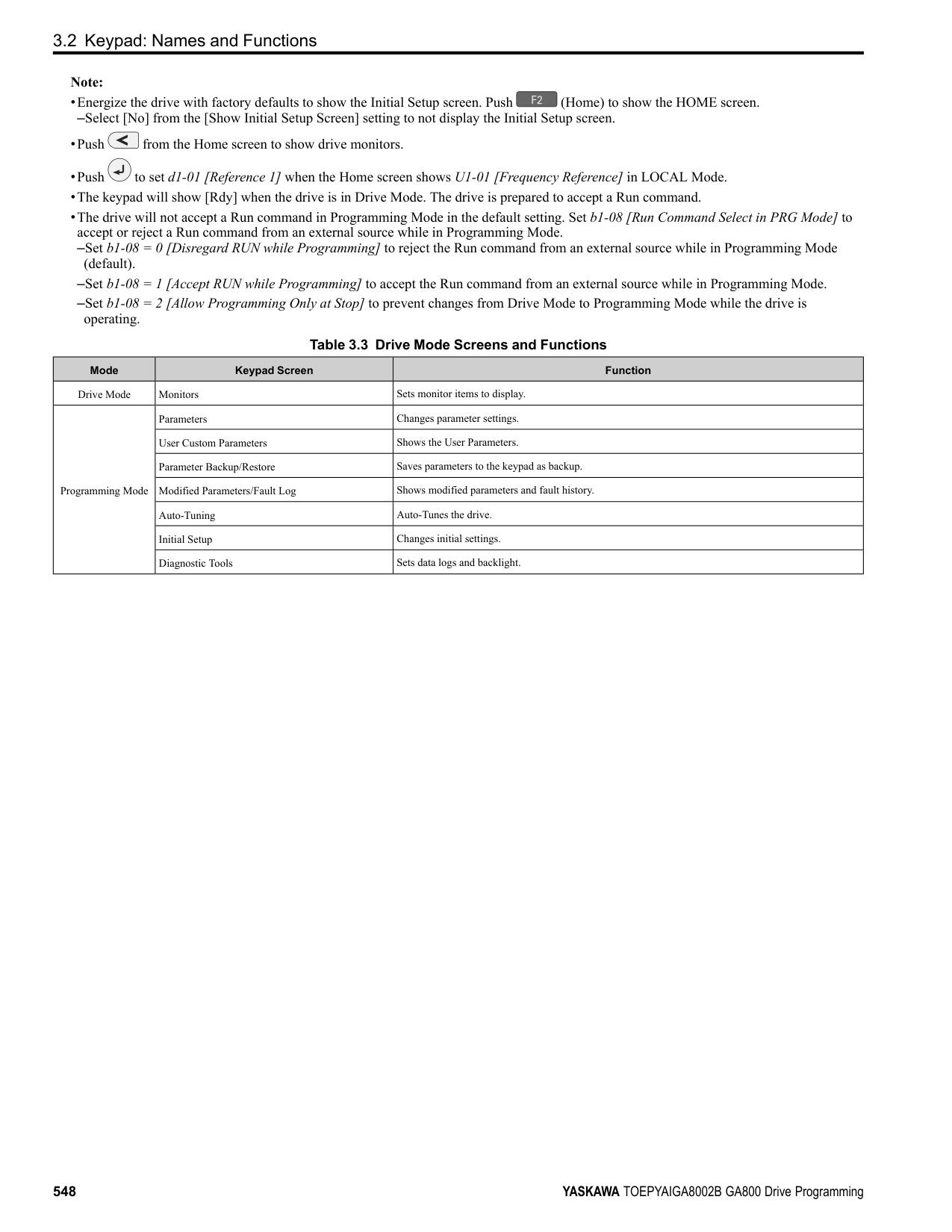
Note:
| | |---| | | | |
KeypadUseandTestRun
| | | |---|---| | | |
| | |---| | | | |
| | |---|
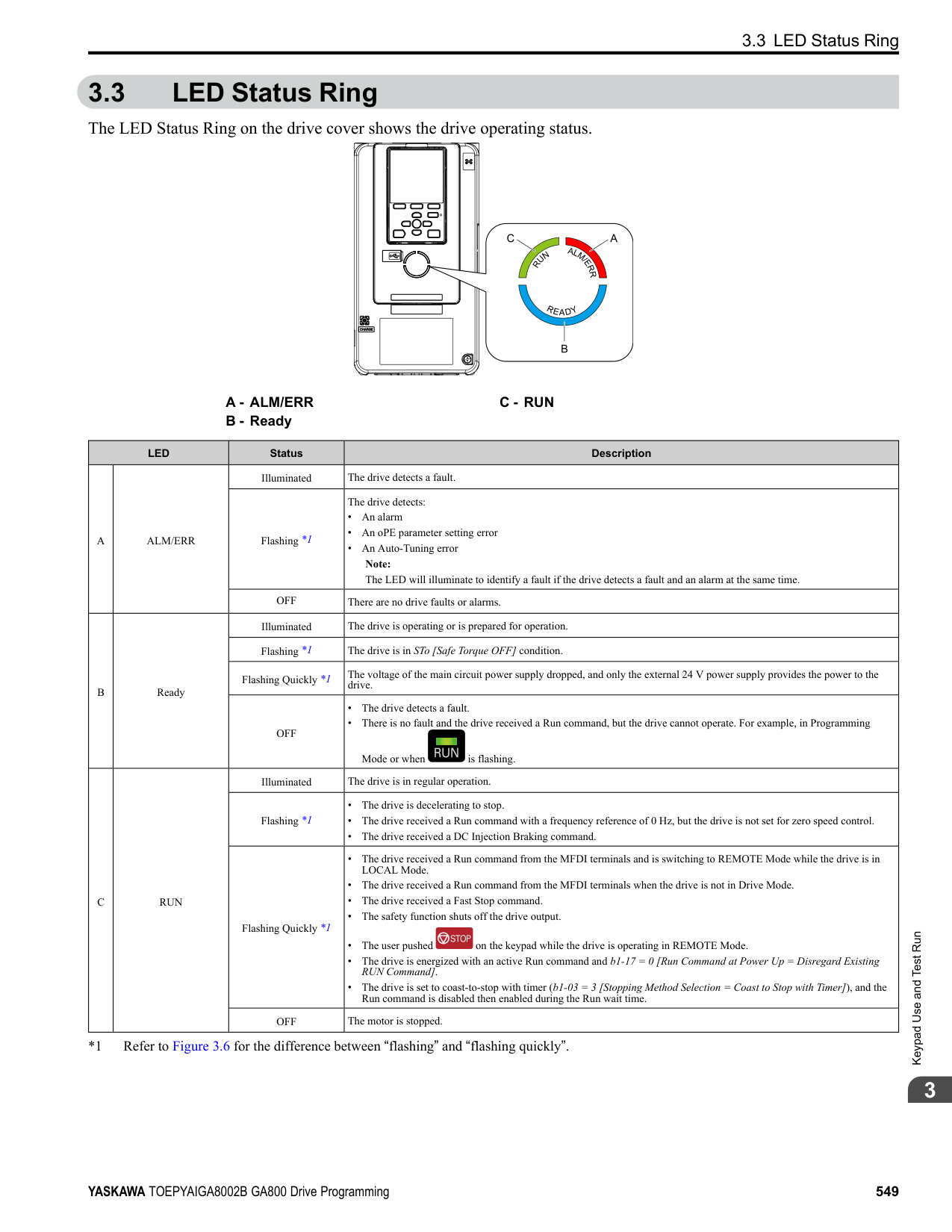
| | | |
The configuration procedure is complete.
◆ Show Monitor Items as a Trend Plot The procedure in this section shows how to show the selected monitor data as a trend plot.
Note:
| | |---| | | | |
| | | |---|---| | | |
The screen will show the monitors as shown in this figure.
| | |---| | | | |
Note:
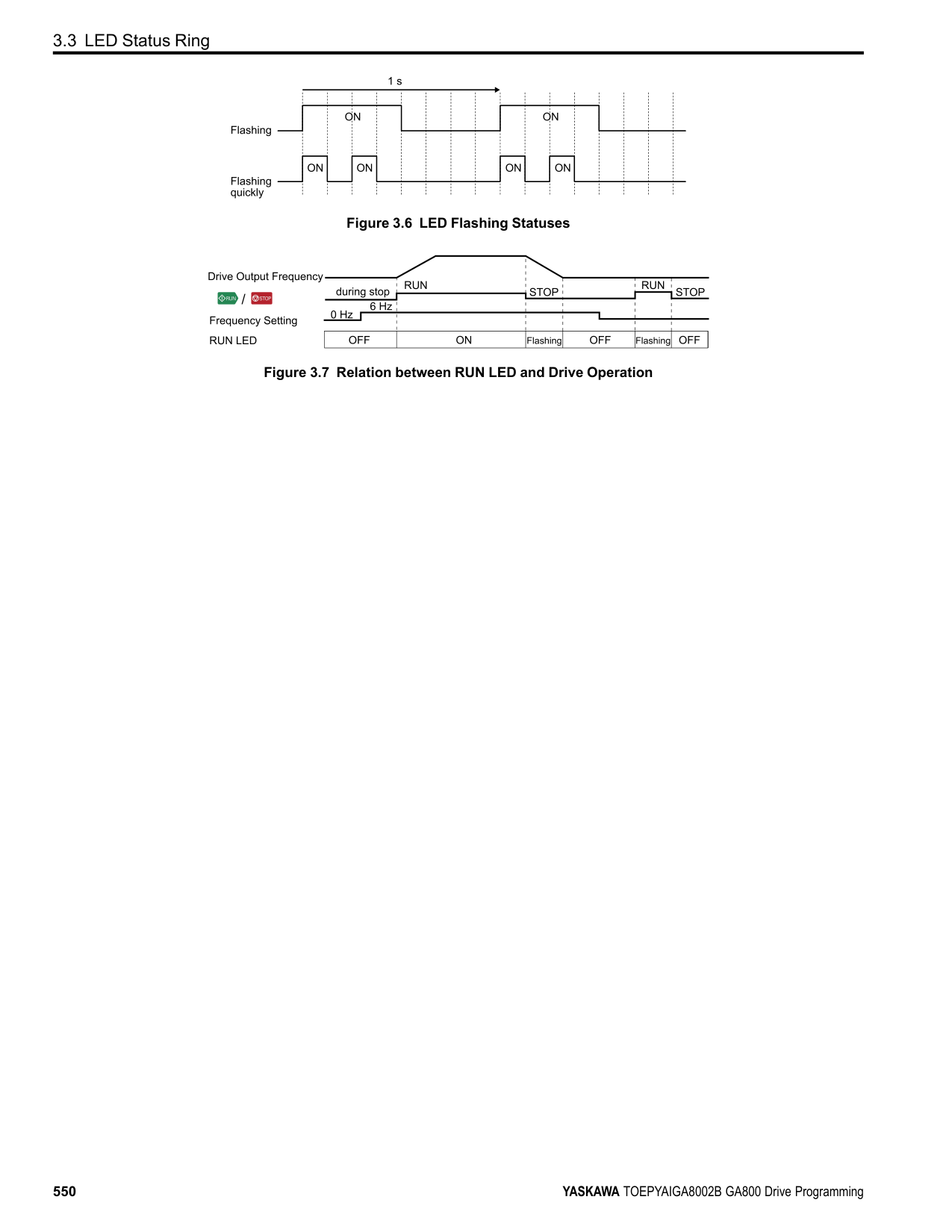
Push (Hold) to switch between Pause and Restart for the monitor display. The “Hold (ENTER)” message flashes while monitoring is paused.
######## ◆ Change Parameter Settings
This example shows how to change the setting value for C1-01 [Acceleration Time 1]. Do the steps in this procedure to set parameters for the application.
Note:
| | |---| | | | |
KeypadUseandTestRun
| | |---| | | | |
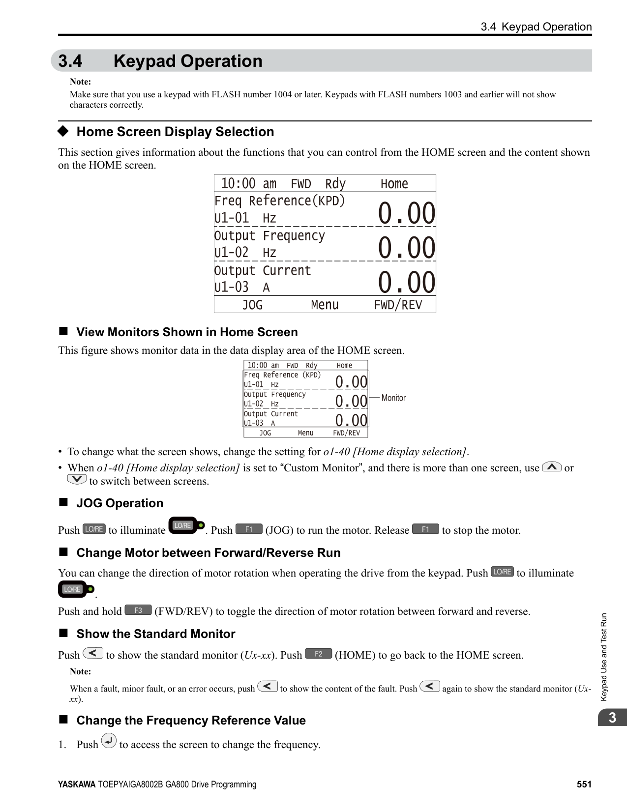
| | |---| | | | |
| | |---| | | | |
| | |---| | | | |
| | |---| | | | |
######## ◆ Examine User Custom Parameters
############### The User Custom Parameters show the parameters set in A2-01 to A2-32 [User Parameter 1 to User Parameter 32]. This lets users to quickly access and change settings to these parameters.
Note: The User Custom Parameters always show A1-06 [Application Selection] at the top of the list. The A2-01 to A2-32 settings change when the A1-06 setting changes, which makes it easier to set and reference the necessary parameter settings.
Note:
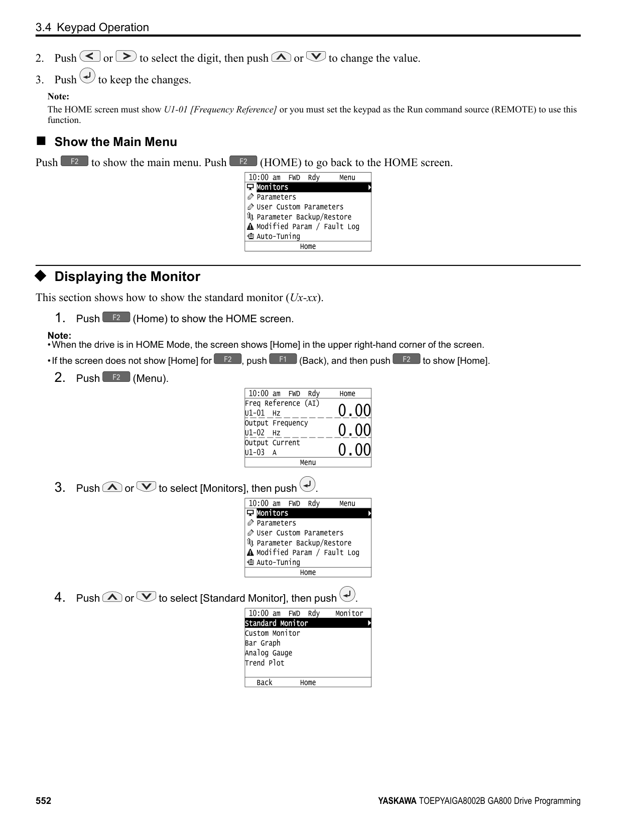
| | |---| | | | |
| | |---| | | | |
| | |---| | | | |
| | |---| | | | |
| | |---| | | | |
The parameter setting procedure is complete.
KeypadUseandTestRun
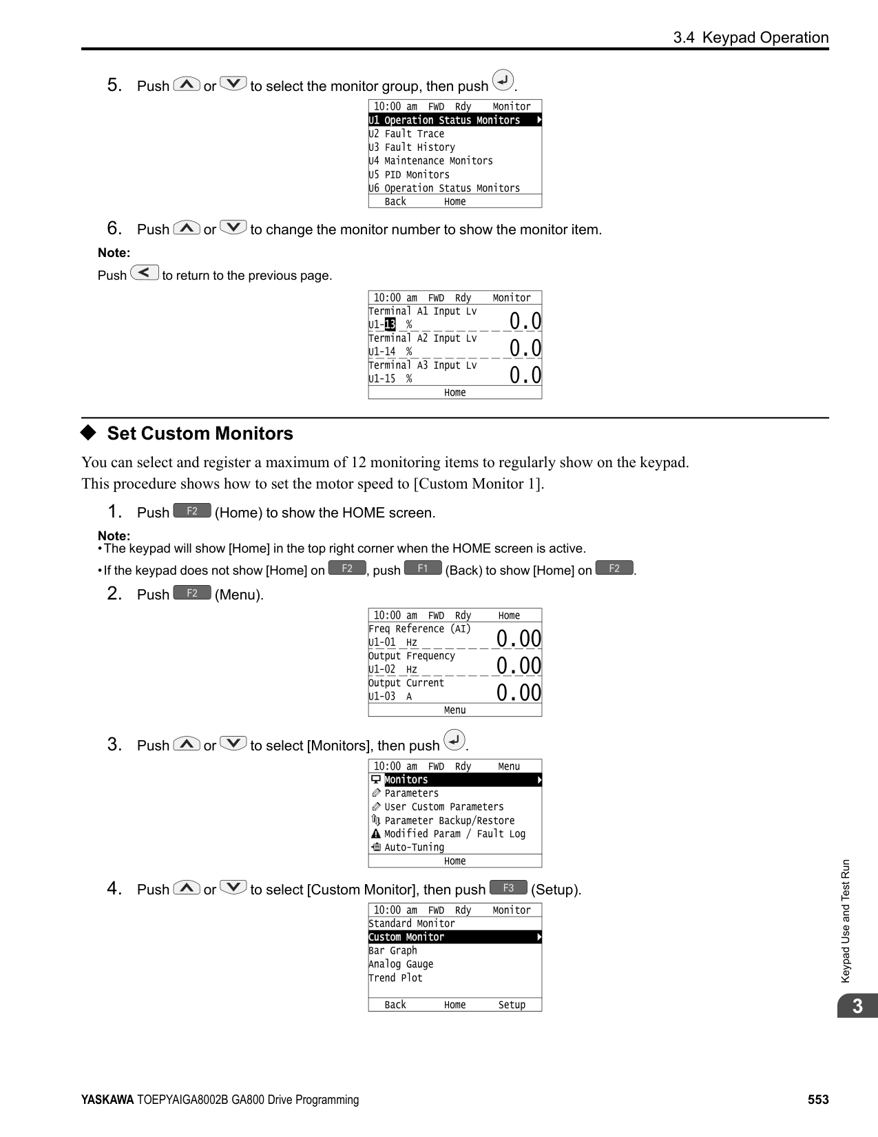
######## ◆ Save a Backup of Parameters
You can save a backup of the drive parameters to the keypad. The keypad can store parameter setting values for a maximum of four drives in different storage areas. Making backups of the parameter settings can save time when setting parameters after replacing a drive. If you set up more than one drive, you can copy the parameter settings from a drive that completed a test run to the other drives.
Note:
Note:
| | |---| | | | |
| | | |---|---| | | |
| | | |---|---| | | |
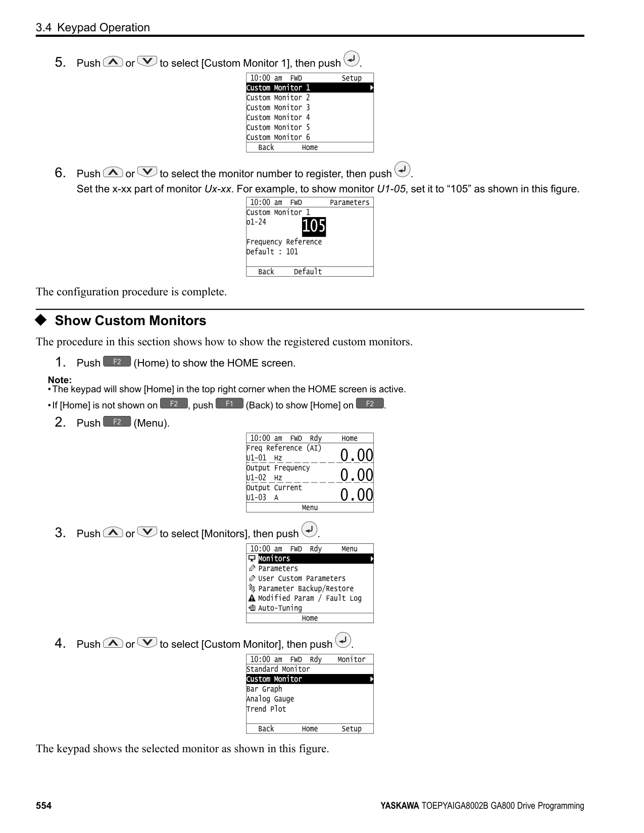
| | | |---|---| | | |
The keypad shows “End” when the backup procedure completes successfully.
◆ Write Backed-up Parameters to the Drive You can back up parameters on the keypad and write them to different drives.
Note:
Note:
| | |---| | | | |
| | | |---|---| | | |
| | |
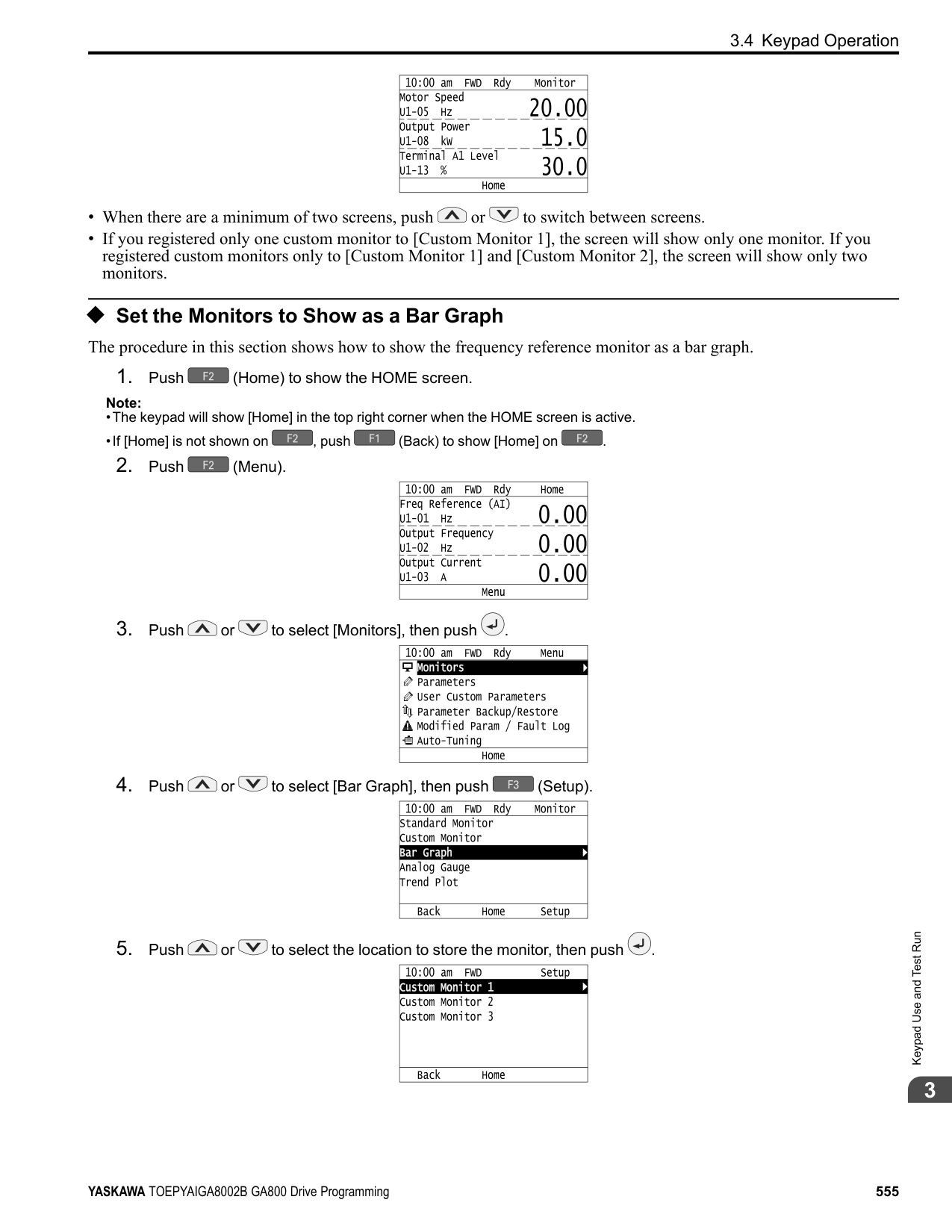
|---|---| | | |
KeypadUseandTestRun
The keypad will show the “End” message when the write process is complete. Note: Different settings and conditions will change the keypad display.
######## ◆ Verify Keypad Parameters and Drive Parameters
This procedure verifies that the parameter setting values that were backed up in the keypad agree with the parameter setting values in the drive.
Note:
Note:
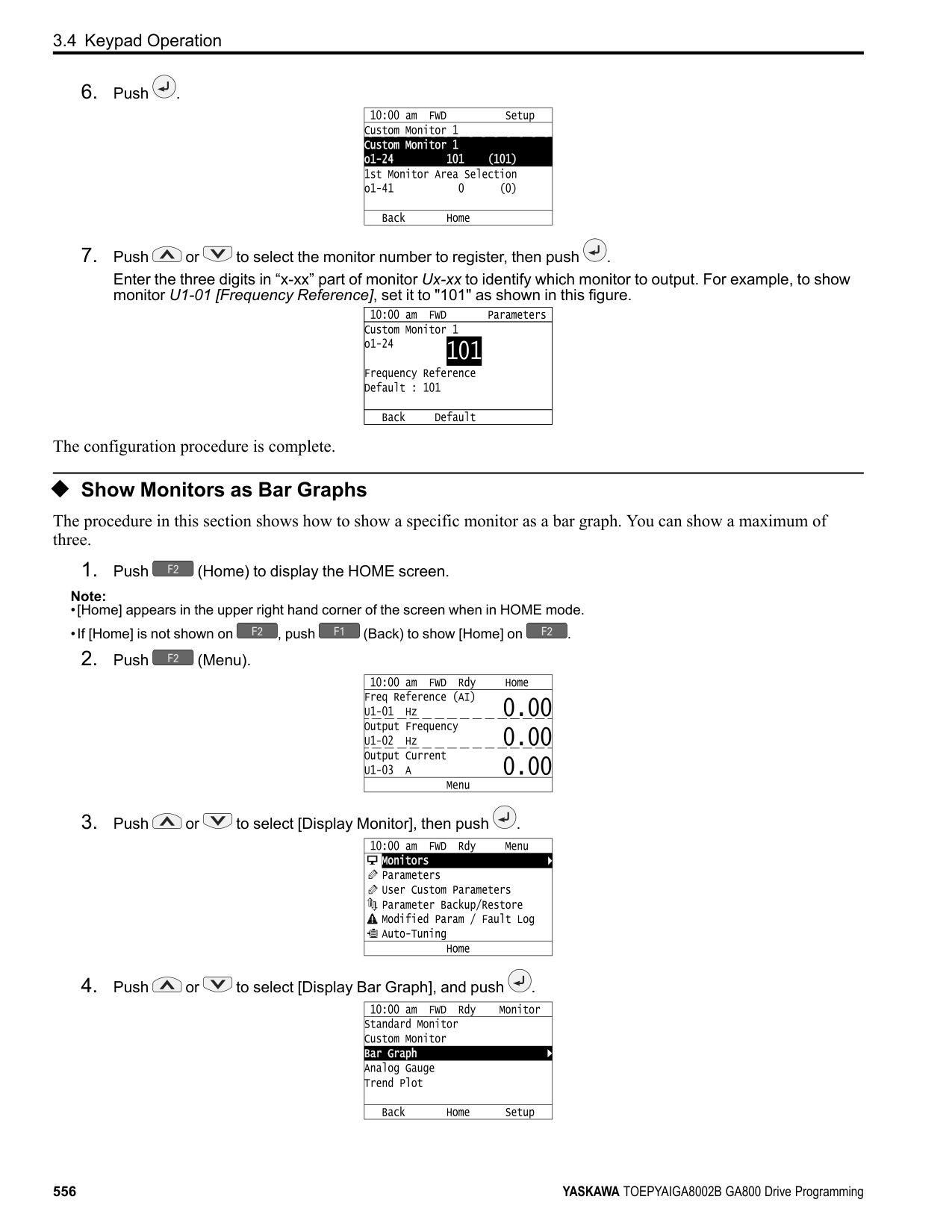
| | |---| | | | |
| | | |---|---| | | |
| | | |---|---| | | |
| | | |---|---| | | |
############### The keypad shows “End” when the parameter settings backed up in the keypad agree with the parameter settings copied to the drive.
################# Note:
The keypad shows vFyE [Parameters do not Match] when the parameter settings backed up in the keypad do not agree with the parameter settings copied to the drive. Push one of the keys to return to the screen in Step 6.
######### ◆ Delete Parameters Backed Up to the Keypad This procedure deletes the parameters that were backed up to the keypad.
Note:
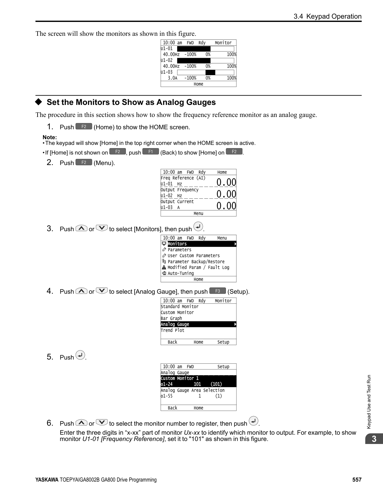
########### 2. Push (Menu).
| | |---| | | | |
| | | |---|---| | | |
| | | |---|---| | | |
The keypad will show the “End” message when the write process is complete.
######## ◆ Check Modified Parameters
This procedure will show all parameters that were changed from their defaults as the result of Auto-Tuning or setting changes. This helps find which settings have been changed, and is very useful when you replace a drive. This lets users quickly access and re-edit changed parameters. If no parameters have been changed, the keypad will show “0 Parameters”.
Note:
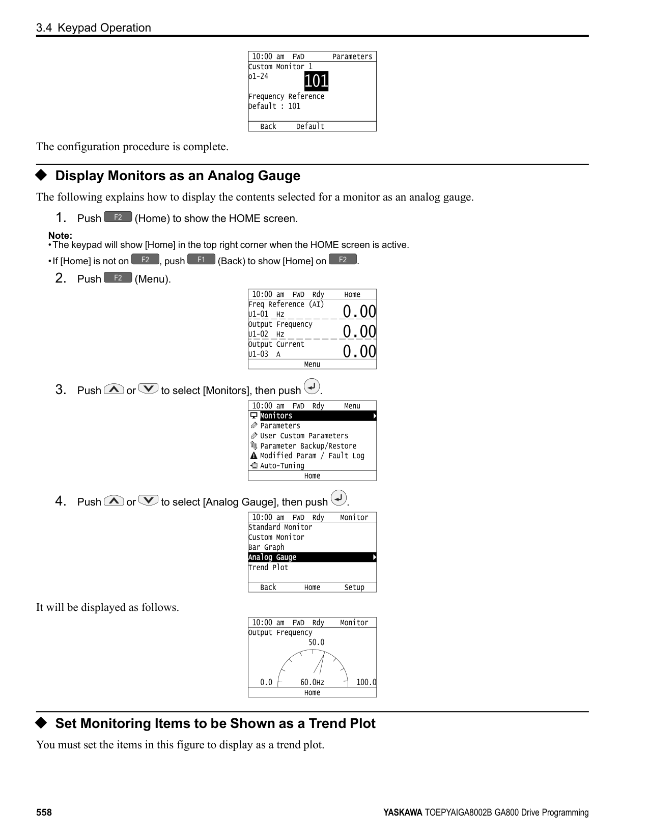
| | |---| | | | |
| | |---| | | | |
| | | |---|---| | | |
| | | |---|---| | | |
| | | |---|---| | | |
| | |---| | | | |
| |
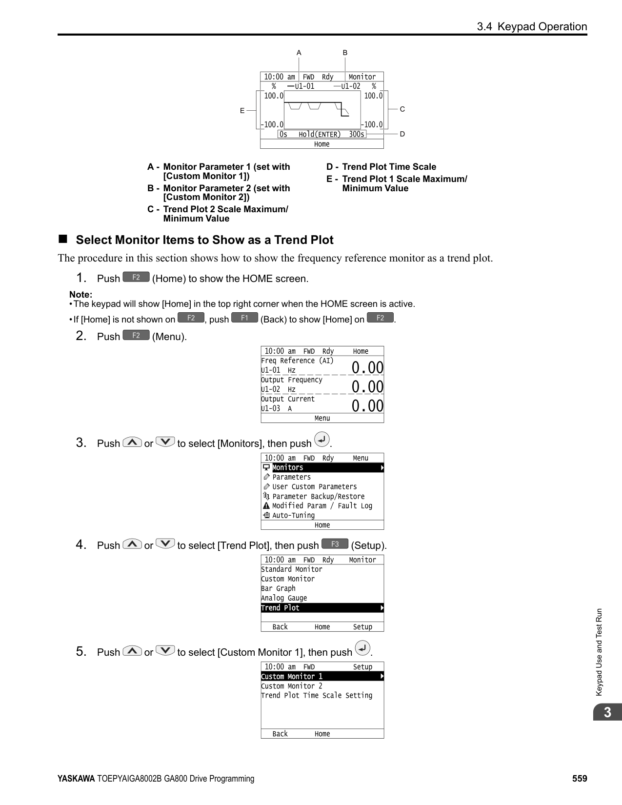
|---| | | | |
| | |---| | | | |
| | |---| | | | |
The parameter revision procedure is complete.
◆ Restore Modified Parameters to Defaults This procedure will set all parameters with changed values to their default settings.
Note:
| | |---| | | | |
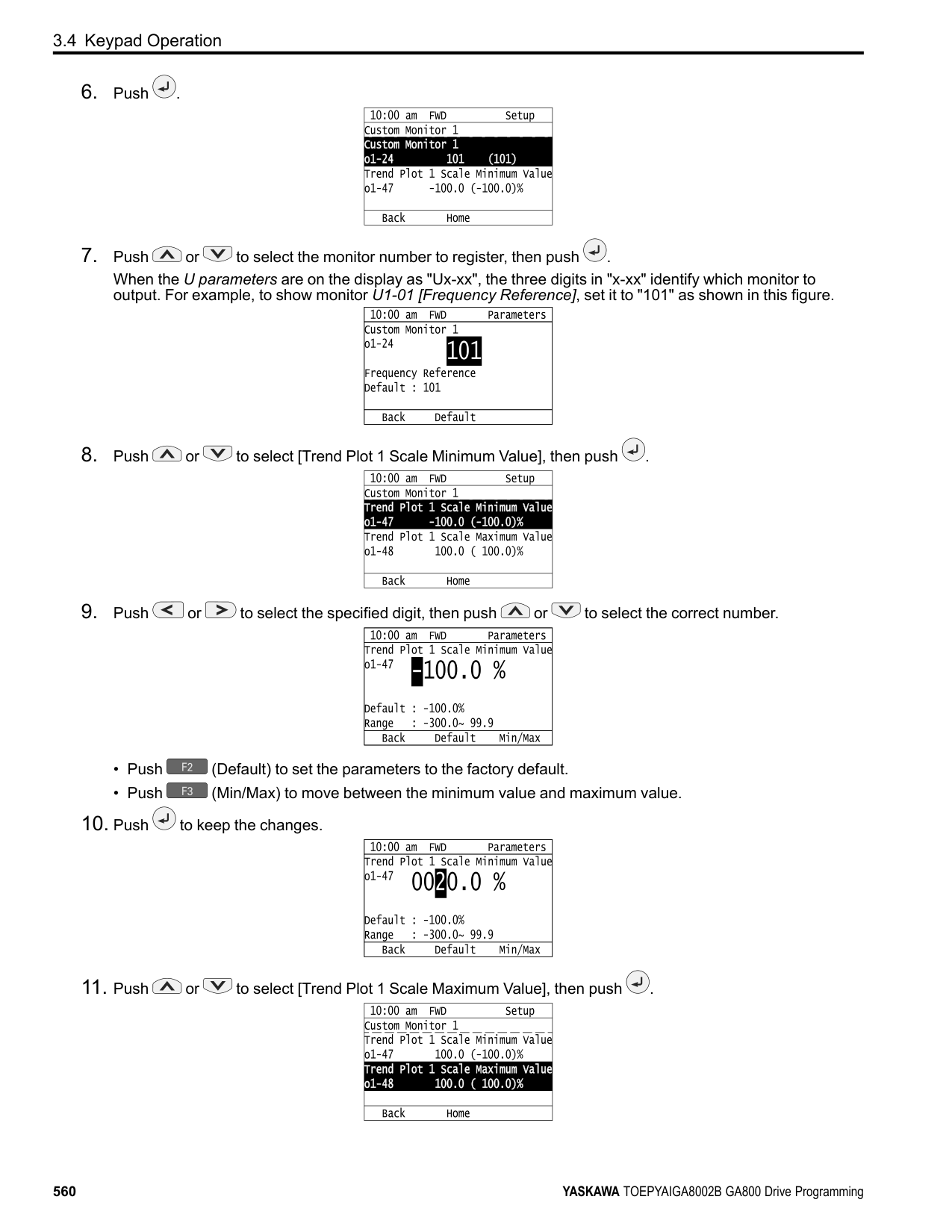
| | |---| | | | |
| | | |---|---| | | |
| | | |---|---| | | |
| | | |---|---| | | |
| | |---| | | | |
| | |---| | | | |
| | |---| | |
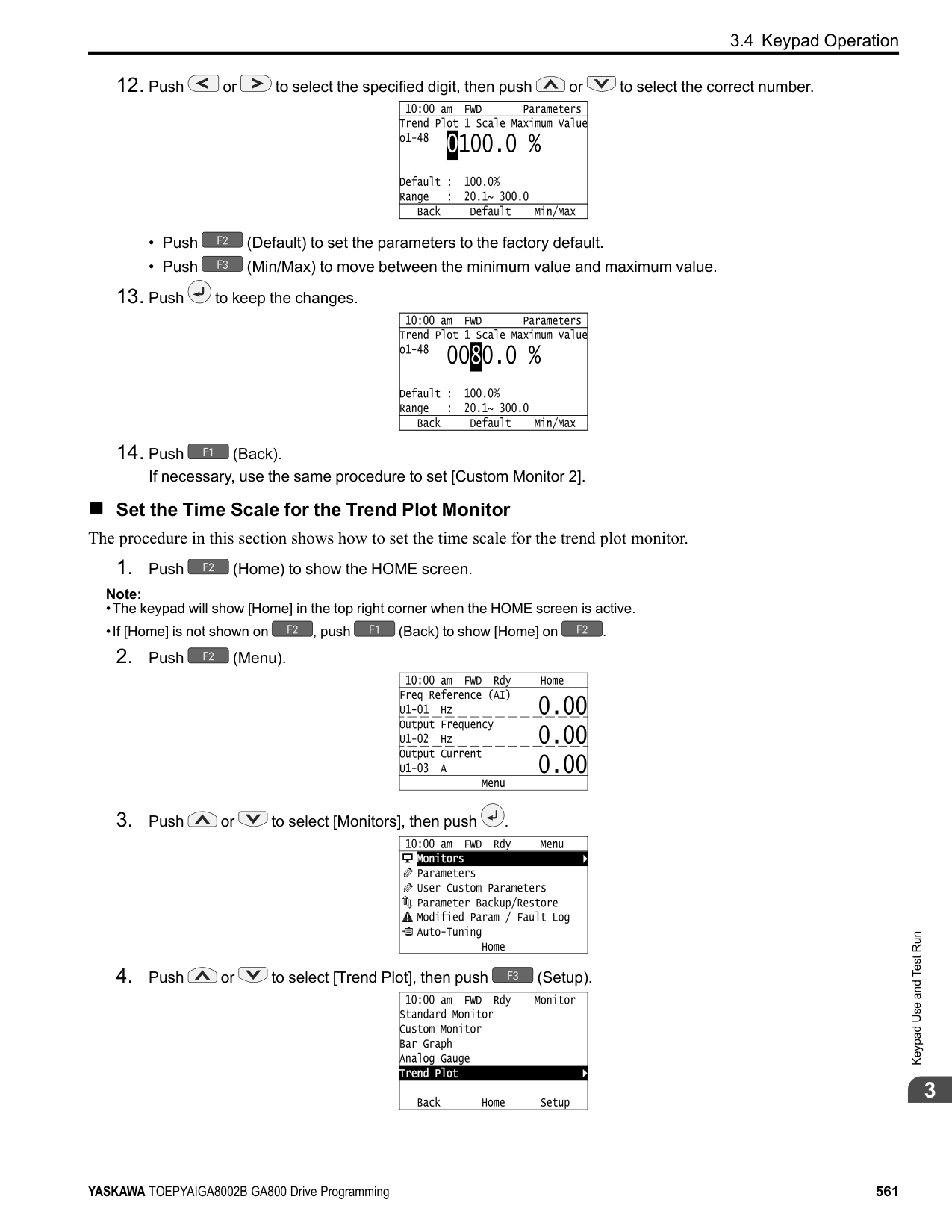
| |
The modified parameters are now set to default values.
◆ Show Fault History You can examine a maximum of 10 fault codes and dates and times that the faults occurred.
Note:
Note:
KeypadUseandTestRun
| | |---| | | | |
| | |---| | | | |
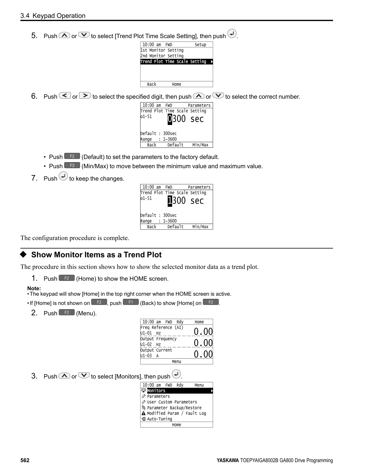
| | | |---|---| | | |
◆ Auto-Tuning the Drive Auto-Tuning uses motor characteristics to automatically set drive parameters. Refer to the motor nameplate or the motor test report for the necessary information for Auto-Tuning.
| | | | | | | |---|---|---|---|---|---| | | | | | | | | | | | | | | | | | | | | |
| | | |---|---| | | | | | | | | | | | | | | | | | | | | | | | |
Figure 3.8 Motor Nameplate (Example)
WARNING! Sudden Movement Hazard. Before you do Auto-Tuning, remove all personnel and objects from the area around the drive, motor, and load. The drive and motor can start suddenly during Auto-Tuning and cause serious injury or death.
WARNING! Electrical Shock Hazard. During Auto-Tuning, the motor will receive high voltage when the motor is stopped. Do not touch the motor until Auto-Tuning is complete. If you touch a motor that is energized, it can cause serious injury or death.
WARNING! Before you do Rotational Auto-Tuning, disconnect the load from the motor. The load can move suddenly and cause serious injury or death.
This procedure shows how to do Rotational Auto-Tuning.
Note:
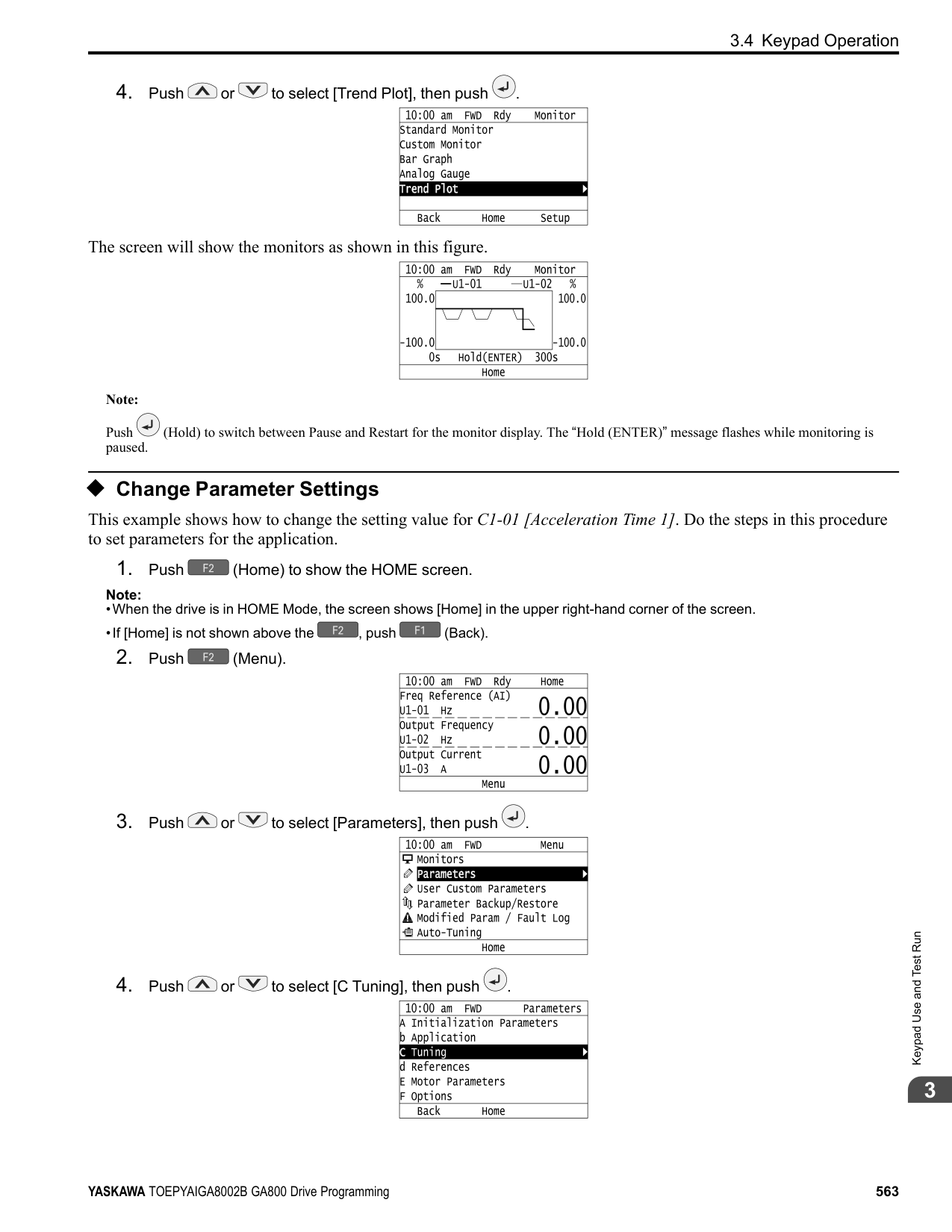
to save the change and move to the next entry field.
| | |---| | | | |
| | | |---|---| | | |
| | | |---|---| | | |
| | | |---|---| | | |
| | | |---|---| | | |
| | | |---|---|
| | |
| | |---| | | | |
Auto-Tuning starts. When doing Rotational Auto-Tuning, the motor will stay stopped for approximately one minute with power energized and then the motor will start to rotate.
KeypadUseandTestRun
The keypad will show a list of the changed parameters as the result of Auto-Tuning.
| | |---| | | | |
| | | |---|---| | | |
To change a parameter again, push or to select the parameter to change, then push to show the parameter setting screen.
############### Auto-Tuning is complete.
################# Note:
If the drive detects an error or you push before Auto-Tuning is complete, Auto-Tuning will stop and the keypad will show an error code. Endx identifies that Auto-Tuning was successful with calculation errors. Find and repair the cause of the error and do Auto-Tuning again, or set the motor parameters manually. You can use the drive in the application if you cannot find the cause of the Endx error. Er-xx identifies that Auto-Tuning was not successful. Find and repair the cause of the error and do Auto-Tuning again.
| | |---| | |
| |
| | |---| | | | |
######### ◆ Set the Keypad Language Display The procedure in this section shows how to set the language shown on the keypad.
Note:
| | |---| | | | |
| | |---| | | | |
The procedure to set the keypad language is complete.
◆ Set the Date and Time The procedure in this section shows how to set the date and time.
Note:
Note:
########### 2. Push (Menu).
Keypad Use and Test Run
| | |---| | | | |
| | |---| | | | |
| | |---| | | | |
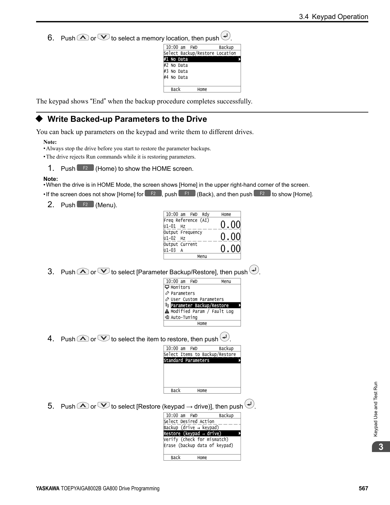
| | |---| | | | |
| | |---| | | | |
| | |---| | | | |
| | |---| | | | |
| | |---| | | | |
The procedure for setting the date and time is complete.
◆ Set Parameters Using the Setup Wizard The Setup Wizard lets users follow simple messages on the keypad to set these basic parameters:
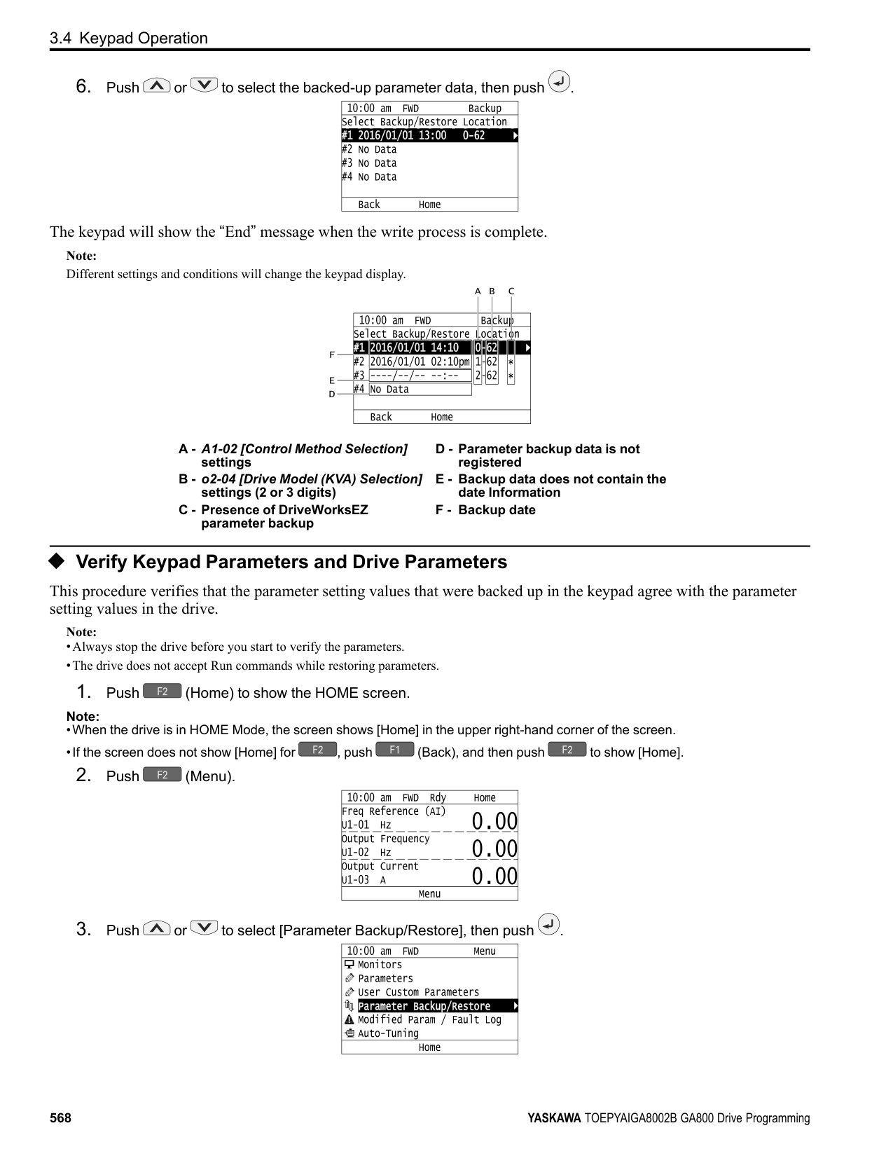
Note:
KeypadUseandTestRun
| | |---| | | | |
Note: This operation will initialize all parameters.
| | |---| | | | |
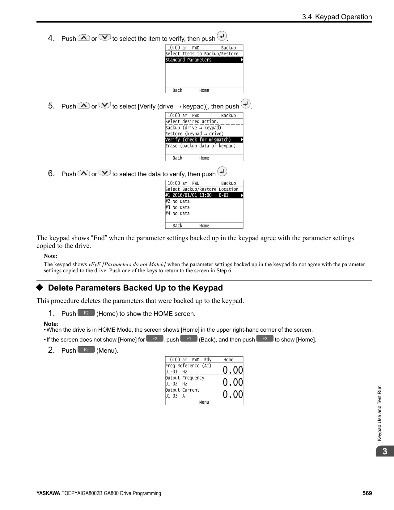
| | | |---|---| | | |
| | | |---|---| | | |
| | | |---|---| | | |
| | | |---|---| | | |
Note:
To change a parameter again, push or to select the parameter to change, then push to show the parameter setting screen.
The Setup Wizard procedure is complete.
◆ Disable the Initial Setup Screen Do the steps in this procedure to not show the initial start-up screen when the drive is energized.
Note:
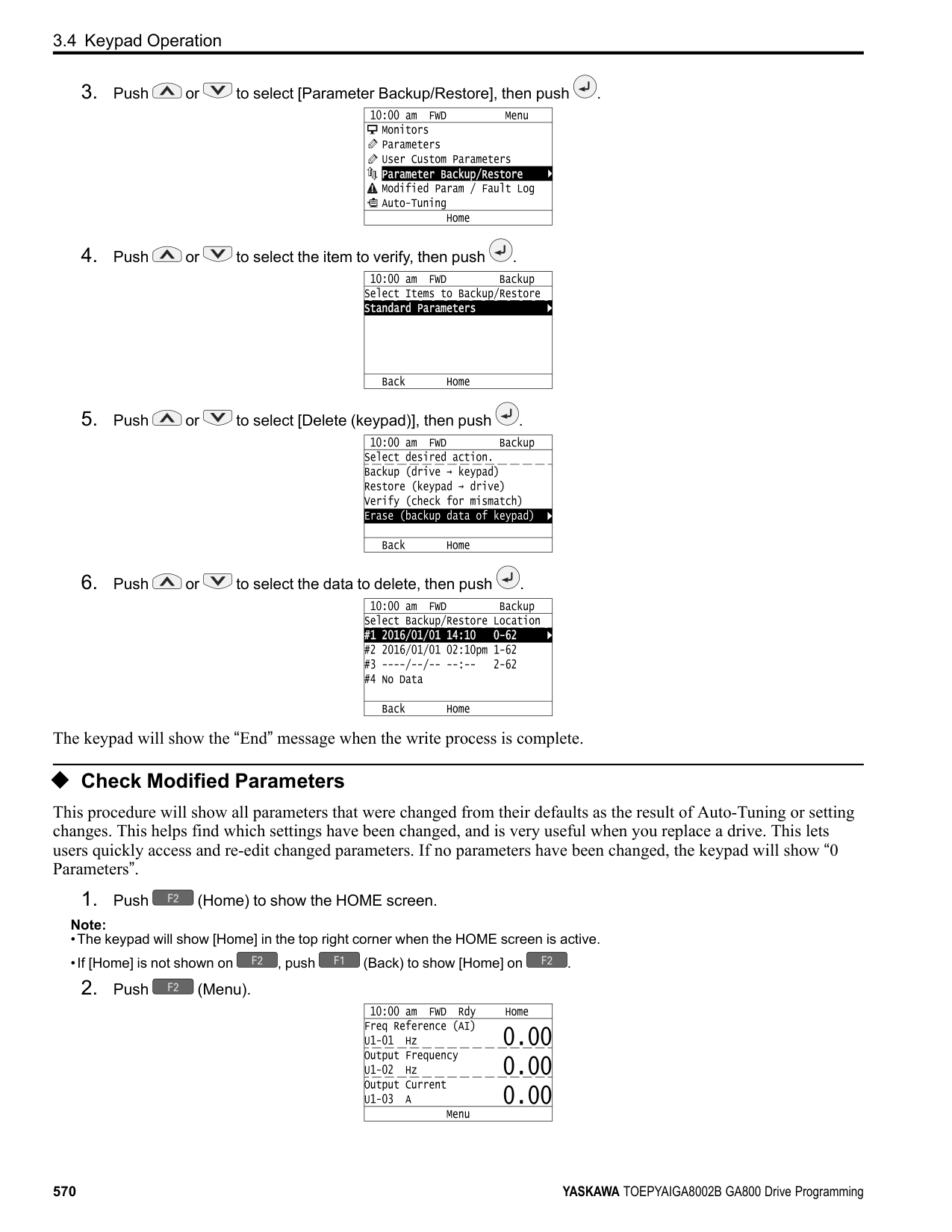
| | |---| | | | |
| | |---| | | | |
KeypadUseandTestRun
######## 3
######### ◆ Start Data Logging The data log function saves drive status information. Monitors Ux-xx are the source of log information. The procedure in this section shows how to start logging data. You can record a maximum of 10 monitors.
Note:
| | |---| | |
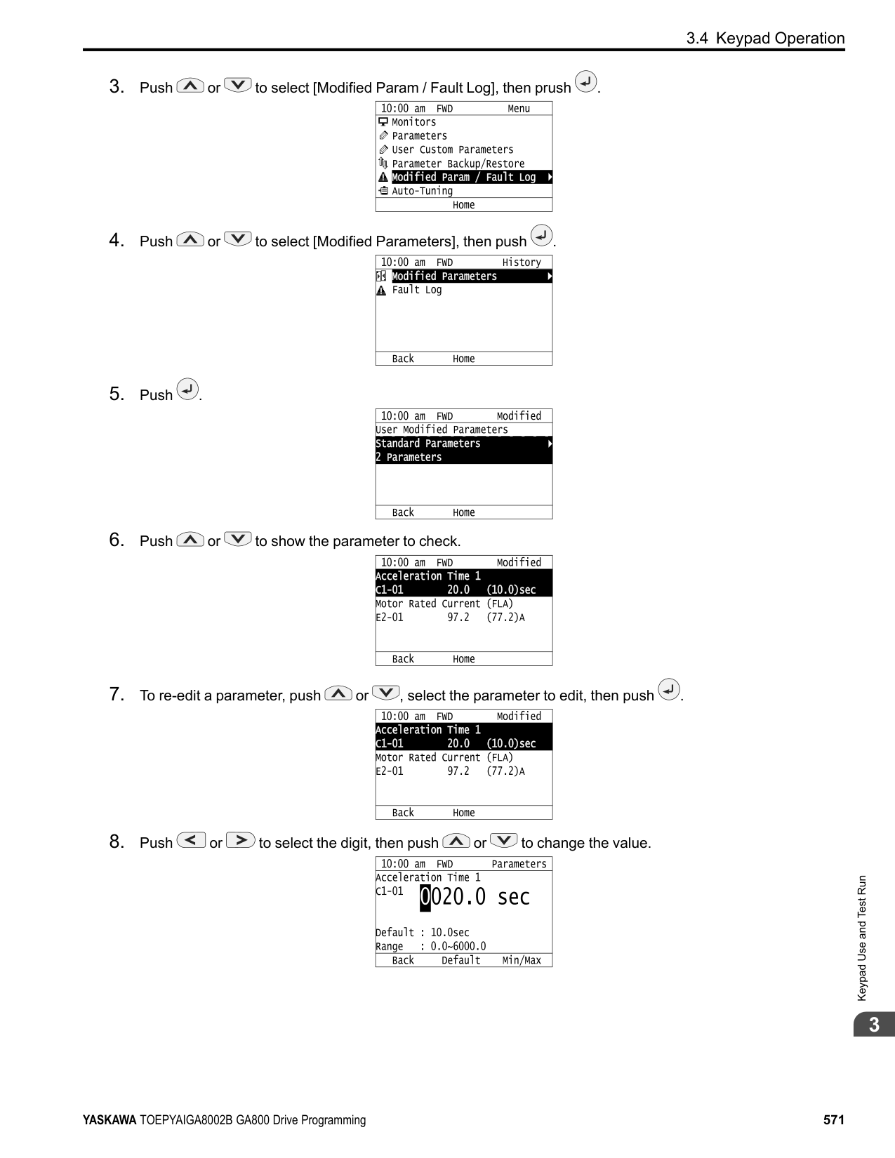
| |
| | |---| | | | |
######## ◆ Configuring the Data Log Content
■ Set Monitor to Log The procedure in this section shows how to set the monitor for which to log data.
Note:
| | |---| | | | |
| | |---| | | | |
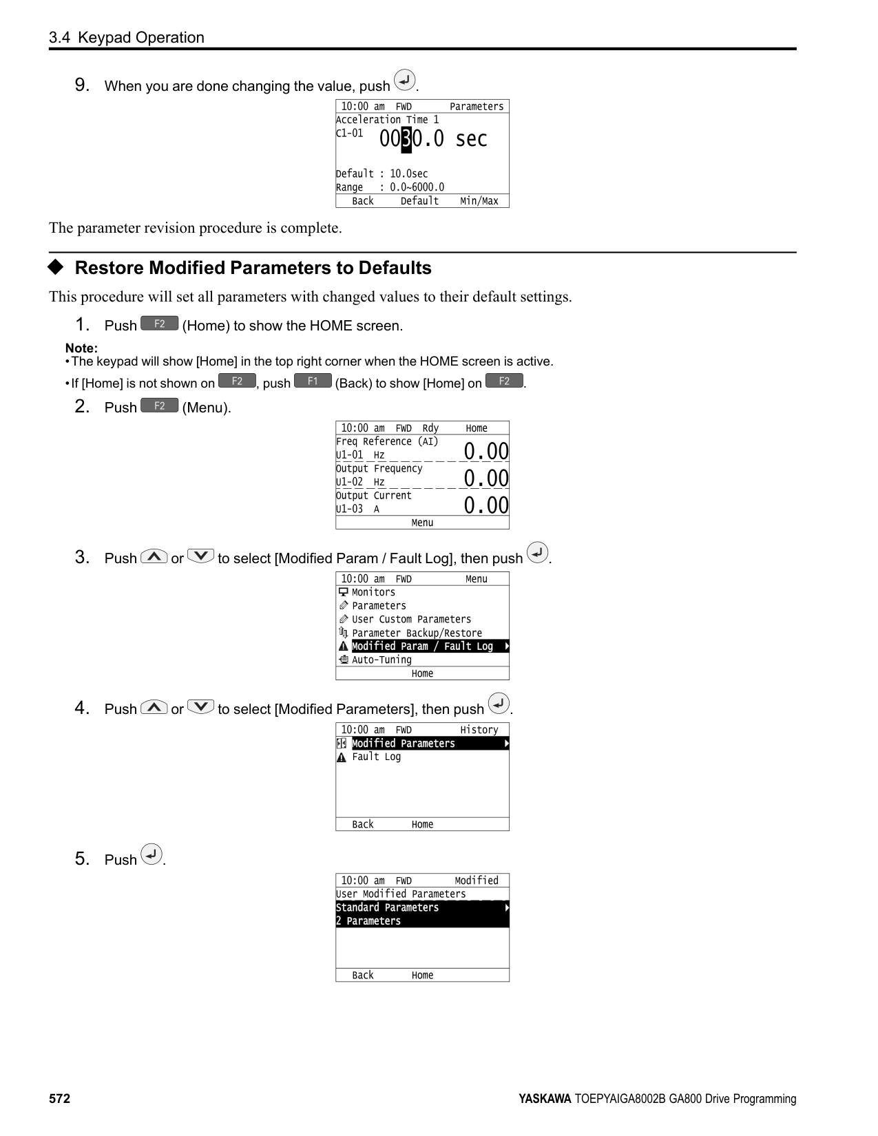
| | |---| | | | |
| | | |---|---| | | |
| | | |---|---| | | |
KeypadUseandTestRun
| | |---| | | | |
The configuration procedure is complete.
■ Set the Sampling Time The procedure in this section shows how to set the sampling time for data logging.
Note:
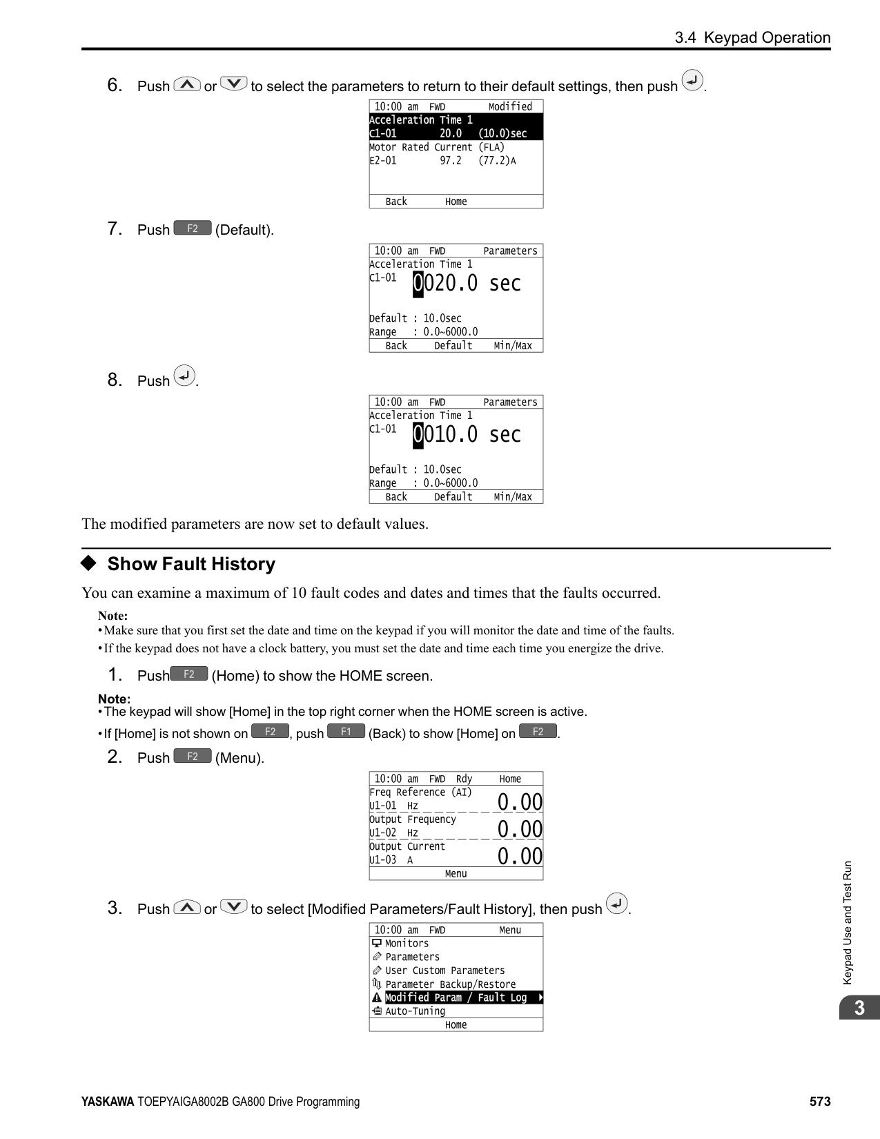
| | |---| | | | |
| | |---| | | | |
| | |---| | | | |
| | |---| | | | |
| | |---| | | | |
The procedure to set the sampling time is complete.
######## ◆ Set Backlight to Automatically Turn OFF
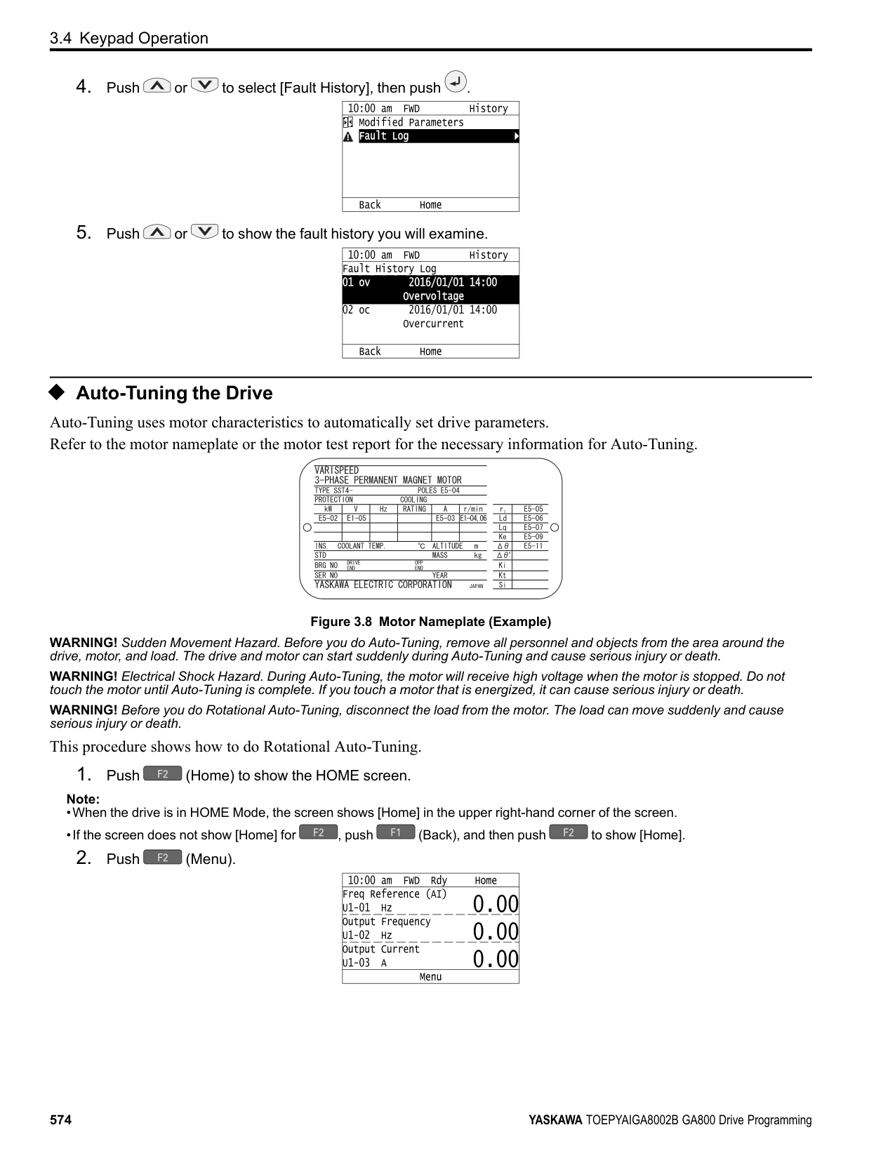
You can set the backlight of the keypad screen to automatically turn OFF after a set length of time since the last key operation on the keypad. The procedure in this section shows how to turn ON and turn OFF the backlight.
Note:
| | |---| | | | |
KeypadUseandTestRun
| | |---| | | | |
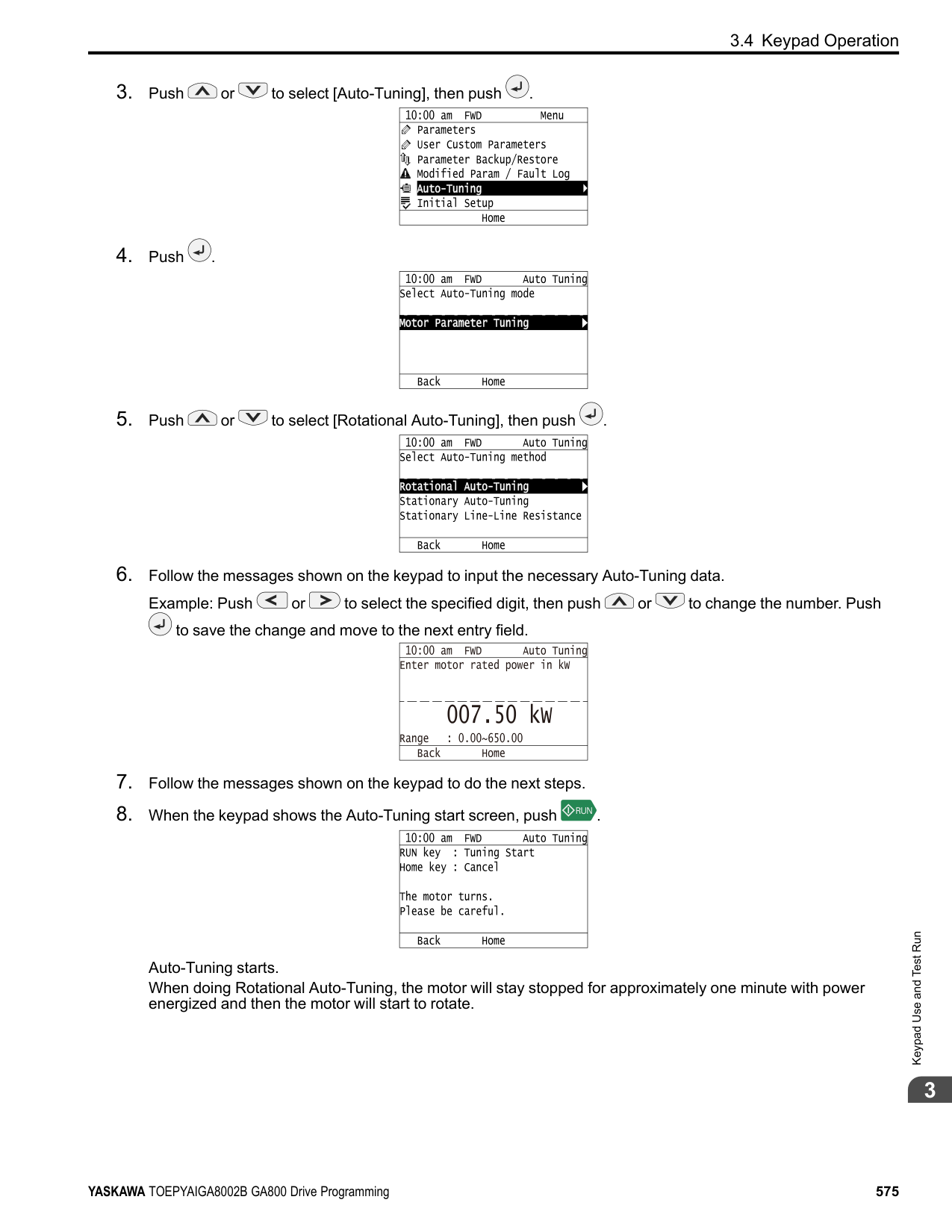
| | |---| | | | |
| | | |---|---| | | |
| | | |---|---| | | |
| | | |---|---| | | |
| | |---| | | | |
| | |---| | | | |
The procedure to set the backlight to turn OFF automatically is complete.
######## ◆ Show Information about the Drive
The procedure in this section shows how to show the drive model, maximum applicable motor output (HD/ND), rated output current (HD/ND), software version, and the serial number on the keypad.
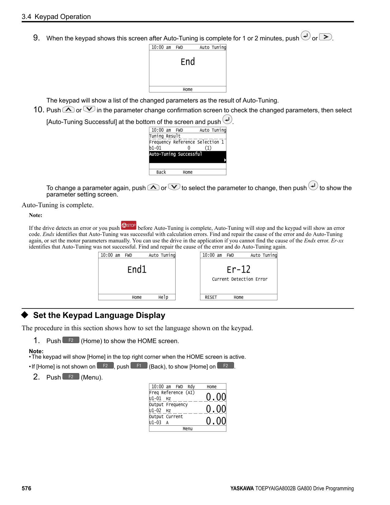
Note:
| | |---| | | | |
| | |---| | | | |
The keypad will show the drive information.
A - Drive Series B - Maximum Applicable Motor Output
(HD/ND) C - Rated Output Current (HD/ND)
D - Drive Software Version E - Serial Number
######## ◆ Write Automatically Backed-up Parameters to the Drive
You can automatically back up parameters to the keypad connected to the drive and write those parameters to a different drive as specified by the settings of o3-06 [Auto Parameter Backup Selection] and o3-07 [Auto Parameter Backup Interval].
Note:
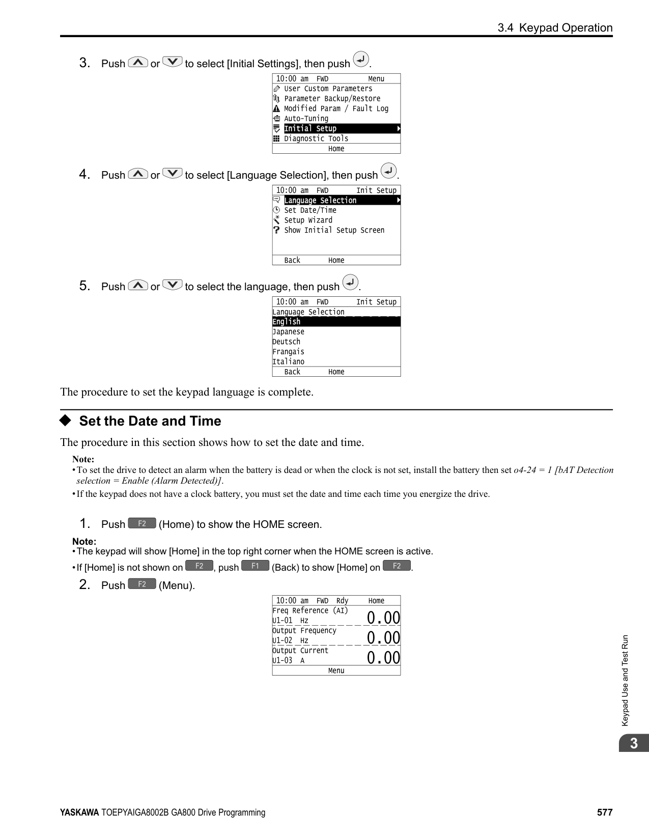
KeypadUseandTestRun
The keypad will show the “End” message when the write process is complete.
###### 3.5 Auto-Tuning
Auto-Tuning uses motor characteristics to automatically set drive parameters for vector control. Think about the type of motor, drive control method, and the motor installation environment and select the best Auto-Tuning method. The keypad will show the messages with prompts to input the necessary parameter information. These prompts are specified by the selected Auto-Tuning method and the control method setting in A1-02.
◆ Auto-Tuning for Induction Motors This section gives information about Auto-Tuning for induction motors. Auto-Tuning sets these parameters:
Note:
Do Stationary Auto-Tuning if you cannot do Rotational Auto-Tuning. There can be large differences between the measured results and the motor characteristics when Auto-Tuning is complete. Examine the parameters for the measured motor characteristics after you do Stationary Auto-Tuning.
Table 3.4 Types of Auto-Tuning for Induction Motors
|Mode|Parameter Settings|Application Conditions and Benefits|Applicable Control Method (A1-02 Setting)|Applicable Control Method (A1-02 Setting)|Applicable Control Method (A1-02 Setting)|Applicable Control Method (A1-02 Setting)|Applicable Control Method (A1-02 Setting)| |---|---|---|---|---|---|---|---| |Mode|Parameter Settings|Application Conditions and Benefits|V/f (0)|CL-V/f (1)|OLV (2)|CLV (3)|AOLV (4)| |Rotational Auto-Tuning|T1-01 = 0|• When you can decouple the motor and load the motor can rotate freely while Auto-Tuning.
• When operating motors that have fixed output characteristics.
• When it is necessary to use motors that have highprecision control.
• When you cannot decouple the motor and load, but the motor load is less than 30%.
|x|x|x|x|x| |Stationary Auto-Tuning 1|T1-01 = 1|• When you cannot decouple the motor and load, but the motor load is more than 30%.
• When the information from the motor test report or motor nameplate is not available. With Stationary Auto-Tuning, the energized drive stays stopped for approximately 1 minute. During this time, the drive automatically measures the necessary motor parameters.
• When operating the motor with a light load after Auto-Tuning. The drive can automatically calculate the motor parameter settings necessary for torque control. Set T1-12 = 1 [Test Mode Selection = Yes] to do a test run after Auto-Tuning.
|-|-|x|x|x| |Line-to-Line Resistance|T1-01 = 2|• After Auto-Tuning, the wiring distance between the drive and motor changed by 50 m or more.
• When the wiring distance is 50 m or more in the V/f Control mode.
• When the motor output and drive capacity are different.
|x|x|x|x|x|
######## ■ Input Data for Induction Motor Auto-Tuning
To do Auto-Tuning, input data for the items in Table 3.5 that have an "x". Before starting Auto-Tuning, prepare the motor test report or record the information on the motor nameplate as a reference.
Keypad Use and Test Run
################# Table 3.5 Input Data for Induction Motor Auto-Tuning
|Input Data|Parameter|Unit|Auto-Tuning Mode (T1-01 Setting)|Auto-Tuning Mode (T1-01 Setting)|Auto-Tuning Mode (T1-01 Setting)|
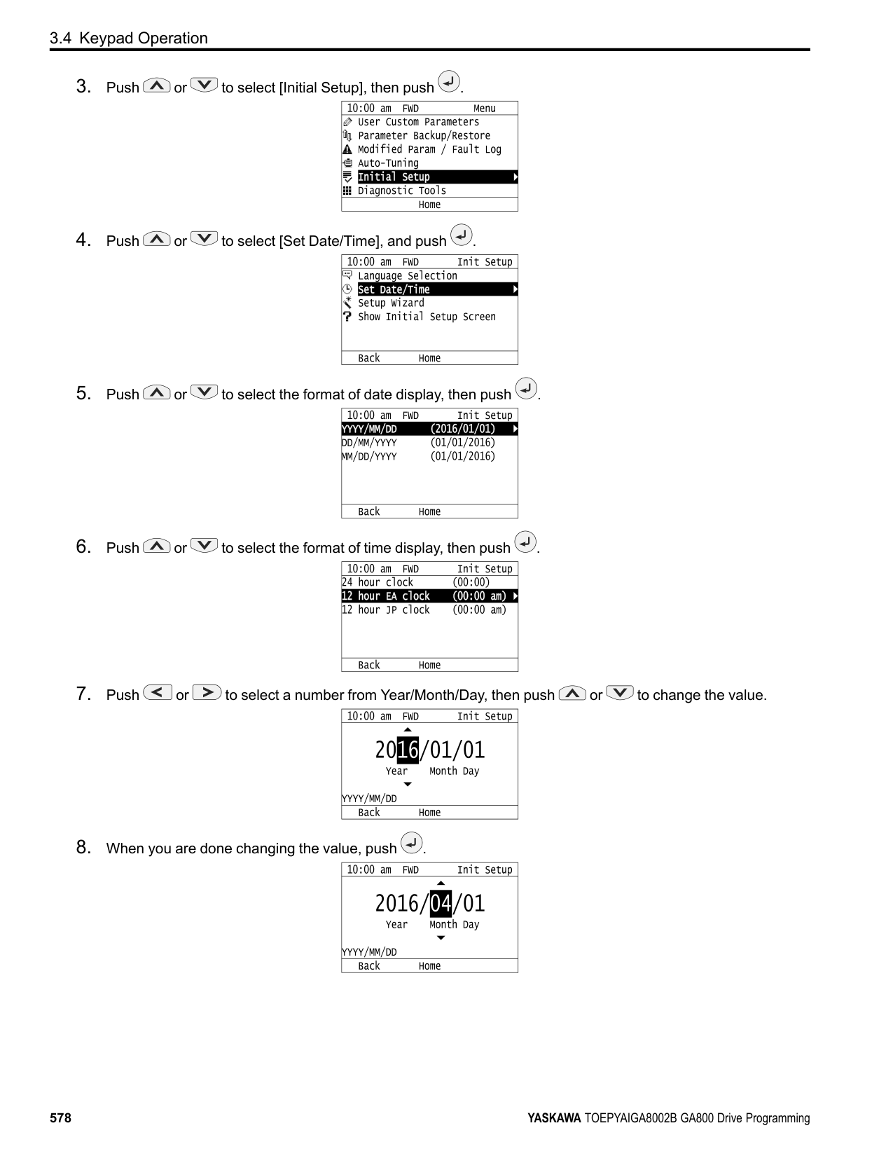
|---|---|---|---|---|---| |Input Data|Parameter|Unit|Rotational Auto-Tuning (0)|Stationary Auto-Tuning 1
(1)|Line-to-Line Resistance (2)| |Motor Rated Power|T1-02|kW|x|x|x| |Motor Rated Voltage|T1-03|V|x|x|-| |Motor Rated Current|T1-04|A|x|x|x| |Motor Base Frequency|T1-05|Hz|x|x|-| |Number of Motor Poles|T1-06|-|x|x|-| |Motor Base Speed|T1-07|min-1|x|x|-| |Encoder Pulse Count (PPR)|T1-08|-|○ *1|○ *1|-| |Motor No-Load Current|T1-09|A|-|x|-| |Motor Rated Slip Frequency|T1-10|Hz|-|○ *2|-| |Motor Iron Loss|T1-11|W|○ *3|-|-| |Test Mode Selection *4|T1-12|-|-|○ *5|-| |No-load voltage|T1-13|V|○ *6|○ *6|-|
◆ Auto-Tuning for Motor Parameters for PM Motor This section gives information about Auto-Tuning for PM motors. Auto-Tuning sets these parameters:
|Mode|Parameter Settings|Application Conditions and Benefits|Applicable Control Method (A1-02 Setting)|Applicable Control Method (A1-02 Setting)|Applicable Control Method (A1-02 Setting)| |---|---|---|---|---|---| |Mode|Parameter Settings|Application Conditions and Benefits|OLV/PM (5)|AOLV/PM (6)|CLV/PM (7)| |PM Motor Parameter Settings|T2-01 = 0|• When the information from the motor test report or motor nameplate is available.
• Rotational/Stationary Auto-Tuning that energizes the motor is not done. Manually input the necessary motor parameters.
|x|x|x| |PM Stationary Auto-Tuning|T2-01 = 1|• When the information from the motor test report or motor nameplate is not available.
Note:
With Stationary Auto-Tuning, the energized drive stays stopped for approximately 1 minute. During this time, the drive automatically measures the necessary motor parameters.|x|x|x| |PM Stationary Auto-Tuning for Stator Resistance|T2-01 = 2|• After Auto-Tuning, the wiring distance between the drive and motor changed by 50 m or more.
• When the motor output and drive capacity are different.
|x|x|x|
|Mode|Parameter Settings|Application Conditions and Benefits|Applicable Control Method (A1-02 Setting)|Applicable Control Method (A1-02 Setting)|Applicable Control Method (A1-02 Setting)|
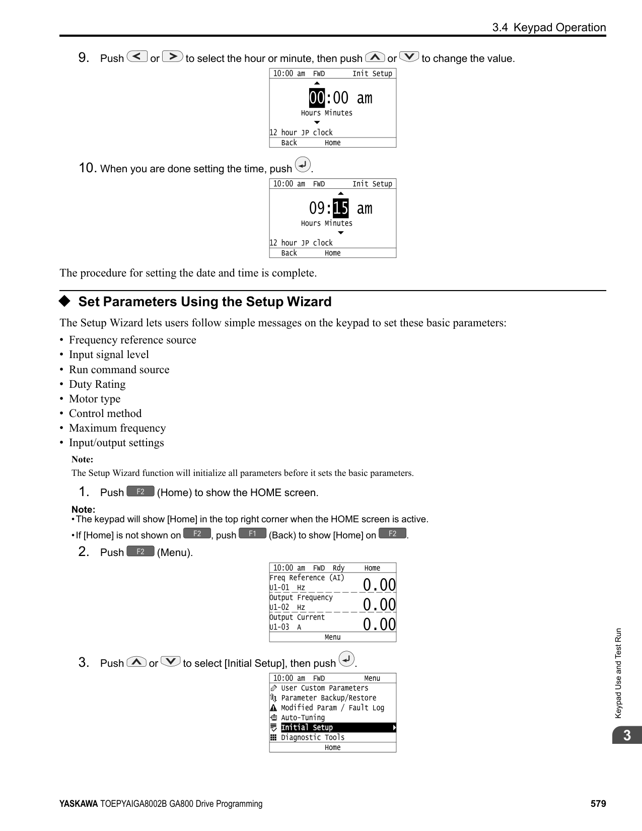
|---|---|---|---|---|---| |Mode|Parameter Settings|Application Conditions and Benefits|OLV/PM (5)|AOLV/PM (6)|CLV/PM (7)| |Z-Pulse Offset (Pole Position)|T2-01 3|• When you do not know the encoder Z-pulse offset.
• When the encoder was replaced
• If you have compensated for the deviation from Z phase (Δθ).
Note:
The motor will rotate slowly while the drive measures the encoder base position.|-|-|x| |PM Rotational Auto-Tuning|T2-01 4|• When the information from the motor test report or motor nameplate is not available.
• When you can decouple the motor and load the motor can rotate freely while Auto-Tuning.
• Values measured during Auto-Tuning are automatically set to the motor parameters.
|x|x|x| |High Frequency Injection AutoTuning|T2-01 5|• Automatically determines the control parameters required to set n8-35 1 [Initial Pole Detection Method High Frequency Injection] or n8-57 1 [HFI Overlap Selection = Enabled].
• Applicable to IPM motors only.
• Perform tuning with the motor connected to the drive. Note:
When you want to set n8-35 1 or n8-57 1, perform High Frequency Injection Auto-Tuning. Configure the drive with the data from the motor nameplate before performing High Frequency Injection Auto-Tuning. High Frequency Injection Auto-Tuning automatically makes adjustments while it is stopped but still energized.|x|x|x|
######## ■ Input Data for PM Motor Auto-Tuning
To do Auto-Tuning, input data for the items in Table 3.7 and Table 3.8 that have an "x". Before starting Auto-Tuning, prepare the motor test report or record the information on the motor nameplate as a reference.
|Input Data|Parameter|Unit|Auto-Tuning Mode (T2-01 Setting)|Auto-Tuning Mode (T2-01 Setting)|Auto-Tuning Mode (T2-01 Setting)|Auto-Tuning Mode (T2-01 Setting)|Auto-Tuning Mode (T2-01 Setting)|Auto-Tuning Mode (T2-01 Setting)| |---|---|---|---|---|---|---|---|---| |Input Data|Parameter|Unit|PM Motor Parameter Settings (0)|PM Motor Parameter Settings (0)|PM Motor Parameter Settings (0)|PM Stationary Auto-Tuning
(1)|PM Stationary Auto-Tuning
(1)|PM Stationary AutoTuning for Stator Resistance
(2)| |Control method selection|A1-02|-|5, 6, 7|5|6, 7|5|6, 7|5, 6, 7| |PM Motor Code Selection|T2-02|-|Motor code of Yaskawa motor *1|FFFF *2|FFFF *2|-|-|-| |PM Motor Type|T2-03|-|-|-|-|x|x|-| |PM Motor Rated Power|T2-04|kW|-|x|x|x|x|-| |PM Motor Rated Voltage|T2-05|V|-|x|x|x|x|-| |PM Motor Rated Current|T2-06|A|-|x|x|x|x|x| |PM Motor Base Frequency|T2-07|Hz|-|x|-|x|-|-| |Number of PM Motor Poles|T2-08|-|-|x|x|x|x|-| |PM Motor Base Speed|T2-09|min-1|-|-|x|-|x|-| |PM Motor Stator Resistance|T2-10|Ω|x|x|x|-|-|-| |PM Motor d-Axis Inductance|T2-11|mH|x|x|x|-|-|-| |PM Motor q-Axis Inductance|T2-12|mH|x|x|x|-|-|-| |Back-EMF Units Selection|T2-13|-|x|x|x|-|-|-| |Back-EMF Voltage Constant (Ke)|T2-14|*3|x|x|x|-|-|-| |Pull-In Current Level|T2-15|%|-|-|-|x|x|-|
|Input Data|Parameter|Unit|Auto-Tuning Mode (T2-01 Setting)|Auto-Tuning Mode (T2-01 Setting)|Auto-Tuning Mode (T2-01 Setting)|Auto-Tuning Mode (T2-01 Setting)|Auto-Tuning Mode (T2-01 Setting)|Auto-Tuning Mode (T2-01 Setting)| |---|---|---|---|---|---|---|---|---| |Input Data|Parameter|Unit|PM Motor Parameter Settings (0)|PM Motor Parameter Settings (0)|PM Motor Parameter Settings (0)|PM Stationary Auto-Tuning
(1)|PM Stationary Auto-Tuning
(1)|PM Stationary AutoTuning for Stator Resistance
(2)| |Control method selection|A1-02|-|5, 6, 7|5|6, 7|5|6, 7|5, 6, 7| |PM Motor Code Selection|T2-02|-|Motor code of Yaskawa motor *1|FFFF *2|FFFF *2|-|-|-| |Encoder Pulse Count (PPR)|T2-16|-|*4|-|*4|-|*4|-| |Encoder Z-Pulse Offset for PM Motor|T2-17|Degrees|*4|-|*4|-|*4|-|
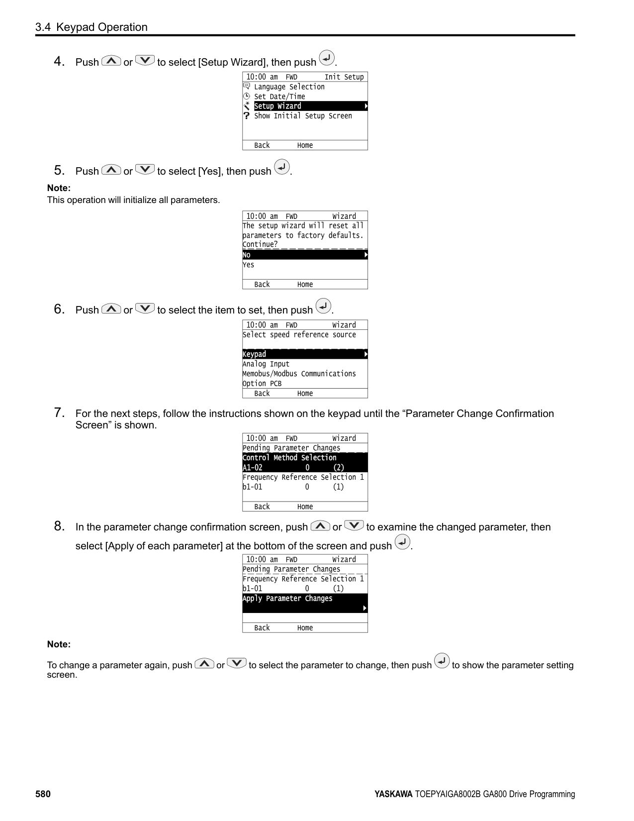
|Input Data|Parameter|Unit|Auto-Tuning Mode (T2-01 Setting)|Auto-Tuning Mode (T2-01 Setting)|Auto-Tuning Mode (T2-01 Setting)|Auto-Tuning Mode (T2-01 Setting)|Auto-Tuning Mode (T2-01 Setting)| |---|---|---|---|---|---|---|---| |Input Data|Parameter|Unit|Z-Pulse Offset (Pole Position)
(3)|PM Rotational Auto-Tuning (4)|PM Rotational Auto-Tuning (4)|PM Rotational Auto-Tuning (4)|High Frequency Injection AutoTuning
(5)| |Control method selection|A1-02|-|7|5|6|7|5, 6, 7| |PM Motor Code Selection|T2-02|-|-|-|-|-|-| |PM Motor Type|T2-03|-|-|x|x|x|-| |PM Motor Rated Power|T2-04|kW|-|x|x|x|-| |PM Motor Rated Voltage|T2-05|V|-|x|x|x|-| |PM Motor Rated Current|T2-06|A|-|x|x|x|-| |PM Motor Base Frequency|T2-07|Hz|-|x|-|-|-| |Number of PM Motor Poles|T2-08|-|-|x|x|x|-| |PM Motor Base Speed|T2-09|min-1|-|-|x|x|-| |PM Motor Stator Resistance|T2-10|Ω|-|-|-|-|-| |PM Motor d-Axis Inductance|T2-11|mH|-|-|-|-|-| |PM Motor q-Axis Inductance|T2-12|mH|-|-|-|-|-| |Back-EMF Units Selection|T2-13|-|-|-|-|-|-| |Back-EMF Voltage Constant (Ke)|T2-14|*1|-|-|-|-|-| |Pull-In Current Level|T2-15|%|-|x|x|x|-| |Encoder Pulse Count (PPR)|T2-16|-|-|-|-|x|-| |Encoder Z-Pulse Offset for PM Motor|T2-17|Degrees|-|-|-|-|-|
######## ◆ Auto-Tuning in EZ Open Loop Vector Control Method
This section gives information about the Auto-Tuning mode for EZ Open Loop Vector Control. Auto-Tuning will set the E9-xx parameters.
Table 3.9 EZ Tuning Mode Selection
|Mode|Parameter Settings|Application Conditions and Benefits|Applicable Control Method (A1-02 Setting)| |---|---|---|---| |Motor Parameter Setting|T4-01 = 0|• Applicable when driving an induction motor or a PM motor
• Suitable for derating torque applications, for example fans and pumps.
|EZOLV (8)| |Line-to-Line Resistance|T4-01 = 1|• After Auto-Tuning, the wiring distance between the drive and motor changed by 50 m or more.
• When the motor output and drive capacity are different.
|EZOLV (8)|
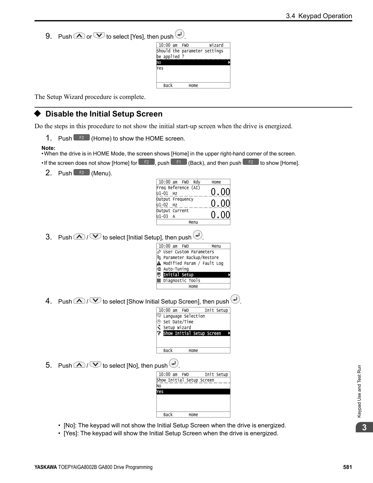
######## ■ Auto-Tuning Input Data in EZ Open Loop Vector Control Method
To do Auto-Tuning, input data for the items in Table 3.10 that have an "x". Before starting Auto-Tuning, prepare the motor test report or record the information on the motor nameplate as a reference.
Table 3.10 Auto-Tuning Input Data in EZ Open Loop Vector Control Method
|Input Data|Parameter|Unit|Auto-Tuning Mode (T4-01 Setting)|Auto-Tuning Mode (T4-01 Setting)| |---|---|---|---|---| |Input Data|Parameter|Unit|Motor Parameter Setting
(0)|Line-to-Line Resistance (1)| |Motor Type Selection|T4-02|-|x|-| |Motor Max Revolutions|T4-03|min-1|x|-| |Motor Rated Revolutions|T4-04|min-1|x|-| |Motor Rated Frequency|T4-05|Hz|x|-| |Motor Rated Voltage|T4-06|V|x|-| |PM Motor Rated Current (FLA)|T4-07|A|x|x| |PM Motor Rated Power (kW)|T4-08|kW|x|-| |Number of Motor Poles|T4-09|-|x|-|
◆ Control Tuning To increase drive responsiveness and prevent hunting, use Auto-Tuning to automatically adjust the control-related parameters. These types of Auto-Tuning are available for the control system:
Table 3.11 Control Loop Tuning Selection
|Mode|T3-00|Application Conditions and Benefits|Applicable Control Method (A1-02 Value)|Applicable Control Method (A1-02 Value)|Applicable Control Method (A1-02 Value)|Applicable Control Method (A1-02 Value)|Applicable Control Method (A1-02 Value)|Applicable Control Method (A1-02 Value)|Applicable Control Method (A1-02 Value)|Applicable Control Method (A1-02 Value)|Applicable Control Method (A1-02 Value)| |---|---|---|---|---|---|---|---|---|---|---|---| |Mode|T3-00|Application Conditions and Benefits|V/f (0)|CL-V/f (1)|OLV (2)|CLV (3)|AOLV (4)|OLV/PM (5)|AOLV/ PM (6)|CLV/PM (7)|EZOLV (8)| |Inertia Tuning|0|• For Feed Forward Control
• When L2-29 1 [Kinetic Energy Backup Method = Single Drive KEB Ride-Thru 2].
• When MFDI H1-xx = 7A [KEB RideThru 2 Activate (N.C.)].
|-|-|-|x|-|-|-|x|-| |ASR Tuning|1|To let the set response frequency (including Inertia Tuning) automatically adjust the ASR gain.|-|-|-|x|-|-|-|x|-|
|Mode|T3-00|Application Conditions and Benefits|Applicable Control Method (A1-02 Value)|Applicable Control Method (A1-02 Value)|Applicable Control Method (A1-02 Value)|Applicable Control Method (A1-02 Value)|Applicable Control Method (A1-02 Value)|Applicable Control Method (A1-02 Value)|Applicable Control Method (A1-02 Value)|Applicable Control Method (A1-02 Value)|Applicable Control Method (A1-02 Value)| |---|---|---|---|---|---|---|---|---|---|---|---| |Mode|T3-00|Application Conditions and Benefits|V/f (0)|CL-V/f (1)|OLV (2)|CLV (3)|AOLV (4)|OLV/PM (5)|AOLV/ PM (6)|CLV/PM (7)|EZOLV (8)| |Deceleration Rate Tuning|2|To automatically adjust the deceleration rate to prevent an ov [Overvoltage] fault.|x|x|x|x|x|x|x|x|x| |KEB Tuning|3|• To automatically adjust parameter settings to prevent an ov [Overvoltage] fault with the KEB Ride-Thru function.
• When L3-11 1 [Overvoltage Suppression Select Enabled].
|x|x|x|x|x|x|x|x|x|
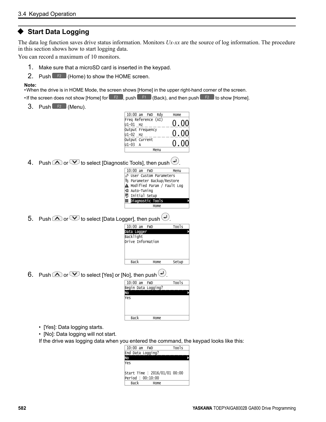
################# Table 3.12 Input Data for Control Tuning
|Input Data|Parameters|Unit|Auto-Tuning Mode (T3-00 Value)|Auto-Tuning Mode (T3-00 Value)|Auto-Tuning Mode (T3-00 Value)|Auto-Tuning Mode (T3-00 Value)| |---|---|---|---|---|---|---| |Input Data|Parameters|Unit|Inertia Tuning (0)|ASR (Speed Regulator)
(1)|Dec Rate Tuning (2)|KEB Tuning (3)| |Test Signal Frequency|T3-01|Hz|x|x|-|-| |Test Signal Amplitude|T3-02|Rad|x|x|-|-| |Motor Inertia|T3-03|Kg∙m2|x|x|-|-| |System Response Frequency|T3-04|Hz|-|x|-|-|
Inertia Tuning uses the motor speed and torque reference to estimate the system inertia and automatically sets the drive parameters related to the inertia ratio of the machinery and motor. Use Inertia Tuning for Feed Forward control or when H1-xx = 7A [MFDI Function Select = KEB Ride-Thru 2 Activate (N.C.)]. Inertia tuning identifies the load inertia and optimizes the speed loop gain and feed forward gain to get a high level of control capability. You can set the speed response without thinking about the load, which increases the precision when synchronizing multiple drives. Since the motor can continue to operate during a power outage, Inertia Tuning keeps the best ramp to stop deceleration curve for KEB Ride-Thru.
ASR Tuning estimates the motor load inertia and automatically sets the parameters. ASR Tuning also uses the measured load inertia value to do an automatic adjustment after calculating the proportional gain of speed control (ASR).
Deceleration Rate Tuning automatically sets the deceleration rate to prevent an ov [Overvoltage] fault during motor deceleration. Set C1-11 [Accel/Decel Time Switchover Freq] first to automatically set parameters C1-02 [Deceleration Time 1] (high speed range) and C1-08 [Deceleration Time 4] (low speed range).
KEB Tuning automatically sets parameters used for the KEB Ride-Thru function and for the overvoltage suppression function. Control Tuning automatically sets the parameters in Table 3.13 to the best values.
################# Table 3.13 Parameters set in Control Tuning
|Parameters Automatically Set|Inertia Tuning|ASR Tuning|Deceleration Rate Tuning|KEB Tuning| |---|---|---|---|---| |C1-02 [Deceleration Time 1]|-|-|x|-| |C1-08 [Deceleration Time 4]|-|-|x *1|-| |C1-09 [Fast Stop Time]|-|-|-|x *2| |C5-01 [ASR Proportional Gain 1]|-|x|-|-| |C5-17 [Motor Inertia]|x|x|-|-|
|Parameters Automatically Set|Inertia Tuning|ASR Tuning|Deceleration Rate Tuning|KEB Tuning| |---|---|---|---|---|
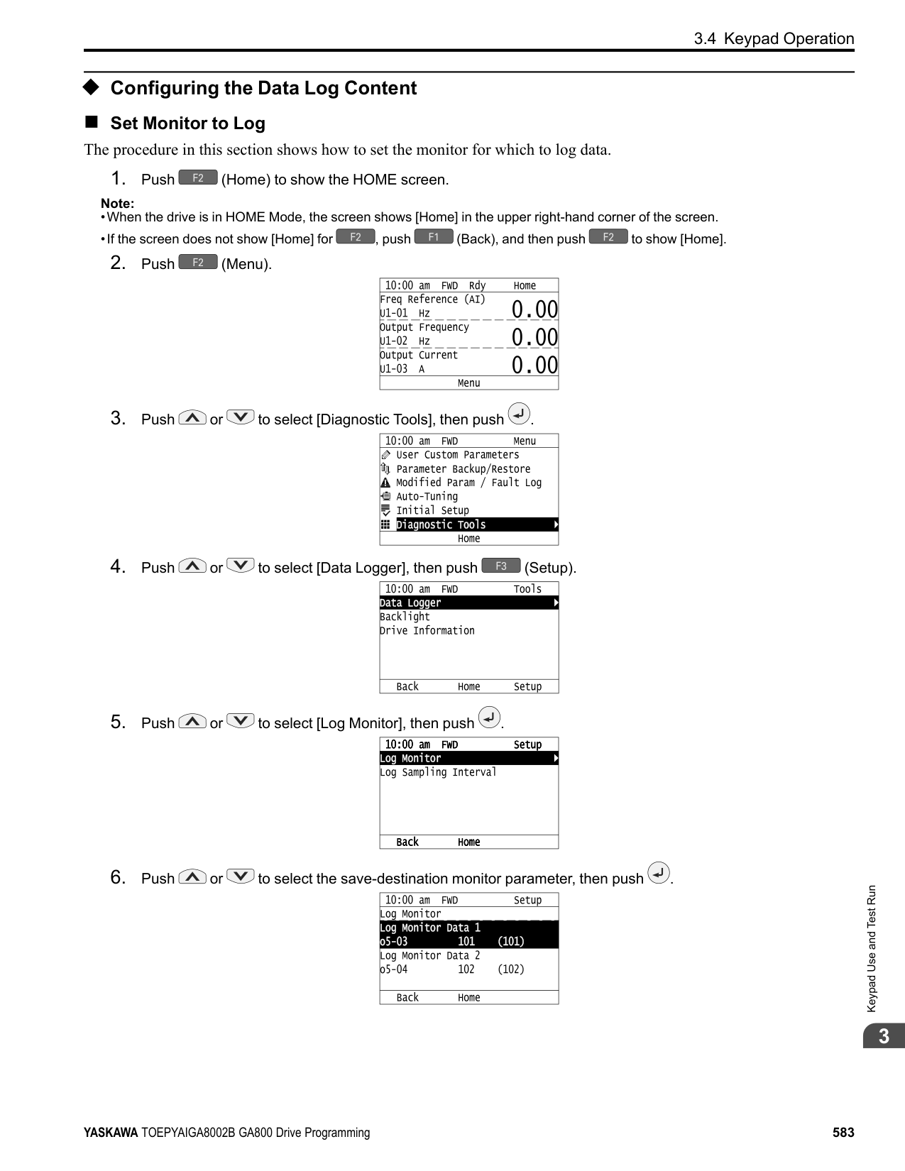
|C5-37 [Motor 2 Inertia]|x|x|-|-| |C5-18 [Load Inertia Ratio]|x|x|-|-| |C5-38 [Motor 2 Load Inertia Ratio]|x|x|-|-| |L2-06 [Kinetic Energy Backup Decel Time]|-|-|-|x *3| |L3-24 [Motor Accel Time @ Rated Torque]|x|x|-|-| |L3-25 [Load Inertia Ratio]|x|x|-|x| |n5-02 [Motor Inertia Acceleration Time]|x|x|-|-| |n5-03 [Feed Forward Control Gain]|x|x|-|-|
◆ Precautions before Auto-Tuning Examine the topics in this section before you start Auto-Tuning.
######## ■ Prepare for Basic Auto-Tuning
Note:
Better performance is possible when you use a motor with a rated voltage that is less than the input supply voltage (by 20 V for 200 V class models or by 40 V for 400 V class models). This is very important when operating the motor at more than 90% of base speed, where high torque precision is necessary. If the input power supply is equal to the motor rated voltage, the drive output voltage will not be sufficient, and performance will decrease.
|Auto-Tuning Type|Mode|Mode|Multifunctional input|Multifunctional output *1| |---|---|---|---|---| |Induction Motor Auto-Tuning|Rotational|Rotational Auto-Tuning|Disabled|Functions the same as during usual operation.| |Induction Motor Auto-Tuning|Stationary|Stationary Auto-Tuning 1|Disabled|Keeps the status at the start of Auto-Tuning.| |Induction Motor Auto-Tuning|Stationary|Line-to-Line Resistance|Disabled|Keeps the status at the start of Auto-Tuning.| |PM Motor Auto-Tuning|Rotational|Z-Pulse Offset (Pole Position)|Disabled|Keeps the status at the start of Auto-Tuning.| |PM Motor Auto-Tuning|Rotational|PM Rotational Auto-Tuning|Disabled|Functions the same as during usual operation.| |PM Motor Auto-Tuning|Stationary|PM Motor Parameter Settings|Disabled|Disabled| |PM Motor Auto-Tuning|Stationary|PM Stationary Auto-Tuning|Disabled|Keeps the status at the start of Auto-Tuning.| |PM Motor Auto-Tuning|Stationary|PM Stationary Auto-Tuning for Stator Resistance|Disabled|Keeps the status at the start of Auto-Tuning.|
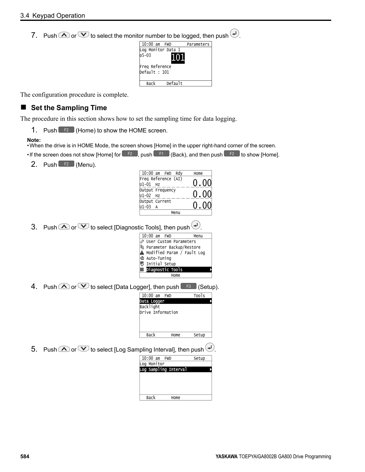
|Auto-Tuning Type|Mode|Mode|Multifunctional input|Multifunctional output *1| |---|---|---|---|---| |EZ Tuning|Stationary|Motor Parameter Setting|Disabled|Disabled| |EZ Tuning|Stationary|Line-to-Line Resistance|Disabled|Keeps the status at the start of Auto-Tuning.| |ASR and Inertia Tuning|Rotational|Inertia Tuning|Disabled|Functions the same as during usual operation.| |ASR and Inertia Tuning|Rotational|ASR (Speed Regulator)|Disabled|Functions the same as during usual operation.| |ASR and Inertia Tuning|Rotational|Deceleration Rate Tuning|Disabled|Functions the same as during usual operation.| |ASR and Inertia Tuning|Rotational|KEB Tuning|Disabled|Functions the same as during usual operation.|
*1 A terminal to which H2-xx = E [MFDO Function Select = Fault] is assigned functions the same as during usual operation. WARNING! Crush Hazard. Wire a sequence that will not let a multi-function output terminal open the holding brake during Stationary Auto-Tuning. If the holding brake is open during Stationary Auto-Tuning, it can cause serious injury or death. WARNING! Before you do Rotational Auto-Tuning, disconnect the load from the motor. The load can move suddenly and cause serious injury or death. WARNING! Electrical Shock Hazard. During Auto-Tuning, the motor will receive high voltage when the motor is stopped. Do not touch the motor until Auto-Tuning is complete. If you touch a motor that is energized, it can cause serious injury or death.
######## ■ Precautions before Rotational Auto-Tuning
WARNING! Electrical Shock Hazard. During Auto-Tuning, the motor will receive high voltage when the motor is stopped. Do not touch the motor until Auto-Tuning is complete. If you touch a motor that is energized, it can cause serious injury or death.
■ Precautions before Stationary Auto-Tuning
WARNING! Electrical Shock Hazard. During Auto-Tuning, the motor will receive high voltage when the motor is stopped. Do not touch the motor until Auto-Tuning is complete. If you touch a motor that is energized, it can cause serious injury or death.
Automatically Set E2-02 [Motor Rated Slip] and E2-03 [Motor No-Load Current] If T1-12 = 1 [Test Mode Selection = Yes] when selecting Stationary Auto-Tuning, the drive will automatically set motor parameters E2-02 [Motor Rated Slip] and E2-03 [Motor No-Load Current] after Auto-Tuning is complete when you use the motor for the first time in Drive Mode. After Stationary Auto-Tuning is complete, use this procedures to do the operation in test mode:
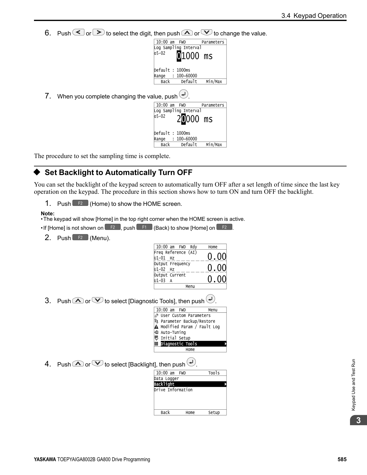
################# Note:
In elevator applications, there is a risk of the cage falling and causing personal injury. Do one of these precautions to decrease the risk:
######## ■ Precautions before Stationary Auto-Tuning for Line-to-Line Resistance and Stator
Resistance Auto-Tuning In V/f control, when the motor cable is 50 meters (164 feet) or longer, do Stationary Auto-Tuning for Line-to-Line Resistance. WARNING! Electrical Shock Hazard. During Auto-Tuning, the motor will receive high voltage when the motor is stopped. Do not touch the motor until Auto-Tuning is complete. If you touch a motor that is energized, it can cause serious injury or death.
################# Note:
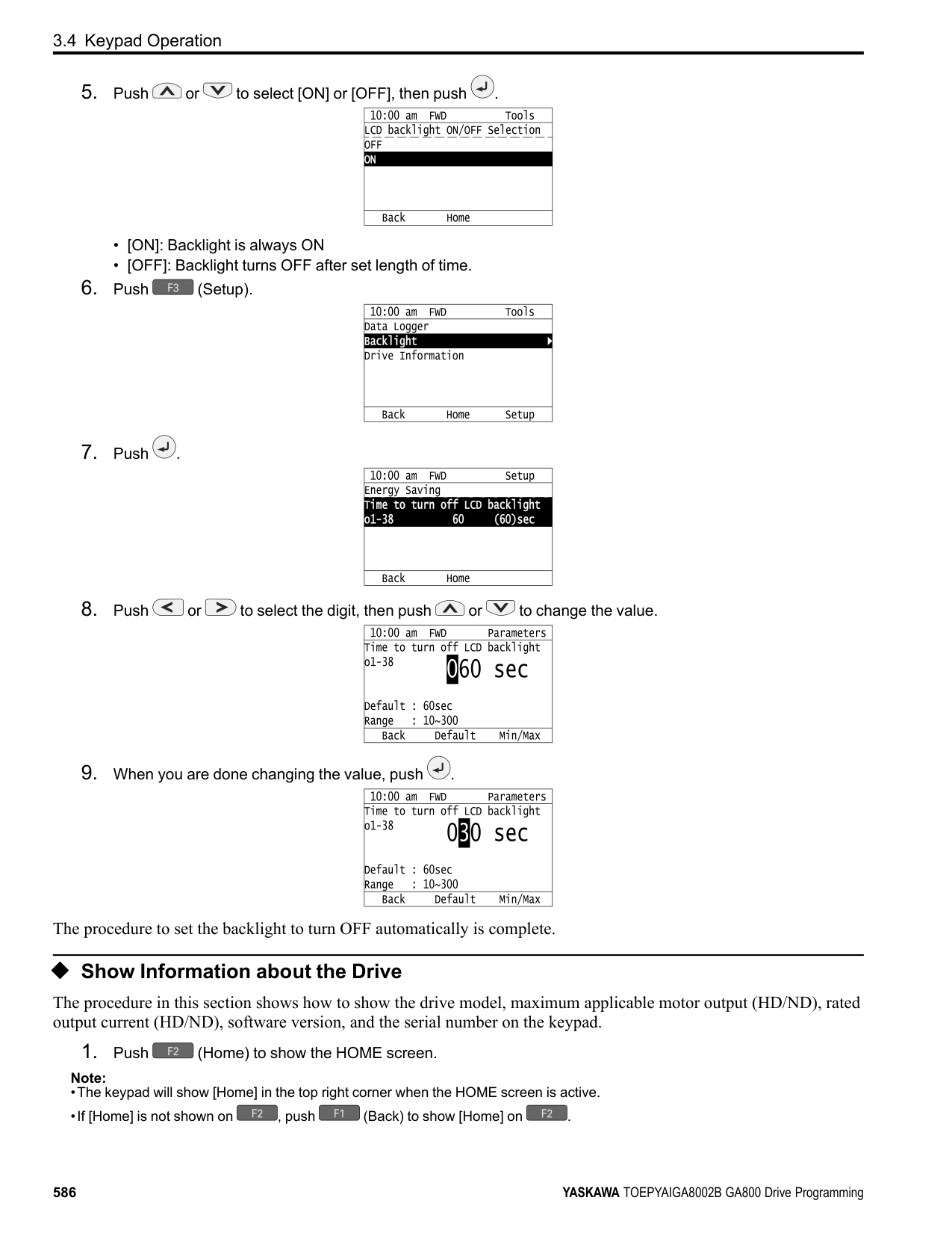
KeypadUseandTestRun
####### 3.6 Test Run
After you use the Setup Wizard to set the basic parameters and Auto-Tune the drive, the next step is to do a test run. WARNING! Crush Hazard. Test the system to make sure that the drive operates safely after you wire the drive and set parameters. If you do not test the system, it can cause damage to equipment or serious injury or death.
◆ No-Load Test Run Before connecting the motor to the machine, make sure that you check the operation status of the motor.
■ Items to Check before Operation Check these items before operation:
◆ Do a No-Load Test Run Do these steps for a no-load test run:
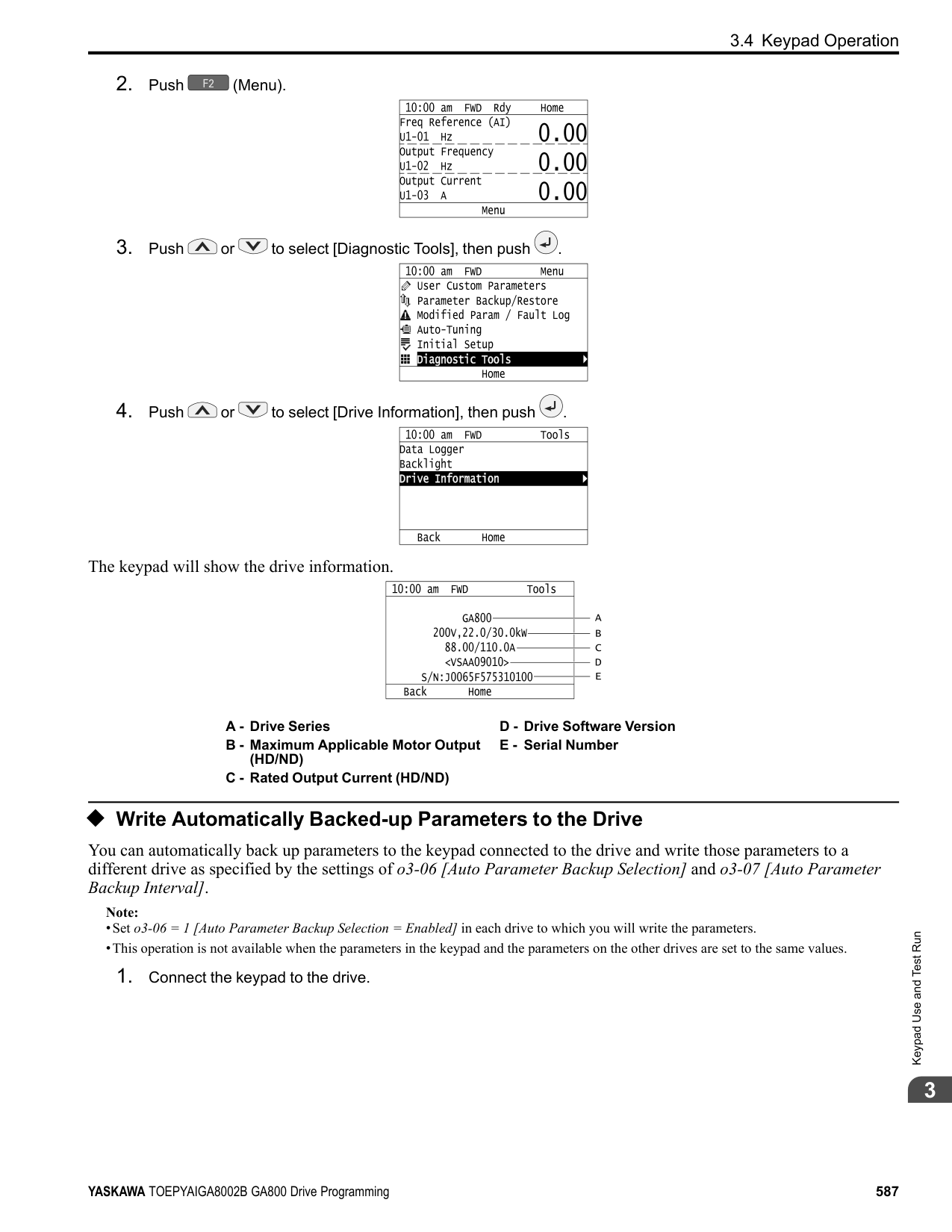
A - Forward Rotation of Motor (Counter Clockwise Direction as Seen from Load Shaft)
◆ Actual-Load Test Run Test the operation without a load, then connect the motor and machine to do a test run.
3.6 Test Run
■ Precautions before Operation Before rotating the motor, check these items:
■ Items to Check before Operation
◆ Do an Actual-Load Test Run Connect the motor and machine, then do the test run with the same procedure you used for the no-load test run.
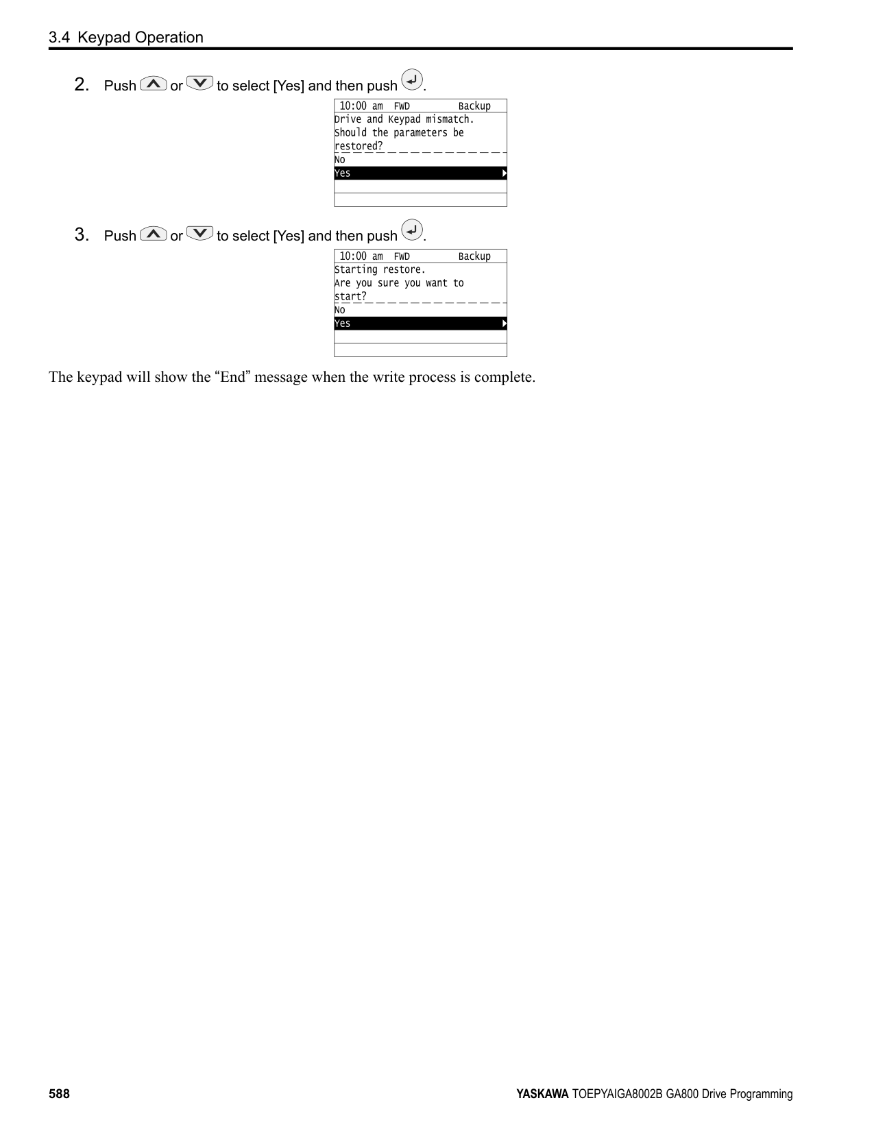
####### 3.7 Fine Tuning during Test Runs (Adjust the ControlFunction)
This section gives information about the adjustment procedures to stop hunting or oscillation errors caused by control function during a test run. Adjust the applicable parameters as specified by your control method and drive status.
######## ◆ V/f Control and Closed Loop V/f Control
################# Table 3.15 Parameters for Fine Tuning the Drive (V/f and CL-V/f)
|Issue|Parameter Number|Possible Solutions|Default|Recommended Setting| |---|---|---|---|---| |Hunting or oscillation at mid-range speeds (10 Hz to 40 Hz)|n1-02 [Hunting Prevention Gain Setting]|• If torque is not sufficient with heavy loads, decrease the setting value.
• If hunting or oscillation occur with light loads, increase the setting value.
• If hunting occurs with a lowinductance motor, for example a motor with a larger frame size or a high-frequency motor, lower the setting value.
|1.00|0.10 - 2.00| |• The volume of the motor excitation sound is too high.
• Hunting or oscillation at low speeds (10 Hz or lower), or at mid-range speeds (10 Hz to 40 Hz)
|C6-02 [Carrier Frequency Selection]|• If the volume of the motor excitation sound is too high, increase the carrier frequency.
• If hunting or oscillation occur at low or mid-range speeds, decrease the carrier frequency.
|1 (2 kHz) *1|1 to upper limit value| |• Unsatisfactory motor torque and speed response
• Hunting or oscillation
|C4-02 [Torque Compensation Delay Time]|• If torque or speed response are slow, decrease the setting value.
• If hunting or oscillation occur, increase the setting value.
|200 ms *2|100 ms to 1000 ms| |• Torque at low speeds (10 Hz or lower) is not sufficient.
• Hunting or oscillation
|C4-01 [Torque Compensation Gain]|• If torque at low speeds (10 Hz or lower) is not sufficient, increase the setting value.
• If hunting or oscillation occur with light loads, decrease the setting value.
|1.00|0.50 - 1.50| |• Torque at low speeds (10 Hz or lower) is not sufficient.
• Large initial vibration at start up.
|• E1-08 [Mid Point AVoltage]
• E1-10 [Minimum Output Voltage]
|• If torque at low speeds (10 Hz or lower) is not sufficient, increase the setting value.
• If there is large initial vibration at start up, decrease the setting value
|• E1-08: 15.0 V *3
• E1-10: 9.0 V *3
|Default setting +/- 5 V *4| |Speed precision is unsatisfactory. (V/f Control)|C3-01 [Slip Compensation Gain]|Set E2-01 [Motor Rated Current],
E2-02 [Motor Rated Slip], and E203 [Motor No-Load Current], then adjust C3-01.|0.0 (no slip compensation)|0.5 - 1.5| |Speed precision is unsatisfactory. (Closed Loop V/f Control)|• C5-01 [ASR Proportional Gain 1]
• C5-02 [ASR Integral Time 1 (I)] *5
|Adjust C5-01, C5-02.|• C5-01: 0.20
• C5-02: 0.200 s
|• Proportional gain 0.10 to 1.00
• Integral time 0.100 to 2.000 s
|
◆ Open Loop Vector Control Method In Open Loop Vector Control, keep C4-01 [Torque Compensation Gain] at its default setting (1.00). If you cannot get speed precision during regeneration in Open Loop Vector Control, set C3-04 = 1 [Slip Compensation @ Regen Select = Enabled above 6 Hz].
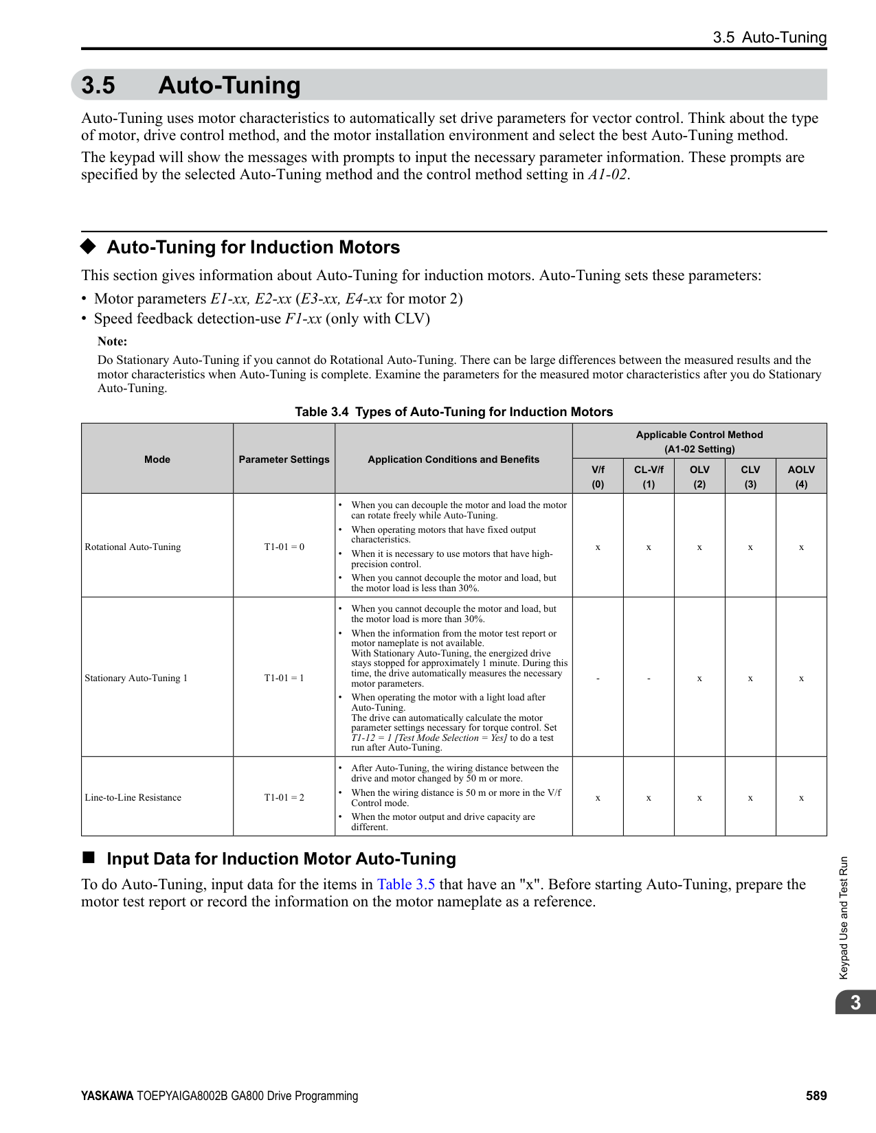
Table 3.16 Parameters for Fine Tuning the Drive (A1-02 = 2[OLV])
|Issue|Parameter Number|Possible Solutions|Default|Recommended Setting| |---|---|---|---|---| |• Unsatisfactory motor torque and speed response
• Hunting or oscillation at midrange speeds (10 Hz to 40 Hz)
|n2-01 [SpdFeedbackDetectCtr (AFR) Gain]|• To increase the speed of torque or speed response, decrease the setting value in increments of 0.05.
• If hunting or oscillation occur, decrease the setting value in increments of 0.05.
|1.00|0.50 - 2.00| |• Unsatisfactory motor torque and speed response
• Hunting or oscillation at midrange speeds (10 Hz to 40 Hz)
|n2-02 [SpdFeedbackDetCtr(AFR) TimeConst1]|• To increase the speed of torque or speed response, decrease the setting value in increments of 10 ms and examine the response.
• If hunting or oscillation occur or if the load inertia is too much, increase the setting value in increments of 50 ms and examine the response.
Note:
Make sure that this parameter setting is: n2-02 ≤ n2-03 [Automatic Freq Regulator Time 2] holds true.
When you adjust n2-02, you must also increase the C4-02
[Motor 1 Torque Comp Delay Time] value by the same ratio.|50 ms|50 ms to 2000 ms| |ov [overvoltage] occurs when the drive stops accelerating, starts to decelerate, or when there are large changes in the load.|n2-03 [SpdFeedbackDetCtr(AFR) TimeConst2]|• If ov occurs, increase the setting value in increments of 50 ms and examine the response.
• If the response is not sufficient, decrease the setting value in increments of 10 ms and examine the response.
Note:
Make sure that this parameter setting is: n2-02 [Automatic Freq Regulator Time 1] ≤ n2-
03. When you adjust n2-03 you must also increase the C4-06
[Motor 2 Torque Comp Delay Time] value by the same ratio.|750 ms|750 ms to 2000 ms| |ov [overvoltage] occurs when the drive stops accelerating, starts to decelerate, or when there are large changes in the load.|C4-06 [Motor 2 Torque Comp Delay Time]|• If ov occurs, increase the setting value in increments of 10 ms and examine the response.
• If the response is not sufficient, decrease the setting value in increments of 2 ms and examine the response.
Note:
Make sure that this parameter setting is: C4-02 [Torque Compensation Delay Time] ≤ C4-06.
When you adjust C4-06, you must also increase the n2-03 [SpdFeedbackDetCtr(AFR) TimeConst2] value by the same ratio.|150 ms|150 ms to 750 ms|
|Issue|Parameter Number|Possible Solutions|Default|Recommended Setting| |---|---|---|---|---| |• Unsatisfactory motor torque and speed response
• Hunting or oscillation
|C4-02 [Torque Compensation Delay Time 1]|• If torque or speed response are slow, decrease the setting value in increments of 2 ms.
• If hunting or oscillation occur, increase the setting value in increments of 10 ms.
Note:
Make sure that this parameter setting is: C4-02 ≤ C4-06 [Motor 2 Torque Comp Delay Time].
When you adjust C4-02, you must also increase the n2-02 [SpdFeedbackDetCtr (AFR) TimeConst1] value by the same
ratio.|20 ms *1|20 ms to 100 ms *1| |• Speed response is slow.
• Speed is not stable.
|C3-02 [Slip Compensation Delay Time]|• If speed response is slow, decrease the setting value in increments of 10 ms.
• If speed is not stable, increase the value in increments of 10 ms.
|200 ms *1|100 ms to 500 ms| |Speed precision is unsatisfactory.|C3-01 [Slip Compensation Gain]|• If speed is too slow, increase the setting value in increments of 0.1.
• If speed is too fast, decrease the setting value in increments of 0.1.
|1.0 *2|0.5 - 1.5| |• The volume of the motor excitation sound is too high.
• Hunting or oscillation at low speeds (10 Hz or lower)
|C6-02 [Carrier Frequency Selection]|• If the volume of the motor excitation sound is too high, increase the carrier frequency.
• If hunting or oscillation occur at low speeds, decrease the carrier frequency.
|1 (2 kHz) *3|0 to upper limit value| |• Torque at low speeds (10 Hz or lower) is not sufficient. speed response is slow.
• Speed response is slow.
• Large initial vibration at start up.
|• E1-08 [Mid Point AVoltage]
• E1-10 [Minimum Output Voltage]
|• If torque or speed response are slow, increase the setting value.
• If there is large initial vibration at start up, decrease the setting value
Note:
If the setting value is set too high, a large torque reference may be output even with light loads.|• E1-08: 11.0 V *2
• E1-10: 2.0 V *2
|Default setting +/- 2 V *4|
######## ◆ Closed Loop Vector Control Method
Table 3.17 Parameters for Fine Tuning the Drive (CLV)
|Issue|Parameter Number|Possible Solutions|Default|Recommended Setting| |---|---|---|---|---| |• Unsatisfactory motor torque and speed response
• Hunting or oscillation
|• High speed C5-01 [ASR Proportional Gain 1]
• Low speed C5-03 [ASR Proportional Gain 2 (P)] *1
|• If torque or speed response are slow, increase the setting value in increments of 5.00.
• If hunting or oscillation occur, decrease the setting value.
|20.00|10.00 - 50.00| |• Unsatisfactory motor torque and speed response
• Hunting or oscillation
|• High speed C5-02 [ASR Integral Time 1]
• Low speed C5-04 [ASR Integral Time 2 (I)] *1
|• If torque or speed response are slow, decrease the setting value.
• If hunting or oscillation occur, increase the setting value.
|0.500 s|0.300 s to 1.000 s| |The drive cannot find ASR proportional gain or integral time for low speed or high speed.|C5-07 [ASR Gain Switchover Frequency] *1|Change the ASR proportional gain and ASR integral time to conform to the output frequency.|0.0 Hz|0.0 Hz to maximum output frequency|
|Issue|Parameter Number|Possible Solutions|Default|Recommended Setting| |---|---|---|---|---| |Hunting or oscillation|C5-06 [ASR Delay Time] *1|• If torque or speed response are slow, decrease the setting value in increments of 0.010.
• If the rigidity of the machine is unsatisfactory and vibration is possible, increase the setting value.
|0.004 s|0.004 s to 0.020 s| |• The volume of the motor excitation sound is too high.
• Hunting or oscillation at low speeds (3 Hz or lower)
|C6-02 [Carrier Frequency Selection]|• If the volume of the motor excitation sound is too high, increase the carrier frequency.
• If hunting or oscillation occur at low speeds, decrease the carrier frequency.
|1 (2.0 kHz) *2|2.0 kHz to upper limit value|
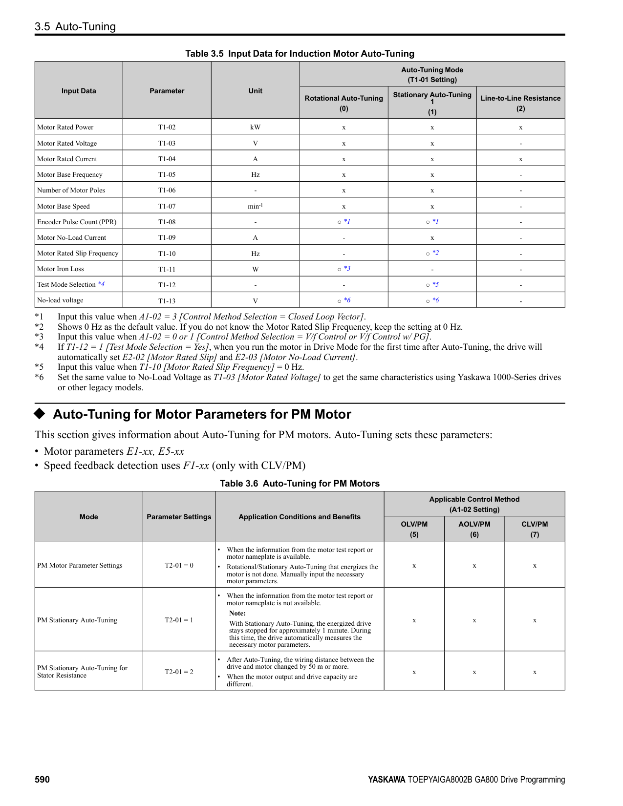
######## ◆ Advanced Open Loop Vector Control Method
################# Table 3.18 Parameters for Fine Tuning the Drive (AOLV)
|Issue|Parameter Number|Possible Solutions|Default|Recommended Setting| |---|---|---|---|---| |• oS [Overspeed] occurs.
• Hunting or oscillation.
|T1-01 [Auto-Tuning Mode Selection]|• Make sure that the output of the drive and the motor are connected correctly.
• Do Rotational Auto-Tuning for a single motor.
|-|0| |The volume of the motor excitation sound is too high.|C6-02 [Carrier Frequency Selection]|If the volume of the motor excitation sound is too high, increase the carrier frequency.|1 (2 kHz) *1|1 to upper limit value| |Speed precision is unsatisfactory|E2-02 [Motor Rated Slip]|• Decouple the motor and machine and do Rotational Auto-Tuning.
• If the motor speed is slow, increase the value of E2-02 in small increments (approximately 0.1% of the default setting value).
• If the motor speed is fast, decrease the value of E2-02 in small increments (approximately 0.1% of the default setting value).
|*2|Set to a value that is ±5% of the current value.| |• Unsatisfactory motor torque and speed response
• Hunting or oscillation
|• High speed C5-01 [ASR Proportional Gain 1]
• Low speed C5-03 [ASR Proportional Gain 2 (P)] *3
|• If torque or speed response are slow, increase the setting value in increments of 5.00.
• If hunting or oscillation occur, decrease the setting value.
|• C5-01 = 10.00
• C5-03 = 20.00
|10.00 - 50.00| |• Unsatisfactory motor torque and speed response
• Hunting or oscillation
|• High speed C5-02 [ASR Integral Time 1]
• Low speed C5-04 [ASR Proportional Gain 2 (P)] *3
|• If torque or speed response are slow, decrease the setting value.
• If hunting or oscillation occur, increase the setting value.
|0.500 s|0.300 s to 1.000 s| |The drive cannot find speed response for low speed or high speed.|• C5-07 [ASR Gain Switchover Frequency] *4
• High speed
C5-01 [ASR Proportional Gain 1]
C5-02 [ASR Integral Time 1]
• Low speed
C5-03 [ASR Proportional Gain 2 (P)] *3
C5-04 [ASR Integral Time 2]
|Change the ASR proportional gain and ASR integral time to conform to the output frequency.|• C5-07 = 0.0 Hz
• C5-01 = 10.00
• C5-02 = 0.500 s
• C5-03 = 20.00
• C5-04 = 0.500 s
|C5-07: 0.0 to maximum output frequency| |Hunting or oscillation|C5-06 [ASR Delay Time] *4|• If torque or speed response are slow, decrease the setting value in increments of 0.010.
• If the rigidity of the machine is unsatisfactory and vibration is possible, increase the setting value.
|0.004 s|0.004 s to 0.020 s|
KeypadUseandTestRun
######## 3
######## ◆ Fine-Tuning Open Loop Vector Control for PM Motors
Table 3.19 Parameters for Fine Tuning the Drive (A1-02 = 5[OLV/PM])
|Issue|Parameter Number|Possible Solutions|Default|Recommended Setting| |---|---|---|---|---| |Unsatisfactory motor performance|E1-xx parameters, E5-xx parameters|• Check the settings for E1-06, E1-04 [Base Frequency, Maximum Output Frequency].
• Check the E5-xx and make sure that all motor data has been set correctly.
Note: Do not set E5-05 [PM Motor Resistance (ohms/phase)] to a line-to-line resistance value.
• Do Auto-Tuning.
|-|-| |Unsatisfactory motor torque and speed response|n8-55 [Motor to Load Inertia Ratio]|Adjust to match the load inertia ratio of the motor and machine.|0|Near the actual load inertia ratio.| |Unsatisfactory motor torque and speed response|n8-45 [Speed Feedback Detection Gain]|Decrease the setting value in increments of 0.05.|0.80|-| |Unsatisfactory motor torque and speed response|C4-01 [Torque Compensation Gain]|Adjust the setting value.
Note:
Setting this value too high can cause overcompensation and motor oscillation.|0.00|1.00| |• Oscillation when the motor starts.
• Motor stalls.
|n8-51 [Pull-in Current @ Accel/ Decel]|Increase the setting value in increments of 5%.|50%|-|
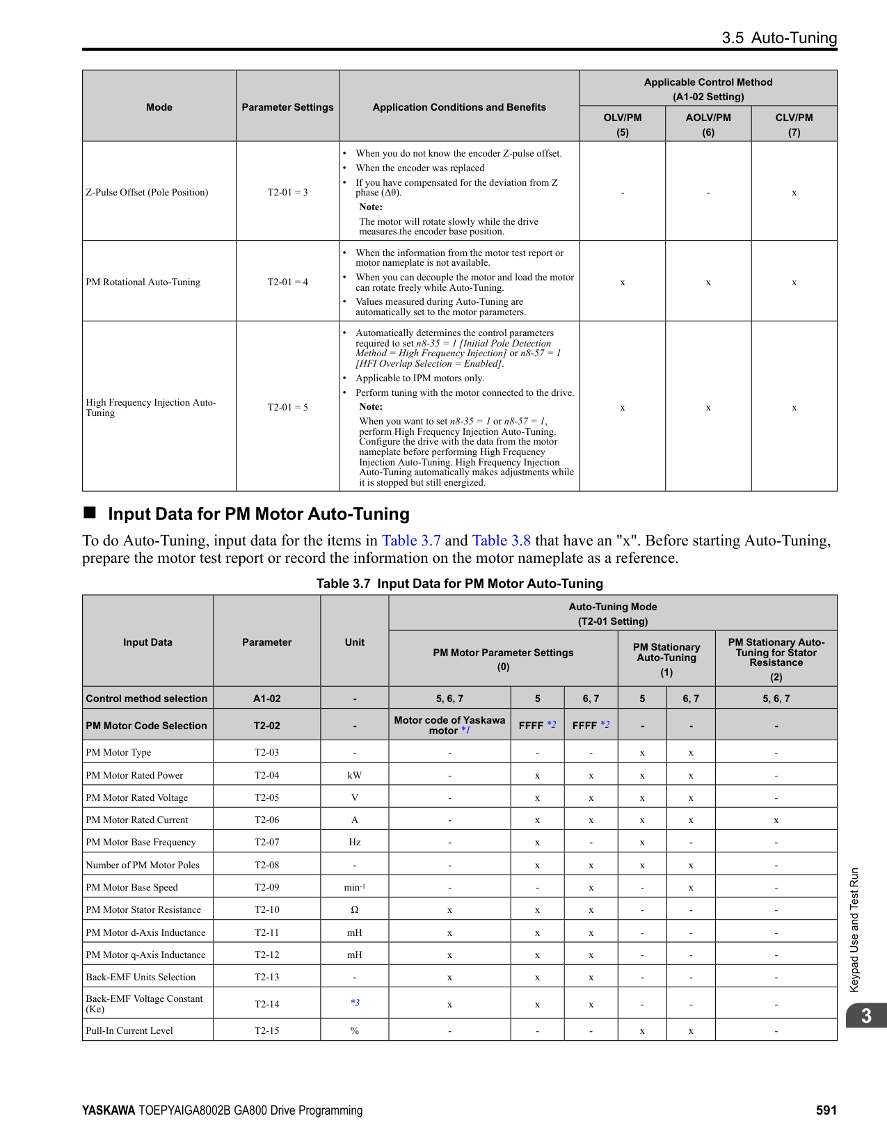
|• Oscillation when the motor starts.
• Motor stalls.
|• b2-02 [DC Injection Braking Current]
• b2-03 [DC Inject Braking Time at Start]
|Use DC Injection Braking at start.
Note:
This can cause the motor to rotate in reverse for approximately 1/8 of a turn at start.|• b2-02: 50%
• b2-03: 0.00 s
|• b2-02: Adjust as necessary.
• b2-03: 0.5 s
| |• Oscillation when the motor starts.
• Motor stalls.
|n8-55 [Motor to Load Inertia Ratio]|Increase the setting value.
Note:
When operating a single motor or with a minimum amount of inertia, setting this value too high can cause motor oscillation.|0|Near the actual load inertia ratio.| |There is too much current during deceleration.|n8-79 [Pull-in Current at Deceleration]|Set n8-79 < n8-51.|50%
Note:
When n8-79 = 0, the drive will apply the n8-51 setting to the pull-in current during deceleration.|Decrease in increments of 5%.| |Stalling or oscillation occurs when load is applied during constant speed|n8-47 [Pull-in Current Comp Filter Time]|Decrease the setting value in increments of 0.2 s.|5.0 s|-| |Stalling or oscillation occurs when load is applied during constant speed|n8-48 [Pull-in/Light Load Id Current]|Increase the setting value in increments of 5%.|30%|-| |Stalling or oscillation occurs when load is applied during constant speed|n8-55 [Motor to Load Inertia Ratio]|Increase the setting value.
Note:
When operating a single motor or with a minimum amount of inertia, setting this value too high can cause motor oscillation.|0|Near the actual load inertia ratio.| |Hunting or oscillation|n8-45 [Speed Feedback Detection Gain]|Increase the setting value in increments of 0.05.|0.80|-| |The drive detects STPo [Motor Step-Out Detected] fault when the load is not too high.|• E5-09 [PM Back-EMF Vpeak (mV/(rad/s))]
• E5-24 [PM Back-EMF L-L Vrms (mV/rpm)]
|• Adjust the setting value.
• Examine the motor code on the motor nameplate or the data sheet, then set correct values for E5-09 or E5-24.
|*1|• Yaskawa motor Set the motor code from the motor nameplate.
• Motor from another manufacturer Set the values from the test report.
| |The drive detected stalling or STPo [Motor Step-Out Detected] at high speed and maximum output voltage.|n8-62 [Output Voltage Limit Level]|Set to a value lower than the actual input voltage.|• 200.0 V
• 400.0 V
|-|
*1 The default setting changes when the settings for E5-01 [Motor Code Selection] and o2-04 [Drive Model (KVA) Selection] change.
######## ◆ Advanced Open Loop Vector Control Method for PM
################# Table 3.20 Parameters for Fine Tuning the Drive (A1-02 = 6[AOLV/PM])
|Issue|Parameter Number|Possible Solutions|Default|Recommended Setting| |---|---|---|---|---| |• Unsatisfactory motor torque and speed response
• Hunting or oscillation
|• High speed C5-01 [ASR Proportional Gain
1]
• Low speed C5-03 [ASR Proportional Gain
2]
|• If torque or speed response are slow, increase the setting value in increments of 5.00.
• If hunting or oscillation occur, decrease the setting value.
|10.00|5.00 to 30.00 *1| |• Unsatisfactory motor torque and speed response
• Hunting or oscillation
|• High speed C5-02 [ASR Integral Time 1]
• Low speed C5-04 [ASR Integral Time 2]
|• If torque or speed response are slow, decrease the setting value.
• If hunting or oscillation occur, increase the setting value.
|0.500 s|0.300 s to 1.000 s *1| |The drive cannot find ASR proportional gain or integral time for low speed or high speed.|C5-07 [ASR Gain Switchover Frequency]|Change the ASR proportional gain and ASR integral time to conform to the output frequency.|0.0%|0.0% to maximum rotation speed| |Hunting or oscillation|C5-06 [ASR Delay Time]|If the rigidity of the machine is unsatisfactory and vibration is possible, increase the setting value in increments of 0.010.|0.016 s|0.016 s to 0.035 s *1| |Step-out|E1-xx parameters, E5-xx parameters|Refer to the motor nameplate or test report and set E1-xx or E5-xx correctly.|-|-|
*1 The best values for a no-load operation are different than the best values for actual loading operation.
######## ◆ Closed Loop Vector Control Method for PM
################# Table 3.21 Parameters for Fine Tuning the Drive (CLV/PM)
|Issue|Parameter Number|Possible Solutions|Default|Recommended Setting| |---|---|---|---|---| |• Unsatisfactory motor torque and speed response
• Hunting or oscillation
|• High speed C5-01 [ASR Proportional Gain
1]
• Low speed C5-03 [ASR Proportional Gain
2]
|• If torque or speed response are slow, increase the setting value in increments of 5.00.
• If hunting or oscillation occur, decrease the setting value.
|20.00|10.00 to 50.00 *1| |• Unsatisfactory motor torque and speed response
• Hunting or oscillation
|• High speed C5-02 [ASR Integral Time 1]
• Low speed C5-04 [ASR Integral Time 2]
|• If torque or speed response are slow, decrease the setting value.
• If hunting or oscillation occur, increase the setting value.
|0.500 s|0.300 to 1.000 s *1| |The drive cannot find speed response for low speed or high speed.|• C5-07 [ASR Gain Switchover Frequency]
• High speed
C5-01 [ASR Proportional Gain 1]
C5-02 [ASR Integral Time 1]
• Low speed
C5-03 [ASR Proportional Gain 2]
C5-04 [ASR Integral Time 2]
|Change the ASR proportional gain and ASR integral time to conform to the output frequency.|• C5-07 = 0.0 %
• C5-01 = 20.00
• C5-02 = 0.500 s
• C5-03 = 20.00
• C5-04 = 0.500 s
|0.0% to maximum rotation speed| |Hunting or oscillation|C5-06 [ASR Delay Time]|If the rigidity of the machine is unsatisfactory and vibration is possible, increase the setting value in increments of 0.010.|0.004 s|0.004 to 0.020 s *1| |Step-out|E1-xx parameters, E5-xx parameters|Refer to the motor nameplate or test report and set E1-xx or E5-xx correctly.|-|-|
*1 The best values for a no-load operation are different than the best values for actual loading operation.
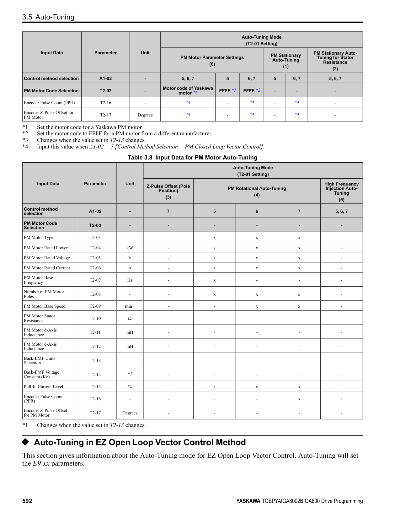
KeypadUseandTestRun
######## ◆ EZ Open Loop Vector Control Method
################# Table 3.22 Parameters for Fine Tuning the Drive (A1-02 = 8[EZOLV])
|Issue|Parameter Number|Possible Solutions|Default|Recommended Setting| |---|---|---|---|---| |• Unsatisfactory motor torque and speed response
• Hunting or oscillation
|• High speed C5-01 [ASR Proportional Gain
1]
• Low speed C5-03 [ASR Proportional Gain
2]
|• If torque or speed response are slow, increase the setting value in increments of 5.00.
• If hunting or oscillation occur, decrease the setting value.
|10.00|10.00 to 50.00 *1| |• Unsatisfactory motor torque and speed response
• Hunting or oscillation
|• High speed C5-02 [ASR Integral Time 1]
• Low speed C5-04 [ASR Integral Time 2]
|• If torque or speed response are slow, decrease the setting value.
• If hunting or oscillation occur, increase the setting value.
|0.500 s|0.300 s to 1.000 s *1| |The drive cannot find ASR proportional gain or integral time for low speed or high speed.|C5-07 [ASR Gain Switchover Frequency]|Change the ASR proportional gain and ASR integral time to conform to the output frequency.|0.0%|0.0% to maximum rotation speed| |Hunting or oscillation|C5-06 [ASR Delay Time]|If the rigidity of the machine is unsatisfactory and vibration is possible, increase the setting value in increments of 0.010.|0.004 s|0.004 s to 0.020 s *1| |Step-out|E9-xx parameters|Refer to the motor nameplate or test report and set E9-xx correctly.|-|-| |Oscillation when the motor starts.|n8-51 [Accel / Decel Pull-In Current]|Increase the setting value.|80%|Increase in increments of 5%.| |Motor stalls.|L7-01 to L7-04 [Torque Limit]|Increase the setting value.|200%|Increase in increments of 10%.|
3.8 Test Run Checklist
####### 3.8 Test Run Checklist
Examine the items in this checklist and check each item before a test run.
|Checked|No.|Description| |---|---|---| | |1|Correctly install and wire the drive as specified by this manual.| | |2|Energize the drive.| | |3|Set the voltage for the power supply in E1-01 [Input AC Supply Voltage].|
Check the applicable items as specified by your control method. WARNING! Sudden Movement Hazard. Correctly wire the start/stop and safety circuits before you energize the drive. If you momentarily close a digital input terminal, it can start a drive that is programmed for 3-Wire control and cause serious injury or death from moving equipment.
Table 3.23 V/f Control [A1-02 = 0] and Closed Loop V/f Control [A1-02 = 1]
|Checked|No.|Description| |---|---|---| | |4|Select the best V/f pattern for your application and motor characteristics. Example: For a motor with a rated frequency of 60 Hz, set E1-03 = 1 [V/f Pattern Selection = Const Trq, 60Hz base, 60Hz max] as a standard V/f pattern.|
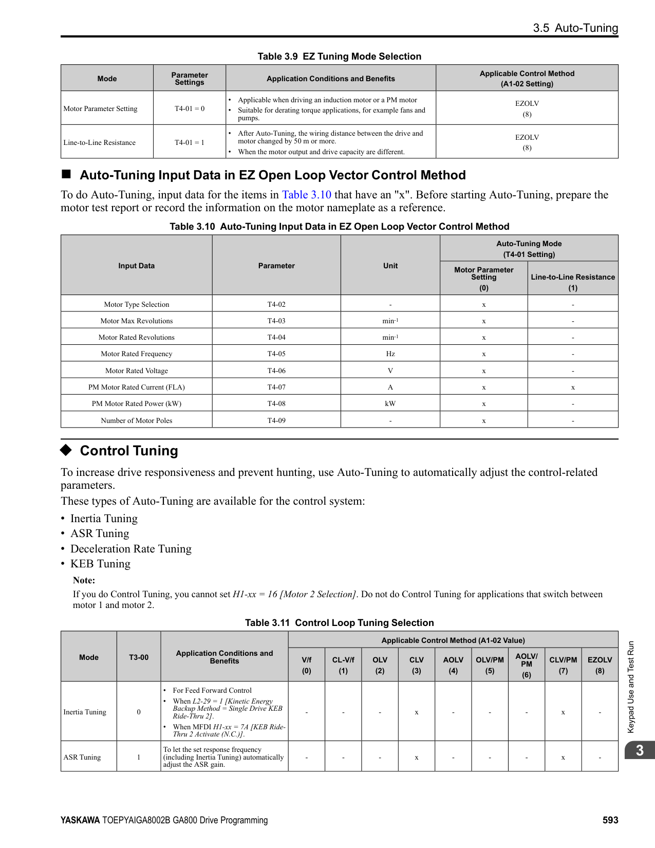
Table 3.24 Closed Loop V/f Control [A1-02 = 1]
|Checked|No.|Description| |---|---|---| | |5|Set F1-01 [Encoder 1 Pulse Count (PPR)] correctly and make sure that encoder pulse counting direction is correct.| | |6|Set C5-01 [ASR Proportional Gain 1] and C5-02 [ASR Integral Time 1].|
Table 3.25 Open Loop Vector Control [A1-02 = 2] or Closed Loop Vector Control [A1-02 = 3]
|Checked|No.|Description| |---|---|---| | |7|Decouple motor shafts and machines.| | |8|Refer to the information on the motor nameplate and set this data correctly:
• Motor rated power (kW) to T1-02
• Motor rated voltage (V) to T1-03
• Motor rated current (A) to T1-04
• Motor base frequency (Hz) to T1-05
• Number of motor poles to T1-06
• Motor base speed (min-1) to T1-07
| | |9|Do Rotational Auto-Tuning.|
|Checked|No.|Description| |---|---|---| | |10|Set F1-01 [Encoder 1 Pulse Count (PPR)] and F1-05 [Encoder 1 Rotation Selection].| | |11|Set C5-01 [ASR Proportional Gain 1] and C5-02 [ASR Integral Time 1].|
|Checked|No.|Description| |---|---|---| | |12|Set E5-01 through E5-24 [PM Motor Settings].|
KeypadUseandTestRun
|Checked|No.|Description| |---|---|---| | |13|Set E5-01 through E5-24 [PM Motor Settings].| | |14|Set C5-01 [ASR Proportional Gain 1] and C5-02 [ASR Integral Time 1].|
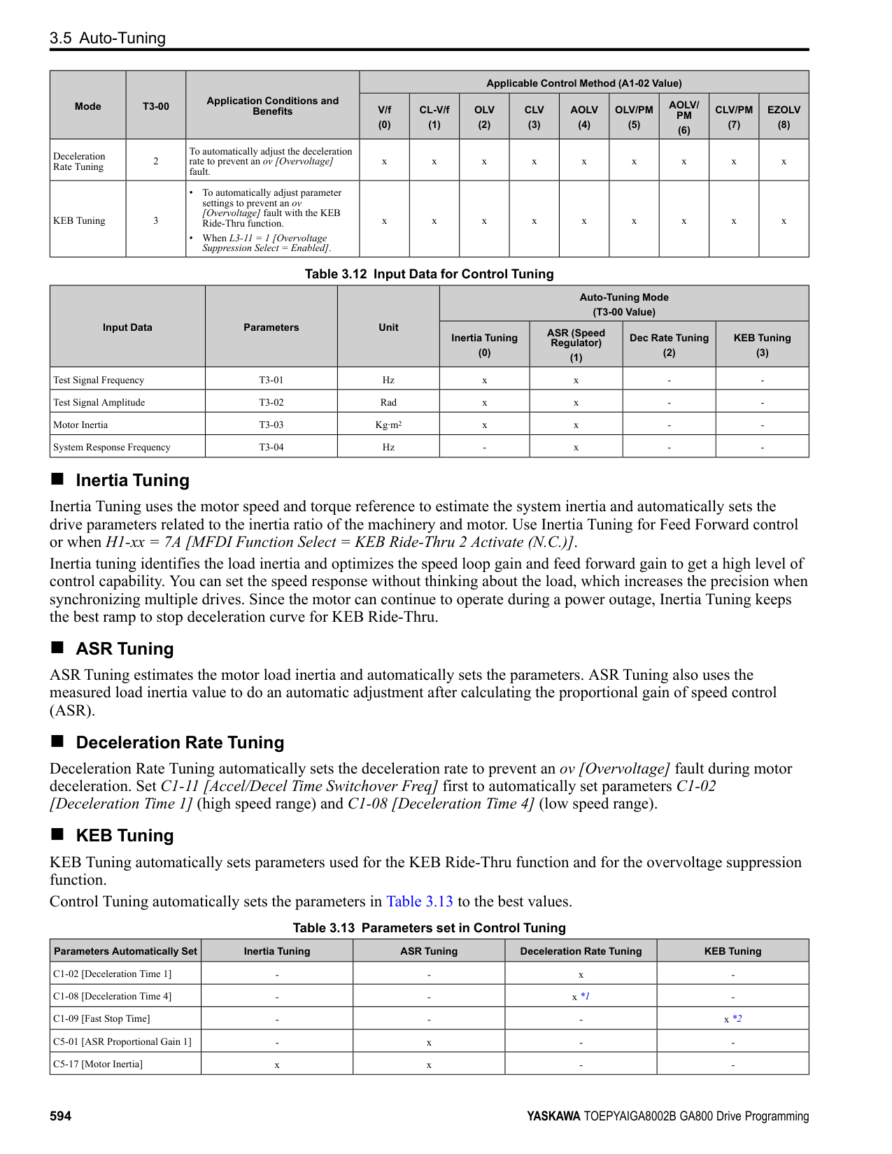
|Checked|No.|Description| |---|---|---| | |15|Set E5-01 through E5-24 [PM Motor Settings].| | |16|Set C5-01 [ASR Proportional Gain 1] and C5-02 [ASR Integral Time 1].|
############### 3.8 Test Run Checklist
|Checked|No.|Description| |---|---|---| | |17|Set F1-01 [Encoder 1 Pulse Count (PPR)] and F1-05 [Encoder 1 Rotation Selection].| | |18|Set E5-11 [Encoder Z-Pulse Offset].|
|Checked|No.|Description| |---|---|---| | |19|The keypad will show “Rdy” after starting to operate the motor.| | |20|To give the Run command and frequency reference from the keypad, push to set to LOCAL Mode (when in LOCAL Mode, the LO/RE LED illuminates).
| | |21|If the motor rotates in the opposite direction during test run, switch two of the motor cables (U/T1, V/T2, W/T3).| | |22|Set Heavy Duty or Normal Duty Mode with C6-01 [Normal / Heavy Duty Selection] to conform to the load condition.| | |23|Set E2-01 [Motor Rated Current (FLA)] and L1-01 [Motor Overload Protection Select] correctly for motor thermal protection.| | |24|Set the drive for REMOTE Mode when the control circuit terminals supply the Run command and frequency reference (in REMOTE Mode, the LO/ RE LED turns OFF).| | |25|When terminal A1 is used for the frequency reference:
• Voltage input
– Set DIP Switch S1-1 on the drive to “V”.
– Set H3-01 = 0, 1 [Terminal A1 Signal Level Select = 0 to 10V (Lower Limit at 0), -10 to +10V (Bipolar Reference)].
– Set H3-02 = 0 [Terminal A1 Function Selection = Frequency Reference].
• Current input
– Set DIP Switch S1-1 on the drive to “I”.
– Set H3-01 = 2, 3 [Terminal A1 Signal Level Select = 4 to 20 mA, 0 to 20 mA].
– Set H3-02 = 0 [Terminal A1 Function Selection = Frequency Reference].
| | |26|When terminal A2 is used for the frequency reference:
• Voltage input
– Set DIP Switch S1-2 on the drive to “V”.
– Set H3-09 = 0, 1 [Terminal A2 Signal Level Select = 0 to 10V (Lower Limit at 0), -10 to 10 V (Bipolar Reference)].
– Set H3-10 = 0 [Terminal A2 Function Selection = Frequency Reference].
• Current input
– Set DIP Switch S1-2 on the drive to “I”.
– Set H3-09 = 2, 3 [Terminal A2 Signal Level Select = 4 to 20 mA, 0 to 20 mA].
– Set H3-10 = 0 [Terminal A2 Function Selection = Frequency Reference].
| | |27|When terminal A3 is used for the frequency reference:
• Voltage input
– Set DIP Switch S4 on the drive to analog input side.
– Set DIP Switch S1-3 on the drive to “V”.
– Set H3-05 = 0, 1 [Terminal A3 Signal Level Select = 0 to 10V (Lower Limit at 0), -10 to +10V (Bipolar Reference)].
– Set H3-06 = 0 [Terminal A3 Function Selection = Frequency Reference].
• Current input
– Set DIP Switch S4 on the drive to analog input side.
– Set DIP Switch S1-3 on the drive to “I”.
– Set H3-05 = 2, 3 [Terminal A3 Signal Level Select = 4 to 20 mA (Lower Limit at 4), 0 to 20 mA (Bipolar Reference)].
– Set H3-06 = 0 [Terminal A3 Function Selection = Frequency Reference].
| | |28|Make sure that the frequency reference reaches the necessary minimum and maximum values.
→ If drive operation is incorrect, make these adjustments: Gain adjustment: Set the maximum voltage and current values, then adjust the analog input gain until the frequency reference reaches the necessary value. (For terminal A1 input: H3-03, for terminal A2 input: H3-11, for terminal A3 input: H3-07) Bias adjustment: Set the maximum voltage/current values, then adjust the analog input bias until the frequency reference reaches the necessary minimum value. (For terminal A1 input: H3-04, for terminal A2 input: H3-12, for terminal A3 input: H3-08)|
4
Mechanical & Electrical Installation
This chapter explains how to properly mount and install the drive, and to wire the control circuit terminals, motor, and power supply.
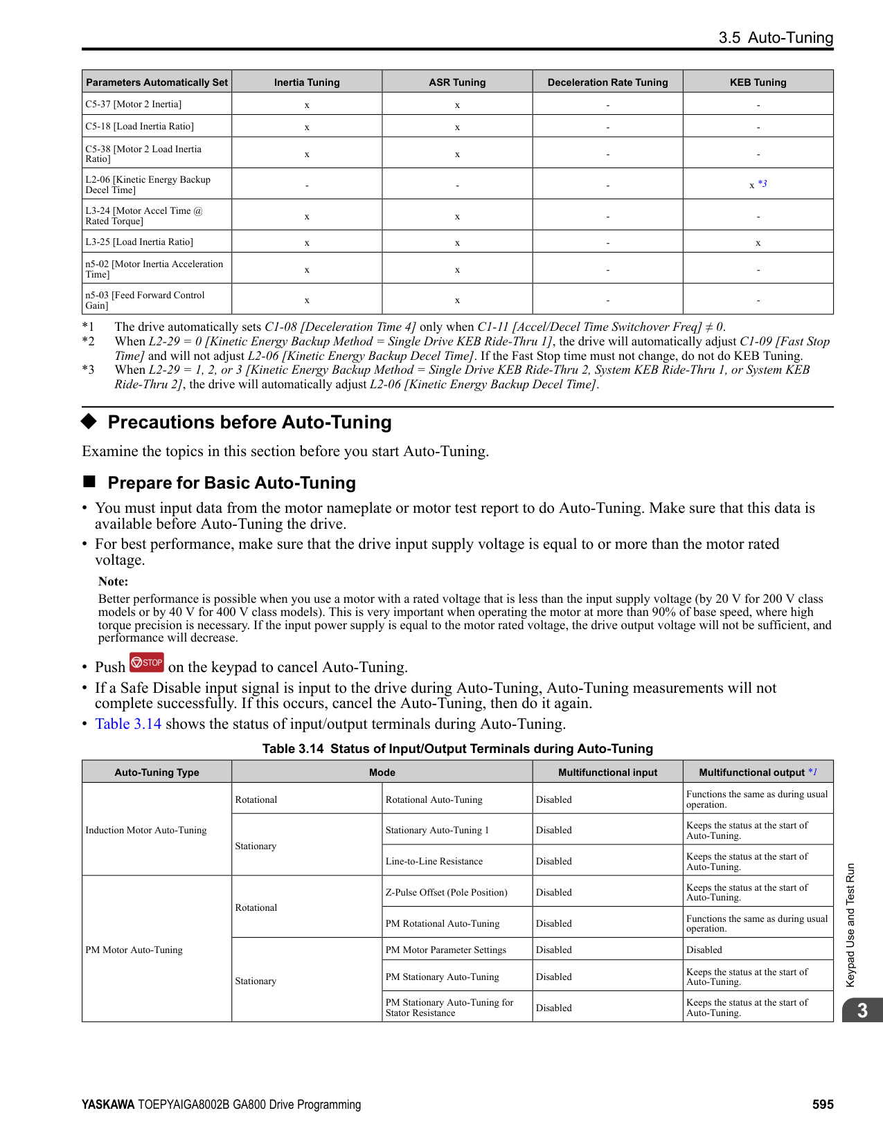
####### 4.1 Section Safety
|DANGER| |---| |Electrical Shock Hazard
Do not examine, connect, or disconnect wiring on an energized drive. Before servicing, disconnect all power to the equipment and wait for the time specified on the warning label at a minimum. The internal capacitor stays charged after the drive is de-energized. The charge indicator LED extinguishes when the DC bus voltage decreases below 50 Vdc. When all indicators are OFF, remove the covers before measuring for dangerous voltages to make sure that the drive is safe.
If you do work on the drive when it is energized, it will cause serious injury or death from electrical shock. The drive has internal capacitors that stay charged after you de-energize the drive.
|
|WARNING| |---| |Electrical Shock Hazard
Do not operate the drive when covers are missing. Replace covers and shields before you operate the drive. Use the drive only as specified by the instructions.
Some figures in this section include drives without covers or safety shields to more clearly show the inside of the drive. If covers or safety shields are missing from the drive, it can cause serous injury or death.
Make sure that the protective ground wire conforms to technical standards and local safety regulations. The IEC/EN 61800-5-1:2007 standard specifies that you must wire the power supply to automatically de-energize when the protective ground wire disconnects. You can also connect a protective ground wire that has a minimum cross-sectional area of 10 mm2 (copper wire) or 16 mm2 (aluminum wire).
If you do not obey the standards and regulations, it can cause serious injury or death. The leakage current of the drive will be more than 3.5 mA in drive models 4414 to 4720.
The drive can cause a residual current with a DC component in the protective earthing conductor. When a residual current operated protective or monitoring device prevents direct or indirect contact, always use a type B Ground Fault Circuit Interrupter (GFCI) as specified by IEC/EN 60755. If you do not use the correct GFCI, it can cause serious injury or death.
Do not wear loose clothing or jewelry when you do work on the drive. Tighten loose clothing and remove all metal objects, for example watches or rings. Loose clothing can catch on the drive and jewelry can conduct electricity and cause serious injury or death. Do not remove covers or touch circuit boards while the drive is energized. If you touch the internal components of an energized drive, it can cause serious injury or death. Only let approved personnel install, wire, maintain, examine, replace parts, and repair the drive. If personnel are not approved, it can cause serious injury or death. Do not modify the drive body or drive circuitry.
Modifications to drive body and circuitry can cause serious injury or death, will cause damage to the drive, and will void the warranty. Yaskawa is not responsible for modifications of the product made by the user.
Fire Hazard Tighten all terminal screws to the correct tightening torque. Connections that are too loose or too tight can cause incorrect operation and damage to the drive. Incorrect connections can also cause death or serious injury from fire. Tighten screws at an angle in the specified range shown in this manual.
If you tighten the screws at an angle not in the specified range, you can have loose connections that can cause damage to the terminal block or start a fire and cause serious injury or death.|
4.1 Section Safety
|WARNING
| |---| |Do not use the main circuit power supply (Overvoltage Category III) at incorrect voltages. Operate the drive in the specification range of the input voltage on the drive nameplate. Voltages that are higher than the permitted nameplate tolerance can cause damage to the drive.
When you install a dynamic braking option, wire the components as specified by the wiring diagrams. Incorrect wiring can cause damage to braking components or serious injury or death.|
|NOTICE| |---| |Do not let unwanted objects, for example metal shavings or wire clippings, fall into the drive during drive installation. Put a temporary cover over the drive during installation. Remove the temporary cover before start-up. Unwanted objects inside of the drive can cause damage to the drive. Obey correct electrostatic discharge (ESD) procedures when you touch the drive. Incorrect ESD procedures can cause damage to the drive circuitry.
Select a motor that is compatible with the load torque and speed range. When 100% continuous torque is necessary at low speed, use an inverter-duty motor or vector-duty motor. When you use a standard fan-cooled motor, decrease the motor torque in the low-speed range.
If you operate a standard fan-cooled motor at low speed and high torque, it will decrease the cooling effects and can cause heat damage.
Obey the speed range specification of the motor as specified by the manufacturer. When you must operate the motor outside of its specifications, contact the motor manufacturer.
If you continuously operate oil-lubricated motors outside of the manufacturer specifications, it can cause damage to the motor bearings.
When the input voltage is 440 V or higher or the wiring distance is longer than 100 m (328 ft), make sure that the motor insulation voltage is sufficient or use an inverter-duty motor or vector-duty motor with reinforced insulation. Motor winding and insulation failure can occur.
Before you connect a dynamic braking option to the drive, make sure that qualified personnel read and obey the Braking Unit and Braking Resistor Unit Installation Manual (TOBPC72060001).
If you do not read and obey the manual or if personnel are not qualified it can cause damage to the drive and braking circuit.
Make sure that all connections are correct after you install the drive and connect peripheral devices. Incorrect connections can cause damage to the drive.|
Note:
Mechanical&ElectricalInstallation
####### 4.2 Removing/Reattaching Covers
This section gives information about how to remove and reattach the front cover and terminal cover for wiring and inspection. Different drive models have different procedures to remove and reattach the covers. Refer to Table 4.1 for more information.
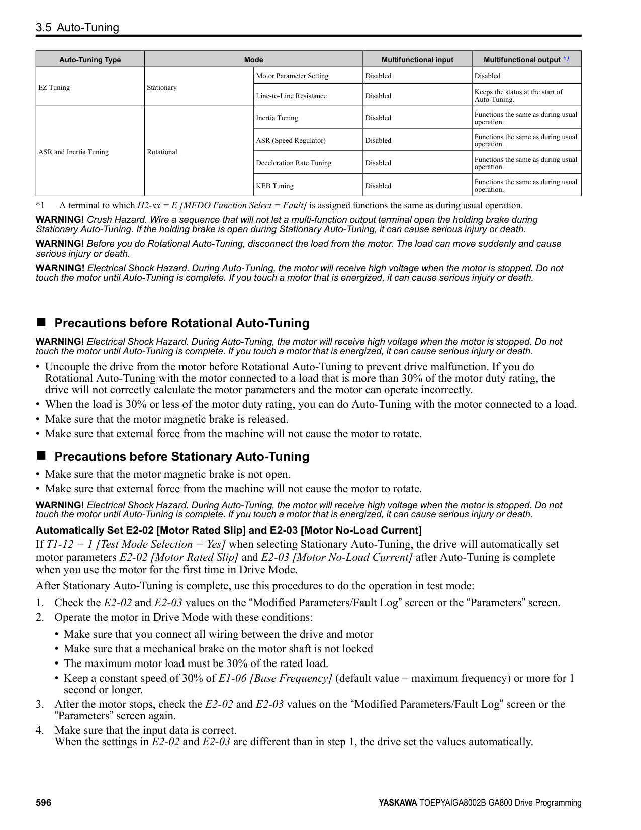
Table 4.1 Procedures to Remove Covers by Drive Model
|Model|Procedure|Reference| |---|---|---| |2004 - 2211 4002 - 4168|Procedure A|612| |2257 - 2415 4208 - 4720|Procedure B|613|
######## ◆ Removing/Reattaching the Cover Using Procedure A
DANGER! Electrical Shock Hazard. Do not examine, connect, or disconnect wiring on an energized drive. Before servicing, disconnect all power to the equipment and wait for the time specified on the warning label at a minimum. The internal capacitor stays charged after the drive is de-energized. The charge indicator LED extinguishes when the DC bus voltage decreases below 50 Vdc. When all indicators are OFF, remove the covers before measuring for dangerous voltages to make sure that the drive is safe. If you do work on the drive when it is energized, it will cause serious injury or death from electrical shock. The drive has internal capacitors that stay charged after you de-energize the drive.
######## ■ Remove the Front Cover
the tab into the keypad connector holder on the front cover.
A - Keypad B - Keypad connector
C - Holder
Figure 4.1 Remove the Keypad and Keypad Connector
Figure 4.2 Loosen the Front Cover Screw
Figure 4.3 Remove the Front Cover
######## ■ Reattach the Front Cover
Note:
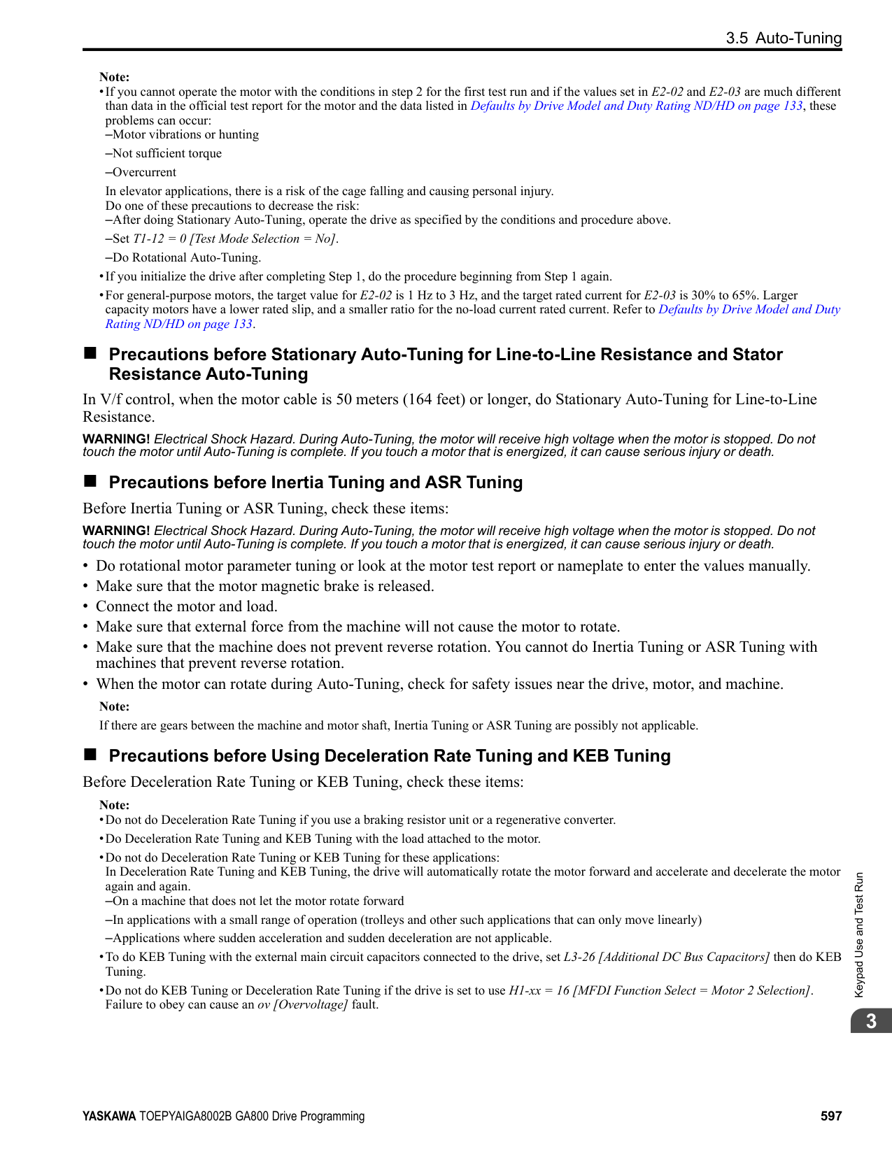
Figure 4.4 Reattach the Front Cover
######## ◆ Removing/Reattaching the Cover Using Procedure B
DANGER! Electrical Shock Hazard. Do not examine, connect, or disconnect wiring on an energized drive. Before servicing, disconnect all power to the equipment and wait for the time specified on the warning label at a minimum. The internal capacitor stays charged after the drive is de-energized. The charge indicator LED extinguishes when the DC bus voltage decreases below 50 Vdc. When all indicators are OFF, remove the covers before measuring for dangerous voltages to make sure that the drive is safe. If you do work on the drive when it is energized, it will cause serious injury or death from electrical shock. The drive has internal capacitors that stay charged after you de-energize the drive.
Mechanical&ElectricalInstallation
######## ■ Remove the Front Cover
A - Keypad B - Keypad connector
C - Connector holder
Figure 4.5 Remove the Terminal Cover, Keypad, and Keypad Connector
Figure 4.6 Loosen the Front Cover Screws
A - Pull forward to remove the front cover.
B - Unhook the tabs found on the sides of the front cover.
Figure 4.7 Pull Forward to Remove the Front Cover
Figure 4.8 Remove the Front Cover
######### ■ Reattach the Front CoverWire the drive and other peripheral devices then reattach the front cover.
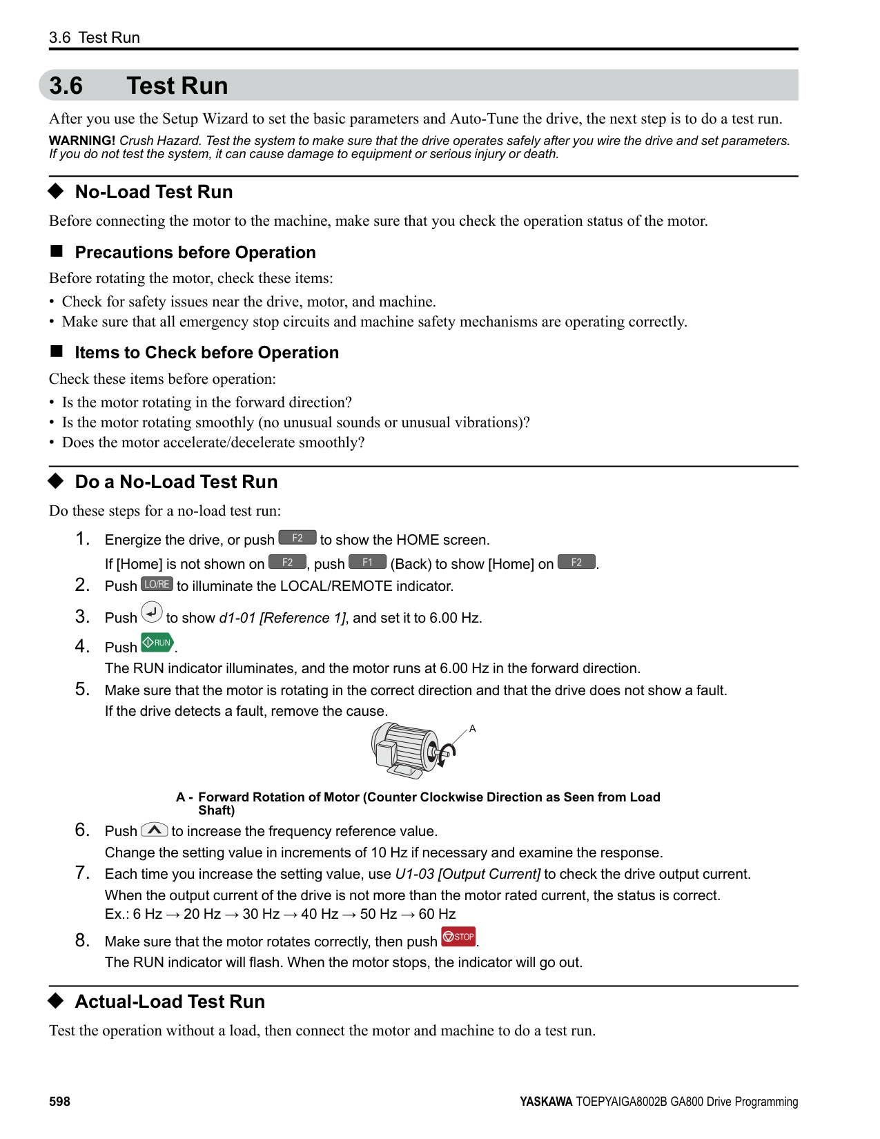
Note: Wire the grounding terminals first, main circuit terminals next, and control circuit terminals last.
A - Hooks
| | | |---|---| | | |
Figure 4.9 Reattach the Front Cover
front cover.
Note: Make sure that you do not pinch wires or signal lines between the front cover and the drive before you reattach the cover.
Figure 4.10 Reattach the Front Cover
######## ■ Remove the Terminal Cover
CAUTION! Crush Hazard. Loosen the cover screws. Do not fully remove them. If you fully remove the cover screws, the terminal cover can fall and cause moderate injury.
################# Figure 4.11 Loosen the Terminal Cover Mounting Screws
Mechanical&ElectricalInstallation
Figure 4.12 Remove the Terminal Cover
######## ■ Reattach the Terminal Cover
Wire the drive and other peripheral devices then reattach the terminal cover. Note:
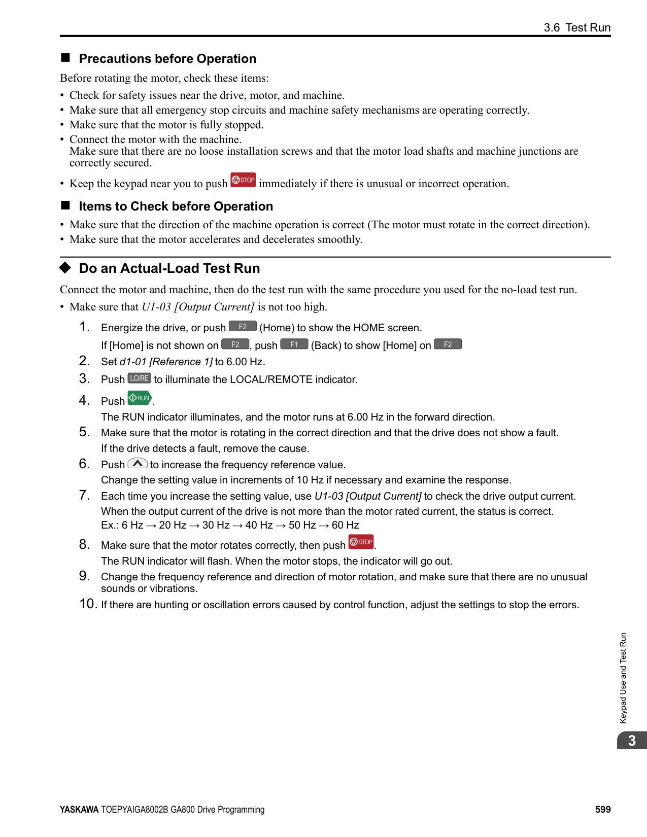
################# Figure 4.13 Reattach the Terminal Cover
####### 4.3 Electrical Installation
DANGER! Electrical Shock Hazard. Do not examine, connect, or disconnect wiring on an energized drive. Before servicing, disconnect all power to the equipment and wait for the time specified on the warning label at a minimum. The internal capacitor stays charged after the drive is de-energized. The charge indicator LED extinguishes when the DC bus voltage decreases below 50 Vdc. When all indicators are OFF, remove the covers before measuring for dangerous voltages to make sure that the drive is safe. If you do work on the drive when it is energized, it will cause serious injury or death from electrical shock. The drive has internal capacitors that stay charged after you de-energize the drive.
WARNING! Electrical Shock Hazard. De-energize the drive and wait 5 minutes minimum until the Charge LED turns off. Remove the front cover and terminal cover to do work on wiring, circuit boards, and other parts. Use terminals for their correct function only. Incorrect wiring, incorrect ground connections, and incorrect repair of protective covers can cause death or serious injury.
WARNING! Electrical Shock Hazard. Use the terminals for the drive only for their intended purpose. Refer to the technical manual for more information about the I/O terminals. Wiring and grounding incorrectly or modifying the cover may damage the equipment or cause injury.
◆ Standard Connection Diagram Wire the drive as specified by Figure 4.14. WARNING! Sudden Movement Hazard. Set the MFDI parameters before you close control circuit switches. Incorrect Run/Stop circuit sequence settings can cause serious injury or death from moving equipment. WARNING! Sudden Movement Hazard. Correctly wire the start/stop and safety circuits before you energize the drive. If you momentarily close a digital input terminal, it can start a drive that is programmed for 3-Wire control and cause serious injury or death from moving equipment. WARNING! Sudden Movement Hazard. When you use a 3-Wire sequence, set A1-03 = 3330 [Initialize Parameters = 3-Wire
Initialization] and make sure that b1-17 = 0 [Run Command at Power Up = Disregard Existing RUN Command] (default). If you do not correctly set the drive parameters for 3-Wire operation before you energize the drive, the motor can suddenly rotate in reverse when you energize the drive.
WARNING! Sudden Movement Hazard. Check the I/O signals and the external sequences for the drive before you set the Application Preset function. When you set the Application Preset function (A1-06 ≠ 0), it changes the I/O terminal functions for the drive and it can cause equipment to operate unusually. This can cause serious injury or death.
WARNING! Fire Hazard. Install sufficient branch circuit short circuit protection as specified by applicable codes and this manual. The drive is suited for circuits that supply not more than 100,000 RMS symmetrical amperes, 240 Vac maximum (200 V Class), 480 Vac maximum (400 V Class). Incorrect branch circuit short circuit protection can cause serious injury or death.
NOTICE: When the input voltage is 440 V or higher or the wiring distance is longer than 100 m (328 ft), make sure that the motor insulation voltage is sufficient or use an inverter-duty motor or vector-duty motor with reinforced insulation. Motor winding and insulation failure can occur.
################# Note:
Do not connect the AC control circuit ground to the drive enclosure. Incorrect ground wiring can cause the control circuit to operate incorrectly.
Mechanical&ElectricalInstallation
| | | | |---|---|---| | | | |
| | | | |---|---|---| | | | | | | | | | | | |
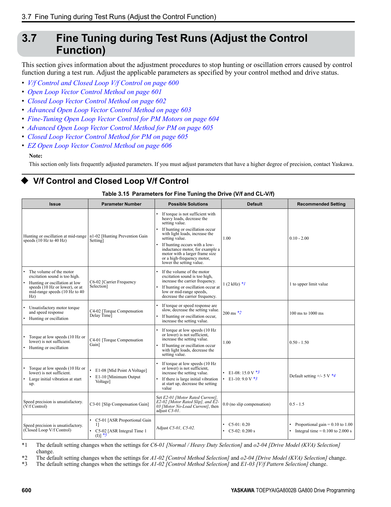
| | | |---|---| | | |
################# Figure 4.14 Standard Drive Connection Diagram
WARNING! Fire Hazard. Only connect factory-recommended devices or circuits to drive terminals B1, B2, -, +1, +2, and +3 terminals. Do not connect AC power to these terminals. Incorrect wiring can cause damage to the drive and serious injury or death from fire.
NOTICE: Do not close the circuit between terminals SP and SN. A closed circuit between these terminals will cause damage to the drive.
NOTICE: Do not close the circuit between terminals SC and SN. A closed circuit between these terminals will cause damage to the drive.
NOTICE: Do not close the circuit between terminals SC and SP. A closed circuit between these terminals will cause damage to the drive.
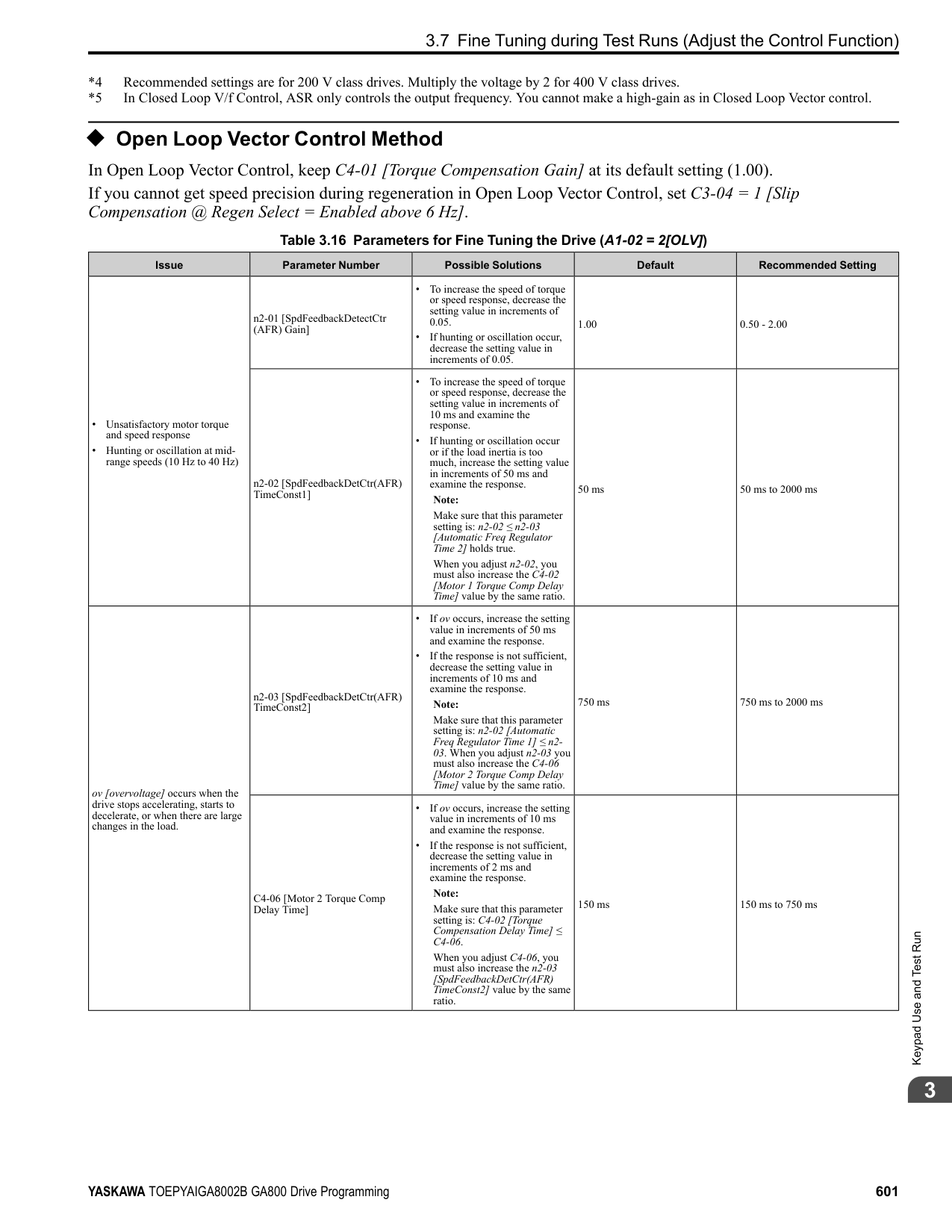
NOTICE: Do not install a jumper between terminals +V, -V, and AC. A closed circuit between these terminals will cause damage to the drive.
Mechanical&ElectricalInstallation
NOTICE: Connect terminals PS and AC correctly for the 24 V power supply. If you connect the wires to the incorrect terminals, it will cause damage to the drive.
4.4 Main Circuit Wiring
####### 4.4 Main Circuit Wiring
This section gives information about the functions, specifications, and procedures necessary to safely and correctly wire the main circuit in the drive. NOTICE: The drive can fail if users frequently turn the drive ON and OFF with the MC on the power source side to Run and Stop the drive. Incorrect operation can decrease the service life of the relay contacts and electrolytic capacitors. If you frequently use the magnetic contactor on the power source side to Run and Stop the drive, it can cause drive failure.
Note: Soldered wire connections can become loose over time and cause unsatisfactory drive performance.
| | | |---|---| | | |
######## ◆ Motor and Main Circuit Connections
WARNING! Electrical Shock Hazard. Do not connect terminals R/L1, S/L2, T/L3, U/T1, V/T2, W/T3, -, +1, +2, +3, B1, or B2 to the ground terminal. If you connect these terminals to earth ground, it can cause damage to the drive or serious injury or death.
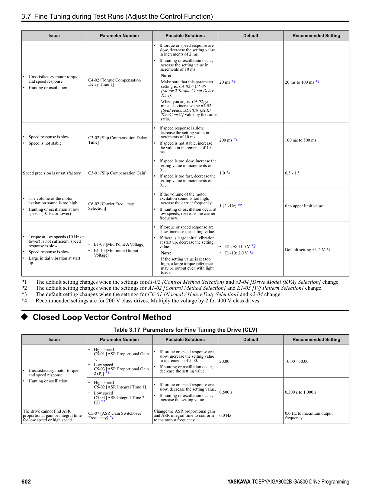
| | | |---|---| | | | | | |
| | | | | | |---|---|---|---|---| | | | | | | | | | | | | | | | | | |
| | | | |---|---|---| | | | |
D - Three-Phase Motor E - Use R, S, T for input power supply. F - Input Protection (Fuses or Circuit
Breakers)
Note: The location of terminals are different for different drive models.
Figure 4.15 Wiring the Main Circuit and Motor
◆ Main Circuit Terminal Functions Refer to Table 4.2 for the functions of drive main circuit terminals.
Mechanical&ElectricalInstallation
Table 4.2 Main Circuit Terminal Functions
|Terminal|Name|Name|Name|Name|Function|
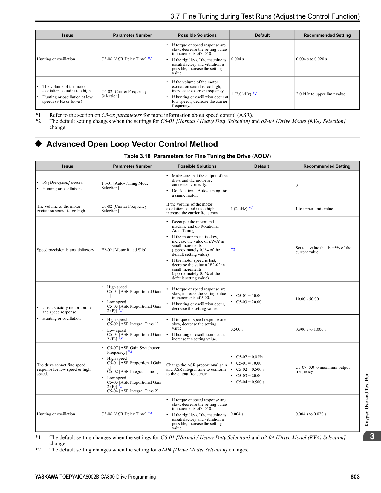
|---|---|---|---|---|---| |Model|2004 - 2082|2110 - 2138|2169 - 2415|-|Function| |Model|4002 - 4044|4060 - 4168|4208 - 4414|4477 - 4720|Function| |R/L1|Main circuit power supply input|Main circuit power supply input|Main circuit power supply input|Main circuit power supply input|To connect a commercial power supply.| |S/L2|Main circuit power supply input|Main circuit power supply input|Main circuit power supply input|Main circuit power supply input|To connect a commercial power supply.| |T/L3|Main circuit power supply input|Main circuit power supply input|Main circuit power supply input|Main circuit power supply input|To connect a commercial power supply.| |U/T1|Drive output|Drive output|Drive output|Drive output|To connect a motor.| |V/T2|Drive output|Drive output|Drive output|Drive output|To connect a motor.| |W/T3|Drive output|Drive output|Drive output|Drive output|To connect a motor.| |B1|Braking resistor connection|Braking resistor connection|-|-|To connect a braking resistor or braking resistor unit.| |B2|Braking resistor connection|Braking resistor connection|-|-|To connect a braking resistor or braking resistor unit.| |+2|• DC power supply input (+1 and -)
• DC reactor connection (+1 and +2)
|-|-|-|To connect peripheral devices, for example:
• DC power input
• Braking unit
• DC link choke Note:
Remove the jumper between terminals +1 and +2 to connect a DC link choke.| |+1|• DC power supply input (+1 and -)
• DC reactor connection (+1 and +2)
|DC power supply input (+1 and -)|• DC power supply input (+1 and -)
• Braking unit connection (+3 and -)
|• DC power supply input (+1 and -)
• Braking unit connection (+3 and -)
|To connect peripheral devices, for example:
• DC power input
• Braking unit
• DC link choke Note:
Remove the jumper between terminals +1 and +2 to connect a DC link choke.| |-|• DC power supply input (+1 and -)
• DC reactor connection (+1 and +2)
|DC power supply input (+1 and -)|• DC power supply input (+1 and -)
• Braking unit connection (+3 and -)
|• DC power supply input (+1 and -)
• Braking unit connection (+3 and -)
|To connect peripheral devices, for example:
• DC power input
• Braking unit
• DC link choke Note:
Remove the jumper between terminals +1 and +2 to connect a DC link choke.| |+3|-|-|• DC power supply input (+1 and -)
• Braking unit connection (+3 and -)
|• DC power supply input (+1 and -)
• Braking unit connection (+3 and -)
|To connect peripheral devices, for example:
• DC power input
• Braking unit
• DC link choke Note:
Remove the jumper between terminals +1 and +2 to connect a DC link choke.| | |• 200 V: D class grounding (ground to 100 Ω or less)
• 400 V: C class grounding (ground to 10 Ω or less)
|• 200 V: D class grounding (ground to 100 Ω or less)
• 400 V: C class grounding (ground to 10 Ω or less)
|• 200 V: D class grounding (ground to 100 Ω or less)
• 400 V: C class grounding (ground to 10 Ω or less)
|• 200 V: D class grounding (ground to 100 Ω or less)
• 400 V: C class grounding (ground to 10 Ω or less)
|To ground the drive.|
Note:
Use terminals B1 and - to connect a CDBR-type control unit to drive models 2004 to 2138 and 4002 to 4168 that have built-in braking transistors.
####### 4.5 Control Circuit Wiring
This section gives information about wiring the control circuit.
◆ Control Circuit Connection Diagram Wire the drive control circuit as shown in Figure 4.16.
| | | | |---|---|---| | | | | | | | | | | | |
| | | |---|---| | | |
Mechanical&ElectricalInstallation
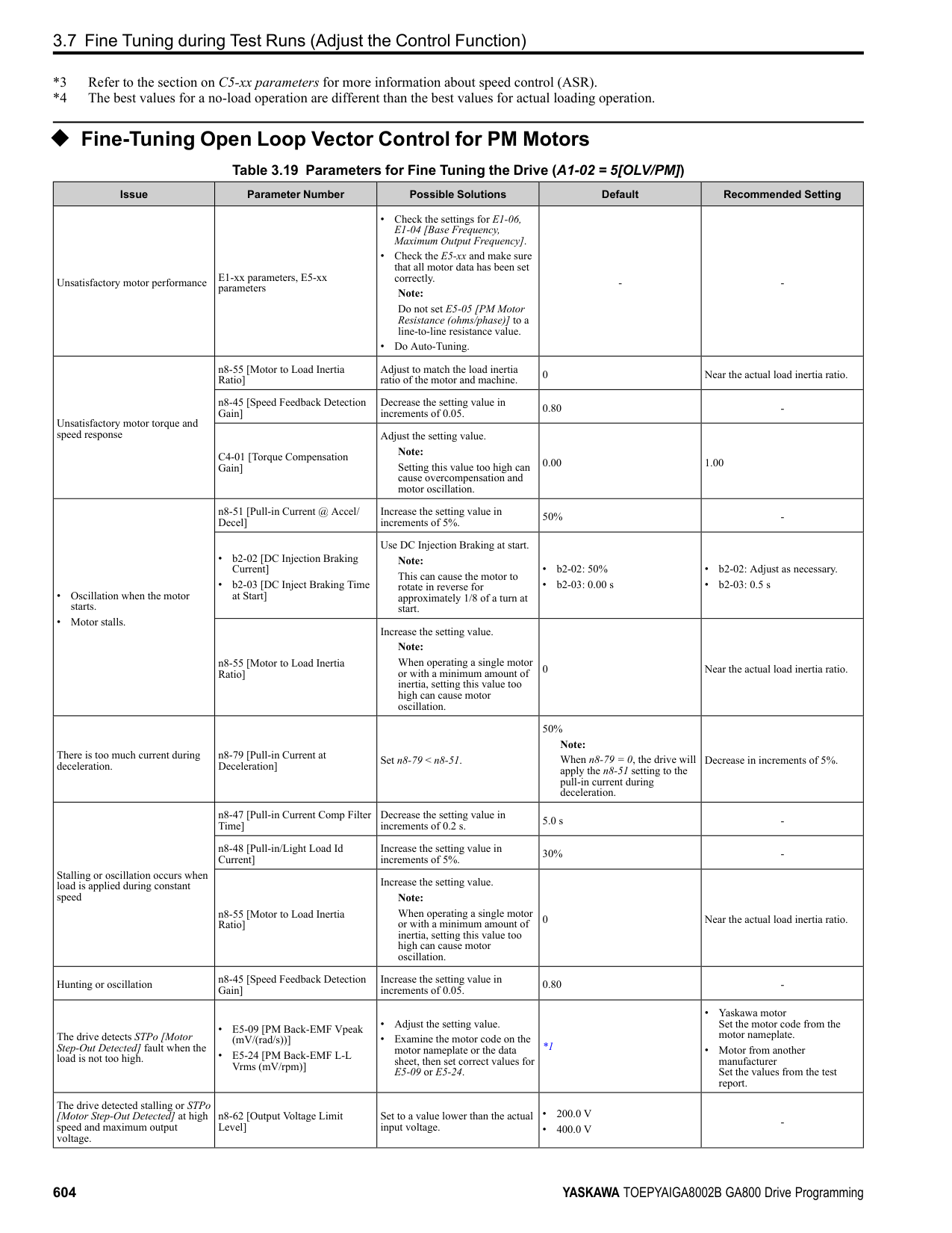
Figure 4.16 Control Circuit Connection Diagram
*1 To operate the control circuit while the main circuit power supply is OFF, connect a 24 V power supply input to terminal PS-AC.
NOTICE: Do not close the circuit between terminals SP and SN. A closed circuit between these terminals will cause damage to the drive.
NOTICE: Do not close the circuit between terminals SC and SN. A closed circuit between these terminals will cause damage to the drive.
NOTICE: Do not close the circuit between terminals SC and SP. A closed circuit between these terminals will cause damage to the drive.
NOTICE: Do not install a jumper between terminals +V, -V, and AC. A closed circuit between these terminals will cause damage to the drive.
NOTICE: Do not ground the AC control circuit terminals and only connect the AC terminals according to the product instructions. If you connect the AC terminals incorrectly, it can cause damage to the drive.
◆ Control Circuit Terminal Block Functions Hx-xx parameters set functions for the multi-function input and output terminals. WARNING! Sudden Movement Hazard. Correctly wire and test all control circuits to make sure that the control circuits operate correctly. If you use a drive that has incorrect control circuit wiring or operation, it can cause death or serious injury. WARNING! Sudden Movement Hazard. Check the I/O signals and the external sequences for the drive before you set the Application Preset function. When you set the Application Preset function (A1-06 ≠ 0), it changes the I/O terminal functions for the drive and it can cause equipment to operate unusually. This can cause serious injury or death. NOTICE: The drive can fail if users frequently turn the drive ON and OFF with the MC on the power source side to Run and Stop the drive. Incorrect operation can decrease the service life of the relay contacts and electrolytic capacitors. If you frequently use the magnetic contactor on the power source side to Run and Stop the drive, it can cause drive failure.
Table 4.3 Multi-function Input Terminals
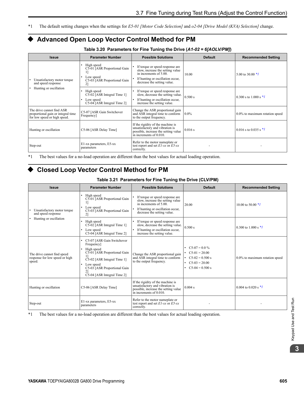
|Type|Terminal|Name (Default)|Function (Signal Level)| |---|---|---|---| |Digital Inputs|S1|MFDI selection 1 (ON: Forward run OFF: Stop)|• Photocoupler
• 24 V, 6 mA Note: Install the wire jumpers between terminals SC-SP and SC-SN to set the MFDI power supply (sinking/sourcing mode or internal/external power supply).
• Sinking Mode: Install a jumper between terminals SC and SP.
NOTICE: Do not close the circuit between terminals SC and SN. A closed circuit between these terminals will cause damage to the drive.
• Sourcing Mode: Install a jumper between terminals SC and SN.
NOTICE: Do not close the circuit between terminals SC and SP. A closed circuit between these terminals will cause damage to the drive.
• External power supply: No jumper necessary between terminals SC-SN and terminals SC-SP.
| |Digital Inputs|S2|MFDI selection 2 (ON: Reverse run OFF: Stop)|• Photocoupler
• 24 V, 6 mA Note: Install the wire jumpers between terminals SC-SP and SC-SN to set the MFDI power supply (sinking/sourcing mode or internal/external power supply).
• Sinking Mode: Install a jumper between terminals SC and SP.
NOTICE: Do not close the circuit between terminals SC and SN. A closed circuit between these terminals will cause damage to the drive.
• Sourcing Mode: Install a jumper between terminals SC and SN.
NOTICE: Do not close the circuit between terminals SC and SP. A closed circuit between these terminals will cause damage to the drive.
• External power supply: No jumper necessary between terminals SC-SN and terminals SC-SP.
| |Digital Inputs|S3|MFDI selection 3 (External fault (N.O.))|• Photocoupler
• 24 V, 6 mA Note: Install the wire jumpers between terminals SC-SP and SC-SN to set the MFDI power supply (sinking/sourcing mode or internal/external power supply).
• Sinking Mode: Install a jumper between terminals SC and SP.
NOTICE: Do not close the circuit between terminals SC and SN. A closed circuit between these terminals will cause damage to the drive.
• Sourcing Mode: Install a jumper between terminals SC and SN.
NOTICE: Do not close the circuit between terminals SC and SP. A closed circuit between these terminals will cause damage to the drive.
• External power supply: No jumper necessary between terminals SC-SN and terminals SC-SP.
| |Digital Inputs|S4|MFDI selection 4 (Fault reset)|• Photocoupler
• 24 V, 6 mA Note: Install the wire jumpers between terminals SC-SP and SC-SN to set the MFDI power supply (sinking/sourcing mode or internal/external power supply).
• Sinking Mode: Install a jumper between terminals SC and SP.
NOTICE: Do not close the circuit between terminals SC and SN. A closed circuit between these terminals will cause damage to the drive.
• Sourcing Mode: Install a jumper between terminals SC and SN.
NOTICE: Do not close the circuit between terminals SC and SP. A closed circuit between these terminals will cause damage to the drive.
• External power supply: No jumper necessary between terminals SC-SN and terminals SC-SP.
| |Digital Inputs|S5|MFDI selection 5 (Multi-step speed reference 1)|• Photocoupler
• 24 V, 6 mA Note: Install the wire jumpers between terminals SC-SP and SC-SN to set the MFDI power supply (sinking/sourcing mode or internal/external power supply).
• Sinking Mode: Install a jumper between terminals SC and SP.
NOTICE: Do not close the circuit between terminals SC and SN. A closed circuit between these terminals will cause damage to the drive.
• Sourcing Mode: Install a jumper between terminals SC and SN.
NOTICE: Do not close the circuit between terminals SC and SP. A closed circuit between these terminals will cause damage to the drive.
• External power supply: No jumper necessary between terminals SC-SN and terminals SC-SP.
| |Digital Inputs|S6|MFDI selection 6 (Multi-step speed reference 2)|• Photocoupler
• 24 V, 6 mA Note: Install the wire jumpers between terminals SC-SP and SC-SN to set the MFDI power supply (sinking/sourcing mode or internal/external power supply).
• Sinking Mode: Install a jumper between terminals SC and SP.
NOTICE: Do not close the circuit between terminals SC and SN. A closed circuit between these terminals will cause damage to the drive.
• Sourcing Mode: Install a jumper between terminals SC and SN.
NOTICE: Do not close the circuit between terminals SC and SP. A closed circuit between these terminals will cause damage to the drive.
• External power supply: No jumper necessary between terminals SC-SN and terminals SC-SP.
| |Digital Inputs|S7|MFDI selection 7 (Jog command)|• Photocoupler
• 24 V, 6 mA Note: Install the wire jumpers between terminals SC-SP and SC-SN to set the MFDI power supply (sinking/sourcing mode or internal/external power supply).
• Sinking Mode: Install a jumper between terminals SC and SP.
NOTICE: Do not close the circuit between terminals SC and SN. A closed circuit between these terminals will cause damage to the drive.
• Sourcing Mode: Install a jumper between terminals SC and SN.
NOTICE: Do not close the circuit between terminals SC and SP. A closed circuit between these terminals will cause damage to the drive.
• External power supply: No jumper necessary between terminals SC-SN and terminals SC-SP.
| |Digital Inputs|S8|MFDI selection 8 (Baseblock command (N.O.))|• Photocoupler
• 24 V, 6 mA Note: Install the wire jumpers between terminals SC-SP and SC-SN to set the MFDI power supply (sinking/sourcing mode or internal/external power supply).
• Sinking Mode: Install a jumper between terminals SC and SP.
NOTICE: Do not close the circuit between terminals SC and SN. A closed circuit between these terminals will cause damage to the drive.
• Sourcing Mode: Install a jumper between terminals SC and SN.
NOTICE: Do not close the circuit between terminals SC and SP. A closed circuit between these terminals will cause damage to the drive.
• External power supply: No jumper necessary between terminals SC-SN and terminals SC-SP.
| |Digital Inputs|SN|MFDI power supply 0 V|MFDI power supply, 24 V (maximum 150 mA) NOTICE: Do not close the circuit between terminals SP and SN. A closed circuit between these terminals will cause damage to the drive.| |Digital Inputs|SC|MFDI selection common|MFDI power supply, 24 V (maximum 150 mA) NOTICE: Do not close the circuit between terminals SP and SN. A closed circuit between these terminals will cause damage to the drive.| |Digital Inputs|SP|MFDI power supply +24 Vdc|MFDI power supply, 24 V (maximum 150 mA) NOTICE: Do not close the circuit between terminals SP and SN. A closed circuit between these terminals will cause damage to the drive.| |Safe Disable Input|H1|Safe Disable input 1|Remove the jumper between terminals H1-HC and H2-HC to use the Safe Disable input.
• 24 V, 6 mA
• ON: Normal operation
• OFF: Coasting motor
• Internal impedance 4.7 kΩ
• OFF Minimum OFF time of 2 ms.
| |Safe Disable Input|H2|Safe Disable input 2|Remove the jumper between terminals H1-HC and H2-HC to use the Safe Disable input.
• 24 V, 6 mA
• ON: Normal operation
• OFF: Coasting motor
• Internal impedance 4.7 kΩ
• OFF Minimum OFF time of 2 ms.
| |Safe Disable Input|HC|Safe Disable function common|Safe Disable function common NOTICE: Do not close the circuit between terminals HC and SN. A closed circuit between these terminals will cause damage to the drive.| |Master Frequency Reference|RP|Master frequency reference pulse train input (Master frequency reference)|• Response frequency: 0 Hz to 32 kHz
• H level duty: 30% to 70%
• H level voltage: 3.5 V to 13.2 V
• L level voltage: 0.0 V to 0.8 V
• Input impedance: 3 kΩ
| |Master Frequency Reference|+V|Power supply for frequency setting|10.5 V (allowable current 20 mA maximum)| |Master Frequency Reference|-V|Power supply for frequency setting|-10.5 V (allowable current 20 mA maximum)| |Master Frequency Reference|A1|MFAI1 (Master frequency reference)|Voltage input or current input
Select terminal A1 with DIP switch S1-1 and H3-01 [Terminal A1 Signal Level Select].
Select terminal A2 with DIP switch S1-2 and H3-09 [Terminal A2 Signal Level Select]
• -10 V to +10 V/-100% to +100% (input impedance: 20 kΩ)
• 0 V to 10 V/100% (input impedance: 20 kΩ)
• 4 mA to 20 mA/100%, 0 mA to 20 mA/100% (input impedance: 250 Ω)
| |Master Frequency Reference|A2|MFAI2 (Combined to terminal A1)|Voltage input or current input
Select terminal A1 with DIP switch S1-1 and H3-01 [Terminal A1 Signal Level Select].
Select terminal A2 with DIP switch S1-2 and H3-09 [Terminal A2 Signal Level Select]
• -10 V to +10 V/-100% to +100% (input impedance: 20 kΩ)
• 0 V to 10 V/100% (input impedance: 20 kΩ)
• 4 mA to 20 mA/100%, 0 mA to 20 mA/100% (input impedance: 250 Ω)
| |Master Frequency Reference|A3|MFAI3/PTC input (Auxiliary frequency reference)|• Voltage input or current input Select using DIP switch S1-3 and H3-05 [Terminal A3 Signal Level Select].
– -10 V to +10 V/-100% to +100% (input impedance: 20 kΩ)
– 0 V to 10 V/100% (input impedance: 20 kΩ)
– 4 mA to 20 mA/100%, 0 mA to 20 mA/100% (input impedance: 250 Ω)
• PTC input (Motor Overheat Protection) Set DIP switch S4 to “PTC” and set DIP switch S1-3 to “V” to set terminal A3 for PTC input.
| |Master Frequency Reference|AC|Frequency reference common|0 V| |Master Frequency Reference|E (G)|Connecting shielded cable|-|
Mechanical&ElectricalInstallation
■ Output Terminals Refer to Table 4.4 and Table 4.5 for a list of output terminals and functions.
Table 4.4 Control Circuit Output Terminals
|Type|Terminal|Name (Default)|Function (Signal Level)| |---|---|---|---| |Fault Relay Output|MA|N.O. output (Fault)|• Relay output
• 30 Vdc, 10 mA to 1 A
• 250 Vac, 10 mA to 1 A
• Minimum load: 5 V, 10 mA (Reference value)
| |Fault Relay Output|MB|N.C. output (Fault)|• Relay output
• 30 Vdc, 10 mA to 1 A
• 250 Vac, 10 mA to 1 A
• Minimum load: 5 V, 10 mA (Reference value)
| |Fault Relay Output|MC|Digital output common|• Relay output
• 30 Vdc, 10 mA to 1 A
• 250 Vac, 10 mA to 1 A
• Minimum load: 5 V, 10 mA (Reference value)
| |MFDO|M1|MFDO (During Run)|• Relay output
• 30 Vdc, 10 mA to 1 A
• 250 Vac, 10 mA to 1 A
• Minimum load: 5 V, 10 mA (Reference value) Note:
Do not set functions that frequently switch ON/OFF to MFDO (M1 to M6) because this will decrease the performance life of the relay contacts. Yaskawa estimates switching life at 200,000 times (assumes 1 A, resistive load).| |MFDO|M2|MFDO (During Run)|• Relay output
• 30 Vdc, 10 mA to 1 A
• 250 Vac, 10 mA to 1 A
• Minimum load: 5 V, 10 mA (Reference value) Note:
Do not set functions that frequently switch ON/OFF to MFDO (M1 to M6) because this will decrease the performance life of the relay contacts. Yaskawa estimates switching life at 200,000 times (assumes 1 A, resistive load).| |MFDO|M3|MFDO (Zero Speed)|• Relay output
• 30 Vdc, 10 mA to 1 A
• 250 Vac, 10 mA to 1 A
• Minimum load: 5 V, 10 mA (Reference value) Note:
Do not set functions that frequently switch ON/OFF to MFDO (M1 to M6) because this will decrease the performance life of the relay contacts. Yaskawa estimates switching life at 200,000 times (assumes 1 A, resistive load).| |MFDO|M4|MFDO (Zero Speed)|• Relay output
• 30 Vdc, 10 mA to 1 A
• 250 Vac, 10 mA to 1 A
• Minimum load: 5 V, 10 mA (Reference value) Note:
Do not set functions that frequently switch ON/OFF to MFDO (M1 to M6) because this will decrease the performance life of the relay contacts. Yaskawa estimates switching life at 200,000 times (assumes 1 A, resistive load).| |MFDO|M5|MFDO (Speed Agree 1)|• Relay output
• 30 Vdc, 10 mA to 1 A
• 250 Vac, 10 mA to 1 A
• Minimum load: 5 V, 10 mA (Reference value) Note:
Do not set functions that frequently switch ON/OFF to MFDO (M1 to M6) because this will decrease the performance life of the relay contacts. Yaskawa estimates switching life at 200,000 times (assumes 1 A, resistive load).|
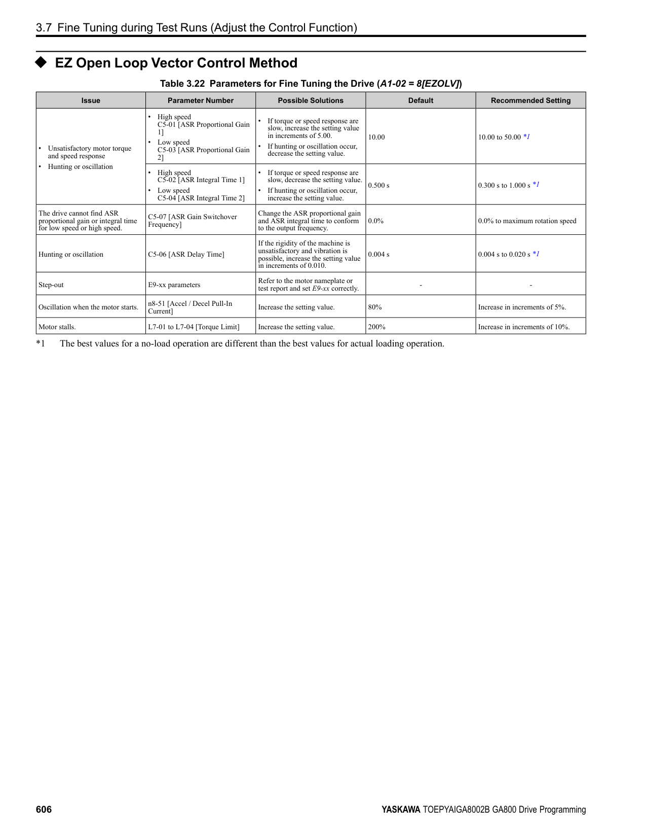
|MFDO|M6|MFDO (Speed Agree 1)|• Relay output
• 30 Vdc, 10 mA to 1 A
• 250 Vac, 10 mA to 1 A
• Minimum load: 5 V, 10 mA (Reference value) Note:
Do not set functions that frequently switch ON/OFF to MFDO (M1 to M6) because this will decrease the performance life of the relay contacts. Yaskawa estimates switching life at 200,000 times (assumes 1 A, resistive load).|
Table 4.5 Control Circuit Monitor Output Terminals
|Type|Terminal|Name (Default)|Function (Signal Level)| |---|---|---|---| |Monitor Output|MP|Pulse train output (Output frequency)|32 kHz (maximum) Refer to “Pulse Train Output” on page 632 for more information.| |Monitor Output|FM|Analog monitor output 1 (Output frequency)|Select voltage or current output.
• 0 V to 10 V/0% to 100%
• -10 V to +10 V/-100% to +100%
• 4 mA to 20 mA (receiver recommended impedance: 250 Ω) Note:
Select with jumper switch S5 and H4-07 [Terminal FM Signal Level Select] or H4-08 [Terminal AM Signal Level Select].| |Monitor Output|AM|Analog monitor output 2 (Output current)|Select voltage or current output.
• 0 V to 10 V/0% to 100%
• -10 V to +10 V/-100% to +100%
• 4 mA to 20 mA (receiver recommended impedance: 250 Ω) Note:
Select with jumper switch S5 and H4-07 [Terminal FM Signal Level Select] or H4-08 [Terminal AM Signal Level Select].| |Monitor Output|AC|Monitor common|0 V|
Table 4.6 External Power Supply Input Terminals
|Type|Terminal|Name (Default)|Function| |---|---|---|---| |External Power Supply Input Terminals|PS|External 24 V power supply input|Supplies backup power to the drive control circuit, keypad, and option board. 21.6 VDC to 26.4 VDC, 700 mA| |External Power Supply Input Terminals|AC|External 24 V power supply ground|0 V|
Table 4.7 Serial Communication Terminals
|Type|Terminal|Terminal Name|Function (Signal Level)|Function (Signal Level)| |---|---|---|---|---| |Modbus Communication|D+|Communication input/output (+)|MEMOBUS/Modbus communications Use an RS-485 cable to connect the drive.
Note:
Set DIP switch S2 to ON to enable the termination resistor in the last drive in a MEMOBUS/Modbus network.|• RS-485
• MEMOBUS/Modbus communication protocol
• Maximum 115.2 kbps
| |Modbus Communication|D-|Communication output (-)|MEMOBUS/Modbus communications Use an RS-485 cable to connect the drive.
Note:
Set DIP switch S2 to ON to enable the termination resistor in the last drive in a MEMOBUS/Modbus network.|• RS-485
• MEMOBUS/Modbus communication protocol
• Maximum 115.2 kbps
| |Modbus Communication|AC|Signal ground|0 V|0 V|
◆ Control Circuit Terminal Configuration The control circuit terminals are in the positions shown in Figure 4.17.
| | | |---|---| | | |
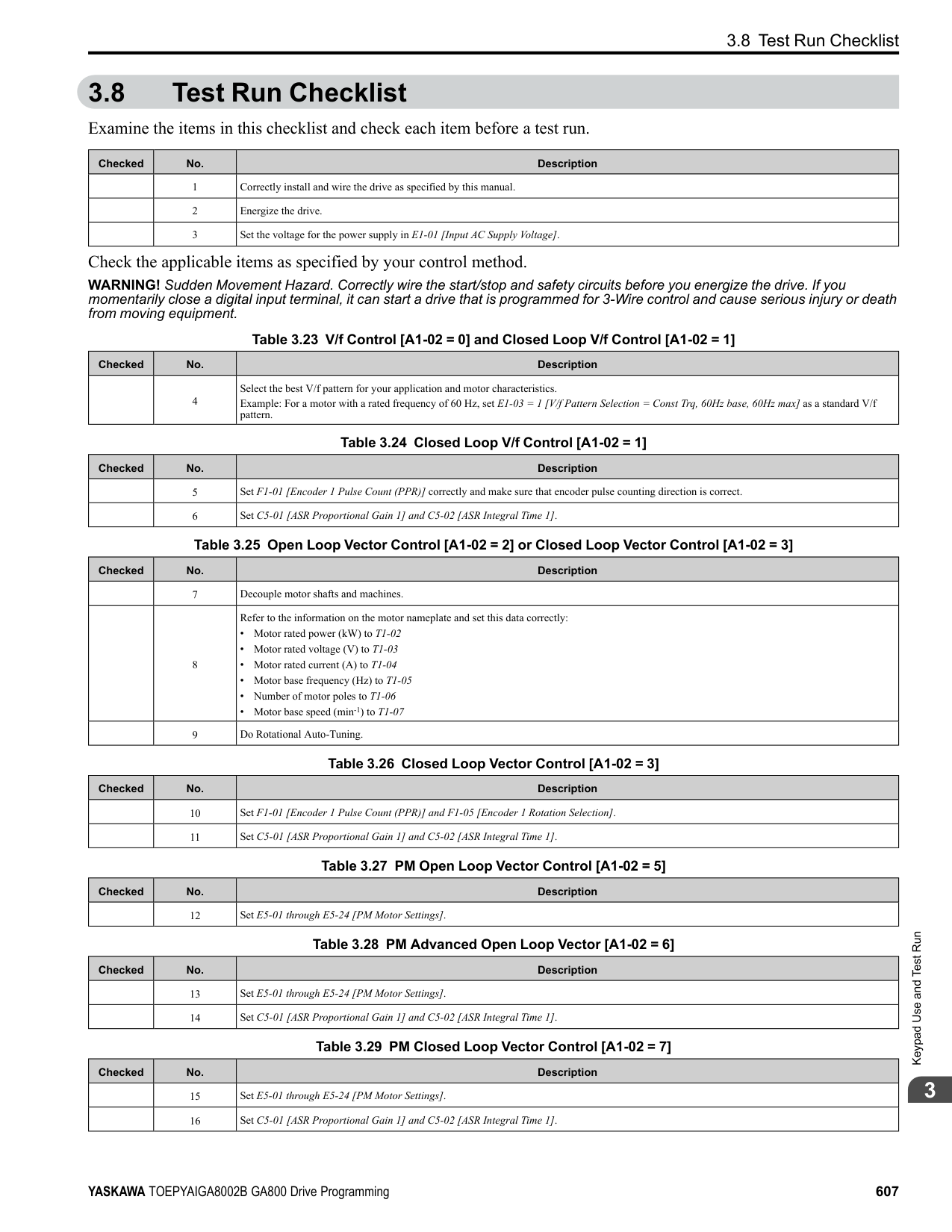
| | |---| | |
| | | |---|---| | | | | | |
| | |---| | | | |
| | | |---|---| | | |
| | | | |---|---|---| | | | |
| | | | |---|---|---| | | | |
| | | | |---|---|---| | | | |
| | | | |---|---|---| | | | |
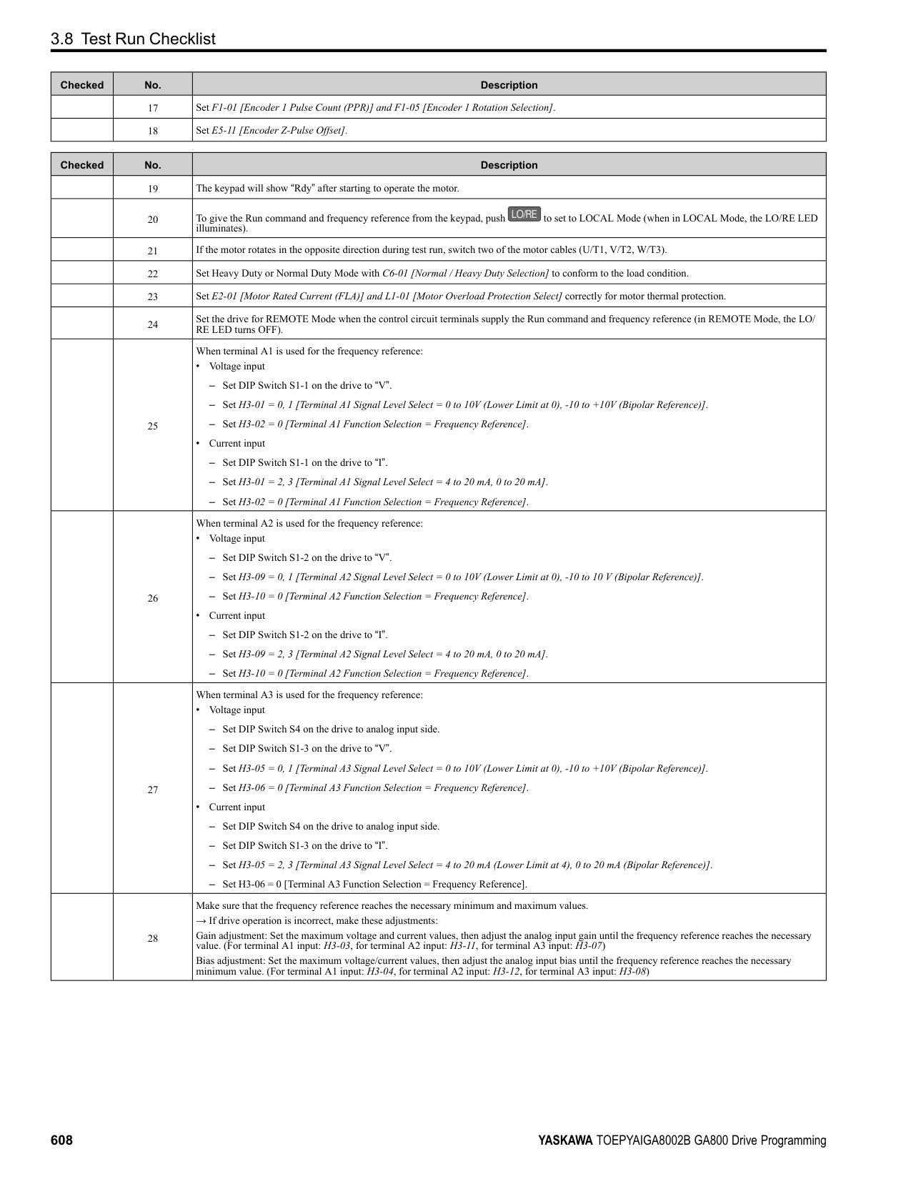
| | | |---|---|
| | | |---|---| | | |
| | | | |---|---|---| | | | | | | | | | | | |
| | | |---|---| | | | | | | | | | | | | | | |
E - Terminal block (TB1) F - Terminal block (TB3) G - Terminal block (TB4)
| | | | |---|---|---| |Circuit the|Circuit the|Circuit the|
| | |---| | |
Figure 4.17 Control
Terminal Arrangement
The tightening torque for the terminal screws is shown on reverse side or the lower front side of the front cover.
Figure 4.18 Tightening Torque Display Location (Reverse side of Front Cover)
| | | |---|---| | | |
Mechanical&ElectricalInstallation
Figure 4.19 Tightening Torque Display Location (Lower Front Side of Front Cover)
######## ■ Control Circuit Wire Gauges and Tightening Torques
Use the tables in this section to select the correct wires. Use shielded wire to wire the control circuit terminal block. Use crimp ferrules on the wire ends to make the wiring procedure easier and more reliable.
Table 4.8 Control Circuit Wire Gauges and Tightening Torques
|Terminal Block|Terminal|Screw Size|Tightening Torque
N∙m (in∙lb)|Bare Wire|Bare Wire|Crimp Ferrule|Crimp Ferrule| |---|---|---|---|---|---|---|---| |Terminal Block|Terminal|Screw Size|Tightening Torque
N∙m (in∙lb)|Recommended Gauge
mm2 (AWG)|Applicable Gauge
mm2 (AWG)|Recommended Gauge
mm2 (AWG)|Applicable Gauge
mm2 (AWG)| |TB1|S1 - S8, SN, SC, SP|M3|0.5 - 0.6 (4.4 - 5.3)|0.75 (18)|• Stranded wire 0.2 - 1.0 (24 - 16)
• Solid wire 0.2 - 1.5 (24 - 16)
|0.5 (20)|0.25 - 0.5 (24 - 20)| |TB2|M1 - M6, MA, MB, MC|M3|0.5 - 0.6 (4.4 - 5.3)|0.75 (18)|• Stranded wire 0.2 - 1.0 (24 - 16)
• Solid wire 0.2 - 1.5 (24 - 16)
|0.5 (20)|0.25 - 0.5 (24 - 20)| |TB3|+V, AC, -V, A1, A2, A3, FM, AM, AC, MP, RP, AC|M3|0.5 - 0.6 (4.4 - 5.3)|0.75 (18)|• Stranded wire 0.2 - 1.0 (24 - 16)
• Solid wire 0.2 - 1.5 (24 - 16)
|0.5 (20)|0.25 - 0.5 (24 - 20)| |TB4|E (G), SN, HC, H1, H2, PS, AC, D+, D-|M3|0.5 - 0.6 (4.4 - 5.3)|0.75 (18)|• Stranded wire 0.2 - 1.0 (24 - 16)
• Solid wire 0.2 - 1.5 (24 - 16)
|0.5 (20)|0.25 - 0.5 (24 - 20)| |TB5|E (G)|M3.5|0.5 - 1.0 (4.4 - 8.9)|0.5 - 2 (20 - 14)|1.25 (12)|-|-|
Crimp Ferrules Attach an insulated sleeve when you use crimp ferrules. Refer to Table 4.9 for the recommended external dimensions and model numbers of the crimp ferrules. Use the CRIMPFOX 6, a crimping tool made by PHOENIX CONTACT.
Figure 4.20 External Dimensions of Crimp Ferrules Table 4.9 Crimp Ferrule Models and Sizes
|Wire Gauge mm2 (AWG)|Model|L (mm)|L1 (mm)|φd1 (mm)|φd2 (mm)| |---|---|---|---|---|---| |0.25 (24)|AI 0.25-8YE|12.5|8|0.8|2.0| |0.34 (22)|AI 0.34-8TQ|12.5|8|0.8|2.0|
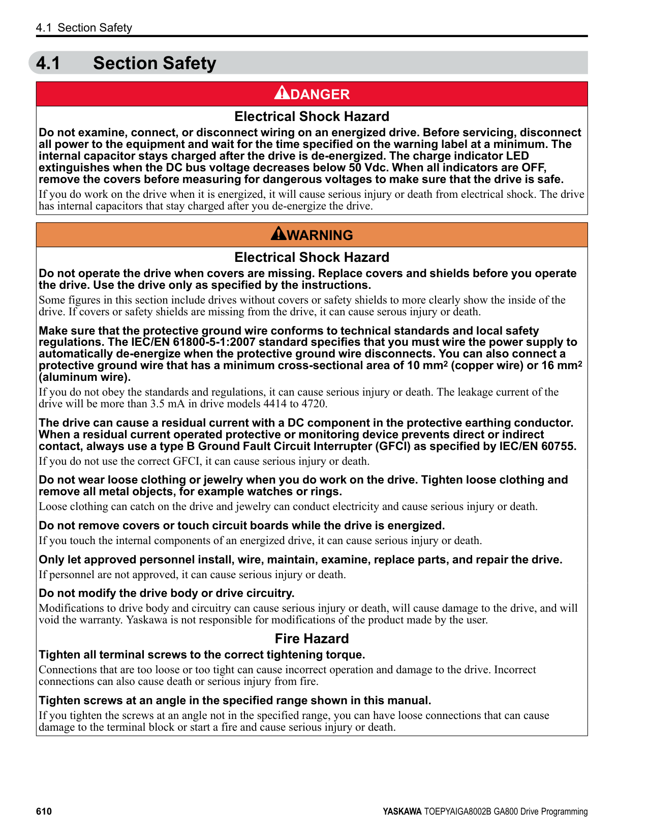
|0.5 (20)|AI 0.5-8WH, AI 0.5-8OG|14|8|1.1|2.5|
######## ◆ Wiring the Control Circuit Terminal
WARNING! Electrical Shock Hazard. Do not remove covers or touch circuit boards while the drive is energized. If you touch the internal components of an energized drive, it can cause serious injury or death.
NOTICE: Do not let wire shields touch other signal lines or equipment. Insulate the wire shields with electrical tape or shrink tubing. If you do not insulate the wire shields, it can cause a short circuit and damage the drive.
################# Note:
Correctly ground the drive terminals and complete main circuit wiring before you wire the control circuit. Remove the keypad and front cover.
You can temporarily store the LED status ring board with the temporary placement holes on the drive. The location of the temporary placement holes is different on different drive models.
| | |---| | |
| | |---| | | | |
A - Drive front B - LED status ring board
C - Temporary placement holes
A - Drive front B - LED status ring board
C - Temporary placement holes
A - Drive front B - LED status ring board
C - Temporary placement holes
| | | |---|---| | | | | | | | | |
| | | | |---|---|---| | | | | | | | |
Mechanical&ElectricalInstallation
WARNING! Fire Hazard. Tighten all terminal screws to the correct tightening torque. Connections that are too loose or too tight can cause incorrect operation and damage to the drive. Incorrect connections can also cause death or serious injury from fire.
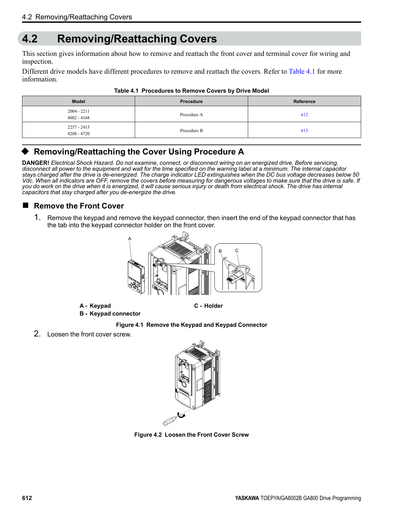
Figure 4.24 Wiring Procedure for the Control Circuit Note:
A - Connect the shield to terminal E (G)
of the drive. B - Sheath
C - Insulate with electrical tape or shrink tubing.
Figure 4.25 Prepare the Ends of Shielded Wire
Figure 4.26 Control Circuit Wiring
| | | |---|---| | | |
| | | | |---|---|---| | | | | | | | |
| | | |---|---| | | |
############### 4.5 Control Circuit Wiring
|cover,|
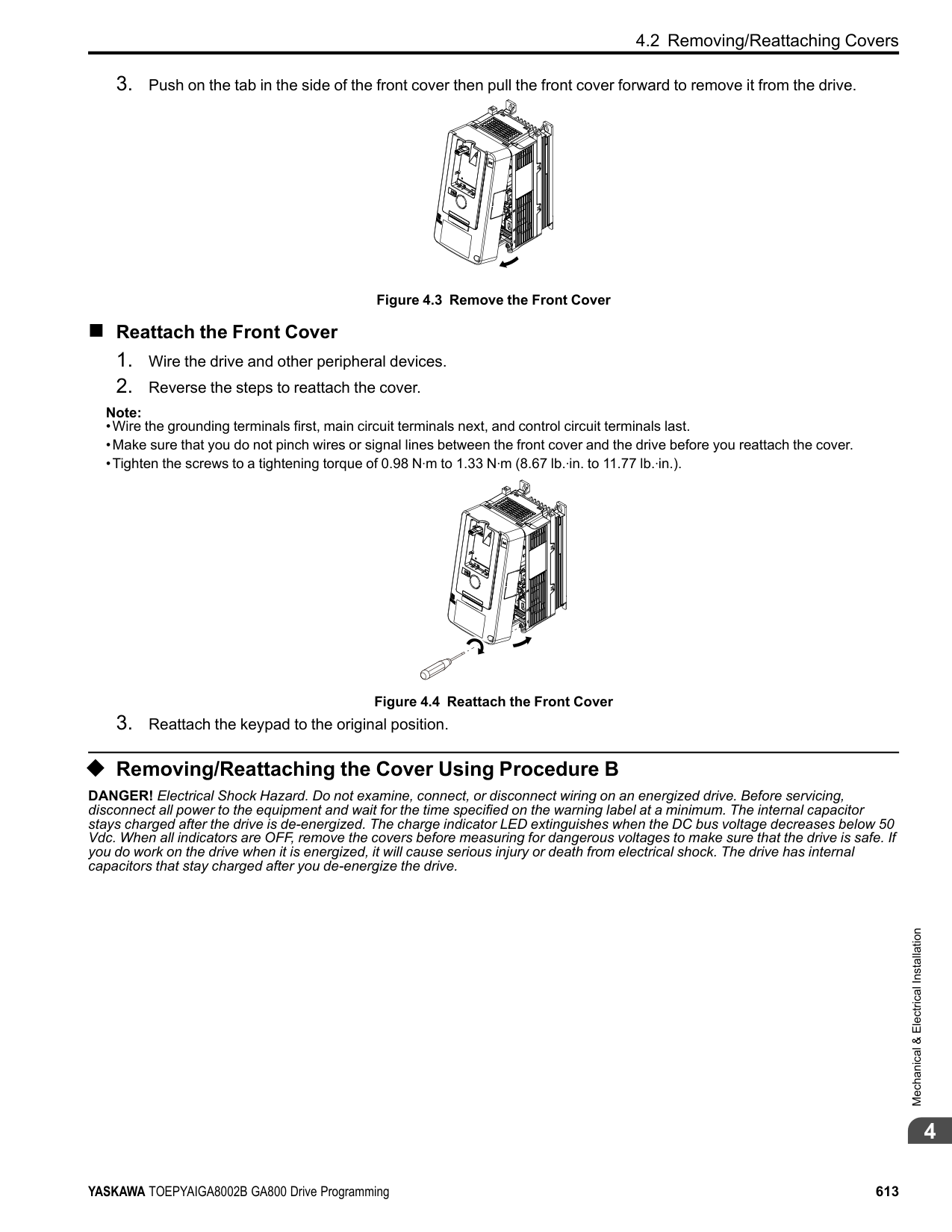
|---|
and the keypad to their initial positions.
######### ◆ Switches and Jumpers on the Terminal Board The terminal board has switches to adapt the drive I/Os to the external control signals as shown in Figure 4.27. Set the switches to select the functions for each terminal.
| | | |---|---| | | |
| | | |---|---| | | |
| | |---| | |
| | | | | | | | |---|---|---|---|---|---|---| | | | | | | | | | | | | | | | |
| | | |---|---| | | | | | |
| | | | | | | | |---|---|---|---|---|---|---| | | | | | | | | | | | | | | | |
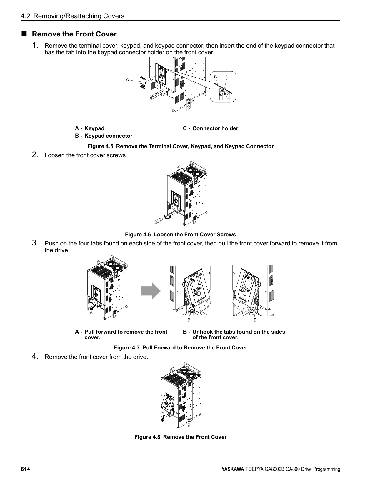
| | | | | | | | |---|---|---|---|---|---|---| | | | | | | | | | | | | | | | |
| | | | | | | | |---|---|---|---|---|---|---| | | | | | | | | | | | | | | | |
| | | | | | | | |---|---|---|---|---|---|---| | | | | | | | | | | | | | | | |
| | | |---|---| | | |
| | | | | |---|---|---|---|
| | | | | |---|---|---|---|
| | | | | |---|---|---|---|
| | | |---|---|
| | |---| | |
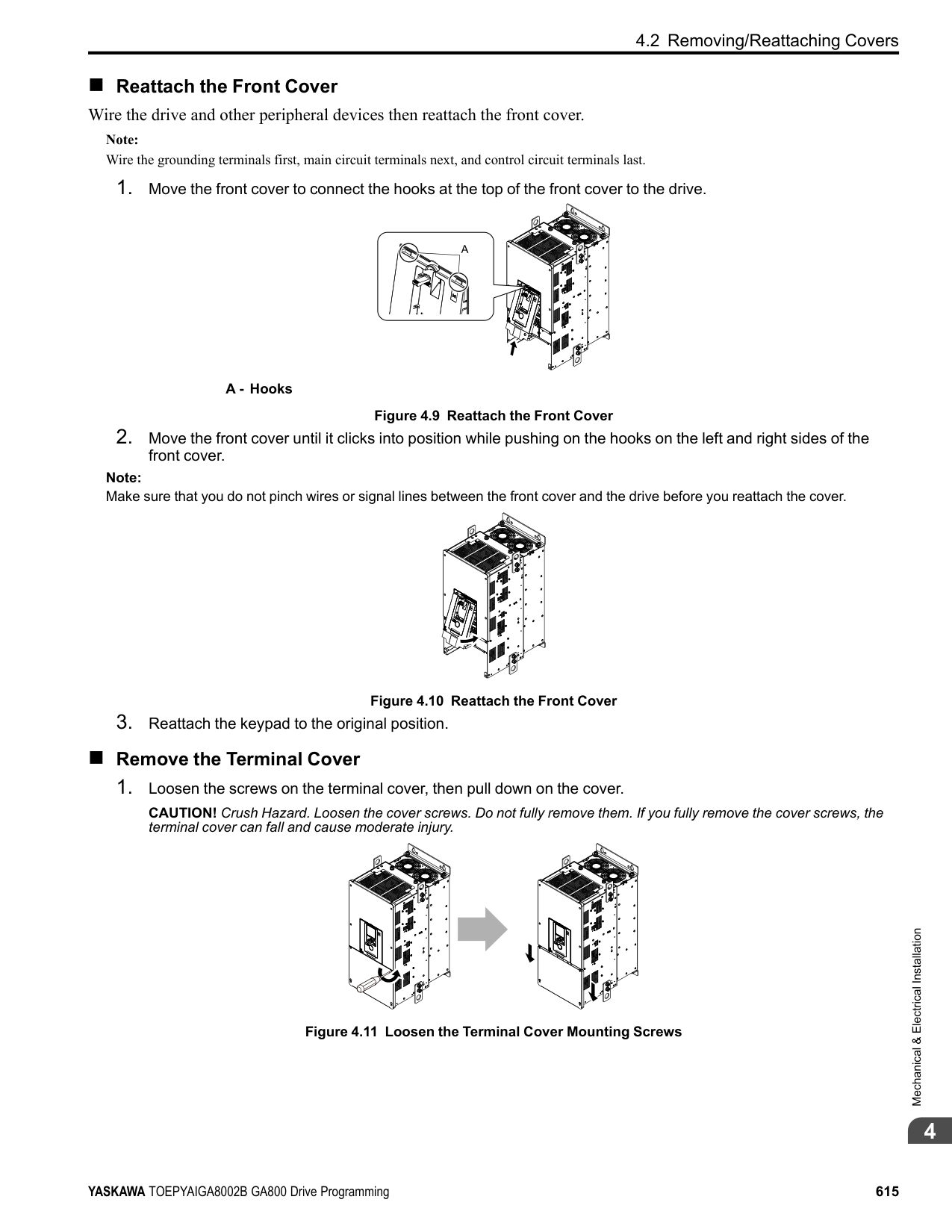
| | | |---|---| | | |
| | | | |---|---|---| | | | | | | | | | | | |
################# Figure 4.27 Locations of Switches Table 4.10 I/O Terminals and Switches Functions Posi-
| | |---| | |
################### tion Switch Terminal Function Default Setting
Enables and disables the MEMOBUS/Modbus communications termination resistor.
OFF
FM: V (voltage output) AM: V (voltage output)
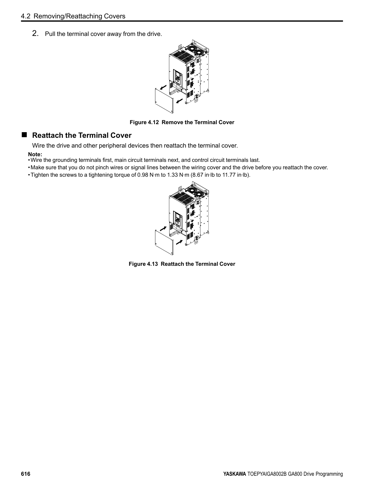
####### 4.6 Control I/O Connections
This section gives information about the settings for the listed control circuit I/O signals.
◆ Pulse Train Output You can use pulse train monitor output terminal MP for sourcing mode or for sinking mode.
Note: Use the formula in Figure 4.28 to calculate the necessary load resistance (kΩ) to increase output voltage VMP(V).
A - Load Impedance Figure 4.28 Wiring to Use Pulse Train Output in Sourcing Mode
|Load Impedance RL(kΩ)|Output Voltage VMP(V)| |---|---| |1.5 kΩ or more|5 Vor more| |4.0 kΩ or more|8 Vor more| |10 kΩ or more|10 Vor more|
|External Power Supply (V)|Load Impedance (kΩ)|Sinking current (mA)| |---|---|---| |10.8 Vdc to 16.5 Vdc|1.0 kΩ or more|16 mA maximum|
A - External power supply B - Load Impedance
C - Sinking current
Figure 4.29 Wiring to Use Pulse Train Output in Sinking Mode
4.6 Control I/O Connections
◆ Set Sinking Mode/Sourcing Mode Close the circuit between terminals SC-SP and SC-SN to set the sinking mode/sourcing mode and the internal/ external power supply for the MFDI terminals. The default setting for the drive is internal power supply sinking mode. NOTICE: Do not close the circuit between terminals SP and SN. A closed circuit between these terminals will cause damage to the drive.
Mode Internal Power Supply (Terminal SN-SP) External 24 V power supply
Sinking Mode (NPN)
Sourcing Mode (PNP)
| | | |---|---| | | |
| | | |---|---| | | |
| | | |---|---| | | |
| | | |---|---| | | |
◆ Set Input Signals for MFAI Terminals A1 to A3 Use terminals A1 to A3 to input a voltage or a current signal. Set the signal type as shown in Table 4.11.
| | | |---|---| | | |
| | | | | | | | | | | | | | | | | | | | | | | | | | | | | | | | |---|---|---|---|---|---|---|---|---|---|---|---|---|---|---|---|---|---|---|---|---|---|---|---|---|---|---|---|---|---|---| | | | | | | | | | | | | | | | | | | | | | | | | | | | | | | | |
| | |
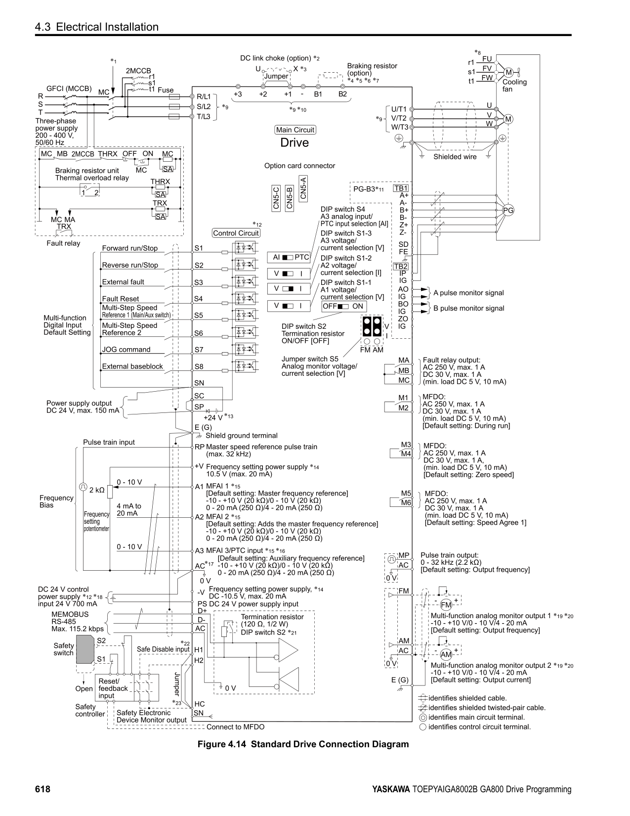
|---|---| | | |
| | | |---|---| | | | | | |
| | | |---|---| | | |
| | | | | | | | |---|---|---|---|---|---|---| | | | | | | | | | | | | | | | |
| | | | | | | | |---|---|---|---|---|---|---| | | | | | | | | | | | | | | | |
| | | | | | | | |---|---|---|---|---|---|---| | | | | | | | | | | | | | | | |
| | | |---|---| | | |
| | | | |---|---|---| | | | |
| | | | |---|---|---| | | | | | | | |
| | | | |---|---|---| | | | |
| | | | |---|---|---| | | | | | | | |
| | | | |---|---|---| | | | |
| | | |---|---|
| | | |---|---| | | |
Figure
of DIP Switch
|4.30 Location| |---|
|S1| |---|
Terminal Input Signal
################# Table 4.11 MFAI Terminals A1 to A3 Signal Settings
DIP Switch Settings Parameter Switch Setting No. Signal Level
Voltage input
S1-1
V (Default)
H3-01
Current input I
Voltage input
S1-2
V
H3-09
0: 0 V to 10 V/0% to 100% (input impedance: 20 kΩ) 1: -10 V to +10 V/-100% to 100% (input impedance: 20 kΩ)
Current input
I (Default)
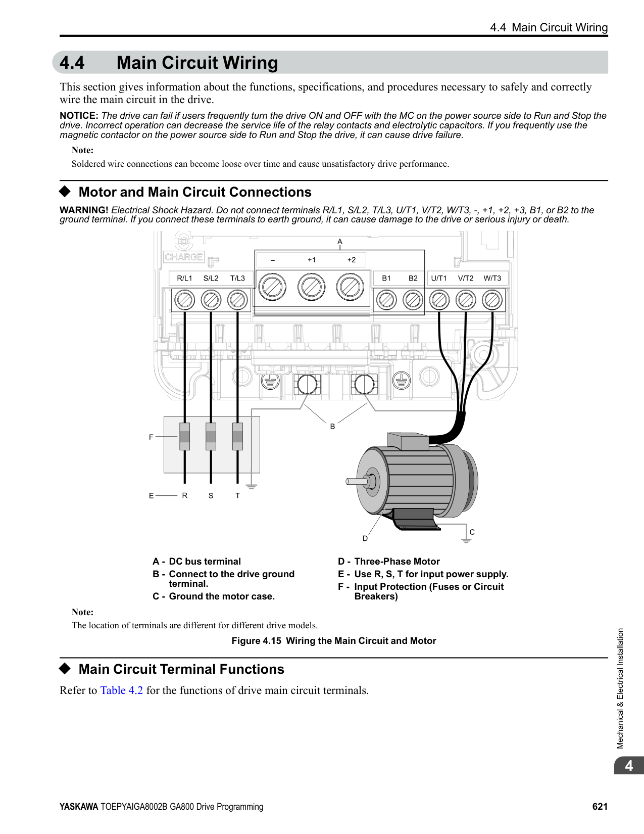
2: 4 mA to 20 mA/0% to 100% (input impedance: 250 Ω) 3: 0 mA to 20 mA/0% to 100% (input impedance: 250 Ω)
Voltage input
S1-3
V (Default)
H3-05
Current input I
|to| |---|
20 mA/0% to 100% (input impedance: 250 Ω)
| | | | |---|---|---| |Ω)| | | | | | |
################# Note:
|A2 together (0.03| |---|
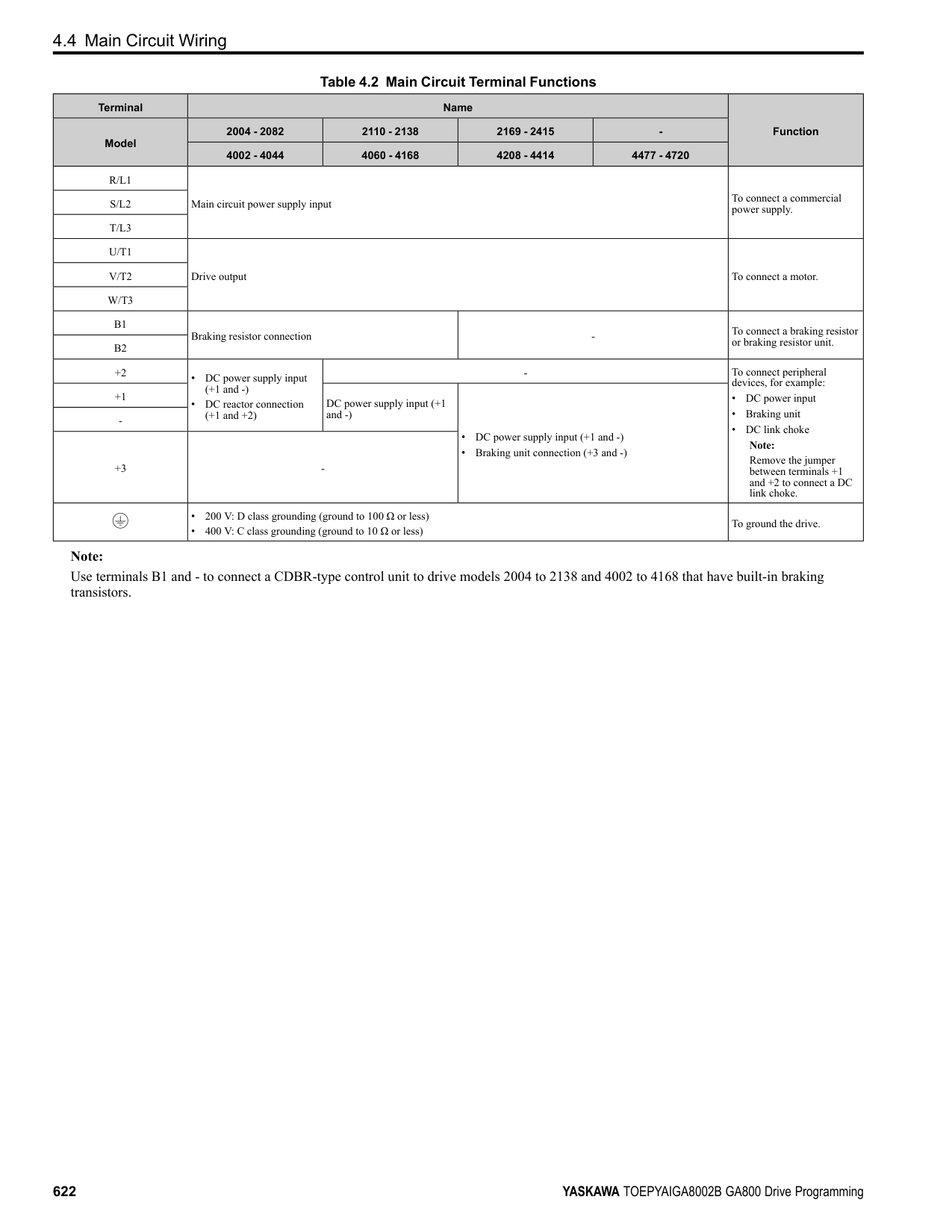
Function Selection = Frequency Reference] to set A1 and A2 to frequency reference. The drive will add the analog input values to make the frequency reference.
| | | |---|---| | | |
| | | |---|---| | | |
| | | |---|---| | | |
◆ Set MFAI Terminal A3 to PTC Input Set terminal A3 as an MFAI or as the PTC input for motor overload protection. Use DIP switch S4 to set the input function.
| | | |---|---| | | |
| | |---| | |
| | | | | | | | | | | | | | | | | | | | | | | | | | | | | | | | |---|---|---|---|---|---|---|---|---|---|---|---|---|---|---|---|---|---|---|---|---|---|---|---|---|---|---|---|---|---|---| | | | | | | | | | | | | | | | | | | | | | | | | | | | | | | | |
| | | |---|---|
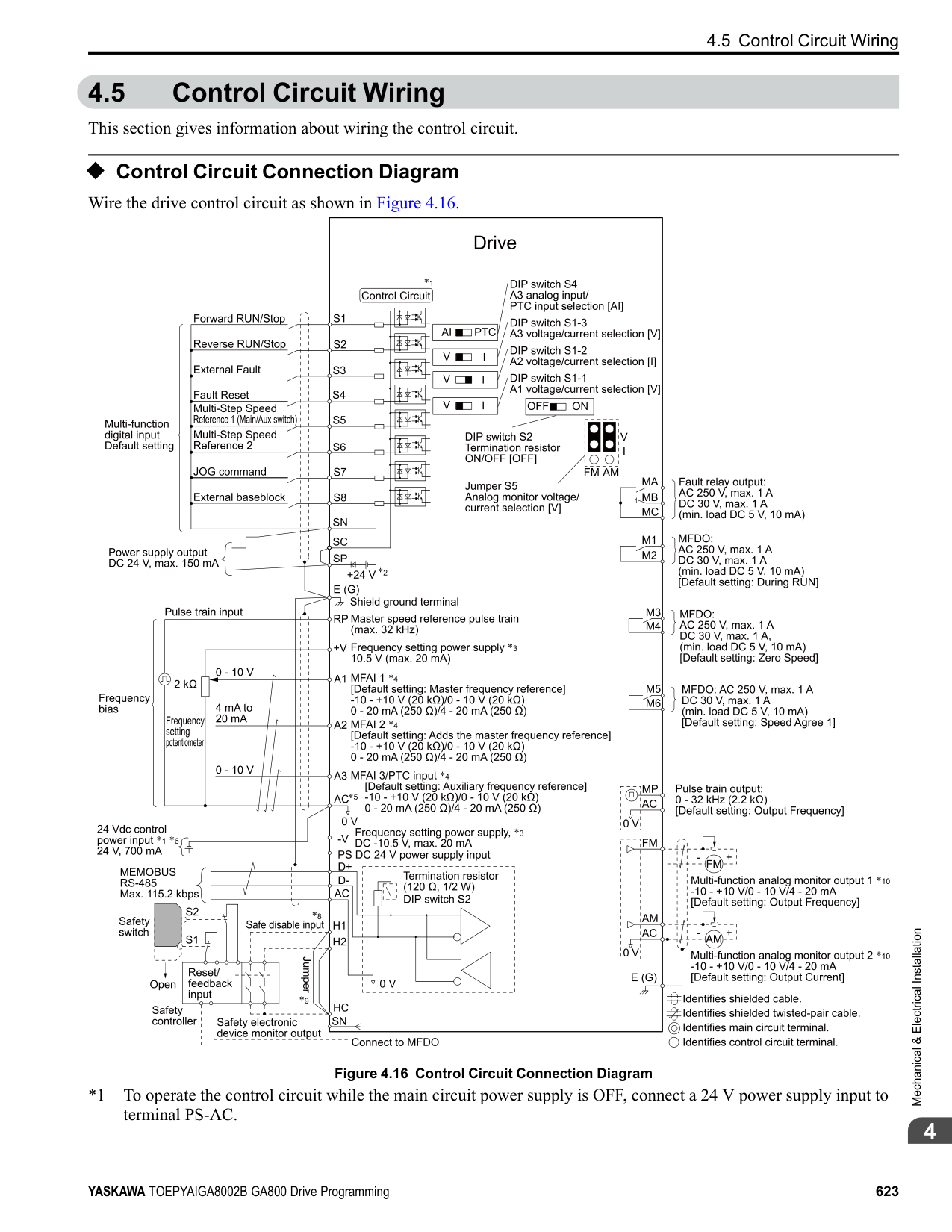
| | | | | |
| | | |---|---| | | |
| | | |---|---| | | |
| | | |---|---| | | |
| | | |---|---| | | |
| | | | | | | | |---|---|---|---|---|---|---| | | | | | | | | | | | | | | | |
| | | |---|---| | | |
| | | | |---|---|---| | | | |
| | | | |---|---|---|
| | | | | | | |
| | | | |---|---|---| | | | |
| | | | |---|---|---| | | | | | | | |
| | | | |---|---|---| | | | |
| | | |---|---|
| | | |---|---| | | |
Figure
Location of DIP Switch
|4.31| |---|
|S4| |---|
Terminal Settings for DIP Switches Description
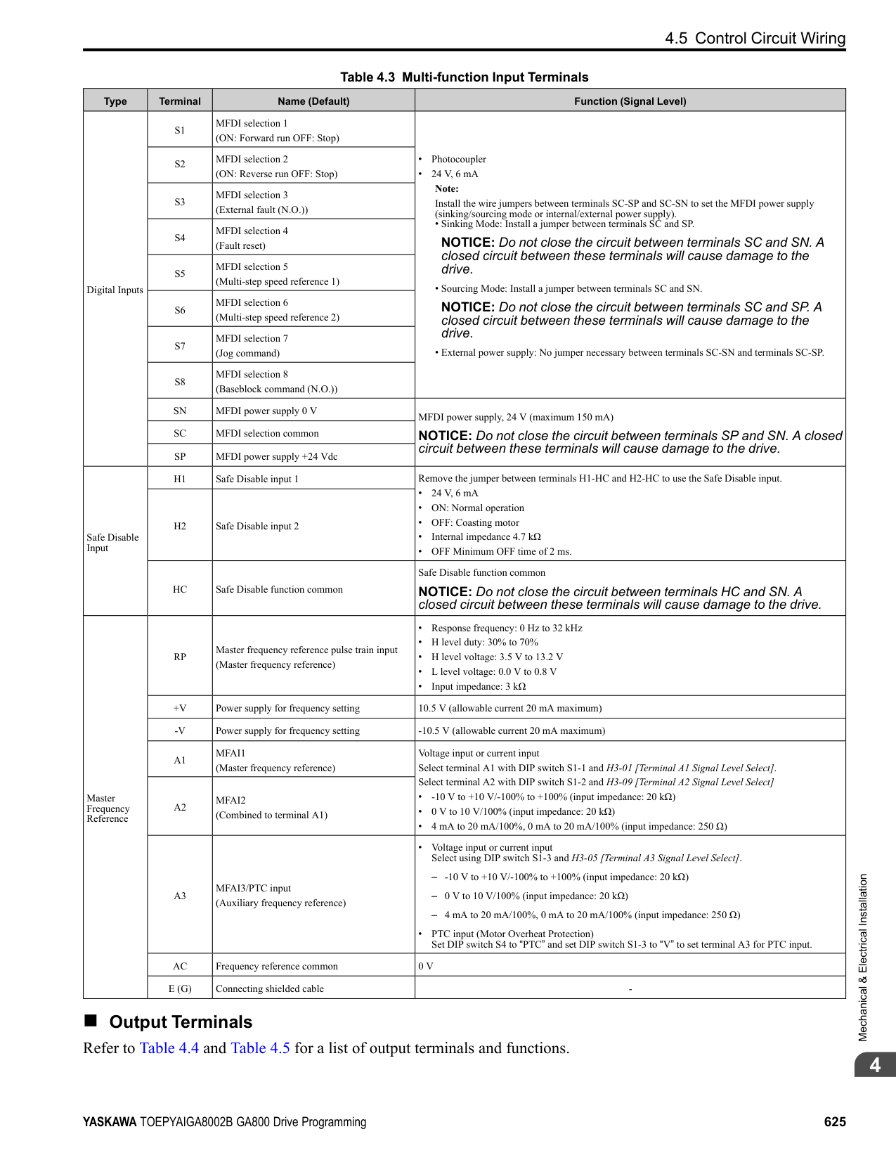
A3
AI (Default)
PTC
Functions as an MFAI terminal. Set H3-06 [Terminal A3 Function Selection] to select the input function.
Functions as the PTC input terminal. Set H3-06 = E [Motor Temperature (PTC Input)]. Set S1-3 to “V” for voltage input.
◆ Set Output Signals for MFAO Terminals FM, AM Set the signal type for terminals AM and FM to voltage or current output. Use jumper switch S5 and H4-07, H4-08 [Terminal FM Signal Level Select, Terminal AM Signal Level Select] to set the signal type.
| | | |---|---| | | |
| | |---| | |
| | | |---|---| | | |
| | | |---|---| | | |
| | | | | | | | | | | | | | | | | | | | | | | | | | | | | | | | |---|---|---|---|---|---|---|---|---|---|---|---|---|---|---|---|---|---|---|---|---|---|---|---|---|---|---|---|---|---|---| | | | | | | | | | | | | | | | | | | | | | | | | | | | | | | | |
4.6 Control I/O Connections
| | | |---|---|
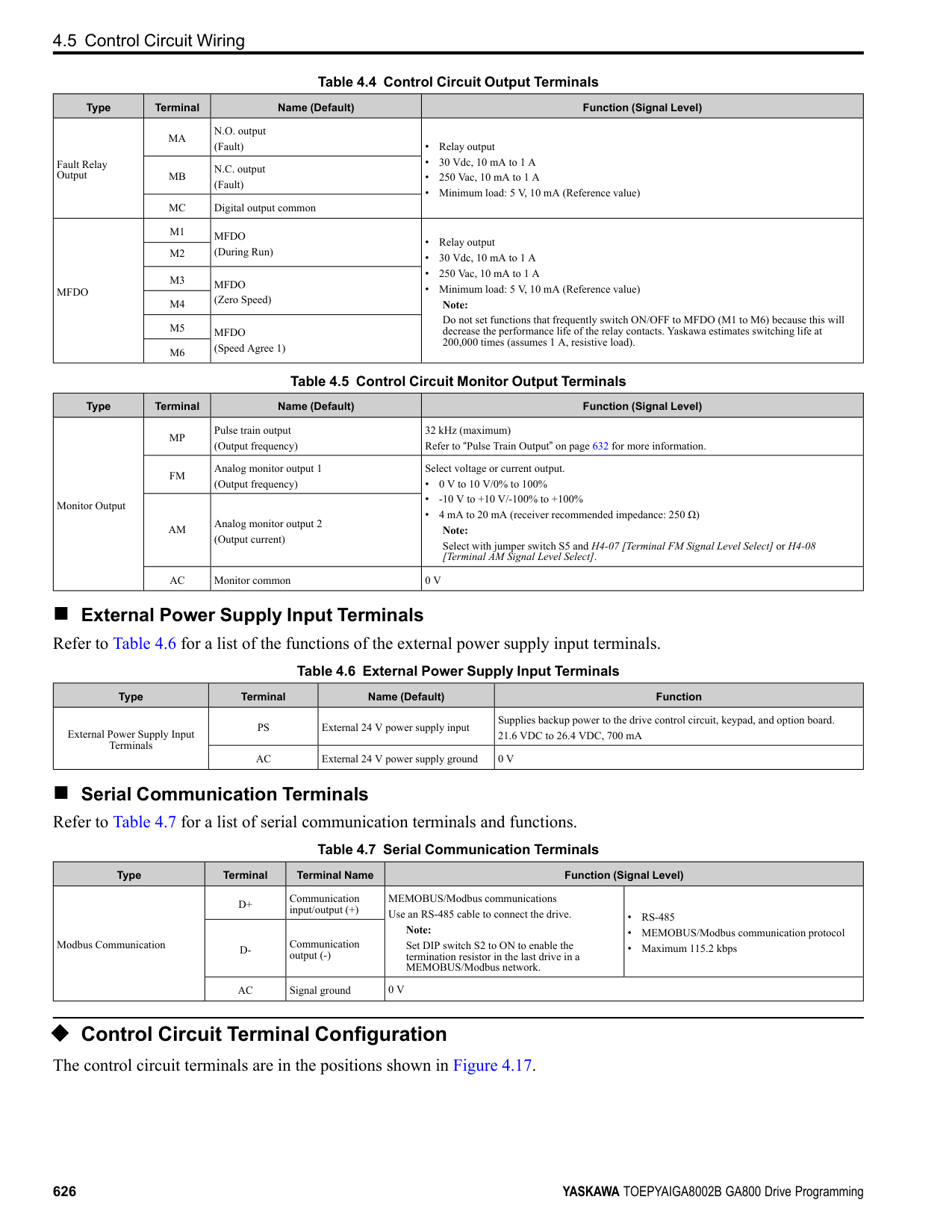
| | |
| | | |---|---| | | |
| | | | |---|---|---| | | | |
| | | | |---|---|---| | | | | | | | |
| | | | |---|---|---| | | | |
| | | | |---|---|---| | | | | | | | |
| | | | |---|---|---| | | | |
| | | |---|---|
| | | |---|---| | | |
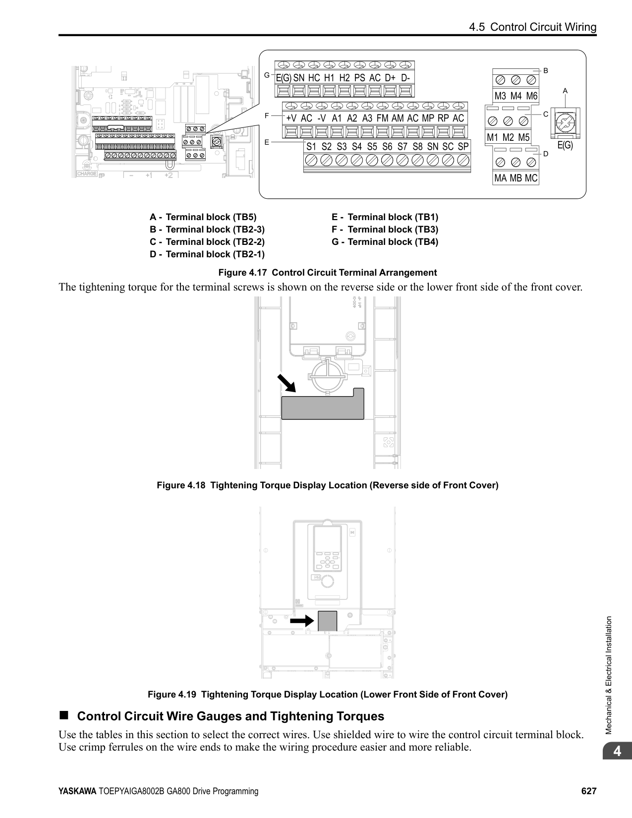
Figure 4.32 Location
Switch S5
|of| |---|
|Jumper| |---|
Terminal Types of Output Signals Jumper Switch S5
Parameter No. Signal Level
FM
Voltage output (Default)
H4-07
0: 0 V to 10 V 1: -10 V to +10 V
Current output 2: 4 mA to 20 mA
AM
Voltage output (Default)
| | | | |---|---|---| | | | |
| | | |---|---| | | |
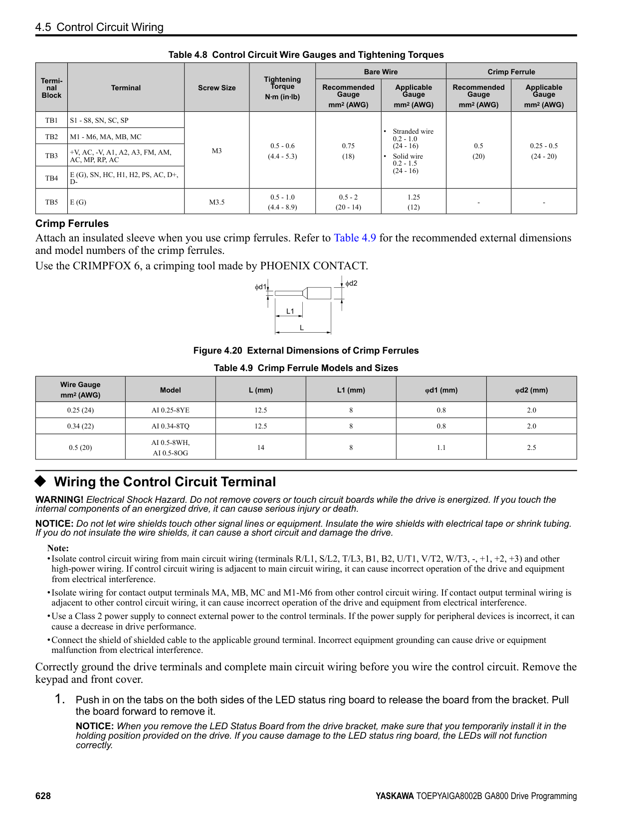
H4-08
| | | | |---|---|---| |to|10|10| | |10|10|
V 1: -10 V to +10 V
0: 0 V
Current output 2: 4 mA to 20 mA
| | | |---|---| | | |
| | | |---|---| | | |
| | | |---|---| | | |
######## ◆ Switch ON Termination Resistor for MEMOBUS/Modbus Communications
| | | |---|---| | | |
| | |---| | |
| | |
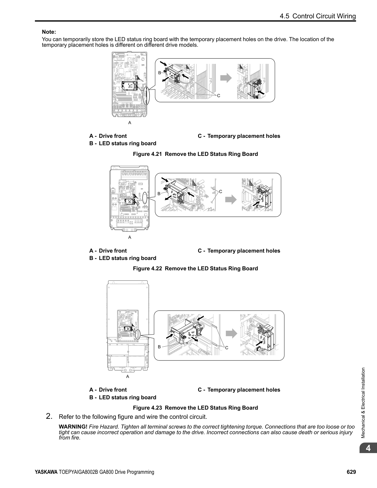
|---|---| | | |
| | | |---|---| | | |
| | | | | | | | | | | | | | | | | | | | | | | | | | | | | | | | |---|---|---|---|---|---|---|---|---|---|---|---|---|---|---|---|---|---|---|---|---|---|---|---|---|---|---|---|---|---|---| | | | | | | | | | | | | | | | | | | | | | | | | | | | | | | | |
When the drive is the last slave in a MEMOBUS/Modbus communications, set DIP switch S2 to the ON position. This drive has a built-in termination resistor for the RS-485 interface.
| | | |---|---| | | |
| | | |---|---| | | | | | |
| | | |---|---| | | |
| | | | | | | | |---|---|---|---|---|---|---| | | | | | | | | | | | | | | | |
| | | |---|---| | | |
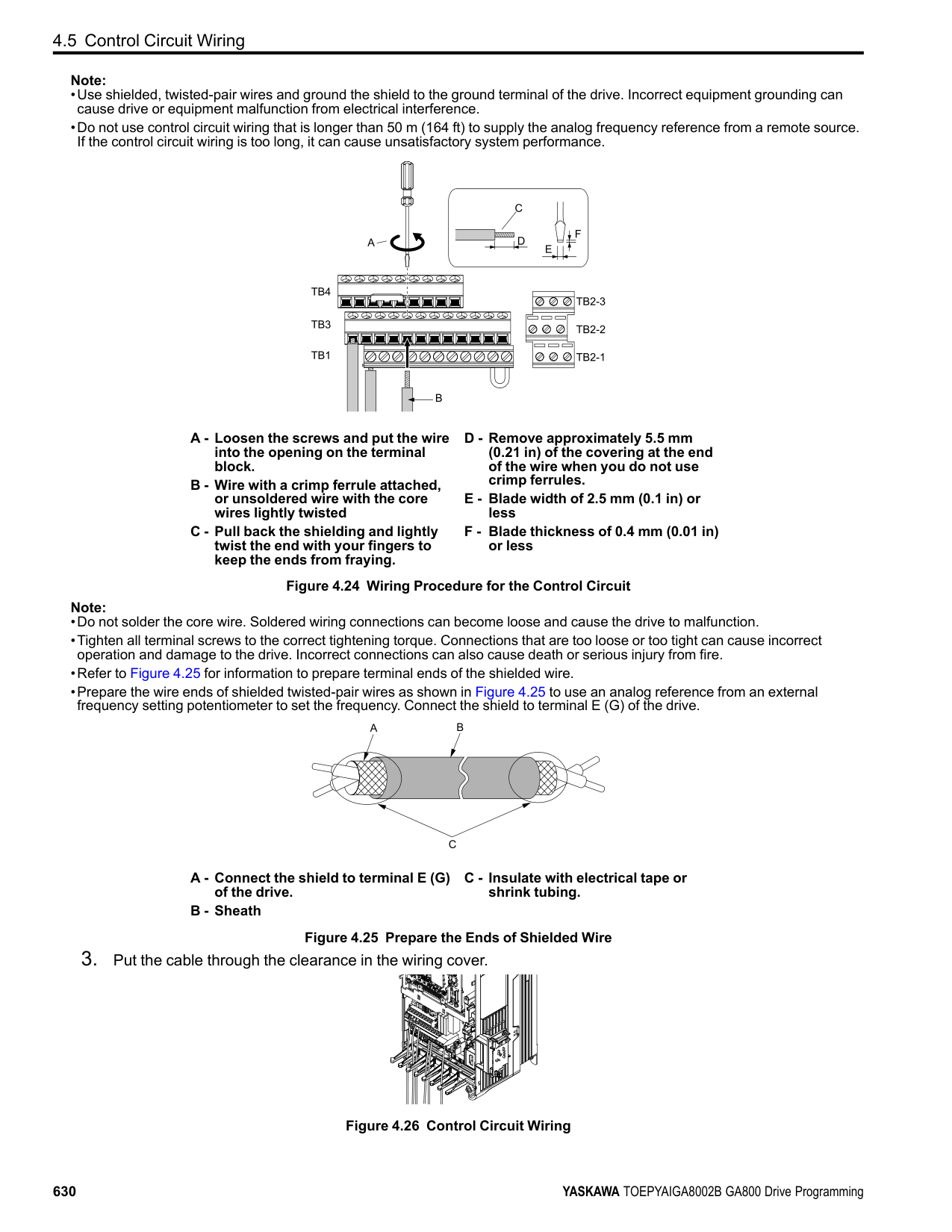
| | | | |---|---|---| | | | |
| | | | |---|---|---| | | | | | | | |
| | | | |---|---|---| | | | |
| | | | |---|---|---| | | | | | | | |
| | | | |---|---|---| | | | |
| | | |---|---|
| | | |---|---| | | |
Location of DIP Switch Table 4.12 MEMOBUS/Modbus Communications Termination Resistor Setting
Figure
|4.33|
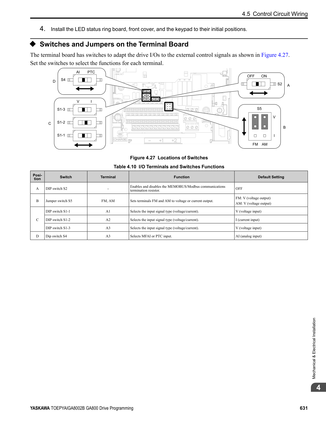
|---|
|S2| |---|
DIP Switch S2 Description
ON The built-in termination resistor is ON. OFF (Default) The built-in termination resistor is OFF.
Mechanical&ElectricalInstallation
####### 4.7 Connect the Drive to a PC
The drive has a mini-B type USB port. You can use a USB cable (USB 2.0, type: A - mini-B) to connect the drive to a type-A USB port on a PC. After you connect the drive to the PC, you can use Yaskawa DriveWizard Industrial software to monitor drive performance and manage parameter settings.
| | | |---|---| | | | | | |
A
BC
D
A - USB 2.0, type A - mini-B cable B - Mini-B type connector
C - Type-A connector D - PC
Figure 4.34 Connect to a PC (USB)
Yaskawa recommends that you use a USB cable with connectors connected with shielded wires.
Figure 4.35 Recommended USB Cable
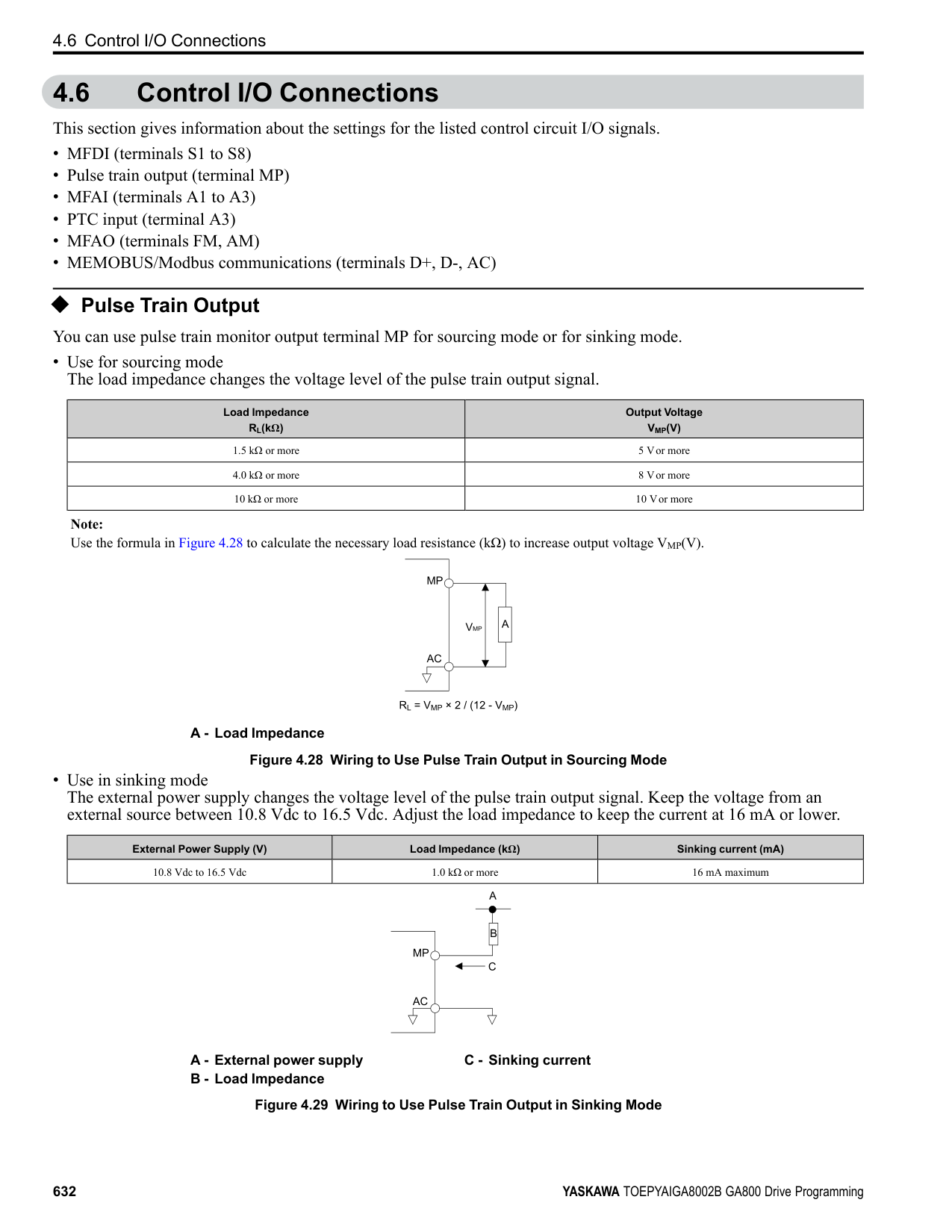
Index
Numerics 24 V power supply
Power supply input terminals.....................................626
Switching by external input.......................................247 Switching by output frequency ...................................248 Switcing by Motor 2 Selection commands......................248
Acceleration time
Parameter ............................................................247 Unit of measurement setting ......................................250
Adjustment of control functionality ..................................600 AFR
Parameter ............................................................486 ALM indicator.....................................................543, 546 ALM/ERR
LED status...........................................................549 Ambient Temperature Setting
Parameter ............................................................478 Analog gauge
Monitors .............................................................557 Analog input
Function selection for terminals A1 through A3 ...............405 Analog Output
Gain/Bias Adjustment .............................................419 Monitor Parameter Selection......................................419 Signal Level Selection .............................................419 Terminal AM Monitor Selection .................................421 Terminal FM Monitor Selection..................................420
Application Preset.......................................................179 ASR
Closed Loop V/f Control adjustment procedure ...............261 Fine tuning ..........................................................263 Parameter ............................................................260 Vector Control Adjustment Procedure...........................261
ASR tuning...............................................................593 Precautions ..........................................................597
Auto-Tuning .............................................................589 ASR and Inertia Tuning Parameters .............................538 ASR tuning..........................................................593 Induction Motor ....................................................589 Induction Motor Parameters ......................................532 Inertia Tuning .......................................................593 PM Motor Parameters..............................................535 PM Motors ..........................................................590 Precautions ..........................................................595 Precautions to Note before ASR Tuning ........................597 Precautions to Note before Inertia Tuning ......................597 Procedure ............................................................574 Rotational Auto-Tuning Precautions.............................596 Stationary Auto-Tuning for Line-to-Line Resistance
precautions....................................................597 Stationary Auto-Tuning Precautions.............................596 Stator resistance Auto-Tuning precautions......................597
Timing of shut-off..................................................585 Backup
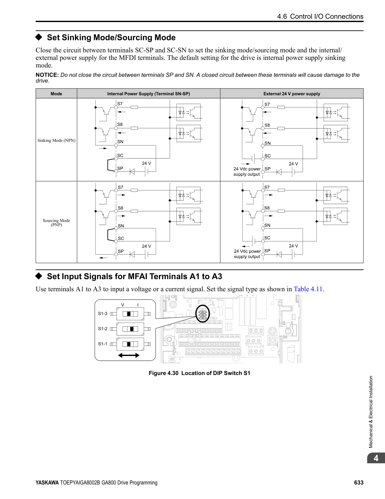
Parameters (drive to keypad) .....................................566 Backup function.........................................................522 Bar graph
Monitors .............................................................555 Base frequency
Parameter ............................................................302 Base Frequency
Motor 2 Parameters ................................................307 Base voltage
Motor 2 parameters.................................................308 Parameter ............................................................303
Bi-Directional function.................................................287 Braking Resistor
Protective function .................................................475 bUS
Detection condition settings.......................................345 Detection conditions ...............................................341 Operation Selection after Detection..............................340
C Capacitor Maintenance Setting........................................524 Carrier frequency
Diminish.............................................................480 Parameter ............................................................269
CE
Detection Selection.................................................424 Detection Time......................................................424 Operation Selection after Detection..............................423
Checklist
Test run ..............................................................607 Communication option
Parameter ............................................................335 Connecting multiple drives ............................................336 Control circuit terminals
Configuration of terminal block..................................626 I/O terminals function selection switches .......................631 Terminal functions .................................................624 Wire gauge ..........................................................627 Wiring................................................................623 Wiring procedure for terminal block.............................628
Control method
Selection .............................................................176 Cooling Fan
Activation Conditions Setting ....................................477 Off Delay Timer ....................................................478
Crimp ferrule ............................................................627 Cumulative Operation TimeSetting...................................523 Current Detection Speed Search ...................................... 211
############## D
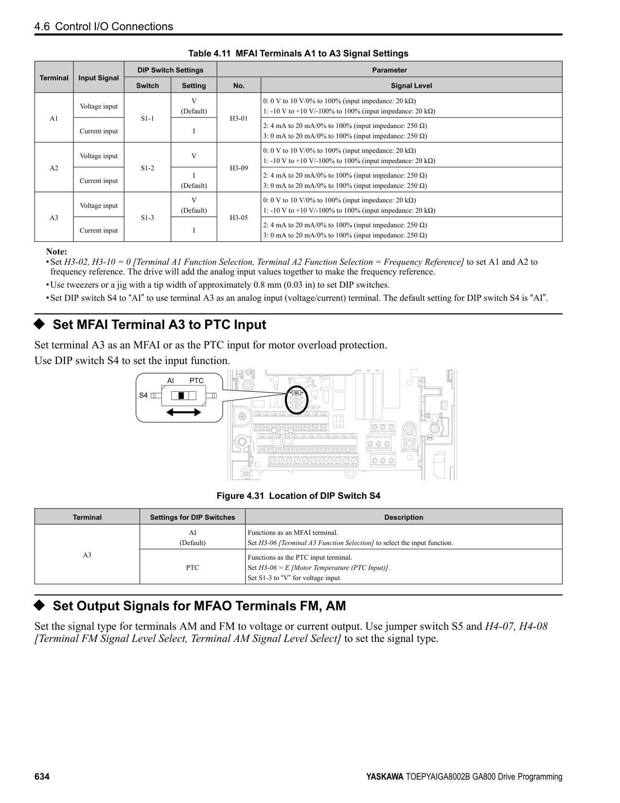
Data log...................................................................583 Monitor selection...................................................583 Sampling time.......................................................584 Start procedure......................................................582 Stop procedure......................................................582
DC Injection Braking
Parameter ............................................................207 Deceleration time
Parameter ............................................................247 Unit of measurement setting ......................................250
Delete
Delete Backed-up Parameters.....................................569 Derating
Ambient Temperature Setting.....................................478
Enclosure Type .....................................................480 External Cooling Fin...............................................480 Finless................................................................480 Side-by-side .........................................................480
dEv
Detection level......................................................319 Detection time ......................................................319 Operation Selection after Detection..............................318
DI-A3
Parameter ............................................................325 Digital input option
Parameter ............................................................325 Digital output option
Parameter ............................................................332 DIP switch ...............................................................631 DO-A3
Parameter ............................................................332 Down 2 command
Parameter ......................................................282, 287 Down command...................................................365–366
Parameter ......................................................282, 287 Drive
Initialization.........................................................177 Initialize Parameters ...............................................177
Drive Mode Unit Monitor Select...................................... 511 Drive Model Selection..................................................519 Droop Control
Parameter ............................................................239 dv3
Detection condition settings.......................................320 dv4
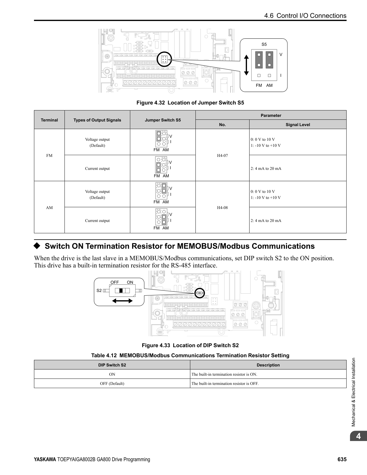
Detection condition settings.......................................320 Dwell function
Parameter ............................................................238 E
EF0
Detection conditions ...............................................341 Detection conditions setting (DeviceNet).......................348 Operation Selection after Detection..............................341
Elapsed Operating Time Selection....................................524 Enclosure Type
Derating..............................................................480 Encoder option
Parameter ............................................................316 Energy-saving control
Parameter ............................................................240 ERF type braking resistor
Protective function .................................................475 External 24 V power supply
Power supply input terminals.....................................626 External Cooling Fin
Derating..............................................................480
Parameter ............................................................250 Fault history
Display procedure ..................................................573 Fault Restart
Parameter ............................................................463
Feed Forward Control
Parameter ............................................................494 Field Forcing
Parameter ............................................................292 Field weakening
Parameter ............................................................292 Fine tuning ...............................................................600 Finless
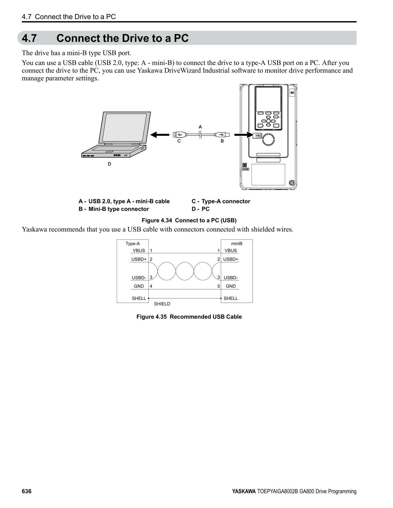
Derating..............................................................480 Firmware update lock...................................................192 Freq Ref Setting Method Select.......................................520 Freq reference bias
Parameter ............................................................287 Frequency Agreement
Parameter ............................................................462 Frequency reference
Command source correlation diagram...........................274 LOCAL/REMOTE Run selection..........................194, 274 Making changes using keypad....................................551 Offset frequency addition .........................................293 Switching between LOCAL/REMOTE .............194, 203, 274 Upper and lower frequency limits................................280
Frequency reference bias
Parameter ............................................................282 Frequency reference hold function
Parameter ......................................................282, 287
Protective function .................................................477 Ground Fault Detection
Protective function .................................................477
Alarm Settings ......................................................481 High-Slip Braking
Parameter ............................................................487 HOME screen............................................................551 Horsepower ..............................................................517
Auto-Tuning.........................................................589 Inertia Tuning............................................................593
Precautions ..........................................................597 Input Phase Detection
Protective function .................................................476 Input voltage
Parameter ............................................................296 Installation
Front cover ..........................................................612 Terminal cover......................................................612
Internal Drive Braking Transistor Protective function .................................................482
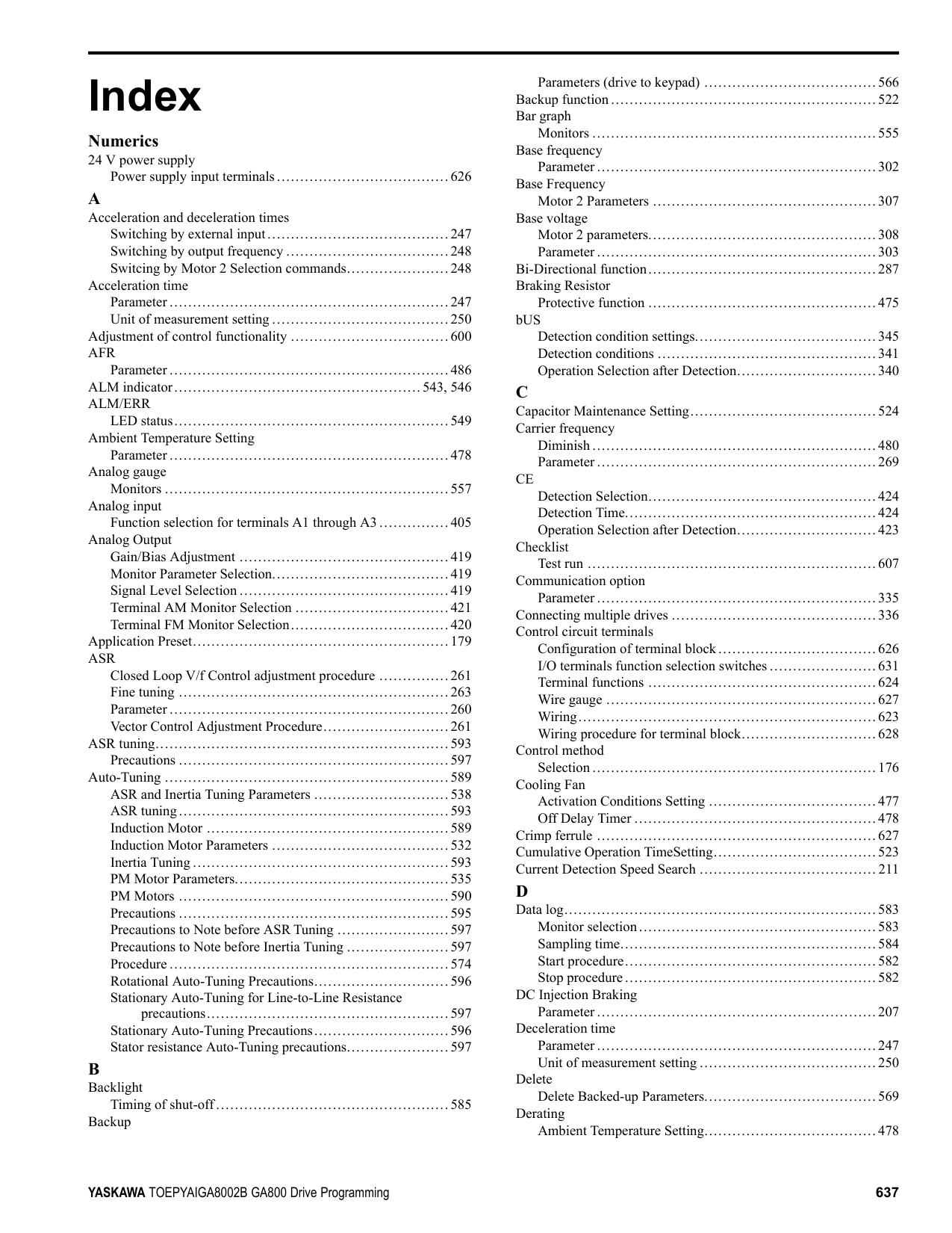
Parameter ............................................................281 Jumper switch ...........................................................631
Compensation Time................................................448 Operation during momentary power loss........................447 Parameter ............................................................441
KEB Ride-Thru Function
KEB Method Selection ............................................451 Single Drive KEB Method ........................................451 System KEB Method...............................................451
Keypad
Backlight setting....................................................585 Data log setting .....................................................583 Display drive information .........................................586 Display software version ..........................................586 HOME screen.......................................................551 Language selection...........................................175, 576 Meaning of indicators..............................................543 Method of operation................................................543 Set date and time ...................................................577 Set time ..............................................................577 Setup Wizard........................................................579 Start/stop data logging .............................................582
Keypad Display .........................................................510 Keypad Display Selection.............................................. 511 Keypad Operation.......................................................517 Keypad-related settings.................................................510 kWh Monitor Initialization ............................................525
Procedure ............................................................576 LCD contrast adjustment...............................................513 LED Light Function Selection ........................................521 LED status ring
ALM/ERR...........................................................549 Ready.................................................................549 RUN..................................................................549
LF
Protective function .................................................477 LF2
Protection Functions ...............................................479 Load Inertia Ratio
Parameter ............................................................460 LO/RE Key Function Selection .......................................517 LOCAL/REMOTE indicator ....................................543, 546 LSo
Protective function .................................................483
Wiring................................................................621 Main menu
Display procedure ..................................................551 Maintenance Period.....................................................523 Maximum Output Frequency
Motor 2 Parameters ................................................306
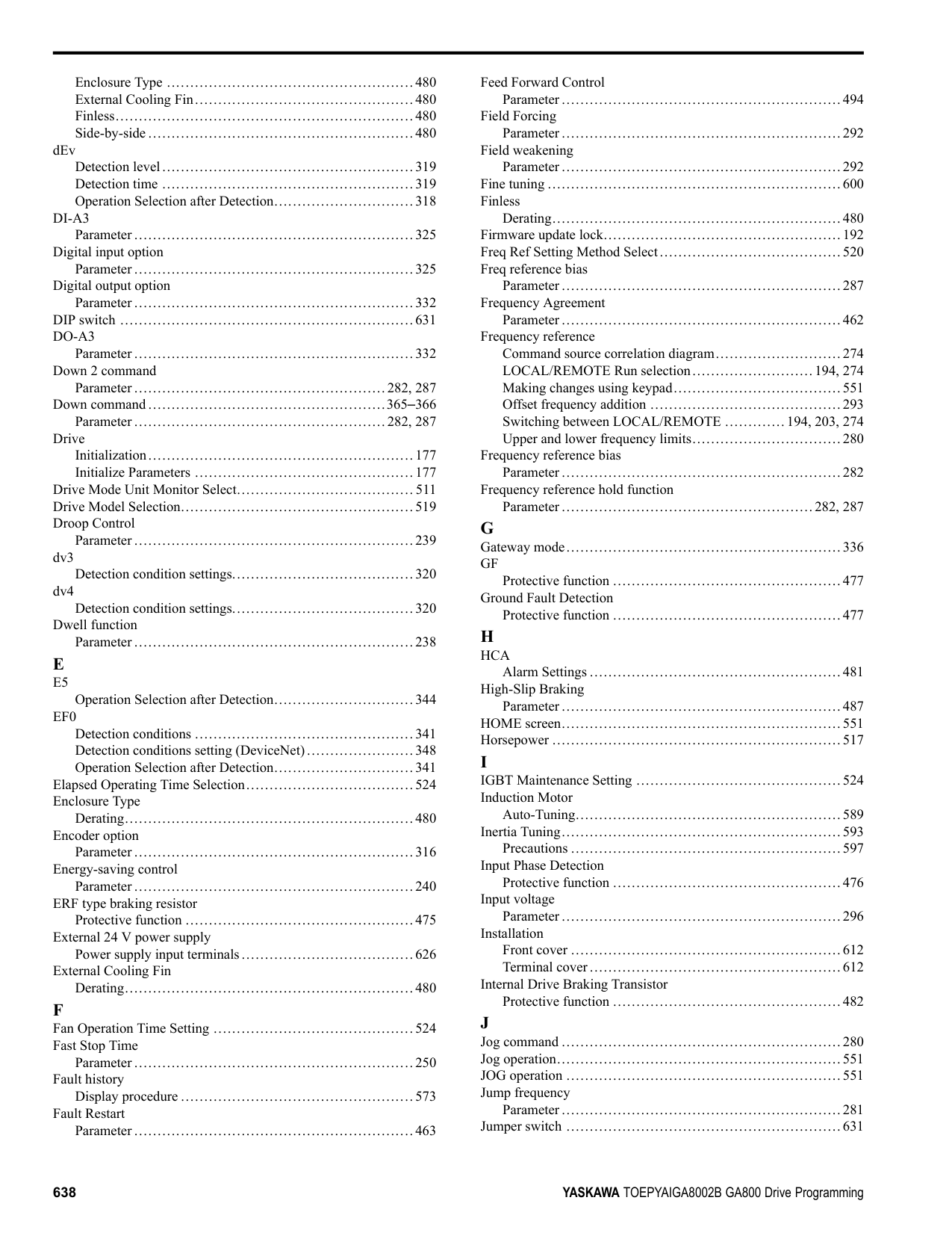
Maximum Output Voltage Motor 2 Parameters ................................................307
Mechanical Weakening Detection
Parameter ............................................................468 MEMOBUS/Modbus communications
Setting for termination resistor ...................................635
MEMOBUS/Modbus Communications
Parameter ............................................................422 Serial communication terminals..................................626
microSD card
Insertion slot ........................................................543 Mid point B frequency
Motor 2 parameters.................................................307
Mid point B voltage Motor 2 parameters.................................................308
Middle Output Frequency
Motor 2 Parameters ................................................307 Parameter ............................................................302
Middle Output Frequency Voltage
Motor 2 Parameters ................................................307 Parameter ............................................................302
Minimum output frequency
Parameter ............................................................302 Minimum Output Frequency
Motor 2 Parameters ................................................307 Induction Motor
Motor Parameters...................................................303 Minimum Output Voltage
Motor 2 Parameters ................................................307 Parameter ............................................................302
Momentary Power Loss
KEB Compensation Time .........................................448 Monitors
Data log setting ...............................................583–584 Display analog gauge ..............................................557 Display bar graph...................................................555 Display procedure ..................................................552 Set custom monitors................................................553 Show custom monitors.............................................554 Start/stop data logging.............................................582 Trend Plot Display .................................................558
Motor
Change direction of motor rotation ..............................551 Positive Temperature Coefficient (PTC) Thermistor ..........435 Wiring................................................................621
Motor 2
Base Frequency.....................................................307 Base voltage.........................................................308 Control mode settings..............................................306 Leakage Inductance ................................................309 Line-to-Line Resistance ...........................................309 Maximum Output Frequency .....................................306 Maximum Output Voltage.........................................307 Mid point B frequency.............................................307 Mid point B voltage................................................308 Middle Output Frequency .........................................307 Middle Output Frequency Voltage ...............................307 Minimum Output Frequency......................................307 Minimum Output Voltage .........................................307 Motor Iron Loss.....................................................310
V/f Pattern...........................................................306 Motor Code Selection .................................................. 311 Motor Overheating
Operation During Detection of Alarms..........................440 Operation During Detection of Faults (PTC Input)............440
Motor Overload
Electric Thermal Protection Operation Time ...................439 Protection Functions ...............................................436
Motor parameters
Motor 2 ..............................................................308 Motor 2 Iron-Core Saturation Coefficient 1 ....................310 Motor 2 Iron-Core Saturation Coefficient 2 ....................310 Motor 2 No-load Current..........................................309 Motor 2 number of motor poles ..................................309 Motor 2 rated Current..............................................308 Motor 2 rated power (kW) ........................................310
Motor Parameters .................................................295, 303 Motor 2 Iron Loss ..................................................310 Motor 2 Leakage Inductance......................................309 Motor 2 Line-to-Line Resistance.................................309 Motor 2 Rated Slip .................................................308
Motor parameters (induction motors) ................................303 Leakage Inductance ................................................305 Line-to-Line Resistance ...........................................304 Motor Iron Loss.....................................................305 Motor Iron-Core Saturation Coefficient 1.......................305 Motor Iron-Core Saturation Coefficient 2.......................305 Motor rated power (kW)...........................................305 No-load Current ....................................................304 Number of motor poles ............................................304 Rated current........................................................303 Rated Slip............................................................303
Motor Power Unit Selection...........................................517 MotorDirect@PowUpWhenUsingKeypad ..........................520 Multi-step speed operation.............................................274
Setting procedure...................................................274
Overcurrent Detection Gain.......................................479 Off-Delay Timer.........................................................220 Offset frequency
Parameter ............................................................293 oH
Alarm Settings ......................................................475
oL2
Protective function .................................................478 On-Delay Timer .........................................................220 Ope Select @Keypad is Disconnect..................................520 Operation During Momentary Power Loss
KEB ride-thru function ............................................441 Operation method selection .......................................447 Parameter ............................................................447 Speed Search function .............................................210
Option card
Parameter ............................................................316 oS
Detection level......................................................319 Detection time ......................................................319 Operation Select at Overspeed....................................317
Output Phase Loss Detection
Protective function .................................................477 Overexcitation deceleration
Parameter ............................................................488 Overtorque detection
Parameter ............................................................466
P Parameter
Access Level Selection ............................................175 Automatic selection ................................................193 Backup (drive to keypad)..........................................566 Changing setting values ...........................................563 Checking modified parameters ...................................570 Checking user custom parameters................................564 Delete Backed-up Parameters.....................................569 Restore (Auto Backup) ............................................587 Restore (keypad to drive)..........................................567 Restoring default settings..........................................572 User-set ..............................................................193 Verify (keypad and drive) .........................................568
Password
Setting................................................................179 Verification..........................................................179
PC
Connection procedure..............................................636 PF
Protective function .................................................476 PGo
Detection time ......................................................320 Operation Selection after Detection..............................317
PGoH Detection level......................................................323
Phase Order Selection ..................................................203 PID control...............................................................222
control block diagram..............................................224 Feedback value input...............................................223 fine tuning ...........................................................225 Parameter ............................................................227 PID feedback loss detection.......................................224 PID Sleep............................................................225 Setpoint input .......................................................223
PM motor parameters
d-Axis inductance ..................................................312 Encoder Z pulse offset.............................................313
PM Motor Parameters ..................................................310 PM Motors
Auto-Tuning.........................................................590 Fine Adjustment ....................................................499
Motor Code Selection.............................................. 311 Motor Parameters...................................................310
Positive Temperature Coefficient (PTC) Thermistor...............435 Protection Functions
DC bus undervoltage...............................................449 Drive Overheating..................................................475 LF2 ...................................................................479 Motor Overload.....................................................436 oC.....................................................................479 oH2 ...................................................................475 Overcurrent..........................................................479 Uv1 ...................................................................449
Protective function
Desynchronization..................................................483 Drive Overheating..................................................475 GF ....................................................................477 Ground Fault Detection............................................477 HCA..................................................................481 Input Phase Detection..............................................476 Internal Drive Braking Transistor ................................482 LF.....................................................................477 Low Speed Desynchronization ...................................483 LSo ...................................................................483 Motor Overheating .................................................440 Motor Overheating (PTC Input)..................................440 oH.....................................................................475 oH3 ...................................................................440 oH4 ...................................................................440 oL2 ...................................................................478 Output Current Overload ..........................................481 Output Phase Loss Detection .....................................477 Overload .............................................................478 PF.....................................................................476 rr ......................................................................482 Software Current Limit Selection ................................478
Pulse Train Input
Terminal RP Function Selection..................................427 Pulse Train Input/Output
Parameter ............................................................426 Pulse train output
Terminal MP function selection ..................................429 Wiring specifications...............................................632
R Ready
LED status...........................................................549 Remove
Front cover ..........................................................612 Terminal cover......................................................612
RESET key...............................................................543 Restore
Parameters (Auto Backup) ........................................587 Parameters (keypad to drive) .....................................567
Reverse Operation Selection...........................................200 RJ-45 connector .........................................................543 Rotational Auto-Tuning
Induction Motor ....................................................589 PM Motors ..........................................................590 Precautions ..........................................................596
rr
Protective function .................................................482 RUN
LED status...........................................................549
Run command
LOCAL/REMOTE Run selection................................196 Switching between LOCAL/REMOTE .........................196
Run Command at Power Up...........................................206 Run Command Selection 2
Switching between LOCAL/REMOTE .........................205 RUN indicator .....................................................543, 546 RUN key .................................................................543
############## S
Sampling time setting
Data log..............................................................584 Serial communication terminals
MEMOBUS/Modbus Communications .........................626 Set date and time
Operation ............................................................577 Set time
Operation ............................................................577 Setup Wizard
Operation ............................................................579 Short Circuit Braking
Parameter ............................................................207 Side-by-side
Derating..............................................................480 Simple Positioning Stop................................................287 Slip compensation
Parameter ............................................................253 Softcharge Relay Maintenance Set ...................................524 Software Current Limit Selection
Protective function .................................................478 Software version
Display procedure ..................................................586 Speed Agreement
Parameter ............................................................462 Speed Detection
Parameter ............................................................462 Speed Estimation Speed Search.......................................212 Speed limit
Parameter ............................................................288 Speed Search function
Operation during momentary power loss........................447 Parameter ............................................................210
Stall Prevention function
Parameter ............................................................452 Stationary Auto-Tuning
Induction Motor ....................................................589 PM Motors ..........................................................590
Stationary Auto-Tuning for Line-to-Line Resistance ..............589
Stator resistance Auto-Tuning.........................................590
Precautions ..........................................................597 Stop command
LOCAL/REMOTE Run selection................................196 STOP key.................................................................543 STOP Key Function Selection.........................................518 Stopping Method Selection ............................................197
Control circuit terminal block functions.........................624 I/O terminals function selection switches .......................631
Terminal function selection............................................633
Termination resistor
Setting switch .......................................................635 Test run
Checklist.............................................................607 Fine tuning ..........................................................600 Procedure for no-load test run ....................................598 Procedure for test run with actual load ..........................598
Tightening torque
Control circuit terminals...........................................627 Timer function
Parameter ............................................................220 Torque compensation
Parameter ............................................................288 Torque Compensation
Parameter ............................................................258 Torque Control
Parameter ............................................................287 Switching to/from Speed Control ................................290
Torque limit function
Parameter ............................................................472 Torque reference
Parameter ............................................................288 Trend Plot
Monitors .............................................................558 Tuning ....................................................................247
############## U
Parameter ............................................................466 Unit of measurement setting
Acceleration and deceleration times .............................250 Unit selector .............................................................517 Up 2 command
Parameter ......................................................282, 287 Up command.......................................................365–366
Parameter ......................................................282, 287 USB port .................................................................543
Connecting a PC....................................................636 User Monitor Select afterPowerUp................................... 511 User Parameter Default Value.........................................518 User-Set Display Units Max Value ...................................513 User-SetDisplayUnits Dec Display...................................513 Uv
Speed Search Selection at Start...................................219 Uv1
Detection level settings ............................................449
################## V/f Pattern................................................................295Second Motor .......................................................306
Parameters (keypad and drive) ...................................568
Control circuit terminals...........................................627
Wiring
Control circuit terminal block ....................................628 Control circuit terminals...........................................623 Main circuit terminals..............................................621 Motor.................................................................621
Z Z pulse Auto-Tuning....................................................590 Zero Servo function
Parameter ............................................................245
############ Revision History
|Date of Publication|Revision Number|Section|Revised Content| |---|---|---|---| |November 2018|1|All|Power ratings| |August 2018|–|–|First Edition|


GA800 Drive
Programming
YASKAWA ELÉTRICO DO BRASIL LTDA. 777, Avenida Piraporinha, Diadema, São Paulo, 09950-000, Brasil Phone: +55-11-3585-1100 Fax:
YASKAWA EUROPE GmbH Hauptstraβe 185, 65760 Eschborn, Germany Phone: +49-6196-569-300 Fax:
YASKAWA AMERICA, INC. 2121, Norman Drive South, Waukegan, IL 60085, U.S.A. Phone: +1-800-YASKAWA (927-
+49-6196-569-398 E-mail: support@yaskawa.eu.com http://www.yaskawa.eu.com
5292) or +1-847-887-7000 Fax:
+1-847-887-7310 http://www.yaskawa.com
+55-11-3585-1187 http://www.yaskawa.com.br
DRIVE CENTER (INVERTER PLANT) 2-13-1, Nishimiyaichi, Yukuhashi, Fukuoka, 824-8511, Japan Phone: +81-930-25-2548 Fax:
+81-930-25-3431 http://www.yaskawa.co.jp
In the event that the end user of this product is to be the military and said product is to be employed in any weapons systems or the manufacture thereof, the export will fall under the relevant regulations as stipulated in the Foreign Exchange and Foreign Trade Regulations. Therefore, be sure to follow all procedures and submit all relevant documentation according to any and all rules, regulations and laws that may apply. Specifications are subject to change without notice for ongoing product modifications and improvements. Original instructions. © 2018 YASKAWA America, Inc.
TOEPYAIGA8002 Revision: B <1>-1YAI
YASKAWA America, Inc.
February 2019 Published in U.S.A.
*TOEPYAIGA8002*