
Ask AI
— answers from the official manualAnswers from the official manual.
Common questions
Common Questions
10 totalHow do I troubleshoot slow internet speeds on the MF29 router?
Check signal strength from the RSSI indicator. Ensure a strong RF reception by moving the router to another location with better coverage. Verify configuration settings and initialization times.
How do I set up WPS on the MF29 router?
Press the WPS button on the device or select ‘PBC’ mode from Settings > Wi-Fi Setting > WPS, then wait within two minutes to activate pairing with a wireless client.
How do I set up basic firewall rules for the MF29 router?
Go to Settings > Firewall > Mac/IP/Port Filtering and select 'Enable'. Input specific details such as MAC address, IP addresses, protocols or port ranges. Click Apply.
What is the best way to maintain the MF29 router?
Ensure at least 20 cm from the device to avoid interference with medical devices like hearing aids and pacemakers. Keep it away from direct sunlight, humid areas, or explosive gases environments.
What is the operating frequency band of the MF29 router?
The device operates on LTE TDD bands including 1800 MHz (Band 3), 2600 MHz (Band 38) and 2300 MHz (Band 40).
How do I factory reset the MF29 router?
Press and hold the Reset button for more than 7 seconds until the device reboots with factory defaults. You will need to reconfigure all settings after resetting (Page 10).
Full Manual
25 pages

| | | | | | | | | | | | |---|---|---|---|---|---|---|---|---|---|---|
| | | | | | | | | | | | |---|---|---|---|---|---|---|---|---|---|---|
MF29 User Manual
MF29T User Manual V1.1-0703.indd 1 2012-7-3 16:46:28
Contents Welcome ..............................................................5 General Information ............................................5
#### LEGAL INFORMATION
Copyright © 2012 ZTE CORPORATION.
All rights reserved.
Safety Precautions ...................................................................... 5 Cleaning and Maintaining ........................................................... 6 Limited Warranty ......................................................................... 6 Limitation of Liability ................................................................... 7
No part of this publication may be excerpted, reproduced, translated or utilized in any form or by any means, electronic or mechanical, including photocopying and microfilm, without the prior written permission of ZTE Corporation.
Getting started .....................................................8
Appearance ................................................................................ 8 LED Indicator ........................................................................ 8 Interface Description ........................................................... 10
The manual is published by ZTE Corporation. We reserve the right to make modifications on print errors or update specifications without prior notice.
Installation ................................................................................. 10 Inserting (U)SIM Card ......................................................... 10 Connecting to Phone ............................................................11 Connecting to Computer ......................................................11 Connecting to the Internet ................................................... 12 Connecting with External Power ......................................... 12 Switching on Your Device .................................................... 12
Version No. : 1.1 Edition Time : 07 03, 2012
Power Supply ............................................................................ 12
Voice ...................................................................13 Making a Call ............................................................................ 13 Answering a Call ....................................................................... 13
Internet Access ..................................................14 Preparation ............................................................................... 14 Establishing a connection between your device and the client . 14 Accessing the WebGUI Configuration Page ............................. 16
2 3
| | | |---|---| | | |
MF29T User Manual V1.1-0703.indd 2-3 2012-7-3 16:46:28
Welcome Thank you for choosing ZTE MF29 Router (hereinafter referred to as “device” or “router”). To get the most from your router and to keep it in the best condition, please read this manual carefully. The pictures, symbols and contents in this manual are for your reference only. They might not be completely identical with your router. ZTE operates a policy of continuous development. We reserve the right to update the technical specifications in this manual at any time without prior notice.
Login ......................................................................................... 16 Accessing the Internet .............................................................. 18
Accessing the Internet by LTE Gateway ............................. 18 Operation Mode ........................................................................ 18 4G Settings ............................................................................... 19 WAN Connection ...................................................................... 21
In Cable Broadband mode .................................................. 21 In 4G Gateway mode .......................................................... 21
SMS Over IP ............................................................................. 22 Sending new SMS ............................................................... 22 Operating Messages in native ............................................. 22
VoIP .......................................................................................... 24 Settings ............................................................................... 24 User Details ......................................................................... 25 Advanced ........................................................................... 26 Supplementary .................................................................... 26
General Information Safety Precautions
Settings ..................................................................................... 27 Wi-Fi Settings ...................................................................... 27 Firewall ................................................................................ 35 Advanced ............................................................................ 39
Usage of WPS .......................................................................... 42 U-Disk Master ........................................................................... 43 Logout ....................................................................................... 43
Troubleshooting ................................................44
How to get help ......................................................................... 45 Technical Parameters ........................................46 Glossary .............................................................47
4 5
| | | |---|---| | | |
MF29T User Manual V1.1-0703.indd 4-5 2012-7-3 16:46:28
#### Cleaning and Maintaining
• This warranty is end user’s sole remedy and ZTE's sole liability for defective or nonconforming items, and is in lieu of all other warranties, expressed, implied or statutory, including but not limited to the implied warranties of merchantability and fitness for a particular purpose, unless otherwise required under the mandatory provisions of the law.
#### Limitation of Liability
ZTE shall not be liable for any loss of profits or indirect, special, incidental or consequential damages resulting from or arising out of or in connection with using of this product, whether or not ZTE had been advised, knew or should have known of the possibility of such damages, including, but not limited to lost profits, interruption of business, cost of capital, cost of substitute facilities or product, or any downtime cost.
#### Limited Warranty
• This warranty does not apply to defects or errors in the Product caused by: i. Reasonable Router Appearance Disfiguration.
6 7
| | | |---|---| | | |
MF29T User Manual V1.1-0703.indd 6-7 2012-7-3 16:46:28
Getting started The router operates on the LTE/HSUPA/HSDPA/WCDMA network and supports voice and data service.
|Indicator|State|Description| |---|---|---| |2 Network mode indication|Blue|Registered to 3G network| |2 Network mode indication|Green|Registered to LTE network| |2 Network mode indication|Red|Registered to EDGE network| |2 Network mode indication|Off|Not Registered| |3 WAN connection status indication|On|WAN connection established (PDP activated)| |3 WAN connection status indication|Blinking|WAN connection establishing (PDP activating)| |3 WAN connection status indication|Off|WAN connection not established (PDP not activated)| |4 Phone status indication|Off|Local phone hang up or VoIP network unregistered or registration failure| |4 Phone status indication|Blinking|Phone picked up, ringing| |4 Phone status indication|On|Local phone calling| |5 Phone status indication|Off|Local phone hang up or VoIP network unregistered or registration failure| |5 Phone status indication|Blinking|Phone picked up, ringing| |5 Phone status indication|On|Local phone calling| |6 WiFi indication|Off|WLAN shut down| |6 WiFi indication|On|WLAN working normally with no data transmission| |6 WiFi indication|Blinking|WLAN working normally with data transmission| |7 Power indication|On|Once power button is pushed and device is powered on| |7 Power indication|Off|Once power button is pushed and device is powered off|
#### Appearance

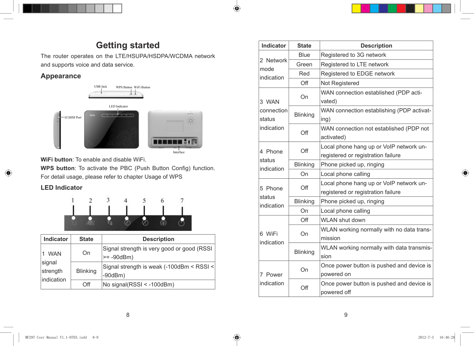
WiFi button: To enable and disable WiFi. WPS button: To activate the PBC (Push Button Config) function. For detail usage, please refer to chapter Usage of WPS LED Indicator

|Indicator|State|Description| |---|---|---| |1 WAN signal strength indication|On|Signal strength is very good or good (RSSI >= -90dBm)| |1 WAN signal strength indication|Blinking|Signal strength is weak (-100dBm < RSSI <
-90dBm)| |1 WAN signal strength indication|Off|No signal(RSSI < -100dBm)|
8 9
| | | |---|---| | | |
MF29T User Manual V1.1-0703.indd 8-9 2012-7-3 16:46:28
##### Interface Description


###### Note:
Please power off the router and remove the external power adapter before removing or inserting the (U)SIM card. If not, the router or (U)SIM card may be damaged.
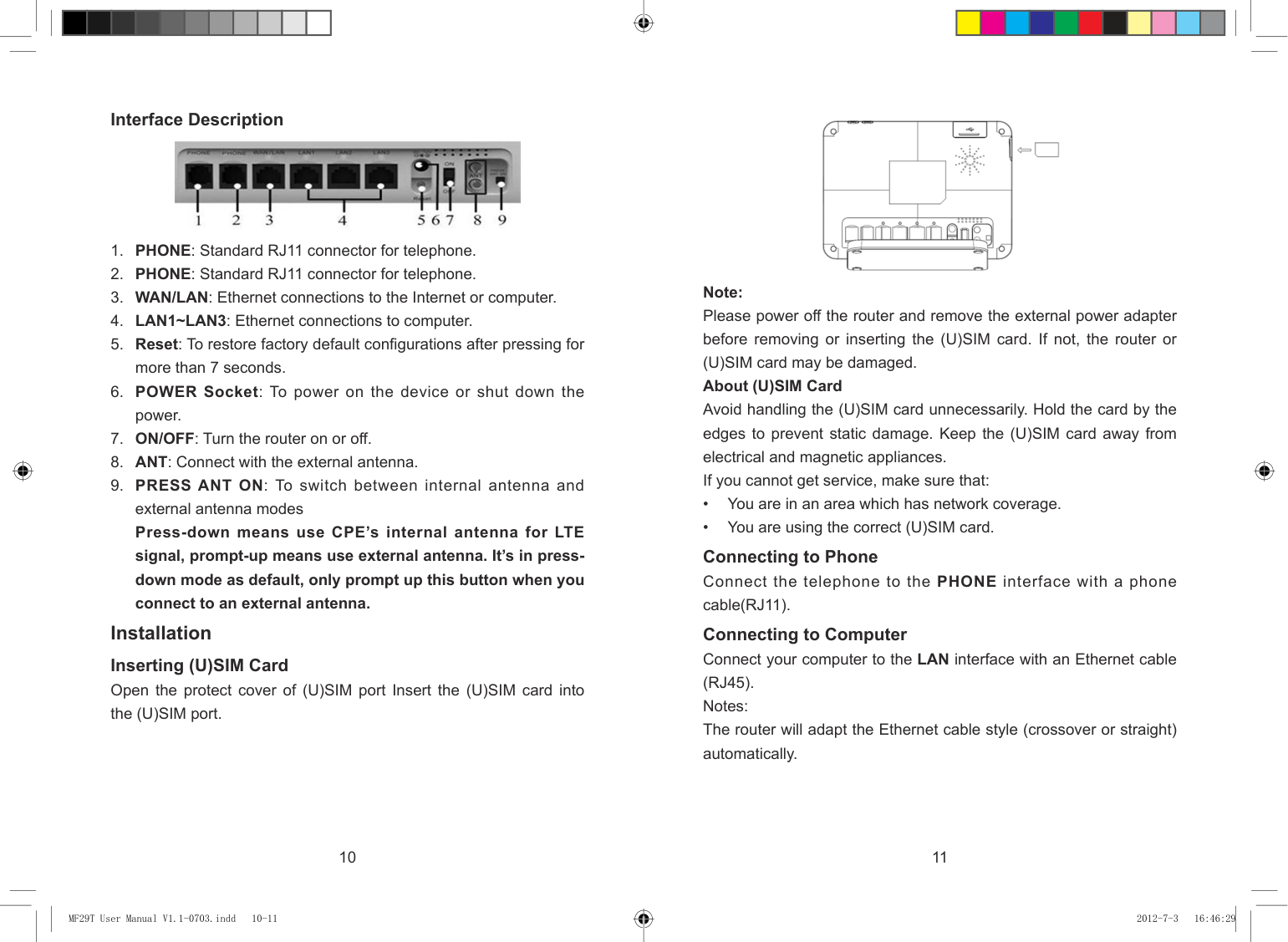
About (U)SIM Card Avoid handling the (U)SIM card unnecessarily. Hold the card by the edges to prevent static damage. Keep the (U)SIM card away from electrical and magnetic appliances. If you cannot get service, make sure that:
Connecting to Phone Connect the telephone to the PHONE interface with a phone cable(RJ11). Connecting to Computer Connect your computer to the LAN interface with an Ethernet cable (RJ45). Notes: The router will adapt the Ethernet cable style (crossover or straight) automatically.
Installation Inserting (U)SIM Card Open the protect cover of (U)SIM port Insert the (U)SIM card into the (U)SIM port.
10 11
| | | |---|---| | | |
MF29T User Manual V1.1-0703.indd 10-11 2012-7-3 16:46:29
Voice
Connecting to the Internet Connect the WAN/LAN interface to the Internet with an Ethernet cable (RJ45). Connecting with External Power Connect the external power adaptor to a standard power outlet. Insert the plug into the power socket at the rear of the router. Switching on Your Device
Making a Call You can make a call through VoIP. The VoIP number is provided by your service operator. Please contact your service operator to get detailed information. To make a call:
Notes: Do not put anything on the top of the router. Do not lay routers to overlap each other when using.
Notes: When the router is turned off, an incoming caller will hear the prompt like “The number you have dialed is currently unavailable.” If the net mode indication LED is blinking constantly, try to move the router to another location. The router takes 1~2 minutes to initialize, attach to the network and obtain an IP address.
Making an International Call If you are making an international call, key in the international access code followed by the country code, area code and number. E.g. 00 11 64 12 345678
#### Power Supply
For normal operation, connect the router to the external power adapter. In case of power failure or when there is no available external power supply, the router will not work.
#### Answering a Call
When the phone rings, pick up the handset to answer it. If the telephone has hands-free function you also can answer the call by pressing the Hands-free button. Press the Hands-free button again to end the call.
12 13
| | | |---|---| | | |
MF29T User Manual V1.1-0703.indd 12-13 2012-7-3 16:46:29
Internet Access The router does not require any drivers, and it supports all operating systems with Ethernet LAN capability, such as Windows 2000, XP, Vista, MAC OS X and Linux. The router supports two computers surfing on internet using Ethernet cable at the same time. Note: All the parameter settings in this chapter are just for your reference. Please contact your service provider for detail.


#### Preparation Establishing a connection between your device and the client Via RJ45 Ethernet cable
Note:
You need to check your Wireless Network Connection. Set the client to obtain an IP address automatically in the Internet protocol (TCP/IP) properties, and the client will get an IP address like”192.168.0.100”.
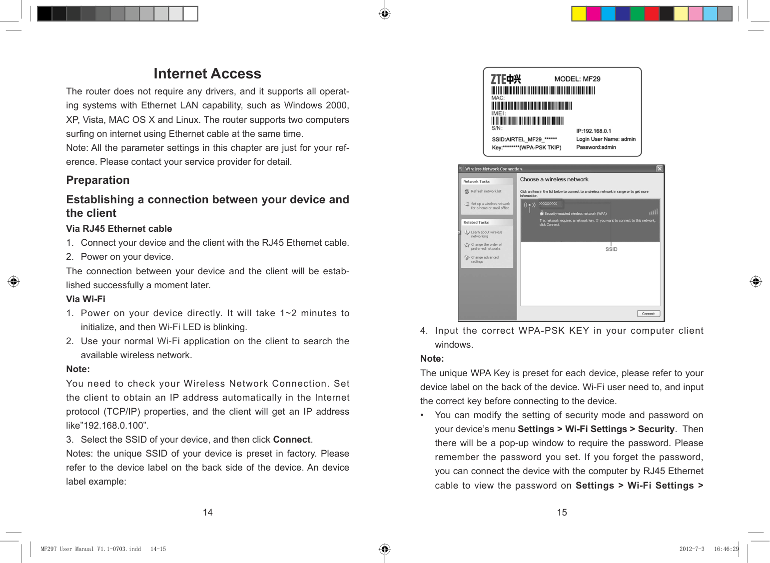
windows. Note:
The unique WPA Key is preset for each device, please refer to your device label on the back of the device. Wi-Fi user need to, and input the correct key before connecting to the device.
• You can modify the setting of security mode and password on your device’s menu Settings > Wi-Fi Settings > Security. Then there will be a pop-up window to require the password. Please remember the password you set. If you forget the password, you can connect the device with the computer by RJ45 Ethernet cable to view the password on Settings > Wi-Fi Settings >
14 15
| | | |---|---| | | |
MF29T User Manual V1.1-0703.indd 14-15 2012-7-3 16:46:29
###### Security.

#### Accessing the WebGUI Configuration Page
Note:
It is recommended that you use IE (6.0 or later), Firefox (2.0 or later), Opera (10.0 or later), Safari (4.0 or later) or Chrome (5.0 or later).
Click Login to log in the device. Note: If you check Save after type in password, the device will save it. Next time when you want to login the device with the same password, what you need to do is click Login. When you login, the following interface appears.

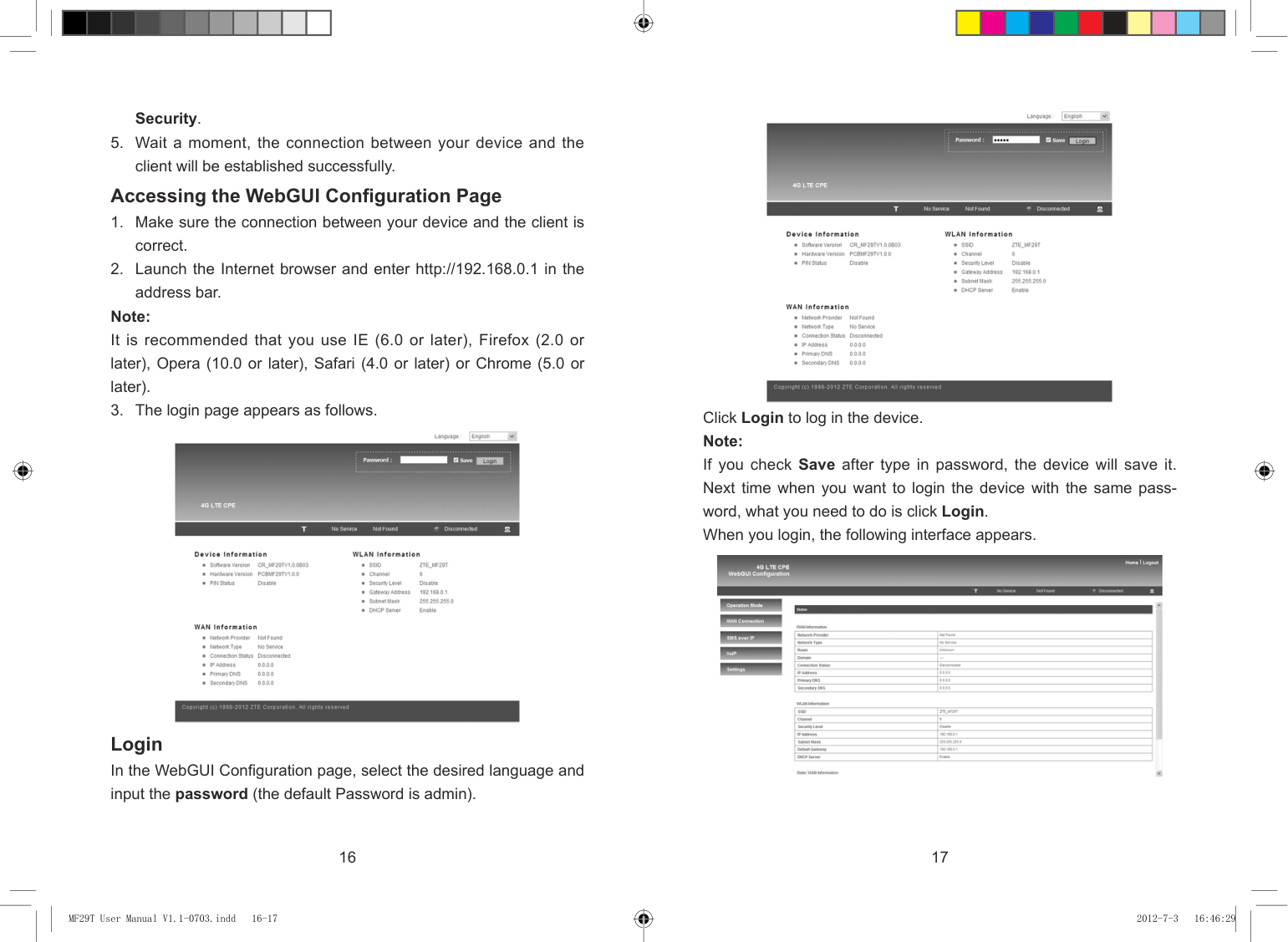

Login In the WebGUI Configuration page, select the desired language and input the password (the default Password is admin).
16 17
| | | |---|---| | | |
MF29T User Manual V1.1-0703.indd 16-17 2012-7-3 16:46:29
The whole interface is divided into three parts. Related functions can be executed by operation in the related areas.
computer.
4G Settings Wireless Info Select Settings > 4G Settings > Wireless Info, the 4G wireless information is shown in the following figure:

Click Refresh to update the wireless information. Network Select Select Settings > 4G Settings > Network Select, the Band Selection Mode is shown in the following figure:

Accessing the Internet Before accessing the internet, make sure;
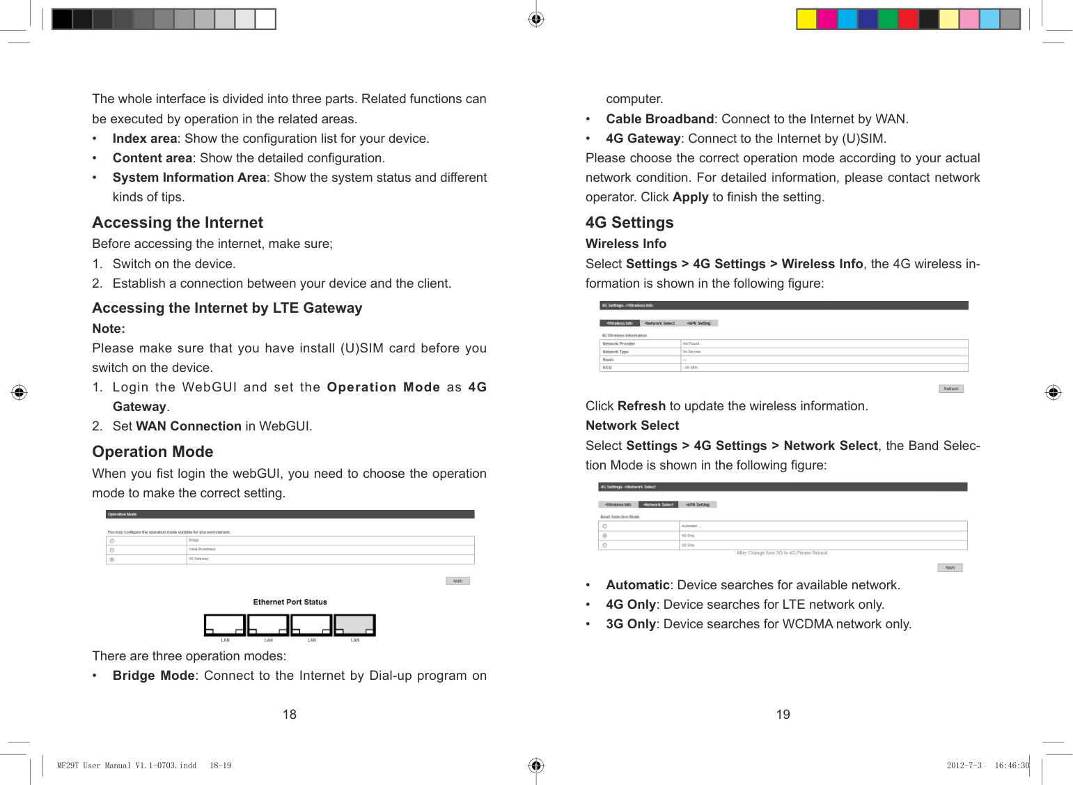
Accessing the Internet by LTE Gateway Note: Please make sure that you have install (U)SIM card before you switch on the device.
Operation Mode When you fist login the webGUI, you need to choose the operation mode to make the correct setting.

There are three operation modes:
• Bridge Mode: Connect to the Internet by Dial-up program on
18 19
| | | |---|---| | | |
MF29T User Manual V1.1-0703.indd 18-19 2012-7-3 16:46:30
Click Apply to confirm your configuration. APN Setting Select Settings > 4G Settings > APN Setting, the APN parameters are shown in the following figure:

Click Set default to set this profile as the default profile. WAN Connection In Cable Broadband mode Click WAN Connection, you can configure how to connect to the Internet.

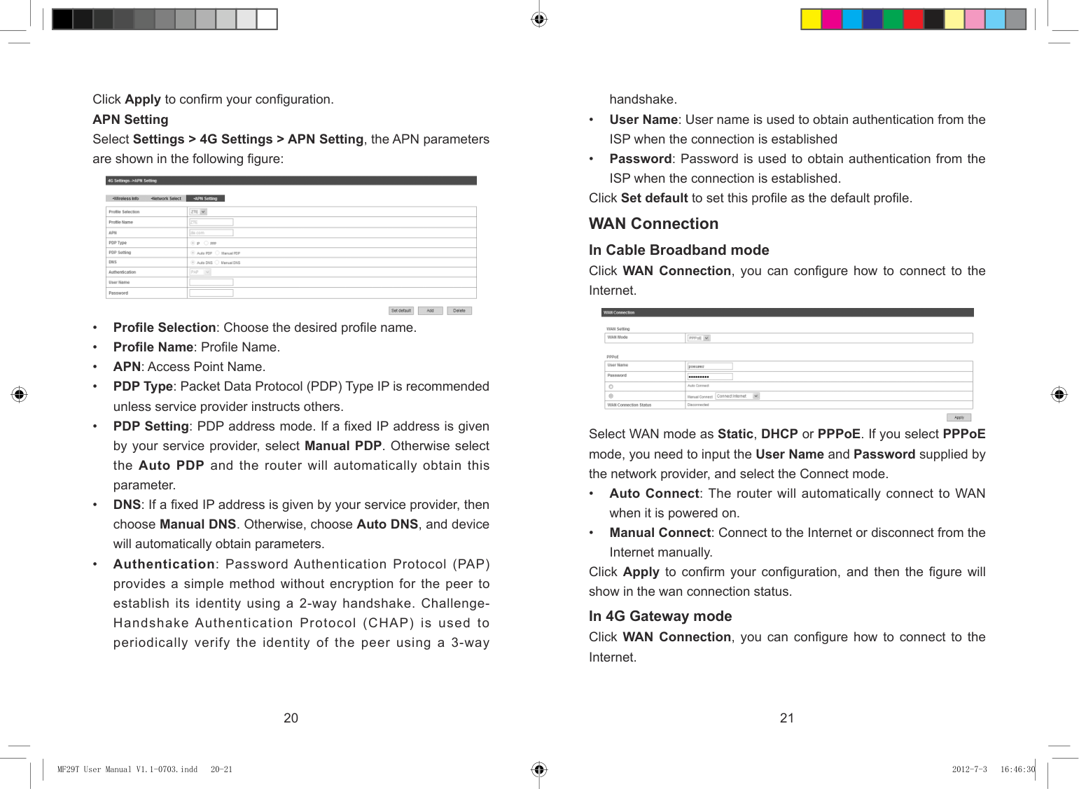
Select WAN mode as Static, DHCP or PPPoE. If you select PPPoE mode, you need to input the User Name and Password supplied by the network provider, and select the Connect mode.
Click Apply to confirm your configuration, and then the figure will show in the wan connection status. In 4G Gateway mode Click WAN Connection, you can configure how to connect to the Internet.
20 21
| | | |---|---| | | |
MF29T User Manual V1.1-0703.indd 20-21 2012-7-3 16:46:30
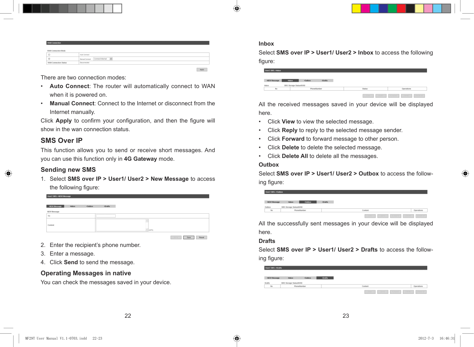
###### Inbox Select SMS over IP > User1/ User2 > Inbox to access the following figure:


There are two connection modes:
All the received messages saved in your device will be displayed here.
Click Apply to confirm your configuration, and then the figure will show in the wan connection status.
SMS Over IP This function allows you to send or receive short messages. And you can use this function only in 4G Gateway mode. Sending new SMS


All the successfully sent messages in your device will be displayed here. Drafts Select SMS over IP > User1/ User2 > Drafts to access the following figure:

Operating Messages in native You can check the messages saved in your device.
22 23
| | | |---|---| | | |
MF29T User Manual V1.1-0703.indd 22-23 2012-7-3 16:46:31

User Details Select VoIP > User > User Details access the following figure:

All the drafts and the messages sent unsuccessfully saved in your device will be displayed here.
• Click View to access the edited interface of selected message,
then click Send to send it. VoIP You can use this function only in 4G Gateway mode. For the detailed VoIP parameters, please consult your service provider. Settings Select VoIP > Settings to access the following figure:

24 25
| | | |---|---| | | |
MF29T User Manual V1.1-0703.indd 24-25 2012-7-3 16:46:31
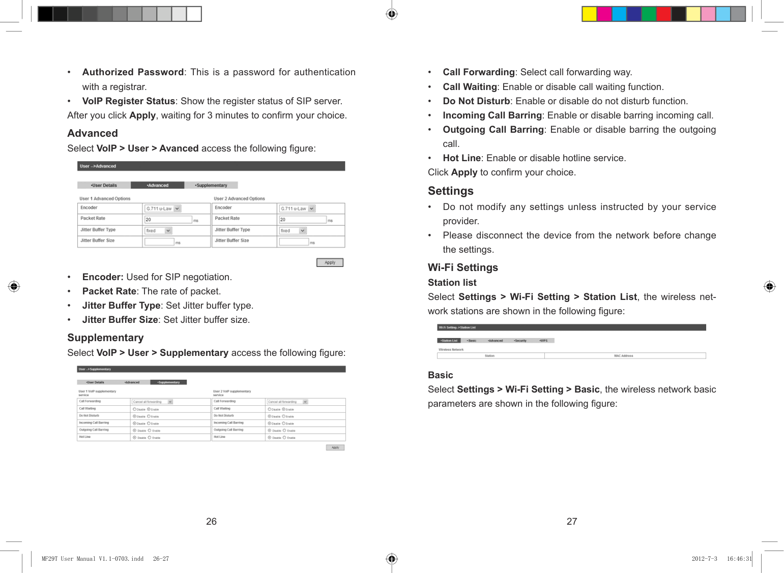
Advanced Select VoIP > User > Avanced access the following figure:

Wi-Fi Settings Station list Select Settings > Wi-Fi Setting > Station List, the wireless network stations are shown in the following figure:

Supplementary Select VoIP > User > Supplementary access the following figure:

Basic Select Settings > Wi-Fi Setting > Basic, the wireless network basic parameters are shown in the following figure:
26 27
| | | |---|---| | | |
MF29T User Manual V1.1-0703.indd 26-27 2012-7-3 16:46:31
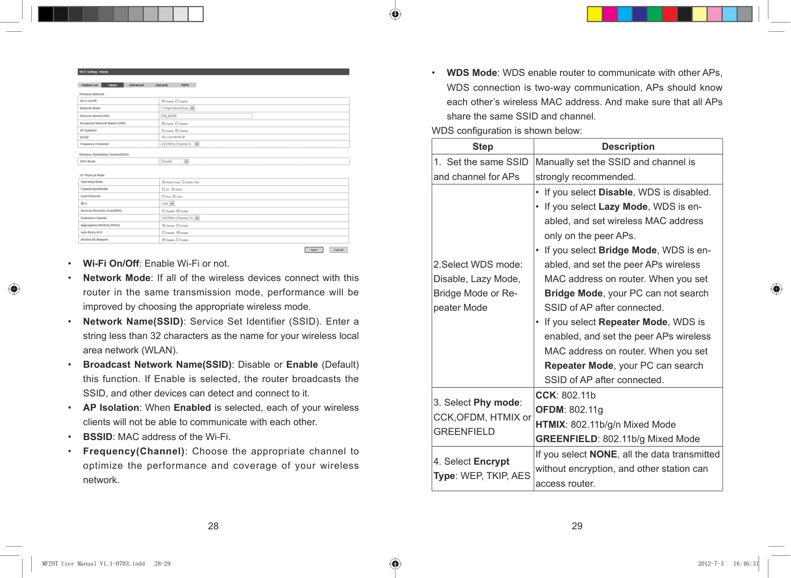
• WDS Mode: WDS enable router to communicate with other APs, WDS connection is two-way communication, APs should know each other’s wireless MAC address. And make sure that all APs share the same SSID and channel.

WDS configuration is shown below:
|Step|Description| |---|---| |1. Set the same SSID and channel for APs|Manually set the SSID and channel is strongly recommended.| |2.Select WDS mode: Disable, Lazy Mode, Bridge Mode or Repeater Mode|• If you select Disable, WDS is disabled.
• If you select Lazy Mode, WDS is enabled, and set wireless MAC address only on the peer APs.
• If you select Bridge Mode, WDS is enabled, and set the peer APs wireless MAC address on router. When you set Bridge Mode, your PC can not search SSID of AP after connected.
• If you select Repeater Mode, WDS is enabled, and set the peer APs wireless MAC address on router. When you set Repeater Mode, your PC can search SSID of AP after connected.
| |3. Select Phy mode: CCK,OFDM, HTMIX or GREENFIELD|CCK: 802.11b OFDM: 802.11g HTMIX: 802.11b/g/n Mixed Mode GREENFIELD: 802.11b/g Mixed Mode| |4. Select Encrypt Type: WEP, TKIP, AES|If you select NONE, all the data transmitted without encryption, and other station can access router.|

28 29
| | | |---|---| | | |
MF29T User Manual V1.1-0703.indd 28-29 2012-7-3 16:46:31

|5. Set peer AP's wireless MAC address on router|Only Repeater Mode and Bridge Mode need this.| |---|---|
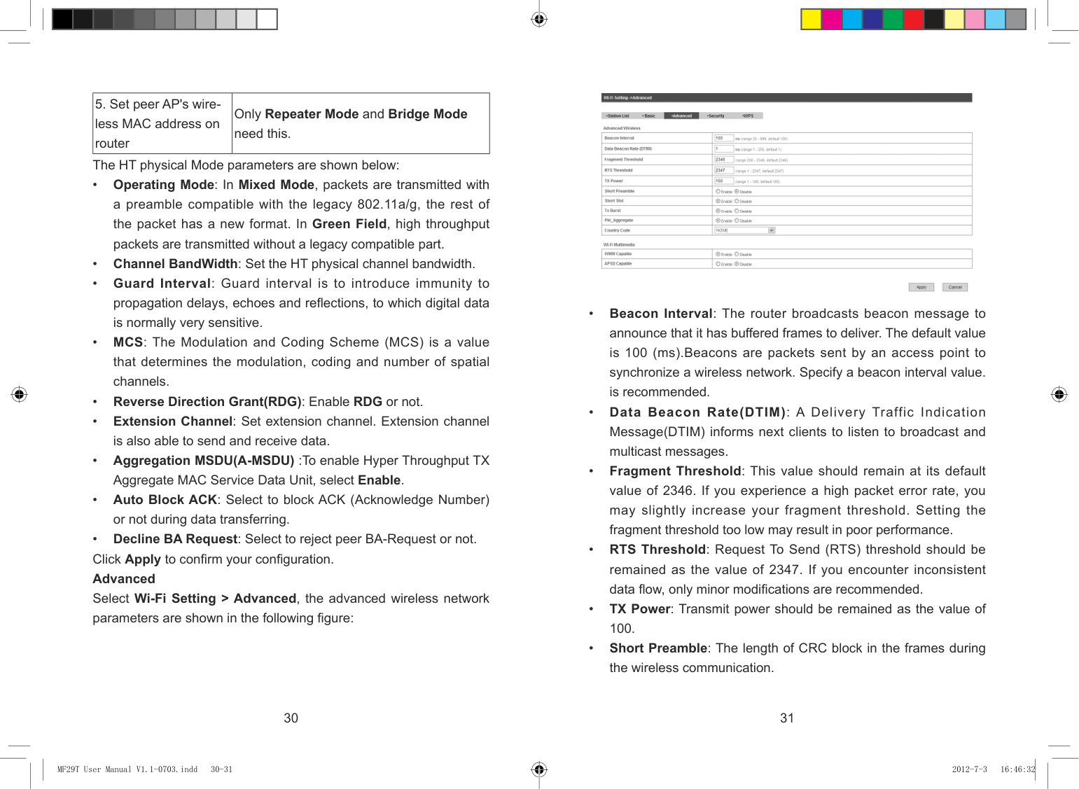
The HT physical Mode parameters are shown below:
30 31
| | | |---|---| | | |
MF29T User Manual V1.1-0703.indd 30-31 2012-7-3 16:46:32
If the Authentication type is SHARED, WEPAUTO, the bottom part of the configuration page displays parameters as shown.
• WEP Keys: At most four keys can be set in the blank. Choose the primary key index. The primary key is the only key in use at a given time. Whatever keys you enter for an access point, you must also enter the same keys for the client adapter in the same order. In other words, WEP key 1 on the AP must match WEP key 1 on the client adapter, WEP key 2 on the AP must match WEP key 2 on the client adapter, etc. Select Hex if use 10 or 26 hexadecimal numbers (0~9, a~f or A~F). Select ASCII if use 5 or 13 ASCII characters (case-sensitive).
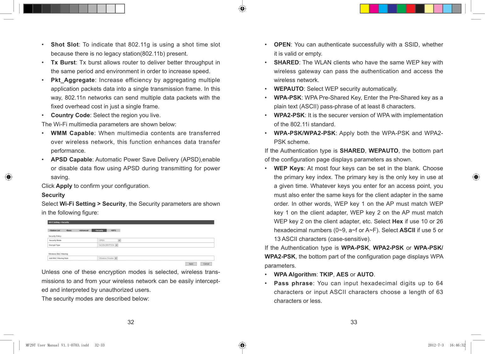
Click Apply to confirm your configuration. Security Select Wi-Fi Setting > Security, the Security parameters are shown in the following figure:

If the Authentication type is WPA-PSK, WPA2-PSK or WPA-PSK/ WPA2-PSK, the bottom part of the configuration page displays WPA parameters.
Unless one of these encryption modes is selected, wireless transmissions to and from your wireless network can be easily intercepted and interpreted by unauthorized users. The security modes are described below:
32 33
| | | |---|---| | | |
MF29T User Manual V1.1-0703.indd 32-33 2012-7-3 16:46:32
To set WPS, select WPS mode, the two modes are described below:
• Key Renewal Interval: Define how long the key should be renew. You can set Wireless MAC Filtering:
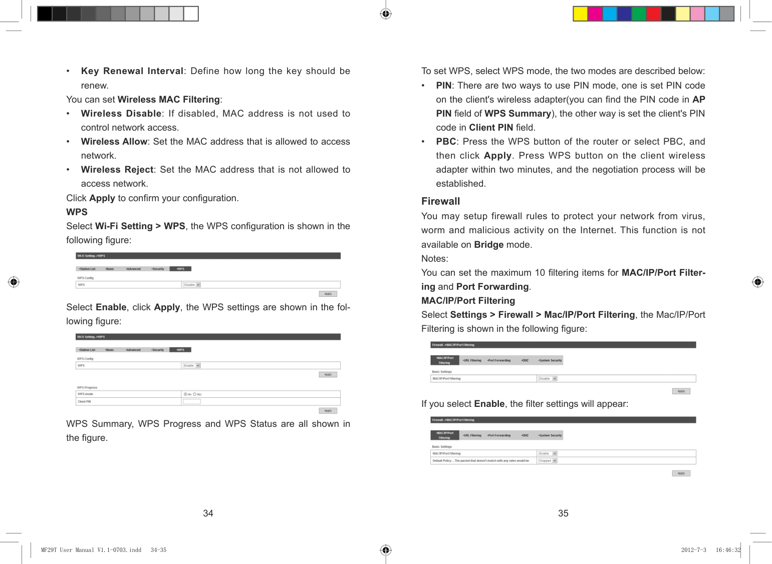
Click Apply to confirm your configuration. WPS Select Wi-Fi Setting > WPS, the WPS configuration is shown in the following figure:
Firewall You may setup firewall rules to protect your network from virus, worm and malicious activity on the Internet. This function is not available on Bridge mode. Notes: You can set the maximum 10 filtering items for MAC/IP/Port Filtering and Port Forwarding. MAC/IP/Port Filtering Select Settings > Firewall > Mac/IP/Port Filtering, the Mac/IP/Port Filtering is shown in the following figure:

Select Enable, click Apply, the WPS settings are shown in the following figure:


If you select Enable, the filter settings will appear:

WPS Summary, WPS Progress and WPS Status are all shown in the figure.
34 35
| | | |---|---| | | |
MF29T User Manual V1.1-0703.indd 34-35 2012-7-3 16:46:32
To add a new rule:

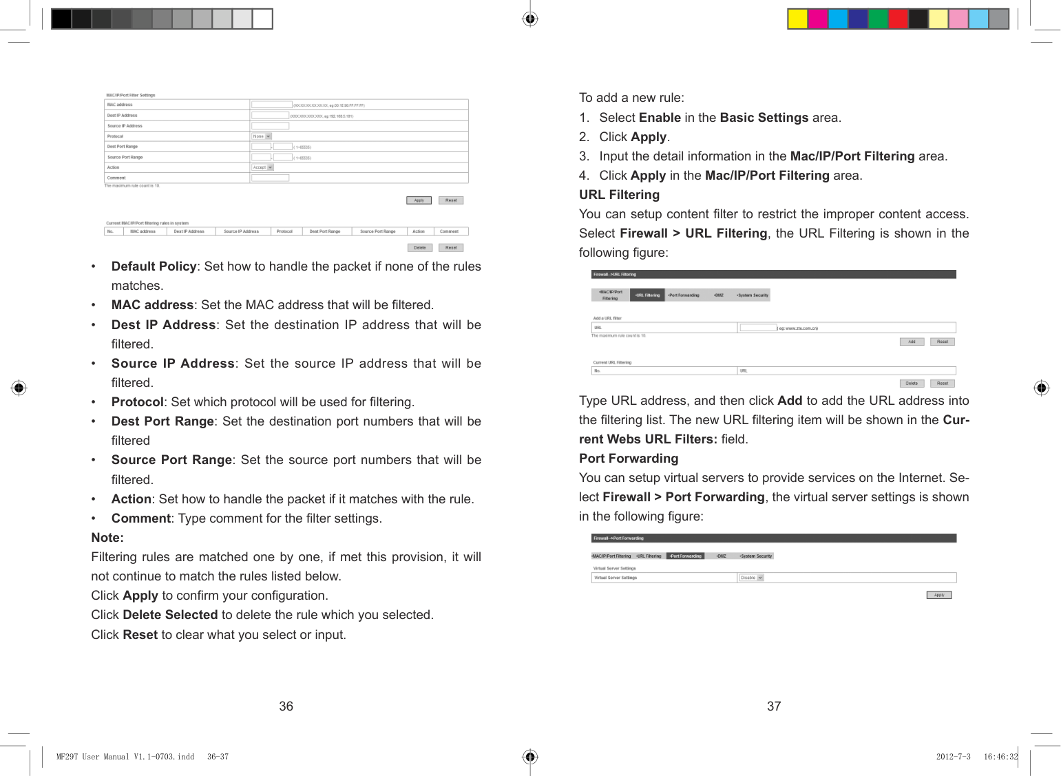

Type URL address, and then click Add to add the URL address into the filtering list. The new URL filtering item will be shown in the Current Webs URL Filters: field. Port Forwarding
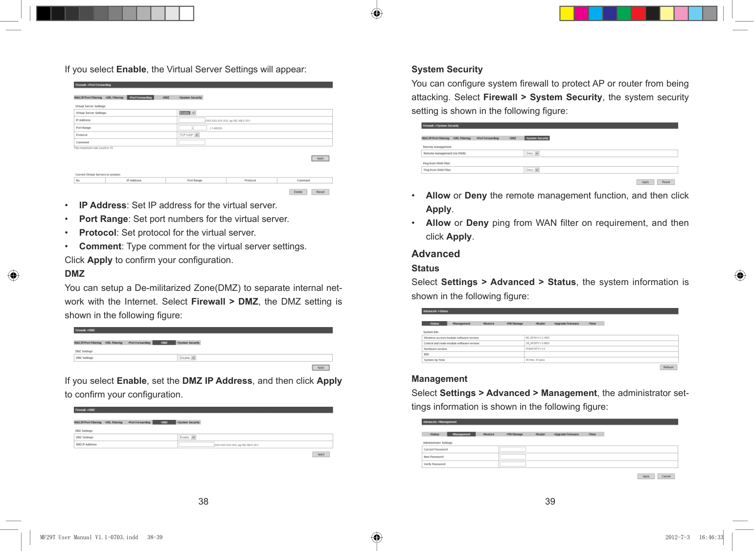
You can setup virtual servers to provide services on the Internet. Select Firewall > Port Forwarding, the virtual server settings is shown in the following figure:

36 37
| | | |---|---| | | |
MF29T User Manual V1.1-0703.indd 36-37 2012-7-3 16:46:32
###### System Security
If you select Enable, the Virtual Server Settings will appear:
You can configure system firewall to protect AP or router from being attacking. Select Firewall > System Security, the system security setting is shown in the following figure:


Advanced Status Select Settings > Advanced > Status, the system information is shown in the following figure:


Management Select Settings > Advanced > Management, the administrator settings information is shown in the following figure:
If you select Enable, set the DMZ IP Address, and then click Apply to confirm your configuration.


38 39
| | | |---|---| | | |
MF29T User Manual V1.1-0703.indd 38-39 2012-7-3 16:46:33
You can change the administrator’s password. Click Apply to confirm your configuration. Restore
Notes: Consecutive inputting wrong PIN code for three times can cause locking of UIM card. To unlock, you need PUK code. PIN code and PUK code may be offered together with the UIM card. If not, please contact with network operator. Please change default PIN code to your own as soon as possible. Router Note: Router can be used in 4G Gateway mode and Cable Broadband mode. Select Settings > Advanced > Router, the router information is shown in the following figure:
Select Settings > Advanced > Restore, click Restore to set all the settings to their factory default values, and then the device will restart automatically.

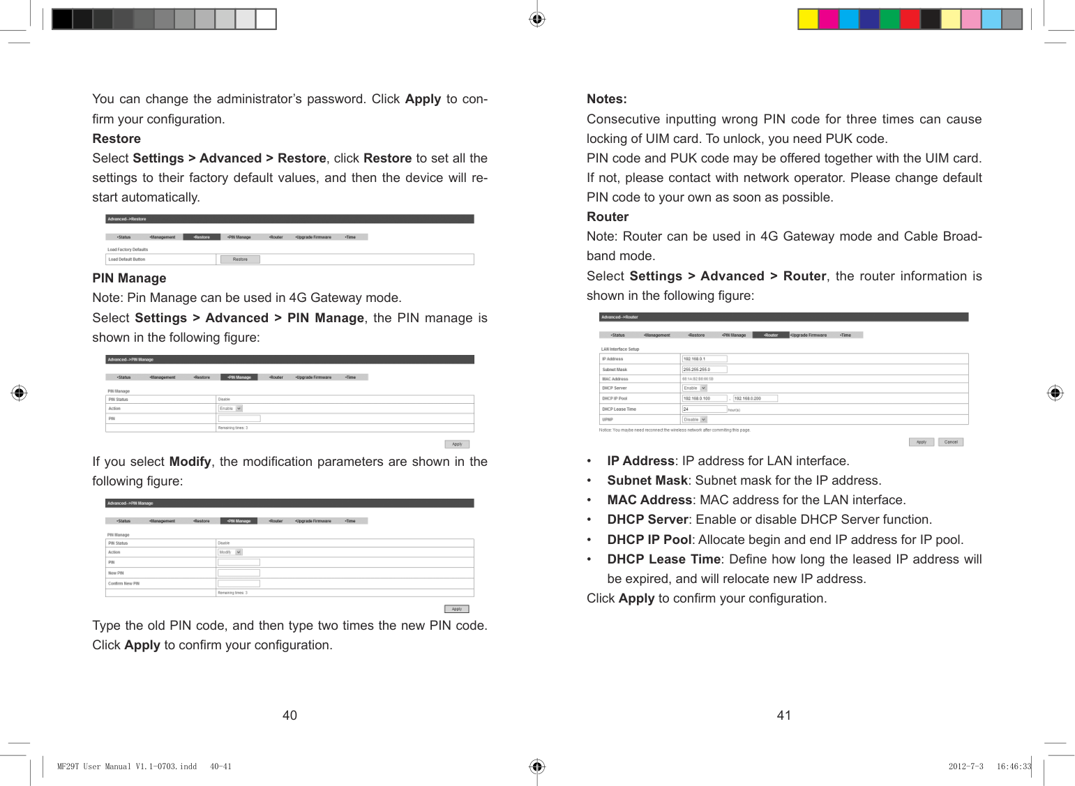
PIN Manage Note: Pin Manage can be used in 4G Gateway mode. Select Settings > Advanced > PIN Manage, the PIN manage is shown in the following figure:


If you select Modify, the modification parameters are shown in the following figure:

Click Apply to confirm your configuration.
Type the old PIN code, and then type two times the new PIN code. Click Apply to confirm your configuration.
40 41
| | | |---|---| | | |
MF29T User Manual V1.1-0703.indd 40-41 2012-7-3 16:46:33
#### U-Disk Master
###### Upgrade Firmware Select Settings > Advanced > Upgrade Firmware to upgrade the software version of the router.


Click Browse..., locate the latest software version, and then click Upgrade. Time Select Settings > Advanced > Time to set the time manually or select SNTP Auto Synchronization mode.

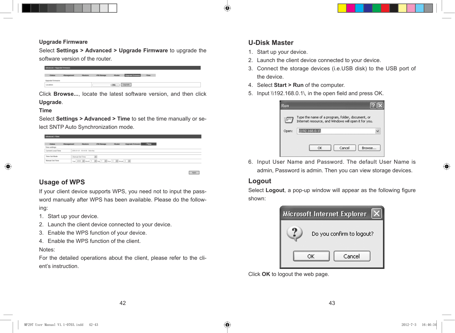
Logout Select Logout, a pop-up window will appear as the following figure shown:
#### Usage of WPS
If your client device supports WPS, you need not to input the password manually after WPS has been available. Please do the following:

Click OK to logout the web page.
42 43
| | | |---|---| | | |
MF29T User Manual V1.1-0703.indd 42-43 2012-7-3 16:46:34
Troubleshooting
Internet Related Problems
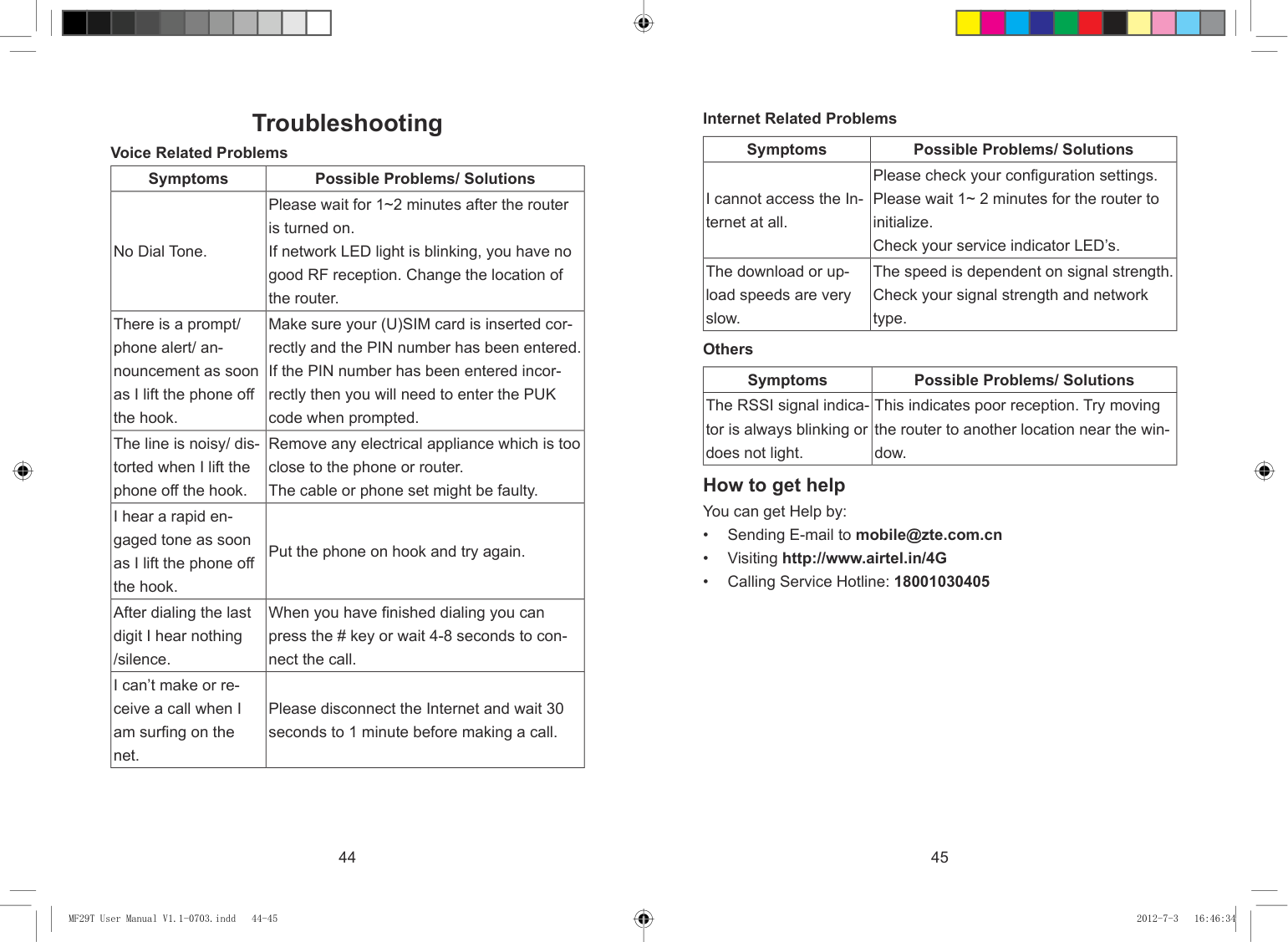
|Symptoms|Possible Problems/ Solutions| |---|---| |I cannot access the Internet at all.|Please check your configuration settings. Please wait 1~ 2 minutes for the router to initialize. Check your service indicator LED’s.| |The download or upload speeds are very slow.|The speed is dependent on signal strength. Check your signal strength and network type.|
Voice Related Problems
|Symptoms|Possible Problems/ Solutions| |---|---| |No Dial Tone.|Please wait for 1~2 minutes after the router is turned on. If network LED light is blinking, you have no good RF reception. Change the location of the router.| |There is a prompt/ phone alert/ announcement as soon as I lift the phone off the hook.|Make sure your (U)SIM card is inserted correctly and the PIN number has been entered. If the PIN number has been entered incorrectly then you will need to enter the PUK code when prompted.| |The line is noisy/ distorted when I lift the phone off the hook.|Remove any electrical appliance which is too close to the phone or router. The cable or phone set might be faulty.| |I hear a rapid engaged tone as soon as I lift the phone off the hook.|Put the phone on hook and try again.| |After dialing the last digit I hear nothing /silence.|When you have finished dialing you can press the # key or wait 4-8 seconds to connect the call.| |I can’t make or receive a call when I am surfing on the net.|Please disconnect the Internet and wait 30 seconds to 1 minute before making a call.|
Others
|Symptoms|Possible Problems/ Solutions| |---|---| |The RSSI signal indicator is always blinking or does not light.|This indicates poor reception. Try moving the router to another location near the window.|
How to get help You can get Help by:
44 45
| | | |---|---| | | |
MF29T User Manual V1.1-0703.indd 44-45 2012-7-3 16:46:34
Technical Parameters Network & Frequency Band LTE TDD:
Glossary
2600 MHz (Band 38) 2300 MHz (Band 40)
UMTS: 2100 MHz (Band 1)
900 MHz (Band 8) Power Adapter Input:
100 V~240 V (AC), 50 Hz~60 Hz Output:
+12 V±10% (DC), 1.5 A Data Service HSDPA: DL 3.6 Mb/s (Category 6)
DL 7.2 Mb/s (Category 8) DL 14.4 Mb/s (Category 10) DL 1.8 Mb/s (Category 12) DL 21 Mb/s (Category 14)
HSUPA:
UL 2 Mb/s (Category 5) UL 5.76 Mb/s (Category 6)
LTE TDD:
DL 68 Mb/s (Category 3) UL 17 Mb/s (Category 3)
###### Dimensions (W×H×D)
202 mm×160 mm×30.5 mm Weight
About 550 g
46 47
| | | |---|---| | | |
MF29T User Manual V1.1-0703.indd 46-47 2012-7-3 16:46:34
| | | | | | | | | | | | |---|---|---|---|---|---|---|---|---|---|---|
| | | | | | | | | | | | |---|---|---|---|---|---|---|---|---|---|---|
ZTE CORPORATION NO. 55, Hi-tech Road South, ShenZhen, P.R.China Postcode: 518057 Tel: +86-755- 26779999 http://www.zte.com.cn E-mail: mobile@zte.com.cn
MF29T User Manual V1.1-0703.indd 48 2012-7-3 16:46:34