
Zyxel Wre2206 Wireless N300 Range Extender User Guide
Ask AI
— answers from the official manualAnswers from the official manual.
Common questions
Common Questions
10 totalHow do I back up my WRE2206's configuration?
Go to Maintenance > Tools > Configuration, click Backup to save a backup of your current settings. This allows you to restore configurations if needed (Page 51).
How do I perform a factory reset of my WRE2206?
Press and hold the WPS button for more than 10 seconds to reload the factory-default configuration. The device will automatically reboot after resetting, defaulting username to admin and password to 1234 (Page 30).
How do I manually configure AP parameters in the WRE2206?
Navigate to the Network > Wireless LAN > AP Select screen, select 'Enter SSID manually', and type the AP's SSID into the provided field. Configure additional security settings as needed (Page 14).
How do I enable MAC address filtering on my WRE2206?
Go to Network > Wireless LAN > MAC Address List, check the 'Active' box and add the desired MAC addresses for permitted devices (Page 38).
What steps do I take if the WRE2206 turns off unexpectedly?
Check power connections, ensure power source is functioning properly and try unplugging and replugging the device. Inspect cables for damage (Page 51).
How do I change my WRE2206's password?
Go to Maintenance > System > Password, enter your current and new passwords in the respective fields and click Apply. Make sure not to use easily guessable passwords (Page 45).
Full Manual
72 pages
User’s Guide
WRE2206
Wireless N300 Range Extender
##### Default Login Details
|Web Address|http://zyxelsetup (Windows) OR http://zyxelsetup.local (Mac)| |---|---| |LAN IP Address|http://192.168.1.2| |User Name|admin| |Password|1234| |SSID|ZyXEL| |Pre-shared Key|00000000|
####### Version 1.00 Edition 2, 06/2018
Copyright © 2018 Zyxel Communications Corporation
######## IMPORTANT! READ CAREFULLY BEFORE USE. KEEP THIS GUIDE FOR FUTURE REFERENCE.
This is a User’s Guide for a system managing a series of products. Not all products support all features. Menushots and graphics in this book may differ slightly from what you see due to differences in release versions or your computer operating system. Every effort has been made to ensure that the information in this manual is accurate.
######## Related Documentation
The Quick Start Guide shows how to connect the managed device, such as the Nebula AP, gateway or security gateway.

Contents Overview
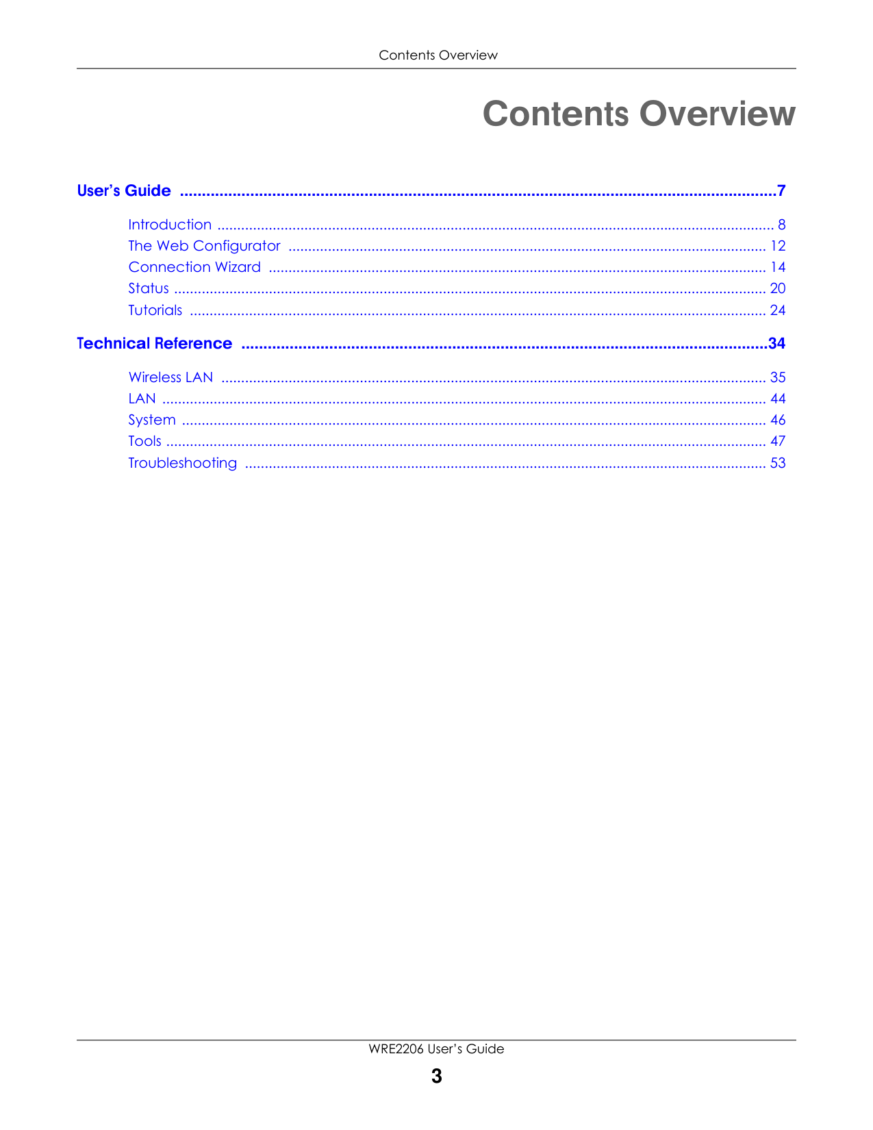
Contents Overview
######### User’s Guide ........................................................................................................................................7
Introduction ............................................................................................................................................. 8 The Web Configurator ......................................................................................................................... 12 Connection Wizard .............................................................................................................................. 14 Status ...................................................................................................................................................... 20 Tutorials .................................................................................................................................................. 24
######### Technical Reference ........................................................................................................................34
Wireless LAN .......................................................................................................................................... 35 LAN ......................................................................................................................................................... 44 System .................................................................................................................................................... 46 Tools ........................................................................................................................................................ 47 Troubleshooting .................................................................................................................................... 53
Table of Contents
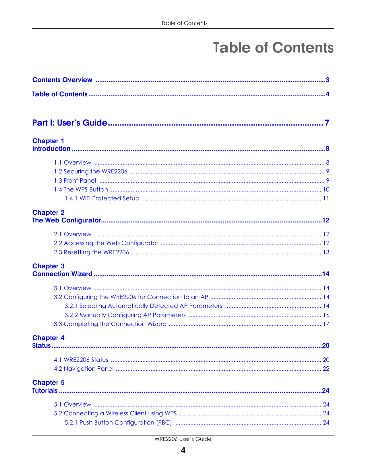
Contents Overview .............................................................................................................................3 Table of Contents.................................................................................................................................4
###### Part I: User’s Guide............................................................................................7
######### Chapter 1Introduction ..........................................................................................................................................8
######### Chapter 2The Web Configurator........................................................................................................................12
######### Chapter 3Connection Wizard............................................................................................................................14
######### Chapter 4Status...................................................................................................................................................20
######### Chapter 5Tutorials ...............................................................................................................................................24
###### Part II: Technical Reference...........................................................................34
######### Chapter 6Wireless LAN .......................................................................................................................................35
######### Chapter 7LAN......................................................................................................................................................44
######### Chapter 8System.................................................................................................................................................46
######### Chapter 9Tools ....................................................................................................................................................47
######### Chapter 10Troubleshooting..................................................................................................................................53
PART I
User’s Guide
|7| |---|
CHAPTER 1 Introduction
#### 1.1 Overview

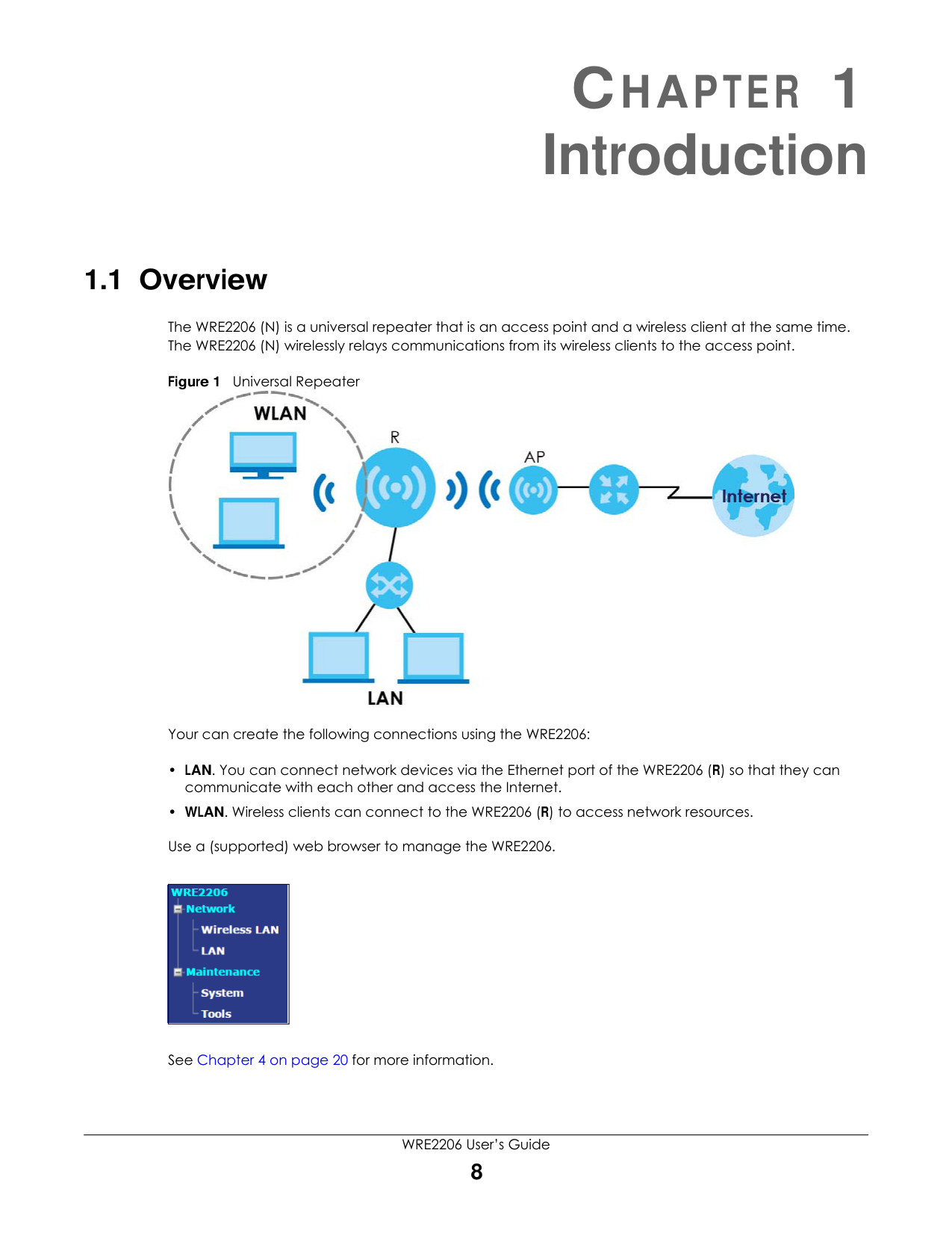
The WRE2206 (N) is a universal repeater that is an access point and a wireless client at the same time. The WRE2206 (N) wirelessly relays communications from its wireless clients to the access point.
Figure 1 Universal Repeater

Your can create the following connections using the WRE2206:
|| |---|
See Chapter 4 on page 20 for more information.
#### 1.2 Securing the WRE2206
Do the following things regularly to make the WRE2206 more secure and to manage the WRE2206 more effectively.
#### 1.3 Front Panel
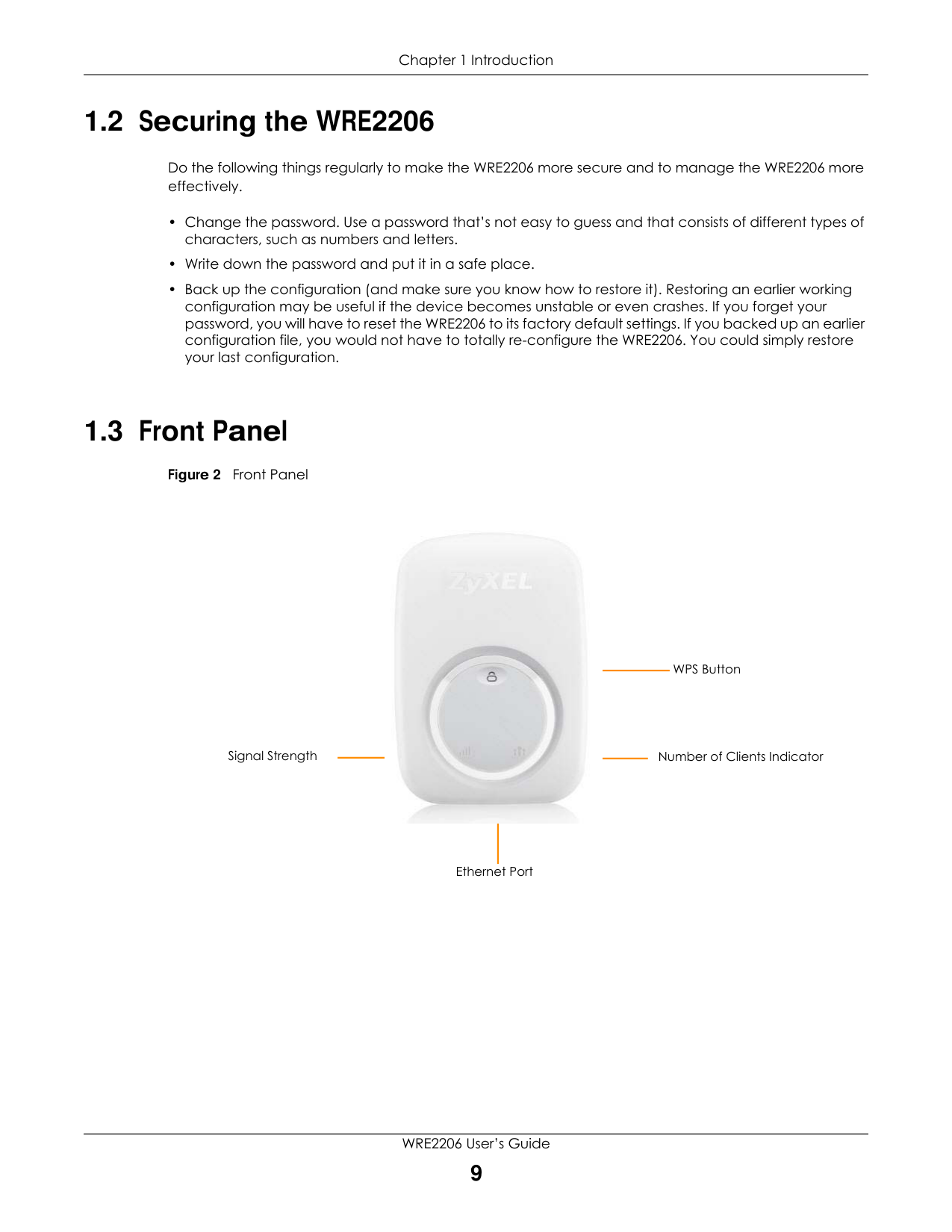
Figure 2 Front Panel
Signal Strength

WPS Button
Number of Clients Indicator
Ethernet Port
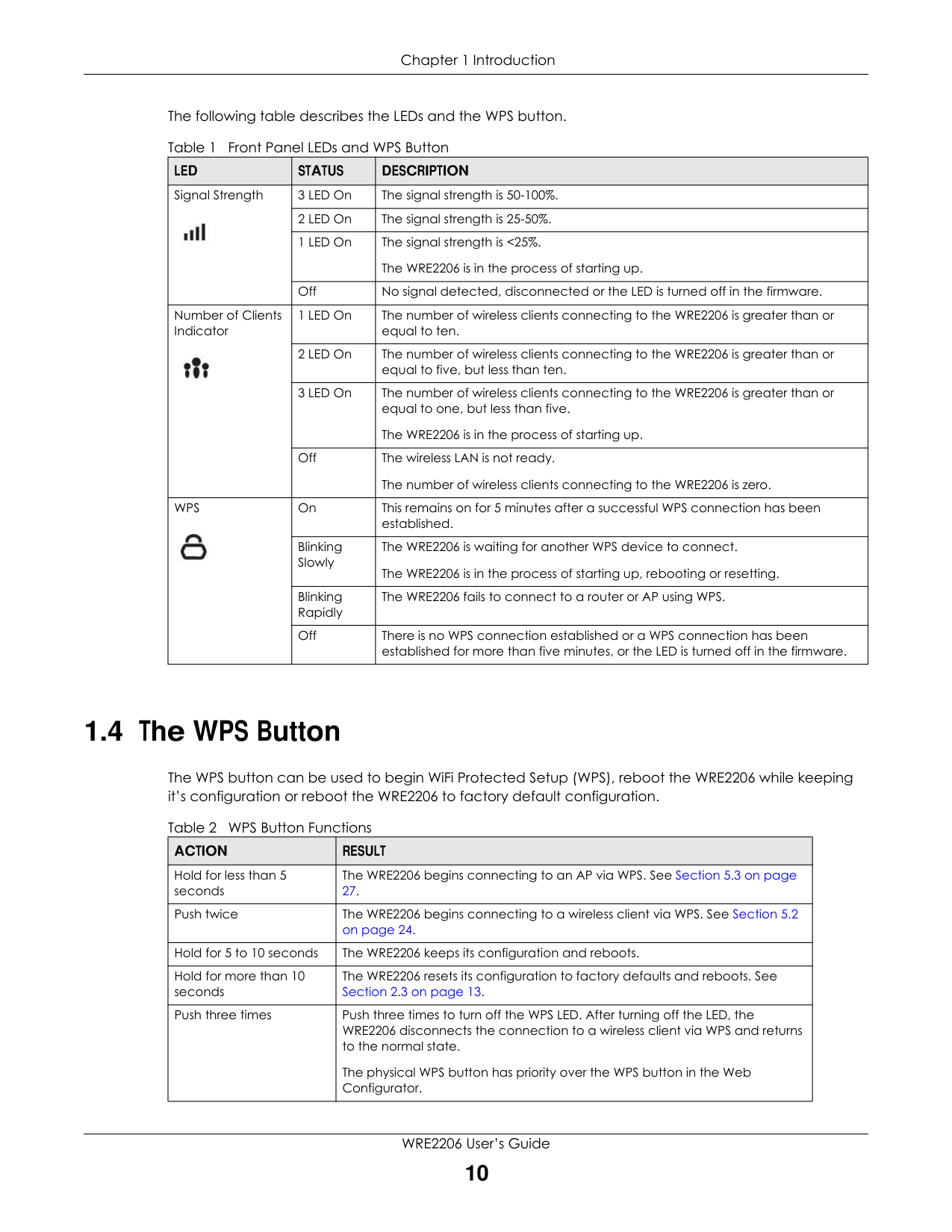
The following table describes the LEDs and the WPS button.
|LED|STATUS|DESCRIPTION| |---|---|---| |Signal Strength
|3 LED On|The signal strength is 50-100%.| |Signal Strength
|2 LED On|The signal strength is 25-50%.| |Signal Strength
|1 LED On|The signal strength is <25%. The WRE2206 is in the process of starting up.| |Signal Strength
|Off|No signal detected, disconnected or the LED is turned off in the firmware.| |Number of Clients Indicator
|1 LED On|The number of wireless clients connecting to the WRE2206 is greater than or equal to ten.| |Number of Clients Indicator
|2 LED On|The number of wireless clients connecting to the WRE2206 is greater than or equal to five, but less than ten.| |Number of Clients Indicator
|3 LED On|The number of wireless clients connecting to the WRE2206 is greater than or equal to one, but less than five.
The WRE2206 is in the process of starting up.| |Number of Clients Indicator
|Off|The wireless LAN is not ready. The number of wireless clients connecting to the WRE2206 is zero.| |WPS

|On|This remains on for 5 minutes after a successful WPS connection has been established.| |WPS

|Blinking Slowly|The WRE2206 is waiting for another WPS device to connect. The WRE2206 is in the process of starting up, rebooting or resetting.| |WPS

|Blinking Rapidly|The WRE2206 fails to connect to a router or AP using WPS.| |WPS

|Off|There is no WPS connection established or a WPS connection has been established for more than five minutes, or the LED is turned off in the firmware.|
#### 1.4 The WPS Button
The WPS button can be used to begin WiFi Protected Setup (WPS), reboot the WRE2206 while keeping it’s configuration or reboot the WRE2206 to factory default configuration.
|ACTION|RESULT| |---|---| |Hold for less than 5 seconds|The WRE2206 begins connecting to an AP via WPS. See Section 5.3 on page 27.| |Push twice|The WRE2206 begins connecting to a wireless client via WPS. See Section 5.2 on page 24.| |Hold for 5 to 10 seconds|The WRE2206 keeps its configuration and reboots.| |Hold for more than 10 seconds|The WRE2206 resets its configuration to factory defaults and reboots. See Section 2.3 on page 13.| |Push three times|Push three times to turn off the WPS LED. After turning off the LED, the WRE2206 disconnects the connection to a wireless client via WPS and returns to the normal state.
The physical WPS button has priority over the WPS button in the Web Configurator.|
###### 1.4.1 WiFi Protected Setup
Your WRE2206 supports Wi-Fi Protected Setup (WPS), which is an easy way to set up a secure wireless network. WPS is an industry standard specification, defined by the WiFi Alliance.
WPS allows you to quickly set up a wireless network with strong security, without having to configure security settings manually. Each WPS connection works between two devices. Both devices must support WPS (check each device’s documentation to make sure).
Depending on the devices you have, you can either press a button (recommended) on the device itself, or in its configuration utility or enter a PIN (a unique Personal Identification Number that allows one device to authenticate the other) in each of the two devices. When WPS is activated on a device, it has two minutes to find another device that also has WPS activated. Then, the two devices connect and set up a secure network by themselves.
For more information on using WPS, see Section 5.2 on page 24.
CHAPTER 2 The Web Configurator
#### 2.1 Overview
This chapter describes how to access the WRE2206 Web Configurator and provides an overview of its screens.
The Web Configurator is an HTML-based management interface that allows easy setup and management of the WRE2206 via Internet browser. Use Internet Explorer 6.0 and later versions, Mozilla Firefox 3 and later versions, or Safari 2.0 and later versions. The recommended screen resolution is 1024 by 768 pixels.
In order to use the Web Configurator you need to allow:
Refer to Chapter 10 Troubleshooting to see how to make sure these functions are allowed in Internet Explorer.
#### 2.2 Accessing the Web Configurator
Note: Your computer or the part of your network connected to the WRE2206 must be on the same subnet as the WRE2206. The WRE2206’s DHCP server is enabled before the WRE2206 is associated with your AP or wireless router and disabled after association. If this is the first time you are accessing your WRE2206, you can configure your computer as a DHCP client (computer factory default) so it will get an IP address automatically from the WRE2206. After the WRE2206 is associated with your wireless router, your computer will get its IP address from the wireless router.
Chapter 2 The Web Configurator

#### 2.3 Resetting the WRE2206
If you forget your password or IP address, or you cannot access the Web Configurator, press the WPS button for more than 10 seconds to reload the factory-default configuration file. This means that you will lose all configurations that you had previously saved, the username will be reset to admin and password will be reset to 1234. The IP address will be reset to “192.168.1.2”.
CHAPTER 3 Connection Wizard
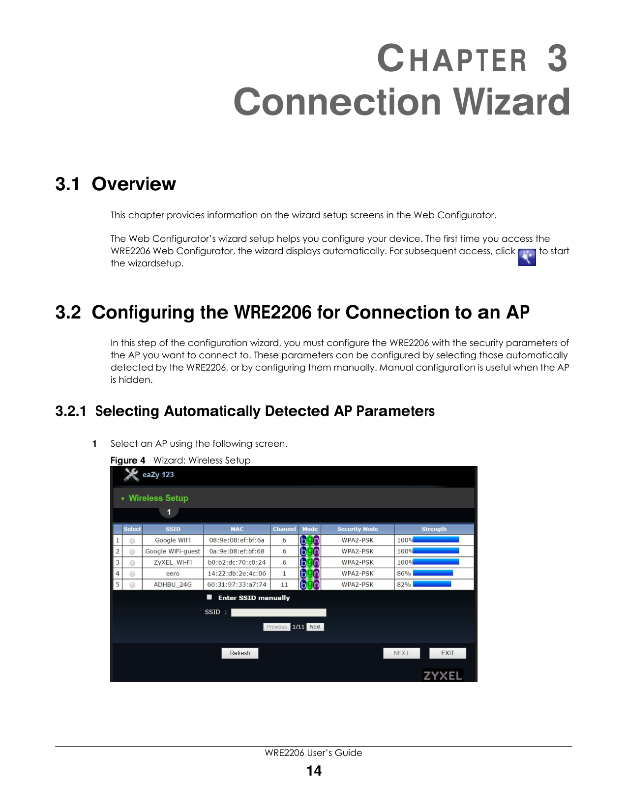
#### 3.1 Overview
This chapter provides information on the wizard setup screens in the Web Configurator.
The Web Configurator’s wizard setup helps you configure your device. The first time you access the WRE2206 Web Configurator, the wizard displays automatically. For subsequent access, click to start the wizardsetup.

#### 3.2 Configuring the WRE2206 for Connection to an AP
In this step of the configuration wizard, you must configure the WRE2206 with the security parameters of the AP you want to connect to. These parameters can be configured by selecting those automatically detected by the WRE2206, or by configuring them manually. Manual configuration is useful when the AP is hidden.
###### 3.2.1 Selecting Automatically Detected AP Parameters
|| |---|
The following table describes the labels in this screen.
|LABEL|DESCRIPTION| |---|---| |Select|Use the radio button to select the wireless device to which you want to connect.| |SSID|This displays the Service Set IDentity of the wireless device. The SSID is a unique name that identifies a wireless network. All devices in a wireless network must use the same SSID.| |MAC|This displays the MAC address of the wireless device.| |Channel|This displays the channel number used by this wireless device.| |Mode|This displays which IEEE 802.11b/g/n wireless networking standards the wireless device supports.| |Security Mode|This displays the type of security configured on the wireless device. When no is shown, no security is configured and you can connect to it without a password.| |Strength|This displays the strength of the wireless signal. The signal strength mainly depends on the antenna output power and the distance between your WRE2206 and this device.| |Enter SSID manually|Select this to setup the AP manually.| |SSID|If Enter SSID manually is selected, use this field to type the SSID of the AP. This is useful when the AP’s SSID is hidden.| |Refresh|Click this to search for available wireless devices within transmission range and update this table.| |BACK|Click this to go back to the previous step in the wizard.| |NEXT|Click this to start the next step in the AP setup process.| |EXIT|Click this to exit the wizard.| |Previous|Click this to see the previous page of APs.| |Next|Click this to see the next page of APs.|
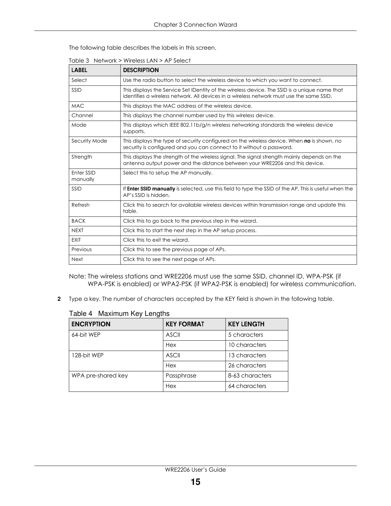
Note: The wireless stations and WRE2206 must use the same SSID, channel ID, WPA-PSK (if WPA-PSK is enabled) or WPA2-PSK (if WPA2-PSK is enabled) for wireless communication.
|ENCRYPTION|KEY FORMAT|KEY LENGTH| |---|---|---| |64-bit WEP|ASCII|5 characters| |64-bit WEP|Hex|10 characters| |128-bit WEP|ASCII|13 characters| |128-bit WEP|Hex|26 characters| |WPA pre-shared key|Passphrase|8-63 characters| |WPA pre-shared key|Hex|64 characters|
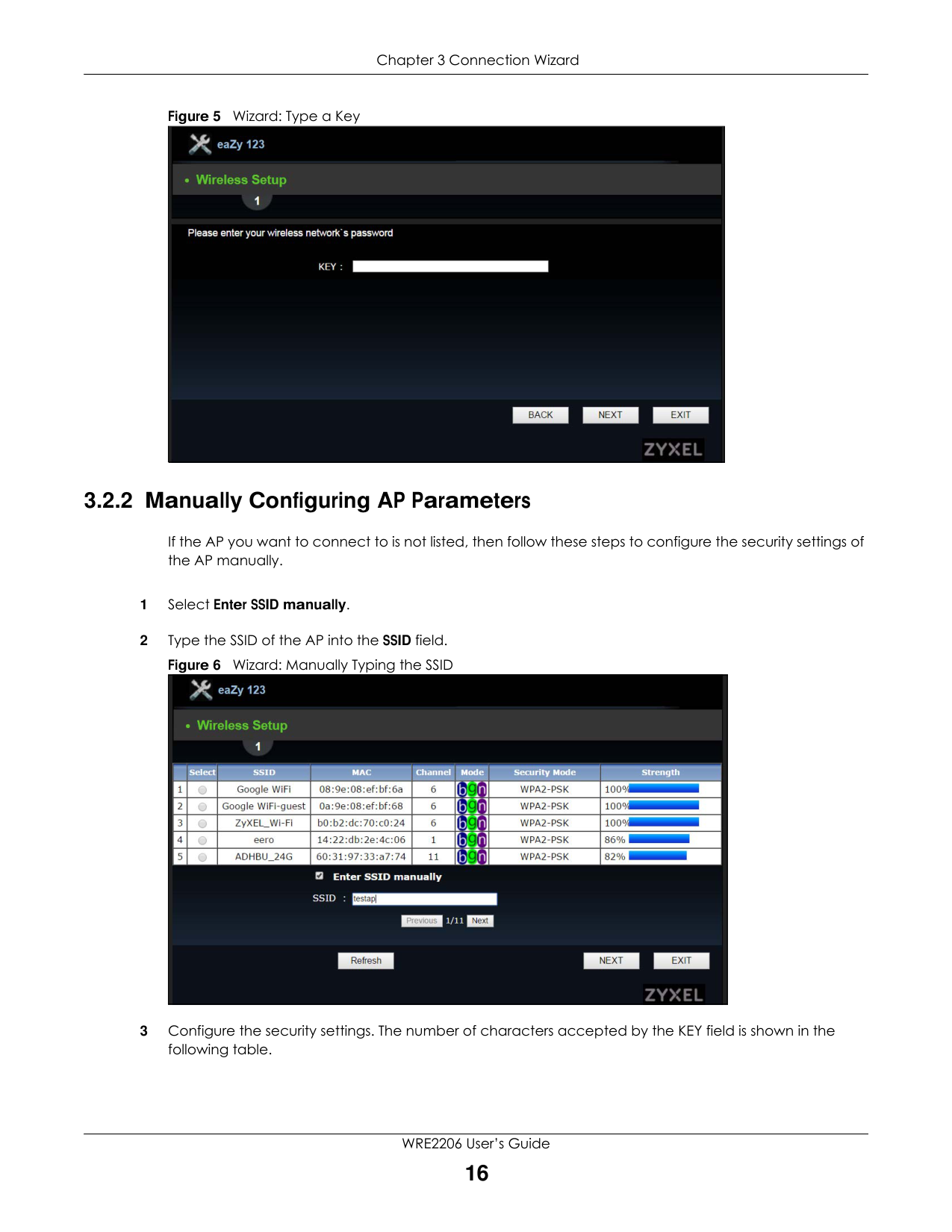
Figure 5 Wizard: Type a Key
|| |---|
###### 3.2.2 Manually Configuring AP Parameters
If the AP you want to connect to is not listed, then follow these steps to configure the security settings of the AP manually.
|| |---|
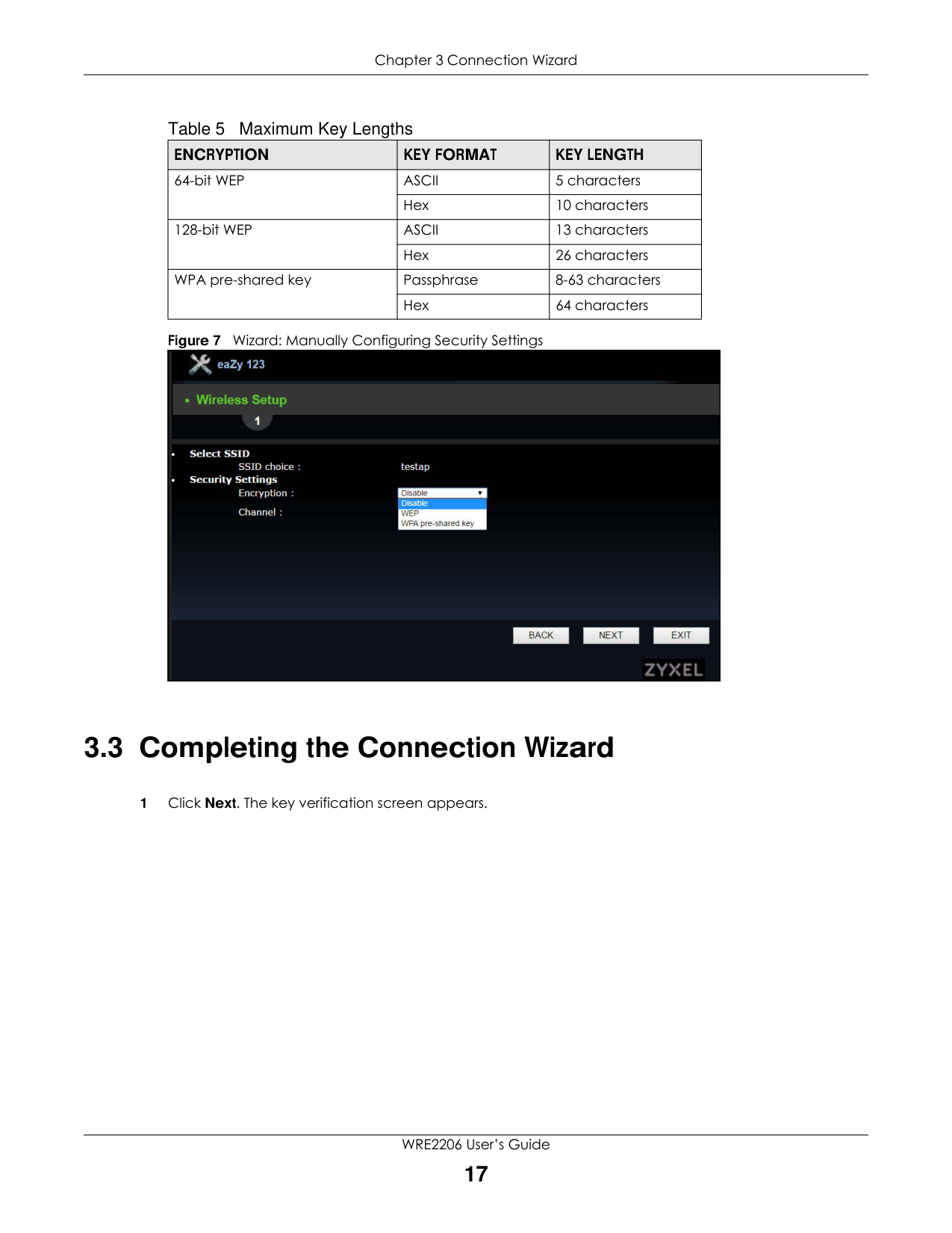
Table 5 Maximum Key Lengths
|ENCRYPTION|KEY FORMAT|KEY LENGTH| |---|---|---| |64-bit WEP|ASCII|5 characters| |64-bit WEP|Hex|10 characters| |128-bit WEP|ASCII|13 characters| |128-bit WEP|Hex|26 characters| |WPA pre-shared key|Passphrase|8-63 characters| |WPA pre-shared key|Hex|64 characters|
|| |---|
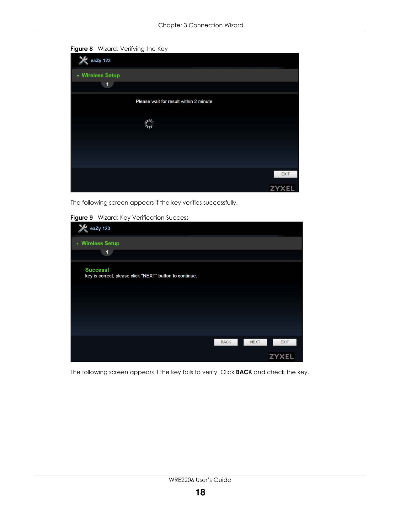
#### 3.3 Completing the Connection Wizard
The following screen appears if the key verifies successfully.
|| |---|
|| |---|
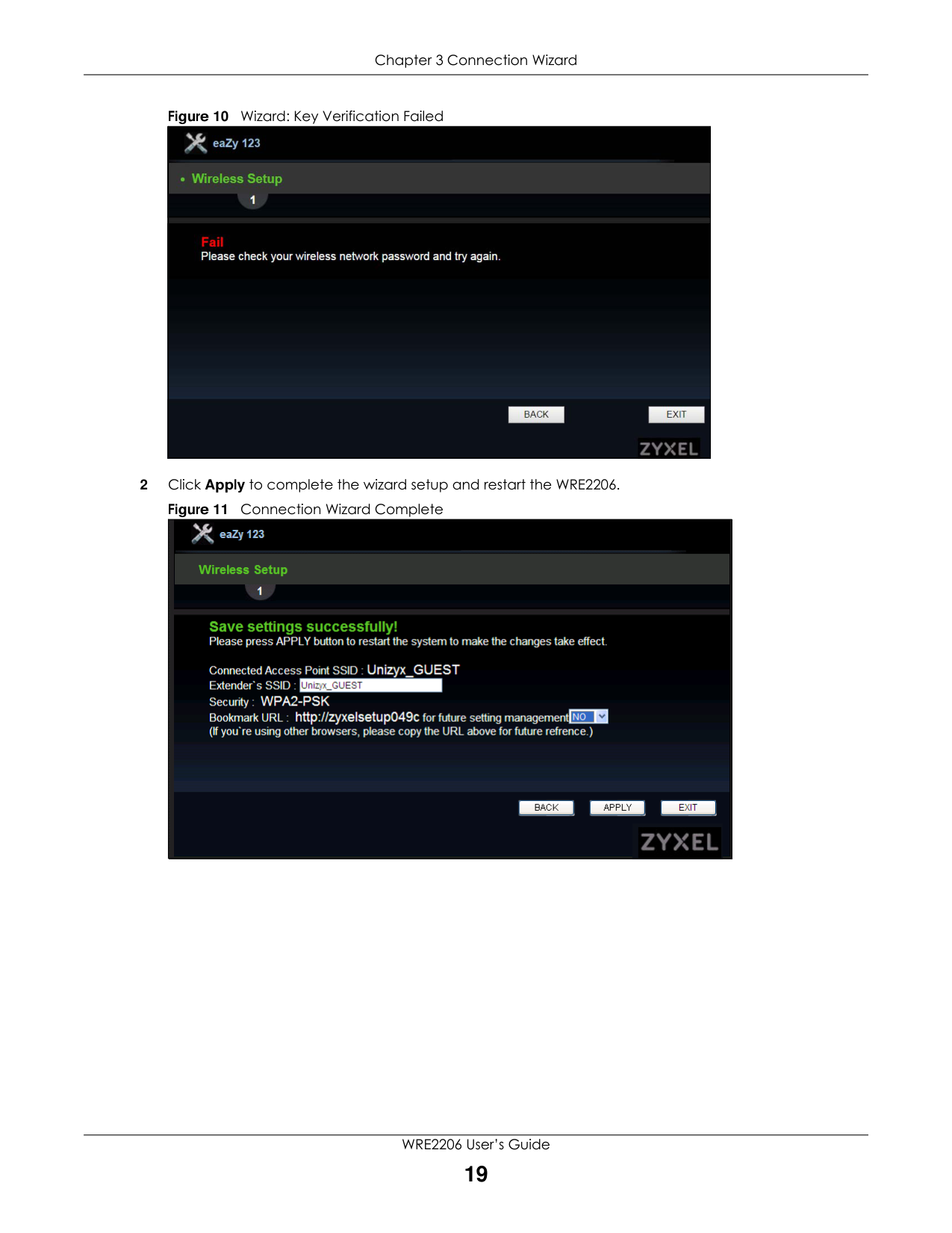
The following screen appears if the key fails to verify. Click BACK and check the key.
############# Figure 10 Wizard: Key Verification Failed
|| |---|
2 Click Apply to complete the wizard setup and restart the WRE2206.
############# Figure 11 Connection Wizard Complete
|| |---|
CHAPTER 4 Status
#### 4.1 WRE2206 Status
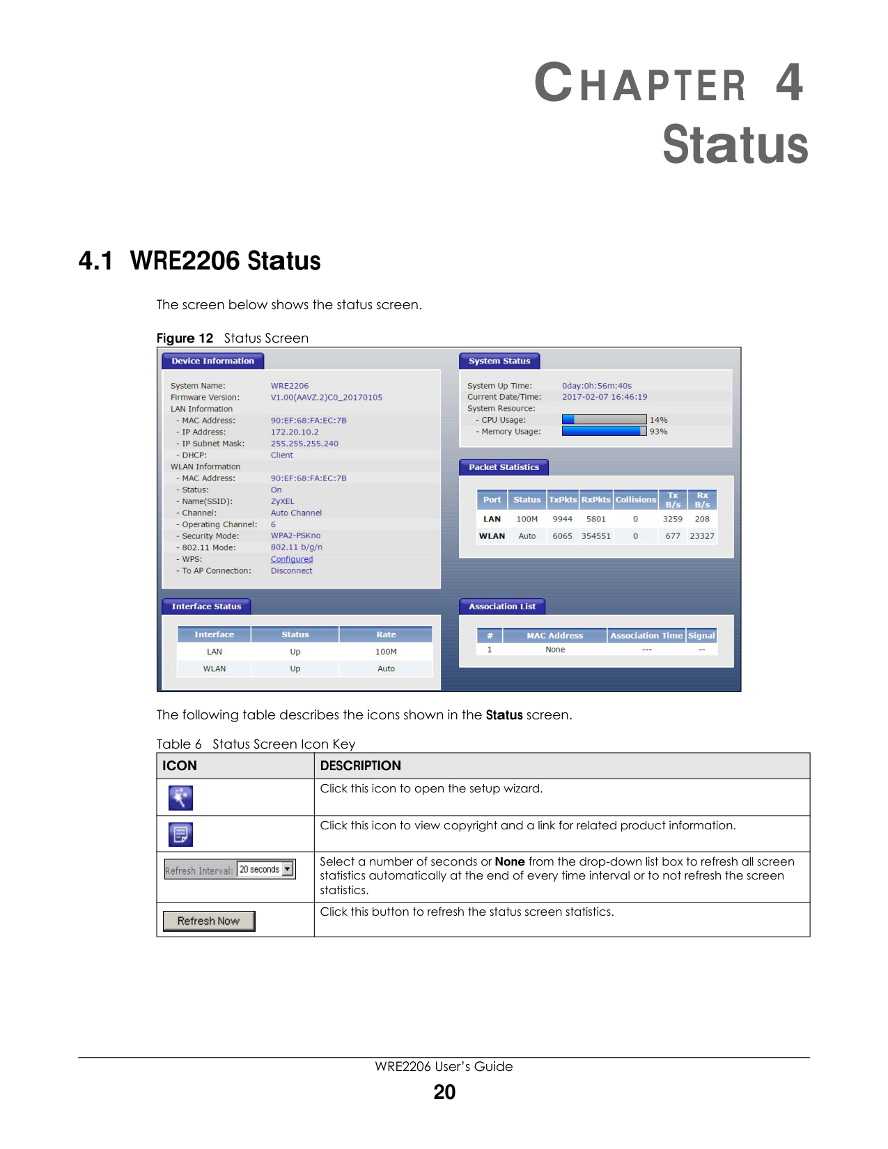
The screen below shows the status screen.
Figure 12 Status Screen
|| |---|
The following table describes the icons shown in the Status screen.
|ICON|DESCRIPTION| |---|---| ||Click this icon to open the setup wizard.| ||Click this icon to view copyright and a link for related product information.| ||| |---|
|Select a number of seconds or None from the drop-down list box to refresh all screen statistics automatically at the end of every time interval or to not refresh the screen statistics.| ||Click this button to refresh the status screen statistics.|
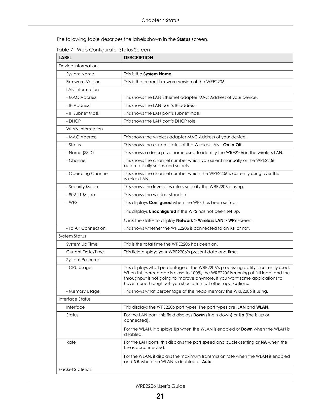
The following table describes the labels shown in the Status screen.
|LABEL|DESCRIPTION| |---|---| |Device Information|Device Information| |System Name|This is the System Name.| |Firmware Version|This is the current firmware version of the WRE2206.| |LAN Information|LAN Information| |- MAC Address|This shows the LAN Ethernet adapter MAC Address of your device.| |- IP Address|This shows the LAN port’s IP address.| |- IP Subnet Mask|This shows the LAN port’s subnet mask.| |- DHCP|This shows the LAN port’s DHCP role.| |WLAN Information|WLAN Information| |- MAC Address|This shows the wireless adapter MAC Address of your device.| |- Status|This shows the current status of the Wireless LAN - On or Off.| |- Name (SSID)|This shows a descriptive name used to identify the WRE2206 in the wireless LAN.| |- Channel|This shows the channel number which you select manually or the WRE2206 automatically scans and selects.| |- Operating Channel|This shows the channel number which the WRE2206 is currently using over the wireless LAN.| |- Security Mode|This shows the level of wireless security the WRE2206 is using.| |- 802.11 Mode|This shows the wireless standard.| |- WPS|This displays Configured when the WPS has been set up. This displays Unconfigured if the WPS has not been set up. Click the status to display Network > Wireless LAN > WPS screen.| |- To AP Connection|This shows whether the WRE2206 is connected to an AP or not.| |System Status|System Status| |System Up Time|This is the total time the WRE2206 has been on.| |Current Date/Time|This field displays your WRE2206’s present date and time.| |System Resource|System Resource| |- CPU Usage|This displays what percentage of the WRE2206’s processing ability is currently used. When this percentage is close to 100%, the WRE2206 is running at full load, and the throughput is not going to improve anymore. If you want some applications to have more throughput, you should turn off other applications.| |- Memory Usage|This shows what percentage of the heap memory the WRE2206 is using.| |Interface Status|Interface Status|
|Interface|This displays the WRE2206 port types. The port types are: LAN and WLAN.| |Status|For the LAN port, this field displays Down (line is down) or Up (line is up or connected).
For the WLAN, it displays Up when the WLAN is enabled or Down when the WLAN is disabled.| |Rate|For the LAN ports, this displays the port speed and duplex setting or NA when the line is disconnected.
For the WLAN, it displays the maximum transmission rate when the WLAN is enabled and NA when the WLAN is disabled or Auto.| |Packet Statistics|Packet Statistics|
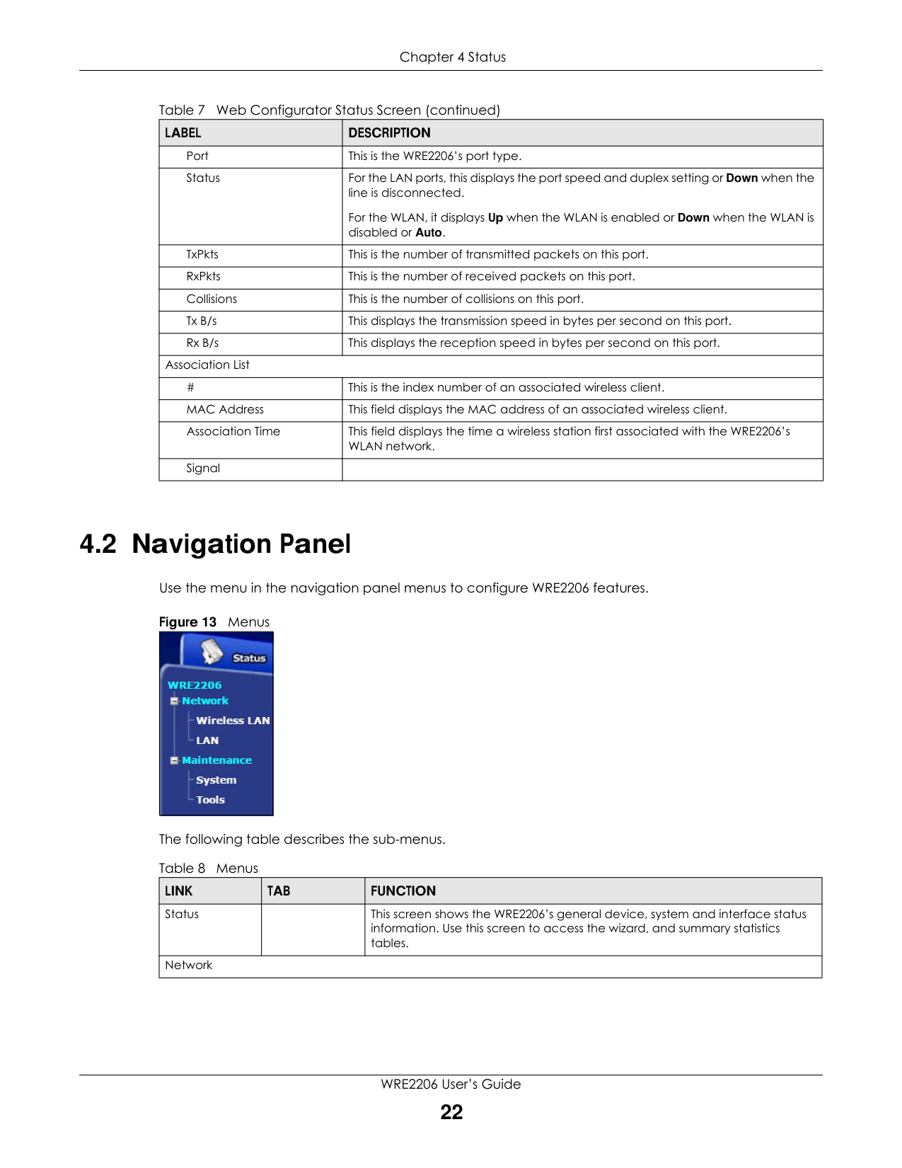
|LABEL|DESCRIPTION| |---|---| |Port|This is the WRE2206’s port type.| |Status|For the LAN ports, this displays the port speed and duplex setting or Down when the line is disconnected.
For the WLAN, it displays Up when the WLAN is enabled or Down when the WLAN is disabled or Auto.| |TxPkts|This is the number of transmitted packets on this port.| |RxPkts|This is the number of received packets on this port.| |Collisions|This is the number of collisions on this port.| |Tx B/s|This displays the transmission speed in bytes per second on this port.| |Rx B/s|This displays the reception speed in bytes per second on this port.| |Association List|Association List| |#|This is the index number of an associated wireless client.| |MAC Address|This field displays the MAC address of an associated wireless client.| |Association Time|This field displays the time a wireless station first associated with the WRE2206’s WLAN network.| |Signal| |
#### 4.2 Navigation Panel
Use the menu in the navigation panel menus to configure WRE2206 features.
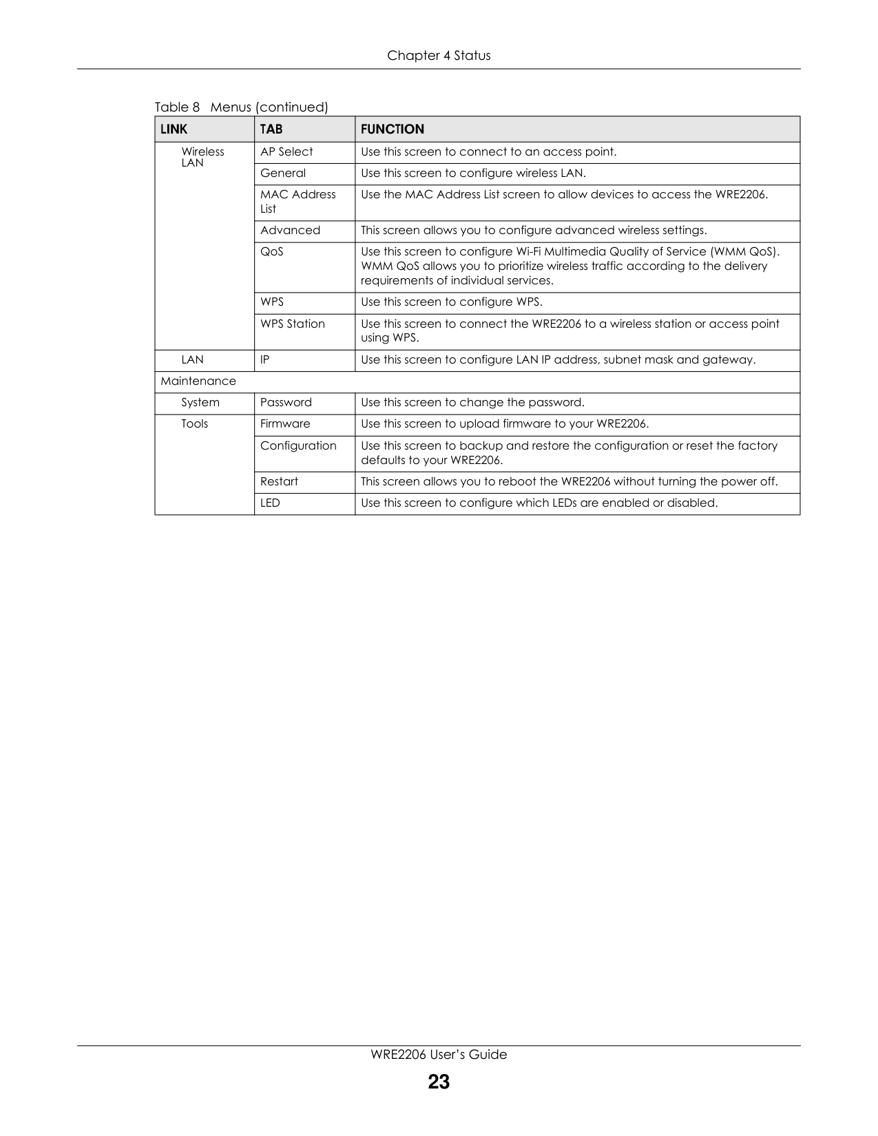
############ Figure 13 Menus
|| |---|
The following table describes the sub-menus.
|LINK|TAB|FUNCTION| |---|---|---| |Status| |This screen shows the WRE2206’s general device, system and interface status information. Use this screen to access the wizard, and summary statistics tables.| |Network|Network|Network|
############# Table 8 Menus (continued)
|LINK|TAB|FUNCTION| |---|---|---| |Wireless LAN|AP Select|Use this screen to connect to an access point.| |Wireless LAN|General|Use this screen to configure wireless LAN.| |Wireless LAN|MAC Address List|Use the MAC Address List screen to allow devices to access the WRE2206.| |Wireless LAN|Advanced|This screen allows you to configure advanced wireless settings.| |Wireless LAN|QoS|Use this screen to configure Wi-Fi Multimedia Quality of Service (WMM QoS). WMM QoS allows you to prioritize wireless traffic according to the delivery requirements of individual services.| |Wireless LAN|WPS|Use this screen to configure WPS.| |Wireless LAN|WPS Station|Use this screen to connect the WRE2206 to a wireless station or access point using WPS.| |LAN|IP|Use this screen to configure LAN IP address, subnet mask and gateway.| |Maintenance|Maintenance|Maintenance| |System|Password|Use this screen to change the password.| |Tools|Firmware|Use this screen to upload firmware to your WRE2206.| |Tools|Configuration|Use this screen to backup and restore the configuration or reset the factory defaults to your WRE2206.|
|Tools|Restart|This screen allows you to reboot the WRE2206 without turning the power off.| |Tools|LED|Use this screen to configure which LEDs are enabled or disabled.|
CHAPTER 5 Tutorials
#### 5.1 Overview
This chapter provides tutorials for your WRE2206 as follows:
#### 5.2 Connecting a Wireless Client using WPS
This section gives you an example of how to connect a client to the WRE2206 using WPS.
There are two WPS methods for creating a secure connection. This tutorial shows you how to do both.
Note: The wireless client must be a WPS-aware device (for example, a WPS USB adapter or PCI card).
###### 5.2.1 Push Button Configuration (PBC)
This section gives you an example of how to set up a wireless network using WPS PBC. This example uses the WRE2206 as the registrar and NWD210N as the wireless client in a notebook.
Note: Your WRE2206 has a WPS button, as well as a Start PBC button in the Web Configurator. Both buttons have exactly the same function; you can use one or the other.
Note: It doesn’t matter whether you press the button on the WRE2206 or the wireless client first. WPS times out after two minutes of pressing a button. Press the button on the second device within about a minute of the first, then wait two minutes for the WPS configuration to complete.
The WRE2206 sends the proper configuration settings to the wireless client. Then the wireless client is able to communicate with the WRE2206 securely.
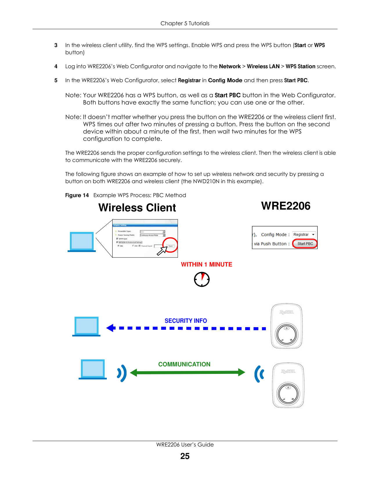
The following figure shows an example of how to set up wireless network and security by pressing a button on both WRE2206 and wireless client (the NWD210N in this example).
Figure 14 Example WPS Process: PBC Method
#### Wireless Client WRE2206
|| |---|

WITHIN 1 MINUTE
SECURITY INFO


COMMUNICATION

|| |---|


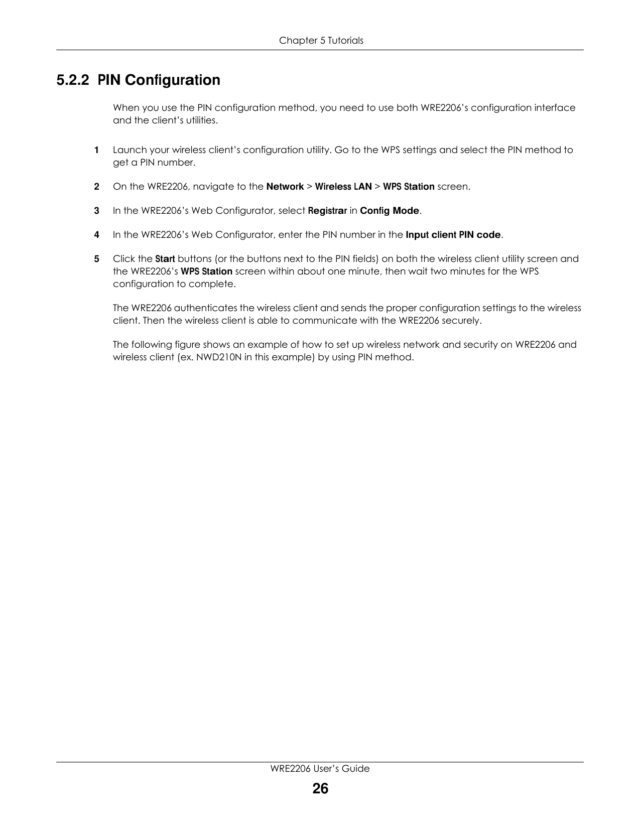
###### 5.2.2 PIN Configuration
When you use the PIN configuration method, you need to use both WRE2206’s configuration interface and the client’s utilities.
The WRE2206 authenticates the wireless client and sends the proper configuration settings to the wireless client. Then the wireless client is able to communicate with the WRE2206 securely.
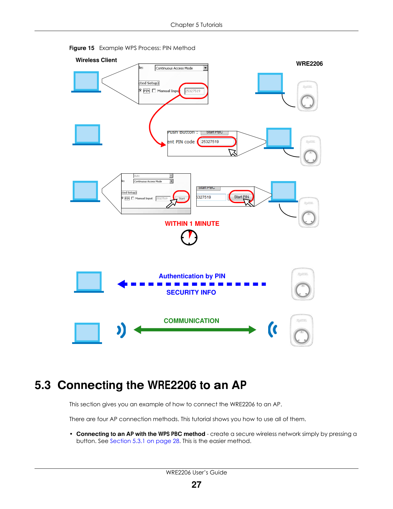
The following figure shows an example of how to set up wireless network and security on WRE2206 and wireless client (ex. NWD210N in this example) by using PIN method.
Figure 15 Example WPS Process: PIN Method
Wireless Client
WRE2206
|| |---|


|| |---|

|
| |---| | |


|| |---|

WITHIN 1 MINUTE


Authentication by PIN
SECURITY INFO

########## COMMUNICATION


#### 5.3 Connecting the WRE2206 to an AP
This section gives you an example of how to connect the WRE2206 to an AP.
There are four AP connection methods. This tutorial shows you how to use all of them.
###### 5.3.1 Connecting to an AP with the WPS PBC Method
This section gives you an example of how to connect to an AP using WPS PBC. This example uses the WRE2206 as the enrollee and an AP as the registrar.
Note: Your WRE2206 has a WPS button located on its panel, as well as a WPS button in its configuration utility. Both buttons have exactly the same function; you can use one or the other.
Note: It doesn’t matter whether you press the button on the WRE2206 or the AP first. WPS times out after two minutes of pressing a button. Press the button on the second device within about a minute of the first, then wait two minutes for the WPS configuration to complete.
The AP sends the proper configuration settings to the WRE2206. Then the WRE2206 is able to communicate with the AP securely.
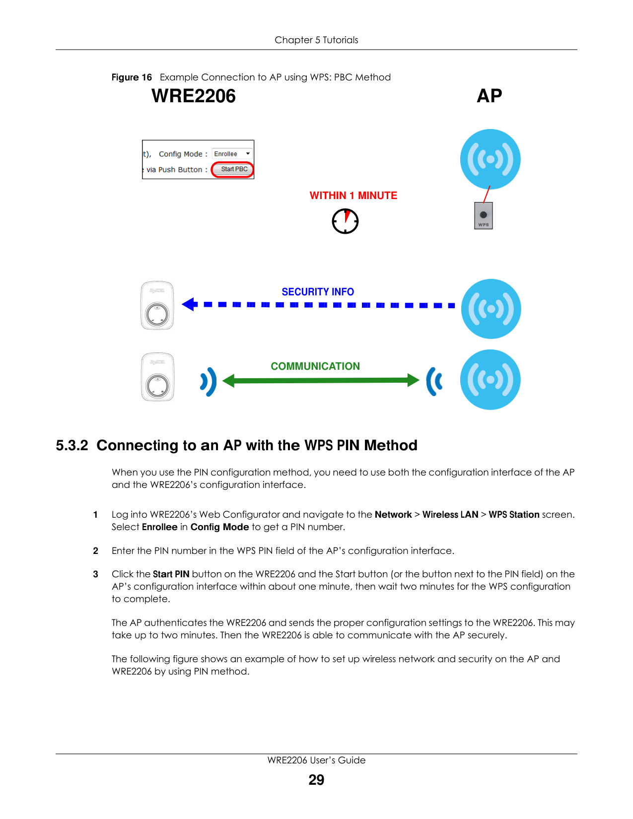
The following figure shows an example of how to set up wireless network and security by pressing a button on both WRE2206 and AP.
Figure 16 Example Connection to AP using WPS: PBC Method
#### WRE2206
#### AP

|| |---|
WITHIN 1 MINUTE
|| |---|


SECURITY INFO


COMMUNICATION


###### 5.3.2 Connecting to an AP with the WPS PIN Method
When you use the PIN configuration method, you need to use both the configuration interface of the AP and the WRE2206’s configuration interface.
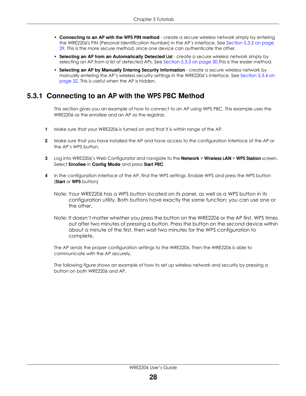
The AP authenticates the WRE2206 and sends the proper configuration settings to the WRE2206. This may take up to two minutes. Then the WRE2206 is able to communicate with the AP securely.
The following figure shows an example of how to set up wireless network and security on the AP and WRE2206 by using PIN method.
Figure 17 Example Connection to AP using WPS: PIN Method
APWRE2206
|| |---|


|| |---|


|
| |---| | |
|
51382179| |---|


WITHIN 1 MINUTE


Authentication by PIN

SECURITY INFO


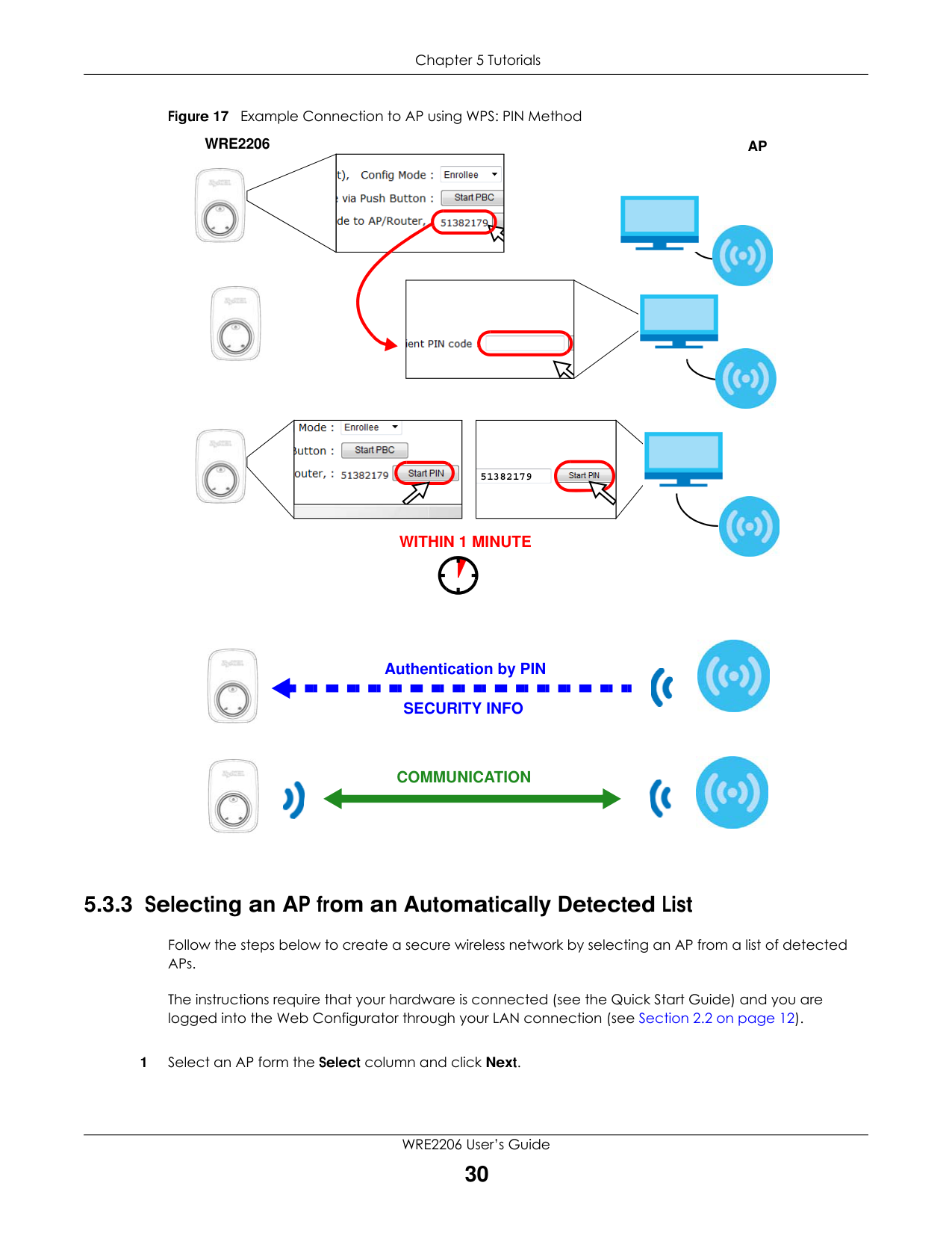
COMMUNICATION


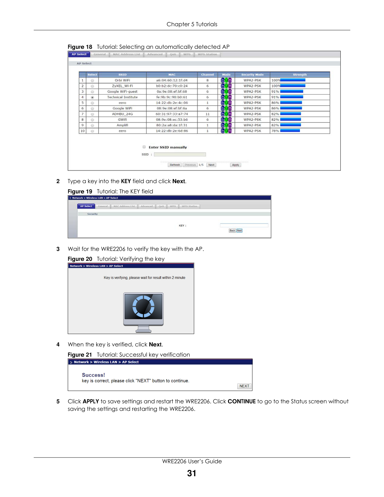
###### 5.3.3 Selecting an AP from an Automatically Detected List
Follow the steps below to create a secure wireless network by selecting an AP from a list of detected APs.
The instructions require that your hardware is connected (see the Quick Start Guide) and you are logged into the Web Configurator through your LAN connection (see Section 2.2 on page 12).
2 Type a key into the KEY field and click Next.
3 Wait for the WRE2206 to verify the key with the AP.
4 When the key is verified, click Next.
|| |---|
|| |---|
|| |---|
|| |---|
|| |---|
###### 5.3.4 Selecting an AP by Manually Entering Security Information
This example shows you how to configure wireless security settings with the following parameters on your WRE2206.
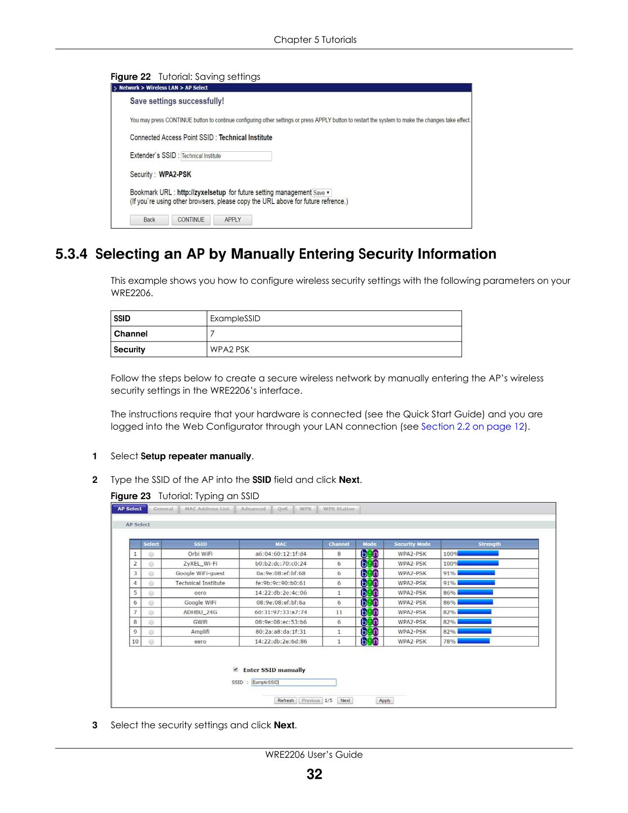
|SSID|ExampleSSID| |---|---| |Channel|7| |Security|WPA2 PSK|
Follow the steps below to create a secure wireless network by manually entering the AP’s wireless security settings in the WRE2206’s interface.
The instructions require that your hardware is connected (see the Quick Start Guide) and you are logged into the Web Configurator through your LAN connection (see Section 2.2 on page 12).
|| |---|
############# Figure 24 Tutorial: Security Settings
|| |---|
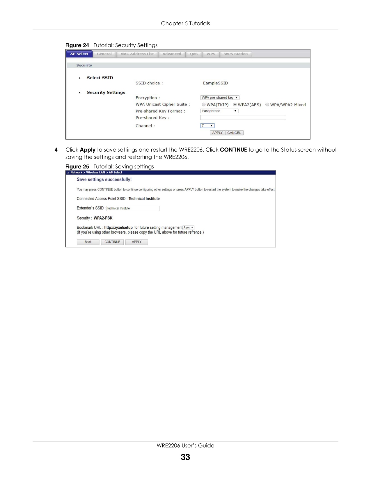
4 Click Apply to save settings and restart the WRE2206. Click CONTINUE to go to the Status screen without
saving the settings and restarting the WRE2206.
############# Figure 25 Tutorial: Saving settings
|| |---|
PART II
Technical Reference
|34| |---|
CHAPTER 6 Wireless LAN
#### 6.1 Overview
This chapter discusses how to configure the wireless network settings in your WRE2206. See Section 1.1 on page 8 for an overview of wireless networks.
#### 6.2 What You Can Do

#### 6.3 What You Should Know
Every wireless network must follow these basic guidelines.
Like radio stations or television channels, each wireless network uses a specific channel, or frequency, to send and receive information.
Security stops unauthorized devices from using the wireless network. It can also protect the information that is sent in the wireless network.
###### 6.3.1 Wireless Security Overview
The following sections introduce different types of wireless security you can set up in the wireless network.
######## 6.3.1.1 MAC Address List
Every wireless client has a unique identification number, called a MAC address.1 A MAC address is usually written using twelve hexadecimal characters2; for example, 00A0C5000002 or 00:A0:C5:00:00:02. To get the MAC address for each wireless client, see the appropriate User’s Guide or other documentation.
You can use the MAC Address List to tell the AP which wireless clients are allowed to use the wireless network. If a wireless client is allowed to use the wireless network, it still has to have the correct settings (SSID, channel, and security). If a wireless client is not allowed to use the wireless network, it does not matter if it has the correct settings.
This type of security does not protect the information that is sent in the wireless network. Furthermore, there are ways for unauthorized devices to get the MAC address of an authorized wireless client. Then, they can use that MAC address to use the wireless network.
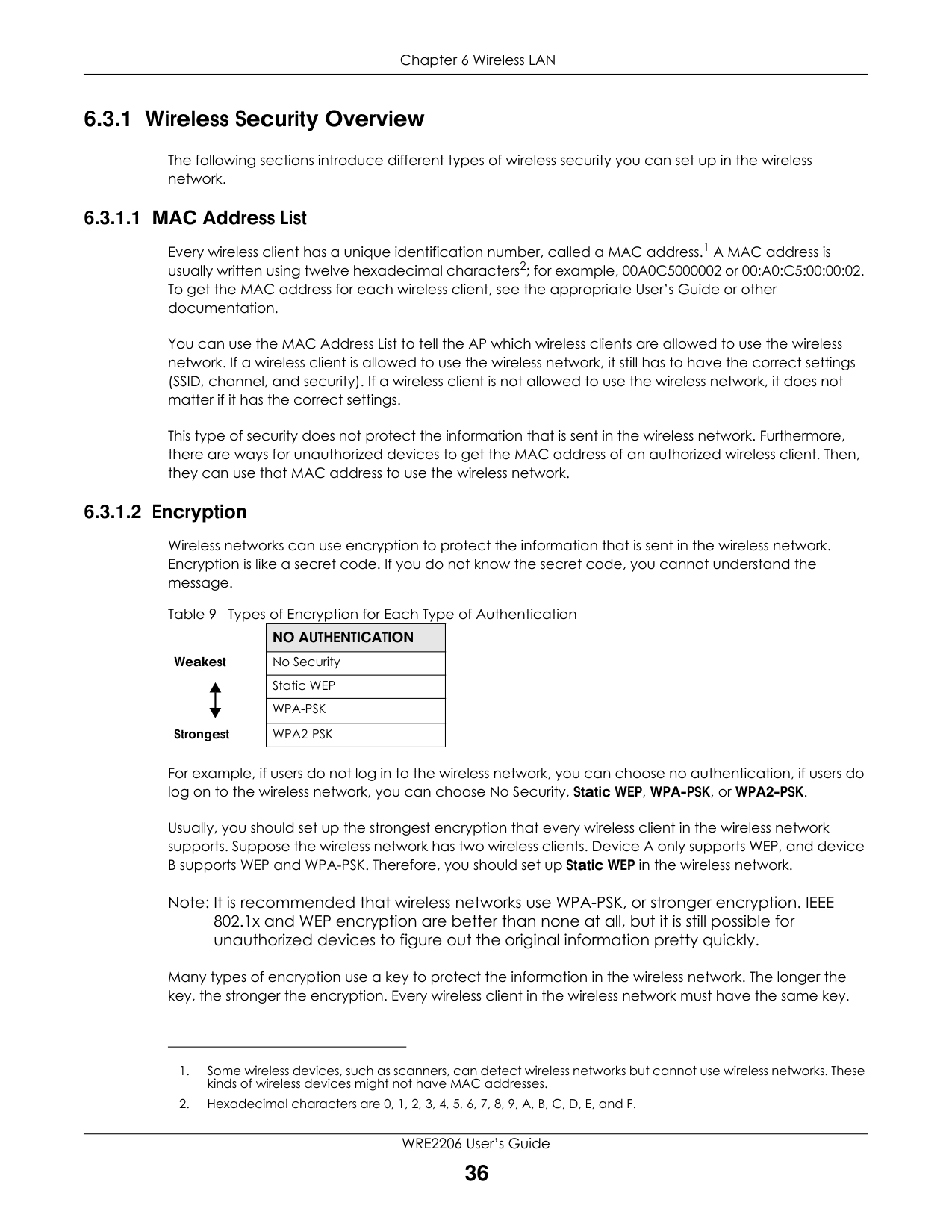
######## 6.3.1.2 Encryption
Wireless networks can use encryption to protect the information that is sent in the wireless network. Encryption is like a secret code. If you do not know the secret code, you cannot understand the message.
Table 9 Types of Encryption for Each Type of Authentication
|NO AUTHENTICATION| |---| |No Security| |Static WEP| |WPA-PSK| |WPA2-PSK|
Weakest
Strongest
For example, if users do not log in to the wireless network, you can choose no authentication, if users do log on to the wireless network, you can choose No Security, Static WEP, WPA-PSK, or WPA2-PSK.
Usually, you should set up the strongest encryption that every wireless client in the wireless network supports. Suppose the wireless network has two wireless clients. Device A only supports WEP, and device B supports WEP and WPA-PSK. Therefore, you should set up Static WEP in the wireless network.
Note: It is recommended that wireless networks use WPA-PSK, or stronger encryption. IEEE 802.1x and WEP encryption are better than none at all, but it is still possible for unauthorized devices to figure out the original information pretty quickly.
Many types of encryption use a key to protect the information in the wireless network. The longer the key, the stronger the encryption. Every wireless client in the wireless network must have the same key.
######## 6.3.1.3 WPS
WiFi Protected Setup (WPS) is an industry standard specification, defined by the WiFi Alliance. WPS allows you to quickly set up a wireless network with strong security, without having to configure security settings manually. Depending on the devices in your network, you can either press a button (on the device itself, or in its configuration utility) or enter a PIN (Personal Identification Number) in the devices. Then, they connect and set up a secure network by themselves. See how to set up a secure wireless network using WPS in the Section 5.2 on page 24.
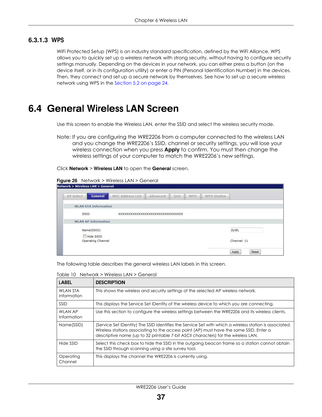
#### 6.4 General Wireless LAN Screen
Use this screen to enable the Wireless LAN, enter the SSID and select the wireless security mode.
Note: If you are configuring the WRE2206 from a computer connected to the wireless LAN and you change the WRE2206’s SSID, channel or security settings, you will lose your wireless connection when you press Apply to confirm. You must then change the wireless settings of your computer to match the WRE2206’s new settings.
Click Network > Wireless LAN to open the General screen.
Figure 26 Network > Wireless LAN > General
|| |---|
The following table describes the general wireless LAN labels in this screen. Table 10 Network > Wireless LAN > General
|LABEL|DESCRIPTION| |---|---| |WLAN STA Information|This shows the wireless and security settings of the selected AP wireless network.| |SSID|This displays the Service Set IDentity of the wireless device to which you are connecting.| |WLAN AP Information|Use this section to configure the wireless settings between the WRE2206 and its wireless clients.| |Name(SSID)|(Service Set IDentity) The SSID identifies the Service Set with which a wireless station is associated. Wireless stations associating to the access point (AP) must have the same SSID. Enter a descriptive name (up to 32 printable 7-bit ASCII characters) for the wireless LAN.| |Hide SSID|Select this check box to hide the SSID in the outgoing beacon frame so a station cannot obtain the SSID through scanning using a site survey tool.| |Operating Channel|This displays the channel the WRE2206 is currently using.|
|LABEL|DESCRIPTION| |---|---| |Apply|Click Apply to save your changes back to the WRE2206.| |Reset|Click Reset to reload the previous configuration for this screen.|
#### 6.5 MAC Address List
The MAC Address List screen allows you to specify which devices are allowed to access the WRE2206, while denying access to all unspecified devices. Every Ethernet device has a unique MAC (Media Access Control) address. The MAC address is assigned at the factory and consists of six pairs of hexadecimal characters, for example, 00:A0:C5:00:00:02. You need to know the MAC address of the devices to configure this screen.
To change your WRE2206’s MAC Address List settings, click Network > Wireless LAN > MAC Address List. The screen appears as shown.
Figure 27 Network > Wireless LAN > MAC Address List
|| |---|
The following table describes the labels in this menu.
|LABEL|DESCRIPTION| |---|---| |Active|Select this to enable MAC address filtering.| |Set|This is the index number of the MAC address.|
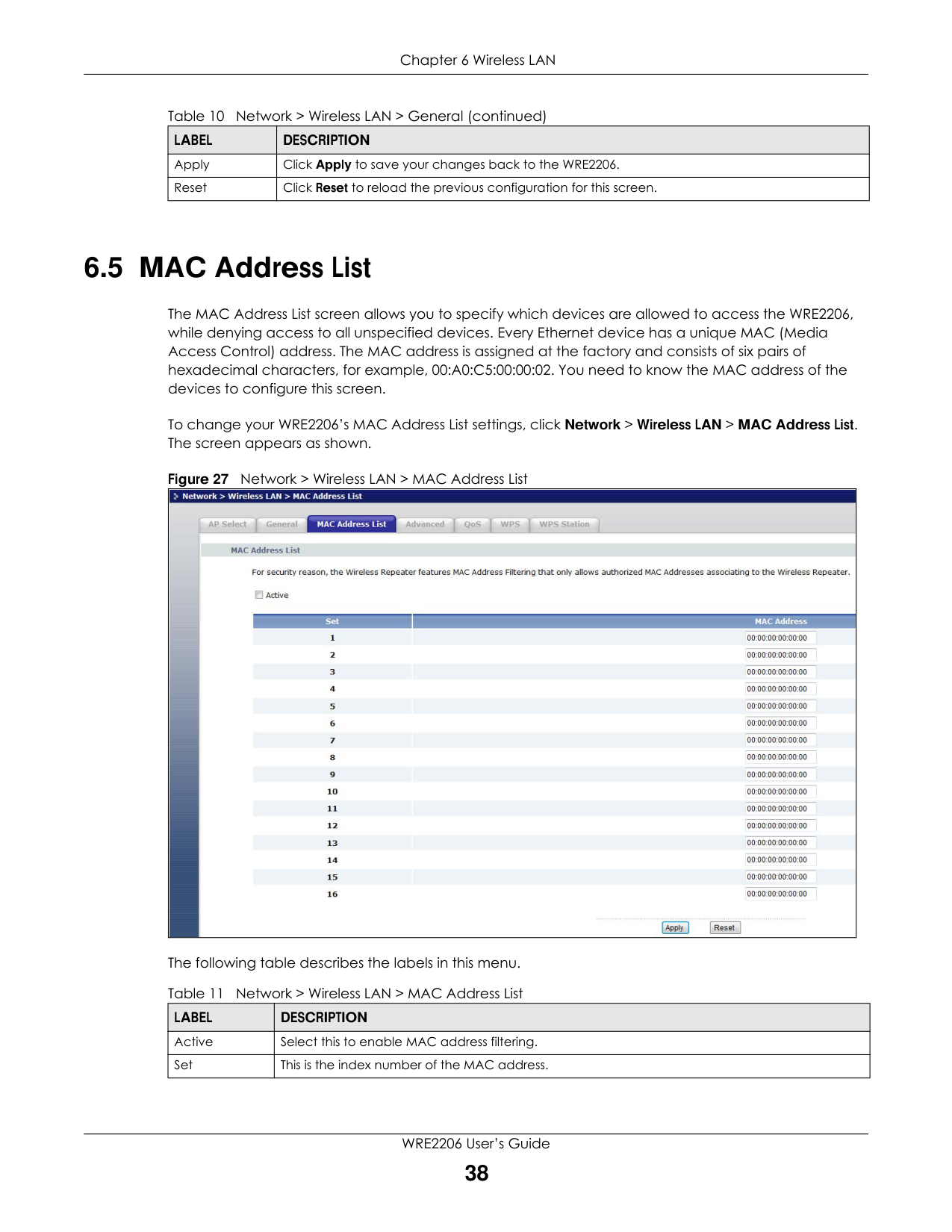
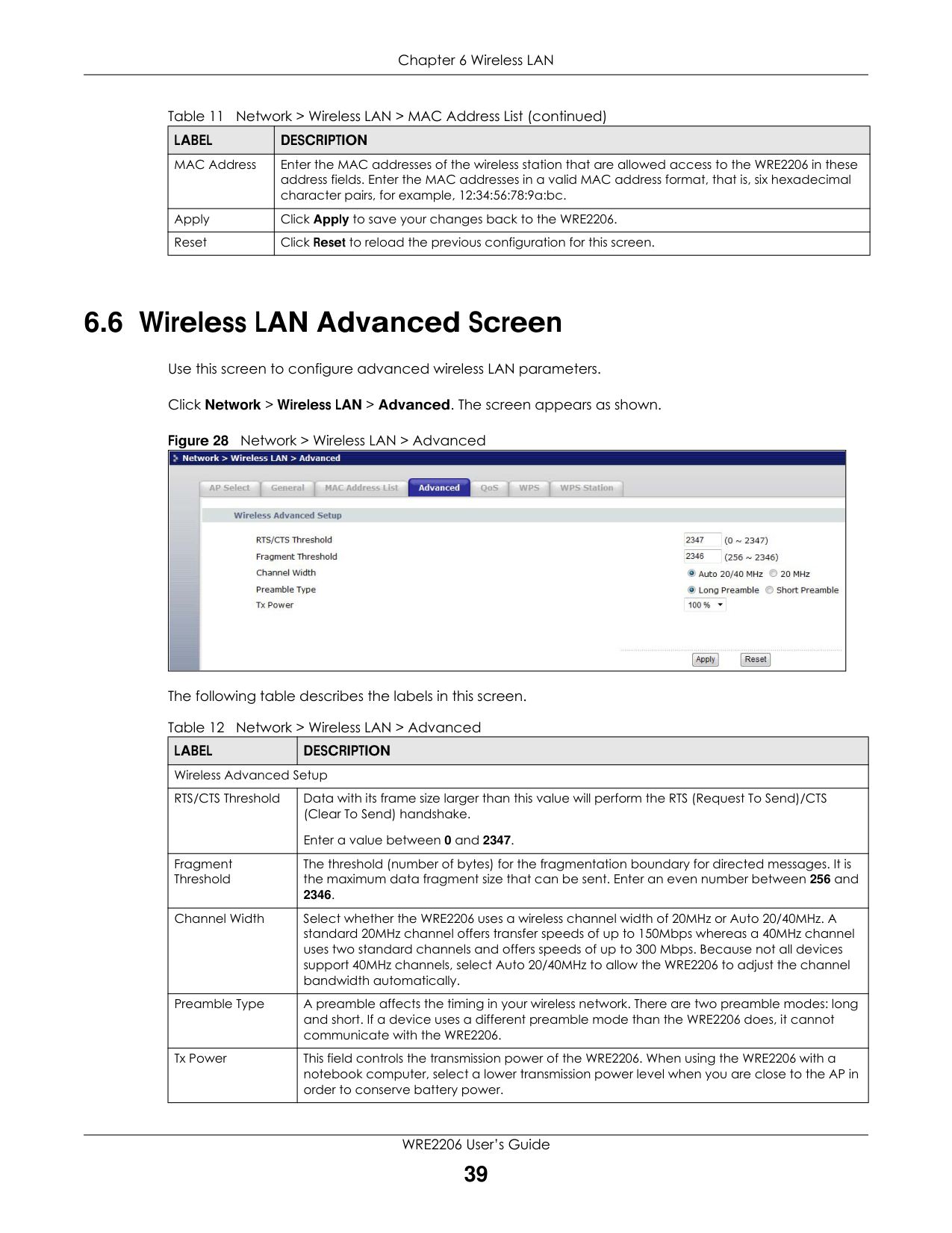
|LABEL|DESCRIPTION| |---|---| |MAC Address|Enter the MAC addresses of the wireless station that are allowed access to the WRE2206 in these address fields. Enter the MAC addresses in a valid MAC address format, that is, six hexadecimal character pairs, for example, 12:34:56:78:9a:bc.| |Apply|Click Apply to save your changes back to the WRE2206.| |Reset|Click Reset to reload the previous configuration for this screen.|
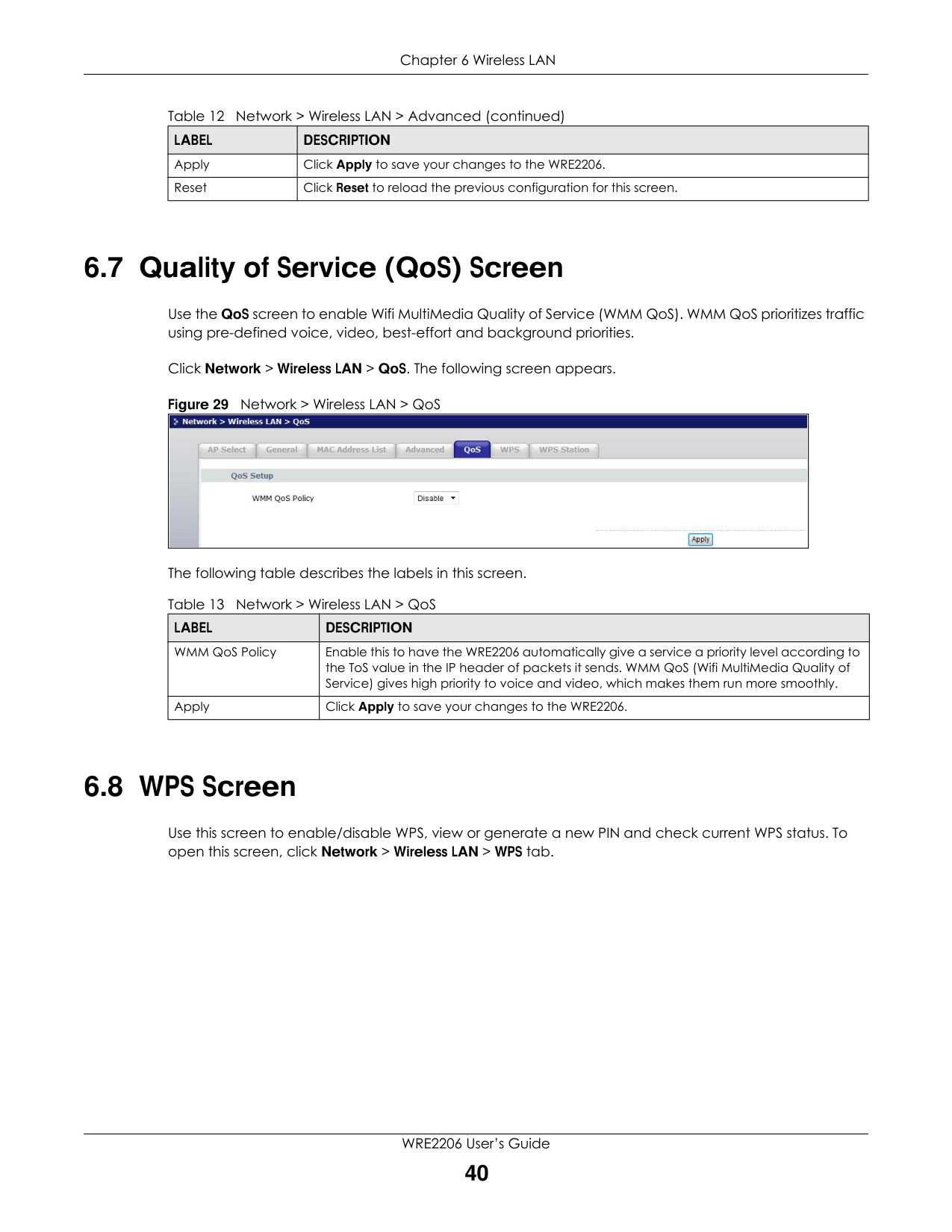
#### 6.6 Wireless LAN Advanced Screen
Use this screen to configure advanced wireless LAN parameters.
Click Network > Wireless LAN > Advanced. The screen appears as shown.
Figure 28 Network > Wireless LAN > Advanced
|| |---|
The following table describes the labels in this screen.
|LABEL|DESCRIPTION| |---|---| |Wireless Advanced Setup|Wireless Advanced Setup| |RTS/CTS Threshold|Data with its frame size larger than this value will perform the RTS (Request To Send)/CTS (Clear To Send) handshake.
Enter a value between 0 and 2347.|
|Fragment Threshold|The threshold (number of bytes) for the fragmentation boundary for directed messages. It is the maximum data fragment size that can be sent. Enter an even number between 256 and 2346.| |Channel Width|Select whether the WRE2206 uses a wireless channel width of 20MHz or Auto 20/40MHz. A standard 20MHz channel offers transfer speeds of up to 150Mbps whereas a 40MHz channel uses two standard channels and offers speeds of up to 300 Mbps. Because not all devices support 40MHz channels, select Auto 20/40MHz to allow the WRE2206 to adjust the channel bandwidth automatically.| |Preamble Type|A preamble affects the timing in your wireless network. There are two preamble modes: long and short. If a device uses a different preamble mode than the WRE2206 does, it cannot communicate with the WRE2206.| |Tx Power|This field controls the transmission power of the WRE2206. When using the WRE2206 with a notebook computer, select a lower transmission power level when you are close to the AP in order to conserve battery power.|
|LABEL|DESCRIPTION| |---|---| |Apply|Click Apply to save your changes to the WRE2206.| |Reset|Click Reset to reload the previous configuration for this screen.|
#### 6.7 Quality of Service (QoS) Screen
Use the QoS screen to enable Wifi MultiMedia Quality of Service (WMM QoS). WMM QoS prioritizes traffic using pre-defined voice, video, best-effort and background priorities.
Click Network > Wireless LAN > QoS. The following screen appears.
Figure 29 Network > Wireless LAN > QoS
|| |---|
The following table describes the labels in this screen.
|LABEL|DESCRIPTION| |---|---| |WMM QoS Policy|Enable this to have the WRE2206 automatically give a service a priority level according to the ToS value in the IP header of packets it sends. WMM QoS (Wifi MultiMedia Quality of Service) gives high priority to voice and video, which makes them run more smoothly.| |Apply|Click Apply to save your changes to the WRE2206.|
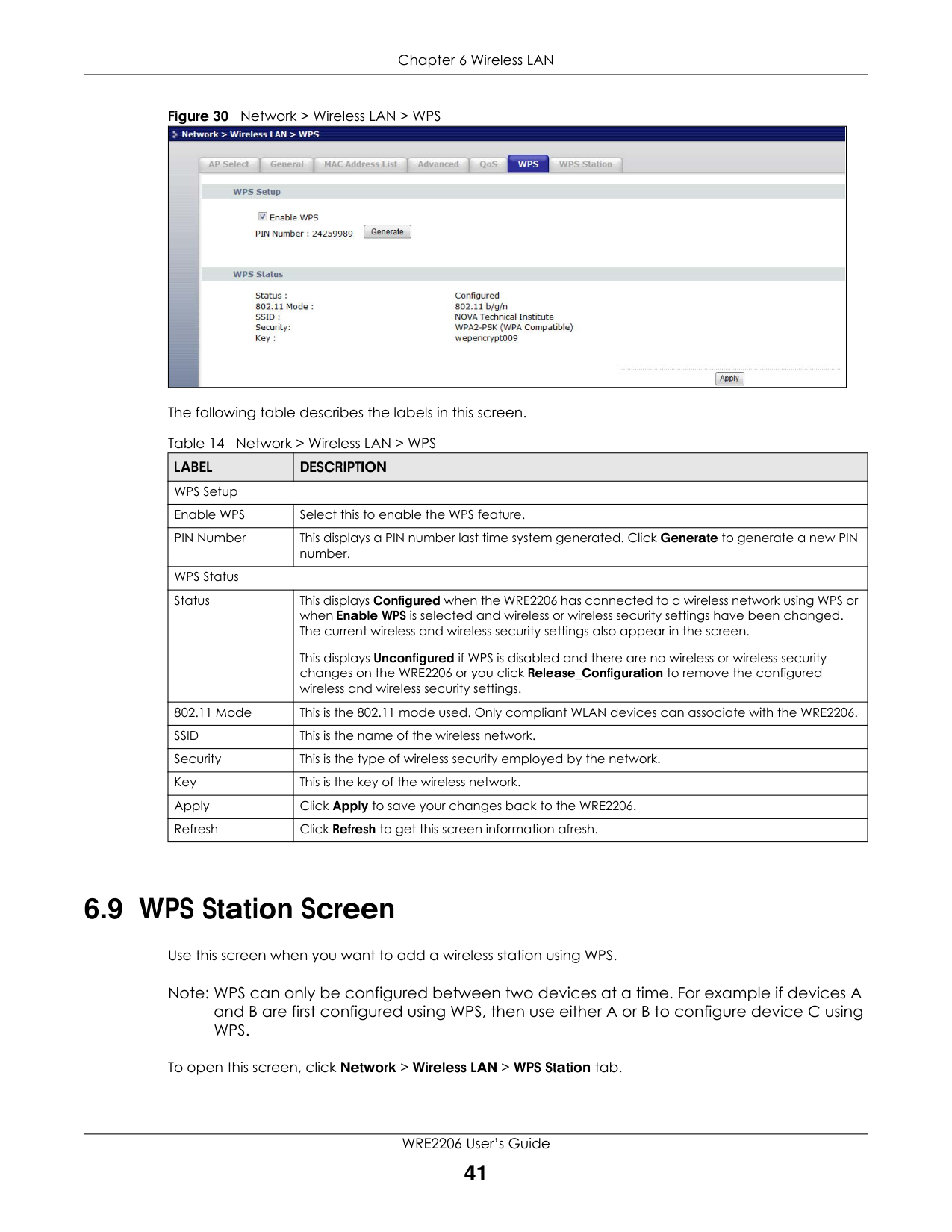
#### 6.8 WPS Screen
Use this screen to enable/disable WPS, view or generate a new PIN and check current WPS status. To open this screen, click Network > Wireless LAN > WPS tab.
Figure 30 Network > Wireless LAN > WPS
|| |---|
The following table describes the labels in this screen.
Table 14 Network > Wireless LAN > WPS
|LABEL|DESCRIPTION| |---|---| |WPS Setup|WPS Setup| |Enable WPS|Select this to enable the WPS feature.| |PIN Number|This displays a PIN number last time system generated. Click Generate to generate a new PIN number.| |WPS Status|WPS Status| |Status|This displays Configured when the WRE2206 has connected to a wireless network using WPS or when Enable WPS is selected and wireless or wireless security settings have been changed. The current wireless and wireless security settings also appear in the screen.
This displays Unconfigured if WPS is disabled and there are no wireless or wireless security changes on the WRE2206 or you click Release_Configuration to remove the configured wireless and wireless security settings.| |802.11 Mode|This is the 802.11 mode used. Only compliant WLAN devices can associate with the WRE2206.| |SSID|This is the name of the wireless network.| |Security|This is the type of wireless security employed by the network.|
|Key|This is the key of the wireless network.| |Apply|Click Apply to save your changes back to the WRE2206.| |Refresh|Click Refresh to get this screen information afresh.|
#### 6.9 WPS Station Screen
Use this screen when you want to add a wireless station using WPS.
Note: WPS can only be configured between two devices at a time. For example if devices A and B are first configured using WPS, then use either A or B to configure device C using WPS.
To open this screen, click Network > Wireless LAN > WPS Station tab.
Note: WPS times out after two minutes of pressing a button. Press the button on the second device within about a minute of the first, then wait two minutes for the WPS configuration to complete.
To add the second wireless station, you have to press these buttons on both device and the wireless station again after the first 2 minutes.
Figure 31 Network > Wireless LAN > WPS Station
|| |---|
The following table describes the labels in this screen.
|LABEL|DESCRIPTION| |---|---|
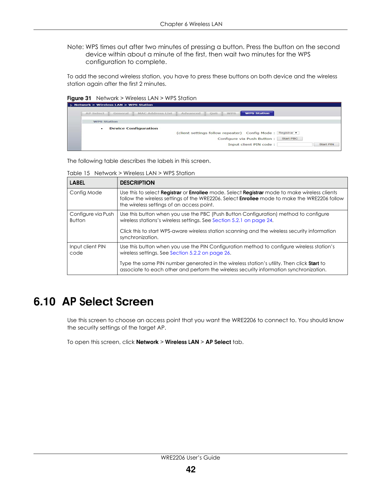
|Config Mode|Use this to select Registrar or Enrollee mode. Select Registrar mode to make wireless clients follow the wireless settings of the WRE2206. Select Enrollee mode to make the WRE2206 follow the wireless settings of an access point.| |Configure via Push Button|Use this button when you use the PBC (Push Button Configuration) method to configure wireless stations’s wireless settings. See Section 5.2.1 on page 24.
Click this to start WPS-aware wireless station scanning and the wireless security information synchronization.| |Input client PIN code|Use this button when you use the PIN Configuration method to configure wireless station’s wireless settings. See Section 5.2.2 on page 26.
Type the same PIN number generated in the wireless station’s utility. Then click Start to associate to each other and perform the wireless security information synchronization.|
#### 6.10 AP Select Screen
Use this screen to choose an access point that you want the WRE2206 to connect to. You should know the security settings of the target AP.
To open this screen, click Network > Wireless LAN > AP Select tab.
Figure 32 Network > Wireless LAN > AP Select
|| |---|
The following table describes the labels in this screen.
|LABEL|DESCRIPTION| |---|---| |Select|Use the radio button to select the wireless device to which you want to connect.| |SSID|This displays the Service Set IDentity of the wireless device. The SSID is a unique name that identifies a wireless network. All devices in a wireless network must use the same SSID.| |MAC|This displays the MAC address of the wireless device.| |Channel|This displays the channel number used by this wireless device.| |Mode|This displays which IEEE 802.11b/g/n wireless networking standards the wireless device supports.| |Security Mode|This displays the type of security configured on the wireless device. When no is shown, no security is configured and you can connect to it without a password.|
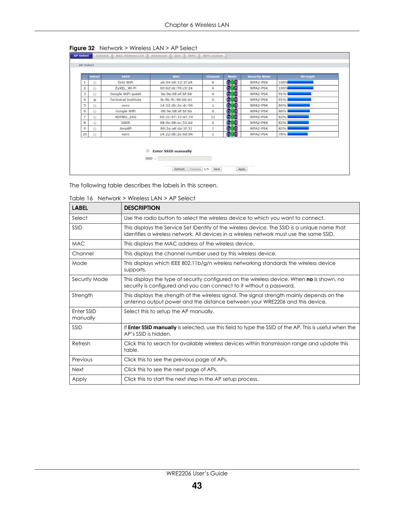
|Strength|This displays the strength of the wireless signal. The signal strength mainly depends on the antenna output power and the distance between your WRE2206 and this device.| |Enter SSID manually|Select this to setup the AP manually.| |SSID|If Enter SSID manually is selected, use this field to type the SSID of the AP. This is useful when the AP’s SSID is hidden.| |Refresh|Click this to search for available wireless devices within transmission range and update this table.| |Previous|Click this to see the previous page of APs.| |Next|Click this to see the next page of APs.| |Apply|Click this to start the next step in the AP setup process.|
CHAPTER 7 LAN
#### 7.1 Overview
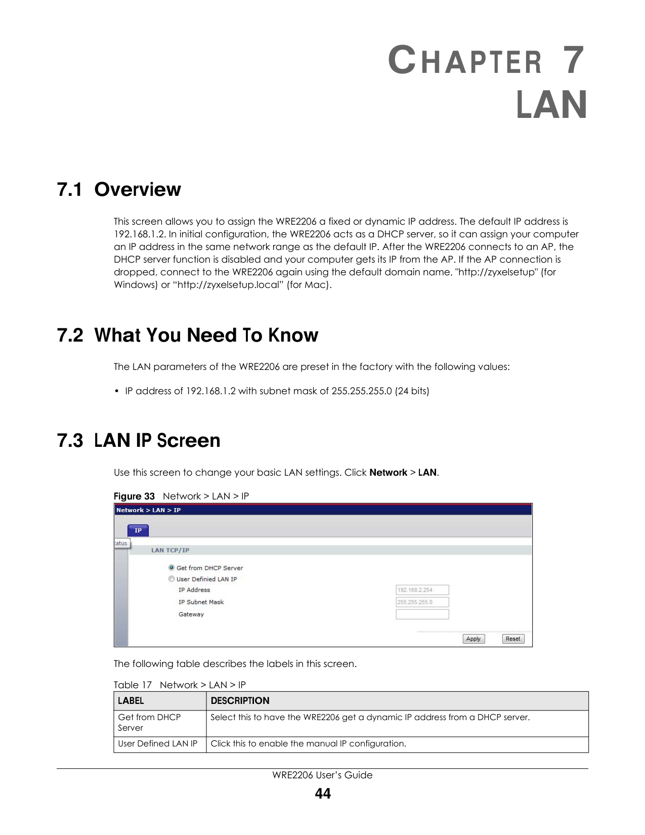
This screen allows you to assign the WRE2206 a fixed or dynamic IP address. The default IP address is 192.168.1.2. In initial configuration, the WRE2206 acts as a DHCP server, so it can assign your computer an IP address in the same network range as the default IP. After the WRE2206 connects to an AP, the DHCP server function is disabled and your computer gets its IP from the AP. If the AP connection is dropped, connect to the WRE2206 again using the default domain name, "http://zyxelsetup" (for Windows) or “http://zyxelsetup.local” (for Mac).
#### 7.2 What You Need To Know
The LAN parameters of the WRE2206 are preset in the factory with the following values:
• IP address of 192.168.1.2 with subnet mask of 255.255.255.0 (24 bits)
#### 7.3 LAN IP Screen
Use this screen to change your basic LAN settings. Click Network > LAN.
Figure 33 Network > LAN > IP
|| |---|
The following table describes the labels in this screen. Table 17 Network > LAN > IP
|LABEL|DESCRIPTION| |---|---| |Get from DHCP Server|Select this to have the WRE2206 get a dynamic IP address from a DHCP server.| |User Defined LAN IP|Click this to enable the manual IP configuration.|
Chapter 7 LAN
Table 17 Network > LAN > IP (continued)
|LABEL|DESCRIPTION| |---|---| |IP Address|Type the IP address of your WRE2206 in dotted decimal notation 192.168.1.2 (factory default).| |IP Subnet Mask|The subnet mask specifies the network number portion of an IP address.| |Gateway|Enter the gateway of your WRE2206 in dotted decimal notation.| |Apply|Click Apply to save your changes back to the WRE2206.| |Reset|Click Reset to begin configuring this screen afresh.|
System
#### 8.1 Overview
This chapter provides information on the System screen.
#### 8.2 What You Can Do
Use the Password screen to set the password (Section 8.3 on page 46).
#### 8.3 System Password Screen
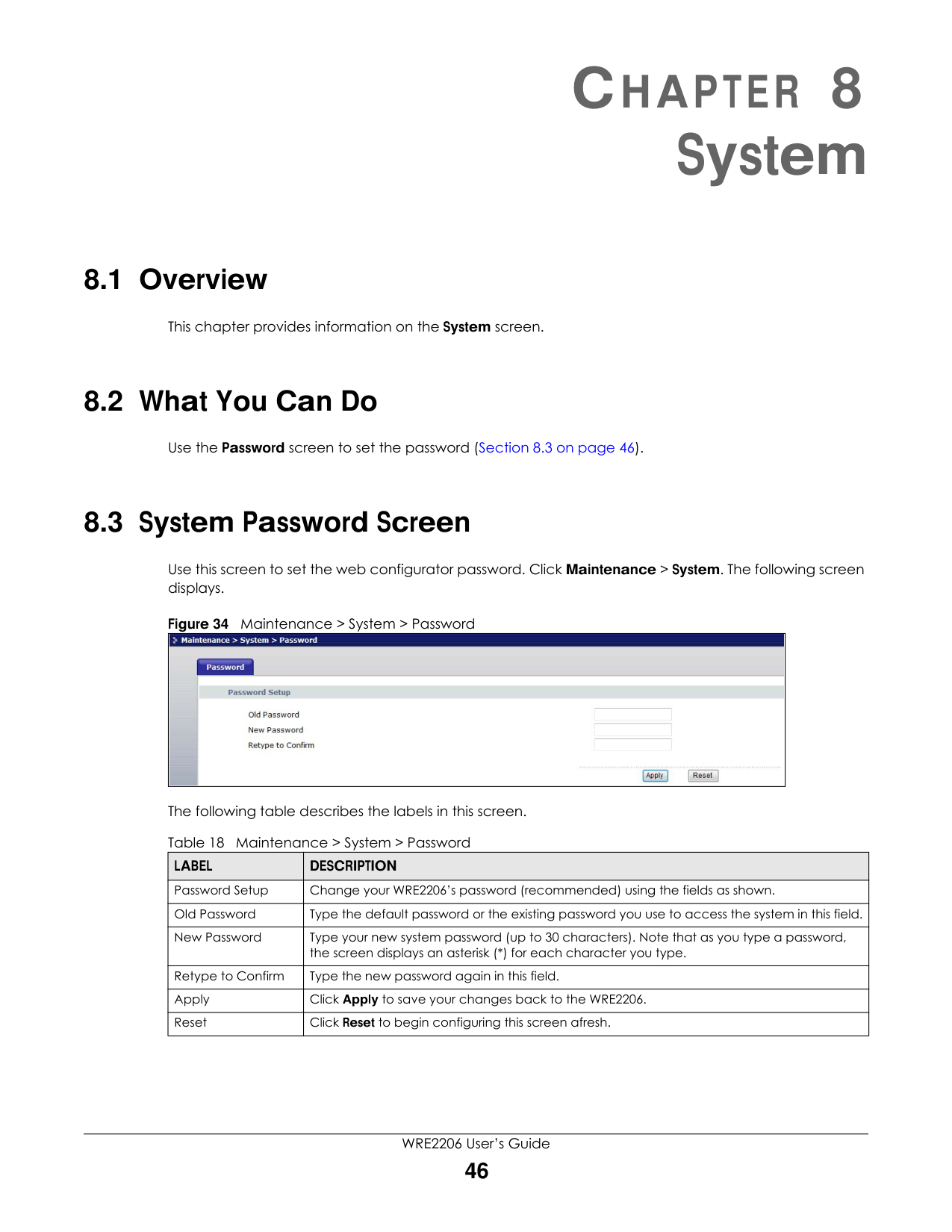
Use this screen to set the web configurator password. Click Maintenance > System. The following screen displays.
Figure 34 Maintenance > System > Password
|| |---|
The following table describes the labels in this screen. Table 18 Maintenance > System > Password
|LABEL|DESCRIPTION| |---|---| |Password Setup|Change your WRE2206’s password (recommended) using the fields as shown.| |Old Password|Type the default password or the existing password you use to access the system in this field.| |New Password|Type your new system password (up to 30 characters). Note that as you type a password, the screen displays an asterisk (*) for each character you type.| |Retype to Confirm|Type the new password again in this field.| |Apply|Click Apply to save your changes back to the WRE2206.| |Reset|Click Reset to begin configuring this screen afresh.|
Tools
#### 9.1 Overview
This chapter shows you how to upload a new firmware, upload or save backup configuration files, restart the WRE2206 and configure LEDs.
#### 9.2 What You Can Do
#### 9.3 Firmware Upload Screen
Find firmware at www.zyxel.com in a file that (usually) uses the system model name with a “*.bin” extension, e.g., “WRE2206.bin”. The upload process uses HTTP (Hypertext Transfer Protocol) and may take up to two minutes. After a successful upload, the system will reboot.
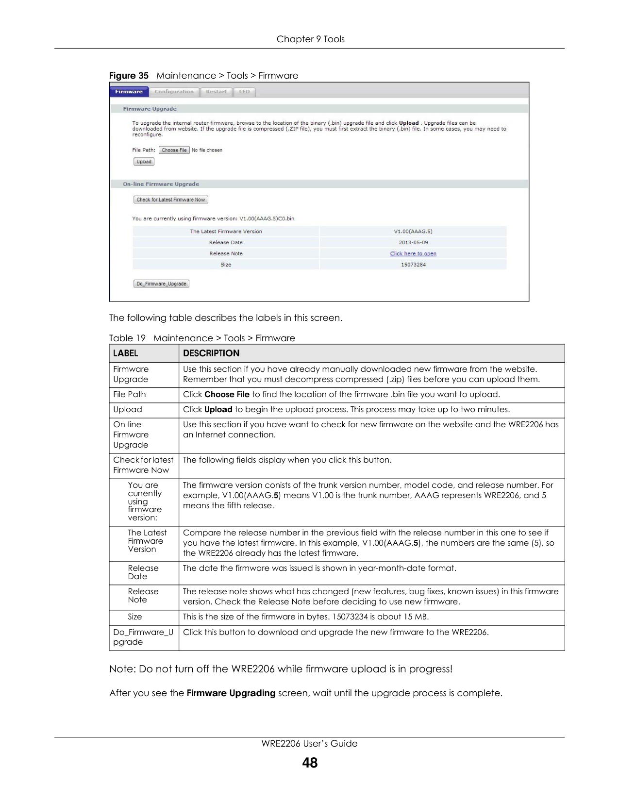
Click Maintenance > Tools. Follow the instructions in this screen to upload firmware to your WRE2206.
|| |---|
The following table describes the labels in this screen.
Table 19 Maintenance > Tools > Firmware
|LABEL|DESCRIPTION| |---|---| |Firmware Upgrade|Use this section if you have already manually downloaded new firmware from the website. Remember that you must decompress compressed (.zip) files before you can upload them.| |File Path|Click Choose File to find the location of the firmware .bin file you want to upload.| |Upload|Click Upload to begin the upload process. This process may take up to two minutes.|
|On-line Firmware Upgrade|Use this section if you have want to check for new firmware on the website and the WRE2206 has an Internet connection.| |Check for latest Firmware Now|The following fields display when you click this button.| |You are currently using firmware version:|The firmware version conists of the trunk version number, model code, and release number. For example, V1.00(AAAG.5) means V1.00 is the trunk number, AAAG represents WRE2206, and 5 means the fifth release.| |The Latest Firmware Version|Compare the release number in the previous field with the release number in this one to see if you have the latest firmware. In this example, V1.00(AAAG.5), the numbers are the same (5), so the WRE2206 already has the latest firmware.| |Release Date|The date the firmware was issued is shown in year-month-date format.| |Release Note|The release note shows what has changed (new features, bug fixes, known issues) in this firmware version. Check the Release Note before deciding to use new firmware.| |Size|This is the size of the firmware in bytes. 15073234 is about 15 MB.| |Do_Firmware_U pgrade|Click this button to download and upgrade the new firmware to the WRE2206.|
Note: Do not turn off the WRE2206 while firmware upload is in progress!
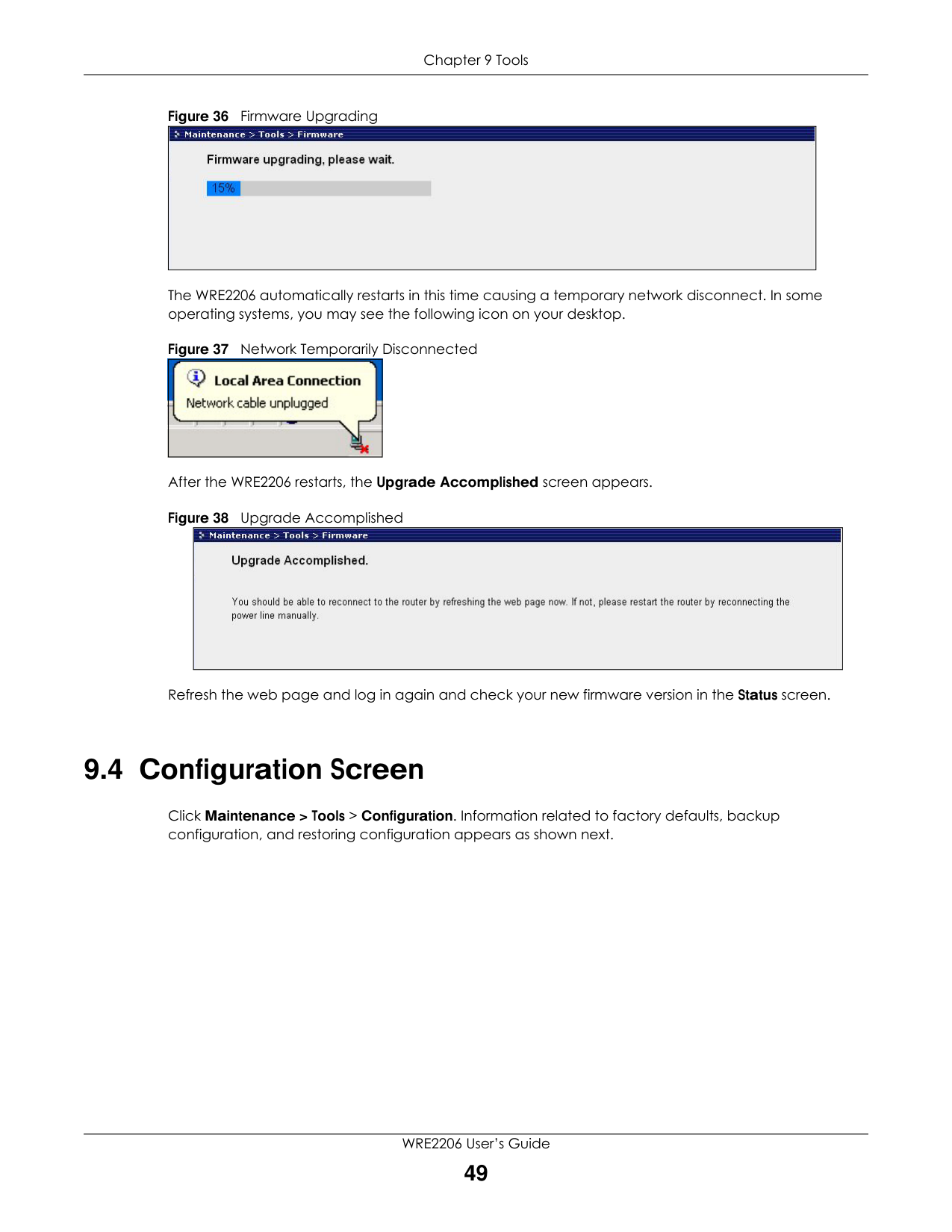
After you see the Firmware Upgrading screen, wait until the upgrade process is complete.
The WRE2206 automatically restarts in this time causing a temporary network disconnect. In some operating systems, you may see the following icon on your desktop.
After the WRE2206 restarts, the Upgrade Accomplished screen appears.
|| |---|
||
|---|
|| |---|
Refresh the web page and log in again and check your new firmware version in the Status screen.
#### 9.4 Configuration Screen
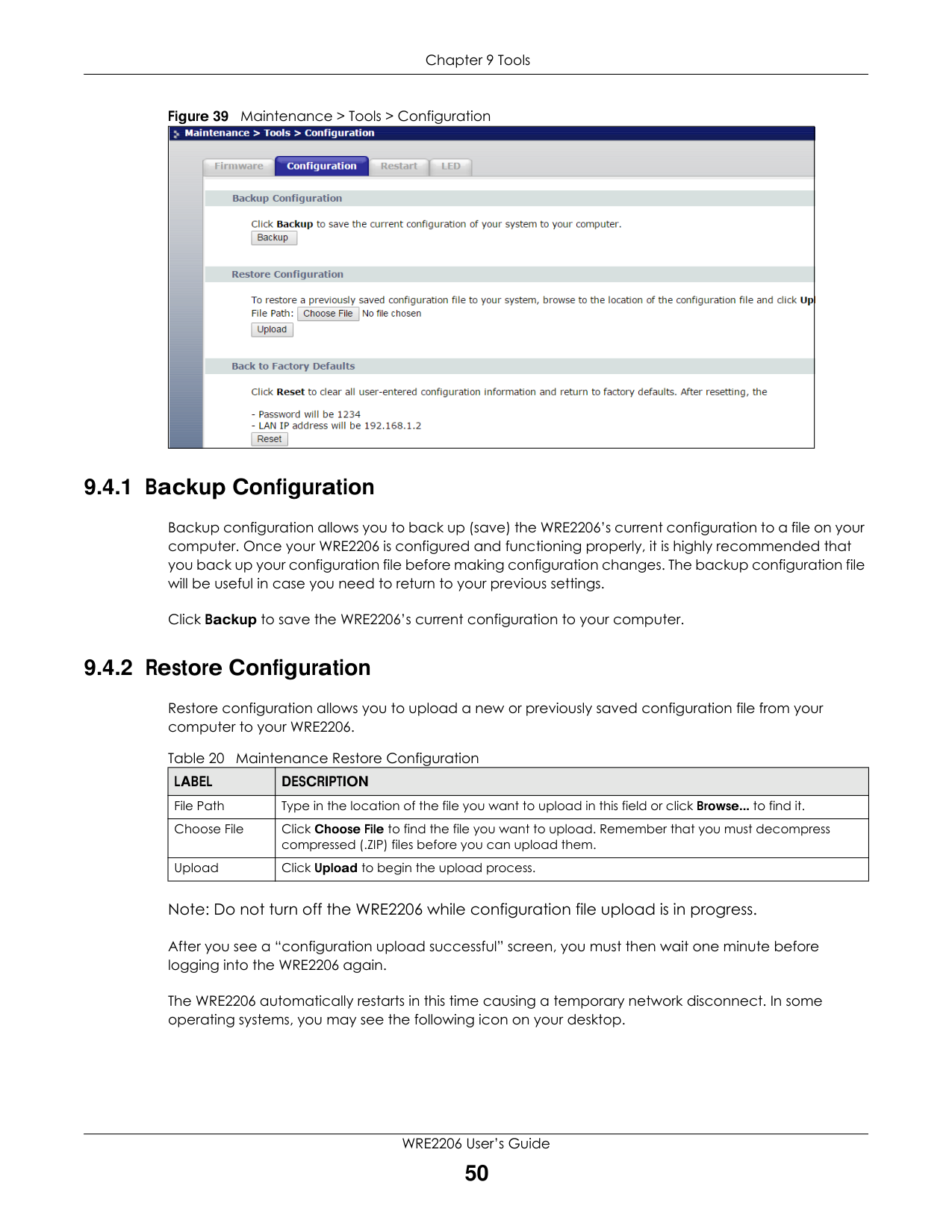
Click Maintenance > Tools > Configuration. Information related to factory defaults, backup configuration, and restoring configuration appears as shown next.
Figure 39 Maintenance > Tools > Configuration
|| |---|
###### 9.4.1 Backup Configuration
Backup configuration allows you to back up (save) the WRE2206’s current configuration to a file on your computer. Once your WRE2206 is configured and functioning properly, it is highly recommended that you back up your configuration file before making configuration changes. The backup configuration file will be useful in case you need to return to your previous settings.
Click Backup to save the WRE2206’s current configuration to your computer.
###### 9.4.2 Restore Configuration
Restore configuration allows you to upload a new or previously saved configuration file from your computer to your WRE2206.
Table 20 Maintenance Restore Configuration
|LABEL|DESCRIPTION| |---|---| |File Path|Type in the location of the file you want to upload in this field or click Browse... to find it.| |Choose File|Click Choose File to find the file you want to upload. Remember that you must decompress compressed (.ZIP) files before you can upload them.| |Upload|Click Upload to begin the upload process.|
Note: Do not turn off the WRE2206 while configuration file upload is in progress.
After you see a “configuration upload successful” screen, you must then wait one minute before logging into the WRE2206 again.
The WRE2206 automatically restarts in this time causing a temporary network disconnect. In some operating systems, you may see the following icon on your desktop.
Figure 40 Temporarily Disconnected
|| |---|
If you uploaded the default configuration file you may need to change the IP address of your computer to be in the same subnet as that of the default WRE2206 IP address (192.168.1.2). Refer to your operating system’s help files for details on how to set up your computer’s IP address.
###### 9.4.3 Back to Factory Defaults
Pressing the Reset button on the Maintenance > Tools > Configuration screen clears all user-entered configuration information and returns the WRE2206 to its factory defaults.
You can also press the WPS button on the front panel for more than 10 seconds to reset the factory defaults of your WRE2206. Refer to Section 2.3 on page 13 for more information on the resetting the WRE2206.
#### 9.5 Restart Screen
System restart allows you to reboot the WRE2206 without turning the power off.
Click Maintenance > Tools > Restart. Click Restart to have the WRE2206 reboot. This does not affect the WRE2206's configuration.
|| |---|
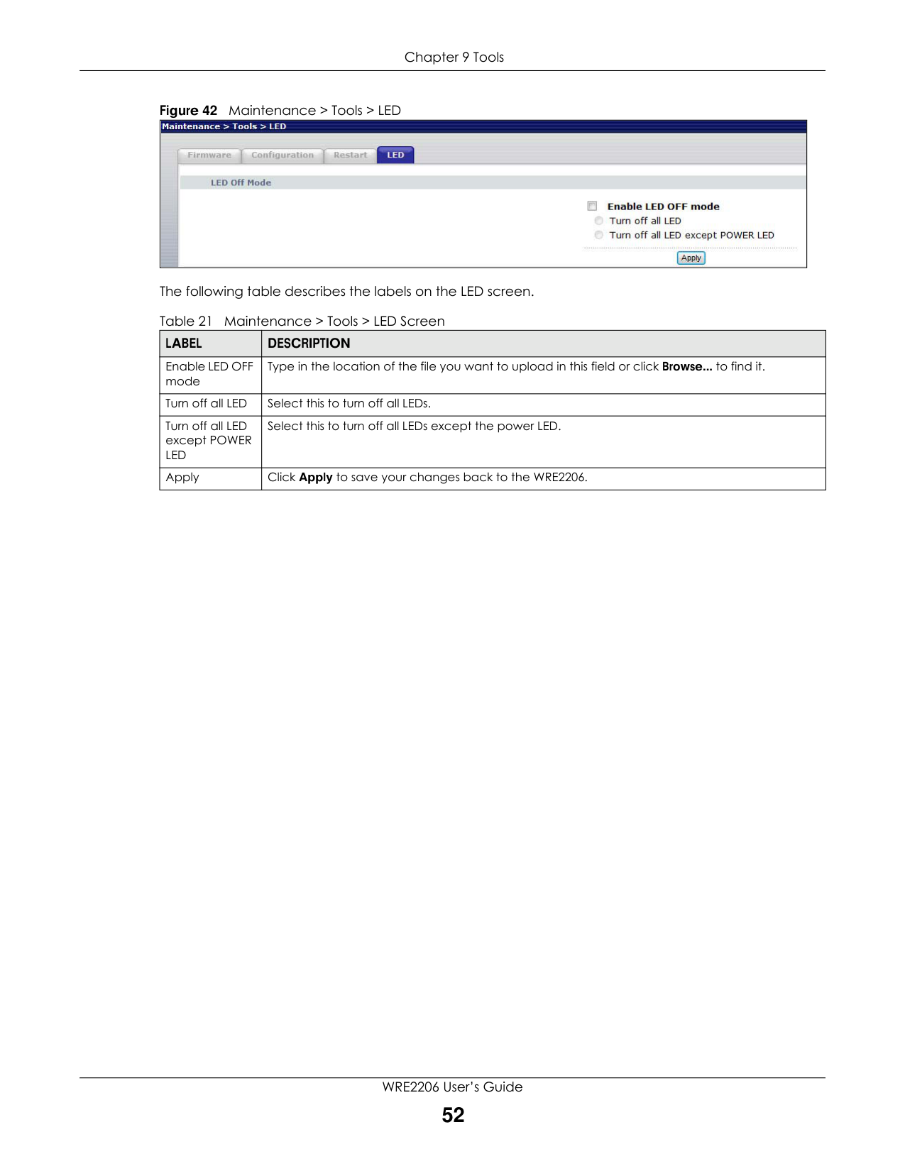
#### 9.6 LED Screen
Click Maintenance > Tools > LED. Use this screen to configure which LEDs are enabled or disabled.
|| |---|
The following table describes the labels on the LED screen. Table 21 Maintenance > Tools > LED Screen
|LABEL|DESCRIPTION| |---|---| |Enable LED OFF mode|Type in the location of the file you want to upload in this field or click Browse... to find it.| |Turn off all LED|Select this to turn off all LEDs.| |Turn off all LED except POWER LED|Select this to turn off all LEDs except the power LED.| |Apply|Click Apply to save your changes back to the WRE2206.|

CHAPTER 10 Troubleshooting
This chapter offers some suggestions to solve problems you might encounter. The potential problems are divided into the following categories.
#### 10.1 Power, Hardware Connections, and LEDs
########### The WRE2206 does not turn on. None of the LEDs turn on.
########### One of the LEDs does not behave as expected.
#### 10.2 WRE2206 Access and Login
########### I don’t know the IP address of my WRE2206.
########### I forgot the username and password.
########### I cannot see or access the Login screen in the Web Configurator.
############ Advanced Suggestions
• If your computer is connected wirelessly, use a computer that is connected to a LAN/ETHERNET port.
########### I can see the Login screen, but I cannot log in to the WRE2206.
#### 10.3 Internet Access
########### I cannot access the Internet.
########### I cannot access the Internet anymore. I had access to the Internet (with the WRE2206), but my Internet connection is not available anymore.
########### The Internet connection is slow or intermittent.
############ Advanced Suggestion
• Check the settings for QoS. If it is disabled, you might consider activating it.
#### 10.4 Resetting the WRE2206 to Its Factory Defaults
If you reset the WRE2206, you lose all of the changes you have made. The WRE2206 re-loads its default settings, and the username/password resets to admin/1234. You have to make all of your changes again.
########### You will lose all of your changes when you reset the WRE2206 to its factory defaults.
To reset the WRE2206,
OR
If the WRE2206 restarts automatically, wait for the WRE2206 to finish restarting, and log in to the Web Configurator. The username is admin and password is 1234.
If the WRE2206 does not restart automatically, disconnect and reconnect the WRE2206’s power. Then, follow the directions above again.
#### 10.5 Wireless Problems
########### I cannot access the WRE2206 or ping any computer from the WLAN.
APPENDIX A
Customer Support
In the event of problems that cannot be solved by using this manual, you should contact your vendor. If you cannot contact your vendor, then contact a Zyxel office for the region in which you bought the device.
See http://www.zyxel.com/homepage.shtml and also http://www.zyxel.com/about_zyxel/zyxel_worldwide.shtml for the latest information.
Please have the following information ready when you contact an office.
######## Required Information
Corporate Headquarters (Worldwide)
Taiwan
Asia
China
Europe
Austria

Latin America
Argentina
Middle East
Israel
North America
USA
Oceania
Australia
Africa
South Africa
APPENDIX B
Legal Information
########## Copyright
Copyright © 2018 by Zyxel Communications Corporation. The contents of this publication may not be reproduced in any part or as a whole, transcribed, stored in a retrieval system, translated into any language, or transmitted in any form or by any means, electronic, mechanical, magnetic, optical, chemical, photocopying, manual, or otherwise, without the prior written permission of Zyxel Communications Corporation. Published by Zyxel Communications Corporation. All rights reserved.
########## Disclaimer
Zyxel does not assume any liability arising out of the application or use of any products, or software described herein. Neither does it convey any license under its patent rights nor the patent rights of others. Zyxel further reserves the right to make changes in any products described herein without notice. This publication is subject to change without notice.
########## Regulatory Notice and Statement UNITED STATES of AMERICA

The following information applies if you use the product within USA area. FCC EMC Statement
########## CANADA
The following information applies if you use the product with RF function within USA area. FCC Radiation Exposure Statement
The following information applies if you use the product within Canada area. Industry Canada ICES statement CAN ICES-3 (B)/NMB-3(B)
############ Industry Canada RSS-GEN & RSS-247 statement
############ Antenna Information
|TYPE|MANUFACTURER|GAIN|CONNECTOR| |---|---|---|---| |PIFA|LYNwave|2 dBi|N/A|
If the product with 5G wireless function operating in 5150-5250 MHz and 5725-5850 MHz , the following attention must be paid,
If the product with 5G wireless function operating in 5250-5350 MHz and 5470-5725 MHz , the following attention must be paid.
############ Informations Antenne
|TYPE|FABRICANT|GAIN|CONNECTEUR| |---|---|---|---| |PIFA|LYNwave|2 dBi|N/A|
Lorsque la fonction sans fil 5G fonctionnant en 5150-5250 MHz and 5725-5850 MHz est activée pour ce produit , il est nécessaire de porter une attention particulière aux choses suivantes
Lorsque la fonction sans fil 5G fonctionnant en 5250-5350 MHz et 5470-5725 MHz est activée pour ce produit , il est nécessaire de porter une attention particulière aux choses suivantes.
• Pour les dispositifs munis d’antennes amovibles, le gain maximal d'antenne permis pour les dispositifs utilisant les bandes de 5 250 à 5 350 MHz
et de 5 470 à 5 725 MHz doit être conforme à la limite de la p.i.r.e. Industry Canada radiation exposure statement
This device complies with IC radiation exposure limits set forth for an uncontrolled environment. This device should be installed and operated with a minimum distance of 20 cm between the radiator and your body.
############ Déclaration d’exposition aux radiations:
Cet équipement est conforme aux limites d’exposition aux rayonnements IC établies pour un environnement non contrôlé. Cet équipement doit être installé et utilisé avec un minimum de 20 cm de distance entre la source de rayonnement et votre corps.
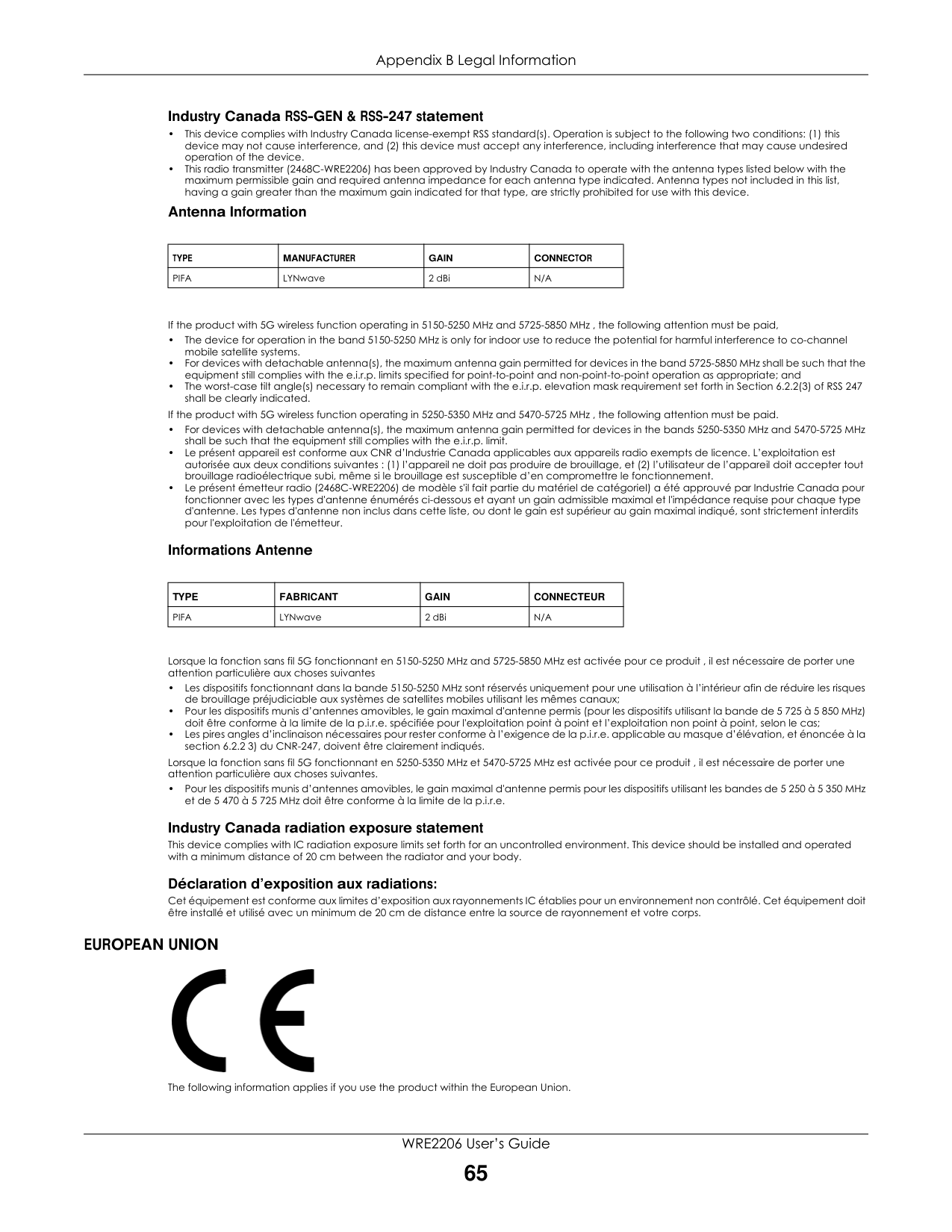
########## EUROPEAN UNION

The following information applies if you use the product within the European Union.
############ Declaration of Conformity with Regard to EU Directive 2014/53/EU (Radio Equipment Directive, RED)
• the band 2,400 to 2,483.5 MHz is 98.86 mW,
|Български (Bulgarian)|С настоящото Zyxel декларира, че това оборудване е в съответствие със съществените изисквания и другите приложими разпоредбите на Директива 2014/53/ЕC.
National Restrictions
• The Belgian Institute for Postal Services and Telecommunications (BIPT) must be notified of any outdoor wireless link having a range exceeding 300 meters. Please check http://www.bipt.be for more details.
• Draadloze verbindingen voor buitengebruik en met een reikwijdte van meer dan 300 meter dienen aangemeld te worden bij het Belgisch Instituut voor postdiensten en telecommunicatie (BIPT). Zie http://www.bipt.be voor meer gegevens.
• Les liaisons sans fil pour une utilisation en extérieur d’une distance supérieure à 300 mètres doivent être notifiées à l’Institut Belge des services Postaux et des Télécommunications (IBPT). Visitez http://www.ibpt.be pour de plus amples détails.
| |---|---| |Español (Spanish)|Por medio de la presente Zyxel declara que el equipo cumple con los requisitos esenciales y cualesquiera otras disposiciones aplicables o exigibles de la Directiva 2014/53/UE..| |Čeština (Czech)|Zyxel tímto prohlašuje, že tento zařízení je ve shodě se základními požadavky a dalšími příslušnými ustanoveními směrnice 2014/53/EU.| |Dansk (Danish)|Undertegnede Zyxel erklærer herved, at følgende udstyr udstyr overholder de væsentlige krav og øvrige relevante krav i direktiv 2014/53/EU.
National Restrictions
• In Denmark, the band 5150 - 5350 MHz is also allowed for outdoor usage.
• I Danmark må frekvensbåndet 5150 - 5350 også anvendes udendørs.
| |Deutsch (German)|Hiermit erklärt Zyxel, dass sich das Gerät Ausstattung in Übereinstimmung mit den grundlegenden Anforderungen und den übrigen einschlägigen Bestimmungen der Richtlinie 2014/53/EU befindet.| |Eesti keel (Estonian)|Käesolevaga kinnitab Zyxel seadme seadmed vastavust direktiivi 2014/53/EL põhinõuetele ja nimetatud direktiivist tulenevatele teistele asjakohastele sätetele.| |Ελληνικά (Greek)|ΜΕ ΤΗΝ ΠΑΡΟΥΣΑ Zyxel ∆ΗΛΩΝΕΙ ΟΤΙ εξοπλισμός ΣΥΜΜΟΡΦΩΝΕΤΑΙ ΠΡΟΣ ΤΙΣ ΟΥΣΙΩ∆ΕΙΣ ΑΠΑΙΤΗΣΕΙΣ ΚΑΙ ΤΙΣ ΛΟΙΠΕΣ ΣΧΕΤΙΚΕΣ ∆ΙΑΤΑΞΕΙΣ ΤΗΣ Ο∆ΗΓΙΑΣ 2014/53/EE.| |English|Hereby, Zyxel declares that this device is in compliance with the essential requirements and other relevant provisions of Directive 2014/53/EU.| |Français (French)|Par la présente Zyxel déclare que l'appareil équipements est conforme aux exigences essentielles et aux autres dispositions pertinentes de la directive 2014/53/UE.| |Hrvatski (Croatian)|Zyxel ovime izjavljuje da je radijska oprema tipa u skladu s Direktivom 2014/53/UE.| |Íslenska (Icelandic)|Hér með lýsir, Zyxel því yfir að þessi búnaður er í samræmi við grunnkröfur og önnur viðeigandi ákvæði tilskipunar 2014/53/ UE.|
|Italiano (Italian)|Con la presente Zyxel dichiara che questo attrezzatura è conforme ai requisiti essenziali ed alle altre disposizioni pertinenti stabilite dalla direttiva 2014/53/UE.
National Restrictions
• This product meets the National Radio Interface and the requirements specified in the National Frequency Allocation Table for Italy. Unless this wireless LAN product is operating within the boundaries of the owner's property, its use requires a “general authorization.” Please check http://www.sviluppoeconomico.gov.it/ for more details.
• Questo prodotto è conforme alla specifiche di Interfaccia Radio Nazionali e rispetta il Piano Nazionale di ripartizione delle frequenze in Italia. Se non viene installato all 'interno del proprio fondo, l'utilizzo di prodotti Wireless LAN richiede una “Autorizzazione Generale”. Consultare http://www.sviluppoeconomico.gov.it/ per maggiori dettagli.
| |Latviešu valoda (Latvian)|Ar šo Zyxel deklarē, ka iekārtas atbilst Direktīvas 2014/53/ES būtiskajām prasībām un citiem ar to saistītajiem noteikumiem. National Restrictions
• The outdoor usage of the 2.4 GHz band requires an authorization from the Electronic Communications Office. Please check http://www.esd.lv for more details.
• 2.4 GHz frekvenèu joslas izmantoðanai ârpus telpâm nepiecieðama atïauja no Elektronisko sakaru direkcijas. Vairâk informâcijas: http://www.esd.lv.
| |Lietuvių kalba (Lithuanian)|Šiuo Zyxel deklaruoja, kad šis įranga atitinka esminius reikalavimus ir kitas 2014/53/ES Direktyvos nuostatas.| |Magyar (Hungarian)|Alulírott, Zyxel nyilatkozom, hogy a berendezés megfelel a vonatkozó alapvetõ követelményeknek és az 2014/53/EU irányelv egyéb elõírásainak.|
|Malti (Maltese)|Hawnhekk, Zyxel, jiddikjara li dan tagħmir jikkonforma mal-ħtiġijiet essenzjali u ma provvedimenti oħrajn relevanti li hemm fid-Dirrettiva 2014/53/UE.| |---|---| |Nederlands (Dutch)|Hierbij verklaart Zyxel dat het toestel uitrusting in overeenstemming is met de essentiële eisen en de andere relevante bepalingen van richtlijn 2014/53/EU.| |Polski (Polish)|Niniejszym Zyxel oświadcza, że sprzęt jest zgodny z zasadniczymi wymogami oraz pozostałymi stosownymi postanowieniami Dyrektywy 2014/53/UE.| |Português (Portuguese)|Zyxel declara que este equipamento está conforme com os requisitos essenciais e outras disposições da Directiva 2014/53/ UE.| |Română (Romanian)|Prin prezenta, Zyxel declară că acest echipament este în conformitate cu cerinţele esenţiale şi alte prevederi relevante ale Directivei 2014/53/UE.| |Slovenčina (Slovak)|Zyxel týmto vyhlasuje, že zariadenia spĺňa základné požiadavky a všetky príslušné ustanovenia Smernice 2014/53/EÚ.| |Slovenščina (Slovene)|Zyxel izjavlja, da je ta oprema v skladu z bistvenimi zahtevami in ostalimi relevantnimi določili direktive 2014/53/EU.| |Suomi (Finnish)|Zyxel vakuuttaa täten että laitteet tyyppinen laite on direktiivin 2014/53/EU oleellisten vaatimusten ja sitä koskevien direktiivin muiden ehtojen mukainen.| |Svenska (Swedish)|Härmed intygar Zyxel att denna utrustning står I överensstämmelse med de väsentliga egenskapskrav och övriga relevanta bestämmelser som framgår av direktiv 2014/53/EU.| |Norsk (Norwegian)|Erklærer herved Zyxel at dette utstyret er I samsvar med de grunnleggende kravene og andre relevante bestemmelser I direktiv 2014/53/EU.|
############## Notes:
• Although Norway, Switzerland and Liechtenstein are not EU member states, the EU Directive 2014/53/EU has also been implemented in those countries.
The regulatory limits for maximum output power are specified in EIRP. The EIRP level (in dBm) of a device can be calculated by adding the gain of the antenna used (specified in dBi) to the output power available at the connector (specified in dBm).List of national codes
|COUNTRY|ISO 3166 2 LETTER CODE|COUNTRY|ISO 3166 2 LETTER CODE| |---|---|---|---| |Austria|AT|Liechtenstein|LI| |Belgium|BE|Lithuania|LT| |Bulgaria|BG|Luxembourg|LU|
|Croatia|HR|Malta|MT| |Cyprus|CY|Netherlands|NL| |Czech Republic|CZ|Norway|NO| |Denmark|DK|Poland|PL| |Estonia|EE|Portugal|PT| |Finland|FI|Romania|RO| |France|FR|Serbia|RS| |Germany|DE|Slovakia|SK| |Greece|GR|Slovenia|SI| |Hungary|HU|Spain|ES| |Iceland|IS|Switzerland|CH| |Ireland|IE|Sweden|SE| |Italy|IT|Turkey|TR| |Latvia|LV|United Kingdom|GB|
########## Safety Warnings
########## Environment Statement
############ ErP (Energy-related Products)
Zyxel products put on the EU market in compliance with the requirement of the European Parliament and the Council published Directive 2009/ 125/EC establishing a framework for the setting of ecodesign requirements for energy-related products (recast), so called as "ErP Directive (Energy-related Products directive) as well as ecodesign requirement laid down in applicable implementing measures, power consumption has satisfied regulation requirements which are:
############ European Union - Disposal and Recycling Information
The symbol below means that according to local regulations your product and/or its battery shall be disposed of separately from domestic waste. If this product is end of life, take it to a recycling station designated by local authorities. At the time of disposal, the separate collection of your product and/or its battery will help save natural resources and ensure that the environment is sustainable development.
Die folgende Symbol bedeutet, dass Ihr Produkt und/oder seine Batterie gemäß den örtlichen Bestimmungen getrennt vom Hausmüll entsorgt werden muss. Wenden Sie sich an eine Recyclingstation, wenn dieses Produkt das Ende seiner Lebensdauer erreicht hat. Zum Zeitpunkt der Entsorgung wird die getrennte Sammlung von Produkt und/oder seiner Batterie dazu beitragen, natürliche Ressourcen zu sparen und die Umwelt und die menschliche Gesundheit zu schützen.
El símbolo de abajo indica que según las regulaciones locales, su producto y/o su batería deberán depositarse como basura separada de la doméstica. Cuando este producto alcance el final de su vida útil, llévelo a un punto limpio. Cuando llegue el momento de desechar el producto, la recogida por separado éste y/o su batería ayudará a salvar los recursos naturales y a proteger la salud humana y medioambiental.
Le symbole ci-dessous signifie que selon les réglementations locales votre produit et/ou sa batterie doivent être éliminés séparément des ordures ménagères. Lorsque ce produit atteint sa fin de vie, amenez-le à un centre de recyclage. Au moment de la mise au rebut, la collecte séparée de votre produit et/ou de sa batterie aidera à économiser les ressources naturelles et protéger l'environnement et la santé humaine.
Il simbolo sotto significa che secondo i regolamenti locali il vostro prodotto e/o batteria deve essere smaltito separatamente dai rifiuti domestici. Quando questo prodotto raggiunge la fine della vita di servizio portarlo a una stazione di riciclaggio. Al momento dello smaltimento, la raccolta separata del vostro prodotto e/o della sua batteria aiuta a risparmiare risorse naturali e a proteggere l'ambiente e la salute umana.
Symbolen innebär att enligt lokal lagstiftning ska produkten och/eller dess batteri kastas separat från hushållsavfallet. När den här produkten når slutet av sin livslängd ska du ta den till en återvinningsstation. Vid tiden för kasseringen bidrar du till en bättre miljö och mänsklig hälsa genom att göra dig av med den på ett återvinningsställe.

########## 台灣

以下訊息僅適用於產品具有無線功能且銷售至台灣地區
以下訊息僅適用於產品屬於專業安裝並銷售至台灣地區
安全警告 - 為了您的安全,請先閱讀以下警告及指示 :
########## About the Symbols
Various symbols are used in this product to ensure correct usage, to prevent danger to the user and others, and to prevent property damage. The meaning of these symbols are described below. It is important that you read these descriptions thoroughly and fully understand the contents.
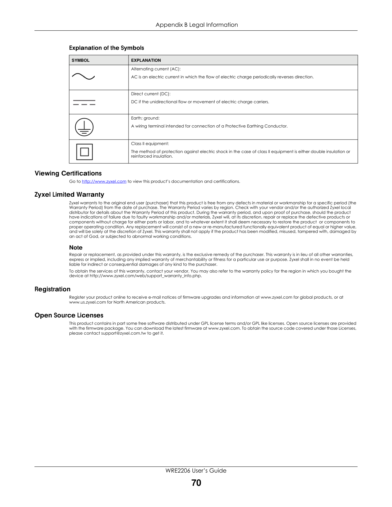
Explanation of the Symbols
|SYMBOL|EXPLANATION| |---|---| ||Alternating current (AC): AC is an electric current in which the flow of electric charge periodically reverses direction.| ||Direct current (DC): DC if the unidirectional flow or movement of electric charge carriers.| ||Earth; ground: A wiring terminal intended for connection of a Protective Earthing Conductor.| ||Class II equipment: The method of protection against electric shock in the case of class II equipment is either double insulation or reinforced insulation.|
########## Viewing Certifications
Go to http://www.zyxel.com to view this product’s documentation and certifications. Zyxel Limited Warranty
Zyxel warrants to the original end user (purchaser) that this product is free from any defects in material or workmanship for a specific period (the Warranty Period) from the date of purchase. The Warranty Period varies by region. Check with your vendor and/or the authorized Zyxel local distributor for details about the Warranty Period of this product. During the warranty period, and upon proof of purchase, should the product have indications of failure due to faulty workmanship and/or materials, Zyxel will, at its discretion, repair or replace the defective products or components without charge for either parts or labor, and to whatever extent it shall deem necessary to restore the product or components to proper operating condition. Any replacement will consist of a new or re-manufactured functionally equivalent product of equal or higher value, and will be solely at the discretion of Zyxel. This warranty shall not apply if the product has been modified, misused, tampered with, damaged by an act of God, or subjected to abnormal working conditions.
############ Note
Repair or replacement, as provided under this warranty, is the exclusive remedy of the purchaser. This warranty is in lieu of all other warranties, express or implied, including any implied warranty of merchantability or fitness for a particular use or purpose. Zyxel shall in no event be held liable for indirect or consequential damages of any kind to the purchaser.
To obtain the services of this warranty, contact your vendor. You may also refer to the warranty policy for the region in which you bought the device at http://www.zyxel.com/web/support_warranty_info.php.
########## Registration
Register your product online to receive e-mail notices of firmware upgrades and information at www.zyxel.com for global products, or at www.us.zyxel.com for North American products.
########## Open Source Licenses
This product contains in part some free software distributed under GPL license terms and/or GPL like licenses. Open source licenses are provided with the firmware package. You can download the latest firmware at www.zyxel.com. To obtain the source code covered under those Licenses, please contact support@zyxel.com.tw to get it.
Index
###### B
Backup configuration 50
###### G
General wireless LAN screen 37
###### C
certifications 67 viewing 70 Channel 21 Configuration
backup 50 reset the factory defaults 51 restore 50
contact information 58 copyright 64 CPU usage 21 customer support 58
###### D
disclaimer 64 duplex setting 21
###### E
encryption 36 key 36
###### F
Firmware upload 47 file extension using HTTP
firmware version 21
###### I
IP Address 45
###### L
LAN setup 44 Link type 21
###### M
MAC 38 MAC address 36 MAC address filtering 38 MAC Address List 36, 38 managing the device
good habits 9 Media access control 38 Memory usage 21
###### N
Navigation Panel 22
###### O
overview 8
###### P
port speed 21
###### Q
Quality of Service (QoS) 40
overview 36 troubleshooting 57 type 36
Wireless tutorial 24 WPS 24
Wizard setup 14 complete 19 wireless LAN 14
WPS button 10, 13
###### R
Reset the device 13 Restore configuration 50 RTS/CTS Threshold 39
###### S
Service Set 37 Service Set IDentification 15, 37, 43 Service Set IDentity. See SSID. SSID 15, 21, 35, 37, 43 Subnet Mask 45 System General Setup 46 System restart 51
###### W
warranty 70 note 70
Web Configurator how to access 12 Overview 12
wireless channel 57 wireless LAN 57 Wireless LAN wizard 14 Wireless network 36
basic guidelines 35 encryption 36 security 35 SSID 35
Wireless security 35