
Ask AI
— answers from the official manualAnswers from the official manual.
Common questions
Common Questions
26 totalHow do I enter the BIOS Setup on the PRIME B660-PLUS D4?
Press the Delete or F2 key during the Power-On Self Test (POST) to enter BIOS Setup at startup. If you miss the POST window, you can also enter BIOS after POST by pressing Ctrl+Alt+Delete simultaneously, pressing the reset button, or turning the system off and back on, then pressing the Delete key. The BIOS Setup program supports two modes: EZ Mode and Advanced Mode, switchable via the F7 hotkey.
How do I clear the CMOS to reset BIOS settings on the PRIME B660-PLUS D4?
To clear the CMOS, turn off the computer and unplug the power cord, then use a metal object such as a screwdriver to short the two pins on the Clear CMOS header (CLRTC). Plug the power cord back in, turn on the computer, and hold down the Del key during boot to re-enter data in BIOS Setup. If this does not help, remove the onboard battery, short the two pins again, then reinstall the battery after clearing.
How do I update the BIOS using ASUS EZ Flash 3?
Insert a USB flash drive (formatted FAT 32/16 with a single partition) containing the latest BIOS file into a USB port. Enter the Advanced Mode of the BIOS Setup, go to the Tool menu, select ASUS EZ Flash 3 Utility, and press Enter. Use the arrow keys to navigate to the USB drive and BIOS file, then press Enter to begin the update; reboot the system when the update is complete. Do not shut down or reset the system during the update process to prevent boot failure.
How do I recover a corrupted BIOS using ASUS CrashFree BIOS 3?
Download the latest BIOS file from https://www.asus.com/support/, rename it to ASUS.CAP or PB660PD4.CAP, and copy it to a USB flash drive. Turn on the system and insert the USB drive; the utility will automatically detect and read the BIOS file, then enter ASUS EZ Flash 3 automatically to begin recovery. After recovery, press F5 to load default BIOS values to ensure system compatibility and stability. Do not shut down or reset the system during the update.
What is the maximum RAM the PRIME B660-PLUS D4 supports, and what speeds are compatible?
The motherboard supports a maximum of 128GB of DDR4 memory across 4 DIMM slots. Supported speeds range from 2133 MHz up to 5066 MHz (OC), including native speeds of 2133/2400/2666/2800/2933/3000/3200 for 12th Gen Intel processors. The board supports Dual Channel Memory Architecture and is compatible with Intel Extreme Memory Profile (XMP).
What safety precautions should I take before installing or removing components on the motherboard?
Unplug the power cord from the wall socket before touching any component to prevent electrical shock. Before handling components, use a grounded wrist strap or touch a safely grounded metal object to avoid static electricity damage. Ensure the ATX power supply is switched off or the power cord is detached before installing or removing any component, as failure to do so may cause severe damage to the motherboard, peripherals, or components.
Show 20 more questions
What M.2 slots are available on the PRIME B660-PLUS D4 and what are their specifications?
What should I do if the system becomes unstable or fails to boot after changing BIOS settings?
How do I reset the motherboard to factory settings?
What is the process for clearing CMOS RTC RAM data?
How do I correctly install a CPU?
What are safety precautions for handling components?
How do I correctly install DDR4 memory?
What are the operating temperature limits and key environmental safety requirements for the PRIME B660-PLUS D4?
How do I install an M.2 Wi-Fi module on the motherboard?
What should I do if my Q-LEDs remain lit during booting?
How can I clear the RTC RAM data of the system setup?
How do I update my ASUSTeK motherboard BIOS using a USB drive?
What is the process to enter BIOS setup on startup?
How do I install a CPU on the PRIME B660-PLUS D4 motherboard?
What is the difference between a single-sided M.2 Rubber Package vs double-sided?
How do I enter BIOS Setup during system boot?
What are the M.2 installation guidelines?
How do I configure USB ports on this motherboard?
What are steps to load optimized defaults in BIOS?
What are the power supply requirements for installing high-end PCI Express x16 cards on this motherboard?
Full Manual
36 pages
PRIME B660-PLUS D4

Motherboard
E19795 Revised Edition v2 January 2022
Copyright © 2022 ASUSTeK COMPUTER INC. All Rights Reserved.
No part of this manual, including the products and software described in it, may be reproduced, transmitted, transcribed, stored in a retrieval system, or translated into any language in any form or by any means, except documentation kept by the purchaser for backup purposes, without the express written permission of ASUSTeK COMPUTER INC. (“ASUS”).
Product warranty or service will not be extended if: (1) the product is repaired, modified or altered, unless such repair, modification of alteration is authorized in writing by ASUS; or (2) the serial number of the product is defaced or missing.
ASUS PROVIDES THIS MANUAL “AS IS” WITHOUT WARRANTY OF ANY KIND, EITHER EXPRESS OR IMPLIED, INCLUDING BUT NOT LIMITED TO THE IMPLIED WARRANTIES OR CONDITIONS OF MERCHANTABILITY OR FITNESS FOR A PARTICULAR PURPOSE. IN NO EVENT SHALL ASUS, ITS DIRECTORS, OFFICERS, EMPLOYEES OR AGENTS BE LIABLE FOR ANY INDIRECT, SPECIAL, INCIDENTAL, OR CONSEQUENTIAL DAMAGES (INCLUDING DAMAGES FOR LOSS OF PROFITS, LOSS OF BUSINESS, LOSS OF USE OR DATA, INTERRUPTION OF BUSINESS AND THE LIKE), EVEN IF ASUS HAS BEEN ADVISED OF THE POSSIBILITY OF SUCH DAMAGES ARISING FROM ANY DEFECT OR ERROR IN THIS MANUAL OR PRODUCT.
SPECIFICATIONS AND INFORMATION CONTAINED IN THIS MANUAL ARE FURNISHED FOR INFORMATIONAL USE ONLY, AND ARE SUBJECT TO CHANGE AT ANY TIME WITHOUT NOTICE, AND SHOULD NOT BE CONSTRUED AS A COMMITMENT BY ASUS. ASUS ASSUMES NO RESPONSIBILITY OR LIABILITY FOR ANY ERRORS OR INACCURACIES THAT MAY APPEAR IN THIS MANUAL, INCLUDING THE PRODUCTS AND SOFTWARE DESCRIBED IN IT.
Products and corporate names appearing in this manual may or may not be registered trademarks or copyrights of their respective companies, and are used only for identification or explanation and to the owners’ benefit, without intent to infringe.
ii
#### Contents
Safety information ......................................................................................................iv About this guide ..........................................................................................................v Package contents .......................................................................................................vi PRIME B660-PLUS D4 specifications summary ......................................................vi
###### Chapter 1 Product Introduction
###### Chapter 2 BIOS and RAID Support
###### Appendix
Notices ..................................................................................................................... A-1 Warranty ................................................................................................................... A-6 ASUS contact information ...................................................................................... A-8 Service and Support ............................................................................................... A-8
iii
#### Safety information Electrical safety
##### Operation safety
iv
#### About this guide
This user guide contains the information you need when installing and configuring the motherboard.
##### How this guide is organized This guide contains the following parts:
####### • Chapter 1: Product Introduction
This chapter describes the features of the motherboard and the new technology it supports. It includes descriptions of the switches, jumpers, and connectors on the motherboard.
####### • Chapter 2: BIOS and RAID Support
This chapter tells how to boot into the BIOS, upgrade BIOS using the EZ Flash Utility and support on RAID.
##### Where to find more information
Refer to the following sources for additional information and for product and software updates.
####### 1. ASUS website
The ASUS website provides updated information on ASUS hardware and software products. Refer to the ASUS contact information.
####### 2. Optional documentation
Your product package may include optional documentation, such as warranty flyers, that may have been added by your dealer. These documents are not part of the standard package.
##### Conventions used in this guide
To ensure that you perform certain tasks properly, take note of the following symbols used throughout this manual.
CAUTION: Information to prevent damage to the components and injuries to yourself when trying to complete a task.
IMPORTANT: Instructions that you MUST follow to complete a task.
NOTE: Tips and additional information to help you complete a task.
v
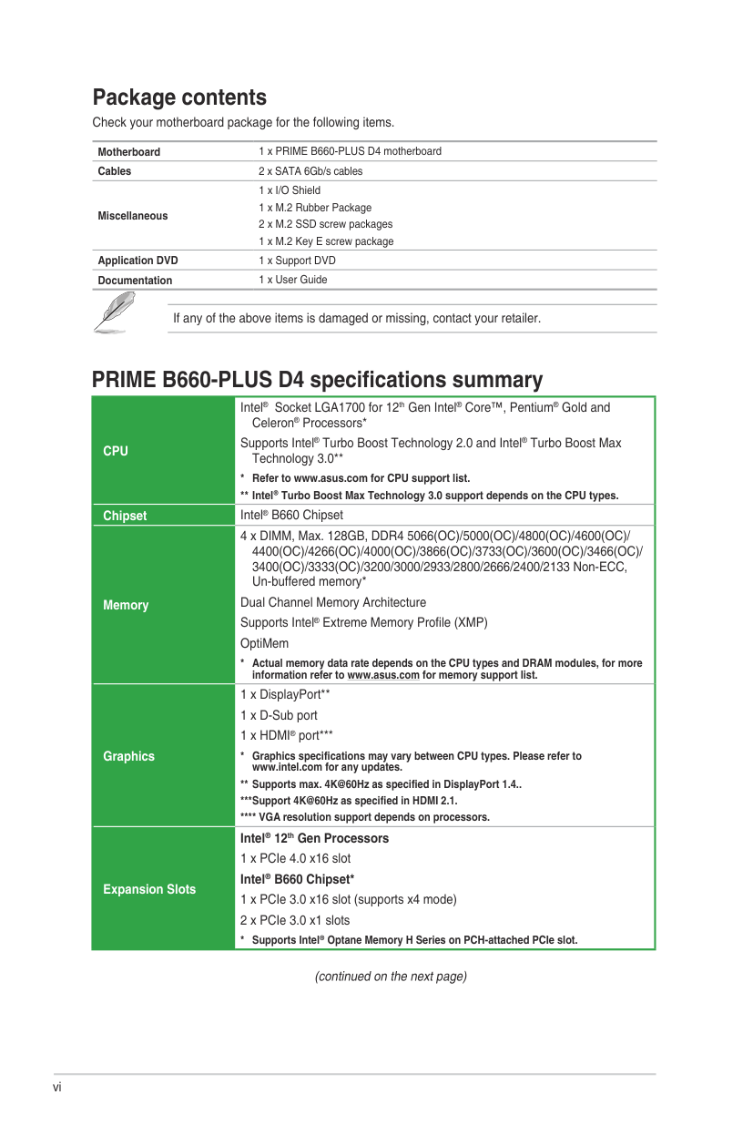
#### Package contents
Check your motherboard package for the following items.
Motherboard 1 x PRIME B660-PLUS D4 motherboard Cables 2 x SATA 6Gb/s cables
1 x I/O Shield
Miscellaneous
Application DVD 1 x Support DVD Documentation 1 x User Guide
If any of the above items is damaged or missing, contact your retailer.
#### PRIME B660-PLUS D4 specifications summary
|CPU
Intel® Socket LGA1700 for 12th Gen Intel® Core™, Pentium® Gold and Celeron® Processors*
Supports Intel® Turbo Boost Technology 2.0 and Intel® Turbo Boost Max Technology 3.0
* Refer to www.asus.com for CPU support list.
Intel® Turbo Boost Max Technology 3.0 support depends on the CPU types.
| |---| |Chipset Intel® B660 Chipset| |Memory
4 x DIMM, Max. 128GB, DDR4 5066(OC)/5000(OC)/4800(OC)/4600(OC)/ 4400(OC)/4266(OC)/4000(OC)/3866(OC)/3733(OC)/3600(OC)/3466(OC)/ 3400(OC)/3333(OC)/3200/3000/2933/2800/2666/2400/2133 Non-ECC, Un-buffered memory*
Dual Channel Memory Architecture Supports Intel® Extreme Memory Profile (XMP) OptiMem
* Actual memory data rate depends on the CPU types and DRAM modules, for more information refer to www.asus.com for memory support list.| |Graphics
1 x DisplayPort 1 x D-Sub port 1 x HDMI® port*
* Graphics specifications may vary between CPU types. Please refer to www.intel.com for any updates.
Supports max. 4K@60Hz as specified in DisplayPort 1.4..
*Support 4K@60Hz as specified in HDMI 2.1.
**** VGA resolution support depends on processors.| |Expansion Slots
Intel® 12th Gen Processors 1 x PCIe 4.0 x16 slot Intel® B660 Chipset*
1 x PCIe 3.0 x16 slot (supports x4 mode)
2 x PCIe 3.0 x1 slots
* Supports Intel® Optane Memory H Series on PCH-attached PCIe slot.|
(continued on the next page)
vi
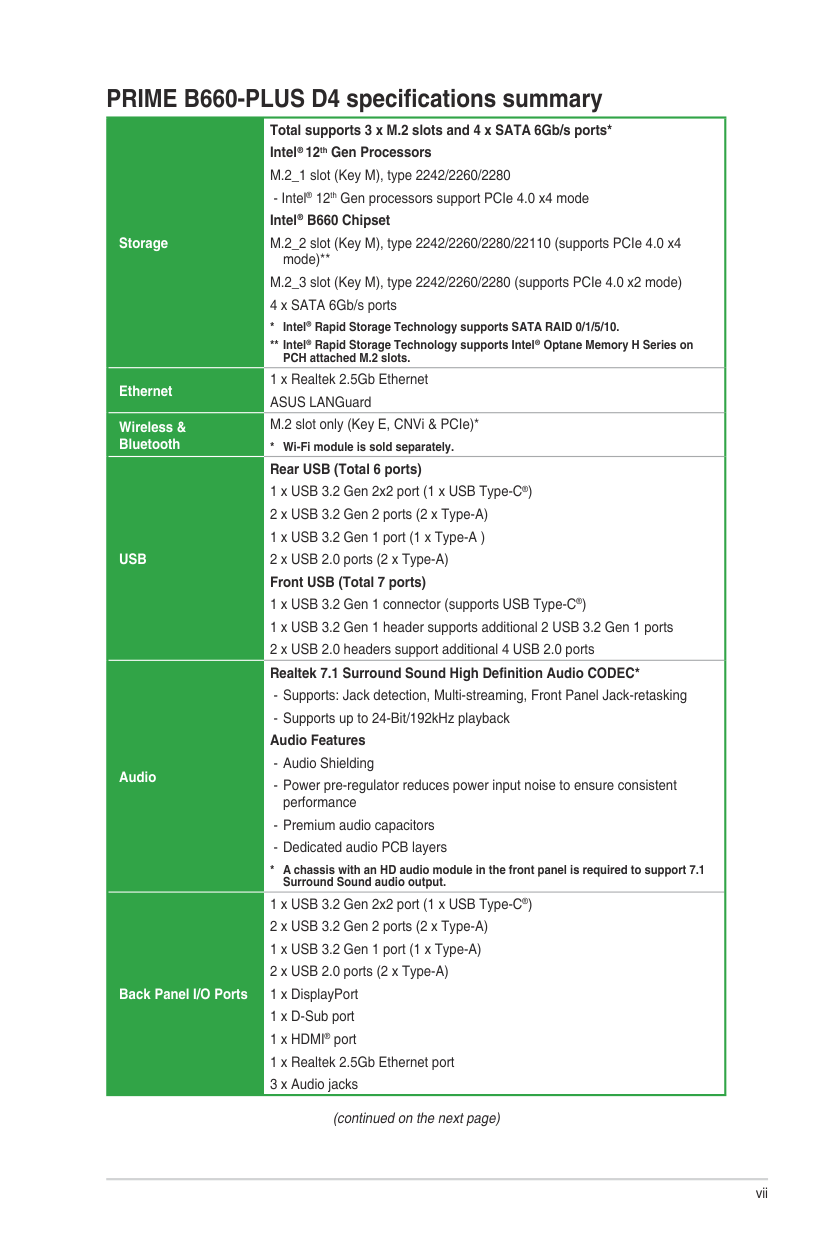
|Storage
Total supports 3 x M.2 slots and 4 x SATA 6Gb/s ports* Intel®12th Gen Processors
M.2_1 slot (Key M), type 2242/2260/2280
- Intel® 12th Gen processors support PCIe 4.0 x4 mode Intel® B660 Chipset
M.2_2 slot (Key M), type 2242/2260/2280/22110 (supports PCIe 4.0 x4 mode)
M.2_3 slot (Key M), type 2242/2260/2280 (supports PCIe 4.0 x2 mode)
4 x SATA 6Gb/s ports
* Intel® Rapid Storage Technology supports SATA RAID 0/1/5/10.
Intel® Rapid Storage Technology supports Intel® Optane Memory H Series on PCH attached M.2 slots.
| |---| |Ethernet
1 x Realtek 2.5Gb Ethernet ASUS LANGuard| |Wireless & Bluetooth
M.2 slot only (Key E, CNVi & PCIe)*
* Wi-Fi module is sold separately.| |USB
Rear USB (Total 6 ports)
1 x USB 3.2 Gen 2x2 port (1 x USB Type-C®)
2 x USB 3.2 Gen 2 ports (2 x Type-A)
1 x USB 3.2 Gen 1 port (1 x Type-A )
2 x USB 2.0 ports (2 x Type-A) Front USB (Total 7 ports) 1 x USB 3.2 Gen 1 connector (supports USB Type-C®)
1 x USB 3.2 Gen 1 header supports additional 2 USB 3.2 Gen 1 ports
2 x USB 2.0 headers support additional 4 USB 2.0 ports
| |Audio
Realtek 7.1 Surround Sound High Definition Audio CODEC*
- Supports: Jack detection, Multi-streaming, Front Panel Jack-retasking
- Supports up to 24-Bit/192kHz playback Audio Features
- Audio Shielding
- Power pre-regulator reduces power input noise to ensure consistent performance
- Premium audio capacitors
- Dedicated audio PCB layers
* A chassis with an HD audio module in the front panel is required to support 7.1 Surround Sound audio output.| |Back Panel I/O Ports
1 x USB 3.2 Gen 2x2 port (1 x USB Type-C®)
2 x USB 3.2 Gen 2 ports (2 x Type-A)
1 x USB 3.2 Gen 1 port (1 x Type-A)
2 x USB 2.0 ports (2 x Type-A) 1 x DisplayPort 1 x D-Sub port 1 x HDMI® port 1 x Realtek 2.5Gb Ethernet port
3 x Audio jacks
|
(continued on the next page)
vii
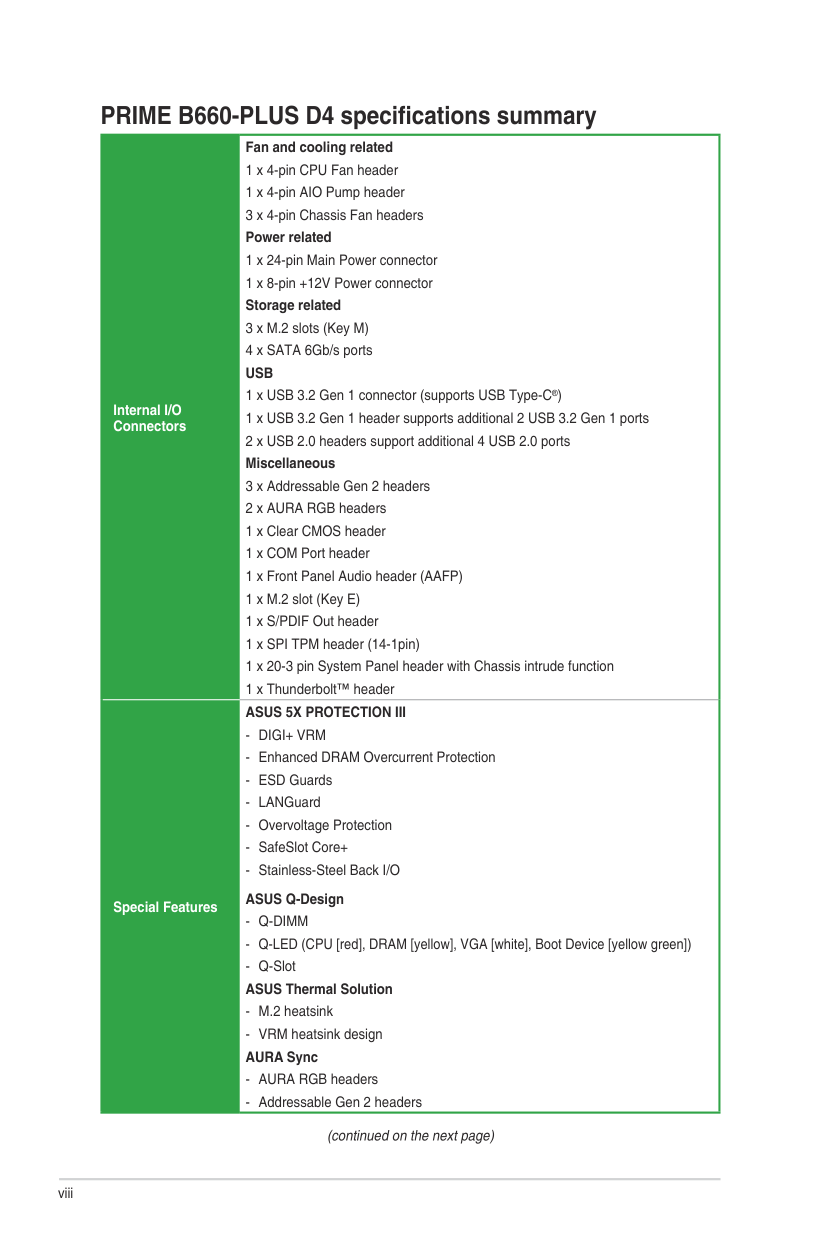
|Internal I/O Connectors
Fan and cooling related 1 x 4-pin CPU Fan header 1 x 4-pin AIO Pump header 3 x 4-pin Chassis Fan headers Power related 1 x 24-pin Main Power connector 1 x 8-pin +12V Power connector Storage related
3 x M.2 slots (Key M)
4 x SATA 6Gb/s ports USB
1 x USB 3.2 Gen 1 connector (supports USB Type-C®)
1 x USB 3.2 Gen 1 header supports additional 2 USB 3.2 Gen 1 ports
2 x USB 2.0 headers support additional 4 USB 2.0 ports Miscellaneous
3 x Addressable Gen 2 headers
2 x AURA RGB headers 1 x Clear CMOS header 1 x COM Port header 1 x Front Panel Audio header (AAFP) 1 x M.2 slot (Key E) 1 x S/PDIF Out header 1 x SPI TPM header (14-1pin) 1 x 20-3 pin System Panel header with Chassis intrude function 1 x Thunderbolt™ header
| |---| |Special Features
ASUS 5X PROTECTION III
- DIGI+ VRM
- Enhanced DRAM Overcurrent Protection
- ESD Guards
- LANGuard
- Overvoltage Protection
- SafeSlot Core+
- Stainless-Steel Back I/O ASUS Q-Design
- Q-DIMM
- Q-LED (CPU [red], DRAM [yellow], VGA [white], Boot Device [yellow green])
- Q-Slot ASUS Thermal Solution
- M.2 heatsink
- VRM heatsink design AURA Sync
- AURA RGB headers
- Addressable Gen 2 headers
|
(continued on the next page)
viii
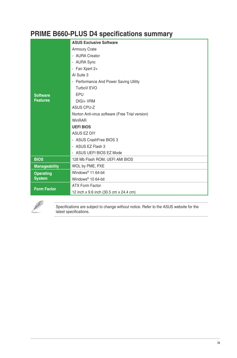
|Software Features
ASUS Exclusive Software Armoury Crate
- AURA Creator
- AURA Sync
- Fan Xpert 2+ AI Suite 3
- Performance And Power Saving Utility TurboV EVO EPU DIGI+ VRM ASUS CPU-Z Norton Anti-virus software (Free Trial version) WinRAR UEFI BIOS ASUS EZ DIY
- ASUS CrashFree BIOS 3
- ASUS EZ Flash 3
- ASUS UEFI BIOS EZ Mode
| |---| |BIOS 128 Mb Flash ROM, UEFI AMI BIOS| |Manageability WOL by PME, PXE| |Operating System
Windows® 11 64-bit Windows® 10 64-bit| |Form Factor
ATX Form Factor 12 inch x 9.6 inch (30.5 cm x 24.4 cm)|
Specifications are subject to change without notice. Refer to the ASUS website for the latest specifications.
ix
########### x
1
Product Introduction
#### 1.1 Before you proceed
Take note of the following precautions before you install motherboard components or change any motherboard settings.
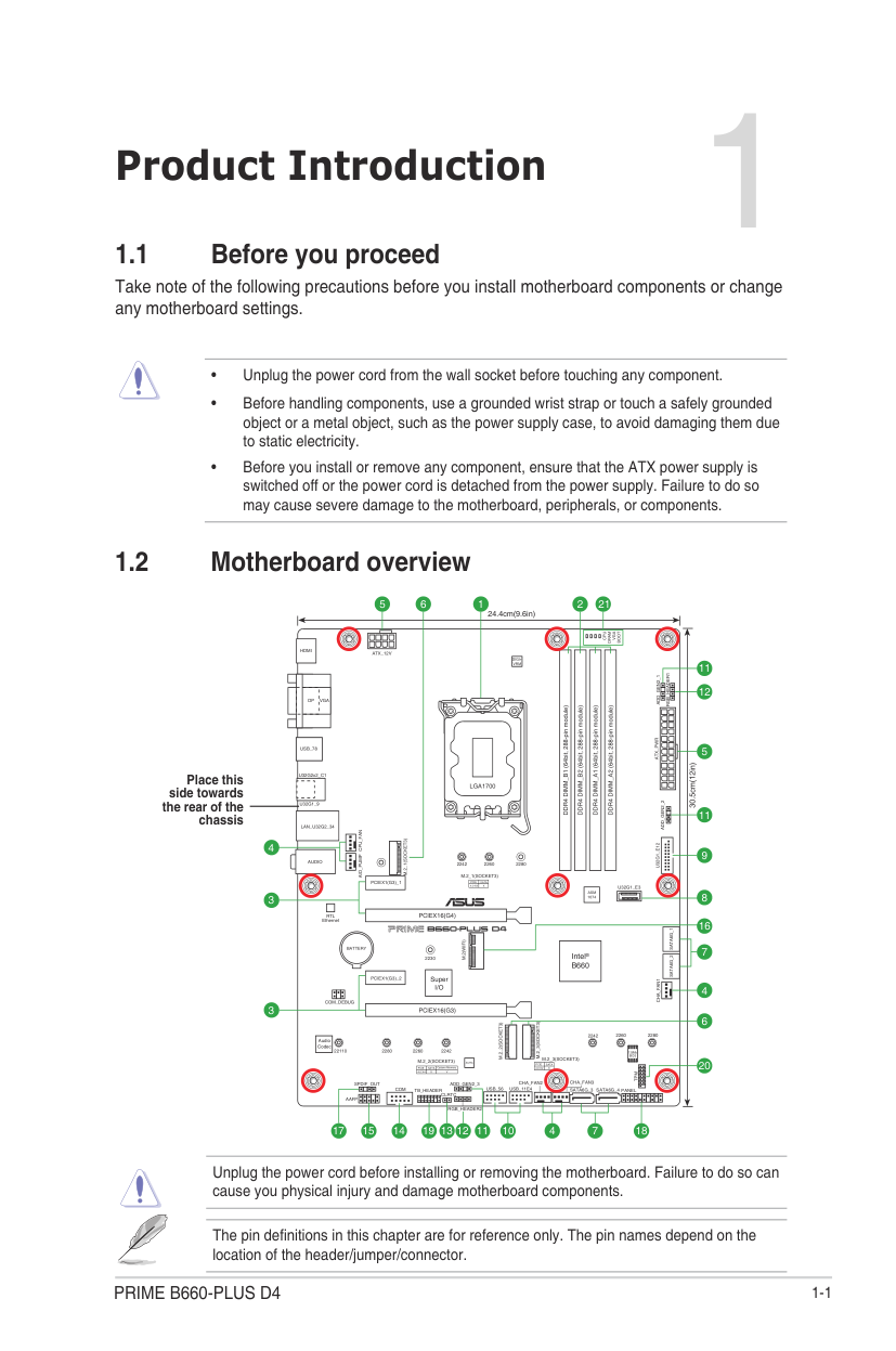
#### 1.2 Motherboard overview
5 216 21
24.4cm(9.6in)
VGA
BOOT
CPU
DRAM
HDMI
ATX_12V
DIGI+ VRM
11
RGB_HEADER1
8
7
20
6
16
DP
VGA
|LGA1700| |---|
ATX_PWRU32G1_E12
USB_78
30.5cm(12in)
Place this side towards the rear of the chassis
U32G2x2_C1
U32G1_9
LAN_U32G2_34
CPU_FANAIO_PUMP
M.2_1(SOCKET3)
9
AUDIO
228022602242
M.2_1(SOCKET3)
|PCIE|SATA| |---|---| |4.0 X4|X|
U32G1_E3
|ASM 1074| |---|
|PCIEX16(G4)| | |---|---|
|PCIEX16(G4)| | |PCIEX16(G4)| |
RTL Ethernet
SATA6G_1SATA6G_2
M.2(WIFI)
|Intel® B660| |---|
BATTERY
2230
|Super I/O| |---|
CHA_FAN1
| | | | |---|---|---|
COM_DEBUG
3
PCIEX16(G3)
M.2_3(SOCKET3)
M.2_2(SOCKET3)

228022602242
|Audio Codec| |---|
228022110 2260 2242
128Mb BIOS
M.2_3(SOCKET3)
M.2_2(SOCKET3)
AURA
|PCIE|SATA| |---|---| |4.0 X2|X|
|PCIE|SATA|Optane Memory| |---|---|---| |4.0 X4|X|V|
TPM
CHA_FAN3CHA_FAN2ADD_GEN2_3
SPDIF_OUT
USB_56 USB_11E4TB_HEADER
| | | | | |---|---|---|---|
COM
SATA6G_4SATA6G_3
PANEL AAFP
CLRTC
RGB_HEADER2
13 1219 11 10141517
74
18
Unplug the power cord before installing or removing the motherboard. Failure to do so can cause you physical injury and damage motherboard components.
The pin definitions in this chapter are for reference only. The pin names depend on the location of the header/jumper/connector.
##### 1.2.1 Layout contents
####### 1. CPU socket
The motherboard comes with a surface mount Intel® Socket LGA1700 designed for 12th Gen Intel® Core™, Pentium® Gold and Celeron® Processors.
For more details, refer to Central Processing Unit (CPU).
####### 2. DDR4 DIMM slots
The motherboard comes with Dual Inline Memory Modules (DIMM) slots designed for DDR4 (Double Data Rate 4) memory modules.
For more details, refer to System memory.
####### 3. Expansion slots
This motherboard supports two PCIe x16 graphics cards and two PCIe 3.0 x1 network cards, SCSI cards or other cards that comply with the PCI Express specification.
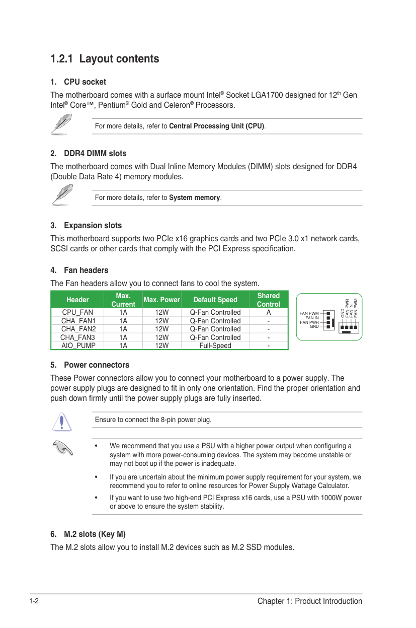
######## 4. Fan headersThe Fan headers allow you to connect fans to cool the system.
|Header|Max. Current|Max. Power|Default Speed|Shared Control| |---|---|---|---|---| |CPU_FAN|1A|12W|Q-Fan Controlled|A| |CHA_FAN1|1A|12W|Q-Fan Controlled|-| |CHA_FAN2|1A|12W|Q-Fan Controlled|-| |CHA_FAN3|1A|12W|Q-Fan Controlled|-| |AIO_PUMP|1A|12W|Full-Speed|-|
FAN PWM
FAN PWR
FAN IN
GND
FAN PWM
FAN IN FAN PWR
GND
####### 5. Power connectors
These Power connectors allow you to connect your motherboard to a power supply. The power supply plugs are designed to fit in only one orientation. Find the proper orientation and push down firmly until the power supply plugs are fully inserted.
Ensure to connect the 8-pin power plug.
######## 6. M.2 slots (Key M)The M.2 slots allow you to install M.2 devices such as M.2 SSD modules.
########## • Intel® 12th Gen Processors
M.2_1 slot (Key M), type 2242/2260/2280
########## • Intel® B660 Chipset
####### 7. SATA 6Gb/s ports
The SATA 6Gb/s ports allow you to connect SATA devices such as optical disc drives and hard disk drives via SATA cables.
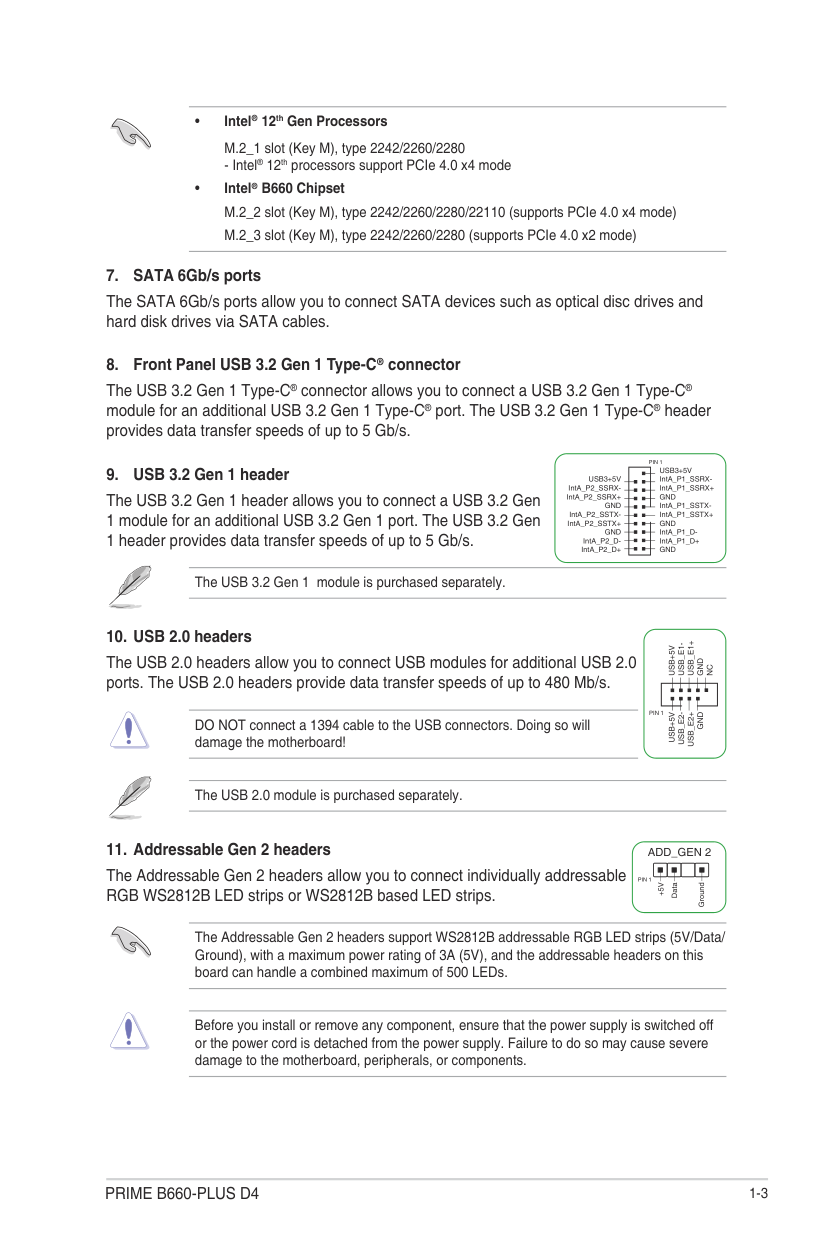
####### 8. Front Panel USB 3.2 Gen 1 Type-C® connector
The USB 3.2 Gen 1 Type-C® connector allows you to connect a USB 3.2 Gen 1 Type-C® module for an additional USB 3.2 Gen 1 Type-C® port. The USB 3.2 Gen 1 Type-C® header provides data transfer speeds of up to 5 Gb/s.
####### 9. USB 3.2 Gen 1 header
The USB 3.2 Gen 1 header allows you to connect a USB 3.2 Gen 1 module for an additional USB 3.2 Gen 1 port. The USB 3.2 Gen 1 header provides data transfer speeds of up to 5 Gb/s.
The USB 3.2 Gen 1 module is purchased separately.
PIN 1 USB3+5V
USB3+5V IntA_P1_SSRXIntA_P1_SSRX+ GND IntA_P1_SSTXIntA_P1_SSTX+ GND IntA_P1_DIntA_P1_D+ GND
| | | | |---|---|---| | | | | | | | | | | | | | | | | | | | | | | | |
| | | | | | | | | | | |
IntA_P2_SSRXIntA_P2_SSRX+
GND IntA_P2_SSTX-
IntA_P2_SSTX+
GND IntA_P2_D-
IntA_P2_D+
####### 10. USB 2.0 headers
USB_E1+
USB_E1-
USB+5V
The USB 2.0 headers allow you to connect USB modules for additional USB 2.0 ports. The USB 2.0 headers provide data transfer speeds of up to 480 Mb/s.
GND
NC
| | | | |---|---|---| | | | | | | | |
PIN 1
USB+5V
USB_E2-
USB_E2+
GND
DO NOT connect a 1394 cable to the USB connectors. Doing so will damage the motherboard!
The USB 2.0 module is purchased separately.
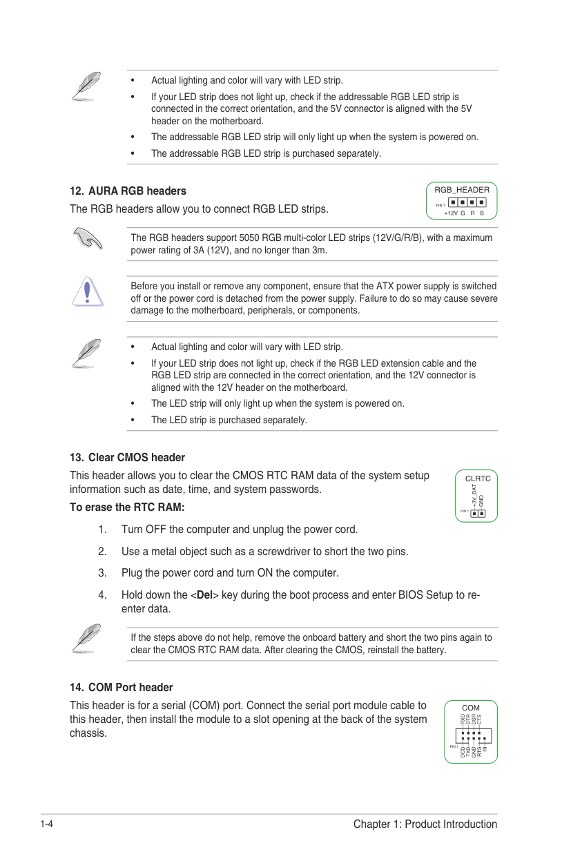
####### 11. Addressable Gen 2 headers
ADD_GEN 2
The Addressable Gen 2 headers allow you to connect individually addressable RGB WS2812B LED strips or WS2812B based LED strips.
PIN 1
+5V
Data
Ground
The Addressable Gen 2 headers support WS2812B addressable RGB LED strips (5V/Data/ Ground), with a maximum power rating of 3A (5V), and the addressable headers on this board can handle a combined maximum of 500 LEDs.
Before you install or remove any component, ensure that the power supply is switched off or the power cord is detached from the power supply. Failure to do so may cause severe damage to the motherboard, peripherals, or components.
The RGB headers support 5050 RGB multi-color LED strips (12V/G/R/B), with a maximum power rating of 3A (12V), and no longer than 3m.
Before you install or remove any component, ensure that the ATX power supply is switched off or the power cord is detached from the power supply. Failure to do so may cause severe damage to the motherboard, peripherals, or components.
This header allows you to clear the CMOS RTC RAM data of the system setup information such as date, time, and system passwords. To erase the RTC RAM:
If the steps above do not help, remove the onboard battery and short the two pins again to clear the CMOS RTC RAM data. After clearing the CMOS, reinstall the battery.
CLRTC
+3V_BAT
GND
PIN 1
This header is for a serial (COM) port. Connect the serial port module cable to this header, then install the module to a slot opening at the back of the system chassis.
############## COM
RXDDTRDSRCTS
| | | | |---|---|---| | | | | | | | |
PIN 1
DCDTXDGNDRTSRI
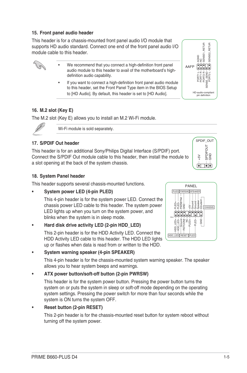
This header is for a chassis-mounted front panel audio I/O module that supports HD audio standard. Connect one end of the front panel audio I/O module cable to this header.
Wi-Fi module is sold separately.
This header is for an additional Sony/Philips Digital Interface (S/PDIF) port. Connect the S/PDIF Out module cable to this header, then install the module to a slot opening at the back of the system chassis.
AGND
NC
AAFP
PORT1 L
PORT2 L
SENSE_SEND
HD-audio-compliant pin definition
SPDIF_OUT
SPDIFOUT
GND
+5V
This 4-pin header is for the system power LED. Connect the chassis power LED cable to this header. The system power LED lights up when you turn on the system power, and blinks when the system is in sleep mode.
This 2-pin header is for the HDD Activity LED. Connect the HDD Activity LED cable to this header. The HDD LED lights up or flashes when data is read from or written to the HDD.
This 4-pin header is for the chassis-mounted system warning speaker. The speaker allows you to hear system beeps and warnings.
This header is for the system power button. Pressing the power button turns the system on or puts the system in sleep or soft-off mode depending on the operating system settings. Pressing the power switch for more than four seconds while the system is ON turns the system OFF.
This 2-pin header is for the chassis-mounted reset button for system reboot without turning off the system power.
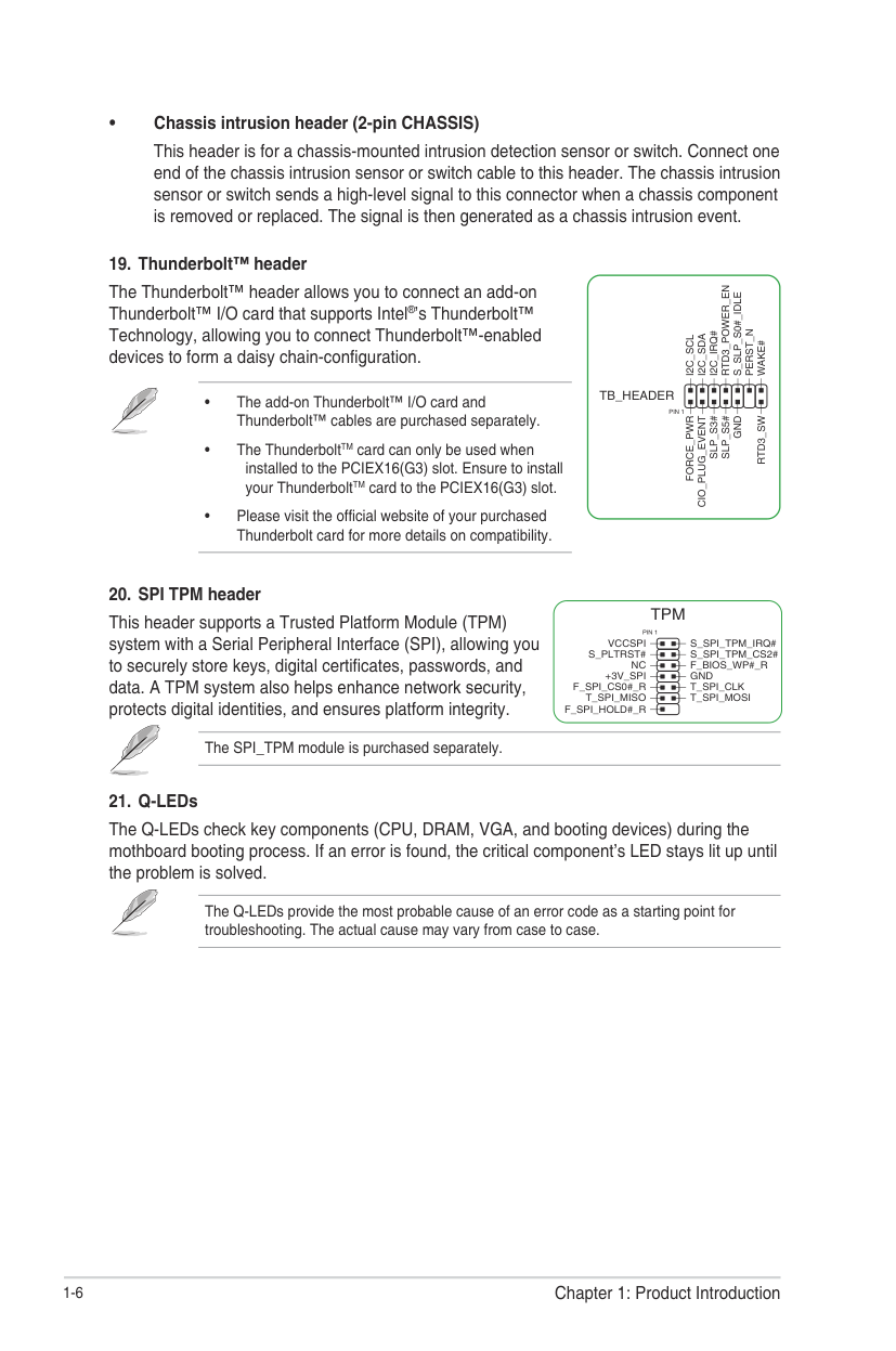
####### • Chassis intrusion header (2-pin CHASSIS)
This header is for a chassis-mounted intrusion detection sensor or switch. Connect one end of the chassis intrusion sensor or switch cable to this header. The chassis intrusion sensor or switch sends a high-level signal to this connector when a chassis component is removed or replaced. The signal is then generated as a chassis intrusion event.
####### 19. Thunderbolt™ header
The Thunderbolt™ header allows you to connect an add-on Thunderbolt™ I/O card that supports Intel®’s Thunderbolt™ Technology, allowing you to connect Thunderbolt™-enabled devices to form a daisy chain-configuration.
RTD3_POWER_EN
S_SLP_S0#_IDLE
PERST_N
I2C_IRQ#
I2C_SDA
I2C_SCL
WAKE#
TB_HEADER
PIN 1
FORCE_PWR
CIO_PLUG_EVENT
GND
RTD3_SW
SLP_S3#
SLP_S5#
####### 20. SPI TPM header
This header supports a Trusted Platform Module (TPM) system with a Serial Peripheral Interface (SPI), allowing you to securely store keys, digital certificates, passwords, and data. A TPM system also helps enhance network security, protects digital identities, and ensures platform integrity.
The SPI_TPM module is purchased separately.
TPM
PIN 1 VCCSPI
S_PLTRST# NC
+3V_SPI F_SPI_CS0#_R
T_SPI_MISO F_SPI_HOLD#_R
####### 21. Q-LEDs
The Q-LEDs check key components (CPU, DRAM, VGA, and booting devices) during the mothboard booting process. If an error is found, the critical component’s LED stays lit up until the problem is solved.
The Q-LEDs provide the most probable cause of an error code as a starting point for troubleshooting. The actual cause may vary from case to case.
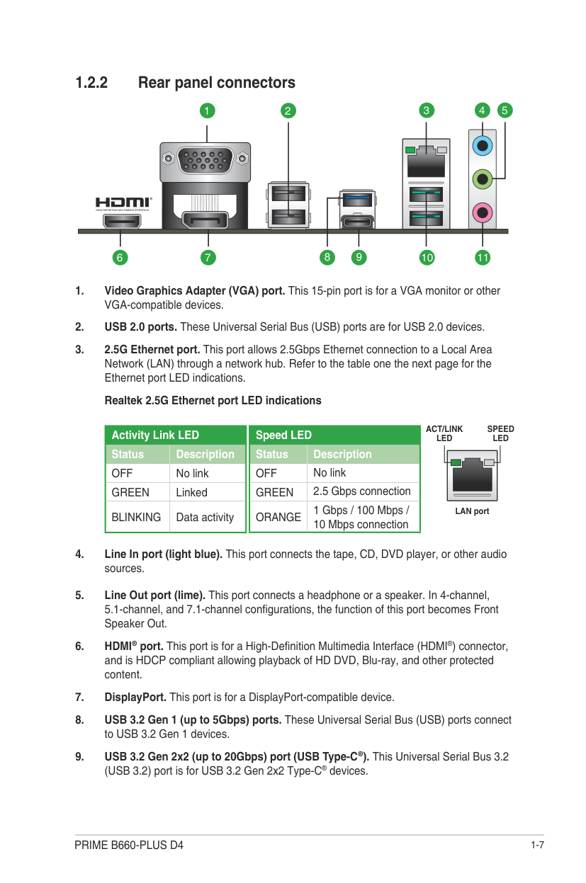
##### 1.2.2 Rear panel connectors
3 4 5
1 2
10679 11
8
|Speed LED|Speed LED| |---|---| |Status|Description| |OFF|No link| |GREEN|2.5 Gbps connection| |ORANGE|1 Gbps / 100 Mbps / 10 Mbps connection|
|Activity Link LED|Activity Link LED| |---|---| |Status|Description| |OFF|No link| |GREEN|Linked| |BLINKING|Data activity|
ACT/LINK LED
SPEED LED
LAN port
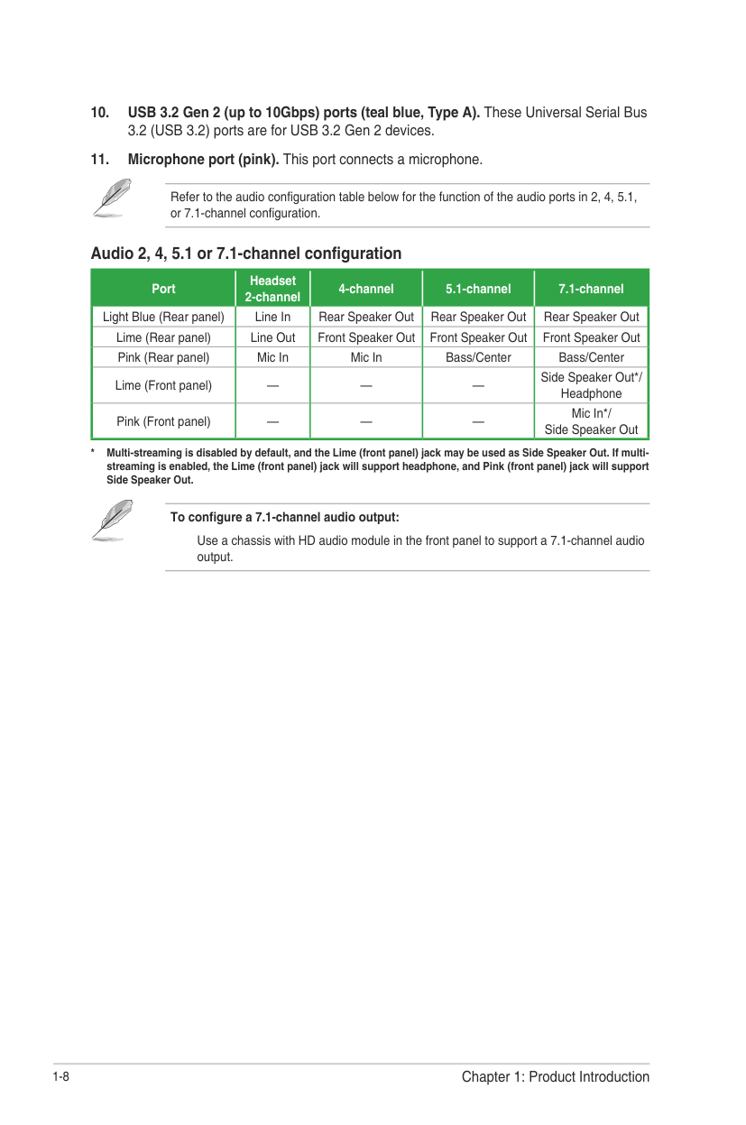
Refer to the audio configuration table below for the function of the audio ports in 2, 4, 5.1, or 7.1-channel configuration.
###### Audio 2, 4, 5.1 or 7.1-channel configuration
|Port Light Blue (Rear panel)|Headset 2-channel Line In|4-channel Rear Speaker Out|5.1-channel Rear Speaker Out|7.1-channel Rear Speaker Out| |---|---|---|---|---| |Lime (Rear panel)|Line Out|Front Speaker Out|Front Speaker Out|Front Speaker Out| |Pink (Rear panel)|Mic In|Mic In|Bass/Center|Bass/Center| |Lime (Front panel)|—|—|—|Side Speaker Out*/ Headphone| |Pink (Front panel)|—|—|—|Mic In*/ Side Speaker Out|
########## To configure a 7.1-channel audio output:
Use a chassis with HD audio module in the front panel to support a 7.1-channel audio output.
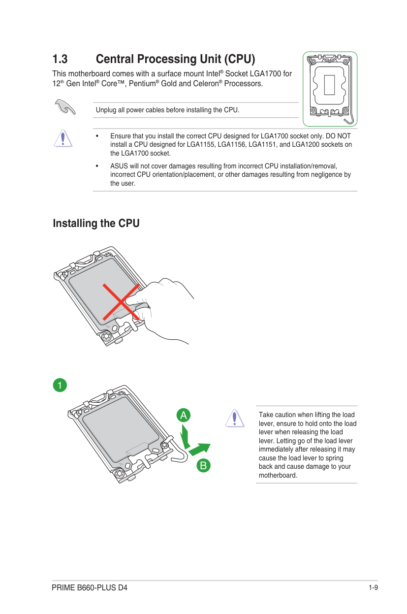
#### 1.3 Central Processing Unit (CPU)
| | |---|
This motherboard comes with a surface mount Intel® Socket LGA1700 for 12th Gen Intel® Core™, Pentium® Gold and Celeron® Processors.
Unplug all power cables before installing the CPU.
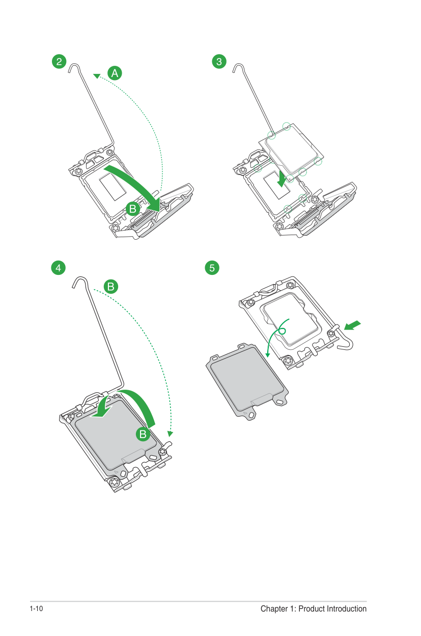
##### Installing the CPU
Take caution when lifting the load lever, ensure to hold onto the load lever when releasing the load lever. Letting go of the load lever immediately after releasing it may cause the load lever to spring back and cause damage to your motherboard.
######## 1-10 Chapter 1: Product Introduction
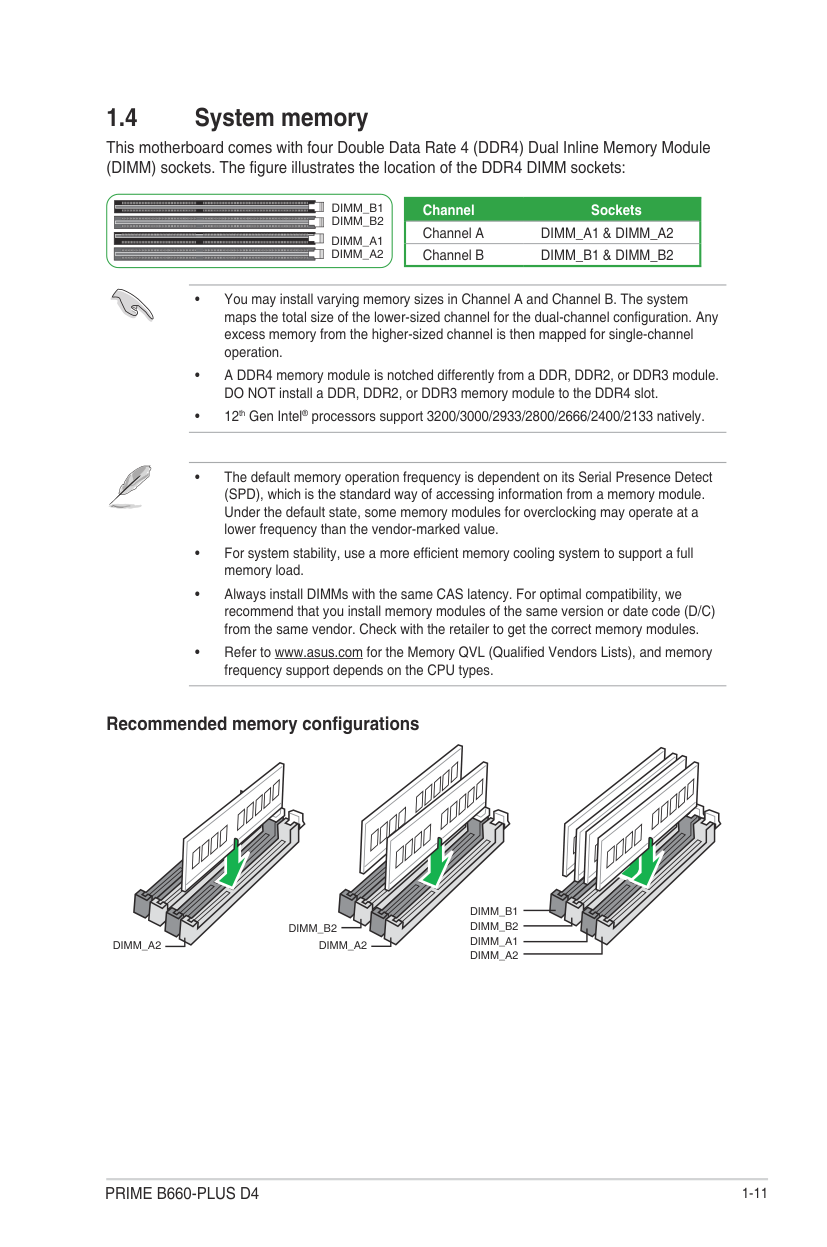
#### 1.4 System memory
This motherboard comes with four Double Data Rate 4 (DDR4) Dual Inline Memory Module (DIMM) sockets. The figure illustrates the location of the DDR4 DIMM sockets:
DIMM_B1
DIMM_B2
DIMM_A1
DIMM_A2
|Channel Sockets| |---| |Channel A DIMM_A1 & DIMM_A2| |Channel B DIMM_B1 & DIMM_B2|

###### Recommended memory configurations
DIMM_A2
DIMM_B1 DIMM_B2
DIMM_B2
DIMM_A2
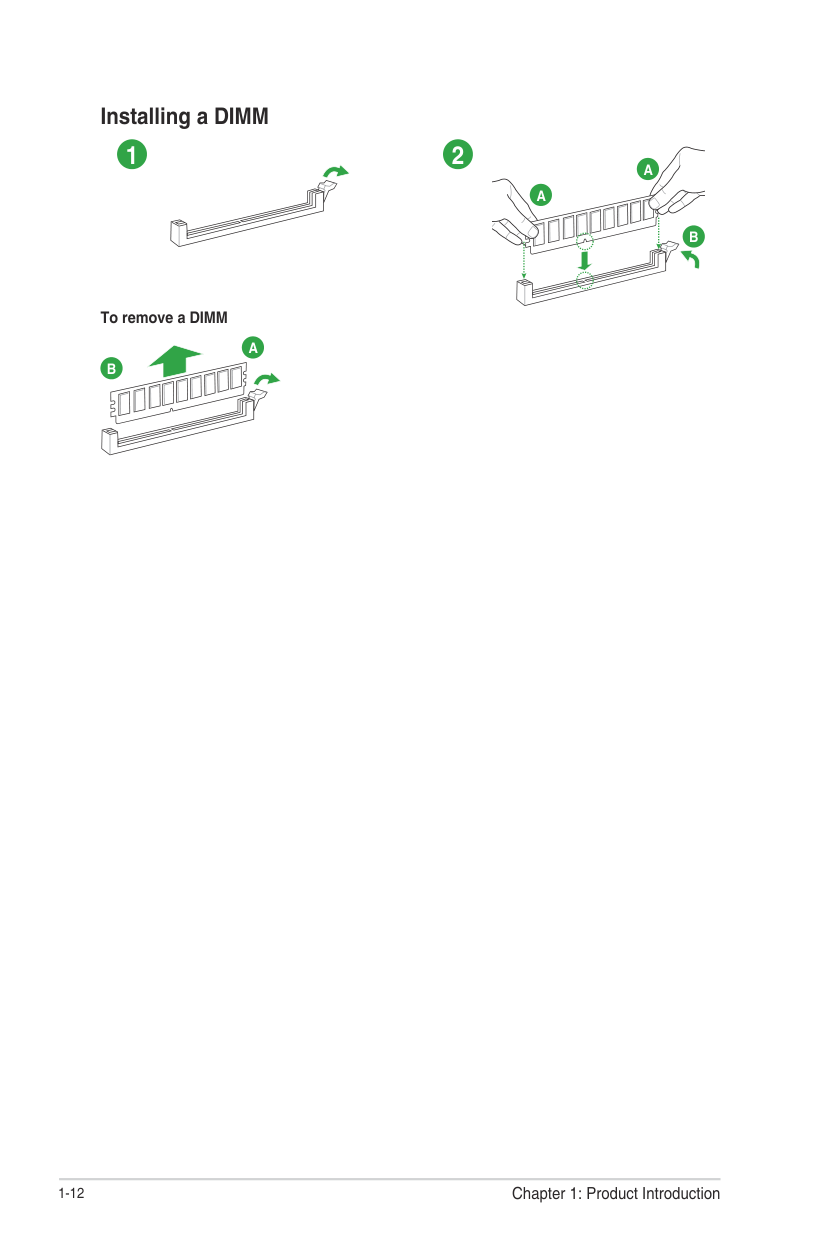
Installing a DIMM
#### 1 2
A
A
B
######### To remove a DIMM
A
B
Chapter 1: Product Introduction
1-12
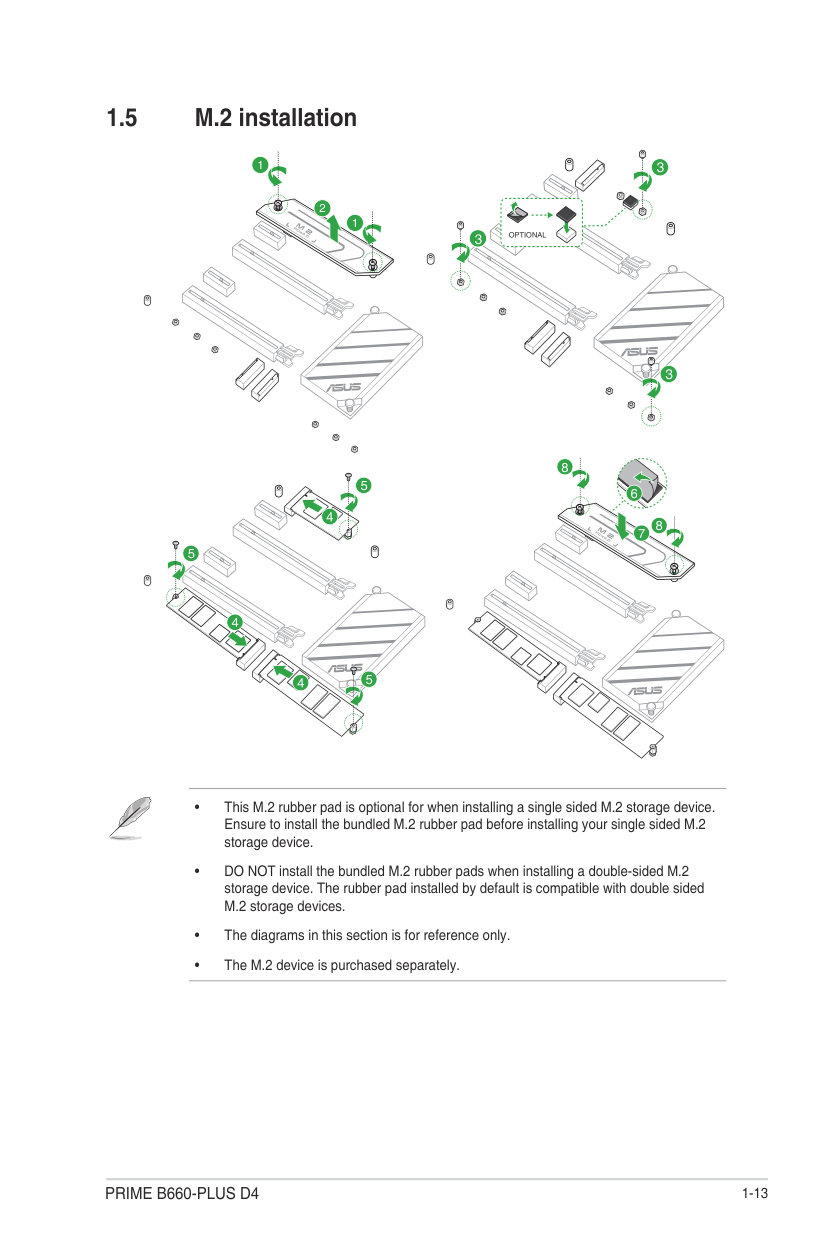
#### 1.5 M.2 installation
1
3
2
1
OPTIONAL
3
3
8
5
4
8
5
4
5
4
######## 1-14 Chapter 1: Product Introduction
BIOS and RAID Support
2
The new ASUS UEFI BIOS is a Unified Extensible Interface that complies with UEFI architecture, offering a user-friendly interface that goes beyond the traditional keyboardonly BIOS controls to enable a more flexible and convenient mouse input. You can easily navigate the new UEFI BIOS with the same smoothness as your operating system. The term “BIOS” in this user manual refers to “UEFI BIOS” unless otherwise specified.
BIOS (Basic Input and Output System) stores system hardware settings such as storage device configuration, overclocking settings, advanced power management, and boot device configuration that are needed for system startup in the motherboard CMOS. In normal circumstances, the default BIOS settings apply to most conditions to ensure optimal performance. DO NOT change the default BIOS settings except in the following circumstances:
Inappropriate BIOS settings may result to instability or boot failure. We strongly recommend that you change the BIOS settings only with the help of a trained service personnel.
BIOS settings and options may vary due to different BIOS release versions. Please refer to the latest BIOS version for settings and options.
For more information on BIOS configurations, please refer to https://www.asus.com/support, or download the BIOS manual by scanning the QR code.

#### 2.2 BIOS Setup program
Use the BIOS Setup to update the BIOS or configure its parameters. The BIOS screens include navigation keys and brief onscreen help to guide you in using the BIOS Setup program.
Entering BIOS at startup To enter BIOS Setup at startup, press
###### Entering BIOS Setup after POST To enter BIOS Setup after POST:
After doing either of the three options, press
BIOS menu screen The BIOS Setup program can be used under two modes: EZ Mode and Advanced Mode. You can change modes from Setup Mode in Boot menu or by pressing the
#### 2.3 ASUS EZ Flash 3
The ASUS EZ Flash 3 feature allows you to update the BIOS without using an OS-based utility.
Ensure to load the BIOS default settings to ensure system compatibility and stability. Select the Load Optimized Defaults item under the Exit menu or press hotkey
####### To update the BIOS:
#### 2.4 ASUS CrashFree BIOS 3
The ASUS CrashFree BIOS 3 utility is an auto recovery tool that allows you to restore the BIOS file when it fails or gets corrupted during the updating process. You can restore a corrupted BIOS file using a USB flash drive that contains the BIOS file.
###### Recovering the BIOS
DO NOT shut down or reset the system while updating the BIOS! Doing so can cause system boot failure!
Appendix
#### Notices FCC Compliance Information
Responsible Party: Asus Computer International
Address: 48720 Kato Rd., Fremont, CA 94538, USA Phone / Fax No: (510)739-3777 / (510)608-4555
This device complies with part 15 of the FCC Rules. Operation is subject to the following two conditions: (1) This device may not cause harmful interference, and (2) this device must accept any interference received, including interference that may cause undesired operation. This equipment has been tested and found to comply with the limits for a Class B digital device, pursuant to part 15 of the FCC Rules. These limits are designed to provide reasonable protection against harmful interference in a residential installation. This equipment generates, uses and can radiate radio frequency energy and, if not installed and used in accordance with the instructions, may cause harmful interference to radio communications. However, there is no guarantee that interference will not occur in a particular installation. If this equipment does cause harmful interference to radio or television reception, which can be determined by turning the equipment off and on, the user is encouraged to try to correct the interference by one or more of the following measures:
##### HDMI Trademark Notice
The terms HDMI, HDMI High-Definition Multimedia Interface, and the HDMI Logo are trademarks or registered trademarks of HDMI Licensing Administrator, Inc.
Compliance Statement of Innovation, Science and Economic Development Canada (ISED)
This device complies with Innovation, Science and Economic Development Canada licence exempt RSS standard(s). Operation is subject to the following two conditions: (1) this device may not cause interference, and (2) this device must accept any interference, including interference that may cause undesired operation of the device. CAN ICES-003(B)/NMB-003(B)
##### Déclaration de conformité de Innovation, Sciences et Développement économique Canada (ISED)
Le présent appareil est conforme aux CNR d’Innovation, Sciences et Développement économique Canada applicables aux appareils radio exempts de licence. L’exploitation est autorisée aux deux conditions suivantes : (1) l’appareil ne doit pas produire de brouillage, et (2) l’utilisateur de l’appareil doit accepter tout brouillage radioélectrique subi, même si le brouillage est susceptible d’en compromettre le fonctionnement. CAN ICES-003(B)/NMB-003(B)
VCCI: Japan Compliance Statement Class B ITE

##### Japan JATE
本製品は電気通信事業者(移動通信会社、固定通信会社、インターネットプロバイダ等)の通信 回線(公衆無線LANを含む)に直接接続することができません。本製品をインターネットに接続す る場合は、必ずルーター等を経由し接続してください。
##### KC: Korea Warning Statement

Google™ License Terms Copyright© 2022 Google Inc. All Rights Reserved. Licensed under the Apache License, Version 2.0 (the “License”); you may not use this file except in compliance with the License. You may obtain a copy of the License at: http://www.apache.org/licenses/LICENSE-2.0 Unless required by applicable law or agreed to in writing, software distributed under the License is distributed on an “AS IS” BASIS, WITHOUT WARRANTIES OR CONDITIONS OF ANY KIND, either express or implied. See the License for the specific language governing permissions and limitations under the License.
##### Declaration of compliance for product environmental regulation
ASUS follows the green design concept to design and manufacture our products, and makes sure that each stage of the product life cycle of ASUS product is in line with global environmental regulations. In addition, ASUS disclose the relevant information based on regulation requirements. Please refer to http://csr.asus.com/Compliance.htm for information disclosure based on regulation requirements ASUS is complied with:
EU REACH and Article 33 Complying with the REACH (Registration, Evaluation, Authorisation, and Restriction of Chemicals) regulatory framework, we published the chemical substances in our products at ASUS REACH website at http://csr.asus.com/english/REACH.htm.
EU RoHS This product complies with the EU RoHS Directive. For more details, see http://csr.asus.com/english/article.aspx?id=35
India RoHS This product complies with the “India E-Waste (Management) Rules, 2016” and prohibits use of lead, mercury, hexavalent chromium, polybrominated biphenyls (PBBs) and polybrominated diphenyl ethers (PBDEs) in concentrations exceeding 0.1% by weight in homogenous materials and 0.01% by weight in homogenous materials for cadmium, except for the exemptions listed in Schedule II of the Rule.
Vietnam RoHS ASUS products sold in Vietnam, on or after September 23, 2011,meet the requirements of the Vietnam Circular 30/2011/TT-BCT.
Các sản phẩm ASUS bán tại Việt Nam, vào ngày 23 tháng 9 năm2011 trở về sau, đều phải đáp ứng các yêu cầu của Thông tư 30/2011/TT-BCT của Việt Nam.
Turkey RoHS AEEE Yönetmeliğine Uygundur
ASUS Recycling/Takeback Services ASUS recycling and takeback programs come from our commitment to the highest standards for protecting our environment. We believe in providing solutions for you to be able to responsibly recycle our products, batteries, other components as well as the packaging materials. Please go to http://csr.asus.com/english/Takeback.htm for detailed recycling information in different regions.
DO NOT throw the motherboard in municipal waste. This product has been designed to enable proper reuse of parts and recycling. This symbol of the crossed out wheeled bin indicates that the product (electrical and electronic equipment) should not be placed in municipal waste. Check local regulations for disposal of electronic products.
DO NOT throw the mercury-containing button cell battery in municipal waste. This symbol of the crossed out wheeled bin indicates that the battery should not be placed in municipal waste.
English ASUSTeK Computer Inc. hereby declares that this device is in compliance with the essential requirements and other relevant provisions of related UKCA Directives. Full text of UKCA declaration of conformity is available at: www.asus.com/support
English ASUSTeK Computer Inc. hereby declares that this device is in compliance with the essential requirements and other relevant provisions of related Directives. Full text of EU declaration of conformity is available at: www.asus.com/support Français AsusTek Computer Inc. déclare par la présente que cet appareil est conforme aux critères essentiels et autres clauses pertinentes des directives concernées. La déclaration de conformité de l’UE peut être téléchargée à partir du site Internet suivant : www.asus.com/support Deutsch ASUSTeK Computer Inc. erklärt hiermit, dass dieses Gerät mit den wesentlichen Anforderungen und anderen relevanten Bestimmungen der zugehörigen Richtlinien übereinstimmt. Der gesamte Text der EUKonformitätserklärung ist verfügbar unter: www.asus.com/support Italiano ASUSTeK Computer Inc. con la presente dichiara che questo dispositivo è conforme ai requisiti essenziali e alle altre disposizioni pertinenti con le direttive correlate. Il testo completo della dichiarazione di conformità UE è disponibile all’indirizzo: www.asus.com/support Русский Компания ASUS заявляет, что это устройство соответствует основным требованиям и другим соответствующим условиям соответствующих директив. Подробную информацию, пожалуйста, смотрите на www.asus.com/support Български С настоящото ASUSTeK Computer Inc. декларира, че това устройство е в съответствие със съществените изисквания и другите приложими постановления на свързаните директиви. Пълният текст на декларацията за съответствие на ЕС е достъпна на адрес: www.asus.com/support Hrvatski ASUSTeK Computer Inc. ovim izjavljuje da je ovaj uređaj sukladan s bitnim zahtjevima i ostalim odgovarajućim odredbama vezanih direktiva. Cijeli tekst EU izjave o sukladnosti dostupan je na: www.asus.com/support Čeština Společnost ASUSTeK Computer Inc. tímto prohlašuje, že toto zařízení splňuje základní požadavky a další příslušná ustanovení souvisejících směrnic. Plné znění prohlášení o shodě EU je k dispozici na adrese: www.asus.com/support Dansk ASUSTeK Computer Inc. erklærer hermed, at denne enhed er i overensstemmelse med hovedkravene og andre relevante bestemmelser i de relaterede direktiver. Hele EU-overensstemmelseserklæringen kan findes på: www.asus.com/support Nederlands ASUSTeK Computer Inc. verklaart hierbij dat dit apparaat voldoet aan de essentiële vereisten en andere relevante bepalingen van de verwante richtlijnen. De volledige tekst van de EU-verklaring van conformiteit is beschikbaar op: www.asus.com/support Eesti Käesolevaga kinnitab ASUSTeK Computer Inc, et see seade vastab asjakohaste direktiivide oluliste nõuetele ja teistele asjassepuutuvatele sätetele. EL vastavusdeklaratsiooni täielik tekst on saadaval järgmisel aadressil: www.asus.com/support Suomi ASUSTeK Computer Inc. ilmoittaa täten, että tämä laite on asiaankuuluvien direktiivien olennaisten vaatimusten ja muiden tätä koskevien säädösten mukainen. EU-yhdenmukaisuusilmoituksen koko teksti on luettavissa osoitteessa: www.asus.com/support Ελληνικά Με το παρόν, η AsusTek Computer Inc. δηλώνει ότι αυτή η συσκευή συμμορφώνεται με τις θεμελιώδεις απαιτήσεις και άλλες σχετικές διατάξεις των Οδηγιών της ΕΕ. Το πλήρες κείμενο της δήλωσης συμβατότητας είναι διαθέσιμο στη διεύθυνση: www.asus.com/support
Magyar Az ASUSTeK Computer Inc. ezennel kijelenti, hogy ez az eszköz megfelel a kapcsolódó Irányelvek lényeges követelményeinek és egyéb vonatkozó rendelkezéseinek. Az EU megfelelőségi nyilatkozat teljes szövege innen letölthető: www.asus.com/support Latviski ASUSTeK Computer Inc. ar šo paziņo, ka šī ierīce atbilst saistīto
Direktīvu būtiskajām prasībām un citiem citiem saistošajiem nosacījumiem. Pilns ES atbilstības paziņojuma teksts pieejams šeit: www.asus.com/support Lietuvių „ASUSTeK Computer Inc.“ šiuo tvirtina, kad šis įrenginys atitinka
pagrindinius reikalavimus ir kitas svarbias susijusių direktyvų nuostatas. Visą ES atitikties deklaracijos tekstą galima rasti: www.asus.com/support Norsk ASUSTeK Computer Inc. erklærer herved at denne enheten er i samsvar med hovedsaklige krav og andre relevante forskrifter i relaterte direktiver. Fullstendig tekst for EU-samsvarserklæringen finnes på: www.asus.com/support Polski Firma ASUSTeK Computer Inc. niniejszym oświadcza, że
urządzenie to jest zgodne z zasadniczymi wymogami i innymi właściwymi postanowieniami powiązanych dyrektyw. Pełny tekst deklaracji zgodności UE jest dostępny pod adresem: www.asus.com/support
Português A ASUSTeK Computer Inc. declara que este dispositivo está em conformidade com os requisitos essenciais e outras disposições relevantes das Diretivas relacionadas. Texto integral da declaração da UE disponível em: www.asus.com/support
Română ASUSTeK Computer Inc. declară că acest dispozitiv se conformează cerinţelor esenţiale şi altor prevederi relevante ale directivelor conexe. Textul complet al declaraţiei de conformitate a Uniunii Europene se găseşte la: www.asus.com/support Srpski ASUSTeK Computer Inc. ovim izjavljuje da je ovaj uređaj u saglasnosti sa osnovnim zahtevima i drugim relevantnim odredbama povezanih Direktiva. Pun tekst EU deklaracije o usaglašenosti je dostupan da adresi: www.asus.com/support Slovensky Spoločnosť ASUSTeK Computer Inc. týmto vyhlasuje, že toto zariadenie vyhovuje základným požiadavkám a ostatým príslušným ustanoveniam príslušných smerníc. Celý text vyhlásenia o zhode pre štáty EÚ je dostupný na adrese: www.asus.com/support Slovenščina ASUSTeK Computer Inc. izjavlja, da je ta naprava skladna z bistvenimi zahtevami in drugimi ustreznimi določbami povezanih direktiv. Celotno besedilo EU-izjave o skladnosti je na voljo na spletnem mestu: www.asus.com/support Español Por la presente, ASUSTeK Computer Inc. declara que este dispositivo cumple los requisitos básicos y otras disposiciones pertinentes de las directivas relacionadas. El texto completo de la declaración de la UE de conformidad está disponible en: www.asus.com/support Svenska ASUSTeK Computer Inc. förklarar härmed att denna enhet överensstämmer med de grundläggande kraven och andra relevanta föreskrifter i relaterade direktiv. Fulltext av EU-försäkran om överensstämmelse finns på: www.asus.com/support Українська ASUSTeK Computer Inc. заявляє, що цей пристрій відповідає основним вимогам та іншим відповідним положенням відповідних Директив. Повний текст декларації відповідності стандартам ЄС доступний на: www.asus.com/support Türkçe AsusTek Computer Inc., bu aygıtın temel gereksinimlerle ve ilişkili Yönergelerin diğer ilgili koşullarıyla uyumlu olduğunu beyan eder. AB uygunluk bildiriminin tam metni şu adreste bulunabilir: www.asus.com/support
Bosanski ASUSTeK Computer Inc. ovim izjavljuje da je ovaj uređaj usklađen sa bitnim zahtjevima i ostalim odgovarajućim odredbama vezanih direktiva. Cijeli tekst EU izjave o usklađenosti dostupan je na: www.asus.com/support
#### Warranty
############### EN: ASUS Guarantee Information
For all the guarantee information, please visit https://www.asus.com/support.
############### F: Garantie ASUS
Pour plus d'informations sur la garantie, consultez le site https://www.asus.com/fr/support/.
############### G: ASUS Garantieinformationen
Die vollständigen Garantieinformationen finden Sie unter https://www.asus.com/de/support/.
############### I: Informativa sulla Garanzia ASUS
Per tutte le informazioni sulla garanzia, visitare https://www.asus.com/it/support.
R: Информация о гарантии ASUS
Для получения полной информации о гарантии посетите https://www.asus.com/ru/support/.
############### DA: ASUS garantioplysninger
Alle garantioplysningerne kan findes på https://www.asus.com/dk/support/.
############### BG: Информация за гаранцията от ASUS
За цялостна информация относно гаранцията, моля, посетете https://www.asus.com/support.
CZ: Informace o záruce společnosti ASUS
Všechny informace o záruce najdete na adrese https://www.asus.com/cz/support/.
CR: Informacije o ASUS jamstvu
Sve informacije o jamstvu potražite na https://www.asus.com/support. DU: ASUS-garantie-informatie
Voor alle informatie over de garantie, gaat u naar https://www.asus.com/nl/support/.
############### EE: Teave ASUS-e garantii kohta
Vaadake garantiiga seotud teavet veebisaidilt https://www.asus.com/ee/. GK: Πληροφορίες εγγύησης ASUS
Για όλες τις πληροφορίες εγγύησης, επισκεφθείτε τη διεύθυνση https://www.asus.com/gr-el/.
############### HUG: ASUS garanciális információk
A garanciára vonatkozó teljes körű információkért látogasson el a https://www.asus.com/hu/support/ oldalra.
############### LV: ASUS garantijas informācija
Lai iegūtu informāciju par garantiju, apmeklējiet vietni https://www.asus.com/lv/.
############# LT: Informacija apie ASUS garantiją
Norėdami gauti visą informaciją apie garantiją, apsilankykite https://www.asus.com/lt/. PL: Informacje o gwarancji firmy ASUS
Wszelkie informacje na temat gwarancji można znaleźć na stronie https://www.asus.com/pl/support.
############### PG: Informações de Garantia ASUS
############### SW: ASUS garantiinformation
Para consultar todas as informações sobre a garantia, visite https://www.asus.com/pt/support/. RO: Informații despre garanția ASUS
För all garantiinformation, besök https://www.asus.com/se/support/. UA: Інформація про Гарантію ASUS
Всю інформацію про гарантію подано тут: https://www.asus.com/ua/support.
Pentru toate informațiile legate de garanție, vizitați https://www.asus.com/ro/support.
MX: Garantía y Soporte Esta Garantía aplica en el país de compra. Usted acepta que en esta garantía:
############### SL: Informacije o garanciji ASUS
Vse informacije o garanciji najdete na spletnem mestu https://www.asus.com/support. SK: Informácie o záruke ASUS
Información de contacto ASUS Esta garantía está respaldada por: ASUSTeK Computer Inc. Centro de Atención ASUS +52 (55) 1946-3663
Všetky ďalšie informácie o záruke nájdete na https://www.asus.com/sk/support. ES: Información de garantía de ASUS
BP: Informações de garantia ASUS Esta garantia aplica-se ao período definido pela garantia legal (90 dias) mais o período de garantia comercial oferecido pela ASUS. Por exemplo: 12M significa 12 meses de garantia no total (3 meses de garantia legal mais 9 meses de garantia contratual), 24 meses significa 24 meses de garantia no total (3 meses de garantia legal mais 21 meses de garantia contratual) e 36 meses significa 36 meses de garantia no total (3 meses de garantia legal e 33 de garantia contratual) a contar da data da garantia declarada (Data de Início da Garantia).
Para obtener toda la información sobre la garantía, visite https://www.asus.com/ES/support/.
Para todas as informações de garantia, visite https://www.asus.com/br/support/.
############### TR: ASUS Garanti Bilgileri
ID: Informasi Garansi ASUS Garansi ini berlaku di negara tempat pembelian. Periode Garansi tertera pada kemasan/kotak dari Produk dan Masa Garansi dimulai sejak tanggal pembelian Produk ASUS dengan kondisi baru. Silahkan pindai Kode QR di bagian bawah halaman terakhir untuk Kartu Garansi versi Web dalam format PDF untuk lebih informasi jelas mengenai jaminan garansi Produk ASUS.
Tüm garanti bilgileri için lütfen https://www.asus.com/tr/support adresini ziyaret edin.
############### FI: ASUS-takuutiedot
Saadaksesi kaikki takuutiedot, siirry osoitteeseen https://www.asus.com/fi/support. NW: Informasjon om ASUS-garanti
https://www.asus.com/vn/support
Du finner fullstendig informasjon om garanti på https://www.asus.com/no/support/. SB: Informacije o ASUS garanciji

Za sve informacije o garanciji, posetite https://www.asus.com/support/.
#### ASUS contact information ASUSTeK COMPUTER INC.
Address: 1F., No. 15, Lide Rd., Beitou Dist., Taipei City 112, Taiwan ASUS COMPUTER INTERNATIONAL (America) Address: 48720 Kato Rd., Fremont, CA 94538, USA
##### ASUS COMPUTER GmbH (Germany and Austria) Address: Harkortstrasse 21-23, 40880 Ratingen, Germany
ASUSTeK (UK) LIMITED Address: 1st Floor, Sackville House, 143-149 Fenchurch Street, London, EC3M 6BL,
England, United Kingdom
#### Service and Support
Visit our multi-language website at https://www.asus.com/support.
