
Ask AI
— answers from the official manualAnswers from the official manual.
Common questions
Common Questions
10 totalHow do I factory reset the Candy Fcm925nrl Ovens?
Press and hold the Power button for 10 seconds until the LED flashes red. This clears all settings and returns the device to factory defaults. You will need to re-pair all connected devices after the reset.
What is the correct procedure if I suspect a gas leak?
Do not use a flame to check for leaks; instead, apply soapy water around joints and connections. If bubbles appear, there is a leakage, and you must contact a qualified electrician or an authorized service center.
How do I adjust the feet on my Candy Fcm925nrl Oven to level it?
Use a wrench to turn each adjustable foot individually until the oven is perfectly balanced and leveled. Ensure that any liquids in pans remain horizontal.
What steps should I take if the oven does not heat up properly?
Check that the oven control knobs are at the correct position, ensure the correct temperature has been selected, and verify there is no obstruction in the gas supply or electrical connection.
What are the safety recommendations for grilling with the Candy Fcm925nrl Oven?
Keep the top lid of the cooktop open during oven functions, close the oven door when using the grill function. Do not cover inner oven walls or bottom with aluminum foil to prevent damage to enamel.
How can I maintain the gas burners on my Candy Fcm925nrl Oven?
Check that burner holes are clear of obstructions, and periodically clean ignition electrodes and gas channels of burners to prevent ignition problems.
Full Manual
24 pages
USER INSTRUCTIONS COOKERS GB
CANDY HOOVER GROUP S.R.L. • Via Privata Eden Fumagalli • 20047 Brugherio Milano Italy
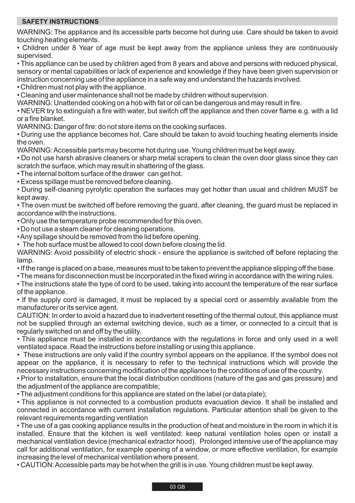
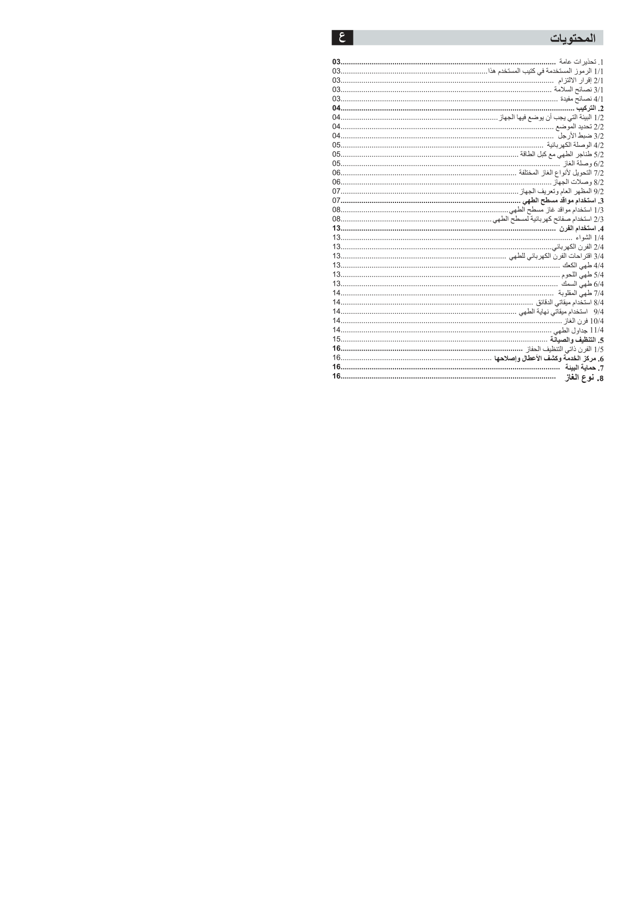
#### CONTENTS GB
............................................................................................03 ...........................................................................................04 ...............................................................04 .............................................................................04 ....................................................................................................04 .....................................................................................................04 ........................................................................................................04 ..............................................05 ......................................................................................................05 .............................................................................................05 .....................................................................................05 ..........................................................................06 ......................................................................06 ..............................................................................................06 ...............................................................07 ........................................................................07 ................................07 ................................................................................08 .........................................................................08 ....................................................................09 .............................................................................................09 ............................................................................................................09 .................................................................................................10 .........................................................09
Safety Instructions
.................................................................................................10 ................................................................................................10 ................................................................................................10
...................................................................................................10 ...........................................................................................10 ..................................................................................10 ................................................................11 .............................................................................................11 .............................................................................12 ........................................................................12 .................................................................12 .....................................................................12
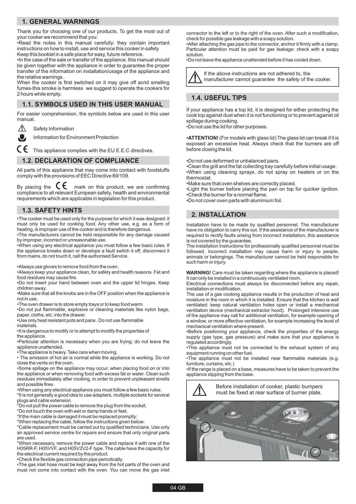
#### SAFETY INSTRUCTIONS
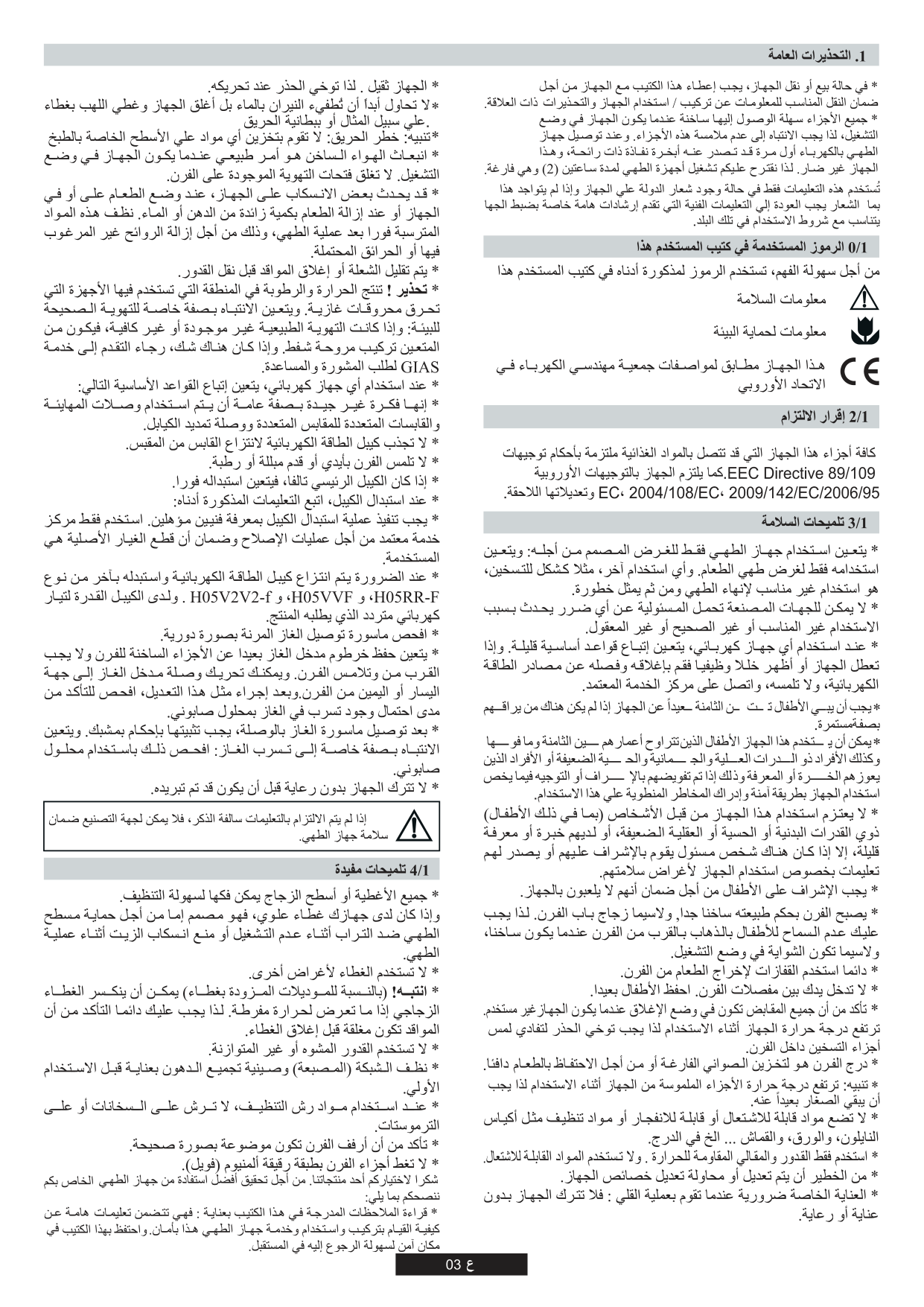
WARNING: The appliance and its accessible parts become hot during use. Care should be taken to avoid touching heating elements.
#### 1. GENERAL WARNINGS
Thank you for choosing one of our products. To get the most out of your cooker we recommend that you:
connector to the left or to the right of the oven. After such a modification, check for possible gas leakage with a soapy solution.
|If the above instructions are not adhered to, the manufacturer cannot guarantee the safety of the cooker.| |---|
#### 1.1. SYMBOLS USED IN THIS USER MANUAL
If your appliance has a top lid, it is designed for either protecting the cook top against dust when it is not functioning or to prevent against oil spillage during cooking.
For easier comprehension, the symbols below are used in this user manual.
Safety Information Information for Environment Protection
This appliance complies with the EU E.E.C directives.
#### 1.2. DECLARATION OF COMPLIANCE
All parts of this appliance that may come into contact with foodstuffs comply with the provisions of EEC Directive 89/109.
By placing the mark on this product, we are confirming compliance to all relevant European safety, health and environmental requirements which are applicable in legislation for this product.
#### 1.3. SAFETY HINTS
Installation have to be made by qualified personnel. The manufacturer have no obligation to carry this out. If the assistance of the manufacturer is required to rectify faults arising from incorrect installation, this assistance is not covered by the guarantee. The installation instructions for professionally qualified personnel must be followed. Incorrect installation may cause harm or injury to people, animals or belongings. The manufacturer cannot be held responsible for such harm or injury.
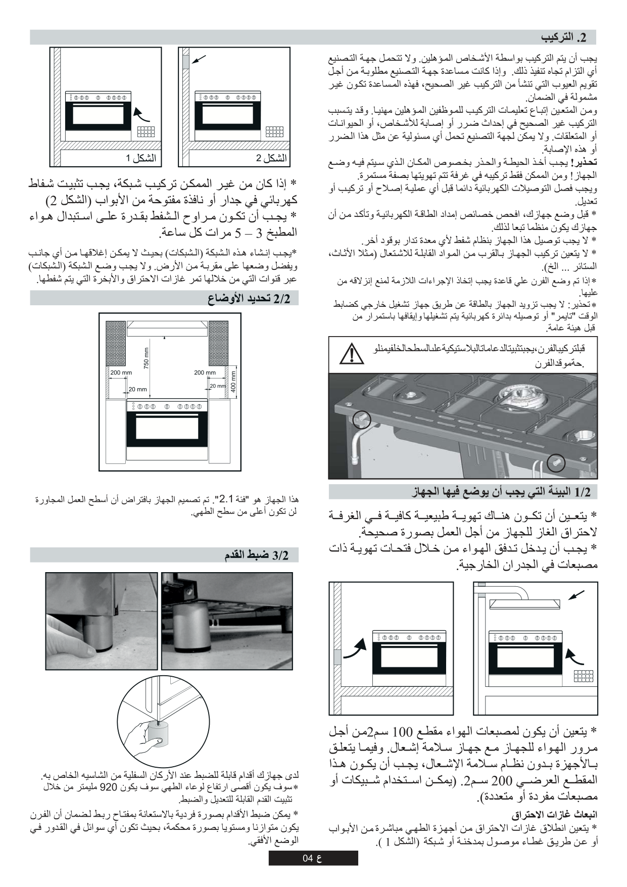
WARNING! Care must be taken regarding where the appliance is placed! It can only be installed in a continuously ventilated room. Electrical connections must always be disconnected before any repair, installation or modification. The use of a gas cooking appliance results in the production of heat and moisture in the room in which it is installed. Ensure that the kitchen is well ventilated: keep natural ventilation holes open or install a mechanical ventilation device (mechanical extractor hood). Prolonged intensive use of the appliance may call for additional ventilation, for example opening of a window, or more effective ventilation, for example increasing the level of mechanical ventilation where present.
|Before installation of cooker, plastic bumpers must be fixed at rear surface of burner plate.| |---| ||
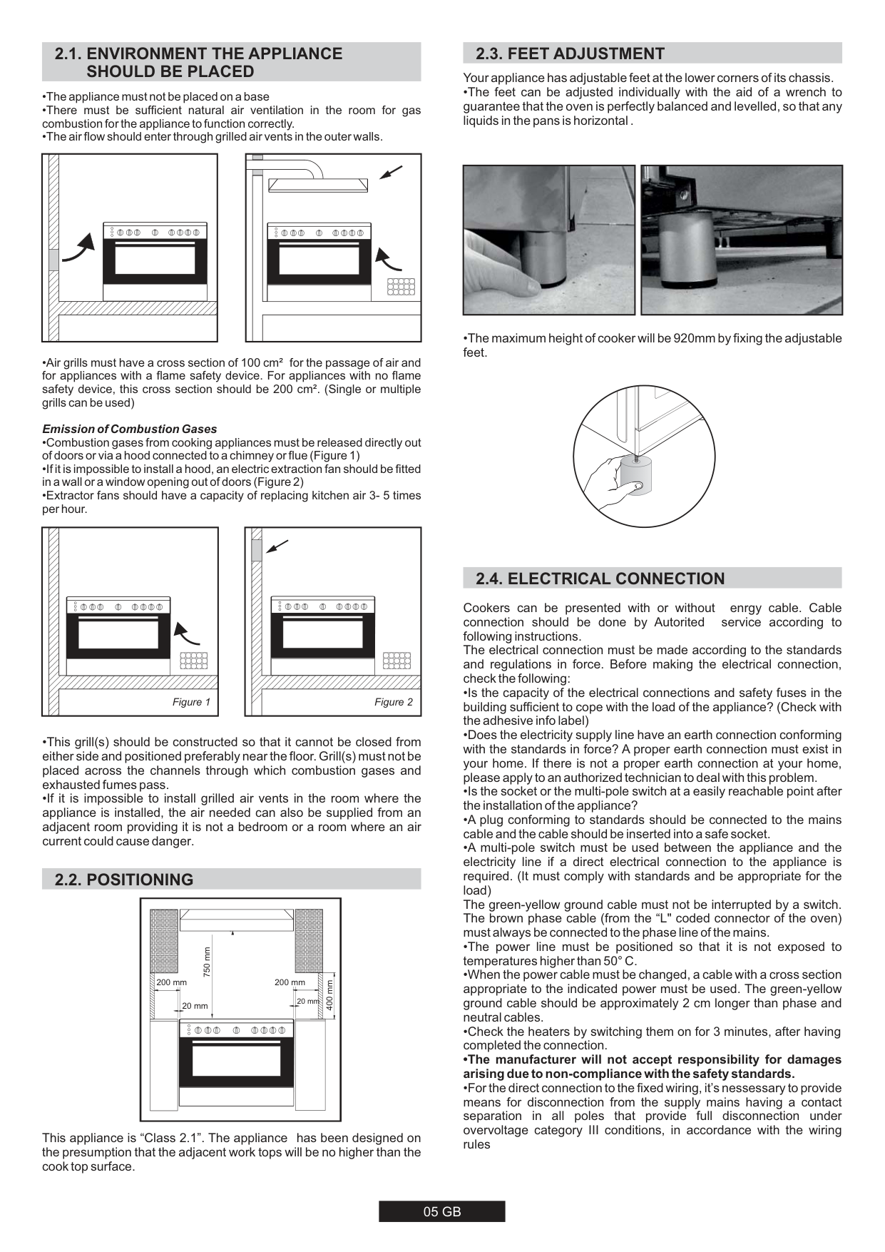
#### 2.1. ENVIRONMENT THE APPLIANCESHOULD BE PLACED
Figure 1 Figure 2
| | |---| | | | |
#### 2.2. POSITIONING
|| | |---| | | | |
750 mm
400 mm
200 mm 200 mm
20 mm 20 mm
| |---|
This appliance is “Class 2.1”. The appliance has been designed on the presumption that the adjacent work tops will be no higher than the cook top surface.
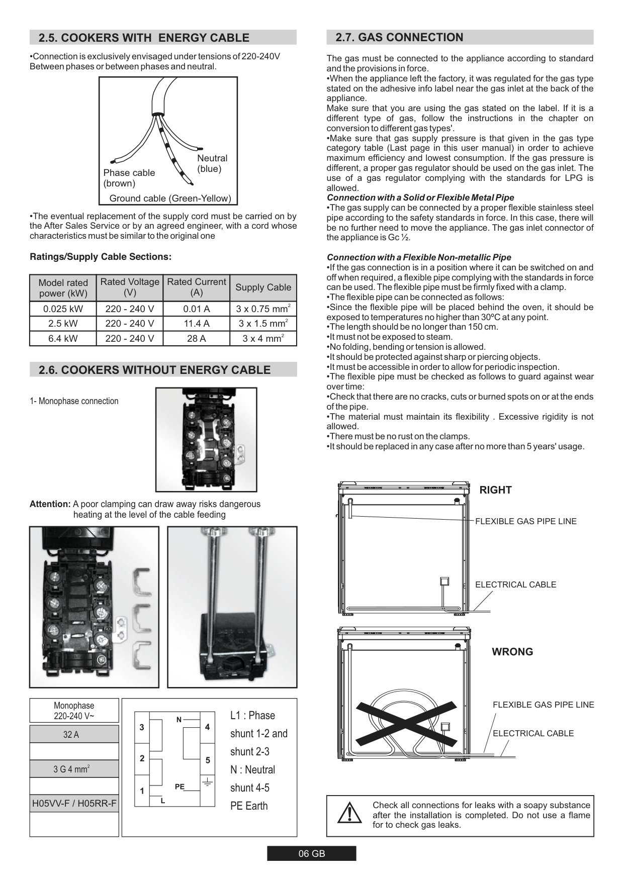
#### 2.3. FEET ADJUSTMENT
Your appliance has adjustable feet at the lower corners of its chassis.
|| |---|
|| |---|
###### 2.4. ELECTRICAL CONNECTION
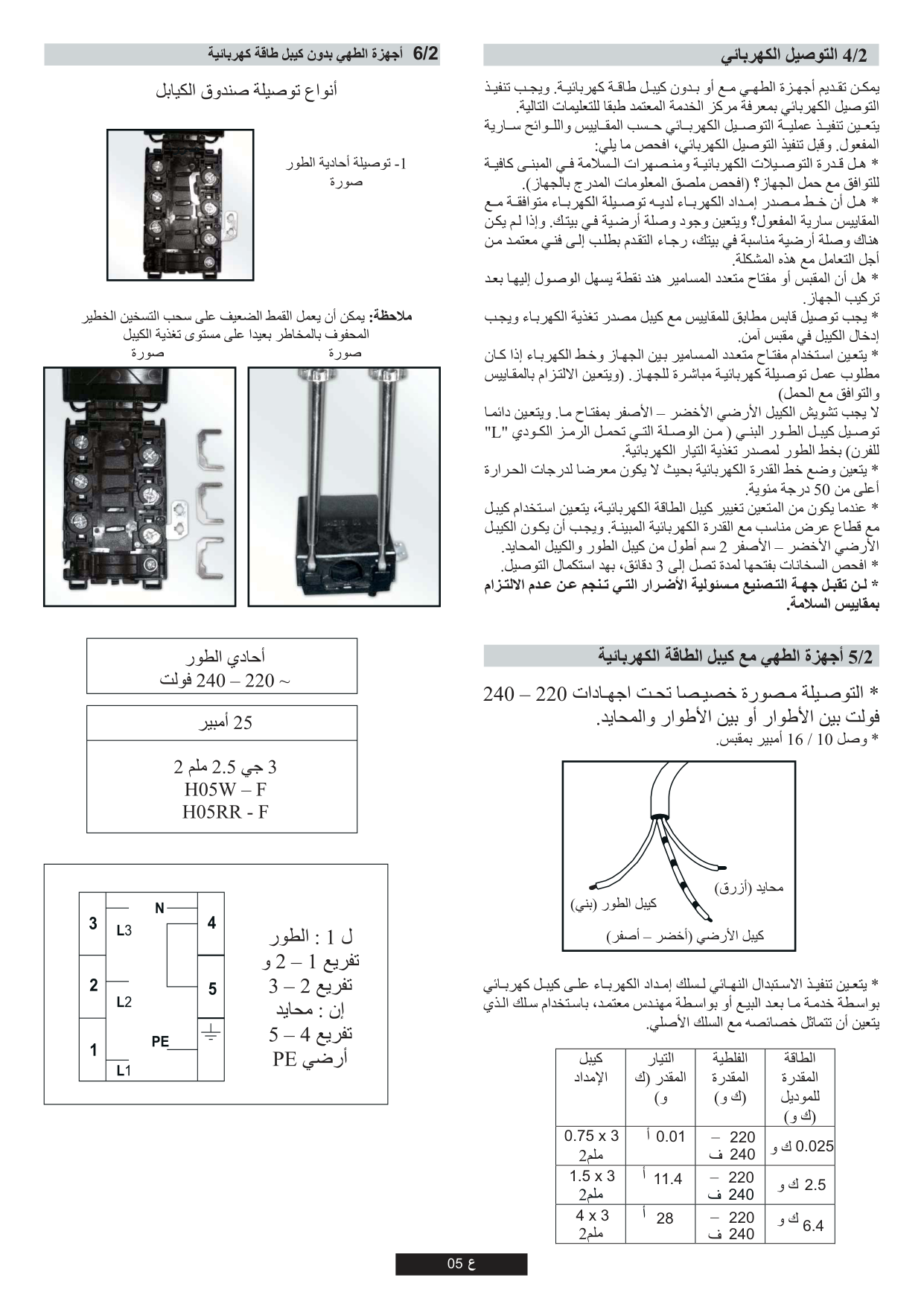
Cookers can be presented with or without enrgy cable. Cable connection should be done by Autorited service according to following instructions. The electrical connection must be made according to the standards and regulations in force. Before making the electrical connection, check the following:
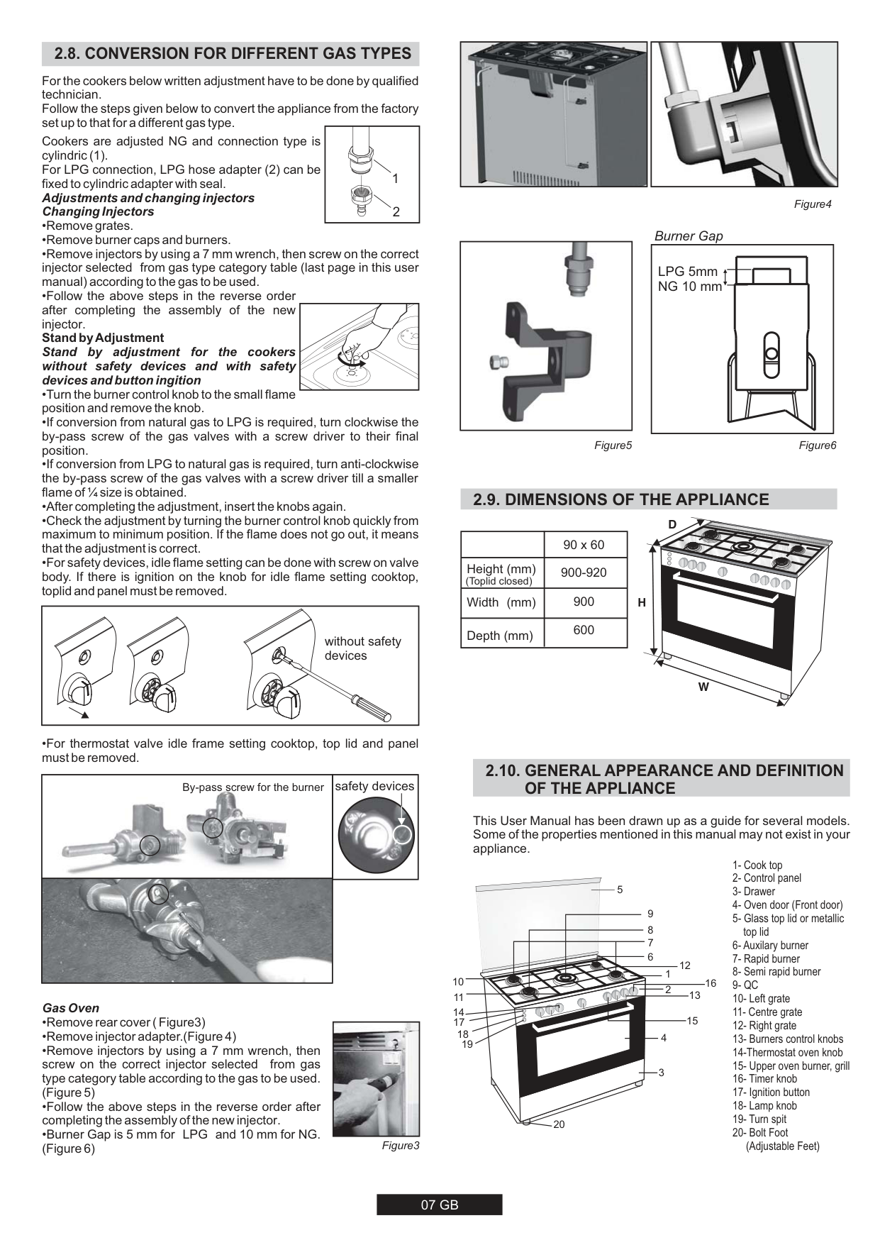
###### 2.5. COOKERS WITH ENERGY CABLE
|Neutral (blue)
Ground cable (Green-Yellow)
Phase cable (brown)| |---|
Ratings/Supply Cable Sections:
|Model rated power (kW)|Rated Voltage (V)|Rated Current (A)|Supply Cable| |---|---|---|---| |0.025 kW|220 - 240 V|0.01 A|23 x 0.75 mm| |2.5 kW|220 - 240 V|11.4 A|23 x 1.5 mm| |6.4 kW|220 - 240 V|28 A|23 x 4 mm|
Cable box connection types
###### 2.6. COOKERS WITHOUT ENERGY CABLE
|| |---|
1- Monophase connection
Attention: A poor clamping can draw away risks dangerous
heating at the level of the cable feeding
|| |---|
|| |---|
|L1 : Phase
shunt 1-2 and
shunt 2-3 N : Neutral shunt 4-5 PE Earth
| |---|
|Monophase 220-240 V~| |---|
|32 A| |---| | | |23 G 4 mm| | | |H05VV-F / H05RR-F| | |
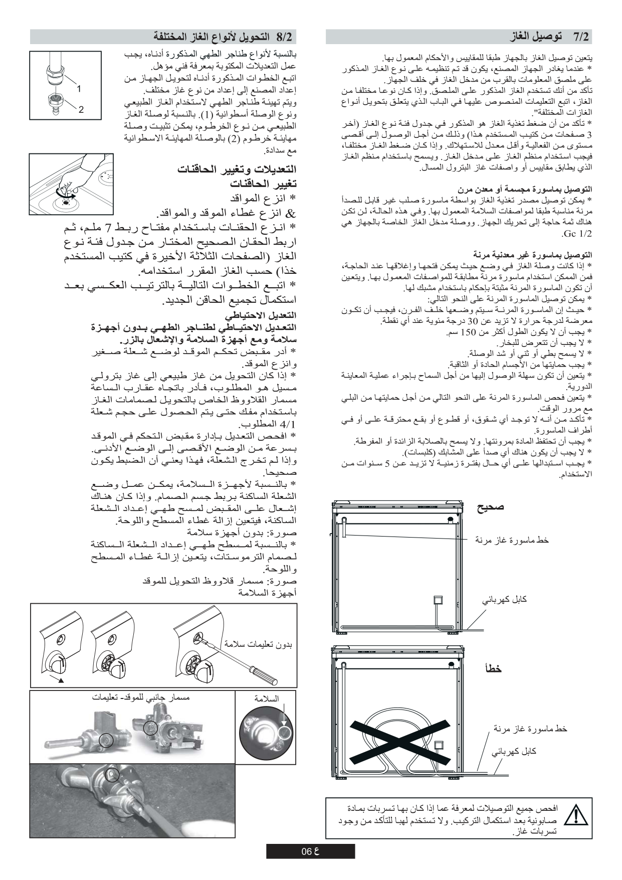
###### 2.7. GAS CONNECTION
The gas must be connected to the appliance according to standard and the provisions in force.
| | | |---|---| | | | | | |
####### RIGHT
FLEXIBLE GAS PIPE LINE
ELECTRICAL CABLE
| | | |---|---| | | | | | |
####### WRONG
FLEXIBLE GAS PIPE LINE
ELECTRICAL CABLE
|Check all connections for leaks with a soapy substance after the installation is completed. Do not use a flame for to check gas leaks.| |---|
#### 2.8. CONVERSION FOR DIFFERENT GAS TYPES
For the cookers below written adjustment have to be done by qualified technician. Follow the steps given below to convert the appliance from the factory set up to that for a different gas type.
Cookers are adjusted NG and connection type is cylindric (1). For LPG connection, LPG hose adapter (2) can be fixed to cylindric adapter with seal. Adjustments and changing injectors Changing Injectors
1
2
| | |---|
|without safety devices| |---|
•For thermostat valve idle frame setting cooktop, top lid and panel must be removed.

safety devices
By-pass screw for the burner


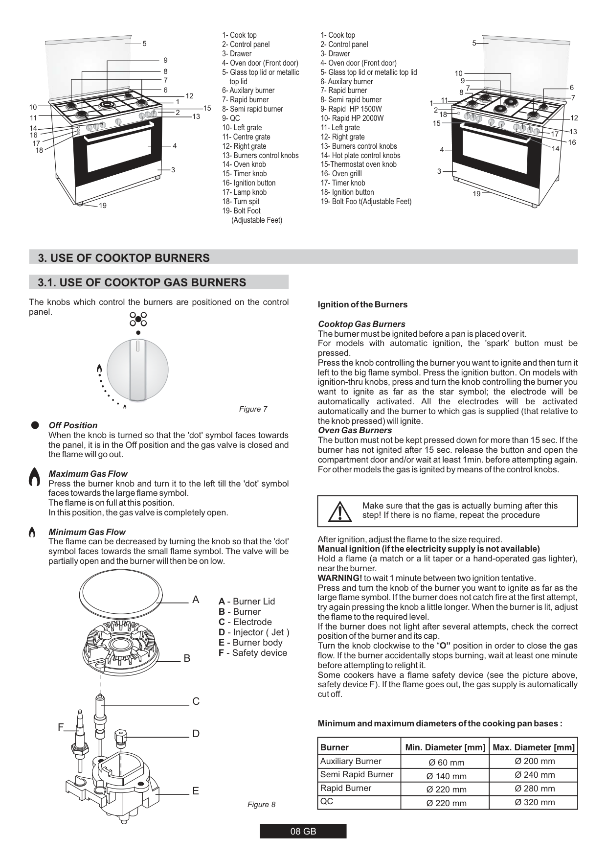
######### Gas Oven

|| |---|
|| |---|
Figure4
Burner Gap
|| |---|
|LPG 5mm NG 10 mm| |---|
Figure5 Figure6
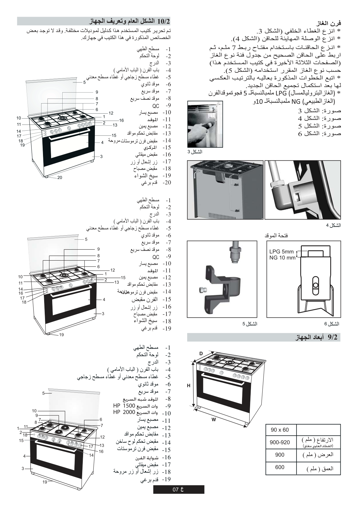
#### 2.9. DIMENSIONS OF THE APPLIANCE
D

| |90 x 60| |---|---| |Height (mm) (Toplid closed)|900-920| |Width (mm)|900| |Depth (mm)|600|
H
W
#### 2.10. GENERAL APPEARANCE AND DEFINITIONOF THE APPLIANCE
This User Manual has been drawn up as a guide for several models. Some of the properties mentioned in this manual may not exist in your appliance.

5
4
3
1
16
2
14
15
20

5
4
3
1
15
2
19

5
10
9
6
7
11 18


12 17
15
13
16
14
19
#### 3. USE OF COOKTOP BURNERS
#### 3.1. USE OF COOKTOP GAS BURNERS
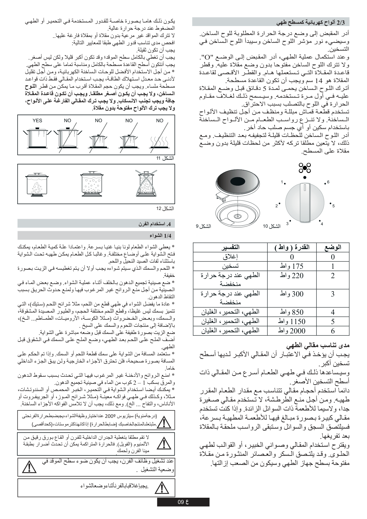
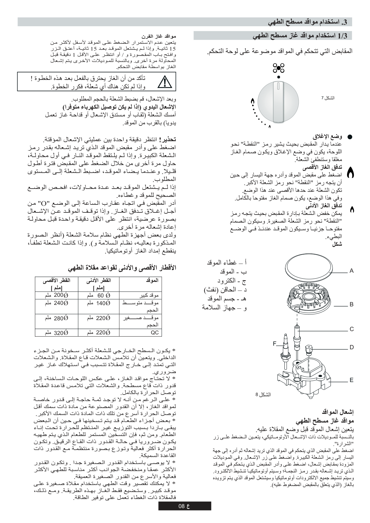
The knobs which control the burners are positioned on the control panel.

Figure 7 Off Position
When the knob is turned so that the 'dot' symbol faces towards the panel, it is in the Off position and the gas valve is closed and the flame will go out.
Maximum Gas Flow Press the burner knob and turn it to the left till the 'dot' symbol faces towards the large flame symbol. The flame is on full at this position. In this position, the gas valve is completely open.
######### Minimum Gas Flow
The flame can be decreased by turning the knob so that the 'dot' symbol faces towards the small flame symbol. The valve will be partially open and the burner will then be on low.
F
Figure 8
Ignition of the Burners Cooktop Gas Burners The burner must be ignited before a pan is placed over it. For models with automatic ignition, the 'spark' button must be pressed. Press the knob controlling the burner you want to ignite and then turn it left to the big flame symbol. Press the ignition button. On models with ignition-thru knobs, press and turn the knob controlling the burner you want to ignite as far as the star symbol; the electrode will be automatically activated. All the electrodes will be activated automatically and the burner to which gas is supplied (that relative to the knob pressed) will ignite. Oven Gas Burners
The button must not be kept pressed down for more than 15 sec. If the burner has not ignited after 15 sec. release the button and open the compartment door and/or wait at least 1min. before attempting again. For other models the gas is ignited by means of the control knobs.
|Make sure that the gas is actually burning after this step! If there is no flame, repeat the procedure| |---|
After ignition, adjust the flame to the size required. Manual ignition (if the electricity supply is not available) Hold a flame (a match or a lit taper or a hand-operated gas lighter), near the burner. WARNING!to wait 1 minute between two ignition tentative. Press and turn the knob of the burner you want to ignite as far as the large flame symbol. If the burner does not catch fire at the first attempt, try again pressing the knob a little longer. When the burner is lit, adjust the flame to the required level. If the burner does not light after several attempts, check the correct position of the burner and its cap. Turn the knob clockwise to the “O” position in order to close the gas flow. If the burner accidentally stops burning, wait at least one minute before attempting to relight it. Some cookers have a flame safety device (see the picture above, safety device F). If the flame goes out, the gas supply is automatically cut off.
Minimum and maximum diameters of the cooking pan bases :
|Burner|Min. Diameter [mm]|Max. Diameter [mm]| |---|---|---| |Auxiliary Burner|Ø 60 mm|Ø 200 mm| |Semi Rapid Burner|Ø 140 mm|Ø 240 mm| |Rapid Burner|Ø 220 mm|Ø 280 mm| |QC|Ø 220 mm|Ø 320 mm|
#### 3.2. USE OF COOKTOP ELECTRICAL PLATES
Turn the knob to the position for the required temperature of the hot plate. The indicator light of the hot plate will come on and the hot plate will start to heat. When cooking is completed, turn the knob to the “O” position. Do not leave the hot plate turned on without a pan on it. The diameter and the base of the pan you use is critical. The minimum diameter of the pan base is 14 cm and the base should be flat. Leave the hot plate to heat up for 5 minutes before placing a pan on it the first time you use it. This will allow the heat resistant coating of the plate to harden due to burning. Use a wet cloth and detergent for cleaning the hot plates. Do not remove food residues from the hot plates with a knife or any other hard, sharp object. Turn on the hot plate for a few moments to dry it after cleaning. However, it must never be left on for more than a few moments without a pan on top.


6
1

5
2
3
4
Figure 9 Figure 10
|Position|Power (Watt)|Power (Watt)|Power (Watt)|Explanation| |---|---|---|---|---| |0|0|0|0|Off| |1|100 W|135 W|175 W|Heating| |2|180 W|220 W|220 W|Cooking at low temperature| |3|250 W|300 W|300 W|Cooking at low temperature| |4|500 W|850 W|850 W|Cooking, Roasting, Boiling| |5|750 W|1150 W|1150 W|Cooking, Roasting, Boiling| |6|1000 W|1500 W|2000 W|Cooking, Roasting, Boiling|
Suitability of Cooking Pans Keep in mind that larger pans have larger heating surfaces. This will help them to cook the food faster than pans with smaller heating surfaces. Always use pan sizes proportionate to the amount of the food to be cooked. In order to prevent splashing, do not use very small pans, especially for foods with excess liquid. If you use excessively large pans for quick cooked foods, sausages and liquids will stick and residues will remain attached to the pan after being emptied. Closed pans and baking trays or moulds are suggested for cooking sweets. Splashed sugar and juices from an open pan may stick to the cooker surface and will be difficult to remove.
|


| |---|
| | |---|
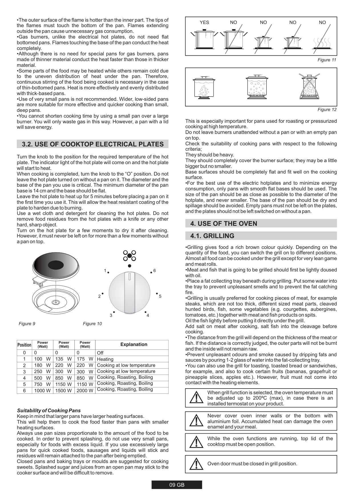
This is especially important for pans used for roasting or pressurized cooking at high temperature. Do not leave burners unattended without a pan or with an empty pan on top. Check the suitability of cooking pans with respect to the following criteria; They should be heavy. They should completely cover the burner surface; they may be a little bigger but no smaller. Base surfaces should be completely flat and fit well on the cooking surface.
•For the best use of the electric hotplates and to minimize energy consumption, only pans with smooth flat bases should be used. The size of the pan should be as close as possible to the diameter of the hotplate, and never smaller. The base of the pan should be dry and spillage should be avoided. Empty pans must not be left on the plates, and the plates should not be left switched on without a pan.
#### 4. USE OF THE OVEN 4.1. GRILLING
|When grill function is selected, the oven temperature must be adjusted up to 200ºC (max), in case there is an installed termostat on your product.| |---|
|Never cover oven inner walls or the bottom with aluminium foil. Accumulated heat can damage the oven enamel and your meal.| |---|
|While the oven functions are running, top lid of the cooktop must be open position.| |---|
|Oven door must be closed in grill position.| |---|
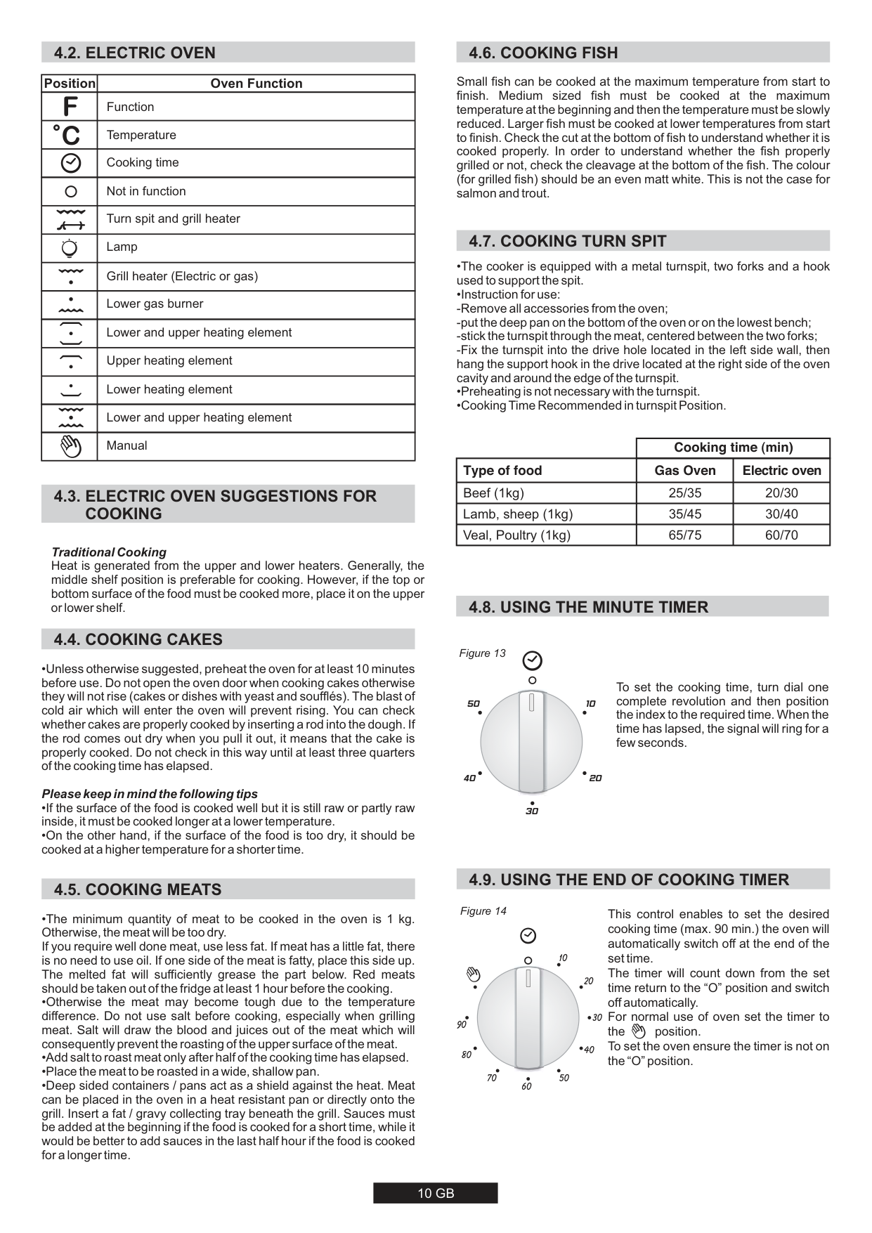
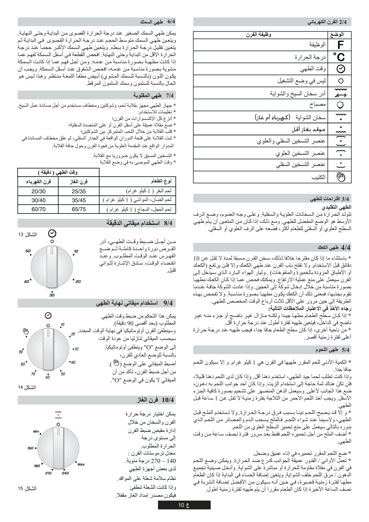
|Position|Oven Function| |---|---| | |Function| | |Temperature| | |Cooking time| | |Not in function| | |Turn spit and grill heater| | |Lamp| | |Grill heater (Electric or gas)| | |Lower gas burner| | |Lower and upper heating element| | |Upper heating element| | |Lower heating element| | |Lower and upper heating element| | |Manual|
######### Traditional Cooking
Heat is generated from the upper and lower heaters. Generally, the middle shelf position is preferable for cooking. However, if the top or bottom surface of the food must be cooked more, place it on the upper or lower shelf.
Small fish can be cooked at the maximum temperature from start to finish. Medium sized fish must be cooked at the maximum temperature at the beginning and then the temperature must be slowly reduced. Larger fish must be cooked at lower temperatures from start to finish. Check the cut at the bottom of fish to understand whether it is cooked properly. In order to understand whether the fish properly grilled or not, check the cleavage at the bottom of the fish. The colour (for grilled fish) should be an even matt white. This is not the case for salmon and trout.
| |Cooking time (min)|Cooking time (min)| |---|---|---| |Type of food|Gas Oven|Electric oven| |Beef (1kg)|25/35|20/30| |Lamb, sheep (1kg)|35/45|30/40| |Veal, Poultry (1kg)|65/75|60/70|
#### 4.8. USING THE MINUTE TIMER
4.4. COOKING CAKES
4.5. COOKING MEATS
Figure 13

50
10
40
20
30
To set the cooking time, turn dial one complete revolution and then position the index to the required time. When the time has lapsed, the signal will ring for a few seconds.
4.9. USING THE END OF COOKING TIMER
Figure 14
This control enables to set the desired cooking time (max. 90 min.) the oven will automatically switch off at the end of the set time. The timer will count down from the set time return to the “O” position and switch off automatically. For normal use of oven set the timer to the position. To set the oven ensure the timer is not on the “O” position.
10

20
30
90
40
80
70
50
60
#### 4.10. GAS OVEN
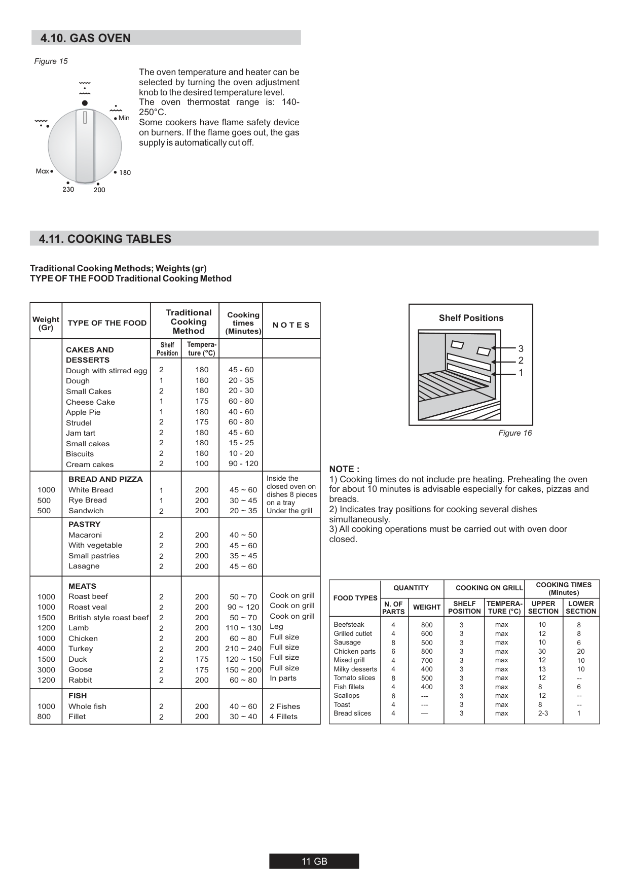
Figure 15

Min
Max
180
230 200
The oven temperature and heater can be selected by turning the oven adjustment knob to the desired temperature level. The oven thermostat range is: 140250°C. Some cookers have flame safety device on burners. If the flame goes out, the gas supply is automatically cut off.
#### 4.11. COOKING TABLES
######### Traditional Cooking Methods;Weights(gr) TYPE OF THE FOOD Traditional Cooking Method
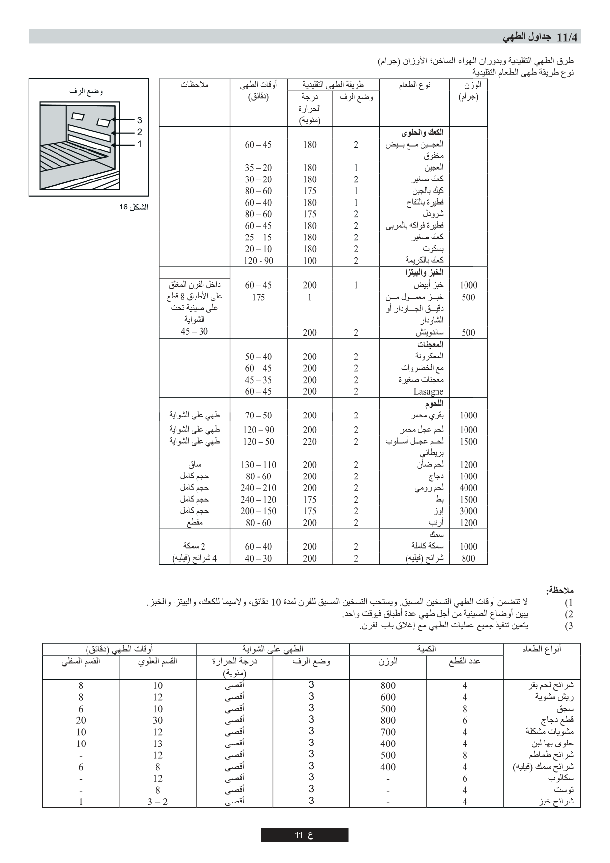
|Weight (Gr)|TYPE OF THE FOOD|Traditional Cooking Method|Traditional Cooking Method|Cooking times (Minutes)|N O T E S| |---|---|---|---|---|---| | |CAKES AND DESSERTS Dough with stirred egg Dough Small Cakes Cheese Cake Apple Pie Strudel Jam tart Small cakes Biscuits Cream cakes|Shelf Position|Temperature (°C)
| | | | |CAKES AND DESSERTS Dough with stirred egg Dough Small Cakes Cheese Cake Apple Pie Strudel Jam tart Small cakes Biscuits Cream cakes|2
1
2
1
1
2
2 2 2 2
|180 180 180 175 180 175 180 180 180 100|45 - 60 20 - 35 20 - 30 60 - 80 40 - 60 60 - 80 45 - 60 15 - 25 10 - 20 90 - 120| | |1000 500 500|BREAD AND PIZZA White Bread Rye Bread Sandwich|1
1
2
|200 200 200|45 ~ 60 30 ~ 45 20 ~ 35|Inside the closed oven on dishes 8 pieces on a tray Under the grill| | |PASTRY Macaroni With vegetable Small pastries Lasagne|2 2 2 2|200 200 200 200|40 ~ 50 45 ~ 60 35 ~ 45 45 ~ 60| |
|1000 1000 1500 1200 1000 4000 1500 3000 1200
|MEATS Roast beef Roast veal British style roast beef Lamb Chicken Turkey Duck Goose Rabbit|2 2 2 2 2 2 2 2 2|200 200 200 200 200 200 175 175 200|50 ~ 70 90 ~ 120 50 ~ 70 110 ~ 130 60 ~ 80 210 ~ 240 120 ~ 150 150 ~ 200 60 ~ 80|Cook on grill Cook on grill Cook on grill Leg Full size Full size Full size Full size In parts| |1000 800|FISH Whole fish Fillet|2 2|200 200|40 ~ 60 30 ~ 40|2 Fishes 4 Fillets|
|3 2 1
Shelf Positions| |---|
Figure 16
######### NOTE :
|FOOD TYPES|QUANTITY|QUANTITY|COOKING ON GRILL|COOKING ON GRILL|COOKING TIMES (Minutes)|COOKING TIMES (Minutes)| |---|---|---|---|---|---|---| |FOOD TYPES|N. OF PARTS|WEIGHT|SHELF POSITION|TEMPERATURE (°C)|UPPER SECTION|LOWER SECTION| |Beefsteak Grilled cutlet Sausage Chicken parts Mixed grill Milky desserts Tomato slices Fish fillets Scallops Toast Bread slices|4 4 8 6 4 4 8 4 6 4 4|800 600 500 800 700 400 500 400
----—|3 3 3 3 3 3 3 3 3 3 3|max max max max max max max max max max max|10 12 10 30
12
13 12 8 12 8 2-3
|8 8 6 20 10 10
-6 --1|
#### 5. CLEANING AND MAINTENANCE
Before all cleaning and maintenance :
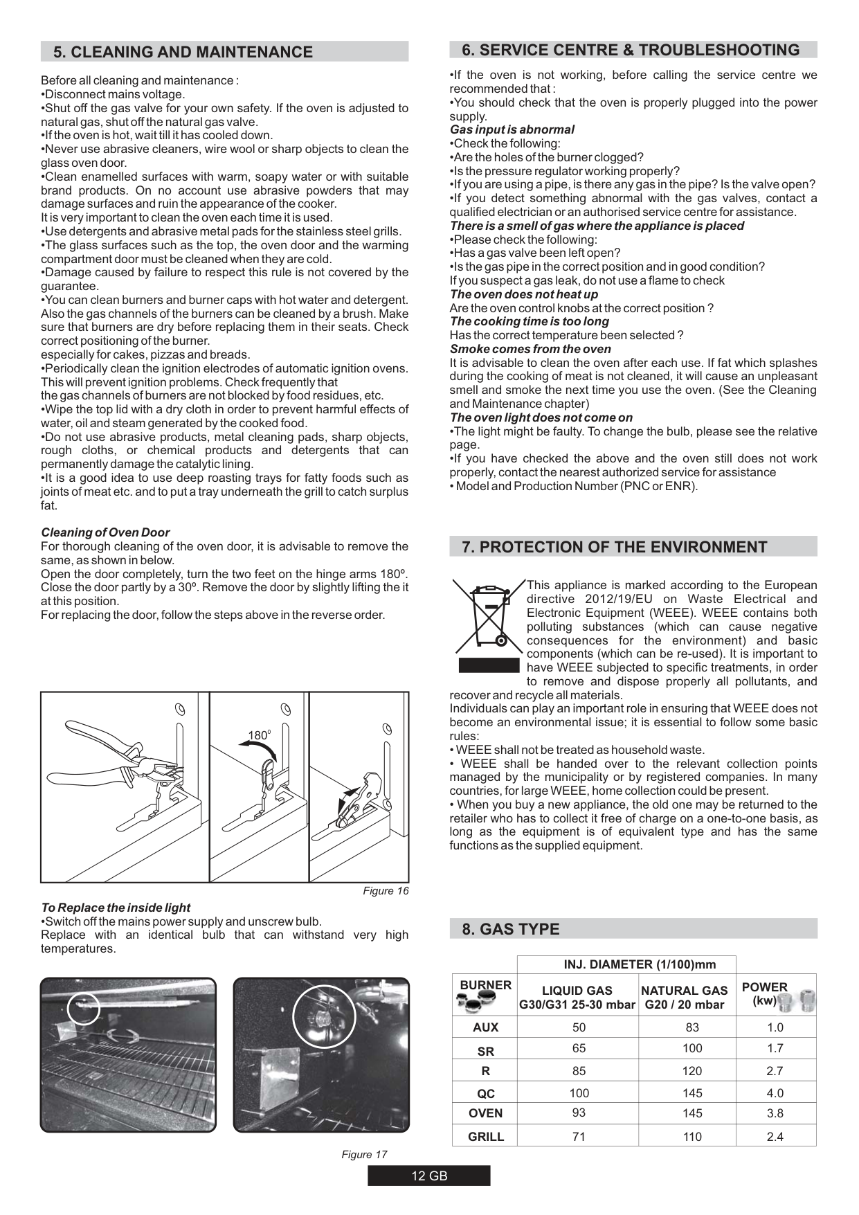
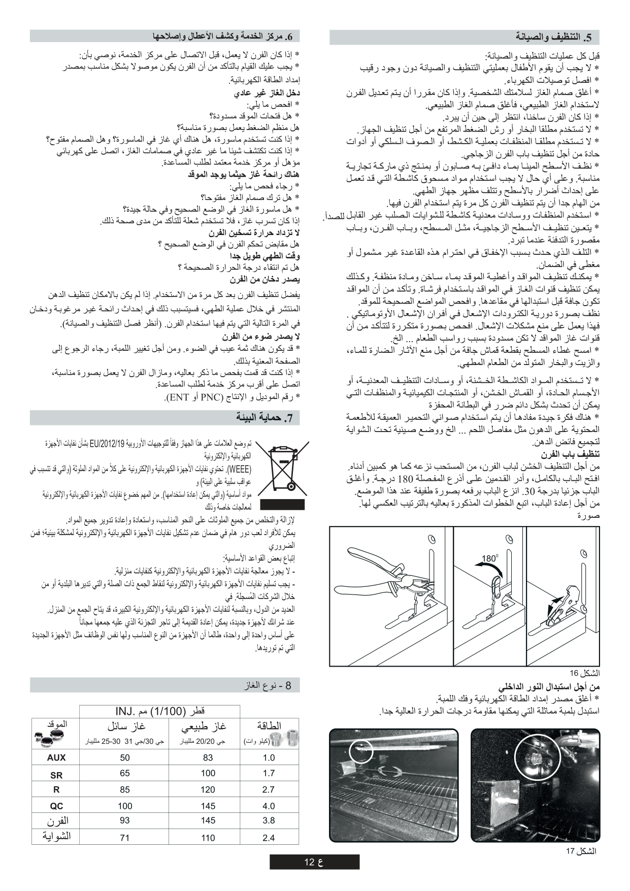
Cleaning of Oven Door For thorough cleaning of the oven door, it is advisable to remove the same, as shown in below. Open the door completely, turn the two feet on the hinge arms 180º. Close the door partly by a 30º. Remove the door by slightly lifting the it at this position. For replacing the door, follow the steps above in the reverse order.
To Replace the inside light
#### 7. PROTECTION OF THE ENVIRONMENT
This appliance is marked according to the European directive 2012/19/EU on Waste Electrical and Electronic Equipment (WEEE). WEEE contains both polluting substances (which can cause negative consequences for the environment) and basic components (which can be re-used). It is important to have WEEE subjected to specific treatments, in order to remove and dispose properly all pollutants, and
recover and recycle all materials. Individuals can play an important role in ensuring that WEEE does not become an environmental issue; it is essential to follow some basic rules:
0180
Figure 16
#### 8. GAS TYPE
| |INJ. DIAMETER (1/100)mm|INJ. DIAMETER (1/100)mm| | |---|---|---|---| |BURNER
|LIQUID GAS G30/G31 25-30 mbar|NATURAL GAS G20 / 20 mbar|
POWER (kw)| |AUX|50|83|1.0| |SR|65|100|1.7| |R|85|120|2.7| |QC|100|145|4.0| |OVEN|93|145|3.8| |GRILL|71|110|2.4|


Figure 17
| | | | | |---|---|---|---| || | || | | | | | | | | | | | | | | | | | | | | | | | | | | | | | |


|3 2 1| |---|
16
| | | | | | | |---|---|---|---|---|---| | | | | | | | | | | | | | | | | | | | | | | | | | | | | | | | | | | | | | | | | | |
| | | | | | | |---|---|---|---|---|---| | | | | | | |
| | | | | | | | |---|---|---|---|---|---|---| | | | | | | | | | | | |3 3 3 3 3 3 3 3 3 3 3| | | |
11
| | | | |---|---|---| | | | | | | | | | | | | | | | |


| | | |---|---| | | |
| | | | | | | | | | | | | | | | | | | | | | | | | | | | | | | | |
|


| |---|
11


6
1


5
2
12
3
4
9 10
| | | | |---|---|---| | | | | | | | | | | | | | | | | | | | | | | | | | | | |
|ﻰﺗﺣﻧﺭﻔﻟﺍﺓﺭﺍﺭﺣﻁﺑﺿﺑﺟﻳ،ءﺍﻭﺷﻟﺍﺔﻔﻳﻅﻭﺭﺎﻳﺗﺧﺍﺩﻧﻋ 200º ﺱﻭﻳﺯﻠﻳﺳ (ﺔﻳﻭﺋﻣﺔﺟﺭﺩ) (ﻰﺻﻗﺃﺩﺣﻛ)،ﺕﺎﺗﺳﻭﻣﺭﺗﻛﺎﻧﻬﻧﺎﻛﺍﺫﺇ (ﺓﺭﺍﺭﺣﻟﺎﻁﺑﺎﺿ) ﻙﺑﺻﺎﺧﻟﺎﺟﺗﻧﻣﻟﺎﯩﻠﻌﺗﺑﺛﻣ.| |---|
|ﻲﻓ ﺩﻗﻭﻣﻟﺍ ﺢﻁﺳ ءﻭﺿ ﻥﻭﻛﻳ ﻥﺃ ﺏﺟﻳ ،ﻥﺭﻔﻟﺍ ﻑﺋﺎﻅﻭ ﻝﻳﻐﺷﺗ ﺩﻧﻋ . ﻝﻳﻐﺷﺗﻟﺍ ﺔﻳﻌﺿﻭ| |---|
|ءﺍﻭﺷﻟﺎﻌﺿﻭءﺎﻧﺛﺄﻧﺭﻔﻟﺎﺑﺎﺑﻗﻼﻏﺈﺑﺟﻳ.| |---|
09
| | |---|


7
| | | | |---|---|---| |200|60| | |240|140| | |280|220| | |320|220|QC|
F
8
######## 08


ﻥﺭﻔﻟﺍﺩﻗﻭﻣﺓﻭﺟﻓ 5 ـﻟﺔﺑﺳﻧﻟﺎﺑﻣﻠﻣ LPG (ﻝﺎﺳﻣﻟﺎﻳﻟﻭﺭﺗﺑﻟﺍﺯﺎﻐﻟﺍ) ﻭ10 ـﻟﺔﺑﺳﻧﻟﺎﺑﻣﻠﻣ NG (ﻲﻌﻳﺑﻁﻟﺍﺯﺎﻐﻟﺍ)
|| |---|


||
|---|
|| |---|
ءﺍﻭﺷﻟﺍ ﺦﻳﺳ
##### ﺩﻗﻭﻣﻟﺍ ﺔﺣﺗﻓ 5

|| |---|
|LPG 5mm NG 10 mm
| |---|
4
3
1
2
15
19


5
10
9
11 18
ﺽﺑﻘﻣ ﻥﺭﻔﻟﺍ
ءﺍﻭﺷﻟﺍ ﺦﻳﺳ
D

H
W
6
7
| | | |---|---| | | | | | | | | |
12 17
13
16
14

19
######## 2
| | | |---|---| | | | | | | | | |


| | | | |---|---|---| | | | |
|| |---|
6/2
|| |---|
|| |---|
| | |---| | |
05
| | | | | |---|---|---|---| |0.75 x 3|0.01|220 240|0.025| |1.5 x 3|11.4|220 240|2.5| |4 x 3|28|220 240|6.4|
|ﻭﻠﻧﻣﻳﻔﻠﺧﻟﺎﺣﻁﺳﻟﺎﯩﻠﻋﺔﻳﻛﻳﺗﺳﻼﺑﻟﺎﺗﺎﻣﺎﻋﺩﻟﺎﺗﻳﺑﺛﺗﺑﺟﻳ،ﻥﺭﻔﻟﺎﺑﻳﻛﺭﺗﻠﺑﻗ ﻥﺭﻔﻟﺍﺩﻗﻭﻣﺔﺣ.| |---| ||
|| |---|
|| |---|
| | |---| | | | |
| | |---| | |
03.2016 • REV:C • 42810235
########## GB
The manufacturer will not be responsible for any inaccuracy resulting from printing or transcript errors contained in this brochure. We reserve the right to carry out modifications to products as required, including ht e interests of con sumption, without prejudice to the characteri stics relating to safety or function.