
Ask AI
— answers from the official manualAnswers from the official manual.
Common questions
Common Questions
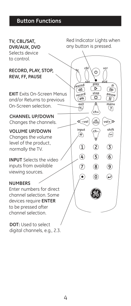
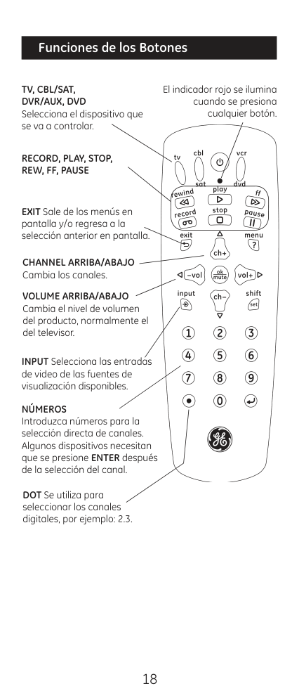
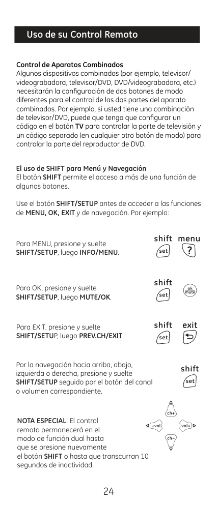
53 totalWhy does my remote only control some functions of my device but not all?
A particular code may only support some functions of your device. Try programming the remote with a different code from the code list to find one that offers more functionality. The remote may also not control all functions of every device. (Page 13)
How do I program the remote using Automatic Code Search?
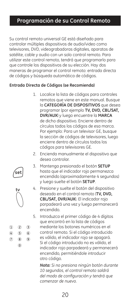
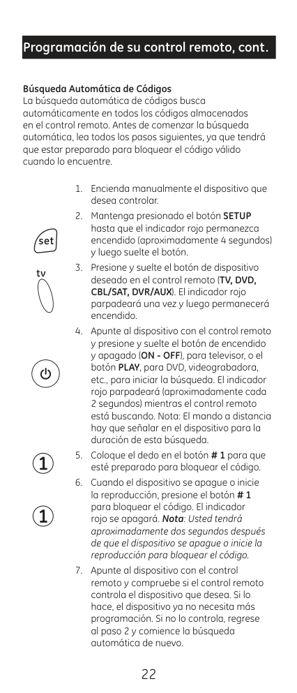
Turn on the device manually, hold SETUP until the red light stays on, release, then press the appropriate device button. Point the remote at the device and press ON-OFF (for TV) or PLAY (for DVD/VCR) to begin the search — the red light will blink approximately every 2 seconds. When the device turns off or starts playing, press button #1 within about 2 seconds to lock in the code. (Page 9)
How long do I have to replace the batteries before losing my programmed codes?
You have up to 10 minutes to replace the batteries without losing your programmed codes. However, you must not press any buttons while the batteries are removed, as pressing buttons without batteries installed will cause all codes to be lost. (Page 3)
What should I do if the remote controls some but not all functions of my device?
Sometimes a particular code only enables some functions of a device. Try programming the remote with a different code from the code list to find one that enables more functions. You can also continue using the Automatic Code Search method to find a better matching code. (Page 8)
What does it mean when the red indicator blinks and stays on after I enter a code?
When the red indicator blinks and remains on after entering a code, it means the remote did not accept the code entered. Try programming the code again or enter a different code from the code list for your device. (Page 13)
How do I control a combo device like a TV/DVD combination unit?
Combination devices require setting up two different device mode buttons — one for each part of the combo unit. For example, for a TV/DVD combo, program a code on the TV button to control the TV portion and a separate code on another mode button (such as DVD) to control the DVD portion. (Page 10)
Show 47 more questions
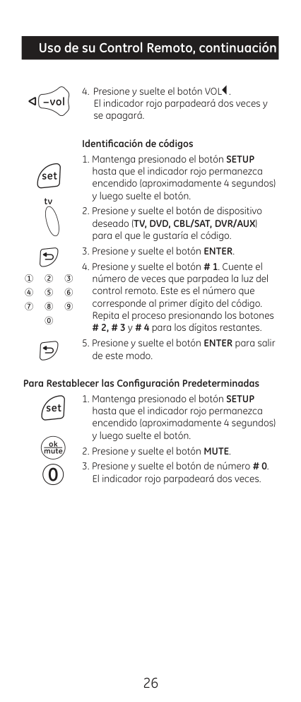
How do I reset the remote to its default settings?
How do I install the batteries in the GE 24922 universal remote?
How long will the remote keep my programmed codes if I remove the batteries?
How do I use the Auto Code Search to program my device?
What should I do if the red indicator blinks and stays on after I enter a code?
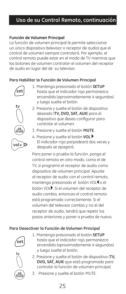
How does the Master Volume feature work and how do I enable it?
What type and how many batteries does the GE 24922 universal remote require?
What battery precautions should I follow when using the GE 24922 remote?
How do I install batteries in the GE 24922 Universal Remote?
How do I program my remote using direct code entry?
What should I do if the remote doesn't control my device after programming?
How do I use the automatic code search feature?
What does it mean if the red indicator flashes and stays on after entering a code?
Can I control combined devices like a TV/DVD combo with this remote?
How do I set up the Master Volume function?
How do I factory reset the remote to its default settings?
What battery precautions should I follow?
What steps should I take if my heat pump shows an E1 error code?
How do I troubleshoot a heat pump showing an E3 error code?
What should I do if my heat pump displays an E4 error code?
How do I handle an F2 condenser temperature sensor error?
What steps should I follow when encountering F6 error code referring to an ODU tube temperature sensor?
How do I address a compressor overload issue causing an H4 error?
What is the procedure for resolving an H5 IPM protection error?
How do I correct a PA AC Current Protection failure?
What actions are needed for an HC PFC Protection alert?
Why might my heat pump suddenly stop working after startup?
How do I program the remote using Direct Code Entry?
How do I identify what code is currently programmed for a device?
How do I set up the Master Volume feature so one device always controls the volume?
Will I lose my programmed codes if I change the batteries?
What are the two methods for programming this universal remote?
What should I do if my remote stops working correctly?
What devices can the GE 24922 universal remote control?
Can I mix old and new batteries in the remote?
What is the battery saver feature and how does it work?
How do I start the direct code entry programming process?
What should I do if my remote stops working properly?
How do I install batteries in my GE universal remote?
How do I start programming the remote using Direct Code Entry?
How long do I need to hold the SETUP button when programming?
How do I install the batteries in my GE universal remote?
What devices can the GE 24922 remote control?
How do I select which device I want to control?
Will I lose my programmed codes if I remove the batteries?
What are the two methods for programming this remote?
What type and size of batteries does the GE 24922 remote require?
Full Manual
102 pages
Service Manual
Instructions
Connect Series Split Heat Pumps
| | | |---|---| | | |
| | | |---|---| | | |
Rev. 07-20
ENGLISH
Foreword
Thank you for choosing GE Appliances Connect Series heat pumps.. Please read this manual carefully in order to properly install the equipment and maximize customer satisfaction.
This manual specifies safe operation requirements from perspectives of product introduction, control, troubleshooting and maintenance, as well as basic principles and implementation methods. Professional operators must abide by relevant national (local) safety requirements and technical specifications set forth in this manual during operations; otherwise, the air conditioning system may fail or be damaged, and personnel safety may be compromised.

Please read this manual before installing this heat pump.
Before repairing the air conditioner, please first read the technical service manual.
Please read this instruction manual before operating this heat pump
Contents

Safety Notifications ......................................................................................................................................................1 Introduction ..................................................................................................................................................................3
Lists of Units...............................................................................................................................................................................................................3
Controls .........................................................................................................................................................................4 Operation Modes ......................................................................................................................................................................................................4 Control Modes ...........................................................................................................................................................................................................6 Functions .....................................................................................................................................................................................................................7
Troubleshooting ......................................................................................................................................................... 10 Wiring Diagrams ..................................................................................................................................................................................................... 10 PCB Layout ................................................................................................................................................................................................................13 Error Codes................................................................................................................................................................................................................21 Troubleshooting ......................................................................................................................................................................................................22 Failures Not Caused by Errors ......................................................................................................................................................................... 36
Maintenance ................................................................................................................................................................37 System Diagram ......................................................................................................................................................................................................37 System Evacuation ................................................................................................................................................................................................37 Refrigerant Charging ............................................................................................................................................................................................38 Maintenance of Major Components ................................................................................................................................................................39 Removal of Major Components ....................................................................................................................................................................... 46 Exploded View and Parts Lists ........................................................................................................................................................................80
########## Appendices .................................................................................................................................................................86
Temperature Sensor Temperature/Resistance/Voltage Lists .............................................................................................................. 86 15 KΩ Temperature Sensors (including ODU temperature sensors) ........................................................................................... 86 20 KΩ Pipeline Temperature Sensors (including temperature sensors for defroster, IDU and ODU pipes) ............... 88 50 KΩ Discharge Temperature Sensors (including discharge air temperature sensor) ......................................................90
Refrigerant R-410A Temperature/Pressure List .........................................................................................................................................92
Indoor Unit Airflow data............................................................................................................................................................................................ 94
Operation Tools...................................................................................................................................................................................................... 98
CONNECT SERIES SERVICE MANUAL
PROHIBITED:
WARNING:
NOTICE:

Maintenance Safety
OBSERVED:
ENGLISH
ENGLISH
##### Operation Safety
PROHIBITED:
WARNING:
NOTICE:
Introduction
##### Lists of Units Outdoor Units
|Model|Power Supply|Circuit Breaker Capacity|Appearance| |---|---|---|---| |Model|V/Ph/Hz|A|Appearance| |AUH2436ZGDA|208/230V-1Ph-60Hz|35|| |AUH4860ZGDA|208/230V-1Ph-60Hz|45||
ENGLISH
Indoor Units
|Model|Cooling/Heating Capacity (Btu/h)|Power Supply|Fuse Capacity|Circuit Breaker Capacity|Appearance| |---|---|---|---|---|---| |Model|Cooling/Heating Capacity (Btu/h)|V/Ph/Hz|A|A|Appearance| |UUY24ZGDAA|24000/24000|208/230V-1Ph-60Hz|3.5|15|| |UUY36ZGDAA|36000/36000|208/230V-1Ph-60Hz|3.5|15|| |UUY48ZGDAA|48000/48000|208/230V-1Ph-60Hz|3.5|15|| |UUY60ZGDAA|54000/54000|208/230V-1Ph-60Hz|3.5|15||
ENGLISH

##### Operation Modes Cooling Mode
Power On
Cooling start control
Indoor fan run
No
Compressor stop for 3 minutes
Satisfying open Compressor condition
Yes
No
Compressor and outdoor fan run
Meet the temperature point shutdown condition
Compressor and outdoor fan stop
Yes
Meet the oil return condition
No
Yes Yes
Meet the oil return end condition
Oil return separation

No
######### Heating Mode
Power On
Heating start control
Indoor fan run
No
Compressor stop for 3 minutes
Satisfying open Compressor condition
Yes
No
Compressor and outdoor fan run
Meet the temperature point shutdown condition
Compressor and outdoor fan stop
Yes
Yes
Meet the oil return condition
No
Meet the defrost end condition

Yes No
No
Meet the oil return end condition
Meet the defrost condition
Meet the defrost condition
Oil return separation
Yes Yes
No
Control Modes Based Control Compressor Control
When the unit comes on in heating or cooling mode; the indoor fan will run for a short time before the compressor starts. Under different modes, the compressor can only be stopped after running for some time (special cases excluded). This is to protect the compressor from short-cycling. Once the compressor has stopped, it cannot be operated right away due to a time delay.
EXV Control
The electric expansion valve will reset when the unit is first started. During the process, the expansion valve will make clicking sounds. The valve will open to a predetermined step before the unit starts in cooling or heating mode.
Outdoor Fan Control
This series heat pump has two types of outdoor units: one with a single fan and the other with dual fans. The outdoor fan can run at the highest level 10 and the lowest level 1. By controlling the speed of outdoor fan, the unit can achieve cooling at low temperature and heating at high temperature. The outdoor unit fan will not run while the system is set to indoor fan mode only.
4-way Valve Control
The 4-way valve will be energized in heat mode (after a brief time delay) on start-up. The 4-way valve will be de energized during cooling and defrost modes.
The 4-way valve will continue to be energized in heating mode after the unit stops. This occurs so the valve will not inadvertently shift into cooling position.
There must be adequate differential pressure for the 4-way valve to function properly. Special Control Defrosting Control

Defrosting will start when the temperature sensed by outdoor tube outdoor coil temperature drops below a calculated value. The 4-way valve will switch to the cooling mode, and outdoor and indoor fan will both stop. The defrost cycle will terminate when the outdoor coil temperature reaches the calculated defrost termination value. The 4-way valve will switch back to the heating mode, and the compressor and outdoor fan(s) will restart.
Oil Return Control
The system will enter oil return mode if the compressor has been running at low frequency for an extended period. The system will exit oil return mode in about 5 minutes.
Protection Control High Pressure Protection Control
The system will shut the compressor down if the high pressure switch is open continuously for a short period of time and display an E1 error code. The compressor will restart after the switch closes for a short period of time. The system will shut the compressor down if the switch opens again within a predetermined time interval. The system will remain in a locked out condition until the power is cycled to the unit.
Low Pressure Protection Control
The system will shut the compressor down if the low pressure switch opens for a short time and display an E3 error code. The system will automatically restart the compressor when the switch closes after a short time delay. The system will shut the compressor down if the switch subsequently opens again within a predetermined time and will require a power reset to restart.
High Temperature Prevention Control
The system will enable high temperature prevention control while in heating mode if the indoor coil temperature rises above a predetermined threshold. The outdoor fan will slow down during high temperature protection mode.
Discharge High Temperature Protection Control
System will enable discharge temperature protection control if the discharge high temperature sensor is detected open for a predetermined amount of time. The system will shut down and display error code E4 during high temperature protection. The system will restore operation when the discharge temperature drops below the safety threshold. The system will lock out if high discharge temperature is sensed again during a certain time period and power must be reset to the unit.
Functions Capacity Selection Set the capacity of the outdoor unit through DIP switch SA2-1 on the outdoor unit main control board.
|Outdoor DIP SA2-1|Outdoor DIP SA2-1|Outdoor DIP SA2-1|Outdoor DIP SA2-1| |---|---|---|---| |AUH2436ZGDA|AUH2436ZGDA|AUH4860ZGDA|AUH4860ZGDA| |24K|36K|48K|60K| ||On| | | | | |---|---|---|---|---| |Off| | | | | | |1|2|3|4| ||On| | | | | |---|---|---|---|---| |Off| | | | | | |1|2|3|4|

||On| | | | | |---|---|---|---|---| |Off| | | | | | |1|2|3|4| ||On| | | | | |---|---|---|---|---| |Off| | | | | | |1|2|3|4| | |Indicates switch position|Indicates switch position|Indicates switch position|Indicates switch position|
######### Set Defrost Mode
DIP switch SA2-2 on the outdoor unit main control board determines the defrost mode. The following is an example of the defrost setting for a 36k unit. Standard Defrost is default, and Strong Defrost is suitable for defrosting in ultra-low temperature environments.
|Outdoor DIP SA2-2|Outdoor DIP SA2-2| |---|---| |Standard Defrost (default)|Strong Defrost| ||On| | | | | |---|---|---|---|---| |Off| | | | | | |1|2|3|4| ||On| | | | | |---|---|---|---|---| |Off| | | | | | |1|2|3|4| | |Indicates switch position|Indicates switch position|
######### Set Operating Mode
DIP switches SA2-3 & SA2-4 on the outdoor unit main control board select the operating mode. The following example shows the 36K outdoor unit. Standard Mode is the default mode.
The heat pump can easily be set to increase the output capacity by adjusting the DIP switches to Strong Mode. The heat pump can also be set to Energy Saving mode if the load is less than expected.

|Outdoor DIP SA2-3/SA2-4|Outdoor DIP SA2-3/SA2-4|Outdoor DIP SA2-3/SA2-4| |---|---|---| |Standard Mode (default)|Strong Mode|Energy Saving Mode| ||On| | | | | |---|---|---|---|---| |Off| | | | | | |1|2|3|4| ||On| | | | | |---|---|---|---|---| |Off| | | | | | |1|2|3|4| ||On| | | | | |---|---|---|---|---| |Off| | | | | | |1|2|3|4| | |Indicates switch position|Indicates switch position|Indicates switch position|
######### Set Indoor Fan Speed
Set the indoor fan speed through the indoor main control board DIP switches. The higher level, the higher the speed of the indoor unit fan.
UUY24ZGDAA UUY36ZGDAA HEAT (Indoor DIP SA2) COOL (Indoor DIP SA1) HEAT (Indoor DIP SA2) COOL (Indoor DIP SA1)
(default)
|On| | | | | |---|---|---|---|---| |Off| | | | | | |1|2|3|4|

|On| | | | | |---|---|---|---|---| |Off| | | | | | |1|2|3|4|
|On| | | | | |---|---|---|---|---| |Off| | | | | | |1|2|3|4|
|On| | | | | |---|---|---|---|---| |Off| | | | | | |1|2|3|4|
|On| | | | | |---|---|---|---|---| |Off| | | | | | |1|2|3|4|
|On| | | | | |---|---|---|---|---| |Off| | | | | | |1|2|3|4|
|On| | | | | |---|---|---|---|---| |Off| | | | | | |1|2|3|4|

|On| | | | | |---|---|---|---|---| |Off| | | | | | |1|2|3|4|
|On| | | | | |---|---|---|---|---| |Off| | | | | | |1|2|3|4|
|On| | | | | |---|---|---|---|---| |Off| | | | | | |1|2|3|4|
|On| | | | | |---|---|---|---|---| |Off| | | | | | |1|2|3|4|
|On| | | | | |---|---|---|---|---| |Off| | | | | | |1|2|3|4|
UUY48ZGDAA UUY60ZGDAA HEAT (Indoor DIP SA2) COOL (Indoor DIP SA1) HEAT (Indoor DIP SA2) COOL (Indoor DIP SA1)

(default)
|On| | | | | |---|---|---|---|---| |Off| | | | | | |1|2|3|4|
|On| | | | | |---|---|---|---|---| |Off| | | | | | |1|2|3|4|
|On| | | | | |---|---|---|---|---| |Off| | | | | | |1|2|3|4|
|On| | | | | |---|---|---|---|---| |Off| | | | | | |1|2|3|4|
|On| | | | | |---|---|---|---|---| |Off| | | | | | |1|2|3|4|

|On| | | | | |---|---|---|---|---| |Off| | | | | | |1|2|3|4|
|On| | | | | |---|---|---|---|---| |Off| | | | | | |1|2|3|4|
|On| | | | | |---|---|---|---|---| |Off| | | | | | |1|2|3|4|
|On| | | | | |---|---|---|---|---| |Off| | | | | | |1|2|3|4|
|On| | | | | |---|---|---|---|---| |Off| | | | | | |1|2|3|4|
|On| | | | | |---|---|---|---|---|

|Off| | | | | | |1|2|3|4|
|On| | | | | |---|---|---|---|---| |Off| | | | | | |1|2|3|4|
Indicates switch position
######### Forced Defrost Control
Press and hold the SW1 button for about 5 seconds to enter the first menu level. The outdoor unit main board display will flash. Short-press the SW1 button to switch the function to “06”. Short-press SW2 or SW3 to change the selection within function “06” to “ON”, followed by a short-press on SW1 to save. The menu will time out if no function is performed within 10 seconds.
Refrigerant Recovery Control Press and hold the SW1 button for about 5 seconds to enter the first menu level. The outdoor unit main
Forced Operation Control
Press and hold the SW1 button for about 5 seconds to enter the first menu level. The outdoor unit main board display will flash. Short-press the SW1 button to switch the function to “09”. Short-press SW2 or SW3
Press and hold SW1 for about 5 seconds to enter the first menu level. The outdoor unit main board display will flash. Short-press the SW1 button to switch the function to "11". Short-press SW2 or SW3 to change the selection to:

Thermostat Functions Please refer to your thermostat user guide for information on your thermostat functions.
##### Wiring Diagrams
The following electric diagram is for reference only. Please refer to diagram attached to the unit as the latest version.
Outdoor Units Model: AUH2436ZGDA

############ Model: AUH4860ZGDA

####### ENGLISH
Indoor Units Model: UUY24ZGDAA, UUY36ZGDAA

Model: UUY48ZGDAA, UUY60ZGDAA

##### PCB Layout Interface
Indoor unit: Model: UUY24ZGDAA, UUY36ZGDAA, UUY48ZGDAA, UUY60ZGDAA
Main Board

|No.|Printing|Interface No.|Interface No.|Printing|Interface| |---|---|---|---|---|---|

|1|AC-N (X2)|Neutral wire input|8|X9 (G_SCAN)|Indoor motor check| |2|AC-L (X1)|Live wire input|9|X14 (OFAN-H-OUT)|AC motor high speed output| |3|CN3|Wired control communication interface|10|X11 (OFAN-H-IN)|AC motor high speed input| |4|CN1|DC motor output|11|X8 (OFAN-L-IN)|AC motor low speed input| |5|X7|Transformer Neutral wire input|12|X6(OFAN-L-OUT)|AC motor low speed output| |6|X13|Transformer Live wire input|13|X3 (C)|Transformer Neutral wire output| |7|X10 (O_SCAN)|4-Way check|14|X4 (R)|Transformer Live wire output|
########### Motor Board

|No.|Printing|Interface No.|Interface No.|Printing|Interface| |---|---|---|---|---|---| |1|DC-MOTOR1|DC motor output|2|COM2|DC motor control signal input|
Indoor unit: Model: AUH2436ZGDA, AUH4860ZGDA
Main Board

|No.|Printing|Interface No.|Interface No.|Printing|Interface| |---|---|---|---|---|---| |1|AC-L|Live wire input|11|H-PRESS|High pressure sensor interface| |2|AC-N|Neutral wire input|12|LPP|System low pressure protection interface| |3|HEAT_TIE_B|Chassis electric heating belt|13|HPP|System high pressure protection interface| |4|HEAT_TIE_C|Compressor electric heating belt|14|T_SENSOR2|2. Outdoor tube temperature sensor interface
4. Outdoor ambient temperature sensor interface
6. Discharge temperature sensor interface| |5|4WAY|4-way valve|15|T_LAC|Low temperature cooling temperature sensing| |6|VA|Electromagnetic valve interface|16|COM7|Unit communication interface| |7|FA|Electronic expansion valve interface|17|CN6|GPRS communication interface| |8|FA1|Electronic expansion valve 1 interface Refrigerant heat dissipation|18|COM-MANUAL|Thermostat interface| |9|COMM1|Drive communication interface|19|DC_MOTOR1
DC_MOTOR2
|DC motor output| |10|L-PRESS|Low pressure sensor interface|20|PWR1|310V DC power supply interface|
Drive Board Model: AUH2436ZGDA
9
8
13
10
⑩
⑩
#### ⑩
⑩

7
17
5
6
15
16
14
3
4
1
2
⑩
⑩
⑩
#### ⑩
⑩
⑩
⑩
⑩
⑩
|No.|Printing|Interface No.|Interface No.|Printing|Interface| |---|---|---|---|---|---| |1|L2-2|PFC induction wire (blue)|10|P-OUT|Reserved| |2|AC-L|Live wire|11|L1-2|PFC induction wire (white)| |3|L1-1|PFC induction wire (brown)|12|L2-1|PFC induction wire (yellow)| |4|N|Neutral wire|13|G-OUT|Reserved|
|5|COMM1|Communication terminal, same with COMM|14|U|Compressor U phase terminal| |6|COMM|Communication terminal, same with COMM1|15|V|Compressor V phase terminal| |7|PWR|Drive power supply terminal|16|W|Compressor W phase terminal| |8|DC-MOTOR1|DC fan terminal|17|JTAG1|Programming interface (for testing)| |9|DC-BUS1|Power discharge terminal (for testing)| | | |
Model: AUH4860ZGDA
47

12
13
11
10
|No.|Printing|Interface No.|Interface No.|Printing|Interface| |---|---|---|---|---|---| |1|L2-2|PFC induction wire (blue)|8|L1-2|PFC induction wire (white)| |2|AC-L|Live wire|9|U|Compressor U phase terminal| |3|L1-1|PFC induction wire (brown)|10|V|Compressor V phase terminal| |4|N|Neutral wire|11|W|Compressor W phase terminal| |5|JTAG1|Programming interface (for testing)|12|PWR|Drive power supply terminal| |6|COMM|Communication terminal, same with COMM|13|DC-BUS|Power discharge terminal (for testing)| |7|L2-1|PFC induction wire (yellow)| | | |
Filtering Board Model: AUH2436ZGDA
2
#### ⑩

1
⑩6 ⑩ 7
⑩
|No.|Printing|Interface No.|Interface No.|Printing|Interface| |---|---|---|---|---|---| |1|⑩AC-L|Power input live wire terminal|5|N-OUT|Power output neutral wire terminal (reserved)| |2|7AC-N|9Power input neutral wire terminal|6|N-OUT|7
3Power output neutral wire terminal| |3|⑩
E1|Filtering board ground wire terminal|7|L-OUT|6 ⑩Power output live wire terminal| |4|E2|8Filtering board grounding hole (reserved)|4|4|4|

1
⑩
2
⑩
⑩
3
⑩4 ⑩
Model: AUH4860ZGDA
9 8
7
6
5
21
|No.|Printing|Interface No.|Interface No.|Printing|Interface| |---|---|---|---|---|---| |1|AC-L|Power input live wire terminal|6|N-OUT1|Power output neutral wire terminal (reserved)| |2|N|Power input neutral wire terminal|7|N-OUT|Power output neutral wire terminal| |3|E|Filtering board ground wire terminal|8|L-OUT1|Power output live wire terminal| |4|E1|Filtering board grounding hole (reserved)|9|L-OUT|Power output live wire terminal| |5|DC-BUS|Power discharge terminal (for testing)| | | |
##### IPM, PFC Testing Method Method of Testing IPM Module
• Turn off power to the outdoor unit for at least one minute. Set a multi meter to diode test function.
Remove the U, V and W wires from the compressor. Testing Steps
######### Method of Testing PFC Module Short Circuit
• Turn off power to the outdoor unit and wait at least one minute. Set a multi meter to diode test. Remove
wires from L1-2, and L2-1. Testing Steps:
########### AUH2436ZGDAA

########### AUH4860ZGDAA

##### Error Codes
|No.|Error code|Error| |---|---|---| |1|E1|Compressor high pressure protection| |2|E3|Compressor low pressure protection| |3|E4|Compressor air discharge high-temperature protection| |4|F2|Condenser temperature sensor error| |5|F3|Outdoor ambient temperature sensor error| |6|F4|Discharge temperature sensor error| |7|F6|ODU tube temperature sensor error| |8|EE|ODU memory chip error| |9|H4|Overload| |10|H5|IPM protection| |11|H6|DC fan error| |12|H7|Driver out-of-step protection| |13|HC|PFC protection| |14|Lc|Startup failure| |15|P0|Driver reset protection| |16|P5|Over-current protection| |17|P6|Master control and driver communication error| |18|P7|Driver module sensor error| |19|P8|Driver module high temperature protection| |20|PA|AC current protection| |21|Pc|Driver current error| |22|PL|Bus low-voltage protection| |23|PH|Bus high-voltage protection| |24|PU|Charge loop error| |25|ee|Drive memory chip error| |26|e1|High pressure sensor error| |27|C4|ODU jumper cap error|
##### Troubleshooting
######## Start
|“E1” Compressor High Pressure Protection| |---| |Error display: ODU main board LED display| |Error judgment condition and method:
It is judged through the action of high pressure switch. If the high pressure switch is cut off, it is judged that high pressure is too high and the system stops operation for protection.| |Possible causes:
• Cut-off valve of ODU is not fully opened
• High pressure switch is abnormal
• Outdoor or indoor fan is not working properly
• IDU filter or air duct is blocked (heating mode)
• Ambient temperature is too high
• System is overcharged
• Refrigerant line set is blocked
|
E1 protection
Check if the system high pressure is higher than 667psi
Yes No
Check if the liquid valve and gas valve of outdoor unit open completely
Check if the wiring of high pressure switch is correct
No
Yes
NoYes
|Reconnect wire according to the circuit diagram| |---|
|Completely open the liquid valve and gas valve of outdoor unit| |---|
Check if the high pressure switch works normally
Check if the air outlet of outdoor fan motor or indoor fan motor is normal
No
Yes
No
Yes
|Replace the high pressure switch| |---|
|Clear the obstacle at indoor and outdoor air outlet or air return port to ensure smooth air outlet| |---|
Check if the indoor and outdoor operating ambient temperature is within normal range
|Replace the outdoor main board| |---|
|Operate the unit in normal ambient temperature range specified in user’s manual| |---|
######## Start
|“E3” Compressor LowPressure Protection, Refrigerant Undercharge Protection, Refrigerant Recovery Mode| |---| |Error display: ODU main board LED display|
|Error judgment condition and method:
It is judged through the action of low pressure switch. If the low pressure switch is cut off, it is judged that low pressure is too low and the system stops operation for protection.| |Possible causes:
• Service valve of ODU is not fully opened
• Low pressure sensor is abnormal
• Outdoor or indoor fan is not working properly
• IDU filter or air duct is blocked (cooling mode)
• Ambient temperature is too low
• System is undercharged
• Refrigerant line set is blocked
|
E3 protection
Check if the system low pressure is lower than 7psi
|Y|es No
| |---|---| | | |
Check if the liquid valve and gas valve of outdoor unit open completely
Charge refrigerant according to the requirement and then turn on the unit to see if E3 protection still occurs
NoYes
Yes
|Completely open the liquid valve and gas valve of outdoor unit| |---|
Check if there is leakage in the pipeline
Check if the low pressure
switch and its wiring are normal
Yes
No
Yes

|Weld the leakage point and recharge refrigerant after vacuum pumping and pressure retaining are passed| |---|
|Reconnect wire according to the circuit diagram or replace the pressure switch| |---|
|Replace the outdoor main control board| |---|
######## Start
|“E4” Compressor Air Discharge HighTemperature Protection| |---| |Error display: ODU main board LED display| |Error judgment condition and method:
Test the compressor discharge temperature through compressor discharge pipe and compressor shell top temperature sensor. If the tested temperature value is higher than 239°F, the unit will stop for protection.| |Possible causes:
• Service valve of ODU is not fully opened
• Electronic expansion valve is abnormal
• Outdoor or indoor fan is not working properly
• IDU filter or air duct is blocked (cooling mode)
• Ambient temperature exceeds allowable operation range
• System is under charged
• Refrigerant lines are blocked
|
E4 Compressor air discharge high temperature protection
Confirm the specific outdoor unit protection module and compressor
Restart the unit and check if the discharge temperature of the failing compressor is equal to or higher than 239°F
Yes No
Is the discharge temperature sensors resistance normal?
Check if the electronic expansion valve of the subcooler is connected to the main board correctly
Yes

No
|Replace the temperature sensor| |---|
No
|Replace the main board of the outdoor unit| |---|
Yes
Does the indoor units capacity match that of the outdoor unit?
|Reconnect the electronic expansion valve of the subccoler| |---|
No
Yes
Does the environmental temperature of the exceed the permitted scope of temperature of the unit
|Check rating capacities of the indoor and outdoor units again| |---|
No
Yes
|1.Check the systems
refrigerant pipe for any leak and add refrigerant
2.Check if the pipeline is jammed
| |---|
|Check rating capacities of the indoor and outdoor units again| |---|
|“F2” Condenser Temperature Sensor Error| |---| |Error display: ODU main board LED display| |Error judgment condition and method:
Sample the AD value of temperature sensor through temperature sensor detecting circuit and judge the range of AD value, If the sampling AD value exceeds upper limit and lower limit in 5 seconds continuously, report the error.| |Possible causes:
• Poor contact between temperature sensor and terminal in main board interface
• Temperature sensor is abnormal
• Detecting circuit is abnormal
|
Malfunction of outdoor coil temperature sensor
Check if the condenser temperature sensor on main board is inserted on the socket correctly
Yes
No
|Correctly insert the temperature sensor on the socket| |---|
Disconnect the temperature sensor and measure if its resistance is normal
Note: Please refer to Appendix 1 for the relation between temperature and resistance of temperature sensor.
Yes
No
|Replace the outdoor main board| |---|
|Replace the temperature sensor| |---|
Start
|“F3” Outdoor Ambient Temperature Sensor Error| |---| |Error display: ODU main board LED display| |Error judgment condition and method:
Sample the AD value of temperature sensor through temperature sensor detecting circuit and judge the range of AD value, If the sampling AD value exceeds upper limit and lower limit in 5 seconds continuously, report the error.| |Possible causes:
• Poor contact between ambient temperature sensor and terminal in main board interface
• Ambient temperature sensor is abnormal
• Detecting circuit is abnormal
|
F3 Outdoor ambient temperature sensor error
Is the terminal between main board and temperature sensor loose or any foreign objects inside the terminal?
Yes
No
|If it is loosened or there are foreign objects, retighten it after treatment.| |---|
Inspect if the temperature sensor is abnormal
|Y|N
es|o| |---|---|---| | | |o|
Note: Please refer to Appendix 1 for the relation between temperature and resistance of temperature sensor.
|Replace the temperature sensor|
|---|
Inspect if the detecting circuit is abnormal
Yes
|Replace the main control board| |---|
|“F4” Discharge Temperature Sensor Error| |---| |Error display: ODU main board LED display| |Error judgment condition and method:
Sample the AD value of temperature sensor through temperature sensor detecting circuit and judge the range of AD value, If the sampling AD value exceeds upper limit and lower limit in 5 seconds continuously, report the error.| |Possible causes:
• Poor contact between temperature sensor and terminal in main board interface
• Temperature sensor is abnormal
• Detecting circuit is abnormal
|
Malfunction of discharge temperature sensor
Check if the discharge temperature sensor on main board is inserted on the socket correctly
Yes
No
|Correctly insert the temperature sensor on the socket| |---|
Disconnect the temperature sensor and measure if its resistance is normal
Yes
Note: Please refer to Appendix 1 for the relation between temperature and resistance of temperature sensor.
No
|Replace the outdoor main board| |---|
|Replace the temperature sensor| |---|
Start
|“F6” ODU Tube Temperature Sensor Error| |---| |Error display: ODU main board LED display| |Error judgment condition and method:
Sample the AD value of temperature sensor through temperature sensor detecting circuit and judge the range of AD value, If the sampling AD value exceeds upper limit and lower limit in 5 seconds continuously, report the error.| |Possible causes:
• Poor contact between temperature sensor and terminal in main board interface
• Temperature sensor is abnormal
• Detecting circuit is abnormal
|
Malfunction of tube temperature sensor
Check if the tube temperature sensor on main board is inserted on the socket correctly
Yes
No
|Correctly insert the temperature sensor on the socket| |---|
Disconnect the temperature sensor and measure if its resistance is normal
Note: Please refer to Appendix 1 for the relation between temperature and resistance of temperature sensor.
Yes
No
|Replace the outdoor main board| |---|
|Replace the temperature sensor| |---|
|“EE” ODU Memory Chip Error| |---| |Error display: ODU main board LED display| |Error judgment condition and method:
If ODU main board cannot read the memory chip, this error will be reported.| |Possible causes:
• Memory chip on the ODU main board is damaged.
• Memory chip is weakly soldered.
• Memory chip lead is short-circuited.
|
Malfunction of ODU memory chip error
|Replace the outdoor main board| |---|
######## Start
|“H4” Overload| |---| |Error display: ODU main board LED display| |Error judgment condition and method:
When condensing pressure is higher than the protection value, system will report overload protection.| |Possible causes:
• Cooling ODU heat exchanger is blocked or heat exchange is bad.
• Heating IDU heat exchanger is blocked or heat exchange is bad.
• Operating temperature is too high.
• System is over charged
|
Outdoor coil is blocked
Yes No
|Remove the obstacle| |---|
Indoor coil is blocked
Yes
No
Ambient temperature is out of the operation range
|Remove the obstacle| |---|
|Y|N
es|o| |---|---|---| | | |o|
|Normal protection. No need to handle it.| |---|
System is over charged
|Y|N
es|o| |---|---|---| | | |o|
|Release a proper amount of refrigerant| |---|
Replace the drive board
|Replace the compressor| |---|
Error still exists?
Yes
|“H5” IPM Protection| |---| |Error display: ODU main board LED display| |Error judgment condition and method:
Drive processor supply voltage is low. IPM module malfunction. System will shut down.| |Possible causes:
• Compressor 3-phase wire connection has open phase or is phase-reversed.
• System is overloaded and compressor current is too high.
• Drive board IPM module is damaged.
• Drive board IPM module’s 15V power supply is lower than 13.5V.
• Drive board 6-line PWM signal and the corresponding element are abnormal.
• Drive board compressor current sampling circuit element is damaged or drive chip current sampling AD terminal is abnormal.
• Compressor is damaged.
|
Compressor 3-phase wire connection is phase reversed or has open phase.
Yes No
|Connect wires according to the phase sequence.| |---|
System is heavy loaded? Compressor current is too high?
Yes
No
Replace the drive board
|Normal protection| |---|
Error still exists?
Yes
|Replace the compressor| |---|
######## Start
|“H6” DC Fan Error| |---| |Error display: ODU main board LED display| |Error judgment condition and method:
Main board does not receive the outdoor fan signal within 30 seconds after outdoor fan run call is initiated| |Possible causes:
• Outdoor fan wiring terminal is not correctly connected to the main board.
• Outdoor fan is damaged.
• Outdoor fan software is incorrect. This can occur after the outdoor fan has been replaced.
|
Malfunction of discharge temperature sensor
Check if the control wire of outdoor fan motor is connected on the outdoor main board correctly
Yes No
|Correctly connect the control wire of fan motor on the main board| |---|
Replace the outdoor fan motor and then restart the unit to see if there still is malfunction of outdoor fan motor
NoYes
|Replace the outdoor main board| |---|
|Operate the unit with the new motor| |---|
|“H7” Driver Out-of-Step Protection| |---| |Error display: ODU main board LED display| |Error judgment condition and method:
The processor cannot detect the compressor rotor position. The running speed is different that the speed called for. Either case will stop compressor operation.| |Possible causes:
• Compressor 3-phase wire connection is out of phase or phase-reversed.
• Compressor wiring is out of phase.
• System is blocked, short of refrigerant or compressor oil.
• Drive board IPM module is damaged.
• Drive board compressor current sampling circuit element is damaged or drive chip current sampling AD terminal is abnormal.
• Compressor is damaged.
|
Start
H7 Compressor out-of-step protection
Compressor 3-phase wire connection is lack of phase or phased-reversing?
Yes
No
|Connect wires according to the phase sequence| |---|
Compressor phase wire connection is bad?
Yes
No
Replace the drive board
|Fasten or replace the compressor phase wires| |---|
Error still exists?
Yes
|Replace the compressor| |---|
|“HC” PFC Protection| |---| |Error display: ODU main board LED display| |Error judgment condition and method:
System shutdown due to drive processor low voltage malfunction.| |Possible causes:
• Power grid voltage is abnormal.
• Drive board PFC module is damaged.
• Drive board IPM module’s 15V power supply is lower than 13.5V.
• Drive board PWM signal for PFC and the corresponding element are abnormal.
• Drive board PFC current sampling circuit element is damaged or drive chip current sampling AD terminal is abnormal.
|
Start
GC PFC protection
Check whether power grid voltage is normal?
Yes
No
|Normal protection| |---|
Drive board PFC is damaged ?
Yes
|Replace the drive board.| |---|
|“Lc” Startup Failure| |---| |Error display: ODU main board LED display| |Error judgment condition and method:
Check the error code on 7 segment LED display of ODU main control board. Inverter compressor startup failure is indicated by a PJ on the display.| |Possible causes:
• Poor contact of compressor U, V, W wire
• Compressor is faulty
• Compressor drive board is faulty
|
LC Startup failure
System is blocked?
|Y|es No| |---|---| | | |
|Eliminate system
failure| |---|
Short of refrigerant? Short of compressor oil?
|Y|N
es|o| |---|---|---| | | |o|
|Fill refrigerant in. Fill compressor oil in.| |---|
Compressor 3-phase sequence is correct or not?
|Y|N
es|o| |---|---|---| | | |o|
|Connect wires according to the correct sequence.| |---|
Compressor 3-phase wires are loose or badly connected?
|Y|N
es|o| |---|---|---| | | |o|
|Reconnect wires or replace the compressor wires| |---|
Replace the drive board
|Replace the compressor| |---|
Error still exists?
Yes
|“P0” Driver Reset Protection| |---| |Error display: ODU main board LED display| |Error judgment condition and method:
Drive board chip resets and starts initialization. After the drive board is energized for 5s, it detects that the chip resets again. In this case, it can be judged as drive chip reset protection.| |Possible causes:
• 3.3V drive chip supply voltage drop.
• TRST lead of JTAG programming is interrupted.
|
Start
P0 Driver reset protection
3.3V drive board voltage is normal or not?
|Y|es No
| |---|---| | | |
|Re-arrange the wires. Heavy current wires should avoid the drive board chip.| |---|
|Replace the drive board| |---|
######## Start
|“P5” Over-Current Protection| |---| |Error display: ODU main board LED display| |Error judgment condition and method:
If compressor’s instant current value is higher than the set current protection value. it will be judged that compressor over-current occurs and system will shut down for protection.| |Possible causes:
• System load is too much and compressor current is too large.
• Compressor 3-phase wire connection is out of phase.
• Compressor wire is loose or has bad contact.
• Drive board current sampling circuit element is damaged or drive chip current sampling AD terminal is abnormal.
• Compressor is damaged.
|
PS Compressor over-current protection

Compressor is running at high frequency and high load. The peak currant has reached the protection value?
Yes No
|Normal protection| |---|
Compressor 3-phase wire connection is correct or not?
Yes
No
|Reconnnect wires according to the correct sequence.| |---|
Compressor 3-phase wires are loose or badly connected?
No
Yes
|Reconnect wires or replace the compressor wires.| |---|
Replace the drive board
|Replace the compressor| |---|
Error still exists?
Yes
####### ENGLISH
|“P6” Master Control and Driver Communication Error| |---| |Error display: ODU main board LED display| |Error judgment condition and method:
If there is no other malfunction and the communication between master control and driver is cut off for 30s, then it can be judged that the communication between master control and driver is faulted. System will shut down for protection.| |Possible causes:
• Communication wire between master control and driver is not well connected, or has bad contact, or is broken.
• The switch power of drive board is abnormal, therefore, the 3.3V power voltage is abnormal.
• Communication circuit of the drive board or the master control board is abnormal.
|
######## Start
P6 Master control and driver communication error
The communication wire between master control and driver is not connected, or is badly connected, or broken?
Yes No
|Reconnect or replace the communication wire.| |---|
Replace the drive board
Error still exists?
Yes
|Replace the master control board.| |---|
|“P7” Driver Module Sensor Error| |---|
|Error display: ODU main board LED display| |Error judgment condition and method:
If IPM or PFC module temperature is lower than the set protection value, then it can be judged that driver module sensor error occurs and system will shut down for protection.| |Possible causes:
• Module temperature sensor is short-circuited or open.
• Drive board current sampling circuit element is damaged or drive chip current sampling AD terminal is abnormal.
|
######## Start
P7 Driver module sensor error
|Replace the drive board| |---|
######## Start
|“P8” Driver Module High Temperature Protection| |---| |Error display: ODU main board LED display| |Error judgment condition and method:
If IPM module temperature or PFC module temperature exceeds the set protection value, then it can be judged that driver module temperature is too high and system will shut down for protection.| |Possible causes:
• Thermal grease is not applied or not evenly applied to the module, or there is other substance on the back of the module.
• The module securing screws are not tight.
• Drive board temperature sampling circuit element is damaged or drive chip temperature sampling AD terminal is abnormal.
|
PB Driver module high temperature protection
Thermal grease is not applied or not evenly applied to the module? Is there foreign matter on the back of the module?
Yes No
|Apply the thermal grease evenly. Remove the foreign matter.| |---|
The module securing screws are not tightened?
|Y|N
es|o| |---|---|---|
| | |o|
|Replace the drive board| |---|
|Tighten the screws| |---|
|“PA” AC Current Protection| |---| |Error display: ODU main board LED display| |Error judgment condition and method:
If input current value exceeds the set protection value, then it can be judged that AC current protection occurs and system will shut down for protection.| |Possible causes:
• System is heavy-loaded and compressor current is too large.
• Grid voltage is abnormal.
• PFC module is damaged.
• Drive board PFC current sampling circuit element is damaged or drive chip PFC current sampling AD terminal is abnormal.
|
######## Start
PA AC current protection
Grid voltage is normal or not ?
Yes No
|Normal protection| |---|
Compressor is running at high frequency and high load?
|Y|N
es|o| |---|---|---| | | |o|
|Replace the drive board| |---|
|Normal protection| |---|
|“Pc” Driver Current Error| |---| |Error display: ODU main board LED display| |Error judgment condition and method:
After power charging, if offset voltage average is detected to exceed 12.5% of 1.65V in 1s, then it can be judged that current detection (or current sensor) circuit is faulted. System will shut down for protection.| |Possible causes:
• Current detection (or current sensor) sampling circuit element is abnormal.
• Drive chip compressor current sampling AD terminal is badly welded or short-circuited.
|
######## Start
PC Current detection (or current sensor) circuit error
|Replace the drive board| |---|
|“PL” Bus Low-Voltage Protection| |---| |Error display: ODU main board LED display| |Error judgment condition and method:
When compressor is running and there is no other malfunction, if busbar voltage is lower than the set value for low voltage protection, then it can be judged that bus low-voltage protection occurs. System will shut down for protection.| |Possible causes:
• Voltage of power grid is abnormal.
• Drive board busbar voltage sampling circuit element is damaged or drive board busbar voltage sampling AD terminal is abnormal.
|
######## Start
PL Bus low-voltage protection
Grid voltage is normal or not?
Yes No
|Replace the drive board.| |---|
|Normal protection| |---|
|“PH” Bus High-Voltage Protection| |---| |Error display: ODU main board LED display| |Error judgment condition and method:
If there is no other malfunction and the busbar voltage is higher than the set value for high voltage protection, then it can be judged that bus high-voltage protection occurs. System will shut down for protection.| |Possible causes:
• Voltage of power grid is abnormal.
• Drive board busbar voltage sampling circuit element is damaged or drive board busbar voltage sampling AD terminal is abnormal.
|
Start
PH Bus low-voltage protection
Grid voltage is normal or not?
Yes
No
|Replace the drive board.| |---|
|Normal protection| |---|
|“PU” Charge Loop Error| |---| |Error display: ODU main board LED display| |Error judgment condition and method:
When the charge loop begins to charge and the busbar voltage cannot reach the set value in a certain period of time, it can be judged that charge loop error exists. System will shut down for protection.| |Possible causes:
• Voltage of power grid is abnormal. Voltage is too low.
• Drive board charge loop element is abnormal.
• Drive board busbar voltage sampling circuit element is damaged or drive chip busbar voltage sampling AD terminal is abnormal.
|
Start
PU Charge loop error
Grid voltage is too low?
Yes
No
|Replace the drive board.| |---|
|Normal protection| |---|
|“ee” Drive Memory Chip Error| |---| |Error display: ODU main board LED display| |Error judgment condition and method:
If power is connected but the drive board and the memory chip cannot detect the memory chip or read the memory chip data correctly, then it can be judged that drive memory chip error exists.| |Possible causes:
• The drive board that needs memory chip is not installed with the memory chip.
• The lead or connector of memory chip is badly welded or short-circuited.
|
Start
ee Drive memory chip error
Drive board is installed with memory chip or not?
|Y|es No
| |---|---| | | |
|Install the memory chip.| |---|
|Replace the drive board.| |---|
######## Start
|“e1” High Pressure Sensor Error| |---| |Error display: ODU main board LED display| |Error judgment condition and method:
Sample the AD value of pressure sensor through pressure sensor detecting circuit and judge the range of AD value, If the sampling AD value exceeds upper limit and lower limit in 30 seconds continuously, report the error.| |Possible causes:
• Poor contact between pressure sensor and terminal in main board interface
• Pressure sensor is abnormal
• Detecting circuit is abnormal
|
High pressure sensor error
Check if the high pressure sensor on main board is inserted on the socket correctly
Yes No
|Correctly insert the pressure sensor on the socket| |---|
Measure the pressure sensor if its AD value is normal
No
Yes
|Replace the outdoor main board| |---|
|Replace the high pressure sensor| |---|
|“C4” ODU Jumper Cap Error| |---| |Error display: ODU main board LED display| |Error judgment condition and method:
If jumper cap model doesn‘t match with main board, report the error| |Possible causes:
• Jumper cap is not installed
• Jumper cap model is wrong
• Detecting circuit is abnormal
|
######## Start
C4 ODU jumper cap error
Find out JUMP printing on the main board to see if the jumper cap is installed at this place
Yes
No
|Install the jumper cap| |---|
Check if the jumper model is correct
No
Yes
|Inspect if the detecting circuit is abnormal|Inspect if the detecting circuit is abnormal| |---|---| |Y|s|
|Replace the jumper cap with correct model| |---|
|Replace the main control board| |---|
Failures Not Caused by Errors If your heat pump fails to function normally, please first check the following items before contacting service:
|Problem|Cause|Corrective measure| |---|---|---| |The heat pump doesn’t run|The compressor is protected by a 3 minute time-delay.|Please wait for time delay protection.| |The heat pump doesn’t run|Wire connection is wrong.|Connect wires according to the wiring diagram.| |The heat pump doesn’t run|Fuse or circuit breaker is broken|Replace the fuse or switch on the circuit breaker.| |The heat pump doesn’t run|Power failure.|Restart after power is resumed.| |The heat pump doesn’t run|Power plug is loose.|Re-insert the power plug.| |The heat pump doesn’t run|Thermostat has weak battery.|Replace the batteries.| |Bad cooling or heating effect.|Air inlet and outlet of the units have been blocked.|Clear the obstacles and keep the room for the units well ventilated.| |Bad cooling or heating effect.|Improper temperature setting|Select a proper temperature.| |Bad cooling or heating effect.|Fan speed is too low.|Select a proper fan speed.| |Bad cooling or heating effect.|Air flow direction is not right.|Change the direction of air louvers.| |Bad cooling or heating effect.|Doors or windows are open.|Close them.| |Bad cooling or heating effect.|Exposed under direct sunshine.|Draw curtains or louvers in front of the windows.| |Bad cooling or heating effect.|Too many heat sources in the room.|Remove unnecessary heat sources.| |Bad cooling or heating effect.|Filter is blocked or dirty.|Send for a professional to clean the filter.| |Bad cooling or heating effect.|Air inlets or outlets of the units are blocked.|Clear away obstacles that are blocking the air inlets and outlets of the units.|
The following situations are not operation failures:
|Problem|Time of occurrence|Cause| |---|---|---| |Mist comes from the heat pump.|During operation.|If the unit is running under high humidity conditions, the air in the room will condense.| |The heat pump generates excessive noise.|System switches to heating mode after defrosting.|Defrosting process will generate some water, which will turn to water vapor.| |The heat pump generates excessive noise.|The heat pump is buzzing at the beginning of operation.|Thermostat will be buzzing when it starts working. The noise will become weak 1 min later.| |Dust comes from the heat pump.|When the unit is turned on, it purrs.|When the system is just started, the refrigerant is not stable. About 30s later, the purr of the unit will dissipate.| |Dust comes from the heat pump.|About 20s after the unit first enables the heating mode or there is refrigerant brushing sound when defrosting under heating.|It’s the sound of 4-way valve switching direction. The sound will disappear after the valve changes its direction.| |Dust comes from the heat pump.|There is hissing sound when the unit is started or stopped and a slight hissing sound during and after operation.|It’s the sound of gaseous refrigerant that stops flowing and the sound of drainage system.| |Dust comes from the heat pump.|There is a sound of crunching during and after operation.|Because of temperature change, front panel and other components may be expanding and contracting.| |Dust comes from the heat pump.|There is a hissing sound when the unit is turned on or suddenly stopped during operation or after defrosting.|Because refrigerant suddenly stops flowing or changes the flow direction.| |Dust comes from the heat pump.|The unit starts operation after being unused for a long time.|Dust inside the units come out together with the air.| |The heat pump generates some smell.|During operation.|The room smell or the smell of cigarette comes out through the units|
NOTICE: • Check the above items and adopt the corresponding corrective measures. If theheat pump continues to function poorly, please stop the heat pump immediately and
contact a local service contractor.
System Diagram

System Evacuation
NOTICE:
Verify if the pressure gauge at the low pressure side of the manifold valve assembly reads 350 microns, if not, it indicates there is leak somewhere. Then, close the valves fully and then stop the vacuum pump.
|Model|Time(min)| |---|---| |AUH2436ZGDA|35| |AUH4860ZGDA|40|

NOTICE:
##### Refrigerant Charging Pre-Charging

######### Refrigerant Charging When Unit is Running
Procedure of Refrigerant Charging Following is the supplementary requirement for refrigerant charging on the basis of normal procedure:
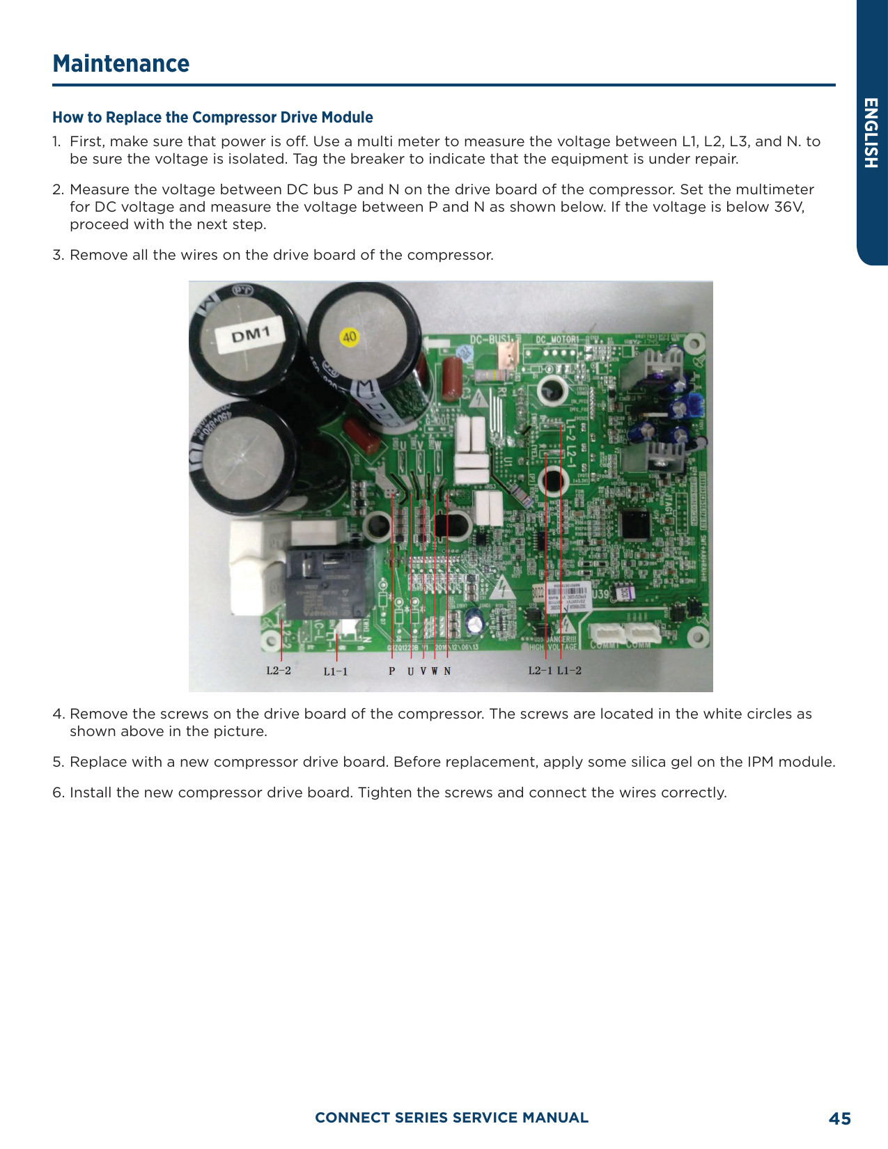
##### Maintenance of Major Components
Replacement of Thermostat Please refer to the instruction manual for your thermostat.
How to Replace the Compressor Diagnosis of Compressor Failure: On Condition that the Unit CAN be Started Up
Inverter compressor QXFT-F310zN450

########### I. Electronic Expansion Valve:
The electronic expansion valve will be reset every time when the unit is powered on or off. Touch the valve and you can feel the movement of the valve spool. In the last stage of the reset process, you will hear the click of the valve and feel its vibration.
Electronic expansion
Touch the electronic expansion valve:

Electronic expansion
########### II. 4-way Valve:
During normal operation, the 4 copper tubes that connect to the valve will have different temperatures. When the 4-way valve is working, it will generate some noise and vibration.

This is the position of the 4-way valve. Do not touch it directly with your hands. There is hot refrigerant at the discharge pipe, so be careful not to be scalded.

Labels on the 4-way valve: D-connect to the discharge side; E-connect to the evaporator of indoor unit; S-connect to the suction side of the liquid separator; C-connect to the outdoor coil. When the system is in cooling mode, C-the pipeline is with high pressure and high temperature; E, S-the pipeline is with low pressure and low temperature. When the system is in heating mode, E-the pipeline is with high pressure and high temperature; C, S-the pipeline is with low pressure and low temperature; Because D is connected to the discharge side, it is with high pressure and high temperature regardless of the operating mode. When the unit is powered on, in defrosting or oil return mode, the 4-way valve will produce some noise. Do not touch the pipes directly with your hands and be aware of the hot temperature.
D- Connect to the exhaust side Caution! High temperature!
Diagnosis of Compressor Failure: On Condition that the Unit CANNOT be Started Up
Refer to the following table for the resistance between any two terminals:
|Compressor model|UV Winding Resistance|VW Winding Resistance|WU Winding Resistance| |---|---|---|---| |QXFT-F310zN450|0.79±7%Ω|0.79±7%Ω|0.79±7%Ω| |QXAU-F516zX440A|0.79±7%Ω|0.79±7%Ω|0.79±7%Ω|
Measure the resistance to ground of each wiring terminal. The resistance should be above 10 megohm. If not, we can judge that the compressor windings are grounded.

Use a multimeter to measure the resistance between two terminals
Measure the resistance to ground of the three terminals respectively
######### Replacement of Compressor
########### 1. Preparation
• Do not carry the compressors horizontally or upside down when carrying the compressors. Make sure the lubricant inside the compressor doesn’t pour out from the oil refrigerant ports. The suction and discharge openings of the compressor must be sealed. Use tape for the openings if the rubber plugs are not available.
NOTICE:

Make sure terminal box cover of the compressor is in good condition.
Make sure the rubber seals of the suction and discharge openings of the compressor are in good condition.
########### 2. Disconnect power
• If the compressor needs to be replaced after judging as above, then switch off the outdoor unit and disconnect the power cable of the outdoor unit. Use insulating tape to wrap the power cable and put a notice card on the power switch to remind people to be cautious of electric shock.
########### 3. Preparation of electric components
• When you detach the compressor wires, temperature sensors and electric heaters, mark them correspondingly for the convenience of reconnecting them.
########### 4. Recover refrigerant
• Recover refrigerant from the system. Recover simultaneously from the high pressure side and low pressure side. Do not recover too quickly; otherwise large quantity of lubricant will escape from the system together with the refrigerant.
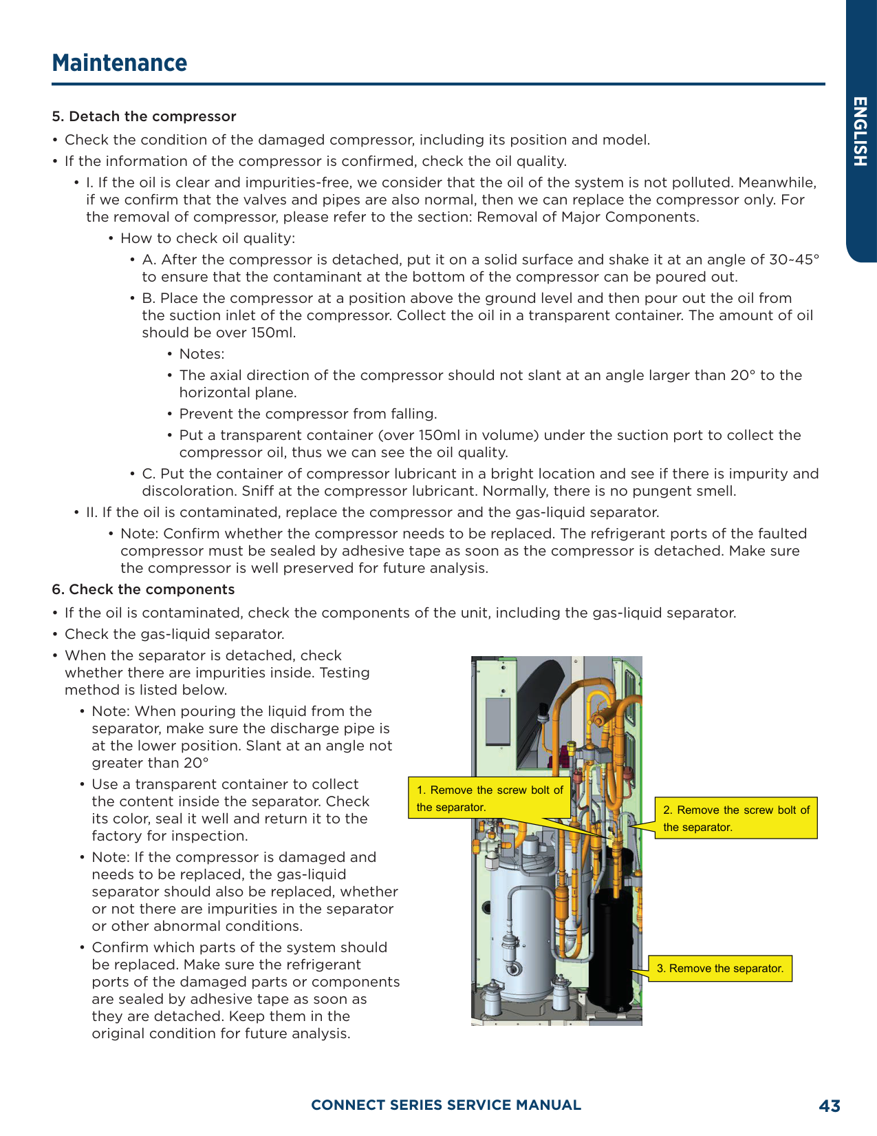
########### 5. Detach the compressor
• How to check oil quality:
• Note: Confirm whether the compressor needs to be replaced. The refrigerant ports of the faulted compressor must be sealed by adhesive tape as soon as the compressor is detached. Make sure the compressor is well preserved for future analysis.
########### 6. Check the components

########### 7. Clear the pipeline
• After confirming which parts of the system should be replaced, check the pipeline of the system. Blow through the main pipeline with nitrogen. After clearing the pipeline, if the components are not replaced immediately, seal the pipeline with adhesive tape to prevent the system from being contaminated by moisture and impurities in the air.
########### 8. Replace the compressor
• For the removal of compressor, please refer to the section: Removal of Major Components.
########### 9. Check/Replace the gas-liquid separator
########### 10. Check the system for leaks
########### 11. Evacuate the system and charge refrigerant
• Please refer to the section of maintenance: vacuum pumping and refrigerant charging.
########### 12. Connect electric components
• Connect cables, compressor wires and the electric heating belt according to the signs marked before and the wiring diagram on the cover of the electric box.
######### How to Replace the Compressor Drive Module

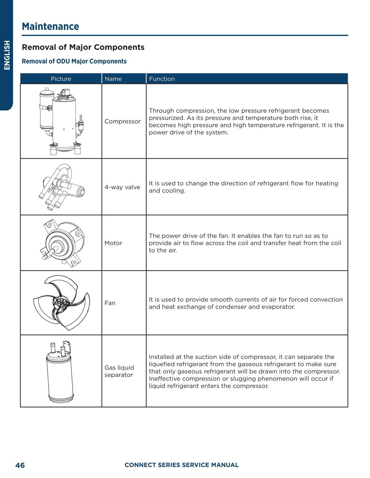
##### Removal of Major Components Removal of ODU Major Components
|Picture|Name|Function| |---|---|---| ||Compressor|Through compression, the low pressure refrigerant becomes pressurized. As its pressure and temperature both rise, it becomes high pressure and high temperature refrigerant. It is the power drive of the system.| ||4-way valve|It is used to change the direction of refrigerant flow for heating and cooling.| ||Motor|The power drive of the fan. It enables the fan to run so as to provide air to flow across the coil and transfer heat from the coil to the air.| ||Fan|It is used to provide smooth currents of air for forced convection and heat exchange of condenser and evaporator.| ||Gas liquid separator|Installed at the suction side of compressor, it can separate the liquefied refrigerant from the gaseous refrigerant to make sure that only gaseous refrigerant will be drawn into the compressor. Ineffective compression or slugging phenomenon will occur if liquid refrigerant enters the compressor.|
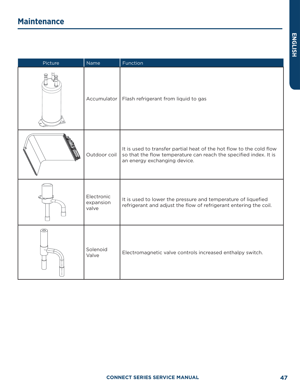
|Picture|Name|Function| |---|---|---| ||Accumulator|Flash refrigerant from liquid to gas| ||Outdoor coil|It is used to transfer partial heat of the hot flow to the cold flow so that the flow temperature can reach the specified index. It is an energy exchanging device.| ||Electronic expansion valve|It is used to lower the pressure and temperature of liquefied refrigerant and adjust the flow of refrigerant entering the coil.| ||Solenoid Valve|Electromagnetic valve controls increased enthalpy switch.|
ENGLISH
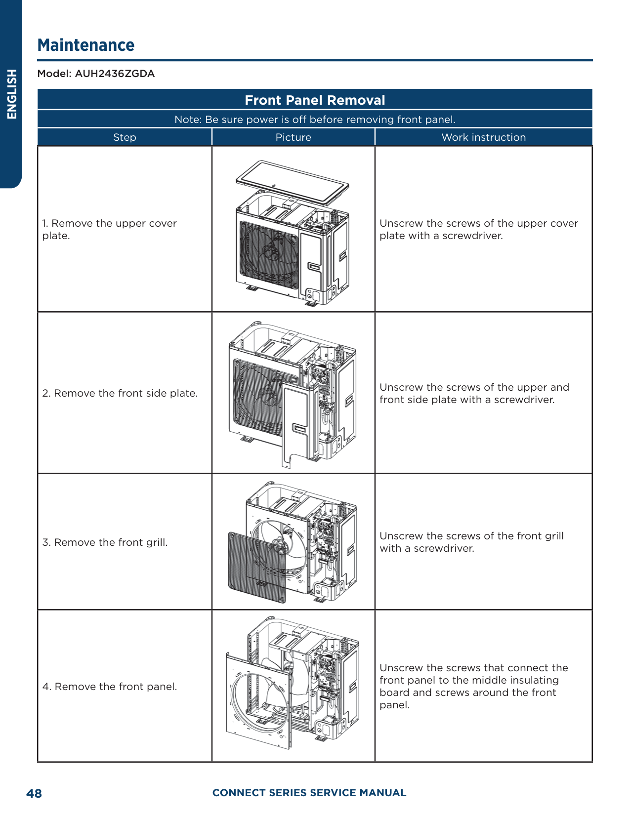
Model: AUH2436ZGDA
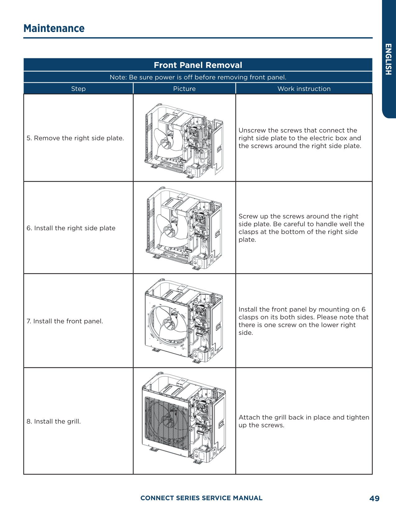
Front Panel Removal Note: Be sure power is off before removing front panel.
|Step|Picture|Work instruction| |---|---|---| |1. Remove the upper cover plate.||Unscrew the screws of the upper cover plate with a screwdriver.| |2. Remove the front side plate.||Unscrew the screws of the upper and front side plate with a screwdriver.| |3. Remove the front grill.||Unscrew the screws of the front grill with a screwdriver.| |4. Remove the front panel.||Unscrew the screws that connect the front panel to the middle insulating board and screws around the front panel.|
|Step|Picture|Work instruction| |---|---|---| |5. Remove the right side plate.||Unscrew the screws that connect the right side plate to the electric box and the screws around the right side plate.| |6. Install the right side plate||Screw up the screws around the right side plate. Be careful to handle well the clasps at the bottom of the right side plate.| |7. Install the front panel.||Install the front panel by mounting on 6 clasps on its both sides. Please note that there is one screw on the lower right side.| |8. Install the grill.||Attach the grill back in place and tighten up the screws.|
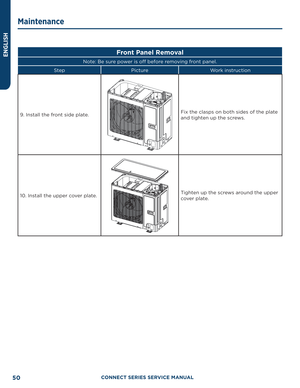
|Step|Picture|Work instruction| |---|---|---| |9. Install the front side plate.||Fix the clasps on both sides of the plate and tighten up the screws.| |10. Install the upper cover plate.||Tighten up the screws around the upper cover plate.|
Model: AUH2436ZGDA
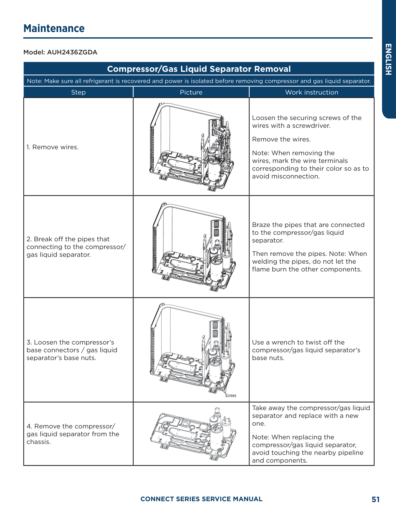
##### Compressor/Gas Liquid Separator Removal
Note: Make sure all refrigerant is recovered and power is isolated before removing compressor and gas liquid separator.
|Step|Picture|Work instruction| |---|---|---| |1. Remove wires.||Loosen the securing screws of the wires with a screwdriver.
Remove the wires. Note: When removing the wires, mark the wire terminals corresponding to their color so as to avoid misconnection.| |2. Break off the pipes that connecting to the compressor/ gas liquid separator.||Braze the pipes that are connected to the compressor/gas liquid separator.
Then remove the pipes. Note: When welding the pipes, do not let the flame burn the other components.| |3. Loosen the compressor’s base connectors / gas liquid separator’s base nuts.||Use a wrench to twist off the compressor/gas liquid separator’s base nuts.| |4. Remove the compressor/ gas liquid separator from the chassis.||Take away the compressor/gas liquid separator and replace with a new one.
Note: When replacing the compressor/gas liquid separator, avoid touching the nearby pipeline and components.|
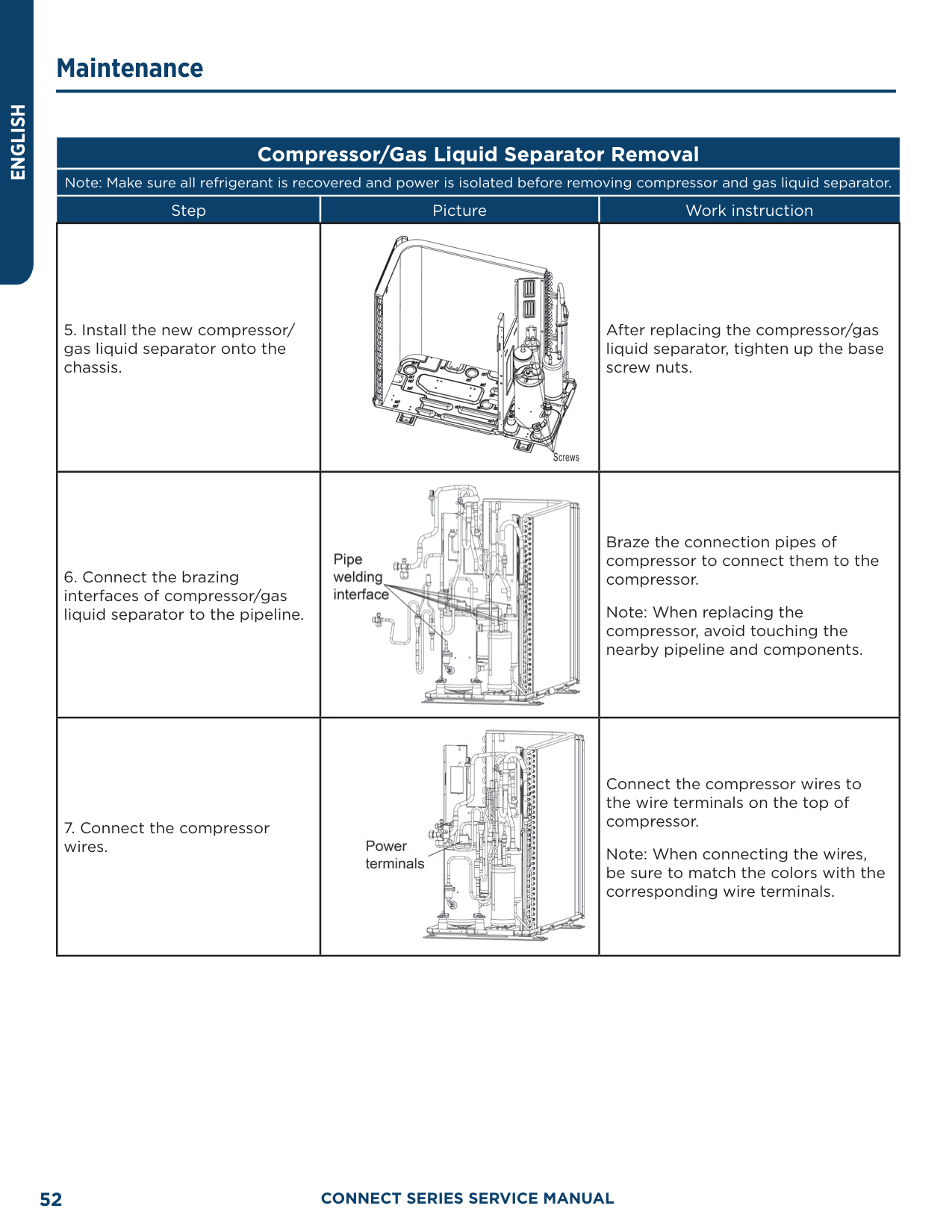
##### Compressor/Gas Liquid Separator Removal
Note: Make sure all refrigerant is recovered and power is isolated before removing compressor and gas liquid separator.
|Step|Picture|Work instruction| |---|---|---| |5. Install the new compressor/ gas liquid separator onto the chassis.||After replacing the compressor/gas liquid separator, tighten up the base screw nuts.| |6. Connect the brazing interfaces of compressor/gas liquid separator to the pipeline.||Braze the connection pipes of compressor to connect them to the compressor.
Note: When replacing the compressor, avoid touching the nearby pipeline and components.| |7. Connect the compressor wires.||Connect the compressor wires to the wire terminals on the top of compressor.
Note: When connecting the wires, be sure to match the colors with the corresponding wire terminals.|
Model: AUH2436ZGDA
##### 4-Way Valve Removal
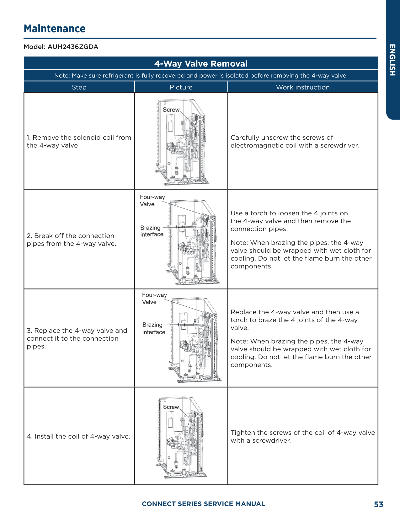
Note: Make sure refrigerant is fully recovered and power is isolated before removing the 4-way valve.
|Step|Picture|Work instruction| |---|---|---| |1. Remove the solenoid coil from the 4-way valve||Carefully unscrew the screws of electromagnetic coil with a screwdriver.| |2. Break off the connection pipes from the 4-way valve.||Use a torch to loosen the 4 joints on the 4-way valve and then remove the connection pipes.
Note: When brazing the pipes, the 4-way valve should be wrapped with wet cloth for cooling. Do not let the flame burn the other components.| |3. Replace the 4-way valve and connect it to the connection pipes.||Replace the 4-way valve and then use a torch to braze the 4 joints of the 4-way valve.
Note: When brazing the pipes, the 4-way valve should be wrapped with wet cloth for cooling. Do not let the flame burn the other components.| |4. Install the coil of 4-way valve.||Tighten the screws of the coil of 4-way valve with a screwdriver.|
ENGLISH
Model: AUH2436ZGDA
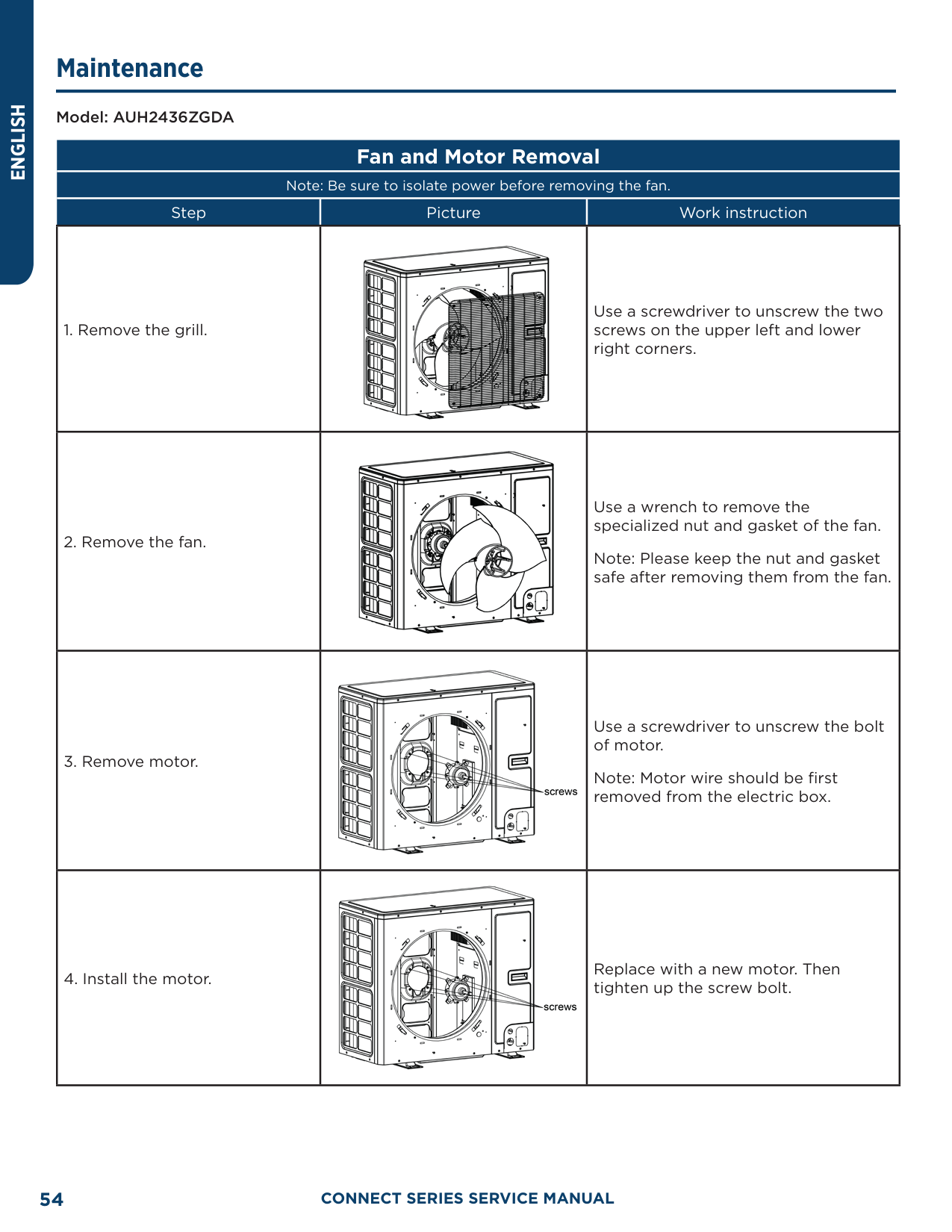
##### Fan and Motor Removal
Note: Be sure to isolate power before removing the fan.
|Step|Picture|Work instruction| |---|---|---|
|1. Remove the grill.||Use a screwdriver to unscrew the two screws on the upper left and lower right corners.| |2. Remove the fan.||Use a wrench to remove the specialized nut and gasket of the fan. Note: Please keep the nut and gasket safe after removing them from the fan.| |3. Remove motor.||Use a screwdriver to unscrew the bolt of motor.
Note: Motor wire should be first removed from the electric box.| |4. Install the motor.||Replace with a new motor. Then tighten up the screw bolt.|
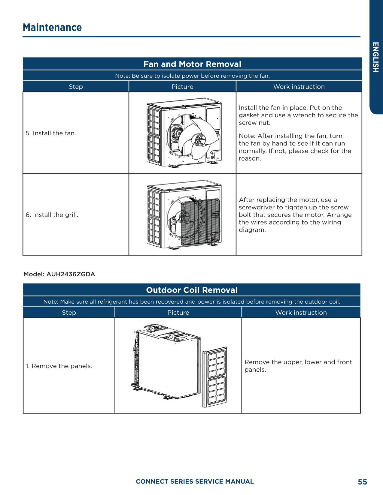
##### Fan and Motor Removal
Note: Be sure to isolate power before removing the fan.
|Step|Picture|Work instruction| |---|---|---| |5. Install the fan.||Install the fan in place. Put on the gasket and use a wrench to secure the screw nut.
Note: After installing the fan, turn the fan by hand to see if it can run normally. If not, please check for the reason.| |6. Install the grill.||After replacing the motor, use a screwdriver to tighten up the screw bolt that secures the motor. Arrange the wires according to the wiring diagram.|
Model: AUH2436ZGDA
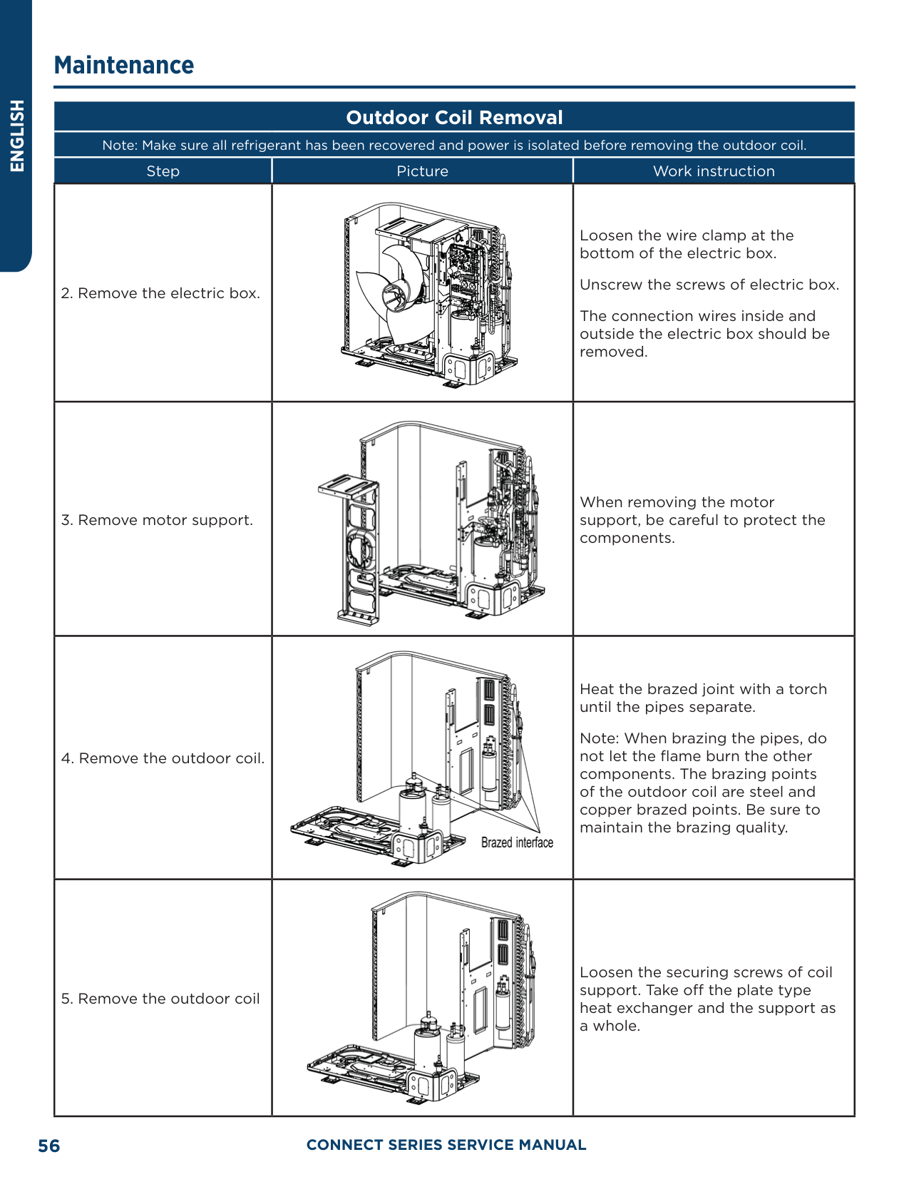
##### Outdoor Coil Removal
Note: Make sure all refrigerant has been recovered and power is isolated before removing the outdoor coil.
|Step|Picture|Work instruction| |---|---|---| |1. Remove the panels.||Remove the upper, lower and front panels.|
|Step|Picture|Work instruction| |---|---|---| |2. Remove the electric box.||Loosen the wire clamp at the bottom of the electric box.
Unscrew the screws of electric box. The connection wires inside and outside the electric box should be removed.| |3. Remove motor support.||When removing the motor support, be careful to protect the components.| |4. Remove the outdoor coil.||Heat the brazed joint with a torch until the pipes separate.
Note: When brazing the pipes, do not let the flame burn the other components. The brazing points of the outdoor coil are steel and copper brazed points. Be sure to maintain the brazing quality.| |5. Remove the outdoor coil||Loosen the securing screws of coil support. Take off the plate type heat exchanger and the support as a whole.|
|Step|Picture|Work instruction|
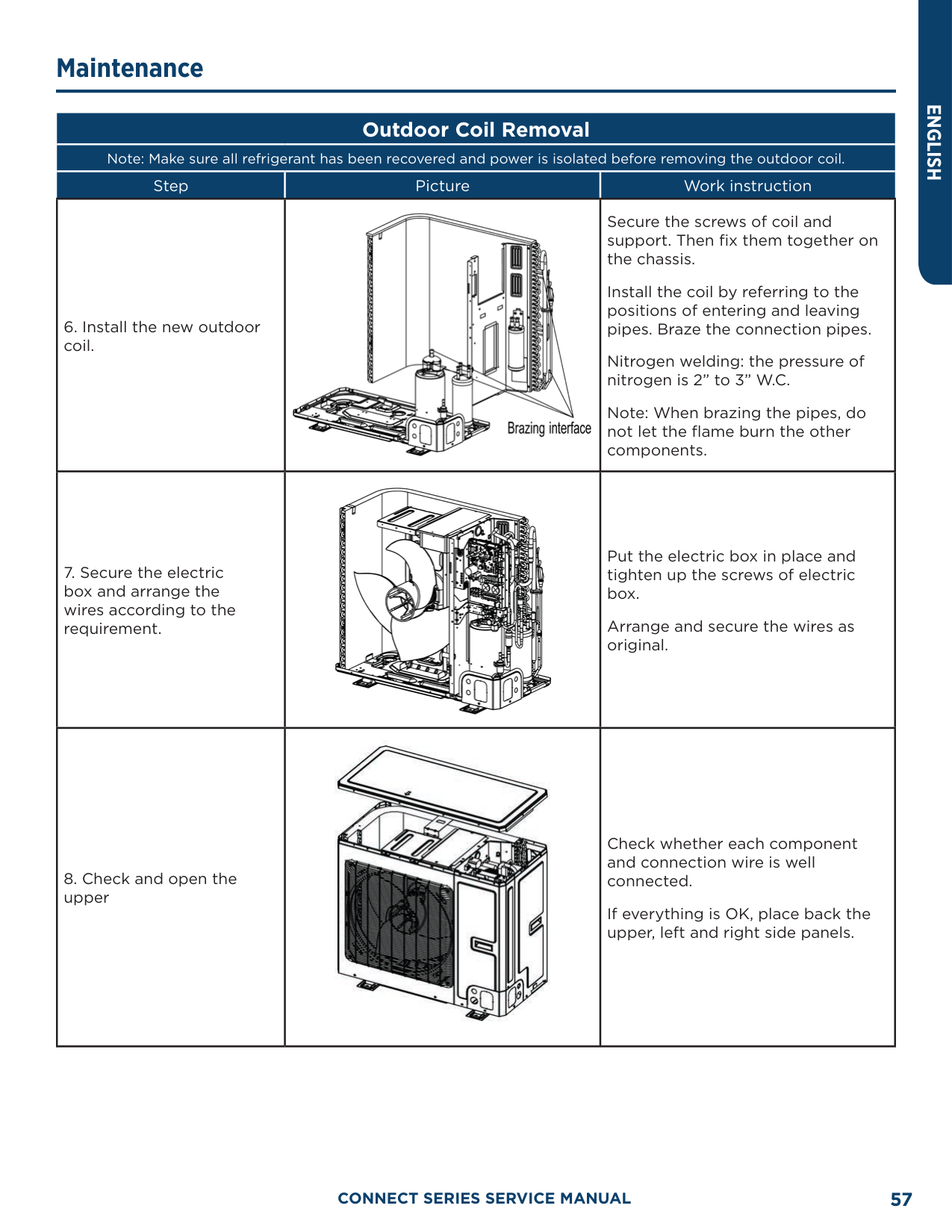
|---|---|---| |6. Install the new outdoor coil.||Secure the screws of coil and support. Then fix them together on the chassis.
Install the coil by referring to the positions of entering and leaving pipes. Braze the connection pipes.
Nitrogen welding: the pressure of nitrogen is 2” to 3” W.C.
Note: When brazing the pipes, do not let the flame burn the other components.| |7. Secure the electric box and arrange the wires according to the requirement.||Put the electric box in place and tighten up the screws of electric box.
Arrange and secure the wires as original.| |8. Check and open the upper||Check whether each component and connection wire is well connected.
If everything is OK, place back the upper, left and right side panels.|
Model: AUH2436ZGDA
##### Electronic Expansion Valve Removal
Note: Recover all refrigerant and isolate power before removing the electronic expansion valve.
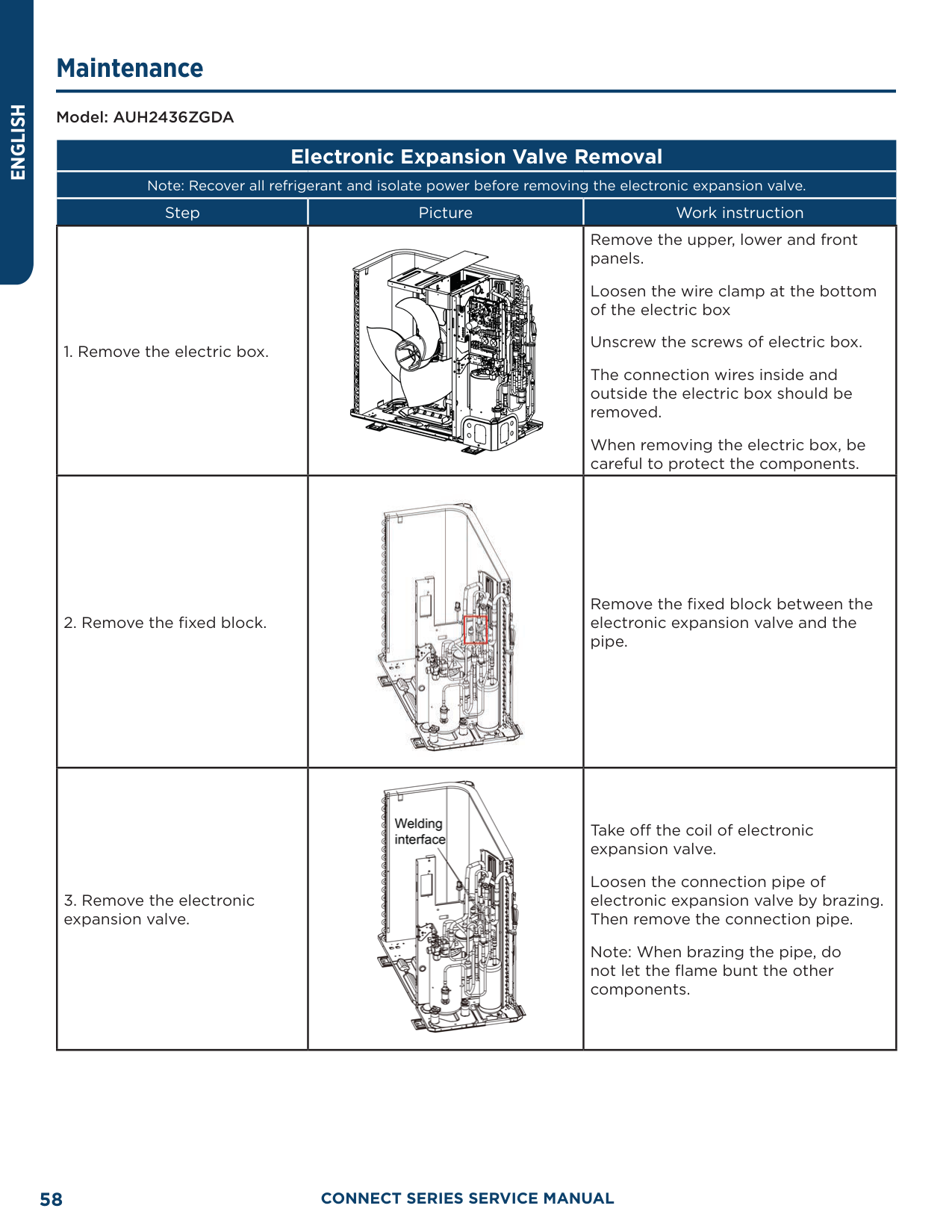
|Step|Picture|Work instruction| |---|---|---| |1. Remove the electric box.||Remove the upper, lower and front panels.
Loosen the wire clamp at the bottom of the electric box
Unscrew the screws of electric box. The connection wires inside and outside the electric box should be removed. When removing the electric box, be careful to protect the components.| |2. Remove the fixed block.||Remove the fixed block between the electronic expansion valve and the pipe.| |3. Remove the electronic expansion valve.||Take off the coil of electronic expansion valve.
Loosen the connection pipe of electronic expansion valve by brazing. Then remove the connection pipe.
Note: When brazing the pipe, do not let the flame bunt the other components.|
############# Note: Recover all refrigerant and isolate power before removing the electronic expansion valve.
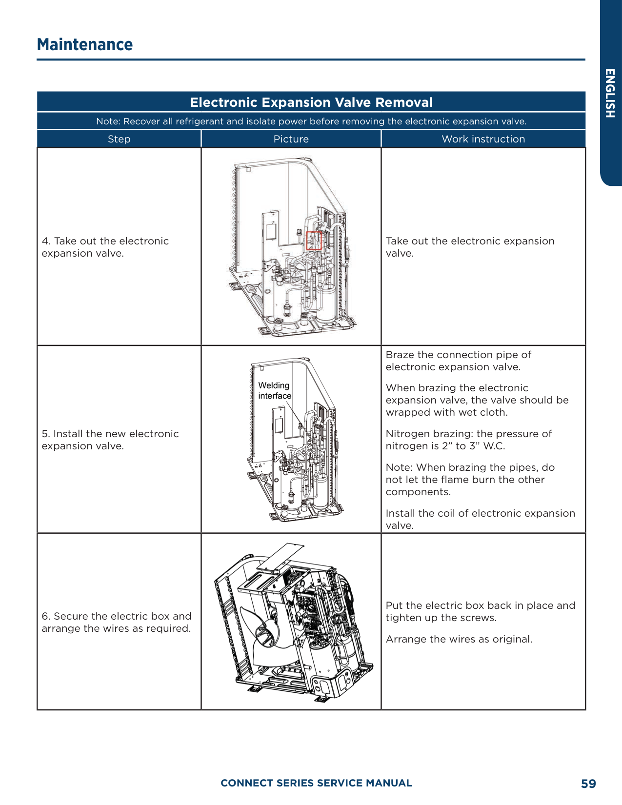
|Step|Picture|Work instruction| |---|---|---| |4. Take out the electronic expansion valve.||Take out the electronic expansion valve.| |5. Install the new electronic expansion valve.||Braze the connection pipe of electronic expansion valve.
When brazing the electronic expansion valve, the valve should be wrapped with wet cloth.
Nitrogen brazing: the pressure of nitrogen is 2” to 3” W.C.
Note: When brazing the pipes, do not let the flame burn the other components.
Install the coil of electronic expansion valve.| |6. Secure the electric box and arrange the wires as required.||Put the electric box back in place and tighten up the screws.
Arrange the wires as original.|
Note: Recover all refrigerant and isolate power before removing the electronic expansion valve.
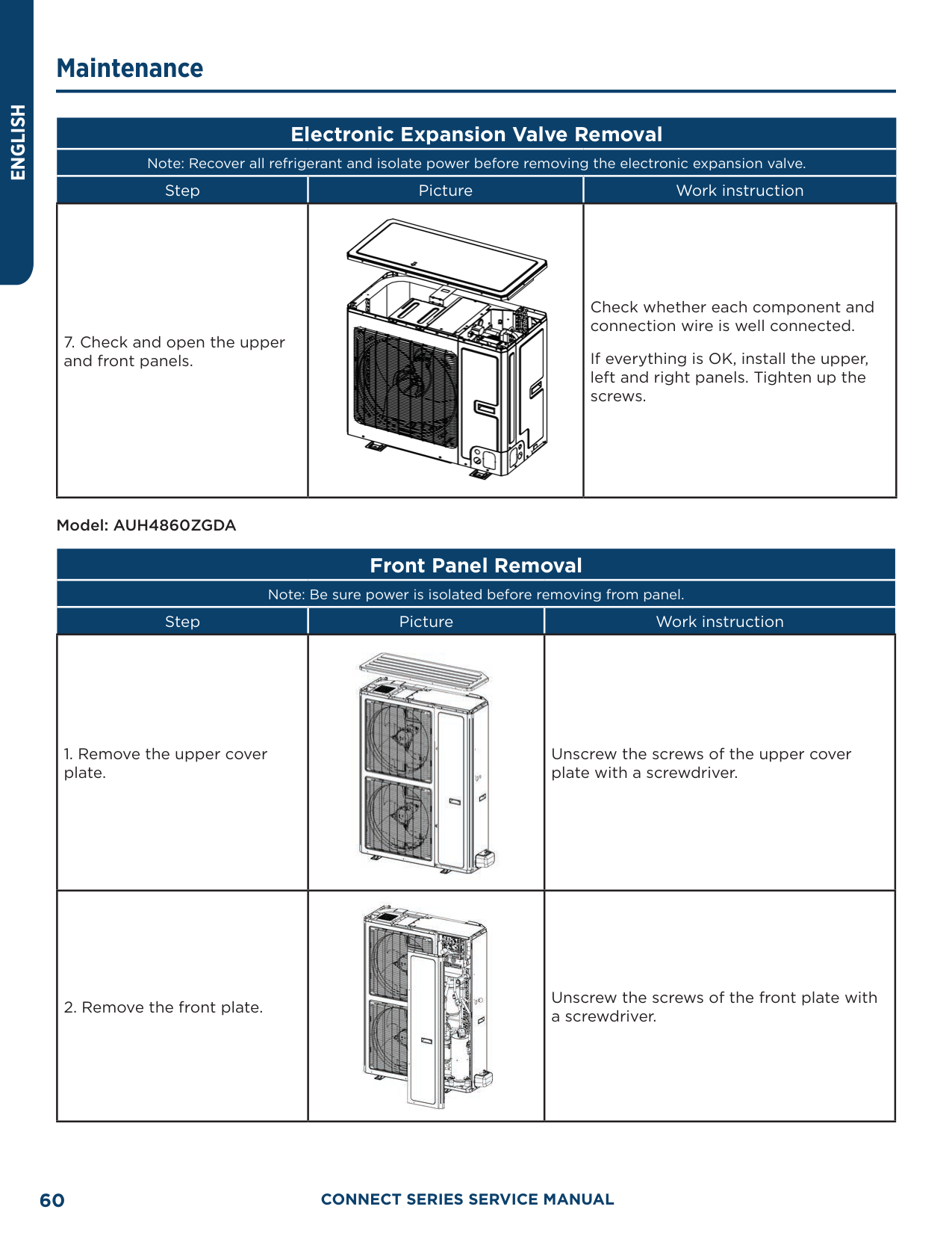
|Step|Picture|Work instruction| |---|---|---| |7. Check and open the upper and front panels.||Check whether each component and connection wire is well connected.
If everything is OK, install the upper, left and right panels. Tighten up the screws.|
Model: AUH4860ZGDA
##### Front Panel Removal
Note: Be sure power is isolated before removing from panel.
|Step|Picture|Work instruction| |---|---|---| |1. Remove the upper cover plate.||Unscrew the screws of the upper cover plate with a screwdriver.| |2. Remove the front plate.||Unscrew the screws of the front plate with a screwdriver.|
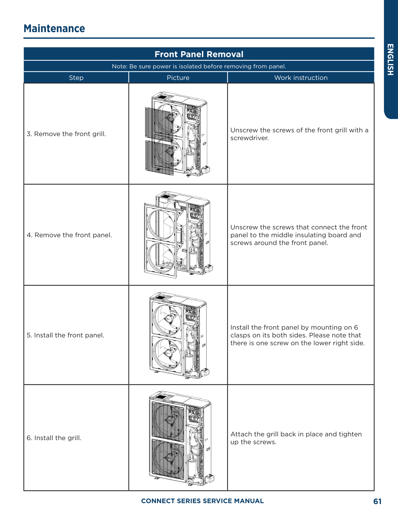
|Step|Picture|Work instruction| |---|---|---| |3. Remove the front grill.||Unscrew the screws of the front grill with a screwdriver.| |4. Remove the front panel.||Unscrew the screws that connect the front panel to the middle insulating board and screws around the front panel.| |5. Install the front panel.||Install the front panel by mounting on 6 clasps on its both sides. Please note that there is one screw on the lower right side.| |6. Install the grill.||Attach the grill back in place and tighten up the screws.|
|Step|Picture|Work instruction| |---|---|---| |7. Remove the valve cover||Unscrew the screws of the valve cover with a screwdriver.| |8. Remove the right side plate.||Unscrew the screws that connect the right side plate to the electric box and the screws around the right side plate.| |9. Install the right side plate.||Screw up the screws around the right side plate. Be careful to handle well the clasps at the bottom of the right side plate.| |10. Install the grill.||Attach the grill back in place and tighten up the screws.|
|Step|Picture|Work instruction| |---|---|---| |11. Install the upper cover plate.||Tighten up the screws around the upper cover plate.|
Model: AUH4860ZGDA
##### Compressor Disassembly
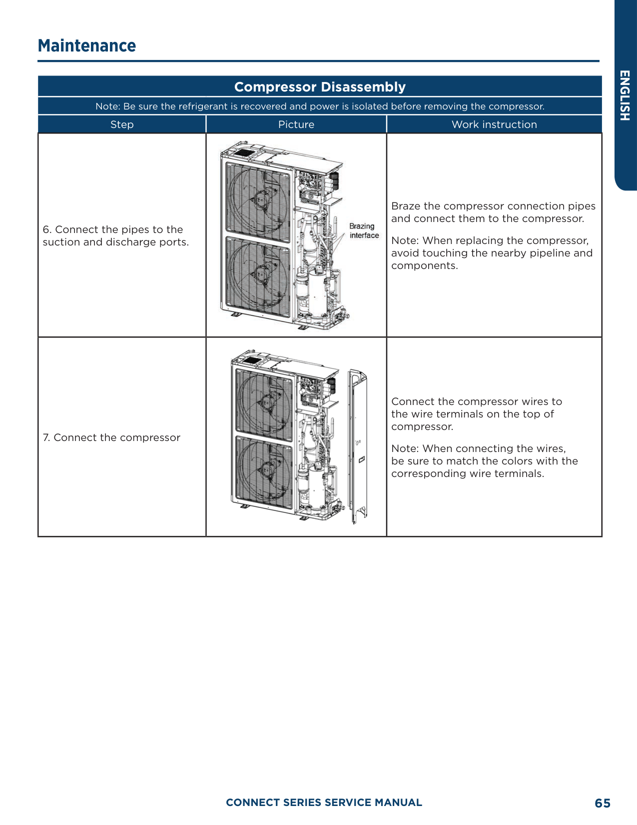
Note: Be sure the refrigerant is recovered and power is isolated before removing the compressor.
|Step|Picture|Work instruction| |---|---|---| |1. Remove wires.||Loosen the securing screws of the wires with a screwdriver. Remove the wires. Note: When removing the wires, mark the wire terminals corresponding to their color so as to avoid misconnection.| |2. Loosen the securing screws at the foot of compressor.||Use a wrench to twist off the screw nuts at the foot of compressor.|
|Step|Picture|Work instruction| |---|---|---| |3. Break off the pipes that connect to the compressor.||Braze the pipes that are connected to the compressor.
Then remove the pipes. Note: When brazing the pipes, do not let the flame burn the other components| |4. Remove the compressor from the chassis||Take out the compressor and replace it. Note: When replacing the compressor, avoid touching the nearby pipeline and components.| |5. Fix the new compressor back onto the chassis.||After replacing the compressor, tighten up the screws at the foot of compressor.|
|Step|Picture|Work instruction| |---|---|---| |6. Connect the pipes to the suction and discharge ports.||Braze the compressor connection pipes and connect them to the compressor.
Note: When replacing the compressor, avoid touching the nearby pipeline and components.| |7. Connect the compressor||Connect the compressor wires to the wire terminals on the top of compressor.
Note: When connecting the wires, be sure to match the colors with the corresponding wire terminals.|
Model: AUH4860ZGDA
##### 4-Way Valve Removal
Note: Make sure refrigerant is fully recovered and power is isolated before removing the 4-way valve.
|Step|Picture|Work instruction| |---|---|---| |1. Remove the solenoid coil from the 4-way valve||Carefully unscrew the screws of electromagnetic coil with a screwdriver.| |2. Break off the connection pipes from the 4-way valve.||Use a torch to loosen the 4 joints on the 4-way valve and then remove the connection pipes.
Note: When brazing the pipes, the 4-way valve should be wrapped with wet cloth for cooling. Do not let the flame burn the other components.| |3. Replace the 4-way valve and connect it to the connection pipes.||Replace the 4-way valve and then use a torch to braze the 4 joints of the 4-way valve.
Note: When brazing the pipes, the 4-way valve should be wrapped with wet cloth for cooling. Do not let the flame burn the other components.|
##### 4-Way Valve Removal
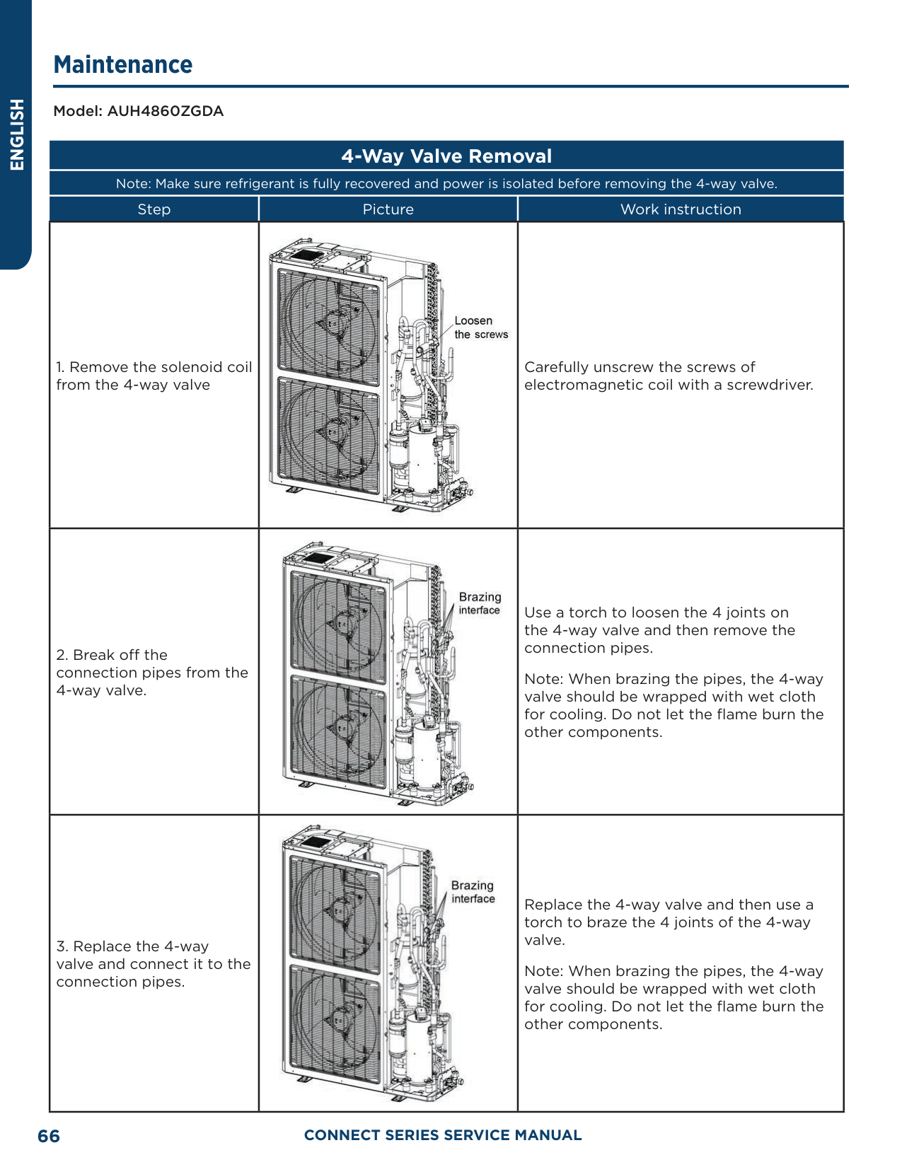
Note: Make sure refrigerant is fully recovered and power is isolated before removing the 4-way valve.
|Step|Picture|Work instruction| |---|---|---| |4. Install the coil of 4-way valve.||Tighten the screws of the coil of 4-way valve with a screwdriver.|
Model: AUH4860ZGDA
##### Fan and Motor Removal
Note: Be sure to isolate power before removing the fan.
|Step|Picture|Work instruction| |---|---|---| |1. Remove the grill.||Use a screwdriver to unscrew the two screws on the upper left and lower right corners.|
|Step|Picture|Work instruction| |---|---|---| |2. Remove the fan.||Use a wrench to remove the specialized nut and gasket of the fan.
Note: Please keep the nut and gasket safe after removing them from the fan.| |3. Remove motor.||Use a screwdriver to unscrew the bolt of motor.
Note: Motor wire should be first removed from the electric box.| |4. Install the motor.||Replace with a new motor. Then tighten up the screw bolt.|
|Step|Picture|Work instruction| |---|---|---| |5. Install the fan.||Install the fan in place. Put on the gasket and use a wrench to secure the screw nut.
Note: After installing the fan, turn the fan by hand to see if it can run normally. If not, please check for the reason.| |6. Install the grill.||After replacing the motor, use a screwdriver to tighten up the screw bolt that secures the motor. Arrange the wires according to the wiring diagram.|
##### Compressor/Gas Liquid Separator Removal
Note: Be sure power is isolated and refrigerant is recovered before removing the gas liquid separator.
|Step|Picture|Work instruction|
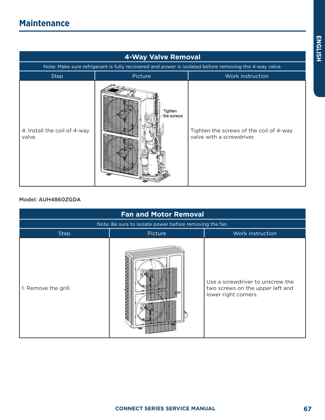
|---|---|---| |1. Loosen the wire clamp at the bottom of the electric box and the screws of electric box.||Remove the upper, lower and front panels.
Loosen the wire clamp at the bottom of the electric box.
Unscrew the screws of electric box.| |2. Remove the electric box.||The connection wires inside and outside the electric box should be removed.
When removing the electric box, be careful to protect the components.| |3. Remove the compressor/ gas liquid separator from the chassis.||Remove the compressor/gas liquid separator and replace with a new one.
Note: When replacing the compressor/gas liquid separator, avoid touching the nearby pipeline and components.|
##### Compressor/Gas Liquid Separator Removal
Note: Be sure power is isolated and refrigerant is recovered before removing the gas liquid separator.
|Step|Picture|Work instruction| |---|---|---| |4. Install the new gas liquid separator||Install the gas liquid separator by referring to the positions of entering and leaving pipes. Braze the two joints
Nitrogen welding: the pressure of nitrogen is 2” to 3” W.C
Note: When brazing the pipes, do not let the flame burn the other components.
Tighten the screws of gas liquid separator.| |5. Secure the electric box and||Put the electric box back in place and tighten up the screws.
Arrange the wires as original.| |6. Check and open the upper and side panels.||Check whether each component and connection wire is well connected.
If everything is OK, install the upper, left and right panels. Tighten up the screws.|
##### Electronic Expansion Valve Removal
Note: Be sure power is isolated and refrigerant is recovered before removing the Electronic Expansion Valve
|Step|Picture|Work instruction| |---|---|---| |1. Loosen the wire clamp at the bottom of the electric box and the screws of electric box.||Remove the upper, lower and front panels.
Loosen the wire clamp at the bottom of the electric box.
Unscrew the screws of electric box.| |2. Remove the electric box.||The connection wires inside and outside the electric box should be removed.
When removing the electric box, be careful to protect the components.| |3. Remove the electronic expansion valve.||Take off the coil of electronic expansion valve.
Loosen the connection pipe of electronic expansion valve using a torch. Remove the connection pipe.
Note: When brazing the pipe, do not let the flame burn the other components.|
############# Note: Be sure power is isolated and refrigerant is recovered before removing the Electronic Expansion Valve
|Step|Picture|Work instruction| |---|---|---| |4. Take out the electronic expansion valve.||Take out the electronic expansion valve.| |5. Install the new electronic expansion valve.||Braze the connection pipe of electronic expansion valve.
When brazing the electronic expansion valve, the valve should be wrapped with wet cloth.
Nitrogen welding: the pressure of nitrogen is 2” to 3” W.C.
Note: When brazing the pipes, do not let the flame burn the other components.
Install the coil of electronic expansion valve.| |6. Secure the electric box and arrange the wires as required.||Put the electric box back in place and tighten up the screws.
Arrange the wires as original.|
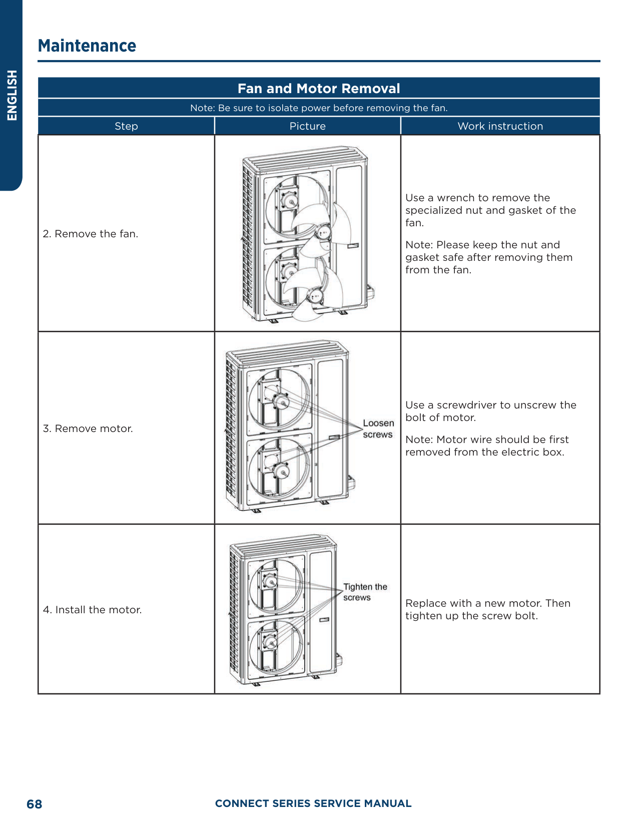
Note: Be sure power is isolated and refrigerant is recovered before removing the Electronic Expansion Valve
|Step|Picture|Work instruction| |---|---|---| |7. Check and open the upper and side panels.||Check whether each component and connection wire is well connected.
If everything is OK, install the upper, left and right panels. Tighten up the screws.|
Removal of IDU Major Components Air handler Unit
##### Electric Box Disassembly and Assembly
Note: Be sure power is isolated and refrigerant is recovered before removing the Electronic Expansion Valve
|Step|Picture|Work instruction| |---|---|---| |1. Remove the upper panel||Loosen screws around the upper panel with a screwdriver.
Remove the upper panel away from the unit.| |2. Remove the electric box.||Disconnect the power cord and control line from the wiring terminals, and then draw them out.
Loosen screws around the electric box with a screwdriver.
Remove the electric box from the unit.|
##### Electric Box Disassembly and Assembly
Note: Be sure power is isolated and refrigerant is recovered before removing the Electronic Expansion Valve
|Step|Picture|Work instruction| |---|---|---| |3. Remove the electric element.||Disconnect the electric element from the wiring terminal.
Loosen screws around the electric element with a screwdriver.
Remove the electric element from the electric box.| |4. Mount the new electric element.||Place the electric element at the proper position.
Tighten the screws around the electric element with a screwdriver.
Wire the electric element to the wiring terminal.| |5. Reinstall the electric box.||Place the electric box at the proper position.
Tighten screws around the electric box with a screwdriver.
Connect the power cord and control line properly.
Reassemble the unit as before.|
##### Fan Motor Disassembly and Assembly
|Step|Picture|Work instruction| |---|---|---| |1. Remove the upper panel.||Loosen screws round the upper panel with a screwdriver.
Remove the upper panel from unit.|
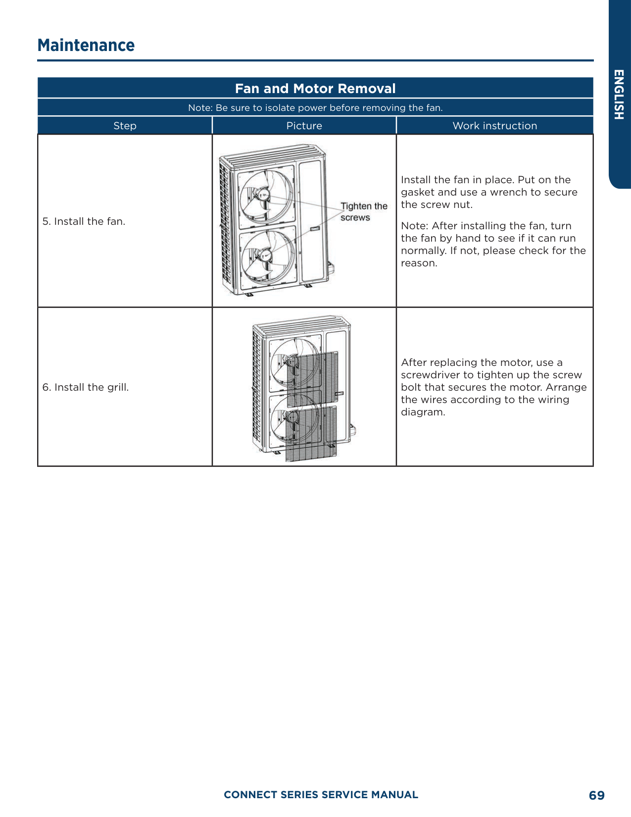
|2. Remove the fan.||Disconnect the wires of the fan from the wiring terminal and draw them out.
Loosen screws located at the front of the fan with a screwdriver.
Remove the fan from the unit.| |3. Remove the motor.||Disconnect the wires of the fan from the wiring terminal and draw them out.
Loosen screws located at the front of the fan with a screwdriver.
Remove the fan from the unit.| |4. Reinstall the fan.||Place the motor at the proper position.
Tighten screws fixing the motor and fan wheel.
Tighten screw bolts fixing the motor bracket.
After the installation, reassemble the unit as before.|
|Step|Picture|Work instruction| |---|---|---| |1. Remove the upper panel.||Loosen screws round the upper panel with a screwdriver.
Remove the upper panel from unit| |2. Remove the lower panel (1) and panel (2).||Loosen screws round the lower panel with a screwdriver.
Remove the lower panel from unit.| |3. Remove the enhanced frame if applicable.||Remove the screws from enhanced frame.
Disassemble the enhanced frame from the unit.| |4. Remove the mounting plate of the drain pan.||Loosen screws at both side of the mounting plate with a screwdriver.
Remove the mounting plate from the unit.|
|Step|Picture|Work instruction| |---|---|---| |5. Remove the primary drain pan.||Remove the primary drain pan from the unit.| |6. Remove the secondary drain pan.||Remove the secondary drain pan from the unit.| |7. Remove the coil.||Remove the coil away from the primary drain pan.
Reassemble the unit as before.|
##### Filter Disassembly and Assembly
|Step|Picture|Work instruction| |---|---|---| |1. Remove the mounting plate||Loosen screws fixing the mounting plate. Remove the mounting plate away from the unit| |2. Remove the filter screen||Remove the filter screen away from the unit. After replacing the filter screen, reassemble the unit as before.|
##### Exploded View and Parts Lists ODU Exploded View and Parts Lists
AUH2436ZGDA

|No.|Material name| |---|---|
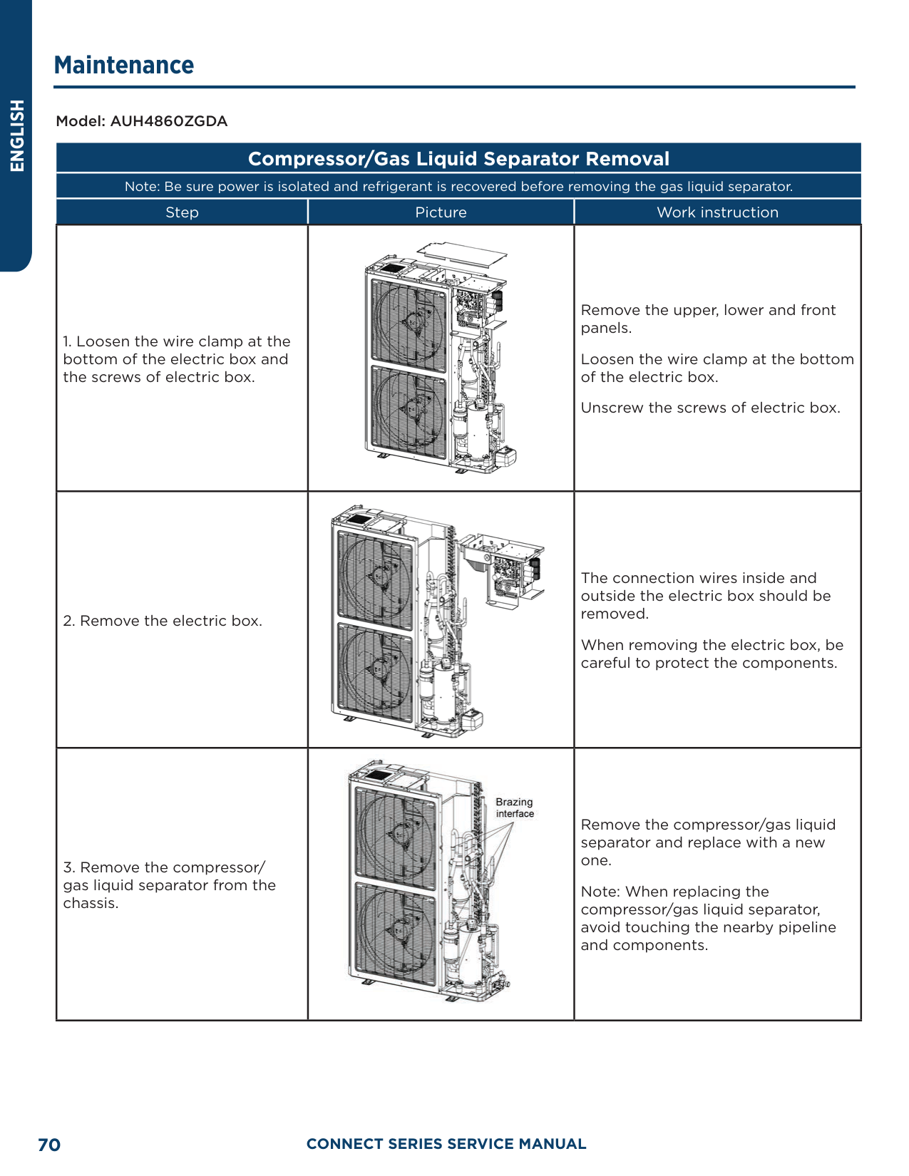
|1|Coping| |2|Electric Box Assembly| |3|PFC Inductance| |4|Filter Board| |5|Reactor Sub-Assembly| |6|Power Switch| |7|Main Board| |8|Inductance| |9|Terminal Board| |10|Terminal Board| |11|Heat Sink| |12|Main Board| |13|Coil Assembly| |14|Filter Sub-Assembly| |15|Electromagnetic Valve Sub-Assembly| |16|Magnet Coil (Electromagnetic Valve)| |17|Electromagnetic Valve| |18|Strainer| |19|Brushless DC Motor| |20|Axial Flow Fan| |21|Cabinet| |22|Diversion Circle| |23|Front Grill| |24|Front Side Plate| |25|Compressor And Fittings| |26|Handle| |27|Chassis Assembly| |28|Foot| |29|Cut Off Valve|
|No.|Material name| |---|---| |30|Fusible Plug| |31|Gas-liquid Separator| |32|Accumulator|
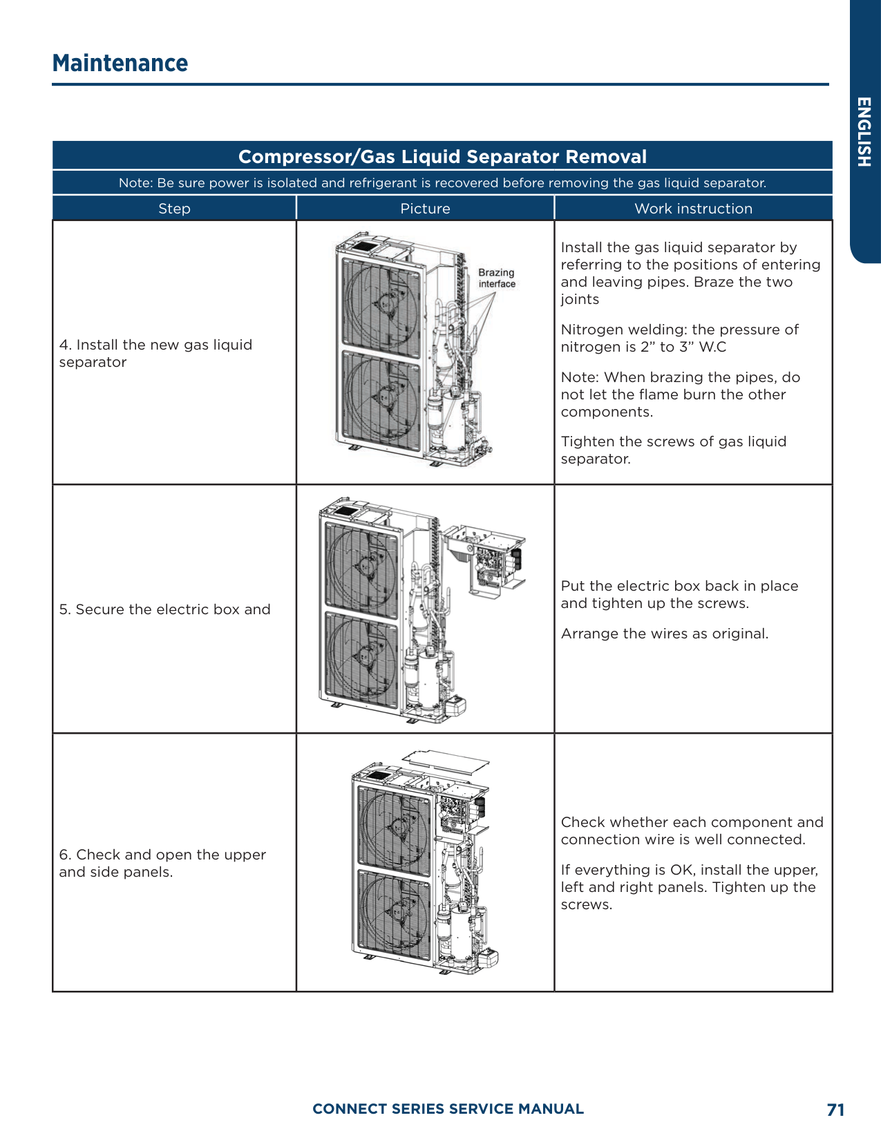
|33|4 Way Valve Coil| |34|Drainage Hole Cap| |35|Temperature Sensor| |36|Temperature Sensor| |37|Electrical Heater(Compressor)| |38|Electrical Heater (Chassis)| |39|Electric Expansion Valve Sub-Assembly| |40|Drainage Joint| |41|Cut-Off Valve 3/8(N)| |42|Strainer| |43|Electric Expand Valve Fitting| |44|One Way Valve| |45|Electronic Expansion Valve| |46|Strainer| |47|Electric Expand Valve Fitting| |48|Electric Expansion Valve Sub-Assembly| |49|Rear Side Plate| |50|4-Way Valve Assembly| |51|Silencer| |52|Pressure Protect Switch| |53|Filter| |54|Pressure Protect Switch| |55|4-Way Valve| |56|Pressure Sensor| |57|Rear Grill|
########### AUH4860ZGDA

|No.|Material name| |---|---| |1|Coping| |2|Rear Grill| |3|Left Side Plate|
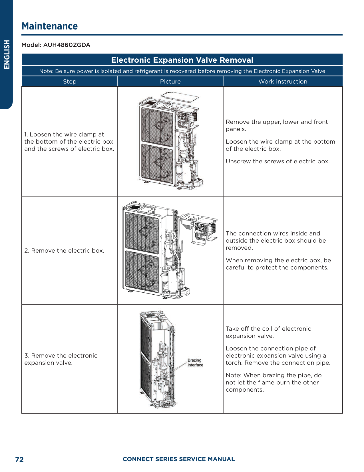
|4|Electric Box Assembly| |5|Drive Board| |6|Radiator| |7|Main Board| |8|Filter Board| |9|Terminal Board| |10|Terminal Board| |11|Inductance Box Assembly| |12|Handle| |13|Axial Flow Fan| |14|Cabinet| |15|Brushless DC Motor| |16|Gas-liquid Separator Sub-Assembly| |17|Front Grill| |18|Front Side Plate| |19|Pressure Protect Switch| |20|Brushless DC Motor| |21|Electromagnetic Valve| |22|Electric Expand Valve Fitting| |23|Electric Expansion Valve Sub-Assembly| |24|Compressor and Fittings| |25|Accumulator|
|No.|Material name| |---|---| |26|Foot| |27|Chassis Sub-Assembly| |28|Cut Off Valve Sub-Assembly| |29|Strainer| |30|Magnet Coil (Electromagnetic Valve)| |31|Electric Expand Valve Fitting| |32|One Way Valve| |33|Cut-off Valve| |34|Electronic Expansion Valve| |35|4-Way Valve Assembly|
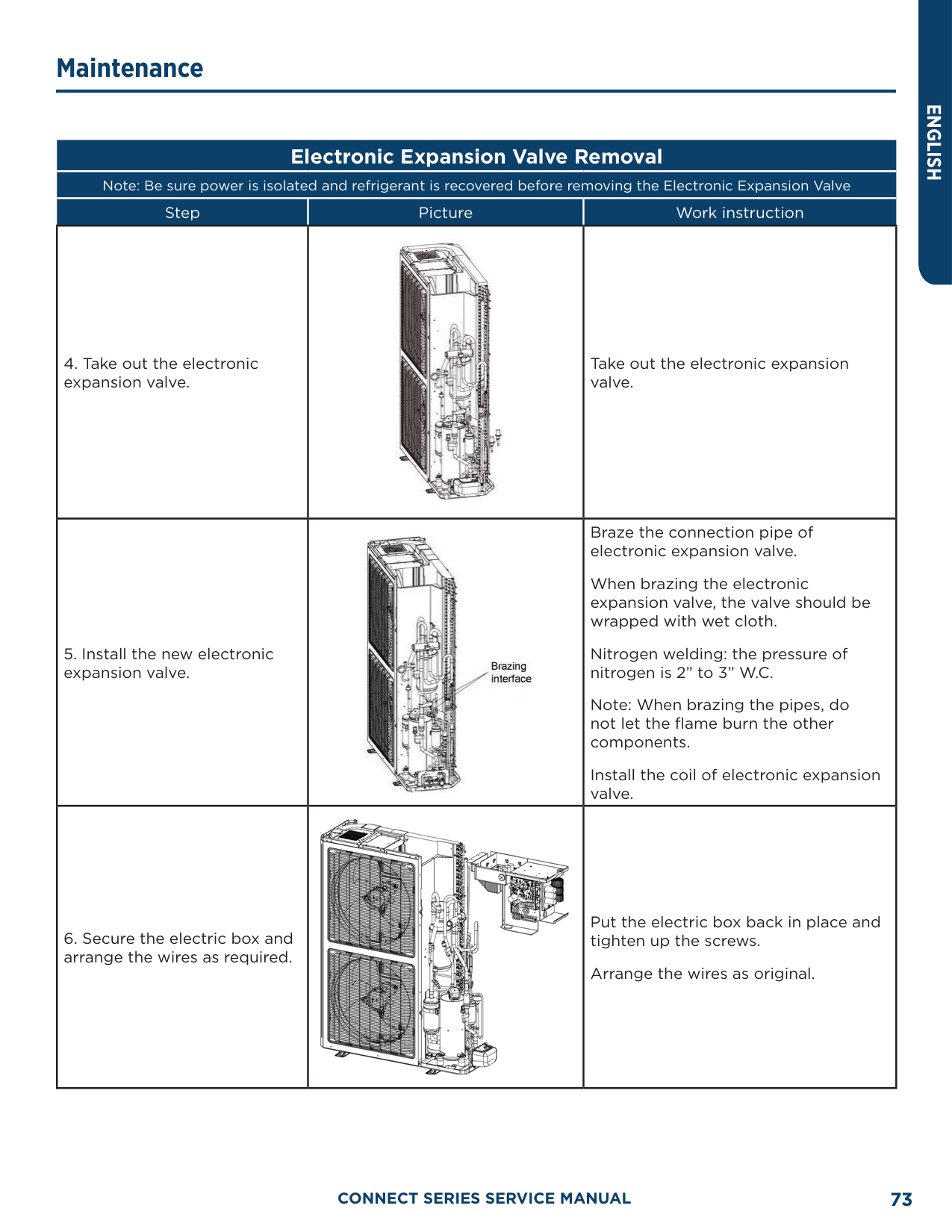
|36|Pressure Sensor| |37|Strainer| |38|Cut Off Valve 3/8| |39|Pressure Protect Switch| |40|Electrical Heater(Compressor)| |41|Electrical Heater(Compressor)| |42|4-Way Valve| |43|Handle| |44|4 Way Valve Coil| |45|Drainage Hole Cap| |46|Drainage Joint| |47|Temperature Sensor| |48|Temperature Sensor| |49|Rear Side Plate Sub-Assembly| |50|Coil Assembly|
######### IDU Exploded View and Parts Lists
UUY24ZGDAA, UUY36ZGDAA

|No.|Material name| |---|---| |1|Coping| |2|Left Side Plate| |3|Electric Box Assembly| |4|Terminal Board| |5|Transformer| |6|Terminal Board| |7|Main Board| |8|Terminal Board| |9|Pinboard| |10|Rear Side Plate| |11|Centrifugal Fan Assembly|
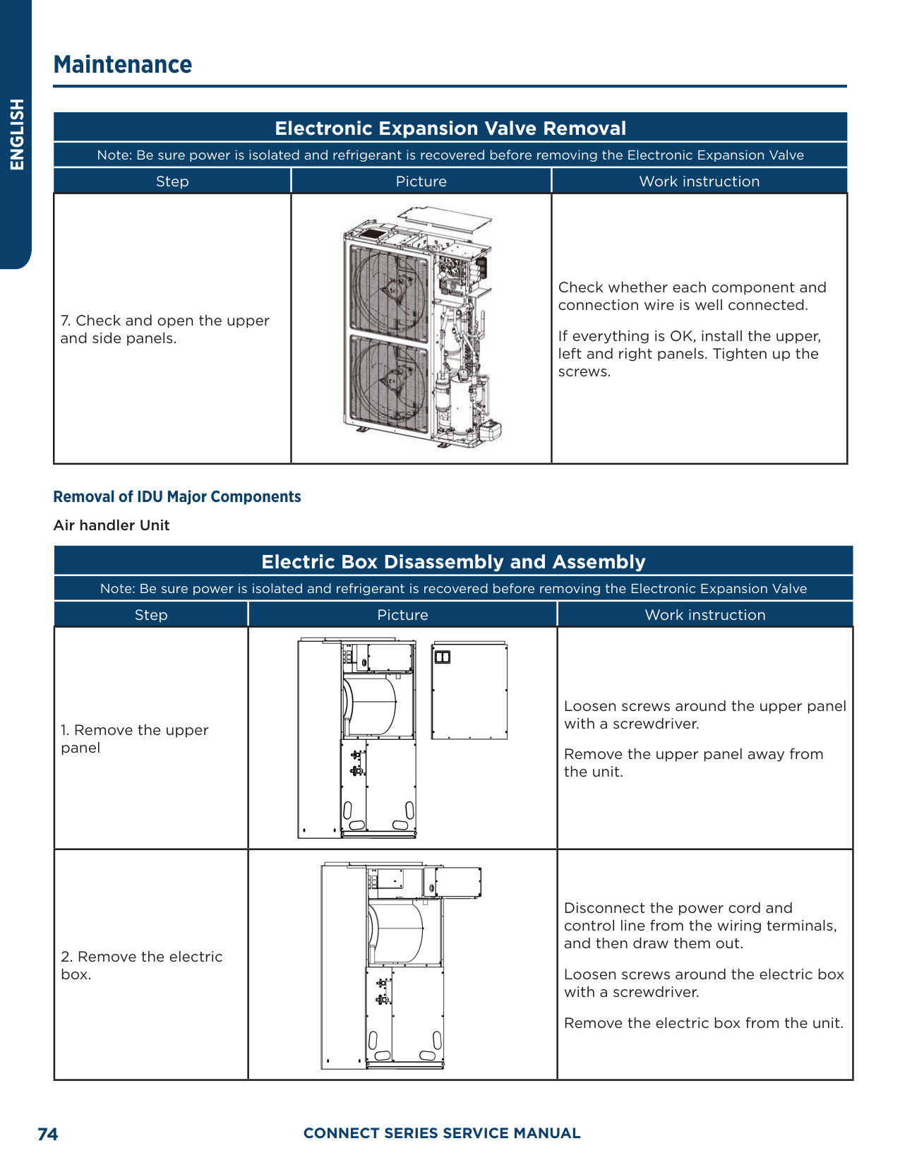
|12|Motor For Centrifugal Fan| |13|Brushless DC Motor| |14|Top Cover Board Sub-Assembly| |15|Bottom Cover Plate Assembly| |16|Right Side Plate| |17|Bottom Cover Plate Assembly| |18|Water Tray| |19|Strainer| |20|Cut-Off Valve 3/8(N)| |21|Thermal Expansion Valve| |22|Cut Off Valve| |23|Evaporator Assembly| |24|Evaporator Assembly| |25|Evaporator Assembly| |26|Water Tray Assembly| |27|Choke Plug| |28|Water Tray| |29|Filter Sub-Assembly|
##### Temperature Sensor Temperature/Resistance/Voltage Lists 15 KΩ Temperature Sensors (including ODU temperature sensors)
|F°|C°|Resistance (kΩ)|Voltage (V)| |---|---|---|---| |-4.0|-20|144|0.311| |-2.2|-19|138.1|0.323| |-0.4|-18|128.6|0.345| |1.4|-17|121.6|0.362| |3.2|-16|115|0.381| |5.0|-15|108.7|0.4| |6.8|-14|102.9|0.42| |8.6|-13|97.4|0.44| |10.4|-12|92.22|0.462| |12.2|-11|87.35|0.484| |14.0|-10|82.75|0.506| |15.8|-9|78.43|0.53|
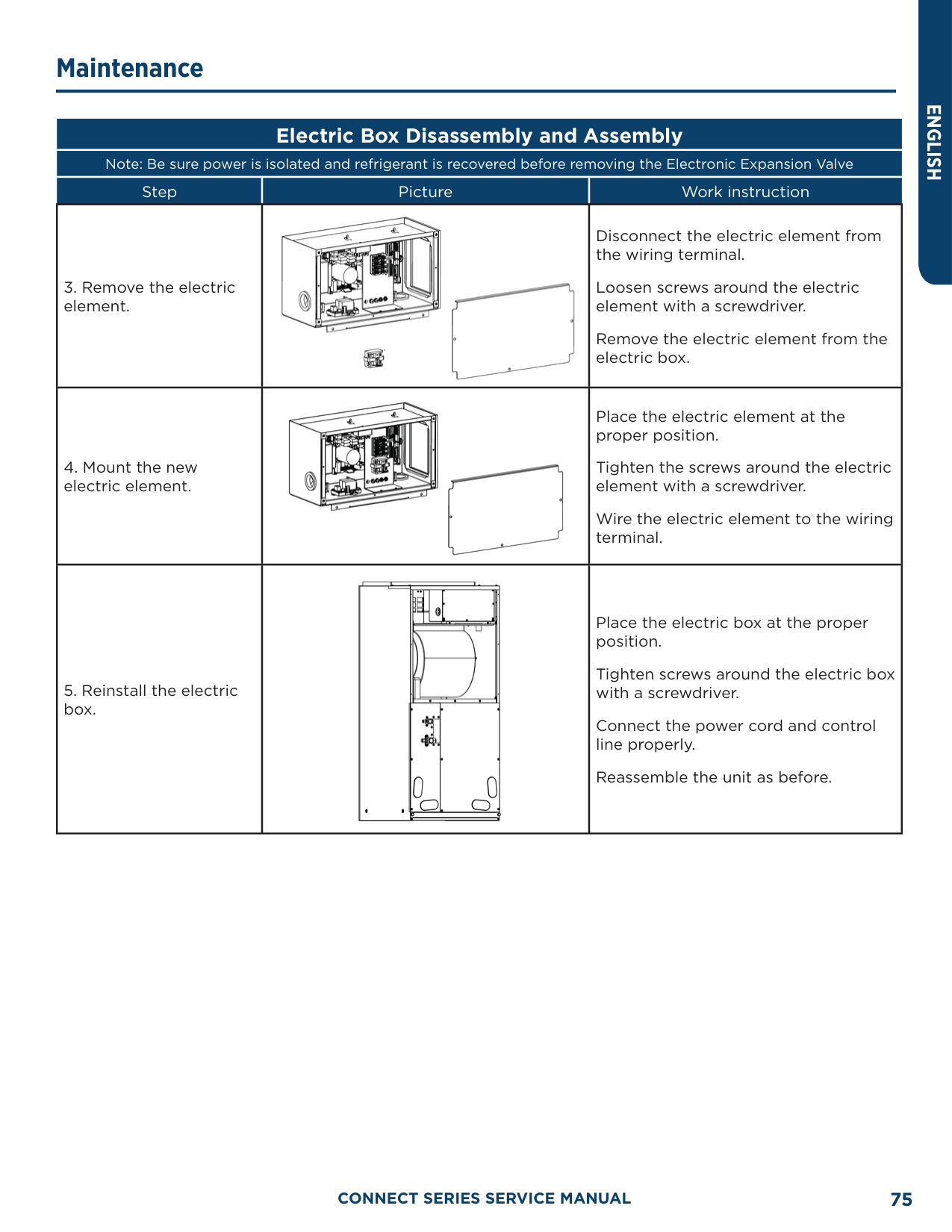
|17.6|-8|74.35|0.554| |19.4|-7|70.5|0.579| |21.2|-6|66.88|0.605| |23.0|-5|63.46|0.631| |24.8|-4|60.23|0.658| |26.6|-3|57.18|0.686| |28.4|-2|54.31|0.714| |30.2|-1|51.59|0.743| |32.0|0|49.02|0.773| |33.8|1|46.8|0.801| |35.6|2|44.31|0.835| |37.4|3|42.14|0.866| |39.2|4|40.09|0.899| |41.0|5|38.15|0.931| |42.8|6|36.32|0.965| |44.6|7|34.58|0.998| |46.4|8|32.94|1.033| |48.2|9|31.38|1.067| |50.0|10|29.9|1.102| |51.8|11|28.51|1.138| |53.6|12|27.18|1.174| |55.4|13|25.92|1.21| |57.2|14|24.73|1.246| |59.0|15|23.6|1.282| |60.8|16|22.53|1.319| |62.6|17|21.51|1.356| |64.4|18|20.54|1.393| |66.2|19|19.63|1.429| |68.0|20|18.75|1.467| |69.8|21|17.93|1.503| |71.6|22|17.14|1.54| |73.4|23|16.39|1.577| |75.2|24|15.68|1.613|
|F°|C°|Resistance (kΩ)|Voltage (V)|
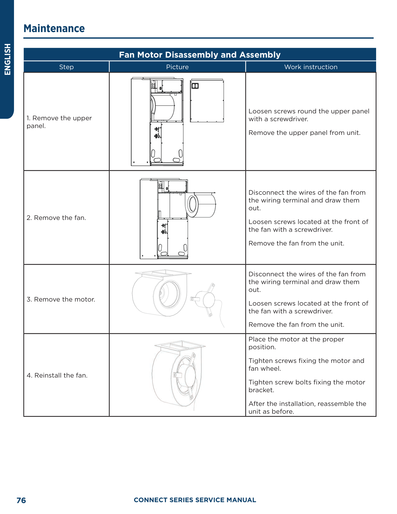
|---|---|---|---| |77.0|25|15|1.65| |78.8|26|14.36|1.686| |80.6|27|13.74|1.722| |82.4|28|13.16|1.758| |84.2|29|12.6|1.793| |86.0|30|12.07|1.829| |87.8|31|11.57|1.863| |89.6|32|11.09|1.897| |91.4|33|10.63|1.931| |93.2|34|10.2|1.964| |95.0|35|9.779|1.998| |96.8|36|9.382|2.03| |98.6|37|9.003|2.062| |100.4|38|8.642|2.094| |102.2|39|5.997|2.125| |105.8|41|7.653|2.185| |107.6|42|7.352|2.215| |109.4|43|7.065|2.243| |111.2|44|6.791|2.272| |113.0|45|6.529|2.299| |114.8|46|6.278|2.326| |116.6|47|6.038|2.353| |118.4|48|5.809|2.379| |120.2|49|5.589|2.404| |122.0|50|5.379|2.429| |123.8|51|5.179|2.453| |125.6|52|4.986|2.477| |127.4|53|4.802|2.5| |129.2|54|4.625|2.522| |131.0|55|4.456|2.544| |132.8|56|4.294|2.566| |134.6|57|4.139|2.586| |136.4|58|3.99|2.607| |138.2|59|3.848|2.626| |140.0|60|3.711|2.646|
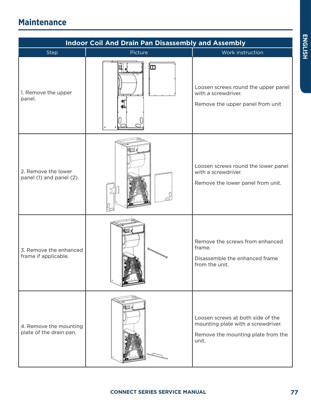
|141.8|61|3.579|2.664| |143.6|62|3.454|2.682| |145.4|63|3.333|2.7| |147.2|64|3.217|2.717| |149.0|65|3.105|2.734| |150.8|66|2.998|2.75| |152.6|67|2.898|2.766| |154.4|68|2.797|2.781| |156.2|69|2.702|2.796| |158.0|70|2.611|2.811|
|F°|C°|Resistance (kΩ)|Voltage (V)| |---|---|---|---| |159.8|71|2.523|2.825| |161.6|72|2.439|2.838| |163.4|73|2.358|2.852| |165.2|74|2.28|2.865| |167.0|75|2.205|2.877| |168.8|76|2.133|2.889| |170.6|77|2.064|2.901| |172.4|78|1.997|2.912| |174.2|79|1.933|2.923| |176.0|80|1.871|2.934| |177.8|81|1.811|2.945| |179.6|82|1.754|2.955| |181.4|83|1.699|2.964| |183.2|84|1.645|2.974| |185.0|85|1.594|2.983| |186.8|86|1.544|2.992| |188.6|87|1.497|3.001| |190.4|88|1.451|3.009| |192.2|89|1.408|3.017| |194.0|90|1.363|3.025| |195.8|91|1.322|3.033| |197.6|92|1.282|3.04|
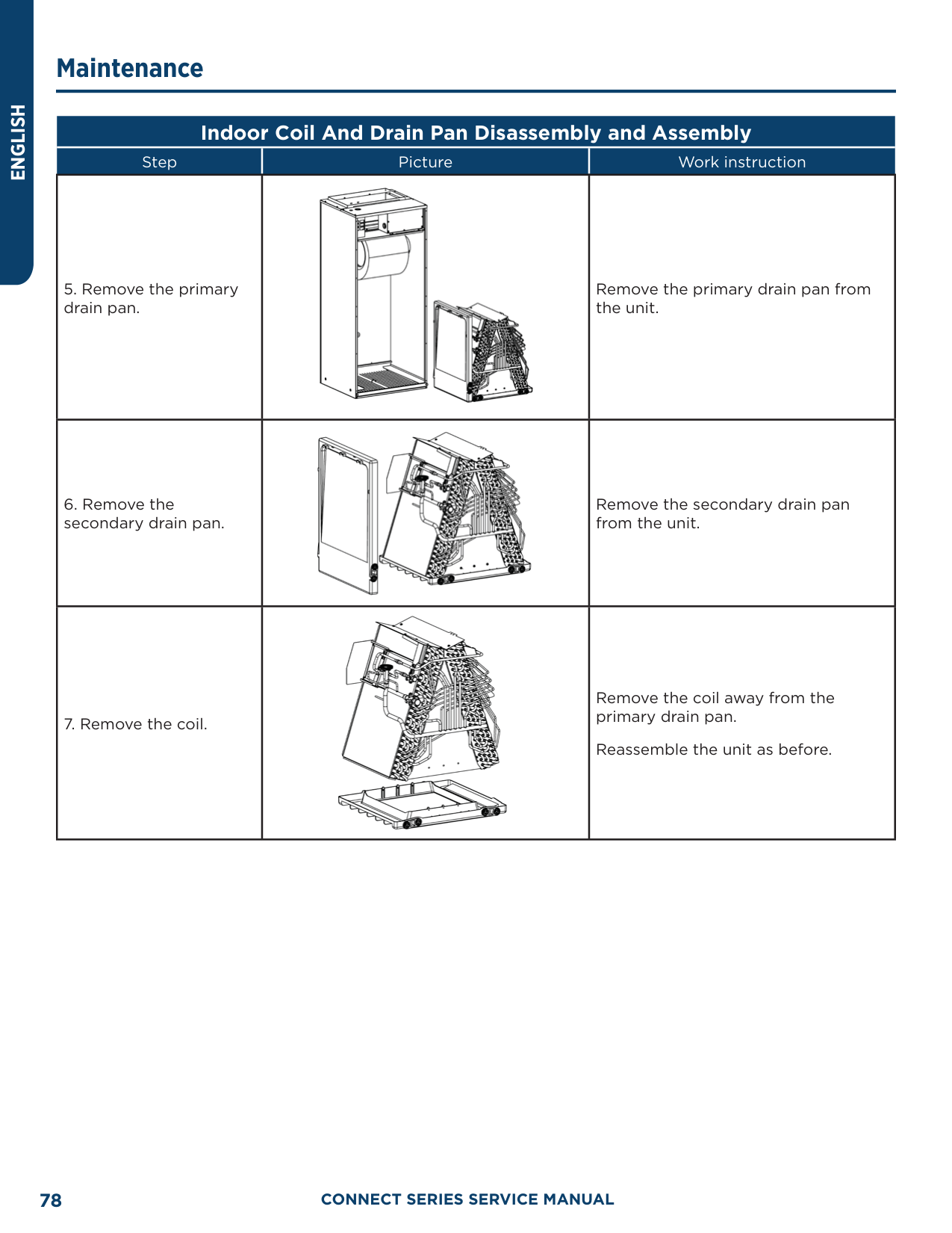
|199.4|93|1.244|3.047| |201.2|94|1.207|3.054| |203.0|95|1.171|3.061| |204.8|96|1.136|3.068| |206.6|97|1.103|3.074| |208.4|98|1.071|3.08| |210.2|99|1.039|3.086| |212.0|100|1.009|3.092| |213.8|101|0.98|3.098| |215.6|102|0.952|3.103| |217.4|103|0.925|3.108| |219.2|104|0.898|3.114| |221.0|105|0.873|3.119| |222.8|106|0.848|3.123| |224.6|107|0.825|3.128| |226.4|108|0.802|3.133| |228.2|109|0.779|3.137| |230.0|110|0.758|3.141| |231.8|111|0.737|3.145| |233.6|112|0.717|3.15| |235.4|113|0.697|3.153| |237.2|114|0.678|3.157| |239.0|115|0.66|3.161|
|F°|C°|Resistance (kΩ)|Voltage (V)| |---|---|---|---| |240.8|116|0.642|3.165| |242.6|117|0.625|3.168| |244.4|118|0.608|3.171| |246.2|119|0.592|3.175| |248.0|120|0.577|3.178| |249.8|121|0.561|3.181| |251.6|122|0.547|3.184| |253.4|123|0.532|3.187| |255.2|124|0.519|3.19|
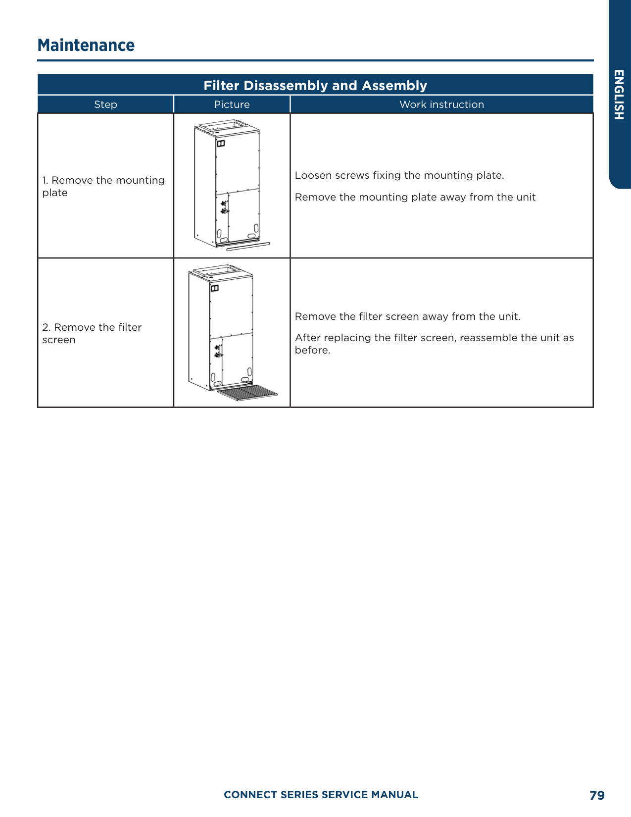
|257.0|125|0.505|3.192| |258.8|126|0.492|3.195| |260.6|127|0.48|3.198| |262.4|128|0.467|3.2| |264.2|129|0.456|3.203| |266.0|130|0.444|3.205| |267.8|131|0.433|3.207| |269.6|132|0.422|3.21| |271.4|133|0.412|3.212| |273.2|134|0.401|3.214| |275.0|135|0.391|3.216| |276.8|136|0.382|3.218| |278.6|137|0.372|3.22| |280.4|138|0.363|3.222| |282.2|139|0.355|3.224| |284.0|140|0.346|3.226| |285.8|141|0.338|3.227| |287.6|142|0.33|3.229| |289.4|143|0.322|3.231| |291.2|144|0.314|3.232| |293.0|145|0.307|3.234| |294.8|146|0.299|3.235| |296.6|147|0.292|3.237| |298.4|148|0.286|3.238| |300.2|149|0.279|3.24| |302.0|150|0.273|3.241| |303.8|151|0.266|3.242| |305.6|152|0.261|3.244| |307.4|153|0.254|3.245| |309.2|154|0.248|3.246| |311.0|155|0.243|3.247| |312.8|156|0.237|3.249| |314.6|157|0.232|3.25| |316.4|158|0.227|3.251| |318.2|159|0.222|3.252| |320.0|160|0.217|3.253|
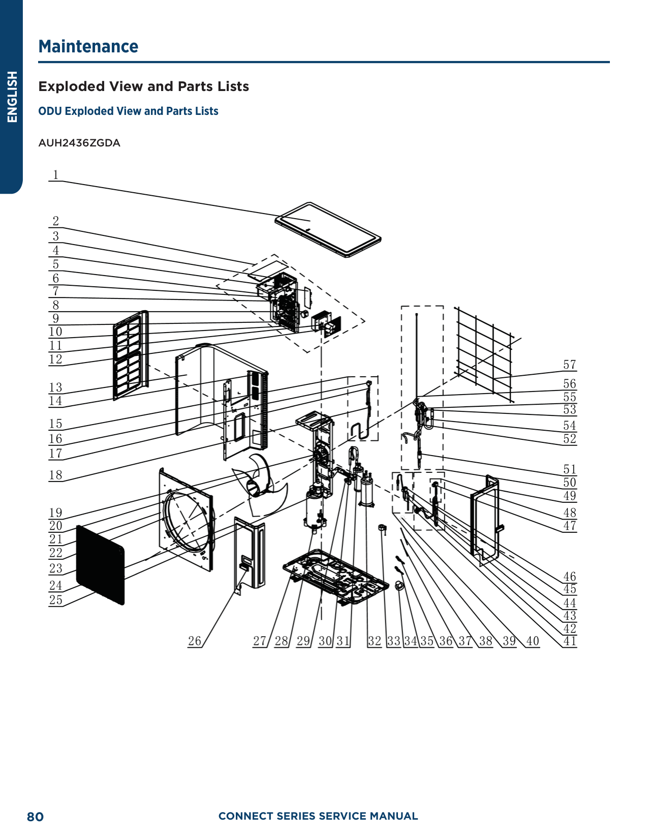
######### 20 KΩ Pipeline Temperature Sensors (including temperature sensors for defroster, IDU and ODU pipes)
|F°|C°|Resistance (kΩ)|Voltage (V)| |---|---|---|---| |-22.0|-30|361.8|0.173| |-20.2|-29|339.8|0.183| |-18.4|-28|319.2|0.195| |-16.6|-27|300|0.206| |-14.8|-26|282.2|0.218| |-13.0|-25|265.5|0.231| |-11.2|-24|249.9|0.245| |-9.4|-23|235.3|0.259| |-7.6|-22|221.6|0.273| |-5.8|-21|208.9|0.288| |-4.0|-20|196.9|0.304| |-2.2|-19|181.4|0.328| |-0.4|-18|171.4|0.345| |1.4|-17|162.1|0.362| |3.2|-16|153.3|0.381| |5.0|-15|145|0.4| |6.8|-14|137.2|0.42| |8.6|-13|129.9|0.44| |10.4|-12|123|0.462| |12.2|-11|116.5|0.484| |14.0|-10|110.3|0.507| |15.8|-9|104.6|0.53| |17.6|-8|99.13|0.554| |19.4|-7|94|0.579| |21.2|-6|89.17|0.605| |23.0|-5|84.61|0.631| |24.8|-4|80.31|0.658| |26.6|-3|76.24|0.686| |28.4|-2|72.41|0.714| |30.2|-1|68.79|0.743|
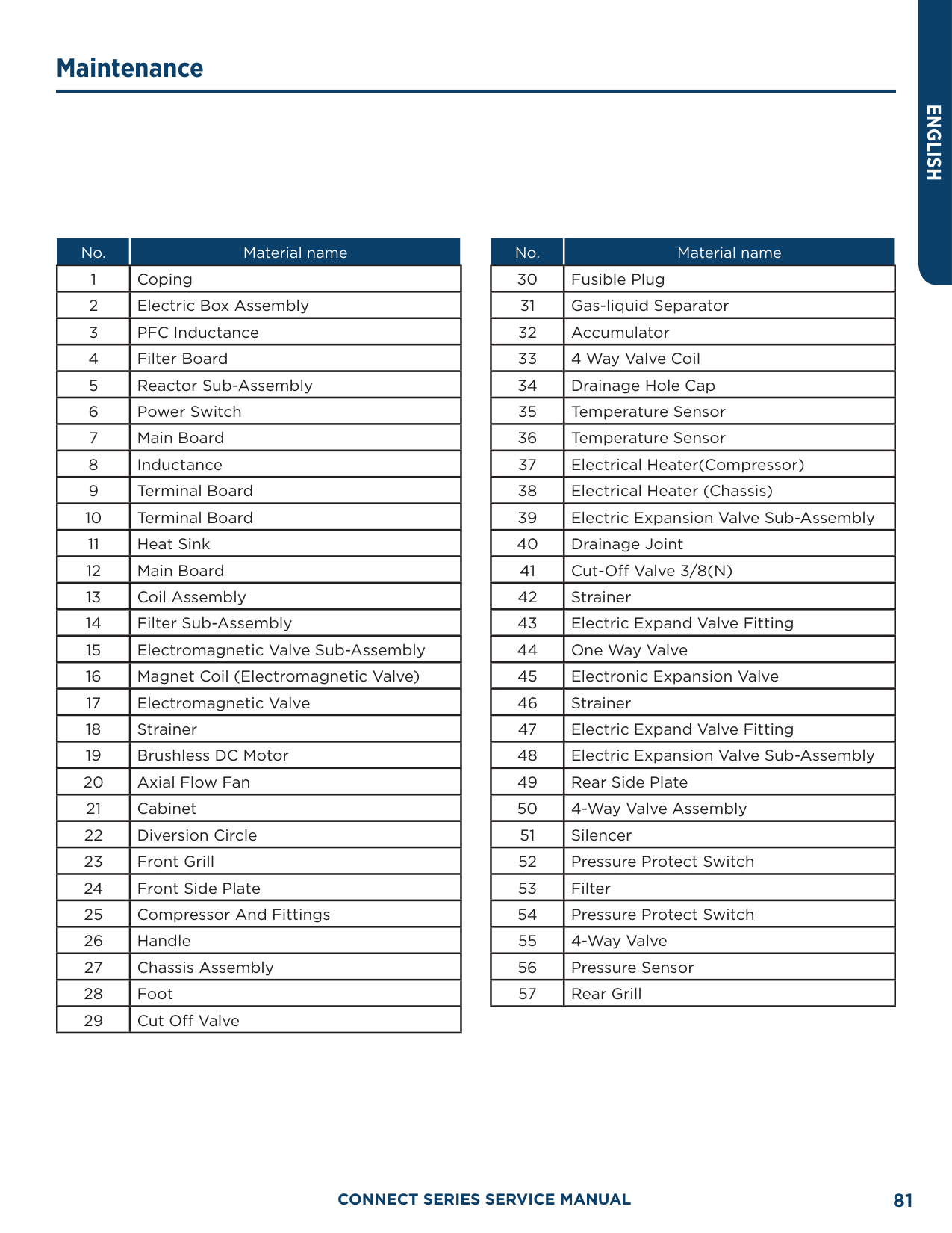
|32.0|0|65.37|0.773| |33.8|1|62.13|0.804| |35.6|2|59.08|0.835| |37.4|3|56.19|0.866| |39.2|4|53.46|0.898| |41.0|5|50.87|0.931| |42.8|6|48.42|0.965| |44.6|7|46.11|0.998| |46.4|8|43.92|1.033| |48.2|9|41.84|1.067| |50.0|10|39.87|1.102| |51.8|11|38.01|1.138| |53.6|12|36.24|1.174| |55.4|13|34.57|1.209| |57.2|14|32.98|1.246| |59.0|15|31.47|1.282| |60.8|16|30.04|1.319| |62.6|17|28.68|1.356|
|F°|C°|Resistance (kΩ)|Voltage (V)| |---|---|---|---| |64.4|18|27.39|1.393| |66.2|19|26.17|1.429| |68.0|20|25.01|1.466| |69.8|21|23.9|1.503| |71.6|22|22.85|1.54| |73.4|23|21.85|1.577| |75.2|24|20.9|1.614| |77.0|25|20|1.65| |78.8|26|19.14|1.686| |80.6|27|18.32|1.722| |82.4|28|17.55|1.758| |84.2|29|16.8|1.793| |86.0|30|16.1|1.828| |87.8|31|15.43|1.863|
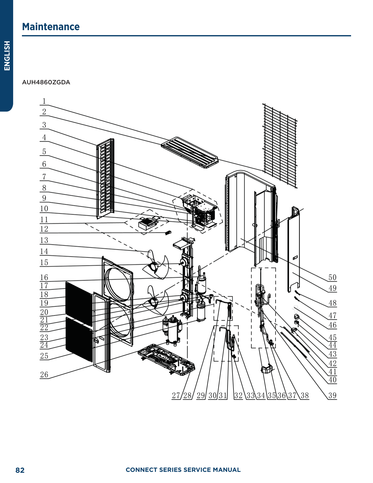
|89.6|32|14.79|1.897| |91.4|33|14.18|1.931| |93.2|34|13.59|1.965| |95.0|35|13.04|1.998| |96.8|36|12.51|2.03| |98.6|37|12|2.063| |100.4|38|11.52|2.094| |102.2|39|11.06|2.125| |104.0|40|10.62|2.155| |105.8|41|10.2|2.185| |107.6|42|9.803|2.215| |109.4|43|9.42|2.243| |111.2|44|9.054|2.272| |113.0|45|8.705|2.299| |114.8|46|8.37|2.326| |116.6|47|8.051|2.353| |118.4|48|7.745|2.379| |120.2|49|7.453|2.404| |122.0|50|7.173|2.429| |123.8|51|6.905|2.453| |125.6|52|6.648|2.477| |127.4|53|6.403|2.5| |129.2|54|6.167|2.522| |131.0|55|5.942|2.544| |132.8|56|5.726|2.565| |134.6|57|5.519|2.586| |136.4|58|5.32|2.607| |138.2|59|5.13|2.626| |140.0|60|4.948|2.646| |141.8|61|4.773|2.664| |143.6|62|4.605|2.682| |145.4|63|4.443|2.7| |147.2|64|4.289|2.717| |149.0|65|4.14|2.734|
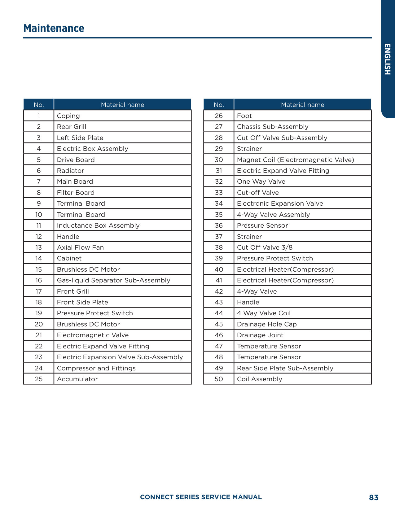
|F°|C°|Resistance (kΩ)|Voltage (V)| |---|---|---|---| |150.8|66|3.998|2.75| |152.6|67|3.861|2.766| |154.4|68|3.729|2.781| |156.2|69|3.603|2.796| |158.0|70|3.481|2.811| |159.8|71|3.364|2.825| |161.6|72|3.252|2.838| |163.4|73|3.144|2.852| |165.2|74|3.04|2.865| |167.0|75|2.94|2.877| |168.8|76|2.844|2.889| |170.6|77|2.752|2.901| |172.4|78|2.663|2.912| |174.2|79|2.577|2.923| |176.0|80|2.495|2.934| |177.8|81|2.415|2.944| |179.6|82|2.339|2.954| |181.4|83|2.265|2.964| |183.2|84|2.194|2.974| |185.0|85|2.125|2.983| |186.8|86|2.059|2.992| |188.6|87|1.996|3.001| |190.4|88|1.934|3.009| |192.2|89|1.875|3.017| |194.0|90|1.818|3.025| |195.8|91|1.763|3.033| |197.6|92|1.71|3.04| |199.4|93|1.658|3.047| |201.2|94|1.609|3.054| |203.0|95|1.561|3.061| |204.8|96|1.515|3.068| |206.6|97|1.47|3.074| |208.4|98|1.427|3.08| |210.2|99|1.386|3.086|
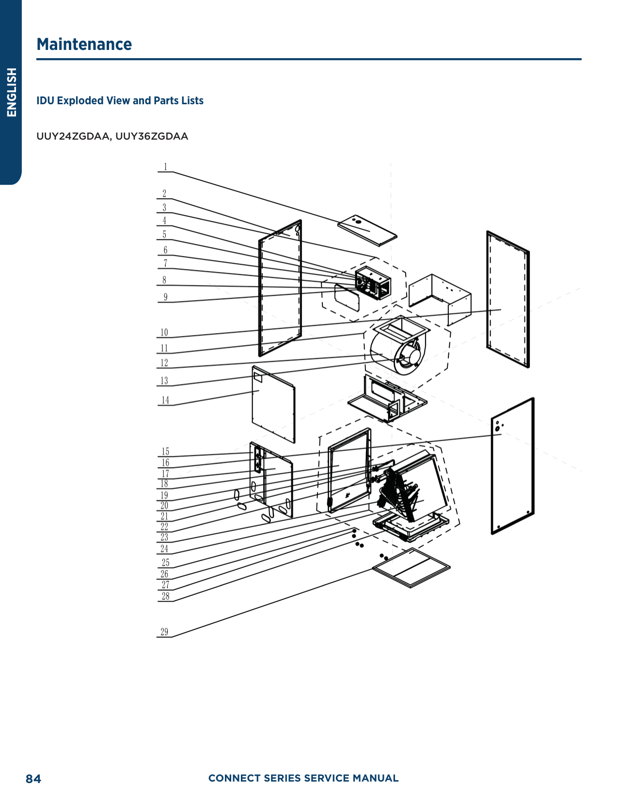
|212.0|100|1.346|3.092| |213.8|101|1.307|3.098| |215.6|102|1.269|3.103| |217.4|103|1.233|3.108| |219.2|104|1.198|3.114| |221.0|105|1.164|3.119| |222.8|106|1.131|3.123| |224.6|107|1.099|3.128| |226.4|108|1.069|3.133| |228.2|109|1.039|3.137| |230.0|110|1.01|3.141| |231.8|111|0.9825|3.145| |233.6|112|0.9556|3.15| |235.4|113|0.9295|3.153|
|F°|C°|Resistance (kΩ)|Voltage (V)| |---|---|---|---| |237.2|114|0.9043|3.157| |239.0|115|0.8799|3.161| |240.8|116|0.8562|3.165| |242.6|117|0.8333|3.168| |244.4|118|0.8111|3.171| |246.2|119|0.7895|3.175| |248.0|120|0.7687|3.178| |249.8|121|0.7485|3.181| |251.6|122|0.7289|3.184| |253.4|123|0.7099|3.187| |255.2|124|0.6915|3.19| |257.0|125|0.6736|3.192| |258.8|126|0.6563|3.195| |260.6|127|0.6395|3.198| |262.4|128|0.6232|3.2| |264.2|129|0.6074|3.203| |266.0|130|0.5921|3.205| |267.8|131|0.5772|3.207|
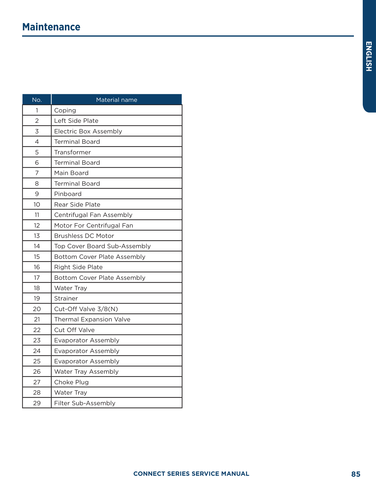
|269.6|132|0.5627|3.21| |271.4|133|0.5487|3.212| |273.2|134|0.5351|3.214| |275.0|135|0.5219|3.216| |276.8|136|0.509|3.218| |278.6|137|0.4966|3.22| |280.4|138|0.4845|3.222| |282.2|139|0.4727|3.224| |284.0|140|0.4613|3.226| |285.8|141|0.4502|3.227| |287.6|142|0.4394|3.229| |289.4|143|0.4289|3.231| |291.2|144|0.4187|3.232| |293.0|145|0.4088|3.234| |294.8|146|0.3992|3.235| |296.6|147|0.3899|3.237| |298.4|148|0.3808|3.238| |300.2|149|0.3719|3.24| |302.0|150|0.3633|3.241| |303.8|151|0.3549|3.242| |305.6|152|0.3468|3.244| |307.4|153|0.3389|3.245| |309.2|154|0.3312|3.246| |311.0|155|0.3237|3.247| |312.8|156|0.3164|3.249| |314.6|157|0.3093|3.25| |316.4|158|0.3024|3.251| |318.2|159|0.2956|3.252| |320.0|160|0.2891|3.253|
######### 50 KΩ Discharge Temperature Sensors (including discharge air temperature sensor)
|F°|C°|Resistance (kΩ)|Voltage (V)| |---|---|---|---| |-22.0|-30|911.56|0.036|

|-20.2|-29|853.66|0.038| |-18.4|-28|799.98|0.041| |-16.6|-27|750.18|0.043| |-14.8|-26|703.92|0.046| |-13.0|-25|660.93|0.049| |-11.2|-24|620.94|0.052| |-9.4|-23|583.72|0.056| |-7.6|-22|549.04|0.059| |-5.8|-21|516.71|0.063| |-4.0|-20|486.55|0.066| |-2.2|-19|458.4|0.07| |-0.4|-18|432.1|0.075| |1.4|-17|407.51|0.079| |3.2|-16|384.51|0.084| |5.0|-15|362.99|0.088| |6.8|-14|342.83|0.094| |8.6|-13|323.94|0.099| |10.4|-12|306.23|0.104| |12.2|-11|289.61|0.11| |14.0|-10|274.02|0.116| |15.8|-9|259.37|0.123| |17.6|-8|245.61|0.129| |19.4|-7|232.67|0.136| |21.2|-6|220.5|0.143| |23.0|-5|209.05|0.151| |24.8|-4|195.97|0.158| |26.6|-3|188.12|0.167| |28.4|-2|178.65|0.175| |30.2|-1|169.68|0.184| |32.0|0|161.02|0.193| |33.8|1|153|0.202| |35.6|2|145.42|0.212| |37.4|3|135.96|0.223| |39.2|4|131.5|0.233| |41.0|5|126.17|0.242| |42.8|6|119.08|0.256|
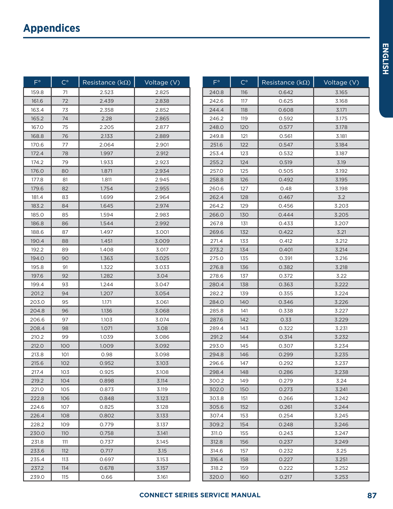
|44.6|7|113.37|0.267| |46.4|8|107.96|0.28| |48.2|9|102.85|0.292| |50.0|10|98.006|0.306| |51.8|11|93.42|0.319| |53.6|12|89.075|0.333| |55.4|13|84.956|0.348| |57.2|14|81.052|0.362| |59.0|15|77.349|0.378|
|F°|C°|Resistance (kΩ)|Voltage (V)| |---|---|---|---| |60.8|16|73.896|0.393| |62.6|17|70.503|0.41| |64.4|18|67.338|0.427| |66.2|19|64.333|0.444| |68.0|20|61.478|0.462| |69.8|21|58.766|0.48| |71.6|22|56.189|0.499| |73.4|23|53.738|0.518| |75.2|24|51.408|0.537| |77.0|25|49.191|0.558| |78.8|26|47.082|0.578| |80.6|27|45.074|0.599| |82.4|28|43.163|0.621| |84.2|29|41.313|0.643| |86.0|30|39.61|0.665| |87.8|31|37.958|0.688| |89.6|32|36.384|0.711| |91.4|33|34.883|0.735| |93.2|34|33.453|0.759| |95.0|35|32.088|0.784| |96.8|36|30.787|0.809| |98.6|37|29.544|0.835| |100.4|38|28.359|0.86|
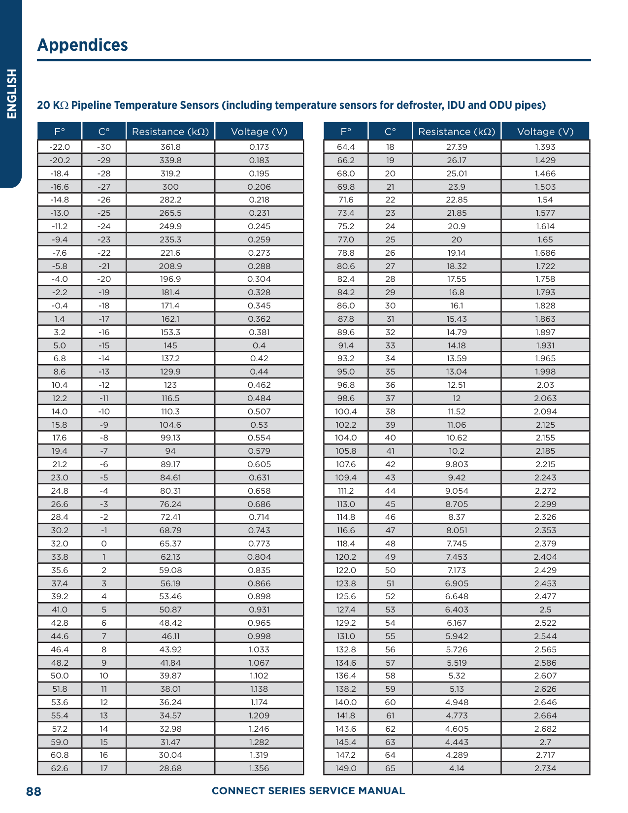
|102.2|39|27.227|0.886| |104.0|40|26.147|0.913| |105.8|41|25.114|0.94| |107.6|42|24.128|0.967| |109.4|43|23.186|0.994| |111.2|44|22.286|1.022| |113.0|45|21.425|1.05| |114.8|46|20.601|1.078| |116.6|47|19.814|1.107| |118.4|48|19.061|1.136| |120.2|49|18.34|1.164| |122.0|50|17.651|1.193| |123.8|51|16.99|1.223| |125.6|52|16.358|1.252| |127.4|53|15.753|1.281| |129.2|54|15.173|1.311| |131.0|55|14.618|1.34| |132.8|56|14.085|1.37| |134.6|57|13.575|1.4| |136.4|58|13.086|1.429| |138.2|59|12.617|1.459| |140.0|60|12.368|1.475| |141.8|61|11.736|1.518|
|F°|C°|Resistance (kΩ)|Voltage (V)| |---|---|---|---| |143.6|62|11.322|1.548| |145.4|63|10.925|1.577| |147.2|64|10.544|1.606| |149.0|65|10.178|1.635| |150.8|66|9.8269|1.664| |152.6|67|9.4896|1.693| |154.4|68|9.1655|1.722| |156.2|69|8.9542|1.741| |158.0|70|8.5551|1.778|

|159.8|71|5.9676|1.806| |161.6|72|7.9913|1.834| |163.4|73|7.7257|1.862| |165.2|74|7.4702|1.889| |167.0|75|7.2245|1.916| |168.8|76|6.9882|1.943| |170.6|77|6.7608|1.969| |172.4|78|6.542|1.995| |174.2|79|6.3315|2.021| |176.0|80|6.1288|2.046| |177.8|81|5.9336|2.071| |179.6|82|5.7457|2.096| |181.4|83|5.5647|2.12| |183.2|84|5.3903|2.144| |185.0|85|5.2223|2.168| |186.8|86|5.0605|2.191| |188.6|87|4.9044|2.214| |190.4|88|4.7541|2.237| |192.2|89|4.6091|2.259| |194.0|90|4.4693|2.281| |195.8|91|4.3345|2.302| |197.6|92|4.2044|2.323| |199.4|93|4.0789|2.344| |201.2|94|3.9579|2.364| |203.0|95|3.841|2.384| |204.8|96|3.7283|2.404| |206.6|97|3.6194|2.423| |208.4|98|3.5143|2.442| |210.2|99|3.4128|2.46| |212.0|100|3.3147|2.478| |213.8|101|3.22|2.496| |215.6|102|3.1285|2.514| |217.4|103|3.0401|2.531| |219.2|104|2.9547|2.547| |221.0|105|2.8721|2.564| |222.8|106|2.7922|2.58|

|224.6|107|2.715|2.595|
|F°|C°|Resistance (kΩ)|Voltage (V)| |---|---|---|---| |226.4|108|2.6404|2.611| |228.2|109|2.5682|2.626| |230.0|110|2.4983|2.64| |231.8|111|2.4308|2.655| |233.6|112|2.3654|2.669| |235.4|113|2.3021|2.682| |237.2|114|2.2409|2.696| |239.0|115|2.1816|2.709| |240.8|116|2.1242|2.722| |242.6|117|2.0686|2.734| |244.4|118|2.0148|2.747| |246.2|119|1.9626|2.759| |248.0|120|1.9123|2.77| |249.8|121|1.8652|2.781| |251.6|122|1.8158|2.793| |253.4|123|1.7698|2.804| |255.2|124|1.7253|2.814| |257.0|125|1.6821|2.825| |258.8|126|1.6402|2.835| |260.6|127|1.5996|2.845| |262.4|128|1.5602|2.855| |264.2|129|1.522|2.864| |266.0|130|1.485|2.873| |267.8|131|1.449|2.882| |269.6|132|1.4141|2.891| |271.4|133|1.3803|2.9| |273.2|134|1.3474|2.908| |275.0|135|1.3155|2.916| |276.8|136|1.2846|2.924| |278.6|137|1.2545|2.932| |280.4|138|1.2233|2.94|
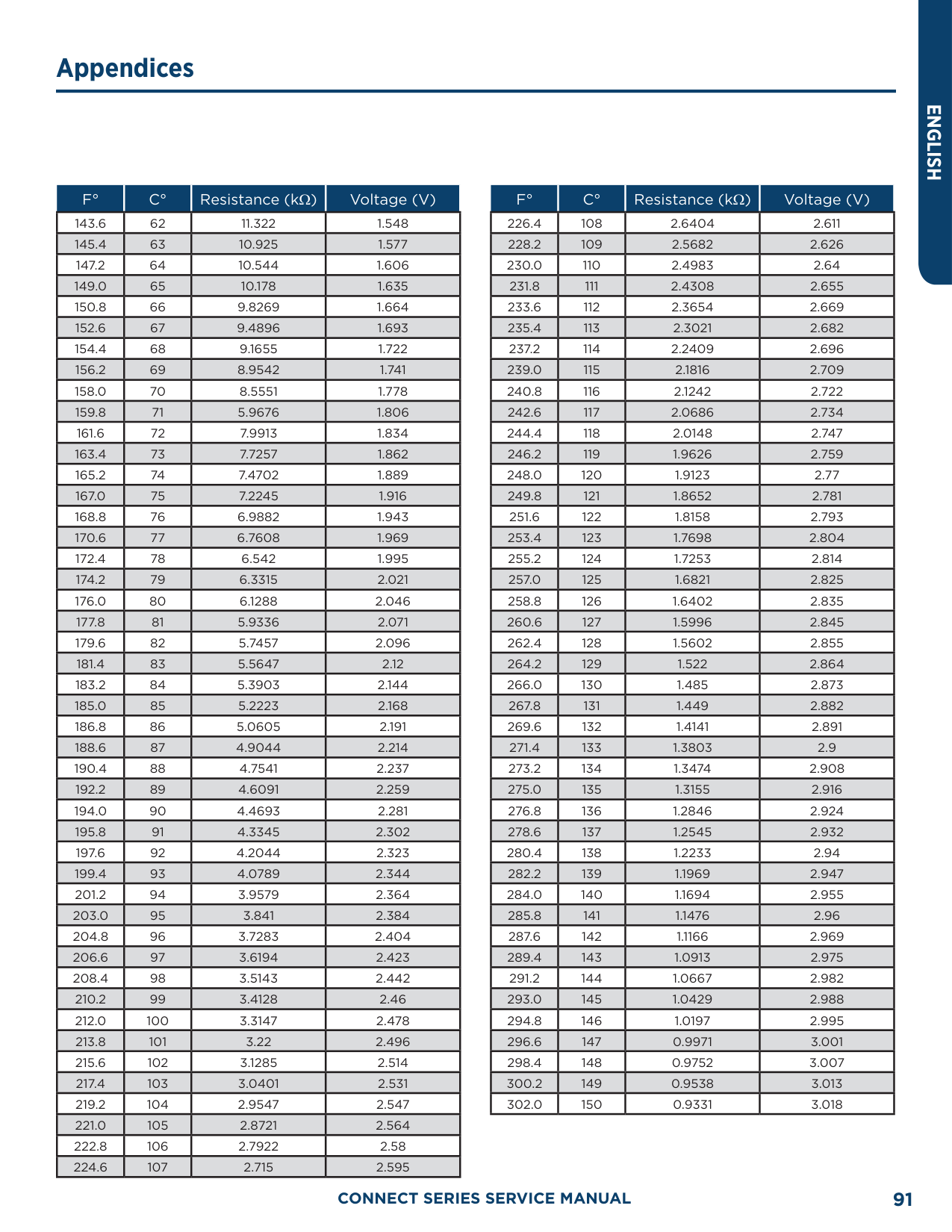
|282.2|139|1.1969|2.947| |284.0|140|1.1694|2.955| |285.8|141|1.1476|2.96| |287.6|142|1.1166|2.969| |289.4|143|1.0913|2.975| |291.2|144|1.0667|2.982| |293.0|145|1.0429|2.988| |294.8|146|1.0197|2.995| |296.6|147|0.9971|3.001| |298.4|148|0.9752|3.007| |300.2|149|0.9538|3.013| |302.0|150|0.9331|3.018|
##### Refrigerant R-410A Temperature/Pressure List
|PSIG|°F| |---|---| |12|–37.7| |14|–34.7| |16|–32.0| |18|–29.4| |20|–36.9| |22|–24.5| |24|–22.2| |26|–20.0| |28|–17.9| |30|–15.8| |32|–13.8| |34|–11.9| |36|–10.1| |38|–8.3| |40|–6.5| |42|–4.5| |44|–3.2| |46|–1.6|
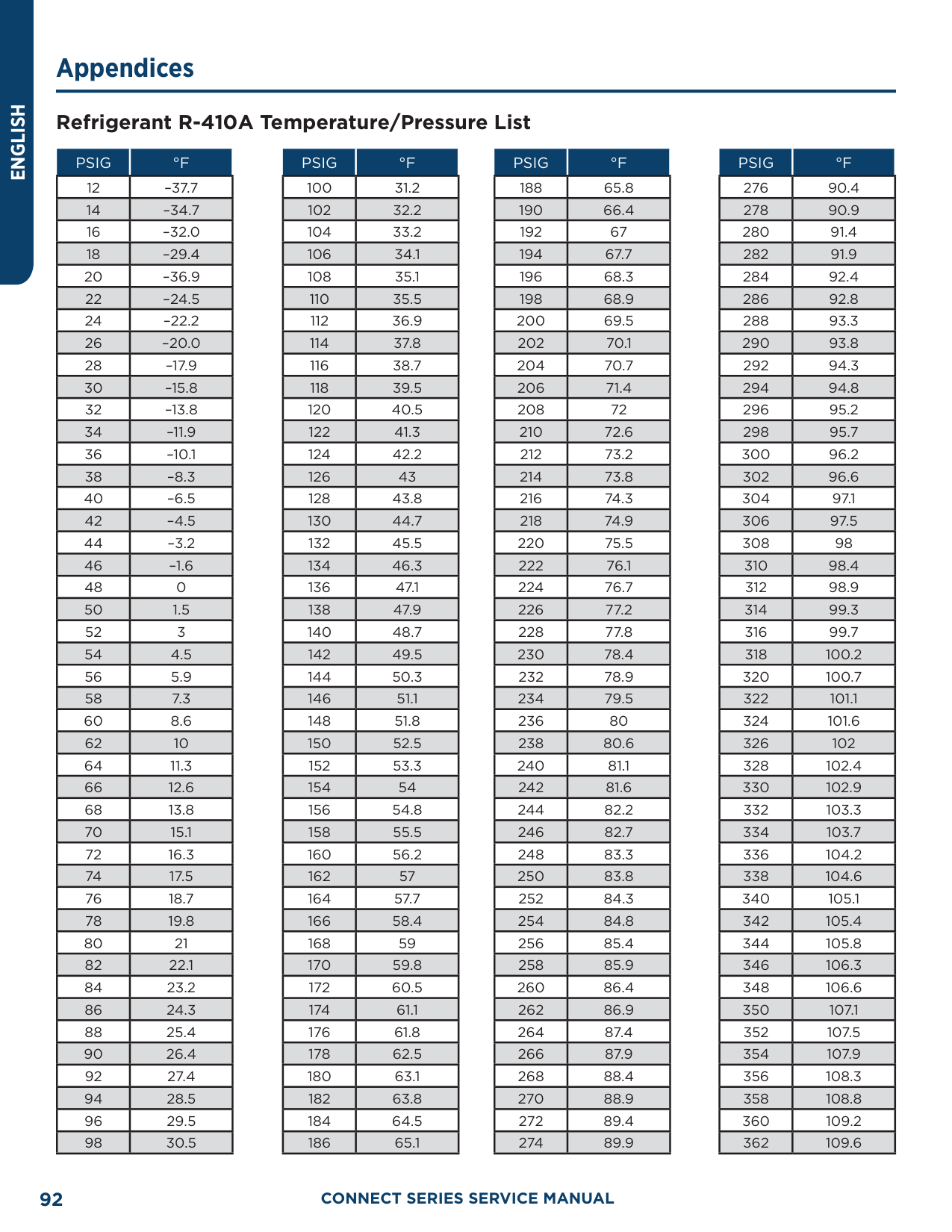
|48|0| |50|1.5| |52|3| |54|4.5| |56|5.9| |58|7.3| |60|8.6| |62|10| |64|11.3| |66|12.6| |68|13.8| |70|15.1| |72|16.3| |74|17.5| |76|18.7| |78|19.8| |80|21| |82|22.1| |84|23.2| |86|24.3| |88|25.4| |90|26.4| |92|27.4| |94|28.5| |96|29.5| |98|30.5|
|PSIG|°F| |---|---| |100|31.2| |102|32.2| |104|33.2| |106|34.1| |108|35.1| |110|35.5|
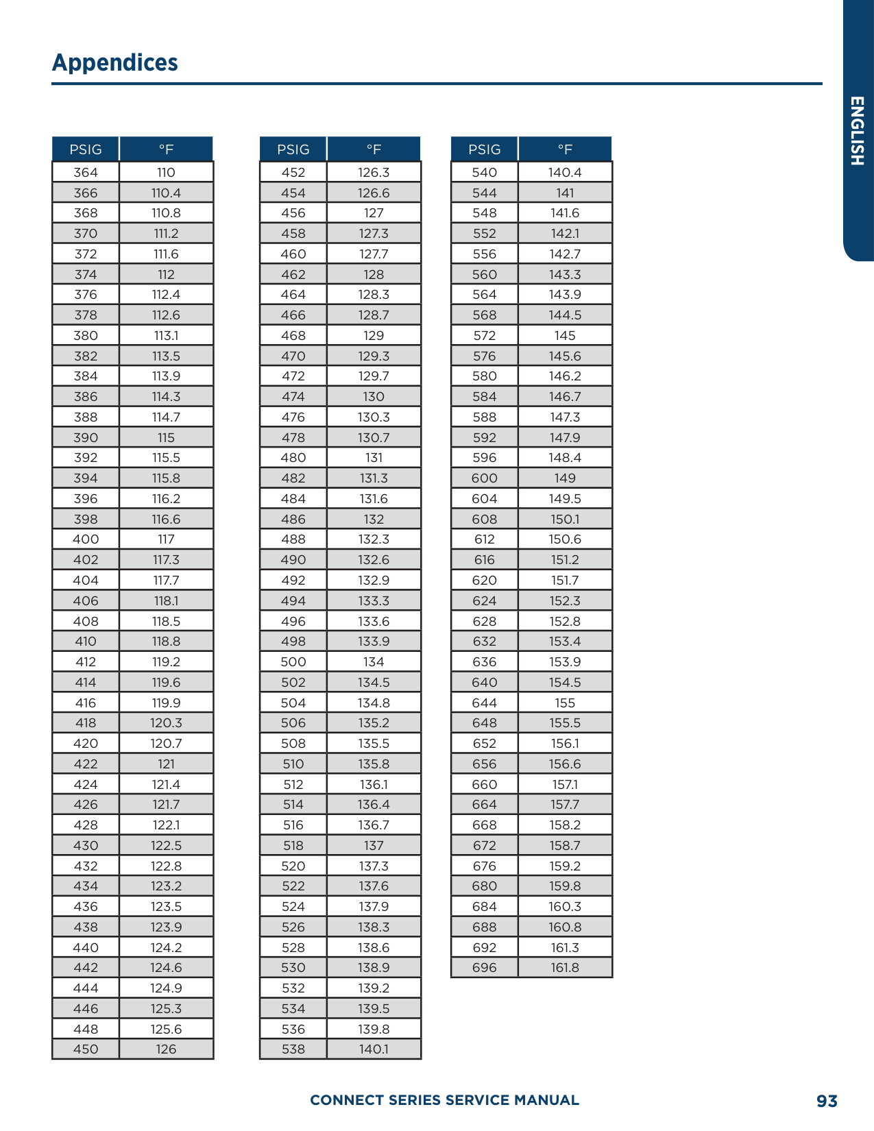
|112|36.9| |114|37.8| |116|38.7| |118|39.5| |120|40.5| |122|41.3| |124|42.2| |126|43| |128|43.8| |130|44.7| |132|45.5| |134|46.3| |136|47.1| |138|47.9| |140|48.7| |142|49.5| |144|50.3| |146|51.1| |148|51.8| |150|52.5| |152|53.3| |154|54| |156|54.8| |158|55.5| |160|56.2| |162|57| |164|57.7| |166|58.4| |168|59| |170|59.8| |172|60.5| |174|61.1| |176|61.8| |178|62.5| |180|63.1| |182|63.8|
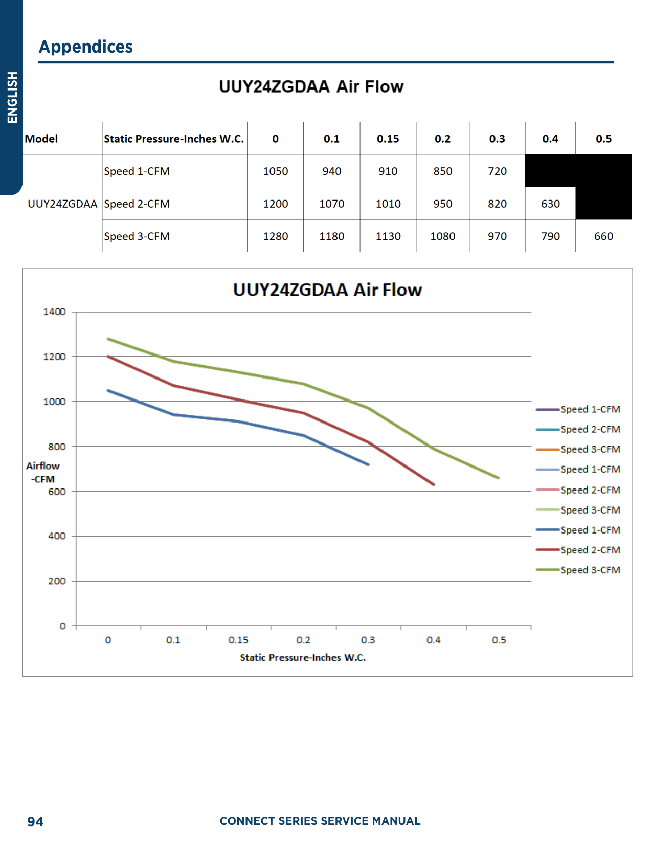
|184|64.5| |186|65.1|
|PSIG|°F| |---|---| |188|65.8| |190|66.4| |192|67| |194|67.7| |196|68.3| |198|68.9| |200|69.5| |202|70.1| |204|70.7| |206|71.4| |208|72| |210|72.6| |212|73.2| |214|73.8| |216|74.3| |218|74.9| |220|75.5| |222|76.1| |224|76.7| |226|77.2| |228|77.8| |230|78.4| |232|78.9| |234|79.5| |236|80| |238|80.6| |240|81.1| |242|81.6| |244|82.2| |246|82.7|
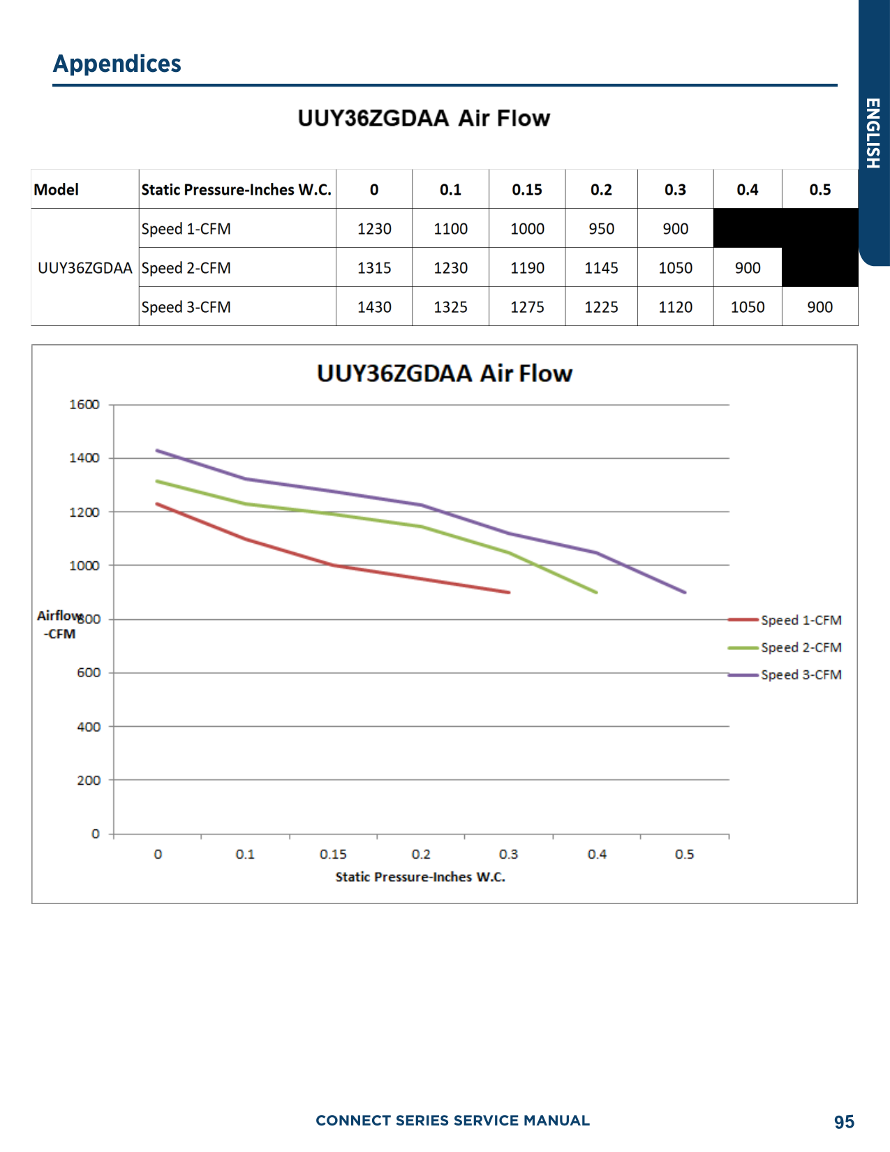
|248|83.3| |250|83.8| |252|84.3| |254|84.8| |256|85.4| |258|85.9| |260|86.4| |262|86.9| |264|87.4| |266|87.9| |268|88.4| |270|88.9| |272|89.4| |274|89.9|
|PSIG|°F| |---|---| |276|90.4| |278|90.9| |280|91.4| |282|91.9| |284|92.4| |286|92.8| |288|93.3| |290|93.8| |292|94.3| |294|94.8| |296|95.2| |298|95.7| |300|96.2| |302|96.6| |304|97.1| |306|97.5| |308|98| |310|98.4|
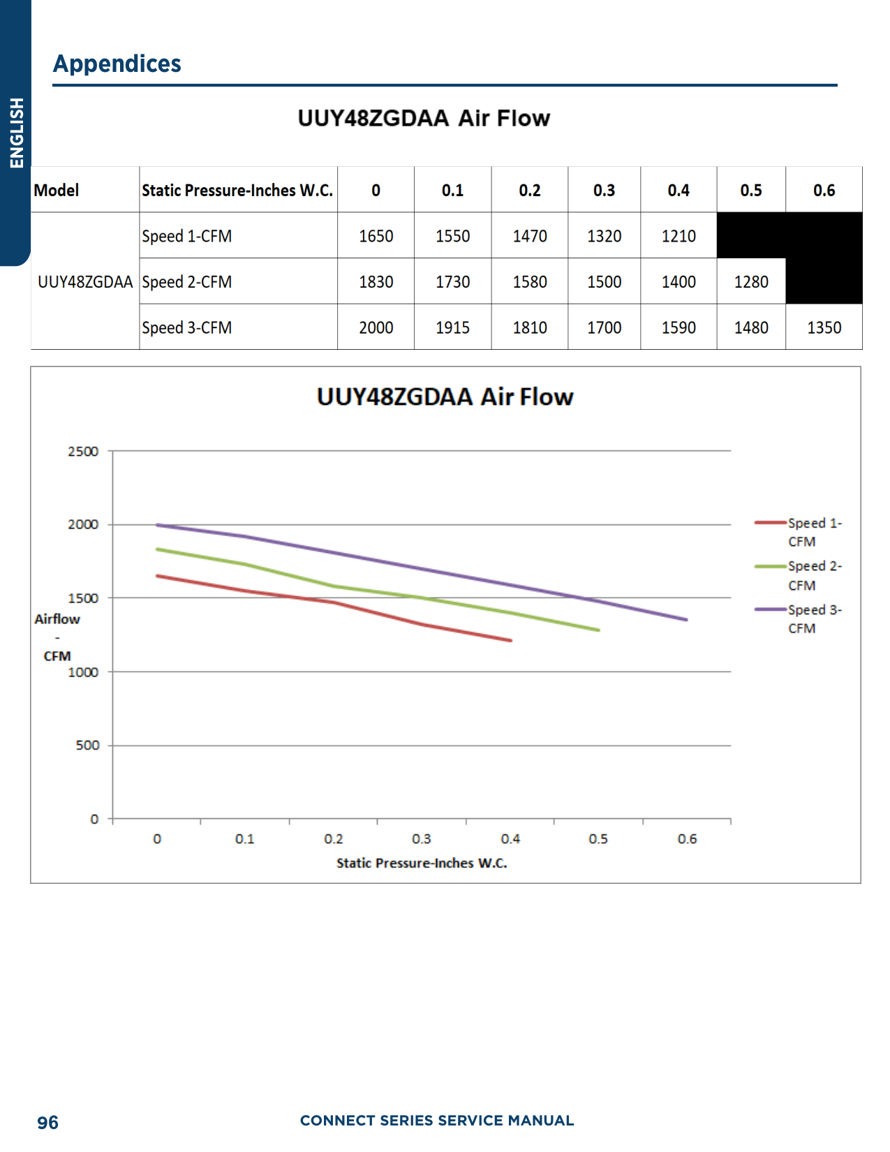
|312|98.9| |314|99.3| |316|99.7| |318|100.2| |320|100.7| |322|101.1| |324|101.6| |326|102| |328|102.4| |330|102.9| |332|103.3| |334|103.7| |336|104.2| |338|104.6| |340|105.1| |342|105.4| |344|105.8| |346|106.3| |348|106.6| |350|107.1| |352|107.5| |354|107.9| |356|108.3| |358|108.8| |360|109.2| |362|109.6|
|PSIG|°F| |---|---| |364|110| |366|110.4| |368|110.8| |370|111.2| |372|111.6| |374|112|
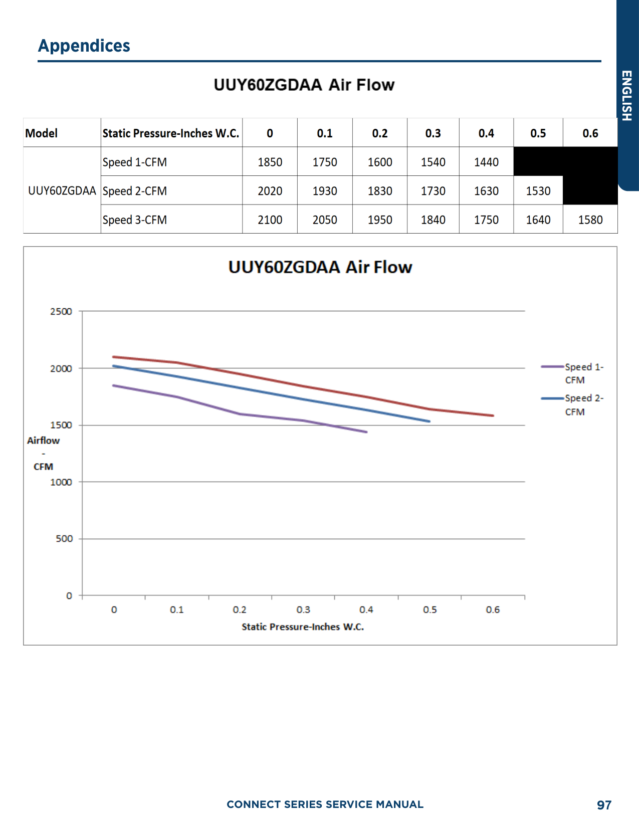
|376|112.4| |378|112.6| |380|113.1| |382|113.5| |384|113.9| |386|114.3| |388|114.7| |390|115| |392|115.5| |394|115.8| |396|116.2| |398|116.6| |400|117| |402|117.3| |404|117.7| |406|118.1| |408|118.5| |410|118.8| |412|119.2| |414|119.6| |416|119.9| |418|120.3| |420|120.7| |422|121| |424|121.4| |426|121.7| |428|122.1| |430|122.5| |432|122.8| |434|123.2| |436|123.5| |438|123.9| |440|124.2| |442|124.6| |444|124.9| |446|125.3|
|448|125.6| |450|126|
|PSIG|°F| |---|---| |452|126.3| |454|126.6| |456|127| |458|127.3| |460|127.7| |462|128| |464|128.3| |466|128.7| |468|129| |470|129.3| |472|129.7| |474|130| |476|130.3| |478|130.7| |480|131| |482|131.3| |484|131.6| |486|132| |488|132.3| |490|132.6| |492|132.9| |494|133.3| |496|133.6| |498|133.9| |500|134| |502|134.5| |504|134.8| |506|135.2| |508|135.5| |510|135.8|

|512|136.1| |514|136.4| |516|136.7| |518|137| |520|137.3| |522|137.6| |524|137.9| |526|138.3| |528|138.6| |530|138.9| |532|139.2| |534|139.5| |536|139.8| |538|140.1|
|PSIG|°F| |---|---| |540|140.4| |544|141| |548|141.6| |552|142.1| |556|142.7| |560|143.3| |564|143.9| |568|144.5| |572|145| |576|145.6| |580|146.2| |584|146.7| |588|147.3| |592|147.9| |596|148.4| |600|149| |604|149.5| |608|150.1|

|612|150.6| |616|151.2| |620|151.7| |624|152.3| |628|152.8| |632|153.4| |636|153.9| |640|154.5| |644|155| |648|155.5| |652|156.1| |656|156.6| |660|157.1| |664|157.7| |668|158.2| |672|158.7| |676|159.2| |680|159.8| |684|160.3| |688|160.8| |692|161.3| |696|161.8|


######## 94


###### 95

ENGLISH


CONNECT SERIES SERVICE MANUAL96


######## CONNECT SERIES SERVICE MANUAL 97
ENGLISH
##### Operation Tools
The following tools will be used: 1) Liquid-level gauge; 2) Screwdriver; 3) Electric driven rotary hammer; 4) Drill; 5) Flare Tool; 6) Torque wrench; 7) Open-end wrench; 8) Pipe cutter; 9) Leak detector; 10) Vacuum pump; 11) Pressure gauge; 12) Multi-meter; 13) Hexagon wrench; 14) Measuring tape.
CONNECT SERIES SERVICE MANUAL98
www.geappliances.com
GE Appliances, A Haier Company Appliance Park, Louisville, KY 40225
©2020 GE Appliances, A Haier CompanyRevision Date: July 2020