
Godox Xpron Ttl Wireless Flash Trigger For Nikon Cameras
Ask AI
— answers from the official manualAnswers from the official manual.
Common questions
Common Questions
10 totalHow do you control the modeling lamp using the device?
Press <MOD> button in multi-group display or single group mode's <MOD> button to toggle ON/OFF, some outdoor flashes require an upgrade for this functionality.
What are safety instructions for using the flash trigger?
Do not disassemble the device, keep away from water or magnetic fields. Turn off during malfunction and avoid over-heating situations.
How do you perform firmware upgrades on this product?
This flash trigger supports firmware upgrades through the Type-C USB port using Godox G2 software, new update files are released on the official website.
How do you set up multi flash settings with frequency and times?
In the multi flash setting (TTL and M icon not displayed), short press the Times button to change frequencies, turn select dial for times value setting.
How do I factory reset the Xpron Ttl Wireless Flash Trigger?
Synchronously press the two function buttons in the middle, and the restore factory settings process is complete until 'RESET' appears on the LCD panel.
What are the steps to install batteries in the flash trigger?
Slide the battery compartment lid of the flash trigger and insert two AA batteries separately. Check the battery level indication on the LCD panel during usage.
Full Manual
15 pages
深圳市神牛摄影器材有限公司 GODOX Photo Equipment Co., Ltd.
地址/Add: 深圳市宝安区福永镇福洲大道西新和村华发工业园A4栋 Building A4, Xinhe Huafa Industrial Zone, Fuzhou RD West, Fuyong Town, Baoan District, Shenzhen 518103, China
电话/Tel: +86-755-29609320(8062) 传真/Fax: +86-755-25723423 邮箱/E-mail: godox@godox.com
705-XPRZS0-00 Made In China
TTL无线引闪器

TTL Wireless Flash Trigger
###### Instruction Manual
说 明 手 册
Contents
Foreword Warning Names of Parts
Body LCD Panel
Battery Installing Batteries Battery Level Indication
28
Using the Flash Trigger As a Wireless Camera Flash Trigger As a Wireless Outdoor Flash Trigger As a Wireless Original Flash Trigger As a Wireless Studio Flash Trigger As a Wireless Shutter Release Trigger As a Flash Trigger
28
with 2.5mm Sync Cord Jack
Setting the Flash Trigger Power Switch Automatically Enter Power Saving Mode Power Switch of AF Assist Beam Channel Settings Wireless ID Settings
33 44
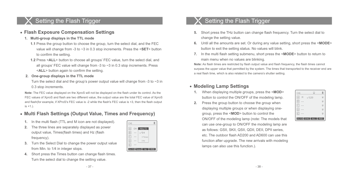
Mode Settings Magnification Function Output Value Settings Flash Exposure Compensation
Settings Multi Flash Settings (Output Value, Times
and Frequency) Modeling Lamp Settings ZOOM Value Settings Shutter Sync Settings Buzz Settings Sync Socket Settings TCM Function SHOOT Function Settings C.Fn: Setting Custom Functions
Compatible Flash Models Compatible Camera Models Technical Data Restore Factory Settings Firmware Upgrade Attentions Caring for Flash Trigger
#### Foreword
Thanks for your purchase of this XProS wireless flash trigger. This wireless flash trigger is suitable for using Sony cameras to control Godox flashes with X system e.g. camera flash, outdoor flash, and studio flash. It can also control Sony original speedlights with the coordination of X1R-S receiver. Featuring multichannel triggering, stable signal transmission, and sensitive reaction, it gives photographers unparalleled flexibility and control over their strobist setups. The flash trigger applies to hotshoe-mounted Sony series cameras, as well as the cameras which have PC sync sockets. With XProS wireless flash trigger, high speed synchronization is available for most of camera flashes in the market which support TTL. The max flash synchronization speed is up to 1/8000s *.
*: 1/8000s is achievable when the camera has a max camera shutter speed of 1/8000s.
#### Warning
#### Names of Parts Body
Do not disassemble. Should repairs become necessary, this product must be sent to an authorized maintenance center. Always keep this product dry. Do not use in rain or in damp conditions. Keep out of reach of children. Do not use the flash unit in the presence of flammable gas. In certain circumstance, please pay attention to the relevant warnings. Do not leave or store the product if the ambient temperature reads over 50℃. Turn off the flash trigger immediately in the event of malfunction. Observe precautions when handling batteries
| | | |---|---| | | |
LCD Panel
MENU Button Magnification/TCM Button
MODE/LOCK Mode Selection/ Locking Button
TEST/Shutter Button
Status Indicator Lamp
Select Dial
--Green: Trigger (Flash) + Focus (Camera) Red: Trigger (Flash) + Shutter (Camera)
Battery Compartment
AF Assist Beam Switch ON (AF Assist Beam outputs)
| | | |---|---| | |--|
OFF (AF Assist Beam do not output)
| | | | |---|---|---| | | | | | | | |
Type-C USB Port
2.5mm Sync Cord Jack
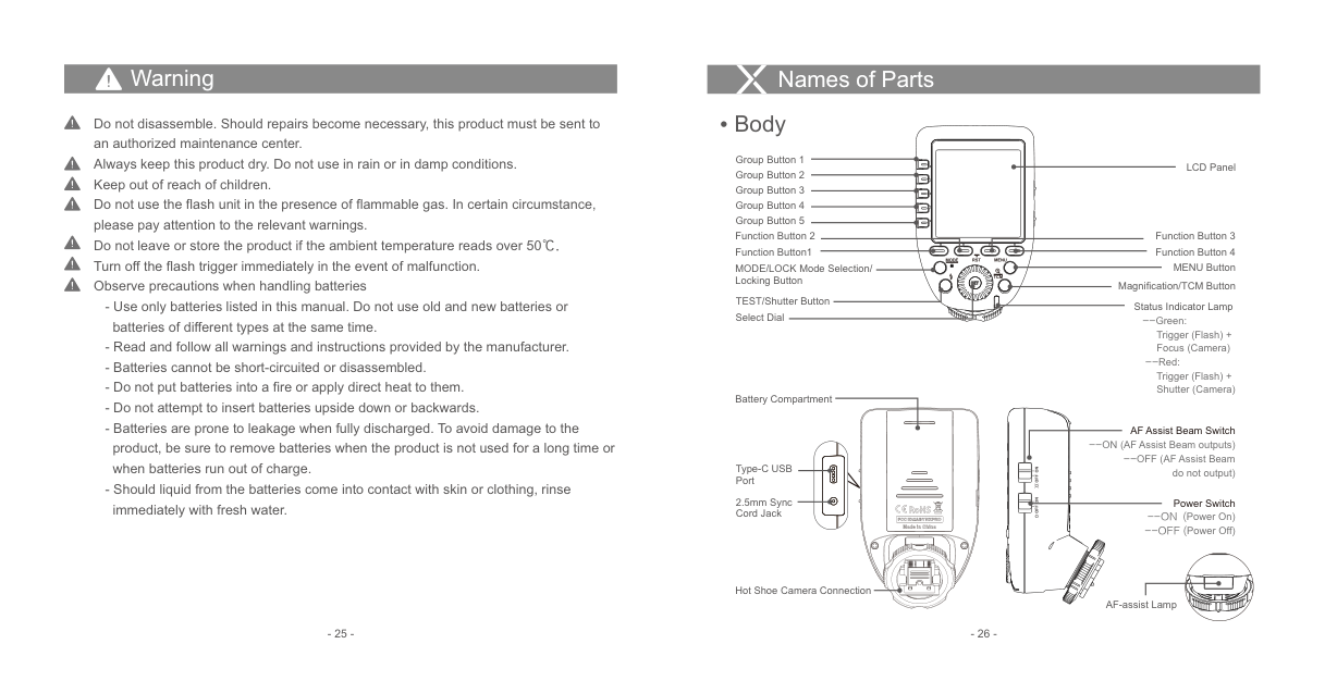
Power Switch --ON (Power On) --OFF (Power Off)
| | | |---|---| | | |
| | | |---|---| | | |
Hot Shoe Camera Connection
AF-assist Lamp
############### - 25 - - 26 -
Battery
Names of Parts
AA alkaline batteries are recommended.
####### LCD Panel
Installing Batteries As shown in the illustration, slide the battery compartment lid of the flash trigger and insert two AA batteries separately. Battery Level Indication
8
32
| | | | | | | |---|---|---|---|---|---| |CH1
|CH1
| | | | | | | | | | | |
1 7
6
4 5
M 1/16 + 0.3
--
Check the battery level indication on the LCD panel to see the remaining battery level during the usage.
--
--
|Battery Level Indication|Meaning|
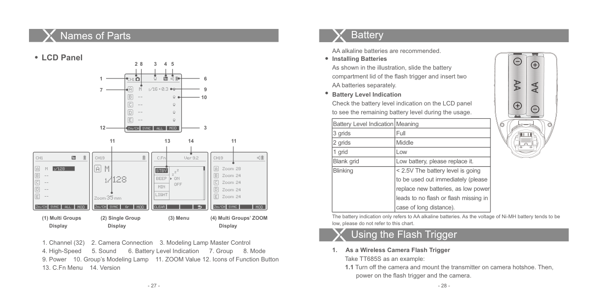
|---|---| |3 grids|Full| |2 grids|Middle| |1 grid|Low| |Blank grid|Low battery, please replace it.| |Blinking|< 2.5V The battery level is going to be used out immediately (please replace new batteries, as low power leads to no flash or flash missing in case of long distance).|
| | | |---|---| | | |
| | | |---|---| | | |
12
3
Zm/CH SYNC ALL MOD
13 14 1111
CH1
CH19
C.Fn
Ver 9.2
########## CH19
A M
|1/128| |---|
M
Zoom 28A Zoom 24 Zoom 24 Zoom 24 Zoom 24
zzz
STBY
--
1/128
BEEP MIN LIGHT
ON OFF
--
--
Zoom35mm
Zm/CH SYNC ALL MOD
Zm/CH SYNC Gr MOD
Zm/CH SYNC MOD
CLEAR
The battery indication only refers to AA alkaline batteries. As the voltage of Ni-MH battery tends to be low, please do not refer to this chart.
(3) Menu
############## (1) Multi Groups Display
(2) Single Group Display
(4) Multi Groups’ ZOOM Display
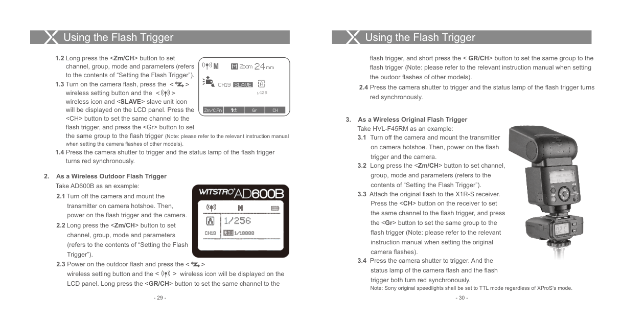
Using the Flash Trigger
power on the flash trigger and the camera.
Using the Flash Trigger
Using the Flash Trigger
flash trigger, and short press the < GR/CH> button to set the same group to the flash trigger (Note: please refer to the relevant instruction manual when setting the oudoor flashes of other models).
M
Zoom 24mm
##### M
< > < >
ACH19
SLAVE
2.4 Press the camera shutter to trigger and the status lamp of the flash trigger turns
1/128
red synchronously.
Zm/C.Fn Gr CH±
############ 3. As a Wireless Original Flash Trigger Take HVL-F45RM as an example:

############ 2. As a Wireless Outdoor Flash Trigger
Take AD600B as an example:

< > < >
trigger both turn red synchronously. Note: Sony original speedlights shall be set to TTL mode regardless of XProS's mode.
Using the Flash Trigger
Using the Flash Trigger
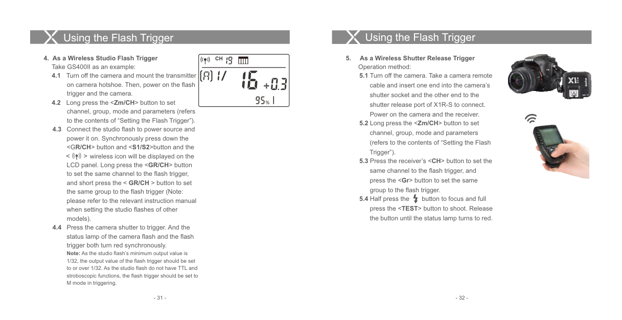
############ 4. As a Wireless Studio Flash Trigger
################ CH
Take GS400II as an example:
wireless icon will be displayed on the LCD panel. Long press the
%
< >
############ 5. As a Wireless Shutter Release Trigger
Operation method:


Using the Flash Trigger
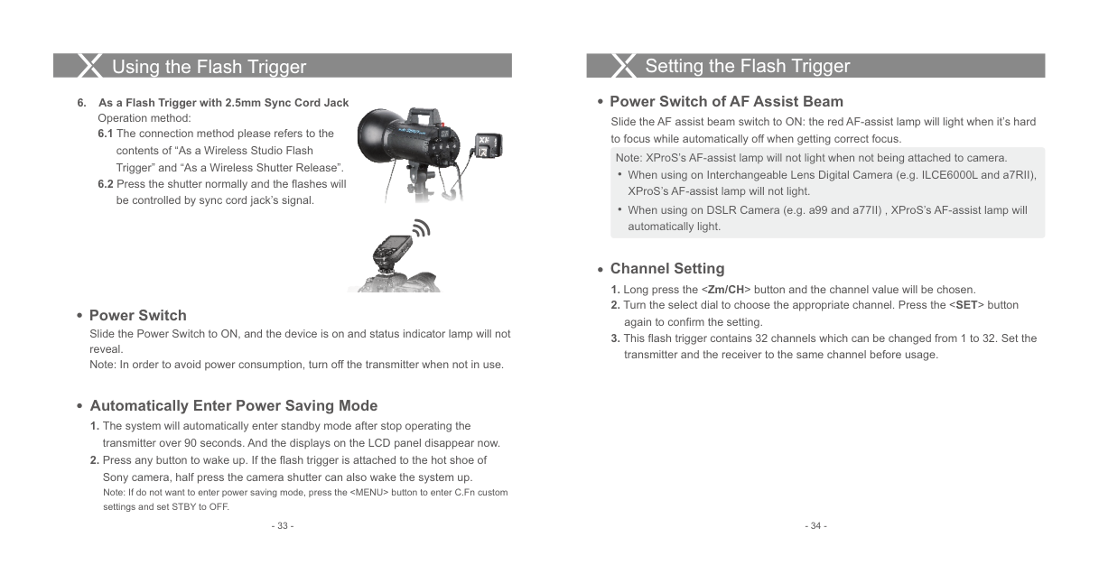
############ 6. As a Flash Trigger with 2.5mm Sync Cord Jack

Operation method:

####### Power Switch
Slide the Power Switch to ON, and the device is on and status indicator lamp will not reveal. Note: In order to avoid power consumption, turn off the transmitter when not in use.
#### Setting the Flash Trigger
Power Switch of AF Assist Beam
Slide the AF assist beam switch to ON: the red AF-assist lamp will light when it’s hard to focus while automatically off when getting correct focus.
Note: XProS’s AF-assist lamp will not light when not being attached to camera.
When using on Interchangeable Lens Digital Camera (e.g. ILCE6000L and a7RII), XProS’s AF-assist lamp will not light.
When using on DSLR Camera (e.g. a99 and a77II) , XProS’s AF-assist lamp will automatically light.
Channel Setting
Automatically Enter Power Saving Mode
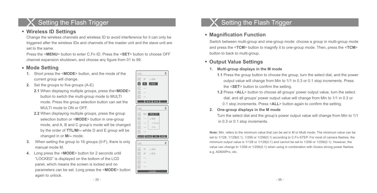
Wireless ID Settings
####### Magnification Function
Change the wireless channels and wireless ID to avoid interference for it can only be triggered after the wireless IDs and channels of the master unit and the slave unit are set to the same. Press the
CH1
M
--
1/64
Gr Gr
CH1
C D E --
M
--
--
1/64
0.1 stop increments. Press
############# 2. One-group displays in the M modeTurn the select dial and the group’s power output value will change from Min to 1/1
| | |---|
CH1
ON
MULTI
--
1/64
in 0.3 or 0.1 stop increments.
--
3 Times 1 Hz
--
Note: Min. refers to the minimum value that can be set in M or Multi mode. The minimum value can be set to 1/128, 1/128(0.1), 1/256 or 1/256(0.1) according to C.Fn-STEP. For most of camera flashes, the minimum output value is 1/128 or 1/128(0.1) and cannot be set to 1/256 or 1/256(0.1). However, the value can change to 1/256 or 1/256(0.1) when using in combination with Godox strong power flashes e.g. AD600Pro, etc.
Zm/CH Times Hz MOD
LOCKED
####### Flash Exposure Compensation Settings
Note: As flash times are restricted by flash output value and flash frequency, the flash times cannot surpass the upper value that permitted by the system. The times that transported to the receiver end are a real flash time, which is also related to the camera’s shutter setting.
Modeling Lamp Settings
Note: The FEC value displayed on the XproS will not be displayed on the flash under its control. As the
| | |---|
########### CH1
FEC values of XproS and flash are two different value, the output value are the total FEC value of XproS and flash(for example, if XProS's FEC value is -2 while the flash's FEC value is +3, then the flash output is +1.).
M 1/128
--
--
--
####### Multi Flash Settings (Output Value, Times and Frequency)
--
Zm/CH SYNC MOD
| | |---|
CH1
ON
MULTI
1/64
--
3 Times 1 Hz
--
Zm/CH Times Hz MOD
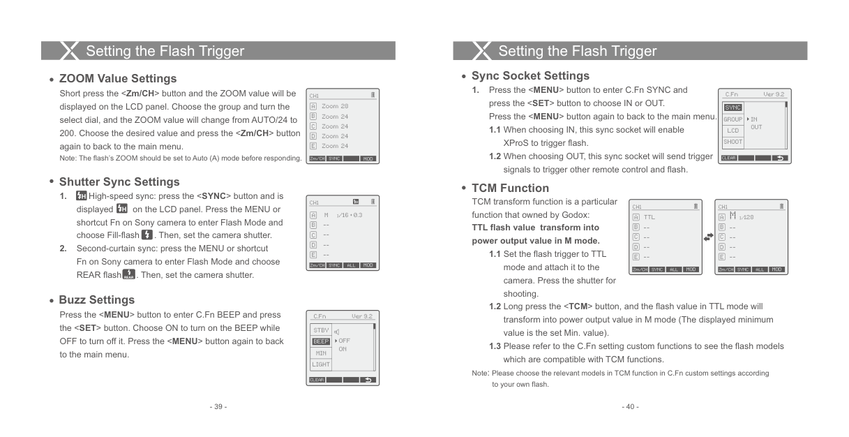
####### Sync Socket Settings
ZOOM Value Settings
Short press the
C.Fn Ver 9.2
| | |---|
########### CH1
|SYNC|IN OUT|
|---|---| |GROUP|IN OUT| |LCD|IN OUT| |SHOOT|IN OUT|
Zoom 28A Zoom 24 Zoom 24 Zoom 24 Zoom 24
CLEAR
Zm/CH SYNC MOD
####### Shutter Sync Settings
TCM Function
TCM transform function is a particular function that owned by Godox:
CH1
| | |---|
| | |---|
########### CH1
CH1
M 1/16 + 0.3
1/128
TTL
TTL flash value transform into power output value in M mode.
--
--
--
--
--
--
--
--
Zm/CH SYNC ALL MOD
Zm/CH SYNC MOD
Zm/CH SYNC MOD
################# REAR
Buzz Settings
Press the
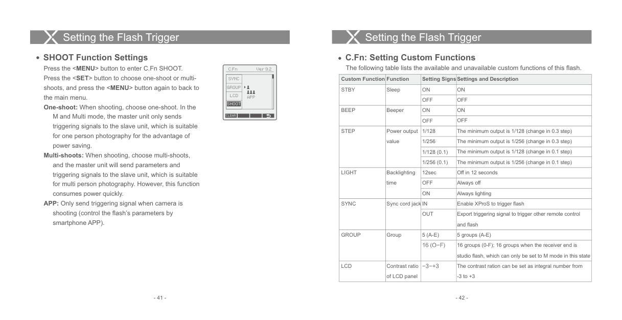
|Custom Function|Function|Setting Signs|Settings and Description| |---|---|---|---| |STBY|Sleep|ON|ON| |STBY|Sleep|OFF|OFF| |BEEP|Beeper|ON|ON| |BEEP|Beeper|OFF|OFF| |STEP|Power output value|1/128|The minimum output is 1/128 (change in 0.3 step)| |STEP|Power output value|1/256|The minimum output is 1/256 (change in 0.3 step)| |STEP|Power output value|1/128 (0.1)|The minimum output is 1/128 (change in 0.1 step)| |STEP|Power output value|1/256 (0.1)|The minimum output is 1/256 (change in 0.1 step)| |LIGHT|Backlighting time|12sec|Off in 12 seconds| |LIGHT|Backlighting time|OFF|Always off| |LIGHT|Backlighting time|ON|Always lighting| |SYNC|Sync cord jack|IN|Enable XProS to trigger flash| |SYNC|Sync cord jack|OUT|Export triggering signal to trigger other remote control and flash| |GROUP|Group|5 (A-E)|5 groups (A-E)| |GROUP|Group|16 (O-F)|16 groups (0-F); 16 groups when the receiver end is studio flash, which can only be set to M mode in this state| |LCD|Contrast ratio of LCD panel|-3-+3|The contrast ration can be set as integral number from
-3 to +3|
| |APP
| |---|---| | |APP
| | |APP
| | |APP
|
SYNC
GROUP LCD
SHOOT
M and Multi mode, the master unit only sends triggering signals to the slave unit, which is suitable for one person photography for the advantage of power saving.
CLEAR
Multi-shoots: When shooting, choose multi-shoots, and the master unit will send parameters and triggering signals to the slave unit, which is suitable for multi person photography. However, this function consumes power quickly.
APP: Only send triggering signal when camera is shooting (control the flash’s parameters by smartphone APP).
#### Compatible Flash ModelsSetting the Flash Trigger
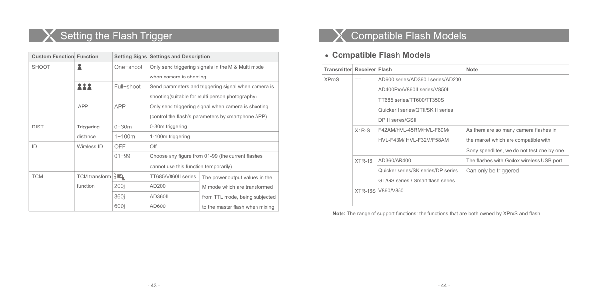
|Custom Function|Function|Setting Signs|Settings and Description|Settings and Description| |---|---|---|---|---| |SHOOT| |One-shoot|Only send triggering signals in the M & Multi mode when camera is shooting|Only send triggering signals in the M & Multi mode when camera is shooting| |SHOOT| |Full-shoot|Send parameters and triggering signal when camera is shooting(suitable for multi person photography)|Send parameters and triggering signal when camera is shooting(suitable for multi person photography)| |SHOOT|APP|APP|Only send triggering signal when camera is shooting (control the flash’s parameters by smartphone APP)|Only send triggering signal when camera is shooting (control the flash’s parameters by smartphone APP)| |DIST|Triggering distance|0-30m|0-30m triggering|0-30m triggering| |DIST|Triggering distance|1-100m|1-100m triggering|1-100m triggering| |ID|Wireless ID|OFF|Off|Off| |ID|Wireless ID|01-99|Choose any figure from 01-99 (the current flashes cannot use this function temporarily)|Choose any figure from 01-99 (the current flashes cannot use this function temporarily)| |TCM|TCM transform function| |TT685/V860II series|The power output values in the M mode which are transformed from TTL mode, being subjected to the master flash when mixing| |TCM|TCM transform function|200j|AD200|The power output values in the M mode which are transformed from TTL mode, being subjected to the master flash when mixing| |TCM|TCM transform function|360j 600j|AD360II AD600|The power output values in the M mode which are transformed from TTL mode, being subjected to the master flash when mixing|
####### Compatible Flash Models
|Transmitter|Receiver|Flash|Note| |---|---|---|---| |XProS|--|AD600 series/AD360II series/AD200 AD400Pro/V860II series/V850II TT685 series/TT600/TT350S QuickerII series/QTII/SK II series DP II series/GSII| | |XProS|X1R-S|F42AM/HVL-45RM/HVL-F60M/ HVL-F43M/ HVL-F32M/F58AM|As there are so many camera flashes in the market which are compatible with Sony speedlites, we do not test one by one.| |XProS|XTR-16|AD360/AR400|The flashes with Godox wireless USB port|
|XProS|XTR-16|Quicker series/SK series/DP series GT/GS series / Smart flash series|Can only be triggered| |XProS|XTR-16S|V860/V850| |
Note: The range of support functions: the functions that are both owned by XProS and flash.
Compatible Flash Models
Technical Data
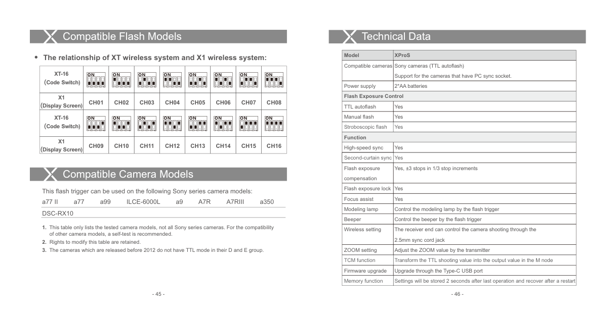
|Model|XProS| |---|---| |Compatible cameras|Sony cameras (TTL autoflash) Support for the cameras that have PC sync socket.| |Power supply|2*AA batteries| |Flash Exposure Control|Flash Exposure Control| |TTL autoflash|Yes| |Manual flash|Yes| |Stroboscopic flash|Yes| |Function|Function| |High-speed sync|Yes| |Second-curtain sync|Yes| |Flash exposure compensation|Yes, ±3 stops in 1/3 stop increments| |Flash exposure lock|Yes| |Focus assist|Yes| |Modeling lamp|Control the modeling lamp by the flash trigger| |Beeper|Control the beeper by the flash trigger| |Wireless setting|The receiver end can control the camera shooting through the 2.5mm sync cord jack| |ZOOM setting|Adjust the ZOOM value by the transmitter| |TCM function|Transform the TTL shooting value into the output value in the M node| |Firmware upgrade|Upgrade through the Type-C USB port| |Memory function|Settings will be stored 2 seconds after last operation and recover after a restart|
######## The relationship of XT wireless system and X1 wireless system:
|XT-16 (Code Switch)|ON
|ON
|ON
|ON
|ON
|ON
|ON
|ON
| |---|---|---|---|---|---|---|---|---| |X1 (Display Screen)|CH01|CH02|CH03|CH04|CH05|CH06|CH07|CH08| |XT-16 (Code Switch)|ON
|ON
|ON
|ON
|ON
|ON
|ON
|ON
| |X1 (Display Screen)|CH09|CH10|CH11|CH12|CH13|CH14|CH15|CH16|
Compatible Camera Models
This flash trigger can be used on the following Sony series camera models:
a77 II a77 a99 ILCE-6000L a9 A7R A7RIII a350 DSC-RX10
#### Technical Data Attentions
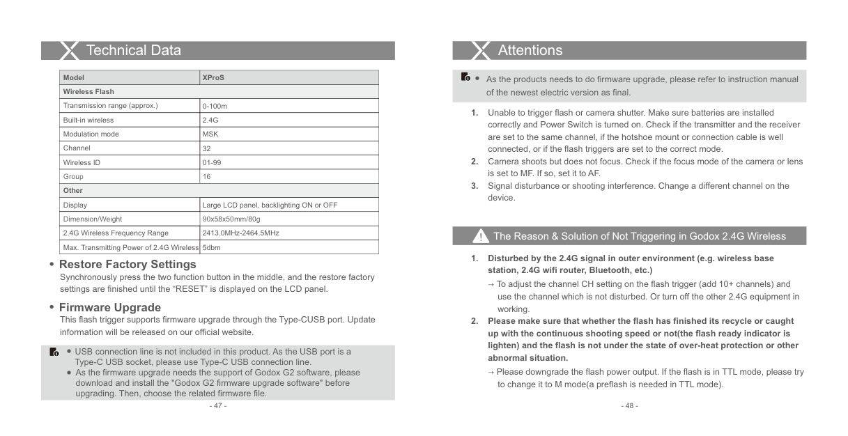
|Model|XProS| |---|---| |Wireless Flash|Wireless Flash| |Transmission range (approx.)|0-100m| |Built-in wireless|2.4G| |Modulation mode|MSK| |Channel|32| |Wireless ID|01-99|
|Group|16| |Other|Other| |Display|Large LCD panel, backlighting ON or OFF| |Dimension/Weight|90x58x50mm/80g| |2.4G Wireless Frequency Range|2413.0MHz-2464.5MHz| |Max. Transmitting Power of 2.4G Wireless|5dbm|
As the products needs to do firmware upgrade, please refer to instruction manual of the newest electric version as final.
######### The Reason & Solution of Not Triggering in Godox 2.4G Wireless
############ 1. Disturbed by the 2.4G signal in outer environment (e.g. wireless basestation, 2.4G wifi router, Bluetooth, etc.)
Restore Factory Settings Synchronously press the two function button in the middle, and the restore factory settings are finished until the “RESET” is displayed on the LCD panel.
→ To adjust the channel CH setting on the flash trigger (add 10+ channels) and use the channel which is not disturbed. Or turn off the other 2.4G equipment in working.
Firmware Upgrade This flash trigger supports firmware upgrade through the Type-CUSB port. Update information will be released on our official website.
############ 2. Please make sure that whether the flash has finished its recycle or caughtup with the continuous shooting speed or not(the flash ready indicator islighten) and the flash is not under the state of over-heat protection or otherabnormal situation.
USB connection line is not included in this product. As the USB port is a Type-C USB socket, please use Type-C USB connection line.
→ Please downgrade the flash power output. If the flash is in TTL mode, please try to change it to M mode(a preflash is needed in TTL mode).
As the firmware upgrade needs the support of Godox G2 software, please download and install the "Godox G2 firmware upgrade software" before upgrading. Then, choose the related firmware file.
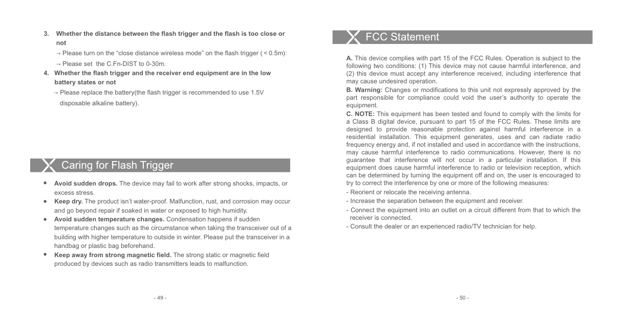
############ 3. Whether the distance between the flash trigger and the flash is too close ornot
→ Please turn on the “close distance wireless mode” on the flash trigger (<0.5m):
→ Please set the C.Fn-DIST to 0-30m.
############ 4. Whether the flash trigger and the receiver end equipment are in the lowbattery states or not
→ Please replace the battery(the flash trigger is recommended to use 1.5V disposable alkaline battery).
Caring for Flash Trigger
Avoid sudden drops. The device may fail to work after strong shocks, impacts, or excess stress. Keep dry. The product isn’t water-proof. Malfunction, rust, and corrosion may occur and go beyond repair if soaked in water or exposed to high humidity. Avoid sudden temperature changes. Condensation happens if sudden temperature changes such as the circumstance when taking the transceiver out of a building with higher temperature to outside in winter. Please put the transceiver in a handbag or plastic bag beforehand. Keep away from strong magnetic field. The strong static or magnetic field produced by devices such as radio transmitters leads to malfunction.
#### FCC Statement
(2) this device must accept any interference received, including interference that may cause undesired operation.