
Ask AI
— answers from the official manualAnswers from the official manual.
Common questions
Common Questions
29 totalWhat power supply does the M9174C1025 require?
The M9174C1025 operates on 120 Vac power. The M9174 series also offers 24 Vac models (M9174D1007 and M9174B1043), allowing flexibility in installation depending on available power sources. (Page 19)
What is the torque rating of the M9174C1025 actuator?
The M9174C1025 is a 75 lb-in. torque actuator, which makes it suitable for mid-range damper and valve control applications. It is part of the M9174 series of modulating non-spring return Modutrol IV motors designed for Series 90 control input. (Page 19)
What is the stroke capability of the M9174 series actuators?
The M9174 series is available with 90°, 160°, and 90/160° (adjustable) stroke models. The M9174C1025 specifically has a 160° stroke with a 60-second timing, making it suitable for applications requiring a wider range of motion. (Page 19)
What is the operating temperature range for the M9174C1025?
The M9174 series, including the M9174C1025, operates within a temperature range of -40 to 150°F (-40 to 67°C). This wide temperature range makes it suitable for both heating and cooling HVAC applications. (Page 6)
How long does it take the M9174C1025 to complete a full stroke?
The M9174C1025 has a 160° stroke with a timing of 60 seconds. For comparison, M9174 models with a 90° stroke operate in 30 seconds. (Page 19)
What control input signal is required for the M9174C1025 actuator?
The M9174C1025 is designed for Series 90 control input, which provides proportioning/modulating control. Optional interface modules are available if you need to convert from other control signals such as 4-20 mA, 2-10 Vdc, or 4-7 Vdc. (Page 19)
Show 23 more questions
Is the M9174C1025 spring return or non-spring return?
What mounting method does the M9174 series use?
What is the minimum torque required to operate Honeywell dampers?
How do I calculate the required torque for my damper application?
Where should I look if I need to select an actuator for a valve application instead of a damper?
What temperature range is safe for the M436 actuator?
What power supply options are available for the M436 motor?
What mounting options are available for the M847 draft actuator?
What is the torque rating of the M836A motor?
How quickly does the M833 actuator respond in heating or cooling applications?
What are the stroke specifications for the M436 and M836 motors?
What is the temperature operating range for the M436 and M836A motors?
Where can I find information about selecting an actuator for a valve application?
How do I determine what torque capacity I need for my application?
How do I select between foot-mounted and direct coupled actuators?
How do I determine what torque I need for my application?
How long does the M833 actuator take to complete its stroke?
What are the temperature operating ranges for the M835 actuator?
Where can I find selection tables for different torque ranges?
Can the M436 be used for both foot-mounted and direct coupled applications?
What power supply does the M847 draft actuator require?
What is the torque rating of the M436 actuator?
What is the difference between spring return and non-spring return actuators?
Full Manual
38 pages
Motor/Actuator Selection Guide
2 • 63-8419Actuator Selection Procedure
Up To 25 Lb-In.
(Including
Economizers)
See Table 1
25-60 Lb-In.
Modutrol Iv
See Table 4
Torque Range And Table
Power
Action
Type
Mounting
Application
M11573
Damper
Valve
Tradeline
Modutrol Iv
See Table 2
Tradeline
Modutrol Iv™
See Table 3
25-144 Lb-In.
See Table 8
35-75 Lb-In.
Modutrol Iv
See Table 5
150-300 Lb-In.
Modutrol Iv
See Table 6
Spring
Return
Non-Spring
Return
Spring
Return
Non-Spring
Return
Foot
Mounted
Foot Mounted
See Valve
Selection Guide
(Form 63-8038)
Electric/
Electronic
Pneumatic
Electric/
Electronic
Pneumatic
Direct
Coupled
Direct
Coupled
35-300 Lb-In.
See Table 9
See Table 12
See Table 13
See Table 10
Calculate Required Torque
(Lb-In.). If Not Known, See
Calculating Torque
Requirements Section
For Detailed Information,
See Honeywell
Valve Selection Guide
(Form 63-8038)
®Introduction
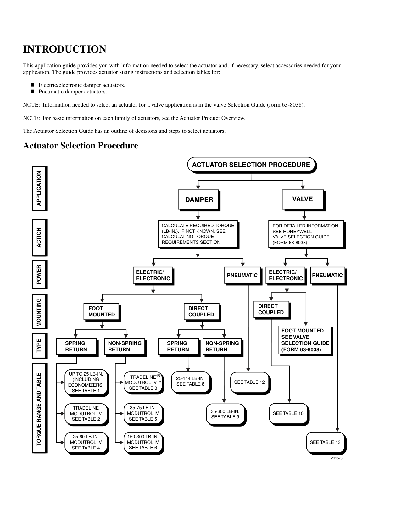
This application guide provides you with information needed to select the actuator and, if necessary, select accessories needed for your application. The guide provides actuator sizing instructions and selection tables for: n Electric/electronic damper actuators. n Pneumatic damper actuators. NOTE: Information needed to select an actuator for a valve application is in the Valve Selection Guide (form 63-8038). NOTE: For basic information on each family of actuators, see the Actuator Product Overview. The Actuator Selection Guide has an outline of decisions and steps to select actuators. Actuator Selection Procedure
Motor/Actuator Selection Guide
63-8419 • 3 Contents INTRODUCTION .............................................................................................................................................................. inside front cover ACTUATOR SELECTION PROCEDURE...................................................................................................................... inside front cover MOTOR/ACTUATOR PRODUCT OVERVIEW .................................................................................................................................... 4 For Dampers .................................................................................................................... 4 Foot-mounted and Specialty ...................................................................................... 4 Direct Coupled ........................................................................................................... 8 Pneumatic .................................................................................................................. 10 For Valves ........................................................................................................................ 12 Electric/Electronic ..................................................................................................... 12 Pneumatic .................................................................................................................. 13 MODUTROL IV MOTOR ORDER NUMBER GUIDE ........................................................................................................................ 14 DIRECT COUPLED ACTUATOR ORDER NUMBER GUIDE ........................................................................................................... 14 CALCULATING TORQUE REQUIREMENTS .................................................................................................................................... 15 ELECTRIC/ELECTRONIC ACTUATORS ............................................................................................................................................ 15 Foot-Mounted Actuators ................................................................................................. 15 Direct Coupled Actuators ................................................................................................ 15 PNEUMATIC ACTUATORS ..................................................................................................................................................................... 15 TablesFoot-Mounted/Specialty Actuators
Table 1. Low torque/specialty (up to 25 lb-in) spring return foot-mounted actuators .... 16 Table 2. TRADELINE® Modutrol IV™ spring return foot-mounted actuators............. 16 Table 3. TRADELINE® Modutrol IV™ non-spring return foot-mounted actuators ..... 17 Table 4. 25-60 lb-in. spring return foot-mounted Modutrol IV actuators ....................... 18 Table 5. 35-75 lb-in. non-spring return foot-mounted Modutrol IV actuators................ 19 Table 6. 150-300 lb-in. non-spring return foot-mounted Modutrol IV actuators............ 20 Table 7. Foot-mounted actuator accessories ................................................................... 22Direct Coupled Actuators
Table 8. 25-144 lb-in. spring return direct coupled actuators ......................................... 24 Table 9. 35-300 lb-in. non-spring return direct coupled actuators .................................. 25 Table 10. Direct coupled valve actuators ........................................................................ 27 Table 11. Direct coupled actuator accessories ................................................................ 28Pneumatic Actuators
Table 12. Pneumatic damper actuators............................................................................ 32 Table 13. Pneumatic valve actuators ............................................................................... 34 Table 14. Pneumatic actuator accessories ....................................................................... 35 Appendices A. DETERMINING DAMPER ACTUATOR TORQUE REQUIREMENTS ..................................................................................... 36 Table A-1. Honeywell D640/D641 damper lb-in. per sq ft value ................................... 37 Table A-2. Honeywell D642/D643 damper lb-in. per sq ft value ................................... 37B. Determining Damper Actuator Torque Requirements When
USING A NON-HONEYWELL DAMPER ........................................................................................................................................ 38 Table B-1. Approximate industry standard damper lb-in. per sq ft value ....................... 38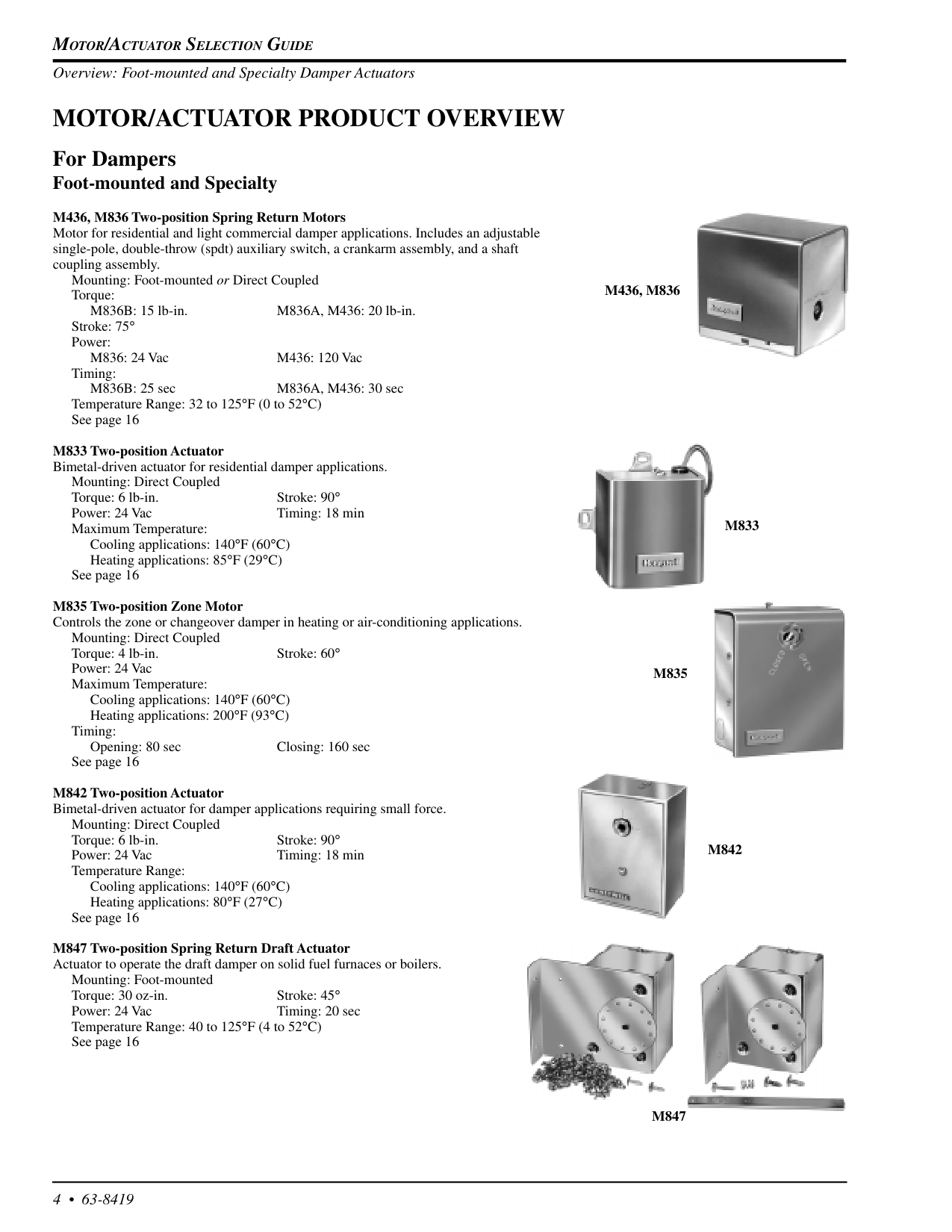
Motor/Actuator Selection Guide
4 • 63-8419Motor/Actuator Product Overview
For Dampers Foot-mounted and Specialty M436, M836 Two-position Spring Return Motors Motor for residential and light commercial damper applications. Includes an adjustable single-pole, double-throw (spdt) auxiliary switch, a crankarm assembly, and a shaft coupling assembly. Mounting: Foot-mounted or Direct Coupled Torque: M836B: 15 lb-in. M836A, M436: 20 lb-in. Stroke: 75° Power: M836: 24 Vac M436: 120 Vac Timing: M836B: 25 sec M836A, M436: 30 sec Temperature Range: 32 to 125°F (0 to 52°C) See page 16 M833 Two-position Actuator Bimetal-driven actuator for residential damper applications. Mounting: Direct Coupled Torque: 6 lb-in. Stroke: 90° Power: 24 Vac Timing: 18 min Maximum Temperature: Cooling applications: 140°F (60°C) Heating applications: 85°F (29°C) See page 16 M835 Two-position Zone Motor Controls the zone or changeover damper in heating or air-conditioning applications. Mounting: Direct Coupled Torque: 4 lb-in. Stroke: 60° Power: 24 Vac Maximum Temperature: Cooling applications: 140°F (60°C) Heating applications: 200°F (93°C) Timing: Opening: 80 sec Closing: 160 sec See page 16 M842 Two-position Actuator Bimetal-driven actuator for damper applications requiring small force. Mounting: Direct Coupled Torque: 6 lb-in. Stroke: 90° Power: 24 Vac Timing: 18 min Temperature Range: Cooling applications: 140°F (60°C) Heating applications: 80°F (27°C) See page 16 M847 Two-position Spring Return Draft Actuator Actuator to operate the draft damper on solid fuel furnaces or boilers. Mounting: Foot-mounted Torque: 30 oz-in. Stroke: 45° Power: 24 Vac Timing: 20 sec Temperature Range: 40 to 125°F (4 to 52°C) See page 16M436, M836
M833
M842
M835
M847
Overview: Foot-mounted and Specialty Damper Actuators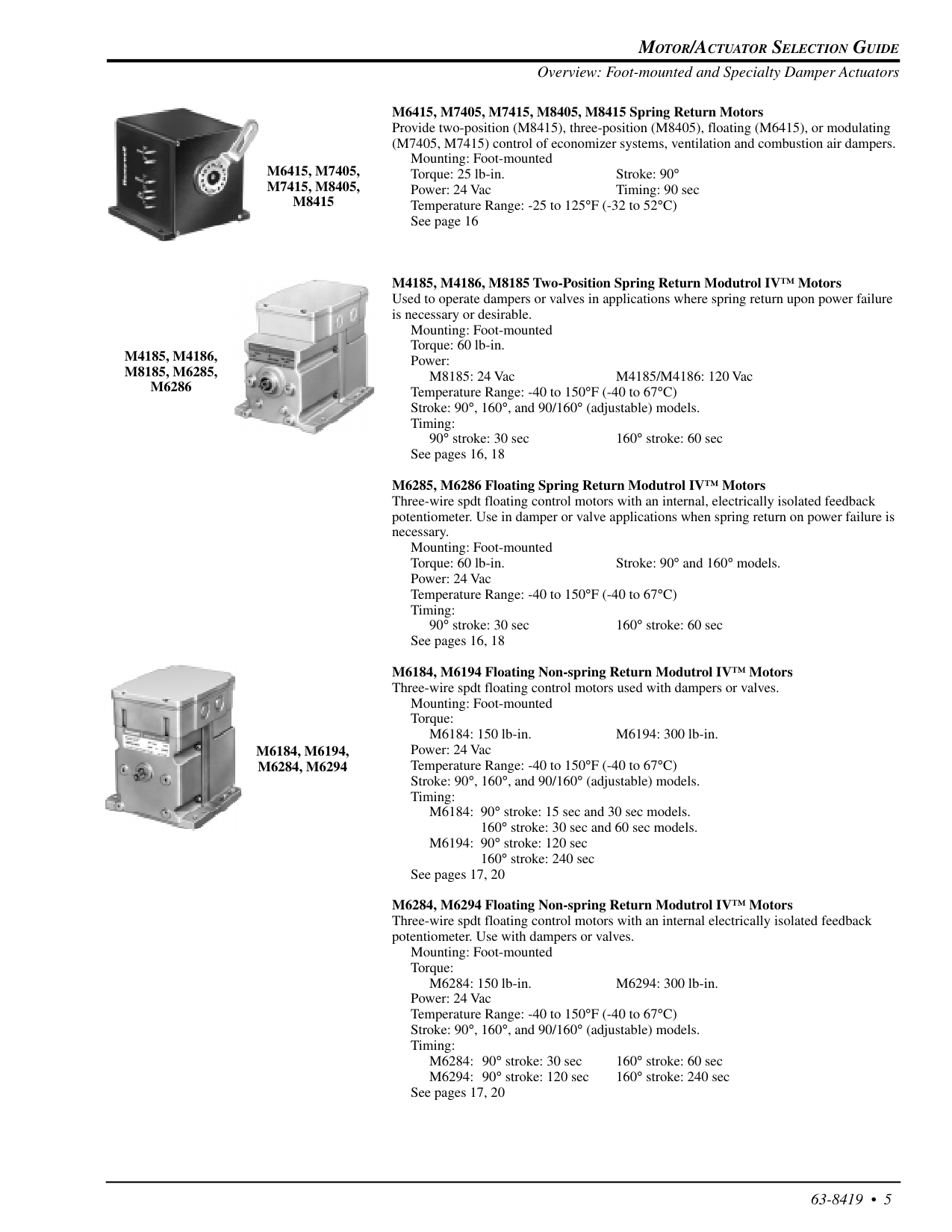
Motor/Actuator Selection Guide
63-8419 • 5M6415, M7405,
M7415, M8405,
M8415
M4185, M4186,
M8185, M6285,
M6286
M6184, M6194,
M6284, M6294
M6415, M7405, M7415, M8405, M8415 Spring Return Motors Provide two-position (M8415), three-position (M8405), floating (M6415), or modulating (M7405, M7415) control of economizer systems, ventilation and combustion air dampers. Mounting: Foot-mounted Torque: 25 lb-in. Stroke: 90° Power: 24 Vac Timing: 90 sec Temperature Range: -25 to 125°F (-32 to 52°C) See page 16 M4185, M4186, M8185 Two-Position Spring Return Modutrol IV™ Motors Used to operate dampers or valves in applications where spring return upon power failure is necessary or desirable. Mounting: Foot-mounted Torque: 60 lb-in. Power: M8185: 24 Vac M4185/M4186: 120 Vac Temperature Range: -40 to 150°F (-40 to 67°C) Stroke: 90°, 160°, and 90/160° (adjustable) models. Timing: 90° stroke: 30 sec 160° stroke: 60 sec See pages 16, 18 M6285, M6286 Floating Spring Return Modutrol IV™ Motors Three-wire spdt floating control motors with an internal, electrically isolated feedback potentiometer. Use in damper or valve applications when spring return on power failure is necessary. Mounting: Foot-mounted Torque: 60 lb-in. Stroke: 90° and 160° models. Power: 24 Vac Temperature Range: -40 to 150°F (-40 to 67°C) Timing: 90° stroke: 30 sec 160° stroke: 60 sec See pages 16, 18 M6184, M6194 Floating Non-spring Return Modutrol IV™ Motors Three-wire spdt floating control motors used with dampers or valves. Mounting: Foot-mounted Torque: M6184: 150 lb-in. M6194: 300 lb-in. Power: 24 Vac Temperature Range: -40 to 150°F (-40 to 67°C) Stroke: 90°, 160°, and 90/160° (adjustable) models. Timing: M6184: 90° stroke: 15 sec and 30 sec models. 160° stroke: 30 sec and 60 sec models. M6194: 90° stroke: 120 sec 160° stroke: 240 sec See pages 17, 20 M6284, M6294 Floating Non-spring Return Modutrol IV™ Motors Three-wire spdt floating control motors with an internal electrically isolated feedback potentiometer. Use with dampers or valves. Mounting: Foot-mounted Torque: M6284: 150 lb-in. M6294: 300 lb-in. Power: 24 Vac Temperature Range: -40 to 150°F (-40 to 67°C) Stroke: 90°, 160°, and 90/160° (adjustable) models. Timing: M6284: 90° stroke: 30 sec 160° stroke: 60 sec M6294: 90° stroke: 120 sec 160° stroke: 240 sec See pages 17, 20 Overview: Foot-mounted and Specialty Damper Actuators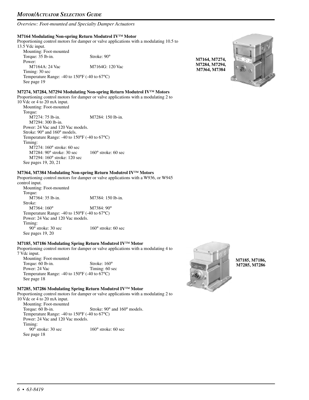
Motor/Actuator Selection Guide
6 • 63-8419M7164, M7274,
M7284, M7294,
M7364, M7384
M7185, M7186,
M7285, M7286
M7164 Modulating Non-spring Return Modutrol IV™ Motor Proportioning control motors for damper or valve applications with a modulating 10.5 to 13.5 Vdc input. Mounting: Foot-mounted Torque: 35 lb-in. Stroke: 90° Power: M7164A: 24 Vac M7164G: 120 Vac Timing: 30 sec Temperature Range: -40 to 150°F (-40 to 67°C) See page 19 M7274, M7284, M7294 Modulating Non-spring Return Modutrol IV™ Motors Proportioning control motors for damper or valve applications with a modulating 2 to 10 Vdc or 4 to 20 mA input. Mounting: Foot-mounted Torque: M7274: 75 lb-in. M7284: 150 lb-in. M7294: 300 lb-in. Power: 24 Vac and 120 Vac models. Stroke: 90° and 160° models. Temperature Range: -40 to 150°F (-40 to 67°C) Timing: M7274: 160° stroke: 60 sec M7284: 90° stroke: 30 sec 160° stroke: 60 sec M7294: 160° stroke: 120 sec See pages 19, 20, 21 M7364, M7384 Modulating Non-spring Return Modutrol IV™ Motors Proportioning control motors for damper or valve applications with a W936, or W945 control input. Mounting: Foot-mounted Torque: M7364: 35 lb-in. M7384: 150 lb-in. Stroke:M7364: 160°
M7384: 90°
Temperature Range: -40 to 150°F (-40 to 67°C) Power: 24 Vac and 120 Vac models. Timing: 90° stroke: 30 sec 160° stroke: 60 sec See pages 19, 20 M7185, M7186 Modulating Spring Return Modutrol IV™ Motor Proportioning control motors for damper or valve applications with a modulating 4 to 7 Vdc input. Mounting: Foot-mounted Torque: 60 lb-in. Stroke: 160° Power: 24 Vac Timing: 60 sec Temperature Range: -40 to 150°F (-40 to 67°C) See page 18 M7285, M7286 Modulating Spring Return Modutrol IV™ Motor Proportioning control motors for damper or valve applications with a modulating 2 to 10 Vdc or 4 to 20 mA input. Mounting: Foot-mounted Torque: 60 lb-in. Stroke: 90° and 160° models. Temperature Range: -40 to 150°F (-40 to 67°C) Power: 24 Vac and 120 Vac models. Timing: 90° stroke: 30 sec 160° stroke: 60 sec See page 18 Overview: Foot-mounted and Specialty Damper Actuators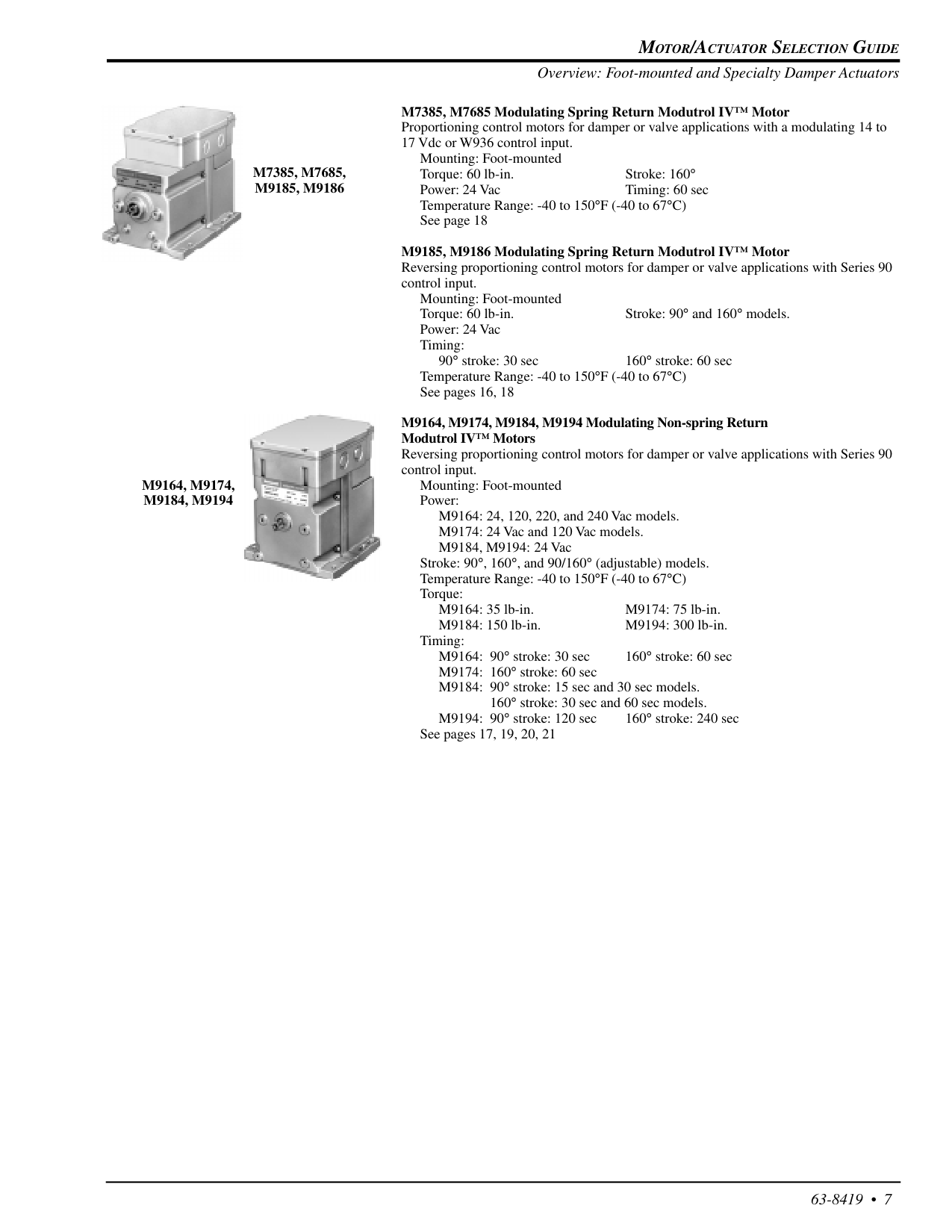
Motor/Actuator Selection Guide
63-8419 • 7M7385, M7685,
M9185, M9186
M9164, M9174,
M9184, M9194
M7385, M7685 Modulating Spring Return Modutrol IV™ Motor Proportioning control motors for damper or valve applications with a modulating 14 to 17 Vdc or W936 control input. Mounting: Foot-mounted Torque: 60 lb-in. Stroke: 160° Power: 24 Vac Timing: 60 sec Temperature Range: -40 to 150°F (-40 to 67°C) See page 18 M9185, M9186 Modulating Spring Return Modutrol IV™ Motor Reversing proportioning control motors for damper or valve applications with Series 90 control input. Mounting: Foot-mounted Torque: 60 lb-in. Stroke: 90° and 160° models. Power: 24 Vac Timing: 90° stroke: 30 sec 160° stroke: 60 sec Temperature Range: -40 to 150°F (-40 to 67°C) See pages 16, 18 M9164, M9174, M9184, M9194 Modulating Non-spring Return Modutrol IV™ Motors Reversing proportioning control motors for damper or valve applications with Series 90 control input. Mounting: Foot-mounted Power: M9164: 24, 120, 220, and 240 Vac models. M9174: 24 Vac and 120 Vac models. M9184, M9194: 24 Vac Stroke: 90°, 160°, and 90/160° (adjustable) models. Temperature Range: -40 to 150°F (-40 to 67°C) Torque: M9164: 35 lb-in. M9174: 75 lb-in. M9184: 150 lb-in. M9194: 300 lb-in. Timing: M9164: 90° stroke: 30 sec 160° stroke: 60 sec M9174: 160° stroke: 60 sec M9184: 90° stroke: 15 sec and 30 sec models. 160° stroke: 30 sec and 60 sec models. M9194: 90° stroke: 120 sec 160° stroke: 240 sec See pages 17, 19, 20, 21 Overview: Foot-mounted and Specialty Damper Actuators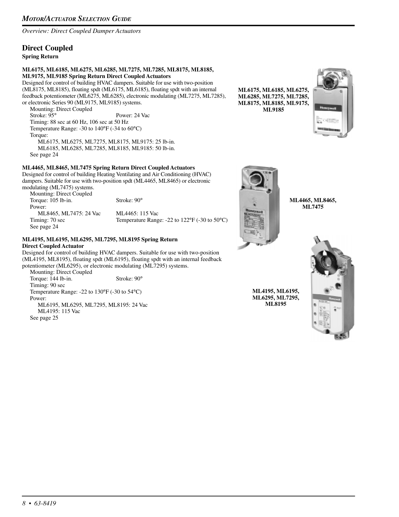
Motor/Actuator Selection Guide
8 • 63-8419 Direct Coupled Spring ReturnMl6175, Ml6185, Ml6275, Ml6285, Ml7275, Ml7285, Ml8175, Ml8185,
ML9175, ML9185 Spring Return Direct Coupled Actuators Designed for control of building HVAC dampers. Suitable for use with two-position (ML8175, ML8185), floating spdt (ML6175, ML6185), floating spdt with an internal feedback potentiometer (ML6275, ML6285), electronic modulating (ML7275, ML7285), or electronic Series 90 (ML9175, ML9185) systems. Mounting: Direct Coupled Stroke: 95° Power: 24 Vac Timing: 88 sec at 60 Hz, 106 sec at 50 Hz Temperature Range: -30 to 140°F (-34 to 60°C) Torque: ML6175, ML6275, ML7275, ML8175, ML9175: 25 lb-in. ML6185, ML6285, ML7285, ML8185, ML9185: 50 lb-in. See page 24 ML4465, ML8465, ML7475 Spring Return Direct Coupled Actuators Designed for control of building Heating Ventilating and Air Conditioning (HVAC) dampers. Suitable for use with two-position spdt (ML4465, ML8465) or electronic modulating (ML7475) systems. Mounting: Direct Coupled Torque: 105 lb-in. Stroke: 90° Power: ML8465, ML7475: 24 Vac ML4465: 115 Vac Timing: 70 sec Temperature Range: -22 to 122°F (-30 to 50°C) See page 24 ML4195, ML6195, ML6295, ML7295, ML8195 Spring Return Direct Coupled Actuator Designed for control of building HVAC dampers. Suitable for use with two-position (ML4195, ML8195), floating spdt (ML6195), floating spdt with an internal feedback potentiometer (ML6295), or electronic modulating (ML7295) systems. Mounting: Direct Coupled Torque: 144 lb-in. Stroke: 90° Timing: 90 sec Temperature Range: -22 to 130°F (-30 to 54°C) Power: ML6195, ML6295, ML7295, ML8195: 24 Vac ML4195: 115 Vac See page 25Ml4195, Ml6195,
Ml6295, Ml7295,
Ml8195
Ml6175, Ml6185, Ml6275,
Ml6285, Ml7275, Ml7285,
Ml8175, Ml8185, Ml9175,
Ml9185
Ml4465, Ml8465,
Ml7475
Overview: Direct Coupled Damper Actuators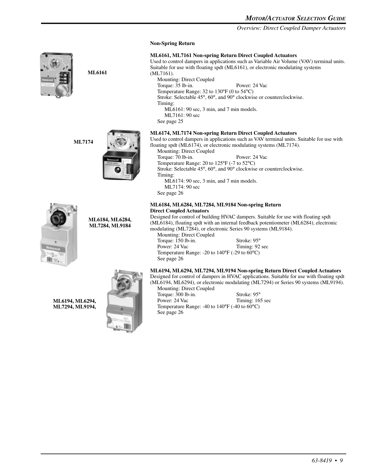
Motor/Actuator Selection Guide
63-8419 • 9 Non-Spring Return ML6161, ML7161 Non-spring Return Direct Coupled Actuators Used to control dampers in applications such as Variable Air Volume (VAV) terminal units. Suitable for use with floating spdt (ML6161), or electronic modulating systems(Ml7161).
Mounting: Direct Coupled Torque: 35 lb-in. Power: 24 Vac Temperature Range: 32 to 130°F (0 to 54°C) Stroke: Selectable 45°, 60°, and 90° clockwise or counterclockwise. Timing: ML6161: 90 sec, 3 min, and 7 min models. ML7161: 90 sec See page 25 ML6174, ML7174 Non-spring Return Direct Coupled Actuators Used to control dampers in applications such as VAV terminal units. Suitable for use with floating spdt (ML6174), or electronic modulating systems (ML7174). Mounting: Direct Coupled Torque: 70 lb-in. Power: 24 Vac Temperature Range: 20 to 125°F (-7 to 52°C) Stroke: Selectable 45°, 60°, and 90° clockwise or counterclockwise. Timing: ML6174: 90 sec, 3 min, and 7 min models. ML7174: 90 sec See page 26 ML6184, ML6284, ML7284, ML9184 Non-spring Return Direct Coupled Actuators Designed for control of building HVAC dampers. Suitable for use with floating spdt (ML6184), floating spdt with an internal feedback potentiometer (ML6284), electronic modulating (ML7284), or electronic Series 90 systems (ML9184). Mounting: Direct Coupled Torque: 150 lb-in. Stroke: 95° Power: 24 Vac Timing: 92 sec Temperature Range: -20 to 140°F (-29 to 60°C) See page 26 ML6194, ML6294, ML7294, ML9194 Non-spring Return Direct Coupled Actuators Designed for control of dampers in HVAC applications. Suitable for use with floating spdt (ML6194, ML6294), or electronic modulating (ML7294) or Series 90 systems (ML9194). Mounting: Direct Coupled Torque: 300 lb-in. Stroke: 95° Power: 24 Vac Timing: 165 sec Temperature Range: -40 to 140°F (-40 to 60°C) See page 26Ml6194, Ml6294,
Ml7294, Ml9194,
Ml6184, Ml6284,
Ml7284, Ml9184
Ml6161
Ml7174
Overview: Direct Coupled Damper Actuators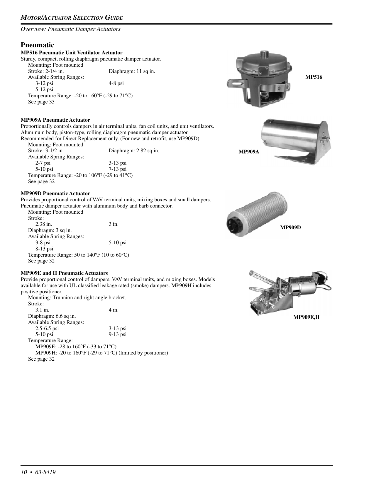
Motor/Actuator Selection Guide
10 • 63-8419 Pneumatic MP516 Pneumatic Unit Ventilator Actuator Sturdy, compact, rolling diaphragm pneumatic damper actuator. Mounting: Foot mounted Stroke: 2-1/4 in. Diaphragm: 11 sq in. Available Spring Ranges: 3-12 psi 4-8 psi 5-12 psi Temperature Range: -20 to 160°F (-29 to 71°C) See page 33 MP909A Pneumatic Actuator Proportionally controls dampers in air terminal units, fan coil units, and unit ventilators. Aluminum body, piston-type, rolling diaphragm pneumatic damper actuator. Recommended for Direct Replacement only. (For new and retrofit, use MP909D). Mounting: Foot mounted Stroke: 3-1/2 in. Diaphragm: 2.82 sq in. Available Spring Ranges: 2-7 psi 3-13 psi 5-10 psi 7-13 psi Temperature Range: -20 to 106°F (-29 to 41°C) See page 32 MP909D Pneumatic Actuator Provides proportional control of VAV terminal units, mixing boxes and small dampers. Pneumatic damper actuator with aluminum body and barb connector. Mounting: Foot mounted Stroke: 2.38 in. 3 in. Diaphragm: 3 sq in. Available Spring Ranges: 3-8 psi 5-10 psi 8-13 psi Temperature Range: 50 to 140°F (10 to 60°C) See page 32 MP909E and H Pneumatic Actuators Provide proportional control of dampers, VAV terminal units, and mixing boxes. Models available for use with UL classified leakage rated (smoke) dampers. MP909H includes positive positioner. Mounting: Trunnion and right angle bracket. Stroke: 3.1 in. 4 in. Diaphragm: 6.6 sq in. Available Spring Ranges: 2.5-6.5 psi 3-13 psi 5-10 psi 9-13 psi Temperature Range: MP909E: -28 to 160°F (-33 to 71°C) MP909H: -20 to 160°F (-29 to 71°C) (limited by positioner) See page 32Mp516
Mp909A
Mp909D
Mp909E,H
Overview: Pneumatic Damper Actuators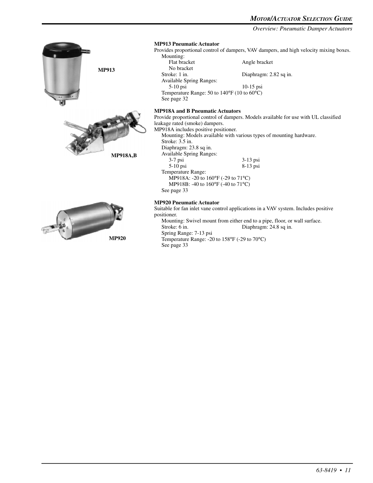
Motor/Actuator Selection Guide
63-8419 • 11Mp913
MP913 Pneumatic Actuator Provides proportional control of dampers, VAV dampers, and high velocity mixing boxes. Mounting: Flat bracket Angle bracket No bracket Stroke: 1 in. Diaphragm: 2.82 sq in. Available Spring Ranges: 5-10 psi 10-15 psi Temperature Range: 50 to 140°F (10 to 60°C) See page 32 MP918A and B Pneumatic Actuators Provide proportional control of dampers. Models available for use with UL classified leakage rated (smoke) dampers. MP918A includes positive positioner. Mounting: Models available with various types of mounting hardware. Stroke: 3.5 in. Diaphragm: 23.8 sq in. Available Spring Ranges: 3-7 psi 3-13 psi 5-10 psi 8-13 psi Temperature Range: MP918A: -20 to 160°F (-29 to 71°C) MP918B: -40 to 160°F (-40 to 71°C) See page 33 MP920 Pneumatic Actuator Suitable for fan inlet vane control applications in a VAV system. Includes positive positioner. Mounting: Swivel mount from either end to a pipe, floor, or wall surface. Stroke: 6 in. Diaphragm: 24.8 sq in. Spring Range: 7-13 psi Temperature Range: -20 to 158°F (-29 to 70°C) See page 33Mp918A,B
Mp920
Overview: Pneumatic Damper Actuators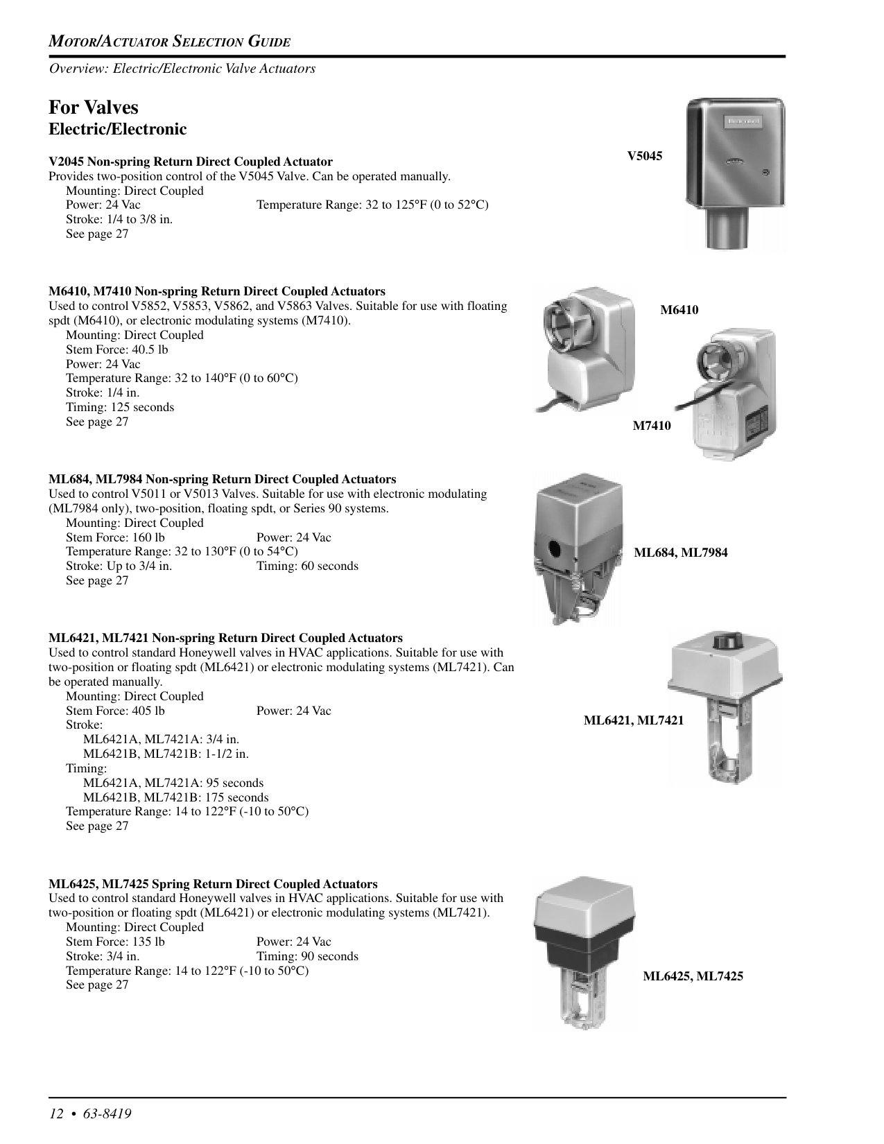
Motor/Actuator Selection Guide
12 • 63-8419 For Valves Electric/Electronic V2045 Non-spring Return Direct Coupled Actuator Provides two-position control of the V5045 Valve. Can be operated manually. Mounting: Direct Coupled Power: 24 Vac Temperature Range: 32 to 125°F (0 to 52°C) Stroke: 1/4 to 3/8 in. See page 27 M6410, M7410 Non-spring Return Direct Coupled Actuators Used to control V5852, V5853, V5862, and V5863 Valves. Suitable for use with floating spdt (M6410), or electronic modulating systems (M7410). Mounting: Direct Coupled Stem Force: 40.5 lb Power: 24 Vac Temperature Range: 32 to 140°F (0 to 60°C) Stroke: 1/4 in. Timing: 125 seconds See page 27 ML684, ML7984 Non-spring Return Direct Coupled Actuators Used to control V5011 or V5013 Valves. Suitable for use with electronic modulating (ML7984 only), two-position, floating spdt, or Series 90 systems. Mounting: Direct Coupled Stem Force: 160 lb Power: 24 Vac Temperature Range: 32 to 130°F (0 to 54°C) Stroke: Up to 3/4 in. Timing: 60 seconds See page 27 ML6421, ML7421 Non-spring Return Direct Coupled Actuators Used to control standard Honeywell valves in HVAC applications. Suitable for use with two-position or floating spdt (ML6421) or electronic modulating systems (ML7421). Can be operated manually. Mounting: Direct Coupled Stem Force: 405 lb Power: 24 Vac Stroke: ML6421A, ML7421A: 3/4 in. ML6421B, ML7421B: 1-1/2 in. Timing: ML6421A, ML7421A: 95 seconds ML6421B, ML7421B: 175 seconds Temperature Range: 14 to 122°F (-10 to 50°C) See page 27 ML6425, ML7425 Spring Return Direct Coupled Actuators Used to control standard Honeywell valves in HVAC applications. Suitable for use with two-position or floating spdt (ML6421) or electronic modulating systems (ML7421). Mounting: Direct Coupled Stem Force: 135 lb Power: 24 Vac Stroke: 3/4 in. Timing: 90 seconds Temperature Range: 14 to 122°F (-10 to 50°C) See page 27V5045
M6410
M7410
Ml684, Ml7984
Ml6421, Ml7421
Ml6425, Ml7425
Overview: Electric/Electronic Valve Actuators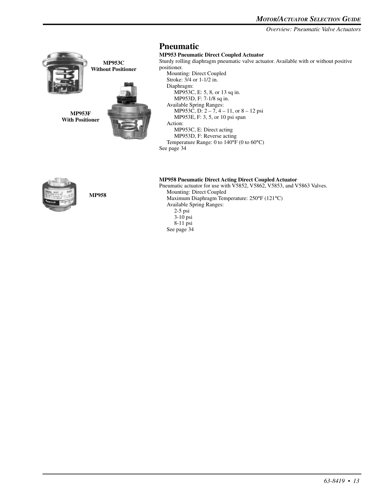
Motor/Actuator Selection Guide
63-8419 • 13 Pneumatic MP953 Pneumatic Direct Coupled Actuator Sturdy rolling diaphragm pneumatic valve actuator. Available with or without positive positioner. Mounting: Direct Coupled Stroke: 3/4 or 1-1/2 in. Diaphragm: MP953C, E: 5, 8, or 13 sq in. MP953D, F: 7-1/8 sq in. Available Spring Ranges: MP953C, D: 2 – 7, 4 – 11, or 8 – 12 psi MP953E, F: 3, 5, or 10 psi span Action: MP953C, E: Direct acting MP953D, F: Reverse acting Temperature Range: 0 to 140°F (0 to 60°C) See page 34 MP958 Pneumatic Direct Acting Direct Coupled Actuator Pneumatic actuator for use with V5852, V5862, V5853, and V5863 Valves. Mounting: Direct Coupled Maximum Diaphragm Temperature: 250°F (121°C) Available Spring Ranges: 2-5 psi 3-10 psi 8-11 psi See page 34Mp953C
Without PositionerMp953F
With PositionerMp958
Overview: Pneumatic Valve Actuators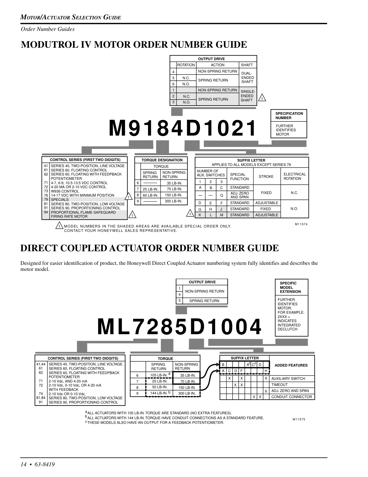
Motor/Actuator Selection Guide
14 • 63-8419Modutrol Iv Motor Order Number Guide
Direct Coupled Actuator Order Number Guide
Designed for easier identification of product, the Honeywell Direct Coupled Actuator numbering system fully identifies and describes the motor model.Series 40, Two-Position, Line Voltage
Series 60, Floating Control
Series 60, Floating With Feedpback
Potentiometer
4-7, 6-9, 10.5-13.5 Vdc Control
4-20 Ma Or 2-10 Vdc Control
W936 Control
14-17 Vdc With Minimum Position
Specials
Series 80, Two-Position, Low Voltage
Series 90, Proportioning Control
Proportional Flame Safequard
Firing Rate Motor
35 Lb-In.
75 Lb-In.
150 Lb-In.
300 Lb-In.
25 Lb-In.
60 Lb-In.
Spring
Return
Non-Spring
Return
Torque
Torque Designation
6 7 8 9N.C.
N.O.
N.C.
N.O.
Spring Return
Spring Return
Non-Spring Return
Non-Spring Return
Rotation
Action
Output Drive
4 5 6 1 2 3 41 61 62 71 72 73 76 79 81 91 94Control Series (First Two Didgits)
Shaft
Dual-
Ended
Shaft
Single-
Ended
Shaft
Number Of
Aux. Switches
Suffix Letter
Applies To All Models Except Series 79
A
Special
Function
B
C
Q
F
J
M
D
E
G
H
K
L
1 2 3Standard
Standard
Standard
Standard
Adj. Zero
And Span
Stroke
Electrical
Rotation
N.C.
N.O.
Fixed
Fixed
Adjustable
Adjustable
Specification
Number
Further
Identifies
Motor
M9184D1021
M11574
Model Numbers In The Shaded Areas Are Available Special Order Only.
Contact Your Honeywell Sales Representative.
1 1 1 1 1Series 40, Two-Position, Line Voltage
Series 60, Floating Control
Series 60, Floating With Feedpback
Potentiometer
2-10 Vdc, AND 4-20 mA 2-10 Vdc, 0-10 Vdc, OR 4-20 mAWith Feedback
2-10 Vdc OR 0-10 Vdc,Series 80, Two-Position, Low Voltage
Series 90, Proportioning Control
105 Lb-In.
25 Lb-In.
50 Lb-In.
144 Lb-In.
35 Lb-In.
70 Lb-In.
150 Lb-In.
300 Lb-In.
Spring
Return
Non-Spring
Return
Torque
6 7 8 9Spring Return
Non-Spring Return
Output Drive
1 4 5 41,44 61 62 71 72 74 81,84 91Control Series (First Two Didgits)
A
Specific
Model
Extension
Further
Identifies
Motor;
For Example:
2Xxx =
Indicates
Integrated
Declutch
Ml7285D1004
M11575
B
C
D
F
A
C
H
D
X
X
X
X
X
X
X
X
Auxiliary Switch
Timeout
Adj. Zero And Span
Conduit Connector
Added Features
Suffix Letter
All Actuators With 105 Lb-In. Torque Are Standard (No Extra Features).
ALL ACTUATORS WITH 144 LB-IN. TORQUE HAVE CONDUIT CONNECTIONS AS A STANDARD FEATURE.These Models Also Have An Output For A Feedback Potentiometer.
a a b b c c c Order Number Guides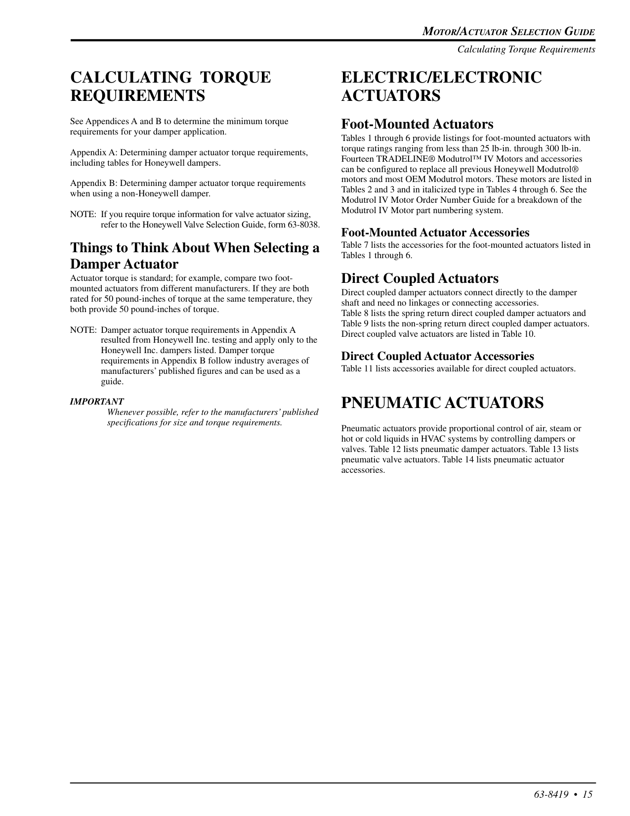
Motor/Actuator Selection Guide
63-8419 • 15Calculating Torque
Requirements
See Appendices A and B to determine the minimum torque requirements for your damper application. Appendix A: Determining damper actuator torque requirements, including tables for Honeywell dampers. Appendix B: Determining damper actuator torque requirements when using a non-Honeywell damper. NOTE: If you require torque information for valve actuator sizing, refer to the Honeywell Valve Selection Guide, form 63-8038. Things to Think About When Selecting a Damper Actuator Actuator torque is standard; for example, compare two foot- mounted actuators from different manufacturers. If they are both rated for 50 pound-inches of torque at the same temperature, they both provide 50 pound-inches of torque. NOTE: Damper actuator torque requirements in Appendix A resulted from Honeywell Inc. testing and apply only to the Honeywell Inc. dampers listed. Damper torque requirements in Appendix B follow industry averages of manufacturers’ published figures and can be used as a guide.Important
Whenever possible, refer to the manufacturers’ published specifications for size and torque requirements.Electric/Electronic
Actuators
Foot-Mounted Actuators Tables 1 through 6 provide listings for foot-mounted actuators with torque ratings ranging from less than 25 lb-in. through 300 lb-in. Fourteen TRADELINE® Modutrol™ IV Motors and accessories can be configured to replace all previous Honeywell Modutrol® motors and most OEM Modutrol motors. These motors are listed in Tables 2 and 3 and in italicized type in Tables 4 through 6. See the Modutrol IV Motor Order Number Guide for a breakdown of the Modutrol IV Motor part numbering system. Foot-Mounted Actuator Accessories Table 7 lists the accessories for the foot-mounted actuators listed in Tables 1 through 6. Direct Coupled Actuators Direct coupled damper actuators connect directly to the damper shaft and need no linkages or connecting accessories. Table 8 lists the spring return direct coupled damper actuators and Table 9 lists the non-spring return direct coupled damper actuators. Direct coupled valve actuators are listed in Table 10. Direct Coupled Actuator Accessories Table 11 lists accessories available for direct coupled actuators.Pneumatic Actuators
Pneumatic actuators provide proportional control of air, steam or hot or cold liquids in HVAC systems by controlling dampers or valves. Table 12 lists pneumatic damper actuators. Table 13 lists pneumatic valve actuators. Table 14 lists pneumatic actuator accessories. Calculating Torque Requirements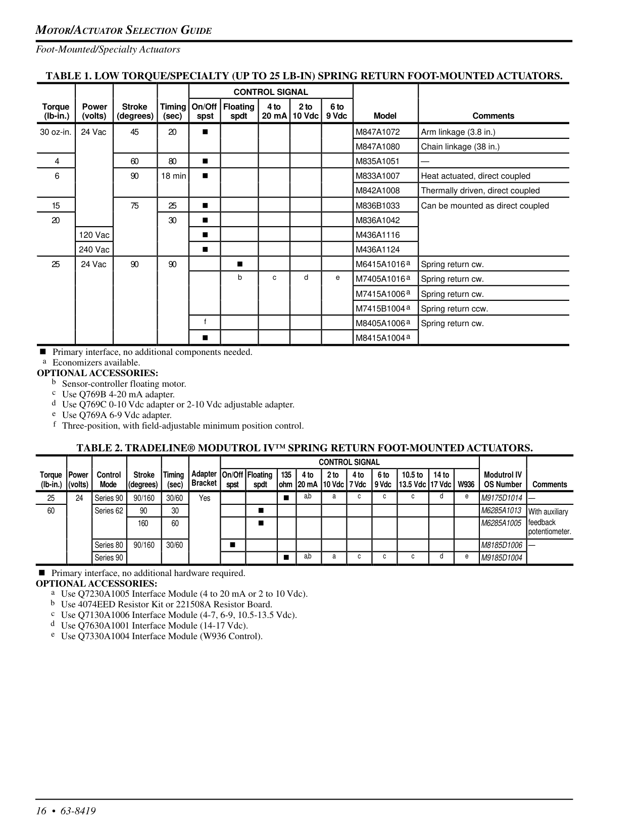
Motor/Actuator Selection Guide
16 • 63-8419 Foot-Mounted/Specialty Actuators TABLE 1. LOW TORQUE/SPECIALTY (UP TO 25 LB-IN) SPRING RETURN FOOT-MOUNTED ACTUATORS. n Primary interface, no additional components needed. a Economizers available.Optional Accessories:
b Sensor-controller floating motor. c Use Q769B 4-20 mA adapter. d Use Q769C 0-10 Vdc adapter or 2-10 Vdc adjustable adapter. e Use Q769A 6-9 Vdc adapter. f Three-position, with field-adjustable minimum position control.Table 2. Tradeline® Modutrol Iv™ Spring Return Foot-Mounted Actuators.
n Primary interface, no additional hardware required.Optional Accessories:
a Use Q7230A1005 Interface Module (4 to 20 mA or 2 to 10 Vdc). b Use 4074EED Resistor Kit or 221508A Resistor Board. c Use Q7130A1006 Interface Module (4-7, 6-9, 10.5-13.5 Vdc). d Use Q7630A1001 Interface Module (14-17 Vdc). e Use Q7330A1004 Interface Module (W936 Control).Control Signal
Torque (lb-in.) Power (volts) Control Mode Stroke (degrees) Timing (sec) Adapter Bracket On/Off spst Floating spdt 135 ohm 4 to 20 mA 2 to 10 Vdc 4 to 7 Vdc 6 to 9 Vdc 10.5 to 13.5 Vdc 14 to 17 VdcW936
Modutrol IV OS Number Comments 25 24 Series 90 90/160 30/60 Yes n a,b a c c c d eM9175D1014
— 60 Series 62 90 30 nM6285A1013
With auxiliary 160 60 nM6285A1005
feedback potentiometer. Series 80 90/160 30/60 nM8185D1006
— Series 90 n a,b a c c c d eM9185D1004
Control Signal
Torque (lb-in.) Power (volts) Stroke (degrees) Timing (sec) On/Off spst Floating spdt 4 to 20 mA 2 to 10 Vdc 6 to 9 Vdc Model Comments 30 oz-in. 24 Vac 45 20 nM847A1072
Arm linkage (3.8 in.)M847A1080
Chain linkage (38 in.) 4 60 80 nM835A1051
— 6 90 18 min nM833A1007
Heat actuated, direct coupledM842A1008
Thermally driven, direct coupled 15 75 25 nM836B1033
Can be mounted as direct coupled 20 30 nM836A1042
120 Vac nM436A1116
240 Vac nM436A1124
25 24 Vac 90 90 n M6415A1016a Spring return cw. b c d e M7405A1016a Spring return cw. M7415A1006a Spring return cw. M7415B1004a Spring return ccw. f M8405A1006a Spring return cw. n M8415A1004a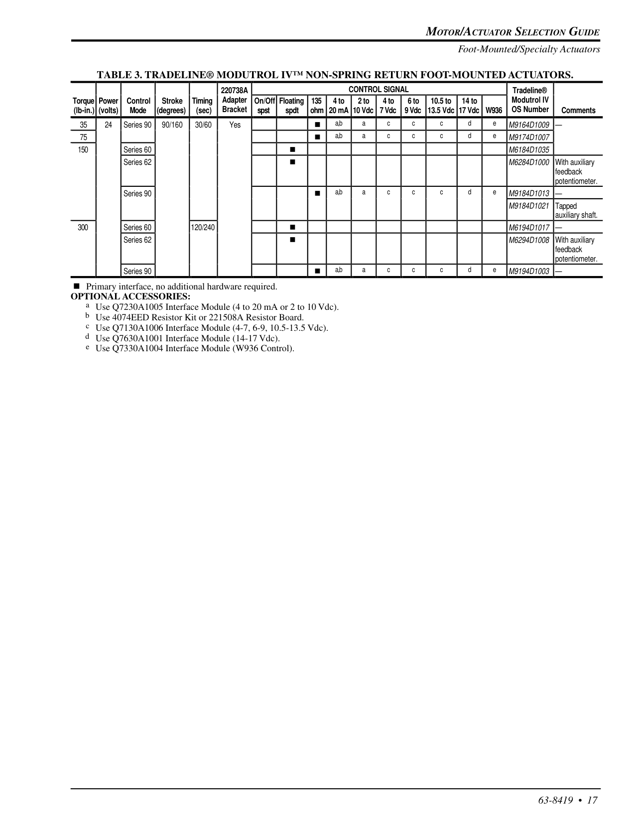
Motor/Actuator Selection Guide
63-8419 • 17 Foot-Mounted/Specialty ActuatorsTable 3. Tradeline® Modutrol Iv™ Non-Spring Return Foot-Mounted Actuators.
220738A
Control Signal
Tradeline® Torque (lb-in.) Power (volts) Control Mode Stroke (degrees) Timing (sec) Adapter Bracket On/Off spst Floating spdt 135 ohm 4 to 20 mA 2 to 10 Vdc 4 to 7 Vdc 6 to 9 Vdc 10.5 to 13.5 Vdc 14 to 17 VdcW936
Modutrol IV OS Number Comments 35 24 Series 90 90/160 30/60 Yes n a,b a c c c d eM9164D1009
— 75 n a,b a c c c d eM9174D1007
150 Series 60 nM6184D1035
Series 62 nM6284D1000
With auxiliary feedback potentiometer. Series 90 n a,b a c c c d eM9184D1013
—M9184D1021
Tapped auxiliary shaft. 300 Series 60 120/240 nM6194D1017
— Series 62 nM6294D1008
With auxiliary feedback potentiometer. Series 90 n a,b a c c c d eM9194D1003
— n Primary interface, no additional hardware required.Optional Accessories:
a Use Q7230A1005 Interface Module (4 to 20 mA or 2 to 10 Vdc). b Use 4074EED Resistor Kit or 221508A Resistor Board. c Use Q7130A1006 Interface Module (4-7, 6-9, 10.5-13.5 Vdc). d Use Q7630A1001 Interface Module (14-17 Vdc). e Use Q7330A1004 Interface Module (W936 Control).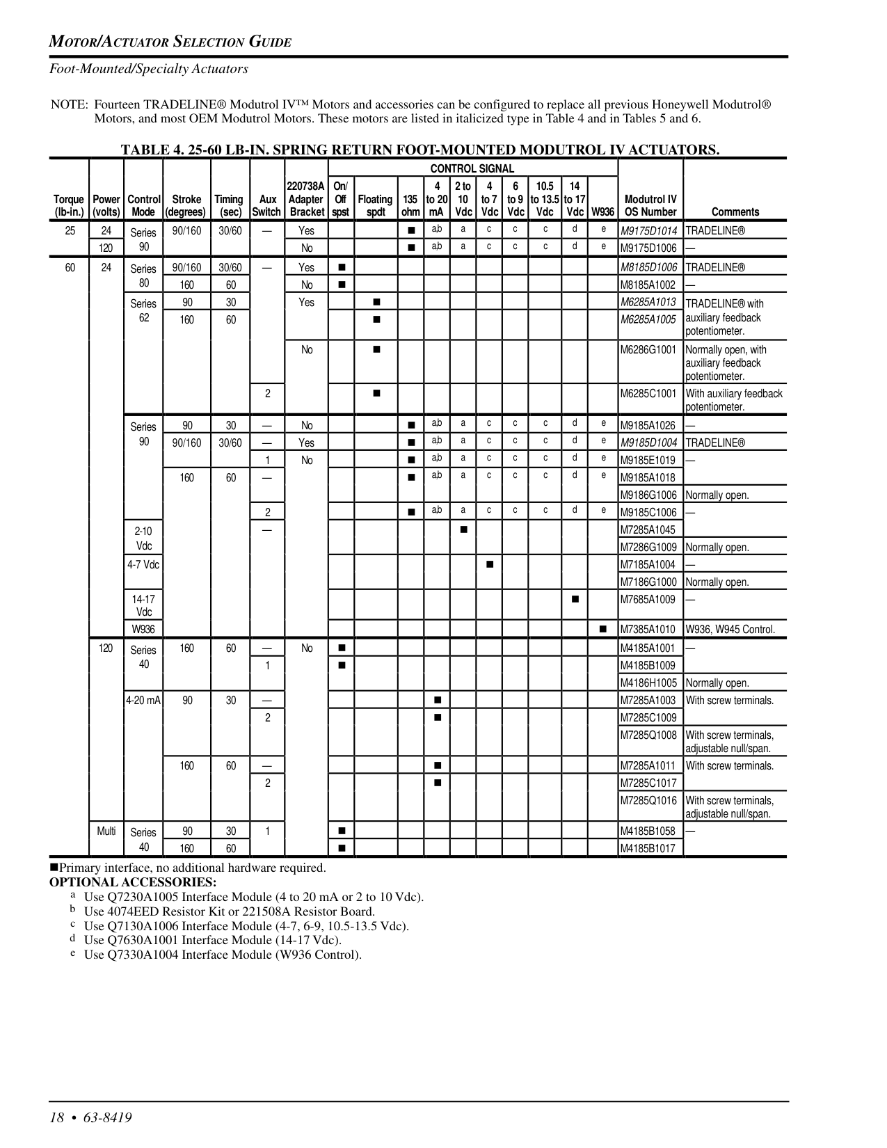
Motor/Actuator Selection Guide
18 • 63-8419 Foot-Mounted/Specialty Actuators NOTE: Fourteen TRADELINE® Modutrol IV™ Motors and accessories can be configured to replace all previous Honeywell Modutrol® Motors, and most OEM Modutrol Motors. These motors are listed in italicized type in Table 4 and in Tables 5 and 6.Table 4. 25-60 Lb-In. Spring Return Foot-Mounted Modutrol Iv Actuators.
Control Signal
Torque (lb-in.) Power (volts) Control Mode Stroke (degrees) Timing (sec) Aux Switch220738A
Adapter Bracket On/ Off spst Floating spdt 135 ohm 4 to 20 mA 2 to 10 Vdc 4 to 7 Vdc 6 to 9 Vdc 10.5 to 13.5 Vdc 14 to 17 Vdc W936 Modutrol IV OS Number Comments 25 24 Series 90/160 30/60 — Yes n a,b a c c c d eM9175D1014
Tradeline®
120 90 No n a,b a c c c d eM9175D1006
— 60 24 Series 90/160 30/60 — Yes nM8185D1006
Tradeline®
80 160 60 No nM8185A1002
— Series 90 30 Yes nM6285A1013
TRADELINE® with 62 160 60 nM6285A1005
auxiliary feedback potentiometer. No nM6286G1001
Normally open, with auxiliary feedback potentiometer. 2 nM6285C1001
With auxiliary feedback potentiometer. Series 90 30 — No n a,b a c c c d eM9185A1026
— 90 90/160 30/60 — Yes n a,b a c c c d eM9185D1004
Tradeline®
1 No n a,b a c c c d eM9185E1019
— 160 60 — n a,b a c c c d eM9185A1018
M9186G1006
Normally open. 2 n a,b a c c c d eM9185C1006
— 2-10 — nM7285A1045
VdcM7286G1009
Normally open. 4-7 Vdc nM7185A1004
—M7186G1000
Normally open. 14-17 Vdc nM7685A1009
—W936
nM7385A1010
W936, W945 Control. 120 Series 160 60 — No nM4185A1001
— 40 1 nM4185B1009
M4186H1005
Normally open. 4-20 mA 90 30 — nM7285A1003
With screw terminals. 2 nM7285C1009
M7285Q1008
With screw terminals, adjustable null/span. 160 60 — nM7285A1011
With screw terminals. 2 nM7285C1017
M7285Q1016
With screw terminals, adjustable null/span. Multi Series 90 30 1 nM4185B1058
— 40 160 60 nM4185B1017
nPrimary interface, no additional hardware required.Optional Accessories:
a Use Q7230A1005 Interface Module (4 to 20 mA or 2 to 10 Vdc). b Use 4074EED Resistor Kit or 221508A Resistor Board. c Use Q7130A1006 Interface Module (4-7, 6-9, 10.5-13.5 Vdc). d Use Q7630A1001 Interface Module (14-17 Vdc). e Use Q7330A1004 Interface Module (W936 Control).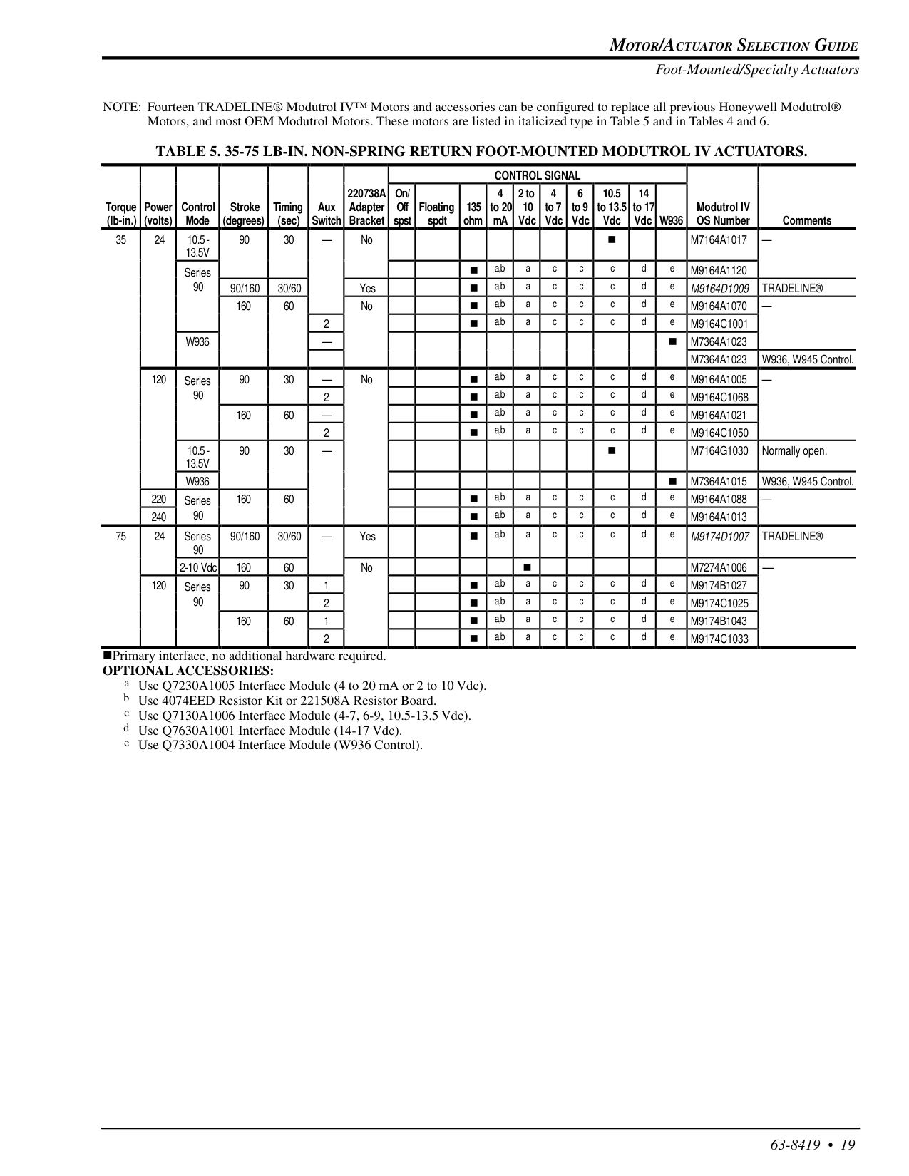
Motor/Actuator Selection Guide
63-8419 • 19 Foot-Mounted/Specialty Actuators NOTE: Fourteen TRADELINE® Modutrol IV™ Motors and accessories can be configured to replace all previous Honeywell Modutrol® Motors, and most OEM Modutrol Motors. These motors are listed in italicized type in Table 5 and in Tables 4 and 6.Table 5. 35-75 Lb-In. Non-Spring Return Foot-Mounted Modutrol Iv Actuators.
nPrimary interface, no additional hardware required.Optional Accessories:
a Use Q7230A1005 Interface Module (4 to 20 mA or 2 to 10 Vdc). b Use 4074EED Resistor Kit or 221508A Resistor Board. c Use Q7130A1006 Interface Module (4-7, 6-9, 10.5-13.5 Vdc). d Use Q7630A1001 Interface Module (14-17 Vdc). e Use Q7330A1004 Interface Module (W936 Control).Control Signal
Torque (lb-in.) Power (volts) Control Mode Stroke (degrees) Timing (sec) Aux Switch220738A
Adapter Bracket On/ Off spst Floating spdt 135 ohm 4 to 20 mA 2 to 10 Vdc 4 to 7 Vdc 6 to 9 Vdc 10.5 to 13.5 Vdc 14 to 17 Vdc W936 Modutrol IV OS Number Comments 35 24 10.5-13.5V
90 30 — No nM7164A1017
— Series n a,b a c c c d eM9164A1120
90 90/160 30/60 Yes n a,b a c c c d eM9164D1009
Tradeline®
160 60 No n a,b a c c c d eM9164A1070
— 2 n a,b a c c c d eM9164C1001
W936
— nM7364A1023
M7364A1023
W936, W945 Control. 120 Series 90 30 — No n a,b a c c c d eM9164A1005
— 90 2 n a,b a c c c d eM9164C1068
160 60 — n a,b a c c c d eM9164A1021
2 n a,b a c c c d eM9164C1050
10.5-13.5V
90 30 — nM7164G1030
Normally open.W936
nM7364A1015
W936, W945 Control. 220 Series 160 60 n a,b a c c c d eM9164A1088
— 240 90 n a,b a c c c d eM9164A1013
75 24 Series 90 90/160 30/60 — Yes n a,b a c c c d eM9174D1007
Tradeline®
2-10 Vdc 160 60 No nM7274A1006
-— 120 Series 90 30 1 n a,b a c c c d eM9174B1027
90 2 n a,b a c c c d eM9174C1025
160 60 1 n a,b a c c c d eM9174B1043
2 n a,b a c c c d eM9174C1033
Motor/Actuator Selection Guide
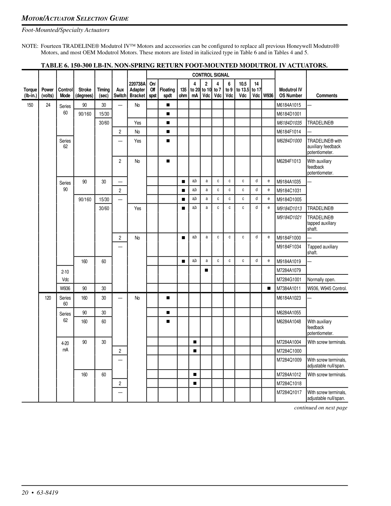
20 • 63-8419 Foot-Mounted/Specialty Actuators NOTE: Fourteen TRADELINE® Modutrol IV™ Motors and accessories can be configured to replace all previous Honeywell Modutrol® Motors, and most OEM Modutrol Motors. These motors are listed in italicized type in Table 6 and in Tables 4 and 5.Table 6. 150-300 Lb-In. Non-Spring Return Foot-Mounted Modutrol Iv Actuators.
continued on next pageControl Signal
Torque (lb-in.) Power (volts) Control Mode Stroke (degrees) Timing (sec) Aux Switch220738A
Adapter Bracket On/ Off spst Floating spdt 135 ohm 4 to 20 mA 2 to 10 Vdc 4 to 7 Vdc 6 to 9 Vdc 10.5 to 13.5 Vdc 14 to 17 Vdc W936 Modutrol IV OS Number Comments 150 24 Series 90 30 — No nM6184A1015
— 60 90/160 15/30 nM6184D1001
30/60 Yes nM6184D1035
Tradeline®
2 No nM6184F1014
— Series 62 — Yes nM6284D1000
TRADELINE® with auxiliary feedback potentiometer. 2 No nM6284F1013
With auxiliary feedback potentiometer. Series 90 30 — n a,b a c c c d eM9184A1035
— 90 2 n a,b a c c c d eM9184C1031
90/160 15/30 — n a,b a c c c d eM9184D1005
30/60 Yes n a,b a c c c d eM9184D1013
Tradeline®
M9184D1021
Tradeline®
tapped auxiliary shaft. 2 No n a,b a c c c d eM9184F1000
— —M9184F1034
Tapped auxiliary shaft. 160 60 n a,b a c c c d eM9184A1019
— 2-10 nM7284A1079
VdcM7284G1001
Normally open.W936
90 30 nM7384A1011
W936, W945 Control. 120 Series 60 160 30 — No nM6184A1023
— Series 90 30 nM6284A1055
62 160 60 nM6284A1048
With auxiliary feedback potentiometer. 4-20 90 30 nM7284A1004
With screw terminals. mA 2 nM7284C1000
—M7284Q1009
With screw terminals, adjustable null/span. 160 60 nM7284A1012
With screw terminals. 2 nM7284C1018
—M7284Q1017
With screw terminals, adjustable null/span.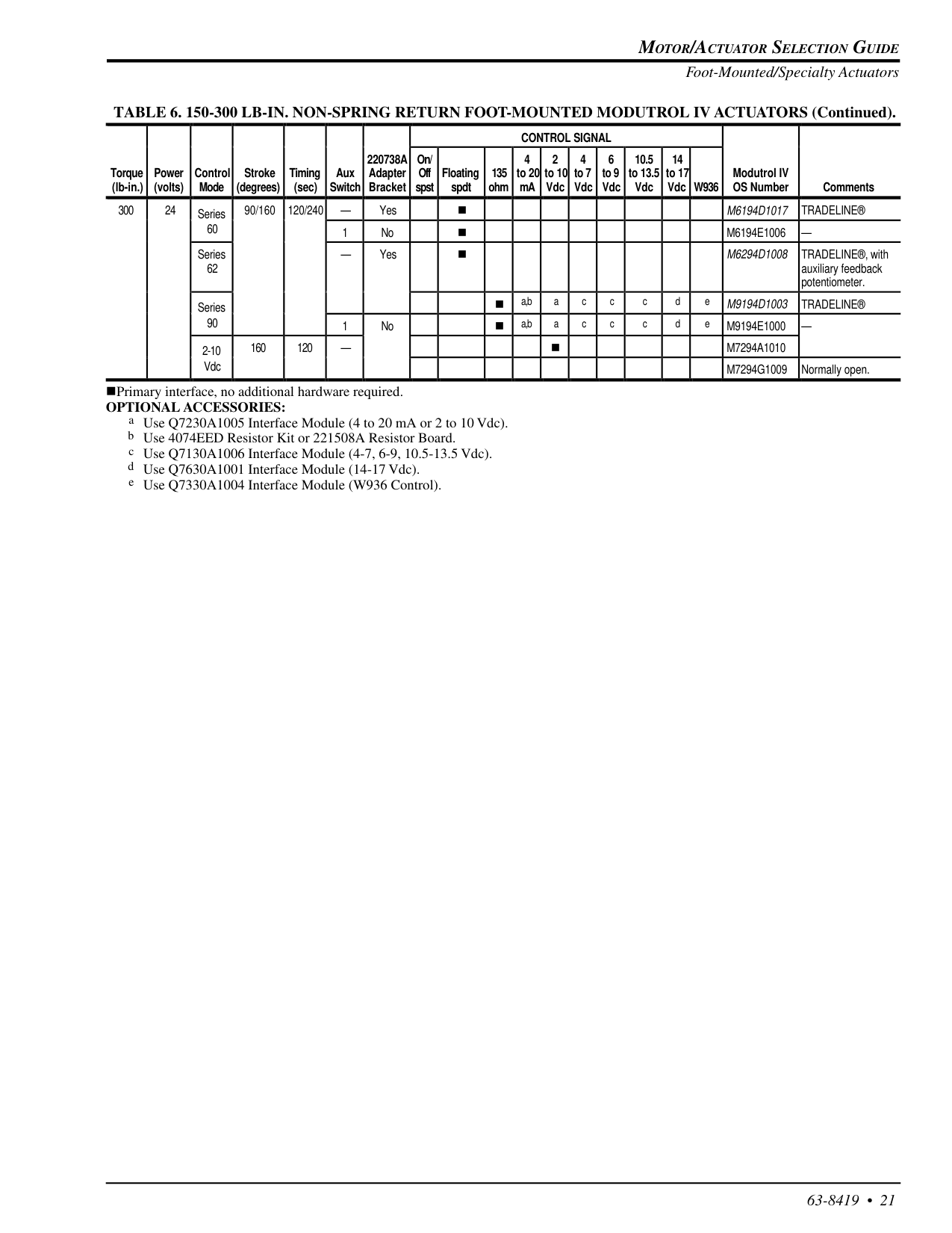
Motor/Actuator Selection Guide
63-8419 • 21 TABLE 6. 150-300 LB-IN. NON-SPRING RETURN FOOT-MOUNTED MODUTROL IV ACTUATORS (Continued).Control Signal
Torque (lb-in.) Power (volts) Control Mode Stroke (degrees) Timing (sec) Aux Switch220738A
Adapter Bracket On/ Off spst Floating spdt 135 ohm 4 to 20 mA 2 to 10 Vdc 4 to 7 Vdc 6 to 9 Vdc 10.5 to 13.5 Vdc 14 to 17 Vdc W936 Modutrol IV OS Number Comments 300 24 Series 90/160 120/240 — Yes nM6194D1017
Tradeline®
60 1 No nM6194E1006
— Series 62 — Yes nM6294D1008
TRADELINE®, with auxiliary feedback potentiometer. Series n a,b a c c c d eM9194D1003
Tradeline®
90 1 No n a,b a c c c d eM9194E1000
— 2-10 160 120 — nM7294A1010
VdcM7294G1009
Normally open. nPrimary interface, no additional hardware required.Optional Accessories:
a Use Q7230A1005 Interface Module (4 to 20 mA or 2 to 10 Vdc). b Use 4074EED Resistor Kit or 221508A Resistor Board. c Use Q7130A1006 Interface Module (4-7, 6-9, 10.5-13.5 Vdc). d Use Q7630A1001 Interface Module (14-17 Vdc). e Use Q7330A1004 Interface Module (W936 Control). Foot-Mounted/Specialty Actuators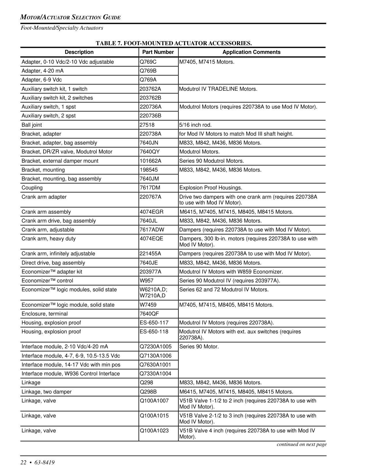
Motor/Actuator Selection Guide
22 • 63-8419 Foot-Mounted/Specialty Actuators continued on next pageTable 7. Foot-Mounted Actuator Accessories.
Description Part Number Application Comments Adapter, 0-10 Vdc/2-10 Vdc adjustableQ769C
M7405, M7415 Motors. Adapter, 4-20 mAQ769B
Adapter, 6-9 VdcQ769A
Auxiliary switch kit, 1 switch203762A
Modutrol IV TRADELINE Motors. Auxiliary switch kit, 2 switches203762B
Auxiliary switch, 1 spst220736A
Modutrol Motors (requires 220738A to use Mod IV Motor). Auxiliary switch, 2 spst220736B
Ball joint 27518 5/16 inch rod. Bracket, adapter220738A
for Mod IV Motors to match Mod III shaft height. Bracket, adapter, bag assembly7640Jn
M833, M842, M436, M836 Motors. Bracket, DR/ZR valve, Modutrol Motor7640Qy
Modutrol Motors. Bracket, external damper mount101662A
Series 90 Modutrol Motors. Bracket, mounting 198545 M833, M842, M436, M836 Motors. Bracket, mounting, bag assembly7640Jm
Coupling7617Dm
Explosion Proof Housings. Crank arm adapter220767A
Drive two dampers with one crank arm (requires 220738A to use with Mod IV Motor). Crank arm assembly4074Egr
M6415, M7405, M7415, M8405, M8415 Motors. Crank arm drive, bag assembly7640Jl
M833, M842, M436, M836 Motors. Crank arm, adjustable7617Adw
Dampers (requires 220738A to use with Mod IV Motor). Crank arm, heavy duty4074Eqe
Dampers, 300 lb-in. motors (requires 220738A to use with Mod IV Motor). Crank arm, infinitely adjustable221455A
Dampers (requires 220738A to use with Mod IV Motor). Direct drive, bag assembly7640Je
M833, M842, M436, M836 Motors. Economizer™ adapter kit203977A
Modutrol IV Motors with W859 Economizer. Economizer™ controlW957
Series 90 Modutrol IV (requires 203977A). Economizer™ logic modules, solid stateW6210A,D;
W7210A,D
Series 62 and 72 Modutrol IV Motors. Economizer™ logic module, solid stateW7459
M7405, M7415, M8405, M8415 Motors. Enclosure, terminal7640Qf
Housing, explosion proofEs-650-117
Modutrol IV Motors (requires 220738A). Housing, explosion proofEs-650-118
Modutrol IV Motors with ext. aux switches (requires220738A).
Interface module, 2-10 Vdc/4-20 mAQ7230A1005
Series 90 Motor. Interface module, 4-7, 6-9, 10.5-13.5 VdcQ7130A1006
Interface module, 14-17 Vdc with min posQ7630A1001
Interface module, W936 Control InterfaceQ7330A1004
LinkageQ298
M833, M842, M436, M836 Motors. Linkage, two damperQ298B
M6415, M7405, M7415, M8405, M8415 Motors. Linkage, valveQ100A1007
V51B Valve 1-1/2 to 2 inch (requires 220738A to use with Mod IV Motor). Linkage, valveQ100A1015
V51B Valve 2-1/2 to 3 inch (requires 220738A to use with Mod IV Motor). Linkage, valveQ100A1023
V51B Valve 4 inch (requires 220738A to use with Mod IV Motor).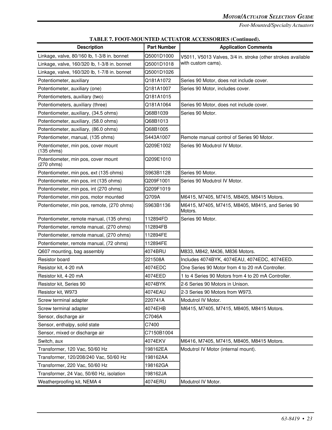
Motor/Actuator Selection Guide
63-8419 • 23 Foot-Mounted/Specialty Actuators TABLE 7. FOOT-MOUNTED ACTUATOR ACCESSORIES (Continued). Description Part Number Application Comments Linkage, valve, 80/160 lb, 1-3/8 in. bonnetQ5001D1000
V5011, V5013 Valves, 3/4 in. stroke (other strokes available Linkage, valve, 160/320 lb, 1-3/8 in. bonnetQ5001D1018
with custom cams). Linkage, valve, 160/320 lb, 1-7/8 in. bonnetQ5001D1026
Potentiometer, auxiliaryQ181A1072
Series 90 Motor, does not include cover. Potentiometer, auxiliary (one)Q181A1007
Series 90 Motor, includes cover. Potentiometers, auxiliary (two)Q181A1015
Potentiometers, auxiliary (three)Q181A1064
Series 90 Motor, does not include cover. Potentiometer, auxiliary, (34.5 ohms)Q68B1039
Series 90 Motor. Potentiometer, auxiliary, (58.0 ohms)Q68B1013
Potentiometer, auxiliary, (86.0 ohms)Q68B1005
Potentiometer, manual, (135 ohms)S443A1007
Remote manual control of Series 90 Motor. Potentiometer, min pos, cover mount (135 ohms)Q209E1002
Series 90 Modutrol IV Motor. Potentiometer, min pos, cover mount (270 ohms)Q209E1010
Potentiometer, min pos, ext (135 ohms)S963B1128
Series 90 Motor. Potentiometer, min pos, int (135 ohms)Q209F1001
Series 90 Modutrol IV Motor. Potentiometer, min pos, int (270 ohms)Q209F1019
Potentiometer, min pos, motor mountedQ709A
M6415, M7405, M7415, M8405, M8415 Motors. Potentiometer, min pos, remote, (270 ohms)S963B1136
M6415, M7405, M7415, M8405, M8415, and Series 90 Motors. Potentiometer, remote manual, (135 ohms)112894Fd
Series 90 Motor. Potentiometer, remote manual, (270 ohms)112894Fb
Potentiometer, remote manual, (270 ohms)112894Fe
Potentiometer, remote manual, (72 ohms)112894Fe
Q607 mounting, bag assembly4074Bru
M833, M842, M436, M836 Motors. Resistor board221508A
Includes 4074BYK, 4074EAU, 4074EDC, 4074EED. Resistor kit, 4-20 mA4074Edc
One Series 90 Motor from 4 to 20 mA Controller. Resistor kit, 4-20 mA4074Eed
1 to 4 Series 90 Motors from 4 to 20 mA Controller. Resistor kit, Series 904074Byk
2-6 Series 90 Motors in Unison. Resistor kit, W9734074Eau
2-3 Series 90 Motors from W973. Screw terminal adapter220741A
Modutrol IV Motor. Screw terminal adapter4074Ehb
M6415, M7405, M7415, M8405, M8415 Motors. Sensor, discharge airC7046A
Sensor, enthalpy, solid stateC7400
Sensor, mixed or discharge airC7150B1004
Switch, aux4074Ekv
M6416, M7405, M7415, M8405, M8415 Motors. Transformer, 120 Vac, 50/60 Hz198162Ea
Modutrol IV Motor (internal mount). Transformer, 120/208/240 Vac, 50/60 Hz198162Aa
Transformer, 220 Vac, 50/60 Hz198162Ga
Transformer, 24 Vac, 50/60 Hz, isolation198162Ja
Weatherproofing kit, NEMA 44074Eru
Modutrol IV Motor.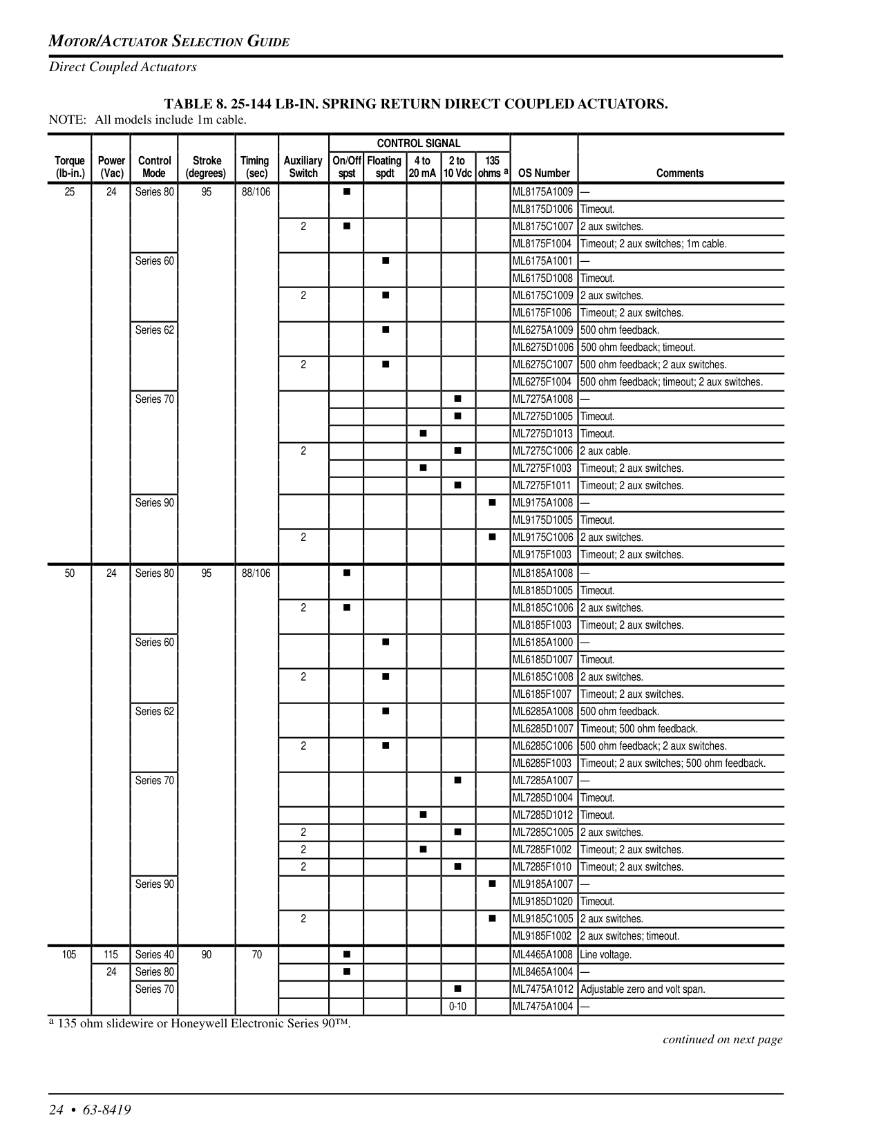
Motor/Actuator Selection Guide
24 • 63-8419 Direct Coupled ActuatorsTable 8. 25-144 Lb-In. Spring Return Direct Coupled Actuators.
NOTE: All models include 1m cable. continued on next page a 135 ohm slidewire or Honeywell Electronic Series 90™.Control Signal
Torque (lb-in.) Power (Vac) Control Mode Stroke (degrees) Timing (sec) Auxiliary Switch On/Off spst Floating spdt 4 to 20 mA 2 to 10 Vdc 135 ohms a OS Number Comments 25 24 Series 80 95 88/106 nMl8175A1009 —
ML8175D1006 Timeout. 2 n ML8175C1007 2 aux switches.Ml8175F1004
Timeout; 2 aux switches; 1m cable. Series 60 nMl6175A1001 —
ML6175D1008 Timeout. 2 n ML6175C1009 2 aux switches.Ml6175F1006
Timeout; 2 aux switches. Series 62 n ML6275A1009 500 ohm feedback. ML6275D1006 500 ohm feedback; timeout. 2 n ML6275C1007 500 ohm feedback; 2 aux switches.Ml6275F1004
500 ohm feedback; timeout; 2 aux switches. Series 70 nMl7275A1008 —
n ML7275D1005 Timeout. n ML7275D1013 Timeout. 2 n ML7275C1006 2 aux cable. nMl7275F1003
Timeout; 2 aux switches. nMl7275F1011
Timeout; 2 aux switches. Series 90 nMl9175A1008 —
ML9175D1005 Timeout. 2 n ML9175C1006 2 aux switches.Ml9175F1003
Timeout; 2 aux switches. 50 24 Series 80 95 88/106 nMl8185A1008 —
ML8185D1005 Timeout. 2 n ML8185C1006 2 aux switches.Ml8185F1003
Timeout; 2 aux switches. Series 60 nMl6185A1000 —
ML6185D1007 Timeout. 2 n ML6185C1008 2 aux switches.Ml6185F1007
Timeout; 2 aux switches. Series 62 n ML6285A1008 500 ohm feedback. ML6285D1007 Timeout; 500 ohm feedback. 2 n ML6285C1006 500 ohm feedback; 2 aux switches.Ml6285F1003
Timeout; 2 aux switches; 500 ohm feedback. Series 70 nMl7285A1007 —
ML7285D1004 Timeout. n ML7285D1012 Timeout. 2 n ML7285C1005 2 aux switches. 2 nMl7285F1002
Timeout; 2 aux switches. 2 nMl7285F1010
Timeout; 2 aux switches. Series 90 nMl9185A1007 —
ML9185D1020 Timeout. 2 n ML9185C1005 2 aux switches.Ml9185F1002
2 aux switches; timeout. 105 115 Series 40 90 70 n ML4465A1008 Line voltage. 24 Series 80 nMl8465A1004 —
Series 70 n ML7475A1012 Adjustable zero and volt span. 0-10Ml7475A1004 —
Motor/Actuator Selection Guide
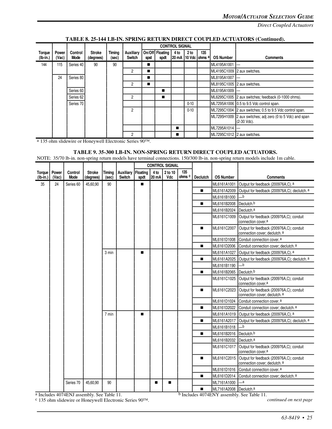
63-8419 • 25 Direct Coupled Actuators TABLE 8. 25-144 LB-IN. SPRING RETURN DIRECT COUPLED ACTUATORS (Continued). a 135 ohm slidewire or Honeywell Electronic Series 90™.Table 9. 35-300 Lb-In. Non-Spring Return Direct Coupled Actuators.
NOTE: 35/70 lb-in. non-spring return models have terminal connections. 150/300 lb-in. non-spring return models include 1m cable. continued on next page a Includes 4074ENJ assembly. See Table 11. b Includes 4074ENY assembly. See Table 11. c 135 ohm slidewire or Honeywell Electronic Series 90™.Control Signal
Torque (lb-in.) Power (Vac) Control Mode Stroke (degrees) Timing (sec) Auxiliary Switch On/Off spst Floating spdt 4 to 20 mA 2 to 10 Vdc 135 ohms a OS Number Comments 144 115 Series 40 90 90 nMl4195A1001 —
2 n ML4195C1009 2 aux switches. 24 Series 80 nMl8195A1007 —
2 n ML8195C1005 2 aux switches. Series 60 nMl6195A1009 —
Series 62 2 n ML6295C1005 2 aux switches; feedback (0-1000 ohms). Series 70 0-10 ML7295A1006 0.5 to 9.5 Vdc control span. 2 0-10 ML7295C1004 2 aux switches; 0.5 to 9.5 Vdc control span. ML7295H1009 2 aux switches; adj zero (0 to 5 Vdc) and span (2-30 Vdc). nMl7295A1014 —
2 n ML7295C1012 2 aux switches.Control Signal
Torque (lb-in.) Power (Vac) Control Mode Stroke (degrees) Timing (sec) Auxiliary Switch Floating spdt 4 to 20 mA 2 to 10 Vdc 135 ohms c Declutch OS Number Comments 35 24 Series 60 45,60,90 90 nMl6161A1001
Output for feedback (200976A,C).a nMl6161A2009
Output for feedback (200976A,C); declutch. aMl6161B1000
—b nMl6161B2008
Declutch.bMl6161B2024
Declutch.aMl6161C1009
Output for feedback (200976A,C); conduit connection cover.a nMl6161C2007
Output for feedback (200976A,C); conduit connection cover; declutch. aMl6161D1008
Conduit connection cover. a nMl6161D2006
Conduit connection cover; declutch. a 3 min nMl6161A1027
Output for feedback (200976A,C).a nMl6161A2025
Output for feedback (200976A,C); declutch. aMl6161B1190
—b nMl6161B2065
Declutch.bMl6161C1025
Output for feedback (200976A,C); conduit connection cover.a nMl6161C2023
Output for feedback (200976A,C); conduit connection cover; declutch. aMl6161D1024
Conduit connection cover. a nMl6161D2022
Conduit connection cover; declutch. a 7 min nMl6161A1019
Output for feedback (200976A,C).a nMl6161A2017
Output for feedback (200976A,C); declutch. aMl6161B1018
—b nMl6161B2016
Declutch.bMl6161B2032
Declutch.aMl6161C1017
Output for feedback (200976A,C); conduit connection cover.a nMl6161C2015
Output for feedback (200976A,C); conduit connection cover; declutch. aMl6161D1016
Conduit connection cover. a nMl6161D2014
Conduit connection cover; declutch. a Series 70 45,60,90 90 n nMl7161A1000
—a nMl7161A2008
Declutch.a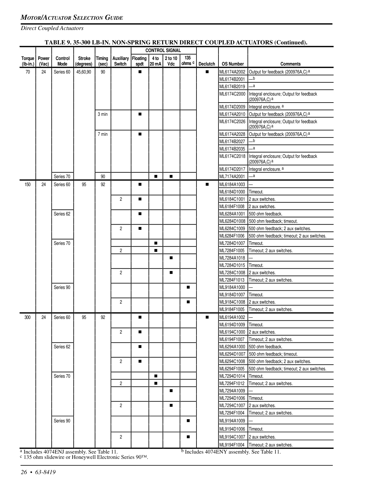
Motor/Actuator Selection Guide
26 • 63-8419 Direct Coupled Actuators TABLE 9. 35-300 LB-IN. NON-SPRING RETURN DIRECT COUPLED ACTUATORS (Continued). a Includes 4074ENJ assembly. See Table 11. b Includes 4074ENY assembly. See Table 11. c 135 ohm slidewire or Honeywell Electronic Series 90™.Control Signal
Torque (lb-in.) Power (Vac) Control Mode Stroke (degrees) Timing (sec) Auxiliary Switch Floating spdt 4 to 20 mA 2 to 10 Vdc 135 ohms c Declutch OS Number Comments 70 24 Series 60 45,60,90 90 n nMl6174A2002
Output for feedback (200976A,C) aMl6174B2001
—bMl6174B2019
—aMl6174C2000
Integral enclosure; Output for feedback (200976A,C) aMl6174D2009
Integral enclosure. a 3 min nMl6174A2010
Output for feedback (200976A,C) aMl6174C2026
Integral enclosure; Output for feedback (200976A,C) a 7 min nMl6174A2028
Output for feedback (200976A,C) aMl6174B2027
—bMl6174B2035
—aMl6174C2018
Integral enclosure; Output for feedback (200976A,C) aMl6174D2017
Integral enclosure. a Series 70 90 n nMl7174A2001
—a 150 24 Series 60 95 92 n nMl6184A1003
—Ml6184D1000
Timeout. 2 nMl6184C1001
2 aux switches.Ml6184F1008
2 aux switches. Series 62 nMl6284A1001
500 ohm feedback.Ml6284D1008
500 ohm feedback; timeout. 2 nMl6284C1009
500 ohm feedback; 2 aux switches.Ml6284F1006
500 ohm feedback; timeout; 2 aux switches. Series 70 nMl7284D1007
Timeout. 2 nMl7284F1005
Timeout; 2 aux switches. nMl7284A1018
—Ml7284D1015
Timeout. 2 nMl7284C1008
2 aux switches.Ml7284F1013
Timeout; 2 aux switches. Series 90 nMl9184A1000
—Ml9184D1007
Timeout. 2 nMl9184C1008
2 aux switches.Ml9184F1005
Timeout; 2 aux switches. 300 24 Series 60 95 92 n nMl6194A1002
—Ml6194D1009
Timeout. 2 nMl6194C1000
2 aux switches.Ml6194F1007
Timeout; 2 aux switches. Series 62 nMl6294A1000
500 ohm feedback.Ml6294D1007
500 ohm feedback; timeout. 2 nMl6294C1008
500 ohm feedback; 2 aux switches.Ml6294F1005
500 ohm feedback; timeout; 2 aux switches. Series 70 nMl7294D1014
Timeout. 2 nMl7294F1012
Timeout; 2 aux switches. nMl7294A1009
—Ml7294D1006
Timeout. 2 nMl7294C1007
2 aux switches.Ml7294F1004
Timeout; 2 aux switches. Series 90 nMl9194A1009
—Ml9194D1006
Timeout. 2 nMl9194C1007
2 aux switches.Ml9194F1004
Timeout; 2 aux switches.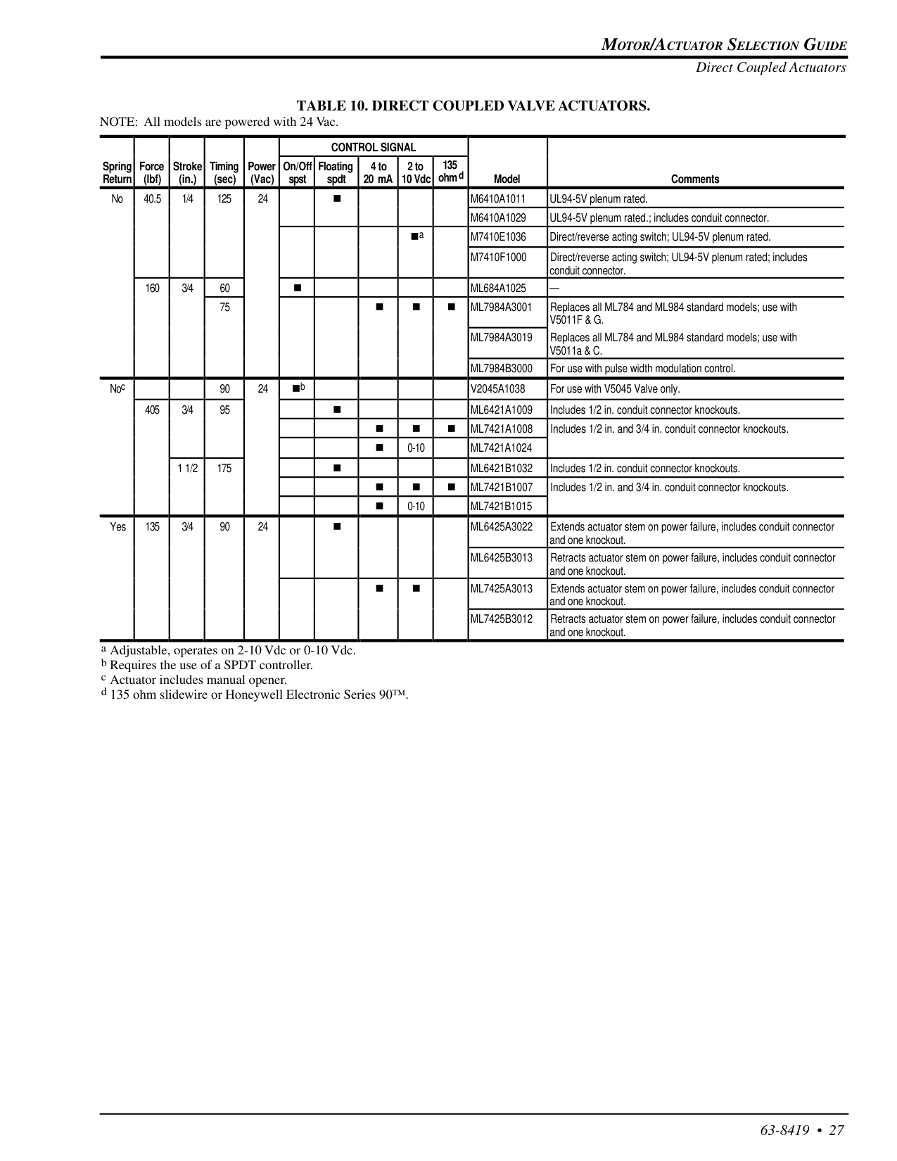
Motor/Actuator Selection Guide
63-8419 • 27 Direct Coupled ActuatorsTable 10. Direct Coupled Valve Actuators.
NOTE: All models are powered with 24 Vac. a Adjustable, operates on 2-10 Vdc or 0-10 Vdc. b Requires the use of a SPDT controller. c Actuator includes manual opener. d 135 ohm slidewire or Honeywell Electronic Series 90™.Control Signal
Spring Return Force (lbf) Stroke (in.) Timing (sec) Power (Vac) On/Off spst Floating spdt 4 to 20 mA 2 to 10 Vdc 135 ohm d Model Comments No 40.5 1/4 125 24 nM6410A1011
UL94-5V plenum rated.M6410A1029
UL94-5V plenum rated.; includes conduit connector. naM7410E1036
Direct/reverse acting switch; UL94-5V plenum rated.M7410F1000
Direct/reverse acting switch; UL94-5V plenum rated; includes conduit connector. 160 3/4 60 nMl684A1025
— 75 n n nMl7984A3001
Replaces all ML784 and ML984 standard models; use withV5011F & G.
Ml7984A3019
Replaces all ML784 and ML984 standard models; use with V5011a & C.Ml7984B3000
For use with pulse width modulation control. Noc 90 24 nbV2045A1038
For use with V5045 Valve only. 405 3/4 95 nMl6421A1009
Includes 1/2 in. conduit connector knockouts. n n nMl7421A1008
Includes 1/2 in. and 3/4 in. conduit connector knockouts. n 0-10Ml7421A1024
1 1/2 175 nMl6421B1032
Includes 1/2 in. conduit connector knockouts. n n nMl7421B1007
Includes 1/2 in. and 3/4 in. conduit connector knockouts. n 0-10Ml7421B1015
Yes 135 3/4 90 24 nMl6425A3022
Extends actuator stem on power failure, includes conduit connector and one knockout.Ml6425B3013
Retracts actuator stem on power failure, includes conduit connector and one knockout. n nMl7425A3013
Extends actuator stem on power failure, includes conduit connector and one knockout.Ml7425B3012
Retracts actuator stem on power failure, includes conduit connector and one knockout.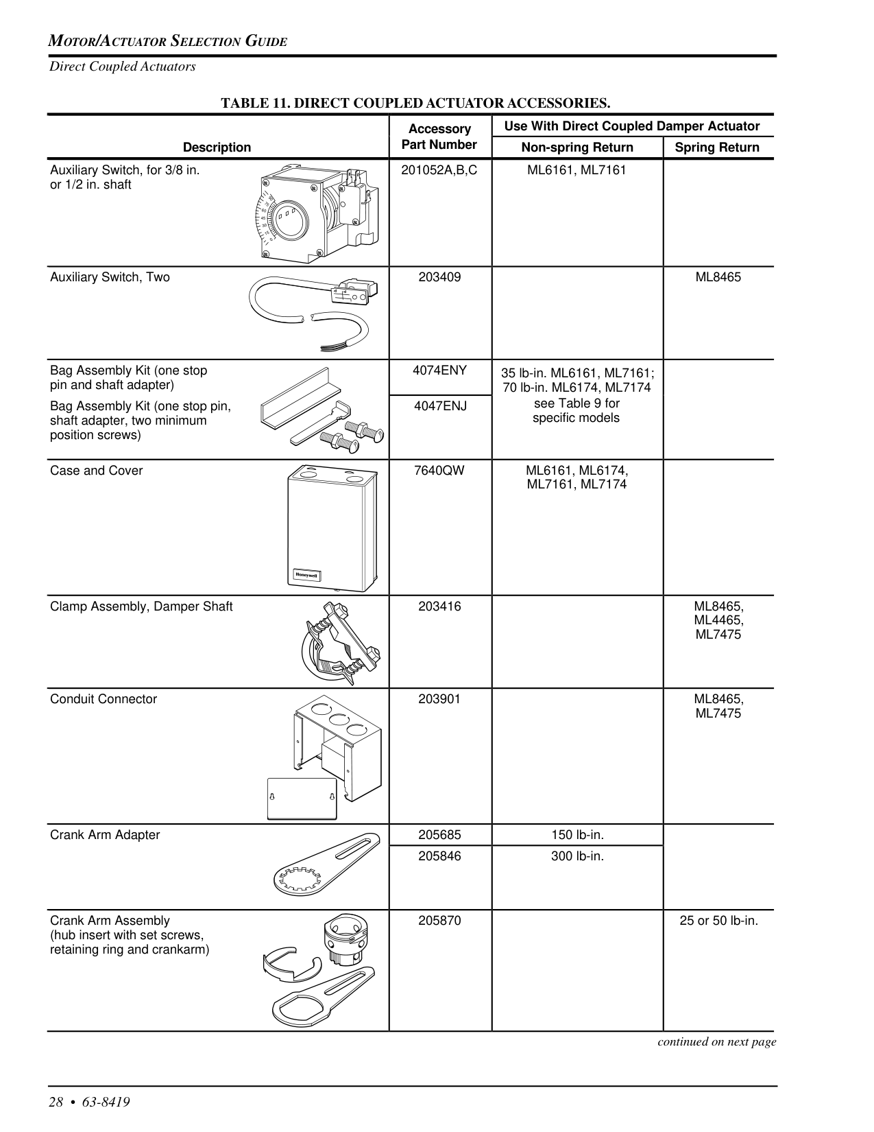
Motor/Actuator Selection Guide
28 • 63-8419 Accessory Use With Direct Coupled Damper Actuator Description Part Number Non-spring Return Spring Return Auxiliary Switch, for 3/8 in. or 1/2 in. shaft201052A,B,C
Ml6161, Ml7161
Auxiliary Switch, Two 203409Ml8465
Bag Assembly Kit (one stop pin and shaft adapter)4074Eny
35 lb-in. ML6161, ML7161; 70 lb-in. ML6174, ML7174 Bag Assembly Kit (one stop pin, shaft adapter, two minimum position screws)4047Enj
see Table 9 for specific models Case and Cover7640Qw
Ml6161, Ml6174,
Ml7161, Ml7174
Clamp Assembly, Damper Shaft 203416Ml8465,
Ml4465,
Ml7475
Conduit Connector 203901Ml8465,
Ml7475
Crank Arm Adapter 205685 150 lb-in. 205846 300 lb-in. Crank Arm Assembly (hub insert with set screws, retaining ring and crankarm) 205870 25 or 50 lb-in. Direct Coupled ActuatorsTable 11. Direct Coupled Actuator Accessories.
continued on next page 90 75 60 45 30 15 0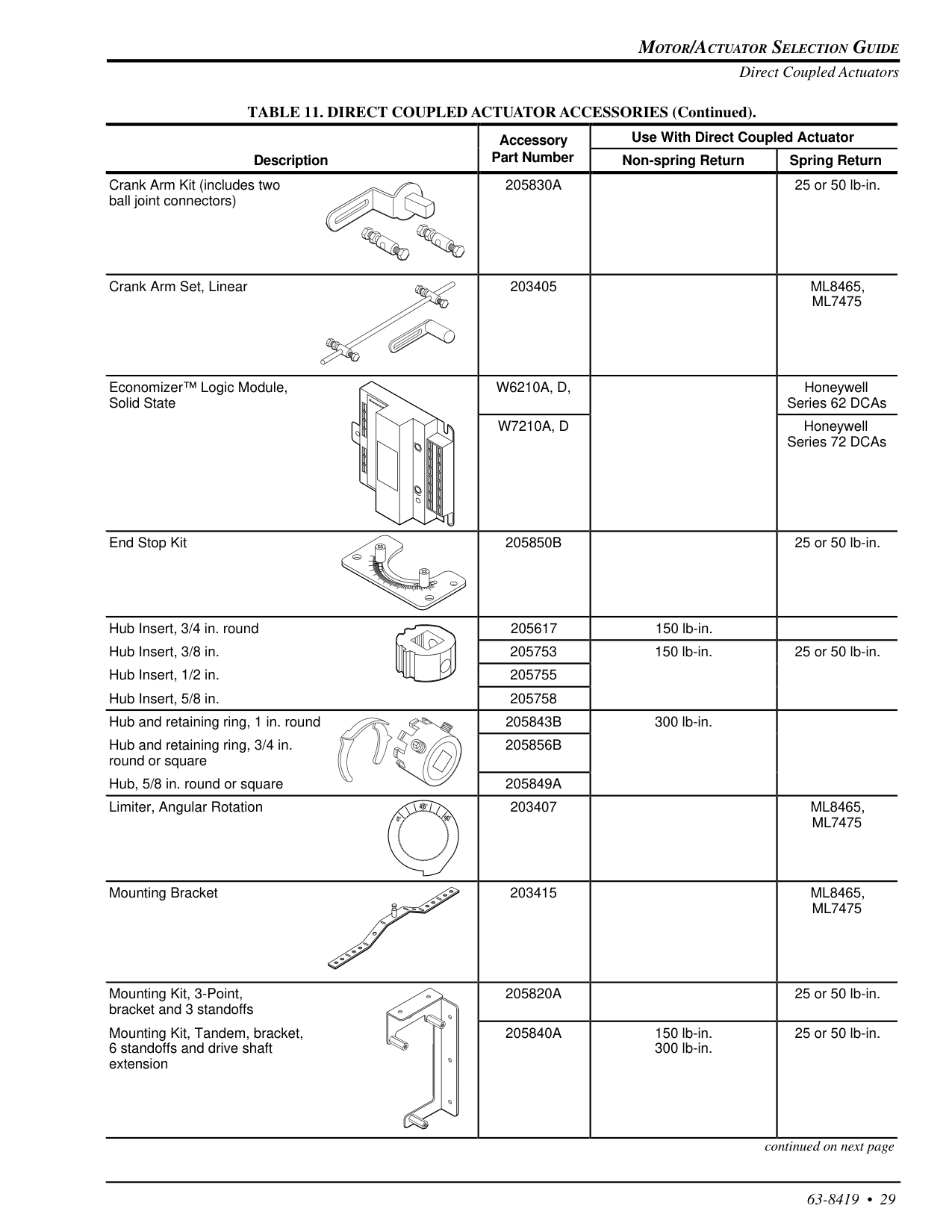
Motor/Actuator Selection Guide
63-8419 • 29 Accessory Use With Direct Coupled Actuator Description Part Number Non-spring Return Spring Return Crank Arm Kit (includes two ball joint connectors)205830A
25 or 50 lb-in. Crank Arm Set, Linear 203405Ml8465,
Ml7475
Economizer™ Logic Module, Solid StateW6210A, D,
Honeywell Series 62 DCAsW7210A, D
Honeywell Series 72 DCAs End Stop Kit205850B
25 or 50 lb-in. Hub Insert, 3/4 in. round 205617 150 lb-in. Hub Insert, 3/8 in. 205753 150 lb-in. 25 or 50 lb-in. Hub Insert, 1/2 in. 205755 Hub Insert, 5/8 in. 205758 Hub and retaining ring, 1 in. round205843B
300 lb-in. Hub and retaining ring, 3/4 in. round or square205856B
Hub, 5/8 in. round or square205849A
Limiter, Angular Rotation 203407Ml8465,
Ml7475
Mounting Bracket 203415Ml8465,
Ml7475
Mounting Kit, 3-Point, bracket and 3 standoffs205820A
25 or 50 lb-in. Mounting Kit, Tandem, bracket, 6 standoffs and drive shaft extension205840A
150 lb-in. 300 lb-in. 25 or 50 lb-in. Direct Coupled Actuators TABLE 11. DIRECT COUPLED ACTUATOR ACCESSORIES (Continued). continued on next page 0° 4 5° 90°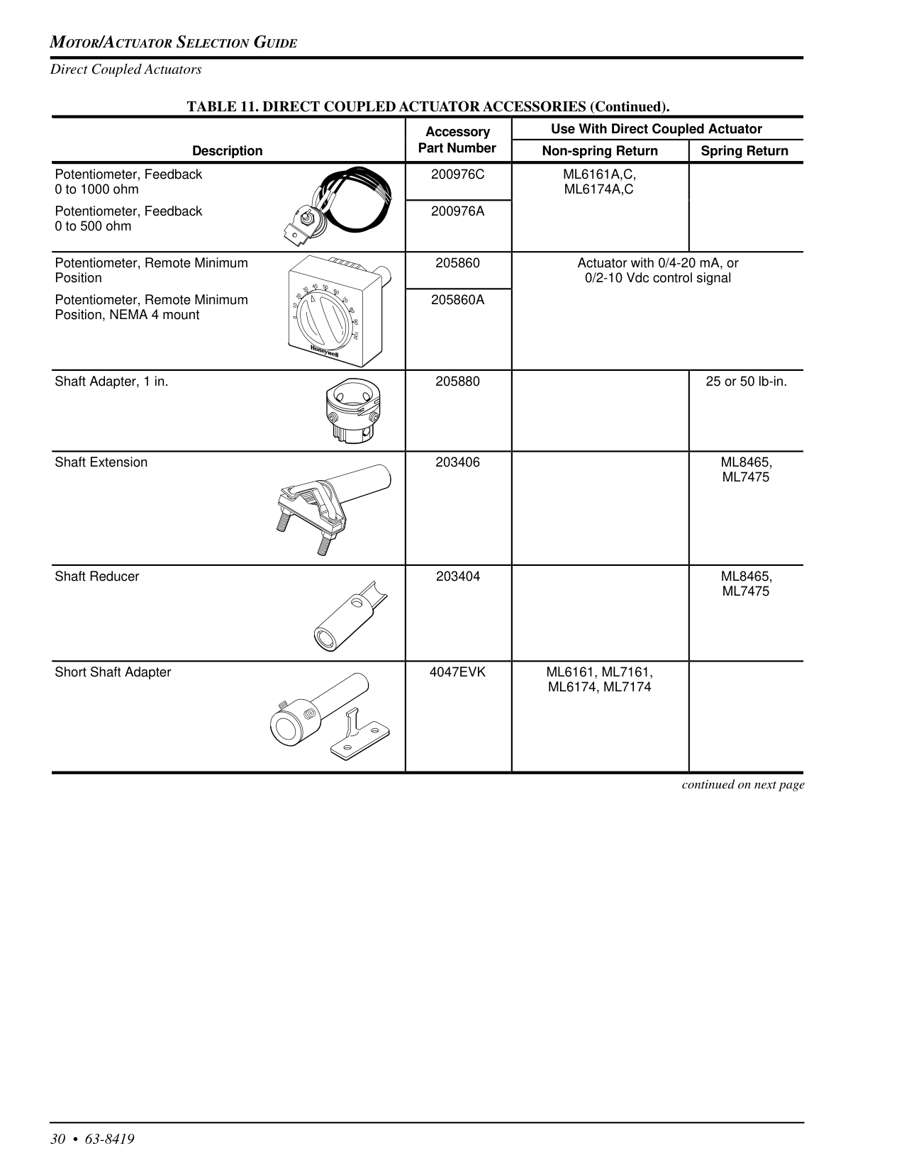
Motor/Actuator Selection Guide
30 • 63-8419 Accessory Use With Direct Coupled Actuator Description Part Number Non-spring Return Spring Return Potentiometer, Feedback 0 to 1000 ohm200976C
Ml6161A,C,
Ml6174A,C
Potentiometer, Feedback 0 to 500 ohm200976A
Potentiometer, Remote Minimum Position 205860 Actuator with 0/4-20 mA, or 0/2-10 Vdc control signal Potentiometer, Remote Minimum Position, NEMA 4 mount205860A
Shaft Adapter, 1 in. 205880 25 or 50 lb-in. Shaft Extension 203406Ml8465,
Ml7475
Shaft Reducer 203404Ml8465,
Ml7475
Short Shaft Adapter4047Evk
Ml6161, Ml7161,
Ml6174, Ml7174
TABLE 11. DIRECT COUPLED ACTUATOR ACCESSORIES (Continued). Direct Coupled Actuators continued on next page 50 40 30 20 10 0 60 70 80 90 100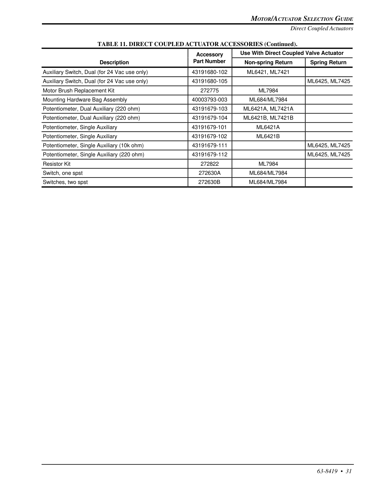
Motor/Actuator Selection Guide
63-8419 • 31 Direct Coupled Actuators Accessory Use With Direct Coupled Valve Actuator Description Part Number Non-spring Return Spring Return Auxiliary Switch, Dual (for 24 Vac use only) 43191680-102Ml6421, Ml7421
Auxiliary Switch, Dual (for 24 Vac use only) 43191680-105Ml6425, Ml7425
Motor Brush Replacement Kit 272775Ml7984
Mounting Hardware Bag Assembly 40003793-003Ml684/Ml7984
Potentiometer, Dual Auxiliary (220 ohm) 43191679-103Ml6421A, Ml7421A
Potentiometer, Dual Auxiliary (220 ohm) 43191679-104Ml6421B, Ml7421B
Potentiometer, Single Auxiliary 43191679-101Ml6421A
Potentiometer, Single Auxiliary 43191679-102Ml6421B
Potentiometer, Single Auxiliary (10k ohm) 43191679-111Ml6425, Ml7425
Potentiometer, Single Auxiliary (220 ohm) 43191679-112Ml6425, Ml7425
Resistor Kit 272822Ml7984
Switch, one spst272630A
Ml684/Ml7984
Switches, two spst272630B
Ml684/Ml7984
TABLE 11. DIRECT COUPLED ACTUATOR ACCESSORIES (Continued).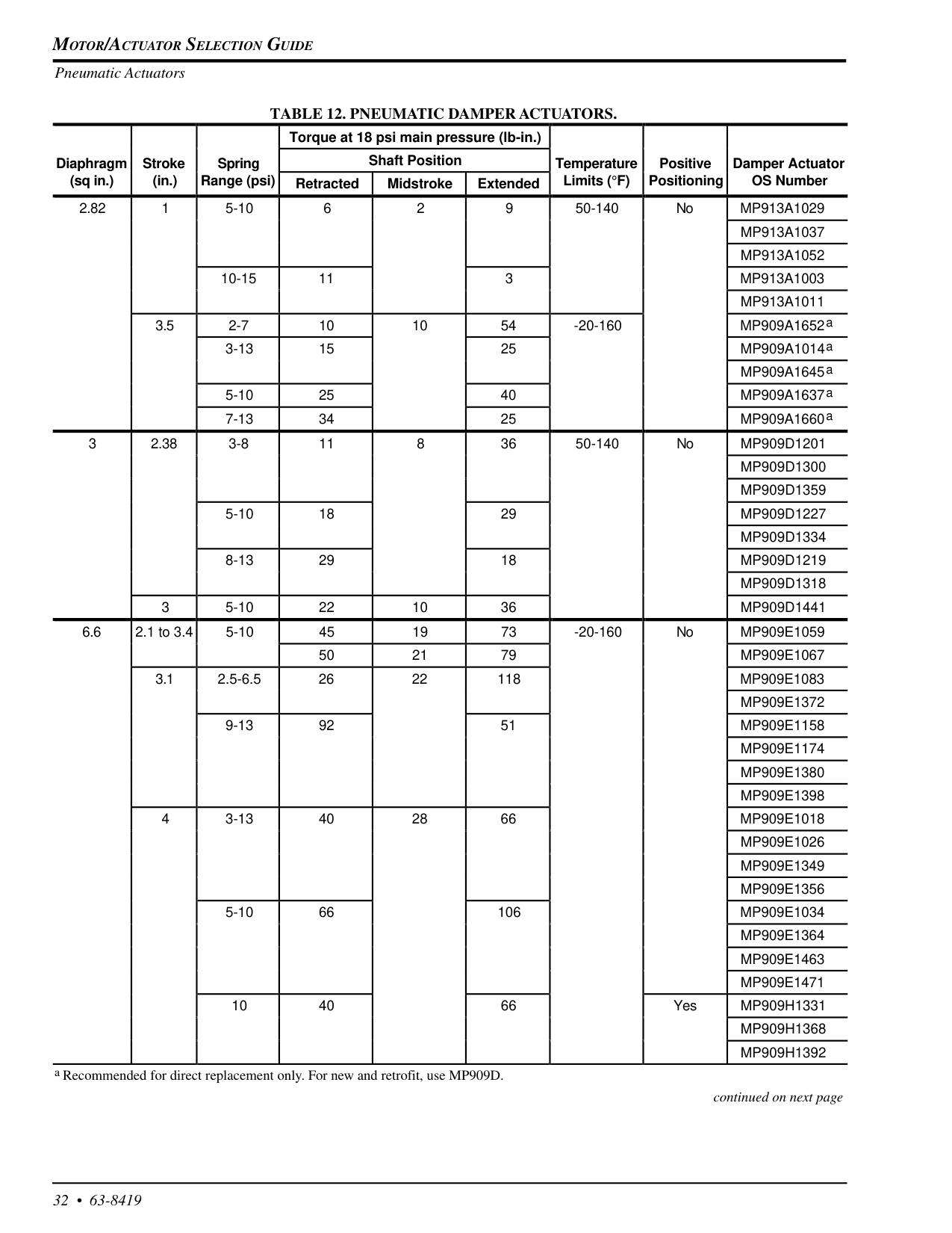
Motor/Actuator Selection Guide
32 • 63-8419 Pneumatic ActuatorsTable 12. Pneumatic Damper Actuators.
continued on next page a Recommended for direct replacement only. For new and retrofit, use MP909D. Torque at 18 psi main pressure (lb-in.) Diaphragm Stroke Spring Shaft Position Temperature Positive Damper Actuator (sq in.) (in.) Range (psi) Retracted Midstroke Extended Limits (°F) Positioning OS Number 2.82 1 5-10 6 2 9 50-140 NoMp913A1029
Mp913A1037
Mp913A1052
10-15 11 3Mp913A1003
Mp913A1011
3.5 2-7 10 10 54 -20-160 MP909A1652a 3-13 15 25 MP909A1014a MP909A1645a 5-10 25 40 MP909A1637a 7-13 34 25 MP909A1660a 3 2.38 3-8 11 8 36 50-140 NoMp909D1201
Mp909D1300
Mp909D1359
5-10 18 29Mp909D1227
Mp909D1334
8-13 29 18Mp909D1219
Mp909D1318
3 5-10 22 10 36Mp909D1441
6.6 2.1 to 3.4 5-10 45 19 73 -20-160 NoMp909E1059
50 21 79Mp909E1067
3.1 2.5-6.5 26 22 118Mp909E1083
Mp909E1372
9-13 92 51Mp909E1158
Mp909E1174
Mp909E1380
Mp909E1398
4 3-13 40 28 66Mp909E1018
Mp909E1026
Mp909E1349
Mp909E1356
5-10 66 106Mp909E1034
Mp909E1364
Mp909E1463
Mp909E1471
10 40 66 YesMp909H1331
Mp909H1368
Mp909H1392
Motor/Actuator Selection Guide
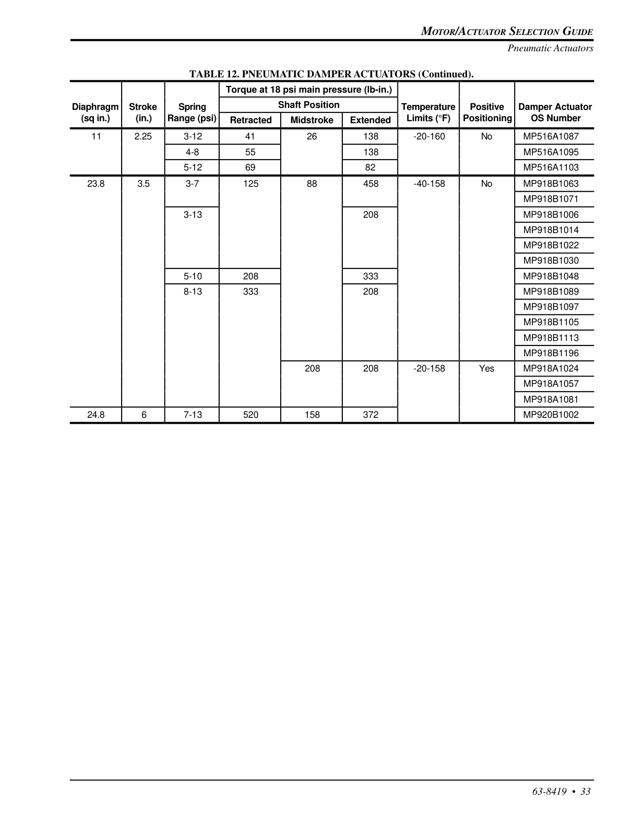
63-8419 • 33 Pneumatic Actuators TABLE 12. PNEUMATIC DAMPER ACTUATORS (Continued). Torque at 18 psi main pressure (lb-in.) Diaphragm Stroke Spring Shaft Position Temperature Positive Damper Actuator (sq in.) (in.) Range (psi) Retracted Midstroke Extended Limits (°F) Positioning OS Number 11 2.25 3-12 41 26 138 -20-160 NoMp516A1087
4-8 55 138Mp516A1095
5-12 69 82Mp516A1103
23.8 3.5 3-7 125 88 458 -40-158 NoMp918B1063
Mp918B1071
3-13 208Mp918B1006
Mp918B1014
Mp918B1022
Mp918B1030
5-10 208 333Mp918B1048
8-13 333 208Mp918B1089
Mp918B1097
Mp918B1105
Mp918B1113
Mp918B1196
208 208 -20-158 YesMp918A1024
Mp918A1057
Mp918A1081
24.8 6 7-13 520 158 372Mp920B1002
Motor/Actuator Selection Guide
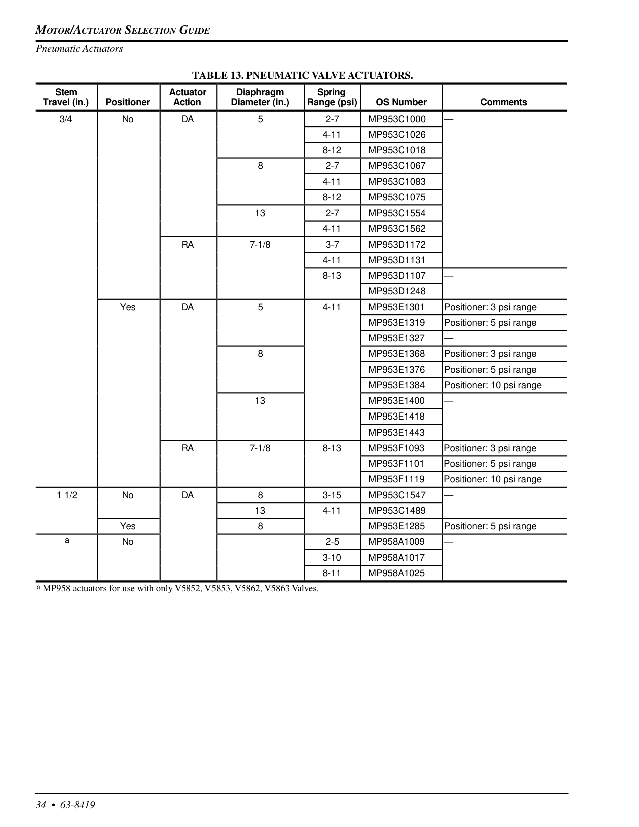
34 • 63-8419 Pneumatic ActuatorsTable 13. Pneumatic Valve Actuators.
a MP958 actuators for use with only V5852, V5853, V5862, V5863 Valves. Stem Travel (in.) Positioner Actuator Action Diaphragm Diameter (in.) Spring Range (psi) OS Number Comments 3/4 NoDa
5 2-7Mp953C1000
— 4-11Mp953C1026
8-12Mp953C1018
8 2-7Mp953C1067
4-11Mp953C1083
8-12Mp953C1075
13 2-7Mp953C1554
4-11Mp953C1562
Ra
7-1/8 3-7Mp953D1172
4-11Mp953D1131
8-13Mp953D1107
—Mp953D1248
YesDa
5 4-11Mp953E1301
Positioner: 3 psi rangeMp953E1319
Positioner: 5 psi rangeMp953E1327
— 8Mp953E1368
Positioner: 3 psi rangeMp953E1376
Positioner: 5 psi rangeMp953E1384
Positioner: 10 psi range 13Mp953E1400
—Mp953E1418
Mp953E1443
Ra
7-1/8 8-13Mp953F1093
Positioner: 3 psi rangeMp953F1101
Positioner: 5 psi rangeMp953F1119
Positioner: 10 psi range 1 1/2 NoDa
8 3-15Mp953C1547
— 13 4-11Mp953C1489
Yes 8Mp953E1285
Positioner: 5 psi range a No 2-5Mp958A1009
— 3-10Mp958A1017
8-11Mp958A1025
Motor/Actuator Selection Guide
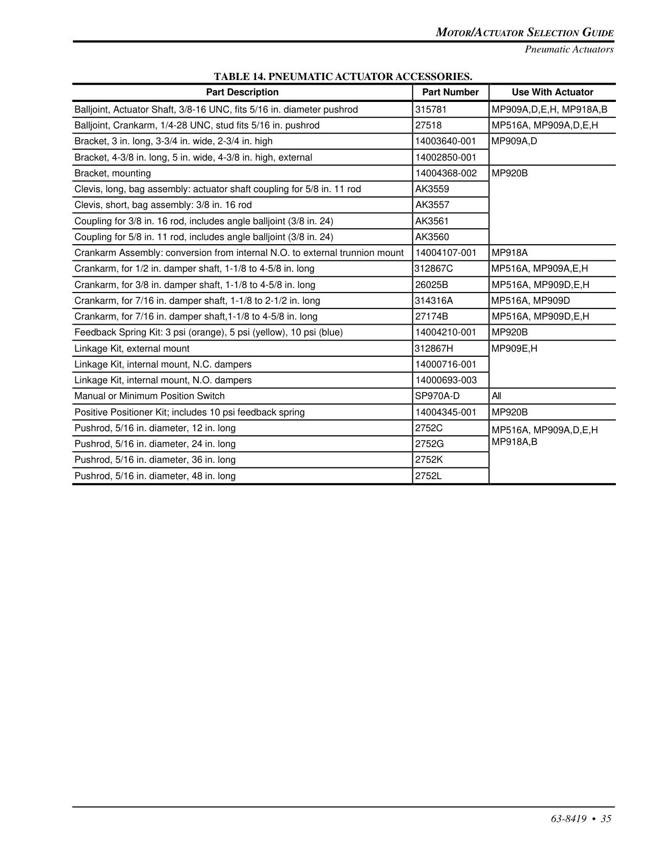
63-8419 • 35 Pneumatic ActuatorsTable 14. Pneumatic Actuator Accessories.
Part Description Part Number Use With Actuator Balljoint, Actuator Shaft, 3/8-16 UNC, fits 5/16 in. diameter pushrod 315781Mp909A,D,E,H, Mp918A,B
Balljoint, Crankarm, 1/4-28 UNC, stud fits 5/16 in. pushrod 27518Mp516A, Mp909A,D,E,H
Bracket, 3 in. long, 3-3/4 in. wide, 2-3/4 in. high 14003640-001Mp909A,D
Bracket, 4-3/8 in. long, 5 in. wide, 4-3/8 in. high, external 14002850-001 Bracket, mounting 14004368-002Mp920B
Clevis, long, bag assembly: actuator shaft coupling for 5/8 in. 11 rodAk3559
Clevis, short, bag assembly: 3/8 in. 16 rodAk3557
Coupling for 3/8 in. 16 rod, includes angle balljoint (3/8 in. 24)Ak3561
Coupling for 5/8 in. 11 rod, includes angle balljoint (3/8 in. 24)Ak3560
Crankarm Assembly: conversion from internal N.O. to external trunnion mount 14004107-001Mp918A
Crankarm, for 1/2 in. damper shaft, 1-1/8 to 4-5/8 in. long312867C
Mp516A, Mp909A,E,H
Crankarm, for 3/8 in. damper shaft, 1-1/8 to 4-5/8 in. long26025B
Mp516A, Mp909D,E,H
Crankarm, for 7/16 in. damper shaft, 1-1/8 to 2-1/2 in. long314316A
Mp516A, Mp909D
Crankarm, for 7/16 in. damper shaft,1-1/8 to 4-5/8 in. long27174B
Mp516A, Mp909D,E,H
Feedback Spring Kit: 3 psi (orange), 5 psi (yellow), 10 psi (blue) 14004210-001Mp920B
Linkage Kit, external mount312867H
Mp909E,H
Linkage Kit, internal mount, N.C. dampers 14000716-001 Linkage Kit, internal mount, N.O. dampers 14000693-003 Manual or Minimum Position SwitchSp970A-D
All Positive Positioner Kit; includes 10 psi feedback spring 14004345-001Mp920B
Pushrod, 5/16 in. diameter, 12 in. long2752C
Mp516A, Mp909A,D,E,H
Pushrod, 5/16 in. diameter, 24 in. long2752G
Mp918A,B
Pushrod, 5/16 in. diameter, 36 in. long2752K
Pushrod, 5/16 in. diameter, 48 in. long2752L

Motor/Actuator Selection Guide
36 • 63-8419 AppendicesAppendix A
Determining Damper
Actuator Torque
Requirements
Use the following procedure to determine the required torque for your damper. NOTE: Damper area is measured using the A and B dimensions as defined in Fig. A-1.Blade
Dimension
B
C5202
Dimension
A
Fig. A-1. Measuring damper area.Note:
The minimum lb-in. per square foot value that can accommodate tight closeoff and no leakage applications is 5, regardless of the value shown in the table.Important
12 lb-in. is the minimum torque required to operate Honeywell dampers.Example:
D640 Damper: A dimension = 24 in. B dimension = 48 in. Static pressure (in. wc) = 1.5 Face velocity = 1000 fpm 24 in. x 48 in. ÷ 144 = 8 sq. ft where: 144 = conversion factor (144 sq. in. per 1 sq. ft) 8 sq. ft x 6.2 lb-in./sq. ft = 49.6 lb-in. where: 6.2 lb-in./sq. ft = value from Table A-1 In this case, you would need an actuator with a minimum torque of 49.6 lb-in. to open and close a D640 Damper with the given area. NOTE: You may add an additional multiplier as a safety factor. (The safety factor covers estimated variations in temperature, voltage, velocity and pressure.)Example:
A safety factor of 20 percent would be a multiplier of 1.2: 49.6 lb-in. x 1.2 = 59.5 lb-in. or 60 lb-in. This example formula applies for all dampers in Tables A-1, A-2 and B-1.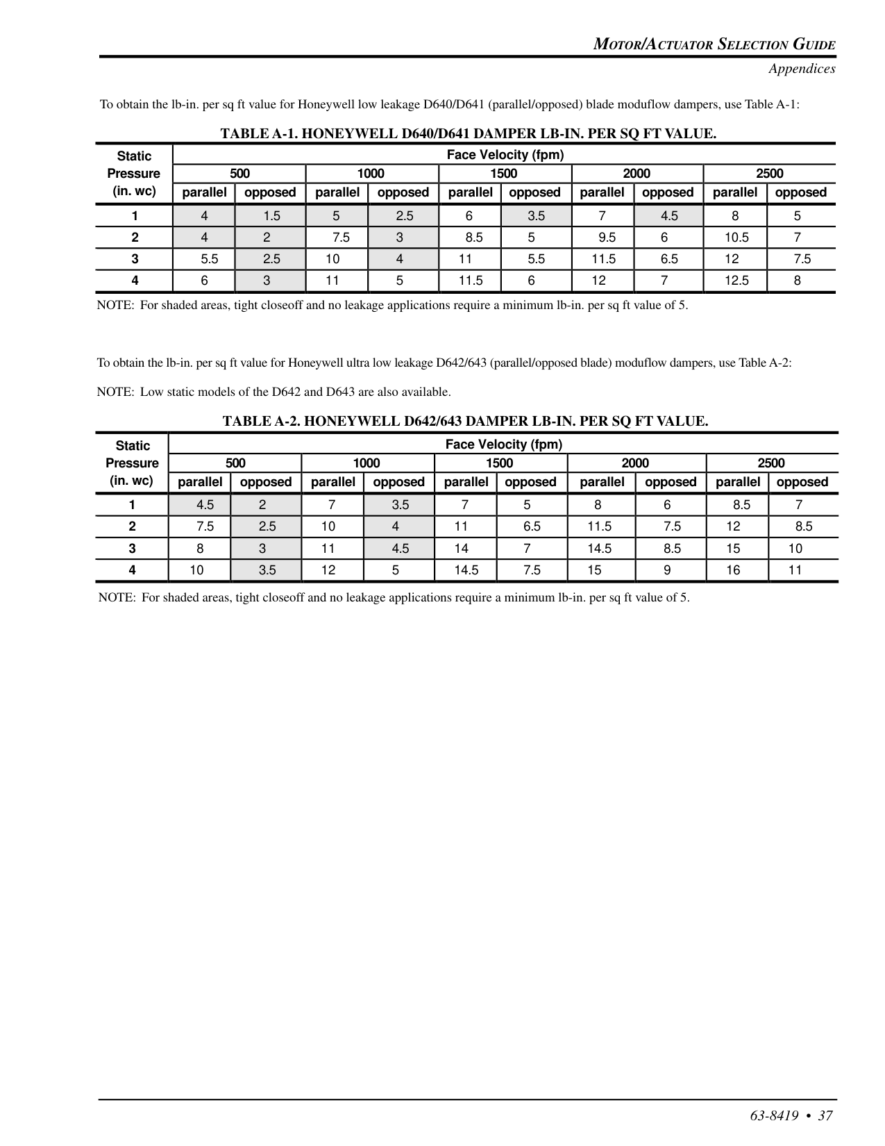
Motor/Actuator Selection Guide
63-8419 • 37 Appendices NOTE: For shaded areas, tight closeoff and no leakage applications require a minimum lb-in. per sq ft value of 5. To obtain the lb-in. per sq ft value for Honeywell low leakage D640/D641 (parallel/opposed) blade moduflow dampers, use Table A-1:Table A-1. Honeywell D640/D641 Damper Lb-In. Per Sq Ft Value.
NOTE: For shaded areas, tight closeoff and no leakage applications require a minimum lb-in. per sq ft value of 5. To obtain the lb-in. per sq ft value for Honeywell ultra low leakage D642/643 (parallel/opposed blade) moduflow dampers, use Table A-2: NOTE: Low static models of the D642 and D643 are also available.Table A-2. Honeywell D642/643 Damper Lb-In. Per Sq Ft Value.
Static Face Velocity (fpm) Pressure 500 1000 1500 2000 2500 (in. wc) parallel opposed parallel opposed parallel opposed parallel opposed parallel opposed 1 4 1.5 5 2.5 6 3.5 7 4.5 8 5 2 4 2 7.5 3 8.5 5 9.5 6 10.5 7 3 5.5 2.5 10 4 11 5.5 11.5 6.5 12 7.5 4 6 3 11 5 11.5 6 12 7 12.5 8 Static Face Velocity (fpm) Pressure 500 1000 1500 2000 2500 (in. wc) parallel opposed parallel opposed parallel opposed parallel opposed parallel opposed 1 4.5 2 7 3.5 7 5 8 6 8.5 7 2 7.5 2.5 10 4 11 6.5 11.5 7.5 12 8.5 3 8 3 11 4.5 14 7 14.5 8.5 15 10 4 10 3.5 12 5 14.5 7.5 15 9 16 11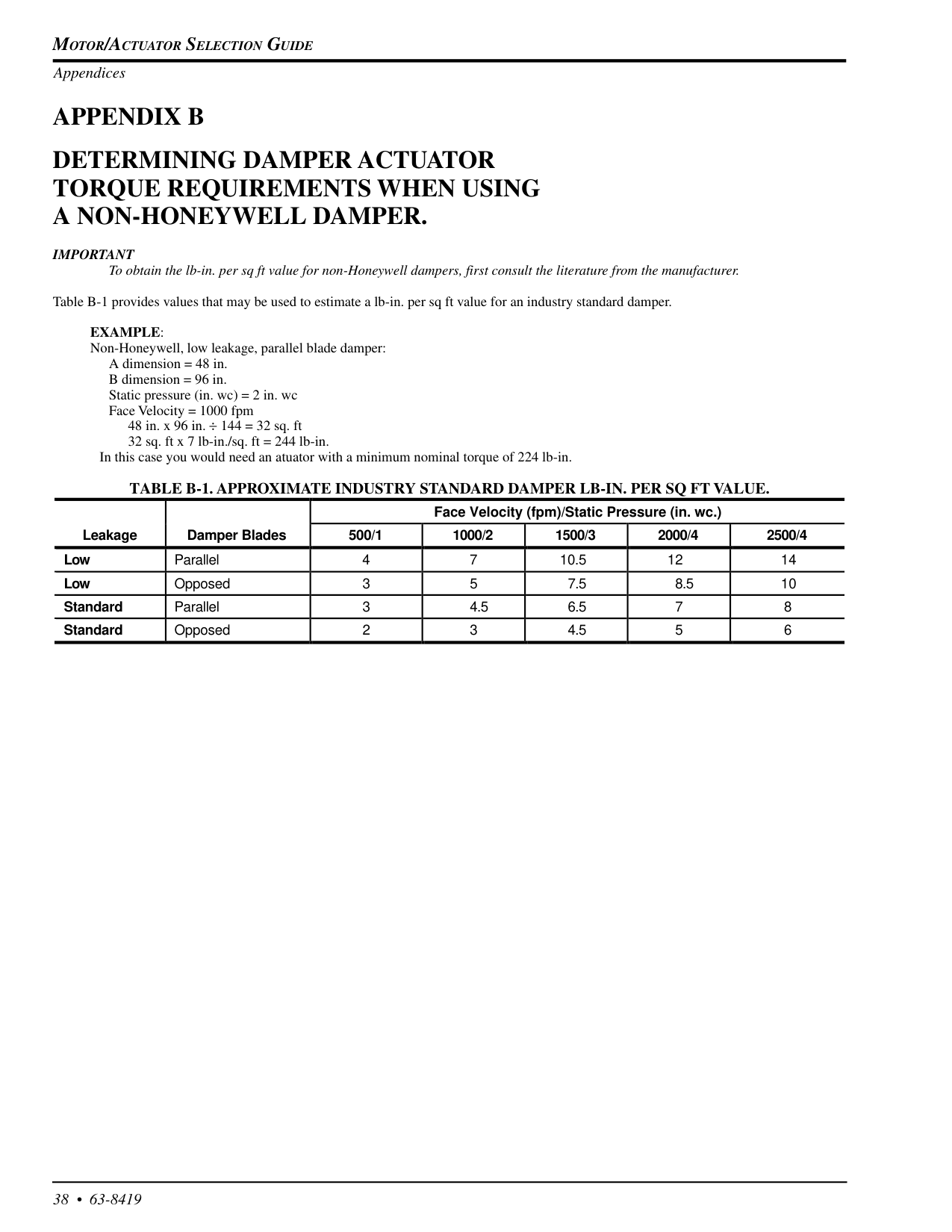
Motor/Actuator Selection Guide
38 • 63-8419 Face Velocity (fpm)/Static Pressure (in. wc.) Leakage Damper Blades 500/1 1000/2 1500/3 2000/4 2500/4 Low Parallel 4 7 10.5 12 14 Low Opposed 3 5 7.5 8.5 10 Standard Parallel 3 4.5 6.5 7 8 Standard Opposed 2 3 4.5 5 6Appendix B
Determining Damper Actuator
Torque Requirements When Using
A Non-Honeywell Damper.
Important
To obtain the lb-in. per sq ft value for non-Honeywell dampers, first consult the literature from the manufacturer. Table B-1 provides values that may be used to estimate a lb-in. per sq ft value for an industry standard damper.Example:
Non-Honeywell, low leakage, parallel blade damper: A dimension = 48 in. B dimension = 96 in. Static pressure (in. wc) = 2 in. wc Face Velocity = 1000 fpm 48 in. x 96 in. ÷ 144 = 32 sq. ft 32 sq. ft x 7 lb-in./sq. ft = 244 lb-in. In this case you would need an atuator with a minimum nominal torque of 224 lb-in.Table B-1. Approximate Industry Standard Damper Lb-In. Per Sq Ft Value.
Appendices