
Ask AI
— answers from the official manualAnswers from the official manual.
Common questions
Common Questions
9 totalIs the Kenmore 665 16632 manual available online?
Yes, the complete Kenmore 665.16632 Ultra Wash Dishwasher User Manual is available online at Manuals Plus for free access and reference.
Why does my dishwasher not fill properly?
Common causes for low/no water filling include a plugged fill valve line, overfill switch being stuck open or improper leveling. Check for debris clogging screens, verify switch operation and correct level settings.
What does error code F9E4 mean?
Error F9E4 indicates an issue with the Lower Spray Arm (LSA) motor or sensor. This occurs on certain models during diagnostics if the LSA doesn't work properly, showing as inoperative motor.
How do I check the door switch operation?
If the door switch is causing a problem, measure resistance of door switch contacts while operating the latch assembly. Resistance should be low and consistent with proper mechanical contact.
Why does my dishwasher shut off when I press Start/Resume?
If the dishwasher stops upon pressing Start/Resume, likely cause is a stuck door switch. Unplug power and inspect connections for shorted wires or faulty components in that circuit.
What does error code 6-4 indicate?
Error 6-4 signifies overfill detection. Check if the float switch is stuck open, ensure dishwasher is level, and confirm items are not causing blockage under the float switching mechanism.
Full Manual
82 pages

####### Manual No. 22110313
Kenmore Elite 2013 Stainless Steel Tall Tub Dishwashers


####### Model Numbers:
665.12762K310 665.12763K310 665.12764K310 665.12769K310 665.12772K310 665.12773K310 665.12774K310 665.12779K310 665.12782K310 665.12783K310 665.12789K310 665.12793K310 665.12803K310
Confidential - Sears Internal Technical Reference Material Do Not Distribute to Anyone Other Than A Sears Associate
© 2013 Sears, Roebuck & Co. Printed in U.S.A.
FORWARD
This Kenmore Manual, “Kenmore Elite 2013 Stainless Steel Tall Tub Dishwashers,” provides the technician with information on the installation, operation, and service of the “Global Wash System" with variable speed wash and drain motors. For specific operating information on the model being serviced, refer to the “Use and Care Guide” provided with the dishwasher.
GOALS AND OBJECTIVES
The goal of this Manual is to provide information that will enable the service technician to properly diagnose malfunctions and repair the "Kenmore Elite 2013 Stainless Steel Tall Tub Dishwashers.”
The objectives of this Job Aid are to:
|Sears Brands Management Corporation assumes no responsibility for any repairs made on our products by anyone other than Authorized Factory Service Technicians.| |---|
Copyright © 2013, Sears Brands Management Corporation
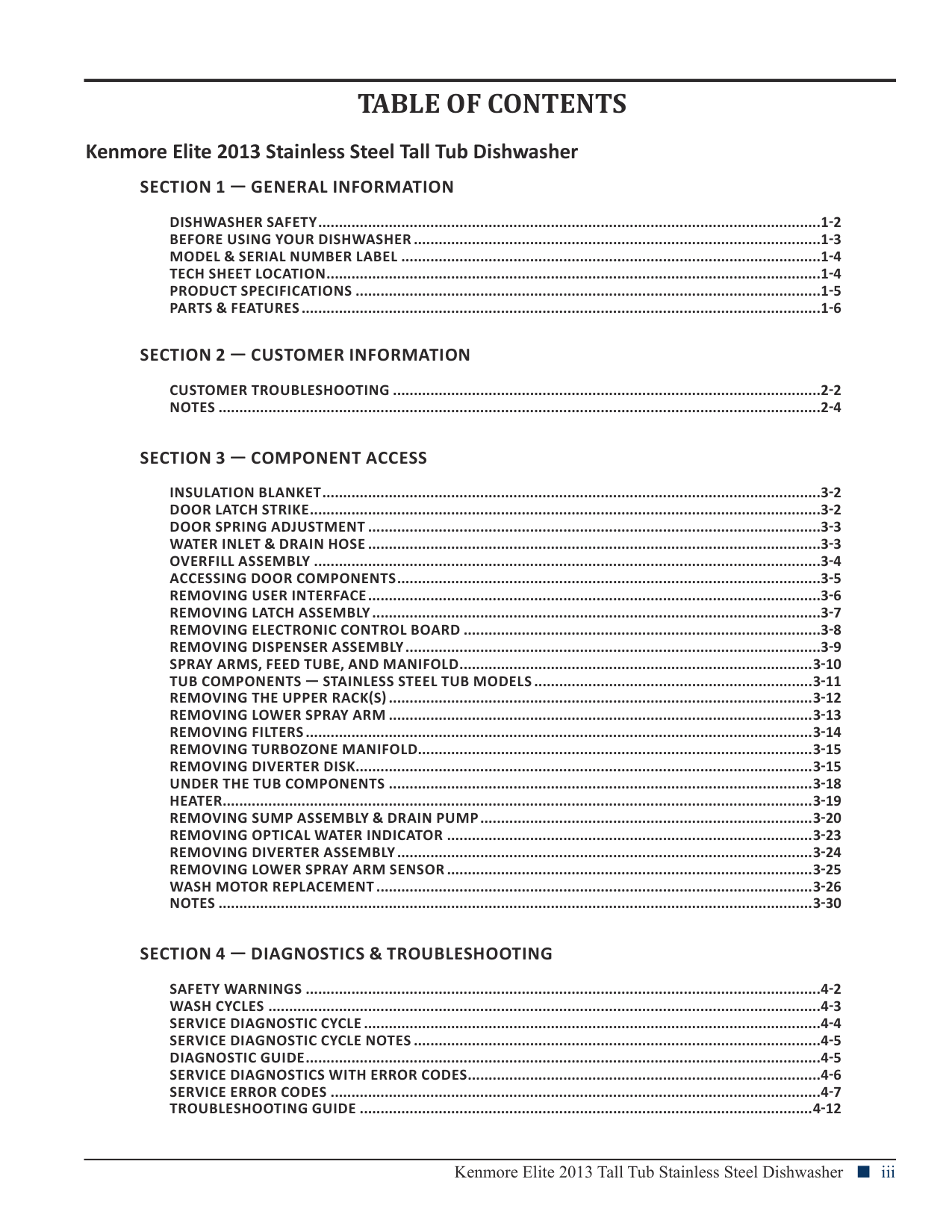
TABLE OF CONTENTS
####### Kenmore Elite 2013 Stainless Steel Tall Tub Dishwasher
########## SECTION 1 — GENERAL INFORMATION
DISHWASHER SAFETY.........................................................................................................................1-2 BEFORE USING YOUR DISHWASHER ..................................................................................................1-3 MODEL & SERIAL NUMBER LABEL .....................................................................................................1-4 TECH SHEET LOCATION.......................................................................................................................1-4 PRODUCT SPECIFICATIONS ................................................................................................................1-5 PARTS & FEATURES.............................................................................................................................1-6
########## SECTION 2 — CUSTOMER INFORMATION
CUSTOMER TROUBLESHOOTING .......................................................................................................2-2 NOTES .................................................................................................................................................2-4
########## SECTION 3 — COMPONENT ACCESS
INSULATION BLANKET........................................................................................................................3-2 DOOR LATCH STRIKE...........................................................................................................................3-2 DOOR SPRING ADJUSTMENT .............................................................................................................3-3 WATER INLET & DRAIN HOSE .............................................................................................................3-3 OVERFILL ASSEMBLY ..........................................................................................................................3-4 ACCESSING DOOR COMPONENTS......................................................................................................3-5 REMOVING USER INTERFACE.............................................................................................................3-6 REMOVING LATCH ASSEMBLY............................................................................................................3-7 REMOVING ELECTRONIC CONTROL BOARD ......................................................................................3-8 REMOVING DISPENSER ASSEMBLY....................................................................................................3-9 SPRAY ARMS, FEED TUBE, AND MANIFOLD.....................................................................................3-10 TUB COMPONENTS — STAINLESS STEEL TUB MODELS ...................................................................3-11 REMOVING THE UPPER RACK(S) ......................................................................................................3-12 REMOVING LOWER SPRAY ARM ......................................................................................................3-13 REMOVING FILTERS..........................................................................................................................3-14 REMOVING TURBOZONE MANIFOLD...............................................................................................3-15 REMOVING DIVERTER DISK..............................................................................................................3-15 UNDER THE TUB COMPONENTS ......................................................................................................3-18 HEATER..............................................................................................................................................3-19 REMOVING SUMP ASSEMBLY & DRAIN PUMP................................................................................3-20 REMOVING OPTICAL WATER INDICATOR ........................................................................................3-23 REMOVING DIVERTER ASSEMBLY....................................................................................................3-24 REMOVING LOWER SPRAY ARM SENSOR ........................................................................................3-25 WASH MOTOR REPLACEMENT.........................................................................................................3-26 NOTES ...............................................................................................................................................3-30
########## SECTION 4 — DIAGNOSTICS & TROUBLESHOOTING
SAFETY WARNINGS ............................................................................................................................4-2 WASH CYCLES .....................................................................................................................................4-3 SERVICE DIAGNOSTIC CYCLE ..............................................................................................................4-4 SERVICE DIAGNOSTIC CYCLE NOTES ..................................................................................................4-5 DIAGNOSTIC GUIDE............................................................................................................................4-5 SERVICE DIAGNOSTICS WITH ERROR CODES.....................................................................................4-6 SERVICE ERROR CODES ......................................................................................................................4-7 TROUBLESHOOTING GUIDE .............................................................................................................4-12
Kenmore Elite 2013 Tall Tub Stainless Steel Dishwasher n iii
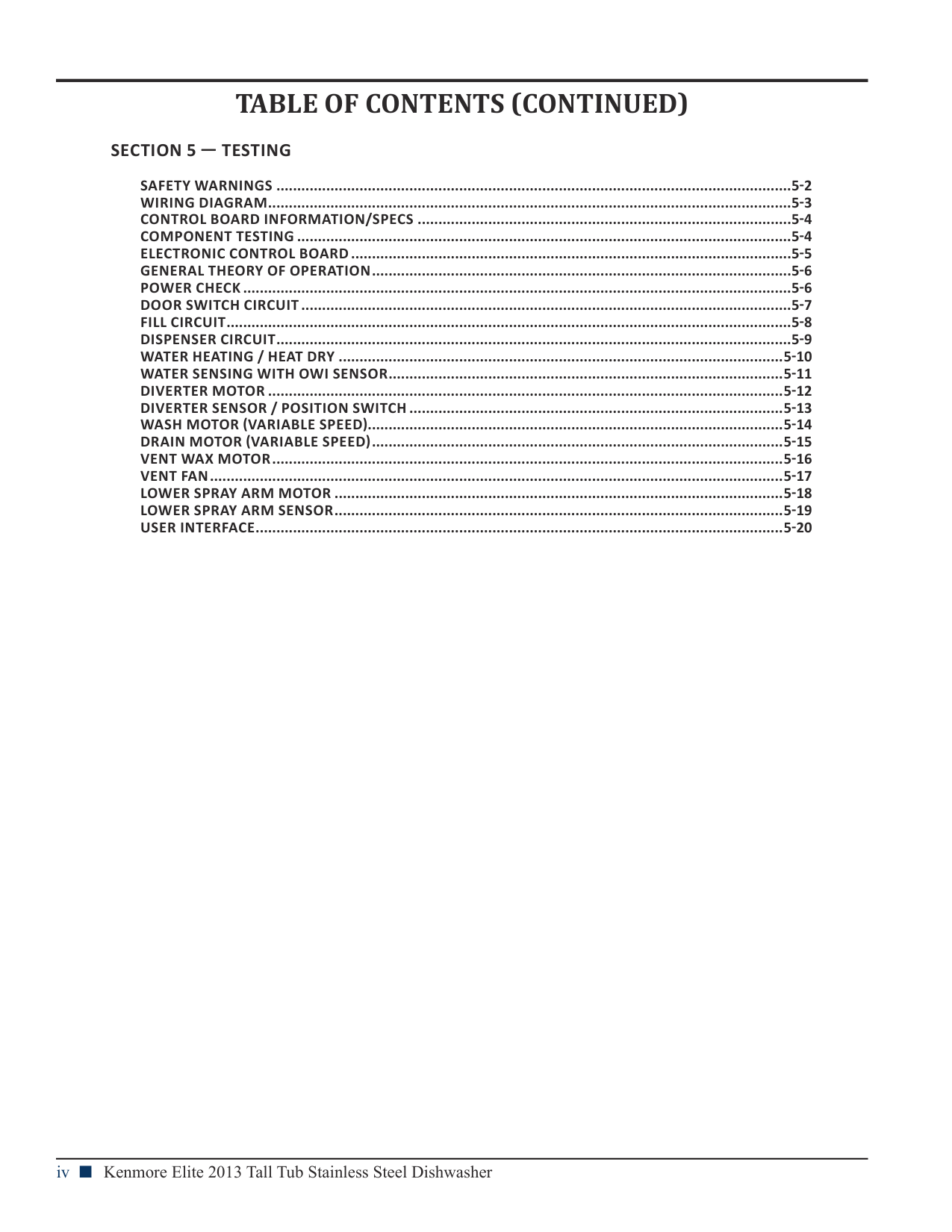
TABLE OF CONTENTS (CONTINUED)
########## SECTION 5 — TESTING
SAFETY WARNINGS ............................................................................................................................5-2 WIRING DIAGRAM..............................................................................................................................5-3 CONTROL BOARD INFORMATION/SPECS ..........................................................................................5-4 COMPONENT TESTING .......................................................................................................................5-4 ELECTRONIC CONTROL BOARD ..........................................................................................................5-5 GENERAL THEORY OF OPERATION.....................................................................................................5-6 POWER CHECK ....................................................................................................................................5-6 DOOR SWITCH CIRCUIT ......................................................................................................................5-7 FILL CIRCUIT........................................................................................................................................5-8 DISPENSER CIRCUIT............................................................................................................................5-9 WATER HEATING / HEAT DRY ...........................................................................................................5-10 WATER SENSING WITH OWI SENSOR...............................................................................................5-11 DIVERTER MOTOR ............................................................................................................................5-12 DIVERTER SENSOR / POSITION SWITCH ..........................................................................................5-13 WASH MOTOR (VARIABLE SPEED)....................................................................................................5-14 DRAIN MOTOR (VARIABLE SPEED)...................................................................................................5-15 VENT WAX MOTOR...........................................................................................................................5-16 VENT FAN..........................................................................................................................................5-17 LOWER SPRAY ARM MOTOR ............................................................................................................5-18 LOWER SPRAY ARM SENSOR............................................................................................................5-19 USER INTERFACE...............................................................................................................................5-20
Section 1: General Information
This section provides general safety, parts, and information for the “Kenmore Elite Stainless Steel Tall Tub Dishwasher.”
Dishwasher Safety
|You can be killed or seriously injured if you don't immediately
You can be killed or seriously injured if you don't follow
All safety messages will tell you what the potential hazard is, tell you how to reduce the chance of injury, and tell you what can happen if the instructions are not followed.
Your safety and the safety of others are very important. We have provided many important safety messages in this manual and on your appliance. Always read and obey all safety messages.
This is the safety alert symbol. This symbol alerts you to potential hazards that can kill or hurt you and others. All safety messages will follow the safety alert symbol and either the word “DANGER” or “WARNING.” These words mean:
follow instructions.
instructions.
DANGER WARNING
| |---|
|IMPORTANT SAFETY INSTRUCTIONS
WARNING: When using the dishwasher, follow basic precautions, including the following:
■ Read all instructions before using the dishwasher.
■ Use the dishwasher only for its intended function.
■ Use only detergents or rinse agents recommended for use in a dishwasher, and keep them out of the reach of children.
■ When loading items to be washed:
1) Locate sharp items so that they are not likely to damage the door seal; and
2) Load sharp knives with the handles up to reduce the risk of cut-type injuries.
■ Do not wash plastic items unless they are marked “dishwasher safe” or the equivalent. For plastic items not so marked, check the manufacturer’s recommendations.
■ Do not touch the heating element during or immediately after use.
■ Do not operate the dishwasher unless all enclosure panels are properly in place.
■ Do not tamper with controls.
■ Do not abuse, sit on, or stand on the door, lid, or dish racks of the dishwasher.
■ To reduce the risk of injury, do not allow children to play in or on the dishwasher.
■ Under certain conditions, hydrogen gas may be produced in a hot water system that has not been used for two weeks or more. HYDROGEN GAS IS EXPLOSIVE. If the hot water system has not been used for such a period, before using the dishwasher turn on all hot water faucets and let the water flow from each for several minutes. This will release any accumulated hydrogen gas. As the gas is flammable, do not smoke or use an open flame during this time.
■ Remove the door or lid to the washing compartment when removing an old dishwasher from service or discarding it.
SAVE THESE INSTRUCTIONS| |---|
|State of California Proposition 65 Warnings: WARNING: This product contains one or more chemicals known to the State of California to cause cancer. WARNING: This product contains one or more chemicals known to the State of California to cause birth defects or other reproductive harm.| |---|
Before Using Your Dishwasher
| | |---| |Tip Over Hazard Do not use dishwasher until completely installed. Do not push down on open door. Doing so can result in serious injury or cuts.|
| | |---| |Electrical Shock Hazard Electrically ground dishwasher. Connect ground wire to green ground connector in terminal box. Do not use an extension cord. Failure to follow these instructions can result in death, fire, or electrical shock.|
####### GROUNDING INSTRUCTIONS
####### SAVE THESE INSTRUCTIONS
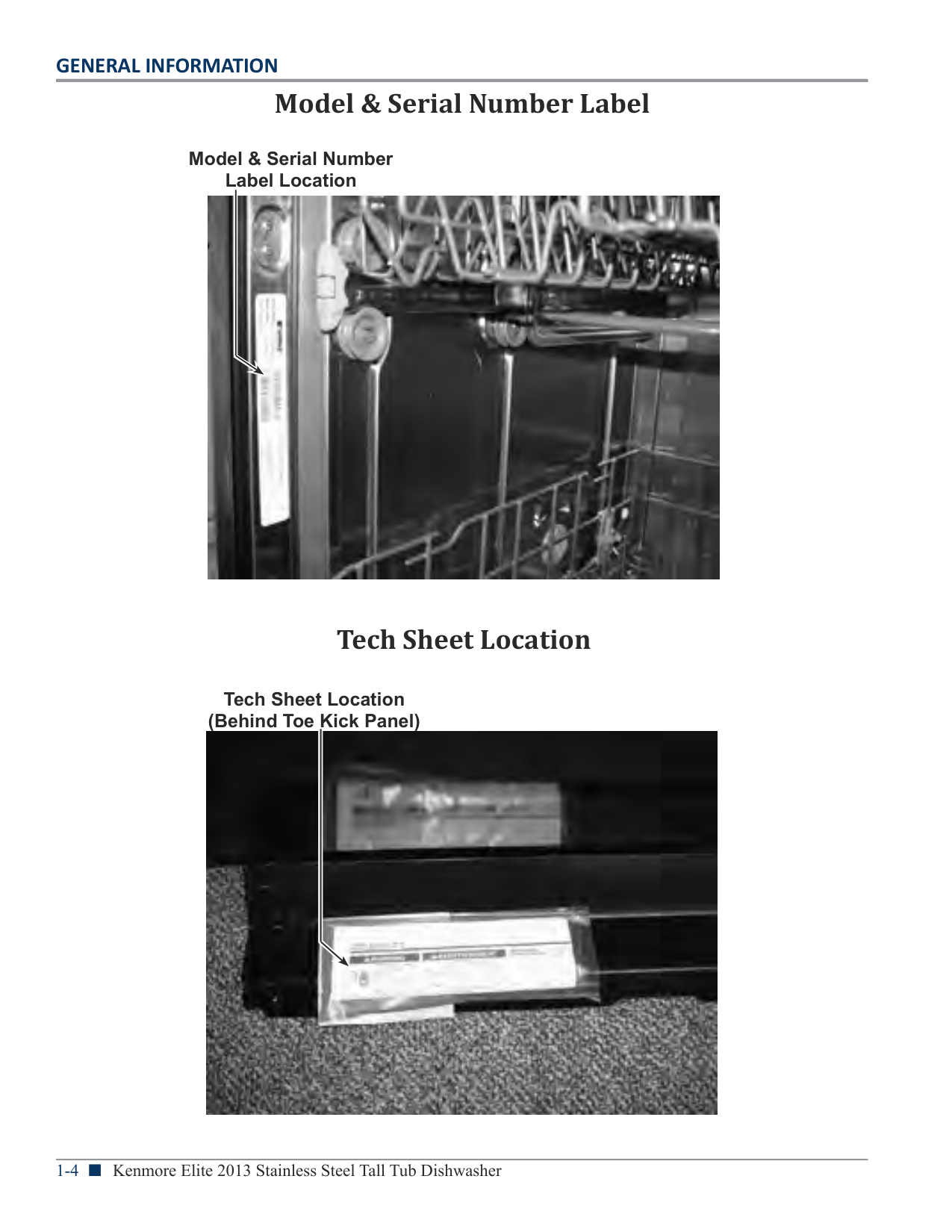
Model & Serial Number Label
Model & Serial Number Label Location

Tech Sheet Location
Tech Sheet Location (Behind Toe Kick Panel)

Product Specifications
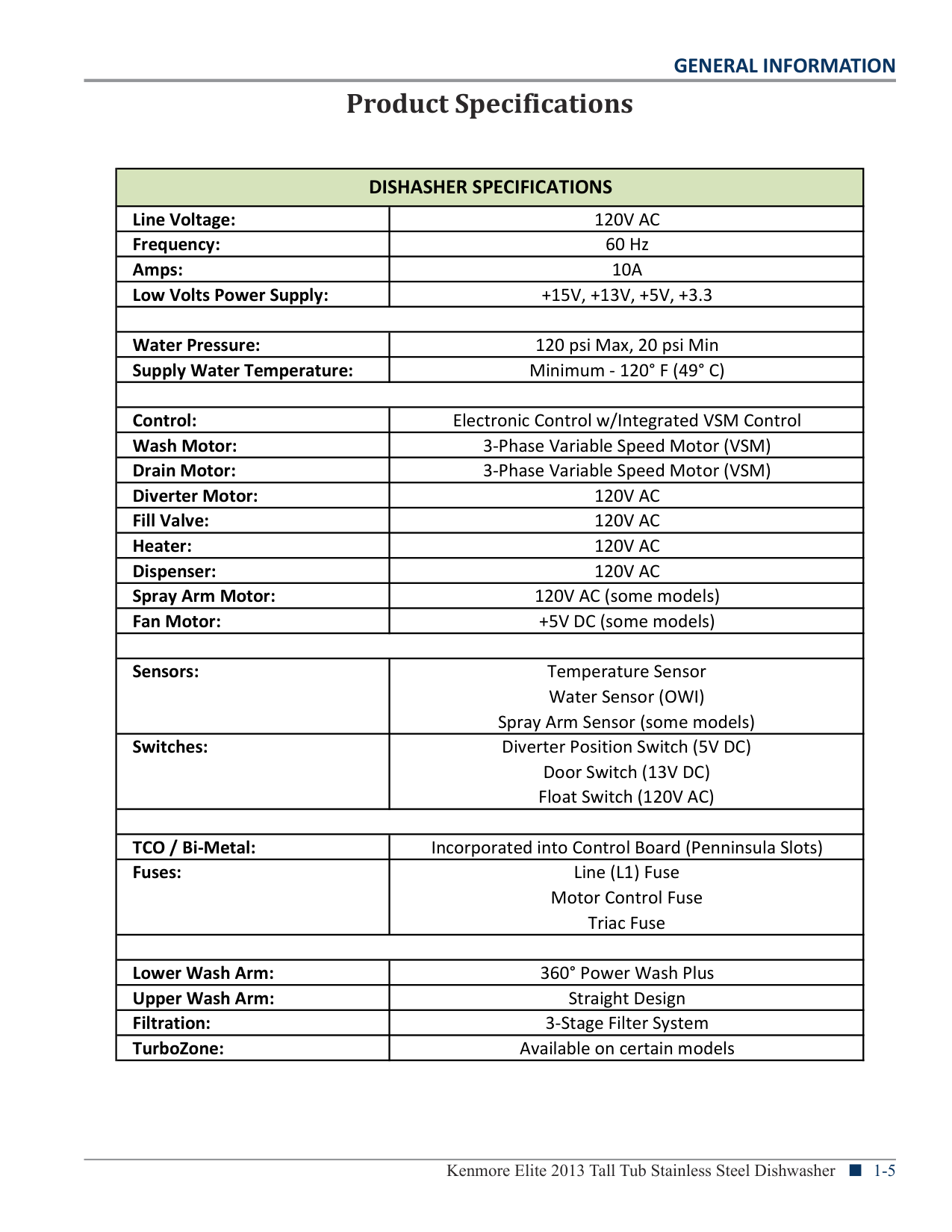
|DISHASHER SPECIFICATIONS|DISHASHER SPECIFICATIONS| |---|---| |Line Voltage:|120V AC| |Frequency:|60 Hz| |Amps:|10A| |Low Volts Power Supply:|+15V, +13V, +5V, +3.3| | | | |Water Pressure:|120 psi Max, 20 psi Min| |Supply Water Temperature:|Minimum - 120° F (49° C)| | | | |Control:|Electronic Control w/Integrated VSM Control| |Wash Motor:|3-Phase Variable Speed Motor (VSM)| |Drain Motor:|3-Phase Variable Speed Motor (VSM)| |Diverter Motor:|120V AC| |Fill Valve:|120V AC| |Heater:|120V AC| |Dispenser:|120V AC| |Spray Arm Motor:|120V AC (some models)| |Fan Motor:|+5V DC (some models)| | | | |Sensors:|Temperature Sensor Water Sensor (OWI) Spray Arm Sensor (some models)| |Switches:|Diverter Position Switch (5V DC) Door Switch (13V DC) Float Switch (120V AC)| | | |
|TCO / Bi-Metal:|Incorporated into Control Board (Penninsula Slots)| |Fuses:|Line (L1) Fuse Motor Control Fuse Triac Fuse| | | | |Lower Wash Arm:|360° Power Wash Plus| |Upper Wash Arm:|Straight Design| |Filtration:|3-Stage Filter System| |TurboZone:|Available on certain models|
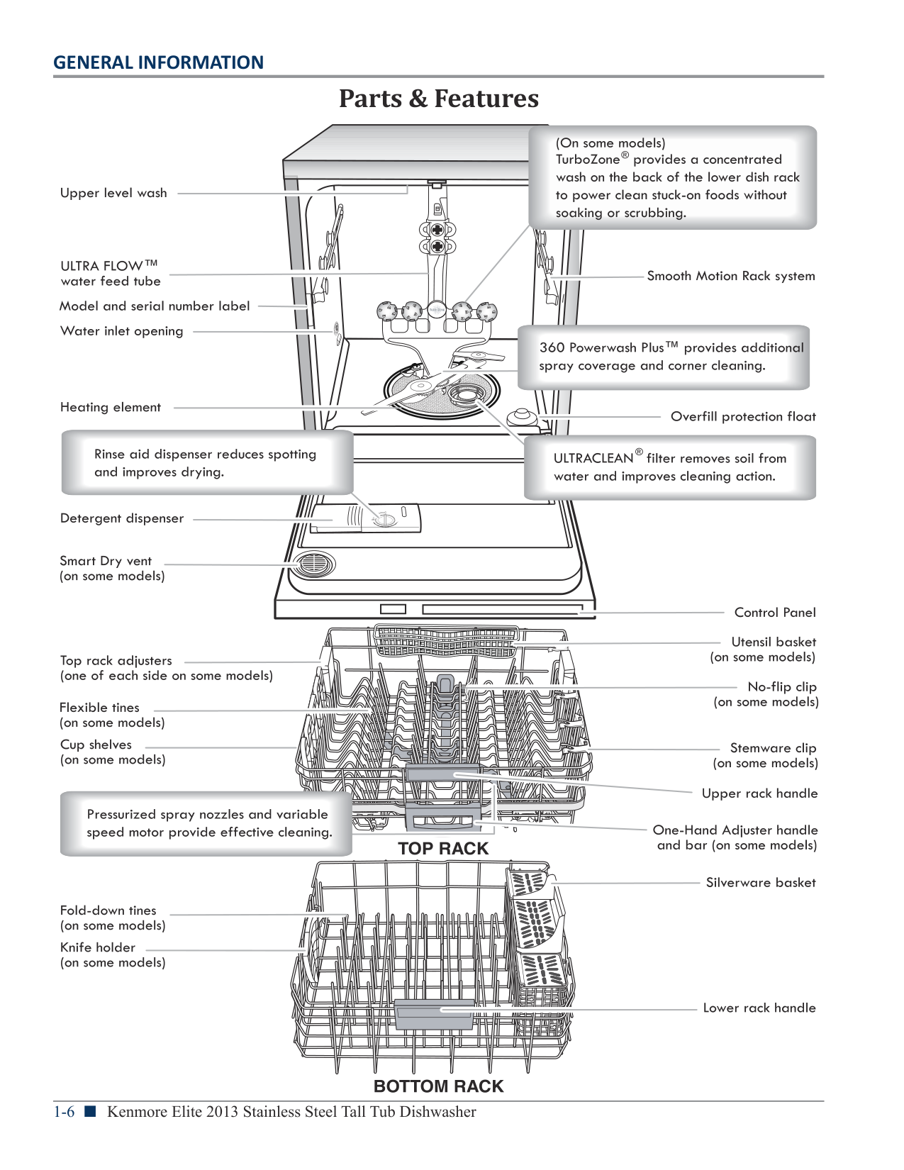
Parts & Features


Section 2: Consumer Information
This section provides consumer troubleshooting information for the “Kenmore Elite Stainless Steel Tall Tub Dishwasher.”
|Consumer Troubleshooting
| |---|
| | |---|
| | |---|
| | |---|
| | |---|
| | |---|
| | |---|
| | |---|
| | |---|
| | |---|
| | |---|
| | |---|
| | |---|
| | |---|
| | |---|
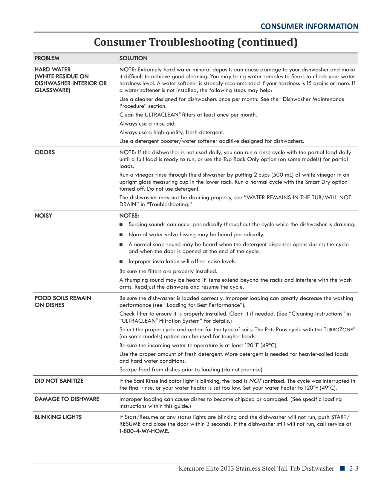
|Consumer Troubleshooting (continued)| |---|
| | |---|
| | |---|
| | |---|
| | |---|
| | |---|
| | |---|
| | |---|
| | |---|
| | |---|
| | |---|
| | |---|
| | |---|
| | |---|
| | |---|
| | |---|
| | |---|
| | |---|
| | |---|
| | |---|
| | |---|
| | |---|
|Consumer Troubleshooting (continued)| |---|
| | |---|
| | |---|
| | |---|
| | |---|
| | |---|
| | |---|
| | |---|
| | |---|
|Notes| |---|
Section 3: Component Access
This section provides service parts access, removal, and installation instructions for the “Kenmore Elite Stainless Steel Tall Tub Dishwasher.”
Kenmore Elite 2013 Stainless Steel Tall Tub Dishwasher n 3-1
Insulation Blanket and Door Latch Strike
|WARNING
| |---| | | |Electrical Shock Hazard Disconnect power before servicing.
Failure to do so can result in death or electrical shock.
Replace all parts and panels before operating.|
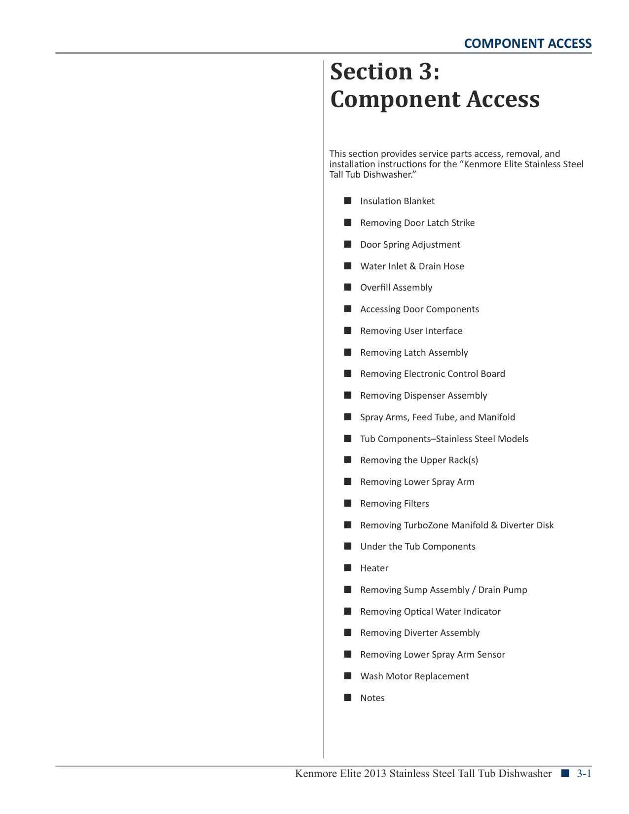
###### Installing Insulation Blanket
(Stainless Steel Tub Models Only)


###### Removing Door Latch Strike
(FID and 2 ½” Console)


Adjustable Door Springs, Wheels, Water Inlet and Drain Hose
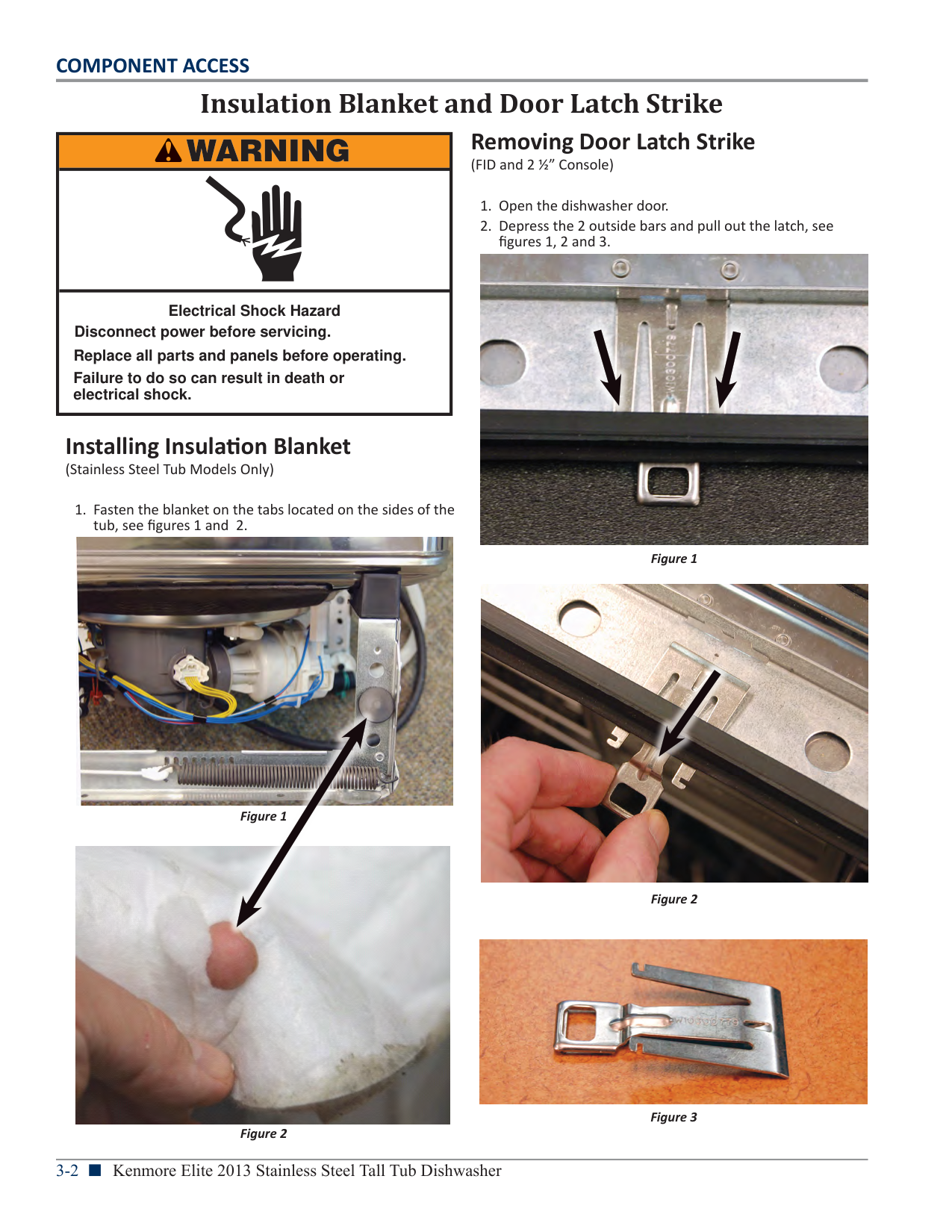
###### Water Inlet and Drain Hose
|WARNING
| |---| | | |Electrical Shock Hazard Disconnect power before servicing.
Failure to do so can result in death or electrical shock.
Replace all parts and panels before operating.|
Drain loop must be higher than drain to prevent siphoning.

|Drain Hose Loop| |---|
|Inlet Hose| |---|
|Water Inlet| | |---|---| |Water Inlet| |
|Water Inlet| |
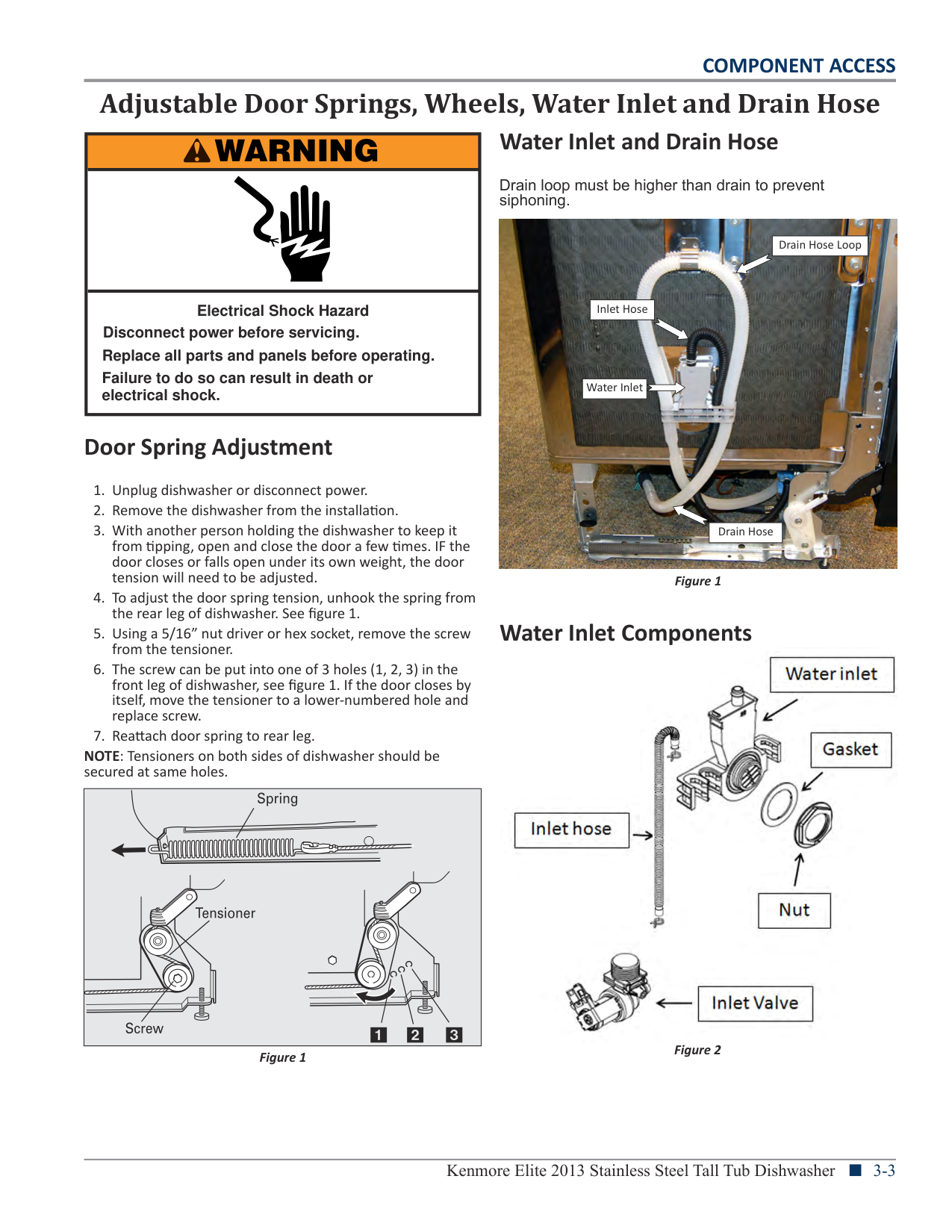
###### Door Spring Adjustment
|Drain Hose| |---|
Water Inlet Components


NOTE: Tensioners on both sides of dishwasher should be secured at same holes.
If wheels were removed, cover the floor when
############### Figure 1
############ NOTES:
Kenmore Elite 2013 Stainless Steel Tall Tub Dishwasher n 3-3
The screw can be put into one of 3 holes (1, 2, 3) in the front leg of
It is all right if dishwasher fits tightly into cabinet opening. Do
Overfill Assembly
|WARNING
| |---| | | |Electrical Shock Hazard Disconnect power before servicing.
Failure to do so can result in death or electrical shock.
Replace all parts and panels before operating.|
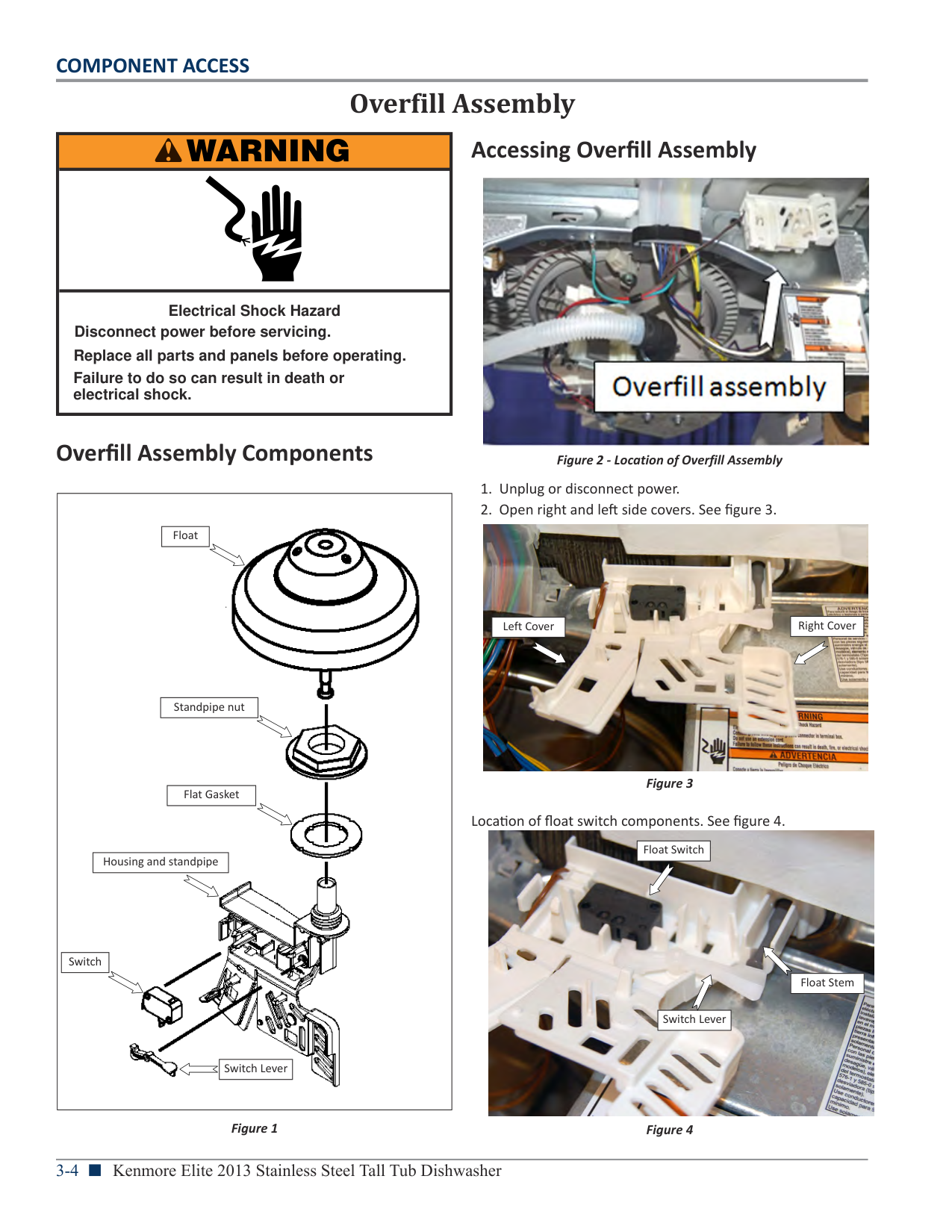
###### Overfill Assembly Components
|
|Float| |---|
|Housing and standpipe| |---|
|Switch| |---|
|Switch Lever| |---|
|Standpipe nut| |---|
|Flat Gasket| |---|
| |---|
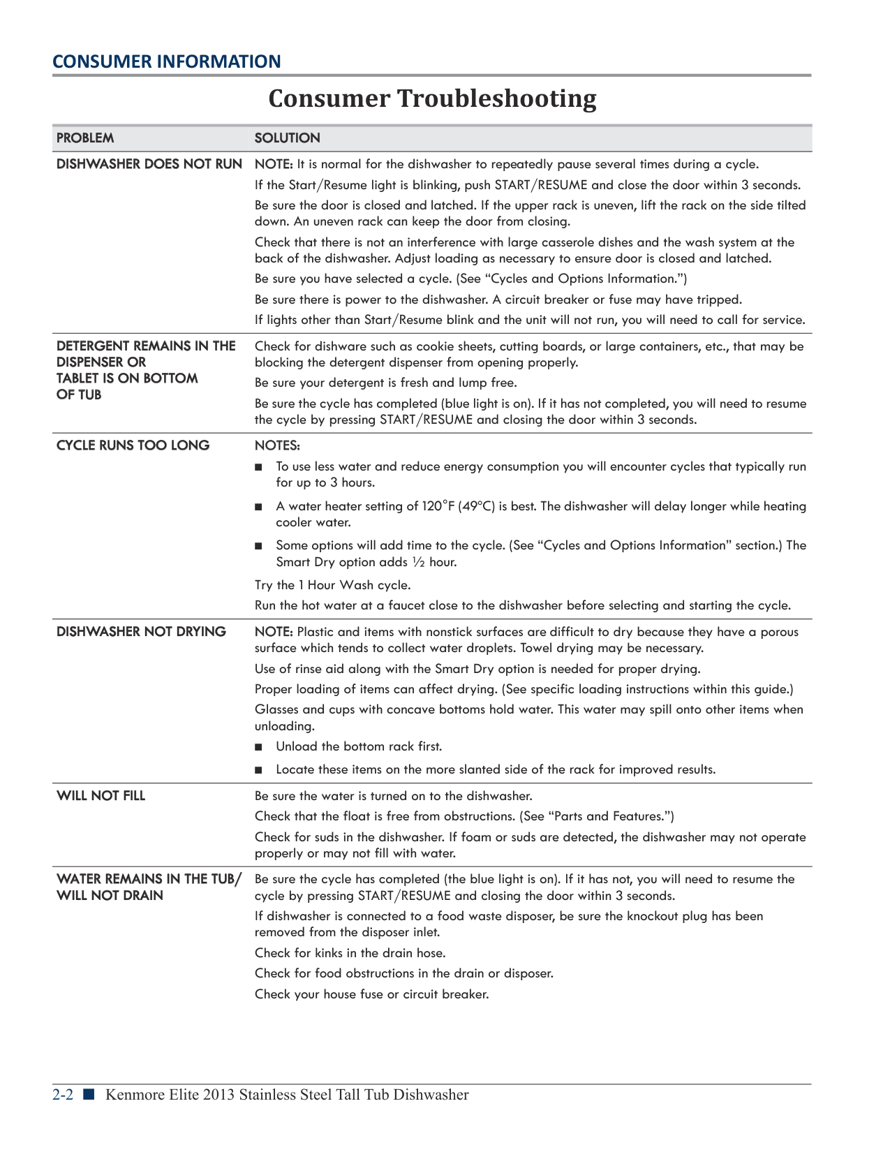
Figure 1
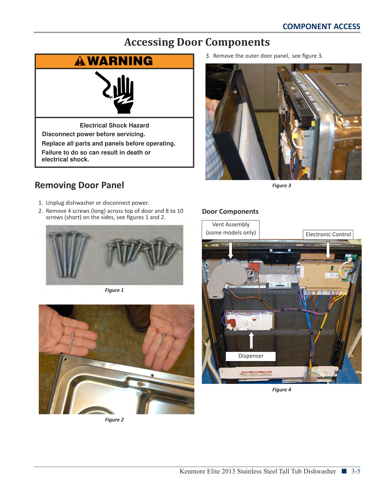
###### Accessing Overfill Assembly

Figure 2 - Location of Overfill Assembly

|Right Cover| |---|
|Left Cover| |---|
Location of float switch components. See figure 4.

|Float Switch| |---|
|Float Stem| |---|
|Switch Lever| |---|
Accessing Door Components
|WARNING
| |---| | | |Electrical Shock Hazard Disconnect power before servicing.
Failure to do so can result in death or electrical shock.
Replace all parts and panels before operating.|


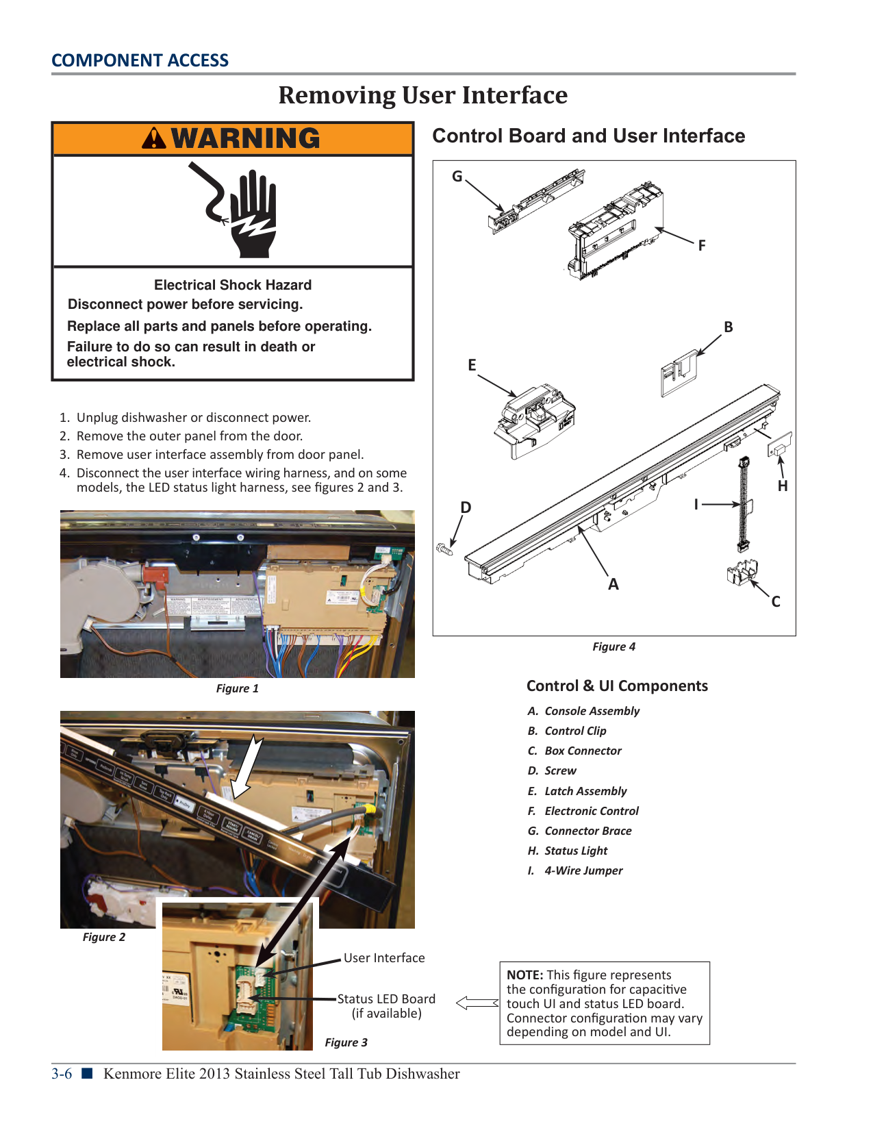
Removing Door Panel
Door Components
|Vent Assembly (some models only)| |---|
|Electronic Control| |---|


|Dispenser| |---|
Removing User Interface
|WARNING
| |---| | | |Electrical Shock Hazard Disconnect power before servicing.
Failure to do so can result in death or electrical shock.
Replace all parts and panels before operating.|

Figure 1
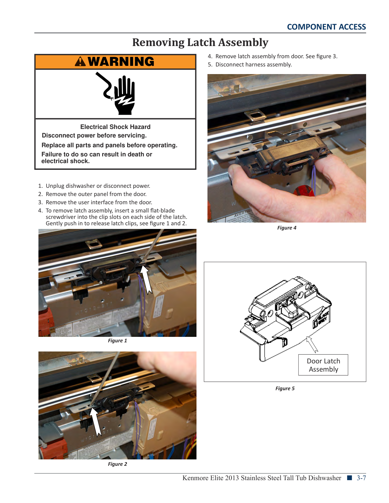
Control Board and User Interface
|
F
C
D
E
A
B
G
I
H
| |---|
Figure 4
########## Control & UI Components


Figure 2
User Interface
|NOTE: This figure represents the configuration for capacitive touch UI and status LED board. Connector configuration may vary depending on model and UI.| |---|
Status LED Board (if available)
Figure 3
Removing Latch Assembly
|WARNING
| |---| | | |Electrical Shock Hazard Disconnect power before servicing.
Failure to do so can result in death or electrical shock.
Replace all parts and panels before operating.|
screwdriver into the clip slots on each side of the latch. Gently push in to release latch clips, see figure 1 and 2.

Figure 4


|
|Door Latch Assembly| |---|
| |---|
Figure 5
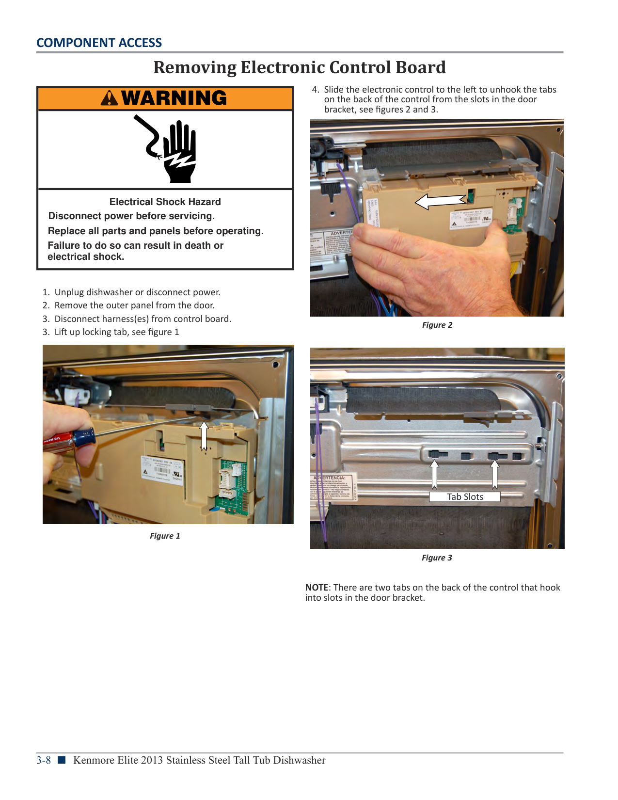
Removing Electronic Control Board
|WARNING
| |---| | | |Electrical Shock Hazard Disconnect power before servicing.
Failure to do so can result in death or electrical shock.
Replace all parts and panels before operating.|

Figure 1


|Tab Slots| |---|
NOTE: There are two tabs on the back of the control that hook into slots in the door bracket.
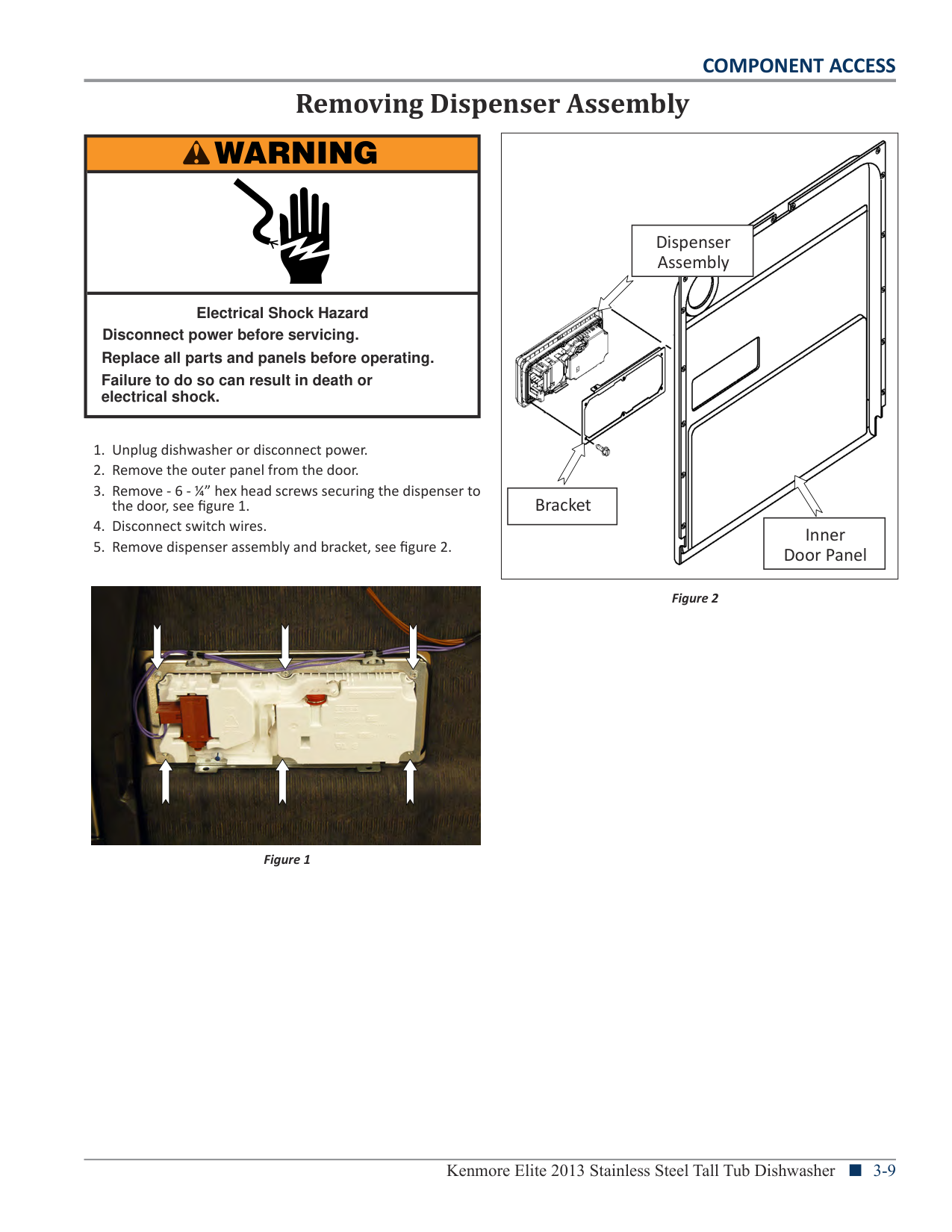
Removing Dispenser Assembly
|WARNING
| |---| | | |Electrical Shock Hazard Disconnect power before servicing.
Failure to do so can result in death or electrical shock.
Replace all parts and panels before operating.|

Figure 1
|
|Bracket| |---|
|Dispenser Assembly| |---|
|Inner Door Panel| |---|
| |---|
Figure 2
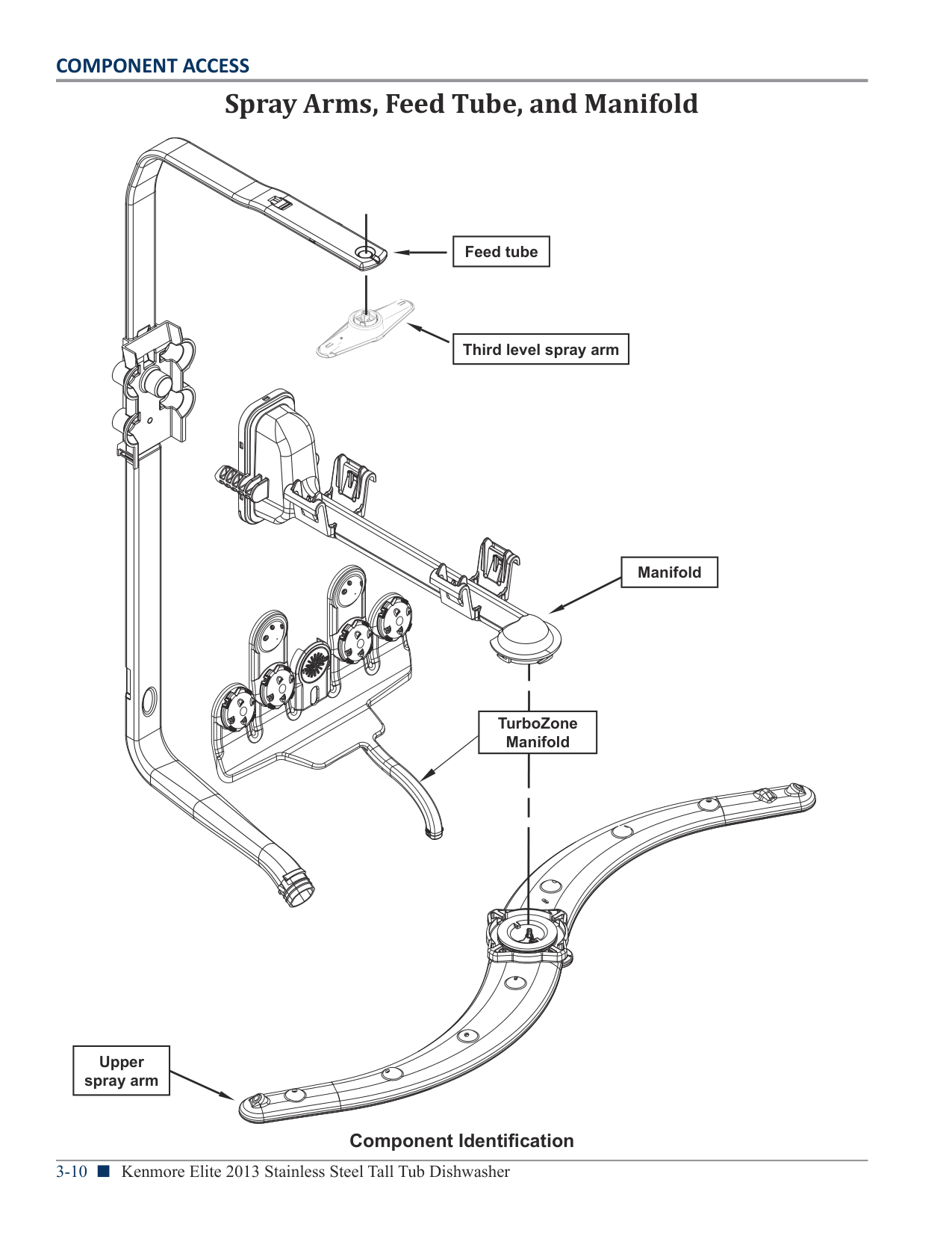
Spray Arms, Feed Tube, and Manifold
| | | |---|---| | | |
| | | |
|---|---|---| | | | |
| | | |---|---| | | |
| | | |---|---| | | |
| | | |---|---| | | | | | |
| | | |---|---| | | |
| | | |---|---| | | |
| | | |---|---| | | |
| | | |---|---| | | |
| | | | |---|---|---| | | | |
| | | | |---|---|---| | | | |
| | | | |---|---|---|
| | | |
| | | |---|---| | | |
| | | |---|---| | | |
|Feed tube| |---|
|Third level spray arm| |---|
| | | |---|---| | | |
|Manifold| |---|
| | | |---|---| | | |
| | | |---|---| | | |
| | | | |---|---|---| | | | |
| | | |---|---| |Tur M|oZone nifold| | | |
| | |
|---|---| | | |
| | | | | |---|---|---|---| | | | | |
|Upper spray arm| |---|
Component Identification
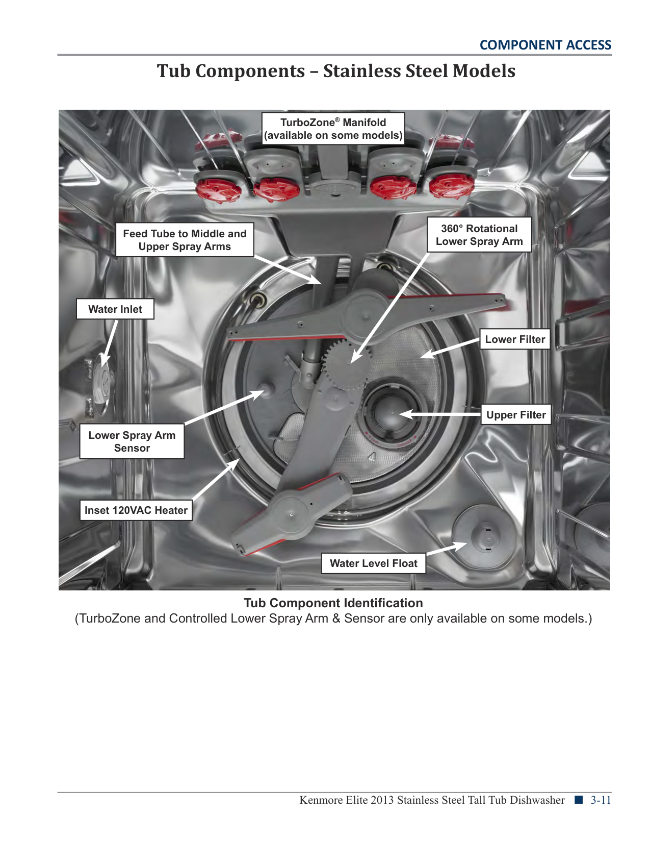
Tub Components – Stainless Steel Models

|TurboZone® Manifold (available on some models)| |---|
|360° Rotational Lower Spray Arm| |---|
|Feed Tube to Middle and Upper Spray Arms| |---|
|Water Inlet| |---|
|Lower Filter| |---|
| |Upper Filter| |---|---| | |Upper Filter|
|Lower Spray Arm Sensor| |---|
|Inset 120VAC Heater| |---|
|Water Level Float| |---|
Tub Component Identification (TurboZone and Controlled Lower Spray Arm & Sensor are only available on some models.)
Removing the Upper Rack(s)
Removable Top Rack (for SatinGlide rails) The removable top rack allows you to wash larger items such as pots, roasters, and cookie sheets in the bottom rack. IMPORTANT: Remove dishes prior to removing the top rack from
###### Removing The Upper Rack
###### Removing The Upper Rack
########## (SatinGlide Max rails)
########## (standard rails)
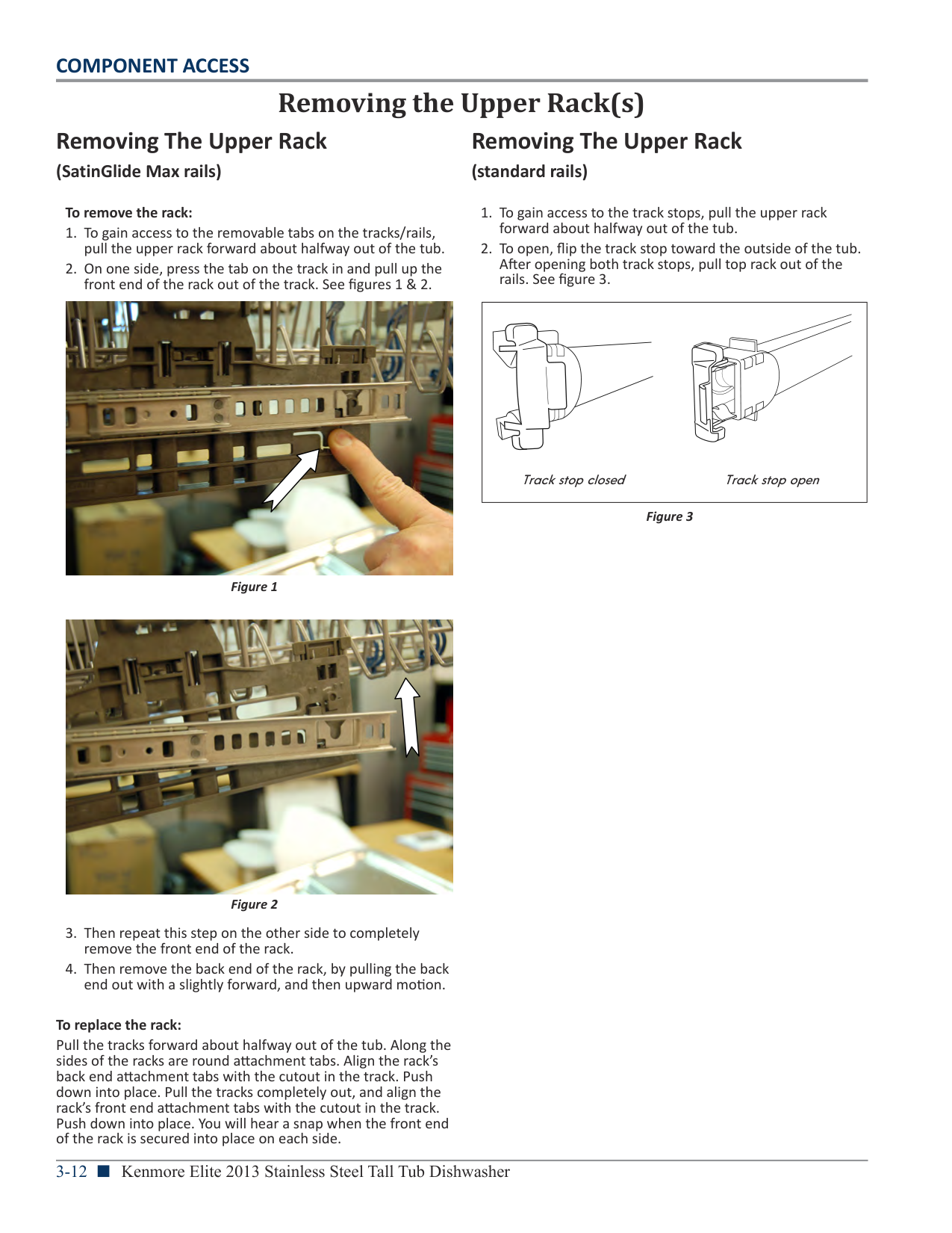
############# To remove the rack:


To remove the rack To gain access to the track stops, pull the upper rack forward about halfway out of the tub. To open, flip the track stop toward the outside of the tub. After opening both track stops, pull top rack out of the rails.
| | |---|
Figure 3
To replace the rack: Pull the tracks forward about halfway out of the tub. Along the sides of the racks are round attachment tabs. Align the rack’s back end attachment tabs with the cutout in the track. Push down into place. Pull the tracks completely out, and align the rack’s front end attachment tabs with the cutout in the track. Push down into place. You will hear a snap when the front end of the rack is secured into place on each side.
Removing Lower Spray Arm
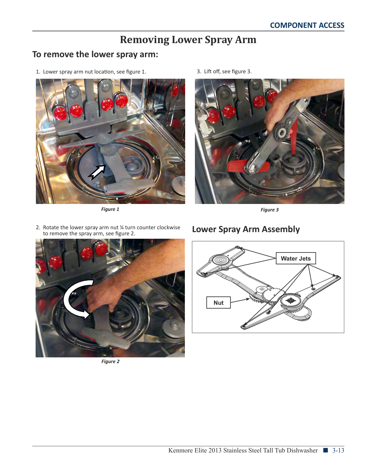
###### To remove the lower spray arm:

to remove the spray arm, see figure 2.


Figure 3
Lower Spray Arm Assembly
| | | |---|---| | | |
|Water Jets| |---|
| | | |---|---| | | |
| | | |---|---| | | |
| | | |---|---| | | |
| | | |---|---| | | |
| | | |---|---| | | |
| | | |---|---| | | |
| | | |---|---| | | |
| | | |---|---| | | |
| | | |---|---| | | |
| | | |---|---| | | |
| | | |---|---| | | |
| | | |---|---| | | |
| | | |---|---| | | |
| | | |---|---| | | |
| | | |---|---|
| | |
|Nut| |---|
| | | |---|---| | | |
| | | |---|---| | | |
| | | |---|---| | | | | | |
| | | |---|---| | | |
| | | |---|---| | | |
| | | |---|---| | | |
| | | |---|---| | | | | | | | | |
| | | |---|---| | | |
| | | |---|---|
| | |
| | | |---|---| | | |
| | | |---|---| | | | | | |
| | | |---|---| | | |
| | | |---|---| | | |
| | | |---|---| | | |
| | | |---|---| | | |
| | | |---|---| | | |
| | | |---|---| | | |
| | | |---|---| | | |
| | | |---|---| | | |
| | | |---|---| | | |
| | | |---|---| | | |
| | | |---|---| | | |
| | | |---|---| | | |
| | | |---|---| | | |
| | | |---|---| | | |
| | | |---|---| | | |
| | | |---|---| | | |
| | | |---|---| | | |
| | | |---|---| | | |
| | | |---|---| | | |
| | | | |---|---|---| | | | |
| | | |---|---| | | |
| | | |---|---| | | |
| | | |---|---| | | |
| | | |---|---| | | |
| | | |---|---| | | |
| | | |---|---| | | |
| | | |---|---| | | |
| | | |---|---| | | |
| | | |---|---|
| | |
| | | |---|---| | | |
| | | |---|---| | | |
| | | |---|---| | | |
| | | |---|---| | | | | | |
| | | |---|---| | | |
| | | |---|---| | | |
| | | |---|---| | | |
| | | |---|---| | | |
| | | |---|---| | | |
| | | |---|---| | | |
| | | |---|---| | | |
| | | |---|---| | | |
| | | |---|---| | | |
| | | |---|---| | | |
| | | |---|---| | | |
| | | |---|---| | | |
| | | |---|---| | | | | | |
| | | |---|---| | | |
| | | |---|---| | | |
| | | |---|---| | | |
| | | |---|---| | | |
| | | | |---|---|---| | | | |
| | | |---|---| | | |
| | | |---|---| | | |
| | | |---|---| | | |
| | | |---|---| | | |
| | | |---|---| | | |
| | | | |---|---|---| | | | |
| | | |---|---| | | |
| | | |---|---| | | |
| | |
|---|---| | | |
| | | |---|---| | | |
| | | |---|---| | | |
| | | | |---|---|---| | | | |
| | | |---|---| | | |
| | | |---|---| | | |
| | | |---|---| | | |
| | | |---|---| | | |
| | | |---|---| | | |
| | | | |---|---|---| | | | |
| | | |---|---| | | |
| | | |---|---| | | |
| | | |---|---| | | |
| | | | |---|---|---| | | | |
| | | |---|---| | | |
| | | | |---|---|---| | | | |
| | | |---|---| | | |
| | | |---|---| | | |
| | | |---|---| | | | | | |
| | | |---|---| | | |
| | | |---|---| | | |
| | | |---|---| | | |
| | | |---|---| | | |
| | | |---|---| | | |
| | | |---|---| | | |
| | | |---|---| | | |
| | | |---|---| | | |
| | | |---|---| | | | | | |
| | | |---|---| | | |
| | | |---|---| | | |
| | | |---|---| | | |
| | | |---|---| | | |
| | | |---|---| | | |
| | | |---|---| | | |
| | | |---|---| | | |
| | | |---|---| | | |
| | | |---|---| | | |
| | | |---|---| | | |
| | | |---|---| | | |
| | | |---|---| | | |
| | | |---|---| | | |
| | | |---|---|
| | |
| | | |---|---| | | |
| | | |---|---| | | |
| | | |---|---| | | |
| | | |---|---| | | |
| | | |---|---| | | |
| | | |---|---| | | |
| | | |---|---| | | |
| | | |---|---| | | | | | |
| | | |---|---| | | |
| | | |---|---| | | |
| | | |---|---| | | |
| | | |---|---| | | |
| | | |---|---| | | |
| | | |---|---| | | |
| | | |---|---| | | |
| | | |---|---| | | |
| | | | |---|---|---| | | | |
| | | |---|---| | | |
| | | |---|---| | | |
| | | |---|---| | | |
| | | |---|---| | | | | | |
| | | |---|---| | | |
| | | |---|---| | | |
| | | |---|---| | | |
| | | | |---|---|---| | | | |
| | | |---|---| | | |
| | | |---|---| | | |
| | | |---|---| | | |
| | | |---|---| | | |
| | | |---|---| | | |
Kenmore Elite 2013 Stainless Steel Tall Tub Dishwasher n 3-13
| | | |---|---| | | |
| | | |---|---| | | | | | |
| | | |---|---| | | |
| | | |---|---| | | |
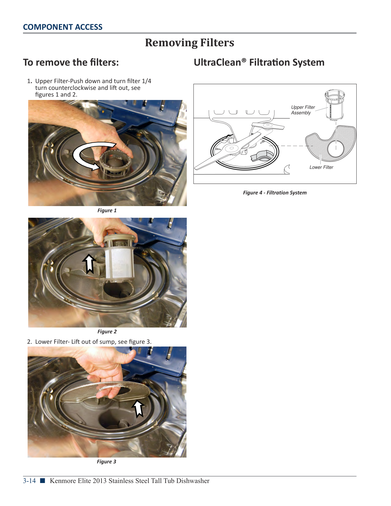
##### To remove the filters:
Removing Filters
##### UltraClean® Filtration System
| | | |---|---| | | | | | |
| | | |---|---| | | |

Upper Filter Assembly
| | | | |---|---|---| | | | |
| | | |---|---| | | |
| | | |---|---| | | |
| | | |---|---| | | |
| | | |---|---| | | |
| | | | |---|---|---| | | | |
| | | |---|---| | | |
Lower Filter
Figure 4 - Filtration System
Figure 1

| | | | | | |---|---|---|---|---| | | | | | | |Lift out of sump, see
Figure 2|figure 3.| | | | | | | | | | | | | | | |

Figure 3
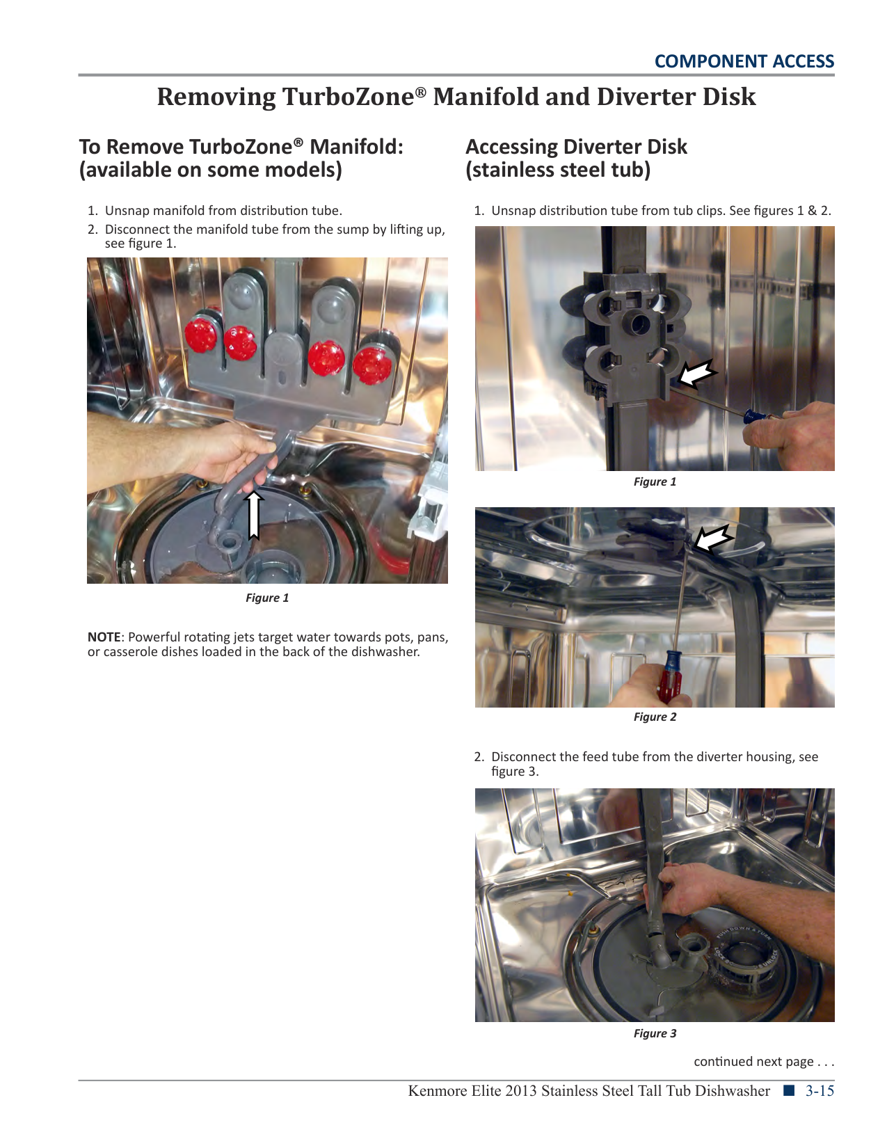
###### To Remove TurboZone® Manifold: (available on some models)
###### Accessing Diverter Disk (stainless steel tub)

Figure 1
NOTE: Powerful rotating jets target water towards pots, pans, or casserole dishes loaded in the back of the dishwasher.
Removing TurboZone® Manifold and Diverter Disk


####### COMPONENT ACCESS
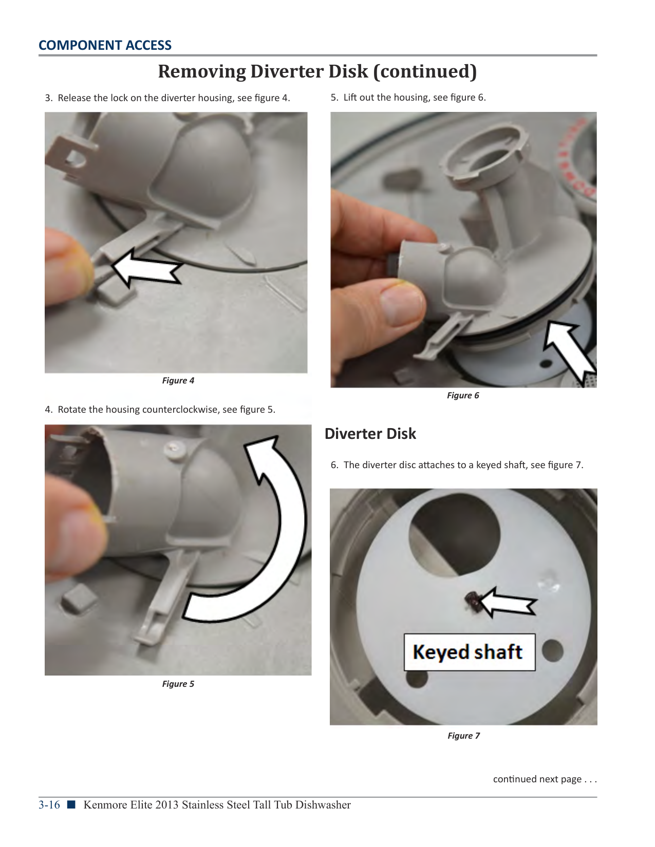
Removing Diverter Disk (continued)

Figure 7
###### Diverter Disk


####### COMPONENT ACCESS
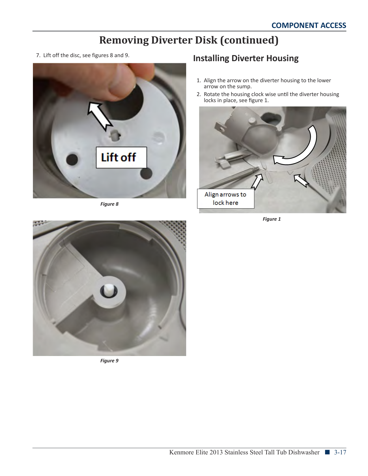
Removing Diverter Disk (continued)
###### Installing Diverter Housing

Figure 1

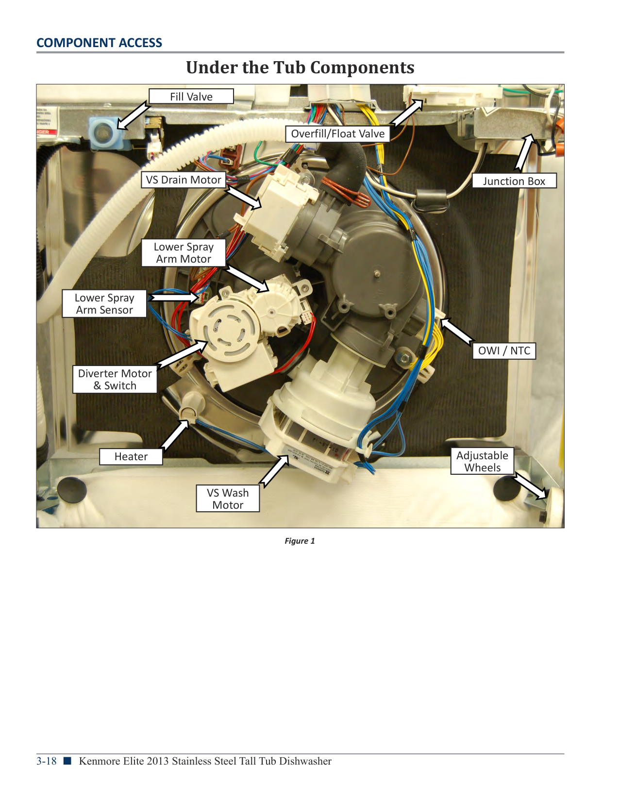
Under the Tub Components
|
|VS Wash Motor| |---|
|Heater| |---|
|OWI / NTC| |---|
|Junction Box| |---|
|Diverter Motor & Switch| |---|
|Overfill/Float Valve| |---|
|VS Drain Motor| |---|
|Fill Valve| |---|
|Adjustable Wheels| |---|
|Lower Spray Arm Motor|
|---|
|Lower Spray Arm Sensor| |---|
| |---|
Figure 1
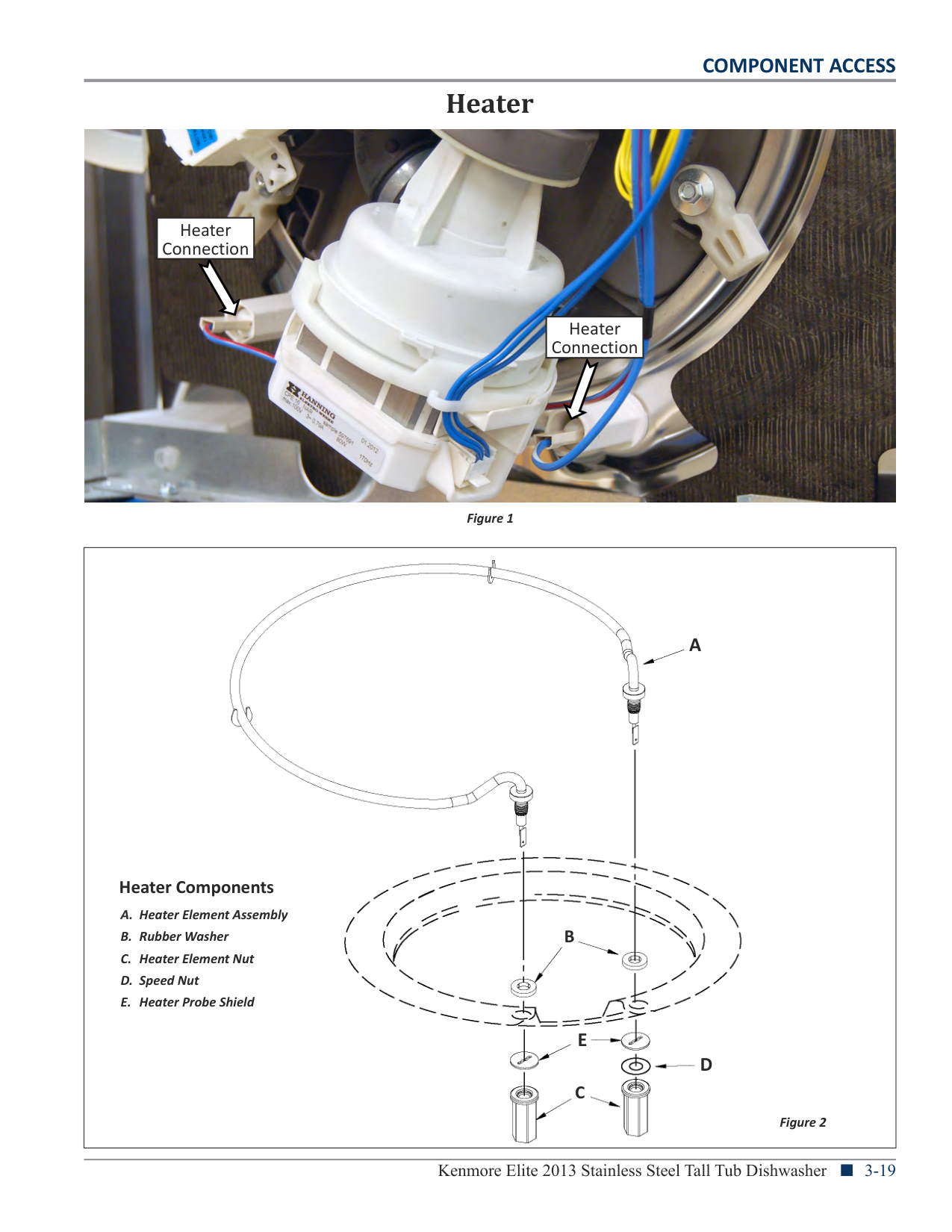
Heater

|Heater Connection| |---|
|Heater Connection| |---|
Figure 1
|
Heater Components
A. Heater Element Assembly
B. Rubber Washer
C. Heater Element Nut
D. Speed Nut
E. Heater Probe Shield
A
B
C
D
E
Figure 2| |---|
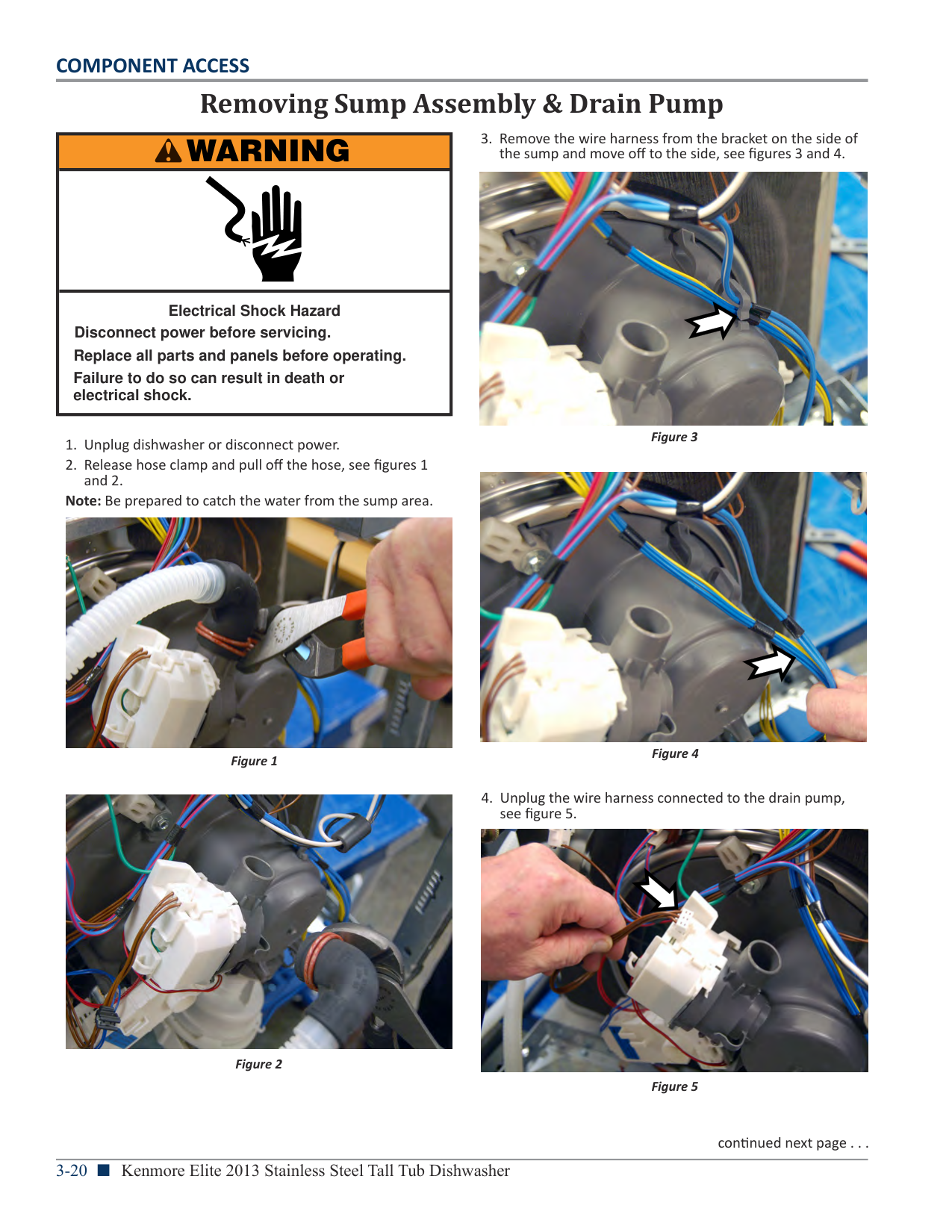
Removing Sump Assembly & Drain Pump
|WARNING
| |---| | | |Electrical Shock Hazard Disconnect power before servicing.
Failure to do so can result in death or electrical shock.
Replace all parts and panels before operating.|
Note: Be prepared to catch the water from the sump area.

Figure 1

Figure 2
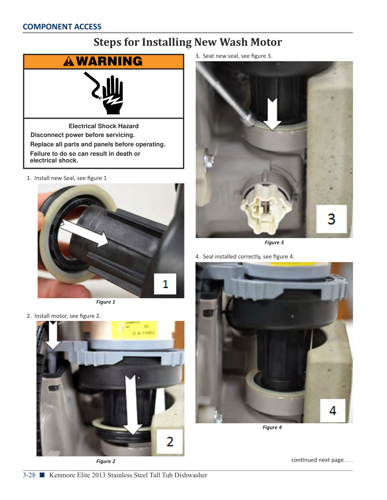


Figure 3


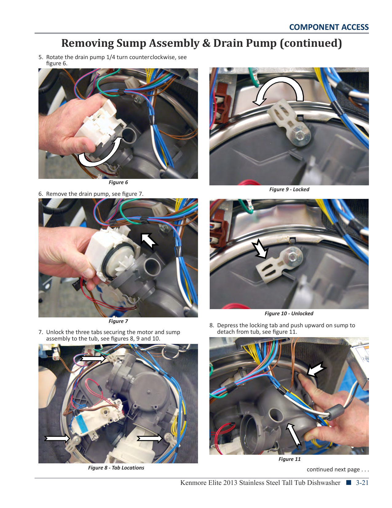
Figure 9 - Locked


Figure 10 - Unlocked


Figure 11
Figure 8 - Tab Locations
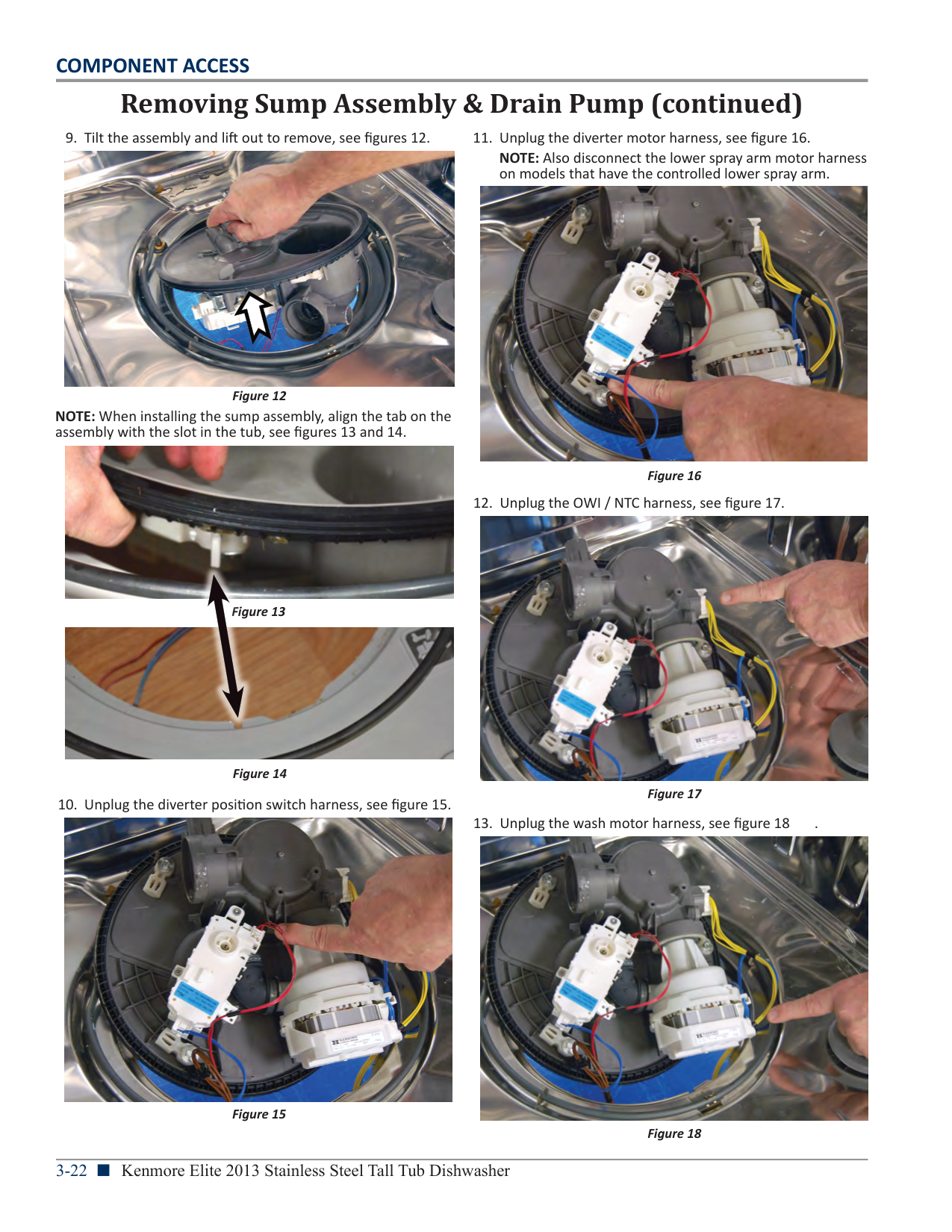
NOTE: Also disconnect the lower spray arm motor harness on models that have the controlled lower spray arm.


NOTE: When installing the sump assembly, align the tab on the assembly with the slot in the tub, see figures 13 and 14.


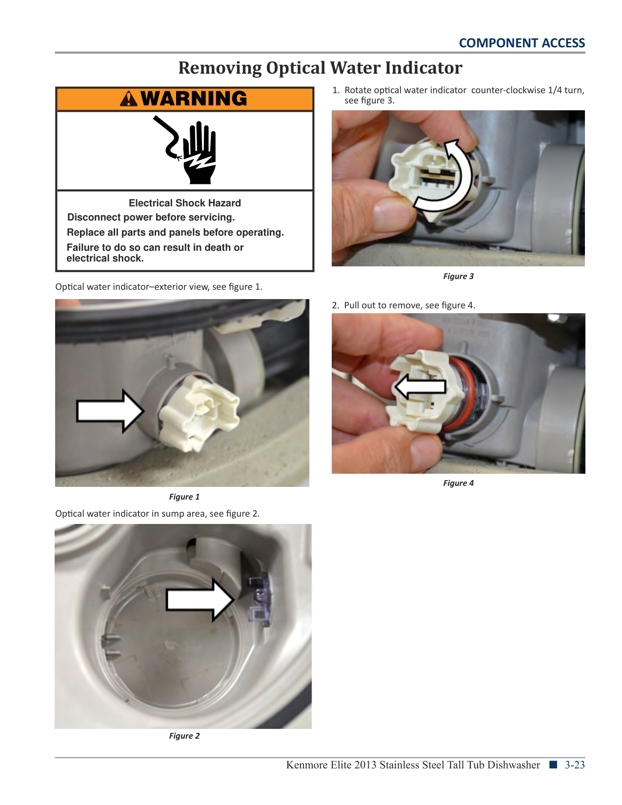
Removing Optical Water Indicator

|WARNING
| |---| | | |Electrical Shock Hazard Disconnect power before servicing.
Failure to do so can result in death or electrical shock.
Replace all parts and panels before operating.|


Figure 3 Optical water indicator–exterior view, see figure 1.

Figure 4 Figure 1
Optical water indicator in sump area, see figure 2.
Figure 2

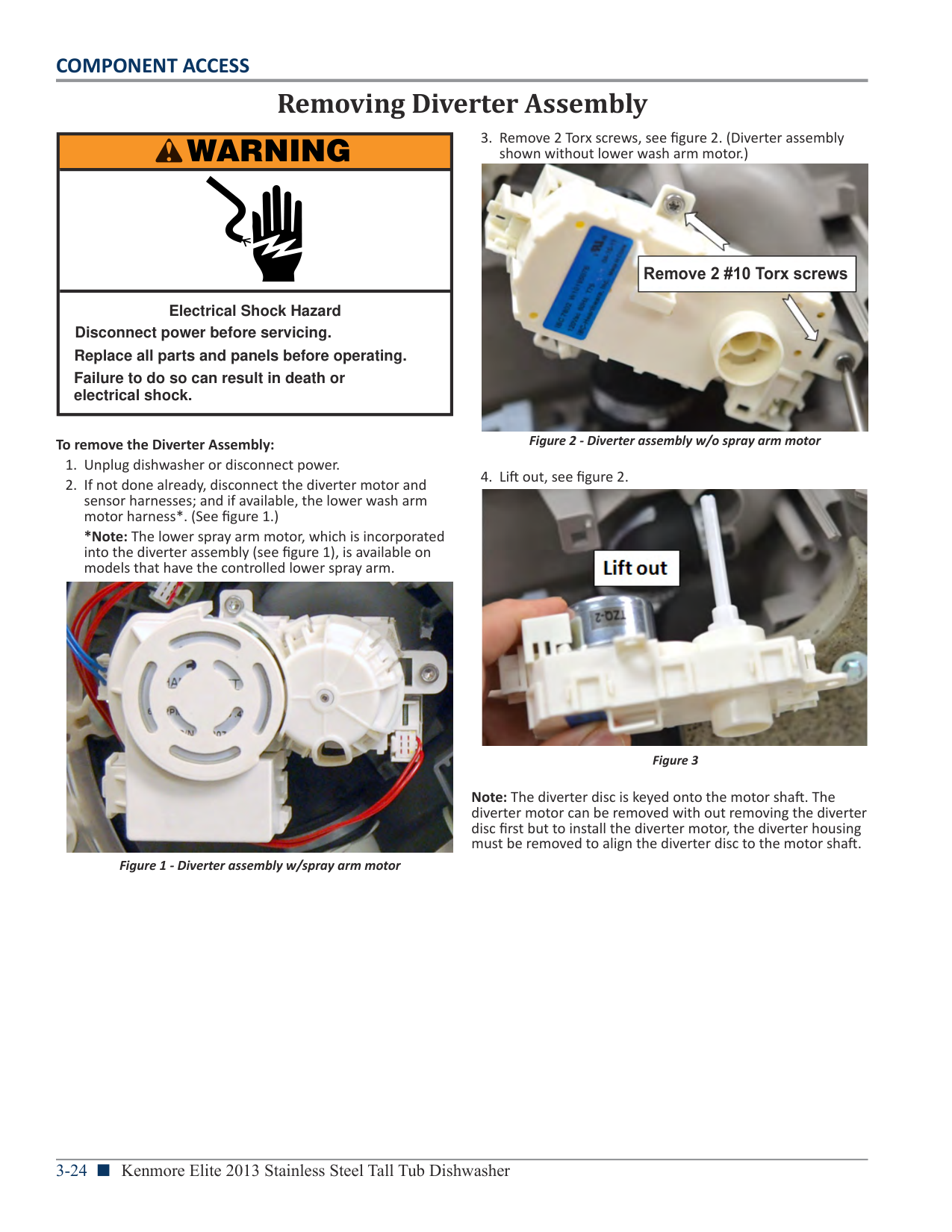
Removing Diverter Assembly
|WARNING
| |---| | | |Electrical Shock Hazard Disconnect power before servicing.
Failure to do so can result in death or electrical shock.
Replace all parts and panels before operating.|

Remove 2 #10 Torx screws
############## Figure 2 - Diverter assembly w/o spray arm motor
############# To remove the Diverter Assembly:
*Note: The lower spray arm motor, which is incorporated into the diverter assembly (see figure 1), is available on models that have the controlled lower spray arm.

Figure 3
Note: The diverter disc is keyed onto the motor shaft. The diverter motor can be removed with out removing the diverter disc first but to install the diverter motor, the diverter housing must be removed to align the diverter disc to the motor shaft.
Figure 1 - Diverter assembly w/spray arm motor
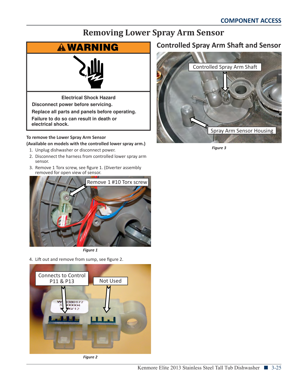
Removing Lower Spray Arm Sensor
|WARNING
| |---| | | |Electrical Shock Hazard Disconnect power before servicing.
Failure to do so can result in death or electrical shock.
Replace all parts and panels before operating.|
To remove the Lower Spray Arm Sensor (Available on models with the controlled lower spray arm.)

|Remove 1 #10 Torx screw| |---|

|Connects to Control P11 & P13| |---|
|Not Used| |---|
###### Controlled Spray Arm Shaft and Sensor

|Controlled Spray Arm Shaft| |---|
|Spray Arm Sensor Housing| |---|
Figure 3

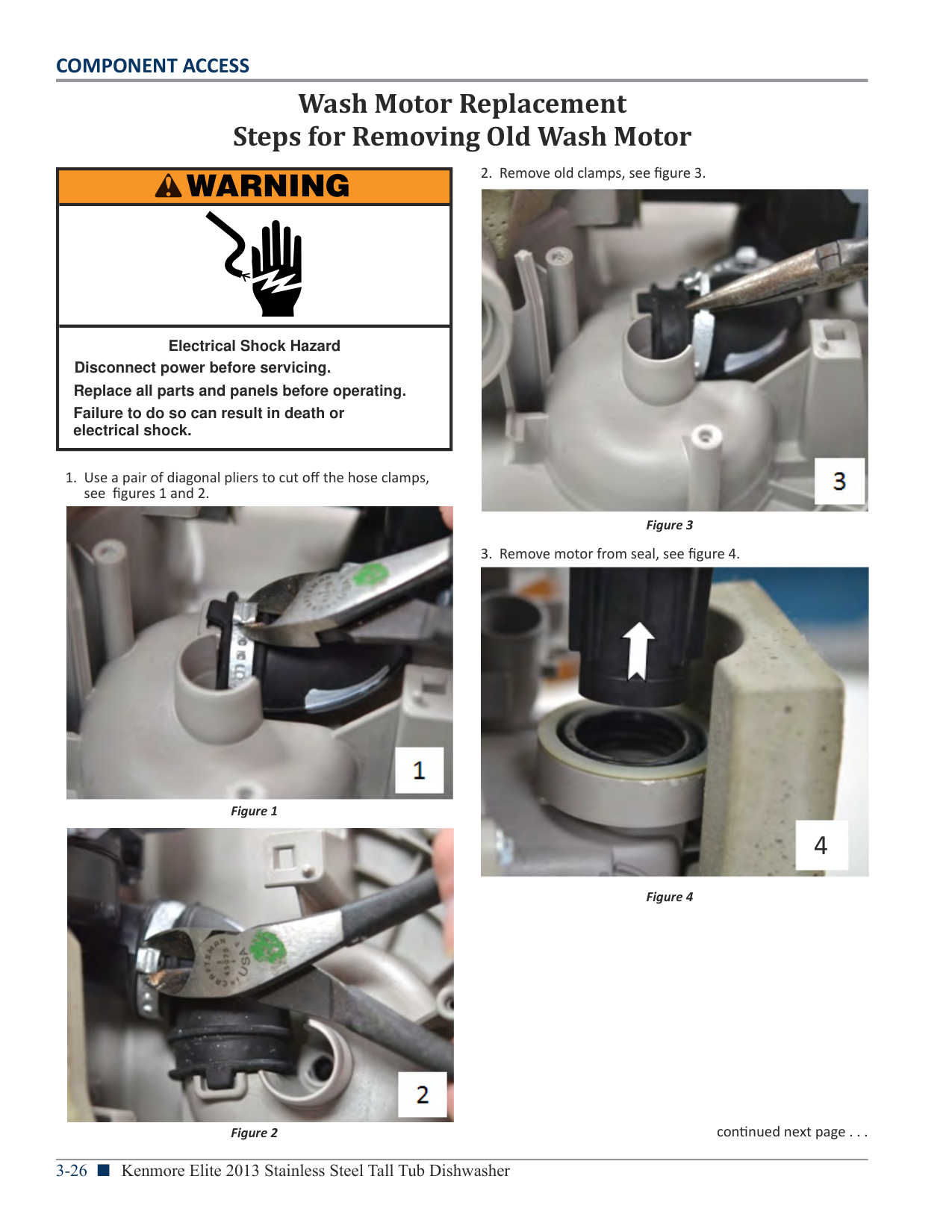
####### COMPONENT ACCESS
Wash Motor Replacement Steps for Removing Old Wash Motor
|WARNING
| |---| | | |Electrical Shock Hazard Disconnect power before servicing.
Failure to do so can result in death or electrical shock.
Replace all parts and panels before operating.|


Figure 1
4


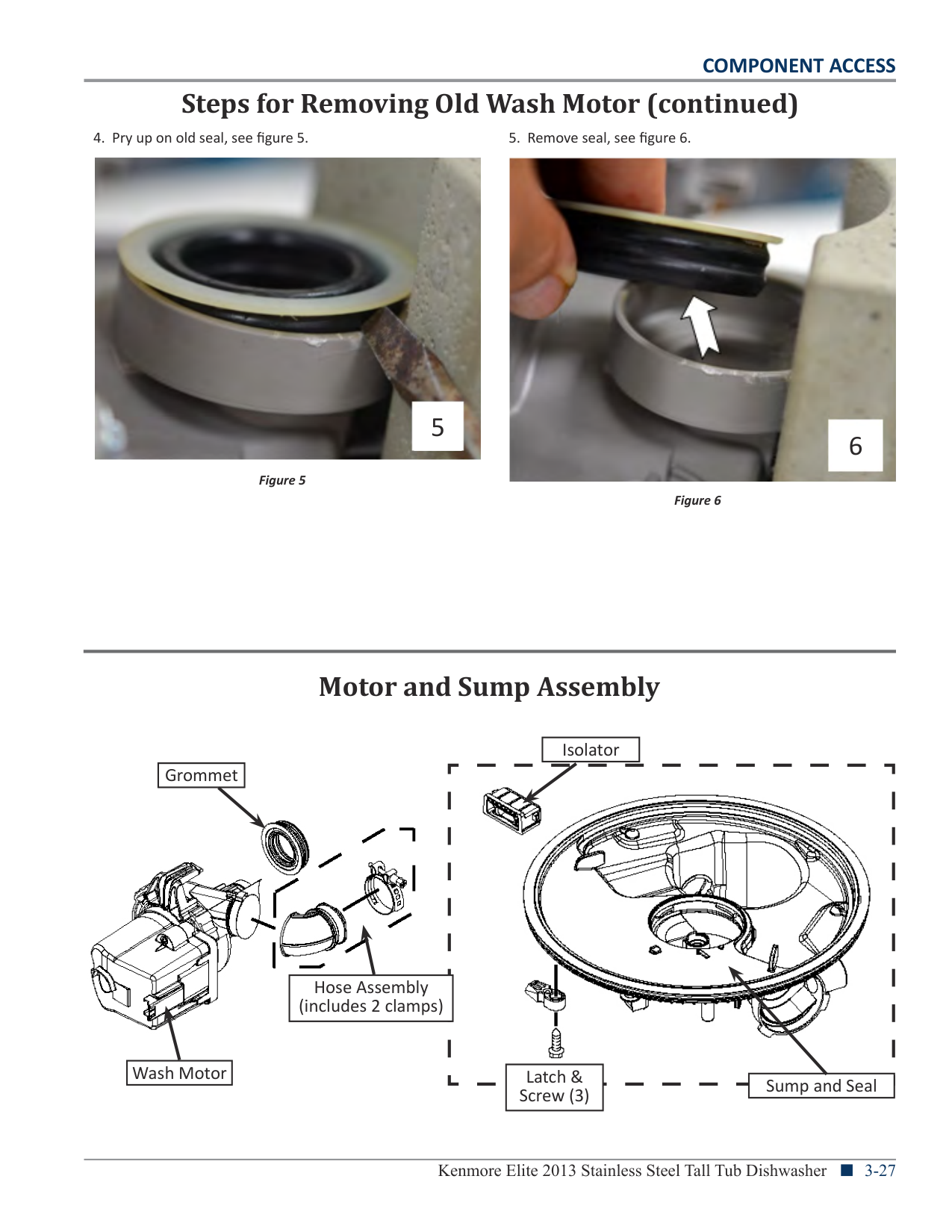
####### COMPONENT ACCESS
Steps for Removing Old Wash Motor (continued)
5
6
Figure 5
Figure 6
Motor and Sump Assembly
|Isolator| |---|
|Grommet| |---|


Hose Assembly (includes 2 clamps)
|Wash Motor| |---|
Latch & Screw (3)
Sump and Seal

####### COMPONENT ACCESS
Steps for Installing New Wash Motor

|WARNING
| |---| | | |Electrical Shock Hazard Disconnect power before servicing.
Failure to do so can result in death or electrical shock.
Replace all parts and panels before operating.|


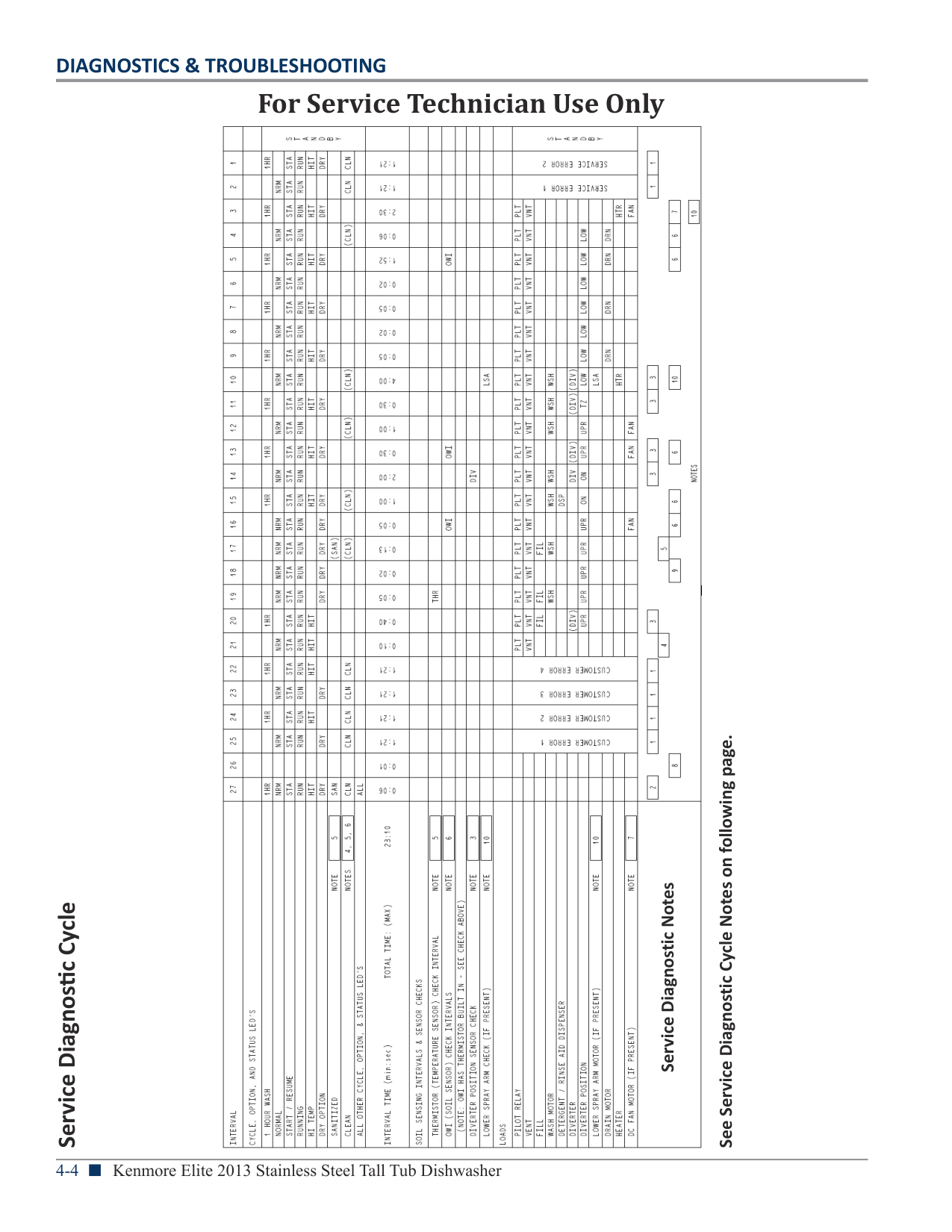
Figure 1
####### COMPONENT ACCESS
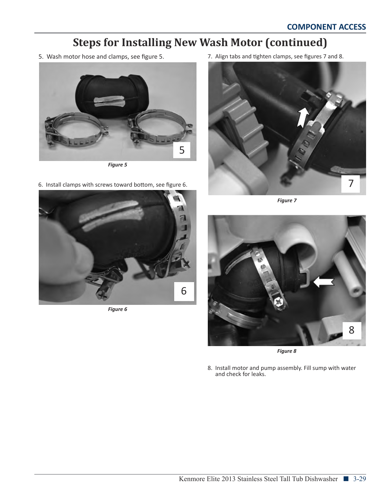
Steps for Installing New Wash Motor (continued)


5

6
COMPONENT ACCESS
Notes
Section 4: Diagnostics & Troubleshooting
This section provides diagnostic, fault codes, and troubleshooting information for the “Kenmore Elite Stainless Steel Tall Tub Dishwasher.”
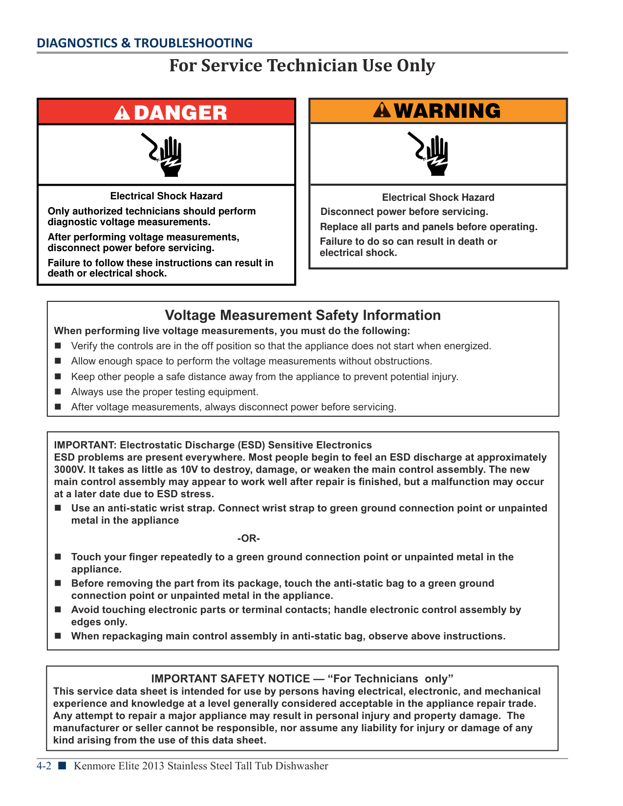
For Service Technician Use Only
|DANGER
| |---| | | |Electrical Shock Hazard
Only authorized technicians should perform diagnostic voltage measurements.
After performing voltage measurements, disconnect power before servicing.
Failure to follow these instructions can result in death or electrical shock.|
|WARNING
| |---| | | |Electrical Shock Hazard Disconnect power before servicing.
Failure to do so can result in death or electrical shock.
Replace all parts and panels before operating.|
|Voltage Measurement Safety Information When performing live voltage measurements, you must do the following: n Verifythecontrolsareintheoffpositionsothattheappliancedoesnotstartwhenenergized. n Allowenoughspacetoperformthevoltagemeasurementswithoutobstructions. n Keepotherpeopleasafedistanceawayfromtheappliancetopreventpotentialinjury. n Alwaysusethepropertestingequipment. n Aftervoltagemeasurements,alwaysdisconnectpowerbeforeservicing.| |---|
|IMPORTANT: Electrostatic Discharge (ESD) Sensitive Electronics ESD problems are present everywhere. Most people begin to feel an ESD discharge at approximately 3000V. It takes as little as 10V to destroy, damage, or weaken the main control assembly. The new main control assembly may appear to work well after repair is finished, but a malfunction may occur at a later date due to ESD stress. n Use an anti-static wrist strap. Connect wrist strap to green ground connection point or unpainted
metal in the appliance
-OR-
n Touch your finger repeatedly to a green ground connection point or unpainted metal in the
appliance.
n Before removing the part from its package, touch the anti-static bag to a green ground
connection point or unpainted metal in the appliance.
n Avoid touching electronic parts or terminal contacts; handle electronic control assembly by
edges only.
n When repackaging main control assembly in anti-static bag, observe above instructions.| |---|
|IMPORTANT SAFETY NOTICE — “For Technicians only” This service data sheet is intended for use by persons having electrical, electronic, and mechanical experience and knowledge at a level generally considered acceptable in the appliance repair trade. Any attempt to repair a major appliance may result in personal injury and property damage. The manufacturer or seller cannot be responsible, nor assume any liability for injury or damage of any kind arising from the use of this data sheet.| |---|
|For Service Technician Use Only| |---|
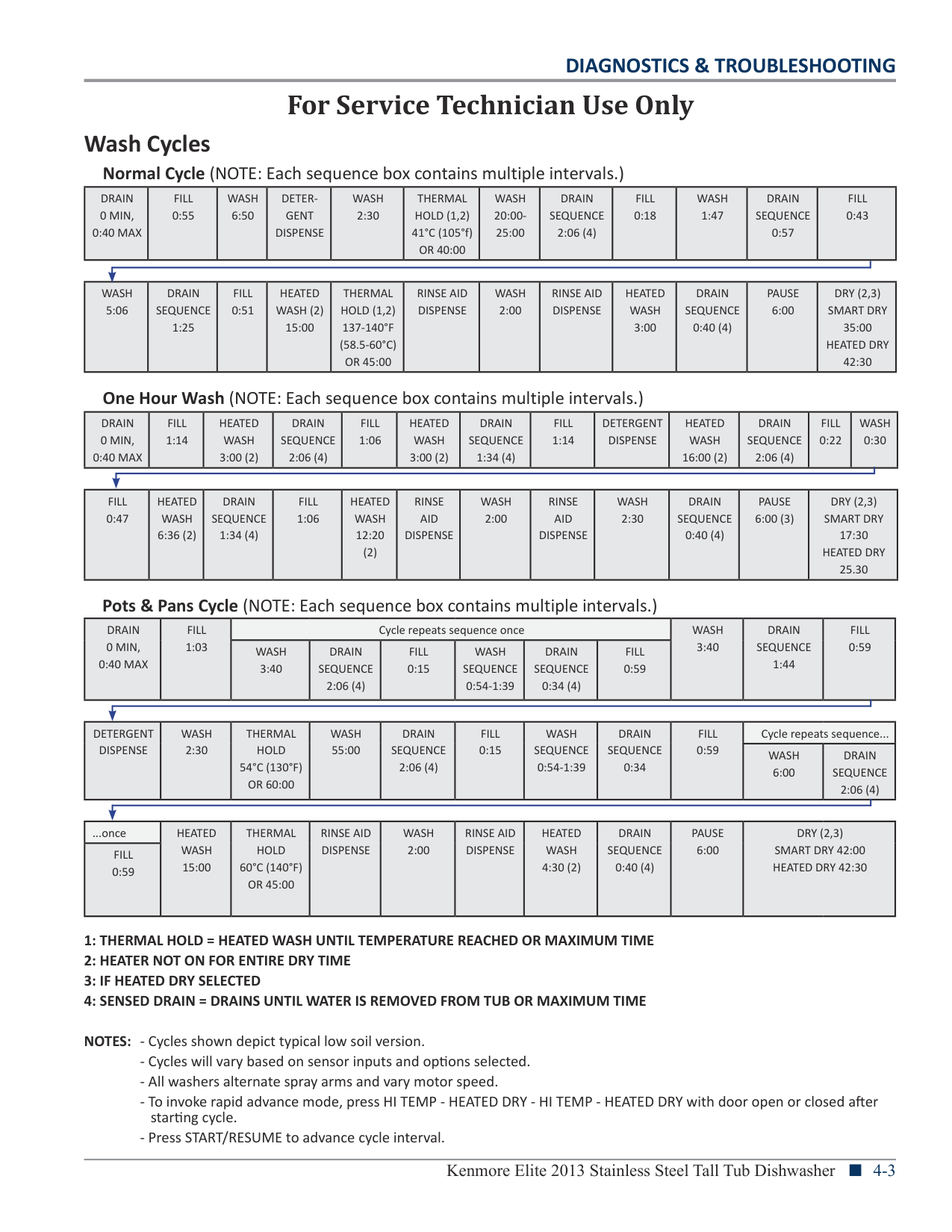
###### Wash Cycles
Normal Cycle (NOTE: Each sequence box contains multiple intervals.)
|DRAIN 0 MIN, 0:40 MAX|FILL 0:55|WASH 6:50|DETERGENT DISPENSE|WASH 2:30|THERMAL HOLD (1,2) 41°C (105°f) OR 40:00|WASH 20:0025:00|DRAIN SEQUENCE 2:06 (4)|FILL 0:18|WASH 1:47|DRAIN SEQUENCE 0:57|FILL 0:43| |---|---|---|---|---|---|---|---|---|---|---|---|
|WASH 5:06|DRAIN SEQUENCE 1:25|FILL 0:51|HEATED WASH (2) 15:00|THERMAL HOLD (1,2) 137-140°F (58.5-60°C) OR 45:00|RINSE AID DISPENSE|WASH 2:00|RINSE AID DISPENSE|HEATED WASH 3:00|DRAIN SEQUENCE 0:40 (4)|PAUSE 6:00|DRY (2,3) SMART DRY 35:00 HEATED DRY 42:30| |---|---|---|---|---|---|---|---|---|---|---|---|
DRAIN 0 MIN, 0:40 MAX
FILL 1:14
HEATED WASH 3:00 (2)
DRAIN SEQUENCE 2:06 (4)
FILL 1:06
HEATED WASH 3:00 (2)
DRAIN SEQUENCE 1:34 (4)
FILL 1:14
DETERGENT DISPENSE
HEATED WASH 16:00 (2)
DRAIN SEQUENCE 2:06 (4)
FILL 0:22
WASH 0:30
|FILL 0:47|HEATED WASH 6:36 (2)|DRAIN SEQUENCE 1:34 (4)|FILL 1:06|HEATED WASH 12:20 (2)|RINSE AID DISPENSE|WASH 2:00|RINSE AID DISPENSE|WASH 2:30|DRAIN SEQUENCE 0:40 (4)|PAUSE 6:00 (3)|DRY (2,3) SMART DRY 17:30 HEATED DRY 25.30| |---|---|---|---|---|---|---|---|---|---|---|---|
DRAIN 0 MIN,
FILL 1:03
Cycle repeats sequence once WASH 3:40
DRAIN SEQUENCE 1:44
FILL 0:59WASH
3:40
DRAIN SEQUENCE 2:06 (4)
FILL 0:15
WASH SEQUENCE 0:54-1:39
DRAIN SEQUENCE 0:34 (4)
FILL 0:59
DETERGENT DISPENSE
WASH 2:30
THERMAL HOLD 54°C (130°F) OR 60:00
WASH 55:00
DRAIN SEQUENCE 2:06 (4)
FILL 0:15
WASH SEQUENCE 0:54-1:39
DRAIN SEQUENCE 0:34
FILL 0:59
Cycle repeats sequence...
WASH 6:00
DRAIN SEQUENCE 2:06 (4)
One Hour Wash (NOTE: Each sequence box contains multiple intervals.)
Pots & Pans Cycle (NOTE: Each sequence box contains multiple intervals.)
|...once|HEATED WASH 15:00|THERMAL HOLD 60°C (140°F) OR 45:00|RINSE AID DISPENSE|WASH 2:00|RINSE AID DISPENSE|HEATED WASH 4:30 (2)|DRAIN SEQUENCE 0:40 (4)|PAUSE 6:00|DRY (2,3) SMART DRY 42:00 HEATED DRY 42:30| |---|---|---|---|---|---|---|---|---|---| |FILL 0:59|HEATED WASH 15:00|THERMAL HOLD 60°C (140°F) OR 45:00|RINSE AID DISPENSE|WASH 2:00|RINSE AID DISPENSE|HEATED WASH 4:30 (2)|DRAIN SEQUENCE 0:40 (4)|PAUSE 6:00|DRY (2,3) SMART DRY 42:00 HEATED DRY 42:30|
NOTES: - Cycles shown depict typical low soil version.
|For Service Technician Use Only| |---|

See Service Diagnostic Cycle Notes on following page.
Service Diagnostic Notes
Service Diagnostic Cycle
|For Service Technician Use Only| |---|
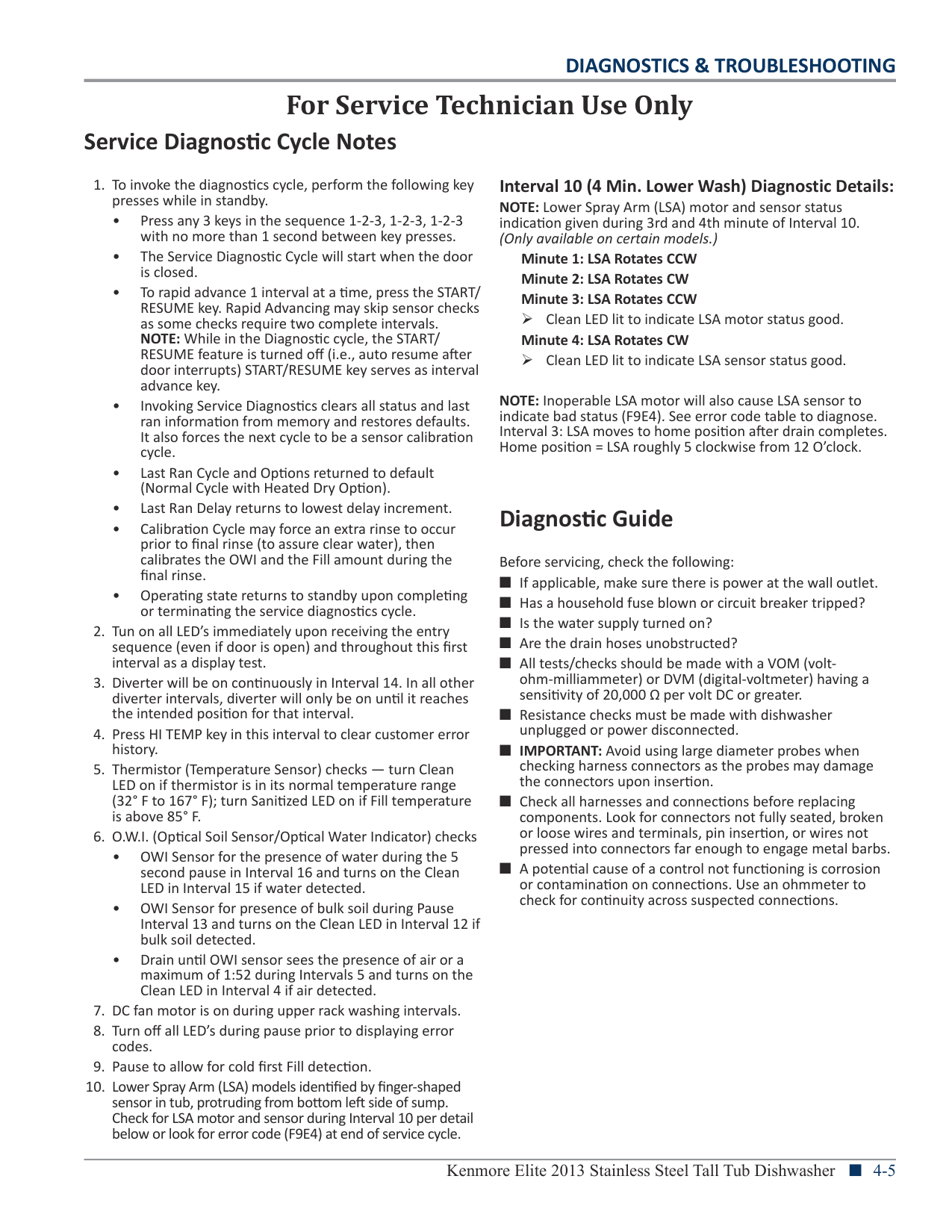
###### Service Diagnostic Cycle Notes
Interval 10 (4 Min. Lower Wash) Diagnostic Details: NOTE: Lower Spray Arm (LSA) motor and sensor status indication given during 3rd and 4th minute of Interval 10. (Only available on certain models.)
NOTE: Inoperable LSA motor will also cause LSA sensor to indicate bad status (F9E4). See error code table to diagnose. Interval 3: LSA moves to home position after drain completes. Home position = LSA roughly 5 clockwise from 12 O’clock.
###### Diagnostic Guide
Before servicing, check the following:
|For Service Technician Use Only| |---|
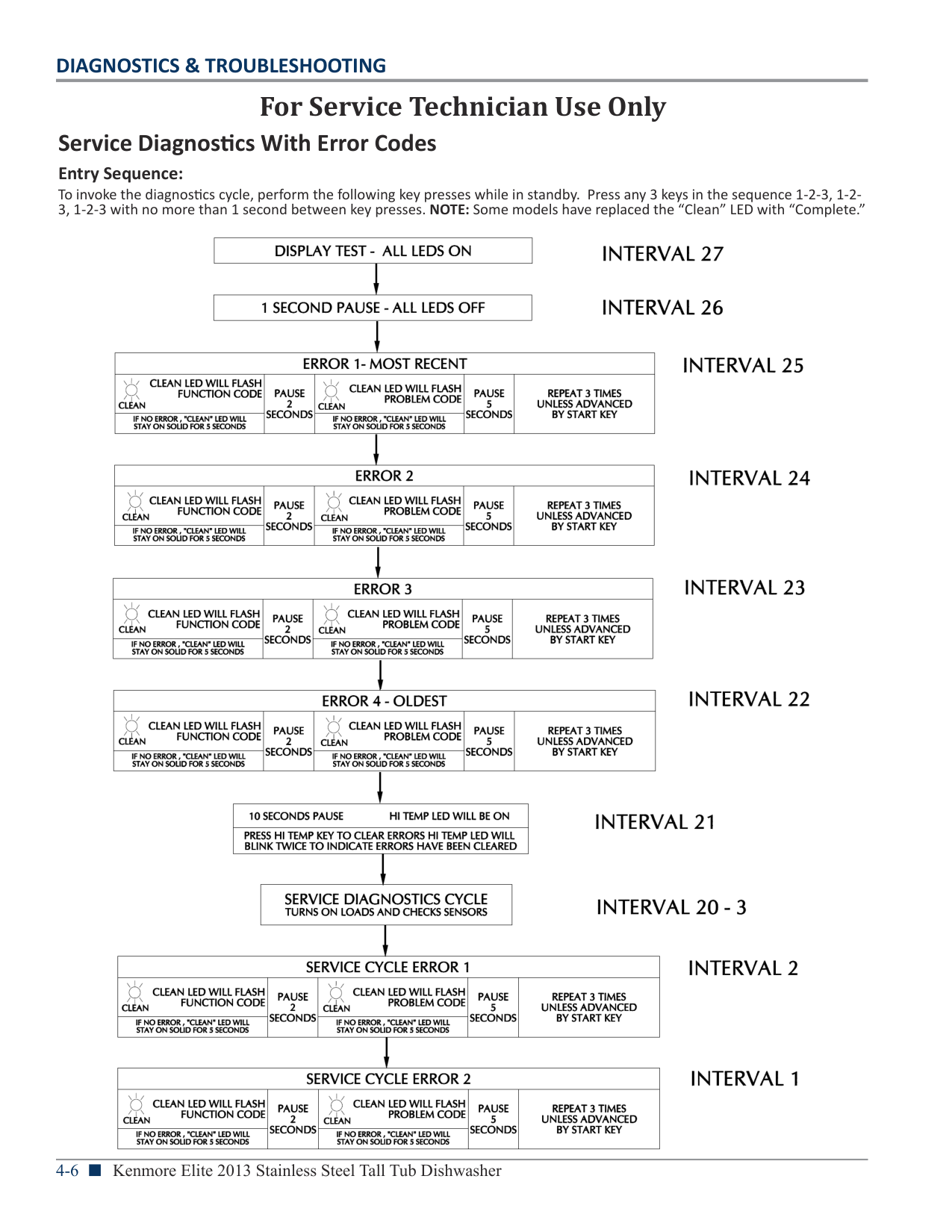
###### Service Diagnostics With Error Codes
Entry Sequence: To invoke the diagnostics cycle, perform the following key presses while in standby. Press any 3 keys in the sequence 1-2-3, 1-23, 1-2-3 with no more than 1 second between key presses. NOTE: Some models have replaced the “Clean” LED with “Complete.”


|For Service Technician Use Only| |---|
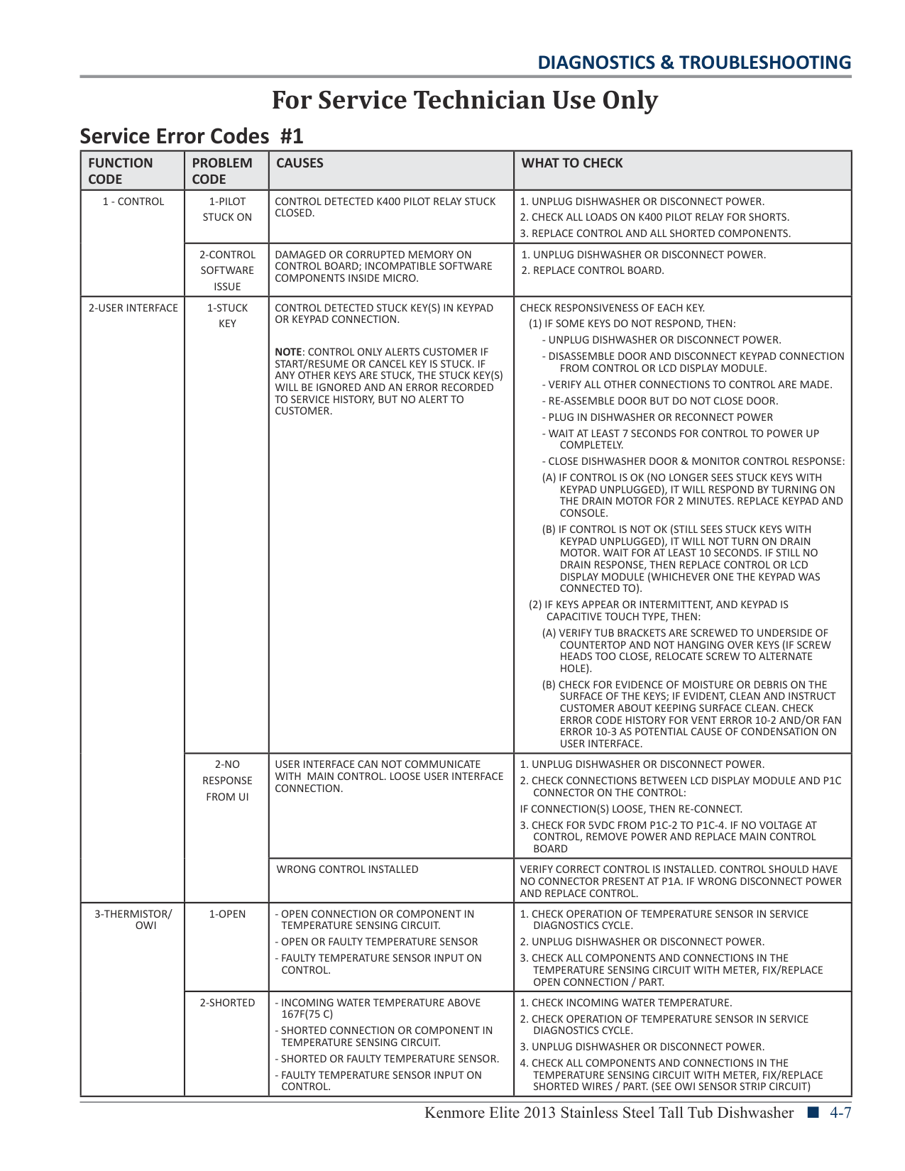
|FUNCTION CODE|PROBLEM CODE|CAUSES|WHAT TO CHECK| |---|---|---|---| |1 - CONTROL|1-PILOT STUCK ON|CONTROL DETECTED K400 PILOT RELAY STUCK CLOSED.|1. UNPLUG DISHWASHER OR DISCONNECT POWER.
2. CHECK ALL LOADS ON K400 PILOT RELAY FOR SHORTS.
3. REPLACE CONTROL AND ALL SHORTED COMPONENTS.
| |1 - CONTROL|2-CONTROL SOFTWARE ISSUE|DAMAGED OR CORRUPTED MEMORY ON CONTROL BOARD; INCOMPATIBLE SOFTWARE COMPONENTS INSIDE MICRO.|1. UNPLUG DISHWASHER OR DISCONNECT POWER.
2. REPLACE CONTROL BOARD.
| |2-USER INTERFACE|1-STUCK KEY|CONTROL DETECTED STUCK KEY(S) IN KEYPAD OR KEYPAD CONNECTION.
NOTE: CONTROL ONLY ALERTS CUSTOMER IF START/RESUME OR CANCEL KEY IS STUCK. IF ANY OTHER KEYS ARE STUCK, THE STUCK KEY(S) WILL BE IGNORED AND AN ERROR RECORDED TO SERVICE HISTORY, BUT NO ALERT TO CUSTOMER.|CHECK RESPONSIVENESS OF EACH KEY.
(1) IF SOME KEYS DO NOT RESPOND, THEN:
- UNPLUG DISHWASHER OR DISCONNECT POWER.
- DISASSEMBLE DOOR AND DISCONNECT KEYPAD CONNECTION FROM CONTROL OR LCD DISPLAY MODULE.
- VERIFY ALL OTHER CONNECTIONS TO CONTROL ARE MADE.
- RE-ASSEMBLE DOOR BUT DO NOT CLOSE DOOR.
- PLUG IN DISHWASHER OR RECONNECT POWER
- WAIT AT LEAST 7 SECONDS FOR CONTROL TO POWER UP COMPLETELY.
- CLOSE DISHWASHER DOOR & MONITOR CONTROL RESPONSE:
(A) IF CONTROL IS OK (NO LONGER SEES STUCK KEYS WITH KEYPAD UNPLUGGED), IT WILL RESPOND BY TURNING ON THE DRAIN MOTOR FOR 2 MINUTES. REPLACE KEYPAD AND CONSOLE.
(B) IF CONTROL IS NOT OK (STILL SEES STUCK KEYS WITH KEYPAD UNPLUGGED), IT WILL NOT TURN ON DRAIN MOTOR. WAIT FOR AT LEAST 10 SECONDS. IF STILL NO DRAIN RESPONSE, THEN REPLACE CONTROL OR LCD DISPLAY MODULE (WHICHEVER ONE THE KEYPAD WAS CONNECTED TO).
(2) IF KEYS APPEAR OR INTERMITTENT, AND KEYPAD IS CAPACITIVE TOUCH TYPE, THEN:
(A) VERIFY TUB BRACKETS ARE SCREWED TO UNDERSIDE OF COUNTERTOP AND NOT HANGING OVER KEYS (IF SCREW HEADS TOO CLOSE, RELOCATE SCREW TO ALTERNATE HOLE).
(B) CHECK FOR EVIDENCE OF MOISTURE OR DEBRIS ON THE SURFACE OF THE KEYS; IF EVIDENT, CLEAN AND INSTRUCT CUSTOMER ABOUT KEEPING SURFACE CLEAN. CHECK ERROR CODE HISTORY FOR VENT ERROR 10-2 AND/OR FAN ERROR 10-3 AS POTENTIAL CAUSE OF CONDENSATION ON USER INTERFACE.
| |2-USER INTERFACE|2-NO RESPONSE FROM UI|USER INTERFACE CAN NOT COMMUNICATE WITH MAIN CONTROL. LOOSE USER INTERFACE CONNECTION.|1. UNPLUG DISHWASHER OR DISCONNECT POWER.
2. CHECK CONNECTIONS BETWEEN LCD DISPLAY MODULE AND P1C CONNECTOR ON THE CONTROL:
IF CONNECTION(S) LOOSE, THEN RE-CONNECT.
3. CHECK FOR 5VDC FROM P1C-2 TO P1C-4. IF NO VOLTAGE AT CONTROL, REMOVE POWER AND REPLACE MAIN CONTROL BOARD
| |2-USER INTERFACE|2-NO RESPONSE FROM UI|WRONG CONTROL INSTALLED|VERIFY CORRECT CONTROL IS INSTALLED. CONTROL SHOULD HAVE NO CONNECTOR PRESENT AT P1A. IF WRONG DISCONNECT POWER AND REPLACE CONTROL.| |3-THERMISTOR/ OWI|1-OPEN|- OPEN CONNECTION OR COMPONENT IN TEMPERATURE SENSING CIRCUIT.
- OPEN OR FAULTY TEMPERATURE SENSOR
- FAULTY TEMPERATURE SENSOR INPUT ON CONTROL.
|1. CHECK OPERATION OF TEMPERATURE SENSOR IN SERVICE DIAGNOSTICS CYCLE.
2. UNPLUG DISHWASHER OR DISCONNECT POWER.
3. CHECK ALL COMPONENTS AND CONNECTIONS IN THE TEMPERATURE SENSING CIRCUIT WITH METER, FIX/REPLACE OPEN CONNECTION / PART.
| |3-THERMISTOR/ OWI|2-SHORTED|- INCOMING WATER TEMPERATURE ABOVE 167F(75 C)
- SHORTED CONNECTION OR COMPONENT IN TEMPERATURE SENSING CIRCUIT.
- SHORTED OR FAULTY TEMPERATURE SENSOR.
- FAULTY TEMPERATURE SENSOR INPUT ON CONTROL.
|1. CHECK INCOMING WATER TEMPERATURE.
2. CHECK OPERATION OF TEMPERATURE SENSOR IN SERVICE DIAGNOSTICS CYCLE.
3. UNPLUG DISHWASHER OR DISCONNECT POWER.
4. CHECK ALL COMPONENTS AND CONNECTIONS IN THE TEMPERATURE SENSING CIRCUIT WITH METER, FIX/REPLACE SHORTED WIRES / PART. (SEE OWI SENSOR STRIP CIRCUIT)
|
|For Service Technician Use Only| |---|
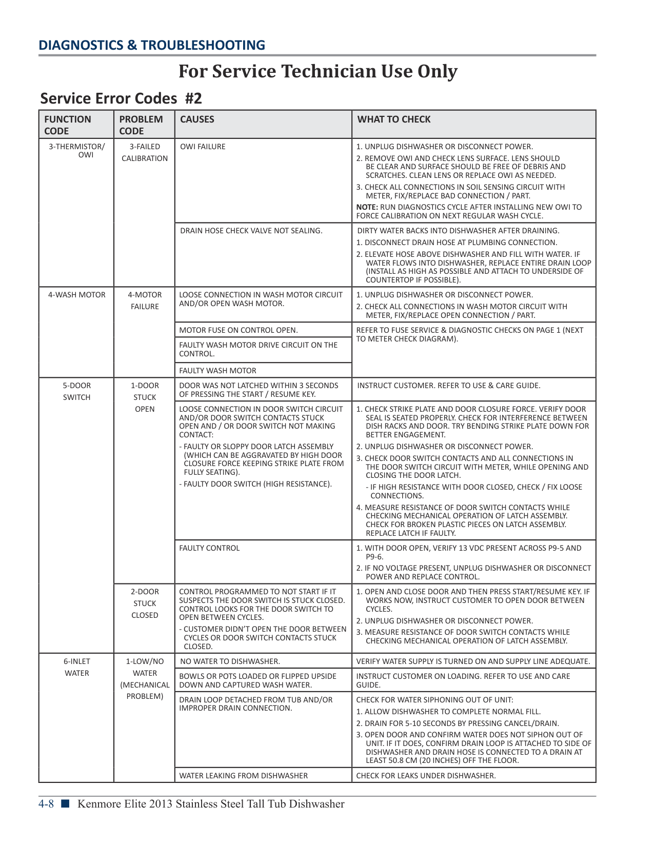
|FUNCTION CODE|PROBLEM CODE|CAUSES|WHAT TO CHECK| |---|---|---|---| |3-THERMISTOR/ OWI|3-FAILED CALIBRATION|OWI FAILURE|1. UNPLUG DISHWASHER OR DISCONNECT POWER.
2. REMOVE OWI AND CHECK LENS SURFACE. LENS SHOULD BE CLEAR AND SURFACE SHOULD BE FREE OF DEBRIS AND SCRATCHES. CLEAN LENS OR REPLACE OWI AS NEEDED.
3. CHECK ALL CONNECTIONS IN SOIL SENSING CIRCUIT WITH METER, FIX/REPLACE BAD CONNECTION / PART.
NOTE: RUN DIAGNOSTICS CYCLE AFTER INSTALLING NEW OWI TO FORCE CALIBRATION ON NEXT REGULAR WASH CYCLE.| |3-THERMISTOR/ OWI|3-FAILED CALIBRATION|DRAIN HOSE CHECK VALVE NOT SEALING.|DIRTY WATER BACKS INTO DISHWASHER AFTER DRAINING.
1. DISCONNECT DRAIN HOSE AT PLUMBING CONNECTION.
2. ELEVATE HOSE ABOVE DISHWASHER AND FILL WITH WATER. IF WATER FLOWS INTO DISHWASHER, REPLACE ENTIRE DRAIN LOOP (INSTALL AS HIGH AS POSSIBLE AND ATTACH TO UNDERSIDE OF COUNTERTOP IF POSSIBLE).
| |4-WASH MOTOR|4-MOTOR FAILURE|LOOSE CONNECTION IN WASH MOTOR CIRCUIT AND/OR OPEN WASH MOTOR.|1. UNPLUG DISHWASHER OR DISCONNECT POWER.
2. CHECK ALL CONNECTIONS IN WASH MOTOR CIRCUIT WITH METER, FIX/REPLACE OPEN CONNECTION / PART.
| |4-WASH MOTOR|4-MOTOR FAILURE|MOTOR FUSE ON CONTROL OPEN.|REFER TO FUSE SERVICE & DIAGNOSTIC CHECKS ON PAGE 1 (NEXT TO METER CHECK DIAGRAM).| |4-WASH MOTOR|4-MOTOR FAILURE|FAULTY WASH MOTOR DRIVE CIRCUIT ON THE CONTROL.|REFER TO FUSE SERVICE & DIAGNOSTIC CHECKS ON PAGE 1 (NEXT TO METER CHECK DIAGRAM).| |4-WASH MOTOR|4-MOTOR FAILURE|FAULTY WASH MOTOR|REFER TO FUSE SERVICE & DIAGNOSTIC CHECKS ON PAGE 1 (NEXT TO METER CHECK DIAGRAM).| |5-DOOR SWITCH|1-DOOR STUCK OPEN|DOOR WAS NOT LATCHED WITHIN 3 SECONDS OF PRESSING THE START / RESUME KEY.|INSTRUCT CUSTOMER. REFER TO USE & CARE GUIDE.| |5-DOOR SWITCH|1-DOOR STUCK OPEN|LOOSE CONNECTION IN DOOR SWITCH CIRCUIT AND/OR DOOR SWITCH CONTACTS STUCK OPEN AND / OR DOOR SWITCH NOT MAKING CONTACT:
- FAULTY OR SLOPPY DOOR LATCH ASSEMBLY (WHICH CAN BE AGGRAVATED BY HIGH DOOR CLOSURE FORCE KEEPING STRIKE PLATE FROM FULLY SEATING).
- FAULTY DOOR SWITCH (HIGH RESISTANCE).
|1. CHECK STRIKE PLATE AND DOOR CLOSURE FORCE. VERIFY DOOR SEAL IS SEATED PROPERLY. CHECK FOR INTERFERENCE BETWEEN DISH RACKS AND DOOR. TRY BENDING STRIKE PLATE DOWN FOR BETTER ENGAGEMENT.
2. UNPLUG DISHWASHER OR DISCONNECT POWER.
3. CHECK DOOR SWITCH CONTACTS AND ALL CONNECTIONS IN THE DOOR SWITCH CIRCUIT WITH METER, WHILE OPENING AND CLOSING THE DOOR LATCH.
- IF HIGH RESISTANCE WITH DOOR CLOSED, CHECK / FIX LOOSE CONNECTIONS.
4. MEASURE RESISTANCE OF DOOR SWITCH CONTACTS WHILE CHECKING MECHANICAL OPERATION OF LATCH ASSEMBLY. CHECK FOR BROKEN PLASTIC PIECES ON LATCH ASSEMBLY. REPLACE LATCH IF FAULTY.
| |5-DOOR SWITCH|1-DOOR STUCK OPEN|FAULTY CONTROL|1. WITH DOOR OPEN, VERIFY 13 VDC PRESENT ACROSS P9-5 AND P9-6.
2. IF NO VOLTAGE PRESENT, UNPLUG DISHWASHER OR DISCONNECT POWER AND REPLACE CONTROL.
| |5-DOOR SWITCH|2-DOOR STUCK CLOSED|CONTROL PROGRAMMED TO NOT START IF IT SUSPECTS THE DOOR SWITCH IS STUCK CLOSED. CONTROL LOOKS FOR THE DOOR SWITCH TO OPEN BETWEEN CYCLES.
- CUSTOMER DIDN’T OPEN THE DOOR BETWEEN CYCLES OR DOOR SWITCH CONTACTS STUCK CLOSED.|1. OPEN AND CLOSE DOOR AND THEN PRESS START/RESUME KEY. IF WORKS NOW, INSTRUCT CUSTOMER TO OPEN DOOR BETWEEN CYCLES.
2. UNPLUG DISHWASHER OR DISCONNECT POWER.
3. MEASURE RESISTANCE OF DOOR SWITCH CONTACTS WHILE CHECKING MECHANICAL OPERATION OF LATCH ASSEMBLY.
| |6-INLET WATER|1-LOW/NO WATER (MECHANICAL PROBLEM)|NO WATER TO DISHWASHER.|VERIFY WATER SUPPLY IS TURNED ON AND SUPPLY LINE ADEQUATE.| |6-INLET WATER|1-LOW/NO WATER (MECHANICAL PROBLEM)|BOWLS OR POTS LOADED OR FLIPPED UPSIDE DOWN AND CAPTURED WASH WATER.|INSTRUCT CUSTOMER ON LOADING. REFER TO USE AND CARE GUIDE.| |6-INLET WATER|1-LOW/NO WATER (MECHANICAL PROBLEM)|DRAIN LOOP DETACHED FROM TUB AND/OR IMPROPER DRAIN CONNECTION.|CHECK FOR WATER SIPHONING OUT OF UNIT:
1. ALLOW DISHWASHER TO COMPLETE NORMAL FILL.
2. DRAIN FOR 5-10 SECONDS BY PRESSING CANCEL/DRAIN.
3. OPEN DOOR AND CONFIRM WATER DOES NOT SIPHON OUT OF UNIT. IF IT DOES, CONFIRM DRAIN LOOP IS ATTACHED TO SIDE OF DISHWASHER AND DRAIN HOSE IS CONNECTED TO A DRAIN AT LEAST 50.8 CM (20 INCHES) OFF THE FLOOR.
| |6-INLET WATER|1-LOW/NO WATER (MECHANICAL PROBLEM)|WATER LEAKING FROM DISHWASHER|CHECK FOR LEAKS UNDER DISHWASHER.|
|For Service Technician Use Only| |---|
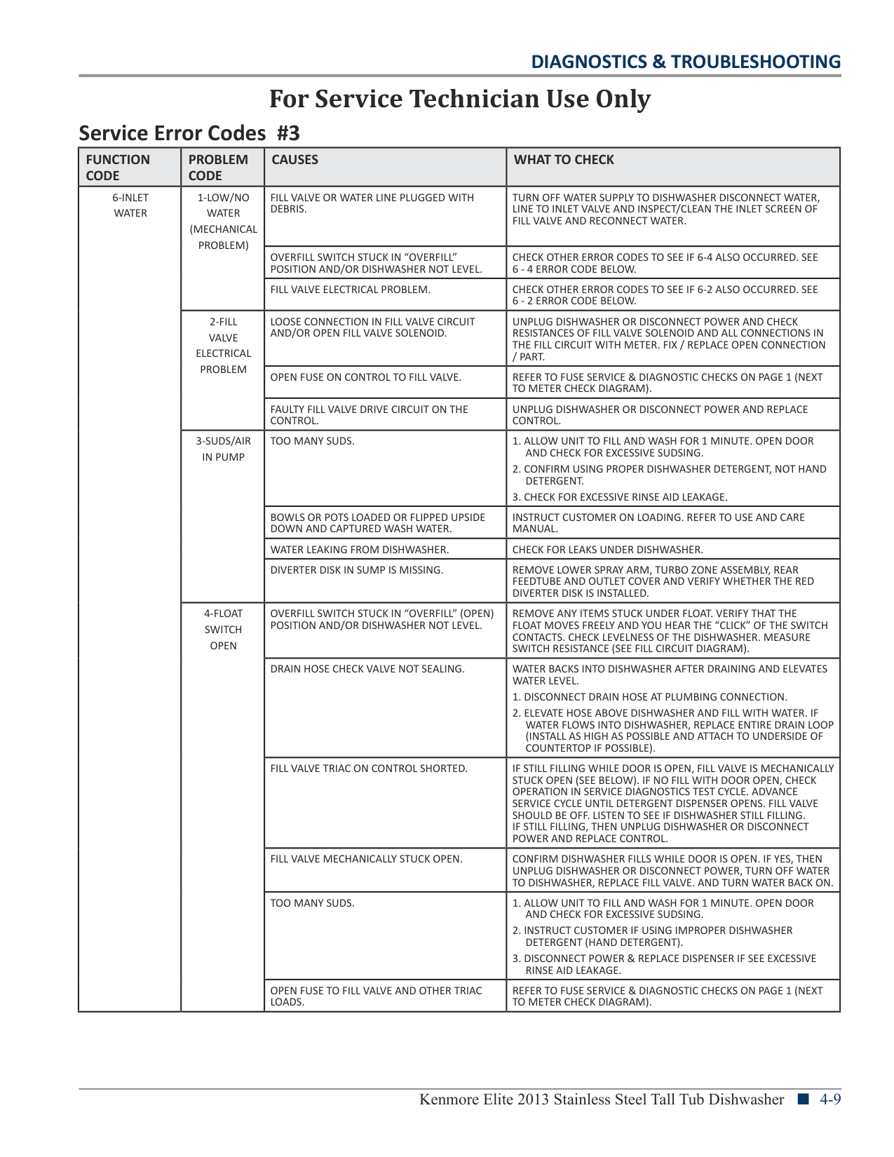
|FUNCTION CODE|PROBLEM CODE|CAUSES|WHAT TO CHECK| |---|---|---|---| |6-INLET WATER|1-LOW/NO WATER (MECHANICAL PROBLEM)|FILL VALVE OR WATER LINE PLUGGED WITH DEBRIS.|TURN OFF WATER SUPPLY TO DISHWASHER DISCONNECT WATER, LINE TO INLET VALVE AND INSPECT/CLEAN THE INLET SCREEN OF FILL VALVE AND RECONNECT WATER.| |6-INLET WATER|1-LOW/NO WATER (MECHANICAL PROBLEM)|OVERFILL SWITCH STUCK IN “OVERFILL” POSITION AND/OR DISHWASHER NOT LEVEL.|CHECK OTHER ERROR CODES TO SEE IF 6-4 ALSO OCCURRED. SEE 6 - 4 ERROR CODE BELOW.| |6-INLET WATER|1-LOW/NO WATER (MECHANICAL PROBLEM)|FILL VALVE ELECTRICAL PROBLEM.|CHECK OTHER ERROR CODES TO SEE IF 6-2 ALSO OCCURRED. SEE 6 - 2 ERROR CODE BELOW.| |6-INLET WATER|2-FILL VALVE ELECTRICAL PROBLEM|LOOSE CONNECTION IN FILL VALVE CIRCUIT AND/OR OPEN FILL VALVE SOLENOID.|UNPLUG DISHWASHER OR DISCONNECT POWER AND CHECK RESISTANCES OF FILL VALVE SOLENOID AND ALL CONNECTIONS IN THE FILL CIRCUIT WITH METER. FIX / REPLACE OPEN CONNECTION / PART.| |6-INLET WATER|2-FILL VALVE ELECTRICAL PROBLEM|OPEN FUSE ON CONTROL TO FILL VALVE.|REFER TO FUSE SERVICE & DIAGNOSTIC CHECKS ON PAGE 1 (NEXT TO METER CHECK DIAGRAM).| |6-INLET WATER|2-FILL VALVE ELECTRICAL PROBLEM|FAULTY FILL VALVE DRIVE CIRCUIT ON THE CONTROL.|UNPLUG DISHWASHER OR DISCONNECT POWER AND REPLACE CONTROL.| |6-INLET WATER|3-SUDS/AIR IN PUMP|TOO MANY SUDS.|1. ALLOW UNIT TO FILL AND WASH FOR 1 MINUTE. OPEN DOOR AND CHECK FOR EXCESSIVE SUDSING.
2. CONFIRM USING PROPER DISHWASHER DETERGENT, NOT HAND DETERGENT.
3. CHECK FOR EXCESSIVE RINSE AID LEAKAGE.
| |6-INLET WATER|3-SUDS/AIR IN PUMP|BOWLS OR POTS LOADED OR FLIPPED UPSIDE DOWN AND CAPTURED WASH WATER.|INSTRUCT CUSTOMER ON LOADING. REFER TO USE AND CARE MANUAL.| |6-INLET WATER|3-SUDS/AIR IN PUMP|WATER LEAKING FROM DISHWASHER.|CHECK FOR LEAKS UNDER DISHWASHER.| |6-INLET WATER|3-SUDS/AIR IN PUMP|DIVERTER DISK IN SUMP IS MISSING.|REMOVE LOWER SPRAY ARM, TURBO ZONE ASSEMBLY, REAR FEEDTUBE AND OUTLET COVER AND VERIFY WHETHER THE RED DIVERTER DISK IS INSTALLED.| |6-INLET WATER|4-FLOAT SWITCH OPEN|OVERFILL SWITCH STUCK IN “OVERFILL” (OPEN) POSITION AND/OR DISHWASHER NOT LEVEL.|REMOVE ANY ITEMS STUCK UNDER FLOAT. VERIFY THAT THE FLOAT MOVES FREELY AND YOU HEAR THE “CLICK” OF THE SWITCH CONTACTS. CHECK LEVELNESS OF THE DISHWASHER. MEASURE SWITCH RESISTANCE (SEE FILL CIRCUIT DIAGRAM).| |6-INLET WATER|4-FLOAT SWITCH OPEN|DRAIN HOSE CHECK VALVE NOT SEALING.|WATER BACKS INTO DISHWASHER AFTER DRAINING AND ELEVATES WATER LEVEL.
1. DISCONNECT DRAIN HOSE AT PLUMBING CONNECTION.
2. ELEVATE HOSE ABOVE DISHWASHER AND FILL WITH WATER. IF WATER FLOWS INTO DISHWASHER, REPLACE ENTIRE DRAIN LOOP (INSTALL AS HIGH AS POSSIBLE AND ATTACH TO UNDERSIDE OF COUNTERTOP IF POSSIBLE).
| |6-INLET WATER|4-FLOAT SWITCH OPEN|FILL VALVE TRIAC ON CONTROL SHORTED.|IF STILL FILLING WHILE DOOR IS OPEN, FILL VALVE IS MECHANICALLY STUCK OPEN (SEE BELOW). IF NO FILL WITH DOOR OPEN, CHECK OPERATION IN SERVICE DIAGNOSTICS TEST CYCLE. ADVANCE SERVICE CYCLE UNTIL DETERGENT DISPENSER OPENS. FILL VALVE SHOULD BE OFF. LISTEN TO SEE IF DISHWASHER STILL FILLING. IF STILL FILLING, THEN UNPLUG DISHWASHER OR DISCONNECT POWER AND REPLACE CONTROL.| |6-INLET WATER|4-FLOAT SWITCH OPEN|FILL VALVE MECHANICALLY STUCK OPEN.|CONFIRM DISHWASHER FILLS WHILE DOOR IS OPEN. IF YES, THEN UNPLUG DISHWASHER OR DISCONNECT POWER, TURN OFF WATER TO DISHWASHER, REPLACE FILL VALVE. AND TURN WATER BACK ON.| |6-INLET WATER|4-FLOAT SWITCH OPEN|TOO MANY SUDS.|1. ALLOW UNIT TO FILL AND WASH FOR 1 MINUTE. OPEN DOOR AND CHECK FOR EXCESSIVE SUDSING.
2. INSTRUCT CUSTOMER IF USING IMPROPER DISHWASHER DETERGENT (HAND DETERGENT).
3. DISCONNECT POWER & REPLACE DISPENSER IF SEE EXCESSIVE RINSE AID LEAKAGE.
| |6-INLET WATER|4-FLOAT SWITCH OPEN|OPEN FUSE TO FILL VALVE AND OTHER TRIAC LOADS.|REFER TO FUSE SERVICE & DIAGNOSTIC CHECKS ON PAGE 1 (NEXT TO METER CHECK DIAGRAM).|
|For Service Technician Use Only| |---|

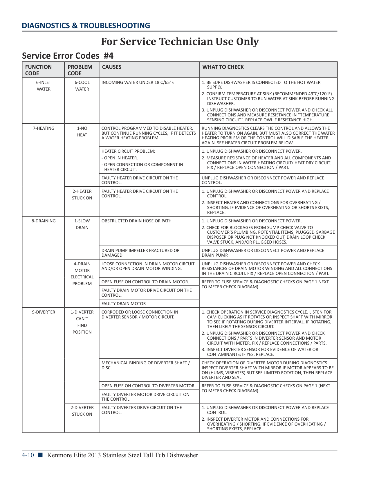
|FUNCTION CODE|PROBLEM CODE|CAUSES|WHAT TO CHECK| |---|---|---|---| |6-INLET WATER|6-COOL WATER|INCOMING WATER UNDER 18 C/65°F.|1. BE SURE DISHWASHER IS CONNECTED TO THE HOT WATER SUPPLY.
2. CONFIRM TEMPERATURE AT SINK (RECOMMENDED 49°C/120°F). INSTRUCT CUSTOMER TO RUN WATER AT SINK BEFORE RUNNING DISHWASHER.
3. UNPLUG DISHWASHER OR DISCONNECT POWER AND CHECK ALL CONNECTIONS AND MEASURE RESISTANCE IN “TEMPERATURE SENSING CIRCUIT”. REPLACE OWI IF RESISTANCE HIGH.
| |7-HEATING|1-NO HEAT|CONTROL PROGRAMMED TO DISABLE HEATER, BUT CONTINUE RUNNING CYCLES, IF IT DETECTS A WATER HEATING PROBLEM.|RUNNING DIAGNOSTICS CLEARS THE CONTROL AND ALLOWS THE HEATER TO TURN ON AGAIN, BUT MUST ALSO CORRECT THE WATER HEATING PROBLEM OR THE CONTROL WILL DISABLE THE HEATER AGAIN. SEE HEATER CIRCUIT PROBLEM BELOW.| |7-HEATING|1-NO HEAT|HEATER CIRCUIT PROBLEM:
- OPEN IN HEATER.
- OPEN CONNECTION OR COMPONENT IN HEATER CIRCUIT.
|1. UNPLUG DISHWASHER OR DISCONNECT POWER.
2. MEASURE RESISTANCE OF HEATER AND ALL COMPONENTS AND CONNECTIONS IN WATER HEATING CIRCUIT/ HEAT DRY CIRCUIT. FIX / REPLACE OPEN CONNECTION / PART.
| |7-HEATING|1-NO HEAT|FAULTY HEATER DRIVE CIRCUIT ON THE CONTROL.|UNPLUG DISHWASHER OR DISCONNECT POWER AND REPLACE CONTROL.| |7-HEATING|2-HEATER STUCK ON|FAULTY HEATER DRIVE CIRCUIT ON THE CONTROL.|1. UNPLUG DISHWASHER OR DISCONNECT POWER AND REPLACE CONTROL.
2. INSPECT HEATER AND CONNECTIONS FOR OVERHEATING / SHORTING. IF EVIDENCE OF OVERHEATING OR SHORTS EXISTS, REPLACE.
| |8-DRAINING|1-SLOW DRAIN|OBSTRUCTED DRAIN HOSE OR PATH|1. UNPLUG DISHWASHER OR DISCONNECT POWER.
2. CHECK FOR BLOCKAGES FROM SUMP CHECK VALVE TO CUSTOMER’S PLUMBING. POTENTIAL ITEMS, PLUGGED GARBAGE DISPOSER OR PLUG NOT KNOCKED OUT, DRAIN LOOP CHECK VALVE STUCK, AND/OR PLUGGED HOSES.
| |8-DRAINING|1-SLOW DRAIN|DRAIN PUMP IMPELLER FRACTURED OR DAMAGED|UNPLUG DISHWASHER OR DISCONNECT POWER AND REPLACE DRAIN PUMP.| |8-DRAINING|4-DRAIN MOTOR ELECTRICAL PROBLEM|LOOSE CONNECTION IN DRAIN MOTOR CIRCUIT AND/OR OPEN DRAIN MOTOR WINDING.|UNPLUG DISHWASHER OR DISCONNECT POWER AND CHECK RESISTANCES OF DRAIN MOTOR WINDING AND ALL CONNECTIONS IN THE DRAIN CIRCUIT. FIX / REPLACE OPEN CONNECTION / PART.| |8-DRAINING|4-DRAIN MOTOR ELECTRICAL PROBLEM|OPEN FUSE ON CONTROL TO DRAIN MOTOR.|REFER TO FUSE SERVICE & DIAGNOSTIC CHECKS ON PAGE 1 NEXT TO METER CHECK DIAGRAM).| |8-DRAINING|4-DRAIN MOTOR ELECTRICAL PROBLEM|FAULTY DRAIN MOTOR DRIVE CIRCUIT ON THE CONTROL.|REFER TO FUSE SERVICE & DIAGNOSTIC CHECKS ON PAGE 1 NEXT TO METER CHECK DIAGRAM).| |8-DRAINING|4-DRAIN MOTOR ELECTRICAL PROBLEM|FAULTY DRAIN MOTOR|REFER TO FUSE SERVICE & DIAGNOSTIC CHECKS ON PAGE 1 NEXT TO METER CHECK DIAGRAM).| |9-DIVERTER|1-DIVERTER CAN’T FIND POSITION|CORRODED OR LOOSE CONNECTION IN DIVERTER SENSOR / MOTOR CIRCUIT.|1. CHECK OPERATION IN SERVICE DIAGNOSTICS CYCLE. LISTEN FOR CAM CLICKING AS IT ROTATES OR INSPECT SHAFT WITH MIRROR TO SEE IF ROTATING DURING DIVERTER INTERVAL. IF ROTATING, THEN LIKELY THE SENSOR CIRCUIT.
2. UNPLUG DISHWASHER OR DISCONNECT POWER AND CHECK CONNECTIONS / PARTS IN DIVERTER SENSOR AND MOTOR CIRCUIT WITH METER. FIX / REPLACE CONNECTIONS / PARTS.
3. INSPECT DIVERTER SENSOR FOR EVIDENCE OF WATER OR CONTAMINANTS; IF YES, REPLACE.
| |9-DIVERTER|1-DIVERTER CAN’T FIND POSITION|MECHANICAL BINDING OF DIVERTER SHAFT / DISC.|CHECK OPERATION OF DIVERTER MOTOR DURING DIAGNOSTICS. INSPECT DIVERTER SHAFT WITH MIRROR IF MOTOR APPEARS TO BE ON (HUMS, VIBRATES) BUT SEE LIMITED ROTATION, THEN REPLACE DIVERTER AND SEAL.| |9-DIVERTER|1-DIVERTER CAN’T FIND POSITION|OPEN FUSE ON CONTROL TO DIVERTER MOTOR.|REFER TO FUSE SERVICE & DIAGNOSTIC CHECKS ON PAGE 1 (NEXT TO METER CHECK DIAGRAM).| |9-DIVERTER|1-DIVERTER CAN’T FIND POSITION|FAULTY DIVERTER MOTOR DRIVE CIRCUIT ON THE CONTROL.|REFER TO FUSE SERVICE & DIAGNOSTIC CHECKS ON PAGE 1 (NEXT TO METER CHECK DIAGRAM).| |9-DIVERTER|2-DIVERTER STUCK ON|FAULTY DIVERTER DRIVE CIRCUIT ON THE CONTROL.|1. UNPLUG DISHWASHER OR DISCONNECT POWER AND REPLACE CONTROL.
2. INSPECT DIVERTER MOTOR AND CONNECTIONS FOR OVERHEATING / SHORTING. IF EVIDENCE OF OVERHEATING / SHORTING EXISTS, REPLACE.
|
|For Service Technician Use Only| |---|
|FUNCTION CODE|PROBLEM CODE|CAUSES|WHAT TO CHECK| |---|---|---|---| |9-DIVERTER|3-DIVERTER DISC MISSING|CONTROL DETECTED DIVERTER DISK IN SUMP IS MISSING.|REMOVE LOWER SPRAY ARM, TURBO ZONE ASSEMBLY, REAR FEED TUBE AND OUTLET COVER AND VERIFY THE ROUND DIVERTER DISK IS INSTALLED.| |9-DIVERTER|4-LOWER SPRAY ARM ERROR|MECHANICAL BINDING OR BLOCKING OF SPRAY ARM.|1. CHECK FOR AND REMOVE ANY BLOCKAGE OF LOWER SPRAY ARM (UTENSILS, POT HANDLES).
2. RUN THE SERVICE DIAGNOSTIC CYCLE AND CHECK FOR THE LSA OPERATION/FAULT DETECTION (NOTE 10). IF FAILURE STILL EXISTS THEN:
3. DISCONNECT POWER FROM THE UNIT AND CHECK WIRING CONNECTION OR DAMAGE AT CONTROLLED LOWER SPRAY ARM MOTOR AND SENSOR.
4. CHECK “TRIAC FUSE DIAGNOSTIC” NEAR “METER CHECK OF LOADS” ON PAGE 1 (REPLACE CONTROL IF OPEN).
5. CHECK FOR OPEN OR SHORTED LSA MOTOR WINDING RESISTANCE. (REPLACE DIVERTER MODULE).
| |9-DIVERTER|4-LOWER SPRAY ARM ERROR|CORRODED OR LOOSE CONNECTION IN SPRAY ARM SENSOR/MOTOR CIRCUIT.|1. CHECK FOR AND REMOVE ANY BLOCKAGE OF LOWER SPRAY ARM (UTENSILS, POT HANDLES).
2. RUN THE SERVICE DIAGNOSTIC CYCLE AND CHECK FOR THE LSA OPERATION/FAULT DETECTION (NOTE 10). IF FAILURE STILL EXISTS THEN:
3. DISCONNECT POWER FROM THE UNIT AND CHECK WIRING CONNECTION OR DAMAGE AT CONTROLLED LOWER SPRAY ARM MOTOR AND SENSOR.
4. CHECK “TRIAC FUSE DIAGNOSTIC” NEAR “METER CHECK OF LOADS” ON PAGE 1 (REPLACE CONTROL IF OPEN).
5. CHECK FOR OPEN OR SHORTED LSA MOTOR WINDING RESISTANCE. (REPLACE DIVERTER MODULE).
| |9-DIVERTER|4-LOWER SPRAY ARM ERROR|OPEN FUSE ON CONTROL TO SPRAY ARM MOTOR.|1. CHECK FOR AND REMOVE ANY BLOCKAGE OF LOWER SPRAY ARM (UTENSILS, POT HANDLES).
2. RUN THE SERVICE DIAGNOSTIC CYCLE AND CHECK FOR THE LSA OPERATION/FAULT DETECTION (NOTE 10). IF FAILURE STILL EXISTS THEN:
3. DISCONNECT POWER FROM THE UNIT AND CHECK WIRING CONNECTION OR DAMAGE AT CONTROLLED LOWER SPRAY ARM MOTOR AND SENSOR.
4. CHECK “TRIAC FUSE DIAGNOSTIC” NEAR “METER CHECK OF LOADS” ON PAGE 1 (REPLACE CONTROL IF OPEN).
5. CHECK FOR OPEN OR SHORTED LSA MOTOR WINDING RESISTANCE. (REPLACE DIVERTER MODULE).
| |9-DIVERTER|4-LOWER SPRAY ARM ERROR|FAULTY SPRAY ARM DRIVE CIRCUIT ON THE CONTROL.|1. CHECK FOR AND REMOVE ANY BLOCKAGE OF LOWER SPRAY ARM (UTENSILS, POT HANDLES).
2. RUN THE SERVICE DIAGNOSTIC CYCLE AND CHECK FOR THE LSA OPERATION/FAULT DETECTION (NOTE 10). IF FAILURE STILL EXISTS THEN:
3. DISCONNECT POWER FROM THE UNIT AND CHECK WIRING CONNECTION OR DAMAGE AT CONTROLLED LOWER SPRAY ARM MOTOR AND SENSOR.
4. CHECK “TRIAC FUSE DIAGNOSTIC” NEAR “METER CHECK OF LOADS” ON PAGE 1 (REPLACE CONTROL IF OPEN).
5. CHECK FOR OPEN OR SHORTED LSA MOTOR WINDING RESISTANCE. (REPLACE DIVERTER MODULE).
| |10-OTHER|1-DISPENSER ELECTRICAL PROBLEM|LOOSE CONNECTION IN DISPENSER CIRCUIT AND/OR OPEN DISPENSER SOLENOID.|UNPLUG DISHWASHER OR DISCONNECT POWER AND CHECK RESISTANCES OF DISPENSER SOLENOID OR WAX MOTOR AND ALL CONNECTIONS IN THE DISPENSER CIRCUIT. FIX / REPLACE OPEN CONNECTION / PART.| |10-OTHER|1-DISPENSER ELECTRICAL PROBLEM|OPEN FUSE ON CONTROL TO DISPENSER.|REFER TO FUSE SERVICE & DIAGNOSTIC CHECKS ON PAGE 1 (NEXT TO METER CHECK DIAGRAM).| |10-OTHER|1-DISPENSER ELECTRICAL PROBLEM|FAULTY DISPENSER DRIVE CIRCUIT ON THE CONTROL.|UNPLUG DISHWASHER OR DISCONNECT POWER AND REPLACE CONTROL.| |10-OTHER|2-VENT WAX MOTOR ELECTRICAL PROBLEM (NOT ALL MODELS)|LOOSE CONNECTION IN VENT CIRCUIT AND/OR OPEN VENT WAX MOTOR.|UNPLUG DISHWASHER OR DISCONNECT POWER AND CHECK RESISTANCES OF VENT WAX MOTOR AND ALL CONNECTIONS IN THE VENT CIRCUIT. FIT / REPLACE OPEN CONNECTION / PARTS.| |10-OTHER|2-VENT WAX MOTOR ELECTRICAL PROBLEM (NOT ALL MODELS)|OPEN FUSE ON CONTROL TO VENT.|REFER TO FUSE SERVICE & DIAGNOSTIC CHECKS ON PAGE 1 (NEXT TO METER CHECK DIAGRAM).| |10-OTHER|2-VENT WAX MOTOR ELECTRICAL PROBLEM (NOT ALL MODELS)|FAULTY VENT DRIVE CIRCUIT ON THE CONTROL.|UNPLUG DISHWASHER OR DISCONNECT POWER AND REPLACE CONTROL.| |10-OTHER|3-DRYING FAN ERROR (ON MODELS WITH FAN)|LOOSE CONNECTION IN FAN CIRCUIT AND/OR OPEN FAN MOTOR.|UNPLUG DISHWASHER OR DISCONNECT POWER AND CHECK RESISTANCES OF FAN MOTOR AND ALL CONNECTIONS IN THE FAN CIRCUIT. FIX / REPLACE OPEN CONNECTIONS OR FAN.| |10-OTHER|3-DRYING FAN ERROR (ON MODELS WITH FAN)|FAULTY FAN DRIVE CIRCUIT ON THE CONTROL.|UNPLUG DISHWASHER OR DISCONNECT POWER AND REPLACE CONTROL.|
############# NOTES:
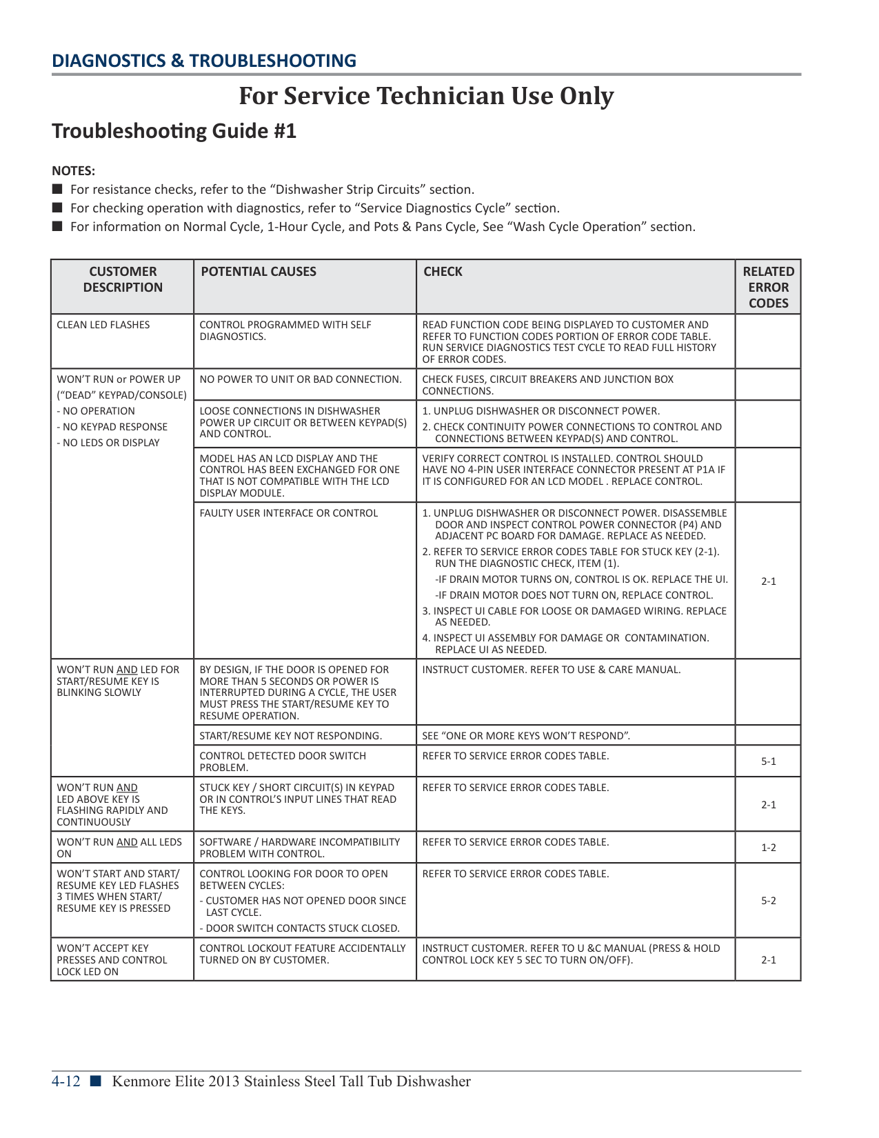
|CUSTOMER DESCRIPTION|POTENTIAL CAUSES|CHECK|RELATED ERROR CODES| |---|---|---|---| |CLEAN LED FLASHES|CONTROL PROGRAMMED WITH SELF DIAGNOSTICS.|READ FUNCTION CODE BEING DISPLAYED TO CUSTOMER AND REFER TO FUNCTION CODES PORTION OF ERROR CODE TABLE. RUN SERVICE DIAGNOSTICS TEST CYCLE TO READ FULL HISTORY OF ERROR CODES.| | |WON’T RUN or POWER UP (“DEAD” KEYPAD/CONSOLE)
- NO OPERATION
- NO KEYPAD RESPONSE
- NO LEDS OR DISPLAY
|NO POWER TO UNIT OR BAD CONNECTION.|CHECK FUSES, CIRCUIT BREAKERS AND JUNCTION BOX CONNECTIONS.| | |WON’T RUN or POWER UP (“DEAD” KEYPAD/CONSOLE)
- NO OPERATION
- NO KEYPAD RESPONSE
- NO LEDS OR DISPLAY
|LOOSE CONNECTIONS IN DISHWASHER POWER UP CIRCUIT OR BETWEEN KEYPAD(S) AND CONTROL.|1. UNPLUG DISHWASHER OR DISCONNECT POWER.
2. CHECK CONTINUITY POWER CONNECTIONS TO CONTROL AND CONNECTIONS BETWEEN KEYPAD(S) AND CONTROL.
| | |WON’T RUN or POWER UP (“DEAD” KEYPAD/CONSOLE)
- NO OPERATION
- NO KEYPAD RESPONSE
- NO LEDS OR DISPLAY
|MODEL HAS AN LCD DISPLAY AND THE CONTROL HAS BEEN EXCHANGED FOR ONE THAT IS NOT COMPATIBLE WITH THE LCD DISPLAY MODULE.|VERIFY CORRECT CONTROL IS INSTALLED. CONTROL SHOULD HAVE NO 4-PIN USER INTERFACE CONNECTOR PRESENT AT P1A IF IT IS CONFIGURED FOR AN LCD MODEL . REPLACE CONTROL.| | |WON’T RUN or POWER UP (“DEAD” KEYPAD/CONSOLE)
- NO OPERATION
- NO KEYPAD RESPONSE
- NO LEDS OR DISPLAY
|FAULTY USER INTERFACE OR CONTROL|1. UNPLUG DISHWASHER OR DISCONNECT POWER. DISASSEMBLE DOOR AND INSPECT CONTROL POWER CONNECTOR (P4) AND ADJACENT PC BOARD FOR DAMAGE. REPLACE AS NEEDED.
2. REFER TO SERVICE ERROR CODES TABLE FOR STUCK KEY (2-1). RUN THE DIAGNOSTIC CHECK, ITEM (1).
-IF DRAIN MOTOR TURNS ON, CONTROL IS OK. REPLACE THE UI.
-IF DRAIN MOTOR DOES NOT TURN ON, REPLACE CONTROL.
3. INSPECT UI CABLE FOR LOOSE OR DAMAGED WIRING. REPLACE AS NEEDED.
4. INSPECT UI ASSEMBLY FOR DAMAGE OR CONTAMINATION. REPLACE UI AS NEEDED.
|2-1| |WON’T RUN AND LED FOR START/RESUME KEY IS BLINKING SLOWLY|BY DESIGN, IF THE DOOR IS OPENED FOR MORE THAN 5 SECONDS OR POWER IS INTERRUPTED DURING A CYCLE, THE USER MUST PRESS THE START/RESUME KEY TO RESUME OPERATION.|INSTRUCT CUSTOMER. REFER TO USE & CARE MANUAL.| | |WON’T RUN AND LED FOR START/RESUME KEY IS BLINKING SLOWLY|START/RESUME KEY NOT RESPONDING.|SEE “ONE OR MORE KEYS WON’T RESPOND”.| | |WON’T RUN AND LED FOR START/RESUME KEY IS BLINKING SLOWLY|CONTROL DETECTED DOOR SWITCH PROBLEM.|REFER TO SERVICE ERROR CODES TABLE.|5-1| |WON’T RUN AND LED ABOVE KEY IS FLASHING RAPIDLY AND CONTINUOUSLY|STUCK KEY / SHORT CIRCUIT(S) IN KEYPAD OR IN CONTROL’S INPUT LINES THAT READ THE KEYS.|REFER TO SERVICE ERROR CODES TABLE.|2-1| |WON’T RUN AND ALL LEDS ON|SOFTWARE / HARDWARE INCOMPATIBILITY PROBLEM WITH CONTROL.|REFER TO SERVICE ERROR CODES TABLE.|1-2| |WON’T START AND START/ RESUME KEY LED FLASHES 3 TIMES WHEN START/ RESUME KEY IS PRESSED|CONTROL LOOKING FOR DOOR TO OPEN BETWEEN CYCLES:
- CUSTOMER HAS NOT OPENED DOOR SINCE LAST CYCLE.
- DOOR SWITCH CONTACTS STUCK CLOSED.
|REFER TO SERVICE ERROR CODES TABLE.|5-2| |WON’T ACCEPT KEY PRESSES AND CONTROL LOCK LED ON|CONTROL LOCKOUT FEATURE ACCIDENTALLY TURNED ON BY CUSTOMER.|INSTRUCT CUSTOMER. REFER TO U &C MANUAL (PRESS & HOLD CONTROL LOCK KEY 5 SEC TO TURN ON/OFF).|2-1|
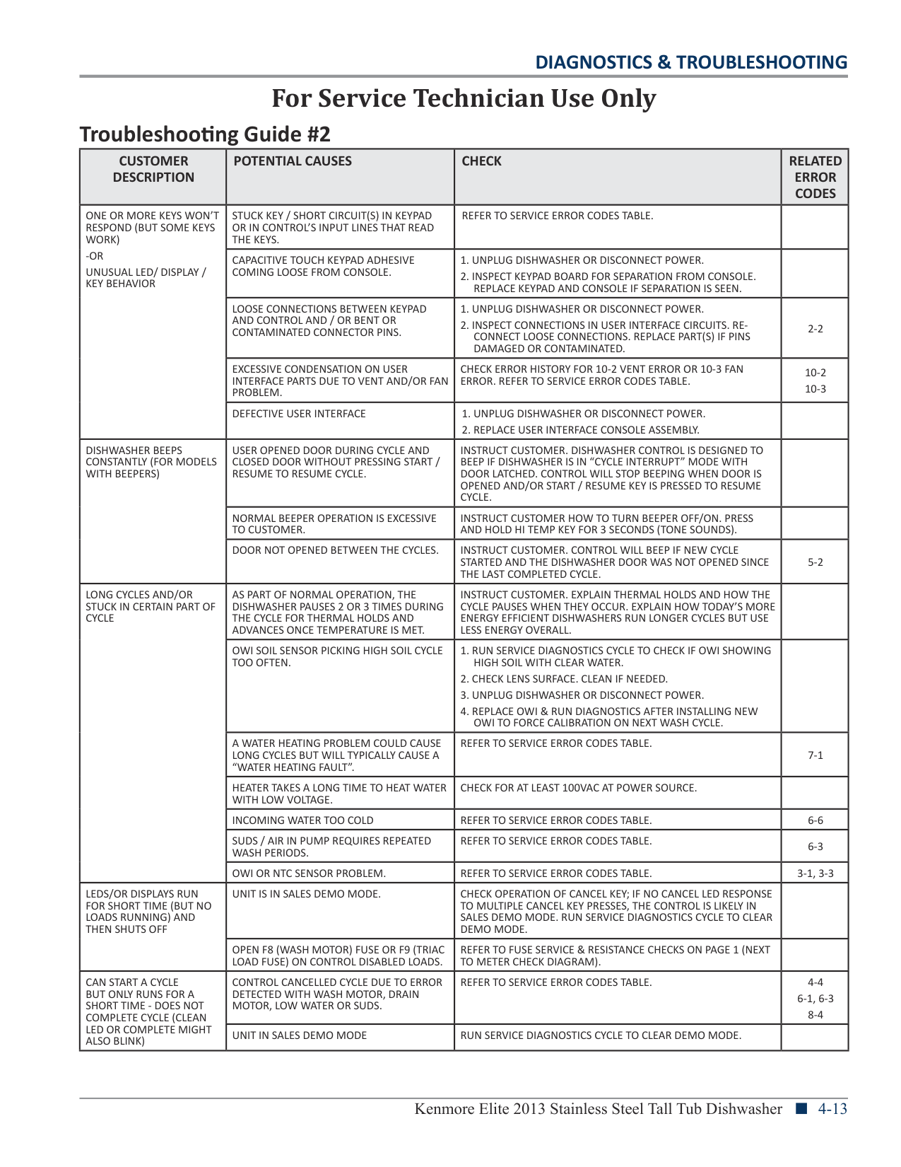
|CUSTOMER DESCRIPTION|POTENTIAL CAUSES|CHECK|RELATED ERROR CODES| |---|---|---|---| |ONE OR MORE KEYS WON’T RESPOND (BUT SOME KEYS WORK)
-OR UNUSUAL LED/ DISPLAY / KEY BEHAVIOR|STUCK KEY / SHORT CIRCUIT(S) IN KEYPAD OR IN CONTROL’S INPUT LINES THAT READ THE KEYS.|REFER TO SERVICE ERROR CODES TABLE.| | |ONE OR MORE KEYS WON’T RESPOND (BUT SOME KEYS WORK)
-OR UNUSUAL LED/ DISPLAY / KEY BEHAVIOR|CAPACITIVE TOUCH KEYPAD ADHESIVE COMING LOOSE FROM CONSOLE.|1. UNPLUG DISHWASHER OR DISCONNECT POWER.
2. INSPECT KEYPAD BOARD FOR SEPARATION FROM CONSOLE. REPLACE KEYPAD AND CONSOLE IF SEPARATION IS SEEN.
| | |ONE OR MORE KEYS WON’T RESPOND (BUT SOME KEYS WORK)
-OR UNUSUAL LED/ DISPLAY / KEY BEHAVIOR|LOOSE CONNECTIONS BETWEEN KEYPAD AND CONTROL AND / OR BENT OR CONTAMINATED CONNECTOR PINS.|1. UNPLUG DISHWASHER OR DISCONNECT POWER.
2. INSPECT CONNECTIONS IN USER INTERFACE CIRCUITS. RECONNECT LOOSE CONNECTIONS. REPLACE PART(S) IF PINS DAMAGED OR CONTAMINATED.
|2-2| |ONE OR MORE KEYS WON’T RESPOND (BUT SOME KEYS WORK)
-OR UNUSUAL LED/ DISPLAY / KEY BEHAVIOR|EXCESSIVE CONDENSATION ON USER INTERFACE PARTS DUE TO VENT AND/OR FAN PROBLEM.|CHECK ERROR HISTORY FOR 10-2 VENT ERROR OR 10-3 FAN ERROR. REFER TO SERVICE ERROR CODES TABLE.|10-2
10-3
| |ONE OR MORE KEYS WON’T RESPOND (BUT SOME KEYS WORK)
-OR UNUSUAL LED/ DISPLAY / KEY BEHAVIOR|DEFECTIVE USER INTERFACE|1. UNPLUG DISHWASHER OR DISCONNECT POWER.
2. REPLACE USER INTERFACE CONSOLE ASSEMBLY.
| | |DISHWASHER BEEPS CONSTANTLY (FOR MODELS WITH BEEPERS)|USER OPENED DOOR DURING CYCLE AND CLOSED DOOR WITHOUT PRESSING START / RESUME TO RESUME CYCLE.|INSTRUCT CUSTOMER. DISHWASHER CONTROL IS DESIGNED TO BEEP IF DISHWASHER IS IN “CYCLE INTERRUPT” MODE WITH DOOR LATCHED. CONTROL WILL STOP BEEPING WHEN DOOR IS OPENED AND/OR START / RESUME KEY IS PRESSED TO RESUME CYCLE.| | |DISHWASHER BEEPS CONSTANTLY (FOR MODELS WITH BEEPERS)|NORMAL BEEPER OPERATION IS EXCESSIVE TO CUSTOMER.|INSTRUCT CUSTOMER HOW TO TURN BEEPER OFF/ON. PRESS AND HOLD HI TEMP KEY FOR 3 SECONDS (TONE SOUNDS).| | |DISHWASHER BEEPS CONSTANTLY (FOR MODELS WITH BEEPERS)|DOOR NOT OPENED BETWEEN THE CYCLES.|INSTRUCT CUSTOMER. CONTROL WILL BEEP IF NEW CYCLE STARTED AND THE DISHWASHER DOOR WAS NOT OPENED SINCE THE LAST COMPLETED CYCLE.|5-2| |LONG CYCLES AND/OR STUCK IN CERTAIN PART OF CYCLE|AS PART OF NORMAL OPERATION, THE DISHWASHER PAUSES 2 OR 3 TIMES DURING THE CYCLE FOR THERMAL HOLDS AND ADVANCES ONCE TEMPERATURE IS MET.|INSTRUCT CUSTOMER. EXPLAIN THERMAL HOLDS AND HOW THE CYCLE PAUSES WHEN THEY OCCUR. EXPLAIN HOW TODAY’S MORE ENERGY EFFICIENT DISHWASHERS RUN LONGER CYCLES BUT USE LESS ENERGY OVERALL.| | |LONG CYCLES AND/OR STUCK IN CERTAIN PART OF CYCLE|OWI SOIL SENSOR PICKING HIGH SOIL CYCLE TOO OFTEN.|1. RUN SERVICE DIAGNOSTICS CYCLE TO CHECK IF OWI SHOWING HIGH SOIL WITH CLEAR WATER.
2. CHECK LENS SURFACE. CLEAN IF NEEDED.
3. UNPLUG DISHWASHER OR DISCONNECT POWER.
4. REPLACE OWI & RUN DIAGNOSTICS AFTER INSTALLING NEW OWI TO FORCE CALIBRATION ON NEXT WASH CYCLE.
| | |LONG CYCLES AND/OR STUCK IN CERTAIN PART OF CYCLE|A WATER HEATING PROBLEM COULD CAUSE LONG CYCLES BUT WILL TYPICALLY CAUSE A “WATER HEATING FAULT”.|REFER TO SERVICE ERROR CODES TABLE.|7-1| |LONG CYCLES AND/OR STUCK IN CERTAIN PART OF CYCLE|HEATER TAKES A LONG TIME TO HEAT WATER WITH LOW VOLTAGE.|CHECK FOR AT LEAST 100VAC AT POWER SOURCE.| | |LONG CYCLES AND/OR STUCK IN CERTAIN PART OF CYCLE|INCOMING WATER TOO COLD|REFER TO SERVICE ERROR CODES TABLE.|6-6| |LONG CYCLES AND/OR STUCK IN CERTAIN PART OF CYCLE|SUDS / AIR IN PUMP REQUIRES REPEATED WASH PERIODS.|REFER TO SERVICE ERROR CODES TABLE.|6-3| |LONG CYCLES AND/OR STUCK IN CERTAIN PART OF CYCLE|OWI OR NTC SENSOR PROBLEM.|REFER TO SERVICE ERROR CODES TABLE.|3-1, 3-3| |LEDS/OR DISPLAYS RUN FOR SHORT TIME (BUT NO LOADS RUNNING) AND THEN SHUTS OFF|UNIT IS IN SALES DEMO MODE.|CHECK OPERATION OF CANCEL KEY; IF NO CANCEL LED RESPONSE TO MULTIPLE CANCEL KEY PRESSES, THE CONTROL IS LIKELY IN SALES DEMO MODE. RUN SERVICE DIAGNOSTICS CYCLE TO CLEAR DEMO MODE.| | |LEDS/OR DISPLAYS RUN FOR SHORT TIME (BUT NO LOADS RUNNING) AND THEN SHUTS OFF|OPEN F8 (WASH MOTOR) FUSE OR F9 (TRIAC LOAD FUSE) ON CONTROL DISABLED LOADS.|REFER TO FUSE SERVICE & RESISTANCE CHECKS ON PAGE 1 (NEXT TO METER CHECK DIAGRAM).| | |CAN START A CYCLE BUT ONLY RUNS FOR A SHORT TIME - DOES NOT COMPLETE CYCLE (CLEAN LED OR COMPLETE MIGHT ALSO BLINK)|CONTROL CANCELLED CYCLE DUE TO ERROR DETECTED WITH WASH MOTOR, DRAIN MOTOR, LOW WATER OR SUDS.|REFER TO SERVICE ERROR CODES TABLE.|4-4 6-1, 6-3 8-4| |CAN START A CYCLE BUT ONLY RUNS FOR A SHORT TIME - DOES NOT COMPLETE CYCLE (CLEAN LED OR COMPLETE MIGHT ALSO BLINK)|UNIT IN SALES DEMO MODE|RUN SERVICE DIAGNOSTICS CYCLE TO CLEAR DEMO MODE.| |
|CUSTOMER DESCRIPTION|POTENTIAL CAUSES|CHECK|RELATED ERROR CODES| |---|---|---|---| |WILL NOT DRAIN OR EXCESS WATER LEFT IN DISHWASHER.
NOTE: CHECK ERROR HISTORY. IF NO ERROR CODES FOR ELECTRICAL PROBLEMS, PROBLEM IS MECHANICAL. DO NOT REPLACE CONTROL.|DRAIN LOOP CHECK VALVE NOT SEALING.|1. DISCONNECT DRAIN HOSE AT PLUMBING CONNECTION.
2. ELEVATE HOSE ABOVE DISHWASHER AND FILL WITH WATER. IF WATER FLOWS INTO DISHWASHER, REPLACE ENTIRE DRAIN LOOP (INSTALL AS HIGH AS POSSIBLE).
| | |WILL NOT DRAIN OR EXCESS WATER LEFT IN DISHWASHER.
NOTE: CHECK ERROR HISTORY. IF NO ERROR CODES FOR ELECTRICAL PROBLEMS, PROBLEM IS MECHANICAL. DO NOT REPLACE CONTROL.|CUSTOMER MISUNDERSTANDS WATER LEVEL AFTER DRAIN.|INSTRUCT CUSTOMER. SUMP WILL NORMALLY HAVE ABOUT 2.4 CM (1 INCH) OF WATER REMAINING IN FILTER CUP HOLE AFTER CYCLE.| | |WILL NOT DRAIN OR EXCESS WATER LEFT IN DISHWASHER.
NOTE: CHECK ERROR HISTORY. IF NO ERROR CODES FOR ELECTRICAL PROBLEMS, PROBLEM IS MECHANICAL. DO NOT REPLACE CONTROL.|DRAINING PROBLEM|REFER TO SERVICE ERROR CODES TABLE.|8-1 , 8-4| |LOWER SPRAY ARM BLOCKING THE FILTER CUP REMOVAL. (CONTROLLED ROTATION LOWER SPRAY ARM MODELS).|DOOR OPENED WHILE LOWER SPRAY ARM MOVING.|INSTRUCT CUSTOMER CONTROLLED LOWER SPRAY ARM POWER IS CUT OFF WHEN DOOR IS OPENED.| | |LOWER SPRAY ARM BLOCKING THE FILTER CUP REMOVAL. (CONTROLLED ROTATION LOWER SPRAY ARM MODELS).|CORRODED OR LOOSE CONNECTION IN SPRAY ARM SENSOR/MOTOR CIRCUIT CAUSING LSA TO STOP SOMEWHERE OTHER THAN HOME POSITION (HOME POSITION
= LSA ROUGHLY 5 CLOCKWISE FROM 12 O’CLOCK.|DISCONNECT POWER AND CHECK CONNECTION AT CONTROLLED LOWER SPRAY ARM MOTOR AND SENSOR AT THE CONTROL.
INSPECT CONNECTORS FOR WATER AND CONTAMINATION AND REPLACE AS NEEDED.
RUN THE SERVICE DIAGNOSTIC CYCLE AND CHECK FOR THE LSA MOTOR/SENSOR OPERATION (NOTE 10). REFER TO SERVICE ERROR CODE TABLE.|9-4| |DETERGENT NOT DISPENSING OR DETERGENT LEFT IN DISPENSER NOTE: CHECK ERROR HISTORY IF NO ERROR CODES FOR ELECTRICAL PROBLEMS, PROBLEM IS MECHANICAL. DO NOT REPLACE CONTROL|ITEM IN LOWER RACK BLOCKED LID OR BLOCKED SPRAY OF WATER TO DISPENSER.|INSTRUCT CUSTOMER ON PROPER DISH LOADING.| | |DETERGENT NOT DISPENSING OR DETERGENT LEFT IN DISPENSER NOTE: CHECK ERROR HISTORY IF NO ERROR CODES FOR ELECTRICAL PROBLEMS, PROBLEM IS MECHANICAL. DO NOT REPLACE CONTROL|MECHANICAL BINDING OF DISPENSER LID.|1. UNPLUG DISHWASHER OR DISCONNECT POWER.
2. CHECK/REPLACE DISPENSER.
| | |DETERGENT NOT DISPENSING OR DETERGENT LEFT IN DISPENSER NOTE: CHECK ERROR HISTORY IF NO ERROR CODES FOR ELECTRICAL PROBLEMS, PROBLEM IS MECHANICAL. DO NOT REPLACE CONTROL|LID LATCH BINDING DUE TO EXCESS DETERGENT IN MECHANISM.|INSTRUCT CUSTOMER ON PROPER DISPENSER FILLING.| | |DETERGENT NOT DISPENSING OR DETERGENT LEFT IN DISPENSER NOTE: CHECK ERROR HISTORY IF NO ERROR CODES FOR ELECTRICAL PROBLEMS, PROBLEM IS MECHANICAL. DO NOT REPLACE CONTROL|DISPENSER ELECTRICAL PROBLEM|REFER TO SERVICE ERROR CODES TABLE.|10-1| |DETERGENT NOT DISPENSING OR DETERGENT LEFT IN DISPENSER NOTE: CHECK ERROR HISTORY IF NO ERROR CODES FOR ELECTRICAL PROBLEMS, PROBLEM IS MECHANICAL. DO NOT REPLACE CONTROL|CONTROL CANCELLED CYCLE DUE TO ERROR DETECTED WITH WASH MOTOR, DRAIN MOTOR, LOW WATER, OR SUDS.|REFER TO SERVICE ERROR CODES TABLE.|4-4 6-1, 6-3 8-4|
|POOR WASH|CYCLE SELECTION OF CUSTOMER NOT APPROPRIATE FOR DISH LOAD.|INSTRUCT CUSTOMER ON CYCLE SELECTION. RECOMMEND “HIGH TEMP” OPTION FOR WASH PERFORMANCE BOOST.| | |POOR WASH|PLUGGED OR DAMAGED SCREENS.|INSPECT FOLLOWING THREE SCREENS:
- FILTER CUP COARSE SCREEN
- FILTER CUP FINE SCREEN
- SUMP FINE SCREEN
| | |POOR WASH|SPRAY ARMS NOT ROTATING OR PLUGGED.|1. CHECK ARM ROTATION. IF ARMS BLOCKED BY DISH ITEM, INSTRUCT CUSTOMER. ALSO CHECK FOR CORRECT UPPER SPRAY ARM ALIGNMENT WITH DOCKING STATION LOCATED ON FEED TUBE AT BACK TUB WALL.
2. CHECK NOZZLES; IF PLUGGED CLEAN NOZZLES AND CONFIRM FILTERS INSTALLED PROPERLY.
3. CONTROLLED LOWER SPRAY ARM MOTOR FAILED. CHECK SPRAY ARM MOVING IN BOTH DIRECTIONS DURING DIAGNOSTICS CYCLE.
|9-4| |POOR WASH|POOR WASH DUE TO DRAINING, DISPENSING &/OR TEMPERATURE PROBLEMS.|SEE “WILL NOT DRAIN OR EXCESS WATER LEFT IN UNIT”, OR “DETERGENT NOT DISPENSING OR DETERGENT LEFT IN DISPENSER”, OR DETAILS ON TEMPERATURE SENSING IN “LONG CYCLES AND/OR STUCK IN CERTAIN PART OF CYCLE”.| | |POOR WASH|CONTROL CANCELLED CYCLE DUE TO ERROR DETECTED WITH WASH MOTOR, DRAIN MOTOR, LOW WATER, OR SUDS.|REFER TO SERVICE ERROR CODES TABLE.|4-4 6-1, 6-3 8-4| |POOR WASH|SOIL SENSOR PROBLEM|REFER TO SERVICE ERROR CODES TABLE NOTE: EVEN IF NO ERROR CODE RECORDED, CONFIRM OWI PASSES ALL OWI CHECKS IN SERVICE DIAGNOSTICS CYCLE AND SEE CHECKS FOR ERROR 3-3.|3-2
3-3
| |POOR WASH|DIVERTER PROBLEM|REFER TO SERVICE ERROR CODES TABLE.|9-1
9-2
| |POOR WASH|DIVERTER DISC MISSING|REMOVE OUTLET COVER AND INSPECT FOR RED PLASTIC DISC THROUGH HOLES IN OUTLET. INSTALL NEW DISC IF MISSING.| |
|CUSTOMER DESCRIPTION|POTENTIAL CAUSES|CHECK|RELATED ERROR CODES| |---|---|---|---| |POOR WASH|HEATING PROBLEM|REFER TO SERVICE ERROR CODES TABLE.|7-1| |POOR WASH|SOFTENER PROBLEM (ONLY SOME MODELS)|REFER TO SERVICE ERROR CODES TABLE.|6-8| |FILM OR SPOTS ON GLASSES AND/OR DISHES|CUSTOMER NOT USING RINSE AID AND/OR HEATED DRY.|CHECK RINSE AID GAGE LEVEL ON DISPENSER;INSTRUCT CUSTOMER HOW TO FILL AND MONITOR ADD / USE RINSE AID.| | |FILM OR SPOTS ON GLASSES AND/OR DISHES|RINSE AID DISPENSER PROBLEM.|REFER TO SERVICE ERROR CODES TABLE.|10-1| |FILM OR SPOTS ON GLASSES AND/OR DISHES|HARD WATER LEAVING FILM ON DISHES.|CHECK WATER HARDNESS. IF HARD, INSTRUCT CUSTOMER TO USE MAXIMUM DETERGENT OR TRY POURING ¼ CUP OF GLASS MAGIC INTO BOTTOM OF DISHWASHER. ALSO RECOMMEND 1 HR WASH CYCLE.| | |FILM OR SPOTS ON GLASSES AND/OR DISHES|HARD WATER LEAVING FILM ON DISHES.|FOR MODELS WITH WATER SOFTENER: CHECK “ADD SALT” LED AT END OF CYCLE; IF ON, ADD SALT; INSTRUCT CUSTOMER.| | |FILM OR SPOTS ON GLASSES AND/OR DISHES|HARD WATER LEAVING FILM ON DISHES.|FOR MODELS WITH WATER SOFTENER: REGEN VALVE ELECTRICAL PROBLEM; REFER TO SERVICE ERROR CODES TABLE.| | |FILM OR SPOTS ON GLASSES AND/OR DISHES|DETERGENT CARRYOVER OR OVER SUDSING.|CHECK WATER HARDNESS. IF BELOW 10 GRAINS, THEN INSTRUCT CUSTOMER TO USE LESS DETERGENT AND RECOMMEND THE “1 HR WASH” CYCLE.|6-3| |FILM OR SPOTS ON GLASSES AND/OR DISHES|ETCHING OF GLASS FROM TOO MUCH DETERGENT AT TOO HIGH OF TEMPERATURE.|CHECK WATER HARDNESS. IF BELOW 10 GRAINS, THEN INSTRUCT CUSTOMER TO USE LESS DETERGENT AND RECOMMEND THE “1 HR WASH” CYCLE.| | |FILM OR SPOTS ON GLASSES AND/OR DISHES|DIVERTER PROBLEMS|REFER TO SERVICE ERROR CODES TABLE.|9-1, 9-2| |FILM OR SPOTS ON GLASSES AND/OR DISHES|DRAIN LOOP CHECK VALVE NOT SEALING.|1. DISCONNECT DRAIN HOSE AT PLUMBING CONNECTION.
2. ELEVATE HOSE ABOVE DISHWASHER AND FILL WITH WATER. IF WATER FLOWS INTO DISHWASHER, REPLACE ENTIRE DRAIN LOOP (INSTALL AS HIGH AS POSSIBLE AND ATTACH TO UNDERSIDE OF COUNTERTOP IF POSSIBLE).
| | |POOR DRY|CUSTOMER NOT USING RINSE AID OR DISPENSER EMPTY.|CHECK RINSE AID GAUGE LEVEL ON DISPENSER; INSTRUCT CUSTOMER HOW TO FILL AND MONITOR ADD / USE RINSE AID.| | |POOR DRY|CUSTOMER NOT USING HEATED DRY OPTION.|RECOMMEND USE OF HEATED DRY OR SMART DRY TO CUSTOMER.| | |POOR DRY|RINSE AID DISPENSER PROBLEM|REFER TO SERVICE ERROR CODES TABLE.|10-1| |POOR DRY|VENT STUCK CLOSED DUE TO PILOT RELAY STUCK ON (NOT ALL MODELS).|REFER TO SERVICE ERROR CODES TABLE.|1-1| |POOR DRY|FAN PROBLEM (ON MODELS WITH FAN)|REFER TO SERVICE ERROR CODES TABLE.|10-3| |POOR DRY|CONTROL CANCELLED CYCLE DUE TO ERROR DETECTED WITH WASH MOTOR, DRAIN MOTOR, LOW WATER, OR SUDS.|REFER TO SERVICE ERROR CODES TABLE.|4-4 6-1, 6-3 8-4| |POOR DRY|HEATING PROBLEM|REFER TO SERVICE ERROR CODES TABLE.|7-1| |SANITIZED LED BLINKS OR INCOMPLETE SANITIZATION MESSAGE AT END OF CYCLE
(CONTROL COULD NOT CONFIRM SANITIZATION ACHIEVED)|DOOR OPENED DURING FINAL RINSE OR DRY.|INSTRUCT CUSTOMER.| | |SANITIZED LED BLINKS OR INCOMPLETE SANITIZATION MESSAGE AT END OF CYCLE
(CONTROL COULD NOT CONFIRM SANITIZATION ACHIEVED)|INCOMING WATER TOO COLD.|REFER TO SERVICE ERROR CODES TABLE.|6-6| |SANITIZED LED BLINKS OR INCOMPLETE SANITIZATION MESSAGE AT END OF CYCLE
(CONTROL COULD NOT CONFIRM SANITIZATION ACHIEVED)|HEATING PROBLEM|REFER TO SERVICE ERROR CODES TABLE.|7-1| |SANITIZED LED BLINKS OR INCOMPLETE SANITIZATION MESSAGE AT END OF CYCLE
(CONTROL COULD NOT CONFIRM SANITIZATION ACHIEVED)|THERMISTOR / OWI SENSOR PROBLEM|REFER TO SERVICE ERROR CODES TABLE.|3-1, 3-2| |SANITIZED LED BLINKS OR INCOMPLETE SANITIZATION MESSAGE AT END OF CYCLE
(CONTROL COULD NOT CONFIRM SANITIZATION ACHIEVED)|INTERMITTENT DOOR SWITCH / LATCH CONNECTION.|REFER TO SERVICE ERROR CODES TABLE.|5-1, 5-2| |SANITIZED LED BLINKS OR INCOMPLETE SANITIZATION MESSAGE AT END OF CYCLE
(CONTROL COULD NOT CONFIRM SANITIZATION ACHIEVED)|LINE VOLTAGE TOO LOW TO HEAT FAST ENOUGH.|CHECK POWER SOURCE. CONFIRM AT LEAST 100V AC.| | |SANITIZED LED BLINKS OR INCOMPLETE SANITIZATION MESSAGE AT END OF CYCLE
(CONTROL COULD NOT CONFIRM SANITIZATION ACHIEVED)|AIR PRESSURE SURGES IN DISHWASHER DUE TO WASHING WITH HIGH SUDS CAUSES BRIEF OPENING OF DOOR SWITCH CONTACTS DURING FINAL RINSE.|REFER TO SERVICE ERROR CODES TABLE.|6-3|
|CUSTOMER DESCRIPTION|POTENTIAL CAUSES|CHECK|RELATED ERROR CODES| |---|---|---|---| |MELTED DISHWARE AND/ OR SPRAY ARM AND/OR DISHWASHER ALWAYS HOT|CUSTOMER USES NON-DISHWASHER SAFE DISHES OR LOADS PLASTIC DISHES DIRECTLY OVER HEATER.|INSTRUCT CUSTOMER.| | |MELTED DISHWARE AND/ OR SPRAY ARM AND/OR DISHWASHER ALWAYS HOT|TEMPERATURE SENSING PROBLEM.|REFER TO SERVICE ERROR CODES TABLE.|3-1| |MELTED DISHWARE AND/ OR SPRAY ARM AND/OR DISHWASHER ALWAYS HOT|WATER HEATING PROBLEM, HEATER STUCK ON.|REFER TO SERVICE ERROR CODES TABLE.|7-2| |MELTED DISHWARE AND/ OR SPRAY ARM AND/OR DISHWASHER ALWAYS HOT|WATER HEATER DISPLACED FROM MOUNTING CLIP AND / OR PULLED OFF CENTER.|INSPECT HEATER. ADJUST BACK INTO POSITION IF NEEDED.| | |NOISY OPERATION|SPRAY ARM STALLED OR BLOCKED AND SPRAYING ON THE DOOR.|- INSTRUCT CUSTOMER IF BLOCKED.
- CHECK SPRAY ARM ROTATION AND INSPECT FOR PLUGGED NOZZLES. IF PLUGGED, CLEAN NOZZLES AND CONFIRM FILTERS INSTALLED PROPERLY.
- CONTROLLED LOWER SPRAY ARM MOTOR FAILED. CHECK SPRAY ARM MOVING IN BOTH DIRECTIONS DURING DIAGNOSTICS CYCLE.
|9-4| |NOISY OPERATION|DIVERTER PROBLEM|REFER TO SERVICE ERROR CODES TABLE.|9-1
9-2,9-3
| |NOISY OPERATION|MOTOR PROBLEMS FORCE CYCLE TO START AND STOP REPEATEDLY.|REFER TO SERVICE ERROR CODES TABLE.|4-2| |NOISY OPERATION|NO OR LOW WATER|REFER TO SERVICE ERROR CODES TABLE.|6-1, 6-2 6-3, 6-4| |NOISY OPERATION|DRAINS TOO LONG|SLOW DRAIN PROBLEM - REFER TO SERVICE ERROR CODE TABLE FOR 8-1.|8-1| |NOISY OPERATION|VENT STUCK OPEN|REFER TO SERVICE ERROR CODES TABLE.|10-2| |NOISY OPERATION|FAN RUNS (MAKES NOISE) AFTER CYCLE COMPLETED (ON MODELS WITH FAN).|DISHWASHER IS DESIGNED TO KEEP FAN RUNNING AFTER CYCLE TO PREVENT MOISTURE BUILDUP IN DISHWASHER. FAN WILL TURN OFF IF DOOR IS OPENED LONGER THAN 5 SEC. INSTRUCT CUSTOMER.| |
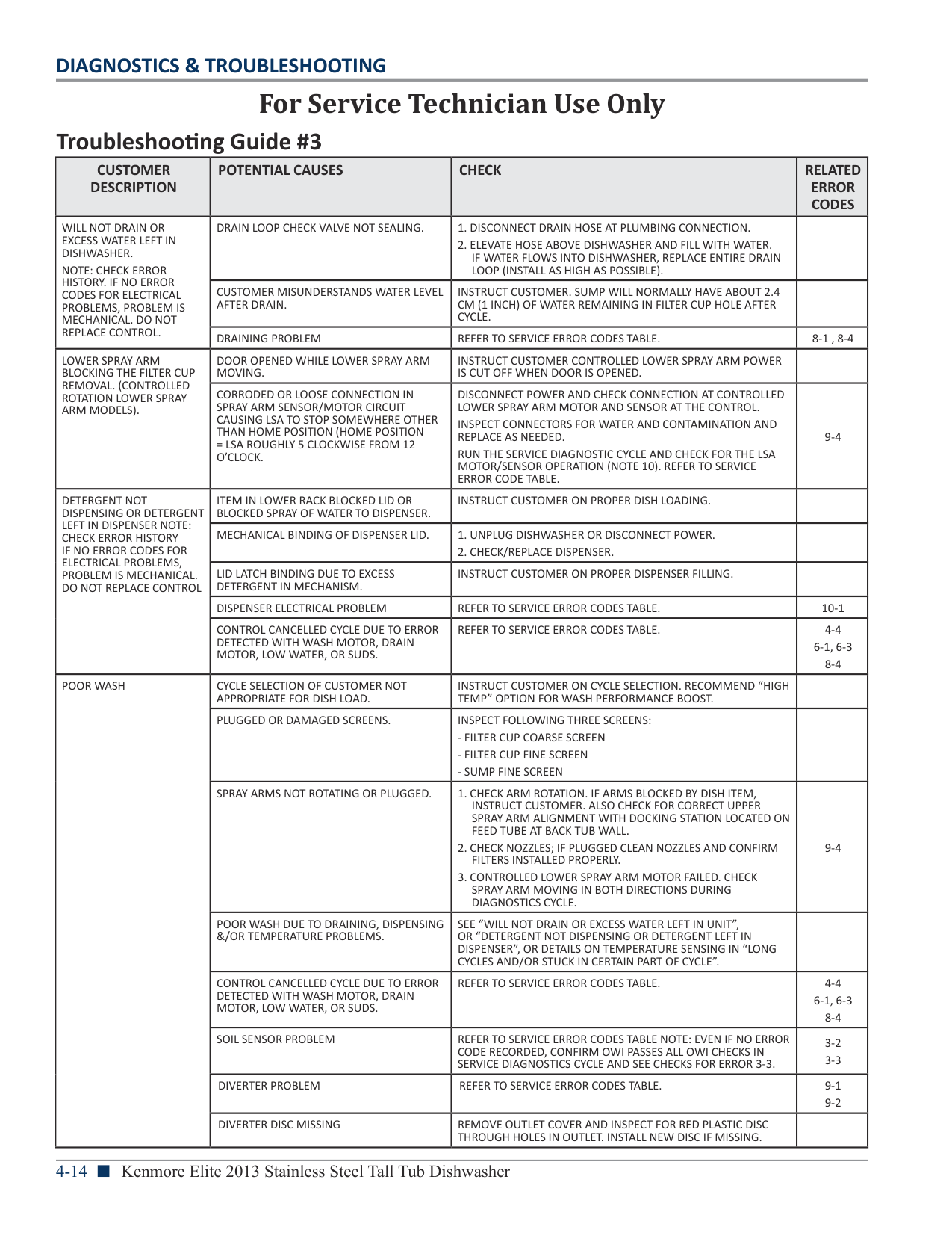
|NOISY OPERATION|EXCESSIVE FAN NOISE DUE TO FAULTY FAN (ON MODELS WITH FAN).|1. CHECK FAN OPERATION DURING SERVICE DIAGNOSTICS TEST CYCLE.
2. UNPLUG DISHWASHER OR DISCONNECT POWER.
3. REPLACE FAN IF DOES NOT SPIN FREELY.
| | |LEAKS OR DRIPS ON CABINET OR FLOOR|VENT WAX MOTOR PROBLEM (NOT ALL MODELS)|REFER TO SERVICE ERROR CODES TABLE.|10-2| |LEAKS OR DRIPS ON CABINET OR FLOOR|FAN PROBLEM (ON MODELS WITH FAN)|REFER TO SERVICE ERROR CODES TABLE.|10-3| |LEAKS OR DRIPS ON CABINET OR FLOOR|TOO MANY SUDS|REFER TO SERVICE ERROR CODES TABLE.|6-3
6-4
| |LEAKS OR DRIPS ON CABINET OR FLOOR|LEAKING DISHWASHER|CHECK DOOR / TUB GASKET AND ALL WATER CONNECTIONS UNDER DISHWASHER. REFER TO SERVICE ERROR TABLE.|6-1 6-3| |LEAKS OR DRIPS ON CABINET OR FLOOR|UNIT UNLEVEL (LEANING FORWARD) AND WATER SURGES OVER FRONT LIP DURING CYCLE.|CHECK ERROR HISTORY FOR FLOAT ERROR 6-4. ERROR 6-4 IS LIKELY TO OCCUR IF UNIT IS SIGNIFICANTLY UNLEVEL AND LEANING FORWARD. REFER TO SERVICE ERROR TABLE.|6-4| |LEAKS OR DRIPS ON CABINET OR FLOOR|AIR PRESSURE SURGE WHEN DOOR IS OPENED AND IMMEDIATELY CLOSED WHILE DISHWASHER IS HOT CAN FORCE DROPLETS OUT THE VENT DUCT.|INSTRUCT CUSTOMER TO LEAVE DOOR OPEN A FEW MINUTES BEFORE RE-CLOSING IF OPENED WHILE DISHWASHER IS HOT TECH.| |
Section 5: Testing
This section provides a wiring diagram, control board specifications, testing procedures and strip circuits the “Kenmore Elite Stainless Steel Tall Tub Dishwasher.”
|DANGER
| |---| | | |Electrical Shock Hazard
Only authorized technicians should perform diagnostic voltage measurements.
After performing voltage measurements, disconnect power before servicing.
Failure to follow these instructions can result in death or electrical shock.|
|WARNING
| |---| | | |Electrical Shock Hazard Disconnect power before servicing.
Failure to do so can result in death or electrical shock.
Replace all parts and panels before operating.|
|Voltage Measurement Safety Information When performing live voltage measurements, you must do the following: n Verifythecontrolsareintheoffpositionsothattheappliancedoesnotstartwhenenergized. n Allowenoughspacetoperformthevoltagemeasurementswithoutobstructions. n Keepotherpeopleasafedistanceawayfromtheappliancetopreventpotentialinjury. n Alwaysusethepropertestingequipment. n Aftervoltagemeasurements,alwaysdisconnectpowerbeforeservicing.| |---|
|IMPORTANT: Electrostatic Discharge (ESD) Sensitive Electronics ESD problems are present everywhere. Most people begin to feel an ESD discharge at approximately 3000V. It takes as little as 10V to destroy, damage, or weaken the main control assembly. The new main control assembly may appear to work well after repair is finished, but a malfunction may occur at a later date due to ESD stress. n Use an anti-static wrist strap. Connect wrist strap to green ground connection point or unpainted
metal in the appliance
-OR-
n Touch your finger repeatedly to a green ground connection point or unpainted metal in the
appliance.
n Before removing the part from its package, touch the anti-static bag to a green ground
connection point or unpainted metal in the appliance.
n Avoid touching electronic parts or terminal contacts; handle electronic control assembly by
edges only.
n When repackaging main control assembly in anti-static bag, observe above instructions.|
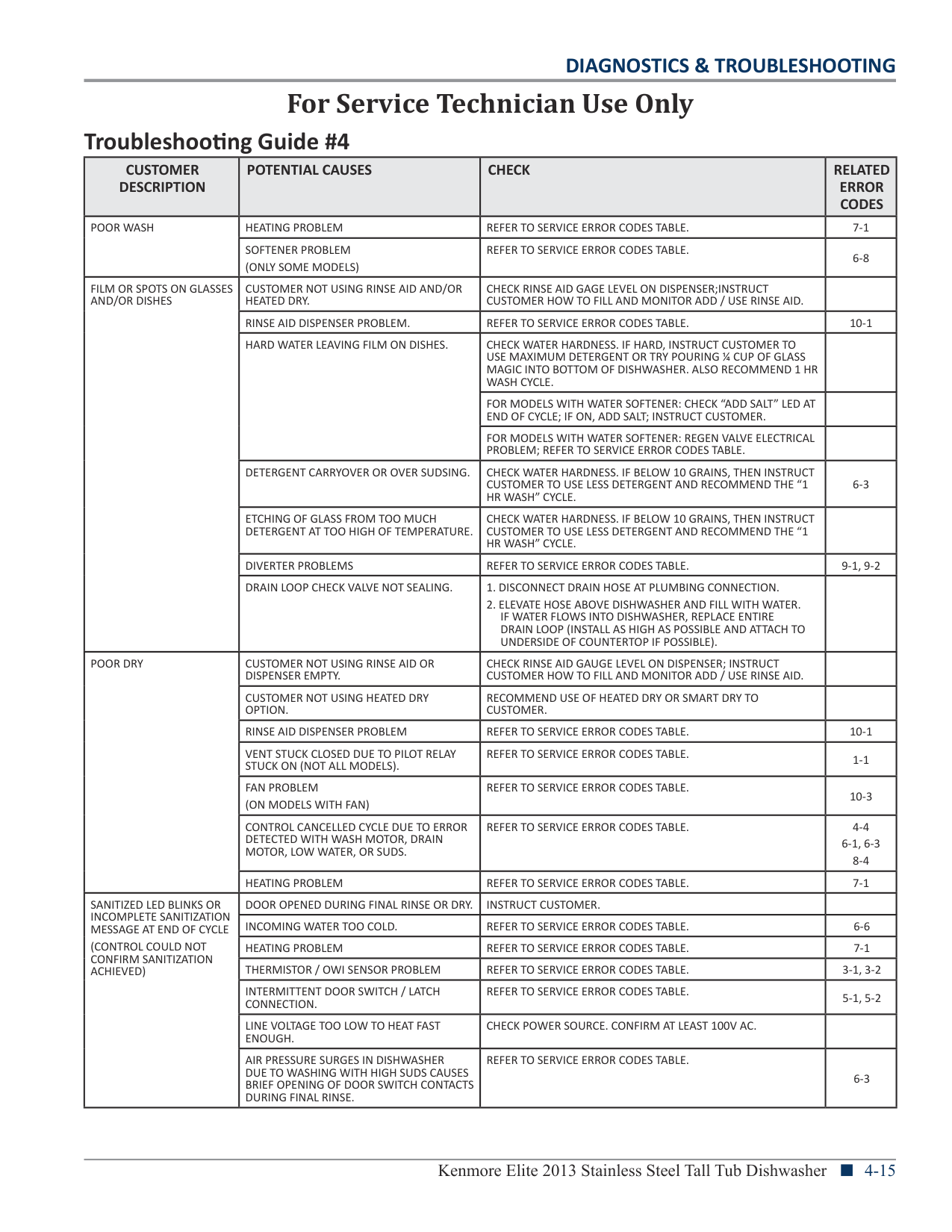
|---|
|IMPORTANT SAFETY NOTICE — “For Technicians only” This service data sheet is intended for use by persons having electrical, electronic, and mechanical experience and knowledge at a level generally considered acceptable in the appliance repair trade. Any attempt to repair a major appliance may result in personal injury and property damage. The manufacturer or seller cannot be responsible, nor assume any liability for injury or damage of any kind arising from the use of this data sheet.| |---|
|Wiring Diagram
Schematic shown with door switch and all other normally open contacts open.
* Denotes energy efficient components. Do not substitute.
For Service Technician Use Only| |---|
|F2
F101
F1| |---|
|DANGER
| |---| | | |Electrical Shock Hazard
Only authorized technicians should perform diagnostic voltage measurements.
After performing voltage measurements, disconnect power before servicing.
Failure to follow these instructions can result in death or electrical shock.|
###### Control Board Information
########## SPECIFICATIONS
ELECTRICAL SUPPLY: (Under Load): 60Hz 120V AC
SUPPLY WATER FLOW RATE: To Fill 1.9 L (2 qt.) In 27 Seconds, 120 psi Maximum, 20 psi Minimum
TRIAC FUSE DIAGNOSTICS: TRIAC LOADS: DISPENSER, DIVERTER MOTOR, FILL VALVE, LOWER SPRAY ARM (SOME MODELS) ¾ If any of the TRIAC loads work, then the TRIAC fuse is OK.
Diagnose and repair non-working triac loads. ¾ If all TRIAC loads fail to operate, TRIAC fuse is open. Replace Control.
WASH/DRAIN MOTOR FUSE DIAGNOSTICS: ¾ If both the wash and drain motors fail to operate, motor
fuse is open. Replace Control. ¾ If only wash or drain motor operates, fuse is OK. Use meter
to measure non-operational motor’s (3) phase resistances. ¾ If a phase is open (>1K ohms) or unequal to the others,
motor is bad. Replace Motor.
¾ If all phases are equal and within range (see wash/drain strip circuit), use meter to verify wiring harness continuity (<3 ohms) from Control connection to motor phase.
¾ If harness continuity is OK, Control is bad. Replace Control. ¾ If harness continuity is open or intermittent, harness is bad.
Repair/Replace harness.
IF ANY OF THE FUSES ARE OPEN: ¾ Inspect and check resistances of all loads on fuse. If any
loads are open, shorted, or show evidence of overheating or pinched wires, replace loads and/or repair wires.
SUPPLY WATER TEMPERATURE: 49° C (120° F) (Before starting a cycle, run water from the sink faucet until hot)
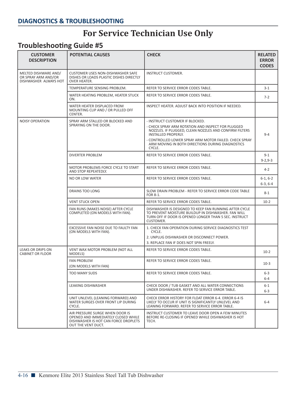
############# WATER CHARGE:
LOWER SPRAY ARM ROTATION: 12 TO 40 rpm
UPPER SPRAY ARM ROTATION: 12 TO 30 rpm
FUSE SERVICE & DIAGNOSTIC CHECKS FOR L1 FUSE, WASH/DRAIN MOTORS FUSE, AND TRIAC FUSE
L1 FUSE DIAGNOSTICS: DISHWASHER IS COMPLETELY UNRESPONSIVE ¾ If Neutral and L1 are present at P4, pins 1 & 2 respectively,
the L1 fuse is open. Replace Control.
###### Component Testing
########## TESTING DISHWASHER COMPONENTS FROM THE CONTROL
Before testing any of the components, perform the following checks:
########## ELECTRONIC CONTROL BOARD
CONTROL ASSEMBLY
PUSH TO RELEASE AND ROTATE
| | | |---|---| | | |
| | | |---|---| | | |
| | | | |---|---|---|
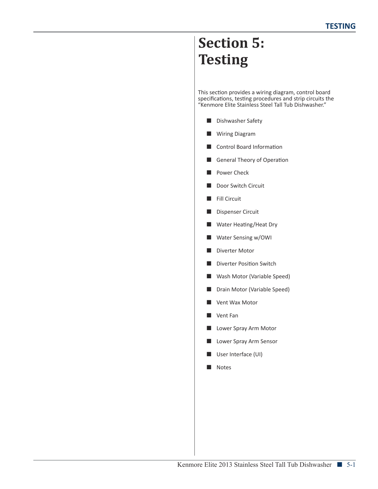
| | | |
| | | |---|---| | | |
| | | | |---|---|---| | | | |
(ROTATE)
| | | |---|---| | | |
| | | |---|---| | | |
| | | |---|---| | | |
| | | | | | |---|---|---|---|---| | | | | | |
| | | |---|---| | | |
| | | |---|---| | | |
| | | |---|---| | | |
| | | |---|---|
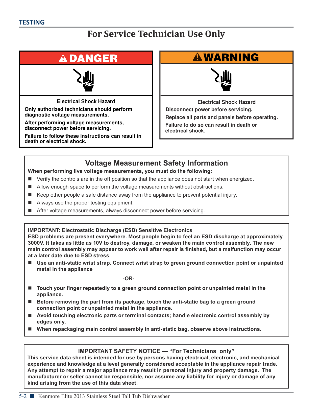
| | |
| | | |---|---| | | |
| | | |---|---| | | |
| | | |---|---| | | | | | |
| | | |---|---| | | |
| | | |---|---| | | |
| | | |---|---| | | |
| | | |---|---| | | |
| | | |---|---| | | |
| | | |---|---| | | |
CONTROL PANEL SNAP LOCKS CONTROL IN PLACE
CONTROL BOX
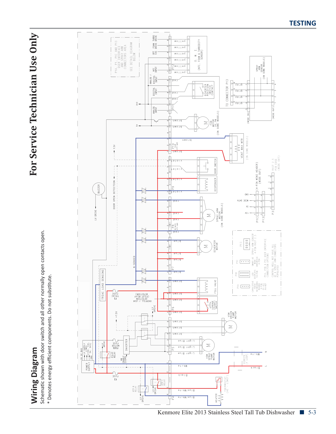
| | | |---|---| | | | | | |
CONTROL BRACE TO REMOVE, PINCH ARMS AND ROTATE
| | | | |---|---|---| | | | |
| | | |---|---| | | |
| | | |---|---| | | |
| | | |---|---| | | |
| | | |---|---| | | |
| | | | |---|---|---| | | | |
| | | |---|---| | | |
| | | |---|---| | | |
| | | |---|---| | | |
| | | |---|---| | | |
| | | | |---|---|---| | | | |
| | | |---|---| | | |
| | | |---|---| | | | | | |
| | | | |---|---|---| | | | |
| | | |---|---| | | |
| | | |---|---| | | | | | | | | |
| | | | |---|---|---| | | | |
| | | |---|---| | | |
4 ARMS
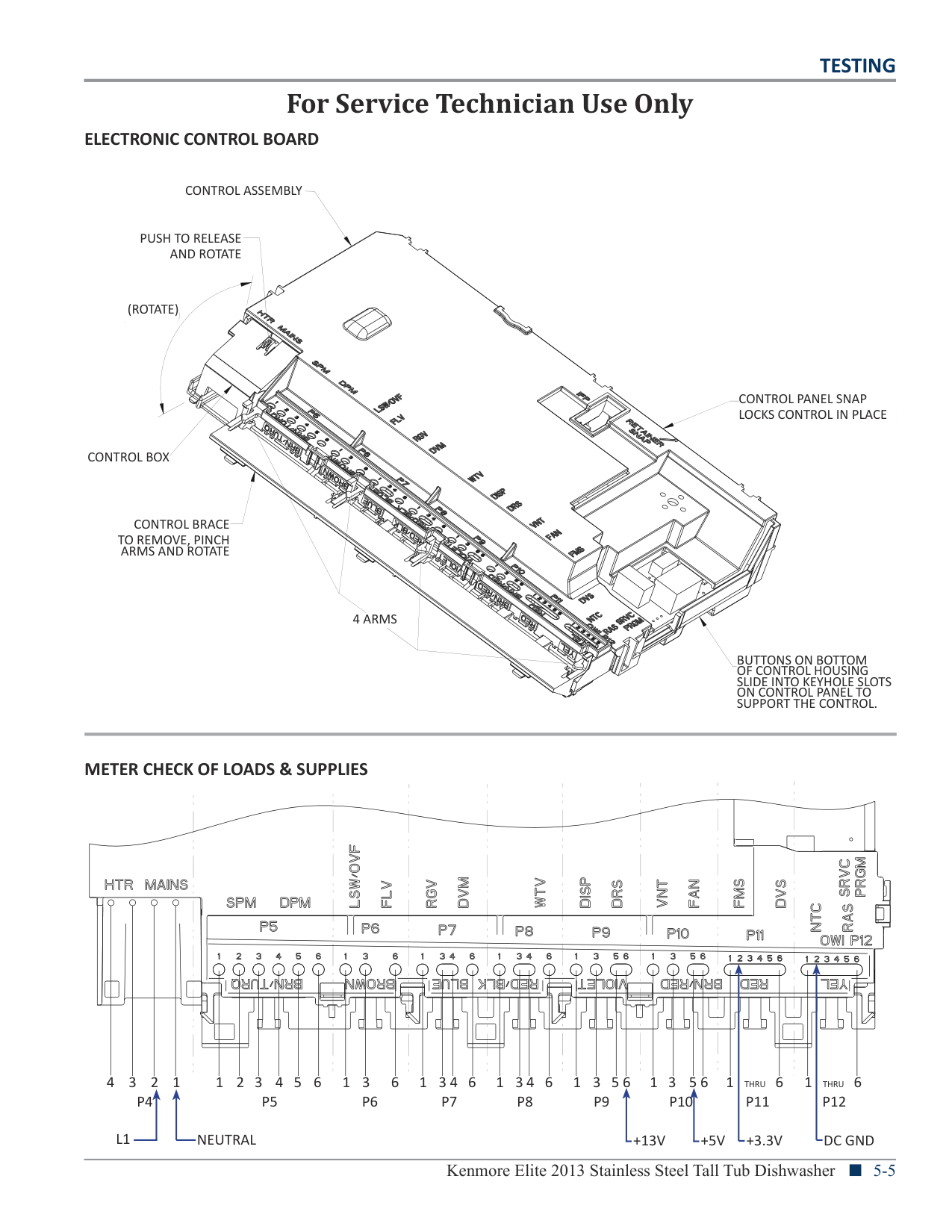
| | | |---|---| | | |
| | | |---|---| | | |
| | | |---|---| | | |
| | | |---|---| | | |
| | | |---|---| | | | | | |
| | | |---|---| | | |
| | | |---|---| | | |
| | | |---|---| | | | | | |
| | | |---|---| | | |
| | | | |---|---|---| | | | |
| | | |---|---| | | | | | |
| | | |---|---| | | |
| | | |---|---| | | | | | |
| | | |---|---| | | |
| | | |---|---| | | |
| | | |---|---| | | |
| | | |---|---| | | |
| | | |---|---| | | | | | |
| | | |---|---| | | |
| | | | |---|---|---| | | | |
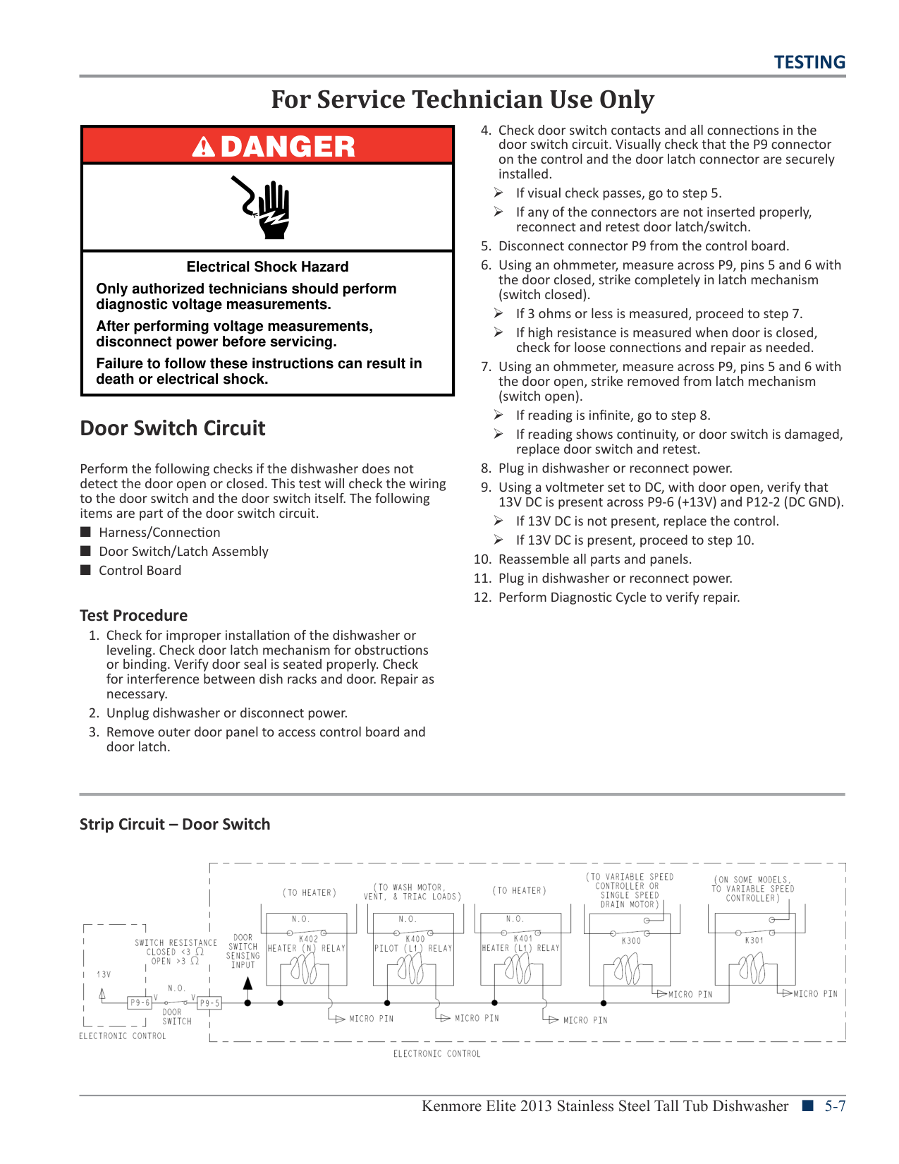
| | | |---|---| | | |
| | | |---|---| | | |
| | | | |---|---|---| | | | |
| | | | |---|---|---| | | | |
| | | |---|---| | | |
| | | |---|---| | | |
| | | |---|---| | | |
| | | |---|---| | | |
| | | |---|---| | | | | | |
| | | |---|---| | | | | | |
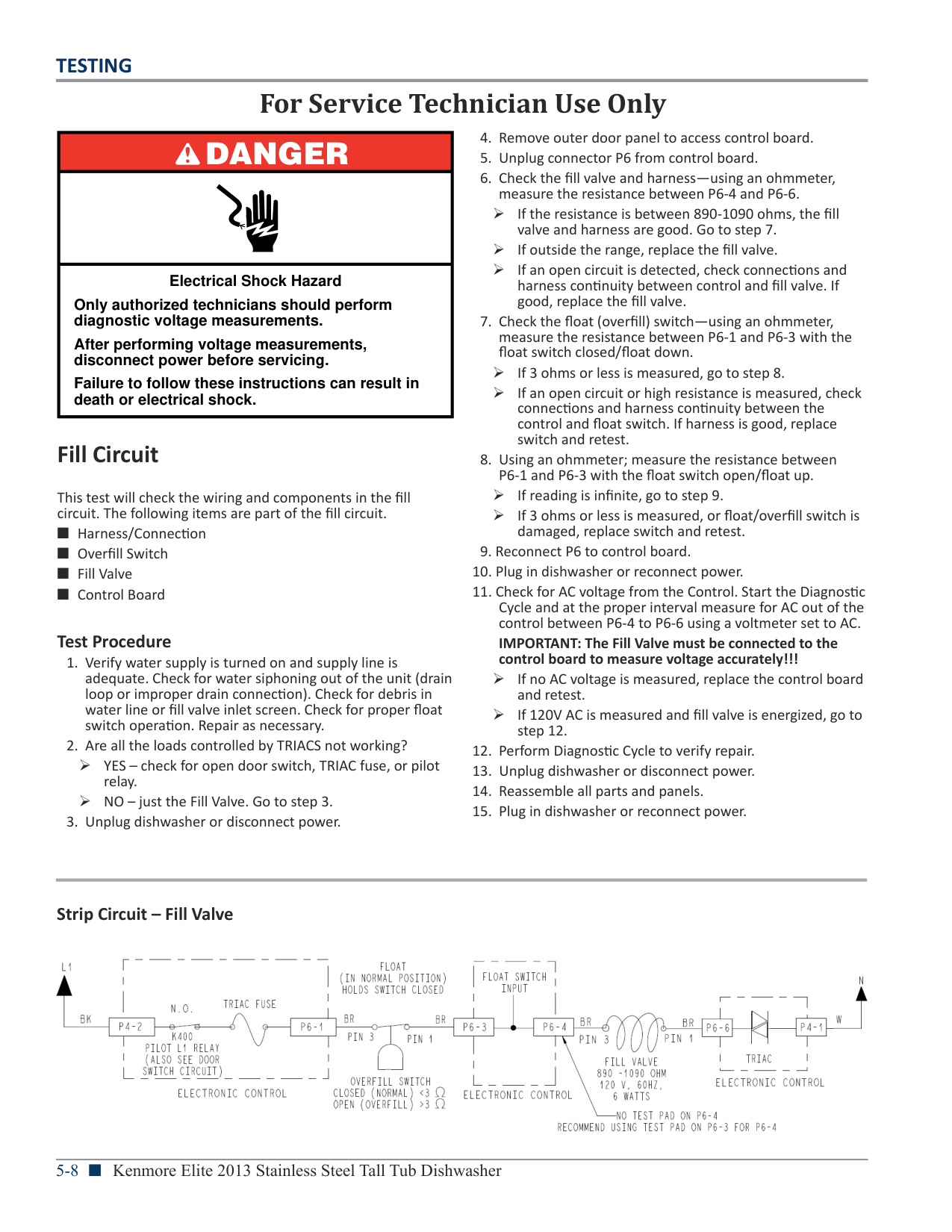
| | | | |---|---|---| | | | |
| | | |---|---| | | |
| | | | |---|---|---| | | | | | | | |
| | | |---|---| | | | | | |
| | | |---|---| | | |
| | | |---|---| | | |
| | | |---|---| | | |
| | | | |---|---|---| | | | |
| | | |---|---| | | |
| | | |---|---| | | |
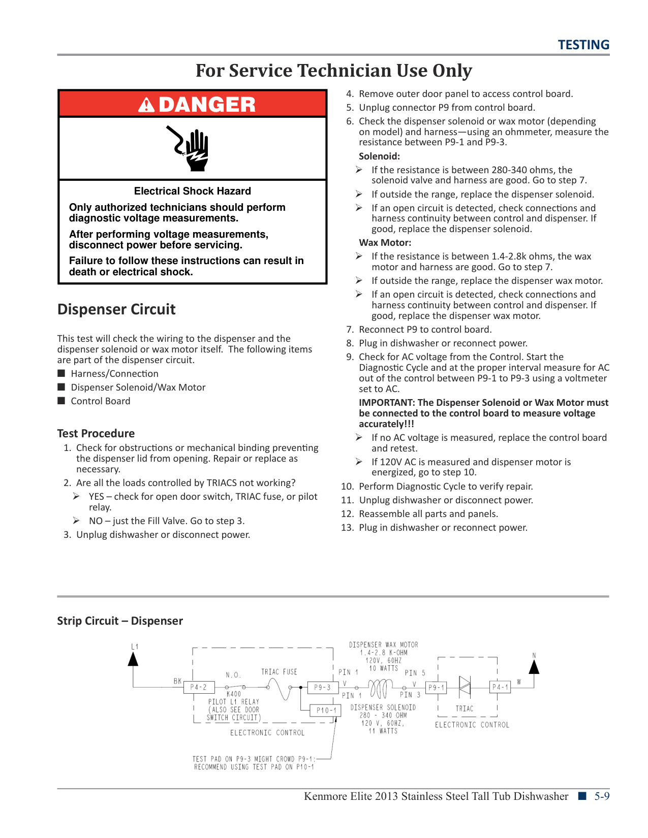
BUTTONS ON BOTTOM OF CONTROL HOUSING SLIDE INTO KEYHOLE SLOTS ON CONTROL PANEL TO SUPPORT THE CONTROL.
########## METER CHECK OF LOADS & SUPPLIES
4 3 2 1 1 2 3 4 5 6 1 3 6 1 3 4 6 1 3 4 6 1 3 5 6 1 3 5 6 1 THRU 6 1 THRU 6 P4 P5 P6 P7 P8 P9 P10 P11 P12
L1 NEUTRAL DC GND+5V+3.3V+13V
|For Service Technician Use Only|For Service Technician Use Only| |---|---| |DANGER
|Power Check
This test checks for incoming and outgoing power to and from the control board. This test assumes that proper voltages is present at the outlet or direct connect cable.
Test Procedure
1. Unplug dishwasher or disconnect power.
2. Remove access panel.
3. Remove terminal box cover.
4. With a voltmeter set to AC, insert black probe inside white wire screw nut (N) and insert red probe inside black wire screw nut (L1).
5. Plug in dishwasher or reconnect power.
¾ If 120V AC is present, unplug dishwasher or disconnect power and proceed to step 6.| | |Power Check
This test checks for incoming and outgoing power to and from the control board. This test assumes that proper voltages is present at the outlet or direct connect cable.
Test Procedure
1. Unplug dishwasher or disconnect power.
2. Remove access panel.
3. Remove terminal box cover.
4. With a voltmeter set to AC, insert black probe inside white wire screw nut (N) and insert red probe inside black wire screw nut (L1).
5. Plug in dishwasher or reconnect power.
¾ If 120V AC is present, unplug dishwasher or disconnect power and proceed to step 6.| |Electrical Shock Hazard
Only authorized technicians should perform diagnostic voltage measurements.
After performing voltage measurements, disconnect power before servicing.
Failure to follow these instructions can result in death or electrical shock.|Power Check
This test checks for incoming and outgoing power to and from the control board. This test assumes that proper voltages is present at the outlet or direct connect cable.
Test Procedure
1. Unplug dishwasher or disconnect power.
2. Remove access panel.
3. Remove terminal box cover.
4. With a voltmeter set to AC, insert black probe inside white wire screw nut (N) and insert red probe inside black wire screw nut (L1).
5. Plug in dishwasher or reconnect power.
¾ If 120V AC is present, unplug dishwasher or disconnect power and proceed to step 6.|
¾ If 120V AC is not present, have customer correct power problem at outlet or breaker.
###### General Theory of Operation
¾ If 120V AC is not present, check for open connection between terminal block and control. Repair as needed.
¾ If +3.3V DC were missing, the dishwasher would become unresponsive. To verify +3.3V ± 5%, with a voltmeter set to DC, connect the black lead to P12-2 (GND) and the red lead to P11-2 (+3.3V).
¾ If +5V DC were missing, the fan motor or diverter switch would not function. To verify +5V ± 5%, with a voltmeter set to DC, connect the black lead to P12-2 (GND) and the red lead to P10-5 (+5V).
¾ If +13V DC was missing, the heater, motors, and all other loads would not turn on. To verify +13V ± 5%, with a voltmeter set to DC, connect the black lead to P12-2 (GND) and the red lead to P9-6 (+13V).
Troubleshooting Missing DC Supplies: Refer to the wiring diagram on page 6-3 when troubleshooting the DC supplies. If +3.3, +5, or +13V DC is missing on the control, unplug dishwasher or disconnect power, and then disconnect all components/loads from the control relying on the missing or loaded supply. Plug in dishwasher or reconnect power and check if the DC supply has returned.
¾ If not, replace the control. ¾ If it has, turn off dishwasher and reconnect one
connector at a time until the component loading down that supply has been identified.
Refer to Wiring Diagram on page 6-3.
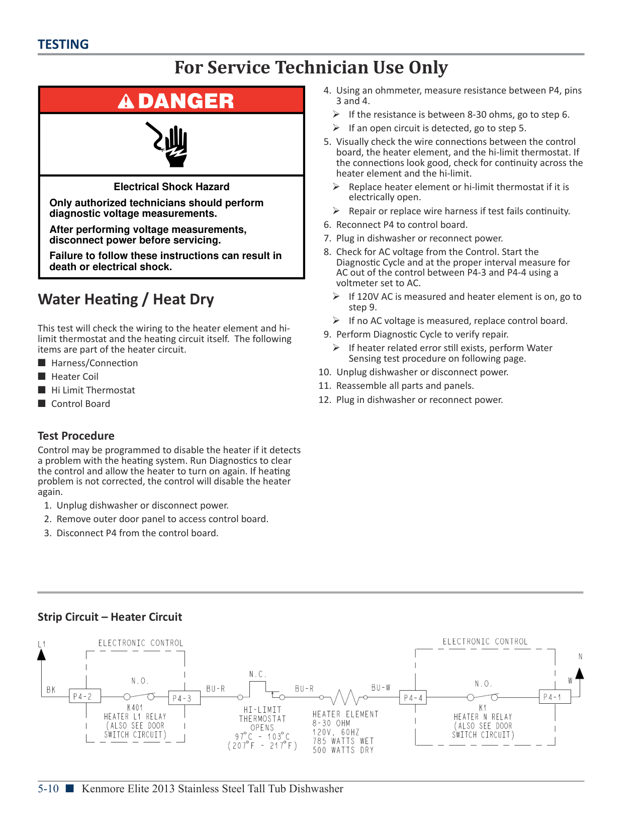
Neutral and L1 (AC voltage) enters the Control Board at P4, pins 1 & 2 respectively. AC is converted to DC at the LV/HV Power Supply. LV (Low Voltage) Supplies include 15V, 13V, 5V, and 3.3V DC. These LV supplies are used to provide power to the microprocessors and board components, control the triacs, power the sensors, buzzer, fan motor, and energize the AC relays. The 170V DC HV (High Voltage) Supply is used to control the variable speed wash and drain motors.
The 13V DC is vital to the operation of the dishwasher. This supply is necessary to operate all 120V AC loads in the dishwasher, whether they are connected to a relay or controlled by triacs. 13V DC is generated by the power supply and flows through the door switch—when closed—to be available to the heater relays, wash & drain motor relays, and the pilot relay. A relay coil becomes energized when the control closes the LV drive circuit for a specific relay completing 13V pathway, which in turn closes the relay switch providing AC to the load. The Pilot relay provides “L1” to the remainder of the components that are controlled by the Neutral-sensed triacs.
There are three fuses on the Control Board: the L1 Fuse, the Motor Fuse, and the Triac Fuse. If the L1 Fuse is open, the entire dishwasher is unresponsive. If the Motor Fuse is open, both variable speed wash and drain motors will not operate. And, if the Triac Fuse is open, all loads controlled by Triacs will not operate. NOTE: Refer to “Fuse Service and Diagnostic Checks” on page 6-4.
|For Service Technician Use Only|For Service Technician Use Only| |---|---| |DANGER
|4. Check door switch contacts and all connections in the door switch circuit. Visually check that the P9 connector on the control and the door latch connector are securely installed.
¾ If visual check passes, go to step 5. ¾ If any of the connectors are not inserted properly,
reconnect and retest door latch/switch.
5. Disconnect connector P9 from the control board.
6. Using an ohmmeter, measure across P9, pins 5 and 6 with the door closed, strike completely in latch mechanism (switch closed).
¾ If 3 ohms or less is measured, proceed to step 7. ¾ If high resistance is measured when door is closed,
check for loose connections and repair as needed.
7. Using an ohmmeter, measure across P9, pins 5 and 6 with the door open, strike removed from latch mechanism
| | |4. Check door switch contacts and all connections in the door switch circuit. Visually check that the P9 connector on the control and the door latch connector are securely installed.
¾ If visual check passes, go to step 5. ¾ If any of the connectors are not inserted properly,
reconnect and retest door latch/switch.
5. Disconnect connector P9 from the control board.
6. Using an ohmmeter, measure across P9, pins 5 and 6 with the door closed, strike completely in latch mechanism (switch closed).
¾ If 3 ohms or less is measured, proceed to step 7. ¾ If high resistance is measured when door is closed,
check for loose connections and repair as needed.
7. Using an ohmmeter, measure across P9, pins 5 and 6 with the door open, strike removed from latch mechanism
| |Electrical Shock Hazard
Only authorized technicians should perform diagnostic voltage measurements.
After performing voltage measurements, disconnect power before servicing.
Failure to follow these instructions can result in death or electrical shock.|4. Check door switch contacts and all connections in the door switch circuit. Visually check that the P9 connector on the control and the door latch connector are securely installed.
¾ If visual check passes, go to step 5. ¾ If any of the connectors are not inserted properly,
reconnect and retest door latch/switch.
5. Disconnect connector P9 from the control board.
6. Using an ohmmeter, measure across P9, pins 5 and 6 with the door closed, strike completely in latch mechanism (switch closed).
¾ If 3 ohms or less is measured, proceed to step 7. ¾ If high resistance is measured when door is closed,
check for loose connections and repair as needed.
7. Using an ohmmeter, measure across P9, pins 5 and 6 with the door open, strike removed from latch mechanism
|
(switch open). ¾ If reading is infinite, go to step 8. ¾ If reading shows continuity, or door switch is damaged,
###### Door Switch Circuit
replace door switch and retest.
¾ If 13V DC is not present, replace the control. ¾ If 13V DC is present, proceed to step 10.
Perform the following checks if the dishwasher does not detect the door open or closed. This test will check the wiring to the door switch and the door switch itself. The following items are part of the door switch circuit.
########## Test Procedure
Strip Circuit – Door Switch

|DANGER
| |---| | | |Electrical Shock Hazard
Only authorized technicians should perform diagnostic voltage measurements.
After performing voltage measurements, disconnect power before servicing.
Failure to follow these instructions can result in death or electrical shock.|
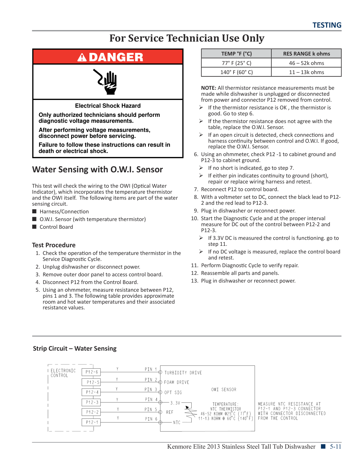
¾ If the resistance is between 890-1090 ohms, the fill
valve and harness are good. Go to step 7. ¾ If outside the range, replace the fill valve. ¾ If an open circuit is detected, check connections and
harness continuity between control and fill valve. If good, replace the fill valve.
¾ If 3 ohms or less is measured, go to step 8. ¾ If an open circuit or high resistance is measured, check
connections and harness continuity between the control and float switch. If harness is good, replace switch and retest.
¾ If reading is infinite, go to step 9. ¾ If 3 ohms or less is measured, or float/overfill switch is
damaged, replace switch and retest.
IMPORTANT: The Fill Valve must be connected to the control board to measure voltage accurately!!!
¾ If no AC voltage is measured, replace the control board and retest. ¾ If 120V AC is measured and fill valve is energized, go to step 12.
###### Fill Circuit
This test will check the wiring and components in the fill circuit. The following items are part of the fill circuit.
########## Test Procedure
¾ YES – check for open door switch, TRIAC fuse, or pilot relay. ¾ NO – just the Fill Valve. Go to step 3.

Strip Circuit – Fill Valve

|DANGER
| |---| | | |Electrical Shock Hazard
Only authorized technicians should perform diagnostic voltage measurements.
After performing voltage measurements, disconnect power before servicing.
Failure to follow these instructions can result in death or electrical shock.|
¾ If the resistance is between 280-340 ohms, the solenoid valve and harness are good. Go to step 7.
¾ If outside the range, replace the dispenser solenoid. ¾ If an open circuit is detected, check connections and
harness continuity between control and dispenser. If good, replace the dispenser solenoid.
Wax Motor:
¾ If the resistance is between 1.4-2.8k ohms, the wax
motor and harness are good. Go to step 7. ¾ If outside the range, replace the dispenser wax motor. ¾ If an open circuit is detected, check connections and
harness continuity between control and dispenser. If good, replace the dispenser wax motor.
IMPORTANT: The Dispenser Solenoid or Wax Motor must be connected to the control board to measure voltage accurately!!!
¾ If no AC voltage is measured, replace the control board and retest. ¾ If 120V AC is measured and dispenser motor is energized, go to step 10.
###### Dispenser Circuit
This test will check the wiring to the dispenser and the dispenser solenoid or wax motor itself. The following items are part of the dispenser circuit.
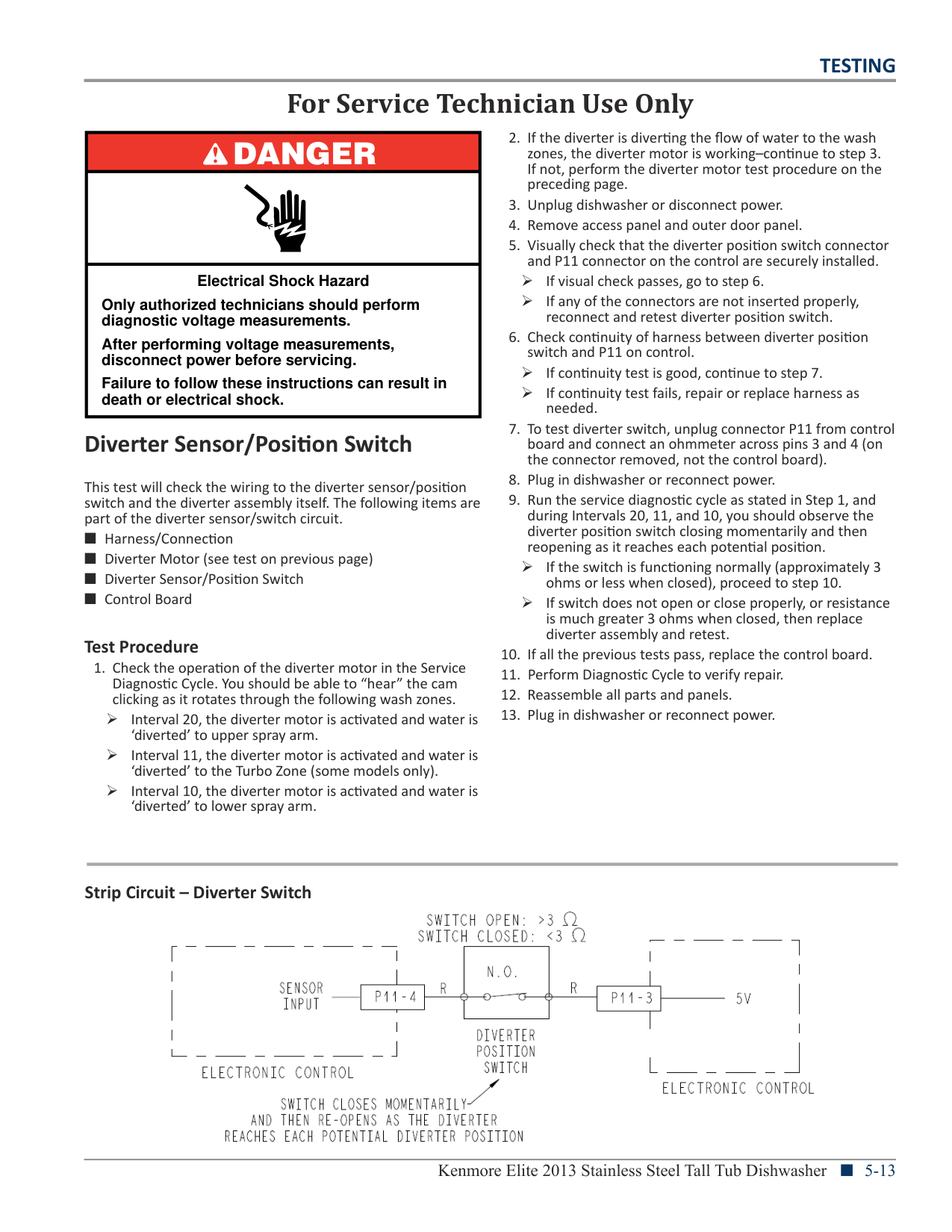
########## Test Procedure
¾ YES – check for open door switch, TRIAC fuse, or pilot relay. ¾ NO – just the Fill Valve. Go to step 3.
Strip Circuit – Dispenser

|DANGER
| |---| | | |Electrical Shock Hazard
Only authorized technicians should perform diagnostic voltage measurements.
After performing voltage measurements, disconnect power before servicing.
Failure to follow these instructions can result in death or electrical shock.|
###### Water Heating / Heat Dry
This test will check the wiring to the heater element and hilimit thermostat and the heating circuit itself. The following items are part of the heater circuit.
¾ If the resistance is between 8-30 ohms, go to step 6. ¾ If an open circuit is detected, go to step 5.
¾ Replace heater element or hi-limit thermostat if it is electrically open. ¾ Repair or replace wire harness if test fails continuity.
¾ If 120V AC is measured and heater element is on, go to step 9. ¾ If no AC voltage is measured, replace control board.
¾ If heater related error still exists, perform Water Sensing test procedure on following page.
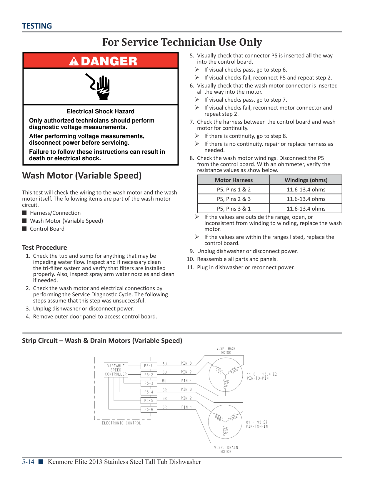
Test Procedure Control may be programmed to disable the heater if it detects a problem with the heating system. Run Diagnostics to clear the control and allow the heater to turn on again. If heating problem is not corrected, the control will disable the heater again.
Strip Circuit – Heater Circuit

|DANGER
| |---| | | |Electrical Shock Hazard
Only authorized technicians should perform diagnostic voltage measurements.
After performing voltage measurements, disconnect power before servicing.
Failure to follow these instructions can result in death or electrical shock.|
###### Water Sensing with O.W.I. Sensor
This test will check the wiring to the OWI (Optical Water Indicator), which incorporates the temperature thermistor and the OWI itself. The following items are part of the water sensing circuit.
########## Test Procedure
|TEMP °F (°C)|RES RANGE k ohms| |---|---| |77° F (25° C)|46 – 52k ohms| |140° F (60° C)|11 – 13k ohms|
NOTE: All thermistor resistance measurements must be made while dishwasher is unplugged or disconnected from power and connector P12 removed from control.
¾ If the thermistor resistance is OK , the thermistor is good. Go to step 6. ¾ If the thermistor resistance does not agree with the table, replace the O.W.I. Sensor.
¾ If an open circuit is detected, check connections and harness continuity between control and O.W.I. If good, replace the O.W.I. Sensor.
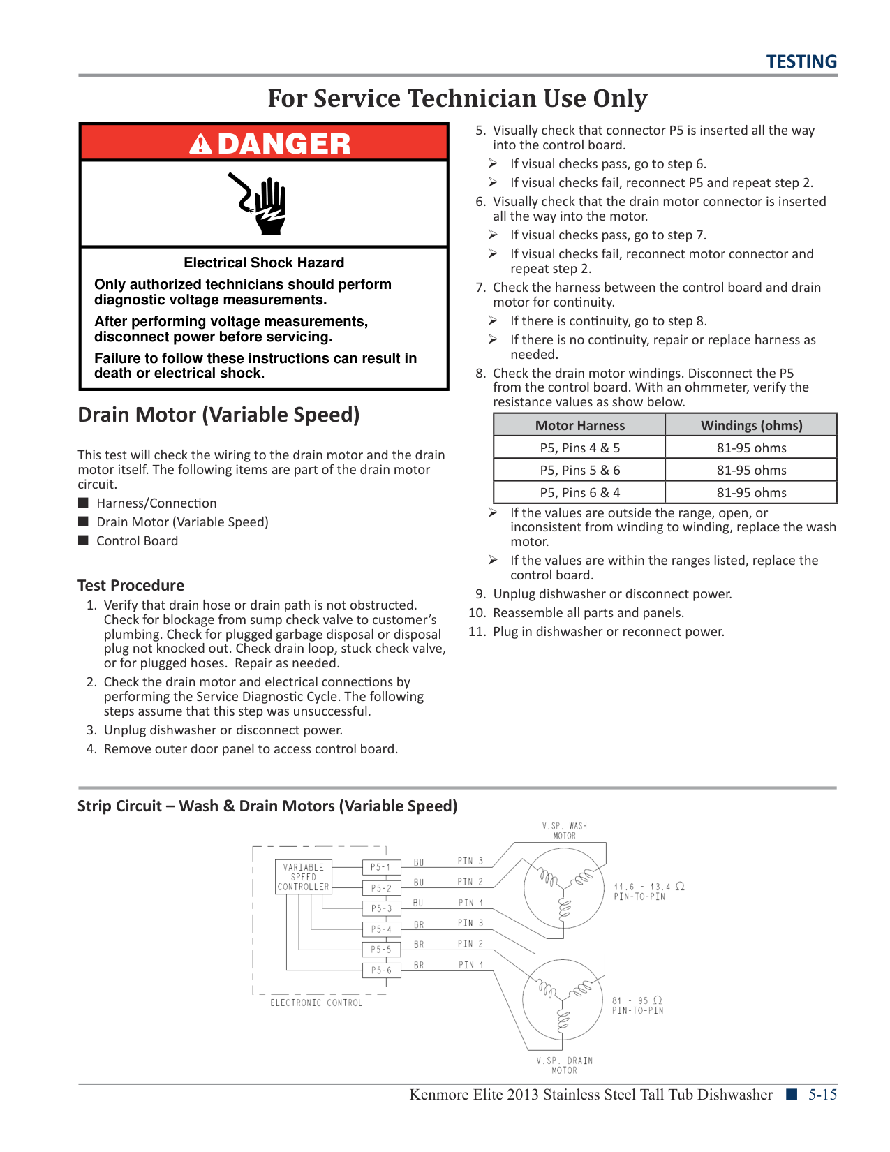
¾ If no short is indicated, go to step 7. ¾ If either pin indicates continuity to ground (short),
repair or replace wiring harness and retest.
¾ If 3.3V DC is measured the control is functioning. go to step 11. ¾ If no DC voltage is measured, replace the control board and retest.
Strip Circuit – Water Sensing

|DANGER
| |---| | | |Electrical Shock Hazard
Only authorized technicians should perform diagnostic voltage measurements.
After performing voltage measurements, disconnect power before servicing.
Failure to follow these instructions can result in death or electrical shock.|
###### Diverter Motor
This test will check the wiring to the diverter motor and the diverter motor itself. The following items are part of the diverter motor circuit.
########## Test Procedure
¾ YES – check for open door switch, TRIAC fuse, or pilot relay. ¾ NO – just the diverter valve. Go to step 3.
¾ If the resistance is between 1300-1600 ohms, the
diverter motor and harness are good. Go to step 7. ¾ If outside the range, replace the diverter assembly. ¾ If an open circuit is detected, check connections and harness continuity between control and diverter assembly. If good, replace the diverter assembly.
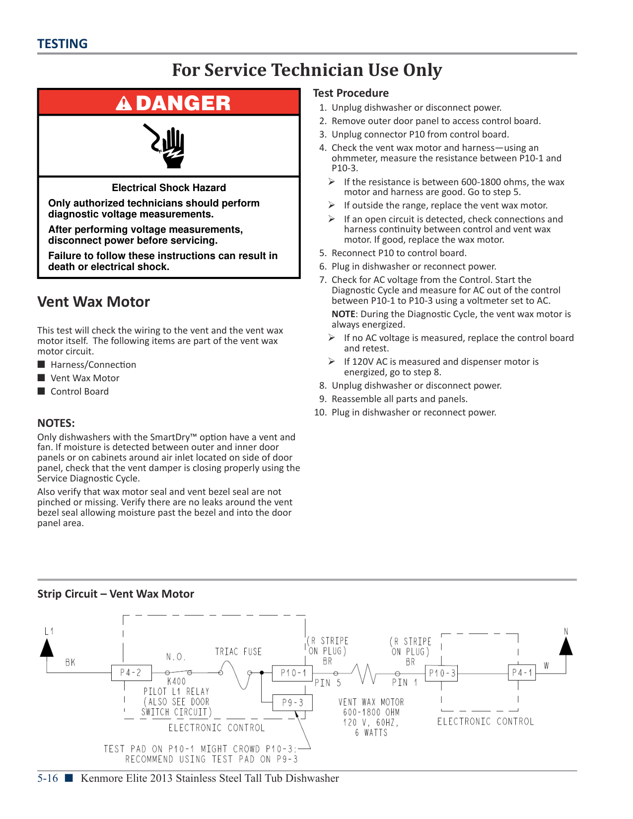
IMPORTANT: The Diverter Motor must be connected to the control board to measure voltage accurately!!!
¾ If no AC voltage is measured, replace the control board and retest. ¾ If 120V AC is measured and diverter is rotating, go to step 10.
¾ If diverter error still exists, perform diverter sensor test procedure on following page.
Strip Circuit – Diverter Motor

|DANGER
| |---| | | |Electrical Shock Hazard
Only authorized technicians should perform diagnostic voltage measurements.
After performing voltage measurements, disconnect power before servicing.
Failure to follow these instructions can result in death or electrical shock.|
###### Diverter Sensor/Position Switch
This test will check the wiring to the diverter sensor/position switch and the diverter assembly itself. The following items are part of the diverter sensor/switch circuit.
########## Test Procedure
Diagnostic Cycle. You should be able to “hear” the cam clicking as it rotates through the following wash zones.
¾ Interval 20, the diverter motor is activated and water is ‘diverted’ to upper spray arm. ¾ Interval 11, the diverter motor is activated and water is ‘diverted’ to the Turbo Zone (some models only). ¾ Interval 10, the diverter motor is activated and water is ‘diverted’ to lower spray arm.
¾ If visual check passes, go to step 6. ¾ If any of the connectors are not inserted properly, reconnect and retest diverter position switch.
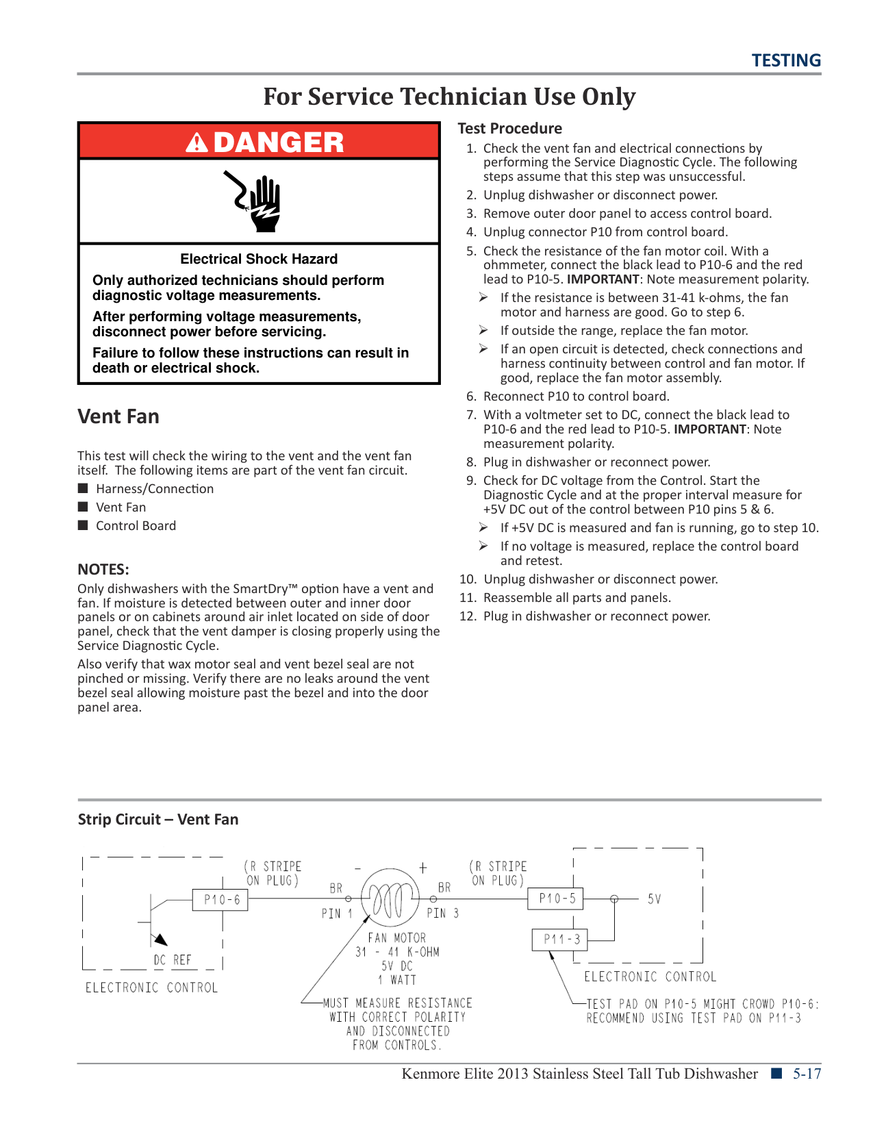
¾ If continuity test is good, continue to step 7. ¾ If continuity test fails, repair or replace harness as
needed.
¾ If the switch is functioning normally (approximately 3 ohms or less when closed), proceed to step 10.
¾ If switch does not open or close properly, or resistance is much greater 3 ohms when closed, then replace diverter assembly and retest.
Strip Circuit – Diverter Switch

|For Service Technician Use Only|For Service Technician Use Only| |---|---| |DANGER
|5. Visually check that connector P5 is inserted all the way into the control board.
¾ If visual checks pass, go to step 6. ¾ If visual checks fail, reconnect P5 and repeat step 2.
6. Visually check that the wash motor connector is inserted all the way into the motor.
¾ If visual checks pass, go to step 7. ¾ If visual checks fail, reconnect motor connector and
repeat step 2.
7. Check the harness between the control board and wash motor for continuity.
¾ If there is continuity, go to step 8. ¾ If there is no continuity, repair or replace harness as
needed.
8. Check the wash motor windings. Disconnect the P5 from the control board. With an ohmmeter, verify the
| | |5. Visually check that connector P5 is inserted all the way into the control board.
¾ If visual checks pass, go to step 6. ¾ If visual checks fail, reconnect P5 and repeat step 2.
6. Visually check that the wash motor connector is inserted all the way into the motor.
¾ If visual checks pass, go to step 7. ¾ If visual checks fail, reconnect motor connector and
repeat step 2.
7. Check the harness between the control board and wash motor for continuity.
¾ If there is continuity, go to step 8. ¾ If there is no continuity, repair or replace harness as
needed.
8. Check the wash motor windings. Disconnect the P5 from the control board. With an ohmmeter, verify the
| |Electrical Shock Hazard
Only authorized technicians should perform diagnostic voltage measurements.
After performing voltage measurements, disconnect power before servicing.
Failure to follow these instructions can result in death or electrical shock.|5. Visually check that connector P5 is inserted all the way into the control board.
¾ If visual checks pass, go to step 6. ¾ If visual checks fail, reconnect P5 and repeat step 2.
6. Visually check that the wash motor connector is inserted all the way into the motor.
¾ If visual checks pass, go to step 7. ¾ If visual checks fail, reconnect motor connector and
repeat step 2.
7. Check the harness between the control board and wash motor for continuity.
¾ If there is continuity, go to step 8. ¾ If there is no continuity, repair or replace harness as
needed.
8. Check the wash motor windings. Disconnect the P5 from the control board. With an ohmmeter, verify the
|
resistance values as show below.
###### Wash Motor (Variable Speed)
|Motor Harness|Windings (ohms)| |---|---| |P5, Pins 1 & 2|11.6-13.4 ohms| |P5, Pins 2 & 3|11.6-13.4 ohms| |P5, Pins 3 & 1|11.6-13.4 ohms|
This test will check the wiring to the wash motor and the wash motor itself. The following items are part of the wash motor circuit.
¾ If the values are outside the range, open, or inconsistent from winding to winding, replace the wash motor.
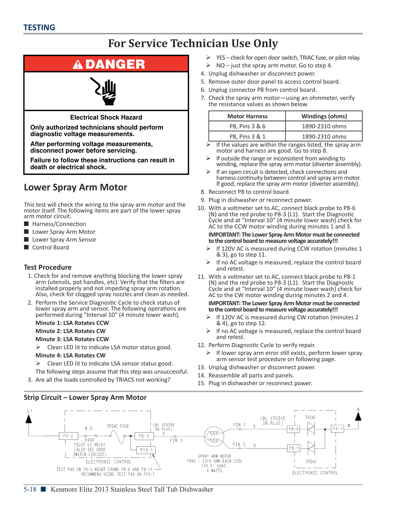
¾ If the values are within the ranges listed, replace the control board.
########## Test Procedure
Strip Circuit – Wash & Drain Motors (Variable Speed)

|For Service Technician Use Only|For Service Technician Use Only| |---|---| |DANGER
|5. Visually check that connector P5 is inserted all the way into the control board.
¾ If visual checks pass, go to step 6. ¾ If visual checks fail, reconnect P5 and repeat step 2.
6. Visually check that the drain motor connector is inserted all the way into the motor.
¾ If visual checks pass, go to step 7. ¾ If visual checks fail, reconnect motor connector and
repeat step 2.
7. Check the harness between the control board and drain motor for continuity.
¾ If there is continuity, go to step 8. ¾ If there is no continuity, repair or replace harness as
needed.
8. Check the drain motor windings. Disconnect the P5 from the control board. With an ohmmeter, verify the
| | |5. Visually check that connector P5 is inserted all the way into the control board.
¾ If visual checks pass, go to step 6. ¾ If visual checks fail, reconnect P5 and repeat step 2.
6. Visually check that the drain motor connector is inserted all the way into the motor.
¾ If visual checks pass, go to step 7. ¾ If visual checks fail, reconnect motor connector and
repeat step 2.
7. Check the harness between the control board and drain motor for continuity.
¾ If there is continuity, go to step 8. ¾ If there is no continuity, repair or replace harness as
needed.
8. Check the drain motor windings. Disconnect the P5 from the control board. With an ohmmeter, verify the
| |Electrical Shock Hazard
Only authorized technicians should perform diagnostic voltage measurements.
After performing voltage measurements, disconnect power before servicing.
Failure to follow these instructions can result in death or electrical shock.|5. Visually check that connector P5 is inserted all the way into the control board.
¾ If visual checks pass, go to step 6. ¾ If visual checks fail, reconnect P5 and repeat step 2.
6. Visually check that the drain motor connector is inserted all the way into the motor.
¾ If visual checks pass, go to step 7. ¾ If visual checks fail, reconnect motor connector and
repeat step 2.
7. Check the harness between the control board and drain motor for continuity.
¾ If there is continuity, go to step 8. ¾ If there is no continuity, repair or replace harness as
needed.
8. Check the drain motor windings. Disconnect the P5 from the control board. With an ohmmeter, verify the
|
resistance values as show below.
###### Drain Motor (Variable Speed)
|Motor Harness|Windings (ohms)| |---|---| |P5, Pins 4 & 5|81-95 ohms| |P5, Pins 5 & 6|81-95 ohms| |P5, Pins 6 & 4|81-95 ohms|
This test will check the wiring to the drain motor and the drain motor itself. The following items are part of the drain motor circuit.
¾ If the values are outside the range, open, or inconsistent from winding to winding, replace the wash motor.
¾ If the values are within the ranges listed, replace the control board.
########## Test Procedure
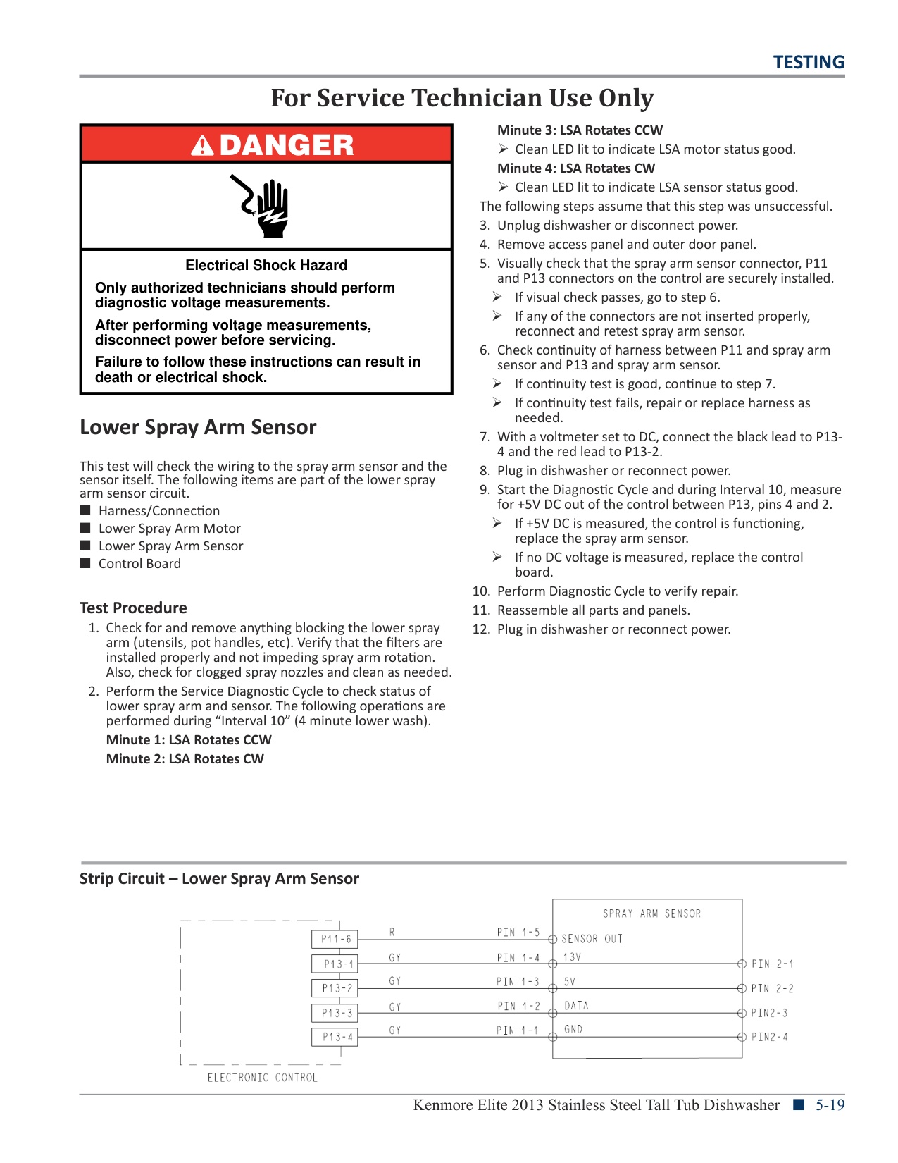
Strip Circuit – Wash & Drain Motors (Variable Speed)

|DANGER
| |---| | | |Electrical Shock Hazard
Only authorized technicians should perform diagnostic voltage measurements.
After performing voltage measurements, disconnect power before servicing.
Failure to follow these instructions can result in death or electrical shock.|
¾ If the resistance is between 600-1800 ohms, the wax
motor and harness are good. Go to step 5. ¾ If outside the range, replace the vent wax motor. ¾ If an open circuit is detected, check connections and harness continuity between control and vent wax motor. If good, replace the wax motor.
NOTE: During the Diagnostic Cycle, the vent wax motor is always energized.
¾ If no AC voltage is measured, replace the control board and retest. ¾ If 120V AC is measured and dispenser motor is energized, go to step 8.
###### Vent Wax Motor
This test will check the wiring to the vent and the vent wax motor itself. The following items are part of the vent wax motor circuit.
NOTES: Only dishwashers with the SmartDry™ option have a vent and fan. If moisture is detected between outer and inner door panels or on cabinets around air inlet located on side of door panel, check that the vent damper is closing properly using the Service Diagnostic Cycle. Also verify that wax motor seal and vent bezel seal are not pinched or missing. Verify there are no leaks around the vent bezel seal allowing moisture past the bezel and into the door panel area.
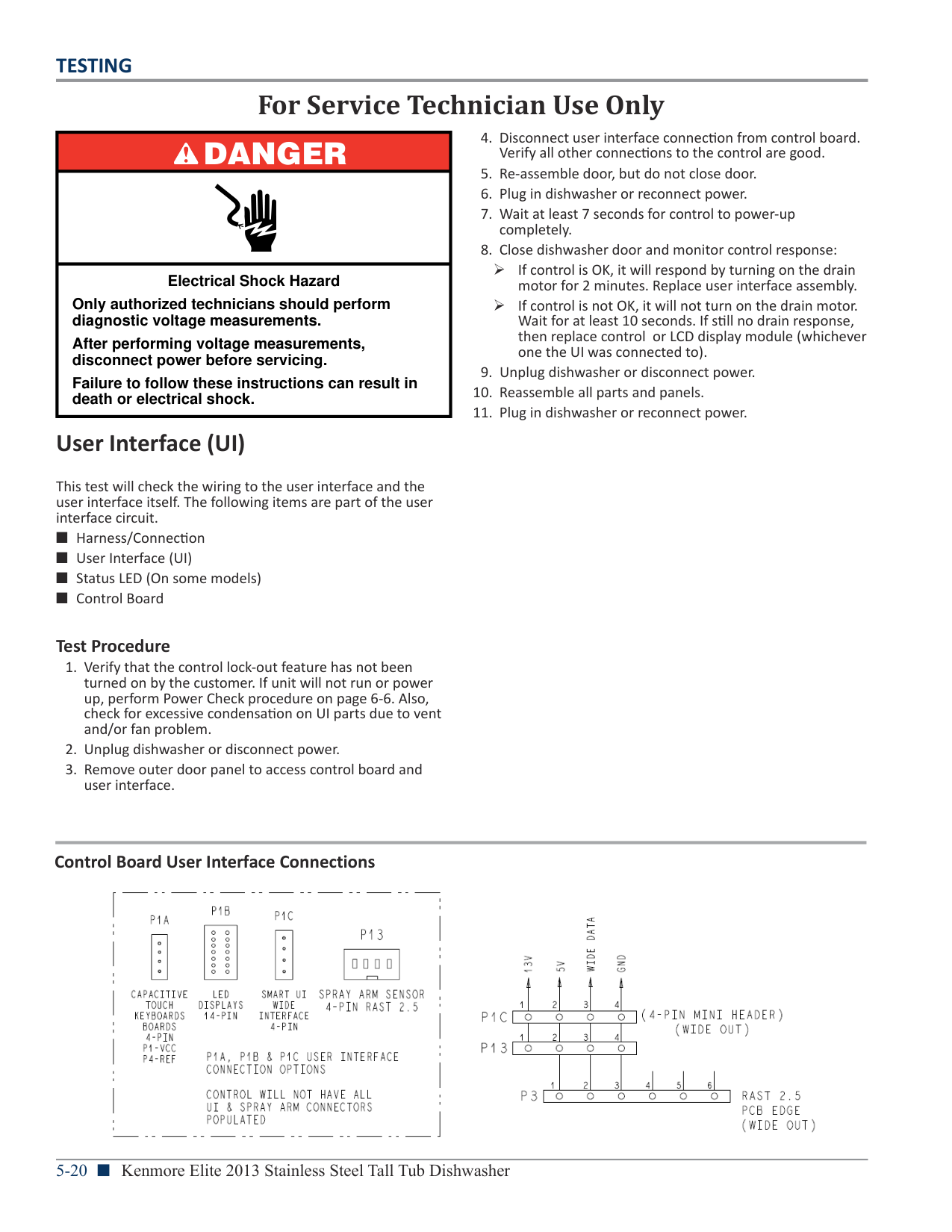
Strip Circuit – Vent Wax Motor

|DANGER
| |---| | | |Electrical Shock Hazard
Only authorized technicians should perform diagnostic voltage measurements.
After performing voltage measurements, disconnect power before servicing.
Failure to follow these instructions can result in death or electrical shock.|
¾ If the resistance is between 31-41 k-ohms, the fan
motor and harness are good. Go to step 6. ¾ If outside the range, replace the fan motor. ¾ If an open circuit is detected, check connections and
harness continuity between control and fan motor. If good, replace the fan motor assembly.
+5V DC out of the control between P10 pins 5 & 6. ¾ If +5V DC is measured and fan is running, go to step 10. ¾ If no voltage is measured, replace the control board
and retest.
###### Vent Fan
This test will check the wiring to the vent and the vent fan itself. The following items are part of the vent fan circuit.
NOTES: Only dishwashers with the SmartDry™ option have a vent and fan. If moisture is detected between outer and inner door panels or on cabinets around air inlet located on side of door panel, check that the vent damper is closing properly using the Service Diagnostic Cycle. Also verify that wax motor seal and vent bezel seal are not pinched or missing. Verify there are no leaks around the vent bezel seal allowing moisture past the bezel and into the door panel area.
Strip Circuit – Vent Fan

|DANGER
|

|---| | | |Electrical Shock Hazard
Only authorized technicians should perform diagnostic voltage measurements.
After performing voltage measurements, disconnect power before servicing.
Failure to follow these instructions can result in death or electrical shock.|
###### Lower Spray Arm Motor
This test will check the wiring to the spray arm motor and the motor itself. The following items are part of the lower spray arm motor circuit.
########## Test Procedure
¾ YES – check for open door switch, TRIAC fuse, or pilot relay. ¾ NO – just the spray arm motor. Go to step 4.
|Motor Harness|Windings (ohms)| |---|---| |P8, Pins 3 & 6|1890-2310 ohms| |P8, Pins 3 & 1|1890-2310 ohms|
¾ If the values are within the ranges listed, the spray arm motor and harness are good. Go to step 8.
¾ If outside the range or inconsistent from winding to
winding, replace the spray arm motor (diverter assembly). ¾ If an open circuit is detected, check connections and
harness continuity between control and spray arm motor. If good, replace the spray arm motor (diverter assembly).

IMPORTANT: The Lower Spray Arm Motor must be connected to the control board to measure voltage accurately!!!
¾ If 120V AC is measured during CCW rotation (minutes 1 & 3), go to step 11.
¾ If no AC voltage is measured, replace the control board and retest.
IMPORTANT: The Lower Spray Arm Motor must be connected to the control board to measure voltage accurately!!!
¾ If 120V AC is measured during CW rotation (minutes 2 & 4), go to step 12.
¾ If no AC voltage is measured, replace the control board and retest.
¾ If lower spray arm error still exists, perform lower spray arm sensor test procedure on following page.
Strip Circuit – Lower Spray Arm Motor

|DANGER
| |---| | | |Electrical Shock Hazard
Only authorized technicians should perform diagnostic voltage measurements.
After performing voltage measurements, disconnect power before servicing.
Failure to follow these instructions can result in death or electrical shock.|
###### Lower Spray Arm Sensor
This test will check the wiring to the spray arm sensor and the sensor itself. The following items are part of the lower spray arm sensor circuit.
########## Test Procedure
The following steps assume that this step was unsuccessful.
¾ If visual check passes, go to step 6. ¾ If any of the connectors are not inserted properly,
reconnect and retest spray arm sensor.
¾ If continuity test is good, continue to step 7. ¾ If continuity test fails, repair or replace harness as
needed.
¾ If +5V DC is measured, the control is functioning, replace the spray arm sensor. ¾ If no DC voltage is measured, replace the control board.
Strip Circuit – Lower Spray Arm Sensor

|For Service Technician Use Only|For Service Technician Use Only| |---|---| |DANGER
|4. Disconnect user interface connection from control board. Verify all other connections to the control are good.
5. Re-assemble door, but do not close door.
6. Plug in dishwasher or reconnect power.
7. Wait at least 7 seconds for control to power-up completely.
8. Close dishwasher door and monitor control response:
¾ If control is OK, it will respond by turning on the drain motor for 2 minutes. Replace user interface assembly.
¾ If control is not OK, it will not turn on the drain motor. Wait for at least 10 seconds. If still no drain response, then replace control or LCD display module (whichever one the UI was connected to).
9. Unplug dishwasher or disconnect power.
10. Reassemble all parts and panels.
11. Plug in dishwasher or reconnect power.
| | |4. Disconnect user interface connection from control board. Verify all other connections to the control are good.
5. Re-assemble door, but do not close door.
6. Plug in dishwasher or reconnect power.
7. Wait at least 7 seconds for control to power-up completely.
8. Close dishwasher door and monitor control response:
¾ If control is OK, it will respond by turning on the drain motor for 2 minutes. Replace user interface assembly.
¾ If control is not OK, it will not turn on the drain motor. Wait for at least 10 seconds. If still no drain response, then replace control or LCD display module (whichever one the UI was connected to).
9. Unplug dishwasher or disconnect power.
10. Reassemble all parts and panels.
11. Plug in dishwasher or reconnect power.
| |Electrical Shock Hazard
Only authorized technicians should perform diagnostic voltage measurements.
After performing voltage measurements, disconnect power before servicing.
Failure to follow these instructions can result in death or electrical shock.|4. Disconnect user interface connection from control board. Verify all other connections to the control are good.
5. Re-assemble door, but do not close door.
6. Plug in dishwasher or reconnect power.
7. Wait at least 7 seconds for control to power-up completely.
8. Close dishwasher door and monitor control response:
¾ If control is OK, it will respond by turning on the drain motor for 2 minutes. Replace user interface assembly.
¾ If control is not OK, it will not turn on the drain motor. Wait for at least 10 seconds. If still no drain response, then replace control or LCD display module (whichever one the UI was connected to).
9. Unplug dishwasher or disconnect power.
10. Reassemble all parts and panels.
11. Plug in dishwasher or reconnect power.
|
###### User Interface (UI)
This test will check the wiring to the user interface and the user interface itself. The following items are part of the user interface circuit.
########## Test Procedure
########## Control Board User Interface Connections


####### Manual No. 22110313 Kenmore Elite 2013 Stainless Steel Tall Tub Dishwasher