
Sanyo Ahx0752 Series Split System Air Conditioner
Ask AI
— answers from the official manualAnswers from the official manual.
Common questions
Common Questions
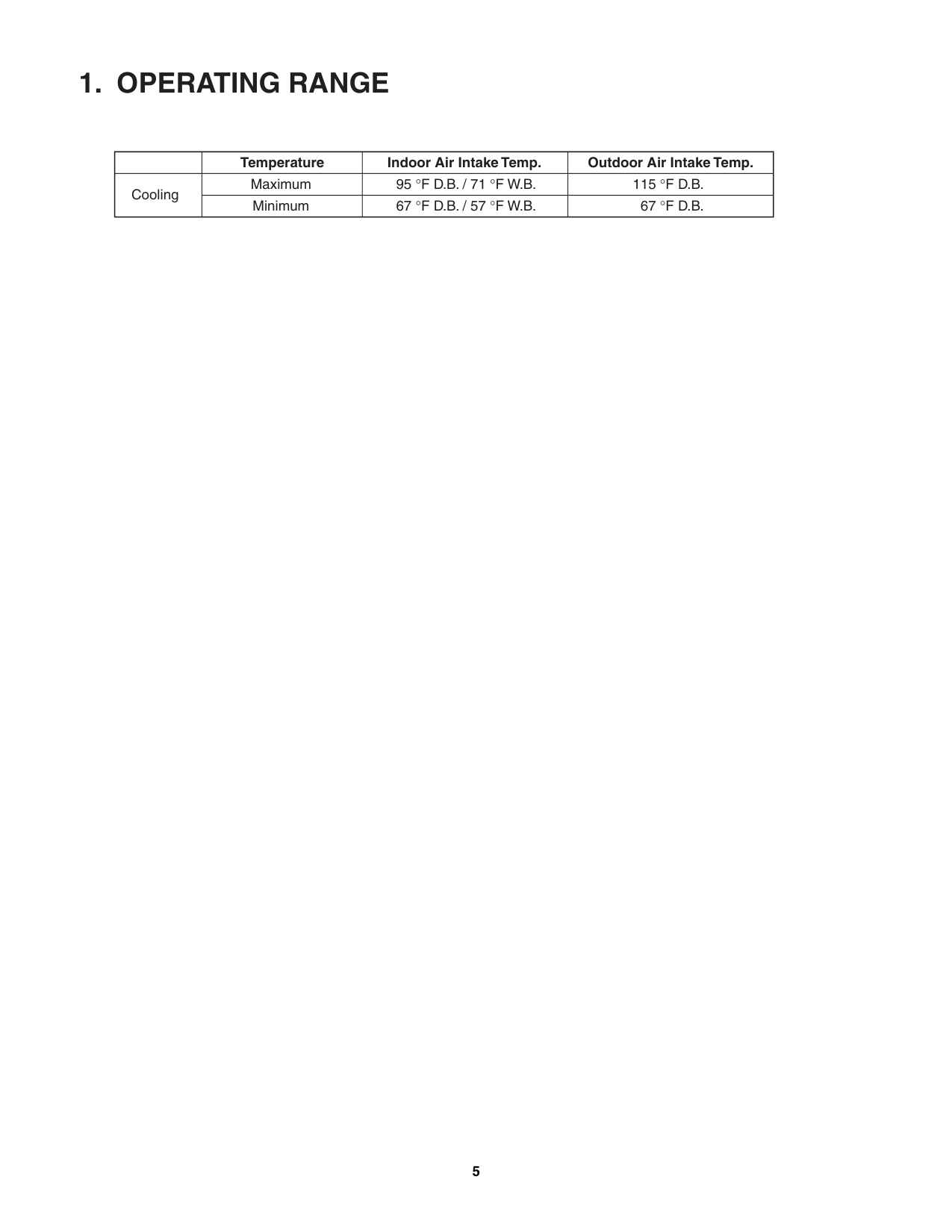
8 totalWhat is the maximum operating temperature range for cooling?
The maximum indoor air intake temperature for cooling is 95 °F D.B., and the outdoor air intake temperature can reach up to 115 °F D.B.
How do I troubleshoot if my Outdoor control circuit board fails?
Before inspecting or repairing, allow at least 30 minutes for high-capacitance electrolytic capacitors to discharge. Ensure the Power Lamp (red) on the P.C.Board has turned off.
What should I do to insulate refrigerant tubing?
Both wide and narrow tubes of this air conditioner may become cold, so insulate them with proper insulation material. The thickness of the insulation should be a minimum of 8 mm.
How do I check if my outdoor unit is functioning correctly?
Apply 220 V AC between terminals L1 and L2 on the outdoor unit terminal plate, and verify the LED (red) illuminates. Short-circuit the T-RUN terminal to COM of TEST/T-RUN terminals; then compressor and fan motor should turn ON about 70 seconds after power is turned on.
How do I set the indoor room temperature?
Press the ON/OFF button on the remote controller to start initial operation. Depending on user settings and ambient conditions, it will enter AUTO operation or COOL mode.
How do I verify that outdoor unit error monitor lamps are functioning?
Remove the top plate of the outdoor unit cover of Electrical Component Box. Check that Power Lamp and Error Monitor Lamps (ERR0, ERR1, ERR2, ERR3) illuminate as expected on control board under test conditions.
Full Manual
97 pages
TECHNICAL & SERVICE MANUAL
OUTDOOR UNIT : CM1972 CM2472 CM3172
|FILE NO.| |---|
Destination: North America
DC INVERTER MULTI-SYSTEM AIR CONDITIONER
|Capacity at 230V|Outdoor Model No.|Product Code No.| |---|---|---| |19,700 BTU/h|CM1972|1 852 330 27| |25,400 BTU/h|CM2472|1 852 330 28| |30,600 BTU/h|CM3172|1 852 330 29|
CM1972
CM2472
|●Wall mounted type
KMS0772 KMS0972 KMS1272 KMS1872 KMS2472
< Applicable Indoor Units >
NOTE
For details about the combination, refer to "Unit Combination Table" in the Appendix of this manual.| |---|
CM3172
IMPORTANT These air conditioners employ new refrigerant R410A. Pay special attention when servicing the unit.
REFERENCE NO. SM700666-02
|When Wiring
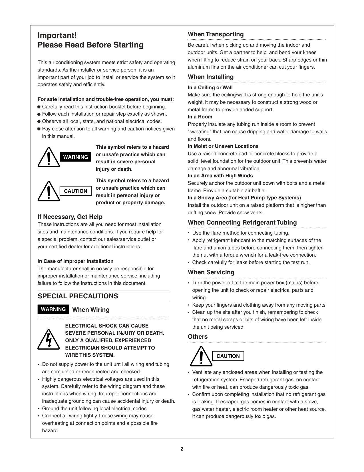
ELECTRICAL SHOCK CAN CAUSE SEVERE PERSONAL INJURY OR DEATH. ONLY A QUALIFIED, EXPERIENCED ELECTRICIAN SHOULD ATTEMPT TO WIRE THIS SYSTEM.
SPECIAL PRECAUTIONS
This symbol refers to a hazard or unsafe practice which can result in severe personal injury or death.
This symbol refers to a hazard or unsafe practice which can result in personal injury or product or property damage.
|CAUTION| |---|
|CAUTION| |---|
WARNING
WARNING
Important! Please Read Before Starting
This air conditioning system meets strict safety and operating standards. As the installer or service person, it is an important part of your job to install or service the system so it operates safely and efficiently.
For safe installation and trouble-free operation, you must: Carefully read this instruction booklet before beginning. Follow each installation or repair step exactly as shown. Observe all local, state, and national electrical codes. Pay close attention to all warning and caution notices given in this manual.
If Necessary, Get Help These instructions are all you need for most installation sites and maintenance conditions. If you require help for a special problem, contact our sales/service outlet or your certified dealer for additional instructions.
In Case of Improper Installation The manufacturer shall in no way be responsible for improper installation or maintenance service, including failure to follow the instructions in this document.
Do not supply power to the unit until all wiring and tubing are completed or reconnected and checked. Highly dangerous electrical voltages are used in this system. Carefully refer to the wiring diagram and these instructions when wiring. Improper connections and inadequate grounding can cause accidental injury or death. Ground the unit following local electrical codes. Connect all wiring tightly. Loose wiring may cause overheating at connection points and a possible fire hazard.
When Transporting
Be careful when picking up and moving the indoor and outdoor units. Get a partner to help, and bend your knees when lifting to reduce strain on your back. Sharp edges or thin aluminum fins on the air conditioner can cut your fingers.
When Installing In a Ceiling or Wall Make sure the ceiling/wall is strong enough to hold the unit’s weight. It may be necessary to construct a strong wood or metal frame to provide added support. In a Room Properly insulate any tubing run inside a room to prevent "sweating" that can cause dripping and water damage to walls and floors. In Moist or Uneven Locations Use a raised concrete pad or concrete blocks to provide a solid, level foundation for the outdoor unit. This prevents water damage and abnormal vibration. In an Area with High Winds Securely anchor the outdoor unit down with bolts and a metal frame. Provide a suitable air baffle. In a Snowy Area (for Heat Pump-type Systems) Install the outdoor unit on a raised platform that is higher than drifting snow. Provide snow vents. When Connecting Refrigerant Tubing
Use the flare method for connecting tubing. Apply refrigerant lubricant to the matching surfaces of the flare and union tubes before connecting them, then tighten the nut with a torque wrench for a leak-free connection. Check carefully for leaks before starting the test run.
When Servicing
Turn the power off at the main power box (mains) before opening the unit to check or repair electrical parts and wiring. Keep your fingers and clothing away from any moving parts. Clean up the site after you finish, remembering to check that no metal scraps or bits of wiring have been left inside the unit being serviced.
Others
Ventilate any enclosed areas when installing or testing the refrigeration system. Escaped refrigerant gas, on contact with fire or heat, can produce dangerously toxic gas. Confirm upon completing installation that no refrigerant gas is leaking. If escaped gas comes in contact with a stove, gas water heater, electric room heater or other heat source, it can produce dangerously toxic gas.| |---|
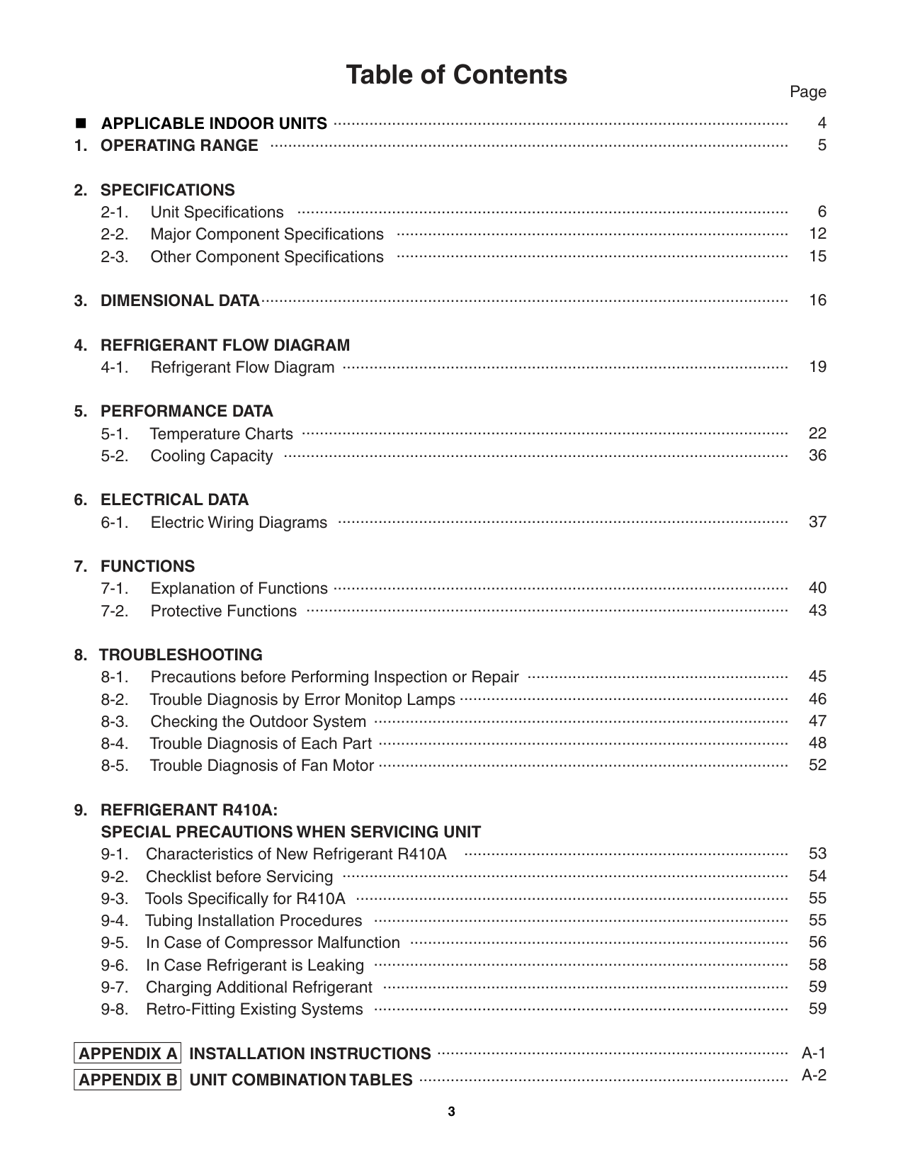
##### Table of Contents
Page APPLICABLE INDOOR UNITS
..................................................................................................... ...................................................................................................................
............................................................................................................. ....................................................................................... .......................................................................................
12
.....................................................................................................................
...................................................................................................
19
............................................................................................................ ................................................................................................................
22
....................................................................................................
..................................................................................................... ...........................................................................................................
40 43
.......................................................... .........................................................................
............................................................................................ ........................................................................................... ...........................................................................................
........................................................................ ................................................................................................... ................................................................................................ ............................................................................................ .................................................................................... ............................................................................................ .......................................................................................... ............................................................................................
.............................................................................. ..................................................................................
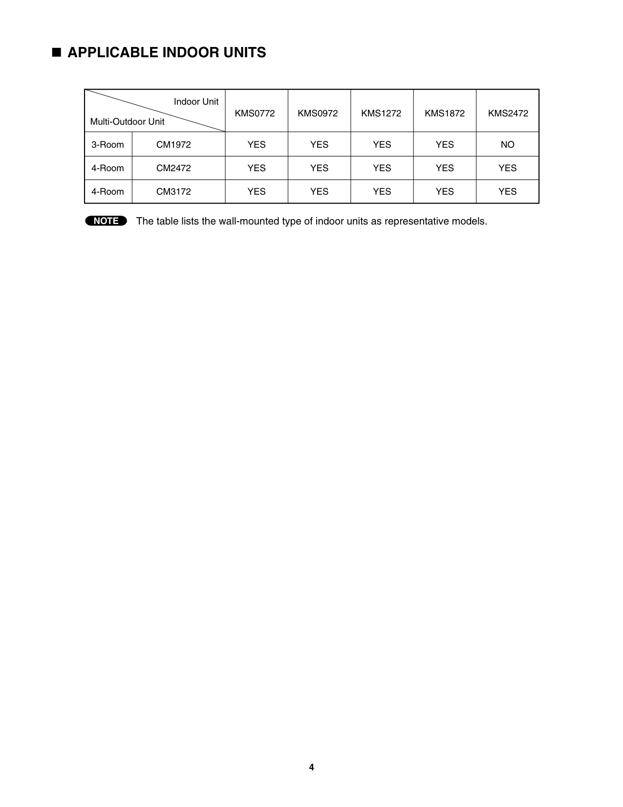
######## APPLICABLE INDOOR UNITS
|Multi-Outdoor Unit
Indoor Unit|Multi-Outdoor Unit
Indoor Unit|KMS0772|KMS0972|KMS1272|KMS1872|KMS2472| |---|---|---|---|---|---|---| |3-Room|CM1972|YES|YES|YES|YES|NO| |4-Room|CM2472
|YES|YES|YES|YES|YES| |4-Room|CM3172|YES|YES|YES|YES|YES|
NOTE The table lists the wall-mounted type of indoor units as representative models.
##### 1. OPERATING RANGE
| |Temperature|Indoor Air Intake Temp.|Outdoor Air Intake Temp.| |---|---|---|---| |Cooling|Maximum|95 °F D.B. / 71 °F W.B.|115 °F D.B.| |Cooling|Minimum|67 °F D.B. / 57 °F W.B.|67 °F D.B.|
##### 2. SPECIFICATIONS
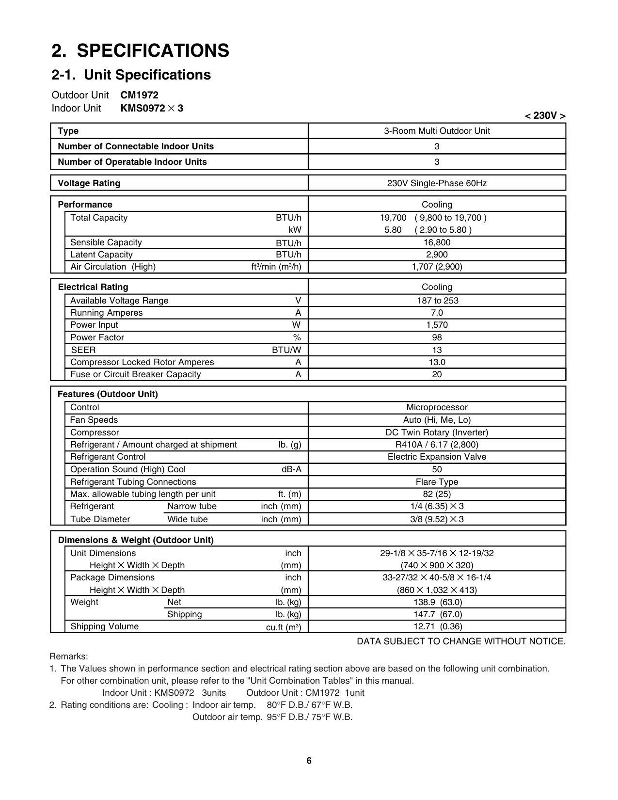
######## 2-1. Unit Specifications
############## Outdoor Unit CM1972 Indoor Unit KMS0972 × 3
##################### < 230V >
|Type|3-Room Multi Outdoor Unit| |---|---| |Number of Connectable Indoor Units|3| |Number of Operatable Indoor Units|3|
|Voltage Rating|230V Single-Phase 60Hz| |---|---|
############################## Performance
Cooling
Total Capacity
BTU/h
19,700 5.80
( 9,800 to 19,700 ) ( 2.90 to 5.80 )
kW
Sensible Capacity Latent Capacity
16,800 2,900
BTU/h
BTU/h
1,707 (2,900)Air Circulation (High) ft3/min (m3/h)
Electrical Rating
Cooling 187 to 253
Available Voltage Range Running Amperes
V A
7.0 1,570
WPower Input
%Power Factor 98
SEER BTU/W 13
A 13.0
Compressor Locked Rotor Amperes
Fuse or Circuit Breaker Capacity A 20
Features (Outdoor Unit)
Control Microprocessor
Fan Speeds Auto (Hi, Me, Lo)
DC Twin Rotary (Inverter)
Compressor Refrigerant / Amount charged at shipment Ib. (g) Refrigerant Control
R410A / 6.17 (2,800) Electric Expansion Valve
dB-A
Operation Sound (High) Cool 50
Flare Type 82 (25)
Refrigerant Tubing Connections
ft. (m)Max. allowable tubing length per unit
1/4 (6.35) × 3 3/8 (9.52) × 3
Refrigerant inch (mm) Tube Diameter inch (mm)
Narrow tube Wide tube
############## Outdoor Unit CM1972 Indoor Unit KMS0972 × 3
##################### < 208V >
|Type|3-Room Multi Outdoor Unit| |---|---| |Number of Connectable Indoor Units|3| |Number of Operatable Indoor Units|3|
|Voltage Rating|208V Single-Phase 60Hz| |---|---|
############################## Performance
Cooling
Total Capacity
BTU/h
19,700 5.80
( 9,800 to 19,700 ) ( 2.90 to 5.80 )
kW
Sensible Capacity Latent Capacity
16,800 2,900
BTU/h
BTU/h
1,707 (2,900)Air Circulation (High) ft3/min (m3/h)
Electrical Rating
Cooling 187 to 253
Available Voltage Range Running Amperes
V A
7.7 1,570
WPower Input
%Power Factor 98
SEER BTU/W 13
A 13.0
Compressor Locked Rotor Amperes
Fuse or Circuit Breaker Capacity A 20
Features (Outdoor Unit)
Control Microprocessor
Fan Speeds Auto (Hi, Me, Lo)
DC Twin Rotary (Inverter)
Compressor Refrigerant / Amount charged at shipment Ib. (g) Refrigerant Control
R410A / 6.17 (2,800) Electric Expansion Valve
dB-A
Operation Sound (High) Cool 50
Flare Type 82 (25)
Refrigerant Tubing Connections
ft. (m)Max. allowable tubing length per unit
1/4 (6.35) × 3 3/8 (9.52) × 3
Refrigerant inch (mm) Tube Diameter inch (mm)
Narrow tube Wide tube
25,400 7.50
( 9,800 to 25,400 ) ( 2.90 to 7.50 )
kW BTU/h
Sensible Capacity Latent Capacity
21,400 4,000
BTU/h
1,707 (2,900)Air Circulation (High) ft3/min (m3/h)
Electrical Rating
Cooling 187 to 253
Available Voltage Range Running Amperes
V A
11.3 2,560
WPower Input
%Power Factor 98
SEER BTU/W 13
A 13.0
Compressor Locked Rotor Amperes
Fuse or Circuit Breaker Capacity A 20
Features (Outdoor Unit)

Control Microprocessor
Fan Speeds Auto (Hi, Me, Lo)
DC Twin Rotary (Inverter)
Compressor Refrigerant / Amount charged at shipment Ib. (g) Refrigerant Control
R410A / 6.17 (2,800) Electric Expansion Valve
dB-A
Operation Sound (High) Cool 50
Flare Type 82 (25)
Refrigerant Tubing Connections
ft. (m)Max. allowable tubing length per unit
1/4 (6.35) × 4 3/8 (9.52) × 3 + 1/2 (12.7) × 1
Refrigerant inch (mm) Tube Diameter inch (mm)
Narrow tube Wide tube
24,400 7.20
( 9,800 to 24,400 ) ( 2.90 to 7.20 )
kW BTU/h
Sensible Capacity Latent Capacity
20,600 3,800
BTU/h
1,707 (2,900)Air Circulation (High) ft3/min (m3/h)
Electrical Rating
Cooling 187 to 253
Available Voltage Range Running Amperes
V A
12.5 2,560
WPower Input
%Power Factor 98
SEER BTU/W 13
A 13.0
Compressor Locked Rotor Amperes
Fuse or Circuit Breaker Capacity A 20
Features (Outdoor Unit)
Control Microprocessor
Fan Speeds Auto (Hi, Me, Lo)

DC Twin Rotary (Inverter)
Compressor Refrigerant / Amount charged at shipment Ib. (g) Refrigerant Control
R410A / 6.17 (2,800) Electric Expansion Valve
dB-A
Operation Sound (High) Cool 50
Flare Type 82 (25)
Refrigerant Tubing Connections
ft. (m)Max. allowable tubing length per unit
1/4 (6.35) × 4 3/8 (9.52) × 3 + 1/2 (12.7) × 1
Refrigerant inch (mm) Tube Diameter inch (mm)
Narrow tube Wide tube
30,600 9.00
( 9,800 to 30,600 ) ( 2.90 to 9.00 )
kW BTU/h
Sensible Capacity Latent Capacity
25,800 4,800
BTU/h
1,942 (3,300)Air Circulation (High) ft3/min (m3/h)
Electrical Rating
Cooling 187 to 253
Available Voltage Range Running Amperes
V A
12.3 2,800
WPower Input
%Power Factor 99
SEER BTU/W 16
A 17.0
Compressor Locked Rotor Amperes
Fuse or Circuit Breaker Capacity A 20
Features (Outdoor Unit)
Control Microprocessor
Fan Speeds Auto (Hi, Me, Lo)
DC Twin Rotary (Inverter)
Compressor Refrigerant / Amount charged at shipment Ib. (g) Refrigerant Control
R410A / 8.38 (3,800) Electric Expansion Valve
dB-A
Operation Sound (High) Cool 53
Flare Type 100 (30.5)
Refrigerant Tubing Connections
ft. (m)Max. allowable tubing length per unit
1/4 (6.35) × 4 3/8 (9.52) × 2 + 1/2 (12.7) × 2
Refrigerant inch (mm) Tube Diameter inch (mm)
Narrow tube Wide tube
28,600 8.40
( 9,800 to 28,600 ) ( 2.90 to 8.40 )
kW BTU/h
Sensible Capacity Latent Capacity
24,200 4,400
BTU/h
1,942 (3,300)Air Circulation (High) ft3/min (m3/h)
Electrical Rating
Cooling 187 to 253
Available Voltage Range Running Amperes
V A
13.6 2,800
WPower Input
%Power Factor 99
SEER BTU/W 16
A 17.0
Compressor Locked Rotor Amperes
Fuse or Circuit Breaker Capacity A 20
Features (Outdoor Unit)
Control Microprocessor
Fan Speeds Auto (Hi, Me, Lo)
DC Twin Rotary (Inverter)
Compressor Refrigerant / Amount charged at shipment Ib. (g) Refrigerant Control
R410A / 8.38 (3,800) Electric Expansion Valve
dB-A

Operation Sound (High) Cool 53
Flare Type 100 (30.5)
Refrigerant Tubing Connections
ft. (m)Max. allowable tubing length per unit
1/4 (6.35) × 4 3/8 (9.52) × 2 + 1/2 (12.7) × 2
Refrigerant inch (mm) Tube Diameter inch (mm)
Narrow tube Wide tube
######## 2-2. Major Component Specifications
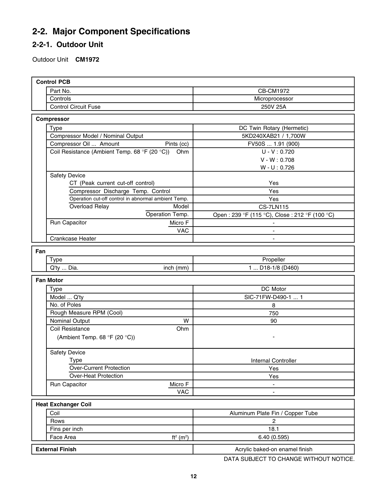
############### 2-2-1. Outdoor Unit
Outdoor Unit CM1972
############################ Control PCB
Part No.
Controls
Control Circuit Fuse
CB-CM1972
Microprocessor 250V 25A
############################ Compressor
Type Compressor Model / Nominal Output
DC Twin Rotary (Hermetic) 5KD240XAB21 / 1,700W
Pints (cc)
FV50S ... 1.91 (900)
Compressor Oil ... Amount
Coil Resistance (Ambient Temp. 68 °F (20 °C)) Ohm
0.720 0.708 0.726
Safety Device
Yes Yes Yes
CT (Peak current cut-off control) Compressor Discharge Temp. Control Operation cut-off control in abnormal ambient Temp.
Overload Relay CS-7LN115Model Operation Temp. Open : 239 °F (115 °C), Close : 212 °F (100 °C)
Run Capacitor
Crankcase Heater

############################ Fan
Type
Propeller Q'ty ... Dia. inch (mm)
1 ... D18-1/8 (D460)
############################ Fan Motor
Type Model ... Q'ty No. of Poles
Rough Measure RPM (Cool)
Nominal Output Coil Resistance
(Ambient Temp. 68 °F (20 °C))
W
Ohm
DC Motor
SIC-71FW-D490-1 ... 1
8
750
90
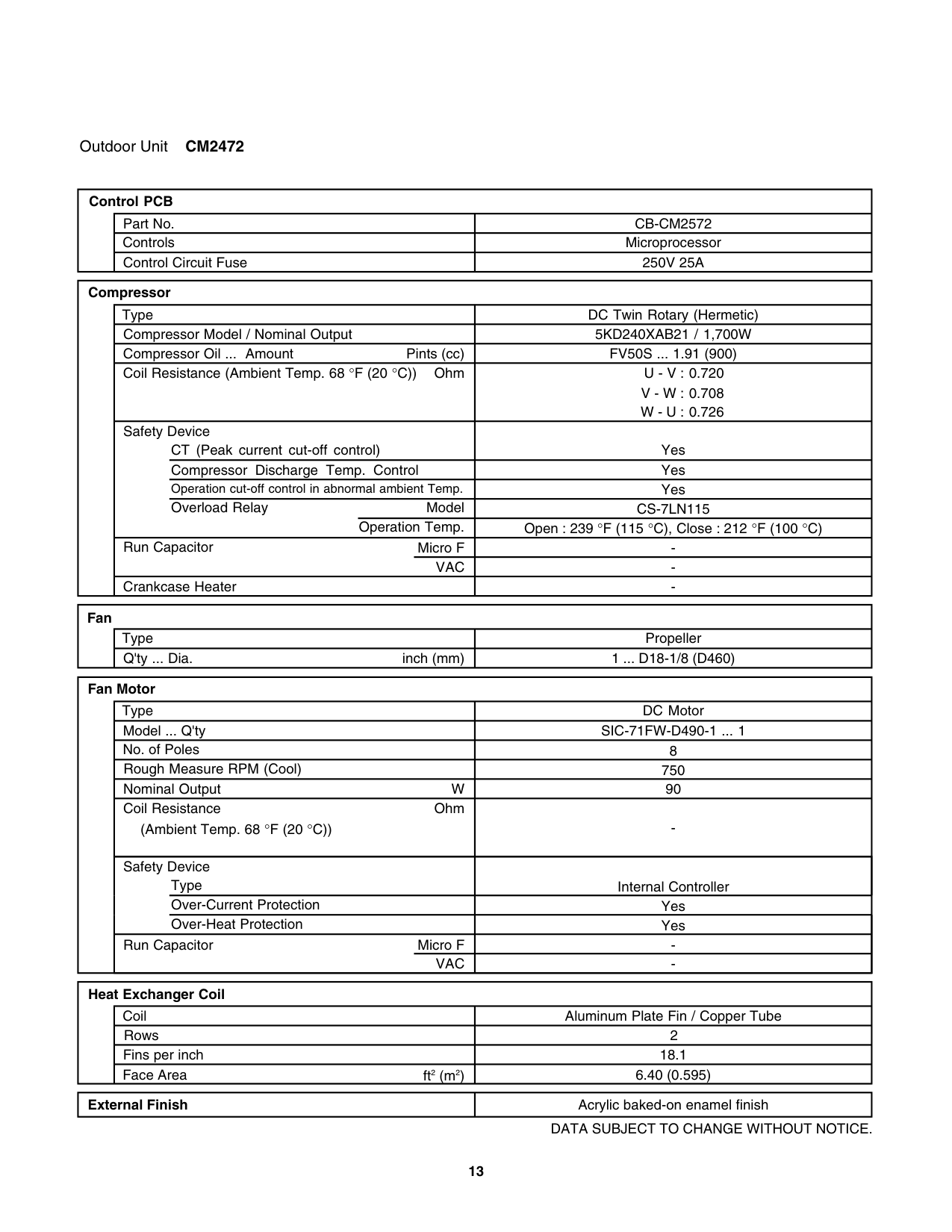
Control PCB
Part No.
Controls
Control Circuit Fuse
CB-CM2572
Microprocessor 250V 25A
############################ Compressor
Type Compressor Model / Nominal Output
DC Twin Rotary (Hermetic) 5KD240XAB21 / 1,700W
Pints (cc)
FV50S ... 1.91 (900)
Compressor Oil ... Amount
Coil Resistance (Ambient Temp. 68 °F (20 °C)) Ohm
0.720 0.708 0.726
Safety Device
Yes Yes Yes
CT (Peak current cut-off control) Compressor Discharge Temp. Control Operation cut-off control in abnormal ambient Temp.
Overload Relay CS-7LN115Model Operation Temp. Open : 239 °F (115 °C), Close : 212 °F (100 °C)
Run Capacitor
Crankcase Heater
############################ Fan
Type
Propeller Q'ty ... Dia. inch (mm)
1 ... D18-1/8 (D460)
############################ Fan Motor
Type Model ... Q'ty No. of Poles
Rough Measure RPM (Cool)
Nominal Output Coil Resistance
(Ambient Temp. 68 °F (20 °C))
W
Ohm
DC Motor
SIC-71FW-D490-1 ... 1
8
750
90
Control PCB
Part No.
Controls
Control Circuit Fuse
CB-CM3172
Microprocessor 250V 25A
############################ Compressor
Type Compressor Model / Nominal Output
DC Twin Rotary (Hermetic) 5JD420XAB22 / 3,000W
Pints (cc)
FV50S ... 2.55 (1,200)
Compressor Oil ... Amount
Coil Resistance (Ambient Temp. 68 °F (20 °C)) Ohm
0.435 0.441 0.452
Safety Device
Yes Yes Yes
CT (Peak current cut-off control) Compressor Discharge Temp. Control Operation cut-off control in abnormal ambient Temp.
Overload Relay CS-7LN115Model Operation Temp. Open : 239 °F (115 °C), Close : 212 °F (100 °C)
Run Capacitor
Crankcase Heater
############################ Fan
Type
Propeller Q'ty ... Dia. inch (mm)
1 ... D18-1/8 (D460)
############################ Fan Motor
Type Model ... Q'ty No. of Poles
Rough Measure RPM (Cool)
Nominal Output Coil Resistance
(Ambient Temp. 68 °F (20 °C))
W
Ohm
DC Motor
SIC-71FW-D490-1 ... 1
8
800
90
-

Safety Device
Type Over-Current Protection Over-Heat Protection
Run Capacitor
Micro F VAC
Internal Controller Yes Yes
Coil Rows Fins per inch
Aluminum Plate Fin / Copper Tube 2 18.1
Face Area ft2 (m2) 7.75 (0.72)
|External Finish|Acrylic baked-on enamel finish| |---|---|
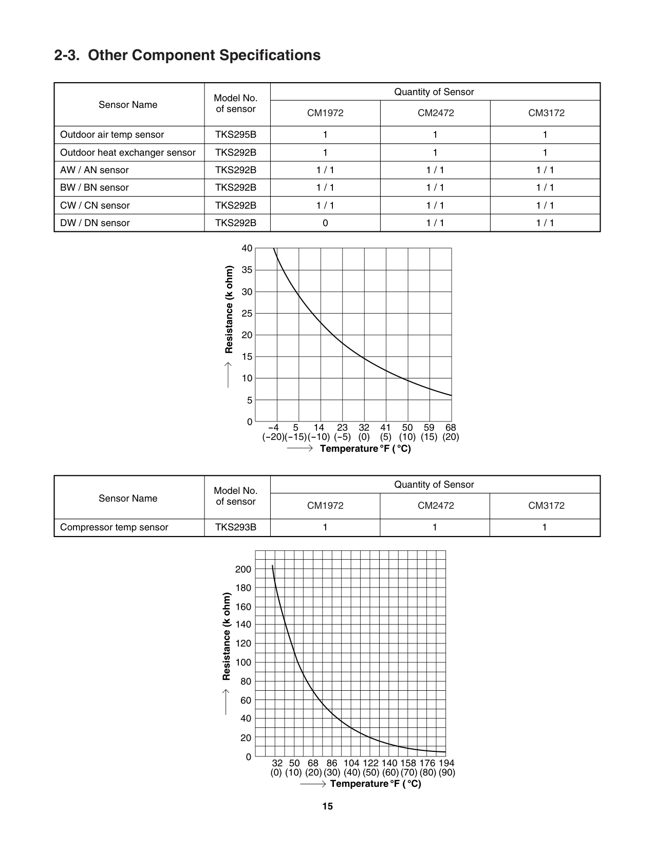
######## 2-3. Other Component Specifications
|Sensor Name|Model No. of sensor|Quantity of Sensor|Quantity of Sensor|Quantity of Sensor| |---|---|---|---|---| |Sensor Name|Model No. of sensor|CM1972|CM2472|CM3172| |Outdoor air temp sensor|TKS295B|1|1|1| |Outdoor heat exchanger sensor|TKS292B|1|1|1| |AW / AN sensor|TKS292B|1 / 1|1 / 1|1 / 1| |BW / BN sensor|TKS292B|1 / 1|1 / 1|1 / 1| |CW / CN sensor|TKS292B|1 / 1|1 / 1|1 / 1| |DW / DN sensor|TKS292B|0|1 / 1|1 / 1|
############################ Resistance (k ohm)
40 35 30 25 20 15 10
| | | | | | | | | | |---|---|---|---|---|---|---|---|---| | | | | | | | | | | | | | | | | | | | | | | | | | | | | | | | | | | | | | | | | | | | | | | | | | | | | | | | | | | | | | | | | | | | | | |
5 0
-451423 32 41 50 59 68
(-20)(-15)(-10) (-5) (0) (5) (10) (15) (20)
Temperature F ( C)
|Sensor Name|Model No. of sensor|Quantity of Sensor|Quantity of Sensor|Quantity of Sensor| |---|---|---|---|---| |Sensor Name|Model No. of sensor|CM1972|CM2472|CM3172| |Compressor temp sensor|TKS293B|1|1|1|
| | | | | | | | | | | | | | | | | | | | |
|---|---|---|---|---|---|---|---|---|---|---|---|---|---|---|---|---|---|---|---| | | | | | | | | | | | | | | | | | | | | | | | | | | | | | | | | | | | | | | | | | | | | | | | | | | | | | | | | | | | | | | | | | | | | | | | | | | | | | | | | | | | | | | | | | | | | | | | | | | | | | | | | | | | | | | | | | | | | | | | | | | | | | | | | | | | | | | | | | | | | | | | | | | | | | | | | | | | | | | | | | | | | | | | | | | | | | | | | | | | | | | | | | | | | | | | | | | | | | | | | | | | | | | | | | | | | | | | | | | | | | | | | | | | | | | | | | | | | | | | | | | | | | | | | | | | | | | | | | | | | | | | | | | | | | | | | | | | | | | | | | | | | | | | | | | | | | | | | | | | | | | | | | | | | | | | | | | | | | | | | | | | | | | | | | | | | | | | | | | | | | | | | | | | | | | | | | | | | | | | | | | | | | | | | | | | | | | | | | | | | | | | | | | | | | | | | | | | | | | | | | | | | | | | | | | | | | | | | | | | | | | | | | | | | | | | | | | | | | | | | |
200
180
############################ Resistance (k ohm)
160
140
120
100
80
60
40
20
0
32 50 68 86 104 122 140 158 176 194
(0) (10) (20)(30) (40) (50) (60)(70) (80) (90)
Temperature F ( C)
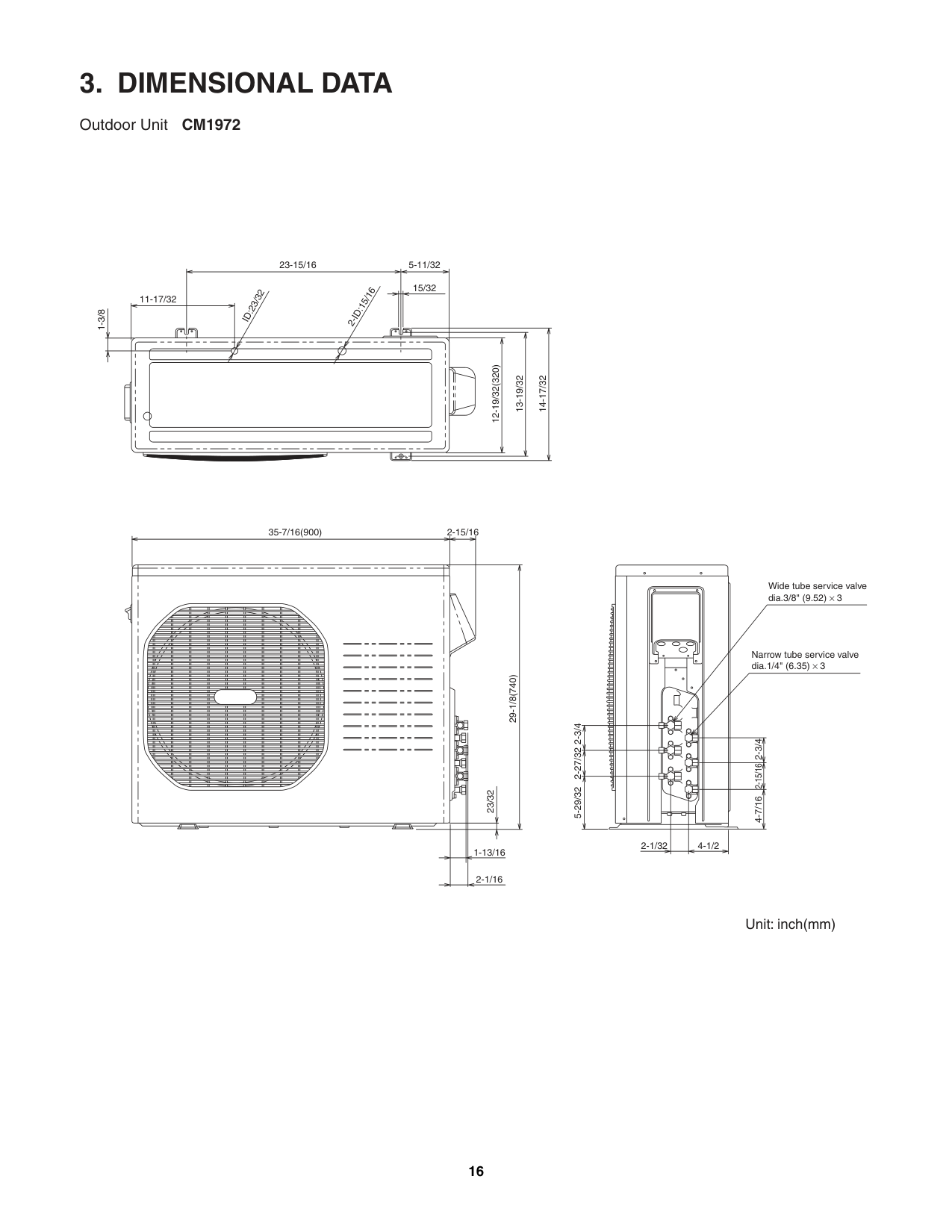
##### 3. DIMENSIONAL DATA
Outdoor Unit CM1972
1-3/8
11-17/32
ID:23/32
23-15/16 5-11/32 15/32
2-ID:15/16
12-19/32(320)
13-19/32
14-17/32
35-7/16(900)
2-15/16
Wide tube service valve dia.3/8" (9.52) × 3
29-1/8(740) 23/32
1-13/16
2-1/16
5-29/32 2-27/32 2-3/4
Narrow tube service valve dia.1/4" (6.35) × 3
2-1/32 4-1/2
2-15/162-3/4
4-7/16
######################## Outdoor Unit CM2472
1-3/8
11-17/32
ID:23/32
23-15/16 5-11/32 15/32
2-ID:15/16
12-19/32(320)
13-19/32
14-17/32
35-7/16(900)
2-15/16
Wide tube service valve dia.3/8" (9.52) × 3
Narrow tube service valve dia.1/4" (6.35) × 4
Wide tube service valve dia.1/2" (12.70) × 1
29-1/8(740) 23/32
5-29/32 2-27/32 2-3/42-3/4
2-15/162-3/42-3/4
4-7/16
2-1/32 4-1/2
1-13/16
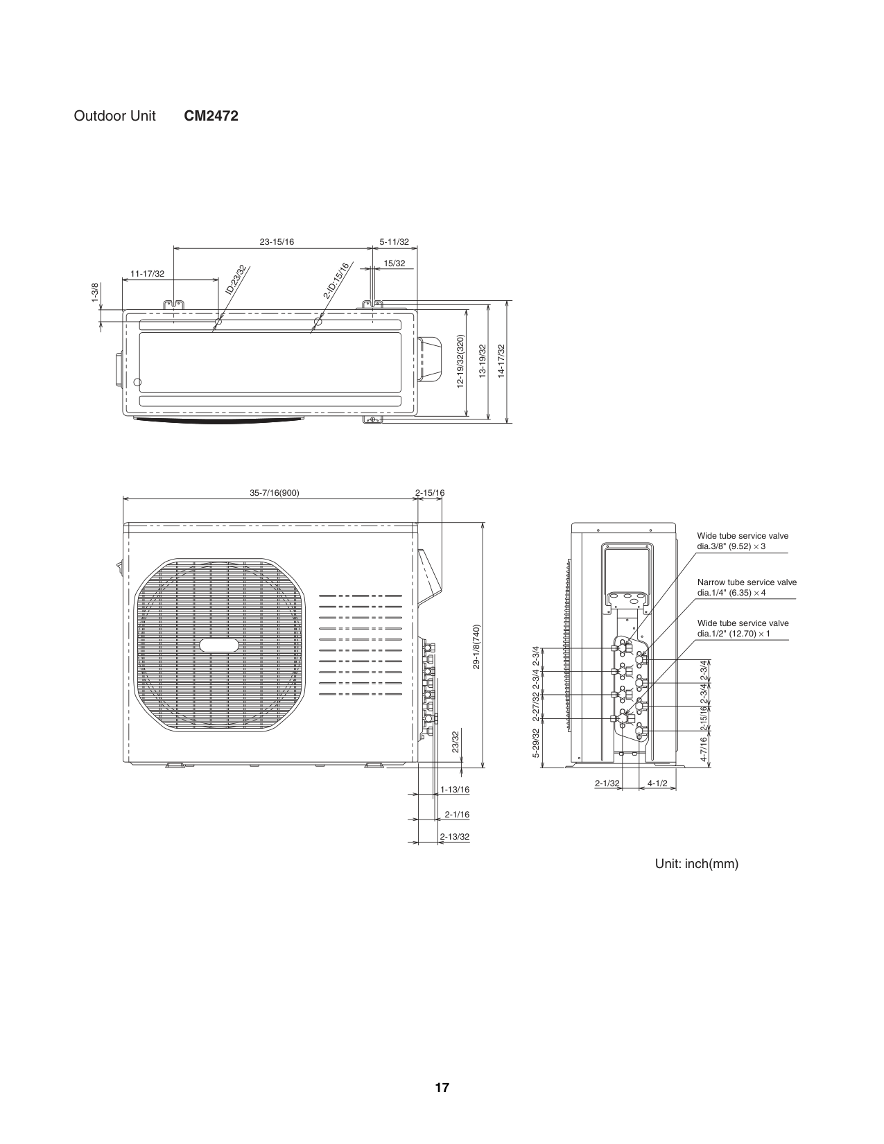
2-1/16
2-13/32
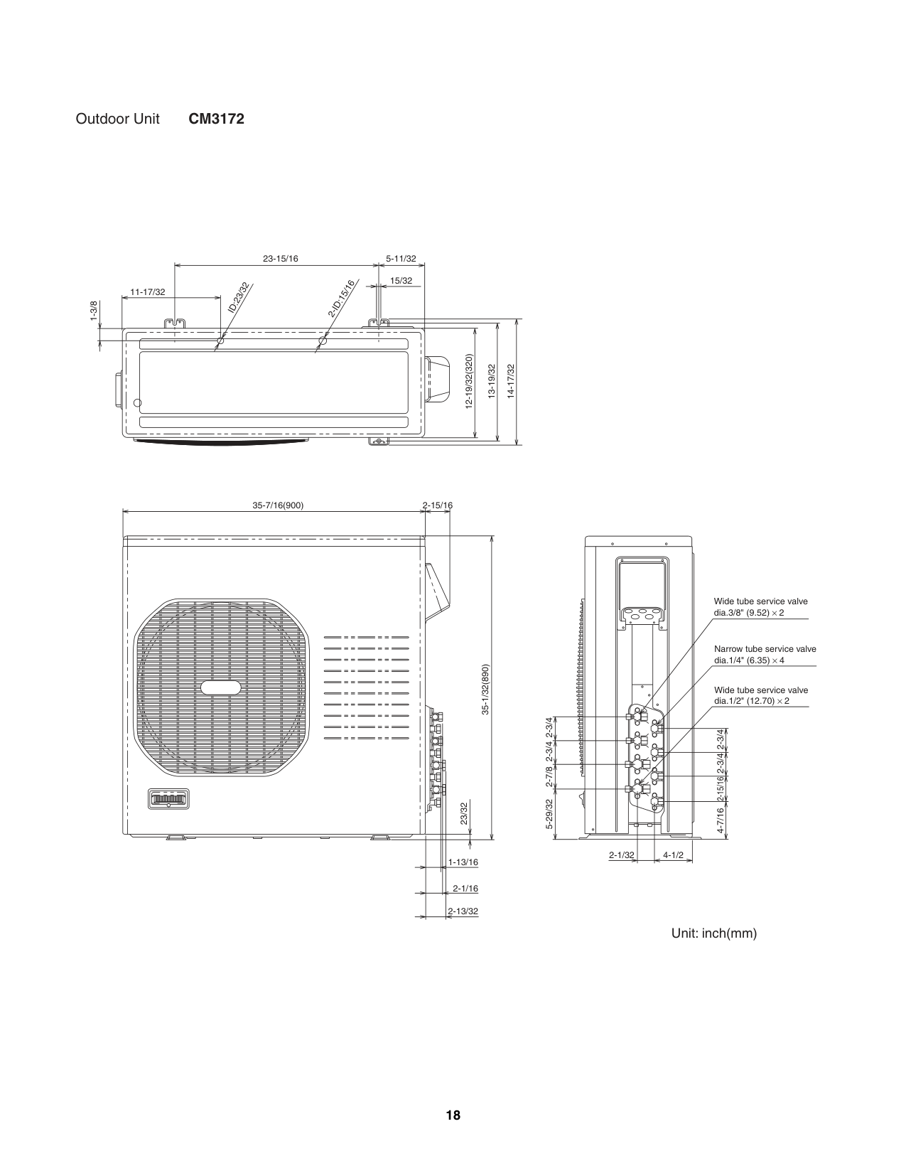
######################## Outdoor Unit CM3172
1-3/8
11-17/32
ID:23/32
23-15/16 5-11/32 15/32
2-ID:15/16
12-19/32(320)
13-19/32
14-17/32
35-7/16(900)
2-15/16
35-1/32(890) 23/32
1-13/16
2-1/16
2-13/32
5-29/32 2-7/8 2-3/42-3/4
Wide tube service valve dia.3/8" (9.52) × 2
Narrow tube service valve dia.1/4" (6.35) × 4
Wide tube service valve dia.1/2" (12.70) × 2
2-15/162-3/42-3/4
4-7/16
2-1/32 4-1/2
Unit: inch(mm)
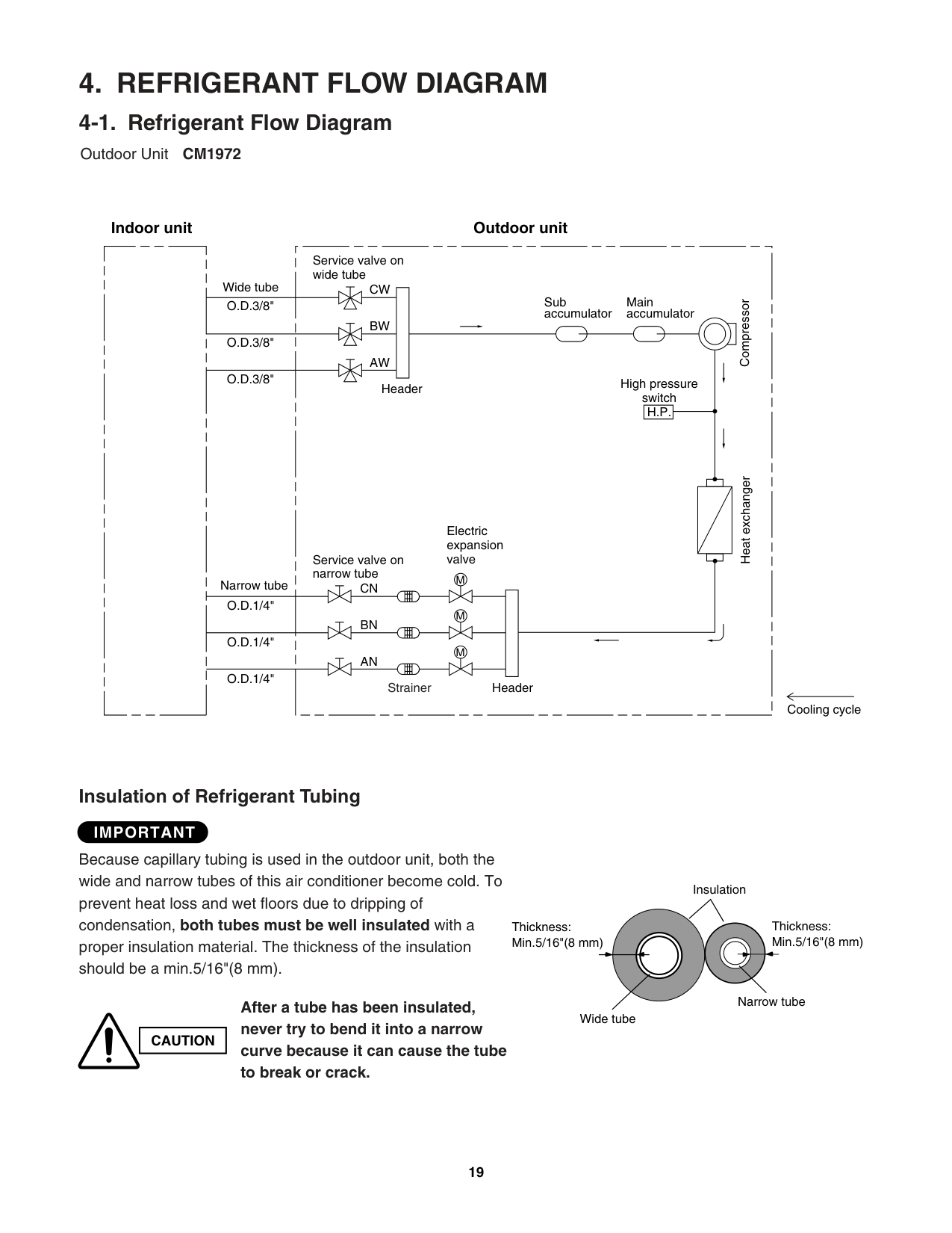
##### 4. REFRIGERANT FLOW DIAGRAM
######## 4-1. Refrigerant Flow Diagram
Outdoor Unit CM1972
###################### Indoor unit Outdoor unit
Service valve on wide tube
Wide tube
CW
Sub accumulator
Main accumulator
O.D.3/8"
Compressor
BW
O.D.3/8"
AW
O.D.3/8"
High pressure switch H.P.
Header
Heat exchanger
Electric expansion valve
Service valve on narrow tube
M
Narrow tube
CN
O.D.1/4"
M
BN
O.D.1/4"
M
AN
O.D.1/4"
Strainer Header
Cooling cycle
############### Insulation of Refrigerant Tubing
####################### IMPORTANT
Because capillary tubing is used in the outdoor unit, both the wide and narrow tubes of this air conditioner become cold. To prevent heat loss and wet floors due to dripping of condensation, both tubes must be well insulated with a proper insulation material. The thickness of the insulation should be a min.5/16"(8 mm).
Insulation
Thickness: Min.5/16"(8 mm)
Thickness: Min.5/16"(8 mm)
Narrow tube
##################### After a tube has been insulated, never try to bend it into a narrow
Wide tube
|CAUTION| |---|
Outdoor Unit CM2472
###################### Indoor unit Outdoor unit
Service valve on wide tube
Wide tube
DW
Sub accumulator
Main accumulator
O.D.3/8"
Compressor
CW
O.D.3/8"
BW
High pressure switch H.P.
O.D.3/8"
AW
O.D.1/2"
Header
Heat exchanger
Electric expansion valve
Service valve on narrow tube
M
Narrow tube
DN
O.D.1/4"
M
CN
O.D.1/4"
M
BN
O.D.1/4"
M
AN
O.D.1/4"
Strainer Header

Cooling cycle
############### Insulation of Refrigerant Tubing
####################### IMPORTANT
Because capillary tubing is used in the outdoor unit, both the wide and narrow tubes of this air conditioner become cold. To prevent heat loss and wet floors due to dripping of condensation, both tubes must be well insulated with a proper insulation material. The thickness of the insulation should be a min.5/16"(8 mm).
Insulation
Thickness: Min.5/16"(8 mm)
Thickness: Min.5/16"(8 mm)
Narrow tube
##################### After a tube has been insulated, never try to bend it into a narrow
Wide tube
|CAUTION| |---|
Outdoor Unit CM3172
###################### Indoor unit Outdoor unit
Service valve on wide tube
Wide tube
DW
Sub accumulator
Main accumulator
O.D.3/8"
Compressor
CW
O.D.3/8"
BW
O.D.1/2"
High pressure switch H.P.
AW
O.D.1/2"
Header
Heat exchanger
Electric expansion valve
Service valve on narrow tube
M
Narrow tube
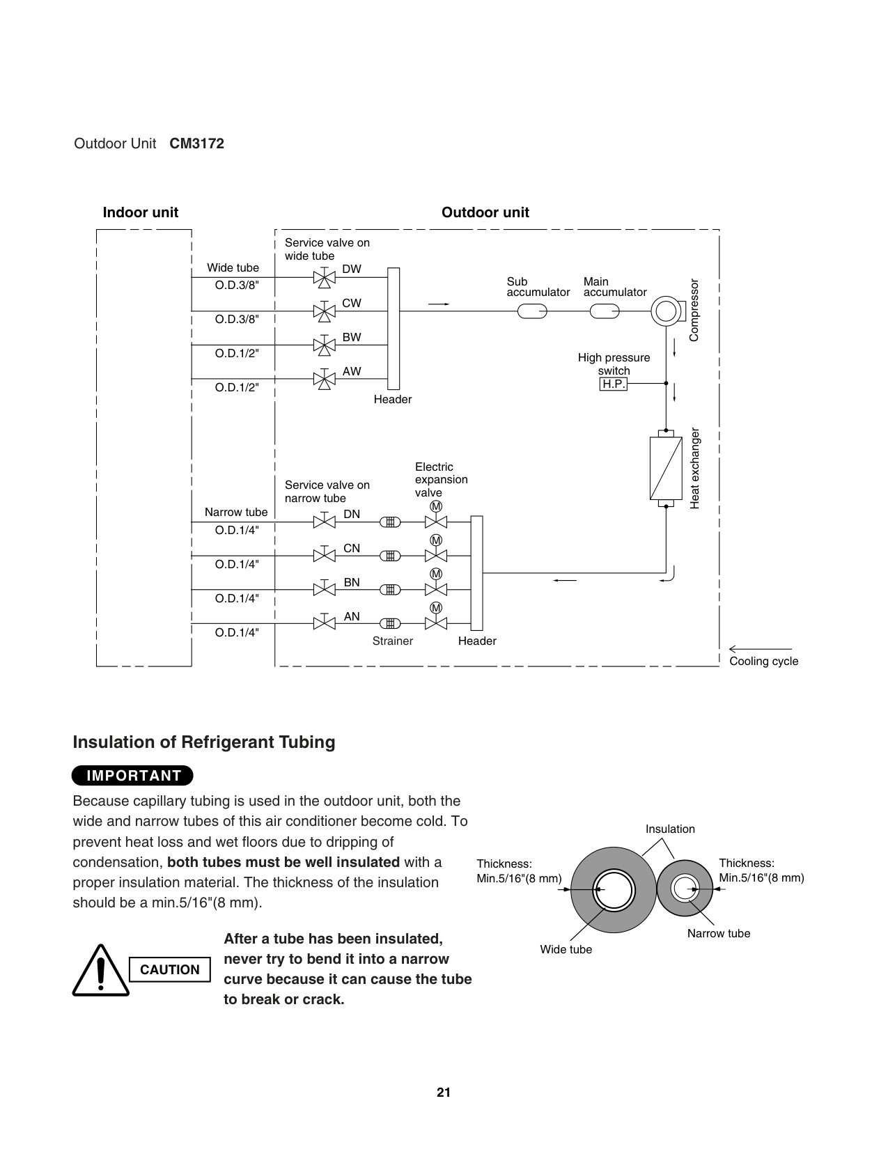
DN
O.D.1/4"
M
CN
O.D.1/4"
M
BN
O.D.1/4"
M
AN
O.D.1/4"
Strainer Header
Cooling cycle
############### Insulation of Refrigerant Tubing
####################### IMPORTANT
Because capillary tubing is used in the outdoor unit, both the wide and narrow tubes of this air conditioner become cold. To prevent heat loss and wet floors due to dripping of condensation, both tubes must be well insulated with a proper insulation material. The thickness of the insulation should be a min.5/16"(8 mm).
Insulation
Thickness: Min.5/16"(8 mm)
Thickness: Min.5/16"(8 mm)
Narrow tube
##################### After a tube has been insulated, never try to bend it into a narrow
Wide tube
|CAUTION| |---|
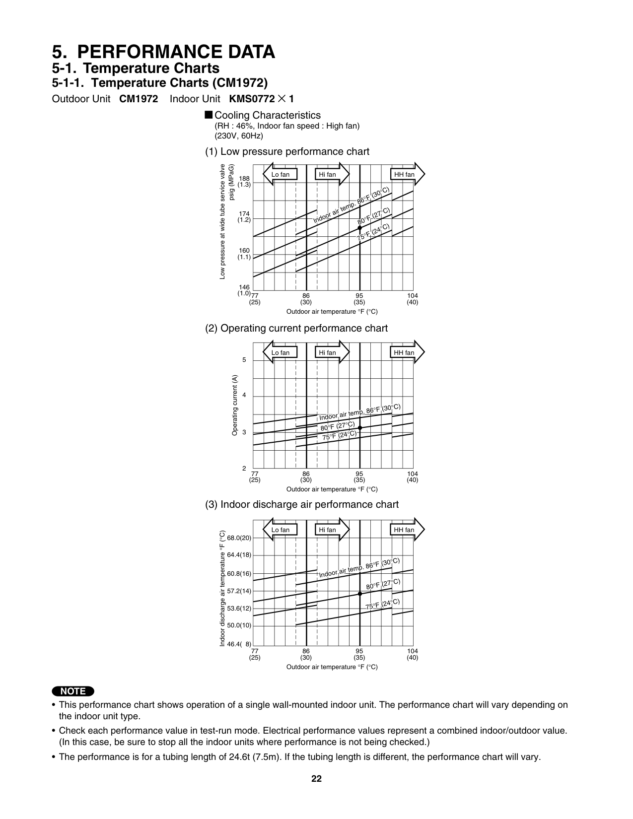
##### 5. PERFORMANCE DATA
############# 5-1-1. Temperature Charts (CM1972)
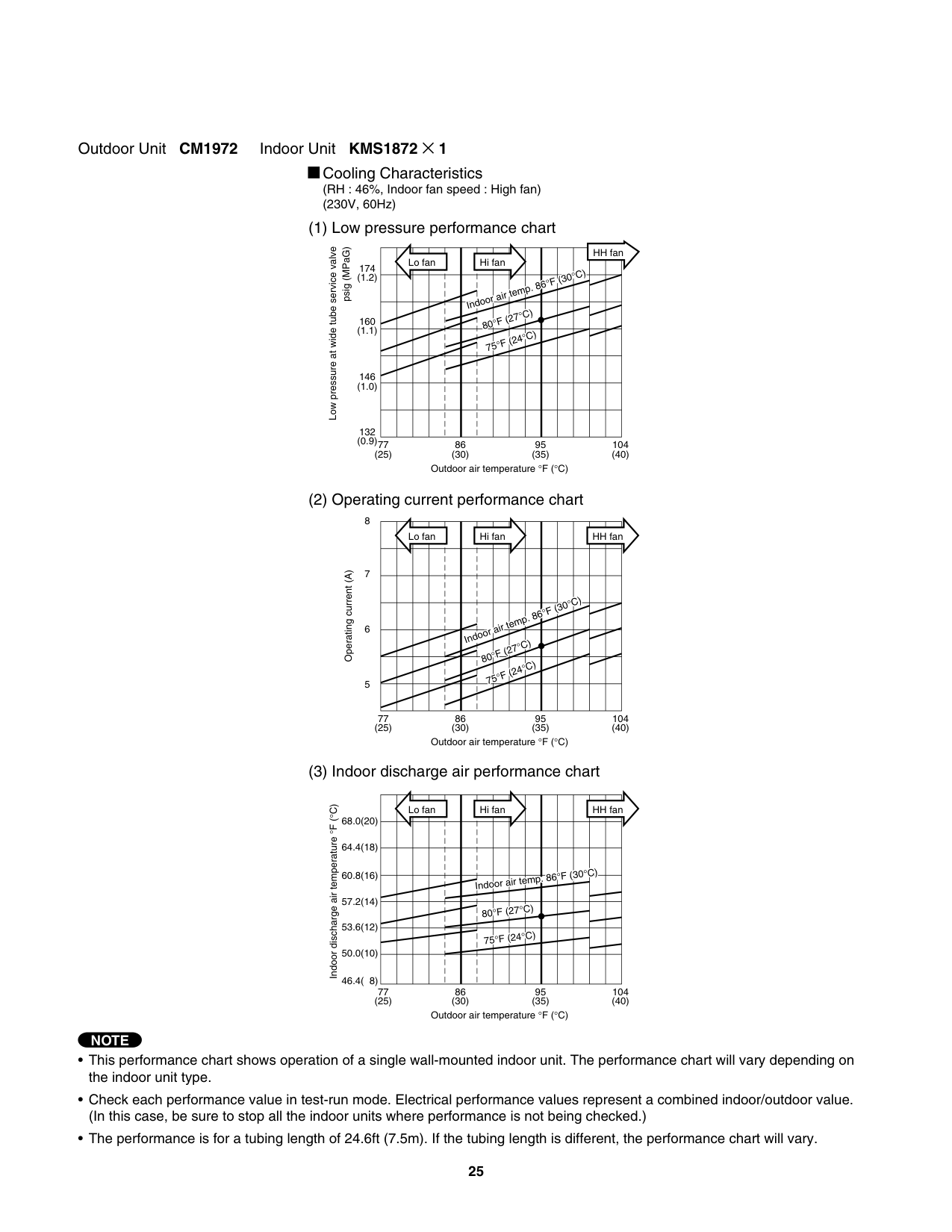
Outdoor Unit CM1972 Indoor Unit KMS0772 × 1
Cooling Characteristics (RH : 46%, Indoor fan speed : High fan) (230V, 60Hz)
| |L|o f|n| | |Hi|an| | | | | |H|fa| |---|---|---|---|---|---|---|---|---|---|---|---|---|---|---| | | | | | | | | | | |°
F|(3°|C)| | | | | | | | |I|do|r air|te|p.|6
F|(2°|C)| | |
| | | | | | | | | |8|0° °
F|(2°|C)| | | | | | | | | | | | |7|5| | | | | | | | | | | | | | | | | | | | | | | | | | | | | | | | | | | | |
Low pressure at wide tube service valve
psig (MPaG)
188
174
160 (1.1)
146 (1.0)77
86 (30)
95 (35)
104 (40)
(25)
Outdoor air temperature °F (°C)
| |L|o f|n| | |Hi|an| | | | | |H|fa| |---|---|---|---|---|---|---|---|---|---|---|---|---|---|---| | | | | | | | | | | | | | | | | | | | | | | | | | | | | | | | | | | | | | | |In|oor|air|em|. 8|°F|(3|°C)| | | | | | | | |80|°F (|7°C|)| | | | | | | | | | | | |7|°F|24°|C)| | | | | | | | | | | | | | | | | | | | | |
Operating current (A)
3
2
77 (25)
86 (30)
95 (35)
104 (40)
Outdoor air temperature °F (°C)
| |L|o f|n| | |Hi|an| | | | | |H|fa| |---|---|---|---|---|---|---|---|---|---|---|---|---|---|---| | | | | | | | | | | | | | | | | | | | | | | |Ind|or|ir|em|. 8|°F|30|°C)| | | | | | | | | | | | |8|°F|(2|°C)| |

| | | | | | | | | | |7|°F|24|°C)| | | | | | | | | | | | | | | | | | | | | | | | | | | | | | | | | |
Indoor discharge air temperature°F (°C)
68.0(20)
64.4(18)
60.8(16)
57.2(14)
53.6(12)
50.0(10)
46.4( 8)
77 (25)
86 (30)
95 (35)
104 (40)
Outdoor air temperature °F (°C)
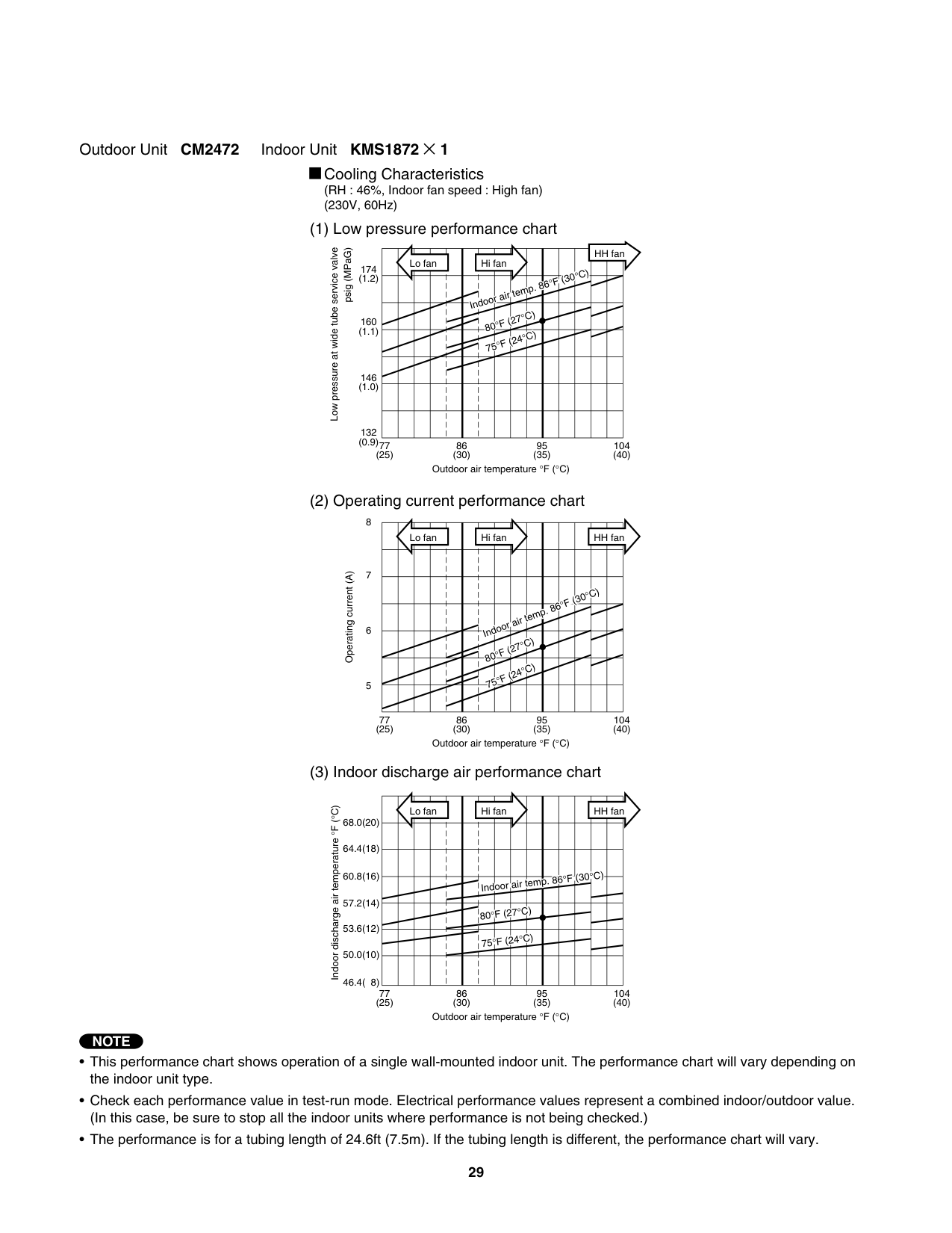
NOTE
######### Outdoor Unit CM1972 Indoor Unit KMS0972 × 1
Cooling Characteristics (RH : 46%, Indoor fan speed : High fan) (230V, 60Hz)
| |L|o f|n| | |Hi|an| | | | | |H|fa| |---|---|---|---|---|---|---|---|---|---|---|---|---|---|---| | | | | | | | | | | | | | | | | | | | | | | | | | | |°F|(3|°C)| | | | | | | | |In|oo|air
F (|te
7°C|p. )
|6| | | | | | | | | | | |80° 75°|F (|4°C|)| | | | | | | | | | | | | | | | | | | | | | | | | | | | | | | | | | | | | |
Low pressure at wide tube service valve
psig (MPaG)
188

174
160 (1.1)
146 (1.0)77
86 (30)
95 (35)
104 (40)
(25)
Outdoor air temperature °F (°C)
| |L|o f|n| | |Hi|an| | | | | |H|fa| |---|---|---|---|---|---|---|---|---|---|---|---|---|---|---| | | | | | | | | | | | | | | | | | | | | | | | | | | | | | | | | | | | | | | | | | | | |°|C)| | | | | | | | |In|oo|air|te|p.|6°F|(3| | | | | | | | | | |8|°F F
|27°C 24°C|) )| | | | | | | | | | | | |7|°| | | | | | | |
Operating current (A)
4
3
77 (25)
86 (30)
95 (35)
104 (40)
Outdoor air temperature °F (°C)
| |L|o f|n| | |Hi|an| | | | | |H|fa| |---|---|---|---|---|---|---|---|---|---|---|---|---|---|---| | | | | | | | | | | | | | | | | | | | | | | | | | | | | | | | | | | | | | | |Ind|or|ir|em|. 8|°F|3|°C)| | | | | | | | | | | | |8|°F|27°|C)| | | | | | | | | | | | | |°F|24°|C)| | | | | | | | | | | | |7| | | | |
Indoor discharge air temperature°F (°C)
68.0(20)
######### Outdoor Unit CM1972 Indoor Unit KMS1272 × 1
Cooling Characteristics (RH : 46%, Indoor fan speed : High fan) (230V, 60Hz)
| |L|o f|n| | |Hi|an| | | | | |H|fa| |---|---|---|---|---|---|---|---|---|---|---|---|---|---|---| | | | | | | |In|oor|air|em|. 8|°F|(3|°C)| | | | | | | | |8|°F (|7°C C|) )| | | | | | | | | | | | |7|°F (|4°| | | | | | | | | | | | | | | | | | | | | | | | | | | | | | | | | | | | | | | | | | | | | | | | | | | | | | |
Low pressure at wide tube service valve
psig (MPaG)
174
160
146 (1.0)
132 (0.9)77
86 (30)
95 (35)
104 (40)
(25)
Outdoor air temperature °F (°C)
| |L|o f|n| | |Hi|an| | | | | |H|fa| |---|---|---|---|---|---|---|---|---|---|---|---|---|---|---| | | | | | | | | | | | | | | | | | | | | | | | | | | | |F|30°|C)| | | | | | | | |Ind|or|ir|em|. 8|°| | | | | | | | | | |8|°F (|7°C °C|) )| | | | | | | | | | | | |7|°F|24| | | | | | | | | | | | | | | | | | | | | | |
Operating current (A)
4
3
77 (25)
86 (30)
95 (35)
104 (40)
Outdoor air temperature °F (°C)
| |L|o f|n| | |Hi|an| | | | | |H|fa| |---|---|---|---|---|---|---|---|---|---|---|---|---|---|---| | | | | | | | | | | | | | | | | | | | | | | | | | | |°F|30°C|)| | | | | | | | |nd|or|ir t|m|. 8| | | | | | | | | | | | |80°|F (|7°C|)| | | | | | | | | | | | |75|°F (|4°C|)| | | | | | | | | | | | | | | | | | | | | |
Indoor discharge air temperature°F (°C)
68.0(20)
######### Outdoor Unit CM1972 Indoor Unit KMS1872 × 1
Cooling Characteristics (RH : 46%, Indoor fan speed : High fan) (230V, 60Hz)
| |L|o f|n| | |Hi|an| | | | | | | | |---|---|---|---|---|---|---|---|---|---|---|---|---|---|---| | | | | | |In|oor|air|e|p.|6°F|(30°|C)| | | | | | | | | |80°|F (|7°C|)| | | | | | | | | | | | |7|°F|24°|C)| | | | | | | | | | | | | | | | | | | | | | | | | | | | | | | | | | | | | | | | | | | | | | | | | | | | | |
Low pressure at wide tube service valve
psig (MPaG)
HH fan
174
160
146 (1.0)
132 (0.9)
77 (25)
86 (30)
95 (35)
104 (40)
Outdoor air temperature °F (°C)
| |L|o f|n| | |Hi|an| | | | | |H|fa| |---|---|---|---|---|---|---|---|---|---|---|---|---|---|---|
| | | | | | | | | | | | | | | | | | | | | | | | | | | |C|)| | | | | | | | |In|oor|ir t|m|. 8|°F (|0°| | | | | | | | | | |°|F (|7°C|)| | | | | | | | | | | | |80 7|°F|24°C|)| | | | | | | | | | | | | | | | | | | | | |
Operating current (A)
6
5
77 (25)
86 (30)
95 (35)
104 (40)
Outdoor air temperature °F (°C)
| |L|o f|n| | |Hi|an| | | | | |H|fa| |---|---|---|---|---|---|---|---|---|---|---|---|---|---|---| | | | | | | | | | | | | | | | | | | | | | | | | | | | |F (|0°|C)| | | | | | | | |nd|or|ir t|mp|8°| | | | | | | | | | | |80|°F (|7°C|)| | | | | | | | | | | | |7|°F|24°|C)| | | | | | | | | | | | | | | | | | | | | |
Indoor discharge air temperature°F (°C)
68.0(20)
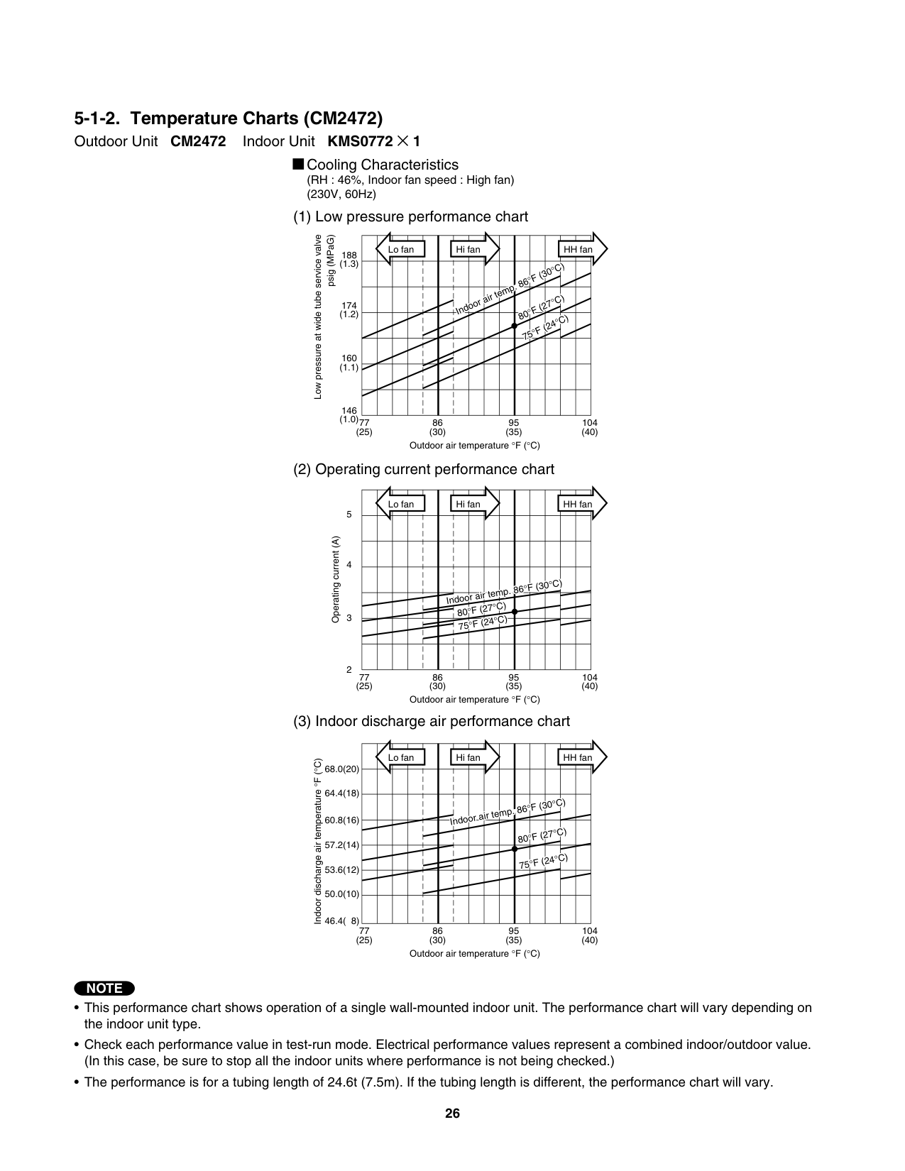
############# 5-1-2. Temperature Charts (CM2472)
Outdoor Unit CM2472 Indoor Unit KMS0772 × 1
Cooling Characteristics (RH : 46%, Indoor fan speed : High fan) (230V, 60Hz)
| |L|o f|n| | |Hi|an| | | | | |H|fa| |---|---|---|---|---|---|---|---|---|---|---|---|---|---|---| | | | | | | | | | | |°|(|0°C|)| | | | | | | | |Ind|or|ir t|m|. 8
°|(|7°C|)| | | | | | | | | | | | |80 7
|°
F|24°C|)| | | | | | | | | | | | | | | | | | | | | | | | | | | | | | | | | | | | | | | | | | | | | | | | | |
Low pressure at wide tube service valve
psig (MPaG)
188 (1.3)
174 (1.2)
160 (1.1)
146 (1.0)77
86 (30)
95 (35)
104 (40)
(25)
Outdoor air temperature °F (°C)
| |L|o f|n| | |Hi|an| | | | | |H|fa| |---|---|---|---|---|---|---|---|---|---|---|---|---|---|---| | | | | | | | | | | | | | | | | | | | | | | | | | | | | | | | | | | | | | | | | | | |°F|(3|°C|)| | | | | | | |I|do 80°
|r ai F (|te 7°C|p. )|6| | | | | | | | | | | |75|°F (|4°C|)| | | | | | | | | | | | | | | | | | | | | |
Operating current (A)
3
2
77 (25)
86 (30)
95 (35)
104 (40)
Outdoor air temperature °F (°C)
| |L|o f|n| | |Hi|an| | | | | |H|fa| |---|---|---|---|---|---|---|---|---|---|---|---|---|---|---| | | | | | | | | | | | | | | | | | | | | | |I|do|r a|r te|p|86°|(|0°C|)| | | | | | | | | | | | |80°|F (|7°C|)| | | | | | | | | | | | |75°|F (|4°|C)| | | | | | | | | | | | | | | | | | | | | | | | | | | | | | | | | |
Indoor discharge air temperature°F (°C)
68.0(20)
64.4(18)
60.8(16)
57.2(14)
53.6(12)
50.0(10)
46.4( 8)
77 (25)
86 (30)
95 (35)
104 (40)
Outdoor air temperature °F (°C)
NOTE
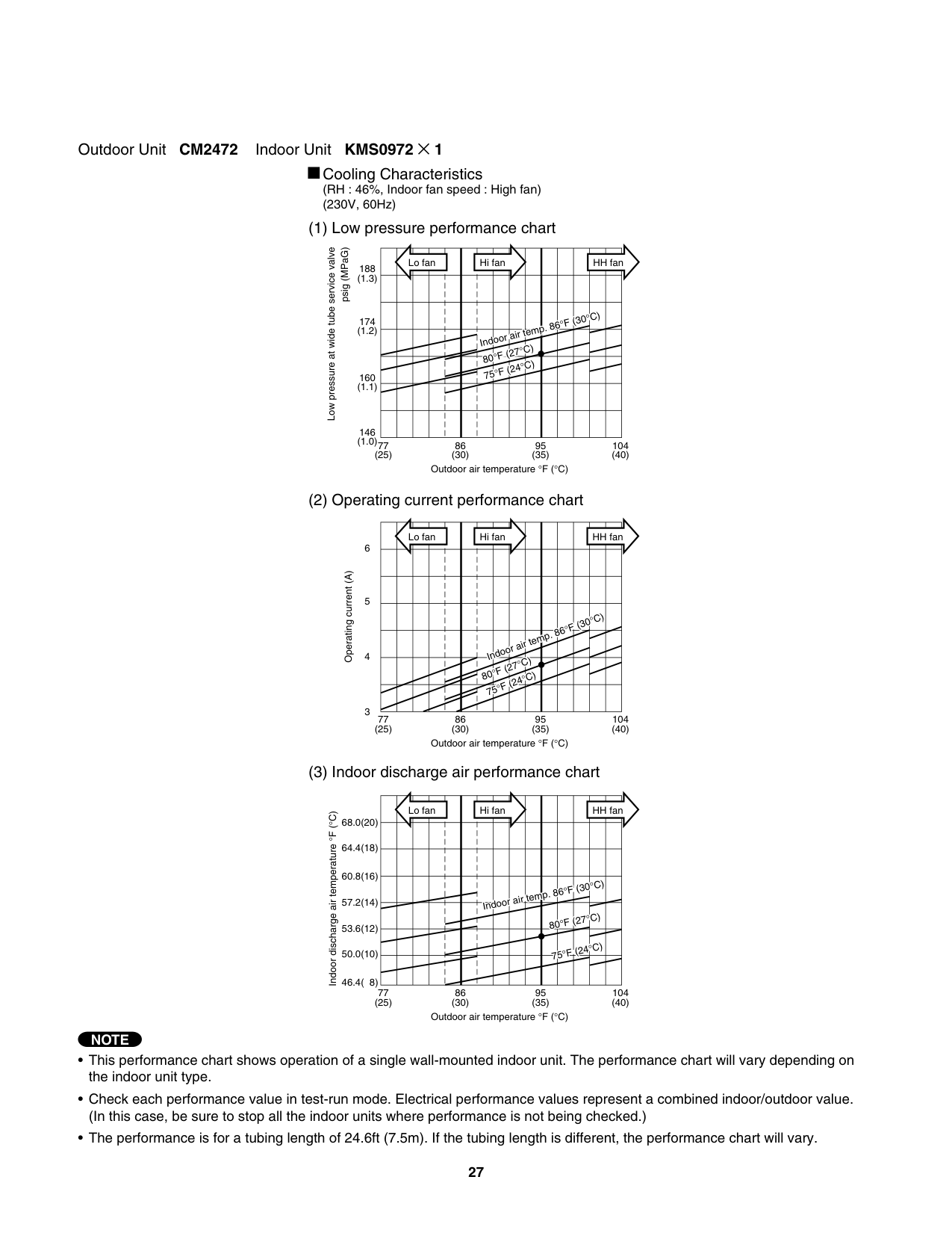
######### Outdoor Unit CM2472 Indoor Unit KMS0972 × 1
Cooling Characteristics (RH : 46%, Indoor fan speed : High fan) (230V, 60Hz)
| |L|o f|n| | |Hi|an| | | | | |H|fa| |---|---|---|---|---|---|---|---|---|---|---|---|---|---|---| | | | | | | | | | | | | | | | | | | | | | | | | | | | |°F|30°|C)| | | | | | | | |Ind|or
F (|ir
7°C|em )
|. 8| | | | | | | | | | | |80 7|° °F (
|4°C|)| | | | | | | | | | | | | | | | | | | | | | | | | | | | | | | | | | | | | |
Low pressure at wide tube service valve
psig (MPaG)
188 (1.3)
174 (1.2)
160 (1.1)
146 (1.0)77
86 (30)
95 (35)
104 (40)
(25)
Outdoor air temperature °F (°C)
| |L|o f|n| | |Hi|an| | | | | |H|fa| |---|---|---|---|---|---|---|---|---|---|---|---|---|---|---| | | | | | | | | | | | | | | | | | | | | | | | | | | | | | | | | | | | | | | | | | | | |°F|(3|°C)| | | | | | | | |I|doo|ai|te|p.|6| | | | | | | | | | |80°|F ( F
|7°C 24°C|) )| | | | | | | | | | | | |7|°| | | | | | | |
Operating current (A)
4
3
77 (25)
86 (30)
95 (35)
104 (40)
Outdoor air temperature °F (°C)
| |L|o f|n| | |Hi|an| | | | | |H|fa| |---|---|---|---|---|---|---|---|---|---|---|---|---|---|---| | | | | | | | | | | | | | | | | | | | | | | | | | | | | | | | | | | | | | | |In|oor|air|te|p.|6°F|(3|°C)| | | | | | | | | | | | |8|°F|27°|C)| | | | | | | | | | | | |7|°F|(2|°C)| | | | | | | | | | | | | | | | | |
Indoor discharge air temperature°F (°C)
68.0(20)
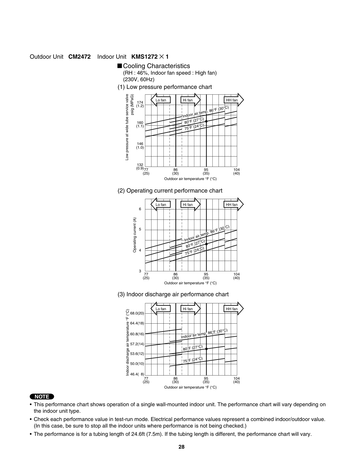
######### Outdoor Unit CM2472 Indoor Unit KMS1272 × 1
Cooling Characteristics (RH : 46%, Indoor fan speed : High fan) (230V, 60Hz)
| |L|o f|n| | |Hi|an| | | | | |H|fa| |---|---|---|---|---|---|---|---|---|---|---|---|---|---|---| | | | | | | |Ind|or|ir t|m|. 8|°F|30°|C)| | | | | | | | |8|°F (|7°C C|) )| | | | | | | | | | | | |7|°F (|4°| | | | | | | | | | | | | | | | | | | | | | | | | | | | | | | | | | | | | | | | | | | | | | | | | | | | | | |
Low pressure at wide tube service valve
psig (MPaG)
174 (1.2)
160 (1.1)
146 (1.0)
132 (0.9)77
86 (30)
95 (35)
104 (40)
(25)
Outdoor air temperature °F (°C)
| |L|o f|n| | |Hi|an| | | | | |H|fa| |---|---|---|---|---|---|---|---|---|---|---|---|---|---|---| | | | | | | | | | | | | | | | | | | | | | | | | | | | |F|(3|°C)| | | | | | | | |In|oor|air|te|p.|6°| | | | | | | | | | |8|°F|27° °C|C) )| | | | | | | | | | | | |7|°F|24| | | | | | | | | | | | | | | | | | | | | | |
Operating current (A)
4
3
77 (25)
86 (30)
95 (35)
104 (40)
Outdoor air temperature °F (°C)
| |L|o f|n| | |Hi|an| | | | | |H|fa| |---|---|---|---|---|---|---|---|---|---|---|---|---|---|---| | | | | | | | | | | | | | | | | | | | | | | | | | | |°|F (|0°C|)| | | | | | | | |ndo|r|ir t|mp|86| | | | | | | | | | | |80°|F (|7°C|)| | | | | | | | | | | | |75°|F (|4°C|)| | | | | | | | | | | | | | | | | | | | | |
Indoor discharge air temperature°F (°C)
68.0(20)
######### Outdoor Unit CM2472 Indoor Unit KMS1872 × 1
Cooling Characteristics (RH : 46%, Indoor fan speed : High fan) (230V, 60Hz)
| |L|o f|n| | |Hi|an| | | | | | | | |---|---|---|---|---|---|---|---|---|---|---|---|---|---|---| | | | | | |In|oo|air|te|p.|6°F|(3°|C)| | | | | | | | | |8|°F (|7°C|)| | | | | | | | | | | | |7|°F|24°C|)| | | | | | | | | | | | | | | | | | | | | | | | | | | | | | | | | | | | | |
| | | | | | | | | | | | | | | |
Low pressure at wide tube service valve
psig (MPaG)
HH fan
174 (1.2)
160 (1.1)
146 (1.0)
132 (0.9)
77 (25)
86 (30)
95 (35)
104 (40)
Outdoor air temperature °F (°C)
| |L|o f|n| | |Hi|an| | | | | |H|fa| |---|---|---|---|---|---|---|---|---|---|---|---|---|---|---| | | | | | | | | | | | | | | | | | | | | | | | | | | | |F|30°|C)| | | | | | | | |In|oor|ir|em|. 8|°| | | | | | | | | | |8|°F (|7°C|)| | | | | | | | | | | | |7|°F|24°C|)| | | | | | | | | | | | | | | | | | | | | |
Operating current (A)
6
5
77 (25)
86 (30)
95 (35)
104 (40)
Outdoor air temperature °F (°C)
| |L|o f|n| | |Hi|an| | | | | |H|fa| |---|---|---|---|---|---|---|---|---|---|---|---|---|---|---| | | | | | | | | | | | | | | | | | | | | | | | | | | | | | |°C)| | | | | | | | |Ind|or|ir|em|. 8|°F|(3| | | | | | | | | |80°|(|7°C|)| | | | | | | | | | | | |75°|F (|4°C|)| | | | | | | | | | | | | | | | | | | | | |
Indoor discharge air temperature°F (°C)
68.0(20)
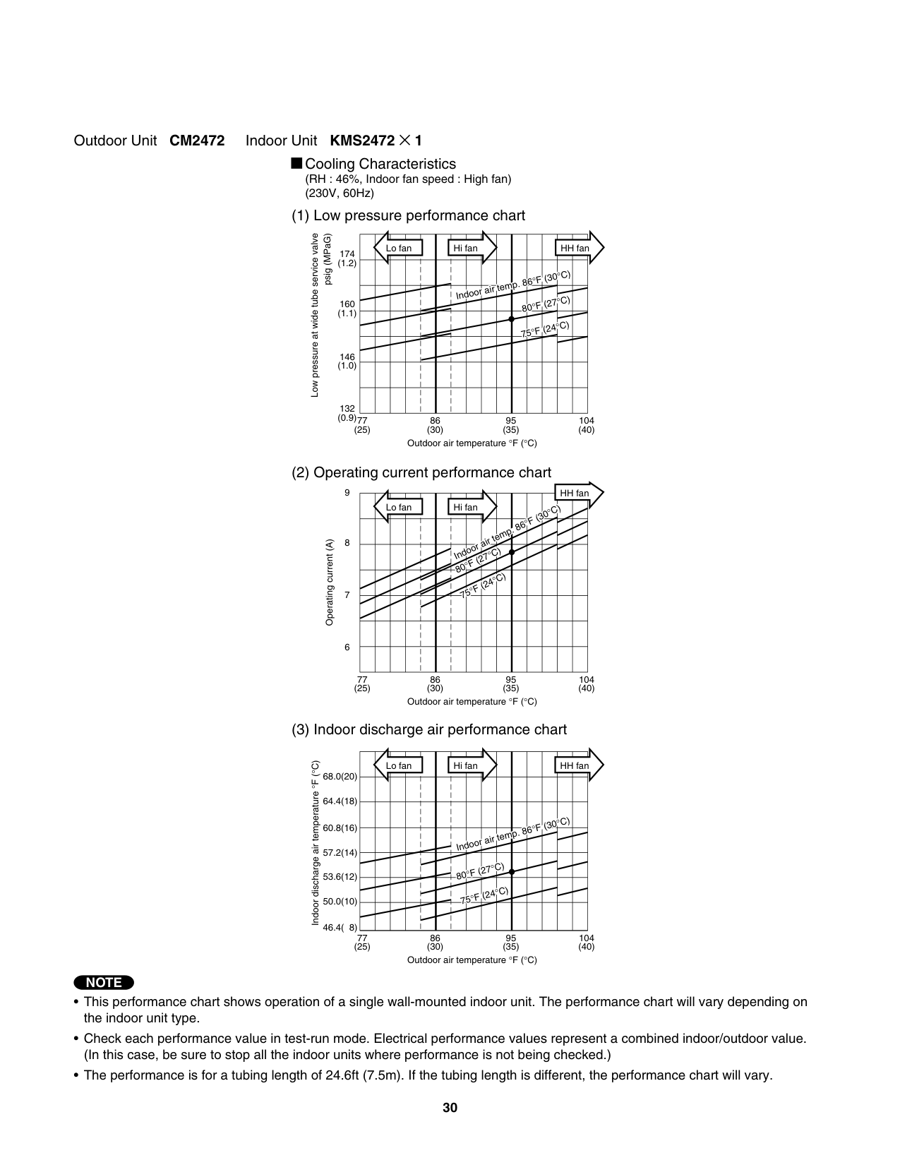
######### Outdoor Unit CM2472 Indoor Unit KMS2472 × 1
Cooling Characteristics (RH : 46%, Indoor fan speed : High fan) (230V, 60Hz)
| |L|o f|n| | |Hi|an| | | | | |H|fa| |---|---|---|---|---|---|---|---|---|---|---|---|---|---|---| | | | | | | | | | | | |°F|(3|°C)| | | | | | | | |In|oor|air|te|p.
8|6
0°F|(2|°C)| | | | | | | | | | | | |7|°F|(2|°C)| | | | | | | | | | | | | | | | | | | | | | | | | | | | | | | | | | | | | | | | | | | | | | | | | |
Low pressure at wide tube service valve
psig (MPaG)
174 (1.2)
160 (1.1)
146 (1.0)
132 (0.9)
77 (25)
86 (30)
95 (35)
104 (40)
Outdoor air temperature °F (°C)
| | | | | | | | | | | | | |HH fan|HH fan| |---|---|---|---|---|---|---|---|---|---|---|---|---|---|---| | |L|o f|n| | |Hi|an| | | | |°C|)| | | | | | | | |Ind|or|ir t|m|. 8°|(|0| | | | | | | | | |80°|(|7°C|)| | | | | | | | | | | | |7|°
F|24°C|)| | | | | | | | | | | | | | | | | | | | | | | | | | | | | | | | | | | | | | | | | | | | | | | | | | | | | |
Operating current (A)
7
6
77 (25)
86 (30)

95 (35)
104 (40)
Outdoor air temperature °F (°C)
| |L|o f|n| | |Hi|an| | | | | |H|fa| |---|---|---|---|---|---|---|---|---|---|---|---|---|---|---| | | | | | | | | | | | | | | | | | | | | | | | | | | | |F|(3|°C)| | | | | | | | |In|oor|air|te|p.|6°| | | | | | | | | | |80|°F (|7°C|)| | | | | | | | | | | | |7|°F|24°|C)| | | | | | | | | | | | | | | | | | | | | |
Indoor discharge air temperature°F (°C)
68.0(20)
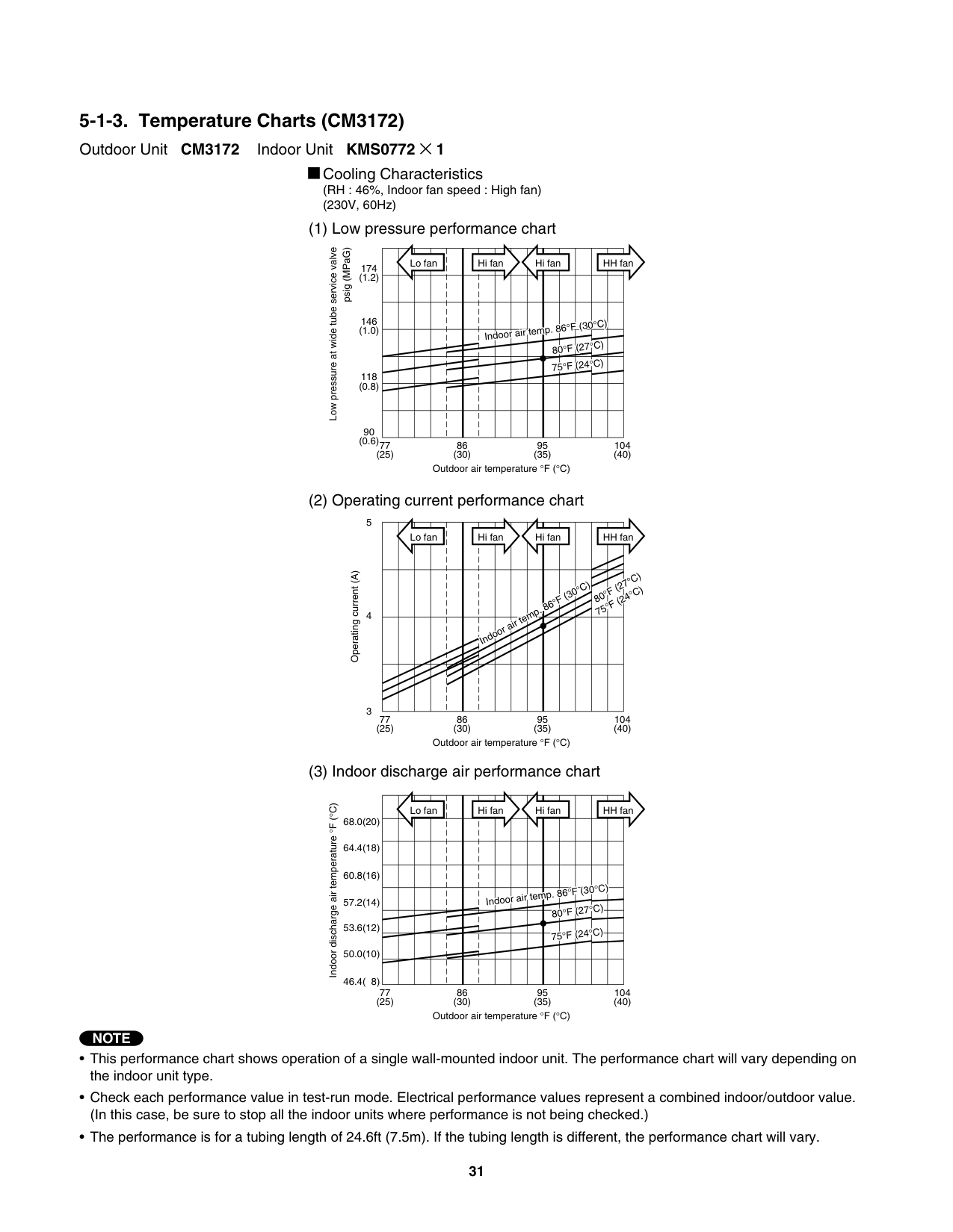
############# 5-1-3. Temperature Charts (CM3172)
Outdoor Unit CM3172 Indoor Unit KMS0772 × 1
Cooling Characteristics (RH : 46%, Indoor fan speed : High fan) (230V, 60Hz)
| |L|o f|n| | | |H|i f|n| |H|i fa| | | | |H|H f|n| |---|---|---|---|---|---|---|---|---|---|---|---|---|---|---|---|---|---|---|---| | | | | | | | | | | | | | | | | | | | | | | | | | | | | | | | | | | |°F|°F|(3|°C)|°C)| | | | | | | | | | | |In|oo|air|te|p. 8|6 °F|6 °F|(27°|C)|C)| | | | | | | | | | | | | | | |7|°F|°F|24°|C)|C)| | | | | | | | | | | | | | | | | | | | | | | | | | | | | | | | | | | | | | | | | | | | |
Low pressure at wide tube service valve
psig (MPaG)
174 (1.2)
146 (1.0)
118 (0.8)
90 (0.6)
77 (25)
86 (30)
95 (35)
104 (40)
Outdoor air temperature °F (°C)
Lo fan Hi fan Hi fan HH fan
F (27°C)
Operating current (A)
F (30°C)
F (24°C)
80°
Indoor air temp. 86°
75°
3
77 (25)
86 (30)
95 (35)
104 (40)
Outdoor air temperature °F (°C)
Indoor discharge air temperatureF (°C)
Lo fan Hi fan Hi fan HH fan
68.0(20)
64.4(18)
60.8(16)
Indoor air temp. 86°F (30°C)
57.2(14)
80°F (27°C) 75°F (24°C)
53.6(12)
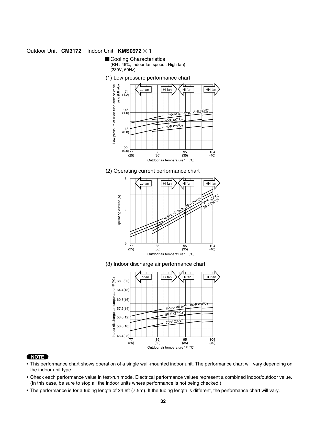
######### Outdoor Unit CM3172 Indoor Unit KMS0972 × 1
Cooling Characteristics (RH : 46%, Indoor fan speed : High fan) (230V, 60Hz)
| |L|o f|n| | | |H|i f|n| |H|i fa| | | | |H|H f|n| |---|---|---|---|---|---|---|---|---|---|---|---|---|---|---|---|---|---|---|---| | | | | | | | | | | | | | | | | | | | | | | | | | | | | | | | | | | |°|°|F (|0°C|0°C|)| | | | | | | | | | |I
80|do
°F (|r a 7°C|r t )|mp|86|86| | | | | | | | | | | | | | |75|°F (|4°C|)| | | | | | | | | | | | | | | | | | | | | | | | | | | | | | | | | | | | | | | | | | | | | | | | | | |
Low pressure at wide tube service valve
psig (MPaG)
174 (1.2)
146 (1.0)
118 (0.8)
90 (0.6)
77 (25)
86 (30)
95 (35)
104 (40)
Outdoor air temperature °F (°C)
Lo fan Hi fan Hi fan HH fan
F (27°C)
Operating current (A)
F (30°C)
F (24°C)
80°
Indoor air temp. 86°
75°
3
77 (25)
86 (30)
95 (35)
104 (40)
Outdoor air temperature °F (°C)
Lo fan Hi fan Hi fan HH fan
Indoor discharge air temperature°F (°C)
68.0(20)
64.4(18)
60.8(16)
Indoor air temp. 86°F (30°C)
57.2(14)
80°F (27°C) 75°F (24°C)
53.6(12)
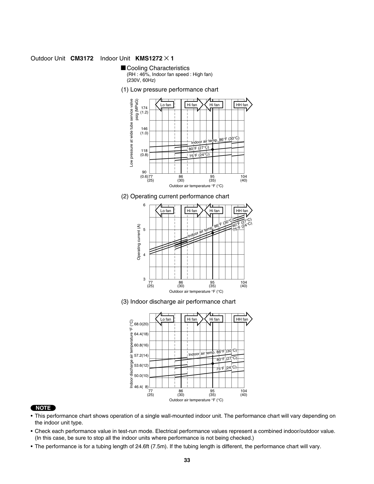
######### Outdoor Unit CM3172 Indoor Unit KMS1272 × 1
Cooling Characteristics (RH : 46%, Indoor fan speed : High fan) (230V, 60Hz)
| |L|o f|n| | | |H|i f|n| |H|i fa| | | | |H|H f|n| |---|---|---|---|---|---|---|---|---|---|---|---|---|---|---|---|---|---|---|---| | | | | | | | | | | | | | | | | | | | | | | | | | | | | | | | | | | | | | | | | | | | | | | | | | | |I|do|r ai|t|mp.|86°F|86°F|(|0°C|0°C|)| | | | | | | | | | |80°|F (|7°C|)| | | | | | | | | | | | | | | | | |75|°F (|4°C|)| | | | | | | | | | | | | | | | | | | | | | | | | | | | | |
Low pressure at wide tube service valve
psig (MPaG)
174 (1.2)
146 (1.0)
118 (0.8)
90 (0.6)
77 (25)
86 (30)
95 (35)
104 (40)
Outdoor air temperature °F (°C)
Lo fan Hi fan Hi fan HH fan
80°F (27°C) 75°F (24°C)
Indoor air temp. 86°F (30°C)
Operating current (A)
3
77 (25)
86 (30)
95 (35)
104 (40)
Outdoor air temperature °F (°C)
Lo fan Hi fan Hi fan HH fan
Indoor discharge air temperature°F (°C)
68.0(20)
64.4(18)
60.8(16)
Indoor air temp. 86°F (30°C) 80°F (27°C) 75°F (24°C)
57.2(14)
53.6(12)
######### Outdoor Unit CM3172 Indoor Unit KMS1872 × 1
Cooling Characteristics (RH : 46%, Indoor fan speed : High fan) (230V, 60Hz)
| | | | | | | | | |L|o fa| | | | |H|i fa| | |---|---|---|---|---|---|---|---|---|---|---|---|---|---|---|---|---|---| | | | | | | | | | | | | | | | | | | | | | | | | | | | | | | | | | | | | | | | | | | | | | |°|C)| | | | | | | | | | | |Ind|or|air|em|. 8 8|°F °F|(30 (27°
|C)| | | | | | | | | | | | | | | |7|°F|(24°|C)| | | | | | | | | | | | | | | | | | | | | | | | | | | | |
Low pressure at wide tube service valve
psig (MPaG)
174 (1.2)
146 (1.0)
118 (0.8)
90 (0.6)
77 (25)
86 (30)
95 (35)
104 (40)
Outdoor air temperature °F (°C)
5
| | | | | | | | | |L|o fa| | | | |H|i fa| | |---|---|---|---|---|---|---|---|---|---|---|---|---|---|---|---|---|---| | | | | | | | | | | |C)| | | | | | | |
| | | | | | | | |°
F|(3|°| | | | | | | | | | | | | | | | |°C|)| | | | | | | | | | | | |I|do|r ai|te
80°
|p. ( F (|6 7 4°C|)| | | | | | | | | | | | | | | |7°| | | | | | | | | | | | | | | | | | | | | | | | | | | | | | | | | | | | | | | | | | | | | | | | | | | | | | | | | | | | | | | | | | | | | | | | | | | | | | | | | | | | | | | |
Operating current (A)
4
77 (25)
86 (30)
95 (35)
104 (40)
Outdoor air temperature °F (°C)
| | | | | | | | | |L|o fa| | | | |H|i fa| | |---|---|---|---|---|---|---|---|---|---|---|---|---|---|---|---|---|---| | | | | | | | | | | | | | | | | | | | | | | | | | | | | | | | | | | | | | | | | | | | | | | | | | | | | | | | | | | | | | | |In|oor|air|em|.|6°F|(30°|(30°|C)| | | | | | | | | | | | | | | |8|°F|°F|27°|C)|C)| | | | | | | | | | | | | |7|°F|°F|24°|C)|C)| | | | | | | | | | | | | | | | | | | | | |
Indoor discharge air temperatureF (°C)
68.0(20)
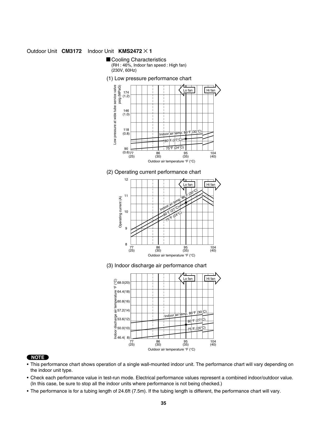
######### Outdoor Unit CM3172 Indoor Unit KMS2472 × 1
Cooling Characteristics (RH : 46%, Indoor fan speed : High fan) (230V, 60Hz)
| | | | | | | | | |L|o fa| | | | |H|i fa| | |---|---|---|---|---|---|---|---|---|---|---|---|---|---|---|---|---|---| | | | | | | | | | | | | | | | | | | | | | | | | | | | | | | | | | | | | | | | | | | | | | | | | | | | | | | | | | | | | | | | | | | | |F|(30°|(30°|C)| | | | | | | | | | |In|oor
80°|air F (
|em 7°C|. )|6°| | | | | | | | | | | | | | |7|°F|24°|C)| | | | | | | | |
Low pressure at wide tube service valve
psig (MPaG)
174 (1.2)
146 (1.0)
118 (0.8)
90 (0.6)
77 (25)
86 (30)
95 (35)
104 (40)
Outdoor air temperature °F (°C)
| | | | | | | | | |L|o fa| | | | |H|i fa| | |---|---|---|---|---|---|---|---|---|---|---|---|---|---|---|---|---|---| | | | | | |Ind|or|ir t|m|. 8|°
F (|0°C|0°C| | | | | | | | | | | | | | | | | | | | | | | | | | | | | | | |F|(2°|C)| | | | | | | | | | | | | | | |8|0° 7°|F (|4°C|)| | | | | | | | | | | | | | | | | | | | | | | | | | | | | | | | | | | | | | | | | | | | | | | | | | | | | | | | | | | | | | | | | |
Operating current (A)
9
8
77 (25)
86 (30)
95 (35)
104 (40)
Outdoor air temperature °F (°C)
| | | | | | | | | |L|o fa| | | | |H|i fa| | |---|---|---|---|---|---|---|---|---|---|---|---|---|---|---|---|---|---| | | | | | | | | | | | | | | | | | | | | | | | | | | | | | | | | | | | | | | | | | | | | | | | | | | | | | | | | | | | | | | | | | | | | |°F|°F|30°|C)|C)| | | | | | | | | |Ind|or|ir|e|p. 8|°F (|°F (|7°C|)|)| | | | | | | | | | | | | |80 75|°F (|°F (|4°C|)|)| | | | | | | | | | | | | | | | | | | | | |
Indoor discharge air temperature°F (°C)
68.0(20)
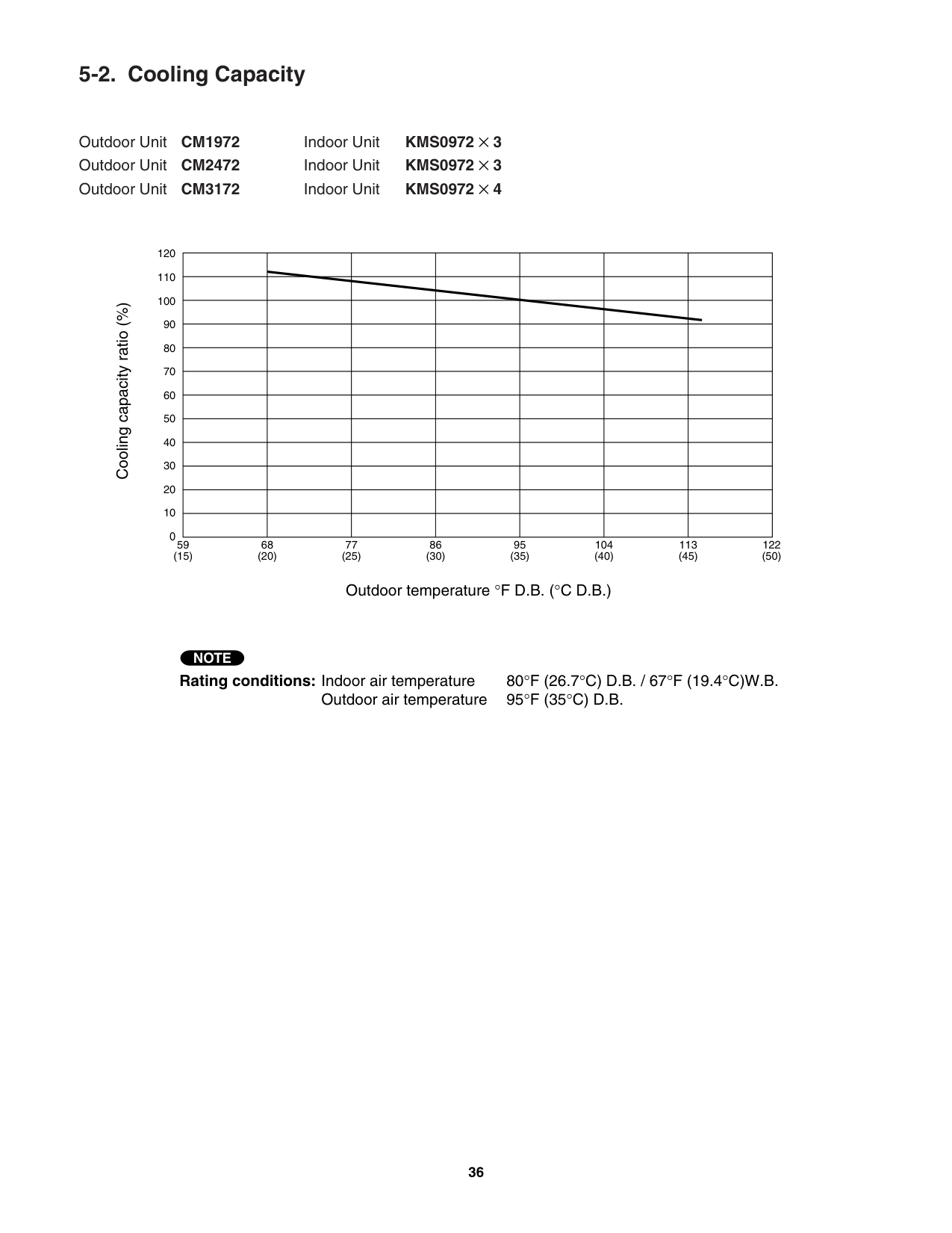
######## 5-2. Cooling Capacity
Outdoor Unit CM1972 Indoor Unit KMS0972 × 3 Outdoor Unit CM2472 Indoor Unit KMS0972 × 3 Outdoor Unit CM3172 Indoor Unit KMS0972 × 4
Cooling capacity ratio (%)
120
| | | | | | | |
|---|---|---|---|---|---|---| | | | | | | | | | | | | | | | | | | | | | | | | | | | | | | | | | | | | | | | | | | | | | | | | | | | | | | | | | | | | | | | | | | | | | | | | | | | | | | | | | | | | | | | |
110
100
90
80
70
60
50
40
30
20
10
0
59 (15)
68 (20)
77 (25)
86 (30)
95 (35)
104 (40)
113 (45)
122 (50)
Outdoor temperature °F D.B. (°C D.B.)
############################ NOTE
Rating conditions: Indoor air temperature 80°F (26.7°C) D.B. / 67°F (19.4°C)W.B.
Outdoor air temperature 95°F (35°C) D.B.
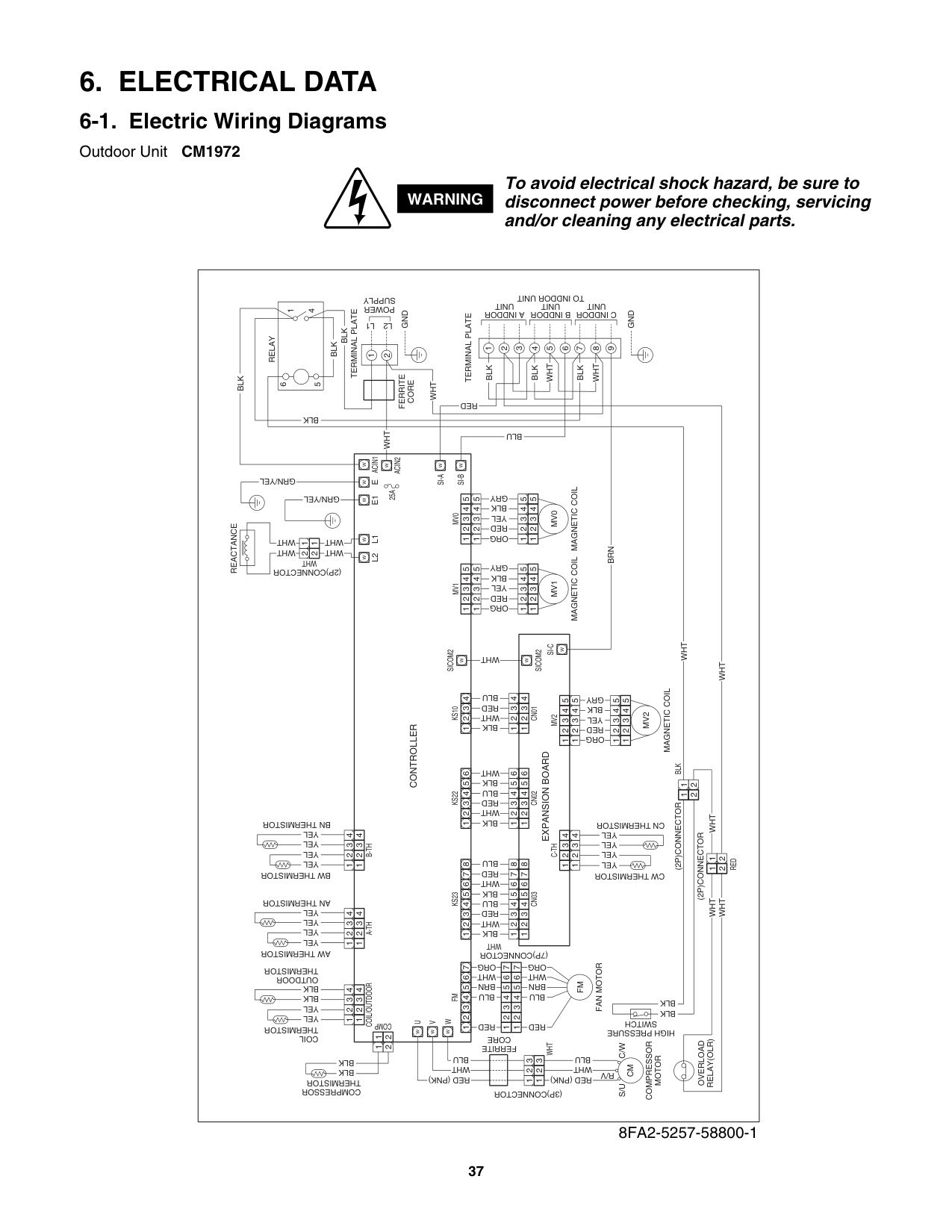
##### 6. ELECTRICAL DATA
######## 6-1. Electric Wiring Diagrams
Outdoor Unit CM1972
WARNING
To avoid electrical shock hazard, be sure to disconnect power before checking, servicing and/or cleaning any electrical parts.
|WHT
REACTANCE
WHT
YEL
YEL
BLK
BLK
BLK
BLK
1
1
1
11
22
11
22
1
22
2
2
3
3
4
4
COIL/OUTDOOR
YEL
YEL
YEL
YEL
1
1
2
2
3
3
4
4
A-TH
COIL
THERMISTOR
COMPRESSOR
THERMISTOR
AW THERMISTOR
AN THERMISTOR
(7P)CONNECTOR
(3P)CONNECTOR
FERRITE
CORE
WHT
YEL
YEL
YEL
YEL
1
1
2
2
3
3
4
4
B-TH BW THERMISTOR
BN THERMISTOR
CW THERMISTOR
HIGH PRESSURE
SWITCH
CN THERMISTOR
(2P)CONNECTOR
(2P)CONNECTOR
OUTDOOR
THERMISTOR
COMPRESSOR
MOTOR
OVERLOAD
RELAY(OLR)
CONTROLLER
EXPANSION BOARD
FAN MOTOR
SICOM2
SICOM2
SI-C
KS10
CN01
W
W
W
L2 L1
MV0
MAGNETIC COIL
MV0
(2P)CONNECTOR
WHT
W
E1
WW
2 2
1 1
WHT
WHT
ACIN1
W
ACIN2
SI-A
SI-B
25A W
U
COMP
W
VW
WW
GRN/YEL
E
W
GRN/YEL
6
1
4
5
BLK
BLK
BLK
GND
BLK
RELAY
TERMINAL PLATE
TERMINAL PLATE
W
W
1
2
1
2
3
4
5
6
7
8
9
L2
POWER
SUPPLY
L1
FERRITE
CORE
WHT
WHT
BLK
RED
BLU
BLK
WHT
BLK
WHT
GND
A INDDOR
UNIT
B INDDOR
UNIT
TO INDDOR UNIT C INDDOR UNIT
5
5
5 4
4 3
3 2
2 1
1
5
4 4
3 3
2 2
1 1
GRY BLK YEL RED ORG
MV1
MAGNETIC COIL
MV1
5
5
5 4
4 3
3 2
2 1
1
5
4 4
3 3
2 2
1 1
GRY BLK YEL RED ORG
BLK
1
1
1
WHT
2
2
2
RED
3
3
3
BLU
4
4
4
KS22
CN02
BLK
1
1
1
WHT
2
2
2
RED
3
3
3
BLU
4
4
4 BLK
5
5
5 WHT
6
6
6
KS23FM
WHT
RED
BLK
S/U C/W
R/V
CN03
BLK
1
1
1
WHT
2
2
2
RED
3
3
1
1
2
2 3
3
3
BLU
4
4
4
BLK
5
5
5
WHT
6
6
6
RED
7
7
7
RED
1
1
2
2
3
3
BLU
4
4
BRN
5
5
WHT
6
6
ORG
RED
BLU
BRN
WHT
ORG
7
1234567
7
BLU YEL
YEL
YEL
YEL
8
8
8
WHT
MV2C-TH
MAGNETIC COIL
MV2
5
5
5 4
4 3
3 2
2 1
1
5
4 4
3
3
2
2
1
1
4 4
3 3
2
2
1 1
FM
CM
GRY BLK YEL RED ORG
BRN
BLU WHT
RED (PNK)
BLU WHT
RED (PNK)
BLK
BLK
WHTWHT
WHT
WHTWHT
| |---|
8FA2-5257-58800-1
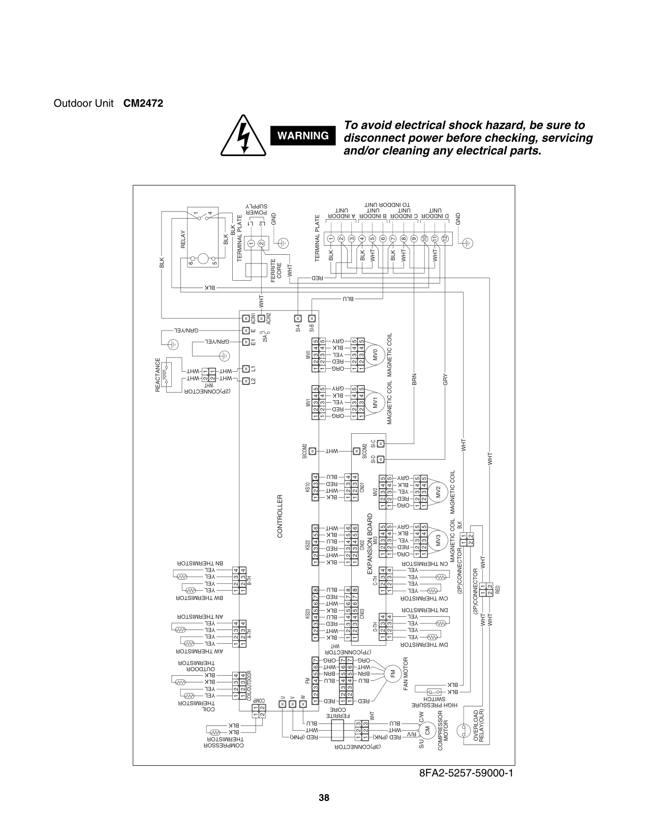
Outdoor Unit CM2472
WARNING
################ To avoid electrical shock hazard, be sure to disconnect power before checking, servicing and/or cleaning any electrical parts.
|WHT
REACTANCE
WHT
YEL
YEL
BLK
BLK
BLK
BLK
1
1
1
11
22
11
22
1
22
2
2
3
3
4
4
COIL/OUTDOOR
YEL
YEL
YEL
YEL
1
1
2
2
3
3
4
4
A-TH
COIL
THERMISTOR
COMPRESSOR
THERMISTOR
AW THERMISTOR
AN THERMISTOR
(7P)CONNECTOR
(3P)CONNECTOR
FERRITE
CORE
WHT
YEL
YEL
YEL
YEL
1
1
2
2
3
3
4
4
B-TH BW THERMISTOR
BN THERMISTOR
CW THERMISTOR
HIGH PRESSURE
SWITCH
CN THERMISTOR
(2P)CONNECTOR
(2P)CONNECTOR
OUTDOOR
THERMISTOR
COMPRESSOR
MOTOR
OVERLOAD
RELAY(OLR)
CONTROLLER
EXPANSION BOARD
FAN MOTOR
SICOM2
SICOM2
SI-C
KS10
CN01
W
W
W SI-D
W
L2 L1
MV0
MAGNETIC COIL
MV0
(2P)CONNECTOR
WHT
W
E
WW
2 2
1 1
WHT
WHT
ACIN1
W
ACIN2
SI-A
SI-B
25A W
U
COMP
W
VW
WW
GRN/YEL
6
1
4
5
BLK
BLK
BLK
GND
BLK
RELAY
TERMINAL PLATE
TERMINAL PLATE
W
W
1
2
1
2
3
4
5
6
7
8
9
10
11
12
L2
POWER
SUPPLY
L1
FERRITE
CORE
WHT
WHT
BLK
RED
BLU
BLK
WHT
WHT
WHT
GND
A INDDOR
UNIT
B INDDOR
UNIT
TO INDDOR UNIT C INDDOR UNIT
D INDDOR
UNIT
5
5
5 4
4 3
3 2
2 1
1
5
4 4
3 3
2 2
1 1
GRY BLK YEL RED ORG
MV1
MAGNETIC COIL
MV1
5
5
5 4
4 3
3 2
2 1
1
5
4 4
3 3
2 2
1 1
GRY BLK YEL RED ORG
BLK
1
1
1
WHT
2
2
2
RED
3
3
3
BLU
4
4
4
KS22
CN02
BLK
1
1
1
WHT
2
2
2
RED
3
3
3
BLU
4
4
4 BLK
5
5
5 WHT
6
6
6
KS23FM
WHT
RED
BLK
S/U C/W
R/V
CN03
BLK
1
1
1
WHT
2
2
2
RED
3
3
1
1
2
2 3
3
3
BLU
4
4
4
BLK
5
5
5
WHT
6
6
6
RED
7
7
7
RED
1
1
2
2
3
3
BLU
4
4
BRN
5
5
WHT
6
6
ORG
RED
BLU
BRN
WHT
ORG
7
1234567
7
BLU YEL
YEL
YEL
YEL
8
8
8
WHT
MV2C-TH
MAGNETIC COIL
MV2
5
5
5 4
4 3
3 2
2 1
1
5
4 4
3
3
2
2
1
1
4 4
3 3
2
2
1 1
DW THERMISTOR
DN THERMISTOR
YEL
YEL
YEL
YEL
D-TH
4 4
3 3
2 2
1 1
FM
CM
GRY BLK YEL RED ORG
MV3
MAGNETIC COIL
MV3
5
5
5 4
4 3
3 2
2 1
1
5
4 4
3 3
2 2
1 1
GRY BLK YEL RED ORG
BRN
BLU WHT
RED (PNK)
BLU WHT
RED (PNK)
BLK
BLK
WHTWHT
WHT
WHTWHT
BLK
GRY
E1
W
GRN/YEL| |---|
8FA2-5257-59000-1
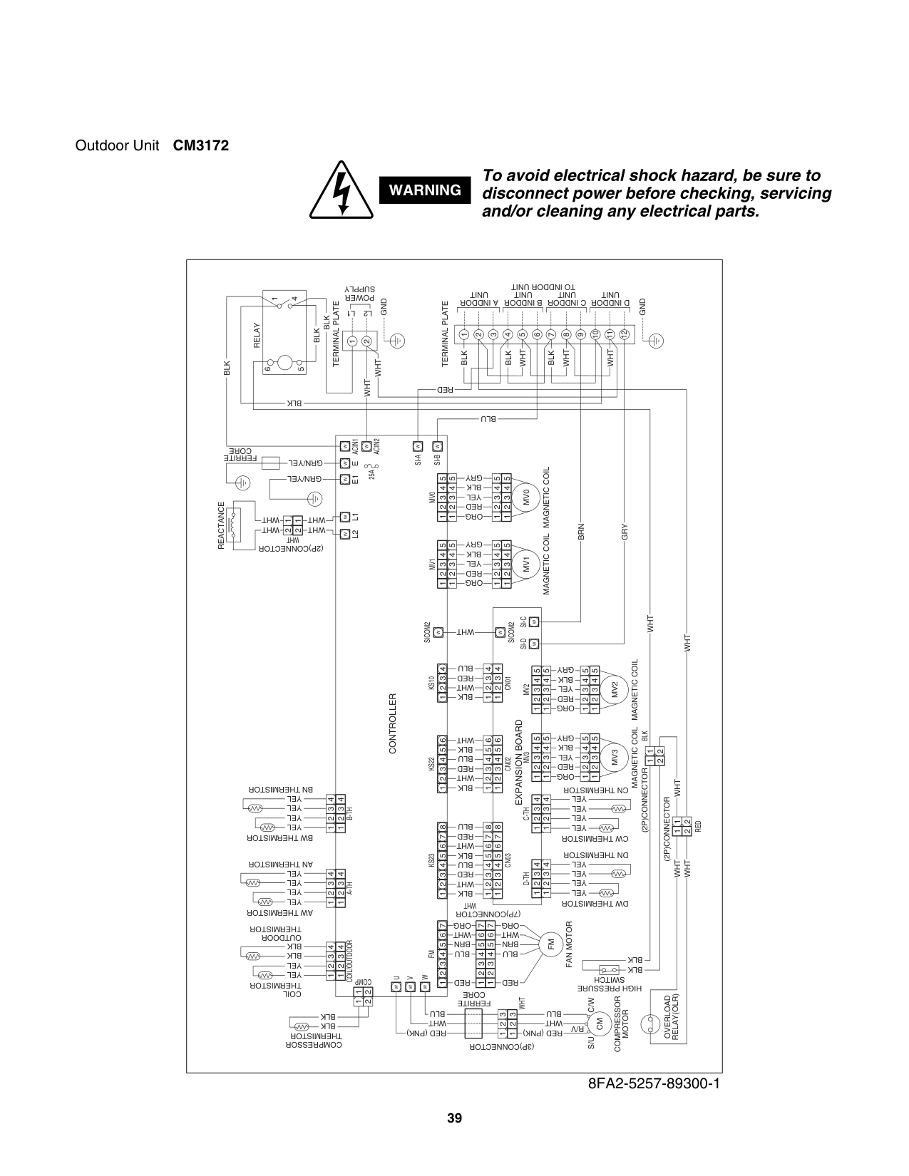
Outdoor Unit CM3172
WARNING
################ To avoid electrical shock hazard, be sure to disconnect power before checking, servicing and/or cleaning any electrical parts.
|WHT
REACTANCE
WHT
YEL
YEL
BLK
BLK
BLK
BLK
1
1
1
11
22
11
22
1
22
2
2
3
3
4
4
COIL/OUTDOOR
YEL
YEL
YEL
YEL
1
1
2
2
3
3
4
4
A-TH
COIL
THERMISTOR
COMPRESSOR
THERMISTOR
AW THERMISTOR
AN THERMISTOR
(7P)CONNECTOR
(3P)CONNECTOR
FERRITE
CORE
WHT
YEL
YEL
YEL
YEL
1
1
2
2
3
3
4
4
B-TH BW THERMISTOR
BN THERMISTOR
CW THERMISTOR
HIGH PRESSURE
SWITCH
CN THERMISTOR
(2P)CONNECTOR
(2P)CONNECTOR
OUTDOOR
THERMISTOR
COMPRESSOR
MOTOR
OVERLOAD
RELAY(OLR)
CONTROLLER
EXPANSION BOARD
FAN MOTOR
SICOM2
SICOM2
SI-C
KS10
CN01
W
W
W SI-D
W
L2 L1
MV0
MAGNETIC COIL
MV0
(2P)CONNECTOR
WHT
W
E
WW
2 2
1 1
WHT
WHT
ACIN1
W
ACIN2
SI-A
SI-B
25A W
U
COMP
W
VW
WW
GRN/YEL
FERRITE
CORE
6
1
4
5
BLK
BLK
BLK
GND
BLK
RELAY
TERMINAL PLATE
TERMINAL PLATE
W
W
1
2
1
2
3
4
5
6
7
8
9
10
11
12
L2
POWER
SUPPLY
L1
WHT WHT
BLK
RED
BLU
BLK
WHT
WHT
WHT
GND
A INDDOR
UNIT
B INDDOR
UNIT
TO INDDOR UNIT C INDDOR UNIT
D INDDOR
UNIT
5
5
5 4
4 3
3 2
2 1
1
5
4 4
3 3
2 2
1 1
GRY BLK YEL RED ORG
MV1
MAGNETIC COIL
MV1
5
5
5 4
4 3
3 2
2 1
1
5
4 4
3 3
2 2
1 1
GRY BLK YEL RED ORG
BLK
1
1
1
WHT
2
2
2
RED
3
3
3
BLU
4
4
4
KS22
CN02
BLK
1
1
1
WHT
2
2
2
RED
3
3
3
BLU
4
4
4 BLK
5
5
5 WHT
6
6
6
KS23FM
WHT
RED
BLK
S/U C/W
R/V
CN03
BLK
1
1
1
WHT
2
2
2
RED
3
3
1
1
2
2 3
3
3
BLU
4
4
4
BLK
5
5
5
WHT
6
6
6
RED
7
7
7
RED
1
1
2
2
3
3
BLU
4
4
BRN
5
5
WHT
6
6
ORG
RED
BLU
BRN
WHT
ORG
7
1234567
7
BLU YEL
YEL
YEL
YEL
8
8
8
WHT
MV2C-TH
MAGNETIC COIL
MV2
5
5
5 4
4 3
3 2
2 1
1
5
4 4
3
3
2
2
1
1
4 4
3 3
2
2
1 1
DW THERMISTOR
DN THERMISTOR
YEL
YEL
YEL
YEL
D-TH
4 4
3 3
2 2
1 1
FM
CM
GRY BLK YEL RED ORG
MV3
MAGNETIC COIL
MV3
5
5
5 4
4 3
3 2
2 1
1
5
4 4
3 3
2 2
1 1
GRY BLK YEL RED ORG
BRN
BLU WHT
RED (PNK)
BLU WHT
RED (PNK)
BLK
BLK
WHTWHT
WHT
WHTWHT
BLK
GRY
E1
W
GRN/YEL| |---|
8FA2-5257-89300-1
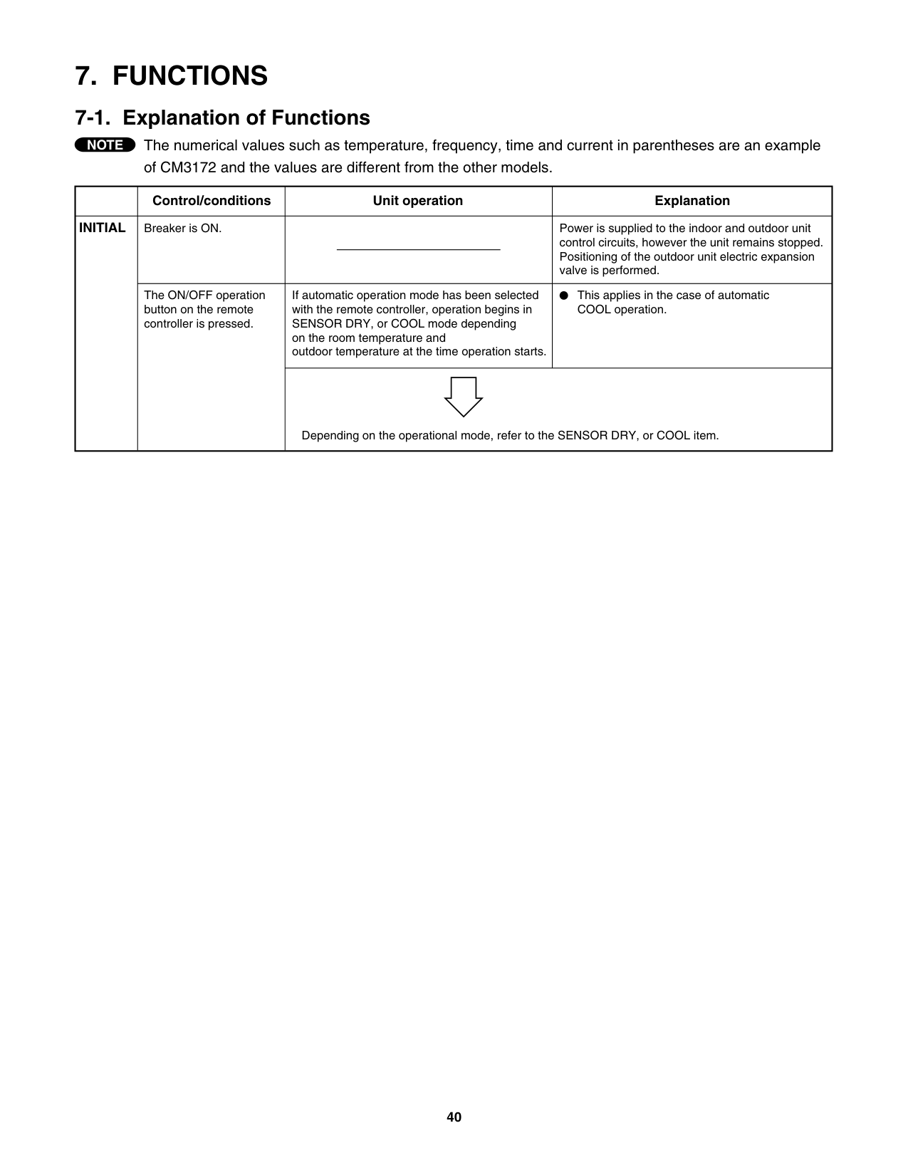
##### 7. FUNCTIONS
######## 7-1. Explanation of Functions
The numerical values such as temperature, frequency, time and current in parentheses are an example of CM3172 and the values are different from the other models.
############################ NOTE
| |Control/conditions|Unit operation|Explanation| |---|---|---|---| |INITIAL|Breaker is ON.| |Power is supplied to the indoor and outdoor unit control circuits, however the unit remains stopped. Positioning of the outdoor unit electric expansion valve is performed.| |INITIAL|The ON/OFF operation button on the remote controller is pressed.|If automatic operation mode has been selected with the remote controller, operation begins in SENSOR DRY, or COOL mode depending on the room temperature and outdoor temperature at the time operation starts.|This applies in the case of automatic COOL operation.| |INITIAL|The ON/OFF operation button on the remote controller is pressed.|Depending on the operational mode, refer to the SENSOR DRY, or COOL item.|Depending on the operational mode, refer to the SENSOR DRY, or COOL item.|
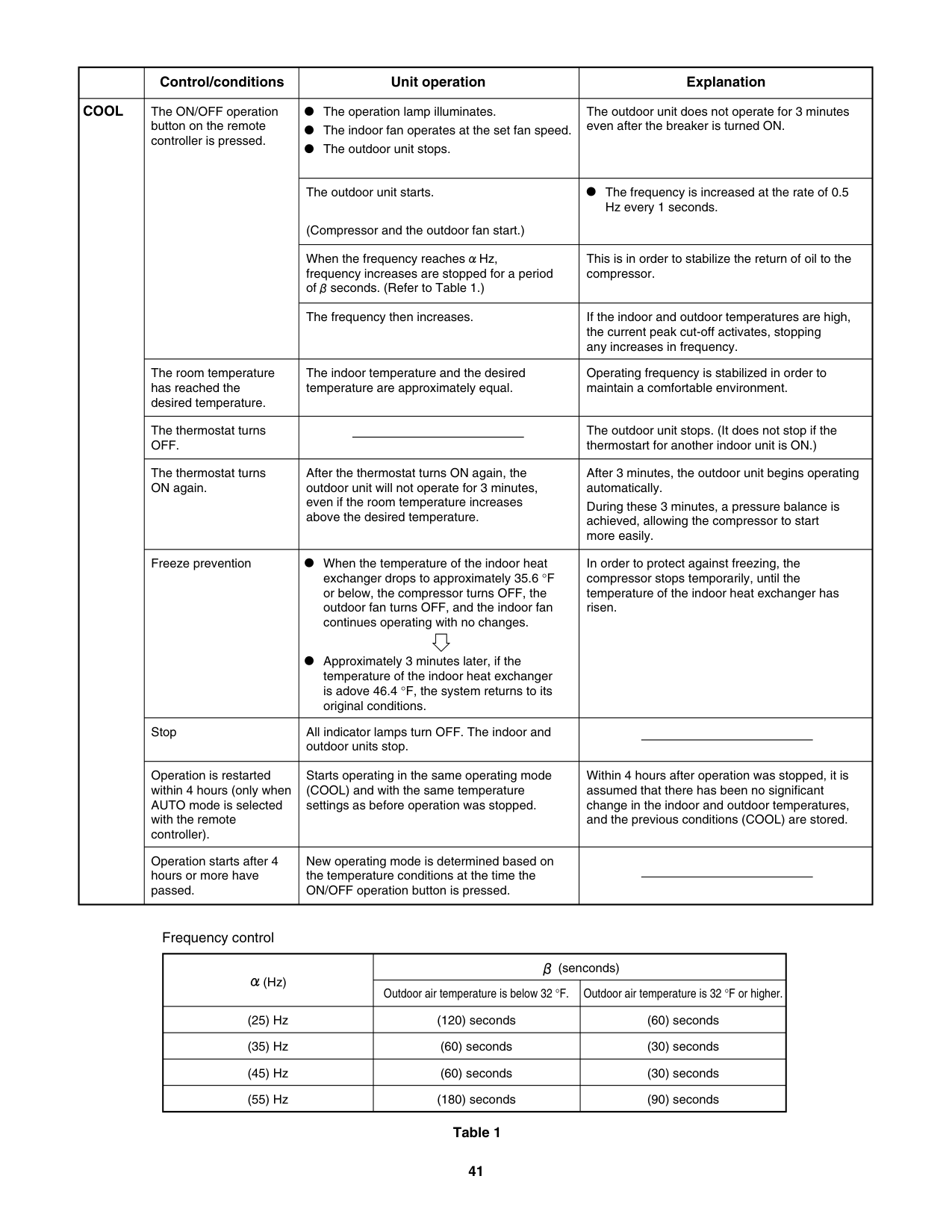
| |Control/conditions|Unit operation|Explanation| |---|---|---|---| |COOL|The ON/OFF operation button on the remote controller is pressed.
|The operation lamp illuminates. The indoor fan operates at the set fan speed. The outdoor unit stops.
|The outdoor unit does not operate for 3 minutes even after the breaker is turned ON.| |COOL|The ON/OFF operation button on the remote controller is pressed.
|The outdoor unit starts.
(Compressor and the outdoor fan start.)
|The frequency is increased at the rate of 0.5 Hz every 1 seconds.| |COOL|The ON/OFF operation button on the remote controller is pressed.
|When the frequency reaches Hz, frequency increases are stopped for a period of seconds. (Refer to Table 1.)
|This is in order to stabilize the return of oil to the compressor.| |COOL|The ON/OFF operation button on the remote controller is pressed.
|The frequency then increases.|If the indoor and outdoor temperatures are high, the current peak cut-off activates, stopping any increases in frequency.| |COOL|The room temperature has reached the desired temperature.|The indoor temperature and the desired temperature are approximately equal.|Operating frequency is stabilized in order to maintain a comfortable environment.| |COOL|The thermostat turns OFF.| |The outdoor unit stops. (It does not stop if the thermostart for another indoor unit is ON.)| |COOL|The thermostat turns ON again.|After the thermostat turns ON again, the outdoor unit will not operate for 3 minutes, even if the room temperature increases above the desired temperature.
|After 3 minutes, the outdoor unit begins operating automatically. During these 3 minutes, a pressure balance is achieved, allowing the compressor to start more easily.| |COOL|Freeze prevention|When the temperature of the indoor heat exchanger drops to approximately 35.6 °F or below, the compressor turns OFF, the outdoor fan turns OFF, and the indoor fan continues operating with no changes.
Approximately 3 minutes later, if the temperature of the indoor heat exchanger is adove 46.4 °F, the system returns to its original conditions.|In order to protect against freezing, the compressor stops temporarily, until the temperature of the indoor heat exchanger has risen.| |COOL|Stop|All indicator lamps turn OFF. The indoor and outdoor units stop.| | |COOL|Operation is restarted within 4 hours (only when AUTO mode is selected with the remote controller).|Starts operating in the same operating mode (COOL) and with the same temperature settings as before operation was stopped.
|Within 4 hours after operation was stopped, it is assumed that there has been no significant change in the indoor and outdoor temperatures, and the previous conditions (COOL) are stored.| |COOL|Operation starts after 4 hours or more have passed.|New operating mode is determined based on the temperature conditions at the time the ON/OFF operation button is pressed.| |
Frequency control
|(Hz)|(senconds)|(senconds)| |---|---|---|
|(Hz)|Outdoor air temperature is below 32 °F.|Outdoor air temperature is 32 °F or higher.| |(25) Hz|(120) seconds|(60) seconds| |(35) Hz|(60) seconds|(30) seconds| |(45) Hz|(60) seconds|(30) seconds| |(55) Hz|(180) seconds|(90) seconds|
############################ Table 1
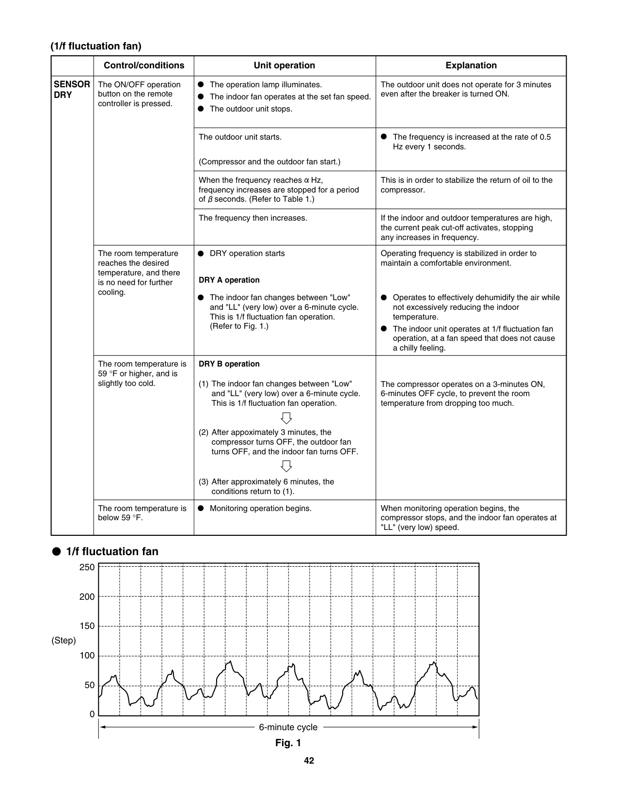
(1/f fluctuation fan)
| |Control/conditions|Unit operation|Explanation| |---|---|---|---| |SENSOR DRY|The ON/OFF operation button on the remote controller is pressed.|The operation lamp illuminates. The indoor fan operates at the set fan speed. The outdoor unit stops.
|The outdoor unit does not operate for 3 minutes even after the breaker is turned ON.
| |SENSOR DRY|The ON/OFF operation button on the remote controller is pressed.|The outdoor unit starts.
(Compressor and the outdoor fan start.)|The frequency is increased at the rate of 0.5 Hz every 1 seconds.
| |SENSOR DRY|The ON/OFF operation button on the remote controller is pressed.|When the frequency reaches Hz, frequency increases are stopped for a period of seconds. (Refer to Table 1.)|This is in order to stabilize the return of oil to the compressor.| |SENSOR DRY|The ON/OFF operation button on the remote controller is pressed.|The frequency then increases.|If the indoor and outdoor temperatures are high, the current peak cut-off activates, stopping any increases in frequency.| |SENSOR DRY|The room temperature reaches the desired temperature, and there is no need for further cooling.
|DRY operation starts
DRY A operation
The indoor fan changes between "Low" and "LL" (very low) over a 6-minute cycle. This is 1/f fluctuation fan operation. (Refer to Fig. 1.)
|Operating frequency is stabilized in order to maintain a comfortable environment.
Operates to effectively dehumidify the air while not excessively reducing the indoor temperature. The indoor unit operates at 1/f fluctuation fan operation, at a fan speed that does not cause a chilly feeling.| |SENSOR DRY|The room temperature is 59 °F or higher, and is slightly too cold.|DRY B operation
The indoor fan changes between "Low" and "LL" (very low) over a 6-minute cycle. This is 1/f fluctuation fan operation.
After appoximately 3 minutes, the compressor turns OFF, the outdoor fan turns OFF, and the indoor fan turns OFF.
After approximately 6 minutes, the conditions return to (1).
(1)
(2)
(3)
|The compressor operates on a 3-minutes ON, 6-minutes OFF cycle, to prevent the room temperature from dropping too much.| |SENSOR DRY|The room temperature is below 59 °F.|Monitoring operation begins.
|When monitoring operation begins, the compressor stops, and the indoor fan operates at "LL" (very low) speed.|
################# 1/f fluctuation fan
250
| | | | | | | | | | | | | | | | | | | |---|---|---|---|---|---|---|---|---|---|---|---|---|---|---|---|---|---| | | | | | | | | | | | | | | | | | | | | | | | | | | | | | | | | | | | | | | | | | | | | | | | | | | | | | | | | | | | | | | | | | | | | | | | | | | | | | | | | | | | | | | | | | | | | | | |
200
150
(Step)
100
50
0
6-minute cycle Fig. 1
######## 7-2. Protective Functions
NOTE
The numerical values such as temperature, frequency, time and current in parentheses are an example of CM3172 and the values are different from the other models.
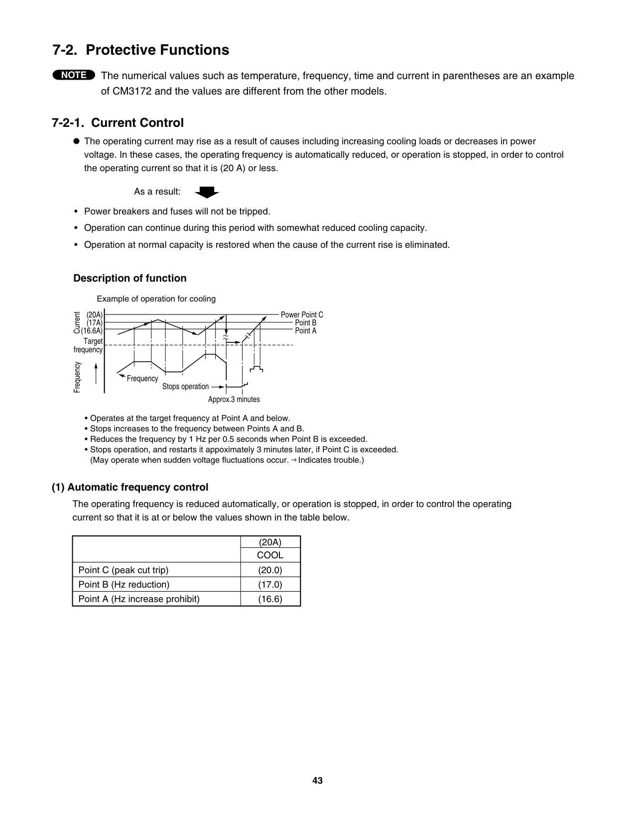
############# 7-2-1. Current Control
The operating current may rise as a result of causes including increasing cooling loads or decreases in power voltage. In these cases, the operating frequency is automatically reduced, or operation is stopped, in order to control the operating current so that it is (20 A) or less.
As a result:
• • •
Power breakers and fuses will not be tripped. Operation can continue during this period with somewhat reduced cooling capacity. Operation at normal capacity is restored when the cause of the current rise is eliminated.
Description of function
Example of operation for cooling
(20A) (17A)
Frequency Current
(16.6A) Target frequency
Frequency
Stops operation
Approx.3 minutes
Power Point C
Point B Point A
• • • •
Operates at the target frequency at Point A and below. Stops increases to the frequency between Points A and B. Reduces the frequency by 1 Hz per 0.5 seconds when Point B is exceeded. Stops operation, and restarts it appoximately 3 minutes later, if Point C is exceeded. (May operate when sudden voltage fluctuations occur. Indicates trouble.)
####################### (1) Automatic frequency control
The operating frequency is reduced automatically, or operation is stopped, in order to control the operating current so that it is at or below the values shown in the table below.
| |(20A)| |---|---| | |COOL| |Point C (peak cut trip)|(20.0)| |Point B (Hz reduction)|(17.0)| |Point A (Hz increase prohibit)|(16.6)|
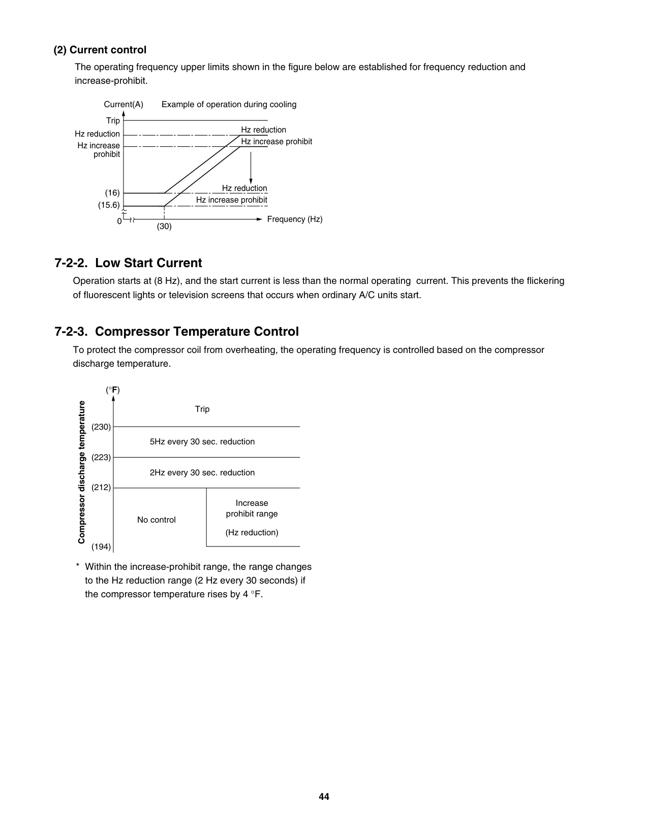
####################### (2) Current control
The operating frequency upper limits shown in the figure below are established for frequency reduction and increase-prohibit.
Example of operation during cooling
Current(A)
Trip Hz reduction
Hz reduction Hz increase prohibit
Hz increase prohibit
Hz reduction Hz increase prohibit
(16) (15.6)
Frequency (Hz)
0
(30)
############# 7-2-2. Low Start Current
Operation starts at (8 Hz), and the start current is less than the normal operating current. This prevents the flickering of fluorescent lights or television screens that occurs when ordinary A/C units start.
############# 7-2-3. Compressor Temperature Control
To protect the compressor coil from overheating, the operating frequency is controlled based on the compressor discharge temperature.
(°F)
Compressor discharge temperature
(230)
(223)
(212)
(194)
Trip
5Hz every 30 sec. reduction
2Hz every 30 sec. reduction
No control
Increase prohibit range (Hz reduction)
##### 8. TROUBLESHOOTING
######## 8-1. Precautions before Performing Inspection or Repair
############# Both the indoor unit and outdoor unit include electronic control circuits. Be sure to pay attention to the following before inspecting or repairing the outdoorside electronic circuits.
High-capacity electrolytic capacitors are used inside the outdoor unit controller (inverter). They retain an electrical charge (charging voltage DC 311 V) even after the power is turned OFF, and some time is required for the charge to dissipate.
Be careful not to touch any electrified parts before the control circuit board Power Lamp (red) turns OFF. If the outdoor control circuit board is normal, approximately 180 seconds will be required for the charge to dissipate. However, allow at least 30 minutes for the charge to dissipate if it is thought there might be trouble with the outdoor control circuit board. For example, if the outdoor control circuit board fuse has blown, approximately 30 minutes will be required to discharge the high-capacity electrolytic capacitors.
######## 8-2. Trouble Diagnosis by Error Monitor Lamps
WARNING
To prevent electric shock, do not inspect or repair until the Power Lamp on the P.C.Board is turned off.
############# 8-2-1. Location of the Error Monitor Lamps
Remove the top plate of outdoor unit and the cover of Electrical Component Box. The Power Lamp and Error Monitor Lamps are located on the P.C.Board of Electrical Component Box. (Fig.1)
Heat Exchanger Rear side P.C.Board of Electrical Component Box.
Front side Fig.1 View from top
Error Monitor Lamps
Power Lamp
############# 8-2-2. Display of the Error Monitor Lamps
If a protective device has activated or there is a sensor failure in the outdoor unit, the 4 error monitor lamps on the outdoor control circuit board will indicate the nature of the trouble.
############################# : ON : OFF
|Error Monitor Lamp|Error Monitor Lamp|Error Monitor Lamp|Error Monitor Lamp|Error Contents| |---|---|---|---|---| |ERR0|ERR1|ERR2|ERR3|Error Contents| | | | | |Sensor for compressor discharge temp| | | | | |Sensor for heat excharge temp|
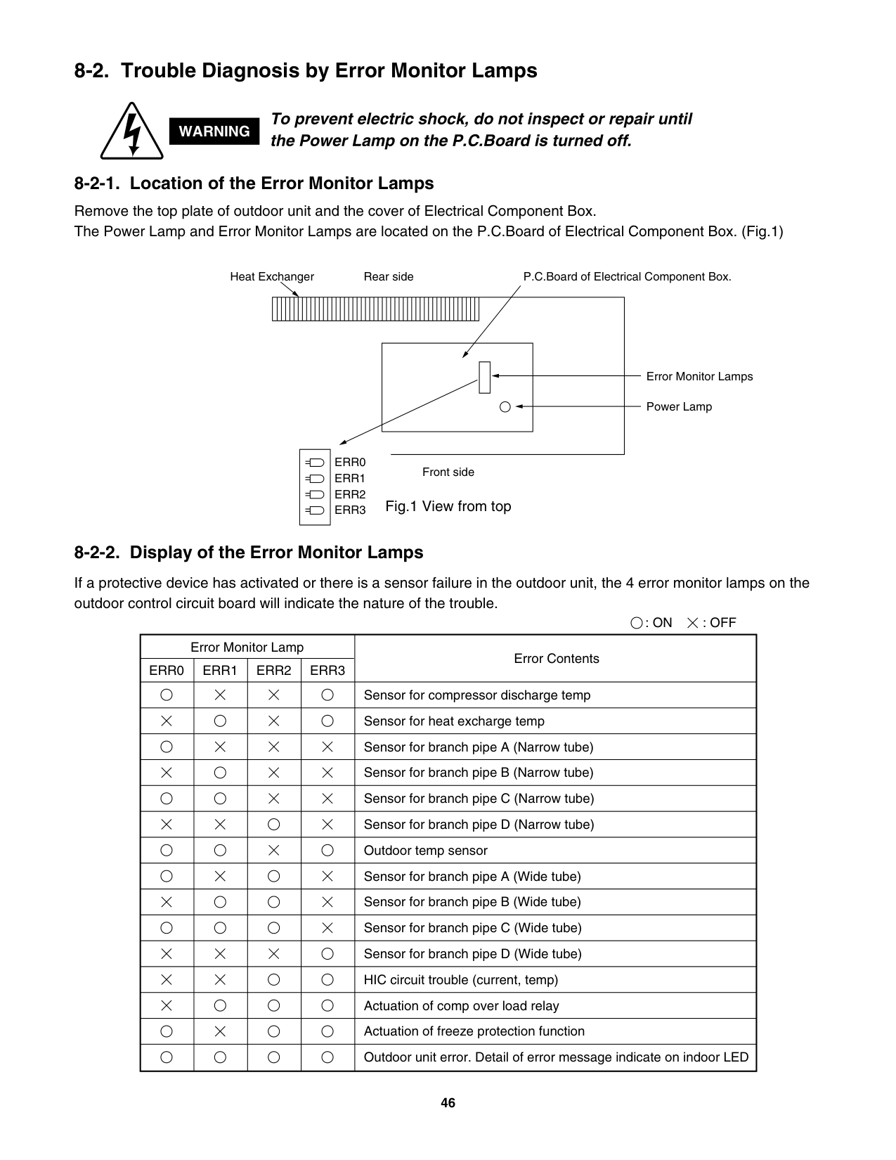
| | | | |Sensor for branch pipe A (Narrow tube)| | | | | |Sensor for branch pipe B (Narrow tube)| | | | | |Sensor for branch pipe C (Narrow tube)| | | | | |Sensor for branch pipe D (Narrow tube)| | | | | |Outdoor temp sensor| | | | | |Sensor for branch pipe A (Wide tube)| | | | | |Sensor for branch pipe B (Wide tube)| | | | | |Sensor for branch pipe C (Wide tube)| | | | | |Sensor for branch pipe D (Wide tube)| | | | | |HIC circuit trouble (current, temp)| | | | | |Actuation of comp over load relay| | | | | |Actuation of freeze protection function| | | | | |Outdoor unit error. Detail of error message indicate on indoor LED|
######## 8-3. Checking the Outdoor System
|No.|Work procedure|Check items (unit operation)| |---|---|---| |1|Apply 220 V AC between terminals L1 and L2 on the outdoor unit terminal plate.
•|The LED (red) on the control board must illuminate.•| |2|Short-circuit the T-RUN terminal to the COM terminal of TEST/T-RUN terminals.
•|The compressor and fan motor must turn ON. (They turn ON about (70) seconds later after the power is turned ON.)
•|
NOTE If the above check items are okay, but the outdoor unit does not operate, there may be a faulty
connection between the indoor unit and the outdoor unit.
######## 8-4. Trouble Diagnosis of Each Part
|Problems
Inspection points|Problems
Inspection points|Indoor unit|Indoor unit|Indoor unit|Indoor unit|Outdoor unit|Outdoor unit|Outdoor unit|Outdoor unit|Outdoor unit|Outdoor unit|Others|No. of Inspection Points for Each part| |---|---|---|---|---|---|---|---|---|---|---|---|---|---| |Problems
Inspection points|Problems
Inspection points|Indoor unit does not operate.|Operation lamp blinking.|Operation lamp does not illuminate.|Indoor fan dose not turn.|Outdoor unit does not operate.|Outdoor fan dose not turn.|The compressor (only) does not
operate.|The compressor stops on occasion.|The compressor speed does not
increase.|The electric expansion valve does
not operate.|Does not cool or cooling
performance is inadequate.|No. of Inspection Points for Each part| |Self-Diagnostics check|Self-Diagnostics check| | | | | | | | | | | | | |Indoor unit|Indoor controller (control unit)| | | | | | | | | | | | | |Indoor unit|Indoor fan motor| | | | | | | | | | | | | |Indoor unit|Room temperature sensor| | | | | | | | | | | | | |Indoor unit|Heat exchanger temperature sensor| | | | | | | | | | | | | |Indoor unit|Inter-unit cable| | | | | | | | | | | | | |Indoor unit|Switch circuit board| | | | | | | | | | | | | |Outdoor unit|Outdoor control circuit board| | | | | | | | | | | |(1)| |Outdoor unit|Diode module| | | | | | | | | | | | | |Outdoor unit|HIC| | | | | | | | | | | | | |Outdoor unit|Electrolytic capacitor| | | | | | | | | | | | | |Outdoor unit|Fuse| | | | | | | | | | | |(2)| |Outdoor unit|Compressor| | | | | | | | | | | |(3)| |Outdoor unit|Compressor protective sensor| | | | | | | | | | | |(4)| |Outdoor unit|Outdoor fan motor| | | | | | | | | | | | | |Outdoor unit|Coil thermistor| | | | | | | | | | | |(5)| |Outdoor unit|Electric expansion valve| | | | | | | | | | | |(6)| |Outdoor unit|Branch tubing temperature sensor| | | | | | | | | | | |(7)|
|Problems
Inspection points|Problems
Inspection points|Indoor unit|Indoor unit|Indoor unit|Indoor unit|Outdoor unit|Outdoor unit|Outdoor unit|Outdoor unit|Outdoor unit|Outdoor unit|Others|No. of Inspection Points for Each part| |---|---|---|---|---|---|---|---|---|---|---|---|---|---| |Problems
Inspection points|Problems
Inspection points|Indoor unit does not operate.|Operation lamp blinking.|Operation lamp does not illuminate.|Indoor fan dose not turn.|Outdoor unit does not operate.|Outdoor fan dose not turn.|The compressor (only) does not
operate.|The compressor stops on occasion.|The compressor speed does not
increase.|The electric expansion valve does
not operate.|Does not cool or cooling
performance is inadequate.|No. of Inspection Points for Each part| |Others|Breaker| | | | | | | | | | | |(8)| |Others|Refrigerant gas pressure| | | | | | | | | | | |(9)|
############# 8-4-2. Inspection Points for Each Part
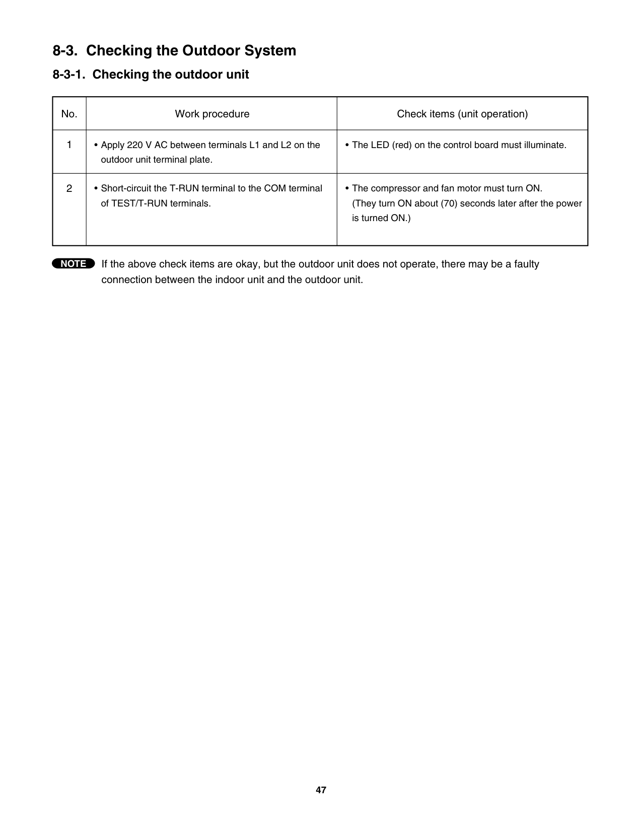
Do not remove or insert the outdoor control circuit board connector when power is being supplied to it. (The controller will be damaged.)
############################ NOTE
####################### (6) Electric expansion valve
######################## When replacing the electric expansion valve and coil, be sure to attach the connectors in the correct positions. Labels are applied to the valve body and coil, corresponding to the connector colors, to identify them.
| |Use a multi-meter to measure the voltage (12 V).
|Model No.|Sequence| |---|---| |CM1972|MV0 MV1 MV2
| |CM2472 CM3172|MV0 MV1 MV2 MV3
|
When the power is turned ON, the needle will move in the following seguence in approximately 10 to 20 seconds for each point.
| |---|---| | |Use a multi-meter to measure the voltage (12 V).
|Model No.|Sequence| |---|---| |CM1972|MV0 MV1 MV2
| |CM2472 CM3172|MV0 MV1 MV2 MV3
|
When the power is turned ON, the needle will move in the following seguence in approximately 10 to 20 seconds for each point.
|
Controller check
Voltage varies
No voltage on circuit board
|Check the illumination of the red Power Lamp.| |---|
| |Check the resistance between the gray lead wire and the other wires. Resistance is OK if it is 46 + / – 4ohm at 68 °F| |---|---| | |Check the resistance between the gray lead wire and the other wires. Resistance is OK if it is 46 + / – 4ohm at 68 °F|
Check the coil resistance.
0 ohm
Approx. 46 +/– 4 ohm
|Replace the controller.| |---|
*1
|Cool the main unit with a damp cloth or other means while welding. When applying vacuum, use the special service magnet and rotate at least 5 revolutions counterclockwise to fully open the electric expansion valve.
NOTE| | |---|---| |Cool the main unit with a damp cloth or other means while welding. When applying vacuum, use the special service magnet and rotate at least 5 revolutions counterclockwise to fully open the electric expansion valve.
NOTE| |
|Replace the coil.| |---|
Use the special service magnet and rotate 5 revolutions clockwise to fully close the valve. Then start the unit and measure the temperature at the inlet and outlet tubes of the electric expansion valve. If the temperature difference is large, the valve is closed. Then rotate 5 revolutions counterclockwise to open the valve. Operation is normal if the temperature difference between the 2 tubes drops.
Open and close the electric expansion valve by hand to check it.
No temperature change Temperature changes
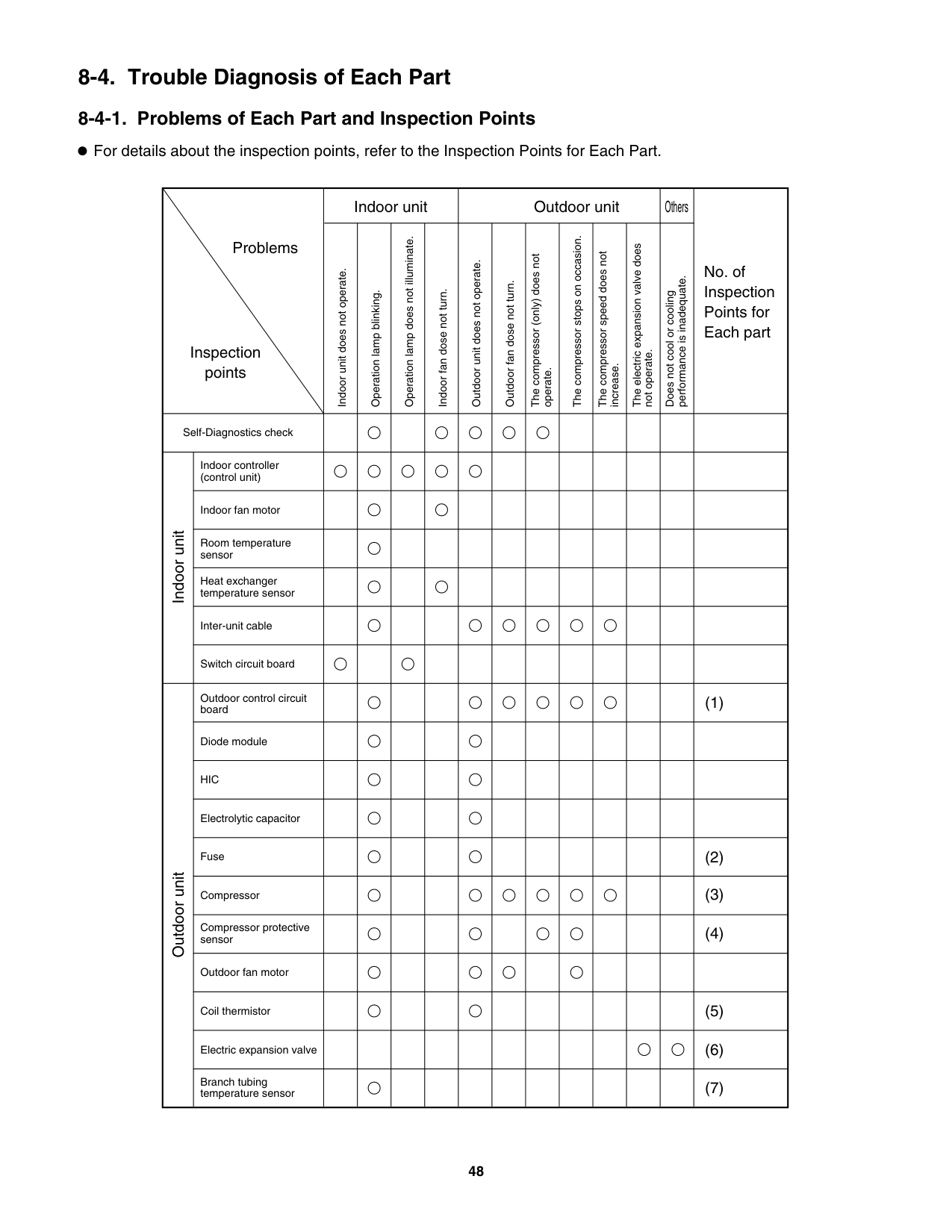
|Replace the electric expansion valve.| |---|
|This part is normal. Check elsewhere.| |---|
*1 If you have manually checked the electric expansion valve, be sure to reapply the outdoor power after you have replaced the wiring. (The position of the elecric expansion valve will changed.)
Check that the breakers and fuses used are of the specified capacity. Check that the breaker and its line are exclusive for A/C use.
Start a COOL test run, and messure the temperatures of the A/C intake air and discharge air. Compare the values with the performance charts.
If the values are higher than the performance charts: Check for refrigerant shortage or blockage of the refrigerant circuit.
< Assessment of refrigerant shortage >
< Distinguishing between refrigerant shortage and refrigerant circuit blockage > If the pressure in the low-pressure section does not change when the circuit is charged 2 to 3 times with refrigerant gas (0.44 lbs each time), or if the change is small, then the problem may not be refrigerant shortage.
The problem may be a blockage of the refrigerant circuit.
############# 8-5. Trouble Diagnosis of Fan Motor
This outdoor DC fan motor contains an internal control PCB. Therefore, it is not possible to measure the coil resistance, and the following procedure should be used to check the motor. Perform the trouble diagnosis by Test Run mode described on Installation Instructions of indoor unit.
Important: (A) Turn OFF the power before connecting or disconnecting the motor connectors.
(B) When performing voltage measurement at the outdoor controller connector for (3) in the table below, the DC motor will trip and voltage output will stop approximately 10 seconds after operation is started. For this reason, to measure the voltage again, first turn OFF the outdoor unit power, then, measure the voltage in Test Run mode.
(Diagnostic results) All of the above measured values are normal. Fan motor trouble (Replace the motor.) Any one of the above measured values is not normal. Outdoor unit controller trouble
(Replace the controller .) (Reference) DC motor connector pin arrangement
|Measurement location|Normal value| |---|---| |(1) Vm-Gnd: Between pin 1 and pin 4|DC 230V or more| |(2) Vcc-Gnd: Between pin 5 and pin 4|DC 14V or more| |(3) Vsp-Gnd: Between pin 7 and pin 4|After fluctuating 4 times between DC 1.7 to 6.1V (1 sec. ON) and DC 0 V (1 sec. OFF), the DC motor trips.|
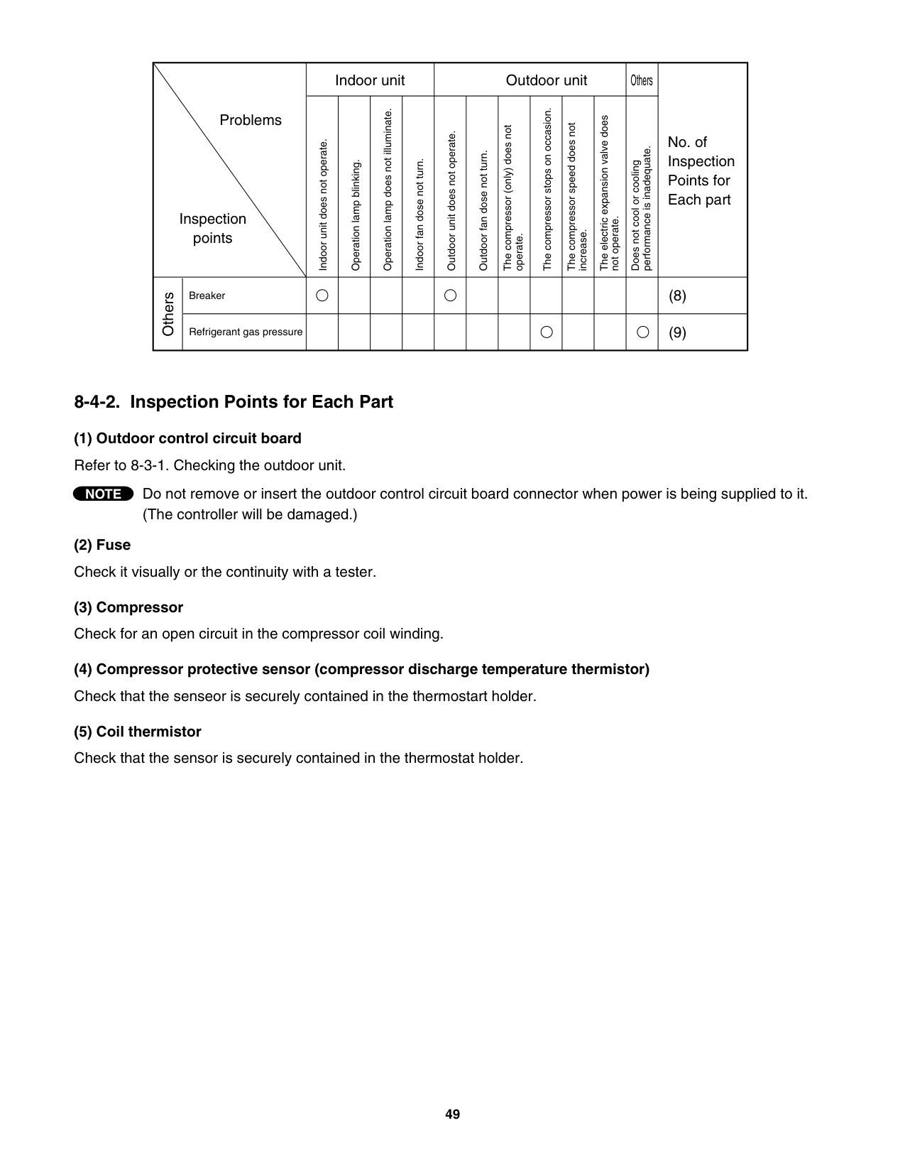
(Remedy for symptom 3 to 5) It is not possible to identify whether the trouble is outdoor unit controller trouble or motor trouble. Therefore, first replace the outdoor unit controller, then (if necessary) replace the DC motor.
##### 9. REFRIGERANT R410A:SPECIAL PRECAUTIONS WHEN SERVICING UNIT
######## 9-1. Characteristics of New Refrigerant R410A
############# 9-1-1. What is New Refrigerant R410A?
R410A is a new refrigerant that contains two types of pseudo-non-azeotropic refrigerant mixture. Its refrigeration capacity and energy efficiency are about the same level as the conventional refrigerant, R22.
############# 9-1-2. Components (mixing proportions)HFC32 (50%) / HFC125 (50%)9-1-3. Characteristics
Less toxic, more chemically stable refrigerant The composition of refrigerant R410A changes whether it is in a gaseous phase or liquid phase. Thus, when there is a refrigerant leak the basic performance of the air conditioner may be degraded because of a change in composition of the remaining refrigerant. Therefore, do not add new refrigerant.Instead, recover the remaining refrigerant with the refrigerant recovery unit. Then, after evacuation, totally recharge the specified amount of refrigerant with the new refrigerant at its normal mixed composition state (in liquid phase). When refrigerant R410A is used, the composition will differ depending on whether it is in gaseous or liquid phase, and the basic performance of the air conditioner will be degraded if it is charged while the refrigerant is in gaseous state. Thus, always charge the refrigerant while it is in liquid phase.
|CAUTION| |---|
Ether-type oil is used for compressor oil for R410A-type units, which is different from the mineral oil used for R22. Thus more attention to moisture prevention and faster replacement work compared with conventional models are required.
######## 9-2. Checklist before Servicing
Use a clutch-type flare tool for R410A or the conventional flare tool. Note that sizes of the resultant flares differ between these two tools. Where a conventional flare tool is used, make sure to observe A Specification (amount of extrusion) by using the flare spacer.
|Diameter of tube D|Specification A|Specification A| |---|---|---| |Diameter of tube D|Flare tool for R410A|Conventional flare tool (for R22)| |Dia.1/4" (6.35 mm)|0 to 0.0196" (0 to 0.5 mm)|0.0472" (1.2 mm)| |Dia.3/8" (9.52 mm)|0 to 0.0196" (0 to 0.5 mm)|0.0472" (1.2 mm)| |Dia.1/2" (12.7 mm)|0 to 0.0196" (0 to 0.5 mm)|0.0472" (1.2 mm)| |Dia.5/8" (15.88 mm)|0 to 0.0196" (0 to 0.5 mm)|0.0472" (1.2 mm)|
####################### Size of flare
Spacer
D
D
A
A
| | | | |---|---|---| | | | |
Flare tool for R410A
Conventional flare tool (R22)
Tubing precautions Refrigerant R410A is more easily affected by dust or moisture compared with R22, thus be sure to temporarily cover the ends of the tubing with caps or tape prior to installation. Never use 0.0276" (0.7 mm)-thick copper tubing or tubing which is less than 0.0315" (0.8 mm) in thickness, since air conditioners with R410A are subject to higher pressure than those using R22 and R407C. No addition of compressor oil for R410A No additional charge of compressor oil is permitted. No use of refrigerant other than R410A Never use a refrigerant other than R410A. If refrigerant R410A is exposed to fire
Through welding, etc., toxic gas may be released when R410A refrigerant is exposed to fire. Therefore, be sure to provide ample ventilation during installation work.
Caution in case of R410A leak Check for possible leak points with the special leak detector for R410A. If a leak occurs inside the room, immediately provide thorough ventilation.
######## 9-3. Tools Specifically for R410A
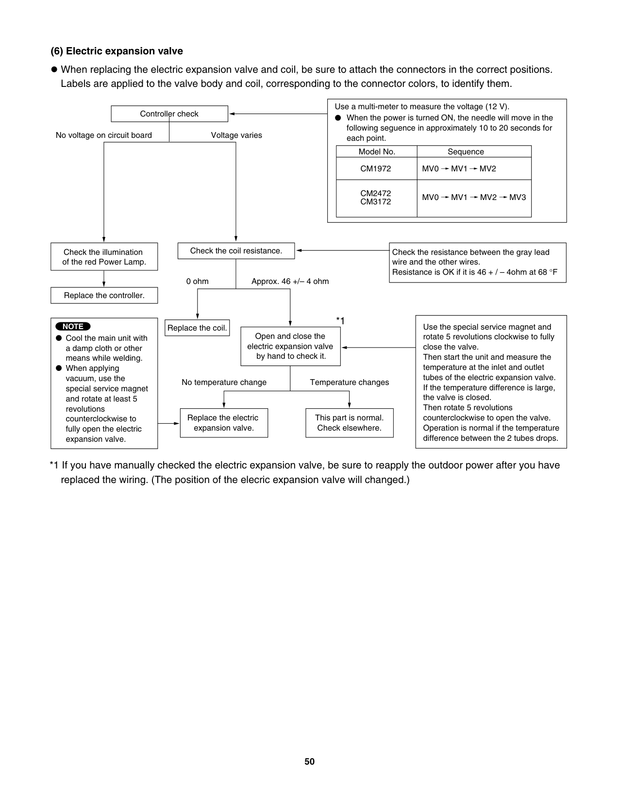
For servicing, use the following tools for R410A
|Tool Distinction|Tool Name| |---|---| |Tools specifically for R410A|Gauge manifold Charging hose Gas leak detector Refrigerant cylinder Charging cylinder Refrigerant recovery unit Vacuum pump with anti-reverse flow (*1) (Solenoid valve-installed type, which prevents oil from flowing back into the unit when the power is off, is recommended.) Vacuum pump (*2)...can be used if the following adapter is attached. Vacuum pump adapter (reverse-flow prevention adapter) (*3). (Solenoid valve-installed adapter attached to a conventional vacuum pump.) Electronic scale for charging refrigerant Flare tool| |Tools which can be commonly used for R22, R407C, and R410A|Bender Torque wrench Cutter, reamer Welding tool, nitrogen gas cylinder|
The above tools specifically for R410A must not be used for R22 and R407C. Doing so will cause malfunction of the unit. For the above vacuum pump (*1, *2) and vacuum pump adapter (*3), those for R22-type units can be used for R410A-type. However, they must be used exclusively for R410A and never alternately with R22 and R407C.
|CAUTION| |---|
To prevent other refrigerants (R22, R407C) from being mistakenly charged to this unit, shape and external diameter of the service port screw has been altered.
######## 9-4. Tubing Installation Procedures
################### When the tubes are connected, always apply HAB oil on the flare portions to improve the sealing of tubing.
The following is the HAB oil generally used: Esso: ZERICE S32
############################ NOTE
For details on tubing installation procedures, refer to the installation manuals attached to the indoor unit and outdoor unit.
######## 9-5. In Case of Compressor Malfunction
Should the compressor malfunction, be sure to make the switch to a replacement compressor as quickly as possible. Use only the tools indicated exclusively for R410A. See "9-3. Tools Specifically for R410A."
|CAUTION| |---|
############# 9-5-1. Procedure for Replacing Compressor
####################### (1) Recovering refrigerant
Any remaining refrigerant inside the unit should not be released to the atmosphere, but recovered using the refrigerant recovery unit for R410A. Do not reuse the recovered refrigerant, since it will contain impurities.
####################### (2) Replacing Compressor
Soon after removing seals of both discharge and suction tubes of the new compressor, replace it quickly.
####################### (3) Checking for sealing
Use nitrogen gas for the pressurized gas, and never use a refrigerant other than R410A. Also do not use oxygen or any flammable gas.
####################### (4) Evacuation
Use a solenoid valve-installed vacuum pumpso that even if power is cut off in the middle of evacuation of air due to a power interruption, the valve will prevent the pump oil from flowing back. The equipment may be damaged if moisture remains in the tubing, thus carry out the evacuation thoroughly. When using a vacuum pump with exhaust air volume more than 0.883 cu.ft./min. and ultimate vacuum pressure rate of 50 micron Hg.
OK
OK
Standard time for evacuation
|Length of tubing|Less than 33 ft. (10 m)|More than 33 ft. (10 m)| |---|---|---| |Evacuation time|More than 10 minutes|More than 15 minutes|
Be sure to charge the specified amount of refrigerant in liquid stateusing the service port of the wide tube service valve. The proper amount is listed on the unit's nameplate.
When the entire amount cannot be charged all at once, charge gradually while operating the unit in Cooling Operation.
Never charge a large amount of liquid refrigerant at once to the unit. This may cause damage to the compressor.
|CAUTION| |---|
When charging with a refrigerant cylinder, use an electronic scale for charging refrigerant. In this case, if the volume of refrigerant in the cylinder becomes less than 20% of the fully-charged amount, the composition of the refrigerant starts to change. Thus, do not use the refrigerant if the amount in the charging cylinder is less than 20%.
Also, charge the minimum necessary amount to the charging cylinder before using it to charge the air conditioning unit.
Example: In case of charging refrigerant to a unit requiring 1.68 lb. (0.76 Kg) using a capacity of a 22 lb. (10 Kg) cylinder, the minimum necessary amount for the cylinder is:
1.68 + 22 0.20 = 6.08 lb. (0.76 + 10 0.20 = 2.76 Kg)
################### For the remaining refrigerant, refer to the instructions of the refrigerant manufacturer.
If using a charging cylinder, transfer the specified amount of liquid refrigerant from the refrigerant cylinder to the charging cylinder. Prepare an evacuated charging cylinder beforehand.
To prevent the composition of R410A from changing, never bleed the refrigerant gas into the atmosphere while transferring the refrigerant. (Fig. 3)
|CAUTION| |---|
Do not use the refrigerant if the amount in the charging cylinder is less than 20%.
Configuration and characteristics of cylinders
Valve
Liquid
Single valve Charge liquid refrigerant with cylinder in up-side-down position.
Valve
Liquid
Single valve (with siphon tube) Charge with cylinder in normal position.
NO!
Charging cylinder
Liquid
Open Refrigerant
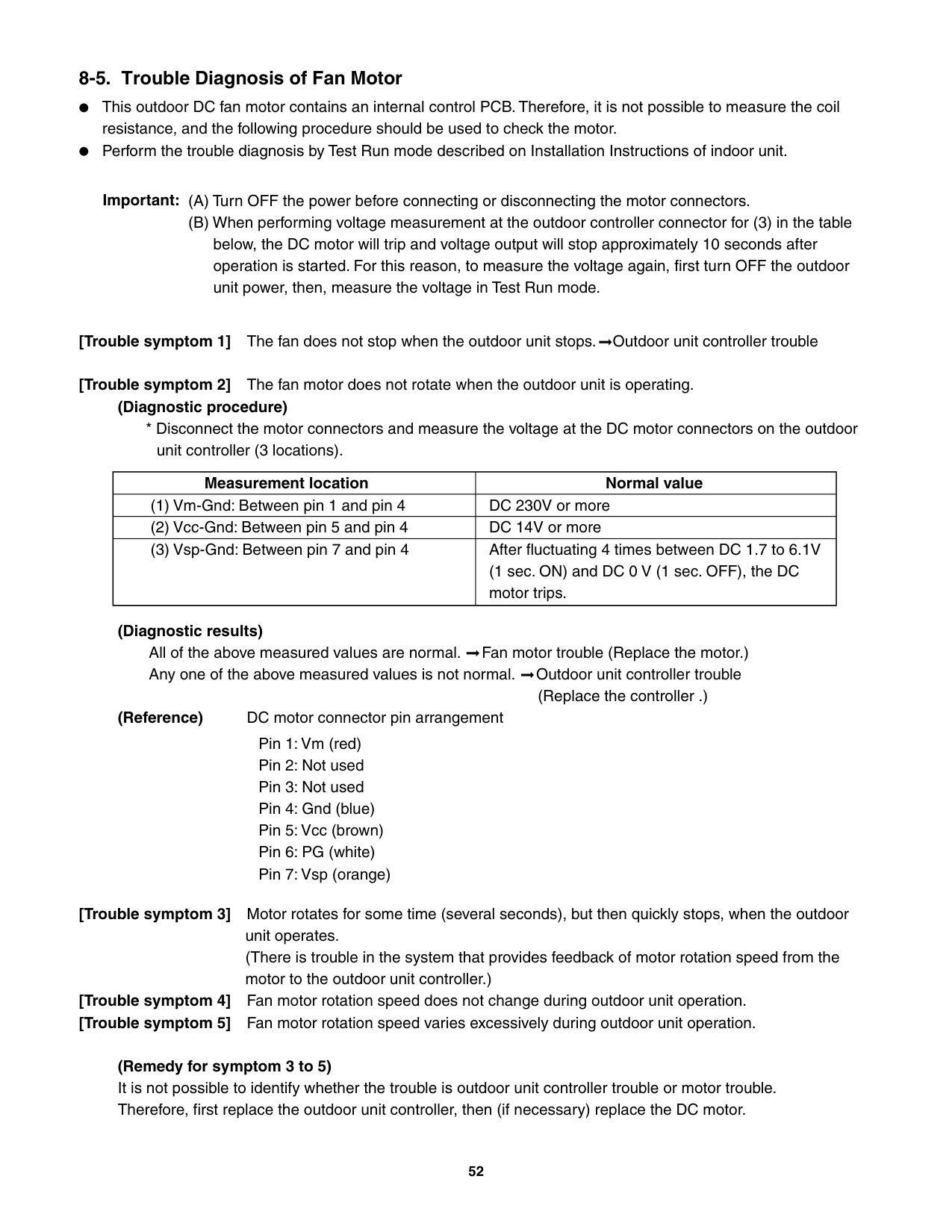
cylinder
######## 9-6. In Case Refrigerant is Leaking
|CAUTION| |---|
Never attempt to charge additional refrigerant when refrigerant has been leaking from the unit. Follow the procedure described below to locate points of leaks and carry out repairs, then recharge the refrigerant.
Use the detector for R410A to locate refrigerant leak points.
Never release the gas to the atmosphere; recover residual refrigerant using the refrigerant recovery unit for R410A, instead. Do not reuse the recovered refrigerant because its composition will have been altered.
Confirm again that no residual refrigerant exists in the unit before starting welding. Weld securely using flux and wax for R410A.
Prevent oxide film from forming inside the tubes utilizing substitution with nitrogen (N2) in the refrigerant circuit of the unit. Leave ends of tubes open during welding.
Use nitrogen gas for the pressurized gas, and never use a refrigerant other than R410A. Also do not use oxygen or any flammable gas.
Use a solenoid valve-installed vacuum pumpso that even if power is cut off in the middle of evacuation of air due to a power interruption, the valve will prevent the pump oil from flowing back. The equipment may be damaged if moisture remains in the tubing, thus carry out the evacuation thoroughly. When using a vacuum pump with exhaust air volume more than 0.883 cu.ft./min. and ultimate vacuum pressure rate of 50 micron Hg.
Standard time for evacuation
(1) Detect leaks
OK
OK
OK
|Length of tubing|Less than 33 ft. (10 m)|More than 33 ft. (10 m)| |---|---|---| |Evacuation time|More than 10 minutes|More than 15 minutes|
Recharge unit in the same manner explained on the previous page "(5) Recharging."
######## 9-7. Charging Additional Refrigerant
Observe the proper amount of refrigerant as stated in this service manual or the installation manual that came with the indoor unit. Charge additional refrigerant in liquid state only.
9-8. Retro-Fitting Existing Systems
####################### Never charge additional refrigerant if refrigerant is leaking from the unit. Follow instructions given in "9-6. In Case Refrigerant is Leaking" and completely carry out repairs. Only then should you recharge the refrigerant.
|CAUTION| |---|
Never use new refrigerant R410A for existing units which use R22.This will cause the air conditioner to operate improperly and may result in a hazardous condition.
9-8-2. Use of Existing Tubing If replacing an older unit that used refrigerant R22 with a R410A unit, do not use its existing tubing.Instead, completely new tubing must be used.
|APPENDIX A| |---|
##### INSTALLATION INSTRUCTIONS
##### CM1972 CM2472 CM3172 (II-852-6-4190-214-00-3)
A-1
|For Outdoor Unit| |---|
INSTALLATION INSTRUCTIONS
###### – Inverter Multi Split System Air Conditioner – COOL/DRY Model
########### This air conditioner uses the new refrigerant R410A.
########### Refrigerant service valve size = 5/16"NOTE
############# Contents
|Model Combinations
Combine indoor and outdoor units only as listed below.
Indoor Unit Outdoor Unit KMS0772 CM1972 KMS0972 CM2472 KMS1272 CM3172 KMS1872 CLM1972 KMS2472 CLM2472
CLM3172
Combine indoor and outdoor units only as listed in the combination tables for 3-room or 4-room outdoor unit as shown in its respective manual.
Power Source: 60 Hz, single-phase, 230 / 208 VAC| |---|
Page
IMPORTANT! Please Read Before Starting .................................. 2
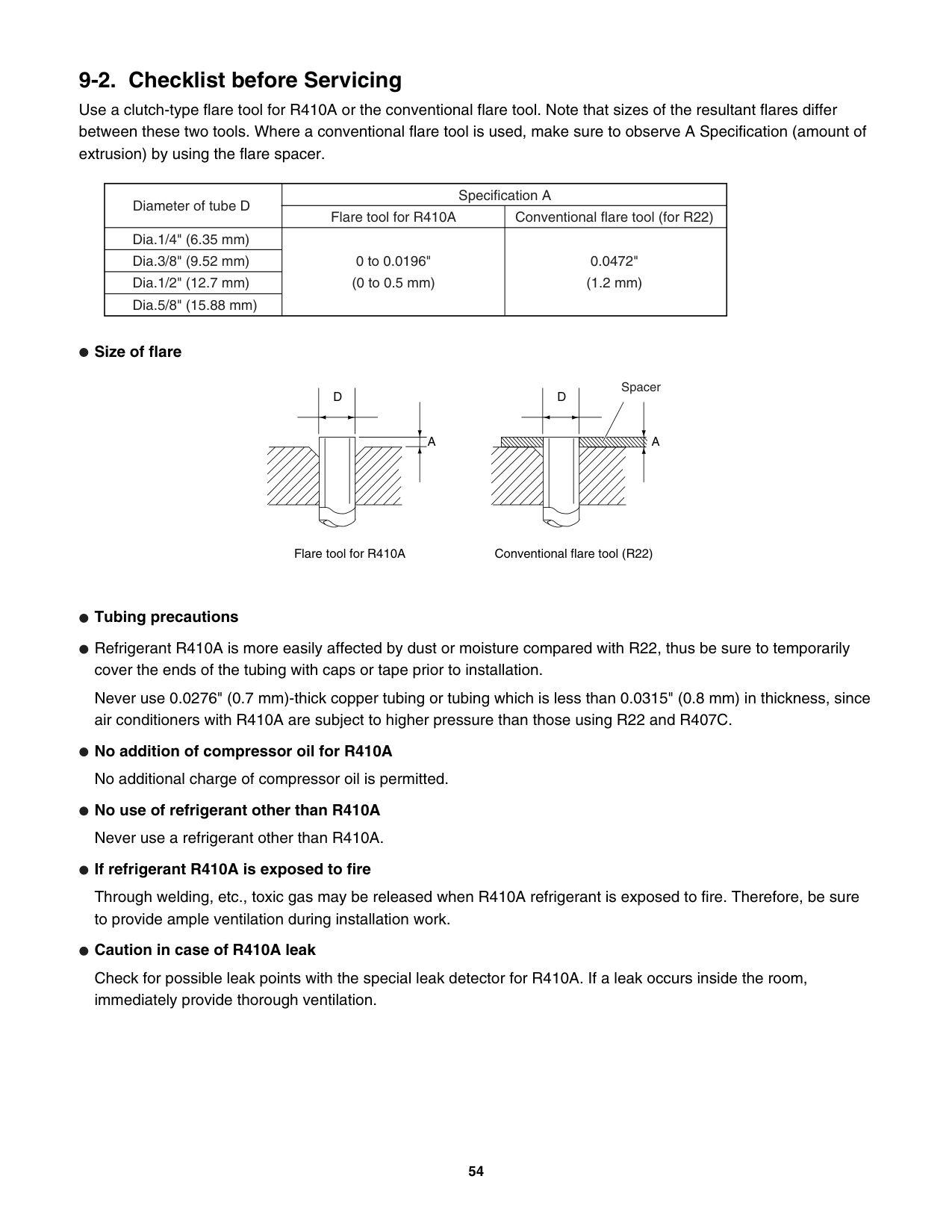
|Be sure to read the yellow instruction sheet attached to the outdoor unit for models using the new refrigerant R410A.| |---|
Combination example
Indoor unit B
Indoor unit A
Indoor unit C
Outdoor unit
Indoor unit D
NOTE
The illustrations are based on the typical appearance of a standard model. Consequently, the shape may differ from that of the air conditioner that you are installing.
SANYO Commercial Solutions In Canada A Division of SANYO North America Corporation SANYO Canada Inc. Cornerstone Business Park, 1-300 Applewood Crescent, Concord 1062 Thorndale Avenue, Ontario, L4K 5C7, Canada Bensenville, IL 60106, U.S.A.
85264190214003 © SANYO 2007
######## IMPORTANT! Please Read Before Starting
This air conditioning system meets strict safety and operating standards. As the installer or service person, it is an important part of your job to install or service the system so it operates safely and efficiently.
For safe installation and trouble-free operation, you must:
Carefully read this instruction booklet before beginning. Follow each installation or repair step exactly as shown. Observe all local, state, and national electrical codes. Pay close attention to all warning and caution notices given in this manual.
This symbol refers to a hazard or unsafe practice which can result in severe personal injury or death. This symbol refers to a hazard or unsafe practice which can result in personal injury or product or property damage.
WARNING
|CAUTION| |---|
If Necessary, Get Help These instructions are all you need for most installation sites and maintenance conditions. If you require help for a special problem, contact our sales/service outlet or your certified dealer for additional instructions.
In Case of Improper Installation The manufacturer shall in no way be responsible for improper installation or maintenance service, including failure to follow the instructions in this document.
############# SPECIAL PRECAUTIONS
WARNING
When Wiring
ELECTRICAL SHOCK CAN CAUSE SEVERE PERSONAL INJURY OR DEATH. ONLY A QUALIFIED, EXPERIENCED ELECTRICIAN SHOULD ATTEMPT TO WIRE THIS SYSTEM.
################# When Transporting
Be careful when picking up and moving the indoor and outdoor units. Get a partner to help, and bend your knees when lifting to reduce strain on your back. Sharp edges or thin aluminum fins on the air conditioner can cut your fingers.
When Installing… …In a Ceiling or Wall
Make sure the ceiling/wall is strong enough to hold the unit’s weight. It may be necessary to construct a strong wood or metal frame to provide added support.
########################## …In a Room
Properly insulate any tubing run inside a room to prevent “sweating” that can cause dripping and water damage to walls and floors.
…In Moist or Uneven Locations Use a raised concrete pad or concrete blocks to provide a solid, level foundation for the outdoor unit. This prevents water damage and abnormal vibration. …In an Area with High Winds
Securely anchor the outdoor unit down with bolts and a metal frame. Provide a suitable air baffle. …In a Snowy Area (for Heat Pump-type Systems)
Install the outdoor unit on a raised platform that is higher than drifting snow. Provide snow vents.
################# When Connecting Refrigerant Tubing
################# Others
|CAUTION| |---|
############# 1. General
This booklet briefly outlines where and how to install the air conditioning system. Please read over the entire set of instructions for the indoor and outdoor units and make sure all accessory parts listed are with the system before beginning. If the electric wiring diagram does not appear in this manual, please check for the diagram on the indoor unit.
####################### 1-1. Tools Required for Installation (not supplied)
####################### 1-2. Accessories Supplied with Unit
1-3. Optional Copper Tubing Kit
Copper tubing for connecting the outdoor unit to the indoor unit is available in kits which contain the narrow and wide tubing, fittings and insulation. Consult your nearest sales outlet or A/C workshop.
1-4. Type of Copper Tube and Insulation Material
If you wish to purchase these materials separately from a local source, you will need:
Cut each tube to the appropriate lengths 1' to 1'4" (30 cm to 40 cm) to dampen vibration between units.
|Parts|Figure|Q’ty|Parts|Figure|Figure|Q’ty|Parts|Figure|Figure|Q’ty| |---|---|---|---|---|---|---|---|---|---|---| |Hex wrench| |1|Cushion rubber| | |4|Reducer (1/2" 3/8")
| |2472|1| |Hex wrench| |1|Cushion rubber| | |4|Reducer (1/2" 3/8")
| |3172|2| |Labels for inter-unit cable and tube|ABCD|4 each|Reducer (3/8" 1/2")| |1972|1|Packed in the outdoor unit.|Packed in the outdoor unit.|Packed in the outdoor unit.|Packed in the outdoor unit.|
Check local electrical codes and regulations before obtaining wire. Also, check any specified instructions or limitations.
|CAUTION| |---|
|Model|Narrow Tube|Narrow Tube|Wide Tube|Wide Tube| |---|---|---|---|---| |Model|Outer Dia.|Thickness|Outer Dia.|Thickness| |KMS0772|1/4" (6.35 mm)|0.0314" (0.8 mm)|3/8" (9.52 mm)|0.0314" (0.8 mm)| |KMS0972|1/4" (6.35 mm)|0.0314" (0.8 mm)|3/8" (9.52 mm)|0.0314" (0.8 mm)| |KMS1272|1/4" (6.35 mm)|0.0314" (0.8 mm)|3/8" (9.52 mm)|0.0314" (0.8 mm)| |KMS1872|1/4" (6.35 mm)|0.0314" (0.8 mm)|1/2" (12.70 mm)|0.0314" (0.8 mm)| |KMS2472|1/4" (6.35 mm)|0.0314" (0.8 mm)|5/8" (15.88 mm)|0.0393" (1.0 mm)|
####################### 1-5. Additional Materials Required for Installation
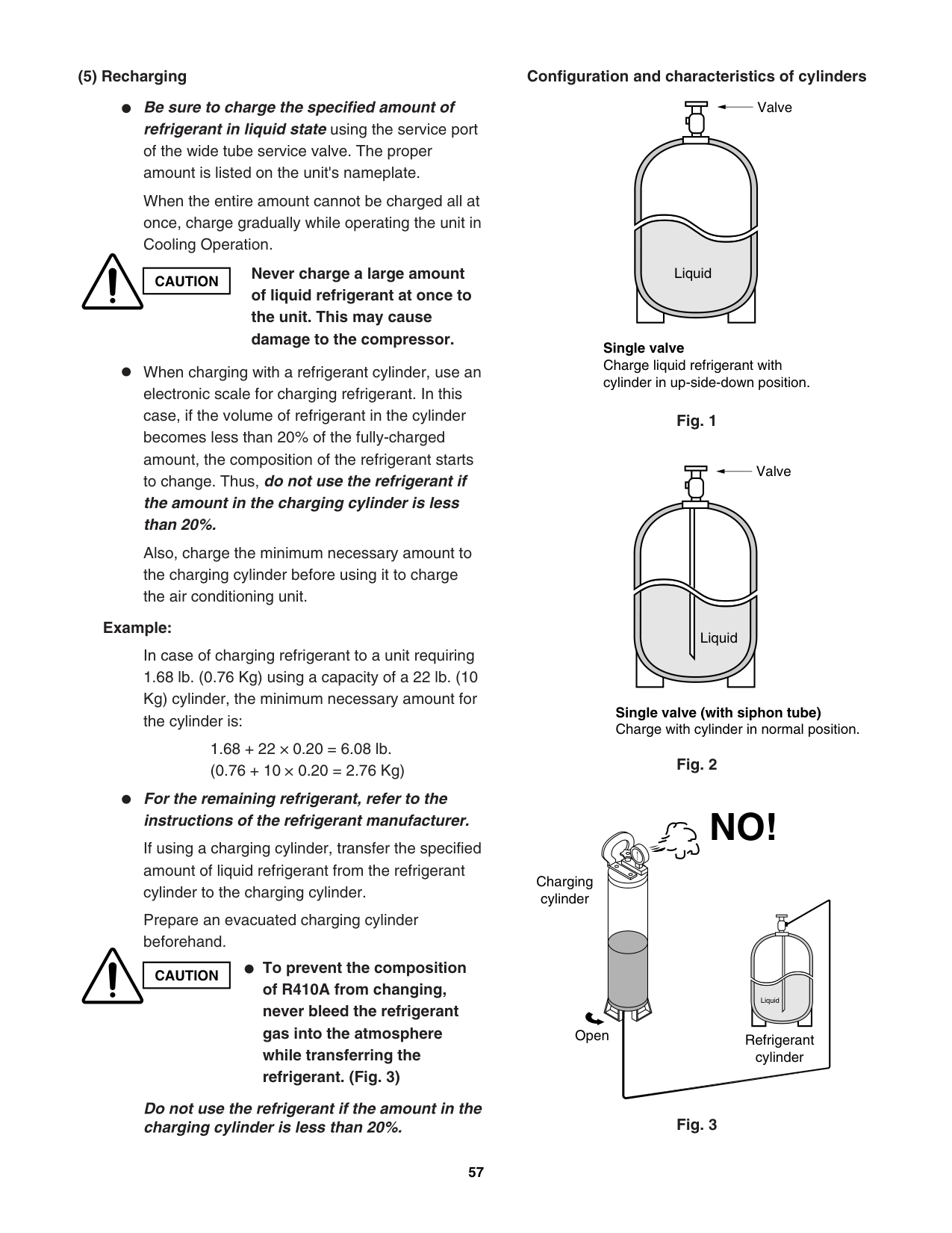
############# 2. Installation Site Selection
####################### 2-1. Indoor Unit
To prevent abnormal heat generation and the possibility of fire, do not place obstacles, enclosures and grilles in front of or surrounding the air conditioner in a way that may block air flow.
WARNING
AVOID: direct sunlight. nearby heat sources that may affect performance of the unit. areas where leakage of flammable gas may be expected. placing or allowing any obstructions near the A/C inlet or outlet. installing in rooms that contain instant-on (rapid-start) fluorescent lamps. (These may prevent the A/C from receiving signals.) places where large amounts of oil mist exist. installing in locations where there are devices that generate high-frequency emissions.
####################### DO:
select an appropriate position from which every corner of the room can be uniformly cooled. (High on a wall is best.)
Indoor unit
Drain hose
Outside drainage Fig. 1
6" (15 cm) min.
2" (5 cm) min.
2" (5 cm) min.
Front View
####################### Fig. 2
Tubing length (L1)
INDOOR UNIT (1)
INDOOR UNIT (2)
Elevation difference (H1)
OUTDOOR UNIT
H2
INDOOR UNIT (3)
H3H4
INDOOR UNIT (4)
select a location that will hold the weight of the unit. select a location where tubing and drain hose have the shortest run to the outside. (Fig. 1) allow room for operation and maintenance as well as unrestricted air flow around the unit. (Fig. 2) install the unit within the maximum elevation difference (H1, H2, H3, H4) above or below the outdoor unit and within a total tubing length (L1+L2+L3, L1+L2+L3+L4) from the outdoor unit as detailed in Table 3 and Fig. 3a.
Fig. 3a
|CAUTION| |---|
Indoor unit
Wall
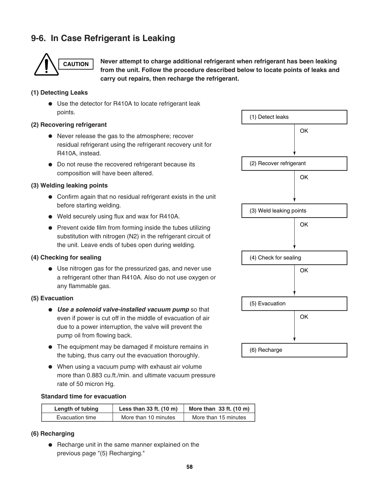
For stable operation of the air conditioner, do not install wall-mounted type indoor units less than 5' (1.5 m) from floor level.
Minimum height from floor level
5' (1.5 m)
Floor level
Fig. 3b
Install the indoor unit more than 3.3' (1 m) away from any antenna or power lines or connecting wires used for television, radio, telephone, security system, or intercom. Electrical noise from any of these sources may affect operation. install in a sturdy manner to avoid increased operating noise.
####################### Table 3
|Model|Max. Allowable Tubing Length per unit (ft.)|Max. Allowable Total Tubing Length at shipment (L1+L2+L3) or (L1+L2+L3+L4) (ft.)|Limit of Total Tubing Length (L1+L2+L3) or (L1+L2+L3+L4) (ft.)|Limit of Elevation Difference (H1, H2, H3, H4) (ft.)
|Required Amount of Additional Refrigerant (oz./ft.)*| |---|---|---|---|---|---| |CM1972/CLM1972|82|150 (L1+L2+L3)|150 (L1+L2+L3)|50|—| |CM2472/CLM2472|82|150 (L1+L2+L3+L4)|200 (L1+L2+L3+L4)|50|0.22| |CM3172/CLM3172|100|150 (L1+L2+L3+L4)|230 (L1+L2+L3+L4)|50|0.22|
No additional charge of compressor oil is necessary. For more detailed charging information, refer to the Technical & Service Manual.
####################### 2-2. Connecting Indoor Units
(1) Connecting indoor unit for CM1972/CLM1972
(A)
Outdoor unit Indoor unit
3/8"(9.52mm)
C
(KMS0772,KMS0972,KMS1272)
3/8"(9.52mm)
1/4"(6.35mm)
3/8"(9.52mm)
B
(KMS0772,KMS0972,KMS1272)
3/8"(9.52mm)
1/4"(6.35mm)
3/8"(9.52mm)
A
(KMS0772,KMS0972,KMS1272)
3/8"(9.52mm)
1/4"(6.35mm)
Fig. 4a
(B)
Outdoor unit Indoor unit
3/8"(9.52mm)
C
(KMS0772,KMS0972,KMS1272)
3/8"(9.52mm)
1/4"(6.35mm)
3/8"(9.52mm)
B
(KMS0772,KMS0972,KMS1272)
3/8"(9.52mm)
1/4"(6.35mm)
1/2"(12.70mm)
A
(KMS1872)
3/8"(9.52mm)
1/4"(6.35mm)
Flare 3/8"(9.52mm)
Union 1/2"(12.70mm)
A joint for connecting tubes of different sizes (3/8"(9.52mm) 1/2"(12.70mm)) Supplied Reducer
Fig. 4b
(A)
Outdoor unit Indoor unit
3/8"(9.52mm)
D
(KMS0772,KMS0972,KMS1272)
3/8"(9.52mm)
1/4"(6.35mm)
3/8"(9.52mm)
C
(KMS0772,KMS0972,KMS1272)
3/8"(9.52mm)
1/4"(6.35mm)
3/8"(9.52mm)
B
(KMS0772,KMS0972,KMS1272)
3/8"(9.52mm)
1/4"(6.35mm)
3/8"(9.52mm)
A
(KMS0772,KMS0972,KMS1272) 1/2"(12.70mm)
1/4"(6.35mm)
Union 3/8"(9.52mm)Flare 1/2"(12.70mm) (1/2"(12.70mm) 3/8"(9.52mm)) Supplied Reducer
Fig. 4c
Fig. 4d
C
B
A
(KMS0772,KMS0972,KMS1272)
(KMS0772,KMS0972,KMS1272)
D
Outdoor unit Indoor unit
(KMS0772,KMS0972,KMS1272)
(KMS1872) 1/2"(12.70mm)
1/2"(12.70mm)
3/8"(9.52mm)
3/8"(9.52mm)
3/8"(9.52mm)
3/8"(9.52mm)
3/8"(9.52mm)
3/8"(9.52mm)
1/4"(6.35mm)
1/4"(6.35mm)
1/4"(6.35mm)
1/4"(6.35mm)
(D)
Fig. 4f
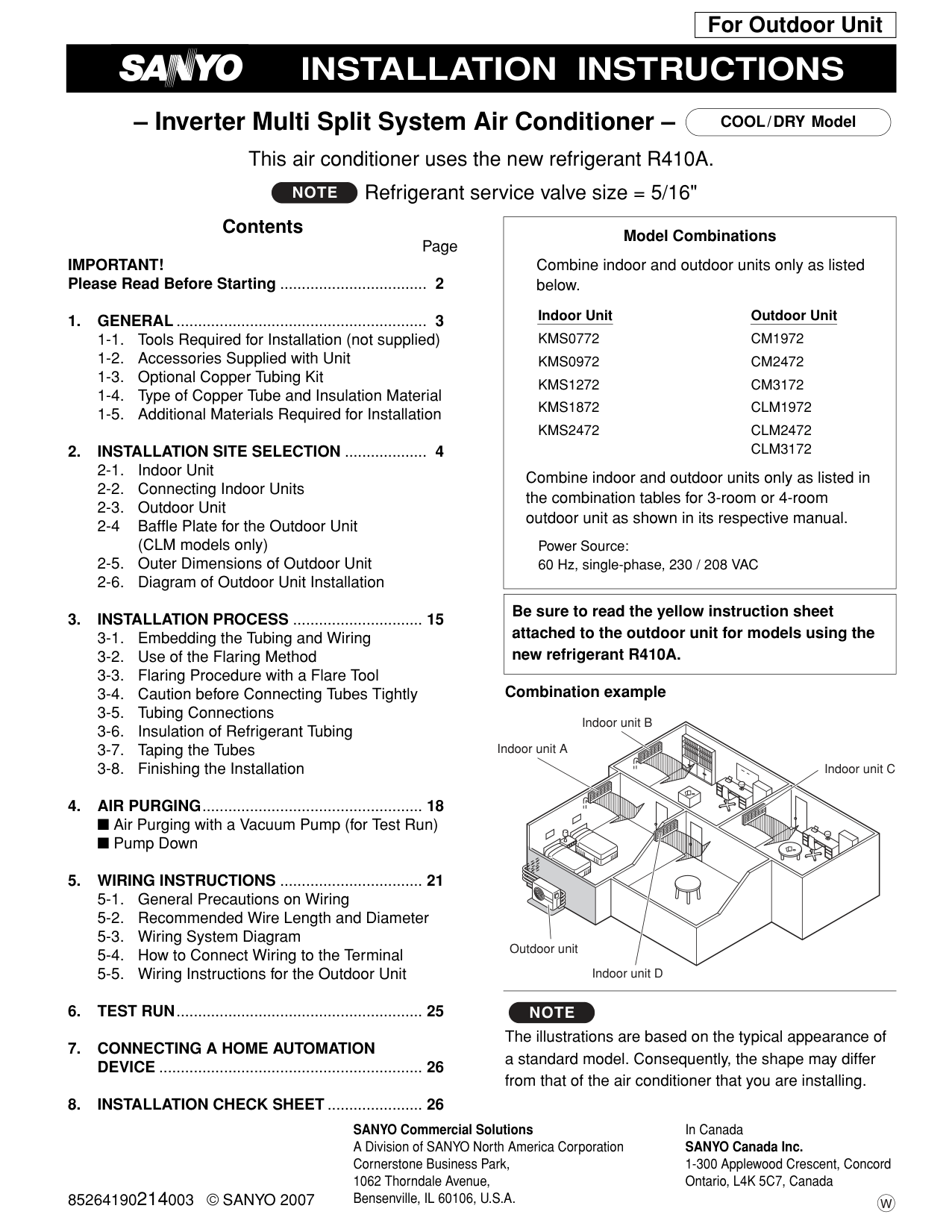
Union 5/8"(15.88mm)Flare 1/2"(12.70mm)
(1/2"(12.70mm) 5/8"(15.88mm)) Locally purchased
C
B
A
(KMS1872)
(KMS0772,KMS0972,KMS1272)
D
Outdoor unit Indoor unit
(KMS0772,KMS0972,KMS1272)
(KMS2472)
Union 1/2"(12.70mm)Flare 3/8"(9.52mm)
(3/8"(9.52mm) 1/2"(12.70mm)) Locally purchased
1/2"(12.70mm)
1/2"(12.70mm)
5/8"(15.88mm)
3/8"(9.52mm)
3/8"(9.52mm)
3/8"(9.52mm)
3/8"(9.52mm)
3/8"(9.52mm)
1/4"(6.35mm)
1/4"(6.35mm)
1/4"(6.35mm)
1/4"(6.35mm)
Outdoor unit Indoor unit
3/8"(9.52mm)
D
(KMS0772,KMS0972,KMS1272)
3/8"(9.52mm)
1/4"(6.35mm)
3/8"(9.52mm)
C
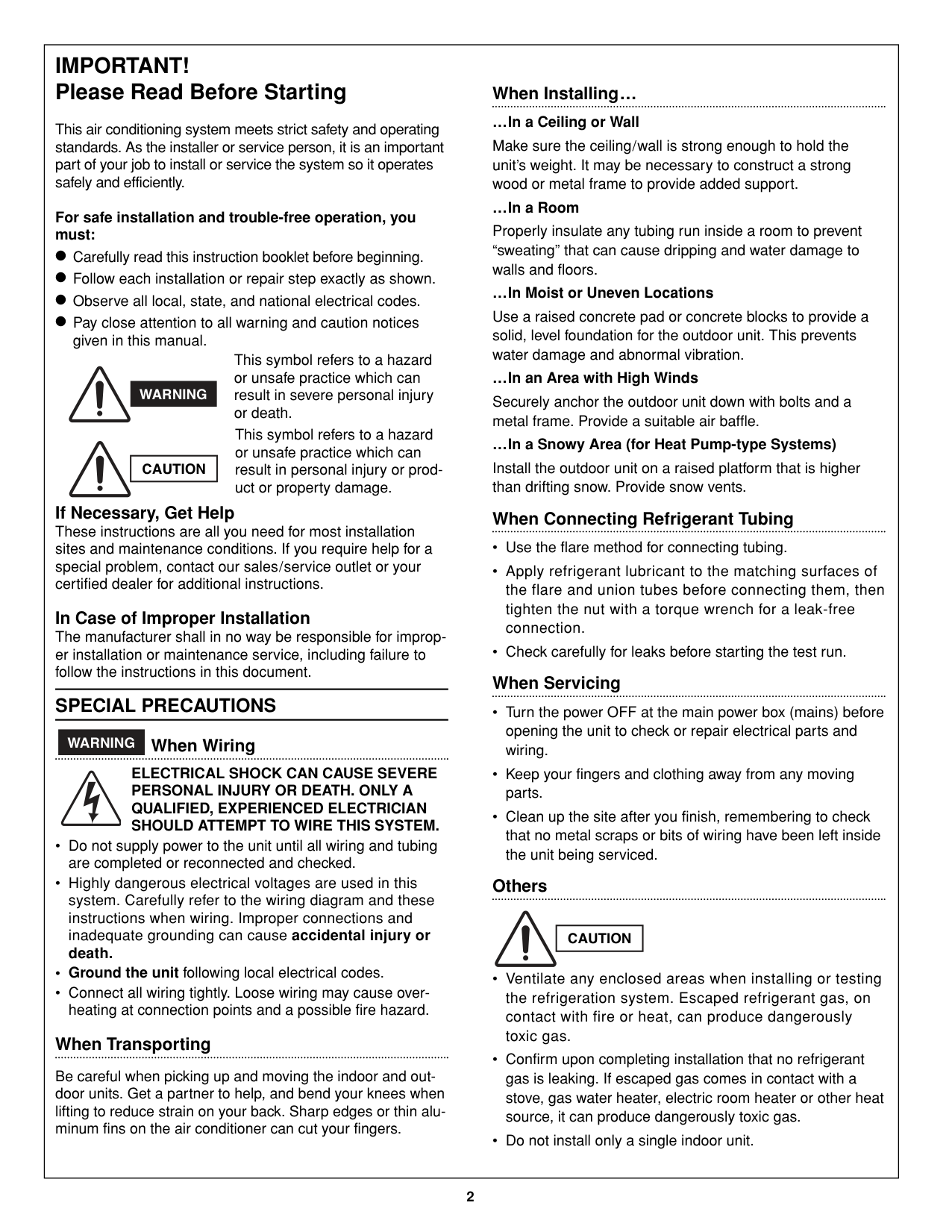
(KMS0772,KMS0972,KMS1272)
3/8"(9.52mm)
1/4"(6.35mm)
3/8"(9.52mm)
B
(KMS0772,KMS0972,KMS1272)
3/8"(9.52mm)
1/4"(6.35mm)
5/8"(15.88mm)
A
(KMS2472) 1/2"(12.70mm)
1/4"(6.35mm)
Union 5/8"(15.88mm)Flare 1/2"(12.70mm) (1/2"(12.70mm) 5/8"(15.88mm)) Locally purchased
Fig. 4e
(A)
Outdoor unit Indoor unit
3/8"(9.52mm)
D
(KMS0772,KMS0972,KMS1272)
3/8"(9.52mm)
1/4"(6.35mm)
3/8"(9.52mm)
C
(KMS0772,KMS0972,KMS1272)
3/8"(9.52mm)
1/4"(6.35mm)
3/8"(9.52mm)
B
(KMS0772,KMS0972,KMS1272)
1/2"(12.70mm)
1/4"(6.35mm)
3/8"(9.52mm)
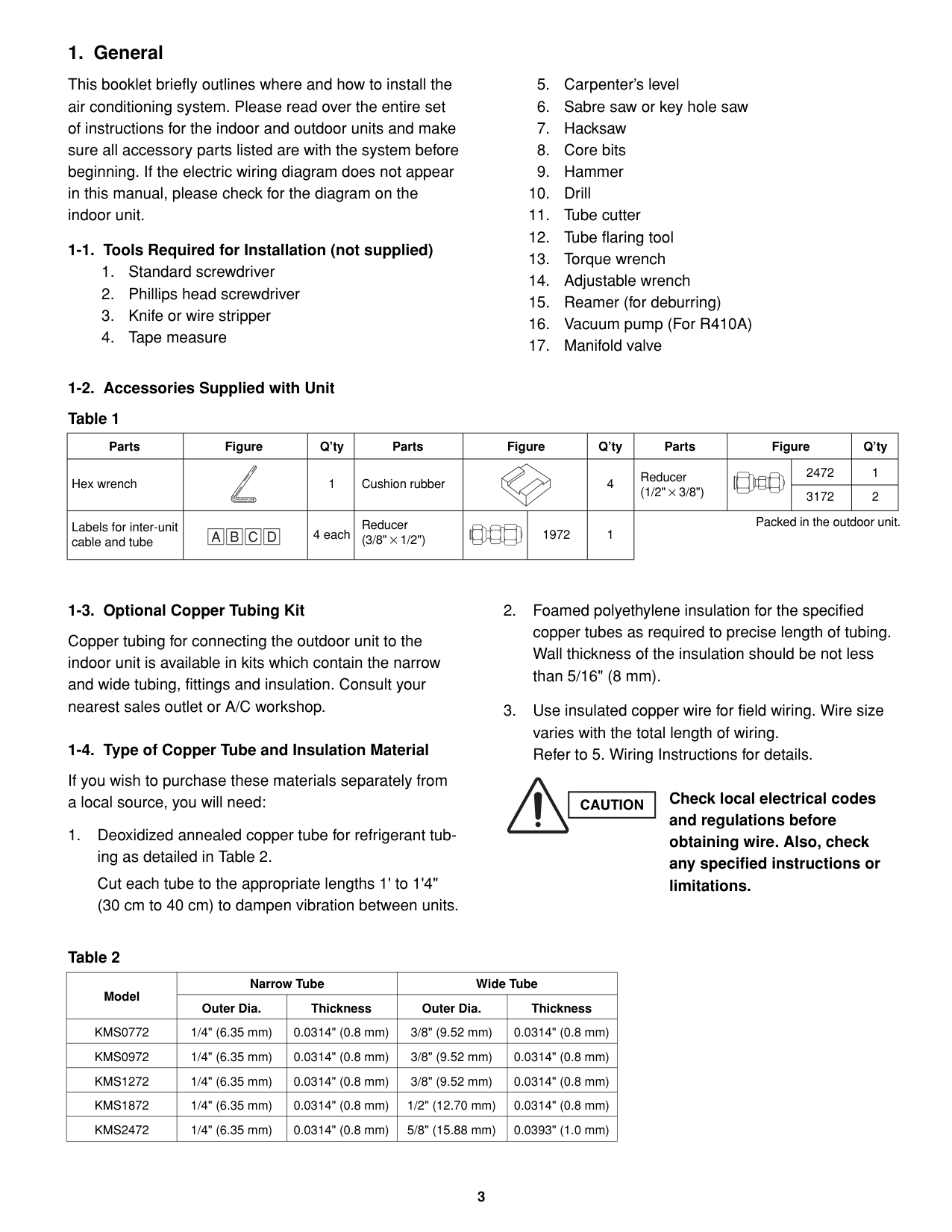
A
(KMS0772,KMS0972,KMS1272)
1/2"(12.70mm)
1/4"(6.35mm)
Union 3/8"(9.52mm)Flare 1/2"(12.70mm) (1/2"(12.70mm) 3/8"(9.52mm)) Supplied Reducer
Fig. 4g
Fig. 4h
Union 3/8"(9.52mm)Flare 1/2"(12.70mm) (1/2"(12.70mm 3/8"(9.52mm)) Supplied Reducer
C
B
A
(KMS0772,KMS0972,KMS1272)
(KMS0772,KMS0972,KMS1272)
D
Outdoor unit Indoor unit
(KMS0772,KMS0972,KMS1272)
(KMS1872)
1/2"(12.70mm)
1/2"(12.70mm)
1/2"(12.70mm)
3/8"(9.52mm)
3/8"(9.52mm)
3/8"(9.52mm)
3/8"(9.52mm)
3/8"(9.52mm)
1/4"(6.35mm)
1/4"(6.35mm)
1/4"(6.35mm)
1/4"(6.35mm)
Outdoor unit Indoor unit
3/8"(9.52mm)
D
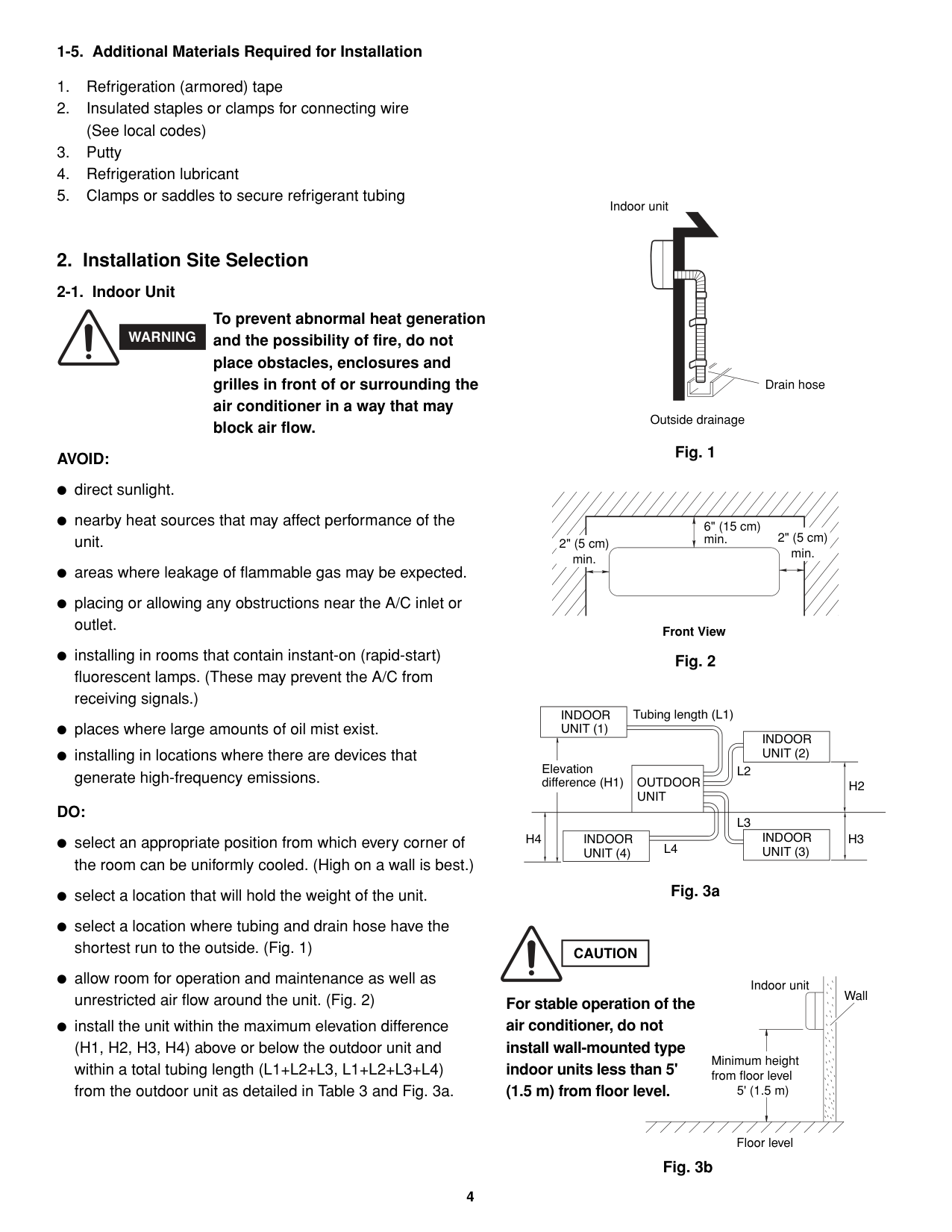
(KMS0772,KMS0972,KMS1272)
3/8"(9.52mm)
1/4"(6.35mm)
3/8"(9.52mm)
C
(KMS0772,KMS0972,KMS1272)
3/8"(9.52mm)
1/4"(6.35mm)
1/2"(12.70mm)
B
(KMS1872)
1/2"(12.70mm)
1/4"(6.35mm)
1/2"(12.70mm)
A
(KMS1872)
1/2"(12.70mm)
1/4"(6.35mm)
Fig. 4i
Fig. 4j
Union 5/8"(15.88mm)Flare 1/2"(12.70mm)
(1/2"(12.70mm) 5/8"(15.88mm)) Locally purchased
C
B
A
(KMS0772,KMS0972,KMS1272)
(KMS0772,KMS0972,KMS1272)
D
Outdoor unit Indoor unit
(KMS0772,KMS0972,KMS1272)
(KMS2472)
Union 3/8"(9.52mm)Flare 1/2"(12.70mm)
(1/2"(12.70mm) 3/8"(9.52mm)) Supplied Reducer
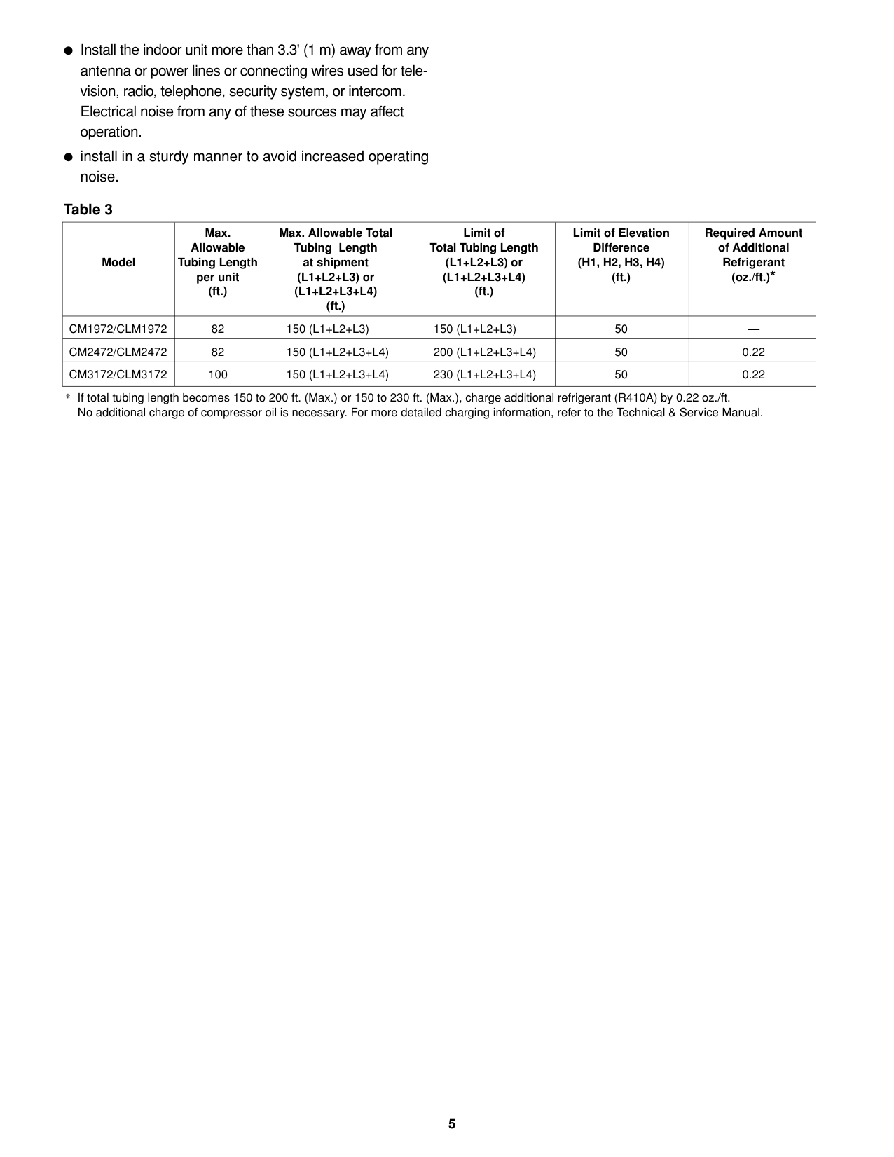
1/2"(12.70mm)
1/2"(12.70mm)
5/8"(15.88mm)
3/8"(9.52mm)
3/8"(9.52mm)
3/8"(9.52mm)
3/8"(9.52mm)
3/8"(9.52mm)
1/4"(6.35mm)
1/4"(6.35mm)
1/4"(6.35mm)
1/4"(6.35mm)
Outdoor unit Indoor unit
3/8"(9.52mm)
D
(KMS0772,KMS0972,KMS1272)
3/8"(9.52mm)
1/4"(6.35mm)
3/8"(9.52mm)
C
(KMS0772,KMS0972,KMS1272)
3/8"(9.52mm)
1/4"(6.35mm)
1/2"(12.70mm)
B
(KMS1872)
1/2"(12.70mm)
1/4"(6.35mm)
5/8"(15.88mm)
A
(KMS2472)
1/2"(12.70mm)
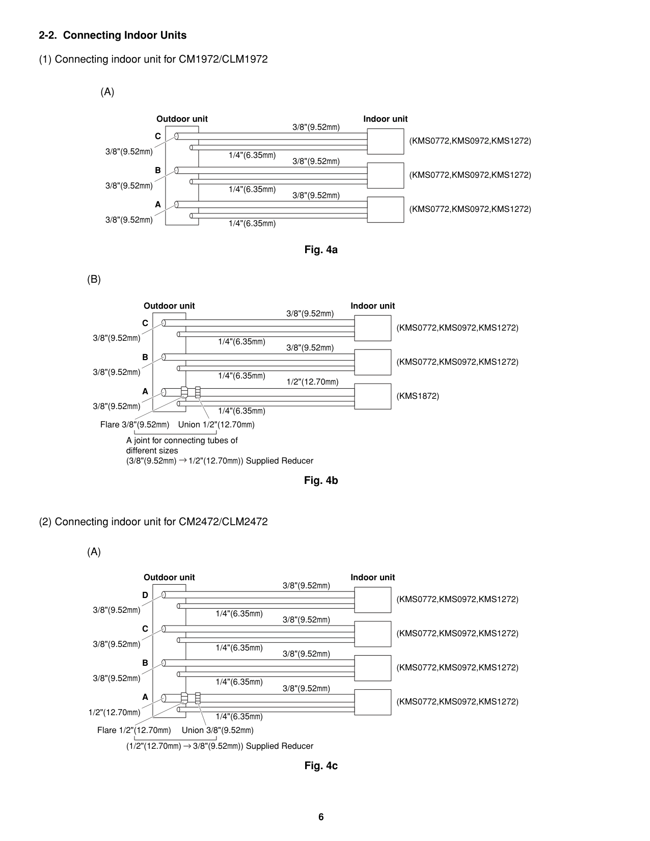
1/4"(6.35mm)
Union 5/8"(15.88mm)Flare 1/2"(12.70mm) (1/2"(12.70mm) 5/8"(15.88mm)) Locally purchased
Fig. 4k
####################### 2-3. Outdoor UnitAVOID:
Exhaust fanNO
Hot air
heat sources, exhaust fans, etc. (Fig. 5a) damp, humid or uneven locations.
Heat source
DO: choose a place as cool as possible. choose a place that is well ventilated. allow enough room around the unit for air intake/ exhaust and possible maintenance. (Fig. 5b)
Obstacle above
Outdoor unit
Min. 7' (2 m)
Air discharge
Min. 7' (2 m)
####################### Fig. 5a
Obstacle
Air intake Min. 6" (15 cm)
Valve side Min. 10" (25 cm)
provide a solid base (level concrete pad, concrete block, 6" × 1'4" (15 × 40 cm) beams or equal), a minimum of 6" (15 cm) above ground level to reduce humidity and protect the unit against possible water damage and decreased service life. (Figs. 5c and 5d)
Air dischargeMin. 4" (10 cm)
Min. 1’8" (50 cm)
Ground
Min. 6" (15 cm) Air intake
####################### Fig. 5b
A solid base must not cover the hole of the bottom plate. Drain holes
|CAUTION| |---|
Install cushion rubber under unit’s feet to reduce vibration and noise. (Fig. 5e) use lug bolts or equal to bolt down unit, reducing vibration and noise. Install in a location where no antenna of a television or radio exists within 10' (3 m).
Anchor bolts (4 pcs.)
Min. 6" (15 cm)
Air intake
####################### 2-4. Baffle Plate for the Outdoor Unit(CLM models only)
Concrete or equal
NOTE
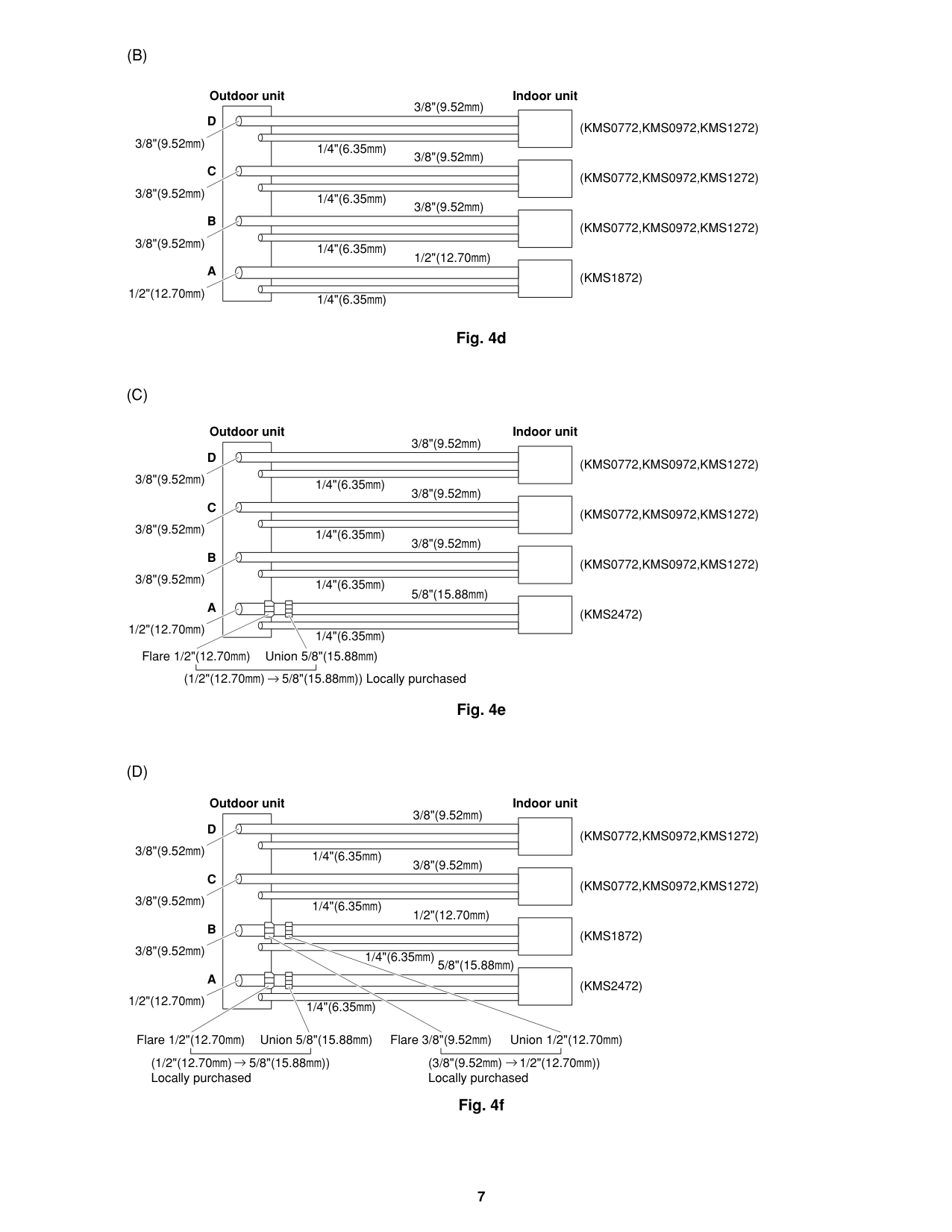
t 6" (15 cm)
Abou t 16" (40 c m)
It is recommended to use baffle plates for models CLM1972, CLM2472 and CLM3172. The baffle plates are not normally required for the other models. When the outdoor unit is installed in a position exposed to strong wind (such as seasonal winds with low air temperature in winter), baffle plates must be installed on the outdoor unit. (Fig. 5f) This unit is designed so that the fan of the outdoor unit runs at low speed when the air conditioner is operated at low outdoor air temperatures. When the outdoor unit is exposed to strong wind, the system pressure drops because of the freeze protector. Install a pair of windbaffle plates at the front and back of the outdoor unit if it will be subject to strong wind during the winter. (Figs. 5f, 5g, 5h, 5i, and 5j)
Abou
Fig. 5c
Cushion rubber
Air intake baffle
Front
Wind
Back
Wind
Air discharge baffle
No air intake baffle required on this side.
D
F
E
C
J
H
L
I
B
K
Q
R
A
G
O
(3- 6.5 mm)
3- 1/4"
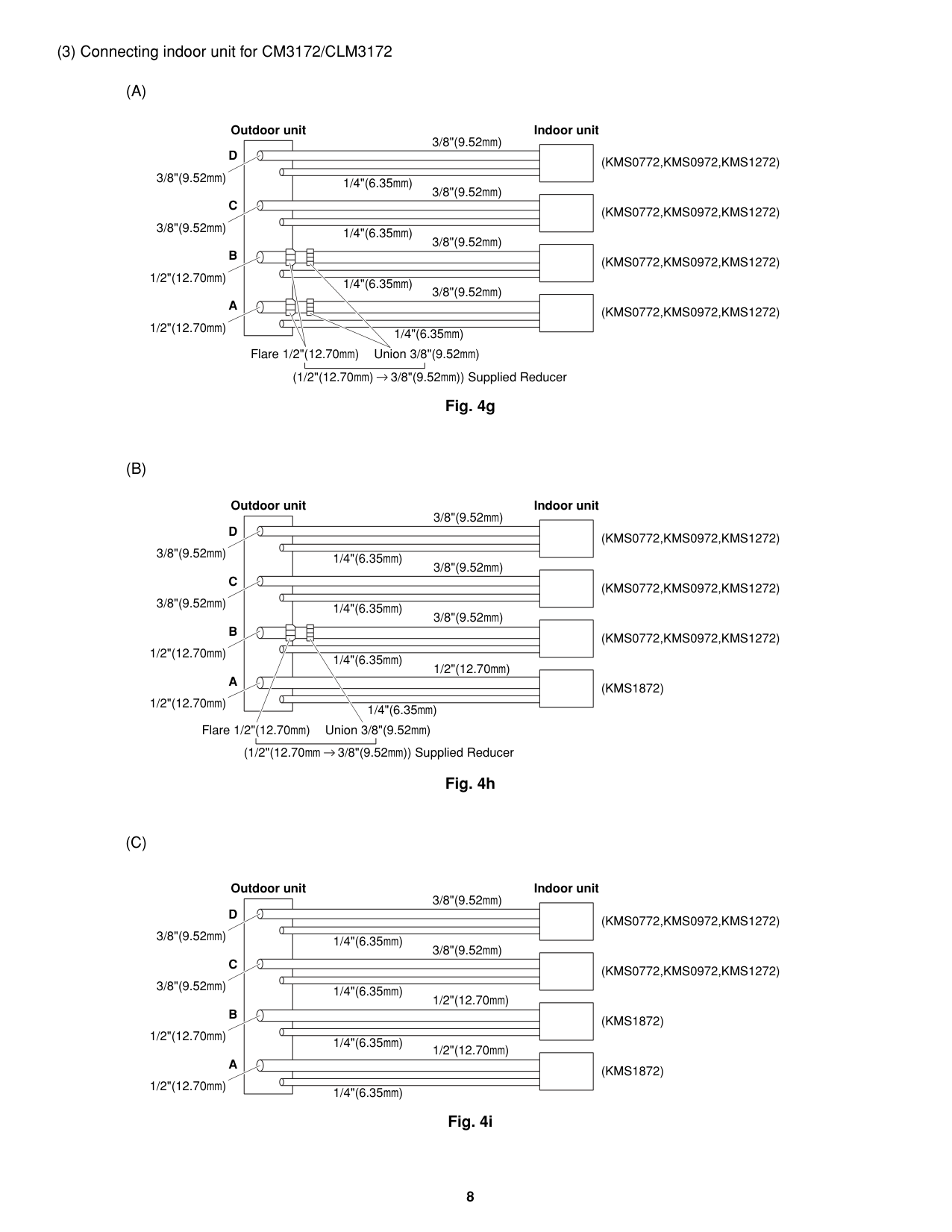
(2- 6 mm)
2- 15/64"
A
B
H
C
E
F
K
G
G
D
(4- 6.5 mm)
4- 1/4"
Fig. 5h For Air Intake
For Air Discharge
Material to be used: Metal plate with corrosion protection treatment Plate thickness: 0.0394 to 0.0472" (1.0 to 1.2 mm)
|Air Intake Baffle| |---|
|Air Discharge Baffle| |---|
Fig. 5g
|Dimensions Model|Dimensions Model|A|B|C|D|E|F|G|H| | |K
|L|O|Q|R| |---|---|---|---|---|---|---|---|---|---|---|---|---|---|---|---|---| |CLM1972, CLM2472|(inch)|25-3/16|25/32|1-31/32|25|10-5/8|10-5/8|25/64|25/32|19/32|25-7/8|19/64|25/64|5-29/32|25/32|25/32| |CLM1972, CLM2472|(mm)|640|20|50|635|270|270|10|20|15|657|7.5|10|150|20|20| |CLM3172|(inch)|25-3/16|25/32|1-3/8|30-29/32|13-25/32|13-25/32|25/64|25/32|19/32|31-25/32|19/64|25/64|5-29/32|25/32|25/32| |CLM3172|(mm)|640|20|35|785|350|350|10|20|15|807|7.5|10|150|20|20|
|Dimensions Model|Dimensions Model|A|B|C|D|E|F|G|H| | |K| |---|---|---|---|---|---|---|---|---|---|---|---|---| |CLM1972, 2472, 3172|(inch)|22-1/16|23-1/32|13-25/3|5-29/32|19-9/32|1-3/8|2-5/32|18-5/16|2-3/8|3-11/32|31/32| |CLM1972, 2472, 3172|(mm)|560|585|350|150|490|35|55|465|60|85|25|
Air Intake Baffle Air Discharge Baffle
|Item|Q’ty|Remarks|
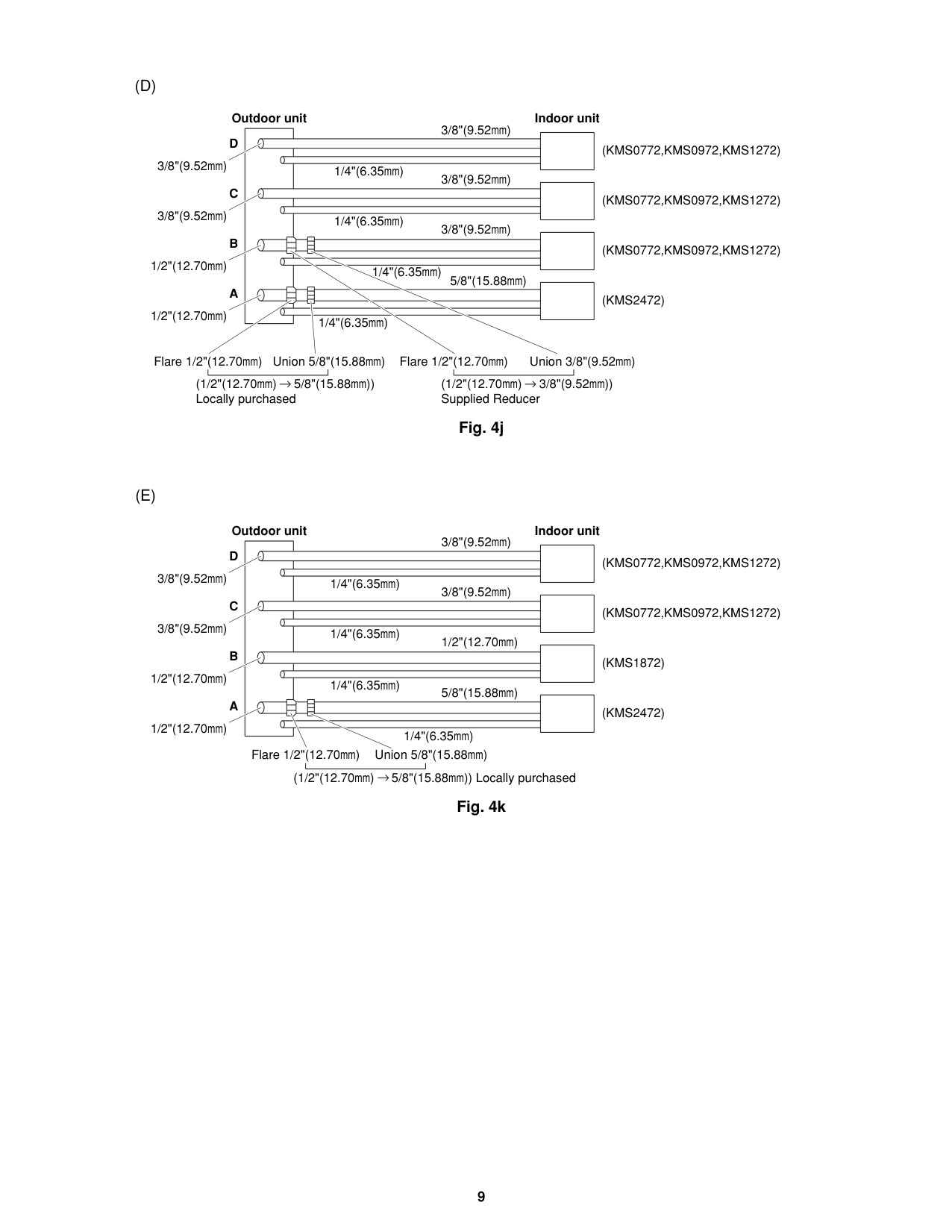
|---|---|---| |Baffle plate|1| | |Screw 5/32 × 15/32" (4 × 12 mm) tapping|2|Attached to outdoor unit| |Bolt 15/64 × 19/32 – 25/32" (M6 × 15 – 20 mm)|3| | |Nut 15/64" (M6)|3| | |Washer|3| | |Spring washer|3| |
|Item|Q’ty|Remarks| |---|---|---| |Baffle plate|1| | |Bolt 15/64 × 13/32 – 19/32" (M6 × 10 – 15 mm)|4| | |Nut 15/64" (M6)|4| | |Washer|4| | |Spring washer|4| |
####################### (3) Installation procedure
Panel side R
Panel top Panel front
Panel top
Panel side R
Panel front
Panel side L
Panel side L
####################### Fig. 5i Fig. 5j
NOTE
In order to prevent contact of the bolts and heat exchanger and other parts inside the unit, install the windbaffle using bolts from inside the unit and fasten the bolts with nuts from outside the unit. When the windbaffle is installed on the unit, the unit has higher wind resistance. In order to prevent the unit from falling over, anchor the legs of the unit using anchor bolts (or similar method).
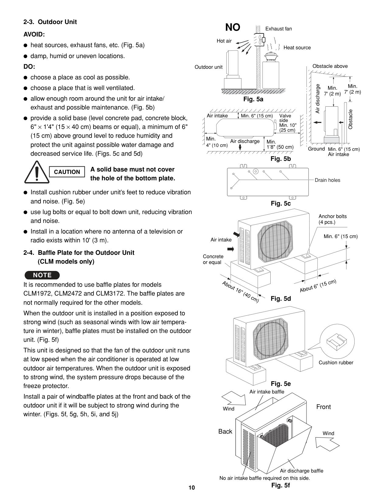
####################### (4) Precautions for installation
Fig. 6b
| | |---| | |
| | |---| | |
| | |---| | |
| | | | |---|---|---| | | | |
23-15/16 5-11/32 15/32
12-19/32
13-19/32
14-17/32
35-7/16 (900)
29-1/8 (740)
2-1/16
2-29/32
A
4-1/22-1/32
5-29/32 2-27/32
2-3/4
4-7/16
2-15/16 2-3/4
Service valve on narrow tube side (Outer diameter 1/4"(6.35))
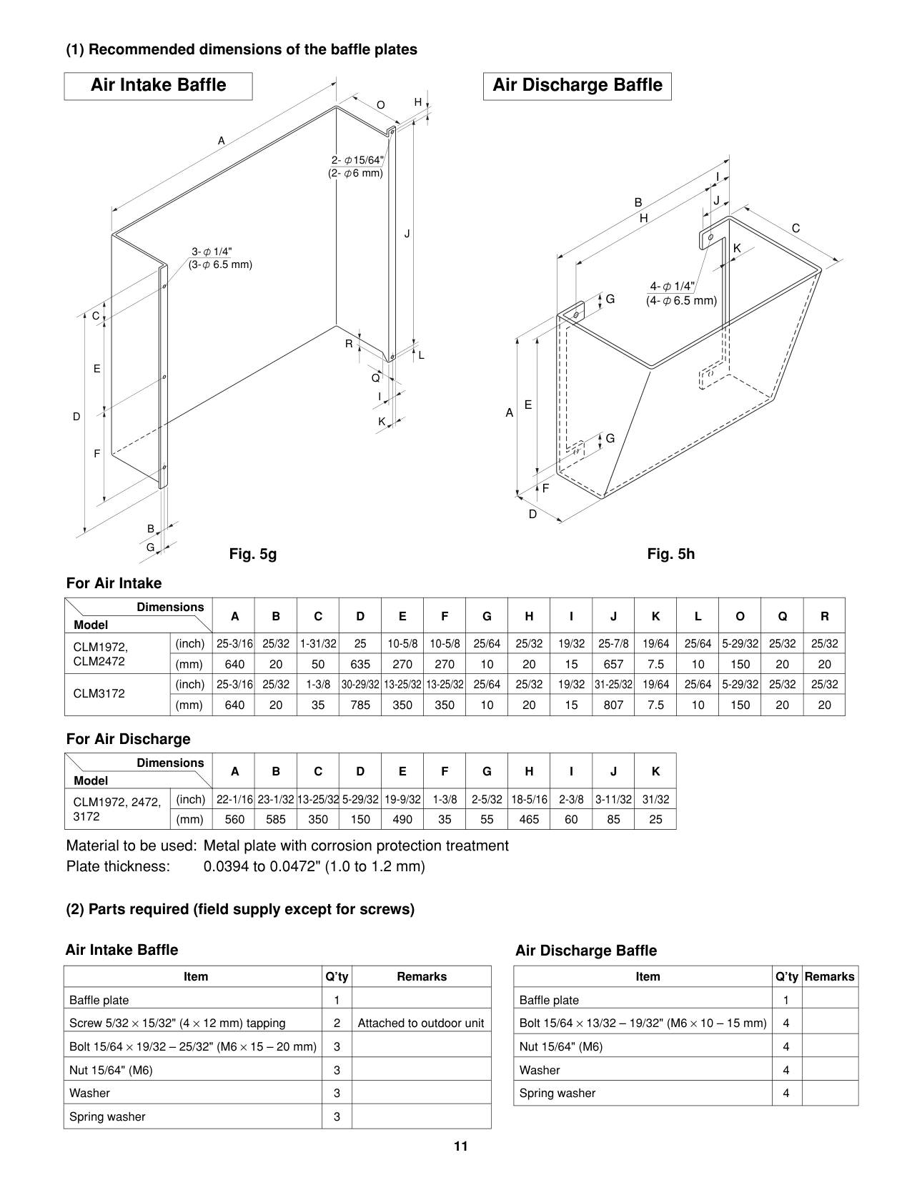
Service valve on wide tube side (Outer diameter 3/8"(9.52))
Service valve on wide tube side (Outer diameter 1/2"(12.70))
A
23/32
Fig. 6c
| | |---| | |
| | |---| | |
| | | | |---|---|---| | | | |
23-15/16
15/32
14-17/32
5-11/32
35-7/16 (900)
23/32
35-1/32 (890)
2-29/32
2-1/16
4-1/22-1/32
4-7/16
5-29/32
2-15/16
2-27/32
2-3/4
2-3/4
A
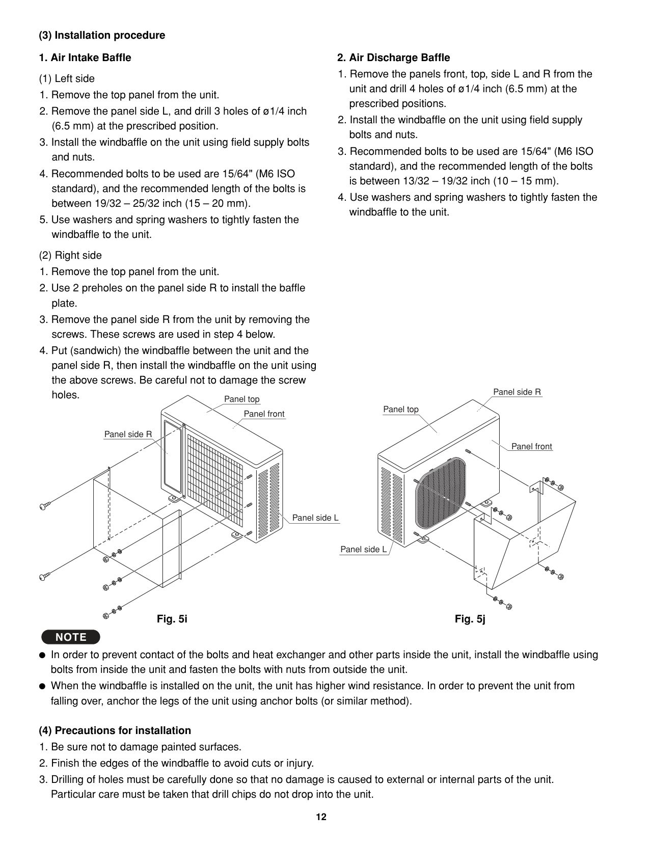
Service valve on narrow tube side (Outer diameter 1/4"(6.35))
Service valve on wide tube side (Outer diameter 1/2"(12.70))
Service valve on wide tube side (Outer diameter 3/8"(9.52))
A
################################## A
23-15/16 5-11/32 15/32
35-7/16 (900)
2-29/32
| | | |---|---| | | | | | |
13-19/32 12-19/32
14-17/32
Service valve on narrow tube side (Outer diameter 1/4"(6.35)) Service valve on wide tube side (Outer diameter 3/8"(9.52))
A
| | | | |---|---|---| | | | |
29-1/8 (740) 23/32
2-3/4
2-15/16 2-3/4
| | |---| | |
5-29/32 2-27/32
| | |---| | |
| | |---| | |
4-7/16
4-1/2
2-1/32
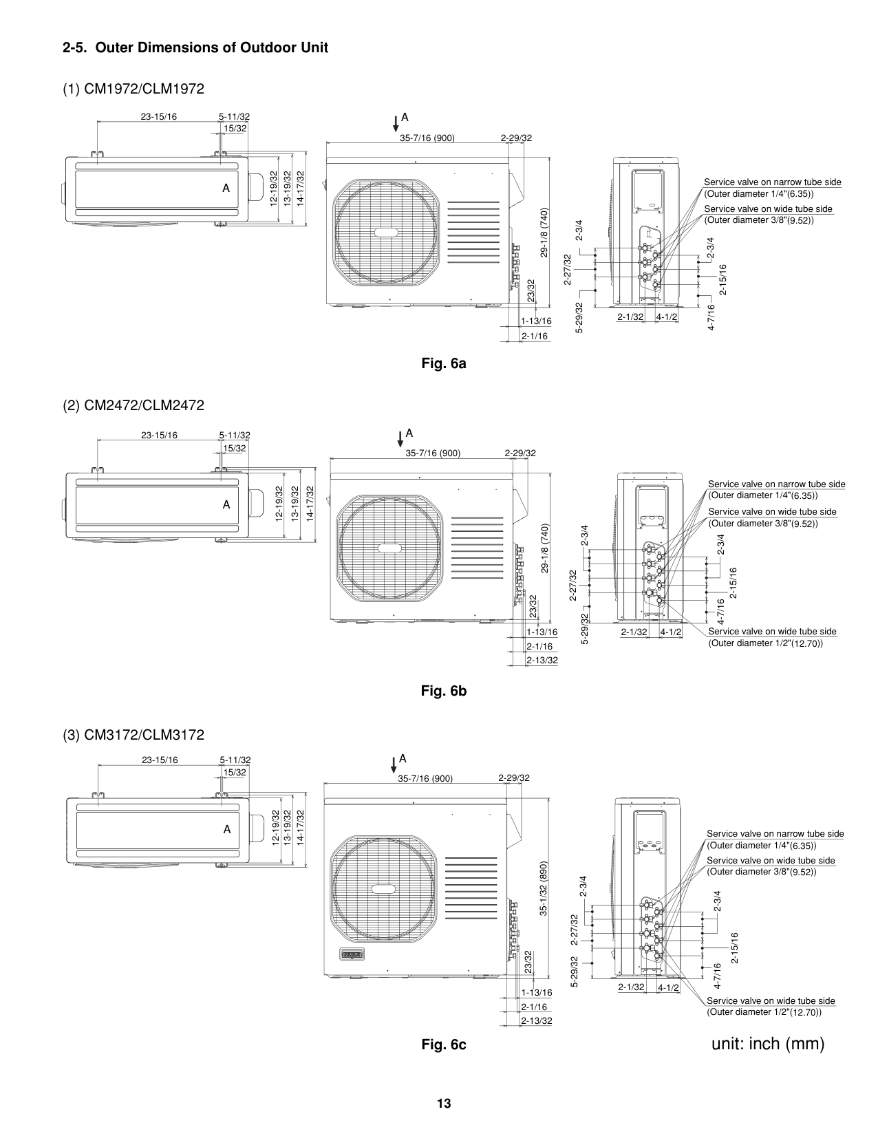
Fig. 6a
############## unit: inch (mm)
################# 2-6. Diagram of Outdoor Unit InstallationNever install only a single indoor unit.
Be sure to connect indoor and outdoor units only in combinations that are listed in the catalog or in the combination table that was provided with the outdoor unit. (Use caution. Connecting any other model may result in operation failure and malfunction.)
The dimensions indicated by in the figure below are spaces that are required in order to maintain performance. Install in a location where the dimensions indicated by are ensured, and where 2 or more faces of the unit are unobstructed. In principle, the top direction should be unobstructed.
Over 4"(10cm)
0cm)
Over8"(2
Service space Power breaker
Indoor unit D
Indoor unit C
Indoor unit B
Indoor unit A
Ensure 6"(15cm) of space if a drain hose is to be used.
"(50cm)
Over 1'8
Over 10"(25cm)
Access panel C
Base (not provided) (concrete or similar material)
Fasten with anchor bolts (not provided) (3/8" or M10, 4 locations)
Ground wire (not provided)
####################### Fig. 7
############# 3. Installation Process
Be sure to bind refrigerant tubing and inter-unit cables together with vinyl tape.
The power cable must be obtained on-site. (#12: Less than 85 ft.) # ... AWG (American Wire Gauge)
Be sure to apply the provided labels to both ends of the inter-unit cables to prevent miswiring.
Securely seal the end of embedded tubing with vinyl tape in order to prevent dirt or moisture entry.
In order to prevent insulation breakdown and ground faults, do not allow the wire ends to contact rainwater, or be subject to dew condensation.
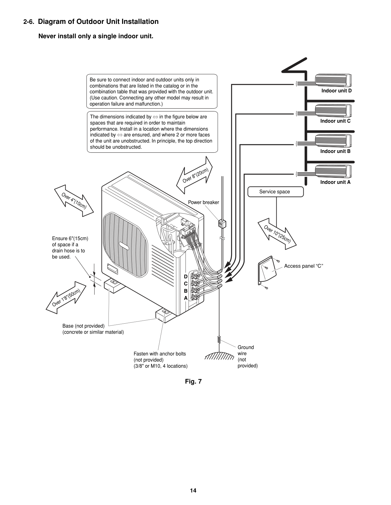
Deburring
|Before| |---|
|After| |---|
Fig. 8
Many of the conventional split system air conditioners employ the flaring method to connect refrigerant tubes which run between indoor and outdoor units. In this method, the copper tubes are flared at each end and connected with flare nuts.
NOTE
Copper tubing
When reaming, hold the tube end downward and be sure that no copper scraps fall into the tube. (Fig. 9)
Reamer
####################### Fig. 9
############################ If the previous flare tool (clutch-type) is used:
############################ If the special R410A flare tool is used:
NOTE
A good flare should have the following characteristics: inside surface is glossy and smooth. edge is smooth. tapered sides are of uniform length.
0.0472" (1.2 mm)
0 to 0.0196" (0 to 0.5 mm)
############################# Adjust so that the amount of tube protrusion is as shown in the figure.
####################### Fig. 10
####################### 3-4. Caution before Connecting Tubes Tightly
####################### 3-5. Tubing Connections
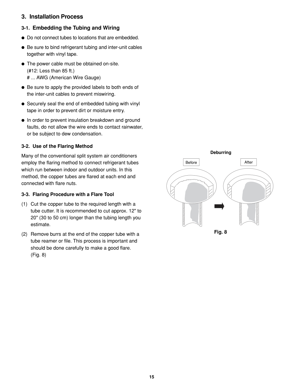
|Tube Dia.|Tightening Torque| |---|---| |1/4" (6.35 mm)|Approx. 120 – 160 lbs·in (140 – 180 kgf·cm)| |3/8" (9.52 mm)|Approx. 300 – 360 lbs·in (340 – 420 kgf·cm)| |1/2" (12.70 mm)|Approx. 430 – 540 lbs·in (490 – 610 kgf·cm)| |5/8" (15.88 mm)|Approx. 590 – 710 lbs·in (680 – 820 kgf·cm)|
Flare nut
Copper tubing
Flare tool
Fig. 11
Apply refrigerant lubricant here and here
Flare nutUnion
Service valve on narrow tube side
Apply the provided labels to the indoor and outdoor unit tubing connectors to prevent errors in connections.
Service valve on wide tube side
Fig. 14
Be sure to match refrigerant tubing and electric wiring between indoor and outdoor units. For more details, refer to “Tubing Check Control” in the Technical & Service Manual.
|CAUTION| |---|
####################### 3-6. Insulation of Refrigerant Tubing
IMPORTANT
To prevent heat loss and wet floors due to dripping of condensation, both tubes must be well insulated with a proper insulation material. The thickness of the insulation should be a minimum 5/16" (8 mm). (Fig. 17)
####################### 3-7. Taping the Tubes
After a tube has been insulated, never try to bend it into a narrow curve, as this may cause the tube to break or crack.
|CAUTION| |---|
NOTE
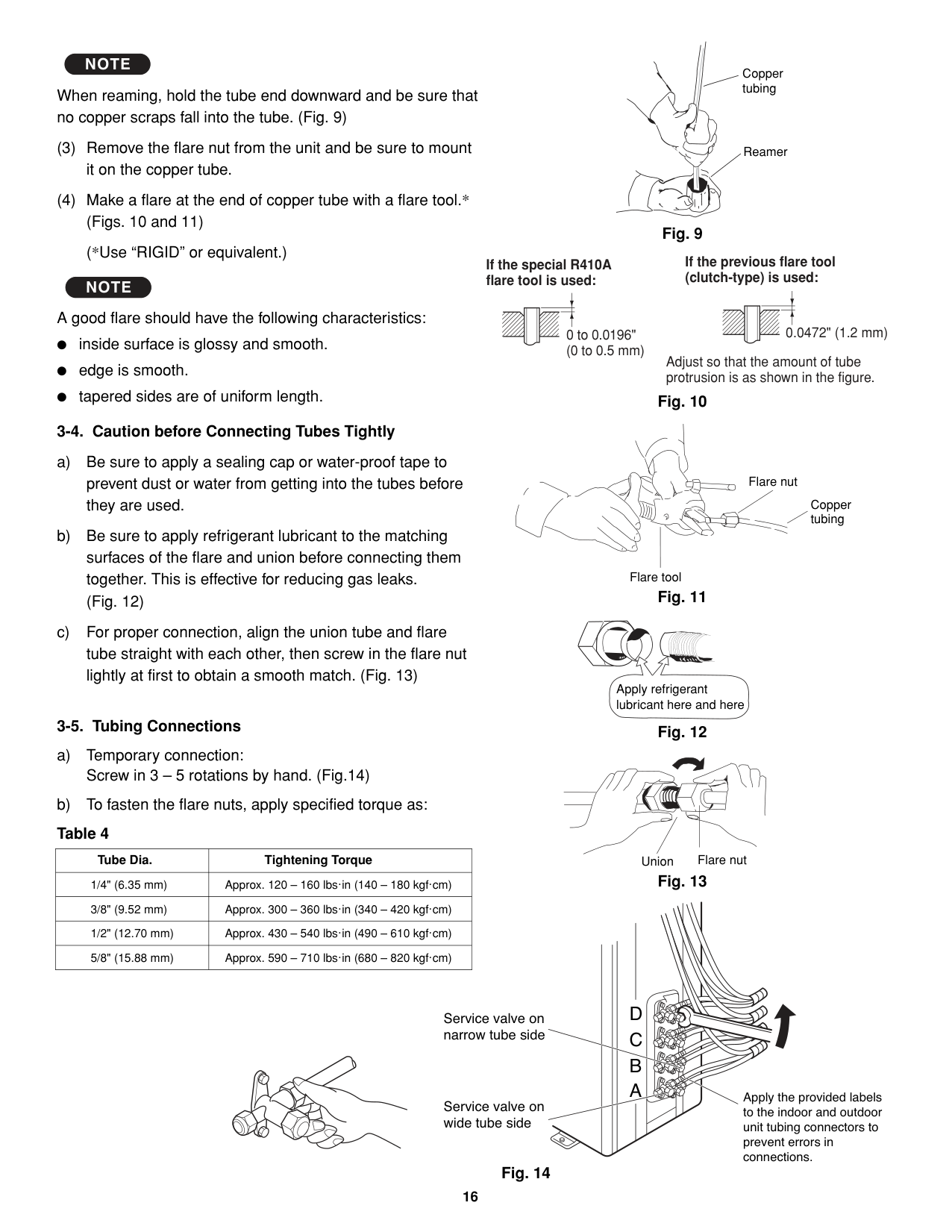
Do not wind the armoring tape too tightly, since this will decrease the heat insulation effect. Also, be sure the condensation drain hose splits away from the bundle and drips clear of the unit and the tubing.
####################### 3-8. Finishing the Installation
After finishing insulating and taping over the tubing, use sealing putty to seal off the hole in the wall to prevent rain and draft from entering. (Fig. 19)
Torque wrench
Spanner
Indoor unit
Outdoor unit
####################### Fig. 15
Insulation Fig. 16
Insulation
Thickness: min. 5/16" (8 mm)
Min. 5/16" (8 mm)
Clamp
Insulated tubes
Apply putty here
Tubing Fig. 19
############# 4. Air Purging
Air and moisture remaining in the refrigerant system have undesirable effects as indicated below. Therefore, they must be purged completely.
Service valve on narrow
pressure in the system rises operating current rises cooling efficiency drops moisture in the air may freeze and block capillary tubing water may lead to corrosion of parts in the refrigerant system
Manifold gauge (special for R410A)
Service valve on wide tube side
High-pressure valve
Low-pressure valve
Vacuum pump adapter (for preventing reverse flow) (special for R410A)
Leave the valve open.
HiLo
Open
| | | |
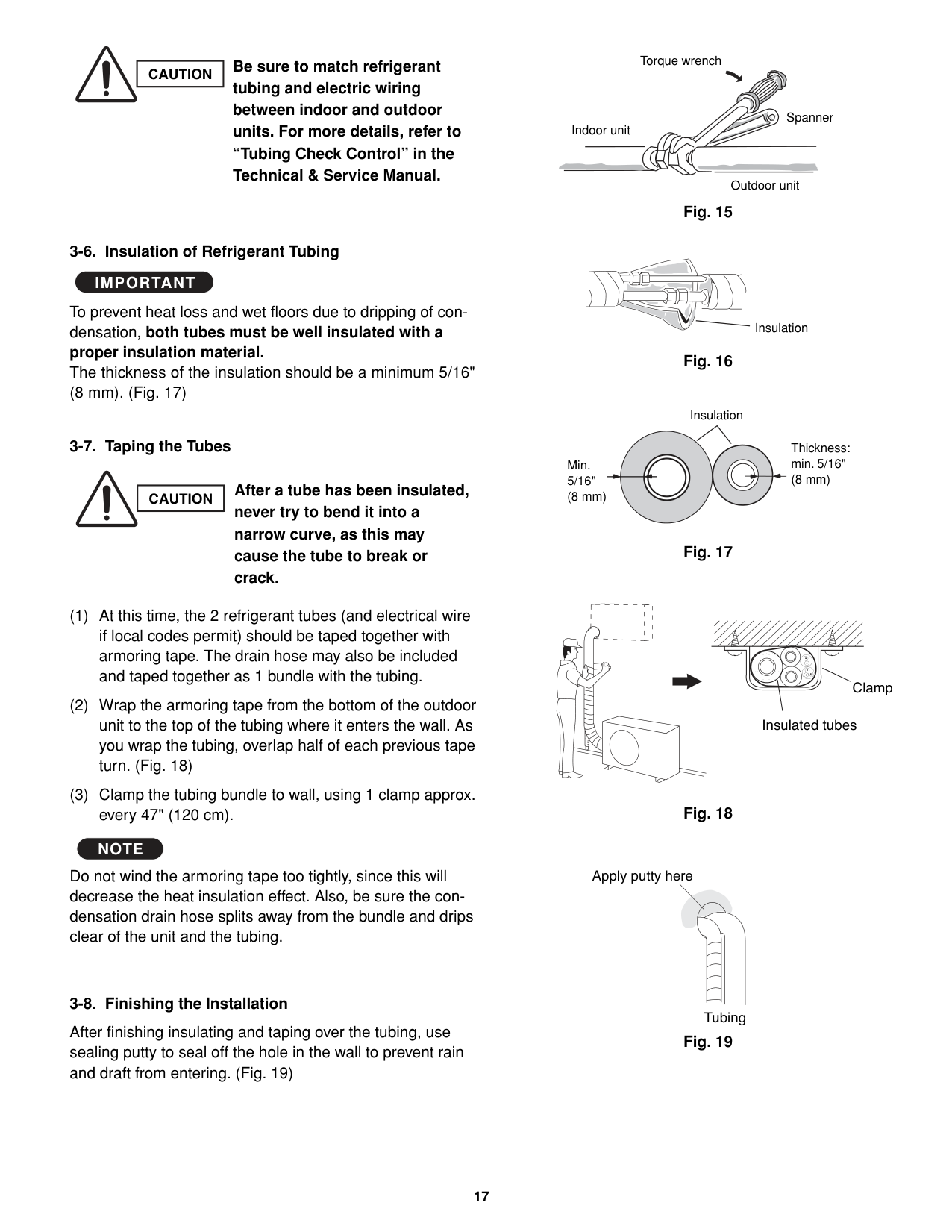
|---|---|---| | | | |
Vacuum pump
Hex wrench
############# Air Purging with a Vacuum Pump (for Test Run)
Charging hose (special for R410A)
With push-pin
####################### Fig. 20
In order to protect the earth’s environment, be sure to use a vacuum pump to perform the air purge. (Never perform an air purge by using the refrigerant gas cylinder or other external gas, or by using the gas inside the outdoor unit.)
In order to prevent charging errors with A/C that uses R410A, the screw diameter at the service valve charging port has been changed. When recharging or performing other servicing, use the special charging hose and manifold gauge.
|CAUTION| |---|
Perform the air purge for tubes A, B, C, and D. Use the same procedures for all tubes.
Stopper Spindle
Cap tightening torque: 170 – 215 lbs·in (200 – 250 kgf·cm) (Tighten by hand, then use a wrench to turn.)
Service port
Screw diameter: 1/2 UNF 20 threads
Valve core
| | | |---|---| | | | | | |
Cap nut tightening torque: 60 – 95 lbs·in (70 – 110 kgf·cm) (Tighten by hand, then use a wrench to turn approximately 30 .)
NOTE External diameter of service port R410A: 5/16"
Before using the vacuum pump adapter, read the vacuum pump adapter manual, and use the adapter correctly.
|CAUTION| |---|
####################### Fig. 21
|When using a hex wrench to open the spindle, an extremely small amount of refrigerant may leak. This does not indicate a problem. Use a hex wrench of a type to which force can be easily applied.| |---|
Be sure to use a manifold valve for air purging. If it is not available, use a stop valve for this purpose. The “Hi” knob of the manifold valve must always be kept closed.
|CAUTION|
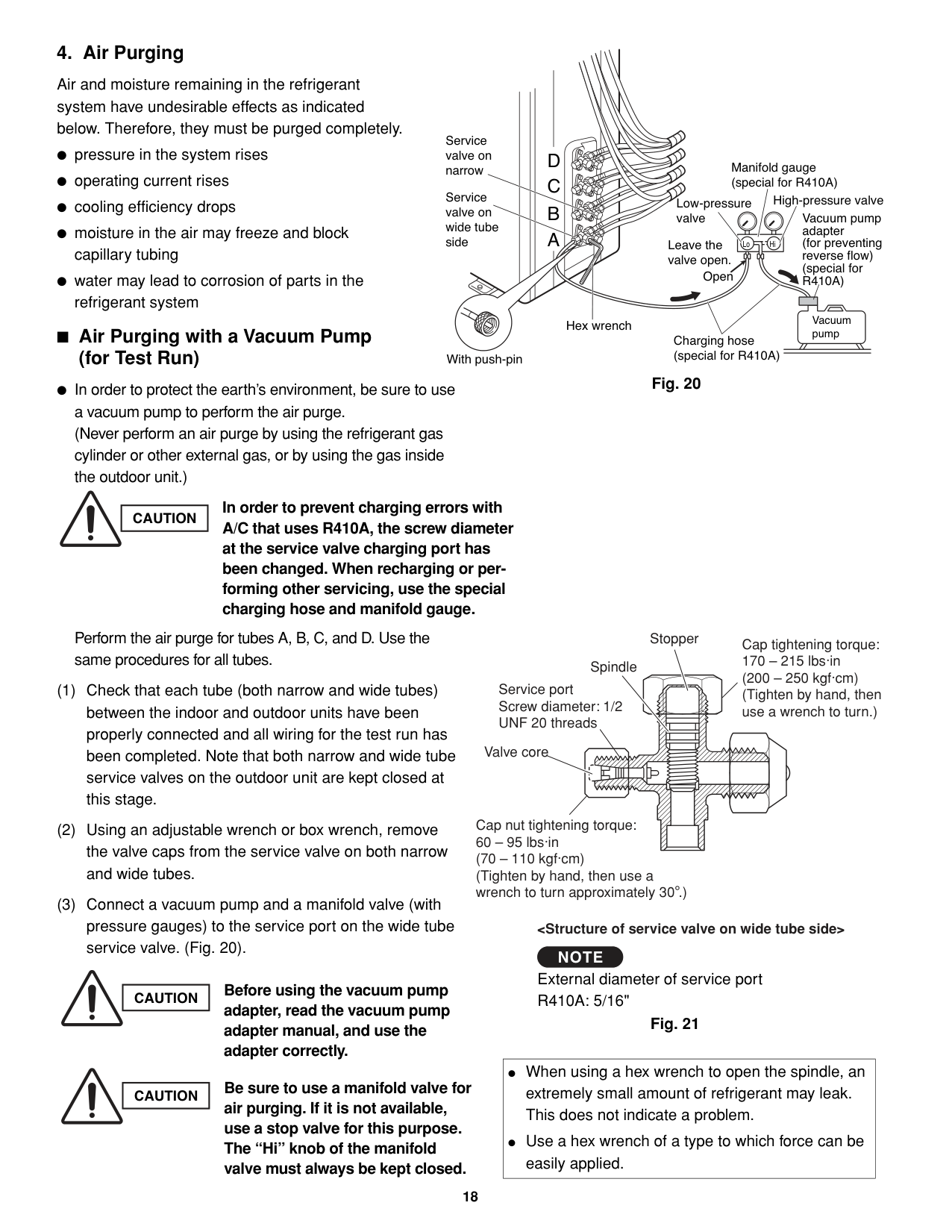
|---|
Table 5
The required time in the above table is calculated based on the assumption that the ideal (or target) vacuum condition is around 10 mmHg abs.
|Required time for evacuation when capacity of 100 liter/h vacuum pump is used
| |---| |20 min. or more|
####################### NOTE
Be sure to completely insert the hex wrench before attempting to turn the valve.
|CAUTION| |---|
|CAUTION| |---|
If a CFC gas detector is used, use a special detector for HFC refrigerant (such as R410 and R134a).
############# Pump Down
|In order to protect the earth’s environment, be sure to perform pump-down to recover refrigerant gas without releasing it into the atmosphere.| |---|
When relocating or disposing of the A/C, request this service from the dealer where the unit was purchased, or from an appropriate agent. Perform pump-down as described below.
What is pump-down? Pump-down refers to recovering the refrigerant gas from the refrigerant cycle at the outdoor unit. This work must be performed during cooling operation. The refrigerant gas cannot be recovered during heating operation. During winter, or if the temperature sensor prevents cooling operation, perform “forced cooling operation.”
####################### Pump-down procedure
If pump-down is not possible If the A/C cannot be operated because of a malfunction or other cause, use a refrigerant recovery device to recover the refrigerant.
Close
D
Narrow tube side
Close
C
Close
B
Charging port
Close
A
####################### Fig. 22
D
C
Wide tube side
B
A
Manifold gauge
####################### Fig. 23
Cap
Cap
After disconnecting the inter-unit tubes, attach the flare nuts with flare bonnets.
Cap
Cap
Fig. 24
############# 5. Wiring Instructions
####################### 5-1. General Precautions on Wiring
####################### 5-2. Recommended Wire Length and Diameter
Regulations on wiring diameter differ from locality to locality. For field wiring requirements, please refer to your local electrical codes. Carefully observe these regulations when carrying out the installation. Table 6 shows maximum wire lengths for control line and power line and fuse or circuit capacity.
####################### NOTE
Refer to the wiring system diagram (Fig. 25a or 25b) for the meaning of (A), (B), and (C) in Table 6.
Refer to your local codes or in the absence of local codes see the National Electric Code: ANSI/NFPA70.
####################### Table 6
|AWG Model|Max. Power Line Length (ft.) (A)|Max. Control Line Length (ft.) (B) (C)|Fuse or Circuit Capasity|
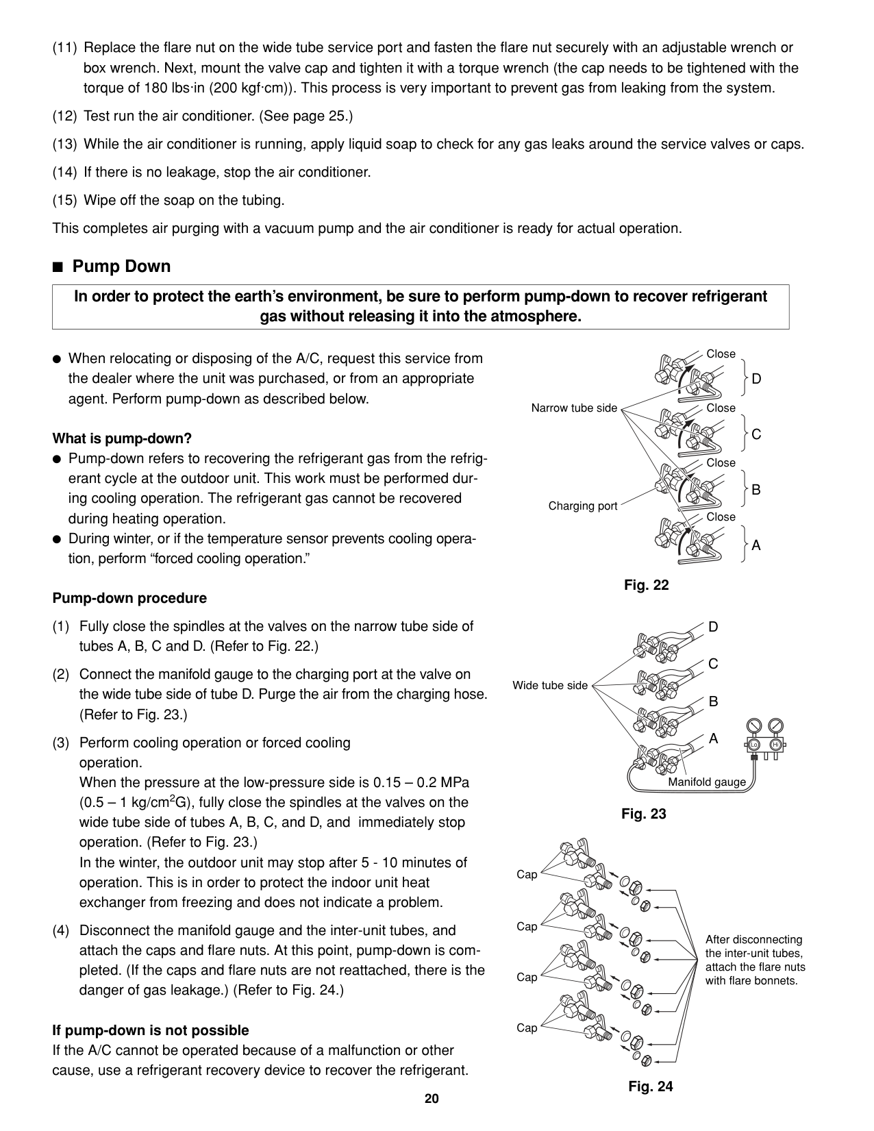
|---|---|---|---| |AWG Model|(#12)|(#14)|Fuse or Circuit Capasity| |CM1972 / CLM1972|85 (Max.)|82 (Max.)|20 A| |CM2472 / CLM2472|85 (Max.)|82 (Max.)|20 A| |CM3172 / CLM3172|85 (Max.)|100 (Max.)|20 A|
... AWG (American Wire Gauge)
WARNING
Be sure to comply with local codes on running the wire from the indoor unit to the outdoor unit (size of wire and wiring method, etc.). Each wire must be firmly connected. No wire should be allowed to touch refrigerant tubing, the compressor, or any moving part. Be sure to connect power wires correctly matching up numbers on terminals of the outdoor unit and respective indoor units A – D.
|CAUTION| |---|
Be sure to connect the power supply line to the outdoor unit as shown in the wiring diagram. The indoor unit draws its power from the outdoor unit. Do not run wiring for antenna, signal, or power lines of television, radio, stereo, telephone, security system, or intercom any closer than 3'4" (1 m) from the power cable and wires between the indoor and outdoor units. Electrical noise may affect the operation.
3 indoor units with CM1972/CLM1972
Field supply
230/208V 230/208V
INDOOR UNIT
OUTDOOR UNIT
Terminal(9P)
Terminal INDOOR UNIT
(B)
2 3
4
230/208V
UNIT A
(C)
Grounding line
(B)
Single-phase 230/208VAC 60HZ
(B)
230/208V 230/208V 230/208V
INDOOR UNIT
TerminalTerminal
(C)
(B)
Grounding line
Power supply
230/208V 230/208V
(B)
Grounding line
230/208V
(B)
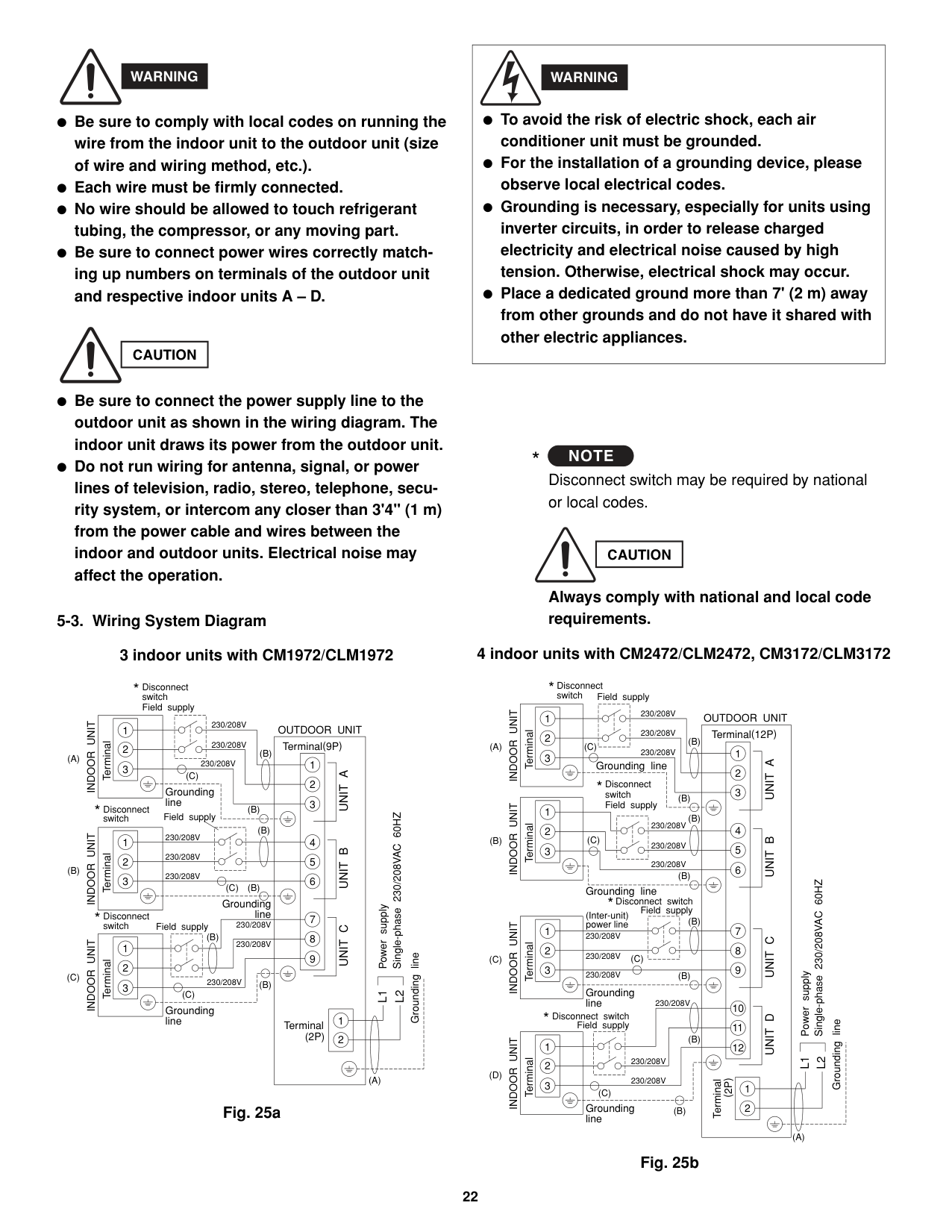
(C)
L1
L2
Grounding line
Terminal (2P)
(A)
Fig. 25a
|To avoid the risk of electric shock, each air conditioner unit must be grounded. For the installation of a grounding device, please observe local electrical codes. Grounding is necessary, especially for units using inverter circuits, in order to release charged electricity and electrical noise caused by high tension. Otherwise, electrical shock may occur. Place a dedicated ground more than 7' (2 m) away from other grounds and do not have it shared with other electric appliances.
WARNING| |---|
####################### NOTE
######### *
Disconnect switch may be required by national or local codes.
|CAUTION| |---|
Always comply with national and local code requirements.
4 indoor units with CM2472/CLM2472, CM3172/CLM3172
Terminal
(B)
(C)
Terminal INDOOR UNIT
Terminal
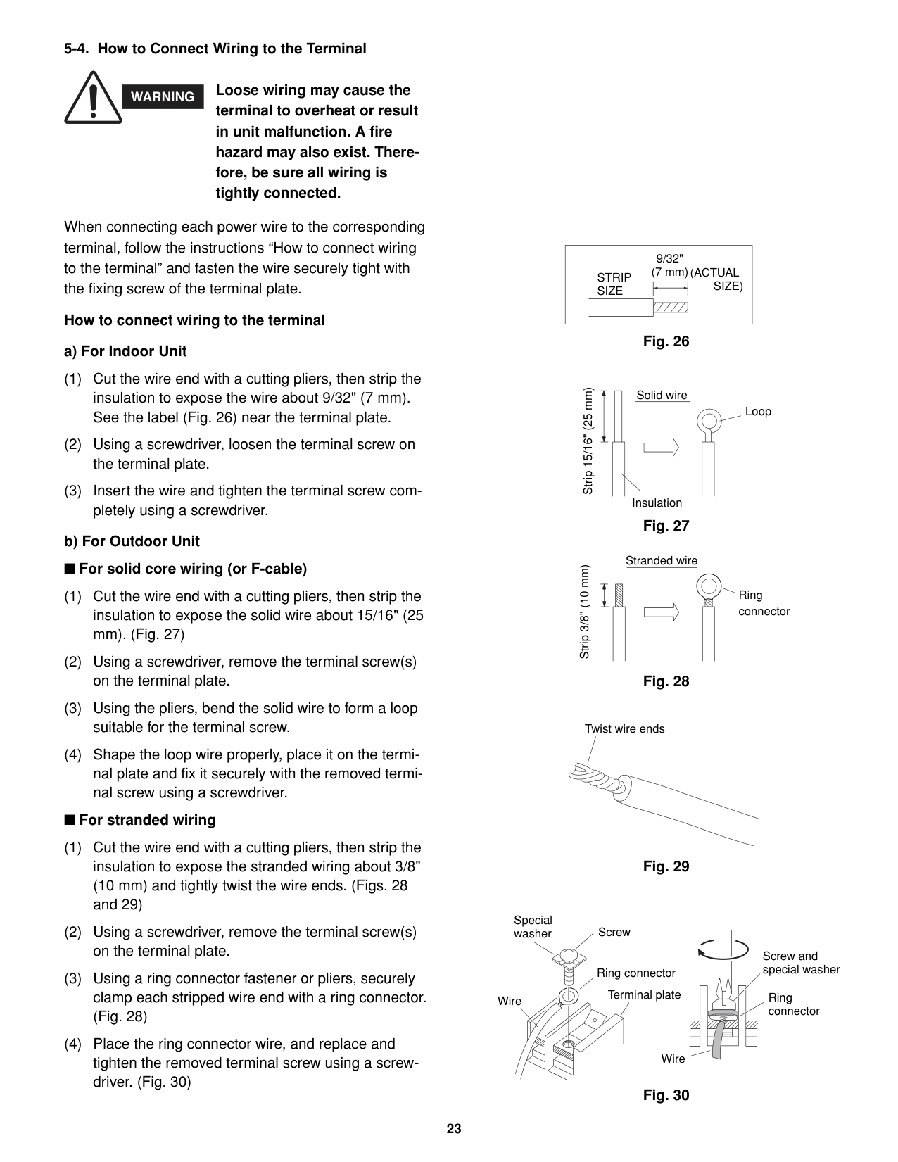
(2P)
Terminal(12P)
OUTDOOR UNIT
Disconnect switch
230/208V 230/208V 230/208V
230/208V 230/208V 230/208V
Grounding line
Grounding line
Field supply
230/208V 230/208V 230/208V
230/208V
Terminal INDOOR UNIT
Terminal INDOOR UNIT
2 3
4
5 6
7
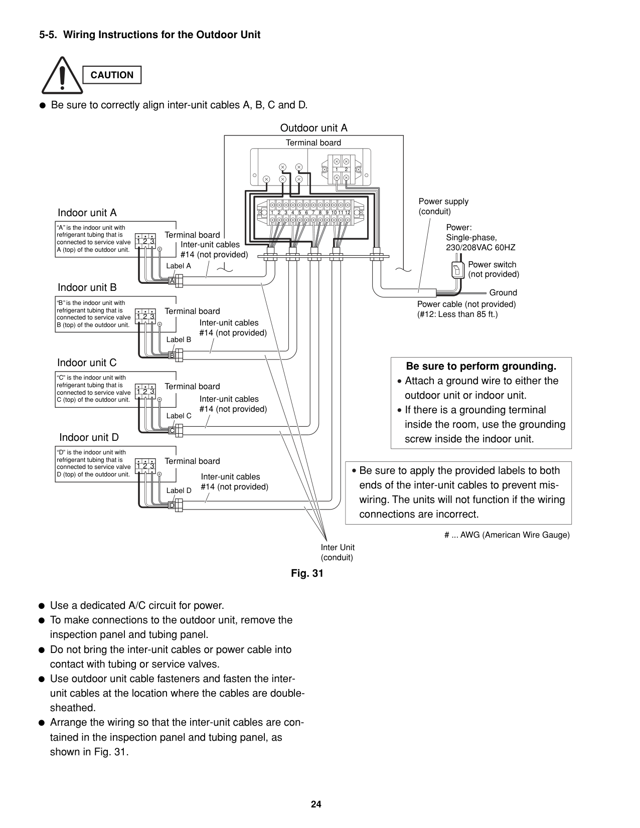
UNIT A
(B)
(B)
(C)
(B)
Single-phase 230/208VAC 60HZ
(Inter-unit) power line
(B)
(C)
(B)
Power supply
Grounding line
Grounding line
(B)
L1
L2
230/208V 230/208V
(C)
Grounding line
(B)
(A)
Fig. 25b
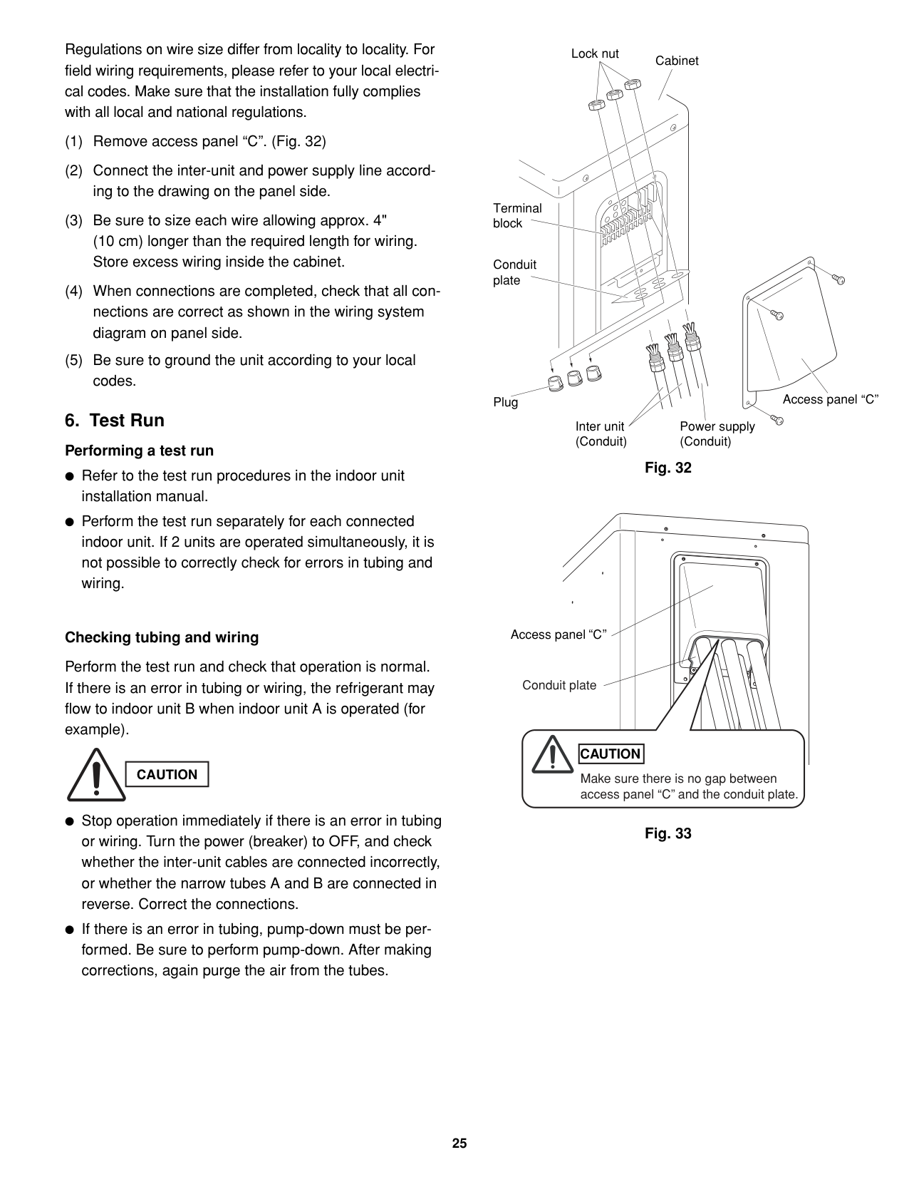
WARNING Loose wiring may cause the terminal to overheat or result in unit malfunction. A fire hazard may also exist. Therefore, be sure all wiring is tightly connected.
When connecting each power wire to the corresponding terminal, follow the instructions “How to connect wiring to the terminal” and fasten the wire securely tight with the fixing screw of the terminal plate.
How to connect wiring to the terminal
####################### For stranded wiring
|STRIP SIZE
9/32" (7 mm)(ACTUAL SIZE)| |---|
Fig. 26
Strip 15/16" (25 mm)
Solid wire
| | | | |---|---|---| | | | |
Loop
Insulation
Fig. 27
Stranded wire
Strip 3/8" (10 mm)
| | | | |---|---|---| | | | |
| | | | |---|---|---| | | | |
Ring connector
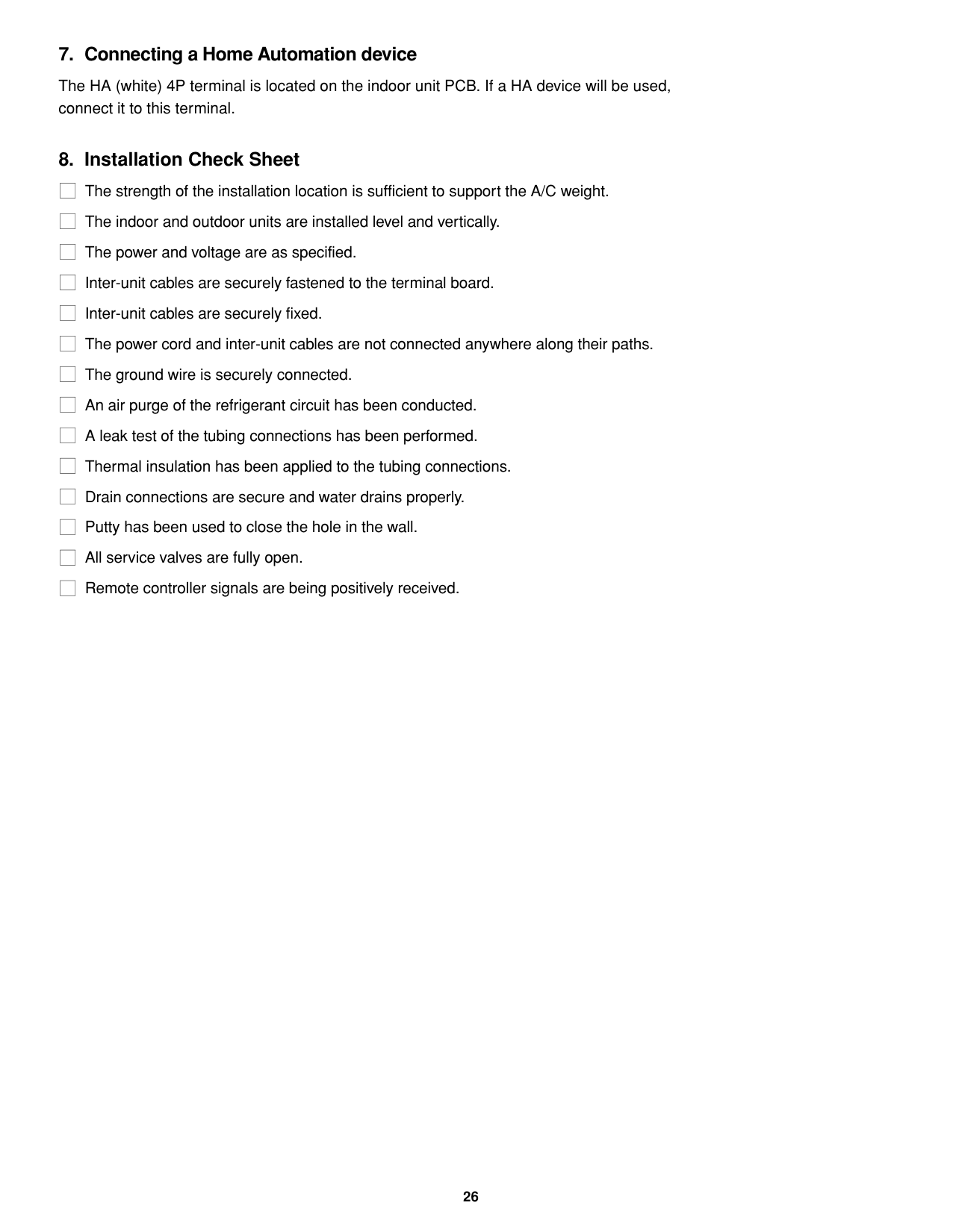
####################### Fig. 28
Twist wire ends
Fig. 29
Special washer
Screw
Screw and special washer
Ring connector
Terminal plate Wire
Ring connector
| | | | |---|---|---| | | | |
| | | | |---|---|---| | | | |
Wire
Fig. 30
####################### 5-5. Wiring Instructions for the Outdoor Unit
|CAUTION| |---|
Be sure to correctly align inter-unit cables A, B, C and D.
#################### Outdoor unit A Terminal board
1 2
refrigerant tubing that is connected to service valve
refrigerant tubing that is connected to service valve
refrigerant tubing that is connected to service valve
C is the indoor unit with
refrigerant tubing that is connected to service valve
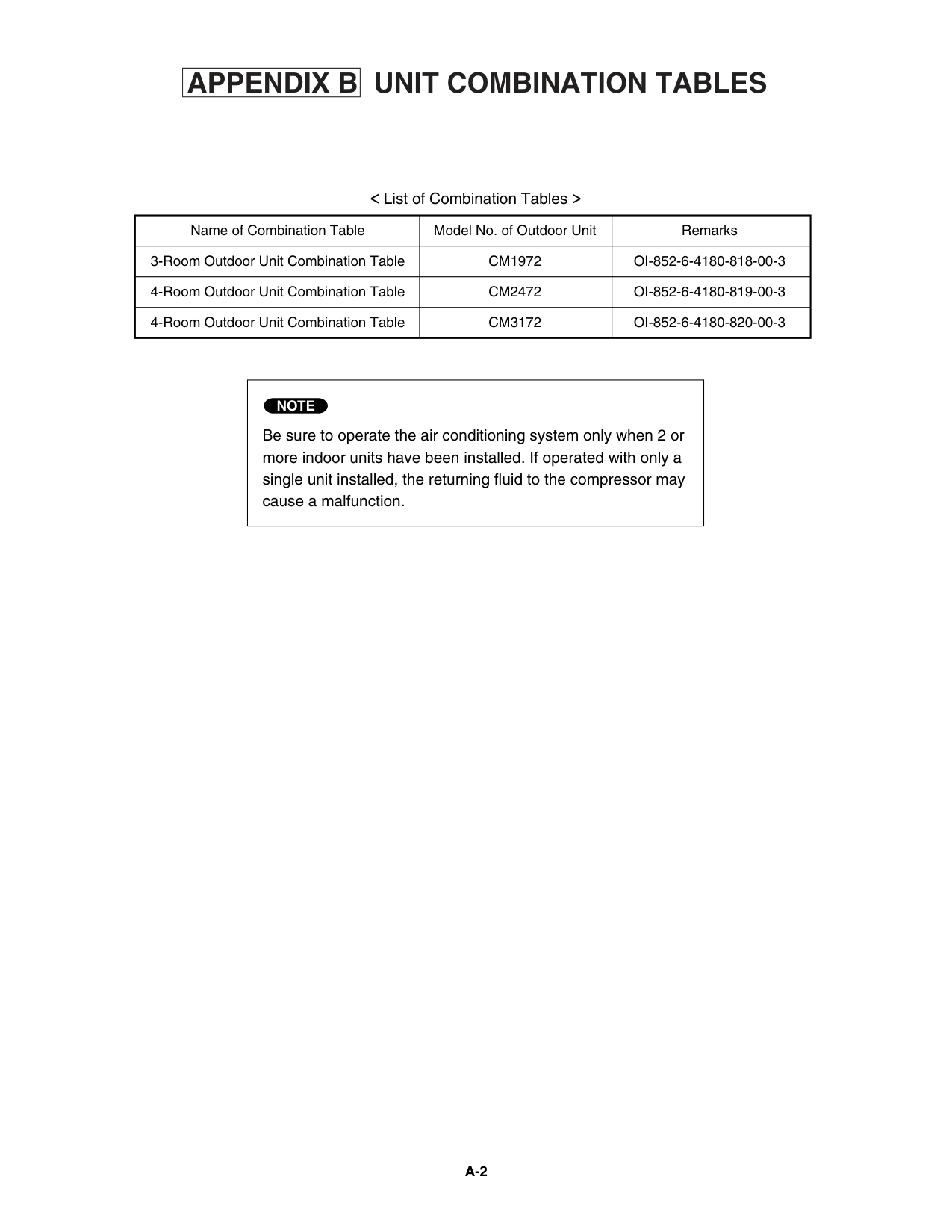
Indoor unit A
Indoor unit D
D is the indoor unit with
1 2 3 4 5 6 7 8 9 10 11 12
Power supply (conduit)
Power: Single-phase, 230/208VAC 60HZ
1 2 3
| | | |---|---| | | |
Power switch (not provided)
Inter-unit cables #14 (not provided)
Terminal board
Inter-unit cables #14 (not provided)
Terminal board
Inter-unit cables #14 (not provided)
Terminal board
Inter-unit cables #14 (not provided)
Terminal board
||A| |---| | | | | |---|---|---|---| | | | | |
Ground
Power cable (not provided) (#12: Less than 85 ft.)
1 2 3
||B| |---| | | | | |---|---|---|---|

| | | | |
|Be sure to perform grounding. Attach a ground wire to either the outdoor unit or indoor unit. If there is a grounding terminal inside the room, use the grounding screw inside the indoor unit.
| |---|
1 2 3
||C| |---| | | | | |---|---|---|---| | | | | |
|Be sure to apply the provided labels to both ends of the inter-unit cables to prevent miswiring. The units will not function if the wiring connections are incorrect.
| |---|
1 2 3
||D| |---| | | | | |---|---|---|---| | | | | |
... AWG (American Wire Gauge)
Inter Unit (conduit)
####################### Fig. 31
Use a dedicated A/C circuit for power. To make connections to the outdoor unit, remove the inspection panel and tubing panel. Do not bring the inter-unit cables or power cable into contact with tubing or service valves. Use outdoor unit cable fasteners and fasten the interunit cables at the location where the cables are doublesheathed. Arrange the wiring so that the inter-unit cables are contained in the inspection panel and tubing panel, as shown in Fig. 31.
Regulations on wire size differ from locality to locality. For field wiring requirements, please refer to your local electrical codes. Make sure that the installation fully complies with all local and national regulations.
Lock nut
Cabinet
Terminal block
Conduit plate
Access panel “C”
Plug
############# 6. Test RunPerforming a test run
Power supply (Conduit)
Inter unit (Conduit)
Fig. 32
Refer to the test run procedures in the indoor unit installation manual. Perform the test run separately for each connected indoor unit. If 2 units are operated simultaneously, it is not possible to correctly check for errors in tubing and wiring.
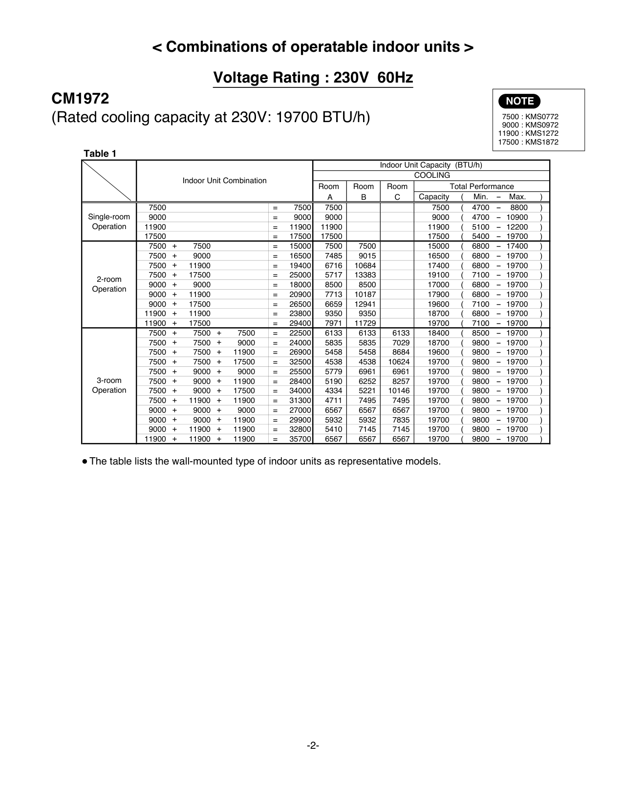
Access panel C
####################### Checking tubing and wiring
Perform the test run and check that operation is normal. If there is an error in tubing or wiring, the refrigerant may flow to indoor unit B when indoor unit A is operated (for example).
Conduit plate
########################### CAUTION
|CAUTION| |---|
Make sure there is no gap between access panel “C” and the conduit plate.
Stop operation immediately if there is an error in tubing or wiring. Turn the power (breaker) to OFF, and check whether the inter-unit cables are connected incorrectly, or whether the narrow tubes A and B are connected in reverse. Correct the connections.
Fig. 33
If there is an error in tubing, pump-down must be performed. Be sure to perform pump-down. After making corrections, again purge the air from the tubes.
############# 7. Connecting a Home Automation device
The HA (white) 4P terminal is located on the indoor unit PCB. If a HA device will be used, connect it to this terminal.
############## 8. Installation Check SheetThe strength of the installation location is sufficient to support the A/C weight.The indoor and outdoor units are installed level and vertically.The power and voltage are as specified.Inter-unit cables are securely fastened to the terminal board.Inter-unit cables are securely fixed.The power cord and inter-unit cables are not connected anywhere along their paths.The ground wire is securely connected.An air purge of the refrigerant circuit has been conducted.A leak test of the tubing connections has been performed.Thermal insulation has been applied to the tubing connections.Drain connections are secure and water drains properly.Putty has been used to close the hole in the wall.All service valves are fully open.Remote controller signals are being positively received.
|APPENDIX B| |---|
##### UNIT COMBINATION TABLES
< List of Combination Tables >
|Name of Combination Table|Model No. of Outdoor Unit|Remarks| |---|---|---| |3-Room Outdoor Unit Combination Table|CM1972|OI-852-6-4180-818-00-3| |4-Room Outdoor Unit Combination Table|CM2472|OI-852-6-4180-819-00-3| |4-Room Outdoor Unit Combination Table|CM3172|OI-852-6-4180-820-00-3|
|Be sure to operate the air conditioning system only when 2 or more indoor units have been installed. If operated with only a single unit installed, the returning fluid to the compressor may cause a malfunction.
NOTE| |---|
############################ A-2
############ Save this Combination Table! Please be sure to hand over this sheet to the user.
|3-Room Outdoor Unit Combination Table| |---|
############ Conditions:
|at 230V| |---|
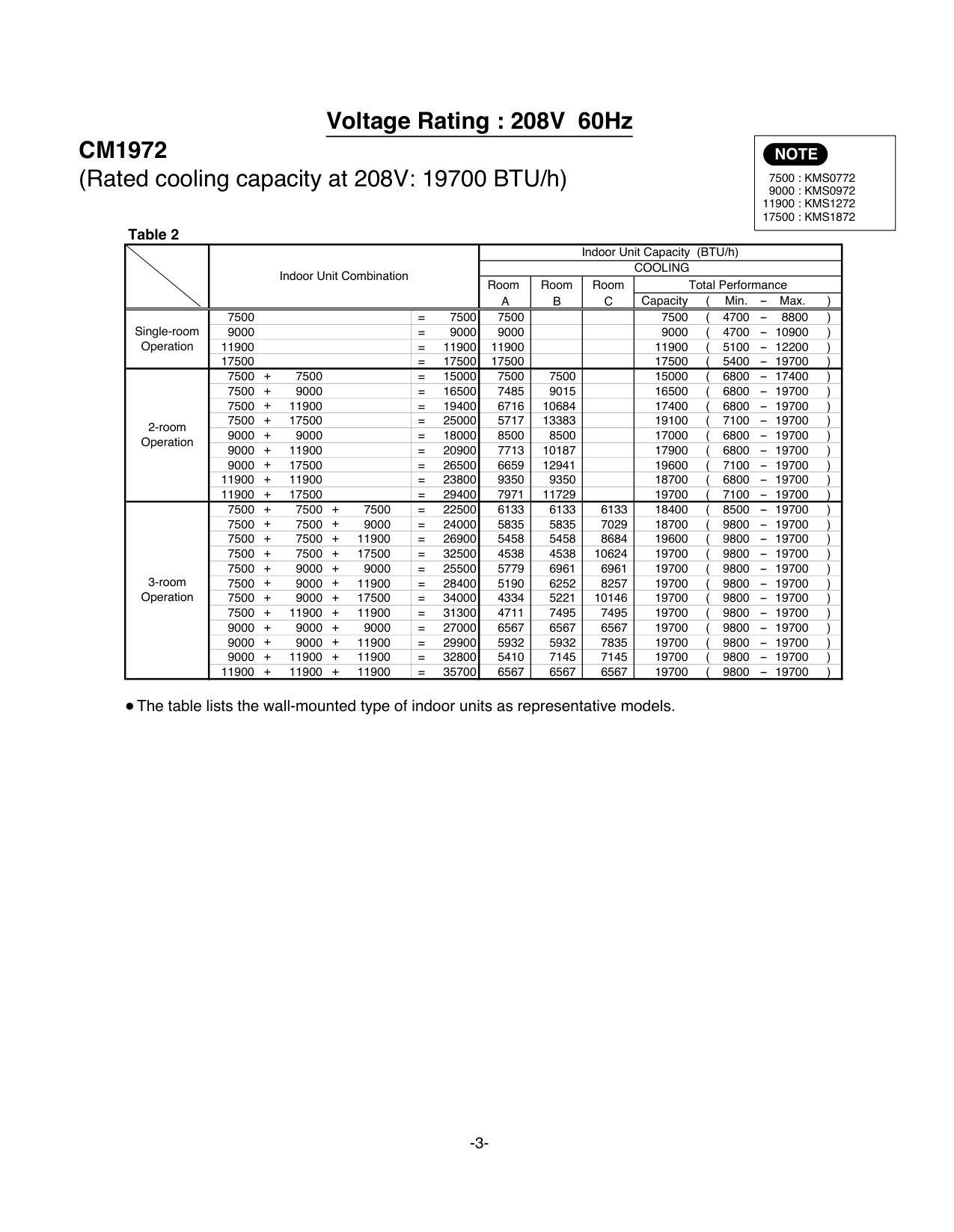
Rated cooling capacity of indoor units: K1, K2, ... (BTU/h) Then:
In this case, all the indoor units installed must not be operated concurrently under any circumstances. Otherwise, the air conditioner may not run properly and trouble may occur.
|Be sure to operate the air conditioning system only when 2 or more indoor units have been installed. If operated with only a single unit installed, the returning fluid to the compressor may cause a malfunction.
NOTE| |---|
|CAUTION| |---|
C x 2 (200%) K1 + K2 + ....... 19700 x 2 7500 + 11900 + 17500 39400 36900
CM1972
Rated cooling capacity of CM1972 outdoor unit: C=19700 (BTU/h)
If the following holds true
Rated cooling capacity of indoor units: K1, K2, ... (BTU/h) Then:
However, since this combination is not found in the 3-room operation column of Table 2, operating all these units concurrently
|at 208V| |---|
Rated cooling capacity of CM1972 outdoor unit: C=19700 (BTU/h)
C x 2 (200%) K1 + K2 + ....... 19700 x 2 7500 + 11900 + 17500 39400 36900
|Pub. OI-85264180818003| |---|
© SANYO 2007
####### < Combinations of operatable indoor units >
####### Voltage Rating : 230V 60Hz
|NOTE
7500 : KMS0772 9000 : KMS0972
11900 : KMS1272 17500 : KMS1872| |---|
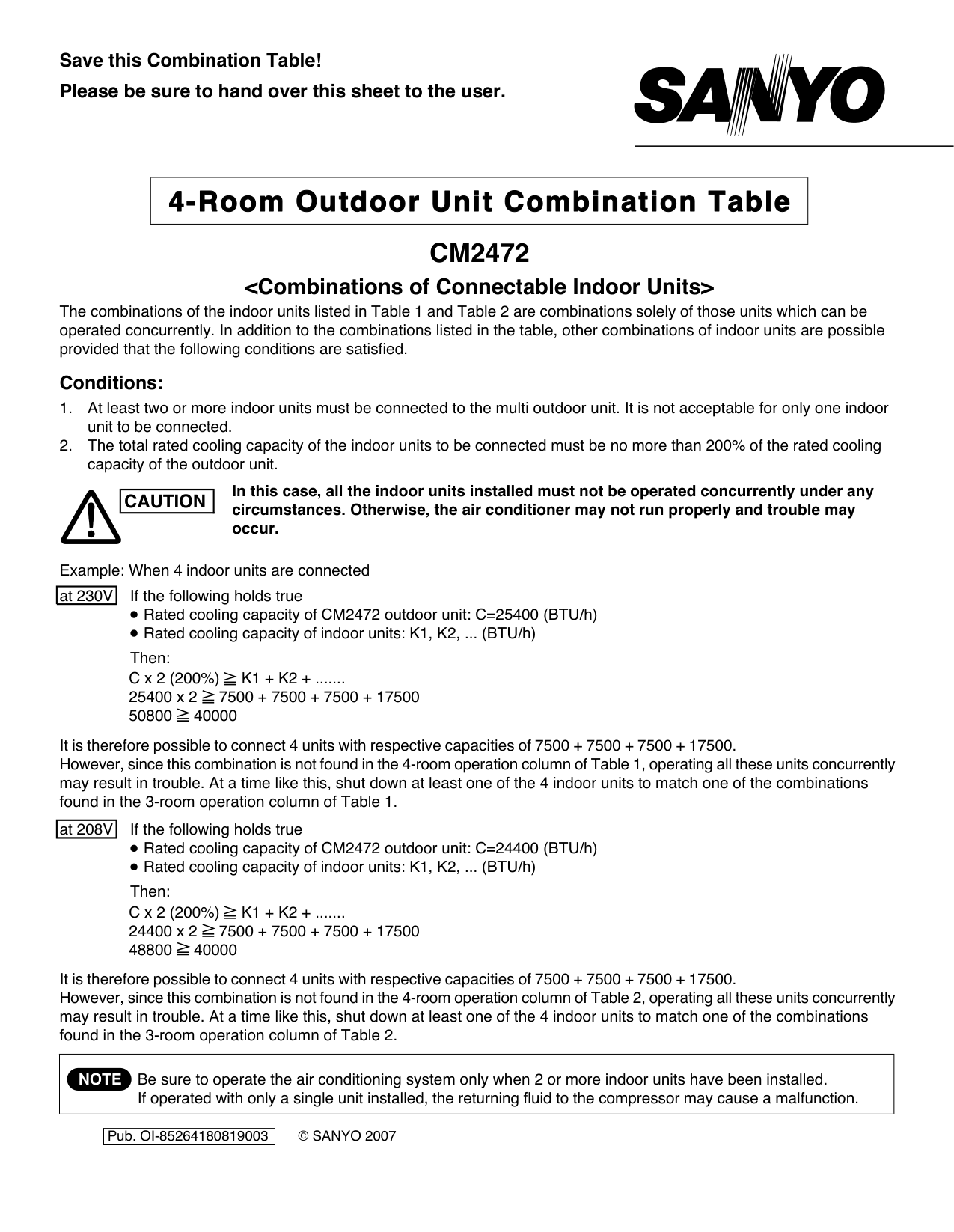
CM1972 (Rated cooling capacity at 230V: 19700 BTU/h)
| |Indoor Unit Combination|Indoor Unit Combination|Indoor Unit Capacity (BTU/h)|Indoor Unit Capacity (BTU/h)|Indoor Unit Capacity (BTU/h)|Indoor Unit Capacity (BTU/h)| |---|---|---|---|---|---|---| | |Indoor Unit Combination|Indoor Unit Combination|COOLING|COOLING|COOLING|COOLING| | |Indoor Unit Combination|Indoor Unit Combination|Room A|Room B|Room C|Total Performance| | |Indoor Unit Combination|Indoor Unit Combination|Room A|Room B|Room C|Capacity ( Min. - Max. )| |Single-room Operation|7500|= 7500|7500| | |7500 ( 4700 - 8800 )| |Single-room Operation|9000|= 9000|9000| | |9000 ( 4700 - 10900 )| |Single-room Operation|11900|= 11900|11900| | |11900 ( 5100 - 12200 )| |Single-room Operation|17500|= 17500|17500| | |17500 ( 5400 - 19700 )| |2-room Operation|7500 + 7500|= 15000|7500|7500| |15000 ( 6800 - 17400 )| |2-room Operation|7500 + 9000|= 16500|7485|9015| |16500 ( 6800 - 19700 )| |2-room Operation|7500 + 11900|= 19400|6716|10684| |17400 ( 6800 - 19700 )| |2-room Operation|7500 + 17500|= 25000|5717|13383| |19100 ( 7100 - 19700 )| |2-room Operation|9000 + 9000|= 18000|8500|8500| |17000 ( 6800 - 19700 )| |2-room Operation|9000 + 11900|= 20900|7713|10187| |17900 ( 6800 - 19700 )| |2-room Operation|9000 + 17500|= 26500|6659|12941| |19600 ( 7100 - 19700 )| |2-room Operation|11900 + 11900|= 23800|9350|9350| |18700 ( 6800 - 19700 )| |2-room Operation|11900 + 17500|= 29400|7971|11729| |19700 ( 7100 - 19700 )| |3-room Operation|7500 + 7500 + 7500|= 22500|6133|6133|6133|18400 ( 8500 - 19700 )| |3-room Operation|7500 + 7500 + 9000|= 24000|5835|5835|7029|18700 ( 9800 - 19700 )| |3-room Operation|7500 + 7500 + 11900|= 26900|5458|5458|8684|19600 ( 9800 - 19700 )| |3-room Operation|7500 + 7500 + 17500|= 32500|4538|4538|10624|19700 ( 9800 - 19700 )| |3-room Operation|7500 + 9000 + 9000|= 25500|5779|6961|6961|19700 ( 9800 - 19700 )| |3-room Operation|7500 + 9000 + 11900|= 28400|5190|6252|8257|19700 ( 9800 - 19700 )| |3-room Operation|7500 + 9000 + 17500|= 34000|4334|5221|10146|19700 ( 9800 - 19700 )| |3-room Operation|7500 + 11900 + 11900|= 31300|4711|7495|7495|19700 ( 9800 - 19700 )| |3-room Operation|9000 + 9000 + 9000|= 27000|6567|6567|6567|19700 ( 9800 - 19700 )| |3-room Operation|9000 + 9000 + 11900|= 29900|5932|5932|7835|19700 ( 9800 - 19700 )| |3-room Operation|9000 + 11900 + 11900|= 32800|5410|7145|7145|19700 ( 9800 - 19700 )| |3-room Operation|11900 + 11900 + 11900|= 35700|6567|6567|6567|19700 ( 9800 - 19700 )|
The table lists the wall-mounted type of indoor units as representative models.
####### Voltage Rating : 208V 60Hz
|NOTE
7500 : KMS0772 9000 : KMS0972
11900 : KMS1272 17500 : KMS1872| |---|
CM1972 (Rated cooling capacity at 208V: 19700 BTU/h)
| |Indoor Unit Combination|Indoor Unit Combination|Indoor Unit Capacity (BTU/h)|Indoor Unit Capacity (BTU/h)|Indoor Unit Capacity (BTU/h)|Indoor Unit Capacity (BTU/h)| |---|---|---|---|---|---|---| | |Indoor Unit Combination|Indoor Unit Combination|COOLING|COOLING|COOLING|COOLING| | |Indoor Unit Combination|Indoor Unit Combination|Room A|Room B|Room C|Total Performance| | |Indoor Unit Combination|Indoor Unit Combination|Room A|Room B|Room C|Capacity ( Min. - Max. )| |Single-room Operation|7500|= 7500|7500| | |7500 ( 4700 - 8800 )| |Single-room Operation|9000|= 9000|9000| | |9000 ( 4700 - 10900 )| |Single-room Operation|11900|= 11900|11900| | |11900 ( 5100 - 12200 )| |Single-room Operation|17500|= 17500|17500| | |17500 ( 5400 - 19700 )| |2-room Operation|7500 + 7500|= 15000|7500|7500| |15000 ( 6800 - 17400 )| |2-room Operation|7500 + 9000|= 16500|7485|9015| |16500 ( 6800 - 19700 )| |2-room Operation|7500 + 11900|= 19400|6716|10684| |17400 ( 6800 - 19700 )| |2-room Operation|7500 + 17500|= 25000|5717|13383| |19100 ( 7100 - 19700 )| |2-room Operation|9000 + 9000|= 18000|8500|8500| |17000 ( 6800 - 19700 )| |2-room Operation|9000 + 11900|= 20900|7713|10187| |17900 ( 6800 - 19700 )| |2-room Operation|9000 + 17500|= 26500|6659|12941| |19600 ( 7100 - 19700 )| |2-room Operation|11900 + 11900|= 23800|9350|9350| |18700 ( 6800 - 19700 )|
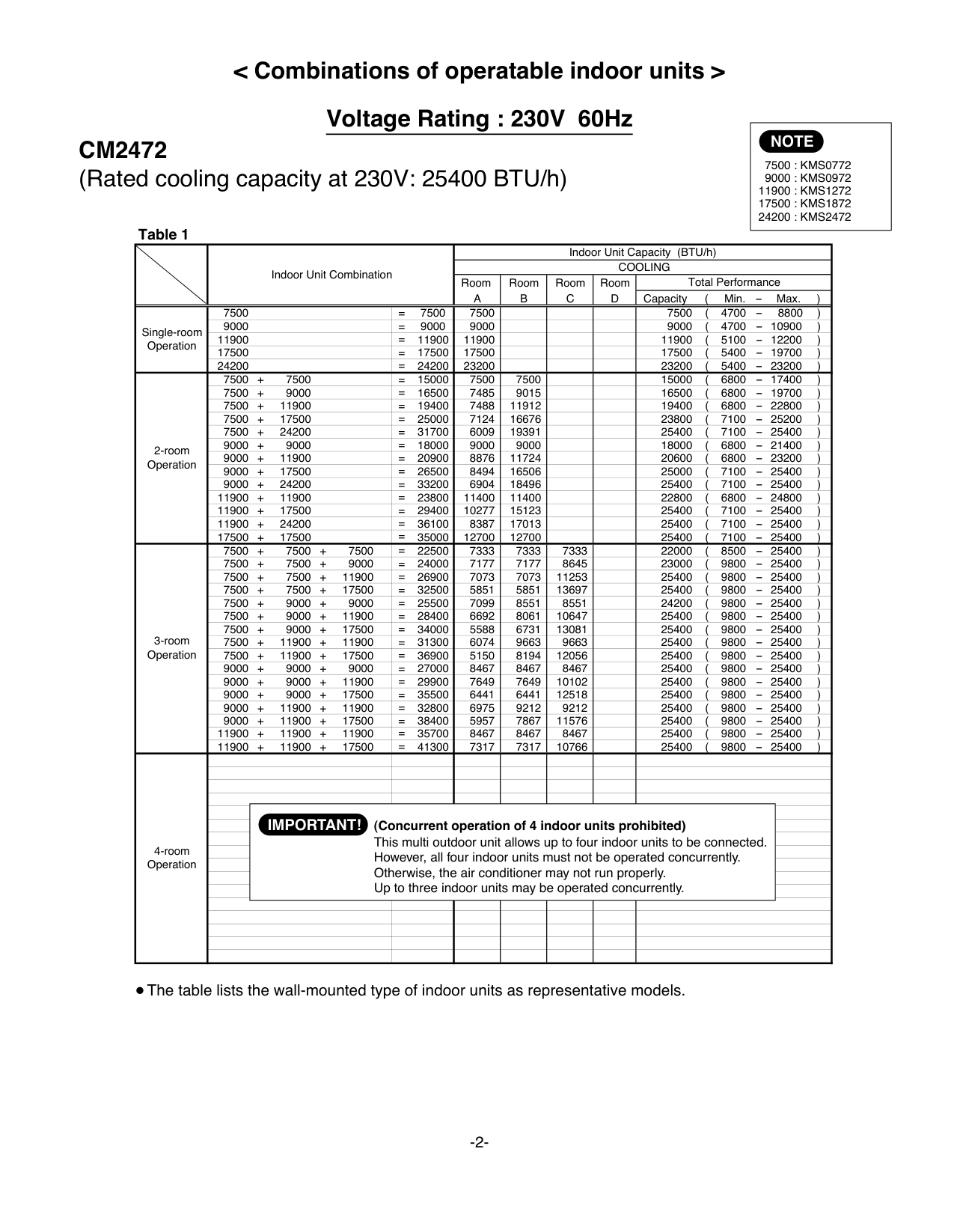
|2-room Operation|11900 + 17500|= 29400|7971|11729| |19700 ( 7100 - 19700 )| |3-room Operation|7500 + 7500 + 7500|= 22500|6133|6133|6133|18400 ( 8500 - 19700 )| |3-room Operation|7500 + 7500 + 9000|= 24000|5835|5835|7029|18700 ( 9800 - 19700 )| |3-room Operation|7500 + 7500 + 11900|= 26900|5458|5458|8684|19600 ( 9800 - 19700 )| |3-room Operation|7500 + 7500 + 17500|= 32500|4538|4538|10624|19700 ( 9800 - 19700 )| |3-room Operation|7500 + 9000 + 9000|= 25500|5779|6961|6961|19700 ( 9800 - 19700 )| |3-room Operation|7500 + 9000 + 11900|= 28400|5190|6252|8257|19700 ( 9800 - 19700 )| |3-room Operation|7500 + 9000 + 17500|= 34000|4334|5221|10146|19700 ( 9800 - 19700 )| |3-room Operation|7500 + 11900 + 11900|= 31300|4711|7495|7495|19700 ( 9800 - 19700 )| |3-room Operation|9000 + 9000 + 9000|= 27000|6567|6567|6567|19700 ( 9800 - 19700 )| |3-room Operation|9000 + 9000 + 11900|= 29900|5932|5932|7835|19700 ( 9800 - 19700 )| |3-room Operation|9000 + 11900 + 11900|= 32800|5410|7145|7145|19700 ( 9800 - 19700 )| |3-room Operation|11900 + 11900 + 11900|= 35700|6567|6567|6567|19700 ( 9800 - 19700 )|
The table lists the wall-mounted type of indoor units as representative models.
############ Save this Combination Table! Please be sure to hand over this sheet to the user.
############ Conditions:
|at 230V| |---|
Rated cooling capacity of indoor units: K1, K2, ... (BTU/h) Then:
may result in trouble. At a time like this, shut down at least one of the 4 indoor units to match one of the combinations
|4-Room Outdoor Unit Combination Table| |---|
In this case, all the indoor units installed must not be operated concurrently under any circumstances. Otherwise, the air conditioner may not run properly and trouble may occur.
|CAUTION| |---|
C x 2 (200%) K1 + K2 + ....... 25400 x 2 7500 + 7500 + 7500 + 17500 50800 40000
CM2472
Rated cooling capacity of CM2472 outdoor unit: C=25400 (BTU/h)
|at 208V| |---|
If the following holds true
Rated cooling capacity of indoor units: K1, K2, ... (BTU/h) Then:
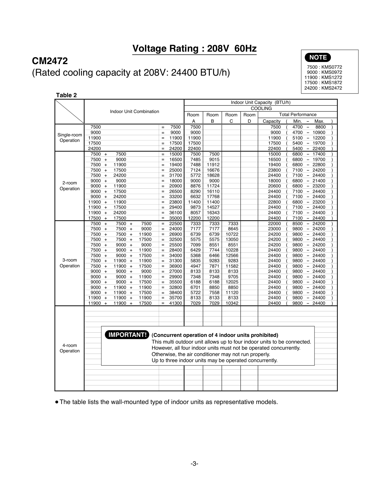
It is therefore possible to connect 4 units with respective capacities of 7500 + 7500 + 7500 + 17500. However, since this combination is not found in the 4-room operation column of Table 2, operating all these units concurrently may result in trouble. At a time like this, shut down at least one of the 4 indoor units to match one of the combinations
Rated cooling capacity of CM2472 outdoor unit: C=24400 (BTU/h)
C x 2 (200%) K1 + K2 + ....... 24400 x 2 7500 + 7500 + 7500 + 17500 48800 40000
|Be sure to operate the air conditioning system only when 2 or more indoor units have been installed. If operated with only a single unit installed, the returning fluid to the compressor may cause a malfunction.
NOTE| |---|
|Pub. OI-85264180819003| |---|
© SANYO 2007
####### < Combinations of operatable indoor units >
####### Voltage Rating : 230V 60Hz
|NOTE
7500 : KMS0772 9000 : KMS0972
11900 : KMS1272 17500 : KMS1872 24200 : KMS2472| |---|
CM2472 (Rated cooling capacity at 230V: 25400 BTU/h)
| |Indoor Unit Combination|Indoor Unit Combination|Indoor Unit Combination|Indoor Unit Capacity (BTU/h)|Indoor Unit Capacity (BTU/h)|Indoor Unit Capacity (BTU/h)|Indoor Unit Capacity (BTU/h)|Indoor Unit Capacity (BTU/h)|Indoor Unit Capacity (BTU/h)| |---|---|---|---|---|---|---|---|---|---| | |Indoor Unit Combination|Indoor Unit Combination|Indoor Unit Combination|COOLING|COOLING|COOLING|COOLING|COOLING|COOLING| | |Indoor Unit Combination|Indoor Unit Combination|Indoor Unit Combination|Room A|Room B|Room C|Room D|Total Performance|Total Performance| | |Indoor Unit Combination|Indoor Unit Combination|Indoor Unit Combination|Room A|Room B|Room C|Room D|Capacity ( Min. - Max. )|Capacity ( Min. - Max. )| |Single-room Operation|7500|7500|= 7500|7500| | | |7500 ( 4700 - 8800 )|7500 ( 4700 - 8800 )| |Single-room Operation|9000|9000|= 9000|9000| | | |9000 ( 4700 - 10900 )|9000 ( 4700 - 10900 )| |Single-room Operation|11900|11900|= 11900|11900| | | |11900 ( 5100 - 12200 )|11900 ( 5100 - 12200 )| |Single-room Operation|17500|17500|= 17500|17500| | | |17500 ( 5400 - 19700 )|17500 ( 5400 - 19700 )| |Single-room Operation|24200|24200|= 24200|23200| | | |23200 ( 5400 - 23200 )|23200 ( 5400 - 23200 )| |2-room Operation|7500 + 7500|7500 + 7500|= 15000|7500|7500| | |15000 ( 6800 - 17400 )|15000 ( 6800 - 17400 )| |2-room Operation|7500 + 9000|7500 + 9000|= 16500|7485|9015| | |16500 ( 6800 - 19700 )|16500 ( 6800 - 19700 )| |2-room Operation|7500 + 11900|7500 + 11900|= 19400|7488|11912| | |19400 ( 6800 - 22800 )|19400 ( 6800 - 22800 )| |2-room Operation|7500 + 17500|7500 + 17500|= 25000|7124|16676| | |23800 ( 7100 - 25200 )|23800 ( 7100 - 25200 )| |2-room Operation|7500 + 24200|7500 + 24200|= 31700|6009|19391| | |25400 ( 7100 - 25400 )|25400 ( 7100 - 25400 )| |2-room Operation|9000 + 9000|9000 + 9000|= 18000|9000|9000| | |18000 ( 6800 - 21400 )|18000 ( 6800 - 21400 )| |2-room Operation|9000 + 11900|9000 + 11900|= 20900|8876|11724| | |20600 ( 6800 - 23200 )|20600 ( 6800 - 23200 )| |2-room Operation|9000 + 17500|9000 + 17500|= 26500|8494|16506| | |25000 ( 7100 - 25400 )|25000 ( 7100 - 25400 )| |2-room Operation|9000 + 24200|9000 + 24200|= 33200|6904|18496| | |25400 ( 7100 - 25400 )|25400 ( 7100 - 25400 )| |2-room Operation|11900 + 11900|11900 + 11900|= 23800|11400|11400| | |22800 ( 6800 - 24800 )|22800 ( 6800 - 24800 )| |2-room Operation|11900 + 17500|11900 + 17500|= 29400|10277|15123| | |25400 ( 7100 - 25400 )|25400 ( 7100 - 25400 )| |2-room Operation|11900 + 24200|11900 + 24200|= 36100|8387|17013| | |25400 ( 7100 - 25400 )|25400 ( 7100 - 25400 )| |2-room Operation|17500 + 17500|17500 + 17500|= 35000|12700|12700| | |25400 ( 7100 - 25400 )|25400 ( 7100 - 25400 )| |3-room Operation|7500 + 7500 + 7500|7500 + 7500 + 7500|= 22500|7333|7333|7333| |22000 ( 8500 - 25400 )|22000 ( 8500 - 25400 )| |3-room Operation|7500 + 7500 + 9000|7500 + 7500 + 9000|= 24000|7177|7177|8645| |23000 ( 9800 - 25400 )|23000 ( 9800 - 25400 )| |3-room Operation|7500 + 7500 + 11900|7500 + 7500 + 11900|= 26900|7073|7073|11253| |25400 ( 9800 - 25400 )|25400 ( 9800 - 25400 )| |3-room Operation|7500 + 7500 + 17500|7500 + 7500 + 17500|= 32500|5851|5851|13697| |25400 ( 9800 - 25400 )|25400 ( 9800 - 25400 )| |3-room Operation|7500 + 9000 + 9000|7500 + 9000 + 9000|= 25500|7099|8551|8551| |24200 ( 9800 - 25400 )|24200 ( 9800 - 25400 )| |3-room Operation|7500 + 9000 + 11900|7500 + 9000 + 11900|= 28400|6692|8061|10647| |25400 ( 9800 - 25400 )|25400 ( 9800 - 25400 )| |3-room Operation|7500 + 9000 + 17500|7500 + 9000 + 17500|= 34000|5588|6731|13081| |25400 ( 9800 - 25400 )|25400 ( 9800 - 25400 )| |3-room Operation|7500 + 11900 + 11900|7500 + 11900 + 11900|= 31300|6074|9663|9663| |25400 ( 9800 - 25400 )|25400 ( 9800 - 25400 )| |3-room Operation|7500 + 11900 + 17500|7500 + 11900 + 17500|= 36900|5150|8194|12056| |25400 ( 9800 - 25400 )|25400 ( 9800 - 25400 )| |3-room Operation|9000 + 9000 + 9000|9000 + 9000 + 9000|= 27000|8467|8467|8467| |25400 ( 9800 - 25400 )|25400 ( 9800 - 25400 )|

|3-room Operation|9000 + 9000 + 11900|9000 + 9000 + 11900|= 29900|7649|7649|10102| |25400 ( 9800 - 25400 )|25400 ( 9800 - 25400 )| |3-room Operation|9000 + 9000 + 17500|9000 + 9000 + 17500|= 35500|6441|6441|12518| |25400 ( 9800 - 25400 )|25400 ( 9800 - 25400 )| |3-room Operation|9000 + 11900 + 11900|9000 + 11900 + 11900|= 32800|6975|9212|9212| |25400 ( 9800 - 25400 )|25400 ( 9800 - 25400 )| |3-room Operation|9000 + 11900 + 17500|9000 + 11900 + 17500|= 38400|5957|7867|11576| |25400 ( 9800 - 25400 )|25400 ( 9800 - 25400 )| |3-room Operation|11900 + 11900 + 11900|11900 + 11900 + 11900|= 35700|8467|8467|8467| |25400 ( 9800 - 25400 )|25400 ( 9800 - 25400 )| |3-room Operation|11900 + 11900 + 17500|11900 + 11900 + 17500|= 41300|7317|7317|10766| |25400 ( 9800 - 25400 )|25400 ( 9800 - 25400 )| |4-room Operation| | | | | | | | | | |4-room Operation| | | | | | | | | | |4-room Operation| | | | | | | | | | |4-room Operation| | | | | | | | | | |4-room Operation| | | | | | | | | | |4-room Operation| |(CIMPORTANT!|ncurrent|perati|n of 4 i|door u|its pr|hibited)| | |4-room Operation| |Th|s multi out|oor uni|allows|p to fo|r indoo|units to be connected.| | |4-room Operation| |Ho|ever, all f|ur indo|r units|ust not|be ope|ated concurrently.| | |4-room Operation| | | | | | | | | | |4-room Operation| |Ot|erwise, th|air con|itioner|ay not|run pro|erly.| | |4-room Operation| |Up|to three in|oor uni|s may b|opera|ed con|urrently.| | |4-room Operation| | | | | | | | | | |4-room Operation| | | | | | | | | | |4-room Operation| | | | | | | | | | |4-room Operation| | | | | | | | | | |4-room Operation| | | | | | | | | |
####### Voltage Rating : 208V 60Hz
|NOTE
7500 : KMS0772 9000 : KMS0972
11900 : KMS1272 17500 : KMS1872 24200 : KMS2472| |---|
CM2472 (Rated cooling capacity at 208V: 24400 BTU/h)
| |Indoor Unit Combination|Indoor Unit Combination|Indoor Unit Combination|Indoor Unit Capacity (BTU/h)|Indoor Unit Capacity (BTU/h)|Indoor Unit Capacity (BTU/h)|Indoor Unit Capacity (BTU/h)|Indoor Unit Capacity (BTU/h)|Indoor Unit Capacity (BTU/h)| |---|---|---|---|---|---|---|---|---|---| | |Indoor Unit Combination|Indoor Unit Combination|Indoor Unit Combination|COOLING|COOLING|COOLING|COOLING|COOLING|COOLING| | |Indoor Unit Combination|Indoor Unit Combination|Indoor Unit Combination|Room A|Room B|Room C|Room D|Total Performance|Total Performance| | |Indoor Unit Combination|Indoor Unit Combination|Indoor Unit Combination|Room A|Room B|Room C|Room D|Capacity ( Min. - Max. )|Capacity ( Min. - Max. )| |Single-room Operation|7500|7500|= 7500|7500| | | |7500 ( 4700 - 8800 )|7500 ( 4700 - 8800 )| |Single-room Operation|9000|9000|= 9000|9000| | | |9000 ( 4700 - 10900 )|9000 ( 4700 - 10900 )| |Single-room Operation|11900|11900|= 11900|11900| | | |11900 ( 5100 - 12200 )|11900 ( 5100 - 12200 )| |Single-room Operation|17500|17500|= 17500|17500| | | |17500 ( 5400 - 19700 )|17500 ( 5400 - 19700 )| |Single-room Operation|24200|24200|= 24200|22400| | | |22400 ( 5400 - 22400 )|22400 ( 5400 - 22400 )| |2-room Operation|7500 + 7500|7500 + 7500|= 15000|7500|7500| | |15000 ( 6800 - 17400 )|15000 ( 6800 - 17400 )| |2-room Operation|7500 + 9000|7500 + 9000|= 16500|7485|9015| | |16500 ( 6800 - 19700 )|16500 ( 6800 - 19700 )| |2-room Operation|7500 + 11900|7500 + 11900|= 19400|7488|11912| | |19400 ( 6800 - 22800 )|19400 ( 6800 - 22800 )| |2-room Operation|7500 + 17500|7500 + 17500|= 25000|7124|16676| | |23800 ( 7100 - 24200 )|23800 ( 7100 - 24200 )| |2-room Operation|7500 + 24200|7500 + 24200|= 31700|5772|18628| | |24400 ( 7100 - 24400 )|24400 ( 7100 - 24400 )| |2-room Operation|9000 + 9000|9000 + 9000|= 18000|9000|9000| | |18000 ( 6800 - 21400 )|18000 ( 6800 - 21400 )| |2-room Operation|9000 + 11900|9000 + 11900|= 20900|8876|11724| | |20600 ( 6800 - 23200 )|20600 ( 6800 - 23200 )| |2-room Operation|9000 + 17500|9000 + 17500|= 26500|8290|16110| | |24400 ( 7100 - 24400 )|24400 ( 7100 - 24400 )| |2-room Operation|9000 + 24200|9000 + 24200|= 33200|6632|17768| | |24400 ( 7100 - 24400 )|24400 ( 7100 - 24400 )| |2-room Operation|11900 + 11900|11900 + 11900|= 23800|11400|11400| | |22800 ( 6800 - 23200 )|22800 ( 6800 - 23200 )| |2-room Operation|11900 + 17500|11900 + 17500|= 29400|9873|14527| | |24400 ( 7100 - 24400 )|24400 ( 7100 - 24400 )| |2-room Operation|11900 + 24200|11900 + 24200|= 36100|8057|16343| | |24400 ( 7100 - 24400 )|24400 ( 7100 - 24400 )| |2-room Operation|17500 + 17500|17500 + 17500|= 35000|12200|12200| | |24400 ( 7100 - 24400 )|24400 ( 7100 - 24400 )| |3-room Operation|7500 + 7500 + 7500|7500 + 7500 + 7500|= 22500|7333|7333|7333| |22000 ( 8500 - 24200 )|22000 ( 8500 - 24200 )| |3-room Operation|7500 + 7500 + 9000|7500 + 7500 + 9000|= 24000|7177|7177|8645| |23000 ( 9800 - 24200 )|23000 ( 9800 - 24200 )| |3-room Operation|7500 + 7500 + 11900|7500 + 7500 + 11900|= 26900|6739|6739|10722| |24200 ( 9800 - 24400 )|24200 ( 9800 - 24400 )| |3-room Operation|7500 + 7500 + 17500|7500 + 7500 + 17500|= 32500|5575|5575|13050| |24200 ( 9800 - 24400 )|24200 ( 9800 - 24400 )| |3-room Operation|7500 + 9000 + 9000|7500 + 9000 + 9000|= 25500|7099|8551|8551| |24200 ( 9800 - 24200 )|24200 ( 9800 - 24200 )| |3-room Operation|7500 + 9000 + 11900|7500 + 9000 + 11900|= 28400|6429|7744|10228| |24400 ( 9800 - 24400 )|24400 ( 9800 - 24400 )| |3-room Operation|7500 + 9000 + 17500|7500 + 9000 + 17500|= 34000|5368|6466|12566| |24400 ( 9800 - 24400 )|24400 ( 9800 - 24400 )| |3-room Operation|7500 + 11900 + 11900|7500 + 11900 + 11900|= 31300|5835|9283|9283| |24400 ( 9800 - 24400 )|24400 ( 9800 - 24400 )| |3-room Operation|7500 + 11900 + 17500|7500 + 11900 + 17500|= 36900|4947|7871|11582| |24400 ( 9800 - 24400 )|24400 ( 9800 - 24400 )| |3-room Operation|9000 + 9000 + 9000|9000 + 9000 + 9000|= 27000|8133|8133|8133| |24400 ( 9800 - 24400 )|24400 ( 9800 - 24400 )|
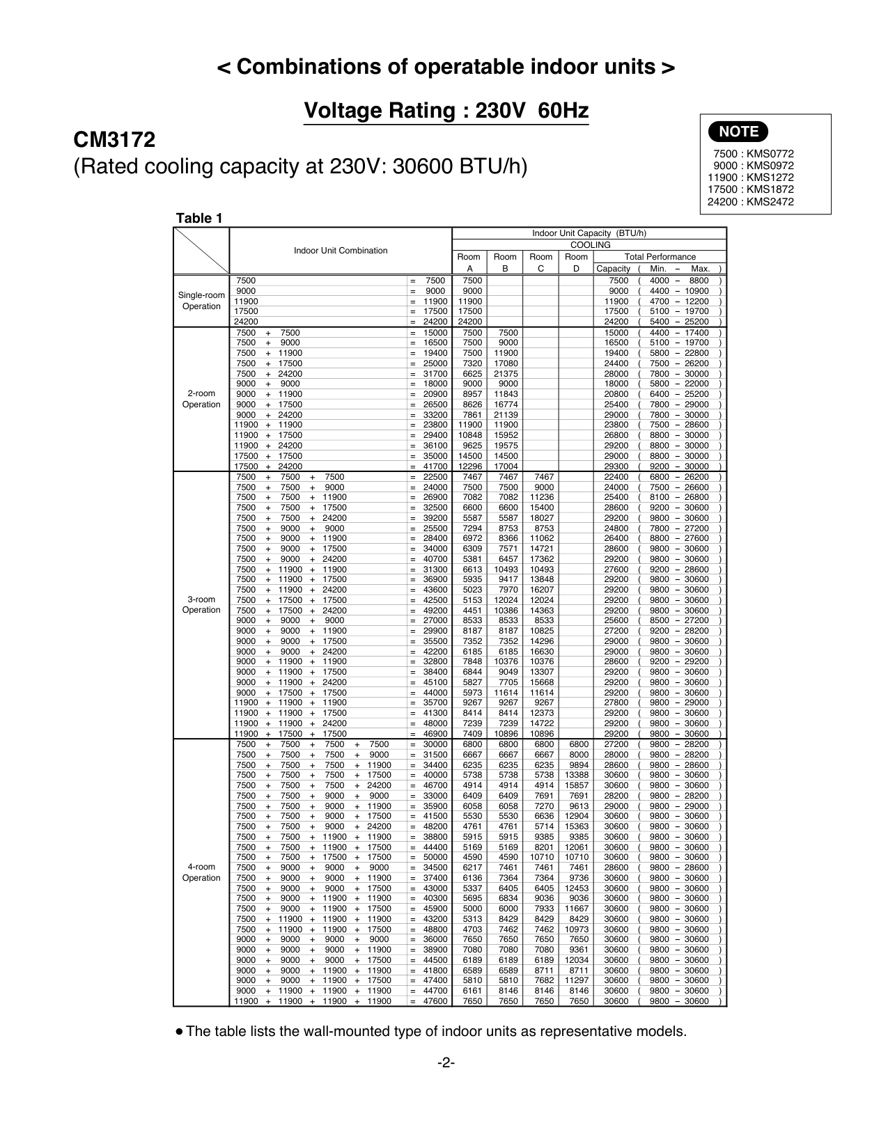
|3-room Operation|9000 + 9000 + 11900|9000 + 9000 + 11900|= 29900|7348|7348|9705| |24400 ( 9800 - 24400 )|24400 ( 9800 - 24400 )| |3-room Operation|9000 + 9000 + 17500|9000 + 9000 + 17500|= 35500|6188|6188|12025| |24400 ( 9800 - 24400 )|24400 ( 9800 - 24400 )| |3-room Operation|9000 + 11900 + 11900|9000 + 11900 + 11900|= 32800|6701|8850|8850| |24400 ( 9800 - 24400 )|24400 ( 9800 - 24400 )| |3-room Operation|9000 + 11900 + 17500|9000 + 11900 + 17500|= 38400|5722|7558|11120| |24400 ( 9800 - 24400 )|24400 ( 9800 - 24400 )| |3-room Operation|11900 + 11900 + 11900|11900 + 11900 + 11900|= 35700|8133|8133|8133| |24400 ( 9800 - 24400 )|24400 ( 9800 - 24400 )| |3-room Operation|11900 + 11900 + 17500|11900 + 11900 + 17500|= 41300|7029|7029|10342| |24400 ( 9800 - 24400 )|24400 ( 9800 - 24400 )| |4-room Operation| | | | | | | | | | |4-room Operation| | | | | | | | | | |4-room Operation| | | | | | | | | | |4-room Operation| | | | | | | | | | |4-room Operation| | | |perati
oor uni ur indo
air con oor uni|n of 4 i allows
r units itioner
s may b
|door u p to fo ust not ay not opera|its pr r indoo be ope run pro ed con| | | |4-room Operation| |(CIMPORTANT!|ncurrent|perati
oor uni ur indo
air con oor uni|n of 4 i allows
r units itioner
s may b
|door u p to fo ust not ay not opera|its pr r indoo be ope run pro ed con|hibited)| | |4-room Operation| |Th|s multi out|perati
oor uni ur indo
air con oor uni|n of 4 i allows
r units itioner
s may b
|door u p to fo ust not ay not opera|its pr r indoo be ope run pro ed con|units to be connected.| | |4-room Operation| |Ho|ever, all f|perati
oor uni ur indo
air con oor uni|n of 4 i allows
r units itioner
s may b
|door u p to fo ust not ay not opera|its pr r indoo be ope run pro ed con|ated concurrently.| | |4-room Operation| | | |perati
oor uni ur indo
air con oor uni|n of 4 i allows
r units itioner
s may b
|door u p to fo ust not ay not opera|its pr r indoo be ope run pro ed con| | | |4-room Operation| |Ot|erwise, th|perati
oor uni ur indo
air con oor uni|n of 4 i allows
r units itioner
s may b
|door u p to fo ust not ay not opera|its pr r indoo be ope run pro ed con|erly.| | |4-room Operation| |Up|to three in|perati
oor uni ur indo
air con oor uni|n of 4 i allows
r units itioner
s may b
|door u p to fo ust not ay not opera|its pr r indoo be ope run pro ed con|urrently.| | |4-room Operation| | | | | | | | | | |4-room Operation| | | | | | | | | | |4-room Operation| | | | | | | | | | |4-room Operation| | | | | | | | | | |4-room Operation| | | | | | | | | |
############ Conditions:
Example: When 4 indoor units are connected If the following holds true
|at 230V| |---|
Rated cooling capacity of indoor units: K1, K2, ... (BTU/h) Then:
It is therefore possible to connect 4 units with respective capacities of 7500 + 7500 + 11900 + 24200.
|4-Room Outdoor Unit Combination Table| |---|
In this case, all the indoor units installed must not be operated concurrently under any circumstances. Otherwise, the air conditioner may not run properly and trouble may occur.
|Be sure to operate the air conditioning system only when 2 or more indoor units have been installed. If operated with only a single unit installed, the returning fluid to the compressor may cause a malfunction.
NOTE| |---|
|CAUTION| |---|
C x 2 (200%) K1 + K2 + ....... 30600 x 2 7500 + 7500 + 11900 + 24200 61200 51100
Save this Combination Table! Please be sure to hand over this sheet to the user.
CM3172
Rated cooling capacity of CM3172 outdoor unit: C=30600 (BTU/h)
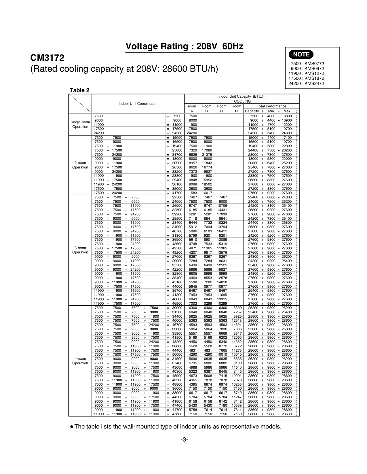
If the following holds true
Rated cooling capacity of indoor units: K1, K2, ... (BTU/h) Then:
It is therefore possible to connect 4 units with respective capacities of 7500 + 7500 + 11900 + 24200. However, since this combination is not found in the 4-room operation column of Table 2, operating all these units concurrently may result in trouble. At a time like this, shut down at least one of the 4 indoor units to match one of the combinations
|at 208V| |---|
Rated cooling capacity of CM3172 outdoor unit: C=28600 (BTU/h)
C x 2 (200%) K1 + K2 + ....... 28600 x 2 7500 + 7500 + 11900 + 24200 57200 51100
|Pub. OI-85264180820003| |---|
© SANYO 2007
####### < Combinations of operatable indoor units >
####### Voltage Rating : 230V 60Hz
|NOTE
7500 : KMS0772 9000 : KMS0972
11900 : KMS1272 17500 : KMS1872 24200 : KMS2472| |---|
CM3172 (Rated cooling capacity at 230V: 30600 BTU/h)
| |Indoor Unit Combination|Indoor Unit Combination|Indoor Unit Capacity (BTU/h)|Indoor Unit Capacity (BTU/h)|Indoor Unit Capacity (BTU/h)|Indoor Unit Capacity (BTU/h)|Indoor Unit Capacity (BTU/h)| |---|---|---|---|---|---|---|---| | |Indoor Unit Combination|Indoor Unit Combination|COOLING|COOLING|COOLING|COOLING|COOLING| | |Indoor Unit Combination|Indoor Unit Combination|Room A|Room B|Room C|Room D|Total Performance| | |Indoor Unit Combination|Indoor Unit Combination|Room A|Room B|Room C|Room D|Capacity ( Min. - Max. )| |Single-room Operation|7500|= 7500|7500| | | |7500 ( 4000 - 8800 )| |Single-room Operation|9000|= 9000|9000| | | |9000 ( 4400 - 10900 )| |Single-room Operation|11900|= 11900|11900| | | |11900 ( 4700 - 12200 )| |Single-room Operation|17500|= 17500|17500| | | |17500 ( 5100 - 19700 )| |Single-room Operation|24200|= 24200|24200| | | |24200 ( 5400 - 25200 )| |2-room Operation|7500 + 7500|= 15000|7500|7500| | |15000 ( 4400 - 17400 )| |2-room Operation|7500 + 9000|= 16500|7500|9000| | |16500 ( 5100 - 19700 )| |2-room Operation|7500 + 11900|= 19400|7500|11900| | |19400 ( 5800 - 22800 )| |2-room Operation|7500 + 17500|= 25000|7320|17080| | |24400 ( 7500 - 26200 )| |2-room Operation|7500 + 24200|= 31700|6625|21375| | |28000 ( 7800 - 30000 )| |2-room Operation|9000 + 9000|= 18000|9000|9000| | |18000 ( 5800 - 22000 )| |2-room Operation|9000 + 11900|= 20900|8957|11843| | |20800 ( 6400 - 25200 )| |2-room Operation|9000 + 17500|= 26500|8626|16774| | |25400 ( 7800 - 29000 )| |2-room Operation|9000 + 24200|= 33200|7861|21139| | |29000 ( 7800 - 30000 )| |2-room Operation|11900 + 11900|= 23800|11900|11900| | |23800 ( 7500 - 28600 )| |2-room Operation|11900 + 17500|= 29400|10848|15952| | |26800 ( 8800 - 30000 )| |2-room Operation|11900 + 24200|= 36100|9625|19575| | |29200 ( 8800 - 30000 )| |2-room Operation|17500 + 17500|= 35000|14500|14500| | |29000 ( 8800 - 30000 )| |2-room Operation|17500 + 24200|= 41700|12296|17004| | |29300 ( 9200 - 30000 )| |3-room Operation|7500 + 7500 + 7500|= 22500|7467|7467|7467| |22400 ( 6800 - 26200 )| |3-room Operation|7500 + 7500 + 9000|= 24000|7500|7500|9000| |24000 ( 7500 - 26600 )| |3-room Operation|7500 + 7500 + 11900|= 26900|7082|7082|11236| |25400 ( 8100 - 26800 )| |3-room Operation|7500 + 7500 + 17500|= 32500|6600|6600|15400| |28600 ( 9200 - 30600 )| |3-room Operation|7500 + 7500 + 24200|= 39200|5587|5587|18027| |29200 ( 9800 - 30600 )| |3-room Operation|7500 + 9000 + 9000|= 25500|7294|8753|8753| |24800 ( 7800 - 27200 )|

|3-room Operation|7500 + 9000 + 11900|= 28400|6972|8366|11062| |26400 ( 8800 - 27600 )| |3-room Operation|7500 + 9000 + 17500|= 34000|6309|7571|14721| |28600 ( 9800 - 30600 )| |3-room Operation|7500 + 9000 + 24200|= 40700|5381|6457|17362| |29200 ( 9800 - 30600 )| |3-room Operation|7500 + 11900 + 11900|= 31300|6613|10493|10493| |27600 ( 9200 - 28600 )| |3-room Operation|7500 + 11900 + 17500|= 36900|5935|9417|13848| |29200 ( 9800 - 30600 )| |3-room Operation|7500 + 11900 + 24200|= 43600|5023|7970|16207| |29200 ( 9800 - 30600 )| |3-room Operation|7500 + 17500 + 17500|= 42500|5153|12024|12024| |29200 ( 9800 - 30600 )| |3-room Operation|7500 + 17500 + 24200|= 49200|4451|10386|14363| |29200 ( 9800 - 30600 )| |3-room Operation|9000 + 9000 + 9000|= 27000|8533|8533|8533| |25600 ( 8500 - 27200 )| |3-room Operation|9000 + 9000 + 11900|= 29900|8187|8187|10825| |27200 ( 9200 - 28200 )| |3-room Operation|9000 + 9000 + 17500|= 35500|7352|7352|14296| |29000 ( 9800 - 30600 )| |3-room Operation|9000 + 9000 + 24200|= 42200|6185|6185|16630| |29000 ( 9800 - 30600 )| |3-room Operation|9000 + 11900 + 11900|= 32800|7848|10376|10376| |28600 ( 9200 - 29200 )| |3-room Operation|9000 + 11900 + 17500|= 38400|6844|9049|13307| |29200 ( 9800 - 30600 )| |3-room Operation|9000 + 11900 + 24200|= 45100|5827|7705|15668| |29200 ( 9800 - 30600 )| |3-room Operation|9000 + 17500 + 17500|= 44000|5973|11614|11614| |29200 ( 9800 - 30600 )| |3-room Operation|11900 + 11900 + 11900|= 35700|9267|9267|9267| |27800 ( 9800 - 29000 )| |3-room Operation|11900 + 11900 + 17500|= 41300|8414|8414|12373| |29200 ( 9800 - 30600 )| |3-room Operation|11900 + 11900 + 24200|= 48000|7239|7239|14722| |29200 ( 9800 - 30600 )| |3-room Operation|11900 + 17500 + 17500|= 46900|7409|10896|10896| |29200 ( 9800 - 30600 )| |4-room Operation|7500 + 7500 + 7500 + 7500|= 30000|6800|6800|6800|6800|27200 ( 9800 - 28200 )| |4-room Operation|7500 + 7500 + 7500 + 9000|= 31500|6667|6667|6667|8000|28000 ( 9800 - 28200 )| |4-room Operation|7500 + 7500 + 7500 + 11900|= 34400|6235|6235|6235|9894|28600 ( 9800 - 28600 )| |4-room Operation|7500 + 7500 + 7500 + 17500|= 40000|5738|5738|5738|13388|30600 ( 9800 - 30600 )| |4-room Operation|7500 + 7500 + 7500 + 24200|= 46700|4914|4914|4914|15857|30600 ( 9800 - 30600 )| |4-room Operation|7500 + 7500 + 9000 + 9000|= 33000|6409|6409|7691|7691|28200 ( 9800 - 28200 )| |4-room Operation|7500 + 7500 + 9000 + 11900|= 35900|6058|6058|7270|9613|29000 ( 9800 - 29000 )| |4-room Operation|7500 + 7500 + 9000 + 17500|= 41500|5530|5530|6636|12904|30600 ( 9800 - 30600 )| |4-room Operation|7500 + 7500 + 9000 + 24200|= 48200|4761|4761|5714|15363|30600 ( 9800 - 30600 )| |4-room Operation|7500 + 7500 + 11900 + 11900|= 38800|5915|5915|9385|9385|30600 ( 9800 - 30600 )| |4-room Operation|7500 + 7500 + 11900 + 17500|= 44400|5169|5169|8201|12061|30600 ( 9800 - 30600 )| |4-room Operation|7500 + 7500 + 17500 + 17500|= 50000|4590|4590|10710|10710|30600 ( 9800 - 30600 )| |4-room Operation|7500 + 9000 + 9000 + 9000|= 34500|6217|7461|7461|7461|28600 ( 9800 - 28600 )| |4-room Operation|7500 + 9000 + 9000 + 11900|= 37400|6136|7364|7364|9736|30600 ( 9800 - 30600 )| |4-room Operation|7500 + 9000 + 9000 + 17500|= 43000|5337|6405|6405|12453|30600 ( 9800 - 30600 )| |4-room Operation|7500 + 9000 + 11900 + 11900|= 40300|5695|6834|9036|9036|30600 ( 9800 - 30600 )| |4-room Operation|7500 + 9000 + 11900 + 17500|= 45900|5000|6000|7933|11667|30600 ( 9800 - 30600 )| |4-room Operation|7500 + 11900 + 11900 + 11900|= 43200|5313|8429|8429|8429|30600 ( 9800 - 30600 )| |4-room Operation|7500 + 11900 + 11900 + 17500|= 48800|4703|7462|7462|10973|30600 ( 9800 - 30600 )| |4-room Operation|9000 + 9000 + 9000 + 9000|= 36000|7650|7650|7650|7650|30600 ( 9800 - 30600 )| |4-room Operation|9000 + 9000 + 9000 + 11900|= 38900|7080|7080|7080|9361|30600 ( 9800 - 30600 )| |4-room Operation|9000 + 9000 + 9000 + 17500|= 44500|6189|6189|6189|12034|30600 ( 9800 - 30600 )| |4-room Operation|9000 + 9000 + 11900 + 11900|= 41800|6589|6589|8711|8711|30600 ( 9800 - 30600 )| |4-room Operation|9000 + 9000 + 11900 + 17500|= 47400|5810|5810|7682|11297|30600 ( 9800 - 30600 )| |4-room Operation|9000 + 11900 + 11900 + 11900|= 44700|6161|8146|8146|8146|30600 ( 9800 - 30600 )| |4-room Operation|11900 + 11900 + 11900 + 11900|= 47600|7650|7650|7650|7650|30600 ( 9800 - 30600 )|
####### Voltage Rating : 208V 60Hz
|NOTE
7500 : KMS0772 9000 : KMS0972
11900 : KMS1272 17500 : KMS1872 24200 : KMS2472| |---|
CM3172 (Rated cooling capacity at 208V: 28600 BTU/h)
| |Indoor Unit Combination|Indoor Unit Combination|Indoor Unit Capacity (BTU/h)|Indoor Unit Capacity (BTU/h)|Indoor Unit Capacity (BTU/h)|Indoor Unit Capacity (BTU/h)|Indoor Unit Capacity (BTU/h)| |---|---|---|---|---|---|---|---| | |Indoor Unit Combination|Indoor Unit Combination|COOLING|COOLING|COOLING|COOLING|COOLING| | |Indoor Unit Combination|Indoor Unit Combination|Room A|Room B|Room C|Room D|Total Performance| | |Indoor Unit Combination|Indoor Unit Combination|Room A|Room B|Room C|Room D|Capacity ( Min. - Max. )| |Single-room Operation|7500|= 7500|7500| | | |7500 ( 4000 - 8800 )| |Single-room Operation|9000|= 9000|9000| | | |9000 ( 4400 - 10900 )| |Single-room Operation|11900|= 11900|11900| | | |11900 ( 4700 - 12200 )| |Single-room Operation|17500|= 17500|17500| | | |17500 ( 5100 - 19700 )| |Single-room Operation|24200|= 24200|24200| | | |24200 ( 5400 - 24800 )| |2-room Operation|7500 + 7500|= 15000|7500|7500| | |15000 ( 4400 - 17400 )| |2-room Operation|7500 + 9000|= 16500|7500|9000| | |16500 ( 5100 - 19700 )| |2-room Operation|7500 + 11900|= 19400|7500|11900| | |19400 ( 5800 - 22800 )| |2-room Operation|7500 + 17500|= 25000|7320|17080| | |24400 ( 7500 - 26200 )| |2-room Operation|7500 + 24200|= 31700|6625|21375| | |28000 ( 7800 - 27600 )| |2-room Operation|9000 + 9000|= 18000|9000|9000| | |18000 ( 5800 - 22000 )| |2-room Operation|9000 + 11900|= 20900|8957|11843| | |20800 ( 6400 - 25200 )| |2-room Operation|9000 + 17500|= 26500|8626|16774| | |25400 ( 7800 - 27600 )| |2-room Operation|9000 + 24200|= 33200|7373|19827| | |27200 ( 7800 - 27600 )| |2-room Operation|11900 + 11900|= 23800|11900|11900| | |23800 ( 7500 - 27600 )| |2-room Operation|11900 + 17500|= 29400|10848|15952| | |26800 ( 8800 - 27600 )| |2-room Operation|11900 + 24200|= 36100|9098|18502| | |27600 ( 8800 - 27600 )| |2-room Operation|17500 + 17500|= 35000|13600|13600| | |27200 ( 8800 - 27600 )| |2-room Operation|17500 + 24200|= 41700|11583|16017| | |27600 ( 9200 - 27600 )| |3-room Operation|7500 + 7500 + 7500|= 22500|7467|7467|7467| |22400 ( 6800 - 24800 )| |3-room Operation|7500 + 7500 + 9000|= 24000|7500|7500|9000| |24000 ( 7500 - 25200 )| |3-room Operation|7500 + 7500 + 11900|= 26900|6747|6747|10706| |24200 ( 8100 - 25400 )| |3-room Operation|7500 + 7500 + 17500|= 32500|6185|6185|14431| |26800 ( 9200 - 27600 )| |3-room Operation|7500 + 7500 + 24200|= 39200|5281|5281|17039| |27600 ( 9800 - 27600 )| |3-room Operation|7500 + 9000 + 9000|= 25500|7118|8541|8541| |24200 ( 7800 - 25400 )| |3-room Operation|7500 + 9000 + 11900|= 28400|6444|7732|10224| |24400 ( 8800 - 25800 )| |3-room Operation|7500 + 9000 + 17500|= 34000|5912|7094|13794| |26800 ( 9800 - 27600 )| |3-room Operation|7500 + 9000 + 24200|= 40700|5086|6103|16411| |27600 ( 9800 - 27600 )| |3-room Operation|7500 + 11900 + 11900|= 31300|5799|9201|9201| |24200 ( 9200 - 27600 )| |3-room Operation|7500 + 11900 + 17500|= 36900|5610|8901|13089| |27600 ( 9800 - 27600 )| |3-room Operation|7500 + 11900 + 24200|= 43600|4748|7533|15319| |27600 ( 9800 - 27600 )| |3-room Operation|7500 + 17500 + 17500|= 42500|4871|11365|11365| |27600 ( 9800 - 27600 )| |3-room Operation|7500 + 17500 + 24200|= 49200|4207|9817|13576| |27600 ( 9800 - 27600 )| |3-room Operation|9000 + 9000 + 9000|= 27000|8267|8267|8267| |24800 ( 8500 - 26200 )| |3-room Operation|9000 + 9000 + 11900|= 29900|7284|7284|9631| |24200 ( 9200 - 25400 )| |3-room Operation|9000 + 9000 + 17500|= 35500|6439|6439|12521| |25400 ( 9800 - 27600 )| |3-room Operation|9000 + 9000 + 24200|= 42200|5886|5886|15827| |27600 ( 9800 - 27600 )| |3-room Operation|9000 + 11900 + 11900|= 32800|6805|8998|8998| |24800 ( 9200 - 26200 )| |3-room Operation|9000 + 11900 + 17500|= 38400|6469|8553|12578| |27600 ( 9800 - 27600 )| |3-room Operation|9000 + 11900 + 24200|= 45100|5508|7282|14810| |27600 ( 9800 - 27600 )| |3-room Operation|9000 + 17500 + 17500|= 44000|5645|10977|10977| |27600 ( 9800 - 27600 )| |3-room Operation|11900 + 11900 + 11900|= 35700|8467|8467|8467| |25400 ( 9800 - 27600 )| |3-room Operation|11900 + 11900 + 17500|= 41300|7953|7953|11695| |27600 ( 9800 - 27600 )| |3-room Operation|11900 + 11900 + 24200|= 48000|6843|6843|13915| |27600 ( 9800 - 27600 )| |3-room Operation|11900 + 17500 + 17500|= 46900|7003|10299|10299| |27600 ( 9800 - 27600 )| |4-room Operation|7500 + 7500 + 7500 + 7500|= 30000|6300|6300|6300|6300|25200 ( 9800 - 25200 )| |4-room Operation|7500 + 7500 + 7500 + 9000|= 31500|6048|6048|6048|7257|25400 ( 9800 - 25400 )| |4-room Operation|7500 + 7500 + 7500 + 11900|= 34400|5625|5625|5625|8925|25800 ( 9800 - 25800 )| |4-room Operation|7500 + 7500 + 7500 + 17500|= 40000|5363|5363|5363|12513|28600 ( 9800 - 28600 )| |4-room Operation|7500 + 7500 + 7500 + 24200|= 46700|4593|4593|4593|14821|28600 ( 9800 - 28600 )| |4-room Operation|7500 + 7500 + 9000 + 9000|= 33000|5864|5864|7036|7036|25800 ( 9800 - 25800 )| |4-room Operation|7500 + 7500 + 9000 + 11900|= 35900|5557|5557|6669|8817|26600 ( 9800 - 26600 )| |4-room Operation|7500 + 7500 + 9000 + 17500|= 41500|5169|5169|6202|12060|28600 ( 9800 - 28600 )| |4-room Operation|7500 + 7500 + 9000 + 24200|= 48200|4450|4450|5340|14359|28600 ( 9800 - 28600 )| |4-room Operation|7500 + 7500 + 11900 + 11900|= 38800|5528|5528|8772|8772|28600 ( 9800 - 28600 )| |4-room Operation|7500 + 7500 + 11900 + 17500|= 44400|4831|4831|7665|11273|28600 ( 9800 - 28600 )| |4-room Operation|7500 + 7500 + 17500 + 17500|= 50000|4290|4290|10010|10010|28600 ( 9800 - 28600 )| |4-room Operation|7500 + 9000 + 9000 + 9000|= 34500|5696|6835|6835|6835|26200 ( 9800 - 26200 )| |4-room Operation|7500 + 9000 + 9000 + 11900|= 37400|5735|6882|6882|9100|28600 ( 9800 - 28600 )| |4-room Operation|7500 + 9000 + 9000 + 17500|= 43000|4988|5986|5986|11640|28600 ( 9800 - 28600 )| |4-room Operation|7500 + 9000 + 11900 + 11900|= 40300|5323|6387|8445|8445|28600 ( 9800 - 28600 )| |4-room Operation|7500 + 9000 + 11900 + 17500|= 45900|4673|5608|7415|10904|28600 ( 9800 - 28600 )| |4-room Operation|7500 + 11900 + 11900 + 11900|= 43200|4965|7878|7878|7878|28600 ( 9800 - 28600 )| |4-room Operation|7500 + 11900 + 11900 + 17500|= 48800|4395|6974|6974|10256|28600 ( 9800 - 28600 )| |4-room Operation|9000 + 9000 + 9000 + 9000|= 36000|7150|7150|7150|7150|28600 ( 9800 - 28600 )| |4-room Operation|9000 + 9000 + 9000 + 11900|= 38900|6617|6617|6617|8749|28600 ( 9800 - 28600 )| |4-room Operation|9000 + 9000 + 9000 + 17500|= 44500|5784|5784|5784|11247|28600 ( 9800 - 28600 )| |4-room Operation|9000 + 9000 + 11900 + 11900|= 41800|6158|6158|8142|8142|28600 ( 9800 - 28600 )| |4-room Operation|9000 + 9000 + 11900 + 17500|= 47400|5430|5430|7180|10559|28600 ( 9800 - 28600 )| |4-room Operation|9000 + 11900 + 11900 + 11900|= 44700|5758|7614|7614|7614|28600 ( 9800 - 28600 )| |4-room Operation|11900 + 11900 + 11900 + 11900|= 47600|7150|7150|7150|7150|28600 ( 9800 - 28600 )|
SANYO Commercial Solutions A Division of SANYO North America Corporation Cornerstone Business Park, 1062 Thorndale Avenue, Bensenville, IL 60106, U.S.A.
Sanyo Canada Inc. 1-300 Applewood Crescent, Concord Ontario, L4K 5C7, CANADA Aug. / 2007 (T)