
ASUS X570 Plus Am4 Tuf Gaming Atx Motherboard
Ask AI
— answers from the official manualAnswers from the official manual.
Common questions
Common Questions
10 totalHow do I safely remove a CPU from the motherboard?
Unplug all power cables before handling the CPU. Hold the CPU by its edges and gently place it on an antistatic pad or back in its packaging to prevent damage due to static electricity (Page 14).
How do I install memory modules properly?
Ensure the motherboard is not powered and match the notches on the DIMM with those on the socket. Firmly press down until both side clips click into place (Page 18).
What steps should I take to factory reset the BIOS?
To erase the RTC RAM data: unplug power, short pins with a metal object like a screwdriver for 5 seconds, plug power back in and press <Del> during boot to enter BIOS setup (Page 23).
How do I install the CPU heatsink correctly?
Apply thermal paste if necessary. Align the retention module with the notches on the motherboard and secure it in place by tightening each mounting screw slowly to distribute pressure evenly (Page 48).
How do I troubleshoot POST BIOS beep codes?
One beep indicates VGA detected; one continuous followed by two short beeps suggests no memory detected; one short and four quick beeps mean hardware component failure. Refer to the manual for comprehensive code explanations (Pages 23-5).
How do I access BIOS setup?
Press <Delete> or <F2> during POST, or use hotkeys Ctrl+Alt+Del after POST to enter the BIOS setup screen (Page 56).
Full Manual
109 pages
###### User Manual of Product 1:
ASUS AM4 TUF Gaming X570-Plus (Wi-Fi) AM4 Zen 3 Ryzen 5000 & 3rd Gen Ryzen ATX Motherboard with PCIe 4.0, Dual M.2, 12+2 with Dr. MOS Power Stage
###### User Manual of Product 2:
ASUS VG248QG 24" G-Sync Gaming Monitor 165Hz 1080p 0.5ms Eye Care with DP HDMI DVI, Black
#### TUF GAMING X570-PLUS
Motherboard
E15235 First Edition V1 May 2019
Copyright © 2019 ASUSTeK COMPUTER INC. All Rights Reserved.
No part of this manual, including the products and software described in it, may be reproduced, transmitted, transcribed, stored in a retrieval system, or translated into any language in any form or by any means, except documentation kept by the purchaser for backup purposes, without the express written permission of ASUSTeK COMPUTER INC. (“ASUS”).
Product warranty or service will not be extended if: (1) the product is repaired, modified or altered, unless such repair, modification of alteration is authorized in writing by ASUS; or (2) the serial number of the product is defaced or missing.
ASUS PROVIDES THIS MANUAL “AS IS” WITHOUT WARRANTY OF ANY KIND, EITHER EXPRESS OR IMPLIED, INCLUDING BUT NOT LIMITED TO THE IMPLIED WARRANTIES OR CONDITIONS OF MERCHANTABILITY OR FITNESS FOR A PARTICULAR PURPOSE. IN NO EVENT SHALL ASUS, ITS DIRECTORS, OFFICERS, EMPLOYEES OR AGENTS BE LIABLE FOR ANY INDIRECT, SPECIAL, INCIDENTAL, OR CONSEQUENTIAL DAMAGES (INCLUDING DAMAGES FOR LOSS OF PROFITS, LOSS OF BUSINESS, LOSS OF USE OR DATA, INTERRUPTION OF BUSINESS AND THE LIKE), EVEN IF ASUS HAS BEEN ADVISED OF THE POSSIBILITY OF SUCH DAMAGES ARISING FROM ANY DEFECT OR ERROR IN THIS MANUAL OR PRODUCT.
SPECIFICATIONS AND INFORMATION CONTAINED IN THIS MANUAL ARE FURNISHED FOR INFORMATIONAL USE ONLY, AND ARE SUBJECT TO CHANGE AT ANY TIME WITHOUT NOTICE, AND SHOULD NOT BE CONSTRUED AS A COMMITMENT BY ASUS. ASUS ASSUMES NO RESPONSIBILITY OR LIABILITY FOR ANY ERRORS OR INACCURACIES THAT MAY APPEAR IN THIS MANUAL, INCLUDING THE PRODUCTS AND SOFTWARE DESCRIBED IN IT.
Products and corporate names appearing in this manual may or may not be registered trademarks or copyrights of their respective companies, and are used only for identification or explanation and to the owners’ benefit, without intent to infringe.
##################### Offer to Provide Source Code of Certain Software
This product contains copyrighted software that is licensed under the General Public License (“GPL”), under the Lesser General Public License Version (“LGPL”) and/or other Free Open Source Software Licenses. Such software in this product is distributed without any warranty to the extent permitted by the applicable law. Copies of these licenses are included in this product.
Where the applicable license entitles you to the source code of such software and/or other additional data, you may obtain it for a period of three years after our last shipment of the product, either
ASUSTeK Computer Inc. Legal Compliance Dept. 15 Li Te Rd., Beitou, Taipei 112 Taiwan
In your request please provide the name, model number and version, as stated in the About Box of the product for which you wish to obtain the corresponding source code and your contact details so that we can coordinate the terms and cost of shipment with you.
The source code will be distributed WITHOUT ANY WARRANTY and licensed under the same license as the corresponding binary/object code.
This offer is valid to anyone in receipt of this information. ASUSTeK is eager to duly provide complete source code as required under various Free Open Source Software licenses. If however you encounter any problems in obtaining the full corresponding source code we would be much obliged if you give us a notification to the email address gpl@asus.com, stating the product and describing the problem (please DO NOT send large attachments such as source code archives, etc. to this email address).
ii
######## Contents
Safety information .......................................................................................................v About this guide .........................................................................................................vi TUF GAMING X570-PLUS specifications summary ..............................................viii Package contents ......................................................................................................xii Installation tools and components .........................................................................xiii
############ Chapter 1: Product Introduction
Chapter 2: Basic Installation
Chapter 3: BIOS Setup
iii
Chapter 4: RAID Support 4.1 AMD RAID Array configurations ...............................................................4-1
4.1.1 RAID definitions ..........................................................................4-1 Appendix
Notices .................................................................................................................... A-1 ASUS contact information ...................................................................................... A-5
iv
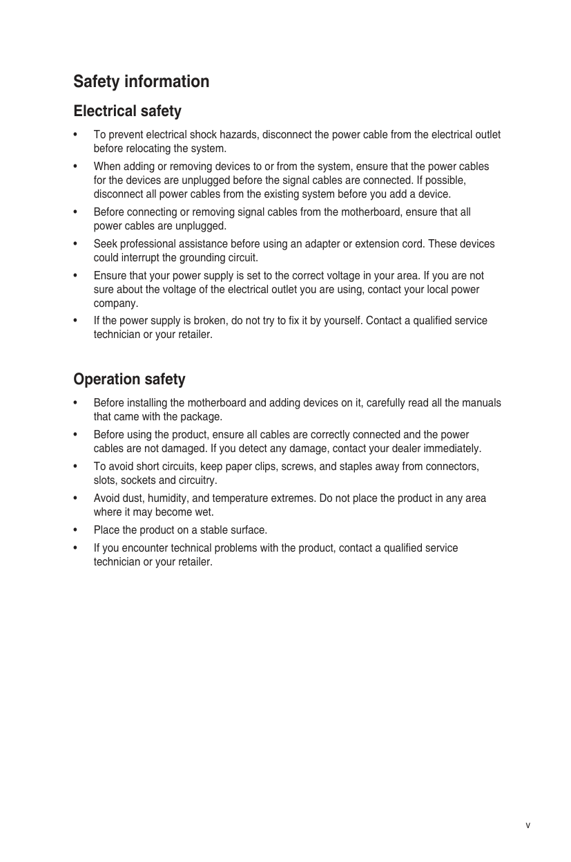
######## Safety information Electrical safety
######### Operation safety
v
######## About this guide
This user guide contains the information you need when installing and configuring the motherboard.
######### How this guide is organized This guide contains the following parts:
This chapter describes the features of the motherboard and the new technology it supports. It includes description of the switches, jumpers, and connectors on the motherboard.
This chapter lists the hardware setup procedures that you have to perform when installing system components.
This chapter tells how to change system settings through the BIOS Setup menus. Detailed descriptions of the BIOS parameters are also provided.
######### Where to find more information
Refer to the following sources for additional information and for product and software updates.
############## 1. ASUS website
The ASUS website (www.asus.com) provides updated information on ASUS hardware and software products.
############## 2. Optional documentation
Your product package may include optional documentation, such as warranty flyers, that may have been added by your dealer. These documents are not part of the standard package.
vi
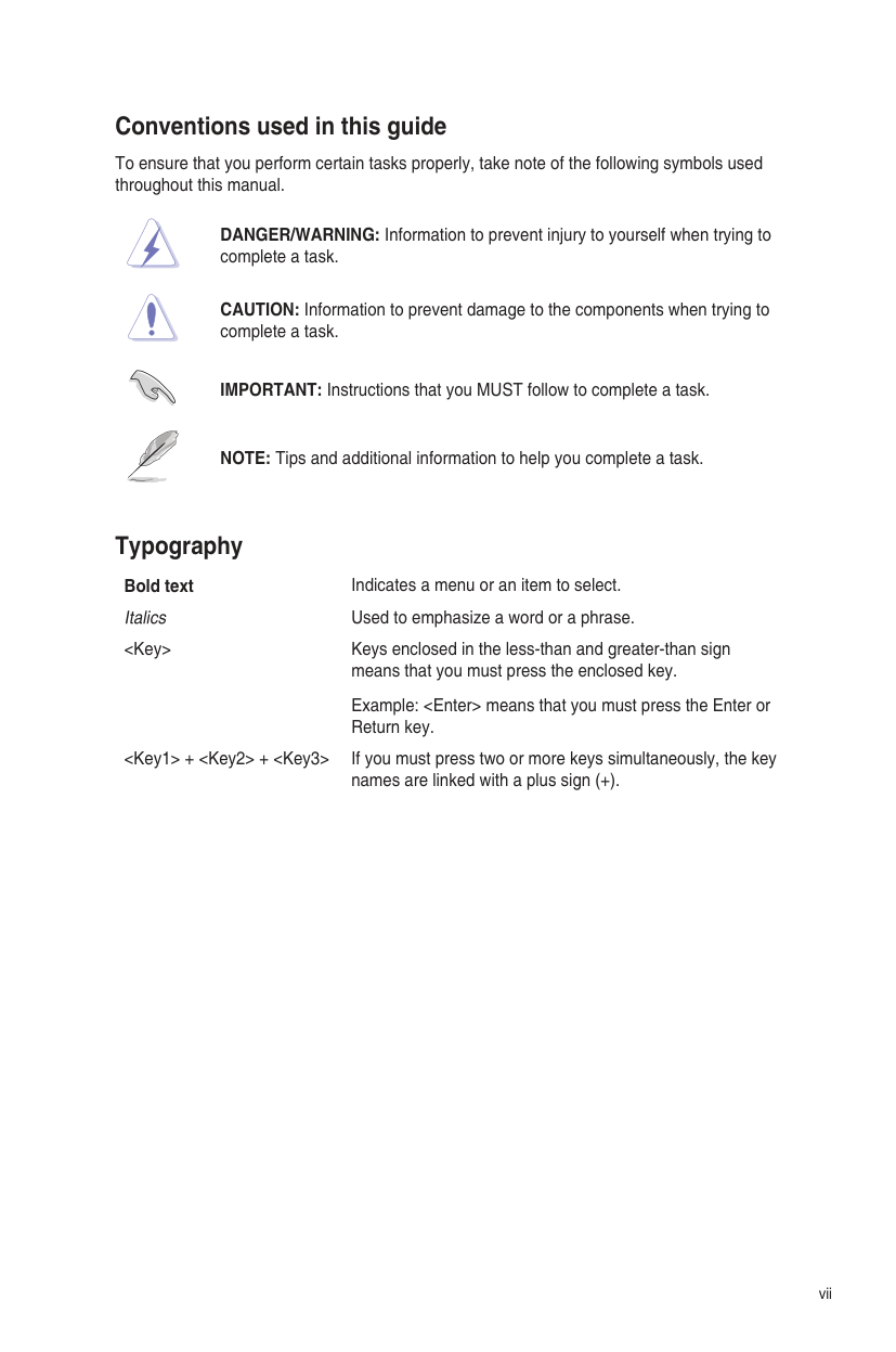
######### Conventions used in this guide
To ensure that you perform certain tasks properly, take note of the following symbols used throughout this manual.
DANGER/WARNING: Information to prevent injury to yourself when trying to complete a task.
CAUTION: Information to prevent damage to the components when trying to complete a task.
IMPORTANT: Instructions that you MUST follow to complete a task.
NOTE: Tips and additional information to help you complete a task.
Typography Bold text Indicates a menu or an item to select. Italics Used to emphasize a word or a phrase.
means that you must press the enclosed key. Example:
vii
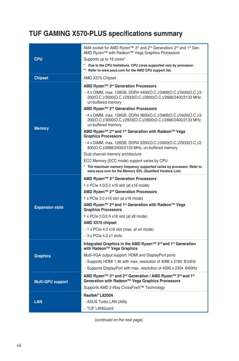
|CPU|AM4 socket for AMD Ryzen™ 3rd and 2nd Generation/ 2nd and 1st Gen AMD Ryzen™ with Radeon™ Vega Graphics Processors
Supports up to 16 cores*
* Due to the CPU limitations, CPU cores supported vary by processor.
** Refer to www.asus.com for the AMD CPU support list.
|
|---|---| |Chipset|AMD X570 Chipset| |Memory|AMD Ryzen™ 3rd Generation Processors
- 4 x DIMM, max. 128GB, DDR4 4400(O.C.)/3466(O.C.)/3400(O.C.)/3 200(O.C.)/3000(O.C.)/2933(O.C.)/2800(O.C.)/2666/2400/2133 MHz, un-buffered memory
AMD Ryzen™ 2nd Generation Processors
- 4 x DIMM, max. 128GB, DDR4 3600(O.C.)/3466(O.C.)/3400(O.C.)/3 200(O.C.)/3000(O.C.)/2933(O.C.)/2800(O.C.)/2666/2400/2133 MHz, un-buffered memory
AMD Ryzen™ 2ndand 1st Generation with Radeon™ Vega Graphics Processors
- 4 x DIMM, max. 128GB, DDR4 3200(O.C.)/3000(O.C.)/2933(O.C.)/2
800(O.C.)/2666/2400/2133 MHz, un-buffered memory Dual channel memory architecture ECC Memory (ECC mode) support varies by CPU.
* The maximum memory frequency supported varies by processor. Refer to www.asus.com for the Memory QVL (Qualified Vendors List).| |Expansion slots|AMD Ryzen™ 3rd Generation Processors 1 x PCIe 4.0/3.0 x16 slot (at x16 mode) AMD Ryzen™ 2nd Generation Processors 1 x PCIe 3.0 x16 slot (at x16 mode)
AMD Ryzen™ 2ndand 1st Generation with Radeon™ Vega Graphics Processors
1 x PCIe 3.0/2.0 x16 slot (at x8 mode) AMD X570 chipset
- 1 x PCIe 4.0 x16 slot (max. at x4 mode)
- 3 x PCIe 4.0 x1 slots
| |Graphics|Integrated Graphics in the AMD Ryzen™ 2ndand 1st Generation with Radeon™ Vega Graphics
Multi-VGA output support: HDMI and DisplayPort ports
- Supports HDMI 1.4b with max. resolution of 4096 x 2160 @24Hz
- Supports DisplayPort with max. resolution of 4096 x 2304 @60Hz
| |Multi-GPU support|AMD Ryzen™ 3rd and 2nd Generation / AMD Ryzen™ 2ndand 1st Generation with Radeon™ Vega Graphics Processors
Supports AMD 2-Way CrossFireX™ Technology| |LAN|Realtek® L8200A
- ASUS Turbo LAN Utility
- TUF LANGuard
|
(continued on the next page)
viii
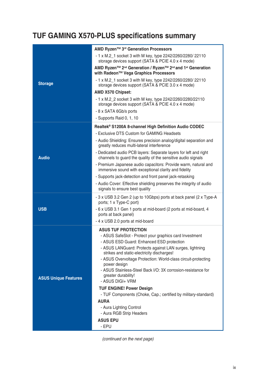
|Storage|AMD Ryzen™ 3rd Generation Processors
- 1 x M.2_1 socket 3 with M key, type 2242/2260/2280/ 22110 storage devices support (SATA & PCIE 4.0 x 4 mode)
AMD Ryzen™ 2nd Generation / Ryzen™ 2ndand 1st Generation with Radeon™ Vega Graphics Processors
- 1 x M.2_1 socket 3 with M key, type 2242/2260/2280/ 22110 storage devices support (SATA & PCIE 3.0 x 4 mode)
AMD X570 Chipset:
- 1 x M.2_2 socket 3 with M key, type 2242/2260/2280/22110 storage devices support (SATA & PCIE 4.0 x 4 mode)
- 8 x SATA 6Gb/s ports
- Supports Raid 0, 1, 10
| |---|---| |Audio|Realtek® S1200A 8-channel High Definition Audio CODEC
- Exclusive DTS Custom for GAMING Headsets
- Audio Shielding: Ensures precision analog/digital separation and greatly reduces multi-lateral interference
- Dedicated audio PCB layers: Separate layers for left and right channels to guard the quality of the sensitive audio signals
- Premium Japanese audio capacitors: Provide warm, natural and immersive sound with exceptional clarity and fidelity
- Supports jack-detection and front panel jack-retasking
- Audio Cover: Effective shielding preserves the integrity of audio signals to ensure best quality
| |USB|- 3 x USB 3.2 Gen 2 (up to 10Gbps) ports at back panel (2 x Type-A ports; 1 x Type-C port)
- 6 x USB 3.1 Gen 1 ports at mid-board (2 ports at mid-board, 4 ports at back panel)
- 4 x USB 2.0 ports at mid-board
| |ASUS Unique Features|ASUS TUF PROTECTION
- ASUS SafeSlot - Protect your graphics card Investment
- ASUS ESD Guard: Enhanced ESD protection
- ASUS LANGuard: Protects against LAN surges, lightning strikes and static-electricity discharges!
- ASUS Overvoltage Protection: World-class circuit-protecting power design
- ASUS Stainless-Steel Back I/O: 3X corrosion-resistance for greater durability!
- ASUS DIGI+ VRM
TUF ENGINE! Power Design
- TUF Components (Choke, Cap.; certified by military-standard) AURA
- Aura Lighting Control
- Aura RGB Strip Headers
ASUS EPU
- EPU|
(continued on the next page)
ix
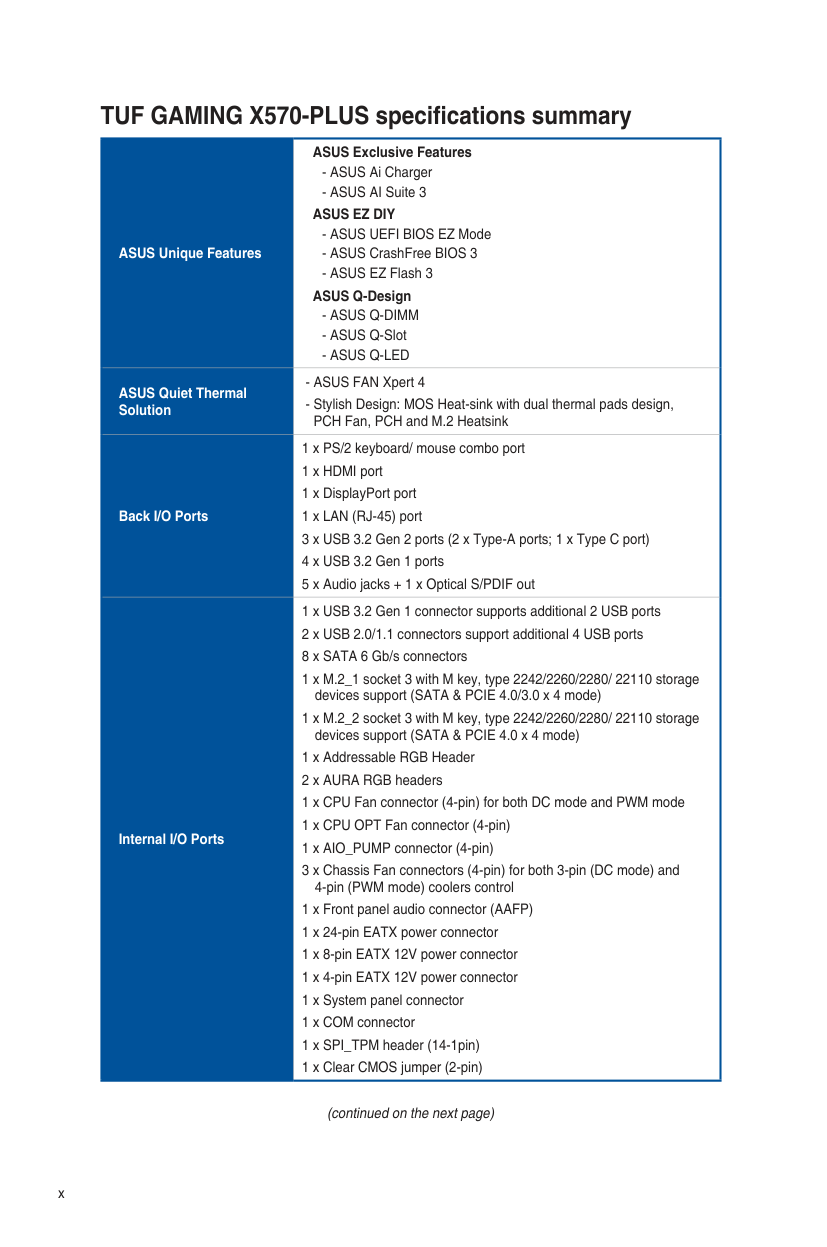
|ASUS Unique Features|ASUS Exclusive Features
- ASUS Ai Charger
- ASUS AI Suite 3
ASUS EZ DIY
- ASUS UEFI BIOS EZ Mode
- ASUS CrashFree BIOS 3
- ASUS EZ Flash 3
ASUS Q-Design
- ASUS Q-DIMM
- ASUS Q-Slot
- ASUS Q-LED
| |---|---| |ASUS Quiet Thermal Solution|- ASUS FAN Xpert 4
- Stylish Design: MOS Heat-sink with dual thermal pads design, PCH Fan, PCH and M.2 Heatsink
| |Back I/O Ports|1 x PS/2 keyboard/ mouse combo port 1 x HDMI port 1 x DisplayPort port 1 x LAN (RJ-45) port
3 x USB 3.2 Gen 2 ports (2 x Type-A ports; 1 x Type C port)
4 x USB 3.2 Gen 1 ports
5 x Audio jacks + 1 x Optical S/PDIF out
| |Internal I/O Ports|1 x USB 3.2 Gen 1 connector supports additional 2 USB ports
2 x USB 2.0/1.1 connectors support additional 4 USB ports 8 x SATA 6 Gb/s connectors
1 x M.2_1 socket 3 with M key, type 2242/2260/2280/ 22110 storage devices support (SATA & PCIE 4.0/3.0 x 4 mode)
1 x M.2_2 socket 3 with M key, type 2242/2260/2280/ 22110 storage devices support (SATA & PCIE 4.0 x 4 mode)
1 x Addressable RGB Header
2 x AURA RGB headers 1 x CPU Fan connector (4-pin) for both DC mode and PWM mode 1 x CPU OPT Fan connector (4-pin) 1 x AIO_PUMP connector (4-pin)
3 x Chassis Fan connectors (4-pin) for both 3-pin (DC mode) and 4-pin (PWM mode) coolers control
1 x Front panel audio connector (AAFP) 1 x 24-pin EATX power connector 1 x 8-pin EATX 12V power connector 1 x 4-pin EATX 12V power connector 1 x System panel connector 1 x COM connector 1 x SPI_TPM header (14-1pin) 1 x Clear CMOS jumper (2-pin)|
(continued on the next page)
x
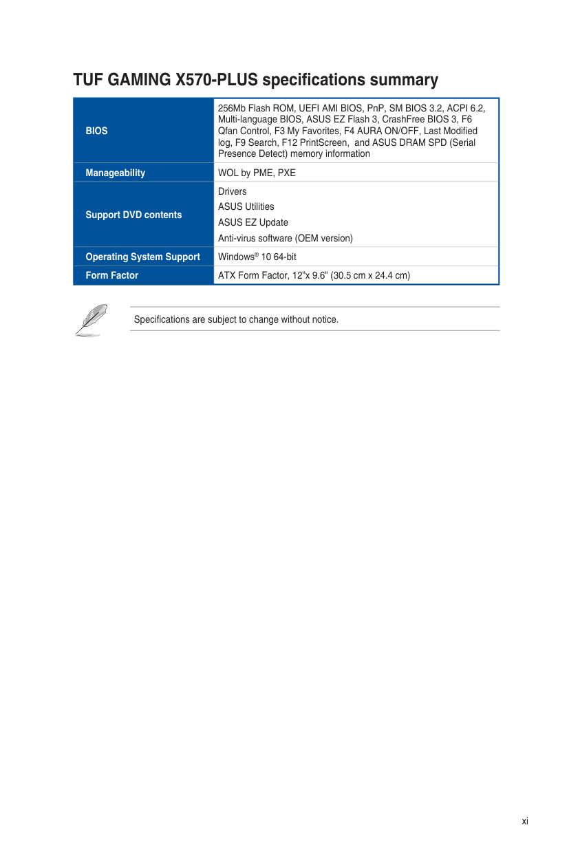
|BIOS|256Mb Flash ROM, UEFI AMI BIOS, PnP, SM BIOS 3.2, ACPI 6.2, Multi-language BIOS, ASUS EZ Flash 3, CrashFree BIOS 3, F6 Qfan Control, F3 My Favorites, F4 AURA ON/OFF, Last Modified log, F9 Search, F12 PrintScreen, and ASUS DRAM SPD (Serial Presence Detect) memory information| |---|---| |Manageability|WOL by PME, PXE| |Support DVD contents|Drivers ASUS Utilities ASUS EZ Update Anti-virus software (OEM version)| |Operating System Support|Windows® 10 64-bit| |Form Factor|ATX Form Factor, 12”x 9.6” (30.5 cm x 24.4 cm)|
Specifications are subject to change without notice.
xi
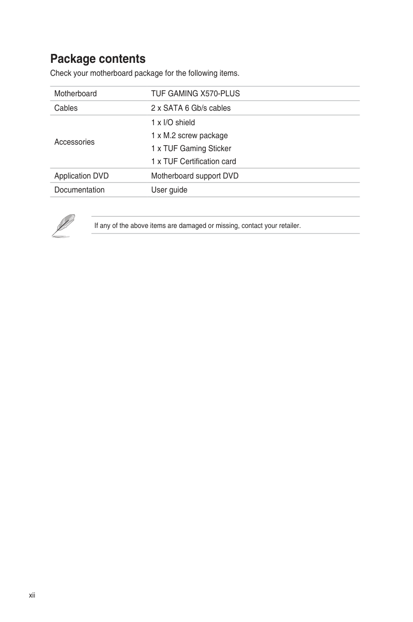
######## Package contents
Check your motherboard package for the following items.
Motherboard TUF GAMING X570-PLUS Cables 2 x SATA 6 Gb/s cables
1 x I/O shield 1 x M.2 screw package 1 x TUF Gaming Sticker 1 x TUF Certification card
Accessories
Application DVD Motherboard support DVD Documentation User guide
If any of the above items are damaged or missing, contact your retailer.
xii
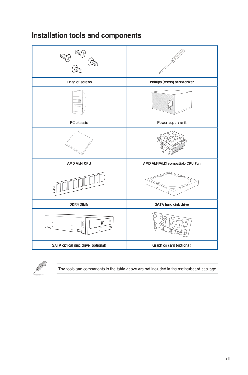
######## Installation tools and components
| | | |---|---| |1 Bag of screws|Phillips (cross) screwdriver| | | | |PC chassis|Power supply unit| | | | |AMD AM4 CPU|AMD AM4/AM3 compatible CPU Fan| | | | |DDR4 DIMM|SATA hard disk drive| | | | |SATA optical disc drive (optional)|Graphics card (optional)|
The tools and components in the table above are not included in the motherboard package.
xiii
###################### xiv
Product Introduction 1
######## 1.1 Motherboard overview 1.1.1 Before you proceed
Take note of the following precautions before you install motherboard components or change any motherboard settings.
######## Chapter 1
######### 1.1.2 Motherboard layout
5
1
2 3 4
2
24.4cm(9.6in)
| | | | | |---|---|---|---|
CPU_FAN CPU_OPT
KBMS _U32G1_56
EATX12V_1EATX12V_2
|DIGI +VRM| |---|
BOOT_DEVICE_LED VGA_LED
CPU_LED
DRAM_LED
7
U32G2 _C3
ADD_GEN2
U32G1_34
| |SOCKET AM4| |---|---|
HDMI_DP
EATXPWR
LAN_U32G2_12
30.5cm(12in)
256Mb
BIOS
CHA_FAN1
AIO_PUMP
AUDIO
U32G1_12
M.2_1(SOCKET3)
SPI_TPM
228022110 2260 2242
9
8
6
1
SATA6G_34SATA6G_12
|PCIEX16_1| | |---|---| |PCIEX16_1| | |PCIEX16_1| |
Realtek® L8200A
|AMD® X570| |---|
|PCIEX1_1| |---|
|Super I/O| |---|
BATTERY
|PCIEX16_2| | |---|---| |PCIEX16_2| | |PCIEX16_2| |

M.2_2(SOCKET3)
|PCIEX1_2| |---|
228022110 2260 2242
CLRTC
|PCIEX1_3| |---|
| | | |---|---|
SATA6G_8SATA6G_7
| | | | | |---|---|---|---|
COM_DEBUG
SATA6G_6SATA6G_5
USB78 USB910
COM
PANEL
CHA_FAN2CHA_FAN3
| | | | |---|---|---|
AAFP
1121516
2 13 514
Refer to 1.1.8 Internal connectors and 2.2.1 Rear I/O connection for more information about rear panel connectors and internal connectors.
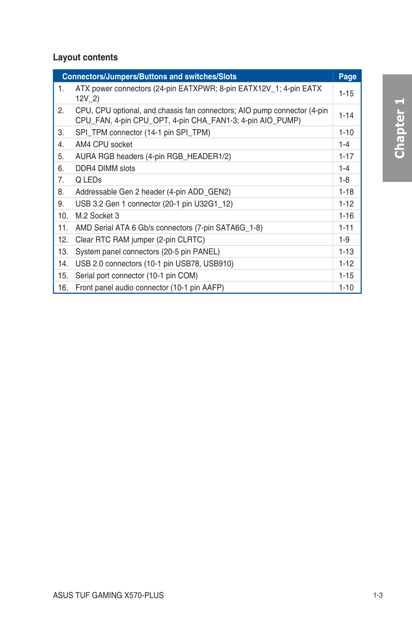
Layout contents
|Connectors/Jumpers/Buttons and switches/Slots|Page| |---|---| |1. ATX power connectors (24-pin EATXPWR; 8-pin EATX12V_1; 4-pin EATX 12V_2)|1-15| |2. CPU, CPU optional, and chassis fan connectors; AIO pump connector (4-pin CPU_FAN, 4-pin CPU_OPT, 4-pin CHA_FAN1-3; 4-pin AIO_PUMP)|1-14| |3. SPI_TPM connector (14-1 pin SPI_TPM)|1-10| |4. AM4 CPU socket|1-4| |5. AURA RGB headers (4-pin RGB_HEADER1/2)|1-17| |6. DDR4 DIMM slots|1-4| |7. Q LEDs|1-8| |8. Addressable Gen 2 header (4-pin ADD_GEN2)|1-18| |9. USB 3.2 Gen 1 connector (20-1 pin U32G1_12)|1-12| |10. M.2 Socket 3|1-16|
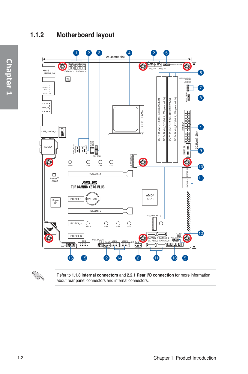
|11. AMD Serial ATA 6 Gb/s connectors (7-pin SATA6G_1-8)|1-11| |12. Clear RTC RAM jumper (2-pin CLRTC)|1-9| |13. System panel connectors (20-5 pin PANEL)|1-13| |14. USB 2.0 connectors (10-1 pin USB78, USB910)|1-12| |15. Serial port connector (10-1 pin COM)|1-15| |16. Front panel audio connector (10-1 pin AAFP)|1-10|
Chapter 1
######## Chapter 1
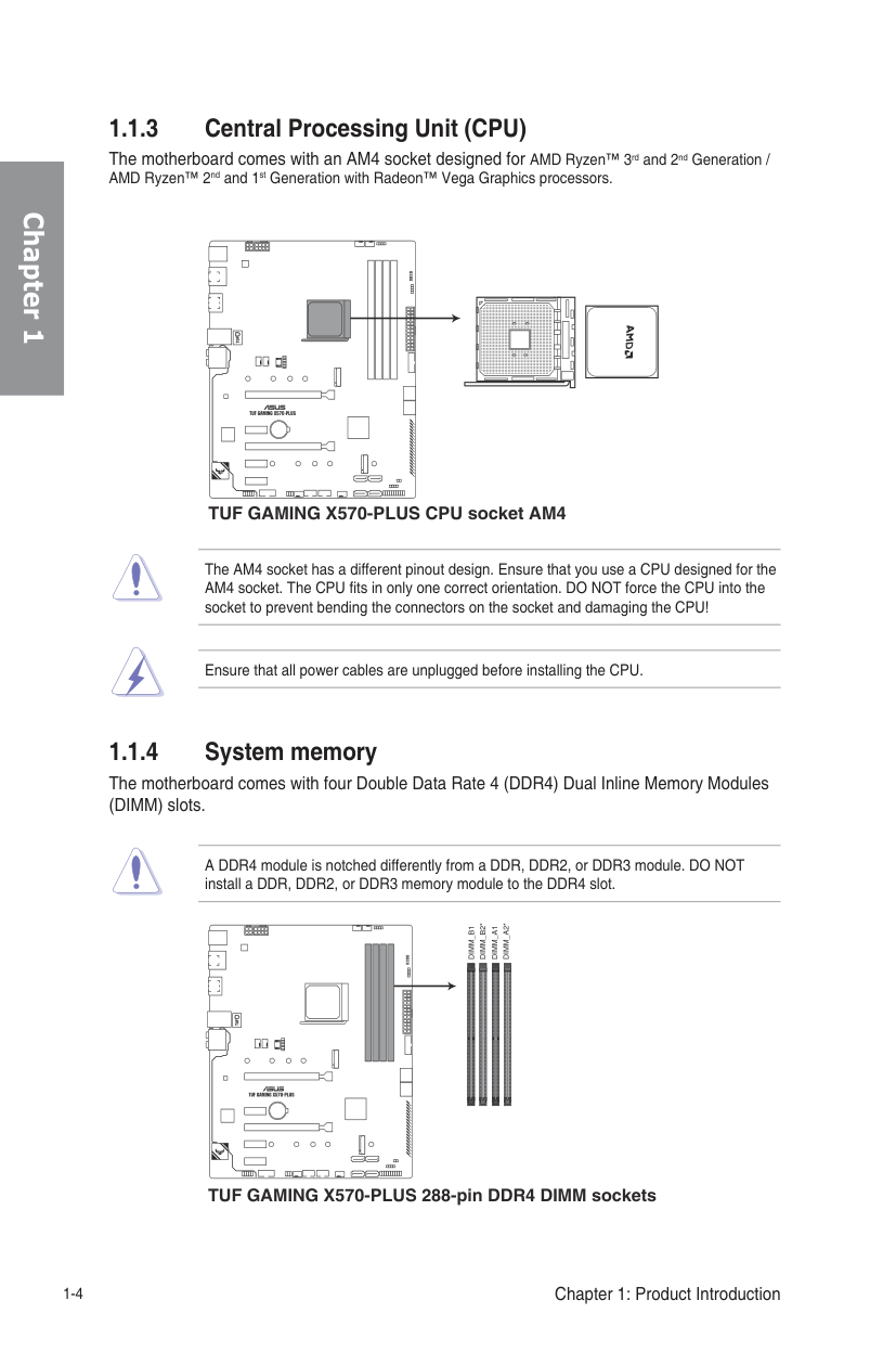
1.1.3 Central Processing Unit (CPU) The motherboard comes with an AM4 socket designed for AMD Ryzen™ 3rd and 2nd Generation / AMD Ryzen™ 2nd and 1st Generation with Radeon™ Vega Graphics processors.
| | | |---|---|
################ TUF GAMING X570-PLUS CPU socket AM4
The AM4 socket has a different pinout design. Ensure that you use a CPU designed for the AM4 socket. The CPU fits in only one correct orientation. DO NOT force the CPU into the socket to prevent bending the connectors on the socket and damaging the CPU!
Ensure that all power cables are unplugged before installing the CPU.
######### 1.1.4 System memory
The motherboard comes with four Double Data Rate 4 (DDR4) Dual Inline Memory Modules (DIMM) slots.
A DDR4 module is notched differently from a DDR, DDR2, or DDR3 module. DO NOT install a DDR, DDR2, or DDR3 memory module to the DDR4 slot.
DIMM_B2*
DIMM_A2*
DIMM_B1
DIMM_A1
| | | |---|---| | | |
| | | |---|---|
| | | |---|---|
TUF GAMING X570-PLUS 288-pin DDR4 DIMM sockets
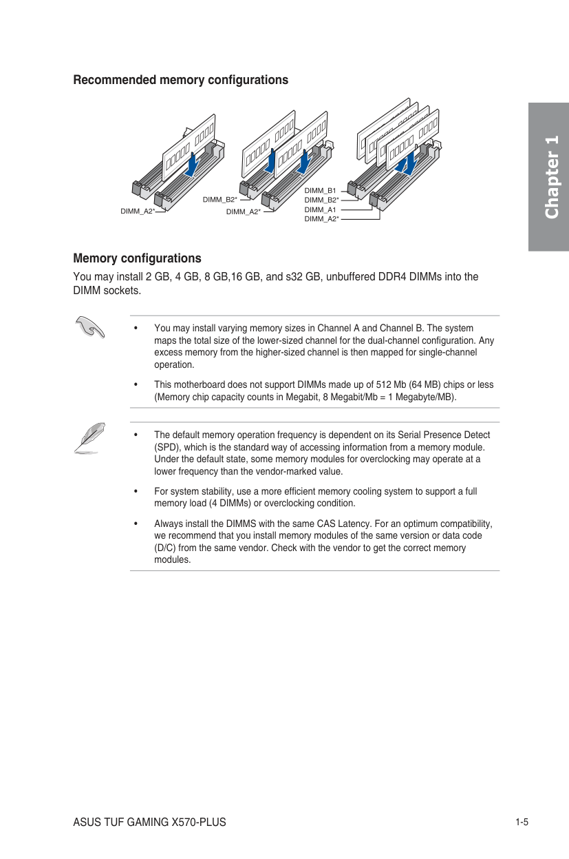
Recommended memory configurations
Memory configurations You may install 2 GB, 4 GB, 8 GB,16 GB, and s32 GB, unbuffered DDR4 DIMMs into the DIMM sockets.
Chapter 1
######## Chapter 1
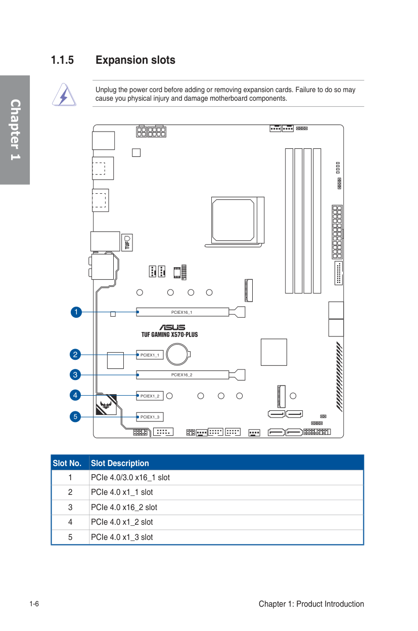
######### 1.1.5 Expansion slots
Unplug the power cord before adding or removing expansion cards. Failure to do so may cause you physical injury and damage motherboard components.
| | | | | |---|---|---|---|
| | | |---|---|
| | |---| | | | | | |
5
PCIEX1_3
| | | | |---|---|---|
| | | |---|---|
| | | | | |---|---|---|---|
| | | | | | | | | | | |---|---|---|---|---|---|---|---|---|---|
|Slot No.|Slot Description| |---|---| |1|PCIe 4.0/3.0 x16_1 slot| |2|PCIe 4.0 x1_1 slot| |3|PCIe 4.0 x16_2 slot| |4|PCIe 4.0 x1_2 slot| |5|PCIe 4.0 x1_3 slot|
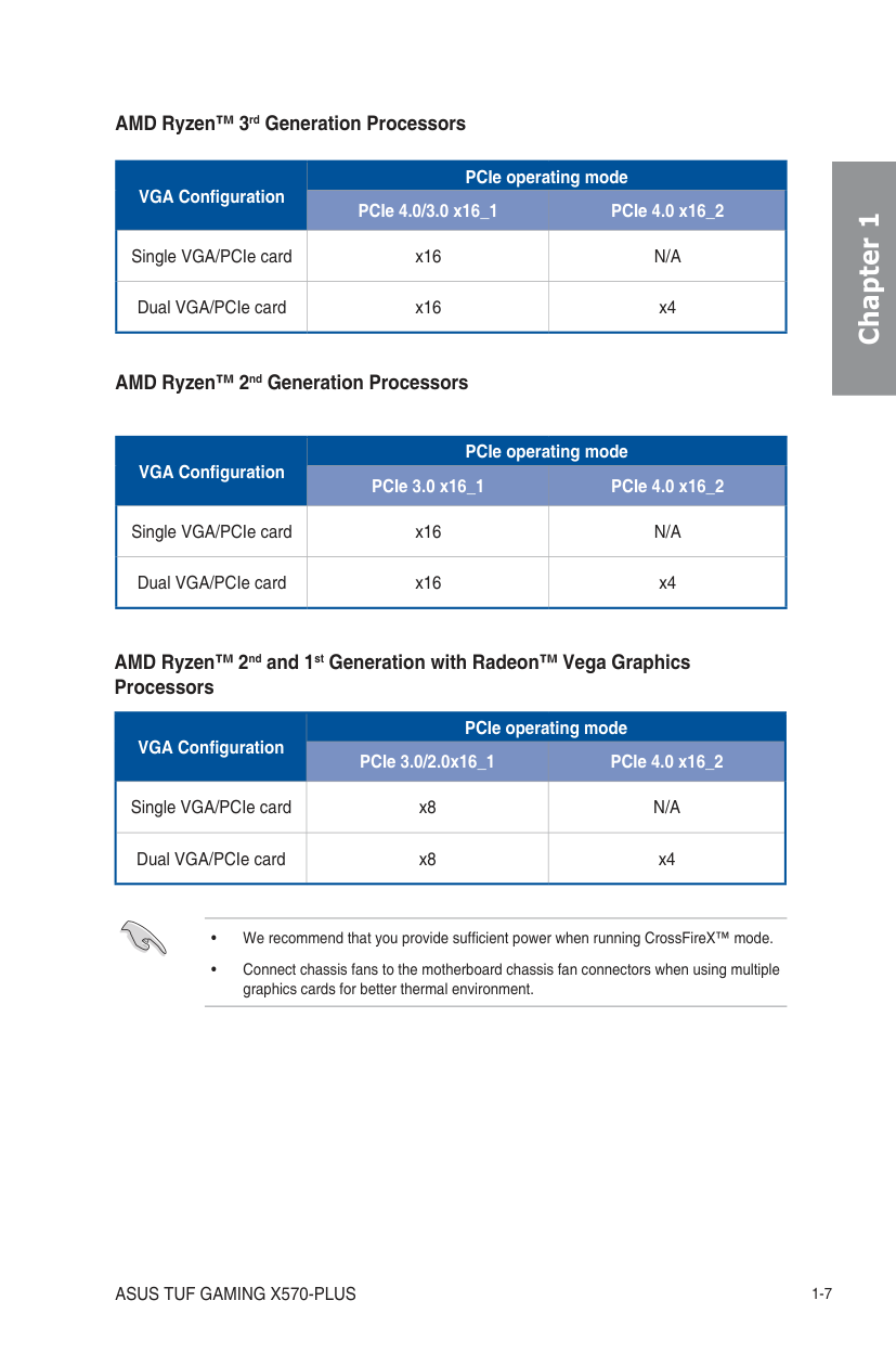
AMD Ryzen™ 3rd Generation Processors
|VGA Configuration|PCIe operating mode|PCIe operating mode|
|---|---|---| |VGA Configuration|PCIe 4.0/3.0 x16_1|PCIe 4.0 x16_2| |Single VGA/PCIe card|x16|N/A| |Dual VGA/PCIe card|x16|x4|
AMD Ryzen™ 2nd Generation Processors
|VGA Configuration|PCIe operating mode|PCIe operating mode| |---|---|---| |VGA Configuration|PCIe 3.0 x16_1|PCIe 4.0 x16_2| |Single VGA/PCIe card|x16|N/A| |Dual VGA/PCIe card|x16|x4|
AMD Ryzen™ 2nd and 1st Generation with Radeon™ Vega Graphics Processors
|VGA Configuration|PCIe operating mode|PCIe operating mode| |---|---|---| |VGA Configuration|PCIe 3.0/2.0x16_1|PCIe 4.0 x16_2| |Single VGA/PCIe card|x8|N/A| |Dual VGA/PCIe card|x8|x4|
######## Chapter 1
######## Chapter 1
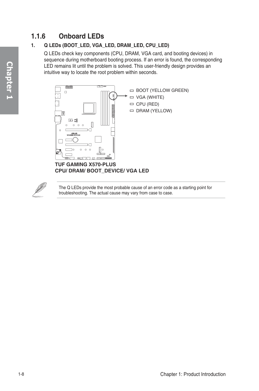
######### 1.1.6 Onboard LEDs
BOOT (YELLOW GREEN)
VGA (WHITE)
CPU (RED) DRAM (YELLOW)
| | | |---|---|
TUF GAMING X570-PLUS CPU/ DRAM/ BOOT_DEVICE/ VGA LED
The Q LEDs provide the most probable cause of an error code as a starting point for troubleshooting. The actual cause may vary from case to case.
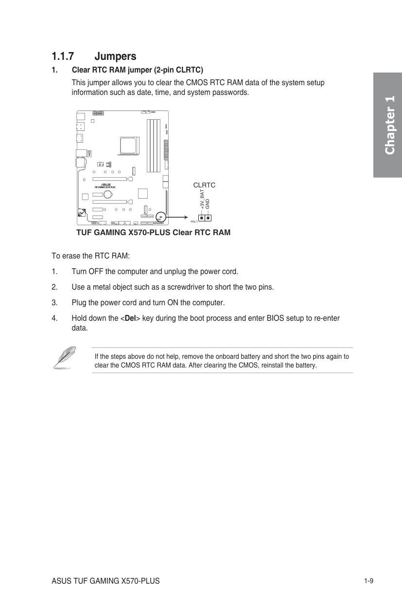
######### 1.1.7 Jumpers
| | | |---|---|
CLRTC
+3V_BAT
GND
| | | |---|---|
PIN 1
TUF GAMING X570-PLUS Clear RTC RAM
To erase the RTC RAM:
If the steps above do not help, remove the onboard battery and short the two pins again to clear the CMOS RTC RAM data. After clearing the CMOS, reinstall the battery.
######## Chapter 1
######## Chapter 1
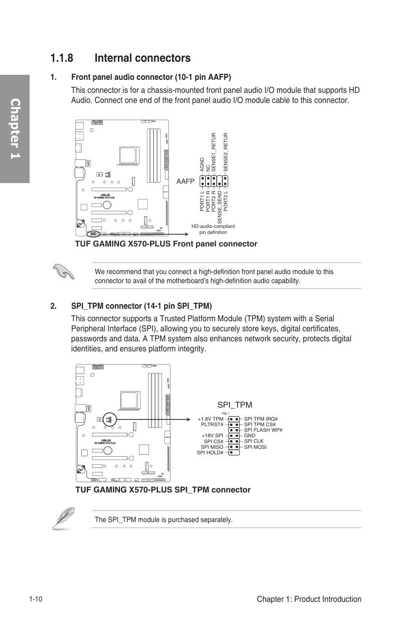
######### 1.1.8 Internal connectors
############### 1. Front panel audio connector (10-1 pin AAFP) This connector is for a chassis-mounted front panel audio I/O module that supports HD Audio. Connect one end of the front panel audio I/O module cable to this connector.
| | | |---|---|
AGND
NC
AAFP
PORT1 L
PORT2 L
SENSE_SEND
| | | |---|---|
HD-audio-compliant pin definition
TUF GAMING X570-PLUS Front panel connector
We recommend that you connect a high-definition front panel audio module to this connector to avail of the motherboard’s high-definition audio capability.
############## 2. SPI_TPM connector (14-1 pin SPI_TPM)
This connector supports a Trusted Platform Module (TPM) system with a Serial Peripheral Interface (SPI), allowing you to securely store keys, digital certificates, passwords and data. A TPM system also enhances network security, protects digital identities, and ensures platform integrity.
| | | |---|---|
################# SPI_TPM
PIN 1
SPI TPM IRQ# SPI TPM CS# SPI FLASH WP# GND SPI CLK SPI MOSI
+1.8V TPM PLTRST# +18V SPI
SPI CS#
SPI MISO SPI HOLD#
| | | |---|---|
TUF GAMING X570-PLUS SPI_TPM connector
The SPI_TPM module is purchased separately.
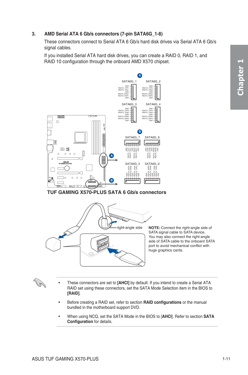
These connectors connect to Serial ATA 6 Gb/s hard disk drives via Serial ATA 6 Gb/s signal cables. If you installed Serial ATA hard disk drives, you can create a RAID 0, RAID 1, and RAID 10 configuration through the onboard AMD X570 chipset.
######################### SATA6G_1
######################### SATA6G_2
GND RSATA_TXP1 RSATA_TXN1
GND RSATA_TXP2 RSATA_TXN2
GND RSATA_RXN1 RSATA_RXP1
GND RSATA_RXN2 RSATA_RXP2
GND
GND
SATA6G_3
######################### SATA6G_4
GND RSATA_TXP3 RSATA_TXN3
GND RSATA_TXP4 RSATA_TXN4
GND RSATA_RXN3 RSATA_RXP3
GND RSATA_RXN4 RSATA_RXP4
| |A
B
| |---|---|
| | |
GND
GND
| | | |---|---|
SATA6G_7
SATA6G_8
GND
RSATA_TXP7
RSATA_TXN7
GND
GND
RSATA_TXP8
RSATA_TXN8
GND
RSATA_RXN7
RSATA_RXP7
GND
RSATA_RXN8
RSATA_RXP8
GND
SATA6G_5
SATA6G_6
RSATA_RXN5
RSATA_RXN6
RSATA_RXP5
RSATA_RXP6
RSATA_TXN5
RSATA_TXN6
RSATA_TXP5
RSATA_TXP6
GND
GND
GND
GND
GND
GND
TUF GAMING X570-PLUS SATA 6 Gb/s connectors
Chapter 1
######## Chapter 1
| | | |---|---|
USB78
USB910
USB_P11+
USB_P11-
USB_P9+
USB_P9-
USB+5V
USB+5V
GND
GND
NC
NC
| | | | |---|---|---| | | | | | | | |
| | | | |---|---|---| | | | | | | | |
PIN 1
PIN 1
USB+5V
USB_P10+
USB+5V
USB_P12+
USB_P10-
GND
USB_P12-
GND
| | | |---|---|
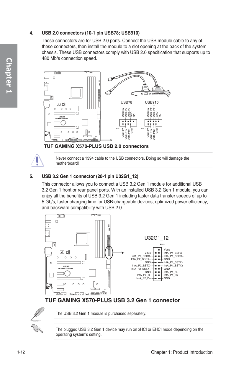
TUF GAMING X570-PLUS USB 2.0 connectors
Never connect a 1394 cable to the USB connectors. Doing so will damage the motherboard!
| | | |---|---|
U32G1_12
PIN 1
| | | | |---|---|---| | | | | | | | | | | | | | | | | | | | | | | | | | | | | | | | | | | | |
Vbus IntA_P1_SSRXIntA_P1_SSRX+ GND IntA_P1_SSTXIntA_P1_SSTX+ GND IntA_P1_DIntA_P1_D+ GND
Vbus IntA_P2_SSRX-
IntA_P2_SSRX+
GND IntA_P2_SSTX-
IntA_P2_SSTX+
GND IntA_P2_D-
IntA_P2_D+
| | | |---|---|
TUF GAMING X570-PLUS USB 3.2 Gen 1 connector
The USB 3.2 Gen 1 module is purchased separately.
The plugged USB 3.2 Gen 1 device may run on xHCI or EHCI mode depending on the operating system’s setting.
############## 6. System panel connector (20-5 pin PANEL)
This connector supports several chassis-mounted functions.
################## PANEL
|+PWR_LED-|+PWR_LED-| |---|---| | | |
|PWR_SW|PWR_SW| |---|---| | | |
SPEAKER
PWRBTN#
Speaker
| | | |---|---|
PLED+
PLED-
GND
GND
GND
+5V
PIN 1
GND
RSTCON#
NC
PLED+
PLED-
HDD_LED+
HDD_LED-
| | | |---|---|
+HDD_LED- RESET
+PWR_LED-
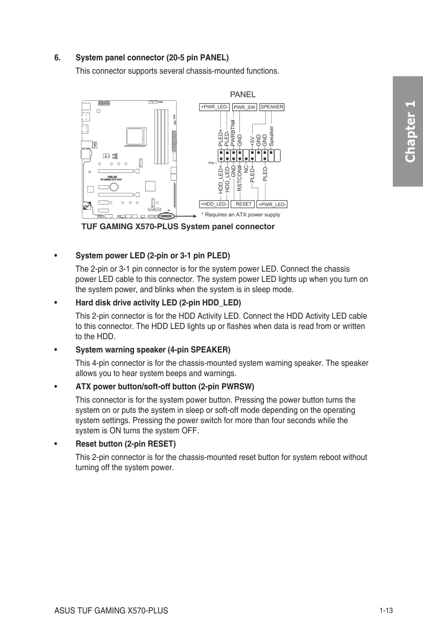
TUF GAMING X570-PLUS System panel connector
############## • System power LED (2-pin or 3-1 pin PLED)
The 2-pin or 3-1 pin connector is for the system power LED. Connect the chassis power LED cable to this connector. The system power LED lights up when you turn on the system power, and blinks when the system is in sleep mode.
############## • Hard disk drive activity LED (2-pin HDD_LED)
This 2-pin connector is for the HDD Activity LED. Connect the HDD Activity LED cable to this connector. The HDD LED lights up or flashes when data is read from or written to the HDD.
############## • System warning speaker (4-pin SPEAKER)
This 4-pin connector is for the chassis-mounted system warning speaker. The speaker allows you to hear system beeps and warnings.
############## • ATX power button/soft-off button (2-pin PWRSW)
This connector is for the system power button. Pressing the power button turns the system on or puts the system in sleep or soft-off mode depending on the operating system settings. Pressing the power switch for more than four seconds while the system is ON turns the system OFF.
############## • Reset button (2-pin RESET)
This 2-pin connector is for the chassis-mounted reset button for system reboot without turning off the system power.
######## Chapter 1
Chapter 1
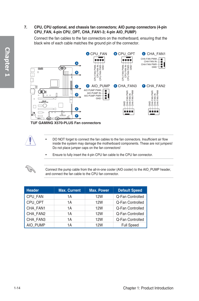
Connect the fan cables to the fan connectors on the motherboard, ensuring that the black wire of each cable matches the ground pin of the connector.
CPU_FANA
B CHA_FAN1
#################### CPU_OPT C
CHA FAN PWM CHA FAN IN CHA FAN PWR GND
CPU FAN PWR
GND
CPU FAN PWR
GND
CPU FAN PWM
CPU FAN IN
CPU FAN PWM
CPU FAN IN
| | | |---|---|
AIO_PUMP AIO PUMP PWM
#################### CHA_FAN3D CHA_FAN2
E
F
CHA FAN PWM
CHA FAN PWM
CHA FAN PWR
CHA FAN PWR
AIO PUMP IN AIO PUMP PWR
CHA FAN IN
CHA FAN IN
GND
GND
GND
| | | |---|---| | | |
################### TUF GAMING X570-PLUS Fan connectors
Connect the pump cable from the all-in-one cooler (AIO cooler) to the AIO_PUMP header, and connect the fan cable to the CPU fan connector.
|Header|Max. Current|Max. Power|Default Speed| |---|---|---|---| |CPU_FAN|1A|12W|Q-Fan Controlled| |CPU_OPT|1A|12W|Q-Fan Controlled|
|CHA_FAN1|1A|12W|Q-Fan Controlled| |CHA_FAN2|1A|12W|Q-Fan Controlled| |CHA_FAN3|1A|12W|Q-Fan Controlled| |AIO_PUMP|1A|12W|Full Speed|
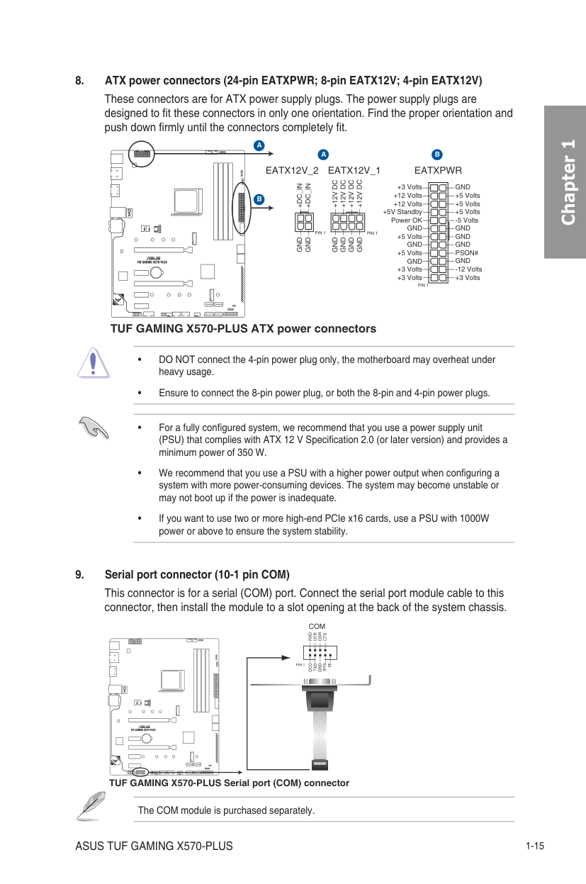
############## 8. ATX power connectors (24-pin EATXPWR; 8-pin EATX12V; 4-pin EATX12V)
These connectors are for ATX power supply plugs. The power supply plugs are designed to fit these connectors in only one orientation. Find the proper orientation and push down firmly until the connectors completely fit.
EATX12V_1EATX12V_2
+12V DC+12V DC+12V DC+12V DC
GNDGNDGNDGND
EATXPWR
PIN 1
PIN 1
GND
+5 Volts +5 Volts +5 Volts
+3 Volts
+3 Volts +12 Volts +12 Volts
+5V Standby Power OK GND +5 Volts GND +5 Volts
GND +3 Volts +3 Volts
| | | | | |---|---|---|---| | | | | | | | | | | | | | | | | | | | | | | | | | | | | | | | | | | | | | | | | | | | | | | | | | |
A B
PIN 1
+DC_IN
+DC_IN GND
GND
| | | |---|---|
| | | |---|---|
TUF GAMING X570-PLUS ATX power connectors
######## Chapter 1
############### 9. Serial port connector (10-1 pin COM) This connector is for a serial (COM) port. Connect the serial port module cable to this connector, then install the module to a slot opening at the back of the system chassis.
######################## COM
RXDDTRDSRCTS
| | | |---|---| | | |
| | |
PIN 1
DCDTXDGNDRTSRI
| | | |---|---|
| | | |---|---|
TUF GAMING X570-PLUS Serial port (COM) connector
The COM module is purchased separately.
Chapter 1
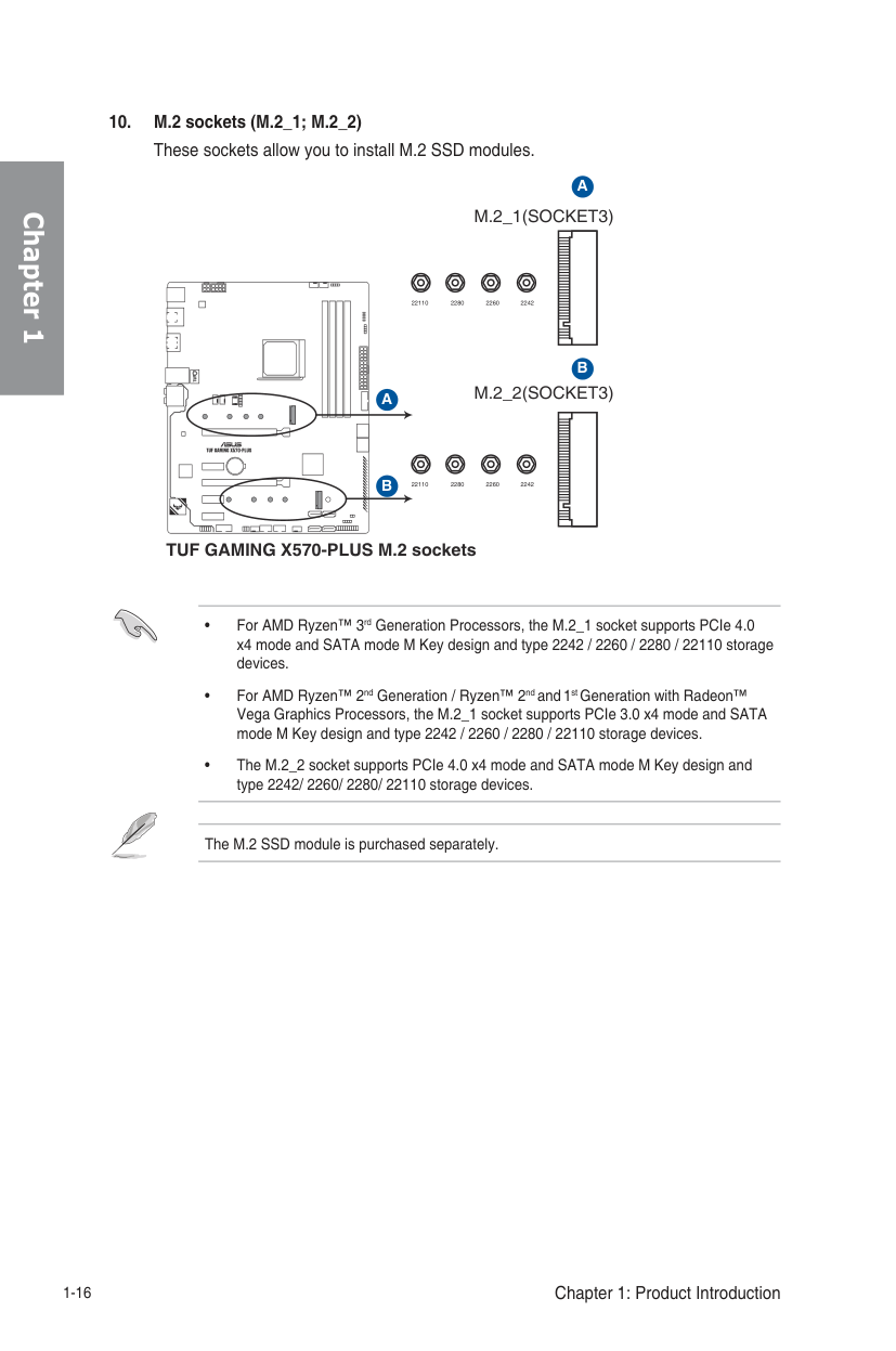
These sockets allow you to install M.2 SSD modules.
M.2_1(SOCKET3)
| |A| |---|---| | |B| | | |
228022110 2260 2242
| | | |---|---|
M.2_2(SOCKET3)
228022110 2260 2242
| | | |---|---|
TUF GAMING X570-PLUS M.2 sockets
The M.2 SSD module is purchased separately.
+12V G R B
B
R
A
G
| |B| |---|---| | | |
+12V
PIN 1
| | | |---|---|
PIN 1
| | | |---|---|
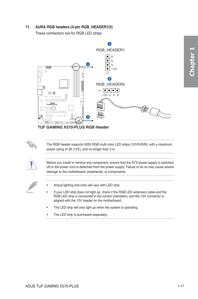
TUF GAMING X570-PLUS RGB Header
Chapter 1
The RGB header supports 5050 RGB multi-color LED strips (12V/G/R/B), with a maximum power rating of 3A (12V), and no longer than 3 m.
Before you install or remove any component, ensure that the ATX power supply is switched off or the power cord is detached from the power supply. Failure to do so may cause severe damage to the motherboard, peripherals, or components.
Chapter 1
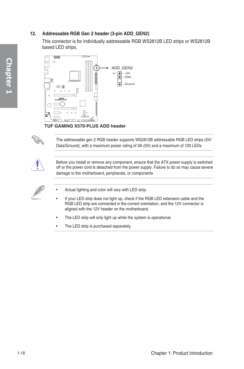
ADD_GEN2
| | | |---|---|
+5V Data
PIN 1
Ground
TUF GAMING X570-PLUS ADD header
The addressable gen 2 RGB header supports WS2812B addressable RGB LED strips (5V/ Data/Ground), with a maximum power rating of 3A (5V) and a maximum of 120 LEDs
Before you install or remove any component, ensure that the ATX power supply is switched off or the power cord is detached from the power supply. Failure to do so may cause severe damage to the motherboard, peripherals, or components
Basic Installation 2
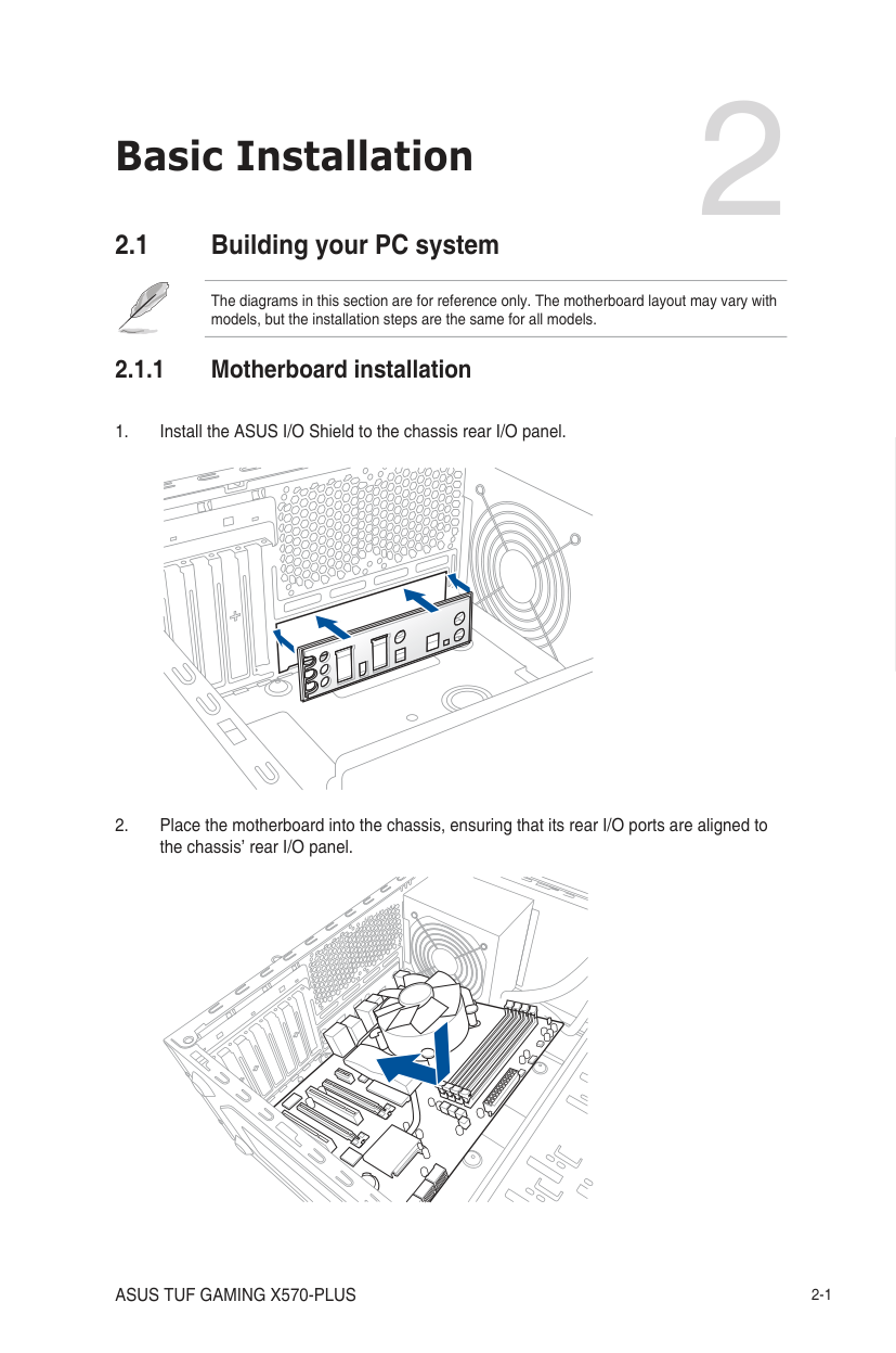
######## 2.1 Building your PC system
The diagrams in this section are for reference only. The motherboard layout may vary with models, but the installation steps are the same for all models.
######### 2.1.1 Motherboard installation
Chapter 2
| | | | | |---|---|---|---|
| | | |---|---|
| | |---| | | | | | |
| | | |---|---| | | | | | |
| | | |---|---| | | | | | |
| | | | |---|---|---|
| | | |---|---|
| | | | | |---|---|---|---|
| | | | | | | | | | | |---|---|---|---|---|---|---|---|---|---|
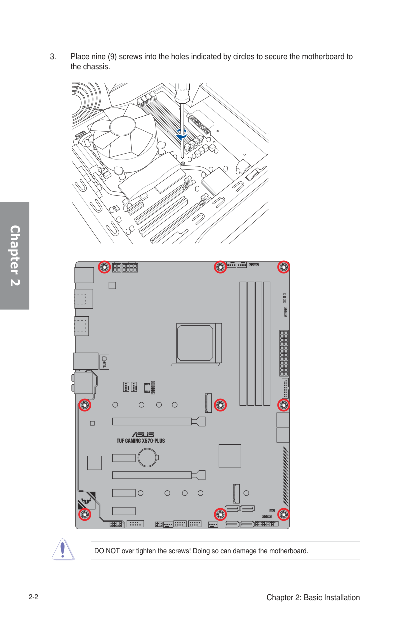
DO NOT over tighten the screws! Doing so can damage the motherboard.
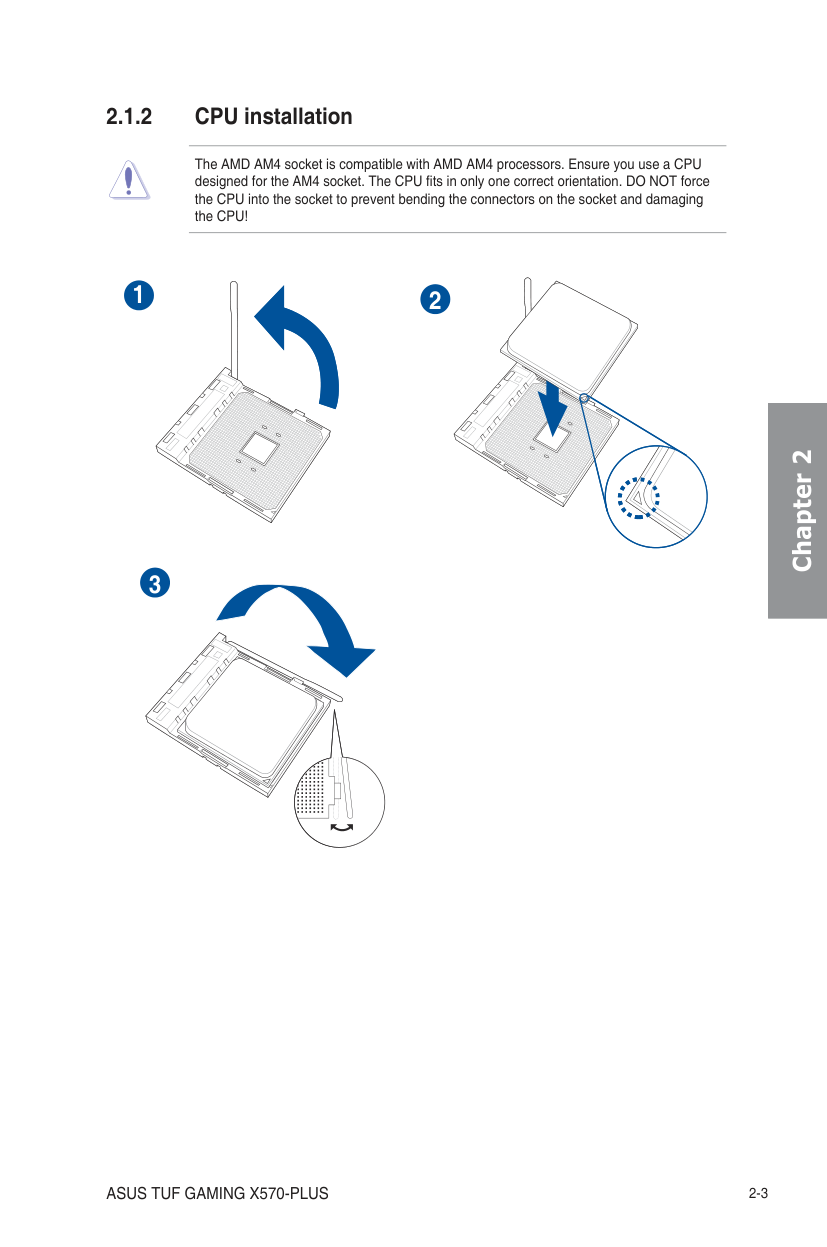
2.1.2 CPU installation
The AMD AM4 socket is compatible with AMD AM4 processors. Ensure you use a CPU designed for the AM4 socket. The CPU fits in only one correct orientation. DO NOT force the CPU into the socket to prevent bending the connectors on the socket and damaging the CPU!
1 2
Chapter 2
3
Chapter 2
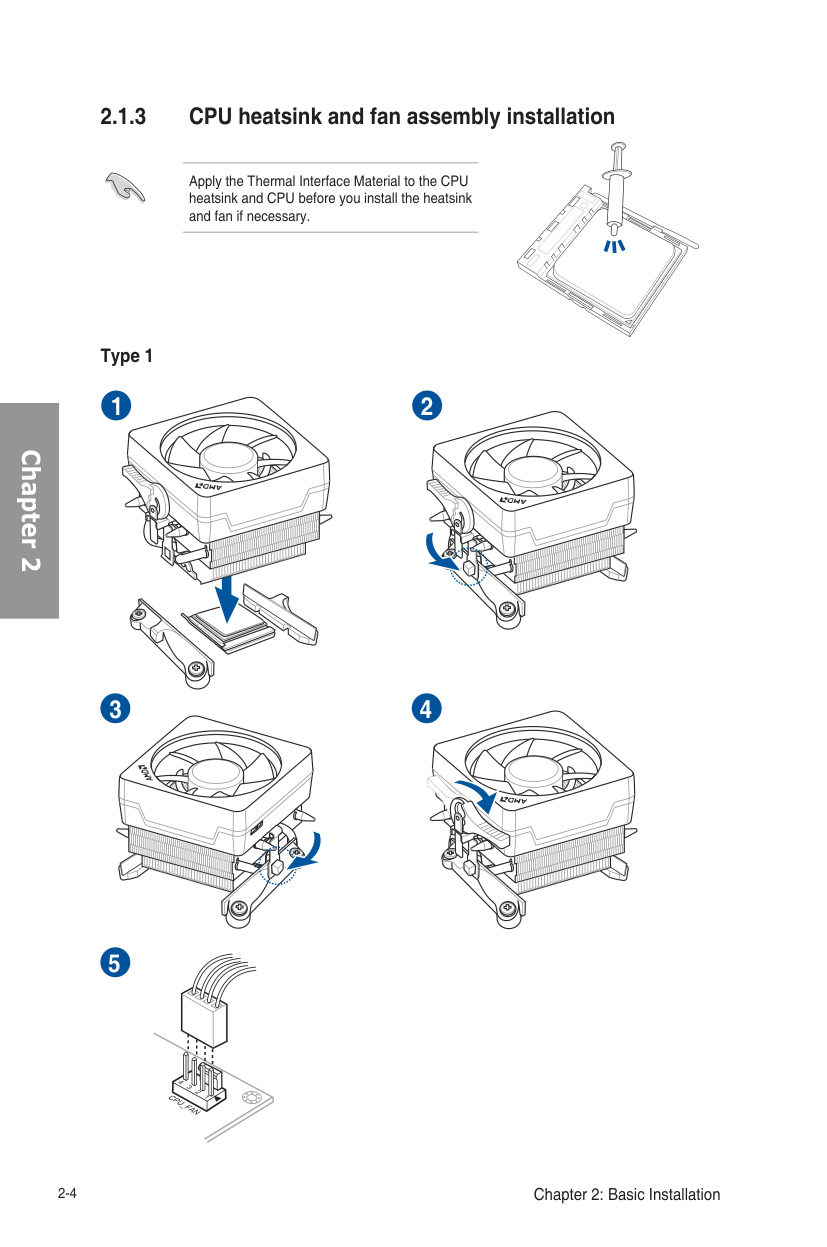
2.1.3 CPU heatsink and fan assembly installation
Apply the Thermal Interface Material to the CPU heatsink and CPU before you install the heatsink and fan if necessary.
Type 1

1 2
3 4
######## 5
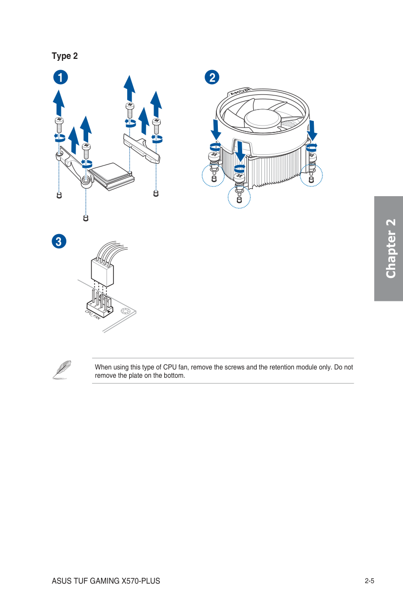
Type 2
######## 1 2
######## 3
Chapter 2
When using this type of CPU fan, remove the screws and the retention module only. Do not remove the plate on the bottom.
######## Chapter 2
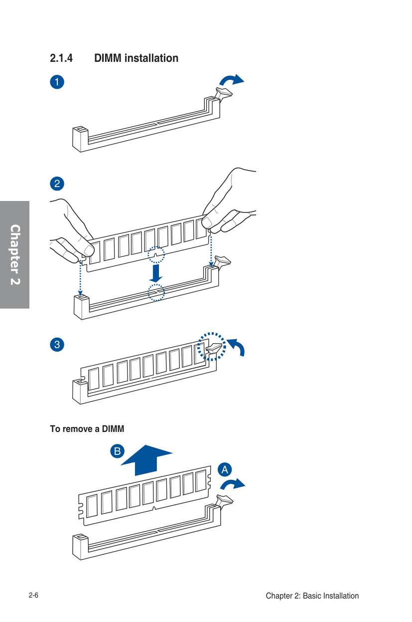
######### 2.1.4 DIMM installation
To remove a DIMM
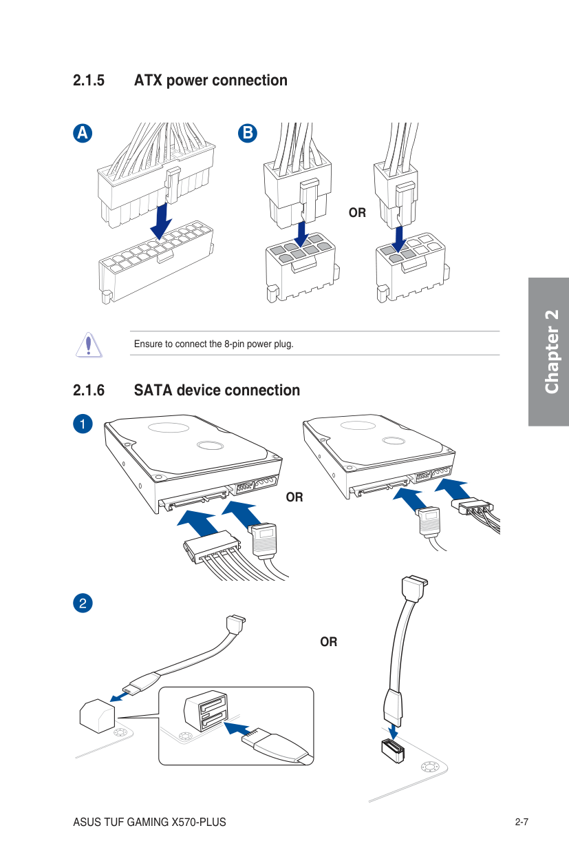
Ensure to connect the 8-pin power plug.
######## A
######## B
OR
Chapter 2
OR
OR
Chapter 2
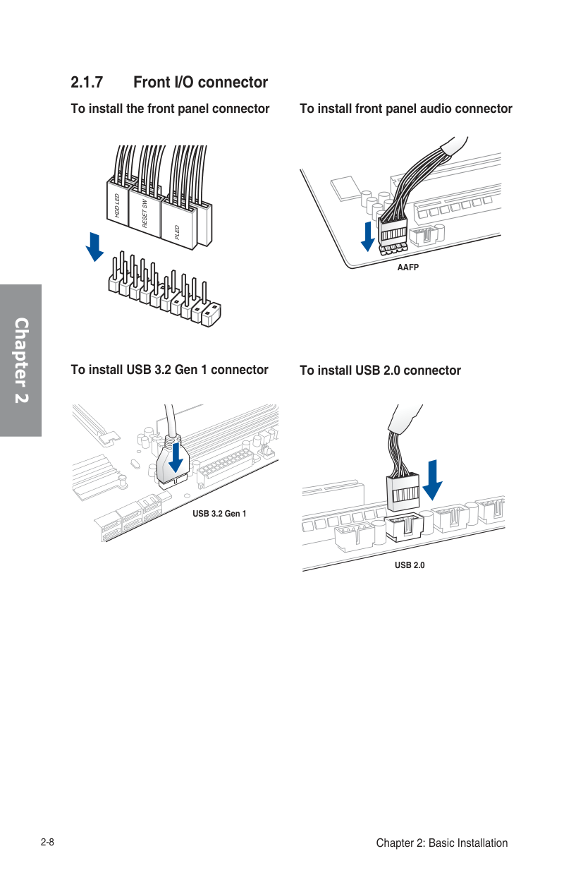
2.1.7 Front I/O connector To install the front panel connector
To install front panel audio connector
AAFP
############ To install USB 3.2 Gen 1 connector
To install USB 2.0 connector
USB 3.2 Gen 1
USB 2.0
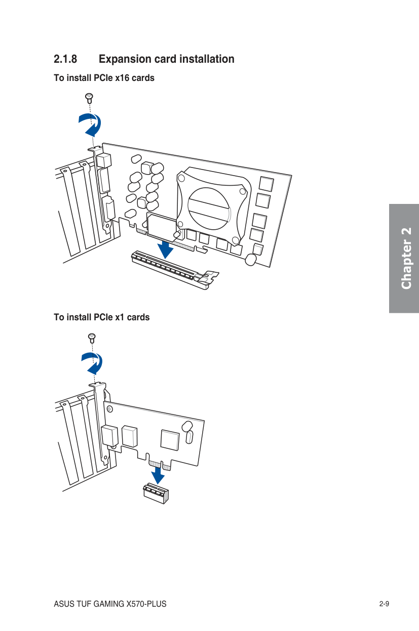
######### 2.1.8 Expansion card installation To install PCIe x16 cards
To install PCIe x1 cards
######## Chapter 2
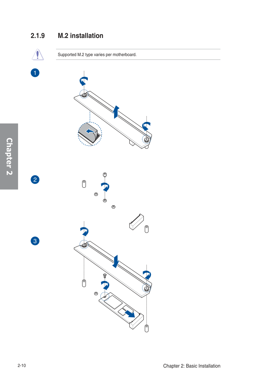
######### 2.1.9 M.2 installation
######## Chapter 2
Supported M.2 type varies per motherboard.
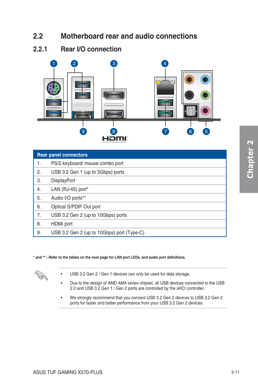
2.2 Motherboard rear and audio connections
1 2 3 4
56789
|Rear panel connectors
1. PS/2 keyboard/ mouse combo port| |---| |2. USB 3.2 Gen 1 (up to 5Gbps) ports| |3. DisplayPort| |4. LAN (RJ-45) port*| |5. Audio I/O ports**| |6. Optical S/PDIF Out port| |7. USB 3.2 Gen 2 (up to 10Gbps) ports| |8. HDMI port| |9. USB 3.2 Gen 2 (up to 10Gbps) port (Type-C)|
Chapter 2
Activity Link LED Speed LED Status Description Status Description Off No link Off 10 Mbps connection Orange Linked Orange 100 Mbps connection Orange (Blinking) Data activity Green 1 Gbps connection Orange (Blinking then steady)
Ready to wake up from S5 mode
ACT/LINK LED
SPEED LED
| | | | |---|---|---| | | | |
LAN port
######## Chapter 2
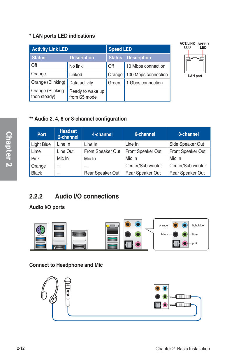
** Audio 2, 4, 6 or 8-channel configuration
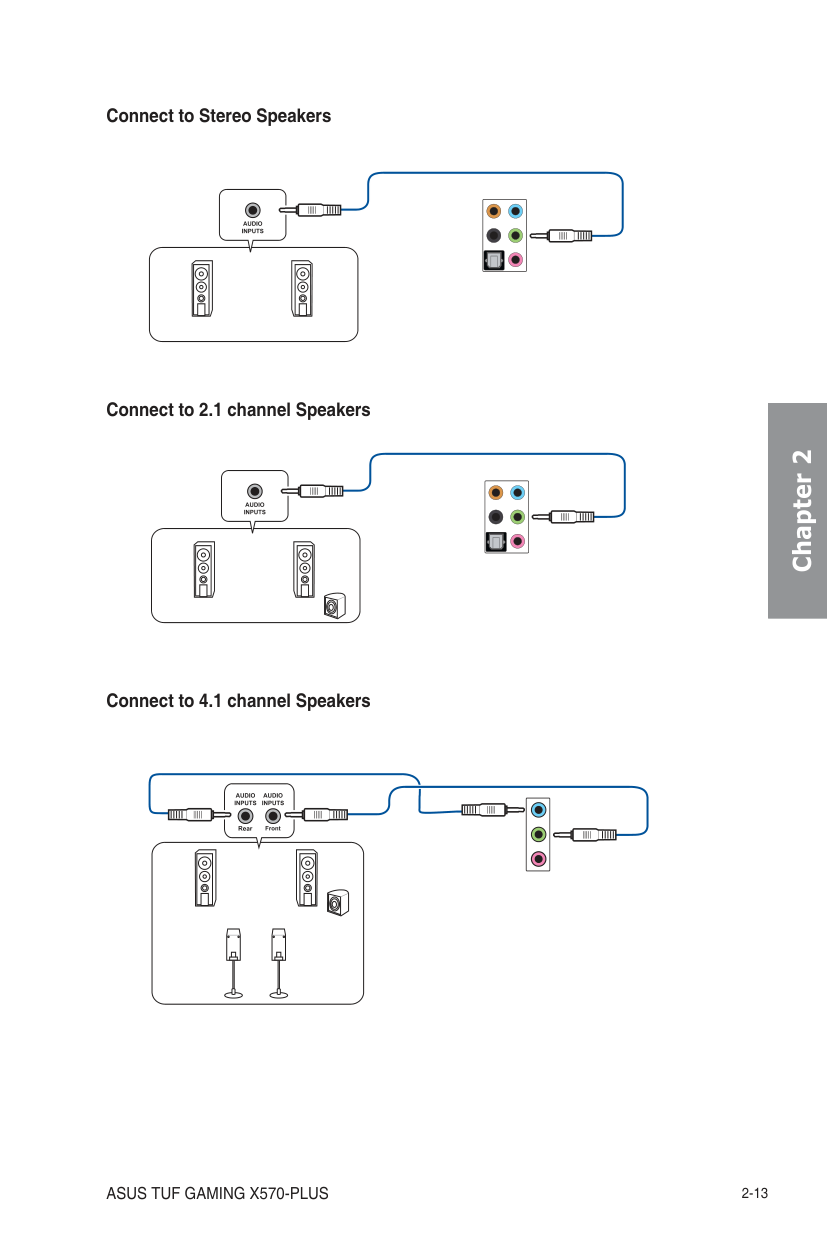
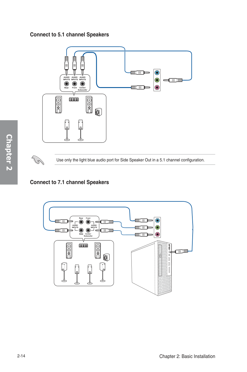
|Port|Headset 2-channel|4-channel|6-channel|8-channel| |---|---|---|---|---| |Light Blue|Line In|Line In|Line In|Side Speaker Out| |Lime|Line Out|Front Speaker Out|Front Speaker Out|Front Speaker Out| |Pink|Mic In|Mic In|Mic In|Mic In| |Orange|–|–|Center/Sub woofer|Center/Sub woofer| |Black|–|Rear Speaker Out|Rear Speaker Out|Rear Speaker Out|
2.2.2 Audio I/O connections Audio I/O ports
| | | |---|---| | | | | | | | | |
| | |---| | |
############ Connect to Headphone and Mic
Connect to Stereo Speakers
Connect to 2.1 channel Speakers
Chapter 2
Chapter 2
Use only the light blue audio port for Side Speaker Out in a 5.1 channel configuration.
############ Connect to 7.1 channel Speakers
| | | |---|---| | | |
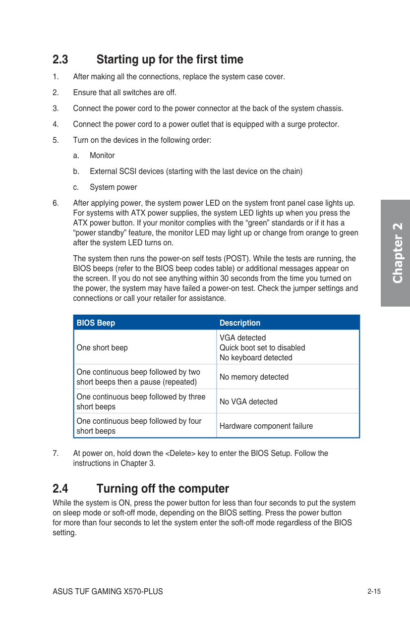
The system then runs the power-on self tests (POST). While the tests are running, the BIOS beeps (refer to the BIOS beep codes table) or additional messages appear on the screen. If you do not see anything within 30 seconds from the time you turned on the power, the system may have failed a power-on test. Check the jumper settings and connections or call your retailer for assistance.
|BIOS Beep
One short beep|Description
VGA detected Quick boot set to disabled No keyboard detected| |---|---| |One continuous beep followed by two short beeps then a pause (repeated)|No memory detected| |One continuous beep followed by three short beeps|No VGA detected| |One continuous beep followed by four short beeps|Hardware component failure|
While the system is ON, press the power button for less than four seconds to put the system on sleep mode or soft-off mode, depending on the BIOS setting. Press the power button for more than four seconds to let the system enter the soft-off mode regardless of the BIOS setting.
Chapter 2
######## Chapter 2
BIOS Setup 3
######## 3.1 Knowing BIOS
The new ASUS UEFI BIOS is a Unified Extensible Interface that complies with UEFI architecture, offering a user-friendly interface that goes beyond the traditional keyboardonly BIOS controls to enable a more flexible and convenient mouse input. You can easily navigate the new UEFI BIOS with the same smoothness as your operating system. The term “BIOS” in this user manual refers to “UEFI BIOS” unless otherwise specified.
BIOS (Basic Input and Output System) stores system hardware settings such as storage device configuration, overclocking settings, advanced power management, and boot device configuration that are needed for system startup in the motherboard CMOS. In normal circumstances, the default BIOS settings apply to most conditions to ensure optimal performance. DO NOT change the default BIOS settings except in the following circumstances:
Inappropriate BIOS settings may result to instability or boot failure. We strongly recommend that you change the BIOS settings only with the help of a trained service personnel.
######## 3.2 BIOS setup program
Use the BIOS Setup to update the BIOS or configure its parameters. The BIOS screen include navigation keys and brief onscreen help to guide you in using the BIOS Setup program.
Entering BIOS at startup To enter BIOS Setup at startup, press
############ Entering BIOS Setup after POST To enter BIOS Setup after POST:
After doing either of the three options, press
Please visit ASUS website for the detailed BIOS content manual.
BIOS menu screen The BIOS Setup program can be used under two modes: EZ Mode and Advanced Mode. You can change modes from Setup Mode in Boot menu or by pressing the
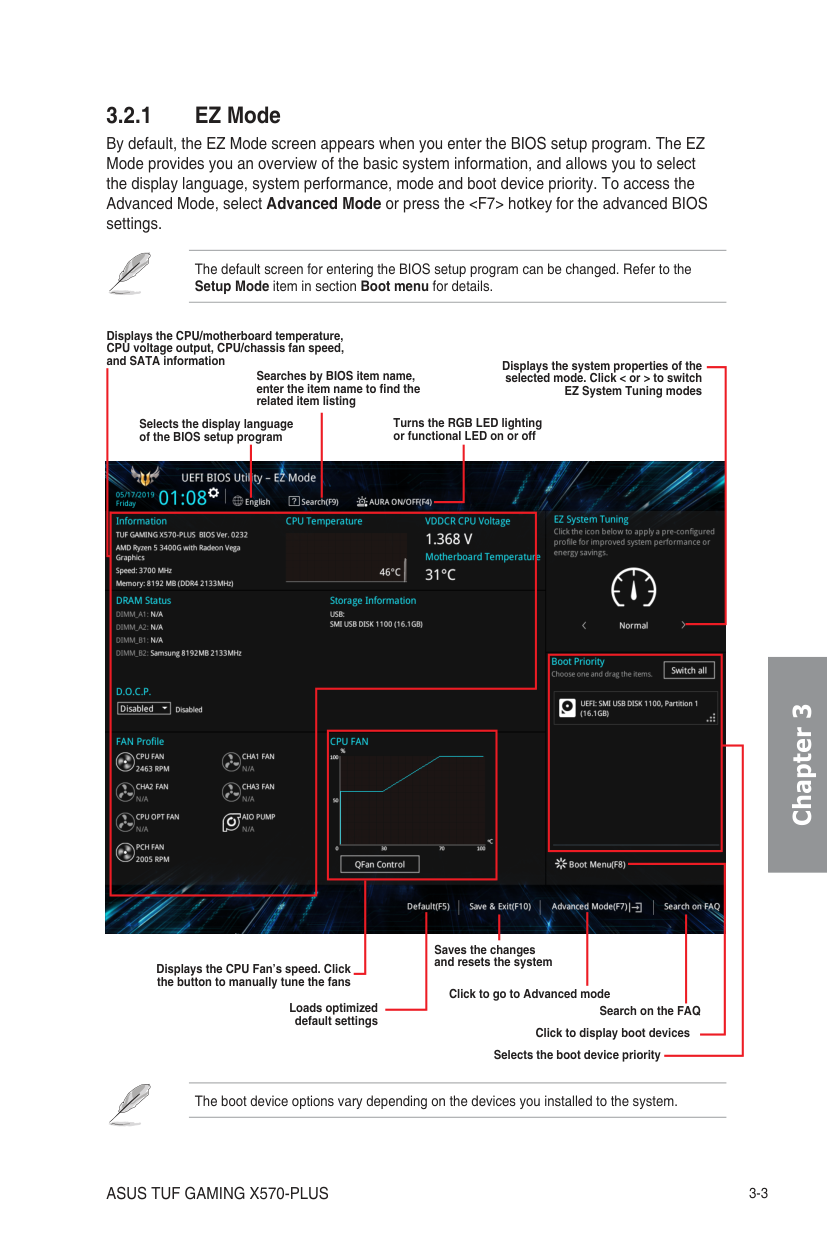
######### 3.2.1 EZ Mode
By default, the EZ Mode screen appears when you enter the BIOS setup program. The EZ Mode provides you an overview of the basic system information, and allows you to select the display language, system performance, mode and boot device priority. To access the Advanced Mode, select Advanced Mode or press the
The default screen for entering the BIOS setup program can be changed. Refer to the Setup Mode item in section Boot menu for details.
Displays the CPU/motherboard temperature, CPU voltage output, CPU/chassis fan speed,
and SATA information Displays the system properties of the selected mode. Click < or > to switch EZ System Tuning modes
Searches by BIOS item name, enter the item name to find the related item listing
Turns the RGB LED lighting or functional LED on or off
Selects the display language of the BIOS setup program

| | | |---|---| | | | |Click to display boot devices
Search on the FAQ|Click to display boot devices
Search on the FAQ|
| | | |---|---| | |Saves the changes|
and resets the system
Displays the CPU Fan’s speed. Click the button to manually tune the fans
Click to go to Advanced mode
Loads optimized default settings
Selects the boot device priority
The boot device options vary depending on the devices you installed to the system.
######## Chapter 3
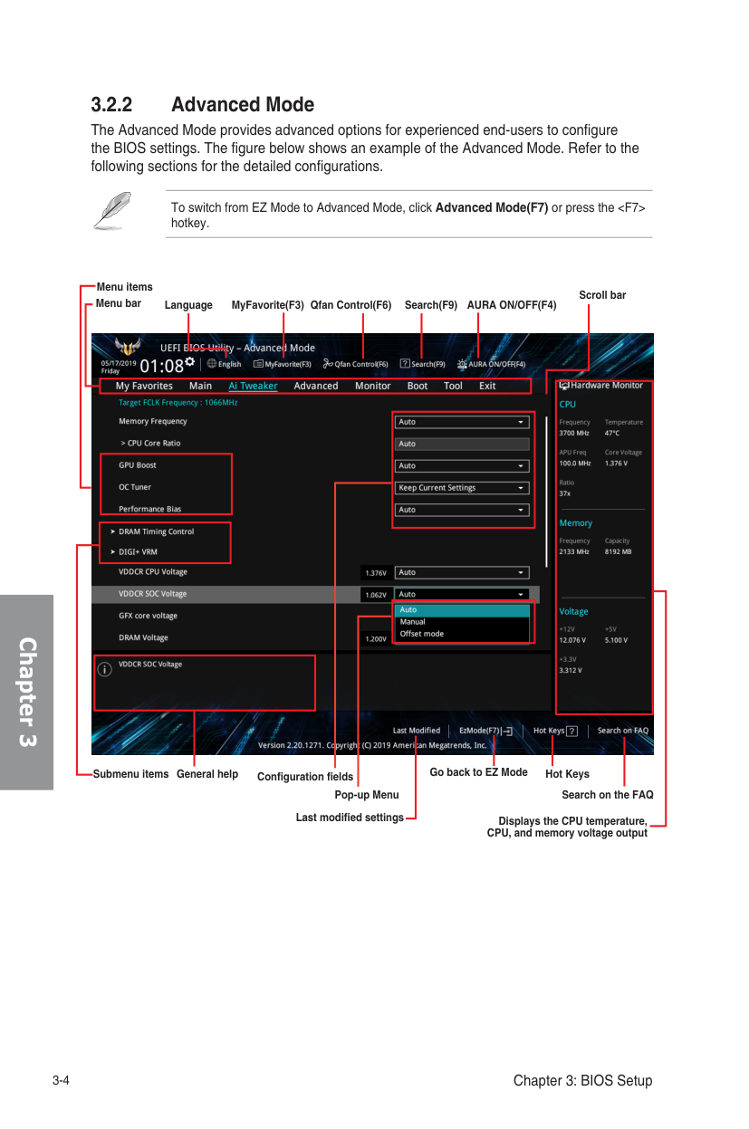
######### 3.2.2 Advanced Mode
The Advanced Mode provides advanced options for experienced end-users to configure the BIOS settings. The figure below shows an example of the Advanced Mode. Refer to the following sections for the detailed configurations.
To switch from EZ Mode to Advanced Mode, click Advanced Mode(F7) or press the
######## Chapter 3
Menu items
Scroll bar
Menu bar Language Qfan Control(F6)MyFavorite(F3)
Search(F9) AURA ON/OFF(F4)

| | | |---|---| | | | |Hot Keys Search on the FAQ|Hot Keys Search on the FAQ|
| | | |---|---|
| | |
Go back to EZ Mode
Submenu items
General help
Configuration fields
Pop-up Menu
Last modified settings
Displays the CPU temperature, CPU, and memory voltage output
Menu bar The menu bar on top of the screen has the following main items:
|My Favorites For saving the frequently-used system settings and configuration.| |---| |Main For changing the basic system configuration| |Ai Tweaker For changing the overclocking settings| |Advanced For changing the advanced system settings| |Monitor
For displaying the system temperature, power status, and changing the fan settings.| |Boot For changing the system boot configuration| |Tool For configuring options for special functions| |Exit For selecting the exit options and loading default settings|
Menu items The highlighted item on the menu bar displays the specific items for that menu. For example, selecting Main shows the Main menu items. The other items (My Favorites, Ai Tweaker, Advanced, Monitor, Boot, Tool, and Exit) on the menu bar have their respective menu items.
Submenu items A greater than sign (>) before each item on any menu screen means that the item has a submenu. To display the submenu, select the item and press
Language This button above the menu bar contains the languages that you can select for your BIOS. Click this button to select the language that you want to display in your BIOS screen.
My Favorites(F3) This button above the menu bar shows all BIOS items in a Tree Map setup. Select frequentlyused BIOS settings and save it to MyFavorites menu.
Refer to section 3.3 My Favorites for more information.
Q-Fan Control(F6) This button above the menu bar displays the current settings of your fans. Use this button to manually tweak the fans to your desired settings.
Refer to section 3.2.3 QFan Control for more information.
Search (F9) This button allows you to search by BIOS item name, enter the item name to find the related item listing.
Chapter 3
Chapter 3
AURA (F4) This button allows you to turn the RGB LED lighting or functional LED on or off. [ON] All AURA effects will be enabled. (Default mode) [OFF] All AURA effects will be disabled.
############ Search on FAQ
Move your mouse over this button to show a QR code, scan this QR code on your mobile device to connect to the BIOS FAQ web page of the ASUS support website. You can also scan the following QR code:

Hot keys This button above the menu bar contains the navigation keys for the BIOS setup program. Use the navigation keys to select items in the menu and change the settings.
Scroll bar A scroll bar appears on the right side of a menu screen when there are items that do not fit on the screen. Press the Up/Down arrow keys or
General help At the bottom of the menu screen is a brief description of the selected item. Use
Configuration fields These fields show the values for the menu items. If an item is user-configurable, you can change the value of the field opposite the item. You cannot select an item that is not user-configurable. A configurable field is highlighted when selected. To change the value of a field, select it and press
Last Modified button This button shows the items that you last modified and saved in BIOS Setup.
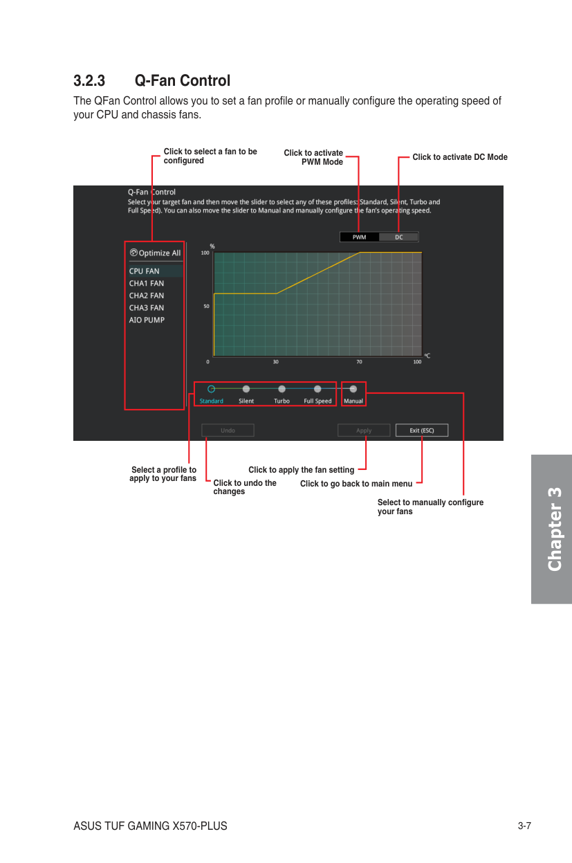
######### 3.2.3 Q-Fan Control
The QFan Control allows you to set a fan profile or manually configure the operating speed of your CPU and chassis fans.
Click to select a fan to be configured
Click to activate PWM Mode
Click to activate DC Mode
| | | |---|---| | | |

| | | |---|---| | | | |Click to go back to main menu|Click to go back to main menu|
Select a profile to apply to your fans
Click to apply the fan setting
Click to undo the changes
Select to manually configure your fans
######## Chapter 3
Chapter 3
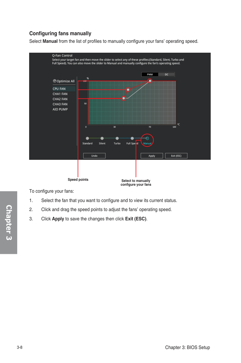
Configuring fans manually Select Manual from the list of profiles to manually configure your fans’ operating speed.

Speed points Select to manually configure your fans
To configure your fans:
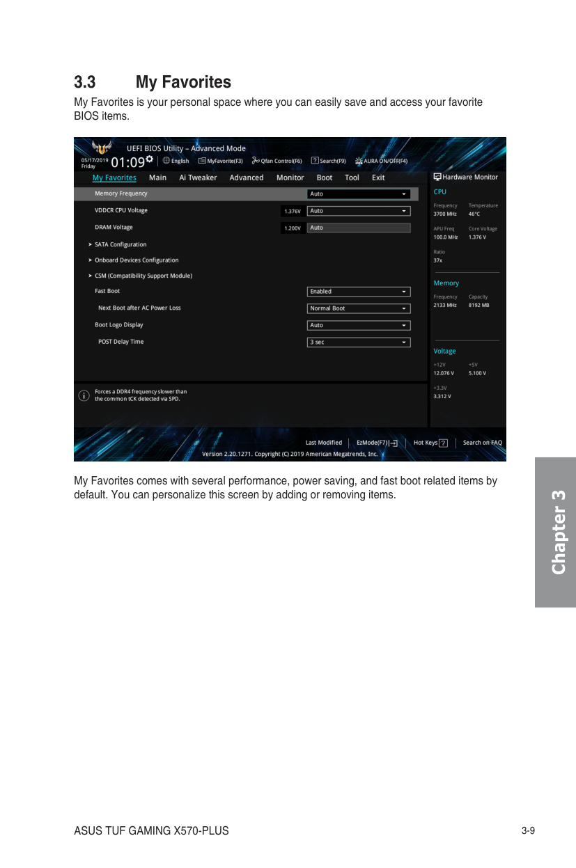
3.3 My Favorites
My Favorites is your personal space where you can easily save and access your favorite BIOS items.

My Favorites comes with several performance, power saving, and fast boot related items by default. You can personalize this screen by adding or removing items.
Chapter 3
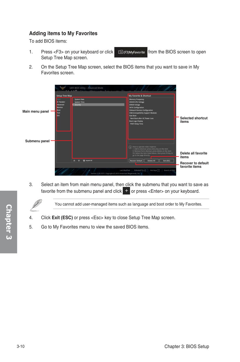
Adding items to My Favorites To add BIOS items:
Chapter 3


You cannot add user-managed items such as language and boot order to My Favorites.
| | | |---|---| | | |
| | |---|
| | |---|
Main menu panel
Selected shortcut items
Submenu panel
Delete all favorite items
Recover to default favorite items
The Main menu screen appears when you enter the Advanced Mode of the BIOS Setup program. The Main menu provides you an overview of the basic system information, and allows you to set the system date, time, language, and security settings.
Security The Security menu items allow you to change the system security settings.
Installed]. After you set a password, these items show [Installed].
The Ai Tweaker menu items allow you to configure overclocking-related items.
Be cautious when changing the settings of the Ai Tweaker menu items. Incorrect field values can cause the system to malfunction
The configuration options for this section vary depending on the CPU and DIMM model you installed on the motherboard.
############ Memory Frequency
This item allows you to set the memory operating frequency. The configurable options vary with the BCLK (base clock) frequency setting. Select the auto mode to apply the optimized setting. Configuration options: [Auto] [DDR4-1333MHz] - [DDR4-4200MHz]
Selecting a very high memory frequency may cause the system to become unstable! If this happens, revert to the default setting.
OC Tuner The OC tuner automatically overclocks the CPU and DRAM frequencies and voltages respectively to enhance the system performance. It also boosts the CPU graphics performance according to the CPU graphics loading. Configuration options: [Keep Current Settings] [OC Tuner]
To keep the current overclocking tuner status, select [Keep Current Settings].
Chapter 3
Chapter 3
3.6 Advanced menu
The Advanced menu items allow you to change the settings for the CPU and other system devices.
Be cautious when changing the settings of the Advanced menu items. Incorrect field values can cause the system to malfunction.
The items in this menu show the CPU-related information that the BIOS automatically detects.
The items in this menu may vary based on the CPU installed.
PSS Support This item allows you enable or disable the generation of ACPI_PPC, _PSS, and _PCT objects. Configuration options: [Disabled] [Enabled]
NX Mode This item allows you enable or disable no-execute page protection function. Configuration options: [Disabled] [Enabled]
SVM Mode This item allows you enable or disable CPU Virtualization. Configuration options: [Disabled] [Enabled]
Core Leveling Mode This item allows you to change the number of compute unit in the system. Configuration options: [Automatic mode] [One] [TWO] [THREE]
######### 3.6.3 NB Configuration
NB Configuration function is not support when using an AMD Ryzen processor.
IGFX Multi-Monitor Enables or disables the Internal Graphics Device Multi-Monitor support for add-on VGA devices. And the memory size of Internal Graphics Device will keep memory reserved. Configuration options: [Disabled] [Enabled] [HybridGraphics]
The IGFX Multi-Monitor item must be enabled before using AMD Dual Graphics technology.
Primary Video Device Selects the primary display device. Configuration options: [IGFX Video] [PCIE Video]
UMA Frame Buffer Size [Auto] Configuration options: [Auto] [64M] [80M] [96M][128M] [256M] [384M] [512M] [768M] [1G] [2G] [3G] [4G]
######### 3.6.4 SATA Configuration
While entering Setup, the BIOS automatically detects the presence of SATA devices. The SATA Port items show Empty if no SATA device is installed to the corresponding SATA port.
SATA Port Enable This item allows you to enable or disable the SATA Device. Configuration options: [Disabled] [Enabled]
SATA Mode This item allows you to set the SATA configuration.
[AHCI] Set to [AHCI] when you want the SATA hard disk drives to use the AHCI (Advanced Host Controller Interface). The AHCI allows the onboard storage driver to enable advanced Serial ATA features that increases storage performance on random workloads by allowing the drive to internally optimize the order of commands.
[RAID] Set to [RAID] when you want to create a RAID configuration from
the SATA hard disk drives. NVMe RAID mode This item allows you enable or disable the NVMe RAID mode. Configuration options: [Disabled] [Enabled] SMART Self Test S.M.A.R.T. (Self-Monitoring, Analysis and Reporting Technology) is a monitoring system that shows a warning message during POST (Power-on Self Test) when an error occurs in the hard disks. Configuration options: [On] [Off] SATA6G_1~8 (Gray), M.2_1 (Gray), M.2_2 (Gray) Select one item and click Enter to assign a new name for the item. Hot Plug
These items allow you to enable/disable SATA Hot Plug Support. Configuration options: [Disabled] [Enabled]
######## Chapter 3
######## Chapter 3
######### 3.6.5 Onboard Devices Configuration
The items in this menu allow you to switch between PCIe Lanes and configure onboard devices.
HD Audio Controller This item allows you to use the Azalia High Definition Audio Controller. Configuration options: [Disabled] [Enabled]
PCIEX16_1 Bandwidth This item displays on AMD Ryzen™ 2nd and 1st Generation with Radeon™ Vega Graphics Processors. [X8 Mode] The PCIe x16_1 slot runs at x8 mode. [PCIe RAID Mode] The Hyper M.2 x16 card and other add-on M.2 devices all run at x4
mode, which allows you to create a PCIe RAID array.
Use PCIe RAID Mode when installing the Hyper M.2 x16 card or other M.2 adapter cards. Installing other devices when using PCIe RAID Mode may cause your PC to fail to boot up.
LED lighting When system is in working state This item allows you to turn the RGB LED lighting on or off when the system is in the working state. Configuration options: [All On] [Stealth Mode] [Aura Only] [Aura Off] When system is in sleep, hibernate or soft off states
This item allows you to turn the RGB LED lighting on or off when the system is in the sleep, hibernate or soft off states. Configuration options: [All On] [Stealth Mode] [Aura Only] [Aura Off]
Realtek LAN Controller Enables or disables the Realtek LAN controllers. Configuration options: [On] [Off]
Realtek PXE OPROM Enables or disables the Realtek PXE OPROM. Configuration options: [On] [Off]
########## 3.6.6 APM ConfigurationThe items in this menu allow you to set system wake and sleep settings.
ErP Ready This item allows you to switch off some power at S4+S5 or S5 to get the system ready for ErP requirement. When set to [Enabled], all other PME options are switched off. Configuration options: [Disabled] [Enable(S4+S5)] [Enable(S5)]
Restore AC Power Loss This item allows your system to go to ON state, OFF state, or both states after an AC power loss. When setting your system to [Last State], it goes to the previous state before the AC power loss. Configuration options: [Power Off] [Power On] [Last State]
############ Power On By PCI-E
This item allows you to enable or disable the Wake-on-LAN function of the onboard LAN controller or other installed PCI-E LAN cards. Configuration options: [Disabled] [Enabled]
Power On By RTC This item allows you to enable or disable the RTC (Real-Time Clock) to generate a wake event and configure the RTC alarm date. When enabled, you can set the days, hours, minutes, or seconds to schedule an RTC alarm date. Configuration options: [Disabled] [Enabled]
######### 3.6.7 PCI Subsytem Settings
SR-IOV Support This item allows you to enable or disable the Single Root IO Virtualization support if your system has SR-IOV capable PCIe devices.
NVM Express devices do not support SMART information.
3.6.8 USB Configuration The items in this menu allow you to change the USB-related features.
The Mass Storage Devices item shows the auto-detected values. If no USB device is detected, the item shows None.
USB Single Port Control This item allows you to enable or disable the individual USB ports.
Refer to section 1.1.2 Motherboard layout for the location of the USB ports.
3.6.11 Network Stack Configuration The items in this menu allow you to enable or disable the UEFI network stack
######## Chapter 3
Chapter 3
######## 3.7 Monitor menu
The Monitor menu displays the system temperature/power status, and allows you to change the fan settings.
Q-Fan Configuration The subitems in this menu allow you to configure the Q-Fan features. Qfan Tuning
Click this item to automatically detect the lowest speed and configure the minimum duty cycle for each fan.
The Boot menu items allow you to change the system boot options. Fast Boot [Disabled] Allows your system to go back to its normal boot speed. [Enabled] Allows your system to accelerate the boot speed.
The following items appear only when you set the Fast Boot to [Enabled].
Next Boot after AC Power Loss [Normal Boot] Returns to normal boot on the next boot after an AC power loss. [Fast Boot] Accelerates the boot speed on the next boot after an AC power loss.
Boot Configuration Setup Mode [Advanced Mode] This item allows you to go to Advanced Mode of the BIOS after
POST.
[EZ Mode] This item allows you to go to EZ Mode of the BIOS after POST. CSM (Compatibility Support Module)
This item allows you to configure the CSM (Compatibility Support Module) items to fully support the various VGA, bootable devices and add-on devices for better compatibility.
Launch CSM [Enabled] For better compatibility, enable the CSM to fully support the non-UEFI
driver add-on devices or the Windows® UEFI mode. [Disabled] Disable the CSM to fully support the Windows® the Windows secure
update and secure boot.
The following items appear only when you set the Launch CSM to [Enabled].
Boot Devices Control This item allows you to select the type of devices that you want to boot. Configuration options: [UEFI and Legacy OPROM] [Legacy OPROM only] [UEFI only] Boot from Network Devices This item allows you to select the type of network devices that you want to launch. Configuration options: [Ignore] [Legacy only] [UEFI only] Boot from Storage Devices This item allows you to select the type of storage devices that you want to launch. Configuration options: [Ignore] [Legacy only] [UEFI only] Boot from PCI-E/PCI Expansion Devices This item allows you to select the type of PCI-E/PCI expansion devices that you want to launch. Configuration options: [Ignore] [Legacy only] [UEFI only]
Secure Boot This item allows you to configure the Windows®Secure Boot settings and manage its keys to protect the system from unauthorized access and malwares during POST.
Boot Option Priorities These items specify the boot device priority sequence from the available devices. The number of device items that appears on the screen depends on the number of devices installed in the system.
Boot Override These items displays the available devices. The number of device items that appears on the screen depends on the number of devices installed in the system. Click an item to start booting from the selected device.
######## 3.9 Tool menu
The Tool menu items allow you to configure options for special functions. Select an item then press
######### 3.9.1 ASUS EZ Flash 3 Utility
This item allows you to run ASUS EZ Flash 3. When you press
For more details, refer to section 3.11.2 ASUS EZ Flash 3.
Chapter 3
Chapter 3
3.10 Exit menu
The Exit menu items allow you to load the optimal default values for the BIOS items, and save or discard your changes to the BIOS items. You can access the EZ Mode from the Exit menu.
Load Optimized Defaults This option allows you to load the default values for each of the parameters on the Setup menus. When you select this option or if you press
Save Changes & Reset Once you are finished making your selections, choose this option from the Exit menu to ensure the values you selected are saved. When you select this option or if you press
Load from Profile This item allows you to load the previous BIOS settings saved in the BIOS Flash. Key in the profile number that saved your BIOS settings, press
Profile Name This item allows you to key in a profile name.
Save to Profile This item allows you to save the current BIOS settings to the BIOS Flash, and create a profile. Key in a profile number from one to eight, press
Load/Save Profile from/to USB Drive This item allows you to load or save profile from your USB drive, load and save profile to your USB drive.
3.9.2 ASUS User Profile This item allows you to store or load multiple BIOS settings.
Discard Changes & Exit This option allows you to exit the Setup program without saving your changes. When you select this option or if you press
Launch EFI Shell from USB drives This item allows you to attempt to launch the EFI Shell application (shellx64.efi) from one of the available filesystem devices.
3.11 Updating BIOS
The ASUS website publishes the latest BIOS versions to provide enhancements on system stability, compatibility,and performance. However, BIOS updating is potentially risky. If there is no problem using the current version of BIOS, DO NOT manually update the BIOS. Inappropriate BIOS updating may result to system’s failure to boot. Carefully follow the instructions in this chapter to update your BIOS when necessary.
Visit http://www.asus.com to download the latest BIOS file for this motherboard.
The following utilities allow you to manage and update the motherboard BIOS setup program.
######### 3.11.1 EZ Update
The EZ Update is a utility that allows you to update the motherboard BIOS in Windows® environment.
Chapter 3
######## Chapter 3
######### 3.11.2 ASUS EZ Flash 3
ASUS EZ Flash 3 allows you to download and update to the latest BIOS through the Internet without having to use a bootable floppy disk or an OS-based utility.
Updating through the Internet varies per region and Internet conditions. Check your local Internet connection before updating through the Internet.
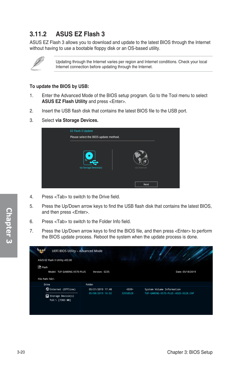
############## To update the BIOS by USB:


Ensure to load the BIOS default settings to ensure system compatibility and stability. Select the Load Optimized Defaults item under the Exit menu. See section 3.10 Exit Menu for details.
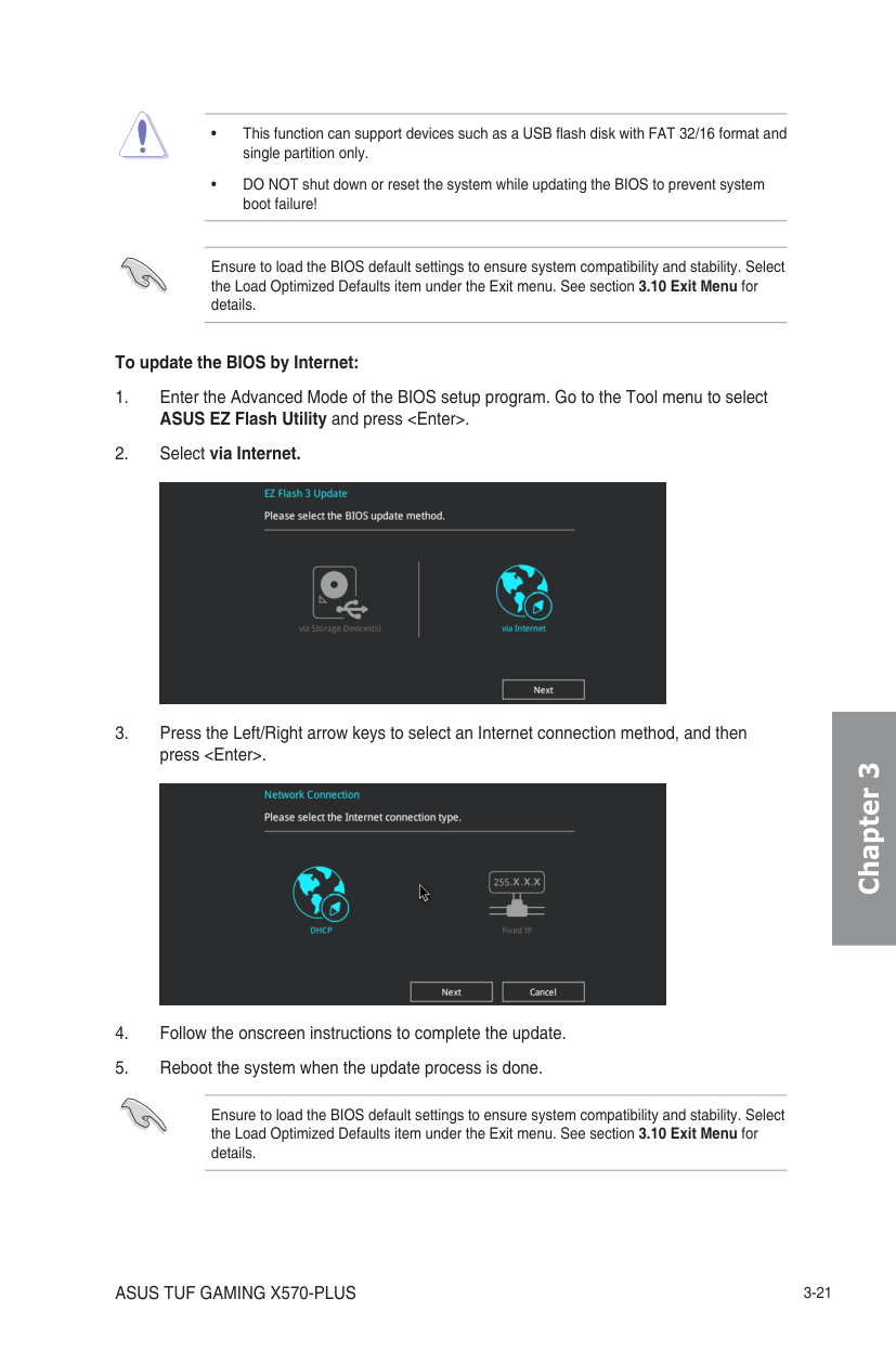
############## To update the BIOS by Internet:
Ensure to load the BIOS default settings to ensure system compatibility and stability. Select the Load Optimized Defaults item under the Exit menu. See section 3.10 Exit Menu for details.


Chapter 3
######## Chapter 3
######### 3.11.3 ASUS CrashFree BIOS 3

The ASUS CrashFree BIOS 3 utility is an auto recovery tool that allows you to restore the BIOS file when it fails or gets corrupted during the updating process. You can restore a corrupted BIOS file using the motherboard support DVD or a USB flash drive that contains the BIOS file.
The BIOS file in the motherboard support DVD may be older than the BIOS file published on the ASUS official website. If you want to use the newer BIOS file, download the file at https://www.asus.com/support/ and save it to a USB flash drive.
############ Recovering the BIOS To recover the BIOS:
DO NOT shut down or reset the system while updating the BIOS! Doing so can cause system boot failure!
RAID Support 4
######## 4.1 AMD RAID Array configurations
The motherboard comes with the RaidXpert2 Configuration Utility that supports Volume, RAIDABLE, RAID 0, RAID 1, and RAID 10 (depends on system licensing) configurations.
For more information on configuring your RAID sets, please refer to the RAID Configuration Guide which you can find at https://www.asus.com/support.
4.1.1 RAID definitions Volume provides the ability to link-together storage from one or several disks, regardless of the size of the space on those disks. This configuration is useful in scavenging space on disks unused by other disks in the array. This configuration does not provide performance benefits or data redundancy, disk failure will result in data loss. RAIDABLE arrays (also known as RAID Ready) are a special type of Volume (JBOD) that allows the user to add more storage space or create a redundant array after a system is installed. RAIDABLE arrays are created using Option ROM, UEFI, or rcadm.
The ability to create RAIDABLE arrays may vary per system.
RAID 10 is data striping and data mirroring combined without parity (redundancy data) having to be calculated and written. With the RAID 10 configuration you get all the benefits of both RAID 0 and RAID 1 configurations. Use four new hard disk drives or use an existing drive and three new drives for this setup.
Chapter 4
ASUS TUF GAMING X570-PLUS 4-1
##### Appendix
######## Notices FCC Compliance Information
Responsible Party: Asus Computer International
Address: 48720 Kato Rd., Fremont, CA 94538, USA Phone / Fax No: (510)739-3777 / (510)608-4555
This device complies with part 15 of the FCC Rules. Operation is subject to the following two conditions: (1) This device may not cause harmful interference, and (2) this device must accept any interference received, including interference that may cause undesired operation. This equipment has been tested and found to comply with the limits for a Class B digital device, pursuant to part 15 of the FCC Rules. These limits are designed to provide reasonable protection against harmful interference in a residential installation. This equipment generates, uses and can radiate radio frequency energy and, if not installed and used in accordance with the instructions, may cause harmful interference to radio communications. However, there is no guarantee that interference will not occur in a particular installation. If this equipment does cause harmful interference to radio or television reception, which can be determined by turning the equipment off and on, the user is encouraged to try to correct the interference by one or more of the following measures:
######### Compliance Statement of Innovation, Science and Economic Development Canada (ISED)
This device complies with Innovation, Science and Economic Development Canada licence exempt RSS standard(s). Operation is subject to the following two conditions: (1) this device may not cause interference, and (2) this device must accept any interference, including interference that may cause undesired operation of the device. CAN ICES-3(B)/NMB-3(B)
######### Déclaration de conformité de Innovation, Sciences et Développement économique Canada (ISED)
Le présent appareil est conforme aux CNR d’Innovation, Sciences et Développement économique Canada applicables aux appareils radio exempts de licence. L’exploitation est autorisée aux deux conditions suivantes : (1) l’appareil ne doit pas produire de brouillage, et (2) l’utilisateur de l’appareil doit accepter tout brouillage radioélectrique subi, même si le brouillage est susceptible d’en compromettre le fonctionnement. CAN ICES-3(B)/NMB-3(B)
VCCI: Japan Compliance Statement Class B ITE

KC: Korea Warning Statement

######## Appendix
REACH
Complying with the REACH (Registration, Evaluation, Authorisation, and Restriction of Chemicals) regulatory framework, we published the chemical substances in our products at ASUS REACH website at http://csr.asus.com/english/REACH.htm.
DO NOT throw the motherboard in municipal waste. This product has been designed to enable proper reuse of parts and recycling. This symbol of the crossed out wheeled bin indicates that the product (electrical and electronic equipment) should not be placed in municipal waste. Check local regulations for disposal of electronic products.
DO NOT throw the mercury-containing button cell battery in municipal waste. This symbol of the crossed out wheeled bin indicates that the battery should not be placed in municipal waste.
######### ASUS Recycling/Takeback Services
ASUS recycling and takeback programs come from our commitment to the highest standards for protecting our environment. We believe in providing solutions for you to be able to responsibly recycle our products, batteries, other components as well as the packaging materials. Please go to http://csr.asus.com/english/Takeback.htm for detailed recycling information in different regions.
Regional notice for California
####### WARNING
Cancer and Reproductive Harm www.P65Warnings.ca.gov
Google™ License Terms Copyright© 2019 Google Inc. All Rights Reserved. Licensed under the Apache License, Version 2.0 (the “License”); you may not use this file except in compliance with the License. You may obtain a copy of the License at: http://www.apache.org/licenses/LICENSE-2.0 Unless required by applicable law or agreed to in writing, software distributed under the License is distributed on an “AS IS” BASIS, WITHOUT WARRANTIES OR CONDITIONS OF ANY KIND, either express or implied. See the License for the specific language governing permissions and limitations under the License.
Appendix
Appendix
English ASUSTeK Computer Inc. hereby declares that this device is in compliance with the essential requirements and other relevant provisions of related Directives. Full text of EU declaration of conformity is available at: www.asus.com/support Français AsusTek Computer Inc. déclare par la présente que cet appareil est conforme aux critères essentiels et autres clauses pertinentes des directives concernées. La déclaration de conformité de l’UE peut être téléchargée à partir du site Internet suivant : www.asus.com/support Deutsch ASUSTeK Computer Inc. erklärt hiermit, dass dieses Gerät mit den wesentlichen Anforderungen und anderen relevanten Bestimmungen der zugehörigen Richtlinien übereinstimmt. Der gesamte Text der EUKonformitätserklärung ist verfügbar unter: www.asus.com/support Italiano ASUSTeK Computer Inc. con la presente dichiara che questo dispositivo è conforme ai requisiti essenziali e alle altre disposizioni pertinenti con le direttive correlate. Il testo completo della dichiarazione di conformità UE è disponibile all’indirizzo: www.asus.com/support Русский Компания ASUS заявляет, что это устройство соответствует основным требованиям и другим соответствующим условиям соответствующих директив. Подробную информацию, пожалуйста, смотрите на www.asus.com/support Български С настоящото ASUSTeK Computer Inc. декларира, че това устройство е в съответствие със съществените изисквания и другите приложими постановления на свързаните директиви. Пълният текст на декларацията за съответствие на ЕС е достъпна на адрес: www.asus.com/support Hrvatski ASUSTeK Computer Inc. ovim izjavljuje da je ovaj uređaj sukladan s bitnim zahtjevima i ostalim odgovarajućim odredbama vezanih direktiva. Cijeli tekst EU izjave o sukladnosti dostupan je na: www.asus.com/support Čeština Společnost ASUSTeK Computer Inc. tímto prohlašuje, že toto zařízení splňuje základní požadavky a další příslušná ustanovení souvisejících směrnic. Plné znění prohlášení o shodě EU je k dispozici na adrese: www.asus.com/support Dansk ASUSTeK Computer Inc. erklærer hermed, at denne enhed er i overensstemmelse med hovedkravene og andre relevante bestemmelser i de relaterede direktiver. Hele EU-overensstemmelseserklæringen kan findes på: www.asus.com/support Nederlands ASUSTeK Computer Inc. verklaart hierbij dat dit apparaat voldoet aan de essentiële vereisten en andere relevante bepalingen van de verwante richtlijnen. De volledige tekst van de EU-verklaring van conformiteit is beschikbaar op: www.asus.com/support Eesti Käesolevaga kinnitab ASUSTeK Computer Inc, et see seade vastab asjakohaste direktiivide oluliste nõuetele ja teistele asjassepuutuvatele sätetele. EL vastavusdeklaratsiooni täielik tekst on saadaval järgmisel aadressil: www.asus.com/support Suomi ASUSTeK Computer Inc. ilmoittaa täten, että tämä laite on asiaankuuluvien direktiivien olennaisten vaatimusten ja muiden tätä koskevien säädösten mukainen. EU-yhdenmukaisuusilmoituksen koko teksti on luettavissa osoitteessa: www.asus.com/support Ελληνικά Με το παρόν, η AsusTek Computer Inc. δηλώνει ότι αυτή η συσκευή συμμορφώνεται με τις θεμελιώδεις απαιτήσεις και άλλες σχετικές διατάξεις των Οδηγιών της ΕΕ. Το πλήρες κείμενο της δήλωσης συμβατότητας είναι διαθέσιμο στη διεύθυνση: www.asus.com/support
Magyar Az ASUSTeK Computer Inc. ezennel kijelenti, hogy ez az eszköz megfelel a kapcsolódó Irányelvek lényeges követelményeinek és egyéb vonatkozó rendelkezéseinek. Az EU megfelelőségi nyilatkozat teljes szövege innen letölthető: www.asus.com/support Latviski ASUSTeK Computer Inc. ar šo paziņo, ka šī ierīce atbilst saistīto
Direktīvu būtiskajām prasībām un citiem citiem saistošajiem nosacījumiem. Pilns ES atbilstības paziņojuma teksts pieejams šeit: www.asus.com/support Lietuvių „ASUSTeK Computer Inc.“ šiuo tvirtina, kad šis įrenginys atitinka
pagrindinius reikalavimus ir kitas svarbias susijusių direktyvų nuostatas. Visą ES atitikties deklaracijos tekstą galima rasti: www.asus.com/support Norsk ASUSTeK Computer Inc. erklærer herved at denne enheten er i samsvar med hovedsaklige krav og andre relevante forskrifter i relaterte direktiver. Fullstendig tekst for EU-samsvarserklæringen finnes på: www.asus.com/support Polski Firma ASUSTeK Computer Inc. niniejszym oświadcza, że urządzenie to jest zgodne z zasadniczymi wymogami i innymi właściwymi postanowieniami powiązanych dyrektyw. Pełny tekst deklaracji zgodności UE jest dostępny pod adresem: www.asus.com/support
Português A ASUSTeK Computer Inc. declara que este dispositivo está em conformidade com os requisitos essenciais e outras disposições relevantes das Diretivas relacionadas. Texto integral da declaração da UE disponível em: www.asus.com/support
Română ASUSTeK Computer Inc. declară că acest dispozitiv se conformează cerinţelor esenţiale şi altor prevederi relevante ale directivelor conexe. Textul complet al declaraţiei de conformitate a Uniunii Europene se găseşte la: www.asus.com/support Srpski ASUSTeK Computer Inc. ovim izjavljuje da je ovaj uređaj u saglasnosti sa osnovnim zahtevima i drugim relevantnim odredbama povezanih Direktiva. Pun tekst EU deklaracije o usaglašenosti je dostupan da adresi: www.asus.com/support Slovensky Spoločnosť ASUSTeK Computer Inc. týmto vyhlasuje, že toto zariadenie vyhovuje základným požiadavkám a ostatým príslušným ustanoveniam príslušných smerníc. Celý text vyhlásenia o zhode pre štáty EÚ je dostupný na adrese: www.asus.com/support Slovenščina ASUSTeK Computer Inc. izjavlja, da je ta naprava skladna z bistvenimi zahtevami in drugimi ustreznimi določbami povezanih direktiv. Celotno besedilo EU-izjave o skladnosti je na voljo na spletnem mestu: www.asus.com/support Español Por la presente, ASUSTeK Computer Inc. declara que este dispositivo cumple los requisitos básicos y otras disposiciones pertinentes de las directivas relacionadas. El texto completo de la declaración de la UE de conformidad está disponible en: www.asus.com/support Svenska ASUSTeK Computer Inc. förklarar härmed att denna enhet överensstämmer med de grundläggande kraven och andra relevanta föreskrifter i relaterade direktiv. Fulltext av EU-försäkran om överensstämmelse finns på: www.asus.com/support Українська ASUSTeK Computer Inc. заявляє, що цей пристрій відповідає основним вимогам та іншим відповідним положенням відповідних Директив. Повний текст декларації відповідності стандартам ЄС доступний на: www.asus.com/support Türkçe AsusTek Computer Inc., bu aygıtın temel gereksinimlerle ve ilişkili Yönergelerin diğer ilgili koşullarıyla uyumlu olduğunu beyan eder. AB uygunluk bildiriminin tam metni şu adreste bulunabilir: www.asus.com/support
Bosanski ASUSTeK Computer Inc. ovim izjavljuje da je ovaj uređaj usklađen sa bitnim zahtjevima i ostalim odgovarajućim odredbama vezanih direktiva. Cijeli tekst EU izjave o usklađenosti dostupan je na: www.asus.com/support
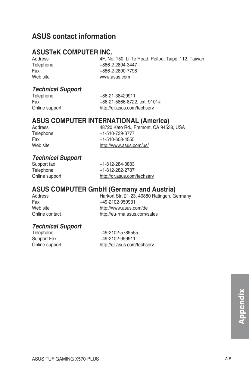
ASUS contact information ASUSTeK COMPUTER INC. Address 4F, No. 150, Li-Te Road, Peitou, Taipei 112, Taiwan Telephone +886-2-2894-3447 Fax +886-2-2890-7798 Web site www.asus.com Technical Support Telephone +86-21-38429911 Fax +86-21-5866-8722, ext. 9101# Online support http://qr.asus.com/techserv ASUS COMPUTER INTERNATIONAL (America) Address 48720 Kato Rd., Fremont, CA 94538, USA Telephone +1-510-739-3777 Fax +1-510-608-4555 Web site http://www.asus.com/us/ Technical Support
Support fax +1-812-284-0883 Telephone +1-812-282-2787 Online support http://qr.asus.com/techserv
ASUS COMPUTER GmbH (Germany and Austria) Address Harkort Str. 21-23, 40880 Ratingen, Germany Fax +49-2102-959931 Web site http://www.asus.com/de Online contact http://eu-rma.asus.com/sales
Technical Support Telephone +49-2102-5789555 Support Fax +49-2102-959911 Online support http://qr.asus.com/techserv
Appendix
######## Appendix
TUF Gaming Monitor VG259 series
User Guide
| | | | |---|---|---| | | | |

First Edition August 2019
Copyright © 2019 ASUSTeK COMPUTER INC. All Rights Reserved.
No part of this manual, including the products and software described in it, may be reproduced, transmitted, transcribed, stored in a retrieval system, or translated into any language in any form or by any means, except documentation kept by the purchaser for backup purposes, without the express written permission of ASUSTeK COMPUTER INC. (“ASUS”).
Product warranty or service will not be extended if: (1) the product is repaired, modified or altered, unless such repair, modification of alteration is authorized in writing by ASUS; or (2) the serial number of the product is defaced or missing.
ASUS PROVIDES THIS MANUAL “AS IS” WITHOUT WARRANTY OF ANY KIND, EITHER EXPRESS OR IMPLIED, INCLUDING BUT NOT LIMITED TO THE IMPLIED WARRANTIES OR CONDITIONS OF MERCHANTABILITY OR FITNESS FOR A PARTICULAR PURPOSE. IN NO EVENT SHALL ASUS, ITS DIRECTORS, OFFICERS, EMPLOYEES OR AGENTS BE LIABLE FOR ANY INDIRECT, SPECIAL, INCIDENTAL, OR CONSEQUENTIAL DAMAGES (INCLUDING DAMAGES FOR LOSS OF PROFITS, LOSS OF BUSINESS, LOSS OF USE OR DATA, INTERRUPTION OF BUSINESS AND THE LIKE), EVEN IF ASUS HAS BEEN ADVISED OF THE POSSIBILITY OF SUCH DAMAGES ARISING FROM ANY DEFECT OR ERROR IN THIS MANUAL OR PRODUCT.
SPECIFICATIONS AND INFORMATION CONTAINED IN THIS MANUAL ARE FURNISHED FOR INFORMATIONAL USE ONLY, AND ARE SUBJECT TO CHANGE AT ANY TIME WITHOUT NOTICE, AND SHOULD NOT BE CONSTRUED AS A COMMITMENT BY ASUS. ASUS ASSUMES NO RESPONSIBILITY OR LIABILITY FOR ANY ERRORS OR INACCURACIES THAT MAY APPEAR IN THIS MANUAL, INCLUDING THE PRODUCTS AND SOFTWARE DESCRIBED IN IT.
Products and corporate names appearing in this manual may or may not be registered trademarks or copyrights of their respective companies, and are used only for identification or explanation and to the owners’ benefit, without intent to infringe.
ii
####### Contents
Notices ......................................................................................................... iv Safety information ....................................................................................... v Care & Cleaning .......................................................................................... vi Takeback Services ..................................................................................... vii
########### Chapter 1: Product introduction
########### Chapter 2: Setup
########### Chapter 3: General instructions3.1 OSD (On-Screen Display) menu ................................................ 3-1
3.2 Specifications summary ............................................................. 3-7
iii
####### Notices Federal Communications Commission Statement
This device complies with Part 15 of the FCC Rules. Operation is subject to the following two conditions:
This equipment has been tested and found to comply with the limits for a Class B digital device, pursuant to Part 15 of the FCC Rules. These limits are designed to provide reasonable protection against harmful interference in a residential installation. This equipment generates, uses and can radiate radio frequency energy and, if not installed and used in accordance with the instructions, may cause harmful interference to radio communications. However, there is no guarantee that interference will not occur in a particular installation. If this equipment does cause harmful interference to radio or television reception, which can be determined by turning the equipment off and on, the user is encouraged to try to correct the interference by one or more of the following measures:
The use of shielded cables for connection of the monitor to the graphics card is required to assure compliance with FCC regulations. Changes or modifications to this unit not expressly approved by the party responsible for compliance
could void the user’s authority to operate this equipment.
Canadian Department of Communications Statement This digital apparatus does not exceed the Class B limits for radio noise emissions from digital apparatus set out in the Radio Interference Regulations of the Canadian Department of Communications.
This class B digital apparatus complies with Canadian ICES-003. This Class B digital apparatus meets all requirements of the Canadian Interference
iv
####### Safety information
This symbol of the crossed out wheeled bin indicates that the product (electrical, electronic equipment, and mercury-containing button cell battery) should not be placed in municipal waste. Please check local regulations for disposal of electronic products.
v
AEEE yönetmeliğine uygundur
####### Care & Cleaning
######### The following symptoms are normal with the monitor:
########### Conventions used in this guide
WARNING: Information to prevent injury to yourself when trying to complete a task.
CAUTION: Information to prevent damage to the components when trying to complete a task.
IMPORTANT: Information that you MUST follow to complete a task.
NOTE: Tips and additional information to aid in completing a task.
vi
Where to find more information Refer to the following sources for additional information and for product and software updates.
####### Takeback Services
ASUS recycling and takeback programs come from our commitment to the highest standards for protecting our environment. We believe in providing solutions for our customers to be able to responsibly recycle our products, batteries and other components as well as the packaging materials.
Please go to http://csr.asus.com/english/Takeback.htm for detail recycling information in different region.
####### Product information for EU energy label
vii
############### viii
####### 1.1 Welcome!

Thank you for purchasing the ASUS® LCD monitor! The latest widescreen LCD monitor from ASUS provides a broader, brighter and crystal-clear display, plus a host of features that enhance your viewing experience. With these features, you can enjoy the convenience and delightful visual experience that the monitor brings to you!
####### 1.2 Package contents
Check your package for the following items: LCD monitor Monitor base Quick start guide Warranty card Power adapter Power cord DisplayPort cable (optional) HDMI cable (optional)


If any of the above items is damaged or missing, contact your retailer immediately.
####### 1.3 Monitor introduction
######### 1.3.1 Front view

|White|ON| |---|---|
############## Status Description
Amber Standby mode/No signal OFF OFF
######### 1.3.2 Back view
| | | | | | | | |---|---|---|---|---|---|---| | | | | | | | |
7

######### 1.3.3 GamePlus Function
The GamePlus function provides a toolkit and creates a better gaming environment for users when playing different types of games. The crosshair overlay with 6 different crosshair options lets you choose the one that best suits the game you're playing. There's also an onscreen timer you can position on the left of the display so you can keep track of the elapsed gaming time; while the FPS (frames per second) counter lets you know how smooth the game is running. Display Alignment displays alignment lines on 4 sides of the screen, serving as an easy and handy tool for you to line up multiple monitors perfectly.
To active GamePlus:
|GamePlus Main Menu|GamePlus — Crosshair|GamePlus — Timer| |---|---|---| |NEXT BACK/EXIT
GamePlus
|FPS| |---|
Crosshair
Timer
FPS Counter
Display Alignment
(Practice Mode)|NEXT BACK/EXIT
GamePlus
|NEXT BACK/EXIT
GamePlus
|
######### 1.3.4 GameVisual Function
The GameVisual function helps you select among different picture modes in a convenient way.
To active GameVisual: Press the GameVisual hotkey repeatedly to select.
####### 2.1 Assembling the monitor arm/base
To assemble the monitor base:
We recommend that you cover the table surface with soft cloth to prevent damage to the monitor.
####### 2.2 Adjusting the monitor
-5°~ +33°
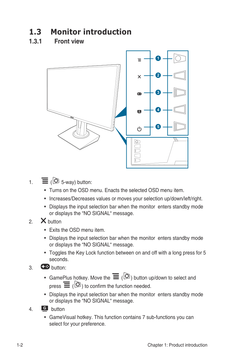
90° 90° 0°
| | | | |---|---|---| | | | | | | | | | | | | | | | | | | | | | | | | | | | |
130mm
(Tilt) (Swivel) (Height adjustment)
It is normal that the monitor slightly shakes while you adjust the viewing angle.
############ Pivoting the monitor
-5°~ +33°
| | | | |---|---|---| | | | |
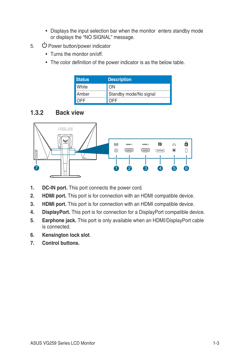
| | | | | | | | | | | | | | | | | | | | | | | |
0°
0°
130mm
90°
90°
It is normal that the monitor slightly shakes while you adjust the viewing angle.
####### 2.3 Detaching the arm (for VESA wallmount)
The detachable arm/base of this monitor is specially designed for VESA wall mount.
To detach the arm/base:
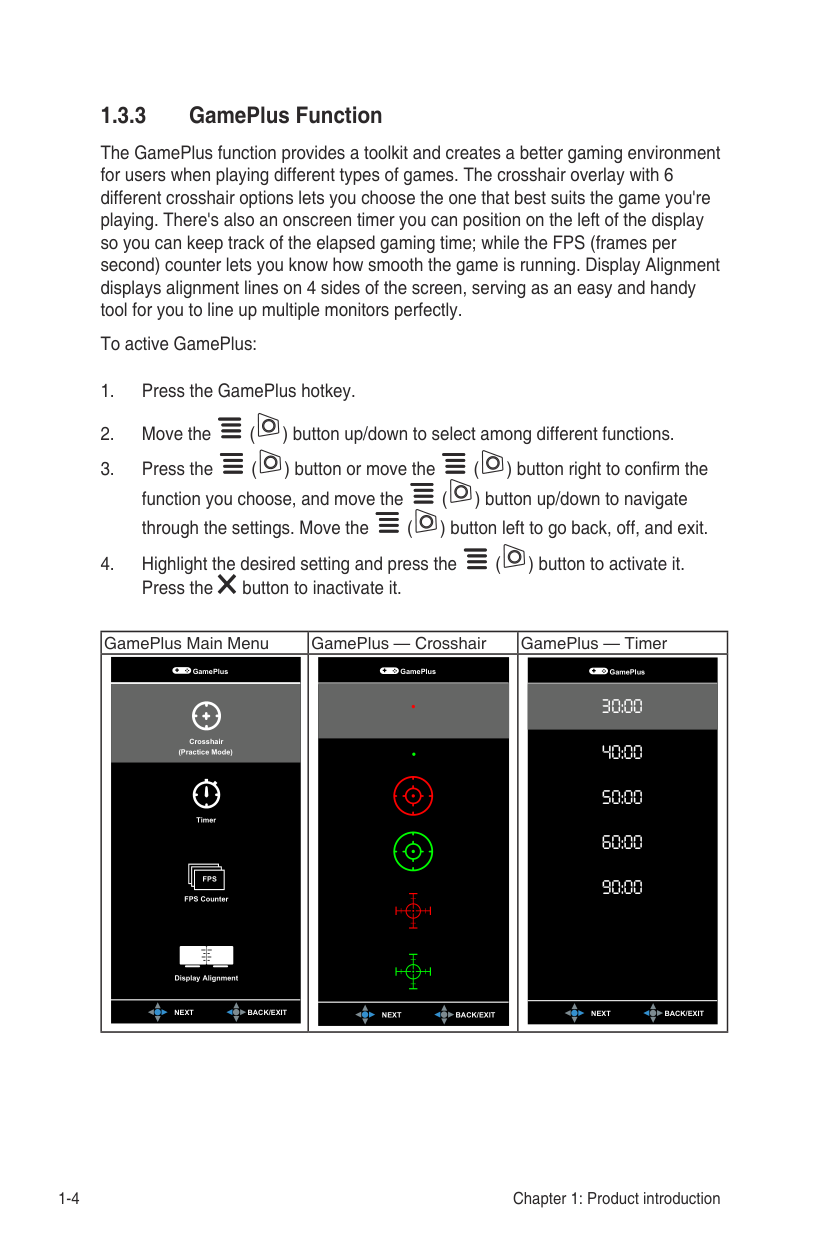
2 1
(Figure 1) (Figure 2)
1
2
(Figure 3)
We recommend that you cover the table surface with soft cloth to prevent damage to the monitor.
####### 2.4 Connecting the cables
Connect the cables as the following instructions:
b. Connect one end of the power cord to the power adapter and the other end to a power outlet.
####### 2.5 Turning on the monitor
Press the power button . See page 1-2 for the location of the power button. The power indicator lights up in white to show that the monitor is ON.
####### 3.1 OSD (On-Screen Display) menu
######### 3.1.1 How to reconfigure
ASUS TUF Gaming VG259 Racing Mode HDMI2 1920x1080@ 120HzGameVisual
Scenery Mode
Racing Mode
Cinema Mode
RTS/RPG Mode
FPS Mode
sRGB Mode
MOBA Mode
( ) left repeatedly until the OSD menu disappears. To adjust other functions, repeat steps 1-3.

######### 3.1.2 OSD function introduction
############ 1. GameVisual
####################### ASUS TUF Gaming VG259 Racing Mode HDMI2 1920x1080@ 120HzGameVisual
Scenery Mode
Racing Mode
Cinema Mode
RTS/RPG Mode
FPS Mode
sRGB Mode
MOBA Mode
############# Please refer to “1.3.4 GameVisual Function”.
############ 2. Blue Light Filter
In this function, you can adjust the blue light filter level.
####################### ASUS TUF Gaming VG259 Racing Mode HDMI2 1920x1080@ 120HzBlue Light Filter
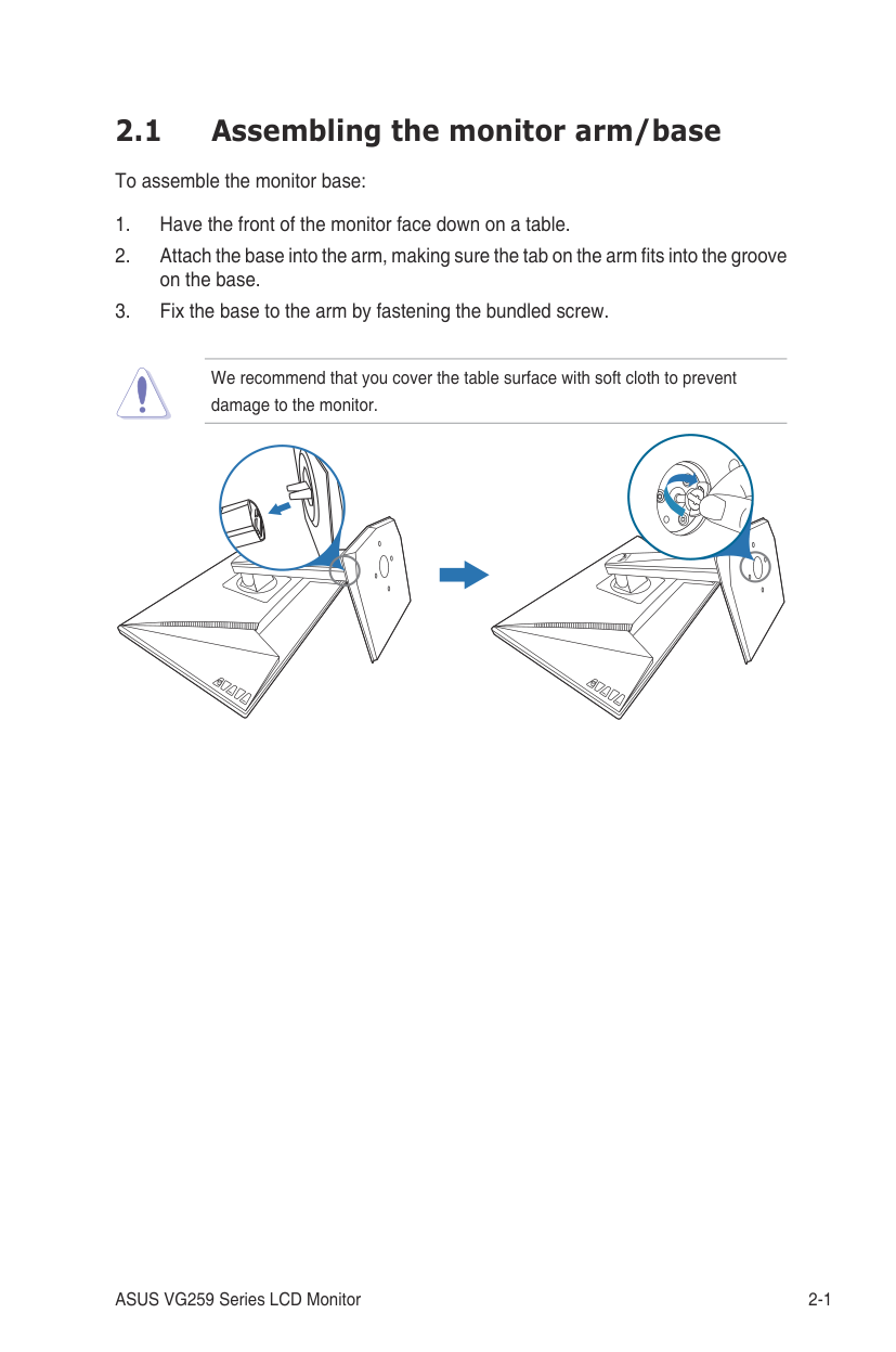
Please refer to the following to alleviate eye strains:
############# 3. ColorSet a desired color setting from this menu.
ASUS TUF Gaming VG259 Racing Mode HDMI2 1920x1080@ 120Hz
Color
Brightness
Contrast
Saturation
Color Temp.
Skin Tone
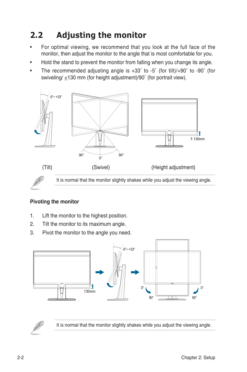
############# 4. ImageSet the image related setting from this menu.
########################## ASUS TUF Gaming VG259 Racing Mode HDMI2 1920x1080@ 120Hz
Image
Sharpness
Trace Free
Aspect Control
VividPixel
ASCR
Adaptive-Sync/FreeSync
ELMB
Shadow Boost
This function is not available when ELMB is activated.
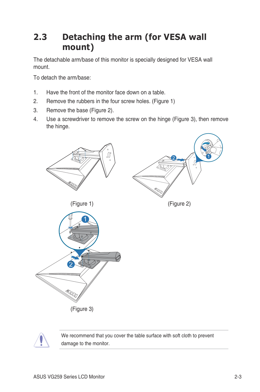
4:3 is only available when input source is in 4:3 format.
To activate Adaptive-Sync/FreeSync, turn off ELMB function first.
To activate ELMB, turn off Adaptive-Sync/FreeSync function first.
This function is only available in Racing mode, RTS/RPG mode, FPS mode or sRGB mode.
Sound
Volume
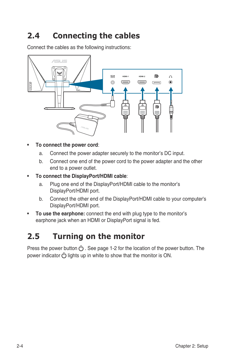
Mute
ASUS TUF Gaming VG259 Racing Mode HDMI2 1920x1080@ 120Hz
ASUS TUF Gaming VG259 Racing Mode HDMI2 1920x1080@ 120Hz
Input Select
Allows you to adjust the system.
ASUS TUF Gaming VG259 Racing Mode HDMI2 1920x1080@ 120Hz
System Setup
GameVisual Demo Mode
ECO Mode
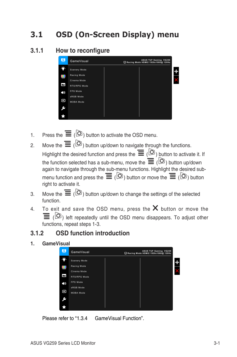
OSD Setup
Language
Key Lock
Information
Power Indicator
Power Key Lock
All Reset
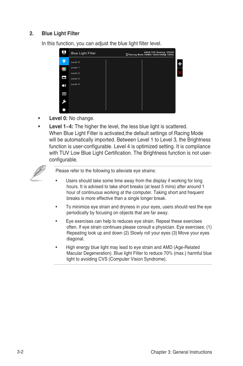
############ 8. MyFavorite
Loads/Saves all settings on the monitor.
MyFavorite
ASUS TUF Gaming VG259 Racing Mode HDMI2 1920x1080@ 120Hz
####### 3.2 Specifications summary
|Brightness (Typ.)
Contrast Ratio (Typ.) Contrast Ratio (Max.) Viewing angle(H/V) CR>10 Display colors Response time Color temperature selection Analog input Digital input Earphone jack Audio input|VG259Q: 400 cd/m2 VG259QR: 300 cd/m2 1000:1 100,000,000:1 (with ASCR on) 178˚/178˚ 16.7 M
3 ms (Gray to gray), 1ms MPRT
4 color temperatures No HDMI x 2, DisplayPort v1.2 x 1 Yes No
| |---|---| |Speaker (Built-in) USB 3.0 port Colors Power LED Tilt Swivel Height adjustment VESA wall mount Kensington lock Voltage rating|2 W x 2 Stereo, RMS No Black White (On)/Amber (Standby)
+33˚~ -5˚
+90˚~ -90˚ 130 mm 100 x 100 mm Yes AC: 100~240V DC: 19V, 2.1A (AC adapter)| |Power consumption|Power On: < 40 W, Standby: < 0.5 W, Power Off: < 0.3 W| |Temperature (Operating)|0˚C~40˚C| |Temperature (Non-operating)|-20˚C~+60˚C| |Dimensions (W x H x D) without stand|563 x 329 x 51 mm| |Dimensions (W x H x D) with stand|563 x 487 x 211 mm (highest) 563 x 357 x 211 mm (lowest) 664 x 415 x 221 mm (package)| |Weight (Esti.)|5.1 kg (Net); 2.9 kg (without stand); 7.4 kg (Gross)|
Panel Type TFT LCD Panel size 24.5”W (16:9, 62.2 cm) wide screen Max. Resolution 1920 x 1080 Pixel pitch 0.2832 mm x 0.2802 mm
|Multi-languages|21 languages (English, French, German, Italian, Spanish, Dutch, Portuguese, Russian, Czech, Croatian, Polish, Romanian, Hungarian, Turkish, Simplified Chinese, Traditional Chinese, Japanese, Korean, Thai, Indonesian, Persian)| |---|---| |Accessories|DisplayPort cable (optional), HDMI cable (optional), power adapter, power cord, quick start guide, warranty card| |Compliance and Standards|UL/cUL, CB, CE, ErP, FCC, CCC, CU, RCM, BSMI, VCCI, RoHS, J-MOSS, WEEE, Windows 7 & 10 WHQL, CEL, MEPS, PSE, UkrSEPRO, KCC, E-Standby, TUV-Flicker Free, TUV-Low Blue Light, ICES-3, PC Recycle|
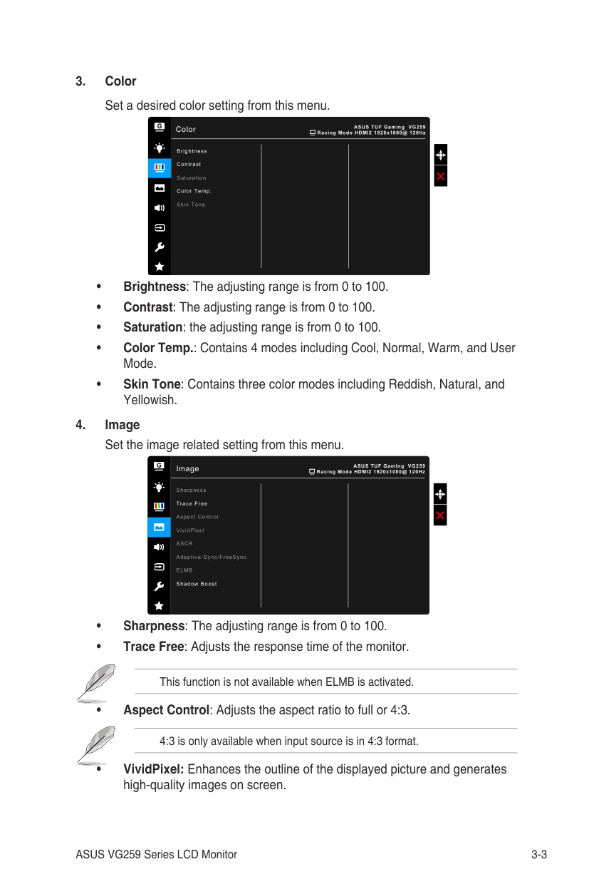
############ *Specifications are subject to change without notice.
####### 3.3 Outline dimensions
275.9 [10.9]
| | | |---|---| | | | | | | | | | | | | | | | | | | | | | | | | | | | | | | | | | | | | | | | | | | | | | | | | | | | | | |
| | | |---|---|
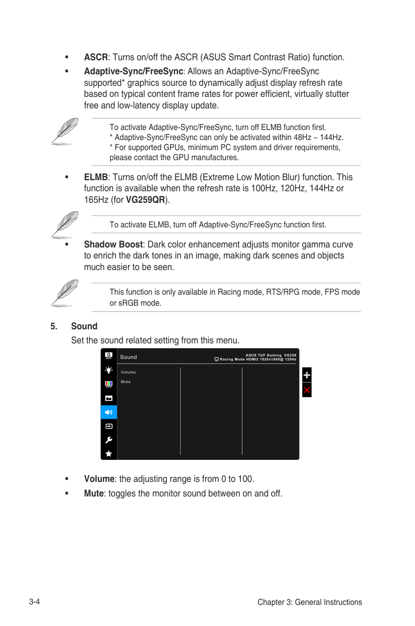
| | | | | | | | | | | | | | | | | | | | | | | | | | | | | | | | | | | | | | | | | | | | | | | | | | | | | |
| | | |---|---| | | |
*Unit: mm(inch)
Swivel: +/-90 Degree ASUS VG259 Outline Dimension
| | | |---|---| | | |
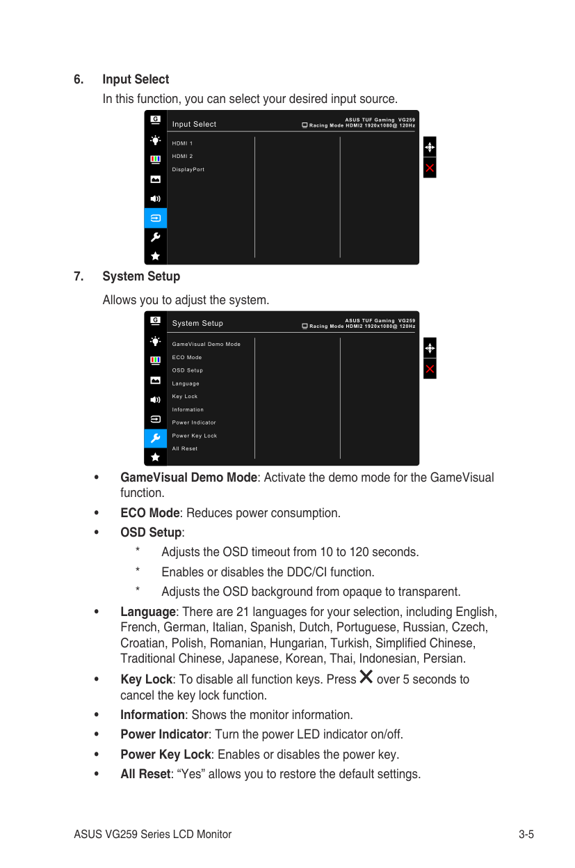
| | | | | | | | | | | | | | | | | | | | | | | | | | | | | | | | | | | | | | | | | | | | |
| | | |---|---| | | | | | | | | | | | |
Pivot: +/-90 Degree
| | | |---|---| | | | | | | | | |

| | | | | | | | | | | | | | | | | | | | | | | | | | | | | | | | | | | | | | |
| | | |---|---| | | | | | | | | | | | |
9.4 [0.4]
271.9 [10.7]
| | | |---|---| | | | | | | | | |
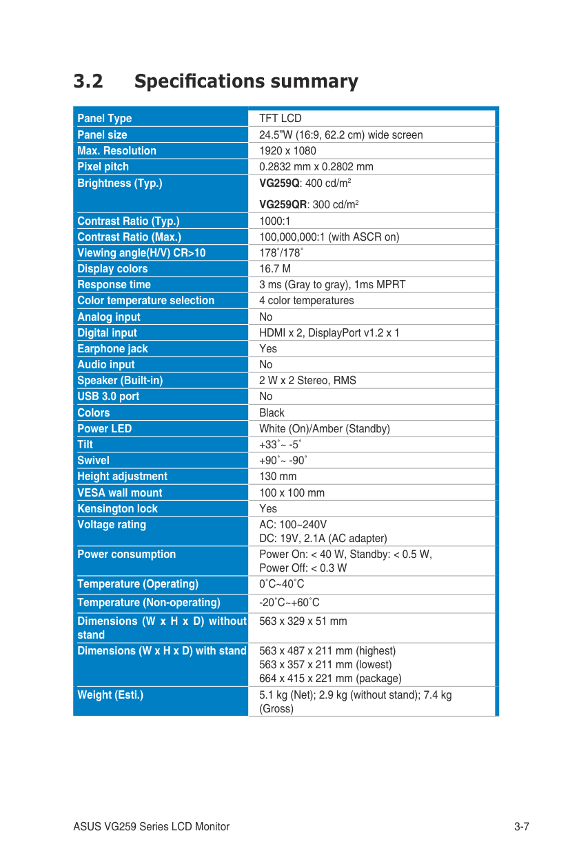
| | | | | | | | | | | | | | | | | | | | | | | | | | | | | | | | | | | | | | |
| | | |---|---| | | | | | | | | | | | |
543.7 [21.4]-Active Area
| | | |---|---| | | |
562.5 [22.1]
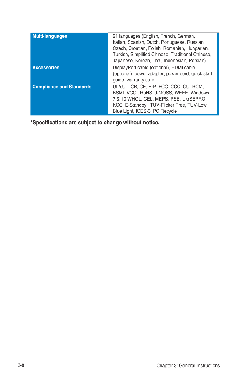
| | | |---|---| | | |
9.4 [0.4]
44.3 [1.7]
60.1 [2.4]
16.1 [0.6]
| | |---| | |
| | |---| | |
51.4 [2.0]
| | | | |---|---|---| | | | |
| | |---|
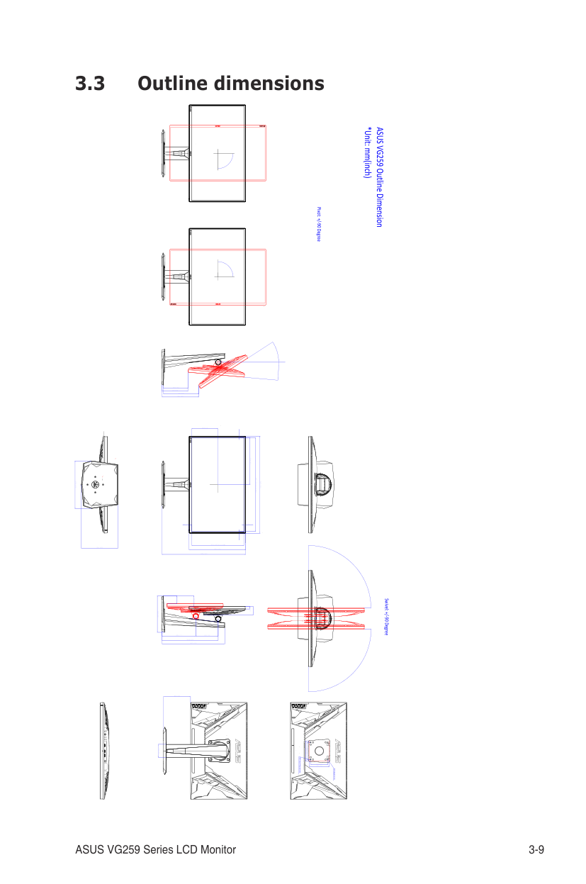
| |
211.4 [8.3]
| | | | |---|---|---| | | | |
| | | |---|---| | | |
| | | |---|---| | | |
| | | |---|---| | | |
| | | |---|---| | | |
100.0 [3.9] 117.0 [4.6]
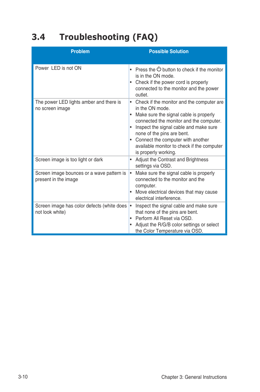
76.9 [3.0]
| | | | |---|---|---|
Wall mount Keep out area
M4*4-Depth 10 mm
####### 3.4 Troubleshooting (FAQ)
############## Problem Possible Solution
Power LED is not ON • Press the button to check if the monitor is in the ON mode.
• Check if the power cord is properly connected to the monitor and the power outlet.
The power LED lights amber and there is no screen image
Screen image is too light or dark • Adjust the Contrast and Brightness settings via OSD.
Screen image bounces or a wave pattern is present in the image
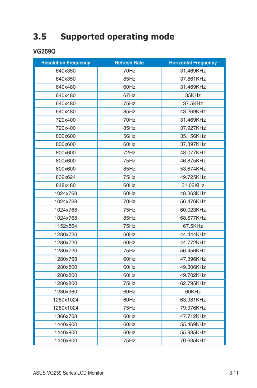
Screen image has color defects (white does not look white)
####### 3.5 Supported operating mode
########### VG259Q
|640x350|70Hz|31.469KHz| |---|---|---| |640x350|85Hz|37.861KHz| |640x480|60Hz|31.469KHz| |640x480|67Hz|35KHz| |640x480|75Hz|37.5KHz| |640x480|85Hz|43.269KHz| |720x400|70Hz|31.469KHz| |720x400|85Hz|37.927KHz| |800x600|56Hz|35.156KHz| |800x600|60Hz|37.897KHz| |800x600|72Hz|48.077KHz| |800x600|75Hz|46.875KHz| |800x600|85Hz|53.674KHz| |832x624|75Hz|49.725KHz| |848x480|60Hz|31.02KHz| |1024x768|60Hz|48.363KHz| |1024x768|70Hz|56.476KHz| |1024x768|75Hz|60.023KHz|
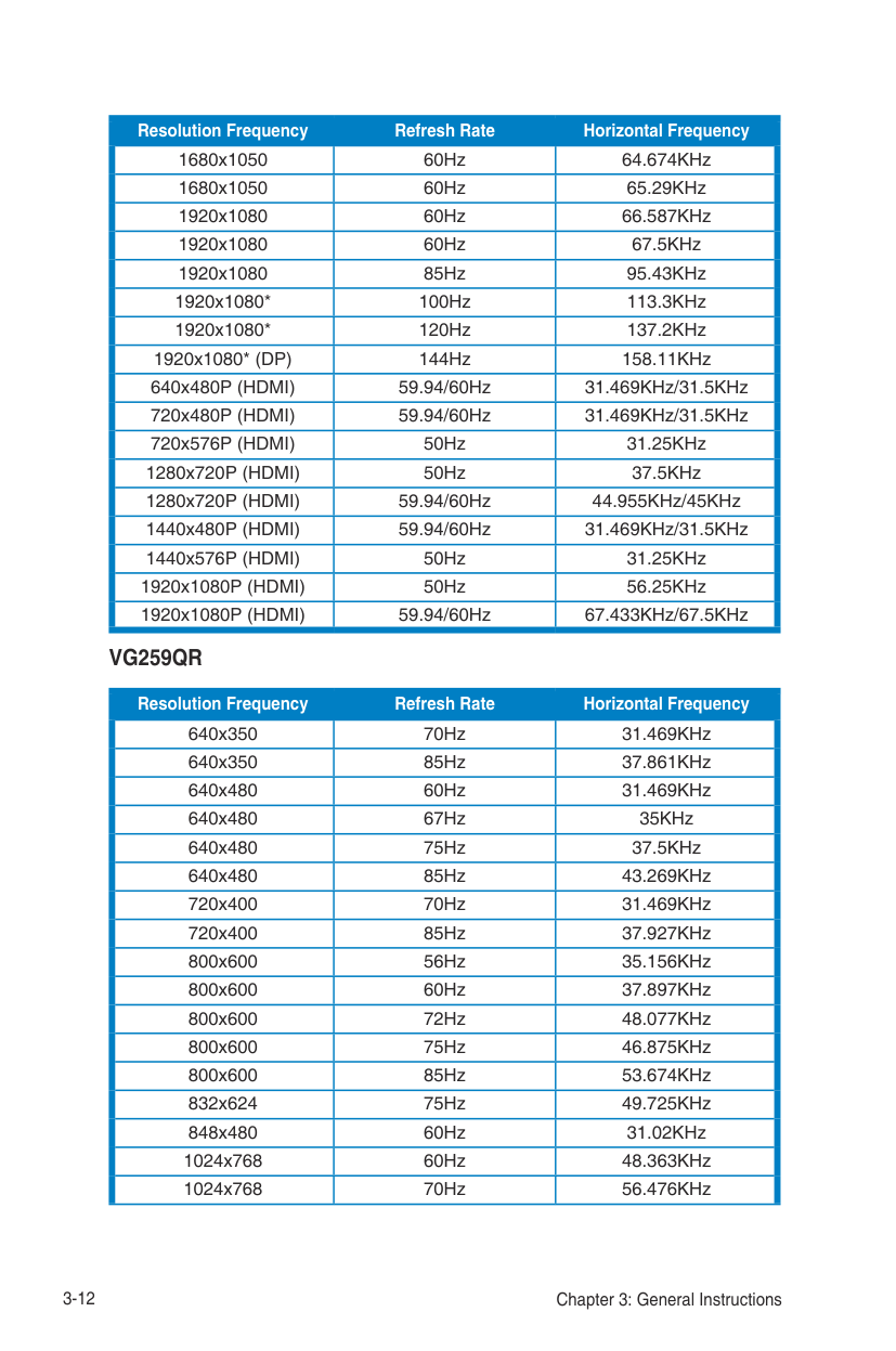
|1024x768|85Hz|68.677KHz| |1152x864|75Hz|67.5KHz| |1280x720|60Hz|44.444KHz| |1280x720|60Hz|44.772KHz| |1280x720|75Hz|56.456KHz| |1280x768|60Hz|47.396KHz| |1280x800|60Hz|49.306KHz| |1280x800|60Hz|49.702KHz| |1280x800|75Hz|62.795KHz| |1280x960|60Hz|60KHz| |1280x1024|60Hz|63.981KHz| |1280x1024|75Hz|79.976KHz| |1366x768|60Hz|47.712KHz| |1440x900|60Hz|55.469KHz| |1440x900|60Hz|55.935KHz| |1440x900|75Hz|70.635KHz|
Resolution Frequency Refresh Rate Horizontal Frequency
|1680x1050|60Hz|64.674KHz| |---|---|---| |1680x1050|60Hz|65.29KHz| |1920x1080|60Hz|66.587KHz| |1920x1080|60Hz|67.5KHz| |1920x1080|85Hz|95.43KHz| |1920x1080*|100Hz|113.3KHz| |1920x1080*|120Hz|137.2KHz| |1920x1080* (DP)|144Hz|158.11KHz| |640x480P (HDMI)|59.94/60Hz|31.469KHz/31.5KHz| |720x480P (HDMI)|59.94/60Hz|31.469KHz/31.5KHz| |720x576P (HDMI)|50Hz|31.25KHz|
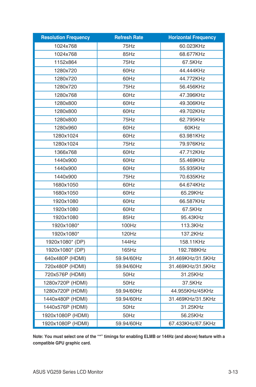
|1280x720P (HDMI)|50Hz|37.5KHz| |1280x720P (HDMI)|59.94/60Hz|44.955KHz/45KHz| |1440x480P (HDMI)|59.94/60Hz|31.469KHz/31.5KHz| |1440x576P (HDMI)|50Hz|31.25KHz| |1920x1080P (HDMI)|50Hz|56.25KHz|
############## Resolution Frequency Refresh Rate Horizontal Frequency
1920x1080P (HDMI) 59.94/60Hz 67.433KHz/67.5KHz VG259QR
|Resolution Frequency|Refresh Rate|Horizontal Frequency| |---|---|---| |640x350|70Hz|31.469KHz| |640x350|85Hz|37.861KHz| |640x480|60Hz|31.469KHz| |640x480|67Hz|35KHz| |640x480|75Hz|37.5KHz| |640x480|85Hz|43.269KHz| |720x400|70Hz|31.469KHz| |720x400|85Hz|37.927KHz| |800x600|56Hz|35.156KHz| |800x600|60Hz|37.897KHz| |800x600|72Hz|48.077KHz| |800x600|75Hz|46.875KHz| |800x600|85Hz|53.674KHz| |832x624|75Hz|49.725KHz| |848x480|60Hz|31.02KHz| |1024x768|60Hz|48.363KHz| |1024x768|70Hz|56.476KHz|
|Resolution Frequency|Refresh Rate|Horizontal Frequency| |---|---|---| |1024x768|75Hz|60.023KHz| |1024x768|85Hz|68.677KHz| |1152x864|75Hz|67.5KHz| |1280x720|60Hz|44.444KHz| |1280x720|60Hz|44.772KHz| |1280x720|75Hz|56.456KHz| |1280x768|60Hz|47.396KHz| |1280x800|60Hz|49.306KHz| |1280x800|60Hz|49.702KHz| |1280x800|75Hz|62.795KHz| |1280x960|60Hz|60KHz| |1280x1024|60Hz|63.981KHz| |1280x1024|75Hz|79.976KHz| |1366x768|60Hz|47.712KHz| |1440x900|60Hz|55.469KHz| |1440x900|60Hz|55.935KHz| |1440x900|75Hz|70.635KHz| |1680x1050|60Hz|64.674KHz| |1680x1050|60Hz|65.29KHz| |1920x1080|60Hz|66.587KHz| |1920x1080|60Hz|67.5KHz| |1920x1080|85Hz|95.43KHz| |1920x1080*|100Hz|113.3KHz| |1920x1080*|120Hz|137.2KHz| |1920x1080* (DP)|144Hz|158.11KHz| |1920x1080* (DP)|165Hz|192.788KHz| |640x480P (HDMI)|59.94/60Hz|31.469KHz/31.5KHz| |720x480P (HDMI)|59.94/60Hz|31.469KHz/31.5KHz| |720x576P (HDMI)|50Hz|31.25KHz| |1280x720P (HDMI)|50Hz|37.5KHz| |1280x720P (HDMI)|59.94/60Hz|44.955KHz/45KHz| |1440x480P (HDMI)|59.94/60Hz|31.469KHz/31.5KHz| |1440x576P (HDMI)|50Hz|31.25KHz| |1920x1080P (HDMI)|50Hz|56.25KHz|
1920x1080P (HDMI) 59.94/60Hz 67.433KHz/67.5KHz
Note: You must select one of the “*” timings for enabling ELMB or 144Hz (and above) feature with a compatible GPU graphic card.