
Ask AI
— answers from the official manualAnswers from the official manual.
Common questions
Common Questions
10 totalWhat should I do if the controller displays 'ref'?
Ensure that you have selected a valid refrigerant in parameter o30. If not, the display will show 'ref' and await a new setting. Choose an appropriate refrigerant based on your system needs.
How do I factory reset the Optyma™ Plus controller?
To return to the factory settings, cut out the supply voltage to the controller, then press and hold both the upper and lower buttons while reconnecting the power.
What does a 'DI2' alarm mean?
A DI2 alarm indicates that there is an issue with the function selected for DI2 input. Check the signal source at the DI2 input to resolve it.
How do I set the temperature units to Fahrenheit?
Set parameter r05 to '1' via the controller menu to change the display unit from Celsius (°C) to Fahrenheit (°F).
What does a c73 code alarm indicate?
The c73 code indicates that the condensing pressure has exceeded its maximum limit, triggering an alarm and stopping the compressor until conditions improve.
How can I clear specific fault alarms on the Optyma™ Plus?
Press the upper button briefly when an error code is displayed to view the alarm report. Clearing or signing for the alarm typically requires acknowledgement but direct instructions are not provided; this may vary based on firmware.
Full Manual
18 pages

User Guide
Controller for condensing unit Optyma™ Plus
SW Ver. 3.7x

www.danfoss.com
Introduction
Application Condensing unit control
Advantages
Principle The controller receives a signal for demanded cooling, and it then starts the compressor. If the compressor is controlled by variable speed, the suction pressure (converted to temperature) will be controlled according to a set temperature value. Condenser pressure regulation is performed again following a signal from the ambient temperature sensor and the set reference. The controller will then control the fan, which allows the condensing temperature to be maintained at the desired value. The controller can also control the heating element in the crankcase so that oil is kept separate from the refrigerant. For excess discharge temperature, the liquid injection will be activated in the suction line (for compressors with the liquid injection option).
Functions
Regulation reference for condensing temperature The controller controls the condensing Reference, which is in detail the di erence between condensing temperature and ambient temperature. The reference setpoint can be shown with a brief push on the middle button and adjusted with the upper and lower button. The reference can be raised at night to allow slower fan speeds to reduce fan noise. This is done via the night set back feature.
This setting can be changed without entering the programming mode so care needs to be taken to not adjust unintentionally.
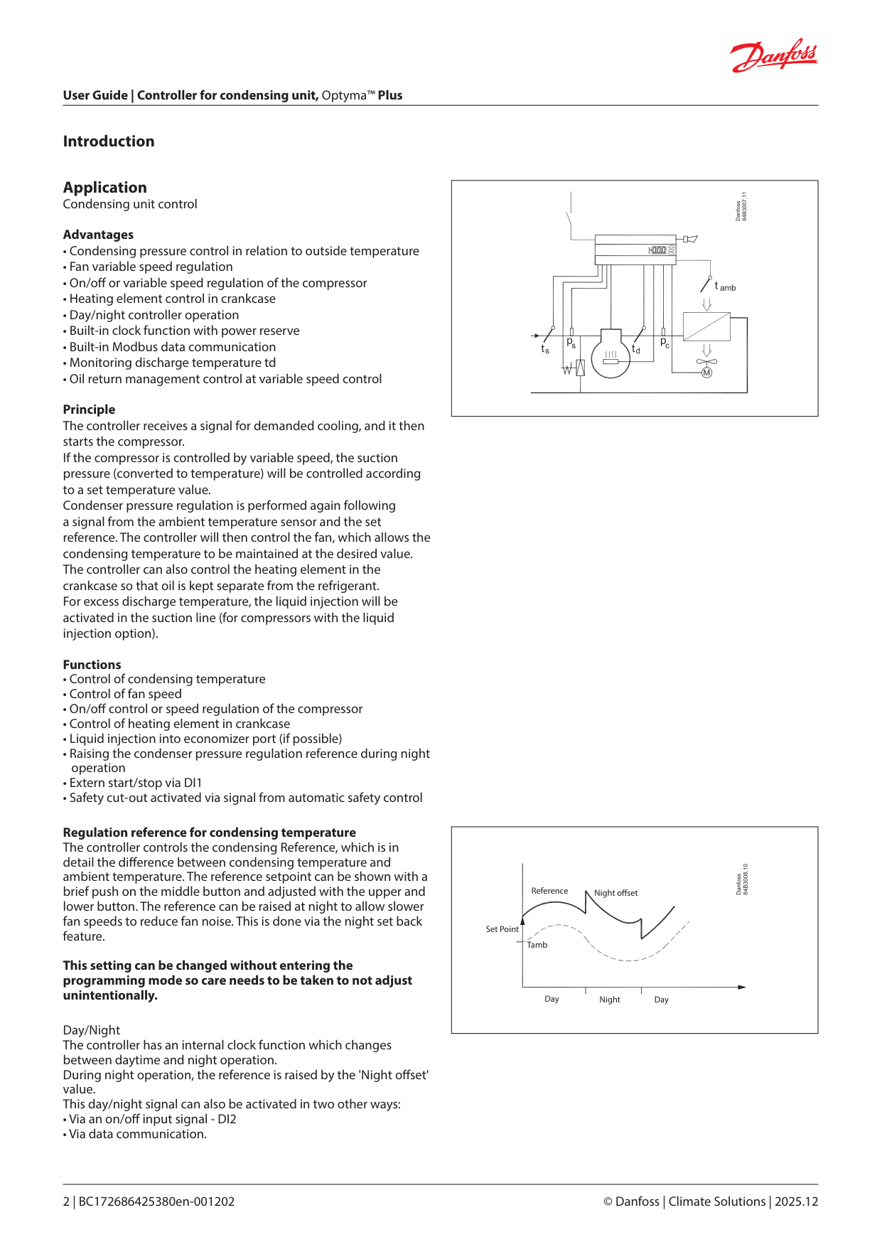
Day/Night The controller has an internal clock function which changes between daytime and night operation. During night operation, the reference is raised by the 'Night o set' value. This day/night signal can also be activated in two other ways:
| | |---|
|Reference Night o set
NightDay Day
Set Point
Tamb| |---|
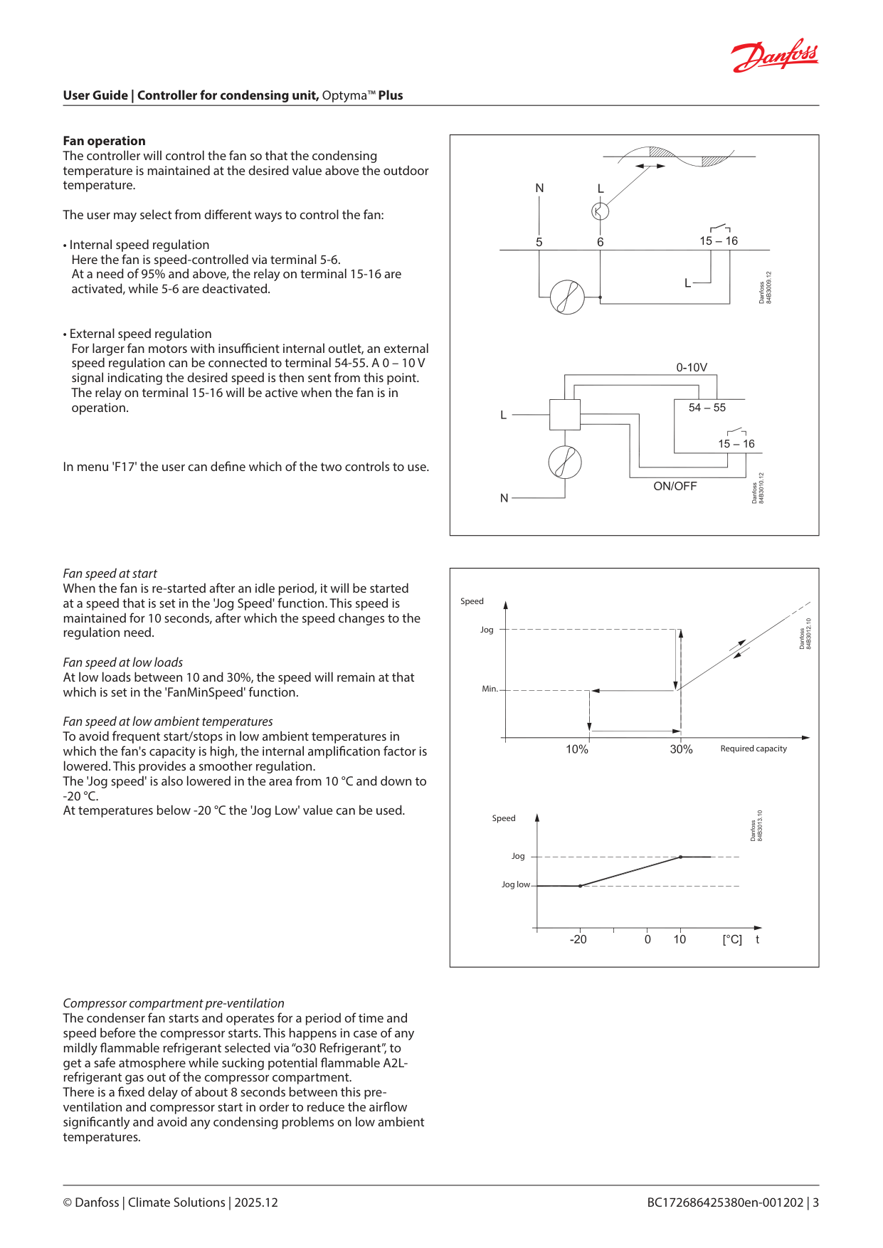
Fan operation The controller will control the fan so that the condensing temperature is maintained at the desired value above the outdoor temperature.
The user may select from di erent ways to control the fan:
In menu 'F17' the user can de ne which of the two controls to use.
|15 – 16
15 – 16
54 – 55| |---|
Fan speed at start When the fan is re-started after an idle period, it will be started at a speed that is set in the 'Jog Speed' function. This speed is maintained for 10 seconds, after which the speed changes to the regulation need.
Fan speed at low loads At low loads between 10 and 30%, the speed will remain at that which is set in the 'FanMinSpeed' function.
Fan speed at low ambient temperatures To avoid frequent start/stops in low ambient temperatures in which the fan's capacity is high, the internal ampli cation factor is lowered. This provides a smoother regulation. The 'Jog speed' is also lowered in the area from 10 °C and down to
|Jog
Min.
Jog low
Jog
Speed
Speed
Required capacity| |---|
Compressor compartment pre-ventilation The condenser fan starts and operates for a period of time and speed before the compressor starts. This happens in case of any mildly ammable refrigerant selected via “o30 Refrigerant”, to get a safe atmosphere while sucking potential ammable A2Lrefrigerant gas out of the compressor compartment. There is a xed delay of about 8 seconds between this preventilation and compressor start in order to reduce the air ow signi cantly and avoid any condensing problems on low ambient temperatures.
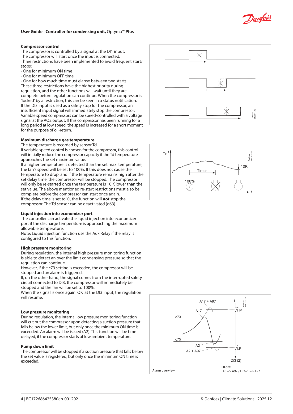
Compressor control The compressor is controlled by a signal at the DI1 input. The compressor will start once the input is connected. Three restrictions have been implemented to avoid frequent start/ stops:
Maximum discharge gas temperature The temperature is recorded by sensor Td. If variable speed control is chosen for the compressor, this control will initially reduce the compressor capacity if the Td temperature approaches the set maximum value. If a higher temperature is detected than the set max. temperature, the fan's speed will be set to 100%. If this does not cause the temperature to drop, and if the temperature remains high after the set delay time, the compressor will be stopped. The compressor will only be re-started once the temperature is 10 K lower than the set value. The above mentioned re-start restrictions must also be complete before the compressor can start once again. If the delay time is set to '0', the function will not stop the compressor. The Td sensor can be deactivated (o63).
Liquid injection into economizer port The controller can activate the liquid injection into economizer port if the discharge temperature is approaching the maximum allowable temperature. Note: Liquid injection function use the Aux Relay if the relay is con gured to this function. High pressure monitoring During regulation, the internal high pressure monitoring function is able to detect an over the limit condensing pressure so that the regulation can continue. However, if the c73 setting is exceeded, the compressor will be stopped and an alarm is triggered. If, on the other hand, the signal comes from the interrupted safety circuit connected to DI3, the compressor will immediately be stopped and the fan will be set to 100%. When the signal is once again 'OK' at the DI3 input, the regulation will resume.
Low pressure monitoring During regulation, the internal low pressure monitoring function will cut out the compressor upon detecting a suction pressure that falls below the lower limit, but only once the minimum ON time is exceeded. An alarm will be issued (A2). This function will be time delayed, if the compressor starts at low ambient temperature.
Pump down limit The compressor will be stopped if a suction pressure that falls below the set value is registered, but only once the minimum ON time is exceeded.
| | |---|
| | |---|
|DI o :
Di3 => A97 / DI2=1 => A97Alarm overview
| |---|
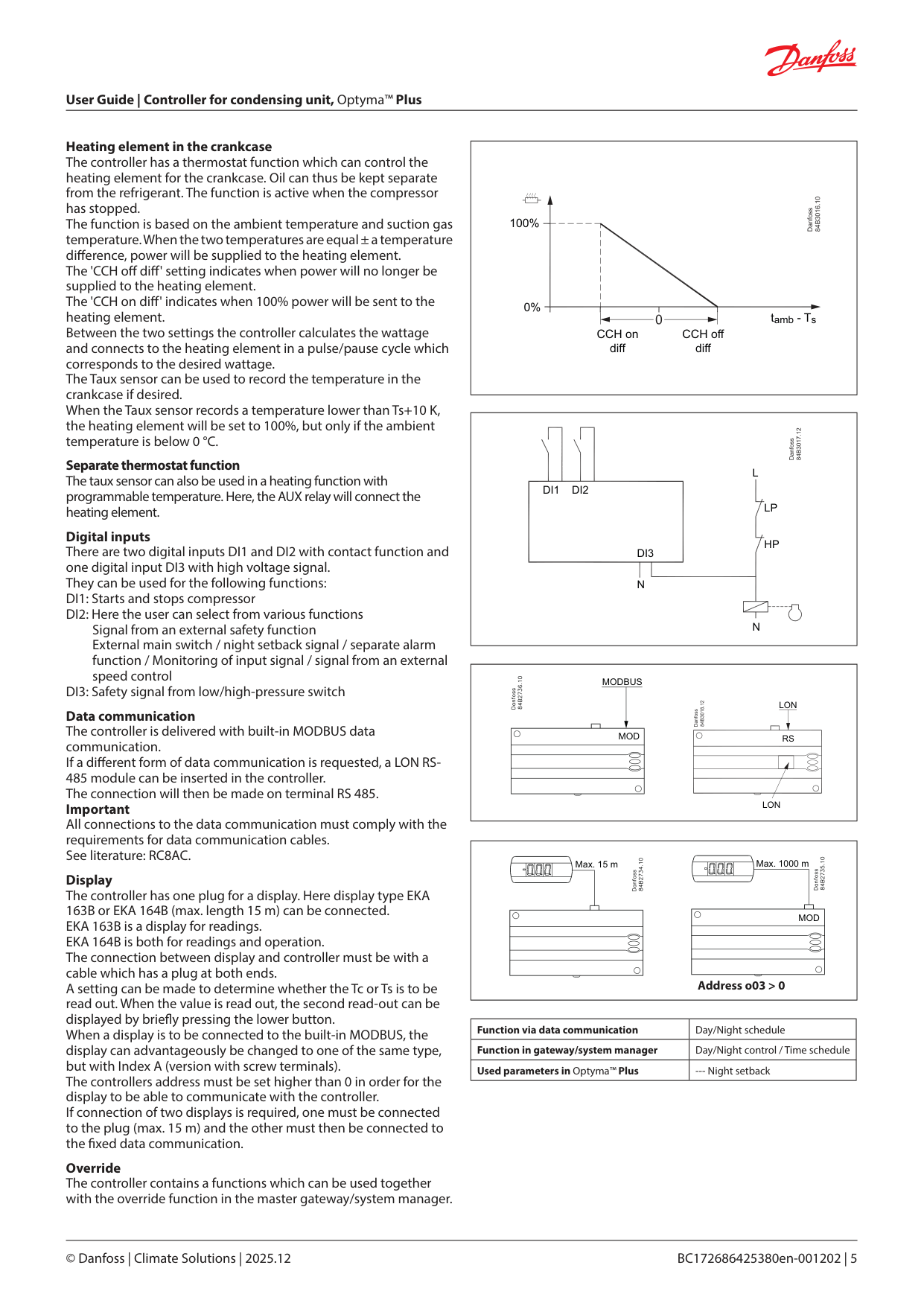
Heating element in the crankcase The controller has a thermostat function which can control the heating element for the crankcase. Oil can thus be kept separate from the refrigerant. The function is active when the compressor has stopped. The function is based on the ambient temperature and suction gas temperature. When the two temperatures are equal ± a temperature di erence, power will be supplied to the heating element. The 'CCH o di ' setting indicates when power will no longer be supplied to the heating element. The 'CCH on di ' indicates when 100% power will be sent to the heating element. Between the two settings the controller calculates the wattage and connects to the heating element in a pulse/pause cycle which corresponds to the desired wattage. The Taux sensor can be used to record the temperature in the crankcase if desired. When the Taux sensor records a temperature lower than Ts+10 K, the heating element will be set to 100%, but only if the ambient temperature is below 0 °C.
Separate thermostat function The taux sensor can also be used in a heating function with programmable temperature. Here, the AUX relay will connect the heating element.
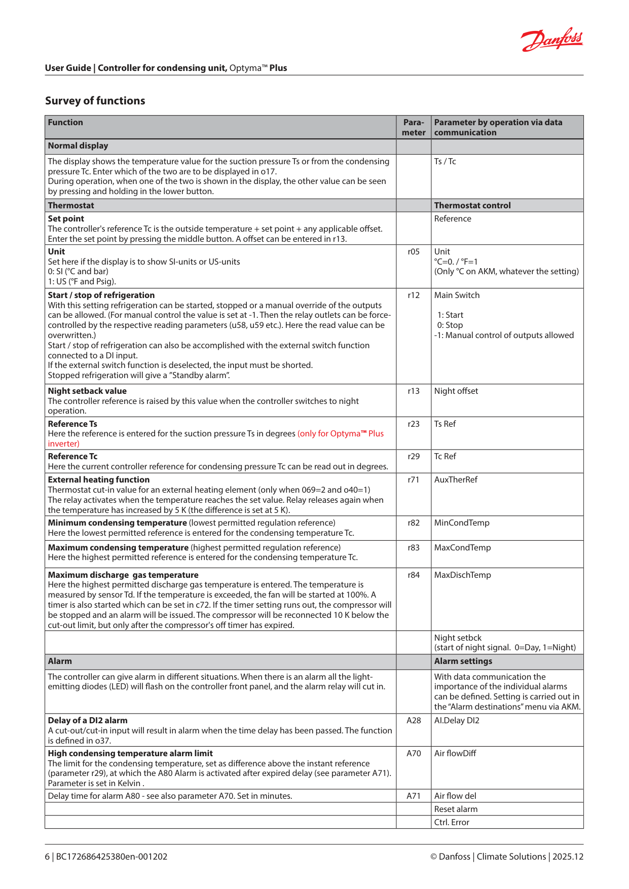
Digital inputs There are two digital inputs DI1 and DI2 with contact function and one digital input DI3 with high voltage signal. They can be used for the following functions: DI1: Starts and stops compressor DI2: Here the user can select from various functions
Signal from an external safety function External main switch / night setback signal / separate alarm function / Monitoring of input signal / signal from an external speed control
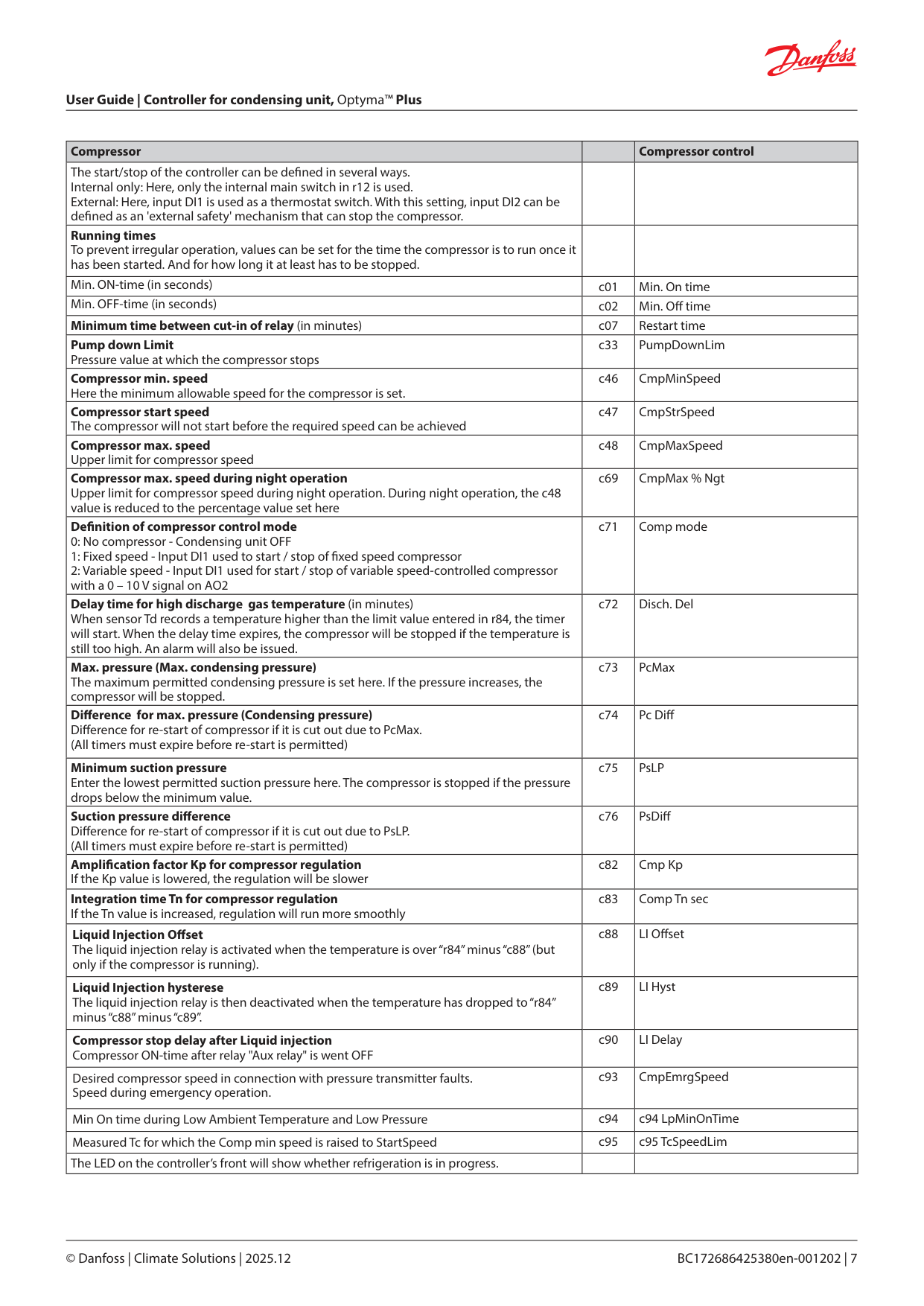
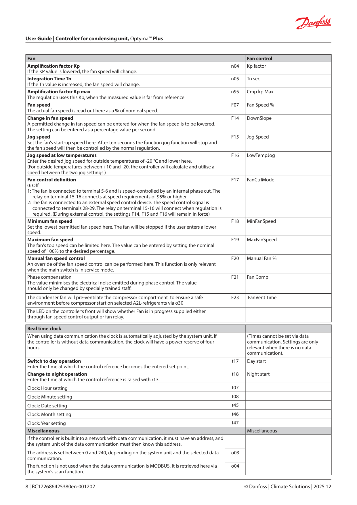
DI3: Safety signal from low/high-pressure switch Data communication The controller is delivered with built-in MODBUS data communication. If a di erent form of data communication is requested, a LON RS485 module can be inserted in the controller. The connection will then be made on terminal RS 485. Important All connections to the data communication must comply with the requirements for data communication cables. See literature: RC8AC. Display The controller has one plug for a display. Here display type EKA 163B or EKA 164B (max. length 15 m) can be connected.
Override The controller contains a functions which can be used together with the override function in the master gateway/system manager.
|100%
0%
CCH on diff
CCH off diff
tamb - Ts|
|---|
|DI1 DI2
DI3
N
N
HP
LP
L| |---|
|LON
LON
RS
MODBUS
MOD| |---|
|Max. 15 m Max. 1000 m
MOD
Address o03 > 0| |---|
|Function via data communication|Day/Night schedule| |---|---| |Function in gateway/system manager|Day/Night control / Time schedule| |Used parameters in Optyma™ Plus|--- Night setback|
Survey of functions
|Function|Parameter|Parameter by operation via data communication| |---|---|---| |Normal display| | | |The display shows the temperature value for the suction pressure Ts or from the condensing pressure Tc. Enter which of the two are to be displayed in o17. During operation, when one of the two is shown in the display, the other value can be seen by pressing and holding in the lower button.| |Ts / Tc| |Thermostat| |Thermostat control| |Set point The controller's reference Tc is the outside temperature + set point + any applicable o set. Enter the set point by pressing the middle button. A o set can be entered in r13.| |Reference| |Unit Set here if the display is to show SI-units or US-units
0: SI (°C and bar)
1: US (°F and Psig).
|r05|Unit °C=0. / °F=1 (Only °C on AKM, whatever the setting)| |Start / stop of refrigeration With this setting refrigeration can be started, stopped or a manual override of the outputs can be allowed. (For manual control the value is set at -1. Then the relay outlets can be forcecontrolled by the respective reading parameters (u58, u59 etc.). Here the read value can be overwritten.) Start / stop of refrigeration can also be accomplished with the external switch function connected to a DI input. If the external switch function is deselected, the input must be shorted. Stopped refrigeration will give a ”Standby alarm”.|r12|Main Switch
1: Start 0: Stop
-1: Manual control of outputs allowed| |Night setback value The controller reference is raised by this value when the controller switches to night operation.|r13|Night o set| |Reference Ts Here the reference is entered for the suction pressure Ts in degrees (only for Optyma™ Plus inverter)|r23|Ts Ref| |Reference Tc Here the current controller reference for condensing pressure Tc can be read out in degrees.|r29|Tc Ref| |External heating function Thermostat cut-in value for an external heating element (only when 069=2 and o40=1) The relay activates when the temperature reaches the set value. Relay releases again when the temperature has increased by 5 K (the di erence is set at 5 K).|r71|AuxTherRef| |Minimum condensing temperature (lowest permitted regulation reference) Here the lowest permitted reference is entered for the condensing temperature Tc.|r82|MinCondTemp| |Maximum condensing temperature (highest permitted regulation reference) Here the highest permitted reference is entered for the condensing temperature Tc.|r83|MaxCondTemp| |Maximum discharge gas temperature Here the highest permitted discharge gas temperature is entered. The temperature is measured by sensor Td. If the temperature is exceeded, the fan will be started at 100%. A timer is also started which can be set in c72. If the timer setting runs out, the compressor will be stopped and an alarm will be issued. The compressor will be reconnected 10 K below the cut-out limit, but only after the compressor's o timer has expired.|r84|MaxDischTemp| | | |Night setbck (start of night signal. 0=Day, 1=Night)| |Alarm| |Alarm settings| |The controller can give alarm in di erent situations. When there is an alarm all the lightemitting diodes (LED) will ash on the controller front panel, and the alarm relay will cut in.| |With data communication the importance of the individual alarms can be de ned. Setting is carried out in the “Alarm destinations” menu via AKM.| |Delay of a DI2 alarm A cut-out/cut-in input will result in alarm when the time delay has been passed. The function is de ned in o37.|A28|AI.Delay DI2| |High condensing temperature alarm limit The limit for the condensing temperature, set as di erence above the instant reference (parameter r29), at which the A80 Alarm is activated after expired delay (see parameter A71). Parameter is set in Kelvin .|A70|Air owDi | |Delay time for alarm A80 - see also parameter A70. Set in minutes.|A71|Air ow del|
| | |Reset alarm| | | |Ctrl. Error|
|Compressor| |Compressor control| |---|---|---| |The start/stop of the controller can be de ned in several ways. Internal only: Here, only the internal main switch in r12 is used. External: Here, input DI1 is used as a thermostat switch. With this setting, input DI2 can be de ned as an 'external safety' mechanism that can stop the compressor.| | | |Running times To prevent irregular operation, values can be set for the time the compressor is to run once it has been started. And for how long it at least has to be stopped.| | | |Min. ON-time (in seconds)|c01|Min. On time| |Min. OFF-time (in seconds)|c02|Min. O time| |Minimum time between cut-in of relay (in minutes)|c07|Restart time| |Pump down Limit Pressure value at which the compressor stops|c33|PumpDownLim| |Compressor min. speed Here the minimum allowable speed for the compressor is set.|c46|CmpMinSpeed| |Compressor start speed The compressor will not start before the required speed can be achieved|c47|CmpStrSpeed| |Compressor max. speed Upper limit for compressor speed|c48|CmpMaxSpeed| |Compressor max. speed during night operation Upper limit for compressor speed during night operation. During night operation, the c48 value is reduced to the percentage value set here|c69|CmpMax % Ngt| |De nition of compressor control mode
0: No compressor - Condensing unit OFF
1: Fixed speed - Input DI1 used to start / stop of xed speed compressor
2: Variable speed - Input DI1 used for start / stop of variable speed-controlled compressor with a 0 – 10 V signal on AO2
|c71|Comp mode| |Delay time for high discharge gas temperature (in minutes) When sensor Td records a temperature higher than the limit value entered in r84, the timer will start. When the delay time expires, the compressor will be stopped if the temperature is still too high. An alarm will also be issued.|c72|Disch. Del| |Max. pressure (Max. condensing pressure) The maximum permitted condensing pressure is set here. If the pressure increases, the compressor will be stopped.|c73|PcMax| |Di erence for max. pressure (Condensing pressure) Di erence for re-start of compressor if it is cut out due to PcMax. (All timers must expire before re-start is permitted)|c74|Pc Di | |Minimum suction pressure Enter the lowest permitted suction pressure here. The compressor is stopped if the pressure drops below the minimum value.|c75|PsLP| |Suction pressure di erence Di erence for re-start of compressor if it is cut out due to PsLP. (All timers must expire before re-start is permitted)|c76|PsDi | |Ampli cation factor Kp for compressor regulation If the Kp value is lowered, the regulation will be slower|c82|Cmp Kp| |Integration time Tn for compressor regulation If the Tn value is increased, regulation will run more smoothly|c83|Comp Tn sec| |Liquid Injection O set The liquid injection relay is activated when the temperature is over “r84” minus “c88” (but only if the compressor is running).|c88|LI O set| |Liquid Injection hysterese The liquid injection relay is then deactivated when the temperature has dropped to “r84” minus “c88” minus “c89”.|c89|LI Hyst| |Compressor stop delay after Liquid injection Compressor ON-time after relay "Aux relay" is went OFF|c90|LI Delay| |Desired compressor speed in connection with pressure transmitter faults. Speed during emergency operation.|c93|CmpEmrgSpeed| |Min On time during Low Ambient Temperature and Low Pressure|c94|c94 LpMinOnTime| |Measured Tc for which the Comp min speed is raised to StartSpeed|c95|c95 TcSpeedLim| |The LED on the controller’s front will show whether refrigeration is in progress.| | |
|Fan| |Fan control| |---|---|---| |Ampli cation factor Kp If the KP value is lowered, the fan speed will change.|n04|Kp factor| |Integration Time Tn If the Tn value is increased, the fan speed will change.|n05|Tn sec| |Ampli cation factor Kp max The regulation uses this Kp, when the measured value is far from reference|n95|Cmp kp Max| |Fan speed The actual fan speed is read out here as a % of nominal speed.|F07|Fan Speed %| |Change in fan speed A permitted change in fan speed can be entered for when the fan speed is to be lowered. The setting can be entered as a percentage value per second.|F14|DownSlope| |Jog speed Set the fan's start-up speed here. After ten seconds the function jog function will stop and the fan speed will then be controlled by the normal regulation.|F15|Jog Speed| |Jog speed at low temperatures Enter the desired jog speed for outside temperatures of -20 °C and lower here. (For outside temperatures between +10 and -20, the controller will calculate and utilise a speed between the two jog settings.)|F16|LowTempJog| |Fan control de nition
0: O
1: The fan is connected to terminal 5-6 and is speed-controlled by an internal phase cut. The relay on terminal 15-16 connects at speed requirements of 95% or higher.
2: The fan is connected to an external speed control device. The speed control signal is connected to terminals 28-29. The relay on terminal 15-16 will connect when regulation is required. (During external control, the settings F14, F15 and F16 will remain in force)
|F17|FanCtrlMode| |Minimum fan speed Set the lowest permitted fan speed here. The fan will be stopped if the user enters a lower speed.|F18|MinFanSpeed|
|Maximum fan speed The fan's top speed can be limited here. The value can be entered by setting the nominal speed of 100% to the desired percentage.|F19|MaxFanSpeed| |Manual fan speed control An override of the fan speed control can be performed here. This function is only relevant when the main switch is in service mode.|F20|Manual Fan %| |Phase compensation The value minimises the electrical noise emitted during phase control. The value should only be changed by specially trained sta .|F21|Fan Comp| |The condenser fan will pre-ventilate the compressor compartment to ensure a safe environment before compressor start on selected A2L-refrigerants via o30|F23|FanVent Time| |The LED on the controller’s front will show whether Fan is in progress supplied either through fan speed control output or fan relay.| | |
|Real time clock| | | |---|---|---| |When using data communication the clock is automatically adjusted by the system unit. If the controller is without data communication, the clock will have a power reserve of four hours.| |(Times cannot be set via data communication. Settings are only relevant when there is no data communication).| |Switch to day operation Enter the time at which the control reference becomes the entered set point.|t17|Day start| |Change to night operation Enter the time at which the control reference is raised with r13.|t18|Night start| |Clock: Hour setting|t07| | |Clock: Minute setting|t08| | |Clock: Date setting|t45| | |Clock: Month setting|t46| | |Clock: Year setting|t47| | |Miscellaneous| |Miscellaneous| |If the controller is built into a network with data communication, it must have an address, and the system unit of the data communication must then know this address.
The address is set between 0 and 240, depending on the system unit and the selected data communication.
The function is not used when the data communication is MODBUS. It is retrieved here via the system's scan function.| | | |If the controller is built into a network with data communication, it must have an address, and the system unit of the data communication must then know this address.
The address is set between 0 and 240, depending on the system unit and the selected data communication.
The function is not used when the data communication is MODBUS. It is retrieved here via the system's scan function.|o03| | |If the controller is built into a network with data communication, it must have an address, and the system unit of the data communication must then know this address.
The address is set between 0 and 240, depending on the system unit and the selected data communication.
The function is not used when the data communication is MODBUS. It is retrieved here via the system's scan function.|o04| |
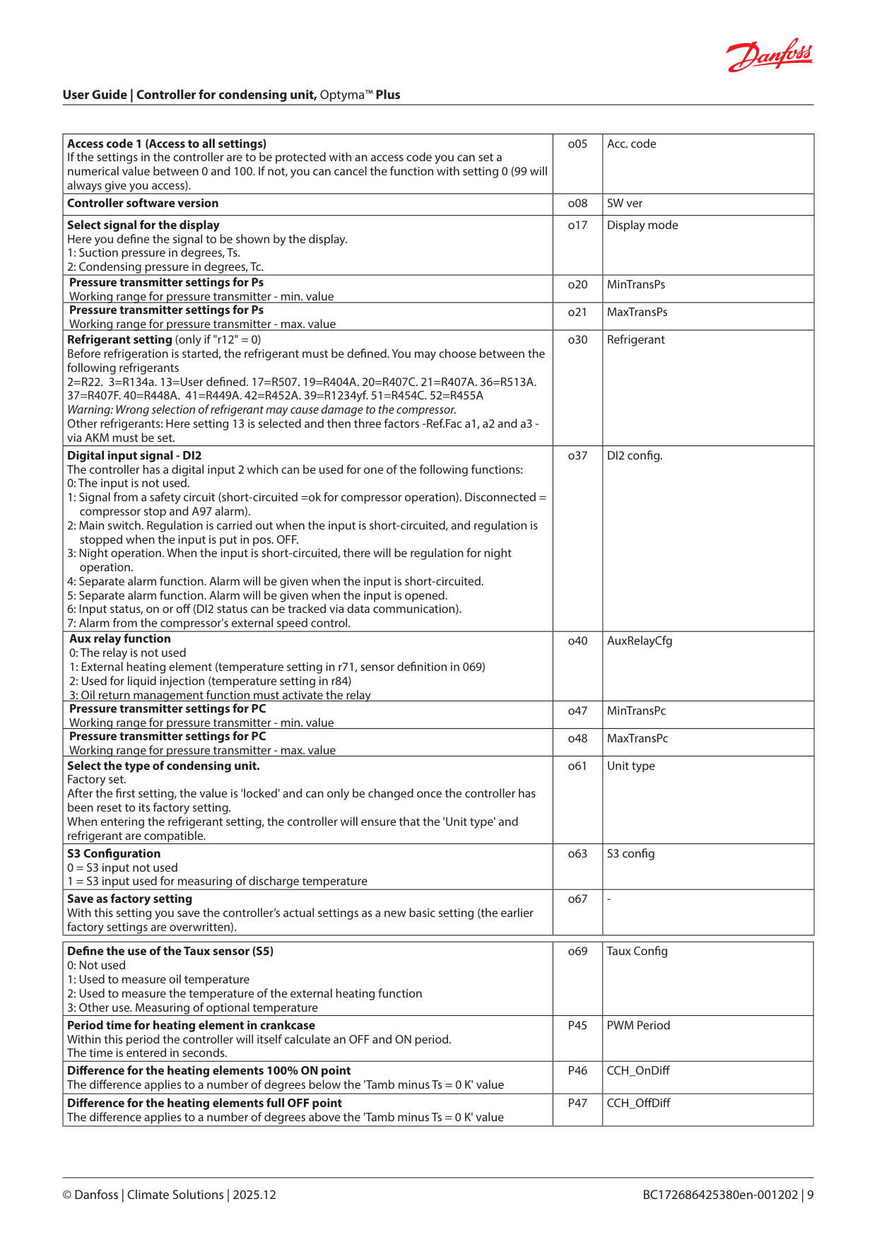
|Access code 1 (Access to all settings) If the settings in the controller are to be protected with an access code you can set a numerical value between 0 and 100. If not, you can cancel the function with setting 0 (99 will always give you access).|o05|Acc. code| |---|---|---| |Controller software version|o08|SW ver| |Select signal for the display Here you de ne the signal to be shown by the display.
1: Suction pressure in degrees, Ts.
2: Condensing pressure in degrees, Tc.
|o17|Display mode| |Pressure transmitter settings for Ps Working range for pressure transmitter - min. value|o20|MinTransPs| |Pressure transmitter settings for Ps Working range for pressure transmitter - max. value|o21|MaxTransPs| |Refrigerant setting (only if "r12" = 0) Before refrigeration is started, the refrigerant must be de ned. You may choose between the following refrigerants 2=R22. 3=R134a. 13=User de ned. 17=R507. 19=R404A. 20=R407C. 21=R407A. 36=R513A. 37=R407F. 40=R448A. 41=R449A. 42=R452A. 39=R1234yf. 51=R454C. 52=R455A Warning: Wrong selection of refrigerant may cause damage to the compressor. Other refrigerants: Here setting 13 is selected and then three factors -Ref.Fac a1, a2 and a3 via AKM must be set.|o30|Refrigerant| |Digital input signal - DI2 The controller has a digital input 2 which can be used for one of the following functions:
0: The input is not used.
1: Signal from a safety circuit (short-circuited =ok for compressor operation). Disconnected = compressor stop and A97 alarm).
2: Main switch. Regulation is carried out when the input is short-circuited, and regulation is stopped when the input is put in pos. OFF.
3: Night operation. When the input is short-circuited, there will be regulation for night operation.
4: Separate alarm function. Alarm will be given when the input is short-circuited.
5: Separate alarm function. Alarm will be given when the input is opened.
6: Input status, on or o (DI2 status can be tracked via data communication).
7: Alarm from the compressor's external speed control.
|o37|DI2 con g.| |Aux relay function
0: The relay is not used
1: External heating element (temperature setting in r71, sensor de nition in 069)
2: Used for liquid injection (temperature setting in r84)
3: Oil return management function must activate the relay
|o40|AuxRelayCfg| |Pressure transmitter settings for PC Working range for pressure transmitter - min. value|o47|MinTransPc| |Pressure transmitter settings for PC Working range for pressure transmitter - max. value|o48|MaxTransPc| |Select the type of condensing unit. Factory set. After the rst setting, the value is 'locked' and can only be changed once the controller has been reset to its factory setting. When entering the refrigerant setting, the controller will ensure that the 'Unit type' and refrigerant are compatible.|o61|Unit type| |S3 Con guration
0 = S3 input not used
1 = S3 input used for measuring of discharge temperature
|o63|S3 con g| |Save as factory setting With this setting you save the controller’s actual settings as a new basic setting (the earlier factory settings are overwritten).|o67|-|
|De ne the use of the Taux sensor (S5)
0: Not used
1: Used to measure oil temperature
2: Used to measure the temperature of the external heating function
3: Other use. Measuring of optional temperature
|o69|Taux Con g| |---|---|---| |Period time for heating element in crankcase Within this period the controller will itself calculate an OFF and ON period. The time is entered in seconds.|P45|PWM Period| |Di erence for the heating elements 100% ON point The di erence applies to a number of degrees below the 'Tamb minus Ts = 0 K' value|P46|CCH_OnDi | |Di erence for the heating elements full OFF point The di erence applies to a number of degrees above the 'Tamb minus Ts = 0 K' value|P47|CCH_O Di |
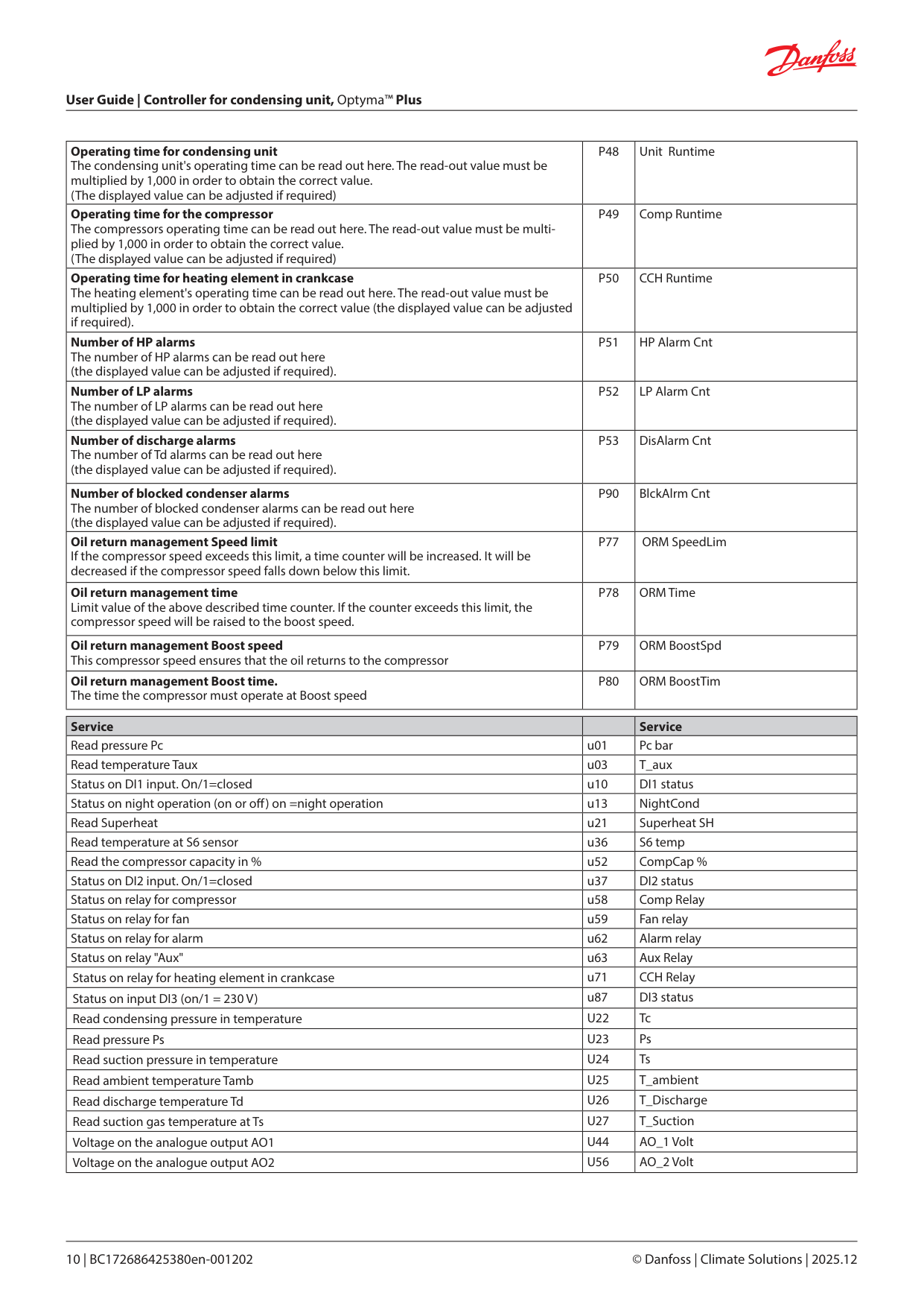
|Operating time for condensing unit The condensing unit's operating time can be read out here. The read-out value must be multiplied by 1,000 in order to obtain the correct value. (The displayed value can be adjusted if required)|P48|Unit Runtime| |---|---|---| |Operating time for the compressor The compressors operating time can be read out here. The read-out value must be multiplied by 1,000 in order to obtain the correct value. (The displayed value can be adjusted if required)|P49|Comp Runtime| |Operating time for heating element in crankcase The heating element's operating time can be read out here. The read-out value must be multiplied by 1,000 in order to obtain the correct value (the displayed value can be adjusted if required).|P50|CCH Runtime| |Number of HP alarms The number of HP alarms can be read out here (the displayed value can be adjusted if required).|P51|HP Alarm Cnt| |Number of LP alarms The number of LP alarms can be read out here (the displayed value can be adjusted if required).|P52|LP Alarm Cnt| |Number of discharge alarms The number of Td alarms can be read out here (the displayed value can be adjusted if required).|P53|DisAlarm Cnt| |Number of blocked condenser alarms The number of blocked condenser alarms can be read out here (the displayed value can be adjusted if required).|P90|BlckAlrm Cnt| |Oil return management Speed limit If the compressor speed exceeds this limit, a time counter will be increased. It will be decreased if the compressor speed falls down below this limit.|P77|ORM SpeedLim| |Oil return management time Limit value of the above described time counter. If the counter exceeds this limit, the compressor speed will be raised to the boost speed.|P78|ORM Time| |Oil return management Boost speed This compressor speed ensures that the oil returns to the compressor|P79|ORM BoostSpd| |Oil return management Boost time. The time the compressor must operate at Boost speed|P80|ORM BoostTim|
|Service| |Service| |---|---|---| |Read pressure Pc|u01|Pc bar| |Read temperature Taux|u03|T_aux| |Status on DI1 input. On/1=closed|u10|DI1 status| |Status on night operation (on or o ) on =night operation|u13|NightCond| |Read Superheat|u21|Superheat SH| |Read temperature at S6 sensor|u36|S6 temp| |Read the compressor capacity in %|u52|CompCap %| |Status on DI2 input. On/1=closed|u37|DI2 status| |Status on relay for compressor|u58|Comp Relay| |Status on relay for fan|u59|Fan relay| |Status on relay for alarm|u62|Alarm relay| |Status on relay "Aux"|u63|Aux Relay| |Status on relay for heating element in crankcase|u71|CCH Relay| |Status on input DI3 (on/1 = 230 V)|u87|DI3 status| |Read condensing pressure in temperature|U22|Tc| |Read pressure Ps|U23|Ps| |Read suction pressure in temperature|U24|Ts| |Read ambient temperature Tamb|U25|T_ambient| |Read discharge temperature Td|U26|T_Discharge| |Read suction gas temperature at Ts|U27|T_Suction| |Voltage on the analogue output AO1|U44|AO_1 Volt| |Voltage on the analogue output AO2|U56|AO_2 Volt|
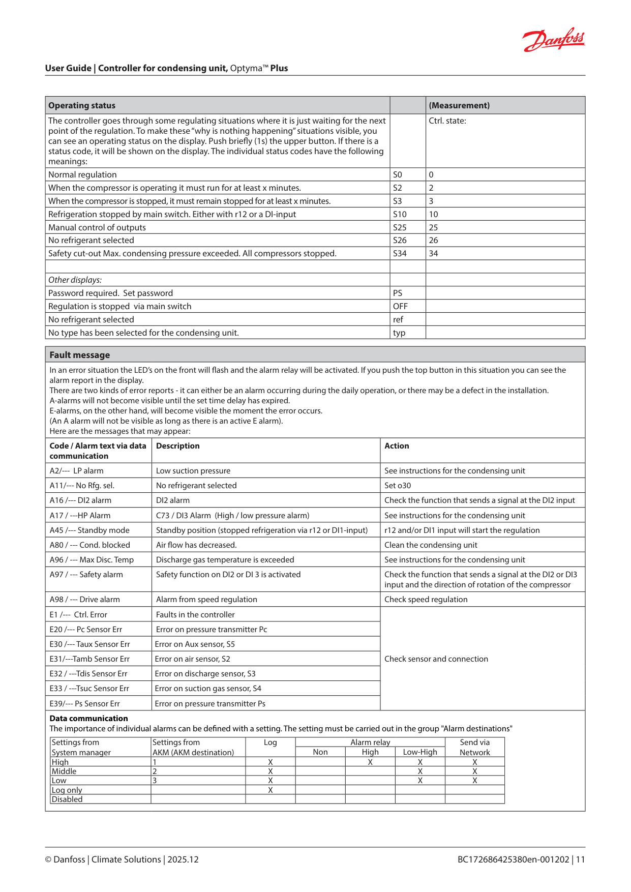
|Operating status| |(Measurement)| |---|---|---|
|The controller goes through some regulating situations where it is just waiting for the next point of the regulation. To make these “why is nothing happening” situations visible, you can see an operating status on the display. Push brie y (1s) the upper button. If there is a status code, it will be shown on the display. The individual status codes have the following meanings:| |Ctrl. state:| |Normal regulation|S0|0| |When the compressor is operating it must run for at least x minutes.|S2|2| |When the compressor is stopped, it must remain stopped for at least x minutes.|S3|3| |Refrigeration stopped by main switch. Either with r12 or a DI-input|S10|10| |Manual control of outputs|S25|25| |No refrigerant selected|S26|26| |Safety cut-out Max. condensing pressure exceeded. All compressors stopped.|S34|34| | | | | |Other displays:| | | |Password required. Set password|PS| | |Regulation is stopped via main switch|OFF| | |No refrigerant selected|ref| | |No type has been selected for the condensing unit.|typ| |
|Fault message|Fault message|Fault message| |---|---|---| |In an error situation the LED’s on the front will ash and the alarm relay will be activated. If you push the top button in this situation you can see the alarm report in the display. There are two kinds of error reports - it can either be an alarm occurring during the daily operation, or there may be a defect in the installation. A-alarms will not become visible until the set time delay has expired. E-alarms, on the other hand, will become visible the moment the error occurs. (An A alarm will not be visible as long as there is an active E alarm). Here are the messages that may appear:|In an error situation the LED’s on the front will ash and the alarm relay will be activated. If you push the top button in this situation you can see the alarm report in the display. There are two kinds of error reports - it can either be an alarm occurring during the daily operation, or there may be a defect in the installation. A-alarms will not become visible until the set time delay has expired. E-alarms, on the other hand, will become visible the moment the error occurs. (An A alarm will not be visible as long as there is an active E alarm). Here are the messages that may appear:|In an error situation the LED’s on the front will ash and the alarm relay will be activated. If you push the top button in this situation you can see the alarm report in the display. There are two kinds of error reports - it can either be an alarm occurring during the daily operation, or there may be a defect in the installation. A-alarms will not become visible until the set time delay has expired. E-alarms, on the other hand, will become visible the moment the error occurs. (An A alarm will not be visible as long as there is an active E alarm). Here are the messages that may appear:| |Code / Alarm text via data communication|Description|Action| |A2/--- LP alarm|Low suction pressure|See instructions for the condensing unit| |A11/--- No Rfg. sel.|No refrigerant selected|Set o30| |A16 /--- DI2 alarm|DI2 alarm|Check the function that sends a signal at the DI2 input| |A17 / ---HP Alarm|C73 / DI3 Alarm (High / low pressure alarm)|See instructions for the condensing unit| |A45 /--- Standby mode|Standby position (stopped refrigeration via r12 or DI1-input)|r12 and/or DI1 input will start the regulation| |A80 / --- Cond. blocked|Air ow has decreased.|Clean the condensing unit| |A96 / --- Max Disc. Temp|Discharge gas temperature is exceeded|See instructions for the condensing unit| |A97 / --- Safety alarm|Safety function on DI2 or DI 3 is activated|Check the function that sends a signal at the DI2 or DI3 input and the direction of rotation of the compressor| |A98 / --- Drive alarm|Alarm from speed regulation|Check speed regulation| |E1 /--- Ctrl. Error|Faults in the controller|Check sensor and connection| |E20 /--- Pc Sensor Err|Error on pressure transmitter Pc|Check sensor and connection| |E30 /--- Taux Sensor Err|Error on Aux sensor, S5|Check sensor and connection| |E31/---Tamb Sensor Err|Error on air sensor, S2|Check sensor and connection| |E32 / ---Tdis Sensor Err|Error on discharge sensor, S3|Check sensor and connection| |E33 / ---Tsuc Sensor Err|Error on suction gas sensor, S4|Check sensor and connection| |E39/--- Ps Sensor Err|Error on pressure transmitter Ps|Check sensor and connection| ||Settings from System manager|Settings from AKM (AKM destination)|Log|Alarm relay|Alarm relay|Alarm relay|Send via Network| |---|---|---|---|---|---|---| |Settings from System manager|Settings from AKM (AKM destination)|Log|Non|High|Low-High|Send via Network| |High|1|X| |X|X|X| |Middle|2|X| | |X|X| |Low|3|X| | |X|X| |Log only| |X| | | | | |Disabled| | | | | | |
Data communication The importance of individual alarms can be de ned with a setting. The setting must be carried out in the group "Alarm destinations"||Settings from System manager|Settings from AKM (AKM destination)|Log|Alarm relay|Alarm relay|Alarm relay|Send via Network| |---|---|---|---|---|---|---| |Settings from System manager|Settings from AKM (AKM destination)|Log|Non|High|Low-High|Send via Network| |High|1|X| |X|X|X| |Middle|2|X| | |X|X| |Low|3|X| | |X|X| |Log only| |X| | | | | |Disabled| | | | | | |
Data communication The importance of individual alarms can be de ned with a setting. The setting must be carried out in the group "Alarm destinations"||Settings from System manager|Settings from AKM (AKM destination)|Log|Alarm relay|Alarm relay|Alarm relay|Send via Network| |---|---|---|---|---|---|---| |Settings from System manager|Settings from AKM (AKM destination)|Log|Non|High|Low-High|Send via Network| |High|1|X| |X|X|X| |Middle|2|X| | |X|X| |Low|3|X| | |X|X| |Log only| |X| | | | | |Disabled| | | | | | |
Data communication The importance of individual alarms can be de ned with a setting. The setting must be carried out in the group "Alarm destinations"|
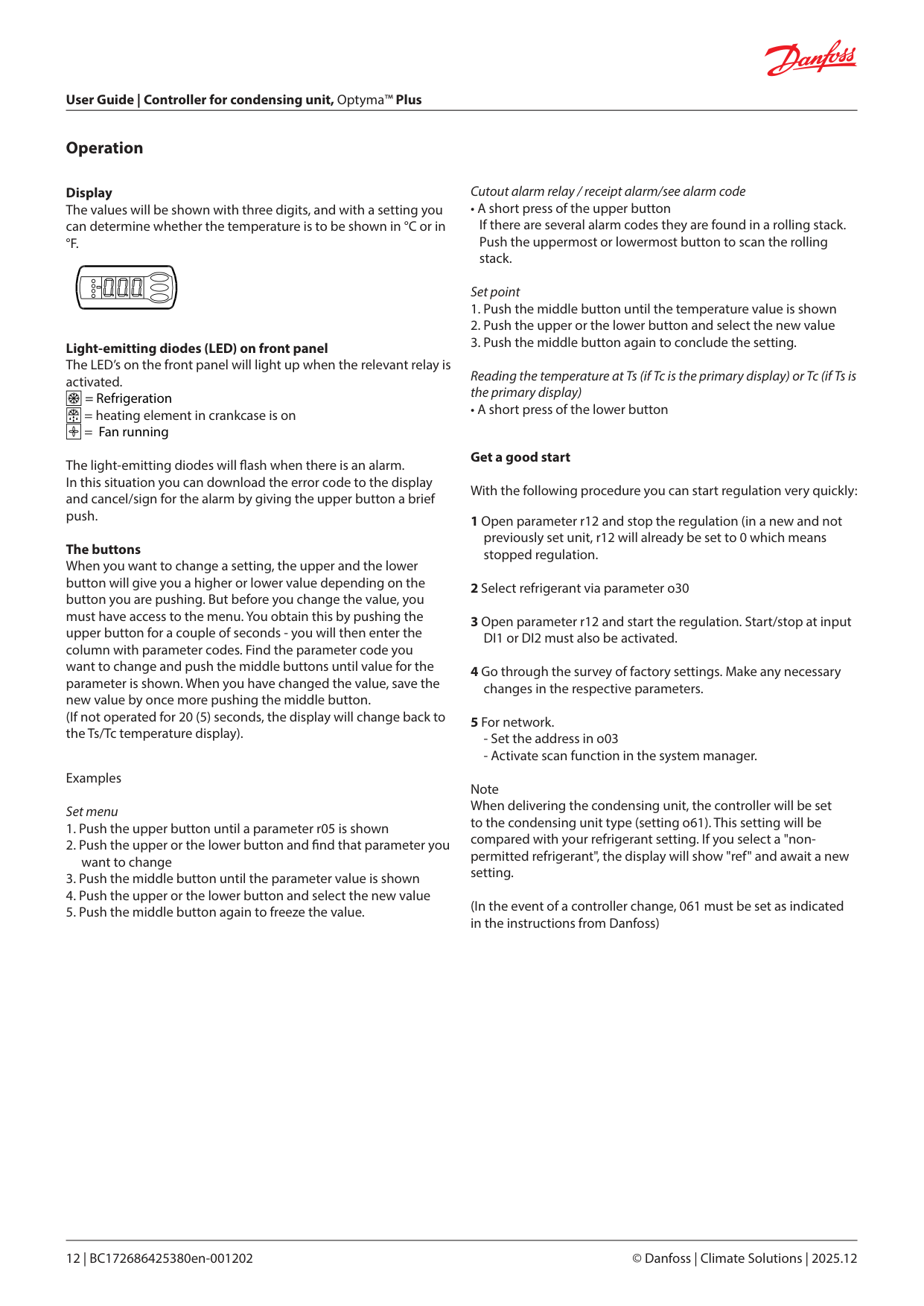
Operation
Display The values will be shown with three digits, and with a setting you can determine whether the temperature is to be shown in °C or in °F.
Light-emitting diodes (LED) on front panel The LED’s on the front panel will light up when the relevant relay is activated.
| | |---|
= Refrigeration
| | |---|
= heating element in crankcase is on
| | |---|
= Fan running
The light-emitting diodes will ash when there is an alarm. In this situation you can download the error code to the display and cancel/sign for the alarm by giving the upper button a brief push.
The buttons When you want to change a setting, the upper and the lower button will give you a higher or lower value depending on the button you are pushing. But before you change the value, you must have access to the menu. You obtain this by pushing the upper button for a couple of seconds - you will then enter the column with parameter codes. Find the parameter code you want to change and push the middle buttons until value for the parameter is shown. When you have changed the value, save the new value by once more pushing the middle button. (If not operated for 20 (5) seconds, the display will change back to the Ts/Tc temperature display).
Examples Set menu
Cutout alarm relay / receipt alarm/see alarm code
• A short press of the upper button If there are several alarm codes they are found in a rolling stack. Push the uppermost or lowermost button to scan the rolling stack.
Set point
Reading the temperature at Ts (if Tc is the primary display) or Tc (if Ts is the primary display)
• A short press of the lower button
Get a good start With the following procedure you can start regulation very quickly:
Note When delivering the condensing unit, the controller will be set to the condensing unit type (setting o61). This setting will be compared with your refrigerant setting. If you select a "nonpermitted refrigerant", the display will show "ref" and await a new setting.
(In the event of a controller change, 061 must be set as indicated in the instructions from Danfoss)
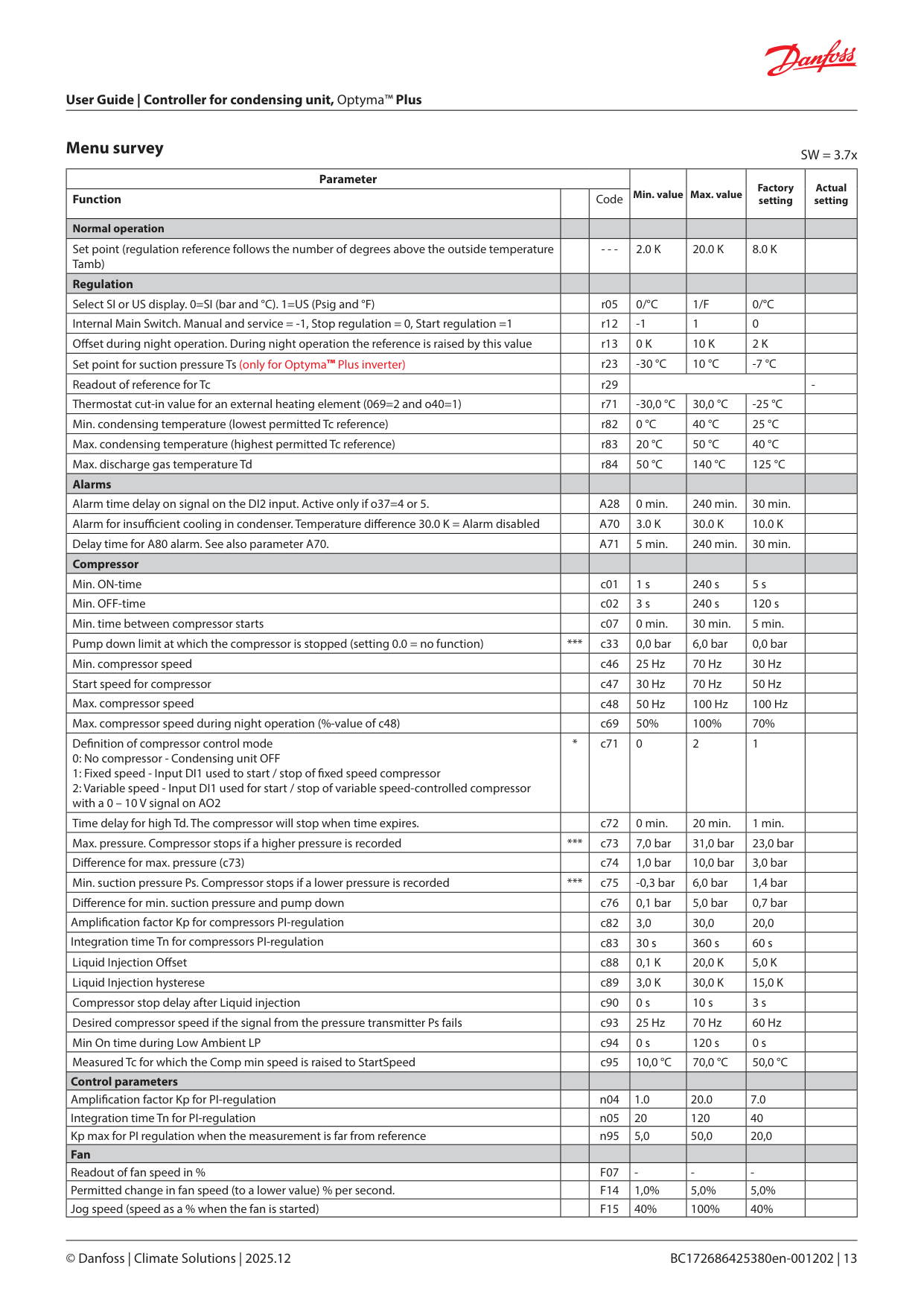
Menu survey SW = 3.7x
|Parameter|Parameter|Parameter|Min. value|Max. value|Factory setting|Actual setting| |---|---|---|---|---|---|---| |Function| |Code|Min. value|Max. value|Factory setting|Actual setting| |Normal operation| | | | | | | |Set point (regulation reference follows the number of degrees above the outside temperature Tamb)| |- - -|2.0 K|20.0 K|8.0 K| | |Regulation| | | | | | | |Select SI or US display. 0=SI (bar and °C). 1=US (Psig and °F)| |r05|0/°C|1/F|0/°C| | |Internal Main Switch. Manual and service = -1, Stop regulation = 0, Start regulation =1| |r12|-1|1|0| | |O set during night operation. During night operation the reference is raised by this value| |r13|0 K|10 K|2 K| | |Set point for suction pressure Ts (only for Optyma™ Plus inverter)| |r23|-30 °C|10 °C|-7 °C| | |Readout of reference for Tc| |r29| | | |-| |Thermostat cut-in value for an external heating element (069=2 and o40=1)| |r71|-30,0 °C|30,0 °C|-25 °C| | |Min. condensing temperature (lowest permitted Tc reference)| |r82|0 °C|40 °C|25 °C| | |Max. condensing temperature (highest permitted Tc reference)| |r83|20 °C|50 °C|40 °C| | |Max. discharge gas temperature Td| |r84|50 °C|140 °C|125 °C| | |Alarms| | | | | | | |Alarm time delay on signal on the DI2 input. Active only if o37=4 or 5.| |A28|0 min.|240 min.|30 min.| | |Alarm for insu cient cooling in condenser. Temperature di erence 30.0 K = Alarm disabled| |A70|3.0 K|30.0 K|10.0 K| | |Delay time for A80 alarm. See also parameter A70.| |A71|5 min.|240 min.|30 min.| | |Compressor| | | | | | | |Min. ON-time| |c01|1 s|240 s|5 s| | |Min. OFF-time| |c02|3 s|240 s|120 s| | |Min. time between compressor starts| |c07|0 min.|30 min.|5 min.| | |Pump down limit at which the compressor is stopped (setting 0.0 = no function)|***|c33|0,0 bar|6,0 bar|0,0 bar| | |Min. compressor speed| |c46|25 Hz|70 Hz|30 Hz| | |Start speed for compressor| |c47|30 Hz|70 Hz|50 Hz| | |Max. compressor speed| |c48|50 Hz|100 Hz|100 Hz| | |Max. compressor speed during night operation (%-value of c48)| |c69|50%|100%|70%| | |De nition of compressor control mode
0: No compressor - Condensing unit OFF
1: Fixed speed - Input DI1 used to start / stop of xed speed compressor
2: Variable speed - Input DI1 used for start / stop of variable speed-controlled compressor with a 0 – 10 V signal on AO2
|*|c71|0|2|1| | |Time delay for high Td. The compressor will stop when time expires.| |c72|0 min.|20 min.|1 min.| | |Max. pressure. Compressor stops if a higher pressure is recorded|***|c73|7,0 bar|31,0 bar|23,0 bar| | |Di erence for max. pressure (c73)| |c74|1,0 bar|10,0 bar|3,0 bar| | |Min. suction pressure Ps. Compressor stops if a lower pressure is recorded|***|c75|-0,3 bar|6,0 bar|1,4 bar| | |Di erence for min. suction pressure and pump down| |c76|0,1 bar|5,0 bar|0,7 bar| | |Ampli cation factor Kp for compressors PI-regulation| |c82|3,0|30,0|20,0| | |Integration time Tn for compressors PI-regulation| |c83|30 s|360 s|60 s| | |Liquid Injection O set| |c88|0,1 K|20,0 K|5,0 K| | |Liquid Injection hysterese| |c89|3,0 K|30,0 K|15,0 K| | |Compressor stop delay after Liquid injection| |c90|0 s|10 s|3 s| | |Desired compressor speed if the signal from the pressure transmitter Ps fails| |c93|25 Hz|70 Hz|60 Hz| | |Min On time during Low Ambient LP| |c94|0 s|120 s|0 s| | |Measured Tc for which the Comp min speed is raised to StartSpeed| |c95|10,0 °C|70,0 °C|50,0 °C| |
|Control parameters| | | | | | | |Ampli cation factor Kp for PI-regulation| |n04|1.0|20.0|7.0| | |Integration time Tn for PI-regulation| |n05|20|120|40| | |Kp max for PI regulation when the measurement is far from reference| |n95|5,0|50,0|20,0| | |Fan| | | | | | | |Readout of fan speed in %| |F07|-|-|-| | |Permitted change in fan speed (to a lower value) % per second.| |F14|1,0%|5,0%|5,0%| | |Jog speed (speed as a % when the fan is started)| |F15|40%|100%|40%| |
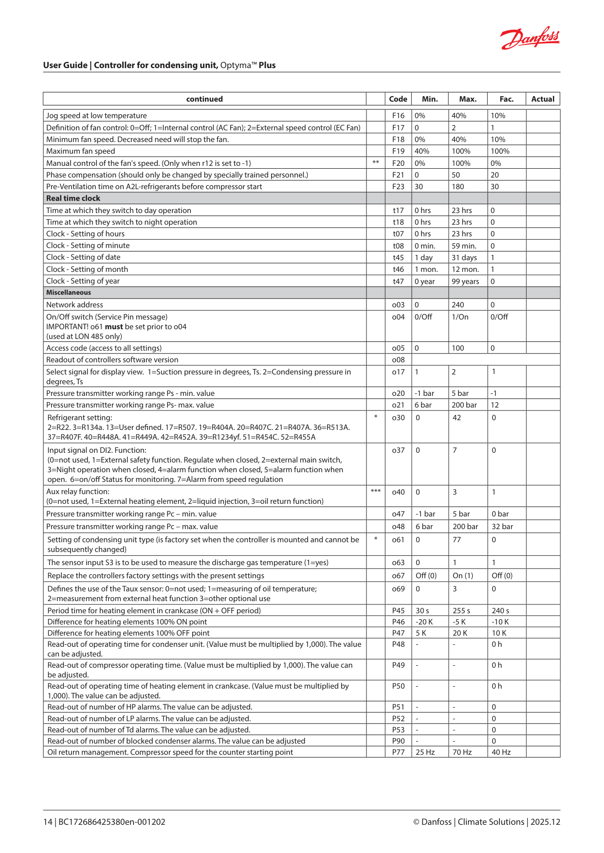
|continued| |Code|Min.|Max.|Fac.|Actual| |---|---|---|---|---|---|---|
|Jog speed at low temperature| |F16|0%|40%|10%| | |---|---|---|---|---|---|---| |De nition of fan control: 0=O ; 1=Internal control (AC Fan); 2=External speed control (EC Fan)| |F17|0|2|1| | |Minimum fan speed. Decreased need will stop the fan.| |F18|0%|40%|10%| | |Maximum fan speed| |F19|40%|100%|100%| | |Manual control of the fan's speed. (Only when r12 is set to -1)|**|F20|0%|100%|0%| | |Phase compensation (should only be changed by specially trained personnel.)| |F21|0|50|20| | |Pre-Ventilation time on A2L-refrigerants before compressor start| |F23|30|180|30| | |Real time clock| | | | | | | |Time at which they switch to day operation| |t17|0 hrs|23 hrs|0| | |Time at which they switch to night operation| |t18|0 hrs|23 hrs|0| | |Clock - Setting of hours| |t07|0 hrs|23 hrs|0| | |Clock - Setting of minute| |t08|0 min.|59 min.|0| | |Clock - Setting of date| |t45|1 day|31 days|1| | |Clock - Setting of month| |t46|1 mon.|12 mon.|1| | |Clock - Setting of year| |t47|0 year|99 years|0| | |Miscellaneous| | | | | | | |Network address| |o03|0|240|0| | |On/O switch (Service Pin message) IMPORTANT! o61 must be set prior to o04 (used at LON 485 only)| |o04|0/O |1/On|0/O | | |Access code (access to all settings)| |o05|0|100|0| | |Readout of controllers software version| |o08| | | | | |Select signal for display view. 1=Suction pressure in degrees, Ts. 2=Condensing pressure in degrees, Ts| |o17|1|2|1| | |Pressure transmitter working range Ps - min. value| |o20|-1 bar|5 bar|-1| | |Pressure transmitter working range Ps- max. value| |o21|6 bar|200 bar|12| | |Refrigerant setting: 2=R22. 3=R134a. 13=User de ned. 17=R507. 19=R404A. 20=R407C. 21=R407A. 36=R513A. 37=R407F. 40=R448A. 41=R449A. 42=R452A. 39=R1234yf. 51=R454C. 52=R455A|*|o30|0|42|0| | |Input signal on DI2. Function: (0=not used, 1=External safety function. Regulate when closed, 2=external main switch, 3=Night operation when closed, 4=alarm function when closed, 5=alarm function when open. 6=on/o Status for monitoring. 7=Alarm from speed regulation| |o37|0|7|0| | |Aux relay function: (0=not used, 1=External heating element, 2=liquid injection, 3=oil return function)|***|o40|0|3|1| | |Pressure transmitter working range Pc – min. value| |o47|-1 bar|5 bar|0 bar| | |Pressure transmitter working range Pc – max. value| |o48|6 bar|200 bar|32 bar| | |Setting of condensing unit type (is factory set when the controller is mounted and cannot be subsequently changed)|*|o61|0|77|0| |
|The sensor input S3 is to be used to measure the discharge gas temperature (1=yes)| |o63|0|1|1| | |Replace the controllers factory settings with the present settings| |o67|O (0)|On (1)|O (0)| | |De nes the use of the Taux sensor: 0=not used; 1=measuring of oil temperature; 2=measurement from external heat function 3=other optional use| |o69|0|3|0| | |Period time for heating element in crankcase (ON + OFF period)| |P45|30 s|255 s|240 s| | |Di erence for heating elements 100% ON point| |P46|-20 K|-5 K|-10 K| | |Di erence for heating elements 100% OFF point| |P47|5 K|20 K|10 K| | |Read-out of operating time for condenser unit. (Value must be multiplied by 1,000). The value can be adjusted.| |P48|-|-|0 h| | |Read-out of compressor operating time. (Value must be multiplied by 1,000). The value can be adjusted.| |P49|-|-|0 h| | |Read-out of operating time of heating element in crankcase. (Value must be multiplied by 1,000). The value can be adjusted.| |P50|-|-|0 h| | |Read-out of number of HP alarms. The value can be adjusted.| |P51|-|-|0| | |Read-out of number of LP alarms. The value can be adjusted.| |P52|-|-|0| | |Read-out of number of Td alarms. The value can be adjusted.| |P53|-|-|0| | |Read-out of number of blocked condenser alarms. The value can be adjusted| |P90|-|-|0| | |Oil return management. Compressor speed for the counter starting point| |P77|25 Hz|70 Hz|40 Hz| |
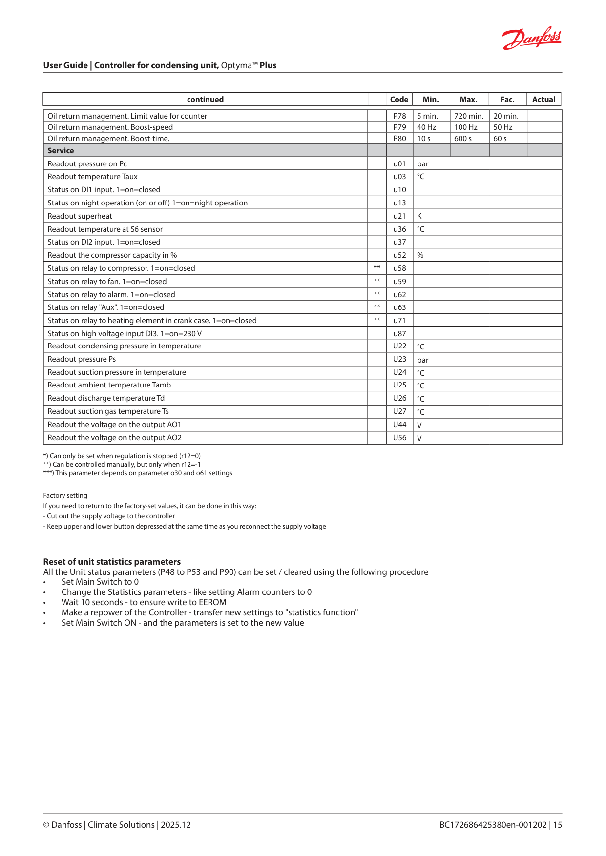
|continued| |Code|Min.|Max.|Fac.|Actual| |---|---|---|---|---|---|---|
|Oil return management. Limit value for counter| |P78|5 min.|720 min.|20 min.| | |---|---|---|---|---|---|---| |Oil return management. Boost-speed| |P79|40 Hz|100 Hz|50 Hz| | |Oil return management. Boost-time.| |P80|10 s|600 s|60 s| | |Service| | | | | | | |Readout pressure on Pc| |u01|bar|bar|bar|bar| |Readout temperature Taux| |u03|°C|°C|°C|°C| |Status on DI1 input. 1=on=closed| |u10| | | | | |Status on night operation (on or o ) 1=on=night operation| |u13| | | | | |Readout superheat| |u21|K|K|K|K| |Readout temperature at S6 sensor| |u36|°C|°C|°C|°C| |Status on DI2 input. 1=on=closed| |u37| | | | | |Readout the compressor capacity in %| |u52|%|%|%|%| |Status on relay to compressor. 1=on=closed|**|u58| | | | | |Status on relay to fan. 1=on=closed|**|u59| | | | | |Status on relay to alarm. 1=on=closed|**|u62| | | | | |Status on relay "Aux". 1=on=closed|**|u63| | | | | |Status on relay to heating element in crank case. 1=on=closed|**|u71| | | | | |Status on high voltage input DI3. 1=on=230 V| |u87| | | | | |Readout condensing pressure in temperature| |U22|°C|°C|°C|°C| |Readout pressure Ps| |U23|bar|bar|bar|bar| |Readout suction pressure in temperature| |U24|°C|°C|°C|°C| |Readout ambient temperature Tamb| |U25|°C|°C|°C|°C| |Readout discharge temperature Td| |U26|°C|°C|°C|°C|
|Readout suction gas temperature Ts| |U27|°C|°C|°C|°C| |Readout the voltage on the output AO1| |U44|V|V|V|V| |Readout the voltage on the output AO2| |U56|V|V|V|V|
***) This parameter depends on parameter o30 and o61 settings
Factory setting If you need to return to the factory-set values, it can be done in this way:
Reset of unit statistics parameters All the Unit status parameters (P48 to P53 and P90) can be set / cleared using the following procedure
Connections
0 – 10 V
0 – 10 V
R=120 Ω
R=120 Ω
AKS32R
AKS32R
| | |---|
|24 25| |---|
|26 27| |---|
|28 2930| |---|
|31 3233| |---|
|34 3536373839| |---|
|40414243| |---|
|51 52 53| |---|
|54555657| |---|
|60 61 62| |---|
S2 S3 S4 S5 S6
EKA Display
RS 485
AO1AO2
MODBUS
DI1 DI2 Pc Ps
| | | | |---|---|---|
FAN
Alarm
Comp CCH Fan Aux
DI3L N
|1|2| | |---|---|---|
|22|23| |---|---|
3 4 5 6 7 8 9 10 11 12 13 14 15 16 17 18 19
| | | | |---|---|---| | | | |
LP HP
230 V 230 V 230 V 230 V 230 V 230 V 230 V 230 V
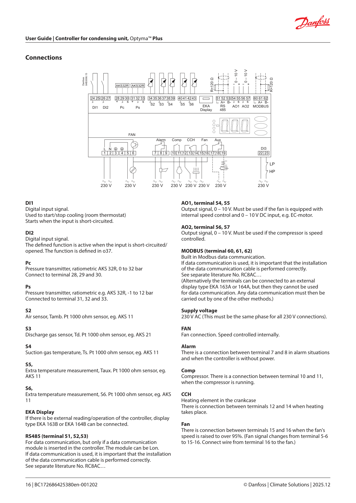
Pc Pressure transmitter, ratiometric AKS 32R, 0 to 32 bar Connect to terminal 28, 29 and 30.
Ps Pressure transmitter, ratiometric e.g. AKS 32R, -1 to 12 bar Connected to terminal 31, 32 and 33.
EKA Display If there is be external reading/operation of the controller, display type EKA 163B or EKA 164B can be connected.
RS485 (terminal 51, 52,53) For data communication, but only if a data communication module is inserted in the controller. The module can be Lon. If data communication is used, it is important that the installation of the data communication cable is performed correctly. See separate literature No. RC8AC…
MODBUS (terminal 60, 61, 62) Built in Modbus data communication. If data communication is used, it is important that the installation of the data communication cable is performed correctly. See separate literature No. RC8AC… (Alternatively the terminals can be connected to an external display type EKA 163A or 164A, but then they cannot be used for data communication. Any data communication must then be carried out by one of the other methods.)
Supply voltage 230 V AC (This must be the same phase for all 230 V connections).
FAN Fan connection. Speed controlled internally.
Alarm There is a connection between terminal 7 and 8 in alarm situations and when the controller is without power.
Comp Compressor. There is a connection between terminal 10 and 11, when the compressor is running.
CCH Heating element in the crankcase There is connection between terminals 12 and 14 when heating takes place.
Fan There is connection between terminals 15 and 16 when the fan's speed is raised to over 95%. (Fan signal changes from terminal 5-6 to 15-16. Connect wire from terminal 16 to the fan.)
Aux Liquid injection in suction line / external heating element / oil return function for speed-controlled compressor There is connection between terminals 17 and 19, when the function is active.
Installation considerations Accidental damage, poor installation, or site conditions, can give rise to malfunctions of the control system, and ultimately lead to a plant breakdown. Every possible safeguard is incorporated into our products to prevent this. However, a wrong installation, for example, could still present problems. Electronic controls are no substitute for normal, good engineering practice. Danfoss will not be responsible for any goods, or plant components, damaged as a result of the above defects. It is the installer's responsibility to check the installation thoroughly, and to t the necessary safety devices. Special reference is made to the necessity of signals to the controller when the compressor is stopped and to the need of liquid receivers before the compressors. Your local Danfoss agent will be pleased to assist with further advice, etc.
DI3 Digital input signal from low/high pressure monitoring. The signal must have a voltage of 0 / 230 V AC.
Electric noise Cables for sensors, DI inputs and data communication must be kept separate from other electric cables:
Data
|Supply voltage|230 V AC +10/-15 %. 5 VA, 50 / 60 Hz|230 V AC +10/-15 %. 5 VA, 50 / 60 Hz|230 V AC +10/-15 %. 5 VA, 50 / 60 Hz| |---|---|---|---| |Sensor S2, S3, S4, S5, S6|Pt 1000|Pt 1000|Pt 1000| |Accuracy|Measuring range|-60 – 120 °C (S3 to 150 °C)|-60 – 120 °C (S3 to 150 °C)| |Accuracy|Controller|±1 K below -35°C ± 0.5 K between -35 – 25 °C; ±1 K above 25 °C|±1 K below -35°C ± 0.5 K between -35 – 25 °C; ±1 K above 25 °C| |Accuracy|Pt 1000 sensor|±0.3 K at 0 °C ±0.005 K per degree|±0.3 K at 0 °C ±0.005 K per degree| |Measuring of Pc, Ps|Pressure transmitter|Ratiometric. eg. AKS 32R, DST-P110|Ratiometric. eg. AKS 32R, DST-P110| |Display|LED, 3-digits|LED, 3-digits|LED, 3-digits| |External display|EKA 163B or 164B (any EKA 163A or 164A)|EKA 163B or 164B (any EKA 163A or 164A)|EKA 163B or 164B (any EKA 163A or 164A)| |Digital inputs DI1, DI2|Signal from contact functions Requirements to contacts: Gold plating Cable length must be max. 15 m Use auxiliary relays when the cable is longer|Signal from contact functions Requirements to contacts: Gold plating Cable length must be max. 15 m Use auxiliary relays when the cable is longer|Signal from contact functions Requirements to contacts: Gold plating Cable length must be max. 15 m Use auxiliary relays when the cable is longer| |Digital input DI3|230 V AC from safety pressostat. Low/high pressure|230 V AC from safety pressostat. Low/high pressure|230 V AC from safety pressostat. Low/high pressure| |Electrical connection cable|Max.1.5 mm2 multi-core cable|Max.1.5 mm2 multi-core cable|Max.1.5 mm2 multi-core cable| |Triac output|Fan|Max. 240 V AC, Min. 28 V AC Max. 2.0 A Leak < 1 mA|Max. 240 V AC, Min. 28 V AC Max. 2.0 A Leak < 1 mA| |Relays*| |CE (250 V AC)|CE (250 V AC)| |Relays*|Comp, CCH|4 (3) A|4 (3) A| |Relays*|Alarm, Fan, Aux|4 (3) A|4 (3) A| |Analog output|2 pcs. 0 – 10 V DC (For external speed control of fans and compressors) Min. load = 10 K ohm. (Max. 1 mA)|2 pcs. 0 – 10 V DC (For external speed control of fans and compressors) Min. load = 10 K ohm. (Max. 1 mA)|2 pcs. 0 – 10 V DC (For external speed control of fans and compressors) Min. load = 10 K ohm. (Max. 1 mA)| |Environments|-25 – 55 °C, During operations
-40 – 70 °C, During transport
|-25 – 55 °C, During operations
-40 – 70 °C, During transport
|-25 – 55 °C, During operations
-40 – 70 °C, During transport
| |Environments|20 - 80% Rh, not condensed|20 - 80% Rh, not condensed|20 - 80% Rh, not condensed| |Environments|No shock in uence / vibrations|No shock in uence / vibrations|No shock in uence / vibrations| |Density|IP 20|IP 20|IP 20| |Mounting|DIN-rail or wall|DIN-rail or wall|DIN-rail or wall| |Weight|0.4 kg|0.4 kg|0.4 kg| |Data communication|Fixed|Fixed|MODBUS| |Data communication|Extension options|Extension options|LON| |Power reserve for the clock|4 hours|4 hours|4 hours| |Approvals|EC Low Voltage Directive and EMC demands re CEmarking complied with LVD tested acc. EN 60730-1 and EN 60730-2-9, A1, A2 EMC-tested acc. EN 61000-6-2 and EN 61000-6-3|EC Low Voltage Directive and EMC demands re CEmarking complied with LVD tested acc. EN 60730-1 and EN 60730-2-9, A1, A2 EMC-tested acc. EN 61000-6-2 and EN 61000-6-3|EC Low Voltage Directive and EMC demands re CEmarking complied with LVD tested acc. EN 60730-1 and EN 60730-2-9, A1, A2 EMC-tested acc. EN 61000-6-2 and EN 61000-6-3|
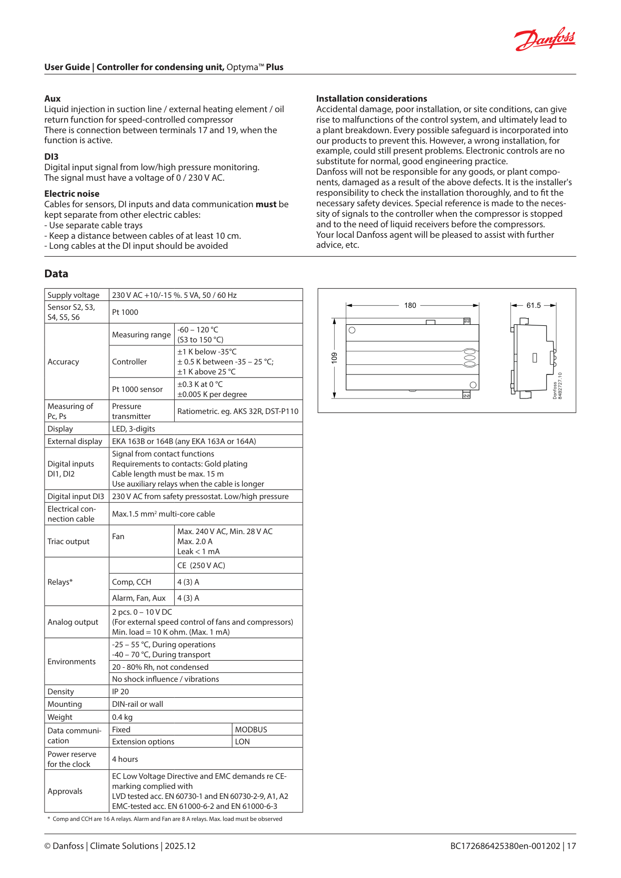
|109
180 61.5| |---|
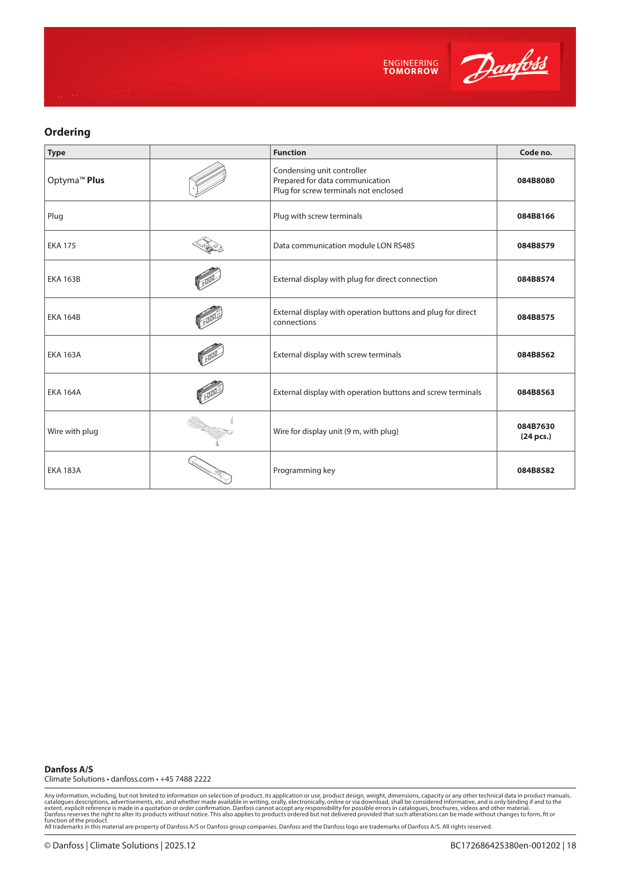
Ordering
|Type| |Function|Code no.| |---|---|---|---| |Optyma™ Plus| |Condensing unit controller Prepared for data communication Plug for screw terminals not enclosed|084B8080| |Plug| |Plug with screw terminals|084B8166| |EKA 175| |Data communication module LON RS485|084B8579| |EKA 163B| |External display with plug for direct connection|084B8574| |EKA 164B| |External display with operation buttons and plug for direct connections|084B8575| |EKA 163A| |External display with screw terminals|084B8562| |EKA 164A| |External display with operation buttons and screw terminals|084B8563| |Wire with plug| |Wire for display unit (9 m, with plug)|084B7630 (24 pcs.)| |EKA 183A| |Programming key|084B8582|