
Haswill Stc 1000 Temperature Controller
Ask AI
— answers from the official manualAnswers from the official manual.
Common questions
Common Questions
10 totalWhat does E1 error code mean on the STC-1000 thermostat?
E1 indicates a broken memory unit. You can press or key to restore default data, perform factory reset, and follow guidance in the manual for further assistance.
How do I set the temperature on the STC-1000 thermostat?
Press the button to access menu list F1; use or to select the code, then press to check and change the value by holding and pressing or. Release keys to back to function menu and repeat for other parameters.
How does the STC-1000 decide when to switch from heating to cooling?
The thermostat switches to heating mode if room temperature ≤ set point - return difference (F2), and switches to cooling mode if temperature ≥ set point + return difference. The compressor will not start until its delay time (F3) is over.
How can I prevent strong electromagnetic interference from affecting my thermostat?
Avoid installing the STC-1000 near transmitting antennas or switchboard rooms, as wireless electromagnetic interference can disrupt its functionality.
How do I factory reset the STC-1000 thermostat?
Hold the and keys at the same time for 5 seconds to restore factory settings. (Page 23)
What does the HH error code mean?
The HH code indicates that the room temperature exceeds 99.9°C. Check and stop the loads manually if necessary.
Full Manual
2 pages
4. Interface & Operation
User Manual of STC-1000 Thermostat
##### 4.1. Front Panel & Icon

Heating and Refrigeration Auto Switch Controller (Version 22.11.06GEN) STC-1000 temperature controller regulates the temperature by turn on/off the power status of the connected load. Within dual individually relays, this unit could connect two loads simultaneously, one for refrigeration, another for heating, and the heating and the refrigeration controlling modes auto switch according to the room sensor temperature; that's why it was called "All-Purpose Temperature Controller."
Under normal status

⚫ Press the key to check the temperature set-point F1;

⚫ Press the key to check the Hysteresis value F2;

⚫ Hold the key for 3s to power off / on;


⚫ Hold the key and the key at the same time for 5s to restore factory settings
1. Package
##### 4.2. Indicators / Characters
Controller 1 PCS Clips 2 PCS Sensor 1 PCS Manual 1 PCS Waterproof Cover 1 PCS
|Indicator|Meaning|Light on|Light off|Light Flashing| |---|---|---|---|---| |Cool|Refrigerating|Working|Stop|Delay| |Heat|Heater status|Working|Stop|N/A| |Set|Setting status|On Set|Non-setting|N/A|
##### 4.3. Dimensions & Installation
2. Specification

Input Power 220V AC ± 10% 50/60HZ; (12/24/48/110V Option) Maximum current 10A (Default) under 220V AC Sensor NTC Sensor (NTC), 25°C /10 KΩ, the sensor cable 200cm Protection Class IP65 to the front panel Storage -10°C ~ 60°C, RH<90%, without condensation Measuring Range: -50.0°C ~ 120°C Controlling Range: -50.0°C ~ 99.9°C Resolution 0.1°C Accuracy ± 1°C Power Consumption ≤ 3W
⚫ Relative humidity > 90%, have condensation.
⚫ The places that temperature <-10°C or >60°C.
3. Environmental Information
⚫ The places that have inflammable and explosives.
⚫ Strong vibration or struck.
Package: The package's material is 100% recyclable. Just dispose of it through specialized recyclers.

⚫ Exposed to the continuous water mist spraying.
⚫ Exposed to the dust.
Product: The electro components can be recycled or reused if it is disassembled for specialized companies.
⚫ Exposure to corrosive and pollution gas (gas, smoke, or salt fog that contains sulfur or ammonia.
Disposal: Please do not burn or throw the controllers in domestic garbage. Observe the respective law in your region concerning the environmentally responsible manner of disposing of its devices.
⚫ Wireless electromagnetic interference or strong magnetic fields (near to transmitting antenna or switch board room);
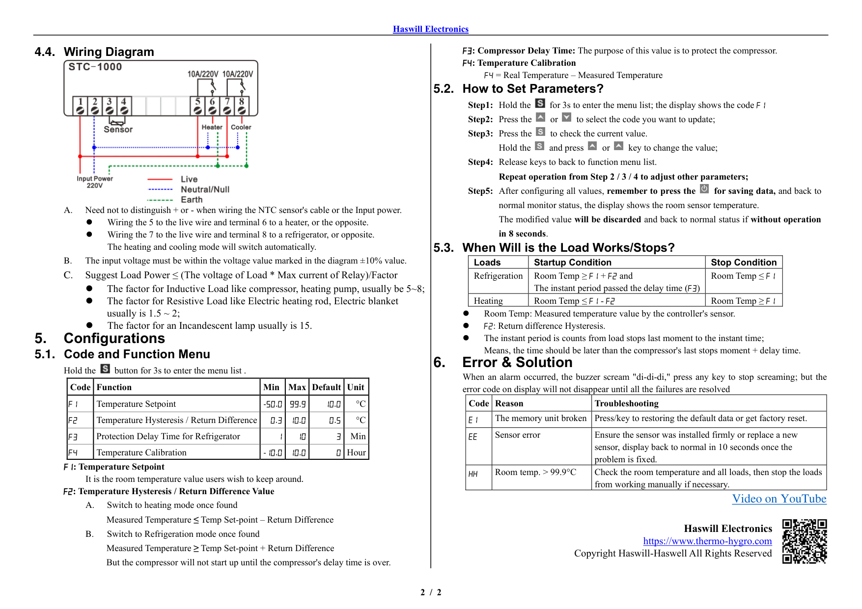
#### 4.4. Wiring Diagram

⚫ Wiring the 5 to the live wire and terminal 6 to a heater, or the opposite.
⚫ Wiring the 7 to the live wire and terminal 8 to a refrigerator, or opposite. The heating and cooling mode will switch automatically.
⚫ The factor for Inductive Load like compressor, heating pump, usually be 5~8;
⚫ The factor for Resistive Load like Electric heating rod, Electric blanket usually is 1.5 ~ 2;
⚫ The factor for an Incandescent lamp usually is 15.
5. Configurations5.1. Code and Function Menu

Hold the button for 3s to enter the menu list .
|Code|Function|Min|Max|Default|Unit| |---|---|---|---|---|---| |F1|Temperature Setpoint|-50.0|99.9|10.0|°C| |F2|Temperature Hysteresis / Return Difference|0.3|10.0|0.5|°C| |F3|Protection Delay Time for Refrigerator|1|10|3|Min| |F4|Temperature Calibration|-10.0|10.0|0|Hour|
##### 5.2. How to Set Parameters?


##### 5.3. When Will is the Load Works/Stops?
|Loads|Startup Condition|Stop Condition| |---|---|---| |Refrigeration|Room Temp ≥ F1 + F2 and The instant period passed the delay time (F3)|Room Temp ≤ F1| |Heating|Room Temp ≤ F1 - F2|Room Temp ≥ F1|
⚫ Room Temp: Measured temperature value by the controller's sensor.
⚫ F2: Return difference Hysteresis.
⚫ The instant period is counts from load stops last moment to the instant time; Means, the time should be later than the compressor's last stops moment + delay time.
|Code|Reason|Troubleshooting| |---|---|---| |E1|The memory unit broken|Press/key to restoring the default data or get factory reset.| |EE|Sensor error|Ensure the sensor was installed firmly or replace a new sensor, display back to normal in 10 seconds once the problem is fixed.| |HH|Room temp. > 99.9°C|Check the room temperature and all loads, then stop the loads from working manually if necessary.|
###### Video on YouTube

Haswill Electronics https://www.thermo-hygro.com
Copyright Haswill-Haswell All Rights Reserved