Ask AI
— answers from the official manualAnswers from the official manual.
Common questions
Common Questions
10 totalWhat is the Honeywell WME Series thermostat and what are its main applications?
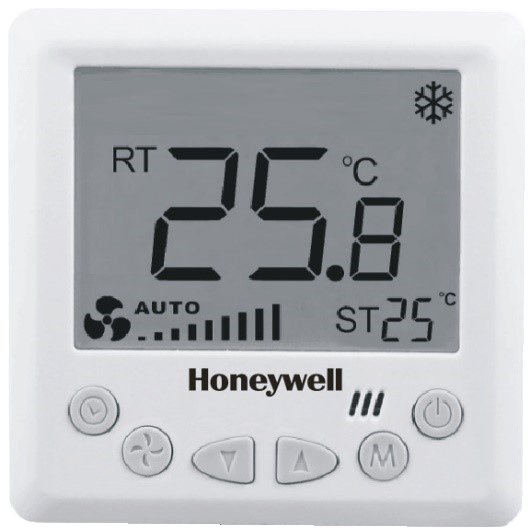
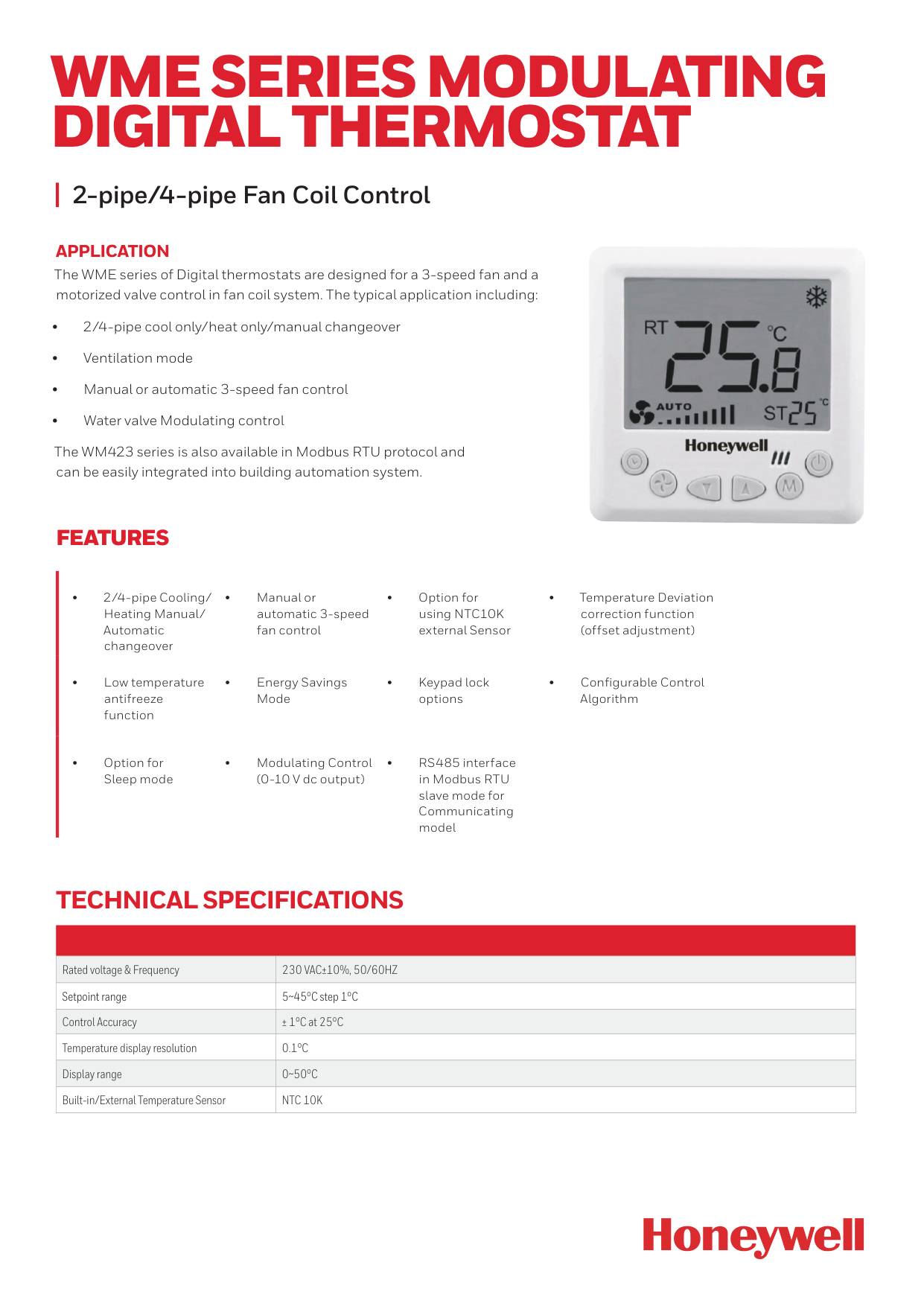
The WME Series is a Digital Thermostat designed for 2-pipe/4-pipe Fan Coil Control systems with 3-speed fan and motorized valve control. It supports cool only, heat only, or manual changeover modes, ventilation mode, manual or automatic fan control, and water valve modulating control. The WM423 series is also available in Modbus RTU protocol for building automation system integration. (Page 1)
What are the key technical specifications and operating voltage for the WME Series thermostat?
The thermostat operates at 230 Vac±10%, 50/60Hz with a setpoint range of 5~45°C (1°C steps), control accuracy of ±1°C at 25°C, and temperature display resolution of 0.1°C. Working current is 5A (resistance load) or 3A (inductance load), with power consumption less than 2W. The NTC 10K sensor is used for built-in/external temperature sensing. (Page 1-2)
How do I access the Installer Setup to configure the thermostat settings?
Press and hold the MODE and down arrow button simultaneously for three seconds to enter Installer Setup. This access method is also valid during keypad lockout. Use the up/down buttons to change settings and the MODE button to move to the next parameter. If no buttons are pressed for 10 seconds, the display returns to normal power-on state. (Page 5-6)
What operating modes does the WME Series thermostat support?
The thermostat supports Comfort mode (with changeover options for cool only, heat only, or manual heat/cool), Ventilation mode (fan operates without valve output), Energy Savings mode (activated via digital input contact), Sleep mode (gradual temperature adjustment during sleep), Freezing Protection mode (automatic heating when temperature drops below 6°C), and On/Off mode. (Page 5)
How does the Sleep Mode function on the WME Series thermostat?
When Sleep Mode is activated, after 1.5 hours the setpoint increases by 0.5°C in Cool Mode or decreases by 0.5°C in Heat Mode. Thereafter, every 30 minutes the setpoint adjusts by 0.5°C accordingly. Sleep Mode deactivates if power is switched off, the mode is changed, or the user adjusts the setpoint temperature. Once deactivated, the thermostat returns to the user-set temperature control. (Page 5)
What are the default Installer Setup settings for the thermostat?
Default settings include: Upper temperature limit 30°C, lower limit 10°C, Cool/Heat Mode enabled, Fan stops when setpoint is reached, Two-Pipe operation, power-on state OFF, low temperature freeze-proofing OFF, built-in sensor enabled, all keypad buttons available, Energy Saving mode disabled, Cool energy-saving temperature 25°C, and Heat energy-saving temperature 15°C. (Page 6)
Show 4 more questions
Full Manual
7 pages
2-pipe/4-pipe Fan Coil Control
Application
The WME series of Digital thermostats are designed for a 3-speed fan and a motorized valve control in fan coil system. The typical application including: • 2/4-pipe cool only/heat only/manual changeover • Ventilation mode • Manual or automatic 3-speed fan control • Water valve Modulating control The WM423 series is also available in Modbus RTU protocol and can be easily integrated into building automation system.Wme Series Modulating
Digital Thermostat
Features
• 2/4-pipe Cooling/ Heating Manual/ Automatic changeover • Manual or automatic 3-speed fan control • Option for using NTC10K external Sensor • Temperature Deviation correction function (offset adjustment) • Low temperature antifreeze function • Energy Savings Mode • Keypad lock options • Configurable Control Algorithm • Option for Sleep mode • Modulating Control (0-10 V dc output) • RS485 interface in Modbus RTU slave mode for Communicating model Rated voltage & Frequency230 Vac±10%, 50/60Hz
Setpoint range 5~45°C step 1°C Control Accuracy ± 1°C at 25°C Temperature display resolution0.1°C
Display range0~50°C
Built-in/External Temperature SensorNtc 10K
Technical Specifications
Working current for the whole product
5(3)A
5A: When the load of the thermostat is resistance 3A: When the load of the thermostat is inductance. For Fan Load: 3A: when the load is inductance For Valve Load: 5A: when the load is resistance Power consumption<2W
Backlight White/Blue Installation Install on 86x86x14mm junction boxPart Number
Description
Operating
Voltage
Application
Backlight
Valve Control Type
Communication
Option
Wme423Wn/U
230 V AC 2/4 Pipe Modulating Control with Remote Sensor option and Energy Saving mode, White backlight.230Vac /
Vac±10%,
50/60Hz
2/4 Pipe White Modulating (0-10V) NoneWme423Bn/U
230 V AC 2/4 Pipe Modulating Control with Remote Sensor option and Energy Saving mode, Blue backlight.230Vac /
Vac±10%,
50/60Hz
2/4 Pipe Blue Modulating (0-10V) NoneWme423Wnm/U
230 V AC 2/4 Pipe, Modulating Control with Modbus and Remote Sensor with Energy Saving mode White backlight.230Vac /
Vac±10%,
50/60Hz
2/4 Pipe White Modulating (0-10V) ModbusWme423Bnm/U
230 V AC 2/4 Pipe, Modulating Control with Modbus and Remote Sensor with Energy Saving mode Blue backlight.230Vac /
Vac±10%,
50/60Hz
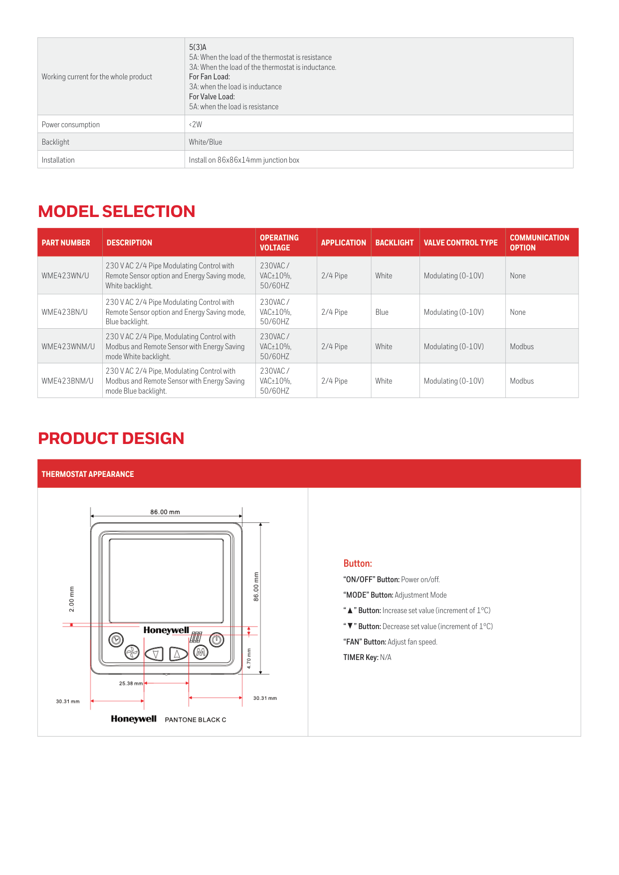
2/4 Pipe White Modulating (0-10V) ModbusThermostat Appearance
Button: “ON/OFF” Button: Power on/off. “MODE” Button: Adjustment Mode “ ” Button: Increase set value (increment of 1°C) “ ” Button: Decrease set value (increment of 1°C) “FAN” Button: Adjust fan speed. TIMER Key: N/A
Model Selection
Product Design
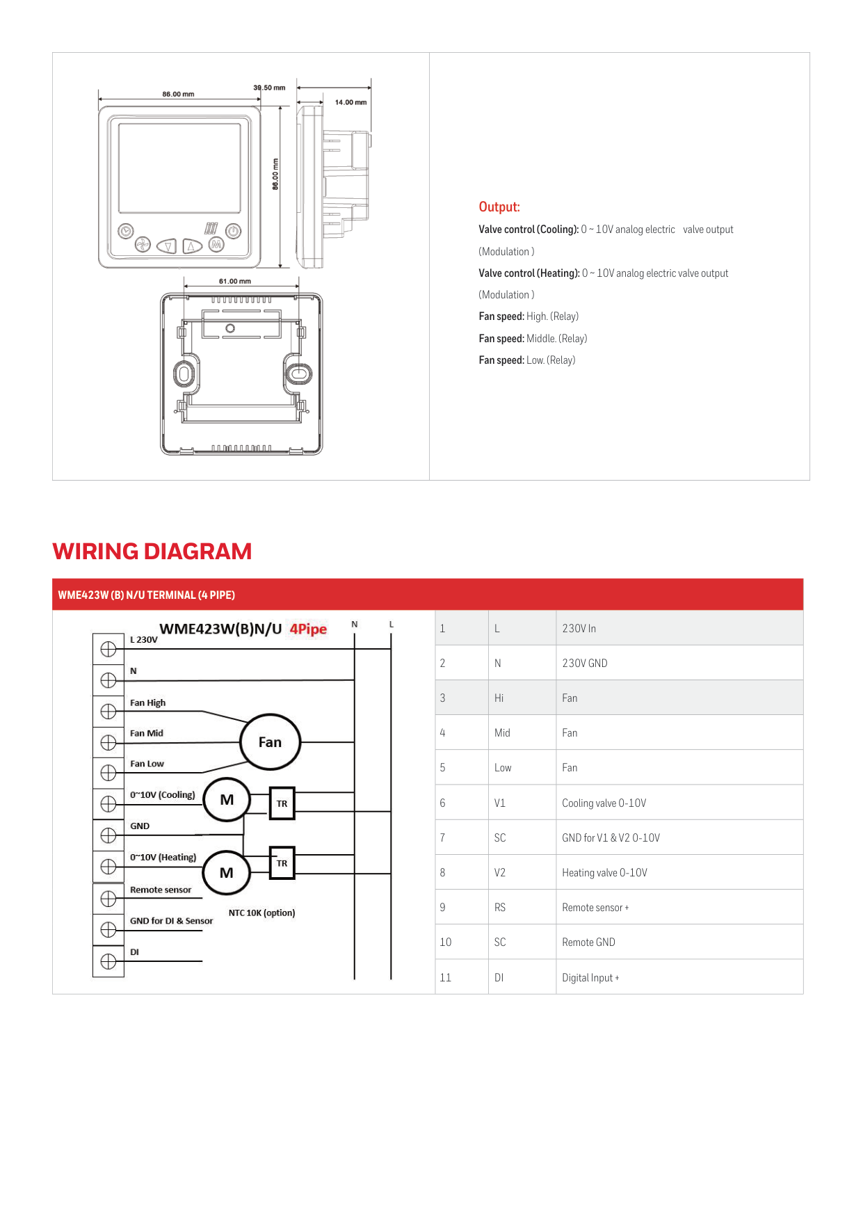
Output: Valve control (Cooling): 0 ~ 10V analog electric valve output (Modulation ) Valve control (Heating): 0 ~ 10V analog electric valve output (Modulation ) Fan speed: High. (Relay) Fan speed: Middle. (Relay) Fan speed: Low. (Relay)
Wme423W (B) N/U Terminal (4 Pipe)
1
L
230V In 2N
230V Gnd
3 Hi Fan 4 Mid Fan 5 Low Fan 6V1
Cooling valve 0-10V 7Sc
GND for V1 & V2 0-10V 8V2
Heating valve 0-10V 9Rs
Remote sensor + 10Sc
Remote GND 11Di
Digital Input +Wiring Diagram
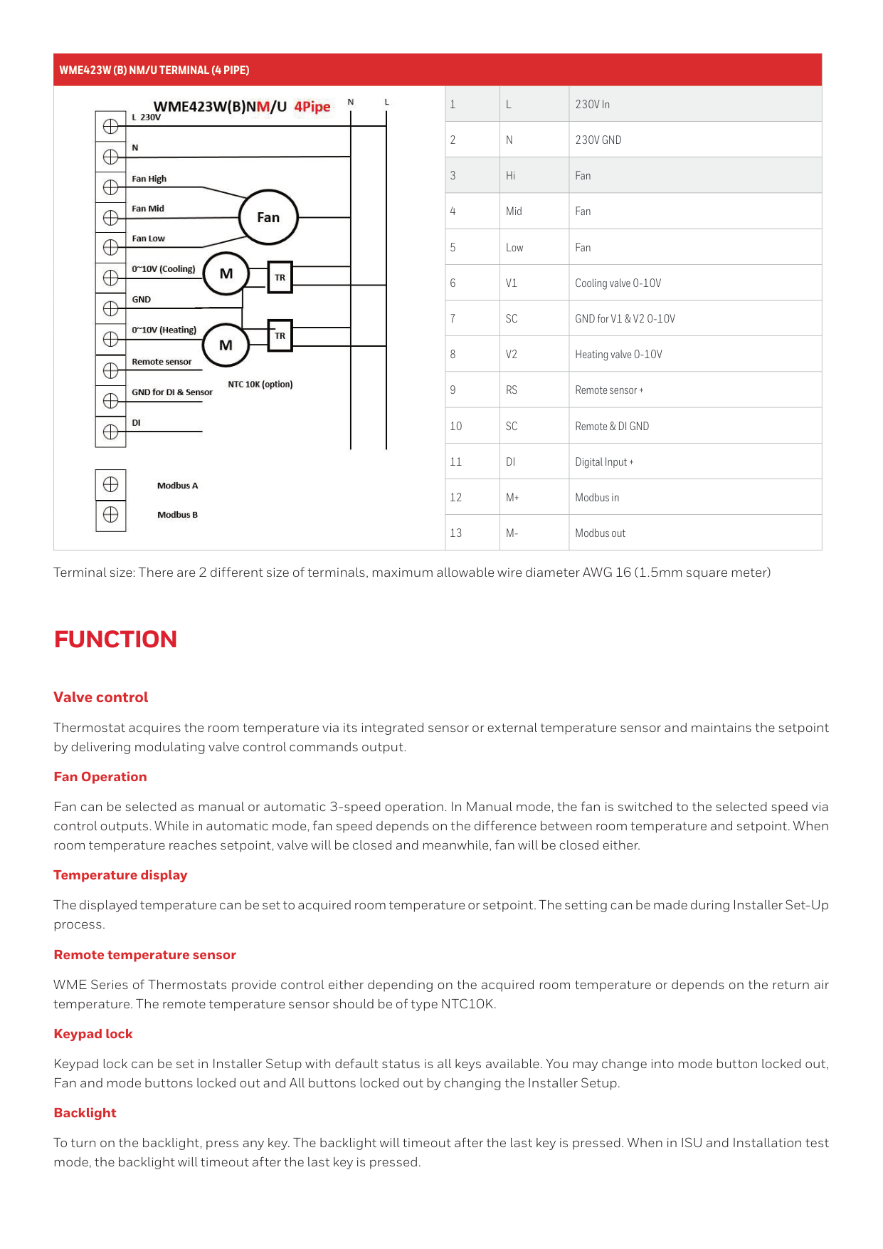
Wme423W (B) Nm/U Terminal (4 Pipe)
1
L
230V In 2N
230V Gnd
3 Hi Fan 4 Mid Fan 5 Low Fan 6V1
Cooling valve 0-10V 7Sc
GND for V1 & V2 0-10V 8V2
Heating valve 0-10V 9Rs
Remote sensor + 10Sc
Remote & DI GND 11Di
Digital Input + 12M+
Modbus in 13M-
Modbus outFunction
Valve control Thermostat acquires the room temperature via its integrated sensor or external temperature sensor and maintains the setpoint by delivering modulating valve control commands output. Fan Operation Fan can be selected as manual or automatic 3-speed operation. In Manual mode, the fan is switched to the selected speed via control outputs. While in automatic mode, fan speed depends on the difference between room temperature and setpoint. When room temperature reaches setpoint, valve will be closed and meanwhile, fan will be closed either. Temperature display The displayed temperature can be set to acquired room temperature or setpoint. The setting can be made during Installer Set-Up process. Remote temperature sensor WME Series of Thermostats provide control either depending on the acquired room temperature or depends on the return air temperature. The remote temperature sensor should be of type NTC10K. Keypad lock Keypad lock can be set in Installer Setup with default status is all keys available. You may change into mode button locked out, Fan and mode buttons locked out and All buttons locked out by changing the Installer Setup. Backlight To turn on the backlight, press any key. The backlight will timeout after the last key is pressed. When in ISU and Installation test mode, the backlight will timeout after the last key is pressed. Terminal size: There are 2 different size of terminals, maximum allowable wire diameter AWG 16 (1.5mm square meter)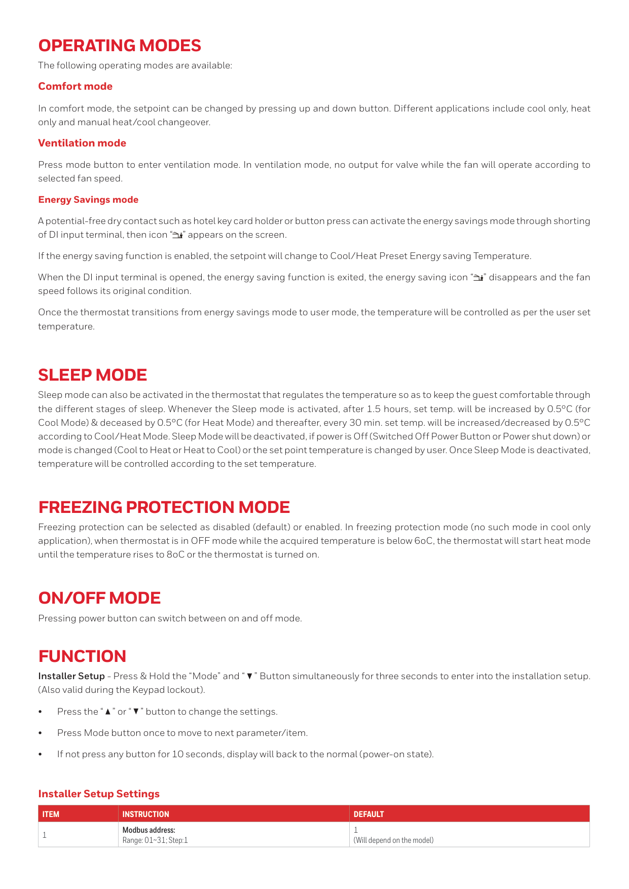
Operating Modes
The following operating modes are available: Comfort mode In comfort mode, the setpoint can be changed by pressing up and down button. Different applications include cool only, heat only and manual heat/cool changeover. Ventilation mode Press mode button to enter ventilation mode. In ventilation mode, no output for valve while the fan will operate according to selected fan speed. Energy Savings mode A potential-free dry contact such as hotel key card holder or button press can activate the energy savings mode through shorting of DI input terminal, then icon “ ” appears on the screen. If the energy saving function is enabled, the setpoint will change to Cool/Heat Preset Energy saving Temperature. When the DI input terminal is opened, the energy saving function is exited, the energy saving icon “ ” disappears and the fan speed follows its original condition. Once the thermostat transitions from energy savings mode to user mode, the temperature will be controlled as per the user set temperature.Sleep Mode
Sleep mode can also be activated in the thermostat that regulates the temperature so as to keep the guest comfortable through the different stages of sleep. Whenever the Sleep mode is activated, after 1.5 hours, set temp. will be increased by 0.5°C (for Cool Mode) & deceased by 0.5°C (for Heat Mode) and thereafter, every 30 min. set temp. will be increased/decreased by 0.5°C according to Cool/Heat Mode. Sleep Mode will be deactivated, if power is Off (Switched Off Power Button or Power shut down) or mode is changed (Cool to Heat or Heat to Cool) or the set point temperature is changed by user. Once Sleep Mode is deactivated, temperature will be controlled according to the set temperature.Freezing Protection Mode
Freezing protection can be selected as disabled (default) or enabled. In freezing protection mode (no such mode in cool only application), when thermostat is in OFF mode while the acquired temperature is below 6oC, the thermostat will start heat mode until the temperature rises to 8oC or the thermostat is turned on.On/Off Mode
Pressing power button can switch between on and off mode.Function
Installer Setup - Press & Hold the “Mode” and “ ” Button simultaneously for three seconds to enter into the installation setup. (Also valid during the Keypad lockout). • Press the “ ” or “ ” button to change the settings. • Press Mode button once to move to next parameter/item. • If not press any button for 10 seconds, display will back to the normal (power-on state).Item
Instruction
Default
1 Modbus address: Range: 01~31; Step:1 1 (Will depend on the model) Installer Setup Settings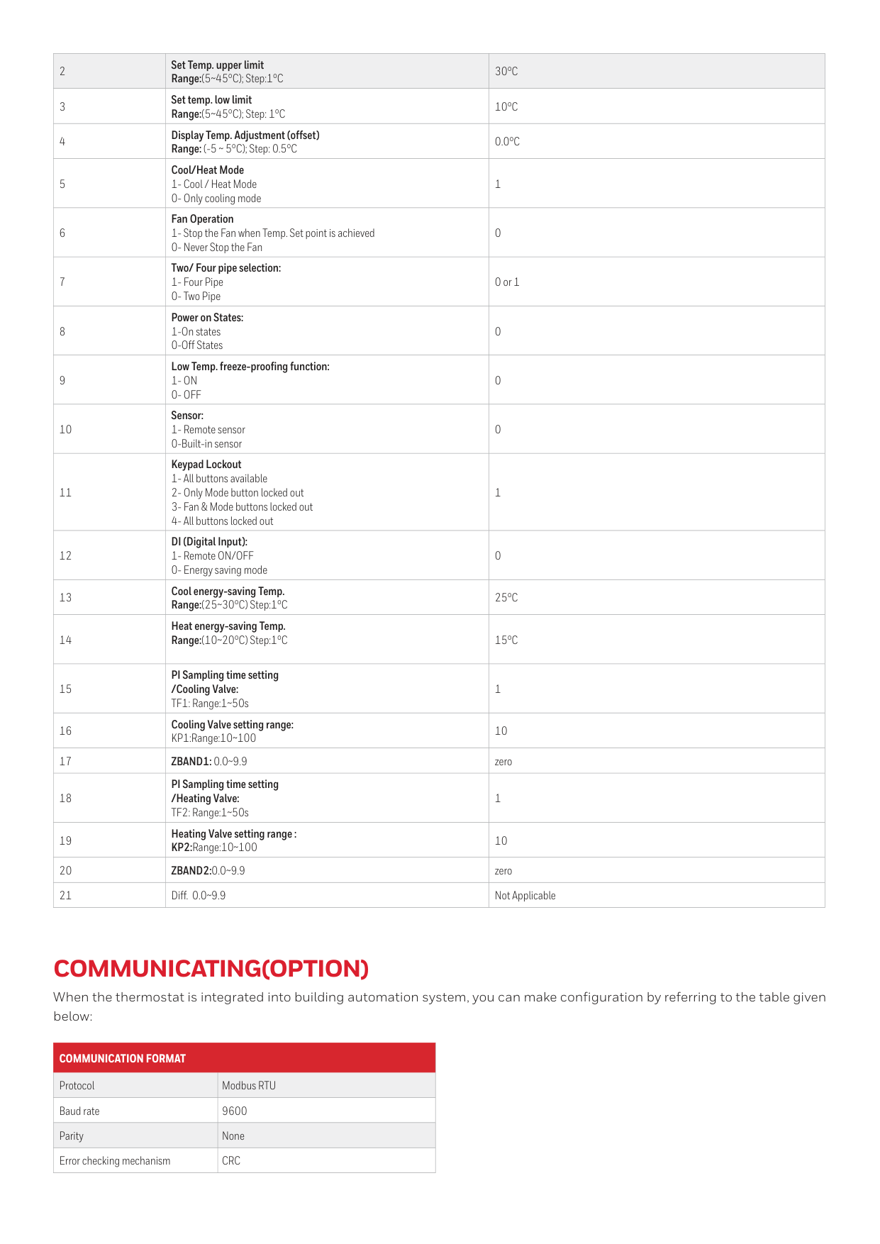
2 Set Temp. upper limit Range:(5~45°C); Step:1°C
30°C
3 Set temp. low limit Range:(5~45°C); Step: 1°C10°C
4 Display Temp. Adjustment (offset) Range: (-5 ~ 5°C); Step: 0.5°C0.0°C
5 Cool/Heat Mode 1- Cool / Heat Mode 0- Only cooling mode 1 6 Fan Operation 1- Stop the Fan when Temp. Set point is achieved 0- Never Stop the Fan 0 7 Two/ Four pipe selection: 1- Four Pipe 0- Two Pipe 0 or 1 8 Power on States: 1-On states 0-Off States 0 9 Low Temp. freeze-proofing function:1- On
0- Off
0 10 Sensor: 1- Remote sensor 0-Built-in sensor 0 11 Keypad Lockout 1- All buttons available 2- Only Mode button locked out 3- Fan & Mode buttons locked out 4- All buttons locked out 1 12 DI (Digital Input): 1- Remote ON/OFF 0- Energy saving mode 0 13 Cool energy-saving Temp. Range:(25~30°C) Step:1°C25°C
14 Heat energy-saving Temp. Range:(10~20°C) Step:1°C15°C
15 PI Sampling time setting /Cooling Valve: TF1: Range:1~50s 1 16 Cooling Valve setting range: KP1:Range:10~100 10 17Zband1: 0.0~9.9
zero 18 PI Sampling time setting /Heating Valve: TF2: Range:1~50s 1 19 Heating Valve setting range : KP2:Range:10~100 10 20Zband2:0.0~9.9
zero 21 Diff. 0.0~9.9 Not ApplicableCommunicating(Option)
When the thermostat is integrated into building automation system, you can make configuration by referring to the table given below:Communication Format
Protocol Modbus RTU Baud rate 9600 Parity None Error checking mechanismCrc
WME Series Modulating Digital Thermostat | 02 | 10/22 © 2022 Honeywell International Inc. For more information, https://honeywellbuildings.in Tel : +91 124 4975000 Email: HBT-Indiabuildings@honeywell.com Honeywell HBT India Buildings Unitech Trade Center, 5th Floor, Sector-43, Block C, Sushant Lok Phase - I, Gurgaon - 122 002. Haryana India https://www.honeywellbuildings.in/
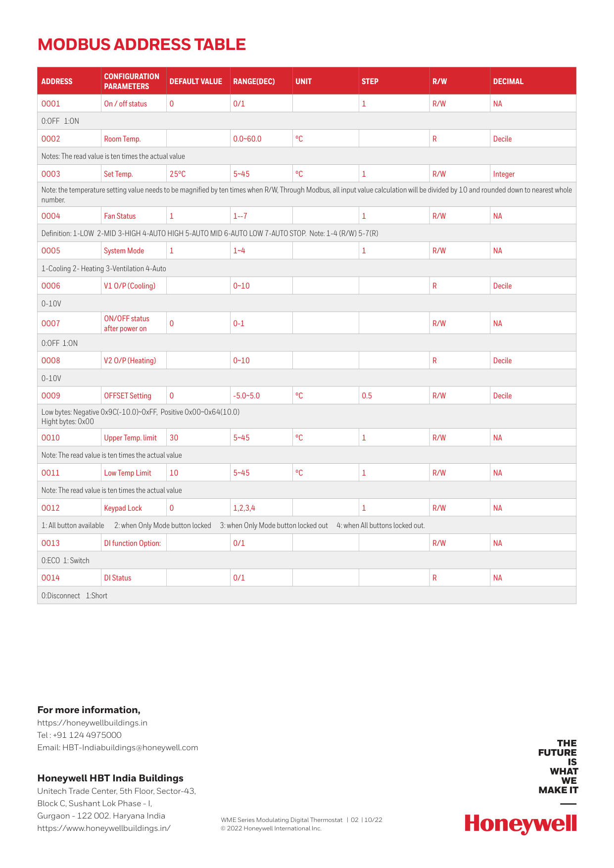
Modbus Address Table
Address
Configuration
Parameters
Default Value
Range(Dec)
Unit
Step
R/W
Decimal
Ooo1
On / off status 0 0/11
R/W
Na
0:Off 1:On
Ooo2
Room Temp.0.0~60.0
°C
R
Decile Notes: The read value is ten times the actual valueOoo3
Set Temp.25°C
5~45°C
1R/W
Integer Note: the temperature setting value needs to be magnified by ten times when R/W, Through Modbus, all input value calculation will be divided by 10 and rounded down to nearest whole number.Ooo4
Fan Status 1 1--71
R/W
Na
Definition: 1-LOW 2-MID 3-HIGH 4-AUTO HIGH 5-AUTO MID 6-AUTO LOW 7-AUTO STOP. Note: 1-4 (R/W) 5-7(R)Ooo5
System Mode 1 1~41
R/W
Na
1-Cooling 2- Heating 3-Ventilation 4-AutoOoo6
V1 O/P (Cooling)0~10
R
Decile0-10V
Ooo7
ON/OFF status after power on 0 0-1R/W
Na
0:Off 1:On
Ooo8
V2 O/P (Heating)0~10
R
Decile0-10V
Ooo9
OFFSET Setting 0 -5.0~5.0°C
0.5R/W
Decile Low bytes: Negative 0x9C(-10.0)~0xFF, Positive 0x00~0x64(10.0) Hight bytes: 0x00Oo10
Upper Temp. limit 30 5~45°C
1R/W
Na
Note: The read value is ten times the actual valueOo11
Low Temp Limit 10 5~45°C
1R/W
Na
Note: The read value is ten times the actual valueOo12
Keypad Lock 0 1,2,3,41
R/W
Na
1: All button available 2: when Only Mode button locked 3: when Only Mode button locked out 4: when All buttons locked out.Oo13
DI function Option: 0/1R/W
Na
0:ECO 1: SwitchOo14
DI Status0/1