
Ask AI
— answers from the official manualAnswers from the official manual.
Common questions
Common Questions
7 totalWhat safety precautions should I follow when using my HP 240 G7 Notebook?
Avoid placing the notebook directly on your lap or obstructing air vents as overheating can cause injury. Use it only on hard, flat surfaces and ensure no other hard surface like an optional printer blocks airflow; soft surfaces such as pillows also obstruct airflow and can overheat components. Also, prevent skin contact with hot surfaces when using the AC adapter. (Page 3)
How do I replace the battery on my HP 240 G7 Notebook?
To remove and insert a new battery, first shut down the computer, disconnect power cords, remove external devices, and take out the battery if unsure about the computer’s status. Turn it upside down lightly, slide the battery release latch to unlock it, pivot upward to extract. To reinstall, align tabs then push towards the computer until secured by battery latch.
What is the recommended method for handling hard drives inside my notebook?
Handle hard drives with care using appropriate protective packaging like static-proof bags. Avoid exposure to magnetic fields, high temperatures, and liquids. Securely pack for transport, ensuring they are not damaged or lose data during transfer.
How do I access the WLAN module in my HP notebook?
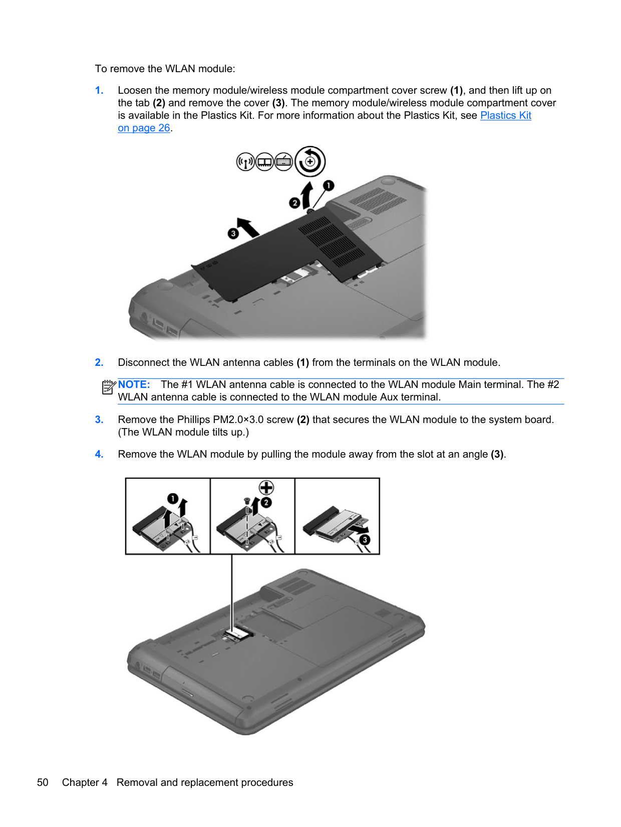
To replace or inspect the WLAN module, shut down and disconnect power. Remove battery and memory/wireless module cover. Disconnect antenna cables by pulling gently from terminals on module, remove securing screw, then pull out at an angle.
How can I safely remove the display bezel for maintenance?
To remove the display bezel while keeping assembly attached to computer, open the laptop and carefully loosen Mylar screw covers along top edge and sides. Flex inside edges until completely disengaged from the enclosure and then lift off.
How do I replace the hard drive in my HP notebook?
Before replacing the hard drive, shut down the computer and disconnect all external devices. Remove battery and memory module cover, carefully detach security screws then pull out the drive ensuring no interference with surrounding components.
Show 1 more questions
Full Manual
142 pages
HP 240 Notebook PC and HP 245 Notebook PC
Maintenance and Service Guide
© Copyright 2012 Hewlett-Packard Development Company, L.P.
AMD and Radeon are trademarks of Advanced Micro Devices, Inc. Bluetooth is a trademark owned by its proprietor and used by Hewlett-Packard Company under license. Intel, Celeron, Core, and Pentium are trademarks of Intel Corporation in the U.S. and other countries. Microsoft and Windows are U.S. registered trademarks of Microsoft Corporation. SD Logo is a trademark of its proprietor.
The information contained herein is subject to change without notice. The only warranties for HP products and services are set forth in the express warranty statements accompanying such products and services. Nothing herein should be construed as constituting an additional warranty. HP shall not be liable for technical or editorial errors or omissions contained herein.
First Edition: November 2012 Document Part Number: 681022-002
#### Safety warning notice
WARNING! To reduce the possibility of heat-related injuries or of overheating the device, do not place the device directly on your lap or obstruct the device air vents. Use the device only on a hard, flat surface. Do not allow another hard surface, such as an adjoining optional printer, or a soft surface, such as pillows or rugs or clothing, to block airflow. Also, do not allow the AC adapter to contact the skin or a soft surface, such as pillows or rugs or clothing, during operation. The device and the AC adapter comply with the user-accessible surface temperature limits defined by the International Standard for Safety of Information Technology Equipment (IEC 60950).
iii
####### iv Safety warning notice
Table of contents

TouchPad .......................................................................................................................... 13 Lights ................................................................................................................................. 14 Buttons ............................................................................................................................... 15 Keys ................................................................................................................................... 16
Bottom ................................................................................................................................................ 17
Tools required .................................................................................................................... 33 Service considerations ....................................................................................................... 33
Plastic parts ....................................................................................................... 33 Cables and connectors ..................................................................................... 33 Drive handling ................................................................................................... 34
Grounding guidelines ......................................................................................................... 34 Electrostatic discharge damage ........................................................................ 34
v
Packaging and transporting guidelines ............................................. 36 Component replacement procedures ................................................................................................. 38
Service tag and PCID label ................................................................................................ 38 Service tag ........................................................................................................ 38 PCID label ......................................................................................................... 39
Computer feet .................................................................................................................... 40 Battery ............................................................................................................................... 41 Display subcomponents (bezel, webcam, panel) .............................................................. 42 WLAN module .................................................................................................................... 49 Memory module ................................................................................................................. 52 Hard drive .......................................................................................................................... 54 RTC battery ....................................................................................................................... 57 Optical drive ....................................................................................................................... 58 Keyboard ........................................................................................................................... 60 Top cover ........................................................................................................................... 63 Power button board ........................................................................................................... 67 TouchPad button board ..................................................................................................... 69 Speakers ............................................................................................................................ 71 USB board ......................................................................................................................... 73 Power connector cable ...................................................................................................... 75 Display assembly ............................................................................................................... 77 System board ..................................................................................................................... 86 Optical drive cable ............................................................................................................. 90 Fan/heat sink assembly ..................................................................................................... 92 Processor ........................................................................................................................... 98
###### 5 Computer Setup (BIOS) and Advanced System Diagnostics ................................................................. 101

Starting Computer Setup ................................................................................. 101 Navigating and selecting in Computer Setup .................................................. 101 Restoring factory settings in Computer Setup ................................................. 102 Updating the BIOS .......................................................................................... 103
Determining the BIOS version ........................................................ 103 Downloading a BIOS update .......................................................... 103
Using Advanced System Diagnostics .............................................................................. 104
Starting Computer Setup ................................................................................. 105 Navigating and selecting in Computer Setup .................................................. 105 Restoring factory settings in Computer Setup ................................................. 106
vi
Updating the BIOS .......................................................................................... 107 Determining the BIOS version ........................................................ 107 Downloading a BIOS update .......................................................... 107
Using Advanced System Diagnostics .............................................................................. 108

Creating recovery media ................................................................................. 114 Backing up your information ............................................................................................ 114 Performing a system recovery ......................................................................................... 115
Using the Windows recovery tools .................................................................. 115 Using f11 recovery tools .................................................................................. 116 Using a Windows 7 operating system DVD (purchased separately) ............... 116
Using the Windows recovery tools .................................................................. 118 Using f11 recovery tools .................................................................................. 119 Using Windows 8 operating system media (purchased separately) ............... 119 Using Windows Refresh for quick and easy recovery ..................................... 120 Remove everything and reinstall Windows ..................................................... 120 Using HP Software Setup ............................................................................... 121
###### Index ................................................................................................................................................................. 131
vii
####### viii
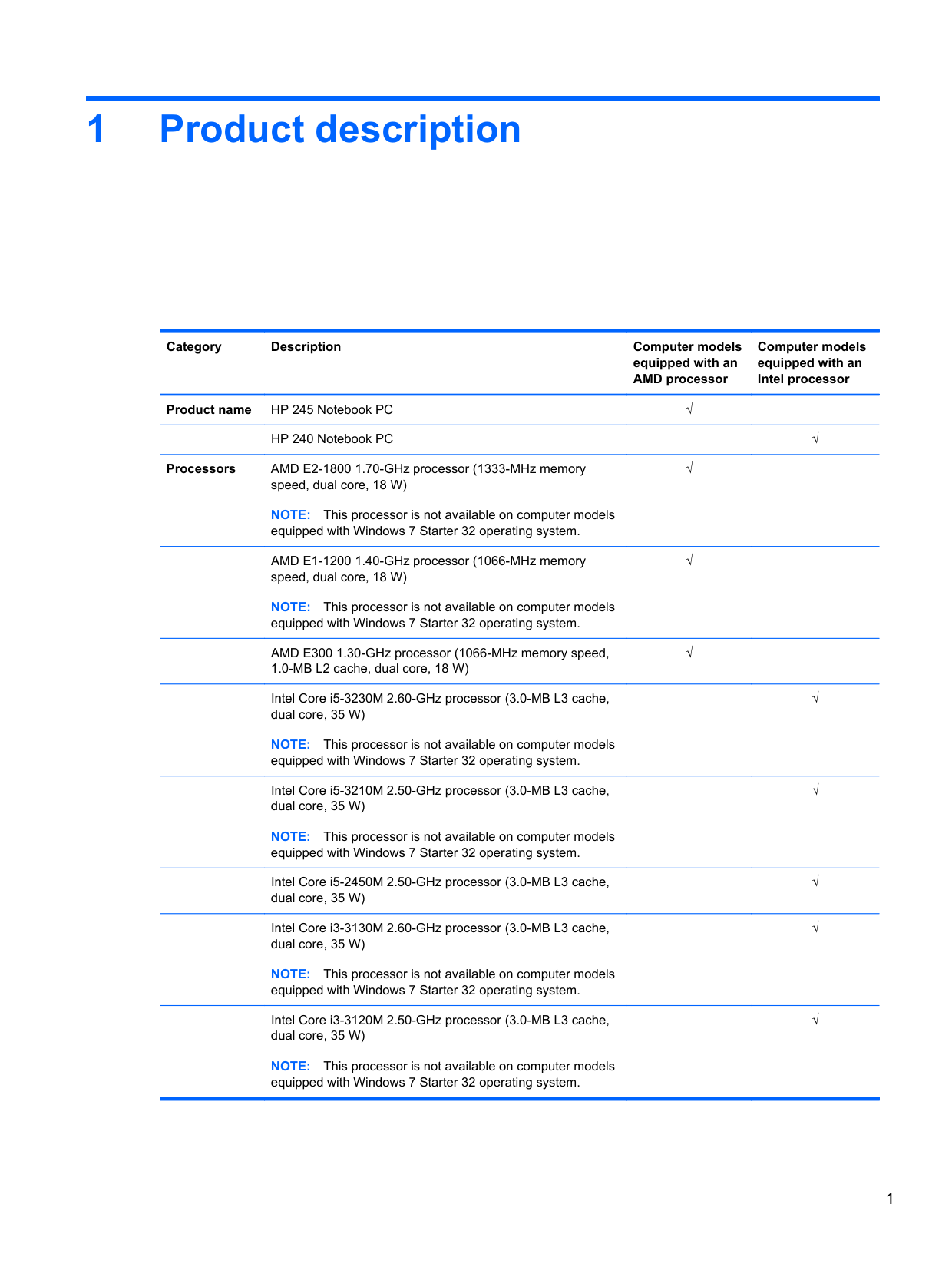
1 Product description
Category Description Computer models equipped with an AMD processor
Computer models equipped with an Intel processor
Product name HP 245 Notebook PC √
HP 240 Notebook PC √
Processors AMD E2-1800 1.70-GHz processor (1333-MHz memory speed, dual core, 18 W) NOTE: This processor is not available on computer models equipped with Windows 7 Starter 32 operating system.
√
AMD E1-1200 1.40-GHz processor (1066-MHz memory speed, dual core, 18 W)
√
NOTE: This processor is not available on computer models equipped with Windows 7 Starter 32 operating system.
AMD E300 1.30-GHz processor (1066-MHz memory speed, 1.0-MB L2 cache, dual core, 18 W)
Intel Core i5-3230M 2.60-GHz processor (3.0-MB L3 cache, dual core, 35 W)
NOTE: This processor is not available on computer models equipped with Windows 7 Starter 32 operating system.
Intel Core i5-3210M 2.50-GHz processor (3.0-MB L3 cache, dual core, 35 W)
NOTE: This processor is not available on computer models equipped with Windows 7 Starter 32 operating system.
Intel Core i5-2450M 2.50-GHz processor (3.0-MB L3 cache, dual core, 35 W)
Intel Core i3-3130M 2.60-GHz processor (3.0-MB L3 cache, dual core, 35 W)
NOTE: This processor is not available on computer models equipped with Windows 7 Starter 32 operating system.
Intel Core i3-3120M 2.50-GHz processor (3.0-MB L3 cache, dual core, 35 W)
NOTE: This processor is not available on computer models equipped with Windows 7 Starter 32 operating system.
√
√
√
√
√
√
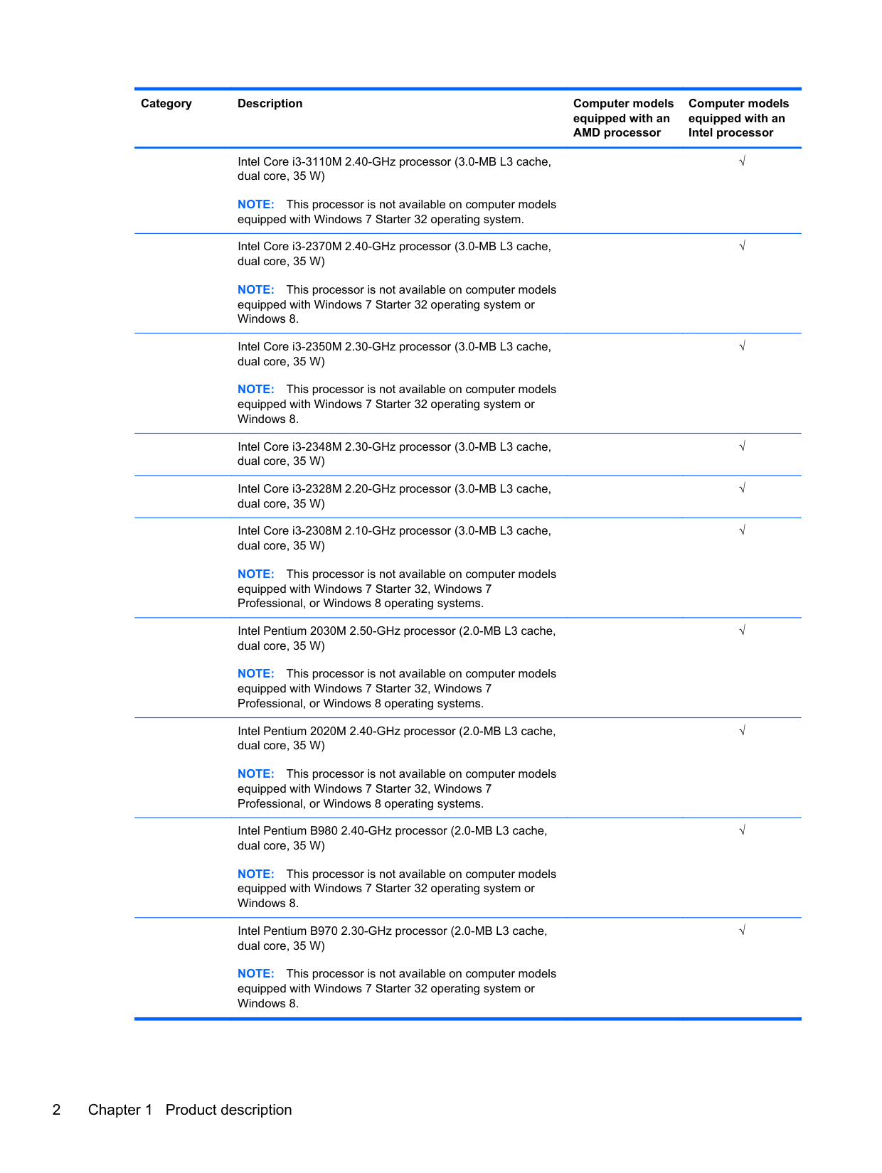
Intel Core i3-3110M 2.40-GHz processor (3.0-MB L3 cache, dual core, 35 W)
NOTE: This processor is not available on computer models equipped with Windows 7 Starter 32 operating system.
Intel Core i3-2370M 2.40-GHz processor (3.0-MB L3 cache, dual core, 35 W)
NOTE: This processor is not available on computer models equipped with Windows 7 Starter 32 operating system or Windows 8.
Intel Core i3-2350M 2.30-GHz processor (3.0-MB L3 cache, dual core, 35 W)
NOTE: This processor is not available on computer models equipped with Windows 7 Starter 32 operating system or Windows 8.
Intel Core i3-2348M 2.30-GHz processor (3.0-MB L3 cache, dual core, 35 W)
Intel Core i3-2328M 2.20-GHz processor (3.0-MB L3 cache, dual core, 35 W)
Intel Core i3-2308M 2.10-GHz processor (3.0-MB L3 cache, dual core, 35 W)
NOTE: This processor is not available on computer models equipped with Windows 7 Starter 32, Windows 7 Professional, or Windows 8 operating systems.
Intel Pentium 2030M 2.50-GHz processor (2.0-MB L3 cache, dual core, 35 W)
NOTE: This processor is not available on computer models equipped with Windows 7 Starter 32, Windows 7 Professional, or Windows 8 operating systems.

Intel Pentium 2020M 2.40-GHz processor (2.0-MB L3 cache, dual core, 35 W)
NOTE: This processor is not available on computer models equipped with Windows 7 Starter 32, Windows 7 Professional, or Windows 8 operating systems.
Intel Pentium B980 2.40-GHz processor (2.0-MB L3 cache, dual core, 35 W)
NOTE: This processor is not available on computer models equipped with Windows 7 Starter 32 operating system or Windows 8.
Intel Pentium B970 2.30-GHz processor (2.0-MB L3 cache, dual core, 35 W)
NOTE: This processor is not available on computer models equipped with Windows 7 Starter 32 operating system or Windows 8.
√
√
√
√
√
√
√
√
√
√
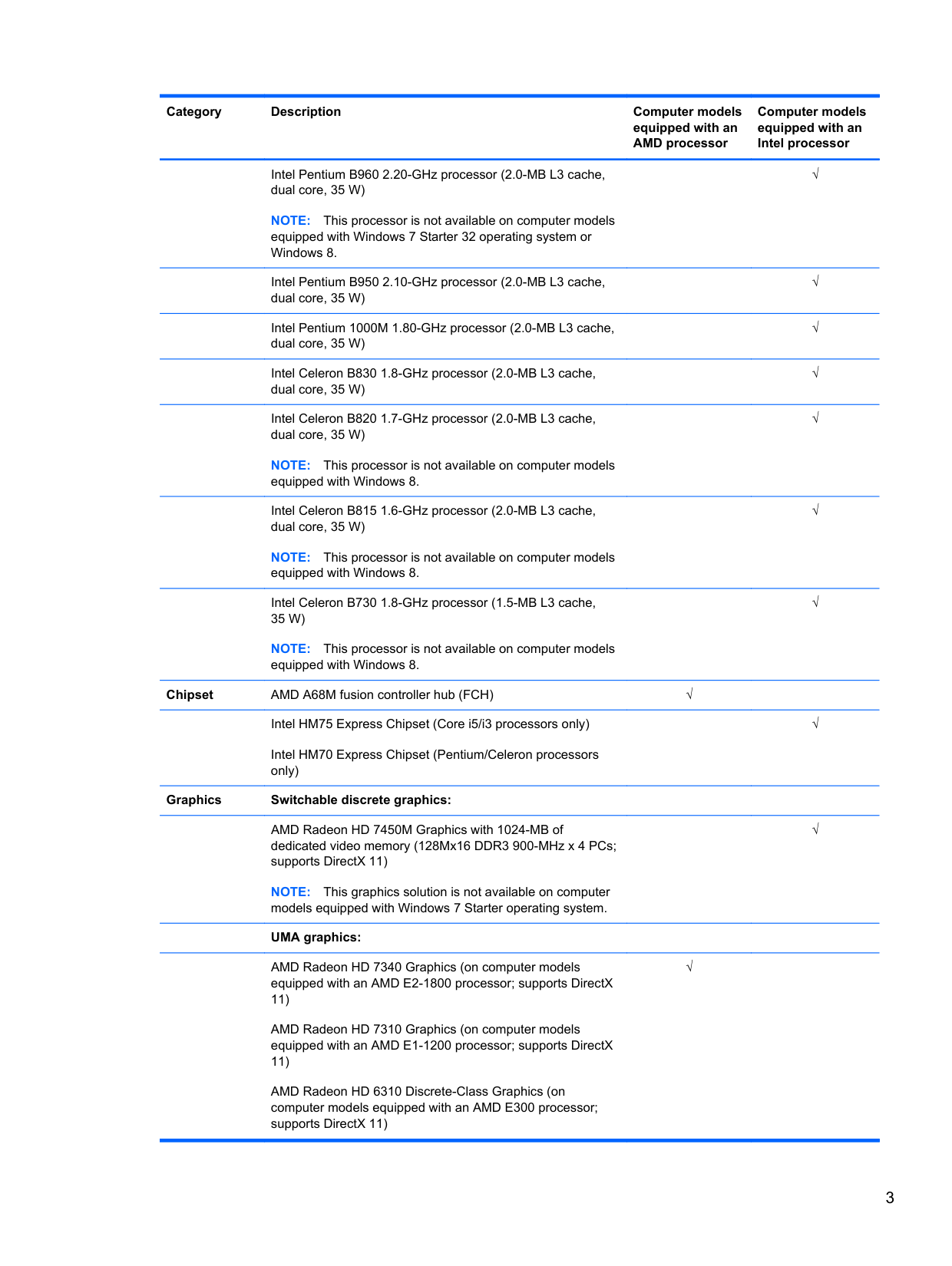
Intel Pentium B960 2.20-GHz processor (2.0-MB L3 cache, dual core, 35 W)
NOTE: This processor is not available on computer models equipped with Windows 7 Starter 32 operating system or Windows 8.
Intel Pentium B950 2.10-GHz processor (2.0-MB L3 cache, dual core, 35 W)
Intel Pentium 1000M 1.80-GHz processor (2.0-MB L3 cache, dual core, 35 W)
Intel Celeron B830 1.8-GHz processor (2.0-MB L3 cache, dual core, 35 W)
Intel Celeron B820 1.7-GHz processor (2.0-MB L3 cache, dual core, 35 W)
NOTE: This processor is not available on computer models equipped with Windows 8.
Intel Celeron B815 1.6-GHz processor (2.0-MB L3 cache, dual core, 35 W)
NOTE: This processor is not available on computer models equipped with Windows 8.
Intel Celeron B730 1.8-GHz processor (1.5-MB L3 cache, 35 W)
NOTE: This processor is not available on computer models equipped with Windows 8.
Chipset AMD A68M fusion controller hub (FCH) √ Intel HM75 Express Chipset (Core i5/i3 processors only) Intel HM70 Express Chipset (Pentium/Celeron processors only)
######## Graphics Switchable discrete graphics:
AMD Radeon HD 7450M Graphics with 1024-MB of dedicated video memory (128Mx16 DDR3 900-MHz x 4 PCs; supports DirectX 11)
NOTE: This graphics solution is not available on computer models equipped with Windows 7 Starter operating system.
######## UMA graphics:
AMD Radeon HD 7340 Graphics (on computer models equipped with an AMD E2-1800 processor; supports DirectX 11)
AMD Radeon HD 7310 Graphics (on computer models equipped with an AMD E1-1200 processor; supports DirectX 11)
AMD Radeon HD 6310 Discrete-Class Graphics (on computer models equipped with an AMD E300 processor; supports DirectX 11)
√
√
√
√
√
√
√
√
√
√
Intel HD Graphics 4000 (on computer models equipped with an Intel Core i5-3210M or i3-3110M processor; supports DirectX 11)
√
Intel HD Graphics 3000 (on computer models equipped with an Intel Core i3-2370M, i3-2350M, or i3-2308M processor; supports DirectX 10)
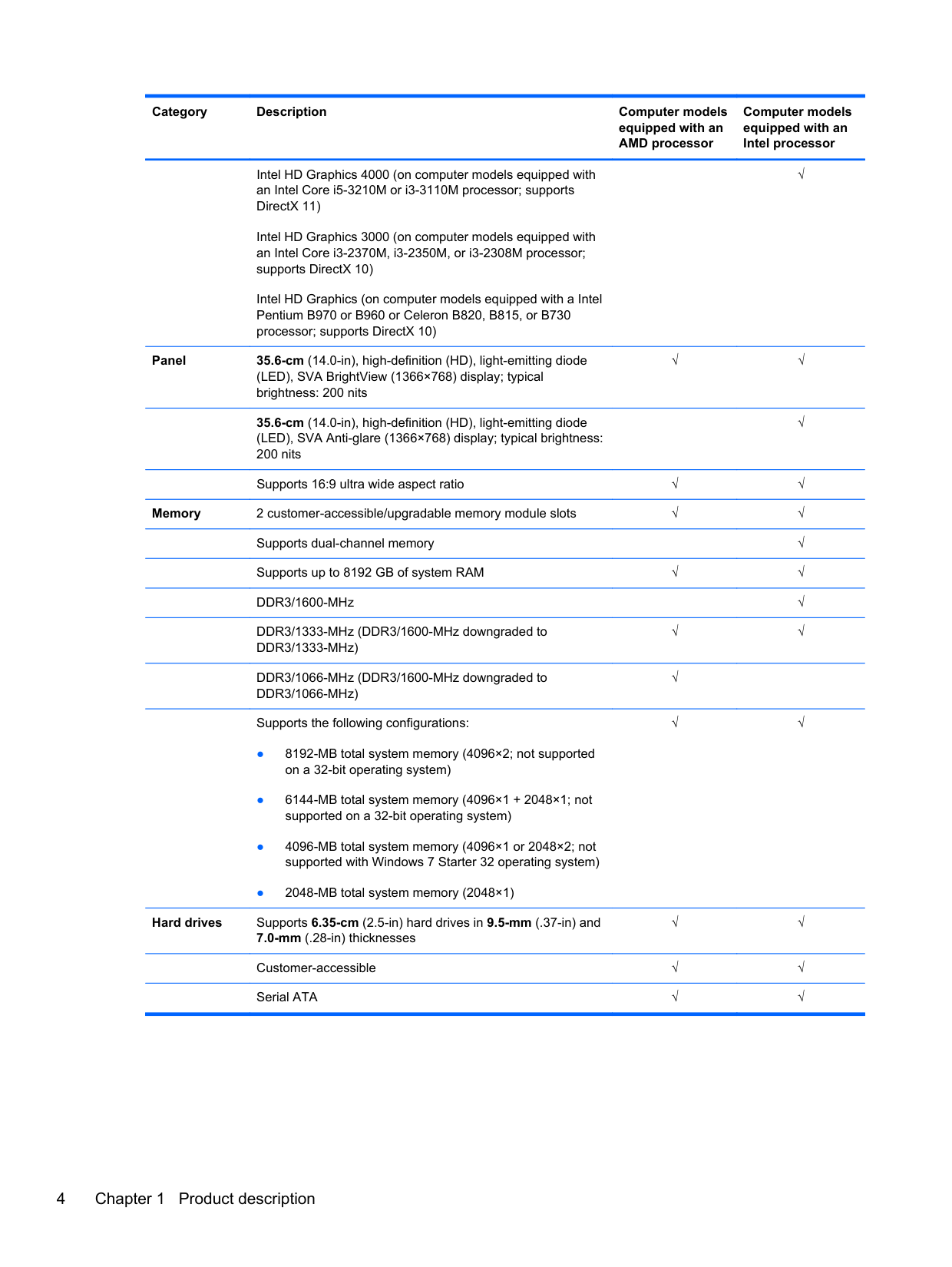
Intel HD Graphics (on computer models equipped with a Intel Pentium B970 or B960 or Celeron B820, B815, or B730 processor; supports DirectX 10)
Panel 35.6-cm (14.0-in), high-definition (HD), light-emitting diode (LED), SVA BrightView (1366×768) display; typical brightness: 200 nits
√√
35.6-cm (14.0-in), high-definition (HD), light-emitting diode (LED), SVA Anti-glare (1366×768) display; typical brightness: 200 nits
√
Supports 16:9 ultra wide aspect ratio √√
Memory 2 customer-accessible/upgradable memory module slots √√ Supports dual-channel memory √ Supports up to 8192 GB of system RAM √√ DDR3/1600-MHz √ DDR3/1333-MHz (DDR3/1600-MHz downgraded to DDR3/1333-MHz)
√√
DDR3/1066-MHz (DDR3/1600-MHz downgraded to DDR3/1066-MHz)
Supports the following configurations:
Hard drives Supports 6.35-cm (2.5-in) hard drives in 9.5-mm (.37-in) and 7.0-mm (.28-in) thicknesses
√
√√
√√
Customer-accessible √√ Serial ATA √√
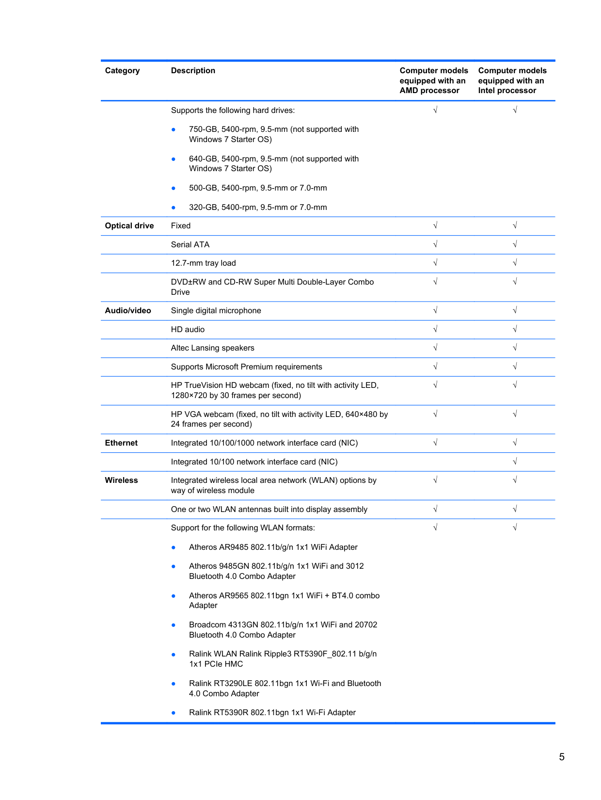
Supports the following hard drives:
√√
Optical drive Fixed √√
Serial ATA √√ 12.7-mm tray load √√ DVD±RW and CD-RW Super Multi Double-Layer Combo Drive
√√
Audio/video Single digital microphone √√
HD audio √√ Altec Lansing speakers √√ Supports Microsoft Premium requirements √√ HP TrueVision HD webcam (fixed, no tilt with activity LED, 1280×720 by 30 frames per second)
√√
HP VGA webcam (fixed, no tilt with activity LED, 640×480 by 24 frames per second)
√√
Ethernet Integrated 10/100/1000 network interface card (NIC) √√
Integrated 10/100 network interface card (NIC) √ Wireless Integrated wireless local area network (WLAN) options by
√√
way of wireless module
One or two WLAN antennas built into display assembly √√ Support for the following WLAN formats:
√√
External media card
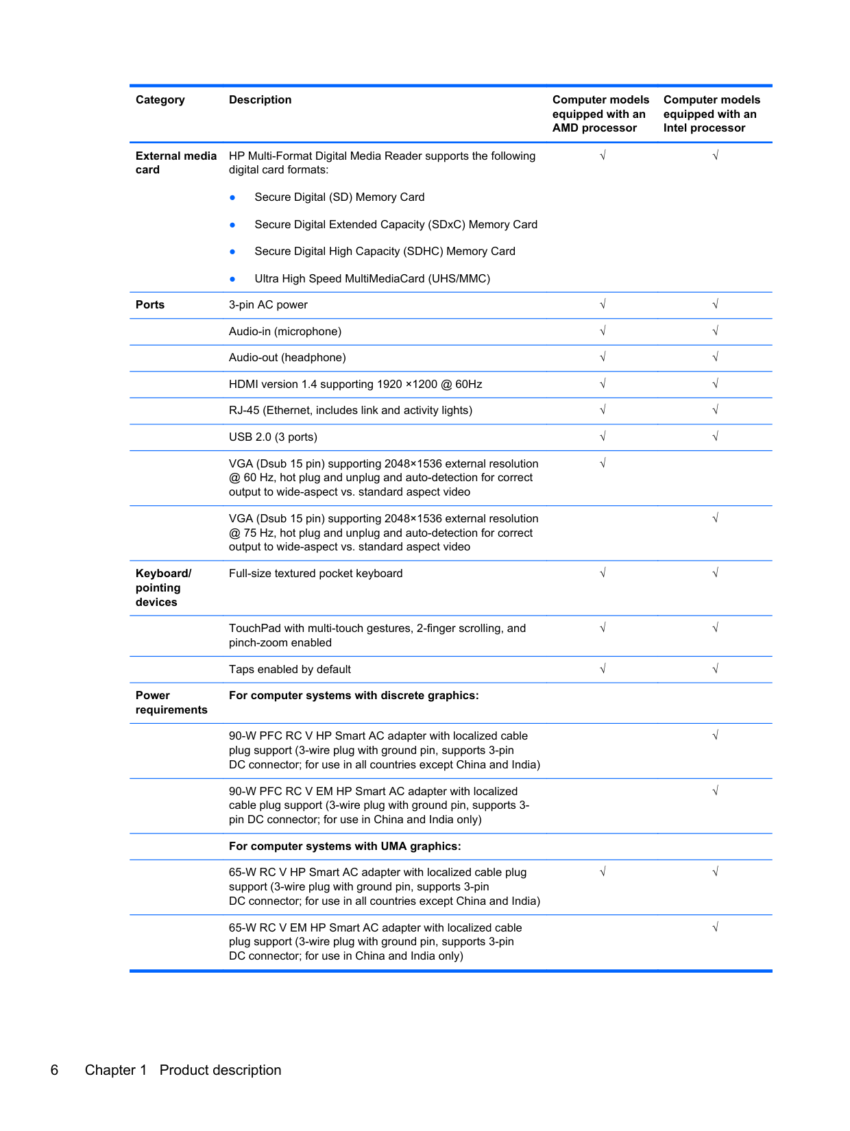
HP Multi-Format Digital Media Reader supports the following digital card formats:
√√
Ports 3-pin AC power √√ Audio-in (microphone) √√ Audio-out (headphone) √√
HDMI version 1.4 supporting 1920 ×1200 @ 60Hz √√ RJ-45 (Ethernet, includes link and activity lights) √√ USB 2.0 (3 ports) √√ VGA (Dsub 15 pin) supporting 2048×1536 external resolution @ 60 Hz, hot plug and unplug and auto-detection for correct output to wide-aspect vs. standard aspect video
√
Keyboard/ pointing devices
Power requirements
VGA (Dsub 15 pin) supporting 2048×1536 external resolution @ 75 Hz, hot plug and unplug and auto-detection for correct output to wide-aspect vs. standard aspect video
√
Full-size textured pocket keyboard √√
TouchPad with multi-touch gestures, 2-finger scrolling, and pinch-zoom enabled
√√
Taps enabled by default √√
For computer systems with discrete graphics:
90-W PFC RC V HP Smart AC adapter with localized cable plug support (3-wire plug with ground pin, supports 3-pin DC connector; for use in all countries except China and India)
90-W PFC RC V EM HP Smart AC adapter with localized cable plug support (3-wire plug with ground pin, supports 3pin DC connector; for use in China and India only)
######## For computer systems with UMA graphics:
65-W RC V HP Smart AC adapter with localized cable plug support (3-wire plug with ground pin, supports 3-pin DC connector; for use in all countries except China and India)
65-W RC V EM HP Smart AC adapter with localized cable plug support (3-wire plug with ground pin, supports 3-pin DC connector; for use in China and India only)
√
√
√√
√
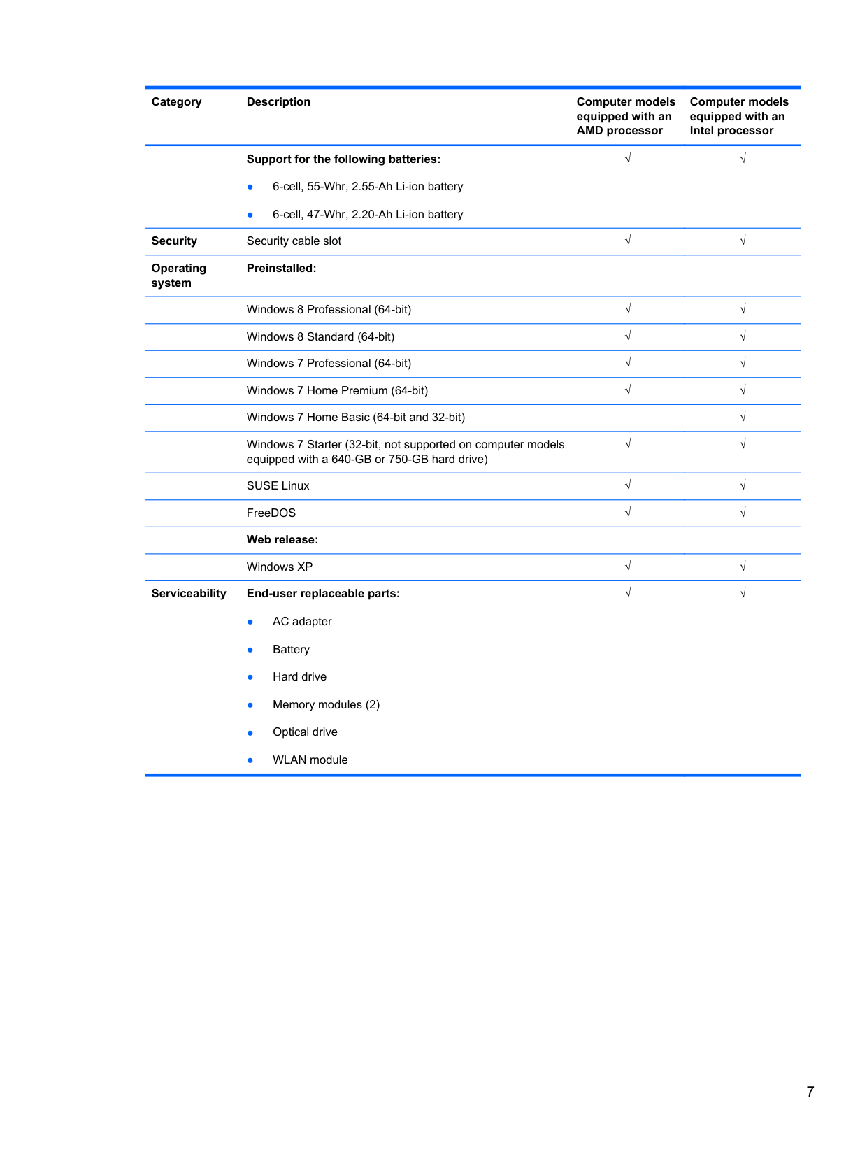
######## Support for the following batteries:
√√
Security Security cable slot √√ Operating system
######## Preinstalled:
Windows 8 Professional (64-bit) √√ Windows 8 Standard (64-bit) √√ Windows 7 Professional (64-bit) √√ Windows 7 Home Premium (64-bit) √√ Windows 7 Home Basic (64-bit and 32-bit) √ Windows 7 Starter (32-bit, not supported on computer models equipped with a 640-GB or 750-GB hard drive)
√√
SUSE Linux √√ FreeDOS √√ Web release:
Windows XP √√ Serviceability End-user replaceable parts:
√√
2 External component identification
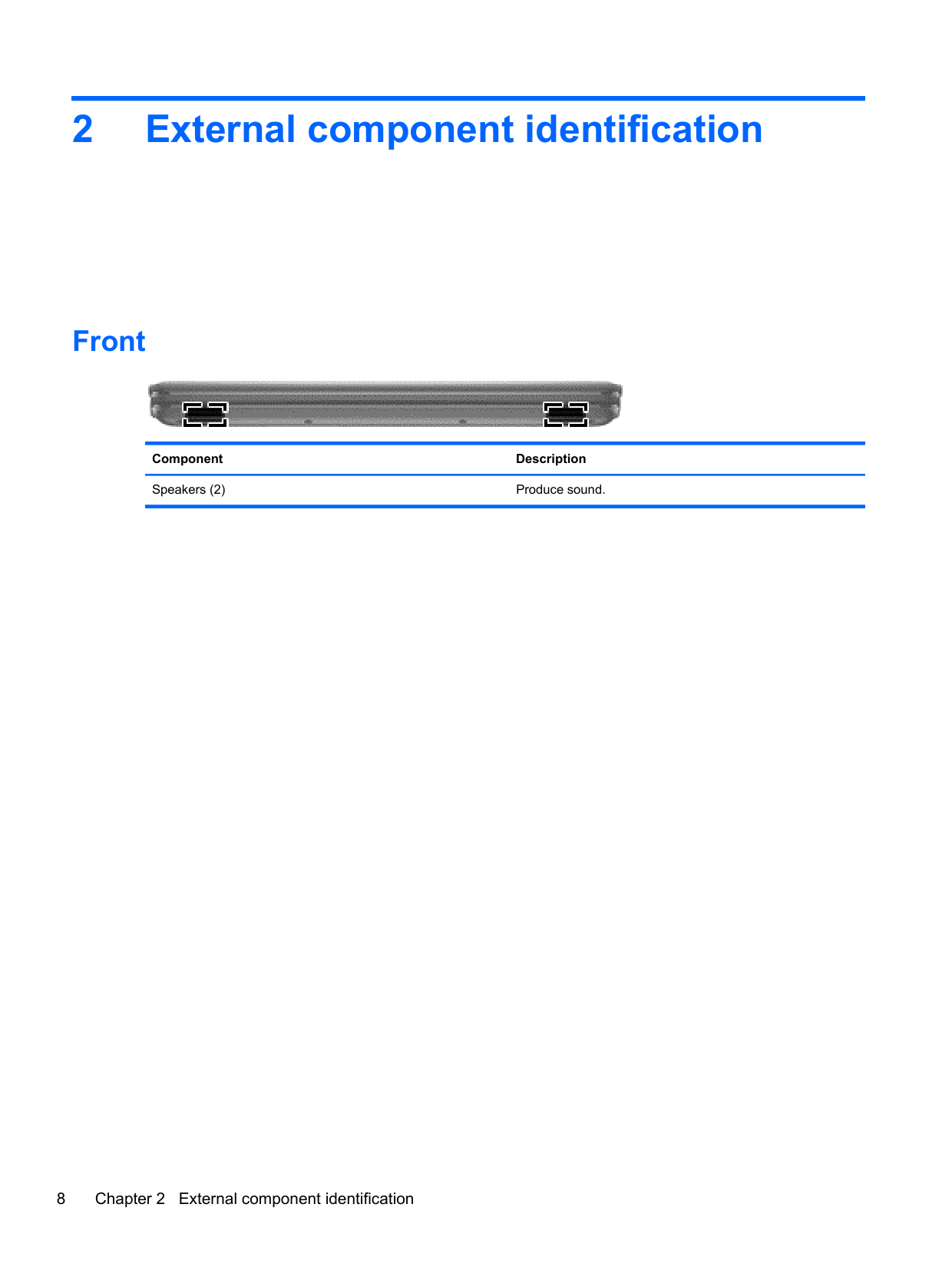
Front

Component Description Speakers (2) Produce sound.
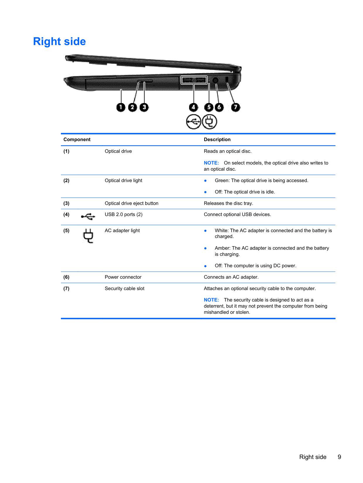
Right side

######## Component Description
NOTE: On select models, the optical drive also writes to an optical disc.
● Off: The optical drive is idle.


NOTE: The security cable is designed to act as a deterrent, but it may not prevent the computer from being mishandled or stolen.
Right side 9
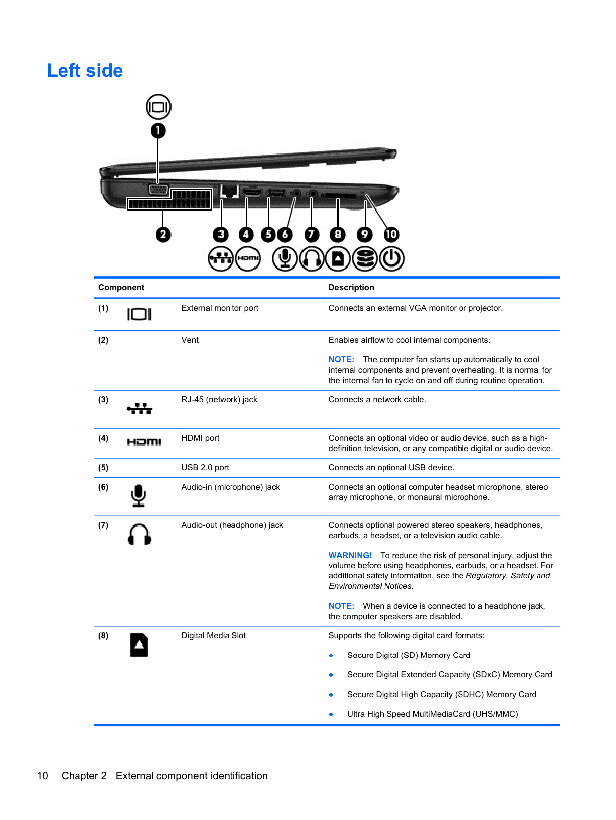
Left side

######## Component Description

NOTE: The computer fan starts up automatically to cool internal components and prevent overheating. It is normal for the internal fan to cycle on and off during routine operation.


WARNING! To reduce the risk of personal injury, adjust the volume before using headphones, earbuds, or a headset. For additional safety information, see the Regulatory, Safety and
Environmental Notices. NOTE: When a device is connected to a headphone jack, the computer speakers are disabled.

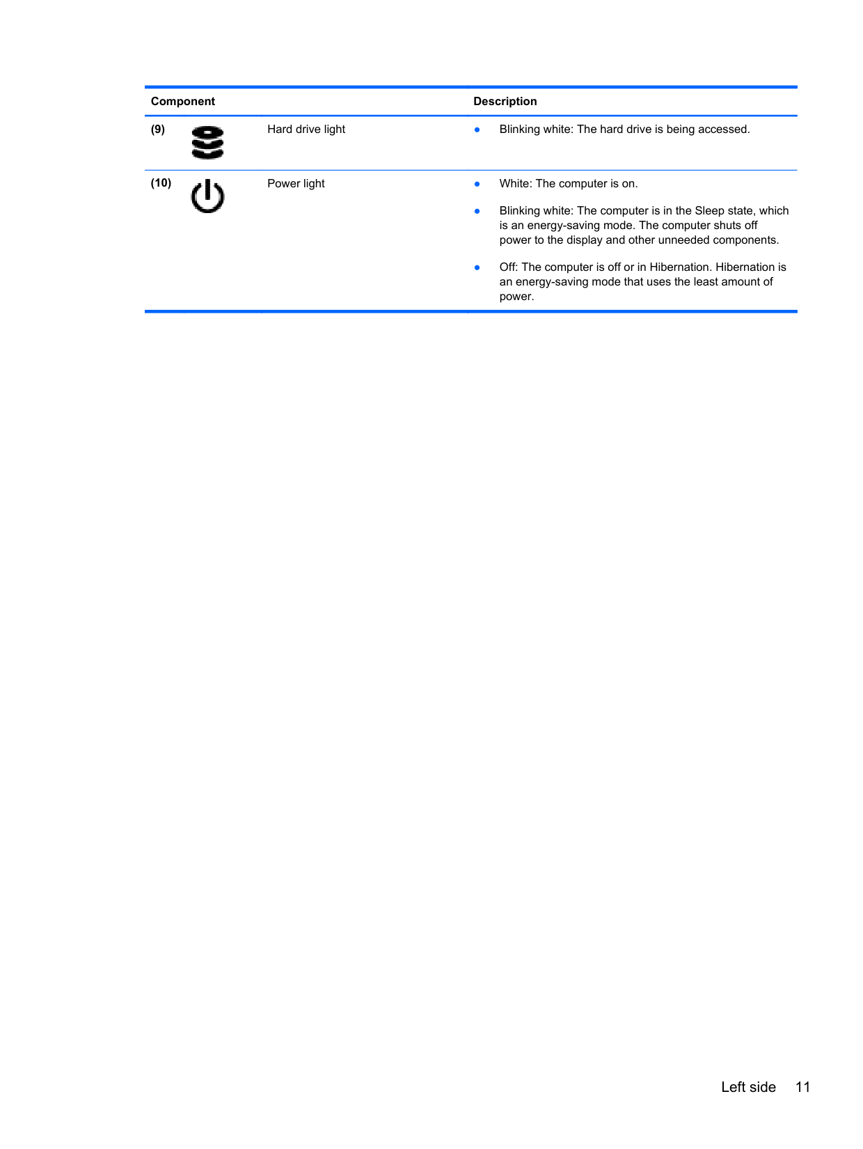
######## Component Description


Left side 11
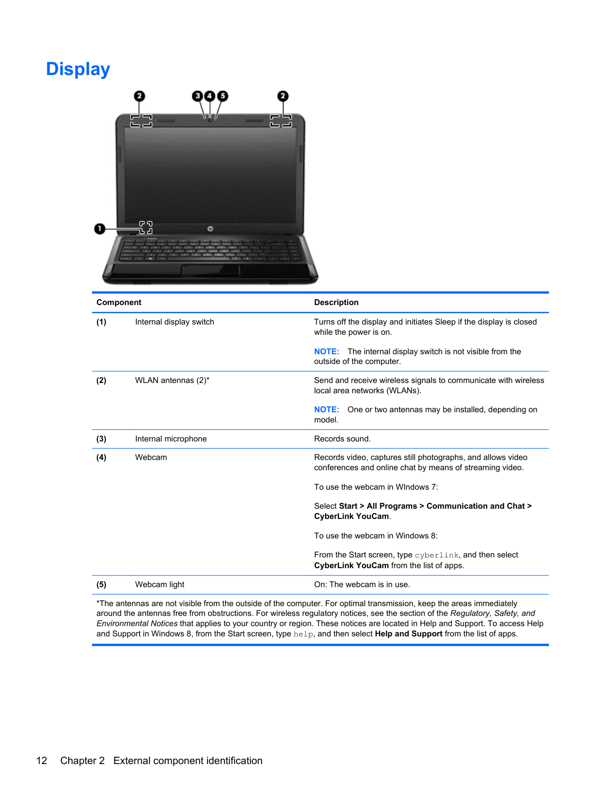
Display

######## Component Description
NOTE: The internal display switch is not visible from the outside of the computer.
NOTE: One or two antennas may be installed, depending on model.
Select Start > All Programs > Communication and Chat > CyberLink YouCam.
To use the webcam in Windows 8: From the Start screen, type cyberlink, and then select CyberLink YouCam from the list of apps.
*The antennas are not visible from the outside of the computer. For optimal transmission, keep the areas immediately around the antennas free from obstructions. For wireless regulatory notices, see the section of the Regulatory, Safety, and Environmental Notices that applies to your country or region. These notices are located in Help and Support. To access Help and Support in Windows 8, from the Start screen, type help, and then select Help and Support from the list of apps.
Top
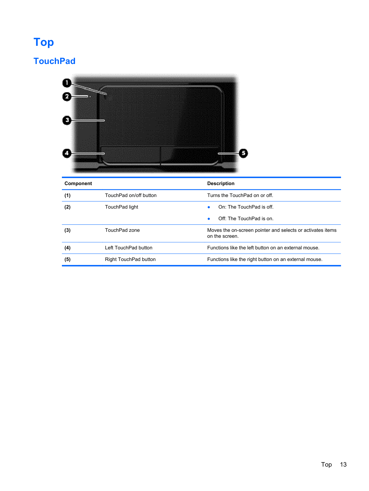
#### TouchPad

######## Component Description
● Off: The TouchPad is on.
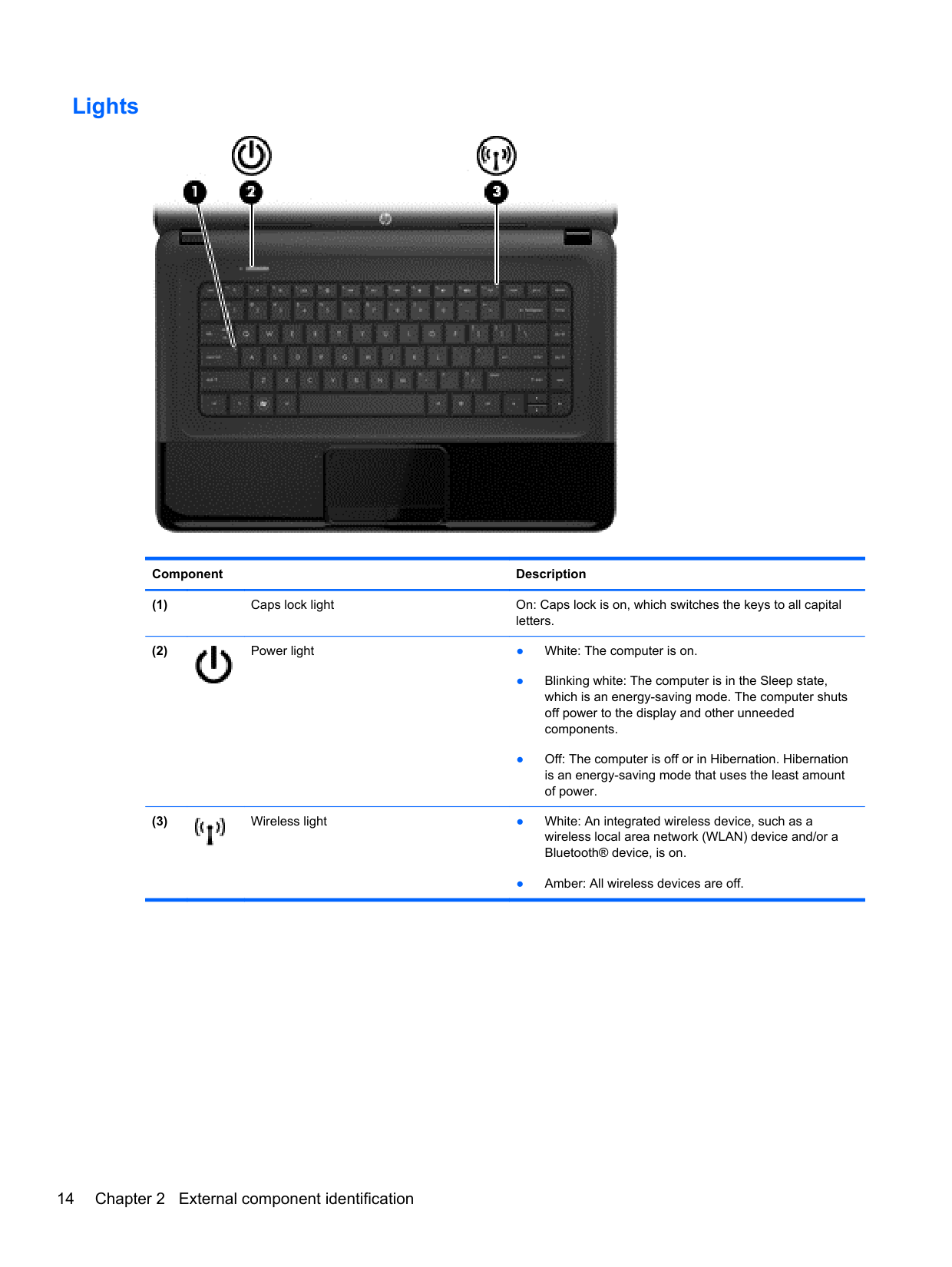
#### Lights

######## Component Description


● Amber: All wireless devices are off.
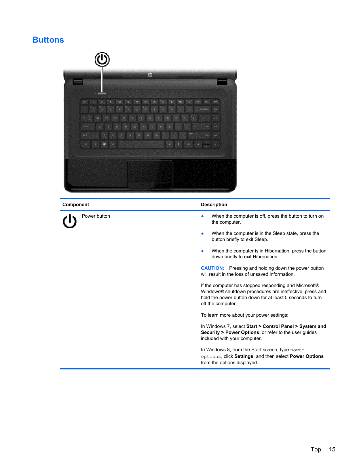
#### Buttons

######## Component Description

Power button ● When the computer is off, press the button to turn on the computer.
CAUTION: Pressing and holding down the power button will result in the loss of unsaved information. If the computer has stopped responding and Microsoft® Windows® shutdown procedures are ineffective, press and hold the power button down for at least 5 seconds to turn off the computer. To learn more about your power settings:
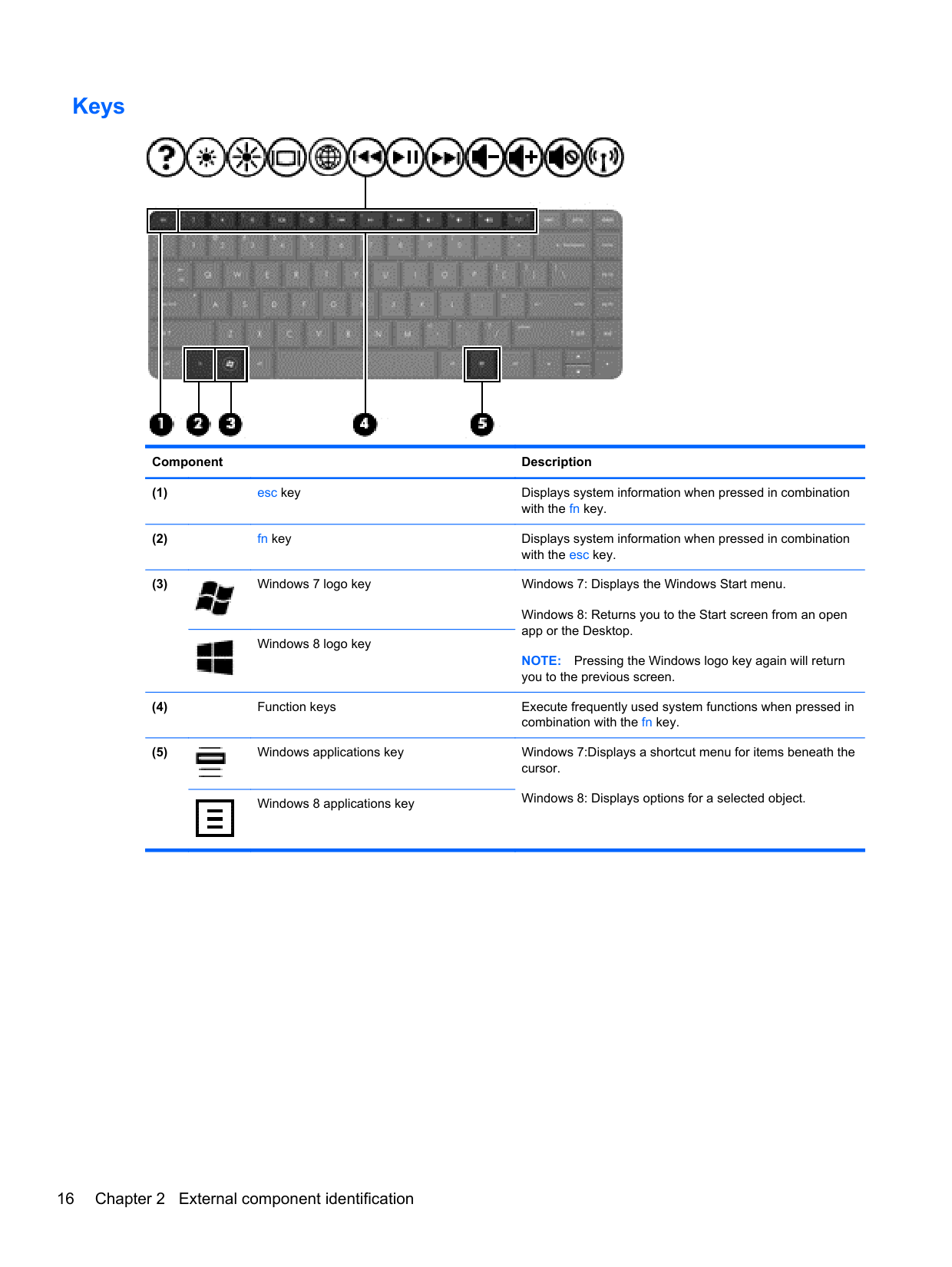
#### Keys

######## Component Description

Windows 8: Returns you to the Start screen from an open app or the Desktop.
NOTE: Pressing the Windows logo key again will return you to the previous screen.

Windows 8 logo key


Windows 8: Displays options for a selected object.Windows 8 applications key
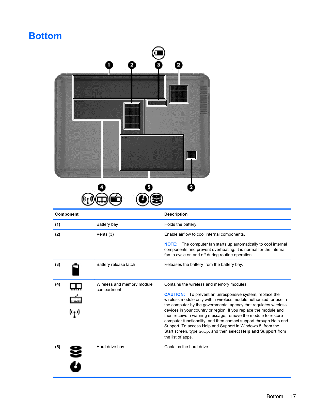
Bottom

######## Component Description
NOTE: The computer fan starts up automatically to cool internal components and prevent overheating. It is normal for the internal fan to cycle on and off during routine operation.


Contains the wireless and memory modules. CAUTION: To prevent an unresponsive system, replace the wireless module only with a wireless module authorized for use in the computer by the governmental agency that regulates wireless devices in your country or region. If you replace the module and then receive a warning message, remove the module to restore computer functionality, and then contact support through Help and Support. To access Help and Support in Windows 8, from the Start screen, type help, and then select Help and Support from the list of apps.


Bottom 17
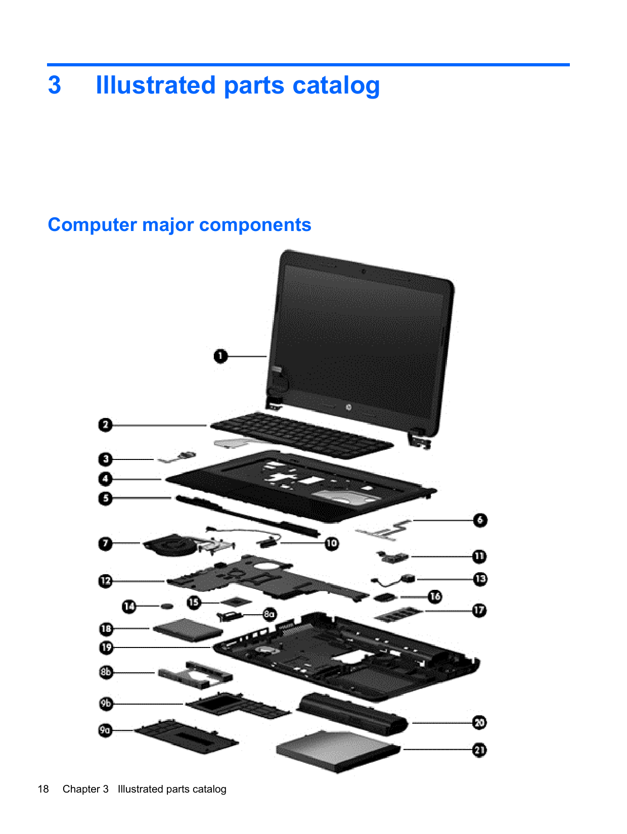
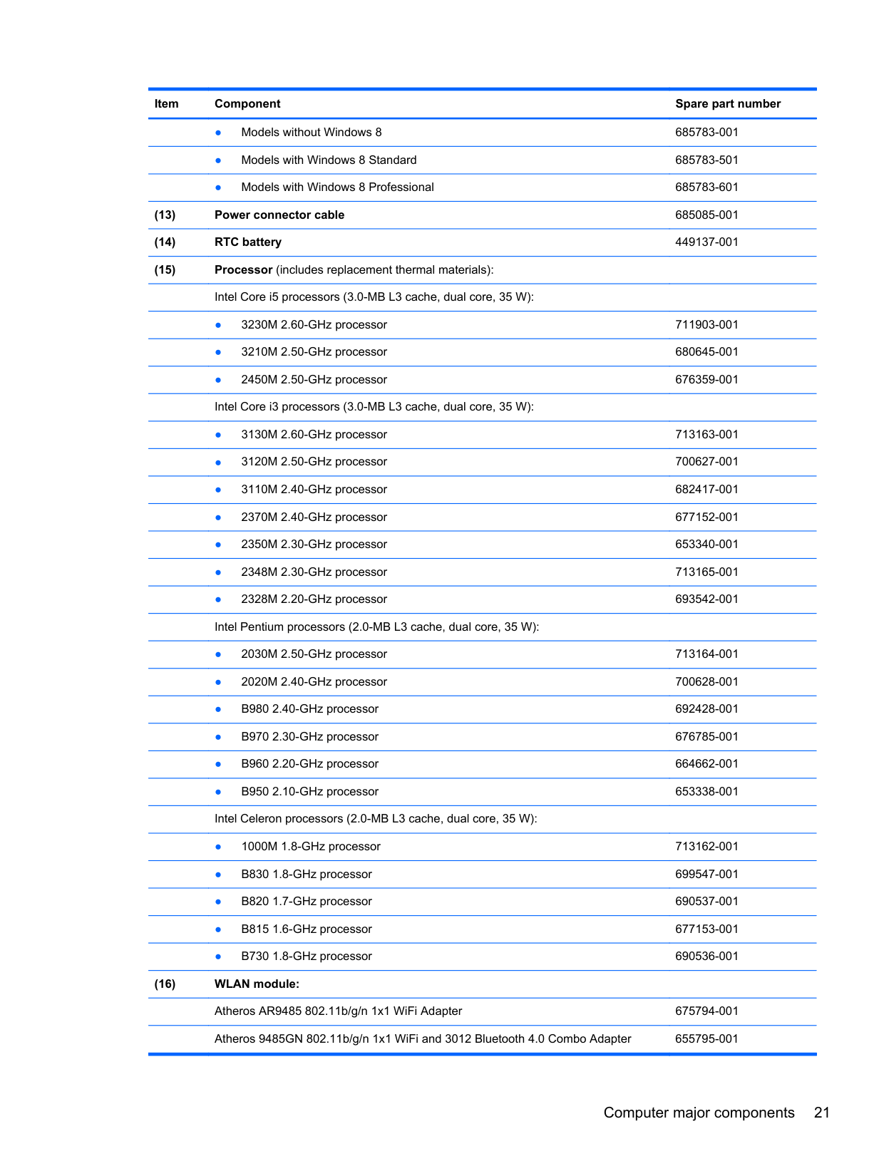
3 Illustrated parts catalog
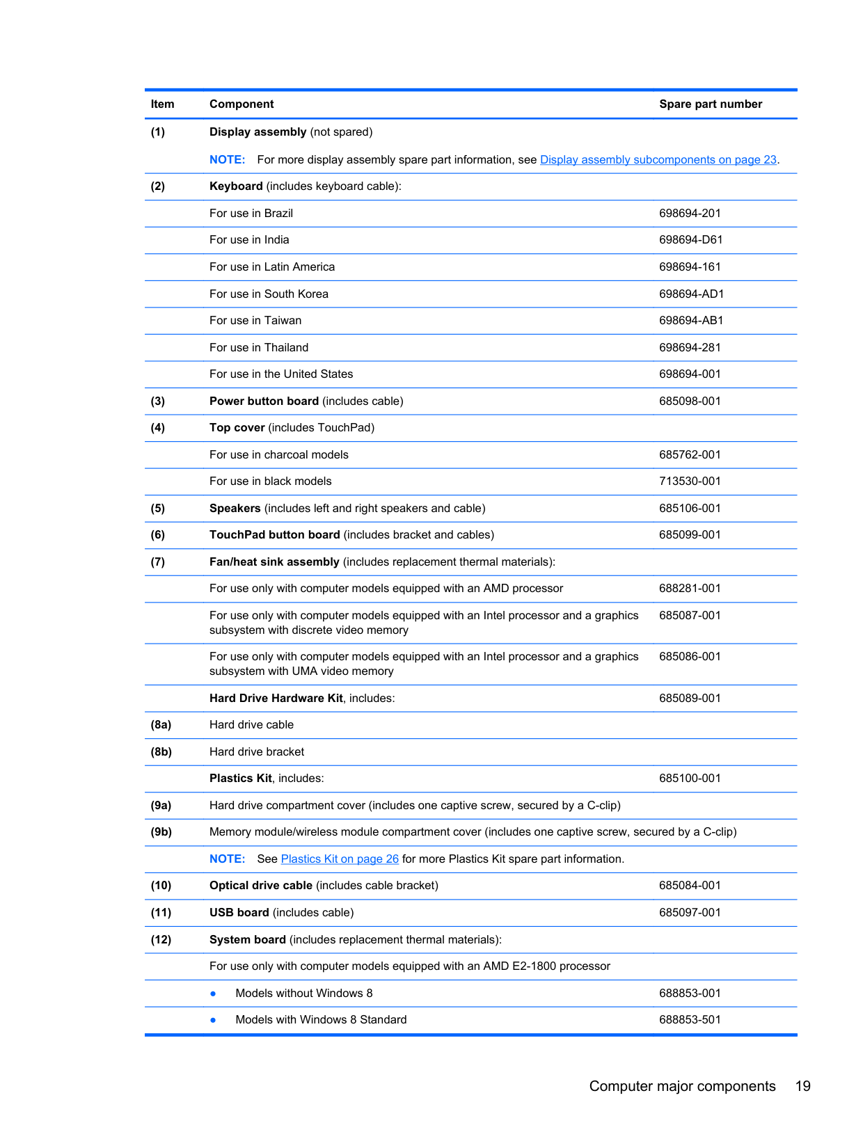
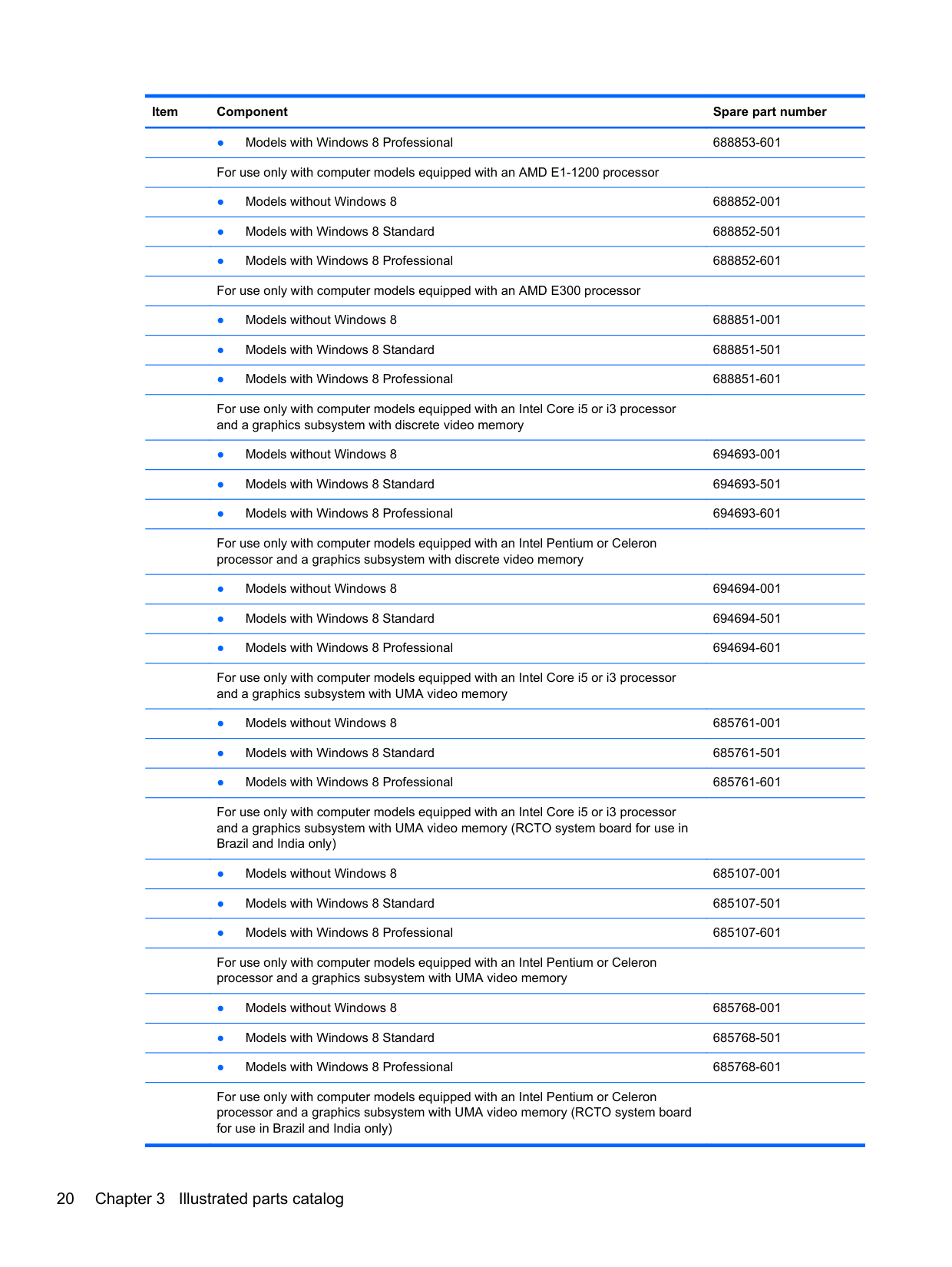
Computer major components

For use only with computer models equipped with an Intel processor and a graphics subsystem with discrete video memory
685087-001
For use only with computer models equipped with an Intel processor and a graphics subsystem with UMA video memory
685086-001
Hard Drive Hardware Kit, includes: 685089-001
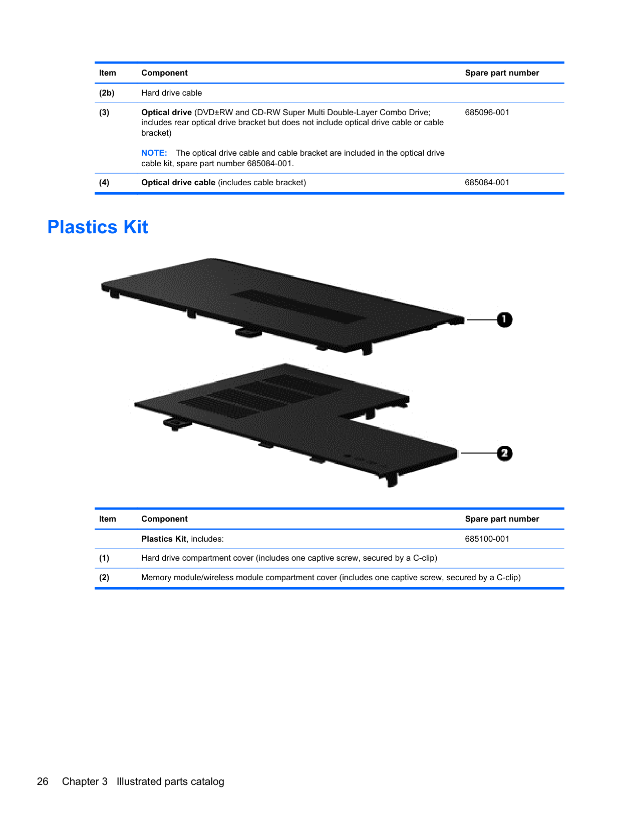
(9a) Hard drive compartment cover (includes one captive screw, secured by a C-clip)
For use only with computer models equipped with an Intel Core i5 or i3 processor and a graphics subsystem with discrete video memory

For use only with computer models equipped with an Intel Pentium or Celeron processor and a graphics subsystem with discrete video memory
For use only with computer models equipped with an Intel Core i5 or i3 processor and a graphics subsystem with UMA video memory
For use only with computer models equipped with an Intel Core i5 or i3 processor and a graphics subsystem with UMA video memory (RCTO system board for use in Brazil and India only)
For use only with computer models equipped with an Intel Pentium or Celeron processor and a graphics subsystem with UMA video memory
For use only with computer models equipped with an Intel Pentium or Celeron processor and a graphics subsystem with UMA video memory (RCTO system board for use in Brazil and India only)
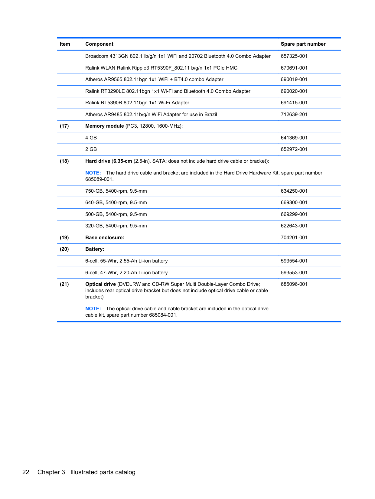
Broadcom 4313GN 802.11b/g/n 1x1 WiFi and 20702 Bluetooth 4.0 Combo Adapter 657325-001 Ralink WLAN Ralink Ripple3 RT5390F_802.11 b/g/n 1x1 PCIe HMC 670691-001 Atheros AR9565 802.11bgn 1x1 WiFi + BT4.0 combo Adapter 690019-001 Ralink RT3290LE 802.11bgn 1x1 Wi-Fi and Bluetooth 4.0 Combo Adapter 690020-001 Ralink RT5390R 802.11bgn 1x1 Wi-Fi Adapter 691415-001 Atheros AR9485 802.11b/g/n WiFi Adapter for use in Brazil 712639-201
NOTE: The hard drive cable and bracket are included in the Hard Drive Hardware Kit, spare part number 685089-001. 750-GB, 5400-rpm, 9.5-mm 634250-001 640-GB, 5400-rpm, 9.5-mm 669300-001 500-GB, 5400-rpm, 9.5-mm 669299-001 320-GB, 5400-rpm, 9.5-mm 622643-001
685096-001
NOTE: The optical drive cable and cable bracket are included in the optical drive cable kit, spare part number 685084-001.
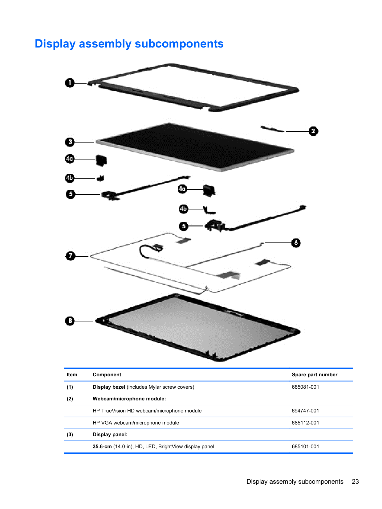
Display assembly subcomponents

######## Item Component Spare part number
Display assembly subcomponents 23
35.6-cm (14.0-in), HD, LED, Anti-glare display panel 694746-001 Hinge covers (includes Mylar screw covers): 685088-001
685083-001
685076-001
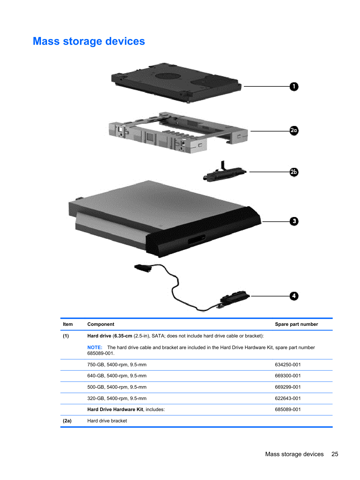
Mass storage devices

######## Item Component Spare part number
NOTE: The hard drive cable and bracket are included in the Hard Drive Hardware Kit, spare part number 685089-001. 750-GB, 5400-rpm, 9.5-mm 634250-001 640-GB, 5400-rpm, 9.5-mm 669300-001 500-GB, 5400-rpm, 9.5-mm 669299-001 320-GB, 5400-rpm, 9.5-mm 622643-001 Hard Drive Hardware Kit, includes: 685089-001
Mass storage devices 25
NOTE: The optical drive cable and cable bracket are included in the optical drive cable kit, spare part number 685084-001.
685096-001
Plastics Kit

Item Component Spare part number Plastics Kit, includes: 685100-001
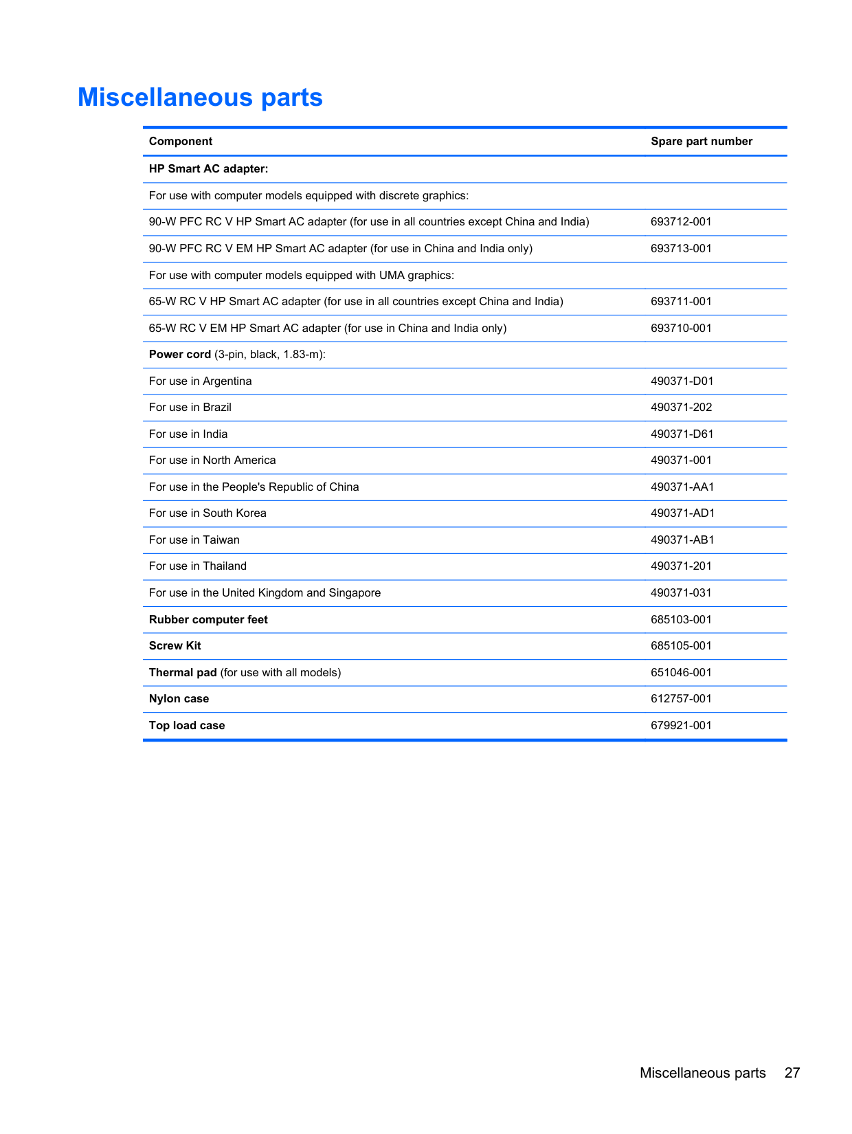
Miscellaneous parts
Component Spare part number HP Smart AC adapter: For use with computer models equipped with discrete graphics: 90-W PFC RC V HP Smart AC adapter (for use in all countries except China and India) 693712-001 90-W PFC RC V EM HP Smart AC adapter (for use in China and India only) 693713-001 For use with computer models equipped with UMA graphics: 65-W RC V HP Smart AC adapter (for use in all countries except China and India) 693711-001 65-W RC V EM HP Smart AC adapter (for use in China and India only) 693710-001 Power cord (3-pin, black, 1.83-m): For use in Argentina 490371-D01 For use in Brazil 490371-202 For use in India 490371-D61 For use in North America 490371-001 For use in the People's Republic of China 490371-AA1 For use in South Korea 490371-AD1 For use in Taiwan 490371-AB1 For use in Thailand 490371-201 For use in the United Kingdom and Singapore 490371-031 Rubber computer feet 685103-001 Screw Kit 685105-001 Thermal pad (for use with all models) 651046-001 Nylon case 612757-001 Top load case 679921-001
Miscellaneous parts 27
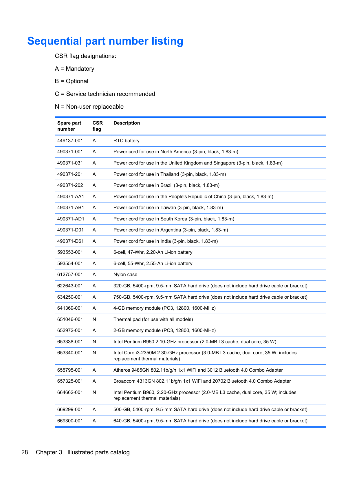
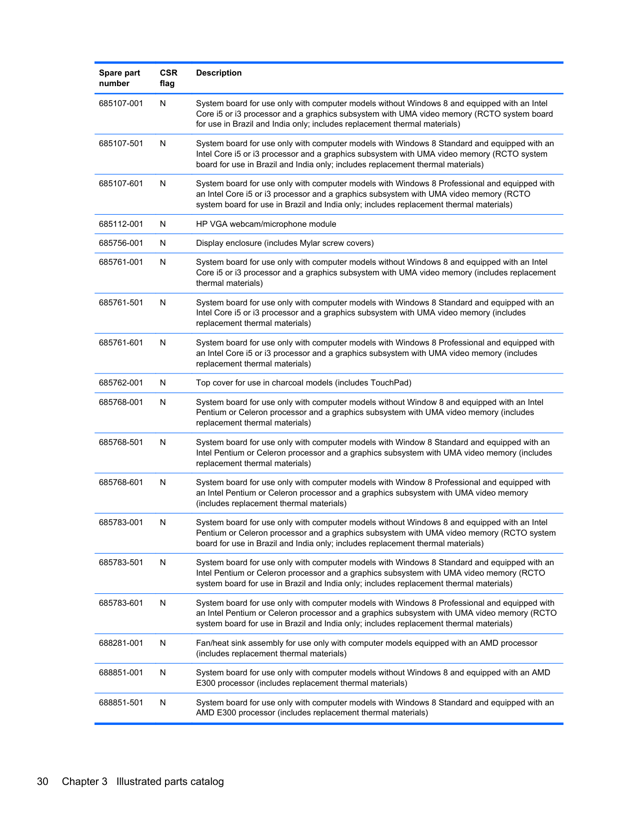
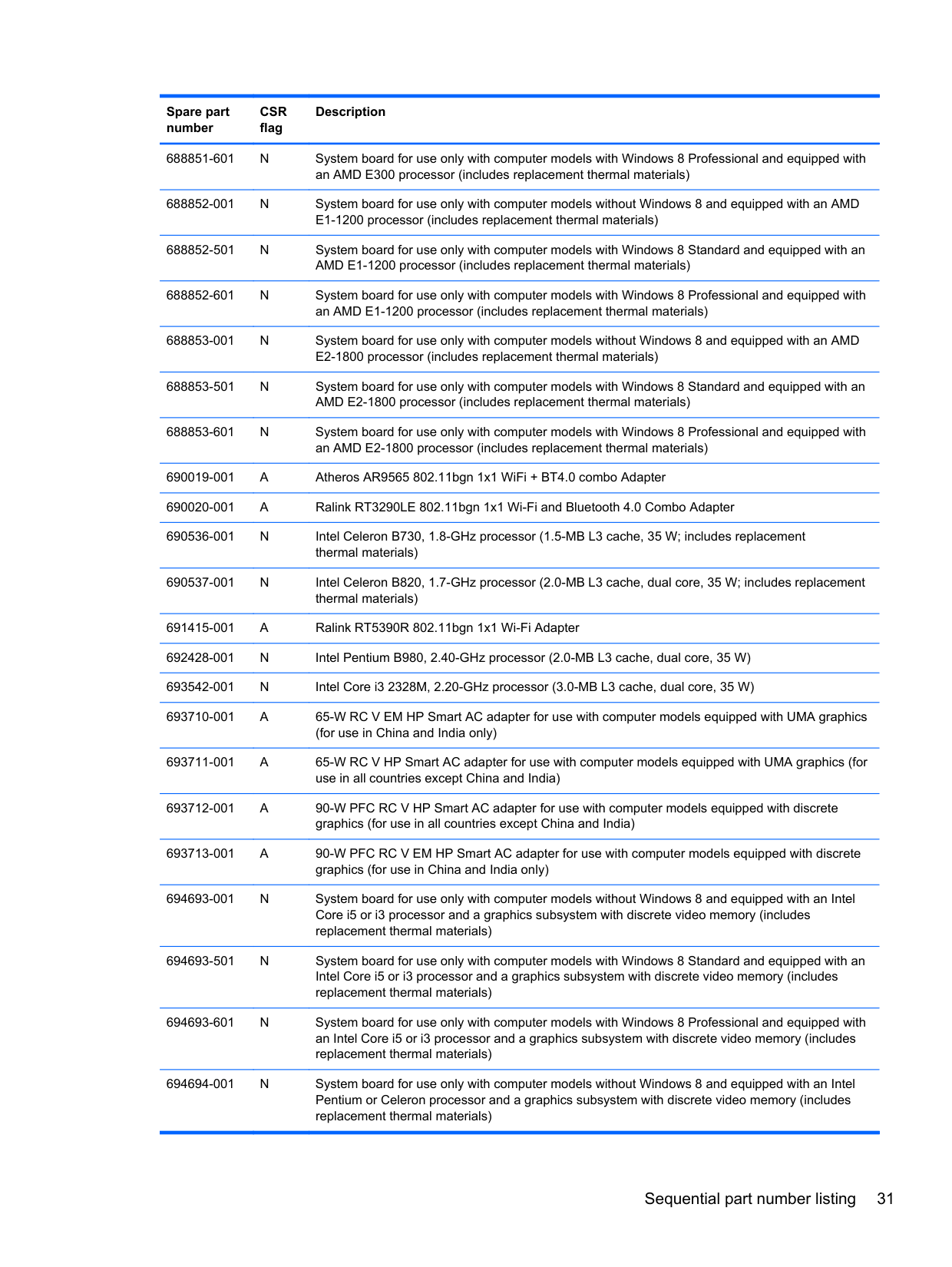
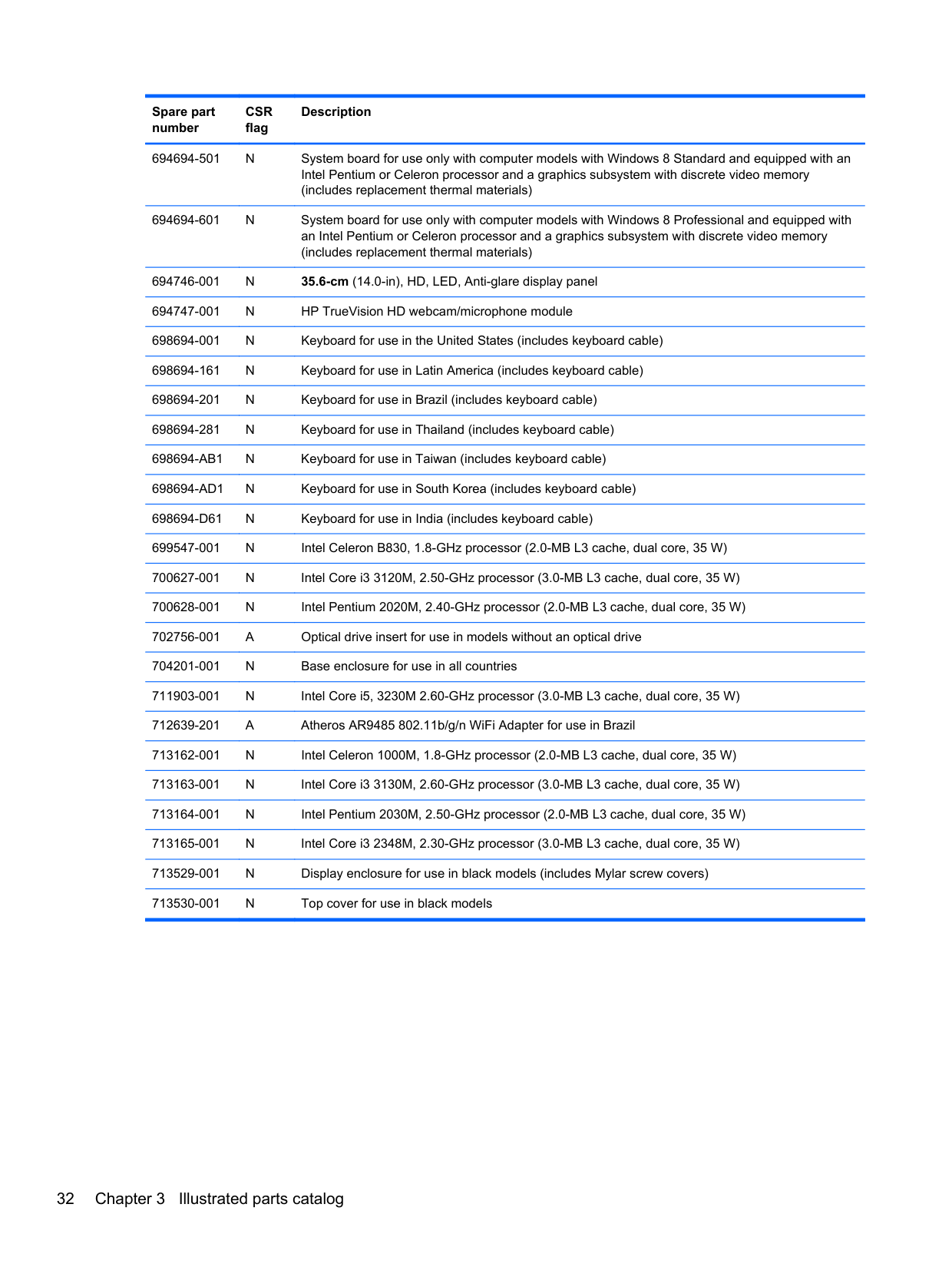
Sequential part number listing
CSR flag designations:
Spare part number
CSR flag
Description
449137-001 A RTC battery 490371-001 A Power cord for use in North America (3-pin, black, 1.83-m) 490371-031 A Power cord for use in the United Kingdom and Singapore (3-pin, black, 1.83-m)
653340-001 N Intel Core i3-2350M 2.30-GHz processor (3.0-MB L3 cache, dual core, 35 W; includes
replacement thermal materials) 655795-001 A Atheros 9485GN 802.11b/g/n 1x1 WiFi and 3012 Bluetooth 4.0 Combo Adapter 657325-001 A Broadcom 4313GN 802.11b/g/n 1x1 WiFi and 20702 Bluetooth 4.0 Combo Adapter 664662-001 N Intel Pentium B960, 2.20-GHz processor (2.0-MB L3 cache, dual core, 35 W; includes
replacement thermal materials)
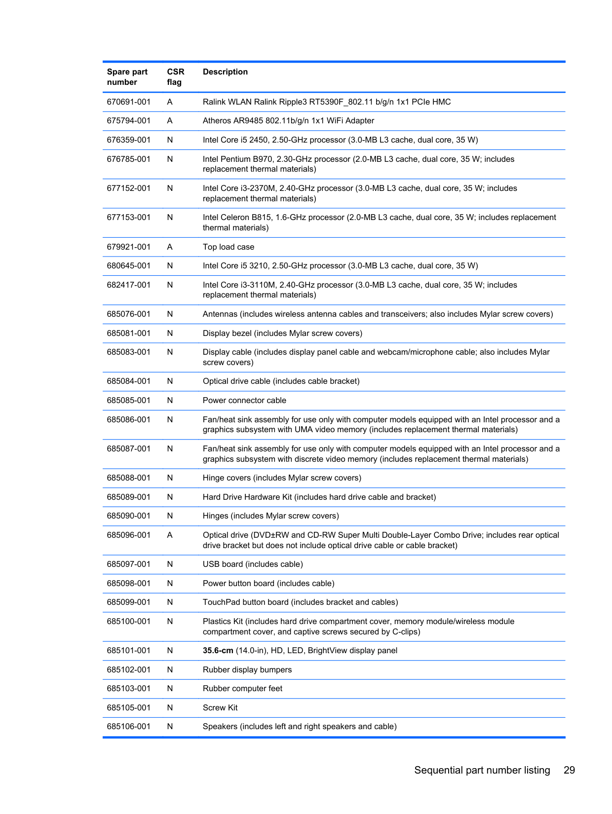
670691-001 A Ralink WLAN Ralink Ripple3 RT5390F_802.11 b/g/n 1x1 PCIe HMC 675794-001 A Atheros AR9485 802.11b/g/n 1x1 WiFi Adapter 676359-001 N Intel Core i5 2450, 2.50-GHz processor (3.0-MB L3 cache, dual core, 35 W) 676785-001 N Intel Pentium B970, 2.30-GHz processor (2.0-MB L3 cache, dual core, 35 W; includes
replacement thermal materials) 677152-001 N Intel Core i3-2370M, 2.40-GHz processor (3.0-MB L3 cache, dual core, 35 W; includes replacement thermal materials) 677153-001 N Intel Celeron B815, 1.6-GHz processor (2.0-MB L3 cache, dual core, 35 W; includes replacement
thermal materials) 679921-001 A Top load case 680645-001 N Intel Core i5 3210, 2.50-GHz processor (3.0-MB L3 cache, dual core, 35 W) 682417-001 N Intel Core i3-3110M, 2.40-GHz processor (3.0-MB L3 cache, dual core, 35 W; includes
replacement thermal materials) 685076-001 N Antennas (includes wireless antenna cables and transceivers; also includes Mylar screw covers) 685081-001 N Display bezel (includes Mylar screw covers)
685107-501 N System board for use only with computer models with Windows 8 Standard and equipped with an Intel Core i5 or i3 processor and a graphics subsystem with UMA video memory (RCTO system board for use in Brazil and India only; includes replacement thermal materials)
685107-601 N System board for use only with computer models with Windows 8 Professional and equipped with an Intel Core i5 or i3 processor and a graphics subsystem with UMA video memory (RCTO system board for use in Brazil and India only; includes replacement thermal materials)
685112-001 N HP VGA webcam/microphone module 685756-001 N Display enclosure (includes Mylar screw covers) 685761-001 N System board for use only with computer models without Windows 8 and equipped with an Intel
Core i5 or i3 processor and a graphics subsystem with UMA video memory (includes replacement thermal materials)
685761-501 N System board for use only with computer models with Windows 8 Standard and equipped with an Intel Core i5 or i3 processor and a graphics subsystem with UMA video memory (includes replacement thermal materials)
685768-001 N System board for use only with computer models without Window 8 and equipped with an Intel Pentium or Celeron processor and a graphics subsystem with UMA video memory (includes replacement thermal materials)
685768-501 N System board for use only with computer models with Window 8 Standard and equipped with an Intel Pentium or Celeron processor and a graphics subsystem with UMA video memory (includes replacement thermal materials)
685768-601 N System board for use only with computer models with Window 8 Professional and equipped with an Intel Pentium or Celeron processor and a graphics subsystem with UMA video memory (includes replacement thermal materials)
685783-001 N System board for use only with computer models without Windows 8 and equipped with an Intel Pentium or Celeron processor and a graphics subsystem with UMA video memory (RCTO system board for use in Brazil and India only; includes replacement thermal materials)
685783-501 N System board for use only with computer models with Windows 8 Standard and equipped with an Intel Pentium or Celeron processor and a graphics subsystem with UMA video memory (RCTO system board for use in Brazil and India only; includes replacement thermal materials)
685783-601 N System board for use only with computer models with Windows 8 Professional and equipped with an Intel Pentium or Celeron processor and a graphics subsystem with UMA video memory (RCTO system board for use in Brazil and India only; includes replacement thermal materials)
688281-001 N Fan/heat sink assembly for use only with computer models equipped with an AMD processor (includes replacement thermal materials)
688852-501 N System board for use only with computer models with Windows 8 Standard and equipped with an AMD E1-1200 processor (includes replacement thermal materials)
688852-601 N System board for use only with computer models with Windows 8 Professional and equipped with
an AMD E1-1200 processor (includes replacement thermal materials) 688853-001 N System board for use only with computer models without Windows 8 and equipped with an AMD
E2-1800 processor (includes replacement thermal materials) 688853-501 N System board for use only with computer models with Windows 8 Standard and equipped with an AMD E2-1800 processor (includes replacement thermal materials)
691415-001 A Ralink RT5390R 802.11bgn 1x1 Wi-Fi Adapter 692428-001 N Intel Pentium B980, 2.40-GHz processor (2.0-MB L3 cache, dual core, 35 W) 693542-001 N Intel Core i3 2328M, 2.20-GHz processor (3.0-MB L3 cache, dual core, 35 W)
4 Removal and replacement procedures
Preliminary replacement requirements
#### Tools required
You will need the following tools to complete the removal and replacement procedures:
#### Service considerations
The following sections include some of the considerations that you must keep in mind during disassembly and assembly procedures.
NOTE: As you remove each subassembly from the computer, place the subassembly (and all accompanying screws) away from the work area to prevent damage.
| | |---|
##### Plastic parts
CAUTION: Using excessive force during disassembly and reassembly can damage plastic parts. Use care when handling the plastic parts. Apply pressure only at the points designated in the maintenance instructions.
##### Cables and connectors
CAUTION: When servicing the computer, be sure that cables are placed in their proper locations during the reassembly process. Improper cable placement can damage the computer. Cables must be handled with extreme care to avoid damage. Apply only the tension required to unseat or seat the cables during removal and insertion. Handle cables by the connector whenever possible. In all cases, avoid bending, twisting, or tearing cables. Be sure that cables are routed in such a way that they cannot be caught or snagged by parts being removed or replaced. Handle flex cables with extreme care; these cables tear easily.
##### Drive handling
CAUTION: Drives are fragile components that must be handled with care. To prevent damage to the computer, damage to a drive, or loss of information, observe these precautions: Before removing or inserting a hard drive, shut down the computer. If you are unsure whether the computer is off or in Hibernation, turn the computer on, and then shut it down through the operating system. Before handling a drive, be sure that you are discharged of static electricity. While handling a drive, avoid touching the connector. Before removing a diskette drive or optical drive, be sure that a diskette or disc is not in the drive and be sure that the optical drive tray is closed. Handle drives on surfaces covered with at least one inch of shock-proof foam. Avoid dropping drives from any height onto any surface. After removing a hard drive, an optical drive, or a diskette drive, place it in a static-proof bag. Avoid exposing an internal hard drive to products that have magnetic fields, such as monitors or speakers. Avoid exposing a drive to temperature extremes or liquids. If a drive must be mailed, place the drive in a bubble pack mailer or other suitable form of protective packaging and label the package “FRAGILE.”
#### Grounding guidelines Electrostatic discharge damage
Electronic components are sensitive to electrostatic discharge (ESD). Circuitry design and structure determine the degree of sensitivity. Networks built into many integrated circuits provide some protection, but in many cases, ESD contains enough power to alter device parameters or melt silicon junctions.
A discharge of static electricity from a finger or other conductor can destroy static-sensitive devices or microcircuitry. Even if the spark is neither felt nor heard, damage may have occurred.
An electronic device exposed to ESD may not be affected at all and can work perfectly throughout a normal cycle. Or the device may function normally for a while, then degrade in the internal layers, reducing its life expectancy.
CAUTION: To prevent damage to the computer when you are removing or installing internal components, observe these precautions: Keep components in their electrostatic-safe containers until you are ready to install them. Before touching an electronic component, discharge static electricity by using the guidelines described in this section. Avoid touching pins, leads, and circuitry. Handle electronic components as little as possible. If you remove a component, place it in an electrostatic-safe container. The following table shows how humidity affects the electrostatic voltage levels generated by different activities.
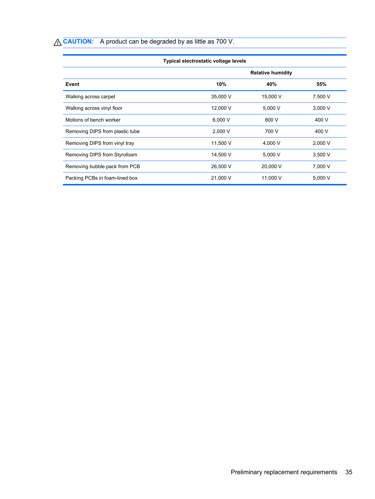
CAUTION: A product can be degraded by as little as 700 V.
Typical electrostatic voltage levels
Relative humidity Event 10% 40% 55% Walking across carpet 35,000 V 15,000 V 7,500 V Walking across vinyl floor 12,000 V 5,000 V 3,000 V Motions of bench worker 6,000 V 800 V 400 V Removing DIPS from plastic tube 2,000 V 700 V 400 V Removing DIPS from vinyl tray 11,500 V 4,000 V 2,000 V Removing DIPS from Styrofoam 14,500 V 5,000 V 3,500 V Removing bubble pack from PCB 26,500 V 20,000 V 7,000 V Packing PCBs in foam-lined box 21,000 V 11,000 V 5,000 V
###### Packaging and transporting guidelines
Follow these grounding guidelines when packaging and transporting equipment:
###### Workstation guidelines
Follow these grounding workstation guidelines:
###### Equipment guidelines
Grounding equipment must include either a wrist strap or a foot strap at a grounded workstation.
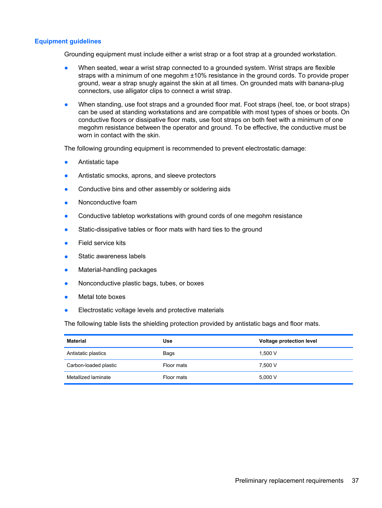
Material Use Voltage protection level
Antistatic plastics Bags 1,500 V Carbon-loaded plastic Floor mats 7,500 V Metallized laminate Floor mats 5,000 V
Component replacement procedures This chapter provides removal and replacement procedures. There are as many as 66 screws that must be removed, replaced, or loosened when servicing the computer. Make special note of each screw's size and location during removal and replacement.
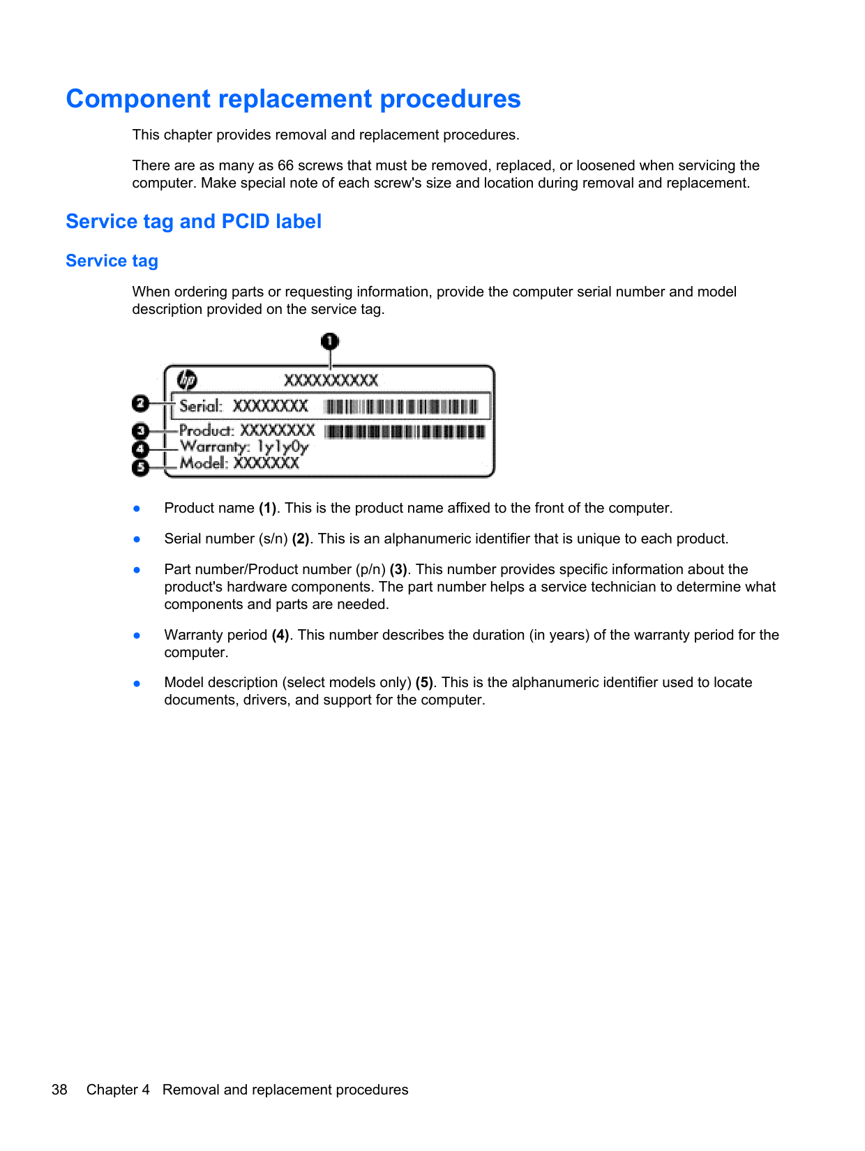
#### Service tag and PCID label Service tag
When ordering parts or requesting information, provide the computer serial number and model description provided on the service tag.

##### PCID label
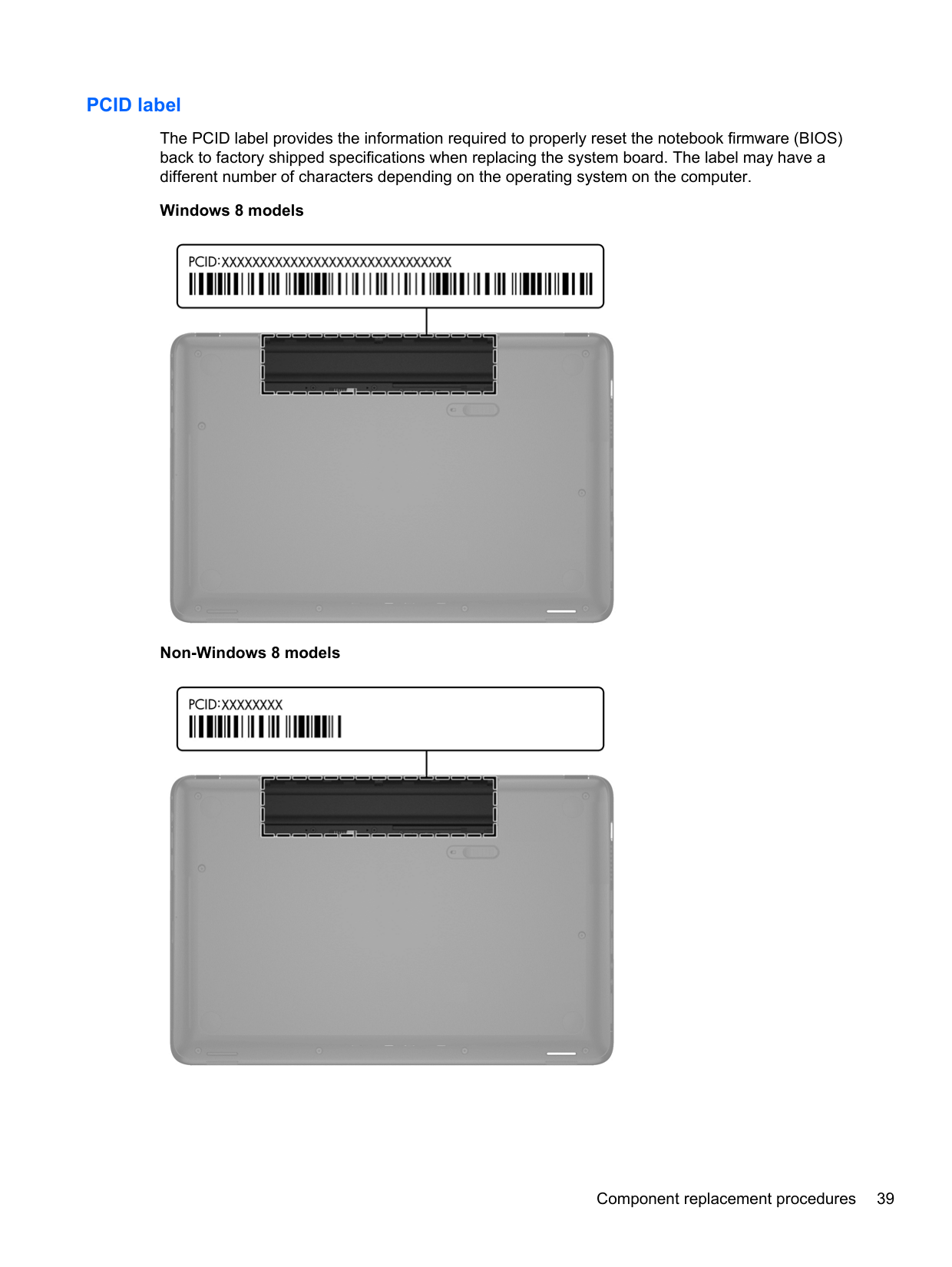
The PCID label provides the information required to properly reset the notebook firmware (BIOS) back to factory shipped specifications when replacing the system board. The label may have a different number of characters depending on the operating system on the computer.
Windows 8 models

Non-Windows 8 models

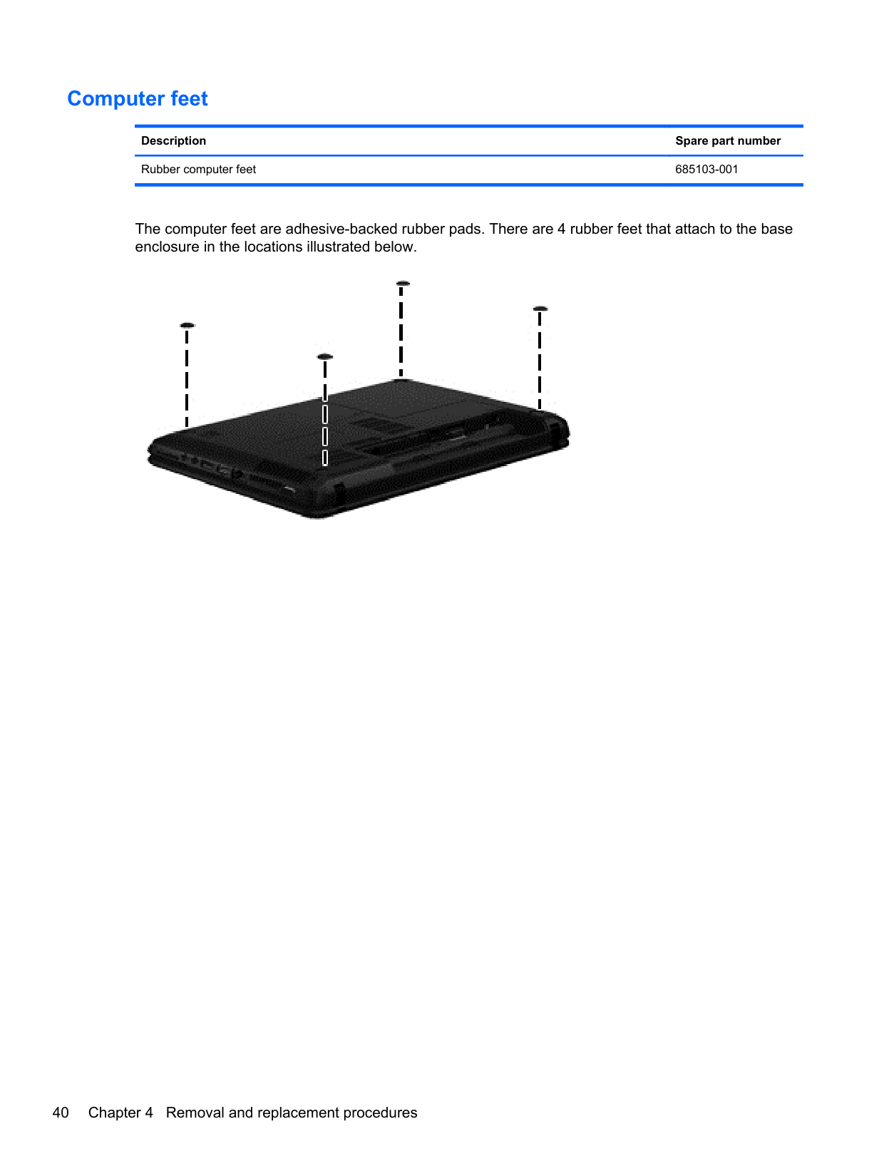
#### Computer feet
Description Spare part number Rubber computer feet 685103-001
The computer feet are adhesive-backed rubber pads. There are 4 rubber feet that attach to the base enclosure in the locations illustrated below.

#### Battery
######## Description Spare part number
6-cell, 55-Whr, 2.55-Ah Li-ion battery 593554-001 6-cell, 47-Whr, 2.20-Ah Li-ion battery 593553-001
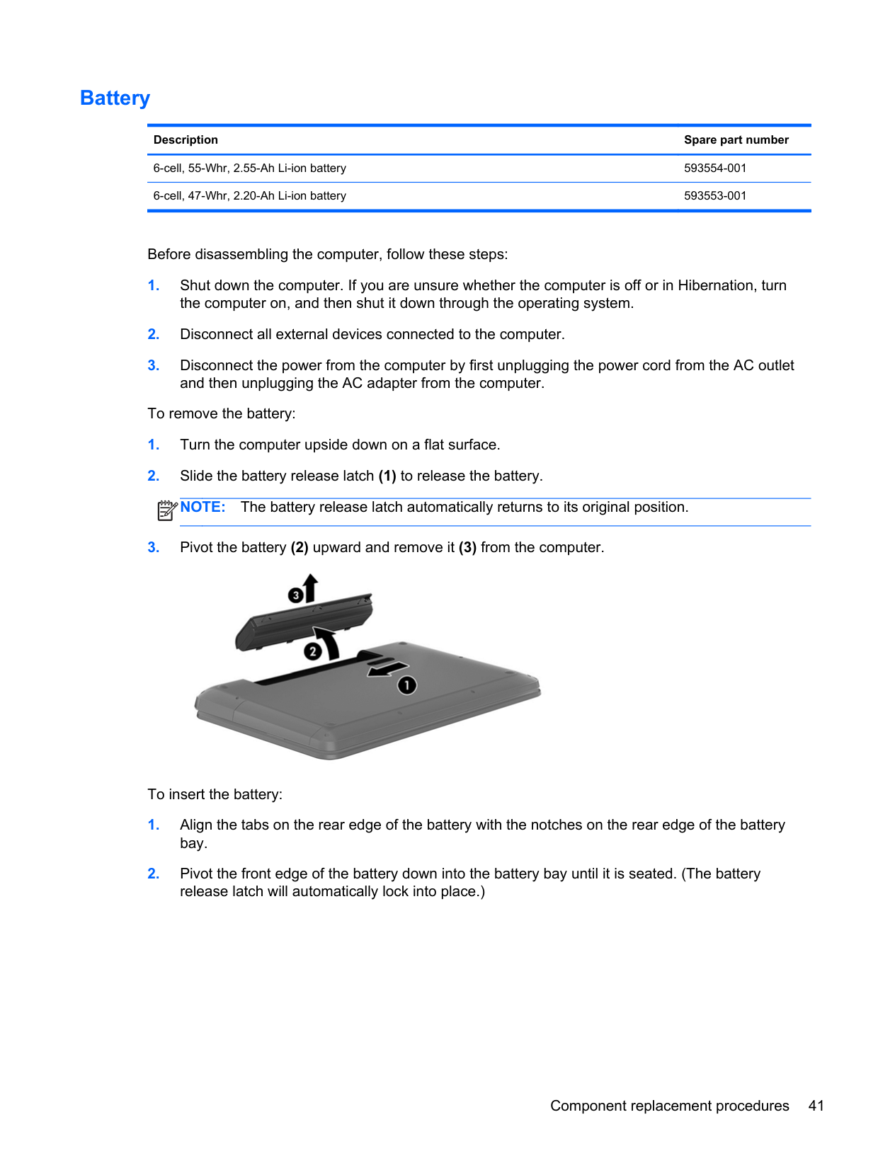
Before disassembling the computer, follow these steps:
To remove the battery:
| | |---|

To insert the battery:
#### Display subcomponents (bezel, webcam, panel)
This section describes removing display subcomponents that do not require that you remove the entire display assembly from the computer. You can remove the display bezel, webcam/microphone module, and display panel while the display assembly is still attached to the computer.
To remove the remaining display subcomponents, including the hinge covers, hinges, cable, antennas, and enclosure, you must remove the entire display assembly from the computer. See Display assembly on page 77 for more information about removing the display assembly in its entirety.
Description Spare part number 35.6-cm (14.0-in), HD, LED, BrightView display panel 685101-001 35.6-cm (14.0-in), HD, LED, Anti-glare display panel 694746-001 Display bezel (includes Mylar screw covers) 685081-001 HP TrueVision HD webcam/microphone module 694747-001 HP VGA webcam/microphone module 685112-001 Rubber display bumpers 685102-001
Before removing the display bezel, webcam/microphone module, and display panel while the display assembly is still attached to the computer, follow these steps:
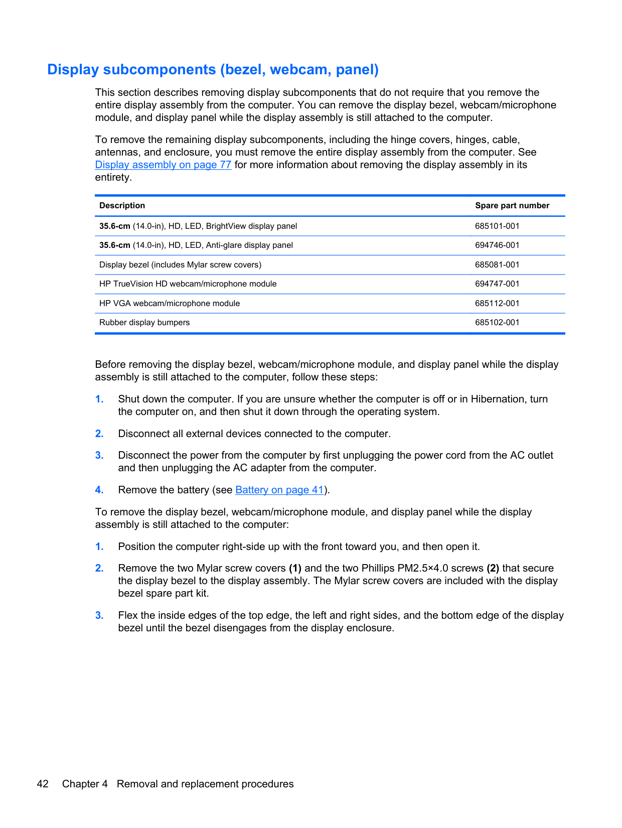
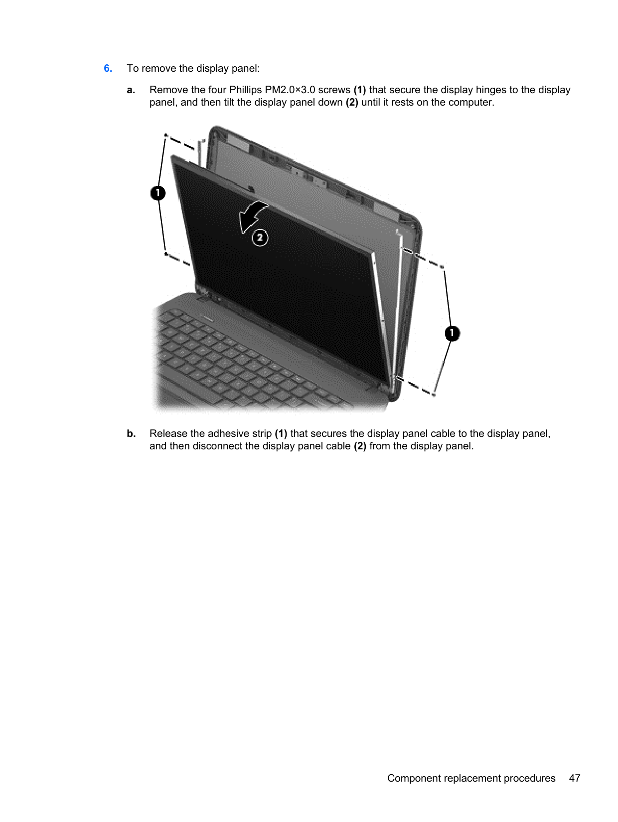
To remove the display bezel, webcam/microphone module, and display panel while the display assembly is still attached to the computer:
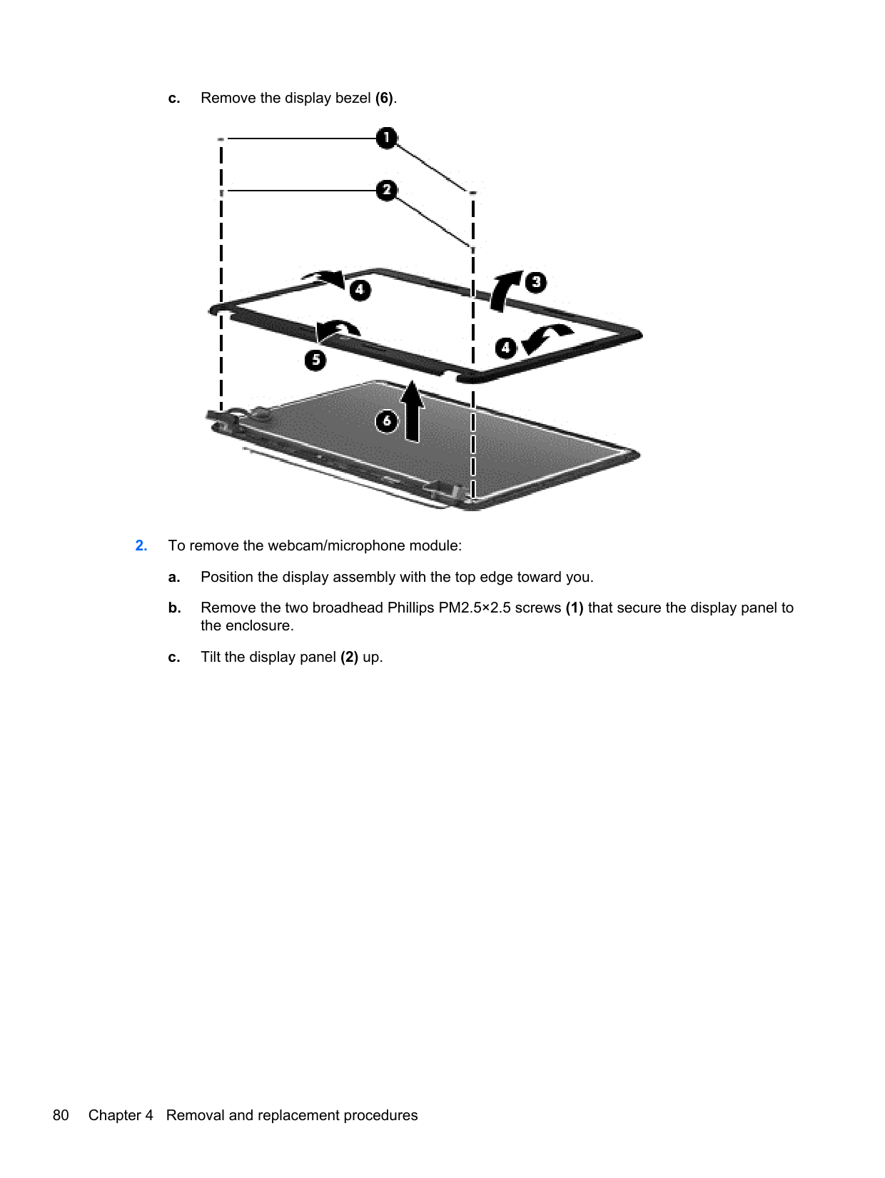
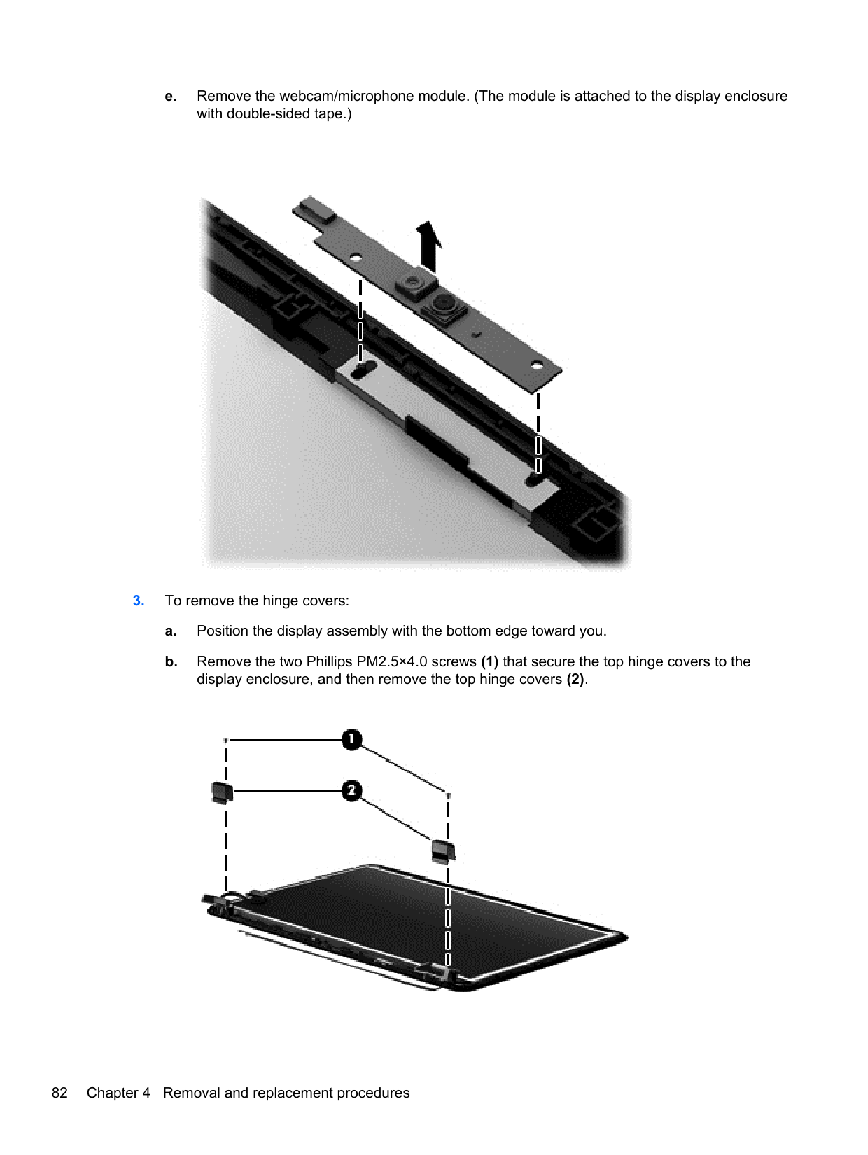
####### 4. Remove the display bezel (3).


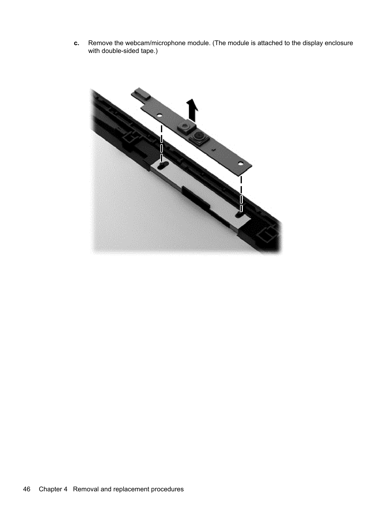
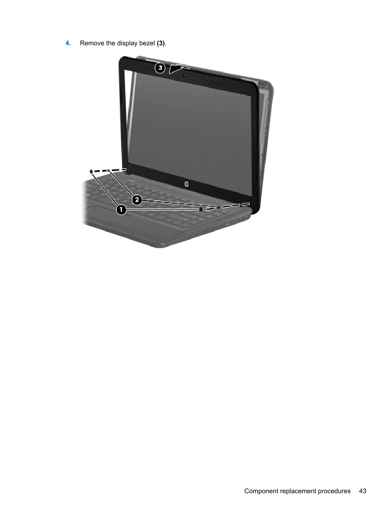
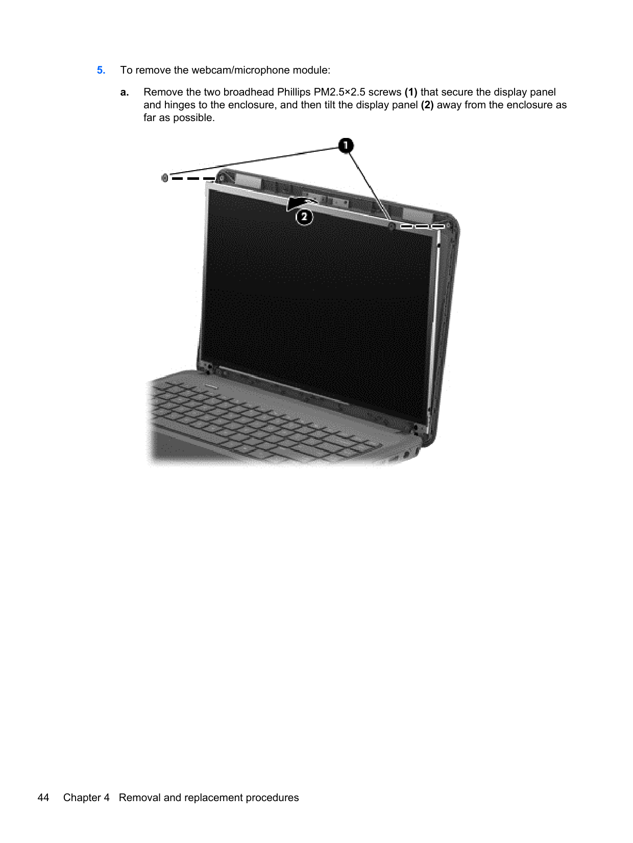
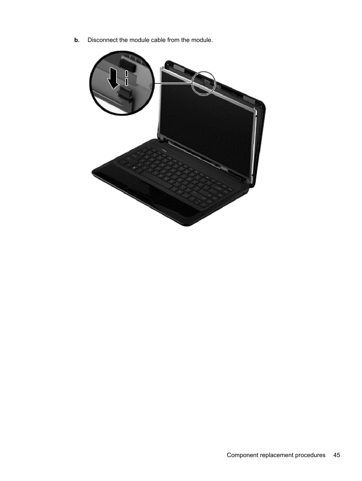
####### b. Disconnect the module cable from the module.

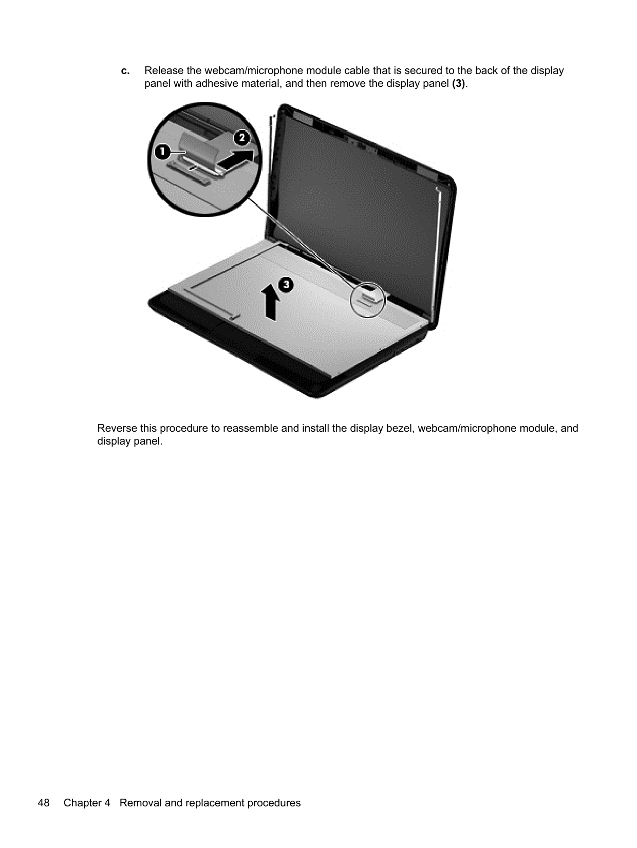
####### c. Remove the webcam/microphone module. (The module is attached to the display enclosurewith double-sided tape.)


Reverse this procedure to reassemble and install the display bezel, webcam/microphone module, and display panel.
#### WLAN module
######## Description Spare part number
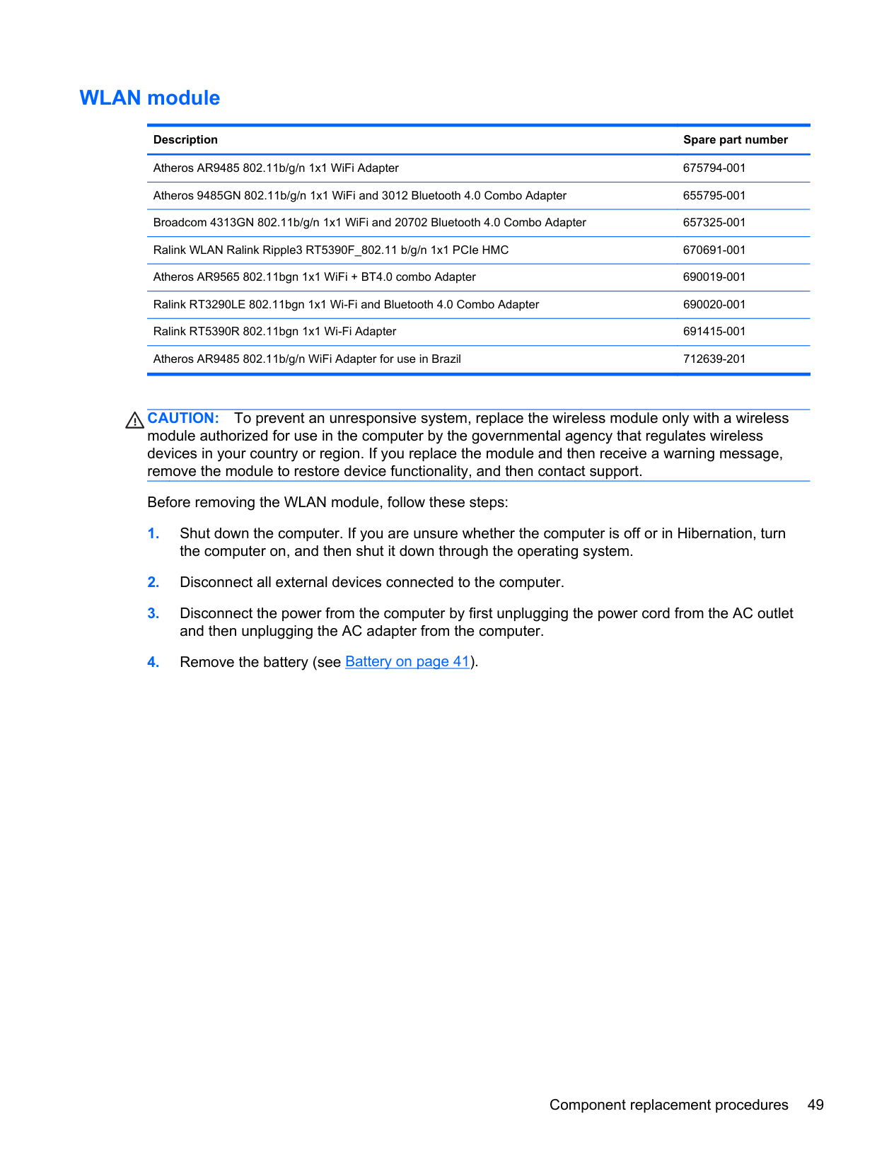
Atheros AR9485 802.11b/g/n 1x1 WiFi Adapter 675794-001 Atheros 9485GN 802.11b/g/n 1x1 WiFi and 3012 Bluetooth 4.0 Combo Adapter 655795-001 Broadcom 4313GN 802.11b/g/n 1x1 WiFi and 20702 Bluetooth 4.0 Combo Adapter 657325-001 Ralink WLAN Ralink Ripple3 RT5390F_802.11 b/g/n 1x1 PCIe HMC 670691-001 Atheros AR9565 802.11bgn 1x1 WiFi + BT4.0 combo Adapter 690019-001 Ralink RT3290LE 802.11bgn 1x1 Wi-Fi and Bluetooth 4.0 Combo Adapter 690020-001 Ralink RT5390R 802.11bgn 1x1 Wi-Fi Adapter 691415-001 Atheros AR9485 802.11b/g/n WiFi Adapter for use in Brazil 712639-201
CAUTION: To prevent an unresponsive system, replace the wireless module only with a wireless module authorized for use in the computer by the governmental agency that regulates wireless devices in your country or region. If you replace the module and then receive a warning message, remove the module to restore device functionality, and then contact support.
Before removing the WLAN module, follow these steps:
To remove the WLAN module:

| | |---|
NOTE: The #1 WLAN antenna cable is connected to the WLAN module Main terminal. The #2 WLAN antenna cable is connected to the WLAN module Aux terminal.

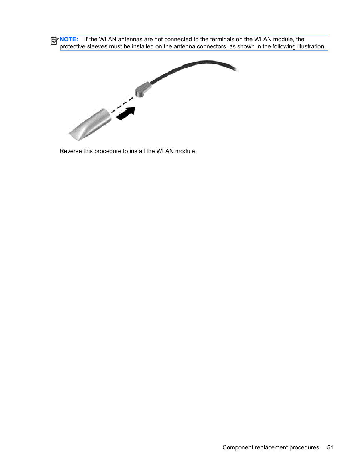
NOTE: If the WLAN antennas are not connected to the terminals on the WLAN module, the protective sleeves must be installed on the antenna connectors, as shown in the following illustration.
| | |---|

Reverse this procedure to install the WLAN module.
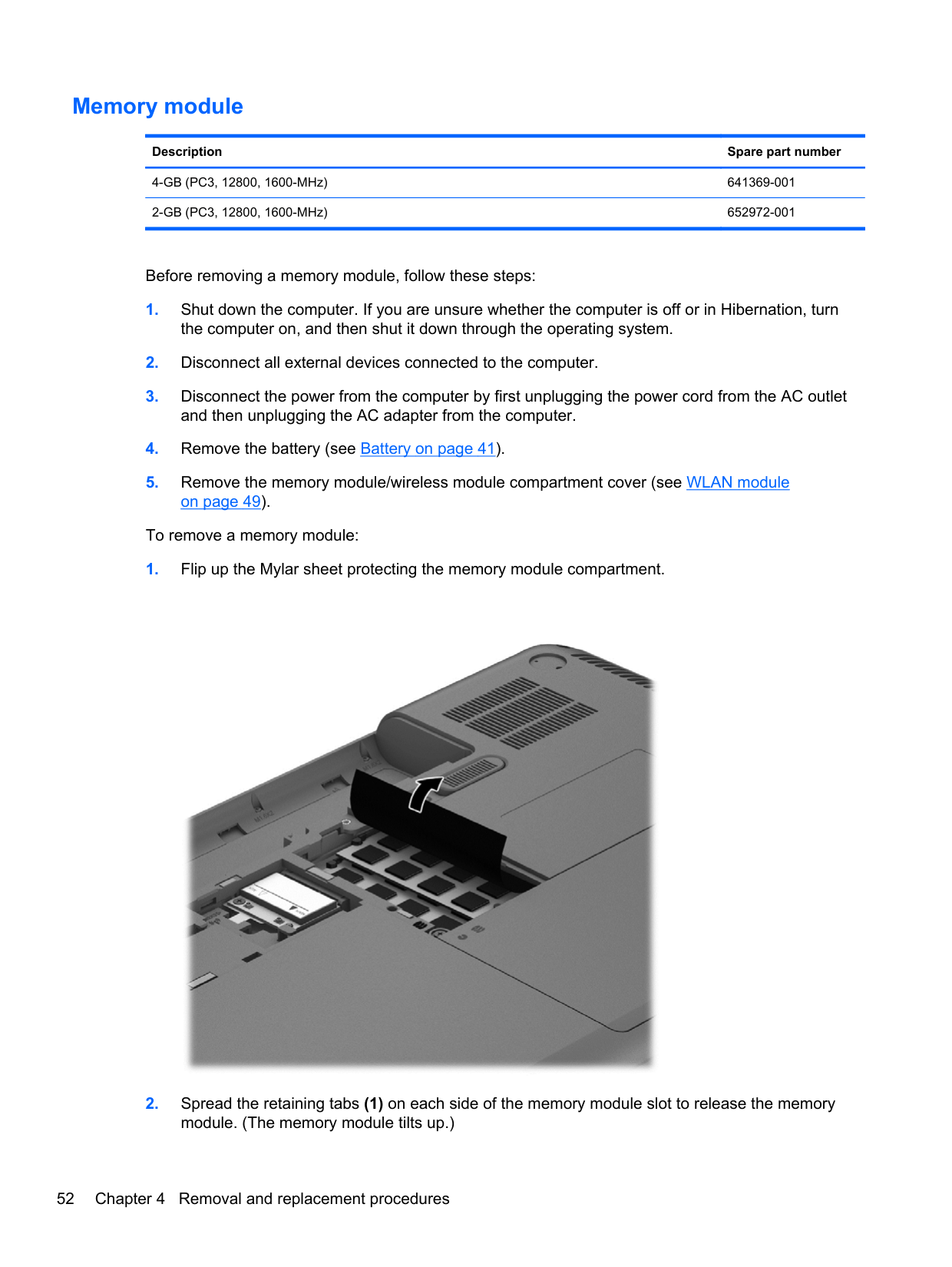
#### Memory module
######## Description Spare part number
4-GB (PC3, 12800, 1600-MHz) 641369-001 2-GB (PC3, 12800, 1600-MHz) 652972-001
Before removing a memory module, follow these steps:
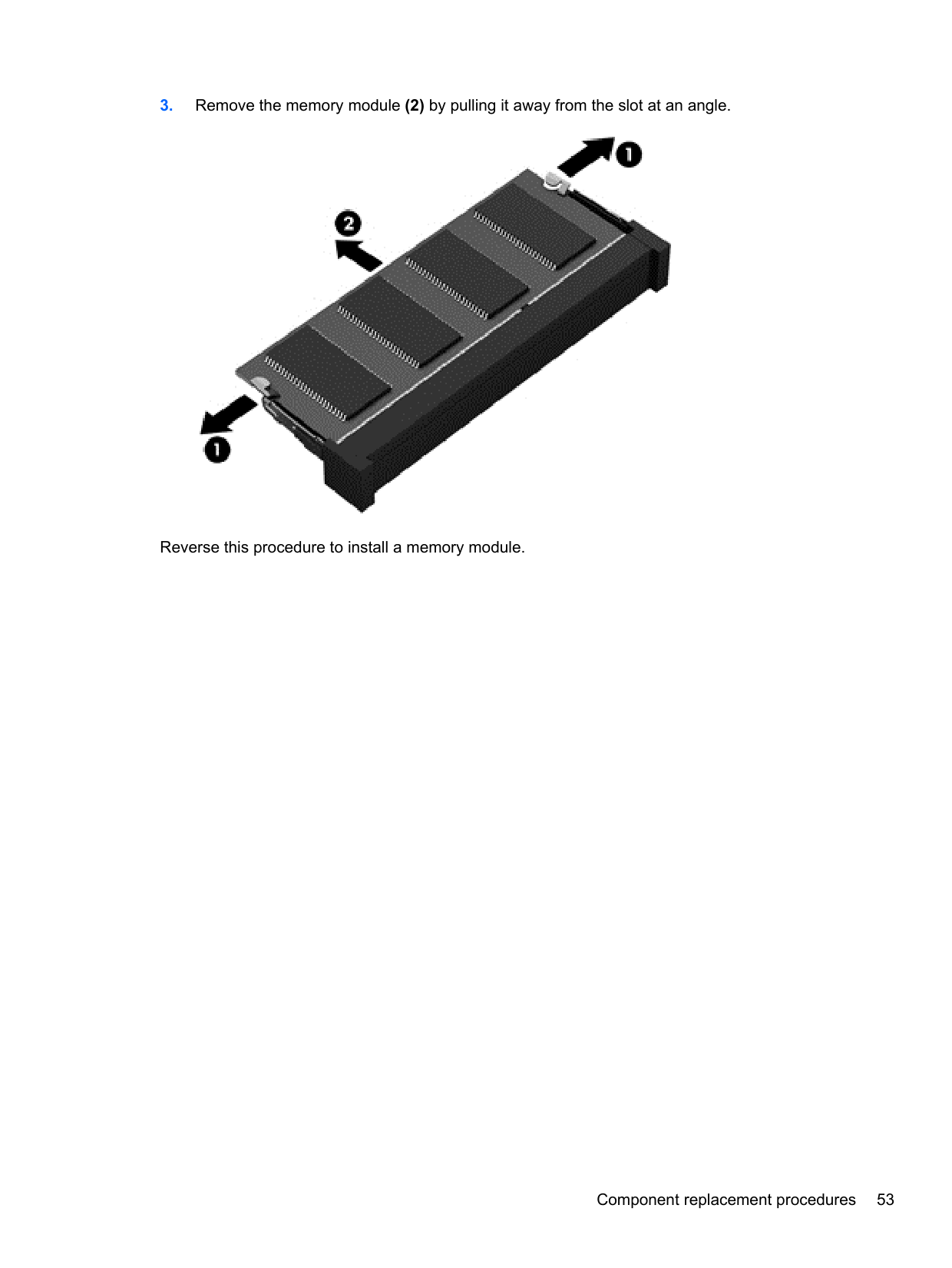
To remove a memory module:


Reverse this procedure to install a memory module.
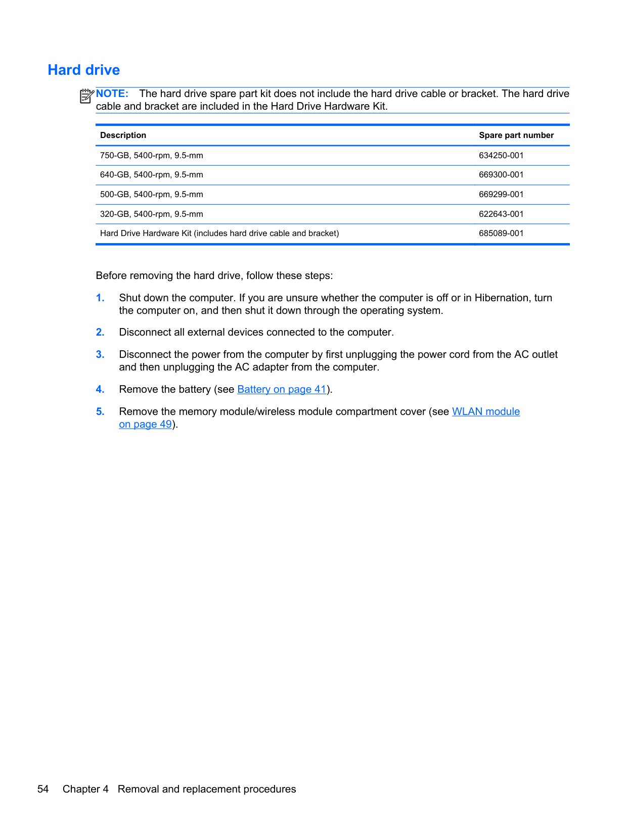
#### Hard drive
NOTE: The hard drive spare part kit does not include the hard drive cable or bracket. The hard drive cable and bracket are included in the Hard Drive Hardware Kit.
| | |---|
Description Spare part number
750-GB, 5400-rpm, 9.5-mm 634250-001 640-GB, 5400-rpm, 9.5-mm 669300-001 500-GB, 5400-rpm, 9.5-mm 669299-001 320-GB, 5400-rpm, 9.5-mm 622643-001 Hard Drive Hardware Kit (includes hard drive cable and bracket) 685089-001
Before removing the hard drive, follow these steps:
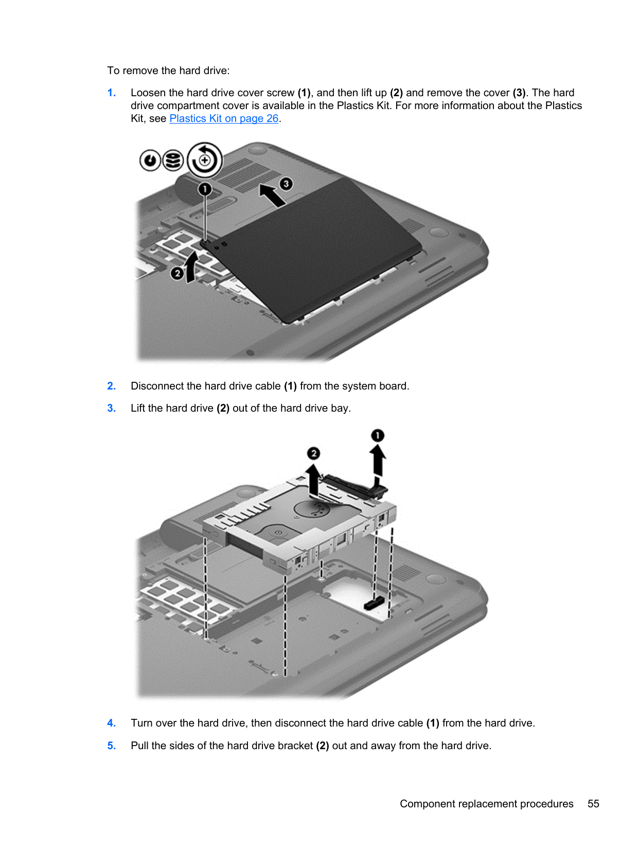
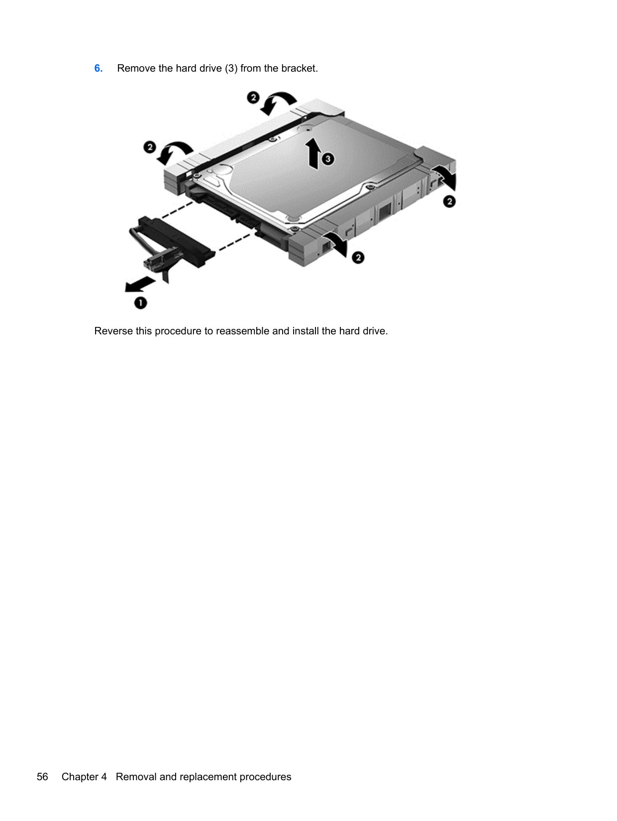
To remove the hard drive:


Reverse this procedure to reassemble and install the hard drive.
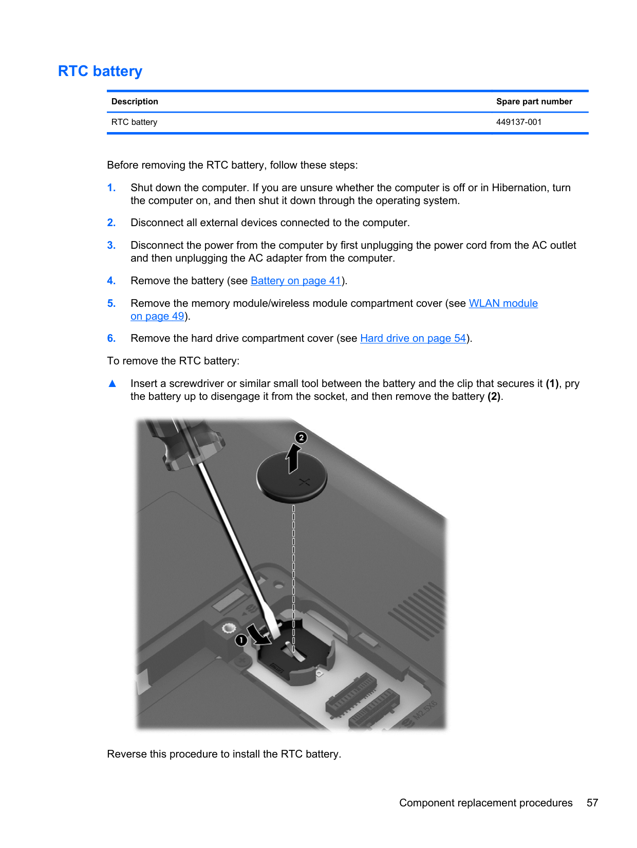
#### RTC battery
Description Spare part number RTC battery 449137-001
Before removing the RTC battery, follow these steps:
▲ Insert a screwdriver or similar small tool between the battery and the clip that secures it (1), pry
the battery up to disengage it from the socket, and then remove the battery (2).

Reverse this procedure to install the RTC battery.
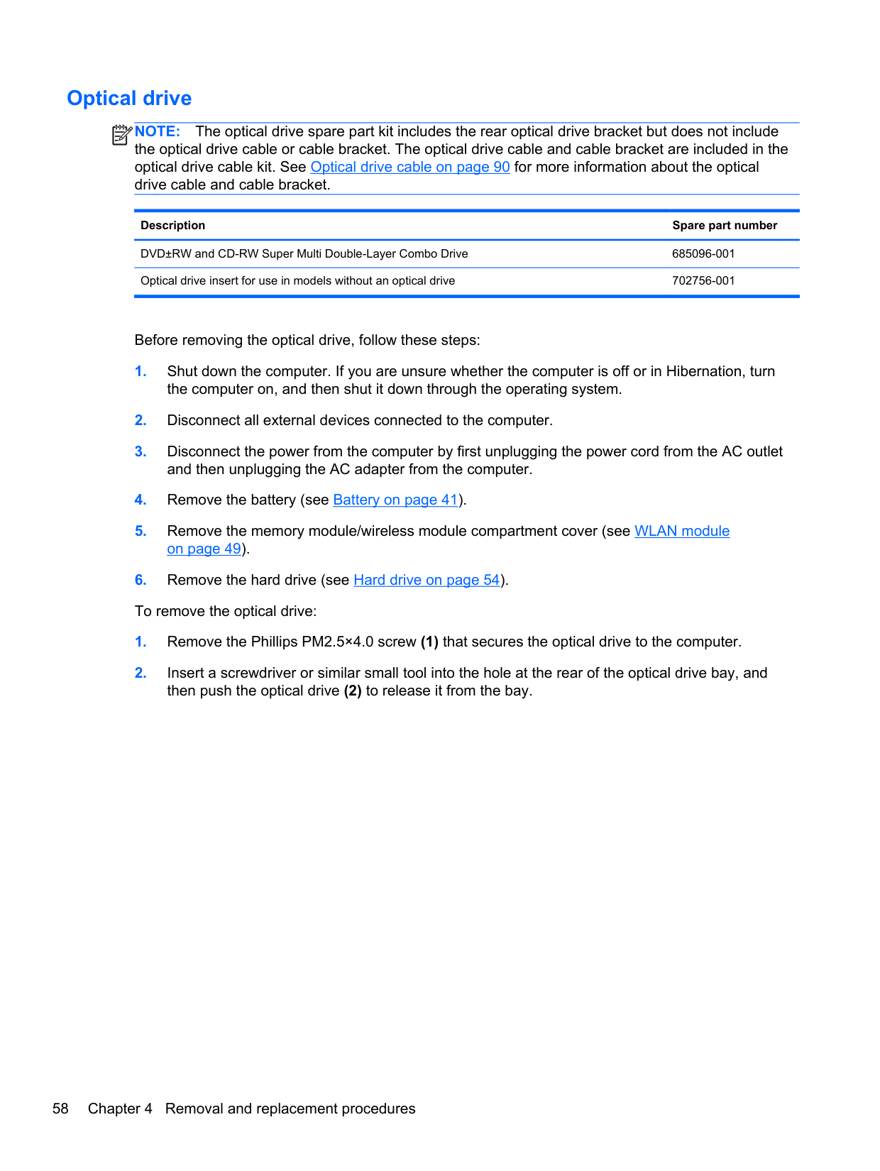
#### Optical drive
NOTE: The optical drive spare part kit includes the rear optical drive bracket but does not include the optical drive cable or cable bracket. The optical drive cable and cable bracket are included in the optical drive cable kit. See Optical drive cable on page 90 for more information about the optical drive cable and cable bracket.
| | |---|
Description Spare part number
DVD±RW and CD-RW Super Multi Double-Layer Combo Drive 685096-001 Optical drive insert for use in models without an optical drive 702756-001
Before removing the optical drive, follow these steps:


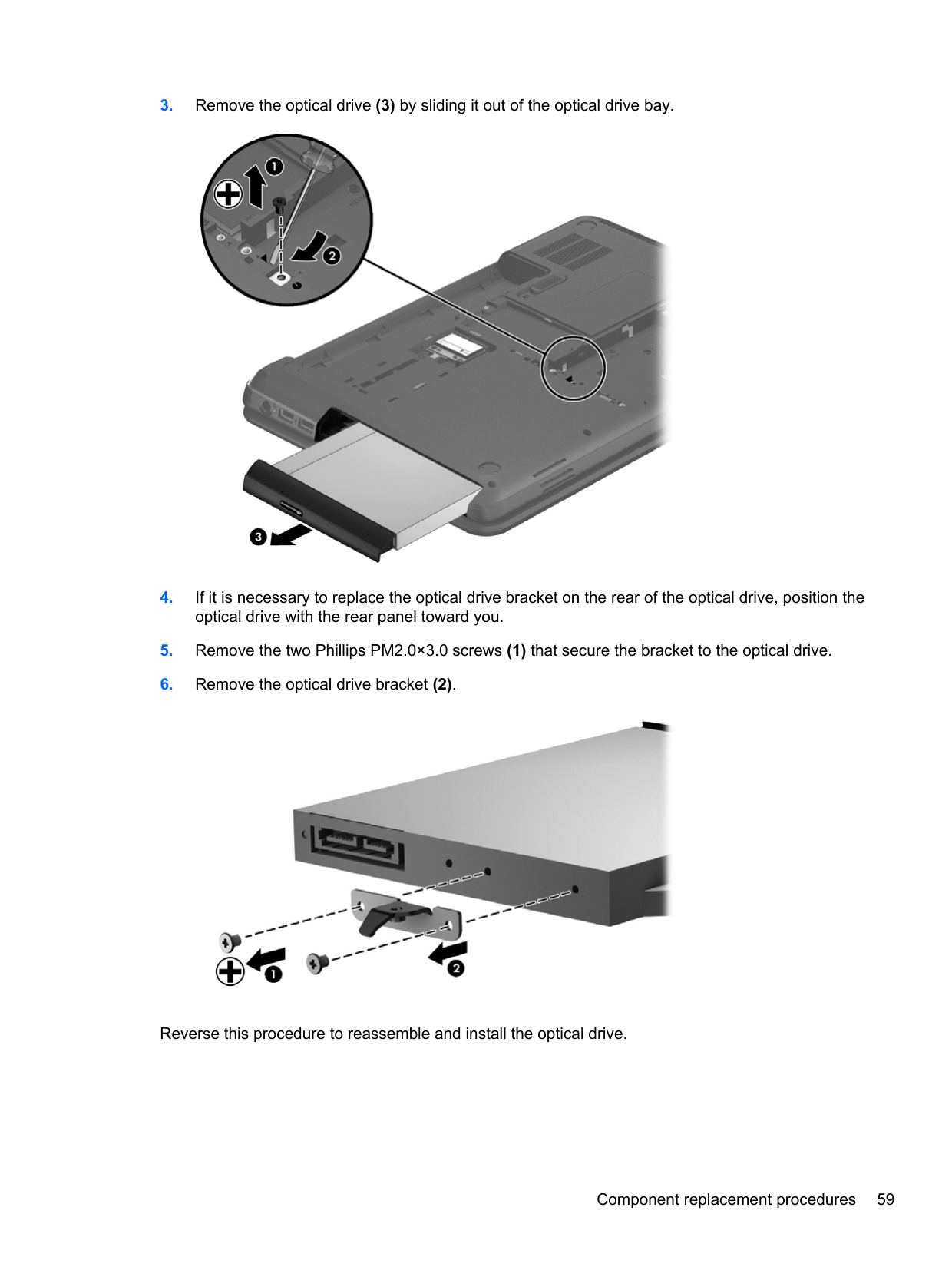
Reverse this procedure to reassemble and install the optical drive.
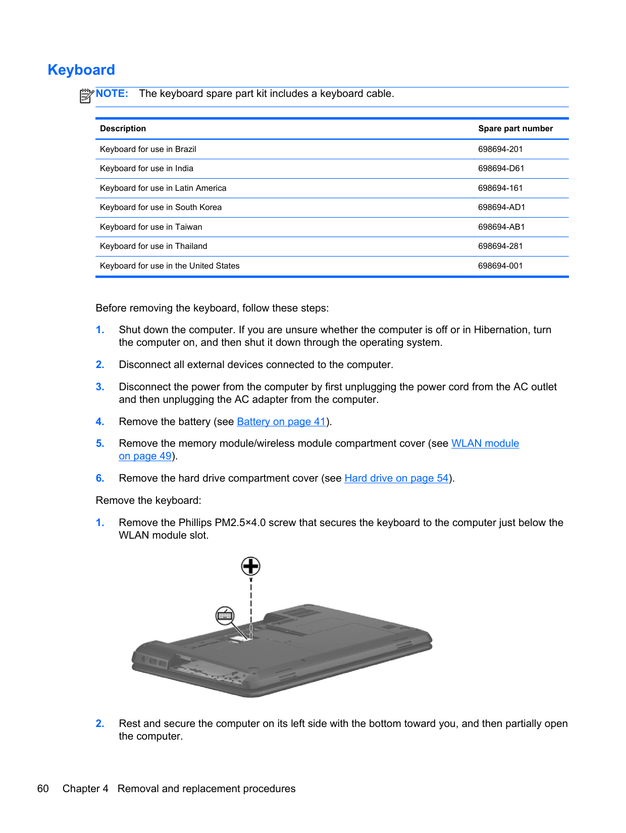
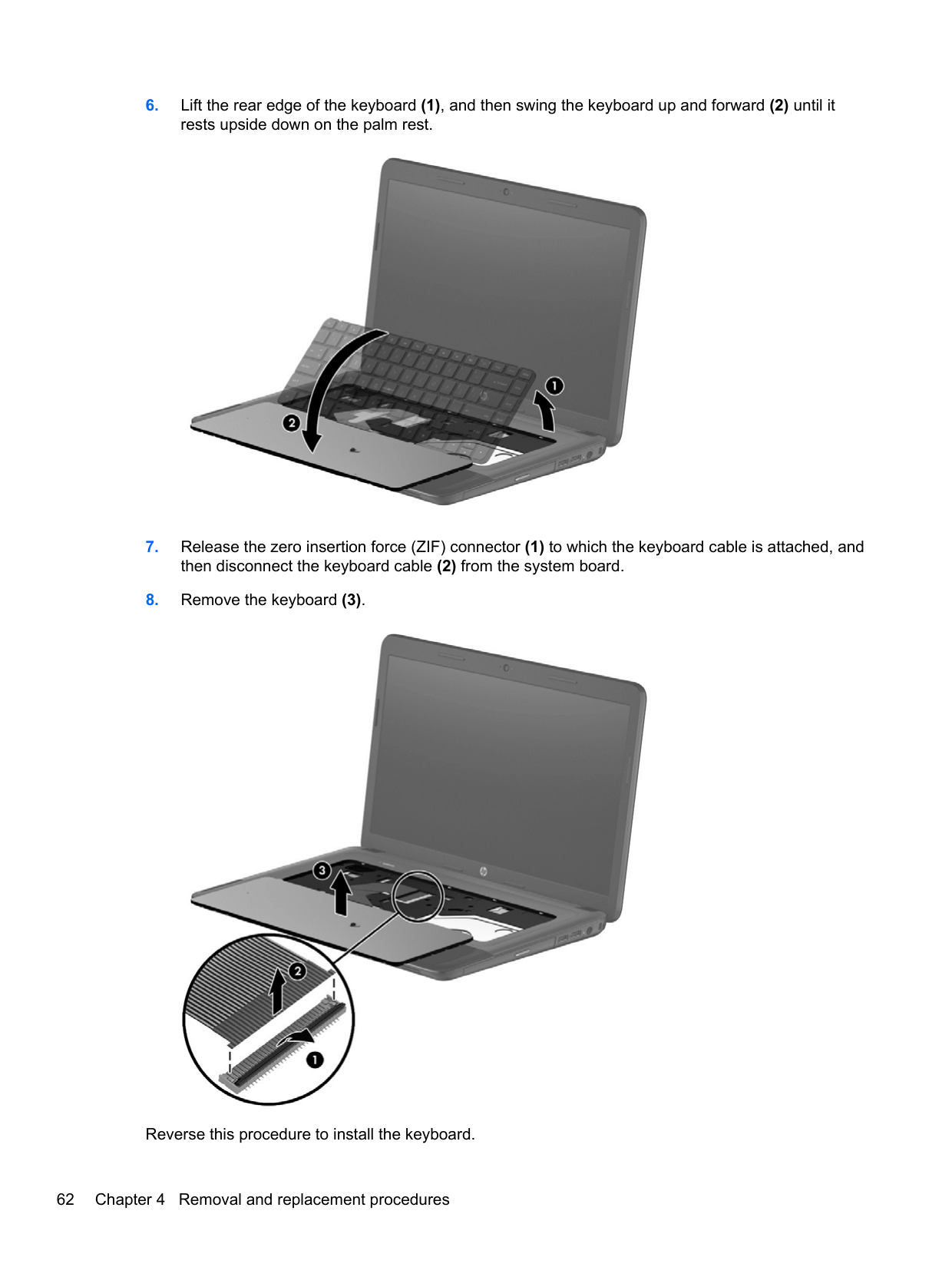
#### Keyboard
NOTE: The keyboard spare part kit includes a keyboard cable.
| | |---|
Description Spare part number Keyboard for use in Brazil 698694-201 Keyboard for use in India 698694-D61 Keyboard for use in Latin America 698694-161 Keyboard for use in South Korea 698694-AD1 Keyboard for use in Taiwan 698694-AB1 Keyboard for use in Thailand 698694-281 Keyboard for use in the United States 698694-001
Before removing the keyboard, follow these steps:


Reverse this procedure to install the keyboard.
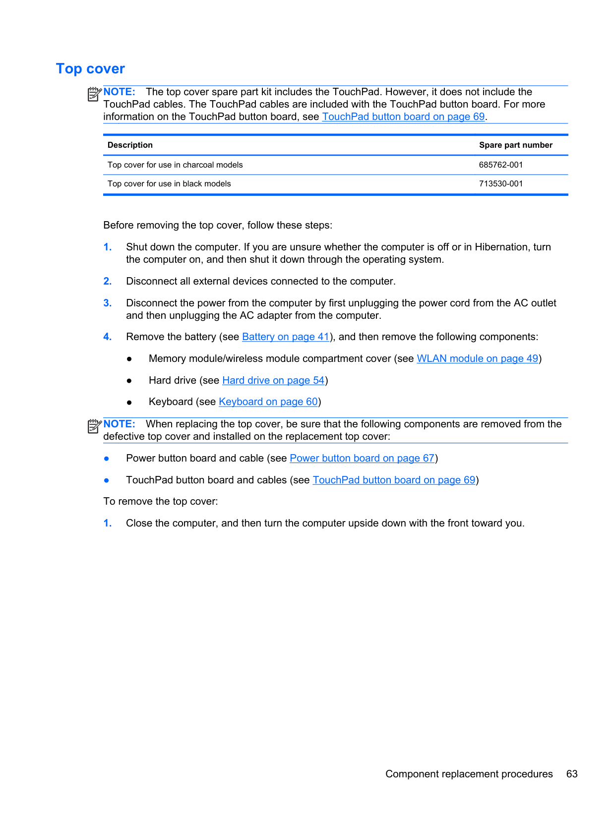
#### Top cover
NOTE: The top cover spare part kit includes the TouchPad. However, it does not include the TouchPad cables. The TouchPad cables are included with the TouchPad button board. For more information on the TouchPad button board, see TouchPad button board on page 69.
| | |---|
Description Spare part number
Top cover for use in charcoal models 685762-001 Top cover for use in black models 713530-001
Before removing the top cover, follow these steps:
NOTE: When replacing the top cover, be sure that the following components are removed from the defective top cover and installed on the replacement top cover:
| | |---|
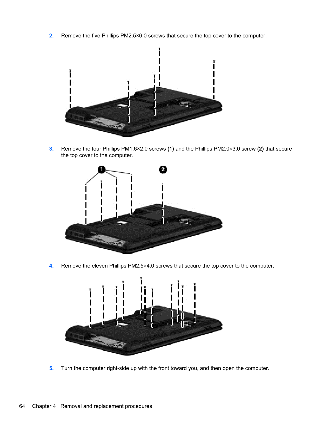
####### 2. Remove the five Phillips PM2.5×6.0 screws that secure the top cover to the computer.

####### 3. Remove the four Phillips PM1.6×2.0 screws (1) and the Phillips PM2.0×3.0 screw (2) that securethe top cover to the computer.

####### 4. Remove the eleven Phillips PM2.5×4.0 screws that secure the top cover to the computer.

####### 5. Turn the computer right-side up with the front toward you, and then open the computer.
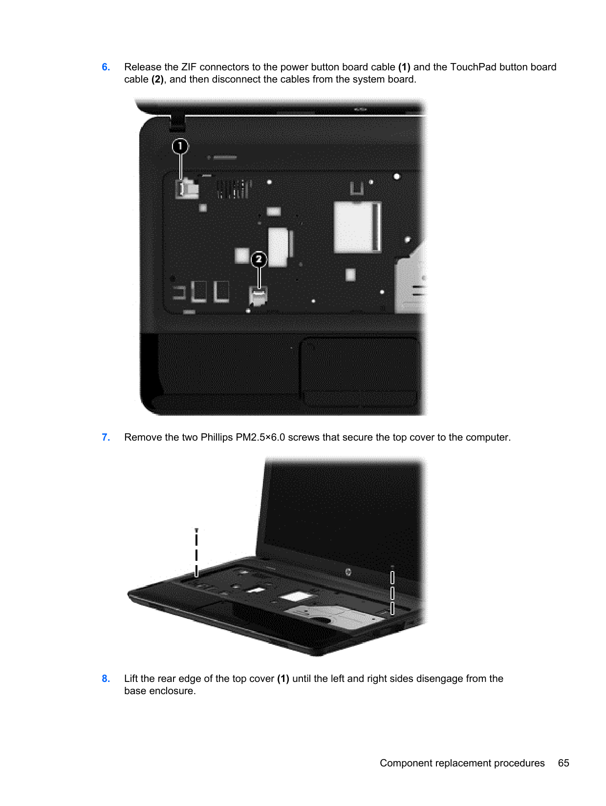
####### 6. Release the ZIF connectors to the power button board cable (1) and the TouchPad button boardcable (2), and then disconnect the cables from the system board.

####### 7. Remove the two Phillips PM2.5×6.0 screws that secure the top cover to the computer.

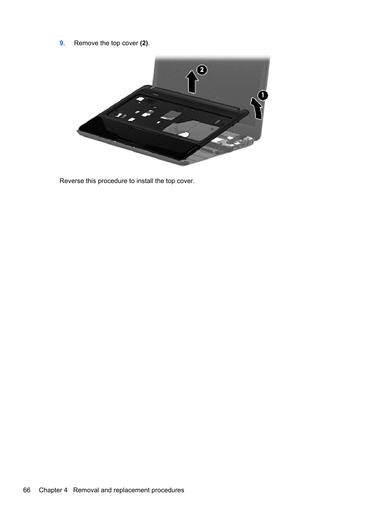
####### 8. Lift the rear edge of the top cover (1) until the left and right sides disengage from thebase enclosure.

Reverse this procedure to install the top cover.
#### Power button board
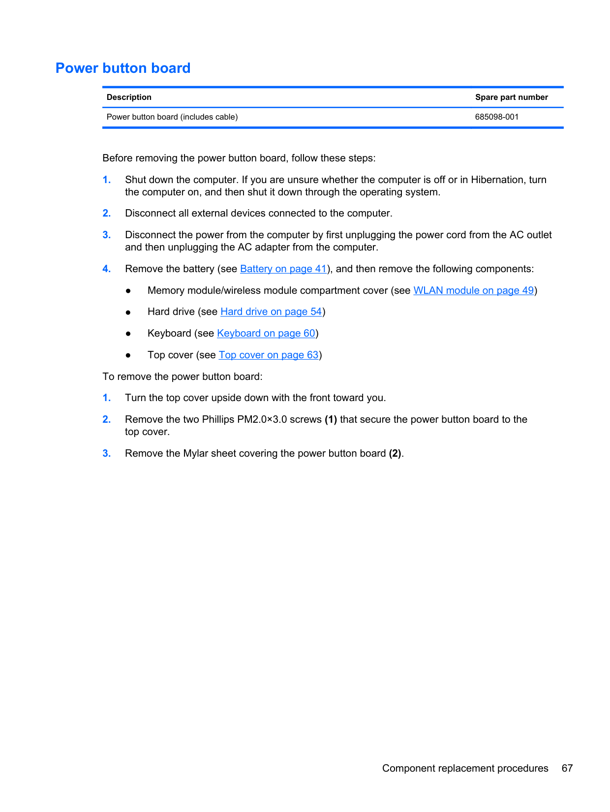
Description Spare part number Power button board (includes cable) 685098-001
Before removing the power button board, follow these steps:
To remove the power button board:

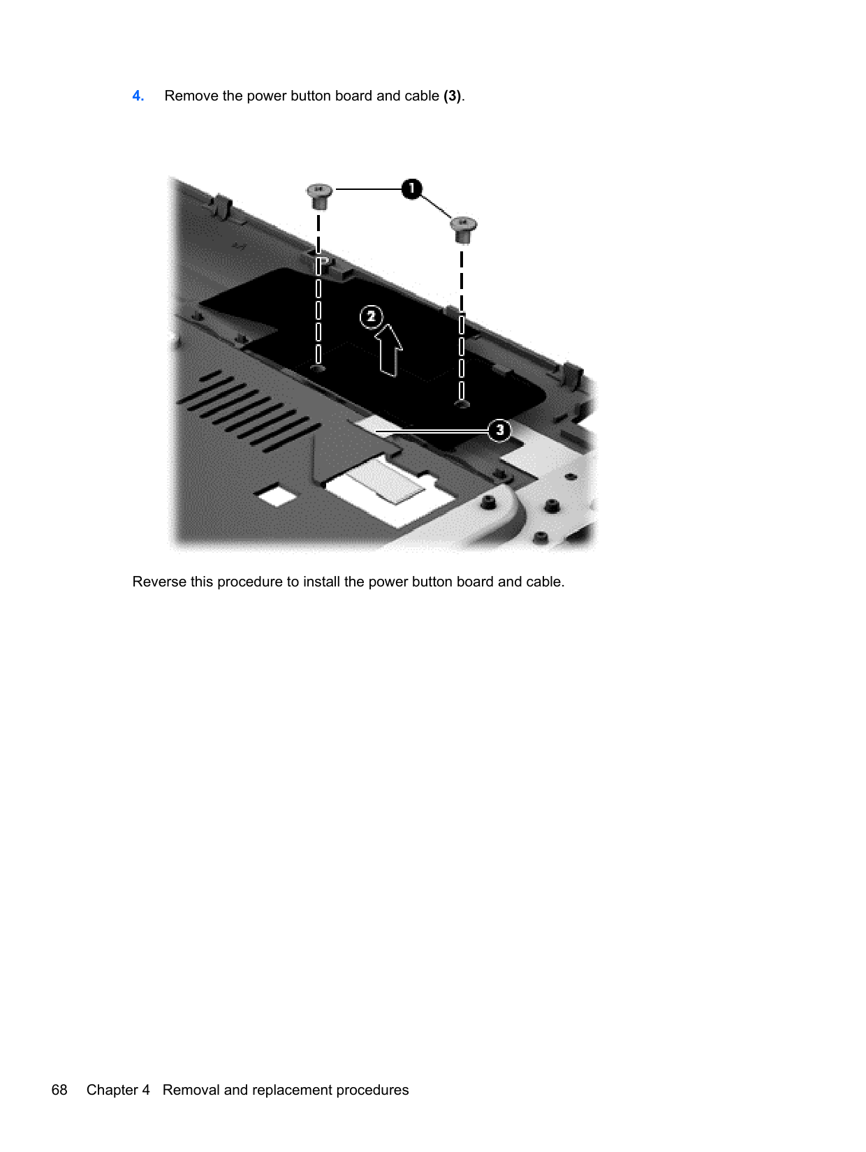
Reverse this procedure to install the power button board and cable.
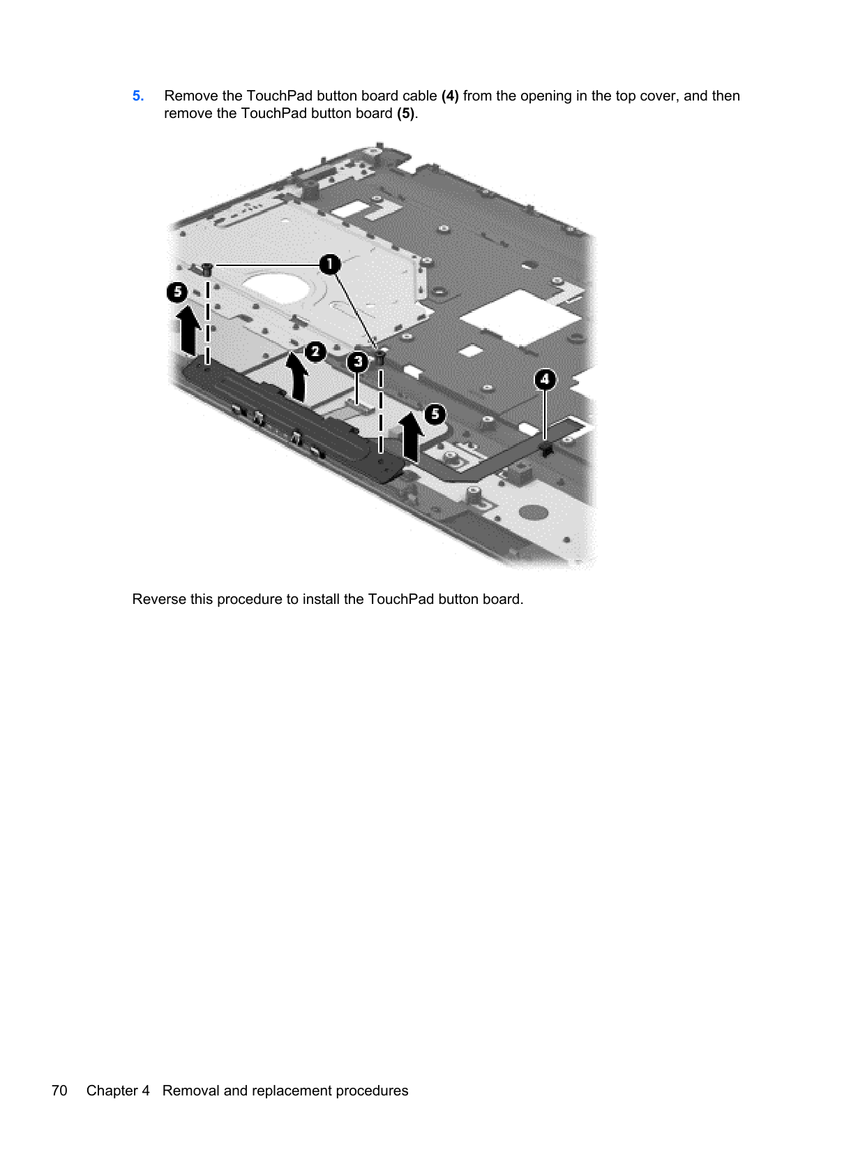
#### TouchPad button board
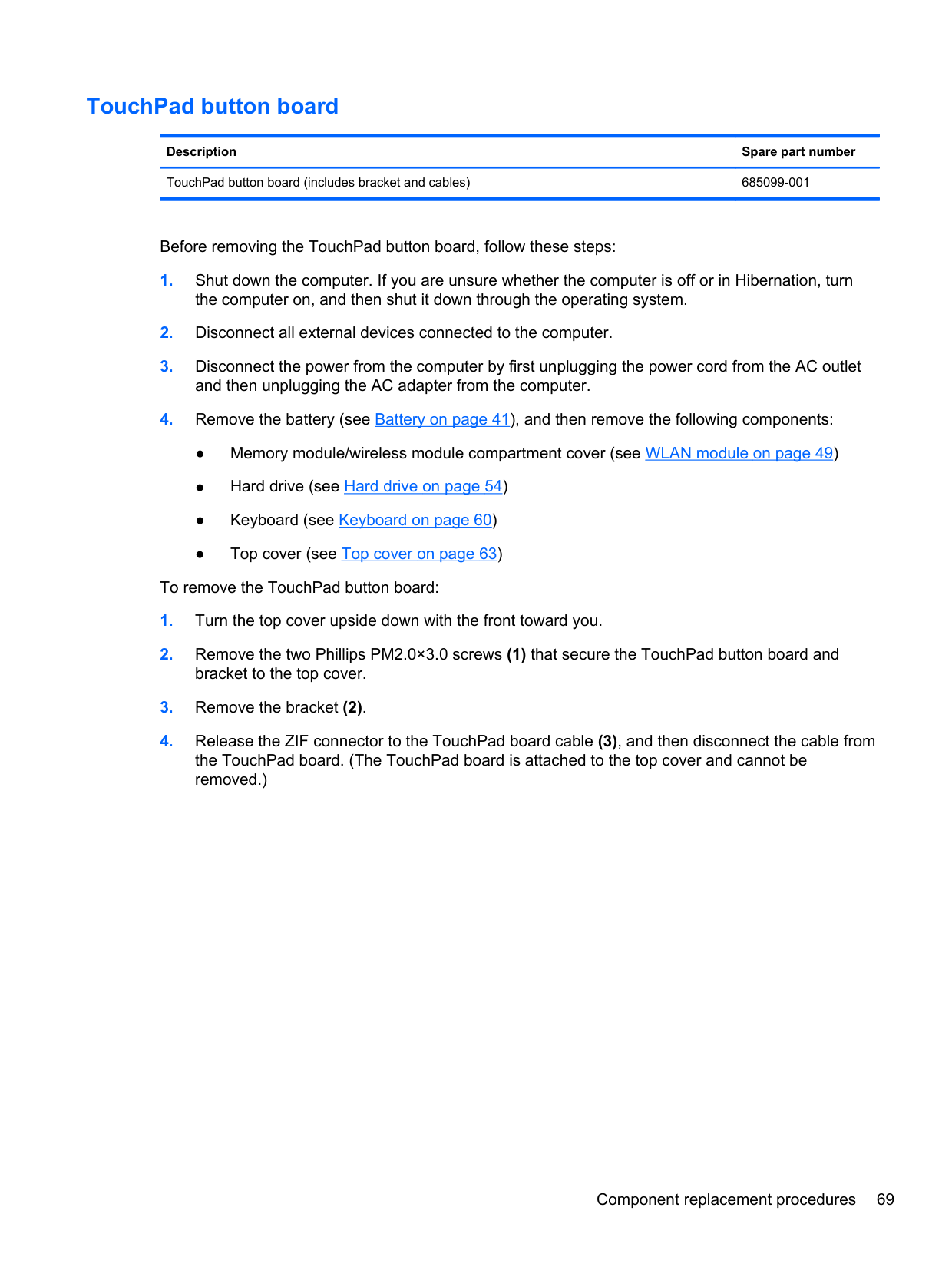
Description Spare part number TouchPad button board (includes bracket and cables) 685099-001
Before removing the TouchPad button board, follow these steps:
the computer on, and then shut it down through the operating system.
and then unplugging the AC adapter from the computer.

Reverse this procedure to install the TouchPad button board.
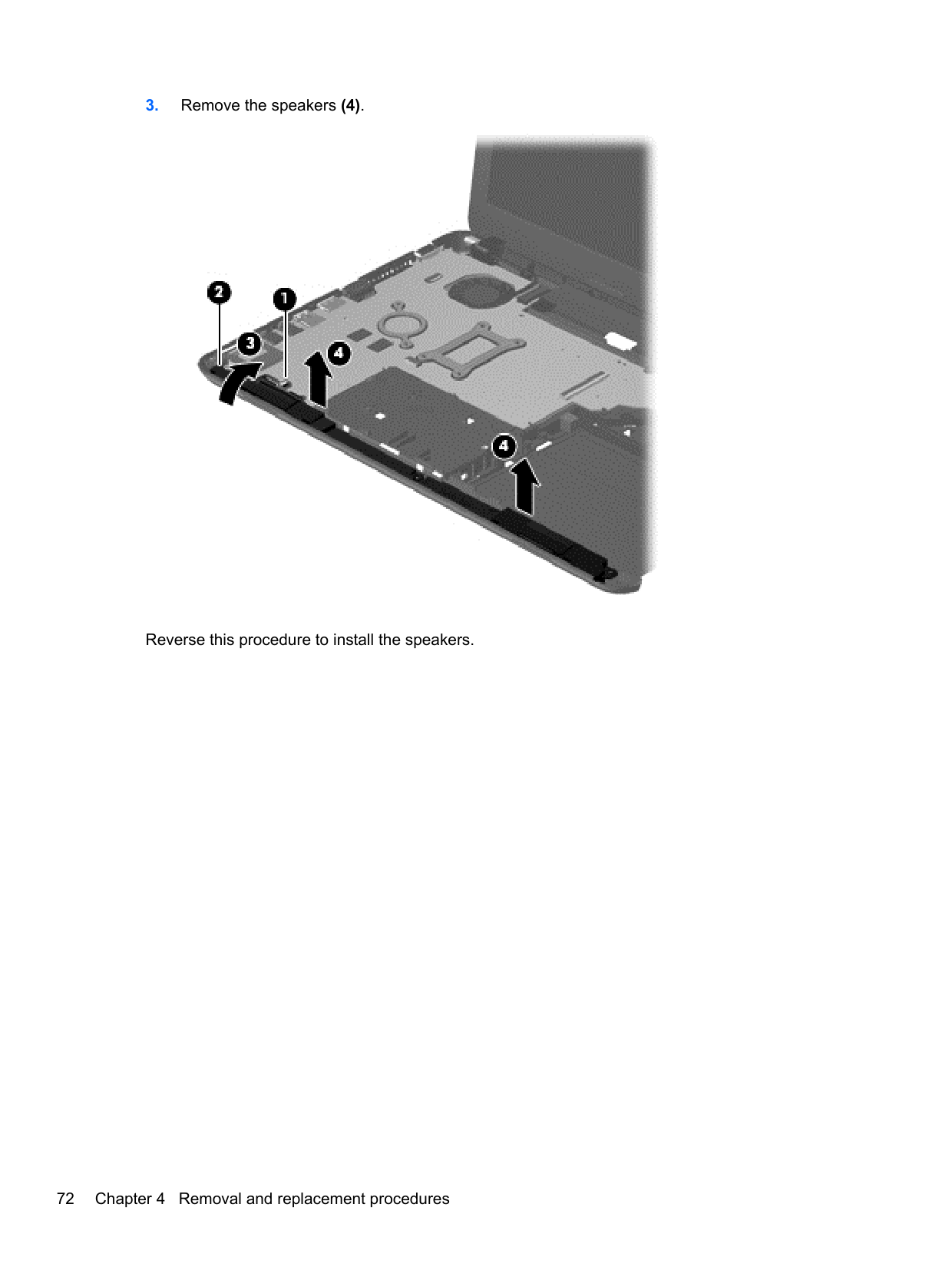
#### Speakers
Description Spare part number Speakers (includes left and right speakers and cable) 685106-001
Before removing the speakers, follow these steps:
the computer on, and then shut it down through the operating system.
and then unplugging the AC adapter from the computer.

Reverse this procedure to install the speakers.
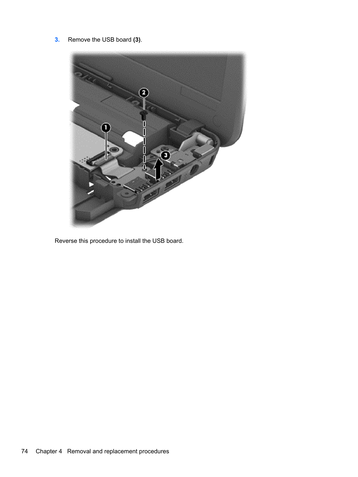
#### USB board
Description Spare part number USB board (includes cable) 685097-001
Before removing the USB board, follow these steps:
the computer on, and then shut it down through the operating system.
and then unplugging the AC adapter from the computer.

Reverse this procedure to install the USB board.
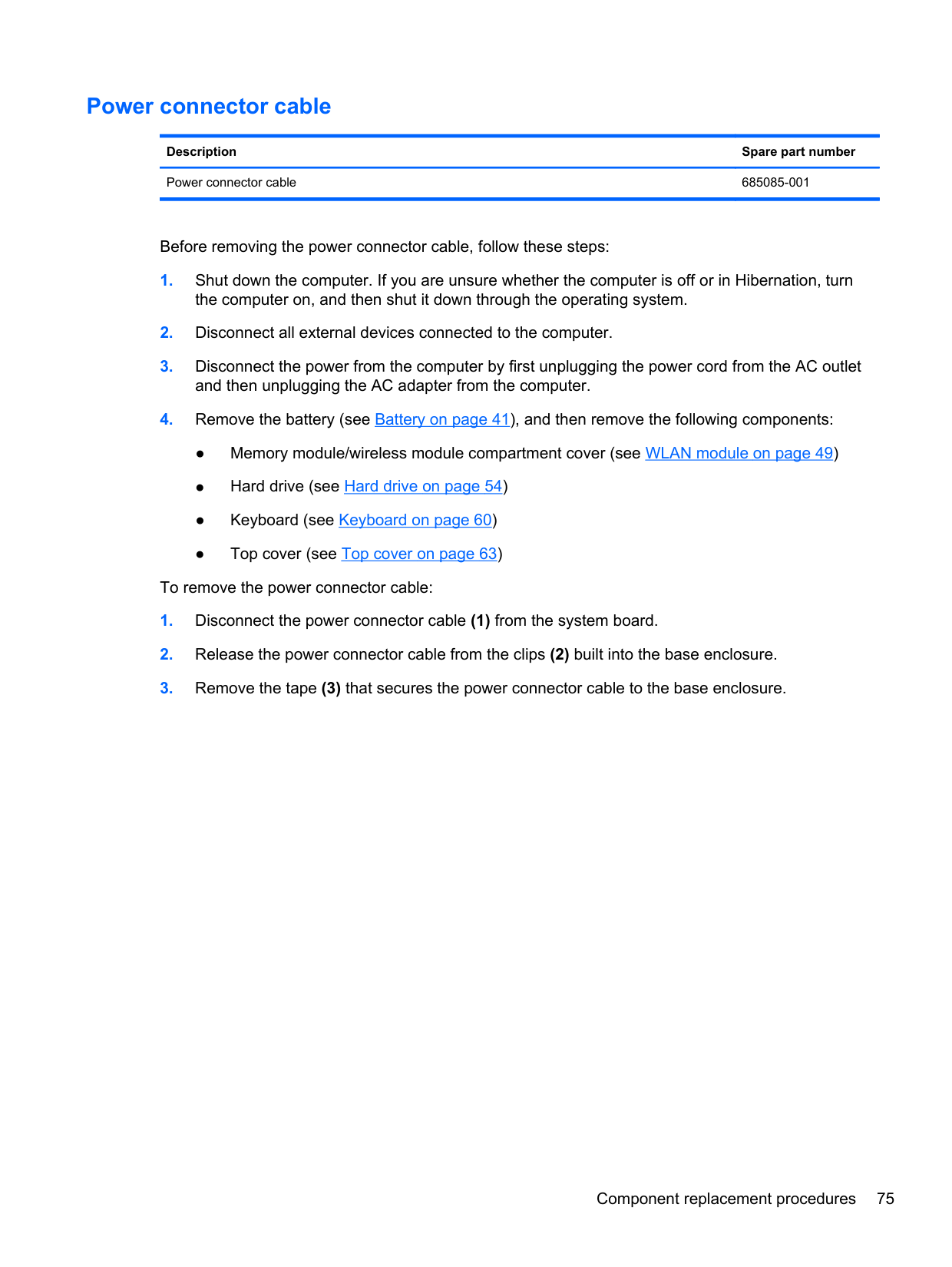
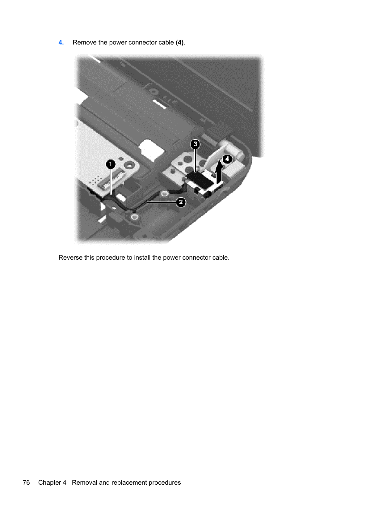
#### Power connector cable
Description Spare part number Power connector cable 685085-001
Before removing the power connector cable, follow these steps:
the computer on, and then shut it down through the operating system.
and then unplugging the AC adapter from the computer.

Reverse this procedure to install the power connector cable.
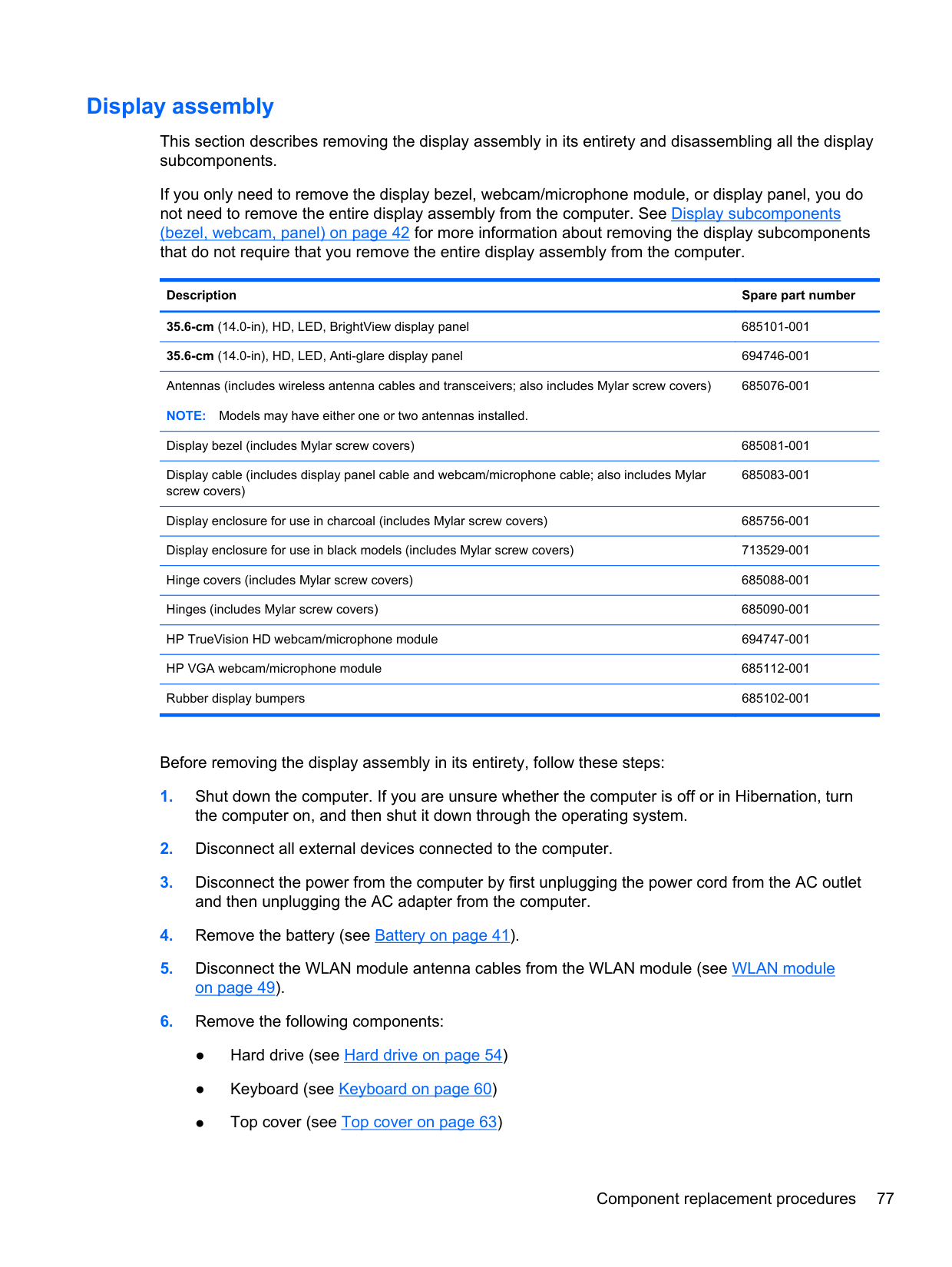
#### Display assembly
This section describes removing the display assembly in its entirety and disassembling all the display subcomponents.
If you only need to remove the display bezel, webcam/microphone module, or display panel, you do not need to remove the entire display assembly from the computer. See Display subcomponents (bezel, webcam, panel) on page 42 for more information about removing the display subcomponents that do not require that you remove the entire display assembly from the computer.
Description Spare part number 35.6-cm (14.0-in), HD, LED, BrightView display panel 685101-001 35.6-cm (14.0-in), HD, LED, Anti-glare display panel 694746-001 Antennas (includes wireless antenna cables and transceivers; also includes Mylar screw covers) NOTE: Models may have either one or two antennas installed.
685076-001
Display bezel (includes Mylar screw covers) 685081-001 Display cable (includes display panel cable and webcam/microphone cable; also includes Mylar screw covers)
685083-001
Display enclosure for use in charcoal (includes Mylar screw covers) 685756-001 Display enclosure for use in black models (includes Mylar screw covers) 713529-001 Hinge covers (includes Mylar screw covers) 685088-001 Hinges (includes Mylar screw covers) 685090-001 HP TrueVision HD webcam/microphone module 694747-001 HP VGA webcam/microphone module 685112-001 Rubber display bumpers 685102-001
Before removing the display assembly in its entirety, follow these steps:
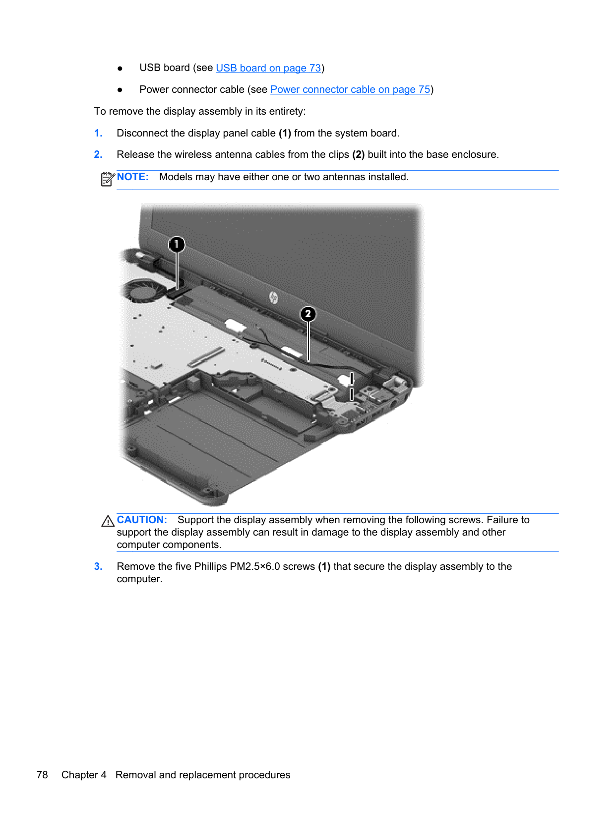
To remove the display assembly in its entirety:
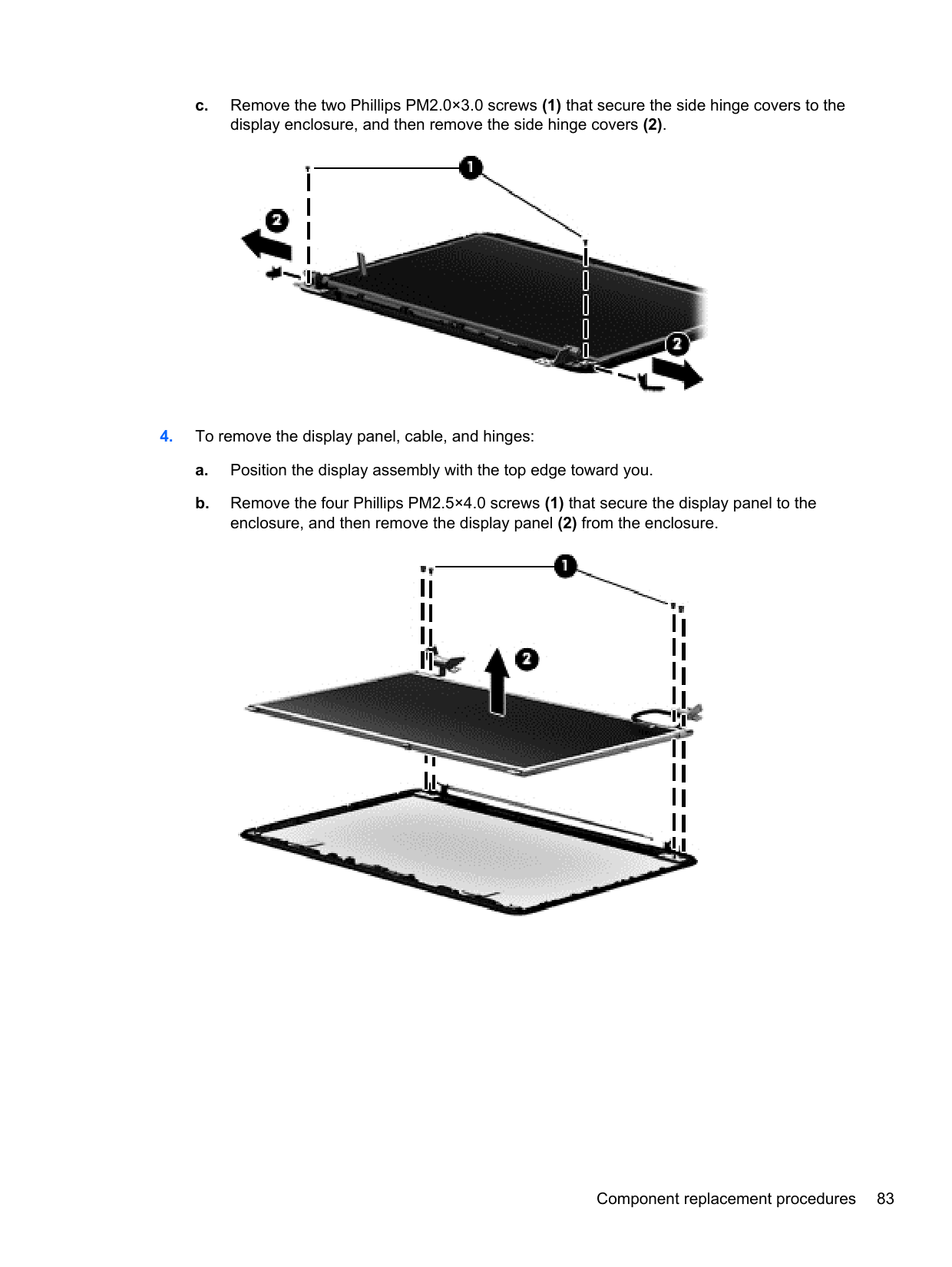
| | |---|

CAUTION: Support the display assembly when removing the following screws. Failure to support the display assembly can result in damage to the display assembly and other computer components.
| | |---|

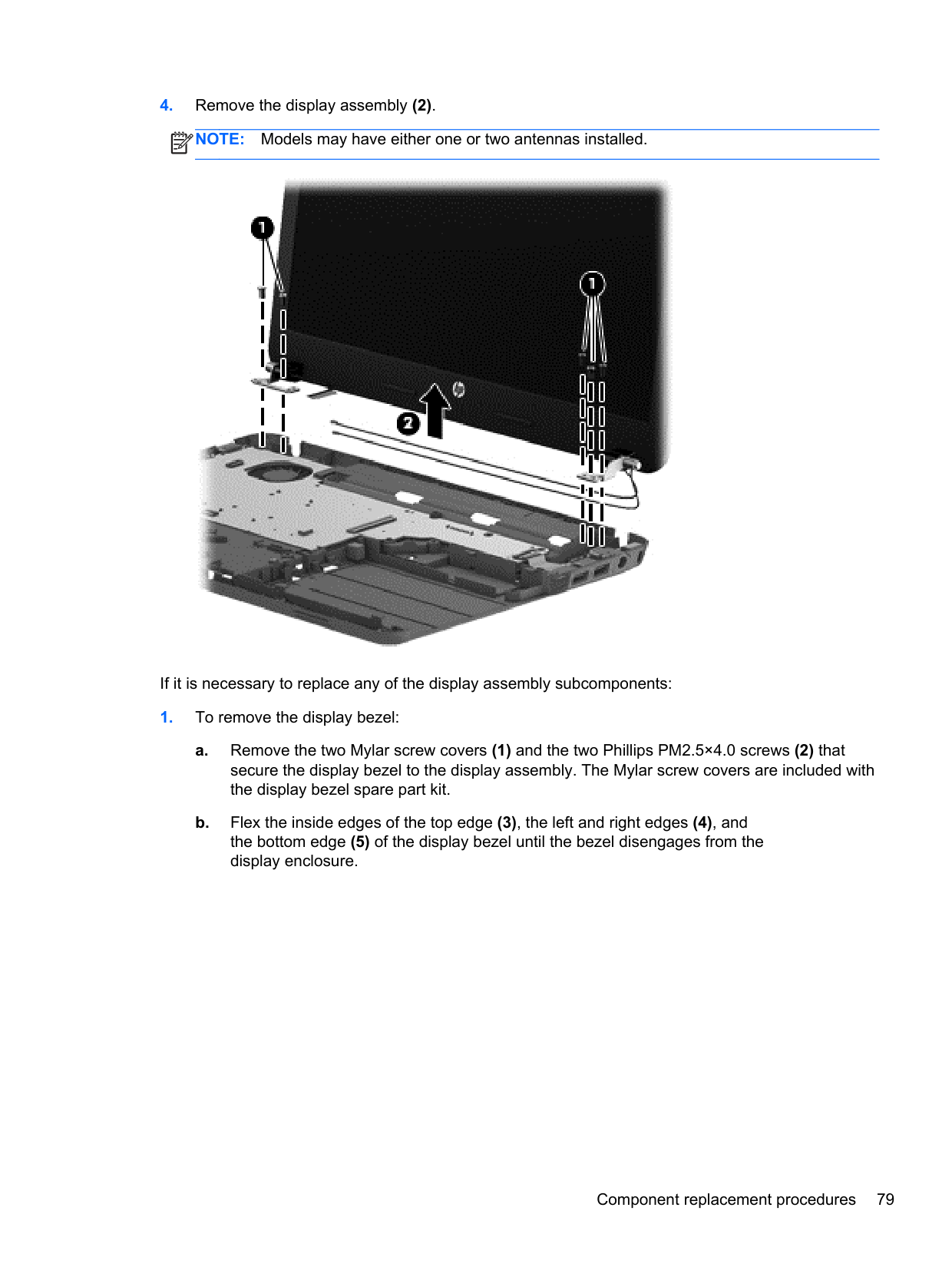
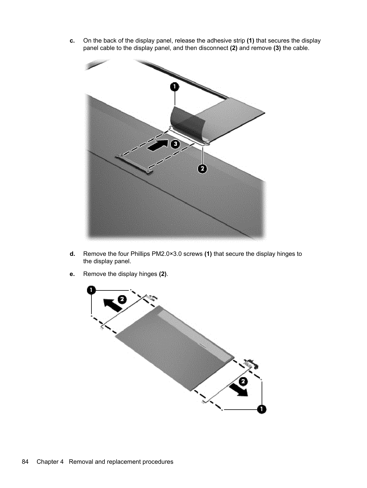
If it is necessary to replace any of the display assembly subcomponents:

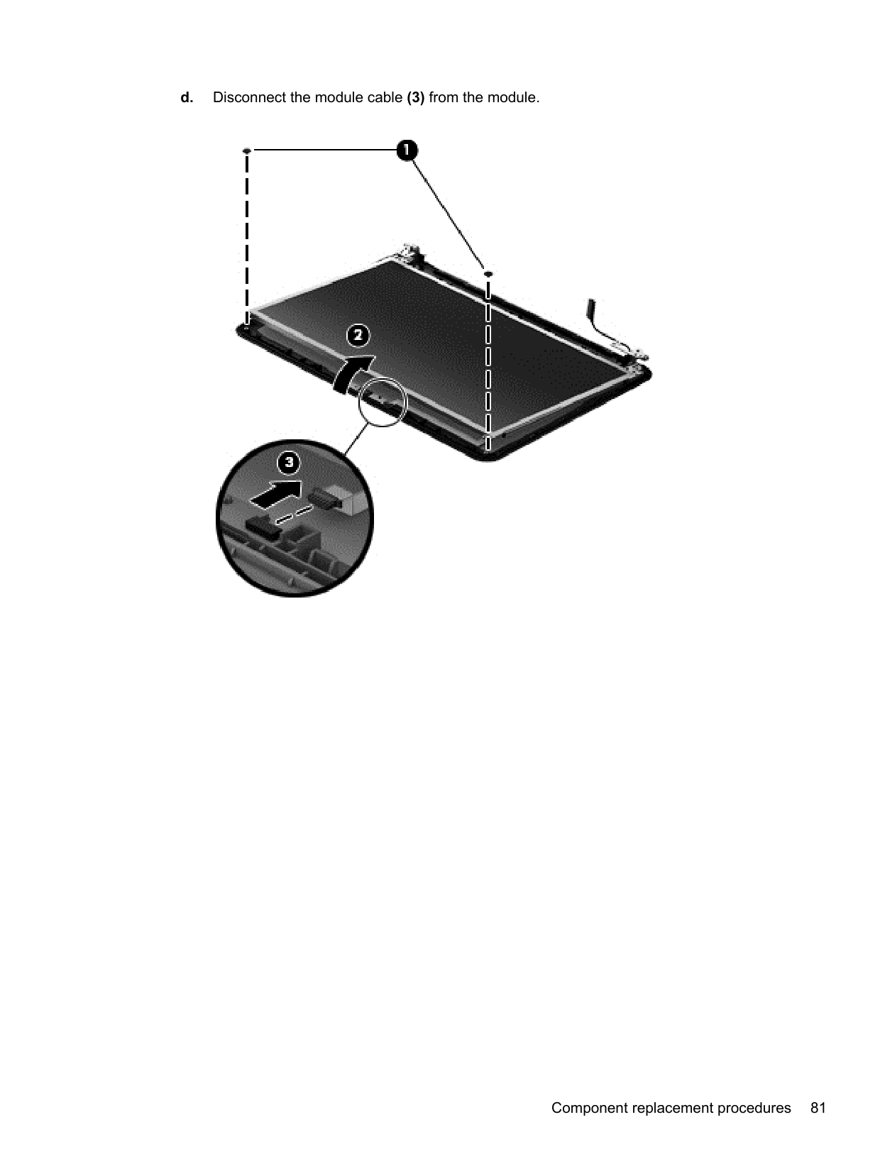
####### d. Disconnect the module cable (3) from the module.


| | |---|
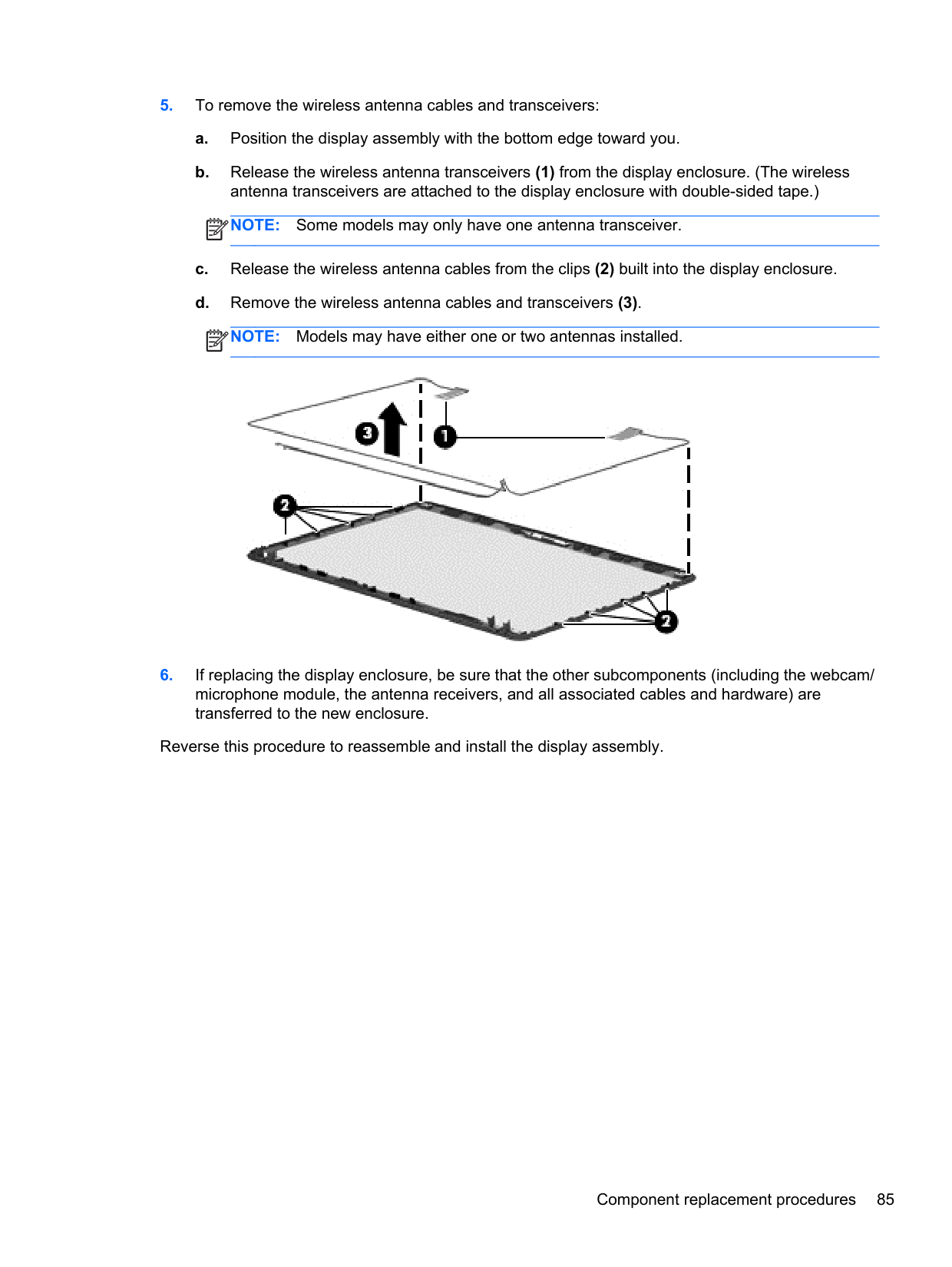
| | |---|

Reverse this procedure to reassemble and install the display assembly.
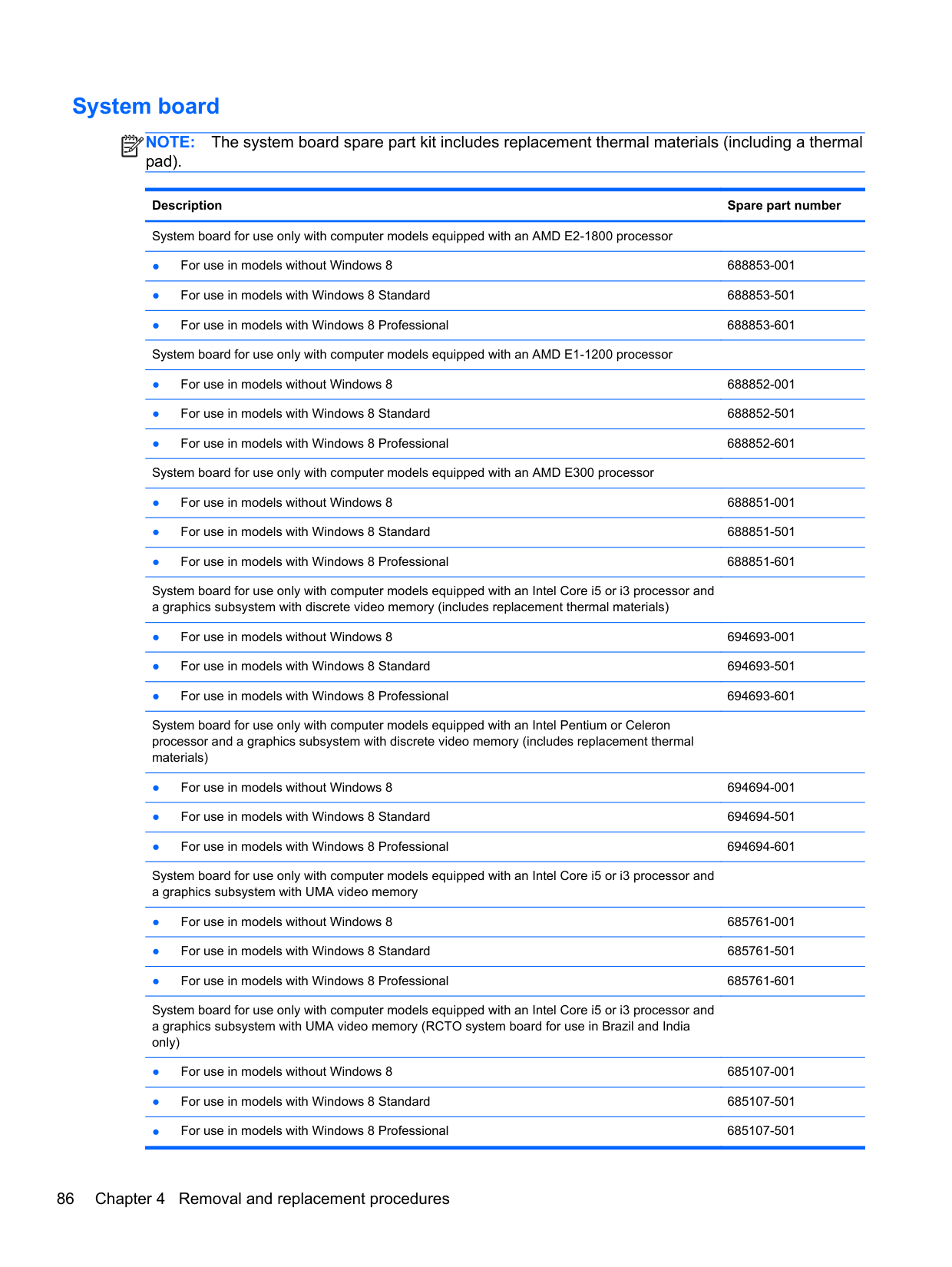
#### System board
NOTE: The system board spare part kit includes replacement thermal materials (including a thermal pad).
| | |---|
Description Spare part number System board for use only with computer models equipped with an AMD E2-1800 processor
System board for use only with computer models equipped with an Intel Core i5 or i3 processor and a graphics subsystem with discrete video memory (includes replacement thermal materials)
System board for use only with computer models equipped with an Intel Pentium or Celeron processor and a graphics subsystem with discrete video memory (includes replacement thermal materials)
System board for use only with computer models equipped with an Intel Core i5 or i3 processor and a graphics subsystem with UMA video memory
System board for use only with computer models equipped with an Intel Core i5 or i3 processor and a graphics subsystem with UMA video memory (RCTO system board for use in Brazil and India only)
######## Description Spare part number
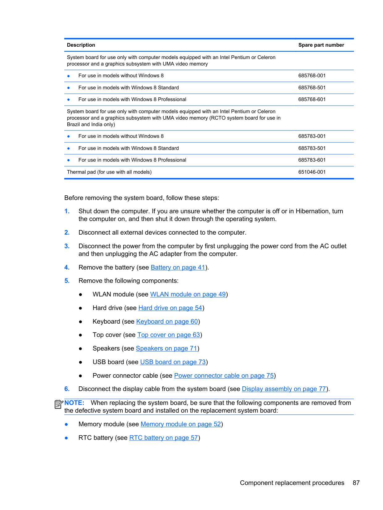
System board for use only with computer models equipped with an Intel Pentium or Celeron processor and a graphics subsystem with UMA video memory
System board for use only with computer models equipped with an Intel Pentium or Celeron processor and a graphics subsystem with UMA video memory (RCTO system board for use in Brazil and India only)
Before removing the system board, follow these steps:
NOTE: When replacing the system board, be sure that the following components are removed from the defective system board and installed on the replacement system board:
| | |---|
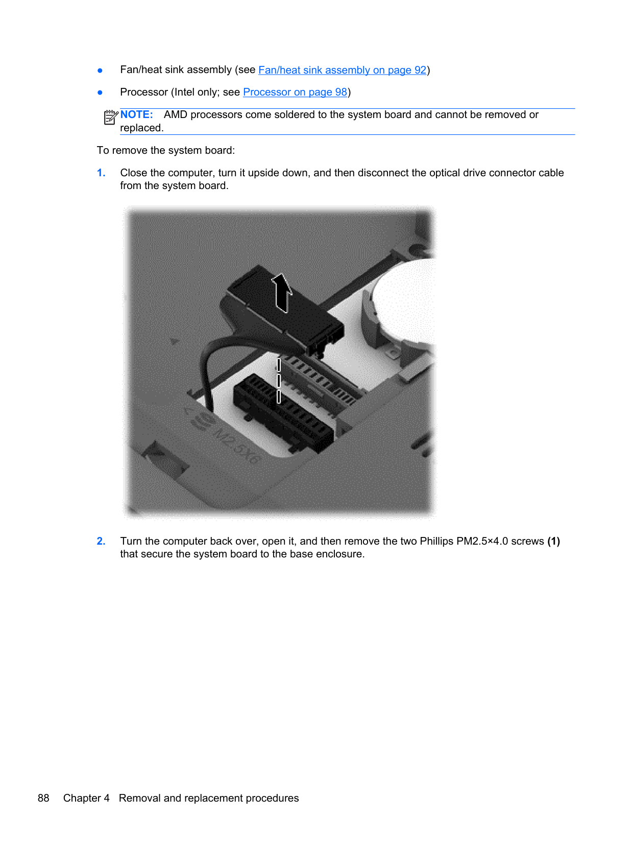
NOTE: AMD processors come soldered to the system board and cannot be removed or replaced.
| | |---|
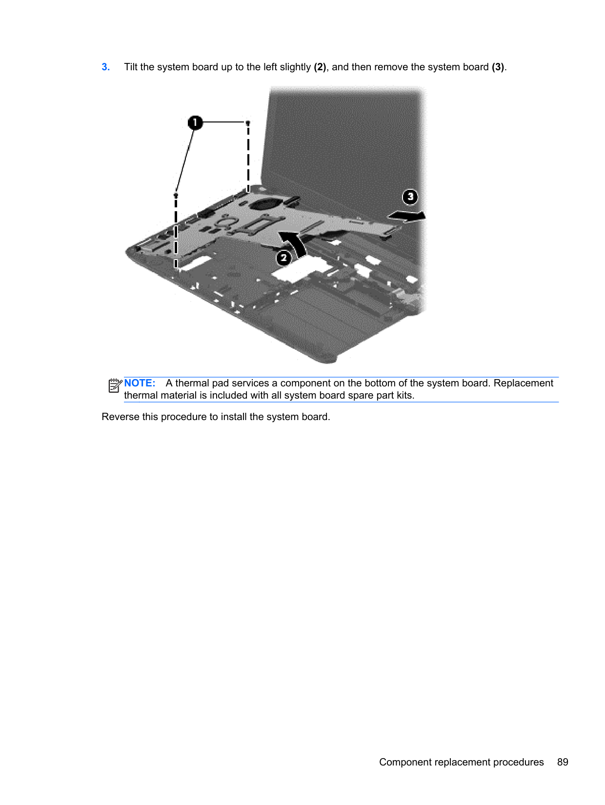
To remove the system board:


NOTE: A thermal pad services a component on the bottom of the system board. Replacement thermal material is included with all system board spare part kits.
| | |---|
Reverse this procedure to install the system board.
#### Optical drive cable
Description Spare part number Optical drive cable (includes cable bracket) 685084-001
Before removing the optical drive cable, follow these steps:
the computer on, and then shut it down through the operating system.
and then unplugging the AC adapter from the computer.
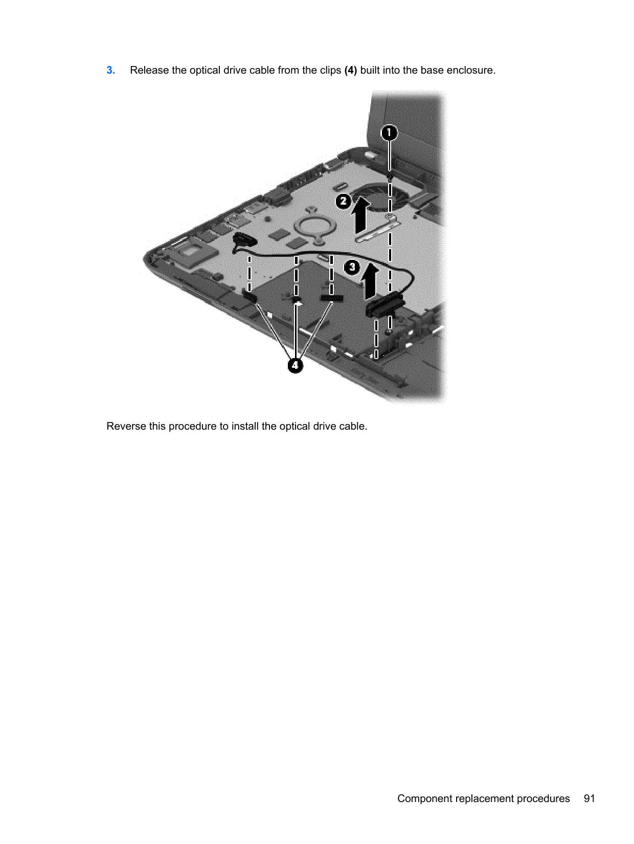
Remove the optical drive cable:

Reverse this procedure to install the optical drive cable.
#### Fan/heat sink assembly
NOTE: The fan/heat sink assembly spare part kit includes replacement thermal materials.
| | |---|
Description Spare part number Fan/heat sink assembly for use only with computer models equipped with an AMD processor 688281-001 Fan/heat sink assembly for use only with computer models equipped with an Intel processor and a graphics subsystem with discrete video memory
685087-001
Fan/heat sink assembly for use only with computer models equipped with an Intel processor and a graphics subsystem with UMA video memory
685086-001
NOTE: To properly ventilate the computer, allow at least 7.6 cm (3.0 in) of clearance on the left side of the computer. The computer uses an electric fan for ventilation. The fan is controlled by a temperature sensor and is designed to turn on automatically when high temperature conditions exist. These conditions are affected by high external temperatures, system power consumption, power management/battery conservation configurations, battery fast charging, and software requirements. Exhaust air is displaced through the ventilation grill located on the left side of the computer.
| | |---|
Before removing the fan/heat sink assembly, follow these steps:
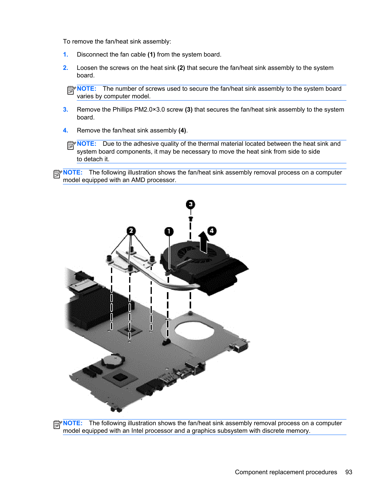
To remove the fan/heat sink assembly:
| |
|---|
NOTE: The number of screws used to secure the fan/heat sink assembly to the system board varies by computer model.
NOTE: Due to the adhesive quality of the thermal material located between the heat sink and system board components, it may be necessary to move the heat sink from side to side to detach it.
| | |---|
NOTE: The following illustration shows the fan/heat sink assembly removal process on a computer model equipped with an AMD processor.
| | |---|

NOTE: The following illustration shows the fan/heat sink assembly removal process on a computer model equipped with an Intel processor and a graphics subsystem with discrete memory.
| | |---|

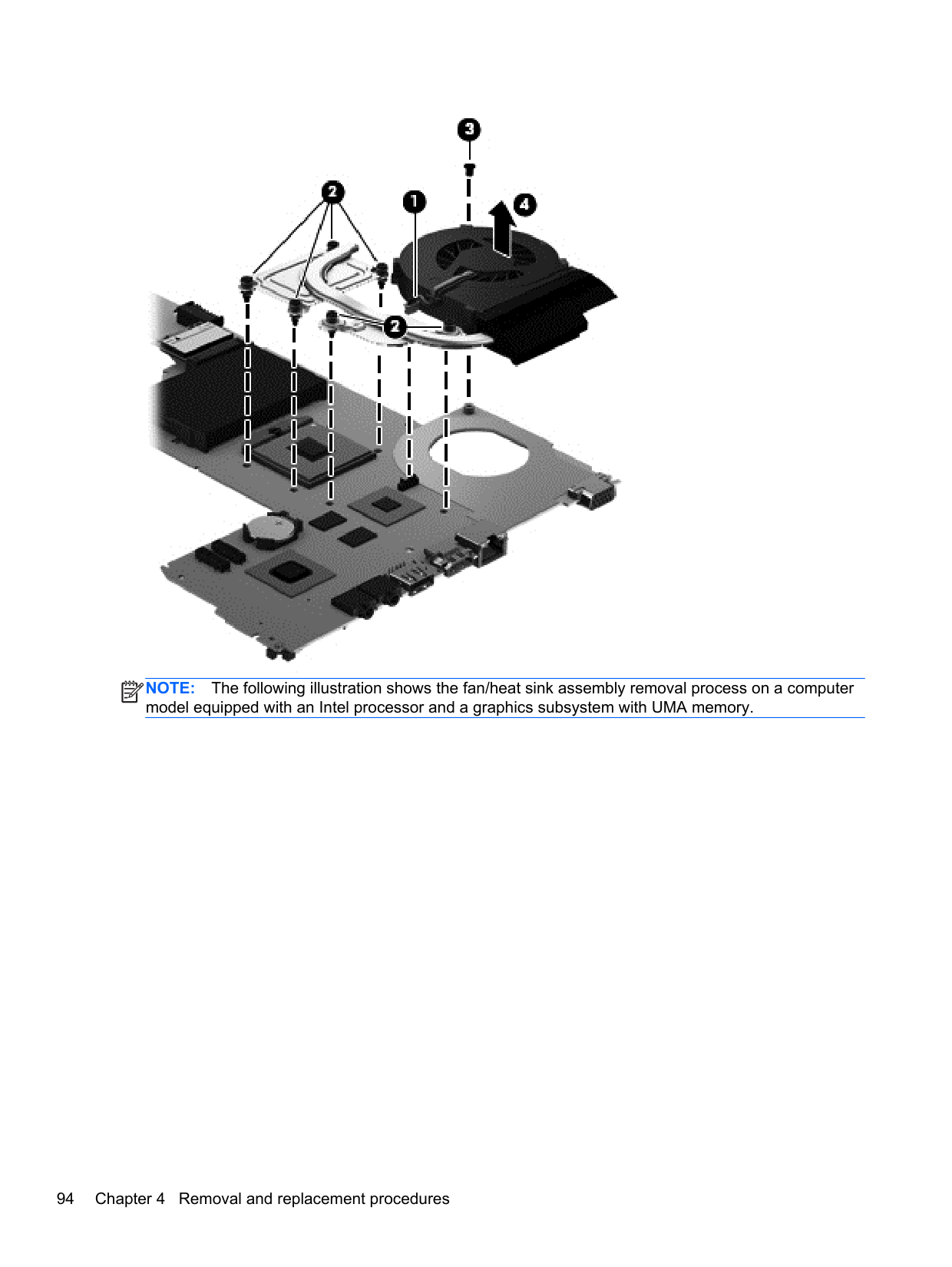
####### NOTE: The following illustration shows the fan/heat sink assembly removal process on a computer model equipped with an Intel processor and a graphics subsystem with UMA memory.
| | |---|

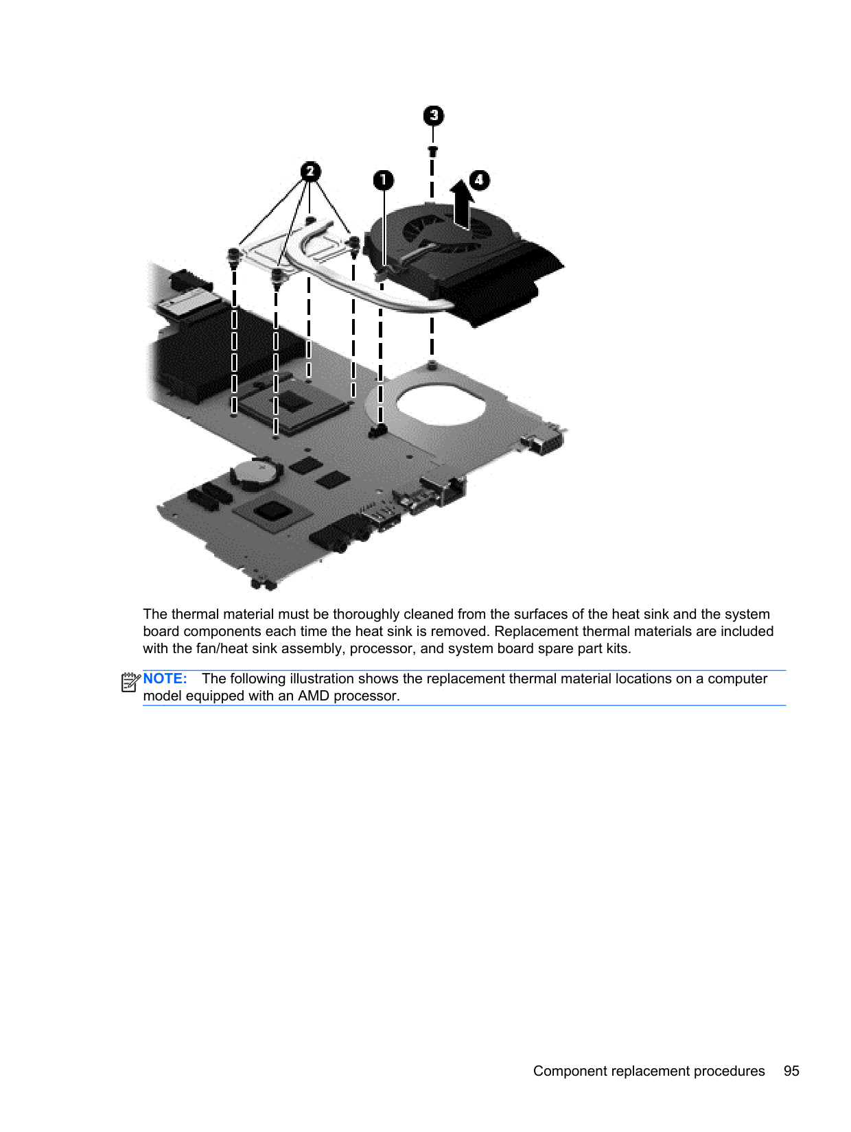
The thermal material must be thoroughly cleaned from the surfaces of the heat sink and the system board components each time the heat sink is removed. Replacement thermal materials are included with the fan/heat sink assembly, processor, and system board spare part kits.
NOTE: The following illustration shows the replacement thermal material locations on a computer model equipped with an AMD processor.
| | |---|

| | |---|
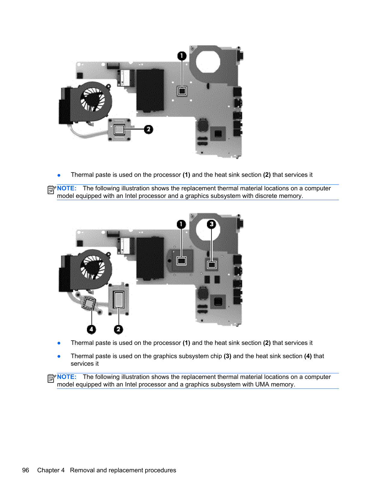
NOTE: The following illustration shows the replacement thermal material locations on a computer model equipped with an Intel processor and a graphics subsystem with discrete memory.

NOTE: The following illustration shows the replacement thermal material locations on a computer model equipped with an Intel processor and a graphics subsystem with UMA memory.
| | |---|

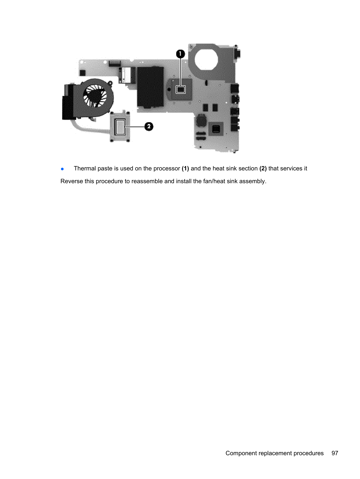
####### ● Thermal paste is used on the processor (1) and the heat sink section (2) that services it Reverse this procedure to reassemble and install the fan/heat sink assembly.
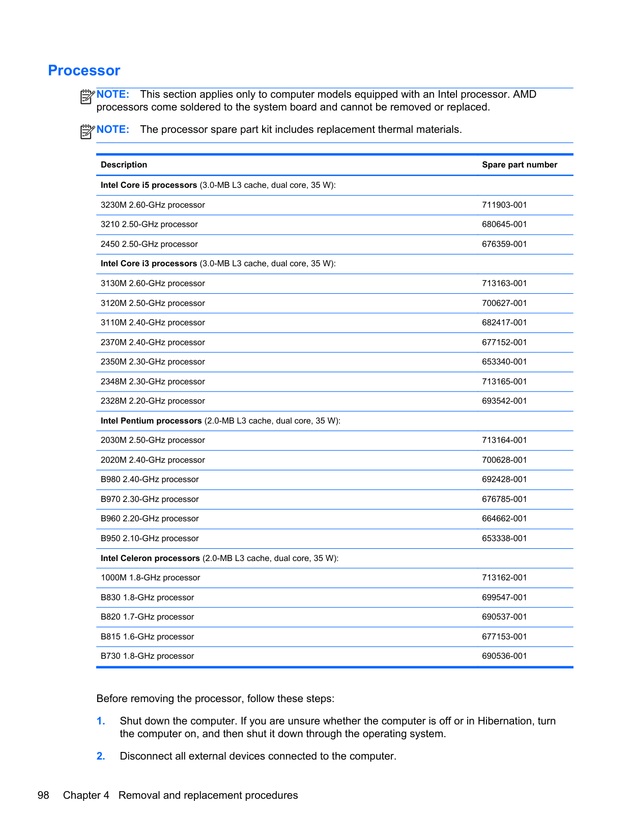
#### Processor
NOTE: This section applies only to computer models equipped with an Intel processor. AMD processors come soldered to the system board and cannot be removed or replaced.
| | |---|
NOTE: The processor spare part kit includes replacement thermal materials.
| | |---|
Description Spare part number Intel Core i5 processors (3.0-MB L3 cache, dual core, 35 W):
3230M 2.60-GHz processor 711903-001 3210 2.50-GHz processor 680645-001 2450 2.50-GHz processor 676359-001 Intel Core i3 processors (3.0-MB L3 cache, dual core, 35 W):
3130M 2.60-GHz processor 713163-001 3120M 2.50-GHz processor 700627-001 3110M 2.40-GHz processor 682417-001 2370M 2.40-GHz processor 677152-001 2350M 2.30-GHz processor 653340-001 2348M 2.30-GHz processor 713165-001 2328M 2.20-GHz processor 693542-001 Intel Pentium processors (2.0-MB L3 cache, dual core, 35 W):
2030M 2.50-GHz processor 713164-001 2020M 2.40-GHz processor 700628-001 B980 2.40-GHz processor 692428-001 B970 2.30-GHz processor 676785-001 B960 2.20-GHz processor 664662-001 B950 2.10-GHz processor 653338-001 Intel Celeron processors (2.0-MB L3 cache, dual core, 35 W):
1000M 1.8-GHz processor 713162-001 B830 1.8-GHz processor 699547-001 B820 1.7-GHz processor 690537-001 B815 1.6-GHz processor 677153-001 B730 1.8-GHz processor 690536-001
Before removing the processor, follow these steps:
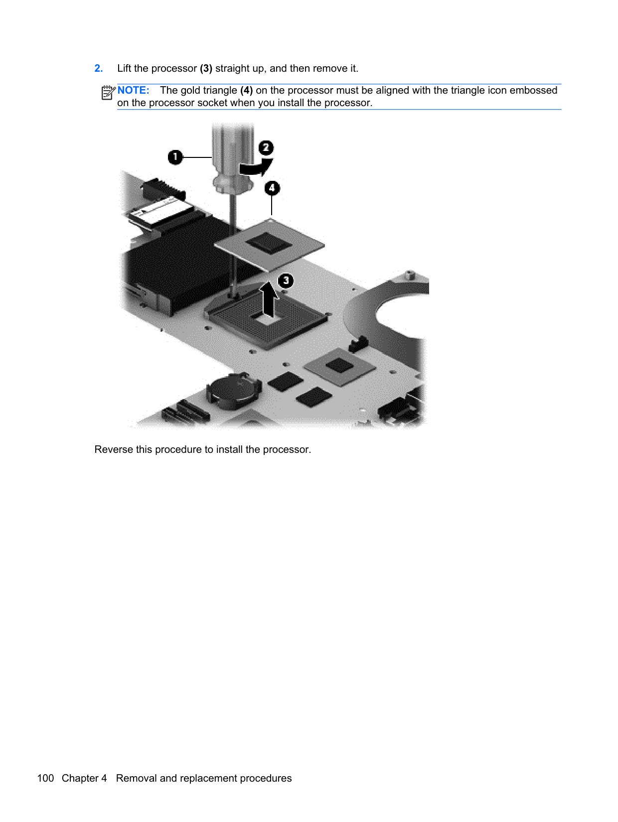
To remove the processor:
NOTE: The gold triangle (4) on the processor must be aligned with the triangle icon embossed on the processor socket when you install the processor.
| | |---|

Reverse this procedure to install the processor.
5 Computer Setup (BIOS) and AdvancedSystem Diagnostics
Windows 7 – Computer Setup (BIOS) and Advanced System Diagnostics
#### Using Computer Setup
Computer Setup, or Basic Input/Output System (BIOS), controls communication between all the input and output devices on the system (such as disk drives, display, keyboard, mouse, and printer). Computer Setup includes settings for the types of devices installed, the startup sequence of the computer, and the amount of system and extended memory.
NOTE: Use extreme care when making changes in Computer Setup. Errors can prevent the computer from operating properly.
| | |---|
Starting Computer Setup NOTE: An external keyboard or mouse connected to a USB port can be used with Computer Setup only if USB legacy support is enabled. To start Computer Setup, follow these steps:
| | |---|
Menu” message is displayed at the bottom of the screen.
##### Navigating and selecting in Computer Setup
To navigate and select in Computer Setup, follow these steps:
NOTE: You can use either a pointing device (TouchPad, pointing stick, or USB mouse) or the keyboard to navigate and make selections in Computer Setup.
| | |---|
Click the Exit icon in the lower-left corner of the screen, and then follow the on-screen instructions.
– or – Use the tab key and the arrow keys to select File > Ignore Changes and Exit, and then press enter.
Click the Save icon in the lower-left corner of the screen, and then follow the on-screen instructions.
– or – Use the tab key and the arrow keys to select File > Save Changes and Exit, and then press enter.
##### Your changes go into effect when the computer restarts. Restoring factory settings in Computer Setup
NOTE: Restoring defaults will not change the hard drive mode.
| | |---|
To return all settings in Computer Setup to the values that were set at the factory, follow these steps:
– or – Use the arrow keys to select File > Save Changes and Exit, and then press enter.
Your changes go into effect when the computer restarts. NOTE: Your password settings and security settings are not changed when you restore the factory settings.
| | |---|
Updating the BIOS Updated versions of the BIOS may be available on the HP website. Most BIOS updates on the HP website are packaged in compressed files called SoftPaqs. Some download packages contain a file named Readme.txt, which contains information regarding installing and troubleshooting the file.
###### Determining the BIOS version
To determine whether available BIOS updates contain later BIOS versions than those currently installed on the computer, you need to know the version of the system BIOS currently installed.
BIOS version information (also known as ROM date and System BIOS) can be displayed by pressing fn+esc (if you are already in Windows) or by using Computer Setup.
– or – Use the tab key and the arrow keys to select File > Ignore Changes and Exit, and then press enter.
###### Downloading a BIOS update
CAUTION: To reduce the risk of damage to the computer or an unsuccessful installation, download and install a BIOS update only when the computer is connected to reliable external power using the AC adapter. Do not download or install a BIOS update while the computer is running on battery power, docked in an optional docking device, or connected to an optional power source. During the download and installation, follow these instructions:
Do not disconnect power on the computer by unplugging the power cord from the AC outlet. Do not shut down the computer or initiate sleep. Do not insert, remove, connect, or disconnect any device, cable, or cord.
Make a note of the path to the location on your hard drive where the BIOS update is downloaded. You will need to access this path when you are ready to install the update.
NOTE: If you connect your computer to a network, consult the network administrator before installing any software updates, especially system BIOS updates.
| | |---|
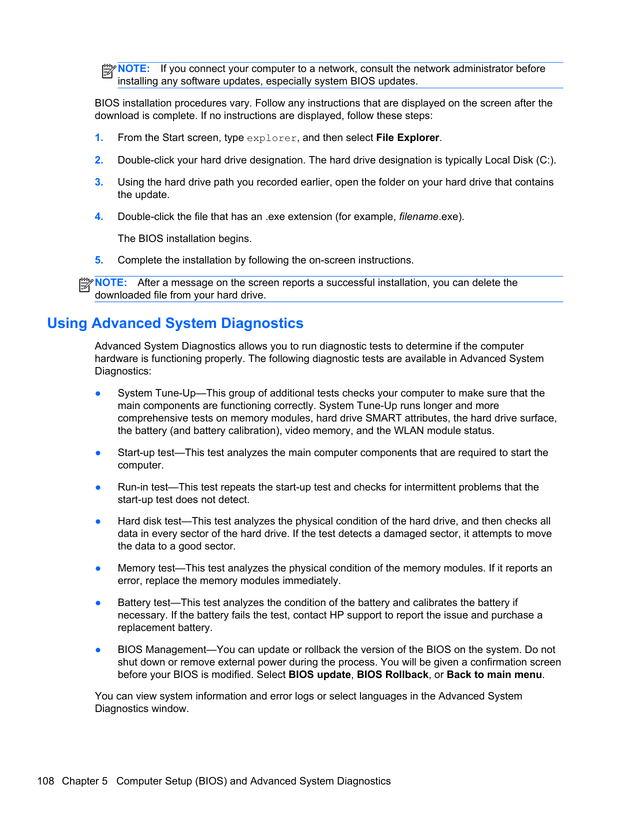
BIOS installation procedures vary. Follow any instructions that are displayed on the screen after the download is complete. If no instructions are displayed, follow these steps:
NOTE: After a message on the screen reports a successful installation, you can delete the downloaded file from your hard drive.
| | |---|
#### Using Advanced System Diagnostics
Advanced System Diagnostics allows you to run diagnostic tests to determine if the computer hardware is functioning properly. The following diagnostic tests are available in Advanced System Diagnostics:
You can view system information and error logs or select languages in the Advanced System Diagnostics window.
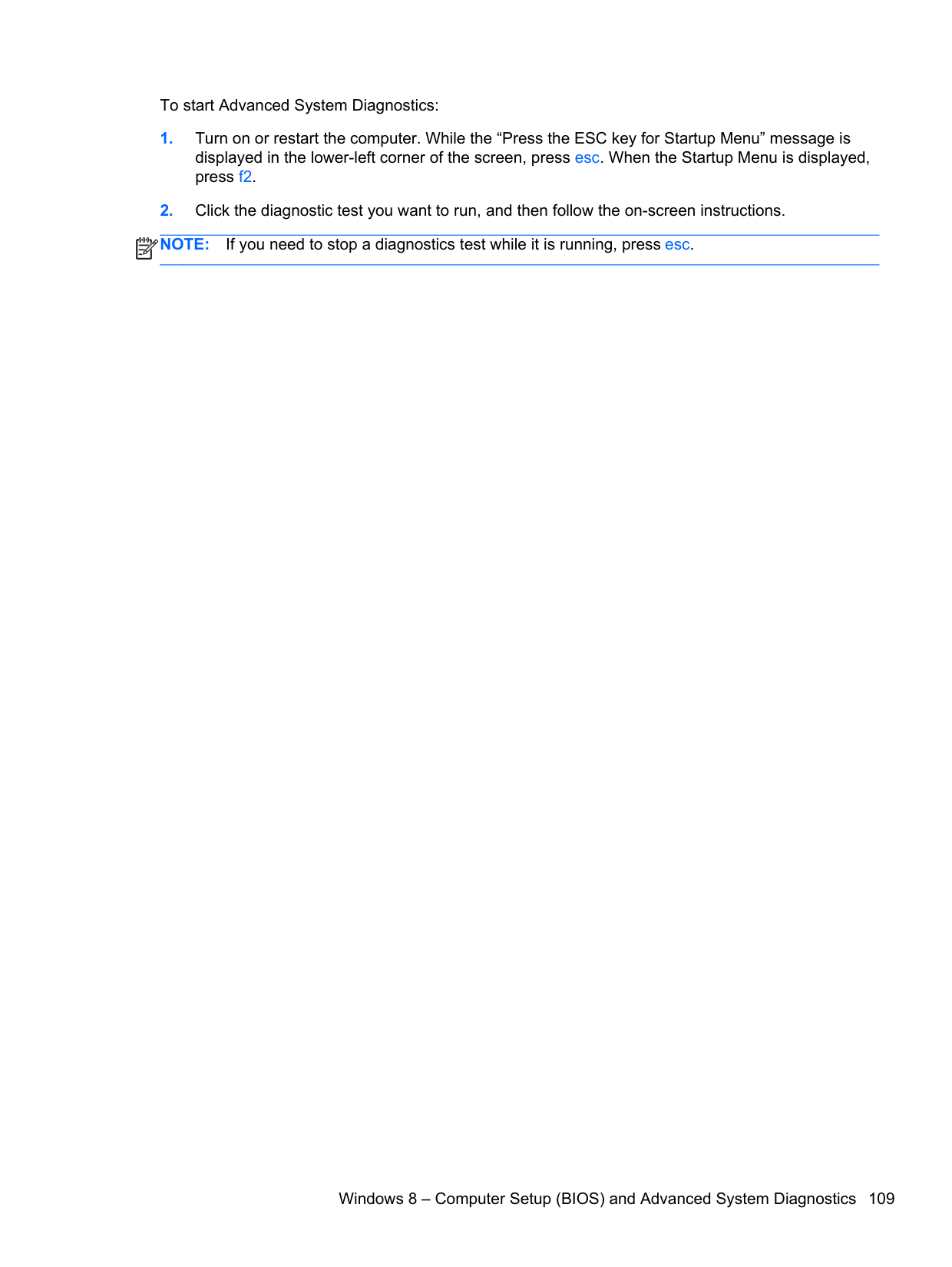
To start Advanced System Diagnostics:
| | |---|
Windows 8 – Computer Setup (BIOS) and Advanced System Diagnostics
#### Using Computer Setup
Computer Setup, or Basic Input/Output System (BIOS), controls communication between all the input and output devices on the system (such as disk drives, display, keyboard, mouse, and printer). Computer Setup includes settings for the types of devices installed, the startup sequence of the computer, and the amount of system and extended memory.
NOTE: Use extreme care when making changes in Computer Setup. Errors can prevent the computer from operating properly.
| | |---|
Starting Computer Setup NOTE: An external keyboard or mouse connected to a USB port can be used with Computer Setup only if USB legacy support is enabled. To start Computer Setup, follow these steps:
| | |---|
##### Navigating and selecting in Computer Setup
To navigate and select in Computer Setup, follow these steps:
| | |---|
NOTE: You can use either a pointing device (TouchPad, pointing stick, or USB mouse) or the keyboard to navigate and make selections in Computer Setup.
To exit Computer Setup menus, choose one of the following methods:
Click the Exit icon in the lower-left corner of the screen, and then follow the on-screen instructions.
– or – Use the tab key and the arrow keys to select File > Ignore Changes and Exit, and then press enter.
Click the Save icon in the lower-left corner of the screen, and then follow the on-screen instructions.
– or – Use the tab key and the arrow keys to select File > Save Changes and Exit, and then press enter.
##### Your changes go into effect when the computer restarts. Restoring factory settings in Computer Setup
NOTE: Restoring defaults will not change the hard drive mode.
| | |---|
To return all settings in Computer Setup to the values that were set at the factory, follow these steps:
– or – Use the arrow keys to select File > Save Changes and Exit, and then press enter.
Your changes go into effect when the computer restarts. NOTE: Your password settings and security settings are not changed when you restore the factory settings.
| | |---|
Updating the BIOS Updated versions of the BIOS may be available on the HP website. Most BIOS updates on the HP website are packaged in compressed files called SoftPaqs. Some download packages contain a file named Readme.txt, which contains information regarding installing and troubleshooting the file.
###### Determining the BIOS version
To determine whether available BIOS updates contain later BIOS versions than those currently installed on the computer, you need to know the version of the system BIOS currently installed.
BIOS version information (also known as ROM date and System BIOS) can be displayed by pressing fn+esc (if you are already in Windows) or by using Computer Setup.
of the screen, and then follow the on-screen instructions.
– or – Use the tab key and the arrow keys to select File > Ignore Changes and Exit, and then press enter.
###### Downloading a BIOS update
CAUTION: To reduce the risk of damage to the computer or an unsuccessful installation, download and install a BIOS update only when the computer is connected to reliable external power using the AC adapter. Do not download or install a BIOS update while the computer is running on battery power, docked in an optional docking device, or connected to an optional power source. During the download and installation, follow these instructions:
Do not disconnect power on the computer by unplugging the power cord from the AC outlet. Do not shut down the computer or initiate sleep. Do not insert, remove, connect, or disconnect any device, cable, or cord.
instructions to identify your computer and access the BIOS update you want to download.
Make a note of the path to the location on your hard drive where the BIOS update is downloaded. You will need to access this path when you are ready to install the update.
NOTE: If you connect your computer to a network, consult the network administrator before installing any software updates, especially system BIOS updates.
| | |---|
BIOS installation procedures vary. Follow any instructions that are displayed on the screen after the download is complete. If no instructions are displayed, follow these steps:
the update.
The BIOS installation begins.
| | |---|
#### Using Advanced System Diagnostics
Advanced System Diagnostics allows you to run diagnostic tests to determine if the computer hardware is functioning properly. The following diagnostic tests are available in Advanced System Diagnostics:
You can view system information and error logs or select languages in the Advanced System Diagnostics window.
To start Advanced System Diagnostics:
| | |---|
6 Specifications

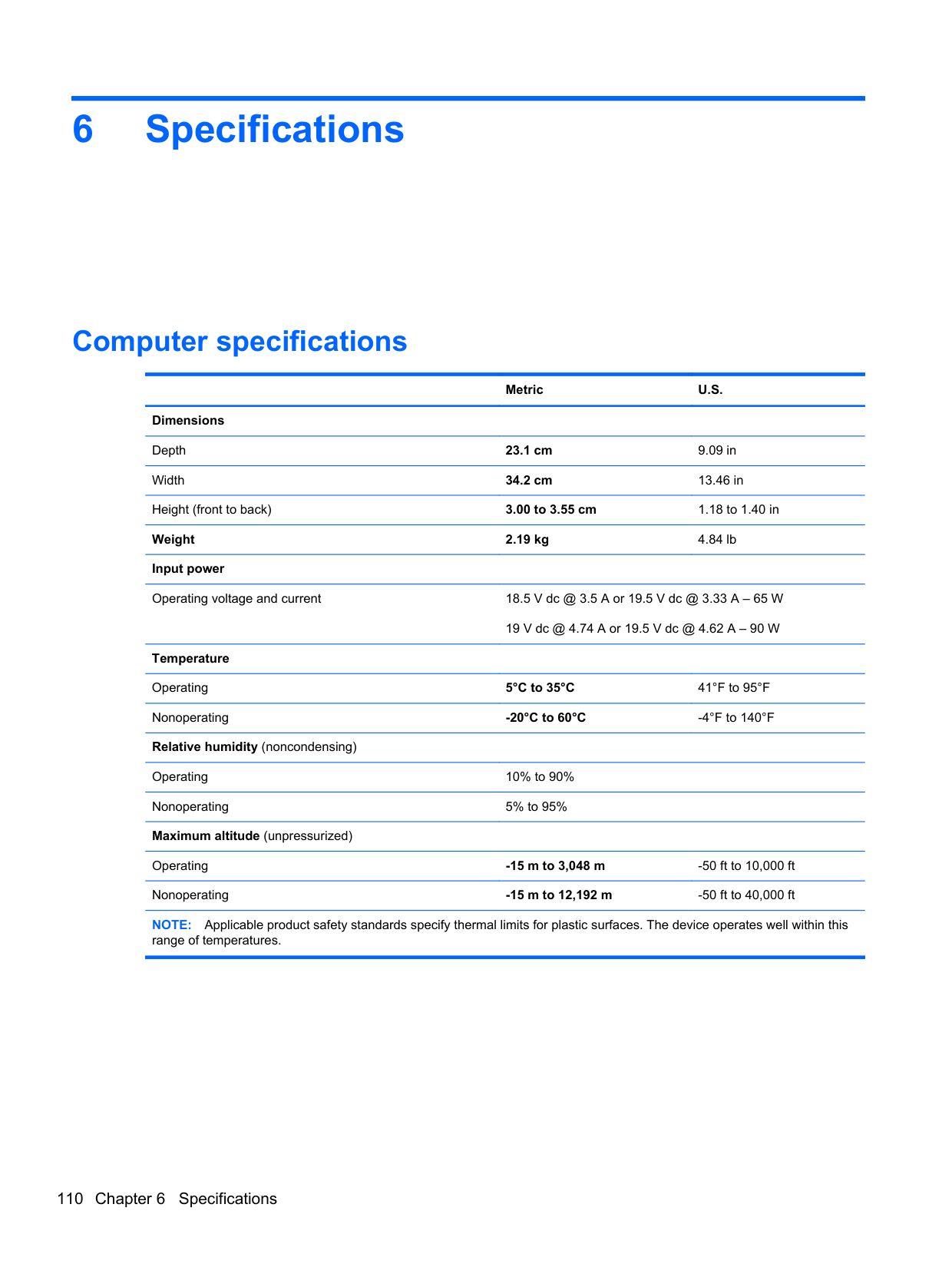
Computer specifications
######## Metric U.S.
Dimensions Depth 23.1 cm 9.09 in Width 34.2 cm 13.46 in Height (front to back) 3.00 to 3.55 cm 1.18 to 1.40 in Weight 2.19 kg 4.84 lb Input power Operating voltage and current 18.5 V dc @ 3.5 A or 19.5 V dc @ 3.33 A – 65 W
19 V dc @ 4.74 A or 19.5 V dc @ 4.62 A – 90 W
Temperature Operating 5°C to 35°C 41°F to 95°F Nonoperating -20°C to 60°C -4°F to 140°F Relative humidity (noncondensing) Operating 10% to 90% Nonoperating 5% to 95% Maximum altitude (unpressurized)
Operating -15 m to 3,048 m -50 ft to 10,000 ft Nonoperating -15 m to 12,192 m -50 ft to 40,000 ft NOTE: Applicable product safety standards specify thermal limits for plastic surfaces. The device operates well within this
range of temperatures.
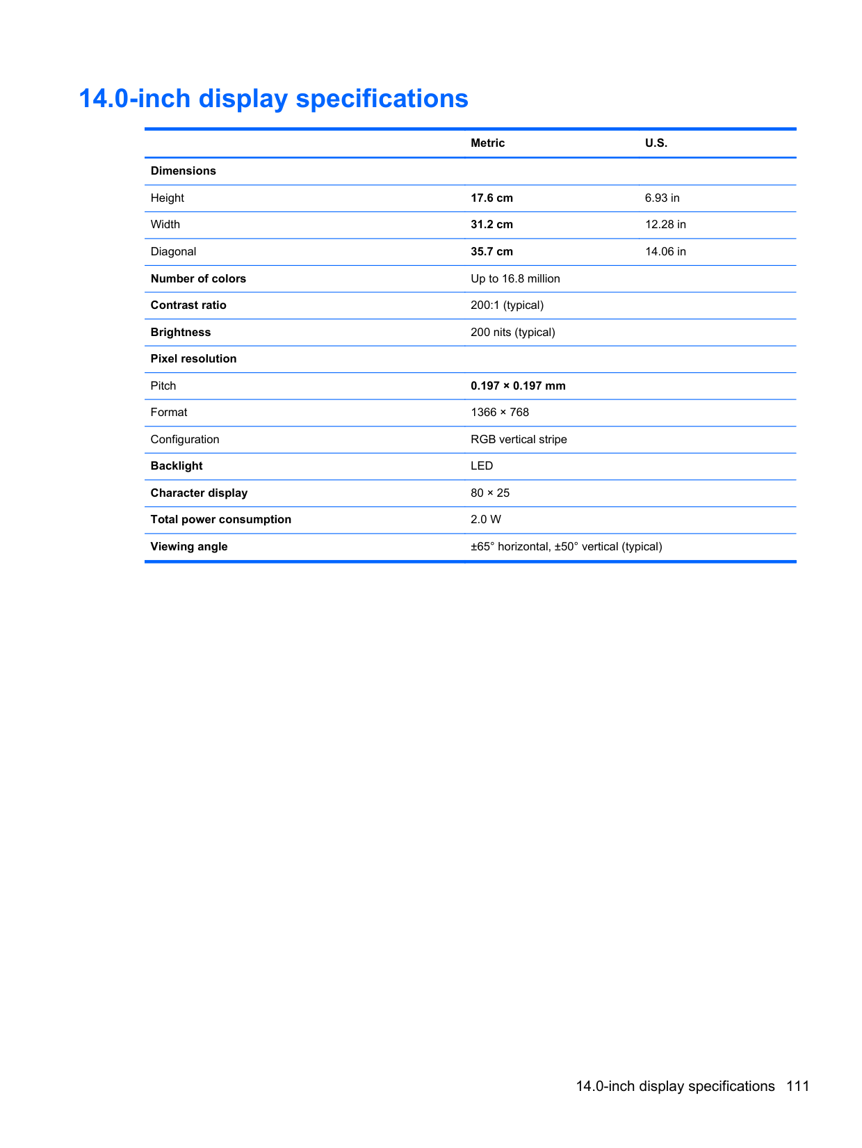
14.0-inch display specifications
######## Metric U.S.
Dimensions Height 17.6 cm 6.93 in Width 31.2 cm 12.28 in Diagonal 35.7 cm 14.06 in Number of colors Up to 16.8 million Contrast ratio 200:1 (typical) Brightness 200 nits (typical) Pixel resolution Pitch 0.197 × 0.197 mm Format 1366 × 768 Configuration RGB vertical stripe Backlight LED Character display 80 × 25 Total power consumption 2.0 W Viewing angle ±65° horizontal, ±50° vertical (typical)
14.0-inch display specifications 111
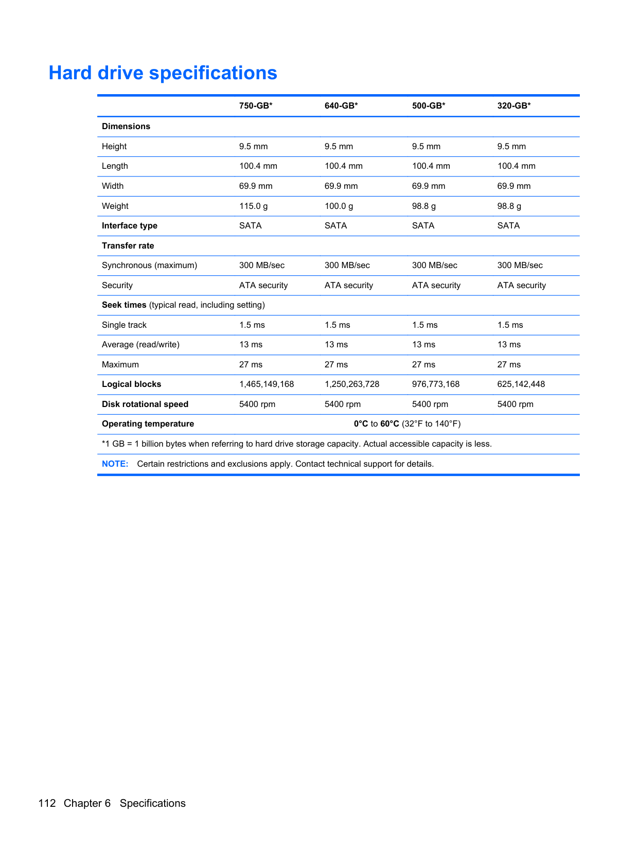
Hard drive specifications
######## 750-GB* 640-GB* 500-GB* 320-GB*
Dimensions Height 9.5 mm 9.5 mm 9.5 mm 9.5 mm Length 100.4 mm 100.4 mm 100.4 mm 100.4 mm Width 69.9 mm 69.9 mm 69.9 mm 69.9 mm Weight 115.0 g 100.0 g 98.8 g 98.8 g Interface type SATA SATA SATA SATA Transfer rate Synchronous (maximum) 300 MB/sec 300 MB/sec 300 MB/sec 300 MB/sec Security ATA security ATA security ATA security ATA security Seek times (typical read, including setting) Single track 1.5 ms 1.5 ms 1.5 ms 1.5 ms Average (read/write) 13 ms 13 ms 13 ms 13 ms Maximum 27 ms 27 ms 27 ms 27 ms Logical blocks 1,465,149,168 1,250,263,728 976,773,168 625,142,448 Disk rotational speed 5400 rpm 5400 rpm 5400 rpm 5400 rpm Operating temperature 0°C to 60°C (32°F to 140°F)
*1 GB = 1 billion bytes when referring to hard drive storage capacity. Actual accessible capacity is less. NOTE: Certain restrictions and exclusions apply. Contact technical support for details.
7 Backup and recovery
Windows 7 – Backup and recovery
To protect your information, use Windows Backup and Restore to back up individual files and folders, back up your entire hard drive (select models only), create system repair discs (select models only) with an optional external optical drive, or create system restore points. In case of system failure, you can use the backup files to restore the contents of your computer.
Windows Backup and Restore provides the following options:
| | |---|
In case of system instability, HP recommends that you print the recovery procedures and save them for later use.
NOTE: Windows includes the User Account Control feature to improve the security of your computer. You may be prompted for your permission or password for tasks such as installing software, running utilities, or changing Windows settings. See Help and Support for more information.
| | |---|
#### Creating recovery media with HP Recovery Disc Creator
HP Recovery Disc Creator is a software program that offers an alternative way to create recovery media. After you successfully set up the computer, you can create recovery media using HP Recovery Disc Creator. This recovery media performs a system recovery if the hard drive becomes corrupted. A system recovery reinstalls the original operating system and the software programs installed at the factory, and then configures the settings for the programs.
HP Recovery Disc Creator can create two kinds of recovery DVDs as follows:
Software Setup utility installs drivers and applications. Creating recovery media

NOTE: Operating system recovery media can be created only once. Thereafter, the option to create that media will not be available.
| | |---|
#### Backing up your information
Recovery after a system failure is as good as your most recent backup. Immediately after software setup, you should create system repair discs (select models only) using HP Recovery Disc Creator using the installed optical drive (select models only) or an optional external optical drive and back up your system. As you add new software and data files, you should continue to back up your system on a regular basis to maintain a reasonably current backup. The system repair discs (select models only) are used to start up (boot) the computer and repair the operating system in case of system instability or failure. Your initial and subsequent backups allow you to restore your data and settings if a failure occurs.
You can back up your information to an optional external hard drive, a network drive, or discs. Note the following when backing up:
| |
|---|
NOTE: DVDs and DVDs with double-layer (DL) support store more information than CDs, so using them for backup reduces the number of recovery discs required.
| | |---|
NOTE: The backup process may take over an hour, depending on file size and the speed of the computer.
| | |---|
#### Performing a system recovery
In case of system failure or instability, the computer provides the following tools to recover your files:
NOTE: If you are unable to boot (start up) your computer and you cannot use the system repair
| | |---|
discs you previously created (select models only), you must purchase a Windows 7 operating system DVD to reboot the computer and repair the operating system. For additional information, see Using a Windows 7 operating system DVD (purchased separately) on page 116.
##### Using the Windows recovery tools
To recover information you previously backed up:
only), or your files. To recover your information using Startup Repair, follow these steps:
CAUTION: Using Startup Repair completely erases hard drive contents and reformats the hard drive. All files you have created and any software installed on the computer are permanently removed. When reformatting is complete, the recovery process restores the operating system, as well as the drivers, software, and utilities from the backup used for recovery.
To check for the HP Recovery partition, click Start, right-click Computer, click Manage, and then click Disk Management.
| | |---|
NOTE: If the HP Recovery partition has been deleted, the f11 restore option will not function. You must recover your operating system and programs using the Windows 7 operating system DVD and the Driver Recovery disc (both purchased separately) if the Windows partition and the HP Recovery partition are not listed. For additional information, see Using a Windows 7 operating system DVD (purchased separately) on page 116.
NOTE: For additional information on recovering information using the Windows tools, perform a search for these topics in Help and Support.
| | |---|
##### Using f11 recovery tools
CAUTION: Using f11 recovery tools completely erases hard drive contents and reformats the hard drive. All files you have created and any software installed on the computer are permanently removed. The f11 recovery tool reinstalls the operating system and HP programs and drivers that were installed at the factory. Software not installed at the factory must be reinstalled.
To recover the original hard drive image using f11:
| | |---|
NOTE: If the HP Recovery partition is not listed, you must recover your operating system and programs using the Windows 7 operating system DVD and the Driver Recovery disc (both purchased separately). For additional information, see Using a Windows 7 operating system DVD (purchased separately) on page 116.
##### Using a Windows 7 operating system DVD (purchased separately)
To order a Windows 7 operating system DVD, go to the HP website. For U.S. support, go to http:// www.hp.com/go/contactHP. For worldwide support, go to http://welcome.hp.com/country/us/en/ wwcontact_us.html. You can also order the DVD by calling support. For contact information, see the Worldwide Telephone Numbers booklet included with the computer.
CAUTION: Using a Windows 7 operating system DVD completely erases hard drive contents and
reformats the hard drive. All files you have created and any software installed on the computer are permanently removed. When reformatting is complete, the recovery process helps you restore the operating system, as well as drivers, software, and utilities.
To initiate recovery using a Windows 7 operating system DVD: NOTE: This process takes several minutes.
| | |---|
Windows 8 – Backup and recovery
To protect your information, use Windows Backup and Restore to back up individual files and folders, back up your entire hard drive, create system repair media (select models only) by using an optional external optical drive, or create system restore points. In case of system failure, you can use the backup files to restore the contents of your computer.
From the Start screen, type restore, click Settings, and then select from the list of displayed options.
NOTE: For detailed instructions on various backup and restore options, perform a search for these topics in Help and Support. From the Start screen, type help, and then select Help and Support. In case of system instability, HP recommends that you print the recovery procedures and save them for later use. NOTE: Windows includes the User Account Control feature to improve the security of your
| | |---|
| | |---|
computer. You may be prompted for your permission or password for tasks such as installing software, running utilities, or changing Windows settings. Refer to Help and Support for more information. From the Start screen, type help, and then select Help and Support.
#### Backing up your information
Recovery after a system failure is as good as your most recent backup. You should create system repair media and your initial backup immediately after initial system setup. As you add new software and data files, you should continue to back up your system on a regular basis to maintain a reasonably current backup. As you add new software and data files, you should continue to back up your system on a regular basis to maintain a reasonably current backup. The system repair media (select models only) are used to start up (boot) the computer and repair the operating system in case of system instability or failure. Your initial and subsequent backups allow you to restore your data and settings if a failure occurs.
On Start screen, type backup, select Settings, and then select Save backup copies of your files with File History.
You can back up your information to an optional external hard drive or a network drive. Note the following when backing up:
To create a backup using Backup and Restore: NOTE: Be sure that the computer is connected to AC power before you start the backup process. NOTE: The backup process may take over an hour, depending on file size and the speed of the computer.
| | |---|
| | |---|
#### Performing a system recovery
In case of system failure or instability, the computer provides the following tools to recover your files:
NOTE: If you are unable to boot (start up) your computer and you cannot use the system repair media you previously created (select models only), you must purchase Windows 8 operating system media to reboot the computer and repair the operating system.
| | |---|
##### Using the Windows recovery tools
To recover information you previously backed up:
▲ From the Start screen, type help, and then select Help and Support. To recover your information using Automatic Repair, follow these steps:
CAUTION: Some Automatic Repair options will completely erase and reformat the hard drive. All files you have created and any software installed on the computer are permanently removed. When reformatting is complete, the recovery process restores the operating system, as well as the drivers, software, and utilities from the backup used for recovery.
– or – From the Start screen, type computer, and then select Computer. NOTE: If the Windows partition and the HP Recovery partition are not listed, you must recover your operating system and programs using the Windows 8 operating system DVD and the Driver Recovery media (both purchased separately).
| | |---|
NOTE: For additional information on recovering information using the Windows tools, perform a search for these topics in Help and Support. From the Start screen, type help, and then select Help and Support.
| | |---|
##### Using f11 recovery tools
CAUTION: Using f11 completely erases hard drive contents and reformats the hard drive. All files
that you have created and any software that you have installed on the computer are permanently removed. The f11 recovery tool reinstalls the operating system and HP programs and drivers that were installed at the factory. Software not installed at the factory must be reinstalled.
To recover the original hard drive image using f11:
| | |---|
NOTE: If the HP Recovery partition is not listed, you must recover your operating system and programs using the Windows 8 operating system media and the Driver Recovery media (both purchased separately). For additional information, see Using a Windows 7 operating system DVD (purchased separately) on page 116.
##### Using Windows 8 operating system media (purchased separately)
To order a Windows 8 operating system DVD, go to http://www.hp.com/support, select your country or region, and follow the on-screen instructions. You can also order the DVD by calling support. For contact information, see the Worldwide Telephone Numbers booklet included with the computer.
CAUTION: Using a Windows 8 operating system media completely erases hard drive contents and reformats the hard drive. All files that you have created and any software that you have installed on the computer are permanently removed. When reformatting is complete, the recovery process helps you restore the operating system, as well as drivers, software, and utilities.
To initiate recovery using a Windows 8 operating system DVD: NOTE: This process takes several minutes.
| | |---|
After the repair is completed:
##### Using Windows Refresh for quick and easy recovery
When your computer is not working properly and you need to regain system stability, the Windows Refresh option allows you to start fresh and keep what is important to you.
IMPORTANT: Refresh removes any traditional applications that were not originally installed on the system at the factory.
| | |---|
| | |---|
NOTE: During Refresh, a list of removed traditional applications will be saved so that you have a quick way to see what you might need to reinstall. See Help and Support for instructions on reinstalling traditional applications. From the Start screen, type help, and then select Help and Support.
NOTE: You may be prompted for your permission or password when using Refresh. See Help and Support for more information. From the Start screen, type help, and then select Help and Support.
| | |---|
To start Refresh:
charms.
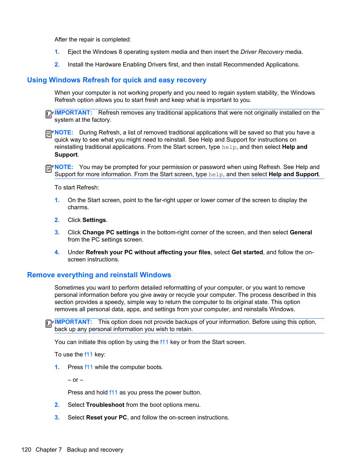
from the PC settings screen.
###### 4. Under Refresh your PC without affecting your files, select Get started, and follow the on-
screen instructions.
##### Remove everything and reinstall Windows
Sometimes you want to perform detailed reformatting of your computer, or you want to remove personal information before you give away or recycle your computer. The process described in this section provides a speedy, simple way to return the computer to its original state. This option removes all personal data, apps, and settings from your computer, and reinstalls Windows.
IMPORTANT: This option does not provide backups of your information. Before using this option, back up any personal information you wish to retain. You can initiate this option by using the f11 key or from the Start screen. To use the f11 key:
| | |---|
– or – Press and hold f11 as you press the power button.
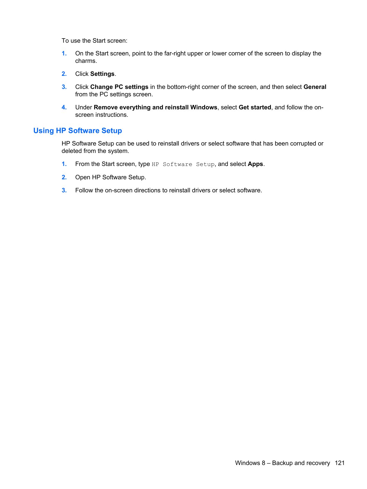
To use the Start screen:
##### Using HP Software Setup
HP Software Setup can be used to reinstall drivers or select software that has been corrupted or deleted from the system.
8 Power cord set requirements
The wide-range input feature of the computer permits it to operate from any line voltage from 100 to 120 volts ac, or from 220 to 240 volts ac.
The 3-conductor power cord set included with the computer meets the requirements for use in the country or region where the equipment is purchased.
Power cord sets for use in other countries and regions must meet the requirements of the country or region where the computer is used.
Requirements for all countries
The following requirements are applicable to all countries and regions:
Requirements for specific countries and regions
######## Country/region Accredited agency Applicable note number
Argentina IRAM 1 Australia SAA 1 Austria OVE 1 Belgium CEBEC 1 Brazil ABNT 1 Canada CSA 2 Chile IMQ 1 Denmark DEMKO 1 Finland FIMKO 1 France UTE 1 Germany VDE 1 India ISI 1 Israel SII 1 Italy IMQ 1 Japan JIS 3 The Netherlands KEMA 1 New Zealand SANZ 1 Norway NEMKO 1 The People's Republic of China CCC 4 Saudi Arabia SASO 7 Singapore PSB 1 South Africa SABS 1 South Korea KTL 5 Sweden SEMKO 1 Switzerland SEV 1 Taiwan BSMI 6 Thailand TISI 1 The United Kingdom ASTA 1
Requirements for specific countries and regions 123
Country/region Accredited agency Applicable note number The United States UL 2
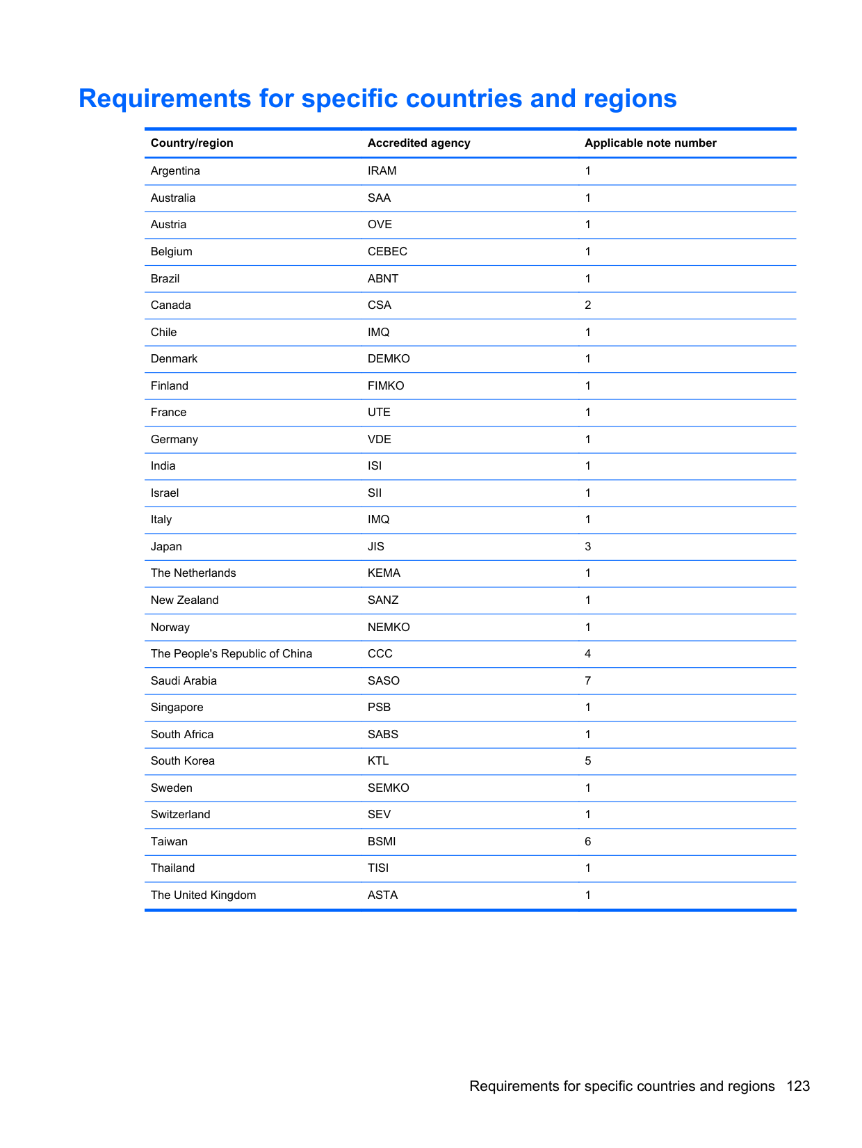
9 Recycling
Battery
When a non-rechargeable or rechargeable battery has reached the end of its useful life, do not dispose of the battery in general household waste. Follow the local laws and regulations in your area for battery disposal.
HP encourages customers to recycle used electronic hardware, HP original print cartridges, and rechargeable batteries. For more information about recycling programs, see the HP Web site at http://www.hp.com/recycle.
Display
WARNING! The backlight contains mercury. Caution must be exercised when removing and handling the backlight to avoid damaging this component and causing exposure to the mercury.
CAUTION: The procedures in this chapter can result in damage to display components. The only components intended for recycling purposes are the liquid crystal display (LCD) panel and the backlight. When you remove these components, handle them carefully.
NOTE: Materials Disposal. This HP product contains mercury in the backlight in the display
| | |---|
assembly that might require special handling at end-of-life. Disposal of mercury may be regulated because of environmental considerations. For disposal or recycling information, contact your local authorities, or see the Electronic Industries Alliance (EIA) Web site at http://www.eiai.org.
This section provides disassembly instructions for the display assembly. The display assembly must be disassembled to gain access to the backlight (1) and the liquid crystal display (LCD) panel (2).

NOTE: The procedures provided in this chapter are general disassembly instructions. Specific details, such as screw sizes, quantities, and locations, and component shapes and sizes, can vary from one computer model to another.
| | |---|
Battery 125
Perform the following steps:

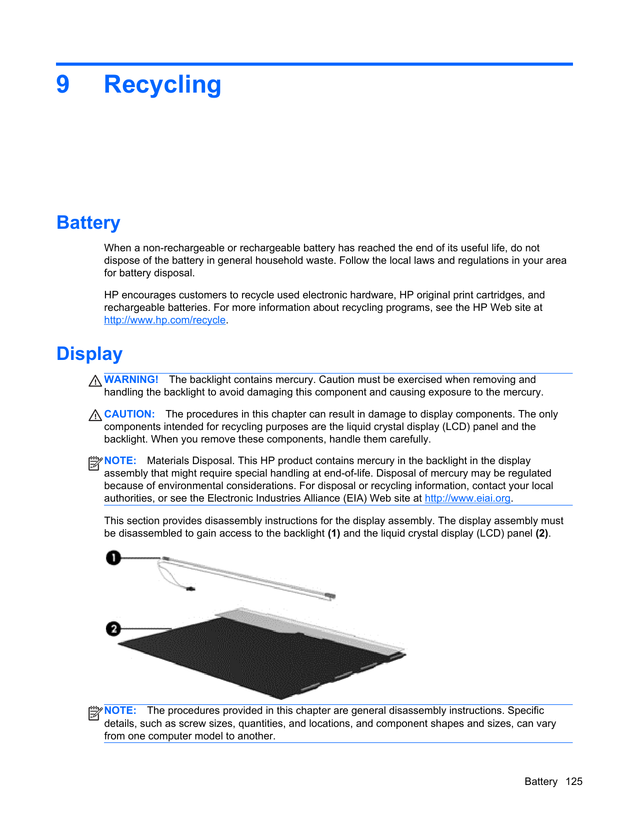


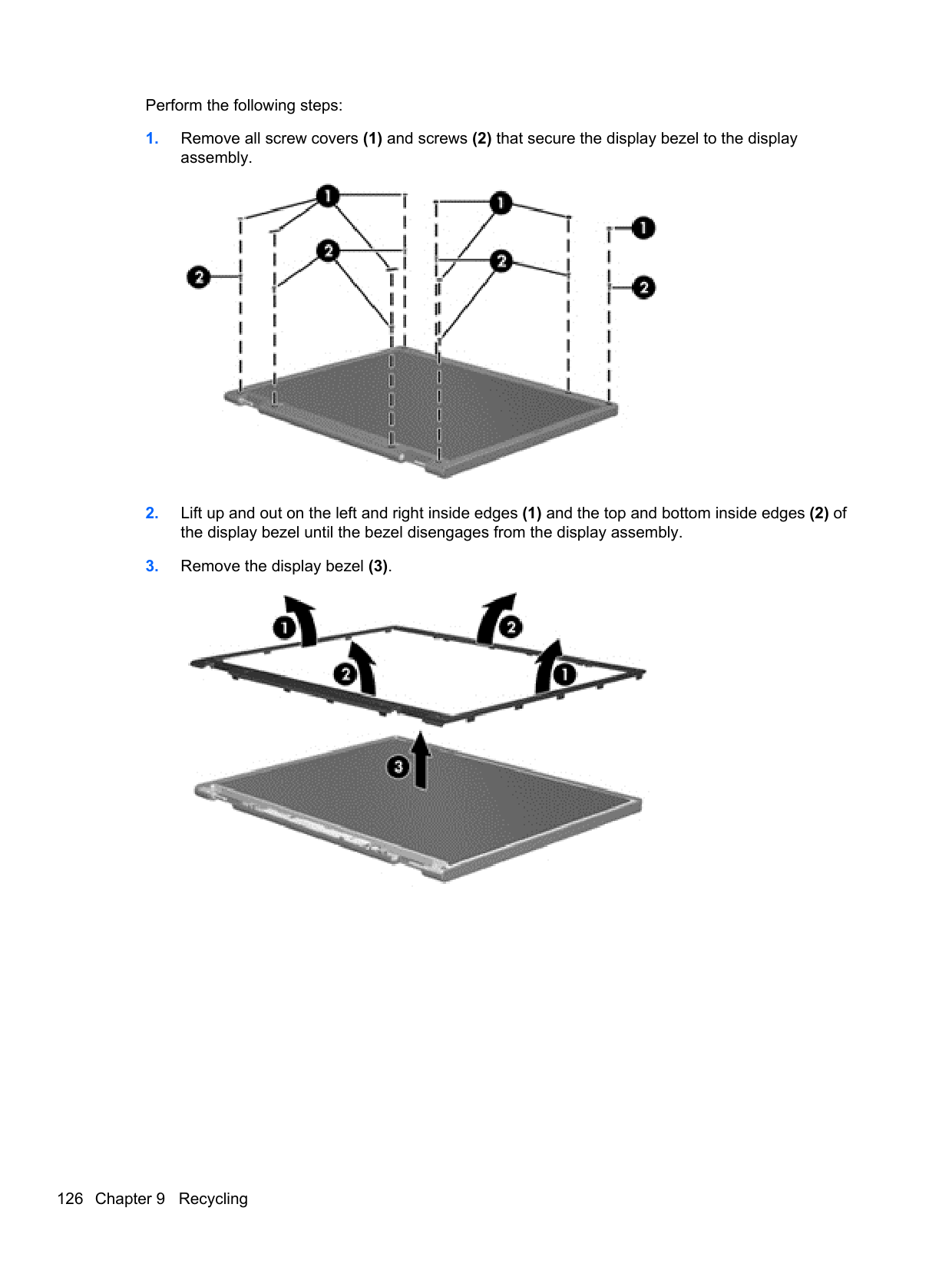


WARNING! The backlight contains mercury. Exercise caution when removing and handling the backlight to avoid damaging this component and causing exposure to the mercury.
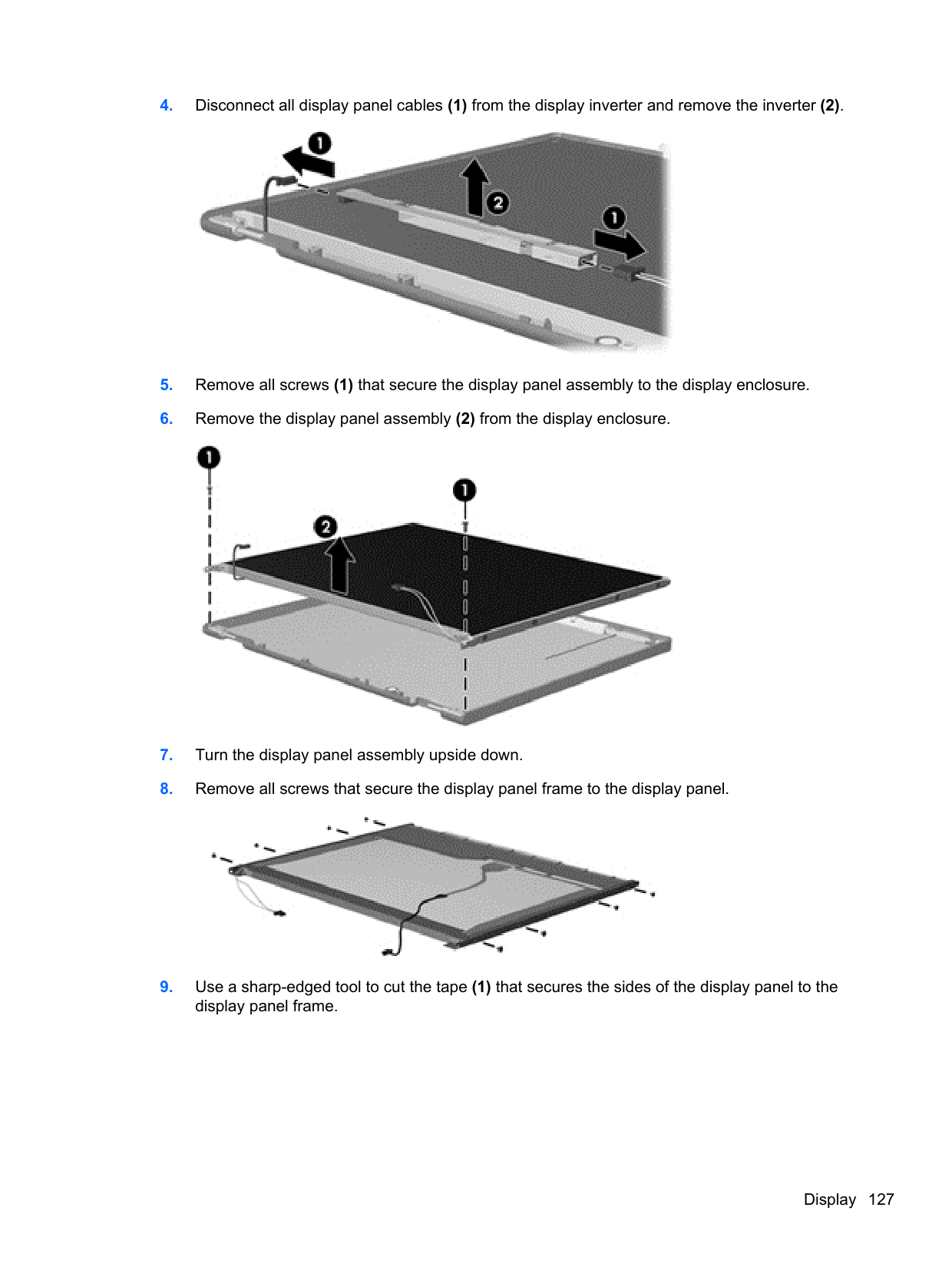


Index
31 advanced system diagnostics 104, 108
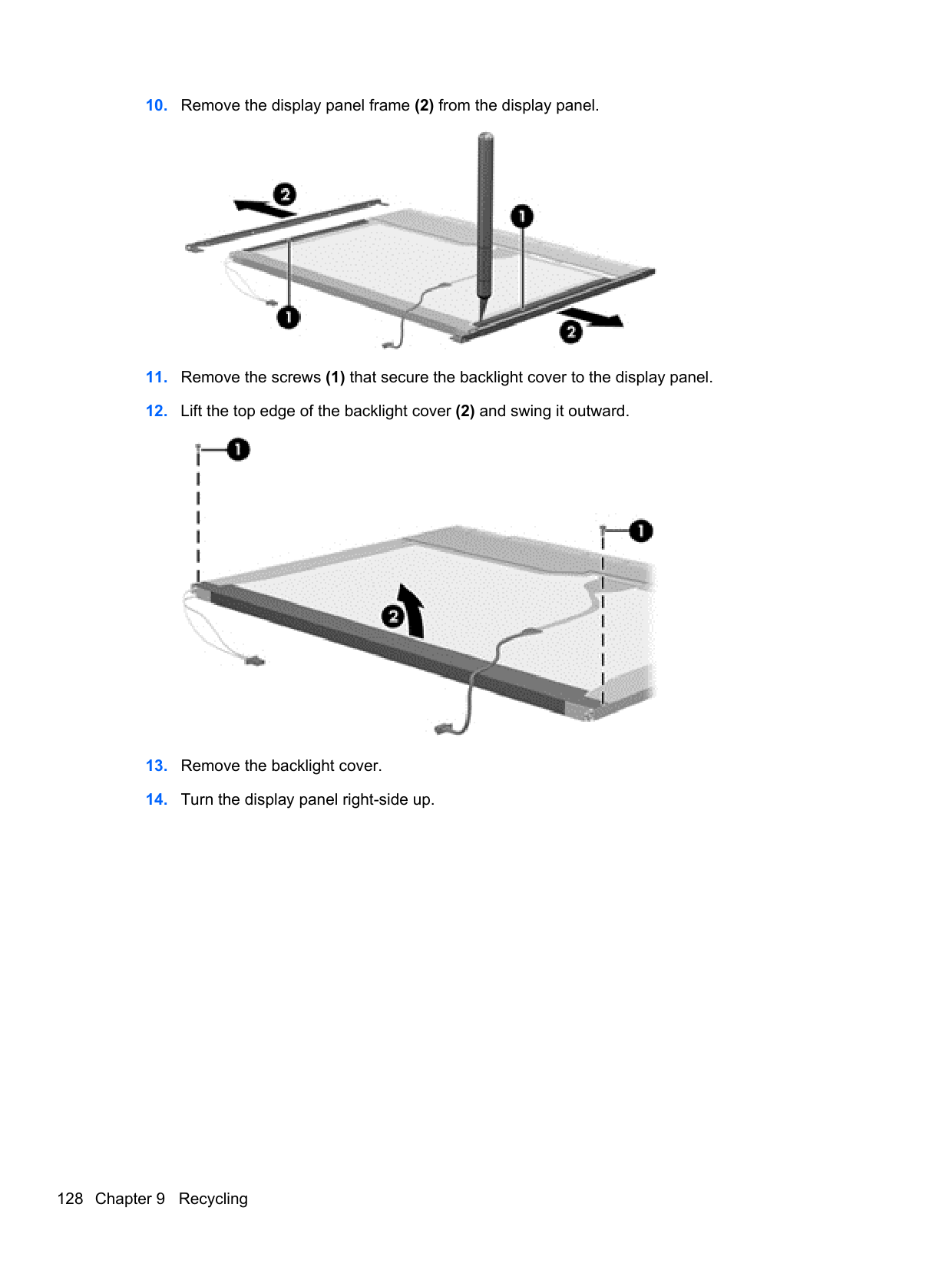
antennas identifying 12 illustrated 24 removing 85 spare part number 29 audio, product description 5 audio-in (microphone) jack,
identifying 10 audio-out (headphone) jack, identifying 10
illustrated 22 spare part number 32
battery
illustrated 22 removing 41 spare part number 28
battery bay, identifying 17 battery release latch, identifying
17 BIOS determining version 103, 107 downloading an update 103,
107 updating 103, 107
buttons left TouchPad 13 optical drive eject 9 power 15
right TouchPad 13 TouchPad on/off 13
C cables, service considerations 33 caps lock light, identifying 14 chipset, product description 3 components
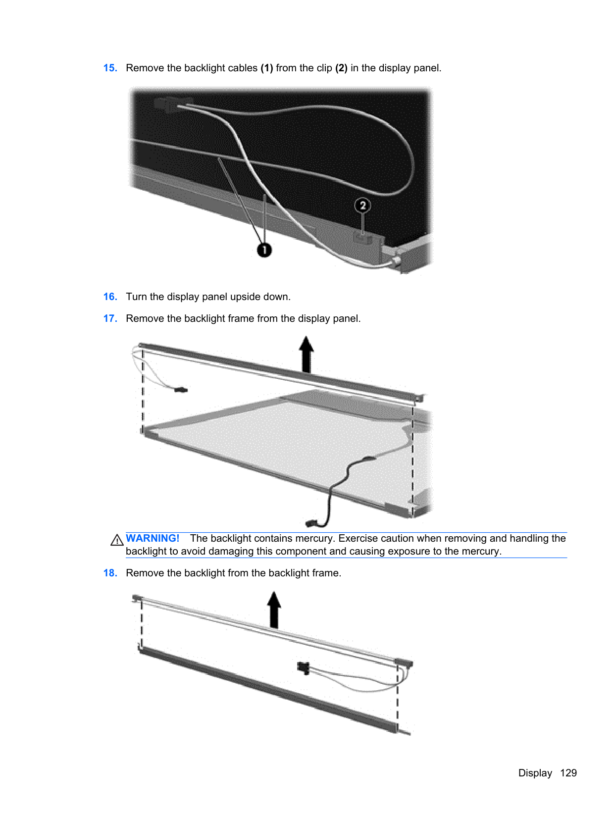
bottom 17 display 12 front 8 left side 10 right side 9 top 13 computer feet locating 40 spare part number 29 computer major components,
illustrated 18 Computer Setup
navigating and selecting 101,
restoring factory settings 102,
computer specifications 110 connectors, service
considerations 33
D Digital Media Slot, identifying 10 display assembly
illustrated 19 removing 42, 77
display assembly subcomponents illustrated 23 removing 42, 77
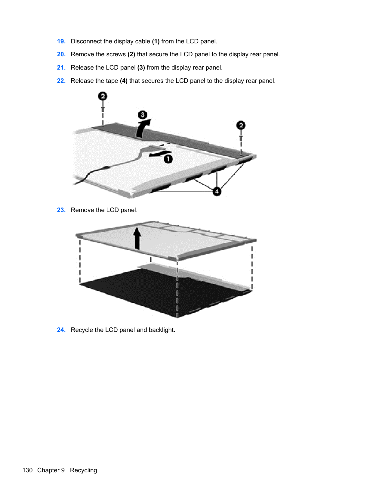
display bezel illustrated 23
removing 42, 79 spare part number 29
display bumpers, spare part
number 29 display cable
illustrated 24 removing 83 spare part number 29
display enclosure illustrated 24, 32 removing 85
display panel illustrated 23 product description 4 removing 47, 83 spare part number 29, 32
display specifications 111
10
illustrated 19 removing 92 spare part number 29, 30
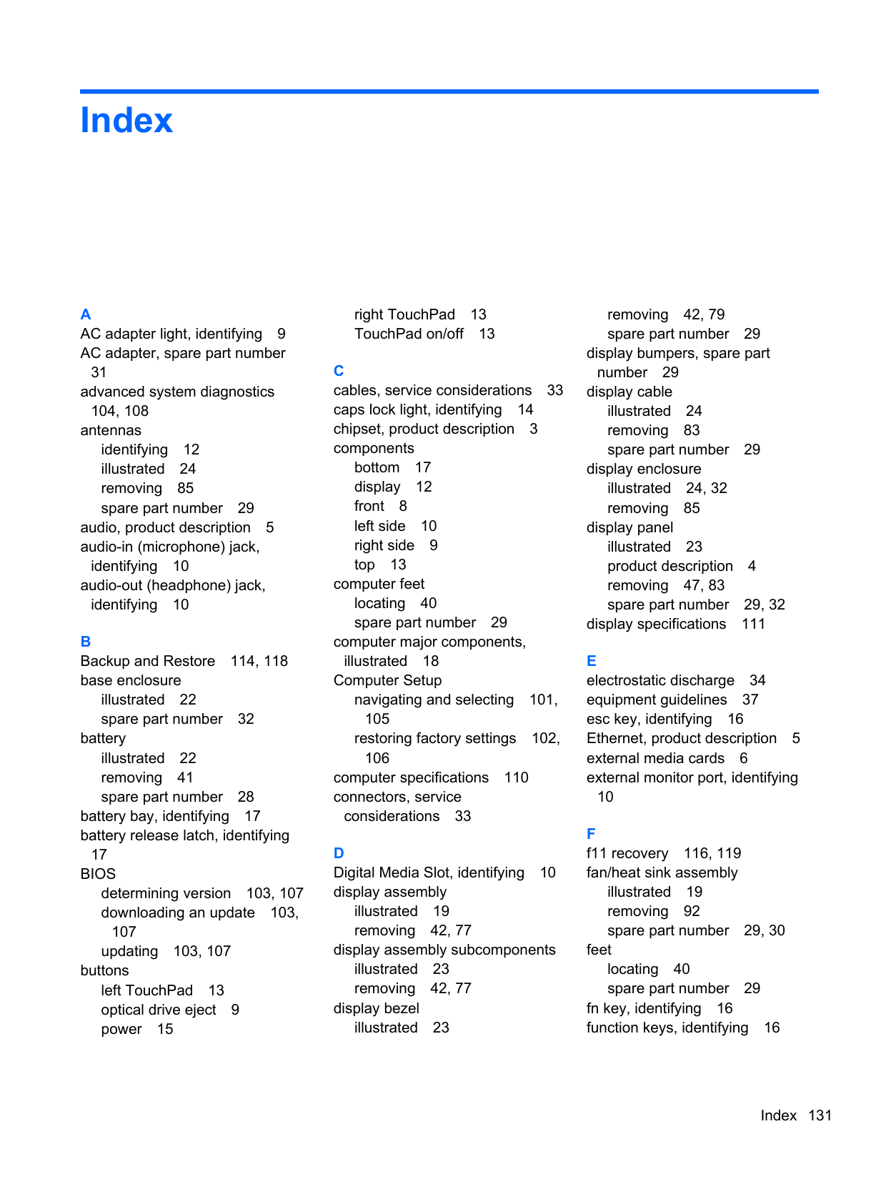
feet
locating 40 spare part number 29
fn key, identifying 16 function keys, identifying 16
equipment 37 grounding 34 packaging 36 transporting 36 workstation 36
illustrated 22, 25 precautions 34 product description 4 removing 54 spare part number 28 specifications 112
hard drive bay, identifying 17 hard drive bracket
illustrated 25 removing 55 spare part number 29
hard drive cable
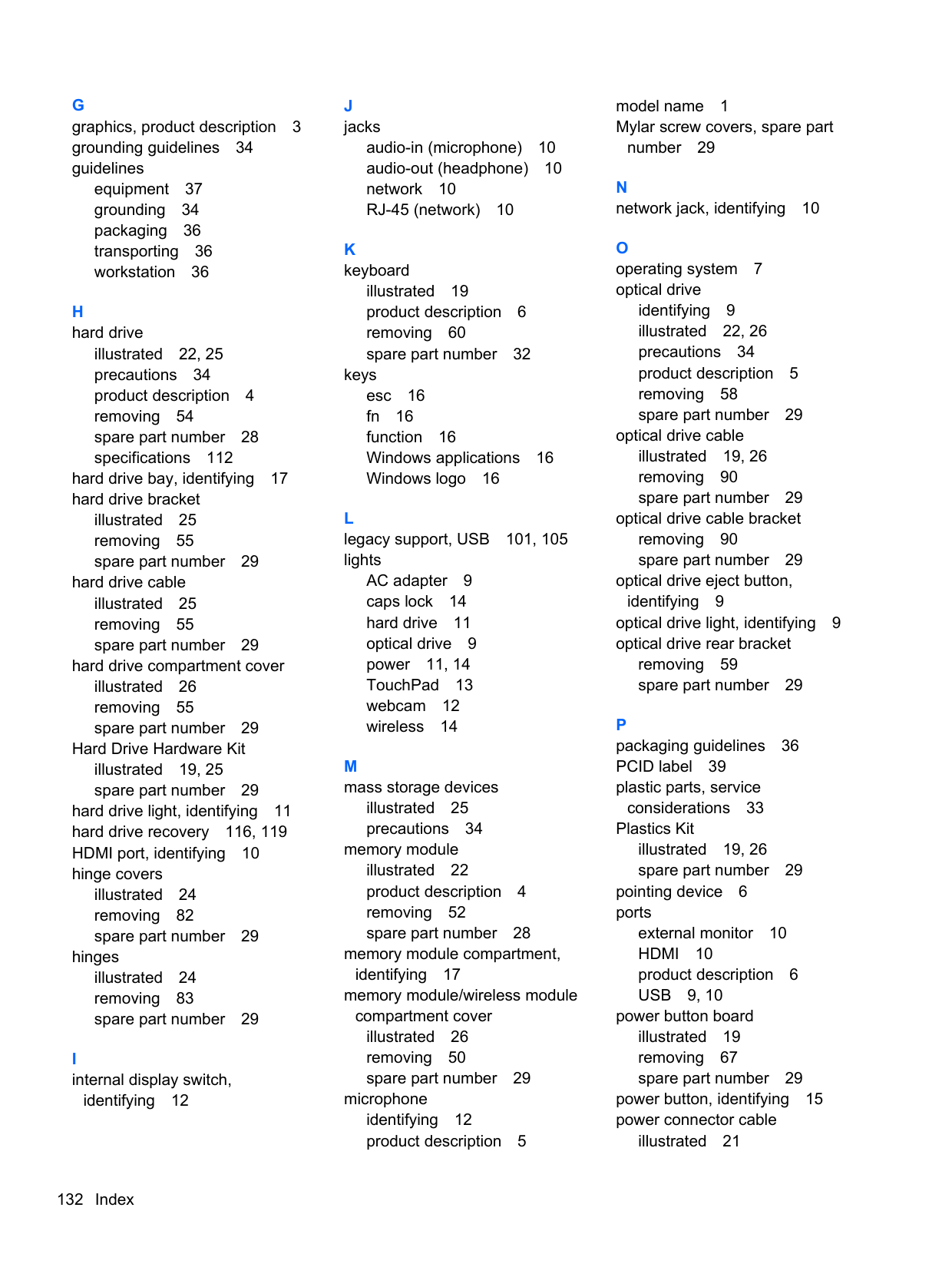
Hard Drive Hardware Kit illustrated 19, 25 spare part number 29
hard drive light, identifying 11 hard drive recovery 116, 119 HDMI port, identifying 10 hinge covers
illustrated 24 removing 82 spare part number 29
hinges
illustrated 24 removing 83 spare part number 29
identifying 12
audio-in (microphone) 10 audio-out (headphone) 10 network 10 RJ-45 (network) 10
illustrated 19 product description 6 removing 60 spare part number 32
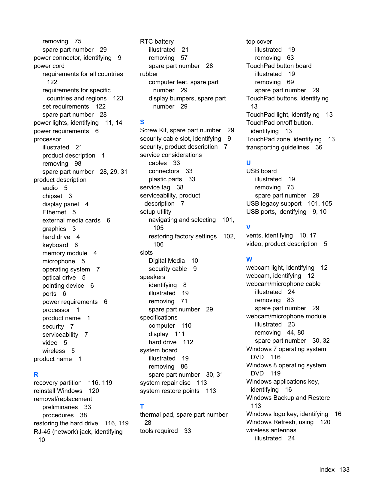
keys esc 16 fn 16 function 16 Windows applications 16 Windows logo 16
AC adapter 9 caps lock 14 hard drive 11 optical drive 9 power 11, 14 TouchPad 13 webcam 12 wireless 14
illustrated 25 precautions 34
memory module illustrated 22 product description 4 removing 52 spare part number 28
memory module compartment, identifying 17 memory module/wireless module compartment cover
illustrated 26 removing 50 spare part number 29
microphone identifying 12 product description 5
model name 1 Mylar screw covers, spare part
number 29
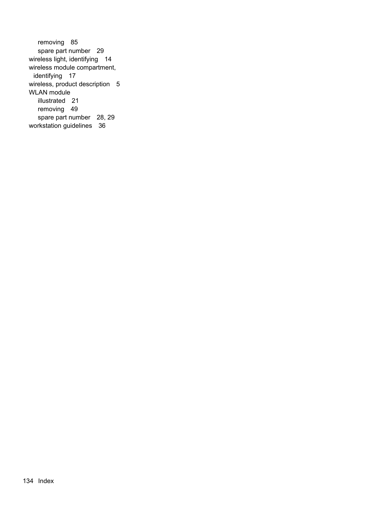
identifying 9 illustrated 22, 26 precautions 34 product description 5 removing 58 spare part number 29
optical drive cable illustrated 19, 26 removing 90 spare part number 29
optical drive cable bracket removing 90 spare part number 29
optical drive eject button,
identifying 9 optical drive light, identifying 9 optical drive rear bracket
removing 59 spare part number 29
considerations 33
Plastics Kit illustrated 19, 26 spare part number 29
pointing device 6 ports
external monitor 10 HDMI 10 product description 6 USB 9, 10
power button board
illustrated 19 removing 67 spare part number 29 power button, identifying 15 power connector cable
illustrated 21
removing 75 spare part number 29
power connector, identifying 9 power cord
requirements for all countries 122 requirements for specific countries and regions 123
set requirements 122 spare part number 28
power lights, identifying 11, 14 power requirements 6 processor
illustrated 21 product description 1 removing 98 spare part number 28, 29, 31
product description audio 5 chipset 3 display panel 4 Ethernet 5 external media cards 6 graphics 3 hard drive 4 keyboard 6 memory module 4 microphone 5 operating system 7 optical drive 5 pointing device 6 ports 6 power requirements 6 processor 1 product name 1 security 7 serviceability 7 video 5 wireless 5 product name 1
R recovery partition 116, 119 reinstall Windows 120 removal/replacement
preliminaries 33 procedures 38
restoring the hard drive 116, 119 RJ-45 (network) jack, identifying
10
RTC battery
illustrated 21 removing 57 spare part number 28
rubber computer feet, spare part number 29 display bumpers, spare part number 29
cables 33 connectors 33 plastic parts 33
service tag 38 serviceability, product
description 7 setup utility
navigating and selecting 101,
restoring factory settings 102,
slots Digital Media 10 security cable 9
speakers identifying 8 illustrated 19 removing 71 spare part number 29
specifications computer 110 display 111 hard drive 112
system board
illustrated 19 removing 86 spare part number 30, 31
system repair disc 113 system restore points 113
28 tools required 33
top cover
illustrated 19 removing 63
TouchPad button board
illustrated 19 removing 69 spare part number 29 TouchPad buttons, identifying
13 TouchPad light, identifying 13 TouchPad on/off button,
identifying 13 TouchPad zone, identifying 13 transporting guidelines 36
illustrated 19 removing 73 spare part number 29
USB legacy support 101, 105 USB ports, identifying 9, 10
illustrated 24 removing 83
webcam/microphone module illustrated 23 removing 44, 80
Windows applications key, identifying 16 Windows Backup and Restore
113 Windows logo key, identifying 16 Windows Refresh, using 120 wireless antennas
illustrated 24
removing 85 spare part number 29 wireless light, identifying 14 wireless module compartment,
identifying 17 wireless, product description 5 WLAN module
illustrated 21 removing 49 spare part number 28, 29
workstation guidelines 36