
Ask AI
— answers from the official manualAnswers from the official manual.
Common questions
Common Questions
9 totalHow do I turn on or off the touchpad?
To turn the touchpad on or off, press the 'Touchpad On/Off' action key (an icon of a hand) located in the function keys row. If necessary, combine this with pressing the fn key to activate the correct function.
What should I do if my computer fan is making loud noises?
It's normal for your computer's fan to cycle on and off during routine operation, including making occasional loud noises as it powers up or adjusts speed. If the noise persists excessively, ensure no hard surfaces block air vents and that dirt hasn't accumulated inside the system which might be obstructing ventilation.
What does an amber-blinking power adapter light indicate on my computer?
An amber-light blinking LED for the AC adapter indicates that there is a low battery level and the AC adapter is not connected to charge it. Connect the adapter to both resolve charging issues and prevent unexpected shutdowns.
How do I clean my display assembly according to HP's guidelines?
To safely remove dirt from your computer's display, first unplug it. Use a cloth moistened with water but not dripping wet; avoid abrasive materials. Clean the display using gentle motions from top to bottom, then dry completely before use.
What are the different USB ports and their functions?
There are several USB SuperSpeed (USB Type-A) ports which allow data transfer and charge small devices like smartphones even when off; one is HP Sleep & Charge capable. Additionally, there's a USB 3.2 Gen 2 Type-C port with DisplayPort output capability.
Where can I find my product serial number for service purposes?
The service label will have your product’s serial number, typically located underneath the computer, inside battery bay doors, or on various labels provided. Refer to Table 2-11 and subsequent tables for detailed placement descriptions.
Full Manual
91 pages

Maintenance and Service Guide
SUMMARY This guide provides information about spare parts, removal and replacement of parts, security, backing up, and more.
© Copyright 2021 HP Development Company, L.P.
AMD, Radeon, and Ryzen are trademarks of Advanced Micro Devices, Inc. Bluetooth is a trademark owned by its proprietor and used by HP Inc. under license. SDHC, SDXC, and microSD are trademarks or registered trademarks of SD-3C LLC. Microsoft and Windows are either registered trademarks or trademarks of Microsoft Corporation in the United States and/or other countries. NVIDIA, GeForce, and Optimus are trademarks and/or registered trademarks of NVIDIA Corporation in the U.S. and other countries. USB Type-C and USB-C are registered trademarks of USB Implementers Forum. DisplayPort™ and the DisplayPort™ logo are trademarks owned by the Video Electronics Standards Association (VESA®) in the United States and other countries. Miracast® is a registered trademark of Wi-Fi Alliance.
The information contained herein is subject to change without notice. The only warranties for HP products and services are set forth in the express warranty statements accompanying such products and services. Nothing herein should be construed as constituting an additional warranty. HP shall not be liable for technical or editorial errors or omissions contained herein.
First Edition: May 2021 Document Part Number: M50596-001
######### Product notice
This guide describes features that are common to most models. Some features may not be available on your computer.
Not all features are available in all editions or versions of Windows. Systems may require upgraded and/or separately purchased hardware, drivers, software or BIOS update to take full advantage of Windows functionality. Windows 10 is automatically updated, which is always enabled. ISP fees may apply and additional requirements may apply over time for updates. Go to http://www.microsoft.com for details.
To access the latest user guides, go to http://www.hp.com/support, and follow the instructions to find your product. Then select Manuals.
######### Software terms
By installing, copying, downloading, or otherwise using any software product preinstalled on this computer, you agree to be bound by the terms of the HP End User License Agreement (EULA). If you do not accept these license terms, your sole remedy is to return the entire unused product (hardware and software) within 14 days for a full refund subject to the refund policy of your seller.
For any further information or to request a full refund of the price of the computer, please contact your seller.
#### Safety warning notice
Reduce the possibility of heat-related injuries or of overheating the computer by following the practices described.
WARNING! To reduce the possibility of heat-related injuries or of overheating the computer, do not place the computer directly on your lap or obstruct the computer air vents. Use the computer only on a hard, flat surface. Do not allow another hard surface, such as an adjoining optional printer, or a soft surface, such as pillows or rugs or clothing, to block airflow. Also, do not allow the AC adapter to come into contact with the skin or a soft surface, such as pillows or rugs or clothing, during operation. The computer and the AC adapter comply with the user-accessible surface temperature limits defined by applicable safety standards.
iii
####### iv Safety warning notice
#### Important notice about Customer Self-Repair parts
Your computer includes Customer Self-Repair parts and parts that should be accessed by only an authorized service provider.
| | |---|
IMPORTANT: See "Removal and replacement procedures for Customer Self-Repair parts" for details.
Accessing parts described in "Removal and replacement procedures for authorized service provider parts" can damage the computer or void your warranty.
v
####### vi Important notice about Customer Self-Repair parts
Table of contents
Low blue light mode (select products only) ........................................................................................ 7 Keyboard area ........................................................................................................................................................ 8 Touchpad settings and components ................................................................................................... 8

Touchpad settings ............................................................................................................. 9 Adjusting touchpad settings .......................................................................... 9 Turning on the touchpad ................................................................................ 9
Touchpad components ...................................................................................................... 9 Lights ................................................................................................................................................. 10 Button ................................................................................................................................................ 10 Special keys ....................................................................................................................................... 11 Action keys ........................................................................................................................................ 13
Bottom ................................................................................................................................................................. 14 Rear ...................................................................................................................................................................... 15 Labels ................................................................................................................................................................... 15
Plastic parts ....................................................................................................................................... 25 Cables and connectors ...................................................................................................................... 25 Drive handling ................................................................................................................................... 25
Electrostatic discharge information .................................................................................................................... 26 Generating static electricity .............................................................................................................. 26 Preventing electrostatic damage to equipment ............................................................................... 27 Personal grounding methods and equipment .................................................................................. 27
vii
Grounding the work area ................................................................................................................... 28 Recommended materials and equipment ........................................................................................ 28
Cleaning your computer ...................................................................................................................................... 29 Enabling HP Easy Clean (select products only) ................................................................................. 29 Removing dirt and debris from your computer ................................................................................ 29 Cleaning your computer with a disinfectant ..................................................................................... 30 Caring for wood veneer (select products only) ................................................................................. 31
Packaging and transporting guidelines .............................................................................................................. 31 Accessing support information ........................................................................................................................... 31
###### 5 Removal and replacement procedures for Customer Self-Repair parts ............................................................. 33Component replacement procedures .................................................................................................................. 33
Preparation for disassembly ............................................................................................................. 33 Solid-state drive ................................................................................................................................ 33 Memory modules ............................................................................................................................... 35
###### 6 Removal and replacement procedures for authorized service provider parts .................................................... 37Component replacement procedures .................................................................................................................. 37
Preparation for disassembly ............................................................................................................. 37 Bottom cover ..................................................................................................................................... 37 Battery ............................................................................................................................................... 38 Speakers ............................................................................................................................................ 40 Card reader ........................................................................................................................................ 40 Heat sink ............................................................................................................................................ 41 Fans ................................................................................................................................................... 43 WLAN module .................................................................................................................................... 44 USB board .......................................................................................................................................... 45 RJ-45 cap ........................................................................................................................................... 46 System board .................................................................................................................................... 47 Touchpad ........................................................................................................................................... 50 Rear fin ............................................................................................................................................... 51 Rear vent ........................................................................................................................................... 52 Display assembly ............................................................................................................................... 53 Power connector cable ...................................................................................................................... 59 Top cover with keyboard ................................................................................................................... 60

####### 7 Using Setup Utility (BIOS) ............................................................................................................................. 62Starting Setup Utility (BIOS) ................................................................................................................................ 62Updating Setup Utility (BIOS) .............................................................................................................................. 62
Determining the BIOS version ........................................................................................................... 62
viii
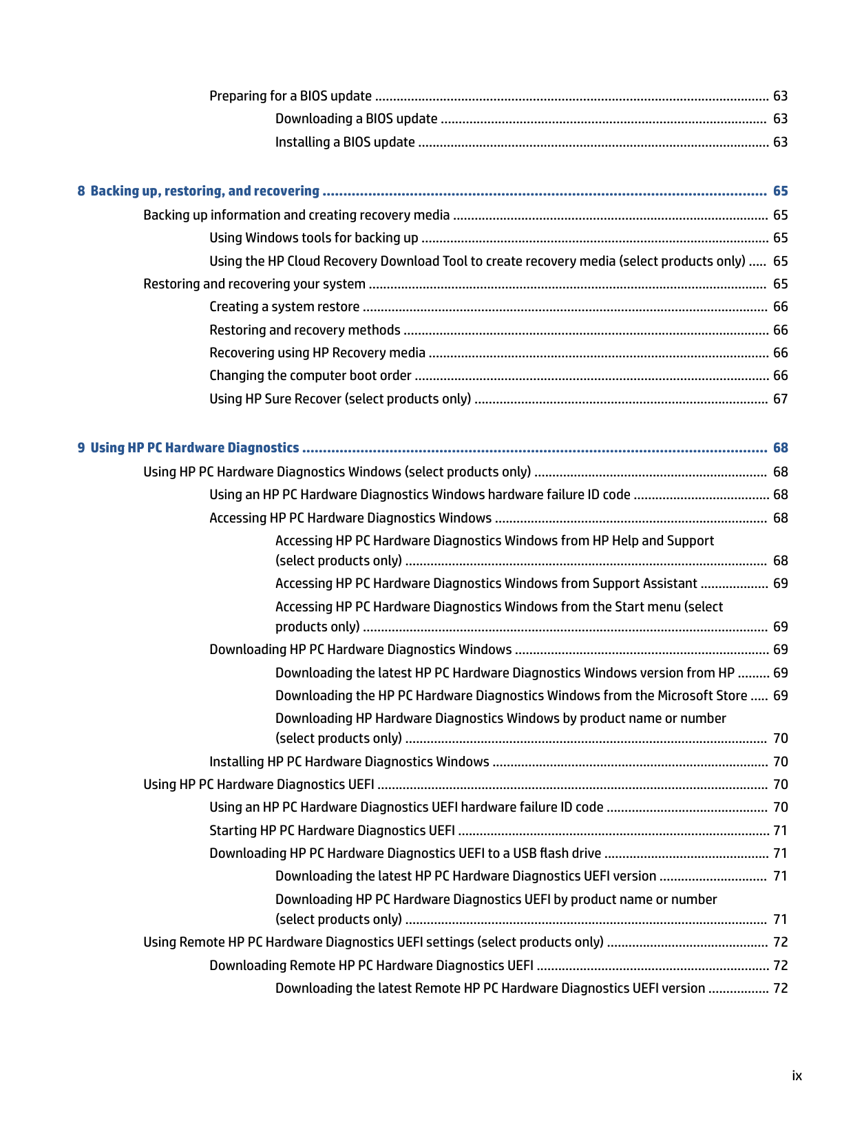
Preparing for a BIOS update .............................................................................................................. 63 Downloading a BIOS update ........................................................................................... 63 Installing a BIOS update .................................................................................................. 63
###### 8 Backing up, restoring, and recovering ........................................................................................................... 65Backing up information and creating recovery media ........................................................................................ 65
Using Windows tools for backing up ................................................................................................. 65 Using the HP Cloud Recovery Download Tool to create recovery media (select products only) ..... 65
Restoring and recovering your system ............................................................................................................... 65 Creating a system restore ................................................................................................................. 66 Restoring and recovery methods ...................................................................................................... 66 Recovering using HP Recovery media ............................................................................................... 66 Changing the computer boot order ................................................................................................... 66 Using HP Sure Recover (select products only) .................................................................................. 67
###### 9 Using HP PC Hardware Diagnostics ................................................................................................................ 68Using HP PC Hardware Diagnostics Windows (select products only) ................................................................. 68
Using an HP PC Hardware Diagnostics Windows hardware failure ID code ...................................... 68 Accessing HP PC Hardware Diagnostics Windows ............................................................................ 68
Accessing HP PC Hardware Diagnostics Windows from HP Help and Support (select products only) ..................................................................................................... 68 Accessing HP PC Hardware Diagnostics Windows from Support Assistant ................... 69 Accessing HP PC Hardware Diagnostics Windows from the Start menu (select products only) ................................................................................................................. 69
Downloading HP PC Hardware Diagnostics Windows ....................................................................... 69 Downloading the latest HP PC Hardware Diagnostics Windows version from HP ......... 69 Downloading the HP PC Hardware Diagnostics Windows from the Microsoft Store ..... 69 Downloading HP Hardware Diagnostics Windows by product name or number (select products only) ..................................................................................................... 70
Installing HP PC Hardware Diagnostics Windows ............................................................................. 70
Using HP PC Hardware Diagnostics UEFI ............................................................................................................. 70 Using an HP PC Hardware Diagnostics UEFI hardware failure ID code ............................................. 70 Starting HP PC Hardware Diagnostics UEFI ....................................................................................... 71 Downloading HP PC Hardware Diagnostics UEFI to a USB flash drive .............................................. 71
Downloading the latest HP PC Hardware Diagnostics UEFI version .............................. 71 Downloading HP PC Hardware Diagnostics UEFI by product name or number (select products only) ..................................................................................................... 71
Using Remote HP PC Hardware Diagnostics UEFI settings (select products only) ............................................. 72 Downloading Remote HP PC Hardware Diagnostics UEFI ................................................................. 72 Downloading the latest Remote HP PC Hardware Diagnostics UEFI version ................. 72

ix
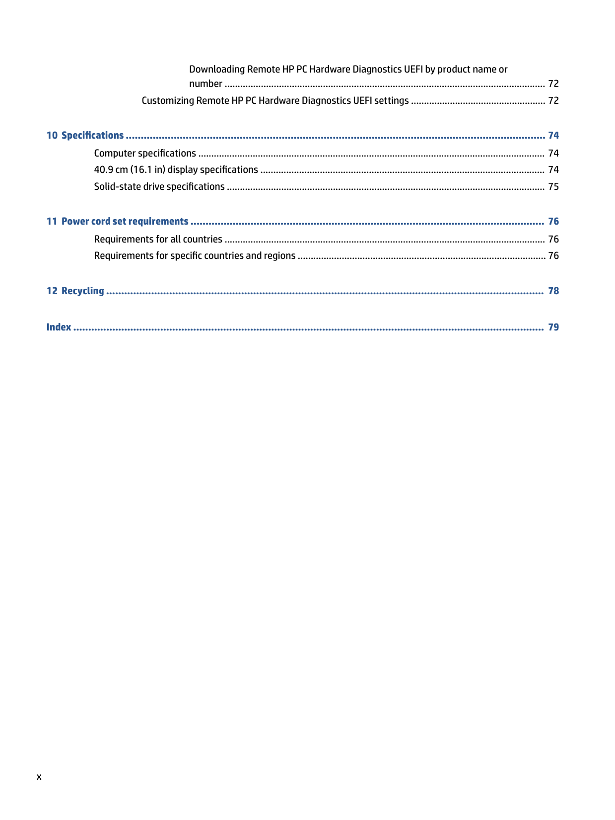
Downloading Remote HP PC Hardware Diagnostics UEFI by product name or number ............................................................................................................................ 72
Customizing Remote HP PC Hardware Diagnostics UEFI settings .................................................... 72
###### Index ............................................................................................................................................................. 79
x
1 Product description
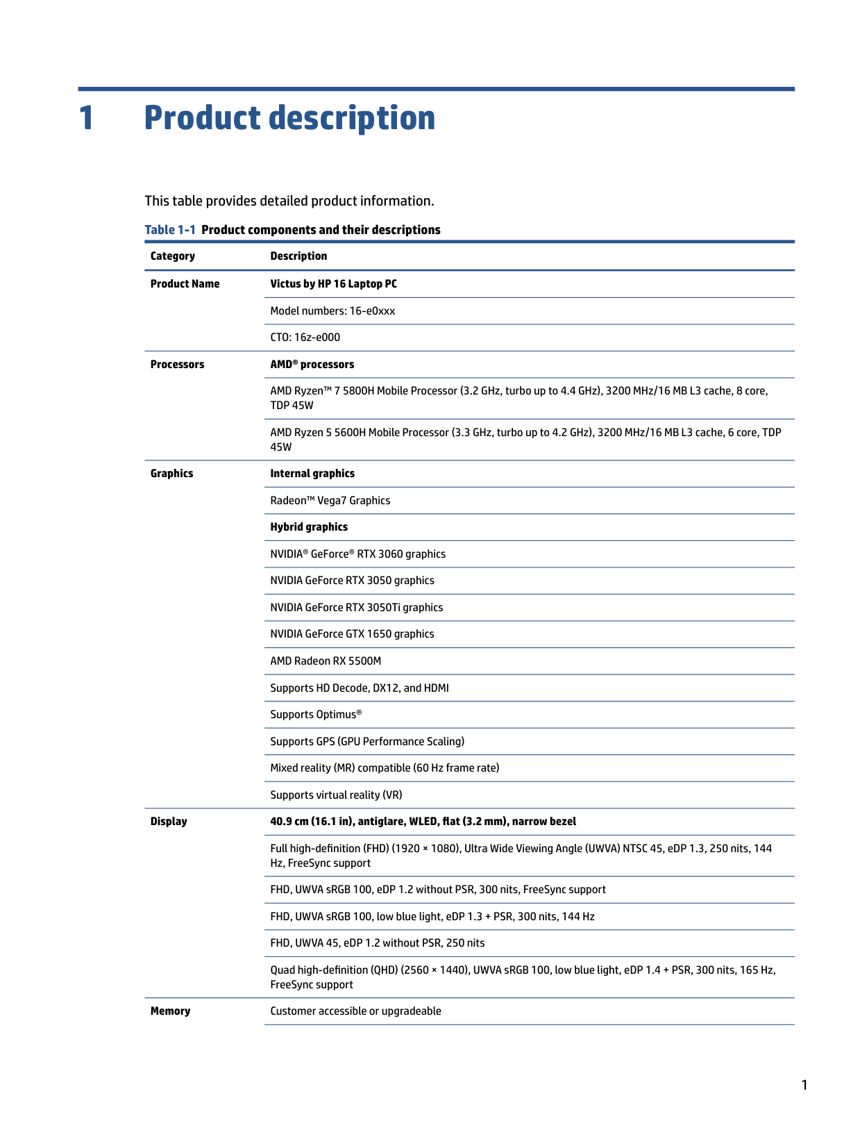
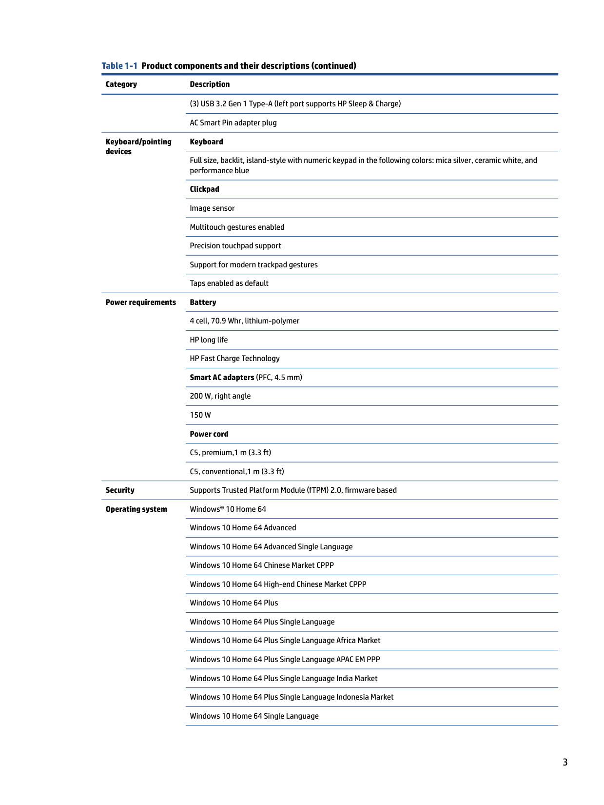
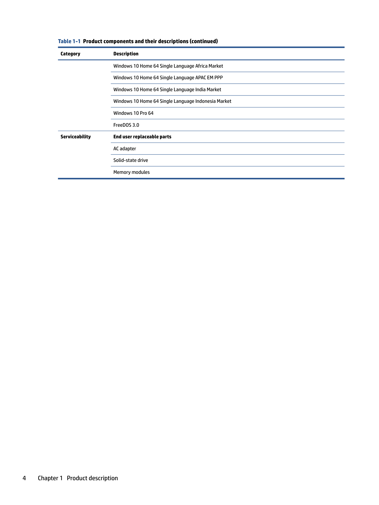
###### This table provides detailed product information. Table 1-1 Product components and their descriptions
Category Description Product Name Victus by HP 16 Laptop PC
Model numbers: 16-e0xxx CTO: 16z-e000
######### Processors AMD® processors
AMD Ryzen™ 7 5800H Mobile Processor (3.2 GHz, turbo up to 4.4 GHz), 3200 MHz/16 MB L3 cache, 8 core, TDP 45W
AMD Ryzen 5 5600H Mobile Processor (3.3 GHz, turbo up to 4.2 GHz), 3200 MHz/16 MB L3 cache, 6 core, TDP 45W

Graphics Internal graphics Radeon™ Vega7 Graphics Hybrid graphics NVIDIA® GeForce® RTX 3060 graphics NVIDIA GeForce RTX 3050 graphics NVIDIA GeForce RTX 3050Ti graphics NVIDIA GeForce GTX 1650 graphics AMD Radeon RX 5500M Supports HD Decode, DX12, and HDMI Supports Optimus® Supports GPS (GPU Performance Scaling) Mixed reality (MR) compatible (60 Hz frame rate) Supports virtual reality (VR)
######### Display 40.9 cm (16.1 in), antiglare, WLED, flat (3.2 mm), narrow bezel
Full high-definition (FHD) (1920 × 1080), Ultra Wide Viewing Angle (UWVA) NTSC 45, eDP 1.3, 250 nits, 144 Hz, FreeSync support
FHD, UWVA sRGB 100, eDP 1.2 without PSR, 300 nits, FreeSync support FHD, UWVA sRGB 100, low blue light, eDP 1.3 + PSR, 300 nits, 144 Hz FHD, UWVA 45, eDP 1.2 without PSR, 250 nits Quad high-definition (QHD) (2560 × 1440), UWVA sRGB 100, low blue light, eDP 1.4 + PSR, 300 nits, 165 Hz, FreeSync support
Memory Customer accessible or upgradeable
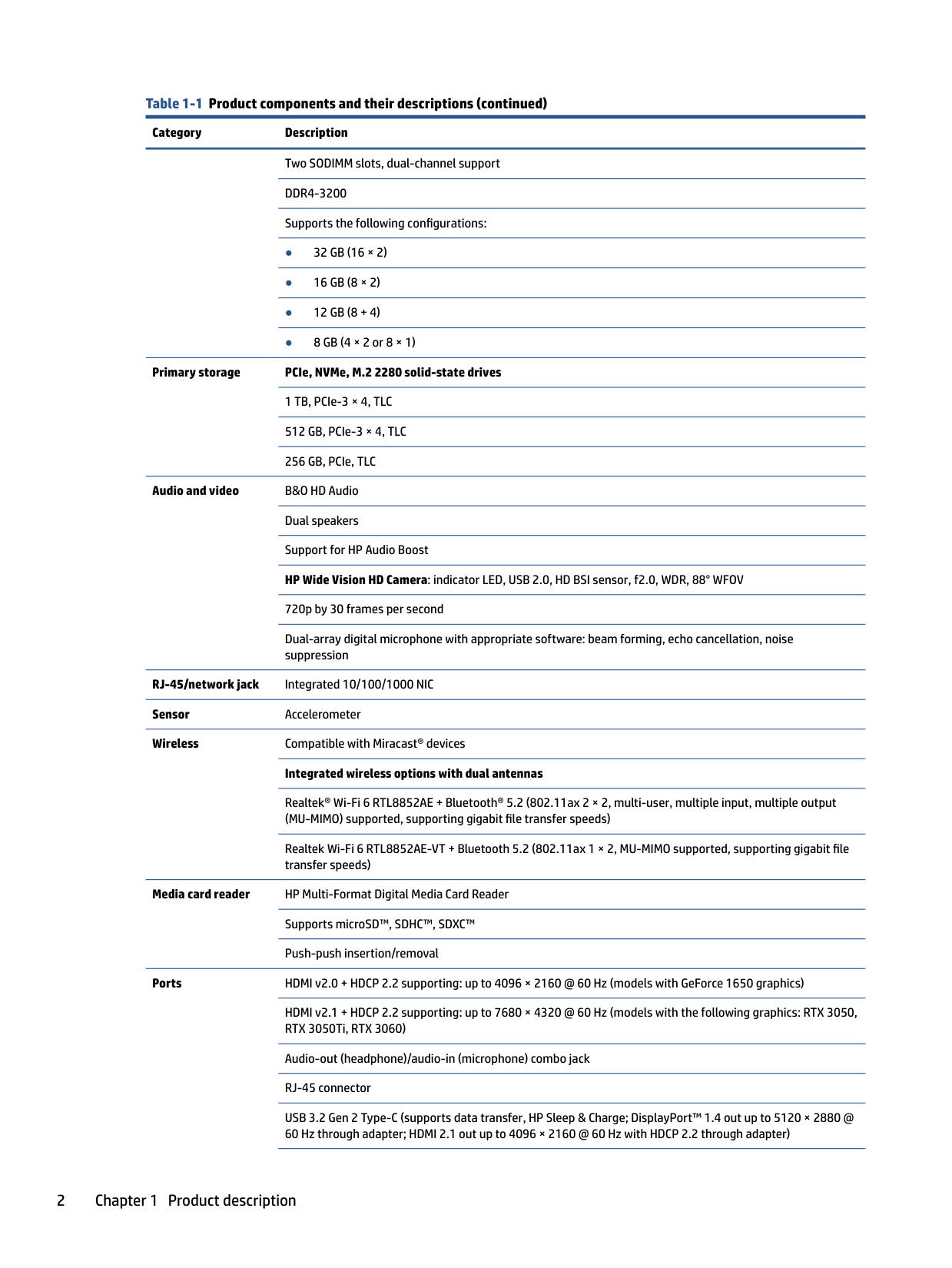
Two SODIMM slots, dual-channel support DDR4-3200 Supports the following configurations:
Primary storage PCIe, NVMe, M.2 2280 solid-state drives 1 TB, PCIe-3 × 4, TLC 512 GB, PCIe-3 × 4, TLC 256 GB, PCIe, TLC
Audio and video B&O HD Audio Dual speakers Support for HP Audio Boost HP Wide Vision HD Camera: indicator LED, USB 2.0, HD BSI sensor, f2.0, WDR, 88° WFOV 720p by 30 frames per second Dual-array digital microphone with appropriate software: beam forming, echo cancellation, noise suppression
RJ-45/network jack Integrated 10/100/1000 NIC Sensor Accelerometer Wireless Compatible with Miracast® devices
######### Integrated wireless options with dual antennas
Realtek® Wi-Fi 6 RTL8852AE + Bluetooth® 5.2 (802.11ax 2 × 2, multi-user, multiple input, multiple output (MU-MIMO) supported, supporting gigabit file transfer speeds)
Realtek Wi-Fi 6 RTL8852AE-VT + Bluetooth 5.2 (802.11ax 1 × 2, MU-MIMO supported, supporting gigabit file transfer speeds)
Media card reader HP Multi-Format Digital Media Card Reader Supports microSD™, SDHC™, SDXC™ Push-push insertion/removal
Ports HDMI v2.0 + HDCP 2.2 supporting: up to 4096 × 2160 @ 60 Hz (models with GeForce 1650 graphics)
HDMI v2.1 + HDCP 2.2 supporting: up to 7680 × 4320 @ 60 Hz (models with the following graphics: RTX 3050, RTX 3050Ti, RTX 3060)
Audio-out (headphone)/audio-in (microphone) combo jack RJ-45 connector USB 3.2 Gen 2 Type-C (supports data transfer, HP Sleep & Charge; DisplayPort™ 1.4 out up to 5120 × 2880 @ 60 Hz through adapter; HDMI 2.1 out up to 4096 × 2160 @ 60 Hz with HDCP 2.2 through adapter)
(3) USB 3.2 Gen 1 Type-A (left port supports HP Sleep & Charge) AC Smart Pin adapter plug
Keyboard/pointing devices
Keyboard
Full size, backlit, island-style with numeric keypad in the following colors: mica silver, ceramic white, and performance blue
Clickpad Image sensor Multitouch gestures enabled Precision touchpad support Support for modern trackpad gestures Taps enabled as default
Power requirements Battery 4 cell, 70.9 Whr, lithium-polymer HP long life HP Fast Charge Technology Smart AC adapters (PFC, 4.5 mm) 200 W, right angle 150 W Power cord C5, premium,1 m (3.3 ft) C5, conventional,1 m (3.3 ft)
Security Supports Trusted Platform Module (fTPM) 2.0, firmware based Operating system Windows® 10 Home 64
Windows 10 Home 64 Advanced Windows 10 Home 64 Advanced Single Language Windows 10 Home 64 Chinese Market CPPP Windows 10 Home 64 High-end Chinese Market CPPP Windows 10 Home 64 Plus Windows 10 Home 64 Plus Single Language Windows 10 Home 64 Plus Single Language Africa Market Windows 10 Home 64 Plus Single Language APAC EM PPP Windows 10 Home 64 Plus Single Language India Market Windows 10 Home 64 Plus Single Language Indonesia Market Windows 10 Home 64 Single Language
Windows 10 Home 64 Single Language Africa Market Windows 10 Home 64 Single Language APAC EM PPP Windows 10 Home 64 Single Language India Market Windows 10 Home 64 Single Language Indonesia Market Windows 10 Pro 64 FreeDOS 3.0
Serviceability End user replaceable parts AC adapter Solid-state drive Memory modules
2 Getting to know your computer
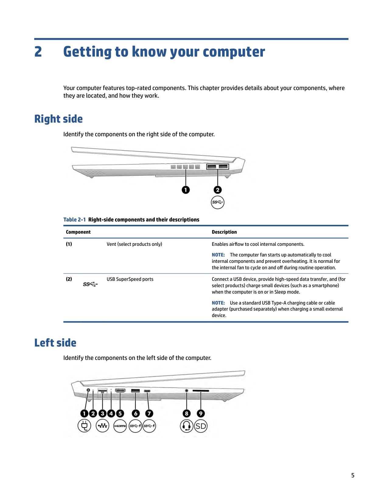
Your computer features top-rated components. This chapter provides details about your components, where they are located, and how they work.
Right side
Identify the components on the right side of the computer.

Table 2-1 Right-side components and their descriptions
Component Description
NOTE: The computer fan starts up automatically to cool internal components and prevent overheating. It is normal for the internal fan to cycle on and off during routine operation.

NOTE: Use a standard USB Type-A charging cable or cable adapter (purchased separately) when charging a small external device.
Left side
Identify the components on the left side of the computer.

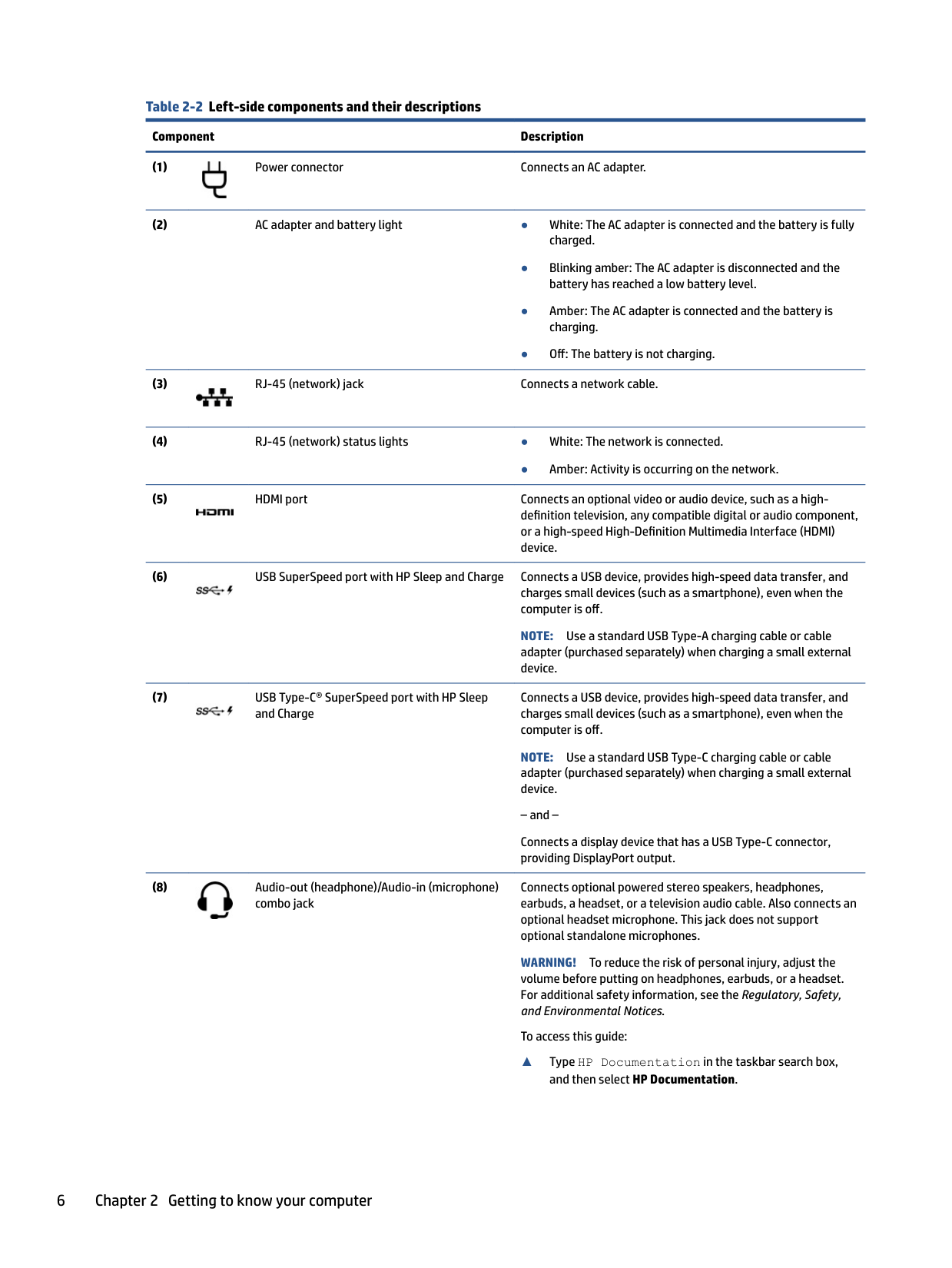
######## Table 2-2 Left-side components and their descriptions
######### Component Description


● Amber: Activity is occurring on the network.


NOTE: Use a standard USB Type-A charging cable or cable adapter (purchased separately) when charging a small external device.

Connects a USB device, provides high-speed data transfer, and charges small devices (such as a smartphone), even when the computer is off.
NOTE: Use a standard USB Type-C charging cable or cable adapter (purchased separately) when charging a small external device. – and – Connects a display device that has a USB Type-C connector, providing DisplayPort output.
Connects optional powered stereo speakers, headphones, earbuds, a headset, or a television audio cable. Also connects an optional headset microphone. This jack does not support optional standalone microphones.

WARNING! To reduce the risk of personal injury, adjust the volume before putting on headphones, earbuds, or a headset. For additional safety information, see the Regulatory, Safety, and Environmental Notices.
To access this guide:
▲ Type HP Documentation in the taskbar search box,
######### and then select HP Documentation.
######## Table 2-2 Left-side components and their descriptions (continued)
######### Component Description
NOTE: When a device is connected to the jack, the computer speakers are disabled.
(9) Memory card reader Reads optional memory cards that enable you to store, manage, share, or access information. To insert a card:

To remove a card:
▲ Press in on the card, and then remove it from the memory
card reader.
Display
The computer display can include essential components such as speakers, antennas, cameras, and microphones.
#### Low blue light mode (select products only)
Your computer display is shipped from the factory in low blue light mode for improved eye comfort and safety. Also, blue light mode automatically adjusts blue light emissions when you are using the computer at night or for reading.
WARNING! To reduce the risk of serious injury, read the Safety & Comfort Guide. It describes proper workstation setup and proper posture, health, and work habits for computer users. The Safety & Comfort Guide also provides important electrical and mechanical safety information. The Safety & Comfort Guide is available on the web at http://www.hp.com/ergo.
Display 7

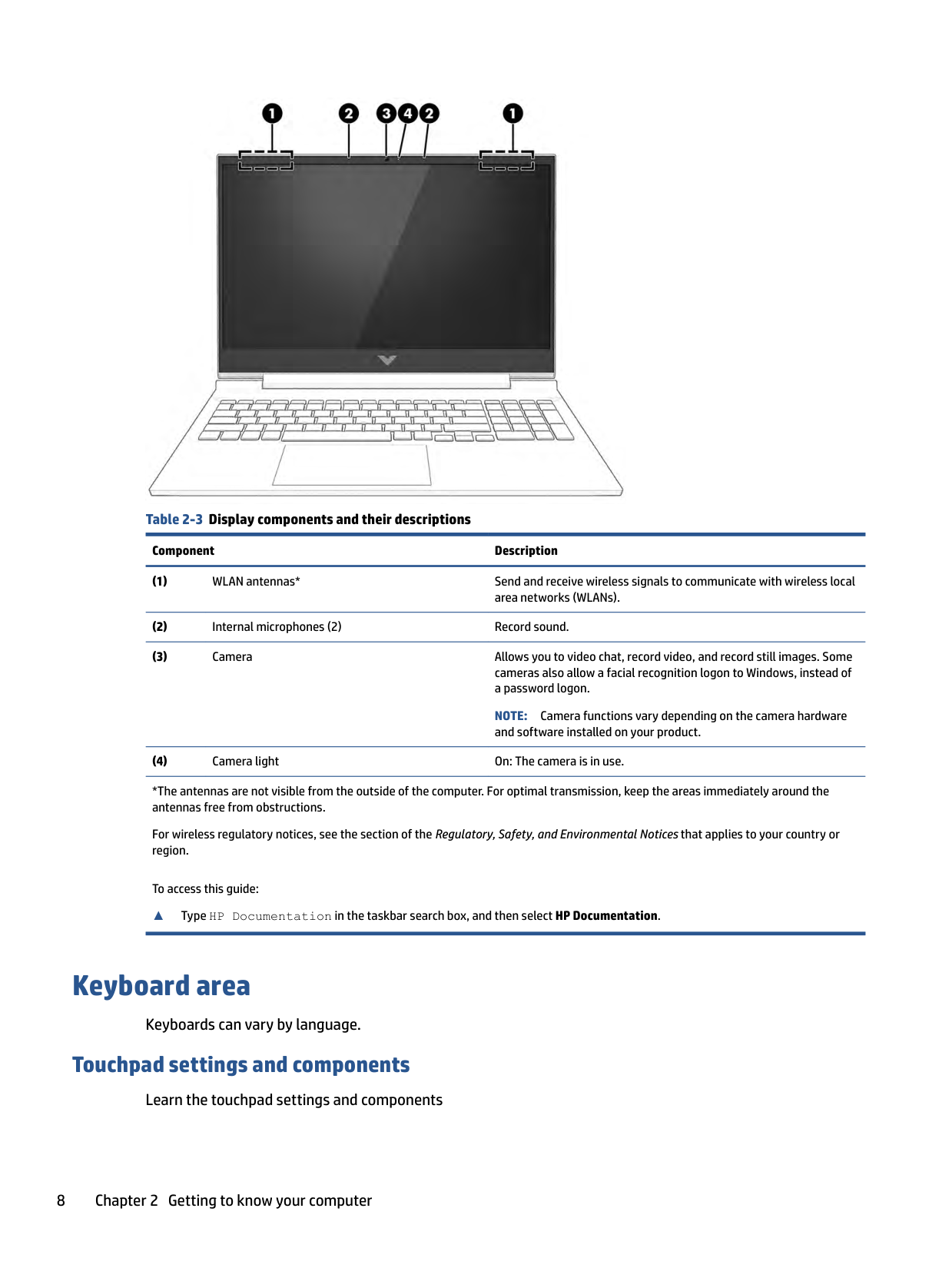
######## Table 2-3 Display components and their descriptions
######### Component Description
NOTE: Camera functions vary depending on the camera hardware and software installed on your product.
*The antennas are not visible from the outside of the computer. For optimal transmission, keep the areas immediately around the antennas free from obstructions.
For wireless regulatory notices, see the section of the Regulatory, Safety, and Environmental Notices that applies to your country or region.
To access this guide:
▲ Type HP Documentation in the taskbar search box, and then select HP Documentation.
Keyboard area
Keyboards can vary by language.
#### Touchpad settings and components
Learn the touchpad settings and components
##### Touchpad settings
Learn how to adjust touchpad settings. Adjusting touchpad settings
Use these steps to adjust touchpad settings and gestures.
###### Turning on the touchpad
Follow these steps to turn on the touchpad.
If you are not using an external mouse, press the Tab key repeatedly until the pointer rests on the touchpad button. Then press the spacebar to select the button.
##### Touchpad components
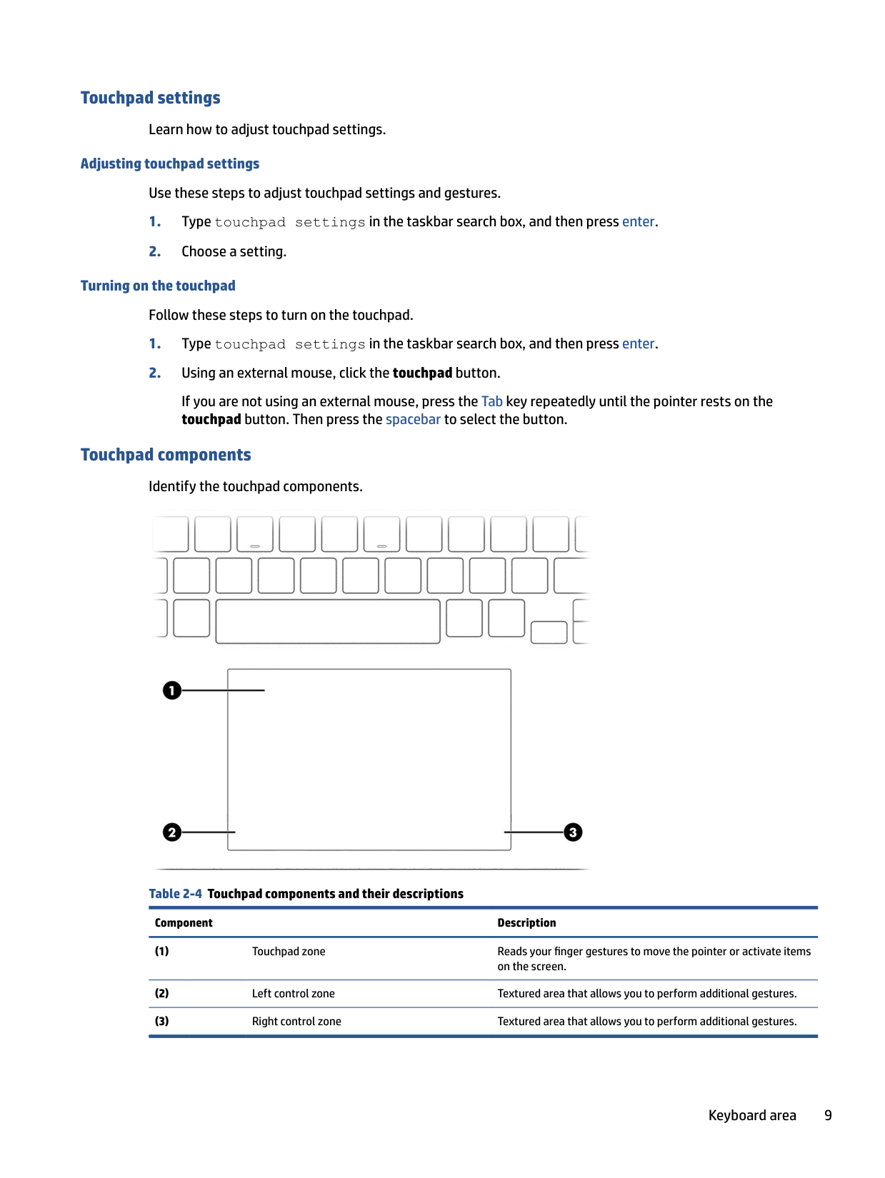
Identify the touchpad components.

Table 2-4 Touchpad components and their descriptions
Component Description
#### Lights
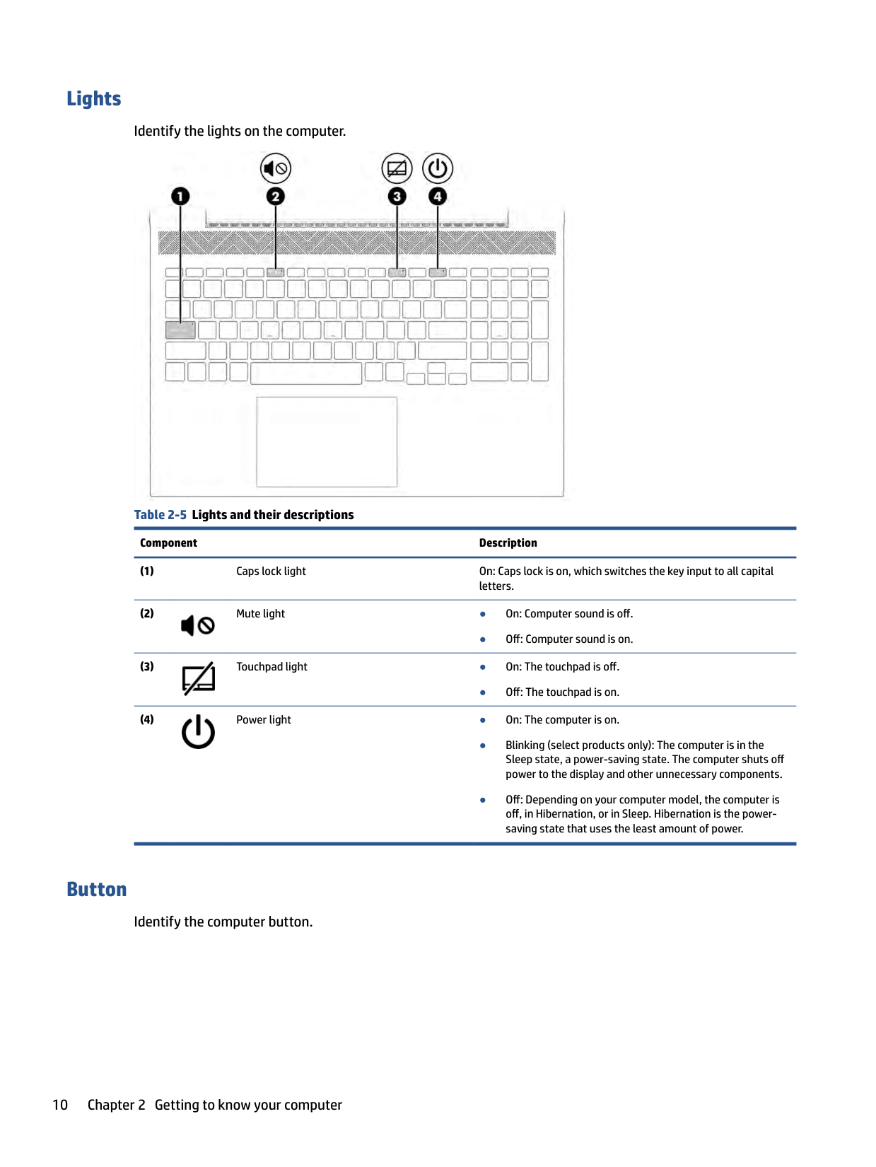
Identify the lights on the computer.

Table 2-5 Lights and their descriptions
Component Description

● Off: Computer sound is on.

● Off: The touchpad is on.

#### Button
Identify the computer button.

######## Table 2-6 Button and its description
######### Component Description

Power button ● When the computer is off, press the button briefly to turn on the computer.
exit Hibernation. IMPORTANT: Pressing and holding down the power button results in the loss of unsaved information. If the computer has stopped responding and shutdown procedures are ineffective, press and hold the power button down for at least 10 seconds to turn off the computer. To learn more about your power settings, see your power options:

▲ Right-click the Power icon , and then select Power Options.
#### Special keys
Identify the special keys.

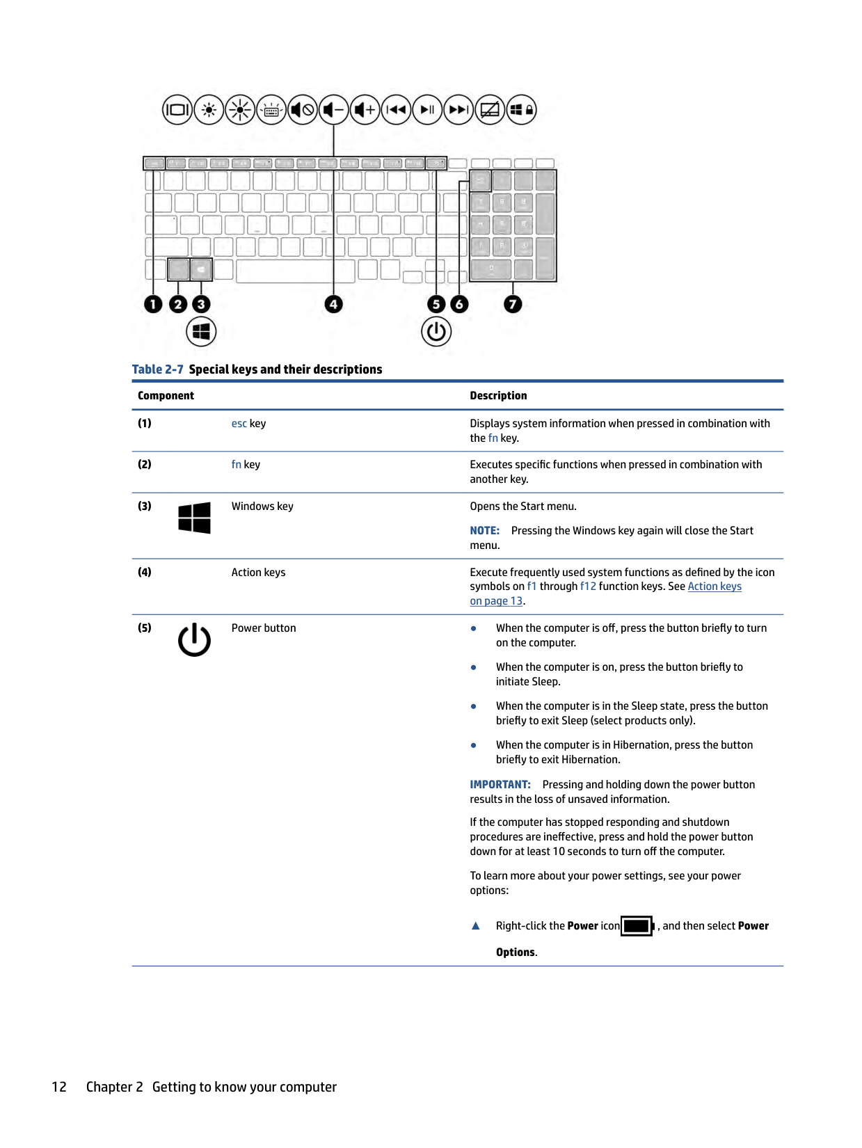
######## Table 2-7 Special keys and their descriptions
######### Component Description

NOTE: Pressing the Windows key again will close the Start menu.

IMPORTANT: Pressing and holding down the power button results in the loss of unsaved information. If the computer has stopped responding and shutdown procedures are ineffective, press and hold the power button down for at least 10 seconds to turn off the computer. To learn more about your power settings, see your power options:

▲ Right-click the Power icon , and then select Power Options.
######## Table 2-7 Special keys and their descriptions (continued)
######### Component Description
NOTE: If the keypad function is active when the computer is turned off, that function is reinstated when the computer is turned back on.
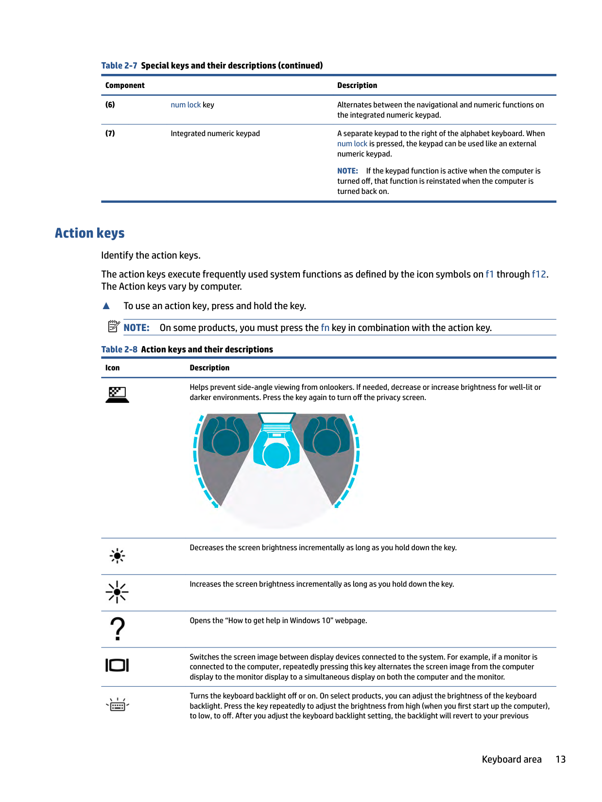
Action keys Identify the action keys. The action keys execute frequently used system functions as defined by the icon symbols on f1 through f12. The Action keys vary by computer.
▲ To use an action key, press and hold the key.
| | |---|
NOTE: On some products, you must press the fn key in combination with the action key. Table 2-8 Action keys and their descriptions
Icon Description

Helps prevent side-angle viewing from onlookers. If needed, decrease or increase brightness for well-lit or darker environments. Press the key again to turn off the privacy screen.


Decreases the screen brightness incrementally as long as you hold down the key.
Increases the screen brightness incrementally as long as you hold down the key.
Opens the “How to get help in Windows 10” webpage.
Switches the screen image between display devices connected to the system. For example, if a monitor is connected to the computer, repeatedly pressing this key alternates the screen image from the computer display to the monitor display to a simultaneous display on both the computer and the monitor.
Turns the keyboard backlight off or on. On select products, you can adjust the brightness of the keyboard backlight. Press the key repeatedly to adjust the brightness from high (when you first start up the computer), to low, to off. After you adjust the keyboard backlight setting, the backlight will revert to your previous
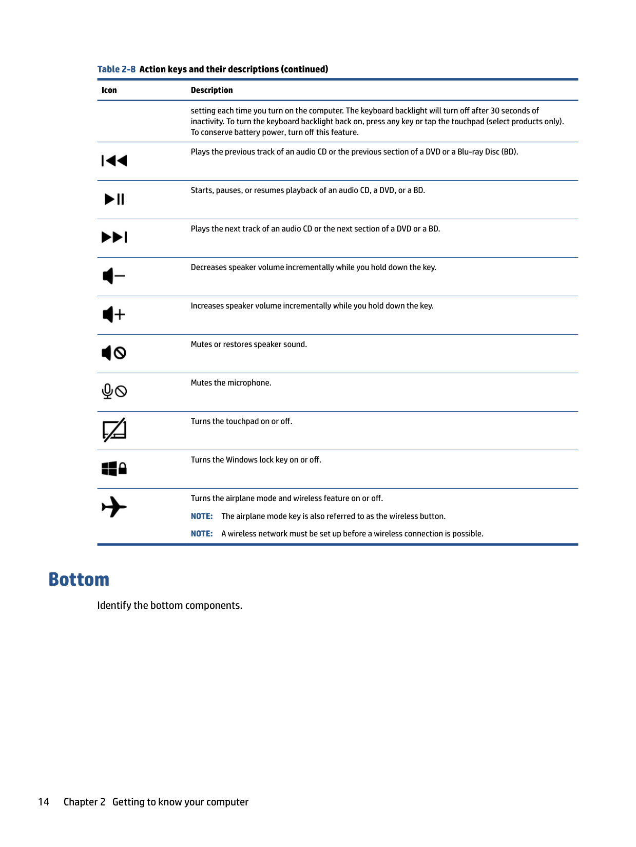
######## Table 2-8 Action keys and their descriptions (continued)
######### Icon Description

setting each time you turn on the computer. The keyboard backlight will turn off after 30 seconds of inactivity. To turn the keyboard backlight back on, press any key or tap the touchpad (select products only). To conserve battery power, turn off this feature.
Plays the previous track of an audio CD or the previous section of a DVD or a Blu-ray Disc (BD).


Starts, pauses, or resumes playback of an audio CD, a DVD, or a BD.
Plays the next track of an audio CD or the next section of a DVD or a BD.
Decreases speaker volume incrementally while you hold down the key.
Increases speaker volume incrementally while you hold down the key.
Mutes or restores speaker sound.
Mutes the microphone.
Turns the touchpad on or off.
Turns the Windows lock key on or off.
Turns the airplane mode and wireless feature on or off. NOTE: The airplane mode key is also referred to as the wireless button. NOTE: A wireless network must be set up before a wireless connection is possible.
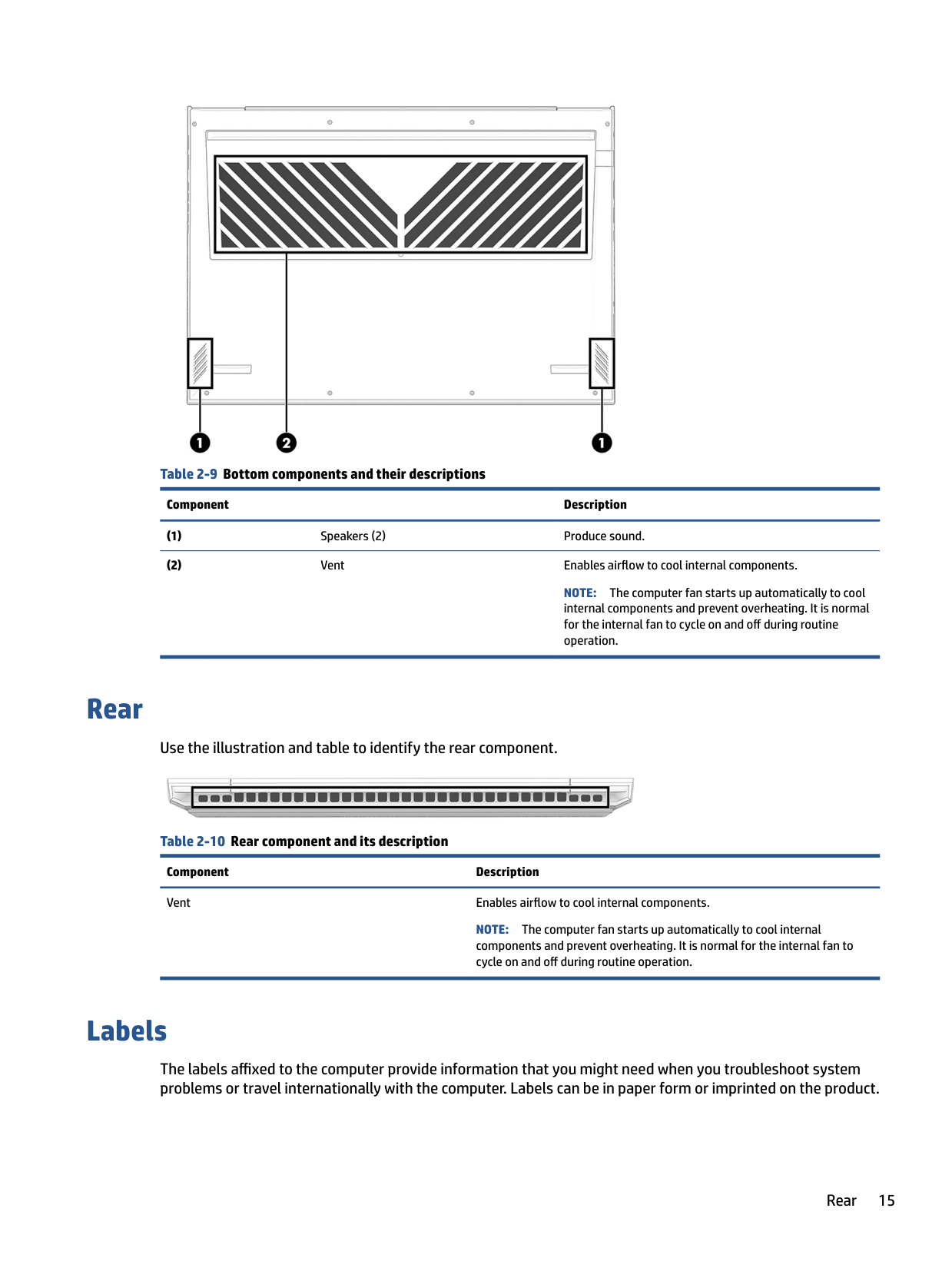
Bottom
Identify the bottom components.

######## Table 2-9 Bottom components and their descriptions
######### Component Description
NOTE: The computer fan starts up automatically to cool internal components and prevent overheating. It is normal for the internal fan to cycle on and off during routine operation.
Rear
Use the illustration and table to identify the rear component.
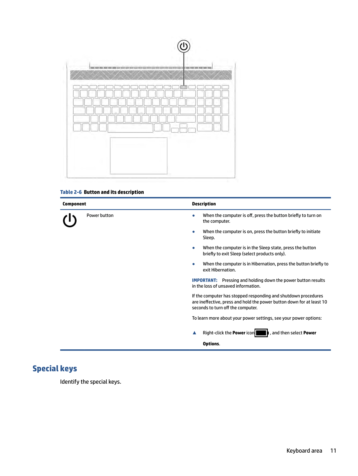

Table 2-10 Rear component and its description Component Description Vent Enables airflow to cool internal components.
NOTE: The computer fan starts up automatically to cool internal components and prevent overheating. It is normal for the internal fan to cycle on and off during routine operation.
Labels
The labels affixed to the computer provide information that you might need when you troubleshoot system problems or travel internationally with the computer. Labels can be in paper form or imprinted on the product.
Rear 15
| | |---|
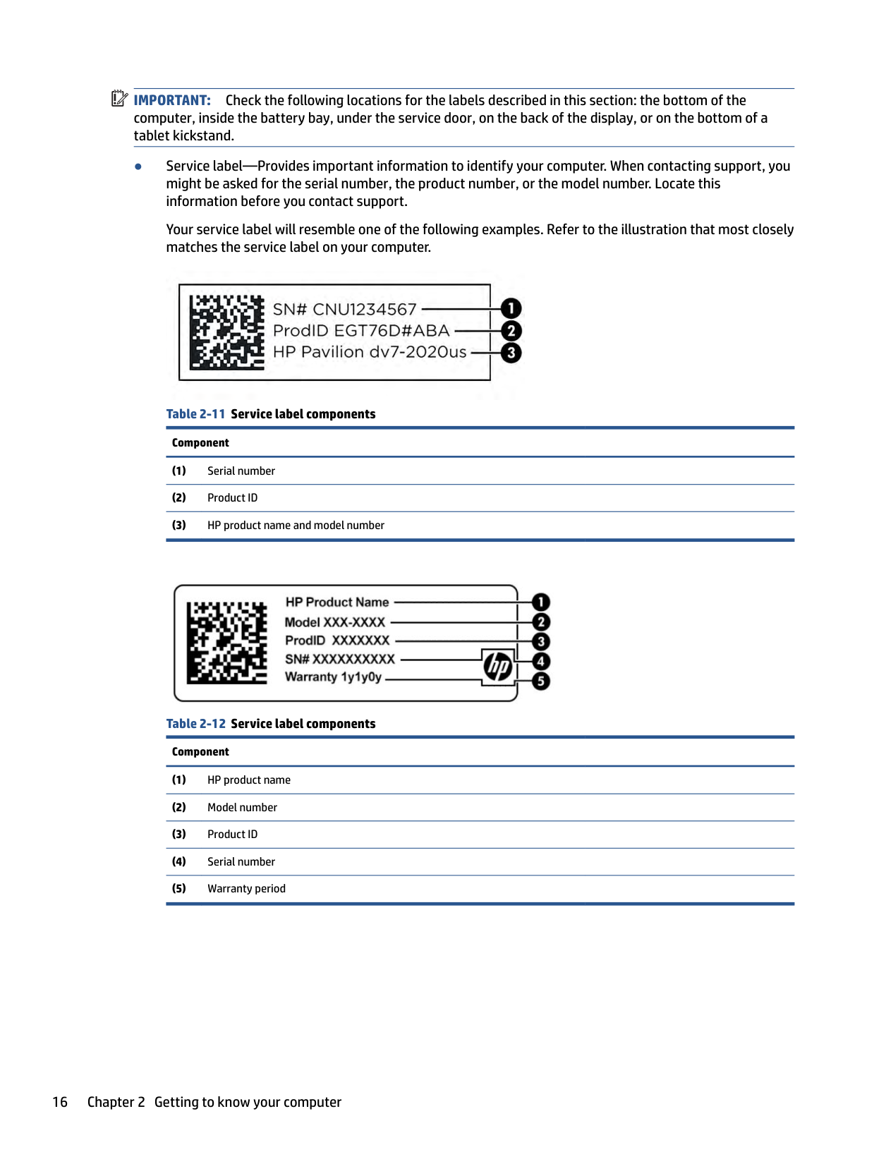
IMPORTANT: Check the following locations for the labels described in this section: the bottom of the computer, inside the battery bay, under the service door, on the back of the display, or on the bottom of a tablet kickstand.
Your service label will resemble one of the following examples. Refer to the illustration that most closely matches the service label on your computer.


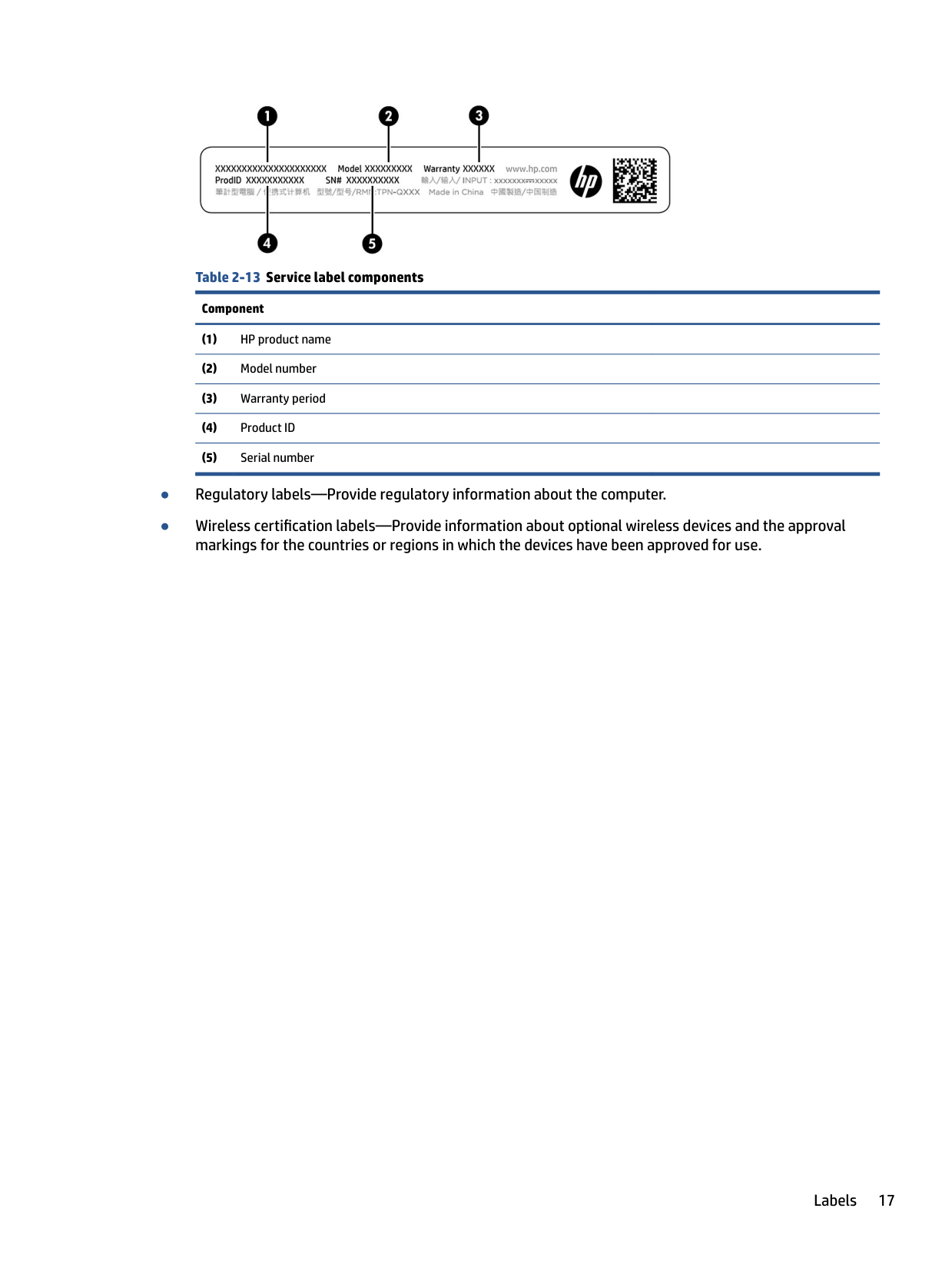
######## Table 2-13 Service label componentsComponent
Labels 17
3 Illustrated parts catalog
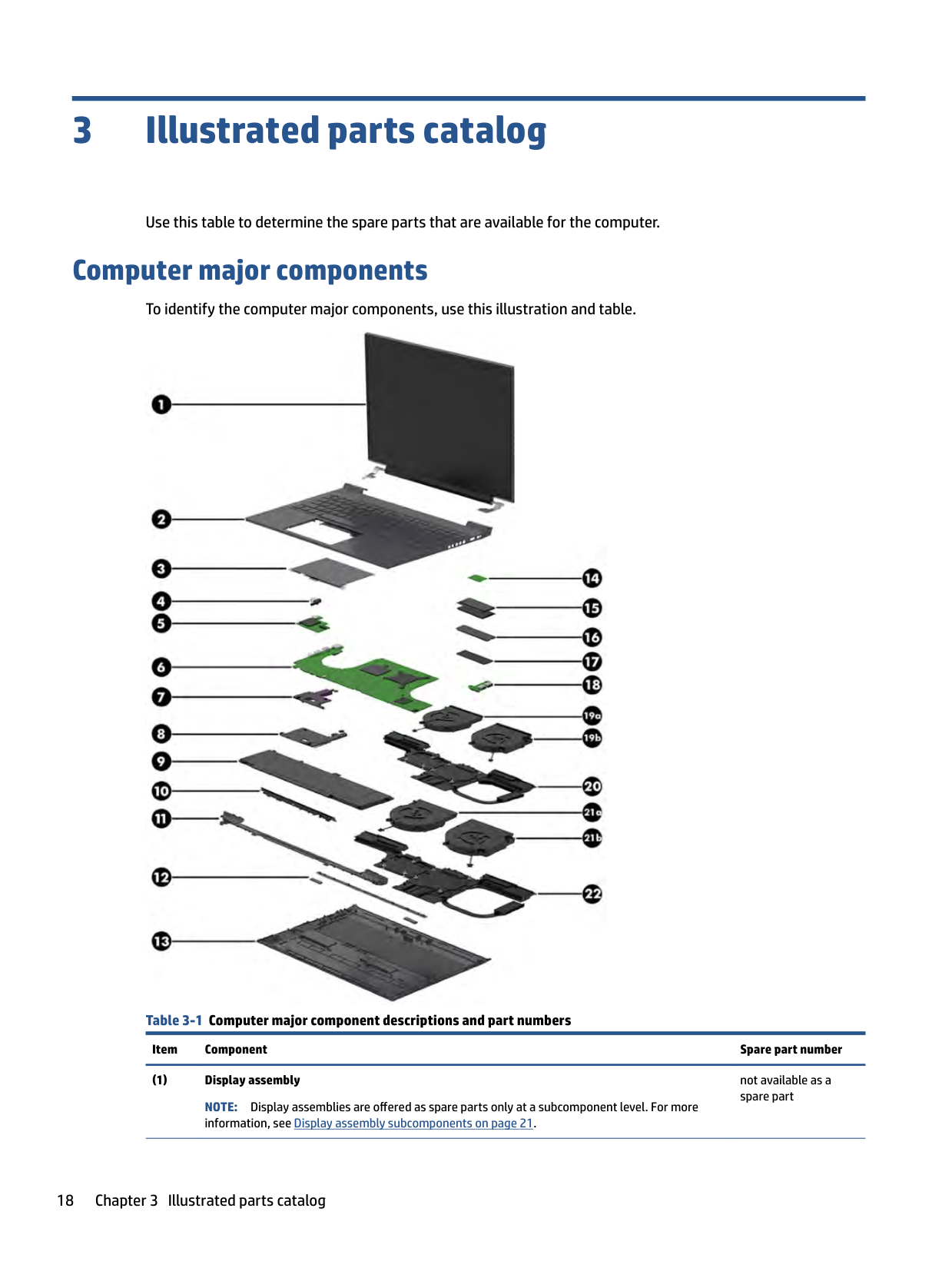
Use this table to determine the spare parts that are available for the computer.
Computer major components
To identify the computer major components, use this illustration and table.

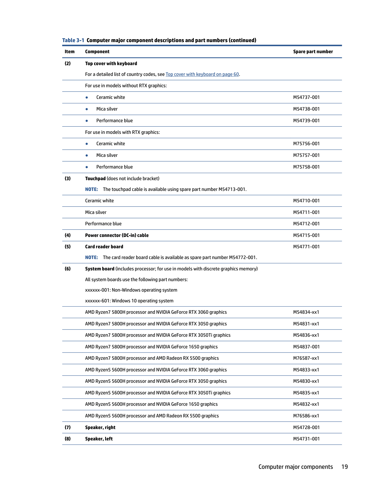
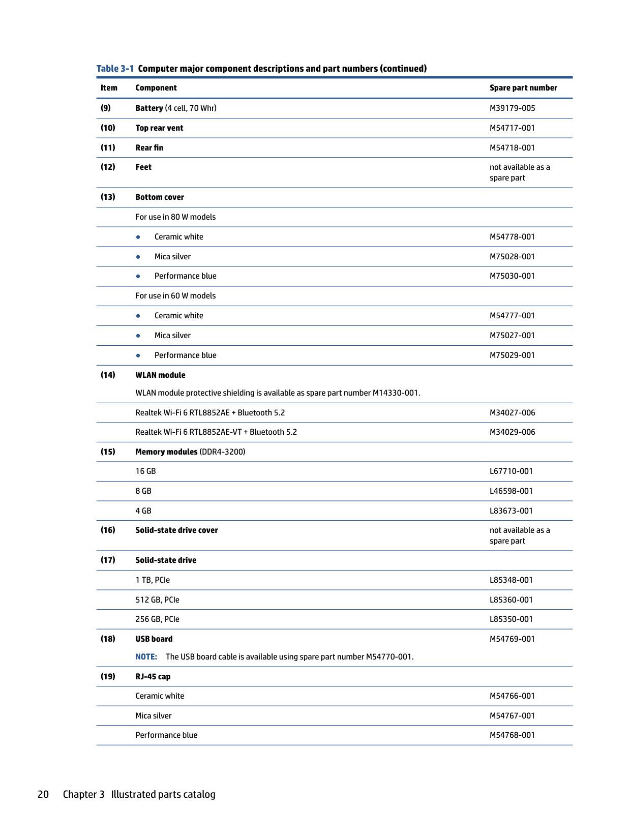
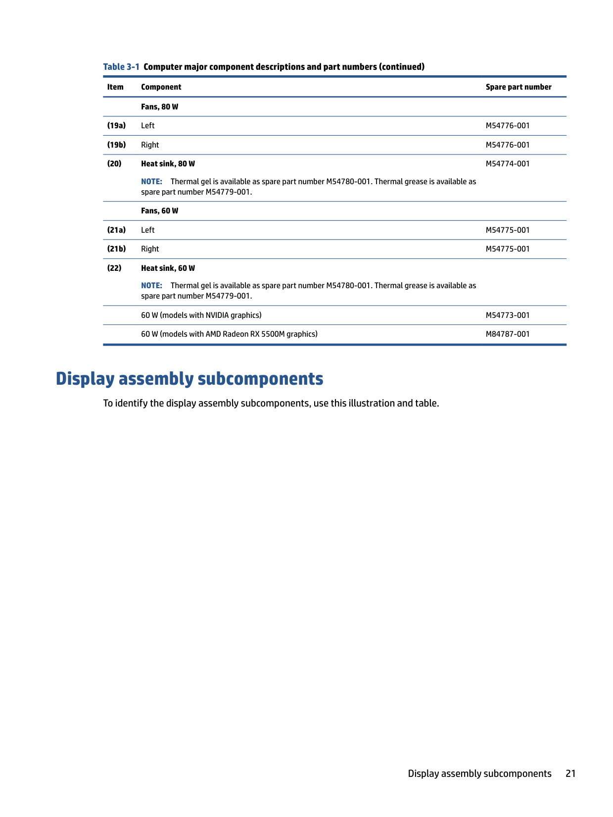
Table 3-1 Computer major component descriptions and part numbers
Item Component Spare part number
not available as a spare part
NOTE: Display assemblies are offered as spare parts only at a subcomponent level. For more information, see Display assembly subcomponents on page 21.
M54771-001
Computer major components 19
M54769-001
######### Fans, 80 W
######### (20) Heat sink, 80 W
NOTE: Thermal gel is available as spare part number M54780-001. Thermal grease is available as spare part number M54779-001.
M54774-001
Fans, 60 W
########## (21a) Left M54775-001
NOTE: Thermal gel is available as spare part number M54780-001. Thermal grease is available as spare part number M54779-001. 60 W (models with NVIDIA graphics) M54773-001 60 W (models with AMD Radeon RX 5500M graphics) M84787-001
Display assembly subcomponents
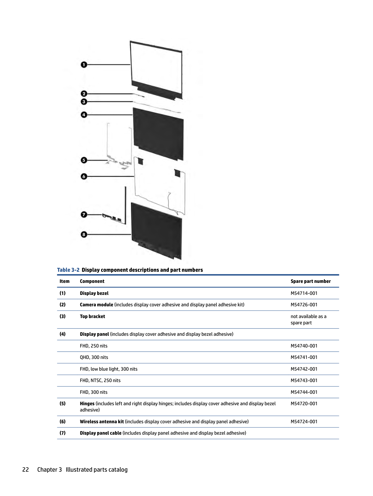
To identify the display assembly subcomponents, use this illustration and table.
Display assembly subcomponents 21

######## Table 3-2 Display component descriptions and part numbers
Item Component Spare part number
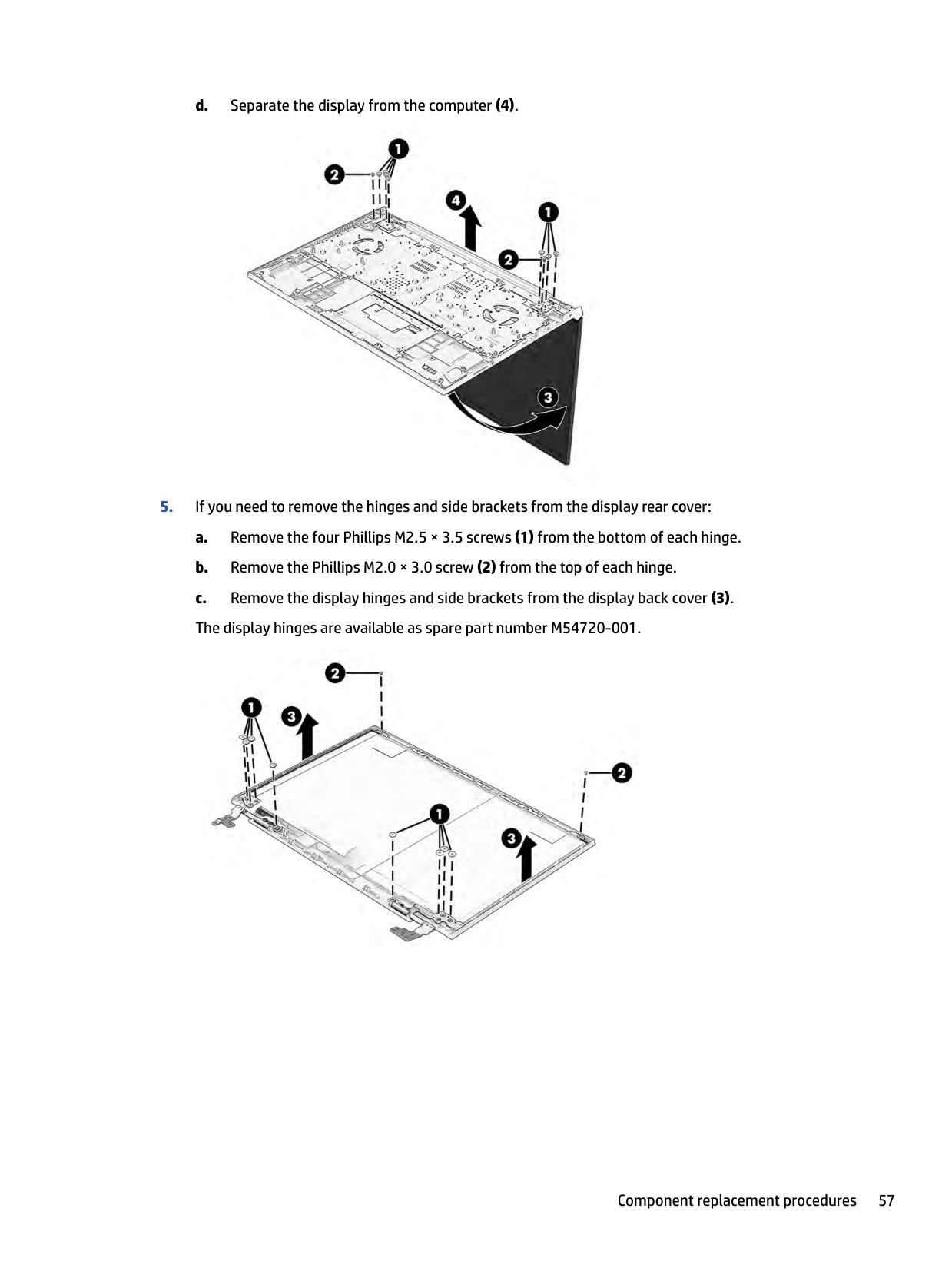
M54720-001
######## Table 3-2 Display component descriptions and part numbers (continued)
######### Item Component Spare part number
For use with FHD, 60 Hz panels M81348-001 For use with FHD, 144 Hz panels M81347-001 For use with QHD panels M84786-001
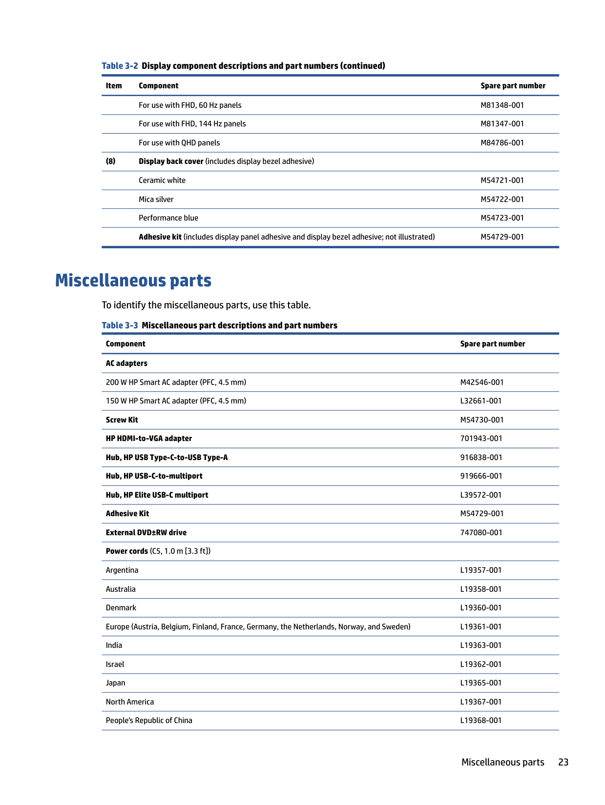
Miscellaneous parts To identify the miscellaneous parts, use this table. Table 3-3 Miscellaneous part descriptions and part numbers
Component Spare part number AC adapters 200 W HP Smart AC adapter (PFC, 4.5 mm) M42546-001 150 W HP Smart AC adapter (PFC, 4.5 mm) L32661-001 Screw Kit M54730-001 HP HDMI-to-VGA adapter 701943-001 Hub, HP USB Type-C-to-USB Type-A 916838-001 Hub, HP USB-C-to-multiport 919666-001 Hub, HP Elite USB-C multiport L39572-001 Adhesive Kit M54729-001 External DVD±RW drive 747080-001 Power cords (C5, 1.0 m [3.3 ft])
Argentina L19357-001 Australia L19358-001 Denmark L19360-001 Europe (Austria, Belgium, Finland, France, Germany, the Netherlands, Norway, and Sweden) L19361-001 India L19363-001 Israel L19362-001 Japan L19365-001 North America L19367-001 People's Republic of China L19368-001
Miscellaneous parts 23
######## Table 3-3 Miscellaneous part descriptions and part numbers (continued)
######### Component Spare part number
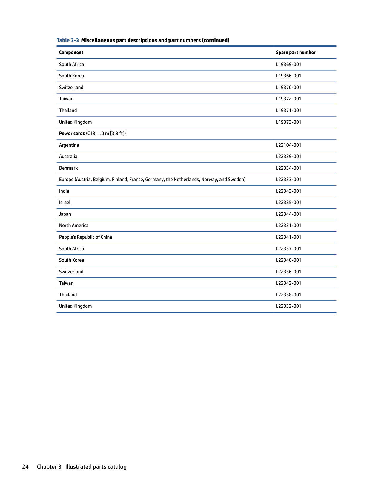
South Africa L19369-001 South Korea L19366-001 Switzerland L19370-001 Taiwan L19372-001 Thailand L19371-001 United Kingdom L19373-001 Power cords (C13, 1.0 m [3.3 ft])
Argentina L22104-001 Australia L22339-001 Denmark L22334-001 Europe (Austria, Belgium, Finland, France, Germany, the Netherlands, Norway, and Sweden) L22333-001 India L22343-001 Israel L22335-001 Japan L22344-001 North America L22331-001 People's Republic of China L22341-001 South Africa L22337-001 South Korea L22340-001 Switzerland L22336-001 Taiwan L22342-001 Thailand L22338-001 United Kingdom L22332-001
4 Removal and replacement procedures preliminary requirements
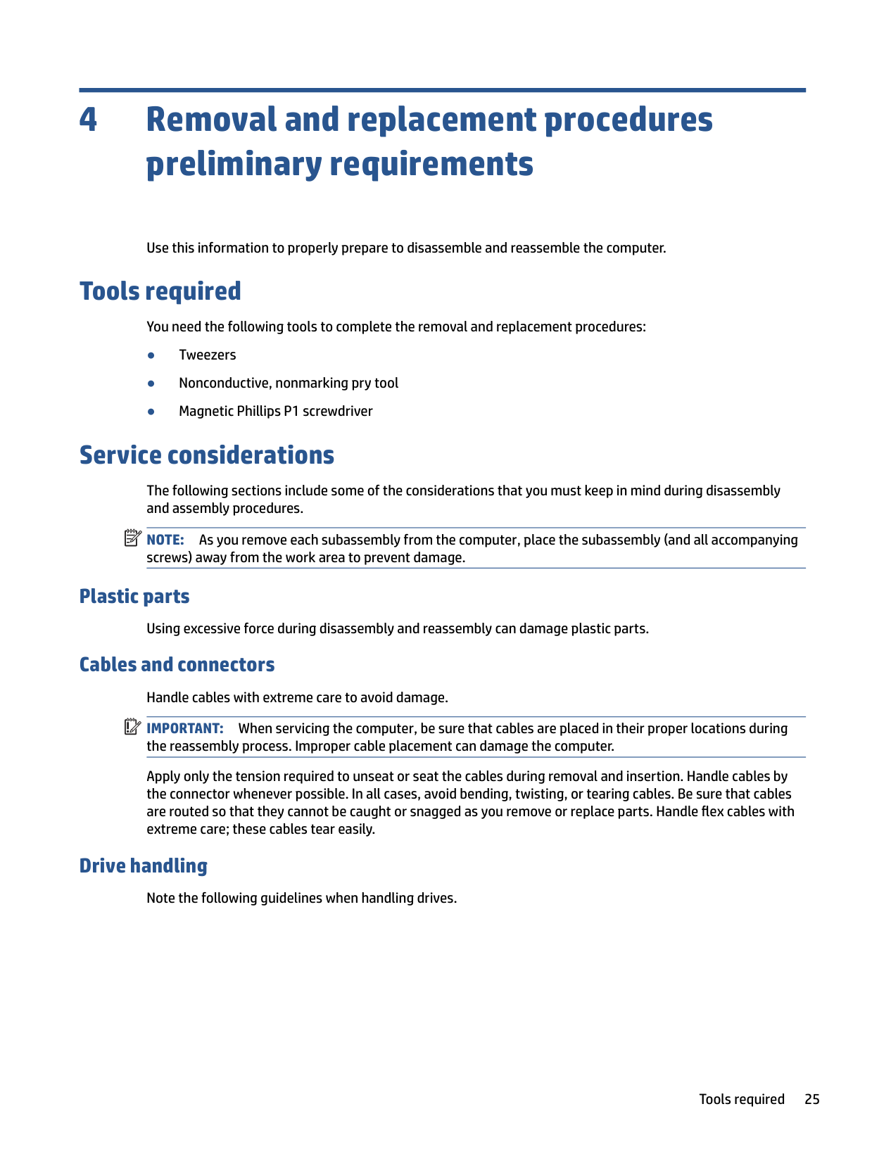
Use this information to properly prepare to disassemble and reassemble the computer.
Tools required
You need the following tools to complete the removal and replacement procedures:
Service considerations
The following sections include some of the considerations that you must keep in mind during disassembly and assembly procedures.
| | |---|
NOTE: As you remove each subassembly from the computer, place the subassembly (and all accompanying screws) away from the work area to prevent damage.
#### Plastic parts
Using excessive force during disassembly and reassembly can damage plastic parts.
Cables and connectors Handle cables with extreme care to avoid damage. IMPORTANT: When servicing the computer, be sure that cables are placed in their proper locations during the reassembly process. Improper cable placement can damage the computer. Apply only the tension required to unseat or seat the cables during removal and insertion. Handle cables by the connector whenever possible. In all cases, avoid bending, twisting, or tearing cables. Be sure that cables are routed so that they cannot be caught or snagged as you remove or replace parts. Handle flex cables with extreme care; these cables tear easily.
| | |---|
#### Drive handling
Note the following guidelines when handling drives.
Tools required 25
| | |---|
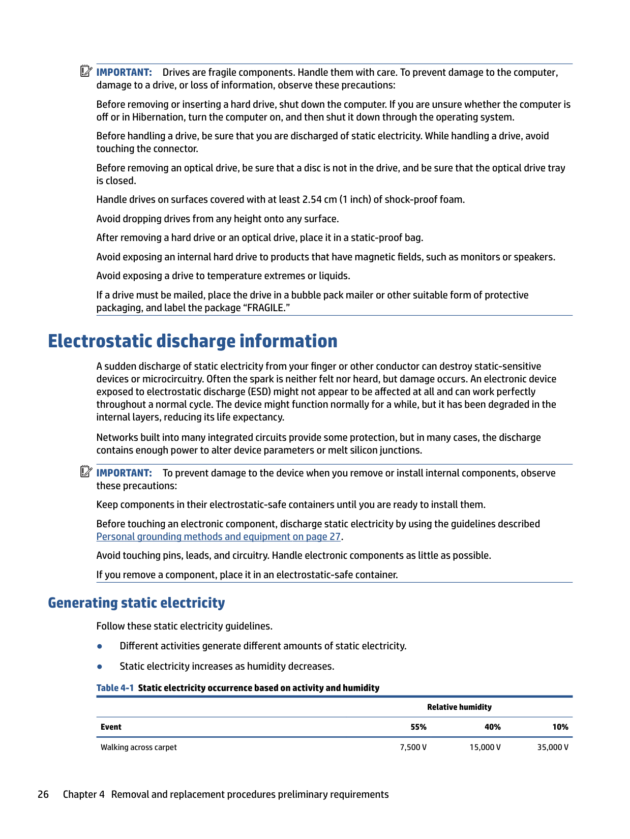
IMPORTANT: Drives are fragile components. Handle them with care. To prevent damage to the computer, damage to a drive, or loss of information, observe these precautions: Before removing or inserting a hard drive, shut down the computer. If you are unsure whether the computer is off or in Hibernation, turn the computer on, and then shut it down through the operating system. Before handling a drive, be sure that you are discharged of static electricity. While handling a drive, avoid touching the connector. Before removing an optical drive, be sure that a disc is not in the drive, and be sure that the optical drive tray is closed. Handle drives on surfaces covered with at least 2.54 cm (1 inch) of shock-proof foam. Avoid dropping drives from any height onto any surface. After removing a hard drive or an optical drive, place it in a static-proof bag. Avoid exposing an internal hard drive to products that have magnetic fields, such as monitors or speakers. Avoid exposing a drive to temperature extremes or liquids. If a drive must be mailed, place the drive in a bubble pack mailer or other suitable form of protective packaging, and label the package “FRAGILE.”
Electrostatic discharge information
A sudden discharge of static electricity from your finger or other conductor can destroy static-sensitive devices or microcircuitry. Often the spark is neither felt nor heard, but damage occurs. An electronic device exposed to electrostatic discharge (ESD) might not appear to be affected at all and can work perfectly throughout a normal cycle. The device might function normally for a while, but it has been degraded in the internal layers, reducing its life expectancy.
Networks built into many integrated circuits provide some protection, but in many cases, the discharge contains enough power to alter device parameters or melt silicon junctions.
| | |---|
IMPORTANT: To prevent damage to the device when you remove or install internal components, observe these precautions: Keep components in their electrostatic-safe containers until you are ready to install them. Before touching an electronic component, discharge static electricity by using the guidelines described Personal grounding methods and equipment on page 27. Avoid touching pins, leads, and circuitry. Handle electronic components as little as possible. If you remove a component, place it in an electrostatic-safe container.
#### Generating static electricity
Follow these static electricity guidelines.
Relative humidity
Event 55% 40% 10% Walking across carpet 7,500 V 15,000 V 35,000 V
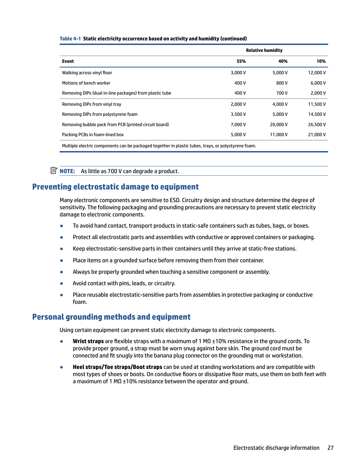
######## Table 4-1 Static electricity occurrence based on activity and humidity (continued)
Relative humidity Event 55% 40% 10% Walking across vinyl floor Motions of bench worker Removing DIPs (dual in-line packages) from plastic tube
3,000 V 400 V 400 V
5,000 V 800 V 700 V
12,000 V 6,000 V 2,000 V
Removing DIPs from vinyl tray Removing DIPs from polystyrene foam Removing bubble pack from PCB (printed circuit board) Packing PCBs in foam-lined box
Multiple electric components can be packaged together in plastic tubes, trays, or polystyrene foam.
20,000 V 11,000 V
11,500 V 14,500 V 26,500 V 21,000 V
| | |---|
NOTE: As little as 700 V can degrade a product.
#### Preventing electrostatic damage to equipment
Many electronic components are sensitive to ESD. Circuitry design and structure determine the degree of sensitivity. The following packaging and grounding precautions are necessary to prevent static electricity damage to electronic components.
#### Personal grounding methods and equipment
Using certain equipment can prevent static electricity damage to electronic components.
Electrostatic discharge information 27
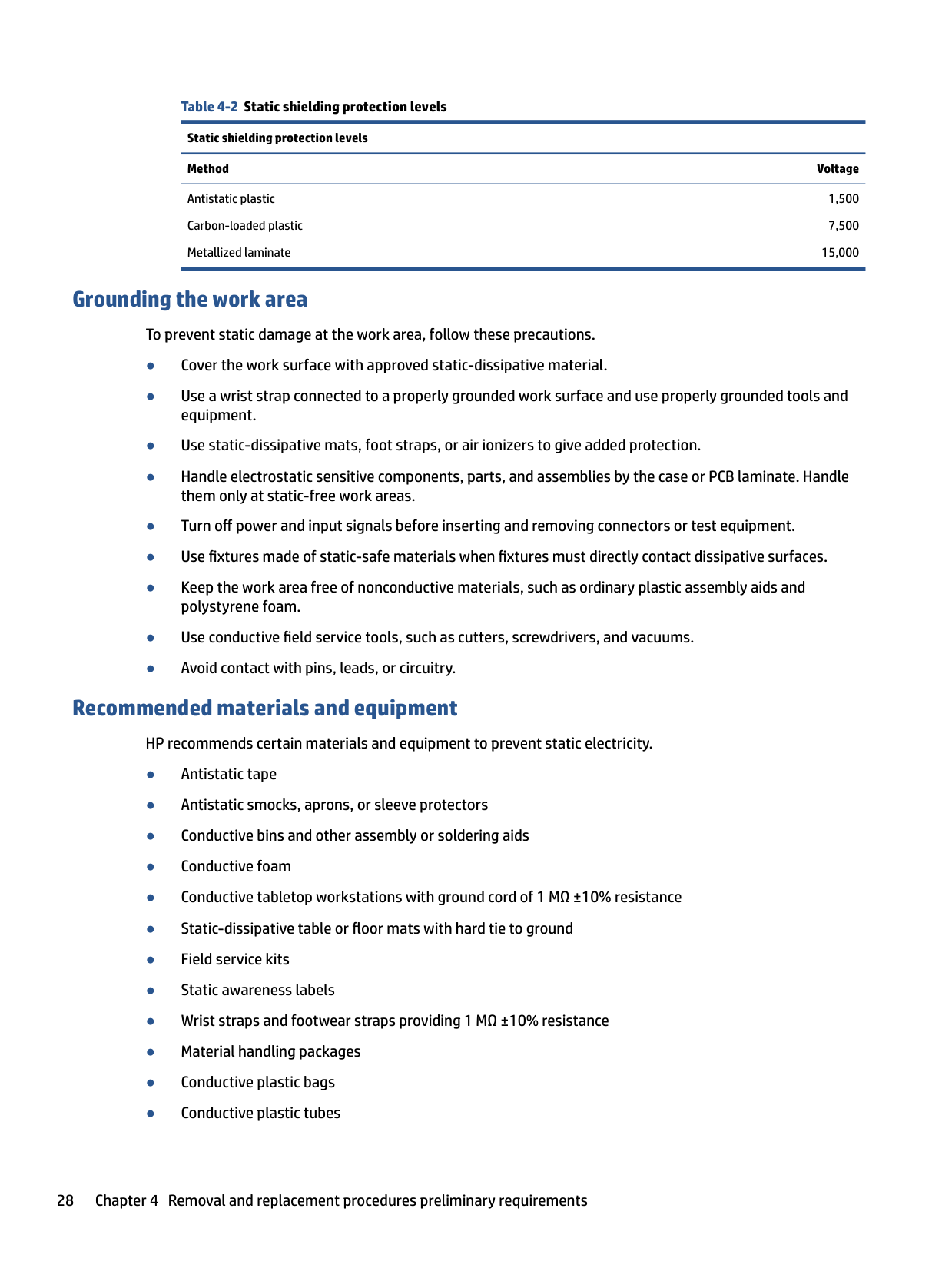
Table 4-2 Static shielding protection levels Static shielding protection levels Method Voltage
Antistatic plastic Carbon-loaded plastic Metallized laminate
1,500 7,500
15,000
#### Grounding the work area
To prevent static damage at the work area, follow these precautions.
#### Recommended materials and equipment
HP recommends certain materials and equipment to prevent static electricity.
Cleaning your computer
Cleaning your computer regularly removes dirt and debris so that your device continues to operate at its best. Use the following information to safely clean the external surfaces of your computer.
#### Enabling HP Easy Clean (select products only)
HP Easy Clean helps you to avoid accidental input while you clean the computer surfaces. This software disables devices such as the keyboard, touch screen, and touchpad for a preset amount of time so that you can clean all computer surfaces.
– or –
– or –
Removing dirt and debris from your computer Here are the recommended steps to clean dirt and debris from your computer. For computers with wood veneer, see Caring for wood veneer (select products only) on page 31.
CAUTION: To prevent electric shock or damage to components, never clean a product while it is turned on or plugged in.
| | |---|
Cleaning your computer 29
| | |---|
IMPORTANT: Keep liquids away from the product. Avoid getting moisture in any openings. If liquid makes its way inside your HP product, it can cause damage to the product. Do not spray liquids directly on the product. Do not use aerosol sprays, solvents, abrasives, or cleaners containing hydrogen peroxide or bleach that might damage the finish.
See Cleaning your computer with a disinfectant on page 30 for recommended steps to clean the high-touch, external surfaces on your computer to help prevent the spread of harmful bacteria and viruses.
#### Cleaning your computer with a disinfectant
The World Health Organization (WHO) recommends cleaning surfaces, followed by disinfection, as a best practice for preventing the spread of viral respiratory illnesses and harmful bacteria.
After cleaning the external surfaces of your computer using the steps in Removing dirt and debris from your computer on page 29, Caring for wood veneer (select products only) on page 31, or both, you might also choose to clean the surfaces with a disinfectant. A disinfectant that is within HP’s cleaning guidelines is an alcohol solution consisting of 70% isopropyl alcohol and 30% water. This solution is also known as rubbing alcohol and is sold in most stores.
Follow these steps when disinfecting high-touch, external surfaces on your computer:
CAUTION: To prevent electric shock or damage to components, never clean a product while it is turned on or plugged in.
CAUTION: Do not use any of the following chemicals or any solutions that contain them, including spray-based surface cleaners: bleach, peroxides (including hydrogen peroxide), acetone, ammonia, ethyl alcohol, methylene chloride, or any petroleum-based materials, such as gasoline, paint thinner, benzene, or toluene.
IMPORTANT: To avoid damaging the surface, avoid abrasive cloths, towels, and paper towels.
IMPORTANT: Keep liquids away from the product. Avoid getting moisture in any openings. If liquid makes its way inside your HP product, it can cause damage to the product. Do not spray liquids directly on the product. Do not use aerosol sprays, solvents, abrasives, or cleaners containing hydrogen peroxide or bleach that might damage the finish.
| | |---|
| | |---|
#### Caring for wood veneer (select products only)
Your product might feature high-quality wood veneer. As with all natural wood products, proper care is important for best results over the life of the product. Because of the nature of natural wood, you might see unique variations in the grain pattern or subtle variations in color, which are normal.
See Removing dirt and debris from your computer on page 29 for the recommended steps to clean the hightouch, external surfaces on your computer. After you remove the dirt and debris, you can also clean the surfaces with a disinfectant. See Cleaning your computer with a disinfectant on page 30 for sanitizing guidelines to help prevent the spread of harmful bacteria and viruses.
Packaging and transporting guidelines
Follow these grounding guidelines when packaging and transporting equipment.
Accessing support information Use this information to find the HP support that you need. Table 4-3 Support information locations
######### Service consideration Path to access information
Records of reported failure incidents stored on the computer
######### Windows:
Pre-operating system failures are logged in the BIOS Event Log. To view the BIOS Event Log:
Packaging and transporting guidelines 31
######## Table 4-3 Support information locations (continued)
######### Service consideration Path to access information
NOTE: If you do not press esc at the appropriate time, you must restart the computer and again repeatedly press esc when the power button light turns white to access the utility.
Post operating system failures are logged in the Event Viewer.

Technical bulletins To locate technical bulletins:
Repair professionals To locate repair professionals:
Component and diagnosis information, failure detection, and required action
To locate diagnosis information and actions:
5 Removal and replacement procedures for Customer Self-Repair parts
| | |---|
This chapter provides removal and replacement procedures for Customer Self-Repair parts. NOTE: The Customer Self-Repair program is not available in all locations. Installing a part that is not supported by the Customer Self-Repair program can void your warranty. Check your warranty to determine whether Customer Self-Repair is supported in your location.
Component replacement procedures To remove and replace computer components, use these procedures. NOTE: Details about your computer, including model, serial number, product key, and length of warranty, are on the service tag at the bottom of your computer. NOTE: HP continually improves and changes product parts. For complete and current information about supported parts for your computer, go to http://partsurfer.hp.com, select your country or region, and then follow the on-screen instructions.
| | |---|
| | |---|
Preparation for disassembly To remove and replace computer components, use these procedures. See Removal and replacement procedures preliminary requirements on page 25 for initial safety procedures.
#### Solid-state drive To remove the solid-state drive, use this procedure and illustration. Table 5-1 Solid-state drive descriptions and part numbers
######### Description Spare part number
1 TB, PCIe L85348-001 512 GB, PCIe L85360-001 256 GB, PCIe L85350-001
Before removing the solid-state drive, follow these steps:
33
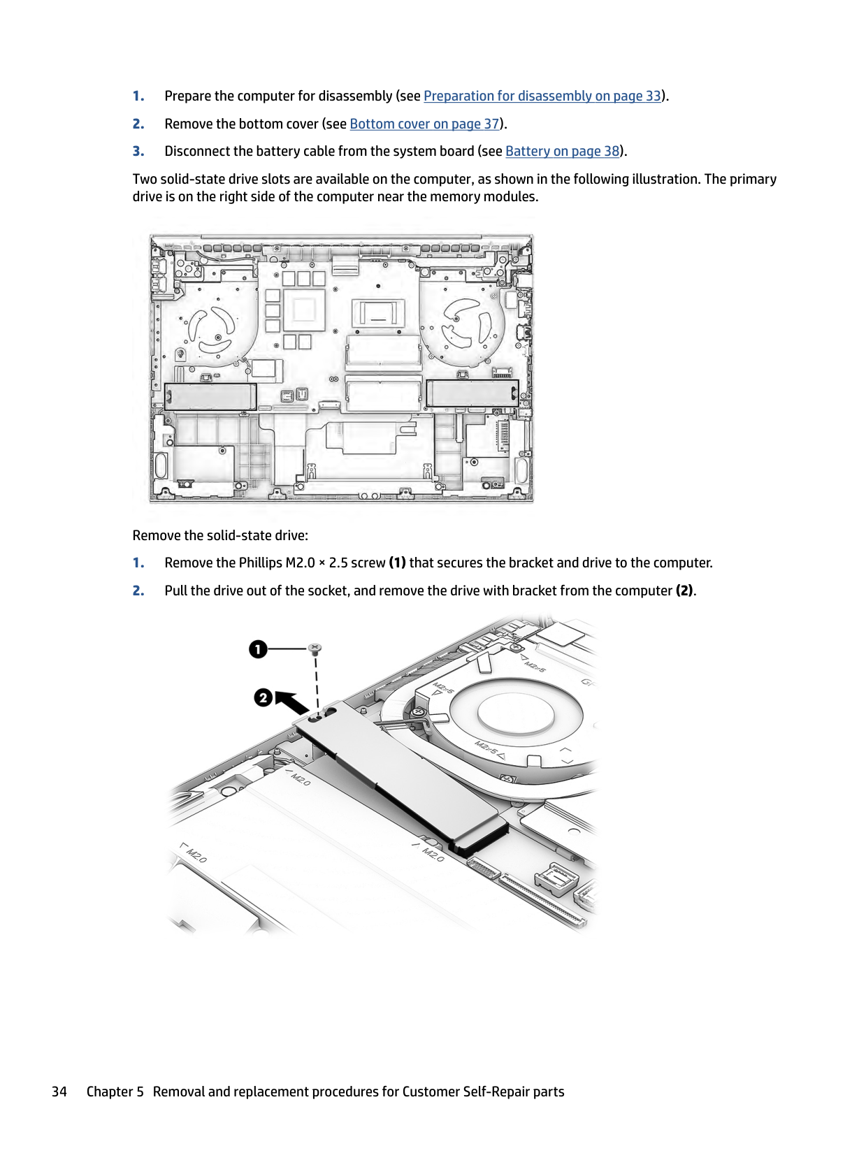
Two solid-state drive slots are available on the computer, as shown in the following illustration. The primary drive is on the right side of the computer near the memory modules.

Remove the solid-state drive:


| | |---|
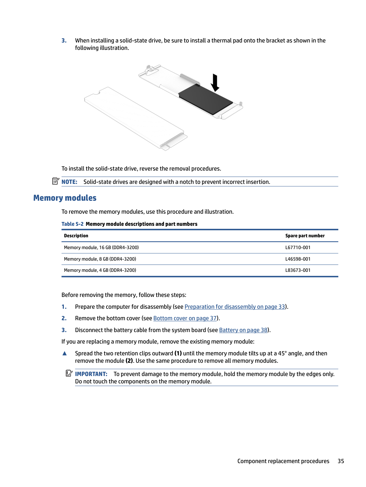
To install the solid-state drive, reverse the removal procedures. NOTE: Solid-state drives are designed with a notch to prevent incorrect insertion.
Memory modules To remove the memory modules, use this procedure and illustration. Table 5-2 Memory module descriptions and part numbers
Description Spare part number
Memory module, 16 GB (DDR4-3200) L67710-001 Memory module, 8 GB (DDR4-3200) L46598-001 Memory module, 4 GB (DDR4-3200) L83673-001
Before removing the memory, follow these steps:
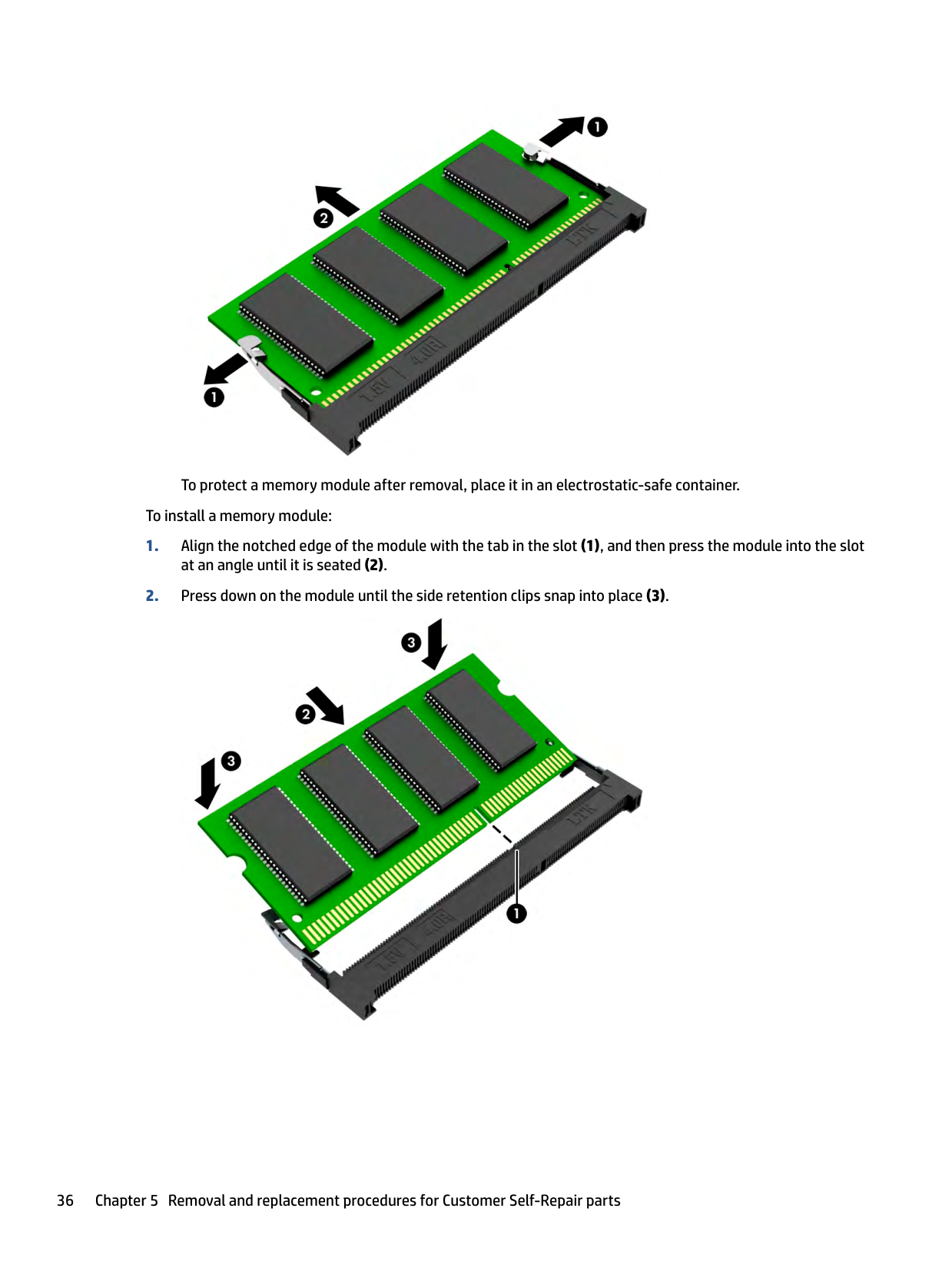
▲ Spread the two retention clips outward (1) until the memory module tilts up at a 45° angle, and then remove the module (2). Use the same procedure to remove all memory modules. IMPORTANT: To prevent damage to the memory module, hold the memory module by the edges only. Do not touch the components on the memory module.
| | |---|
Component replacement procedures 35

To protect a memory module after removal, place it in an electrostatic-safe container. To install a memory module:

6 Removal and replacement procedures for authorized service provider parts
| | |---|
| | |---|
This chapter provides removal and replacement procedures for authorized service provider parts. IMPORTANT: Components described in this chapter should be accessed only by an authorized service provider. Accessing these parts can damage the computer or void the warranty. NOTE: Details about your computer, including model, serial number, product key, and length of warranty, are on the service tag at the bottom of your computer.
Component replacement procedures To remove and replace computer components, use these procedures. NOTE: HP continually improves and changes product parts. For complete and current information about supported parts for your computer, go to http://partsurfer.hp.com, select your country or region, and then follow the on-screen instructions.
| | |---|
You must remove, replace, or loosen as many as 71 screws when you service the parts described in this chapter. Make special note of each screw size and location during removal and replacement.
Preparation for disassembly To remove and replace computer components, use these procedures. See Removal and replacement procedures preliminary requirements on page 25 for initial safety procedures.
#### Bottom cover To remove the bottom cover, use this procedure and illustration. Table 6-1 Bottom cover descriptions and part numbers
Description Spare part number Bottom cover for use in 80 W models
37
######## Table 6-1 Bottom cover descriptions and part numbers (continued)
######### Description Spare part number
● Mica silver M75027-001 ● Performance blue M75029-001
Before removing the bottom cover, prepare the computer for disassembly (see Preparation for disassembly on page 33).
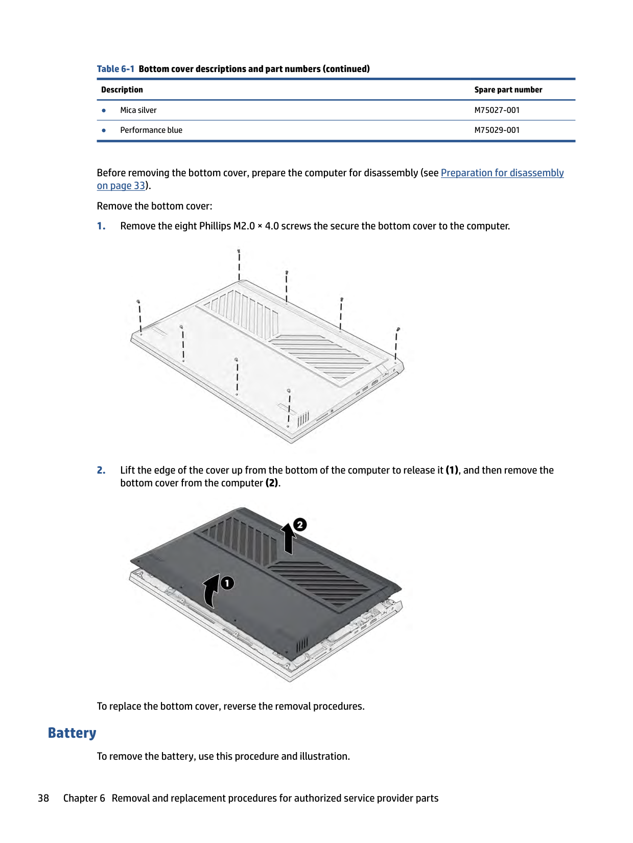
Remove the bottom cover:


To replace the bottom cover, reverse the removal procedures.
#### Battery
To remove the battery, use this procedure and illustration.
Table 6-2 Battery description and part number Description Spare part number 4 cell, 70 Whr, Li-ion battery M39179-005
WARNING! To avoid personal injury and damage to the product:
Before removing the battery, follow these steps:
WARNING! To reduce potential safety issues, use only the user-replaceable battery provided with the computer, a replacement battery provided by HP, or a compatible battery purchased from HP.
| | |---|
IMPORTANT: Removing a battery that is the sole power source for the computer can cause loss of information. To prevent loss of information, save your work or shut down the computer through Windows before you remove the battery.
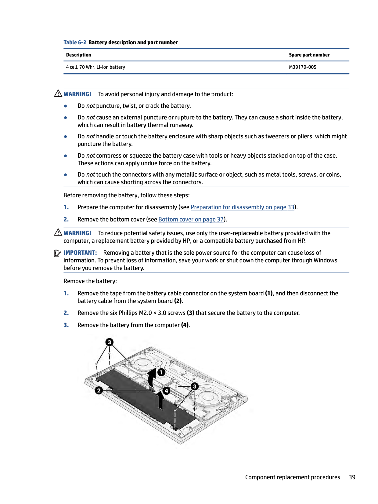
Remove the battery:

To replace the battery, reverse the removal procedures.
Speakers To remove the speakers, use this procedure and illustration. Table 6-3 Speaker description and part number
Description Spare part number
Speaker, right M54728-001 Speaker, left M54731-001
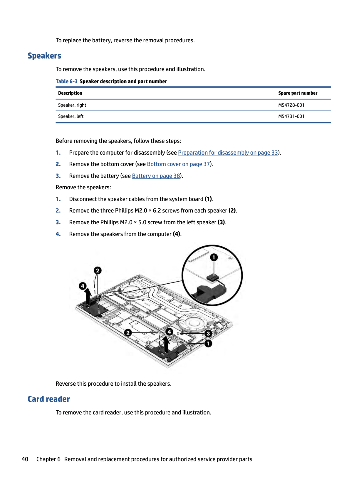
Before removing the speakers, follow these steps:

Reverse this procedure to install the speakers.
#### Card reader
To remove the card reader, use this procedure and illustration.
######## Table 6-4 Card reader description and part number
######### Description Spare part number
Card reader M54771-001 Card reader cable M54772-001
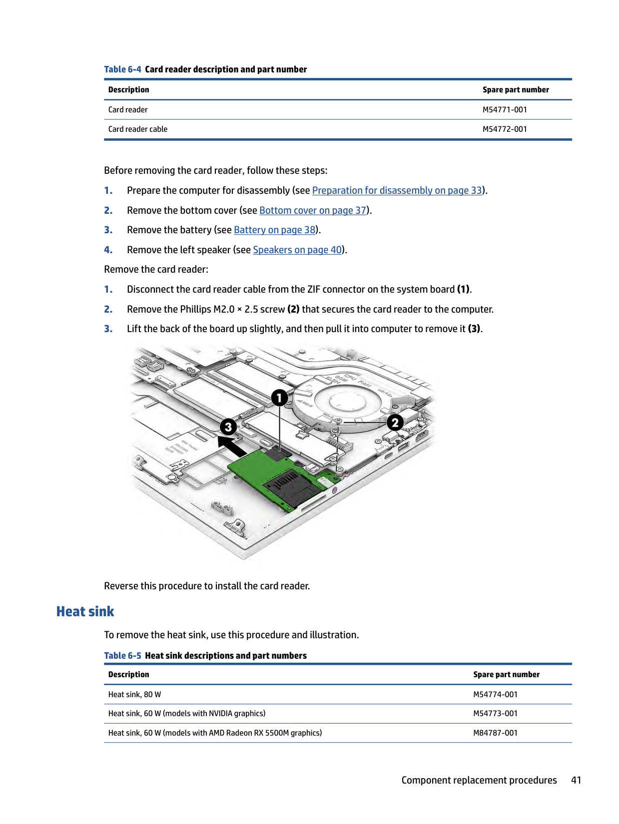
Before removing the card reader, follow these steps:

Reverse this procedure to install the card reader.
Heat sink To remove the heat sink, use this procedure and illustration. Table 6-5 Heat sink descriptions and part numbers
Description Spare part number
Heat sink, 80 W M54774-001 Heat sink, 60 W (models with NVIDIA graphics) M54773-001 Heat sink, 60 W (models with AMD Radeon RX 5500M graphics) M84787-001
######## Table 6-5 Heat sink descriptions and part numbers (continued)
######### Description Spare part number
Thermal grease M54779-001 Thermal gel M54780-001
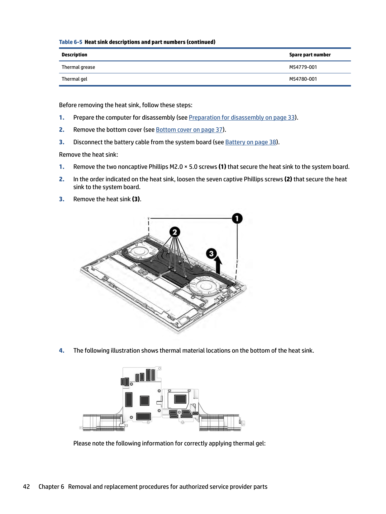
Before removing the heat sink, follow these steps:


Please note the following information for correctly applying thermal gel:
#### Fans
Reverse this procedure to install the heat sink.
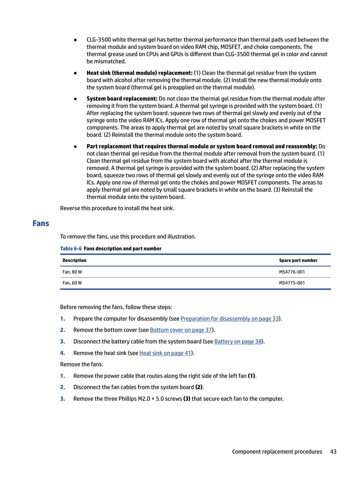
To remove the fans, use this procedure and illustration. Table 6-6 Fans description and part number
Description Spare part number
Fan, 80 W M54776-001 Fan, 60 W M54775-001
Before removing the fans, follow these steps:

Reverse this procedure to install the fans.
WLAN module To remove the WLAN module, use this procedure and illustration. Table 6-7 WLAN module descriptions and part numbers
Description Spare part number
Realtek Wi-Fi 6 RTL8852AE + Bluetooth 5.2 M34027-006 Realtek Wi-Fi 6 RTL8852AE-VT + Bluetooth 5.2 M34029-006 WLAN module protective shielding M14330-001
| | |---|
IMPORTANT: To prevent an unresponsive system, replace the wireless module only with a wireless module authorized for use in the computer by the governmental agency that regulates wireless devices in your country or region. If you replace the module and then receive a warning message, remove the module to restore device functionality, and then contact technical support.
Before removing the WLAN module, follow these steps:
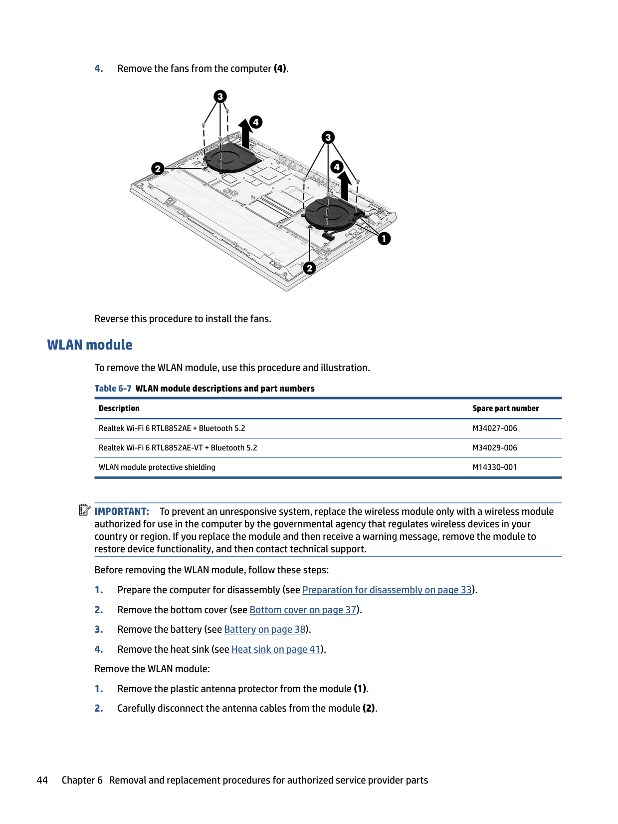
NOTE: Models have either one or two WLAN antennas. On models with two antennas, the #1 white WLAN antenna cable connects to the WLAN module #1 Main terminal. The #2 black WLAN antenna cable connects to the WLAN module #1 Aux terminal.

| | |---|

Reverse this procedure to install the WLAN module.
#### USB board
To remove the USB board, use this procedure and illustration.
######## Table 6-8 USB board description and part number
######### Description Spare part number
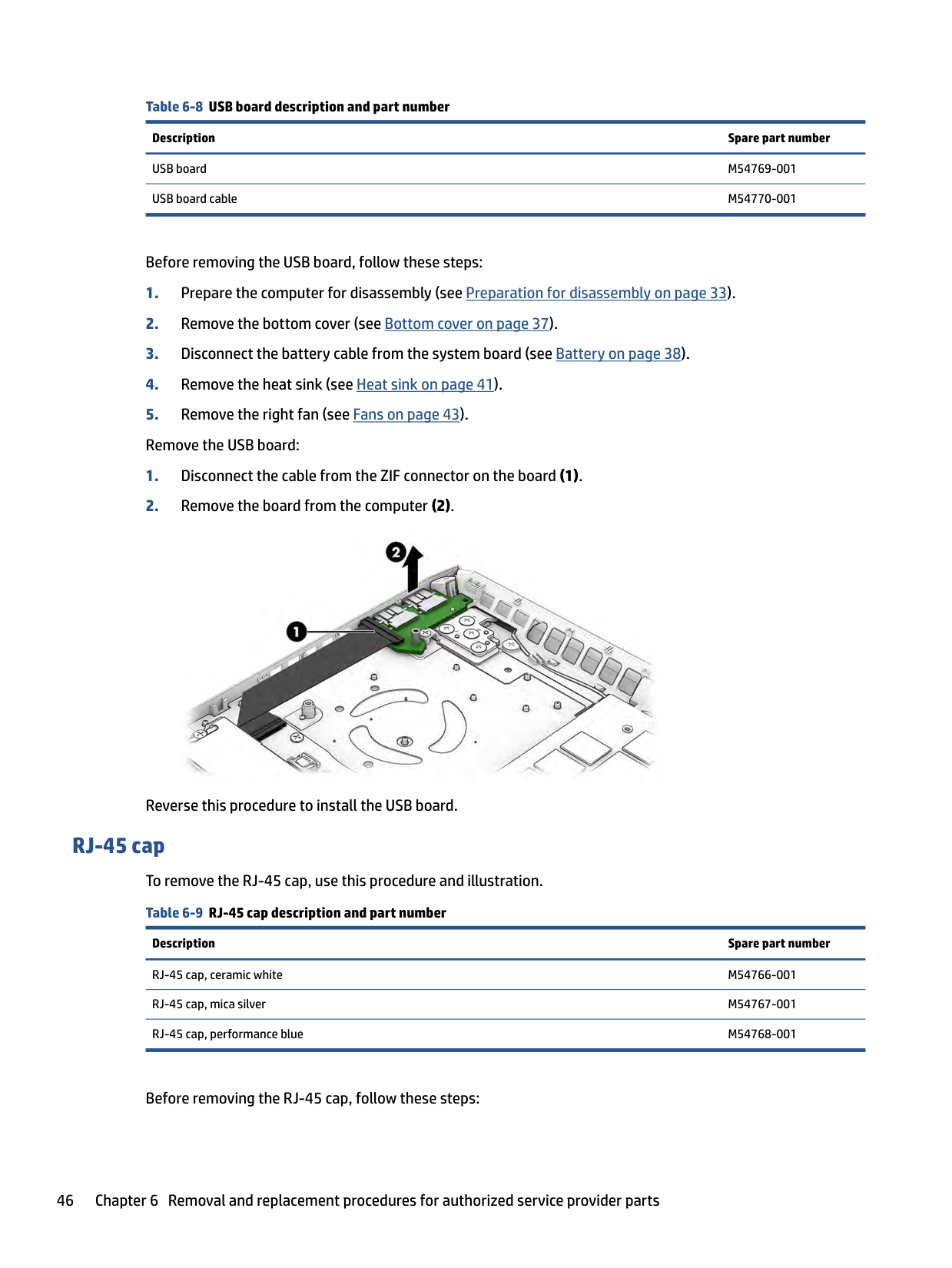
USB board M54769-001 USB board cable M54770-001
Before removing the USB board, follow these steps:

Reverse this procedure to install the USB board.
RJ-45 cap To remove the RJ-45 cap, use this procedure and illustration. Table 6-9 RJ-45 cap description and part number
Description Spare part number
RJ-45 cap, ceramic white M54766-001 RJ-45 cap, mica silver M54767-001 RJ-45 cap, performance blue M54768-001
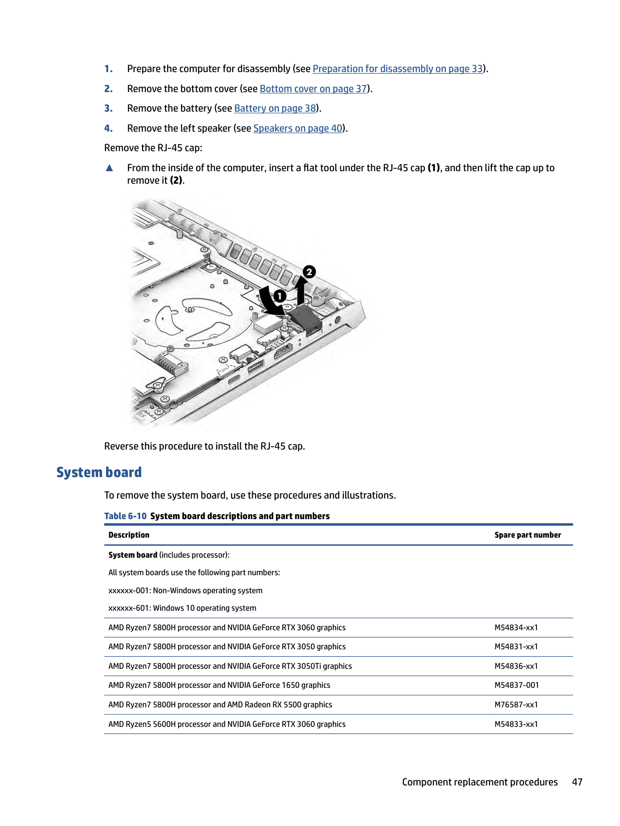
Before removing the RJ-45 cap, follow these steps:
▲ From the inside of the computer, insert a flat tool under the RJ-45 cap (1), and then lift the cap up to
remove it (2).

Reverse this procedure to install the RJ-45 cap.
System board To remove the system board, use these procedures and illustrations. Table 6-10 System board descriptions and part numbers
Description Spare part number System board (includes processor): All system boards use the following part numbers: xxxxxx-001: Non-Windows operating system xxxxxx-601: Windows 10 operating system AMD Ryzen7 5800H processor and NVIDIA GeForce RTX 3060 graphics M54834-xx1 AMD Ryzen7 5800H processor and NVIDIA GeForce RTX 3050 graphics M54831-xx1 AMD Ryzen7 5800H processor and NVIDIA GeForce RTX 3050Ti graphics M54836-xx1 AMD Ryzen7 5800H processor and NVIDIA GeForce 1650 graphics M54837-001 AMD Ryzen7 5800H processor and AMD Radeon RX 5500 graphics M76587-xx1 AMD Ryzen5 5600H processor and NVIDIA GeForce RTX 3060 graphics M54833-xx1
######## Table 6-10 System board descriptions and part numbers (continued)
######### Description Spare part number
AMD Ryzen5 5600H processor and NVIDIA GeForce RTX 3050 graphics M54830-xx1 AMD Ryzen5 5600H processor and NVIDIA GeForce RTX 3050Ti graphics M54835-xx1 AMD Ryzen5 5600H processor and NVIDIA GeForce 1650 graphics M54832-xx1 AMD Ryzen5 5600H processor and AMD Radeon RX 5500 graphics M76586-xx1
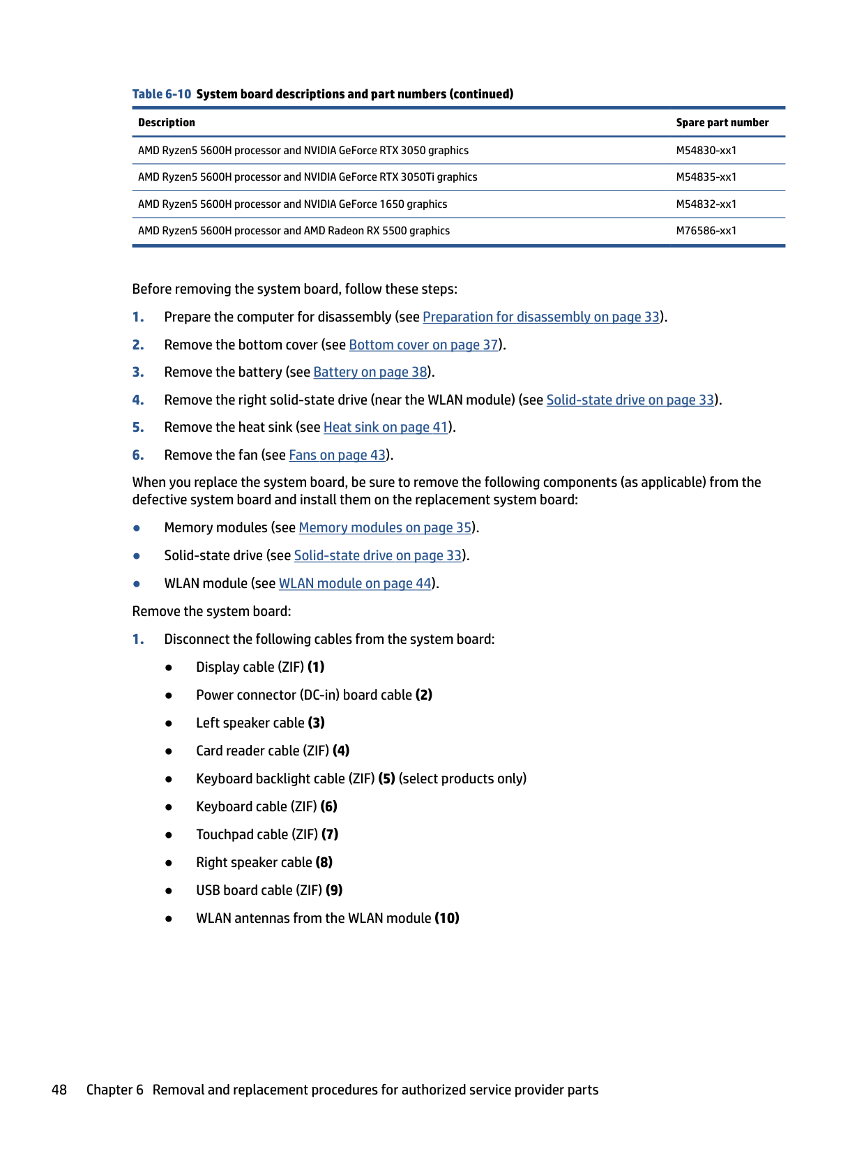
Before removing the system board, follow these steps:
When you replace the system board, be sure to remove the following components (as applicable) from the defective system board and install them on the replacement system board:

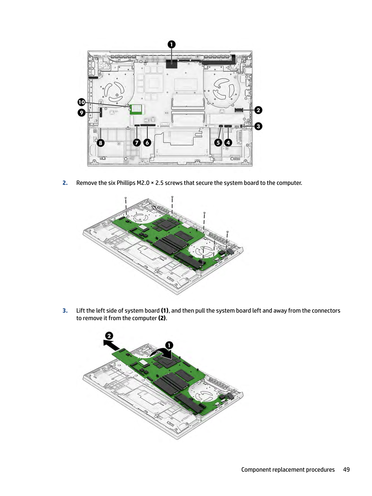
####### 2. Remove the six Phillips M2.0 × 2.5 screws that secure the system board to the computer.

####### 3. Lift the left side of system board (1), and then pull the system board left and away from the connectorsto remove it from the computer (2).

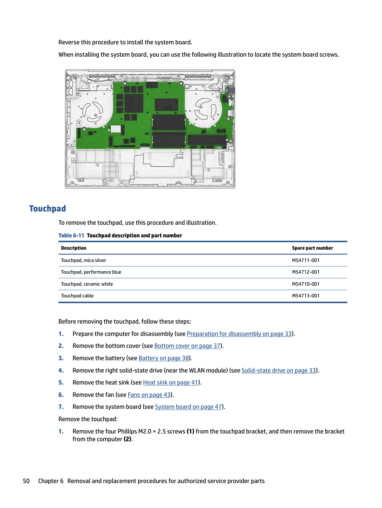
Reverse this procedure to install the system board. When installing the system board, you can use the following illustration to locate the system board screws.

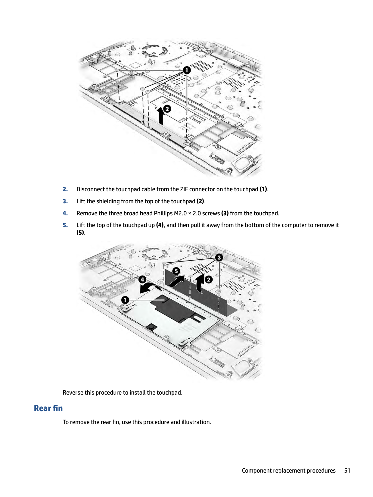
#### Touchpad To remove the touchpad, use this procedure and illustration. Table 6-11 Touchpad description and part number
######### Description Spare part number
Touchpad, mica silver M54711-001 Touchpad, performance blue M54712-001 Touchpad, ceramic white M54710-001 Touchpad cable M54713-001
Before removing the touchpad, follow these steps:

###### (5).

Reverse this procedure to install the touchpad.
#### Rear fin
To remove the rear fin, use this procedure and illustration.
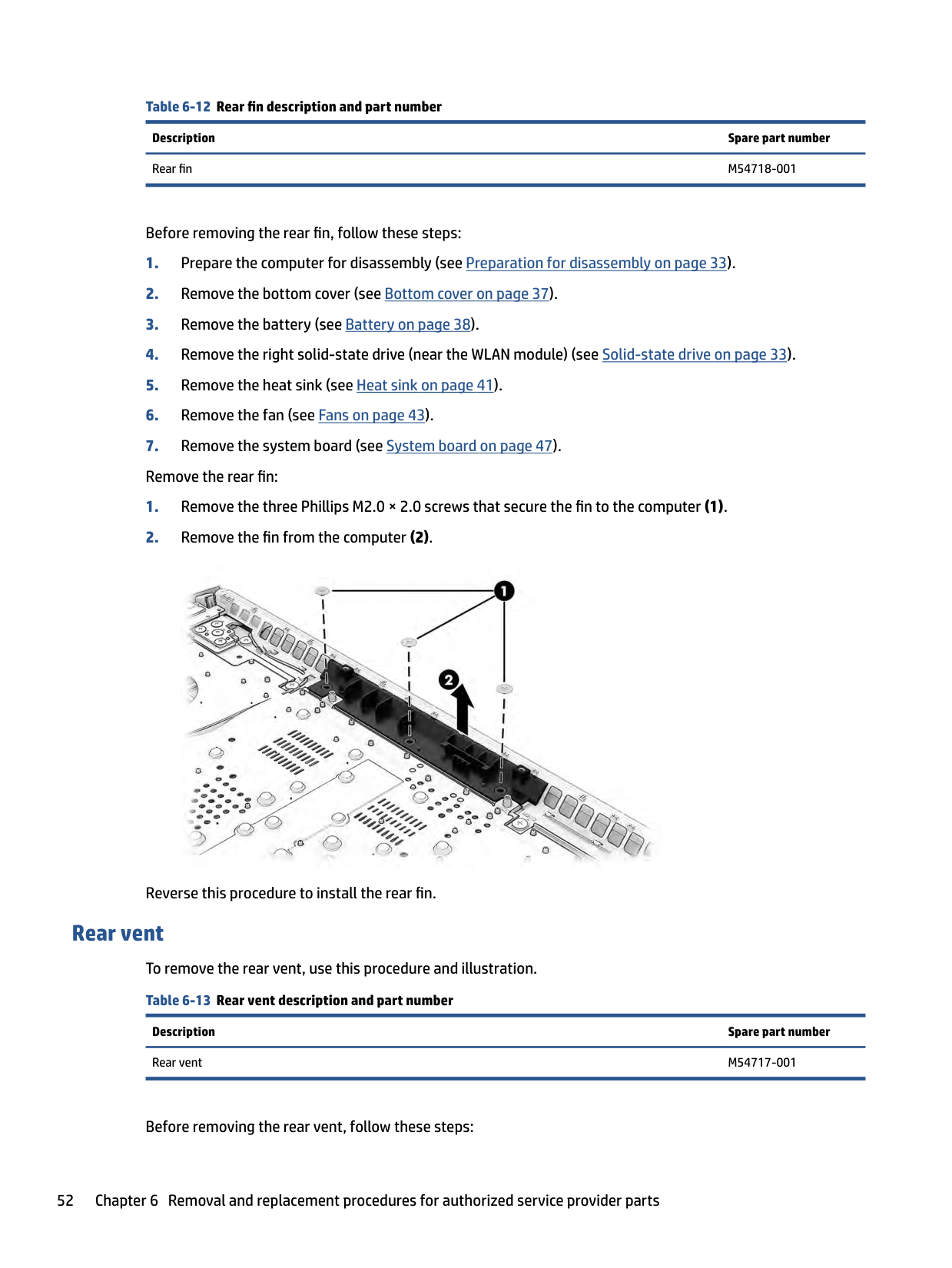
Table 6-12 Rear fin description and part number Description Spare part number Rear fin M54718-001
Before removing the rear fin, follow these steps:

Reverse this procedure to install the rear fin.
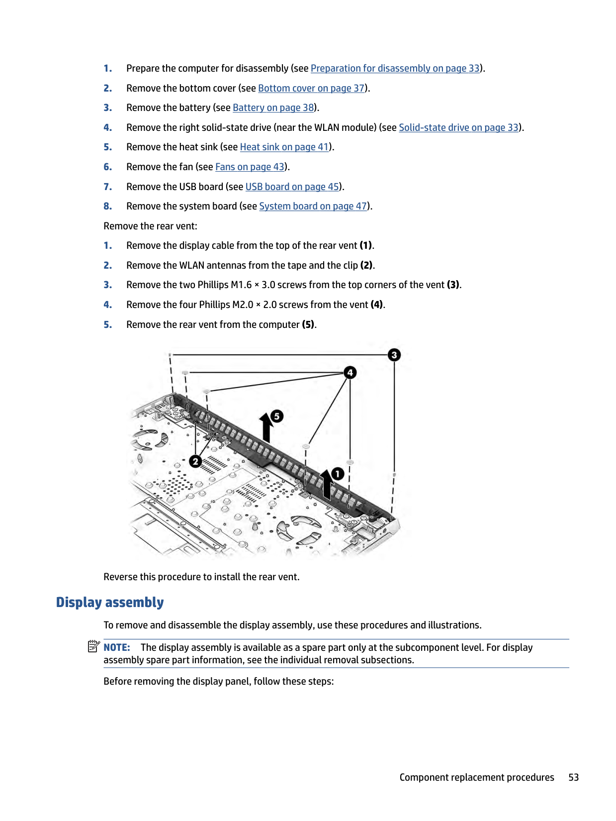
Rear vent To remove the rear vent, use this procedure and illustration. Table 6-13 Rear vent description and part number
Description Spare part number Rear vent M54717-001
Before removing the rear vent, follow these steps:

Reverse this procedure to install the rear vent.
Display assembly To remove and disassemble the display assembly, use these procedures and illustrations. NOTE: The display assembly is available as a spare part only at the subcomponent level. For display assembly spare part information, see the individual removal subsections. Before removing the display panel, follow these steps:
| | |---|
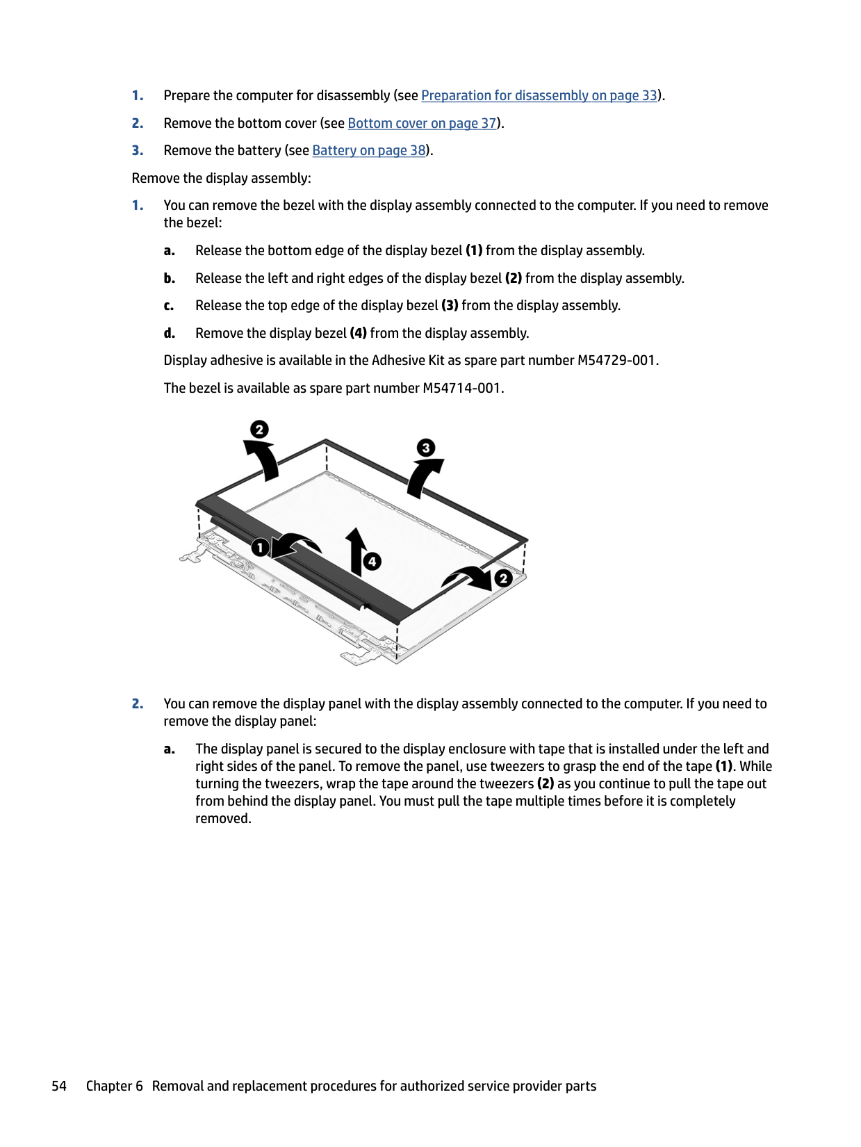
Remove the display assembly:


| | |---|

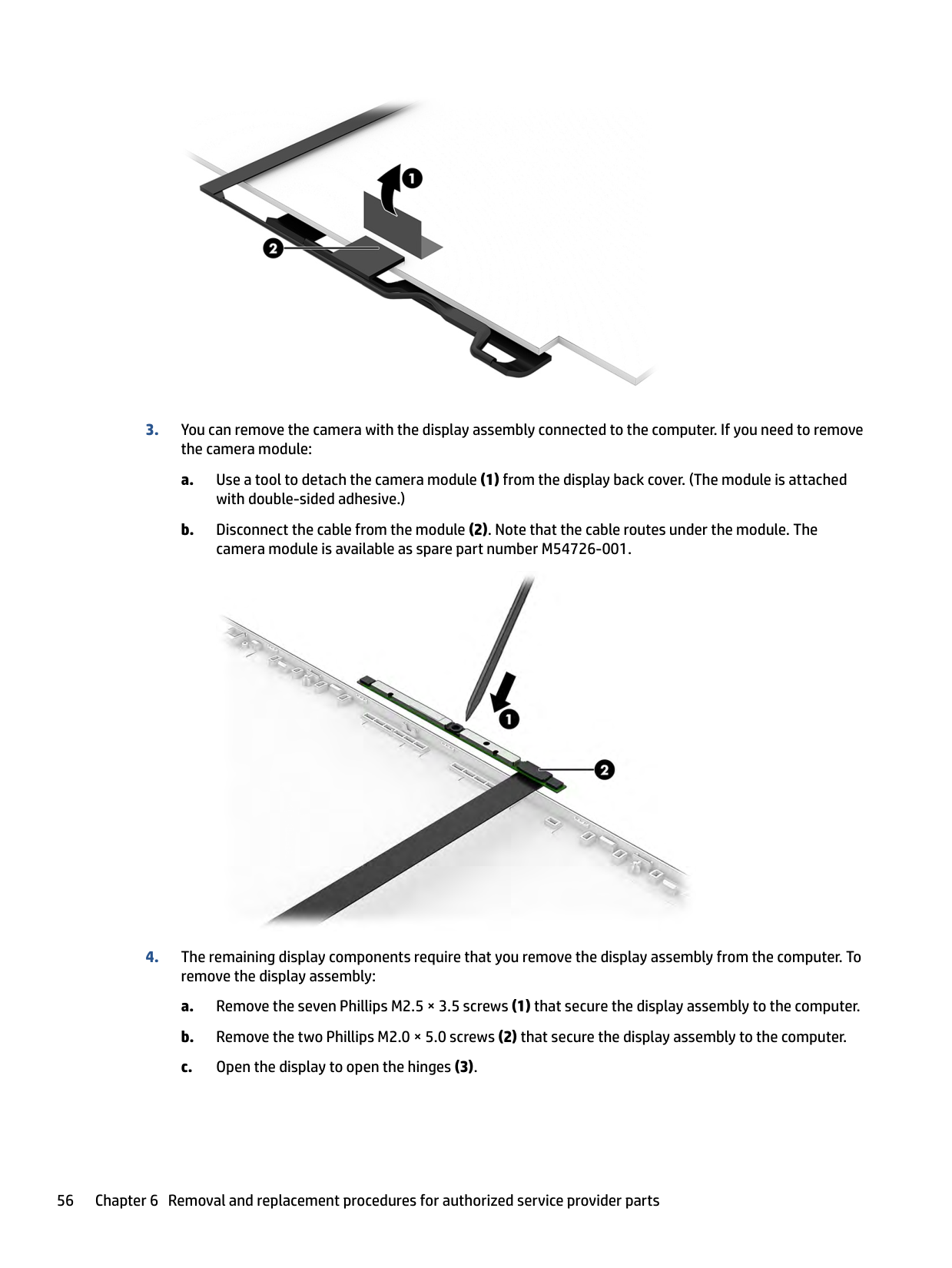
a. Use a tool to detach the camera module (1) from the display back cover. (The module is attached
with double-sided adhesive.)
b. Disconnect the cable from the module (2). Note that the cable routes under the module. The
camera module is available as spare part number M54726-001.


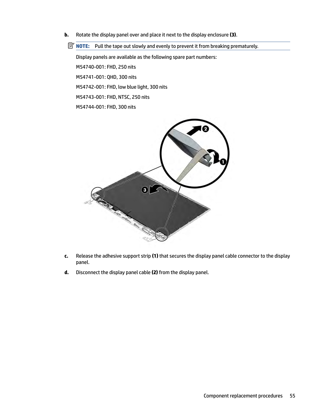
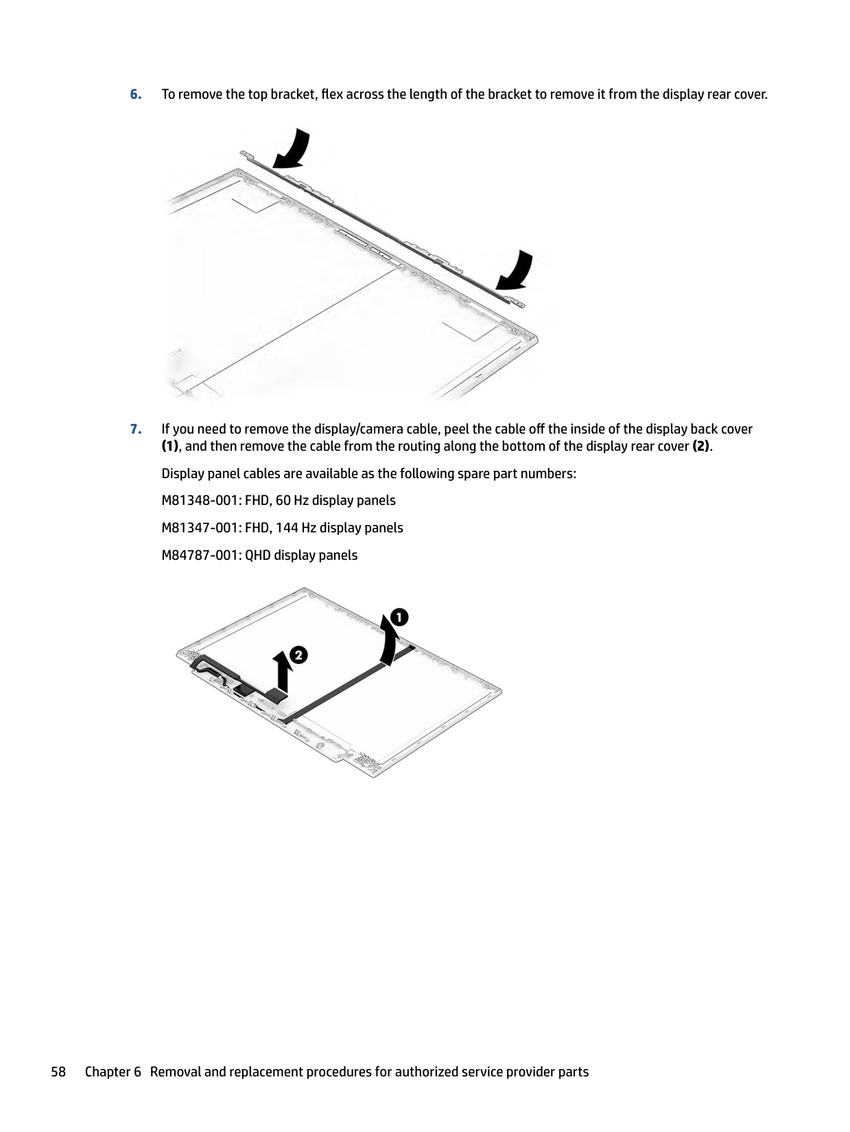
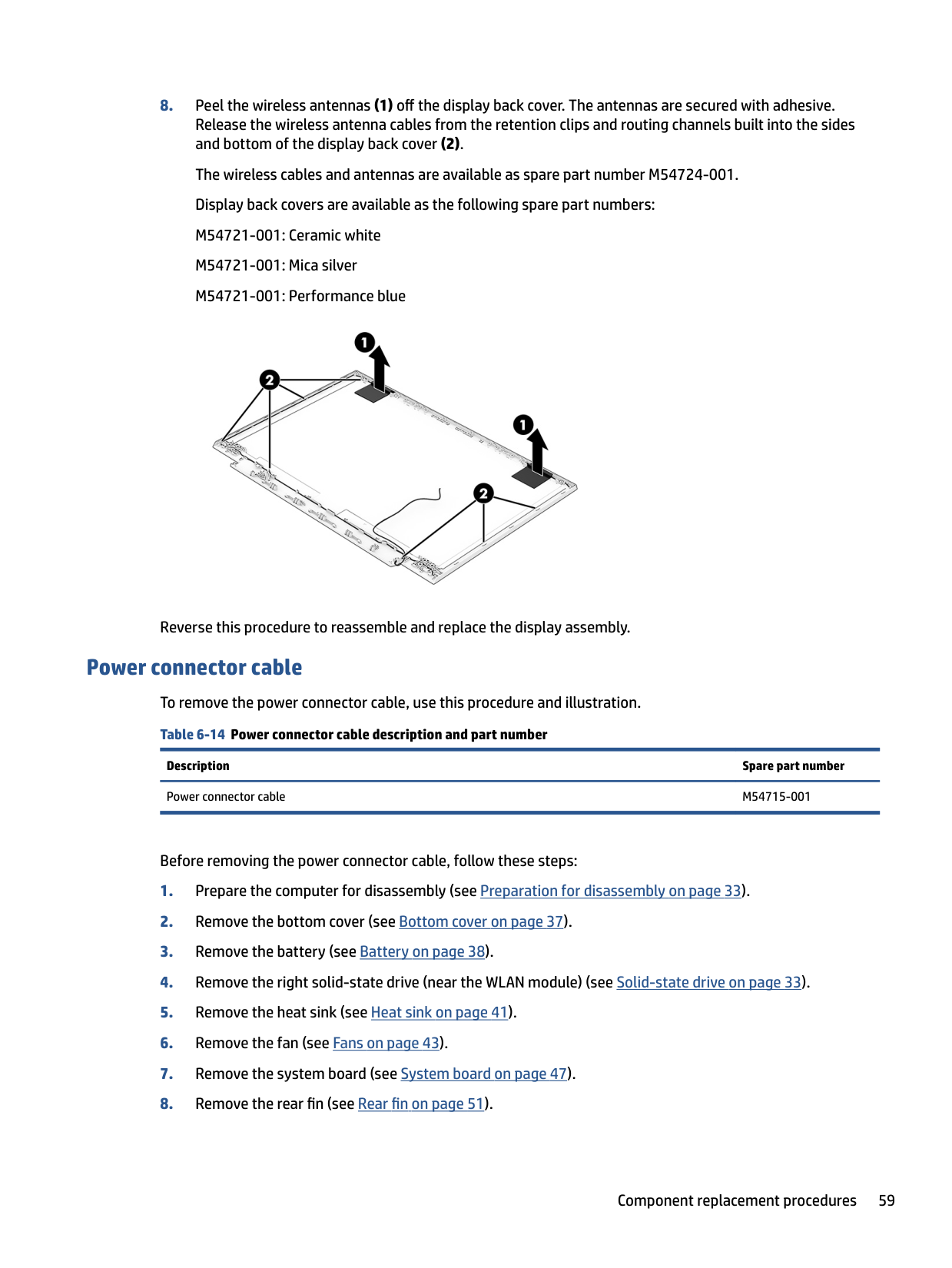
(1), and then remove the cable from the routing along the bottom of the display rear cover (2). Display panel cables are available as the following spare part numbers: M81348-001: FHD, 60 Hz display panels M81347-001: FHD, 144 Hz display panels M84787-001: QHD display panels


Reverse this procedure to reassemble and replace the display assembly.
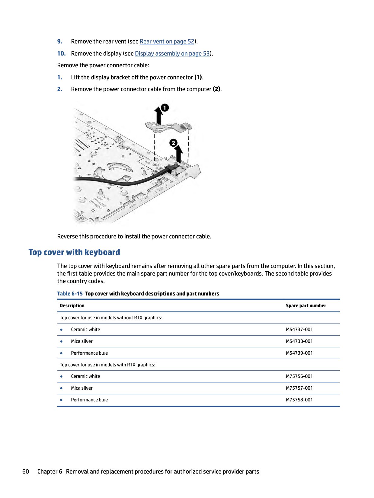
Power connector cable To remove the power connector cable, use this procedure and illustration. Table 6-14 Power connector cable description and part number
Description Spare part number Power connector cable M54715-001
Before removing the power connector cable, follow these steps:

Reverse this procedure to install the power connector cable.
#### Top cover with keyboard
The top cover with keyboard remains after removing all other spare parts from the computer. In this section, the first table provides the main spare part number for the top cover/keyboards. The second table provides the country codes.
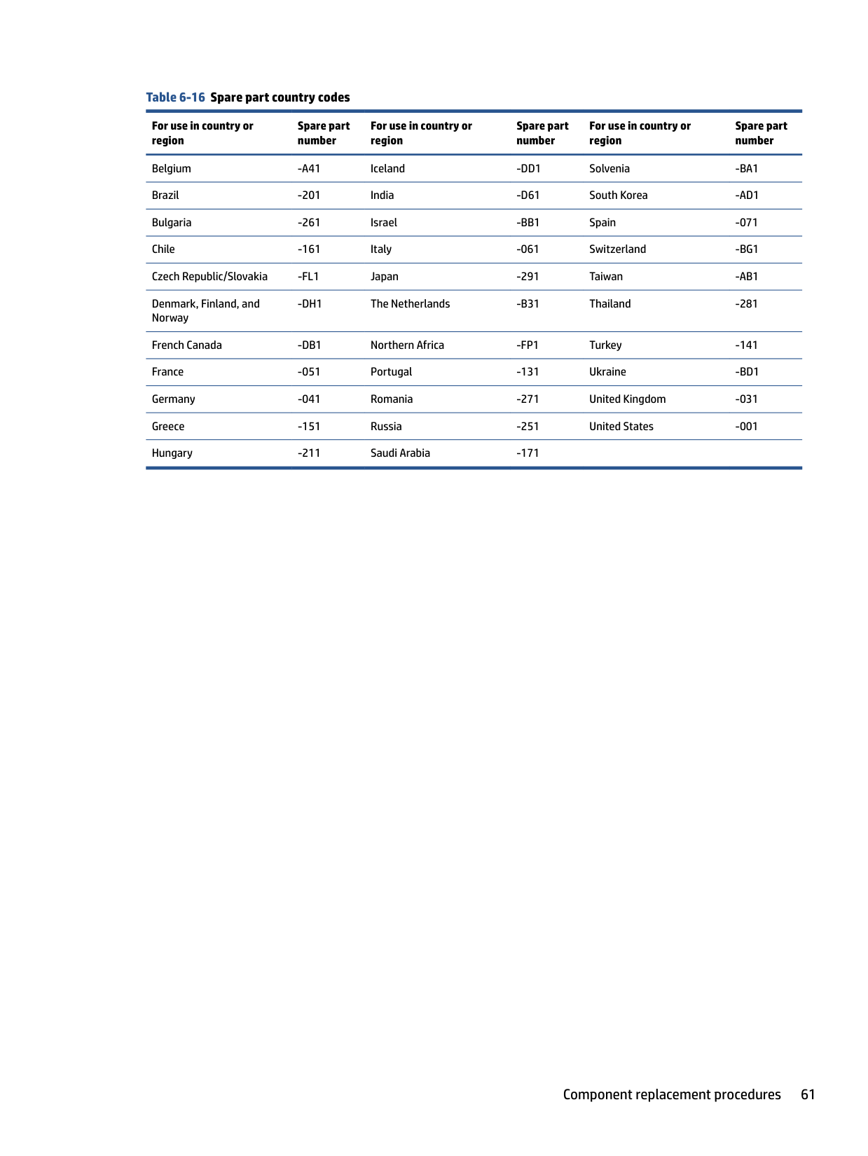
######## Table 6-16 Spare part country codes
For use in country or region
Spare part number
For use in country or region
Spare part number
For use in country or region
Spare part number
Belgium -A41 Iceland -DD1 Solvenia -BA1 Brazil -201 India -D61 South Korea -AD1 Bulgaria -261 Israel -BB1 Spain -071 Chile -161 Italy -061 Switzerland -BG1 Czech Republic/Slovakia -FL1 Japan -291 Taiwan -AB1 Denmark, Finland, and Norway
-DH1 The Netherlands -B31 Thailand -281
French Canada -DB1 Northern Africa -FP1 Turkey -141 France -051 Portugal -131 Ukraine -BD1 Germany -041 Romania -271 United Kingdom -031 Greece -151 Russia -251 United States -001 Hungary -211 Saudi Arabia -171
7 Using Setup Utility (BIOS)
Setup Utility, or Basic Input/Output System (BIOS), controls communication between all the input and output devices on the system (such as disk drives, display, keyboard, mouse, and printer). Setup Utility (BIOS) includes settings for the types of devices installed, the startup sequence of the computer, and the amount of system and extended memory.
| | |---|
NOTE: To start Setup Utility on convertible computers, your computer must be in notebook mode and you must use the keyboard attached to your notebook.
Starting Setup Utility (BIOS) You have several ways to access the Setup Utility (BIOS). IMPORTANT: Use extreme care when making changes in Setup Utility (BIOS). Errors can prevent the computer from operating properly.
| | |---|
▲ Turn on or restart the computer and quickly press f10.
– or – Turn on or restart the computer, quickly press esc, and then press f10 when the Start menu is displayed.
Updating Setup Utility (BIOS)
Updated versions of Setup Utility (BIOS) might be available on the HP website. Most BIOS updates on the HP website are packaged in compressed files called SoftPaqs. Some download packages contain a file named Readme.txt, which contains information regarding installing and troubleshooting the file.
Determining the BIOS version To decide whether you need to update Setup Utility (BIOS), first determine the BIOS version on your computer. To reveal the BIOS version information (also known as ROM date and System BIOS), use one of these options.
– or – Select the question mark icon in the taskbar.
Preparing for a BIOS update Be sure to follow all prerequisites before downloading and installing a BIOS update. IMPORTANT: To reduce the risk of damage to the computer or an unsuccessful installation, download and install a BIOS update only when the computer is connected to reliable external power using the AC adapter. Do not download or install a BIOS update while the computer is running on battery power, docked in an optional docking device, or connected to an optional power source. During the download and installation, follow these instructions:
| | |---|
| | |---|
NOTE: If your computer is connected to a network, consult the network administrator before installing any software updates, especially system BIOS updates.
##### Downloading a BIOS update
After you review the prerequisites, you can check for and download BIOS updates.
– or – Select the question mark icon in the taskbar.
Make a note of the path to the location on your hard drive where the BIOS update is downloaded. You will need to access this path when you are ready to install the update.
##### Installing a BIOS update
BIOS installation procedures vary. Follow any instructions that appear on the screen after the download is complete. If no instructions appear, follow these steps.
Updating Setup Utility (BIOS) 63
| | |---|
####### NOTE: After a message on the screen reports a successful installation, you can delete the downloaded file from your hard drive.
8 Backing up, restoring, and recovering
You can use Windows tools or HP software to back up your information, create a restore point, reset your computer, create recovery media, or restore your computer to its factory state. Performing these standard procedures can return your computer to a working state faster.
| | |---|
IMPORTANT: If you will be performing recovery procedures on a tablet, the tablet battery must be at least 70% charged before you start the recovery process.
IMPORTANT: For a tablet with a detachable keyboard, connect the tablet to the keyboard base before beginning any recovery process.
Backing up information and creating recovery media
These methods of creating recovery media and backups are available on select products only.
#### Using Windows tools for backing up
HP recommends that you back up your information immediately after initial setup. You can do this task either using Windows Backup locally with an external USB drive or using online tools.
| | |---|
IMPORTANT: Windows is the only option that allows you to back up your personal information. Schedule regular backups to avoid information loss.
| | |---|
NOTE: If computer storage is 32 GB or less, Microsoft® System Restore is disabled by default.
#### Using the HP Cloud Recovery Download Tool to create recovery media (select products only)
You can use the HP Cloud Recovery Download Tool to create HP Recovery media on a bootable USB flash drive. For details:
▲ Go to http://www.hp.com/support, search for HP Cloud Recovery, and then select the result that
matches the type of computer that you have.
| | |---|
NOTE: If you cannot create recovery media yourself, contact support to obtain recovery discs. Go to http://www.hp.com/support, select your country or region, and then follow the on-screen instructions.
| | |---|
IMPORTANT: HP recommends that you follow the Restoring and recovery methods on page 66 to restore your computer before you obtain and use the HP recovery discs. Using a recent backup can return your machine to a working state sooner than using the HP recovery discs. After the system is restored, reinstalling all the operating system software released since your initial purchase can be a lengthy process.
Restoring and recovering your system
You have several tools available to recover your system both within and outside of Windows if the desktop cannot load.
HP recommends that you attempt to restore your system using the Restoring and recovery methods on page 66.
65
#### Creating a system restore
System Restore is available in Windows. The System Restore software can automatically or manually create restore points, or snapshots, of the system files and settings on the computer at a particular point.
When you use System Restore, it returns your computer to its state at the time you made the restore point. Your personal files and documents should not be affected.
#### Restoring and recovery methods
After you run the first method, test to see whether the issue still exists before you proceed to the next method, which might now be unnecessary.
NOTE: The options Remove everything and then Fully clean the drive can take several hours to complete and leave no information on your computer. It is the safest way to reset your computer before you recycle it.
| |
|---|
| | |---|
For more information about the first two methods, see the Get Help app: Select the Start button, select the Get Help app, and then enter the task you want to perform. NOTE: You must be connected to the internet to access the Get Help app.
#### Recovering using HP Recovery media
You can use HP Recovery media to recover the original operating system and software programs that were installed at the factory. On select products, it can be created on a bootable USB flash drive using the HP Cloud Recovery Download Tool.
For details, see Using the HP Cloud Recovery Download Tool to create recovery media (select products only) on page 65.
| | |---|
NOTE: If you cannot create recovery media yourself, contact support to obtain recovery discs. Go to http://www.hp.com/support, select your country or region, and then follow the on-screen instructions.
To recover your system:
| | |---|
▲ Insert the HP Recovery media, and then restart the computer. NOTE: HP recommends that you follow the Restoring and recovery methods on page 66 to restore your computer before you obtain and use the HP recovery discs. Using a recent backup can return your machine to a working state sooner than using the HP recovery discs. After the system is restored, reinstalling all the operating system software released since your initial purchase can be a lengthy process.
#### Changing the computer boot order
If your computer does not restart using the HP Recovery media, you can change the computer boot order, the order of devices listed in BIOS for startup information. You can select an optical drive or a USB flash drive, depending on the location of your HP Recovery media.
| | |---|
IMPORTANT: For a tablet with a detachable keyboard, connect the tablet to the keyboard base before beginning these steps.
66 Chapter 8 Backing up, restoring, and recovering
To change the boot order:
‒ or – Turn on or restart the tablet, quickly press and hold the volume down button, and then select f9.
#### Using HP Sure Recover (select products only)
Select computer models are configured with HP Sure Recover, a PC operating system (OS) recovery solution built into the hardware and software. HP Sure Recover can fully restore the HP OS image without installed recovery software.
Using HP Sure Recover, an administrator or user can restore the system and install:
To access the latest documentation for HP Sure Recover, go to http://www.hp.com/support. Follow the onscreen instructions to find your product and locate your documentation.
Restoring and recovering your system 67
9 Using HP PC Hardware Diagnostics
You can use the HP PC Hardware Diagnostics utility to determine whether your computer hardware is running properly. The three versions are HP PC Hardware Diagnostics Windows, HP PC Hardware Diagnostics UEFI (Unified Extensible Firmware Interface), and (for select products only) Remote HP PC Hardware Diagnostics UEFI, a firmware feature.
Using HP PC Hardware Diagnostics Windows (select products only)
HP PC Hardware Diagnostics Windows is a Windows-based utility that allows you to run diagnostic tests to determine whether the computer hardware is functioning properly. The tool runs within the Windows operating system to diagnose hardware failures.
If HP PC Hardware Diagnostics Windows is not installed on your computer, first you must download and install it. To download HP PC Hardware Diagnostics Windows, see Downloading HP PC Hardware Diagnostics Windows on page 69.
#### Using an HP PC Hardware Diagnostics Windows hardware failure ID code
When HP PC Hardware Diagnostics Windows detects a failure that requires hardware replacement, a 24-digit failure ID code is generated for select component tests. For interactive tests, such as keyboard, mouse, or audio and video palette, you must perform troubleshooting steps before you can receive a failure ID.
▲ You have several options after you receive a failure ID:
– or –

– or –
#### Accessing HP PC Hardware Diagnostics Windows
After HP PC Hardware Diagnostics Windows is installed, you can access it from HP Help and Support, HP Support Assistant, or the Start menu.
##### Accessing HP PC Hardware Diagnostics Windows from HP Help and Support (select products only)
After HP PC Hardware Diagnostics Windows is installed, follow these steps to access it from HP Help and Support.
| | |---|
NOTE: To stop a diagnostic test, select Cancel.
##### Accessing HP PC Hardware Diagnostics Windows from Support Assistant
After HP PC Hardware Diagnostics Windows is installed, follow these steps to access it from HP Support Assistant.
– or – Select the question mark icon in the taskbar.
| | |---|
NOTE: To stop a diagnostic test, select Cancel.
##### Accessing HP PC Hardware Diagnostics Windows from the Start menu (select products only)
After HP PC Hardware Diagnostics Windows is installed, follow these steps to access it from the Start menu.
| | |---|
NOTE: To stop a diagnostic test, select Cancel.
#### Downloading HP PC Hardware Diagnostics Windows
The HP PC Hardware Diagnostics Windows downloading instructions are provided in English only. You must use a Windows computer to download this tool because only .exe files are provided.
##### Downloading the latest HP PC Hardware Diagnostics Windows version from HP
To download HP PC Hardware Diagnostics Windows from HP, follow these steps.
The tool downloads to the selected location.
##### Downloading the HP PC Hardware Diagnostics Windows from the Microsoft Store
You can download the HP PC Hardware Diagnostics Windows from the Microsoft Store.
Using HP PC Hardware Diagnostics Windows (select products only) 69
The tool downloads to the selected location.
##### Downloading HP Hardware Diagnostics Windows by product name or number (select products only)
| | |---|
You can download HP PC Hardware Diagnostics Windows by product name or number. NOTE: For some products, you might have to download the software to a USB flash drive by using the product name or number.
The tool downloads to the selected location.
#### Installing HP PC Hardware Diagnostics Windows
To install HP PC Hardware Diagnostics Windows, navigate to the folder on your computer or the USB flash drive where the .exe file downloaded, double-click the .exe file, and then follow the on-screen instructions.
Using HP PC Hardware Diagnostics UEFI
HP PC Hardware Diagnostics UEFI (Unified Extensible Firmware Interface) allows you to run diagnostic tests to determine whether the computer hardware is functioning properly. The tool runs outside the operating system so that it can isolate hardware failures from issues that are caused by the operating system or other software components.
| | |---|
NOTE: For Windows 10 S computers, you must use a Windows computer and a USB flash drive to download and create the HP UEFI support environment because only .exe files are provided. For more information, see Downloading HP PC Hardware Diagnostics UEFI to a USB flash drive on page 71.
If your PC does not start in Windows, you can use HP PC Hardware Diagnostics UEFI to diagnose hardware issues.
#### Using an HP PC Hardware Diagnostics UEFI hardware failure ID code
When HP PC Hardware Diagnostics UEFI detects a failure that requires hardware replacement, a 24-digit failure ID code is generated.
For assistance in solving the problem:
▲ Select Contact HP, accept the HP privacy disclaimer, and then use a mobile device to scan the failure ID code that appears on the next screen. The HP Customer Support - Service Center page appears with your failure ID and product number automatically filled in. Follow the on-screen instructions.
– or – Contact support, and provide the failure ID code.
| | |---|
NOTE: To start diagnostics on a convertible computer, your computer must be in notebook mode, and you must use the attached keyboard.
| | |---|
NOTE: If you need to stop a diagnostic test, press esc.
#### Starting HP PC Hardware Diagnostics UEFI
To start HP PC Hardware Diagnostics UEFI, follow this procedure.
| | |---|
#### Downloading HP PC Hardware Diagnostics UEFI to a USB flash drive
Downloading HP PC Hardware Diagnostics UEFI to a USB flash drive can be useful in some situations.
| | |---|
NOTE: The HP PC Hardware Diagnostics UEFI downloading instructions are provided in English only, and you must use a Windows computer to download and create the HP UEFI support environment because only .exe files are provided.
##### Downloading the latest HP PC Hardware Diagnostics UEFI version
To download the latest HP PC Hardware Diagnostics UEFI version to a USB flash drive, follow this procedure.
##### Downloading HP PC Hardware Diagnostics UEFI by product name or number (select products only)
You can download HP PC Hardware Diagnostics UEFI by product name or number (select products only) to a USB flash drive.
| | |---|
NOTE: For some products, you might have to download the software to a USB flash drive by using the product name or number.
Using HP PC Hardware Diagnostics UEFI 71
Using Remote HP PC Hardware Diagnostics UEFI settings (select products only)
Remote HP PC Hardware Diagnostics UEFI is a firmware (BIOS) feature that downloads HP PC Hardware Diagnostics UEFI to your computer. It can then execute the diagnostics on your computer, and it might upload results to a preconfigured server.
For more information about Remote HP PC Hardware Diagnostics UEFI, go to http://www.hp.com/go/ techcenter/pcdiags, and then select Find out more.
#### Downloading Remote HP PC Hardware Diagnostics UEFI
HP Remote PC Hardware Diagnostics UEFI is also available as a SoftPaq that you can download to a server. Downloading the latest Remote HP PC Hardware Diagnostics UEFI version
You can download the latest HP PC Hardware Diagnostics UEFI version to a USB flash drive.
Downloading Remote HP PC Hardware Diagnostics UEFI by product name or number You can download HP Remote PC Hardware Diagnostics UEFI by product name or number. NOTE: For some products, you might have to download the software by using the product name or number.
| | |---|
#### Customizing Remote HP PC Hardware Diagnostics UEFI settings
Using the Remote HP PC Hardware Diagnostics setting in Computer Setup (BIOS), you can perform several customizations.
Using Remote HP PC Hardware Diagnostics UEFI settings (select products only) 73
10 Specifications
This chapter provides specifications for your computer.
Computer specifications
This section provides specifications for your computer. When traveling with your computer, the computer dimensions and weights, as well as input power ratings and operating specifications, provide helpful information.
Table 10-1 Computer specifications
Metric U.S. Dimensions
Width 370 mm 14.6 in Depth 260 mm 10.2 in Height (front to back) 23.5 mm 0.93 in Weight 2468.4 g 5.44 lb Input power
Operating voltage and current 19.5 V dc @ 10.3 A – 200 W 19.5 V dc @ 7.70 A – 150 W
Temperature Operating 5°C to 35°C 41°F to 95°F Nonoperating –20°C to 60°C –4°F to 140°F Relative humidity (noncondensing) Operating 10% to 90% Nonoperating 5% to 95% Maximum altitude (unpressurized)

Operating –15 m to 3,048 m –50 ft to 10,000 ft Nonoperating –15 m to 12,192 m –50 ft to 40,000 ft NOTE: Applicable product safety standards specify thermal limits for plastic surfaces. The device operates well within this range of
temperatures.
40.9 cm (16.1 in) display specifications
This section provides specifications for your display.
74 Chapter 10 Specifications
######## Table 10-2 Display specifications
Metric U.S. Active diagonal size 40.9 cm 16.1 in Resolution 2560 × 1440 (QHD)
1920 × 1080 (FHD) Surface treatment Antiglare Brightness 250 nits
300 nits
Viewing angle UWVA Backlight WLED Display panel interface eDP
Solid-state drive specifications This section provides specifications for your solid-state drives. Table 10-3 Solid-state drive specifications
256 GB* 512 GB* 1 TB*
Dimensions Height 1.0 mm 1.0 mm 1.0 mm Length 50.8 mm 50.8 mm 50.8 mm Width 28.9 mm 28.9 mm 28.9 mm Weight < 10 g < 10 g < 10 g Interface type PCIe PCIe PCIe
Ready time, maximum (to not busy) 1.0 ms < 1.0 ms 1.0 ms Access times, logical 0.1 ms 0.1 ms 0.1 ms Transfer rate
Sequential read up to 2150 MB/s up to 2150 MB/s up to 2150 MB/s Random read Up to 300,000 IOPs Up to 300,000 IOPs Up to 300,000 IOPs Sequential write up to 1550 MB/s up to 1550 MB/s up to 1550 MB/s Random write Up to 100,000 IOPs Up to 100,000 IOPs Up to 100,000 IOPs Total logical sectors 468,883,296 1,000,215,216 1,500,336,388 Operating temperature 0°C to 70°C (32°F to 158°F)
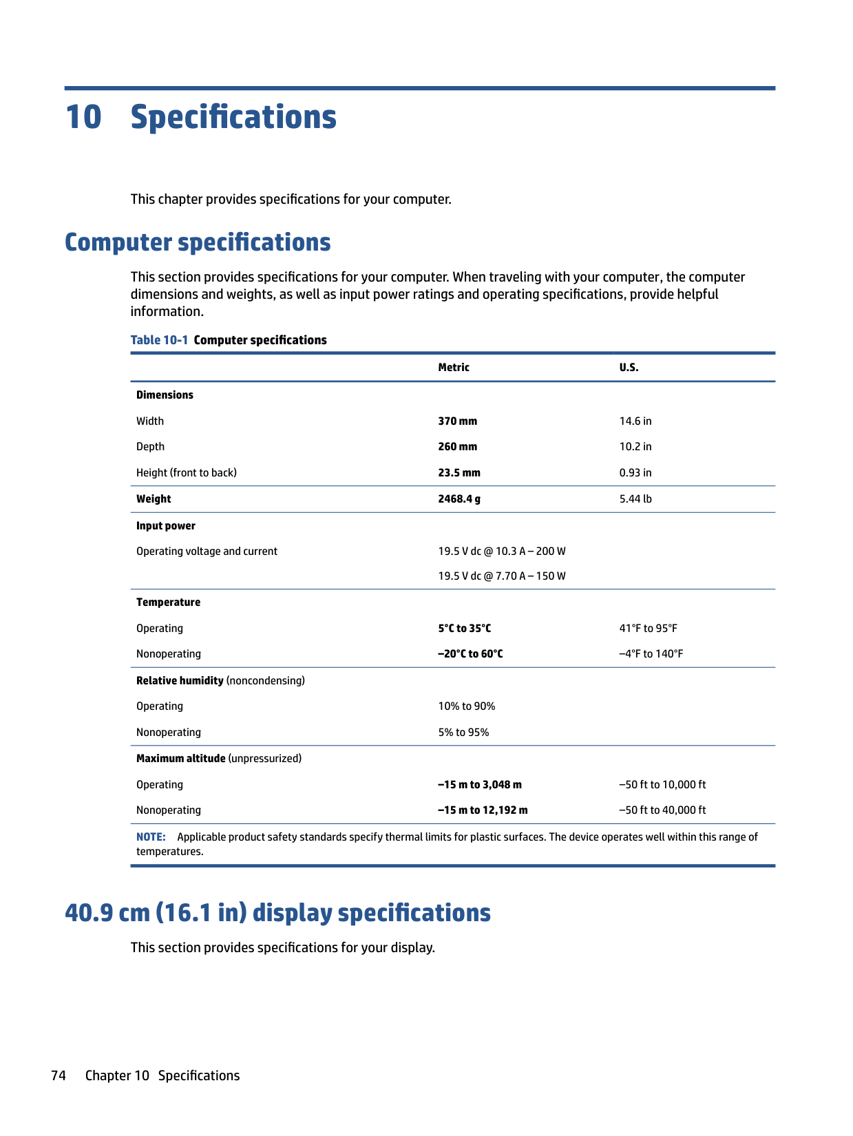
*1 GB = 1 billion bytes when referring to hard drive storage capacity. Actual accessible capacity is less. Actual drive specifications might differ slightly.
NOTE: Certain restrictions and exclusions apply. Contact support for details.
Solid-state drive specifications 75
11 Power cord set requirements
This chapter provides power cord requirements for countries and regions. The wide-range input feature of the computer permits it to operate from any line voltage from 100 V ac to 120 V ac, or from 220 V ac to 240 V ac. The three-conductor power cord set included with the computer meets the requirements for use in the country or region where the equipment is purchased. Power cord sets for use in other countries or regions must meet the requirements of the country and region where the computer is used.
Requirements for all countries
These power cord requirements are applicable to all countries and regions.
Requirements for specific countries and regions To determine power cord requirements for specific countries and regions, use this table. Table 11-1 Power cord requirements for specific countries and regions
######### Country/region Accredited agency Applicable note number
Argentina IRAM 1 Australia SAA 1 Austria OVE 1 Belgium CEBEC 1 Brazil ABNT 1 Canada CSA 2 Chile IMQ 1 Denmark DEMKO 1 Finland FIMKO 1 France UTE 1 Germany VDE 1
76 Chapter 11 Power cord set requirements
######## Table 11-1 Power cord requirements for specific countries and regions (continued)
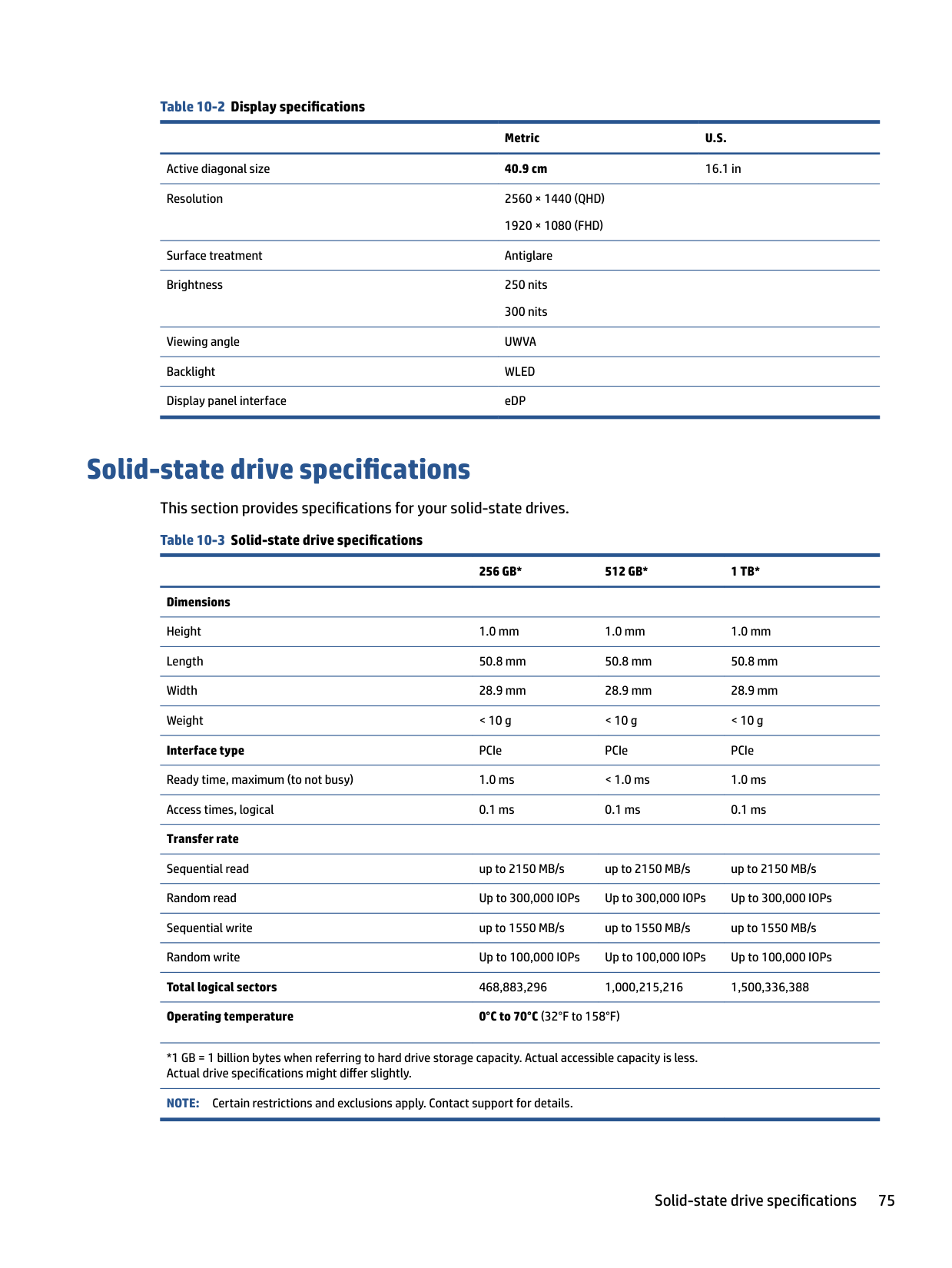
######### Country/region Accredited agency Applicable note number
India BIS 1 Israel SII 1 Italy IMQ 1 Japan JIS 3 Netherlands KEMA 1 New Zealand SANZ 1 Norway NEMKO 1 People's Republic of China CCC 4 Saudi Arabia SASO 7 Singapore PSB 1 South Africa SABS 1 South Korea KTL 5 Sweden SEMKO 1 Switzerland SEV 1 Taiwan BSMI 6 Thailand TISI 1 United Kingdom ASTA 1 United States UL 2
Requirements for specific countries and regions 77
12 Recycling
When a nonrechargeable or rechargeable battery has reached the end of its useful life, do not dispose of the battery in general household waste. Follow the local laws and regulations in your area for battery disposal.
HP encourages customers to recycle used electronic hardware, HP original print cartridges, and rechargeable batteries. For more information about recycling programs, see the HP website at http://www.hp.com/recycle.
78 Chapter 12 Recycling
Index
identifying 6 action key, identifying 12 action keys
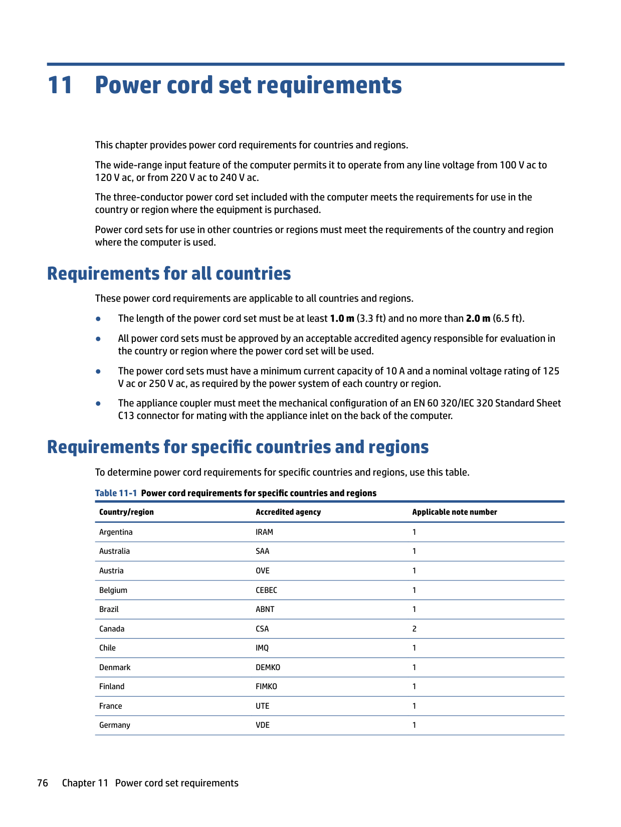
airplane mode 14 decrease screen brightness 13 help 13 identifying 13 increase screen brightness 13 keyboard backlight 14 mute microphone 14 mute volume
mute 14 next track 14 pause 14 play 14 previous track 14 privacy screen 13 speaker volume 14 switch screen image 13 touchpad 14 using 13 volume
mute 14
Windows lock 14 airplane mode key 14 audio
adjusting volume 14
audio-out (headphone)/audio-in (microphone) combo jack, identifying 6
determining version 62 downloading an update 63 starting the Setup Utility 62 updating 62 Bluetooth label 15 boot order, changing 66 bottom components 14
bottom cover removal 37 spare part number 37
buttons left touchpad 9 power 11, 12 right touchpad 9
C camera
identifying 8 camera light, identifying 8 caps lock light 10 card reader
removal 40 spare part numbers 40
caring for your computer 29 cautions
electrostatic discharge 25, 26
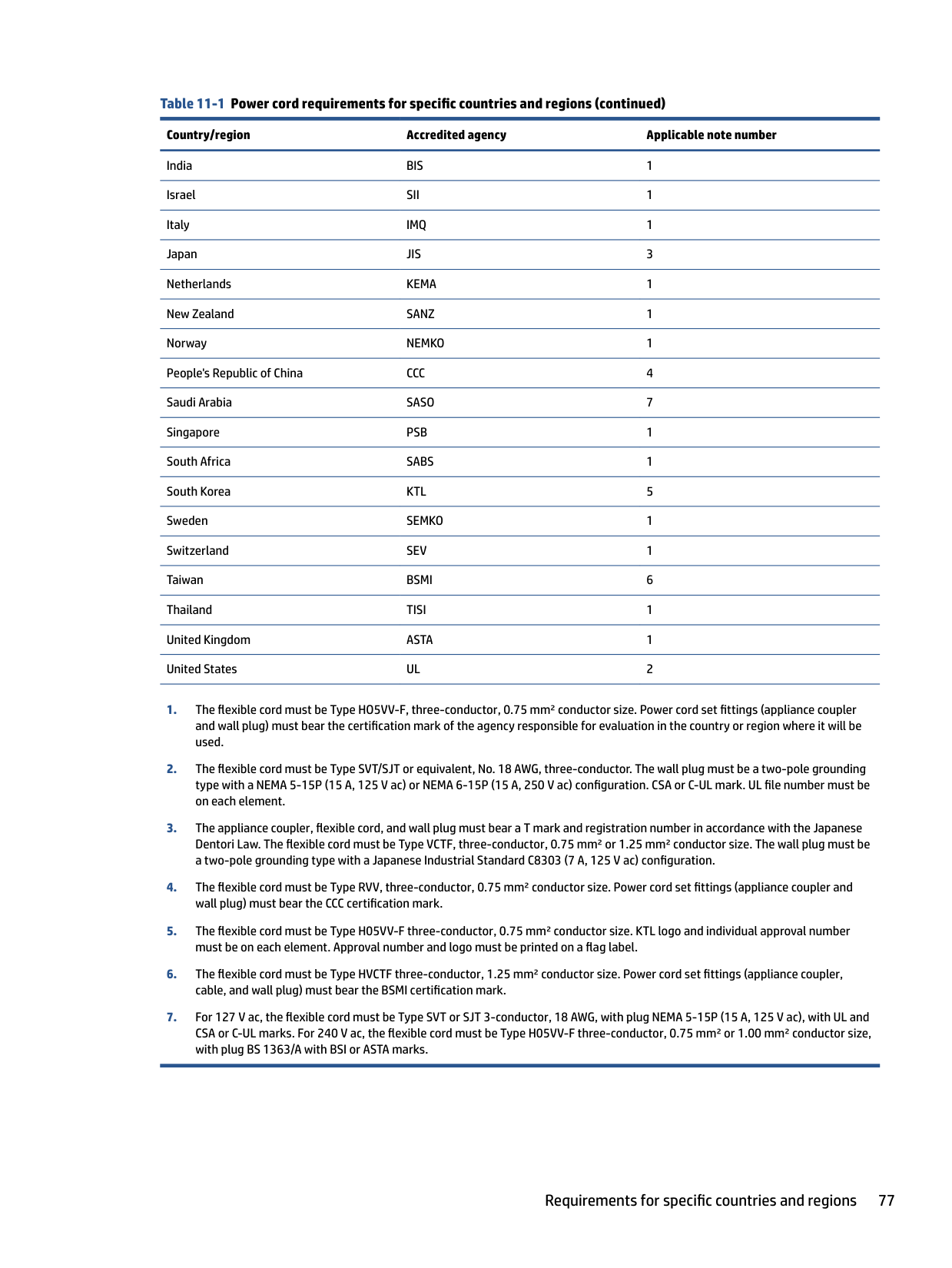
cleaning your computer 29 caring for wood veneer 31 disinfecting 30 HP Easy Clean 29 removing dirt and debris 29
components bottom 14 display 7 keyboard area 8 left side 5 lights 10 rear 15 right side 5 touchpad 8, 9
computer major components 18 computer specifications 74 connectors
power 6 control zone 9
D decrease screen brightness action
key 13 display
specifications 74
display assembly
subcomponents 21 display components 7 display panel
illustrated 22 spare part number 22
preventing damage 25, 26, 27 esc key, identifying 12
removal 43 spare part number 43
fn key, identifying 12
13 grounding methods 25, 26, 27 guidelines
packaging 25, 31 transporting 25, 31 workstation 25
specifications 74 HDMI port
identifying 6
heat sink removal 41 spare part number 41
HP PC Hardware Diagnostics UEFI downloading 71 failure ID code 70 starting 71 using 70
HP PC Hardware Diagnostics Windows
accessing 68, 69 downloading 69 failure ID code 68
installing 70 using 68
HP Recovery media
recovery 66 HP Sure Recover 67
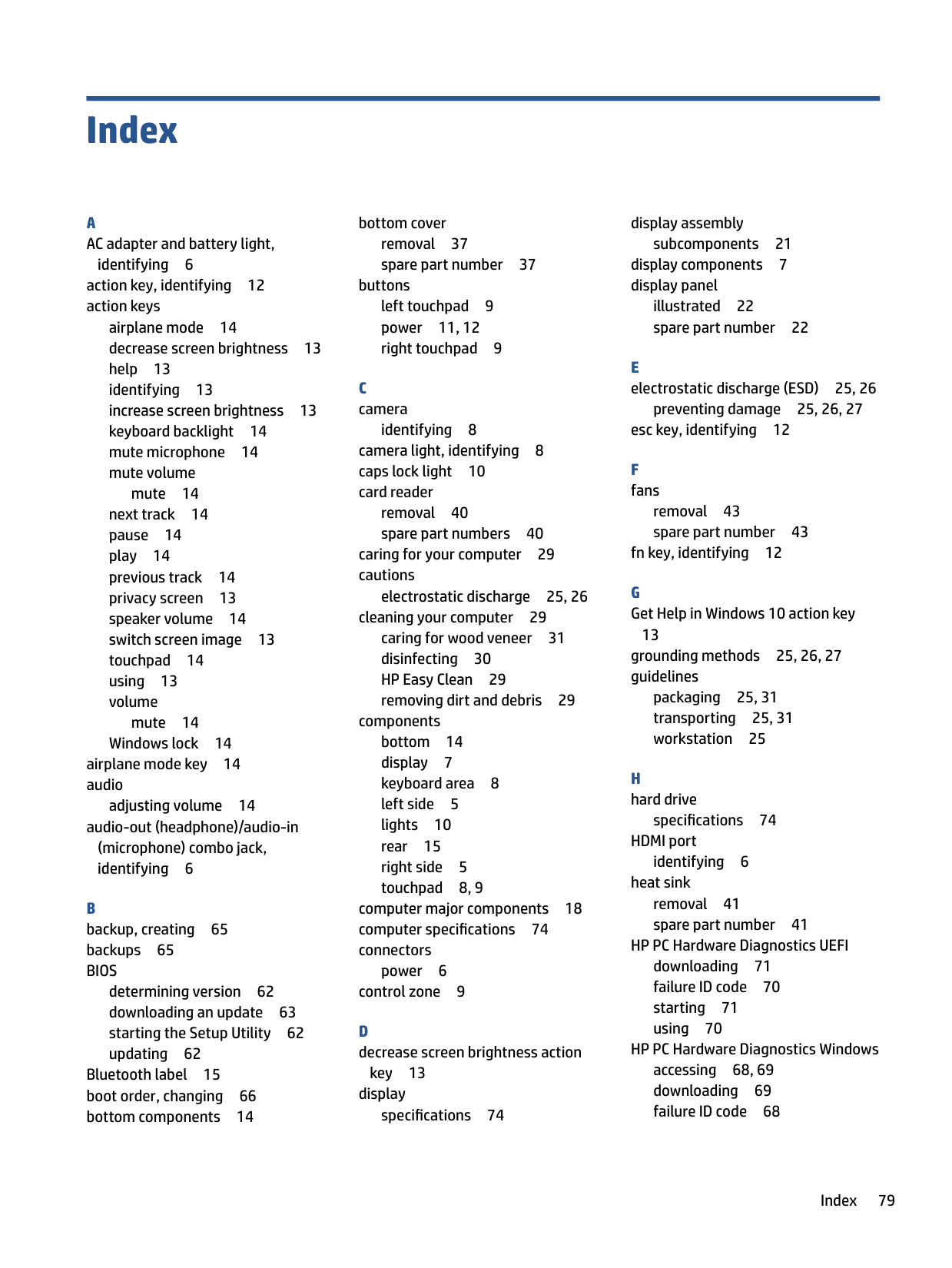
key 13 integrated numeric keypad, identifying 13 internal microphones, identifying 8
audio-out (headphone)/audio-in
(microphone) 6 network 6 RJ-45 (network) 6
product description 3 keyboard backlight action key 14 keyboard with top cover
spare part numbers 60 keypad, integrated numeric 13 keys
action 12 airplane mode 14 esc 12 fn 12 num lock 13 touchpad 14 Windows 12 Windows lock 14
Bluetooth 15 regulatory 15 serial number 15 service 15 wireless certification 15 WLAN 15
left control zone, identifying 9 left side components 5 lights
AC adapter and battery 6 camera 8
80 Index
caps lock 10 mute 10 power 10 RJ-45 (network) status 6 touchpad 9, 10 low blue light mode 7
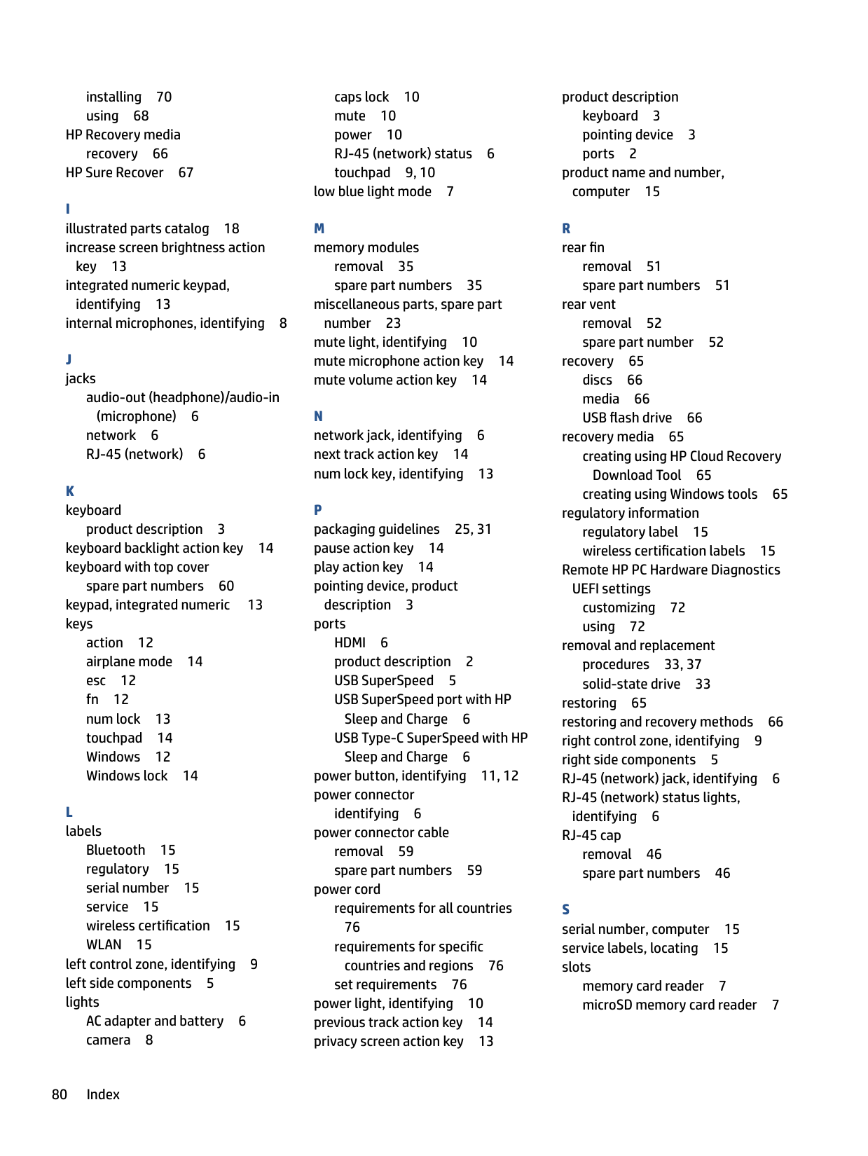
removal 35 spare part numbers 35 miscellaneous parts, spare part
number 23 mute light, identifying 10 mute microphone action key 14 mute volume action key 14
P packaging guidelines 25, 31 pause action key 14 play action key 14 pointing device, product
description 3
ports HDMI 6 product description 2 USB SuperSpeed 5 USB SuperSpeed port with HP
Sleep and Charge 6 USB Type-C SuperSpeed with HP
Sleep and Charge 6 power button, identifying 11, 12 power connector
identifying 6
power connector cable removal 59 spare part numbers 59
power cord requirements for all countries 76 requirements for specific countries and regions 76
set requirements 76 power light, identifying 10 previous track action key 14 privacy screen action key 13
product description keyboard 3 pointing device 3 ports 2
product name and number, computer 15
removal 51 spare part numbers 51
rear vent removal 52 spare part number 52
recovery 65 discs 66 media 66 USB flash drive 66
recovery media 65 creating using HP Cloud Recovery Download Tool 65 creating using Windows tools 65
regulatory information regulatory label 15 wireless certification labels 15
Remote HP PC Hardware Diagnostics
UEFI settings customizing 72 using 72
removal and replacement procedures 33, 37 solid-state drive 33
restoring 65 restoring and recovery methods 66 right control zone, identifying 9 right side components 5 RJ-45 (network) jack, identifying 6 RJ-45 (network) status lights,
identifying 6
RJ-45 cap removal 46 spare part numbers 46
memory card reader 7 microSD memory card reader 7
solid-state drive removal and replacement 33 specifications 75
spare part country codes 60 speaker
removal 40 spare part numbers 40
speaker volume action keys 14 speakers 15 special keys
identifying 11 using 11
specifications computer 74 display 74 hard drive 74 solid-state drive 75
static electricity 25, 26 support information 31 switch screen image action key 13 system board
removal 47 spare part numbers 47
system restore 66 system restore point, creating 65
removal 50 settings 9 spare part numbers 50
touchpad buttons
identifying 9 touchpad components 8 touchpad key 14 touchpad light, identifying 9, 10 touchpad settings, adjusting 9 touchpad zone, identifying 9 transporting guidelines 25, 31 traveling with the computer 15
illustrated 20 removal 45 spare part number 20 spare part numbers 45
USB SuperSpeed port with HP Sleep and Charge, identifying 6 USB SuperSpeed port, identifying 5
USB Type-C SuperSpeed port with HP Sleep and Charge, identifying 6
adjusting 14
backup 65 recovery media 65 system restore point 65
Windows key, identifying 12 Windows lock key 14 Windows tools, using 65 wireless antennas, identifying 8 wireless certification label 15 WLAN antennas, identifying 8 WLAN device 15 WLAN label 15 WLAN module
removal 44 spare part numbers 44
workstation guidelines 25