Ask AI
— answers from the official manualAnswers from the official manual.
Common questions
Common Questions
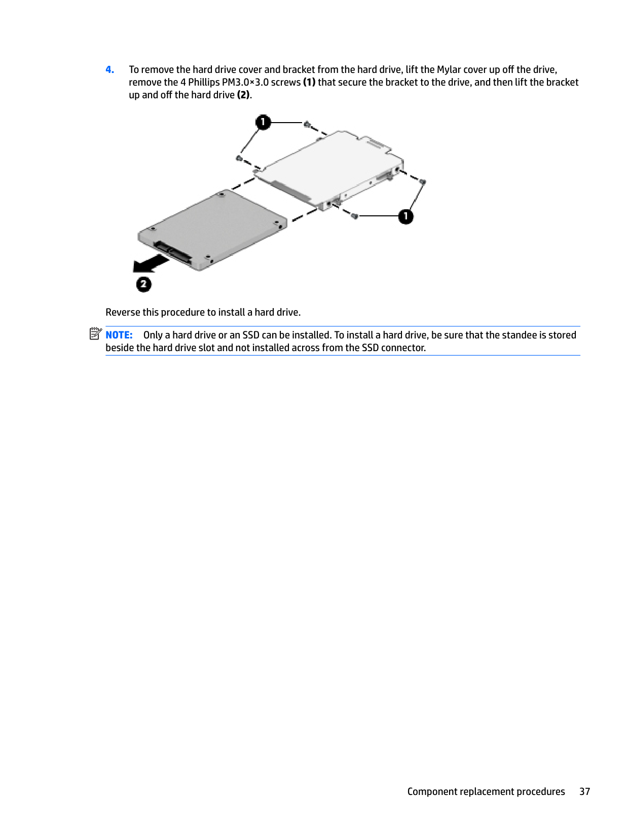
9 totalHow can I remove the hard drive from my HP EliteBook 820 G3 Notebook PC?
To remove the hard drive, start by turning off the computer, disconnecting all devices and power. Then, take off the bottom cover and battery, loosen the four captive screws securing the hard drive to the chassis, slide it away from the center of the system housing, lift it out, and if needed, separate the hard drive cover and bracket from the hard drive.
What is the correct way to replace the keyboard on an HP EliteBook 820 G3 Notebook PC?
To replace the keyboard, shut down the computer completely. After unplugging power and disconnecting devices, remove the bottom cover, battery, keyboard screws, lift off and disengage cable connections before removing it.
How do I check or update the BIOS on my HP EliteBook?
Navigate to Computer Setup via f9 boot prompt. Determine your current BIOS version by checking within the setup menu. Download updates from HP's support site, following instructions provided there and update through the same menu.
What should I do if my HP EliteBook 820 G3 Notebook PC displays an error code related to the BIOS?
To resolve BIOS-related issues, start Computer Setup and restore factory settings from there. Alternatively, update the BIOS version by determining your current version, downloading a suitable update from HP Support, and then updating it via Computer Setup.
What is the warranty period for my HP EliteBook 820 G3 Notebook PC?
The warranty details are located on the service tag at the bottom of your computer. See page 16, 'Locating system information', on how to find this information.
How do I backup and recover using HP Recovery Manager?
To use HP Recovery Manager for backing up or recovering your Windows 10 system, start by determining if you have the recovery partition available. Then follow instructions in Chapter 12 of the manual to prepare necessary steps and media.
Full Manual
121 pages

HP EliteBook 828 G3 Notebook PC HP EliteBook 820 G3 Notebook PC
Maintenance and Service Guide
© Copyright 2015, 2016 HP Development Company, L.P.
AMD is a trademark of Advanced Micro Devices, Inc. Bluetooth is a trademark owned by its proprietor and used by HP Inc. under license. Intel is a trademark of Intel Corporation in the U.S. and other countries. Linux® is the registered trademark of Linus Torvalds in the U.S. and other countries. Microsoft and Windows are either registered trademarks or trademarks of Microsoft Corporation in the United States and/or other countries. Qualcomm is a trademark of Qualcomm Incorporated, registered in the United States and other countries, used with permission.
For DTS patents, see http://patents.dts.com. Manufactured under license from DTS Licensing Limited. DTS, the Symbol, & DTS and the Symbol together are registered trademarks, and DTS Studio Sound is a trademark of DTS, Inc. © DTS, Inc. All Rights
Reserved .
Product notice This guide describes features that are common to most models. Some features may not be available on your computer. Not all features are available in all editions of Windows 10 or Windows 8. This computer may require upgraded and/or separately purchased hardware, drivers and/or software to take full advantage of Windows 10 or Windows 8 functionality. See http://www.microsoft.com for details. The information contained herein is subject to change without notice. The only warranties for HP products and services are set forth in the express warranty statements accompanying such products and services. Nothing herein should be construed as constituting an additional warranty. HP shall not be liable for technical or editorial errors or omissions contained herein. Second Edition: March 2016 First Edition: October 2015 Document Part Number: 843203-002
#### Important Notice about Customer Self-Repair Parts
CAUTION: Your computer includes Customer Self-Repair parts and parts that should only be accessed by an authorized service provider. See Chapter 5, "Removal and replacement procedures for Customer Self-Repair parts," for details. Accessing parts described in Chapter 6, "Removal and replacement procedures for Authorized Service Provider only parts," can damage the computer or void your warranty.
iii
####### iv Important Notice about Customer Self-Repair Parts
#### Safety warning notice
WARNING! To reduce the possibility of heat-related injuries or of overheating the device, do not place the device directly on your lap or obstruct the device air vents. Use the device only on a hard, flat surface. Do not allow another hard surface, such as an adjoining optional printer, or a soft surface, such as pillows or rugs or clothing, to block airflow. Also, do not allow the AC adapter to contact the skin or a soft surface, such as pillows or rugs or clothing, during operation. The device and the AC adapter comply with the user-accessible surface temperature limits defined by the International Standard for Safety of Information Technology Equipment (IEC 60950-1).

v
####### vi Safety warning notice
Table of contents
TouchPad ........................................................................................................................................... 10 Lights ................................................................................................................................................. 11 Buttons, speakers, and fingerprint reader ........................................................................................ 12 Keys ................................................................................................................................................... 13 Using the hot keys ............................................................................................................................. 13
Bottom ................................................................................................................................................................. 15 Front ..................................................................................................................................................................... 15 Locating system information .............................................................................................................................. 16
Plastic parts ....................................................................................................................................... 27 Cables and connectors ...................................................................................................................... 28 Drive handling ................................................................................................................................... 28
Grounding guidelines ........................................................................................................................................... 29
Electrostatic discharge damage ........................................................................................................ 29 Packaging and transporting guidelines .......................................................................... 30 Workstation guidelines ................................................................................................... 30 Equipment guidelines ..................................................................................................... 31
vii
###### 5 Removal and replacement procedures for Customer Self-Repair parts ............................................................. 32Component replacement procedures .................................................................................................................. 32
Bottom cover ..................................................................................................................................... 32 Battery ............................................................................................................................................... 35 Hard drive .......................................................................................................................................... 36 SSD ..................................................................................................................................................... 38 Memory modules ............................................................................................................................... 40 WLAN/Bluetooth combo card ............................................................................................................ 42 WWAN module ................................................................................................................................... 44 Keyboard ........................................................................................................................................... 46

###### 6 Removal and replacement procedures for Authorized Service Provider parts ................................................... 49Component replacement procedures .................................................................................................................. 49
System board .................................................................................................................................... 49 RTC battery ........................................................................................................................................ 52 Heat sink/fan assembly .................................................................................................................... 53 Fingerprint reader assembly ............................................................................................................. 55 Touchpad button board ..................................................................................................................... 56 NFC module ....................................................................................................................................... 57 Smart card reader board ................................................................................................................... 58 Speaker assembly ............................................................................................................................. 59 Display assembly ............................................................................................................................... 61 Top cover ........................................................................................................................................... 65
###### 7 Computer Setup (BIOS), TPM, and HP Sure Start in Windows 10 ........................................................................ 67Using Computer Setup ......................................................................................................................................... 67
Starting Computer Setup .................................................................................................................. 67 Navigating and selecting in Computer Setup ................................................................................... 67 Restoring factory settings in Computer Setup ................................................................................. 68 Updating the BIOS ............................................................................................................................. 69
Determining the BIOS version ......................................................................................... 69 Downloading a BIOS update ........................................................................................... 69
Changing the boot order using the f9 prompt .................................................................................. 70 TPM BIOS settings (select products only) ........................................................................................................... 70 Using HP Sure Start (select products only) ......................................................................................................... 71
###### 8 Computer Setup (BIOS), TPM, and HP Sure Start in Windows 8 ......................................................................... 72Using Computer Setup ......................................................................................................................................... 72
Starting Computer Setup .................................................................................................................. 72 Navigating and selecting in Computer Setup ................................................................................... 72
viii
Restoring factory settings in Computer Setup ................................................................................. 73 Updating the BIOS ............................................................................................................................. 74
Determining the BIOS version ......................................................................................... 74 Downloading a BIOS update ........................................................................................... 74
Changing the boot order using the f9 prompt .................................................................................. 75 TPM BIOS settings (select products only) ........................................................................................................... 75 Using HP Sure Start (select products only) ......................................................................................................... 76
Starting Computer Setup .................................................................................................................. 77 Navigating and selecting in Computer Setup ................................................................................... 77 Restoring factory settings in Computer Setup ................................................................................. 78 Updating the BIOS ............................................................................................................................. 79

Determining the BIOS version ......................................................................................... 79 Downloading a BIOS update ........................................................................................... 79
Changing the boot order using the f9 prompt .................................................................................. 80 TPM BIOS settings (select products only) ........................................................................................................... 80 Using HP Sure Start (select products only) ......................................................................................................... 81
Creating HP Recovery media (select products only) ......................................................................... 84 Using Windows tools ........................................................................................................................................... 85 Restore and recovery ........................................................................................................................................... 86
Recovering using HP Recovery Manager ........................................................................................... 86 What you need to know before you get started ............................................................. 86 Using the HP Recovery partition (select products only) ................................................. 87 Using HP Recovery media to recover .............................................................................. 87 Changing the computer boot order ................................................................................ 88 Removing the HP Recovery partition (select products only) ......................................... 89
Using the Windows recovery tools .................................................................................................... 90 Using f11 recovery tools ................................................................................................................... 91
ix
Using Windows operating system media (purchased separately) ................................................... 92 Using Windows Refresh or Windows Reset ...................................................................................... 93 Using HP Software Setup .................................................................................................................. 93
Guidelines .......................................................................................................................................... 94 Creating recovery media with HP Recovery Disc Creator ................................................................. 94
Creating recovery media ................................................................................................. 95 Backing up your information ............................................................................................................. 95
Performing a system recovery ............................................................................................................................ 96 Using the Windows recovery tools .................................................................................................... 96 Using f11 recovery tools (select models only) ................................................................................. 97 Using Windows 7 operating system media ....................................................................................... 97

Index ........................................................................................................................................................... 109
x
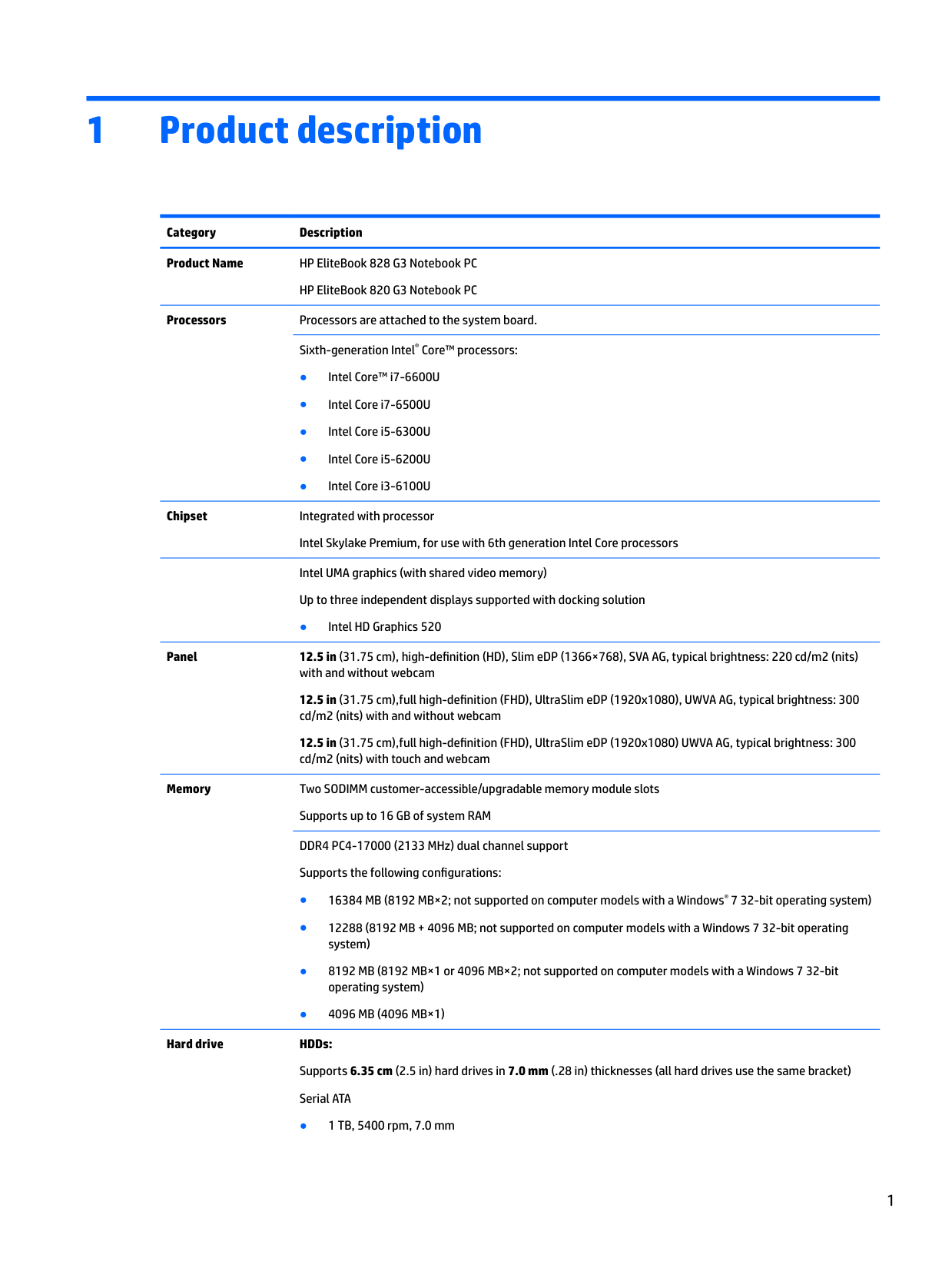
1 Product description
Category Description Product Name HP EliteBook 828 G3 Notebook PC
HP EliteBook 820 G3 Notebook PC
Processors Processors are attached to the system board.
Sixth-generation Intel® Core™ processors:

Chipset Integrated with processor Intel Skylake Premium, for use with 6th generation Intel Core processors Intel UMA graphics (with shared video memory) Up to three independent displays supported with docking solution
● Intel HD Graphics 520
Panel 12.5 in (31.75 cm), high-definition (HD), Slim eDP (1366×768), SVA AG, typical brightness: 220 cd/m2 (nits) with and without webcam 12.5 in (31.75 cm),full high-definition (FHD), UltraSlim eDP (1920x1080), UWVA AG, typical brightness: 300 cd/m2 (nits) with and without webcam 12.5 in (31.75 cm),full high-definition (FHD), UltraSlim eDP (1920x1080) UWVA AG, typical brightness: 300 cd/m2 (nits) with touch and webcam
Memory Two SODIMM customer-accessible/upgradable memory module slots Supports up to 16 GB of system RAM DDR4 PC4-17000 (2133 MHz) dual channel support Supports the following configurations:
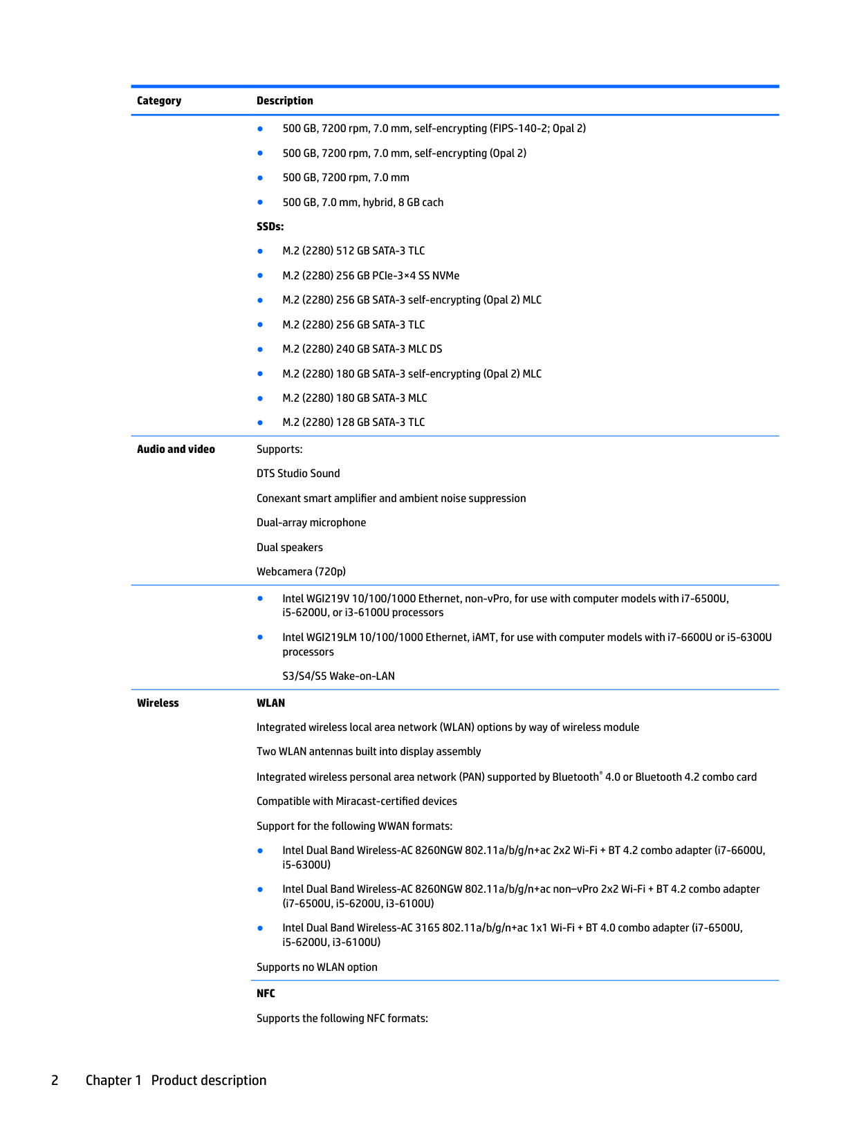
Hard drive HDDs: Supports 6.35 cm (2.5 in) hard drives in 7.0 mm (.28 in) thicknesses (all hard drives use the same bracket) Serial ATA
Audio and video Supports: DTS Studio Sound Conexant smart amplifier and ambient noise suppression Dual-array microphone Dual speakers Webcamera (720p)
Wireless WLAN Integrated wireless local area network (WLAN) options by way of wireless module Two WLAN antennas built into display assembly Integrated wireless personal area network (PAN) supported by Bluetooth® 4.0 or Bluetooth 4.2 combo card Compatible with Miracast-certified devices Support for the following WWAN formats:
Supports no WLAN option NFC Supports the following NFC formats:
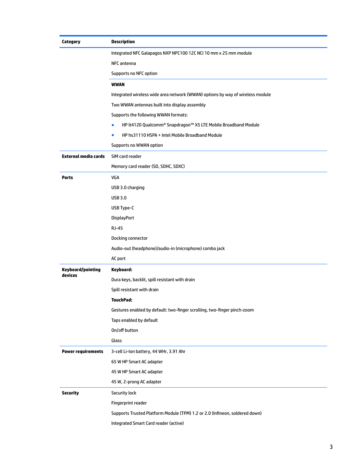
Integrated NFC Galapagos NXP NPC100 12C NCI 10 mm x 25 mm module NFC antenna Supports no NFC option WWAN Integrated wireless wide area network (WWAN) options by way of wireless module Two WWAN antennas built into display assembly Supports the following WWAN formats:
######## External media cards SIM card reader
Memory card reader (SD, SDHC, SDXC)
Ports VGA USB 3.0 charging USB 3.0 USB Type-C DisplayPort RJ-45 Docking connector Audio-out (headphone)/audio-in (microphone) combo jack AC port
Keyboard/pointing devices
Keyboard: Dura keys, backlit, spill resistant with drain Spill resistant with drain TouchPad: Gestures enabled by default: two-finger scrolling, two-finger pinch-zoom Taps enabled by default On/off button Glass
Power requirements 3-cell Li-Ion battery, 44 WHr, 3.91 Ahr
65 W HP Smart AC adapter 45 W HP Smart AC adapter 45 W, 2-prong AC adapter
Security Security lock Fingerprint reader Supports Trusted Platform Module (TPM) 1.2 or 2.0 (Infineon, soldered down) Integrated Smart Card reader (active)
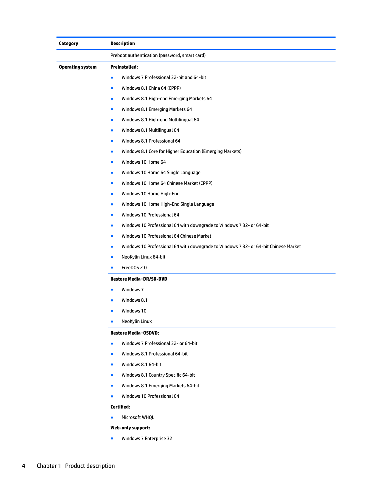
Preboot authentication (password, smart card) Operating system Preinstalled:
Serviceability End user replaceable parts: AC adapter Battery Hard drive SSD Memory module WLAN WWAN Keyboard
2 External component identification
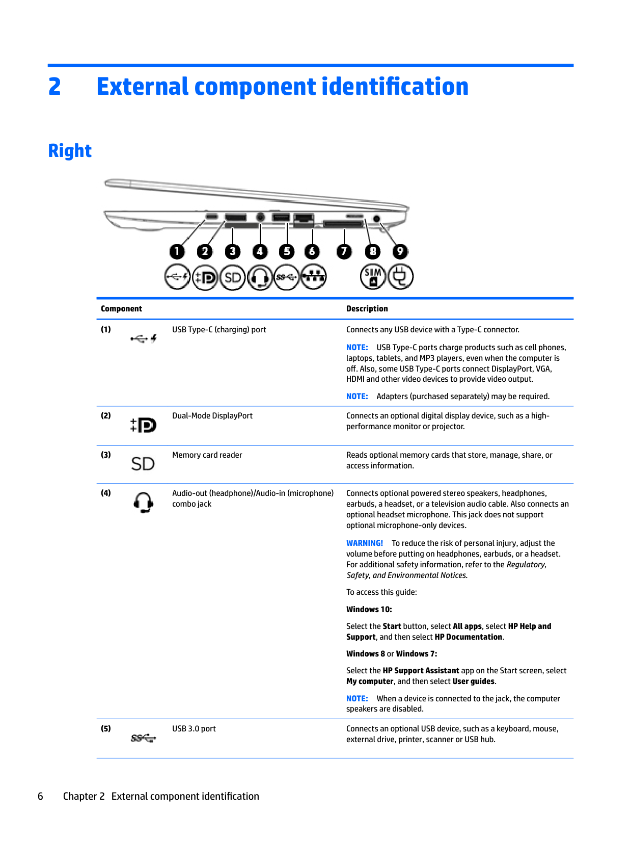
Right

######## Component Description

NOTE: USB Type-C ports charge products such as cell phones, laptops, tablets, and MP3 players, even when the computer is off. Also, some USB Type-C ports connect DisplayPort, VGA, HDMI and other video devices to provide video output.
NOTE: Adapters (purchased separately) may be required.


Connects optional powered stereo speakers, headphones, earbuds, a headset, or a television audio cable. Also connects an optional headset microphone. This jack does not support optional microphone-only devices.
WARNING! To reduce the risk of personal injury, adjust the volume before putting on headphones, earbuds, or a headset. For additional safety information, refer to the Regulatory, Safety, and Environmental Notices.
To access this guide: Windows 10: Select the Start button, select All apps, select HP Help and Support, and then select HP Documentation. Windows 8 or Windows 7: Select the HP Support Assistant app on the Start screen, select My computer, and then select User guides. NOTE: When a device is connected to the jack, the computer speakers are disabled.


Right 7
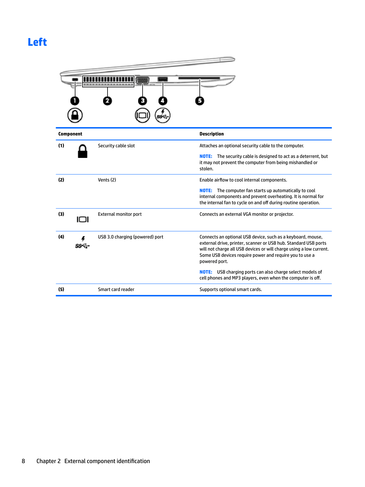
Left

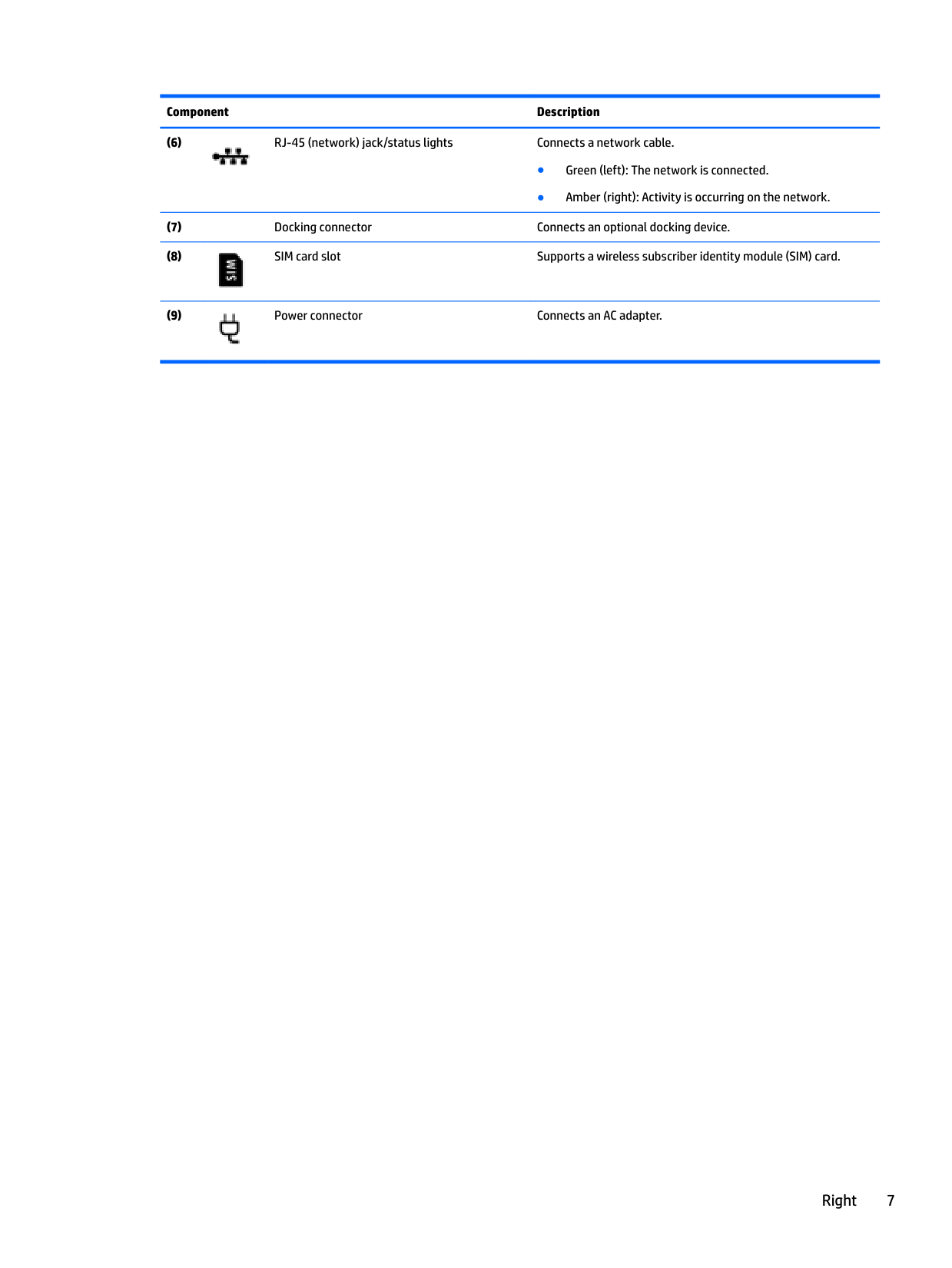
######## Component Description

NOTE: The security cable is designed to act as a deterrent, but it may not prevent the computer from being mishandled or stolen.
NOTE: The computer fan starts up automatically to cool internal components and prevent overheating. It is normal for the internal fan to cycle on and off during routine operation.


NOTE: USB charging ports can also charge select models of cell phones and MP3 players, even when the computer is off.
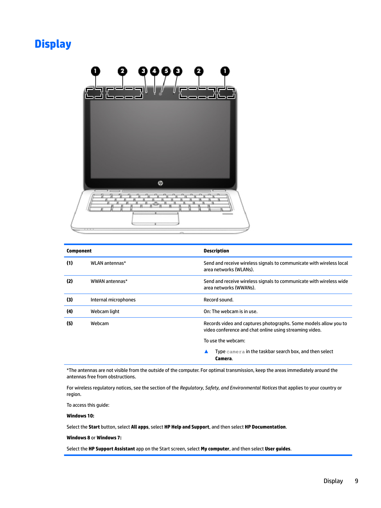
Display

######## Component Description
▲ Type camera in the taskbar search box, and then select
######## Camera.
*The antennas are not visible from the outside of the computer. For optimal transmission, keep the areas immediately around the antennas free from obstructions.
For wireless regulatory notices, see the section of the Regulatory, Safety, and Environmental Notices that applies to your country or region.
To access this guide: Windows 10: Select the Start button, select All apps, select HP Help and Support, and then select HP Documentation. Windows 8 or Windows 7: Select the HP Support Assistant app on the Start screen, select My computer, and then select User guides.
Display 9
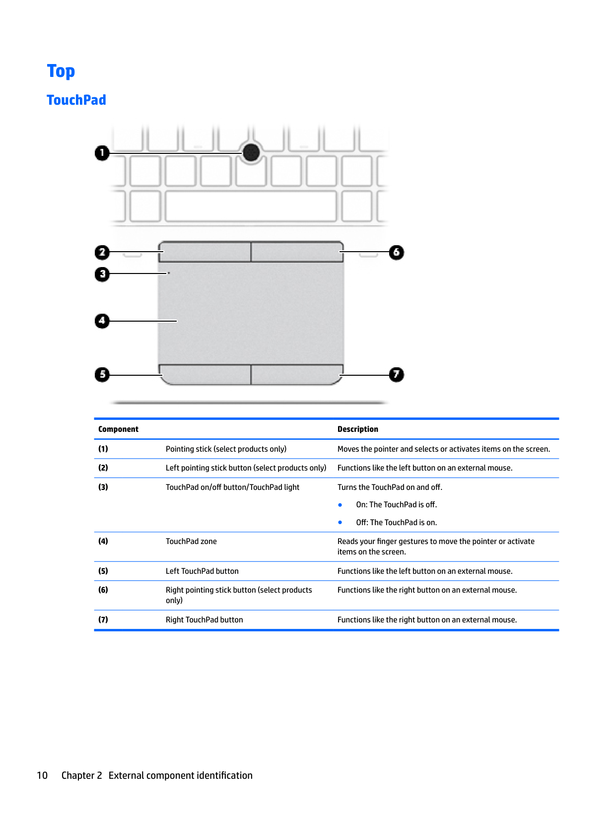
Top
#### TouchPad

######## Component Description
Functions like the right button on an external mouse.
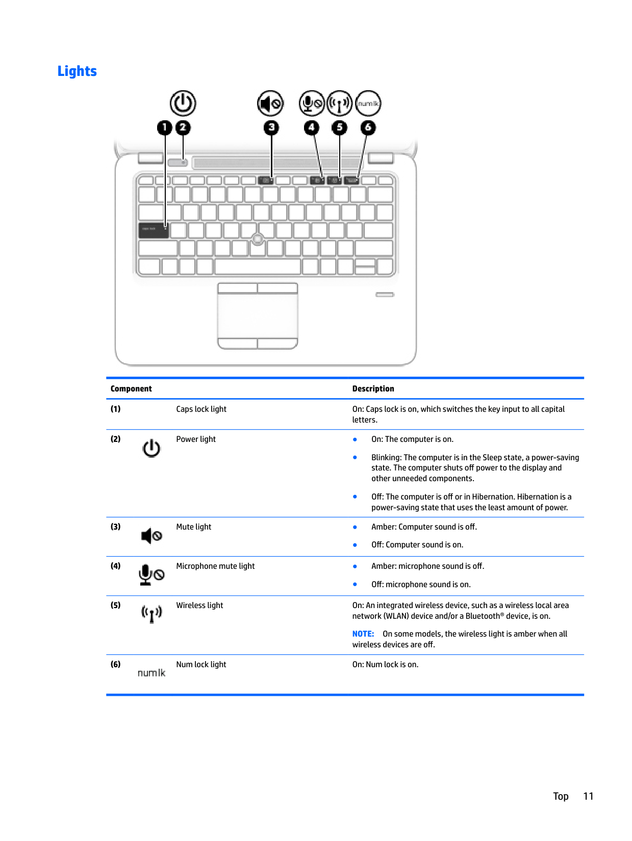
#### Lights


######## Component Description


● Off: Computer sound is on.

● Off: microphone sound is on.

NOTE: On some models, the wireless light is amber when all wireless devices are off.

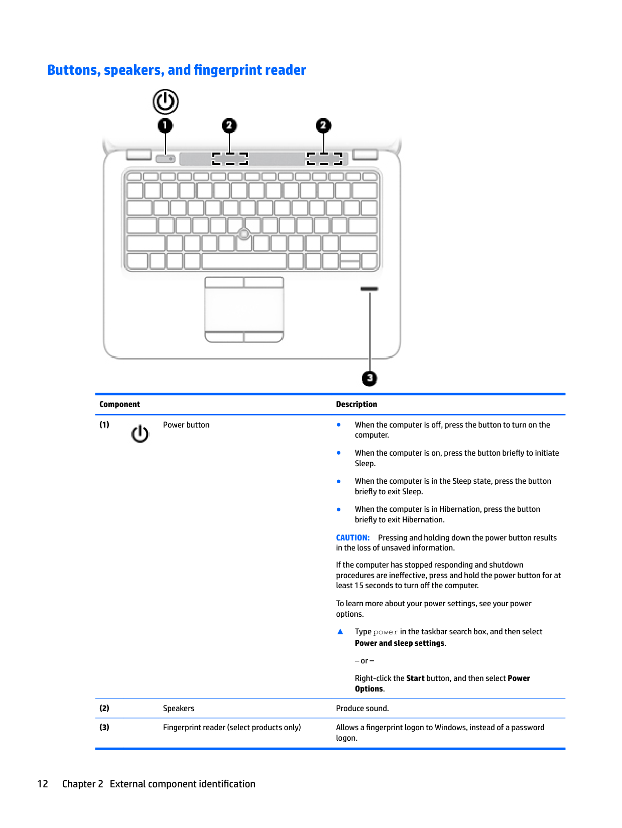
#### Buttons, speakers, and fingerprint reader

######## Component Description

CAUTION: Pressing and holding down the power button results in the loss of unsaved information. If the computer has stopped responding and shutdown procedures are ineffective, press and hold the power button for at least 15 seconds to turn off the computer. To learn more about your power settings, see your power options.
▲ Type power in the taskbar search box, and then select
Power and sleep settings.
or –
Right-click the Start button, and then select Power Options.
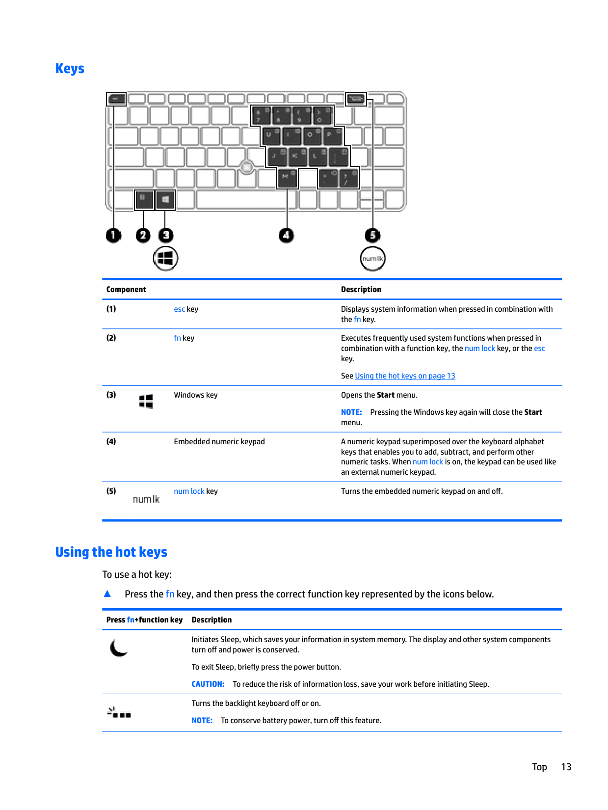
#### Keys

######## Component Description

NOTE: Pressing the Windows key again will close the Start menu.

#### Using the hot keys
To use a hot key:
▲ Press the fn key, and then press the correct function key represented by the icons below.
Press fn+function key Description


Initiates Sleep, which saves your information in system memory. The display and other system components turn off and power is conserved.
To exit Sleep, briefly press the power button. CAUTION: To reduce the risk of information loss, save your work before initiating Sleep. Turns the backlight keyboard off or on. NOTE: To conserve battery power, turn off this feature.
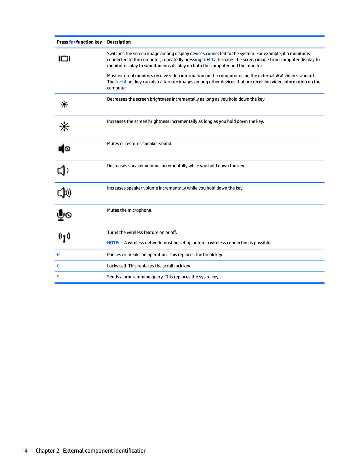
######## Press fn+function key Description


Switches the screen image among display devices connected to the system. For example, if a monitor is connected to the computer, repeatedly pressing fn+f4 alternates the screen image from computer display to monitor display to simultaneous display on both the computer and the monitor.
Most external monitors receive video information on the computer using the external VGA video standard. The fn+f4 hot key can also alternate images among other devices that are receiving video information on the computer.
Decreases the screen brightness incrementally as long as you hold down the key.


Increases the screen brightness incrementally as long as you hold down the key.
Mutes or restores speaker sound.

Decreases speaker volume incrementally while you hold down the key.

Increases speaker volume incrementally while you hold down the key.

Mutes the microphone.

Turns the wireless feature on or off. NOTE: A wireless network must be set up before a wireless connection is possible.
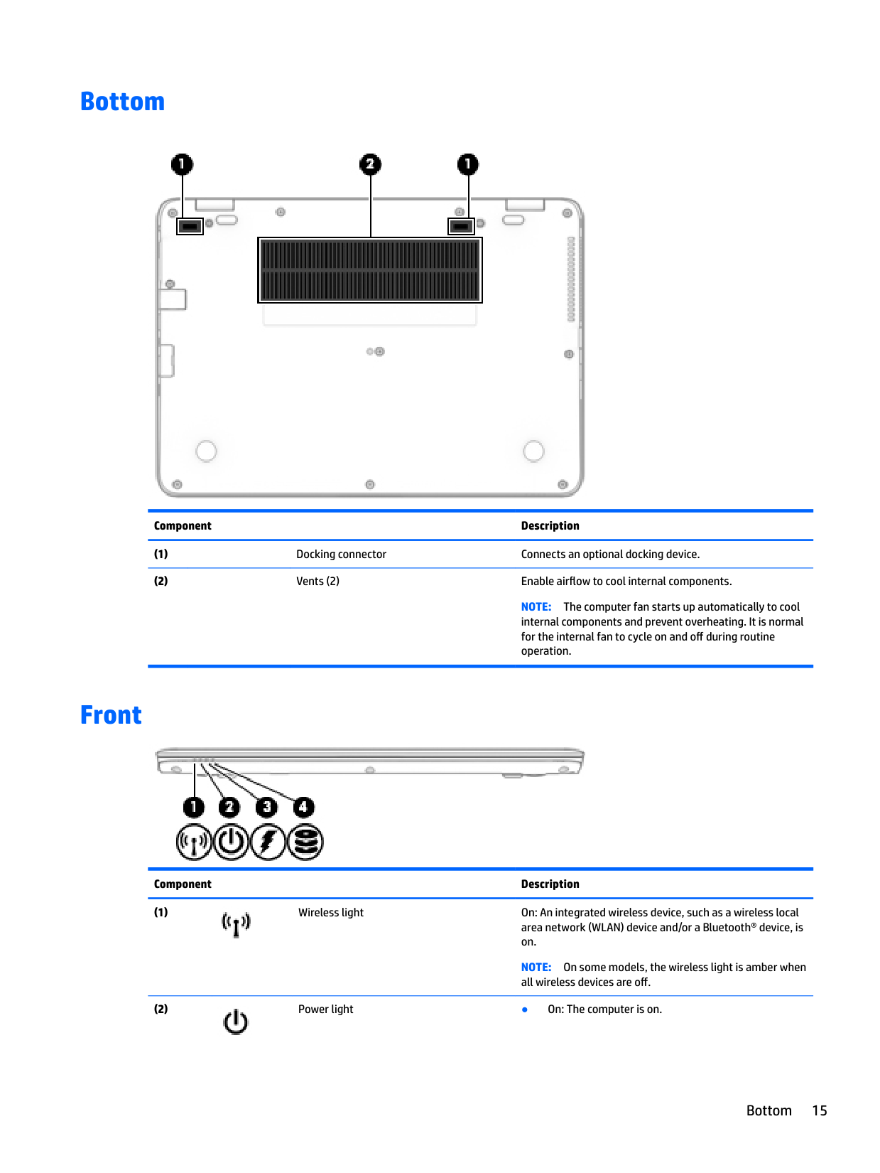
Bottom

######## Component Description
NOTE: The computer fan starts up automatically to cool internal components and prevent overheating. It is normal for the internal fan to cycle on and off during routine operation.
Front

######## Component Description

NOTE: On some models, the wireless light is amber when all wireless devices are off.

Bottom 15
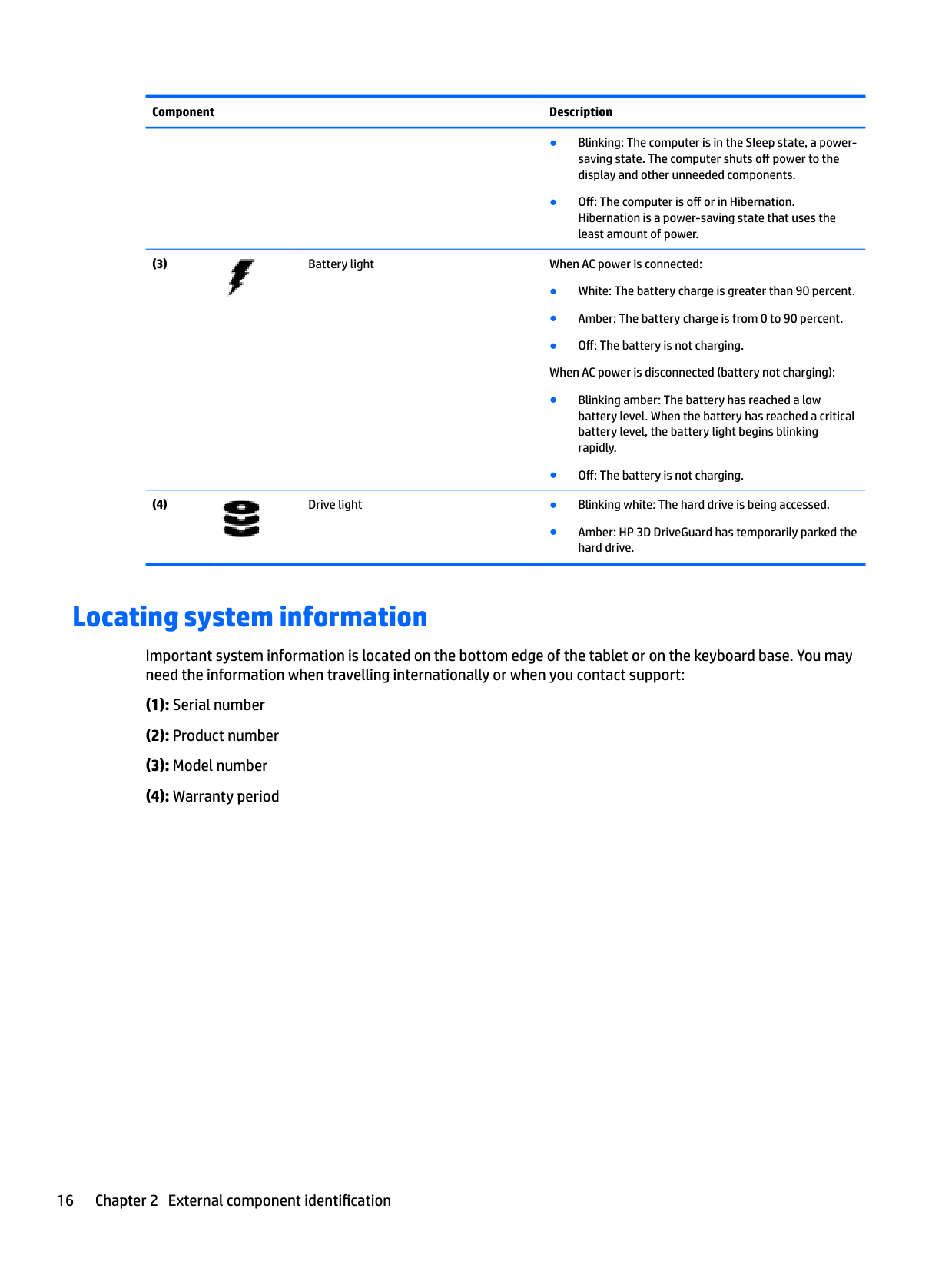
######## Component Description


● Amber: HP 3D DriveGuard has temporarily parked the hard drive.
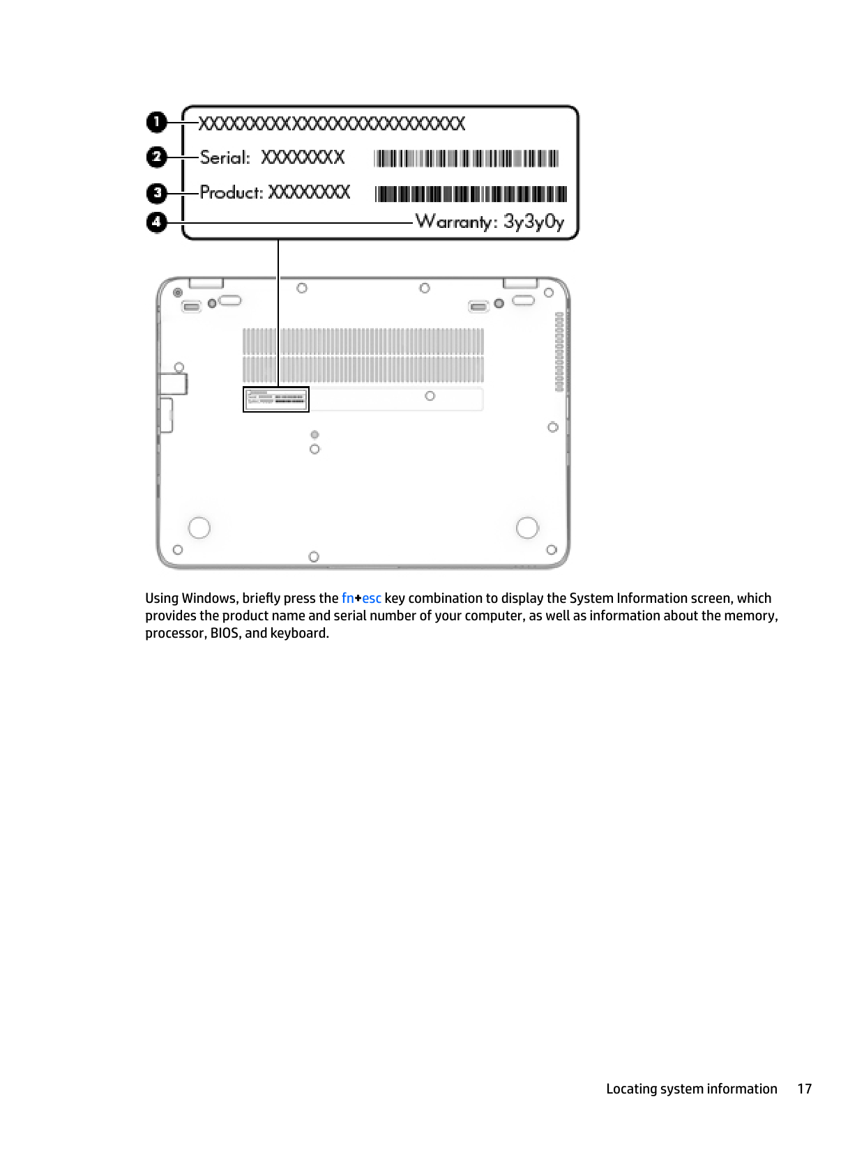
Locating system information
Important system information is located on the bottom edge of the tablet or on the keyboard base. You may need the information when travelling internationally or when you contact support:

Using Windows, briefly press the fn+esc key combination to display the System Information screen, which provides the product name and serial number of your computer, as well as information about the memory, processor, BIOS, and keyboard.
Locating system information 17
3 Illustrated parts catalog
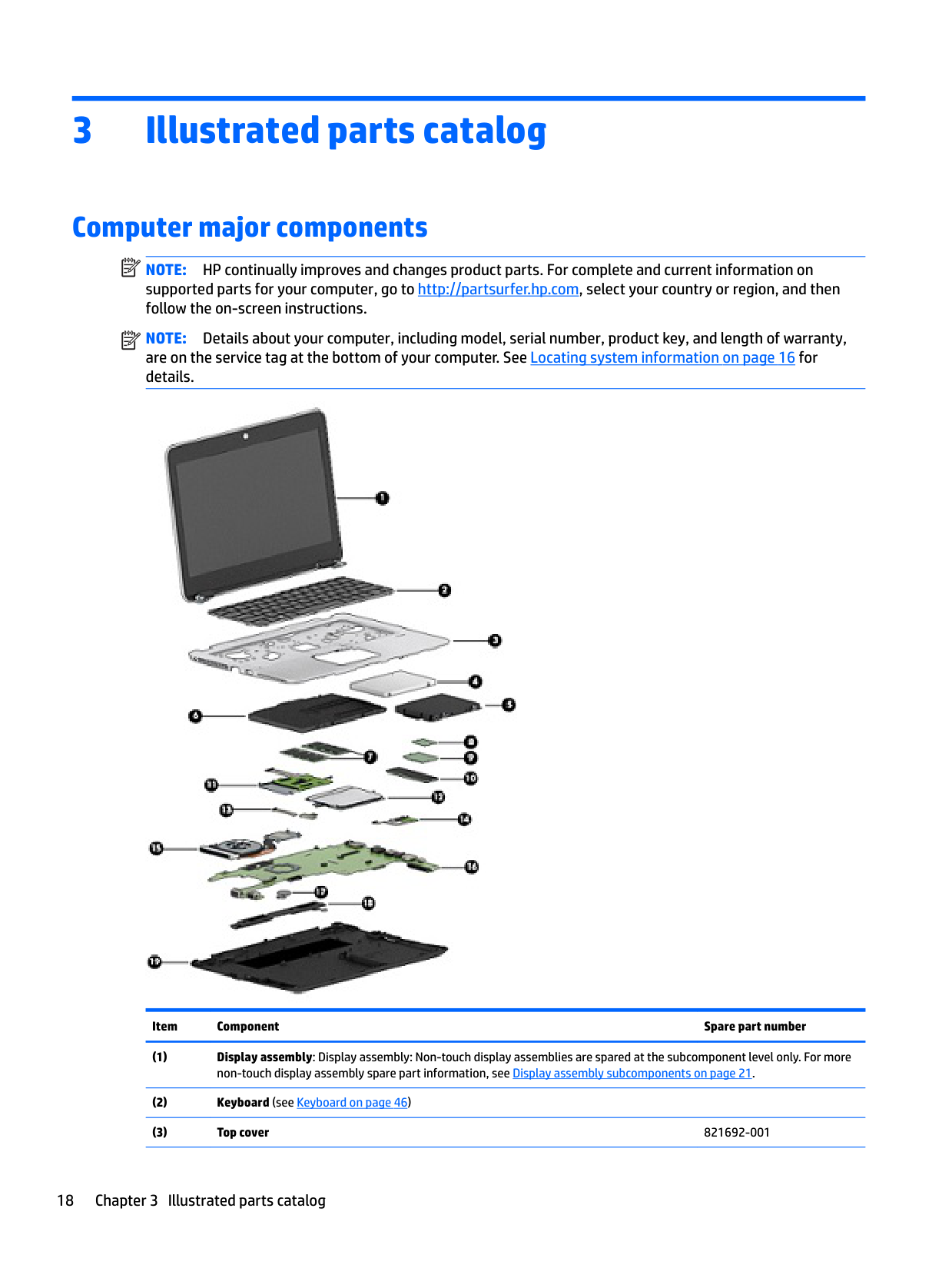
Computer major components
| | |---|
NOTE: HP continually improves and changes product parts. For complete and current information on supported parts for your computer, go to http://partsurfer.hp.com, select your country or region, and then follow the on-screen instructions.
| | |---|
NOTE: Details about your computer, including model, serial number, product key, and length of warranty, are on the service tag at the bottom of your computer. See Locating system information on page 16 for details.

Item Component Spare part number
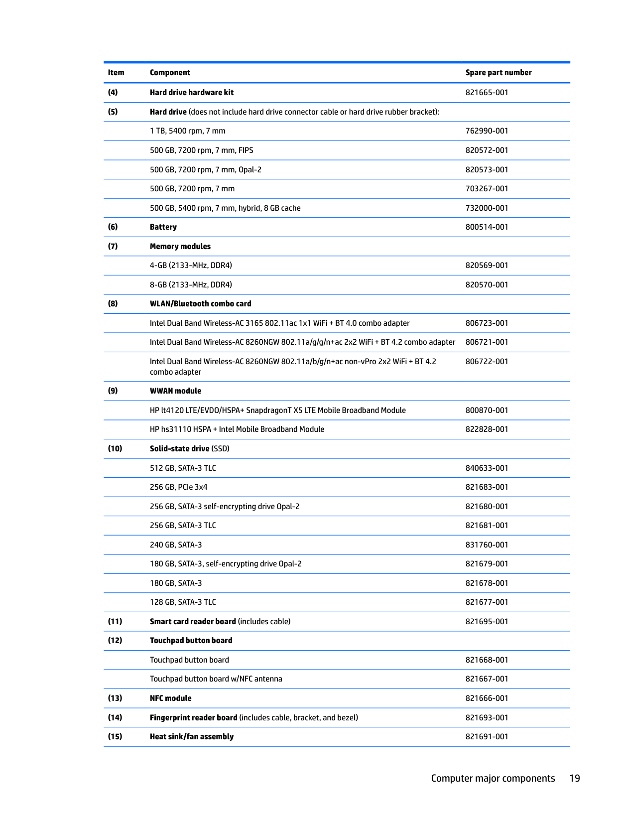
Intel Dual Band Wireless-AC 8260NGW 802.11a/b/g/n+ac non-vPro 2x2 WiFi + BT 4.2 combo adapter
806722-001
Computer major components 19
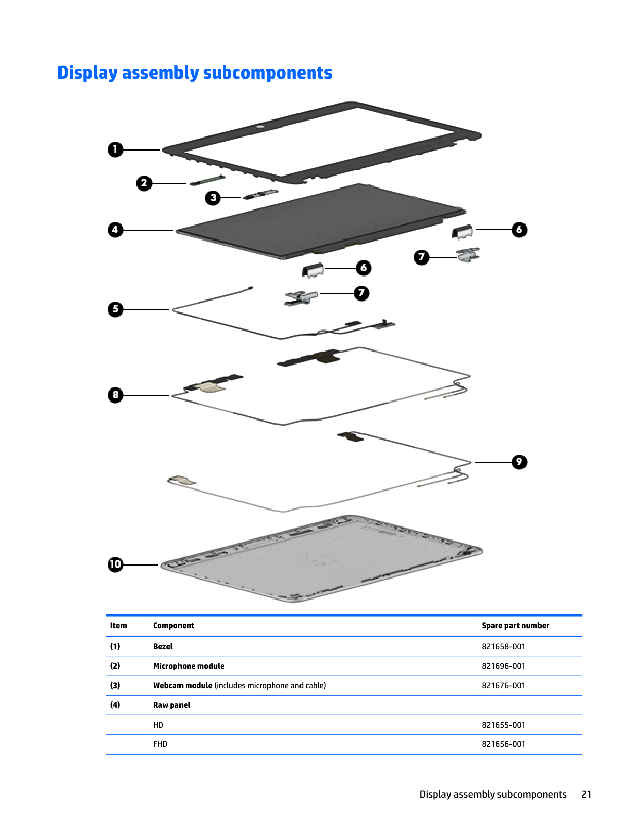
Display assembly subcomponents

######## Item Component Spare part number
Display assembly subcomponents 21
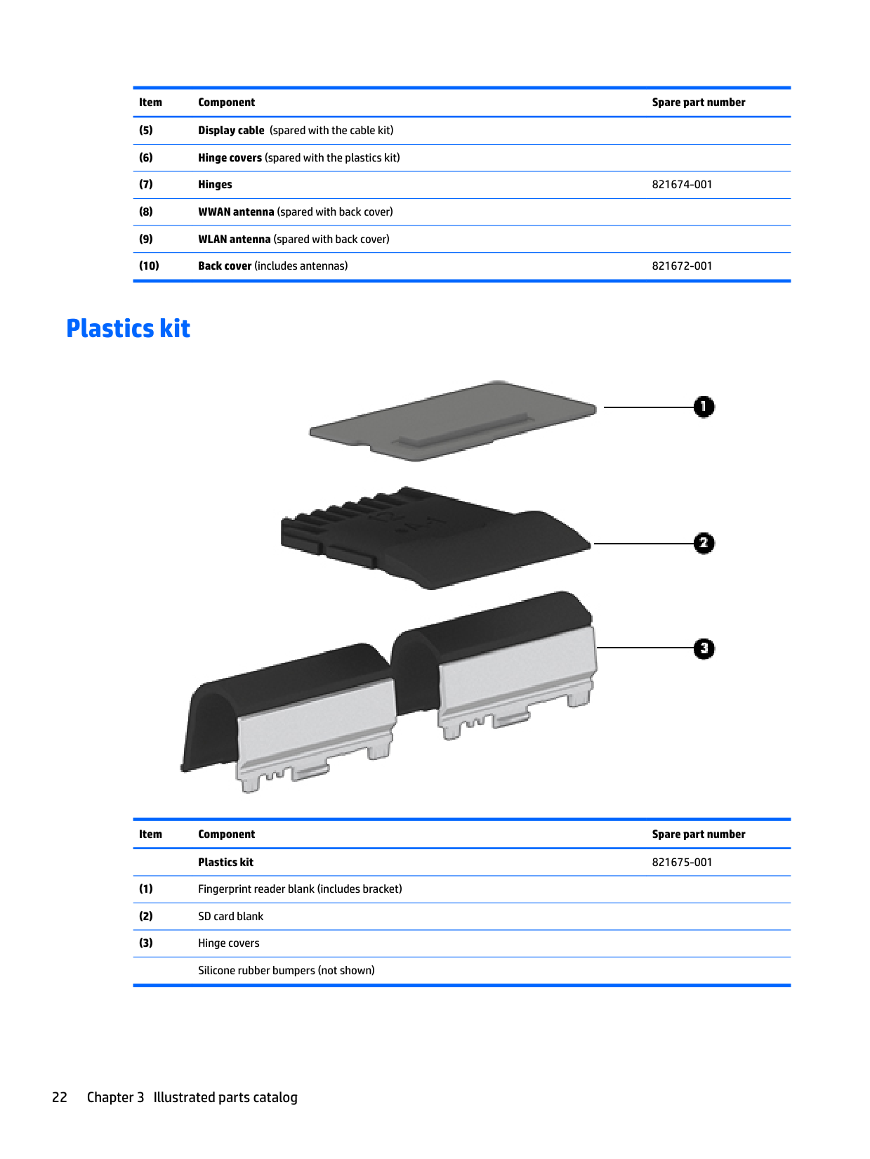
Plastics kit

Item Component Spare part number Plastics kit 821675-001
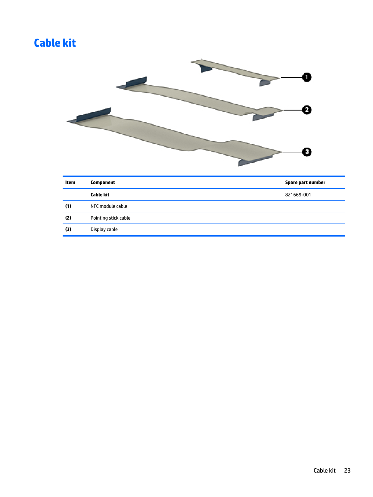
Cable kit

Item Component Spare part number Cable kit 821669-001
Cable kit 23
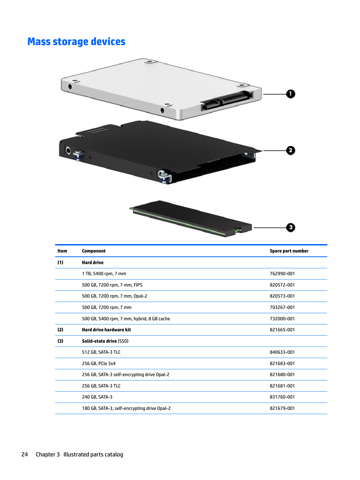
Mass storage devices

######## Item Component Spare part number
######## Item Component Spare part number
180 GB, SATA-3 821678-001 128 GB, SATA-3 TLC 821677-001
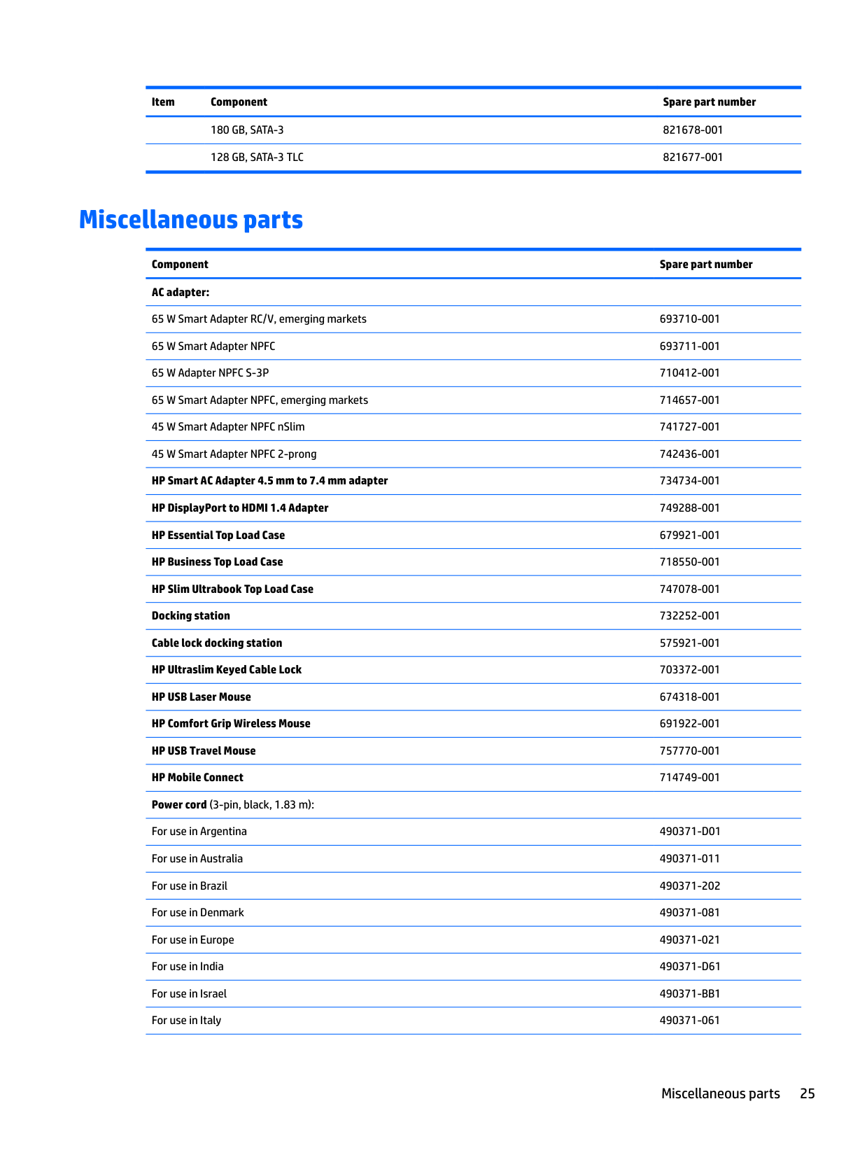
Miscellaneous parts
Component Spare part number AC adapter:
65 W Smart Adapter RC/V, emerging markets 693710-001 65 W Smart Adapter NPFC 693711-001 65 W Adapter NPFC S-3P 710412-001 65 W Smart Adapter NPFC, emerging markets 714657-001 45 W Smart Adapter NPFC nSlim 741727-001 45 W Smart Adapter NPFC 2-prong 742436-001 HP Smart AC Adapter 4.5 mm to 7.4 mm adapter 734734-001 HP DisplayPort to HDMI 1.4 Adapter 749288-001 HP Essential Top Load Case 679921-001 HP Business Top Load Case 718550-001 HP Slim Ultrabook Top Load Case 747078-001 Docking station 732252-001 Cable lock docking station 575921-001 HP Ultraslim Keyed Cable Lock 703372-001 HP USB Laser Mouse 674318-001 HP Comfort Grip Wireless Mouse 691922-001 HP USB Travel Mouse 757770-001 HP Mobile Connect 714749-001 Power cord (3-pin, black, 1.83 m):
For use in Argentina 490371-D01 For use in Australia 490371-011 For use in Brazil 490371-202 For use in Denmark 490371-081 For use in Europe 490371-021 For use in India 490371-D61 For use in Israel 490371-BB1 For use in Italy 490371-061
Miscellaneous parts 25
######## Component Spare part number
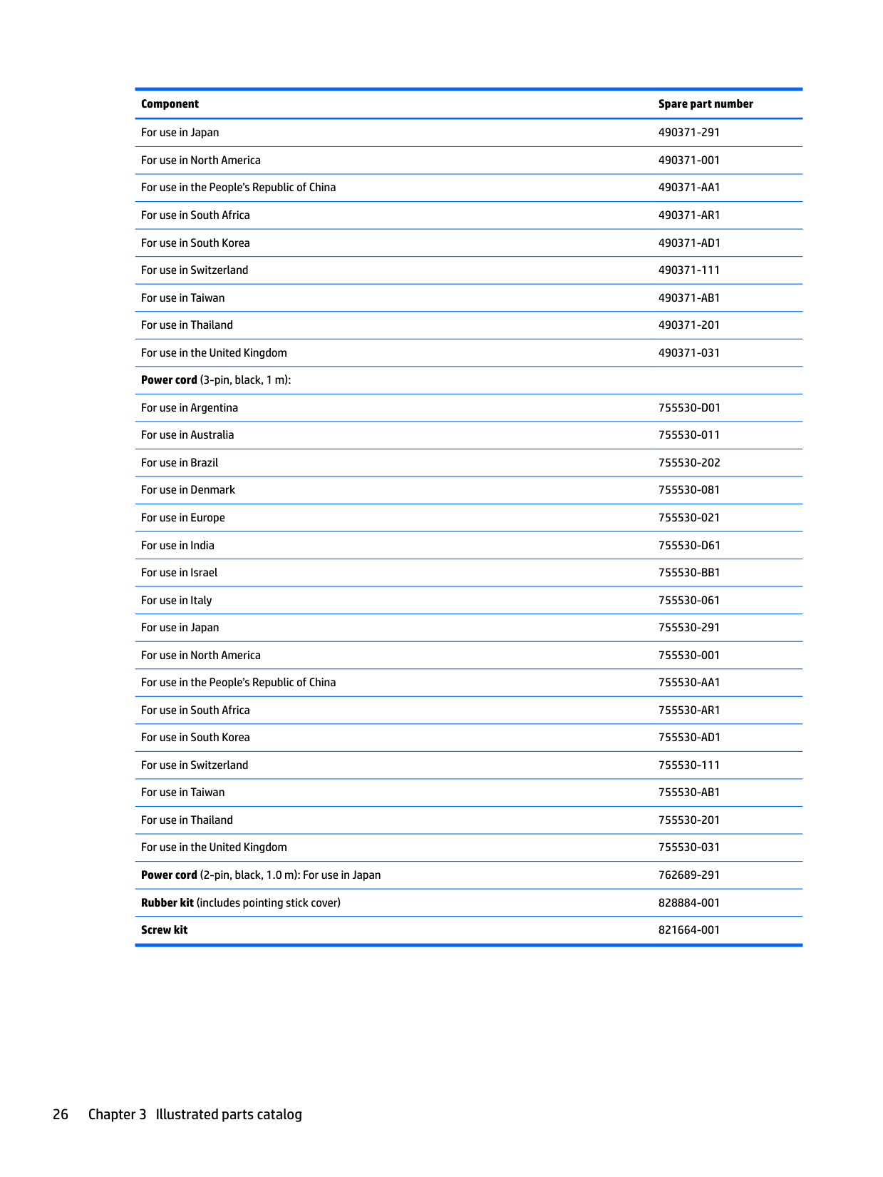
For use in Japan 490371-291 For use in North America 490371-001 For use in the People’s Republic of China 490371-AA1 For use in South Africa 490371-AR1 For use in South Korea 490371-AD1 For use in Switzerland 490371-111 For use in Taiwan 490371-AB1 For use in Thailand 490371-201 For use in the United Kingdom 490371-031 Power cord (3-pin, black, 1 m):
For use in Argentina 755530-D01 For use in Australia 755530-011 For use in Brazil 755530-202 For use in Denmark 755530-081 For use in Europe 755530-021 For use in India 755530-D61 For use in Israel 755530-BB1 For use in Italy 755530-061 For use in Japan 755530-291 For use in North America 755530-001 For use in the People’s Republic of China 755530-AA1 For use in South Africa 755530-AR1 For use in South Korea 755530-AD1 For use in Switzerland 755530-111 For use in Taiwan 755530-AB1 For use in Thailand 755530-201 For use in the United Kingdom 755530-031 Power cord (2-pin, black, 1.0 m): For use in Japan 762689-291 Rubber kit (includes pointing stick cover) 828884-001 Screw kit 821664-001
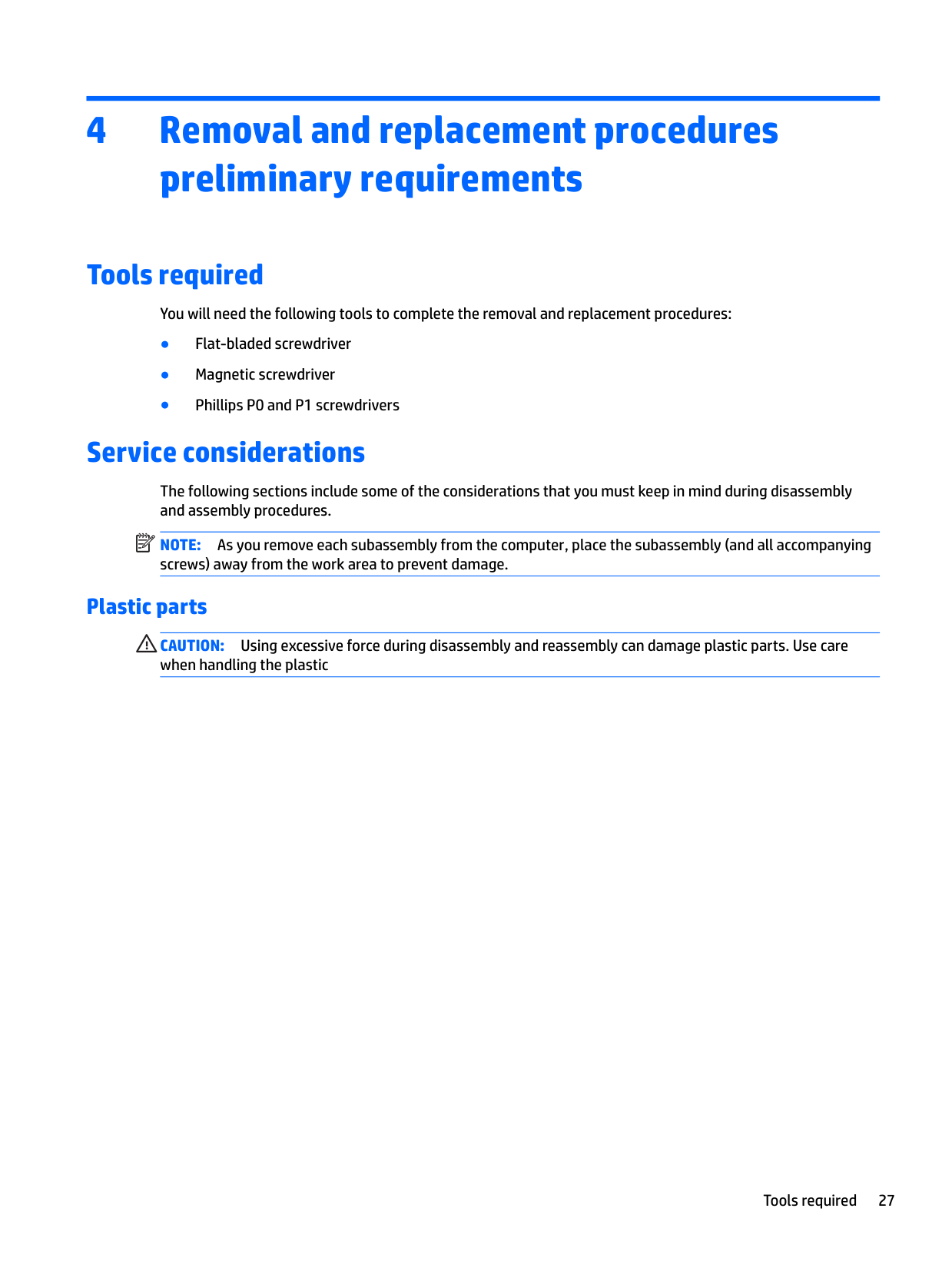
4 Removal and replacement procedurespreliminary requirements
Tools required
You will need the following tools to complete the removal and replacement procedures:
Service considerations
The following sections include some of the considerations that you must keep in mind during disassembly and assembly procedures.
| | |---|
NOTE: As you remove each subassembly from the computer, place the subassembly (and all accompanying screws) away from the work area to prevent damage.
#### Plastic parts
CAUTION: Using excessive force during disassembly and reassembly can damage plastic parts. Use care when handling the plastic
Tools required 27
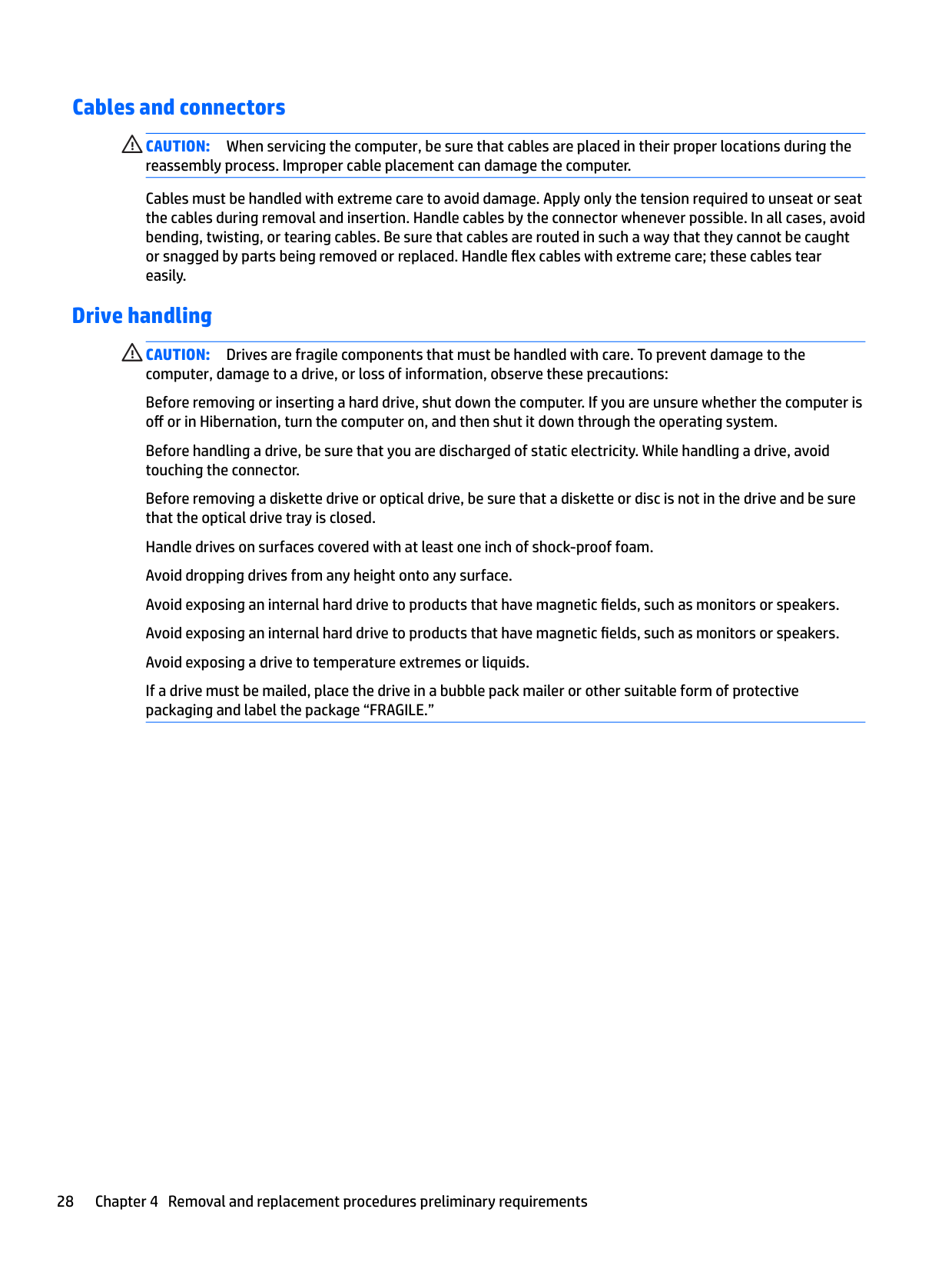
#### Cables and connectors
CAUTION: When servicing the computer, be sure that cables are placed in their proper locations during the reassembly process. Improper cable placement can damage the computer.
Cables must be handled with extreme care to avoid damage. Apply only the tension required to unseat or seat the cables during removal and insertion. Handle cables by the connector whenever possible. In all cases, avoid bending, twisting, or tearing cables. Be sure that cables are routed in such a way that they cannot be caught or snagged by parts being removed or replaced. Handle flex cables with extreme care; these cables tear easily.
Drive handling CAUTION: Drives are fragile components that must be handled with care. To prevent damage to the computer, damage to a drive, or loss of information, observe these precautions: Before removing or inserting a hard drive, shut down the computer. If you are unsure whether the computer is off or in Hibernation, turn the computer on, and then shut it down through the operating system. Before handling a drive, be sure that you are discharged of static electricity. While handling a drive, avoid touching the connector. Before removing a diskette drive or optical drive, be sure that a diskette or disc is not in the drive and be sure that the optical drive tray is closed. Handle drives on surfaces covered with at least one inch of shock-proof foam. Avoid dropping drives from any height onto any surface. Avoid exposing an internal hard drive to products that have magnetic fields, such as monitors or speakers. Avoid exposing an internal hard drive to products that have magnetic fields, such as monitors or speakers. Avoid exposing a drive to temperature extremes or liquids. If a drive must be mailed, place the drive in a bubble pack mailer or other suitable form of protective packaging and label the package “FRAGILE.”
Grounding guidelines
#### Electrostatic discharge damage
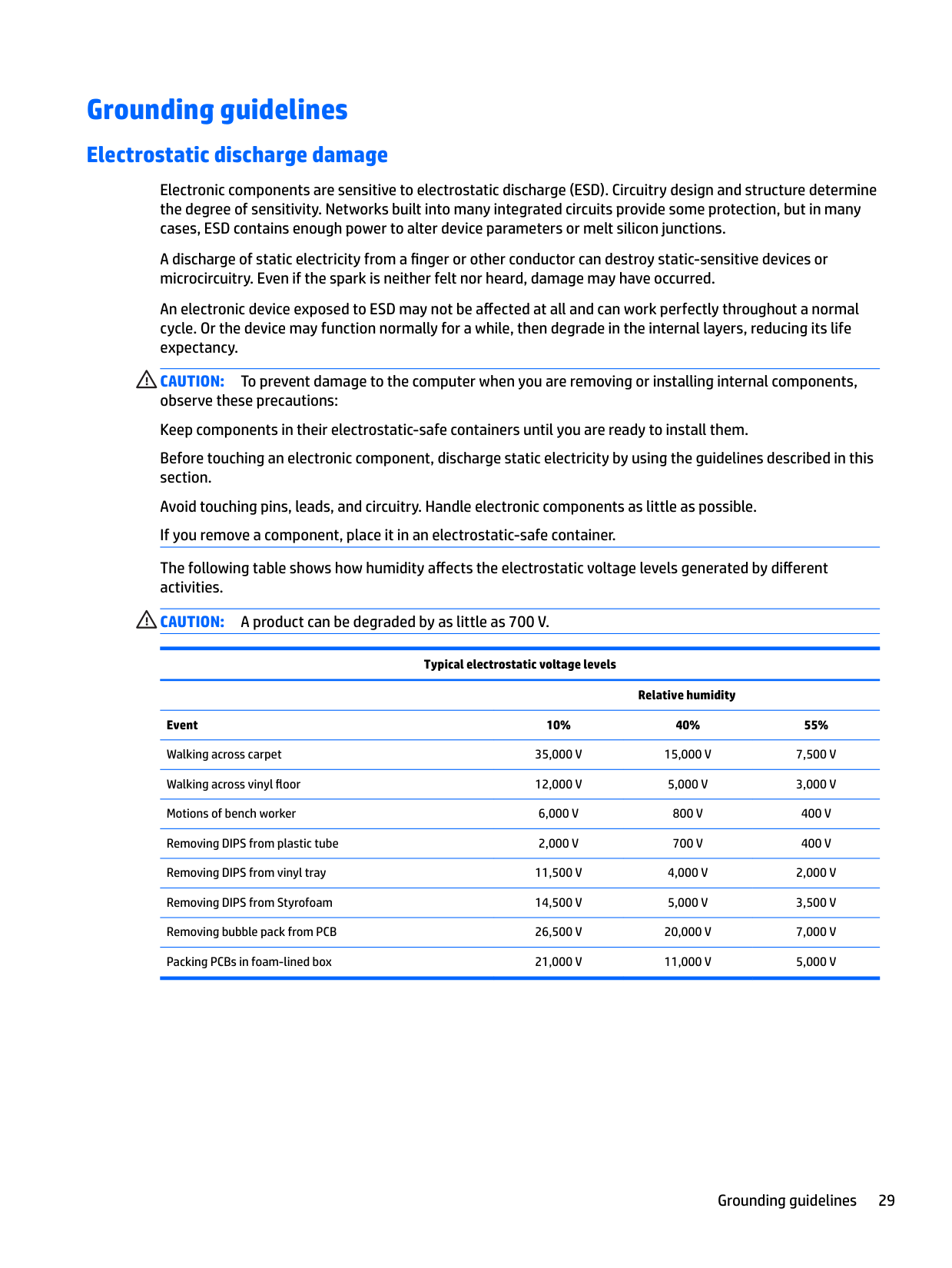
Electronic components are sensitive to electrostatic discharge (ESD). Circuitry design and structure determine the degree of sensitivity. Networks built into many integrated circuits provide some protection, but in many cases, ESD contains enough power to alter device parameters or melt silicon junctions.
A discharge of static electricity from a finger or other conductor can destroy static-sensitive devices or microcircuitry. Even if the spark is neither felt nor heard, damage may have occurred.
An electronic device exposed to ESD may not be affected at all and can work perfectly throughout a normal cycle. Or the device may function normally for a while, then degrade in the internal layers, reducing its life expectancy.
CAUTION: To prevent damage to the computer when you are removing or installing internal components, observe these precautions: Keep components in their electrostatic-safe containers until you are ready to install them. Before touching an electronic component, discharge static electricity by using the guidelines described in this section. Avoid touching pins, leads, and circuitry. Handle electronic components as little as possible. If you remove a component, place it in an electrostatic-safe container. The following table shows how humidity affects the electrostatic voltage levels generated by different activities. CAUTION: A product can be degraded by as little as 700 V.
Typical electrostatic voltage levels
Relative humidity Event 10% 40% 55% Walking across carpet 35,000 V 15,000 V 7,500 V Walking across vinyl floor 12,000 V 5,000 V 3,000 V Motions of bench worker 6,000 V 800 V 400 V Removing DIPS from plastic tube 2,000 V 700 V 400 V Removing DIPS from vinyl tray 11,500 V 4,000 V 2,000 V Removing DIPS from Styrofoam 14,500 V 5,000 V 3,500 V Removing bubble pack from PCB 26,500 V 20,000 V 7,000 V Packing PCBs in foam-lined box 21,000 V 11,000 V 5,000 V
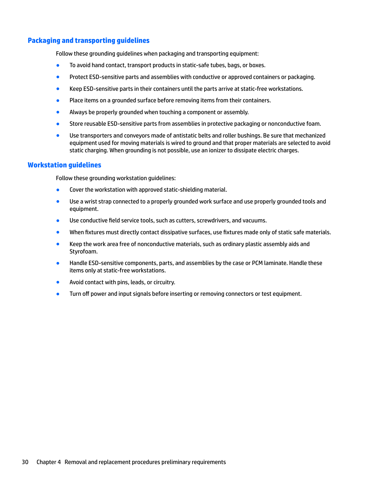
##### Packaging and transporting guidelines
Follow these grounding guidelines when packaging and transporting equipment:
##### Workstation guidelines
Follow these grounding workstation guidelines:

##### Equipment guidelines
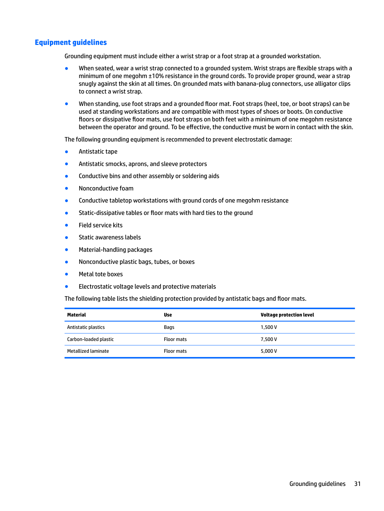
Grounding equipment must include either a wrist strap or a foot strap at a grounded workstation.
Material Use Voltage protection level
Antistatic plastics Bags 1,500 V Carbon-loaded plastic Floor mats 7,500 V Metallized laminate Floor mats 5,000 V
5 Removal and replacement procedures forCustomer Self-Repair parts
| | |---|
This chapter provides removal and replacement procedures for Customer Self-Repair parts. NOTE: The Customer Self-Repair program is not available in all locations. Installing a part not supported by the Customer Self-Repair program may void your warranty. Check your warranty to determine if Customer Self-Repair is supported in your location.
Component replacement procedures
| | |---|
NOTE: Details about your computer, including model, serial number, product key, and length of warranty, are on the service tag at the bottom of your computer. See Locating system information on page 16 for details.
| | |---|
NOTE: HP continually improves and changes product parts. For complete and current information on supported parts for your computer, go to http://partsurfer.hp.com, select your country or region, and then follow the on-screen instructions.
There are as many as xx screws that must be removed, replaced, and/or loosened when servicing Customer Self-Repair parts. Make special note of each screw size and location during removal and replacement.
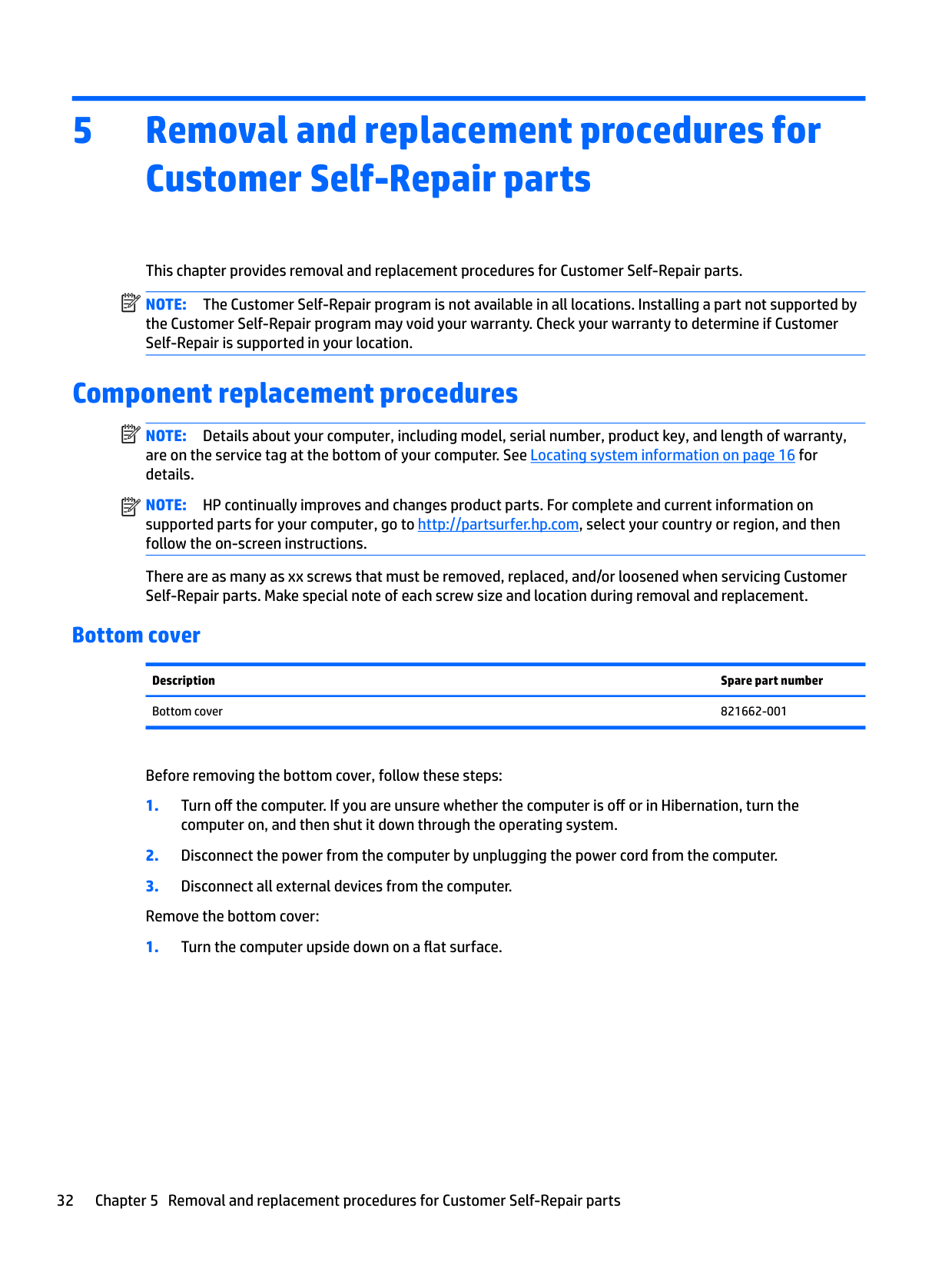
#### Bottom cover
Description Spare part number Bottom cover 821662-001
Before removing the bottom cover, follow these steps:
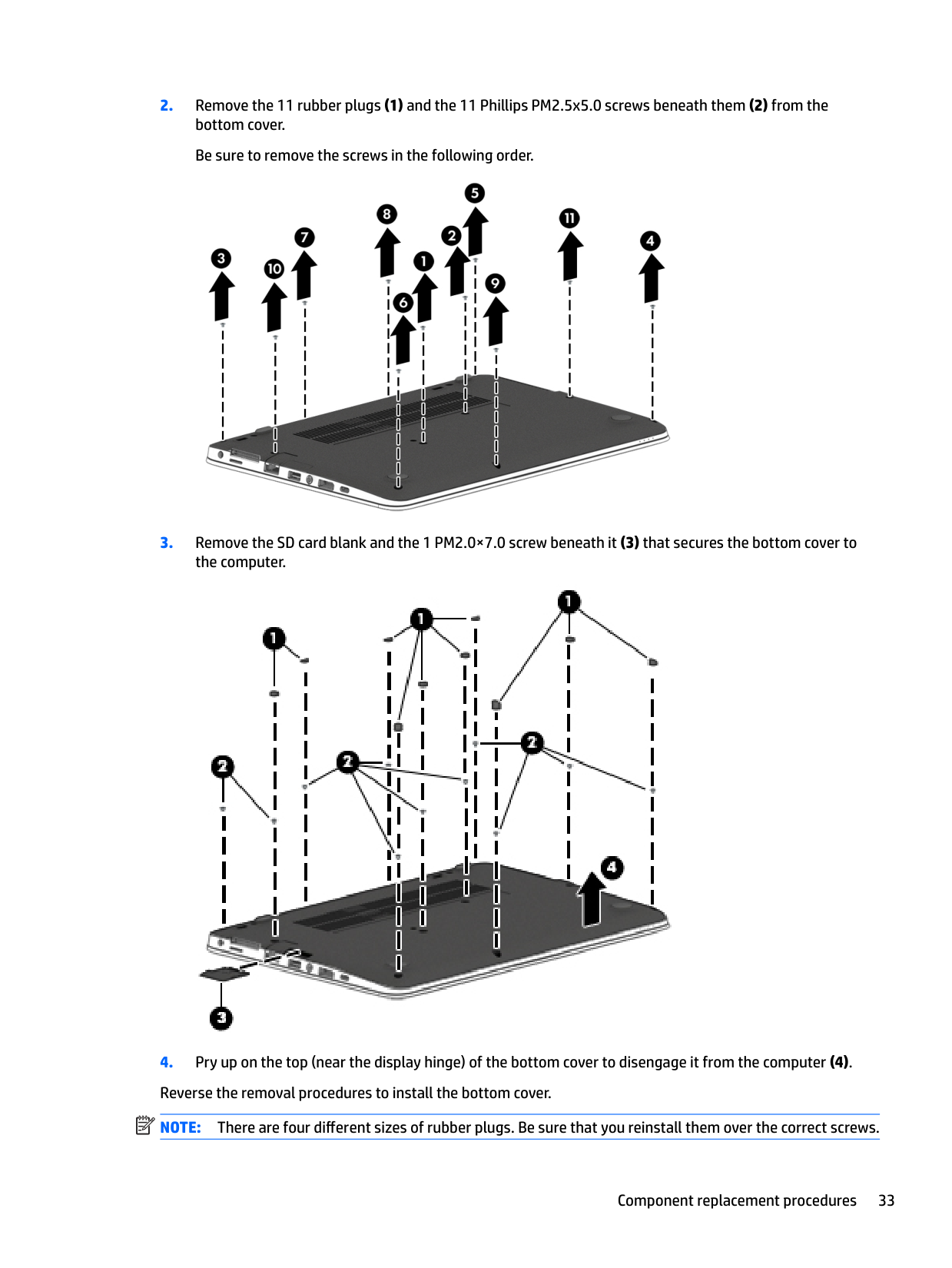
####### 2. Remove the 11 rubber plugs (1) and the 11 Phillips PM2.5x5.0 screws beneath them (2) from thebottom cover.Be sure to remove the screws in the following order.

####### 3. Remove the SD card blank and the 1 PM2.0×7.0 screw beneath it (3) that secures the bottom cover tothe computer.

| | |---|
####### 4. Pry up on the top (near the display hinge) of the bottom cover to disengage it from the computer (4).Reverse the removal procedures to install the bottom cover.NOTE: There are four different sizes of rubber plugs. Be sure that you reinstall them over the correct screws.
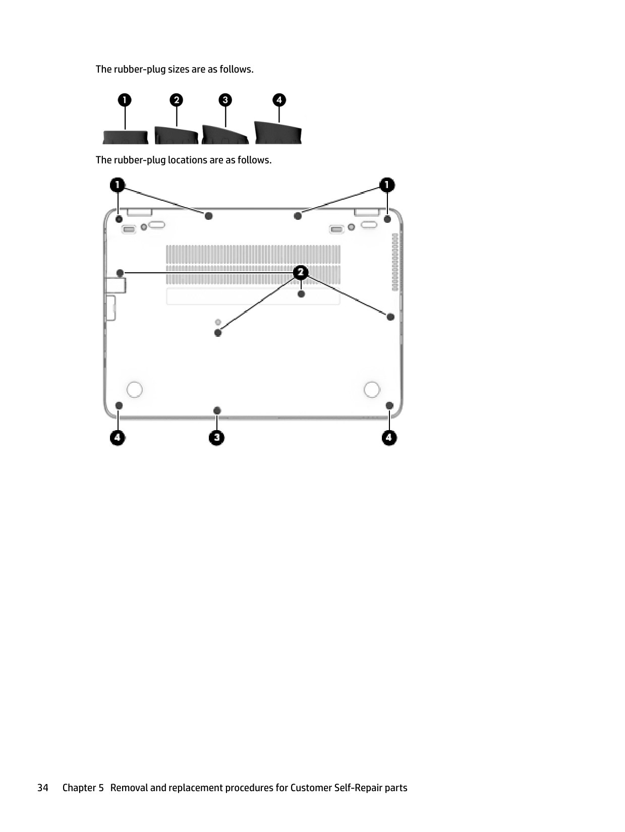
The rubber-plug sizes are as follows.

The rubber-plug locations are as follows.

#### Battery
Description Spare part number 3-cell, 44 WHr, 3.91 Ah Li-ion battery 800514-001
Before removing the battery, follow these steps:
WARNING! To reduce potential safety issues, use only the user-replaceable battery provided with the computer, a replacement battery provided by HP, or a compatible battery purchased from HP.
CAUTION: Removing a user-replaceable battery that is the sole power source for the computer can cause loss of information. To prevent loss of information, save your work or shut down the computer through Windows before removing the battery.
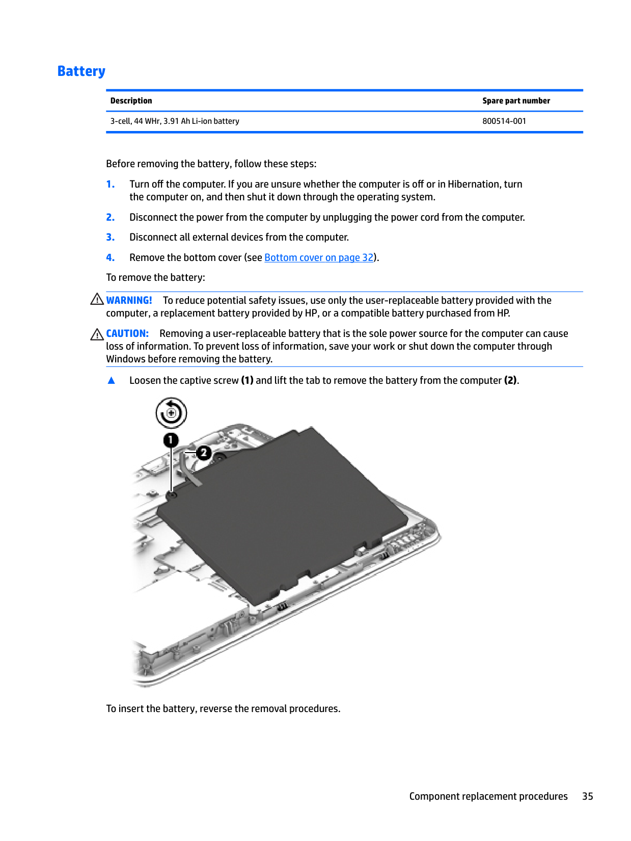
▲ Loosen the captive screw (1) and lift the tab to remove the battery from the computer (2).

To insert the battery, reverse the removal procedures.
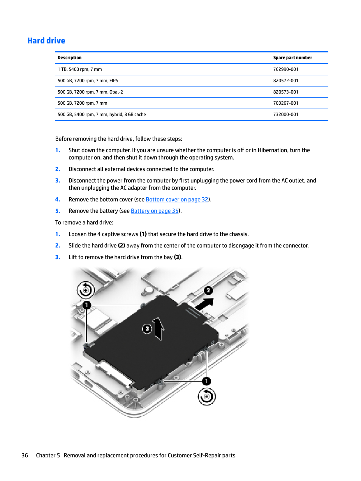
#### Hard drive
######## Description Spare part number
1 TB, 5400 rpm, 7 mm 762990-001 500 GB, 7200 rpm, 7 mm, FIPS 820572-001 500 GB, 7200 rpm, 7 mm, Opal-2 820573-001 500 GB, 7200 rpm, 7 mm 703267-001 500 GB, 5400 rpm, 7 mm, hybrid, 8 GB cache 732000-001
Before removing the hard drive, follow these steps:


| | |---|
Reverse this procedure to install a hard drive. NOTE: Only a hard drive or an SSD can be installed. To install a hard drive, be sure that the standee is stored beside the hard drive slot and not installed across from the SSD connector.
#### SSD
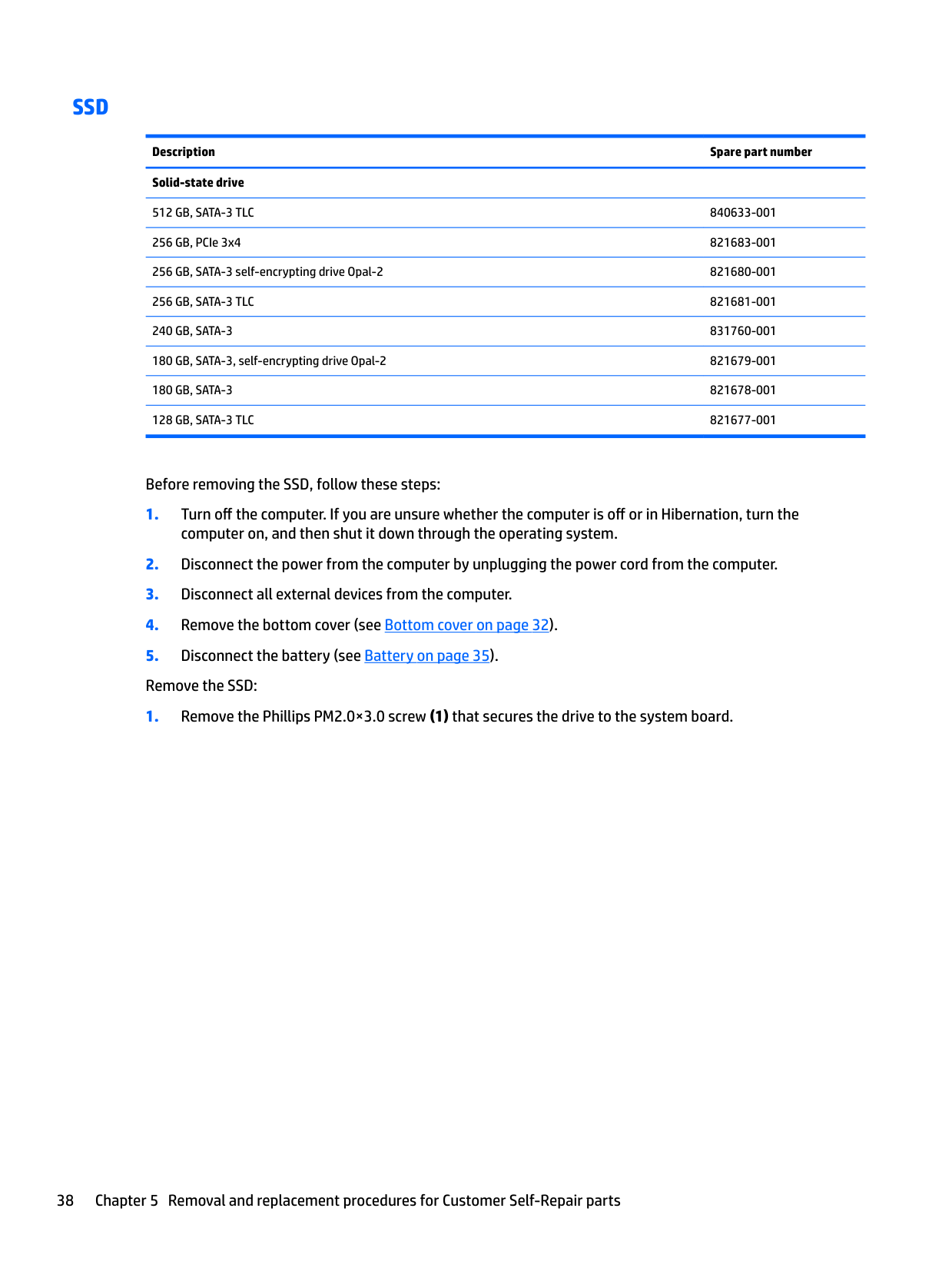
Description Spare part number Solid-state drive
512 GB, SATA-3 TLC 840633-001 256 GB, PCIe 3x4 821683-001 256 GB, SATA-3 self-encrypting drive Opal-2 821680-001 256 GB, SATA-3 TLC 821681-001 240 GB, SATA-3 831760-001 180 GB, SATA-3, self-encrypting drive Opal-2 821679-001 180 GB, SATA-3 821678-001 128 GB, SATA-3 TLC 821677-001
Before removing the SSD, follow these steps:

| | |---|
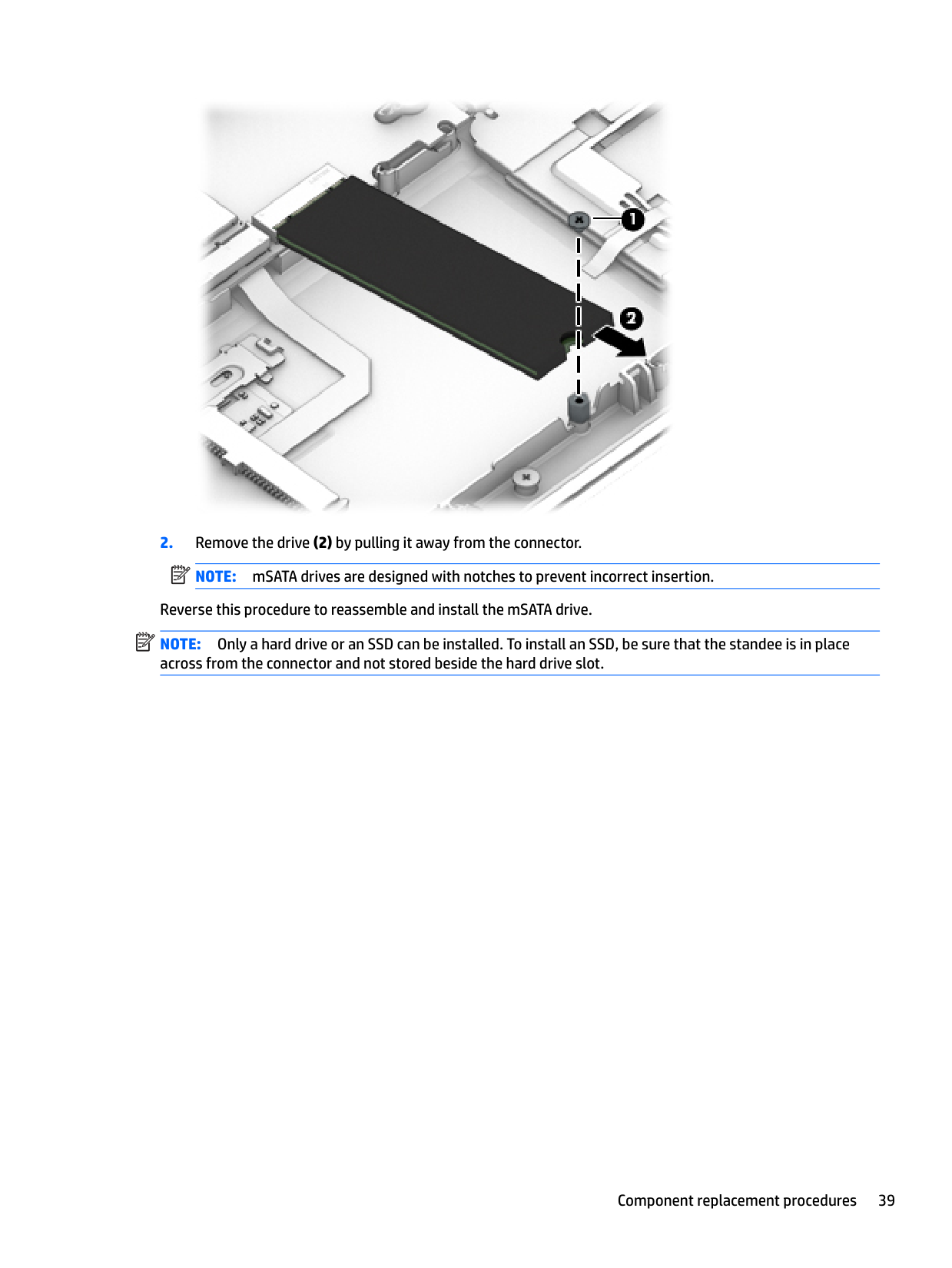
| | |---|
Reverse this procedure to reassemble and install the mSATA drive. NOTE: Only a hard drive or an SSD can be installed. To install an SSD, be sure that the standee is in place across from the connector and not stored beside the hard drive slot.
Memory modules NOTE: Primary and expansion memory is installed in a side-by-side configuration in the bottom of the computer. If only one memory module is installed, it must be installed in the socket labeled 1.
| | |---|
Description Spare part number
4-GB (2133-MHz, DDR4) 820569-001 8-GB (2133-MHz, DDR4) 820570-001
Update BIOS before adding memory modules Before adding new memory, make sure you update the computer to the latest BIOS. CAUTION: Failure to update the computer to the latest BIOS prior to installing new memory may result in various system problems. To update BIOS:
| | |---|
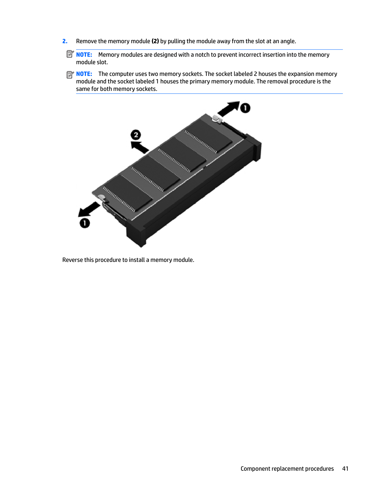
NOTE: Memory modules are designed with a notch to prevent incorrect insertion into the memory module slot.
| | |---|
NOTE: The computer uses two memory sockets. The socket labeled 2 houses the expansion memory module and the socket labeled 1 houses the primary memory module. The removal procedure is the same for both memory sockets.

Reverse this procedure to install a memory module.
WLAN/Bluetooth combo card The computer uses a card that provides both WLAN and Bluetooth functionality. The WLAN module and WWAN module are not interchangeable.
Description Spare part number
Intel Dual Band Wireless-AC 3165 802.11ac 1x1 WiFi + BT 4.0 combo adapter 806723-001 Intel Dual Band Wireless-AC 8260NGW 802.11a/g/g/n+ac 2x2 WiFi + BT 4.2 combo adapter 806721-001 Intel Dual Band Wireless-AC 8260NGW 802.11a/b/g/n+ac non-vPro 2x2 WiFi + BT 4.2 combo adapter 806722-001
Before removing the WLAN module, follow these steps:
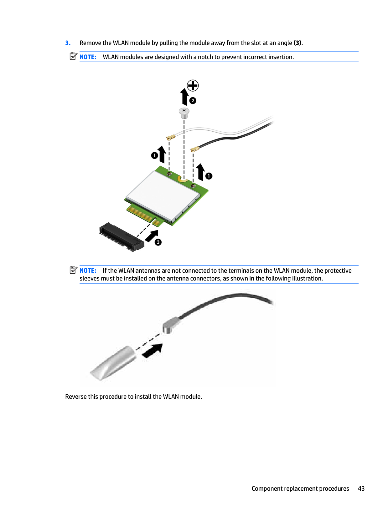
NOTE: The WLAN antenna cable labeled “1” connects to the WLAN module “Main” terminal labeled “1”. The WLAN antenna cable labeled “2” connects to the WLAN module “Aux” terminal labeled “2”. If the computer is equipped with an 802.11a/b/g/n WLAN module, the yellow WLAN antenna cable connects to the middle terminal on the WLAN module.
| | |---|
| | |---|
| | |---|

NOTE: If the WLAN antennas are not connected to the terminals on the WLAN module, the protective sleeves must be installed on the antenna connectors, as shown in the following illustration.

Reverse this procedure to install the WLAN module.
WWAN module The WLAN module and WWAN module are not interchangeable. The WWAN module is available on select models only.
Description Spare part number
HP lt4120 LTE/EVDO/HSPA+ SnapdragonT X5 LTE Mobile Broadband Module 800870-001 HP hs31110 HSPA + Intel Mobile Broadband Module 822828-001
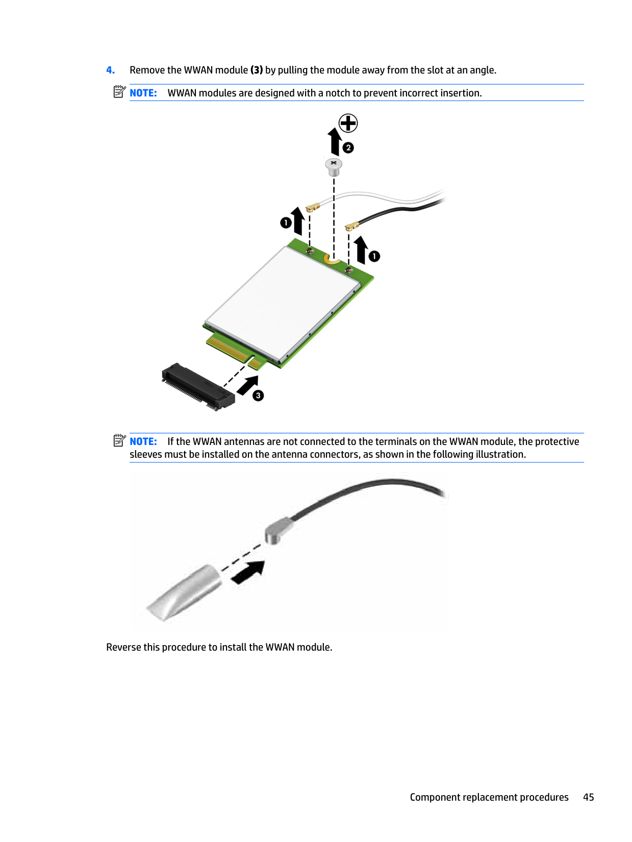
Before removing the WWAN module, follow these steps:
computer on, and then shut it down through the operating system.
then unplugging the AC adapter from the computer. 4. Remove the bottom cover (see Bottom cover on page 32).
NOTE: The red WWAN antenna cable is connected to the WWAN module “Main” terminal. The blue WWAN antenna cable is connected to the WWAN module “Aux” terminal.
| | |---|
| | |---|
| | |---|

NOTE: If the WWAN antennas are not connected to the terminals on the WWAN module, the protective sleeves must be installed on the antenna connectors, as shown in the following illustration.

Reverse this procedure to install the WWAN module.
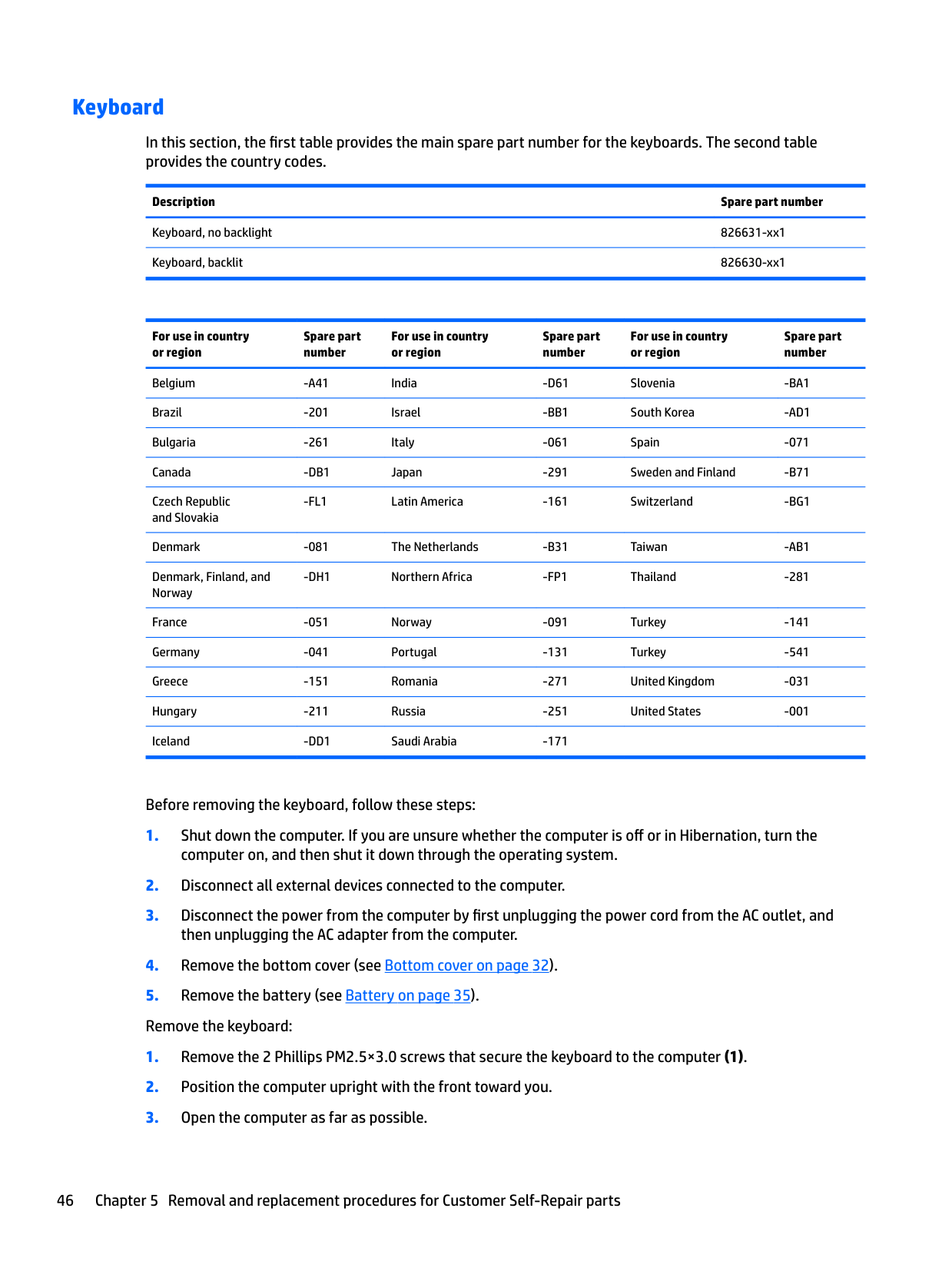
#### Keyboard
In this section, the first table provides the main spare part number for the keyboards. The second table provides the country codes.
Description Spare part number
Keyboard, no backlight 826631-xx1 Keyboard, backlit 826630-xx1
For use in country or region
Spare part number
For use in country or region
Spare part number
For use in country or region
Spare part number
Belgium -A41 India -D61 Slovenia -BA1 Brazil -201 Israel -BB1 South Korea -AD1 Bulgaria -261 Italy -061 Spain -071 Canada -DB1 Japan -291 Sweden and Finland -B71 Czech Republic and Slovakia
-FL1 Latin America -161 Switzerland -BG1
Denmark -081 The Netherlands -B31 Taiwan -AB1 Denmark, Finland, and Norway
-DH1 Northern Africa -FP1 Thailand -281
France -051 Norway -091 Turkey -141 Germany -041 Portugal -131 Turkey -541 Greece -151 Romania -271 United Kingdom -031 Hungary -211 Russia -251 United States -001 Iceland -DD1 Saudi Arabia -171
Before removing the keyboard, follow these steps:
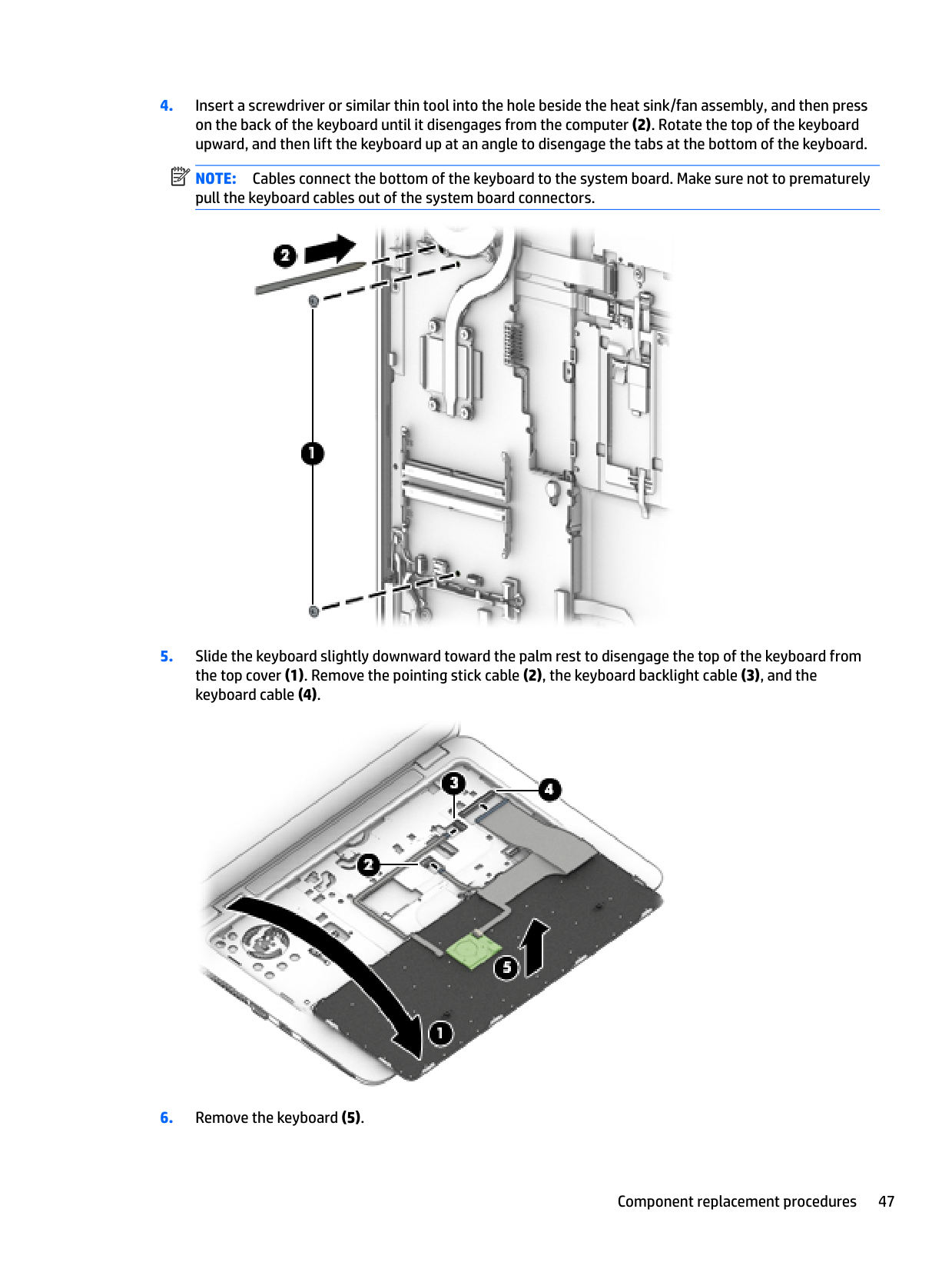
####### 4. Insert a screwdriver or similar thin tool into the hole beside the heat sink/fan assembly, and then presson the back of the keyboard until it disengages from the computer (2). Rotate the top of the keyboardupward, and then lift the keyboard up at an angle to disengage the tabs at the bottom of the keyboard.
| | |---|
NOTE: Cables connect the bottom of the keyboard to the system board. Make sure not to prematurely pull the keyboard cables out of the system board connectors.

####### 5. Slide the keyboard slightly downward toward the palm rest to disengage the top of the keyboard fromthe top cover (1). Remove the pointing stick cable (2), the keyboard backlight cable (3), and thekeyboard cable (4).

####### 6. Remove the keyboard (5).
####### Reverse this procedure to install the keyboard.
6 Removal and replacement procedures for Authorized Service Provider parts
This chapter provides removal and replacement procedures for Authorized Service Provider only parts. CAUTION: Components described in this chapter should only be accessed by an authorized service provider. Accessing these parts can damage the computer or void the warranty. CAUTION: This computer does not have user-replaceable parts. Only HP authorized service providers should perform the removal and replacement procedures described here. Accessing the internal part could damage the computer or void the warranty.
Component replacement procedures
| | |---|
NOTE: Details about your computer, including model, serial number, product key, and length of warranty, are on the service tag at the bottom of your computer. See Locating system information on page 16 for details.
| | |---|
NOTE: HP continually improves and changes product parts. For complete and current information on supported parts for your computer, go to http://partsurfer.hp.com, select your country or region, and then follow the on-screen instructions.
There are as many as xx screws that must be removed, replaced, and/or loosened when servicing Authorized Service Provider only parts. Make special note of each screw size and location during removal and replacement.
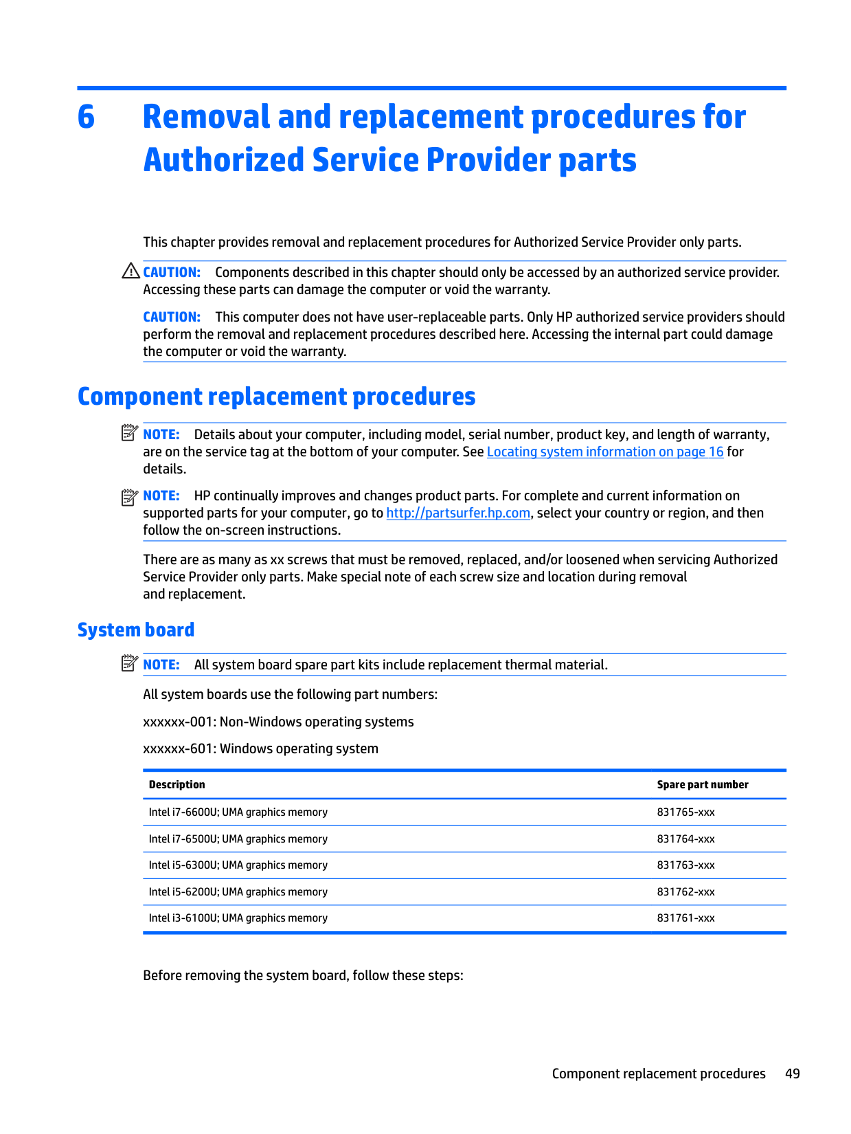
System board NOTE: All system board spare part kits include replacement thermal material. All system boards use the following part numbers: xxxxxx-001: Non-Windows operating systems xxxxxx-601: Windows operating system
| | |---|
Description Spare part number
Intel i7-6600U; UMA graphics memory 831765-xxx Intel i7-6500U; UMA graphics memory 831764-xxx Intel i5-6300U; UMA graphics memory 831763-xxx Intel i5-6200U; UMA graphics memory 831762-xxx Intel i3-6100U; UMA graphics memory 831761-xxx
Before removing the system board, follow these steps:
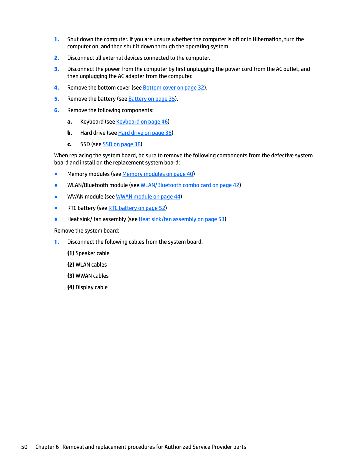
When replacing the system board, be sure to remove the following components from the defective system board and install on the replacement system board:


#### RTC battery
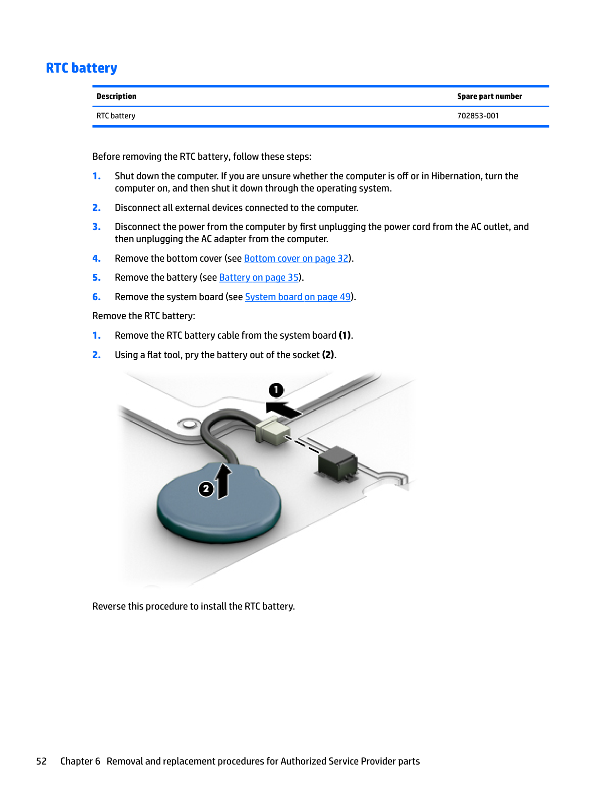
Description Spare part number RTC battery 702853-001
Before removing the RTC battery, follow these steps:

Reverse this procedure to install the RTC battery.
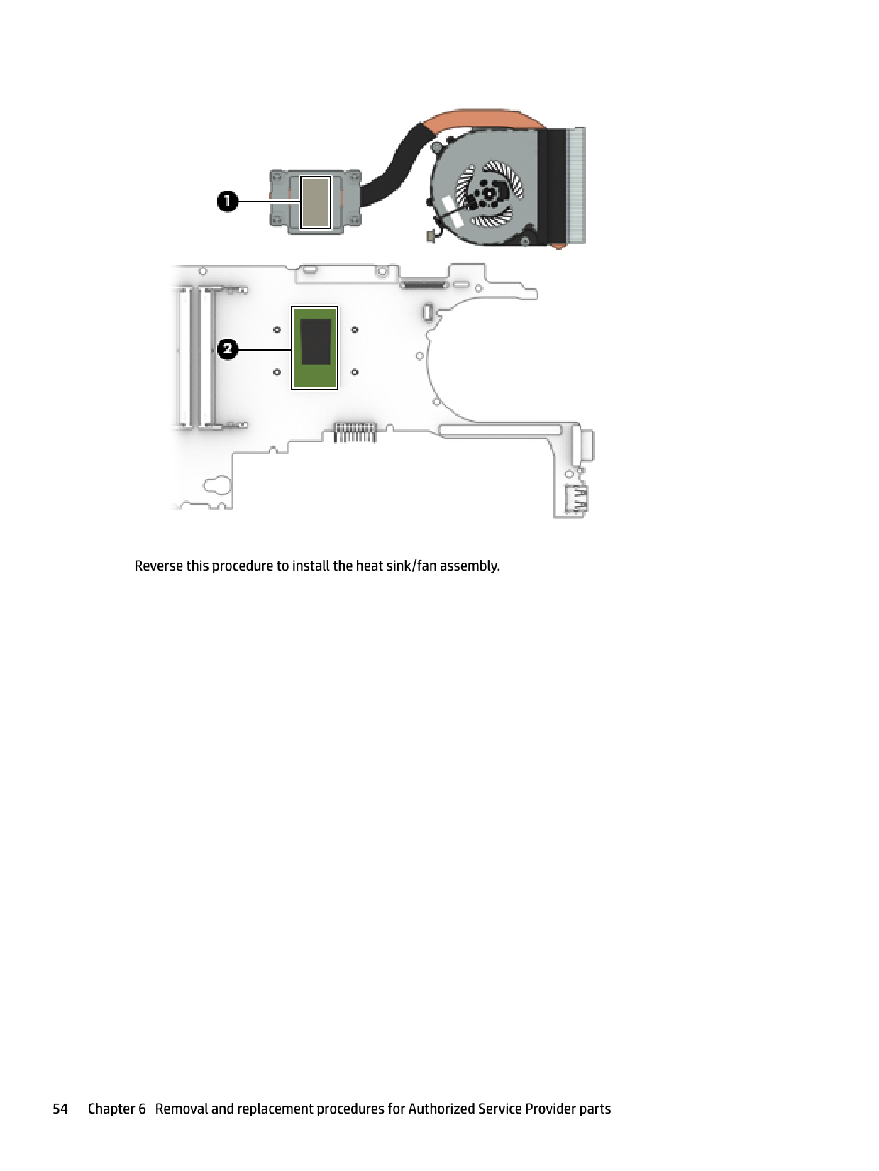
#### Heat sink/fan assembly
| | |---|
NOTE: The heat sink/fan assembly spare part kit includes replacement thermal material.
Description Spare part number Heat sink/thermal module with fans 821691-001
Before removing the heat sink/fan assembly, follow these steps:
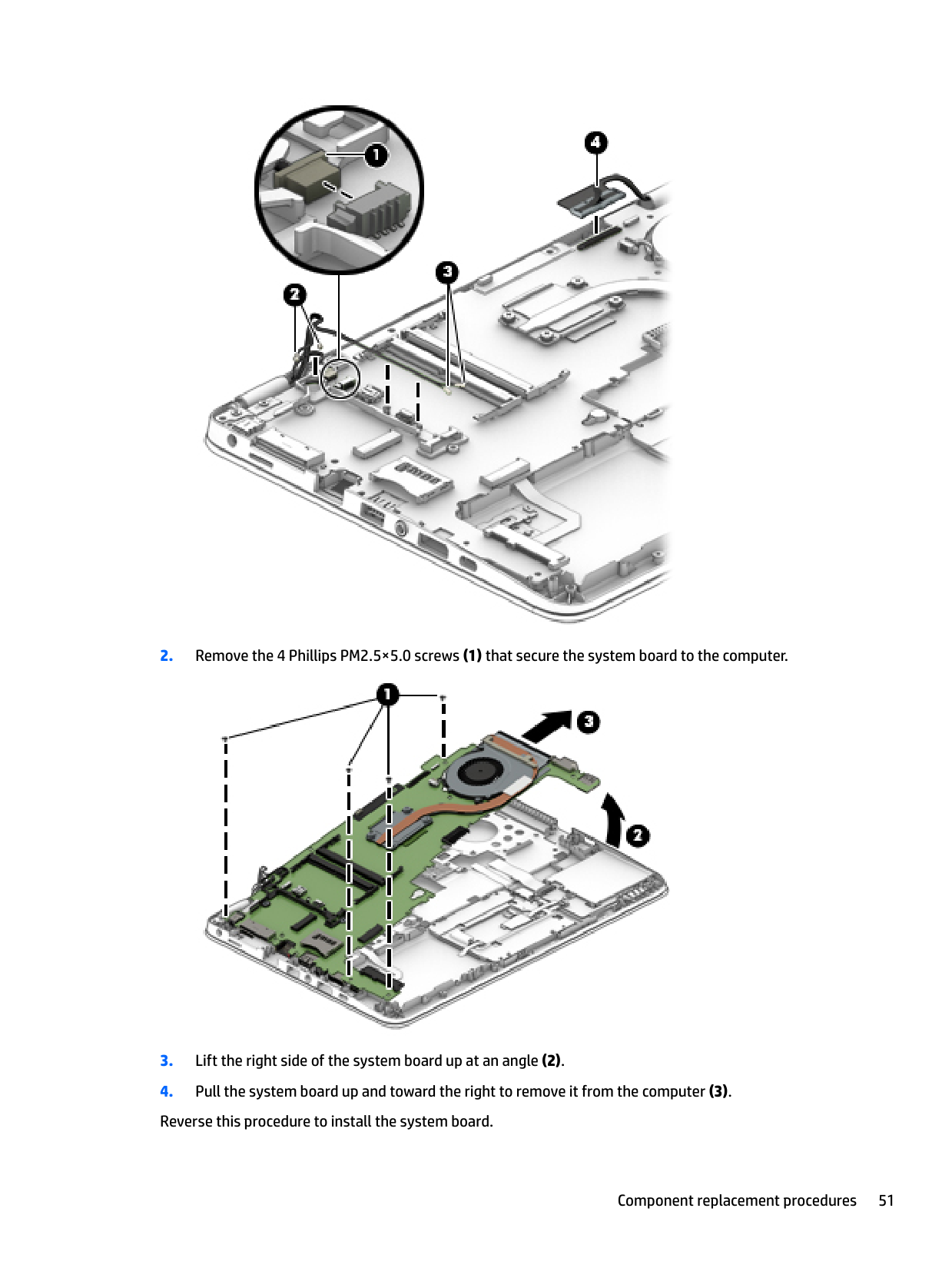
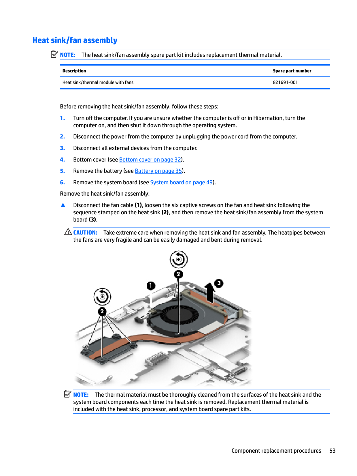
▲ Disconnect the fan cable (1), loosen the six captive screws on the fan and heat sink following the sequence stamped on the heat sink (2), and then remove the heat sink/fan assembly from the system board (3).
CAUTION: Take extreme care when removing the heat sink and fan assembly. The heatpipes between the fans are very fragile and can be easily damaged and bent during removal.
| | |---|

NOTE: The thermal material must be thoroughly cleaned from the surfaces of the heat sink and the system board components each time the heat sink is removed. Replacement thermal material is included with the heat sink, processor, and system board spare part kits.

####### Reverse this procedure to install the heat sink/fan assembly.
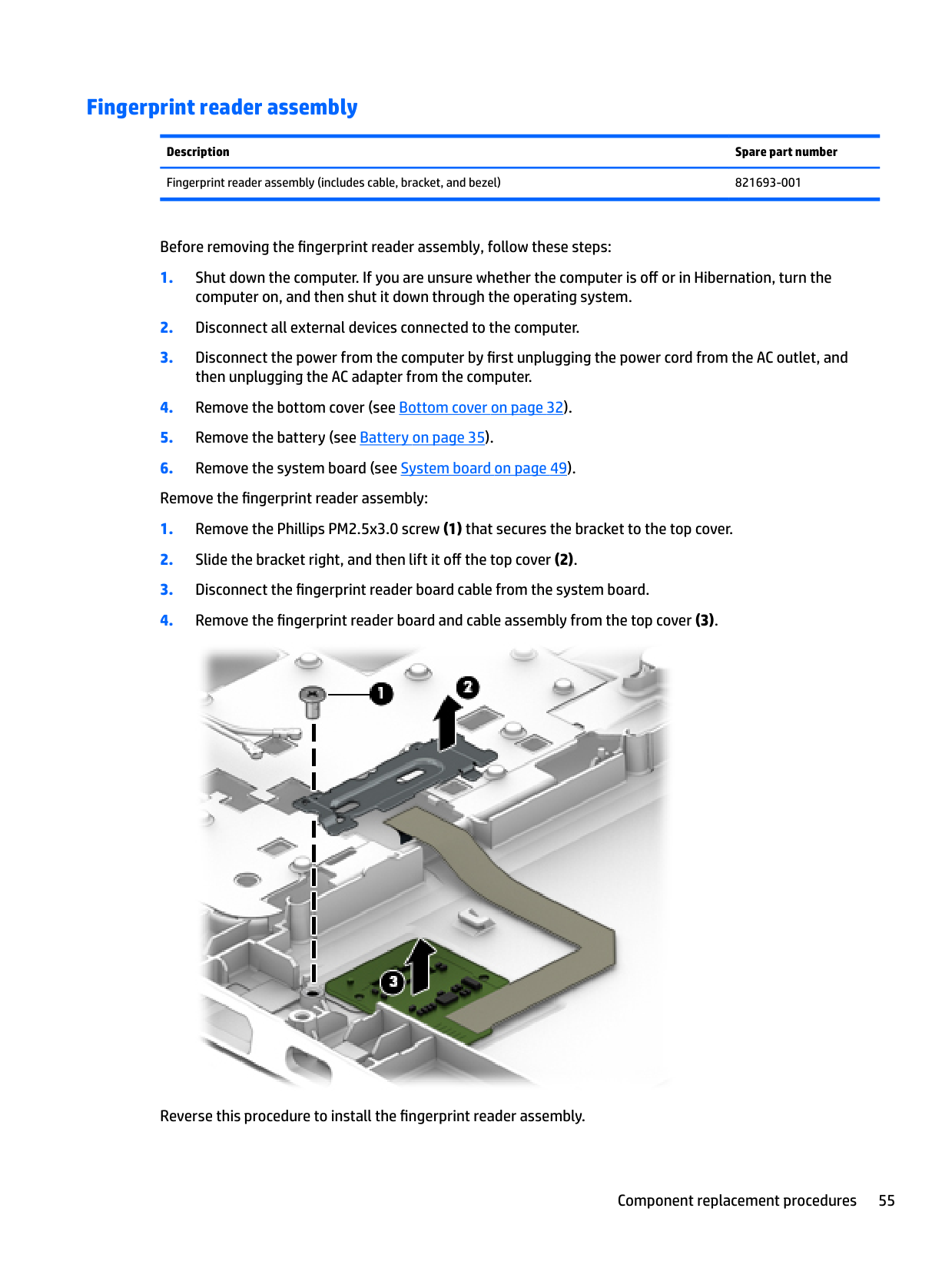
#### Fingerprint reader assembly
Description Spare part number Fingerprint reader assembly (includes cable, bracket, and bezel) 821693-001
Before removing the fingerprint reader assembly, follow these steps:
computer on, and then shut it down through the operating system.
then unplugging the AC adapter from the computer. 4. Remove the bottom cover (see Bottom cover on page 32).

Reverse this procedure to install the fingerprint reader assembly.
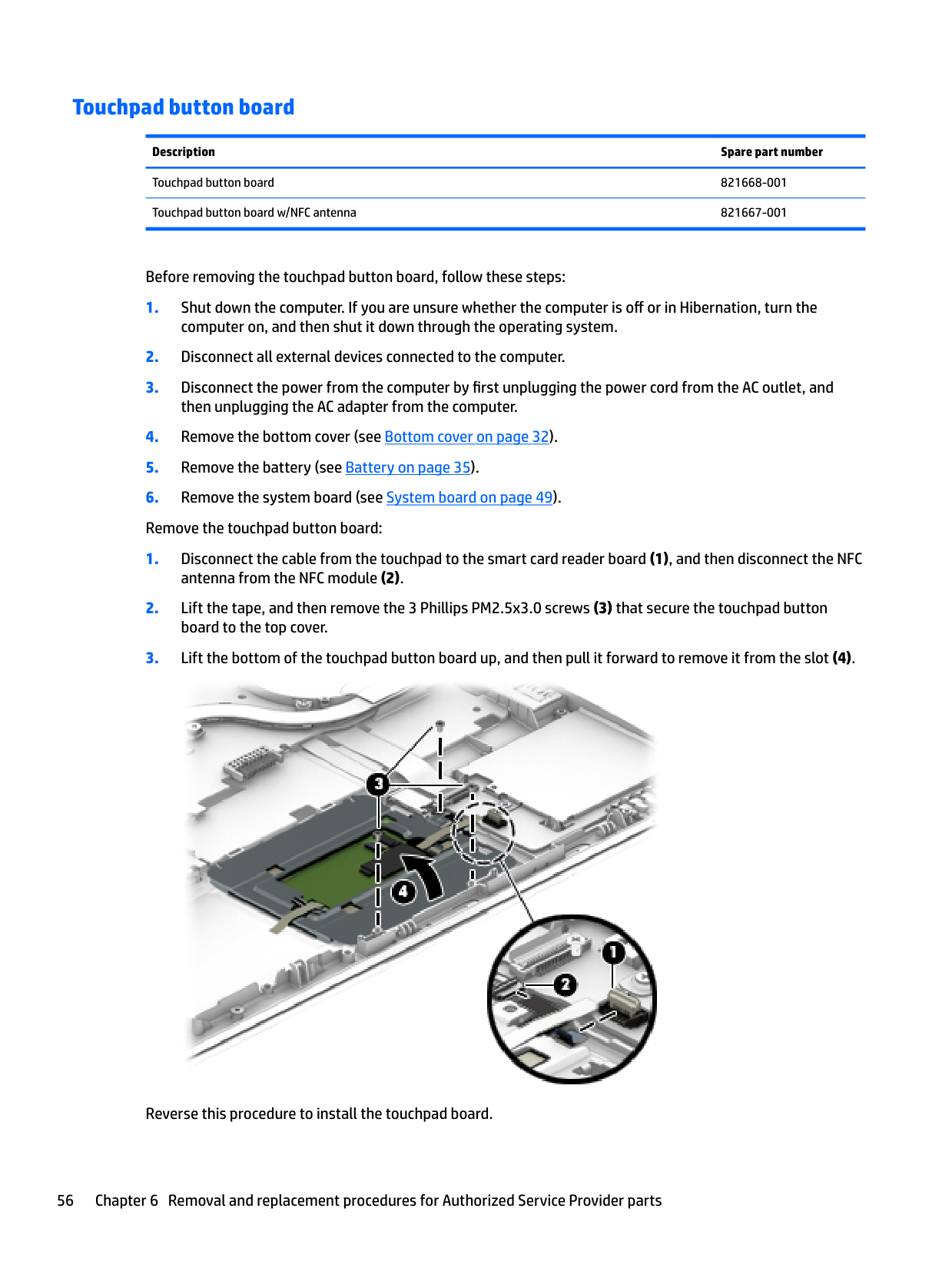
#### Touchpad button board
######## Description Spare part number
Touchpad button board 821668-001 Touchpad button board w/NFC antenna 821667-001
Before removing the touchpad button board, follow these steps:

Reverse this procedure to install the touchpad board.
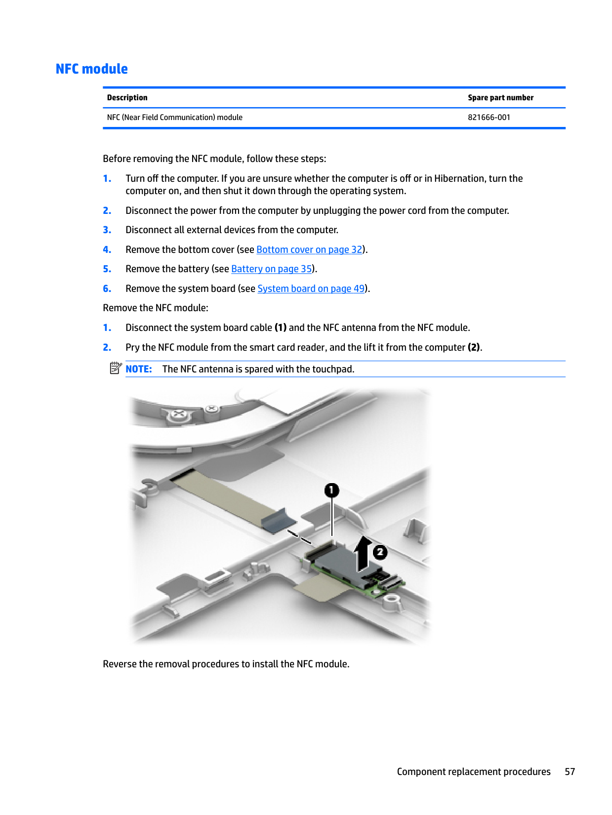
#### NFC module
Description Spare part number NFC (Near Field Communication) module 821666-001
Before removing the NFC module, follow these steps:
| | |---|

Reverse the removal procedures to install the NFC module.
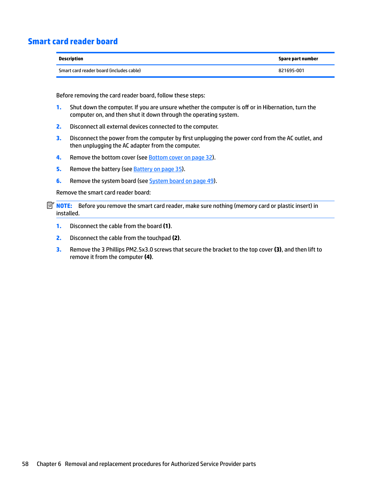
#### Smart card reader board
Description Spare part number Smart card reader board (includes cable) 821695-001
Before removing the card reader board, follow these steps:
computer on, and then shut it down through the operating system.
then unplugging the AC adapter from the computer. 4. Remove the bottom cover (see Bottom cover on page 32).
| | |---|

Reverse this procedure to install the card reader board.
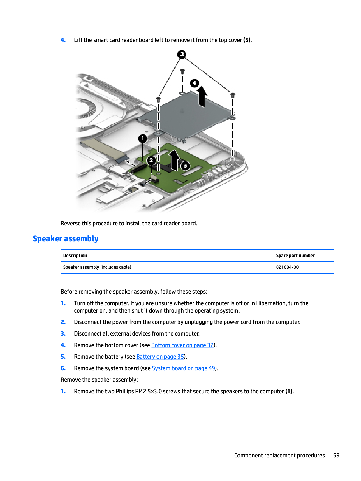
#### Speaker assembly
Description Spare part number Speaker assembly (includes cable) 821684-001
Before removing the speaker assembly, follow these steps:

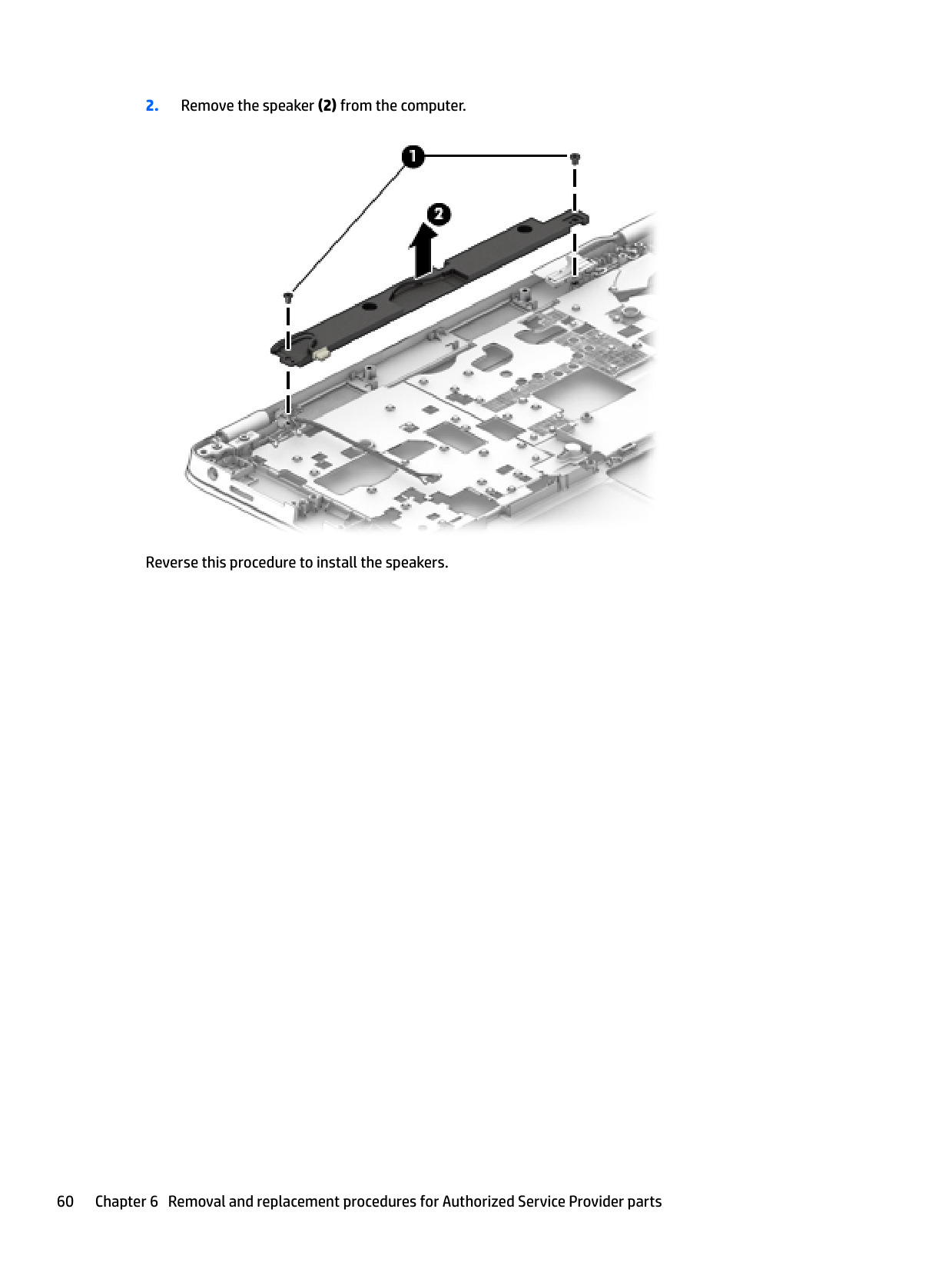
Reverse this procedure to install the speakers.
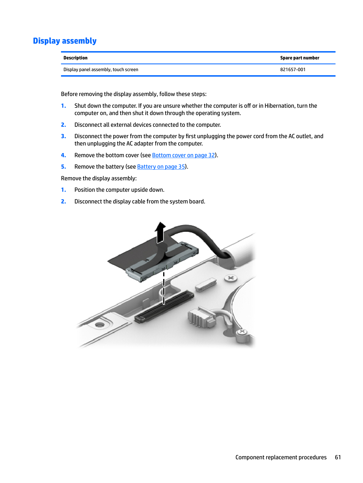
#### Display assembly
Description Spare part number Display panel assembly, touch screen 821657-001
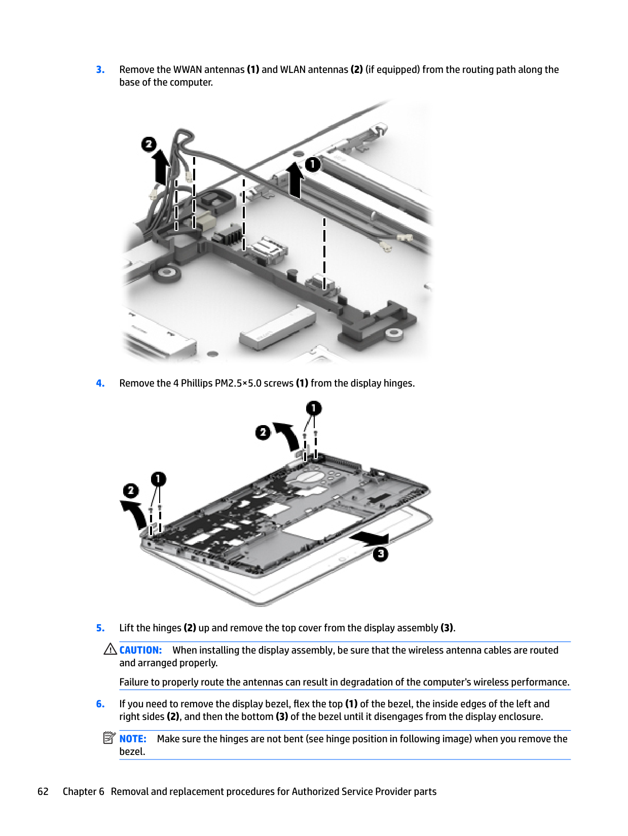
Before removing the display assembly, follow these steps:


CAUTION: When installing the display assembly, be sure that the wireless antenna cables are routed and arranged properly. Failure to properly route the antennas can result in degradation of the computer's wireless performance.
| | |---|
NOTE: Make sure the hinges are not bent (see hinge position in following image) when you remove the bezel.

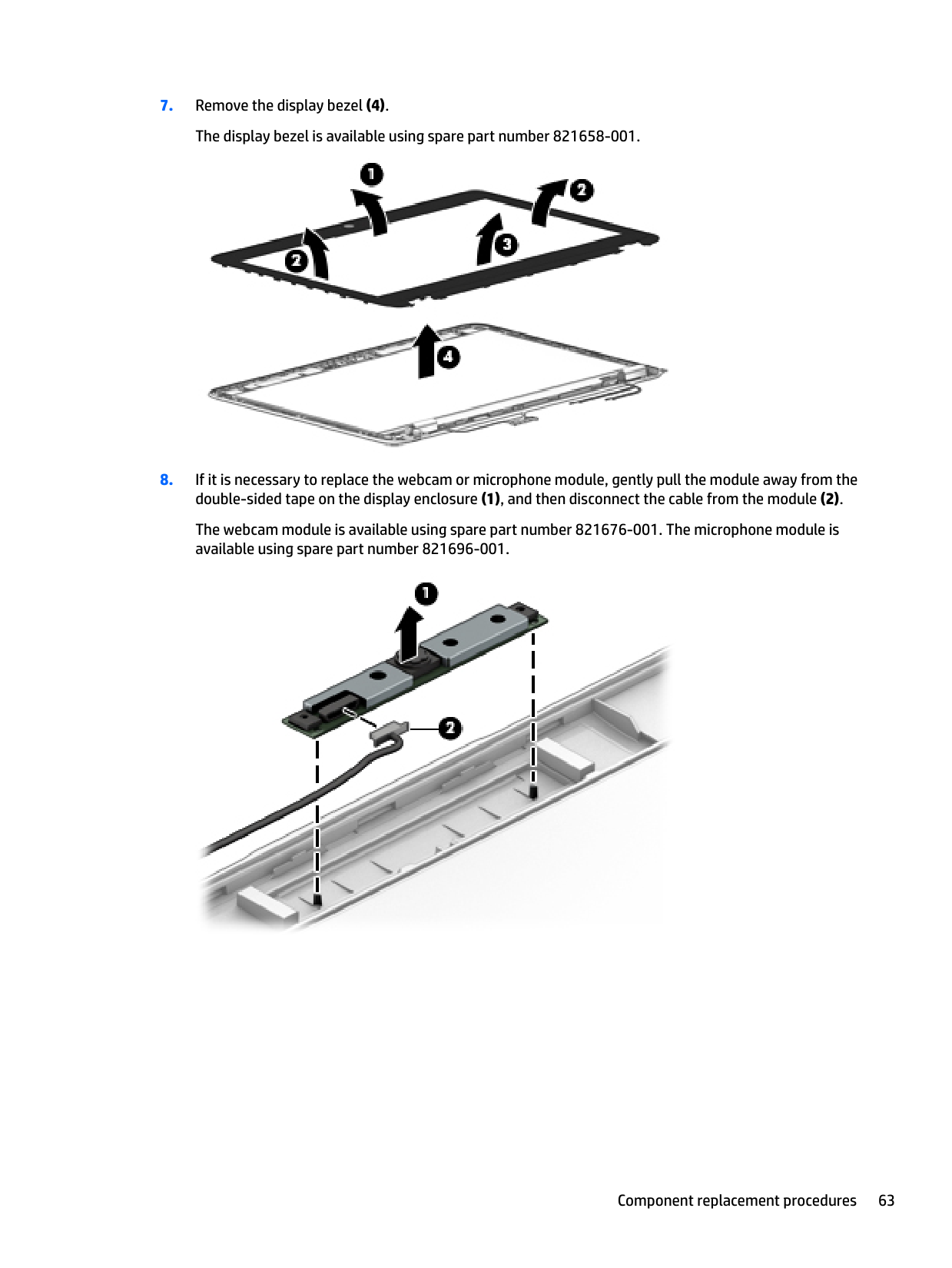
The webcam module is available using spare part number 821676-001. The microphone module is available using spare part number 821696-001.

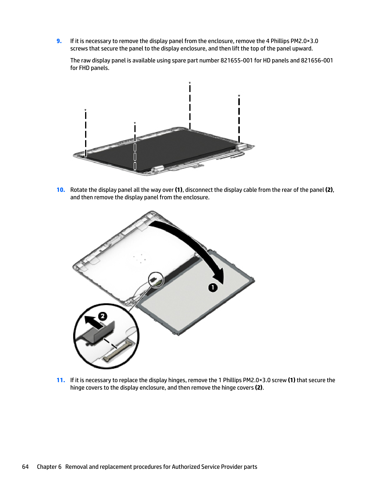
####### 9. If it is necessary to remove the display panel from the enclosure, remove the 4 Phillips PM2.0×3.0screws that secure the panel to the display enclosure, and then lift the top of the panel upward.
The raw display panel is available using spare part number 821655-001 for HD panels and 821656-001 for FHD panels.

####### 10. Rotate the display panel all the way over (1), disconnect the display cable from the rear of the panel (2),and then remove the display panel from the enclosure.

####### 11. If it is necessary to replace the display hinges, remove the 1 Phillips PM2.0×3.0 screw (1) that secure thehinge covers to the display enclosure, and then remove the hinge covers (2).


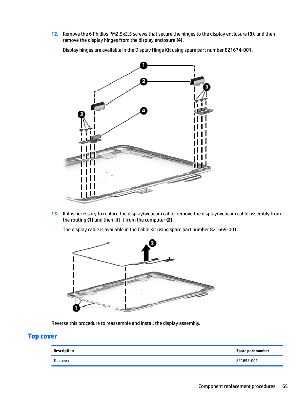
Reverse this procedure to reassemble and install the display assembly.
#### Top cover
Description Spare part number Top cover 821692-001
Before removing the top cover, follow these steps:
7 Computer Setup (BIOS), TPM, and HP Sure Start in Windows 10
Using Computer Setup
Computer Setup, or Basic Input/Output System (BIOS), controls communication between all the input and output devices on the system (such as disk drives, display, keyboard, mouse, and printer). Computer Setup includes settings for the types of devices installed, the startup sequence of the computer, and the amount of system and extended memory.
| | |---|
NOTE: Use extreme care when making changes in Computer Setup. Errors can prevent the computer from operating properly.
Starting Computer Setup NOTE: An external keyboard or mouse connected to a USB port can be used with Computer Setup only if USB legacy support is enabled. To start Computer Setup, follow these steps:

| | |---|
▲ Start Computer Setup.
▲ Turn on or restart the computer, and when the HP logo appears, press f10 to enter Computer Setup.
▲ Turn off the tablet. Press the power button in combination with the volume down button until the Startup menu is displayed, and then tap F10 to enter Computer Setup.
#### Navigating and selecting in Computer Setup
| | |---|
To exit Computer Setup menus, choose one of the following methods:
– or – Select Main, select Ignore Changes and Exit, and then press enter.
– or – Select Main, select Save Changes and Exit, and then press enter.
Your changes go into effect when the computer restarts.
Restoring factory settings in Computer Setup NOTE: Restoring defaults will not change the hard drive mode. To return all settings in Computer Setup to the values that were set at the factory, follow these steps:
| | |---|
NOTE: On select products, the selections may display Restore Defaults instead of Apply Factory Defaults and Exit.
| | |---|
– or – Select Main, select Save Changes and Exit, and then press enter.
| | |---|
Your changes go into effect when the computer restarts. NOTE: Your password settings and security settings are not changed when you restore the factory settings.
Updating the BIOS Updated versions of the BIOS may be available on the HP website. Most BIOS updates on the HP website are packaged in compressed files called SoftPaqs. Some download packages contain a file named Readme.txt, which contains information regarding installing and troubleshooting the file.
##### Determining the BIOS version
To decide whether you need to update Computer Setup (BIOS), first determine the BIOS version on your computer.
BIOS version information (also known as ROM date and System BIOS) can be accessed by pressing fn+esc (if you are already in Windows) or by using Computer Setup.
– or – Select Main, select Ignore Changes and Exit, and then press enter.
To check for later BIOS versions, see Downloading a BIOS update on page 69. Downloading a BIOS update
CAUTION: To reduce the risk of damage to the computer or an unsuccessful installation, download and install a BIOS update only when the computer is connected to reliable external power using the AC adapter. Do not download or install a BIOS update while the computer is running on battery power, docked in an optional docking device, or connected to an optional power source. During the download and installation, follow these instructions:
Do not disconnect power on the computer by unplugging the power cord from the AC outlet. Do not shut down the computer or initiate Sleep. Do not insert, remove, connect, or disconnect any device, cable, or cord.
– or – Select the question mark icon in the taskbar.
Make a note of the path to the location on your hard drive where the BIOS update is downloaded. You will need to access this path when you are ready to install the update.
| | |---|
NOTE: If you connect your computer to a network, consult the network administrator before installing any software updates, especially system BIOS updates.
BIOS installation procedures vary. Follow any instructions that are revealed on the screen after the download is complete. If no instructions are revealed, follow these steps:
| | |---|
NOTE: After a message on the screen reports a successful installation, you can delete the downloaded file from your hard drive.
#### Changing the boot order using the f9 prompt
To dynamically choose a boot device for the current startup sequence, follow these steps:
● Computers or tablets with keyboards:
▲ Turn on or restart the computer, and when the HP logo appears, press f9 to enter the Boot
Device Options menu. ● Tablets without keyboards:
▲ Turn off the tablet. Press the power button in combination with the volume down button until the Startup menu is displayed, and then tap F9 to enter the Boot Device Options menu.
TPM BIOS settings (select products only)
| | |---|
IMPORTANT: Before enabling Trusted Platform Module (TPM) functionality on this system, you must ensure that your intended use of TPM complies with relevant local laws, regulations and policies, and approvals or licenses must be obtained if applicable. For any compliance issues arising from your operation/usage of TPM which violates the above mentioned requirement, you shall bear all the liabilities wholly and solely. HP will not be responsible for any related liabilities.
TPM provides additional security for your computer. You can modify the TPM settings in Computer Setup (BIOS).
| | |---|
NOTE: If you change the TPM setting to Hidden, TPM is not visible in the operating system. To access TPM settings in Computer Setup:
Using HP Sure Start (select products only)
Select computer models are configured with HP Sure Start, a technology that continuously monitors the computer's BIOS for attacks or corruption. If the BIOS becomes corrupted or is attacked, HP Sure Start automatically restores the BIOS to its previously safe state, without user intervention.
HP Sure Start is configured and already enabled so that most users can use the HP Sure Start default configuration. The default configuration can be customized by advanced users.
To access the latest documentation on HP Sure Start, go to http://www.hp.com/support, and select your country. Select Drivers & Downloads, and then follow the on-screen instructions.
Using HP Sure Start (select products only) 71
8 Computer Setup (BIOS), TPM, and HP Sure Start in Windows 8
Using Computer Setup
Computer Setup, or Basic Input/Output System (BIOS), controls communication between all the input and output devices on the system (such as disk drives, display, keyboard, mouse, and printer). Computer Setup includes settings for the types of devices installed, the startup sequence of the computer, and the amount of system and extended memory.
| | |---|
NOTE: Use extreme care when making changes in Computer Setup. Errors can prevent the computer from operating properly.
Starting Computer Setup NOTE: An external keyboard or mouse connected to a USB port can be used with Computer Setup only if USB legacy support is enabled. To start Computer Setup, follow these steps:
| | |---|
▲ Start Computer Setup.
● Computers or tablets with keyboards:
▲ Turn on or restart the computer, and when the HP logo appears, press f10 to enter Computer Setup.
● Tablets without keyboards:
▲ Turn off the tablet. Press the power button in combination with the volume down button until the Startup menu is displayed, and then tap F10 to enter Computer Setup.
#### Navigating and selecting in Computer Setup
| | |---|
To exit Computer Setup menus, choose one of the following methods:
● To exit Computer Setup menus without saving your changes: Select the Exit icon in the lower-right corner of the screen, and then follow the on-screen instructions.
– or – Select Main, select Ignore Changes and Exit, and then press enter.
● To save your changes and exit Computer Setup menus: Select the Save icon in the lower-right corner of the screen, and then follow the on-screen instructions.
– or – Select Main, select Save Changes and Exit, and then press enter.
Your changes go into effect when the computer restarts.
Restoring factory settings in Computer Setup NOTE: Restoring defaults will not change the hard drive mode. To return all settings in Computer Setup to the values that were set at the factory, follow these steps:
| | |---|
| | |---|
follow the on-screen instructions.
– or – Select Main, select Save Changes and Exit, and then press enter.
| | |---|
Your changes go into effect when the computer restarts. NOTE: Your password settings and security settings are not changed when you restore the factory settings.
Using Computer Setup 73
Updating the BIOS Updated versions of the BIOS may be available on the HP website. Most BIOS updates on the HP website are packaged in compressed files called SoftPaqs. Some download packages contain a file named Readme.txt, which contains information regarding installing and troubleshooting the file.
##### Determining the BIOS version
To decide whether you need to update Computer Setup (BIOS), first determine the BIOS version on your computer.
BIOS version information (also known as ROM date and System BIOS) can be accessed by pressing fn+esc (if you are already in Windows) or by using Computer Setup.
screen, and then follow the on-screen instructions.
– or – Select Main, select Ignore Changes and Exit, and then press enter.
To check for later BIOS versions, see Downloading a BIOS update on page 74. Downloading a BIOS update
CAUTION: To reduce the risk of damage to the computer or an unsuccessful installation, download and install a BIOS update only when the computer is connected to reliable external power using the AC adapter. Do not download or install a BIOS update while the computer is running on battery power, docked in an optional docking device, or connected to an optional power source. During the download and installation, follow these instructions:
Do not disconnect power on the computer by unplugging the power cord from the AC outlet. Do not shut down the computer or initiate Sleep. Do not insert, remove, connect, or disconnect any device, cable, or cord.
Make a note of the path to the location on your hard drive where the BIOS update is downloaded. You will need to access this path when you are ready to install the update.
| | |---|
NOTE: If you connect your computer to a network, consult the network administrator before installing any software updates, especially system BIOS updates.
BIOS installation procedures vary. Follow any instructions that are revealed on the screen after the download is complete. If no instructions are revealed, follow these steps:
| | |---|
NOTE: After a message on the screen reports a successful installation, you can delete the downloaded file from your hard drive.
#### Changing the boot order using the f9 prompt
To dynamically choose a boot device for the current startup sequence, follow these steps:
▲ Turn on or restart the computer, and when the HP logo appears, press f9 to enter the Boot Device Options menu.
▲ Turn off the tablet. Press the power button in combination with the volume down button until the Startup menu is displayed, and then tap F9 to enter the Boot Device Options menu.
TPM BIOS settings (select products only)
| | |---|
IMPORTANT: Before enabling Trusted Platform Module (TPM) functionality on this system, you must ensure that your intended use of TPM complies with relevant local laws, regulations and policies, and approvals or licenses must be obtained if applicable. For any compliance issues arising from your operation/usage of TPM which violates the above mentioned requirement, you shall bear all the liabilities wholly and solely. HP will not be responsible for any related liabilities.
TPM provides additional security for your computer. You can modify the TPM settings in Computer Setup (BIOS).
| | |---|
NOTE: If you change the TPM setting to Hidden, TPM is not visible in the operating system. To access TPM settings in Computer Setup:
TPM BIOS settings (select products only) 75
Using HP Sure Start (select products only)
Select computer models are configured with HP Sure Start, a technology that continuously monitors the computer's BIOS for attacks or corruption. If the BIOS becomes corrupted or is attacked, HP Sure Start automatically restores the BIOS to its previously safe state, without user intervention.
HP Sure Start is configured and already enabled so that most users can use the HP Sure Start default configuration. The default configuration can be customized by advanced users.
To access the latest documentation on HP Sure Start, go to http://www.hp.com/support, and select your country. Select Drivers & Downloads, and then follow the on-screen instructions.
9 Computer Setup (BIOS), TPM, and HP Sure Start in Windows 7
Using Computer Setup
Computer Setup, or Basic Input/Output System (BIOS), controls communication between all the input and output devices on the system (such as disk drives, display, keyboard, mouse, and printer). Computer Setup includes settings for the types of devices installed, the startup sequence of the computer, and the amount of system and extended memory.
| | |---|
NOTE: Use extreme care when making changes in Computer Setup. Errors can prevent the computer from operating properly.
Starting Computer Setup NOTE: An external keyboard or mouse connected to a USB port can be used with Computer Setup only if USB legacy support is enabled. To start Computer Setup, follow these steps:
| | |---|
▲ Start Computer Setup.
● Computers or tablets with keyboards:
▲ Turn on or restart the computer, and when the HP logo appears, press f10 to enter Computer Setup.
● Tablets without keyboards:
▲ Turn off the tablet. Press the power button in combination with the volume down button until the Startup menu is displayed, and then tap F10 to enter Computer Setup.
#### Navigating and selecting in Computer Setup
| | |---|
To exit Computer Setup menus, choose one of the following methods:
● To exit Computer Setup menus without saving your changes: Select the Exit icon in the lower-right corner of the screen, and then follow the on-screen instructions.
– or – Select Main, select Ignore Changes and Exit, and then press enter.
● To save your changes and exit Computer Setup menus: Select the Save icon in the lower-right corner of the screen, and then follow the on-screen instructions.
– or – Select Main, select Save Changes and Exit, and then press enter.
Your changes go into effect when the computer restarts.
Restoring factory settings in Computer Setup NOTE: Restoring defaults will not change the hard drive mode. To return all settings in Computer Setup to the values that were set at the factory, follow these steps:
| | |---|
| | |---|
follow the on-screen instructions.
– or – Select Main, select Save Changes and Exit, and then press enter.
| | |---|
Your changes go into effect when the computer restarts. NOTE: Your password settings and security settings are not changed when you restore the factory settings.
Updating the BIOS Updated versions of the BIOS may be available on the HP website. Most BIOS updates on the HP website are packaged in compressed files called SoftPaqs. Some download packages contain a file named Readme.txt, which contains information regarding installing and troubleshooting the file.
##### Determining the BIOS version
To decide whether you need to update Computer Setup (BIOS), first determine the BIOS version on your computer.
BIOS version information (also known as ROM date and System BIOS) can be accessed by pressing fn+esc (if you are already in Windows) or by using Computer Setup.
screen, and then follow the on-screen instructions.
– or – Select Main, select Ignore Changes and Exit, and then press enter.
To check for later BIOS versions, see Downloading a BIOS update on page 79. Downloading a BIOS update
CAUTION: To reduce the risk of damage to the computer or an unsuccessful installation, download and install a BIOS update only when the computer is connected to reliable external power using the AC adapter. Do not download or install a BIOS update while the computer is running on battery power, docked in an optional docking device, or connected to an optional power source. During the download and installation, follow these instructions:
Do not disconnect power on the computer by unplugging the power cord from the AC outlet. Do not shut down the computer or initiate Sleep. Do not insert, remove, connect, or disconnect any device, cable, or cord.
Make a note of the path to the location on your hard drive where the BIOS update is downloaded. You will need to access this path when you are ready to install the update.
| | |---|
NOTE: If you connect your computer to a network, consult the network administrator before installing any software updates, especially system BIOS updates.
BIOS installation procedures vary. Follow any instructions that are revealed on the screen after the download is complete. If no instructions are revealed, follow these steps:
The BIOS installation begins.
| | |---|
#### Changing the boot order using the f9 prompt
To dynamically choose a boot device for the current startup sequence, follow these steps:
● Computers or tablets with keyboards:

▲ Turn on or restart the computer, and when the HP logo appears, press f9 to enter the Boot
Device Options menu. ● Tablets without keyboards:
▲ Turn off the tablet. Press the power button in combination with the volume down button until the Startup menu is displayed, and then tap F9 to enter the Boot Device Options menu.
TPM BIOS settings (select products only)
| | |---|
IMPORTANT: Before enabling Trusted Platform Module (TPM) functionality on this system, you must ensure that your intended use of TPM complies with relevant local laws, regulations and policies, and approvals or licenses must be obtained if applicable. For any compliance issues arising from your operation/usage of TPM which violates the above mentioned requirement, you shall bear all the liabilities wholly and solely. HP will not be responsible for any related liabilities.
TPM provides additional security for your computer. You can modify the TPM settings in Computer Setup (BIOS).
| | |---|
NOTE: If you change the TPM setting to Hidden, TPM is not visible in the operating system. To access TPM settings in Computer Setup:
Using HP Sure Start (select products only)
Select computer models are configured with HP Sure Start, a technology that continuously monitors the computer's BIOS for attacks or corruption. If the BIOS becomes corrupted or is attacked, HP Sure Start automatically restores the BIOS to its previously safe state, without user intervention.
HP Sure Start is configured and already enabled so that most users can use the HP Sure Start default configuration. The default configuration can be customized by advanced users.
To access the latest documentation on HP Sure Start, go to http://www.hp.com/support, and select your country. Select Drivers & Downloads, and then follow the on-screen instructions.
Using HP Sure Start (select products only) 81
10 HP PC Hardware Diagnostics (UEFI)
HP PC Hardware Diagnostics is a Unified Extensible Firmware Interface (UEFI) that allows you to run diagnostic tests to determine whether the computer hardware is functioning properly. The tool runs outside the operating system so that it can isolate hardware failures from issues that are caused by the operating system or other software components.
When HP PC Hardware Diagnostics (UEFI) detects a failure that requires hardware replacement, a 24-digit Failure ID is generated. This ID can then be provided to support to help determine how to correct the problem.
| | |---|
NOTE: To start diagnostics on a convertible computer, your computer must be in notebook mode and you must use the keyboard attached. To start HP PC Hardware Diagnostics (UEFI), follow these steps:
NOTE: The HP PC Hardware Diagnostics (UEFI) download instructions are provided in English only, and you must use a Windows computer to download and create the HP UEFI support environment because only .exe files are offered.
| | |---|
| | |---|
| | |---|
NOTE: If you need to stop a diagnostic test, press esc.
Downloading HP PC Hardware Diagnostics (UEFI) to a USB device
| | |---|
NOTE: The HP PC Hardware Diagnostics (UEFI) download instructions are provided in English only, and you must use a Windows computer to download and create the HP UEFI support environment because only .exe files are offered.
There are two options to download HP PC Hardware Diagnostics to a USB device. Download the latest UEFI version
82 Chapter 10 HP PC Hardware Diagnostics (UEFI)
###### Download any version of UEFI for a specific product
– or – Click Find Now to let HP automatically detect your product.
Downloading HP PC Hardware Diagnostics (UEFI) to a USB device 83
11 Backing up and recovering Windows 10
This chapter provides information about the following processes. The information in the chapter is standard procedure for most products.
▲ Type support in the taskbar search box, and then select the HP Support Assistant app.
‒ or – Click the question mark icon in the taskbar.
| | |---|
IMPORTANT: If you will be performing recovery procedures on a tablet, the tablet battery must be at least 70% charged before you start the recovery process.
IMPORTANT: For a tablet with a detachable keyboard, connect the keyboard to the keyboard dock before beginning any recovery process.
Creating recovery media and backups
The following methods of creating recovery media and backups are available on select products only. Choose the available method according to your computer model.

| | |---|
#### Creating HP Recovery media (select products only)
If possible, check for the presence of the Recovery partition and the Windows partition. From the Start menu, select File Explorer, and then select This PC.
You can use Windows tools to create system restore points and create backups of personal information, see Using Windows tools on page 85.
| |
|---|
To create HP Recovery media: IMPORTANT: For a tablet with a detachable keyboard, connect the keyboard to the keyboard dock before beginning these steps.
Using Windows tools
You can create recovery media, system restore points, and backups of personal information using Windows tools.
| | |---|
NOTE: If storage is 32 GB or less, Microsoft System Restore is disabled by default. For more information and steps, see the Get started app.
▲ Select the Start button, and then select the Get started app.
Using Windows tools 85
Restore and recovery
There are several options for recovering your system. Choose the method that best matches your situation and level of expertise:
| |
|---|
IMPORTANT: Not all methods are available on all products.
▲ Select the Start button, and then select the Get started app.
▲ Type recovery in the taskbar search box, select HP Recovery Manager, select Reinstall drivers
and/or applications, and then follow the on-screen instructions.
#### Recovering using HP Recovery Manager
HP Recovery Manager software allows you to recover the computer to its original factory state by using the HP Recovery media that you either created or that you obtained from HP, or by using the HP Recovery partition (select products only). If you have not already created recovery media, see Creating HP Recovery media (select products only) on page 84.
##### What you need to know before you get started
IMPORTANT: Recovery through HP Recovery Manager should be used as a final attempt to correct computer issues.
| | |---|
website. Go to http://www.hp.com/support, select your country or region, and follow the on-screen instructions.
| | |---|
| | |---|
IMPORTANT: HP Recovery Manager does not automatically provide backups of your personal data. Before beginning recovery, back up any personal data you want to retain. Using HP Recovery media, you can choose from one of the following recovery options: NOTE: Only the options available for your computer display when you start the recovery process.
The HP Recovery partition (select products only) allows System Recovery only. Using the HP Recovery partition (select products only)
The HP Recovery partition allows you to perform a system recovery without the need for recovery discs or a recovery USB flash drive. This type of recovery can be used only if the hard drive is still working.
| | |---|
To start HP Recovery Manager from the HP Recovery partition: IMPORTANT: For a tablet with a detachable keyboard, connect the keyboard to the keyboard dock before beginning these steps (select products only).
For computers or tablets with keyboards attached, press f11 while the computer boots, or press and hold f11 as you press the power button.
For tablets without keyboards: Turn on or restart the tablet, and then quickly hold down the volume down button; then select f11.

##### Using HP Recovery media to recover
You can use HP Recovery media to recover the original system. This method can be used if your system does not have an HP Recovery partition or if the hard drive is not working properly.
NOTE: If the computer does not automatically restart in HP Recovery Manager, change the computer boot order. See Changing the computer boot order on page 88.
| | |---|
##### Changing the computer boot order
If your computer does not restart in HP Recovery Manager, you can change the computer boot order, which is the order of devices listed in BIOS where the computer looks for startup information. You can change the selection to an optical drive or a USB flash drive.
| | |---|
To change the boot order: IMPORTANT: For a tablet with a detachable keyboard, connect the keyboard to the keyboard dock before beginning these steps.

▲ Turn on or restart the computer or tablet, quickly press esc, and then press f9 for boot options. For tablets without keyboards:
▲ Turn on or restart the tablet, and then quickly hold down the volume down button; then select f9.
Removing the HP Recovery partition (select products only) HP Recovery Manager software allows you to remove the HP Recovery partition to free up hard drive space. IMPORTANT: After you remove the HP Recovery partition, you will not be able to perform System Recovery or create HP recovery media from the HP Recovery partition. So before you remove the Recovery partition, create HP Recovery media; see Creating HP Recovery media (select products only) on page 84. NOTE: The Remove Recovery Partition option is only available on products that support this function. Follow these steps to remove the HP Recovery partition:
| | |---|
| | |---|
12 Backing up and recovering Windows 8
To protect your information, use Windows backup and restore utilities to back up individual files and folders, back up your entire hard drive, create system repair media (select models only) by using the installed optical drive (select models only) or an optional external optical drive, or create system restore points. In case of system failure, you can use the backup files to restore the contents of your computer.
| | |---|
| | |---|
From the Start screen, type restore, and then select from the list of displayed options. NOTE: For detailed instructions on various backup and restore options, perform a search for these topics in Windows Help and Support. In case of system instability, HP recommends that you print the recovery procedures and save them for later use. NOTE: Windows includes the User Account Control feature to improve the security of your computer. You may be prompted for your permission or password for tasks such as installing software, running utilities, or changing Windows settings. For more information, see Windows Help and Support.
Backing up your information
Recovery after a system failure is as good as your most recent backup. You should create system repair media and your initial backup immediately after initial system setup. As you add new software and data files, you should continue to back up your system on a regular basis to maintain a reasonably current backup.
For more information on the Windows backup features, see Windows Help and Support.
Performing a system recovery
In case of system failure or instability, the computer provides the following tools to recover your files:
| | |---|
NOTE: If you are unable to boot (start up) your computer and you cannot use the system repair media you previously created (select models only), you must purchase Windows operating system media to reboot the computer and repair the operating system. For additional information, see Using Windows operating system
media (purchased separately) on page 92.
#### Using the Windows recovery tools
To recover information you previously backed up, see Windows Help and Support for steps on restoring files and folders.
To recover your information using Automatic Repair, follow these steps:
CAUTION: Some Startup Repair options will completely erase and reformat the hard drive. All files you have created and any software installed on the computer are permanently removed. When reformatting is complete, the recovery process restores the operating system, as well as the drivers, software, and utilities from the backup used for recovery.
– or – From the Start screen, type pc, and then select This PC. NOTE: If the Windows partition and the Recovery Image partition are not listed, you must recover your operating system and programs using the Windows operating system DVD and the Driver Recovery media (both purchased separately). For additional information, see Using Windows operating system media (purchased separately) on page 92.
| | |---|
| |
|---|
NOTE: For additional information on recovering information using the Windows tools, perform a search for these topics in Windows Help and Support.
#### Using f11 recovery tools
CAUTION: Using f11 completely erases hard drive contents and reformats the hard drive. All files that you have created and any software that you have installed on the computer are permanently removed. The f11 recovery tool reinstalls the operating system and HP programs and drivers that were installed at the factory. Software not installed at the factory must be reinstalled.
To recover the original hard drive image using f11:
NOTE: If the Recovery Image partition is not listed, you must recover your operating system and programs using the Windows operating system media and the Driver Recovery media (both purchased separately). For additional information, see Using Windows operating system media (purchased separately) on page 92.
| | |---|
#### Using Windows operating system media (purchased separately)
To order a Windows operating system DVD, contact support. See the Worldwide Telephone Numbers booklet included with the computer. You can also find contact information from the HP website. Go to http://www.hp.com/support, select your country or region, and follow the on-screen instructions.

CAUTION: Using a Windows operating system media completely erases hard drive contents and reformats the hard drive. All files that you have created and any software that you have installed on the computer are permanently removed. When reformatting is complete, the recovery process helps you restore the operating system, as well as drivers, software, and utilities.
| | |---|
To initiate a full install of the operating system using a Windows operating system DVD: NOTE: This process takes several minutes.
#### Using Windows Refresh or Windows Reset
When your computer is not working properly and you need to regain system stability, the Windows Refresh option allows you to start fresh and keep what is important to you.
The Windows Reset option allows you to perform detailed reformatting of your computer, or remove personal information before you give away or recycle your computer. For more information on these features, see Windows Help and Support.
#### Using HP Software Setup
HP Software Setup can be used to reinstall drivers or select software that has been corrupted or deleted from the system.
13 Backing up and recovering Windows 7
Your computer includes HP and Windows tools to help you safeguard your information and retrieve it if you ever need to. These tools will help you return your computer to a proper working state, all with simple steps. This section provides information about the following processes:
Creating recovery media and backups
Recovery after a system failure is only as good as your most recent backup.

| | |---|
NOTE: This guide describes an overview of backing up, restoring, and recovering options. For more details about the tools provided, see Help and Support. To access Help and Support, select Start > Help and Support.
| | |---|
NOTE: HP recommends that you print the recovery procedures and save them for later use, in case of system instability. In case of system failure, you can use the backup files to restore the contents of your computer. See Backing up your information on page 95.
#### Guidelines
#### Creating recovery media with HP Recovery Disc Creator
HP Recovery Disc Creator is a software program that offers an alternative way to create recovery media. After you successfully set up the computer, you can create recovery media using HP Recovery Disc Creator. This recovery media allows you to reinstall your original operating system as well as select drivers and
applications if the hard drive becomes corrupted. HP Recovery Disc Creator can create two kinds of recovery DVDs:
Creating recovery media NOTE: The Windows 7 operating system DVD can be created only once. Thereafter, the option to create that media will not be available after you create a Windows DVD. To create the Windows DVD:
| | |---|
#### Backing up your information
You should create system repair media and your initial backup immediately after initial system setup. As you add new software and data files, you should continue to back up your system on a regular basis to maintain a reasonably current backup. You should also create Windows system repair media (select models only) which can be used to start up (boot) the computer and repair the operating system in case of system instability or failure. Your initial and subsequent backups allow you to restore your data and settings if a failure occurs.
You can back up your information to an optional external hard drive, a network drive, or discs. Note the following when backing up:
| | |---|
NOTE: For detailed instructions on various backup and restore options, perform a search for these topics in Help and Support. To access Help and Support, select Start > Help and Support.
| | |---|
NOTE: Windows includes the User Account Control feature to improve the security of your computer. You
may be prompted for your permission or password for tasks such as installing software, running utilities, or changing Windows settings. Refer to Help and Support. To access Help and Support, select Start > Help and Support.
Creating recovery media and backups 95
| | |---|
To create a backup using Windows Backup and Restore: NOTE: The backup process may take over an hour, depending on file size and the speed of the computer.
create system repair media (select models only).
Performing a system recovery
In case of system failure or instability, the computer provides the following tools to recover your files:
| | |---|
NOTE: If you are unable to boot (start up) your computer and you cannot use the system repair media you previously created (select models only), you must purchase Windows 7 operating system media to reboot the computer and repair the operating system. For additional information, see Using Windows 7 operating system media on page 97.
#### Using the Windows recovery tools
Using the Windows recovery tools, you can:
| | |---|
NOTE: For detailed instructions on various recovery and restore options, perform a search for these topics in Help and Support. To access Help and Support, select Start > Help and Support.
| | |---|
NOTE: Windows includes the User Account Control feature to improve the security of your computer. You
may be prompted for your permission or password for tasks such as installing software, running utilities, or changing Windows settings. Refer to Help and Support. To access Help and Support, select Start > Help and Support.
To recover information you previously backed up:
To recover your information using Startup Repair, follow these steps: CAUTION: Some Startup Repair options will completely erase and reformat the hard drive. All files you have created and any software installed on the computer are permanently removed. When reformatting is complete, the recovery process restores the operating system, as well as the drivers, software, and utilities from the backup used for recovery.
NOTE: If the Windows partition is not listed, you must recover your operating system and programs using the Windows 7 operating system DVD and the Driver Recovery media. For additional information, see Using Windows 7 operating system media on page 97.
| | |---|
| | |---|
NOTE: For additional information on recovering information using the Windows tools, select Start > Help and Support.
#### Using f11 recovery tools (select models only)
CAUTION: Using f11 completely erases hard drive contents and reformats the hard drive. All files that you have created and any software that you have installed on the computer are permanently removed. The f11 recovery tool reinstalls the operating system and HP programs and drivers that were installed at the factory. Software not installed at the factory must be reinstalled.
To recover the original hard drive image using f11:
NOTE: If the HP Recovery partition is not listed, you must recover your operating system and programs using the Windows 7 operating system media and the Driver Recovery media. For additional information, see Using Windows 7 operating system media on page 97.
| |
|---|
#### Using Windows 7 operating system media
If you cannot use the recovery media you previously created using the HP Recovery Disc Creator (select models only), you must purchase a Windows 7 operating system DVD to reboot the computer and repair the operating system.
To order a Windows 7 operating system DVD, go to the HP website. For U.S. support, go to http://www.hp.com/support. For worldwide support, go to http://welcome.hp.com/country/us/en/ wwcontact_us.html. You can also order the DVD by calling support. For contact information, see the Worldwide Telephone Numbers booklet included with the computer.
CAUTION: Using a Windows 7 operating system DVD completely erases hard drive contents and reformats the hard drive. All files that you have created and any software that you have installed on the computer are permanently removed. When reformatting is complete, the recovery process helps you restore the operating system, as well as drivers, software, and utilities.
To initiate recovery using a Windows 7 operating system DVD:
Performing a system recovery 97
| | |---|
NOTE: This process takes several minutes.
14 Specifications
Input power The power information in this section may be helpful if you plan to travel internationally with the computer. The computer operates on DC power, which can be supplied by an AC or a DC power source. The AC power source must be rated at 100–240 V, 50–60 Hz. Although the computer can be powered from a standalone DC power source, it should be powered only with an AC adapter or a DC power source supplied and approved by HP for use with this computer. The computer can operate on DC power within the following specifications.
Input Power Rating Operating voltage and current 19.5 V dc @ 2.31 A – 45 W
19.5 V dc @ 3.33 A – 65 W
| | |---|
NOTE: This product is designed for IT power systems in Norway with phase-to-phase voltage not exceeding 240 V rms.
| | |---|
NOTE: The computer operating voltage and current can be found on the system regulatory label.
Operating environment
Factor Metric U.S. Temperature Operating (writing to optical disc) 5°C to 35°C 41°F to 95°F Nonoperating -20°C to 60°C -4°F to 140°F Relative humidity (noncondensing) Operating 10% to 90% 10% to 90% Nonoperating 5% to 95% 5% to 95% Maximum altitude (unpressurized)
Operating -15 m to 3,048 m -50 ft to 10,000 ft Nonoperating -15 m to 12,192 m -50 ft to 40,000 ft
Input power 99
15 Power cord set requirements
The wide-range input feature of the computer permits it to operate from any line voltage from 100 to 120 volts AC, or from 220 to 240 volts AC.
The 3-conductor power cord set included with the computer meets the requirements for use in the country or region where the equipment is purchased.
Power cord sets for use in other countries and regions must meet the requirements of the country or region where the computer is used.
Requirements for all countries
The following requirements are applicable to all countries and regions:
Requirements for specific countries and regions
######## Country/region Accredited agency Applicable note number
Australia EANSW 1 Austria OVE 1 Belgium CEBC 1 Canada CSA 2 Denmark DEMKO 1 Finland FIMKO 1 France UTE 1 Germany VDE 1 Italy IMQ 1 Japan METI 3 The Netherlands KEMA 1 Norway NEMKO 1 The People's Republic of China COC 5 South Korea EK 4
100 Chapter 15 Power cord set requirements
######## Country/region Accredited agency Applicable note number
Sweden SEMKO 1 Switzerland SEV 1 Taiwan BSMI 4 The United Kingdom BSI 1 The United States UL 2
Requirements for specific countries and regions 101
16 Statement of memory volatility
The purpose of this chapter is to provide general information regarding nonvolatile memory in HP Business PCs. This chapter also provides general instructions for restoring nonvolatile memory that can contain personal data after the system has been powered off and the hard drive has been removed.
HP Business PC products that use Intel®-based or AMD®-based system boards contain volatile DDR memory. The amount of nonvolatile memory present in the system depends upon the system configuration. Intelbased and AMD-based system boards contain nonvolatile memory subcomponents as originally shipped from HP, assuming that no subsequent modifications have been made to the system and assuming that no applications, features, or functionality have been added to or installed on the system.
Following system shutdown and removal of all power sources from an HP Business PC system, personal data can remain on volatile system memory (DIMMs) for a finite period of time and will also remain in nonvolatile memory. Use the steps below to remove personal data from the PC, including the nonvolatile memory found in Intel-based and AMD-based system boards.
| | |---|
● Clear the drive contents by using a third party utility designed to erase data from an SSD.
| | |---|
IMPORTANT: If you clear data using Secure Erase, it cannot be recovered.
– or –
| | |---|
| | |---|
● Clear the contents of the drive by using the following Disk Sanitizer command steps: IMPORTANT: If you clear data using Disk Sanitizer, it cannot be recovered. NOTE: The amount of time it takes for Disk Sanitizer to run can take several hours. Plug the computer into an AC outlet before starting.
103
Nonvolatile memory usage
Nonvolatile Memory Type
Amount (Size) Does this memory store customer data?
Does this memory retain data when power is removed?
What is the purpose of this memory?
How is data input into this memory?
How is this memory write-protected?
HP Sure Start flash (select models only)
2 MBytes No Yes Provides protected backup of critical System BIOS code, EC firmware, and critical PC configuration data for select platforms that support HP Sure Start.
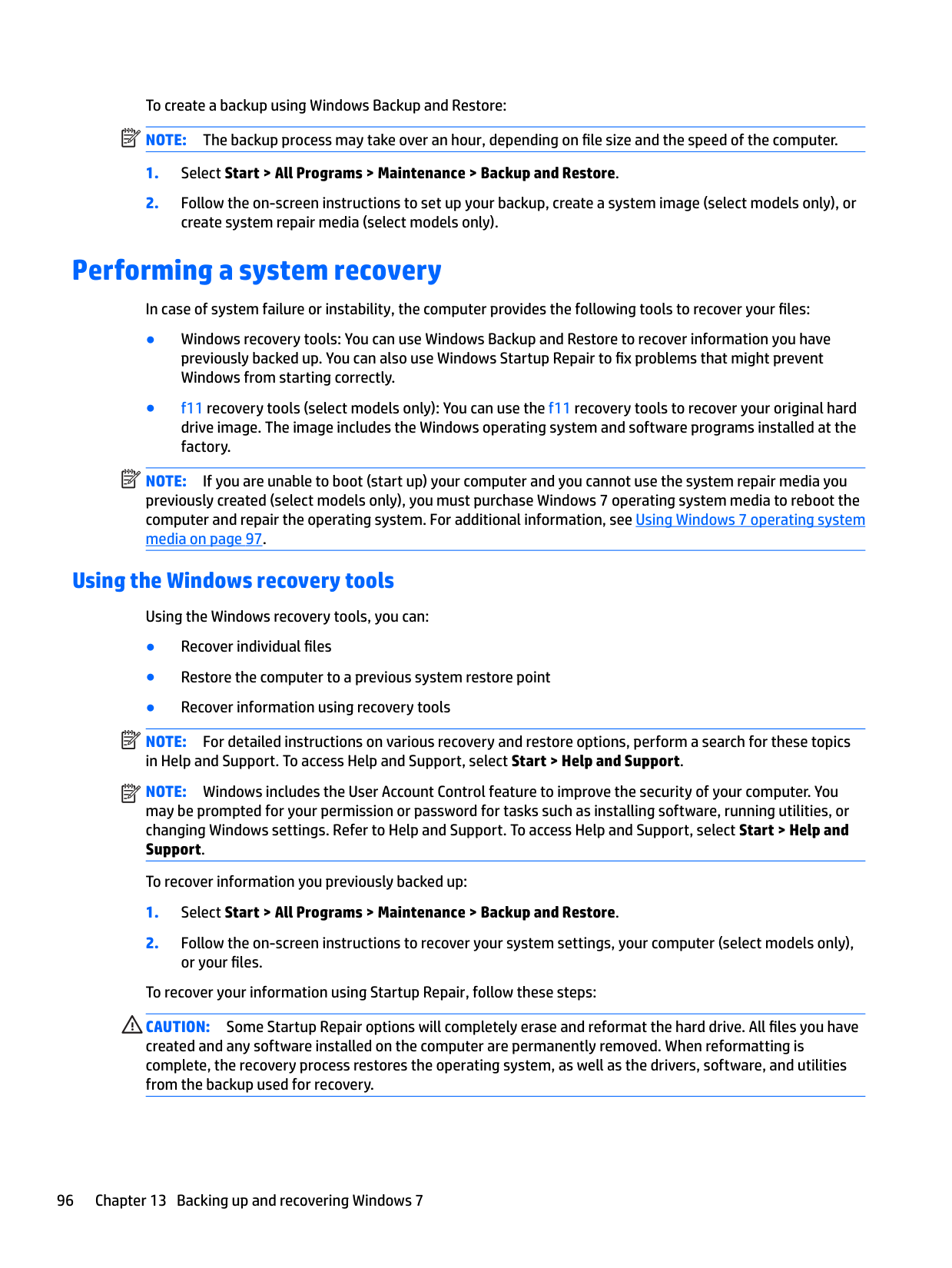
For more information, see Using HP Sure Start (select models only) on page 107.
Real Time Clock (RTC) battery backed-up CMOS configuration memory
Controller (NIC) EEPROM
256 Bytes No Yes Stores system date and time and noncritical data.
64 KBytes (not customer accessible)
No Yes Stores NIC configuration and NIC firmware.
DIMM Serial Presence Detect (SPD) configuration data
256 Bytes per memory module, 128 Bytes programmable (not customer accessible)
System BIOS 4 MBytes to 5 MBytes
No Yes Stores memory module information.
Yes Yes Stores system BIOS code and PC configuration data.
Data cannot be written to this device via the host processor. The content is managed solely by the HP Sure Start Embedded Controller.
This memory is protected by the HP Sure Start Embedded Controller.
RTC battery backed-up CMOS is programmed using the Computer Setup (BIOS), or changing the Microsoft Windows date & time.
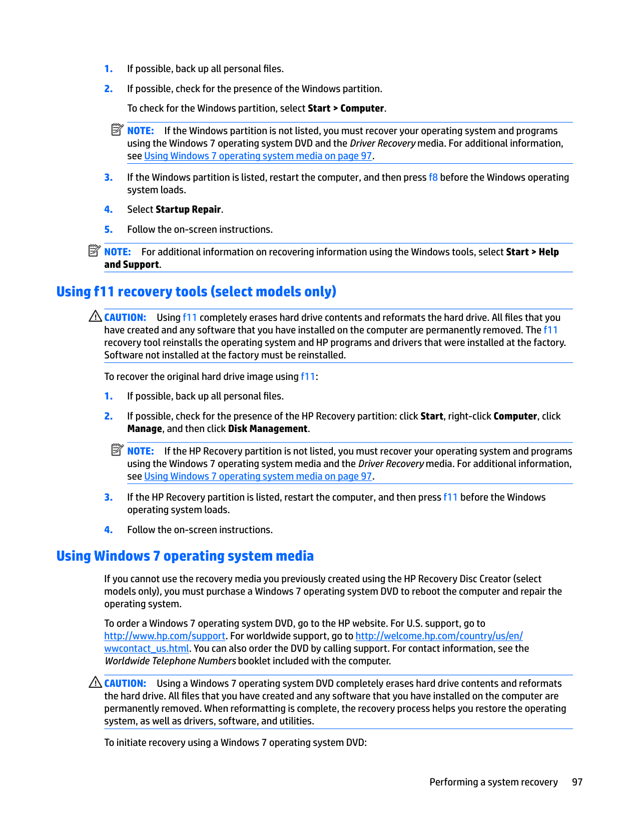
NIC EEPROM is programmed using a utility from the NIC vendor that can be run from DOS.
DIMM SPD is programmed by the memory vendor.
This memory is not writeprotected.
A utility is required to write data to this memory and is available from the NIC vendor. Writing data to this ROM in an inappropriate manner will render the NIC nonfunctional.
Data cannot be written to this memory when the module is installed in a PC. The specific writeprotection method varies by memory vendor.
System BIOS code is programmed at the factory. Code is updated when the system BIOS is updated. Configuration data and settings are input using the Computer Setup (BIOS) or a custom utility.
NOTE: Writing data to this ROM in an inappropriate manner can render the PC nonfunctional.
A utility is required for writing data to this memory and is available on the HP website; go to http://www.hp.com/ support, and select your country. Select Drivers &
Nonvolatile Memory Type
Amount (Size) Does this memory store customer data?
Does this memory retain data when power is removed?
What is the purpose of this memory?
How is data input into this memory?
How is this memory write-protected?
Intel Management Engine Firmware (present in only specific ZBook and EliteBook models. For more information, go to http://www.hp.com/ support, and select your country. Select Drivers & Downloads, and then follow the on-screen instructions.)
1.5 MBytes or 5 MBytes
Yes Yes Stores Management Engine Code, Settings, Provisioning Data and iAMT third-party data store.
Management Engine Code is programmed at the factory. Code is updated via Intel secure firmware update utility. Unique Provisioning Data can be entered at the factory or by an administrator using the Management Engine (MEBx) setup utility. The third party data store contents can be populated by a remote management console or local applications that have been registered by an administrator to have access to the space.
Bluetooth flash 2 Mbit No Yes Stores Bluetooth configuration and firmware.
Bluetooth flash is programmed at the factory. Tools for writing data to this memory are not publicly available but can be obtained from the silicon vendor.
802.11 WLAN EEPROM
4 Kbit to 8 Kbit No Yes Stores configuration and calibration data.
802.11 WLAN EEPROM is programmed at the factory. Tools for writing data to this memory are not made public.
Web camera 64 Kbit No Yes Stores webcam configuration and firmware.
Webcam memory is programmed using a utility from the device manufacturer that can be run from Windows.
Fingerprint reader 512 KByte flash Yes Yes Stores
fingerprint templates.
Fingerprint reader memory is programmed by user enrollment in HP ProtectTools Security Manager.
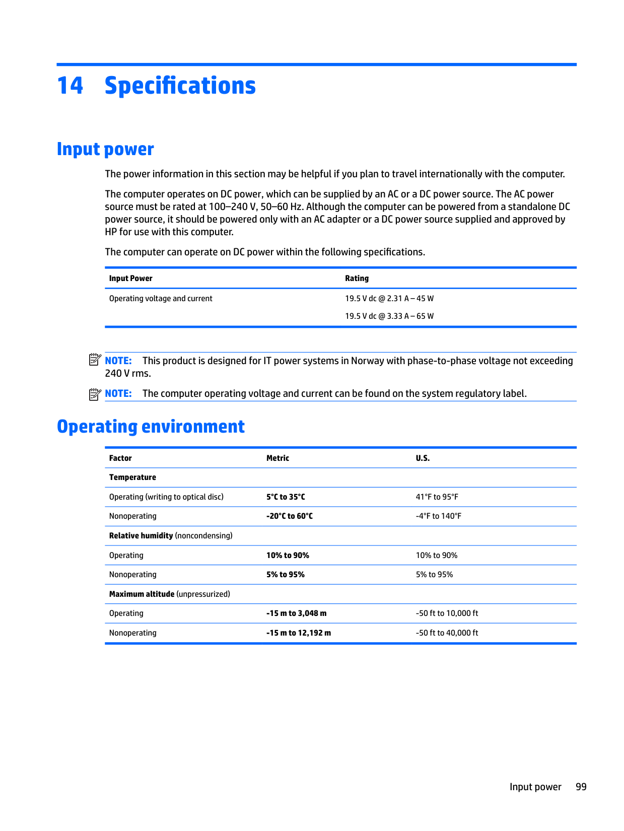
Downloads, and then follow the on-screen instructions.
The Intel chipset is configured to enforce hardware protection to block all direct read/write access to this area. An Intel utility is required for updating the firmware. Only firmware updates digitally signed by Intel can be applied using this utility.
A utility is required for writing data to this memory and is made available through newer versions of the driver whenever the flash requires an upgrade.
A utility is required for writing data to this memory and is typically not made available to the public unless a firmware upgrade is necessary to address a unique issue.
A utility is required for writing data to this memory and is typically not made available to the public unless a firmware upgrade is necessary to address a unique issue.
Only a digitally signed application can make the call to write to the flash.
Nonvolatile memory usage 105
Questions and answers
IMPORTANT: Restore defaults does not securely erase any data on your hard drive. See question and answer 6 for steps to securely erase data. Restore defaults does not reset the Custom Secure Boot keys. See question and answer 7 for information about resetting the keys.

The Unified Extensible Firmware Interface (UEFI) BIOS is an industry-standard software interface between the platform firmware and an operating system (OS). It is a replacement for the older BIOS architecture, but supports much of the legacy BIOS functionality.
Like the legacy BIOS, the UEFI BIOS provides an interface to display the system information and configuration settings and to change the configuration of your computer before an OS is loaded. BIOS provides a secure run-time environment that supports a Graphic User Interface (GUI). In this environment, you can use either a pointing device (Touchscreen, TouchPad, pointing stick, or USB mouse) or the keyboard to navigate and make menu and configuration selections. The UEFI BIOS also contains basic system diagnostics.
The UEFI BIOS provides functionality beyond that of the legacy BIOS. In addition, the UEFI BIOS works to initialize the computer’s hardware before loading and executing the OS; the run-time environment allows the loading and execution of software programs from storage devices to provide more functionality, such as advanced hardware diagnostics (with the ability to display more detailed system information) and advanced firmware management and recovery software.
HP has provided options in Computer Setup (BIOS) to allow you to run in legacy BIOS, if required by the operating system. Examples of this requirement would be if you upgrade or downgrade the OS.
The DIMM SPD memory contains information about the memory module, such as size, serial number, data width, speed/timing, voltage, and thermal information. This information is written by the module manufacturer and stored on an EEPROM. This EEPROM cannot be written to when the memory module is installed in a PC. Third-party tools do exist that can write to the EEPROM when the memory module is not installed in a PC. Various third-party tools are available to read SPD memory.
This message relates to clearing the Real Time Clock (RTC) CMOS memory that contains PC configuration data.
| | |---|
| | |---|
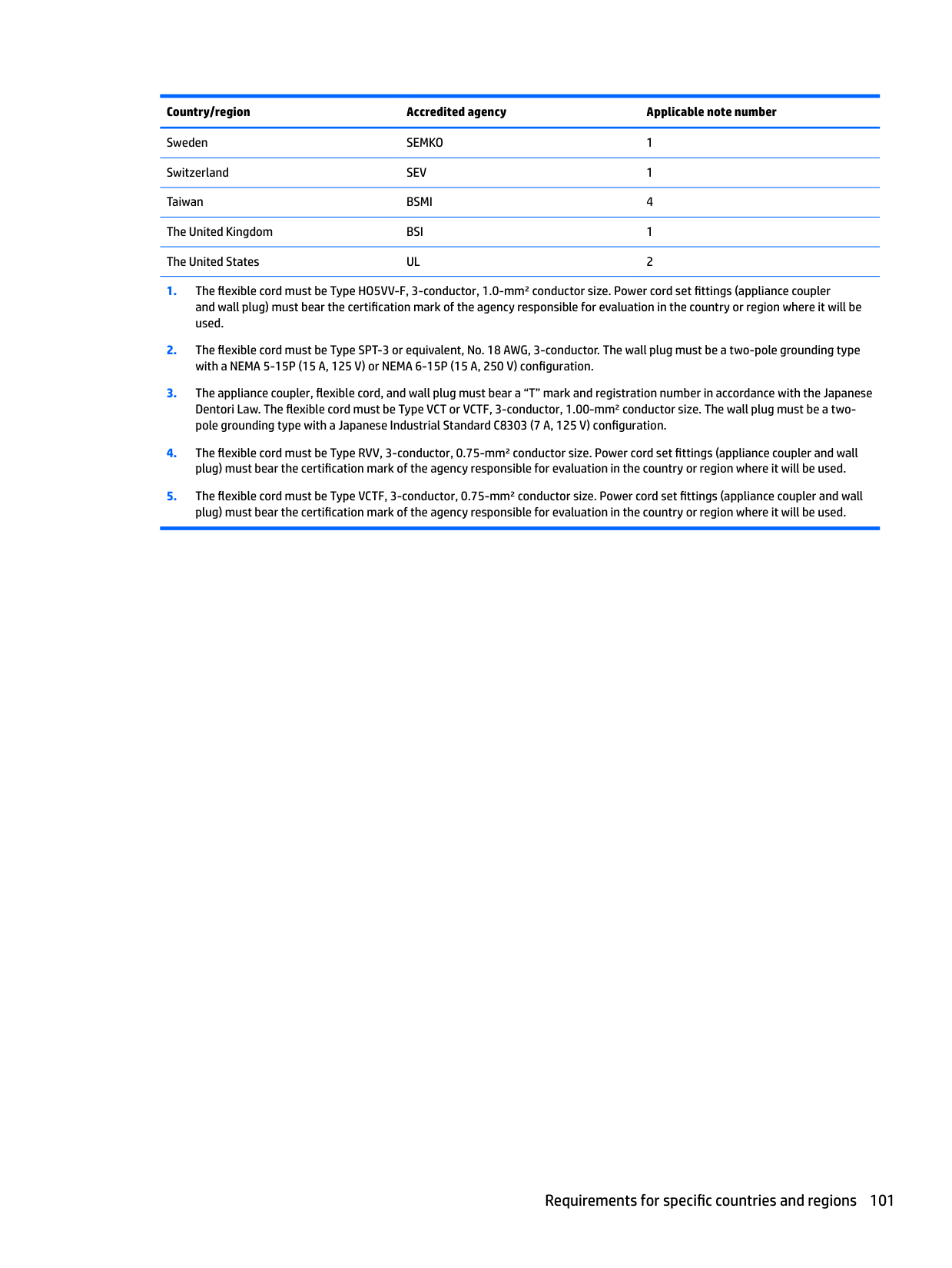
IMPORTANT: Resetting will result in the loss of information.
These steps will not reset Custom Secure Boot Keys. See question and answer 7 for information about resetting the keys.
###### 7. How can the Custom Secure Boot Keys be reset?
Secure Boot is a feature to ensure that only authenticated code can start on a platform. If you enabled Secure Boot and created Custom Secure Boot Keys, simply disabling Secure Boot will not clear the keys. You must also select to clear the Custom Secure Boot Keys. Use the same Secure Boot access procedure you used to create the Custom Secure Boot Keys, but make the selection to clear or delete all Secure Boot Keys.
Using HP Sure Start (select models only)
Select computer models are configured with HP Sure Start, a technology that continuously monitors your computer's BIOS for attacks or corruption. If the BIOS becomes corrupted or is attacked, HP Sure Start restores the BIOS to its previously safe state, without user intervention. Those select computer models ship with HP Sure Start configured and enabled. HP Sure Start is configured and already enabled so that most users can use the HP Sure Start default configuration. The default configuration can be customized by advanced users.
To access the latest documentation on HP Sure Start, go to http://www.hp.com/support, and select your country. Select Drivers & Downloads, and then follow the on-screen instructions.
Using HP Sure Start (select models only) 107
17 Recycling

When a non-rechargeable or rechargeable battery has reached the end of its useful life, do not dispose of the battery in general household waste. Follow the local laws and regulations in your area for battery disposal.
HP encourages customers to recycle used electronic hardware, HP original print cartridges, and rechargeable batteries. For more information about recycling programs, see the HP Web site at http://www.hp.com/recycle.
108 Chapter 17 Recycling
Index
spare part numbers 25 antennas
disconnecting 42, 44 audio, product description 2 audio-out (headphone)/audio-in
(microphone) combo jack, identifying 6
spare part number 22 Backup and Restore 96 backup tools 94 backups 84
creating 95 recovering 96
battery removal 35 spare part number 19, 35
battery light 16 bezel
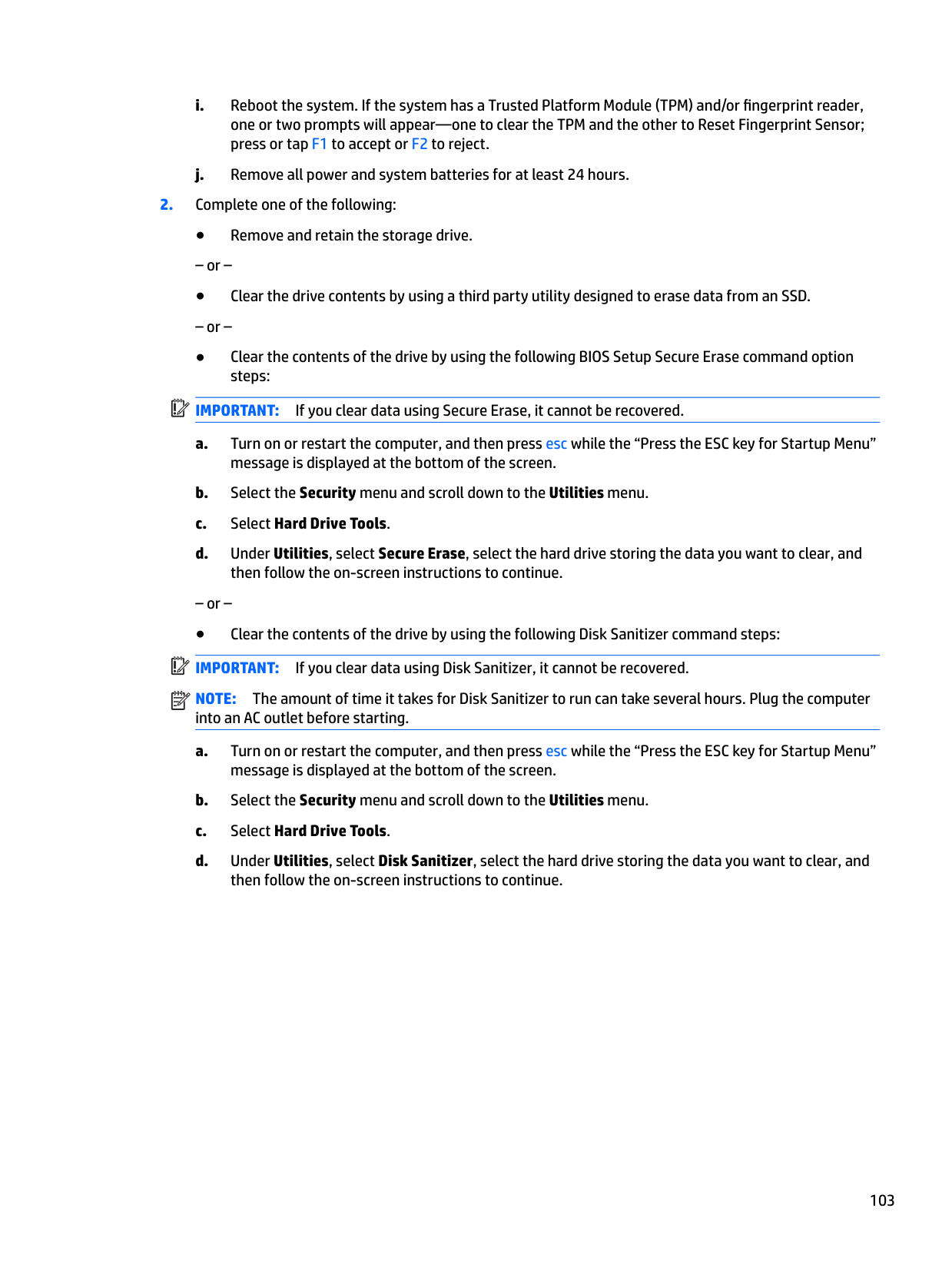
spare part number 21 BIOS
determining version 69, 74, 79 downloading an update 69, 74,
79
updating 69, 74, 79 Bluetooth card
spare part number 42 boot order
changing 88 bottom cover
spare part number 20, 32
buttons left pointing stick 10 left TouchPad 10 power 12 right pointing stick 10 right TouchPad 10
C cable lock docking station, spare part
number 25 cable lock, spare part number 25 caps lock light, identifying 11 case
spare part numbers 25 chipset, product description 1 components
bottom 15 display 9 front 15 left side 8 right side 6 top 10
computer major components 18 Computer Setup
navigating and selecting 67, 72, 77 restoring factory settings 68, 73, 78 connector, power 7
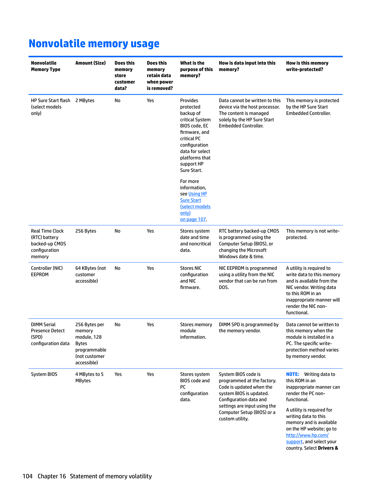
D display assembly
removal 61 spare part numbers 61 subcomponents 21
display bezel
removal 62 display cable
spare part number 22 display hinge
removal 64 display image, switching 14 display panel
product description 1 docking connector, identifying 7, 15 docking station, spare part number
25 drive light 16 Driver Recovery DVD,
creating 94 using for restore 97
Dual-Mode DisplayPort identifying 6
identifying 13 esc key, identifying 13 external monitor port 8
removal 55 spare part number 55
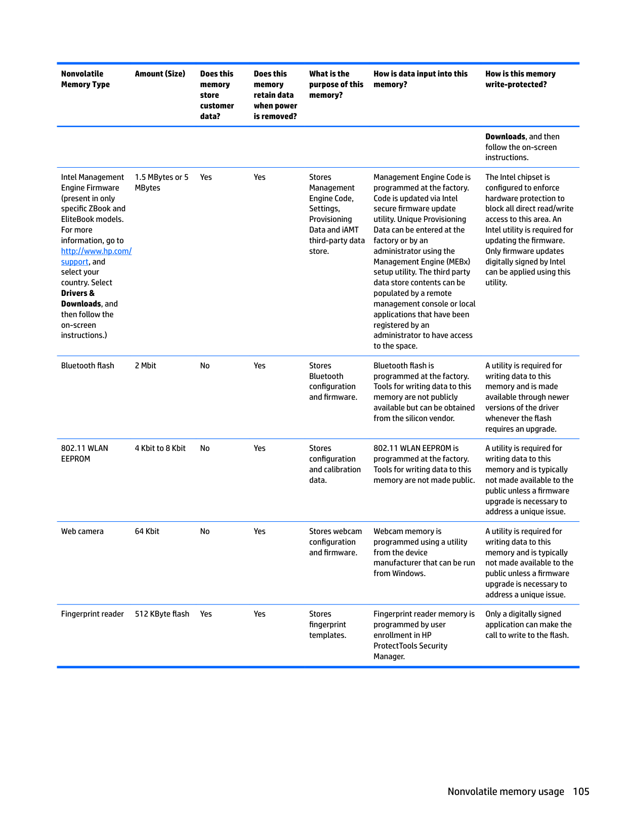
fingerprint reader board
spare part number 19 fingerprint reader, identifying 12 fn key, identifying 13
H hard drive
product description 1 removing 36 spare part numbers 19, 24, 36
hard drive hardware kit
spare part number 19, 24 hard drive recovery 91, 97 heat sink
removal 53 spare part numbers 53
heat sink/fan assembly
spare part number 19 hinge
removal 64 hinges
spare part number 22
hot keys microphone mute 14 Sleep 13 switching screen image 14 using 13
HP PC Hardware Diagnostics (UEFI) using 82 HP Recovery Disc Creator, using 94
HP Recovery Manager correcting boot problems 88 starting 87 HP Recovery media creating 84 recovery 87
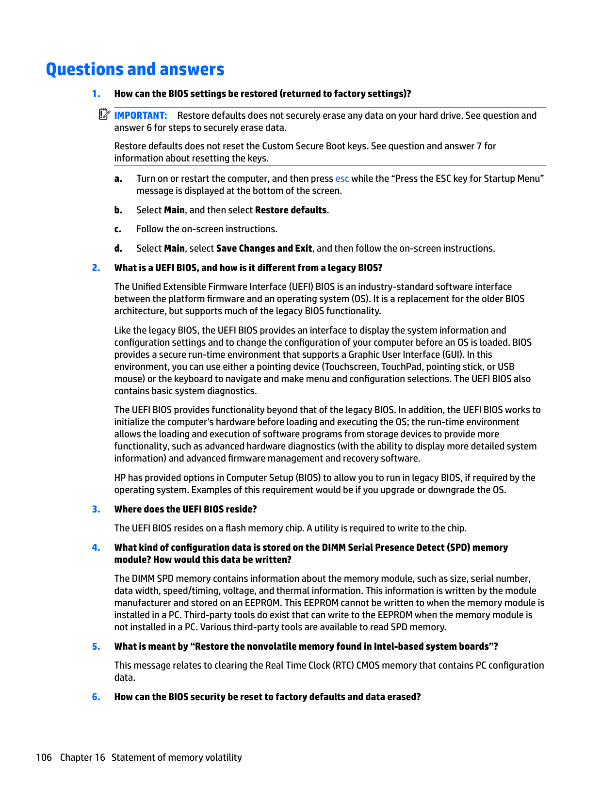
HP Recovery partition checking for presence 97 recovery 87 removing 89 using for recovery 97
HP Sure Start 107
identifying 9 internal microphones, identifying 9
audio-out (headphone)/audio-in
(microphone) combo 6 network 7 RJ-45 (network) 7
product description 3 removal 46 spare part number 18 spare part numbers 46
keypad embedded numeric 13
keys esc 13 fn 13 Windows key 13
serial number 16 legacy support, USB 67, 72, 77 lights
battery 16 caps lock 11 drive 16 microphone mute 11 num lock 11 power 11, 15 RJ-45 (network) 7
110 Index
webcam 9 wireless 11, 15
nonvolatile 102 volatile 102
memory card reader, identifying 6 memory module
product description 1 removal 40 spare part number 19 spare part numbers 40
microphone
product description 2 microphone module
spare part number 21 microphone mute key, identifying 14 microphone mute light, identifying
11 minimized image recovery 87 minimized image, creating 86 model name 1 mouse
spare part numbers 25
removal 57 spare part number 57 spare part numbers 19

nonvolatile memory 102 num lock light 11
description 4 original system recovery 86
description 3 pointing stick 10 ports
Dual-Mode DisplayPort 6 external monitor 8 product description 3
USB 3.0 charging (powered) 8 USB Type-C (charging) 6
power button, identifying 12 power connector, identifying 7 power cord
set requirements 100 power lights 11, 15 power requirements, product
description 3 processor
product description 1
product description audio 2 chipset 1 display panel 1 external media cards 3 hard drive 1 keyboard 3 memory module 1 microphone 2 operating system 4 pointing device 3 ports 3 power requirements 3 processors 1 product name 1 security 3 serviceability 5 video 2 wireless 2
product name 1 product name and number,
computer 16
R raw panel
spare part number 21 recover
options 86
recovery 93 discs 85, 87 HP Recovery Manager 86 media 87 starting 87 supported discs 85 system 86 USB flash drive 87 using HP Recovery media 85
recovery media creating 84 creating using HP Recovery
Manager 85 recovery media, creating 94 recovery media, using for restore
97 recovery partition 91, 97
removing 89 recovery tools 94 recovery tools, Windows 96 recovery, system 96 refresh 93 regulatory information 16 removal/replacement
procedures 32, 49 removing personal data from volatile
system memory 102 reset 93 restoring the hard drive 91, 97 RJ-45 (network) jack, identifying 7 RJ-45 (network) lights, identifying
7
RTC battery removal 52 spare part number 20, 52 rubber kit, spare part number 26
S screen image, switching 14 screw kit, spare part number 26 security cable slot, identifying 8 security, product description 3 serial number 16 serial number, computer 16 serviceability, product description 5 setup utility
navigating and selecting 67, 72, 77 restoring factory settings 68,
73, 78 SIM
spare part numbers 25 SIM card slot, identifying 7 slots
security cable 8 SIM card 7 smart card 8
smart card reader spare part number 19
smart card reader board removal 58 spare part number 58
smart card slot 8 solid-state drive
removal 38 spare part numbers 19, 24, 38
speaker assembly removal 59 spare part number 20, 59
speakers, identifying 12 Startup Repair, using 96 supported discs, recovery 85 Sure Start
using 71, 76, 81
system board removal 49 spare part number 20 spare part numbers 49
system information locating 16
system memory, removing personal
data from volatile 102 system recovery 86 system restore point creating 85

system restore point, creating 84
removal 65 spare part number 65
TouchPad buttons 10
touchpad button board removal 56 spare part number 19, 56
TouchPad zone identifying 10 TPM settings 70, 75, 80
identifying 8 USB 3.0 port 6 USB legacy support 67, 72, 77 USB ports, identifying 6 USB Type-C (charging) port,
identifying 6
removal 63 spare part number 21
webcam, identifying 9 Windows
Refresh 93 Reset 93 system restore point 84, 85
Windows 7 operating system DVD creating 94 using for restore 97
Windows 7 operating system media creating 94 using for restore 97
Windows key, identifying 13 Windows operating system DVD 92 Windows Startup Repair, using 96 Windows tools
using 85 wireless antennas
disconnecting 42, 44 wireless antennas, identifying 9 wireless light 11, 15 wireless, product description 2 WLAN antenna
spare part number 22 WLAN antennas, identifying 9 WLAN/Bluetooth combo card
removal 42 spare part number 19, 42
WWAN antenna
spare part number 22 WWAN antennas, identifying 9 WWAN module
removal 44 spare part number 44 spare part numbers 19
spare part numbers 18