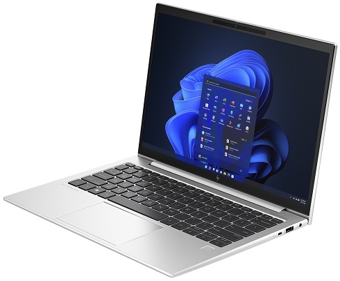
HP Elitebook 840 14 Inch G11 Notebook PC
Ask AI
— answers from the official manualAnswers from the official manual.
Common questions
Common Questions
28 totalHow do I safely clean my HP EliteBook 840 G11 without damaging it?
Turn off the device and unplug the power cord before cleaning, then wipe exterior surfaces gently with a moist (not dripping wet) microfiber cloth. Avoid abrasive cloths, aerosol sprays, solvents, and cleaners containing hydrogen peroxide or bleach. Make sure all surfaces have completely air-dried before turning the device back on. (Page 32)
What disinfectant solution is safe to use on the EliteBook 840 G11?
HP recommends using an alcohol solution consisting of 70% isopropyl alcohol and 30% water, also known as rubbing alcohol, to disinfect high-touch external surfaces. Avoid chemicals such as bleach, hydrogen peroxide, acetone, ammonia, ethyl alcohol, methylene chloride, or petroleum-based materials like gasoline or paint thinner. Always moisten a microfiber cloth with the solution rather than spraying directly on the product. (Page 33)
What should I do if the computer stops responding and won't shut down normally?
If the computer has stopped responding and normal shutdown procedures are ineffective, press and hold the power button for at least 4 seconds to turn off the computer. Be aware that pressing and holding the power button results in the loss of unsaved information. (Page 20)
How can I tell what the battery light indicator means on my EliteBook 840 G11?
When AC power is connected, a white battery light means the charge is greater than 90%, amber means the charge is between 0 and 90%, and off means the battery is not charging. When AC power is disconnected, a blinking amber light means the battery has reached a low level, and rapid blinking amber indicates a critical battery level. (Page 15)
What memory configurations are supported by the EliteBook 840 G11?
The EliteBook 840 G11 supports two upgradeable memory module slots with up to 64 GB of DDR5-5600 MHz RAM. Supported configurations include 8 GB (1×8 GB), 16 GB (1×16 GB or 2×8 GB), 32 GB (1×32 GB or 2×16 GB), and 64 GB (2×32 GB). (Page 9–10)
Which parts on the EliteBook 840 G11 can I replace myself without voiding the warranty?
End-user replaceable parts include the AC adapter, access panel (bottom cover), memory modules, solid-state drive, WLAN module, WWAN module, fan, and speakers. Accessing parts designated for authorized service providers only can damage the computer or void your warranty. (Page 12)
Show 22 more questions
What are the wireless connectivity options available?
Where can I locate the service tag on my computer?
How do I maintain my EliteBook's display screen?
What steps do I take if my computer overheats?
Where do I find touchpad settings?
What tools do I need to disassemble the EliteBook 840 G11?
How do I prevent overheating when using the EliteBook 840 G11?
How do I turn on or adjust the touchpad settings on the EliteBook 840 G11?
What wireless connectivity options are available on the EliteBook 840 G11?
How do I reset my HP EliteBook 840 G11 if it is unresponsive?
Can I clean my notebook's keyboard and touchpad while it is powered on?
What is recommended for cleaning my touchscreen?
What safety precautions should I take when operating the notebook?
How do I enable privacy settings on my screen?
What steps should I follow to adjust touchpad settings on my HP EliteBook?
How do I verify if my device supports fingerprint sign-in?
Why should I avoid placing my laptop directly on my lap?
What security cables are compatible with my HP EliteBook?
Which parts can an end-user replace on their HP EliteBook?
What is the process for replacing a faulty WLAN or WWAN module?
What precautions should I take when handling hard drives during servicing?
How can I prevent damage by electrostatic discharge when handling components?
Full Manual
107 pages

Maintenance and Service Guide HP EliteBook 840 14 inch G11 Notebook PC
###### SUMMARY
This guide provides maintenance information about such topics as spare parts, removal and replacement of parts, security, and backing up.
#### Legal information
© Copyright 2024 HP Development Company, L.P.
AMD is a trademark of Advanced Micro Devices, Inc. Bluetooth is a trademark owned by its proprietor and used by HP Inc. under license. Intel, Core, Thunderbolt, and vPro are trademarks of Intel Corporation or its subsidiaries in the U.S. and/or other countries. Microsoft and Windows are either registered trademarks or trademarks of Microsoft Corporation in the United States and/or other countries. USB Type-C and USB-C are registered trademarks of USB Implementers Forum. DisplayPort™ and the DisplayPort™ logo are trademarks owned by the Video Electronics Standards Association (VESA®) in the United States and other countries. Wi-Fi is a registered trademark of the Wi-Fi Alliance®.
The information contained herein is subject to change without notice. The only warranties for HP products and services are set forth in the express warranty statements accompanying such products and services. Nothing herein should be construed as constituting an additional warranty. HP shall not be liable for technical or editorial errors or omissions contained herein.
First Edition: March 2024 Document Part Number: N90667-001
######### Product notice
This guide describes features that are common to most models. Some features may not be available on your computer.
Not all features are available in all editions or versions of Windows. Systems may require upgraded and/or separately purchased hardware, drivers, software or BIOS update to take full advantage of Windows functionality. Windows is automatically updated, which is always enabled. High-speed internet and Microsoft account required. ISP fees may apply and additional requirements may apply over time for updates. See http://www.windows.com. If your product ships with Windows in S Mode: Windows in S Mode works exclusively with apps from the Microsoft Store within Windows. Certain default settings, features, and apps cannot be changed. Some accessories and apps that are compatible with Windows may not work (including some antivirus, PDF writers, driver utilities, and accessibility apps), and performance may vary, even if you switch out of S Mode. If you switch to Windows, you cannot switch back to S Mode. Learn more at Windows.com/ SmodeFAQ.
To access the latest user guides, go to http://www.hp.com/support, and follow the instructions to find your product. Then select Manuals.
######### Software terms
By installing, copying, downloading, or otherwise using any software product preinstalled on this computer, you agree to be bound by the terms of the HP End User License Agreement (EULA). If you do not accept these license terms, your sole remedy is to return the entire unused product (hardware and software) within 14 days for a full refund subject to the refund policy of your seller.
For any further information or to request a full refund of the price of the computer, please contact your seller.
#### Safety warning notice
Reduce the possibility of heat-related injuries or of overheating the computer by following the practices described.

WARNING! To reduce the possibility of heat-related injuries or of overheating the computer, do not place the computer directly on your lap or obstruct the computer air vents. Use the computer only on a hard, flat surface. Do not allow another hard surface, such as an adjoining optional printer, or a soft surface, such as pillows or rugs or clothing, to block airflow. Also, do not allow the AC adapter to come into contact with the skin or a soft surface, such as pillows or rugs or clothing, during operation. The computer and the AC adapter provided by HP comply with the user-accessible surface temperature limits defined by applicable safety standards.
iii
#### Important notice about Customer Self-Repair parts
Your computer includes Customer Self-Repair parts and parts that should be accessed only by an authorized service provider.

IMPORTANT: See "Removal and replacement procedures for Customer Self-Repair parts" for details.
Accessing parts described in "Removal and replacement procedures for authorized service provider parts" can damage the computer or void your warranty.
iv Important notice about Customer Self-Repair parts
Table of contents
Display...................................................................................................................................................................................................................................................7 Low blue light mode (select products only)......................................................................................................................................................7
Keyboard area.................................................................................................................................................................................................................................8 Touchpad.................................................................................................................................................................................................................................8
Touchpad settings.................................................................................................................................................................................................8 Adjusting touchpad settings...............................................................................................................................................................9 Turning on the touchpad........................................................................................................................................................................9
Touchpad components......................................................................................................................................................................................9 Lights........................................................................................................................................................................................................................................10 Button and fingerprint reader.................................................................................................................................................................................11 Special keys.........................................................................................................................................................................................................................12
Bottom................................................................................................................................................................................................................................................13 Rear ......................................................................................................................................................................................................................................................14 Labels..................................................................................................................................................................................................................................................14
Service considerations.........................................................................................................................................................................................................28 Plastic parts........................................................................................................................................................................................................................28 Cables and connectors..............................................................................................................................................................................................28 Drive handling...................................................................................................................................................................................................................28
Electrostatic discharge information............................................................................................................................................................................29 Generating static electricity...................................................................................................................................................................................29 Preventing electrostatic damage to equipment......................................................................................................................................30 Personal grounding methods and equipment...........................................................................................................................................30 Grounding the work area............................................................................................................................................................................................31 Recommended materials and equipment.....................................................................................................................................................31
Cleaning your computer.......................................................................................................................................................................................................32 Enabling HP Easy Clean (select products only)........................................................................................................................................32 Removing dirt and debris from your computer.........................................................................................................................................32
v
Cleaning your computer with a disinfectant...............................................................................................................................................33 Caring for wood veneer (select products only)........................................................................................................................................34
Packaging and transporting guidelines.....................................................................................................................................................................34 Accessing support information......................................................................................................................................................................................35
###### 5 Removal and replacement procedures for Customer Self-Repair parts................................................................................................37
Component replacement procedures........................................................................................................................................................................37 Preparation for disassembly...................................................................................................................................................................................37 Bottom cover......................................................................................................................................................................................................................37 WLAN module....................................................................................................................................................................................................................38 WWAN module..................................................................................................................................................................................................................40 Solid-state drive................................................................................................................................................................................................................41 Memory modules............................................................................................................................................................................................................43 Speakers...............................................................................................................................................................................................................................45 Fan.............................................................................................................................................................................................................................................46
###### 6 Removal and replacement procedures for authorized service provider parts.................................................................................48
Component replacement procedures.......................................................................................................................................................................48 Battery....................................................................................................................................................................................................................................48 Fingerprint reader board...........................................................................................................................................................................................49 RTC battery.........................................................................................................................................................................................................................50 NFC module.........................................................................................................................................................................................................................51 Touchpad..............................................................................................................................................................................................................................52 Smart card reader.........................................................................................................................................................................................................53 Audio jack.............................................................................................................................................................................................................................54 USB board............................................................................................................................................................................................................................55 Heat sink...............................................................................................................................................................................................................................56 System board....................................................................................................................................................................................................................58 Display assembly.............................................................................................................................................................................................................61 Top cover with keyboard.............................................................................................................................................................................................70
###### 7 Backing up, restoring, and recovering................................................................................................................................................................................72
Backing up information and creating recovery media....................................................................................................................................72 Using Windows tools for backing up..................................................................................................................................................................72 Using the HP Cloud Recovery Download Tool to create recovery media (select products only)..........................72
Restoring and recovering your system.......................................................................................................................................................................72 Creating a system restore .......................................................................................................................................................................................73 Restoring and recovery methods........................................................................................................................................................................73 Recovering using HP Recovery media.............................................................................................................................................................73 Changing the computer boot order...................................................................................................................................................................74 Using HP Sure Recover (select products only)...........................................................................................................................................74
###### 8 Computer Setup (BIOS), TPM, and HP Sure Start.....................................................................................................................................................75
Using Computer Setup...........................................................................................................................................................................................................75 Navigating and selecting in Computer Setup ...........................................................................................................................................75 Restoring factory settings in Computer Setup..........................................................................................................................................75 Updating the BIOS..........................................................................................................................................................................................................76
Determining the BIOS version....................................................................................................................................................................76
vi
Preparing for a BIOS update........................................................................................................................................................................76 Downloading a BIOS update.............................................................................................................................................................77 Installing a BIOS update.......................................................................................................................................................................77
Changing the boot order using the f9 prompt ...........................................................................................................................................77 TPM BIOS settings (select products only) ...............................................................................................................................................................78 Using HP Sure Start (select products only)..............................................................................................................................................................78
Using HP PC Hardware Diagnostics Windows (select products only)................................................................................................ 79 Using an HP PC Hardware Diagnostics Windows hardware failure ID code....................................................................... 79 Accessing HP PC Hardware Diagnostics Windows.............................................................................................................................. 79
Accessing HP PC Hardware Diagnostics Windows from HP Support Assistant................................................. 79 Accessing HP PC Hardware Diagnostics Windows from the Start menu (select products only)............80
Downloading HP PC Hardware Diagnostics Windows........................................................................................................................80 Downloading the latest HP PC Hardware Diagnostics Windows version from HP.............................................80 Downloading the HP PC Hardware Diagnostics Windows from the Microsoft Store.......................................80 Downloading HP Hardware Diagnostics Windows by product name or number (select products only) ...............................................................................................................................................................................................................................80
Installing HP PC Hardware Diagnostics Windows...................................................................................................................................81
Using HP PC Hardware Diagnostics UEFI.................................................................................................................................................................81 Using an HP PC Hardware Diagnostics UEFI hardware failure ID code...................................................................................81 Starting HP PC Hardware Diagnostics UEFI................................................................................................................................................81 Starting HP PC Hardware Diagnostics UEFI through HP Hotkey Support software (select products only)...........................................................................................................................................................................................................................................82 Downloading HP PC Hardware Diagnostics UEFI to a USB flash drive...................................................................................82
Downloading the latest HP PC Hardware Diagnostics UEFI version.............................................................................83 Downloading HP PC Hardware Diagnostics UEFI by product name or number (select products only) ...............................................................................................................................................................................................................................83
Using Remote HP PC Hardware Diagnostics UEFI settings (select products only)...................................................................83
Downloading Remote HP PC Hardware Diagnostics UEFI...............................................................................................................83 Downloading the latest Remote HP PC Hardware Diagnostics UEFI version.........................................................83 Downloading Remote HP PC Hardware Diagnostics UEFI by product name or number................................83
Customizing Remote HP PC Hardware Diagnostics UEFI settings............................................................................................84
vii
Requirements for specific countries and regions.............................................................................................................................................93
###### 13 Recycling..............................................................................................................................................................................................................................................96Index.................................................................................................................................................................................................................................................................97
viii
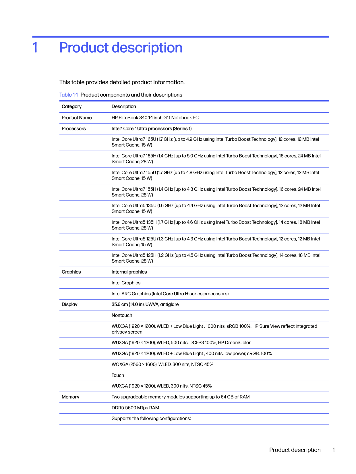
Product description1
This table provides detailed product information. Table 1-1 Product components and their descriptions
Category Description Product Name HP EliteBook 840 14 inch G11 Notebook PC Processors Intel® Core™ Ultra processors (Series 1)
Intel Core Ultra7 165U (1.7 GHz [up to 4.9 GHz using Intel Turbo Boost Technology], 12 cores, 12 MB Intel Smart Cache, 15 W)
Intel Core Ultra7 165H (1.4 GHz [up to 5.0 GHz using Intel Turbo Boost Technology], 16 cores, 24 MB Intel Smart Cache, 28 W)
Intel Core Ultra7 155U (1.7 GHz [up to 4.8 GHz using Intel Turbo Boost Technology], 12 cores, 12 MB Intel Smart Cache, 15 W)
Intel Core Ultra7 155H (1.4 GHz [up to 4.8 GHz using Intel Turbo Boost Technology], 16 cores, 24 MB Intel Smart Cache, 28 W)
Intel Core Ultra5 135U (1.6 GHz [up to 4.4 GHz using Intel Turbo Boost Technology], 12 cores, 12 MB Intel Smart Cache, 15 W)
Intel Core Ultra5 135H (1.7 GHz [up to 4.6 GHz using Intel Turbo Boost Technology], 14 cores, 18 MB Intel Smart Cache, 28 W)
Intel Core Ultra5 125U (1.3 GHz [up to 4.3 GHz using Intel Turbo Boost Technology], 12 cores, 12 MB Intel Smart Cache, 15 W)
Intel Core Ultra5 125H (1.2 GHz [up to 4.5 GHz using Intel Turbo Boost Technology], 14 cores, 18 MB Intel Smart Cache, 28 W)
Graphics Internal graphics Intel Graphics Intel ARC Graphics (Intel Core Ultra H-series processors)
######### Display 35.6 cm (14.0 in), UWVA, antiglare Nontouch
WUXGA (1920 × 1200), WLED + Low Blue Light , 1000 nits, sRGB 100%, HP Sure View reflect integrated privacy screen
WUXGA (1920 × 1200), WLED, 500 nits, DCI-P3 100%, HP DreamColor WUXGA (1920 × 1200), WLED + Low Blue Light , 400 nits, low power, sRGB, 100% WQXGA (2560 × 1600), WLED, 300 nits, NTSC 45% Touch WUXGA (1920 × 1200), WLED, 300 nits, NTSC 45%
Memory Two upgradeable memory modules supporting up to 64 GB of RAM DDR5-5600 MTps RAM Supports the following configurations:
Primary storage Solid-state drives, PCIe, NVMe, M.2 2280 2 TB, PCIe Gen4 × 4, triple-layer cell (TLC) 1 TB, PCIe Gen4 × 4, TLC 1 TB, PCIe Gen4 × 4 512 GB, PCIe Gen4 × 4, TLC 512 GB, PCIe Gen4 × 4, TLC, self-encrypted OPAL2 512 GB, PCIe 256 GB, PCIe Gen4 × 4, TLC, self-encrypted OPAL2 256 GB, PCIe Embedded MultiMedia Controller (eMMC) v5.0 32 GB
Audio and video Camera, wide field-of-view, dual-array digital microphone (select products only) 5 MP camera 5 MP + IR Camera privacy cover Dual speakers Microphone (dual array) Discrete amplifiers
Wireless Integrated WLAN options with dual antennas (M.2 2230 socket MIPI/BRI) Intel BE200 Wi-Fi® 7 Bluetooth® 5.4 WLAN (vPro®) Intel BE200 Wi-Fi 7 Bluetooth 5.4 WLAN (non-vPro) Intel AX211 Wi-Fi 6E Bluetooth 5.3 WLAN (vPro®) Intel AX211 Wi-Fi 6E Bluetooth 5.3 WLAN (non-vPro) Low-Power Wide-Area Network (LPWAN)
Qualcomm 9205 LTE-M (CAT-M1) (requires HP Protect and Trace with Wolf Connect for Mobile narrow [MNB] modules)
Near-field communication (NFC) (select products only) NFC NXP NPC300
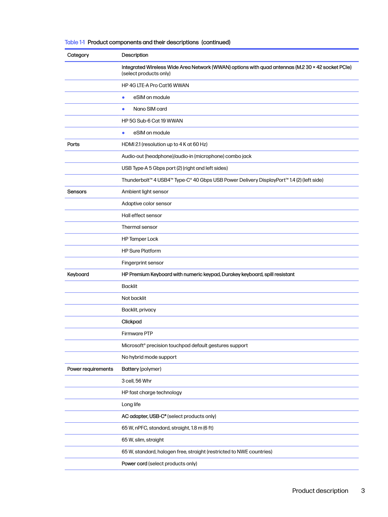
######### Integrated Wireless Wide Area Network (WWAN) options with quad antennas (M.2 30 × 42 socket PCIe) (select products only)
● eSIM on module
Ports HDMI 2.1 (resolution up to 4 K at 60 Hz) Audio-out (headphone)/audio-in (microphone) combo jack USB Type-A 5 Gbps port (2) (right and left sides) Thunderbolt™ 4 USB4™ Type-C® 40 Gbps USB Power Delivery DisplayPort™ 1.4 (2) (left side)
Sensors Ambient light sensor Adaptive color sensor Hall effect sensor Thermal sensor HP Tamper Lock HP Sure Platform Fingerprint sensor

Keyboard HP Premium Keyboard with numeric keypad, Durakey keyboard, spill resistant Backlit Not backlit Backlit, privacy Clickpad Firmware PTP Microsoft® precision touchpad default gestures support No hybrid mode support
Power requirements Battery (polymer) 3 cell, 56 Whr HP fast charge technology Long life AC adapter, USB-C® (select products only) 65 W, nPFC, standard, straight, 1.8 m (6 ft) 65 W, slim, straight 65 W, standard, halogen free, straight (restricted to NWE countries) Power cord (select products only)
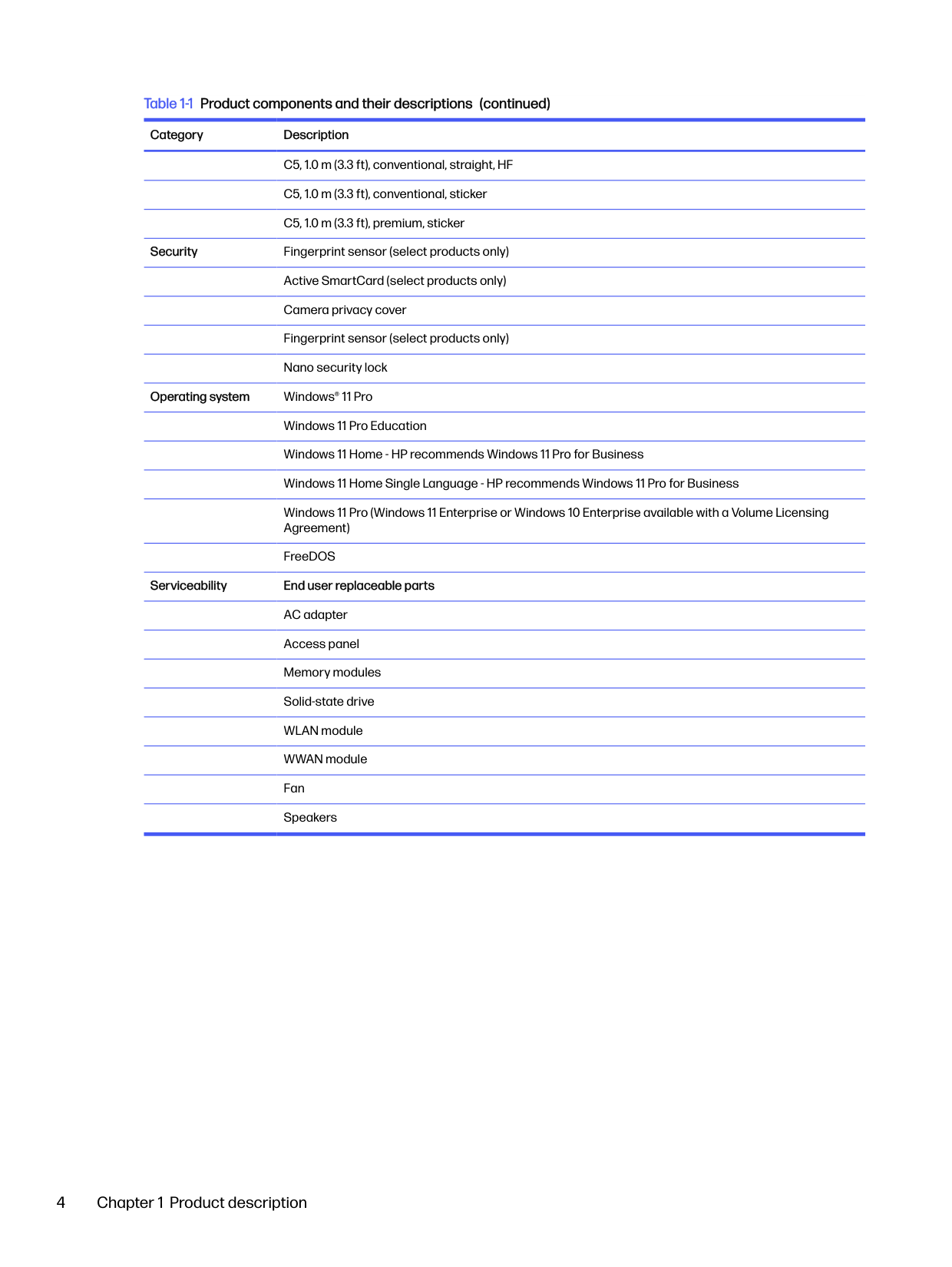
C5, 1.0 m (3.3 ft), conventional, straight, HF C5, 1.0 m (3.3 ft), conventional, sticker C5, 1.0 m (3.3 ft), premium, sticker
Security Fingerprint sensor (select products only) Active SmartCard (select products only) Camera privacy cover Fingerprint sensor (select products only) Nano security lock
Operating system Windows® 11 Pro Windows 11 Pro Education Windows 11 Home - HP recommends Windows 11 Pro for Business Windows 11 Home Single Language - HP recommends Windows 11 Pro for Business Windows 11 Pro (Windows 11 Enterprise or Windows 10 Enterprise available with a Volume Licensing Agreement) FreeDOS
Serviceability End user replaceable parts AC adapter Access panel Memory modules Solid-state drive WLAN module WWAN module Fan Speakers
Components2
Your computer features top-rated components. This chapter provides details about your components, where they are located, and how they work.
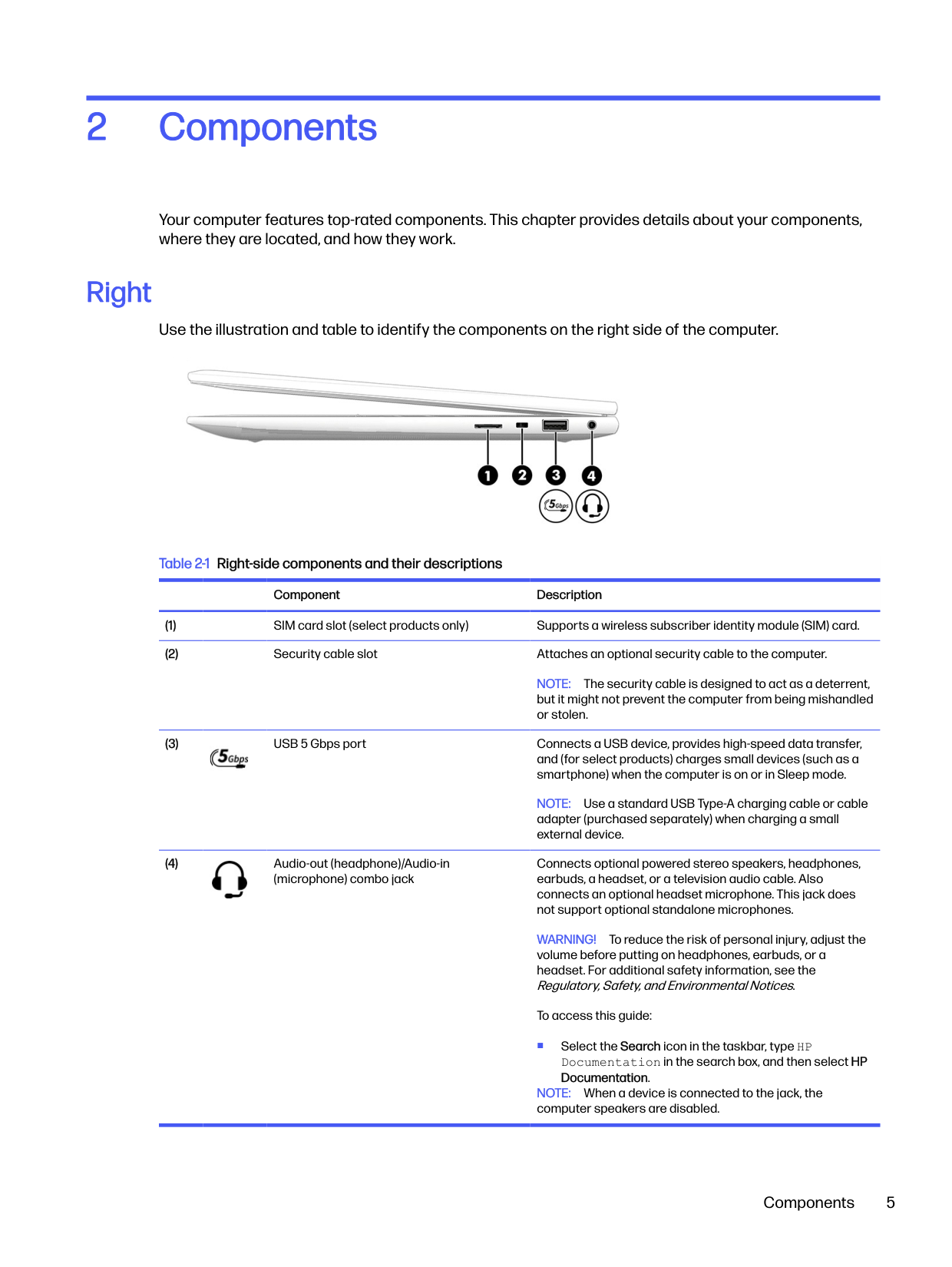
Right
Use the illustration and table to identify the components on the right side of the computer.

Table 2-1 Right-side components and their descriptions
Component Description
NOTE: The security cable is designed to act as a deterrent, but it might not prevent the computer from being mishandled or stolen.

NOTE: Use a standard USB Type-A charging cable or cable adapter (purchased separately) when charging a small external device.
Connects optional powered stereo speakers, headphones, earbuds, a headset, or a television audio cable. Also connects an optional headset microphone. This jack does not support optional standalone microphones.

WARNING! To reduce the risk of personal injury, adjust the volume before putting on headphones, earbuds, or a headset. For additional safety information, see the Regulatory, Safety, and Environmental Notices.
To access this guide:
■ Select the Search icon in the taskbar, type HP Documentation in the search box, and then select HP Documentation.
NOTE: When a device is connected to the jack, the computer speakers are disabled.
Components 5
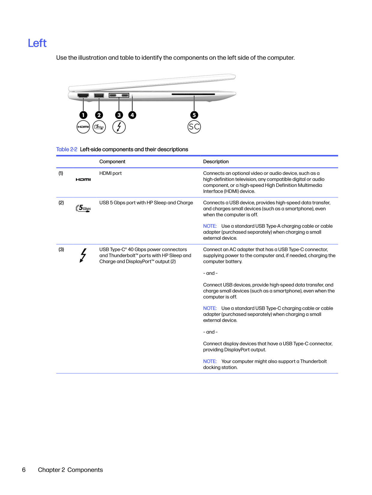
Left
Use the illustration and table to identify the components on the left side of the computer.

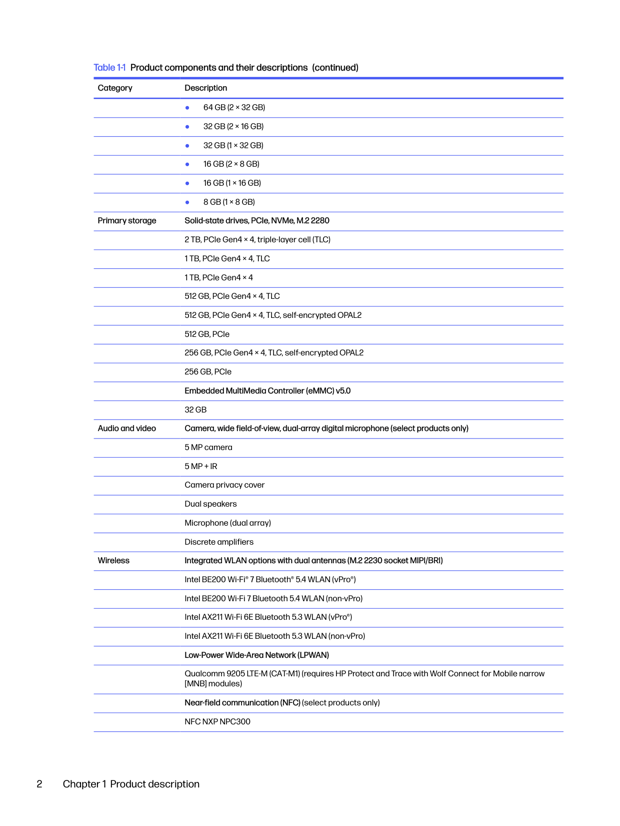
Table 2-2 Left-side components and their descriptions
Component Description


NOTE: Use a standard USB Type-A charging cable or cable adapter (purchased separately) when charging a small external device.
Connect an AC adapter that has a USB Type-C connector, supplying power to the computer and, if needed, charging the computer battery.

Connect USB devices, provide high-speed data transfer, and charge small devices (such as a smartphone), even when the computer is off.
NOTE: Use a standard USB Type-C charging cable or cable adapter (purchased separately) when charging a small external device.
Connect display devices that have a USB Type-C connector, providing DisplayPort output.
NOTE: Your computer might also support a Thunderbolt docking station.
######## Table 2-2 Left-side components and their descriptions (continued)
######### Component Description

Display
Use the illustration and table to identify the display components.
#### Low blue light mode (select products only)
Your computer display is shipped from the factory in low blue light mode for improved eye comfort and safety. Also, blue light mode automatically adjusts blue light emissions when you are using the computer at night or for reading.

WARNING! To reduce the risk of serious injury, read theSafety & Comfort Guide. It describes proper workstation setup and proper posture, health, and work habits for computer users. TheSafety & Comfort Guidealso provides important electrical and mechanical safety information. TheSafety & Comfort Guideis available on the web at http://www.hp.com/ergo.

NOTE: Refer to the illustration that most closely matches your computer.

Display 7
######## Table 2-3 Display components and their descriptions
######### Component Description
Adjusts the brightness of the display, depending on the ambient light, and manages and controls the color temperature. Color temperature enables you to measure and adjust the warmth or coolness of the light source.
NOTE: Camera functions vary depending on the camera hardware and software installed on your product.
NOTE: If you have both front-facing and rear-facing cameras, when one camera lens is revealed and ready to use, the other is concealed.
*The antennas are not visible from the outside of the computer. For optimal transmission, keep the areas immediately around the antennas free from obstructions.
For wireless regulatory notices, see the section of theRegulatory, Safety, and Environmental Notices that applies to your country or region.
To access this guide:
■ Select the Search icon in the taskbar, type HP Documentation in the search box, and then select HP Documentation.
Keyboard area Keyboards can vary by language. NOTE: The keyboard, including the function keys and power key (select products only), is disabled in stand, tent, and tablet modes. To enable the keyboard, including the power key, change to the clamshell mode.

#### Touchpad
The touchpad settings and components are described here. Touchpad settings
You learn how to adjust the touchpad settings and components here.
###### Adjusting touchpad settings
Use these steps to adjust touchpad settings and gestures.
###### Turning on the touchpad
Follow these steps to turn on the touchpad.
If you are not using an external mouse, press the Tab key repeatedly until the pointer rests on the touchpad button. Then press the spacebar to select the button.
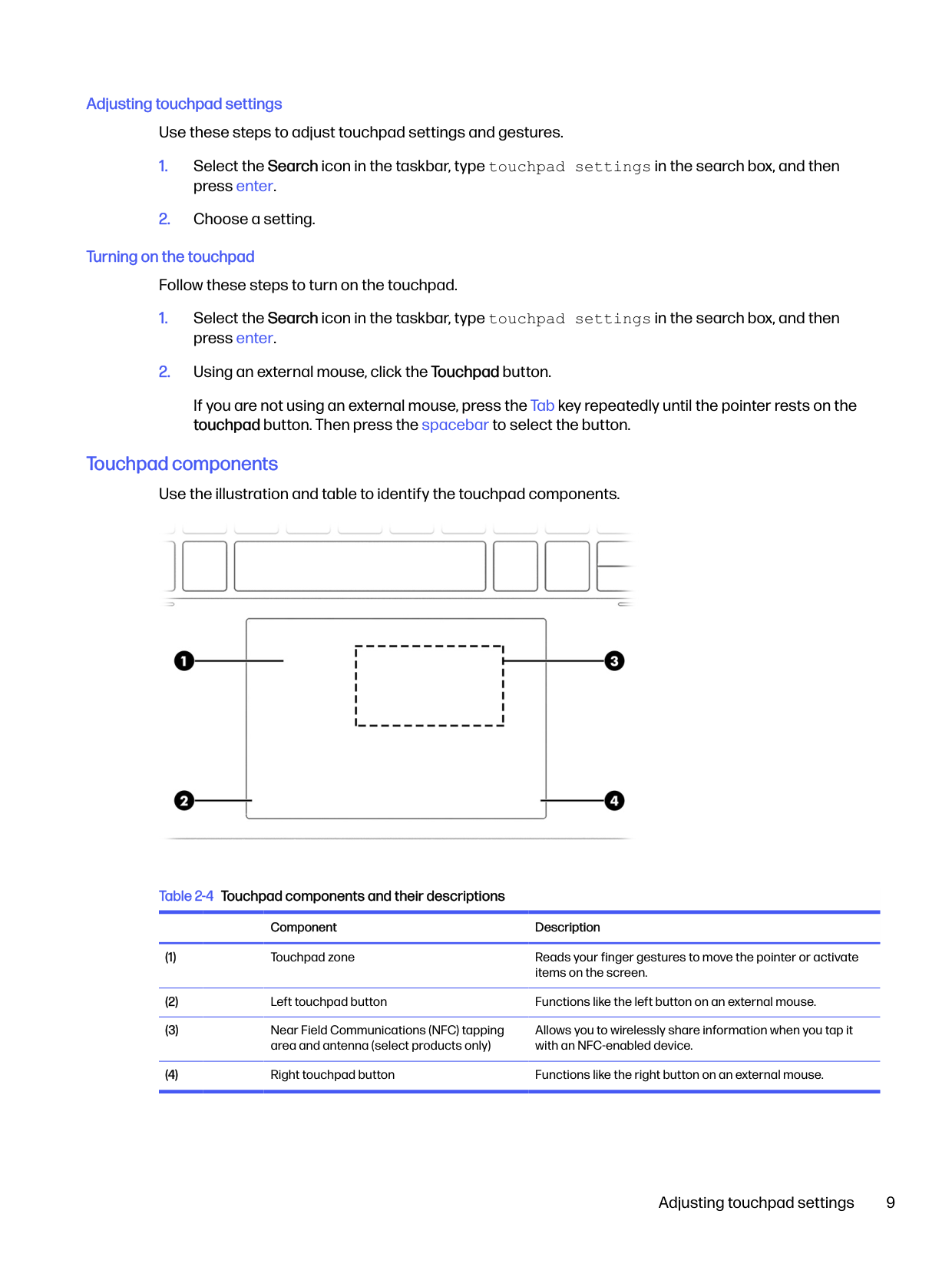
##### Touchpad components
Use the illustration and table to identify the touchpad components.

Table 2-4 Touchpad components and their descriptions
Component Description
Allows you to wirelessly share information when you tap it with an NFC-enabled device.
Adjusting touchpad settings 9
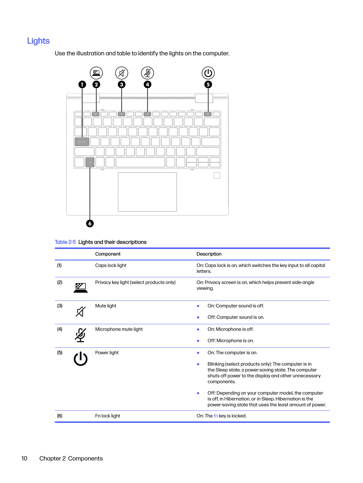
#### Lights
Use the illustration and table to identify the lights on the computer.

Table 2-5 Lights and their descriptions
Component Description


● Off: Computer sound is on.

● Off: Microphone is on.

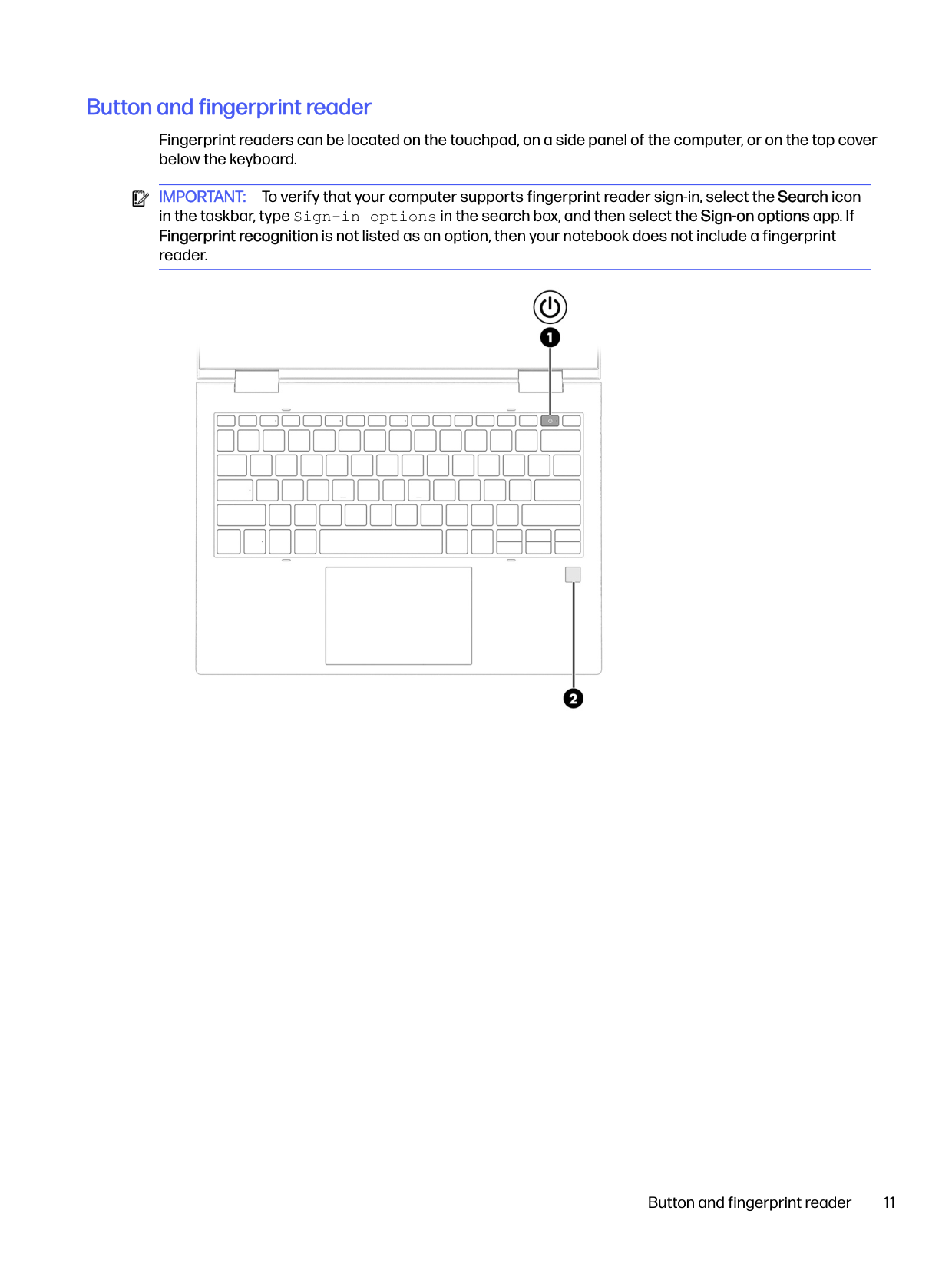
#### Button and fingerprint reader
Fingerprint readers can be located on the touchpad, on a side panel of the computer, or on the top cover below the keyboard.

IMPORTANT: To verify that your computer supports fingerprint reader sign-in, select the Search icon in the taskbar, type Sign-in options in the search box, and then select the Sign-on options app. If Fingerprint recognition is not listed as an option, then your notebook does not include a fingerprint reader.

Button and fingerprint reader 11
######## Table 2-6 Button and fingerprint reader and their descriptions
######### Component Description

IMPORTANT: Pressing and holding down the power button results in the loss of unsaved information. If the computer has stopped responding and shutdown procedures are ineffective, press and hold the power button for at least 4 seconds to turn off the computer. To learn more about your power settings, use the Power icon.
● Right-click the Power icon , and then select Power

and sleep settings.
■ Touch your finger to the fingerprint reader.
IMPORTANT: To prevent fingerprint logon issues, make sure when you register your fingerprint that all sides of your finger are registered by the fingerprint reader.
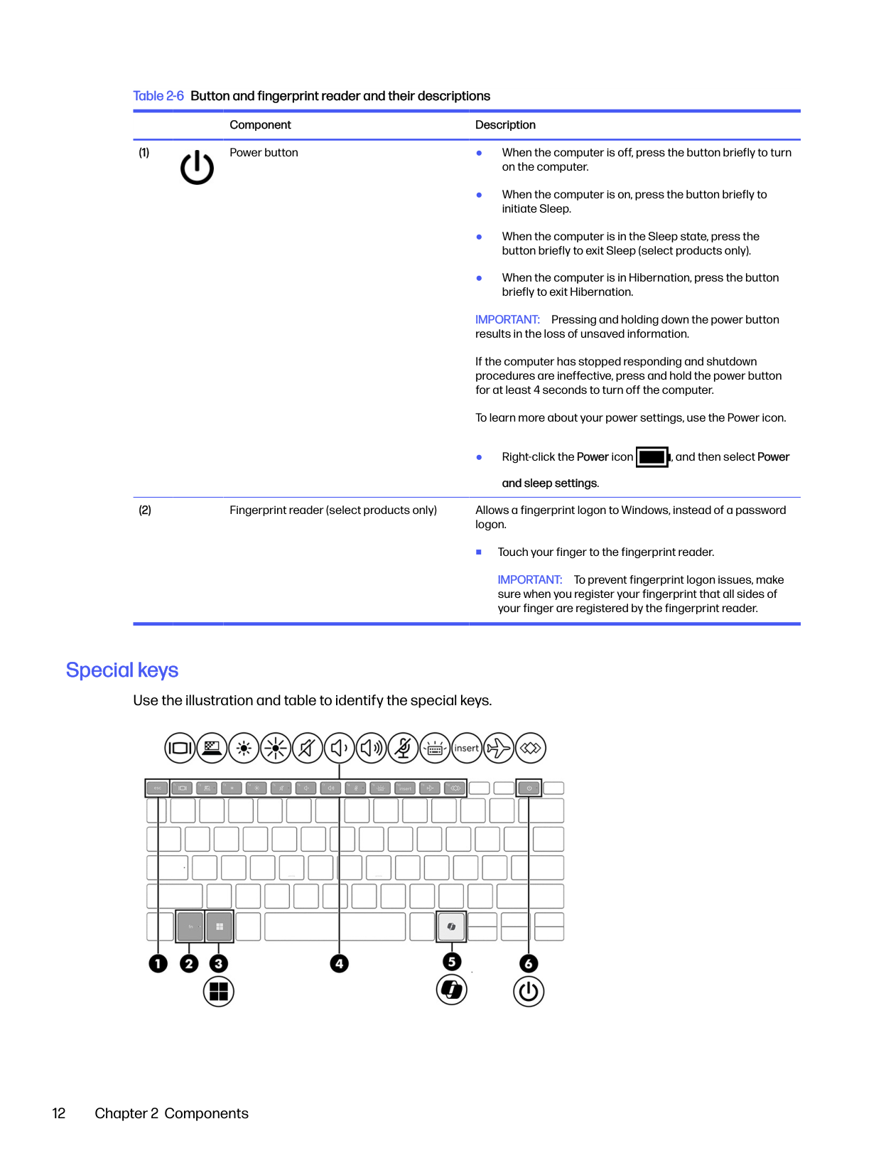
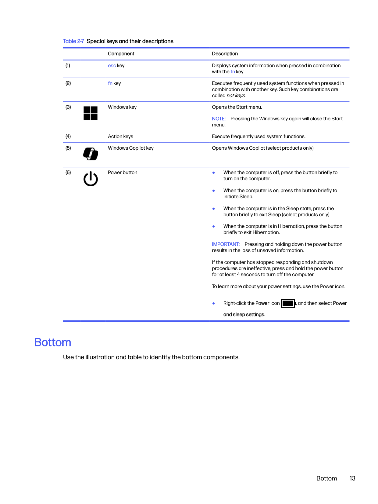
#### Special keys
Use the illustration and table to identify the special keys.

######## Table 2-7 Special keys and their descriptions
######### Component Description

NOTE: Pressing the Windows key again will close the Start menu.


IMPORTANT: Pressing and holding down the power button results in the loss of unsaved information. If the computer has stopped responding and shutdown procedures are ineffective, press and hold the power button for at least 4 seconds to turn off the computer. To learn more about your power settings, use the Power icon.

● Right-click the Power icon , and then select Power
and sleep settings.
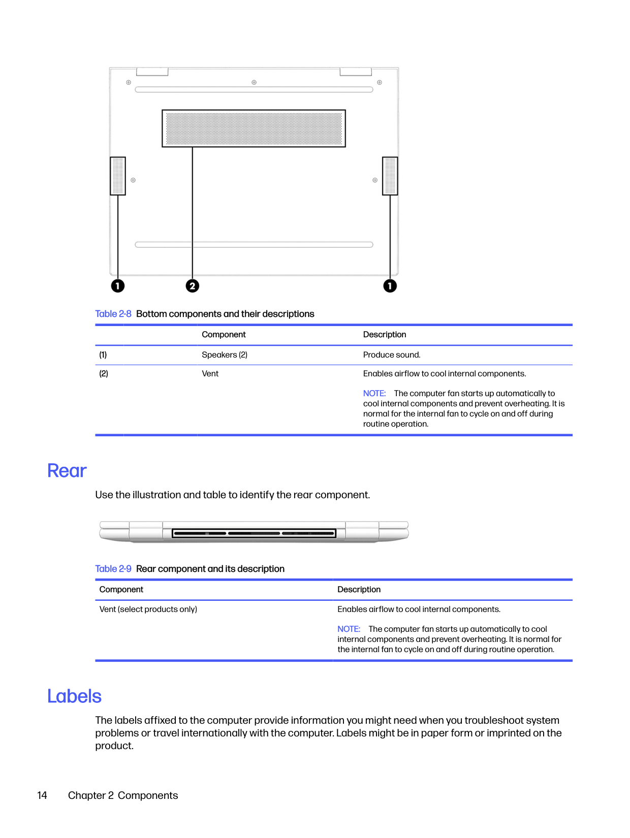
Bottom
Use the illustration and table to identify the bottom components.
Bottom 13

######## Table 2-8 Bottom components and their descriptions
######### Component Description
NOTE: The computer fan starts up automatically to cool internal components and prevent overheating. It is normal for the internal fan to cycle on and off during routine operation.
Rear
Use the illustration and table to identify the rear component.

Table 2-9 Rear component and its description Component Description Vent (select products only) Enables airflow to cool internal components.
NOTE: The computer fan starts up automatically to cool internal components and prevent overheating. It is normal for the internal fan to cycle on and off during routine operation.
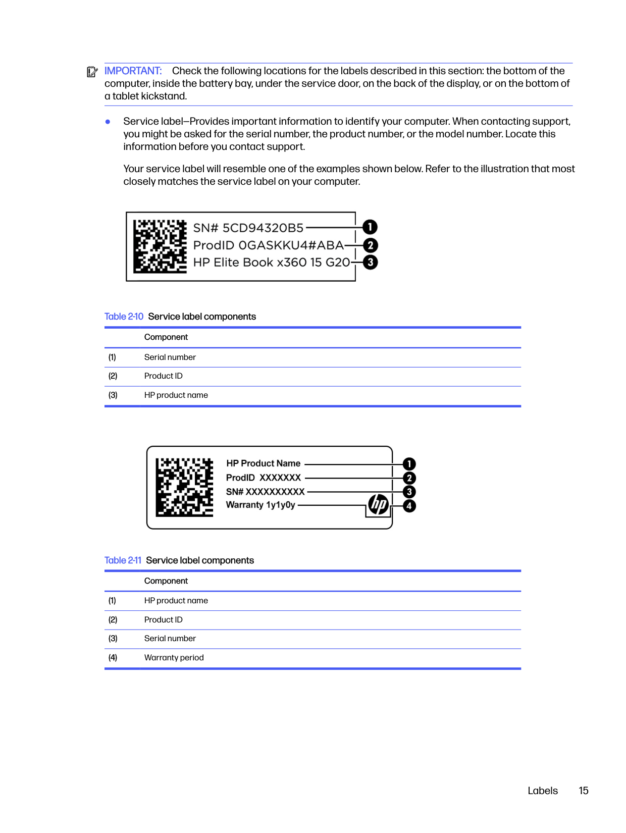
Labels
The labels affixed to the computer provide information you might need when you troubleshoot system problems or travel internationally with the computer. Labels might be in paper form or imprinted on the product.

IMPORTANT: Check the following locations for the labels described in this section: the bottom of the computer, inside the battery bay, under the service door, on the back of the display, or on the bottom of a tablet kickstand.
● Service label—Provides important information to identify your computer. When contacting support, you might be asked for the serial number, the product number, or the model number. Locate this information before you contact support.
Your service label will resemble one of the examples shown below. Refer to the illustration that most closely matches the service label on your computer.


####### Labels 15

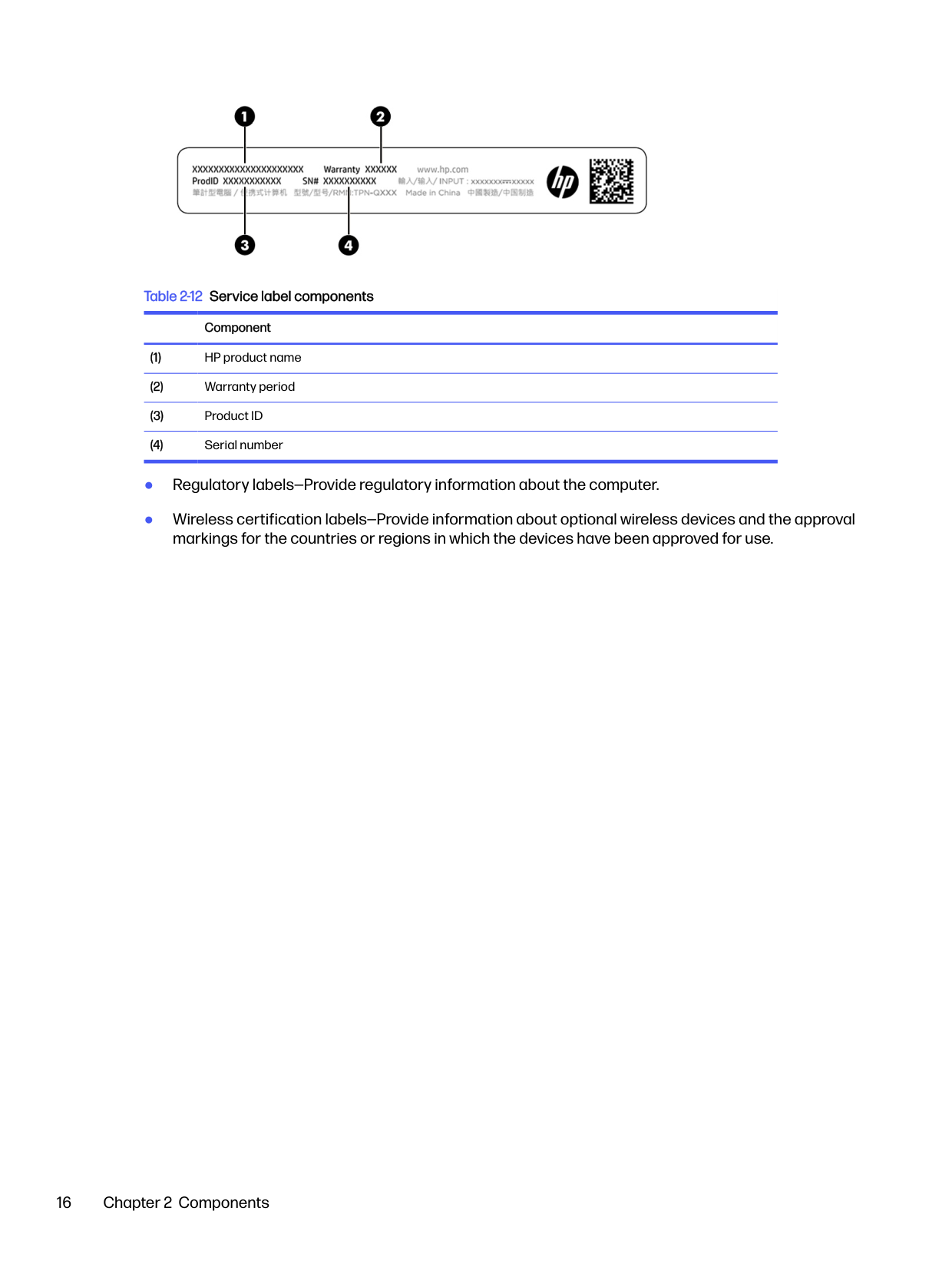
######## Table 2-12 Service label componentsComponent
Illustrated parts catalog3
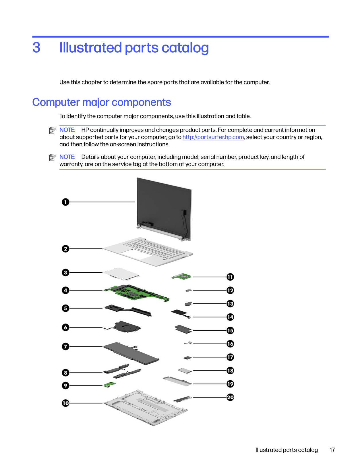
Use this chapter to determine the spare parts that are available for the computer.
Computer major components To identify the computer major components, use this illustration and table. NOTE: HP continually improves and changes product parts. For complete and current information about supported parts for your computer, go to http://partsurfer.hp.com, select your country or region, and then follow the on-screen instructions. NOTE: Details about your computer, including model, serial number, product key, and length of warranty, are on the service tag at the bottom of your computer.


Illustrated parts catalog 17
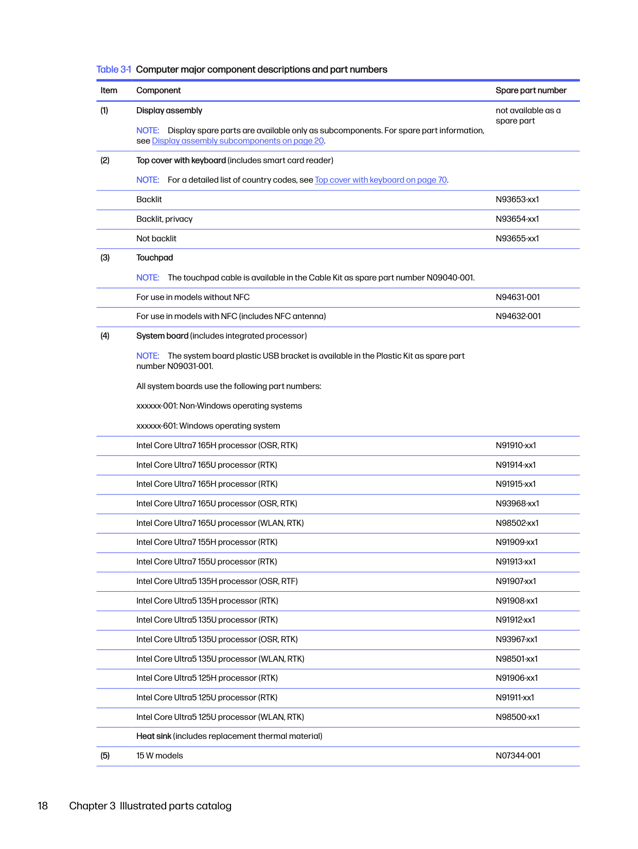
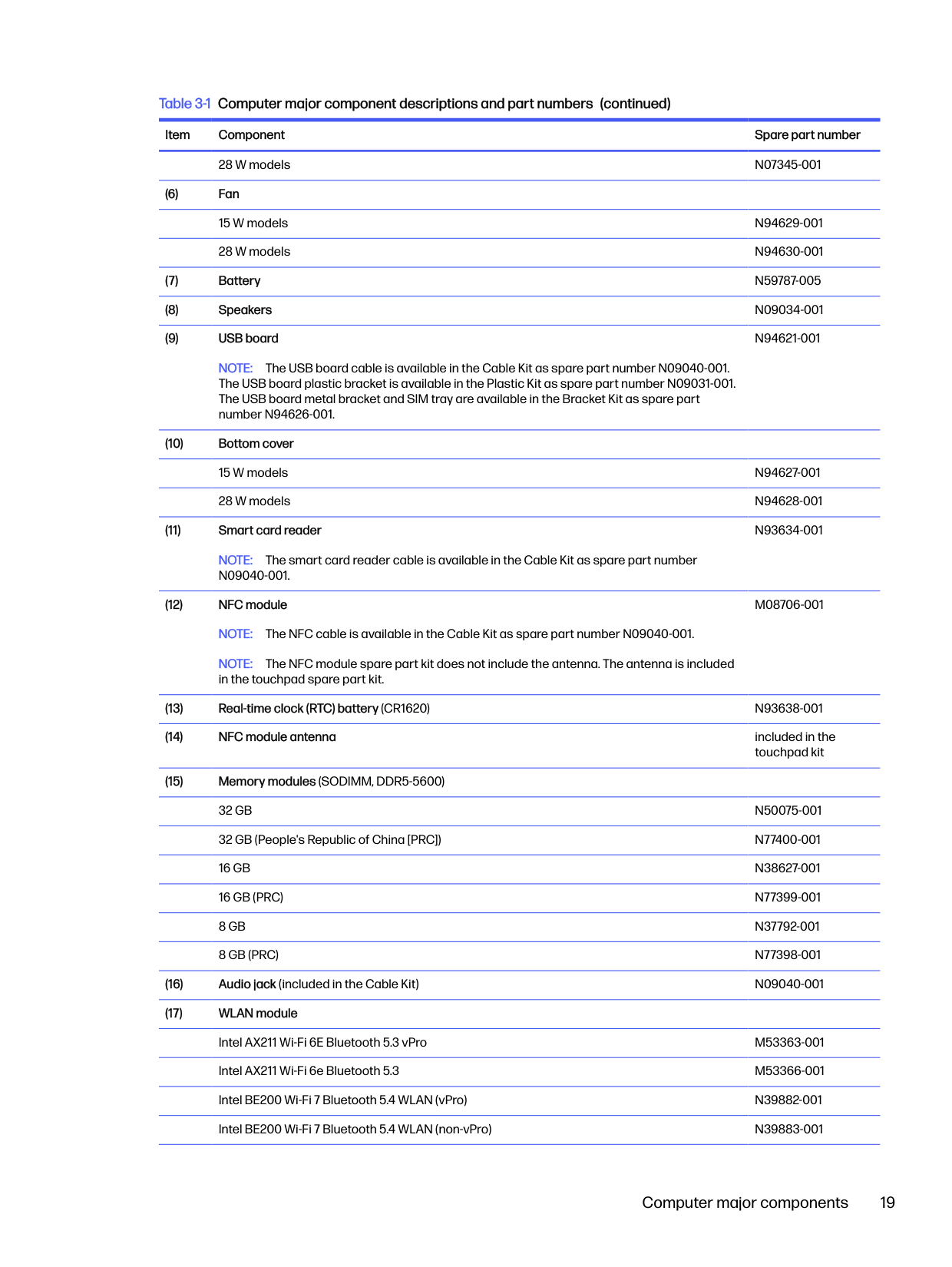
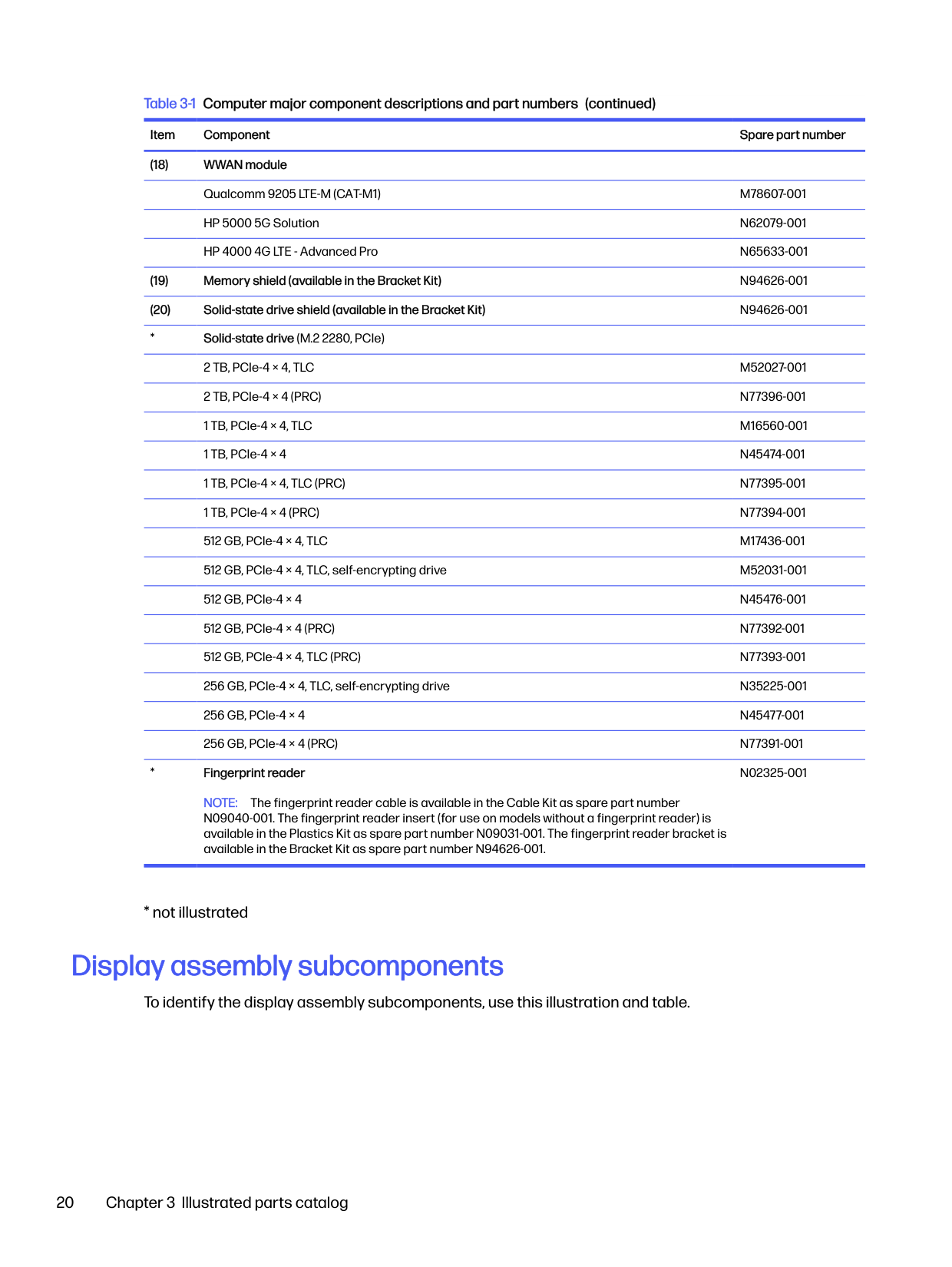
######## Table 3-1 Computer major component descriptions and part numbers
Item Component Spare part number
NOTE: Display spare parts are available only as subcomponents. For spare part information, see Display assembly subcomponents on page 20.
not available as a spare part
NOTE: The system board plastic USB bracket is available in the Plastic Kit as spare part number N09031-001. All system boards use the following part numbers: xxxxxx-001: Non-Windows operating systems xxxxxx-601: Windows operating system Intel Core Ultra7 165H processor (OSR, RTK) N91910-xx1 Intel Core Ultra7 165U processor (RTK) N91914-xx1 Intel Core Ultra7 165H processor (RTK) N91915-xx1 Intel Core Ultra7 165U processor (OSR, RTK) N93968-xx1 Intel Core Ultra7 165U processor (WLAN, RTK) N98502-xx1 Intel Core Ultra7 155H processor (RTK) N91909-xx1 Intel Core Ultra7 155U processor (RTK) N91913-xx1 Intel Core Ultra5 135H processor (OSR, RTF) N91907-xx1 Intel Core Ultra5 135H processor (RTK) N91908-xx1 Intel Core Ultra5 135U processor (RTK) N91912-xx1 Intel Core Ultra5 135U processor (OSR, RTK) N93967-xx1 Intel Core Ultra5 135U processor (WLAN, RTK) N98501-xx1 Intel Core Ultra5 125H processor (RTK) N91906-xx1 Intel Core Ultra5 125U processor (RTK) N91911-xx1 Intel Core Ultra5 125U processor (WLAN, RTK) N98500-xx1 Heat sink (includes replacement thermal material)
NOTE: The USB board cable is available in the Cable Kit as spare part number N09040-001. The USB board plastic bracket is available in the Plastic Kit as spare part number N09031-001. The USB board metal bracket and SIM tray are available in the Bracket Kit as spare part number N94626-001.
N94621-001
NOTE: The smart card reader cable is available in the Cable Kit as spare part number N09040-001.
N93634-001
NOTE: The NFC module spare part kit does not include the antenna. The antenna is included in the touchpad spare part kit.
M08706-001
Computer major components 19
NOTE: The fingerprint reader cable is available in the Cable Kit as spare part number N09040-001. The fingerprint reader insert (for use on models without a fingerprint reader) is available in the Plastics Kit as spare part number N09031-001. The fingerprint reader bracket is available in the Bracket Kit as spare part number N94626-001.
N02325-001
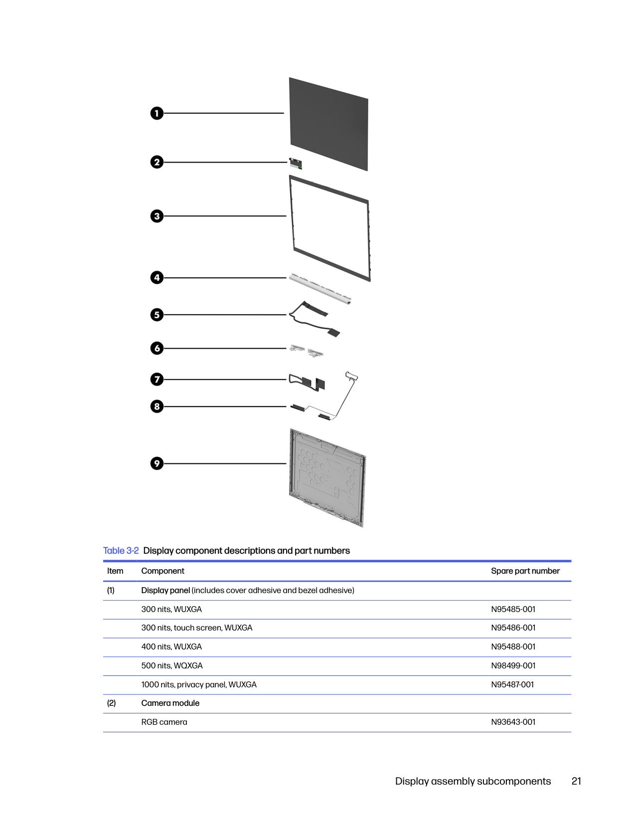
Display assembly subcomponents
To identify the display assembly subcomponents, use this illustration and table.

######## Table 3-2 Display component descriptions and part numbers
######### Item Component Spare part number
Display assembly subcomponents 21
######## Table 3-2 Display component descriptions and part numbers (continued)
######### Item Component Spare part number
RGB + IR camera N93644-001 Microphone only N94622-001
not available as a spare part
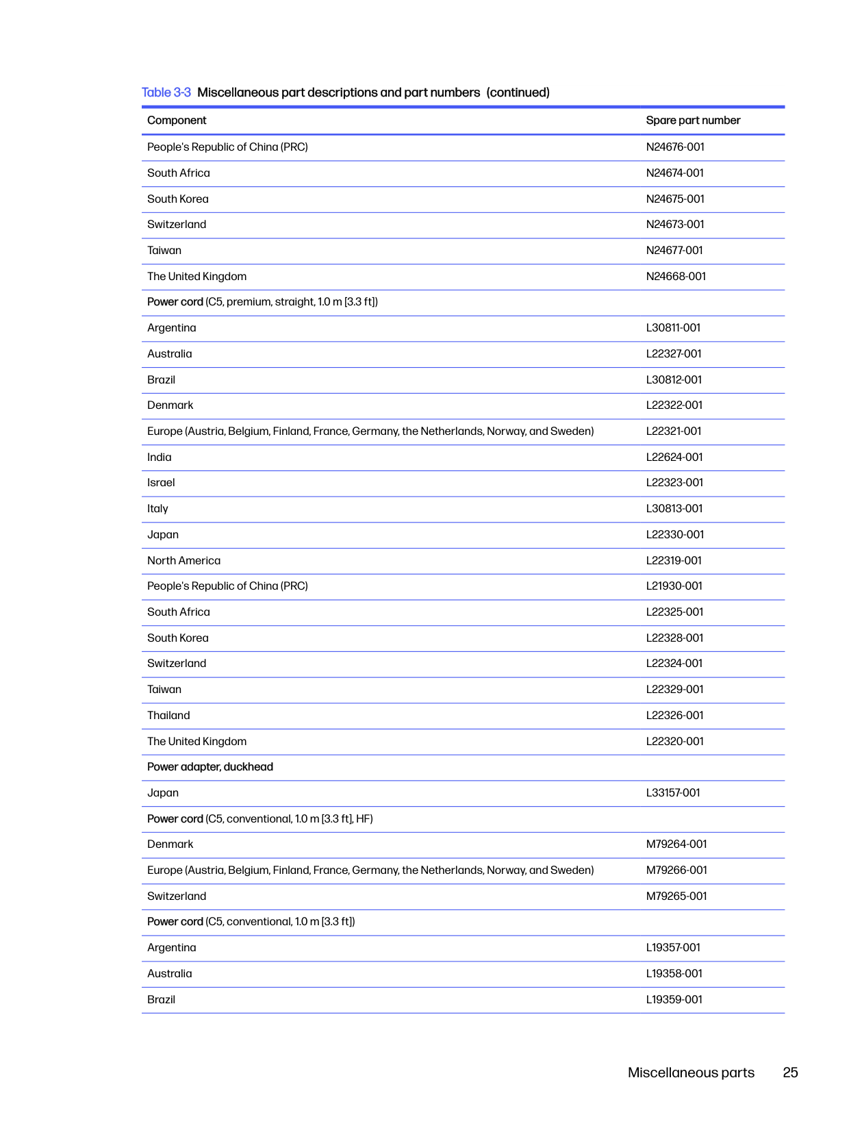
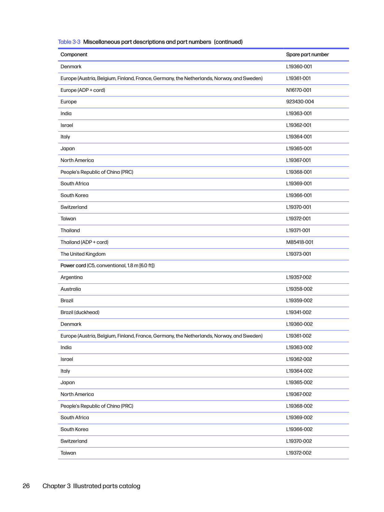
Miscellaneous parts To identify the miscellaneous parts, use this table. Table 3-3 Miscellaneous part descriptions and part numbers
Component Spare part number AC adapters
280 W, PFC, 7.4 mm M52952-001 120 W, PFC, 7.4 mm L89695-001 120 W, PFC, 4.5 mm M95377-001 65 W, nPFC, slim, USB-C M54350-001 65 W, nPFC, USB-C, 1.8 m (6.0 ft) L67440-001 65 W, USB Type-C N05175-001 65 W, nPFC, USB-C, 1.8 m (6 ft), HF N90678-001 65 W, PD P02292-001 Cable Kit, Computer (includes cables for USB board, smart card reader, audio jack, fingerprint reader, touchpad, and NFC module)
N09040-001
Cable Kit, Display (includes cables for microphone module, camera, ACS board, ALS board, ALS panel, privacy panel, and display transfer board)
N09039-001
Plastics Kit (includes smart card insert, fingerprint reader insert, SIM insert, left and right I/O frames, WWAN rubber spacer, and NI/CU gasket)
N09031-001
Bracket Kit (includes solid-state drive shield, memory module shields [WLAN and WWAN models], memory module can, USB bracket, fingerprint reader bracket, and SIM tray)
N94626-001
USB-C-to-DisplayPort adapter 831753-001 USB-C-to-DisplayPort adapter, G2 N81435-001 USB-C-to-HDMI 2.0 adapter 935325-001 USB-C-to-VGA adapter 831751-001 USB-C-to-RJ-45 adapter M95985-001 USB-C-to-USB-A adapter L65254-001 USB 3.0-to-gigabit RJ-45 adapter M95984-001 USB-C (male)-to-USB-C (male) adapter L65253-001 HDMI-to-VGA adapter 701943-001 DisplayPort-to-DVI adapter 753744-001 USB-C-to-USB-A hub 916838-001 HP Universal USB-C Multiport Hub M96882-001 Multiport USB-C travel hub N60372-001 Screw Kit (for use with HP USB-C Dock G5) L64089-001 Screw Kit (for use in product component removal and replacement) N94624-001 USB mouse L95713-001 HP Wireless Premium Mouse 923947-001 HP 435 Wireless Mouse M62277-001 HP 715 multidevice, rechargeable mouse N21845-001 HP USB Keyboard L95712-001
HP USB Slim Smart Card CCID Keyboard 911725-001 Nano lock 918431-001 External optical drive 747080-001 Thunderbolt 120 W G4 dock (with cable) M97105-001 Thunderbolt 120 W G4 dock (with cable) (TAA) N17490-001 Thunderbolt 280 W G4 dock (with cable) M97106-001 Thunderbolt 280 W G4 dock (with cable) (TAA) N17491-001 Thunderbolt dock 120 W (with cable) L15809-001 USB-C Dock G5 (with cable) L64086-001 USB-C/A universal dock (with cable) L64087-001 HP USB-C Essential Dock, G5 N31329-001 HP USB-C Essential Dock, G5 (TAA) N35937-001 Bottom case for USB-C/A universal dock L64088-001 Bottom case for USB-C Dock G5 L65256-001 Cable kit for use with Thunderbolt 120 W G4 dock M88058-001 Cable kit for use with Thunderbolt 280 W G4 dock M88059-001 HP Business 14.1 laptop bag M55007-001 HP Renew 14.1 laptop sleeve N19981-001
People's Republic of China (PRC) N24676-001 South Africa N24674-001 South Korea N24675-001 Switzerland N24673-001 Taiwan N24677-001 The United Kingdom N24668-001
Power cord (C5, premium, straight, 1.0 m [3.3 ft]) Argentina L30811-001 Australia L22327-001 Brazil L30812-001 Denmark L22322-001 Europe (Austria, Belgium, Finland, France, Germany, the Netherlands, Norway, and Sweden) L22321-001 India L22624-001 Israel L22323-001 Italy L30813-001 Japan L22330-001 North America L22319-001 People's Republic of China (PRC) L21930-001 South Africa L22325-001 South Korea L22328-001 Switzerland L22324-001 Taiwan L22329-001 Thailand L22326-001 The United Kingdom L22320-001 Power adapter, duckhead Japan L33157-001 Power cord (C5, conventional, 1.0 m [3.3 ft], HF)
Denmark M79264-001 Europe (Austria, Belgium, Finland, France, Germany, the Netherlands, Norway, and Sweden) M79266-001 Switzerland M79265-001 Power cord (C5, conventional, 1.0 m [3.3 ft])
########## Denmark L19360-001
Argentina L19357-002 Australia L19358-002 Brazil L19359-002 Brazil (duckhead) L19341-002 Denmark L19360-002 Europe (Austria, Belgium, Finland, France, Germany, the Netherlands, Norway, and Sweden) L19361-002 India L19363-002 Israel L19362-002 Italy L19364-002 Japan L19365-002 North America L19367-002 People's Republic of China (PRC) L19368-002 South Africa L19369-002 South Korea L19366-002 Switzerland L19370-002
4
Removal and replacement procedures preliminary requirements
Use this information to properly prepare to disassemble and reassemble the computer.
Tools required
You need the following tools to complete the removal and replacement procedures:
Service considerations
The following sections include some of the considerations that you must keep in mind during disassembly and assembly procedures.

NOTE: As you remove each subassembly from the computer, place the subassembly (and all accompanying screws) away from the work area to prevent damage.
#### Plastic parts
Using excessive force during disassembly and reassembly can damage plastic parts.
Cables and connectors Handle cables with extreme care to avoid damage. IMPORTANT: When servicing the computer, be sure that cables are placed in their proper locations during the reassembly process. Improper cable placement can damage the computer. Apply only the tension required to unseat or seat the cables during removal and insertion. Handle cables by the connector whenever possible. In all cases, avoid bending, twisting, or tearing cables. Be sure that cables are routed so that they cannot be caught or snagged as you remove or replace parts. Handle flex cables with extreme care; these cables tear easily.

Drive handling Note the following guidelines when handling drives. IMPORTANT: Drives are fragile components. Handle them with care. To prevent damage to the computer, damage to a drive, or loss of information, observe these precautions:

Electrostatic discharge information
A sudden discharge of static electricity from your finger or other conductor can destroy static-sensitive devices or microcircuitry. Often the spark is neither felt nor heard, but damage occurs. An electronic device exposed to electrostatic discharge (ESD) might not appear to be affected at all and can work perfectly throughout a normal cycle. The device might function normally for a while, but it has been degraded in the internal layers, reducing its life expectancy.
Networks built into many integrated circuits provide some protection, but in many cases, the discharge contains enough power to alter device parameters or melt silicon junctions.

IMPORTANT: To prevent damage to the device when you remove or install internal components, observe these precautions:
#### Generating static electricity
Follow these static electricity guidelines:
Electrostatic discharge information 29
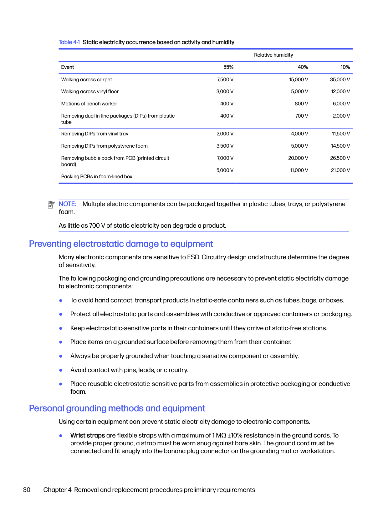
######## Table 4-1 Static electricity occurrence based on activity and humidity
Relative humidity Event 55% 40% 10% Walking across carpet Walking across vinyl floor Motions of bench worker Removing dual in-line packages (DIPs) from plastic tube
7,500 V 3,000 V
15,000 V
35,000 V
5,000 V 800 V 700 V
12,000 V 6,000 V 2,000 V
400 V 400 V
Removing DIPs from vinyl tray Removing DIPs from polystyrene foam Removing bubble pack from PCB (printed circuit board) Packing PCBs in foam-lined box
11,500 V 14,500 V 26,500 V 21,000 V
20,000 V 11,000 V

NOTE: Multiple electric components can be packaged together in plastic tubes, trays, or polystyrene foam. As little as 700 V of static electricity can degrade a product.
#### Preventing electrostatic damage to equipment
Many electronic components are sensitive to ESD. Circuitry design and structure determine the degree of sensitivity.
The following packaging and grounding precautions are necessary to prevent static electricity damage to electronic components:
#### Personal grounding methods and equipment
Using certain equipment can prevent static electricity damage to electronic components.
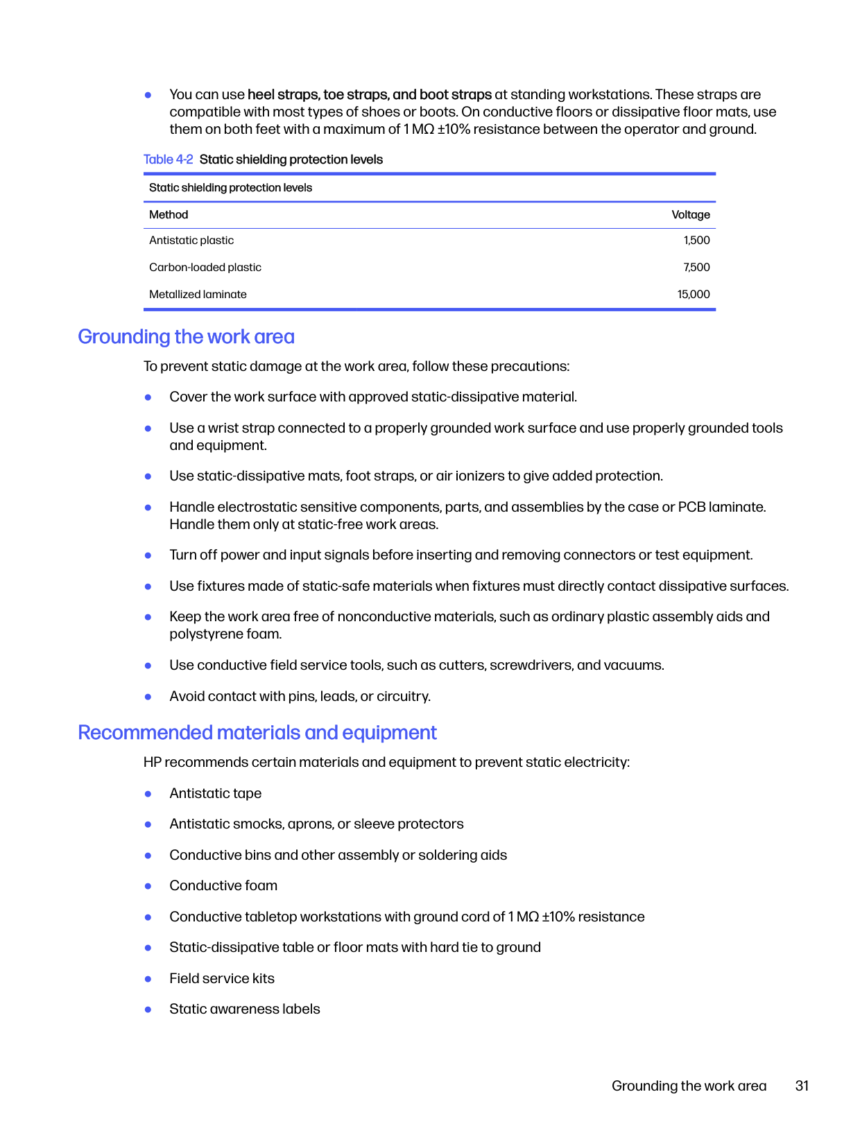
Table 4-2 Static shielding protection levels Static shielding protection levels Method Voltage Antistatic plastic Carbon-loaded plastic Metallized laminate
1,500 7,500
15,000
#### Grounding the work area
To prevent static damage at the work area, follow these precautions:
#### Recommended materials and equipment
HP recommends certain materials and equipment to prevent static electricity:
Grounding the work area 31

Cleaning your computer
Cleaning your computer regularly removes dirt and debris so that your device continues to operate at its best. Use the following information to safely clean the external surfaces of your computer.
#### Enabling HP Easy Clean (select products only)
HP Easy Clean helps you to avoid accidental input while you clean the computer surfaces. This software disables devices such as the keyboard, touch screen, and touchpad for a preset amount of time so that you can clean all computer surfaces.
Removing dirt and debris from your computer Here are the recommended steps to clean dirt and debris from your computer. For computers with wood veneer, see Caring for wood veneer (select products only) on page 34.

CAUTION: To prevent electric shock or damage to components, never clean a product while it is turned on or plugged in.
IMPORTANT: Keep liquids away from the product. Avoid getting moisture in any openings. If liquid makes its way inside your HP product, it can cause damage to the product. Do not spray liquids directly on the product. Do not use aerosol sprays, solvents, abrasives, or cleaners containing hydrogen peroxide or bleach that might damage the finish.


See Cleaning your computer with a disinfectant on page 33 for recommended steps to clean the high-touch, external surfaces on your computer to help prevent the spread of harmful bacteria and viruses.
#### Cleaning your computer with a disinfectant
The World Health Organization (WHO) recommends cleaning surfaces, followed by disinfection, as a best practice for preventing the spread of viral respiratory illnesses and harmful bacteria.
After cleaning the external surfaces of your computer using the steps in Removing dirt and debris from your computer on page 32, Caring for wood veneer (select products only) on page 34, or both, you might also choose to clean the surfaces with a disinfectant. A disinfectant that is within HP’s cleaning guidelines is an alcohol solution consisting of 70% isopropyl alcohol and 30% water. This solution is also known as rubbing alcohol and is sold in most stores.
Follow these steps when disinfecting high-touch, external surfaces on your computer:
CAUTION: To prevent electric shock or damage to components, never clean a product while it is turned on or plugged in.


CAUTION: Do not use any of the following chemicals or any solutions that contain them, including spray-based surface cleaners: bleach, peroxides (including hydrogen peroxide), acetone, ammonia, ethyl alcohol, methylene chloride, or any petroleum-based materials, such as gasoline, paint thinner, benzene, or toluene.

IMPORTANT: To avoid damaging the surface, avoid abrasive cloths, towels, and paper towels.
Cleaning your computer with a disinfectant 33
IMPORTANT: Keep liquids away from the product. Avoid getting moisture in any openings. If liquid makes its way inside your HP product, it can cause damage to the product. Do not spray liquids directly on the product. Do not use aerosol sprays, solvents, abrasives, or cleaners containing hydrogen peroxide or bleach that might damage the finish.

#### Caring for wood veneer (select products only)
Your product might feature high-quality wood veneer. As with all natural wood products, proper care is important for best results over the life of the product. Because of the nature of natural wood, you might see unique variations in the grain pattern or subtle variations in color, which are normal.
See Removing dirt and debris from your computer on page 32 for the recommended steps to clean the high-touch, external surfaces on your computer. After you remove the dirt and debris, you can also clean the surfaces with a disinfectant. See Cleaning your computer with a disinfectant on page 33 for sanitizing guidelines to help prevent the spread of harmful bacteria and viruses.
Packaging and transporting guidelines
Follow these grounding guidelines when packaging and transporting equipment:
Accessing support information To find the HP support that you need, use this information. Table 4-3 Support information locations
######### Service consideration Path to access information
Records of reported failure incidents stored on the computer
######### Windows®:
Preoperating system failures are logged in the BIOS Event Log. To view the BIOS Event Log:
NOTE: If you do not press esc at the appropriate time, you must restart the computer and again repeatedly press esc when the power button light turns white to access the utility.
Post-operating system failures are logged in the Event Viewer.

Technical bulletins To locate technical bulletins:
####### Accessing support information 35
######## Table 4-3 Support information locations (continued) Service consideration Path to access information Repair professionals To locate repair professionals:
Component and diagnosis information, failure detection, and required action
To locate diagnosis information and actions:
5
Removal and replacement procedures for Customer Self-Repair parts

This chapter provides removal and replacement procedures for Customer Self-Repair parts. NOTE: The Customer Self-Repair program is not available in all locations. Installing a part that is not supported by the Customer Self-Repair program can void your warranty. Check your warranty to determine whether Customer Self-Repair is supported in your location.
Component replacement procedures To remove and replace computer components, use these procedures. NOTE: Details about your computer, including model, serial number, product key, and length of warranty, are on the service tag at the bottom of your computer. NOTE: HP continually improves and changes product parts. For complete and current information about supported parts for your computer, go to https://partsurfer.hp.com/partsurfer/, select your country or region, and then follow the on-screen instructions. Make special note of each screw size and location during removal and replacement.


Preparation for disassembly To remove and replace computer components, use these procedures: For initial safety procedures, see Removal and replacement procedures preliminary requirements on page 28.
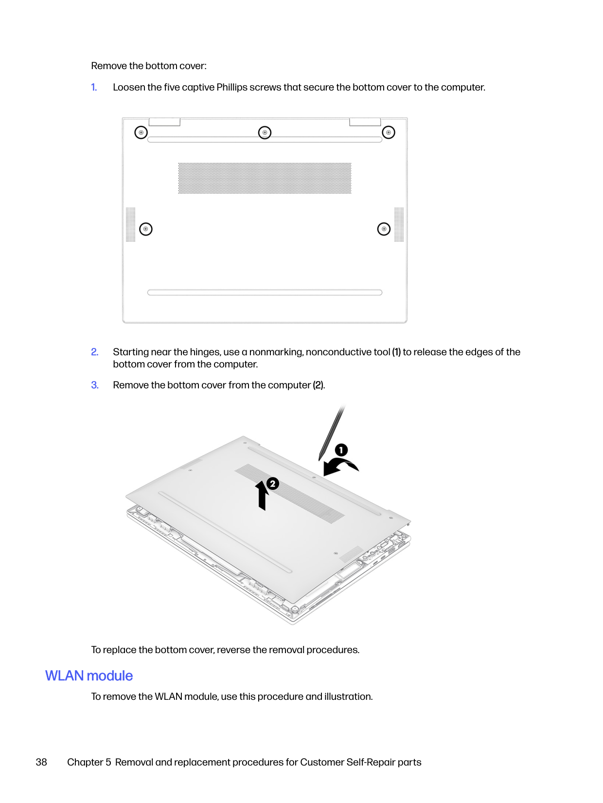
#### Bottom cover To remove the bottom cover, use this procedure and illustration. Table 5-1 Bottom cover description and part number
######### Description Spare part number
15 W models N94627-001 28 W models N94628-001
Before removing the bottom cover, prepare the computer for disassembly (see Preparation for disassembly on page 37).
Removal and replacement procedures for Customer Self-Repair parts 37
Remove the bottom cover:


To replace the bottom cover, reverse the removal procedures.
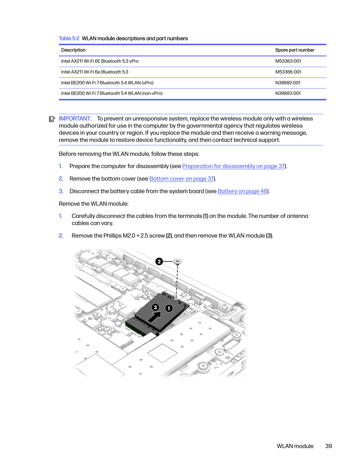
#### WLAN module
To remove the WLAN module, use this procedure and illustration.
######## Table 5-2 WLAN module descriptions and part numbers
######### Description Spare part number
Intel AX211 Wi-Fi 6E Bluetooth 5.3 vPro M53363-001 Intel AX211 Wi-Fi 6e Bluetooth 5.3 M53366-001 Intel BE200 Wi-Fi 7 Bluetooth 5.4 WLAN (vPro) N39882-001 Intel BE200 Wi-Fi 7 Bluetooth 5.4 WLAN (non-vPro) N39883-001

IMPORTANT: To prevent an unresponsive system, replace the wireless module only with a wireless module authorized for use in the computer by the governmental agency that regulates wireless devices in your country or region. If you replace the module and then receive a warning message, remove the module to restore device functionality, and then contact technical support.
Before removing the WLAN module, follow these steps:

WLAN module 39

To install the WLAN module, reverse this procedure.
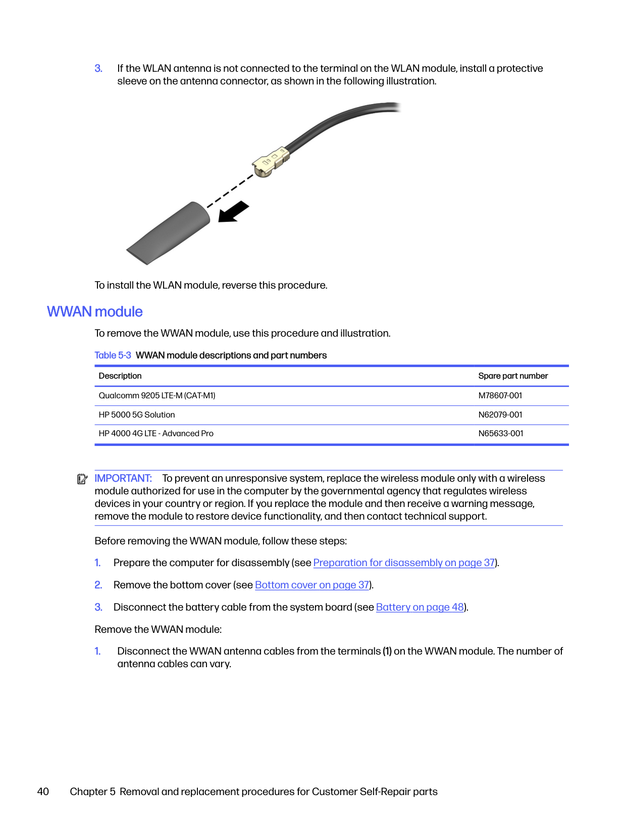
#### WWAN module To remove the WWAN module, use this procedure and illustration. Table 5-3 WWAN module descriptions and part numbers
######### Description Spare part number
Qualcomm 9205 LTE-M (CAT-M1) M78607-001 HP 5000 5G Solution N62079-001 HP 4000 4G LTE - Advanced Pro N65633-001

IMPORTANT: To prevent an unresponsive system, replace the wireless module only with a wireless module authorized for use in the computer by the governmental agency that regulates wireless devices in your country or region. If you replace the module and then receive a warning message, remove the module to restore device functionality, and then contact technical support.
Before removing the WWAN module, follow these steps:


Reverse this procedure to install the WWAN module.
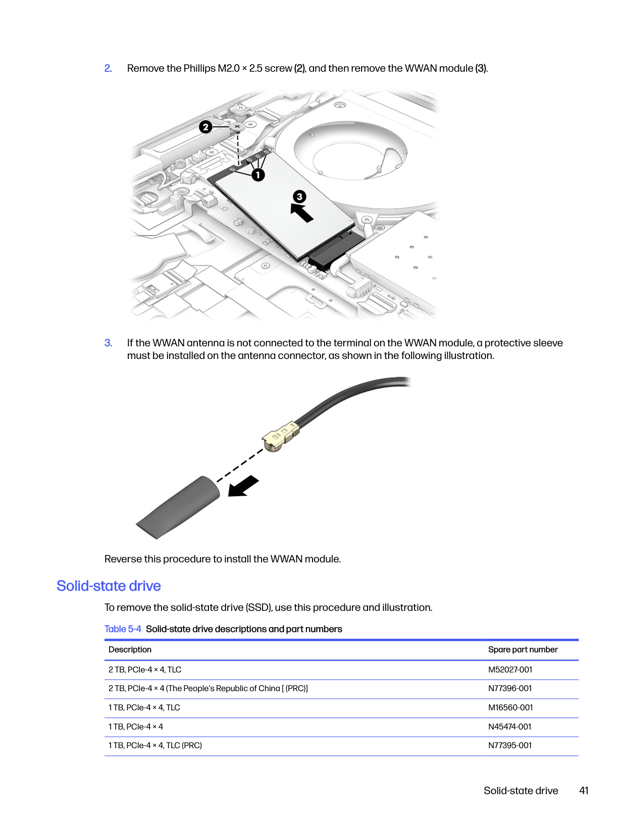
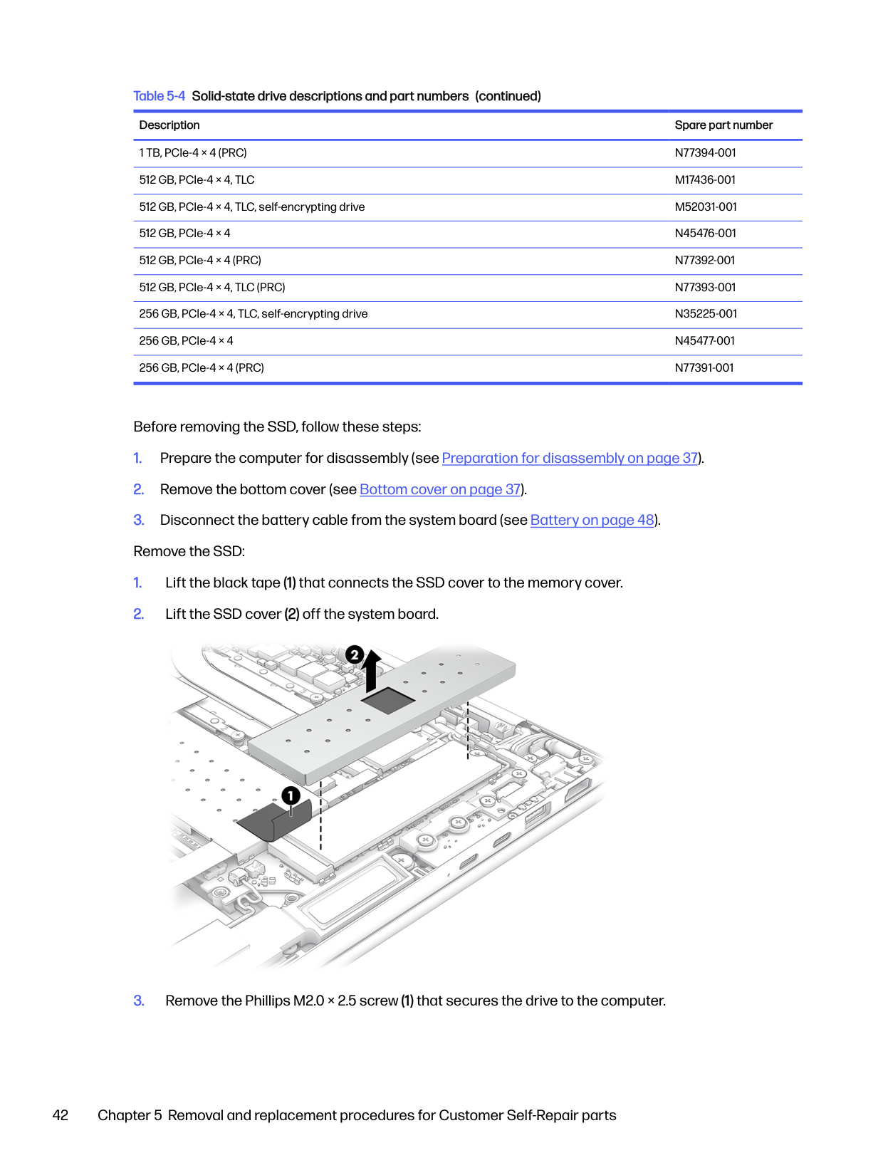
#### Solid-state drive To remove the solid-state drive (SSD), use this procedure and illustration. Table 5-4 Solid-state drive descriptions and part numbers
######### Description Spare part number
2 TB, PCIe-4 × 4, TLC M52027-001 2 TB, PCIe-4 × 4 (The People's Republic of China [ (PRC)] N77396-001 1 TB, PCIe-4 × 4, TLC M16560-001 1 TB, PCIe-4 × 4 N45474-001 1 TB, PCIe-4 × 4, TLC (PRC) N77395-001
Solid-state drive 41
######## Table 5-4 Solid-state drive descriptions and part numbers (continued)
######### Description Spare part number
1 TB, PCIe-4 × 4 (PRC) N77394-001 512 GB, PCIe-4 × 4, TLC M17436-001 512 GB, PCIe-4 × 4, TLC, self-encrypting drive M52031-001 512 GB, PCIe-4 × 4 N45476-001 512 GB, PCIe-4 × 4 (PRC) N77392-001 512 GB, PCIe-4 × 4, TLC (PRC) N77393-001 256 GB, PCIe-4 × 4, TLC, self-encrypting drive N35225-001 256 GB, PCIe-4 × 4 N45477-001 256 GB, PCIe-4 × 4 (PRC) N77391-001
Before removing the SSD, follow these steps:


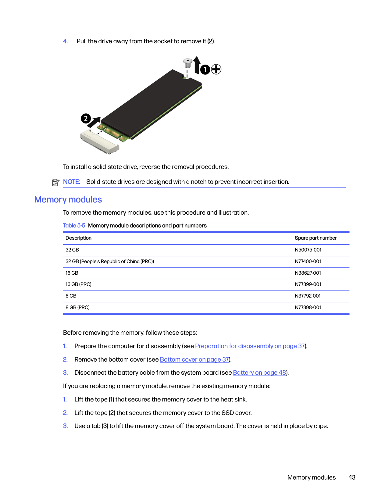
To install a solid-state drive, reverse the removal procedures. NOTE: Solid-state drives are designed with a notch to prevent incorrect insertion.
#### Memory modules To remove the memory modules, use this procedure and illustration. Table 5-5 Memory module descriptions and part numbers
######### Description Spare part number
32 GB N50075-001 32 GB (People's Republic of China (PRC)) N77400-001 16 GB N38627-001 16 GB (PRC) N77399-001 8 GB N37792-001 8 GB (PRC) N77398-001
Before removing the memory, follow these steps:
Memory modules 43


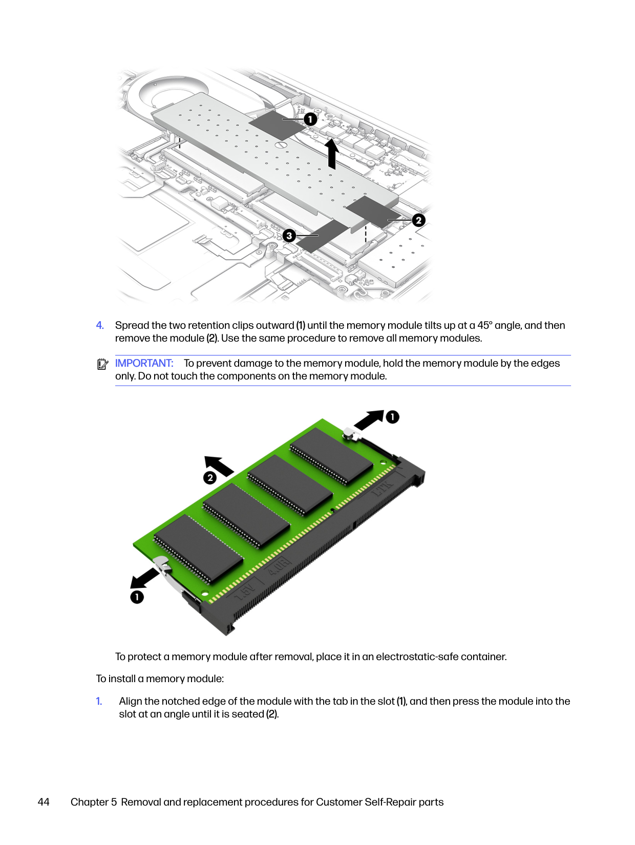
IMPORTANT: To prevent damage to the memory module, hold the memory module by the edges only. Do not touch the components on the memory module.

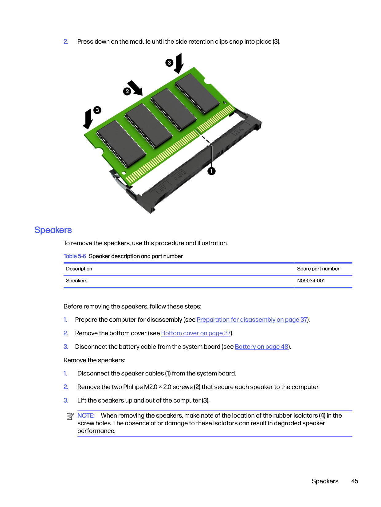
To protect a memory module after removal, place it in an electrostatic-safe container. To install a memory module:

Speakers To remove the speakers, use this procedure and illustration. Table 5-6 Speaker description and part number
Description Spare part number Speakers N09034-001
Before removing the speakers, follow these steps:

NOTE: When removing the speakers, make note of the location of the rubber isolators (4) in the screw holes. The absence of or damage to these isolators can result in degraded speaker performance.
Speakers 45
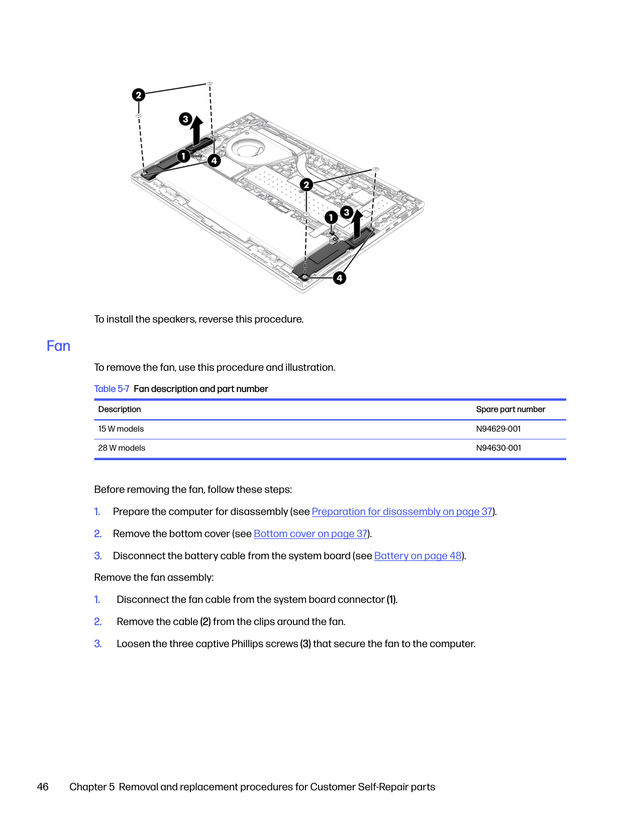
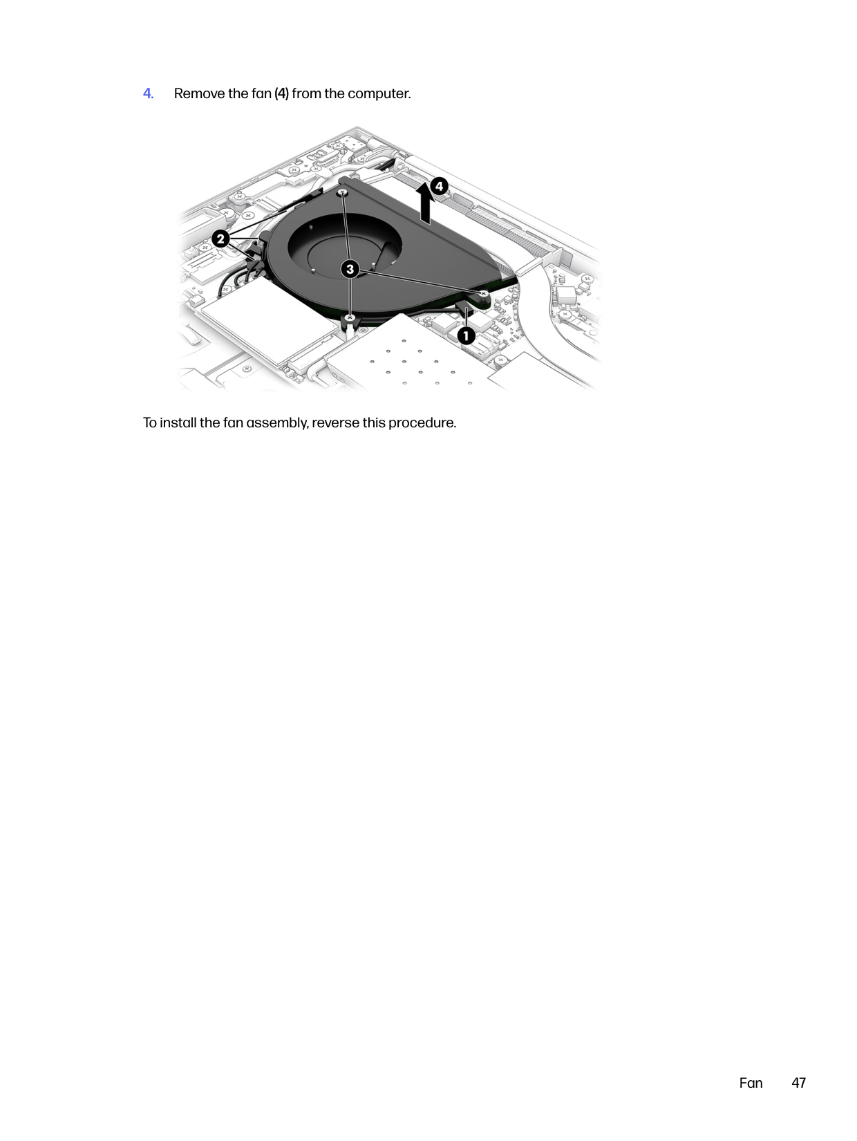
#### Fan

To install the speakers, reverse this procedure.
To remove the fan, use this procedure and illustration. Table 5-7 Fan description and part number
Description Spare part number
15 W models N94629-001 28 W models N94630-001
Before removing the fan, follow these steps:

To install the fan assembly, reverse this procedure.
Fan 47
6
Removal and replacement procedures for authorized service provider parts


This chapter provides removal and replacement procedures for authorized service provider parts. IMPORTANT: Only an authorized service provider should access the components described in this chapter. Accessing these parts can damage the computer or void the warranty. NOTE: Details about your computer, including model, serial number, product key, and length of warranty, are on the service tag at the bottom of your computer.
Component replacement procedures To remove and replace computer components, use the procedures described in this section. NOTE: HP continually improves and changes product parts. For complete and current information about supported parts for your computer, go to https://partsurfer.hp.com/partsurfer/, select your country or region, and then follow the on-screen instructions. Make special note of each screw size and location during removal and replacement.

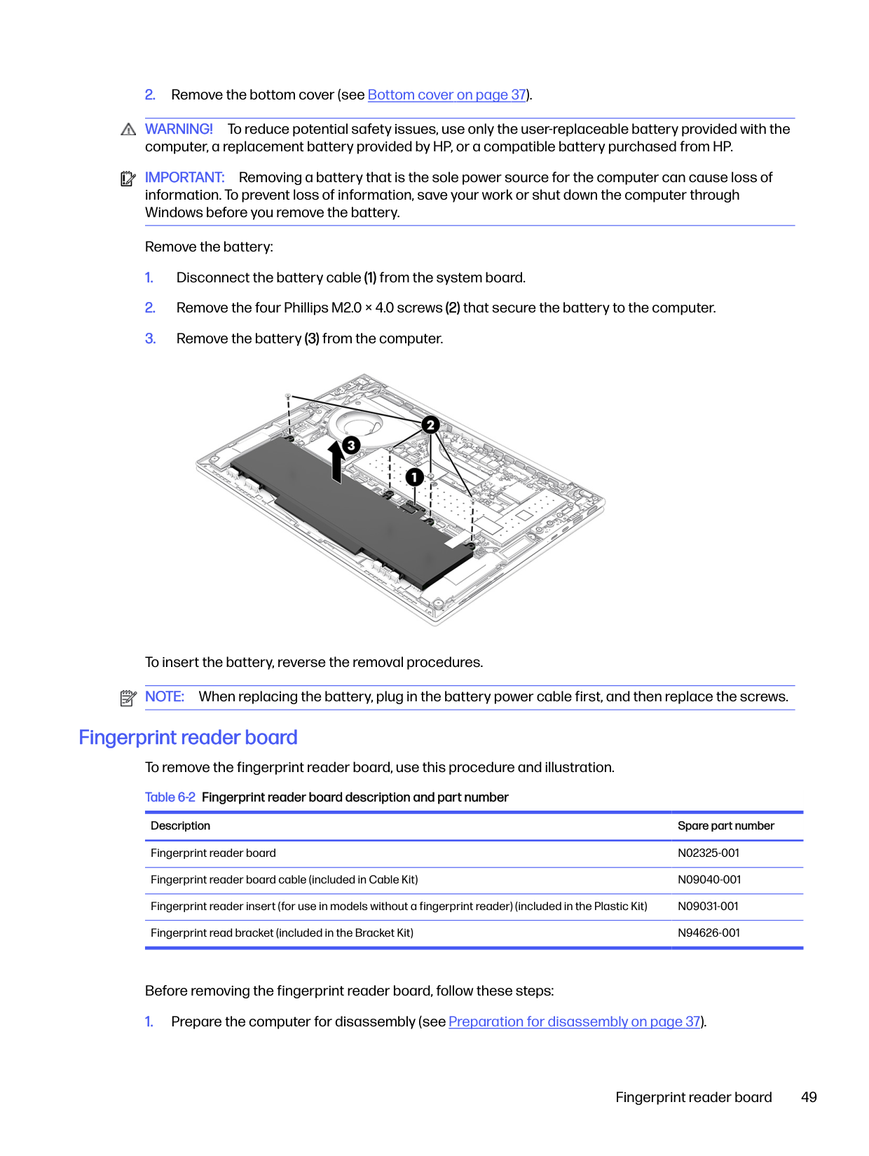
#### Battery
To remove the battery, use this procedure and illustration. Table 6-1 Battery description and part number
Description Spare part number Battery, 3 cell, 56 Whr N59787-005

WARNING! To avoid personal injury and damage to the product:
Before removing the battery, follow these steps:

WARNING! To reduce potential safety issues, use only the user-replaceable battery provided with the computer, a replacement battery provided by HP, or a compatible battery purchased from HP.

IMPORTANT: Removing a battery that is the sole power source for the computer can cause loss of information. To prevent loss of information, save your work or shut down the computer through Windows before you remove the battery.
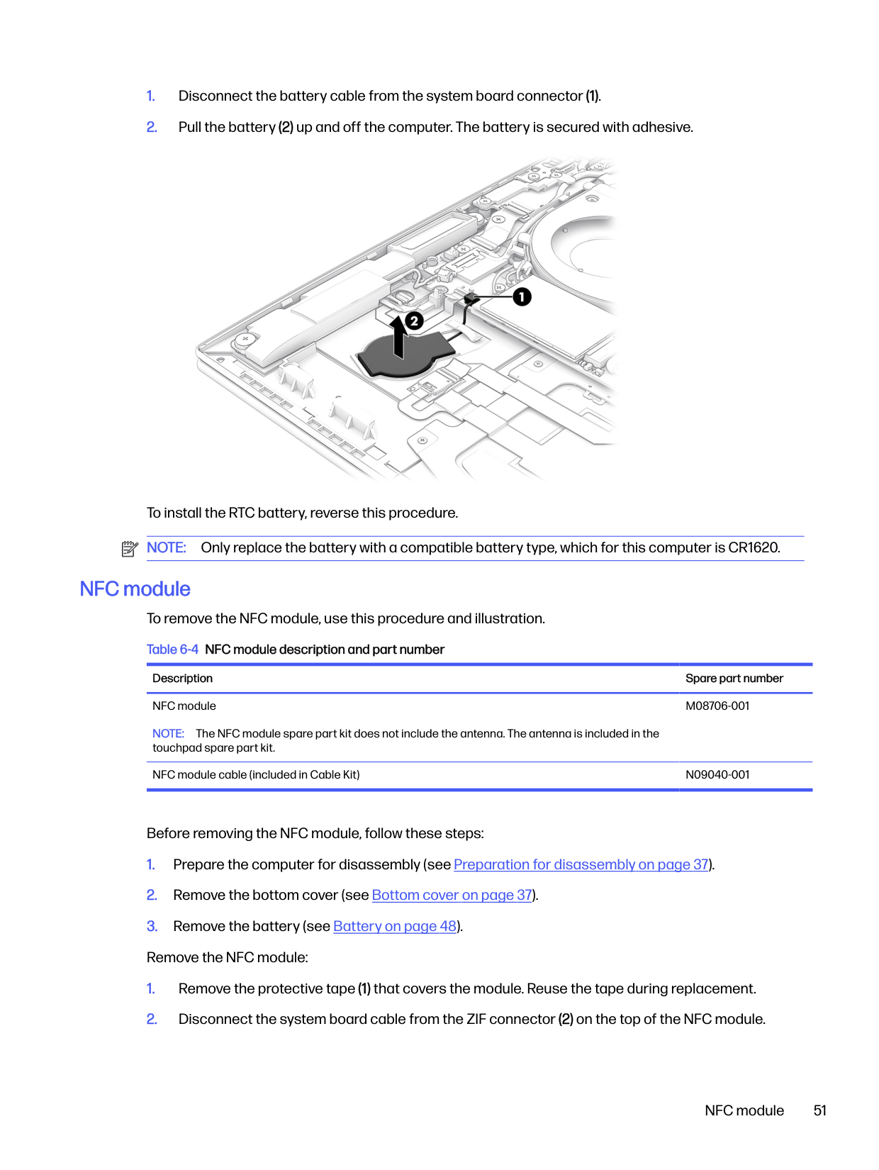
Remove the battery:


To insert the battery, reverse the removal procedures. NOTE: When replacing the battery, plug in the battery power cable first, and then replace the screws.
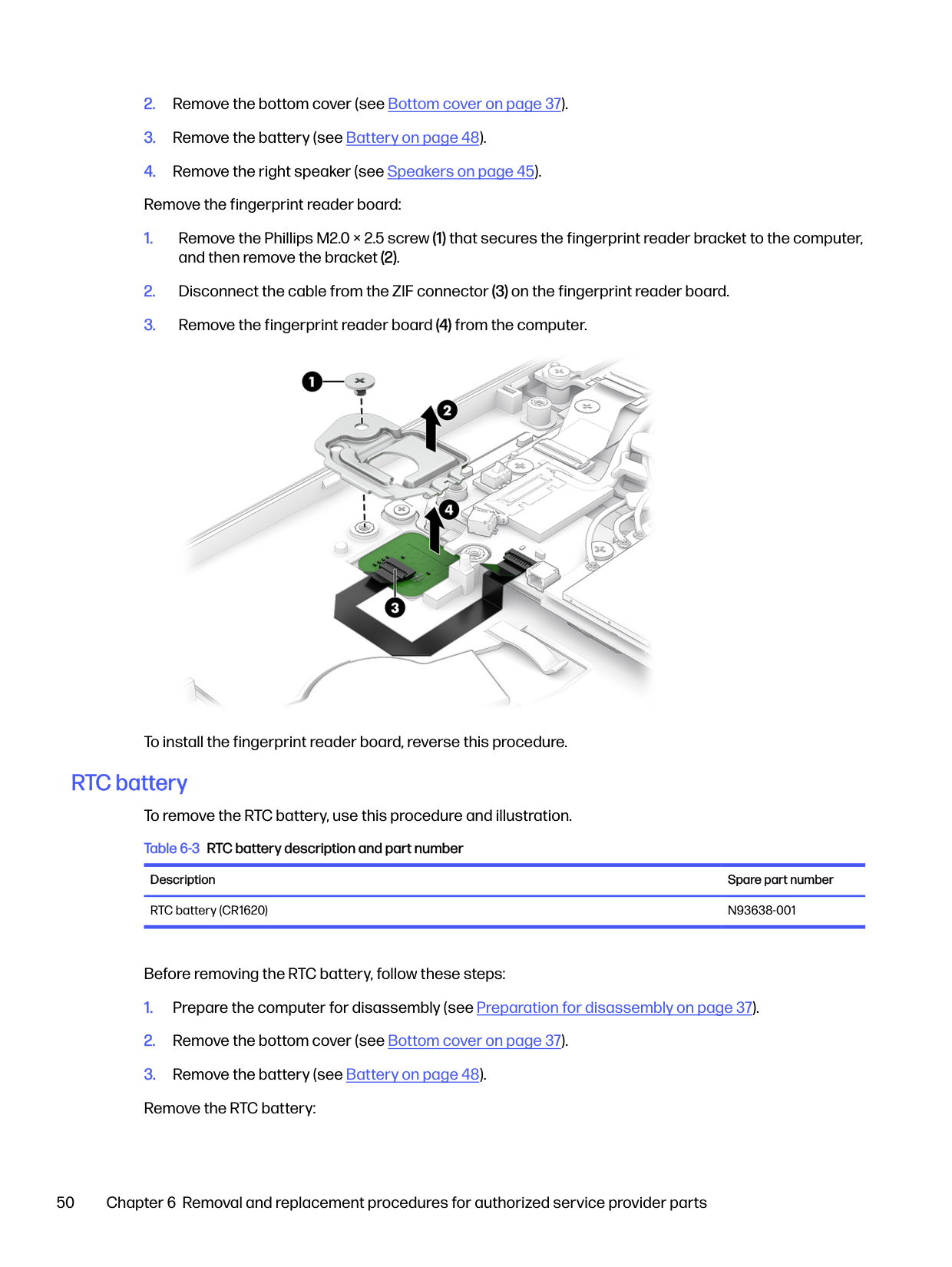
#### Fingerprint reader board To remove the fingerprint reader board, use this procedure and illustration. Table 6-2 Fingerprint reader board description and part number
Description Spare part number Fingerprint reader board N02325-001 Fingerprint reader board cable (included in Cable Kit) N09040-001 Fingerprint reader insert (for use in models without a fingerprint reader) (included in the Plastic Kit) N09031-001 Fingerprint read bracket (included in the Bracket Kit) N94626-001
Before removing the fingerprint reader board, follow these steps:
Fingerprint reader board 49

To install the fingerprint reader board, reverse this procedure.
#### RTC battery To remove the RTC battery, use this procedure and illustration. Table 6-3 RTC battery description and part number
Description Spare part number RTC battery (CR1620) N93638-001
Before removing the RTC battery, follow these steps:


To install the RTC battery, reverse this procedure. NOTE: Only replace the battery with a compatible battery type, which for this computer is CR1620.
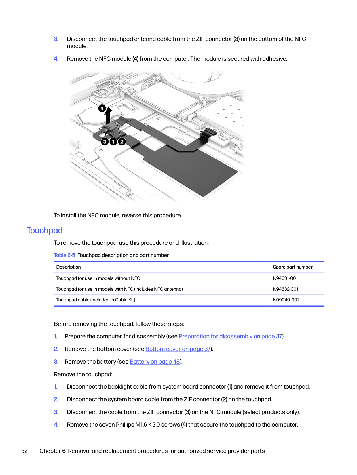
#### NFC module To remove the NFC module, use this procedure and illustration. Table 6-4 NFC module description and part number
Description Spare part number NFC module NOTE: The NFC module spare part kit does not include the antenna. The antenna is included in the touchpad spare part kit.
M08706-001
NFC module cable (included in Cable Kit) N09040-001
Before removing the NFC module, follow these steps:
NFC module 51

To install the NFC module, reverse this procedure.
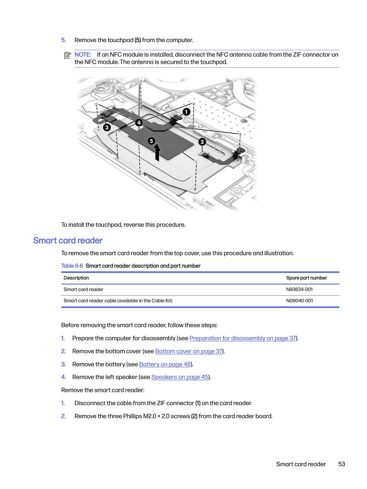
Touchpad To remove the touchpad, use this procedure and illustration. Table 6-5 Touchpad description and part number
Description Spare part number
Touchpad for use in models without NFC N94631-001 Touchpad for use in models with NFC (includes NFC antenna) N94632-001 Touchpad cable (included in Cable Kit) N09040-001
Before removing the touchpad, follow these steps:

NOTE: If an NFC module is installed, disconnect the NFC antenna cable from the ZIF connector on the NFC module. The antenna is secured to the touchpad.

To install the touchpad, reverse this procedure.
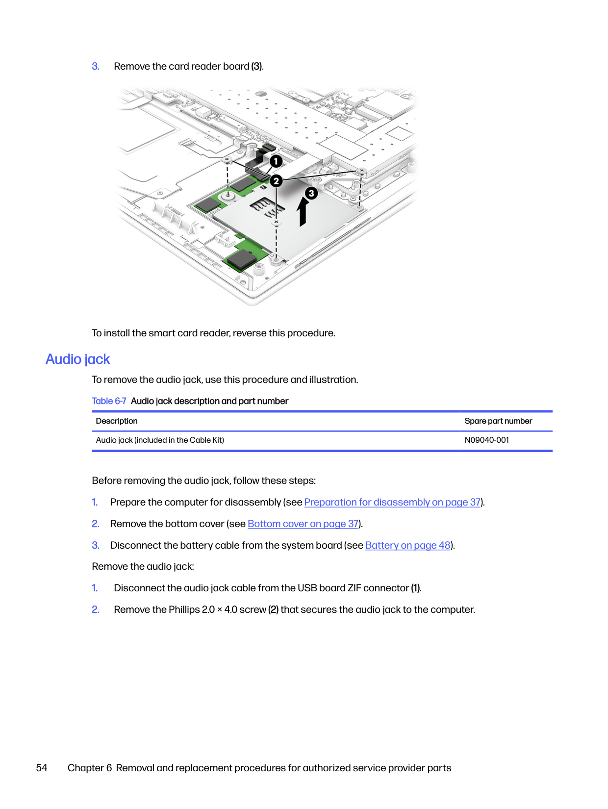
Smart card reader To remove the smart card reader from the top cover, use this procedure and illustration. Table 6-6 Smart card reader description and part number
Description Spare part number
Smart card reader N93634-001 Smart card reader cable (available in the Cable Kit) N09040-001
Before removing the smart card reader, follow these steps:
Smart card reader 53

To install the smart card reader, reverse this procedure.
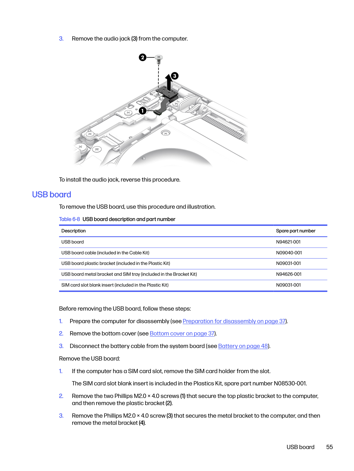
Audio jack To remove the audio jack, use this procedure and illustration. Table 6-7 Audio jack description and part number
Description Spare part number Audio jack (included in the Cable Kit) N09040-001
Before removing the audio jack, follow these steps:

To install the audio jack, reverse this procedure.
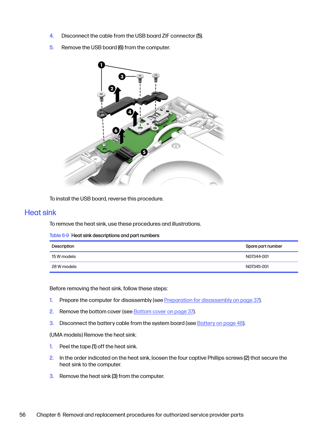
USB board To remove the USB board, use this procedure and illustration. Table 6-8 USB board description and part number
Description Spare part number USB board N94621-001 USB board cable (included in the Cable Kit) N09040-001 USB board plastic bracket (included in the Plastic Kit) N09031-001 USB board metal bracket and SIM tray (included in the Bracket Kit) N94626-001 SIM card slot blank insert (included in the Plastic Kit) N09031-001
Before removing the USB board, follow these steps:
USB board 55

To install the USB board, reverse this procedure.
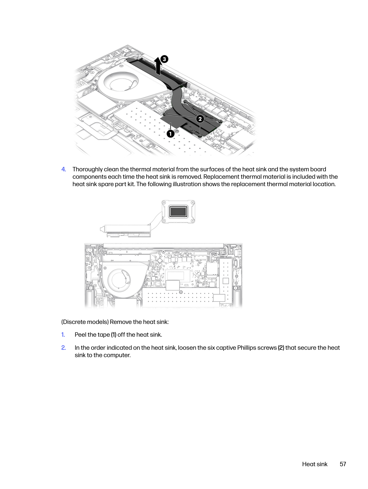
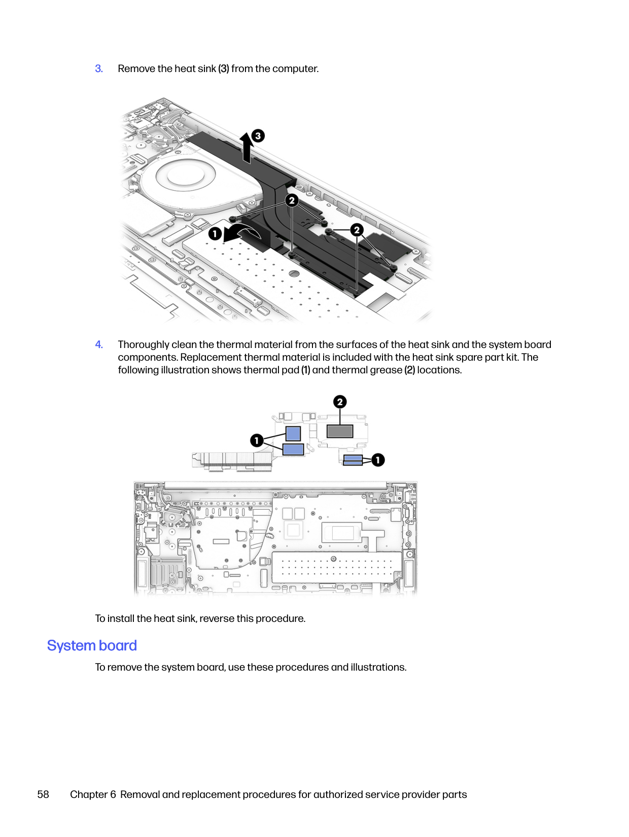
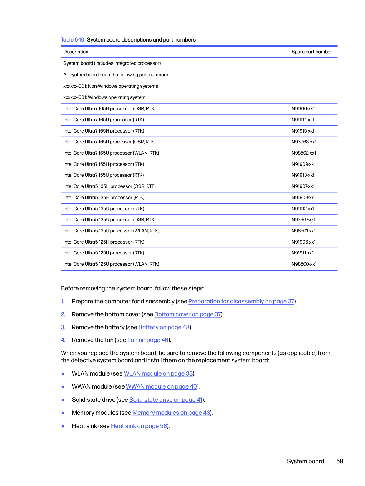
Heat sink To remove the heat sink, use these procedures and illustrations. Table 6-9 Heat sink descriptions and part numbers
Description Spare part number
15 W models N07344-001 28 W models N07345-001
Before removing the heat sink, follow these steps:


(Discrete models) Remove the heat sink:
Heat sink 57


To install the heat sink, reverse this procedure.
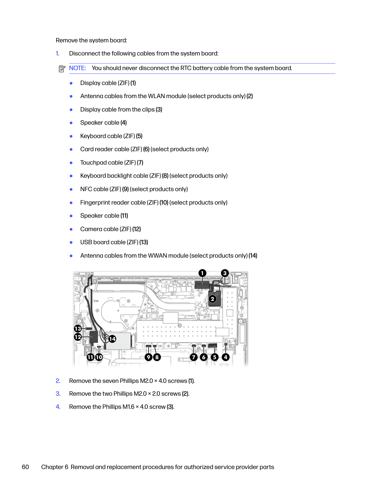
#### System board
To remove the system board, use these procedures and illustrations.
Table 6-10 System board descriptions and part numbers Description Spare part number System board (includes integrated processor) All system boards use the following part numbers: xxxxxx-001: Non-Windows operating systems xxxxxx-601: Windows operating system Intel Core Ultra7 165H processor (OSR, RTK) N91910-xx1 Intel Core Ultra7 165U processor (RTK) N91914-xx1 Intel Core Ultra7 165H processor (RTK) N91915-xx1 Intel Core Ultra7 165U processor (OSR, RTK) N93968-xx1 Intel Core Ultra7 165U processor (WLAN, RTK) N98502-xx1 Intel Core Ultra7 155H processor (RTK) N91909-xx1 Intel Core Ultra7 155U processor (RTK) N91913-xx1 Intel Core Ultra5 135H processor (OSR, RTF) N91907-xx1 Intel Core Ultra5 135H processor (RTK) N91908-xx1 Intel Core Ultra5 135U processor (RTK) N91912-xx1 Intel Core Ultra5 135U processor (OSR, RTK) N93967-xx1 Intel Core Ultra5 135U processor (WLAN, RTK) N98501-xx1 Intel Core Ultra5 125H processor (RTK) N91906-xx1 Intel Core Ultra5 125U processor (RTK) N91911-xx1 Intel Core Ultra5 125U processor (WLAN, RTK) N98500-xx1
Before removing the system board, follow these steps:
When you replace the system board, be sure to remove the following components (as applicable) from the defective system board and install them on the replacement system board:
System board 59
Remove the system board:


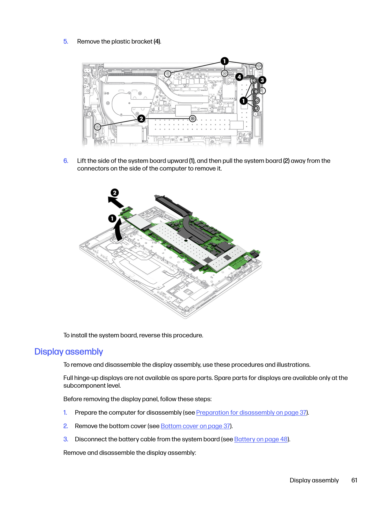
To install the system board, reverse this procedure.
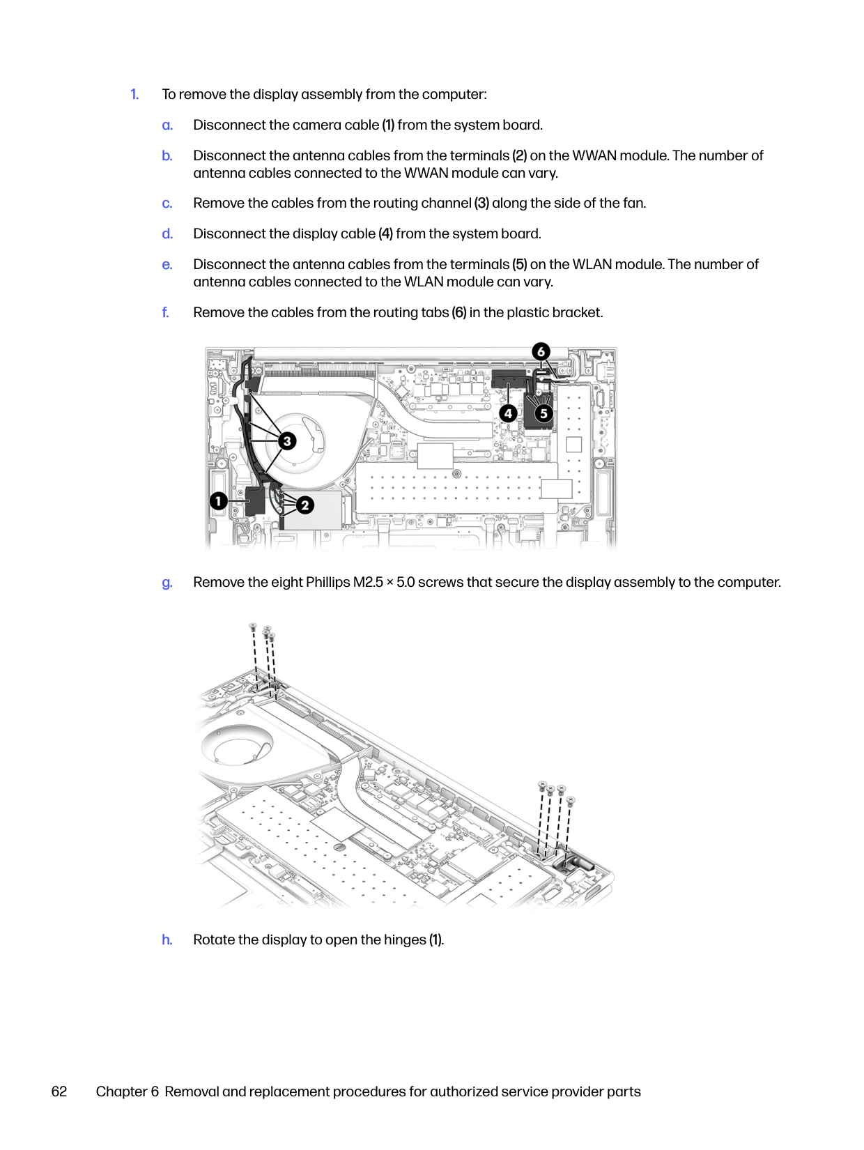
Display assembly To remove and disassemble the display assembly, use these procedures and illustrations. Full hinge-up displays are not available as spare parts. Spare parts for displays are available only at the subcomponent level. Before removing the display panel, follow these steps:


c. Swing the top edge of the hinge cover (3) up and forward, and then remove it (4) from the display back cover. The hinge cover is available in the Hinge Kit as spare part number P00213-001 for models without WWAN and N94625-001 for models with WWAN.


The hinges are available as spare part number P00213-001 for models without WWAN and N94625-001 for models with WWAN.

The display transfer board cable is included in the Panel Cable Kit, spare part number N09039-001.


■ Detach the camera module from the display back cover. The camera module is attached to the display back cover with double-sided adhesive. The camera module is available using spare part numbers N93644-001 (infrared) and N93643-001 (RGB).

The microphone module cable is included in the Panel Cable Kit, spare part number N09039-001.

■ Detach the microphone module from the display back cover. The microphone module is attached to the display back cover with double-sided adhesive. The microphone module is available using spare part number N94622-001.

To reassemble and replace the display assembly, reverse this procedure.
#### Top cover with keyboard
The top cover with keyboard remains after removing all other spare parts from the computer. In this section, the first table provides the main spare part number for the top covers with keyboards. The second table provides the country codes.
For use in country or region
Spare part number
For use in country or region
Spare part number
For use in country or region
Spare part number
Belgium -A41 Iceland -DD1 Saudi Arabia -171 Brazil -201 India -D61 Slovenia -BA1 Bulgaria -261 Israel -BB1 South Korea -AD1 Chile -161 Italy -061 Spain -071 Czech Republic/Slovakia -FL1 Japan -291 Switzerland -BG1 Denmark -081 Kazakhstan -DF1 Taiwan -AB1 Denmark, Finland, and Norway
-DH1 The Netherlands -B31 Thailand -281
French Canada -DB1 Northern Africa -FP1 Turkey -141 Finland/Sweden -B71 Norway -091 Turkey-F -541 France -051 Portugal -131 Ukraine -BD1 Germany -041 Romania -271 United Kingdom -031 Greece -151 Russia -251 United States -001 Hungary -211
Top cover with keyboard 71
Backing up, restoring, and recovering7
You can use Windows tools or HP software to back up your information, create a restore point, reset your computer, create recovery media, or restore your computer to its factory state. Performing these standard procedures can return your computer to a working state faster.

IMPORTANT: If you are performing recovery procedures on a tablet, the tablet battery must be at least 70% charged before you start the recovery process.

IMPORTANT: For a tablet with a detachable keyboard, connect the tablet to the keyboard base before beginning any recovery process.
Backing up information and creating recovery media
These methods of creating recovery media and backups are available on select products only.
#### Using Windows tools for backing up
HP recommends that you back up your information immediately after initial setup. You can do this task either using Windows Backup locally with an external USB flash drive or using online tools.

NOTE: If computer storage is 32 GB or less, Microsoft® System Restore is disabled by default.
#### Using the HP Cloud Recovery Download Tool to create recovery media (select products only)
You can use the HP Cloud Recovery Download Tool to create HP Recovery media on a bootable USB flash drive. For details: ■ Go to http://www.hp.com, search for HP Cloud Recovery, and then select the result that matches the
type of computer that you have.

NOTE: If you cannot create recovery media yourself, contact support to obtain recovery discs. Go to http://www.hp.com/support, select your country or region, and then follow the on-screen instructions.

IMPORTANT: HP recommends that you follow the Restoring and recovery methods on page 73 to restore your computer before you obtain and use the HP recovery discs. Using a recent backup can return your machine to a working state sooner than using the HP recovery discs. After the system is restored, reinstalling all the operating system software released since your initial purchase can be a lengthy process.
Restoring and recovering your system
You have several tools available to recover your system both within and outside of Windows if the desktop cannot load.
HP recommends that you attempt to restore your system using the Restoring and recovery methods on page 73.
#### Creating a system restore
System Restore is available in Windows. The System Restore software can automatically or manually create restore points, or snapshots, of the system files and settings on the computer at a particular point.
When you use System Restore, it returns your computer to its state at the time you made the restore point. Your personal files and documents should not be affected.
#### Restoring and recovery methods
After you run the first method, test to see whether the issue still exists before you proceed to the next method, which might now be unnecessary.
NOTE: The options Remove everything and then Fully clean the drive can take several hours to complete and leave no information on your computer. It is the safest way to reset your computer before you recycle it.

For more information about the first two methods, see the Get Help app:
■ Select the Start button, select All apps, select the Get Help app, and then enter the task you want to
perform.

NOTE: You must be connected to the internet to access the Get Help app.
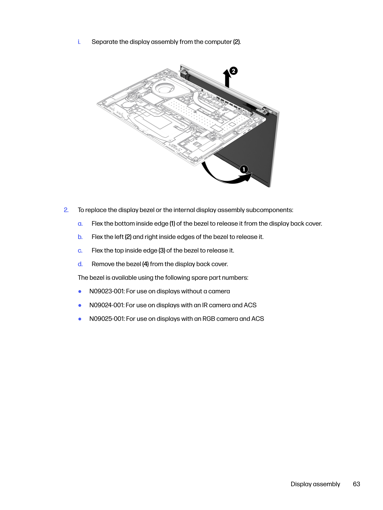
#### Recovering using HP Recovery media
You can use HP Recovery media to recover the operating system and drivers that were installed at the factory. On select products, you can create recovery media on a bootable USB flash drive using the HP Cloud Recovery Download Tool.
For details, see Using the HP Cloud Recovery Download Tool to create recovery media (select products only) on page 72.

NOTE: If you cannot create recovery media yourself, contact support to obtain recovery discs. Go to http://www.hp.com/support, select your country or region, and then follow the on-screen instructions.
To recover your system:

■ Insert the HP Recovery media, and then restart the computer. NOTE: HP recommends that you follow the Restoring and recovery methods on page 73 to restore your computer before you obtain and use the HP recovery discs. Using a recent backup can return your machine to a working state sooner than using the HP recovery discs. After the system is restored, reinstalling all the operating system software released since your initial purchase can be a lengthy process.
Creating a system restore 73
#### Changing the computer boot order
If your computer does not restart using the HP Recovery media, you can change the computer boot order, which is the order of devices listed in BIOS for startup information. You can select an optical drive or a USB flash drive, depending on the location of your HP Recovery media.

IMPORTANT: For a tablet with a detachable keyboard, connect the tablet to the keyboard base before beginning these steps. To change the boot order:
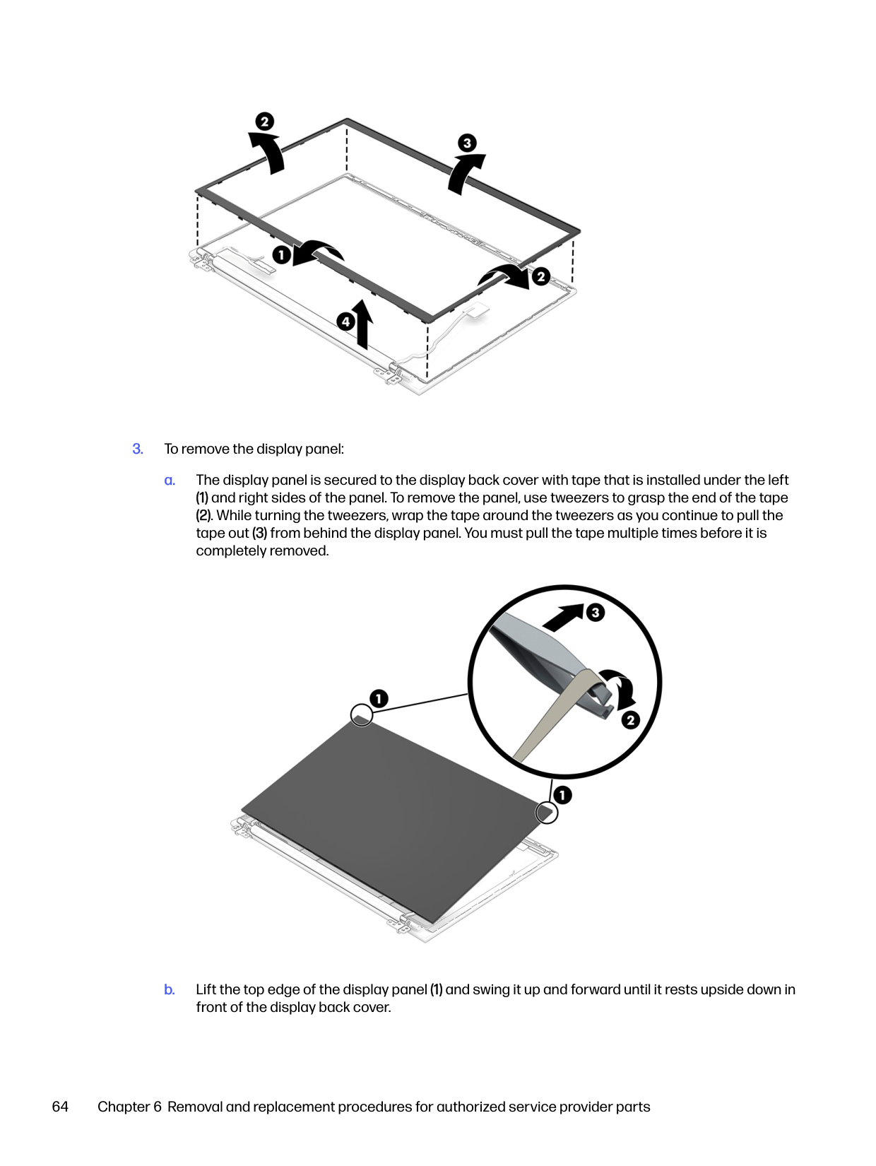
#### Using HP Sure Recover (select products only)
Select computer models are configured with HP Sure Recover, a PC operating system (OS) recovery solution built into the hardware and software. HP Sure Recover can fully restore the HP OS image without installed recovery software.
Using HP Sure Recover, an administrator or user can restore the system and install:
To access the latest documentation for HP Sure Recover, go to http://www.hp.com/support. Follow the on-screen instructions to find your product and locate your documentation.
8
Computer Setup (BIOS), TPM, and HP Sure Start
HP provides several tools to help set up and protect your computer.
Using Computer Setup
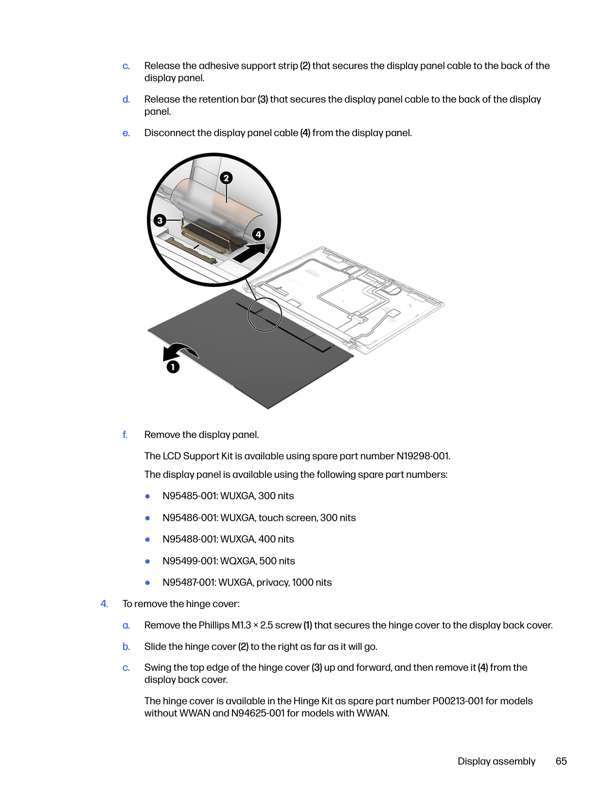
Computer Setup, or Basic Input/Output System (BIOS), controls communication between all the input and output devices on the system (such as hard drives, display, keyboard, mouse, and printer). Computer Setup includes settings for types of devices installed, the startup sequence of the computer, and amount of system and extended memory.

NOTE: Use extreme care when making changes in Computer Setup. Errors can prevent the computer from operating properly. To start Computer Setup, turn on or restart the computer, and when the HP logo appears, press f10 to enter Computer Setup.
#### Navigating and selecting in Computer Setup
You can navigate and select in Computer Setup using one or more methods.
To exit Computer Setup, choose one of the following methods:


Your changes go into effect when the computer restarts.
Restoring factory settings in Computer Setup To return all settings in Computer Setup to the values that were set at the factory, follow these steps. NOTE: Restoring defaults will not change the hard drive mode.
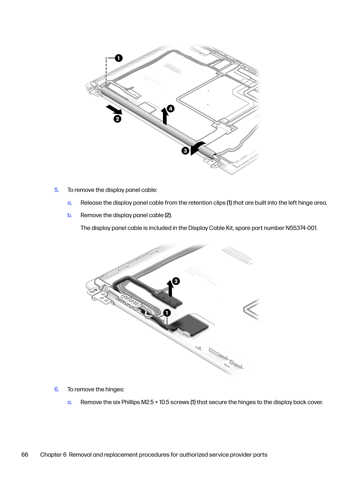

Computer Setup (BIOS), TPM, and HP Sure Start 75


NOTE: On select products, the selections might display Restore Defaults instead of Apply Factory Defaults and Exit.

Your changes go into effect when the computer restarts. NOTE: Your password settings and security settings are not changed when you restore the factory settings.
#### Updating the BIOS
Updated versions of the BIOS might be available on the HP website. Most BIOS updates on the HP website are packaged in compressed files calledSoftPaqs.
Some download packages contain a file named Readme.txt, which contains information regarding installing and troubleshooting the file.
##### Determining the BIOS version
To decide whether you need to update Computer Setup (BIOS), first determine the BIOS version on your computer.
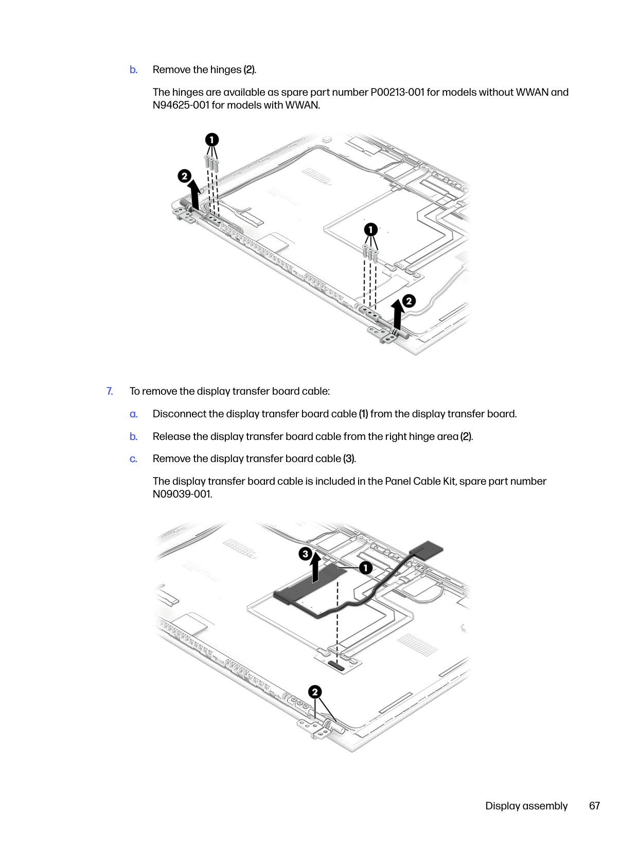
If you are already in Windows, you can access BIOS version information (also known asROM dateand System BIOS) by pressing fn+esc (select products only). Or you can use Computer Setup.

To check for later BIOS versions, see Preparing for a BIOS update on page 76. Preparing for a BIOS update
Be sure to follow all prerequisites before downloading and installing a BIOS update.

IMPORTANT: To reduce the risk of damage to the computer or an unsuccessful installation, download and install a BIOS update only when the computer is connected to reliable external power using the AC adapter. Do not download or install a BIOS update while the computer is running on battery power, docked in an optional docking device, or connected to an optional power source. During the download and installation, follow these instructions:
Do not disconnect power on the computer by unplugging the power cord from the AC outlet. Do not shut down the computer or initiate Sleep. Do not insert, remove, connect, or disconnect any device, cable, or cord.
###### Downloading a BIOS update
After you review the prerequisites, you can check for and download BIOS updates.
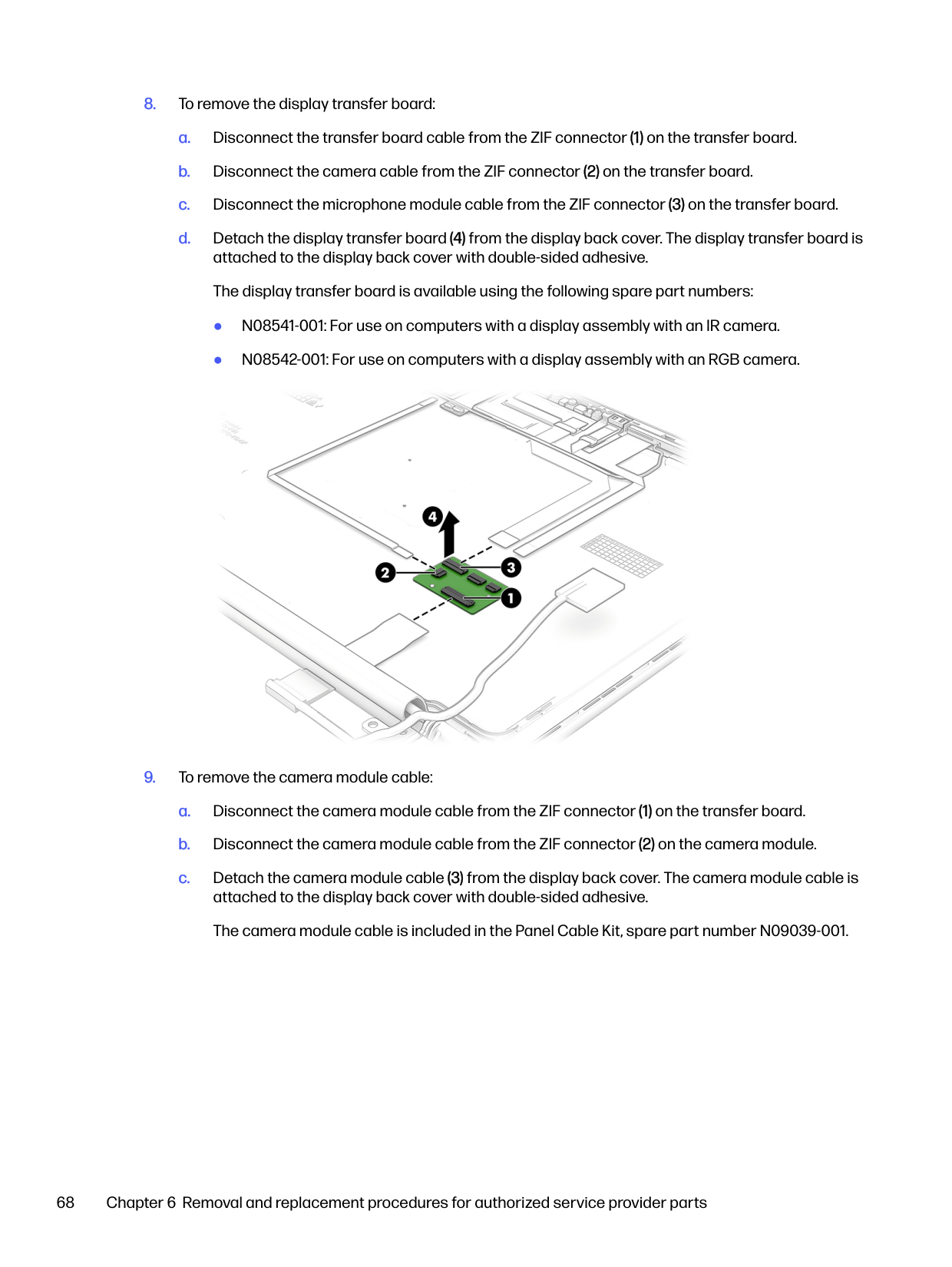
Make a note of the path to the location on your hard drive where the BIOS update is downloaded. You will need to access this path when you are ready to install the update.

NOTE: If you connect your computer to a network, consult the network administrator before installing any software updates, especially system BIOS updates.
###### Installing a BIOS update
BIOS installation procedures vary. Follow any instructions that are displayed on the screen after the download is complete. If no instructions are displayed, follow these steps.

NOTE: After a message on the screen reports a successful installation, you can delete the downloaded file from your hard drive.
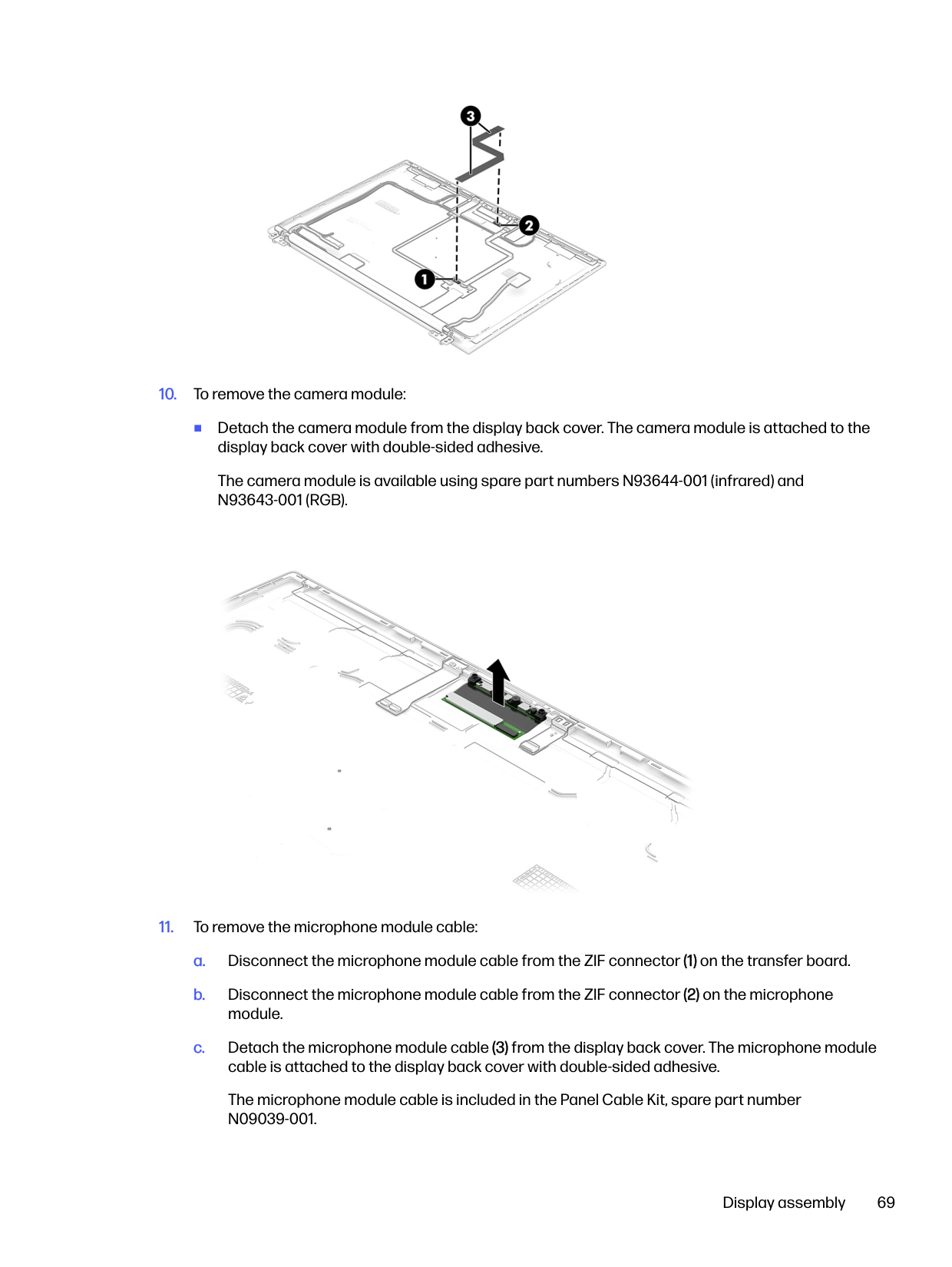
#### Changing the boot order using the f9 prompt
To dynamically choose a boot device for the current startup sequence, follow these steps.
● Turn on or restart the computer, and when the HP logo appears, press f9 to enter the Boot Device Options menu.
Downloading a BIOS update 77
TPM BIOS settings (select products only)
TPM provides additional security for your computer. You can modify the TPM settings in Computer Setup (BIOS).

IMPORTANT: Before enabling Trusted Platform Module (TPM) functionality on this system, you must ensure that your intended use of TPM complies with relevant local laws, regulations and policies, and approvals or licenses must be obtained if applicable. For any compliance issues arising from your operation or usage of TPM that violates the previously mentioned requirement, you shall bear all the liabilities wholly and solely. HP will not be responsible for any related liabilities.

NOTE: If you change the TPM setting to Hidden, TPM is not visible in the operating system. To access TPM settings in Computer Setup:
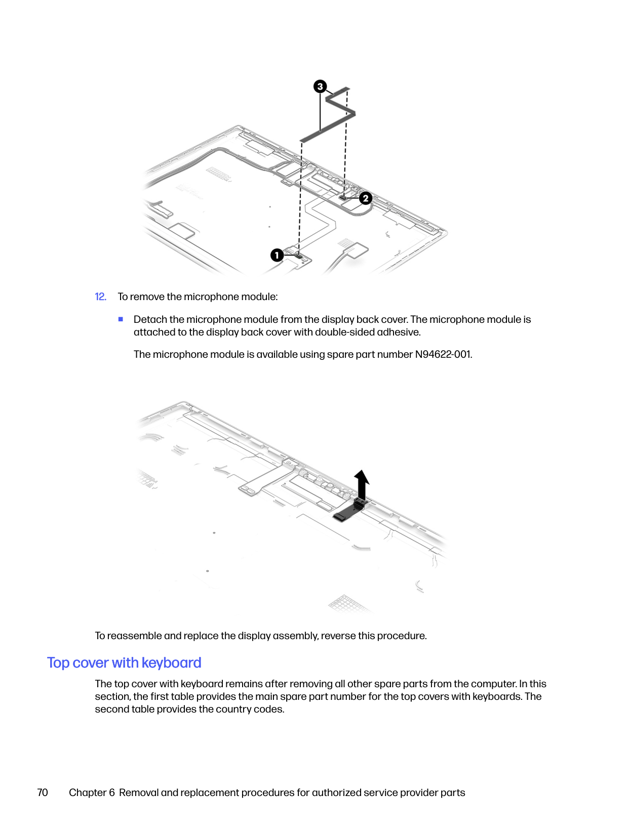
Using HP Sure Start (select products only)
Select computer models are configured with HP Sure Start, a technology that monitors the computer's BIOS for attacks or corruption. If the BIOS becomes corrupted or is attacked, HP Sure Start automatically restores the BIOS to its previously safe state, without user intervention.
HP Sure Start is configured and already enabled so that most users can use the HP Sure Start default configuration. Advanced users can customize the default configuration.
To access the latest documentation on HP Sure Start, go to http://www.hp.com/support. Select Find your product, and then follow the on-screen instructions.
Using HP PC Hardware Diagnostics9
You can use the HP PC Hardware Diagnostics utility to determine whether your computer hardware is running properly. The three versions are HP PC Hardware Diagnostics Windows, HP PC Hardware Diagnostics UEFI (Unified Extensible Firmware Interface), and (for select products only) Remote HP PC Hardware Diagnostics UEFI, a firmware feature.
Using HP PC Hardware Diagnostics Windows (select products only)
HP PC Hardware Diagnostics Windows is a Windows-based utility that allows you to run diagnostic tests to determine whether the computer hardware is functioning properly. The tool runs within the Windows operating system to diagnose hardware failures.
If HP PC Hardware Diagnostics Windows is not installed on your computer, you must download and install it. To download HP PC Hardware Diagnostics Windows, see Downloading HP PC Hardware Diagnostics Windows on page 80.
#### Using an HP PC Hardware Diagnostics Windows hardware failure ID code
When HP PC Hardware Diagnostics Windows detects a failure that requires hardware replacement, a 24-digit failure ID code is generated for select component tests. For interactive tests, such as keyboard, mouse, or audio and video palette, you must perform troubleshooting steps before you can receive a failure ID.
You have several options after you receive a failure ID:
#### Accessing HP PC Hardware Diagnostics Windows
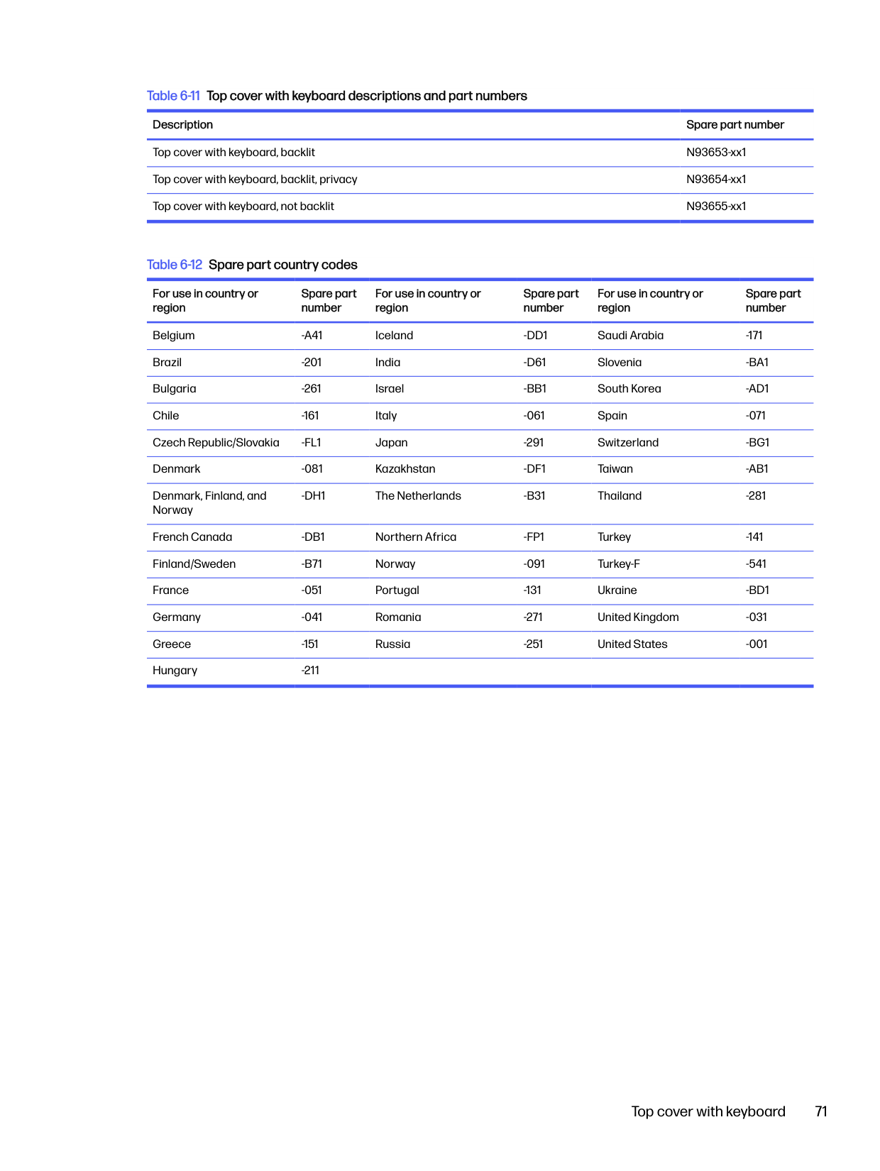
After HP PC Hardware Diagnostics Windows is installed, you can access it from HP Support Assistant or the Start menu.
##### Accessing HP PC Hardware Diagnostics Windows from HP Support Assistant
After HP PC Hardware Diagnostics Windows is installed, follow these steps to access it from HP Support Assistant:
Using HP PC Hardware Diagnostics 79

NOTE: To stop a diagnostic test, select Cancel.
##### Accessing HP PC Hardware Diagnostics Windows from the Start menu (select products only)
After HP PC Hardware Diagnostics Windows is installed, follow these steps to access it from the Start menu:
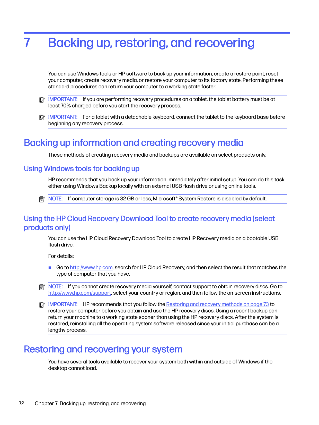
on-screen instructions.

NOTE: To stop a diagnostic test, select Cancel.
#### Downloading HP PC Hardware Diagnostics Windows
The HP PC Hardware Diagnostics Windows downloading instructions are provided in English only. You must use a Windows computer to download this tool because only .exe files are provided.
##### Downloading the latest HP PC Hardware Diagnostics Windows version from HP
To download HP PC Hardware Diagnostics Windows from HP, follow these steps:
The tool downloads to the selected location.
##### Downloading the HP PC Hardware Diagnostics Windows from the Microsoft Store You can download the HP PC Hardware Diagnostics Windows from the Microsoft Store:
##### Downloading HP Hardware Diagnostics Windows by product name or number (select products only)

You can download HP PC Hardware Diagnostics Windows by product name or number. NOTE: For some products, you might have to download the software to a USB flash drive by using the product name or number.
The tool downloads to the selected location.
#### Installing HP PC Hardware Diagnostics Windows
To install HP PC Hardware Diagnostics Windows, navigate to the folder on your computer or the USB flash drive where the .exe file downloaded, double-click the .exe file, and then follow the on-screen instructions.
Using HP PC Hardware Diagnostics UEFI
HP PC Hardware Diagnostics Unified Extensible Firmware Interface (UEFI) allows you to run diagnostic tests to determine whether the computer hardware is functioning properly. The tool runs outside the operating system so that it can isolate hardware failures from issues that are caused by the operating system or other software components.

NOTE: For some products, you must use a Windows computer and a USB flash drive to download and create the HP UEFI support environment because only .exe files are provided. For more information, see Downloading HP PC Hardware Diagnostics UEFI to a USB flash drive on page 82.
If your PC does not start in Windows, you can use HP PC Hardware Diagnostics UEFI to diagnose hardware issues.
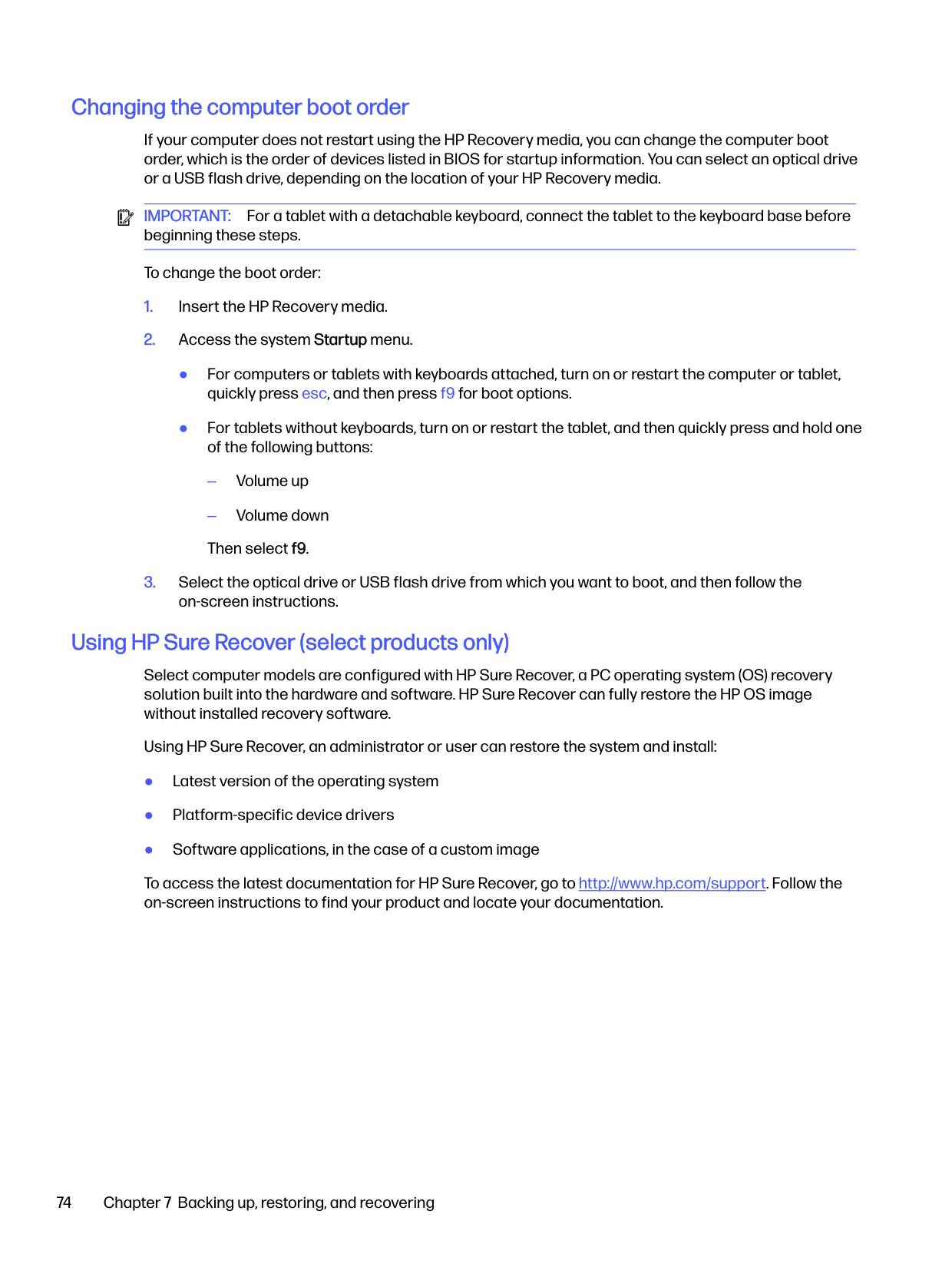
#### Using an HP PC Hardware Diagnostics UEFI hardware failure ID code
When HP PC Hardware Diagnostics UEFI detects a failure that requires hardware replacement, a 24-digit failure ID code is generated.
For assistance in solving the problem, complete one of these tasks:
#### Starting HP PC Hardware Diagnostics UEFI
To start HP PC Hardware Diagnostics UEFI, follow this procedure.
Installing HP PC Hardware Diagnostics Windows 81

#### Starting HP PC Hardware Diagnostics UEFI through HP Hotkey Support software (select products only)
This section describes how to start HP PC Hardware Diagnostics UEFI through HP Hotkey Support software.

NOTE: You must disable fast boot to access HP PC Hardware Diagnostics UEFI from the HP System Information application. To disable fast boot:


IMPORTANT: To prevent loss of data, save your work in all open apps before restarting your computer. NOTE: When the restart is complete, the computer opens the HP PC Hardware Diagnostics UEFI Application. Proceed with the troubleshooting tests.
#### Downloading HP PC Hardware Diagnostics UEFI to a USB flash drive
Downloading HP PC Hardware Diagnostics UEFI to a USB flash drive can be useful in some situations.

NOTE: The HP PC Hardware Diagnostics UEFI downloading instructions are provided in English only, and you must use a Windows computer to download and create the HP UEFI support environment because only .exe files are provided.
##### Downloading the latest HP PC Hardware Diagnostics UEFI version
To download the latest HP PC Hardware Diagnostics UEFI version to a USB flash drive, follow this procedure:
##### Downloading HP PC Hardware Diagnostics UEFI by product name or number (select products only)
You can download HP PC Hardware Diagnostics UEFI by product name or number (select products only) to a USB flash drive.

NOTE: For some products, you might have to download the software to a USB flash drive by using the product name or number.
Using Remote HP PC Hardware Diagnostics UEFI settings (select products only)
Remote HP PC Hardware Diagnostics UEFI is a firmware (BIOS) feature that downloads HP PC Hardware Diagnostics UEFI to your computer. It can then run the diagnostics on your computer, and it might upload results to a preconfigured server.
For more information about Remote HP PC Hardware Diagnostics UEFI, go to http://www.hp.com/go/techcenter/pcdiags, and then select Find out more.
#### Downloading Remote HP PC Hardware Diagnostics UEFI
Remote HP PC Hardware Diagnostics UEFI is also available as a SoftPaq that you can download to a server.
##### Downloading the latest Remote HP PC Hardware Diagnostics UEFI version
You can download the latest Remote HP PC Hardware Diagnostics UEFI version to a USB flash drive.
Downloading Remote HP PC Hardware Diagnostics UEFI by product name or number You can download Remote HP PC Hardware Diagnostics UEFI by product name or number. NOTE: For some products, you might have to download the software by using the product name or number.

Downloading the latest HP PC Hardware Diagnostics UEFI version 83
#### Customizing Remote HP PC Hardware Diagnostics UEFI settings
Using the Remote HP PC Hardware Diagnostics setting in Computer Setup (BIOS), you can perform several customizations.
Specifications10
This chapter provides specifications for your computer system.
Computer specifications
This section provides specifications for your computer. When you travel with your computer, the computer dimensions and weights, as well as input power ratings and operating specifications, provide helpful information.
Table 10-1 Computer specifications
Metric U.S.
Dimensions Width 315.6 mm 12.4 in Depth 224.4 mm 8.8 in Height 19.2 mm 0.8 in Weight 1.4 kg 3.14 lbs Input power Operating voltage and current 5 V DC @ 3 A / 9 V DC @ 3 A / 12 V
DC @ 5 A / 15 V DC @ 4.33 A / 20 V DC @ 3.25 A – 65 W USB-C
5 V DC @ 3 A / 9 V DC @ 3 A / 10 V DC @ 5 A / 12 V DC @ 5 A / 15 V DC @ 4.33 A / 20 V DC @ 3.25 A – 65 W USB-C
Temperature Operating 5°C to 35°C 41°F to 95°F Nonoperating –20°C to 60°C –4°F to 140°F Relative humidity (noncondensing) Operating 10% to 90% Nonoperating 5% to 95% Maximum altitude (unpressurized)
Operating –15 m to 3,048 m –50 ft to 10,000 ft Nonoperating –15 m to 12,192 m –50 ft to 40,000 ft

NOTE: Applicable product safety standards specify thermal limits for plastic surfaces. The device operates well within this range of temperatures.
Specifications 85
Display specifications This section provides specifications for your display. Table 10-2 Display specifications
Metric U.S. Active diagonal size 35.6 cm 14.0 in Resolution 1920 × 1200 (WUXGA) Surface treatment Antiglare Brightness 300 nits (45% CG)
400 nits (100% sRGB) 800 nits (100% sRGB, HP Sure View) 1000 nits (privacy)
Viewing angle UWVA Backlight WLED
LED Display panel interface eDP
Solid-state drive specifications This section provides specifications for your solid-state drives. Table 10-3 Solid-state drive specifications
512 GB* 1 TB* 2 TB*
Dimensions Height 1.0 mm 1.0 mm 1.0 mm Length 50.8 mm 50.8 mm 50.8 mm Width 28.9 mm 28.9 mm 28.9 mm Weight < 10 g < 10 g < 10 g Interface type PCIe PCIe PCIe
Ready time, maximum (to not busy) < 1.0 ms 1.0 ms 1.0 ms Access times, logical 0.1 ms 0.1 ms 0.1 ms Transfer rate
Sequential read up to 2150 MBps up to 2150 MBps up to 3800 MBps Random read Up to 300,000 IOPs Up to 300,000 IOPs Up to 300,000 IOPs Sequential write up to 1550 MBps up to 1550 MBps up to 2670 MBps Random write Up to 100,000 IOPs Up to 100,000 IOPs Up to 100,000 IOPs Total logical sectors 1,000,215,216 1,500,336,388 2,998,846
86 Chapter 10 Specifications
######## Table 10-3 Solid-state drive specifications (continued)
######### 512 GB* 1 TB* 2 TB* Operating temperature 0°C to 70°C
0°C to 70°C (32°F to 158°F)
0°C to 70°C (32°F to 158°F)
(32°F to 158°F)

NOTE: *1 GB = 1 billion bytes when referring to hard drive storage capacity. Actual accessible capacity is less. Actual drive specifications might differ slightly. Certain restrictions and exclusions apply. Contact support for details.
Solid-state drive specifications 87
Statement of memory volatility11
For general information regarding nonvolatile memory in HP business computers, and to restore nonvolatile memory that can contain personal data after the system has been turned off and the hard drive has been removed, use these instructions.
HP business computer products that use Intel®-based or AMD®-based system boards contain volatile DDR memory. The amount of nonvolatile memory present in the system depends upon the system configuration. Intel-based and AMD-based system boards contain nonvolatile memory subcomponents as originally shipped from HP, with the following assumptions:
Following system shutdown and removal of all power sources from an HP business computer system, personal data can remain on volatile system memory (DIMMs) for a finite period of time and also remains in nonvolatile memory. Use the following steps to remove personal data from the computer, including the nonvolatile memory found in Intel-based and AMD-based system boards.

NOTE: If your tablet has a keyboard base, connect to the keyboard base before beginning steps in this chapter.
Current BIOS steps
Use these instructions to restore nonvolatile memory.


– or –
– or –

NOTE: If you clear data using Secure Erase, you cannot recover it.
– or – Clear the contents of the drive using the following Disk Sanitizer commands steps:
i. Turn on or restart the computer, and then quickly press esc. ii. Select the Security menu and scroll down to the Utilities menu. iii. Select Hard Drive Utilities.
Current BIOS steps 89
iv. Under Utilities, select Disk Sanitizer, select the hard drive with the data that you want to
clear, and then follow the on-screen instructions to continue.

NOTE: The amount of time it takes for Disk Sanitizer to run can take several hours. Plug the computer into an AC outlet before starting.
Nonvolatile memory usage Use this table to troubleshoot nonvolatile memory usage. Table 11-1 Troubleshooting steps for nonvolatile memory usage
######### Description Volatility description Storage user data How to erase
Primary storage device, holds the OS, applications, and application settings
Non-volatile, 8-256 GB of eMMC or NVMe SSD storage, removable
Yes1 Follow instructions below under “Erase the Primary Storage Device”
System memory (RAM), holds transient data during system operation
Volatile, SODIMM socket. Removable (4 GB/8 GB/16 GB)
Yes Unplug unit from power
Permanent system BIOS settings Non-volatile; 16 KB; stored No2 Follow instructions below under “Clearing BIOS Settings”
System boot ROM (BIOS) Non-volatile memory, 128 Mbit (16 MB) socketed, removable
No Download the latest BIOS for your model from the HP website and follow the instructions to flash the BIOS that are on the website
RTC (CMOS) RAM Volatile memory, 256 bytes located in AMD embedded System on Chip (SoC)
No Unplug unit from main power, remove top cover and press Clear CMOS button
Keyboard/mouse (ROM) Non-volatile, 2 KB embedded in the super I/O controller (SIO2)
Yes N/A
Keyboard/mouse (RAM) Volatile, 256 bytes embedded in the super I/O controller (SIO2)
No Unplug unit from main power
LOM EEPROM Non-volatile, 2 MB embedded in LAN controller
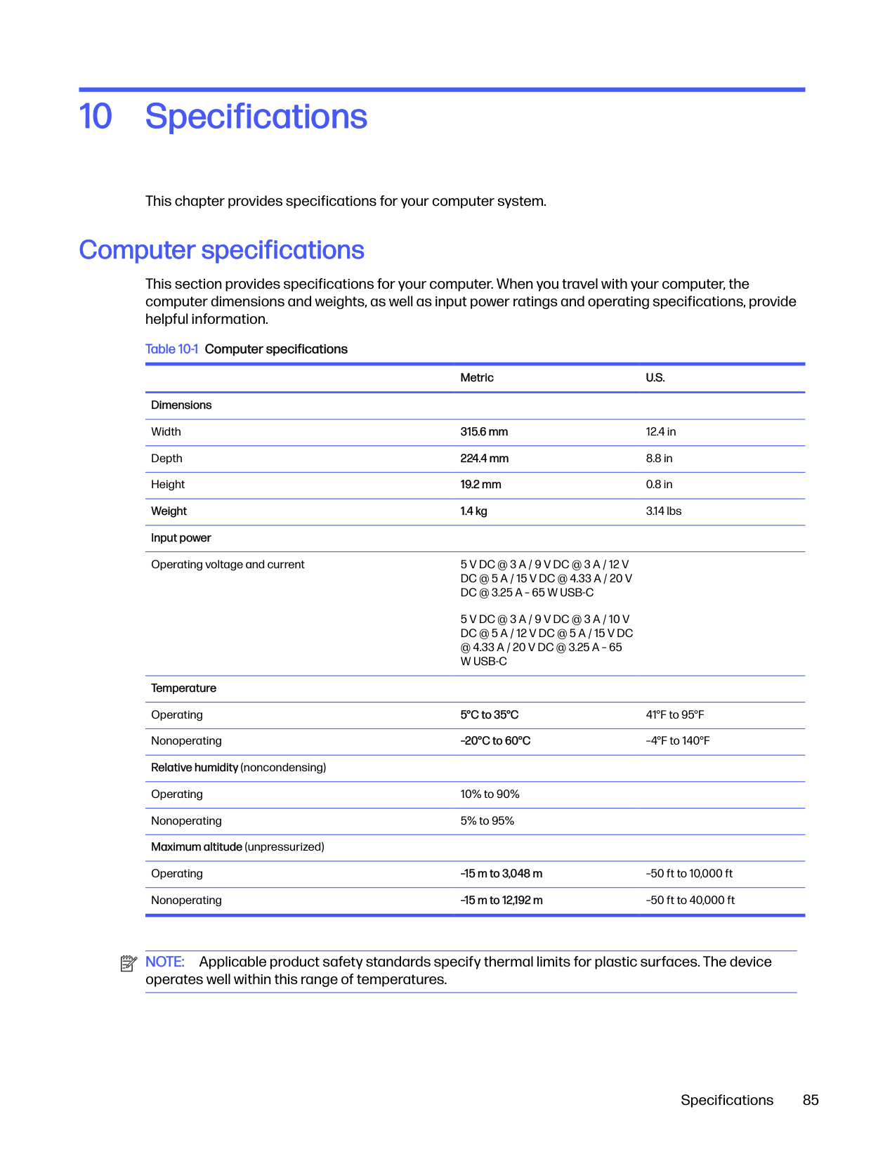
No N/A
Trusted Platform Module (TPM) Non-volatile; 51 KB ROM for firmware and 38 KB system parametric data
No3 Follow instructions below under “Clearing TPM”
Questions and answers
Use this section to answer your questions about nonvolatile memory.
IMPORTANT: The restore defaults feature does not securely erase any information on your hard drive. See question and answer 6 for steps to securely erase information. The restore defaults feature does not reset the Custom Secure Boot keys. See question and answer 7 for information about resetting the keys.
The Unified Extensible Firmware Interface (UEFI) BIOS is an industry-standard software interface between the platform firmware and an operating system (OS). It replaces the older BIOS architecture but supports much of the legacy BIOS functionality.
Like the legacy BIOS, the UEFI BIOS provides an interface to display the system information and configuration settings and to change the configuration of your computer before an OS is loaded. BIOS provides a secure runtime environment that supports a Graphic User Interface (GUI). In this environment, you can use either a pointing device (touch screen, touchpad, pointing stick, or USB mouse) or the keyboard to navigate and make menu and configuration selections. The UEFI BIOS also contains basic system diagnostics.
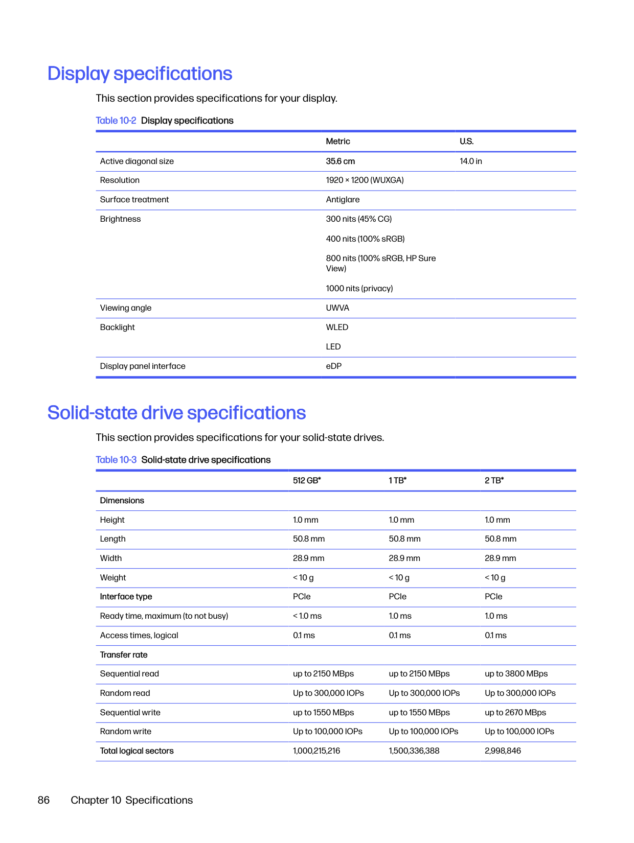
The UEFI BIOS provides functionality beyond that of the legacy BIOS. In addition, the UEFI BIOS works to initialize the computer’s hardware before loading and executing the OS; the runtime environment allows the loading and execution of software programs from storage devices to provide more functionality, such as advanced hardware diagnostics (with the ability to display more detailed system information) and advanced firmware management and recovery software.
HP has provided options in Computer Setup (BIOS) to allow you to run in legacy BIOS, if required by the operating system. Examples of this requirement would be if you upgrade or downgrade the OS.
The DIMM SPD memory contains information about the memory module, such as size, serial number, data width, speed and timing, voltage, and thermal information. This information is written by the module manufacturer and stored on an EEPROM. You cannot write to this EEPROM when the memory module is installed in a computer. Third-party tools do exist that can write to the EEPROM when the memory module is not installed in a computer. Various third-party tools are available to read SPD memory.

Questions and answers 91
This message relates to clearing the Real Time Clock (RTC) CMOS memory that contains computer configuration data.
###### 6. How can the BIOS security be reset to factory defaults and erase the data?IMPORTANT: Resetting results in the loss of information.

These steps do not reset Custom Secure Boot Keys. See question and answer 7 for information about resetting the keys.
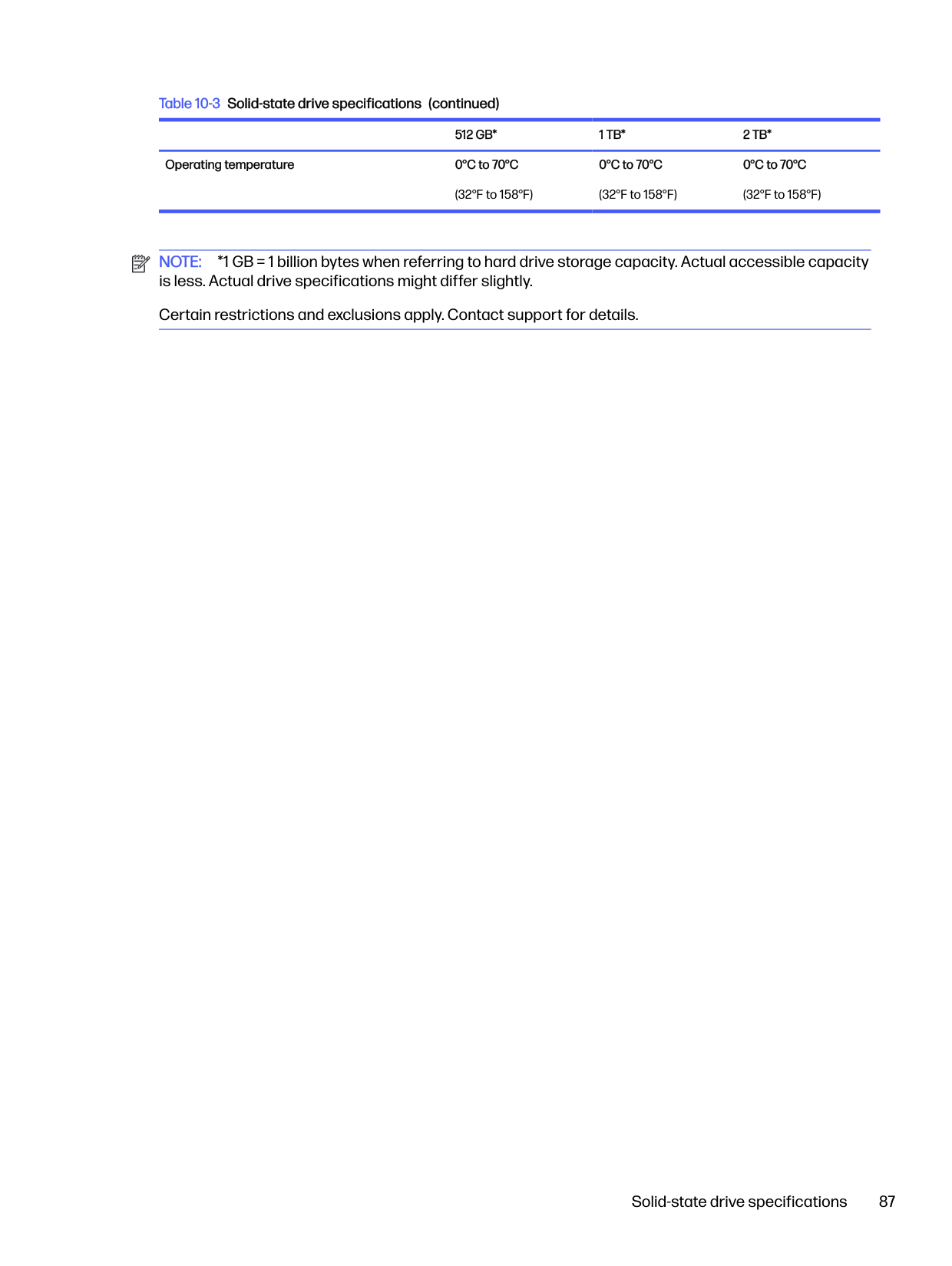
###### 7. How can the Custom Secure Boot Keys be reset?
Secure Boot is a feature to ensure that only authenticated code can start on a platform. If you enabled Secure Boot and created Custom Secure Boot Keys, disabling Secure Boot does not clear the keys. You must also select to clear the Custom Secure Boot Keys. Use the same Secure Boot access procedure that you used to create the Custom Secure Boot Keys, but select to clear or delete all Secure Boot Keys.
Using HP Sure Start (select products only)
Select computer models are configured with HP Sure Start, a technology that continuously monitors your computer's BIOS for attacks or corruption.
If the BIOS becomes corrupted or is attacked, HP Sure Start restores the BIOS to its previously safe state, without user intervention. Those select computer models ship with HP Sure Start configured and enabled. HP Sure Start is configured and already enabled so that most users can use the HP Sure Start default configuration. Advanced users can customize the default configuration.
To access the latest documentation on HP Sure Start, go to http://www.hp.com/support.
Power cord set requirements12
This chapter provides power cord requirements for countries and regions. The wide-range input feature of the computer permits it to operate from any line voltage from 100 V AC to 120 V AC, or from 220 V AC to 240 V AC. The three-conductor power cord set included with the computer meets the requirements for use in the country or region where the equipment is purchased. Power cord sets for use in other countries or regions must meet the requirements of the country and region where the computer is used.
Requirements for all countries
These power cord requirements are applicable to all countries and regions.
Requirements for specific countries and regions To determine power cord requirements for specific countries and regions, use this table. Table 12-1 Power cord requirements for specific countries and regions
######### Country/region Accredited agency Applicable note number
Argentina IRAM 1 Australia SAA 1 Austria OVE 1 Belgium CEBEC 1 Brazil ABNT 1 Canada CSA 2 Chile IMQ 1 Denmark DEMKO 1 Finland FIMKO 1 France UTE 1
Power cord set requirements 93
Table 12-1 Power cord requirements for specific countries and regions (continued) Country/region Accredited agency Applicable note number Germany VDE 1 India BIS 1 Israel SII 1 Italy IMQ 1 Japan JIS 3 Netherlands KEMA 1 New Zealand SANZ 1 Norway NEMKO 1 People's Republic of China CCC 4 Saudi Arabia SASO 7 Singapore PSB 1 South Africa SABS 1 South Korea KTL 5 Sweden SEMKO 1 Switzerland SEV 1 Taiwan BSMI 6 Thailand TISI 1 United Kingdom ASTA 1 United States UL 2
94 Chapter 12 Power cord set requirements
Requirements for specific countries and regions 95
Recycling13
When a nonrechargeable or rechargeable battery has reached the end of its useful life, do not dispose of the battery in general household waste. Follow the local laws and regulations in your area for battery disposal.
HP encourages customers to recycle used electronic hardware, HP original print cartridges, and rechargeable batteries. For more information about recycling programs, see the HP website at http://www.hp.com/recycle.
96 Chapter 13 Recycling
Index
###### A
AC adapters, spare part numbers 22 ambient light and color sensor, identifying 8
audio jack removal 54 spare part number 54
audio-out (headphone)/audio-in (microphone) combo jack, identifying 5
audio, product description 2
###### B
backup, creating 72 backups 72 battery
illustrated 19 spare part number 19
battery light 7 BIOS
determining version 76 downloading an update 76, 77 updating 76 Bluetooth label 14 boot order
changing using the f9
prompt 77 boot order, changing 74 bottom cover
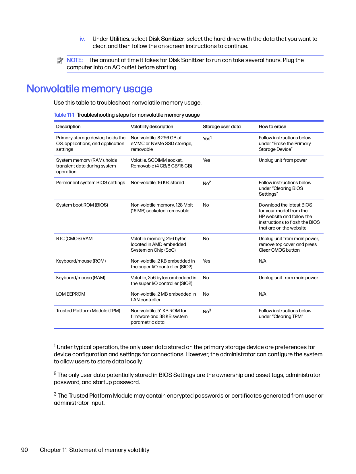
illustrated 19 removal 37 spare part number 19, 37
buttons left touchpad 9 power 12, 13 right touchpad 9
###### C
camera 8
identifying 8 camera light, identifying 8 camera module
removal 69 spare part numbers 69
camera module cable removal 68
spare part number 68 camera privacy cover,
identifying 8 caps lock light, identifying 10 caring for your computer 32 cautions
electrostatic discharge 28, 29
cleaning your computer 32 caring for wood veneer 34 disinfecting 33 HP Easy Clean 32 removing dirt and debris 32
components bottom 13 display 7 keyboard area 8 left side 6 rear 14 right side 5
computer major components 17 Computer Setup
navigating and selecting 75 restoring factory settings 75 starting 75
computer specifications 85 connector, power 6
D display
specifications 85, 86 display assembly
subcomponents 20
display back cover illustrated 22 spare part number 22
display bezel illustrated 22 removal 63 spare part number 22 spare part numbers 63
display cable illustrated 22 spare part number 22
display components 7 display panel
illustrated 21 product description 1 removal 64
spare part number 21 spare part numbers 65
display panel cable removal 66 spare part number 66
display transfer board removal 68 spare part numbers 68
display transfer board cable removal 67 spare part number 67
###### E
electrostatic discharge (ESD) 28, 29 preventing damage 28-30
esc key, identifying 13
###### F
fan
illustrated 19 removal 46
fingerprint reader illustrated 20
fingerprint reader board removal 49 spare part numbers 49
fingerprint reader, identifying 12 fn key, identifying 13 fn lock light, identifying 10
###### G
graphics, product description 1 grounding methods 28-30 guidelines
packaging 28, 34 transporting 28, 34 workstation 28
###### H
hard drive product description 2 specifications 85 HDMI port, identifying 6
heat sink removal 56 spare part numbers 56
hinge illustrated 22 removal 66 spare part number 22, 67
hinge cover removal 65 spare part number 66
HP PC Hardware Diagnostics UEFI downloading 82 failure ID code 81 HP Hotkey Support software 82 starting 81, 82 using 81
HP PC Hardware Diagnostics Windows accessing 79, 80 downloading 80 failure ID code 79 installing 81 using 79
HP Recovery media recovery 73 HP Sure Recover 74 HP Sure Start 88, 92
###### I
illustrated parts catalog 17 internal microphones,
identifying 8
###### J
jacks audio-out (headphone)/audio-in (microphone) combo 5
###### K
keyboard product description 3
keys esc 13 fn 13 Windows 13 Windows Copilot 13
###### L
labels Bluetooth 14 regulatory 14 serial number 14
service 14 wireless certification 14 WLAN 14
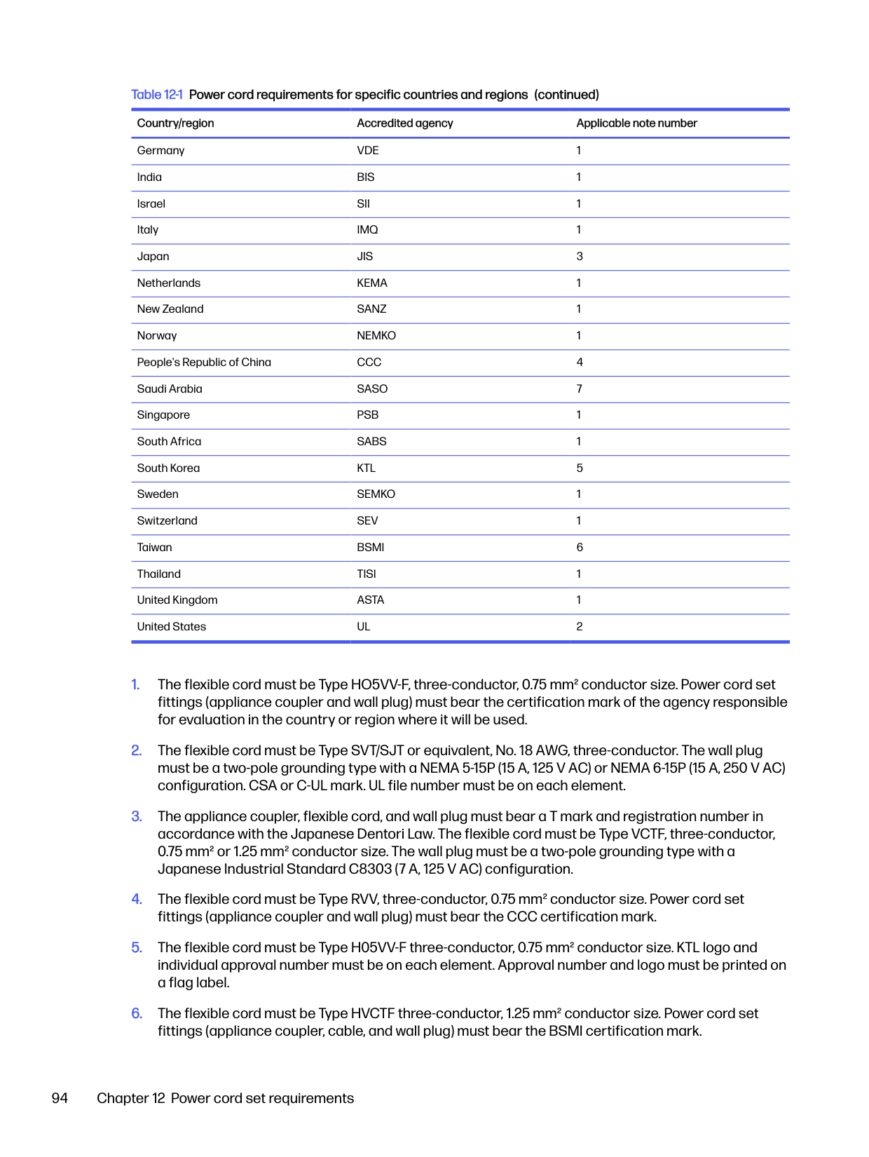
left side components 6 lights
AC adapter and battery 7 battery 7 camera 8 caps lock 10 fn lock 10 microphone mute 10 power 10 privacy key 10
lights, mute 10 low blue light mode 7
memory nonvolatile 88 volatile 88
memory module product description 1
memory modules removal 43 spare part numbers 43
microphone product description 2
microphone module removal 70 spare part number 70
microphone module cable removal 69 spare part number 70
microphone mute light,
identifying 10 model name 1 mute light, identifying 10
Near Field Communications (NFC) tapping area and antenna, identifying 9
NFC module removal 51 spare part number 51

nonvolatile memory 88
operating system, product description 4
98 Index
ports HDMI 6 product description 3 USB 5 Gbps 5 USB 5 Gbps port with HP Sleep
and Charge 6
USB Type-C power connector and Thunderbolt port with HP Sleep and Charge 6
power button, identifying 12, 13 power connector
identifying USB Type-C 6 power cord
requirements for all countries 93
requirements for specific
countries and regions 93 set requirements 93
power cords, spare part
numbers 24, 25, 27 power lights 10 power requirements, product
description 3 primary storage
product description 2 privacy key light 10 processor
product description 1
product description 3 audio 2 display panel 1 graphics 1 hard drive 2 keyboard 3 memory module 1 microphone 2 operating system 4 ports 3 power requirements 3 primary storage 2 processors 1 product name 1 security 4 sensors 3 serviceability 4 solid-state drive 2 video 2 wireless 2 product name 1 product name and number,
computer 14
R recovery 72
discs 73 media 73 USB flash drive 73
recovery media 72
creating using HP Cloud Recovery Download Tool 72
creating using Windows tools 72
regulatory information regulatory label 14 wireless certification labels 14
Remote HP PC Hardware Diagnostics UEFI settings customizing 84 using 83
removal and replacement procedures 37, 48 solid-state drive 41
removing personal data from
volatile system memory 88 restoring 72 restoring and recovery
methods 73 right side components 5 RTC battery
illustrated 19 spare part number 19
###### S
Screw Kit, spare part number 23 security cable slot, identifying 5 security, product description 4 sensors
product description 3 serial number, computer 14 service labels, locating 14 serviceability, product
description 4
setup utility navigating and selecting 75 restoring factory settings 75
SIM card holder removal 55
SIM card slot blank insert
spare part number 55 SIM card slot, identifying 5 slots
security cable 5 SIM card 5 smart card 7
smart card reader removal 53 spare part numbers 53
smart card slot, identifying 7 solid-state drive
illustrated 20 product description 2 removal and replacement 41 spare part number 20 specifications 86
spare part country codes 70 speaker
removal 45 spare part numbers 45
speakers illustrated 19 spare part number 19
speakers, identifying 14 special keys, using 12 specifications
computer 85 display 85, 86 hard drive 85 solid-state drive 86
static electricity 28, 29 support information 35 Sure Start
using 78
system board illustrated 18 removal 58 spare part number 18 spare part numbers 58
system memory, removing
personal data from volatile 88 system restore 73 system restore point, creating 72
###### T
top cover with keyboard illustrated 18 spare part numbers 18, 70
touchpad illustrated 18 removal 52 settings 8, 9 spare part number 18, 52
touchpad buttons
identifying 9 touchpad zone, identifying 9 TPM settings 78 transporting guidelines 28, 34 traveling with the computer 14
###### U
USB 5 Gbps port with HP Sleep and Charge, identifying 6
USB 5 Gbps port, identifying 5 USB board
removal 55 spare part number 55
USB Type-C power connector and Thunderbolt port with HP Sleep and Charge, identifying 6
###### V
vents
identifying 14 vents, identifying 14 video, product description 2
###### W
Windows backup 72 recovery media 72 system restore point 72
Windows Copilot key, identifying 13 Windows key, identifying 13 Windows tools, using 72 wireless antennas
illustrated 22 spare part number 22
wireless antennas, identifying 8 wireless certification label 14 wireless, product description 2 WLAN antennas, identifying 8 WLAN device 14 WLAN label 14 WLAN module
illustrated 19 removal 38 spare part number 19 spare part numbers 38
workstation guidelines 28 WWAN antennas, identifying 8 WWAN module
removal 40 spare part numbers 40