Ask AI
— answers from the official manualAnswers from the official manual.
Common questions
Common Questions
10 totalWhat should I do if the power indicator doesn't turn on?
Ensure your AC adapter is properly connected and working. If it's an external issue like a blown fuse, contact technical support for further assistance.
How do I perform a system recovery using the Windows f11 recovery tools?
Press F11 during startup and select 'Repair your computer'. Choose options such as System Restore, System Image Recovery, or Startup Repair. Follow the on-screen instructions to complete the process.
What steps are involved in factory resetting my HP EliteBook 840 G1?
Press and hold the power button for 10 seconds until the LED flashes red. This initiates a factory reset which clears all settings but saves the OS installation and license keys. Re-pair any previously connected devices after reset.
How do I access and use Computer Setup in Windows 7 or 8?
To start Computer Setup, press F10 at startup. Navigate through the menus by using the arrow keys to select options. Use the 'Esc' key to navigate back.
What should I do if my laptop gets very hot and the fan is noisy?
Ensure airflow isn't obstructed; use hard surfaces like a desk rather than soft ones. Avoid placing it directly on your lap as this can cause overheating. If problems persist, seek service.
How do I replace the battery in my HP EliteBook?
Access the battery bay, release and remove the old battery, then insert a new compatible replacement like the 3-cell, 24-Wh, or 6-cell, 60-Wh batteries.
Full Manual
176 pages
HP EliteBook 740 G1 Notebook PC HP EliteBook 840 G1 Notebook PC HP ZBook 14 Mobile Workstation HP EliteBook 750 G1 Notebook PC HP EliteBook 850 G1 Notebook PC
Maintenance and Service Guide
© Copyright 2013—2015 Hewlett-Packard Development Company, L.P.
Bluetooth is a trademark owned by its proprietor and used by Hewlett-Packard Company under license. Intel and Core are U.S. registered trademarks of Intel Corporation. Microsoft, Windows, and Windows Vista are U.S. registered trademarks of Microsoft Corporation. SD Logo is a trademark of its proprietor.
The information contained herein is subject to change without notice. The only warranties for HP products and services are set forth in the express warranty statements accompanying such products and services. Nothing herein should be construed as constituting an additional warranty. HP shall not be liable for technical or editorial errors or omissions contained herein.
Third Edition: April 2015 Second Edition: November 2014 First Edition: September 2013 Document Part Number: 734761-003
#### Important Notice about Customer Self-Repair Parts
CAUTION: Your computer includes Customer Self-Repair parts and parts that should only be accessed by an authorized service provider. See Chapter 5, "Removal and replacement procedures for Customer Self-Repair parts," for details. Accessing parts described in Chapter 6, "Removal and replacement procedures for Authorized Service Provider only parts," can damage the computer or void your warranty.
iii
####### iv Important Notice about Customer Self-Repair Parts
#### Safety warning notice
WARNING! To reduce the possibility of heat-related injuries or of overheating the device, do not place the device directly on your lap or obstruct the device air vents. Use the device only on a hard, flat surface. Do not allow another hard surface, such as an adjoining optional printer, or a soft surface, such as pillows or rugs or clothing, to block airflow. Also, do not allow the AC adapter to contact the skin or a soft surface, such as pillows or rugs or clothing, during operation. The device and the AC adapter comply with the user-accessible surface temperature limits defined by the International Standard for Safety of Information Technology Equipment (IEC 60950).
v
####### vi Safety warning notice
Table of contents

TouchPad ............................................................................................................................................. 9 Lights ................................................................................................................................................. 10 Buttons and fingerprint reader (select models only) ....................................................................... 11 Keys ................................................................................................................................................... 12
Front ..................................................................................................................................................................... 13 Left ....................................................................................................................................................................... 15 Right ..................................................................................................................................................................... 16 Bottom ................................................................................................................................................................. 17 Service tag ........................................................................................................................................................... 19
HP EliteBook 740/840/ZBook 14 models ......................................................................................... 31 HP EliteBook 750/850 models .......................................................................................................... 32
Mass storage devices .......................................................................................................................................... 33 Plastics Kit ........................................................................................................................................................... 35 Miscellaneous parts ............................................................................................................................................. 36 Sequential part number listing ........................................................................................................................... 38
Plastic parts ....................................................................................................................................... 53 Cables and connectors ...................................................................................................................... 53 Drive handling ................................................................................................................................... 54
Grounding guidelines ........................................................................................................................................... 54 Electrostatic discharge damage ....................................................................................................... 54 Packaging and transporting guidelines ......................................................................... 55 Workstation guidelines ................................................................................ 55
vii
###### 5 Removal and replacement procedures for Customer Self-Repair parts ............................................................. 57Component replacement procedures ................................................................................................................. 57
Service cover ..................................................................................................................................... 57 Battery ............................................................................................................................................... 59 Hard drive .......................................................................................................................................... 60 Solid-state drive (SSD) ...................................................................................................................... 62 RTC battery ........................................................................................................................................ 64 Memory module ................................................................................................................................ 65 WWAN module ................................................................................................................................... 67 WLAN module .................................................................................................................................... 69 Keyboard ........................................................................................................................................... 71
###### 6 Removal and replacement procedures for Authorized Service Provider parts ................................................... 75Component replacement procedures ................................................................................................................. 75
Display panel (non-touch) ................................................................................................................ 75 Base enclosure .................................................................................................................................. 79
Base enclosure (HP EliteBook 840/HP ZBook14 models) ............................................. 79 Base enclosure (HP EliteBook 850 models) ................................................................... 82
Fan ..................................................................................................................................................... 85 Card reader board ............................................................................................................................. 86 VGA/USB board .................................................................................................................................. 87 Heat sink ............................................................................................................................................ 88 Power button board .......................................................................................................................... 92 Fingerprint reader assembly ............................................................................................................. 94 System board .................................................................................................................................... 96 Speaker assembly ........................................................................................................................... 106 Display assembly ............................................................................................................................ 108

###### 7 Computer Setup (BIOS), MultiBoot, and System Diagnostics in Windows 8 ...................................................... 115Using Computer Setup ....................................................................................................................................... 115
Starting Computer Setup ................................................................................................................ 115 Navigating and selecting in Computer Setup ................................................................................. 115 Restoring factory settings in Computer Setup ............................................................................... 116 Updating the BIOS ........................................................................................................................... 116
Determining the BIOS version ...................................................................................... 116 Downloading a BIOS update ......................................................................................... 117
HP Sure Start ................................................................................................................................... 117
Using MultiBoot ................................................................................................................................................. 118 About the boot device order ........................................................................................................... 118 Choosing MultiBoot preferences .................................................................................................... 118
viii
Setting a new boot order in Computer Setup .............................................................. 118 Dynamically choosing a boot device using the f9 prompt ........................................... 119 Setting a MultiBoot Express prompt ............................................................................ 119 Entering MultiBoot Express preferences ..................................................................... 119
Using HP PC Hardware Diagnostics (UEFI) (select models only) ...................................................................... 120 Downloading HP PC Hardware Diagnostics (UEFI) to a USB device ............................................... 120
###### 8 Computer Setup (BIOS) and HP PC Hardware Diagnostics (UEFI) in Windows 7 ................................................. 121Using Computer Setup ....................................................................................................................................... 121
Starting Computer Setup ................................................................................................................ 121 Navigating and selecting in Computer Setup ................................................................................. 121 Restoring factory settings in Computer Setup ............................................................................... 122 Updating the BIOS ........................................................................................................................... 122
Determining the BIOS version ...................................................................................... 122 Downloading a BIOS update ......................................................................................... 123
HP Sure Start ................................................................................................................................... 123
Using MultiBoot ................................................................................................................................................. 124 About the boot device order ........................................................................................................... 124 Choosing MultiBoot preferences .................................................................................................... 124
Setting a new boot order in Computer Setup .............................................................. 124 Dynamically choosing a boot device using the f9 prompt ........................................... 125 Setting a MultiBoot Express prompt ............................................................................ 125 Entering MultiBoot Express preferences ..................................................................... 125
Using HP PC Hardware Diagnostics (UEFI) (select models only) ...................................................................... 126 Downloading HP PC Hardware Diagnostics (UEFI) to a USB device ............................................... 126
####### 9 Computer Setup (BIOS) and Advanced System Diagnostics in SUSE Linux ........................................................ 127Starting Computer Setup .................................................................................................................................. 127Using Computer Setup ....................................................................................................................................... 127

Navigating and selecting in Computer Setup ................................................................................. 127 Restoring factory settings in Computer Setup ............................................................................... 129
Updating the BIOS .............................................................................................................................................. 129 Determining the BIOS version ......................................................................................................... 129 Downloading a BIOS update ........................................................................................................... 130
HP Sure Start ..................................................................................................................................................... 130 Using MultiBoot ................................................................................................................................................. 131
About the boot device order ........................................................................................................... 131 Choosing MultiBoot preferences .................................................................................................... 131
Dynamically choosing a boot device using the f9 prompt ........................................... 131 Using HP PC Hardware Diagnostics (UEFI) (select models only) ...................................................................... 131 Downloading HP PC Hardware Diagnostics (UEFI) to a USB device ............................................... 132
ix
Using the Windows recovery tools ................................................................................................. 134 Using f11 recovery tools ................................................................................................................. 135 Using Windows 8 operating system media (purchased separately) ............................................. 135 Using Windows Refresh for quick and easy recovery .................................................................... 136 Remove everything and reinstall Windows .................................................................................... 136 Using HP Software Setup ................................................................................................................ 137
Guidelines ........................................................................................................................................ 138 Creating recovery media with HP Recovery Disc Creator ............................................................... 138
Creating recovery media .............................................................................................. 139 Backing up your information .......................................................................................................... 139
Performing a system recovery .......................................................................................................................... 140 Using the Windows recovery tools ................................................................................................. 140 Using f11 recovery tools (select models only) ............................................................................... 142 Using Windows 7 operating system media .................................................................................... 142

x
###### Index ........................................................................................................................................................... 161
xi
####### xii
1 Product description
HP EliteBook 750/850 HP EliteBook 740 G1 Notebook PC √
Category Description HP
HP ZBook 14
EliteBook 740/840
Product Name HP EliteBook 840 G1 Notebook PC √ HP ZBook 14 Mobile Workstation √ HP EliteBook 750 G1 Notebook PC √ HP EliteBook 850 G1 Notebook PC √
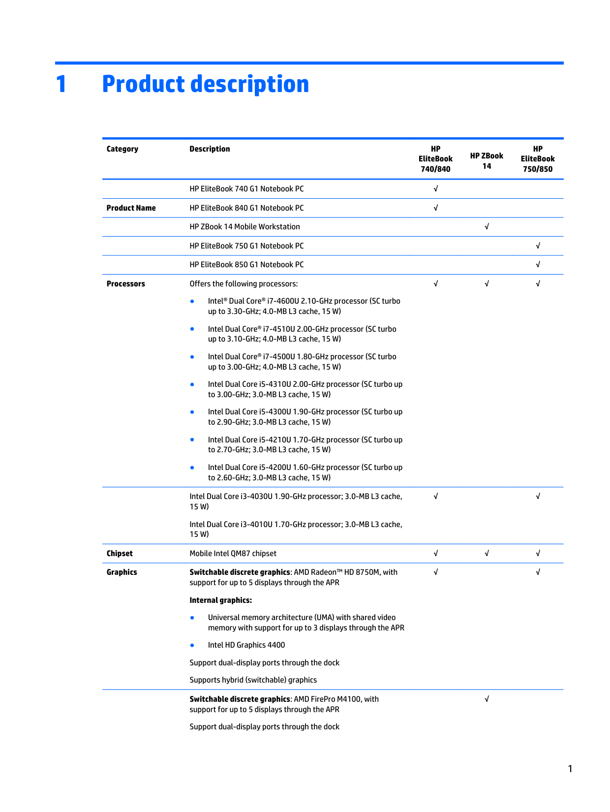
Processors Offers the following processors:

√√√
Intel Dual Core i3-4030U 1.90-GHz processor; 3.0-MB L3 cache, 15 W)
Intel Dual Core i3-4010U 1.70-GHz processor; 3.0-MB L3 cache, 15 W)
√ √
Chipset Mobile Intel QM87 chipset √√√ Graphics Switchable discrete graphics: AMD Radeon™ HD 8750M, with
√ √
support for up to 5 displays through the APR Internal graphics:
######## Switchable discrete graphics: AMD FirePro M4100, with
support for up to 5 displays through the APR Support dual-display ports through the dock
√
Supports hybrid (switchable) graphics
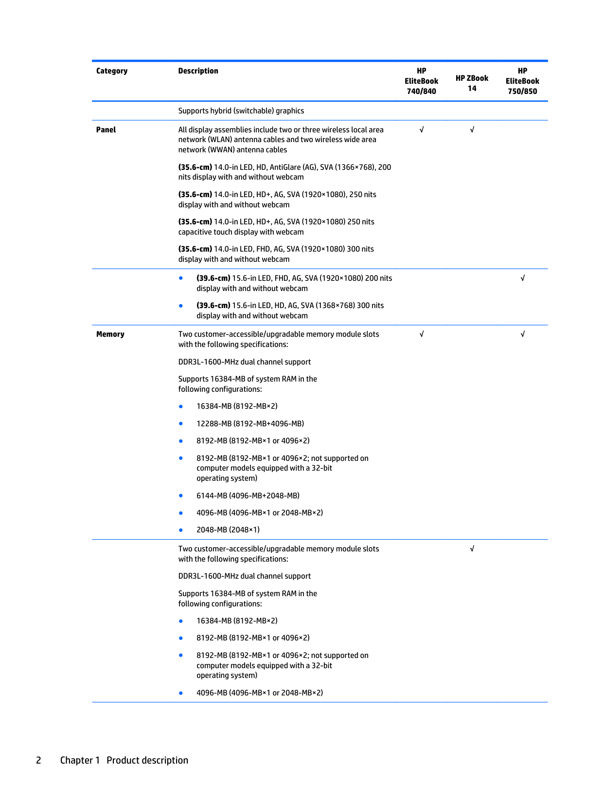
Panel All display assemblies include two or three wireless local area network (WLAN) antenna cables and two wireless wide area network (WWAN) antenna cables
(35.6-cm) 14.0-in LED, HD, AntiGlare (AG), SVA (1366×768), 200 nits display with and without webcam
(35.6-cm) 14.0-in LED, HD+, AG, SVA (1920×1080), 250 nits display with and without webcam
(35.6-cm) 14.0-in LED, HD+, AG, SVA (1920×1080) 250 nits capacitive touch display with webcam
(35.6-cm) 14.0-in LED, FHD, AG, SVA (1920×1080) 300 nits display with and without webcam
Memory Two customer-accessible/upgradable memory module slots with the following specifications: DDR3L-1600-MHz dual channel support Supports 16384-MB of system RAM in the following configurations:
Two customer-accessible/upgradable memory module slots with the following specifications:
DDR3L-1600-MHz dual channel support Supports 16384-MB of system RAM in the following configurations:
√√
√
√ √
√
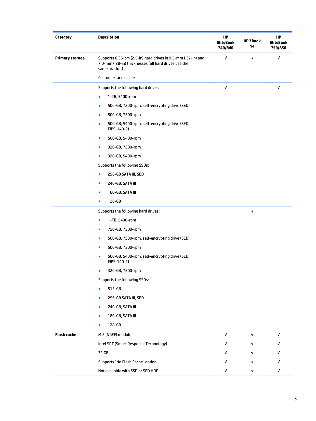
Primary storage Supports 6.35-cm (2.5-in) hard drives in 9.5-mm (.37-in) and 7.0-mm (.28-in) thicknesses (all hard drives use the same bracket)
Customer-accessible
Supports the following hard drives:
Supports the following hard drives:
Flash cache M.2 (NGFF) module Intel SRT (Smart Response Technology) 32 GB Supports "No Flash Cache" option Not available with SSD or SED HDD
√√√
√ √
√
√ √ √ √ √
√ √ √ √ √
√ √ √ √ √
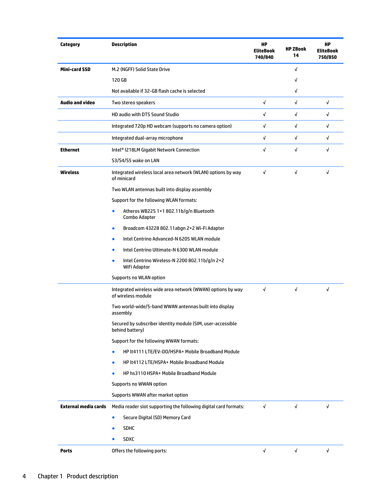
Mini-card SSD M.2 (NGFF) Solid State Drive 120 GB Not available if 32-GB flash cache is selected
√ √ √
Audio and video Two stereo speakers √√√ HD audio with DTS Sound Studio √√√ Integrated 720p HD webcam (supports no camera option) √√√ Integrated dual-array microphone √√√
Ethernet Intel® I218LM Gigabit Network Connection
S3/S4/S5 wake on LAN
√√√
Wireless Integrated wireless local area network (WLAN) options by way of minicard Two WLAN antennas built into display assembly Support for the following WLAN formats:
Supports no WLAN option
√√√
Integrated wireless wide area network (WWAN) options by way of wireless module
Two world-wide/5-band WWAN antennas built into display assembly
Secured by subscriber identity module (SIM, user-accessible behind battery)
Support for the following WWAN formats:
√√√

External media cards Media reader slot supporting the following digital card formats:
√√√
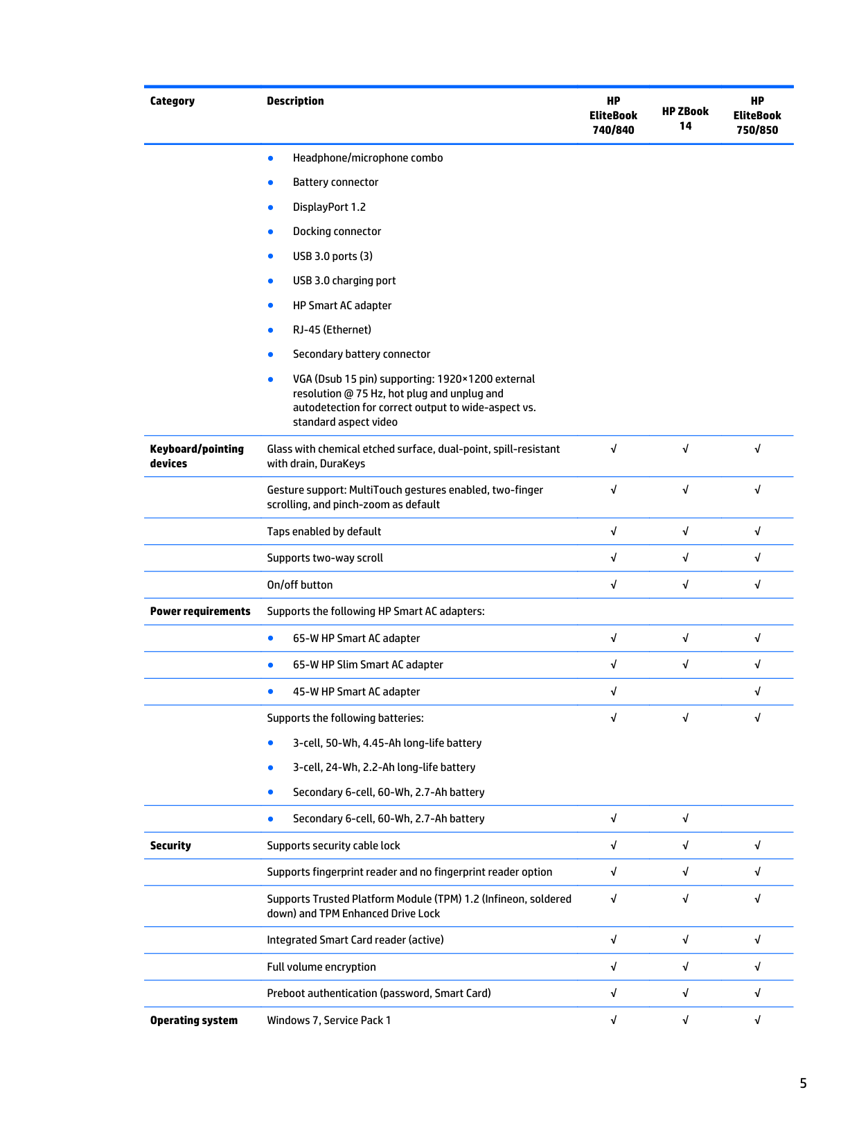
Ports Offers the following ports: √√√
Keyboard/pointing devices
Glass with chemical etched surface, dual-point, spill-resistant with drain, DuraKeys
√√√
Gesture support: MultiTouch gestures enabled, two-finger scrolling, and pinch-zoom as default

√√√
Taps enabled by default √√√ Supports two-way scroll √√√
On/off button √√√ Power requirements Supports the following HP Smart AC adapters:
√√√
Security Supports security cable lock √√√ Supports fingerprint reader and no fingerprint reader option √√√ Supports Trusted Platform Module (TPM) 1.2 (Infineon, soldered down) and TPM Enhanced Drive Lock
√√√
Integrated Smart Card reader (active) √√√ Full volume encryption √√√ Preboot authentication (password, Smart Card) √√√
Operating system Windows 7, Service Pack 1 √√√
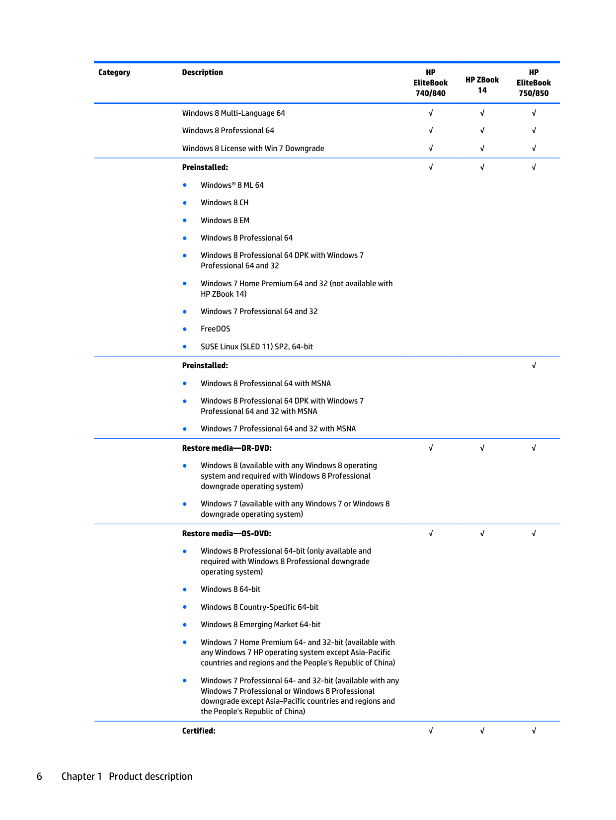
Windows 8 Multi-Language 64 Windows 8 Professional 64 Windows 8 License with Win 7 Downgrade
√ √ √
√ √ √
√ √ √
######## Preinstalled:
######## Preinstalled:
######## Restore media—DR-DVD:
√√√
√
√√√
######## Restore media—OS-DVD:
√√√
Certified: √√√
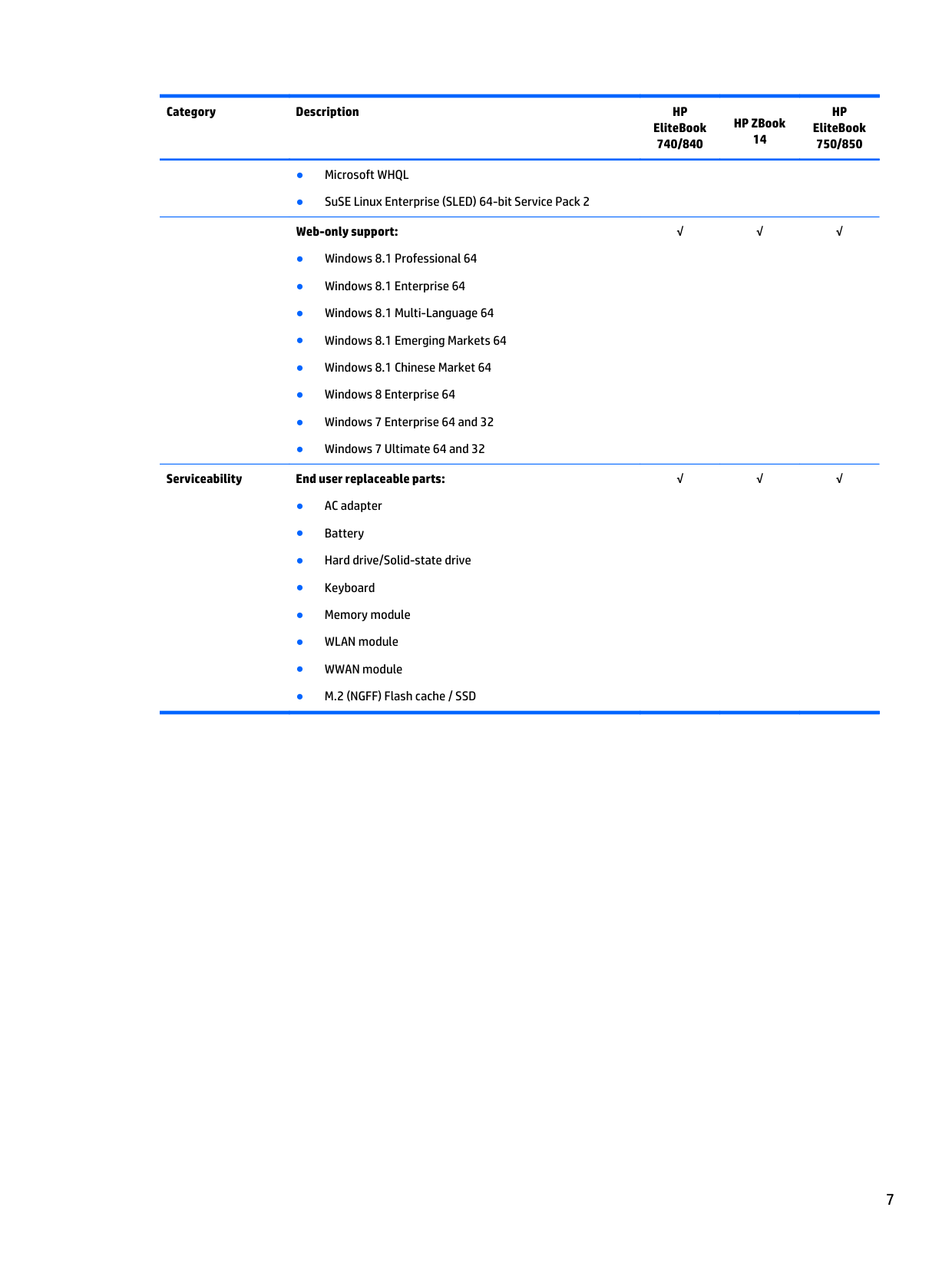
######## Serviceability End user replaceable parts:
√√√
√√√
2 External component identification
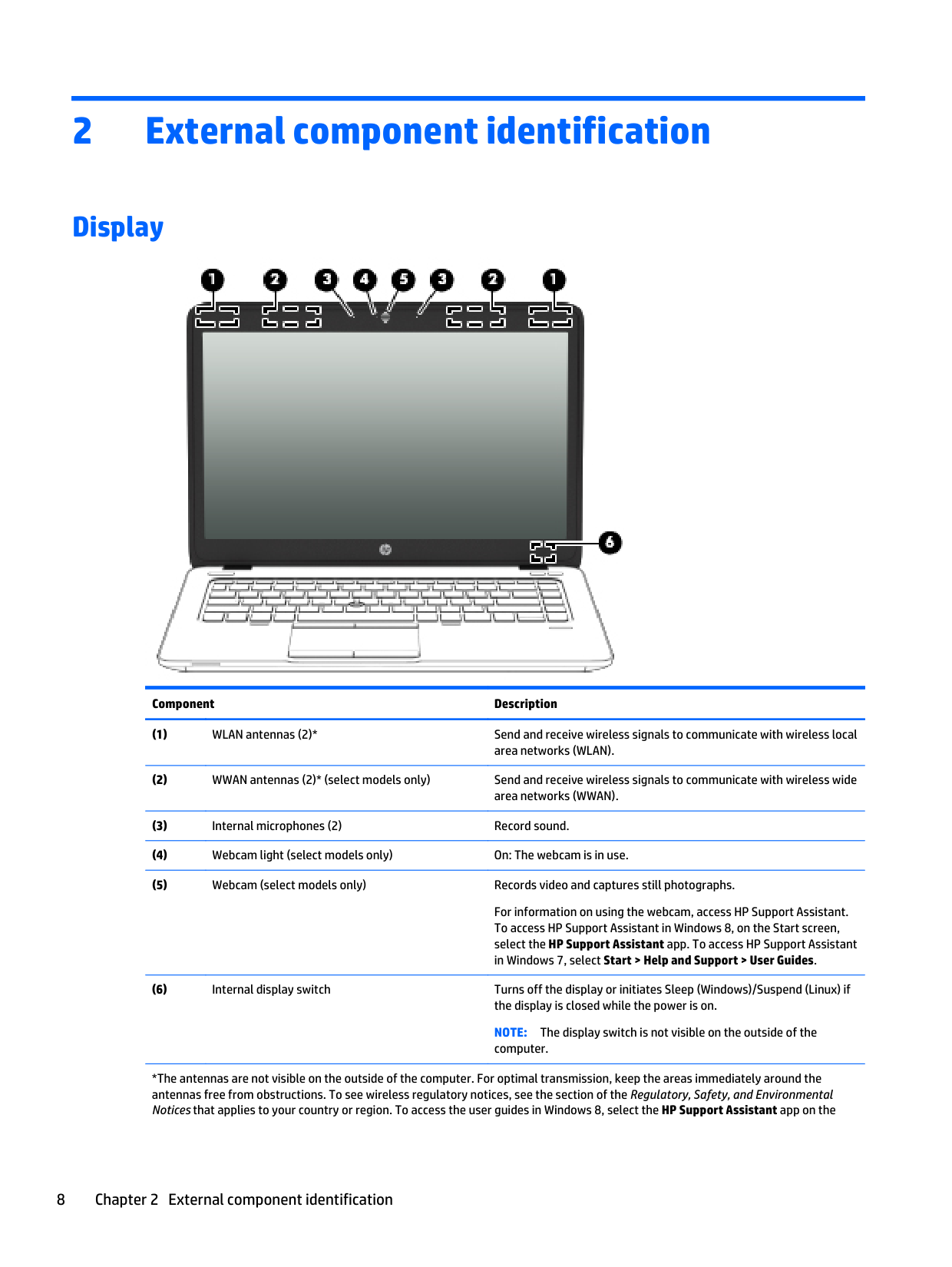
Display

######## Component Description
For information on using the webcam, access HP Support Assistant. To access HP Support Assistant in Windows 8, on the Start screen, select the HP Support Assistant app. To access HP Support Assistant in Windows 7, select Start > Help and Support > User Guides.
NOTE: The display switch is not visible on the outside of the computer.
*The antennas are not visible on the outside of the computer. For optimal transmission, keep the areas immediately around the antennas free from obstructions. To see wireless regulatory notices, see the section of the Regulatory, Safety, and Environmental Notices that applies to your country or region. To access the user guides in Windows 8, select the HP Support Assistant app on the
Component Description Start screen, select My computer, and then select User guides. TO access the user guides in Windows 7, select Start > Help and Support > User Guides.
Top
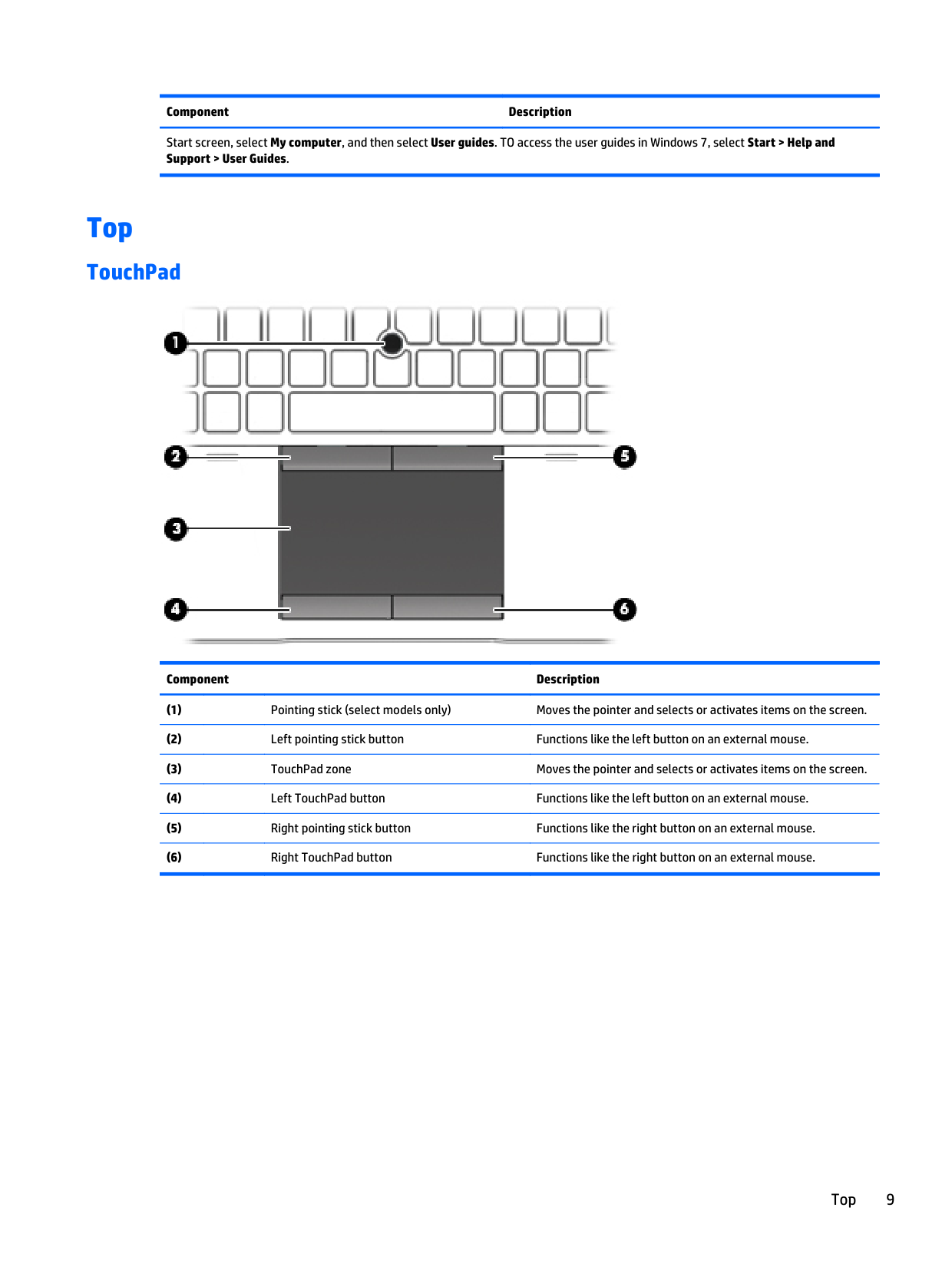
#### TouchPad

######## Component Description
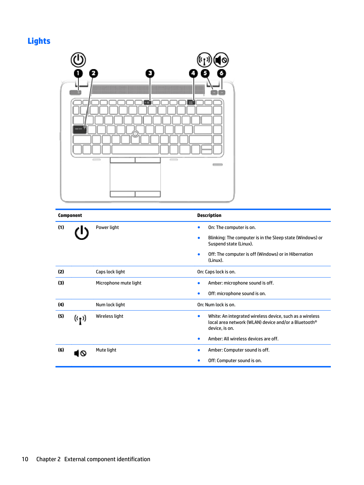
#### Lights

######## Component Description

● Off: microphone sound is on.

● Amber: All wireless devices are off.

● Off: Computer sound is on.
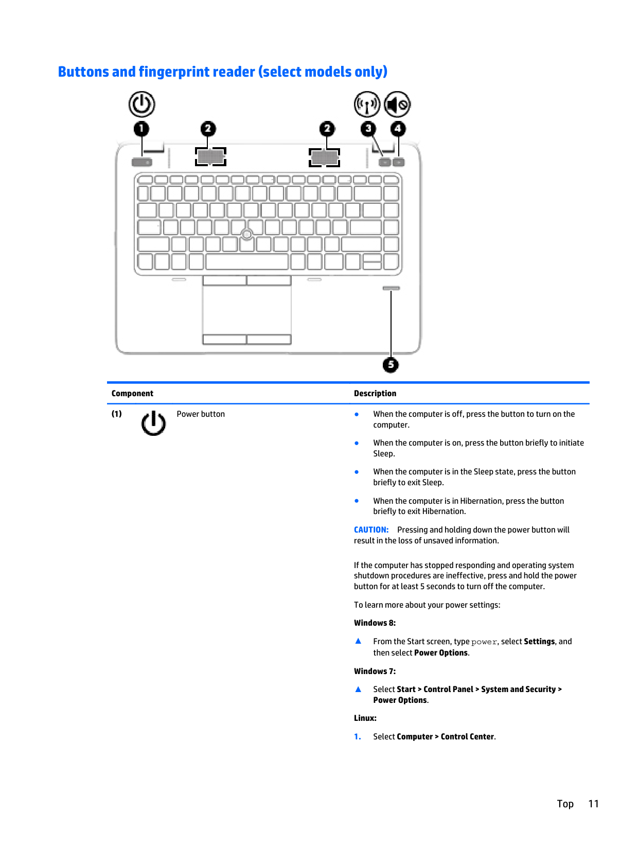
#### Buttons and fingerprint reader (select models only)

######## Component Description

CAUTION: Pressing and holding down the power button will result in the loss of unsaved information.
If the computer has stopped responding and operating system shutdown procedures are ineffective, press and hold the power button for at least 5 seconds to turn off the computer.
To learn more about your power settings: Windows 8:
▲ From the Start screen, type power, select Settings, and
then select Power Options. Windows 7:
▲ Select Start > Control Panel > System and Security >
Power Options. Linux:


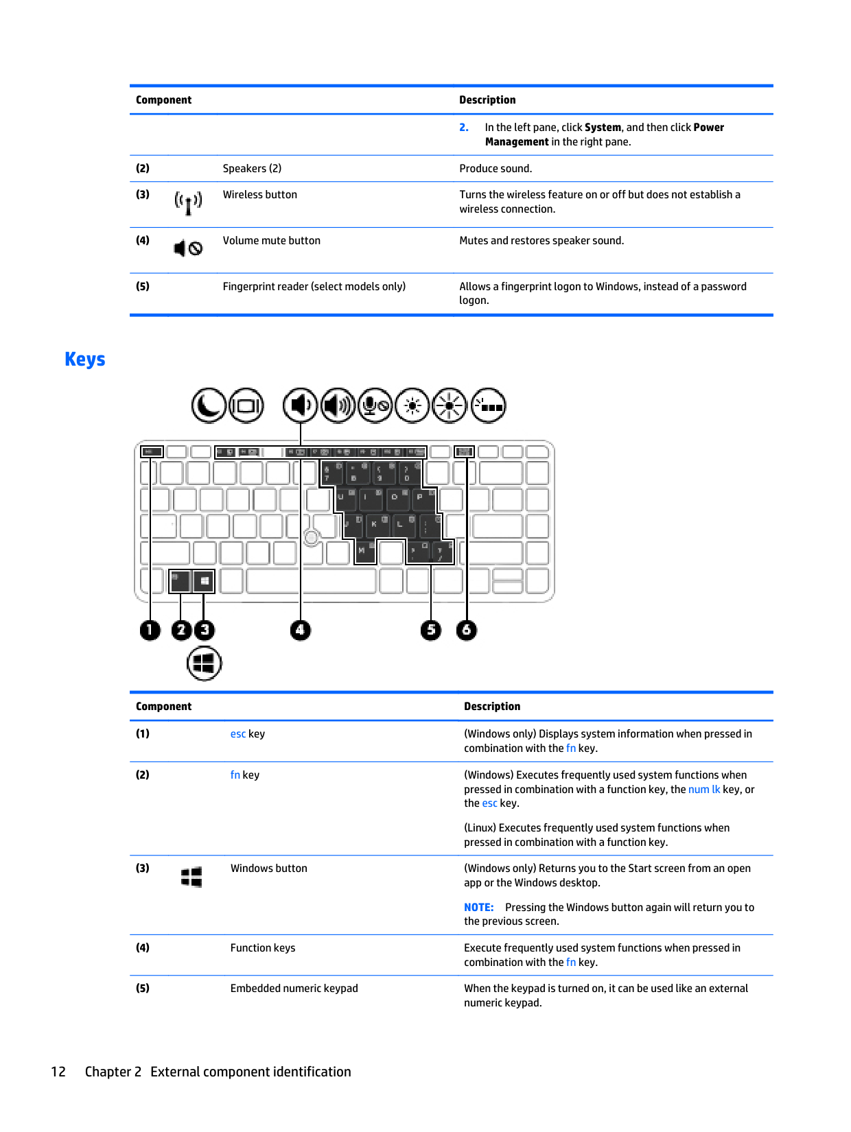
#### Keys

######## Component Description
(Linux) Executes frequently used system functions when pressed in combination with a function key.

NOTE: Pressing the Windows button again will return you to the previous screen.
(Linux) Alternates between the navigational and numeric functions on the integrated numeric keypad.
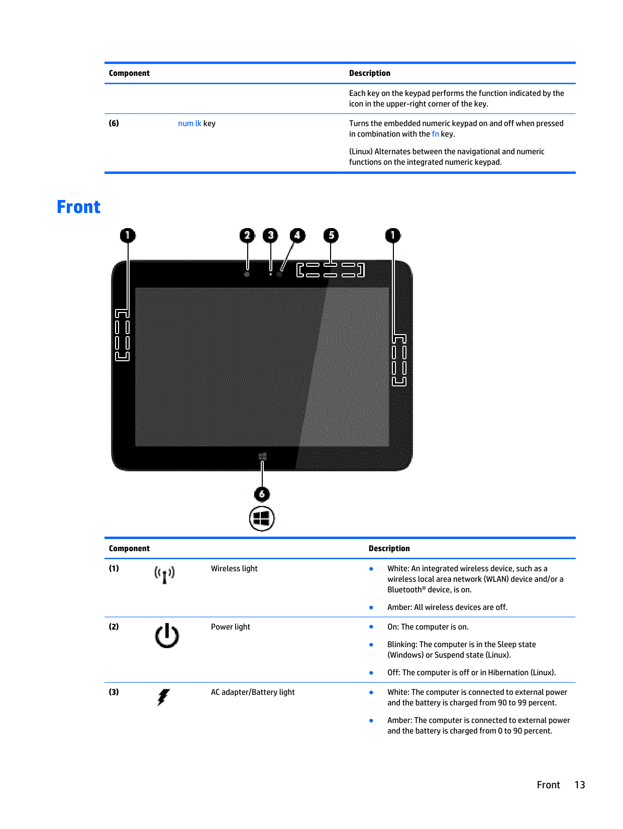
Front

######## Component Description

● Amber: All wireless devices are off.


Front 13

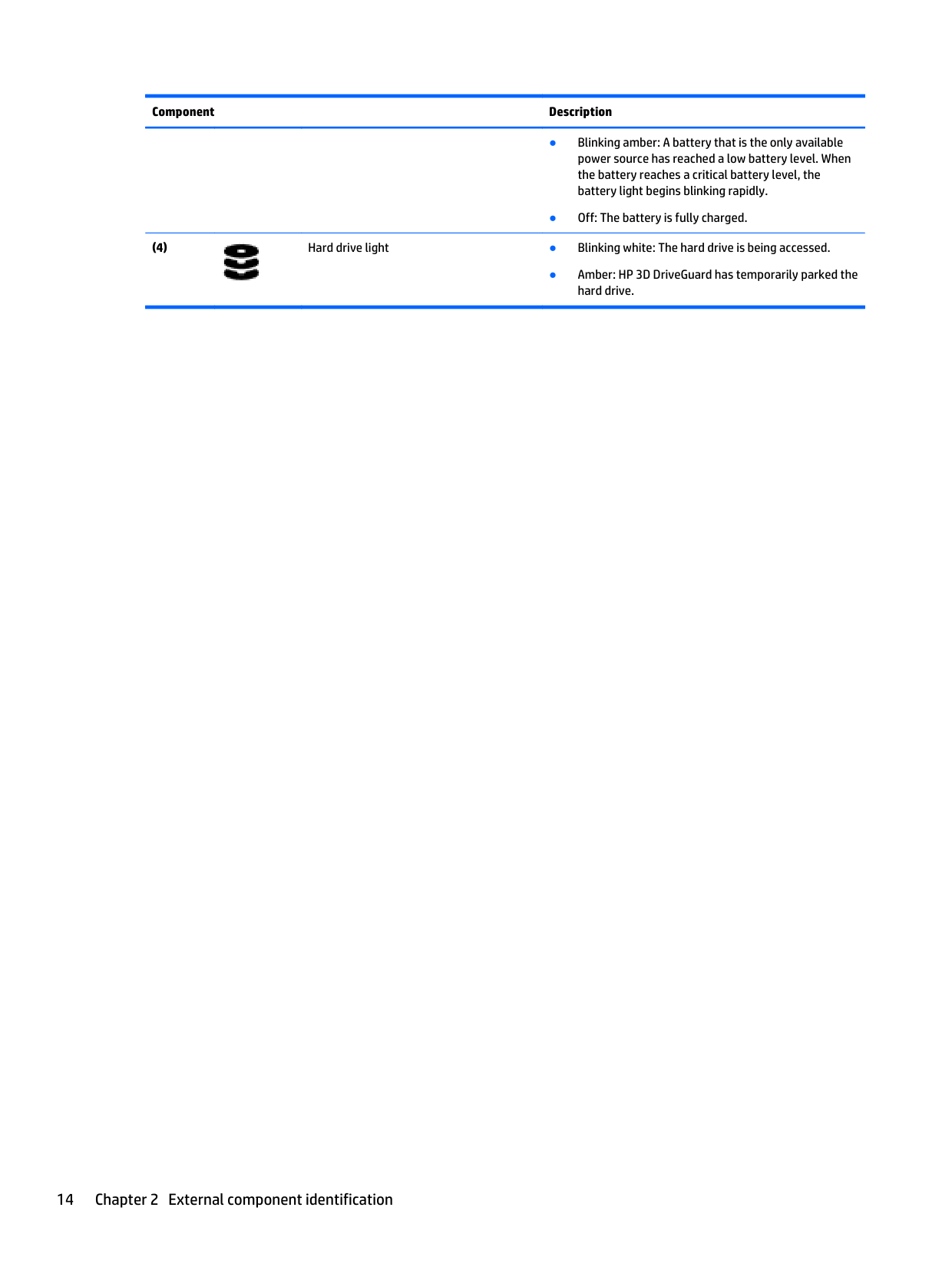
● Amber: HP 3D DriveGuard has temporarily parked the hard drive.
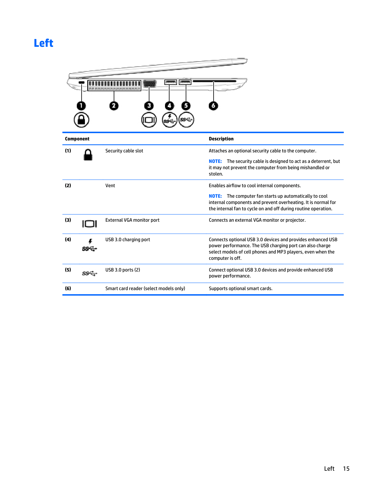
Left

######## Component Description

NOTE: The security cable is designed to act as a deterrent, but it may not prevent the computer from being mishandled or stolen.
NOTE: The computer fan starts up automatically to cool internal components and prevent overheating. It is normal for the internal fan to cycle on and off during routine operation.


Left 15
Right

######## Component Description

Produces sound when connected to optional powered stereo speakers, headphones, earbuds, a headset, or television audio. Also connects an optional headset microphone.
WARNING! To reduce the risk of personal injury, adjust the volume before putting on headphones, earbuds, or a headset. For additional safety information, see the Regulatory, Safety, and Environmental Notices.
To access the user guides: Windows 8: Select the HP Support Assistant app on the Start screen, select My computer, and then select User guides. Windows 7: Select Start > Help and Support > User Guides. NOTE: When a device is connected to the jack, the computer speakers are disabled. NOTE: Be sure that the device cable has a 4-conductor connector that supports both audio-out (headphone) and audio-in (microphone).


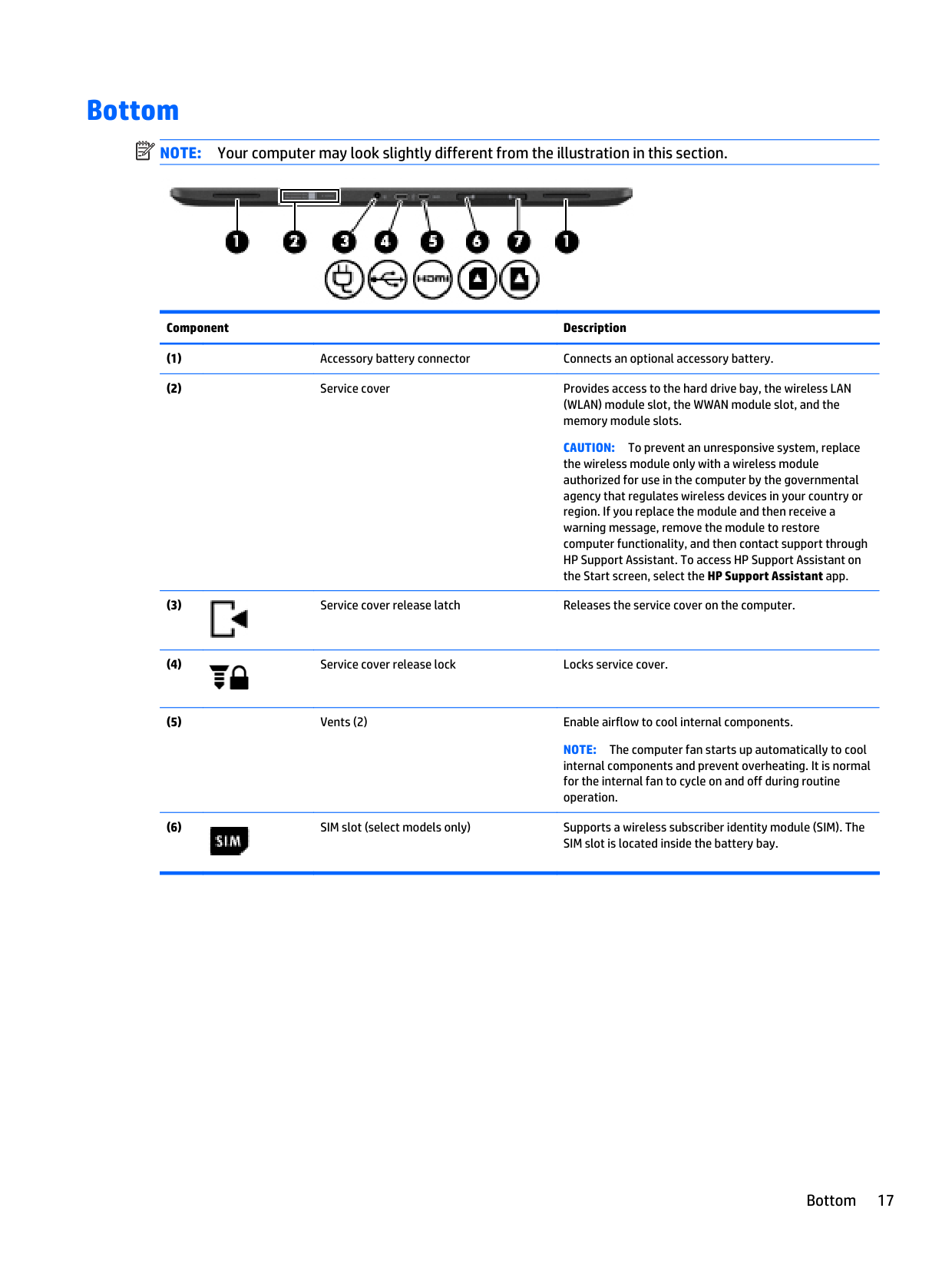
Bottom
| | |---|
NOTE: Your computer may look slightly different from the illustration in this section.

Component Description
CAUTION: To prevent an unresponsive system, replace the wireless module only with a wireless module authorized for use in the computer by the governmental agency that regulates wireless devices in your country or region. If you replace the module and then receive a warning message, remove the module to restore computer functionality, and then contact support through HP Support Assistant. To access HP Support Assistant on the Start screen, select the HP Support Assistant app.


NOTE: The computer fan starts up automatically to cool internal components and prevent overheating. It is normal for the internal fan to cycle on and off during routine operation.

Bottom 17

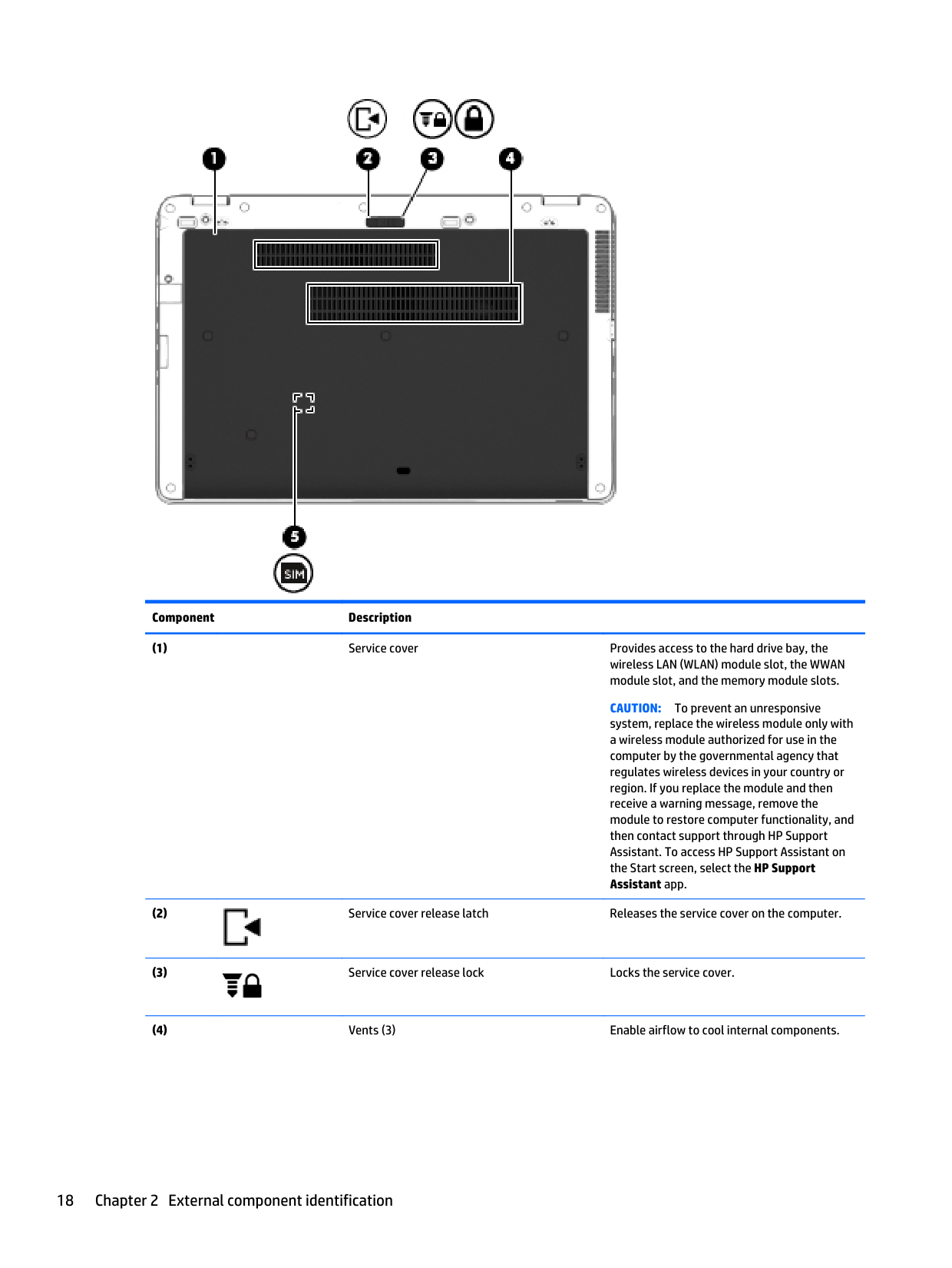
######## Component Description
CAUTION: To prevent an unresponsive system, replace the wireless module only with a wireless module authorized for use in the computer by the governmental agency that regulates wireless devices in your country or region. If you replace the module and then receive a warning message, remove the module to restore computer functionality, and then contact support through HP Support Assistant. To access HP Support Assistant on the Start screen, select the HP Support Assistant app.


######## Component Description
NOTE: The computer fan starts up automatically to cool internal components and prevent overheating. It is normal for the internal fan to cycle on and off during routine operation.

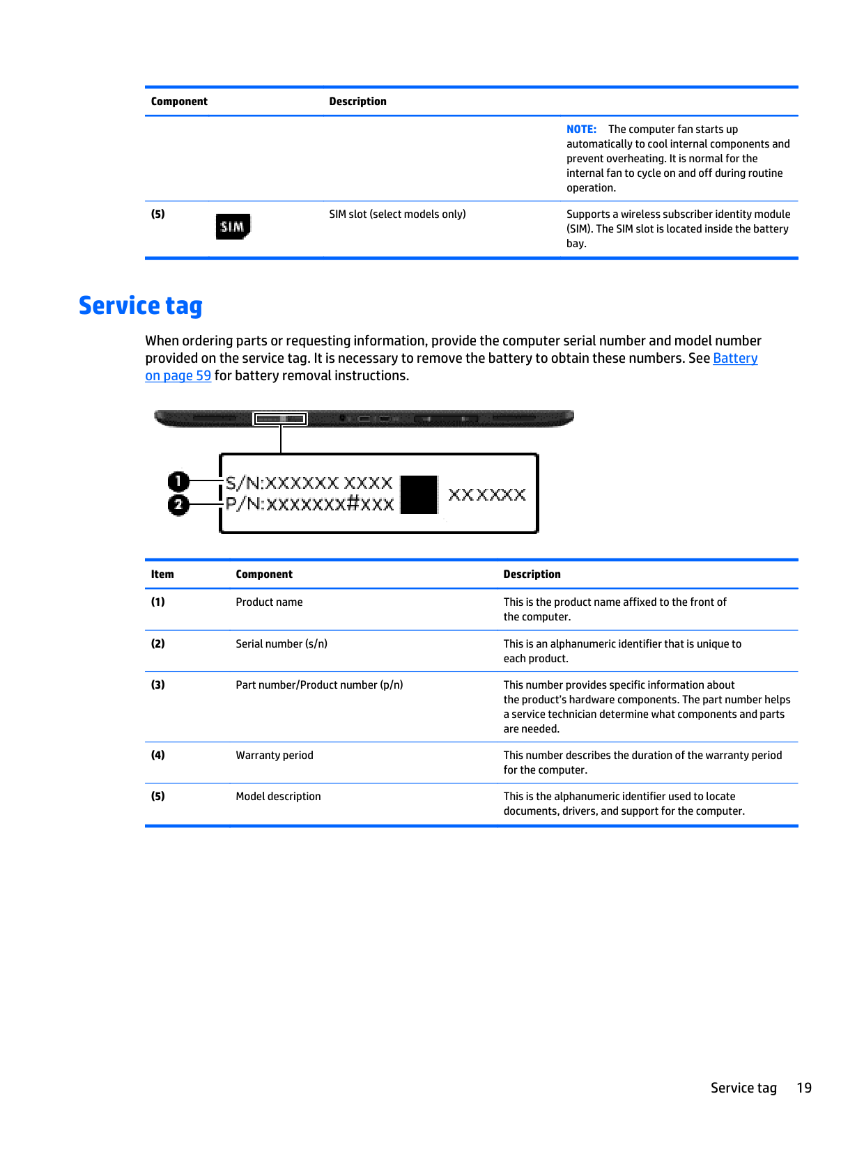
Service tag
When ordering parts or requesting information, provide the computer serial number and model number provided on the service tag. It is necessary to remove the battery to obtain these numbers. See Battery on page 59 for battery removal instructions.

Item Component Description
Service tag 19
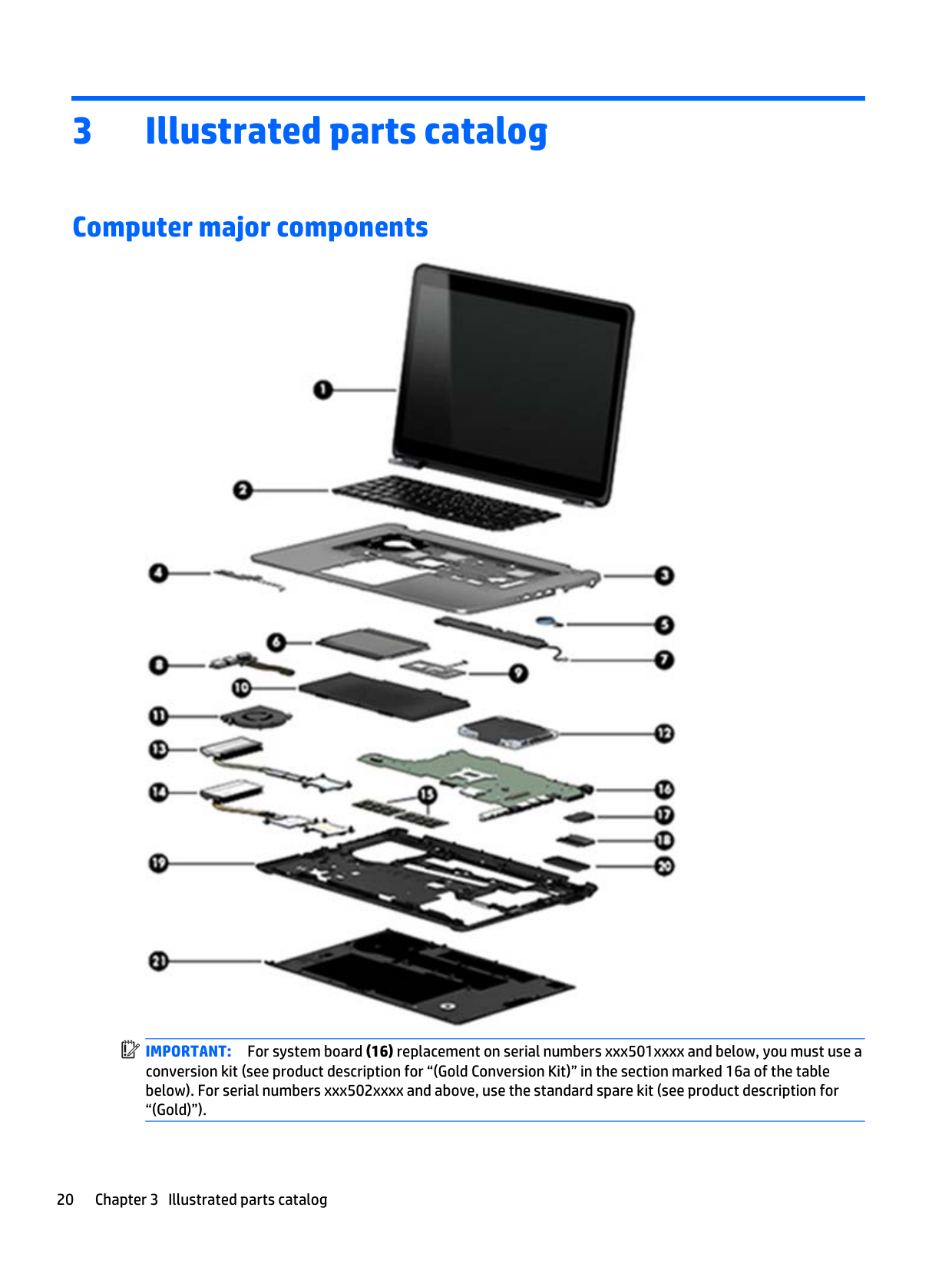
3 Illustrated parts catalog
Computer major components
| | |---|

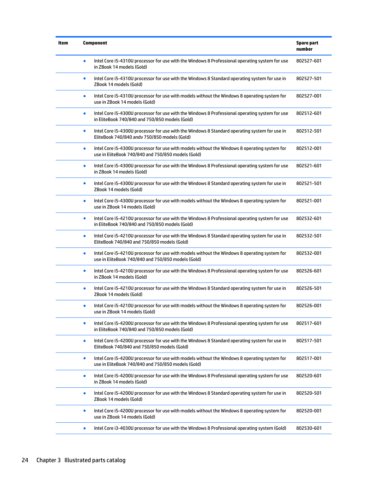
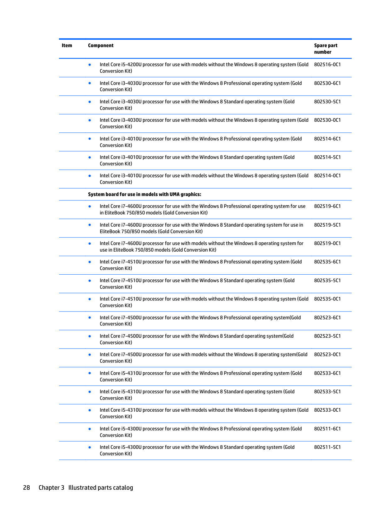
IMPORTANT: For system board (16) replacement on serial numbers xxx501xxxx and below, you must use a conversion kit (see product description for “(Gold Conversion Kit)” in the section marked 16a of the table below). For serial numbers xxx502xxxx and above, use the standard spare kit (see product description for “(Gold)”).
3-cell, 50-Wh, 4.5-Ah 717376-001 3-cell, 24-Wh, 2.4-Ah 717375-001
1-TB, 5400-rpm hard drive, locked, for use in EliteBook 740/840 models (does not include hard drive bracket or screws)
776476-001
1-TB, 5400-rpm, locked 763529-001 750-GB, 7200-rpm, 2.5-inch, for use in EliteBook 740/840 and ZBook 14 models 633252-001 500-GB, 7200-rpm, 7-mm, SED 703268-001 500-GB, 7200-rpm, 2.5-inch, SED 683801-001
500-GB, 7200-rpm, 7-mm 703267-001 500-GB, 7200-rpm, 7-mm, locked (HGST), for use in EliteBook 740/840 and ZBook 14 models 782123-001
500-GB, 5400-rpm, 7-mm 683802-001 500-GB, 5400-rpm, 7-mm, FIPS 730946-001 500-GB, 5400-rpm, 7-mm, locked (SGT), for use in EliteBook 740/840 and ZBook 14 models 773555-001 500-GB, 5400-rpm, 7-mm, locked (SGT), for use in EliteBook 740/840 and ZBook 14 models 776626-001
320-GB, 7200-rpm, 7-mm 634862-001 320-GB, 5400-rpm, 7-mm, WD, locked, for use in EliteBook 740/840 and ZBook 14 models 789520-001 Hard Drive Hardware Kit (not illustrated, includes hard drive bracket and screws) 730793-001
802519-601
802519-501
802519-001

802518-001
802522-601
802522-501
802522-001
802536-601
802536-501
802536-001
802528-601
802528-501
802528-001
802524-601
802524-501
802524-001
802525-601
802525-501
802525-001
802534-601
802534-501
802534-001
######### ● Intel Core i5-4310U processor for use with the Windows 8 Professional operating system for usein ZBook 14 models (Gold)
802527-601
######### ● Intel Core i5-4310U processor for use with the Windows 8 Standard operating system for use inZBook 14 models (Gold)
802527-501
######### ● Intel Core i5-4310U processor for use with models without the Windows 8 operating system foruse in ZBook 14 models (Gold)
802527-001
######### ● Intel Core i5-4300U processor for use with the Windows 8 Professional operating system for usein EliteBook 740/840 and 750/850 models (Gold)
802512-601
######### ● Intel Core i5-4300U processor for use with the Windows 8 Standard operating system for use inEliteBook 740/840 andv 750/850 models (Gold)
802512-501
######### ● Intel Core i5-4300U processor for use with models without the Windows 8 operating system foruse in EliteBook 740/840 and 750/850 models (Gold)
802512-001
######### ● Intel Core i5-4300U processor for use with the Windows 8 Professional operating system for usein ZBook 14 models (Gold)
802521-601
######### ● Intel Core i5-4300U processor for use with the Windows 8 Standard operating system for use inZBook 14 models (Gold)
802521-501
######### ● Intel Core i5-4300U processor for use with models without the Windows 8 operating system foruse in ZBook 14 models (Gold)
802521-001
######### ● Intel Core i5-4210U processor for use with the Windows 8 Professional operating system for usein EliteBook 740/840 and 750/850 models (Gold)
802532-601
######### ● Intel Core i5-4210U processor for use with the Windows 8 Standard operating system for use inEliteBook 740/840 and 750/850 models (Gold)
802532-501
######### ● Intel Core i5-4210U processor for use with models without the Windows 8 operating system foruse in EliteBook 740/840 and 750/850 models (Gold)
802532-001
######### ● Intel Core i5-4210U processor for use with the Windows 8 Professional operating system for usein ZBook 14 models (Gold)
802526-601
######### ● Intel Core i5-4210U processor for use with the Windows 8 Standard operating system for use inZBook 14 models (Gold)
802526-501
######### ● Intel Core i5-4210U processor for use with models without the Windows 8 operating system foruse in ZBook 14 models (Gold)
802526-001
######### ● Intel Core i5-4200U processor for use with the Windows 8 Professional operating system for usein EliteBook 740/840 and 750/850 models (Gold)
######### ● Intel Core i5-4200U processor for use with the Windows 8 Standard operating system for use inEliteBook 740/840 and 750/850 models (Gold)
######### ● Intel Core i5-4200U processor for use with models without the Windows 8 operating system foruse in EliteBook 740/840 and 750/850 models (Gold)
######### ● Intel Core i5-4200U processor for use with the Windows 8 Professional operating system for usein ZBook 14 models (Gold)
######### ● Intel Core i5-4200U processor for use with the Windows 8 Standard operating system for use inZBook 14 models (Gold)
######### ● Intel Core i5-4200U processor for use with models without the Windows 8 operating system foruse in ZBook 14 models (Gold)
802517-601
802517-501
802517-001
802520-601
802520-501
802520-001
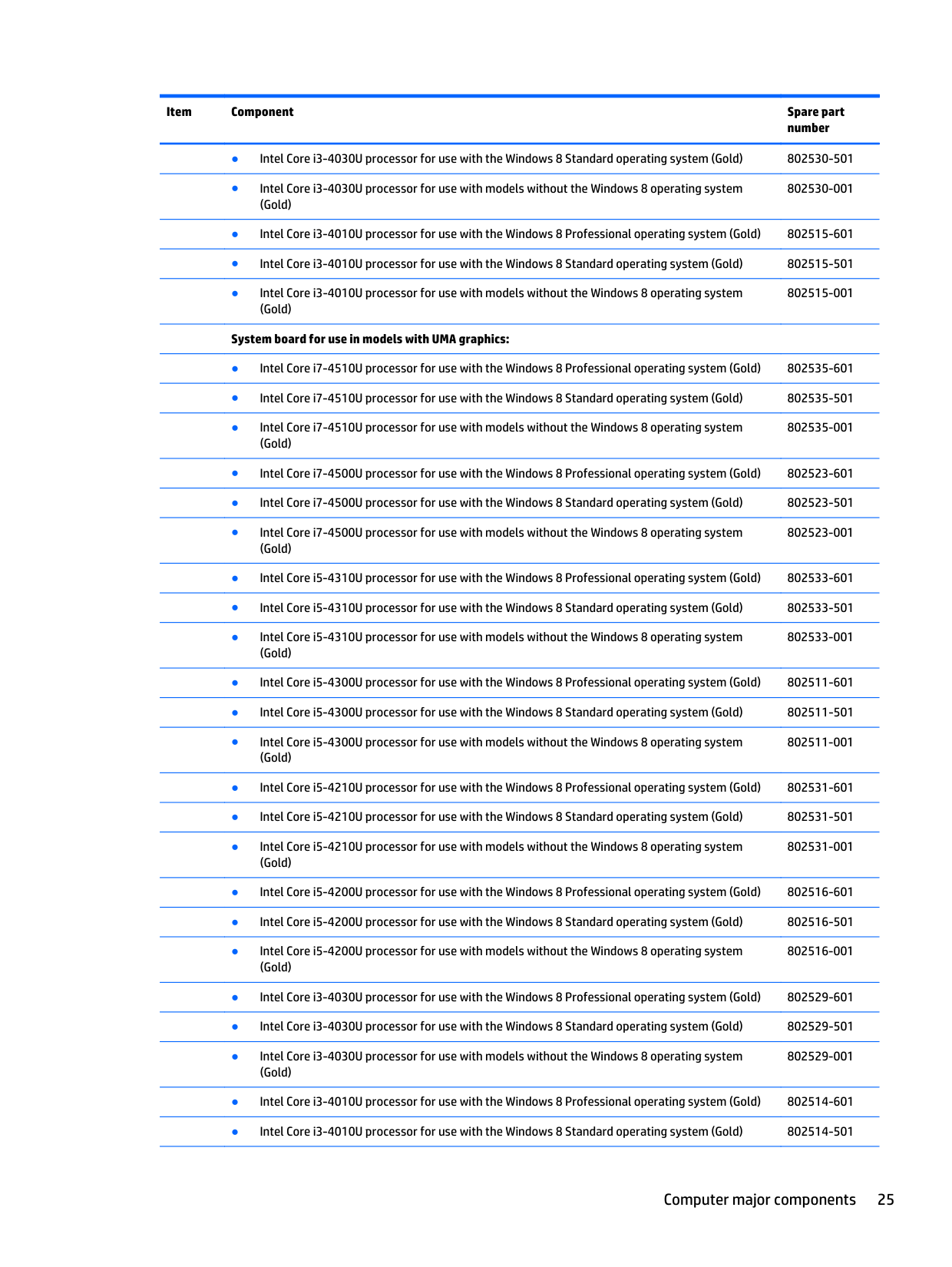
######### ● Intel Core i3-4030U processor for use with the Windows 8 Professional operating system (Gold) 802530-601
802530-001
802515-001
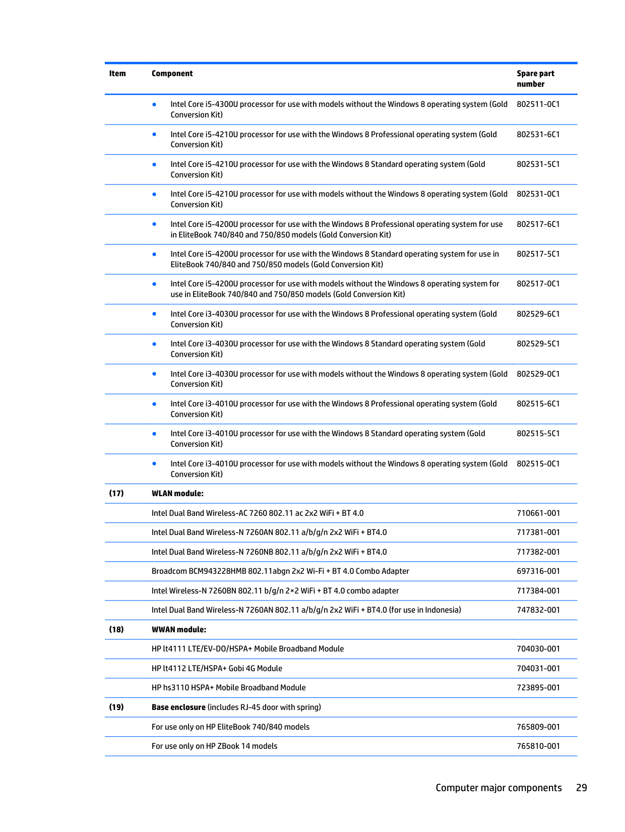
######## System board for use in models with UMA graphics:
802535-001
802523-001
802533-001
802511-001
802531-001
802516-001
802529-001
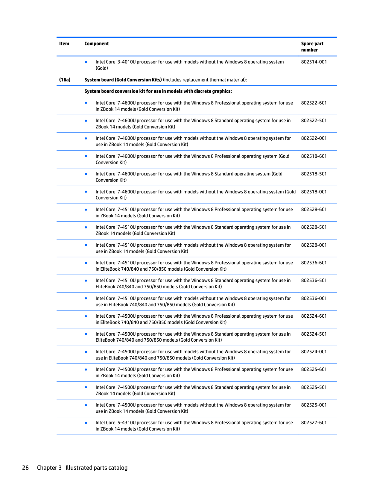
802522-6C1
802522-5C1
802522-0C1
802518-6C1
802518-5C1
802518-0C1
802528-6C1
802528-5C1
802528-0C1
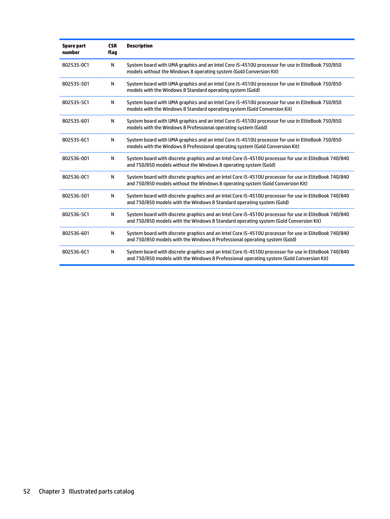
802536-6C1
802536-5C1
802536-0C1
802524-6C1
802524-5C1
802524-0C1
802525-6C1
802525-5C1
802525-0C1
802514-001
802527-6C1
802527-5C1
802527-0C1
802534-6C1
802534-5C1
802534-0C1
802512–6C1
802512–5C1
802512–0C1
802521-6C1
802521-5C1
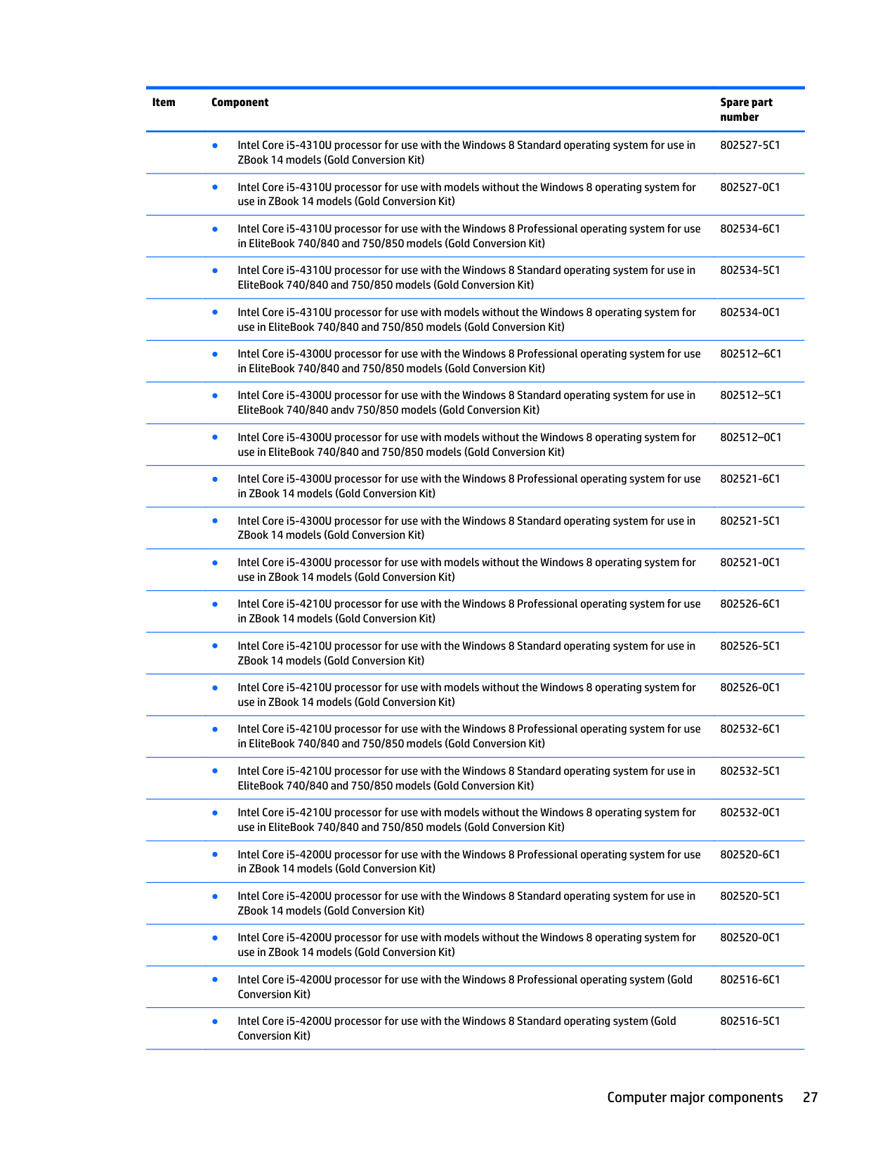
802521-0C1
802526-6C1
802526-5C1
802526-0C1
802532-6C1
802532-5C1
802532-0C1
802520-6C1
802520-5C1
802520-0C1
802516-6C1
802516-5C1
802516-0C1
802530-6C1
802530-5C1
802530-0C1
802514-6C1
802514-5C1
######## System board for use in models with UMA graphics:
802519-6C1
802519-5C1
802519-0C1
802535-6C1
802535-5C1
802535-0C1
802523-6C1
802523-5C1
802523-0C1
802533-6C1
802533-5C1
802533-0C1
802511-6C1
802514-0C1
802511-5C1
802511-0C1
802531-6C1
802531-5C1
802531-0C1
802517-6C1
802517-5C1
802517-0C1
802529-6C1
802529-5C1
802529-0C1
802515-6C1
802515-5C1
802515-0C1
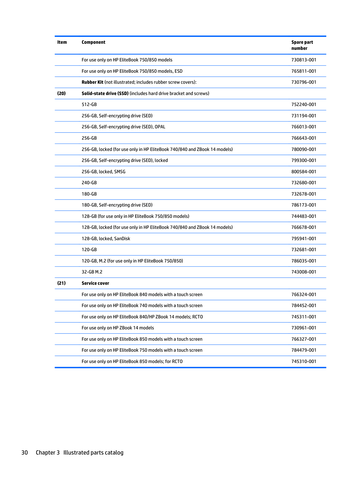
256-GB, locked, SMSG 800584-001 240-GB 732680-001 180-GB 732678-001 180-GB, Self-encrypting drive (SED) 786173-001 128-GB (for use only in HP EliteBook 750/850 models) 744483-001 128-GB, locked (for use only in HP EliteBook 740/840 and ZBook 14 models) 766678-001
128-GB, locked, SanDisk 795941-001 120-GB 732681-001 120-GB, M.2 (for use only in HP EliteBook 750/850) 786035-001
32-GB M.2 743008-001
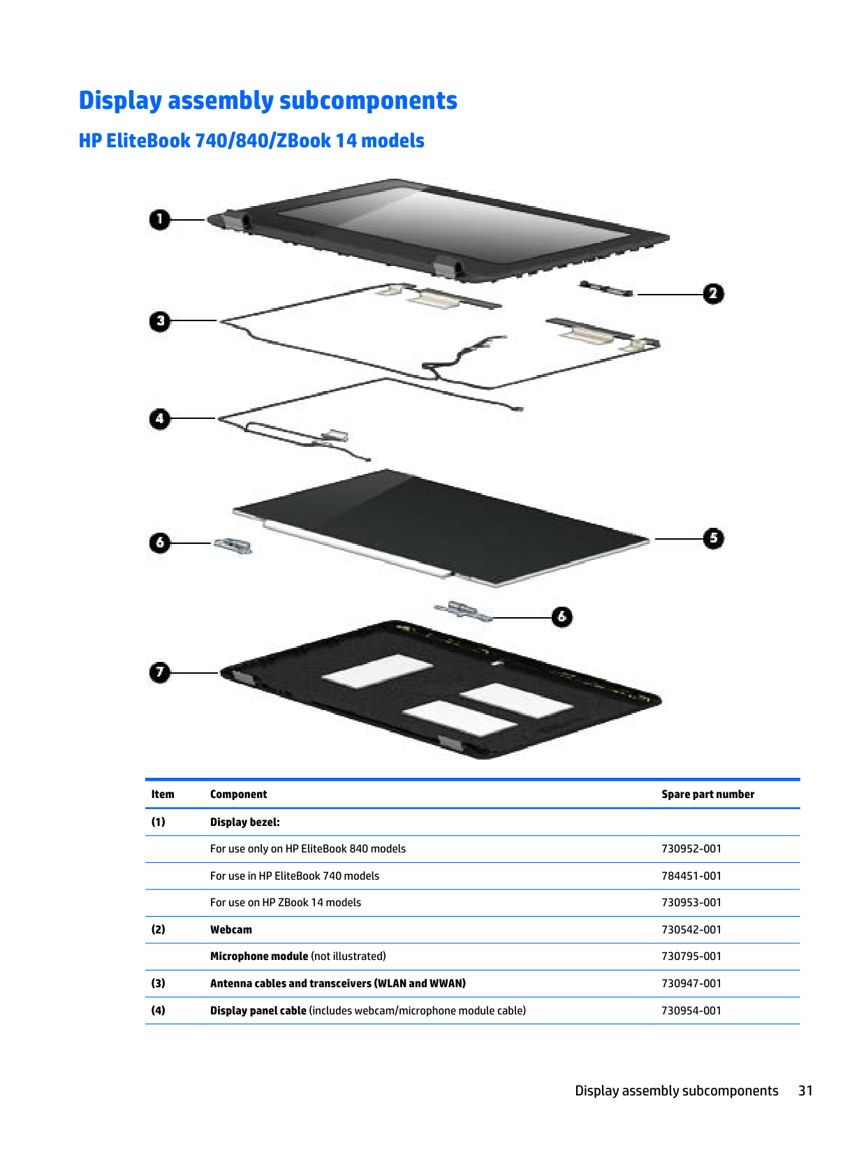
Display assembly subcomponents
#### HP EliteBook 740/840/ZBook 14 models

######## Item Component Spare part number
Display assembly subcomponents 31
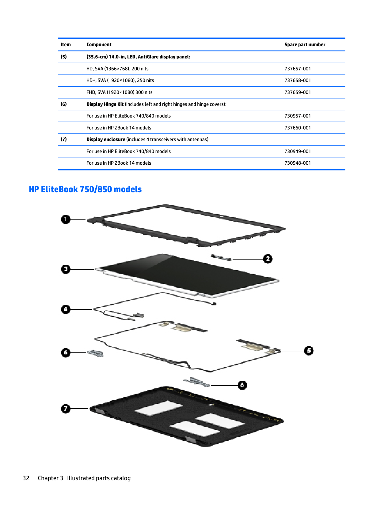
#### HP EliteBook 750/850 models

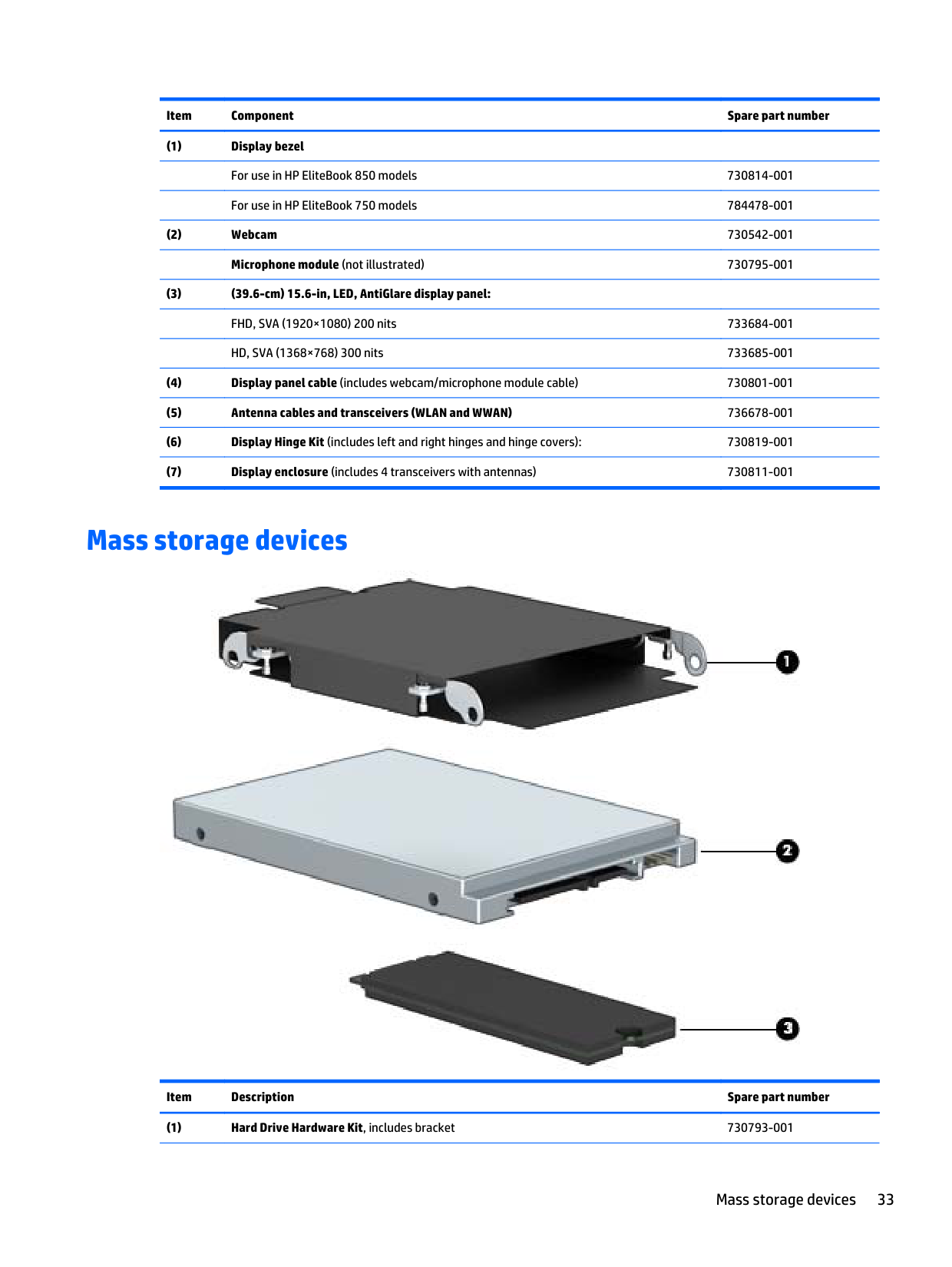
Mass storage devices

######## Item Description Spare part number
Mass storage devices 33
500-GB, 7200-rpm, 7-mm, locked (HGST)(for use in EliteBook 740/840 and ZBook 14 models)
782123-001
500-GB, 5400-rpm, 7-mm 683802-001 500-GB, 5400-rpm, 7-mm, FIPS 730946-001 500-GB, 5400-rpm, 7-mm, locked (SGT)(for use in EliteBook 740/840 and ZBook 14 models)
773555-001
500-GB, 5400-rpm, 7-mm, locked (SGT)(for use in EliteBook 740/840 and ZBook 14 models)
776626-001
320-GB, 7200-rpm, 7-mm 634862-001 320-GB, 5400-rpm, 7-mm, WD, locked (for use in EliteBook 740/840 and ZBook 14 models) 789520-001
120-GB, M.2 (for use only in HP EliteBook 750/850) 786035-001 32-GB 743008-001
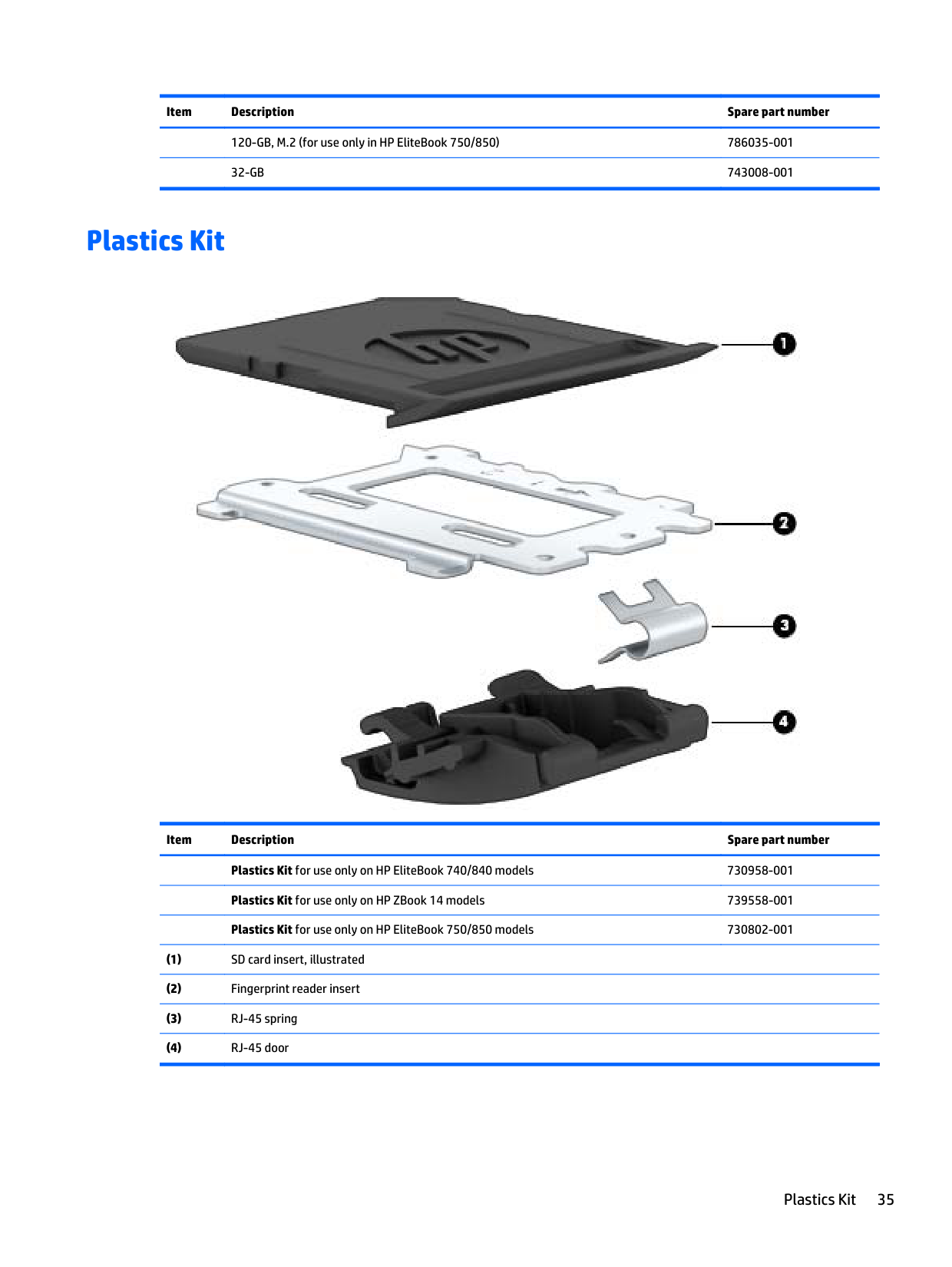
Plastics Kit

######## Item Description Spare part number
Plastics Kit for use only on HP EliteBook 740/840 models 730958-001 Plastics Kit for use only on HP ZBook 14 models 739558-001 Plastics Kit for use only on HP EliteBook 750/850 models 730802-001
Plastics Kit 35
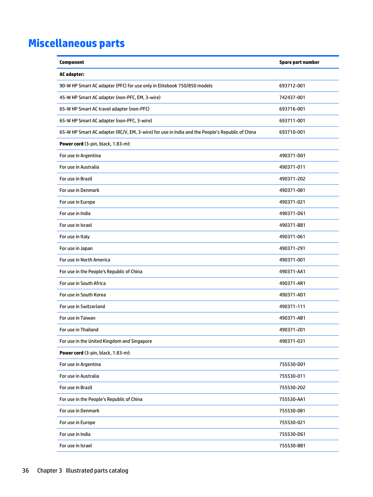
Miscellaneous parts
Component Spare part number AC adapter:
90-W HP Smart AC adapter (PFC) for use only in Elitebook 750/850 models 693712-001 45-W HP Smart AC adapter (non-PFC, EM, 3-wire) 742437-001 65-W HP Smart AC travel adapter (non-PFC) 693716-001 65-W HP Smart AC adapter (non-PFC, 3-wire) 693711-001 65-W HP Smart AC adapter (RC/V, EM, 3-wire) for use in India and the People’s Republic of China 693710-001 Power cord (3-pin, black, 1.83-m):
For use in Argentina 490371-D01 For use in Australia 490371-011 For use in Brazil 490371-202 For use in Denmark 490371-081 For use in Europe 490371-021 For use in India 490371-D61 For use in Israel 490371-BB1 For use in Italy 490371-061 For use in Japan 490371-291 For use in North America 490371-001 For use in the People's Republic of China 490371-AA1 For use in South Africa 490371-AR1 For use in South Korea 490371-AD1 For use in Switzerland 490371-111 For use in Taiwan 490371-AB1 For use in Thailand 490371-201 For use in the United Kingdom and Singapore 490371-031 Power cord (3-pin, black, 1.83-m):
For use in Argentina 755530-D01 For use in Australia 755530-011 For use in Brazil 755530-202 For use in the People’s Republic of China 755530-AA1 For use in Denmark 755530-081 For use in Europe 755530-021 For use in India 755530-D61 For use in Israel 755530-BB1
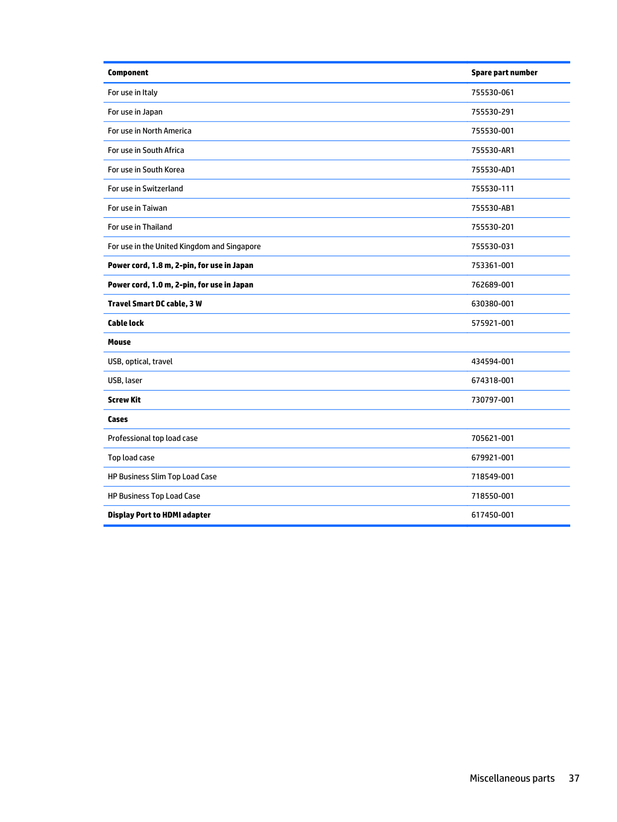
######## Component Spare part number
For use in Italy 755530-061 For use in Japan 755530-291 For use in North America 755530-001 For use in South Africa 755530-AR1 For use in South Korea 755530-AD1 For use in Switzerland 755530-111 For use in Taiwan 755530-AB1 For use in Thailand 755530-201 For use in the United Kingdom and Singapore 755530-031 Power cord, 1.8 m, 2-pin, for use in Japan 753361-001 Power cord, 1.0 m, 2-pin, for use in Japan 762689-001 Travel Smart DC cable, 3 W 630380-001 Cable lock 575921-001 Mouse
USB, optical, travel 434594-001 USB, laser 674318-001 Screw Kit 730797-001 Cases
Professional top load case 705621-001 Top load case 679921-001 HP Business Slim Top Load Case 718549-001 HP Business Top Load Case 718550-001 Display Port to HDMI adapter 617450-001
Miscellaneous parts 37
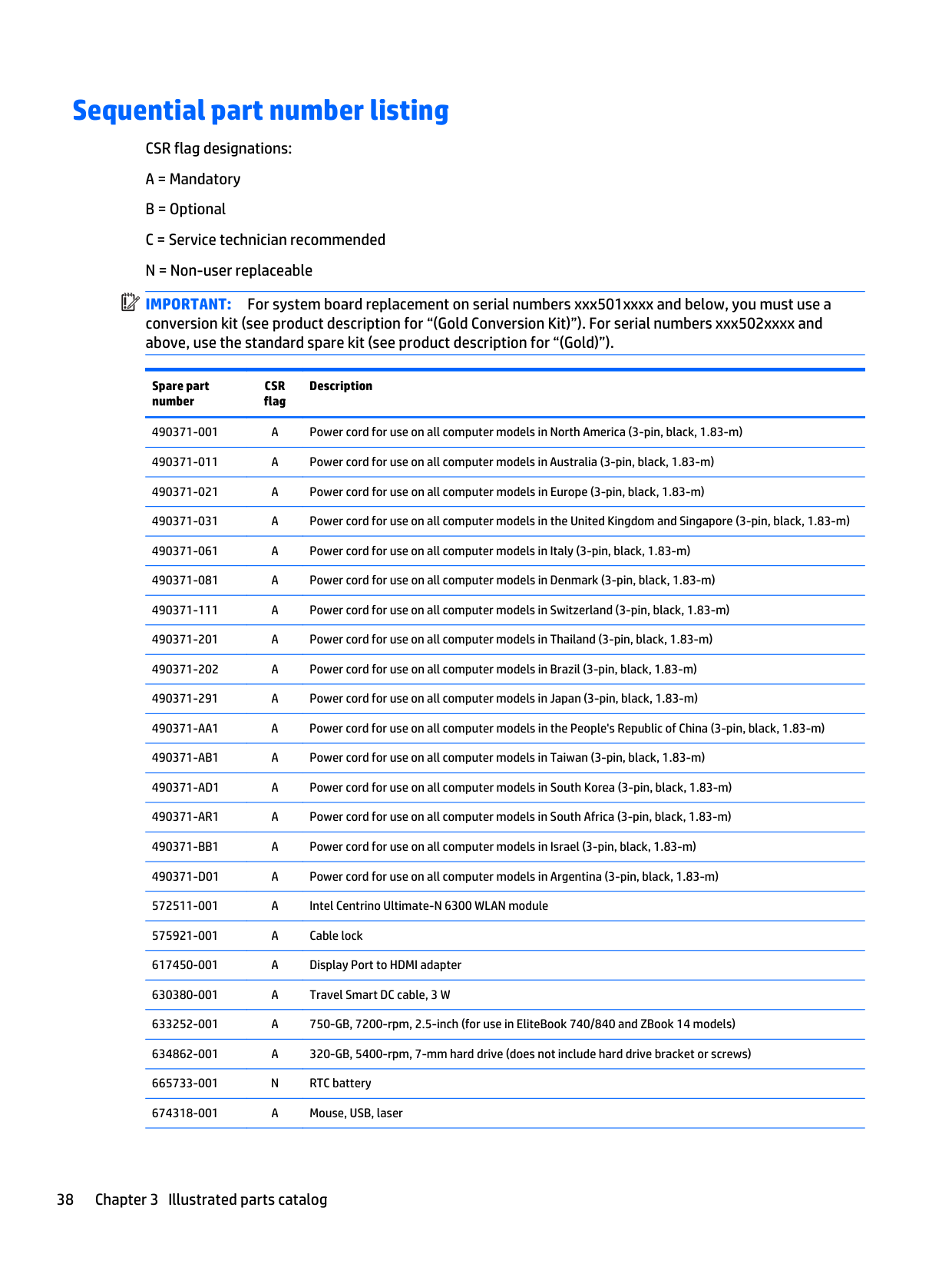
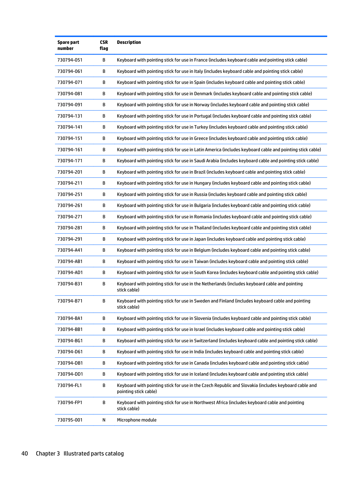
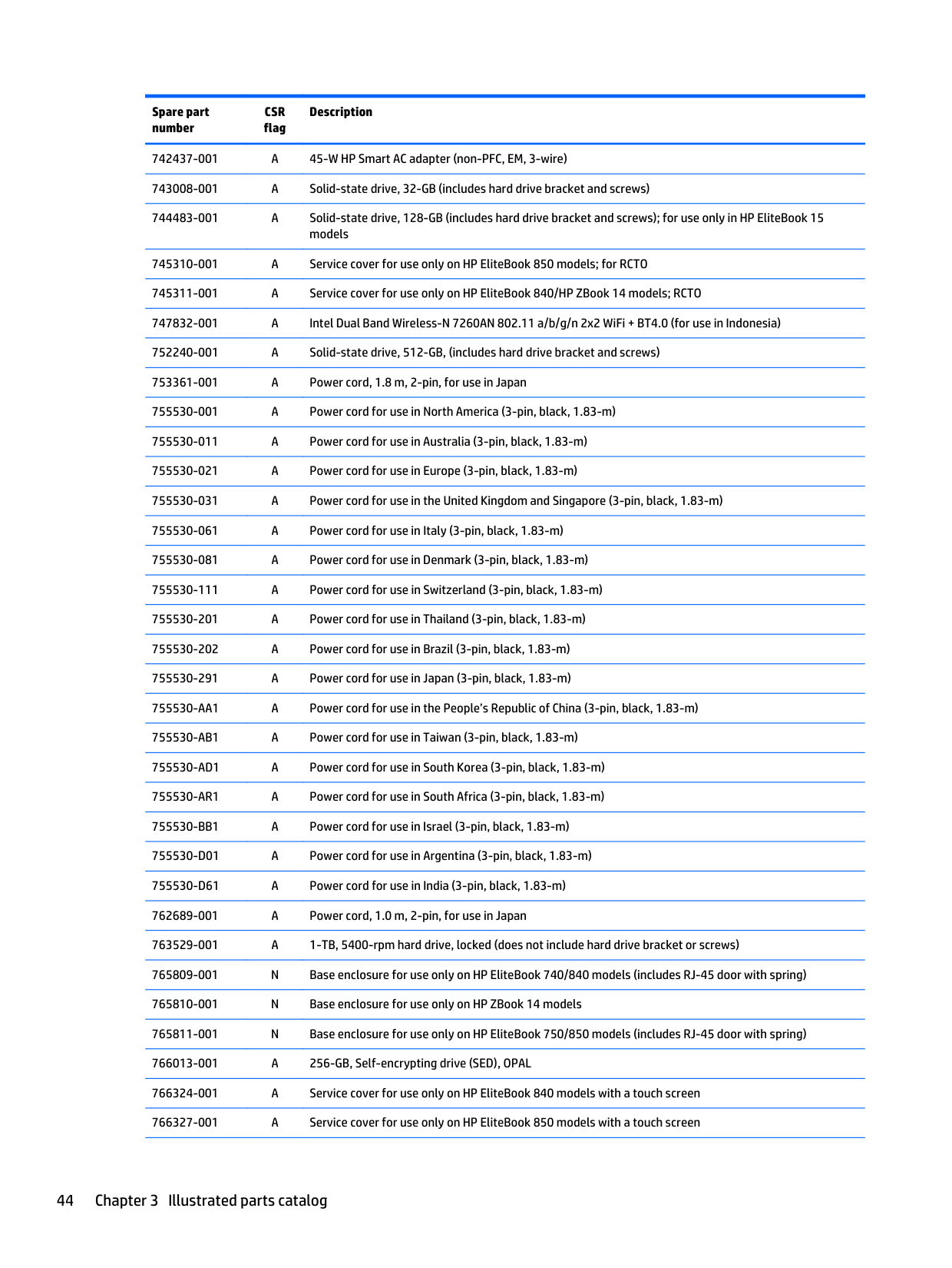
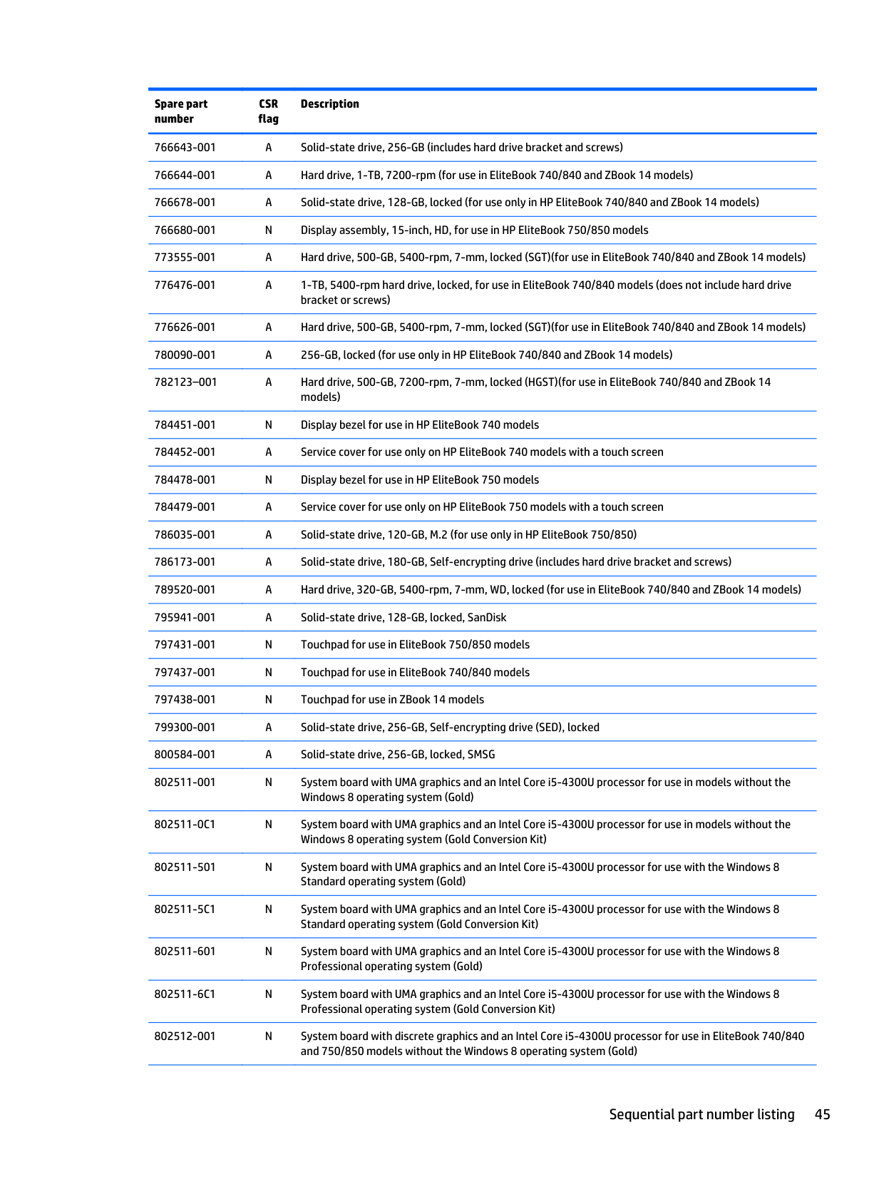
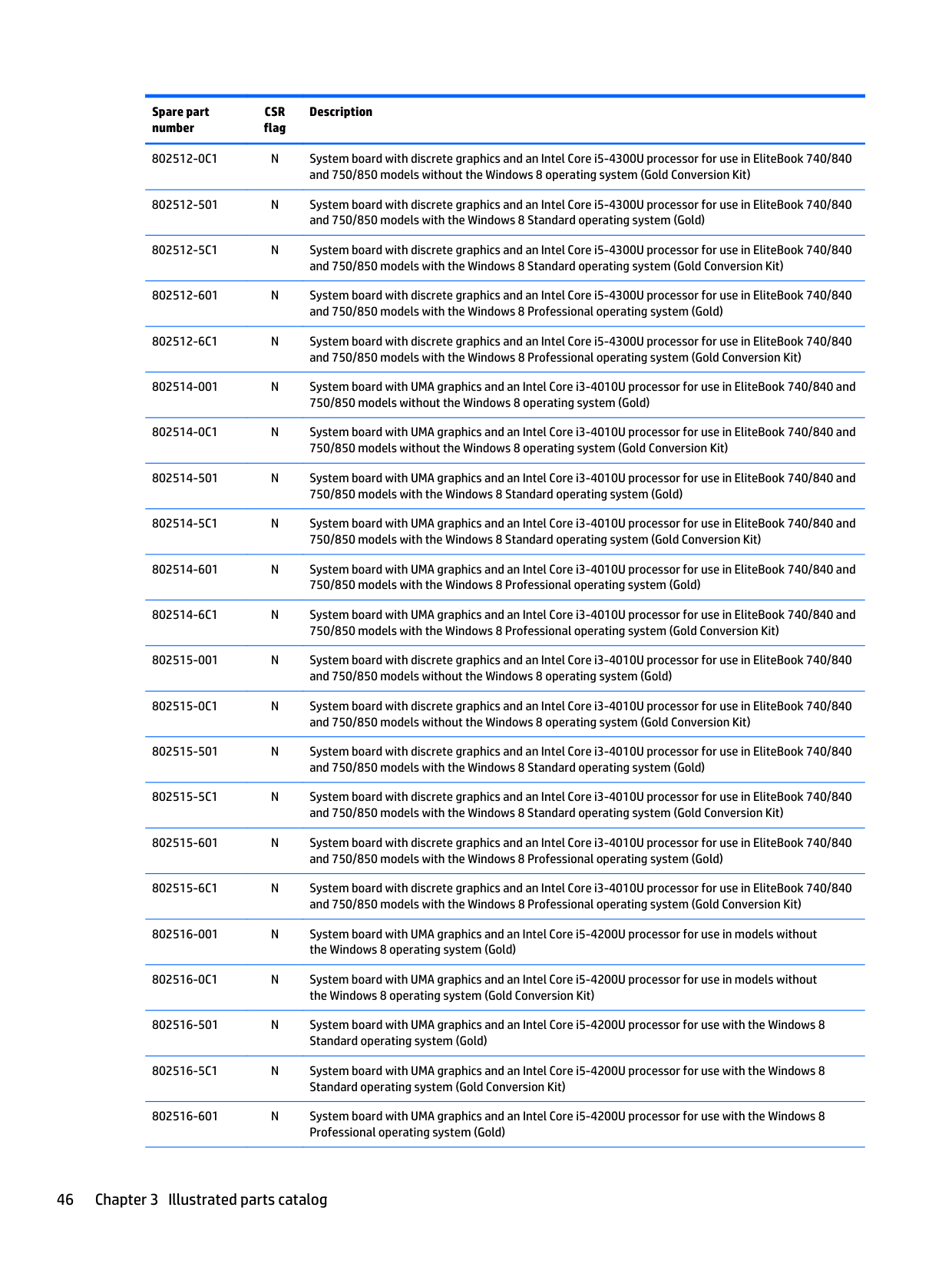
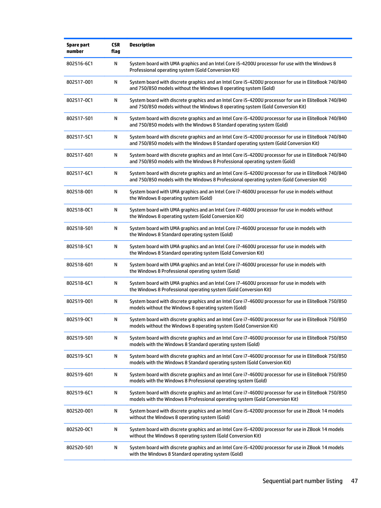
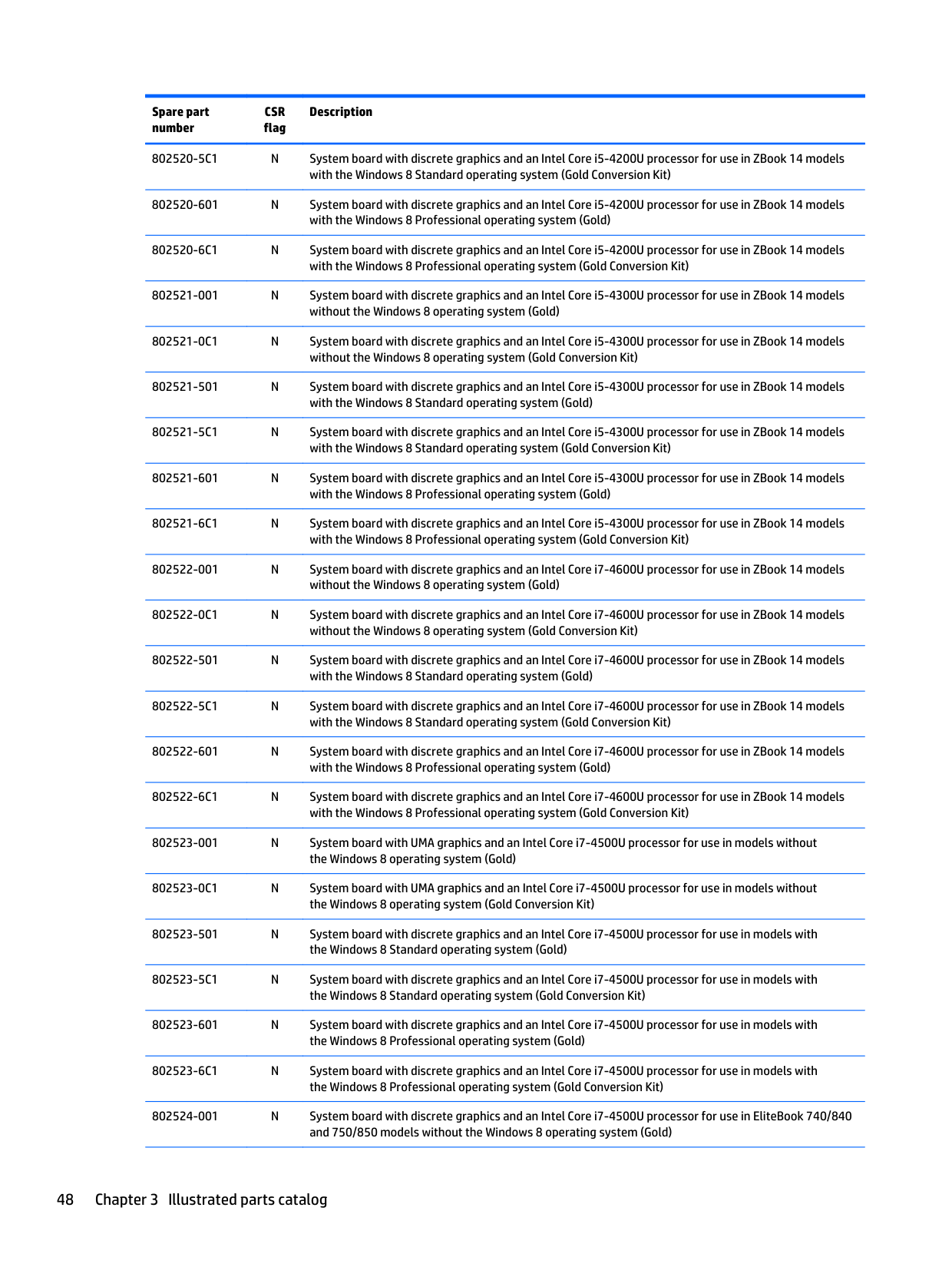
Sequential part number listing
CSR flag designations:
| | |---|
IMPORTANT: For system board replacement on serial numbers xxx501xxxx and below, you must use a conversion kit (see product description for “(Gold Conversion Kit)”). For serial numbers xxx502xxxx and above, use the standard spare kit (see product description for “(Gold)”).
Spare part number
CSR flag
Description
490371-001 A Power cord for use on all computer models in North America (3-pin, black, 1.83-m) 490371-011 A Power cord for use on all computer models in Australia (3-pin, black, 1.83-m) 490371-021 A Power cord for use on all computer models in Europe (3-pin, black, 1.83-m) 490371-031 A Power cord for use on all computer models in the United Kingdom and Singapore (3-pin, black, 1.83-m) 490371-061 A Power cord for use on all computer models in Italy (3-pin, black, 1.83-m) 490371-081 A Power cord for use on all computer models in Denmark (3-pin, black, 1.83-m) 490371-111 A Power cord for use on all computer models in Switzerland (3-pin, black, 1.83-m)
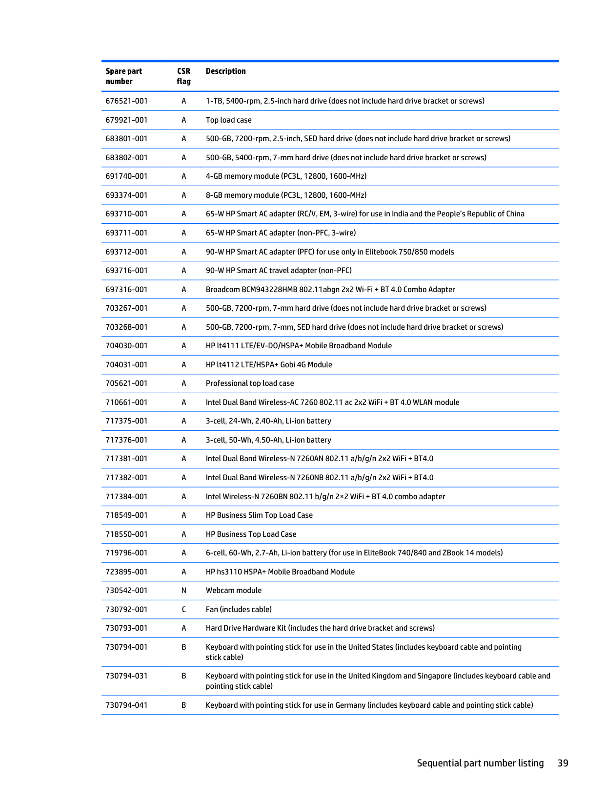
676521-001 A 1-TB, 5400-rpm, 2.5-inch hard drive (does not include hard drive bracket or screws) 679921-001 A Top load case
730794-031 B Keyboard with pointing stick for use in the United Kingdom and Singapore (includes keyboard cable and pointing stick cable)
730794-041 B Keyboard with pointing stick for use in Germany (includes keyboard cable and pointing stick cable)
730794-051 B Keyboard with pointing stick for use in France (includes keyboard cable and pointing stick cable) 730794-061 B Keyboard with pointing stick for use in Italy (includes keyboard cable and pointing stick cable) 730794-071 B Keyboard with pointing stick for use in Spain (includes keyboard cable and pointing stick cable) 730794-081 B Keyboard with pointing stick for use in Denmark (includes keyboard cable and pointing stick cable) 730794-091 B Keyboard with pointing stick for use in Norway (includes keyboard cable and pointing stick cable) 730794-131 B Keyboard with pointing stick for use in Portugal (includes keyboard cable and pointing stick cable) 730794-141 B Keyboard with pointing stick for use in Turkey (includes keyboard cable and pointing stick cable) 730794-151 B Keyboard with pointing stick for use in Greece (includes keyboard cable and pointing stick cable) 730794-161 B Keyboard with pointing stick for use in Latin America (includes keyboard cable and pointing stick cable) 730794-171 B Keyboard with pointing stick for use in Saudi Arabia (includes keyboard cable and pointing stick cable) 730794-201 B Keyboard with pointing stick for use in Brazil (includes keyboard cable and pointing stick cable) 730794-211 B Keyboard with pointing stick for use in Hungary (includes keyboard cable and pointing stick cable) 730794-251 B Keyboard with pointing stick for use in Russia (includes keyboard cable and pointing stick cable) 730794-261 B Keyboard with pointing stick for use in Bulgaria (includes keyboard cable and pointing stick cable) 730794-271 B Keyboard with pointing stick for use in Romania (includes keyboard cable and pointing stick cable) 730794-281 B Keyboard with pointing stick for use in Thailand (includes keyboard cable and pointing stick cable) 730794-291 B Keyboard with pointing stick for use in Japan (includes keyboard cable and pointing stick cable) 730794-A41 B Keyboard with pointing stick for use in Belgium (includes keyboard cable and pointing stick cable) 730794-AB1 B Keyboard with pointing stick for use in Taiwan (includes keyboard cable and pointing stick cable) 730794-AD1 B Keyboard with pointing stick for use in South Korea (includes keyboard cable and pointing stick cable) 730794-B31 B Keyboard with pointing stick for use in the Netherlands (includes keyboard cable and pointing
stick cable) 730794-B71 B Keyboard with pointing stick for use in Sweden and Finland (includes keyboard cable and pointing
stick cable) 730794-BA1 B Keyboard with pointing stick for use in Slovenia (includes keyboard cable and pointing stick cable) 730794-BB1 B Keyboard with pointing stick for use in Israel (includes keyboard cable and pointing stick cable) 730794-BG1 B Keyboard with pointing stick for use in Switzerland (includes keyboard cable and pointing stick cable) 730794-D61 B Keyboard with pointing stick for use in India (includes keyboard cable and pointing stick cable) 730794-DB1 B Keyboard with pointing stick for use in Canada (includes keyboard cable and pointing stick cable) 730794-DD1 B Keyboard with pointing stick for use in Iceland (includes keyboard cable and pointing stick cable) 730794-FL1 B Keyboard with pointing stick for use in the Czech Republic and Slovakia (includes keyboard cable and
pointing stick cable)
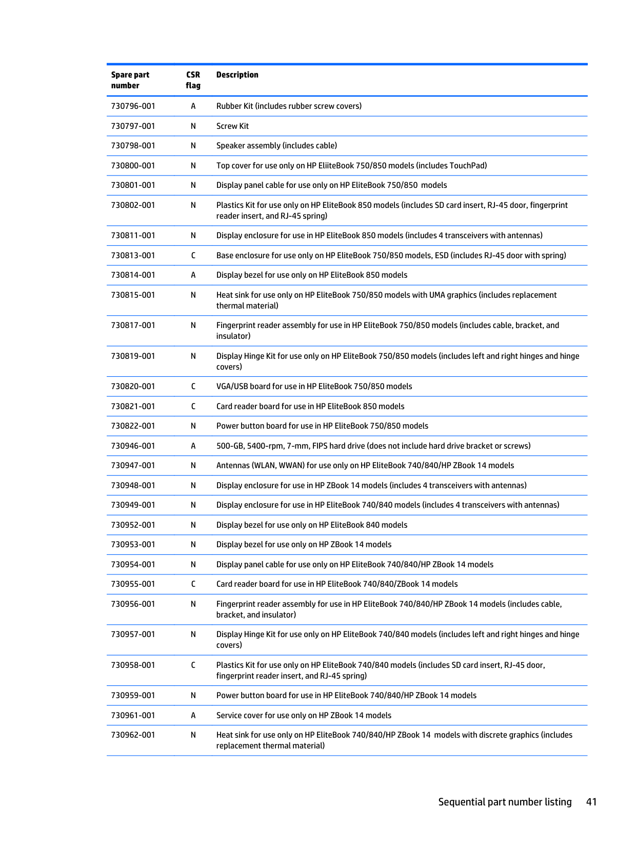
730811-001 N Display enclosure for use in HP EliteBook 850 models (includes 4 transceivers with antennas)
730817-001 N Fingerprint reader assembly for use in HP EliteBook 750/850 models (includes cable, bracket, and insulator)
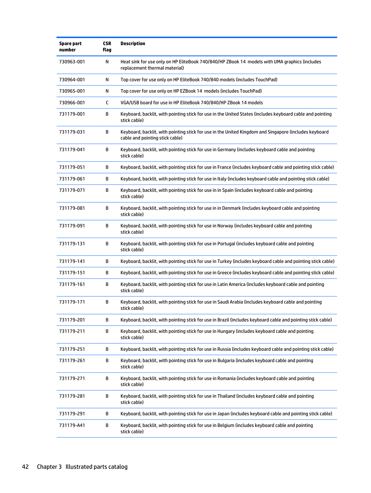
731179-001 B Keyboard, backlit, with pointing stick for use in the United States (includes keyboard cable and pointing stick cable)
731179-031 B Keyboard, backlit, with pointing stick for use in the United Kingdom and Singapore (includes keyboard cable and pointing stick cable)
731179-041 B Keyboard, backlit, with pointing stick for use in Germany (includes keyboard cable and pointing
stick cable) 731179-051 B Keyboard, backlit, with pointing stick for use in France (includes keyboard cable and pointing stick cable) 731179-061 B Keyboard, backlit, with pointing stick for use in Italy (includes keyboard cable and pointing stick cable) 731179-071 B Keyboard, backlit, with pointing stick for use in in Spain (includes keyboard cable and pointing
stick cable) 731179-081 B Keyboard, backlit, with pointing stick for use in in Denmark (includes keyboard cable and pointing stick cable) 731179-091 B Keyboard, backlit, with pointing stick for use in Norway (includes keyboard cable and pointing stick cable) 731179-131 B Keyboard, backlit, with pointing stick for use in Portugal (includes keyboard cable and pointing stick cable)
731179-141 B Keyboard, backlit, with pointing stick for use in Turkey (includes keyboard cable and pointing stick cable) 731179-151 B Keyboard, backlit, with pointing stick for use in Greece (includes keyboard cable and pointing stick cable) 731179-161 B Keyboard, backlit, with pointing stick for use in Latin America (includes keyboard cable and pointing
stick cable) 731179-171 B Keyboard, backlit, with pointing stick for use in Saudi Arabia (includes keyboard cable and pointing
stick cable) 731179-201 B Keyboard, backlit, with pointing stick for use in Brazil (includes keyboard cable and pointing stick cable) 731179-211 B Keyboard, backlit, with pointing stick for use in Hungary (includes keyboard cable and pointing
stick cable) 731179-251 B Keyboard, backlit, with pointing stick for use in Russia (includes keyboard cable and pointing stick cable) 731179-261 B Keyboard, backlit, with pointing stick for use in Bulgaria (includes keyboard cable and pointing
stick cable) 731179-271 B Keyboard, backlit, with pointing stick for use in Romania (includes keyboard cable and pointing stick cable) 731179-281 B Keyboard, backlit, with pointing stick for use in Thailand (includes keyboard cable and pointing
stick cable) 731179-291 B Keyboard, backlit, with pointing stick for use in Japan (includes keyboard cable and pointing stick cable) 731179-A41 B Keyboard, backlit, with pointing stick for use in Belgium (includes keyboard cable and pointing
stick cable)
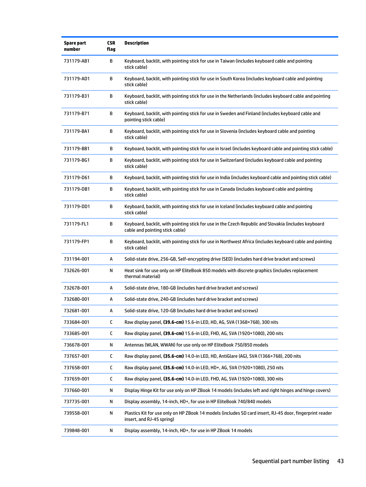
731179-AB1 B Keyboard, backlit, with pointing stick for use in Taiwan (includes keyboard cable and pointing stick cable)
731179-AD1 B Keyboard, backlit, with pointing stick for use in South Korea (includes keyboard cable and pointing stick cable)
731179-B31 B Keyboard, backlit, with pointing stick for use in the Netherlands (includes keyboard cable and pointing stick cable)
731179-B71 B Keyboard, backlit, with pointing stick for use in Sweden and Finland (includes keyboard cable and pointing stick cable)
731179-BG1 B Keyboard, backlit, with pointing stick for use in Switzerland (includes keyboard cable and pointing
stick cable) 731179-D61 B Keyboard, backlit, with pointing stick for use in India (includes keyboard cable and pointing stick cable) 731179-DB1 B Keyboard, backlit, with pointing stick for use in Canada (includes keyboard cable and pointing
stick cable) 731179-DD1 B Keyboard, backlit, with pointing stick for use in Iceland (includes keyboard cable and pointing stick cable) 731179-FL1 B Keyboard, backlit, with pointing stick for use in the Czech Republic and Slovakia (includes keyboard cable and pointing stick cable) 731179-FP1 B Keyboard, backlit, with pointing stick for use in Northwest Africa (includes keyboard cable and pointing
stick cable) 731194-001 A Solid-state drive, 256-GB, Self-encrypting drive (SED) (includes hard drive bracket and screws) 732626-001 N Heat sink for use only on HP EliteBook 850 models with discrete graphics (includes replacement
thermal material) 732678-001 A Solid-state drive, 180-GB (includes hard drive bracket and screws)
739558-001 N Plastics Kit for use only on HP ZBook 14 models (includes SD card insert, RJ-45 door, fingerprint reader insert, and RJ-45 spring)
739848-001 N Display assembly, 14-inch, HD+, for use in HP ZBook 14 models
742437-001 A 45-W HP Smart AC adapter (non-PFC, EM, 3-wire) 743008-001 A Solid-state drive, 32-GB (includes hard drive bracket and screws) 744483-001 A Solid-state drive, 128-GB (includes hard drive bracket and screws); for use only in HP EliteBook 15
models
776476-001 A 1-TB, 5400-rpm hard drive, locked, for use in EliteBook 740/840 models (does not include hard drive
bracket or screws) 776626-001 A Hard drive, 500-GB, 5400-rpm, 7-mm, locked (SGT)(for use in EliteBook 740/840 and ZBook 14 models) 780090-001 A 256-GB, locked (for use only in HP EliteBook 740/840 and ZBook 14 models) 782123–001 A Hard drive, 500-GB, 7200-rpm, 7-mm, locked (HGST)(for use in EliteBook 740/840 and ZBook 14
models) 784451-001 N Display bezel for use in HP EliteBook 740 models 784452-001 A Service cover for use only on HP EliteBook 740 models with a touch screen 784478-001 N Display bezel for use in HP EliteBook 750 models 784479-001 A Service cover for use only on HP EliteBook 750 models with a touch screen 786035-001 A Solid-state drive, 120-GB, M.2 (for use only in HP EliteBook 750/850) 786173-001 A Solid-state drive, 180-GB, Self-encrypting drive (includes hard drive bracket and screws) 789520-001 A Hard drive, 320-GB, 5400-rpm, 7-mm, WD, locked (for use in EliteBook 740/840 and ZBook 14 models) 795941-001 A Solid-state drive, 128-GB, locked, SanDisk 797431-001 N Touchpad for use in EliteBook 750/850 models
802511-6C1 N System board with UMA graphics and an Intel Core i5-4300U processor for use with the Windows 8 Professional operating system (Gold Conversion Kit)
802512-601 N System board with discrete graphics and an Intel Core i5-4300U processor for use in EliteBook 740/840 and 750/850 models with the Windows 8 Professional operating system (Gold)
802512-6C1 N System board with discrete graphics and an Intel Core i5-4300U processor for use in EliteBook 740/840 and 750/850 models with the Windows 8 Professional operating system (Gold Conversion Kit)
802514-6C1 N System board with UMA graphics and an Intel Core i3-4010U processor for use in EliteBook 740/840 and 750/850 models with the Windows 8 Professional operating system (Gold Conversion Kit)
802515-501 N System board with discrete graphics and an Intel Core i3-4010U processor for use in EliteBook 740/840 and 750/850 models with the Windows 8 Standard operating system (Gold)
802516-5C1 N System board with UMA graphics and an Intel Core i5-4200U processor for use with the Windows 8 Standard operating system (Gold Conversion Kit)
802517-0C1 N System board with discrete graphics and an Intel Core i5-4200U processor for use in EliteBook 740/840 and 750/850 models without the Windows 8 operating system (Gold Conversion Kit)
802517-501 N System board with discrete graphics and an Intel Core i5-4200U processor for use in EliteBook 740/840 and 750/850 models with the Windows 8 Standard operating system (Gold)
802517-5C1 N System board with discrete graphics and an Intel Core i5-4200U processor for use in EliteBook 740/840 and 750/850 models with the Windows 8 Standard operating system (Gold Conversion Kit)
802517-601 N System board with discrete graphics and an Intel Core i5-4200U processor for use in EliteBook 740/840 and 750/850 models with the Windows 8 Professional operating system (Gold)
802518-0C1 N System board with UMA graphics and an Intel Core i7-4600U processor for use in models without the Windows 8 operating system (Gold Conversion Kit)
802518-501 N System board with UMA graphics and an Intel Core i7-4600U processor for use in models with the Windows 8 Standard operating system (Gold)
802518-5C1 N System board with UMA graphics and an Intel Core i7-4600U processor for use in models with the Windows 8 Standard operating system (Gold Conversion Kit)
802518-601 N System board with UMA graphics and an Intel Core i7-4600U processor for use in models with the Windows 8 Professional operating system (Gold)
802521-0C1 N System board with discrete graphics and an Intel Core i5-4300U processor for use in ZBook 14 models without the Windows 8 operating system (Gold Conversion Kit)
802521-501 N System board with discrete graphics and an Intel Core i5-4300U processor for use in ZBook 14 models with the Windows 8 Standard operating system (Gold)
802521-5C1 N System board with discrete graphics and an Intel Core i5-4300U processor for use in ZBook 14 models with the Windows 8 Standard operating system (Gold Conversion Kit)
802521-601 N System board with discrete graphics and an Intel Core i5-4300U processor for use in ZBook 14 models with the Windows 8 Professional operating system (Gold)
802522-0C1 N System board with discrete graphics and an Intel Core i7-4600U processor for use in ZBook 14 models without the Windows 8 operating system (Gold Conversion Kit)
802522-501 N System board with discrete graphics and an Intel Core i7-4600U processor for use in ZBook 14 models with the Windows 8 Standard operating system (Gold)
802522-5C1 N System board with discrete graphics and an Intel Core i7-4600U processor for use in ZBook 14 models with the Windows 8 Standard operating system (Gold Conversion Kit)
802522-601 N System board with discrete graphics and an Intel Core i7-4600U processor for use in ZBook 14 models with the Windows 8 Professional operating system (Gold)
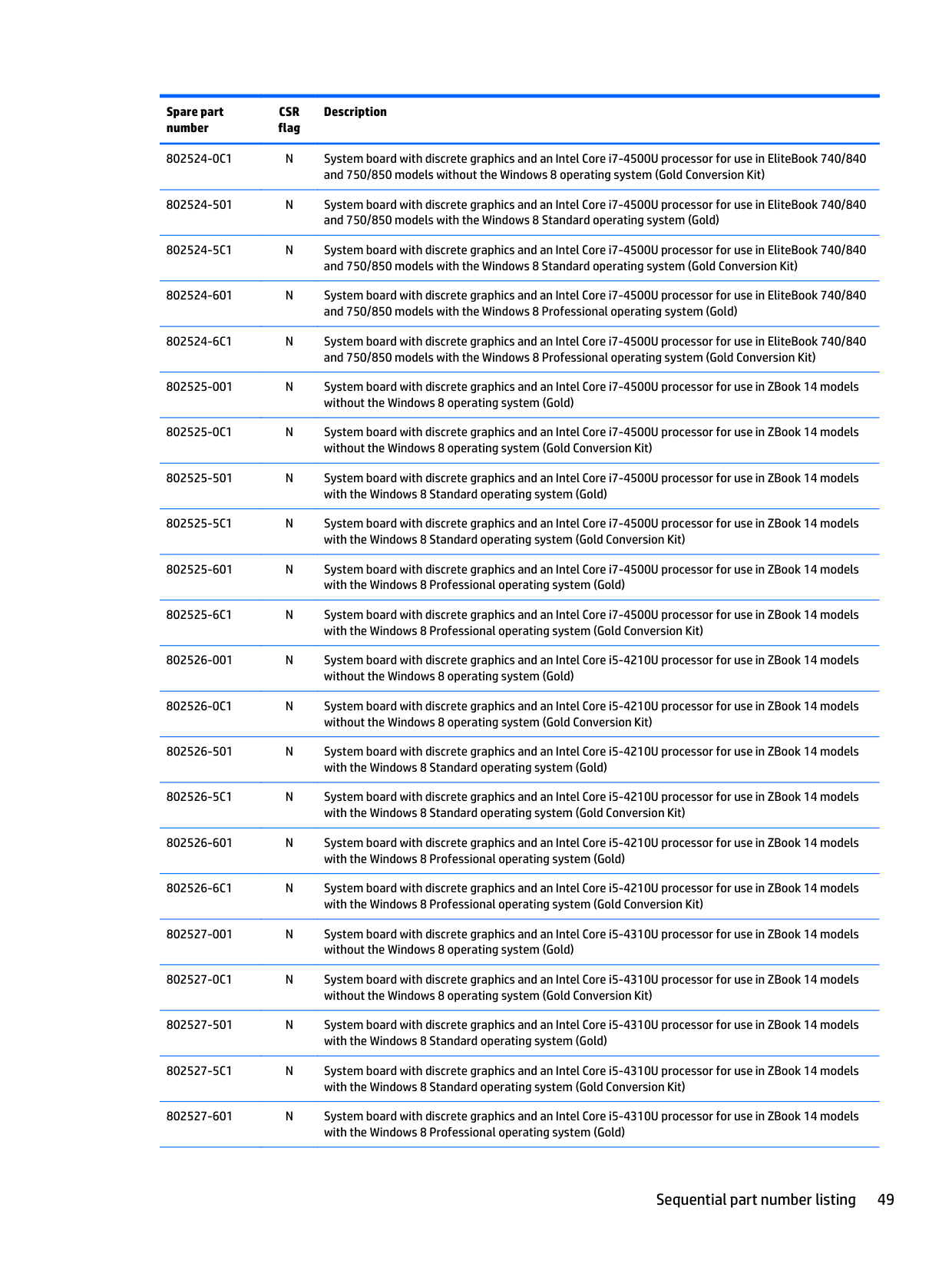
######### 802524-0C1 N System board with discrete graphics and an Intel Core i7-4500U processor for use in EliteBook 740/840and 750/850 models without the Windows 8 operating system (Gold Conversion Kit)
802524-6C1 N System board with discrete graphics and an Intel Core i7-4500U processor for use in EliteBook 740/840 and 750/850 models with the Windows 8 Professional operating system (Gold Conversion Kit)
802525-0C1 N System board with discrete graphics and an Intel Core i7-4500U processor for use in ZBook 14 models without the Windows 8 operating system (Gold Conversion Kit)
802525-501 N System board with discrete graphics and an Intel Core i7-4500U processor for use in ZBook 14 models with the Windows 8 Standard operating system (Gold)
802525-5C1 N System board with discrete graphics and an Intel Core i7-4500U processor for use in ZBook 14 models with the Windows 8 Standard operating system (Gold Conversion Kit)
802526-501 N System board with discrete graphics and an Intel Core i5-4210U processor for use in ZBook 14 models with the Windows 8 Standard operating system (Gold)
802526-5C1 N System board with discrete graphics and an Intel Core i5-4210U processor for use in ZBook 14 models with the Windows 8 Standard operating system (Gold Conversion Kit)
802526-601 N System board with discrete graphics and an Intel Core i5-4210U processor for use in ZBook 14 models with the Windows 8 Professional operating system (Gold)
802527-0C1 N System board with discrete graphics and an Intel Core i5-4310U processor for use in ZBook 14 models without the Windows 8 operating system (Gold Conversion Kit)
802527-501 N System board with discrete graphics and an Intel Core i5-4310U processor for use in ZBook 14 models with the Windows 8 Standard operating system (Gold)
802527-5C1 N System board with discrete graphics and an Intel Core i5-4310U processor for use in ZBook 14 models with the Windows 8 Standard operating system (Gold Conversion Kit)
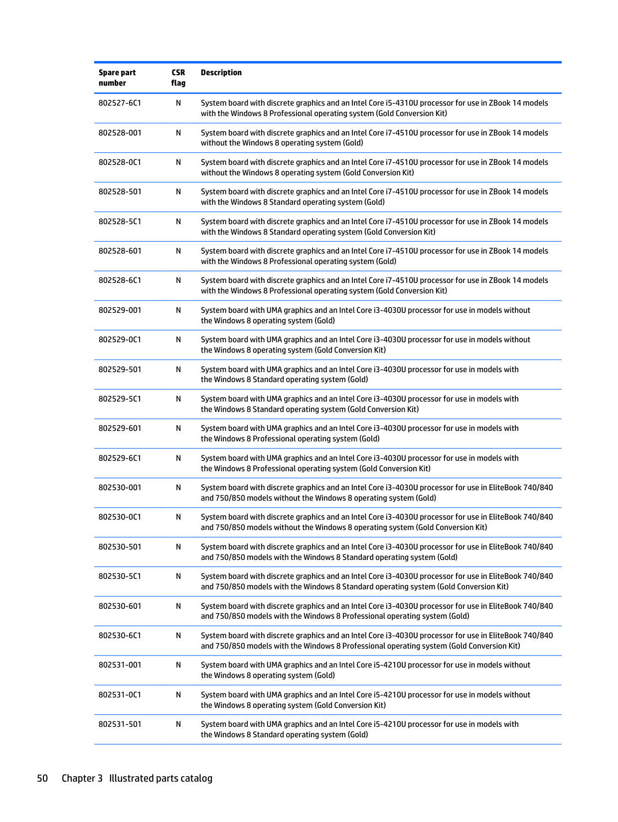
802528-0C1 N System board with discrete graphics and an Intel Core i7-4510U processor for use in ZBook 14 models without the Windows 8 operating system (Gold Conversion Kit)
802528-501 N System board with discrete graphics and an Intel Core i7-4510U processor for use in ZBook 14 models with the Windows 8 Standard operating system (Gold)
802528-5C1 N System board with discrete graphics and an Intel Core i7-4510U processor for use in ZBook 14 models with the Windows 8 Standard operating system (Gold Conversion Kit)
802528-601 N System board with discrete graphics and an Intel Core i7-4510U processor for use in ZBook 14 models with the Windows 8 Professional operating system (Gold)
802529-0C1 N System board with UMA graphics and an Intel Core i3-4030U processor for use in models without the Windows 8 operating system (Gold Conversion Kit)
802529-501 N System board with UMA graphics and an Intel Core i3-4030U processor for use in models with the Windows 8 Standard operating system (Gold)
802529-5C1 N System board with UMA graphics and an Intel Core i3-4030U processor for use in models with the Windows 8 Standard operating system (Gold Conversion Kit)
802529-601 N System board with UMA graphics and an Intel Core i3-4030U processor for use in models with the Windows 8 Professional operating system (Gold)
######### 802531-5C1 N System board with UMA graphics and an Intel Core i5-4210U processor for use in models withthe Windows 8 Standard operating system (Gold Conversion Kit)
802531-6C1 N System board with UMA graphics and an Intel Core i5-4210U processor for use in models with the Windows 8 Professional operating system (Gold Conversion Kit)
802532-0C1 N System board with discrete graphics and an Intel Core i5-4210U processor for use in EliteBook 740/840 and 750/850 models without the Windows 8 operating system (Gold Conversion Kit)
802532-501 N System board with discrete graphics and an Intel Core i5-4210U processor for use in EliteBook 740/840 and 750/850 models with the Windows 8 Standard operating system (Gold)
802532-5C1 N System board with discrete graphics and an Intel Core i5-4210U processor for use in EliteBook 740/840 and 750/850 models with the Windows 8 Standard operating system (Gold Conversion Kit)
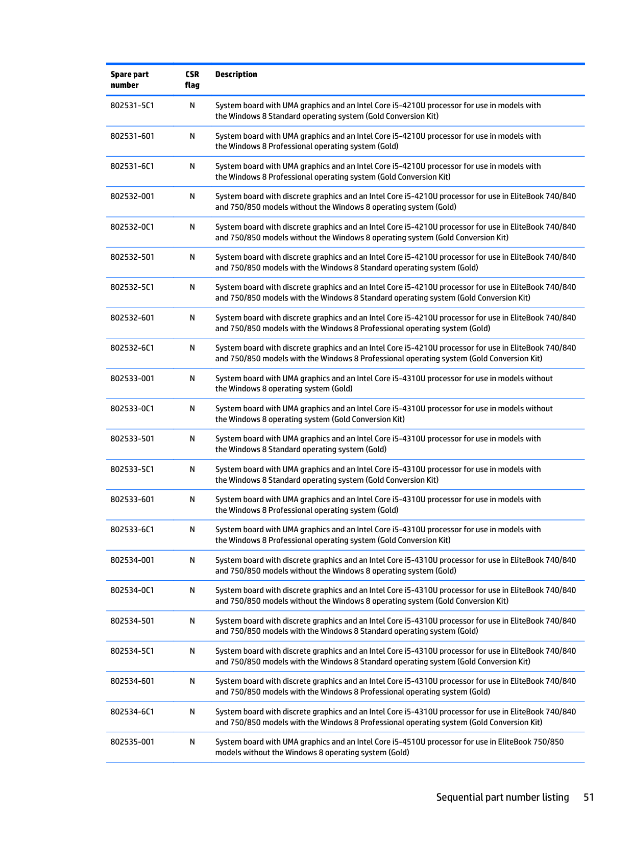
802533-0C1 N System board with UMA graphics and an Intel Core i5-4310U processor for use in models without the Windows 8 operating system (Gold Conversion Kit)
802533-501 N System board with UMA graphics and an Intel Core i5-4310U processor for use in models with the Windows 8 Standard operating system (Gold)
802533-5C1 N System board with UMA graphics and an Intel Core i5-4310U processor for use in models with the Windows 8 Standard operating system (Gold Conversion Kit)
802533-601 N System board with UMA graphics and an Intel Core i5-4310U processor for use in models with the Windows 8 Professional operating system (Gold)
802534-0C1 N System board with discrete graphics and an Intel Core i5-4310U processor for use in EliteBook 740/840 and 750/850 models without the Windows 8 operating system (Gold Conversion Kit)
802534-501 N System board with discrete graphics and an Intel Core i5-4310U processor for use in EliteBook 740/840 and 750/850 models with the Windows 8 Standard operating system (Gold)
802534-5C1 N System board with discrete graphics and an Intel Core i5-4310U processor for use in EliteBook 740/840 and 750/850 models with the Windows 8 Standard operating system (Gold Conversion Kit)
802534-601 N System board with discrete graphics and an Intel Core i5-4310U processor for use in EliteBook 740/840 and 750/850 models with the Windows 8 Professional operating system (Gold)
802535-501 N System board with UMA graphics and an Intel Core i5-4510U processor for use in EliteBook 750/850 models with the Windows 8 Standard operating system (Gold)
802535-5C1 N System board with UMA graphics and an Intel Core i5-4510U processor for use in EliteBook 750/850 models with the Windows 8 Standard operating system (Gold Conversion Kit)
802535-601 N System board with UMA graphics and an Intel Core i5-4510U processor for use in EliteBook 750/850 models with the Windows 8 Professional operating system (Gold)
802536-0C1 N System board with discrete graphics and an Intel Core i5-4510U processor for use in EliteBook 740/840 and 750/850 models without the Windows 8 operating system (Gold Conversion Kit)
802536-501 N System board with discrete graphics and an Intel Core i5-4510U processor for use in EliteBook 740/840 and 750/850 models with the Windows 8 Standard operating system (Gold)
802536-5C1 N System board with discrete graphics and an Intel Core i5-4510U processor for use in EliteBook 740/840 and 750/850 models with the Windows 8 Standard operating system (Gold Conversion Kit)
4 Removal and replacement procedures preliminary requirements
Tools required
You will need the following tools to complete the removal and replacement procedures:
Service considerations
The following sections include some of the considerations that you must keep in mind during disassembly and assembly procedures.
| | |---|
NOTE: As you remove each subassembly from the computer, place the subassembly (and all accompanying screws) away from the work area to prevent damage.
#### Plastic parts
CAUTION: Using excessive force during disassembly and reassembly can damage plastic parts. Use care when handling the plastic parts. Apply pressure only at the points designated in the maintenance instructions.
Cables and connectors CAUTION: When servicing the computer, be sure that cables are placed in their proper locations during the reassembly process. Improper cable placement can damage the computer. Cables must be handled with extreme care to avoid damage. Apply only the tension required to unseat or seat the cables during removal and insertion. Handle cables by the connector whenever possible. In all cases, avoid bending, twisting, or tearing cables. Be sure that cables are routed in such a way that they cannot be caught or snagged by parts being removed or replaced. Handle flex cables with extreme care; these cables tear easily.
Tools required 53
Drive handling CAUTION: Drives are fragile components that must be handled with care. To prevent damage to the computer, damage to a drive, or loss of information, observe these precautions: Before removing or inserting a hard drive, shut down the computer. If you are unsure whether the computer is off or in Hibernation, turn the computer on, and then shut it down through the operating system. Before handling a drive, be sure that you are discharged of static electricity. While handling a drive, avoid touching the connector. Before removing a diskette drive or optical drive, be sure that a diskette or disc is not in the drive and be sure that the optical drive tray is closed. Handle drives on surfaces covered with at least one inch of shock-proof foam. Avoid dropping drives from any height onto any surface. After removing a hard drive, an optical drive, or a diskette drive, place it in a static-proof bag. Avoid exposing an internal hard drive to products that have magnetic fields, such as monitors or speakers. Avoid exposing a drive to temperature extremes or liquids. If a drive must be mailed, place the drive in a bubble pack mailer or other suitable form of protective packaging and label the package “FRAGILE.”
Grounding guidelines
#### Electrostatic discharge damage
Electronic components are sensitive to electrostatic discharge (ESD). Circuitry design and structure determine the degree of sensitivity. Networks built into many integrated circuits provide some protection, but in many cases, ESD contains enough power to alter device parameters or melt silicon junctions.
A discharge of static electricity from a finger or other conductor can destroy static-sensitive devices or microcircuitry. Even if the spark is neither felt nor heard, damage may have occurred.
An electronic device exposed to ESD may not be affected at all and can work perfectly throughout a normal cycle. Or the device may function normally for a while, then degrade in the internal layers, reducing its life expectancy.
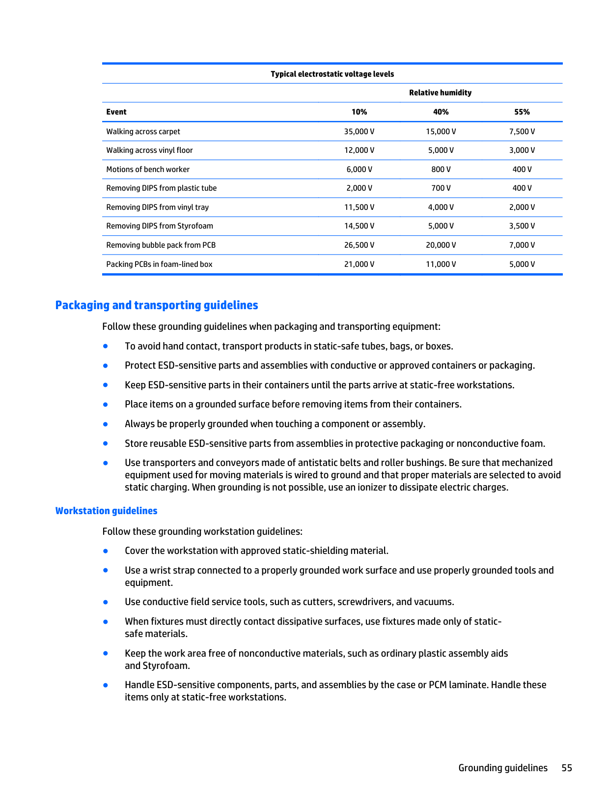
CAUTION: To prevent damage to the computer when you are removing or installing internal components, observe these precautions: Keep components in their electrostatic-safe containers until you are ready to install them. Before touching an electronic component, discharge static electricity by using the guidelines described in this section. Avoid touching pins, leads, and circuitry. Handle electronic components as little as possible. If you remove a component, place it in an electrostatic-safe container. The following table shows how humidity affects the electrostatic voltage levels generated by different activities. CAUTION: A product can be degraded by as little as 700 V.
######## Typical electrostatic voltage levels
Relative humidity Event 10% 40% 55% Walking across carpet 35,000 V 15,000 V 7,500 V Walking across vinyl floor 12,000 V 5,000 V 3,000 V Motions of bench worker 6,000 V 800 V 400 V Removing DIPS from plastic tube 2,000 V 700 V 400 V Removing DIPS from vinyl tray 11,500 V 4,000 V 2,000 V Removing DIPS from Styrofoam 14,500 V 5,000 V 3,500 V Removing bubble pack from PCB 26,500 V 20,000 V 7,000 V Packing PCBs in foam-lined box 21,000 V 11,000 V 5,000 V
##### Packaging and transporting guidelines
Follow these grounding guidelines when packaging and transporting equipment:
###### Workstation guidelines
Follow these grounding workstation guidelines:
Grounding guidelines 55
###### Equipment guidelines
Grounding equipment must include either a wrist strap or a foot strap at a grounded workstation.
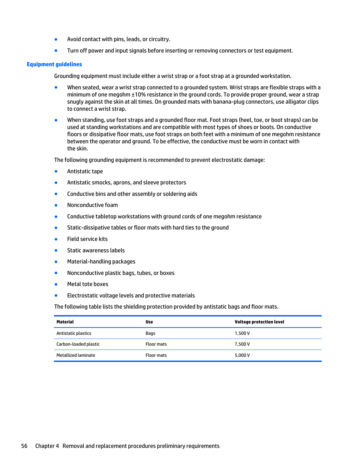
The following grounding equipment is recommended to prevent electrostatic damage:
Material Use Voltage protection level
Antistatic plastics Bags 1,500 V Carbon-loaded plastic Floor mats 7,500 V Metallized laminate Floor mats 5,000 V
5 Removal and replacement procedures for Customer Self-Repair parts
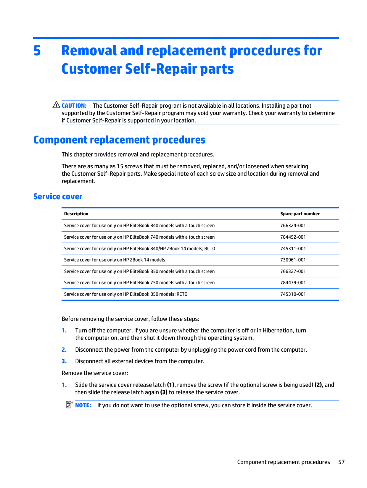
CAUTION: The Customer Self-Repair program is not available in all locations. Installing a part not supported by the Customer Self-Repair program may void your warranty. Check your warranty to determine if Customer Self-Repair is supported in your location.
Component replacement procedures This chapter provides removal and replacement procedures. There are as many as 15 screws that must be removed, replaced, and/or loosened when servicing the Customer Self-Repair parts. Make special note of each screw size and location during removal and replacement.
#### Service cover
######## Description Spare part number
Service cover for use only on HP EliteBook 840 models with a touch screen 766324-001 Service cover for use only on HP EliteBook 740 models with a touch screen 784452-001 Service cover for use only on HP EliteBook 840/HP ZBook 14 models; RCTO 745311-001 Service cover for use only on HP ZBook 14 models 730961-001 Service cover for use only on HP EliteBook 850 models with a touch screen 766327-001 Service cover for use only on HP EliteBook 750 models with a touch screen 784479-001 Service cover for use only on HP EliteBook 850 models; RCTO 745310-001
Before removing the service cover, follow these steps:
| | |---|

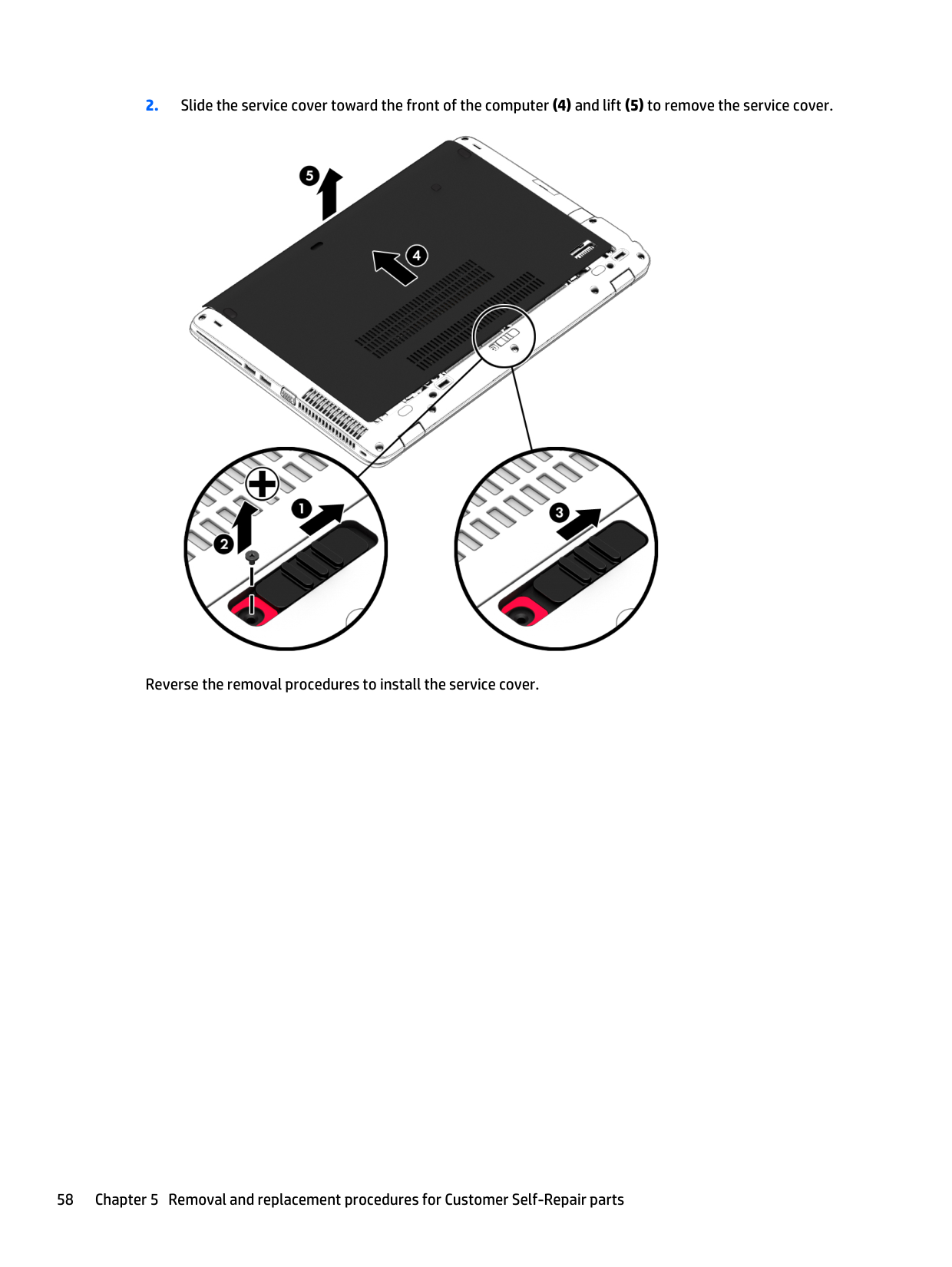
Reverse the removal procedures to install the service cover.
#### Battery
######## Description Spare part number
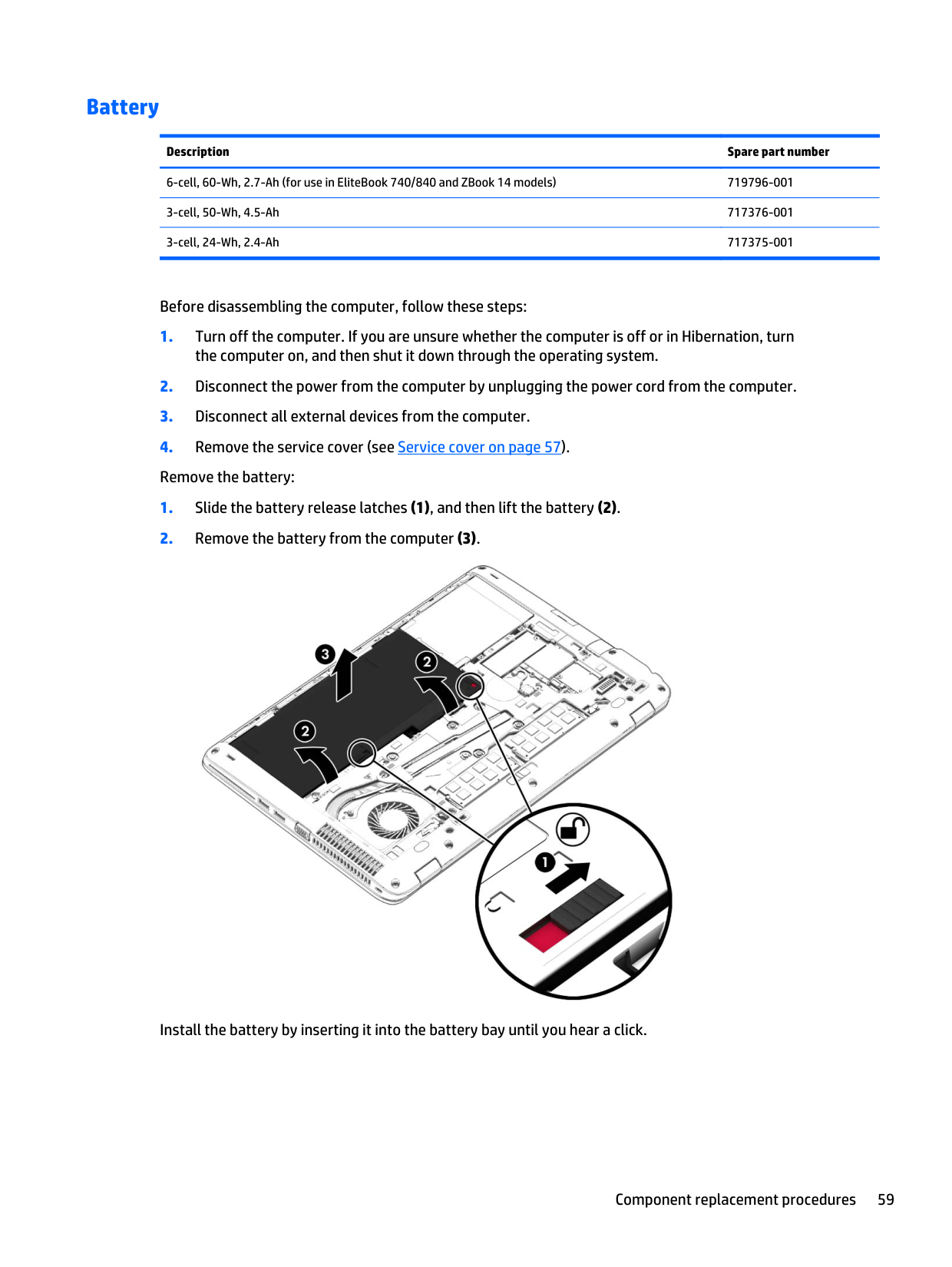
6-cell, 60-Wh, 2.7-Ah (for use in EliteBook 740/840 and ZBook 14 models) 719796-001 3-cell, 50-Wh, 4.5-Ah 717376-001 3-cell, 24-Wh, 2.4-Ah 717375-001
Before disassembling the computer, follow these steps:

Install the battery by inserting it into the battery bay until you hear a click.
#### Hard drive
| | |---|
NOTE: The hard drive spare part kit does not include the hard drive bracket or screws.
Description Spare part number 1-TB, 7200-rpm (for use in EliteBook 740/840 and ZBook 14 models) 766644-001 1-TB, 5400-rpm, 2.5-inch 676521-001 1-TB, 5400-rpm hard drive, locked, for use in EliteBook 740/840 models (does not include hard drive bracket or screws)
776476-001
1-TB, 5400-rpm, locked 763529-001 750-GB, 7200-rpm, 2.5-inch (for use in EliteBook 740/840 and ZBook 14 models) 633252-001 500-GB, 7200-rpm, 7-mm, SED 703268-001 500-GB, 7200-rpm, 2.5-inch, SED 683801-001 500-GB, 7200-rpm, 7-mm 703267-001 500-GB, 7200-rpm, 7-mm, locked (HGST)(for use in EliteBook 740/840 and ZBook 14 models) 782123-001 500-GB, 5400-rpm, 7-mm 683802-001 500-GB, 5400-rpm, 7-mm, FIPS 730946-001 500-GB, 5400-rpm, 7-mm, locked (SGT)(for use in EliteBook 740/840 and ZBook 14 models) 773555-001 500-GB, 5400-rpm, 7-mm, locked (SGT)(for use in EliteBook 740/840 and ZBook 14 models) 776626-001 320-GB, 5400-rpm, 7-mm 634862-001 320-GB, 5400-rpm, 7-mm, WD, locked (for use in EliteBook 740/840 and ZBook 14 models) 789520-001 Hard Drive Hardware Kit (includes hard drive bracket and screws) 730793-001
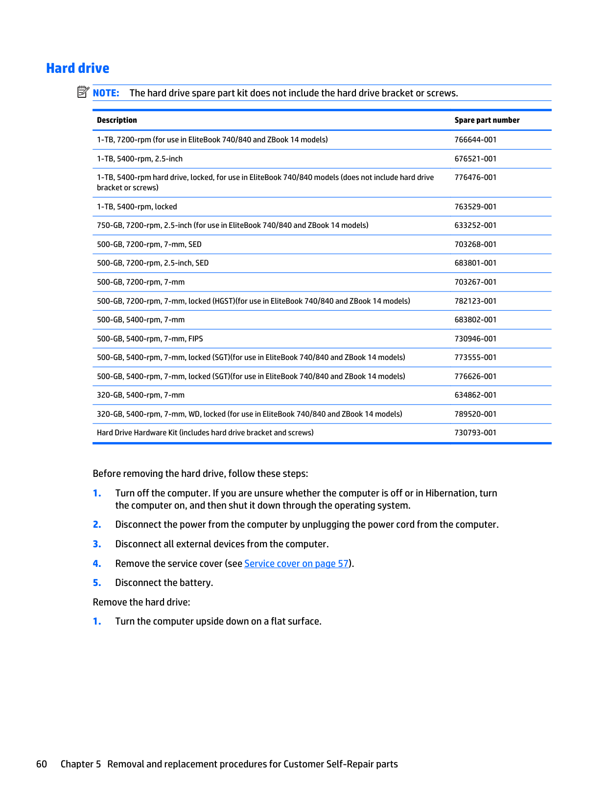
Before removing the hard drive, follow these steps:


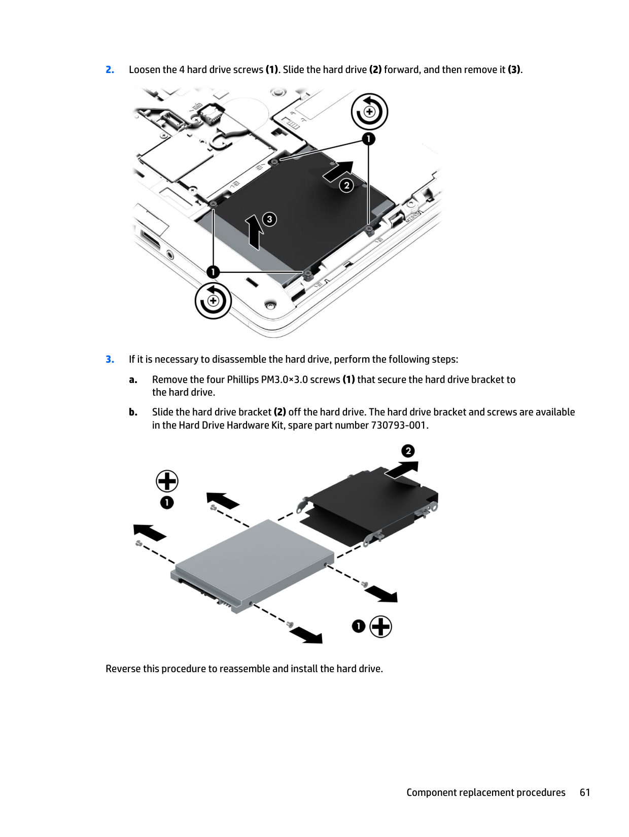
Reverse this procedure to reassemble and install the hard drive.
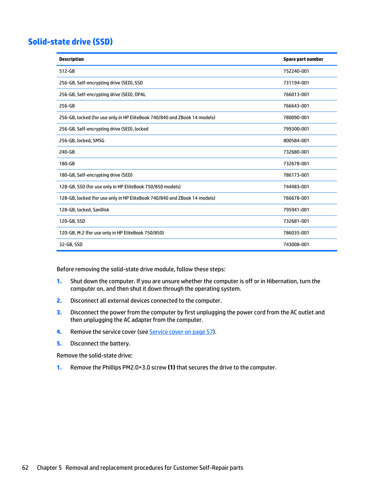
#### Solid-state drive (SSD)
######## Description Spare part number
512-GB 752240-001 256-GB, Self-encrypting drive (SED), SSD 731194-001 256-GB, Self-encrypting drive (SED), OPAL 766013-001 256-GB 766643-001 256-GB, locked (for use only in HP EliteBook 740/840 and ZBook 14 models) 780090-001 256-GB, Self-encrypting drive (SED), locked 799300-001 256-GB, locked, SMSG 800584-001 240-GB 732680-001 180-GB 732678-001 180-GB, Self-encrypting drive (SED) 786173-001 128-GB, SSD (for use only in HP EliteBook 750/850 models) 744483-001 128-GB, locked (for use only in HP EliteBook 740/840 and ZBook 14 models) 766678-001 128-GB, locked, SanDisk 795941-001 120-GB, SSD 732681-001 120-GB, M.2 (for use only in HP EliteBook 750/850) 786035-001 32-GB, SSD 743008-001
Before removing the solid-state drive module, follow these steps:

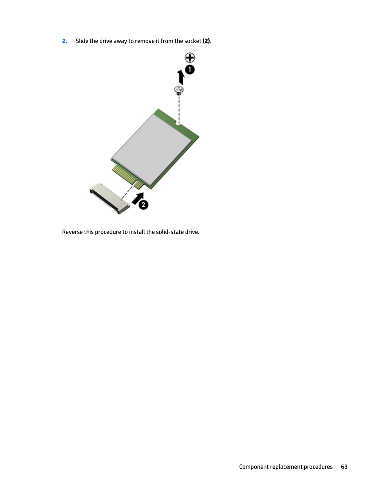
Reverse this procedure to install the solid-state drive.
#### RTC battery
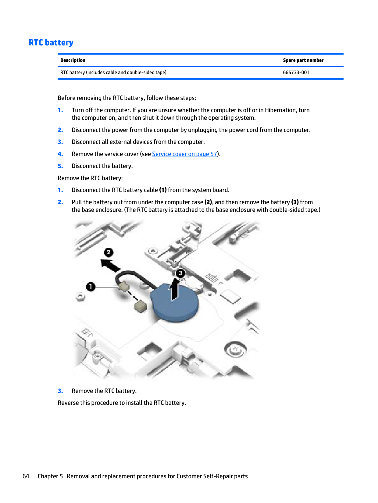
Description Spare part number RTC battery (includes cable and double-sided tape) 665733-001
Before removing the RTC battery, follow these steps:

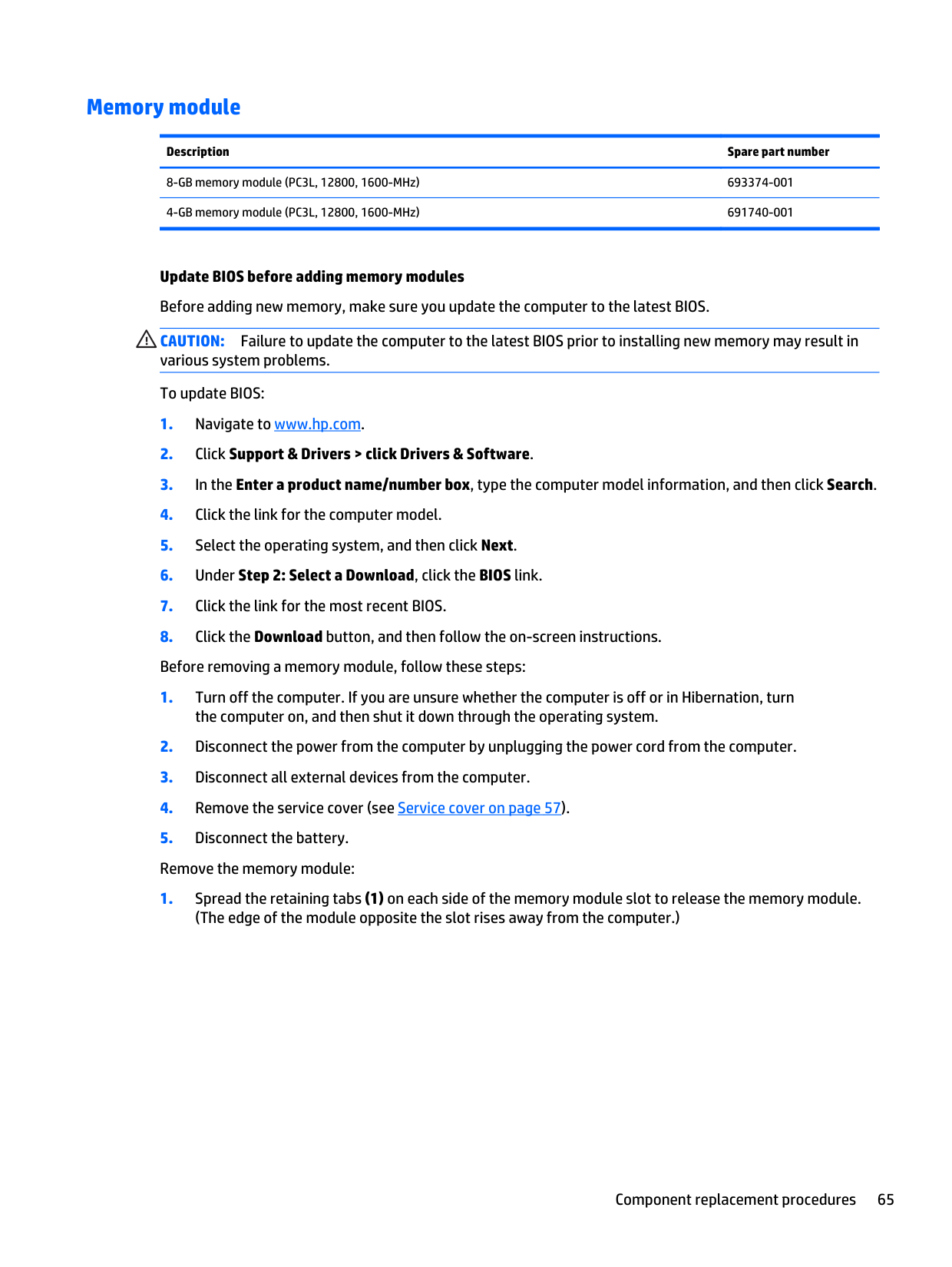
#### Memory module
######## Description Spare part number
8-GB memory module (PC3L, 12800, 1600-MHz) 693374-001 4-GB memory module (PC3L, 12800, 1600-MHz) 691740-001
Update BIOS before adding memory modules Before adding new memory, make sure you update the computer to the latest BIOS. CAUTION: Failure to update the computer to the latest BIOS prior to installing new memory may result in various system problems. To update BIOS:
| | |---|
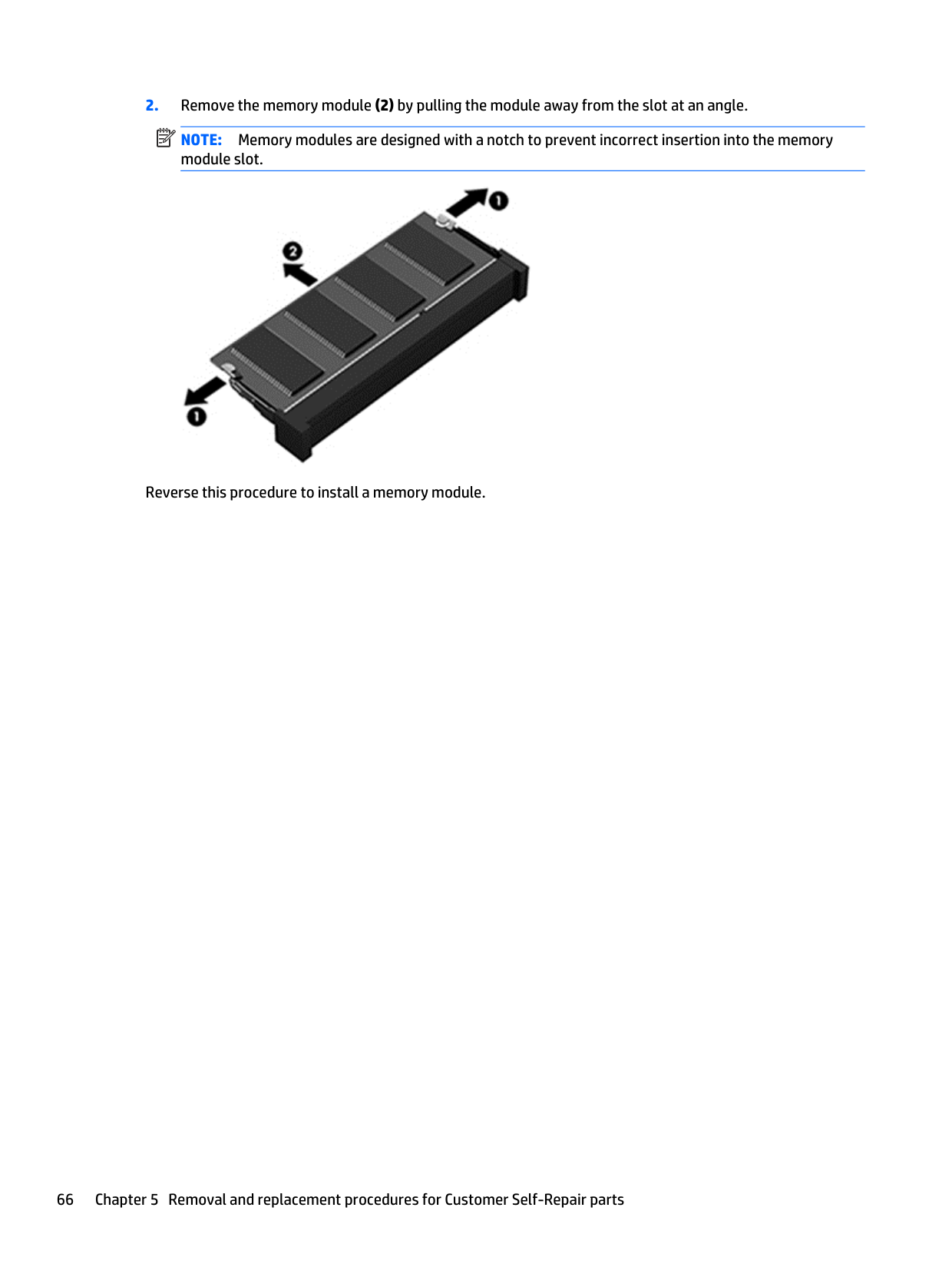
NOTE: Memory modules are designed with a notch to prevent incorrect insertion into the memory module slot.

Reverse this procedure to install a memory module.
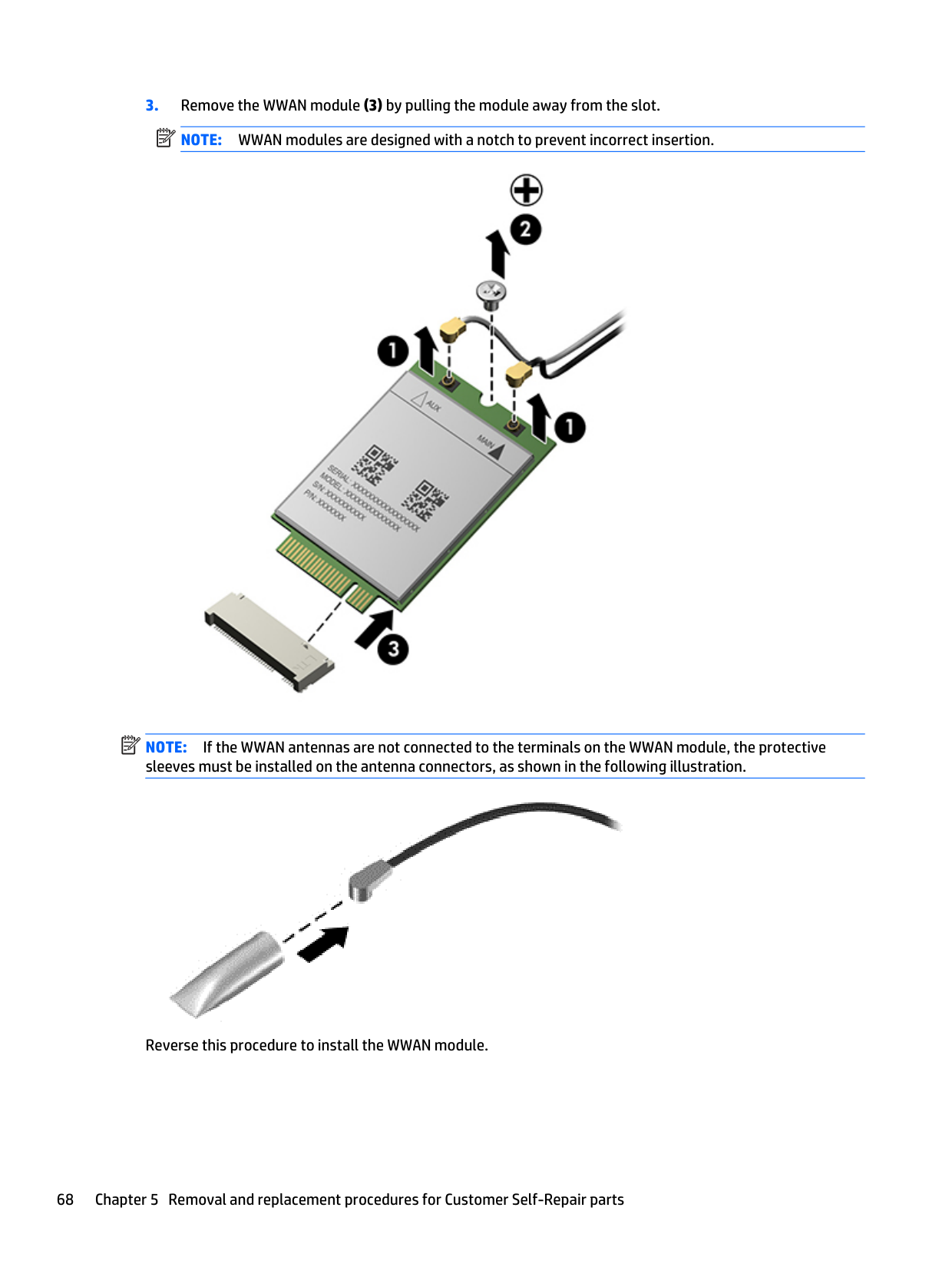
#### WWAN module
| | |---|
NOTE: The WWAN module and the WLAN module are not interchangeable.
Description Spare part number
Before removing the WWAN module, follow these steps:
NOTE: The red WWAN antenna cable is connected to the WWAN module “Main” terminal. The blue WWAN antenna cable is connected to the WWAN module “Aux” terminal.
| | |---|
| | |---|

| | |---|
NOTE: If the WWAN antennas are not connected to the terminals on the WWAN module, the protective sleeves must be installed on the antenna connectors, as shown in the following illustration.

Reverse this procedure to install the WWAN module.
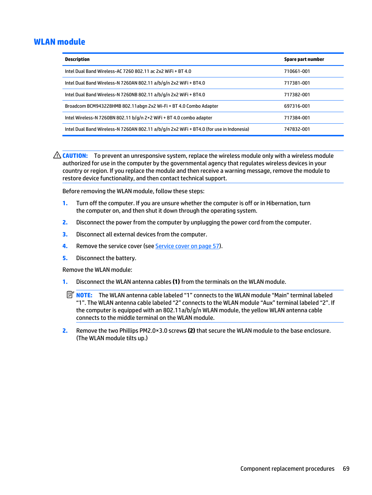
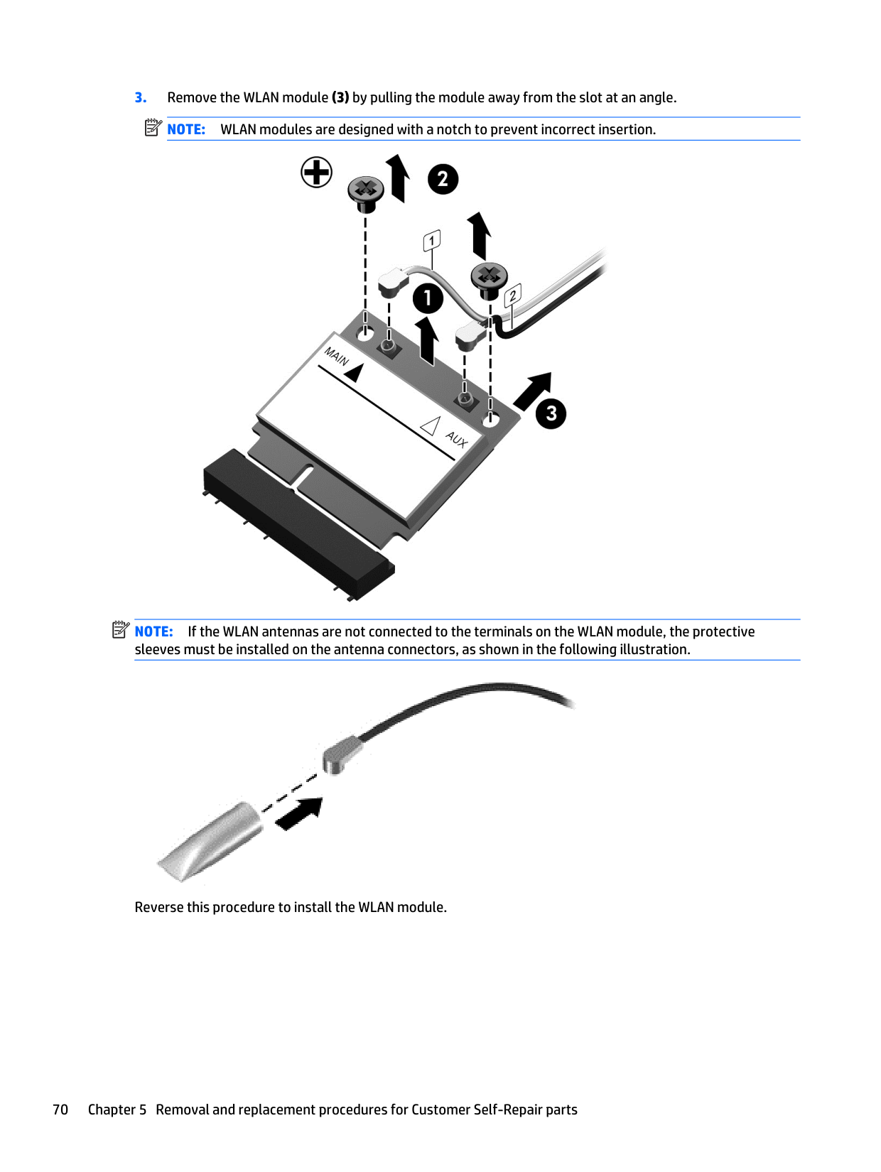
#### WLAN module
######## Description Spare part number
Intel Dual Band Wireless-AC 7260 802.11 ac 2x2 WiFi + BT 4.0 710661-001 Intel Dual Band Wireless-N 7260AN 802.11 a/b/g/n 2x2 WiFi + BT4.0 717381-001 Intel Dual Band Wireless-N 7260NB 802.11 a/b/g/n 2x2 WiFi + BT4.0 717382-001 Broadcom BCM943228HMB 802.11abgn 2x2 Wi-Fi + BT 4.0 Combo Adapter 697316-001 Intel Wireless-N 7260BN 802.11 b/g/n 2×2 WiFi + BT 4.0 combo adapter 717384-001 Intel Dual Band Wireless-N 7260AN 802.11 a/b/g/n 2x2 WiFi + BT4.0 (for use in Indonesia) 747832-001
CAUTION: To prevent an unresponsive system, replace the wireless module only with a wireless module authorized for use in the computer by the governmental agency that regulates wireless devices in your country or region. If you replace the module and then receive a warning message, remove the module to restore device functionality, and then contact technical support.
Before removing the WLAN module, follow these steps:
NOTE: The WLAN antenna cable labeled “1” connects to the WLAN module “Main” terminal labeled “1”. The WLAN antenna cable labeled “2” connects to the WLAN module “Aux” terminal labeled “2”. If the computer is equipped with an 802.11a/b/g/n WLAN module, the yellow WLAN antenna cable connects to the middle terminal on the WLAN module.
| | |---|
| | |---|

| | |---|
NOTE: If the WLAN antennas are not connected to the terminals on the WLAN module, the protective sleeves must be installed on the antenna connectors, as shown in the following illustration.

Reverse this procedure to install the WLAN module.
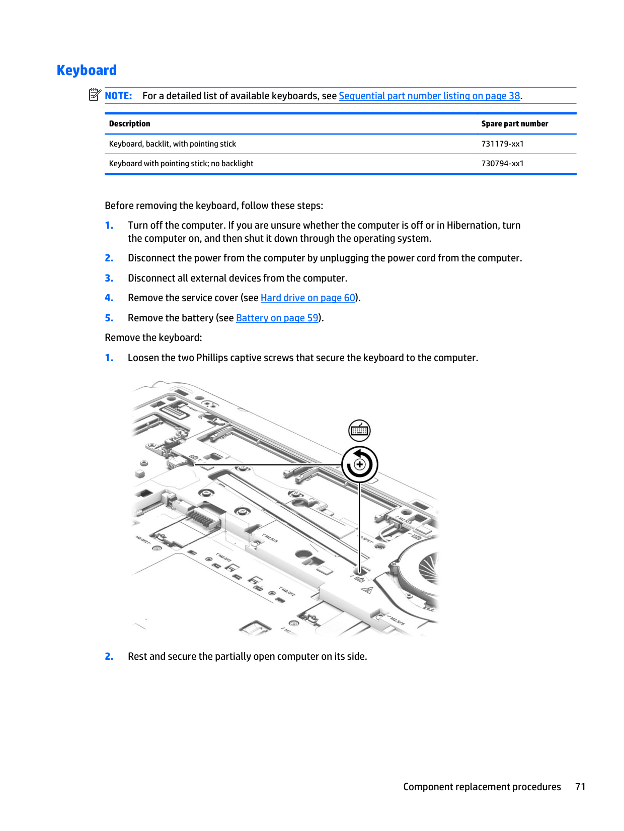
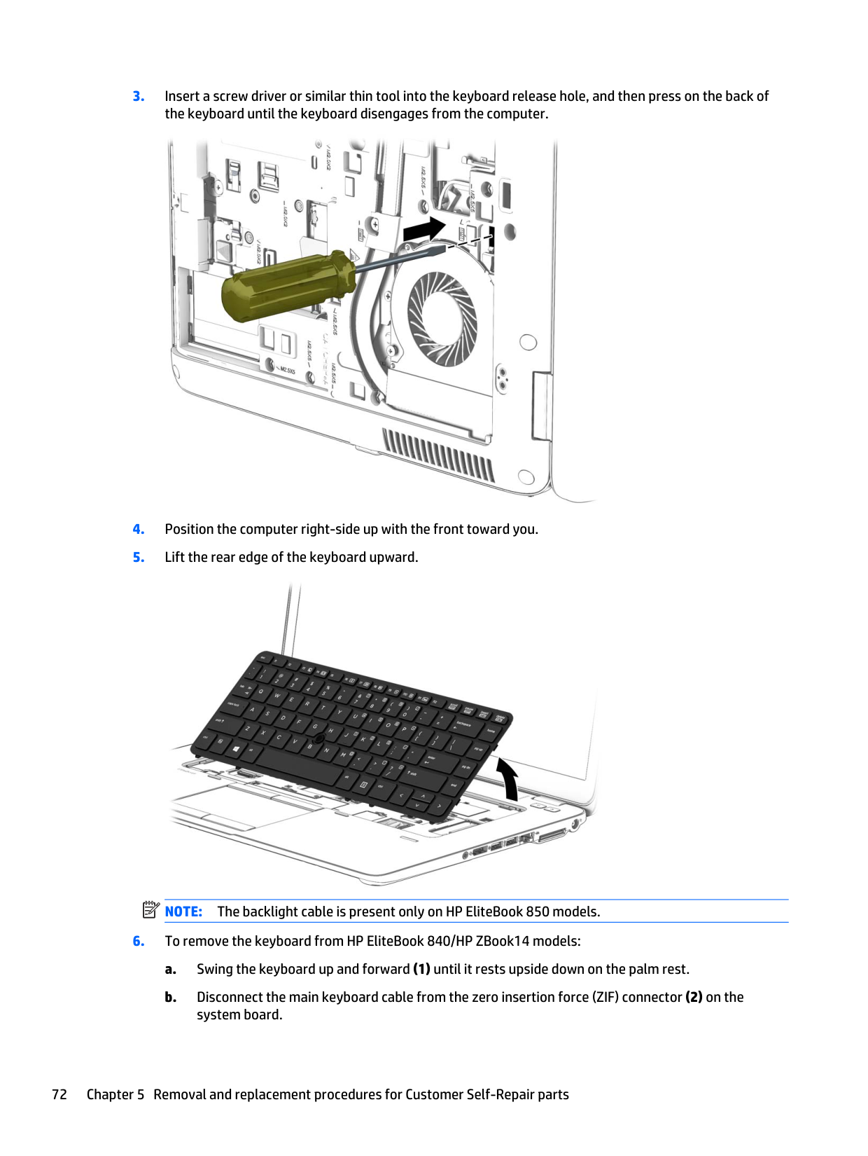
#### Keyboard
| | |---|
NOTE: For a detailed list of available keyboards, see Sequential part number listing on page 38.
######## Description Spare part number
Keyboard, backlit, with pointing stick 731179-xx1 Keyboard with pointing stick; no backlight 730794-xx1
Before removing the keyboard, follow these steps:


NOTE: The backlight cable is present only on HP EliteBook 850 models.
| | |---|


Reverse this procedure to install the keyboard.
6 Removal and replacement procedures for Authorized Service Provider parts
CAUTION: Components described in this chapter should only be accessed by an authorized service provider. Accessing these parts can damage the computer or void the warranty.
Component replacement procedures NOTE: Details about your computer, including model, serial number, product key, and length of warranty, are on the service tag at the bottom of your computer. See Service tag and PCID label on page 21 for details. This chapter provides removal and replacement procedures for Authorized Service Provider only parts. There are as many as 61 screws that must be removed, replaced, and/or loosened when servicing the Authorized Service Provider parts. Make special note of each screw size and location during removal and replacement.
| | |---|
#### Display panel (non-touch)
| | |---|
NOTE: HP EliteBook 840 models offer both touch and non-touch displays. Non-touch displays are spared at the subcomponent level only. Touch displays are only spared as a whole (touch display components are not spared).
In non-touch models, you can remove the raw display panel with the display assembly still connected to the computer. The following section shows how to remove the raw display panel without removing the display assembly from the computer.
See Display assembly on page 108 later in this chapter to remove internal components that require that you remove the display assembly.
Description Spare part number Display bezel Display bezel for use in HP EliteBook 840 models 730952-001 Display bezel for use in HP EliteBook 740 models 784451-001 Display bezel for use in HP ZBook 14 models 730953-001 Display bezel for use in HP EliteBook 850 models 730814-001 Display bezel for use in HP EliteBook 750 models 784478-001 Display panel (35.6-cm) 14.0-in LED, HD, AntiGlare (AG), SVA (1366×768), 200 nits 737657-001 (35.6-cm) 14.0-in LED, HD+, AG, SVA (1920×1080), 250 nits 737658-001 (35.6-cm) 14.0-in LED, FHD, AG, SVA (1920×1080), 300 nits 737659-001 (39.6-cm) 15.6-in LED, HD, AG, SVA (1368×768), 300 nits 733684-001
Description Spare part number (39.6-cm) 15.6-in LED, FHD, AG, SVA (1920×1080), 200 nits 733685-001 Webcam module 730542-001 Microphone module 730795-001
Before removing the display assembly, follow these steps:

####### 4. Lift and rotate the panel onto the computer (2).

####### 5. On the back of the display panel, lift the tape that secures the display cable to the display panel (1), andthe disconnect the display cable from the panel (2).


CAUTION: Handle the module with caution. The module has a thin profile and is susceptible to damage when not handled carefully.

Reverse this procedure to reassemble and install the display panel components.
#### Base enclosure
Base enclosure removal procedures for HP EliteBook 840/HP ZBook 14 models and HP EliteBook 15 models are in separated in the following sections.
##### Base enclosure (HP EliteBook 840/HP ZBook14 models)
######## Description Spare part number
Base enclosure for use only on HP EliteBook 740/840 models 765809-001 Base enclosure for use only on HP ZBook 14 models 765810-001
Before removing the base enclosure, follow these steps:
Use the following image as an overview of all base enclosure screw locations.

Remove the base enclosure:
####### 2. Remove the seven rubber screw covers from the screws outside of the service cover.NOTE: The eight screws outside of the service cover also have rubber covers.
| | |---|

####### 3. Remove the 16 Torx T8M2.5×5.0 screws that secure the base enclosure to the computer.

####### 4. Remove the Phillips PM2.0×8.0 screw (1) near the media card reader and the six Phillips PM2.0×5.0broadhead screws (2) inside the battery bay that secure the base enclosure to the computer.

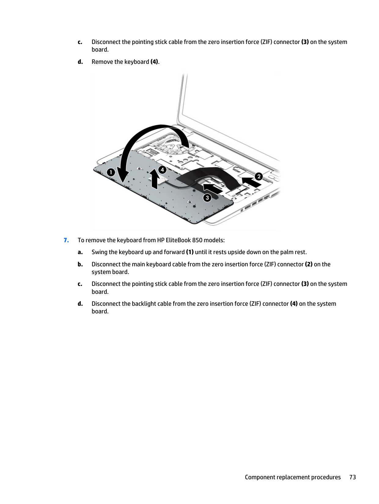

Reverse this procedure to install the base enclosure.
##### Base enclosure (HP EliteBook 850 models)
######## Description Spare part number
Base enclosure for use only on HP EliteBook 750/850 models (includes RJ-45 door with spring) 730813-001 Base enclosure for use only on HP EliteBook 750/850 models, ESD (includes RJ-45 door with spring) 765811-001
Before removing the base enclosure, follow these steps:
Use the following image as an overview of all base enclosure screw locations.

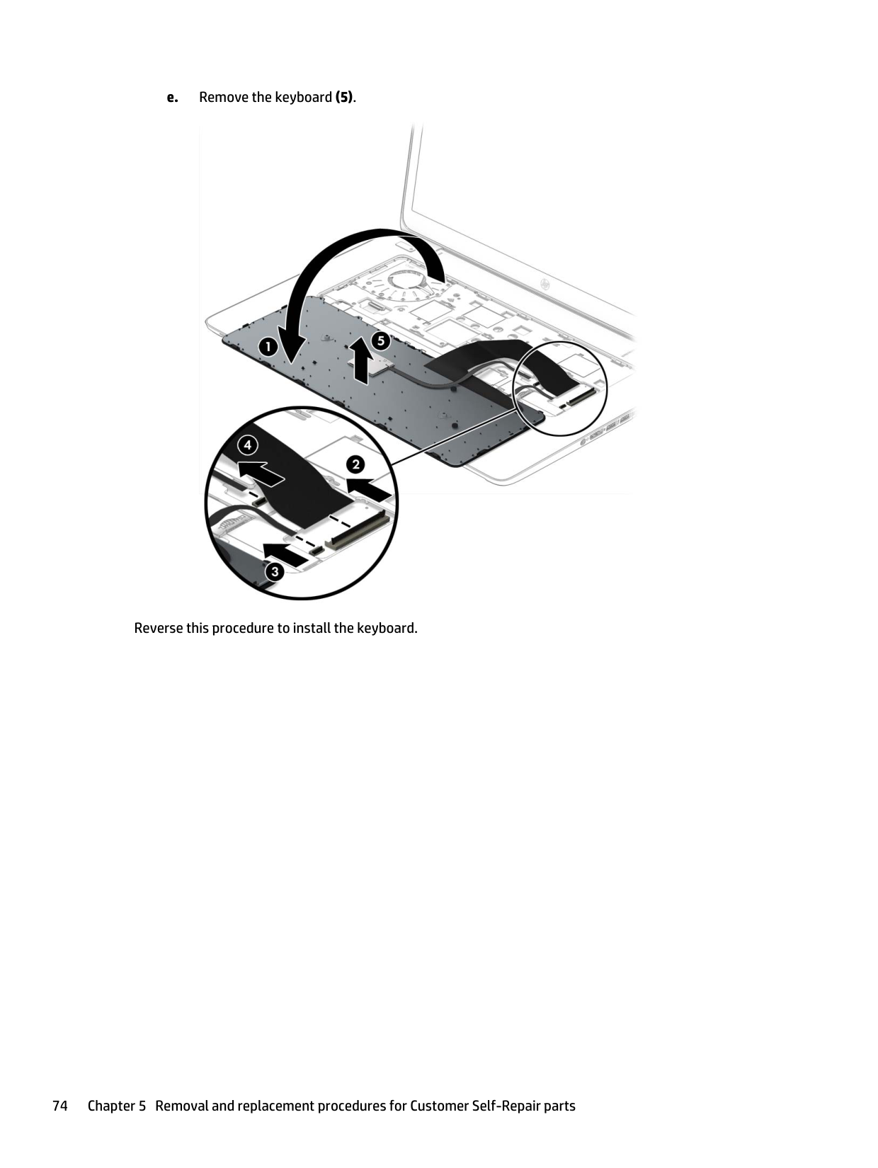
Remove the base enclosure:
####### 2. Remove the seven rubber screw covers from the screws outside of the service cover.

####### 3. Remove the 21 Torx T8M2.5×5.0 screws that secure the base enclosure to the computer.

####### 4. Remove the Phillips PM2.0×8.0 screw (1) near the media card reader and the five Phillips PM2.0×5.0broadhead screws (2) inside the battery bay that secure the base enclosure to the computer.


Reverse this procedure to install the base enclosure.
#### Fan
Description Spare part number Fan (includes cable) 730792-001
Before removing the fan, follow these steps:

Reverse this procedure to install the fan.
#### Card reader board
######## Description Spare part number
Card reader board for use in HP EliteBook 740/840/HP ZBook 14 models 730955-001 Card reader board for use in HP EliteBook 750/850 models 730821-001
Before removing the card reader board, follow these steps:
the computer on, and then shut it down through the operating system.
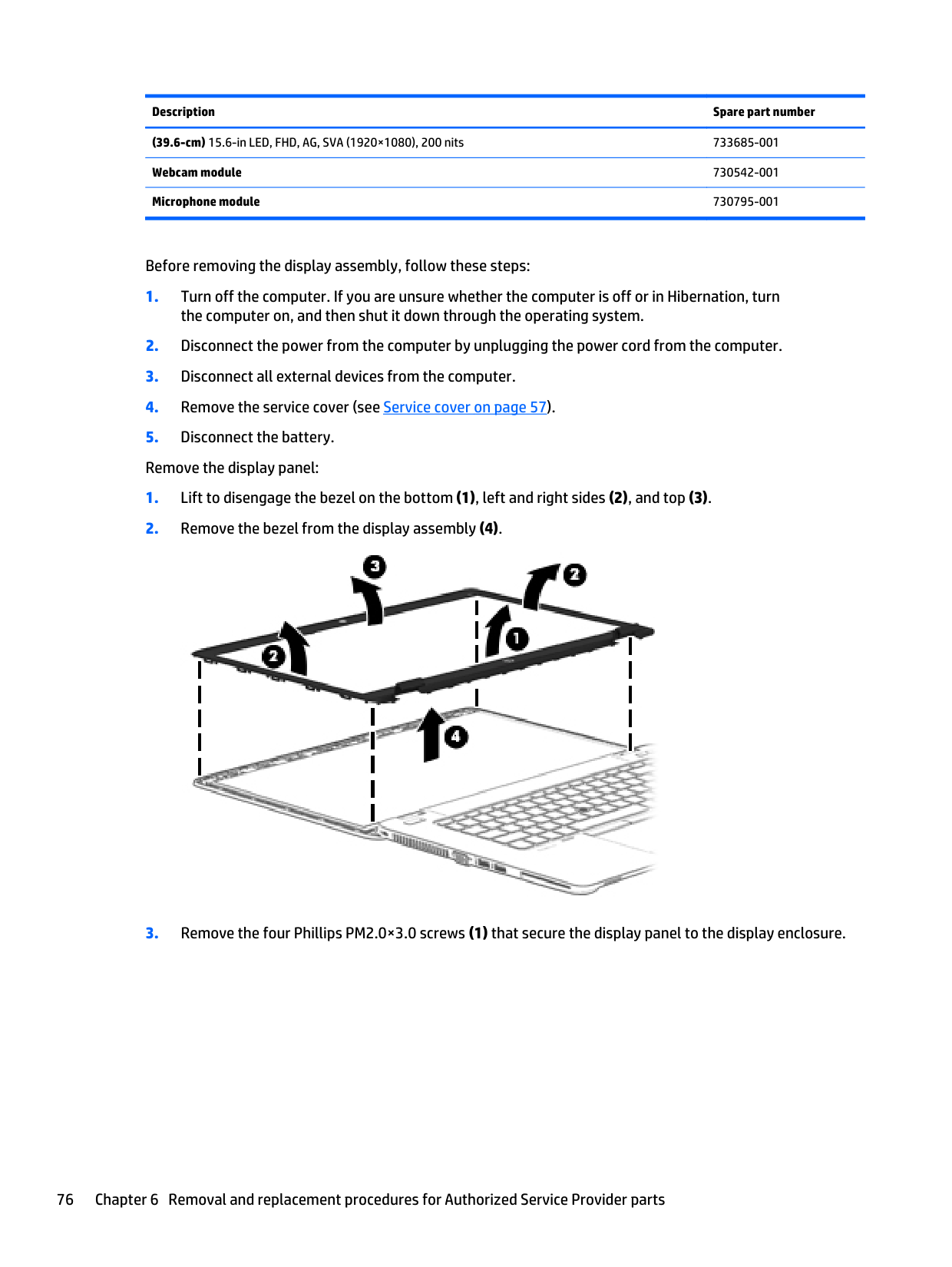
Remove the card reader board:

Reverse this procedure to install the card reader board.
#### VGA/USB board
######## Description Spare part number
VGA/USB board for use in HP EliteBook 740/840/HP ZBook 14 models 730966-001 VGA/USB board for use in HP EliteBook 750/850 models 730820-001
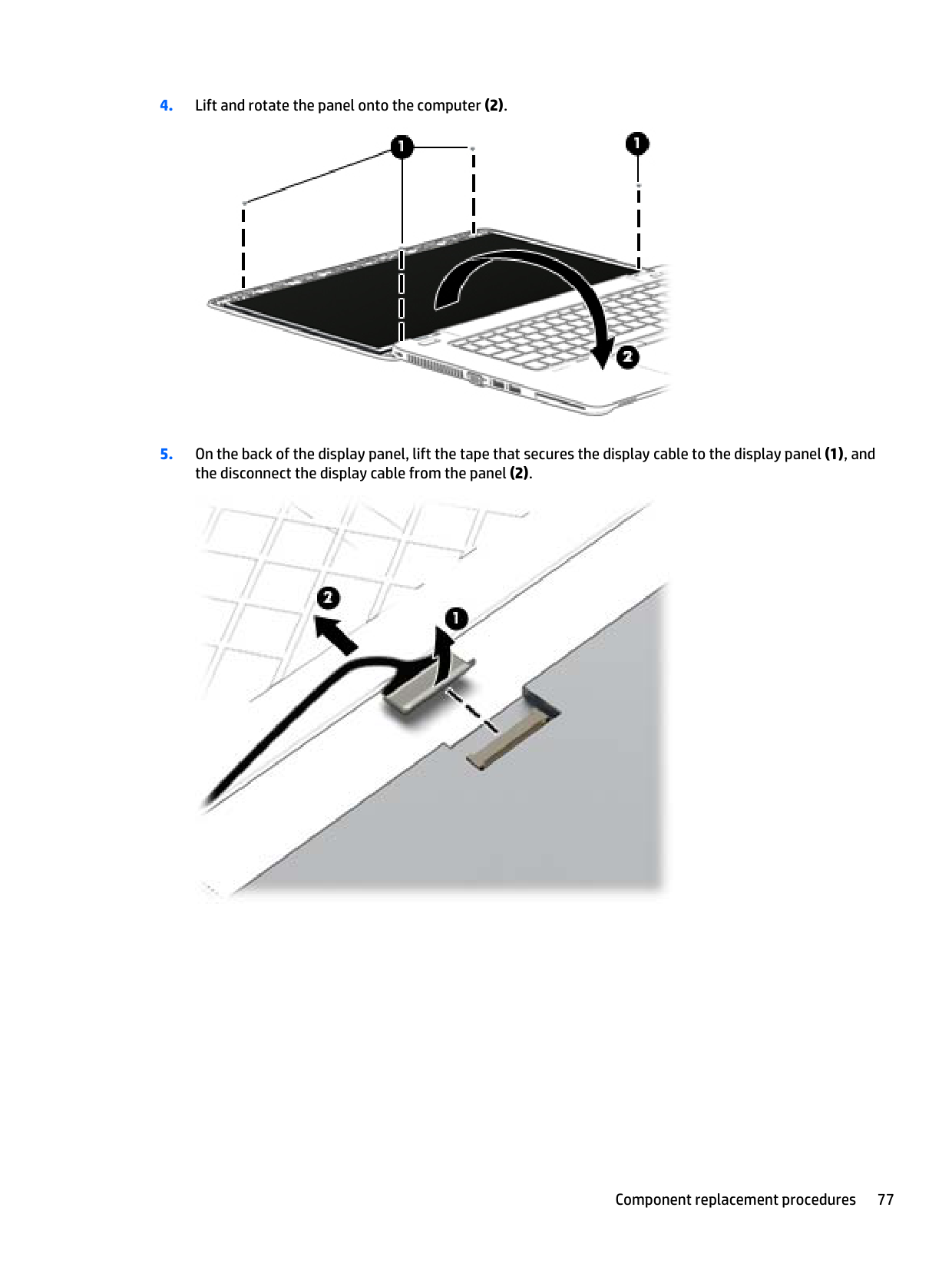
Before removing the VGA/USB board, follow these steps:
the computer on, and then shut it down through the operating system.
Remove the VGA/USB board:

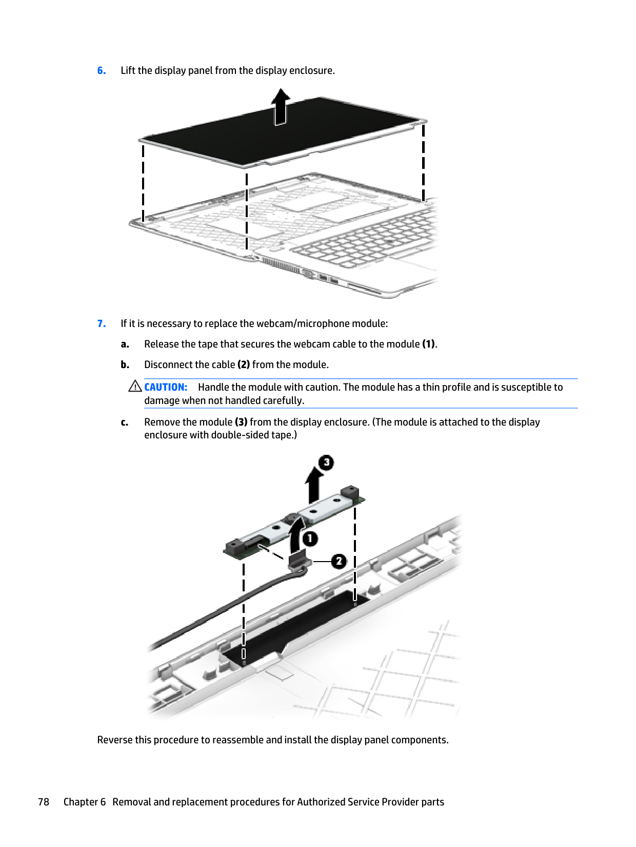
Reverse this procedure to install the VGA/USB board.
#### Heat sink
| | |---|
NOTE: The heat sink spare part kit includes replacement thermal material.
Description Spare part number
For use only on HP EliteBook 740/840/HP ZBook 14 models with discrete graphics 730962-001 For use only on HP EliteBook 740/840/HP ZBook 14 models with UMA graphics 730963-001 For use only on HP EliteBook 750/850 models with discrete graphics 732626-001 For use only on HP EliteBook 750/850 models with UMA graphics 730815-001
Before removing the heat sink, follow these steps:
| | |---|
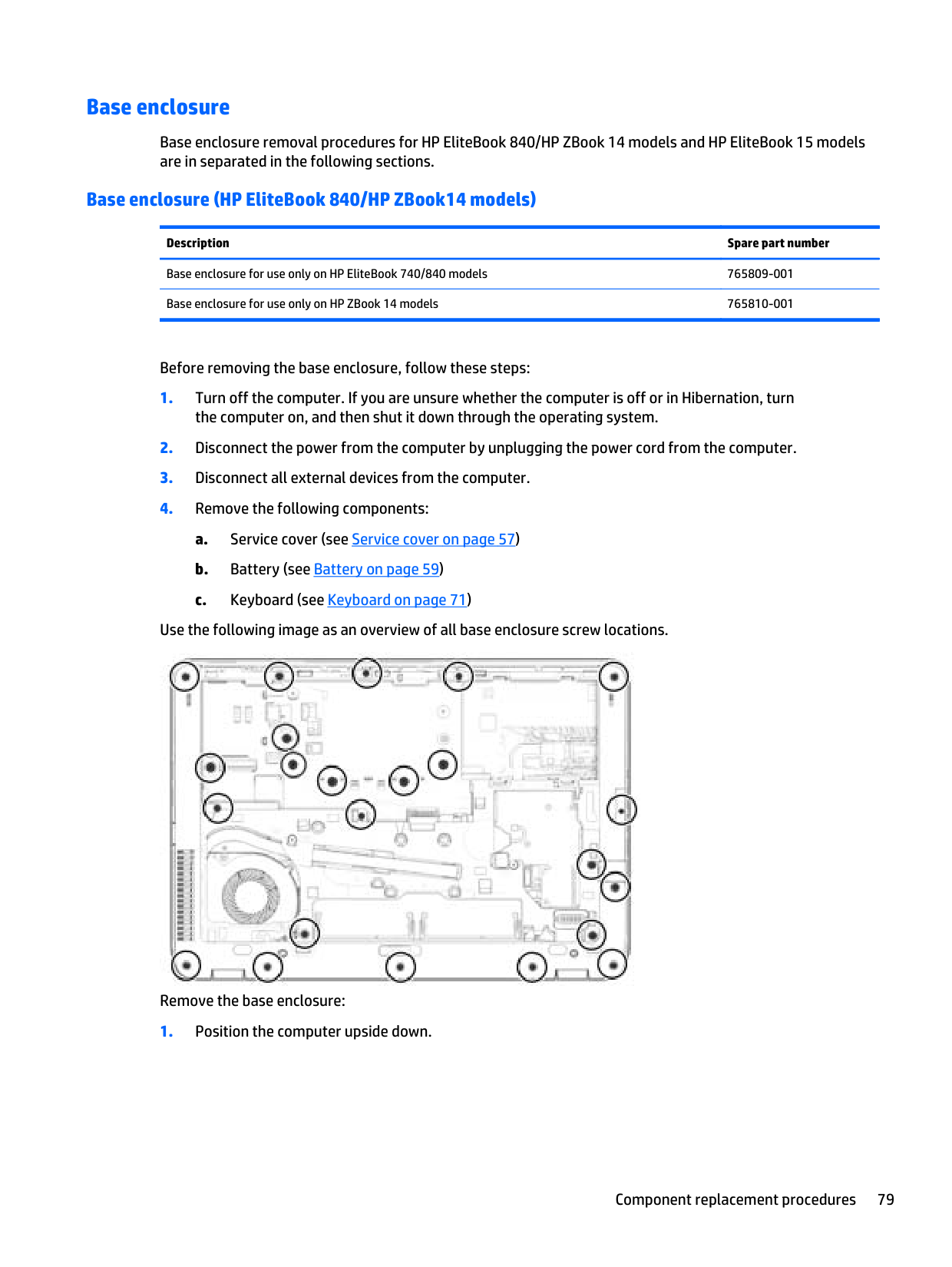
Remove the heat sink: NOTE: Step 2 applies to computer models equipped with a graphics subsystem with discrete memory. See step 3 for heat sink removal information for computer models equipped with a graphics subsystem with UMA memory.
(1) – (6) that secure the heat sink to the system board, and then remove the heat sink (7). NOTE: Due to the adhesive quality of the thermal material located between the heat sink and the system board components, it may be necessary to move the heat sink from side to side to detach it.
| | |---|

– (4) that secure the heat sink to the system board, and then remove the heat sink (5). NOTE: Due to the adhesive quality of the thermal material located between the heat sink and the system board components, it may be necessary to move the heat sink from side to side to detach it.

| | |---|
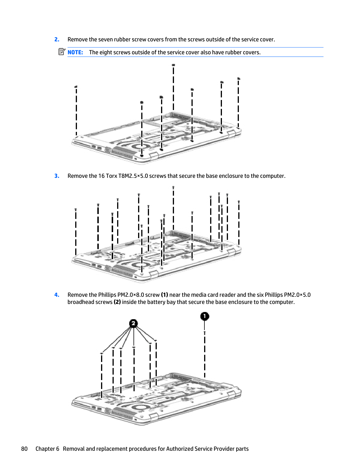
###### a. Discrete models:
Thermal paste is used on the system board components (1) and (3) and on the heat sink areas (2) and (4) that services them.

###### b. UMA models:
Thermal paste is used on the system board component (1) and on the heat sink area (2) that services it.

Reverse this procedure to install the heat sink.
#### Power button board
######## Description Spare part number
Power button board for use in HP EliteBook 740/840/HP ZBook 14 models 730959-001 Power button board for use in HP EliteBook 750/850 models 730822-001
Before removing the power button board, follow these steps:
the computer on, and then shut it down through the operating system.
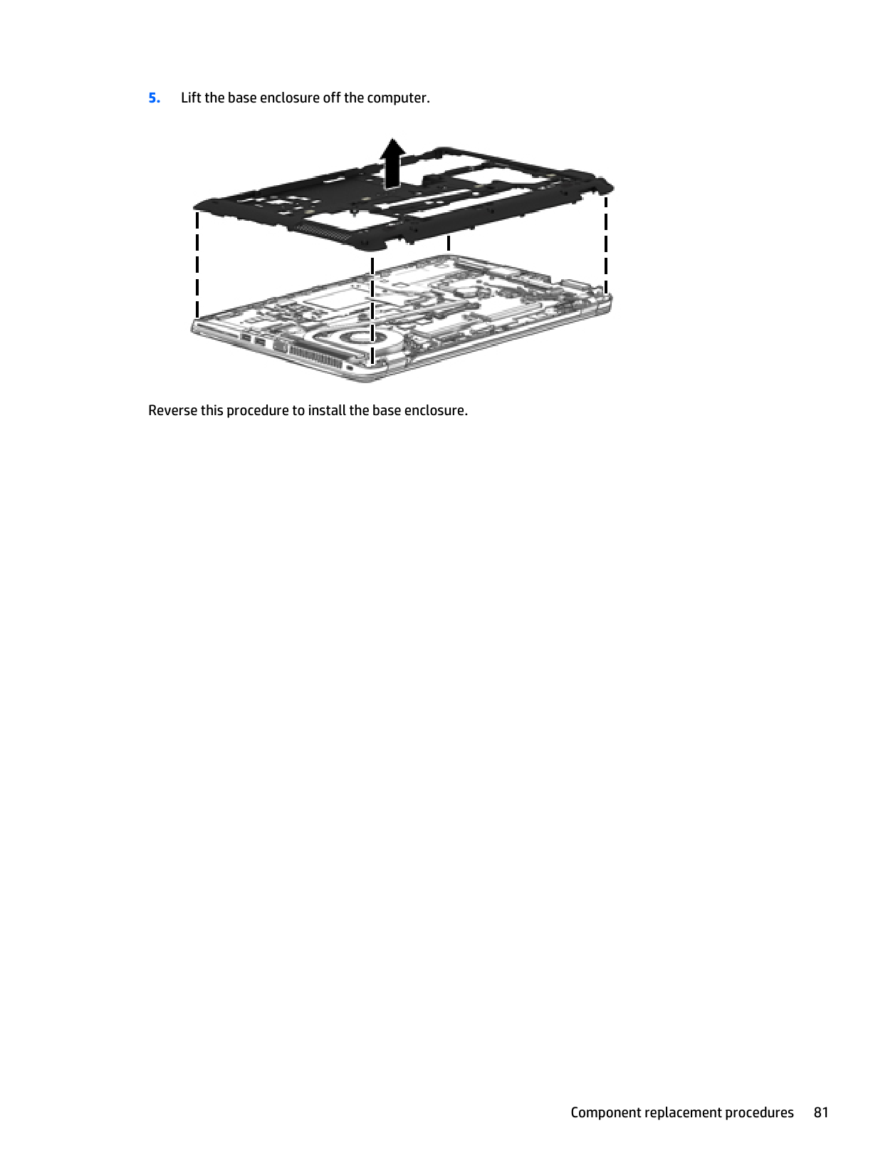
Remove the power button board:

Reverse this procedure to install the power button board.
#### Fingerprint reader assembly
######## Description Spare part number
Fingerprint reader assembly for use in HP EliteBook 740/840/HP ZBook 14 models (includes cable, bracket, and insulator)
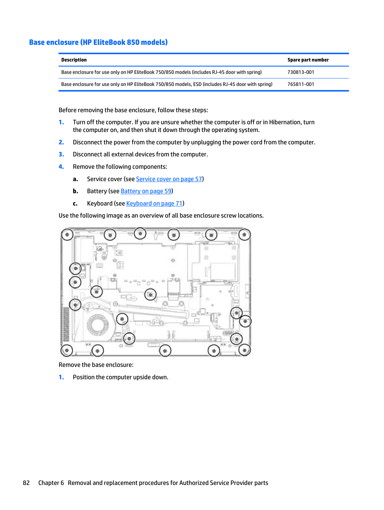
Fingerprint reader assembly for use in HP EliteBook 750/850 models (includes cable, bracket, and insulator)
730956-001
730817-001
Before removing the fingerprint reader assembly, follow these steps:
the computer on, and then shut it down through the operating system.
Remove the fingerprint reader assembly:
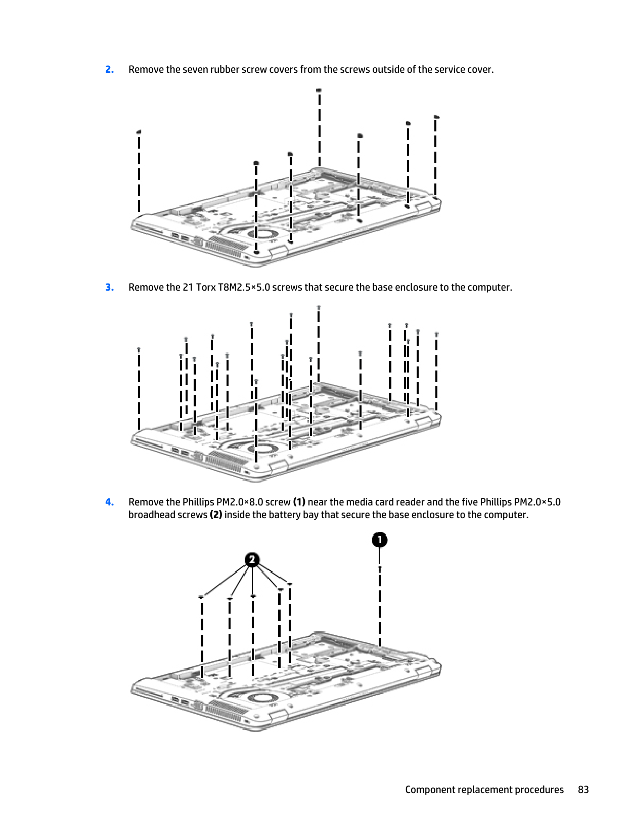

Reverse this procedure to install the fingerprint reader assembly.
System board NOTE: The system board spare part kit includes replacement thermal material. IMPORTANT: For system board replacement on serial numbers xxx501xxxx and below, you must use a conversion kit (see product description for “(Gold Conversion Kit)”). For serial numbers xxx502xxxx and above, use the standard spare kit (see product description for “(Gold)”).
| | |---|
| | |---|
Description Spare part
number System board for use in models with discrete graphics:
Intel Core i7-4600U processor for use with the Windows 8 Professional operating system for use in EliteBook 750/850 models (Gold)
802519-601
Intel Core i7-4600U processor for use with the Windows 8 Standard operating system for use in EliteBook 750/850 models (Gold)
802519-501
Intel Core i7-4600U processor for use with models without the Windows 8 operating system for use in EliteBook 750/850 models (Gold)
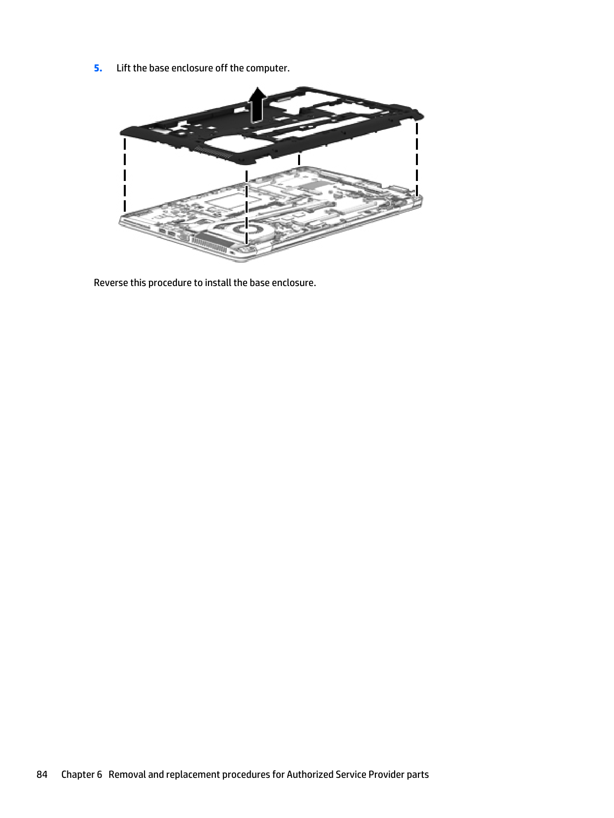
802519-001
Intel Core i7-4600U processor for use with the Windows 8 Professional operating system (Gold) 802518-601 Intel Core i7-4600U processor for use with the Windows 8 Standard operating system (Gold) 802518-501 Intel Core i7-4600U processor for use with models without the Windows 8 operating system (Gold) 802518-001 Intel Core i7-4600U processor for use with the Windows 8 Professional operating system for use in ZBook 14 models (Gold)
802522-601
Intel Core i7-4600U processor for use with the Windows 8 Standard operating system for use in ZBook 14 models (Gold)
Intel Core i7-4600U processor for use with models without the Windows 8 operating system for use in ZBook 14 models (Gold)
Intel Core i7-4510U processor for use with the Windows 8 Professional operating system for use in EliteBook 740/840 and 750/850 models (Gold)
Intel Core i7-4510U processor for use with the Windows 8 Standard operating system for use in EliteBook 740/840 and 750/850 models (Gold)
Intel Core i7-4510U processor for use with models without the Windows 8 operating system for use in EliteBook 740/840 and 750/850 models (Gold)
Intel Core i7-4510U processor for use with the Windows 8 Professional operating system for use in ZBook 14 models (Gold)
Intel Core i7-4510U processor for use with the Windows 8 Standard operating system for use in ZBook 14 models (Gold)
Intel Core i7-4510U processor for use with models without the Windows 8 operating system for use in ZBook 14 models (Gold)
Intel Core i7-4500U processor for use with the Windows 8 Professional operating system for use in EliteBook 740/840 and 750/850 models (Gold)
Intel Core i7-4500U processor for use with the Windows 8 Standard operating system for use in EliteBook 740/840 and 750/850 models (Gold)
Intel Core i7-4500U processor for use with models without the Windows 8 operating system for use in EliteBook 740/840 and 750/850 models (Gold)
802522-501
802522-001
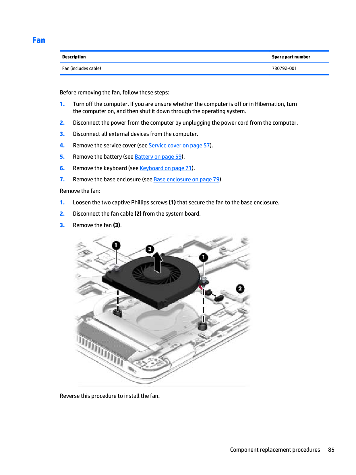
802536-601
802536-501
802536-001
802528-601
802528-501
802528-001
802524-601
802524-501
Intel Core i7-4500U processor for use with the Windows 8 Professional operating system for use in ZBook 14 models (Gold)
Intel Core i7-4500U processor for use with the Windows 8 Standard operating system for use in ZBook 14 models (Gold)
Intel Core i7-4500U processor for use with models without the Windows 8 operating system for use in ZBook 14 models (Gold)
Intel Core i5-4310U processor for use with the Windows 8 Professional operating system for use in EliteBook 740/840 and 750/850 models (Gold)
Intel Core i5-4310U processor for use with the Windows 8 Standard operating system for use in EliteBook 740/840 and 750/850 models (Gold)
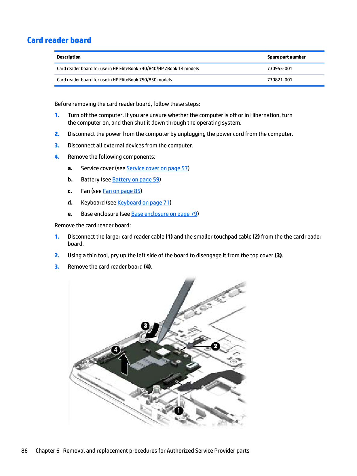
Intel Core i5-4310U processor for use with models without the Windows 8 operating system for use in EliteBook 740/840 and 750/850 models (Gold)
Intel Core i5-4310U processor for use with the Windows 8 Professional operating system for use in ZBook 14 models (Gold)
Intel Core i5-4310U processor for use with the Windows 8 Standard operating system for use in ZBook 14 models (Gold)
Intel Core i5-4310U processor for use with models without the Windows 8 operating system for use in ZBook 14 models (Gold)
Intel Core i5-4300U processor for use with the Windows 8 Professional operating system for use in EliteBook 740/840 and 750/850 models (Gold)
Intel Core i5-4300U processor for use with the Windows 8 Standard operating system for use in EliteBook 740/840 andv 750/850 models (Gold)
Intel Core i5-4300U processor for use with models without the Windows 8 operating system for use in EliteBook 740/840 and 750/850 models (Gold)
Intel Core i5-4300U processor for use with the Windows 8 Professional operating system for use in ZBook 14 models (Gold)
Intel Core i5-4300U processor for use with the Windows 8 Standard operating system for use in ZBook 14 models (Gold)
Intel Core i5-4300U processor for use with models without the Windows 8 operating system for use in ZBook 14 models (Gold)
Intel Core i5-4210U processor for use with the Windows 8 Professional operating system for use in EliteBook 740/840 and 750/850 models (Gold)
Intel Core i5-4210U processor for use with the Windows 8 Standard operating system for use in EliteBook 740/840 and 750/850 models (Gold)
Intel Core i5-4210U processor for use with models without the Windows 8 operating system for use in EliteBook 740/840 and 750/850 models (Gold)
Intel Core i5-4210U processor for use with the Windows 8 Professional operating system for use in ZBook 14 models (Gold)
Intel Core i5-4210U processor for use with the Windows 8 Standard operating system for use in ZBook 14 models (Gold)
Intel Core i5-4210U processor for use with models without the Windows 8 operating system for use in ZBook 14 models (Gold)
Intel Core i5-4200U processor for use with the Windows 8 Professional operating system for use in EliteBook 740/840 and 750/850 models (Gold)
Intel Core i5-4200U processor for use with the Windows 8 Standard operating system for use in EliteBook 740/840 and 750/850 models (Gold)
802525-501
802525-001
802534-601
802534-501
802534-001
802527-601
802527-501
802527-001
802512-601
802512-501
802512-001
802521-601
802521-501
802521-001
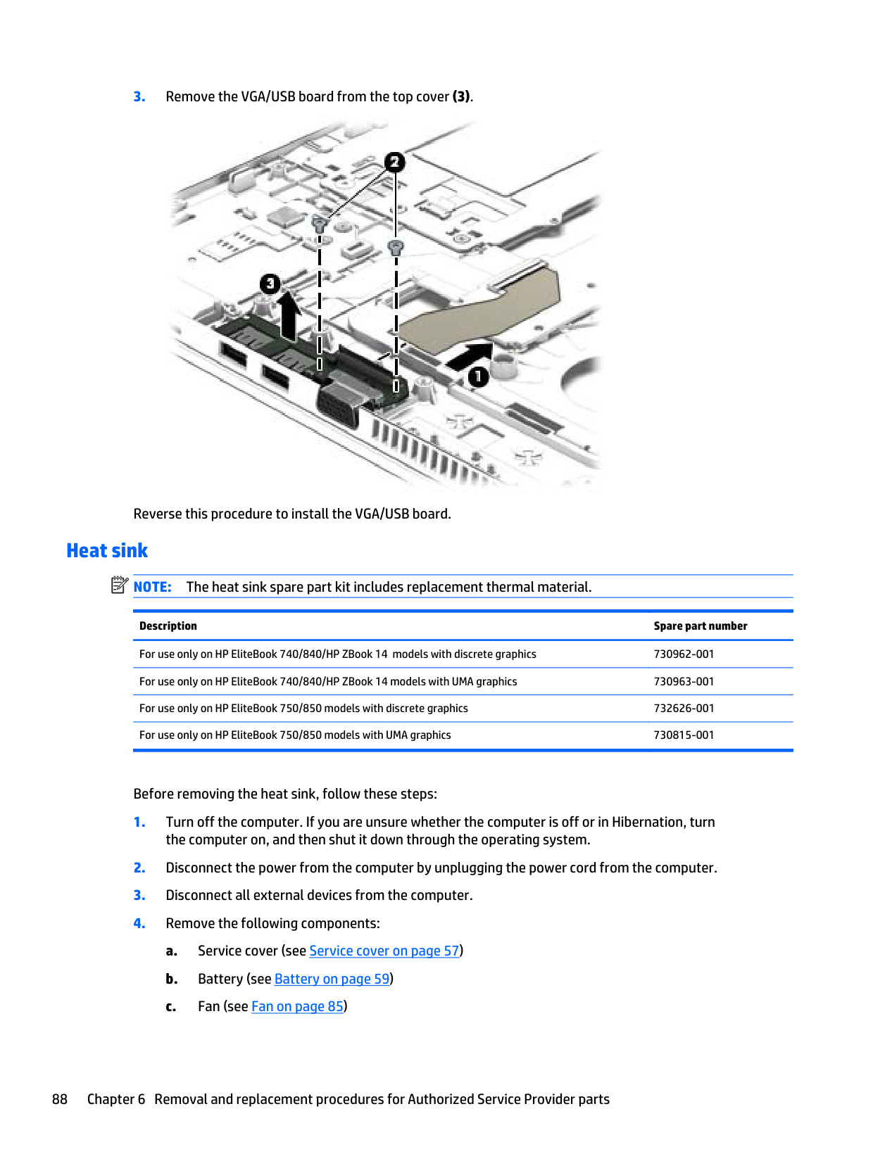
802532-601
802532-501
802532-001
802526-601
802526-501
802526-001
802517-601
802517-501
Intel Core i5-4200U processor for use with models without the Windows 8 operating system for use in EliteBook 740/840 and 750/850 models (Gold)
802517-001
Intel Core i5-4200U processor for use with the Windows 8 Professional operating system for use in ZBook 14 models (Gold)
802520-601
Intel Core i5-4200U processor for use with the Windows 8 Standard operating system for use in ZBook 14 models (Gold)
802520-501
Intel Core i5-4200U processor for use with models without the Windows 8 operating system for use in ZBook 14 models (Gold)
802520-001
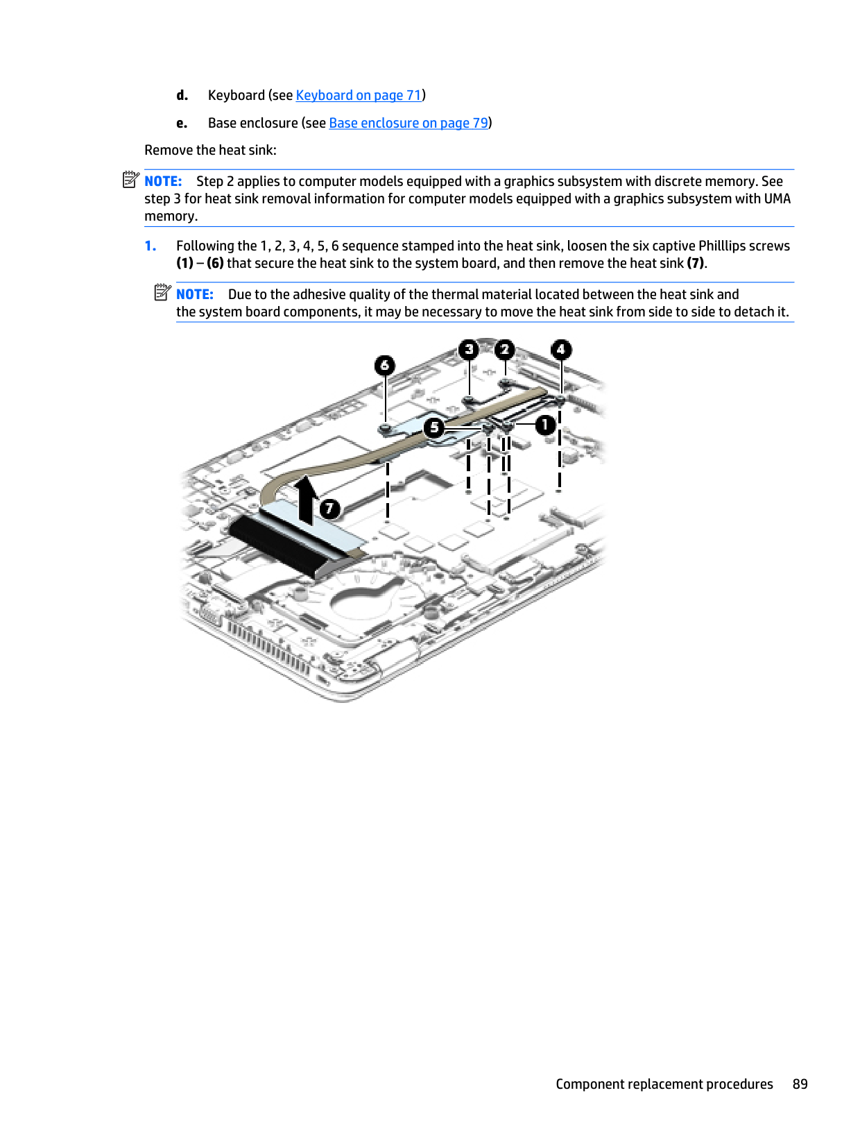
Intel Core i3-4030U processor for use with the Windows 8 Professional operating system (Gold) 802530-601 Intel Core i3-4030U processor for use with the Windows 8 Standard operating system (Gold) 802530-501 Intel Core i3-4030U processor for use with models without the Windows 8 operating system (Gold) 802530-001 Intel Core i3-4010U processor for use with the Windows 8 Professional operating system (Gold) 802515-601 Intel Core i3-4010U processor for use with the Windows 8 Standard operating system (Gold) 802515-501 Intel Core i3-4010U processor for use with models without the Windows 8 operating system (Gold) 802515-001 System board for use in models with UMA graphics:
Intel Core i7-4510U processor for use with the Windows 8 Professional operating system (Gold) 802535-601 Intel Core i7-4510U processor for use with the Windows 8 Standard operating system (Gold) 802535-501 Intel Core i7-4510U processor for use with models without the Windows 8 operating system (Gold) 802535-001 Intel Core i7-4500U processor for use with the Windows 8 Professional operating system (Gold) 802523-601 Intel Core i7-4500U processor for use with the Windows 8 Standard operating system (Gold) 802523-501 Intel Core i7-4500U processor for use with models without the Windows 8 operating system (Gold) 802523-001 Intel Core i5-4310U processor for use with the Windows 8 Professional operating system (Gold) 802533-601 Intel Core i5-4310U processor for use with the Windows 8 Standard operating system (Gold) 802533-501 Intel Core i5-4310U processor for use with models without the Windows 8 operating system (Gold) 802533-001 Intel Core i5-4300U processor for use with the Windows 8 Professional operating system (Gold) 802511-601 Intel Core i5-4300U processor for use with the Windows 8 Standard operating system (Gold) 802511-501 Intel Core i5-4300U processor for use with models without the Windows 8 operating system (Gold) 802511-001 Intel Core i5-4210U processor for use with the Windows 8 Professional operating system (Gold) 802531-601 Intel Core i5-4210U processor for use with the Windows 8 Standard operating system (Gold) 802531-501 Intel Core i5-4210U processor for use with models without the Windows 8 operating system (Gold) 802531-001 Intel Core i5-4200U processor for use with the Windows 8 Professional operating system (Gold) 802516-601 Intel Core i5-4200U processor for use with the Windows 8 Standard operating system (Gold) 802516-501 Intel Core i5-4200U processor for use with models without the Windows 8 operating system (Gold) 802516-001 Intel Core i3-4030U processor for use with the Windows 8 Professional operating system (Gold) 802529-601 Intel Core i3-4030U processor for use with the Windows 8 Standard operating system (Gold) 802529-501
Intel Core i3-4030U processor for use with models without the Windows 8 operating system (Gold) 802529-001 Intel Core i3-4010U processor for use with the Windows 8 Professional operating system (Gold) 802514-601 Intel Core i3-4010U processor for use with the Windows 8 Standard operating system (Gold) 802514-501 Intel Core i3-4010U processor for use with models without the Windows 8 operating system (Gold) 802514-001 System board (Gold Conversion Kits) (includes replacement thermal material): System board conversion kit for use in models with discrete graphics:
Intel Core i7-4600U processor for use with the Windows 8 Professional operating system for use in ZBook 14 models (Gold Conversion Kit)
802522-6C1
Intel Core i7-4600U processor for use with the Windows 8 Standard operating system for use in ZBook 14 models (Gold Conversion Kit)
802522-5C1
Intel Core i7-4600U processor for use with models without the Windows 8 operating system for use in ZBook 14 models (Gold Conversion Kit)
802522-0C1
Intel Core i7-4600U processor for use with the Windows 8 Professional operating system (Gold Conversion Kit) 802518-6C1 Intel Core i7-4600U processor for use with the Windows 8 Standard operating system (Gold Conversion Kit) 802518-5C1 Intel Core i7-4600U processor for use with models without the Windows 8 operating system (Gold Conversion Kit) 802518-0C1 Intel Core i7-4510U processor for use with the Windows 8 Professional operating system for use in ZBook 14 models (Gold Conversion Kit)
802528-6C1
Intel Core i7-4510U processor for use with the Windows 8 Standard operating system for use in ZBook 14 models (Gold Conversion Kit)
Intel Core i7-4510U processor for use with models without the Windows 8 operating system for use in ZBook 14 models (Gold Conversion Kit)
Intel Core i7-4510U processor for use with the Windows 8 Professional operating system for use in EliteBook 740/840 and 750/850 models (Gold Conversion Kit)
Intel Core i7-4510U processor for use with the Windows 8 Standard operating system for use in EliteBook 740/840 and 750/850 models (Gold Conversion Kit)
Intel Core i7-4510U processor for use with models without the Windows 8 operating system for use in EliteBook 740/840 and 750/850 models (Gold Conversion Kit)
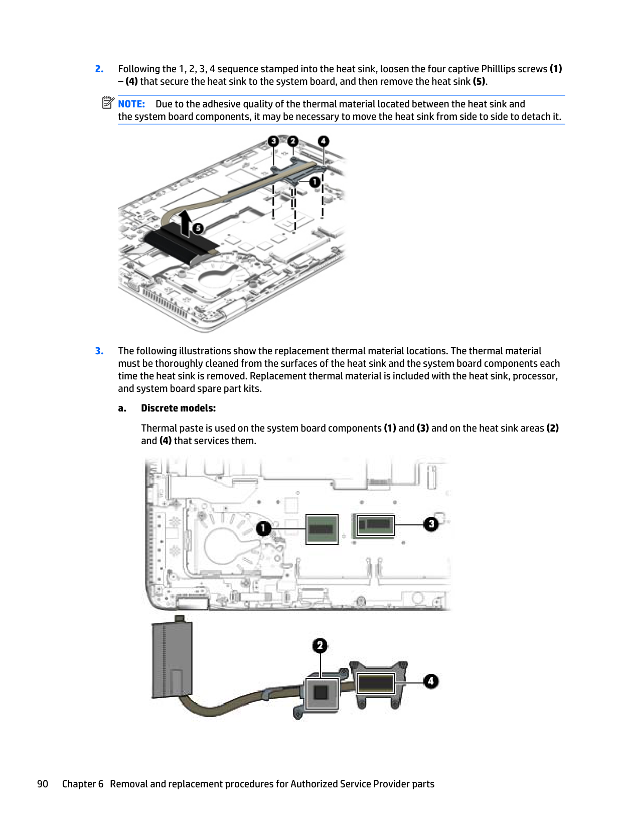
Intel Core i7-4500U processor for use with the Windows 8 Professional operating system for use in EliteBook 740/840 and 750/850 models (Gold Conversion Kit)
Intel Core i7-4500U processor for use with the Windows 8 Standard operating system for use in EliteBook 740/840 and 750/850 models (Gold Conversion Kit)
Intel Core i7-4500U processor for use with models without the Windows 8 operating system for use in EliteBook 740/840 and 750/850 models (Gold Conversion Kit)
802528-5C1
802528-0C1
802536-6C1
802536-5C1
802536-0C1
802524-6C1
802524-5C1
Intel Core i7-4500U processor for use with the Windows 8 Professional operating system for use in ZBook 14 models (Gold Conversion Kit)
Intel Core i7-4500U processor for use with the Windows 8 Standard operating system for use in ZBook 14 models (Gold Conversion Kit)
Intel Core i7-4500U processor for use with models without the Windows 8 operating system for use in ZBook 14 models (Gold Conversion Kit)
Intel Core i5-4310U processor for use with the Windows 8 Professional operating system for use in ZBook 14 models (Gold Conversion Kit)
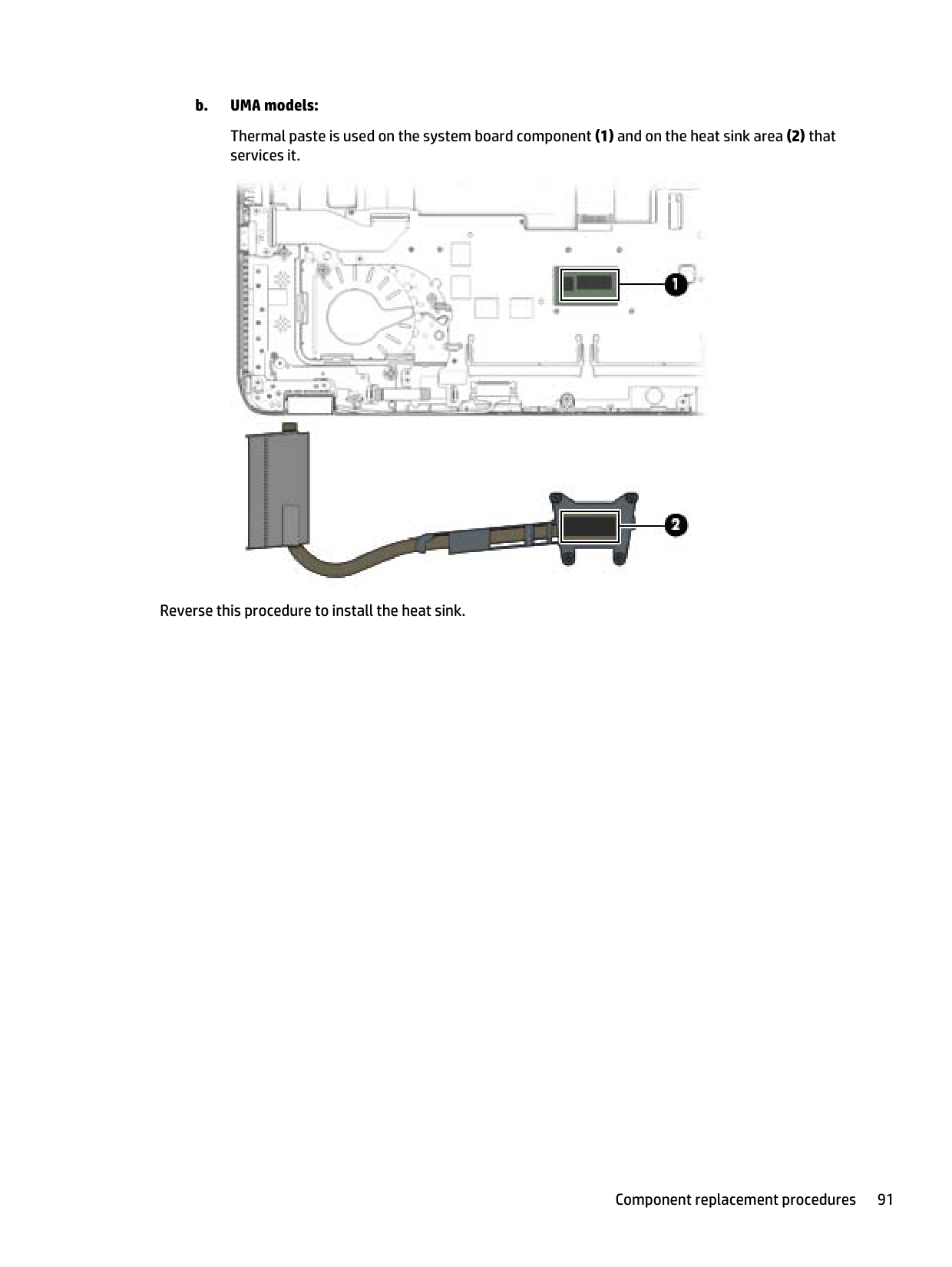
802525-5C1
802525-0C1
802527-6C1
Intel Core i5-4310U processor for use with the Windows 8 Standard operating system for use in ZBook 14 models (Gold Conversion Kit)
802527-5C1
Intel Core i5-4310U processor for use with models without the Windows 8 operating system for use in ZBook 14 models (Gold Conversion Kit)
802527-0C1
Intel Core i5-4310U processor for use with the Windows 8 Professional operating system for use in EliteBook 740/840 and 750/850 models (Gold Conversion Kit)
802534-6C1
Intel Core i5-4310U processor for use with the Windows 8 Standard operating system for use in EliteBook 740/840 and 750/850 models (Gold Conversion Kit)
802534-5C1
Intel Core i5-4310U processor for use with models without the Windows 8 operating system for use in EliteBook 740/840 and 750/850 models (Gold Conversion Kit)
802534-0C1
Intel Core i5-4300U processor for use with the Windows 8 Professional operating system for use in EliteBook 740/840 and 750/850 models (Gold Conversion Kit)
802512–6C1
Intel Core i5-4300U processor for use with the Windows 8 Standard operating system for use in EliteBook 740/840 andv 750/850 models (Gold Conversion Kit)
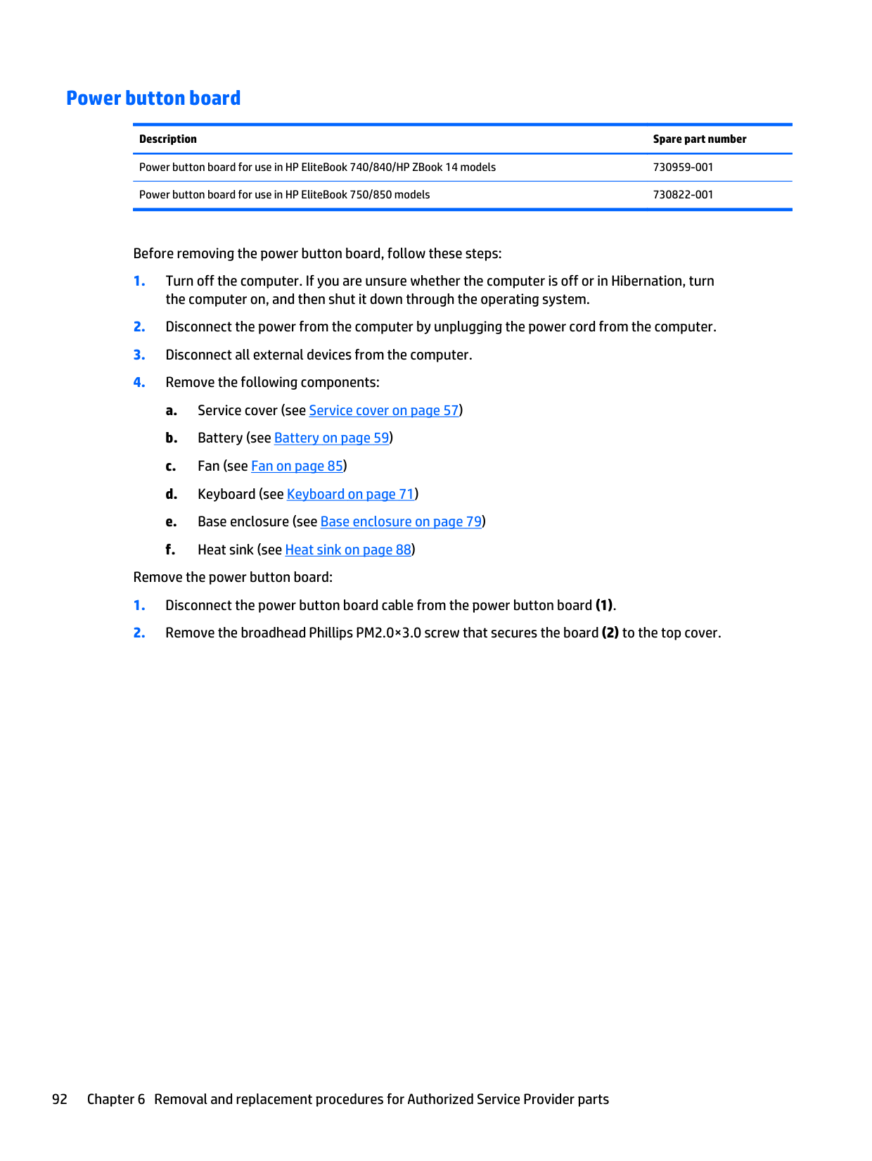
802512–5C1
Intel Core i5-4300U processor for use with models without the Windows 8 operating system for use in EliteBook 740/840 and 750/850 models (Gold Conversion Kit)
802512–0C1
Intel Core i5-4300U processor for use with the Windows 8 Professional operating system for use in ZBook 14 models (Gold Conversion Kit)
802521-6C1
Intel Core i5-4300U processor for use with the Windows 8 Standard operating system for use in ZBook 14 models (Gold Conversion Kit)
802521-5C1
Intel Core i5-4300U processor for use with models without the Windows 8 operating system for use in ZBook 14 models (Gold Conversion Kit)
802521-0C1
Intel Core i5-4210U processor for use with the Windows 8 Professional operating system for use in ZBook 14 models (Gold Conversion Kit)
802526-6C1
Intel Core i5-4210U processor for use with the Windows 8 Standard operating system for use in ZBook 14 models (Gold Conversion Kit)
802526-5C1
Intel Core i5-4210U processor for use with models without the Windows 8 operating system for use in ZBook 14 models (Gold Conversion Kit)
802526-0C1
Intel Core i5-4210U processor for use with the Windows 8 Professional operating system for use in EliteBook 740/840 and 750/850 models (Gold Conversion Kit)
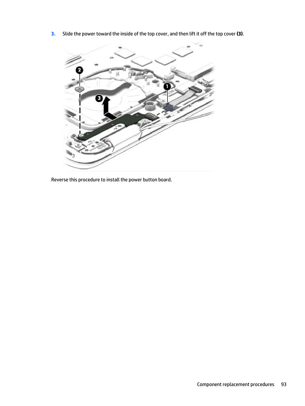
802532-6C1
Intel Core i5-4210U processor for use with the Windows 8 Standard operating system for use in EliteBook 740/840 and 750/850 models (Gold Conversion Kit)
802532-5C1
Intel Core i5-4210U processor for use with models without the Windows 8 operating system for use in EliteBook 740/840 and 750/850 models (Gold Conversion Kit)
802532-0C1
Intel Core i5-4200U processor for use with the Windows 8 Professional operating system for use in ZBook 14 models (Gold Conversion Kit)
802520-6C1
Intel Core i5-4200U processor for use with the Windows 8 Standard operating system for use in ZBook 14 models (Gold Conversion Kit)
802520-5C1
Intel Core i5-4200U processor for use with models without the Windows 8 operating system for use in ZBook 14 models (Gold Conversion Kit)
802520-0C1
Intel Core i5-4200U processor for use with the Windows 8 Professional operating system (Gold Conversion Kit) 802516-6C1 Intel Core i5-4200U processor for use with the Windows 8 Standard operating system (Gold Conversion Kit) 802516-5C1 Intel Core i5-4200U processor for use with models without the Windows 8 operating system (Gold Conversion Kit) 802516-0C1
Intel Core i3-4030U processor for use with the Windows 8 Professional operating system (Gold Conversion Kit) 802530-6C1 Intel Core i3-4030U processor for use with the Windows 8 Standard operating system (Gold Conversion Kit) 802530-5C1 Intel Core i3-4030U processor for use with models without the Windows 8 operating system (Gold Conversion Kit) 802530-0C1
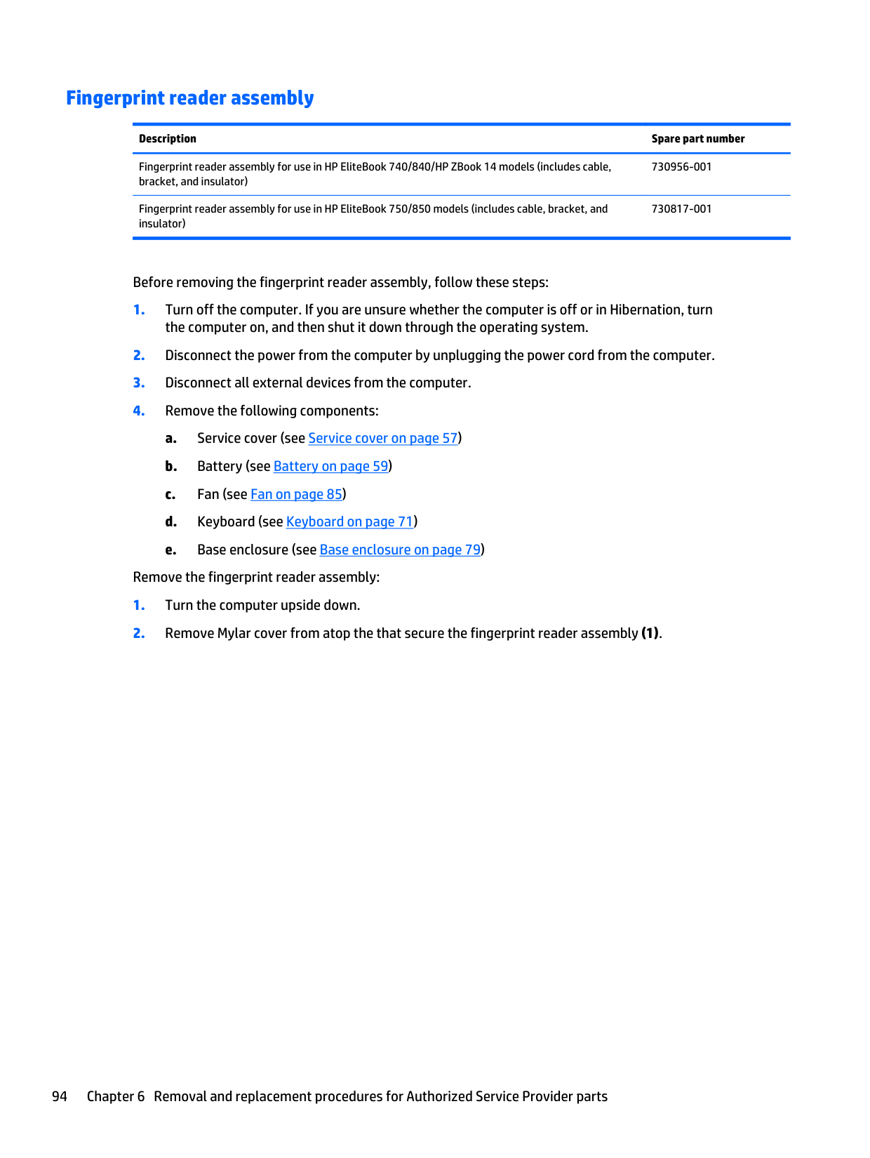
Intel Core i7-4600U processor for use with the Windows 8 Professional operating system for use in EliteBook 750/850 models (Gold Conversion Kit)
802519-6C1
Intel Core i7-4600U processor for use with the Windows 8 Standard operating system for use in EliteBook 750/850 models (Gold Conversion Kit)
802519-5C1
Intel Core i7-4600U processor for use with models without the Windows 8 operating system for use in EliteBook 750/850 models (Gold Conversion Kit)
802519-0C1
Intel Core i7-4510U processor for use with the Windows 8 Professional operating system (Gold Conversion Kit) 802535-6C1 Intel Core i7-4510U processor for use with the Windows 8 Standard operating system (Gold Conversion Kit) 802535-5C1 Intel Core i7-4510U processor for use with models without the Windows 8 operating system (Gold Conversion Kit) 802535-0C1 Intel Core i7-4500U processor for use with the Windows 8 Professional operating system(Gold Conversion Kit) 802523-6C1 Intel Core i7-4500U processor for use with the Windows 8 Standard operating system(Gold Conversion Kit) 802523-5C1 Intel Core i7-4500U processor for use with models without the Windows 8 operating system(Gold Conversion Kit) 802523-0C1 Intel Core i5-4310U processor for use with the Windows 8 Professional operating system (Gold Conversion Kit) 802533-6C1 Intel Core i5-4310U processor for use with the Windows 8 Standard operating system (Gold Conversion Kit) 802533-5C1 Intel Core i5-4310U processor for use with models without the Windows 8 operating system (Gold Conversion Kit) 802533-0C1 Intel Core i5-4300U processor for use with the Windows 8 Professional operating system (Gold Conversion Kit) 802511-6C1 Intel Core i5-4300U processor for use with the Windows 8 Standard operating system (Gold Conversion Kit) 802511-5C1 Intel Core i5-4300U processor for use with models without the Windows 8 operating system (Gold Conversion Kit) 802511-0C1 Intel Core i5-4210U processor for use with the Windows 8 Professional operating system (Gold Conversion Kit) 802531-6C1 Intel Core i5-4210U processor for use with the Windows 8 Standard operating system (Gold Conversion Kit) 802531-5C1 Intel Core i5-4210U processor for use with models without the Windows 8 operating system (Gold Conversion Kit) 802531-0C1 Intel Core i5-4200U processor for use with the Windows 8 Professional operating system for use in EliteBook 740/840 and 750/850 models (Gold Conversion Kit)
802517-6C1
Intel Core i5-4200U processor for use with the Windows 8 Standard operating system for use in EliteBook 740/840 and 750/850 models (Gold Conversion Kit)
802517-5C1
Intel Core i5-4200U processor for use with models without the Windows 8 operating system for use in EliteBook 740/840 and 750/850 models (Gold Conversion Kit)
802517-0C1
Intel Core i3-4030U processor for use with the Windows 8 Professional operating system (Gold Conversion Kit) 802529-6C1 Intel Core i3-4030U processor for use with the Windows 8 Standard operating system (Gold Conversion Kit) 802529-5C1
Intel Core i3-4030U processor for use with models without the Windows 8 operating system (Gold Conversion Kit) 802529-0C1
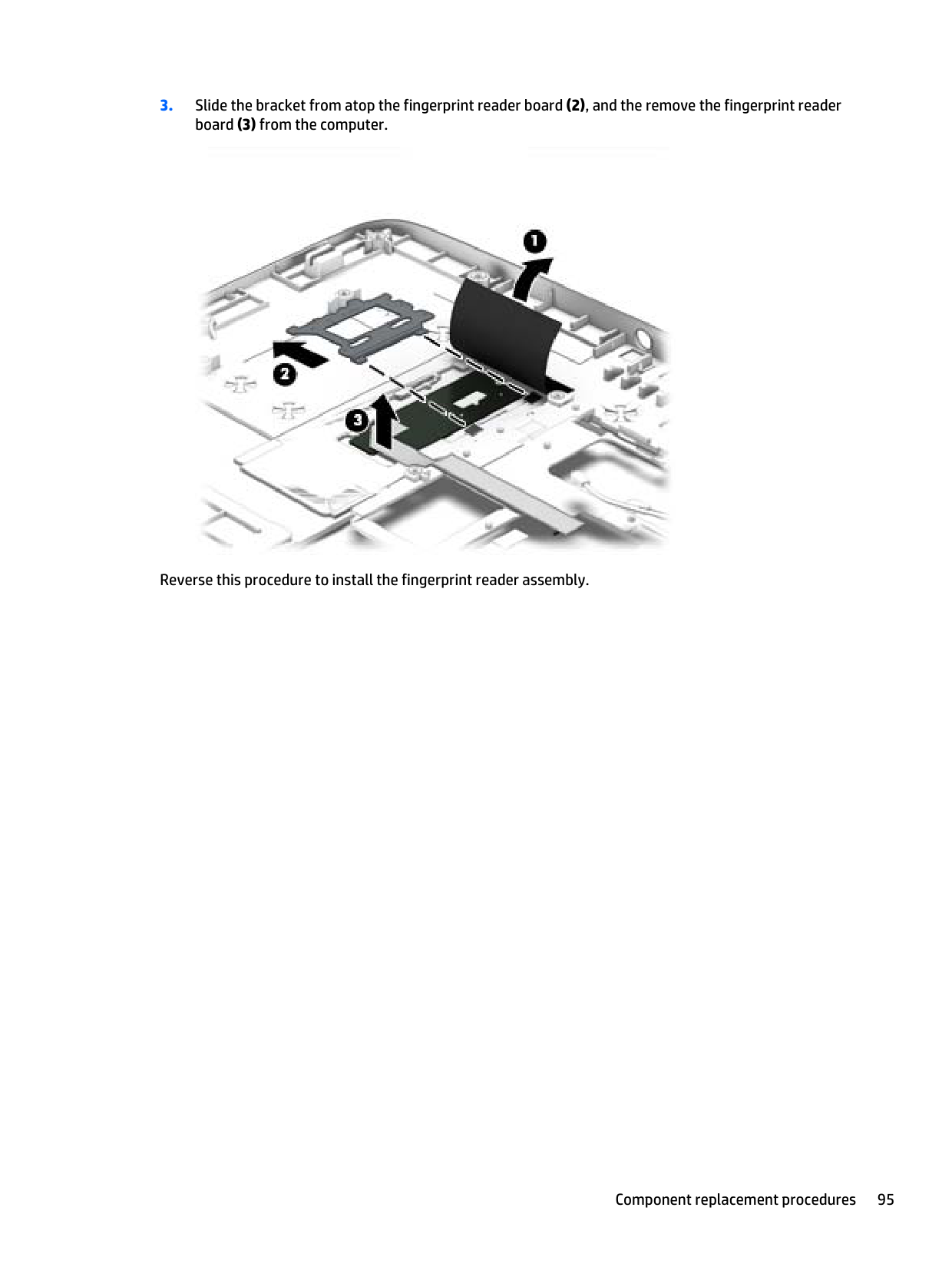
Before removing the system board, follow these steps:
the computer on, and then shut it down through the operating system.
When replacing the system board, be sure that the following components are removed from the defective system board and installed on the replacement system board:
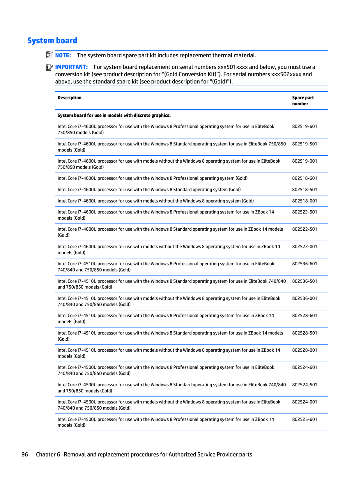
| | |---|

####### 9. Note the routing location of the antenna cables (7) when removing them.

####### 10. Remove the three Phillips PM2.5×5.0 screws that secure the system board to the top cover.

####### 11. Lift the left side of the system board (1).
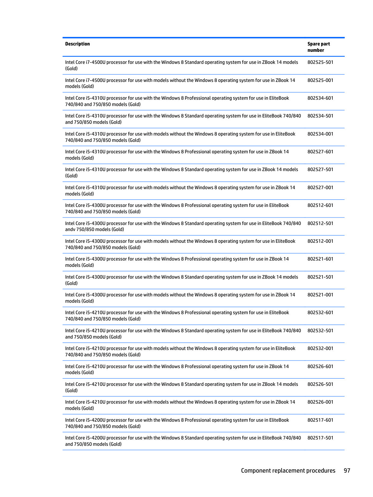

Reverse this procedure to install the system board.
#### Speaker assembly
Description Spare part number Speaker assembly (includes cable) 730798-001
Before removing the speaker assembly, follow these steps:
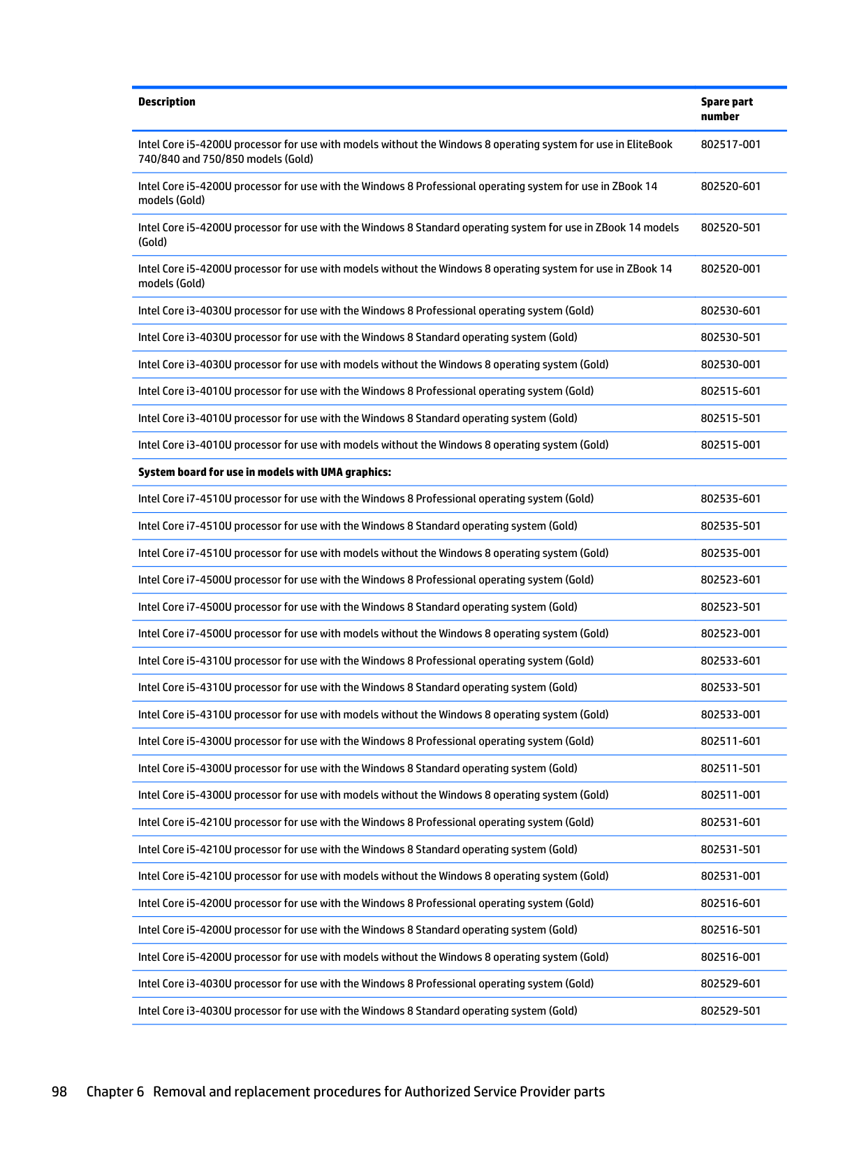
Remove the speaker assembly:

Reverse this procedure to install the speaker assembly.
#### Display assembly
| | |---|
NOTE: HP EliteBook 840 models offer both touch and non-touch displays. Non-touch displays are spared at the subcomponent level only. Touch displays are only spared as a whole (touch display components are not spared).
In non-touch models, you can remove the raw display panel with the display assembly still connected to the computer. For more information, see Display panel (non-touch) on page 75.
The following section shows how to remove the raw display panel without removing the display assembly from the computer. See the display section later in this chapter to remove internal components that require that you remove the display assembly.
Description Spare part number Display assembly, touch screen (whole assembly) Display assembly, 14-inch, HD+, for use in HP EliteBook 740/840 models 737735-001
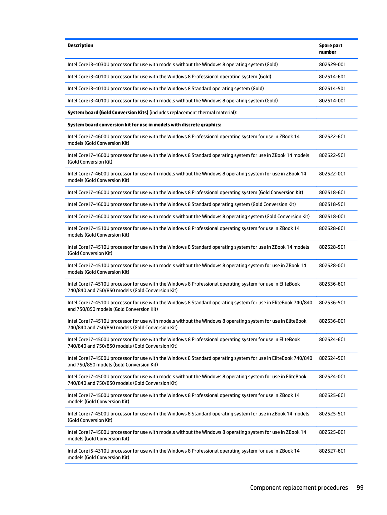
Before removing the display assembly, follow these steps:
Remove the display assembly:

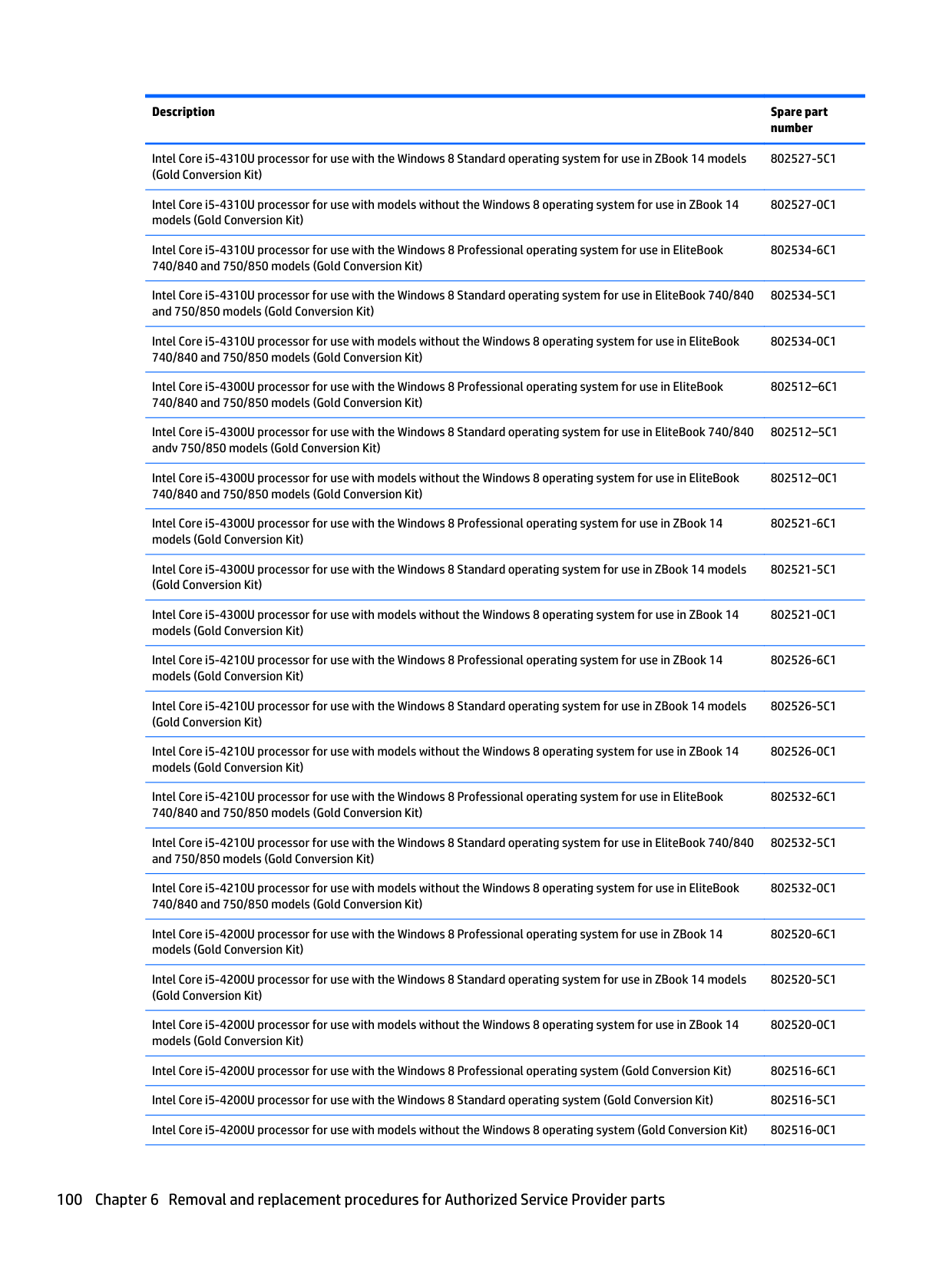

The display bezel is available using spare part number 730952-001 for HP EliteBook 840 models, 784451-001 for HP EliteBook 740 models, 730953-001 for HP ZBook 14 models, 730814-001 for HP EliteBook 850 models, and 784478-001 for HP EliteBook 750 models.
NOTE: In these steps, the display assembly will not be connected to the computer as shown in the illustration.

| | |---|
| |
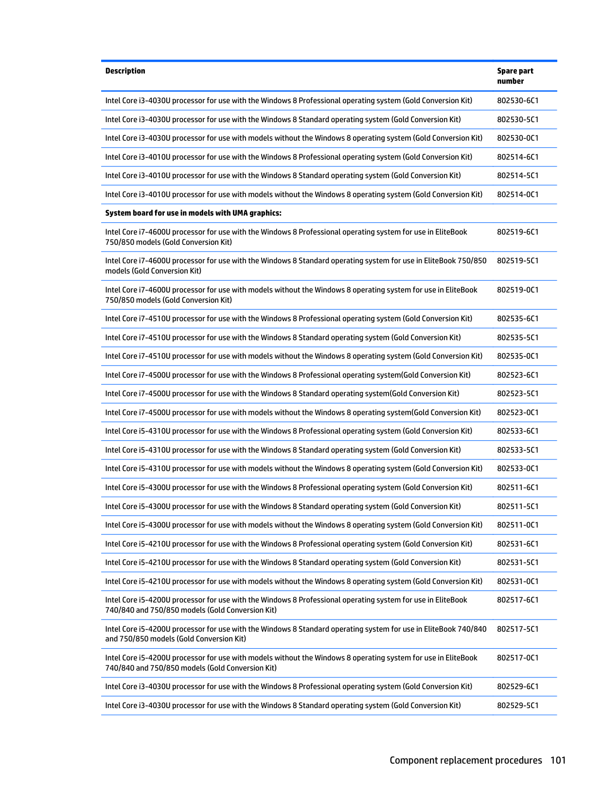
|---|
NOTE: In these steps, the display assembly will not be connected to the computer as shown in the illustration.

####### 10. Lift the tape that secures the display cable to the display panel (1), and the disconnect the display cablefrom the panel (2).


The webcam is available using spare part number 730542-001. The microphone module is available using spare part number 730795-001.
CAUTION: Handle the module with caution. The module has a thin profile and is susceptible to damage when not handled carefully.

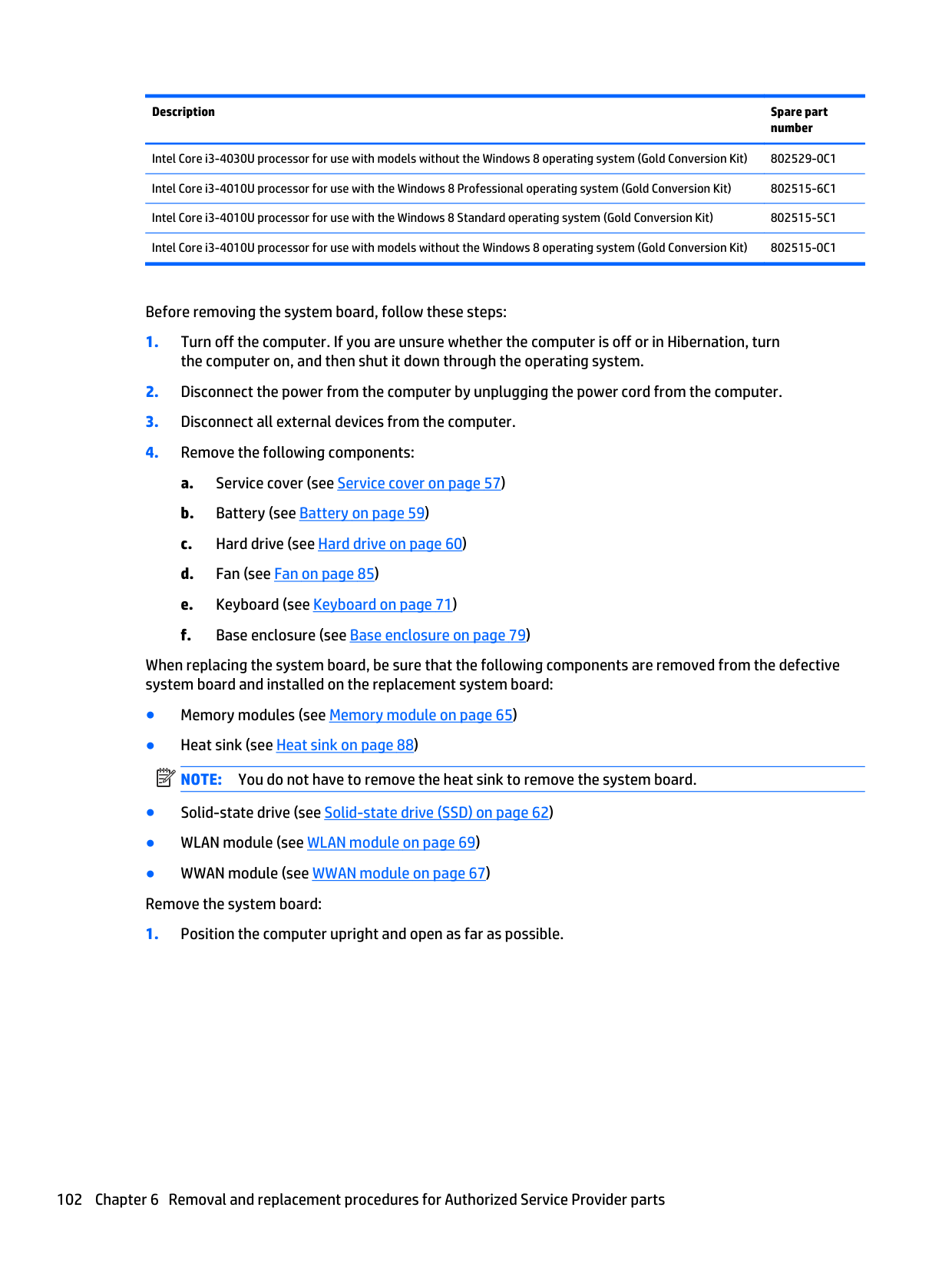
Display hinges are available using spare part number 730957-001 for HP EliteBook 740/840 models, 737660-001 for HP ZBook 14 models, and 730819-001 for HP EliteBook 750/850 models.


The antenna cables and transceivers are included in the Cable Kits, spare part numbers 730947-001 (for use only on HP EliteBook 740/840/HP ZBook 14 models) and 736678-001 (for use only on HP EliteBook 750/850 models).

Reverse this procedure to reassemble and install the display assembly.
7 Computer Setup (BIOS), MultiBoot, and System Diagnostics in Windows 8
Using Computer Setup
Computer Setup, or Basic Input/Output System (BIOS), controls communication between all the input and output devices on the system (such as disk drives, display, keyboard, mouse, and printer). Computer Setup includes settings for the types of devices installed, the startup sequence of the computer, and the amount of system and extended memory.
| | |---|
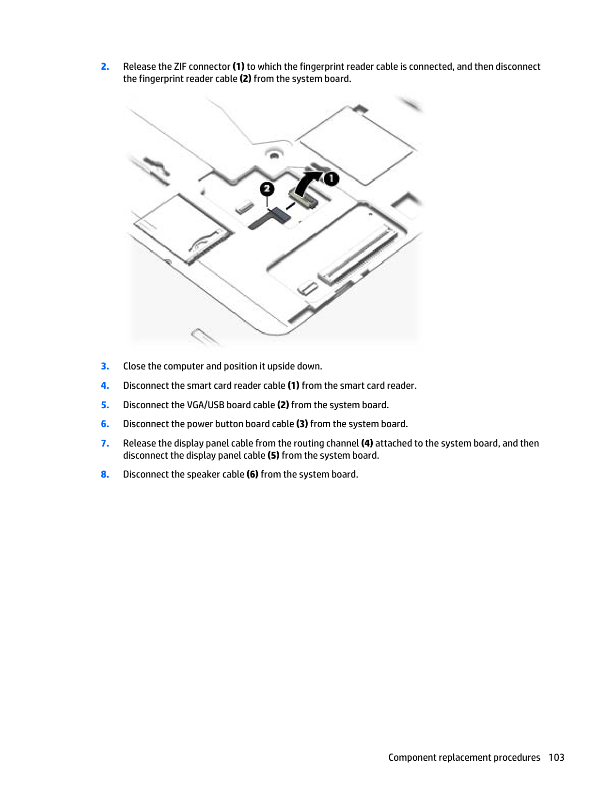
NOTE: Use extreme care when making changes in Computer Setup. Errors can prevent the computer from operating properly.
Starting Computer Setup NOTE: An external keyboard or mouse connected to a USB port can be used with Computer Setup only if USB legacy support is enabled. To start Computer Setup, follow these steps:
| | |---|
#### Navigating and selecting in Computer Setup
To navigate and select in Computer Setup, follow these steps:
NOTE: You can use either a pointing device (TouchPad, pointing stick, or USB mouse) or the keyboard to navigate and make selections in Computer Setup.
| | |---|
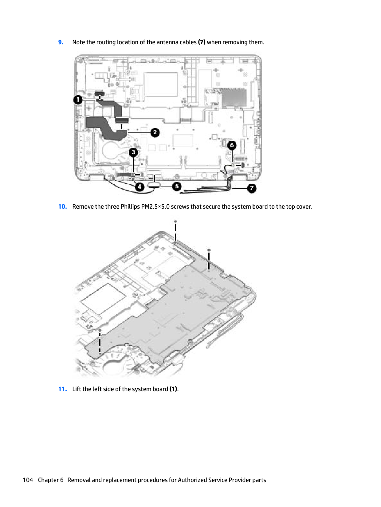
To exit Computer Setup menus, choose one of the following methods:
– or – Use the tab key and the arrow keys to select File > Save Changes and Exit, and then press enter.
Your changes go into effect when the computer restarts.
Restoring factory settings in Computer Setup NOTE: Restoring defaults will not change the hard drive mode. To return all settings in Computer Setup to the values that were set at the factory, follow these steps:
| | |---|
– or – Use the arrow keys to select File > Save Changes and Exit, and then press enter.
| | |---|
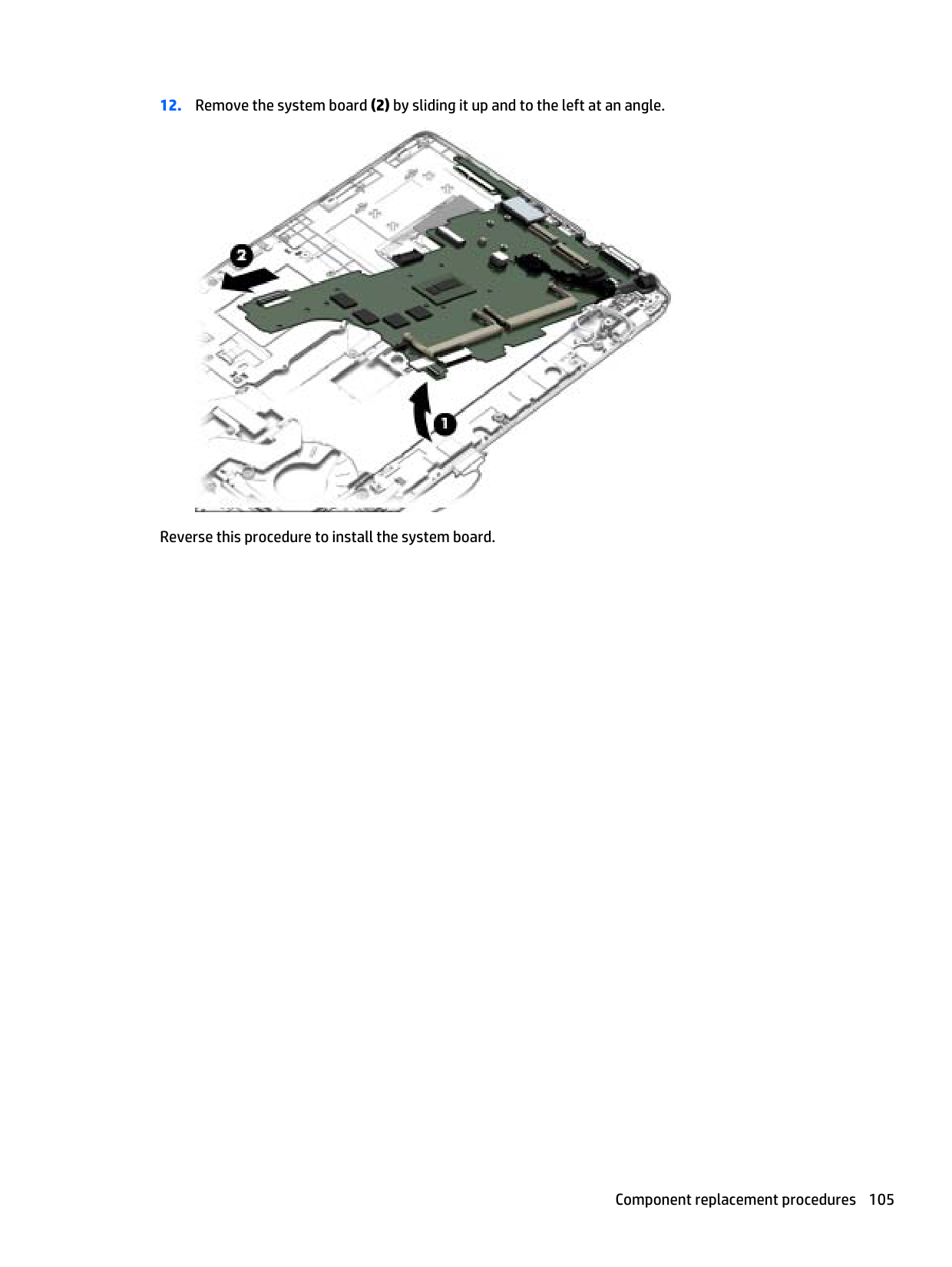
Your changes go into effect when the computer restarts. NOTE: Your password settings and security settings are not changed when you restore the factory settings.
Updating the BIOS Updated versions of the BIOS may be available on the HP website. Most BIOS updates on the HP website are packaged in compressed files called SoftPaqs. Some download packages contain a file named Readme.txt, which contains information regarding installing and troubleshooting the file.
##### Determining the BIOS version
To determine whether available BIOS updates contain later BIOS versions than those currently installed on the computer, you need to know the version of the system BIOS currently installed.
BIOS version information (also known as ROM date and System BIOS) can be displayed by pressing fn+esc (if you are already in Windows) or by using Computer Setup.
##### Downloading a BIOS update
CAUTION: To reduce the risk of damage to the computer or an unsuccessful installation, download and install a BIOS update only when the computer is connected to reliable external power using the AC adapter. Do not download or install a BIOS update while the computer is running on battery power, docked in an optional docking device, or connected to an optional power source. During the download and installation, follow these instructions:
Do not disconnect power on the computer by unplugging the power cord from the AC outlet. Do not shut down the computer or initiate Sleep. Do not insert, remove, connect, or disconnect any device, cable, or cord.
If the update is more recent than your BIOS, make a note of the path to the location on your hard drive where the BIOS update is downloaded. You will need to access this path when you are ready to install the update.
| | |---|
NOTE: If you connect your computer to a network, consult the network administrator before installing any software updates, especially system BIOS updates.
BIOS installation procedures vary. Follow any instructions that are displayed on the screen after the download is complete. If no instructions are displayed, follow these steps:
| | |---|
NOTE: After a message on the screen reports a successful installation, you can delete the downloaded file from your hard drive.
#### HP Sure Start
Select Intel-based 2013 HP Business Notebook PCs offer HP Sure Start, which provides hardware-based assurance of the following:
HP Sure Start verifies the integrity of critical, non-executable platform data residing in the main flash and provides selfhealing mechanisms to restore any code or critical platform data that has been lost or is corrupted within the flash.
In conjunction with BIOS support, code running on the EC verifies the integrity of the following:
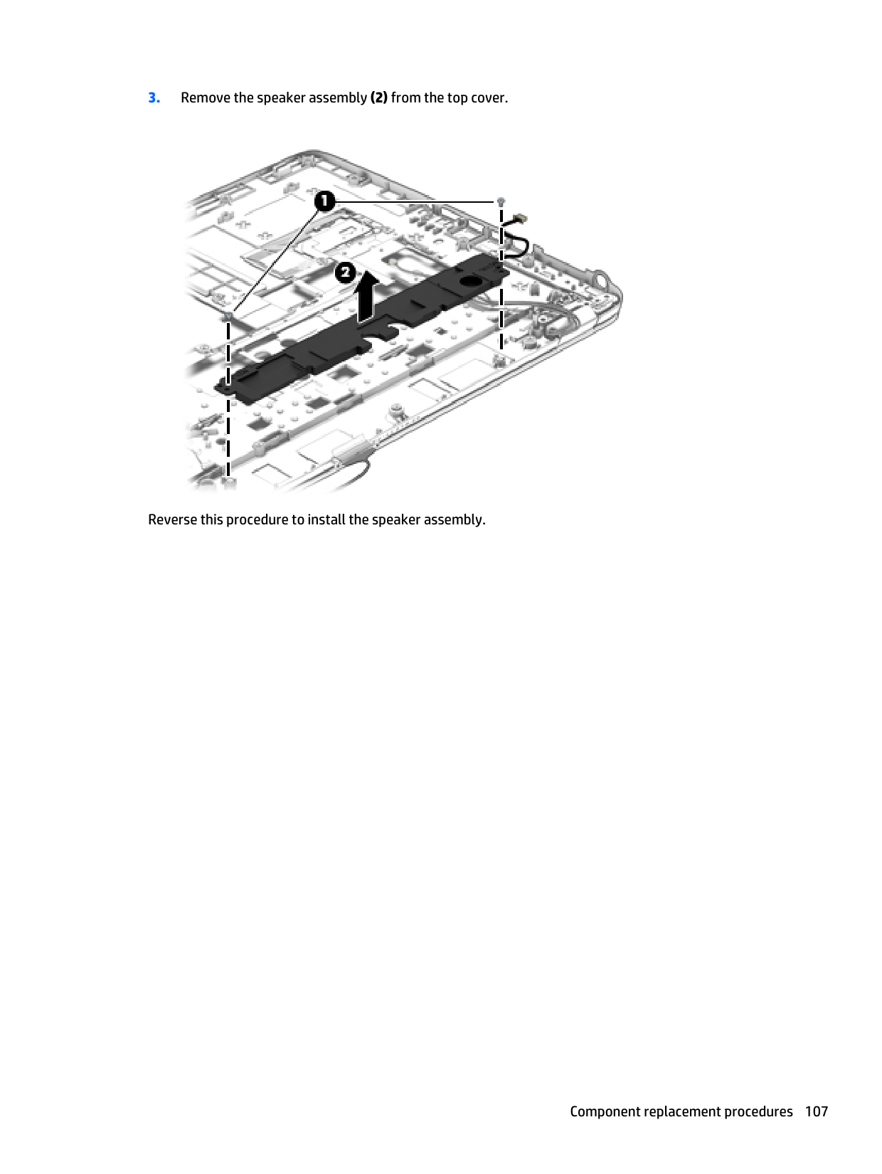
The EC is responsible for power control/power cycle, thermal monitor/fan control, many LEDs, and PS2 keyboard and mouse.
Using MultiBoot
#### About the boot device order
As the computer starts, the system attempts to boot from enabled devices. The MultiBoot utility, which is enabled at the factory, controls the order in which the system selects a boot device. Boot devices can include optical drives, diskette drives, a network interface card (NIC), hard drives, and USB devices. Boot devices contain bootable media or files that the computer needs to start and operate properly.
| | |---|
NOTE: Some boot devices must be enabled in Computer Setup before they can be included in the boot order. You can change the order in which the computer searches for a boot device by changing the boot order in Computer Setup. You can also press esc while the “Press the ESC key for Startup Menu” message is displayed at the bottom of the screen, and then press f9. Pressing f9 displays a menu that shows the current boot devices and allows you to select a boot device. Or, you can use MultiBoot Express to set the computer to prompt you for a boot location each time the computer turns on or restarts.
#### Choosing MultiBoot preferences
You can use MultiBoot in the following ways:
##### Setting a new boot order in Computer Setup
To start Computer Setup and set a boot device order that the computer uses each time it is turned on or restarted, follow these steps:
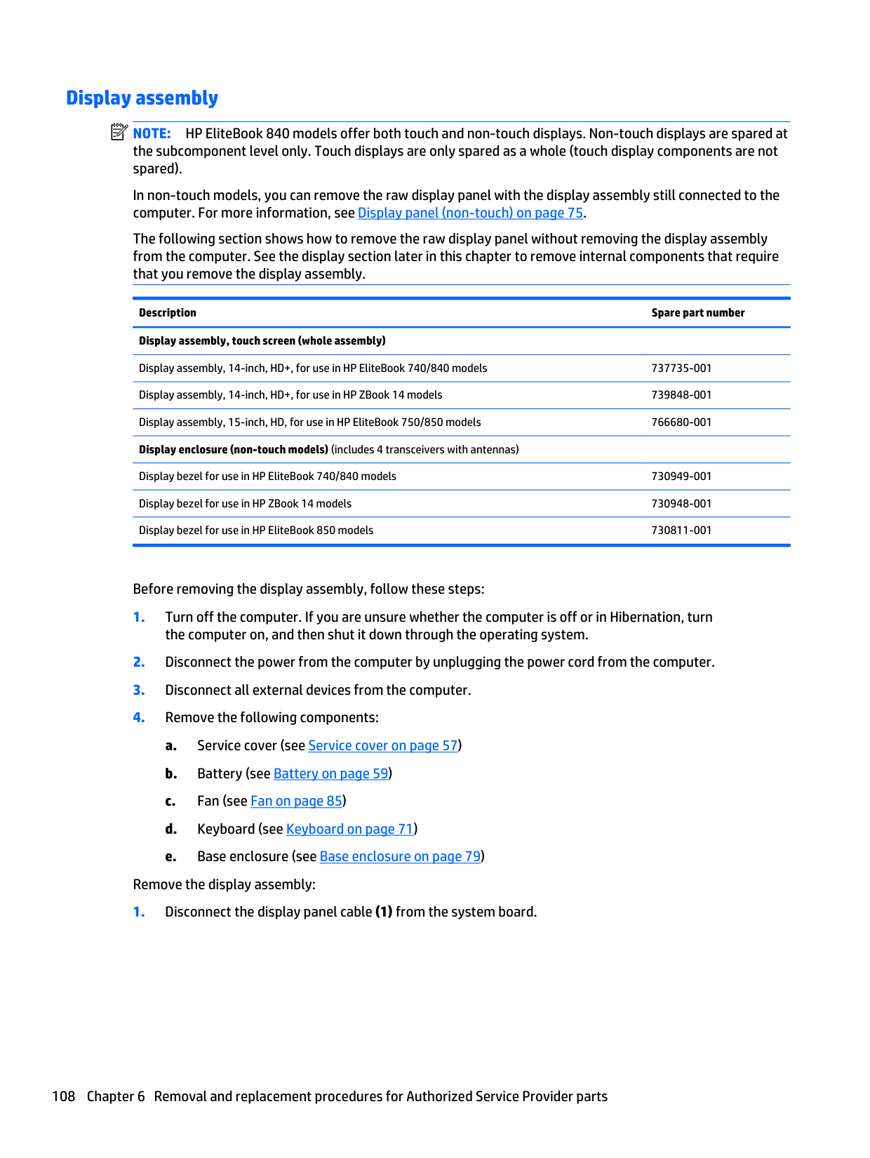
– or – To move the device down in the boot order, use a pointing device to click the down arrow, or press the key.
– or – Use the arrow keys to select File > Save Changes and Exit, and then press enter.
##### Dynamically choosing a boot device using the f9 prompt
To dynamically choose a boot device for the current startup sequence, follow these steps:
##### Setting a MultiBoot Express prompt
To start Computer Setup and set the computer to display the MultiBoot startup location menu each time the computer is started or restarted, follow these steps:
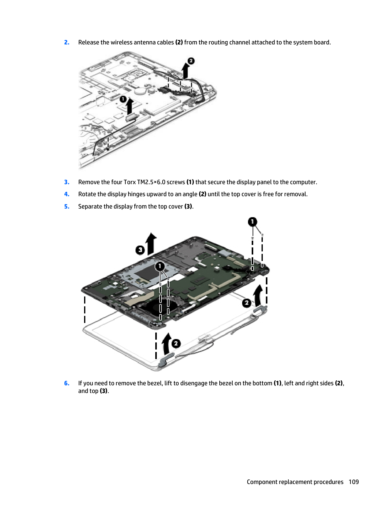
– or – Use the arrow keys to select File > Save Changes and Exit, and then press enter.
Your changes go into effect when the computer restarts. Entering MultiBoot Express preferences
When the Express Boot menu is displayed during startup, you have the following choices:
Using MultiBoot 119
Using HP PC Hardware Diagnostics (UEFI) (select models only)
HP PC Hardware Diagnostics is a Unified Extensible Firmware Interface (UEFI) that allows you to run diagnostic tests to determine if the computer hardware is functioning properly. The tool runs outside of the operating system to isolate hardware failures from issues that may be caused by the operating system or other software components.
To start HP PC Hardware Diagnostics UEFI:
After pressing f2, the BIOS searches three places for the HP PC Hardware Diagnostics (UEFI) tools in the following order:
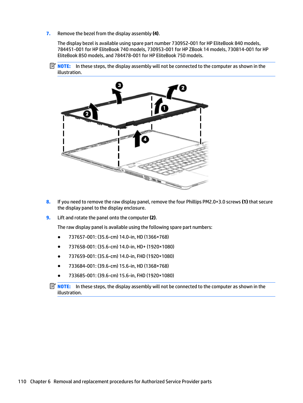
| | |---|
| | |---|
#### Downloading HP PC Hardware Diagnostics (UEFI) to a USB device
| | |---|
NOTE: The HP PC Hardware Diagnostics (UEFI) download instructions are provided in English only.
– or – Click Download, and then select Run.
8 Computer Setup (BIOS) and HP PC Hardware Diagnostics (UEFI) in Windows 7
Using Computer Setup
Computer Setup, or Basic Input/Output System (BIOS), controls communication between all the input and output devices on the system (such as disk drives, display, keyboard, mouse, and printer). Computer Setup includes settings for the types of devices installed, the startup sequence of the computer, and the amount of system and extended memory.
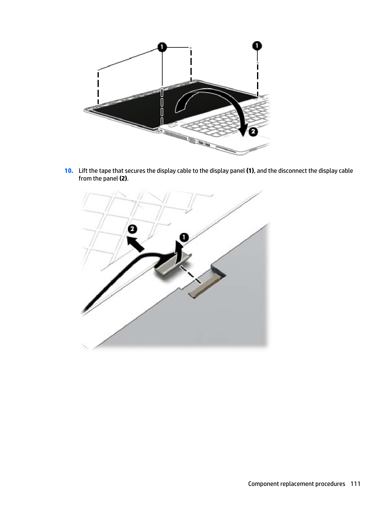
| | |---|
NOTE: Use extreme care when making changes in Computer Setup. Errors can prevent the computer from operating properly.
Starting Computer Setup NOTE: An external keyboard or mouse connected to a USB port can be used with Computer Setup only if USB legacy support is enabled. To start Computer Setup, follow these steps:
| | |---|
message is displayed at the bottom of the screen.
#### Navigating and selecting in Computer Setup
To navigate and select in Computer Setup, follow these steps:
| | |---|
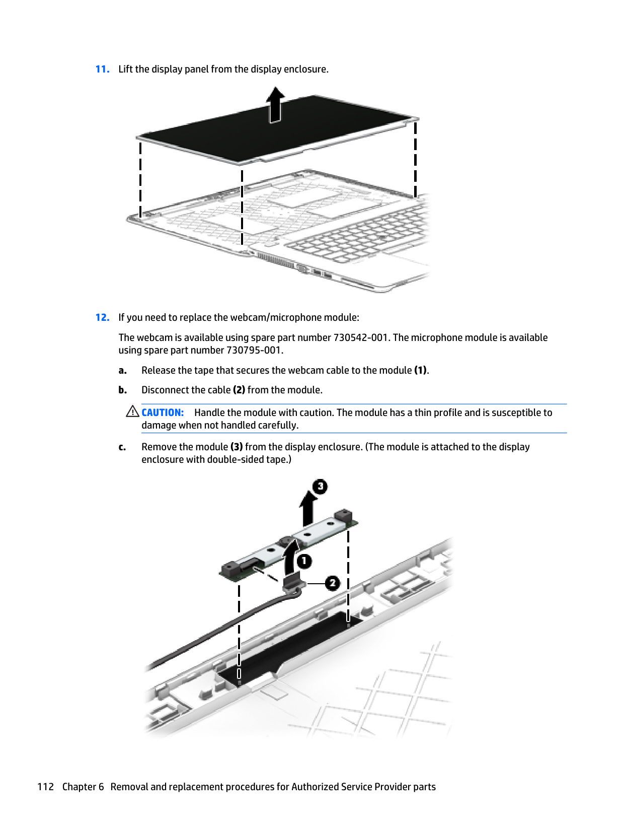
To exit Computer Setup menus, choose one of the following methods:
● To exit Computer Setup menus without saving your changes: Click the Exit icon in the lower-right corner of the screen, and then follow the on-screen instructions.
● To save your changes and exit Computer Setup menus: Click the Save icon in the lower-right corner of the screen, and then follow the on-screen instructions.
– or – Use the tab key and the arrow keys to select File > Save Changes and Exit, and then press enter.
Your changes go into effect when the computer restarts.
Restoring factory settings in Computer Setup NOTE: Restoring defaults will not change the hard drive mode. To return all settings in Computer Setup to the values that were set at the factory, follow these steps:
| | |---|
message is displayed at the bottom of the screen.
follow the on-screen instructions.
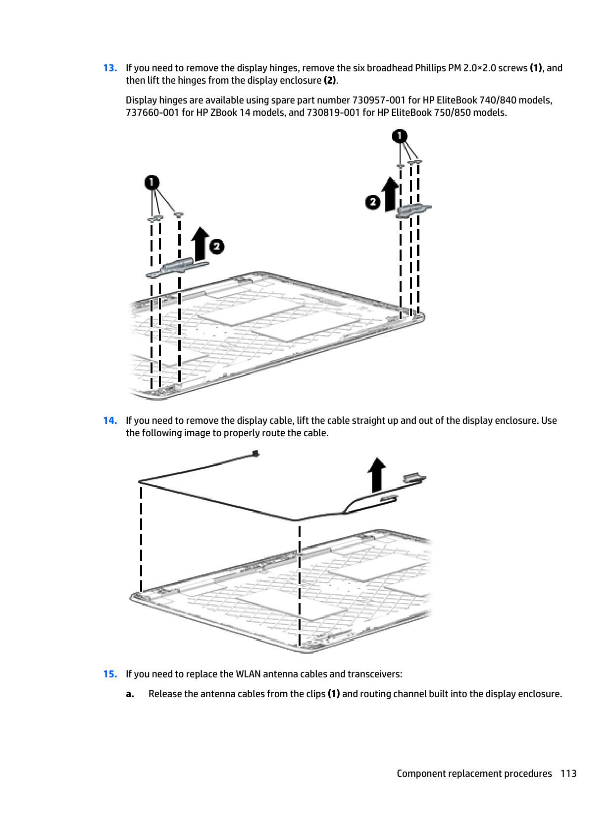
– or – Use the arrow keys to select File > Save Changes and Exit, and then press enter.
| | |---|
Your changes go into effect when the computer restarts. NOTE: Your password settings and security settings are not changed when you restore the factory settings.
Updating the BIOS Updated versions of the BIOS may be available on the HP website. Most BIOS updates on the HP website are packaged in compressed files called SoftPaqs. Some download packages contain a file named Readme.txt, which contains information regarding installing and troubleshooting the file.
##### Determining the BIOS version
To determine whether available BIOS updates contain later BIOS versions than those currently installed on the computer, you need to know the version of the system BIOS currently installed.
BIOS version information (also known as ROM date and System BIOS) can be displayed by pressing fn+esc (if you are already in Windows) or by using Computer Setup.
screen, and then follow the on-screen instructions.
##### Downloading a BIOS update
CAUTION: To reduce the risk of damage to the computer or an unsuccessful installation, download and install a BIOS update only when the computer is connected to reliable external power using the AC adapter. Do not download or install a BIOS update while the computer is running on battery power, docked in an optional docking device, or connected to an optional power source. During the download and installation, follow these instructions:
Do not disconnect power on the computer by unplugging the power cord from the AC outlet. Do not shut down the computer or initiate Sleep. Do not insert, remove, connect, or disconnect any device, cable, or cord.
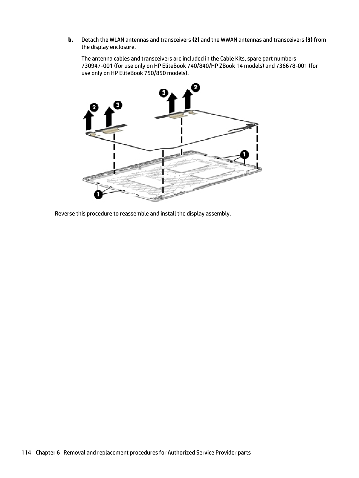
If the update is more recent than your BIOS, make a note of the path to the location on your hard drive where the BIOS update is downloaded. You will need to access this path when you are ready to install the update.
| | |---|
NOTE: If you connect your computer to a network, consult the network administrator before installing any software updates, especially system BIOS updates.
| | |---|
BIOS installation procedures vary. Follow any instructions that are displayed on the screen after the download is complete. If no instructions are displayed, follow these steps:
update.
The BIOS installation begins.
#### HP Sure Start
Select Intel-based 2013 HP Business Notebook PCs offer HP Sure Start, which provides hardware-based assurance of the following:
HP Sure Start verifies the integrity of critical, non-executable platform data residing in the main flash and provides selfhealing mechanisms to restore any code or critical platform data that has been lost or is corrupted within the flash.
In conjunction with BIOS support, code running on the EC verifies the integrity of the following:
The EC is responsible for power control/power cycle, thermal monitor/fan control, many LEDs, and PS2 keyboard and mouse.
Using MultiBoot
#### About the boot device order
As the computer starts, the system attempts to boot from enabled devices. The MultiBoot utility, which is enabled at the factory, controls the order in which the system selects a boot device. Boot devices can include optical drives, diskette drives, a network interface card (NIC), hard drives, and USB devices. Boot devices contain bootable media or files that the computer needs to start and operate properly.
| | |---|
NOTE: Some boot devices must be enabled in Computer Setup before they can be included in the boot order. You can change the order in which the computer searches for a boot device by changing the boot order in Computer Setup. You can also press esc while the “Press the ESC key for Startup Menu” message is displayed at the bottom of the screen, and then press f9. Pressing f9 displays a menu that shows the current boot devices and allows you to select a boot device. Or, you can use MultiBoot Express to set the computer to prompt you for a boot location each time the computer turns on or restarts.
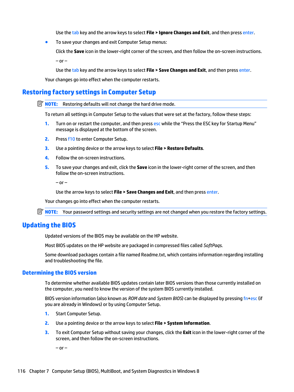
#### Choosing MultiBoot preferences
You can use MultiBoot in the following ways:
##### time the computer is turned on or restarted. Setting a new boot order in Computer Setup
To start Computer Setup and set a boot device order that the computer uses each time it is turned on or restarted, follow these steps:
message is displayed at the bottom of the screen.
– or – To move the device down in the boot order, use a pointing device to click the down arrow, or press the key.
screen, and then follow the on-screen instructions.
– or – Use the arrow keys to select File > Save Changes and Exit, and then press enter.
##### Dynamically choosing a boot device using the f9 prompt
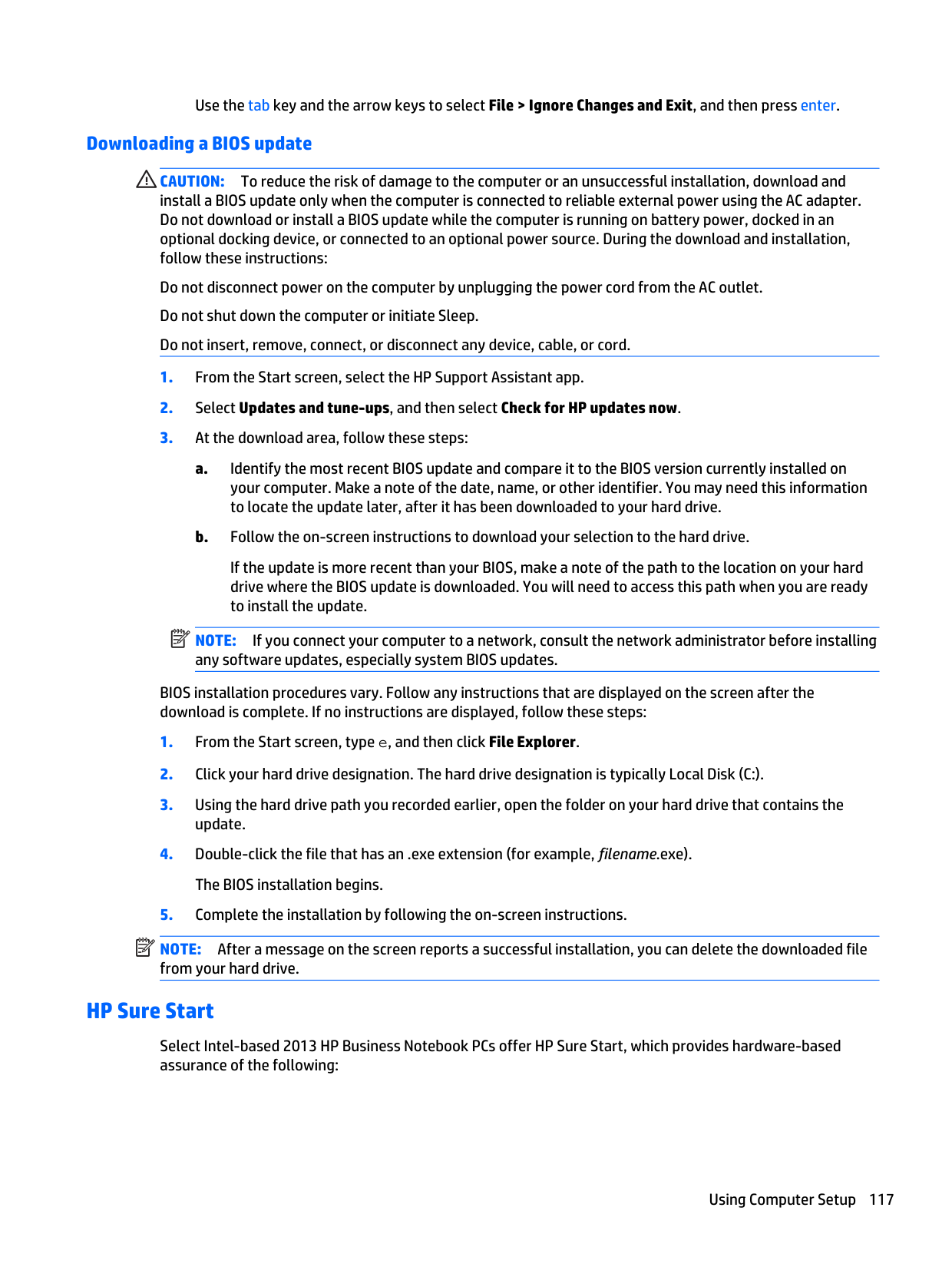
To dynamically choose a boot device for the current startup sequence, follow these steps:
the “Press the ESC key for Startup Menu” message is displayed at the bottom of the screen.
##### Setting a MultiBoot Express prompt
To start Computer Setup and set the computer to display the MultiBoot startup location menu each time the computer is started or restarted, follow these steps:
message is displayed at the bottom of the screen.
screen, and then follow the on-screen instructions.
– or – Use the arrow keys to select File > Save Changes and Exit, and then press enter.
Your changes go into effect when the computer restarts. Entering MultiBoot Express preferences
When the Express Boot menu is displayed during startup, you have the following choices:
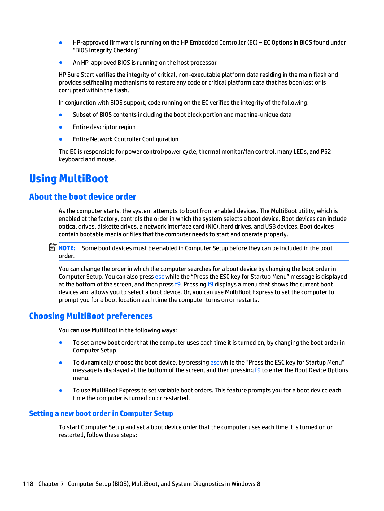
Using MultiBoot 125
Using HP PC Hardware Diagnostics (UEFI) (select models only)
HP PC Hardware Diagnostics is a Unified Extensible Firmware Interface (UEFI) that allows you to run diagnostic tests to determine if the computer hardware is functioning properly. The tool runs outside of the operating system to isolate hardware failures from issues that may be caused by the operating system or other software components.
To start HP PC Hardware Diagnostics UEFI:
After pressing f2, the BIOS searches three places for the HP PC Hardware Diagnostics (UEFI) tools in the following order:
a. Connected USB drive
| | |---|
NOTE: To download the HP PC Hardware Diagnostics (UEFI) tool to a USB drive, see Downloading HP PC Hardware Diagnostics (UEFI) to a USB device on page 120.
b. Hard drive c. BIOS
| | |---|

#### Downloading HP PC Hardware Diagnostics (UEFI) to a USB device
| | |---|
NOTE: The HP PC Hardware Diagnostics (UEFI) download instructions are provided in English only.
– or – Click Download, and then select Run.
9 Computer Setup (BIOS) and Advanced System Diagnostics in SUSE Linux
Computer Setup, or Basic Input/Output System (BIOS), controls communication between all the input and output devices on the system (such as disk drives, display, keyboard, mouse, and printer). Computer Setup includes settings for the types of peripherals installed, the startup sequence of the computer, and the amount of system and extended memory.
| | |---|
NOTE: Use extreme care when making changes in Computer Setup. Errors can prevent the computer from operating properly.
Starting Computer Setup NOTE: An external keyboard or mouse connected to a USB port can be used with Computer Setup only if USB legacy support is enabled. To start Computer Setup, follow these steps:
| |

|---|
Using Computer Setup
#### Navigating and selecting in Computer Setup
To navigate and select in Computer Setup, follow these steps:
NOTE: You can use either a pointing device (TouchPad, pointing stick, or USB mouse) or the keyboard to navigate and make selections in Computer Setup.
| | |---|
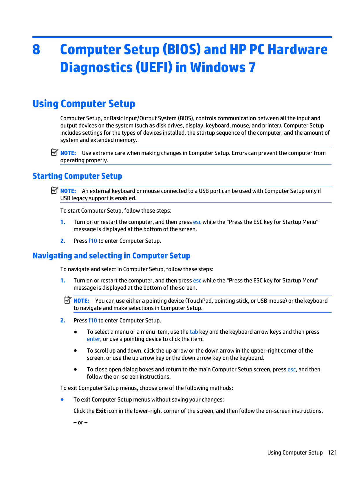
– or –
Starting Computer Setup 127
Use the tab key and the arrow keys to select Menu > Ignore Changes and Exit, and then press enter.
Your changes go into effect when the computer restarts.
Restoring factory settings in Computer Setup NOTE: Restoring defaults will not change the hard drive mode. To return all settings in Computer Setup to the values that were set at the factory, follow these steps:
| | |---|
| | |---|

– or – Use the arrow keys to select Menu > Save Changes and Exit, and then press enter.
Your changes go into effect when the computer restarts. NOTE: Your password settings and security settings are not changed when you restore the factory settings.
Updating the BIOS Updated versions of the BIOS may be available on the HP Web site. Most BIOS updates on the HP Web site are packaged in compressed files called SoftPaqs. Some download packages contain a file named Readme.txt, which contains information regarding installing and troubleshooting the file.
#### Determining the BIOS version
To determine whether available BIOS updates contain later BIOS versions than those currently installed on the computer, you need to know the version of the system BIOS currently installed.
BIOS version information (also known as ROM date and System BIOS) can be displayed as follows:
– or – Use the tab key and the arrow keys to select Menu > Ignore Changes and Exit, and then press enter.
| | |---|
NOTE: You can also determine the BIOS version by turning on or restarting the computer, pressing the esc key while the “Press the ESC key for Startup Menu” message is displayed at the bottom of the screen, and then pressing the f1 key. Follow the on-screen instructions to exit this screen.
Updating the BIOS 129
#### Downloading a BIOS update
CAUTION: To reduce the risk of damage to the computer or an unsuccessful installation, download and install a BIOS update only when the computer is connected to reliable external power using the AC adapter. Do not download or install a BIOS update while the computer is running on battery power, docked in an optional docking device, or connected to an optional power source. During the download and installation, follow these instructions:
Do not disconnect power from the computer by unplugging the power cord from the AC outlet. Do not shut down the computer or initiate Suspend or Hibernation. Do not insert, remove, connect, or disconnect any device, cable, or cord.
| | |---|
NOTE: After a message on the screen reports a successful installation, you can delete the downloaded file from your hard drive.
HP Sure Start
Select Intel-based 2013 HP Business Notebook PCs offer HP Sure Start, which provides hardware-based assurance of the following:
HP Sure Start verifies the integrity of critical, non-executable platform data residing in the main flash and provides selfhealing mechanisms to restore any code or critical platform data that has been lost or is corrupted within the flash.
In conjunction with BIOS support, code running on the EC verifies the integrity of the following:
The EC is responsible for power control/power cycle, thermal monitor/fan control, many LEDs, and PS2 keyboard and mouse.
Using MultiBoot
#### About the boot device order
As the computer starts, the system attempts to boot from enabled devices. The MultiBoot utility, which is enabled at the factory, controls the order in which the system selects a boot device. Boot devices can include optical drives, diskette drives, a network interface card (NIC), hard drives, and USB devices. Boot devices contain bootable media or files that the computer needs to start and operate properly.
| | |---|
NOTE: Some boot devices must be enabled in Computer Setup before they can be included in the boot order. You can change the order in which the computer searches for a boot device by changing the boot order in Computer Setup. You can also press esc while the “Press the ESC key for Startup Menu” message is displayed at the bottom of the screen, and then press f9. Pressing f9 displays a menu that shows the current boot devices and allows you to select a boot device. Or, you can use MultiBoot Express to set the computer to prompt you for a boot location each time the computer turns on or restarts.
#### Choosing MultiBoot preferences
You can use MultiBoot in the following ways:
##### Dynamically choosing a boot device using the f9 prompt
To dynamically choose a boot device for the current startup sequence, follow these steps:
Using HP PC Hardware Diagnostics (UEFI) (select models only)
| | |---|
HP PC Hardware Diagnostics is a Unified Extensible Firmware Interface (UEFI) that allows you to run diagnostic tests to determine if the computer hardware is functioning properly. The tool runs outside of the operating system to isolate hardware failures from issues that may be caused by the operating system or other software components.
Downloading HP PC Hardware Diagnostics (UEFI) to a USB device NOTE: The HP PC Hardware Diagnostics (UEFI) download instructions are provided in English only.
Using MultiBoot 131
After pressing f2, the BIOS searches three places for the HP PC Hardware Diagnostics (UEFI) tools in the following order:
– or – Click Download, and then select Run.
#### Downloading HP PC Hardware Diagnostics (UEFI) to a USB device
| | |---|
NOTE: The HP PC Hardware Diagnostics (UEFI) download instructions are provided in English only.
– or – Click Download, and then select Run.
10 Backup and recovery in Windows 8
| | |---|
| | |---|
To protect your information, use Windows backup and restore utilities to back up individual files and folders, back up your entire hard drive, create system repair media (select models only) by using the installed optical drive (select models only) or an optional external optical drive, or create system restore points. In case of system failure, you can use the backup files to restore the contents of your computer.
From the Start screen, type restore, click Settings, and then select from the list of displayed options. NOTE: For detailed instructions on various backup and restore options, perform a search for these topics in HP Support Assistant. To access HP Support Assistant on the Start screen, select the HP Support Assistant app.
In case of system instability, HP recommends that you print the recovery procedures and save them for later use.
NOTE: Windows includes the User Account Control feature to improve the security of your computer. You may be prompted for your permission or password for tasks such as installing software, running utilities, or changing Windows settings. Refer to HP Support Assistant. To access HP Support Assistant on the Start screen, select the HP Support Assistant app.
Backing up your information
| | |---|
| | |---|
Recovery after a system failure is as good as your most recent backup. You should create system repair media and your initial backup immediately after initial system setup. As you add new software and data files, you should continue to back up your system on a regular basis to maintain a reasonably current backup. The system repair media (select models only) are used to start up (boot) the computer and repair the operating system in case of system instability or failure. Your initial and subsequent backups allow you to restore your data and settings if a failure occurs.
On Start screen, type backup, click Settings, and then select Save backup copies of your files with File History.
You can back up your information to an optional external hard drive or a network drive. Note the following when backing up:
settings. The screen shot can be a time-saver if you have to reset your preferences. To create a backup using Backup and Restore: NOTE: Be sure that the computer is connected to AC power before you start the backup process. NOTE: The backup process may take over an hour, depending on file size and the speed of the computer.
Backing up your information 133
Performing a system recovery
In case of system failure or instability, the computer provides the following tools to recover your files:

| | |---|
NOTE: If you are unable to boot (start up) your computer and you cannot use the system repair media you previously created (select models only), you must purchase Windows 8 operating system media to reboot the computer and repair the operating system. For additional information, see Using Windows 8 operating system media (purchased separately) on page 135.
#### Using the Windows recovery tools
To recover information you previously backed up:
▲ Access HP Support Assistant. To access HP Support Assistant on the Start screen, select the HP Support
Assistant app. To recover your information using Automatic Repair, follow these steps: CAUTION: Some Automatic Repair options will completely erase and reformat the hard drive. All files you have created and any software installed on the computer are permanently removed. When reformatting is complete, the recovery process restores the operating system, as well as the drivers, software, and utilities from the backup used for recovery.
– or – From the Start screen, type c, and then select Computer.
NOTE: If the Windows partition and the HP Recovery partition are not listed, you must recover your operating system and programs using the Windows 8 operating system DVD and the Driver Recovery media (both purchased separately). For additional information, see Using Windows 8 operating system
media (purchased separately) on page 135.
| |
|---|
| | |---|
NOTE: For additional information on recovering information using the Windows tools, perform a search for these topics in HP Support Assistant. To access HP Support Assistant on the Start screen, select the HP Support Assistant app.
#### Using f11 recovery tools
CAUTION: Using f11 completely erases hard drive contents and reformats the hard drive. All files that you have created and any software that you have installed on the computer are permanently removed. The f11 recovery tool reinstalls the operating system and HP programs and drivers that were installed at the factory. Software not installed at the factory must be reinstalled.
To recover the original hard drive image using f11:
NOTE: If the HP Recovery partition is not listed, you must recover your operating system and programs using the Windows 8 operating system media and the Driver Recovery media (both purchased separately). For additional information, see Using Windows 8 operating system media (purchased separately) on page 135.
| | |---|
#### Using Windows 8 operating system media (purchased separately)
To order a Windows 8 operating system DVD, contact support. See the Worldwide Telephone Numbers booklet included with the computer. You can also find contact information from the HP website. Go to http://www.hp.com/support, select your country or region, and follow the on-screen instructions.
CAUTION: Using a Windows 8 operating system media completely erases hard drive contents and reformats the hard drive. All files that you have created and any software that you have installed on the computer are permanently removed. When reformatting is complete, the recovery process helps you restore the operating system, as well as drivers, software, and utilities.
| | |---|
To initiate recovery using a Windows 8 operating system DVD: NOTE: This process takes several minutes.
#### Using Windows Refresh for quick and easy recovery
When your computer is not working properly and you need to regain system stability, the Windows Refresh option allows you to start fresh and keep what is important to you.
| | |---|
| | |---|
| |
|---|
IMPORTANT: Refresh removes any traditional applications that were not originally installed on the system at the factory.
NOTE: During Refresh, a list of removed traditional applications will be saved so that you have a quick way to see what you might need to reinstall. See HP Support Assistant for instructions on reinstalling traditional applications. To access HP Support Assistant on the Start screen, select the HP Support Assistant app.
NOTE: You may be prompted for your permission or password when using Refresh. See HP Support Assistant for more information. To access HP Support Assistant on the Start screen, select the HP Support Assistant app.
To start Refresh:
#### Remove everything and reinstall Windows
Sometimes you want to perform detailed reformatting of your computer, or you want to remove personal information before you give away or recycle your computer. The process described in this section provides a speedy, simple way to return the computer to its original state. This option removes all personal data, apps, and settings from your computer, and reinstalls Windows.
| | |---|
IMPORTANT: This option does not provide backups of your information. Before using this option, back up any personal information you wish to retain. You can initiate this option by using the f11 key or from the Start screen. To use the f11 key:
– or – Press and hold f11 as you press the power button.
#### Using HP Software Setup
HP Software Setup can be used to reinstall drivers or select software that has been corrupted or deleted from the system.
11 Backup and recovery in Windows 7
Your computer includes HP and Windows tools to help you safeguard your information and retrieve it if you ever need to. These tools will help you return your computer to a proper working state, all with simple steps. This section provides information about the following processes:
Creating recovery media and backups
Recovery after a system failure is only as good as your most recent backup.
| | |---|
| | |---|
NOTE: This guide describes an overview of backing up, restoring, and recovering options. For more details about the tools provided, see Help and Support. To access Help and Support, select Start > Help and Support.
NOTE: HP recommends that you print the recovery procedures and save them for later use, in case of system instability. In case of system failure, you can use the backup files to restore the contents of your computer. See Backing up your information on page 139.
#### Guidelines
#### Creating recovery media with HP Recovery Disc Creator
HP Recovery Disc Creator is a software program that offers an alternative way to create recovery media. After you successfully set up the computer, you can create recovery media using HP Recovery Disc Creator. This recovery media allows you to reinstall your original operating system as well as select drivers and
applications if the hard drive becomes corrupted. HP Recovery Disc Creator can create two kinds of recovery DVDs:
Creating recovery media NOTE: The Windows 7 operating system DVD can be created only once. Thereafter, the option to create that media will not be available after you create a Windows DVD. To create the Windows DVD:
| | |---|
#### Backing up your information
You should create system repair media and your initial backup immediately after initial system setup. As you add new software and data files, you should continue to back up your system on a regular basis to maintain a reasonably current backup. You should also create Windows system repair media (select models only) which can be used to start up (boot) the computer and repair the operating system in case of system instability or failure. Your initial and subsequent backups allow you to restore your data and settings if a failure occurs.
You can back up your information to an optional external hard drive, a network drive, or discs. Note the following when backing up:
| | |---|
| | |---|
NOTE: For detailed instructions on various backup and restore options, perform a search for these topics in Help and Support. To access Help and Support, select Start > Help and Support.
NOTE: Windows includes the User Account Control feature to improve the security of your computer. You
may be prompted for your permission or password for tasks such as installing software, running utilities, or changing Windows settings. Refer to Help and Support. To access Help and Support, select Start > Help and Support.
Creating recovery media and backups 139
| | |---|
To create a backup using Windows Backup and Restore: NOTE: The backup process may take over an hour, depending on file size and the speed of the computer.
create system repair media (select models only).
Performing a system recovery
In case of system failure or instability, the computer provides the following tools to recover your files:
f11 recovery tools (select models only): You can use the f11 recovery tools to recover your original hard drive image. The image includes the Windows operating system and software programs installed at the factory.
| | |---|
NOTE: If you are unable to boot (start up) your computer and you cannot use the system repair media you previously created (select models only), you must purchase Windows 7 operating system media to reboot the computer and repair the operating system. For additional information, see Using Windows 8 operating system media (purchased separately) on page 135.
#### Using the Windows recovery tools
| | |---|
| | |---|
Using the Windows recovery tools, you can:
may be prompted for your permission or password for tasks such as installing software, running utilities, or changing Windows settings. Refer to Help and Support. To access Help and Support, select Start > Help and Support.
To recover information you previously backed up:
To recover your information using Startup Repair, follow these steps:
CAUTION: Some Startup Repair options will completely erase and reformat the hard drive. All files you have created and any software installed on the computer are permanently removed. When reformatting is complete, the recovery process restores the operating system, as well as the drivers, software, and utilities from the backup used for recovery.
NOTE: If the Windows partition is not listed, you must recover your operating system and programs using the Windows 7 operating system DVD and the Driver Recovery media. For additional information, see Using Windows 8 operating system media (purchased separately) on page 135.
| | |---|
| | |---|
NOTE: For additional information on recovering information using the Windows tools, select Start > Help and Support.
#### Using f11 recovery tools (select models only)
CAUTION: Using f11 completely erases hard drive contents and reformats the hard drive. All files that you have created and any software that you have installed on the computer are permanently removed. The f11 recovery tool reinstalls the operating system and HP programs and drivers that were installed at the factory. Software not installed at the factory must be reinstalled.
To recover the original hard drive image using f11:
NOTE: If the HP Recovery partition is not listed, you must recover your operating system and programs using the Windows 7 operating system media and the Driver Recovery media. For additional information, see Using Windows 8 operating system media (purchased separately) on page 135.
| | |---|
#### Using Windows 7 operating system media
If you cannot use the recovery media you previously created using the HP Recovery Disc Creator (select models only), you must purchase a Windows 7 operating system DVD to reboot the computer and repair the operating system.
To order a Windows 7 operating system DVD, go to the HP website. For U.S. support, go to http://www.hp.com/support. For worldwide support, go to http://welcome.hp.com/country/us/en/ wwcontact_us.html. You can also order the DVD by calling support. For contact information, see the Worldwide Telephone Numbers booklet included with the computer.
CAUTION: Using a Windows 7 operating system DVD completely erases hard drive contents and reformats the hard drive. All files that you have created and any software that you have installed on the computer are permanently removed. When reformatting is complete, the recovery process helps you restore the operating system, as well as drivers, software, and utilities.
| | |---|
To initiate recovery using a Windows 7 operating system DVD: NOTE: This process takes several minutes.
After the repair is completed:
12 Backup and Recovery in SUSE Linux
Recovery after a system failure is as good as your most recent backup. As you add new software and data files, you should continue to back up your system on a regular basis to maintain a reasonably current backup.
Your computer includes tools provided by HP to help you safeguard your information and retrieve it if ever needed.
Creating backups
Backing up your information
You should back up your computer files on a regular schedule to maintain a current backup. You can manually back up your information to an optional external drive, a network drive, or discs. Back up your system at the following times:
NOTE: Before you back up your information, be sure you have designated a location to save the backup files.
| | |---|
| | |---|
NOTE: If multiple backups have been performed, click Use the latest version to restore the latest version.
Performing a system recovery
Recovery allows you to repair or restore the computer to its original factory state. You can create an HP Factory Image, using an installed or an external DVD±RW optical drive.
| | |---|
NOTE: Your computer may not come equipped with an internal optical drive. In order to create the HP Factory Image, you may need to plug in an external optical drive.
CAUTION: Using Recovery completely erases hard drive contents and reformats the hard drive. All files you have created and any software installed on the computer are permanently removed. The recovery tool reinstalls the original operating system and HP programs and drivers that were installed at the factory. Software, drivers, and updates not installed by HP must be manually reinstalled. Personal files must be restored from a backup.
To restore the computer using the HP Factory Image, you must first create the recovery ISO file and then burn it to an optical disc.
| | |---|
NOTE: HP recommends that you create the HP Factory Image in the event of a system failure.
Remove everything and reinstall SLED
Sometimes you want to perform detailed reformatting of your computer, or you want to remove personal information before you give away or recycle your computer. The process described in this section provides a speedy, simple way to return the computer to its original state. This option removes all personal data, applications, and settings from your computer, and reinstalls the Linux operating system.
| | |---|
IMPORTANT: This option does not provide backups of your information. Before using this option, back up any personal information you wish to retain. You can initiate this option by using the f11 key. To use the f11 key:
Press f11 while the computer boots.
– or – Press and hold f11 as you press the power button. Select System Recovery and follow the on-screen instructions.
13 Specifications
Computer specifications–HP EliteBook 840/HP ZBook 14 models
######## Metric U.S.

Dimensions Width 33.9 cm 13.35 in Depth 23.7 cm 9.33 in Height Height (touch models)
2.1 cm 2.3 cm
0.83 in 0.89 in
######## Weight
Non-touch panel: Equipped with 3-cell (24 Whr) battery, UMA graphics, one memory module, WLAN module, and solidstate drive
Touch panel: Equipped with 3-cell (24 Whr) battery, UMA graphics, one memory module, WLAN module, and solidstate drive
1.62 kg 3.57 lbs
1.78 kg 3.92 lbs
Non-touch panel: Equipped with 3-cell (50 Whr) battery, UIMA graphics, one memory module, WLAN module, and solidstate drive
1.74 kg 3.83 lbs
Touch panel: Equipped with 3-cell (50 Whr) battery, UIMA graphics, one memory module, WLAN module, and solidstate drive
1.87 kg 4.12 lbs
Input power Operating voltage and current 18.5 V dc @ 3.5 A - 65 W
– or – 19.0 V dc @ 4.74 A - 90 W
Temperature Operating 5°C to 35°C 41°F to 95°F Nonoperating -20°C to 60°C -4°F to 140°F Relative humidity (noncondensing) Operating 10% to 90% Nonoperating 5% to 95% Maximum altitude (unpressurized)
Operating -15 m to 3,048 m -50 ft to 10,000 ft Nonoperating -15 m to 12,192 m -50 ft to 40,000 ft NOTE: Applicable product safety standards specify thermal limits for plastic surfaces. The device operates well within this range of
temperatures.
Computer specifications–HP EliteBook 840/HP ZBook 14 models 147
Computer specifications–HP EliteBook 850 models
Metric U.S.
Dimensions Width 37.6 cm 14.78 in Depth 25.4 cm 9.98 in Height 2.2 cm 0.85 in Weight
Equipped with 3-cell (24 Whr) battery, UIMA graphics, one memory module, WLAN module, and solid-state drive
Equipped with 3-cell (50 Whr) battery, UIMA graphics, one memory module, WLAN module, and solid-state drive
Input power Operating voltage and current 18.5 V dc @ 3.5 A - 65 W
– or – 19.0 V dc @ 4.74 A - 90 W
Temperature Operating 5°C to 35°C 41°F to 95°F Nonoperating -20°C to 60°C -4°F to 140°F Relative humidity (noncondensing) Operating 10% to 90% Nonoperating 5% to 95% Maximum altitude (unpressurized)
Operating -15 m to 3,048 m -50 ft to 10,000 ft Nonoperating -15 m to 12,192 m -50 ft to 40,000 ft NOTE: Applicable product safety standards specify thermal limits for plastic surfaces. The device operates well within this range of
temperatures.
35.6-cm (14.0-in) HD SVA display specifications
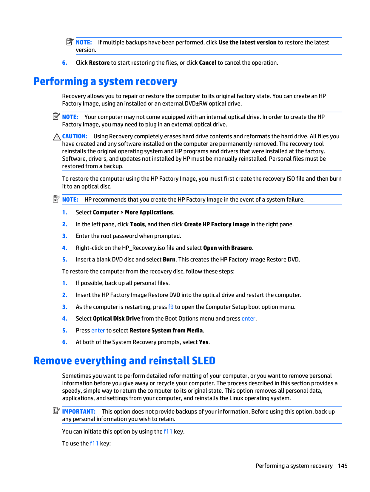
######## Metric U.S.
Dimensions Height 22.43 cm 8.83 in Width 36.0 cm 14.17 in Depth 0.38 cm 0.15 in Diagonal 35.6 cm 15.6 in Weight < 1.1 lb (500 g) (max)
Contrast ratio 300:1 (typical) Brightness 200 nits (typical) Refresh Rate 60 Hz Surface Treatment Anti-glare Pixel resolution Format HD (1366 x 768) Configuration RGB stripe LCD Mode TN PPI 101 PPI Interface eDP 1.2 (1 lane) Viewing angle SVA 40/40/15/30 (Left/Right/Down/Up)
35.6-cm (14.0-in) HD+ SVA display specifications
######## Metric U.S.
Dimensions Height 20.6 cm 8.09 in Width 32.1 cm 12.6 in Depth 0.36 cm 0.14 in Diagonal 35.6 cm 14.0 in Weight 0.72 lb (325 g) (max) Contrast ratio 300:1 (typical) Brightness 250 nits (typical) Refresh Rate 60 Hz Surface Treatment Anti-glare Pixel resolution Format HD+ (1600 x 900) Configuration RGB stripe LCD Mode TN PPI 131 PPI Interface eDP 1.2 (1 lane) Viewing angle SVA 40/40/15/30 (Left/Right/Down/Up)
35.6-cm (14.0-in) HD+ SVA display specifications 149
35.6-cm (14.0-in) HD+ SVA display specifications
######## Metric U.S.
Dimensions Height 20.6 cm 8.09 in Width 32.1 cm 12.6 in Depth 0.36 cm 0.14 in Diagonal 35.6 cm 14.0 in Weight 0.75 lb (340 g) (max) Contrast ratio 300:1 (typical) Brightness 300 nits (typical) Refresh Rate 60 Hz Surface Treatment Anti-glare Pixel resolution Format FHD (1920 x 1080) Configuration RGB stripe LCD Mode IPS/FFS/VA PPI 157 PPI Interface eDP 1.2 (1 lane) Viewing angle UWVA 85/85/85/85 (Left/Right/Down/Up)
39.6-cm (15.6-in) HD SVA display specifications
######## Metric U.S.
Dimensions Height 20.6 cm 8.09 in Width 32.1 cm 12.6 in Depth 0.36 cm 0.14 in Diagonal 39.6 cm 14.0 in Weight < 1.1 lb (500 g) (max) Contrast ratio 300:1 (typical) Brightness 200 nits (typical) Refresh Rate 60 Hz Surface Treatment Anti-glare Pixel resolution Format HD (1366 x 768)
Configuration RGB stripe LCD Mode TN PPI 125 PPI Interface eDP 1.2 (1 lane) Viewing angle SVA 40/40/15/30 (Left/Right/Down/Up)
39.6-cm (15.6-in) FHD SVA display specifications
######## Metric U.S.

Dimensions Height 20.6 cm 8.09 in Width 32.1 cm 12.6 in Depth 0.36 cm 0.14 in Diagonal 39.6 cm 14.0 in Weight < 0.84 lb (380 g) (max) Contrast ratio 400:1 (typical) Brightness 300 nits (typical) Refresh Rate 60 Hz Surface Treatment Anti-glare Pixel resolution Format HD (1920 x 1080) Configuration RGB stripe LCD Mode TN PPI 142 PPI Interface eDP 1.2 (1 lane) Viewing angle SVA 45/45/25/35 (Left/Right/Down/Up)
Hard drive specifications
######## 1-TB* 500-GB* 320-GB*
Dimensions Height 9.5 mm 9.5 mm 9.5 mm Width 70 mm 70 mm 70 mm Weight 115 g 101 g 115 g
39.6-cm (15.6-in) FHD SVA display specifications 151
1-TB* 500-GB* 320-GB* Interface type SATA SATA SATA Transfer rate Synchronous (maximum) Synchronous (maximum) 300 MB/s (Drive Capability) Security ATA security Seek times (typical read, including setting) Single track 3 ms 1.5ms/3 ms 1.5 ms Average (read/write) 13 ms 11 ms/13 ms 11 ms Maximum 24 ms 22 ms/24 ms 22 ms Logical blocks 1,953,525,168 976,773,168 625,142,448 Disk rotational speed 5400 rpm 5400 rpm or 7200
5400 rpm or 7200 rpm
rpm
Operating temperature 0°C to 60°C (32°F to 140°F)
*1 GB = 1 billion bytes when referring to hard drive storage capacity. Actual accessible capacity is less. NOTE: Certain restrictions and exclusions apply. Contact technical support for details.
Solid-state drive specifications
######## 128-GB* 180-GB* 240-GB* 256-GB*
Dimensions Height 7 mm 7 mm 7 mm 7 mm Width 70 mm 70 mm 70 mm 70 mm Weight 73 g 78 g 78 g 73 g Interface SATA 3 (6 Gb/s) SATA 3 (6 Gb/s) SATA 3 (6 Gb/s) SATA 3 (6 Gb/s) Transfer rate Maximum Sequential Read 415 MB/s Up to 550 MB/s 550 MB/s Up to 460 MB/s Maximum Sequential Write 175 MB/s Up to 520 MB/s 520 MB/s Up to 260 MB/s Total logical sectors 250,069,680 351,651,888 468,862,128 500,118,192 Features ATA Security;
ATA Security; ATA-8; SATA 3.0; DIPM; TRIM
ATA Security; ATA-8; SATA 3.0; DIPM; TRIM
ATA Security; ATA-8 compliant; SATA 3.0; DIPM; TRIM

ATA-8; SATA 3.0; DIPM; TRIM
Operating temperature 0° to 70°C (32°F to 158°F)
*1 GB = 1 billion bytes when referring to hard drive storage capacity. Actual accessible capacity is less. NOTE: Certain restrictions and exclusions apply. Contact technical support for details.
14 Statement of Volatility
The purpose of this document is to provide general information regarding non-volatile memory in industrystandards based HP Business Notebook PC systems and provide general instructions for restoring nonvolatile memory that can contain personal data after the system has been powered off and the hard drive has been removed.
HP Business Notebook PC products that use Intel®-based or AMD®-based system boards contain volatile DDR memory. The amount of nonvolatile memory present in the system depends upon the system configuration. Intel-based and AMD-based system boards contain nonvolatile memory subcomponents as originally shipped from HP assuming that no subsequent modifications have been made to the system and assuming that no applications, features, or functionality have been added to or installed on the system.
Following system shutdown and removal of all power sources from an HP Business Notebook PC system, personal data can remain on volatile system memory (DIMMs) for a finite period of time and will also remain in nonvolatile memory. The steps below will remove personal data from the notebook PC, including the nonvolatile memory found in Intel-based and AMD-based system boards. Some of these steps are disclosed in the Maintenance & Service Guides available for HP PC products available on the product support pages at www.hp.com.
If the HP notebook model number includes Intel® Centrino with VPro™, reboot the PC and enter BIOS Setup by pressing F10 when prompted. Select System Configuration, then AMT Options.
153
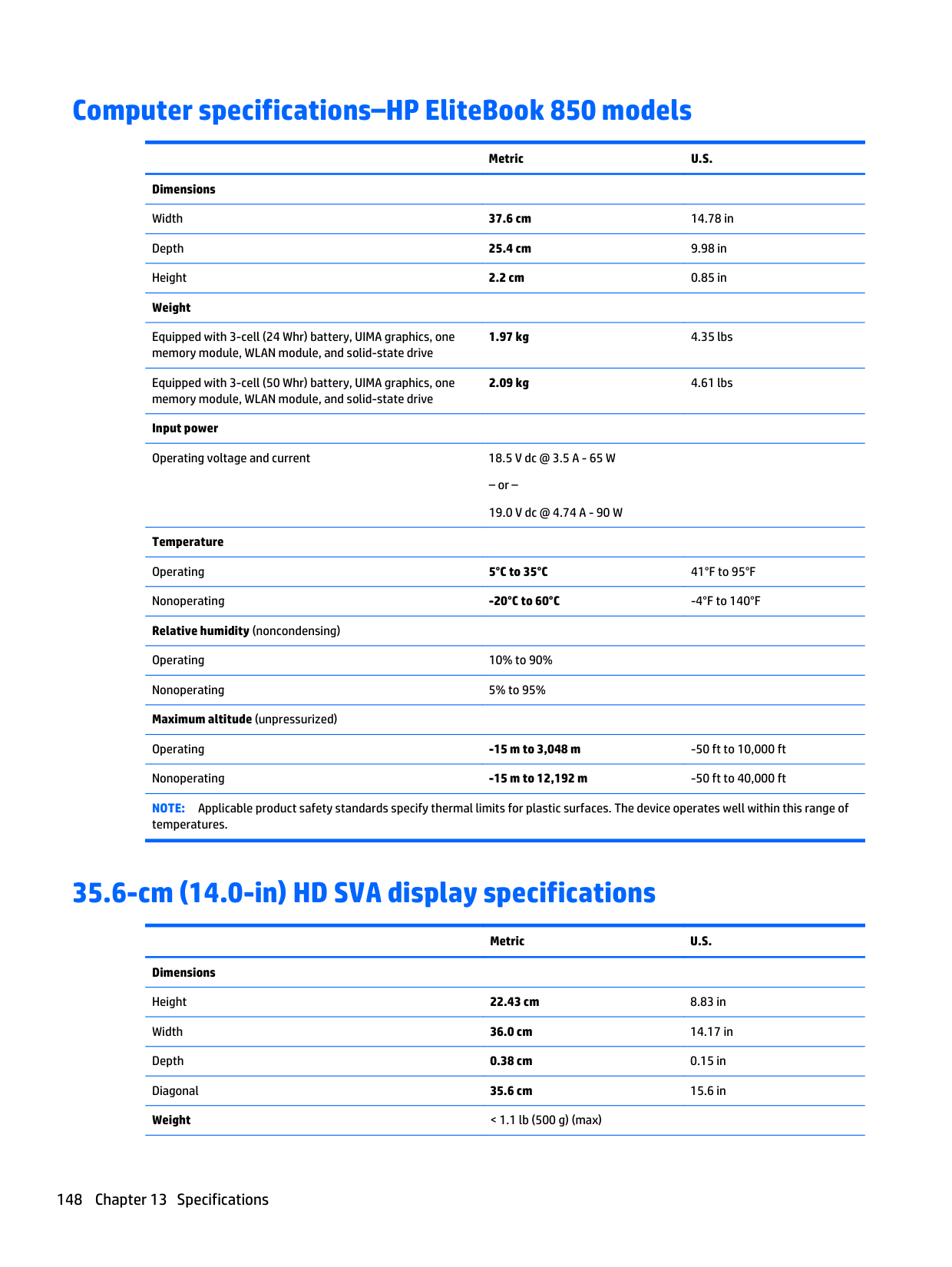
Then select Un-configure AMT on next boot. Select Save then Yes. Select the File menu, and then select Save Changes and Exit. Reboot the system and confirm that you want to un-configure AMT.
###### a. Hard Disk Drive (HDD)
Clear the HDD contents by using the HP Disk Sanitizer® utility or a third party application that, ideally, is U.S. Department of Defense (DOD) 5220.22-M approved.
To run HP Disk Sanitizer, enter BIOS Setup by powering on the system and pressing F10 when prompted near the bottom of the display, or press ESC to display the start up menu, then press F10. Select the Security menu and scroll down to the Utilities menu. Select Disk Sanitizer and select the desired drive. For a higher level of protection, select Optimum.
| | |---|
NOTE: This process will take a long time, and the amount of time varies based on the hard drive capacity.
###### b. Solid State Drive (SSD)
Clear the SSD contents by using the BIOS Setup Secure Erase command option, or by using a third party utility designed to erase data from an SSD. To run Secure Erase, enter BIOS Setup by powering on the system and pressing F10 when prompted near the bottom of the display. Select the Security menu and scroll down to the Utilities menu. Select Secure Erase and select the desired hard drive.
HP Sure Start
Select Intel-based 2013 HP Business Notebook PCs offer HP Sure Start, which provides hardware-based assurance of the following:
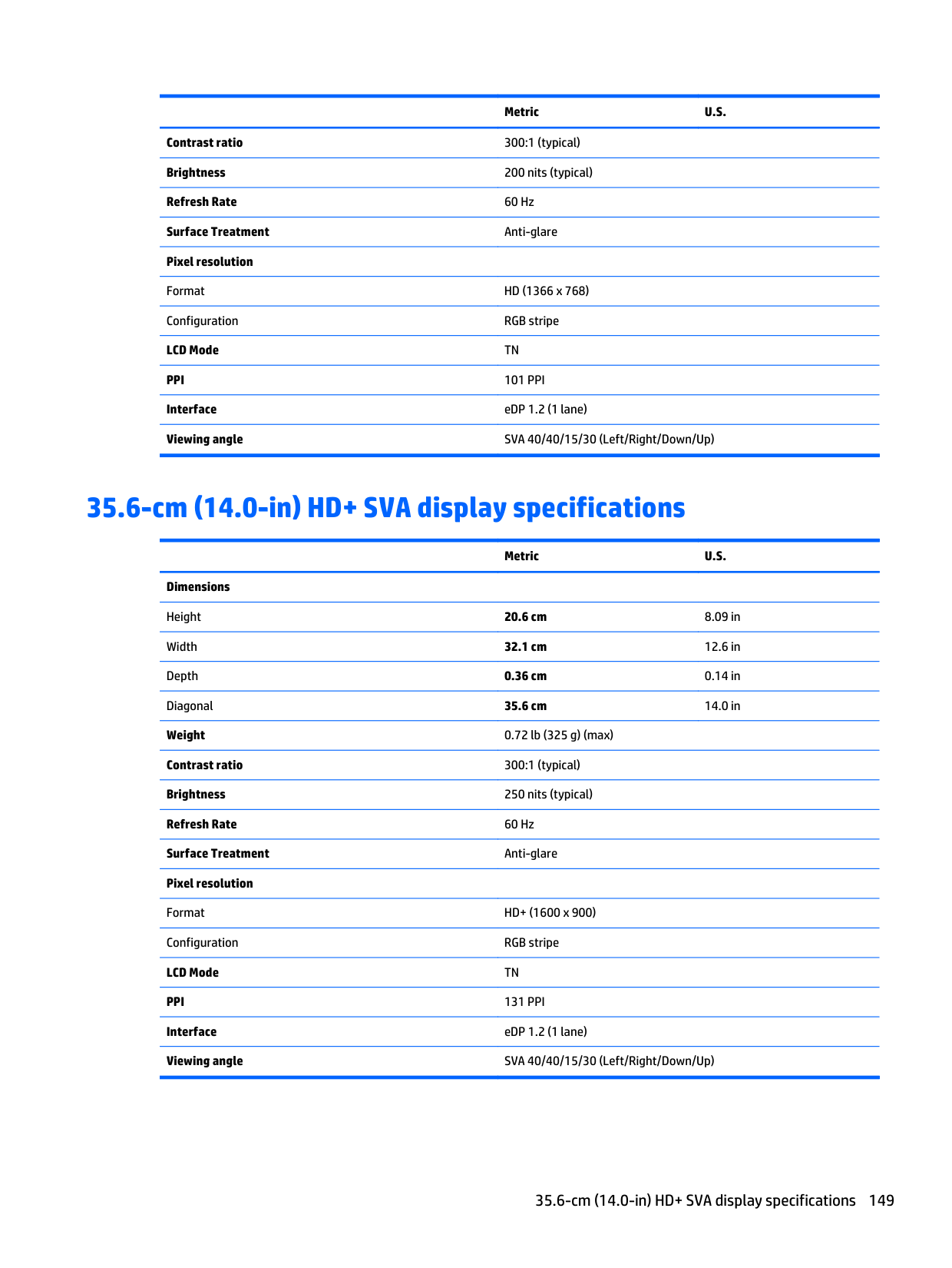
HP Sure Start verifies the integrity of critical, non-executable platform data residing in the main flash and provides selfhealing mechanisms to restore any code or critical platform data that has been lost or is corrupted within the flash.
In conjunction with BIOS support, code running on the EC verifies the integrity of the following:
The EC is responsible for power control/power cycle, thermal monitor/fan control, many LEDs, and PS2 keyboard and mouse.
Non-volatile memory usage
Non Volatile Memory Type
Amount (Size)
Does this memory store customer data?
Does this memory retain data when power is removed?
What is the purpose of this memory?
How is data input into this memory?
How is this memory write protected?
Real Time Clock (RTC) battery backed-up CMOS configuration memory (CMOS)
Controller (NIC) EEPROM
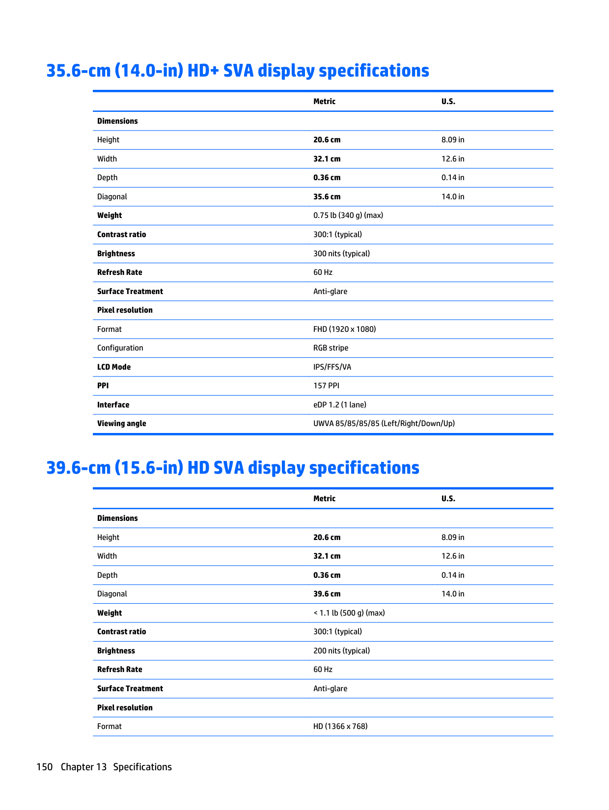
256 Bytes No Yes Stores system date and time and limited keyboard controller data.
64 Kbytes (not customer accessible)
No Yes Store NIC configuration and NIC firmware.
Keyboard ROM 64 Kbytes (not customer accessible)
No Yes Stores firmware code (keyboard, mouse, & battery management).
DIMM Serial Presence Detect (SPD) configuration data
256 Bytes per memory module, 128 Bytes programmabl e (not customer accessible)
No Yes Stores memory module information.
System BIOS 4 to 5 MBytes Yes Yes Store system BIOS code and PC configuration data.
Intel Management Engine Firmware (present only in models ending in a ‘p’ or ‘w’ or with Intel Centrino Pro technology)
1.5 or 5MByte Yes Yes Stores Management Engine Code, Settings, Provisioning Data and iAMT third party data store.
Using the F10 Setup utility or changing the Microsoft® Windows® date & time.
Using a utility from the NIC vendor that can be run from DOS.
Programmed at the factory. Code is updated when the system BIOS is updated.
Programmed by the memory vendor.
This memory is not writeprotected. HP recommends password protecting the F10 Setup utility.
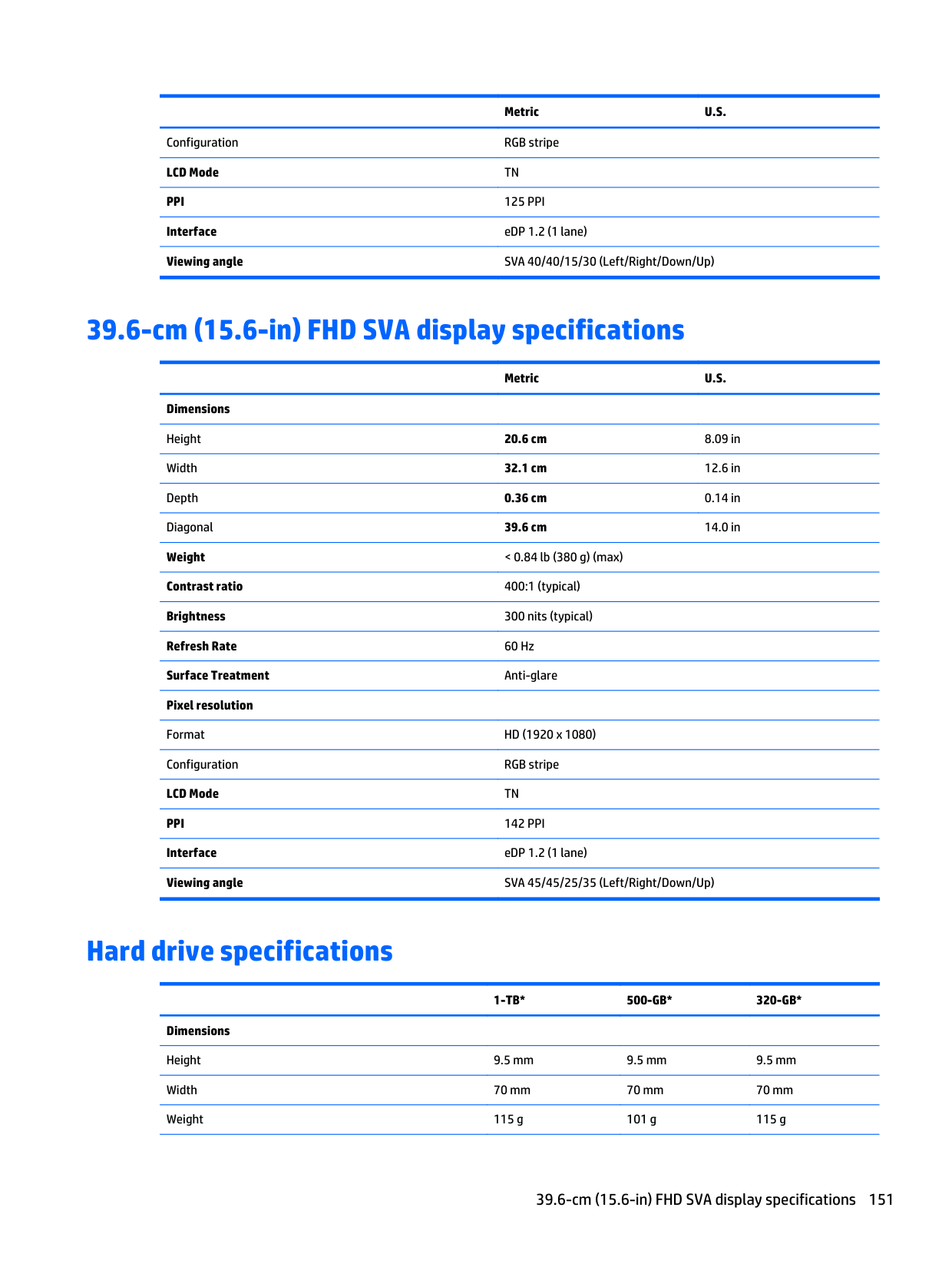
A utility is required to write data to this memory and is available from NIC vendor. Writing data to this ROM in an inappropriate manner will render the NIC nonfunctional.
A utility is required for writing data to this memory and is available on the HP website. Writing data to this ROM in an inappropriate manner can render the PC nonfunctional.
Data cannot be written to this memory when the module is installed in a PC. The specific write protection method varies by memory vendor.
System BIOS code is programmed at the factory. Code is updated when the system BIOS is updated. Configuration data and settings are input using the F10 setup utility or a custom utility.
Management Engine Code is programmed at the factory. Code is updated via Intel secure firmware update utility. Unique Provisioning Data can be entered at the factory or by an administrator using the Management Engine (MEBx) setup utility. The third party data store contents can populated by a remote management console or local applications registered by an
A utility is required for writing data to this memory and is available on the HP website. Writing data to this ROM in an inappropriate manner can render the PC nonfunctional.
The Intel chipset is configured to enforce HW protection to block all direct read/write access to this area. An Intel utility is required for updating the firmware. Only firmware updates digitally signed by Intel can be applied using this utility.
Non-volatile memory usage 155
Non Volatile Memory Type
Amount (Size)
Does this memory store customer data?
Does this memory retain data when power is removed?
What is the purpose of this memory?
Bluetooth flash 2Mbit No Yes Stores Bluetooth configuration and firmware.
802.11 WLAN EEPROM
4kb to 8kb No Yes Stores configuration and calibration data.
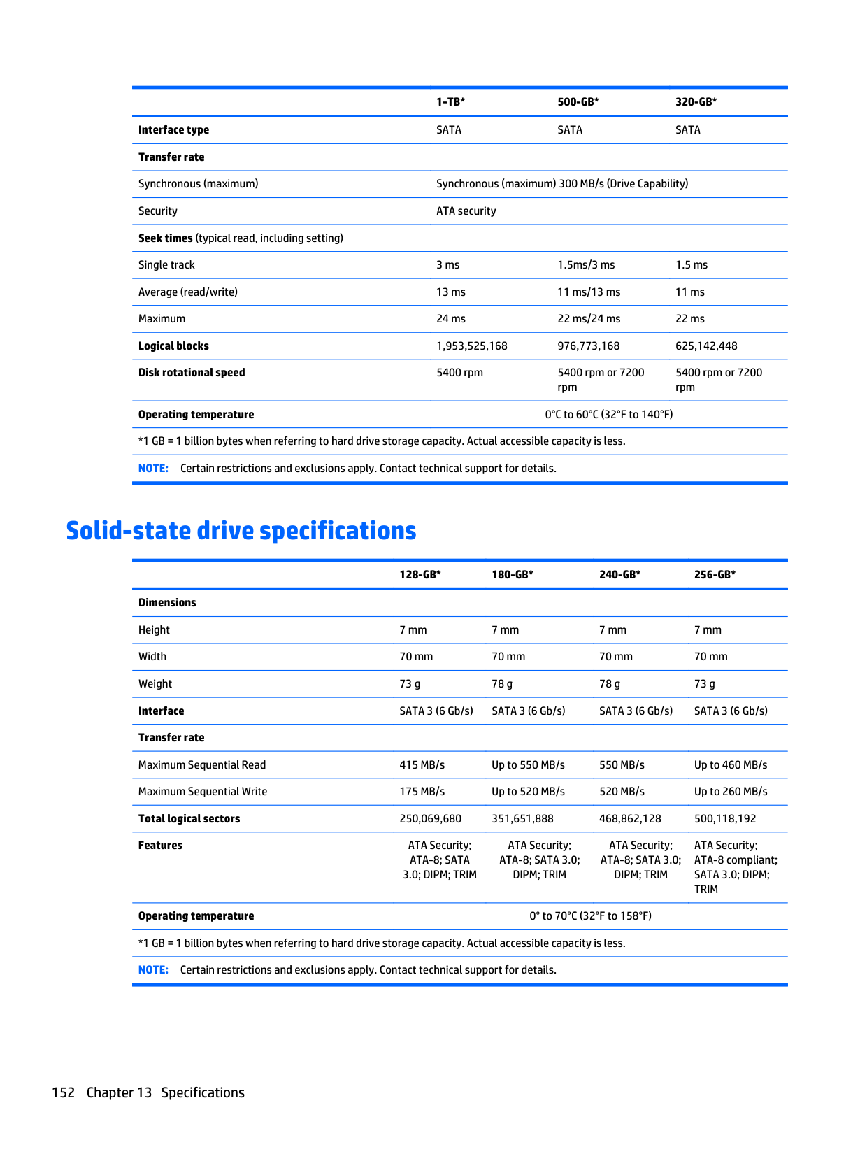
Web Camera 64K bit No Yes Store Web Cam configuration and firmware.
Fingerprint Reader 512kByte Flash
Yes Yes Stores
fingerprint templates.
How is data input into this memory?
How is this memory write protected?
administrator to have access to the space.
Programmed at the factory. Tools for writing data to this memory are not publicly available but can be obtained from the silicon vendor.
Programmed at the factory. Tools for writing data to this memory are not made public.
Using a utility from the device manufacturer that can be run from Windows.
By enrolling in HP ProtectTools Security Manager.
A utility is required for writing data to this memory and is made available through newer versions of the driver if the flash requires an upgrade.
A utility is required for writing data to this memory and is typically not made available to the public unless a firmware upgrade is necessary to address a unique issue.
A utility is required for writing data to this memory and is typically not made available to the public unless a firmware upgrade is necessary to address a unique issue.
Only a digitally signed application can make the call to write to the flash.
Questions and answers
The DIMM SPD memory contains information about the memory module such as size, serial number, data width, speed/timing, voltage and thermal information. This information is written by the module manufacturer and stored on an EEPROM. This EEPROM cannot be written to when the memory module is installed in a PC. Third party tools do exist that can write to the EEPROM when the memory module is not installed in a PC. There are various third party tools available to read SPD memory.
The process of resetting the CMOS will return certain system settings to factory default but will not reset many of the system data and configuration defaults to their factory settings. To return these system data and configuration defaults to factory settings, refer to question and answer 1 and follow the instructions for returning the BIOS settings to factory defaults.
Questions and answers 157
15 Power cord set requirements
The wide-range input feature of the computer permits it to operate from any line voltage from 100 to 120 volts AC, or from 220 to 240 volts AC.
The 3-conductor power cord set included with the computer meets the requirements for use in the country or region where the equipment is purchased.
Power cord sets for use in other countries and regions must meet the requirements of the country or region where the computer is used.
Requirements for all countries
The following requirements are applicable to all countries and regions:
Requirements for specific countries and regions
######## Country/region Accredited agency Applicable note number
Australia EANSW 1 Austria OVE 1 Belgium CEBC 1 Canada CSA 2 Denmark DEMKO 1 Finland FIMKO 1 France UTE 1 Germany VDE 1 Italy IMQ 1 Japan METI 3 The Netherlands KEMA 1 Norway NEMKO 1 The People's Republic of China COC 5 South Korea EK 4
158 Chapter 15 Power cord set requirements
######## Country/region Accredited agency Applicable note number
Sweden SEMKO 1 Switzerland SEV 1 Taiwan BSMI 4 The United Kingdom BSI 1 The United States UL 2
Requirements for specific countries and regions 159
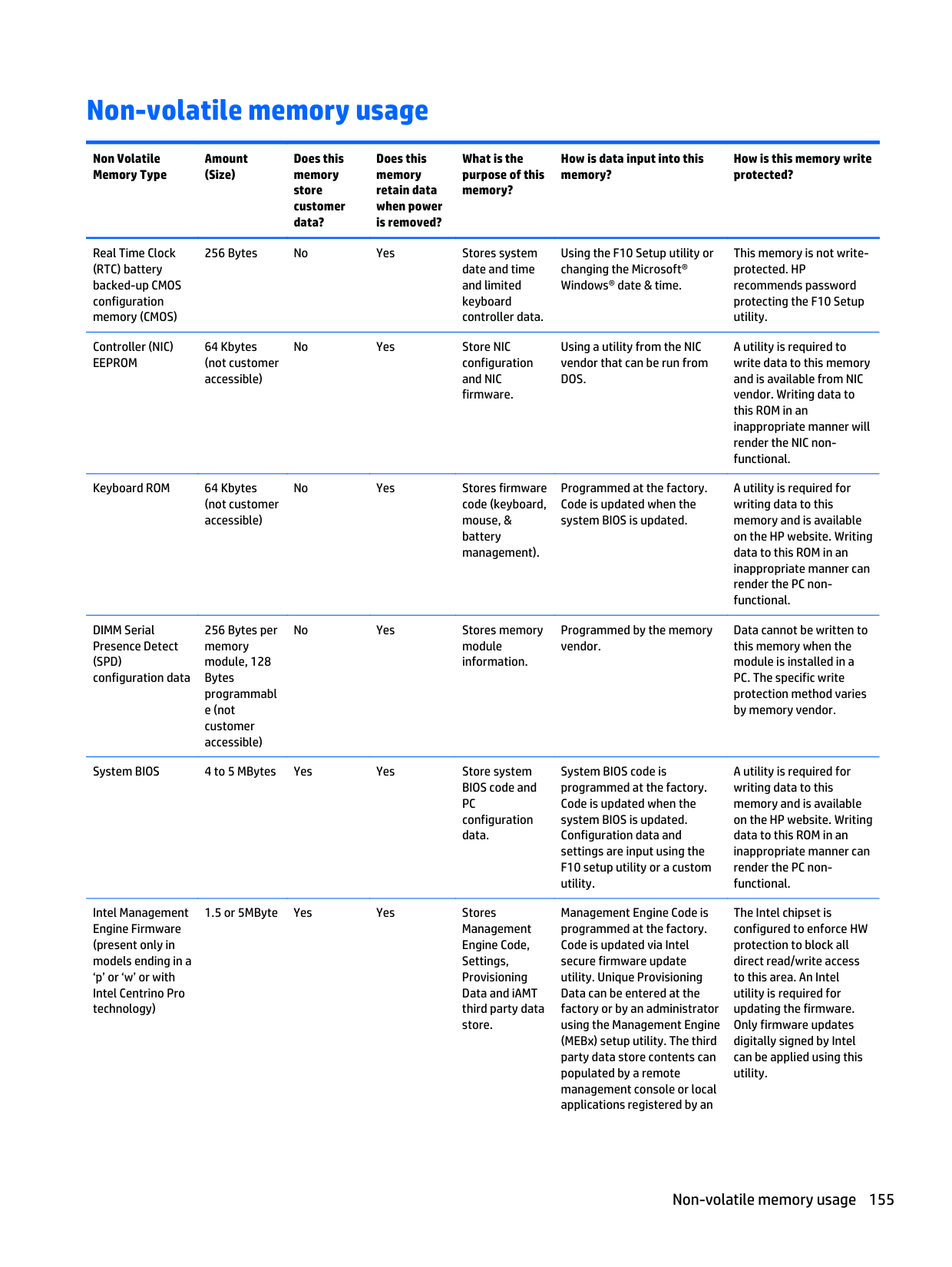
16 Recycling
When a non-rechargeable or rechargeable battery has reached the end of its useful life, do not dispose of the battery in general household waste. Follow the local laws and regulations in your area for battery disposal.
HP encourages customers to recycle used electronic hardware, HP original print cartridges, and rechargeable batteries. For more information about recycling programs, see the HP Web site at http://www.hp.com/ recycle.
160 Chapter 16 Recycling
Index
39, 44
AC adapter/battery light 13 accessory battery connector,
identifying 17
antenna removal 113 spare part numbers 31, 33, 41,
43, 114 audio, product description 4 audio-in (microphone) jack,
identifying 16 audio-out (headphone) jack, identifying 16
creating 139 recovering 140
base enclosure spare part numbers 29, 41, 44, 79, 82
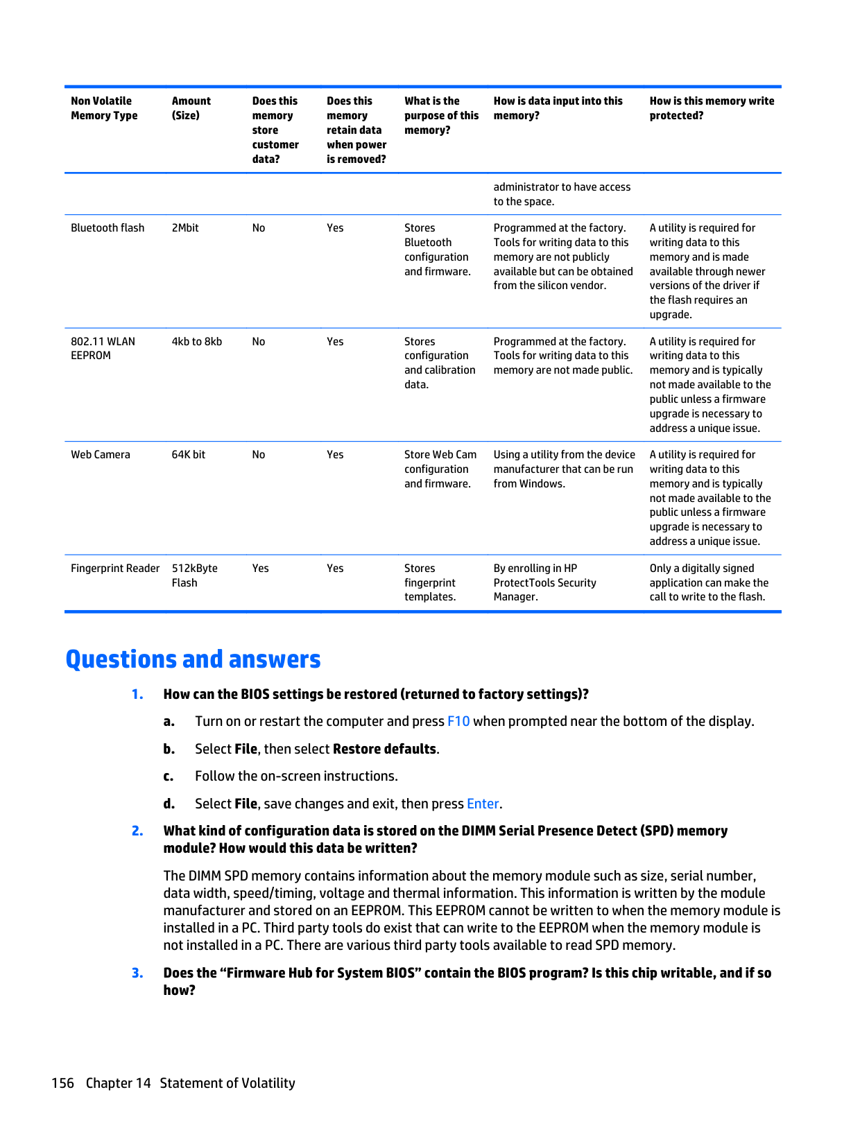
battery removal 59 spare part numbers 21, 39, 59
BIOS determining version 116, 122, 129 downloading an update 117, 123, 130 updating 116, 122, 129 Blu-ray ROM DVD±RW SuperMulti DL Drive precautions 54
buttons left pointing stick 9 left TouchPad 9
power 11 right pointing stick 9 right TouchPad 9 Windows button 12
C cables, service considerations 53 caps lock light, identifying 10 card reader board
removal 86 spare part number 21, 41, 86
chipset, product description 1 components
bottom 17 display 8 front 13 left side 15 right side 16 top 9
computer major components 20 computer part number 19 computer reset 136, 145 Computer Setup
navigating and selecting 115,
restoring factory settings 116,
computer setup navigating and selecting 127 restoring factory settings 129
computer specifications 147, 148 connector, power 16 connectors, service considerations
53
D display
specifications 148, 149, 150, 151
display assembly removal 108 subcomponents 31
display bezel spare part numbers 31, 33, 41
display enclosure, spare part numbers 32, 33, 41
display hinge removal 113 spare part numbers 32, 33, 41,
43
Display Hinge Kit, spare part numbers 32, 33, 41, 43
display panel product description 2 removal 75 spare part numbers 32, 33
display panel cable
spare part numbers 31, 33, 41 DisplayPort, identifying 16 docking connector, identifying 16 Driver Recovery DVD, creating 138 using for restore 142
drives, preventing damage 54 DVD-ROM Drive
precautions 54 DVD±RW Double-Layer with SuperMulti Drive precautions 54
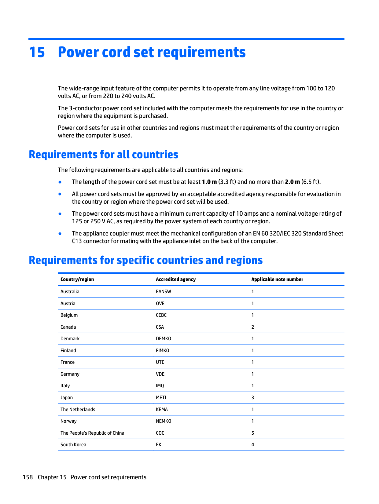
identifying 12 equipment guidelines 56 esc key, identifying 12 Ethernet, product description 4 external VGA monitor port 15
removal 85 spare part number 22, 39, 85
fingerprint reader assembly removal 94 spare part number 41, 94
fingerprint reader board spare part number 21
fingerprint reader insert,
illustrated 35 fingerprint reader, identifying 12 flash cache
product description 3 fn key, identifying 12 function keys, identifying 12
equipment 56 grounding 54 packaging 55 transporting 55 workstation 55
precautions 54 product description 3 removal 60 spare part numbers 22, 34, 39,
44, 45, 60
specifications 151 hard drive bracket
removal 61
Hard Drive Hardware Kit contents 33 spare part number 22, 33, 39,
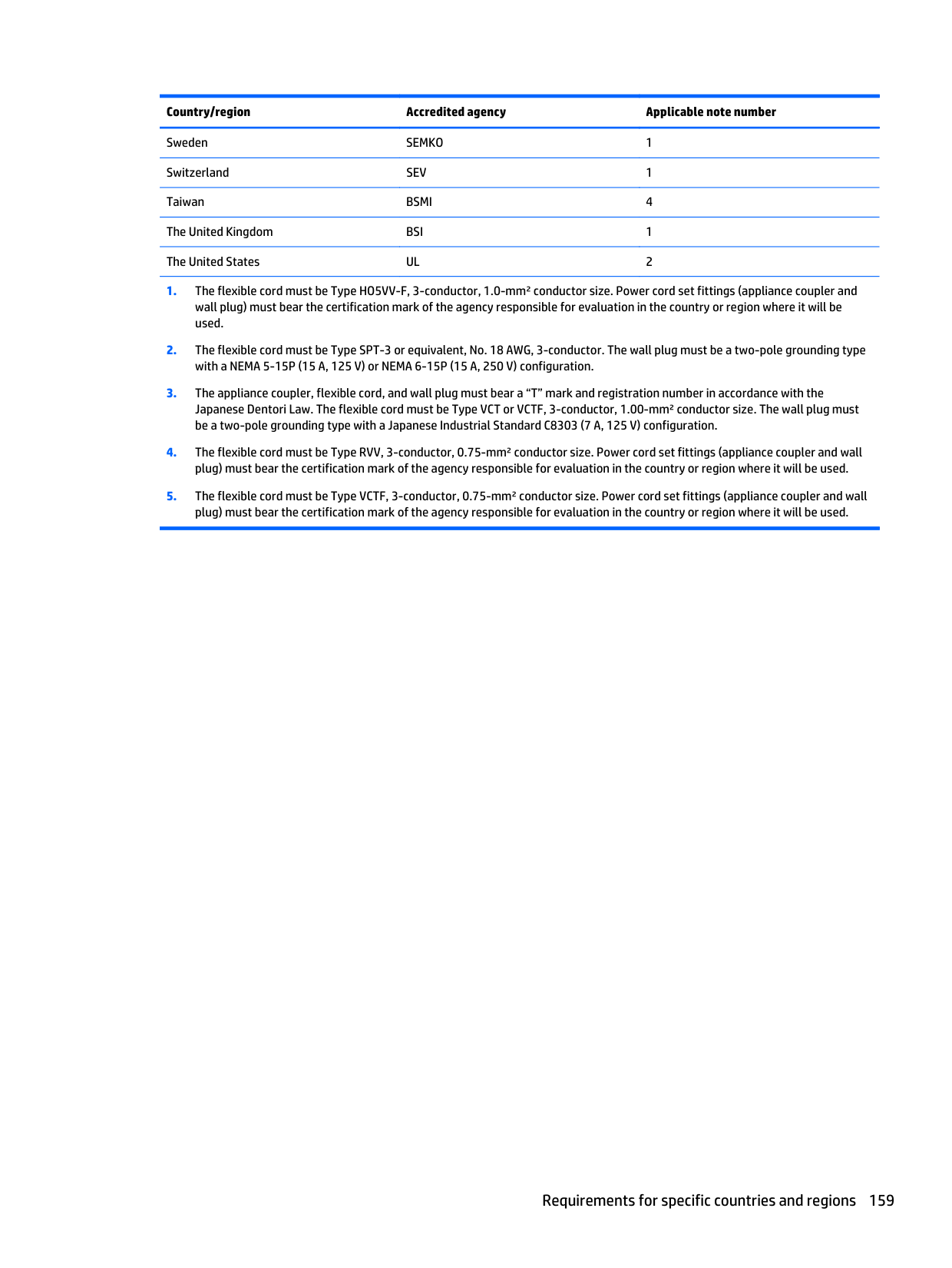
60 hard drive light 14 hard drive recovery 135, 142 hard drive, identifying 17, 18 headphone (audio-out) jack 16 heat sink
removal 88 spare part numbers 22, 41, 42,
43, 88 HP Recovery Disc Creator, using 138
HP Recovery partition checking for presence 142 using for recovery 142
identifying 8 internal display switch 8 internal microphones, identifying 8
audio-in (microphone) 16 audio-out (headphone) 16 network 16 RJ-45 (network) 16
product description 5 removal 71 spare part numbers 21, 39, 40,
42, 43, 71 keypad
embedded numeric 12
keys esc 12 fn 12 function 12
18 legacy support, USB 115, 121, 127 lights
AC adapter/battery 13 caps lock 10 hard drive 14 power 10, 13 webcam 8 wireless 10, 13
illustrated 33 precautions 54 spare part numbers 33
memory card reader, identifying 16 memory module
identifying 17, 18 product description 2 removal 65 spare part numbers 22, 39, 65
microphone product description 4 microphone (audio-in) jack,
identifying 16 microphone module
spare part numbers 31, 33, 40, 76
mini-card SSD
product description 4 model description 19 model name 1 mouse, spare part numbers 37
description 5 optical drive
precautions 54
considerations 53
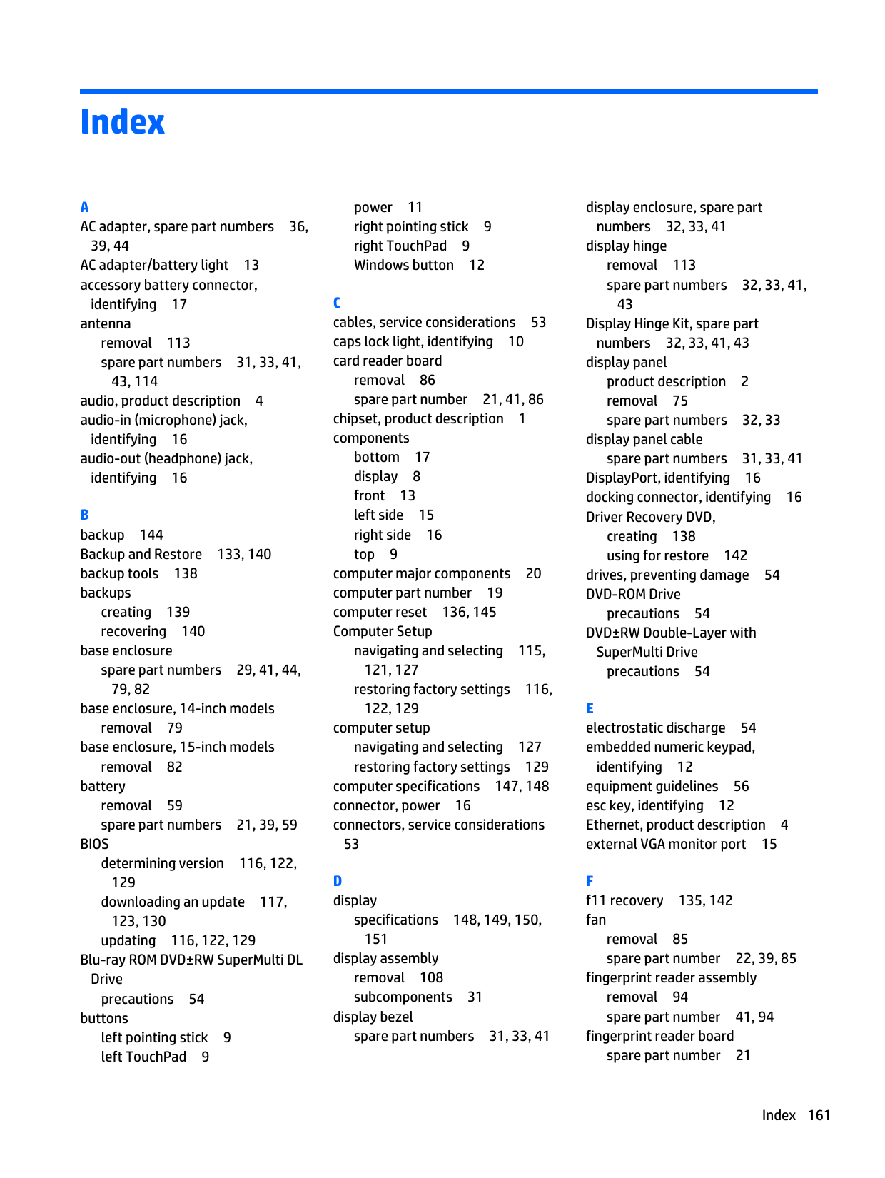
Plastics Kit contents 35 spare part numbers 35, 41
pointing device, product
description 5 pointing stick 9 ports
DisplayPort 16 external VGA monitor 15 product description 4
power button board removal 92 spare part number 21, 41, 92
power button, identifying 11 power connector, identifying 16 power cord
set requirements 158 spare part numbers 36, 38, 44
power lights 10, 13 power requirements, product
description 5 processor
product description 1
product description audio 4 chipset 1 display panel 2 Ethernet 4 external media cards 4 flash cache 3 graphics 1 hard drive 3
keyboard 5 memory module 2 microphone 4 mini-card SSD 4 operating system 5 pointing device 5 ports 4 power requirements 5 processors 1 product name 1 security 5 serviceability 7 solid-state drive 3 video 4 wireless 4
product name 1, 19 product number 19
R recovery 136, 144 recovery media, creating 138 recovery media, using for restore
142 recovery partition 135, 142 recovery tools 138 recovery tools, Windows 140 recovery, system 140 recycle
computer 136 refresh 136 removal/replacement
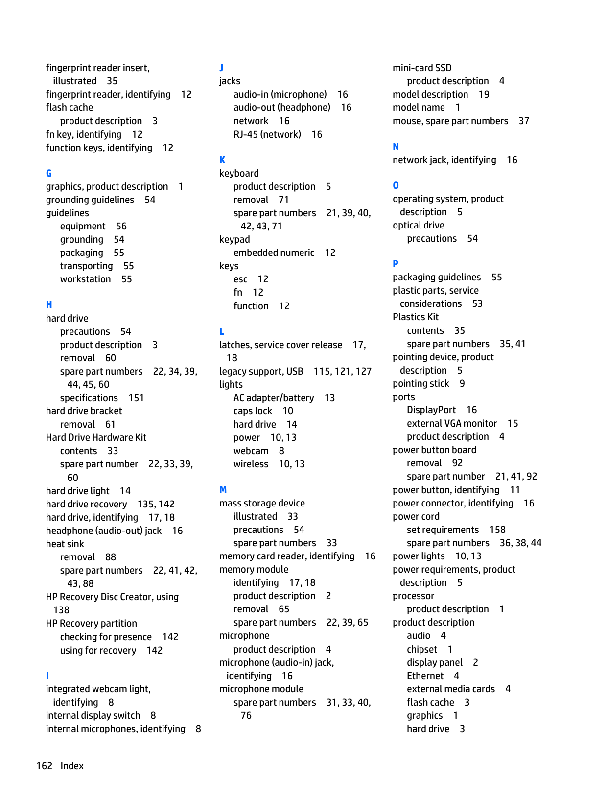
preliminaries 53 procedures 57, 75
remove everything and reinstall Windows 136
reset computer 136, 145 steps 136, 145
restoring the hard drive 135, 142 RJ-45 (network) jack, identifying 16 RJ-45 door, illustrated 35 RJ-45 flat spring, illustrated 35 RTC battery
removal 64 spare part number 21, 38, 64
Rubber Kit, spare part numbers 30, 41
S Screw Kit, spare part numbers 37,
41 SD card insert 35 security cable slot, identifying 15 security, product description 5 serial number 19 service considerations
cables 53 connectors 53 plastic parts 53
service cover removal 57 spare part numbers 30, 57 service cover release latch 17, 18 service tag 19 serviceability, product description 7 setup utility
navigating and selecting 115,
restoring factory settings 116,
SIM slot, identifying 17, 19 SLED
remove everything and reinstall option 145
slots security cable 15 smart card 15
smart card slot 15 solid-state drive
precautions 54 product description 3 removal 62 spare part numbers 30, 34, 44,
62 specifications 152
speaker assembly removal 106 spare part number 21, 41, 106
speakers, identifying 12 specifications
computer 147, 148 display 148, 149, 150, 151 hard drive 151 solid-state drive 152
Startup Repair, using 140
system board removal 96 spare part numbers 22, 45, 46,
47, 48, 49, 50, 51, 52, 96 system board, gold conversion kits spare part numbers 26, 99
41, 42 TouchPad
buttons 9 TouchPad zone
identifying 9 transporting guidelines 55
removal 87 spare part number 21, 41, 42,
87 video, product description 4
removal 78 spare part numbers 31, 33, 39
webcam, identifying 8 webcam/microphone module
removal 112 Windows
Refresh 136 reinstall 136 remove everything and reinstall
option 136 reset 136
Windows 7 operating system DVD creating 138 using for restore 142
Windows button, identifying 12 Windows Startup Repair, using 140 wireless antenna
removal 113 spare part numbers 31, 33, 114
Wireless Antenna Kit, spare part
numbers 114 wireless antennas, identifying 8 wireless light 10, 13 wireless, product description 4 WLAN antennas, identifying 8 WLAN module
removal 69 spare part numbers 29, 38, 39,
69 workstation guidelines 55 WWAN antennas, identifying 8 WWAN module
removal 67 spare part numbers 29, 39, 67