HP Elitebook 840 G3 Notebook PC
Laptops · 9 Q&As

HP Elitebook 840 G3 Notebook PC

Ask AI

— answers from the official manual

Answers from the official manual.

Common questions

The EliteBook 840 G3 is the high-water mark of HP business laptop repairability. iFixit gave it a 10/10 repairability score — every meaningful component is field-replaceable with hand tools, and the battery is accessible behind two captive screws and a pull tab. Later generations are still serviceable (the 840 G7 battery, for example, comes out after removing the bottom cover and four 4.5mm screws), but the G3 was the easiest by a meaningful margin.

If you've landed here, you almost certainly need to crack one open. The procedures below are sequenced the way you'd actually do them — battery first because everything else needs the battery removed, then the components in the order they're stacked.

Before you start

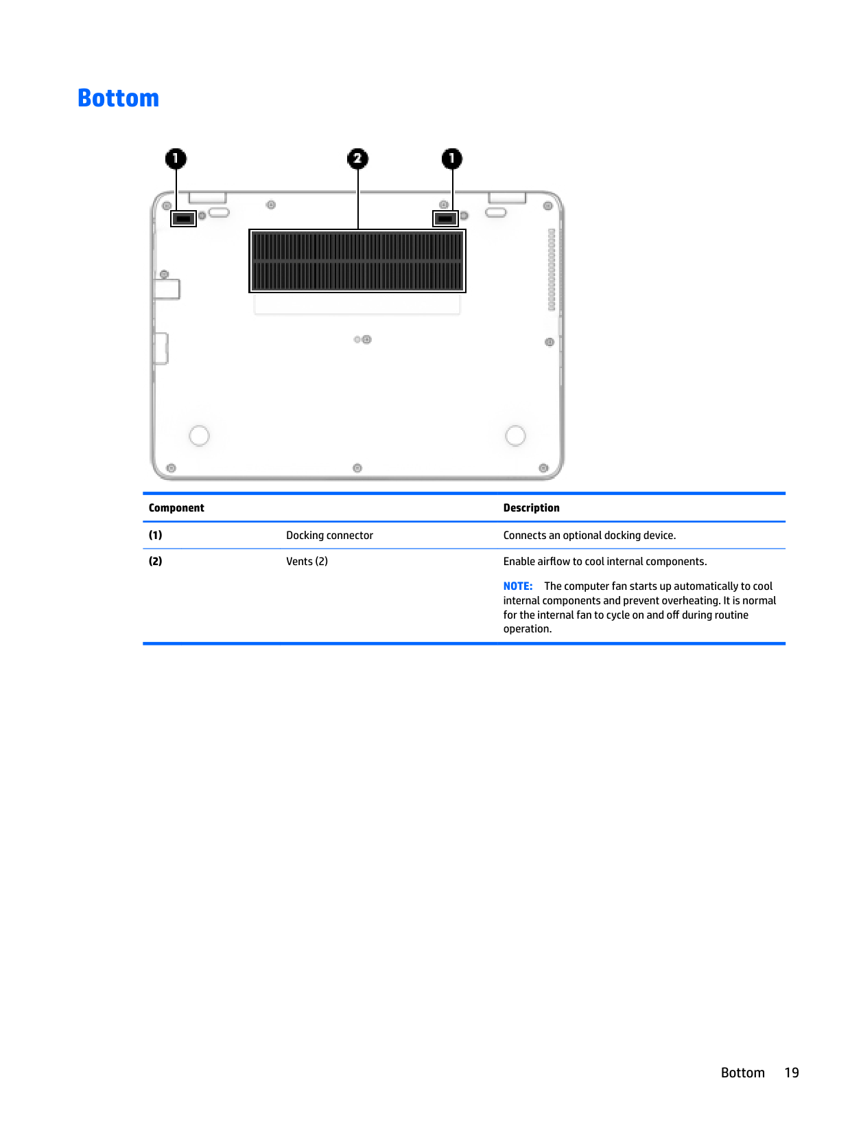
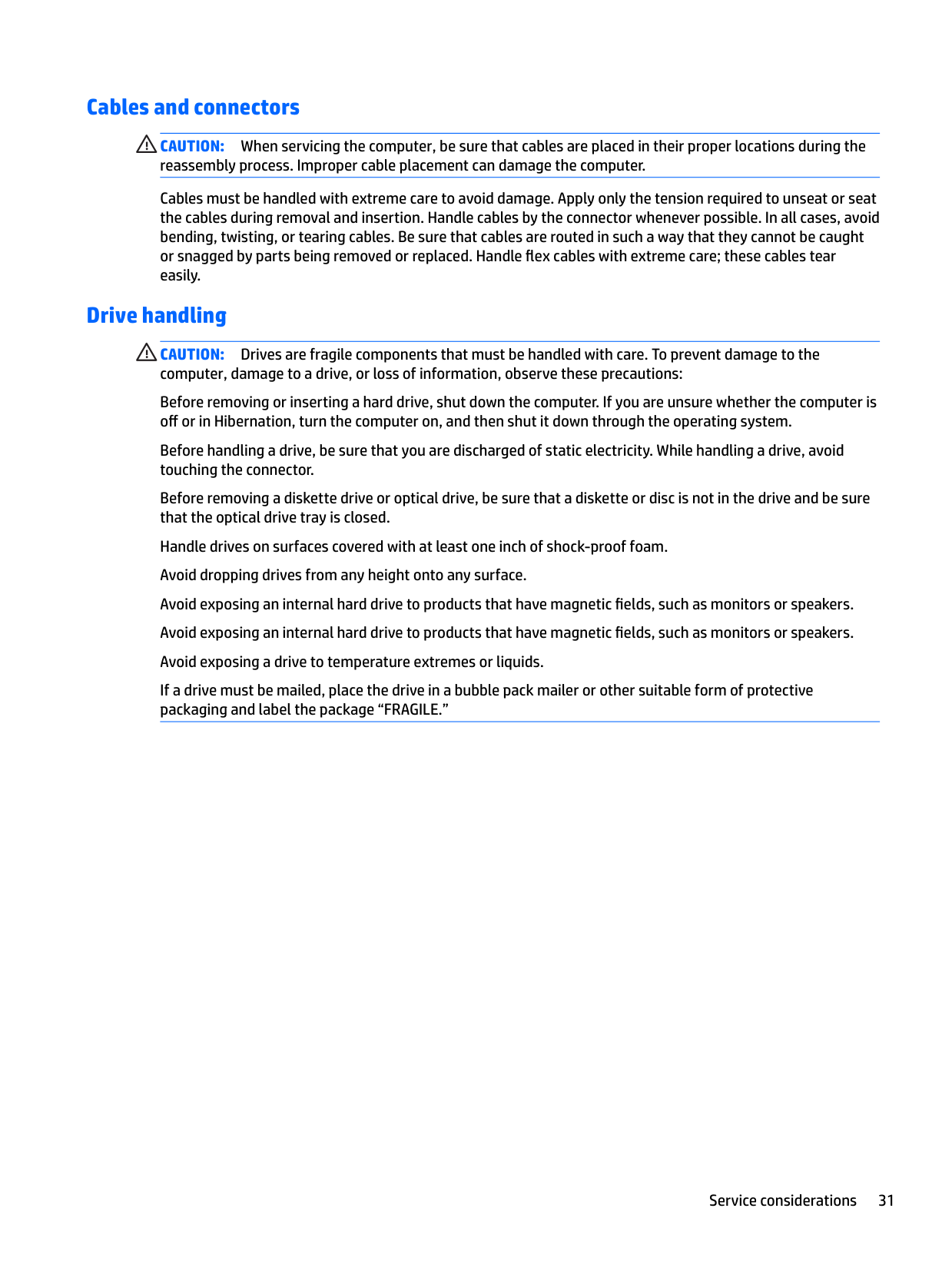
Power down. Unplug. Disconnect any external devices. Flip the laptop upside down on a soft surface (not glass — these have rubber feet that grip glass and you'll strip a screw). You'll need a Phillips #00 driver and a plastic pry tool or guitar pick.

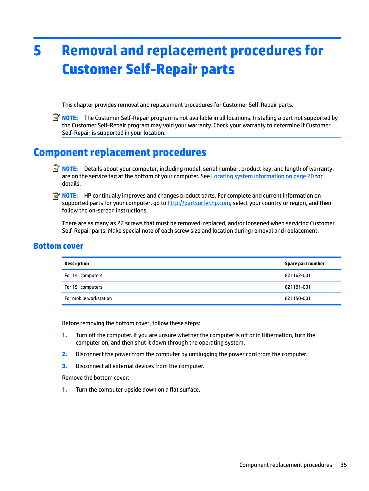
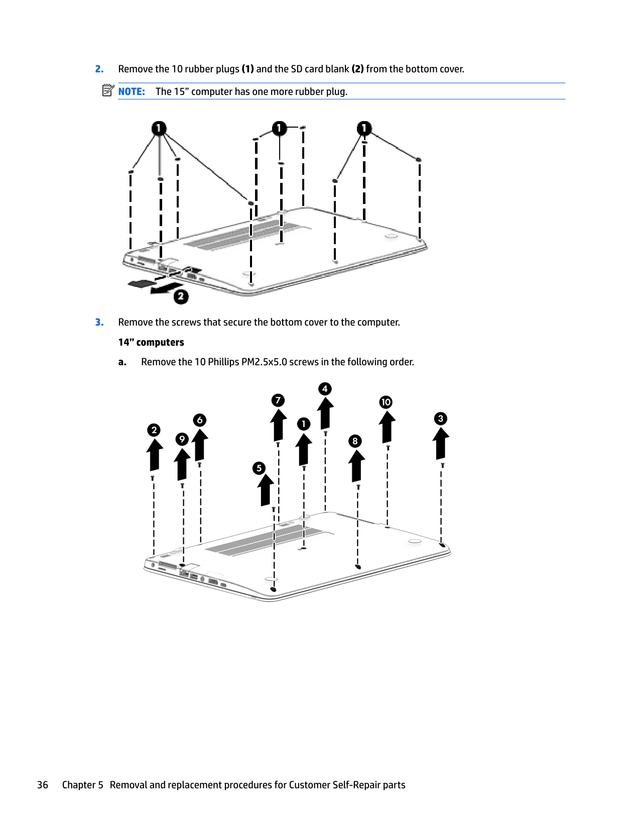
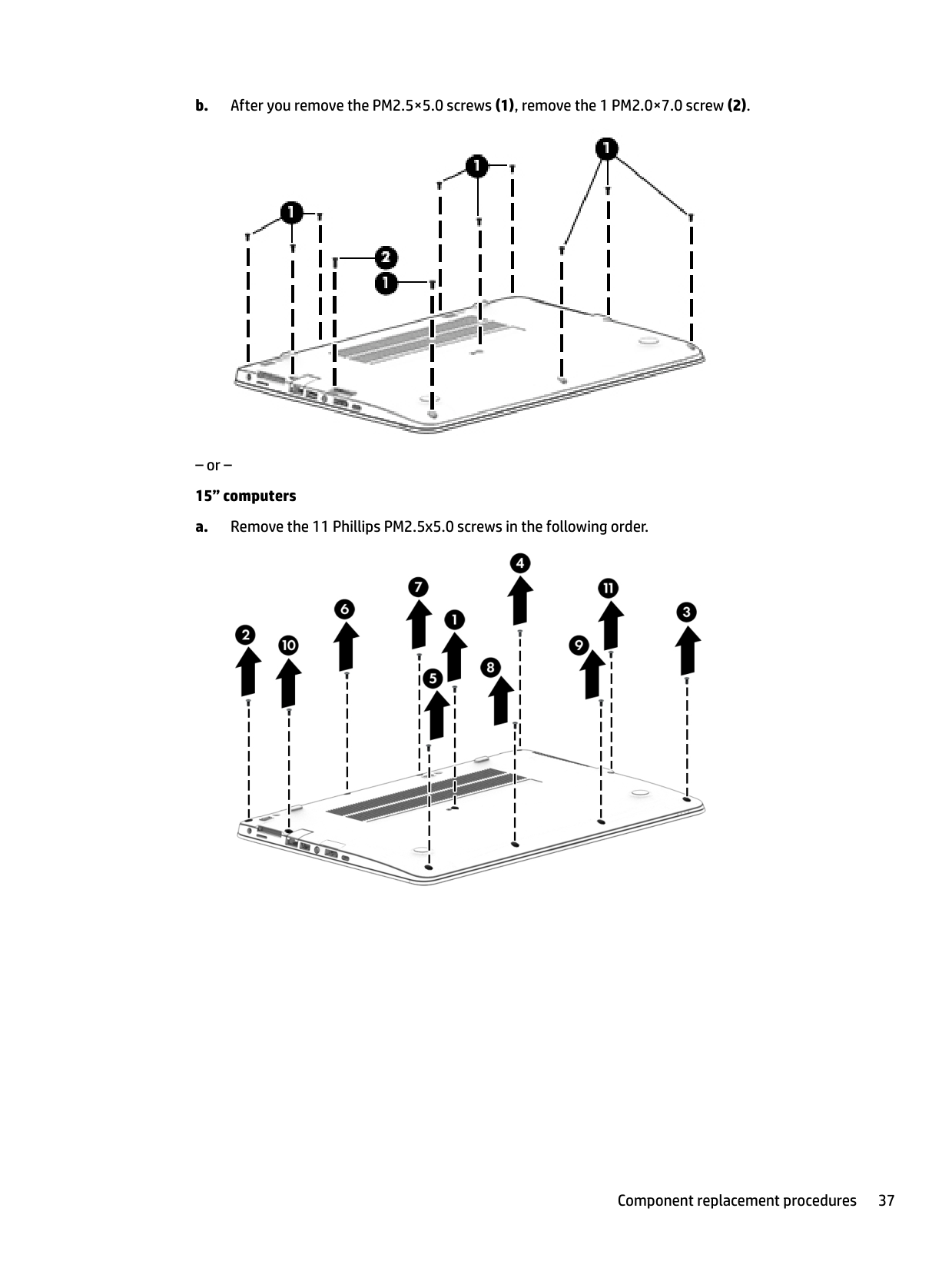
The bottom cover is held on by: - 10 rubber plugs along the edges, each hiding a Phillips screw underneath - An SD card blank in the slot (on SKUs that have one) — pop it out - A row of clips along the seam — no glue, just pressure

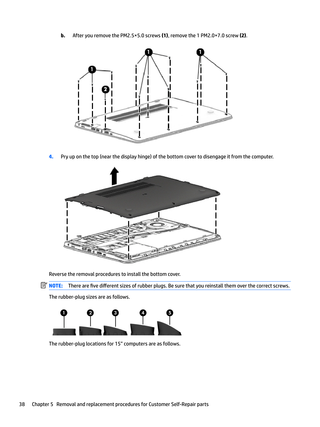
Lift along the back edge first. The front clips are the directional ones: when you reassemble, press the front edge in flat, then work toward the back. Reverse that order and the front clips bend.
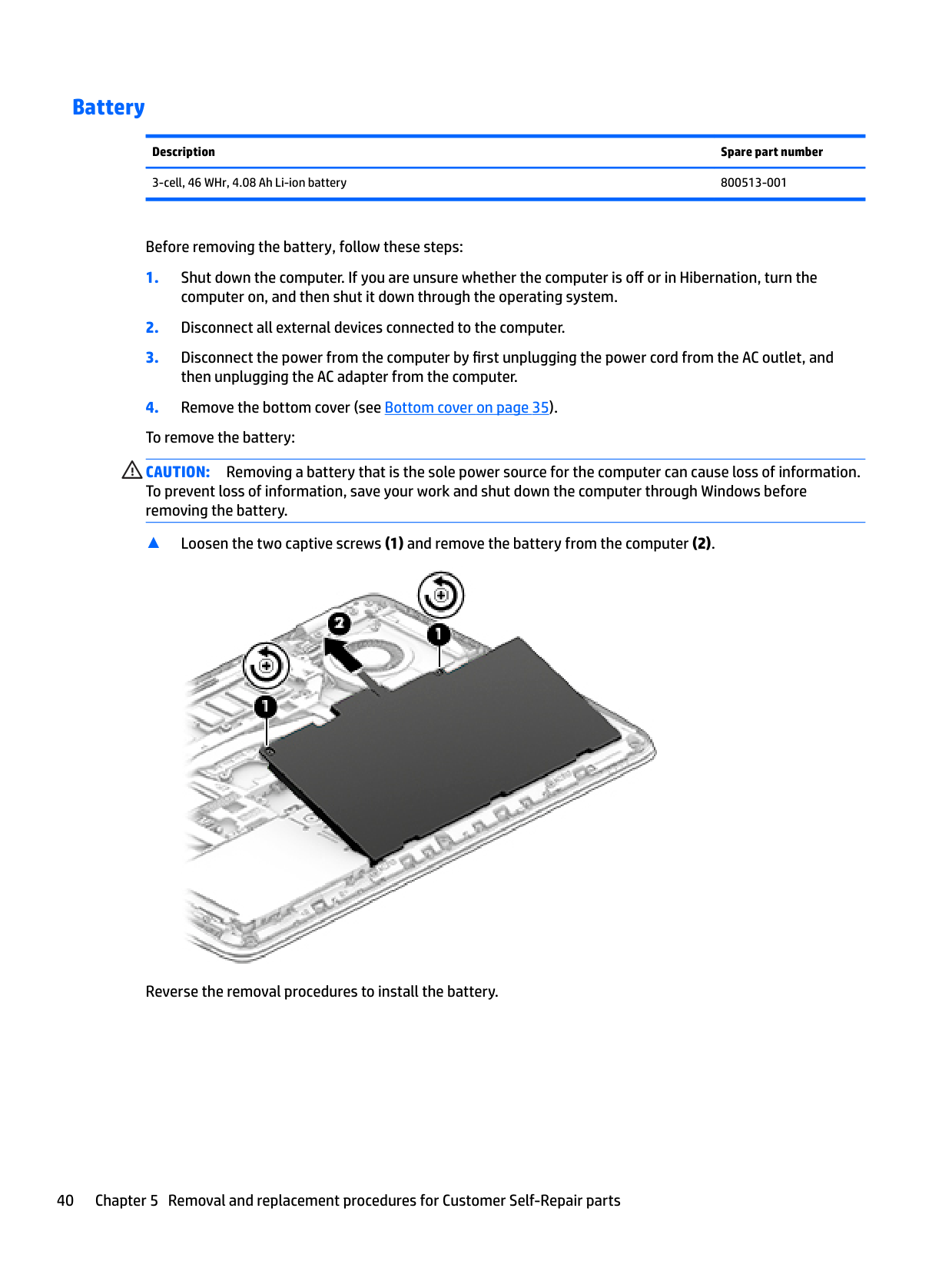
Battery

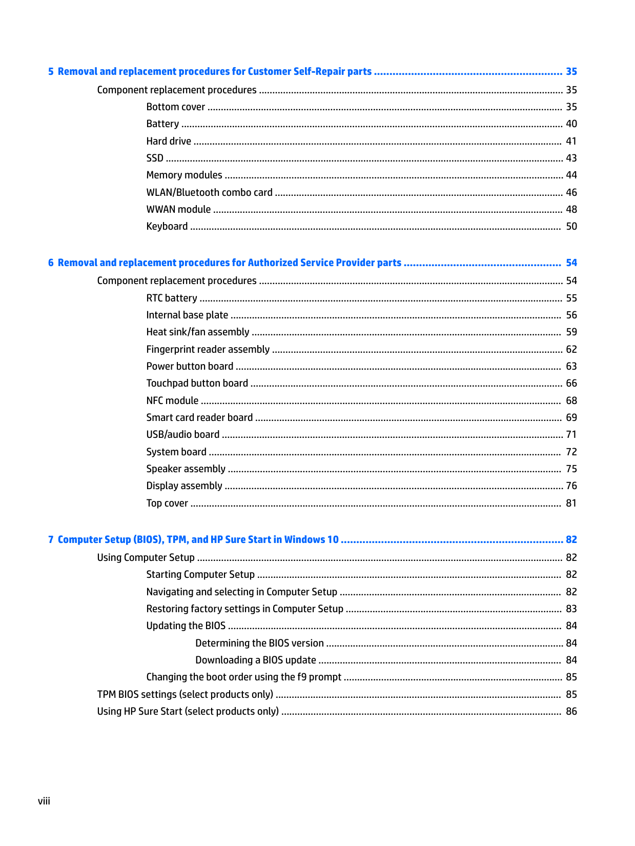
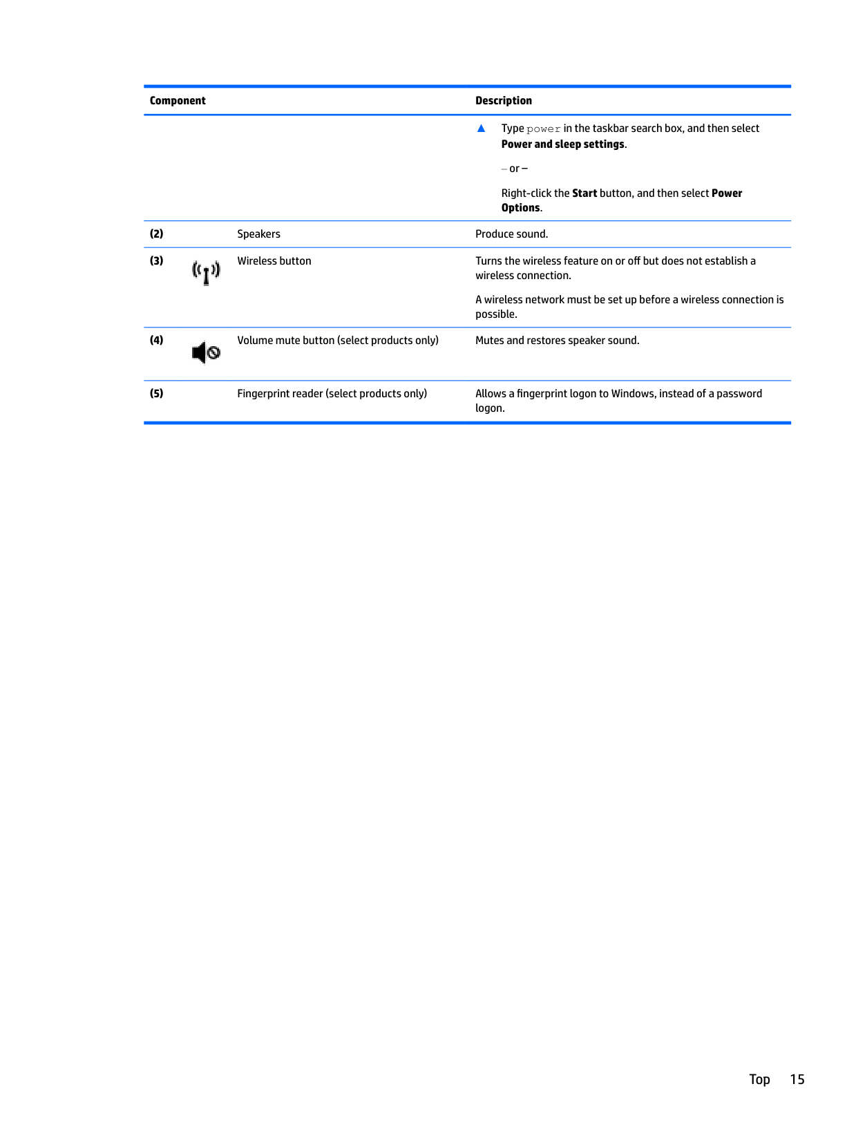
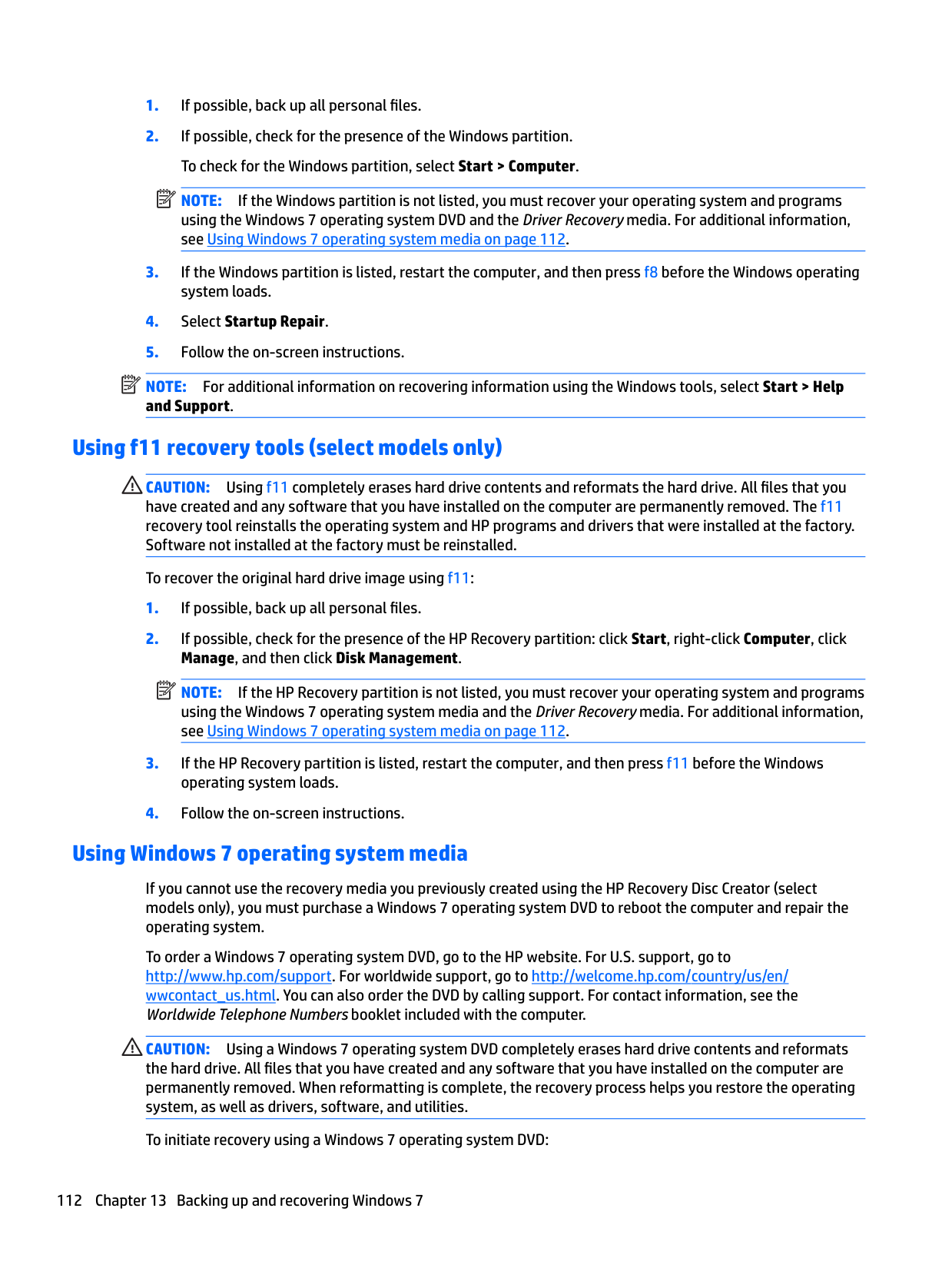
The battery sits in the center of the chassis. Release the latch (one finger, sliding mechanism), lift it out, drop the new one in, latch. That's it.

Soft-reset before you boot: with the battery removed and AC unplugged, hold the power button for 15 seconds. This drains residual capacitor charge and resolves "won't power on after a battery swap" cases. The manual mentions this. Most people skip it.

Calibration, after the new battery: charge to 100%, run on battery to 5%, charge back to 100%. Skip this and you'll see the battery percentage jump erratically for weeks until the BIOS gauge catches up.

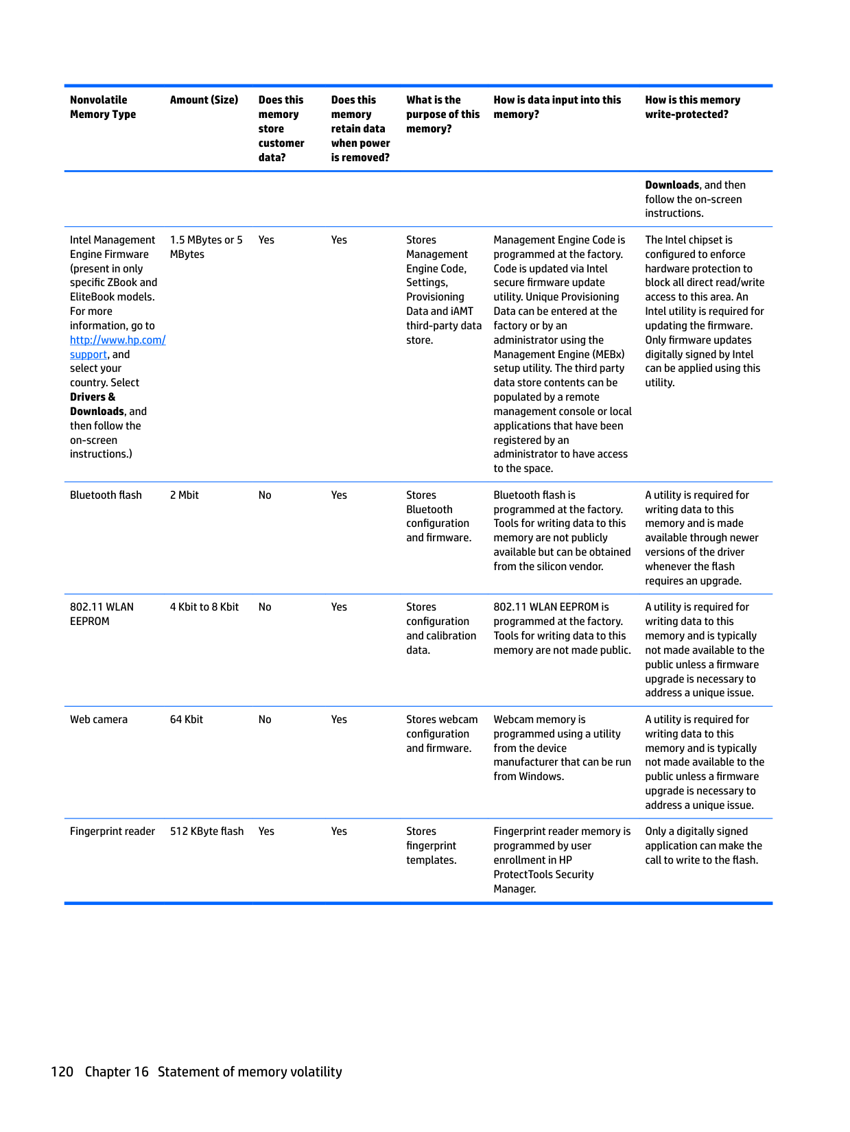
Source: page 40 of the maintenance manual
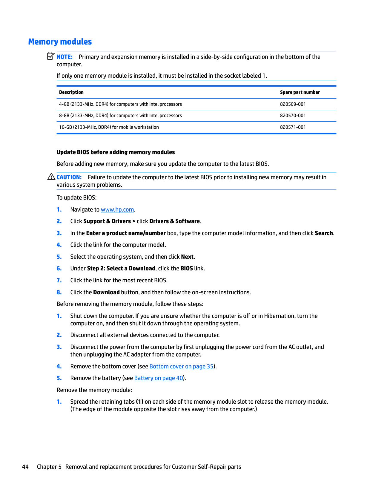
RAM

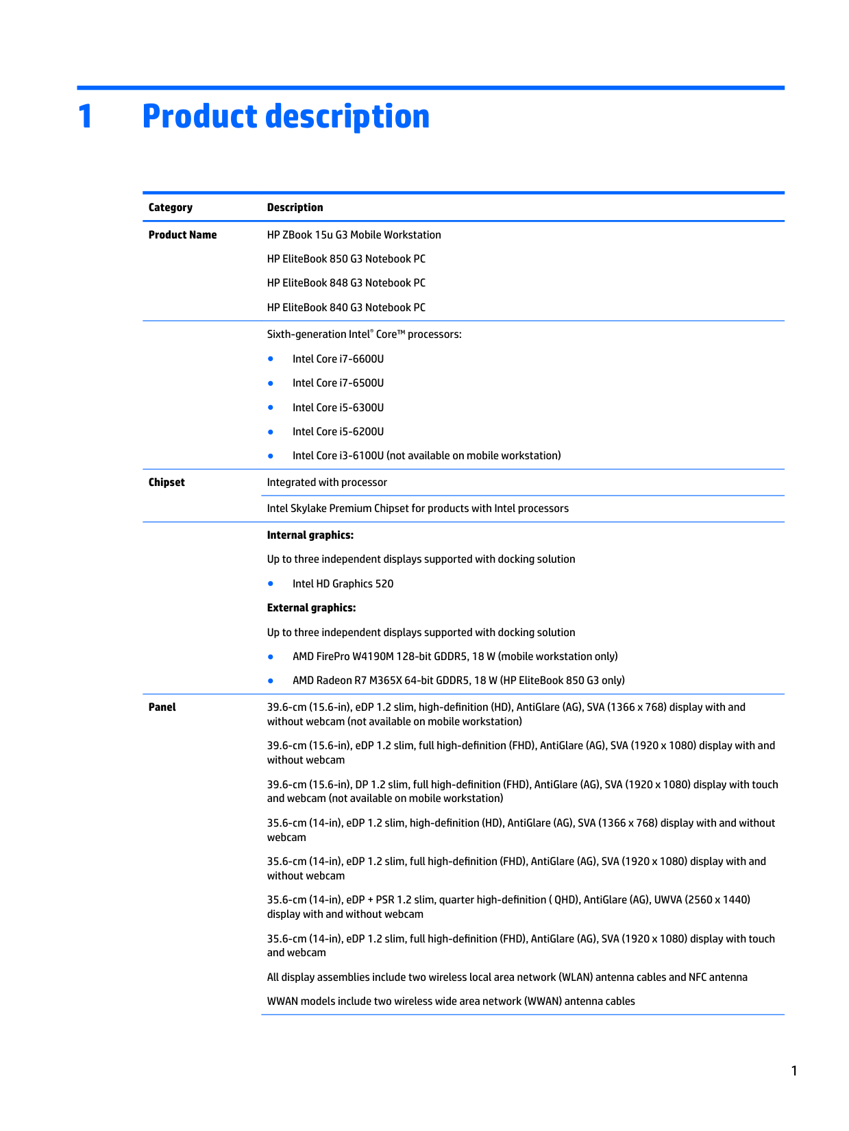
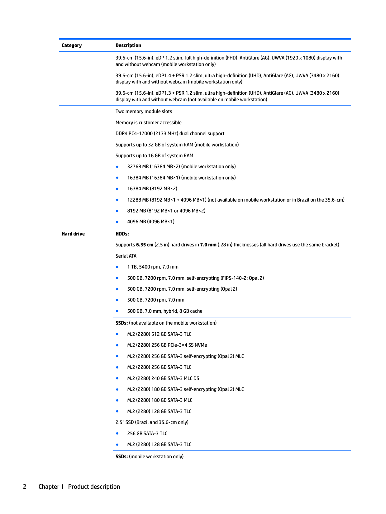
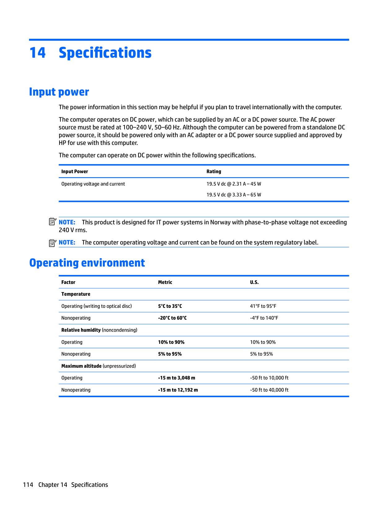
Two SO-DIMM slots, exposed once the bottom is off. They're DDR4. Maximum 16GB per slot, 32GB total.

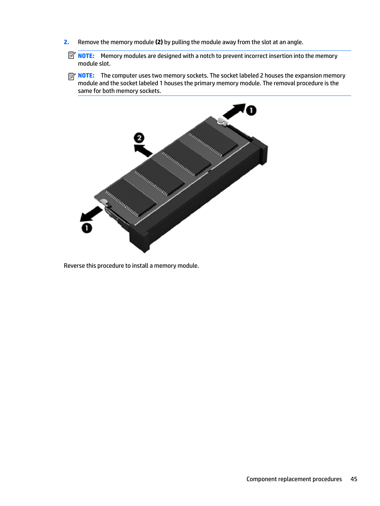
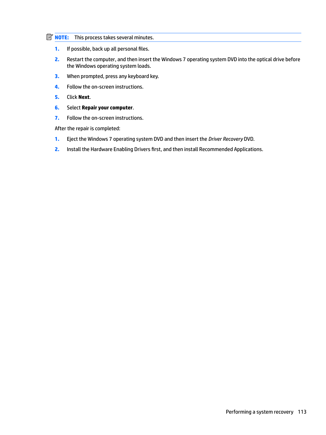
Push the retaining tabs outward on either side of the existing module. It pops up at about 30°. Pull straight out at that angle. Insert the new module the same way, push down until it clicks flat.

If you're upgrading both slots, do it as a matched pair (same speed, same capacity, same vendor if possible). Mismatched modules will boot, but the BIOS drops to the speed of the slower one.
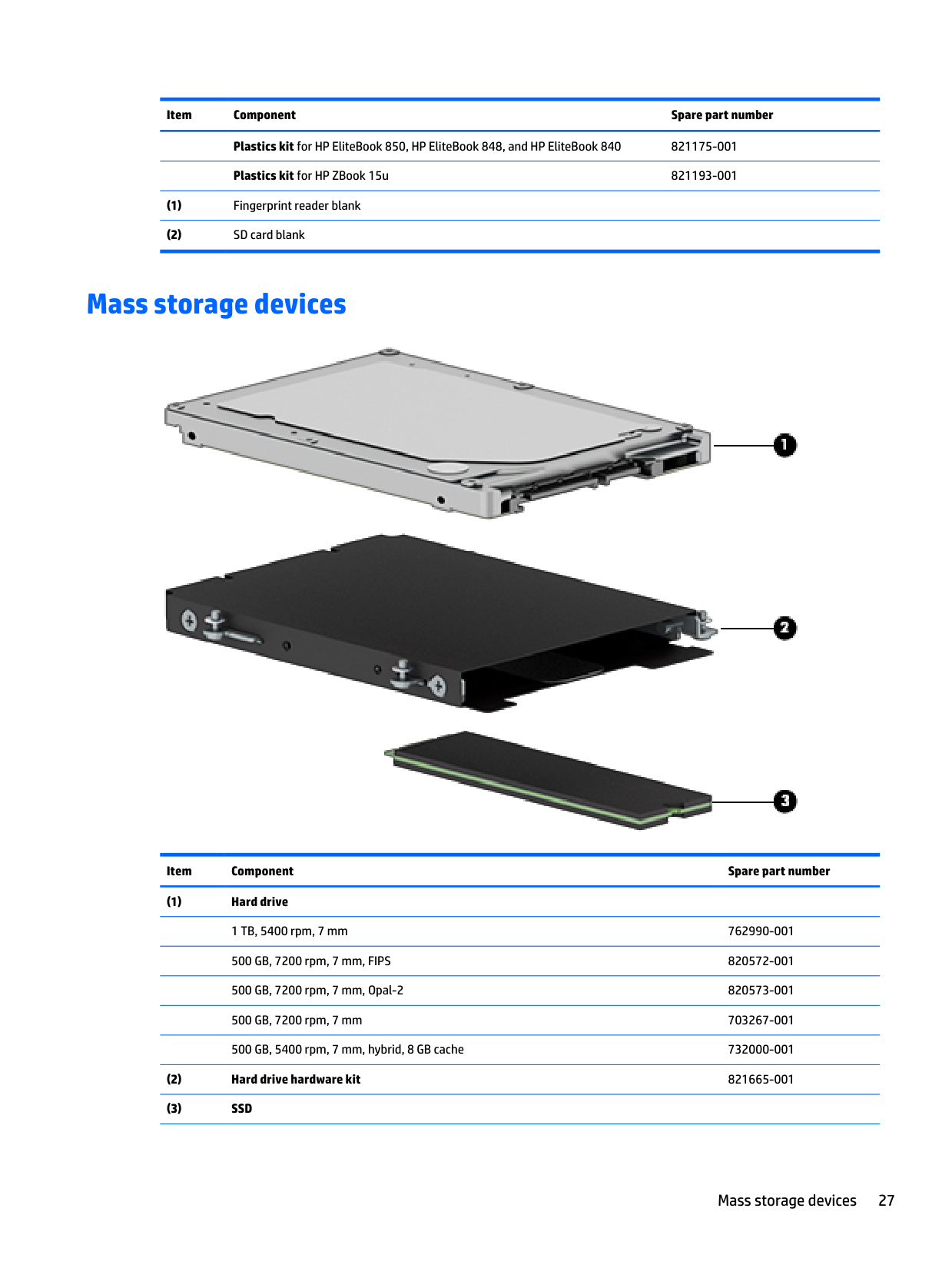
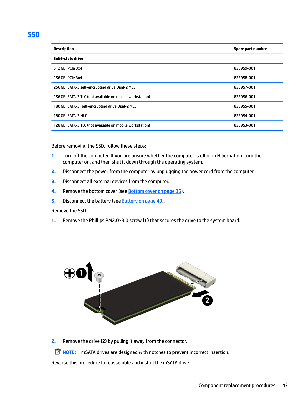
SSD

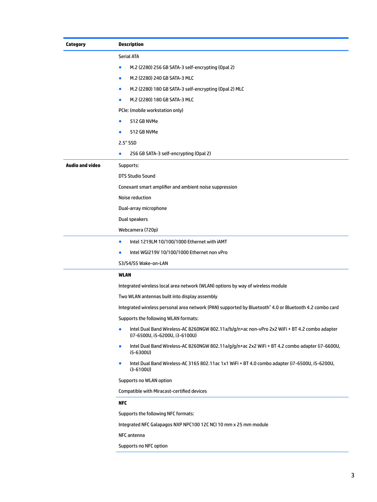
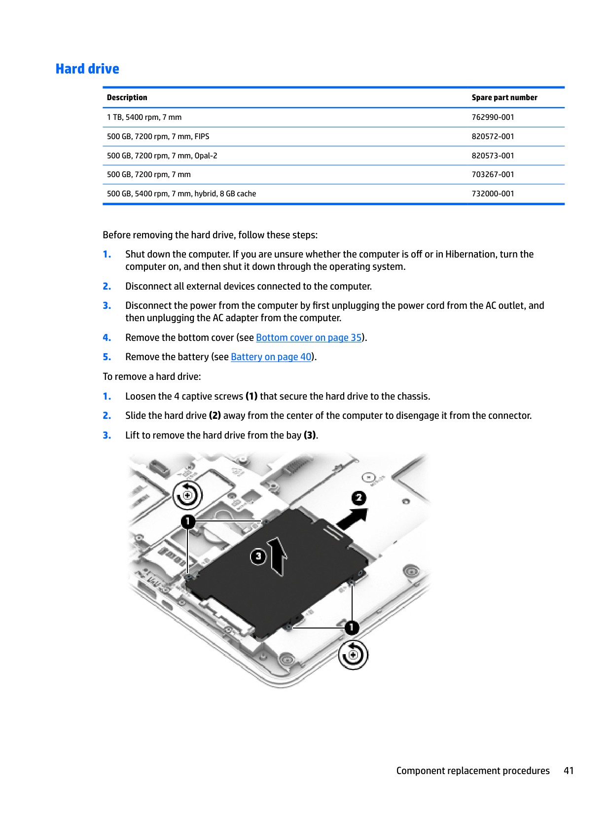
The M.2 slot is on the system board, not in the 2.5" bay. Some SKUs have both: M.2 boots, 2.5" SATA is bulk storage.

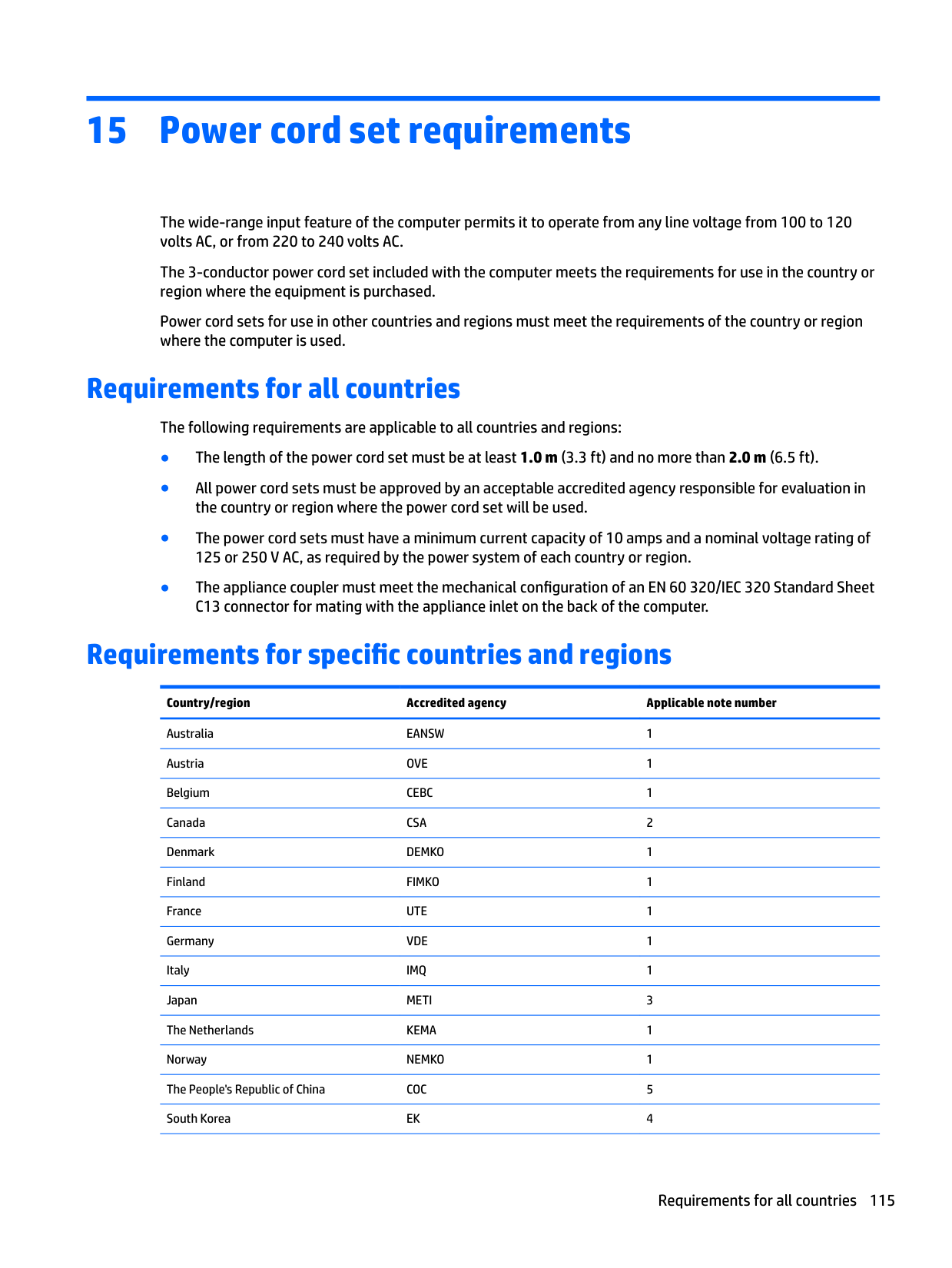
For the M.2: loosen the single retaining screw on the far end of the slot. The drive lifts at 30°. Pull it out at the same angle. Slide the new drive in at the same angle, push down, screw it back. The 840 G3's M.2 slot is sized for the standard 2280 (80mm) form factor — the screw mount is at the 80mm position. Shorter drives (2230, 2242) connect electrically but have nowhere to anchor, so 2280 is what to buy.

If your new SSD doesn't show up after install, three things to check before assuming the drive is bad: BIOS version (some older BIOS revisions don't recognize newer NVMe controllers — update via USB before installing the drive), Secure Boot setting (temporarily disable to test), and that you actually used a 2280 drive.
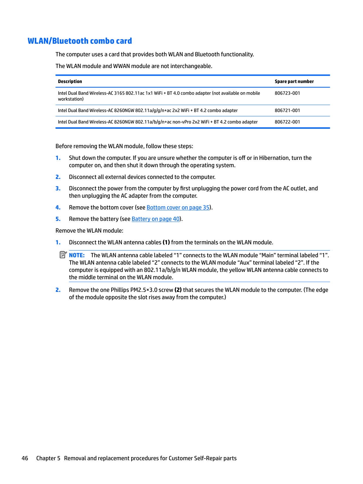
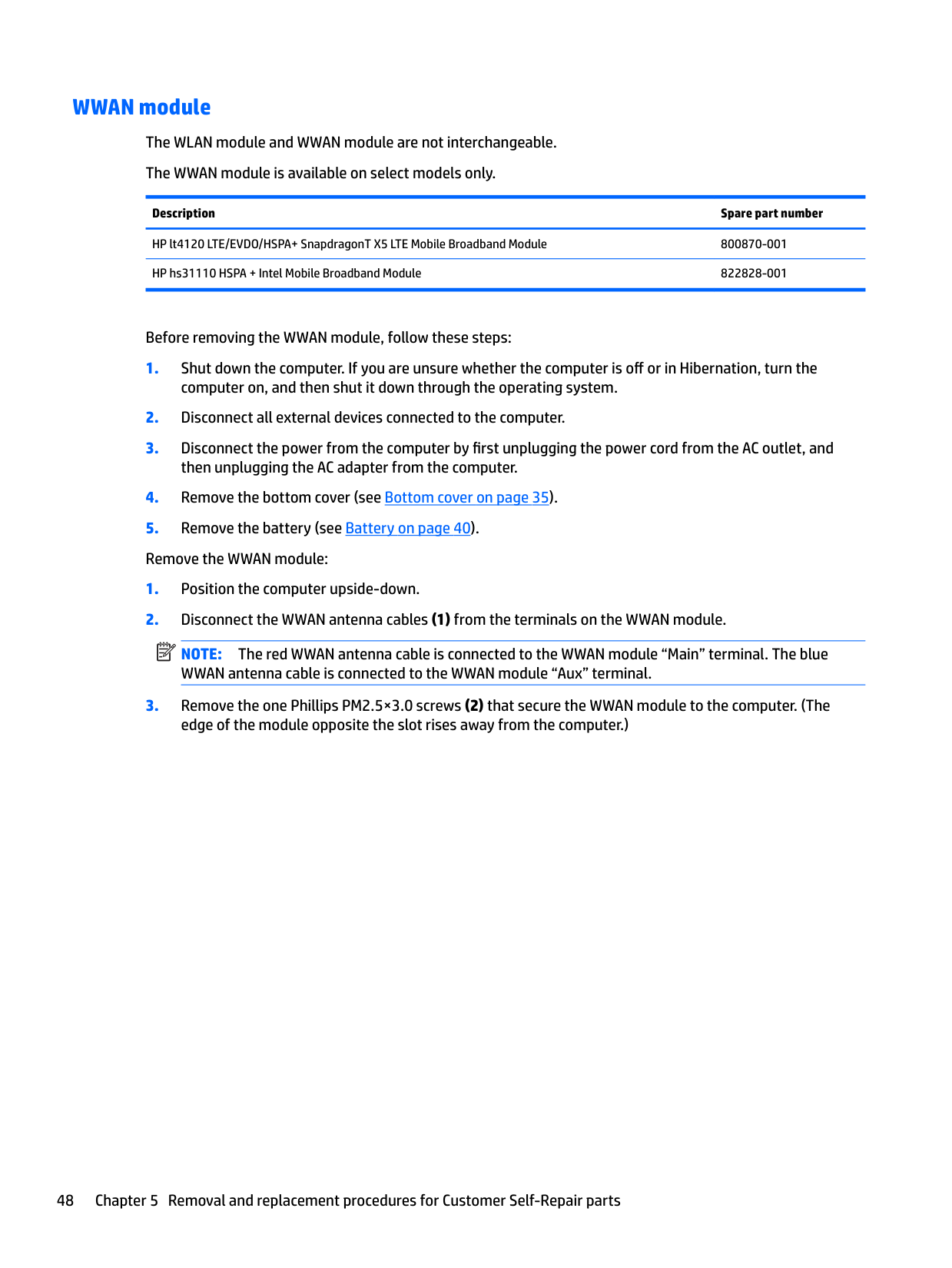
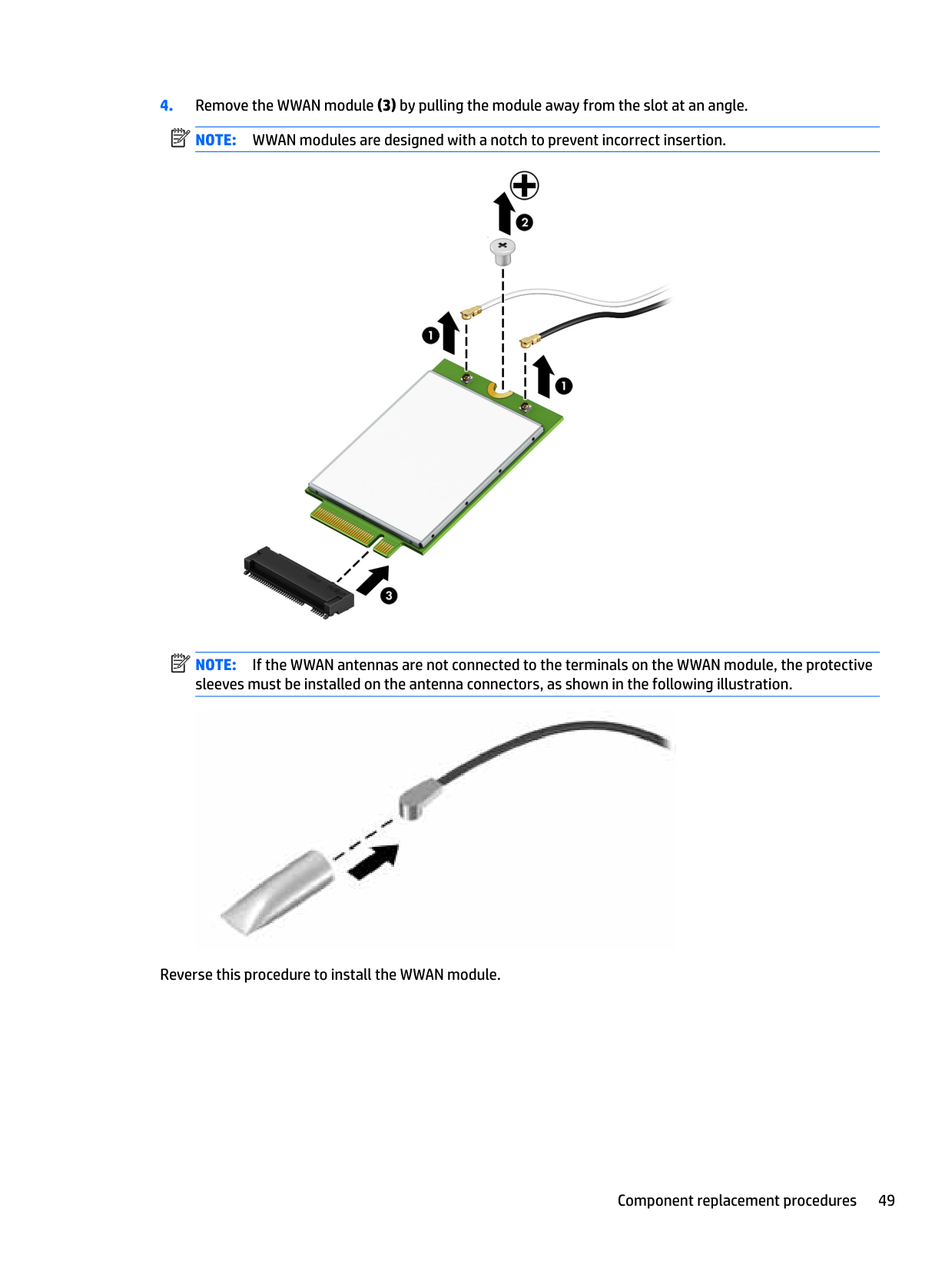
WLAN / WWAN modules

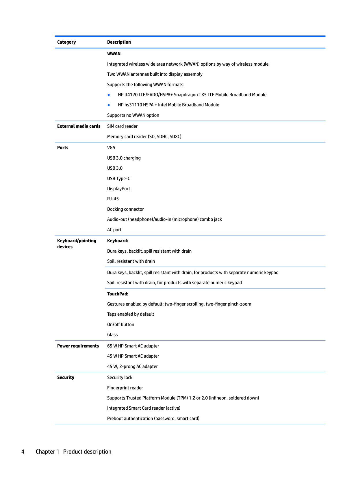
Both are mini-card modules on the system board, both replaceable independently. WLAN is your Wi-Fi/Bluetooth (combo card on most SKUs). WWAN is the cellular modem — only present if you ordered an LTE-enabled SKU.

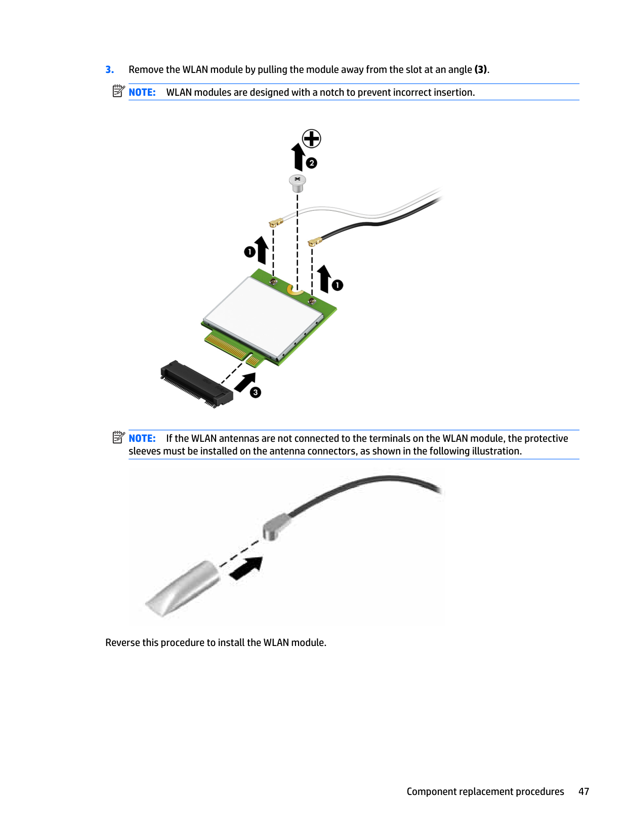
Each card has antenna cables that clip on and off. Before you disconnect them, note which color cable goes to which terminal. Standard convention is black to MAIN and white to AUX, but verify before pulling. Reverse the antennas on reassembly and the radio will work but with a 5-10 dB hit, which on edge-of-coverage cellular is the difference between getting data and not.

A single screw releases each card.

When you're done

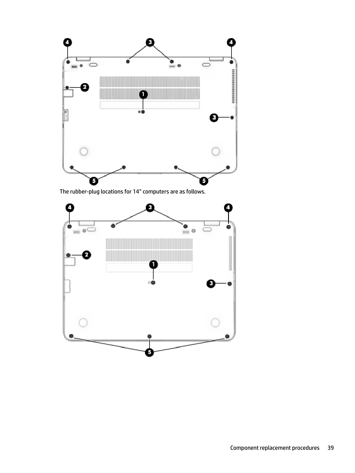
Reverse the order. Bottom cover front-edge first. Reinsert the rubber plugs (they're not interchangeable — try to put each back where it came from since the screw lengths vary). Battery in last.

Boot it. If something's wrong, the soft-reset (15 seconds with battery and AC out) is the first move, not the second. Then check Device Manager for whichever component you swapped.

When the issue isn't a part

Mid-life EliteBook 840 G3 system boards do fail. If a freshly-installed component (RAM, SSD) isn't detected after a BIOS update and re-seat, the system board is the suspect, not the part. HP Support can look up the part number for your specific SKU.

https://support.hp.com/us-en/product/details/hp-elitebook-840-g3-notebook-pc

Other models in the line

Full Manual

137 pages
Page 1

![image 1](c04887250_images/imageFile1.png)

HP ZBook 15u G3 Mobile Workstation HP EliteBook 850 G3 Notebook PC HP EliteBook 848 G3 Notebook PC HP EliteBook 840 G3 Notebook PC

Maintenance and Service Guide

© Copyright 2015, 2016 HP Development Company, L.P.

AMD and AMD Radeon are trademarks of Advanced Micro Devices, Inc. Bluetooth is a trademark owned by its proprietor and used by HP Inc. under license. Intel and Core are trademarks of Intel Corporation in the U.S. and other countries. Linux® is the registered trademark of Linus Torvalds in the U.S. and other countries. Microsoft and Windows are either registered trademarks or trademarks of Microsoft Corporation in the United States and/or other countries.

For DTS patents, see http://patents.dts.com. Manufactured under license from DTS Licensing Limited. DTS, the Symbol, & DTS and the Symbol together are registered trademarks, and DTS Studio Sound is a trademark of DTS, Inc. © DTS, Inc. All Rights

Reserved .

Product notice This guide describes features that are common to most models. Some features may not be available on your computer. Not all features are available in all editions of Windows 10 or Windows 8. This computer may require upgraded and/or separately purchased hardware, drivers and/or software to take full advantage of Windows 10 or Windows 8 functionality. See http://www.microsoft.com for details. The information contained herein is subject to change without notice. The only warranties for HP products and services are set forth in the express warranty statements accompanying such products and services. Nothing herein should be construed as constituting an additional warranty. HP shall not be liable for technical or editorial errors or omissions contained herein. Second Edition: March 2016 First Edition: October 2015 Document Part Number: 831002-002

#### Important Notice about Customer Self-Repair Parts

CAUTION: Your computer includes Customer Self-Repair parts and parts that should only be accessed by an authorized service provider. See Chapter 5, "Removal and replacement procedures for Customer Self-Repair parts," for details. Accessing parts described in Chapter 6, "Removal and replacement procedures for Authorized Service Provider only parts," can damage the computer or void your warranty.

iii

####### iv Important Notice about Customer Self-Repair Parts

#### Safety warning notice

WARNING! To reduce the possibility of heat-related injuries or of overheating the device, do not place the device directly on your lap or obstruct the device air vents. Use the device only on a hard, flat surface. Do not allow another hard surface, such as an adjoining optional printer, or a soft surface, such as pillows or rugs or clothing, to block airflow. Also, do not allow the AC adapter to contact the skin or a soft surface, such as pillows or rugs or clothing, during operation. The device and the AC adapter comply with the user-accessible surface temperature limits defined by the International Standard for Safety of Information Technology Equipment (IEC 60950-1).

Page 2

v

####### vi Safety warning notice

Table of contents

  • 1 Product description ....................................................................................................................................... 1
  • 2 External component identification .................................................................................................................. 7 Right ....................................................................................................................................................................... 7 Left ......................................................................................................................................................................... 9 Display ................................................................................................................................................................. 10 Top ........................................................................................................................................................................ 11
  • TouchPad ........................................................................................................................................... 11 Lights ................................................................................................................................................. 12 Buttons, speakers, and fingerprint reader ........................................................................................ 14 Keys ................................................................................................................................................... 16 Using the hot keys ............................................................................................................................. 17

    Bottom ................................................................................................................................................................. 19 Front ..................................................................................................................................................................... 20 Locating system information .............................................................................................................................. 20

  • 3 Illustrated parts catalog .............................................................................................................................. 22 Computer major components .............................................................................................................................. 22 Display assembly subcomponents ...................................................................................................................... 25 Plastics kit ............................................................................................................................................................ 26 Mass storage devices ........................................................................................................................................... 27 Miscellaneous parts ............................................................................................................................................. 28
  • 4 Removal and replacement procedures preliminary requirements .................................................................... 30 Tools required ...................................................................................................................................................... 30 Service considerations ......................................................................................................................................... 30
  • Plastic parts ....................................................................................................................................... 30 Cables and connectors ...................................................................................................................... 31 Drive handling ................................................................................................................................... 31

    Grounding guidelines ........................................................................................................................................... 32

    Electrostatic discharge damage ........................................................................................................ 32 Packaging and transporting guidelines .......................................................................... 33 Workstation guidelines ................................................................................................... 33 Equipment guidelines ..................................................................................................... 34

    vii

    ###### 5 Removal and replacement procedures for Customer Self-Repair parts ............................................................. 35Component replacement procedures .................................................................................................................. 35

    Page 3

    Bottom cover ..................................................................................................................................... 35 Battery ............................................................................................................................................... 40 Hard drive .......................................................................................................................................... 41 SSD ..................................................................................................................................................... 43 Memory modules ............................................................................................................................... 44 WLAN/Bluetooth combo card ............................................................................................................ 46 WWAN module ................................................................................................................................... 48 Keyboard ........................................................................................................................................... 50

    ###### 6 Removal and replacement procedures for Authorized Service Provider parts ................................................... 54Component replacement procedures .................................................................................................................. 54

    RTC battery ........................................................................................................................................ 55 Internal base plate ............................................................................................................................ 56 Heat sink/fan assembly .................................................................................................................... 59 Fingerprint reader assembly ............................................................................................................. 62 Power button board .......................................................................................................................... 63 Touchpad button board ..................................................................................................................... 66 NFC module ....................................................................................................................................... 68 Smart card reader board ................................................................................................................... 69 USB/audio board ................................................................................................................................ 71 System board .................................................................................................................................... 72 Speaker assembly ............................................................................................................................. 75 Display assembly ............................................................................................................................... 76 Top cover ........................................................................................................................................... 81

    ###### 7 Computer Setup (BIOS), TPM, and HP Sure Start in Windows 10 ........................................................................ 82Using Computer Setup ......................................................................................................................................... 82

    Starting Computer Setup .................................................................................................................. 82 Navigating and selecting in Computer Setup ................................................................................... 82 Restoring factory settings in Computer Setup ................................................................................. 83 Updating the BIOS ............................................................................................................................. 84

    Determining the BIOS version ......................................................................................... 84 Downloading a BIOS update ........................................................................................... 84

    Changing the boot order using the f9 prompt .................................................................................. 85 TPM BIOS settings (select products only) ........................................................................................................... 85 Using HP Sure Start (select products only) ......................................................................................................... 86

    viii

  • 8 Computer Setup (BIOS), TPM, and HP Sure Start in Windows 8 ......................................................................... 87 Using Computer Setup ......................................................................................................................................... 87
  • Starting Computer Setup .................................................................................................................. 87 Navigating and selecting in Computer Setup ................................................................................... 87 Restoring factory settings in Computer Setup ................................................................................. 88 Updating the BIOS ............................................................................................................................. 89

    Determining the BIOS version ......................................................................................... 89 Downloading a BIOS update ........................................................................................... 89

    Changing the boot order using the f9 prompt .................................................................................. 90 TPM BIOS settings (select products only) ........................................................................................................... 90 Using HP Sure Start (select products only) ......................................................................................................... 91

  • 9 Computer Setup (BIOS), TPM, and HP Sure Start in Windows 7 ......................................................................... 92 Using Computer Setup ......................................................................................................................................... 92
  • Page 4

    Starting Computer Setup .................................................................................................................. 92 Navigating and selecting in Computer Setup ................................................................................... 92 Restoring factory settings in Computer Setup ................................................................................. 93 Updating the BIOS ............................................................................................................................. 94

    Determining the BIOS version ......................................................................................... 94 Downloading a BIOS update ........................................................................................... 94

    Changing the boot order using the f9 prompt .................................................................................. 95 TPM BIOS settings (select products only) ........................................................................................................... 95 Using HP Sure Start (select products only) ......................................................................................................... 96

  • 10 HP PC Hardware Diagnostics (UEFI) .............................................................................................................. 97 Downloading HP PC Hardware Diagnostics (UEFI) to a USB device .................................................................... 97
  • 11 Backing up and recovering Windows 10 ....................................................................................................... 99 Creating recovery media and backups ................................................................................................................ 99
  • Creating HP Recovery media (select products only) ......................................................................... 99 Using Windows tools ......................................................................................................................................... 100 Restore and recovery ......................................................................................................................................... 101

    Recovering using HP Recovery Manager ........................................................................................ 101 What you need to know before you get started ........................................................... 101 Using the HP Recovery partition (select products only) .............................................. 102 Using HP Recovery media to recover ............................................................................ 102 Changing the computer boot order .............................................................................. 103 Removing the HP Recovery partition (select products only) ....................................... 104

    ix

  • 12 Backing up and recovering Windows 8 ....................................................................................................... 105 Backing up your information ............................................................................................................................. 105 Performing a system recovery .......................................................................................................................... 105
  • Using the Windows recovery tools .................................................................................................. 105 Using f11 recovery tools ................................................................................................................. 106 Using Windows operating system media (purchased separately) ................................................. 107 Using Windows Refresh or Windows Reset .................................................................................... 108 Using HP Software Setup ................................................................................................................ 108

  • 13 Backing up and recovering Windows 7 ....................................................................................................... 109 Creating recovery media and backups .............................................................................................................. 109
  • Guidelines ........................................................................................................................................ 109 Creating recovery media with HP Recovery Disc Creator ............................................................... 109

    Creating recovery media ............................................................................................... 110 Backing up your information .......................................................................................................... 110

    Performing a system recovery .......................................................................................................................... 111 Using the Windows recovery tools .................................................................................................. 111 Using f11 recovery tools (select models only) ............................................................................... 112 Using Windows 7 operating system media ..................................................................................... 112

    Page 5

  • 14 Specifications .......................................................................................................................................... 114 Input power ........................................................................................................................................................ 114 Operating environment ..................................................................................................................................... 114
  • 15 Power cord set requirements .................................................................................................................... 115 Requirements for all countries .......................................................................................................................... 115 Requirements for specific countries and regions ............................................................................................. 115
  • 16 Statement of memory volatility ................................................................................................................ 117 Nonvolatile memory usage ............................................................................................................................... 119 Questions and answers ..................................................................................................................................... 121 Using HP Sure Start (select models only) .......................................................................................................... 122
  • 17 Recycling ................................................................................................................................................ 123
  • ###### Index ........................................................................................................................................................... 124

    x

    1 Product description

    Category Description Product Name HP ZBook 15u G3 Mobile Workstation

    HP EliteBook 850 G3 Notebook PC HP EliteBook 848 G3 Notebook PC HP EliteBook 840 G3 Notebook PC Sixth-generation Intel® Core™ processors:

  • ● Intel Core i7-6600U
  • ● Intel Core i7-6500U
  • ● Intel Core i5-6300U
  • ● Intel Core i5-6200U
  • ● Intel Core i3-6100U (not available on mobile workstation)
  • Chipset Integrated with processor Intel Skylake Premium Chipset for products with Intel processors Internal graphics: Up to three independent displays supported with docking solution

  • ● Intel HD Graphics 520 External graphics: Up to three independent displays supported with docking solution
  • Page 6

  • ● AMD FirePro W4190M 128-bit GDDR5, 18 W (mobile workstation only)
  • ● AMD Radeon R7 M365X 64-bit GDDR5, 18 W (HP EliteBook 850 G3 only)
  • Panel 39.6-cm (15.6-in), eDP 1.2 slim, high-definition (HD), AntiGlare (AG), SVA (1366 x 768) display with and without webcam (not available on mobile workstation) 39.6-cm (15.6-in), eDP 1.2 slim, full high-definition (FHD), AntiGlare (AG), SVA (1920 x 1080) display with and without webcam 39.6-cm (15.6-in), DP 1.2 slim, full high-definition (FHD), AntiGlare (AG), SVA (1920 x 1080) display with touch and webcam (not available on mobile workstation) 35.6-cm (14-in), eDP 1.2 slim, high-definition (HD), AntiGlare (AG), SVA (1366 x 768) display with and without webcam 35.6-cm (14-in), eDP 1.2 slim, full high-definition (FHD), AntiGlare (AG), SVA (1920 x 1080) display with and without webcam 35.6-cm (14-in), eDP + PSR 1.2 slim, quarter high-definition ( QHD), AntiGlare (AG), UWVA (2560 x 1440) display with and without webcam 35.6-cm (14-in), eDP 1.2 slim, full high-definition (FHD), AntiGlare (AG), SVA (1920 x 1080) display with touch and webcam All display assemblies include two wireless local area network (WLAN) antenna cables and NFC antenna WWAN models include two wireless wide area network (WWAN) antenna cables

    39.6-cm (15.6-in), eDP 1.2 slim, full high-definition (FHD), AntiGlare (AG), UWVA (1920 x 1080) display with and without webcam (mobile workstation only)

    39.6-cm (15.6-in), eDP1.4 + PSR 1.2 slim, ultra high-definition (UHD), AntiGlare (AG), UWVA (3480 x 2160) display with and without webcam (mobile workstation only)

    39.6-cm (15.6-in), eDP1.3 + PSR 1.2 slim, ultra high-definition (UHD), AntiGlare (AG), UWVA (3480 x 2160) display with and without webcam (not available on mobile workstation)

    Two memory module slots Memory is customer accessible. DDR4 PC4-17000 (2133 MHz) dual channel support Supports up to 32 GB of system RAM (mobile workstation) Supports up to 16 GB of system RAM

  • ● 32768 MB (16384 MB×2) (mobile workstation only)
  • ● 16384 MB (16384 MB×1) (mobile workstation only)
  • ● 16384 MB (8192 MB×2)
  • ● 12288 MB (8192 MB×1 + 4096 MB×1) (not available on mobile workstation or in Brazil on the 35.6-cm)
  • ● 8192 MB (8192 MB×1 or 4096 MB×2)
  • ● 4096 MB (4096 MB×1)
  • Hard drive HDDs: Supports 6.35 cm (2.5 in) hard drives in 7.0 mm (.28 in) thicknesses (all hard drives use the same bracket) Serial ATA

  • ● 1 TB, 5400 rpm, 7.0 mm
  • ● 500 GB, 7200 rpm, 7.0 mm, self-encrypting (FIPS-140-2; Opal 2)
  • ● 500 GB, 7200 rpm, 7.0 mm, self-encrypting (Opal 2)
  • Page 7

  • ● 500 GB, 7200 rpm, 7.0 mm
  • ● 500 GB, 7.0 mm, hybrid, 8 GB cache SSDs: (not available on the mobile workstation)
  • ● M.2 (2280) 512 GB SATA-3 TLC
  • ● M.2 (2280) 256 GB PCIe-3×4 SS NVMe
  • ● M.2 (2280) 256 GB SATA-3 self-encrypting (Opal 2) MLC
  • ● M.2 (2280) 256 GB SATA-3 TLC
  • ● M.2 (2280) 240 GB SATA-3 MLC DS
  • ● M.2 (2280) 180 GB SATA-3 self-encrypting (Opal 2) MLC
  • ● M.2 (2280) 180 GB SATA-3 MLC
  • ● M.2 (2280) 128 GB SATA-3 TLC 2.5” SSD (Brazil and 35.6-cm only)
  • ● 256 GB SATA-3 TLC
  • ● M.2 (2280) 128 GB SATA-3 TLC SSDs: (mobile workstation only)
  • Serial ATA
  • ● M.2 (2280) 256 GB SATA-3 self-encrypting (Opal 2)
  • ● M.2 (2280) 240 GB SATA-3 MLC
  • ● M.2 (2280) 180 GB SATA-3 self-encrypting (Opal 2) MLC
  • ● M.2 (2280) 180 GB SATA-3 MLC PCIe: (mobile workstation only)
  • ● 512 GB NVMe
  • ● 512 GB NVMe 2.5” SSD
  • ● 256 GB SATA-3 self-encrypting (Opal 2)
  • Audio and video Supports: DTS Studio Sound Conexant smart amplifier and ambient noise suppression Noise reduction Dual-array microphone Dual speakers Webcamera (720p)

  • ● Intel 1219LM 10/100/1000 Ethernet with iAMT
  • Page 8

  • ● Intel WGI219V 10/100/1000 Ethernet non vPro S3/S4/S5 Wake-on-LAN WLAN Integrated wireless local area network (WLAN) options by way of wireless module Two WLAN antennas built into display assembly Integrated wireless personal area network (PAN) supported by Bluetooth® 4.0 or Bluetooth 4.2 combo card Supports the following WLAN formats:
  • ● Intel Dual Band Wireless-AC 8260NGW 802.11a/b/g/n+ac non-vPro 2x2 WiFi + BT 4.2 combo adapter (i7-6500U, i5-6200U, i3-6100U)
  • ● Intel Dual Band Wireless-AC 8260NGW 802.11a/g/g/n+ac 2x2 WiFi + BT 4.2 combo adapter (i7-6600U, i5-6300U)
  • ● Intel Dual Band Wireless-AC 3165 802.11ac 1x1 WiFi + BT 4.0 combo adapter (i7-6500U, i5-6200U, i3-6100U)
  • Supports no WLAN option Compatible with Miracast-certified devices NFC Supports the following NFC formats: Integrated NFC Galapagos NXP NPC100 12C NCI 10 mm x 25 mm module NFC antenna Supports no NFC option

    WWAN Integrated wireless wide area network (WWAN) options by way of wireless module Two WWAN antennas built into display assembly Supports the following WWAN formats:

  • ● HP lt4120 LTE/EVDO/HSPA+ SnapdragonT X5 LTE Mobile Broadband Module
  • ● HP hs31110 HSPA + Intel Mobile Broadband Module Supports no WWAN option
  • ######## External media cards SIM card reader

    Memory card reader (SD, SDHC, SDXC)

    Ports VGA USB 3.0 charging USB 3.0 USB Type-C DisplayPort RJ-45 Docking connector Audio-out (headphone)/audio-in (microphone) combo jack AC port

    Keyboard/pointing devices

    Keyboard: Dura keys, backlit, spill resistant with drain Spill resistant with drain Dura keys, backlit, spill resistant with drain, for products with separate numeric keypad Spill resistant with drain, for products with separate numeric keypad TouchPad: Gestures enabled by default: two-finger scrolling, two-finger pinch-zoom Taps enabled by default On/off button Glass

    Power requirements 65 W HP Smart AC adapter 45 W HP Smart AC adapter 45 W, 2-prong AC adapter

    Security Security lock Fingerprint reader Supports Trusted Platform Module (TPM) 1.2 or 2.0 (Infineon, soldered down) Integrated Smart Card reader (active) Preboot authentication (password, smart card)

    Page 9

    ######## Operating system Preinstalled:

  • ● Windows® 7 Professional 64-bit
  • ● Windows 10 Home 64 Chinese Market (CPPP)
  • ● Windows 10 Home 64 High-end
  • ● Windows 10 Home 64 High-end Single Language
  • ● Windows 10 Home 64 High-end Chinese Market
  • ● Windows 10 Professional 64
  • ● Windows 10 Professional 64 with downgrade to Windows 7 64-bit
  • ● FreeDOS 2.0 (Not available preinstalled on mobile workstation)
  • ● Windows 7 Professional 32-bit
  • ● Windows 8.1 China 64 (CPPP)
  • ● Windows 8.1 High-end Emerging Markets 64
  • ● Windows 8.1 Emerging Markets 64
  • ● Windows 8.1 High-end Multilingual 64
  • ● Windows 8.1 Multilingual 64
  • ● Windows 8.1 Professional 64
  • ● Windows 8.1 Core for Higher Education (Multilingual)
  • ● Windows 10 Home 64
  • ● Windows 10 Home 64 Single Language
  • ● Windows 10 Home 64 Chinese Market
  • ● Windows 10 Professional 64 with downgrade to Windows 7 32-bit
  • ● NeoKylin Linux 64 (not available on mobile workstation) Restore Media–DR/SR-DVD
  • ● Windows 8.1
  • ● NeoKylin Linux Restore Media–OS-DVD
  • ● Windows 8.1 Professional 64-bit
  • Page 10

  • ● Windows 8.1 64-bit
  • ● Windows 8.1 Country Specific 64-bit
  • ● Windows 8.1 Emerging Market 64-bit
  • ● Windows 7 Professional 32-bit Certified
  • ● Microsoft WHQL Web-only support
  • ● Windows 10 Enterprise
  • ● Windows 8.1 Enterprise
  • ● Windows 7 Enterprise 64- and 32-bit (mobile workstation only)
  • ● Windows 8.1 Emerging Markets 64
  • ● Windows 8.1 Multilingual 64
  • ● Windows 8.1 Professional 64
  • ● Windows 8.1 China 64
  • ● Windows 7 Professional 32-bit
  • Serviceability End user replaceable parts: AC adapter Battery Hard drive SSD Memory module WLAN WWAN Keyboard

    2 External component identification

    Right

    ![image 2](c04887250_images/imageFile2.png)

    ######## Component Description

    Page 11

  • (1) USB Type-C (charging) port Connects any USB device with a Type-C connector.
  • ![image 3](c04887250_images/imageFile3.png)

    NOTE: USB Type-C ports charge products such as cell phones, laptops, tablets, and MP3 players, even when the computer is off. Also, some USB Type-C ports connect DisplayPort, VGA, HDMI and other video devices to provide video output.

    NOTE: Adapters (purchased separately) may be required.

  • (2) Dual-Mode DisplayPort Connects an optional digital display device, such as a highperformance monitor or projector.
  • ![image 4](c04887250_images/imageFile4.png)

  • (3) Memory card reader Reads optional memory cards that store, manage, share, or access information.
  • ![image 5](c04887250_images/imageFile5.png)

  • (4) Audio-out (headphone)/Audio-in (microphone) combo jack
  • ![image 6](c04887250_images/imageFile6.png)

    Connects optional powered stereo speakers, headphones, earbuds, a headset, or a television audio cable. Also connects an optional headset microphone. This jack does not support optional microphone-only devices.

    WARNING! To reduce the risk of personal injury, adjust the volume before putting on headphones, earbuds, or a headset. For additional safety information, refer to the Regulatory, Safety, and Environmental Notices.

    To access this guide: Windows 10: Select the Start button, select All apps, select HP Help and Support, and then select HP Documentation. Windows 8 or Windows 7: Select the HP Support Assistant app on the Start screen, select My computer, and then select User guides. NOTE: When a device is connected to the jack, the computer speakers are disabled.

  • (5) USB 3.0 port Connects an optional USB device, such as a keyboard, mouse, external drive, printer, scanner or USB hub.
  • Page 12

    ![image 7](c04887250_images/imageFile7.png)

    Right 7

    ######## Component Description

  • (6) RJ-45 (network) jack/status lights Connects a network cable.
  • ![image 8](c04887250_images/imageFile8.png)

  • ● Green (left): The network is connected.
  • ● Amber (right): Activity is occurring on the network.
  • (7) Docking connector Connects an optional docking device.
  • (8) SIM card slot Supports a wireless subscriber identity module (SIM) card.
  • ![image 9](c04887250_images/imageFile9.png)

  • (9) Power connector Connects an AC adapter.
  • ![image 10](c04887250_images/imageFile10.png)

    Left

    Page 13

    ![image 11](c04887250_images/imageFile11.png)

    ######## Component Description

  • (1) Security cable slot Attaches an optional security cable to the computer.
  • ![image 12](c04887250_images/imageFile12.png)

    NOTE: The security cable is designed to act as a deterrent, but it may not prevent the computer from being mishandled or stolen.

  • (2) Vents (2) Enable airflow to cool internal components.
  • NOTE: The computer fan starts up automatically to cool internal components and prevent overheating. It is normal for the internal fan to cycle on and off during routine operation.

  • (3) External monitor port Connects an external VGA monitor or projector.
  • ![image 13](c04887250_images/imageFile13.png)

  • (4) USB 3.0 charging (powered) port Connects an optional USB device, such as a keyboard, mouse, external drive, printer, scanner or USB hub. Standard USB ports will not charge all USB devices or will charge using a low current. Some USB devices require power and require you to use a powered port.
  • ![image 14](c04887250_images/imageFile14.png)

    NOTE: USB charging ports can also charge select models of cell phones and MP3 players, even when the computer is off.

  • (5) Smart card reader Supports optional smart cards.
  • Page 14

    Left 9

    Display

    ![image 15](c04887250_images/imageFile15.png)

    ######## Component Description

  • (1) WLAN antennas* Send and receive wireless signals to communicate with wireless local area networks (WLANs).
  • (2) WWAN antennas* Send and receive wireless signals to communicate with wireless wide area networks (WWANs).
  • (3) Internal microphones Record sound.
  • (4) Webcam light On: The webcam is in use.
  • (5) Webcam Records video and captures photographs. Some models allow you to video conference and chat online using streaming video. To use the webcam:
  • ▲ Type camera in the taskbar search box, and then select

    ######## Camera.

    *The antennas are not visible from the outside of the computer. For optimal transmission, keep the areas immediately around the antennas free from obstructions.

    For wireless regulatory notices, see the section of the Regulatory, Safety, and Environmental Notices that applies to your country or region.

    To access this guide: Windows 10: Select the Start button, select All apps, select HP Help and Support, and then select HP Documentation. Windows 8 or Windows 7: Select the HP Support Assistant app on the Start screen, select My computer, and then select User guides.

    Top

    Page 15

    #### TouchPad

    ![image 16](c04887250_images/imageFile16.png)

    ######## Component Description

  • (1) Pointing stick (select products only) Moves the pointer and selects or activates items on the screen.
  • (2) Left pointing stick button (select products only) Functions like the left button on an external mouse.
  • (3) TouchPad on/off button/TouchPad light Turns the TouchPad on and off.
  • ● On: The TouchPad is off.
  • ● Off: The TouchPad is on.
  • (4) TouchPad zone Reads your finger gestures to move the pointer or activate items on the screen.
  • (5) Left TouchPad button Functions like the left button on an external mouse.
  • (6) Right pointing stick button (select products only)
  • Functions like the right button on an external mouse.

  • (7) Right TouchPad button Functions like the right button on an external mouse.
  • #### Lights

    | |

    Page 16

    |---|

    NOTE: Refer to the illustration that most closely matches your computer.

    ![image 17](c04887250_images/imageFile17.png)

    Component Description

  • (1) Power light ● On: The computer is on.
  • ![image 18](c04887250_images/imageFile18.png)

  • ● Blinking: The computer is in the Sleep state, a power-saving state. The computer shuts off power to the display and other unneeded components.
  • ● Off: The computer is off or in Hibernation. Hibernation is a power-saving state that uses the least amount of power.
  • (2) Microphone mute light ● Amber: microphone sound is off.
  • ![image 19](c04887250_images/imageFile19.png)

    ● Off: microphone sound is on.

  • (3) Num lock light On: Num lock is on.
  • ![image 20](c04887250_images/imageFile20.png)

    Page 17

  • (4) Wireless light On: An integrated wireless device, such as a wireless local area network (WLAN) device and/or a Bluetooth® device, is on.
  • ![image 21](c04887250_images/imageFile21.png)

    NOTE: On some models, the wireless light is amber when all wireless devices are off.

  • (5) Mute light ● Amber: Computer sound is off.
  • ![image 22](c04887250_images/imageFile22.png)

    ● Off: Computer sound is on.

  • (6) Caps lock light On: Caps lock is on, which switches the key input to all capital letters.
  • (7) TouchPad light ● On: The TouchPad is off.
  • ● Off: The TouchPad is on.

    ![image 23](c04887250_images/imageFile23.png)

    ######## Component Description

  • (1) Power light ● On: The computer is on.
  • ![image 24](c04887250_images/imageFile24.png)

  • ● Blinking: The computer is in the Sleep state, a power-saving state. The computer shuts off power to the display and other unneeded components.
  • Page 18

  • ● Off: The computer is off or in Hibernation. Hibernation is a power-saving state that uses the least amount of power.
  • (2) Microphone mute light ● Amber: microphone sound is off.
  • ![image 25](c04887250_images/imageFile25.png)

    ● Off: microphone sound is on.

  • (3) Num lock light On: Num lock is on.
  • ![image 26](c04887250_images/imageFile26.png)

  • (4) Wireless light On: An integrated wireless device, such as a wireless local area network (WLAN) device and/or a Bluetooth® device, is on.
  • ![image 27](c04887250_images/imageFile27.png)

    NOTE: On some models, the wireless light is amber when all wireless devices are off.

  • (5) Mute light ● Amber: Computer sound is off.
  • ![image 28](c04887250_images/imageFile28.png)

    ● Off: Computer sound is on.

  • (6) Caps lock light On: Caps lock is on, which switches the key input to all capital letters.
  • Page 19

  • (7) TouchPad light ● On: The TouchPad is off.
  • ● Off: The TouchPad is on.

    #### Buttons, speakers, and fingerprint reader

    ![image 29](c04887250_images/imageFile29.png)

    ######## Component Description

  • (1) Power button ● When the computer is off, press the button to turn on the computer.
  • ![image 30](c04887250_images/imageFile30.png)

  • ● When the computer is on, press the button briefly to initiate Sleep.
  • ● When the computer is in the Sleep state, press the button briefly to exit Sleep.
  • ● When the computer is in Hibernation, press the button briefly to exit Hibernation.
  • CAUTION: Pressing and holding down the power button results in the loss of unsaved information. If the computer has stopped responding and shutdown procedures are ineffective, press and hold the power button for at least 15 seconds to turn off the computer. To learn more about your power settings, see your power options.

    ▲ Type power in the taskbar search box, and then select

    ######## Power and sleep settings.

    Page 20

    ‒ or – Right-click the Start button, and then select Power Options.

  • (2) Speakers Produce sound.
  • (3) Wireless button Turns the wireless feature on or off but does not establish a wireless connection.
  • ![image 31](c04887250_images/imageFile31.png)

    A wireless network must be set up before a wireless connection is possible.

  • (4) Volume mute button (select products only) Mutes and restores speaker sound.
  • ![image 32](c04887250_images/imageFile32.png)

  • (5) Fingerprint reader (select products only) Allows a fingerprint logon to Windows, instead of a password logon.
  • #### Keys

    | | |---|

    NOTE: Refer to the illustration that most closely matches your computer.

    ![image 33](c04887250_images/imageFile33.png)

    Component Description

    Page 21

  • (1) esc key Displays system information when pressed in combination with the fn key.
  • (2) fn key Executes frequently used system functions when pressed in combination with a function key, the num lock key, or the esc key. See Using the hot keys on page 17
  • (3) Windows key Opens the Start menu.
  • ![image 34](c04887250_images/imageFile34.png)

    NOTE: Pressing the Windows key again will close the Start menu.

  • (4) Embedded numeric keypad A numeric keypad superimposed over the keyboard alphabet keys that enables you to add, subtract, and perform other numeric tasks. When num lock is on, the keypad can be used like an external numeric keypad.
  • (5) Windows application key Displays options for a selected object.
  • ![image 35](c04887250_images/imageFile35.png)

  • (6) num lock key Turns the embedded numeric keypad on and off.
  • ![image 36](c04887250_images/imageFile36.png)

    ![image 37](c04887250_images/imageFile37.png)

    ######## Component Description

  • (1) esc key Displays system information when pressed in combination with the fn key.
  • (2) fn key Executes frequently used system functions when pressed in combination with a function key, the num lock key, or the esc key. See Using the hot keys on page 17
  • Page 22

  • (3) Windows key Opens the Start menu.
  • ![image 38](c04887250_images/imageFile38.png)

    NOTE: Pressing the Windows key again will close the Start menu.

  • (4) num lock key Alternates between the navigational and numeric functions on the integrated numeric keypad.
  • ![image 39](c04887250_images/imageFile39.png)

  • (5) Integrated numeric keypad A separate keypad to the right of the alphabet keyboard that enables you to add, subtract, and perform other numeric tasks. When num lock is on, the integrated keypad can be used like an external numeric keypad.
  • #### Using the hot keys

    To use a hot key:

    ▲ Press the fn key, and then press the correct function key represented by the icons below.

    Press fn+function key Description

    ![image 40](c04887250_images/imageFile40.png)

    ![image 41](c04887250_images/imageFile41.png)

    Initiates Sleep, which saves your information in system memory. The display and other system components turn off and power is conserved.

    Page 23

    To exit Sleep, briefly press the power button. CAUTION: To reduce the risk of information loss, save your work before initiating Sleep. Turns the backlight keyboard off or on. NOTE: To conserve battery power, turn off this feature.

    ![image 42](c04887250_images/imageFile42.png)

    Switches the screen image among display devices connected to the system. For example, if a monitor is connected to the computer, repeatedly pressing fn+f4 alternates the screen image from computer display to monitor display to simultaneous display on both the computer and the monitor.

    ######## Press fn+function key Description

    ![image 43](c04887250_images/imageFile43.png)

    Most external monitors receive video information on the computer using the external VGA video standard. The fn+f4 hot key can also alternate images among other devices that are receiving video information on the computer.

    Decreases the screen brightness incrementally as long as you hold down the key.

    ![image 44](c04887250_images/imageFile44.png)

    ![image 45](c04887250_images/imageFile45.png)

    Increases the screen brightness incrementally as long as you hold down the key.

    Decreases speaker volume incrementally while you hold down the key.

    ![image 46](c04887250_images/imageFile46.png)

    Increases speaker volume incrementally while you hold down the key.

    ![image 47](c04887250_images/imageFile47.png)

    Page 24

    Mutes the microphone.

  • R Pauses or breaks an operation. This replaces the break key. C Locks cell. This replaces the scroll lock key.
  • S Sends a programming query. This replaces the sys rq key.
  • Bottom

    ![image 48](c04887250_images/imageFile48.png)

    ######## Component Description

  • (1) Docking connector Connects an optional docking device.
  • (2) Vents (2) Enable airflow to cool internal components.
  • NOTE: The computer fan starts up automatically to cool internal components and prevent overheating. It is normal for the internal fan to cycle on and off during routine operation.

    Bottom 19

    Front

    ![image 49](c04887250_images/imageFile49.png)

    ######## Component Description

    Page 25

  • (1) Wireless light On: An integrated wireless device, such as a wireless local area network (WLAN) device and/or a Bluetooth® device, is on.
  • ![image 50](c04887250_images/imageFile50.png)

    NOTE: On some models, the wireless light is amber when all wireless devices are off.

  • (2) Power light ● On: The computer is on.
  • ![image 51](c04887250_images/imageFile51.png)

  • ● Blinking: The computer is in the Sleep state, a powersaving state. The computer shuts off power to the display and other unneeded components.
  • ● Off: The computer is off or in Hibernation. Hibernation is a power-saving state that uses the least amount of power.
  • (3) Battery light When AC power is connected:
  • ![image 52](c04887250_images/imageFile52.png)

  • ● White: The battery charge is greater than 90 percent.
  • ● Amber: The battery charge is from 0 to 90 percent.
  • ● Off: The battery is not charging. When AC power is disconnected (battery not charging):
  • ● Blinking amber: The battery has reached a low battery level. When the battery has reached a critical battery level, the battery light begins blinking rapidly.
  • ● Off: The battery is not charging.
  • (4) Drive light ● Blinking white: The hard drive is being accessed.
  • Page 26

    ![image 53](c04887250_images/imageFile53.png)

    ● Amber: HP 3D DriveGuard has temporarily parked the hard drive.

    Locating system information

    Important system information is located on the bottom edge of the tablet or on the keyboard base. You may need the information when travelling internationally or when you contact support:

  • (1): Serial number
  • (2): Product number
  • (3): Model number
  • (4): Warranty period
  • | | |---|

    IMPORTANT: Check the following locations for the labels described in this section: the bottom of the computer, inside the battery bay, under the service door, or on the back of the display.

  • ● Service label—Provides important information to identify your computer. When contacting support, you will probably be asked for the serial number, and possibly for the product number or the model number. Locate these numbers before you contact support.
  • Your service label will resemble one of the examples shown below. Refer to the illustration that most closely matches the service label on your computer.

    ![image 54](c04887250_images/imageFile54.png)

    Page 27

    Component

  • (1) Serial number
  • (2) Product number
  • (3) Warranty period
  • (4) Model number (select products only)
  • ![image 55](c04887250_images/imageFile55.png)

    Component

  • (1) Model name (select products only)
  • (2) Product number
  • (3) Serial number
  • (4) Warranty period
  • ● Regulatory label(s)—Provide(s) regulatory information about the computer.
  • ● Wireless certification label(s)—Provide(s) information about optional wireless devices and the approval markings for the countries or regions in which the devices have been approved for use.
  • Using Windows, briefly press the fn+esc key combination to display the System Information screen, which provides the product name and serial number of your computer, as well as information about the memory, processor, BIOS, and keyboard.

    Locating system information 21

    3 Illustrated parts catalog

    Page 28

    Computer major components

    | | |---|

    NOTE: HP continually improves and changes product parts. For complete and current information on supported parts for your computer, go to http://partsurfer.hp.com, select your country or region, and then follow the on-screen instructions.

    | | |---|

    NOTE: Details about your computer, including model, serial number, product key, and length of warranty, are on the service tag at the bottom of your computer. See Locating system information on page 20 for details.

    ![image 56](c04887250_images/imageFile56.png)

    Item Component Spare part number

  • (1) Display assembly: Display assembly: Non-touch display assemblies are spared at the subcomponent level only. For more non-touch display assembly spare part information, see Display assembly subcomponents on page 25.
  • (2) Keyboard (see Keyboard on page 50)
  • (3) Top cover
  • Top cover for HP EliteBook 848 and HP EliteBook 840 821173-001 Top cover for HP EliteBook 850 821191-001 Top cover for HP ZBook 15u 821155-001

    Page 29

  • (4) Power button board For 14” computers 821169-001 For 15” computers 821190-001
  • (5) TouchPad Touchpad button board for HP EliteBook 848 and HP EliteBook 840 821171-001 Touchpad button board w/NFC antenna (not for HP ZBook 15u) 821172-001 Touchpad button board for HP EliteBook 850 836620-001 Touchpad button board for HP ZBook 15u 821153-001 Touchpad button board w/NFC antenna for HP ZBook 15u 821154-001
  • (6) Hard drive (does not include hard drive connector cable or hard drive rubber bracket): 1 TB, 5400 rpm, 7 mm 762990-001 500 GB, 7200 rpm, 7 mm, FIPS 820572-001 500 GB, 7200 rpm, 7 mm, Opal-2 820573-001 500 GB, 7200 rpm, 7 mm 703267-001 500 GB, 5400 rpm, 7 mm, hybrid, 8 GB cache 732000-001
  • (7) Smart card reader board (includes cable) Not available with mobile workstation 821167-001 Mobile workstation only 821188-001
  • (8) Hard drive hardware kit 821665-001
  • (9) NFC module (antenna spared with touchpad) 821666-001
  • (10) Speakers (includes cable) 821170-001
  • (11) Fingerprint reader assembly (includes cable and bracket) 821165-001
  • (12) USB/audio board (includes cable) For HP EliteBook 850 836619-001 For HP EliteBook 848 and HP EliteBook 840 837846-001
  • (13) System board (includes processor and replacement thermal material, see System board on page 72)
  • (14) Solid-state drive (SSD) 512 GB, PCIe 3x4 823959-001 256 GB, PCIe 3x4 823958-001 256 GB, SATA-3 self-encrypting drive Opal-2 MLC 823957-001 256 GB, SATA-3 TLC (not available on mobile workstation) 823956-001
  • Computer major components 23

    180 GB, SATA-3, self-encrypting drive Opal-2 MLC 823955-001 180 GB, SATA-3 MLC 823954-001 128 GB, SATA-3 TLC (not available on mobile workstation) 823953-001

  • (15) Heat sink/fan assembly Heat sink/thermal module with fans for 14” computers 821163-001 Heat sink/thermal module with fans for 15” computers with UMA graphics 821184-001 Heat sink/thermal module with fans for 15” computers with discrete graphics 821185-001
  • (16) WLAN/Bluetooth combo card
  • Intel Dual Band Wireless-AC 3165 802.11ac 1x1 WiFi + BT 4.0 combo adapter (not available on mobile workstation)

    806723-001

    Intel Dual Band Wireless-AC 8260NGW 802.11a/g/g/n+ac 2x2 WiFi + BT 4.2 combo adapter 806721-001 Intel Dual Band Wireless-AC 8260NGW 802.11a/b/g/n+ac non-vPro 2x2 WiFi + BT 4.2 combo adapter

    Page 30

    806722-001

  • (17) WWAN module HP lt4120 LTE/EVDO/HSPA+ SnapdragonT X5 LTE Mobile Broadband Module 800870-001 HP hs31110 HSPA + Intel Mobile Broadband Module 822828-001
  • (18) Memory module 4-GB (2133-MHz, DDR4) for computers with Intel processors 820569-001 8-GB (2133-MHz, DDR4) for computers with Intel processors 820570-001 16-GB (2133-MHz, DDR4) for mobile workstation 820571-001
  • (19) RTC battery 665733-001
  • (20) Internal base plate
  • Internal base plate for 14” computers 821164-001
  • Internal base plate for 15” computers 821186-001
  • (21) Battery 800513-001
  • (22) Bottom cover
  • For 14” computers 821162-001
  • For 15” computers 821181-001 For mobile workstation 821150-001
  • Display assembly subcomponents

    ![image 57](c04887250_images/imageFile57.png)

    ######## Item Component Spare part number

  • (1) Bezel For HP EliteBook 848 and HP EliteBook 840 821160-001 For HP EliteBook 850 821183-001 For HP ZBook 15u 821152-001
  • Page 31

  • (2) Left hinge cover (a) and right hinge cover (b) (spared with hinges)
  • (3) Left hinge (a) and right hinge (b)
  • For 14” computers 821166-001
  • For 15” computers 821187-001
  • (4) Microphone module For HP EliteBook 850, HP EliteBook 848, and HP EliteBook 840 821168-001 For HP ZBook 15u 821189-001
  • Display assembly subcomponents 25

  • (5) Webcam module (includes microphone) 821676-001
  • (6) Display/webcam cable xxxxxx-001 For 14” computers 821174-001 For 15” computers 821192-001
  • (7) WLAN antenna (spared with back cover)
  • (8) WWAN antenna (spared with back cover)
  • (9) Raw panel HD for HP EliteBook 848 and HP EliteBook 840 823950-001 FHD for HP EliteBook 848 and HP EliteBook 840 823951-001 QHD for HP EliteBook 848 and HP EliteBook 840 823952-001 HD for HP EliteBook 850 824515-001 FHD for HP EliteBook 850 824516-001 UHD for HP EliteBook 850 824517-001 FHD SVA for HP ZBook 15u 827869-001 FHD UVWA for HP ZBook 15u 827870-001 UHD for HP ZBook 15u 827871-001
  • (10) Back cover (includes antennas) For HP EliteBook 848 and HP EliteBook 840 821161-001 For HP EliteBook 850 with HD raw panel 821180-001 For HP EliteBook 850 with FHD raw panel 839527-001 For HP ZBook 15u with HD raw panel 821151-001 For HP ZBook 15u with FHD raw panel 839528-001
  • Plastics kit

    ![image 58](c04887250_images/imageFile58.png)

    Plastics kit for HP EliteBook 850, HP EliteBook 848, and HP EliteBook 840 821175-001 Plastics kit for HP ZBook 15u 821193-001

  • (1) Fingerprint reader blank
  • Page 32

  • (2) SD card blank
  • Mass storage devices

    ![image 59](c04887250_images/imageFile59.png)

    ######## Item Component Spare part number

  • (1) Hard drive 1 TB, 5400 rpm, 7 mm 762990-001 500 GB, 7200 rpm, 7 mm, FIPS 820572-001 500 GB, 7200 rpm, 7 mm, Opal-2 820573-001 500 GB, 7200 rpm, 7 mm 703267-001 500 GB, 5400 rpm, 7 mm, hybrid, 8 GB cache 732000-001
  • (2) Hard drive hardware kit 821665-001
  • (3) SSD
  • Mass storage devices 27

    512 GB, PCIe 3x4 823959-001 256 GB, PCIe 3x4 823958-001 256 GB, SATA-3 self-encrypting drive Opal-2 MLC 823957-001 256 GB, SATA-3 TLC (not available on mobile workstation) 823956-001 180 GB, SATA-3, self-encrypting drive Opal-2 MLC 823955-001 180 GB, SATA-3 MLC 823954-001 128 GB, SATA-3 TLC (not available on mobile workstation) 823953-001

    Miscellaneous parts

    Component Spare part number AC adapter:

    45 W HP Smart AC adapter, nPFC, slim for HP EliteBook 850, HP EliteBook 848, and HP EliteBook 840 741727-001 45 W HP Smart AC adapter, nPFC, 2P for HP EliteBook 850, HP EliteBook 848, and HP EliteBook 840 742436-001 65 W HP Smart AC adapter, nPFC, S-3P for HP ZBook 15u and HP EliteBook 850 710412-001 65 W HP Smart AC adapter, nPFC, emerging markets 714657-001 65 W HP Smart AC adapter for HP ZBook 15u, HP EliteBook 848, and HP EliteBook 840 693711-001 HP Mobile Connect for HP EliteBook 850 714749-001 HP DisplayPort to HDMI cable for 14” computers 749288-001 HP Essential Top Load Case for 14” computers 679921-001 Cable lock docking station for HP EliteBook 848 and HP EliteBook 840 575921-001 HP USB Laser Mouse for 14” computers 674318-001 HP USB Travel Mouse for 14” computers 757770-001 Power cord (3-pin, black, 1.83 m):

    For use in Argentina (not available with HP EliteBook 850) 490371-D01 For use in Australia (not available with HP EliteBook 850) 490371-011 For use in Brazil (not available with HP EliteBook 850) 490371-202 For use in Denmark (not available with HP EliteBook 850) 490371-081 For use in Europe (not available with HP EliteBook 850) 490371-021 For use in India (not available withHP EliteBook 850) 490371-D61 For use in Israel (not available with HP EliteBook 850) 490371-BB1 For use in Italy (not available with HP EliteBook 850, HP EliteBook 848, or HP EliteBook 840) 490371-061 For use in Japan (not available with HP EliteBook 850) 490371-291 For use in North America 490371-001

    Component Spare part number For use in the People’s Republic of China (not available with HP EliteBook 850) 490371-AA1 For use in South Africa (not available with HP EliteBook 850) 490371-AR1 For use in South Korea (not available with HP EliteBook 850) 490371-AD1 For use in Switzerland (not available with HP EliteBook 850) 490371-111 For use in Taiwan (not available with HP EliteBook 850) 490371-AB1 For use in Thailand (not available with HP EliteBook 850) 490371-201 For use in the United Kingdom (not available with HP EliteBook 850, HP EliteBook 848, or HP EliteBook 840)

    Page 33

    490371-031

    Power cord (3-pin, black, 1 m):

    For use in Argentina (HP EliteBook 848 and HP EliteBook 840) 755530-D01 For use in Australia (HP EliteBook 848 and HP EliteBook 840) 755530-011 For use in Brazil (HP EliteBook 848 and HP EliteBook 840) 755530-202 For use in Denmark (HP EliteBook 848 and HP EliteBook 840) 755530-081 For use in Europe (HP EliteBook 848 and HP EliteBook 840) 755530-021 For use in India (HP EliteBook 848 and HP EliteBook 840) 755530-D61 For use in Israel (HP EliteBook 848 and HP EliteBook 840) 755530-BB1 For use in Japan (HP EliteBook 848 and HP EliteBook 840) 755530-291 For use in North America (not available with mobile workstation) 755530-001 For use in the People’s Republic of China (HP EliteBook 848 and HP EliteBook 840) 755530-AA1 For use in South Africa (HP EliteBook 848 and HP EliteBook 840) 755530-AR1 For use in South Korea (HP EliteBook 848 and HP EliteBook 840) 755530-AD1 For use in Switzerland (HP EliteBook 848 and HP EliteBook 840) 755530-111 For use in Taiwan (HP EliteBook 848 and HP EliteBook 840) 755530-AB1 For use in Thailand (HP EliteBook 848 and HP EliteBook 840) 755530-201 Power cord (2-pin, black, 1 m): For use in Japan with HP EliteBook 848 and HP EliteBook 840 762689-291 Screw kit 821664-001

    Miscellaneous parts 29

    4 Removal and replacement procedurespreliminary requirements

    Tools required

    You will need the following tools to complete the removal and replacement procedures:

    ● Phillips P0 screwdriver

    Service considerations

    The following sections include some of the considerations that you must keep in mind during disassembly and assembly procedures.

    | | |---|

    NOTE: As you remove each subassembly from the computer, place the subassembly (and all accompanying screws) away from the work area to prevent damage.

    Page 34

    #### Plastic parts

    CAUTION: Using excessive force during disassembly and reassembly can damage plastic parts. Use care when handling the plastic

    #### Cables and connectors

    CAUTION: When servicing the computer, be sure that cables are placed in their proper locations during the reassembly process. Improper cable placement can damage the computer.

    Cables must be handled with extreme care to avoid damage. Apply only the tension required to unseat or seat the cables during removal and insertion. Handle cables by the connector whenever possible. In all cases, avoid bending, twisting, or tearing cables. Be sure that cables are routed in such a way that they cannot be caught or snagged by parts being removed or replaced. Handle flex cables with extreme care; these cables tear easily.

    Drive handling CAUTION: Drives are fragile components that must be handled with care. To prevent damage to the computer, damage to a drive, or loss of information, observe these precautions: Before removing or inserting a hard drive, shut down the computer. If you are unsure whether the computer is off or in Hibernation, turn the computer on, and then shut it down through the operating system. Before handling a drive, be sure that you are discharged of static electricity. While handling a drive, avoid touching the connector. Before removing a diskette drive or optical drive, be sure that a diskette or disc is not in the drive and be sure that the optical drive tray is closed. Handle drives on surfaces covered with at least one inch of shock-proof foam. Avoid dropping drives from any height onto any surface. Avoid exposing an internal hard drive to products that have magnetic fields, such as monitors or speakers. Avoid exposing an internal hard drive to products that have magnetic fields, such as monitors or speakers. Avoid exposing a drive to temperature extremes or liquids. If a drive must be mailed, place the drive in a bubble pack mailer or other suitable form of protective packaging and label the package “FRAGILE.”

    Service considerations 31

    Grounding guidelines

    #### Electrostatic discharge damage

    Electronic components are sensitive to electrostatic discharge (ESD). Circuitry design and structure determine the degree of sensitivity. Networks built into many integrated circuits provide some protection, but in many cases, ESD contains enough power to alter device parameters or melt silicon junctions.

    A discharge of static electricity from a finger or other conductor can destroy static-sensitive devices or microcircuitry. Even if the spark is neither felt nor heard, damage may have occurred.

    An electronic device exposed to ESD may not be affected at all and can work perfectly throughout a normal cycle. Or the device may function normally for a while, then degrade in the internal layers, reducing its life expectancy.

    CAUTION: To prevent damage to the computer when you are removing or installing internal components, observe these precautions: Keep components in their electrostatic-safe containers until you are ready to install them. Before touching an electronic component, discharge static electricity by using the guidelines described in this section. Avoid touching pins, leads, and circuitry. Handle electronic components as little as possible. If you remove a component, place it in an electrostatic-safe container. The following table shows how humidity affects the electrostatic voltage levels generated by different activities. CAUTION: A product can be degraded by as little as 700 V.

    Typical electrostatic voltage levels

    Page 35

    Relative humidity Event 10% 40% 55% Walking across carpet 35,000 V 15,000 V 7,500 V Walking across vinyl floor 12,000 V 5,000 V 3,000 V Motions of bench worker 6,000 V 800 V 400 V Removing DIPS from plastic tube 2,000 V 700 V 400 V Removing DIPS from vinyl tray 11,500 V 4,000 V 2,000 V Removing DIPS from Styrofoam 14,500 V 5,000 V 3,500 V Removing bubble pack from PCB 26,500 V 20,000 V 7,000 V Packing PCBs in foam-lined box 21,000 V 11,000 V 5,000 V

    ##### Packaging and transporting guidelines

    Follow these grounding guidelines when packaging and transporting equipment:

  • ● To avoid hand contact, transport products in static-safe tubes, bags, or boxes.
  • ● Protect ESD-sensitive parts and assemblies with conductive or approved containers or packaging.
  • ● Keep ESD-sensitive parts in their containers until the parts arrive at static-free workstations.
  • ● Place items on a grounded surface before removing items from their containers.
  • ● Always be properly grounded when touching a component or assembly.
  • ● Store reusable ESD-sensitive parts from assemblies in protective packaging or nonconductive foam.
  • ● Use transporters and conveyors made of antistatic belts and roller bushings. Be sure that mechanized equipment used for moving materials is wired to ground and that proper materials are selected to avoid static charging. When grounding is not possible, use an ionizer to dissipate electric charges.
  • ##### Workstation guidelines

    Follow these grounding workstation guidelines:

  • ● Cover the workstation with approved static-shielding material.
  • ● Use a wrist strap connected to a properly grounded work surface and use properly grounded tools and equipment.
  • ● Use conductive field service tools, such as cutters, screwdrivers, and vacuums.
  • ● When fixtures must directly contact dissipative surfaces, use fixtures made only of static safe materials.
  • ● Keep the work area free of nonconductive materials, such as ordinary plastic assembly aids and Styrofoam.
  • ● Handle ESD-sensitive components, parts, and assemblies by the case or PCM laminate. Handle these items only at static-free workstations.
  • ● Avoid contact with pins, leads, or circuitry.
  • Page 36

  • ● Turn off power and input signals before inserting or removing connectors or test equipment.
  • Grounding guidelines 33

    ##### Equipment guidelines

    Grounding equipment must include either a wrist strap or a foot strap at a grounded workstation.

  • ● When seated, wear a wrist strap connected to a grounded system. Wrist straps are flexible straps with a minimum of one megohm ±10% resistance in the ground cords. To provide proper ground, wear a strap snugly against the skin at all times. On grounded mats with banana-plug connectors, use alligator clips to connect a wrist strap.
  • ● When standing, use foot straps and a grounded floor mat. Foot straps (heel, toe, or boot straps) can be used at standing workstations and are compatible with most types of shoes or boots. On conductive floors or dissipative floor mats, use foot straps on both feet with a minimum of one megohm resistance between the operator and ground. To be effective, the conductive must be worn in contact with the skin. The following grounding equipment is recommended to prevent electrostatic damage:
  • ● Antistatic tape
  • ● Antistatic smocks, aprons, and sleeve protectors
  • ● Conductive bins and other assembly or soldering aids
  • ● Nonconductive foam
  • ● Conductive tabletop workstations with ground cords of one megohm resistance
  • ● Static-dissipative tables or floor mats with hard ties to the ground
  • ● Field service kits
  • ● Static awareness labels
  • ● Material-handling packages
  • ● Nonconductive plastic bags, tubes, or boxes
  • ● Metal tote boxes
  • ● Electrostatic voltage levels and protective materials The following table lists the shielding protection provided by antistatic bags and floor mats.
  • Material Use Voltage protection level

    Page 37

    Antistatic plastics Bags 1,500 V Carbon-loaded plastic Floor mats 7,500 V Metallized laminate Floor mats 5,000 V

    5 Removal and replacement procedures forCustomer Self-Repair parts

    | | |---|

    This chapter provides removal and replacement procedures for Customer Self-Repair parts. NOTE: The Customer Self-Repair program is not available in all locations. Installing a part not supported by the Customer Self-Repair program may void your warranty. Check your warranty to determine if Customer Self-Repair is supported in your location.

    Component replacement procedures

    | | |---|

    NOTE: Details about your computer, including model, serial number, product key, and length of warranty, are on the service tag at the bottom of your computer. See Locating system information on page 20 for details.

    | | |---|

    NOTE: HP continually improves and changes product parts. For complete and current information on supported parts for your computer, go to http://partsurfer.hp.com, select your country or region, and then follow the on-screen instructions.

    There are as many as 22 screws that must be removed, replaced, and/or loosened when servicing Customer Self-Repair parts. Make special note of each screw size and location during removal and replacement.

    #### Bottom cover

    Page 38

    ######## Description Spare part number

    For 14” computers 821162-001 For 15” computers 821181-001 For mobile workstation 821150-001

    Before removing the bottom cover, follow these steps:

  • 1. Turn off the computer. If you are unsure whether the computer is off or in Hibernation, turn the computer on, and then shut it down through the operating system.
  • 2. Disconnect the power from the computer by unplugging the power cord from the computer.
  • 3. Disconnect all external devices from the computer. Remove the bottom cover:
  • 1. Turn the computer upside down on a flat surface.
  • 2. Remove the 10 rubber plugs (1) and the SD card blank (2) from the bottom cover. NOTE: The 15” computer has one more rubber plug.
  • ![image 60](c04887250_images/imageFile60.png)

  • 3. Remove the screws that secure the bottom cover to the computer.
  • | | |---|

    ###### 14” computers

    Page 39

  • a. Remove the 10 Phillips PM2.5x5.0 screws in the following order.
  • ![image 61](c04887250_images/imageFile61.png)

    ![image 62](c04887250_images/imageFile62.png)

    – or –

    ###### 15” computers

  • a. Remove the 11 Phillips PM2.5x5.0 screws in the following order.
  • ![image 63](c04887250_images/imageFile63.png)

    ![image 64](c04887250_images/imageFile64.png)

  • 4. Pry up on the top (near the display hinge) of the bottom cover to disengage it from the computer.
  • ![image 65](c04887250_images/imageFile65.png)

    | | |---|

    Page 40

    Reverse the removal procedures to install the bottom cover. NOTE: There are five different sizes of rubber plugs. Be sure that you reinstall them over the correct screws. The rubber-plug sizes are as follows.

    ![image 66](c04887250_images/imageFile66.png)

    The rubber-plug locations for 15” computers are as follows.

    ![image 67](c04887250_images/imageFile67.png)

    ####### The rubber-plug locations for 14” computers are as follows.

    ![image 68](c04887250_images/imageFile68.png)

    #### Battery

    Description Spare part number 3-cell, 46 WHr, 4.08 Ah Li-ion battery 800513-001

    Before removing the battery, follow these steps:

  • 1. Shut down the computer. If you are unsure whether the computer is off or in Hibernation, turn the computer on, and then shut it down through the operating system.
  • 2. Disconnect all external devices connected to the computer.
  • 3. Disconnect the power from the computer by first unplugging the power cord from the AC outlet, and then unplugging the AC adapter from the computer.
  • 4. Remove the bottom cover (see Bottom cover on page 35). To remove the battery:
  • CAUTION: Removing a battery that is the sole power source for the computer can cause loss of information. To prevent loss of information, save your work and shut down the computer through Windows before removing the battery.

    Page 41

    ▲ Loosen the two captive screws (1) and remove the battery from the computer (2).

    ![image 69](c04887250_images/imageFile69.png)

    Reverse the removal procedures to install the battery.

    #### Hard drive

    ######## Description Spare part number

    1 TB, 5400 rpm, 7 mm 762990-001 500 GB, 7200 rpm, 7 mm, FIPS 820572-001 500 GB, 7200 rpm, 7 mm, Opal-2 820573-001 500 GB, 7200 rpm, 7 mm 703267-001 500 GB, 5400 rpm, 7 mm, hybrid, 8 GB cache 732000-001

    Before removing the hard drive, follow these steps:

  • 1. Shut down the computer. If you are unsure whether the computer is off or in Hibernation, turn the computer on, and then shut it down through the operating system.
  • 2. Disconnect all external devices connected to the computer.
  • 3. Disconnect the power from the computer by first unplugging the power cord from the AC outlet, and then unplugging the AC adapter from the computer.
  • 4. Remove the bottom cover (see Bottom cover on page 35).
  • 5. Remove the battery (see Battery on page 40). To remove a hard drive:
  • 1. Loosen the 4 captive screws (1) that secure the hard drive to the chassis.
  • 2. Slide the hard drive (2) away from the center of the computer to disengage it from the connector.
  • 3. Lift to remove the hard drive from the bay (3).
  • Page 42

    ![image 70](c04887250_images/imageFile70.png)

  • 4. To remove the hard drive cover and bracket from the hard drive, lift the Mylar cover up off the drive, remove the 4 Phillips PM3.0×3.0 screws (1) that secure the bracket to the drive, and then lift the bracket up and off the hard drive (2).
  • ![image 71](c04887250_images/imageFile71.png)

    Reverse this procedure to install a hard drive.

    #### SSD

    Description Spare part number Solid-state drive

    512 GB, PCIe 3x4 823959-001 256 GB, PCIe 3x4 823958-001 256 GB, SATA-3 self-encrypting drive Opal-2 MLC 823957-001 256 GB, SATA-3 TLC (not available on mobile workstation) 823956-001 180 GB, SATA-3, self-encrypting drive Opal-2 MLC 823955-001 180 GB, SATA-3 MLC 823954-001 128 GB, SATA-3 TLC (not available on mobile workstation) 823953-001

    Before removing the SSD, follow these steps:

  • 1. Turn off the computer. If you are unsure whether the computer is off or in Hibernation, turn the computer on, and then shut it down through the operating system.
  • 2. Disconnect the power from the computer by unplugging the power cord from the computer.
  • 3. Disconnect all external devices from the computer.
  • 4. Remove the bottom cover (see Bottom cover on page 35).
  • 5. Disconnect the battery (see Battery on page 40). Remove the SSD:
  • 1. Remove the Phillips PM2.0×3.0 screw (1) that secures the drive to the system board.
  • Page 43

    ![image 72](c04887250_images/imageFile72.png)

  • 2. Remove the drive (2) by pulling it away from the connector. NOTE: mSATA drives are designed with notches to prevent incorrect insertion.
  • | | |---|

    Reverse this procedure to reassemble and install the mSATA drive.

    Memory modules NOTE: Primary and expansion memory is installed in a side-by-side configuration in the bottom of the computer. If only one memory module is installed, it must be installed in the socket labeled 1.

    | | |---|

    Description Spare part number

    4-GB (2133-MHz, DDR4) for computers with Intel processors 820569-001 8-GB (2133-MHz, DDR4) for computers with Intel processors 820570-001 16-GB (2133-MHz, DDR4) for mobile workstation 820571-001

    Update BIOS before adding memory modules Before adding new memory, make sure you update the computer to the latest BIOS. CAUTION: Failure to update the computer to the latest BIOS prior to installing new memory may result in various system problems. To update BIOS:

  • 1. Navigate to www.hp.com.
  • 2. Click Support & Drivers > click Drivers & Software.
  • 3. In the Enter a product name/number box, type the computer model information, and then click Search.
  • Page 44

  • 4. Click the link for the computer model.
  • 5. Select the operating system, and then click Next.
  • 6. Under Step 2: Select a Download, click the BIOS link.
  • 7. Click the link for the most recent BIOS.
  • 8. Click the Download button, and then follow the on-screen instructions. Before removing the memory module, follow these steps:
  • 1. Shut down the computer. If you are unsure whether the computer is off or in Hibernation, turn the computer on, and then shut it down through the operating system.
  • 2. Disconnect all external devices connected to the computer.
  • 3. Disconnect the power from the computer by first unplugging the power cord from the AC outlet, and then unplugging the AC adapter from the computer.
  • 4. Remove the bottom cover (see Bottom cover on page 35).
  • 5. Remove the battery (see Battery on page 40). Remove the memory module:
  • 1. Spread the retaining tabs (1) on each side of the memory module slot to release the memory module. (The edge of the module opposite the slot rises away from the computer.)
  • 2. Remove the memory module (2) by pulling the module away from the slot at an angle.
  • | | |---|

    NOTE: Memory modules are designed with a notch to prevent incorrect insertion into the memory module slot.

    Page 45

    | | |---|

    NOTE: The computer uses two memory sockets. The socket labeled 2 houses the expansion memory module and the socket labeled 1 houses the primary memory module. The removal procedure is the same for both memory sockets.

    ![image 73](c04887250_images/imageFile73.png)

    Reverse this procedure to install a memory module.

    WLAN/Bluetooth combo card The computer uses a card that provides both WLAN and Bluetooth functionality. The WLAN module and WWAN module are not interchangeable.

    Description Spare part number

    Intel Dual Band Wireless-AC 3165 802.11ac 1x1 WiFi + BT 4.0 combo adapter (not available on mobile workstation)

    806723-001

    Intel Dual Band Wireless-AC 8260NGW 802.11a/g/g/n+ac 2x2 WiFi + BT 4.2 combo adapter 806721-001 Intel Dual Band Wireless-AC 8260NGW 802.11a/b/g/n+ac non-vPro 2x2 WiFi + BT 4.2 combo adapter 806722-001

    Before removing the WLAN module, follow these steps:

  • 1. Shut down the computer. If you are unsure whether the computer is off or in Hibernation, turn the computer on, and then shut it down through the operating system.
  • 2. Disconnect all external devices connected to the computer.
  • 3. Disconnect the power from the computer by first unplugging the power cord from the AC outlet, and then unplugging the AC adapter from the computer.
  • 4. Remove the bottom cover (see Bottom cover on page 35).
  • Page 46

  • 5. Remove the battery (see Battery on page 40). Remove the WLAN module:
  • 1. Disconnect the WLAN antenna cables (1) from the terminals on the WLAN module.
  • NOTE: The WLAN antenna cable labeled “1” connects to the WLAN module “Main” terminal labeled “1”. The WLAN antenna cable labeled “2” connects to the WLAN module “Aux” terminal labeled “2”. If the computer is equipped with an 802.11a/b/g/n WLAN module, the yellow WLAN antenna cable connects to the middle terminal on the WLAN module.

  • 2. Remove the one Phillips PM2.5×3.0 screw (2) that secures the WLAN module to the computer. (The edge of the module opposite the slot rises away from the computer.)
  • | | |---|

  • 3. Remove the WLAN module by pulling the module away from the slot at an angle (3). NOTE: WLAN modules are designed with a notch to prevent incorrect insertion.
  • | | |---|

    | | |---|

    ![image 74](c04887250_images/imageFile74.png)

    Page 47

    NOTE: If the WLAN antennas are not connected to the terminals on the WLAN module, the protective sleeves must be installed on the antenna connectors, as shown in the following illustration.

    ![image 75](c04887250_images/imageFile75.png)

    Reverse this procedure to install the WLAN module.

    WWAN module The WLAN module and WWAN module are not interchangeable. The WWAN module is available on select models only.

    Description Spare part number

    HP lt4120 LTE/EVDO/HSPA+ SnapdragonT X5 LTE Mobile Broadband Module 800870-001 HP hs31110 HSPA + Intel Mobile Broadband Module 822828-001

    Before removing the WWAN module, follow these steps:

  • Shut down the computer. If you are unsure whether the computer is off or in Hibernation, turn the
  • computer on, and then shut it down through the operating system.

  • 2. Disconnect all external devices connected to the computer.
  • 3. Disconnect the power from the computer by first unplugging the power cord from the AC outlet, and
  • then unplugging the AC adapter from the computer. 4. Remove the bottom cover (see Bottom cover on page 35).

  • Remove the battery (see Battery on page 40). Remove the WWAN module:
  • 1. Position the computer upside-down.
  • Page 48

  • 2. Disconnect the WWAN antenna cables (1) from the terminals on the WWAN module.
  • NOTE: The red WWAN antenna cable is connected to the WWAN module “Main” terminal. The blue WWAN antenna cable is connected to the WWAN module “Aux” terminal.

  • 3. Remove the one Phillips PM2.5×3.0 screws (2) that secure the WWAN module to the computer. (The edge of the module opposite the slot rises away from the computer.)
  • | | |---|

  • 4. Remove the WWAN module (3) by pulling the module away from the slot at an angle. NOTE: WWAN modules are designed with a notch to prevent incorrect insertion.
  • | | |---|

    | | |---|

    ![image 76](c04887250_images/imageFile76.png)

    NOTE: If the WWAN antennas are not connected to the terminals on the WWAN module, the protective sleeves must be installed on the antenna connectors, as shown in the following illustration.

    ![image 77](c04887250_images/imageFile77.png)

    Page 49

    Reverse this procedure to install the WWAN module.

    #### Keyboard

    In this section, the first table provides the main spare part number for the keyboards. The second table provides the country codes.

    Description Spare part number

    Keyboard, no backlight for HP EliteBook 848 and HP EliteBook 840 821176-xx1 Keyboard, backlit for HP EliteBook 848 and HP EliteBook 840 821177-xx1 Keyboard, no backlight for HP EliteBook 850 821194-xx1 Keyboard, backlit for HP EliteBook 850 821195-xx1 Keyboard, no backlight for HP ZBook 15u 821156-xx1 Keyboard, backlit for HP zBook 15u 821157-xx1

    For use in country or region

    Spare part number

    For use in country or region

    Spare part number

    For use in country or region

    Spare part number

    Belgium -A41 India -D61 Saudi Arabia -171 Brazil -201 Israel -BB1 Slovenia -BA1 Bulgaria -261 Italy -061 South Korea -AD1 Canada -DB1 Japan -291 Spain -071 Czech Republic and Slovakia

    -FL1 Latin America -161 Sweden and Finland -B71

    Page 50

    Denmark -081 The Netherlands -B31 Switzerland -BG1 Denmark, Finland, and Norway

    -DH1 Northern Africa -FP1 Taiwan -AB1

    France -051 Norway -091 Thailand -281 Germany -041 Portugal -131 Turkey -141 Greece -151 Romania -271 United Kingdom -031 Hungary -211 Russia -251 United States -001 Iceland -DD1

    Before removing the keyboard, follow these steps:

  • 1. Shut down the computer. If you are unsure whether the computer is off or in Hibernation, turn the computer on, and then shut it down through the operating system.
  • 2. Disconnect all external devices connected to the computer.
  • 3. Disconnect the power from the computer by first unplugging the power cord from the AC outlet, and then unplugging the AC adapter from the computer.
  • 4. Remove the bottom cover (see Bottom cover on page 35).
  • 5. Remove the battery (see Battery on page 40).
  • Remove the keyboard:

  • 1. On 14” computers, remove the 2 Phillips PM2.5×5.0 screws that secure the keyboard to the computer
  • (1). NOTE: The screws are labeled with a keyboard symbol.

    | | |---|

    Page 51

    ![image 78](c04887250_images/imageFile78.png)

    – or – On 15” computers, remove the four Phillips PM2.5×5.0 screws that secure the keyboard to the computer

    ###### (1).

    ![image 79](c04887250_images/imageFile79.png)

  • 2. Position the computer upright with the front toward you.
  • 3. Open the computer as far as possible.
  • 4. Insert a screwdriver or similar thin tool into the hole beside the heat sink/fan assembly, and then press on the back of the keyboard until it disengages from the computer (2). Rotate the top of the keyboard upward, and then lift the keyboard up at an angle to disengage the tabs at the bottom of the keyboard.
  • | | |---|

    NOTE: Cables connect the bottom of the keyboard to the system board. Make sure not to prematurely pull the keyboard cables out of the system board connectors.

    ####### 5. Slide the keyboard slightly downward toward the palm rest to disengage the top of the keyboard fromthe top cover (1). Remove the keyboard backlight cable (2), pointing stick cable (3), and keyboard cable

    (4).

    ![image 80](c04887250_images/imageFile80.png)

    ####### 6. Remove the keyboard (5).Reverse this procedure to install the keyboard.

    Page 52

    6 Removal and replacement procedures forAuthorized Service Provider parts

    This chapter provides removal and replacement procedures for Authorized Service Provider only parts. CAUTION: Components described in this chapter should only be accessed by an authorized service provider. Accessing these parts can damage the computer or void the warranty. CAUTION: This computer does not have user-replaceable parts. Only HP authorized service providers should perform the removal and replacement procedures described here. Accessing the internal part could damage the computer or void the warranty.

    Component replacement procedures

    | | |---|

    NOTE: Details about your computer, including model, serial number, product key, and length of warranty, are on the service tag at the bottom of your computer. See Locating system information on page 20 for details.

    | | |---|

    NOTE: HP continually improves and changes product parts. For complete and current information on supported parts for your computer, go to http://partsurfer.hp.com, select your country or region, and then follow the on-screen instructions.

    There are as many as 45 screws that must be removed, replaced, and/or loosened when servicing Authorized Service Provider only parts. Make special note of each screw size and location during removal and replacement.

    #### RTC battery

    Description Spare part number RTC battery 665733-001

    Before removing the RTC battery, follow these steps:

  • 1. Shut down the computer. If you are unsure whether the computer is off or in Hibernation, turn the computer on, and then shut it down through the operating system.
  • Page 53

  • 2. Disconnect all external devices connected to the computer.
  • 3. Disconnect the power from the computer by first unplugging the power cord from the AC outlet, and then unplugging the AC adapter from the computer.
  • 4. Remove the bottom cover (see Bottom cover on page 35).
  • 5. Remove the battery (see Battery on page 40). Remove the RTC battery:
  • 1. Remove the RTC battery cable from the system board (1).
  • 2. Lift the mylar cover (2).
  • 3. Using a flat tool, pry the battery out of the socket (3).
  • ![image 81](c04887250_images/imageFile81.png)

    Reverse this procedure to install the RTC battery.

    #### Internal base plate

    ######## Description Spare part number

  • Internal base plate for 14” computers 821164-001
  • Internal base plate for 15” computers 821186-001
  • Before removing the internal base plate, follow these steps:

  • 1. Shut down the computer. If you are unsure whether the computer is off or in Hibernation, turn the computer on, and then shut it down through the operating system.
  • Page 54

  • 2. Disconnect all external devices connected to the computer.
  • 3. Disconnect the power from the computer by first unplugging the power cord from the AC outlet, and then unplugging the AC adapter from the computer.
  • 4. Remove the bottom cover (see Bottom cover on page 35).
  • 5. Remove the battery (see Battery on page 40). Remove the internal base plate:
  • 1. On 14” computers, remove 4 Phillips PM2.0x7.0 screws (1) and 6 PM2.5x2.5 screws (2).
  • ![image 82](c04887250_images/imageFile82.png)

    – or – On 15” computers, remove 3 Phillips PM2.0x7.0 screws (1) and 6 PM2.5x5.0 screws (2).

    ![image 83](c04887250_images/imageFile83.png)

  • 2. On 14” computers, remove 9 Phillips PM2.5x5.0 screws (1), and then remove the base plate from the computer (2).
  • ![image 84](c04887250_images/imageFile84.png)

    – or – On 15” computers, remove 8 Phillips PM2.5x2.5 screws (3), and then remove the base plate from the computer (4).

    ![image 85](c04887250_images/imageFile85.png)

    Reverse this procedure to install the internal base plate.

    Page 55

    #### Heat sink/fan assembly

    | | |---|

    NOTE: The heat sink/fan assembly spare part kit includes replacement thermal material.

    Description Spare part number

  • Heat sink/thermal module with fans for 14” computers 821163-001
  • Heat sink/thermal module with fans for 15” computers with UMA graphics 821184-001 Heat sink/thermal module with fans for 15” computers with discrete graphics 821185-001
  • Before removing the heat sink/fan assembly, follow these steps:

  • 1. Turn off the computer. If you are unsure whether the computer is off or in Hibernation, turn the computer on, and then shut it down through the operating system.
  • 2. Disconnect the power from the computer by unplugging the power cord from the computer.
  • 3. Disconnect all external devices from the computer.
  • 4. Bottom cover (see Bottom cover on page 35).
  • 5. Remove the battery (see Battery on page 40).
  • 6. Remove the internal base plate (see Internal base plate on page 56). Remove the heat sink/fan assembly:
  • ▲ On 14” computers, loosen the six captive screws on the fan and heat sink following the sequence stamped on the heat sink (1), disconnect the fan cable (2), and then remove the heat sink/fan assembly from the system board (3).

    Page 56

    CAUTION: Take extreme care when removing the heat sink and fan assembly. The heatpipes between the fans are very fragile and can be easily damaged and bent during removal.

    ![image 86](c04887250_images/imageFile86.png)

    | | |---|

    NOTE: The thermal material must be thoroughly cleaned from the surfaces of the heat sink and the system board components each time the heat sink is removed. Replacement thermal material is included with the heat sink, processor, and system board spare part kits.

    ![image 87](c04887250_images/imageFile87.png)

    – or – On 15” computers, disconnect the fan cable (1), loosen the eight captive screws on the fan and heat sin following the sequence stamped on the heat sink (2), and then remove the heat sink/fan assembly from the system board (3). CAUTION: Take extreme care when removing the heat sink and fan assembly. The heatpipes between the fans are very fragile and can be easily damaged and bent during removal.

    ![image 88](c04887250_images/imageFile88.png)

    | | |---|

    NOTE: The thermal material must be thoroughly cleaned from the surfaces of the heat sink and the system board components each time the heat sink is removed. Replacement thermal material is included with the heat sink, processor, and system board spare part kits.

    ![image 89](c04887250_images/imageFile89.png)

    Reverse this procedure to install the heat sink/fan assembly.

    Page 57

    #### Fingerprint reader assembly

    Description Spare part number Fingerprint reader assembly (includes cable, bracket, and bezel) 821165-001

    Before removing the fingerprint reader assembly, follow these steps:

  • 1. Shut down the computer. If you are unsure whether the computer is off or in Hibernation, turn the computer on, and then shut it down through the operating system.
  • 2. Disconnect all external devices connected to the computer.
  • 3. Disconnect the power from the computer by first unplugging the power cord from the AC outlet, and then unplugging the AC adapter from the computer.
  • 4. Remove the bottom cover (see Bottom cover on page 35).
  • 5. Remove the battery (see Battery on page 40).
  • 6. Remove the following components:
  • a. Keyboard (see Keyboard on page 50)
  • b. Hard drive (Hard drive on page 41)
  • c. Internal base plate (Internal base plate on page 56)
  • Remove the fingerprint reader assembly:

  • 1. Disconnect the fingerprint reader board cable from the system board (1).
  • 2. Lift the mylar cover, and then remove it from the computer (2).
  • Page 58

  • 3. Slide the bracket right, and then lift it off the top cover (3).
  • 4. Remove the fingerprint reader board and cable assembly from the top cover (4).
  • ![image 90](c04887250_images/imageFile90.png)

    Reverse this procedure to install the fingerprint reader assembly.

    #### Power button board

    ######## Description Spare part number

    Power button board assembly for 14” computers 821169-001 Power button board assembly for 15” computers 821190-001

    Before removing the power button board, follow these steps:

  • 1. Shut down the computer. If you are unsure whether the computer is off or in Hibernation, turn the computer on, and then shut it down through the operating system.
  • 2. Disconnect all external devices connected to the computer.
  • 3. Disconnect the power from the computer by first unplugging the power cord from the AC outlet, and then unplugging the AC adapter from the computer.
  • 4. Remove the bottom cover (see Bottom cover on page 35).
  • 5. Remove the battery (see Battery on page 40).
  • 6. Remove the following components:
  • Page 59

  • a. Keyboard (see Keyboard on page 50)
  • b. Hard drive (Hard drive on page 41)
  • c. Internal base plate (Internal base plate on page 56)
  • Remove the power button board from a 14” computer:
  • 1. Disconnect the cable from the system board (1).
  • 2. Remove the Phillips PM2.5×2.5 screw (2) that secures the power button board to the top cover.
  • 3. Push the lever left (3).
  • 4. Slide the power button board left from beneath the hinge (4).
  • ![image 91](c04887250_images/imageFile91.png)

  • Remove the power button board from a 15” computer:
  • 1. Disconnect the cable from the system board (1).
  • 2. Remove the Phillips PM2.5×2.5 screw (2) that secures the power button board to the top cover.
  • 3. Remove the 3 Phillips PM2.5×5.0 screws (3) that secure the hinge to the top cover.
  • 4. Lift the hinge (4).
  • Page 60

  • 5. Push the lever left, and then slide the power button board left (5).
  • ![image 92](c04887250_images/imageFile92.png)

    Reverse this procedure to install the power button board.

    #### Touchpad button board

    ######## Description Spare part number

    Touchpad button board for HP EliteBook 848 and HP EliteBook 840 821171-001 Touchpad button board w/NFC antenna (not for HP ZBook 15u) 821172-001 Touchpad button board for HP EliteBook 850 836620-001 Touchpad button board for HP ZBook 15u 821153-001 Touchpad button board w/NFC antenna for HP ZBook 15u 821154-001

    Before removing the touchpad button board, follow these steps:

  • 1. Shut down the computer. If you are unsure whether the computer is off or in Hibernation, turn the computer on, and then shut it down through the operating system.
  • 2. Disconnect all external devices connected to the computer.
  • 3. Disconnect the power from the computer by first unplugging the power cord from the AC outlet, and then unplugging the AC adapter from the computer.
  • 4. Remove the bottom cover (see Bottom cover on page 35).
  • 5. Remove the battery (see Battery on page 40).
  • 6. Remove the following components:
  • a. Keyboard (see Keyboard on page 50)
  • Page 61

  • b. Hard drive (Hard drive on page 41)
  • c. Internal base plate (Internal base plate on page 56)
  • Remove the touchpad button board:

  • 1. Disconnect the cable from the touchpad to the smart card reader board (1), and then disconnect the NFC antenna from the NFC module (2).
  • 2. Lift the tape (3), and then remove the 2 Phillips PM2.5x2.5 screws (4) that secure the touchpad button board to the top cover.
  • 3. Lift the top of the touchpad button board up, and then pull it forward to remove it from the slot (5).
  • ![image 93](c04887250_images/imageFile93.png)

    Reverse this procedure to install the touchpad board.

    #### NFC module

    Description Spare part number NFC (Near Field Communication) module 821666-001

    Before removing the NFC module, follow these steps:

  • 1. Turn off the computer. If you are unsure whether the computer is off or in Hibernation, turn the computer on, and then shut it down through the operating system.
  • 2. Disconnect the power from the computer by unplugging the power cord from the computer.
  • Page 62

  • 3. Disconnect all external devices from the computer.
  • 4. Remove the bottom cover (see Bottom cover on page 35).
  • 5. Remove the battery (see Battery on page 40).
  • 6. Remove the following components:
  • a. Keyboard (see Keyboard on page 50)
  • b. Hard drive (see Hard drive on page 41)
  • c. Internal base plate (see Internal base plate on page 56)
  • Remove the NFC module:

  • 1. Disconnect the system board cable (1) and the NFC antenna (2) from the NFC module.
  • 2. Pry the NFC module from the smart card reader, and the lift it from the computer (3). NOTE: The NFC antenna is spared with the touchpad.
  • | | |---|

    ![image 94](c04887250_images/imageFile94.png)

    Page 63

    Reverse the removal procedures to install the NFC module.

    #### Smart card reader board

    ######## Description Spare part number

    Smart card reader board (not available with mobile workstation) 821167-001 Smart card reader board (mobile workstation only) 821188-001

    Before removing the card reader board, follow these steps:

  • 1. Shut down the computer. If you are unsure whether the computer is off or in Hibernation, turn the computer on, and then shut it down through the operating system.
  • 2. Disconnect all external devices connected to the computer.
  • 3. Disconnect the power from the computer by first unplugging the power cord from the AC outlet, and then unplugging the AC adapter from the computer.
  • 4. Remove the bottom cover (see Bottom cover on page 35).
  • 5. Remove the battery (see Battery on page 40).
  • 6. Remove the following components:
  • a. Keyboard (see Keyboard on page 50)
  • b. Hard drive (Hard drive on page 41)
  • c. Internal base plate (Internal base plate on page 56)
  • d. NFC module (see NFC module on page 68)
  • Page 64

    | | |---|

    Remove the smart card reader board: NOTE: Before you remove the smart card reader, make sure nothing (memory card or plastic insert) in installed.

  • 1. Disconnect the cable from the board (1).
  • 2. Disconnect the cable from the touchpad (2).
  • 3. Lever the plastic tab left (3), and then slide the smart card reader board left to remove it from the top cover (4).
  • ![image 95](c04887250_images/imageFile95.png)

    Reverse this procedure to install the card reader board.

    #### USB/audio board

    ######## Description Spare part number

    USB/audio board for HP EliteBook 850 836619-001 USB/audio board for HP EliteBook 848 and HP EliteBook 840 837846-001

    Before removing the USB/audio board, follow these steps:

    Page 65

  • Shut down the computer. If you are unsure whether the computer is off or in Hibernation, turn the
  • computer on, and then shut it down through the operating system.

  • 2. Disconnect all external devices connected to the computer.
  • 3. Disconnect the power from the computer by first unplugging the power cord from the AC outlet, and
  • then unplugging the AC adapter from the computer. 4. Remove the bottom cover (see Bottom cover on page 35).

  • 5. Remove the battery (see Battery on page 40).
  • 6. Remove the following components:
  • a. Keyboard (see Keyboard on page 50)
  • b. Hard drive (Hard drive on page 41)
  • c. Internal base plate (Internal base plate on page 56)
  • Remove the USB/audio board:

  • 1. Disconnect the cable from the board (1).
  • 2. Remove the 2 Phillips PM2.5×5.0 screws (2) that secure the USB/audio board to the computer.
  • 3. Lift the board off the top cover (3).
  • Page 66

    ![image 96](c04887250_images/imageFile96.png)

    Reverse this procedure to install the USB/audio board.

    System board NOTE: All system board spare part kits include replacement thermal material. All system boards use the following part numbers: xxxxxx-001: Non-Windows operating systems xxxxxx-601: Windows operating system

    | | |---|

    Description Spare part number

    Intel i7-6600U for HP EliteBook 848 and HP EliteBook 840; UMA graphics memory 826808-xxx Intel i7-6500U for HP EliteBook 848 and HP EliteBook 840; UMA graphics memory 826807-xxx Intel i5-6300U for HP EliteBook 848 and HP EliteBook 840; UMA graphics memory 826806-xxx Intel i5-6200U for HP EliteBook 848 and HP EliteBook 840; UMA graphics memory 826805-xxx Intel i3-6100U for HP EliteBook 848 and HP EliteBook 840; UMA graphics memory 826804-xxx Intel i7-6600U for HP EliteBook 850; UMA graphics memory 832424-xxx Intel i7-6500U for HP EliteBook 850; UMA graphics memory 832423-xxx Intel i5-6300U for HP EliteBook 850; UMA graphics memory 832422-xxx Intel i5-6200U for HP EliteBook 850; UMA graphics memory 832421-xxx Intel i3-6100U for HP EliteBook 850; UMA graphics memory 832420-xxx Intel i7-6600U for HP EliteBook 850; discrete graphics memory 832429-xxx Intel i7-6500U for HP EliteBook 850; discrete graphics memory 832428-xxx Intel i5-6300U for HP EliteBook 850; discrete graphics memory 832427-xxx Intel i5-6200U for HP EliteBook 850; discrete graphics memory 832426-xxx Intel i3-6100U for HP EliteBook 850; discrete graphics memory 832425-xxx Intel i7-6600U for HP ZBook 15u; discrete graphics memory 839236-xxx Intel i7-6500U for HP ZBook 15u; discrete graphics memory 839235-xxx Intel i5-6300U for HP ZBook 15u; discrete graphics memory 839234-xxx Intel i5-6200U for HP ZBook 15u; discrete graphics memory 839233-xxx

    Before removing the system board, follow these steps:

  • 1. Shut down the computer. If you are unsure whether the computer is off or in Hibernation, turn the computer on, and then shut it down through the operating system.
  • 2. Disconnect all external devices connected to the computer.
  • 3. Disconnect the power from the computer by first unplugging the power cord from the AC outlet, and then unplugging the AC adapter from the computer.
  • 4. Remove the bottom cover (see Bottom cover on page 35).
  • 5. Remove the battery (see Battery on page 40).
  • 6. Remove the following components:
  • Page 67

  • a. Keyboard (see Keyboard on page 50)
  • b. Hard drive (see Hard drive on page 41)
  • c. Internal base plate (see Internal base plate on page 56)
  • d. Fingerprint reader assembly (see Fingerprint reader assembly on page 62)
  • e. Power button board (see Power button board on page 63)
  • f. USB/audio board (see USB/audio board on page 71)
  • g. Smart card reader board (see Smart card reader board on page 69)
  • When replacing the system board, be sure to remove the following components from the defective system board and install on the replacement system board:

  • ● Memory modules (see Memory modules on page 44)
  • ● WLAN/Bluetooth module (see WLAN/Bluetooth combo card on page 46)
  • ● WWAN module (see WWAN module on page 48)
  • ● SSD (see SSD on page 43)
  • ● RTC battery (see RTC battery on page 55)
  • Page 68

  • ● Heat sink/ fan assembly (see Heat sink/fan assembly on page 59) Remove the system board:
  • 1. Disconnect the following cables from the system board:
  • (1) Speaker cable
  • (2) Display cable
  • (3) Webcam cable (select products only)
  • ![image 97](c04887250_images/imageFile97.png)

  • 2. On a 14” computer, remove the 2 Phillips PM2.5×5.0 screws (1) that secure the system board to the computer.
  • ![image 98](c04887250_images/imageFile98.png)

    – or – On a 15” computer, remove the 1 Phillips PM2.5×5.0 screws (1) that secures the system board to the computer.

    ![image 99](c04887250_images/imageFile99.png)

  • 3. Lift the right side of the system board up at an angle (2).
  • 4. Pull the system board up and toward the right to remove it from the computer (3). Reverse this procedure to install the system board.
  • #### Speaker assembly

    Page 69

    Description Spare part number Speaker assembly (includes cable) 821170-001

    Before removing the speaker assembly, follow these steps:

  • 1. Turn off the computer. If you are unsure whether the computer is off or in Hibernation, turn the computer on, and then shut it down through the operating system.
  • 2. Disconnect the power from the computer by unplugging the power cord from the computer.
  • 3. Disconnect all external devices from the computer.
  • 4. Remove the bottom cover (see Bottom cover on page 35).
  • 5. Remove the battery (see Battery on page 40).
  • 6. Remove the keyboard (see Keyboard on page 50).
  • 7. Remove the heat sink/fan assembly (see Heat sink/fan assembly on page 59).
  • 8. Remove the system board (see System board on page 72). Remove the speaker assembly:
  • 1. Remove the two Phillips PM2.5x2.5 screws that secure the speakers to the computer (1).
  • 2. Remove the speaker (2) from the computer.
  • ![image 100](c04887250_images/imageFile100.png)

    Reverse this procedure to install the speakers.

    Page 70

    #### Display assembly

    ######## Description Spare part number

    Display panel assembly, touch screen for HP EliteBook 848 and HP EliteBook 840 821178-001 Display panel assembly, touch screen for HP EliteBook 850 821196-001 Display panel assembly, touch screen for HP ZBook 15u 827872-001

    Before removing the display assembly, follow these steps:

  • 1. Shut down the computer. If you are unsure whether the computer is off or in Hibernation, turn the computer on, and then shut it down through the operating system.
  • 2. Disconnect all external devices connected to the computer.
  • 3. Disconnect the power from the computer by first unplugging the power cord from the AC outlet, and then unplugging the AC adapter from the computer.
  • 4. Remove the bottom cover (see Bottom cover on page 35).
  • 5. Remove the battery (see Battery on page 40).
  • 6. Remove the following components:
  • a. WLAN module (see WLAN/Bluetooth combo card on page 46)
  • b. WWAN module (see WWAN module on page 48)
  • Remove the display assembly:

  • 1. Position the computer upside down.
  • 2. Disconnect the display cable from the system board.
  • Page 71

  • 3. Remove the WLAN antennas and WWAN antennas (if equipped) from the routing path along the base of the computer.
  • ####### 4. On a 14” computer, remove the 5 Phillips PM2.5×5.0 screws (1) from the display hinges.

    ![image 101](c04887250_images/imageFile101.png)

    – or – On a 15” computer, remove the 4 Phillips PM2.5×5.0 screws (1) from the display hinges.

    ![image 102](c04887250_images/imageFile102.png)

    ####### 5. Lift the display assembly straight up and remove it (2).

    CAUTION: When installing the display assembly, be sure that the wireless antenna cables are routed and arranged properly. Failure to properly route the antennas can result in degradation of the computer's wireless performance.

  • 6. If you need to remove the display bezel, flex the top (1) of the bezel, the inside edges of the left and right sides (2), and then the bottom (3) of the bezel until it disengages from the display enclosure..
  • NOTE: Make sure the hinges are not bent (see hinge position in following image) when you remove the bezel.

  • 7. Remove the display bezel (4).
  • The display bezel is available using spare part number 821152-001 for HP ZBook 15u, 821183-001 for HP EliteBook 850, and 821160-001 for HP EliteBook 848 and HP EliteBook 840.

    ![image 103](c04887250_images/imageFile103.png)

  • 8. If it is necessary to replace the webcam or microphone module, gently pull the module away from the double-sided tape on the display enclosure (1), and then disconnect the cable from the module (2).
  • Page 72

    | | |---|

    The webcam module is available using spare part number 821676-001. The microphone module is available using spare part number 821168-001 (or 821189-001 for the mobile workstation).

    ![image 104](c04887250_images/imageFile104.png)

    ####### 9. If it is necessary to remove the display panel from the enclosure, remove the 4 Phillips PM2.0×3.0screws that secure the panel to the display enclosure, and then lift the top of the panel upward.

    (HP EliteBook 848 and HP EliteBook 840 only) The raw display panel is available using spare part number 823950-001 for HD panels, 823951-001 for FHD panels, and 823952-001 for QHD panels.

    (HP EliteBook 850 only) The raw display panel is available using spare part number 824515-001 for HD panels, 824516-001 for FHD panels, and 824517-001 for UHD panels.

    (HP ZBook 15u only) The raw display panel is available using spare part number 827869-001 for FHD SVA panels, 827870-001 for FHD UVWA panels, and 827871-001 for UHD panels.

    ![image 105](c04887250_images/imageFile105.png)

    ####### 10. Rotate the display panel all the way over (1), disconnect the display cable from the rear of the panel (2),and then remove the display panel from the enclosure.

    ![image 106](c04887250_images/imageFile106.png)

    ####### 11. If it is necessary to replace the display hinges, remove the 1 Phillips PM2.0×3.0 screw (1) that secure thehinge covers to the display enclosure, and then remove the hinge covers (2).

  • 12. Remove the 6 Phillips PM2.5x2.5 screws that secure the hinges to the display enclosure (3), and then remove the display hinges from the display enclosure (4).
  • Page 73

    Display hinges are available in the Display Hinge Kit using spare part number 821166-001 for 14” computers and 821187-001 for 15” computers.

    ![image 107](c04887250_images/imageFile107.png)

  • 13. If it is necessary to replace the display/webcam cable, lift the display/webcam cable assembly (1 ) from the routing (2) and disconnect the cable if needed (3).
  • The display cable is available in the Cable Kit using spare part number 821174-001 for 14” computers and 821192-001 for 15” computers.

    ![image 108](c04887250_images/imageFile108.png)

    Reverse this procedure to reassemble and install the display assembly.

    #### Top cover

    ######## Description Spare part number

    Top cover for HP EliteBook 848 and HP EliteBook 840 821173-001 Top cover for HP EliteBook 850 821191-001 Top cover for HP ZBook 15u 821155-001

    Before removing the top cover, follow these steps:

  • 1. Shut down the computer. If you are unsure whether the computer is off or in Hibernation, turn the computer on, and then shut it down through the operating system.
  • 2. Disconnect all external devices connected to the computer.
  • 3. Disconnect the power from the computer by first unplugging the power cord from the AC outlet, and then unplugging the AC adapter from the computer.
  • 4. Remove all other components. Reverse this procedure to install the top cover.
  • Page 74

    7 Computer Setup (BIOS), TPM, and HP SureStart in Windows 10

    Using Computer Setup

    Computer Setup, or Basic Input/Output System (BIOS), controls communication between all the input and output devices on the system (such as disk drives, display, keyboard, mouse, and printer). Computer Setup includes settings for the types of devices installed, the startup sequence of the computer, and the amount of system and extended memory.

    | | |---|

    NOTE: Use extreme care when making changes in Computer Setup. Errors can prevent the computer from operating properly.

    Starting Computer Setup NOTE: An external keyboard or mouse connected to a USB port can be used with Computer Setup only if USB legacy support is enabled. To start Computer Setup, follow these steps:

    | | |---|

    ▲ Start Computer Setup.

  • ● Computers or tablets with keyboards:
  • ▲ Turn on or restart the computer, and when the HP logo appears, press f10 to enter Computer Setup.

  • ● Tablets without keyboards:
  • Page 75

    ▲ Turn off the tablet. Press the power button in combination with the volume down button until the Startup menu is displayed, and then tap F10 to enter Computer Setup.

    #### Navigating and selecting in Computer Setup

  • ● To select a menu or a menu item, use the tab key and the keyboard arrow keys and then press enter, or use a pointing device to select the item. NOTE: On tablets without keyboards, you can use your finger to make selections.
  • ● To scroll up and down, select the up arrow or the down arrow in the upper-right corner of the screen, or use the up arrow key or the down arrow key on the keyboard.
  • ● To close open dialog boxes and return to the main Computer Setup screen, press esc, and then follow the on-screen instructions.
  • | | |---|

    To exit Computer Setup menus, choose one of the following methods:

  • ● To exit Computer Setup menus without saving your changes: Select the Exit icon in the lower-right corner of the screen, and then follow the on-screen instructions.
  • – or – Select Main, select Ignore Changes and Exit, and then press enter.

  • ● To save your changes and exit Computer Setup menus: Select the Save icon in the lower-right corner of the screen, and then follow the on-screen instructions.
  • – or – Select Main, select Save Changes and Exit, and then press enter.

    Your changes go into effect when the computer restarts.

    Page 76

    Restoring factory settings in Computer Setup NOTE: Restoring defaults will not change the hard drive mode. To return all settings in Computer Setup to the values that were set at the factory, follow these steps:

    | | |---|

  • 1. Start Computer Setup. See Starting Computer Setup on page 82.
  • 2. Select Main, and then select Apply Factory Defaults and Exit.
  • NOTE: On select products, the selections may display Restore Defaults instead of Apply Factory Defaults and Exit.

  • 3. Follow the on-screen instructions.
  • 4. To save your changes and exit, select the Save icon in the lower-right corner of the screen, and then follow the on-screen instructions.
  • | | |---|

    – or – Select Main, select Save Changes and Exit, and then press enter.

    | | |---|

    Your changes go into effect when the computer restarts. NOTE: Your password settings and security settings are not changed when you restore the factory settings.

    Page 77

    Using Computer Setup 83

    Updating the BIOS Updated versions of the BIOS may be available on the HP website. Most BIOS updates on the HP website are packaged in compressed files called SoftPaqs. Some download packages contain a file named Readme.txt, which contains information regarding installing and troubleshooting the file.

    ##### Determining the BIOS version

    To decide whether you need to update Computer Setup (BIOS), first determine the BIOS version on your computer.

    BIOS version information (also known as ROM date and System BIOS) can be accessed by pressing fn+esc (if you are already in Windows) or by using Computer Setup.

  • 1. Start Computer Setup. See Starting Computer Setup on page 82.
  • 2. Select Main, and then select System Information.
  • 3. To exit Computer Setup without saving your changes, select the Exit icon in the lower-right corner of the screen, and then follow the on-screen instructions.
  • – or – Select Main, select Ignore Changes and Exit, and then press enter.

    To check for later BIOS versions, see Downloading a BIOS update on page 84. Downloading a BIOS update

    CAUTION: To reduce the risk of damage to the computer or an unsuccessful installation, download and install a BIOS update only when the computer is connected to reliable external power using the AC adapter. Do not download or install a BIOS update while the computer is running on battery power, docked in an optional docking device, or connected to an optional power source. During the download and installation, follow these instructions:

    Do not disconnect power on the computer by unplugging the power cord from the AC outlet. Do not shut down the computer or initiate Sleep. Do not insert, remove, connect, or disconnect any device, cable, or cord.

  • 1. Type support in the taskbar search box, and then select the HP Support Assistant app.
  • Page 78

    – or – Select the question mark icon in the taskbar.

  • 2. Select Updates, and then select Check for updates and messages.
  • 3. Follow the on-screen instructions.
  • 4. At the download area, follow these steps:
  • a. Identify the most recent BIOS update and compare it to the BIOS version currently installed on your computer. Make a note of the date, name, or other identifier. You may need this information to locate the update later, after it has been downloaded to your hard drive.
  • b. Follow the on-screen instructions to download your selection to the hard drive.
  • Make a note of the path to the location on your hard drive where the BIOS update is downloaded. You will need to access this path when you are ready to install the update.

    | | |---|

    NOTE: If you connect your computer to a network, consult the network administrator before installing any software updates, especially system BIOS updates.

    BIOS installation procedures vary. Follow any instructions that are revealed on the screen after the download is complete. If no instructions are revealed, follow these steps:

  • 1. Type file in the taskbar search box, and then select File Explorer.
  • 2. Select your hard drive designation. The hard drive designation is typically Local Disk (C:).
  • 3. Using the hard drive path you recorded earlier, open the folder that contains the update.
  • 4. Double-click the file that has an .exe extension (for example, filename.exe). The BIOS installation begins.
  • 5. Complete the installation by following the on-screen instructions.
  • Page 79

    | | |---|

    NOTE: After a message on the screen reports a successful installation, you can delete the downloaded file from your hard drive.

    #### Changing the boot order using the f9 prompt

    To dynamically choose a boot device for the current startup sequence, follow these steps:

  • 1. Access the Boot Device Options menu:
  • ● Computers or tablets with keyboards:

    ▲ Turn on or restart the computer, and when the HP logo appears, press f9 to enter the Boot

    Device Options menu. ● Tablets without keyboards:

    ▲ Turn off the tablet. Press the power button in combination with the volume down button until the Startup menu is displayed, and then tap F9 to enter the Boot Device Options menu.

  • 2. Select a boot device, then press enter.
  • TPM BIOS settings (select products only)

    | |

    Page 80

    |---|

    IMPORTANT: Before enabling Trusted Platform Module (TPM) functionality on this system, you must ensure that your intended use of TPM complies with relevant local laws, regulations and policies, and approvals or licenses must be obtained if applicable. For any compliance issues arising from your operation/usage of TPM which violates the above mentioned requirement, you shall bear all the liabilities wholly and solely. HP will not be responsible for any related liabilities.

    TPM provides additional security for your computer. You can modify the TPM settings in Computer Setup (BIOS).

    | | |---|

    NOTE: If you change the TPM setting to Hidden, TPM is not visible in the operating system. To access TPM settings in Computer Setup:

  • 1. Start Computer Setup. See Starting Computer Setup on page 82.
  • 2. Select Security, select TPM Embedded Security, and then follow the on-screen instructions.
  • TPM BIOS settings (select products only) 85

    Using HP Sure Start (select products only)

    Select computer models are configured with HP Sure Start, a technology that continuously monitors the computer's BIOS for attacks or corruption. If the BIOS becomes corrupted or is attacked, HP Sure Start automatically restores the BIOS to its previously safe state, without user intervention.

    HP Sure Start is configured and already enabled so that most users can use the HP Sure Start default configuration. The default configuration can be customized by advanced users.

    To access the latest documentation on HP Sure Start, go to http://www.hp.com/support, and select your country. Select Drivers & Downloads, and then follow the on-screen instructions.

    Page 81

    8 Computer Setup (BIOS), TPM, and HP SureStart in Windows 8

    Using Computer Setup

    Computer Setup, or Basic Input/Output System (BIOS), controls communication between all the input and output devices on the system (such as disk drives, display, keyboard, mouse, and printer). Computer Setup includes settings for the types of devices installed, the startup sequence of the computer, and the amount of system and extended memory.

    | | |---|

    NOTE: Use extreme care when making changes in Computer Setup. Errors can prevent the computer from operating properly.

    Starting Computer Setup NOTE: An external keyboard or mouse connected to a USB port can be used with Computer Setup only if USB legacy support is enabled. To start Computer Setup, follow these steps:

    | | |---|

    ▲ Start Computer Setup.

    ● Computers or tablets with keyboards:

    ▲ Turn on or restart the computer, and when the HP logo appears, press f10 to enter Computer Setup.

    ● Tablets without keyboards:

    Page 82

    ▲ Turn off the tablet. Press the power button in combination with the volume down button until the Startup menu is displayed, and then tap F10 to enter Computer Setup.

    #### Navigating and selecting in Computer Setup

  • ● To select a menu or a menu item, use the tab key and the keyboard arrow keys and then press enter, or use a pointing device to select the item. NOTE: On tablets without keyboards, you can use your finger to make selections.
  • ● To scroll up and down, select the up arrow or the down arrow in the upper-right corner of the screen, or use the up arrow key or the down arrow key on the keyboard.
  • ● To close open dialog boxes and return to the main Computer Setup screen, press esc, and then follow the on-screen instructions.
  • | | |---|

    To exit Computer Setup menus, choose one of the following methods:

    ● To exit Computer Setup menus without saving your changes: Select the Exit icon in the lower-right corner of the screen, and then follow the on-screen instructions.

    – or – Select Main, select Ignore Changes and Exit, and then press enter.

    ● To save your changes and exit Computer Setup menus: Select the Save icon in the lower-right corner of the screen, and then follow the on-screen instructions.

    – or – Select Main, select Save Changes and Exit, and then press enter.

    Your changes go into effect when the computer restarts.

    Restoring factory settings in Computer Setup NOTE: Restoring defaults will not change the hard drive mode. To return all settings in Computer Setup to the values that were set at the factory, follow these steps:

    Page 83

    | | |---|

  • 1. Start Computer Setup. See Starting Computer Setup on page 87.
  • 2. Select Main, and then select Apply Factory Defaults and Exit. NOTE: On select products, the selections may display Restore Defaults instead of Apply Factory Defaults and Exit.
  • 3. Follow the on-screen instructions.
  • 4. To save your changes and exit, select the Save icon in the lower-right corner of the screen, and then
  • | | |---|

    follow the on-screen instructions.

    – or – Select Main, select Save Changes and Exit, and then press enter.

    | | |---|

    Your changes go into effect when the computer restarts. NOTE: Your password settings and security settings are not changed when you restore the factory settings.

    Updating the BIOS Updated versions of the BIOS may be available on the HP website. Most BIOS updates on the HP website are packaged in compressed files called SoftPaqs. Some download packages contain a file named Readme.txt, which contains information regarding installing and troubleshooting the file.

    Page 84

    ##### Determining the BIOS version

    To decide whether you need to update Computer Setup (BIOS), first determine the BIOS version on your computer.

    BIOS version information (also known as ROM date and System BIOS) can be accessed by pressing fn+esc (if you are already in Windows) or by using Computer Setup.

  • 1. Start Computer Setup. See Starting Computer Setup on page 82.
  • 2. Select Main, and then select System Information.
  • 3. To exit Computer Setup without saving your changes, select the Exit icon in the lower-right corner of the
  • screen, and then follow the on-screen instructions.

    – or – Select Main, select Ignore Changes and Exit, and then press enter.

    To check for later BIOS versions, see Downloading a BIOS update on page 89. Downloading a BIOS update

    CAUTION: To reduce the risk of damage to the computer or an unsuccessful installation, download and install a BIOS update only when the computer is connected to reliable external power using the AC adapter. Do not download or install a BIOS update while the computer is running on battery power, docked in an optional docking device, or connected to an optional power source. During the download and installation, follow these instructions:

    Do not disconnect power on the computer by unplugging the power cord from the AC outlet. Do not shut down the computer or initiate Sleep. Do not insert, remove, connect, or disconnect any device, cable, or cord.

  • 1. From the Start screen, type support, and then select the HP Support Assistant app.
  • 2. Select Updates, and then select Check for updates and messages.
  • 3. Follow the on-screen instructions.
  • 4. At the download area, follow these steps:
  • Page 85

  • a. Identify the most recent BIOS update and compare it to the BIOS version currently installed on your computer. Make a note of the date, name, or other identifier. You may need this information to locate the update later, after it has been downloaded to your hard drive.
  • b. Follow the on-screen instructions to download your selection to the hard drive.
  • Make a note of the path to the location on your hard drive where the BIOS update is downloaded. You will need to access this path when you are ready to install the update.

    | | |---|

    NOTE: If you connect your computer to a network, consult the network administrator before installing any software updates, especially system BIOS updates.

    BIOS installation procedures vary. Follow any instructions that are revealed on the screen after the download is complete. If no instructions are revealed, follow these steps:

  • 1. From the Start screen, type file, and then select File Explorer.
  • 2. Select your hard drive designation. The hard drive designation is typically Local Disk (C:).
  • 3. Using the hard drive path you recorded earlier, open the folder that contains the update.
  • 4. Double-click the file that has an .exe extension (for example, filename.exe). The BIOS installation begins.
  • 5. Complete the installation by following the on-screen instructions.
  • | | |---|

    Page 86

    NOTE: After a message on the screen reports a successful installation, you can delete the downloaded file from your hard drive.

    #### Changing the boot order using the f9 prompt

    To dynamically choose a boot device for the current startup sequence, follow these steps:

  • 1. Access the Boot Device Options menu:
  • ● Computers or tablets with keyboards:
  • ▲ Turn on or restart the computer, and when the HP logo appears, press f9 to enter the Boot Device Options menu.

  • ● Tablets without keyboards:
  • ▲ Turn off the tablet. Press the power button in combination with the volume down button until the Startup menu is displayed, and then tap F9 to enter the Boot Device Options menu.

  • 2. Select a boot device, then press enter.
  • TPM BIOS settings (select products only)

    | | |---|

    IMPORTANT: Before enabling Trusted Platform Module (TPM) functionality on this system, you must ensure that your intended use of TPM complies with relevant local laws, regulations and policies, and approvals or licenses must be obtained if applicable. For any compliance issues arising from your operation/usage of TPM which violates the above mentioned requirement, you shall bear all the liabilities wholly and solely. HP will not be responsible for any related liabilities.

    Page 87

    TPM provides additional security for your computer. You can modify the TPM settings in Computer Setup (BIOS).

    | | |---|

    NOTE: If you change the TPM setting to Hidden, TPM is not visible in the operating system. To access TPM settings in Computer Setup:

  • 1. Start Computer Setup. See Starting Computer Setup on page 82.
  • 2. Select Security, select TPM Embedded Security, and then follow the on-screen instructions.
  • Using HP Sure Start (select products only)

    Select computer models are configured with HP Sure Start, a technology that continuously monitors the computer's BIOS for attacks or corruption. If the BIOS becomes corrupted or is attacked, HP Sure Start automatically restores the BIOS to its previously safe state, without user intervention.

    HP Sure Start is configured and already enabled so that most users can use the HP Sure Start default configuration. The default configuration can be customized by advanced users.

    To access the latest documentation on HP Sure Start, go to http://www.hp.com/support, and select your country. Select Drivers & Downloads, and then follow the on-screen instructions.

    Using HP Sure Start (select products only) 91

    9 Computer Setup (BIOS), TPM, and HP SureStart in Windows 7

    Using Computer Setup

    Page 88

    Computer Setup, or Basic Input/Output System (BIOS), controls communication between all the input and output devices on the system (such as disk drives, display, keyboard, mouse, and printer). Computer Setup includes settings for the types of devices installed, the startup sequence of the computer, and the amount of system and extended memory.

    | | |---|

    NOTE: Use extreme care when making changes in Computer Setup. Errors can prevent the computer from operating properly.

    Starting Computer Setup NOTE: An external keyboard or mouse connected to a USB port can be used with Computer Setup only if USB legacy support is enabled. To start Computer Setup, follow these steps:

    | | |---|

    ▲ Start Computer Setup.

    ● Computers or tablets with keyboards:

    ▲ Turn on or restart the computer, and when the HP logo appears, press f10 to enter Computer Setup.

    ● Tablets without keyboards:

    ▲ Turn off the tablet. Press the power button in combination with the volume down button until the Startup menu is displayed, and then tap F10 to enter Computer Setup.

    #### Navigating and selecting in Computer Setup

    Page 89

  • ● To select a menu or a menu item, use the tab key and the keyboard arrow keys and then press enter, or use a pointing device to select the item. NOTE: On tablets without keyboards, you can use your finger to make selections.
  • ● To scroll up and down, select the up arrow or the down arrow in the upper-right corner of the screen, or use the up arrow key or the down arrow key on the keyboard.
  • ● To close open dialog boxes and return to the main Computer Setup screen, press esc, and then follow the on-screen instructions.
  • | | |---|

    To exit Computer Setup menus, choose one of the following methods:

    ● To exit Computer Setup menus without saving your changes: Select the Exit icon in the lower-right corner of the screen, and then follow the on-screen instructions.

    – or – Select Main, select Ignore Changes and Exit, and then press enter.

    ● To save your changes and exit Computer Setup menus: Select the Save icon in the lower-right corner of the screen, and then follow the on-screen instructions.

    – or – Select Main, select Save Changes and Exit, and then press enter.

    Your changes go into effect when the computer restarts.

    Restoring factory settings in Computer Setup NOTE: Restoring defaults will not change the hard drive mode. To return all settings in Computer Setup to the values that were set at the factory, follow these steps:

    | | |---|

    Page 90

  • 1. Start Computer Setup. See Starting Computer Setup on page 92.
  • 2. Select Main, and then select Apply Factory Defaults and Exit. NOTE: On select products, the selections may display Restore Defaults instead of Apply Factory Defaults and Exit.
  • 3. Follow the on-screen instructions.
  • 4. To save your changes and exit, select the Save icon in the lower-right corner of the screen, and then
  • | | |---|

    follow the on-screen instructions.

    – or – Select Main, select Save Changes and Exit, and then press enter.

    | | |---|

    Your changes go into effect when the computer restarts. NOTE: Your password settings and security settings are not changed when you restore the factory settings.

    Using Computer Setup 93

    Updating the BIOS Updated versions of the BIOS may be available on the HP website. Most BIOS updates on the HP website are packaged in compressed files called SoftPaqs. Some download packages contain a file named Readme.txt, which contains information regarding installing and troubleshooting the file.

    ##### Determining the BIOS version

    Page 91

    To decide whether you need to update Computer Setup (BIOS), first determine the BIOS version on your computer.

    BIOS version information (also known as ROM date and System BIOS) can be accessed by pressing fn+esc (if you are already in Windows) or by using Computer Setup.

  • 1. Start Computer Setup. See Starting Computer Setup on page 82.
  • 2. Select Main, and then select System Information.
  • 3. To exit Computer Setup without saving your changes, select the Exit icon in the lower-right corner of the
  • screen, and then follow the on-screen instructions.

    – or – Select Main, select Ignore Changes and Exit, and then press enter.

    To check for later BIOS versions, see Downloading a BIOS update on page 94. Downloading a BIOS update

    CAUTION: To reduce the risk of damage to the computer or an unsuccessful installation, download and install a BIOS update only when the computer is connected to reliable external power using the AC adapter. Do not download or install a BIOS update while the computer is running on battery power, docked in an optional docking device, or connected to an optional power source. During the download and installation, follow these instructions:

    Do not disconnect power on the computer by unplugging the power cord from the AC outlet. Do not shut down the computer or initiate Sleep. Do not insert, remove, connect, or disconnect any device, cable, or cord.

  • 1. Access Help and Support by selecting Start > All Programs > HP Help and Support > HP Support Assistant.
  • 2. Select Updates, and then select Check for updates and messages.
  • 3. Follow the on-screen instructions.
  • 4. At the download area, follow these steps:
  • Page 92

  • a. Identify the most recent BIOS update and compare it to the BIOS version currently installed on your computer. Make a note of the date, name, or other identifier. You may need this information to locate the update later, after it has been downloaded to your hard drive.
  • b. Follow the on-screen instructions to download your selection to the hard drive.
  • Make a note of the path to the location on your hard drive where the BIOS update is downloaded. You will need to access this path when you are ready to install the update.

    | | |---|

    NOTE: If you connect your computer to a network, consult the network administrator before installing any software updates, especially system BIOS updates.

    BIOS installation procedures vary. Follow any instructions that are revealed on the screen after the download is complete. If no instructions are revealed, follow these steps:

  • 1. Select Start > Computer.
  • 2. Select your hard drive designation. The hard drive designation is typically Local Disk (C:). 3. Using the hard drive path you recorded earlier, open the folder that contains the update. 4. Double-click the file that has an .exe extension (for example, filename.exe).
  • The BIOS installation begins.

    | | |---|

  • Complete the installation by following the on-screen instructions. NOTE: After a message on the screen reports a successful installation, you can delete the downloaded file from your hard drive.
  • #### Changing the boot order using the f9 prompt

    Page 93

    To dynamically choose a boot device for the current startup sequence, follow these steps:

  • Access the Boot Device Options menu:
  • ● Computers or tablets with keyboards:

    ▲ Turn on or restart the computer, and when the HP logo appears, press f9 to enter the Boot

    Device Options menu. ● Tablets without keyboards:

    ▲ Turn off the tablet. Press the power button in combination with the volume down button until the Startup menu is displayed, and then tap F9 to enter the Boot Device Options menu.

  • Select a boot device, then press enter.
  • TPM BIOS settings (select products only)

    | | |---|

    IMPORTANT: Before enabling Trusted Platform Module (TPM) functionality on this system, you must ensure that your intended use of TPM complies with relevant local laws, regulations and policies, and approvals or licenses must be obtained if applicable. For any compliance issues arising from your operation/usage of TPM which violates the above mentioned requirement, you shall bear all the liabilities wholly and solely. HP will not be responsible for any related liabilities.

    TPM provides additional security for your computer. You can modify the TPM settings in Computer Setup (BIOS).

    | | |---|

    Page 94

    NOTE: If you change the TPM setting to Hidden, TPM is not visible in the operating system. To access TPM settings in Computer Setup:

  • 1. Start Computer Setup. See Starting Computer Setup on page 82.
  • 2. Select Security, select TPM Embedded Security, and then follow the on-screen instructions.
  • TPM BIOS settings (select products only) 95

    Using HP Sure Start (select products only)

    Select computer models are configured with HP Sure Start, a technology that continuously monitors the computer's BIOS for attacks or corruption. If the BIOS becomes corrupted or is attacked, HP Sure Start automatically restores the BIOS to its previously safe state, without user intervention.

    HP Sure Start is configured and already enabled so that most users can use the HP Sure Start default configuration. The default configuration can be customized by advanced users.

    To access the latest documentation on HP Sure Start, go to http://www.hp.com/support, and select your country. Select Drivers & Downloads, and then follow the on-screen instructions.

    10 HP PC Hardware Diagnostics (UEFI)

    HP PC Hardware Diagnostics is a Unified Extensible Firmware Interface (UEFI) that allows you to run diagnostic tests to determine whether the computer hardware is functioning properly. The tool runs outside the operating system so that it can isolate hardware failures from issues that are caused by the operating system or other software components.

    When HP PC Hardware Diagnostics (UEFI) detects a failure that requires hardware replacement, a 24-digit Failure ID is generated. This ID can then be provided to support to help determine how to correct the problem.

    | | |---|

    Page 95

    NOTE: To start diagnostics on a convertible computer, your computer must be in notebook mode and you must use the keyboard attached. To start HP PC Hardware Diagnostics (UEFI), follow these steps:

  • 1. Turn on or restart the computer, quickly press esc.
  • NOTE: The HP PC Hardware Diagnostics (UEFI) download instructions are provided in English only, and you must use a Windows computer to download and create the HP UEFI support environment because only .exe files are offered.

  • 2. Press or tap f2. The BIOS searches three places for the diagnostic tools, in the following order:
  • a. Connected USB drive NOTE: To download the HP PC Hardware Diagnostics (UEFI) tool to a USB drive, see Downloading HP PC Hardware Diagnostics (UEFI) to a USB device on page 97.
  • b. Hard drive
  • c. BIOS
  • 3. When the diagnostic tool opens, select the type of diagnostic test you want to run, and then follow the on-screen instructions.
  • | | |---|

    | | |---|

    Page 96

    | | |---|

    NOTE: If you need to stop a diagnostic test, press esc.

    Downloading HP PC Hardware Diagnostics (UEFI) to a USB device

    | | |---|

    NOTE: The HP PC Hardware Diagnostics (UEFI) download instructions are provided in English only, and you must use a Windows computer to download and create the HP UEFI support environment because only .exe files are offered.

    There are two options to download HP PC Hardware Diagnostics to a USB device. Download the latest UEFI version

  • 1. Go to http://www.hp.com/go/techcenter/pcdiags. The HP PC Diagnostics home page is displayed.
  • 2. In the HP PC Hardware Diagnostics section, click the Download link, and then select Run.
  • Downloading HP PC Hardware Diagnostics (UEFI) to a USB device 97

    ###### Download any version of UEFI for a specific product

  • 1. Go to http://www.hp.com/support, and then select your country. The HP Support page is displayed.
  • Page 97

  • 2. Click Drivers & Downloads.
  • 3. In the text box, enter the product name, and then click Go.
  • – or – Click Find Now to let HP automatically detect your product.

  • 4. Select your computer, and then select your operating system.
  • 5. In the Diagnostic section, follow the on-screen instructions to select and download the UEFI version you want.
  • 98 Chapter 10 HP PC Hardware Diagnostics (UEFI)

    11 Backing up and recovering Windows 10

    This chapter provides information about the following processes. The information in the chapter is standard procedure for most products.

  • ● Creating recovery media and backups
  • ● Restoring and recovering your system For additional information, refer to the HP support assistant app.
  • ▲ Type support in the taskbar search box, and then select the HP Support Assistant app.

    ‒ or – Click the question mark icon in the taskbar.

    | | |---|

    Page 98

    IMPORTANT: If you will be performing recovery procedures on a tablet, the tablet battery must be at least 70% charged before you start the recovery process.

    IMPORTANT: For a tablet with a detachable keyboard, connect the keyboard to the keyboard dock before beginning any recovery process.

    Creating recovery media and backups

    The following methods of creating recovery media and backups are available on select products only. Choose the available method according to your computer model.

  • ● Use HP Recovery Manager to create HP Recovery media after you successfully set up the computer. This step creates a backup of the HP Recovery partition on the computer. The backup can be used to reinstall the original operating system in cases where the hard drive is corrupted or has been replaced. For information on creating recovery media, see Creating HP Recovery media (select products only) on page 99. For information on the recovery options that are available using the recovery media, see Using Windows tools on page 100.
  • ● Use Windows tools to create system restore points and create backups of personal information. For more information, see Recovering using HP Recovery Manager on page 101. NOTE: If storage is 32 GB or less, Microsoft System Restore is disabled by default.
  • | | |---|

    #### Creating HP Recovery media (select products only)

    If possible, check for the presence of the Recovery partition and the Windows partition. From the Start menu, select File Explorer, and then select This PC.

  • ● If your computer does not list the Windows partition and the Recovery partition, you can obtain recovery media for your system from support. See the Worldwide Telephone Numbers booklet included with the computer. You can also find contact information on the HP website. Go to http://www.hp.com/support, select your country or region, and follow the on-screen instructions.
  • Creating recovery media and backups 99

    You can use Windows tools to create system restore points and create backups of personal information, see Using Windows tools on page 100.

    Page 99

  • ● If your computer does list the Recovery partition and the Windows partition, you can use HP Recovery Manager to create recovery media after you successfully set up the computer. HP Recovery media can be used to perform system recovery if the hard drive becomes corrupted. System recovery reinstalls the original operating system and software programs that were installed at the factory and then configures the settings for the programs. HP Recovery media can also be used to customize the system or restore the factory image if you replace the hard drive.
  • ◦ Only one set of recovery media can be created. Handle these recovery tools carefully, and keep them in a safe place.
  • ◦ HP Recovery Manager examines the computer and determines the required storage capacity for the media that will be required.
  • ◦ To create recovery discs, your computer must have an optical drive with DVD writer capability, and you must use only high-quality blank DVD-R, DVD+R, DVD-R DL, or DVD+R DL discs. Do not use rewritable discs such as CD±RW, DVD±RW, double-layer DVD±RW, or BD-RE (rewritable Blu-ray) discs; they are not compatible with HP Recovery Manager software. Or, instead, you can use a highquality blank USB flash drive.
  • ◦ If your computer does not include an integrated optical drive with DVD writer capability, but you would like to create DVD recovery media, you can use an external optical drive (purchased separately) to create recovery discs. If you use an external optical drive, it must be connected directly to a USB port on the computer; the drive cannot be connected to a USB port on an external device, such as a USB hub. If you cannot create DVD media yourself, you can obtain recovery discs for your computer from HP. See the Worldwide Telephone Numbers booklet included with the computer. You can also find contact information on the HP website. Go to http://www.hp.com/ support, select your country or region, and follow the on-screen instructions.
  • ◦ Be sure that the computer is connected to AC power before you begin creating the recovery media.
  • ◦ The creation process can take an hour or more. Do not interrupt the creation process.
  • ◦ If necessary, you can exit the program before you have finished creating all of the recovery DVDs. HP Recovery Manager will finish burning the current DVD. The next time you start HP Recovery Manager, you will be prompted to continue.
  • | | |---|

    To create HP Recovery media: IMPORTANT: For a tablet with a detachable keyboard, connect the keyboard to the keyboard dock before beginning these steps.

  • 1. Type recovery in the taskbar search box, and then select HP Recovery Manager.
  • 2. Select Create recovery media, and then follow the on-screen instructions. If you ever need to recover the system, see Recovering using HP Recovery Manager on page 101.
  • Using Windows tools

    You can create recovery media, system restore points, and backups of personal information using Windows tools.

    Page 100

    | | |---|

    NOTE: If storage is 32 GB or less, Microsoft System Restore is disabled by default. For more information and steps, see the Get started app.

    ▲ Select the Start button, and then select the Get started app.

    Restore and recovery

    There are several options for recovering your system. Choose the method that best matches your situation and level of expertise:

    | | |---|

    IMPORTANT: Not all methods are available on all products.

  • ● Windows offers several options for restoring from backup, refreshing the computer, and resetting the computer to its original state. For more information see the Get started app.
  • ▲ Select the Start button, and then select the Get started app.

  • ● If you need to correct a problem with a preinstalled application or driver, use the Reinstall drivers and/or applications option (select products only) of HP Recovery Manager to reinstall the individual application or driver.
  • ▲ Type recovery in the taskbar search box, select HP Recovery Manager, select Reinstall drivers

    Page 101

    and/or applications, and then follow the on-screen instructions.

  • ● If you want to recover the Windows partition to original factory content, you can choose the System Recovery option from the HP Recovery partition (select products only) or use the HP Recovery media. For more information, see Recovering using HP Recovery Manager on page 101. If you have not already created recovery media, see Creating HP Recovery media (select products only) on page 99.
  • ● On select products, if you want to recover the computer's original factory partition and content, or if you have replaced the hard drive, you can use the Factory Reset option of HP Recovery media. For more information, see Recovering using HP Recovery Manager on page 101.
  • ● On select products, if you want to remove the recovery partition to reclaim hard drive space, HP Recovery Manager offers the Remove Recovery Partition option. For more information, see Removing the HP Recovery partition (select products only) on page 104.
  • #### Recovering using HP Recovery Manager

    HP Recovery Manager software allows you to recover the computer to its original factory state by using the HP Recovery media that you either created or that you obtained from HP, or by using the HP Recovery partition (select products only). If you have not already created recovery media, see Creating HP Recovery media (select products only) on page 99.

    ##### What you need to know before you get started

  • ● HP Recovery Manager recovers only software that was installed at the factory. For software not provided with this computer, you must either download the software from the manufacturer's website or reinstall the software from the media provided by the manufacturer.
  • IMPORTANT: Recovery through HP Recovery Manager should be used as a final attempt to correct computer issues.

  • ● HP Recovery media must be used if the computer hard drive fails. If you have not already created recovery media, see Creating HP Recovery media (select products only) on page 99.
  • ● To use the Factory Reset option (select products only), you must use HP Recovery media. If you have not already created recovery media, see Creating HP Recovery media (select products only) on page 99.
  • ● If your computer does not allow the creation of HP Recovery media or if the HP Recovery media does not work, you can obtain recovery media for your system from support. See the Worldwide Telephone Numbers booklet included with the computer. You can also find contact information from the HP
  • | |

    Page 102

    |---|

    website. Go to http://www.hp.com/support, select your country or region, and follow the on-screen instructions.

    | | |---|

    | | |---|

    IMPORTANT: HP Recovery Manager does not automatically provide backups of your personal data. Before beginning recovery, back up any personal data you want to retain. Using HP Recovery media, you can choose from one of the following recovery options: NOTE: Only the options available for your computer display when you start the recovery process.

  • ● System Recovery—Reinstalls the original operating system, and then configures the settings for the programs that were installed at the factory.
  • ● Factory Reset—Restores the computer to its original factory state by deleting all information from the hard drive and re-creating the partitions. Then it reinstalls the operating system and the software that was installed at the factory.
  • The HP Recovery partition (select products only) allows System Recovery only. Using the HP Recovery partition (select products only)

    The HP Recovery partition allows you to perform a system recovery without the need for recovery discs or a recovery USB flash drive. This type of recovery can be used only if the hard drive is still working.

    | | |---|

    Page 103

    To start HP Recovery Manager from the HP Recovery partition: IMPORTANT: For a tablet with a detachable keyboard, connect the keyboard to the keyboard dock before beginning these steps (select products only).

  • 1. Type recovery in the taskbar search box, select Recovery Manager, and then select HP Recovery Environment.
  • - or-
  • For computers or tablets with keyboards attached, press f11 while the computer boots, or press and hold f11 as you press the power button.

    For tablets without keyboards: Turn on or restart the tablet, and then quickly hold down the volume down button; then select f11.

  • - or Turn on or restart the tablet, and then quickly hold down the Windows button; then select f11.
  • 2. Select Troubleshoot from the boot options menu.
  • 3. Select Recovery Manager, and then follow the on-screen instructions.
  • ##### Using HP Recovery media to recover

    You can use HP Recovery media to recover the original system. This method can be used if your system does not have an HP Recovery partition or if the hard drive is not working properly.

  • 1. If possible, back up all personal files.
  • 2. Insert the HP Recovery media, and then restart the computer.
  • NOTE: If the computer does not automatically restart in HP Recovery Manager, change the computer boot order. See Changing the computer boot order on page 103.

  • 3. Follow the on-screen instructions.
  • Page 104

    | | |---|

    ##### Changing the computer boot order

    If your computer does not restart in HP Recovery Manager, you can change the computer boot order, which is the order of devices listed in BIOS where the computer looks for startup information. You can change the selection to an optical drive or a USB flash drive.

    | | |---|

    To change the boot order: IMPORTANT: For a tablet with a detachable keyboard, connect the keyboard to the keyboard dock before beginning these steps.

  • 1. Insert the HP Recovery media.
  • 2. Access BIOS: For computers or tablets with keyboards attached:
  • ▲ Turn on or restart the computer or tablet, quickly press esc, and then press f9 for boot options. For tablets without keyboards:

    ▲ Turn on or restart the tablet, and then quickly hold down the volume down button; then select f9.

  • or Turn on or restart the tablet, and then quickly hold down the Windows button; then select f9.
  • 3. Select the optical drive or USB flash drive from which you want to boot.
  • 4. Follow the on-screen instructions.
  • Page 105

    Removing the HP Recovery partition (select products only) HP Recovery Manager software allows you to remove the HP Recovery partition to free up hard drive space. IMPORTANT: After you remove the HP Recovery partition, you will not be able to perform System Recovery or create HP recovery media from the HP Recovery partition. So before you remove the Recovery partition, create HP Recovery media; see Creating HP Recovery media (select products only) on page 99. NOTE: The Remove Recovery Partition option is only available on products that support this function. Follow these steps to remove the HP Recovery partition:

    | | |---|

    | | |---|

  • 1. Type recovery in the taskbar search box, and then select HP Recovery Manager.
  • 2. Select Remove Recovery Partition, and then follow the on-screen instructions.
  • 12 Backing up and recovering Windows 8

    To protect your information, use Windows backup and restore utilities to back up individual files and folders, back up your entire hard drive, create system repair media (select models only) by using the installed optical drive (select models only) or an optional external optical drive, or create system restore points. In case of system failure, you can use the backup files to restore the contents of your computer.

    | | |---|

    | | |---|

    Page 106

    From the Start screen, type restore, and then select from the list of displayed options. NOTE: For detailed instructions on various backup and restore options, perform a search for these topics in Windows Help and Support. In case of system instability, HP recommends that you print the recovery procedures and save them for later use. NOTE: Windows includes the User Account Control feature to improve the security of your computer. You may be prompted for your permission or password for tasks such as installing software, running utilities, or changing Windows settings. For more information, see Windows Help and Support.

    Backing up your information

    Recovery after a system failure is as good as your most recent backup. You should create system repair media and your initial backup immediately after initial system setup. As you add new software and data files, you should continue to back up your system on a regular basis to maintain a reasonably current backup.

    For more information on the Windows backup features, see Windows Help and Support.

    Performing a system recovery

    In case of system failure or instability, the computer provides the following tools to recover your files:

  • ● Windows recovery tools: You can use Windows Backup and Restore to recover information you have previously backed up. You can also use Windows Automatic Repair to fix problems that might prevent Windows from starting correctly.
  • ● f11 recovery tools: You can use the f11 recovery tools to recover your original hard drive image. The image includes the Windows operating system and software programs installed at the factory.
  • | | |---|

    NOTE: If you are unable to boot (start up) your computer and you cannot use the system repair media you previously created (select models only), you must purchase Windows operating system media to reboot the computer and repair the operating system. For additional information, see Using Windows operating system

    media (purchased separately) on page 107.

    #### Using the Windows recovery tools

    Page 107

    To recover information you previously backed up, see Windows Help and Support for steps on restoring files and folders.

    To recover your information using Automatic Repair, follow these steps:

    Backing up your information 105

    CAUTION: Some Startup Repair options will completely erase and reformat the hard drive. All files you have created and any software installed on the computer are permanently removed. When reformatting is complete, the recovery process restores the operating system, as well as the drivers, software, and utilities from the backup used for recovery.

  • 1. If possible, back up all personal files.
  • 2. If possible, check for the presence of the Recovery Image partition and the Windows partition. From the Start screen, type file, and then click File Explorer.
  • – or – From the Start screen, type pc, and then select This PC. NOTE: If the Windows partition and the Recovery Image partition are not listed, you must recover your operating system and programs using the Windows operating system DVD and the Driver Recovery media (both purchased separately). For additional information, see Using Windows operating system media (purchased separately) on page 107.

  • 3. If the Windows partition and the Recovery Image partition are listed, restart the computer by pressing and holding the shift key while clicking Restart.
  • 4. Select Troubleshoot, then select Advanced Options, and then select Startup Repair.
  • 5. Follow the on-screen instructions.
  • | | |---|

    | | |---|

    NOTE: For additional information on recovering information using the Windows tools, perform a search for these topics in Windows Help and Support.

    Page 108

    #### Using f11 recovery tools

    CAUTION: Using f11 completely erases hard drive contents and reformats the hard drive. All files that you have created and any software that you have installed on the computer are permanently removed. The f11 recovery tool reinstalls the operating system and HP programs and drivers that were installed at the factory. Software not installed at the factory must be reinstalled.

    To recover the original hard drive image using f11:

  • 1. If possible, back up all personal files.
  • 2. If possible, check for the presence of the Recovery Image partition: From the Start screen, type pc, and then select This PC.
  • NOTE: If the Recovery Image partition is not listed, you must recover your operating system and programs using the Windows operating system media and the Driver Recovery media (both purchased separately). For additional information, see Using Windows operating system media (purchased separately) on page 107.

  • 3. If the Recovery Image partition is listed, restart the computer, and then press esc while the “Press the ESC key for Startup Menu” message is displayed at the bottom of the screen.
  • 4. Press f11 while the “Press for recovery” message is displayed on the screen.
  • 5. Follow the on-screen instructions.
  • | | |---|

    #### Using Windows operating system media (purchased separately)

    To order a Windows operating system DVD, contact support. See the Worldwide Telephone Numbers booklet included with the computer. You can also find contact information from the HP website. Go to http://www.hp.com/support, select your country or region, and follow the on-screen instructions.

    CAUTION: Using a Windows operating system media completely erases hard drive contents and reformats the hard drive. All files that you have created and any software that you have installed on the computer are permanently removed. When reformatting is complete, the recovery process helps you restore the operating system, as well as drivers, software, and utilities.

    Page 109

    | | |---|

    To initiate a full install of the operating system using a Windows operating system DVD: NOTE: This process takes several minutes.

  • 1. If possible, back up all personal files.
  • 2. Insert the Windows operating system DVD into the optical drive, and then restart the computer.
  • 3. When prompted, press any keyboard key.
  • 4. Follow the on-screen instructions. After the installation is completed:
  • 1. Eject the Windows operating system media and then insert the Driver Recovery media.
  • 2. Install the Hardware Enabling Drivers first, and then install Recommended Applications.
  • Performing a system recovery 107

    #### Using Windows Refresh or Windows Reset

    When your computer is not working properly and you need to regain system stability, the Windows Refresh option allows you to start fresh and keep what is important to you.

    The Windows Reset option allows you to perform detailed reformatting of your computer, or remove personal information before you give away or recycle your computer. For more information on these features, see Windows Help and Support.

    #### Using HP Software Setup

    HP Software Setup can be used to reinstall drivers or select software that has been corrupted or deleted from the system.

    Page 110

  • 1. From the Start screen, type HP Software Setup.
  • 2. Open HP Software Setup.
  • 3. Follow the on-screen directions to reinstall drivers or select software.
  • 13 Backing up and recovering Windows 7

    Your computer includes HP and Windows tools to help you safeguard your information and retrieve it if you ever need to. These tools will help you return your computer to a proper working state, all with simple steps. This section provides information about the following processes:

  • ● Creating recovery media and backups
  • ● Restoring and recovering your system
  • Creating recovery media and backups

    Recovery after a system failure is only as good as your most recent backup.

  • 1. After you successfully set up the computer, create HP Recovery media. This step creates a Windows 7 operating system DVD and a Driver Recovery DVD. The Windows DVD can be used to reinstall the original operating system in cases where the hard drive is corrupted or has been replaced. The Driver Recovery DVD installs specific drivers and applications. See Creating recovery media with HP Recovery Disc Creator on page 109.
  • 2. Use Windows Backup and Recovery tools to perform the following:
  • ● Back up individual files and folders
  • ● Back up your entire hard drive (select models only)
  • ● Create system repair discs (select models only) with the installed optical drive (select models only) or an optional external optical drive
  • ● Create system restore points
  • Page 111

    | | |---|

    NOTE: This guide describes an overview of backing up, restoring, and recovering options. For more details about the tools provided, see Help and Support. To access Help and Support, select Start > Help and Support.

    | | |---|

    NOTE: HP recommends that you print the recovery procedures and save them for later use, in case of system instability. In case of system failure, you can use the backup files to restore the contents of your computer. See Backing up your information on page 110.

    #### Guidelines

  • ● When creating recovery media or backing up to discs, use any of the following types of discs (purchased separately): DVD+R, DVD+R DL, DVD-R, DVD-R DL, or DVD±RW. The discs you use will depend on the type of optical drive you are using.
  • ● Be sure that the computer is connected to AC power before you start the recovery media creation process or the backup process.
  • #### Creating recovery media with HP Recovery Disc Creator

    HP Recovery Disc Creator is a software program that offers an alternative way to create recovery media. After you successfully set up the computer, you can create recovery media using HP Recovery Disc Creator. This recovery media allows you to reinstall your original operating system as well as select drivers and

    Creating recovery media and backups 109

    applications if the hard drive becomes corrupted. HP Recovery Disc Creator can create two kinds of recovery DVDs:

    Page 112

  • ● Windows 7 operating system DVD—Installs the operating system without additional drivers or applications.
  • ● Driver Recovery DVD—Installs specific drivers and applications only, in the same way that the HP Software Setup utility installs drivers and applications.
  • Creating recovery media NOTE: The Windows 7 operating system DVD can be created only once. Thereafter, the option to create that media will not be available after you create a Windows DVD. To create the Windows DVD:

    | | |---|

  • 1. Select Start > All Programs > Productivity and Tools > HP Recovery Disc Creator.
  • 2. Select Windows disk.
  • 3. From the drop-down menu, select the drive for burning the recovery media.
  • 4. Click the Create button to start the burning process. After the Windows 7 operating system DVD has been created, create the Driver Recovery DVD:
  • 1. Select Start > All Programs > Productivity and Tools > HP Recovery Disc Creator.
  • 2. Select Driver disk.
  • 3. From the drop-down menu, select the drive for burning the recovery media.
  • 4. Click the Create button to start the burning process.
  • #### Backing up your information

    You should create system repair media and your initial backup immediately after initial system setup. As you add new software and data files, you should continue to back up your system on a regular basis to maintain a reasonably current backup. You should also create Windows system repair media (select models only) which can be used to start up (boot) the computer and repair the operating system in case of system instability or failure. Your initial and subsequent backups allow you to restore your data and settings if a failure occurs.

    Page 113

    You can back up your information to an optional external hard drive, a network drive, or discs. Note the following when backing up:

  • ● Store personal files in the Documents library, and back it up regularly.
  • ● Back up templates that are stored in their associated directories.
  • ● Save customized settings that appear in a window, toolbar, or menu bar by taking a screen shot of your settings. The screen shot can be a time-saver if you have to reset your preferences.
  • ● When backing up to discs, number each disc after removing it from the drive.
  • | | |---|

    NOTE: For detailed instructions on various backup and restore options, perform a search for these topics in Help and Support. To access Help and Support, select Start > Help and Support.

    | | |---|

    NOTE: Windows includes the User Account Control feature to improve the security of your computer. You

    may be prompted for your permission or password for tasks such as installing software, running utilities, or changing Windows settings. Refer to Help and Support. To access Help and Support, select Start > Help and Support.

    | | |---|

    To create a backup using Windows Backup and Restore: NOTE: The backup process may take over an hour, depending on file size and the speed of the computer.

    Page 114

  • 1. Select Start > All Programs > Maintenance > Backup and Restore.
  • 2. Follow the on-screen instructions to set up your backup, create a system image (select models only), or
  • create system repair media (select models only).

    Performing a system recovery

    In case of system failure or instability, the computer provides the following tools to recover your files:

  • ● Windows recovery tools: You can use Windows Backup and Restore to recover information you have previously backed up. You can also use Windows Startup Repair to fix problems that might prevent Windows from starting correctly.
  • ● f11 recovery tools (select models only): You can use the f11 recovery tools to recover your original hard drive image. The image includes the Windows operating system and software programs installed at the factory.
  • | | |---|

    NOTE: If you are unable to boot (start up) your computer and you cannot use the system repair media you previously created (select models only), you must purchase Windows 7 operating system media to reboot the computer and repair the operating system. For additional information, see Using Windows 7 operating system media on page 112.

    #### Using the Windows recovery tools

    Using the Windows recovery tools, you can:

  • ● Recover individual files
  • ● Restore the computer to a previous system restore point
  • Page 115

  • ● Recover information using recovery tools
  • | | |---|

    NOTE: For detailed instructions on various recovery and restore options, perform a search for these topics in Help and Support. To access Help and Support, select Start > Help and Support.

    | | |---|

    NOTE: Windows includes the User Account Control feature to improve the security of your computer. You

    may be prompted for your permission or password for tasks such as installing software, running utilities, or changing Windows settings. Refer to Help and Support. To access Help and Support, select Start > Help and Support.

    To recover information you previously backed up:

  • 1. Select Start > All Programs > Maintenance > Backup and Restore.
  • 2. Follow the on-screen instructions to recover your system settings, your computer (select models only), or your files.
  • To recover your information using Startup Repair, follow these steps: CAUTION: Some Startup Repair options will completely erase and reformat the hard drive. All files you have created and any software installed on the computer are permanently removed. When reformatting is complete, the recovery process restores the operating system, as well as the drivers, software, and utilities from the backup used for recovery.

  • 1. If possible, back up all personal files.
  • 2. If possible, check for the presence of the Windows partition. To check for the Windows partition, select Start > Computer.
  • Page 116

    NOTE: If the Windows partition is not listed, you must recover your operating system and programs using the Windows 7 operating system DVD and the Driver Recovery media. For additional information, see Using Windows 7 operating system media on page 112.

  • 3. If the Windows partition is listed, restart the computer, and then press f8 before the Windows operating system loads.
  • 4. Select Startup Repair.
  • 5. Follow the on-screen instructions.
  • | | |---|

    | | |---|

    NOTE: For additional information on recovering information using the Windows tools, select Start > Help and Support.

    #### Using f11 recovery tools (select models only)

    CAUTION: Using f11 completely erases hard drive contents and reformats the hard drive. All files that you have created and any software that you have installed on the computer are permanently removed. The f11 recovery tool reinstalls the operating system and HP programs and drivers that were installed at the factory. Software not installed at the factory must be reinstalled.

    To recover the original hard drive image using f11:

  • 1. If possible, back up all personal files.
  • 2. If possible, check for the presence of the HP Recovery partition: click Start, right-click Computer, click Manage, and then click Disk Management.
  • Page 117

    NOTE: If the HP Recovery partition is not listed, you must recover your operating system and programs using the Windows 7 operating system media and the Driver Recovery media. For additional information, see Using Windows 7 operating system media on page 112.

  • 3. If the HP Recovery partition is listed, restart the computer, and then press f11 before the Windows operating system loads.
  • 4. Follow the on-screen instructions.
  • | | |---|

    #### Using Windows 7 operating system media

    If you cannot use the recovery media you previously created using the HP Recovery Disc Creator (select models only), you must purchase a Windows 7 operating system DVD to reboot the computer and repair the operating system.

    To order a Windows 7 operating system DVD, go to the HP website. For U.S. support, go to http://www.hp.com/support. For worldwide support, go to http://welcome.hp.com/country/us/en/ wwcontact_us.html. You can also order the DVD by calling support. For contact information, see the Worldwide Telephone Numbers booklet included with the computer.

    CAUTION: Using a Windows 7 operating system DVD completely erases hard drive contents and reformats the hard drive. All files that you have created and any software that you have installed on the computer are permanently removed. When reformatting is complete, the recovery process helps you restore the operating system, as well as drivers, software, and utilities.

    To initiate recovery using a Windows 7 operating system DVD:

    | | |---|

    NOTE: This process takes several minutes.

  • 1. If possible, back up all personal files.
  • Page 118

  • 2. Restart the computer, and then insert the Windows 7 operating system DVD into the optical drive before the Windows operating system loads.
  • 3. When prompted, press any keyboard key.
  • 4. Follow the on-screen instructions.
  • 5. Click Next.
  • 6. Select Repair your computer.
  • 7. Follow the on-screen instructions. After the repair is completed:
  • 1. Eject the Windows 7 operating system DVD and then insert the Driver Recovery DVD.
  • 2. Install the Hardware Enabling Drivers first, and then install Recommended Applications.
  • 14 Specifications

    Input power The power information in this section may be helpful if you plan to travel internationally with the computer. The computer operates on DC power, which can be supplied by an AC or a DC power source. The AC power source must be rated at 100–240 V, 50–60 Hz. Although the computer can be powered from a standalone DC power source, it should be powered only with an AC adapter or a DC power source supplied and approved by HP for use with this computer. The computer can operate on DC power within the following specifications.

    Input Power Rating Operating voltage and current 19.5 V dc @ 2.31 A – 45 W

    19.5 V dc @ 3.33 A – 65 W

    | | |---|

    NOTE: This product is designed for IT power systems in Norway with phase-to-phase voltage not exceeding 240 V rms.

    | |

    Page 119

    |---|

    NOTE: The computer operating voltage and current can be found on the system regulatory label.

    Operating environment

    Factor Metric U.S. Temperature Operating (writing to optical disc) 5°C to 35°C 41°F to 95°F Nonoperating -20°C to 60°C -4°F to 140°F Relative humidity (noncondensing) Operating 10% to 90% 10% to 90% Nonoperating 5% to 95% 5% to 95% Maximum altitude (unpressurized)

    Operating -15 m to 3,048 m -50 ft to 10,000 ft Nonoperating -15 m to 12,192 m -50 ft to 40,000 ft

    114 Chapter 14 Specifications

    15 Power cord set requirements

    The wide-range input feature of the computer permits it to operate from any line voltage from 100 to 120 volts AC, or from 220 to 240 volts AC.

    The 3-conductor power cord set included with the computer meets the requirements for use in the country or region where the equipment is purchased.

    Power cord sets for use in other countries and regions must meet the requirements of the country or region where the computer is used.

    Requirements for all countries

    The following requirements are applicable to all countries and regions:

  • ● The length of the power cord set must be at least 1.0 m (3.3 ft) and no more than 2.0 m (6.5 ft).
  • ● All power cord sets must be approved by an acceptable accredited agency responsible for evaluation in the country or region where the power cord set will be used.
  • Page 120

  • ● The power cord sets must have a minimum current capacity of 10 amps and a nominal voltage rating of 125 or 250 V AC, as required by the power system of each country or region.
  • ● The appliance coupler must meet the mechanical configuration of an EN 60 320/IEC 320 Standard Sheet C13 connector for mating with the appliance inlet on the back of the computer.
  • Requirements for specific countries and regions

    ######## Country/region Accredited agency Applicable note number

    Australia EANSW 1 Austria OVE 1 Belgium CEBC 1 Canada CSA 2 Denmark DEMKO 1 Finland FIMKO 1 France UTE 1 Germany VDE 1 Italy IMQ 1 Japan METI 3 The Netherlands KEMA 1 Norway NEMKO 1 The People's Republic of China COC 5 South Korea EK 4

    Requirements for all countries 115

    ######## Country/region Accredited agency Applicable note number

    Sweden SEMKO 1 Switzerland SEV 1 Taiwan BSMI 4 The United Kingdom BSI 1 The United States UL 2

  • 1. The flexible cord must be Type HO5VV-F, 3-conductor, 1.0-mm² conductor size. Power cord set fittings (appliance coupler and wall plug) must bear the certification mark of the agency responsible for evaluation in the country or region where it will be used.
  • 2. The flexible cord must be Type SPT-3 or equivalent, No. 18 AWG, 3-conductor. The wall plug must be a two-pole grounding type with a NEMA 5-15P (15 A, 125 V) or NEMA 6-15P (15 A, 250 V) configuration.
  • 3. The appliance coupler, flexible cord, and wall plug must bear a “T” mark and registration number in accordance with the Japanese Dentori Law. The flexible cord must be Type VCT or VCTF, 3-conductor, 1.00-mm² conductor size. The wall plug must be a twopole grounding type with a Japanese Industrial Standard C8303 (7 A, 125 V) configuration.
  • 4. The flexible cord must be Type RVV, 3-conductor, 0.75-mm² conductor size. Power cord set fittings (appliance coupler and wall plug) must bear the certification mark of the agency responsible for evaluation in the country or region where it will be used.
  • 5. The flexible cord must be Type VCTF, 3-conductor, 0.75-mm² conductor size. Power cord set fittings (appliance coupler and wall plug) must bear the certification mark of the agency responsible for evaluation in the country or region where it will be used.
  • 116 Chapter 15 Power cord set requirements

    16 Statement of memory volatility

    Page 121

    The purpose of this chapter is to provide general information regarding nonvolatile memory in HP Business PCs. This chapter also provides general instructions for restoring nonvolatile memory that can contain personal data after the system has been powered off and the hard drive has been removed.

    HP Business PC products that use Intel®-based or AMD®-based system boards contain volatile DDR memory. The amount of nonvolatile memory present in the system depends upon the system configuration. Intelbased and AMD-based system boards contain nonvolatile memory subcomponents as originally shipped from HP, assuming that no subsequent modifications have been made to the system and assuming that no applications, features, or functionality have been added to or installed on the system.

    Following system shutdown and removal of all power sources from an HP Business PC system, personal data can remain on volatile system memory (DIMMs) for a finite period of time and will also remain in nonvolatile memory. Use the steps below to remove personal data from the PC, including the nonvolatile memory found in Intel-based and AMD-based system boards.

  • 1. Follow steps (a) through (j) below to restore the nonvolatile memory that can contain personal data. Restoring or reprogramming nonvolatile memory that does not store personal data is neither necessary nor recommended.
  • a. Turn on or restart the computer, and then press esc while the “Press the ESC key for Startup Menu” message is displayed at the bottom of the screen. NOTE: If the system has a BIOS administrator password, enter the password at the prompt.
  • b. Select Main, select Restore Defaults, and then select Yes to load defaults.
  • c. Select the Security menu, select Restore Security Level Defaults, and then select Yes to restore security level defaults.
  • d. If an asset or ownership tag is set, select the Security menu and scroll down to the Utilities menu. Select System IDs, and then select Asset Tracking Number. Clear the tag, and then make the selection to return to the prior menu.
  • e. If a DriveLock password is set, select the Security menu, and scroll down to Hard Drive Tools under the Utilities menu. Select Hard Drive Tools, select DriveLock, then uncheck the checkbox for DriveLock password on restart. Select OK to proceed.
  • f. If an Automatic DriveLock password is set, select the Security menu, scroll down to Hard Drive Tools under the Utilities menu. Select Hard Drive Tools, scroll down to Automatic DriveLock, then select the desired hard drive and disable protection. At the automatic drive lock warning screen, select Yes to continue. Repeat this procedure if more than one hard drive has an Automatic DriveLock password.
  • g. Select the Main menu, and then select Reset BIOS Security to factory default. Click Yes at the warning message.
  • h. Select the Main menu, select Save Changes and Exit, select Yes to save changes and exit, and then select Shutdown.
  • | | |---|

    117

  • i. Reboot the system. If the system has a Trusted Platform Module (TPM) and/or fingerprint reader, one or two prompts will appear—one to clear the TPM and the other to Reset Fingerprint Sensor; press or tap F1 to accept or F2 to reject.
  • Page 122

  • j. Remove all power and system batteries for at least 24 hours.
  • 2. Complete one of the following:
  • ● Remove and retain the storage drive.
  • – or –
  • ● Clear the drive contents by using a third party utility designed to erase data from an SSD.

  • – or –
  • ● Clear the contents of the drive by using the following BIOS Setup Secure Erase command option steps:
  • | | |---|

    IMPORTANT: If you clear data using Secure Erase, it cannot be recovered.

  • a. Turn on or restart the computer, and then press esc while the “Press the ESC key for Startup Menu” message is displayed at the bottom of the screen.
  • b. Select the Security menu and scroll down to the Utilities menu.
  • c. Select Hard Drive Tools.
  • Page 123

  • d. Under Utilities, select Secure Erase, select the hard drive storing the data you want to clear, and then follow the on-screen instructions to continue.
  • – or –

    | | |---|

    | | |---|

    ● Clear the contents of the drive by using the following Disk Sanitizer command steps: IMPORTANT: If you clear data using Disk Sanitizer, it cannot be recovered. NOTE: The amount of time it takes for Disk Sanitizer to run can take several hours. Plug the computer into an AC outlet before starting.

  • a. Turn on or restart the computer, and then press esc while the “Press the ESC key for Startup Menu” message is displayed at the bottom of the screen.
  • b. Select the Security menu and scroll down to the Utilities menu.
  • c. Select Hard Drive Tools.
  • d. Under Utilities, select Disk Sanitizer, select the hard drive storing the data you want to clear, and then follow the on-screen instructions to continue.
  • Nonvolatile memory usage

    Nonvolatile Memory Type

    Amount (Size) Does this memory store customer data?

    Page 124

    Does this memory retain data when power is removed?

    What is the purpose of this memory?

    How is data input into this memory?

    How is this memory write-protected?

    HP Sure Start flash (select models only)

    2 MBytes No Yes Provides protected backup of critical System BIOS code, EC firmware, and critical PC configuration data for select platforms that support HP Sure Start.

    For more information, see Using HP Sure Start (select models only) on page 122.

    Real Time Clock (RTC) battery backed-up CMOS configuration memory

    Controller (NIC) EEPROM

    256 Bytes No Yes Stores system date and time and noncritical data.

    64 KBytes (not customer accessible)

    No Yes Stores NIC configuration and NIC firmware.

    DIMM Serial Presence Detect (SPD) configuration data

    256 Bytes per memory module, 128 Bytes programmable (not customer accessible)

    Page 125

    System BIOS 4 MBytes to 5 MBytes

    No Yes Stores memory module information.

    Yes Yes Stores system BIOS code and PC configuration data.

    Data cannot be written to this device via the host processor. The content is managed solely by the HP Sure Start Embedded Controller.

    This memory is protected by the HP Sure Start Embedded Controller.

    RTC battery backed-up CMOS is programmed using the Computer Setup (BIOS), or changing the Microsoft Windows date & time.

    NIC EEPROM is programmed using a utility from the NIC vendor that can be run from DOS.

    DIMM SPD is programmed by the memory vendor.

    This memory is not writeprotected.

    A utility is required to write data to this memory and is available from the NIC vendor. Writing data to this ROM in an inappropriate manner will render the NIC nonfunctional.

    Data cannot be written to this memory when the module is installed in a PC. The specific writeprotection method varies by memory vendor.

    System BIOS code is programmed at the factory. Code is updated when the system BIOS is updated. Configuration data and settings are input using the Computer Setup (BIOS) or a custom utility.

    NOTE: Writing data to this ROM in an inappropriate manner can render the PC nonfunctional.

    Page 126

    A utility is required for writing data to this memory and is available on the HP website; go to http://www.hp.com/ support, and select your country. Select Drivers &

    Nonvolatile memory usage 119

    Nonvolatile Memory Type

    Amount (Size) Does this memory store customer data?

    Does this memory retain data when power is removed?

    What is the purpose of this memory?

    How is data input into this memory?

    How is this memory write-protected?

    Intel Management Engine Firmware (present in only specific ZBook and EliteBook models. For more information, go to http://www.hp.com/ support, and select your country. Select Drivers & Downloads, and then follow the on-screen instructions.)

    1.5 MBytes or 5 MBytes

    Yes Yes Stores Management Engine Code, Settings, Provisioning Data and iAMT third-party data store.

    Management Engine Code is programmed at the factory. Code is updated via Intel secure firmware update utility. Unique Provisioning Data can be entered at the factory or by an administrator using the Management Engine (MEBx) setup utility. The third party data store contents can be populated by a remote management console or local applications that have been registered by an administrator to have access to the space.

    Bluetooth flash 2 Mbit No Yes Stores Bluetooth configuration and firmware.

    Bluetooth flash is programmed at the factory. Tools for writing data to this memory are not publicly available but can be obtained from the silicon vendor.

    Page 127

    802.11 WLAN EEPROM

    4 Kbit to 8 Kbit No Yes Stores configuration and calibration data.

    802.11 WLAN EEPROM is programmed at the factory. Tools for writing data to this memory are not made public.

    Web camera 64 Kbit No Yes Stores webcam configuration and firmware.

    Webcam memory is programmed using a utility from the device manufacturer that can be run from Windows.

    Fingerprint reader 512 KByte flash Yes Yes Stores

    fingerprint templates.

    Fingerprint reader memory is programmed by user enrollment in HP ProtectTools Security Manager.

    Downloads, and then follow the on-screen instructions.

    The Intel chipset is configured to enforce hardware protection to block all direct read/write access to this area. An Intel utility is required for updating the firmware. Only firmware updates digitally signed by Intel can be applied using this utility.

    A utility is required for writing data to this memory and is made available through newer versions of the driver whenever the flash requires an upgrade.

    A utility is required for writing data to this memory and is typically not made available to the public unless a firmware upgrade is necessary to address a unique issue.

    A utility is required for writing data to this memory and is typically not made available to the public unless a firmware upgrade is necessary to address a unique issue.

    Page 128

    Only a digitally signed application can make the call to write to the flash.

    Questions and answers

  • 1. How can the BIOS settings be restored (returned to factory settings)?
  • IMPORTANT: Restore defaults does not securely erase any data on your hard drive. See question and answer 6 for steps to securely erase data. Restore defaults does not reset the Custom Secure Boot keys. See question and answer 7 for information about resetting the keys.

  • a. Turn on or restart the computer, and then press esc while the “Press the ESC key for Startup Menu” message is displayed at the bottom of the screen.
  • b. Select Main, and then select Restore defaults.
  • c. Follow the on-screen instructions.
  • d. Select Main, select Save Changes and Exit, and then follow the on-screen instructions.
  • 2. What is a UEFI BIOS, and how is it different from a legacy BIOS?
  • The Unified Extensible Firmware Interface (UEFI) BIOS is an industry-standard software interface between the platform firmware and an operating system (OS). It is a replacement for the older BIOS architecture, but supports much of the legacy BIOS functionality.

    Like the legacy BIOS, the UEFI BIOS provides an interface to display the system information and configuration settings and to change the configuration of your computer before an OS is loaded. BIOS provides a secure run-time environment that supports a Graphic User Interface (GUI). In this environment, you can use either a pointing device (Touchscreen, TouchPad, pointing stick, or USB mouse) or the keyboard to navigate and make menu and configuration selections. The UEFI BIOS also contains basic system diagnostics.

    The UEFI BIOS provides functionality beyond that of the legacy BIOS. In addition, the UEFI BIOS works to initialize the computer’s hardware before loading and executing the OS; the run-time environment allows the loading and execution of software programs from storage devices to provide more functionality, such as advanced hardware diagnostics (with the ability to display more detailed system information) and advanced firmware management and recovery software.

    HP has provided options in Computer Setup (BIOS) to allow you to run in legacy BIOS, if required by the operating system. Examples of this requirement would be if you upgrade or downgrade the OS.

  • 3. Where does the UEFI BIOS reside? The UEFI BIOS resides on a flash memory chip. A utility is required to write to the chip.
  • 4. What kind of configuration data is stored on the DIMM Serial Presence Detect (SPD) memory module? How would this data be written?
  • Page 129

    The DIMM SPD memory contains information about the memory module, such as size, serial number, data width, speed/timing, voltage, and thermal information. This information is written by the module manufacturer and stored on an EEPROM. This EEPROM cannot be written to when the memory module is installed in a PC. Third-party tools do exist that can write to the EEPROM when the memory module is not installed in a PC. Various third-party tools are available to read SPD memory.

  • 5. What is meant by “Restore the nonvolatile memory found in Intel-based system boards”?
  • This message relates to clearing the Real Time Clock (RTC) CMOS memory that contains PC configuration data.

  • 6. How can the BIOS security be reset to factory defaults and data erased?
  • | | |---|

    Questions and answers 121

    | | |---|

    IMPORTANT: Resetting will result in the loss of information.

    These steps will not reset Custom Secure Boot Keys. See question and answer 7 for information about resetting the keys.

  • a. Turn on or restart the computer, and then press esc while the “Press the ESC key for Startup Menu” message is displayed at the bottom of the screen.
  • b. Select Main, and then select Reset BIOS Security to Factory Default.
  • c. Follow the on-screen instructions.
  • d. Select Main, select Save Changes and Exit, and then follow the on-screen instructions.
  • Page 130

    ###### 7. How can the Custom Secure Boot Keys be reset?

    Secure Boot is a feature to ensure that only authenticated code can start on a platform. If you enabled Secure Boot and created Custom Secure Boot Keys, simply disabling Secure Boot will not clear the keys. You must also select to clear the Custom Secure Boot Keys. Use the same Secure Boot access procedure you used to create the Custom Secure Boot Keys, but make the selection to clear or delete all Secure Boot Keys.

  • a. Turn on or restart the computer, and then press esc while the “Press the ESC key for Startup Menu” message is displayed at the bottom of the screen.
  • b. Select the Security menu, select Secure Boot Configuration, and then follow the on-screen instructions.
  • c. At the Secure Boot Configuration window, select Secure Boot, select Clear Secure Boot Keys, and then follow the on-screen instructions to continue.
  • Using HP Sure Start (select models only)

    Select computer models are configured with HP Sure Start, a technology that continuously monitors your computer's BIOS for attacks or corruption. If the BIOS becomes corrupted or is attacked, HP Sure Start restores the BIOS to its previously safe state, without user intervention. Those select computer models ship with HP Sure Start configured and enabled. HP Sure Start is configured and already enabled so that most users can use the HP Sure Start default configuration. The default configuration can be customized by advanced users.

    To access the latest documentation on HP Sure Start, go to http://www.hp.com/support, and select your country. Select Drivers & Downloads, and then follow the on-screen instructions.

    17 Recycling

    When a non-rechargeable or rechargeable battery has reached the end of its useful life, do not dispose of the battery in general household waste. Follow the local laws and regulations in your area for battery disposal.

    HP encourages customers to recycle used electronic hardware, HP original print cartridges, and rechargeable batteries. For more information about recycling programs, see the HP Web site at http://www.hp.com/recycle.

    123

    Index

    Page 131

  • A AC adapter, spare part numbers 28 antennas
  • disconnecting 46, 48 audio, product description 3 audio-out (headphone)/audio-in

    (microphone) combo jack, identifying 7

  • B back cover
  • spare part number 26 Backup and Restore 111 backup tools 109 backups 99

    creating 110 recovering 111

    battery spare part number 40 spare part numbers 24

    battery light 20 bezel

    spare part number 25 BIOS

    determining version 84, 89, 94 downloading an update 84, 89,

    94

    updating 84, 89, 94 Bluetooth card

    spare part number 46 Bluetooth label 21 boot order

    Page 132

    changing 103 bottom 21 bottom cover

    spare part number 24, 35

    buttons left pointing stick 11 left TouchPad 11 power 14 right pointing stick 11 right TouchPad 11

    C cable

    spare part number 26 cable lock docking station, spare part

    number 28 cables

    spare part numbers 28 caps lock light, identifying 12, 14 cases

    spare part numbers 28 chipset, product description 1 components

    bottom 19 display 10 front 20 left side 9 right side 7 top 11

    computer major components 22 Computer Setup

    navigating and selecting 82, 87, 92 restoring factory settings 83, 88, 93 connector, power 8

    D display assembly

    removal 76 spare part numbers 76 subcomponents 25

    display bezel

    Page 133

  • removal 78
  • display hinge

  • removal 79
  • display image, switching 17 display panel

    product description 1 docking connector, identifying 8, 19 drive light 20 Driver Recovery DVD, creating 109 using for restore 112

    Dual-Mode DisplayPort identifying 7

  • E embedded numeric keypad,
  • identifying 16 esc key, identifying 16, 17 external monitor port 9

  • F f11 recovery 106, 112 fingerprint reader
  • spare part number 23

    fingerprint reader assembly removal 62 spare part number 62

    fingerprint reader, identifying 15 fn key, identifying 16, 17

    Page 134

    H hard drive

    product description 2 removing 41 spare part numbers 23, 27, 41

    hard drive hardware kit

    spare part number 23, 27 hard drive recovery 106, 112 heat sink

    removal 59 spare part numbers 59

    heat sink/fan assembly

    spare part number 24 hinge

    removal 79 hinges

    spare part number 25

    hot keys microphone mute 18 Sleep 17 switching screen image 17 using 17

    HP PC Hardware Diagnostics (UEFI)

    using 97 HP Recovery Disc Creator, using 109 HP Recovery Manager

    correcting boot problems 103 starting 102

    HP Recovery media creating 99 recovery 102 HP Recovery partition checking for presence 112 recovery 102 removing 104 using for recovery 112

    Page 135

    HP Sure Start 122

  • I input power 114 integrated numeric keypad,
  • identifying 17 integrated webcam light,

    identifying 10 internal base plate

    spare part number 24, 56 internal microphones, identifying

    10

  • J jacks
  • audio-out (headphone)/audio-in

    (microphone) combo 7 network 8 RJ-45 (network) 8

  • K keyboard
  • product description 4 removal 50 spare part number 22 spare part numbers 50

    keypad

    embedded numeric 16 integrated numeric 17

    Page 136

    keys esc 16, 17 fn 16, 17 Windows application 16 Windows key 16, 17

  • L labels
  • Bluetooth 21 regulatory 21 serial number 20, 21 wireless certification 21 WLAN 21

    legacy support, USB 82, 87, 92

    lights battery 20 caps lock 12, 14 drive 20 microphone mute 12, 13 num lock 12, 13 power 12, 13, 20 RJ-45 (network) 8 TouchPad 12, 14 webcam 10 wireless 12, 13, 20

  • M memory
  • nonvolatile 117 volatile 117

    memory card reader, identifying 7 memory module

    removal 44 spare part number 24 spare part numbers 44

    mice

    spare part numbers 28 microphone

    product description 3 microphone module

    spare part number 25 microphone mute key, identifying 18 microphone mute light, identifying 12, 13

    Page 137

    minimized image recovery 102 minimized image, creating 101 model name 1

  • N network jack, identifying 8 NFC module
  • removal 68 spare part number 23, 68

    nonvolatile memory 117 num lock light 12, 13

  • O operating environment 114 operating system, product
  • description 5 original system recovery 101

    P pointing device, product

    description 4 pointing stick 11 ports

    Dual-Mode DisplayPort 7 external monitor 9 product description 4 USB 3.0 charging (powered) 9 USB Type-C (charging) 7

    power button board

    spare part number 23 power button board assembly removal 63 spare part number 63 power button, identifying 14 power connector, identifying 8 power cord

    set requirements 115 power lights 12, 13, 20 power requirements, product

    description 4

    product description audio 3 chipset 1 display panel 1 external media cards 4 hard drive 2 keyboard 4 microphone 3 operating system 5 pointing device 4 ports 4 power requirements 4 product name 1 security 4 serviceability 6 video 3

    product name 1 product name and number,

    computer 20, 21

    R raw panel

    spare part number 26 recover

    options 101

    recovery 108 discs 100, 102 HP Recovery Manager 101

    media 102 starting 102 supported discs 100 system 101 USB flash drive 102 using HP Recovery media 100

    recovery media creating 99 creating using HP Recovery

    Manager 100 recovery media, creating 109 recovery media, using for restore

    112 recovery partition 106, 112

    removing 104 recovery tools 109 recovery tools, Windows 111 recovery, system 111 refresh 108 regulatory information 20 regulatory label 21 wireless certification labels 21

    removal/replacement procedures 35, 54 removing personal data from volatile

    system memory 117 reset 108 restoring the hard drive 106, 112 RJ-45 (network) jack, identifying 8 RJ-45 (network) lights, identifying

    8

    RTC battery removal 55 spare part number 24, 55

    S screen image, switching 17 screw kit, spare part number 29 security cable slot, identifying 9 security, product description 4 serial number 20, 21 serial number, computer 20, 21 serviceability, product description 6 setup utility

    navigating and selecting 82, 87, 92 restoring factory settings 83, 88, 93

    SIM card slot, identifying 8 SIM, spare part number 28

    slots security cable 9 SIM card 8 smart card 9

    smart card reader board removal 69 spare part number 69 spare part numbers 23

    smart card slot 9 solid-state drive

    removal 43 spare part numbers 23, 43

    solid–state drive spare part numbers 27

    speaker assembly removal 75 spare part number 75

    speakers, identifying 15 Startup Repair, using 111 supported discs, recovery 100 Sure Start

    using 86, 91, 96

    system board removal 72 spare part number 23 spare part numbers 72

    system information locating 20

    system memory, removing personal

    data from volatile 117 system recovery 101 system restore point creating 100

    system restore point, creating 99

    T top cover

    removal 81

  • spare part number 22, 81
  • TouchPad buttons 11

  • spare part number 23
  • touchpad button board removal 66 spare part number 66

    TouchPad light, identifying 12, 14 TouchPad zone

    identifying 11 TPM settings 85, 90, 95 traveling with the computer 21

  • U USB 3.0 charging (powered),
  • identifying 9 USB 3.0 port 7 USB legacy support 82, 87, 92 USB ports, identifying 7 USB Type-C (charging) port,

    identifying 7

    USB/audio board removal 71 spare part number 23, 71

  • V vents, identifying 9, 19 video, product description 3
  • W warranty period 20 webcam 10 webcam light, identifying 10 webcam module
  • removal 78 spare part number 26

    webcam, identifying 10 Windows

    Refresh 108 Reset 108 system restore point 99, 100

    Windows 7 operating system DVD creating 109 using for restore 112

    Windows 7 operating system media creating 109 using for restore 112

    Windows application key,

    identifying 16 Windows key, identifying 16, 17 Windows operating system DVD

    107 Windows Startup Repair, using 111 Windows tools

    using 100 wireless antennas

    disconnecting 46, 48 wireless antennas, identifying 10 wireless certification label 21 wireless light 12, 13, 20 WLAN antenna

    spare part number 26 WLAN antennas, identifying 10

    WLAN device 21 WLAN label 21 WLAN/Bluetooth combo card

    removal 46 spare part number 24, 46

    WWAN antenna

    spare part number 26 WWAN antennas, identifying 10 WWAN module

    removal 48 spare part number 24, 48

    More from HP

    Similar Laptops