Ask AI
— answers from the official manualAnswers from the official manual.
Common questions
Common Questions
8 totalWhat steps should I follow to replace the battery on my HP EliteBook 840 G4?
First shut down the computer and disconnect power. Then remove the bottom cover by turning off, disconnecting external devices, unplugging AC and removing screws. Loosen battery captive screws and use pull tab to detach the battery.
How can I update the BIOS on my EliteBook 840 G4?
To update BIOS, navigate to www.hp.com and click Support & Drivers -> click Drivers & Software. Search by computer model, select OS, choose 'BIOS' and download the latest version following the instructions provided.
What is the correct procedure for replacing a hard drive on my EliteBook 840 G4?
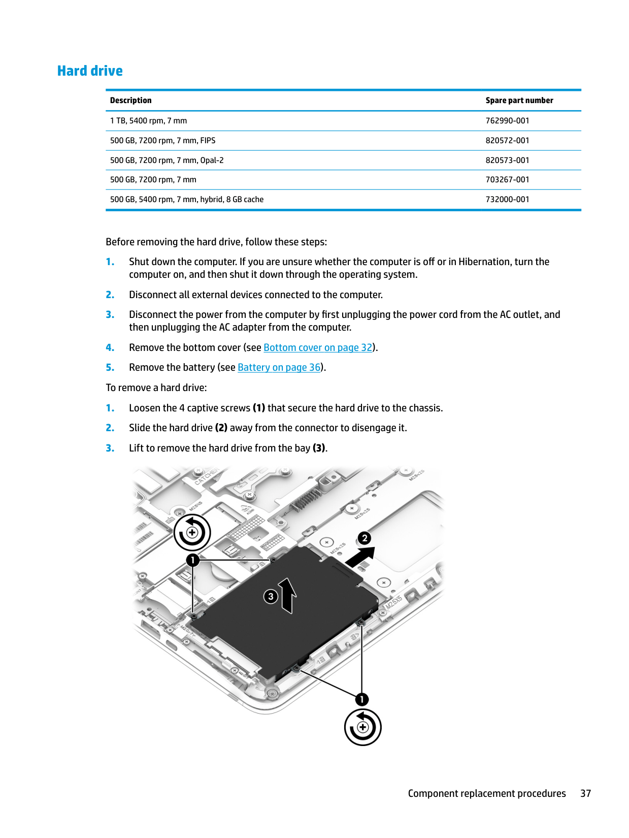
Shut down computer; remove power cord, disconnect devices. Then take off bottom cover and battery as instructed in manual sections (pages 32 to 36). Loosen captive screws securing the hard drive, slide it away from connectors and lift out.
How do I install a WLAN/Bluetooth combo card on my EliteBook 840 G4?
Shut down computer and disconnect power. Remove bottom cover, battery as instructed then carefully take apart by freeing wires and screws from the module, taking care to note wiring order for reinstallation.
What is an important safety precaution when working with customer self-repair parts on my EliteBook?
Avoid using excessive force during disassembly as it can damage plastic parts and be cautious of electrostatic discharge which can harm sensitive electronic components.
How do you replace the heat sink/fan assembly in the HP Elitebook 840 G4?
Turn off the computer, disconnect power and external devices. Remove bottom cover, battery then keyboard as detailed earlier; loosen six captive screws on fan/heat sink (following sequence stamp), disconnect fan cable from system board and take out heat sink/fan assembly.
Full Manual
116 pages

HP EliteBook 840 G4 Notebook PC HP EliteBook 848 G4 Notebook PC
Maintenance and Service Guide
© Copyright 2016 HP Development Company, L.P.
AMD and AMD Radeon are trademarks of Advanced Micro Devices, Inc. Bluetooth is a trademark owned by its proprietor and used by HP Inc. under license. Intel and Core are trademarks of Intel Corporation in the U.S. and other countries. Linux® is the registered trademark of Linus Torvalds in the U.S. and other countries. Microsoft and Windows are trademarks of the Microsoft group of companies.
The information contained herein is subject to change without notice. The only warranties for HP products and services are set forth in the express warranty statements accompanying such products and services. Nothing herein should be construed as constituting an additional warranty. HP shall not be liable for technical or editorial errors or omissions contained herein.
First Edition: December 2016 Document Part Number: 914960-001
######## Product notice
This user guide describes features that are common to most models. Some features may not be available on your computer.
Not all features are available in all editions of Windows. This computer may require upgraded and/or separately purchased hardware, drivers and/or software to take full advantage of Windows functionality. Go to http://www.microsoft.com for details.
Your product does not support Windows 8 or Windows 7
In accordance with Microsoft’s support policy, HP does not support the Windows 8 or Windows 7 operating system on this product or provide any Windows 8 or Windows 7 drivers on http://support.hp.com.
######## Software terms
By installing, copying, downloading, or otherwise using any software product preinstalled on this computer, you agree to be bound by the terms of the HP End User License Agreement (EULA). If you do not accept these license terms, your sole remedy is to return the entire unused product (hardware and software) within 14 days for a full refund subject to the refund policy of your seller.
For any further information or to request a full refund of the price of the computer, please contact your seller.
#### Important Notice about Customer Self-Repair Parts
CAUTION: Your computer includes Customer Self-Repair parts and parts that should only be accessed by an authorized service provider. See Chapter 5, "Removal and replacement procedures for Customer Self-Repair parts," for details. Accessing parts described in Chapter 6, "Removal and replacement procedures for Authorized Service Provider only parts," can damage the computer or void your warranty.
iii
####### iv Important Notice about Customer Self-Repair Parts
#### Safety warning notice
WARNING! To reduce the possibility of heat-related injuries or of overheating the device, do not place the device directly on your lap or obstruct the device air vents. Use the device only on a hard, flat surface. Do not allow another hard surface, such as an adjoining optional printer, or a soft surface, such as pillows or rugs or clothing, to block airflow. Also, do not allow the AC adapter to contact the skin or a soft surface, such as pillows or rugs or clothing, during operation. The device and the AC adapter comply with the user-accessible surface temperature limits defined by the International Standard for Safety of Information Technology Equipment (IEC 60950-1).
v
####### vi Safety warning notice
Table of contents
TouchPad ............................................................................................................................................. 9 Lights ................................................................................................................................................. 10 Buttons, speakers, and fingerprint reader ........................................................................................ 11 Keys ................................................................................................................................................... 13 Using the hot keys ............................................................................................................................. 14
Bottom ................................................................................................................................................................. 15 Front ..................................................................................................................................................................... 16 Labels ................................................................................................................................................................... 17

Plastic parts ....................................................................................................................................... 27 Cables and connectors ...................................................................................................................... 28 Drive handling ................................................................................................................................... 28
Grounding guidelines ........................................................................................................................................... 29
Electrostatic discharge damage ........................................................................................................ 29 Packaging and transporting guidelines .......................................................................... 30 Workstation guidelines ................................................................................................... 30 Equipment guidelines ..................................................................................................... 31
vii
Bottom cover ..................................................................................................................................... 32 Battery ............................................................................................................................................... 36 Hard drive .......................................................................................................................................... 37 Solid-state drive (SSD) ...................................................................................................................... 39 Memory modules ............................................................................................................................... 40 WLAN/Bluetooth combo card ............................................................................................................ 42 WWAN module ................................................................................................................................... 44 RTC battery ........................................................................................................................................ 46 Keyboard ........................................................................................................................................... 47
Internal base plate ............................................................................................................................ 50 Heat sink/fan assembly .................................................................................................................... 53 Fingerprint reader assembly ............................................................................................................. 55 Touchpad board ................................................................................................................................. 57 NFC module ....................................................................................................................................... 58 Smart card reader board ................................................................................................................... 59 USB/audio board ................................................................................................................................ 61 System board .................................................................................................................................... 62 Speaker assembly ............................................................................................................................. 66 Display assembly ............................................................................................................................... 67 Power button board .......................................................................................................................... 73 Top cover ........................................................................................................................................... 75
Starting Computer Setup .................................................................................................................. 78 Navigating and selecting in Computer Setup ................................................................................... 78 Restoring factory settings in Computer Setup ................................................................................. 78 Updating the BIOS ............................................................................................................................. 79

Determining the BIOS version ......................................................................................... 79 Downloading a BIOS update ........................................................................................... 80
Changing the boot order using the f9 prompt .................................................................................. 80 TPM BIOS settings (select products only) ........................................................................................................... 81 Using HP Sure Start (select products only) ......................................................................................................... 81
viii
Creating HP Recovery media (select products only) ......................................................................... 84 Using Windows tools ........................................................................................................................................... 85 Restore and recovery ........................................................................................................................................... 86
Recovering using HP Recovery Manager ........................................................................................... 86 What you need to know before you get started ............................................................. 86 Using the HP Recovery partition (select products only) ................................................. 87 Using HP Recovery media to recover .............................................................................. 87 Changing the computer boot order ................................................................................ 88 Removing the HP Recovery partition (select products only) ......................................... 89
Index ........................................................................................................................................................... 103
ix
####### x
1 Product description

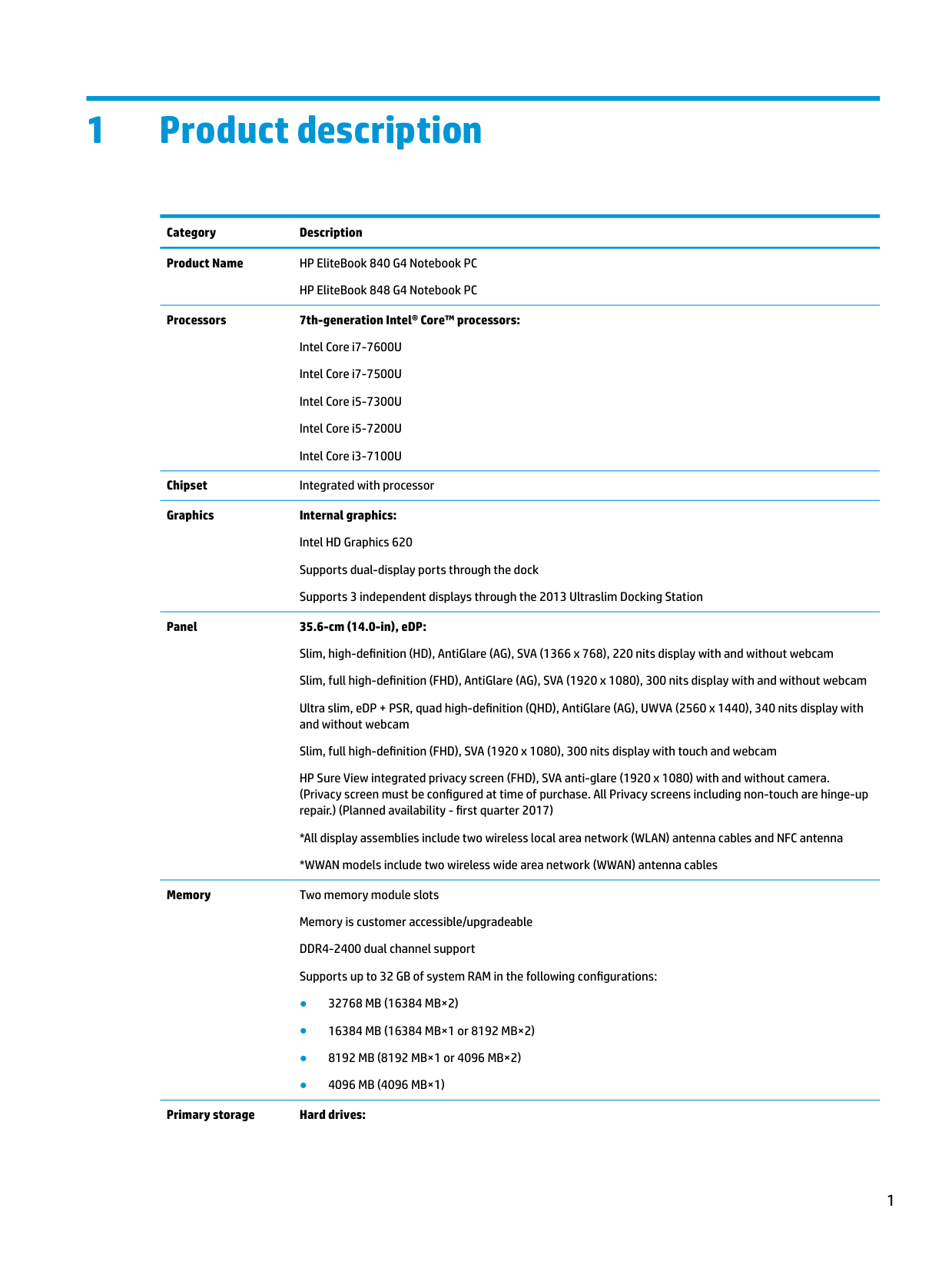
Category Description Product Name HP EliteBook 840 G4 Notebook PC
HP EliteBook 848 G4 Notebook PC
######## Processors 7th-generation Intel® Core™ processors:
Intel Core i7-7600U Intel Core i7-7500U Intel Core i5-7300U Intel Core i5-7200U Intel Core i3-7100U
Chipset Integrated with processor Graphics Internal graphics:
Intel HD Graphics 620 Supports dual-display ports through the dock Supports 3 independent displays through the 2013 Ultraslim Docking Station
Panel 35.6-cm (14.0-in), eDP: Slim, high-definition (HD), AntiGlare (AG), SVA (1366 x 768), 220 nits display with and without webcam Slim, full high-definition (FHD), AntiGlare (AG), SVA (1920 x 1080), 300 nits display with and without webcam Ultra slim, eDP + PSR, quad high-definition (QHD), AntiGlare (AG), UWVA (2560 x 1440), 340 nits display with and without webcam Slim, full high-definition (FHD), SVA (1920 x 1080), 300 nits display with touch and webcam HP Sure View integrated privacy screen (FHD), SVA anti-glare (1920 x 1080) with and without camera. (Privacy screen must be configured at time of purchase. All Privacy screens including non-touch are hinge-up repair.) (Planned availability - first quarter 2017)
Memory Two memory module slots Memory is customer accessible/upgradeable DDR4-2400 dual channel support Supports up to 32 GB of system RAM in the following configurations:
######## Primary storage Hard drives:

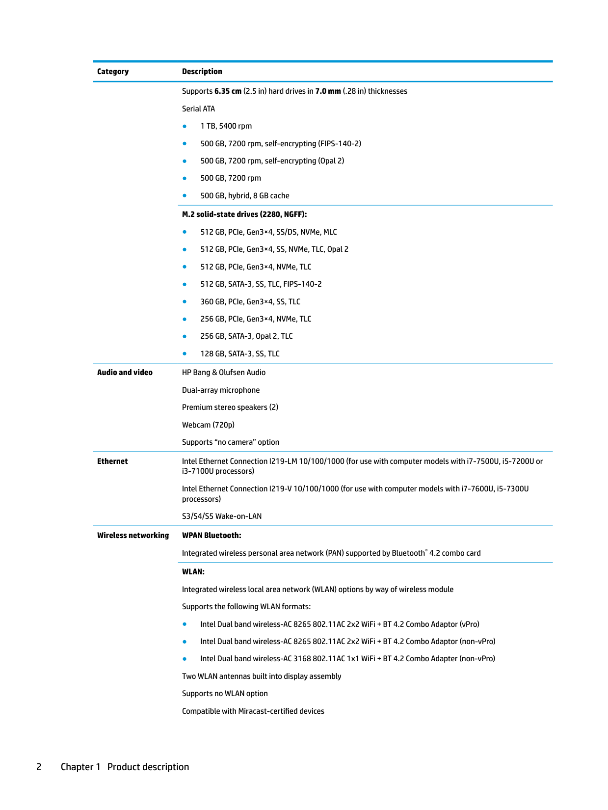
Supports 6.35 cm (2.5 in) hard drives in 7.0 mm (.28 in) thicknesses Serial ATA
Audio and video HP Bang & Olufsen Audio Dual-array microphone Premium stereo speakers (2) Webcam (720p) Supports “no camera” option
Ethernet Intel Ethernet Connection I219-LM 10/100/1000 (for use with computer models with i7-7500U, i5-7200U or i3-7100U processors) Intel Ethernet Connection I219-V 10/100/1000 (for use with computer models with i7-7600U, i5-7300U processors) S3/S4/S5 Wake-on-LAN
Wireless networking WPAN Bluetooth: Integrated wireless personal area network (PAN) supported by Bluetooth® 4.2 combo card WLAN: Integrated wireless local area network (WLAN) options by way of wireless module Supports the following WLAN formats:
Bluetooth Disabled IOPT Support S3/S4 wake on Wireless LAN (Intel only) Support for WiFi SAR in BIOS (Intel WLAN only) Support for HP Sure Connect NFC: Integrated NFC NXP NPC100 I2C NCI 10 mm x 25 mm module NFC antenna Supports no NFC option WWAN: Integrated wireless wide area network (WWAN) options by way of wireless module Two WWAN antennas (world wide 5 band, configured at top of panel on all units) Supports the following WWAN formats:
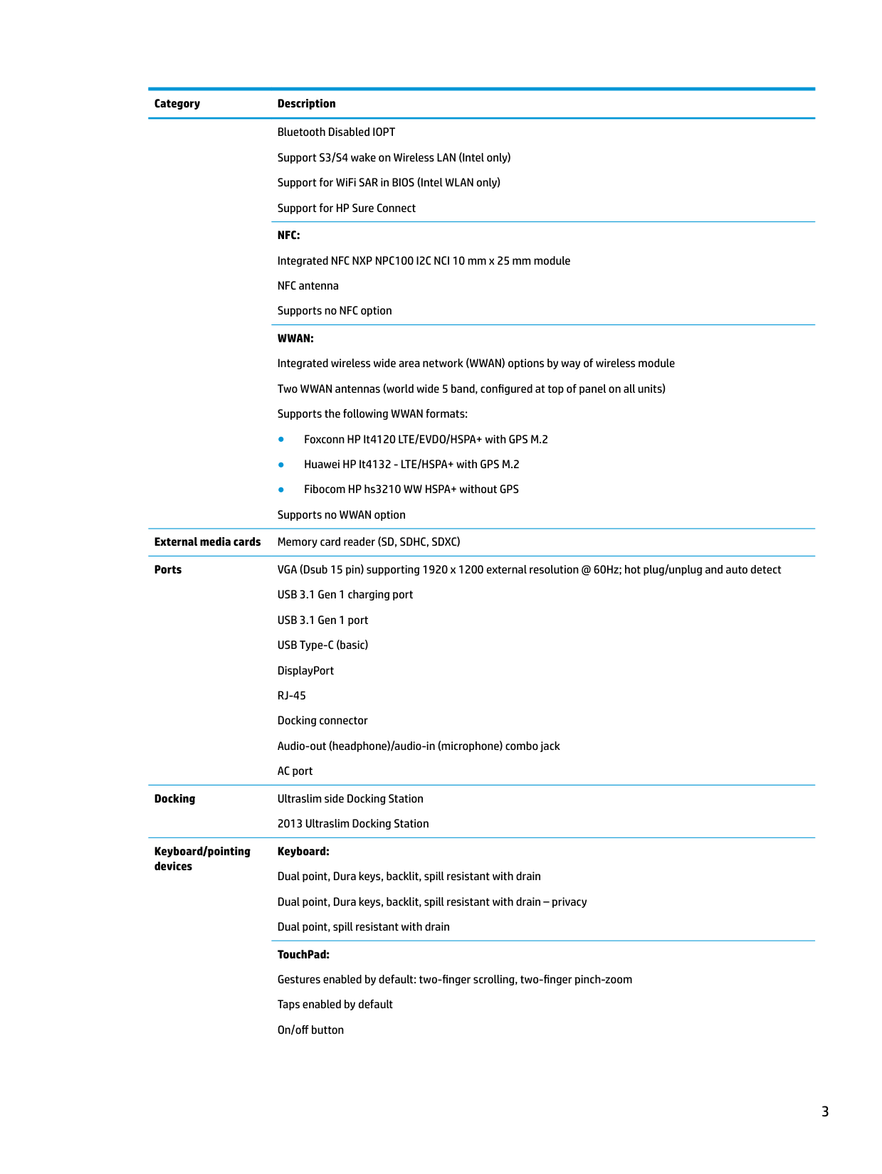
External media cards Memory card reader (SD, SDHC, SDXC) Ports VGA (Dsub 15 pin) supporting 1920 x 1200 external resolution @ 60Hz; hot plug/unplug and auto detect
USB 3.1 Gen 1 charging port USB 3.1 Gen 1 port USB Type-C (basic) DisplayPort RJ-45 Docking connector Audio-out (headphone)/audio-in (microphone) combo jack AC port
Docking Ultraslim side Docking Station
2013 Ultraslim Docking Station
Keyboard/pointing devices
Keyboard: Dual point, Dura keys, backlit, spill resistant with drain Dual point, Dura keys, backlit, spill resistant with drain – privacy Dual point, spill resistant with drain TouchPad: Gestures enabled by default: two-finger scrolling, two-finger pinch-zoom Taps enabled by default On/off button
Glass
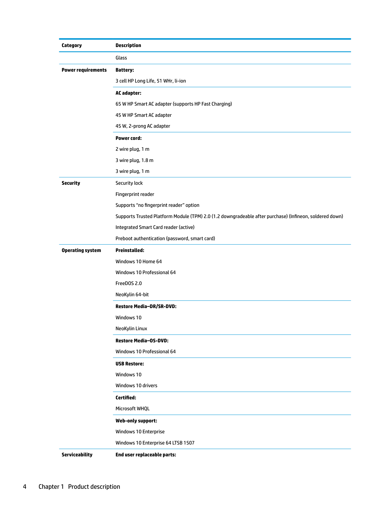
Power requirements Battery: 3 cell HP Long Life, 51 WHr, li-ion AC adapter: 65 W HP Smart AC adapter (supports HP Fast Charging) 45 W HP Smart AC adapter 45 W, 2-prong AC adapter Power cord:
Security Security lock Fingerprint reader Supports “no fingerprint reader” option Supports Trusted Platform Module (TPM) 2.0 (1.2 downgradeable after purchase) (Infineon, soldered down) Integrated Smart Card reader (active) Preboot authentication (password, smart card)
Operating system Preinstalled: Windows 10 Home 64 Windows 10 Professional 64 FreeDOS 2.0 NeoKylin 64-bit Restore Media–DR/SR-DVD: Windows 10 NeoKylin Linux Restore Media–OS-DVD: Windows 10 Professional 64 USB Restore: Windows 10 Windows 10 drivers Certified: Microsoft WHQL Web-only support: Windows 10 Enterprise Windows 10 Enterprise 64 LTSB 1507
######## Serviceability End user replaceable parts:
AC adapter Battery Hard drive Solid-state drive Memory module WLAN module WWAN module Keyboard
2 External component identification
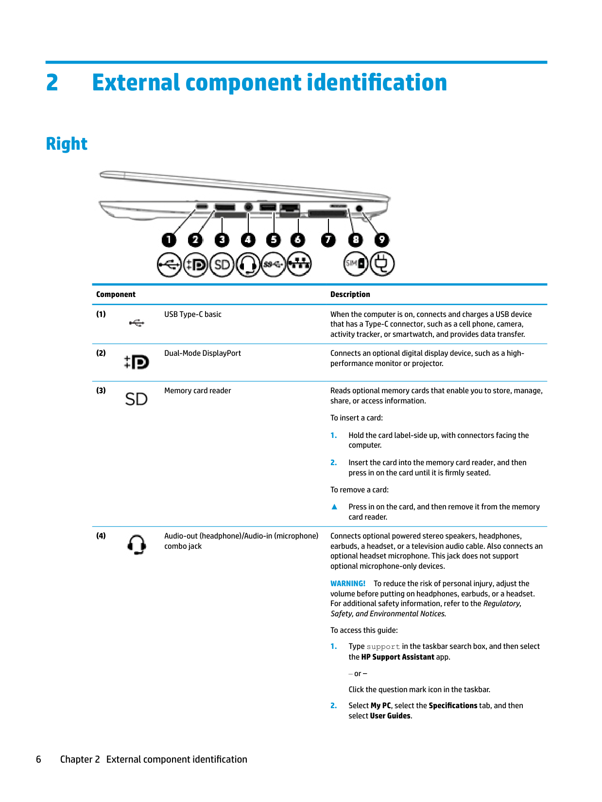
Right

######## Component Description


To remove a card:
▲ Press in on the card, and then remove it from the memory
card reader.
Connects optional powered stereo speakers, headphones, earbuds, a headset, or a television audio cable. Also connects an optional headset microphone. This jack does not support optional microphone-only devices.

WARNING! To reduce the risk of personal injury, adjust the volume before putting on headphones, earbuds, or a headset. For additional safety information, refer to the Regulatory, Safety, and Environmental Notices.
To access this guide:
or – Click the question mark icon in the taskbar.

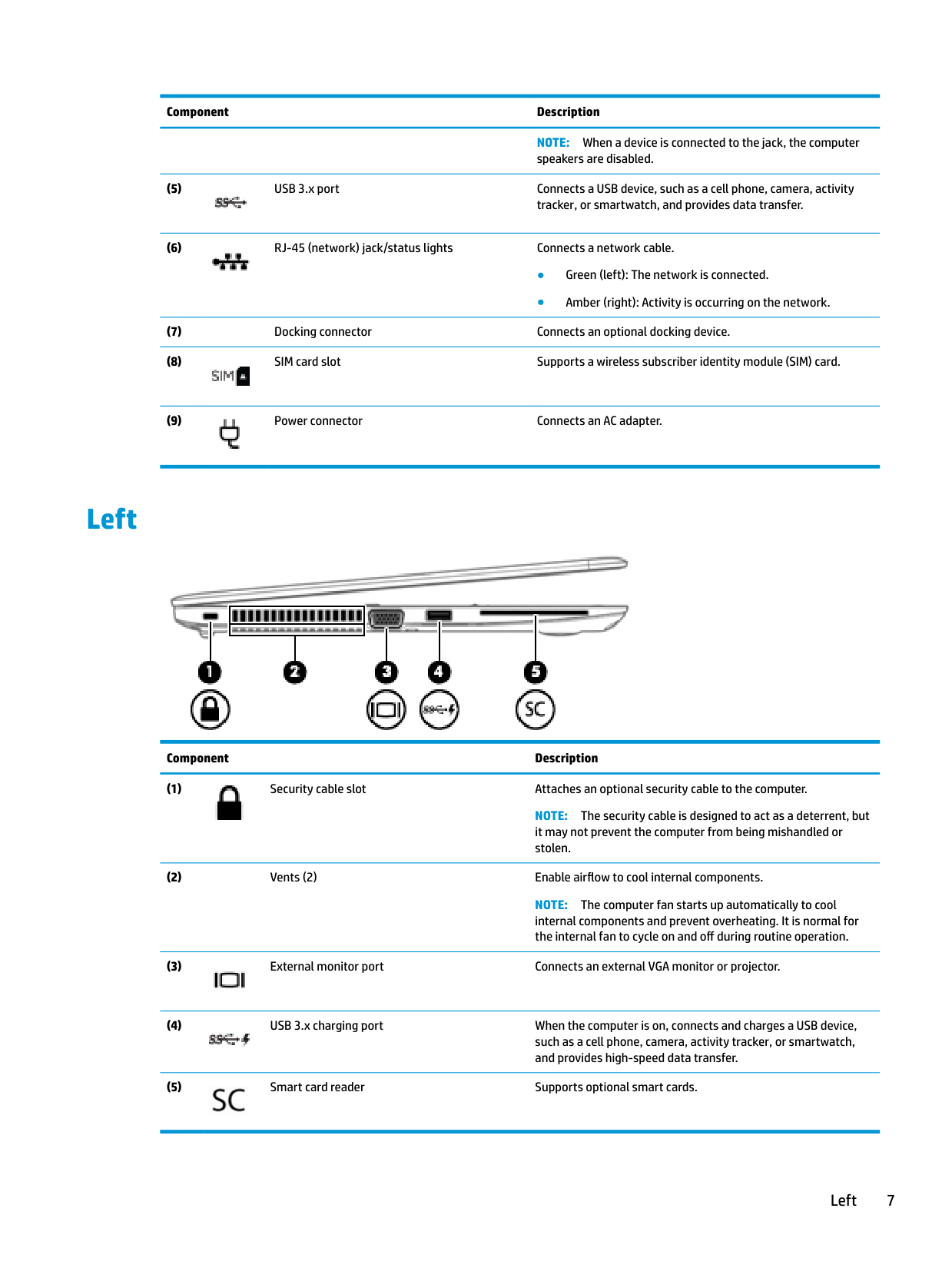
######## Component Description
NOTE: When a device is connected to the jack, the computer speakers are disabled.


Left

######## Component Description

NOTE: The security cable is designed to act as a deterrent, but it may not prevent the computer from being mishandled or stolen.
NOTE: The computer fan starts up automatically to cool internal components and prevent overheating. It is normal for the internal fan to cycle on and off during routine operation.


Left 7
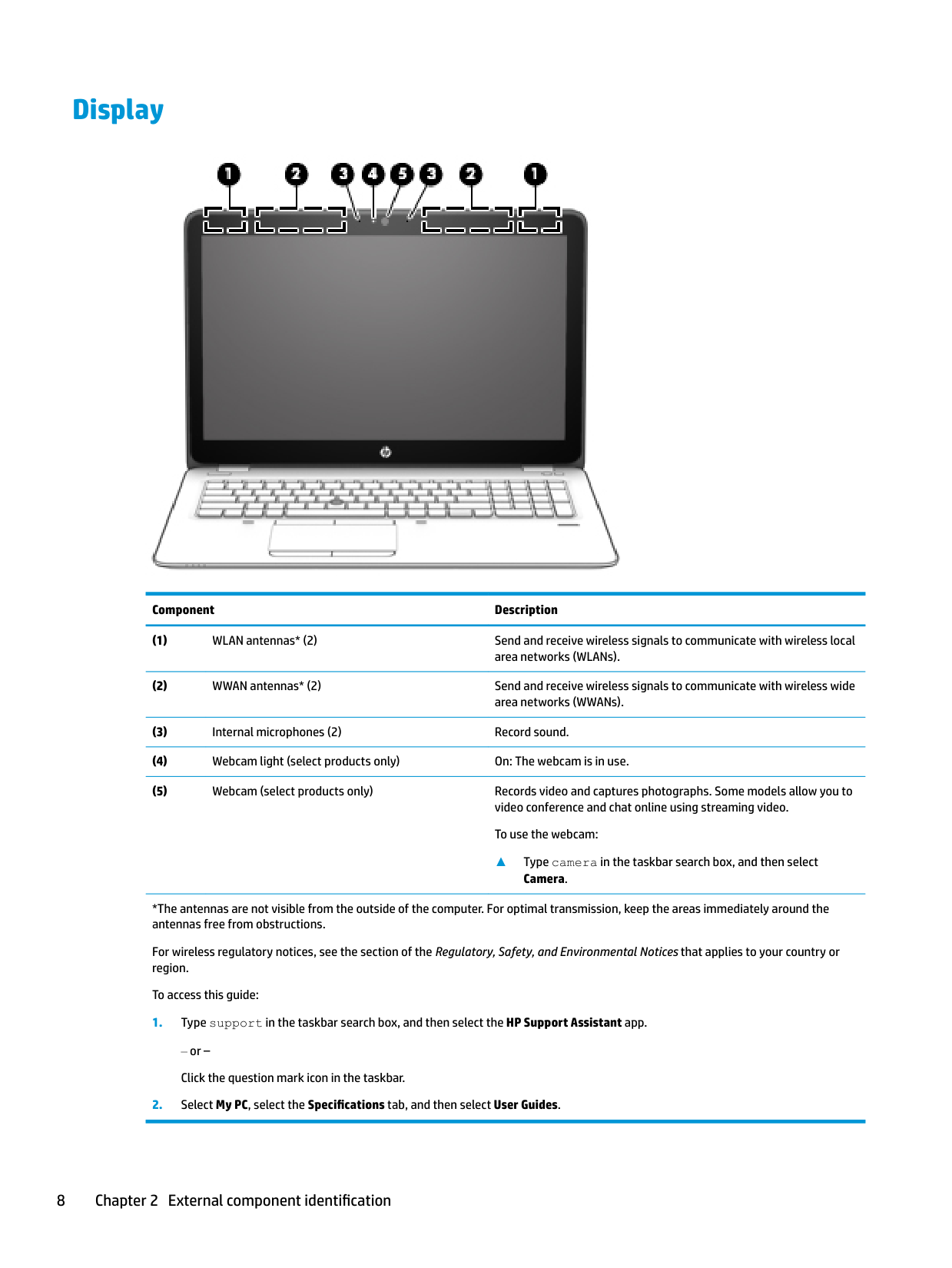
Display

######## Component Description
▲ Type camera in the taskbar search box, and then select Camera.
*The antennas are not visible from the outside of the computer. For optimal transmission, keep the areas immediately around the antennas free from obstructions.
For wireless regulatory notices, see the section of the Regulatory, Safety, and Environmental Notices that applies to your country or region.
To access this guide:
‒ or – Click the question mark icon in the taskbar.
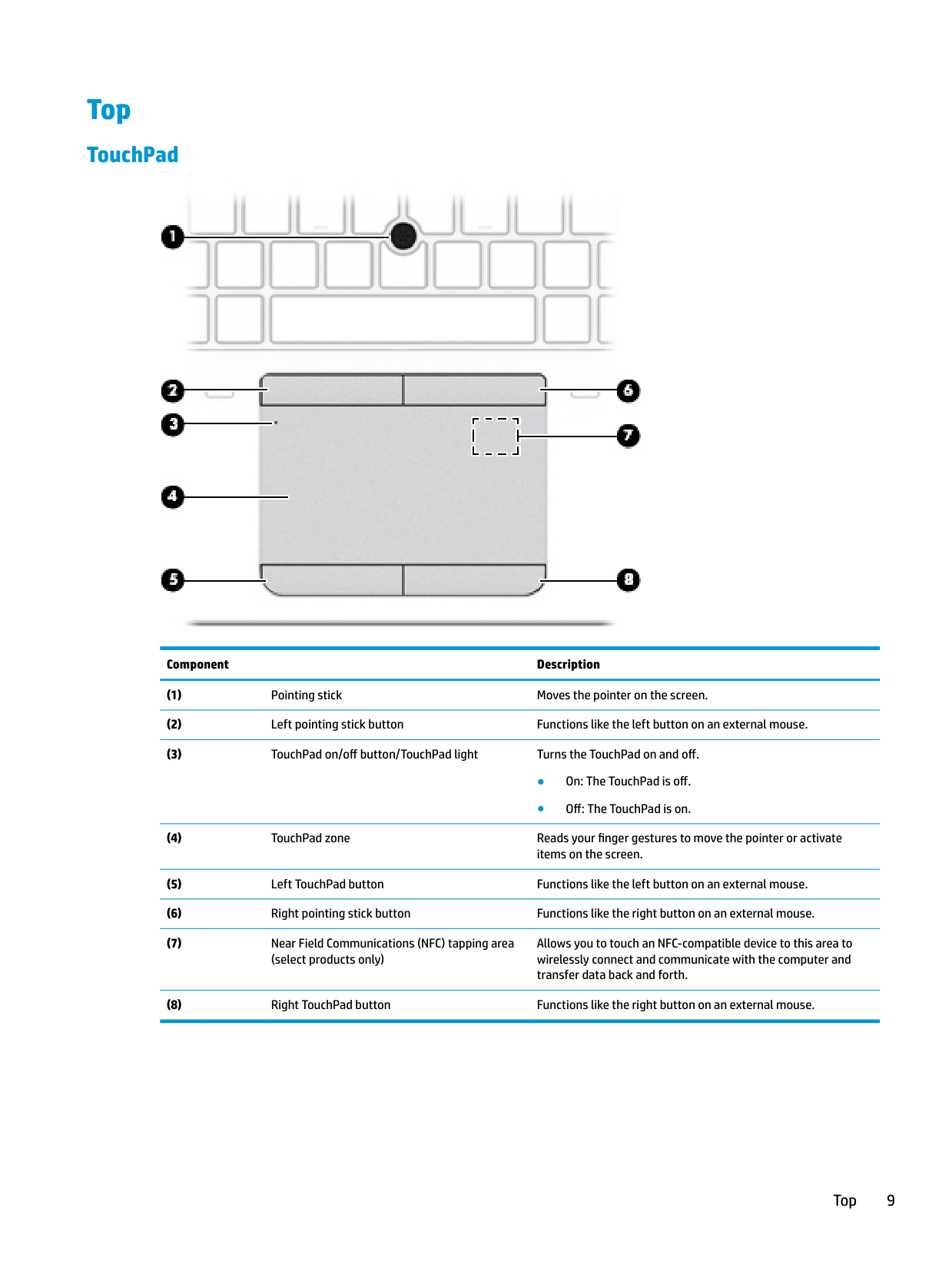
Top
#### TouchPad

######## Component Description
Allows you to touch an NFC-compatible device to this area to wirelessly connect and communicate with the computer and transfer data back and forth.
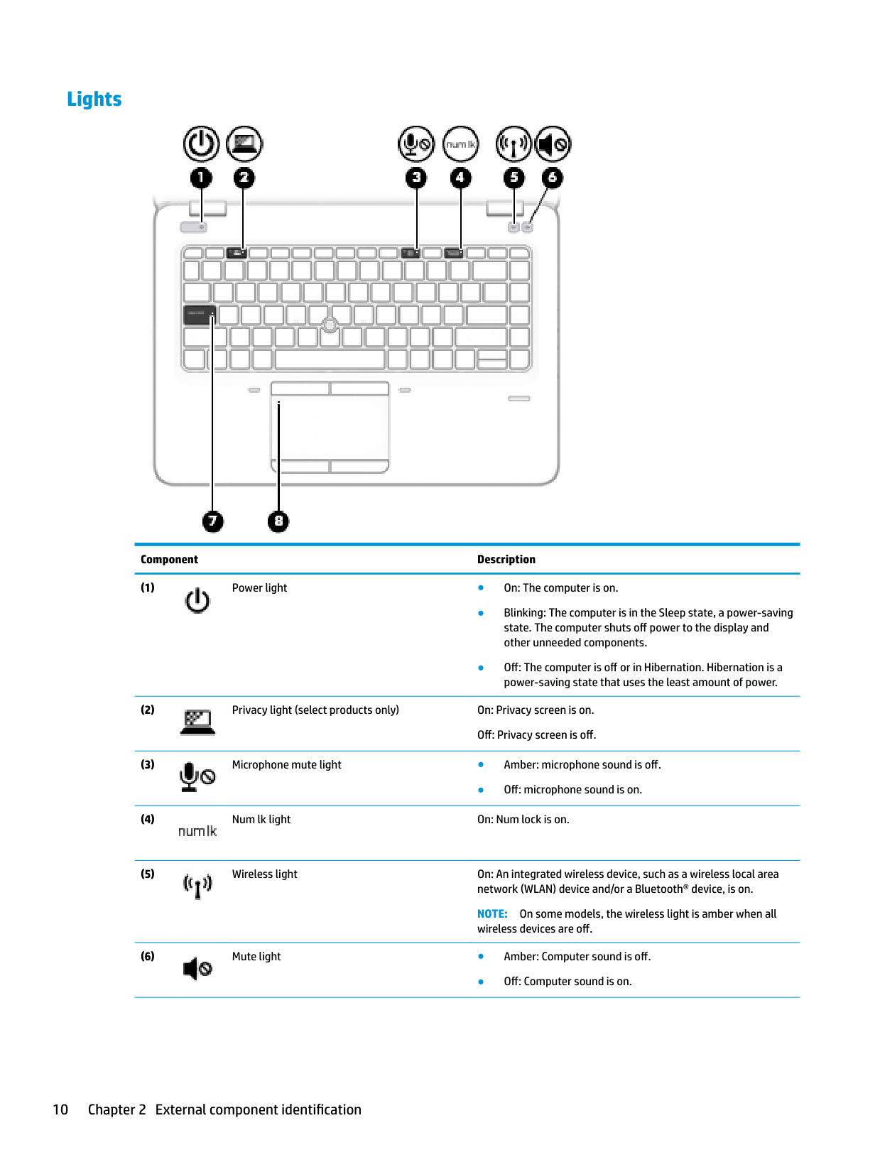
#### Lights

######## Component Description


● Off: microphone sound is on.


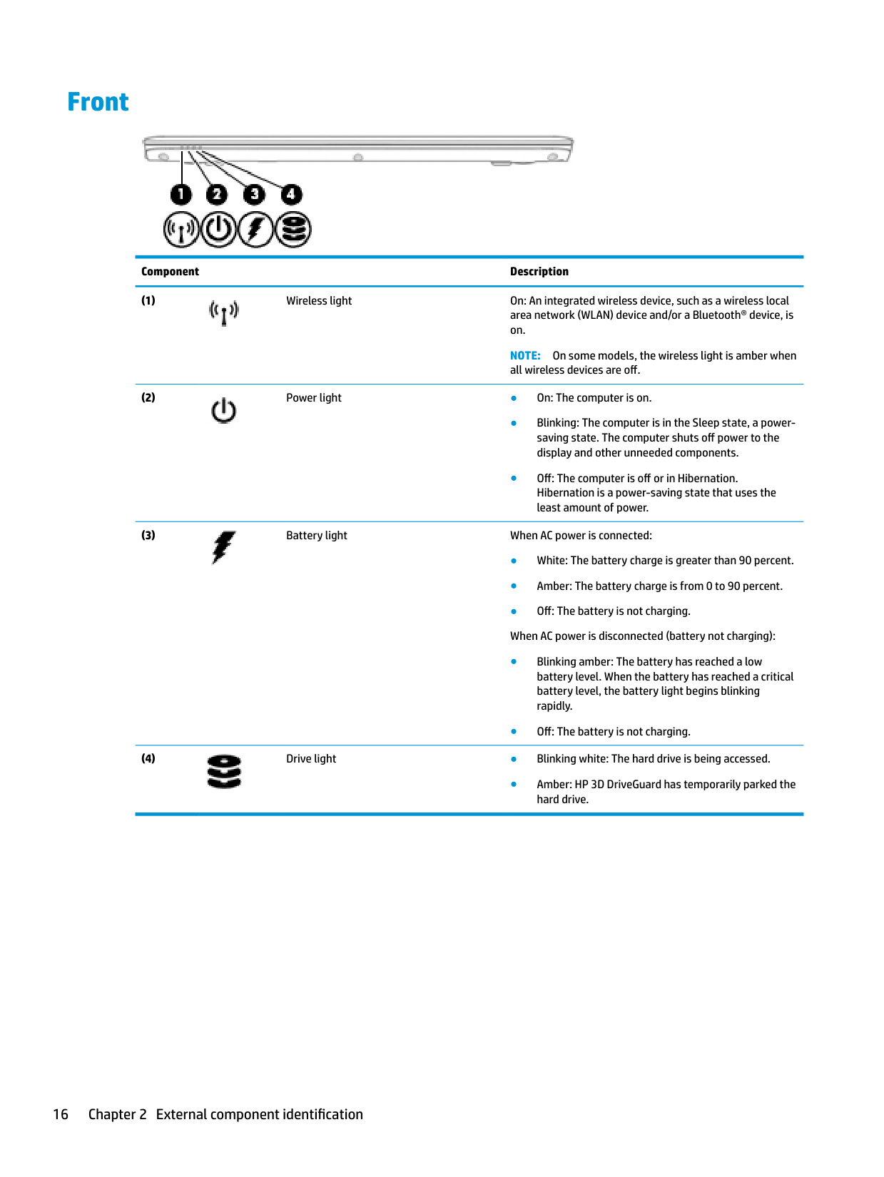
NOTE: On some models, the wireless light is amber when all wireless devices are off.

● Off: Computer sound is on.
● Off: The TouchPad is on.
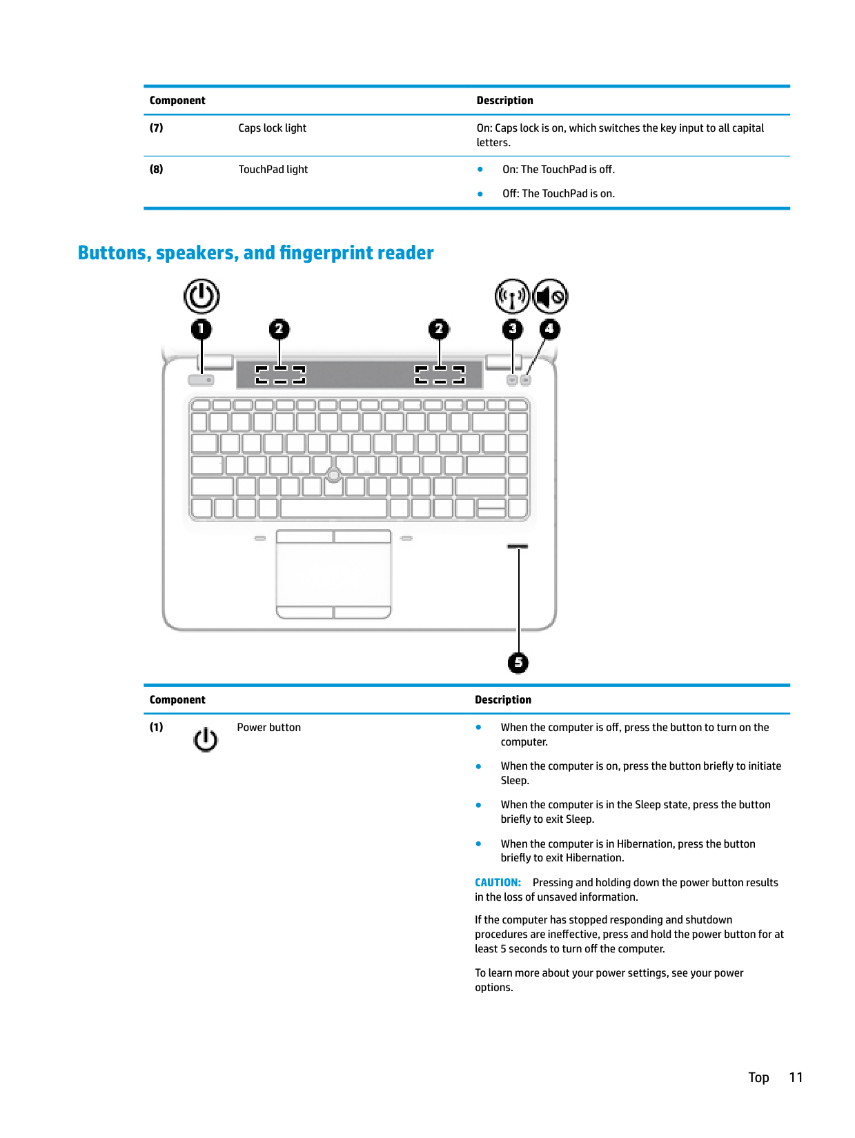
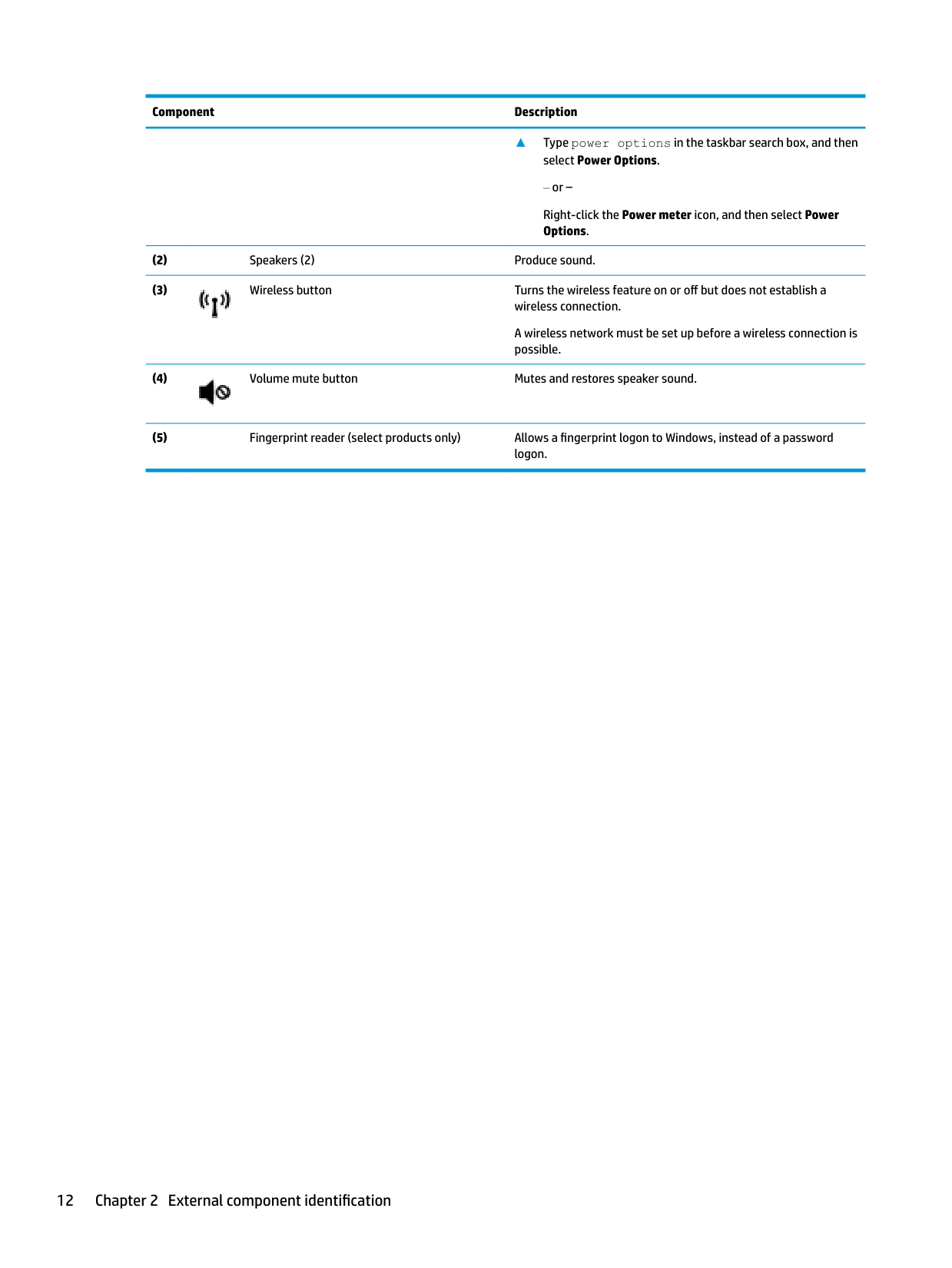
#### Buttons, speakers, and fingerprint reader

######## Component Description

CAUTION: Pressing and holding down the power button results in the loss of unsaved information. If the computer has stopped responding and shutdown procedures are ineffective, press and hold the power button for at least 5 seconds to turn off the computer. To learn more about your power settings, see your power options.
▲ Type power options in the taskbar search box, and then
######## select Power Options.
‒ or – Right-click the Power meter icon, and then select Power Options.

A wireless network must be set up before a wireless connection is possible.

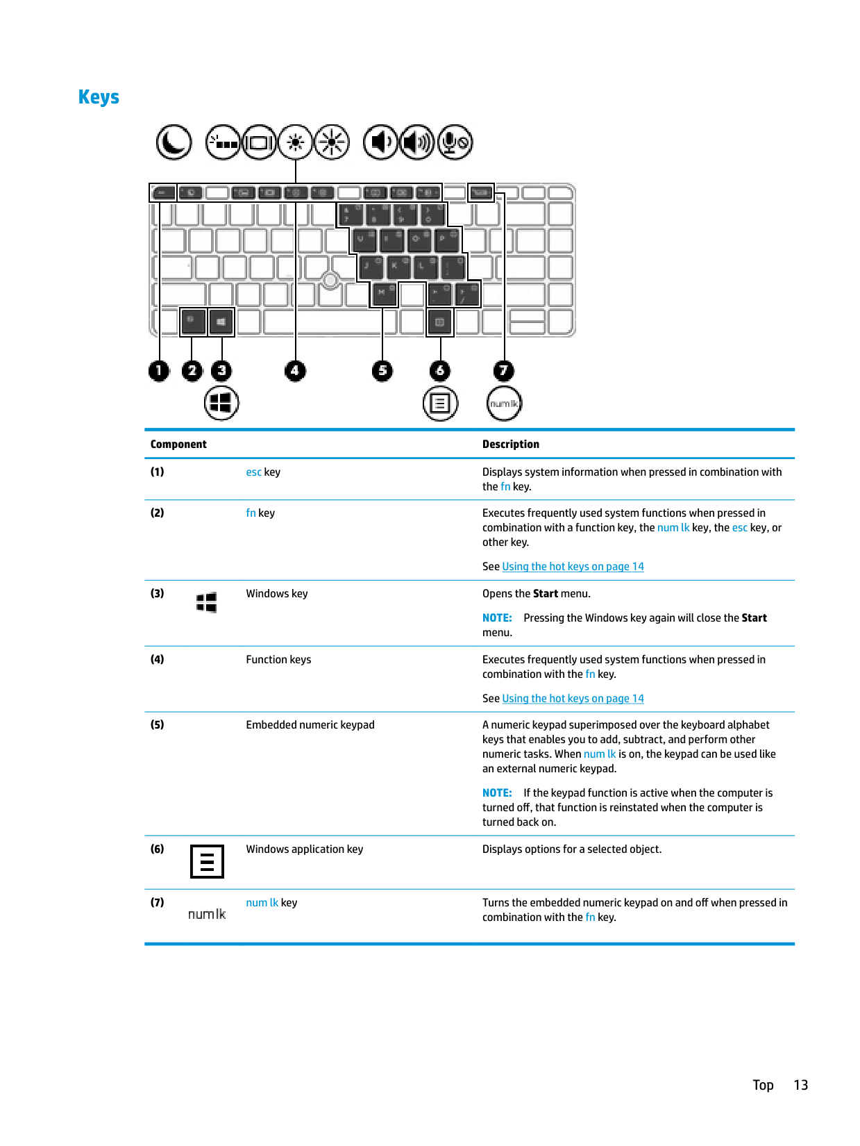
#### Keys

######## Component Description

NOTE: Pressing the Windows key again will close the Start menu.
NOTE: If the keypad function is active when the computer is turned off, that function is reinstated when the computer is turned back on.


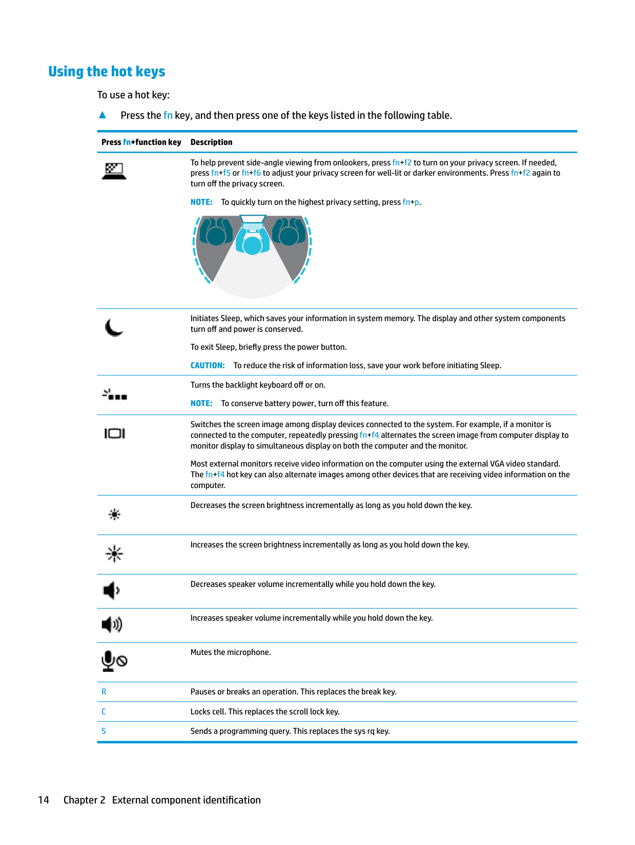
#### Using the hot keys
To use a hot key:
▲ Press the fn key, and then press one of the keys listed in the following table.
Press fn+function key Description

To help prevent side-angle viewing from onlookers, press fn+f2 to turn on your privacy screen. If needed, press fn+f5 or fn+f6 to adjust your privacy screen for well-lit or darker environments. Press fn+f2 again to turn off the privacy screen.
NOTE: To quickly turn on the highest privacy setting, press fn+p.


Initiates Sleep, which saves your information in system memory. The display and other system components turn off and power is conserved.
To exit Sleep, briefly press the power button. CAUTION: To reduce the risk of information loss, save your work before initiating Sleep. Turns the backlight keyboard off or on. NOTE: To conserve battery power, turn off this feature.
Switches the screen image among display devices connected to the system. For example, if a monitor is connected to the computer, repeatedly pressing fn+f4 alternates the screen image from computer display to monitor display to simultaneous display on both the computer and the monitor.
Most external monitors receive video information on the computer using the external VGA video standard. The fn+f4 hot key can also alternate images among other devices that are receiving video information on the computer.
Decreases the screen brightness incrementally as long as you hold down the key.


Increases the screen brightness incrementally as long as you hold down the key.
Decreases speaker volume incrementally while you hold down the key.
Increases speaker volume incrementally while you hold down the key.

Mutes the microphone.
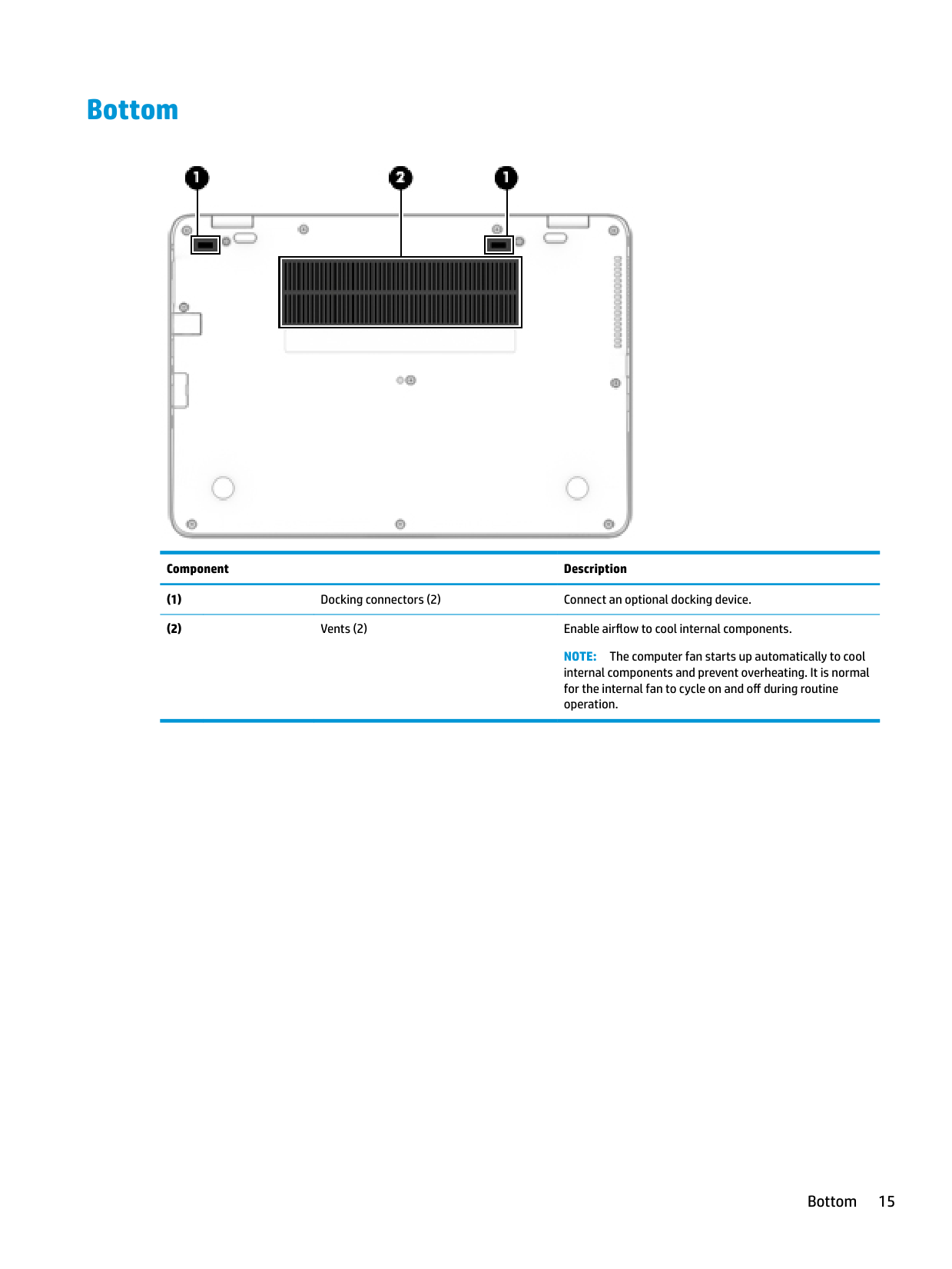
Bottom

######## Component Description
NOTE: The computer fan starts up automatically to cool internal components and prevent overheating. It is normal for the internal fan to cycle on and off during routine operation.
Bottom 15
Front

######## Component Description

NOTE: On some models, the wireless light is amber when all wireless devices are off.


● Amber: HP 3D DriveGuard has temporarily parked the hard drive.
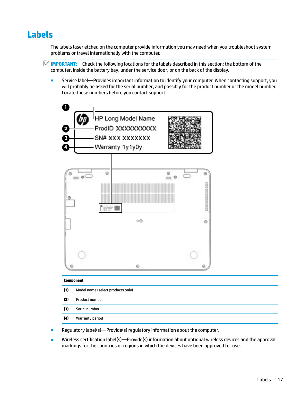
Labels
The labels laser etched on the computer provide information you may need when you troubleshoot system problems or travel internationally with the computer.
| | |---|
IMPORTANT: Check the following locations for the labels described in this section: the bottom of the computer, inside the battery bay, under the service door, or on the back of the display.

Component
Labels 17
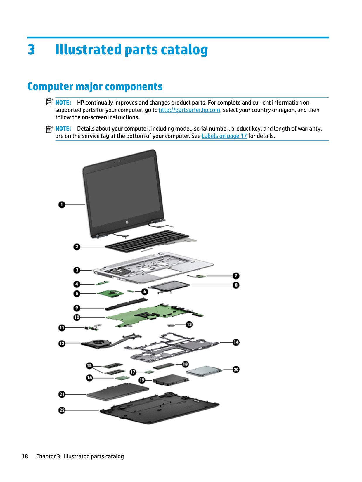
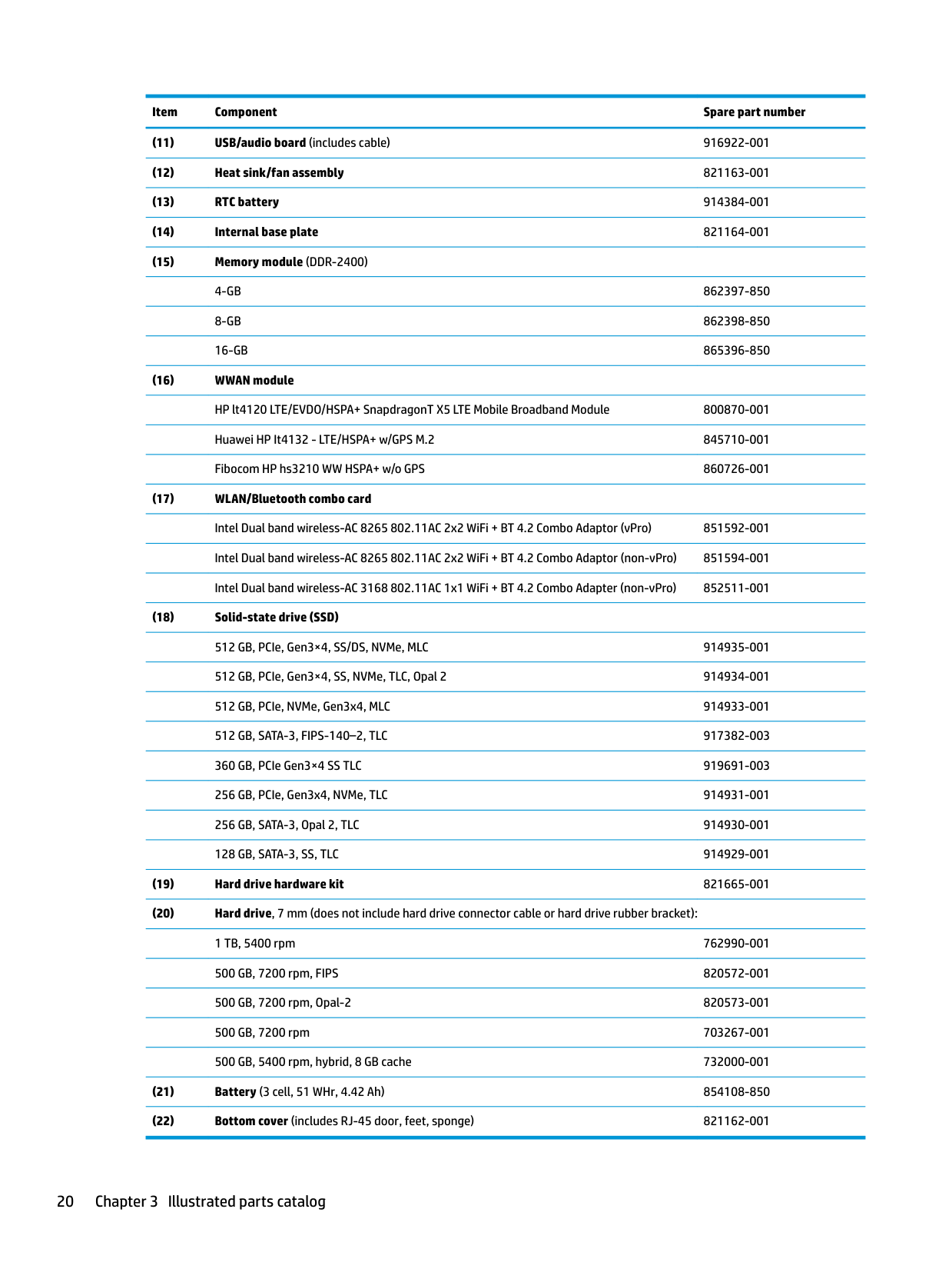
3 Illustrated parts catalog
Computer major components
| | |---|
NOTE: HP continually improves and changes product parts. For complete and current information on supported parts for your computer, go to http://partsurfer.hp.com, select your country or region, and then follow the on-screen instructions.
| | |---|
NOTE: Details about your computer, including model, serial number, product key, and length of warranty, are on the service tag at the bottom of your computer. See Labels on page 17 for details.

Non-touch display assemblies are spared at the subcomponent level only. For more nontouch display assembly spare part information, see Display assembly subcomponents on page 21.
Touch 910584-001 Privacy 922076-001
Computer major components 19
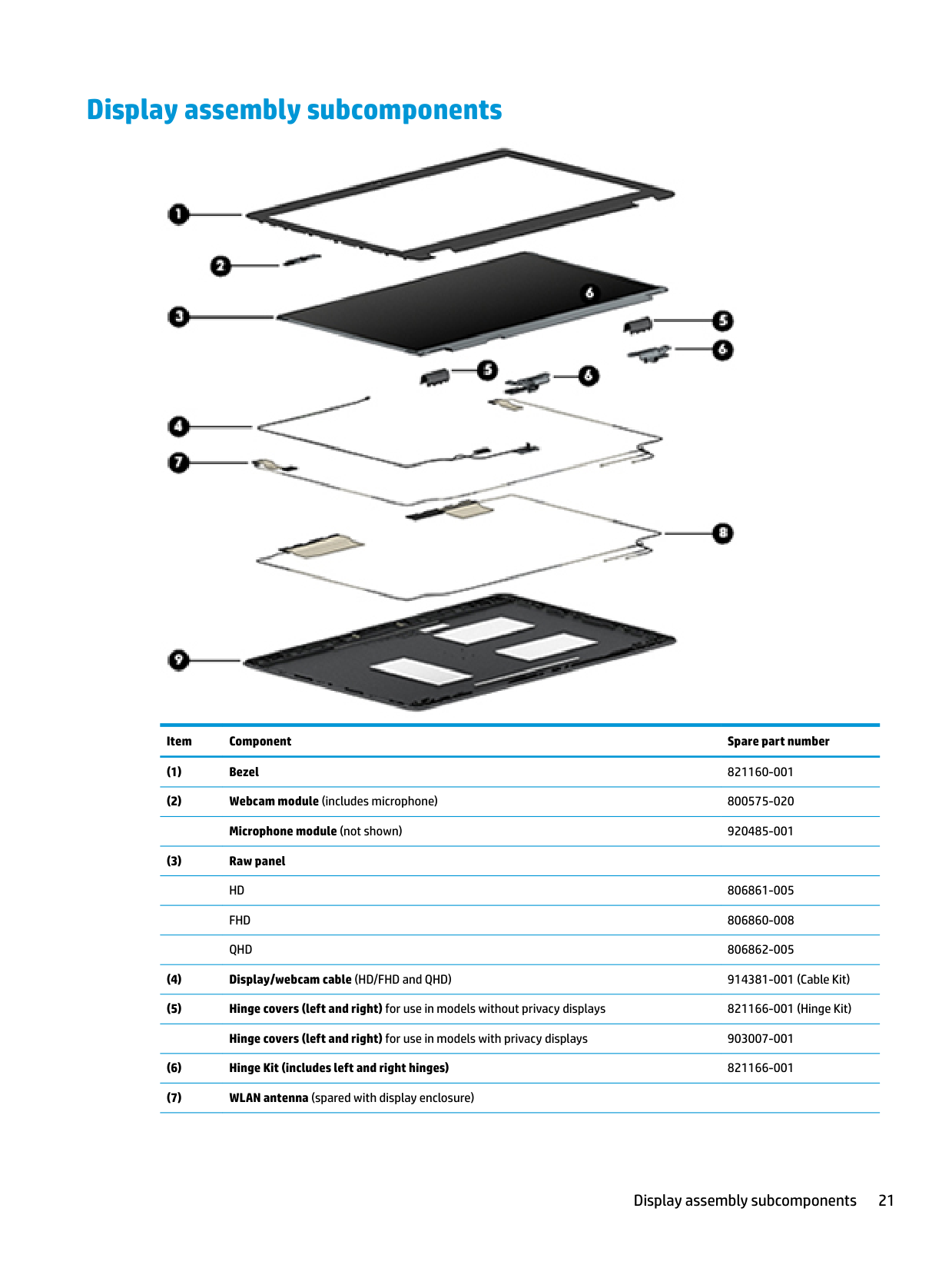
Display assembly subcomponents

######## Item Component Spare part number
Display assembly subcomponents 21
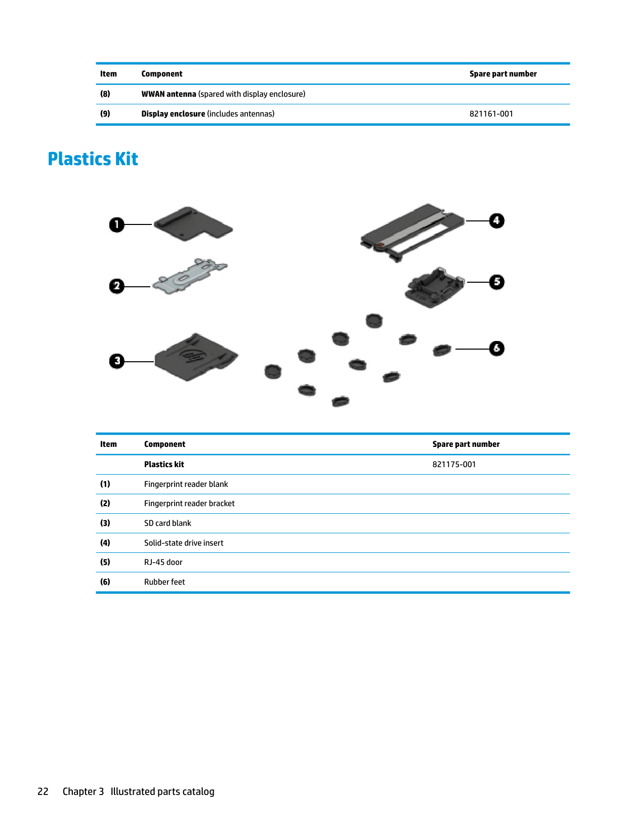
Plastics Kit

Item Component Spare part number Plastics kit 821175-001
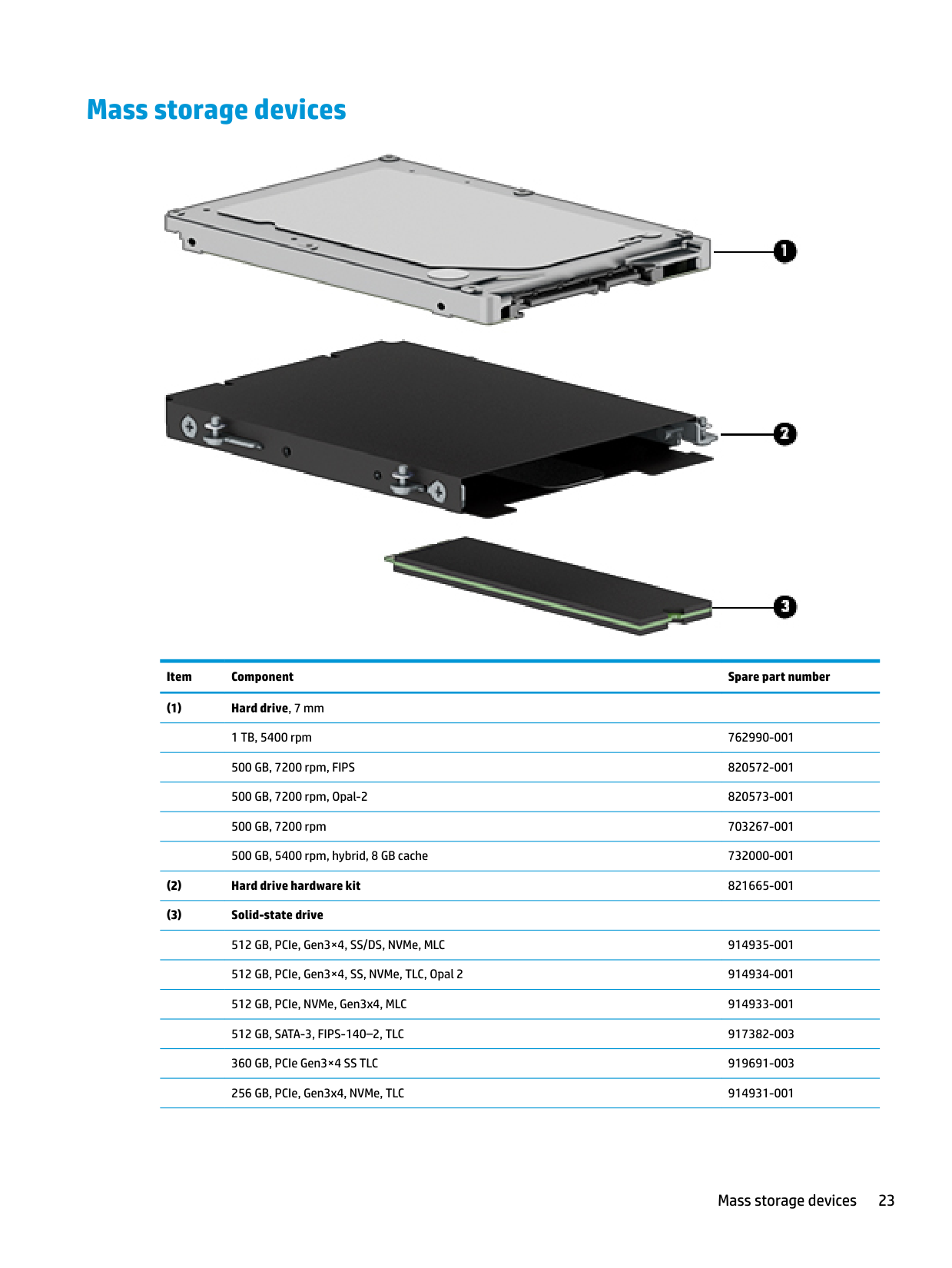
Mass storage devices

######## Item Component Spare part number
Mass storage devices 23
256 GB, SATA-3, Opal 2, TLC 914930-001 128 GB, SATA-3, SS, TLC 914929-001
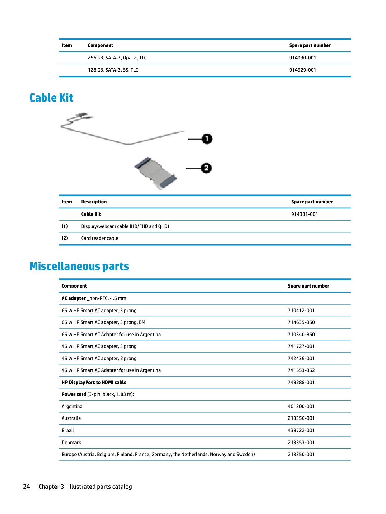
Cable Kit

Item Description Spare part number Cable Kit 914381-001
Miscellaneous parts
Component Spare part number AC adapter _non-PFC, 4.5 mm
65 W HP Smart AC adapter, 3 prong 710412-001 65 W HP Smart AC adapter, 3 prong, EM 714635-850 65 W HP Smart AC Adapter for use in Argentina 710340-850 45 W HP Smart AC adapter, 3 prong 741727-001 45 W HP Smart AC adapter, 2 prong 742436-001 45 W HP Smart AC Adapter for use in Argentina 741553-852 HP DisplayPort to HDMI cable 749288-001 Power cord (3-pin, black, 1.83 m):
Argentina 401300-001 Australia 213356-001 Brazil 438722-001 Denmark 213353-001 Europe (Austria, Belgium, Finland, France, Germany, the Netherlands, Norway and Sweden) 213350-001
India 404827-001 Israel 398063-001 Italy 213352-001
Japan 349756-002 North America 213349-009 People’s Republic of China 286497-008
Miscellaneous parts 25
######### Pointing stick covers (20 count) 828884-001 RJ-45 door (20 count) 917396-001
4 Removal and replacement procedurespreliminary requirements
Tools required
You will need the following tools to complete the removal and replacement procedures:
● Phillips P0 screwdriver
Service considerations
The following sections include some of the considerations that you must keep in mind during disassembly and assembly procedures.
| | |---|
NOTE: As you remove each subassembly from the computer, place the subassembly (and all accompanying screws) away from the work area to prevent damage.
#### Plastic parts
CAUTION: Using excessive force during disassembly and reassembly can damage plastic parts. Use care when handling the plastic
Tools required 27
#### Cables and connectors
CAUTION: When servicing the computer, be sure that cables are placed in their proper locations during the reassembly process. Improper cable placement can damage the computer.
Cables must be handled with extreme care to avoid damage. Apply only the tension required to unseat or seat the cables during removal and insertion. Handle cables by the connector whenever possible. In all cases, avoid bending, twisting, or tearing cables. Be sure that cables are routed in such a way that they cannot be caught or snagged by parts being removed or replaced. Handle flex cables with extreme care; these cables tear easily.
Drive handling CAUTION: Drives are fragile components that must be handled with care. To prevent damage to the computer, damage to a drive, or loss of information, observe these precautions: Before removing or inserting a hard drive, shut down the computer. If you are unsure whether the computer is off or in Hibernation, turn the computer on, and then shut it down through the operating system. Before handling a drive, be sure that you are discharged of static electricity. While handling a drive, avoid touching the connector. Before removing a diskette drive or optical drive, be sure that a diskette or disc is not in the drive and be sure that the optical drive tray is closed. Handle drives on surfaces covered with at least one inch of shock-proof foam. Avoid dropping drives from any height onto any surface. Avoid exposing an internal hard drive to products that have magnetic fields, such as monitors or speakers. Avoid exposing an internal hard drive to products that have magnetic fields, such as monitors or speakers. Avoid exposing a drive to temperature extremes or liquids. If a drive must be mailed, place the drive in a bubble pack mailer or other suitable form of protective packaging and label the package “FRAGILE.”
Grounding guidelines
#### Electrostatic discharge damage
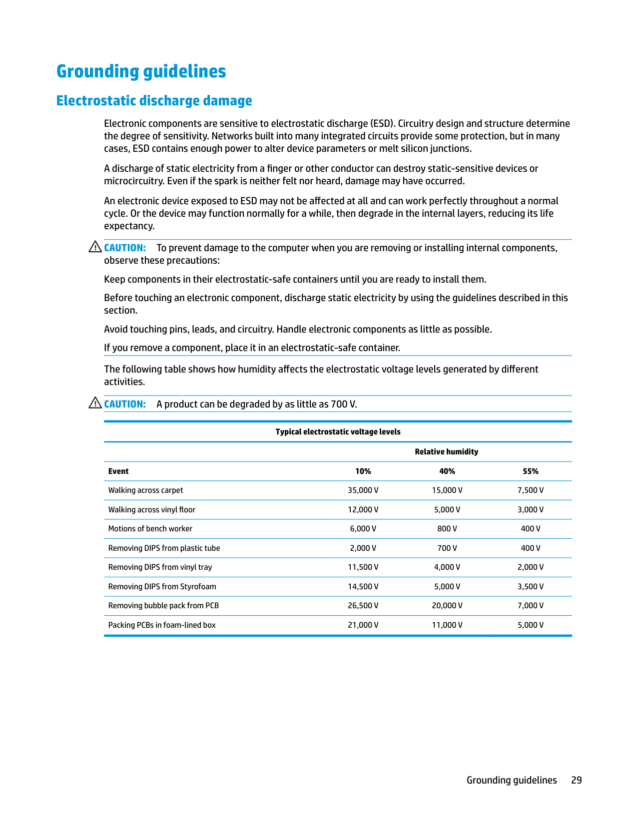
Electronic components are sensitive to electrostatic discharge (ESD). Circuitry design and structure determine the degree of sensitivity. Networks built into many integrated circuits provide some protection, but in many cases, ESD contains enough power to alter device parameters or melt silicon junctions.
A discharge of static electricity from a finger or other conductor can destroy static-sensitive devices or microcircuitry. Even if the spark is neither felt nor heard, damage may have occurred.
An electronic device exposed to ESD may not be affected at all and can work perfectly throughout a normal cycle. Or the device may function normally for a while, then degrade in the internal layers, reducing its life expectancy.
CAUTION: To prevent damage to the computer when you are removing or installing internal components, observe these precautions: Keep components in their electrostatic-safe containers until you are ready to install them. Before touching an electronic component, discharge static electricity by using the guidelines described in this section. Avoid touching pins, leads, and circuitry. Handle electronic components as little as possible. If you remove a component, place it in an electrostatic-safe container. The following table shows how humidity affects the electrostatic voltage levels generated by different activities. CAUTION: A product can be degraded by as little as 700 V.
Typical electrostatic voltage levels
Relative humidity Event 10% 40% 55% Walking across carpet 35,000 V 15,000 V 7,500 V Walking across vinyl floor 12,000 V 5,000 V 3,000 V Motions of bench worker 6,000 V 800 V 400 V Removing DIPS from plastic tube 2,000 V 700 V 400 V Removing DIPS from vinyl tray 11,500 V 4,000 V 2,000 V Removing DIPS from Styrofoam 14,500 V 5,000 V 3,500 V Removing bubble pack from PCB 26,500 V 20,000 V 7,000 V Packing PCBs in foam-lined box 21,000 V 11,000 V 5,000 V
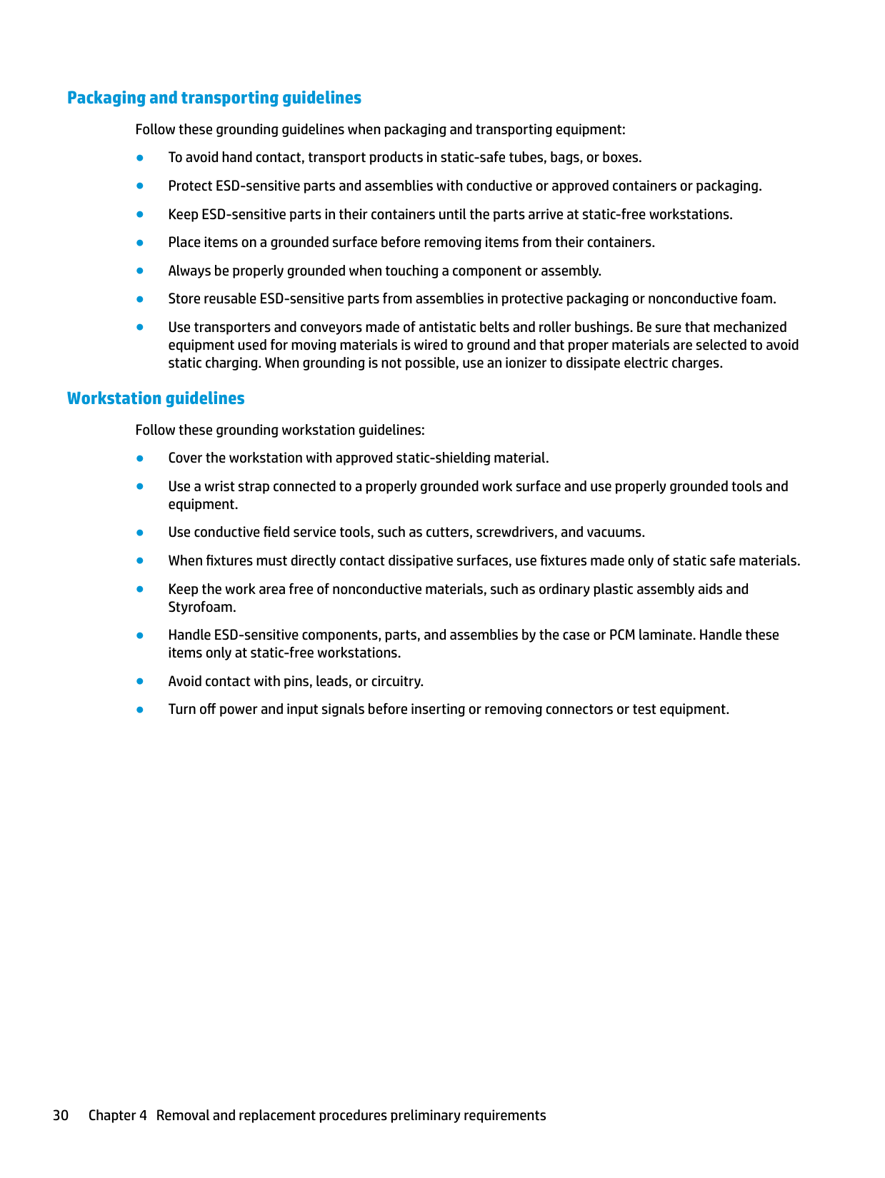
##### Packaging and transporting guidelines
Follow these grounding guidelines when packaging and transporting equipment:
##### Workstation guidelines
Follow these grounding workstation guidelines:
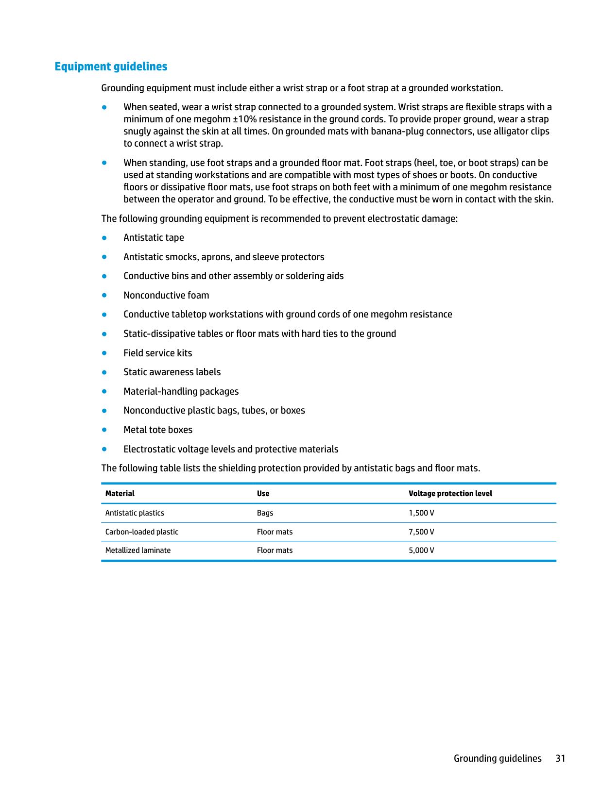
##### Equipment guidelines
Grounding equipment must include either a wrist strap or a foot strap at a grounded workstation.
Material Use Voltage protection level
Antistatic plastics Bags 1,500 V Carbon-loaded plastic Floor mats 7,500 V Metallized laminate Floor mats 5,000 V
5 Removal and replacement procedures forCustomer Self-Repair parts
| | |---|
This chapter provides removal and replacement procedures for Customer Self-Repair parts. NOTE: The Customer Self-Repair program is not available in all locations. Installing a part not supported by the Customer Self-Repair program may void your warranty. Check your warranty to determine if Customer Self-Repair is supported in your location.
Component replacement procedures
| | |---|
NOTE: Details about your computer, including model, serial number, product key, and length of warranty, are on the service tag at the bottom of your computer. See Labels on page 17 for details.
| | |---|
NOTE: HP continually improves and changes product parts. For complete and current information on supported parts for your computer, go to http://partsurfer.hp.com, select your country or region, and then follow the on-screen instructions.
There are as many as 26 screws that must be removed, replaced, and/or loosened when servicing Customer Self-Repair parts. Make special note of each screw size and location during removal and replacement.
#### Bottom cover
Description Spare part number Bottom cover (includes RJ-45 door, feet, sponge) 821162-001
Before removing the bottom cover, follow these steps:
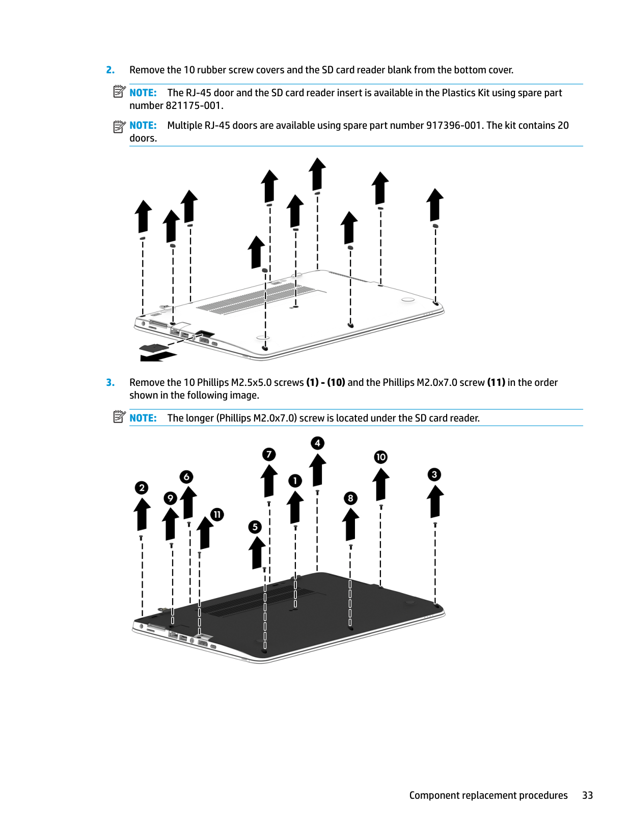
####### 2. Remove the 10 rubber screw covers and the SD card reader blank from the bottom cover.
| | |---|
NOTE: The RJ-45 door and the SD card reader insert is available in the Plastics Kit using spare part number 821175-001.
| | |---|
NOTE: Multiple RJ-45 doors are available using spare part number 917396-001. The kit contains 20 doors.

####### 3. Remove the 10 Phillips M2.5x5.0 screws (1) - (10) and the Phillips M2.0x7.0 screw (11) in the ordershown in the following image.NOTE: The longer (Phillips M2.0x7.0) screw is located under the SD card reader.
| | |---|


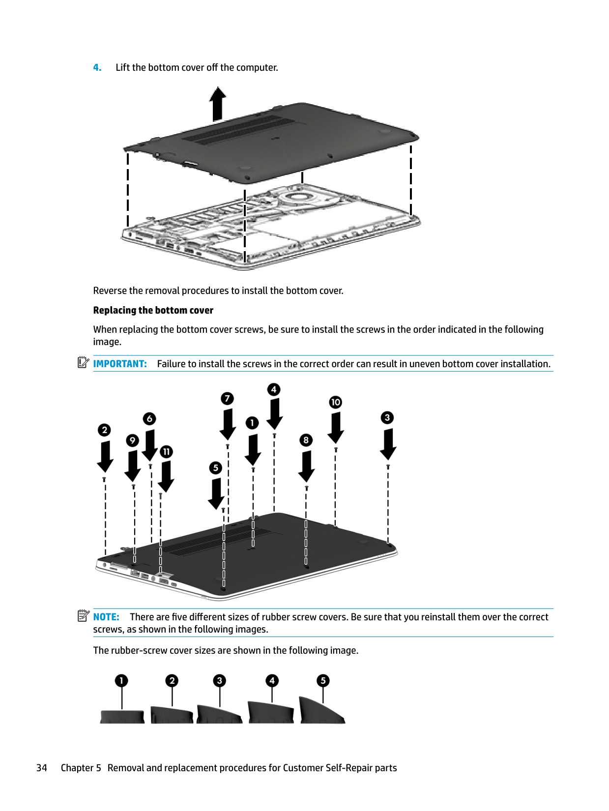
Reverse the removal procedures to install the bottom cover. Replacing the bottom cover
When replacing the bottom cover screws, be sure to install the screws in the order indicated in the following image.
| | |---|
IMPORTANT: Failure to install the screws in the correct order can result in uneven bottom cover installation.
| | |---|

NOTE: There are five different sizes of rubber screw covers. Be sure that you reinstall them over the correct screws, as shown in the following images. The rubber-screw cover sizes are shown in the following image.

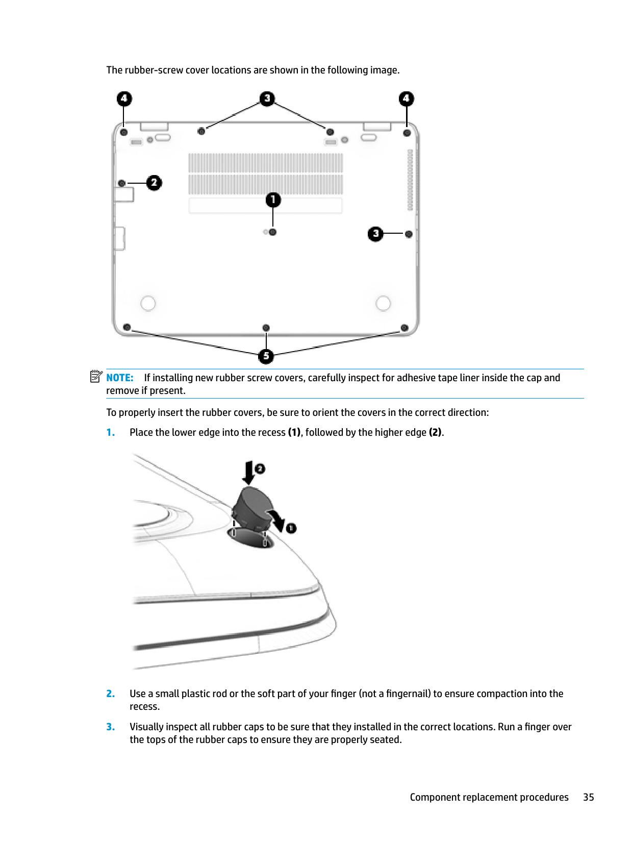
The rubber-screw cover locations are shown in the following image.
| | |---|

NOTE: If installing new rubber screw covers, carefully inspect for adhesive tape liner inside the cap and remove if present. To properly insert the rubber covers, be sure to orient the covers in the correct direction:


#### Battery
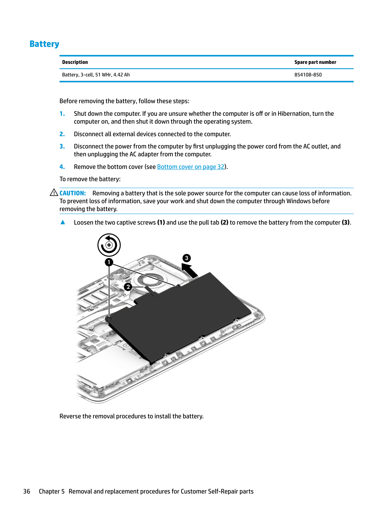
Description Spare part number Battery, 3-cell, 51 WHr, 4.42 Ah 854108-850
Before removing the battery, follow these steps:
CAUTION: Removing a battery that is the sole power source for the computer can cause loss of information. To prevent loss of information, save your work and shut down the computer through Windows before removing the battery.
▲ Loosen the two captive screws (1) and use the pull tab (2) to remove the battery from the computer (3).

Reverse the removal procedures to install the battery.
#### Hard drive
######## Description Spare part number
1 TB, 5400 rpm, 7 mm 762990-001 500 GB, 7200 rpm, 7 mm, FIPS 820572-001 500 GB, 7200 rpm, 7 mm, Opal-2 820573-001 500 GB, 7200 rpm, 7 mm 703267-001 500 GB, 5400 rpm, 7 mm, hybrid, 8 GB cache 732000-001
Before removing the hard drive, follow these steps:


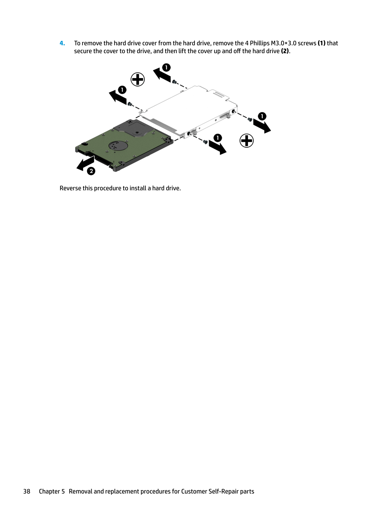
Reverse this procedure to install a hard drive.
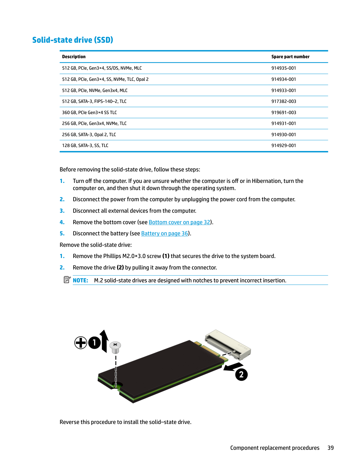
#### Solid-state drive (SSD)
######## Description Spare part number
512 GB, PCIe, Gen3×4, SS/DS, NVMe, MLC 914935-001 512 GB, PCIe, Gen3×4, SS, NVMe, TLC, Opal 2 914934-001 512 GB, PCIe, NVMe, Gen3x4, MLC 914933-001 512 GB, SATA-3, FIPS-140–2, TLC 917382-003 360 GB, PCIe Gen3×4 SS TLC 919691-003 256 GB, PCIe, Gen3x4, NVMe, TLC 914931-001 256 GB, SATA-3, Opal 2, TLC 914930-001 128 GB, SATA-3, SS, TLC 914929-001
Before removing the solid-state drive, follow these steps:
| | |---|

Reverse this procedure to install the solid–state drive.
Memory modules NOTE: Primary and expansion memory is installed in a side-by-side configuration in the bottom of the computer. If only one memory module is installed, it must be installed in the socket labeled ‘1’.
| | |---|
Description Spare part number
4-GB (DDR-2400) 862397-850 8-GB (DDR-2400) 862398-850 16-GB (DDR-2400) 865396-850
Update BIOS before adding memory modules Before adding new memory, make sure you update the computer to the latest BIOS. CAUTION: Failure to update the computer to the latest BIOS prior to installing new memory may result in various system problems. To update BIOS:
| | |---|
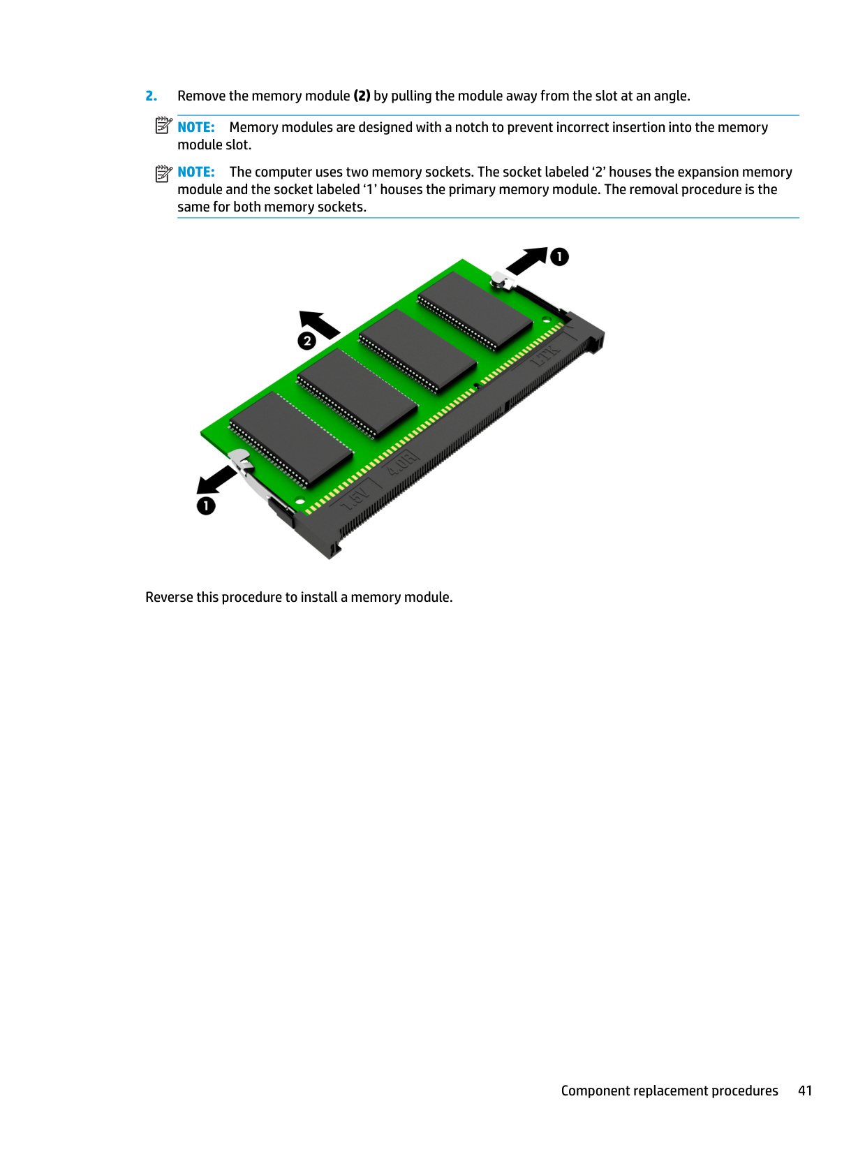
NOTE: Memory modules are designed with a notch to prevent incorrect insertion into the memory module slot.
| | |---|
NOTE: The computer uses two memory sockets. The socket labeled ‘2’ houses the expansion memory module and the socket labeled ‘1’ houses the primary memory module. The removal procedure is the same for both memory sockets.

Reverse this procedure to install a memory module.
WLAN/Bluetooth combo card The computer uses a card that provides both WLAN and Bluetooth functionality. The WLAN module and WWAN module are not interchangeable.
Description Spare part number
Intel Dual Band Wireless-AC 3165 802.11ac 1x1 WiFi + BT 4.0 combo adapter 851592-001 Intel Dual Band Wireless-AC 8260NGW 802.11a/g/g/n+ac 2x2 WiFi + BT 4.2 combo adapter 851594-001 Intel Dual Band Wireless-AC 8260NGW 802.11a/b/g/n+ac non-vPro 2x2 WiFi + BT 4.2 combo adapter 852511-001
Before removing the WLAN module, follow these steps:
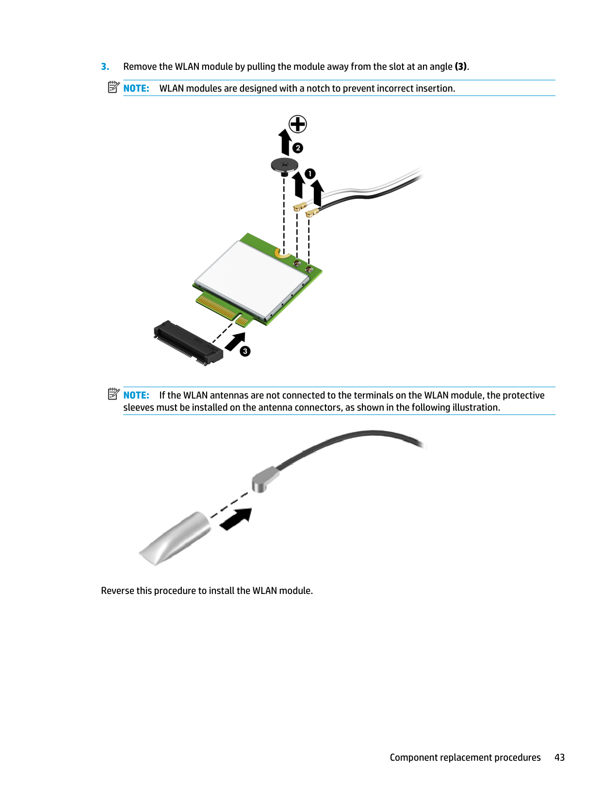
NOTE: The WLAN antenna cable labeled ‘1’ connects to the WLAN module “Main” terminal labeled ‘1’. The WLAN antenna cable labeled ‘2’ connects to the WLAN module ‘Aux’ terminal labeled ‘2’. If the computer is equipped with an 802.11a/b/g/n WLAN module, the yellow WLAN antenna cable connects to the middle terminal on the WLAN module.
| | |---|
| | |---|
| | |---|

NOTE: If the WLAN antennas are not connected to the terminals on the WLAN module, the protective sleeves must be installed on the antenna connectors, as shown in the following illustration.

Reverse this procedure to install the WLAN module.
WWAN module The WLAN module and WWAN module are not interchangeable. The WWAN module is available on select models only.
Description Spare part number
HP lt4120 LTE/EVDO/HSPA+ SnapdragonT X5 LTE Mobile Broadband Module 800870-001 Huawei HP It4132 - LTE/HSPA+ with GPS 845710-001 Fibocom HP hs3210 WW HSPA+ without GPS 860726-001
Before removing the WWAN module, follow these steps:
computer on, and then shut it down through the operating system.
then unplugging the AC adapter from the computer. 4. Remove the bottom cover (see Bottom cover on page 32).
NOTE: The red WWAN antenna cable is connected to the WWAN module ‘Main’ terminal. The blue WWAN antenna cable is connected to the WWAN module ‘Aux’ terminal.
| | |---|
| | |---|
| | |---|

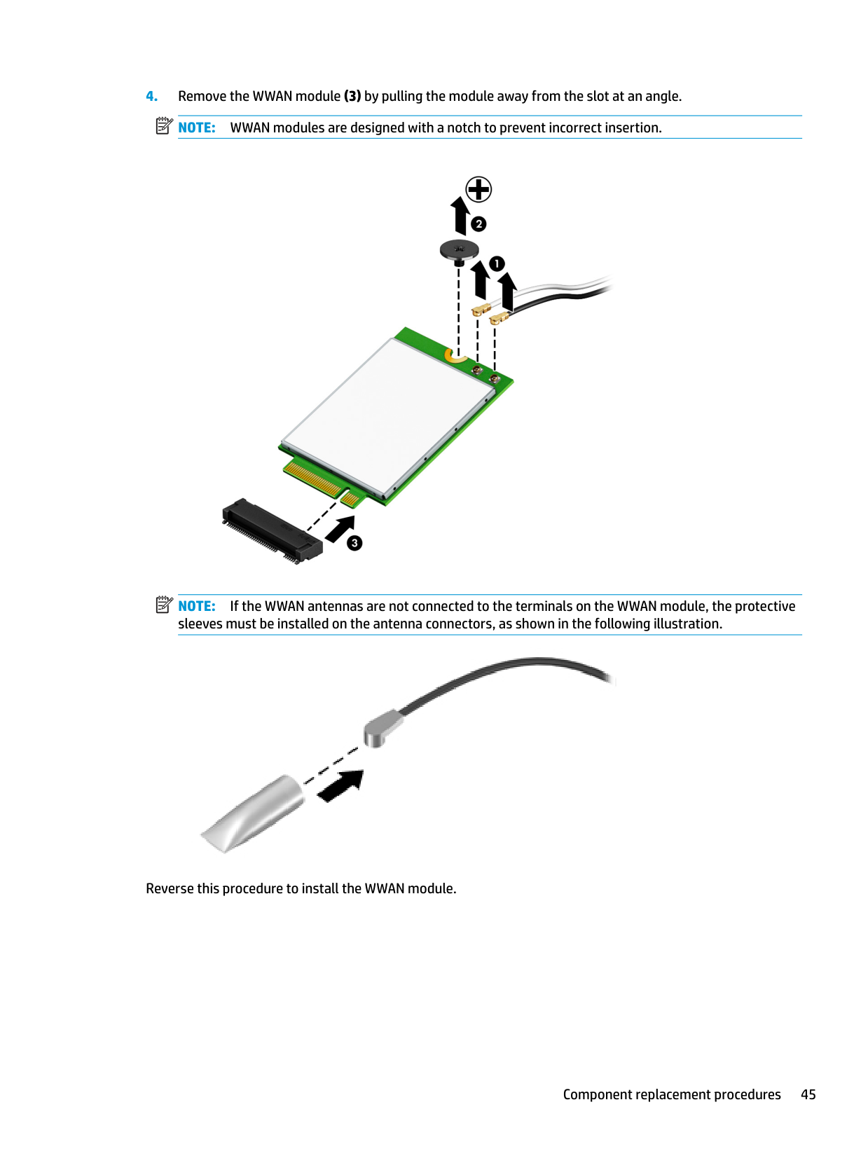
NOTE: If the WWAN antennas are not connected to the terminals on the WWAN module, the protective sleeves must be installed on the antenna connectors, as shown in the following illustration.

Reverse this procedure to install the WWAN module.
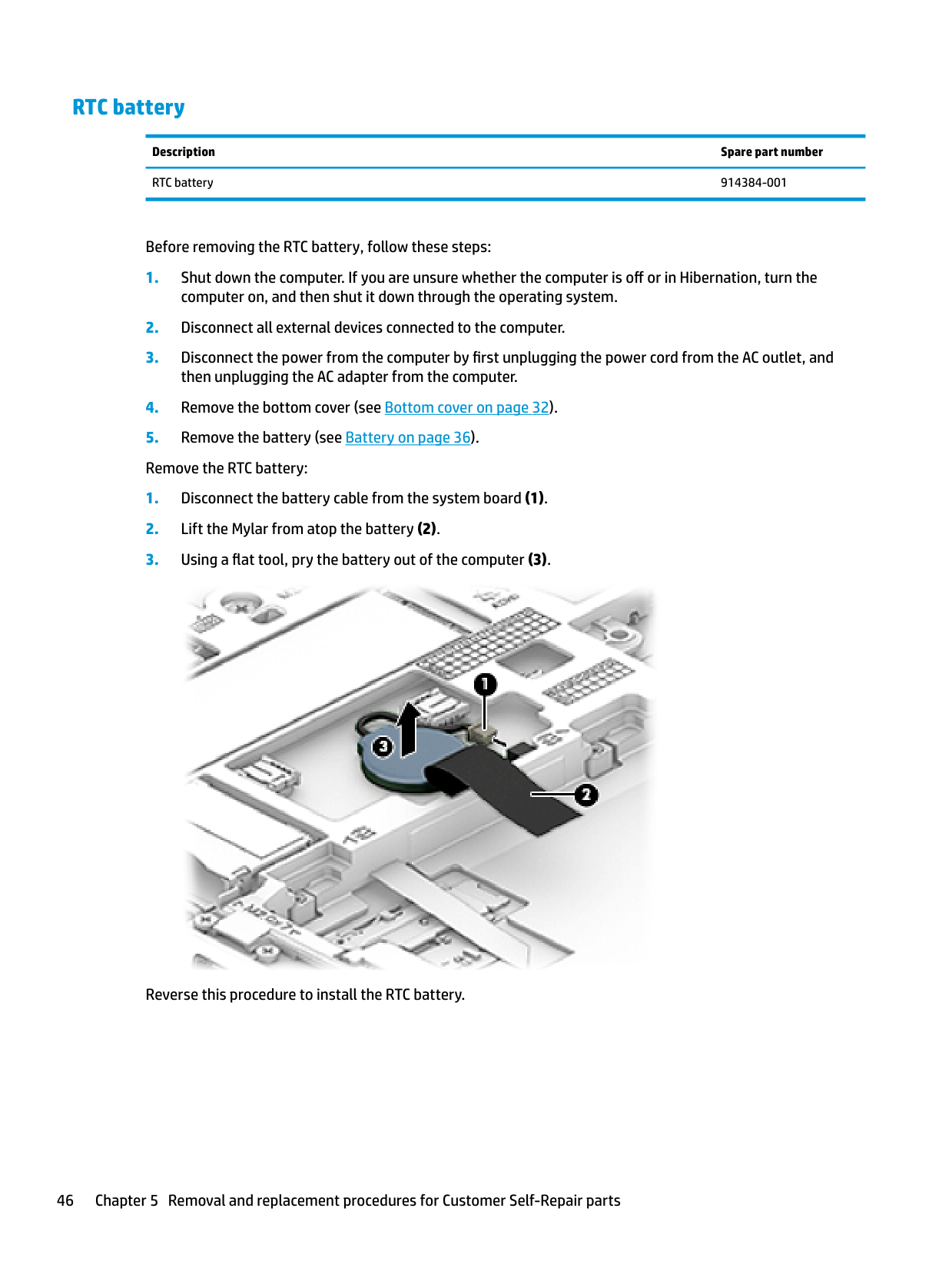
#### RTC battery
Description Spare part number RTC battery 914384-001
Before removing the RTC battery, follow these steps:

Reverse this procedure to install the RTC battery.
#### Keyboard
In this section, the first table provides the main spare part number for the keyboards. The second table provides the country codes.
Description Spare part number
Keyboard, no backlight 836307-xx1 Keyboard, backlit 836308-xx1 Keyboard, backlit, privacy 903008-xx1 Keyboard for use in Japan; without a backlight 923272-291 Keyboard for use in Japan; with a backlight 923273-291 Pointing stick covers (20 count) 828884-001
For use in country or region
Spare part number
For use in country or region
Spare part number
For use in country or region
Spare part number
Belgium -A41 India -D61 Slovenia -BA1 Brazil -201 Israel -BB1 South Korea -AD1 Bulgaria -261 Italy -061 Spain -071 Canada -DB1 Japan -291 Sweden and Finland -B71 Czech Republic and Slovakia
-FL1 Latin America -161 Switzerland -BG1
Denmark -081 The Netherlands -B31 Taiwan -AB1 Denmark, Finland, and Norway
-DH1 Northern Africa -FP1 Thailand -281
France -051 Norway -091 Turkey -141 Germany -041 Portugal -131 Turkey F -541 Greece -151 Romania -271 United Kingdom -031 Hungary -211 Russia -251 United States -001 Iceland -DD1 Saudi Arabia -171
Before removing the keyboard, follow these steps:
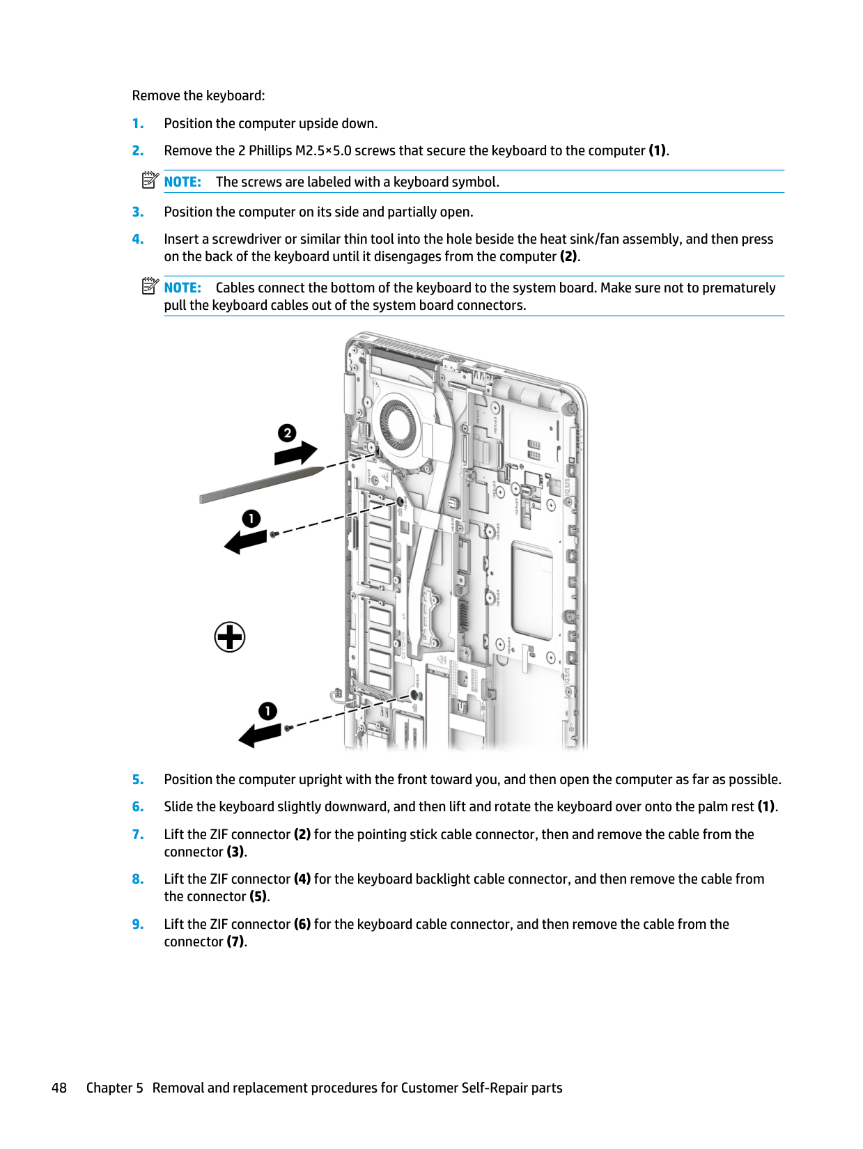
Remove the keyboard:
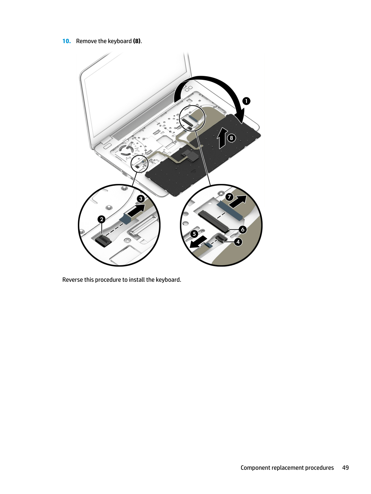
NOTE: Cables connect the bottom of the keyboard to the system board. Make sure not to prematurely pull the keyboard cables out of the system board connectors.

| | |---|
| | |---|

Reverse this procedure to install the keyboard.
6 Removal and replacement procedures forAuthorized Service Provider parts
This chapter provides removal and replacement procedures for Authorized Service Provider only parts. CAUTION: Components described in this chapter should only be accessed by an authorized service provider. Accessing these parts can damage the computer or void the warranty. CAUTION: This computer does not have user-replaceable parts. Only HP authorized service providers should perform the removal and replacement procedures described here. Accessing the internal part could damage the computer or void the warranty.
Component replacement procedures
| | |---|
NOTE: Details about your computer, including model, serial number, product key, and length of warranty, are on the service tag at the bottom of your computer. See Labels on page 17 for details.
| | |---|
NOTE: HP continually improves and changes product parts. For complete and current information on supported parts for your computer, go to http://partsurfer.hp.com, select your country or region, and then follow the on-screen instructions.
There are as many as 45 screws that must be removed, replaced, and/or loosened when servicing Authorized Service Provider only parts. Make special note of each screw size and location during removal and replacement.
#### Internal base plate
Description Spare part number Internal base plate 821164-001
Before removing the internal base plate, follow these steps:
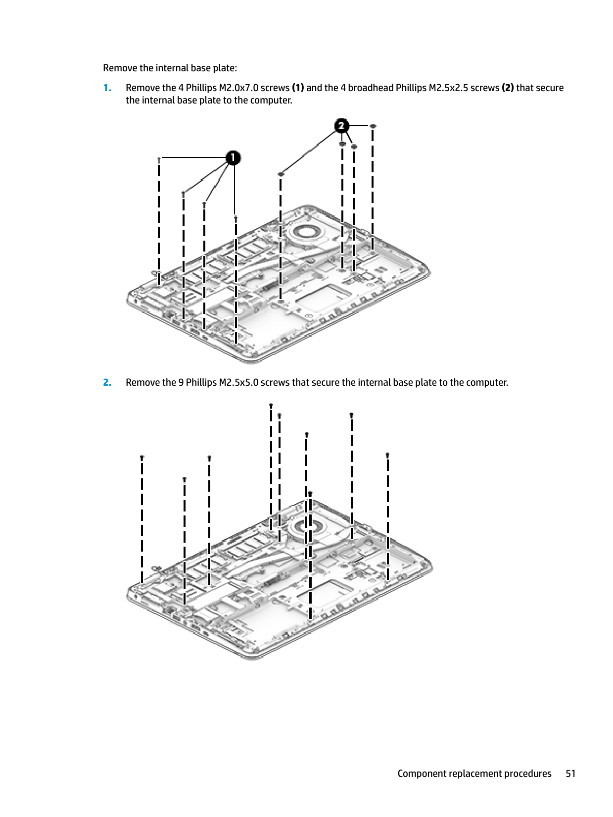
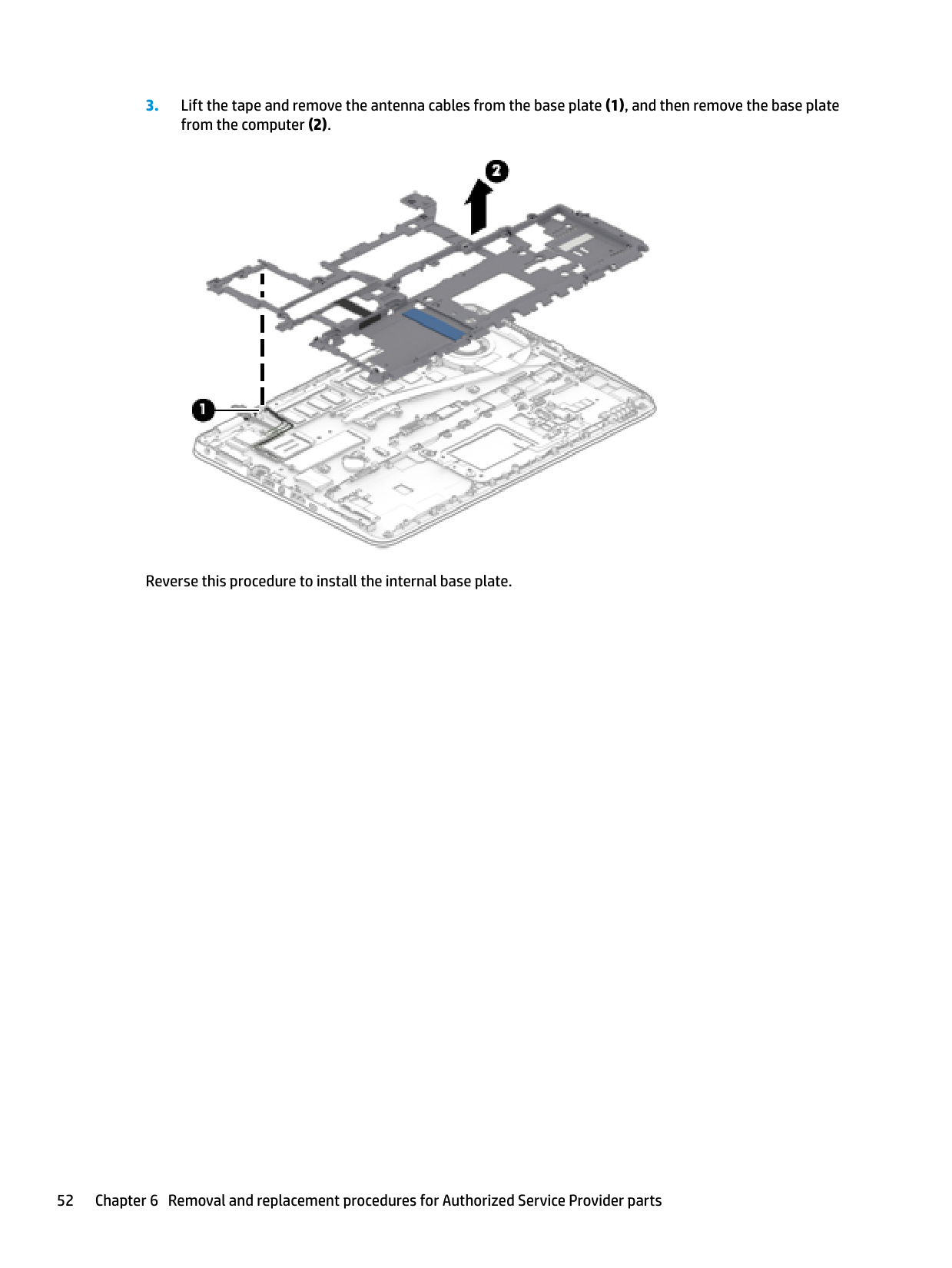
Remove the internal base plate:


Reverse this procedure to install the internal base plate.
#### Heat sink/fan assembly
| | |---|
NOTE: The heat sink/fan assembly spare part kit includes replacement thermal material.
Description Spare part number Heat sink/thermal module 821163-001
Before removing the heat sink/fan assembly, follow these steps:
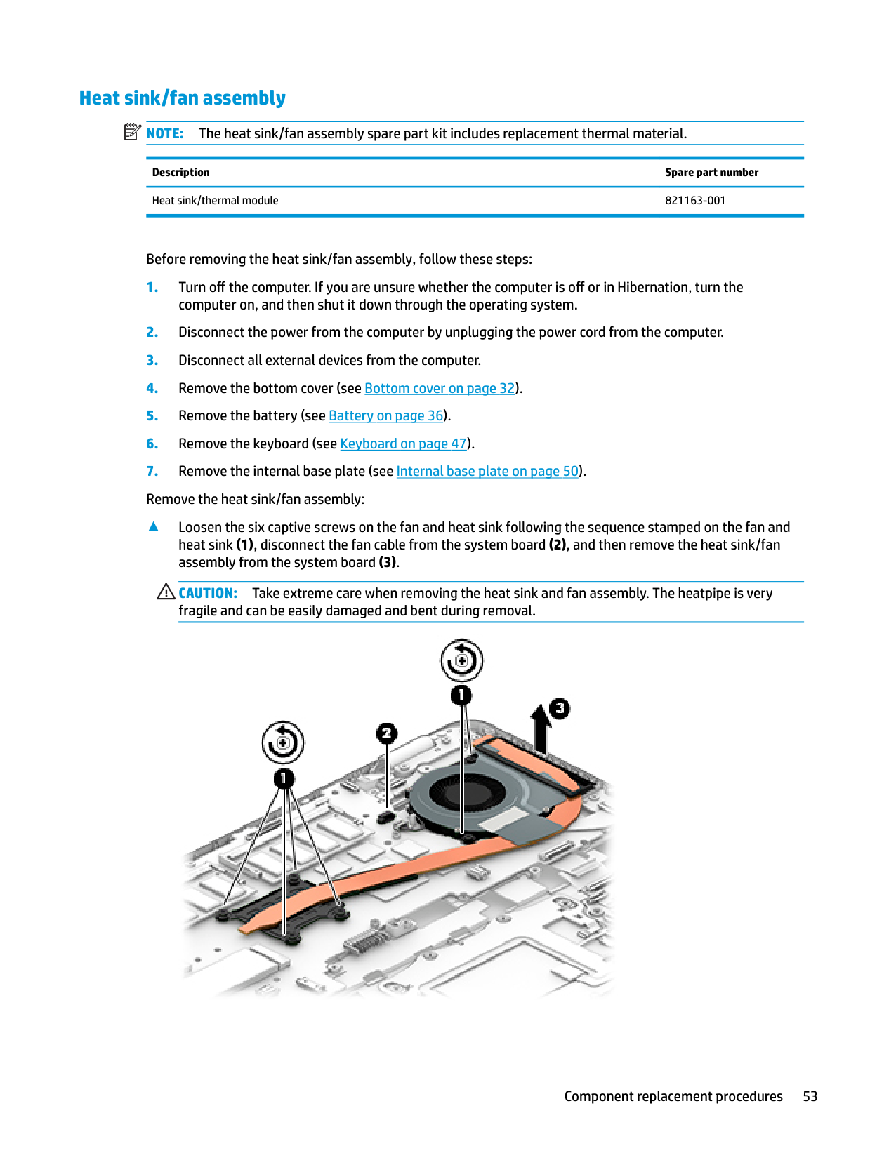
▲ Loosen the six captive screws on the fan and heat sink following the sequence stamped on the fan and heat sink (1), disconnect the fan cable from the system board (2), and then remove the heat sink/fan assembly from the system board (3).
CAUTION: Take extreme care when removing the heat sink and fan assembly. The heatpipe is very fragile and can be easily damaged and bent during removal.

| | |---|
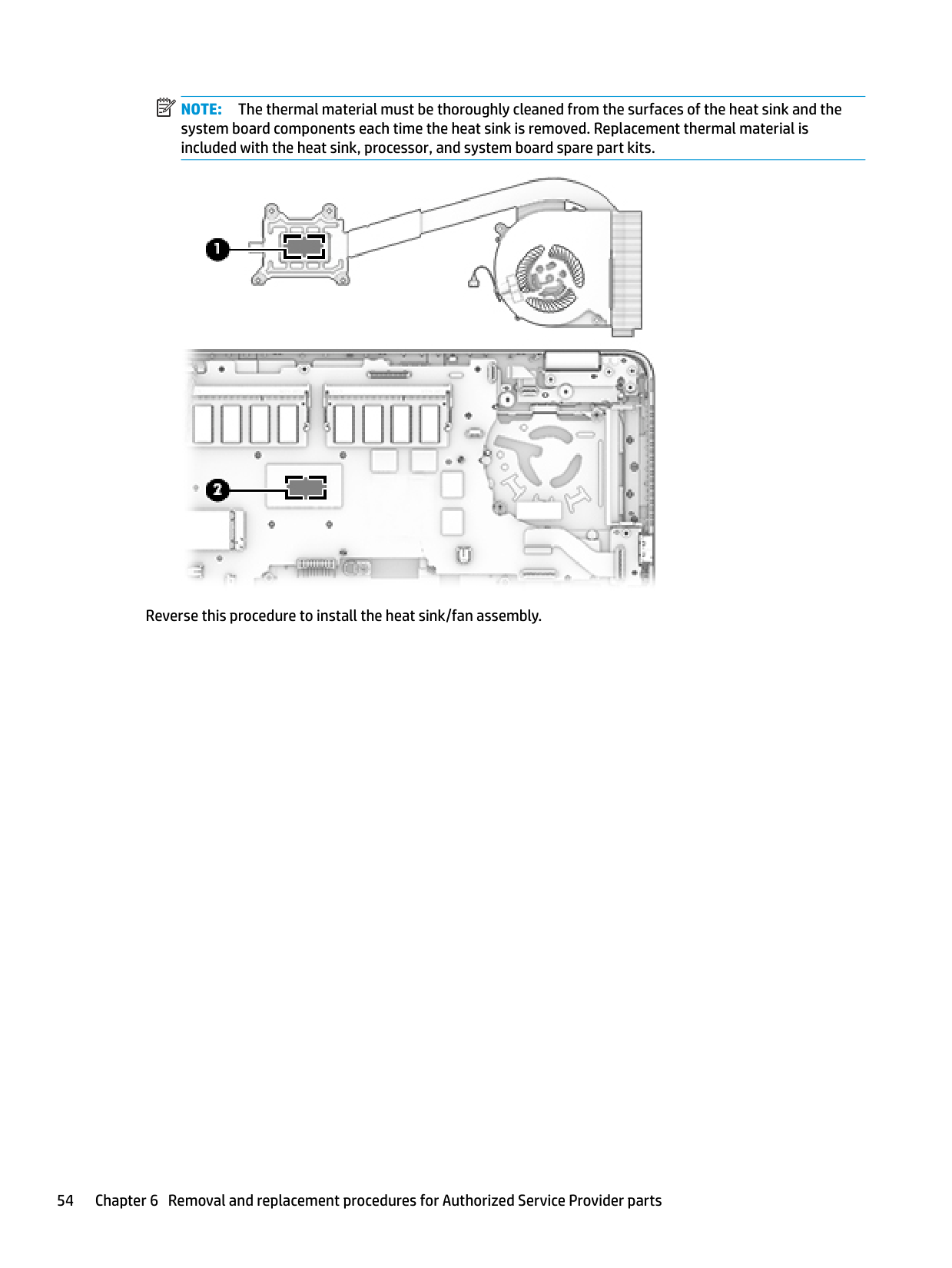
NOTE: The thermal material must be thoroughly cleaned from the surfaces of the heat sink and the system board components each time the heat sink is removed. Replacement thermal material is included with the heat sink, processor, and system board spare part kits.

Reverse this procedure to install the heat sink/fan assembly.
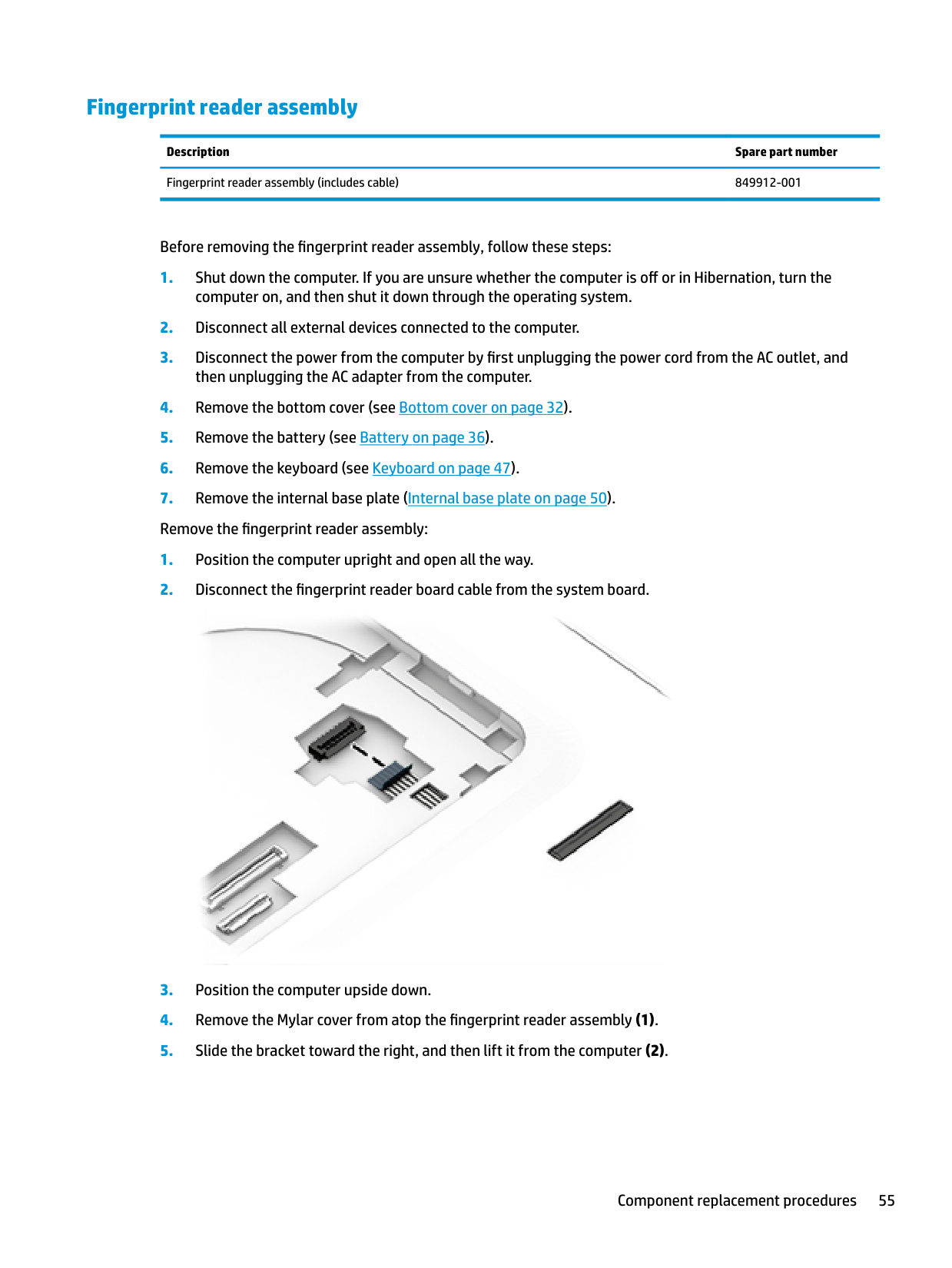
#### Fingerprint reader assembly
Description Spare part number Fingerprint reader assembly (includes cable) 849912-001
Before removing the fingerprint reader assembly, follow these steps:


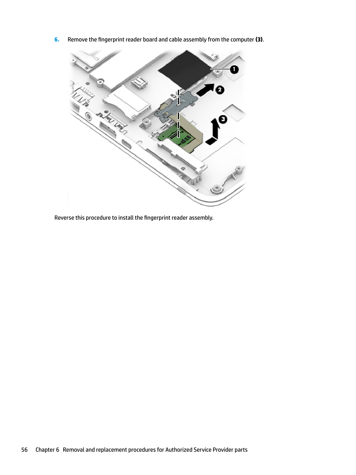
Reverse this procedure to install the fingerprint reader assembly.
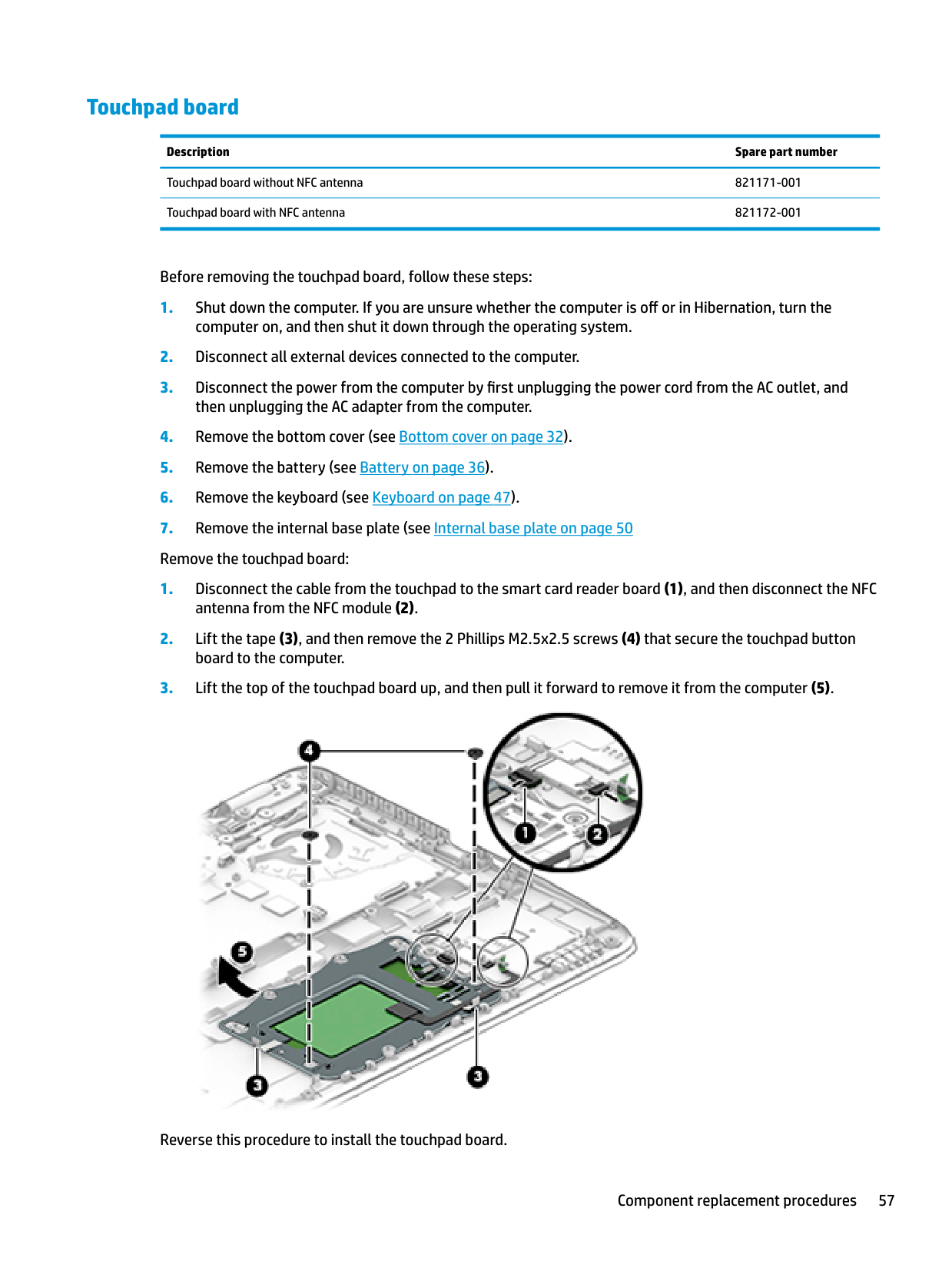
#### Touchpad board
######## Description Spare part number
Touchpad board without NFC antenna 821171-001 Touchpad board with NFC antenna 821172-001
Before removing the touchpad board, follow these steps:

Reverse this procedure to install the touchpad board.
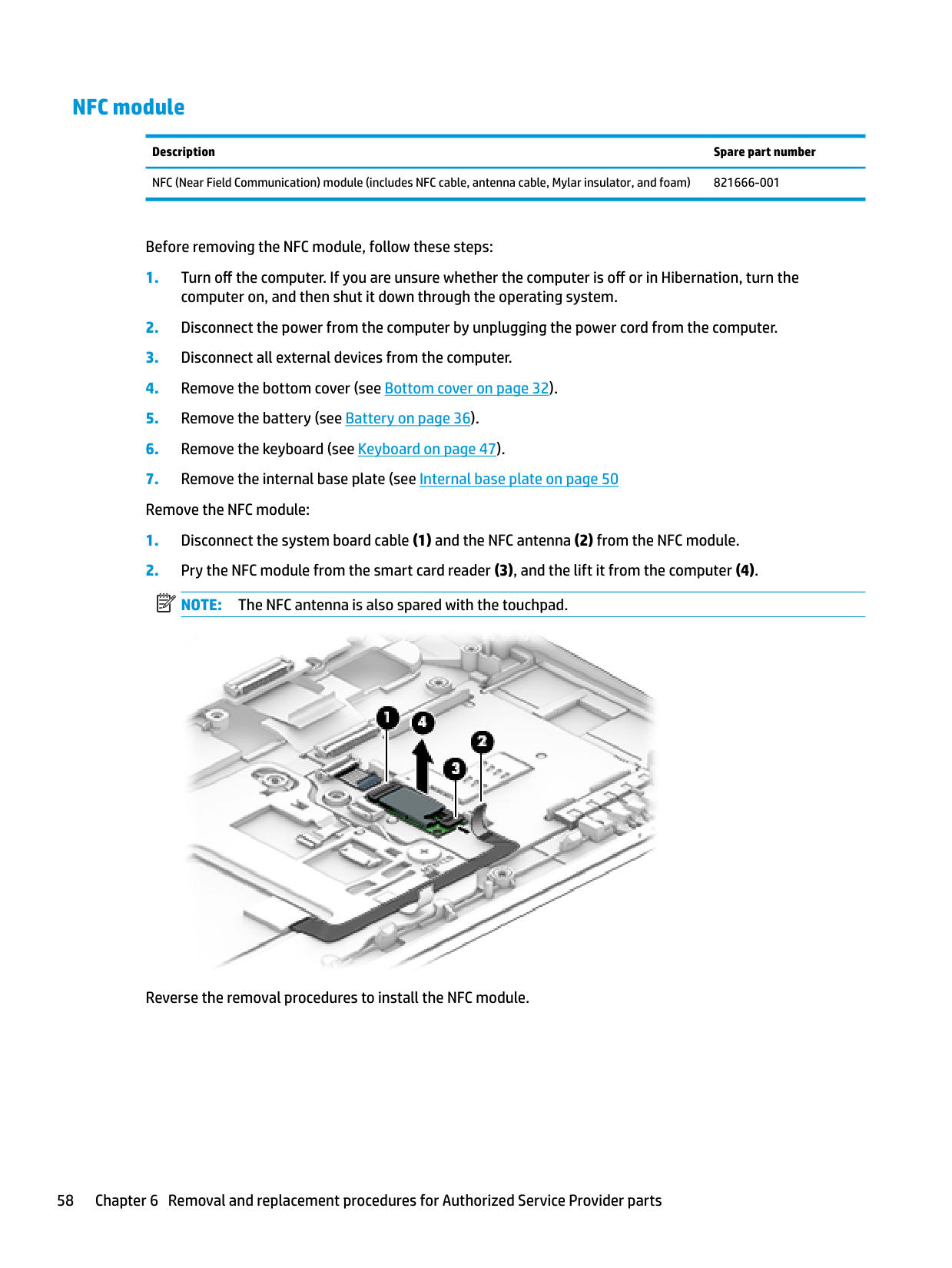
#### NFC module
Description Spare part number NFC (Near Field Communication) module (includes NFC cable, antenna cable, Mylar insulator, and foam) 821666-001
Before removing the NFC module, follow these steps:
| | |---|

Reverse the removal procedures to install the NFC module.
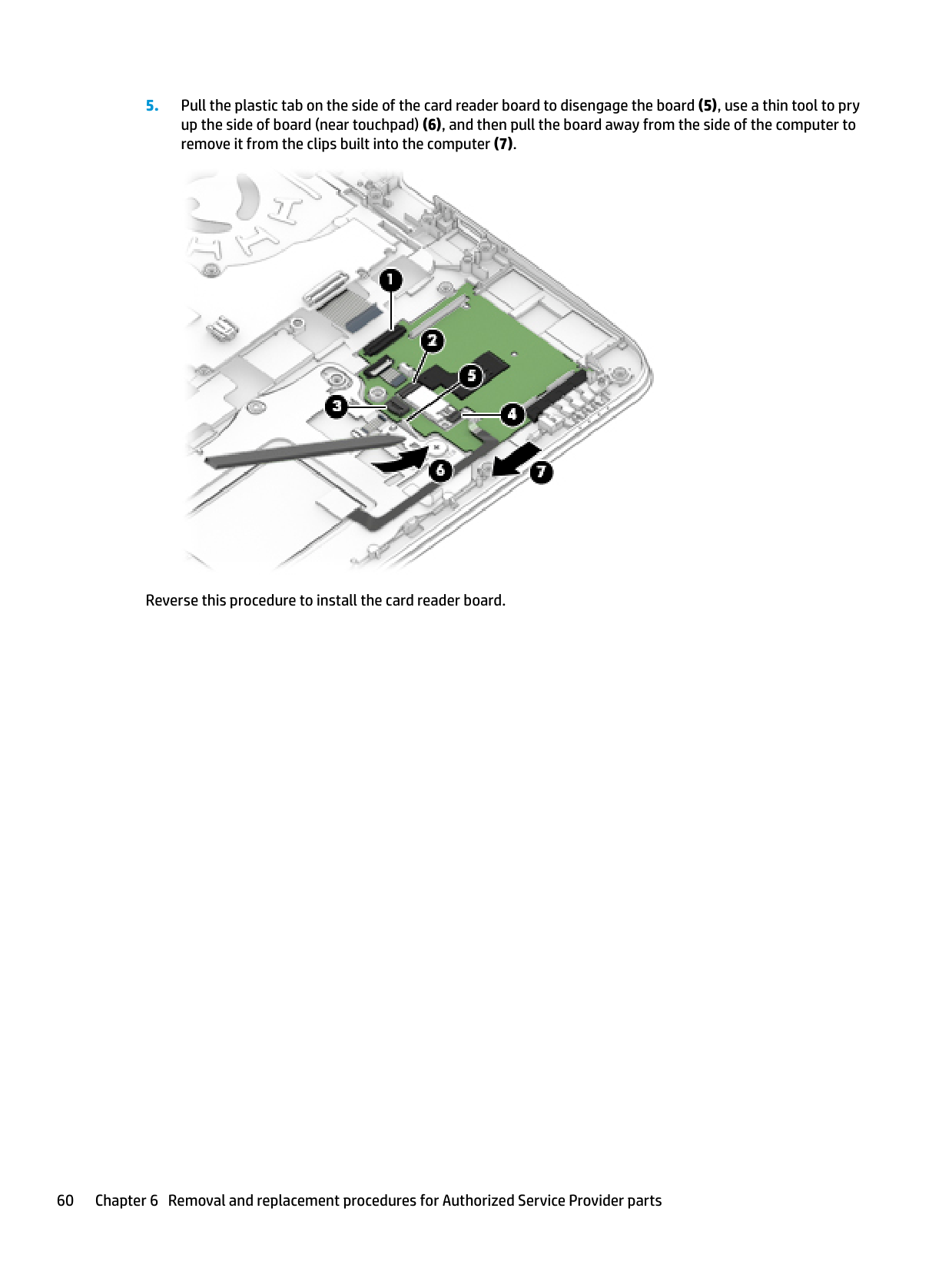
#### Smart card reader board
Description Spare part number Smart card reader board 914380-001 Smart card reader cable (available in Cable Kit) 914381-001 (Cable Kit)
Before removing the card reader board, follow these steps:
computer on, and then shut it down through the operating system.
then unplugging the AC adapter from the computer. 4. Remove the bottom cover (see Bottom cover on page 32).
| | |---|

Reverse this procedure to install the card reader board.
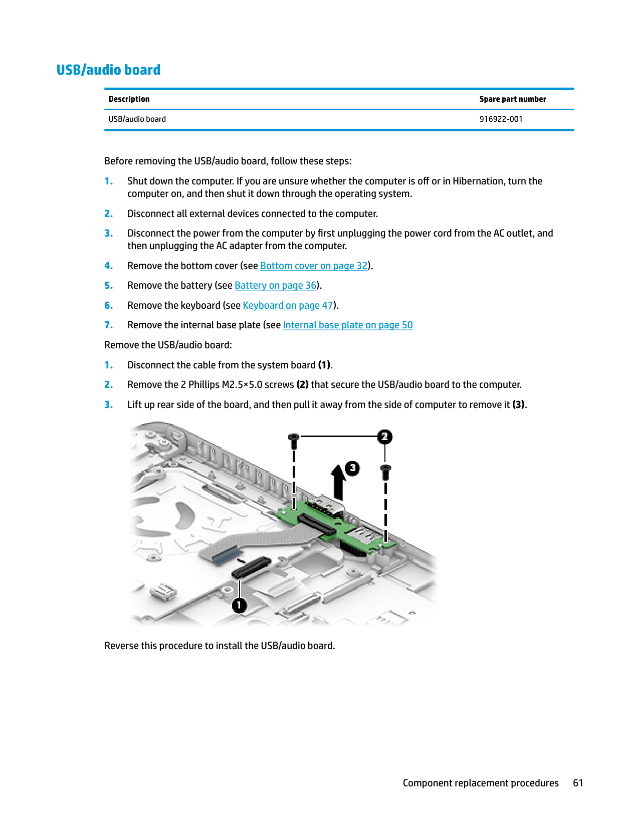
#### USB/audio board
Description Spare part number USB/audio board 916922-001
Before removing the USB/audio board, follow these steps:
computer on, and then shut it down through the operating system.
then unplugging the AC adapter from the computer. 4. Remove the bottom cover (see Bottom cover on page 32).

Reverse this procedure to install the USB/audio board.
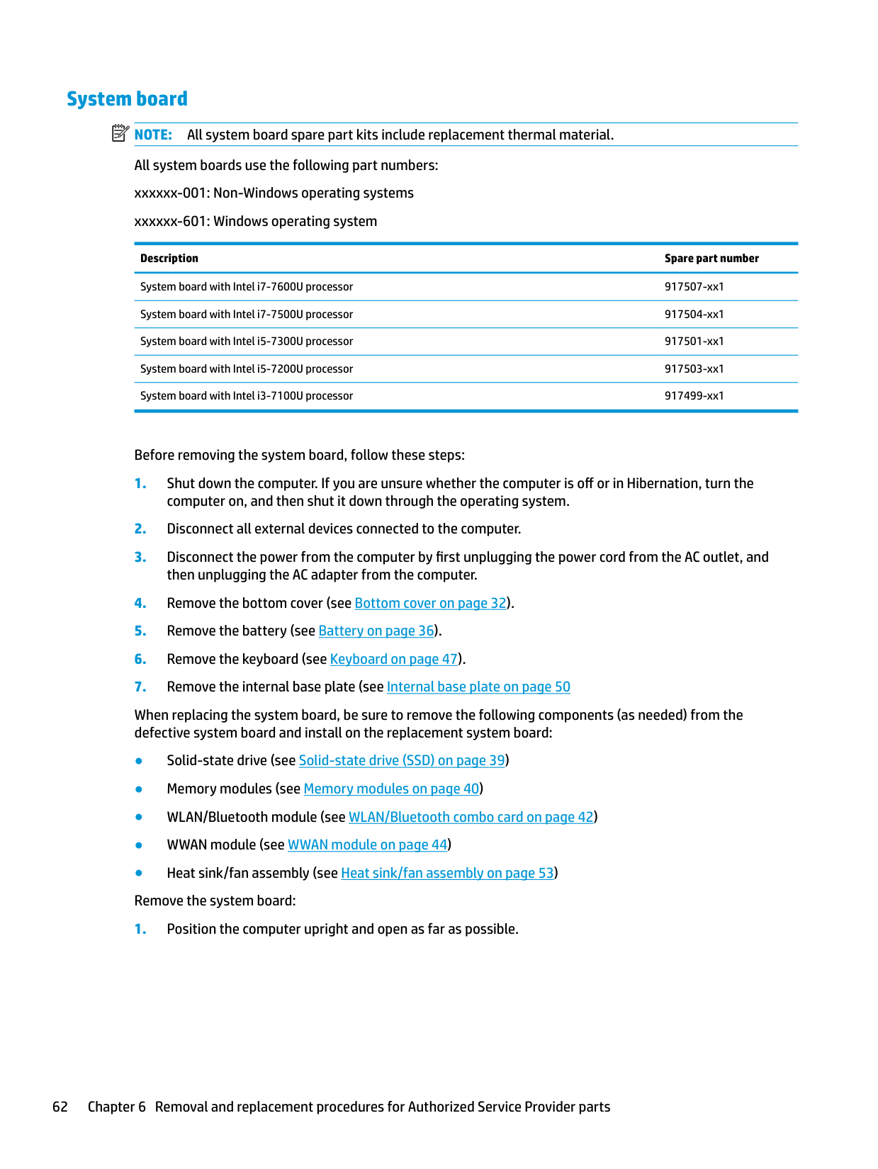
System board NOTE: All system board spare part kits include replacement thermal material. All system boards use the following part numbers: xxxxxx-001: Non-Windows operating systems xxxxxx-601: Windows operating system
| | |---|
Description Spare part number
System board with Intel i7-7600U processor 917507-xx1 System board with Intel i7-7500U processor 917504-xx1 System board with Intel i5-7300U processor 917501-xx1 System board with Intel i5-7200U processor 917503-xx1 System board with Intel i3-7100U processor 917499-xx1
Before removing the system board, follow these steps:
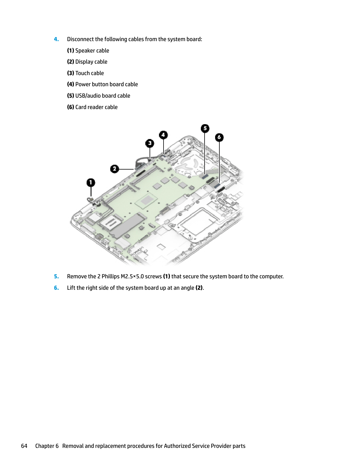
When replacing the system board, be sure to remove the following components (as needed) from the defective system board and install on the replacement system board:
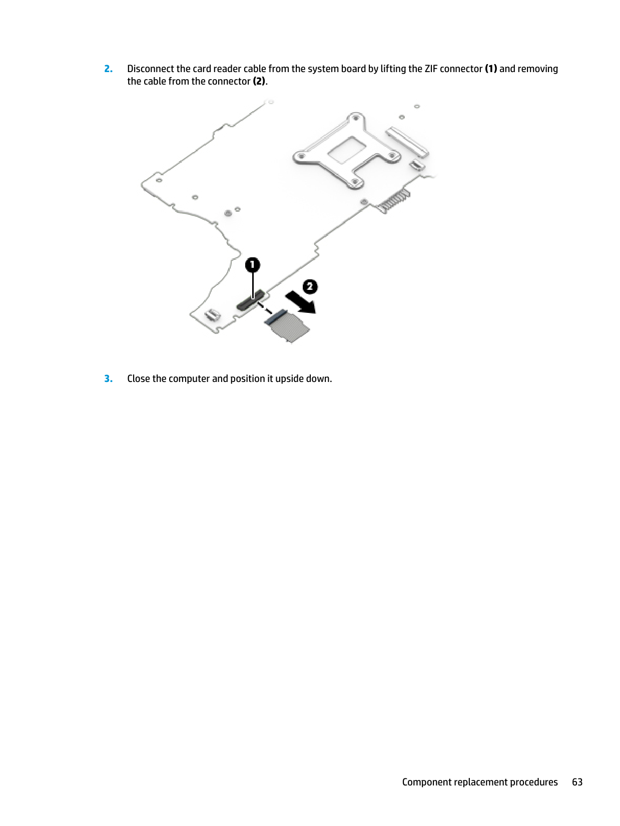
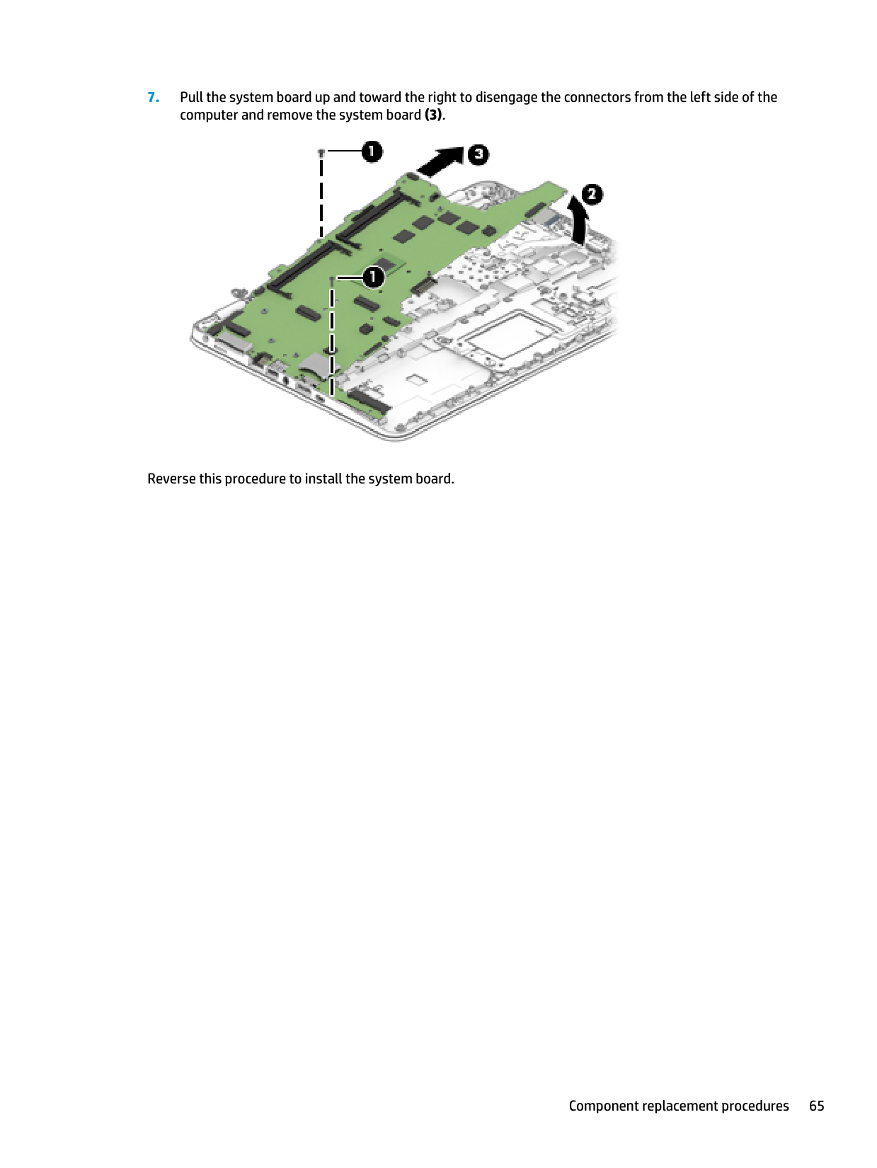
####### 2. Disconnect the card reader cable from the system board by lifting the ZIF connector (1) and removingthe cable from the connector (2).

####### 3. Close the computer and position it upside down.


Reverse this procedure to install the system board.
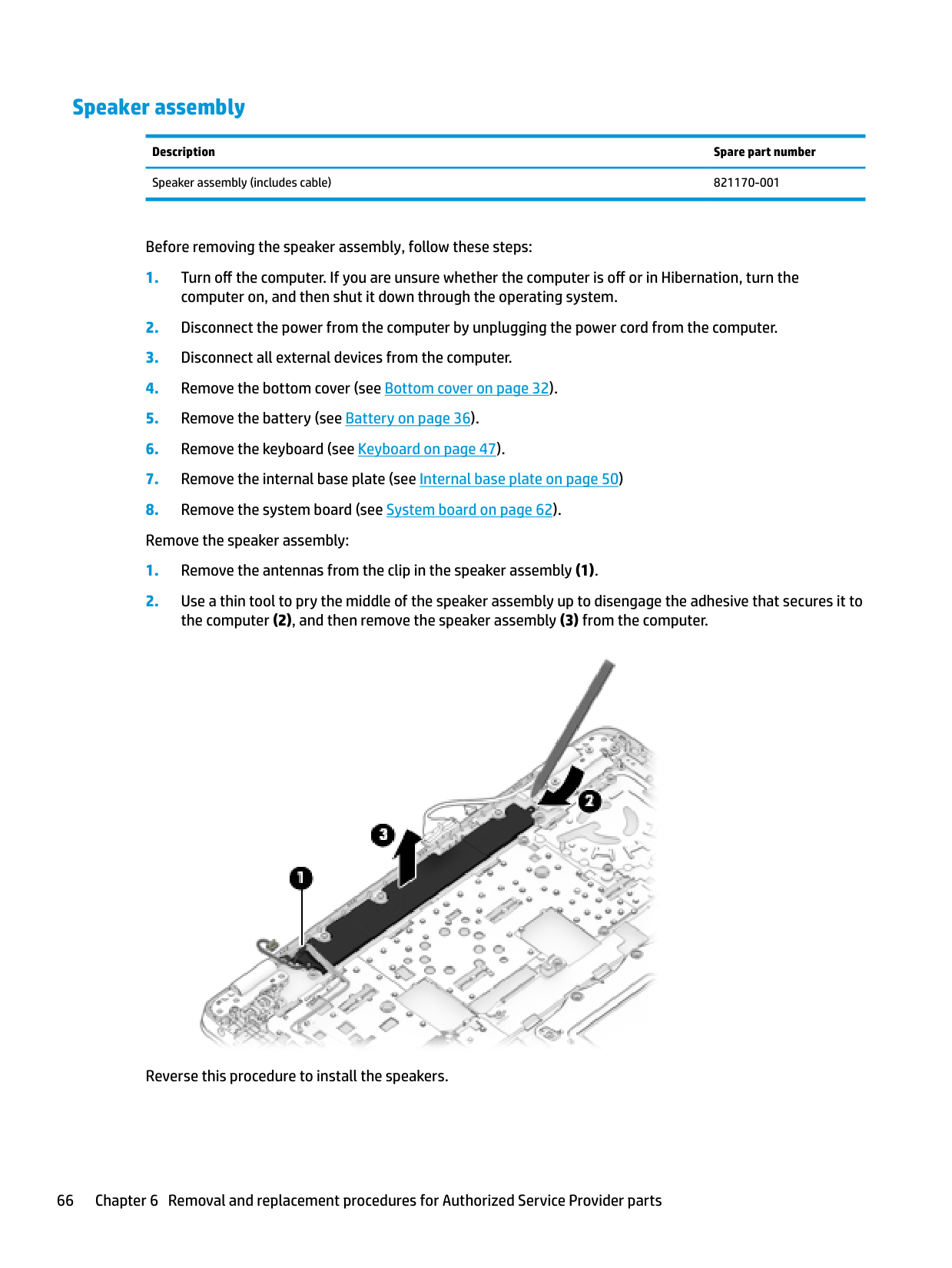
#### Speaker assembly
Description Spare part number Speaker assembly (includes cable) 821170-001
Before removing the speaker assembly, follow these steps:

Reverse this procedure to install the speakers.
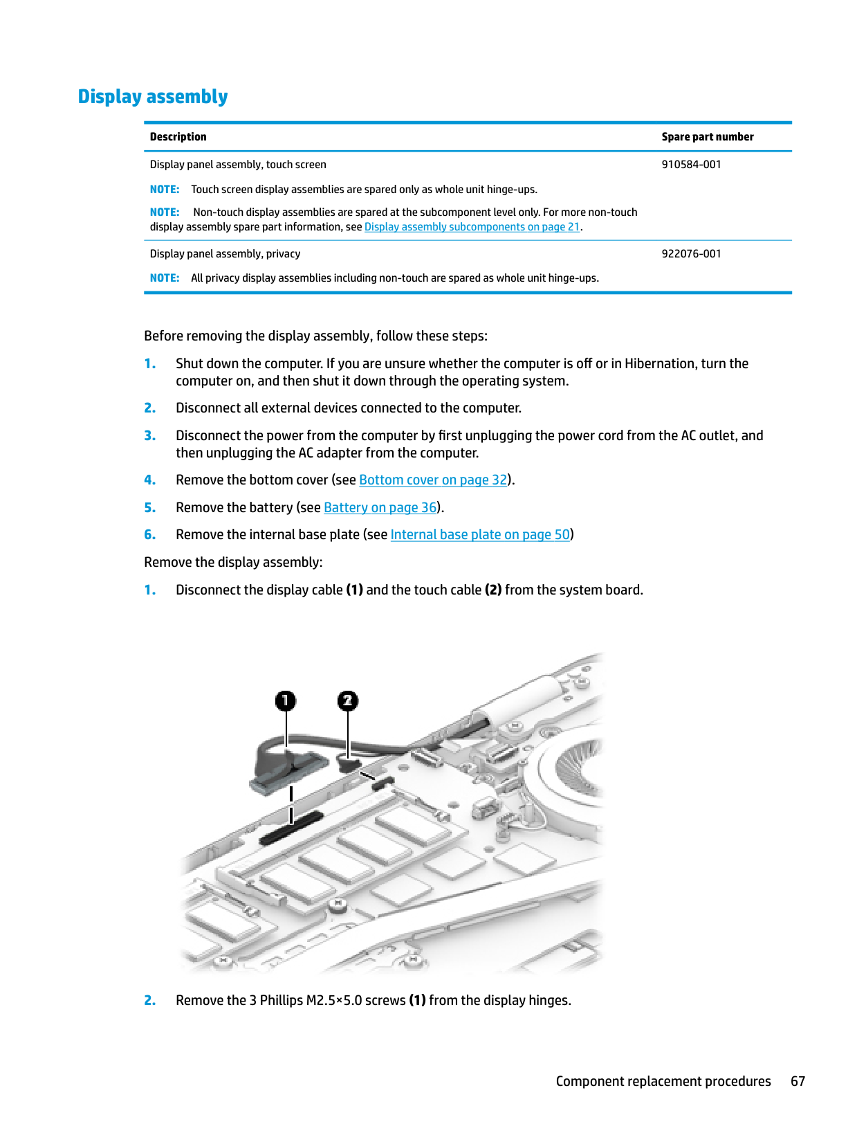
#### Display assembly
Description Spare part number Display panel assembly, touch screen
910584-001
NOTE: Touch screen display assemblies are spared only as whole unit hinge-ups. NOTE: Non-touch display assemblies are spared at the subcomponent level only. For more non-touch display assembly spare part information, see Display assembly subcomponents on page 21.
Display panel assembly, privacy NOTE: All privacy display assemblies including non-touch are spared as whole unit hinge-ups.
922076-001
Before removing the display assembly, follow these steps:

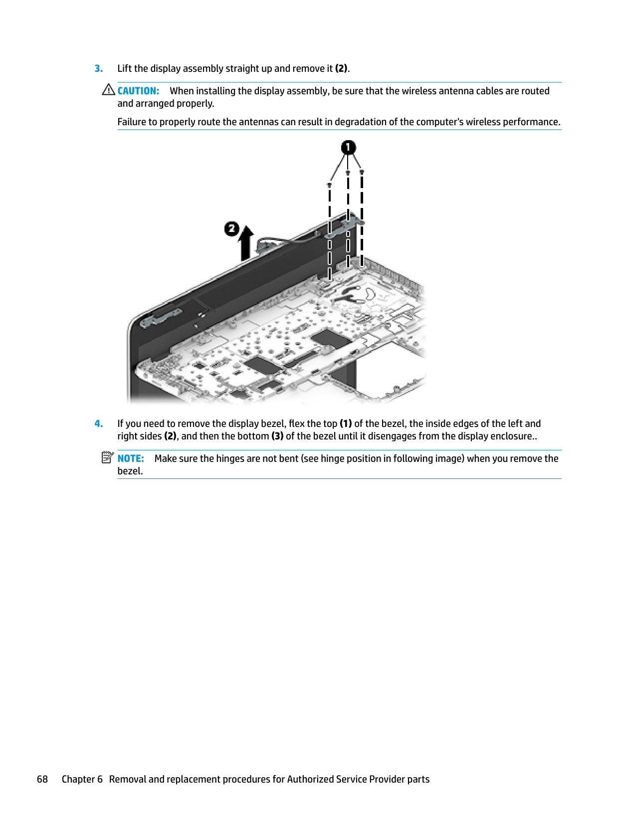
CAUTION: When installing the display assembly, be sure that the wireless antenna cables are routed and arranged properly. Failure to properly route the antennas can result in degradation of the computer's wireless performance.

| | |---|
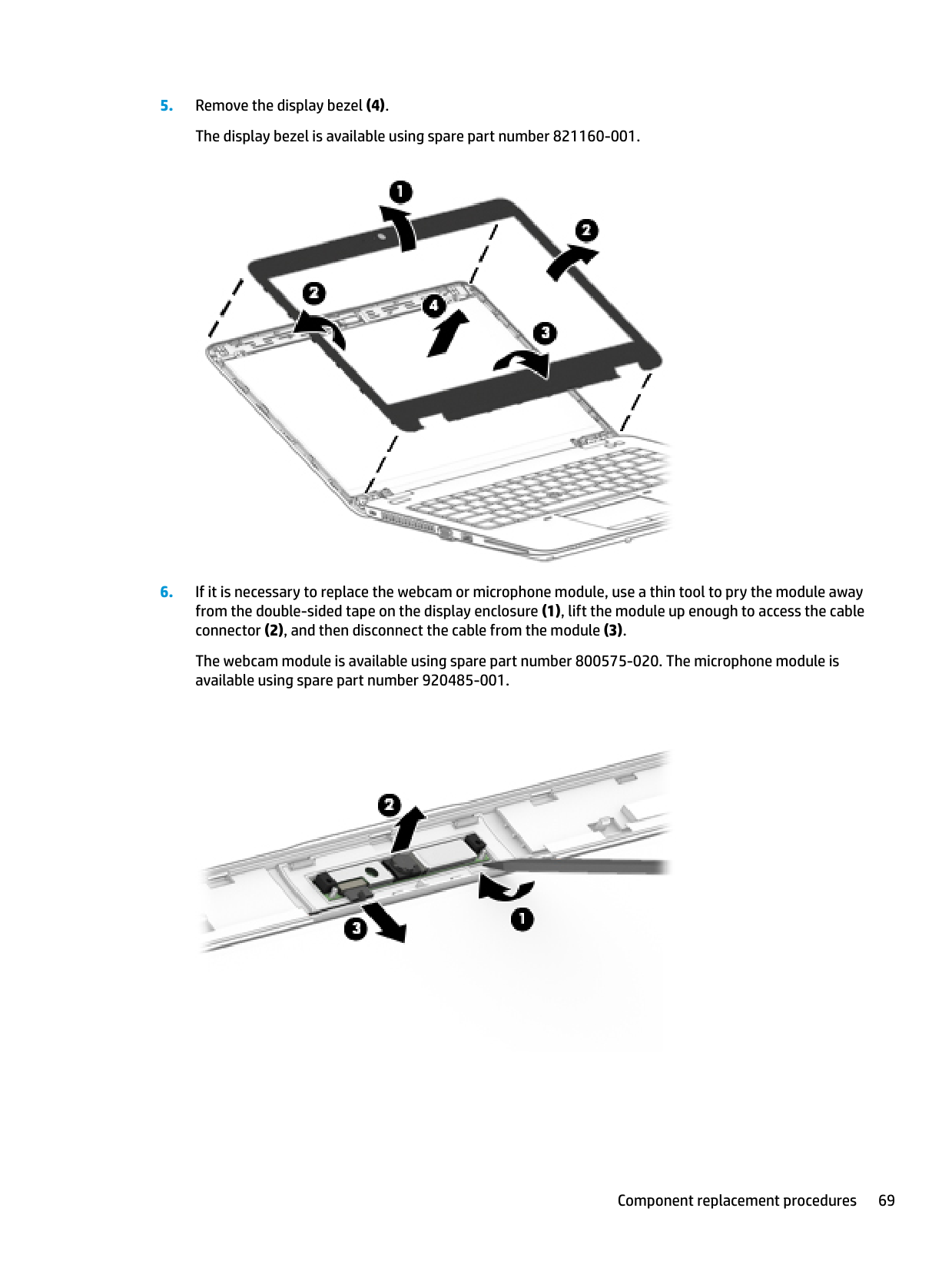
NOTE: Make sure the hinges are not bent (see hinge position in following image) when you remove the bezel.

The webcam module is available using spare part number 800575-020. The microphone module is available using spare part number 920485-001.

(2).
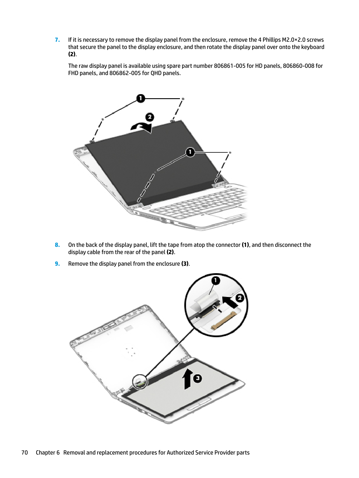
The raw display panel is available using spare part number 806861-005 for HD panels, 806860-008 for FHD panels, and 806862-005 for QHD panels.


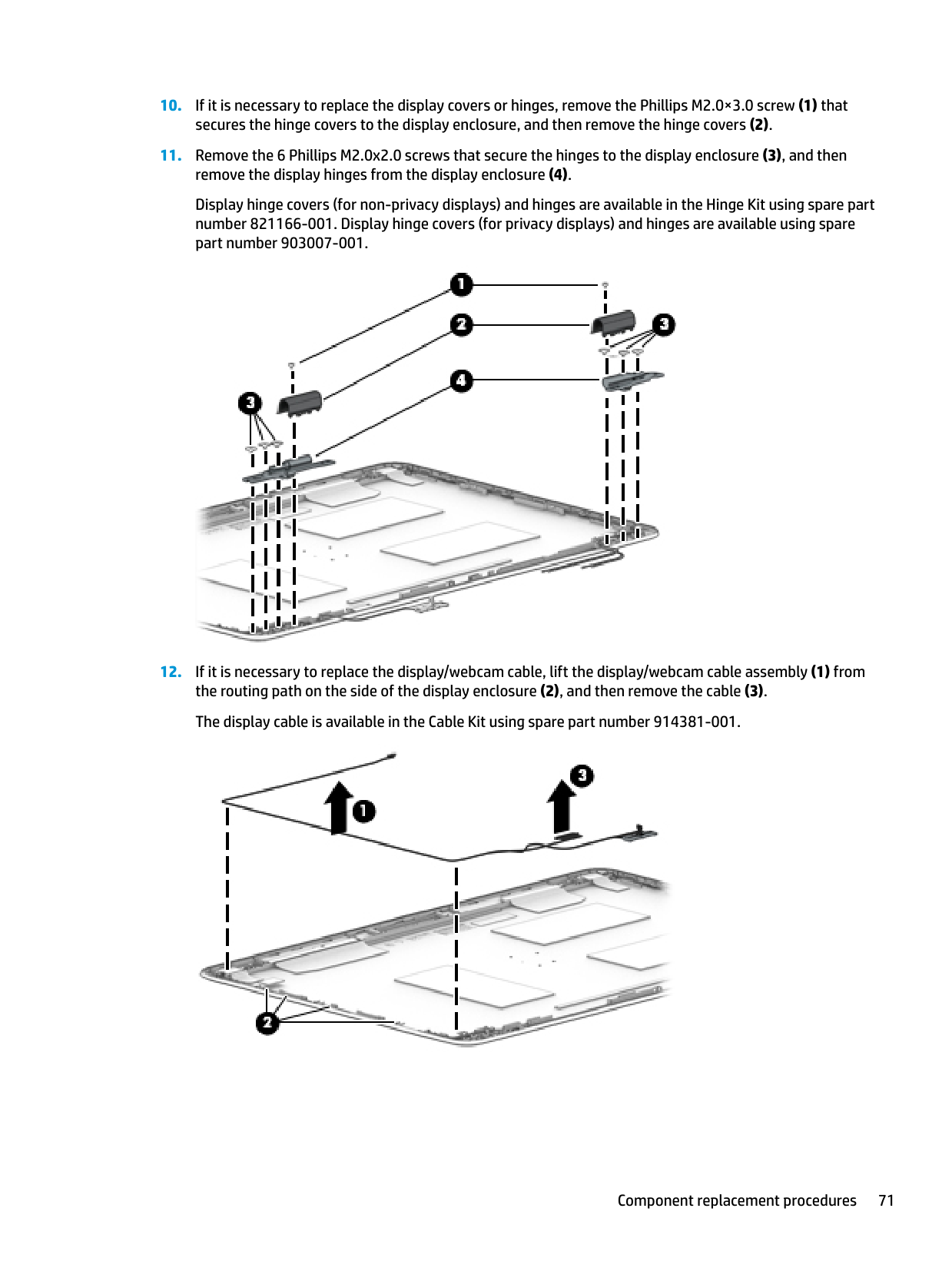
Display hinge covers (for non-privacy displays) and hinges are available in the Hinge Kit using spare part number 821166-001. Display hinge covers (for privacy displays) and hinges are available using spare part number 903007-001.


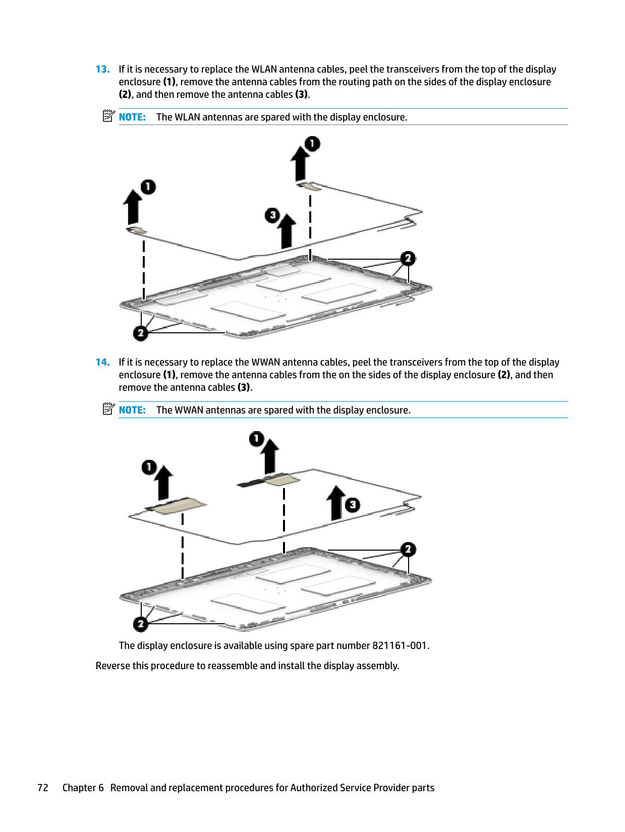
(2), and then remove the antenna cables (3). NOTE: The WLAN antennas are spared with the display enclosure.

| | |---|
| | |---|

The display enclosure is available using spare part number 821161-001. Reverse this procedure to reassemble and install the display assembly.
#### Power button board
Description Spare part number Power button board assembly 914382-001
Before removing the power button board, follow these steps:
computer on, and then shut it down through the operating system.
then unplugging the AC adapter from the computer. 4. Remove the bottom cover (see Bottom cover on page 32).
| | |---|
NOTE: The power button board sits under the right display hinge. You do not have to remove the display to remove the board, but you do have to rotate the right display hinge upward to gain access.
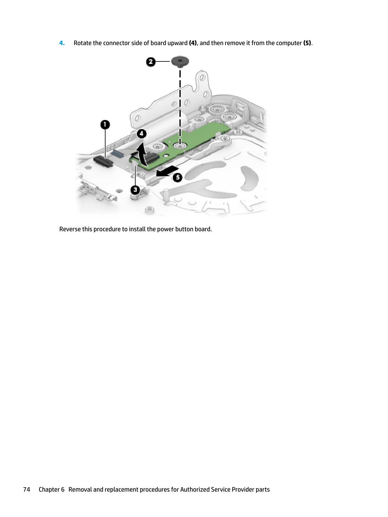
Remove the power button board:

Reverse this procedure to install the power button board.
#### Top cover
######## Description Spare part number
Top cover, standard 821173-001 Top cover, privacy 903979-001
The top cover remains after removing all other spared parts from the computer.
7 Interpreting system validation diagnosticfront panel LEDs and audible codes
During the system validation phase that occurs at system startup, the BIOS validates the functionality of the following subsystems and conditions:
| | |---|
If an error is detected, specific patterns of long and short blinks, accompanied by long and short beeps (where applicable) are used to identify the error. These patterns will make up a two part code:
Number of long beeps/blinks Error category
Patterns of blink/beep codes are determined by using the following parameters:
| | |---|
76 Chapter 7 Interpreting system validation diagnostic front panel LEDs and audible codes
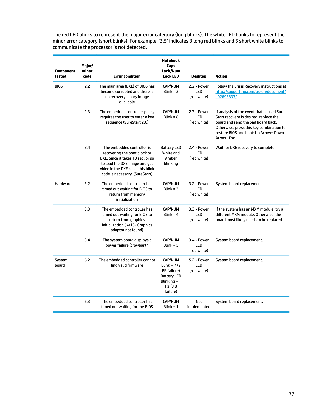
The red LED blinks to represent the major error category (long blinks). The white LED blinks to represent the minor error category (short blinks). For example, ‘3.5’ indicates 3 long red blinks and 5 short white blinks to communicate the processor is not detected.
Notebook Caps Lock/Num
Major/ minor
Component tested
Lock LED Desktop Action BIOS 2.2 The main area (DXE) of BIOS has
code Error condition
CAP/NUM Blink = 2
2.2 - Power LED (red.white)
Follow the Crisis Recovery instructions at http://support.hp.com/us-en/document/ c02693833/.
become corrupted and there is no recovery binary image available
sequence (SureStart 2.0)
CAP/NUM Blink = 8
2.3 - Power LED (red.white)
If analysis of the event that caused Sure Start recovery is desired, replace the board and send the bad board back. Otherwise, press this key combination to restore BIOS and boot: Up Arrow+ Down Arrow+ Esc.
DXE. Since it takes 10 sec. or so to load the DXE image and get video in the DXE case, this blink code is necessary. (SureStart)
Hardware 3.2 The embedded controller has
timed out waiting for BIOS to return from memory initialization
return from graphics initialization ( 4/13- Graphics adaptor not found)
CAP/NUM Blink = 4
3.3 - Power LED (red.white)
If the system has an MXM module, try a different MXM module. Otherwise, the board most likely needs to be replaced.
Battery LED White and Amber blinking
CAP/NUM Blink = 3
CAP/NUM Blink = 5
System board
CAP/NUM Blink = 7 (2 BB failure) Battery LED Blinking = 1 Hz (3 B failure)
5.2 - Power LED (red.white)
System board replacement.
CAP/NUM Blink = 1
2.4 - Power LED (red.white)
Wait for DXE recovery to complete.
3.2 - Power LED (red.white)
System board replacement.
3.4 - Power LED (red.white)
System board replacement.
Not implemented
System board replacement.
77
8 Computer Setup (BIOS), TPM, and HP SureStart
Using Computer Setup
Computer Setup, or Basic Input/Output System (BIOS), controls communication between all the input and output devices on the system (such as disk drives, display, keyboard, mouse, and printer). Computer Setup includes settings for the types of devices installed, the startup sequence of the computer, and the amount of system and extended memory.
| | |---|
NOTE: Use extreme care when making changes in Computer Setup. Errors can prevent the computer from operating properly.
#### Starting Computer Setup
| | |---|
NOTE: An external keyboard or mouse connected to a USB port can be used with Computer Setup only if USB legacy support is enabled.
▲ Turn on or restart the computer, and when the HP logo appears, press f10 to enter Computer Setup.
#### Navigating and selecting in Computer Setup
To exit Computer Setup menus, choose one of the following methods:
– or – Select Main, select Ignore Changes and Exit, and then press enter.
– or – Select Main, select Save Changes and Exit, and then press enter.
Your changes go into effect when the computer restarts.
#### Restoring factory settings in Computer Setup
| | |---|
NOTE: Restoring defaults will not change the hard drive mode.
To return all settings in Computer Setup to the values that were set at the factory, follow these steps:
NOTE: On select products, the selections may display Restore Defaults instead of Apply Factory Defaults and Exit.
| | |---|
– or – Select Main, select Save Changes and Exit, and then press enter.
| | |---|
Your changes go into effect when the computer restarts. NOTE: Your password settings and security settings are not changed when you restore the factory settings.
Updating the BIOS Updated versions of the BIOS may be available on the HP website. Most BIOS updates on the HP website are packaged in compressed files called SoftPaqs. Some download packages contain a file named Readme.txt, which contains information regarding installing and troubleshooting the file.
##### Determining the BIOS version
To decide whether you need to update Computer Setup (BIOS), first determine the BIOS version on your computer.
BIOS version information (also known as ROM date and System BIOS) can be accessed by pressing fn+esc (if you are already in Windows) or by using Computer Setup.
– or – Select Main, select Ignore Changes and Exit, and then press enter.
To check for later BIOS versions, see Downloading a BIOS update on page 80.
Using Computer Setup 79
##### Downloading a BIOS update
CAUTION: To reduce the risk of damage to the computer or an unsuccessful installation, download and install a BIOS update only when the computer is connected to reliable external power using the AC adapter. Do not download or install a BIOS update while the computer is running on battery power, docked in an optional docking device, or connected to an optional power source. During the download and installation, follow these instructions:
Do not disconnect power on the computer by unplugging the power cord from the AC outlet. Do not shut down the computer or initiate Sleep. Do not insert, remove, connect, or disconnect any device, cable, or cord.
– or – Select the question mark icon in the taskbar.
Make a note of the path to the location on your hard drive where the BIOS update is downloaded. You will need to access this path when you are ready to install the update.
| | |---|
NOTE: If you connect your computer to a network, consult the network administrator before installing any software updates, especially system BIOS updates.
BIOS installation procedures vary. Follow any instructions that are revealed on the screen after the download is complete. If no instructions are revealed, follow these steps:
| | |---|
NOTE: After a message on the screen reports a successful installation, you can delete the downloaded file from your hard drive.
#### Changing the boot order using the f9 prompt
To dynamically choose a boot device for the current startup sequence, follow these steps:
● Turn on or restart the computer, and when the HP logo appears, press f9 to enter the Boot Device Options menu.
TPM BIOS settings (select products only)
| | |---|
IMPORTANT: Before enabling Trusted Platform Module (TPM) functionality on this system, you must ensure that your intended use of TPM complies with relevant local laws, regulations and policies, and approvals or licenses must be obtained if applicable. For any compliance issues arising from your operation/usage of TPM which violates the above mentioned requirement, you shall bear all the liabilities wholly and solely. HP will not be responsible for any related liabilities.
TPM provides additional security for your computer. You can modify the TPM settings in Computer Setup (BIOS).
| | |---|
NOTE: If you change the TPM setting to Hidden, TPM is not visible in the operating system. To access TPM settings in Computer Setup:
Using HP Sure Start (select products only)
Select computer models are configured with HP Sure Start, a technology that monitors the computer's BIOS for attacks or corruption. If the BIOS becomes corrupted or is attacked, HP Sure Start automatically restores the BIOS to its previously safe state, without user intervention.
HP Sure Start is configured and already enabled so that most users can use the HP Sure Start default configuration. The default configuration can be customized by advanced users.
To access the latest documentation on HP Sure Start, go to http://www.hp.com/support. Select Find your product, and then follow the on-screen instructions.
TPM BIOS settings (select products only) 81
9 Using HP PC Hardware Diagnostics (UEFI)
HP PC Hardware Diagnostics is a Unified Extensible Firmware Interface (UEFI) that allows you to run diagnostic tests to determine whether the computer hardware is functioning properly. The tool runs outside the operating system so that it can isolate hardware failures from issues that are caused by the operating system or other software components.
When HP PC Hardware Diagnostics (UEFI) detects a failure that requires hardware replacement, a 24-digit Failure ID code is generated. This ID code can then be provided to support to help determine how to correct the problem.
| | |---|
NOTE: To start diagnostics on a convertible computer, your computer must be in notebook mode and you must use the keyboard attached. To start HP PC Hardware Diagnostics (UEFI), follow these steps:
| | |---|
| | |---|
NOTE: If you need to stop a diagnostic test, press esc.
Downloading HP PC Hardware Diagnostics (UEFI) to a USB device
| | |---|
NOTE: The HP PC Hardware Diagnostics (UEFI) download instructions are provided in English only, and you must use a Windows computer to download and create the HP UEFI support environment because only .exe files are offered.
There are two options to download HP PC Hardware Diagnostics to a USB device. Download the latest UEFI version
82 Chapter 9 Using HP PC Hardware Diagnostics (UEFI)
– or – Select Identify now to let HP automatically detect your product.
###### Additional BIOS crisis recovery tool
HP provides a BIOS crisis recovery tool through the HP PC Hardware Diagnostics 3-in-1 USB key. This tool can be used by HP authorized service providers to recover systems that have failed due to a corrupted BIOS. For more information about using the 3-in-1 USB key for BIOS crisis recovery, go to http://www.hp.com/go/ techcenter/pcdiags. Additional information is included in the web-based training offered by HP University. See the modules that cover HP PC Hardware Diagnostics (UEFI).
Downloading HP PC Hardware Diagnostics (UEFI) to a USB device 83
10 Backup and recovery
This chapter provides information about the following processes. The information in the chapter is standard procedure for most products.
▲ Type support in the taskbar search box, and then select the HP Support Assistant app.
‒ or – Click the question mark icon in the taskbar.
| | |---|
IMPORTANT: If you will be performing recovery procedures on a tablet, the tablet battery must be at least 70% charged before you start the recovery process.
IMPORTANT: For a tablet with a detachable keyboard, connect the keyboard to the keyboard dock before beginning any recovery process.
Creating recovery media and backups
The following methods of creating recovery media and backups are available on select products only. Choose the available method according to your computer model.
| | |---|
#### Creating HP Recovery media (select products only)
If possible, check for the presence of the Recovery partition and the Windows partition. From the Start menu, select File Explorer, and then select This PC.
You can use Windows tools to create system restore points and create backups of personal information, see Using Windows tools on page 85.
— Only one set of recovery media can be created. Handle these recovery tools carefully, and keep them in a safe place.
— HP Recovery Manager examines the computer and determines the required storage capacity for the media that will be required.
— To create recovery discs, your computer must have an optical drive with DVD writer capability, and you must use only high-quality blank DVD-R, DVD+R, DVD-R DL, or DVD+R DL discs. Do not use rewritable discs such as CD±RW, DVD±RW, double-layer DVD±RW, or BD-RE (rewritable Blu-ray) discs; they are not compatible with HP Recovery Manager software. Or, instead, you can use a highquality blank USB flash drive.
— If your computer does not include an integrated optical drive with DVD writer capability, but you would like to create DVD recovery media, you can use an external optical drive (purchased separately) to create recovery discs. If you use an external optical drive, it must be connected directly to a USB port on the computer; the drive cannot be connected to a USB port on an external device, such as a USB hub. If you cannot create DVD media yourself, you can obtain recovery discs for your computer from HP. See the Worldwide Telephone Numbers booklet included with the computer. You can also find contact information on the HP website. Go to http://www.hp.com/ support, select your country or region, and follow the on-screen instructions.
— Be sure that the computer is connected to AC power before you begin creating the recovery media.
— The creation process can take an hour or more. Do not interrupt the creation process.
— If necessary, you can exit the program before you have finished creating all of the recovery DVDs. HP Recovery Manager will finish burning the current DVD. The next time you start HP Recovery Manager, you will be prompted to continue.
| | |---|
To create HP Recovery media: IMPORTANT: For a tablet with a detachable keyboard, connect the keyboard to the keyboard dock before beginning these steps.
Using Windows tools
You can create recovery media, system restore points, and backups of personal information using Windows tools.
| | |---|
NOTE: If storage is 32 GB or less, Microsoft System Restore is disabled by default. For more information and steps, see the Get started app.
▲ Select the Start button, and then select the Get started app.
Using Windows tools 85
Restore and recovery
There are several options for recovering your system. Choose the method that best matches your situation and level of expertise:
| | |---|
IMPORTANT: Not all methods are available on all products.
▲ Select the Start button, and then select the Get started app.
▲ Type recovery in the taskbar search box, select HP Recovery Manager, select Reinstall drivers and/or applications, and then follow the on-screen instructions.
#### Recovering using HP Recovery Manager
HP Recovery Manager software allows you to recover the computer to its original factory state by using the HP Recovery media that you either created or that you obtained from HP, or by using the HP Recovery partition (select products only). If you have not already created recovery media, see Creating HP Recovery media (select products only) on page 84.
##### What you need to know before you get started
IMPORTANT: Recovery through HP Recovery Manager should be used as a final attempt to correct computer issues.
| | |---|
website. Go to http://www.hp.com/support, select your country or region, and follow the on-screen instructions.
| | |---|
| | |---|
IMPORTANT: HP Recovery Manager does not automatically provide backups of your personal data. Before beginning recovery, back up any personal data you want to retain. Using HP Recovery media, you can choose from one of the following recovery options: NOTE: Only the options available for your computer display when you start the recovery process.
The HP Recovery partition (select products only) allows System Recovery only. Using the HP Recovery partition (select products only)
The HP Recovery partition allows you to perform a system recovery without the need for recovery discs or a recovery USB flash drive. This type of recovery can be used only if the hard drive is still working.
| | |---|
To start HP Recovery Manager from the HP Recovery partition: IMPORTANT: For a tablet with a detachable keyboard, connect the keyboard to the keyboard dock before beginning these steps (select products only).
For computers or tablets with keyboards attached, press f11 while the computer boots, or press and hold f11 as you press the power button.
For tablets without keyboards: Turn on or restart the tablet, and then quickly hold down the volume up button; then select f11.
##### Using HP Recovery media to recover
You can use HP Recovery media to recover the original system. This method can be used if your system does not have an HP Recovery partition or if the hard drive is not working properly.
NOTE: If the computer does not automatically restart in HP Recovery Manager, change the computer boot order. See Changing the computer boot order on page 88.
| | |---|
##### Changing the computer boot order
If your computer does not restart in HP Recovery Manager, you can change the computer boot order, which is the order of devices listed in BIOS where the computer looks for startup information. You can change the selection to an optical drive or a USB flash drive.
| | |---|
To change the boot order: IMPORTANT: For a tablet with a detachable keyboard, connect the keyboard to the keyboard dock before beginning these steps.
▲ Turn on or restart the computer or tablet, quickly press esc, and then press f9 for boot options. For tablets without keyboards:
▲ Turn on or restart the tablet, and then quickly hold down the volume up button; then select f9.
Removing the HP Recovery partition (select products only) HP Recovery Manager software allows you to remove the HP Recovery partition to free up hard drive space. IMPORTANT: After you remove the HP Recovery partition, you will not be able to perform System Recovery or create HP recovery media from the HP Recovery partition. So before you remove the Recovery partition, create HP Recovery media; see Creating HP Recovery media (select products only) on page 84. NOTE: The Remove Recovery Partition option is only available on products that support this function. Follow these steps to remove the HP Recovery partition:
| | |---|
| | |---|
11 Specifications
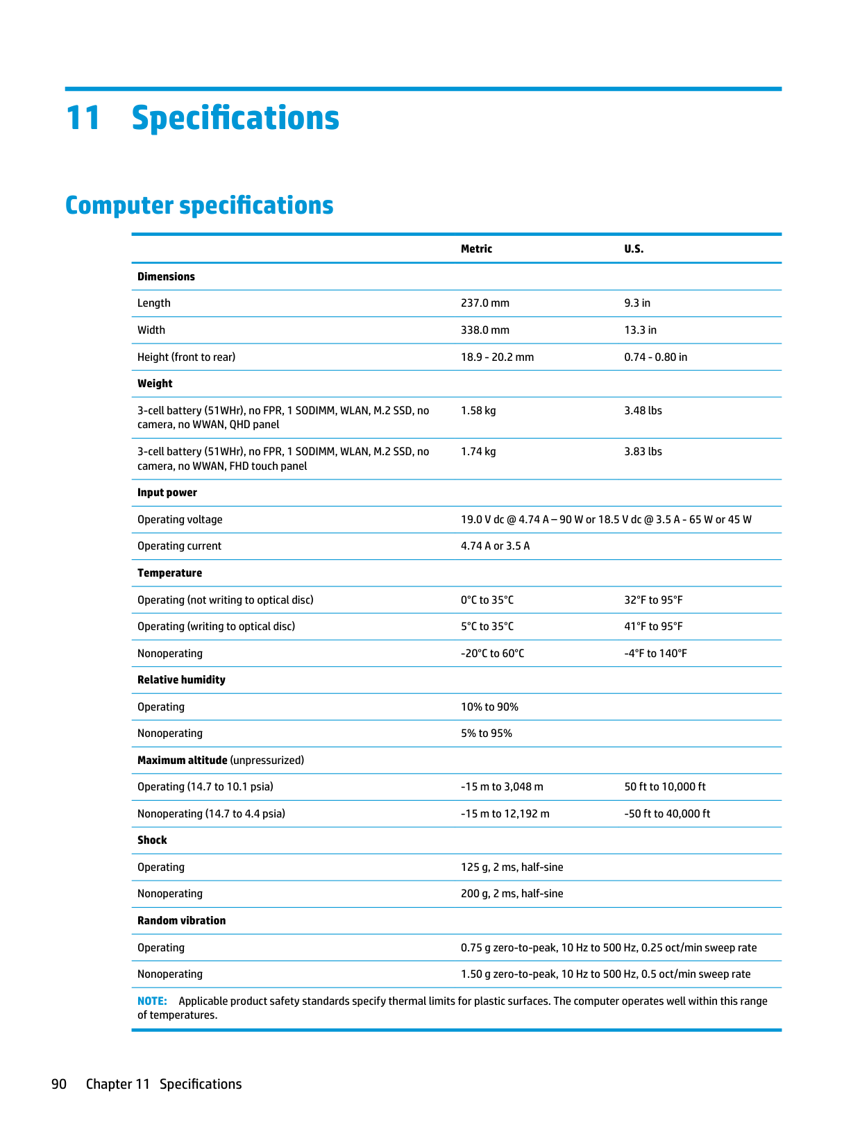
Computer specifications
######## Metric U.S.
Dimensions Length 237.0 mm 9.3 in Width 338.0 mm 13.3 in Height (front to rear) 18.9 - 20.2 mm 0.74 - 0.80 in Weight
3-cell battery (51WHr), no FPR, 1 SODIMM, WLAN, M.2 SSD, no camera, no WWAN, QHD panel
1.58 kg 3.48 lbs
3-cell battery (51WHr), no FPR, 1 SODIMM, WLAN, M.2 SSD, no camera, no WWAN, FHD touch panel
1.74 kg 3.83 lbs
Input power Operating voltage 19.0 V dc @ 4.74 A – 90 W or 18.5 V dc @ 3.5 A - 65 W or 45 W Operating current 4.74 A or 3.5 A Temperature
Operating (not writing to optical disc) 0°C to 35°C 32°F to 95°F Operating (writing to optical disc) 5°C to 35°C 41°F to 95°F Nonoperating -20°C to 60°C -4°F to 140°F
Relative humidity Operating 10% to 90% Nonoperating 5% to 95% Maximum altitude (unpressurized) Operating (14.7 to 10.1 psia) -15 m to 3,048 m 50 ft to 10,000 ft Nonoperating (14.7 to 4.4 psia) -15 m to 12,192 m -50 ft to 40,000 ft Shock
Operating 125 g, 2 ms, half-sine Nonoperating 200 g, 2 ms, half-sine Random vibration
Operating 0.75 g zero-to-peak, 10 Hz to 500 Hz, 0.25 oct/min sweep rate Nonoperating 1.50 g zero-to-peak, 10 Hz to 500 Hz, 0.5 oct/min sweep rate NOTE: Applicable product safety standards specify thermal limits for plastic surfaces. The computer operates well within this range of temperatures.
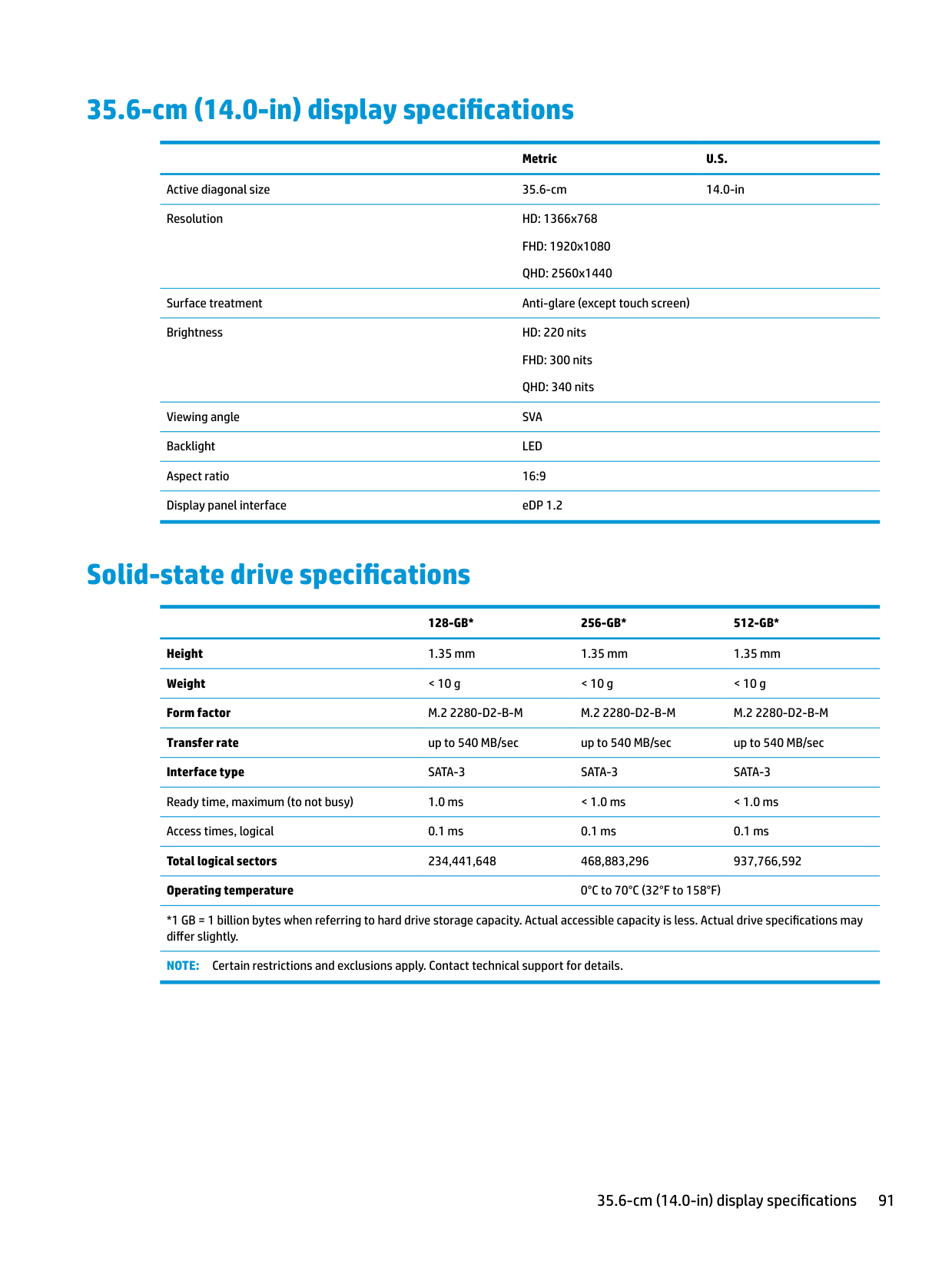
35.6-cm (14.0-in) display specifications
Metric U.S. Active diagonal size 35.6-cm 14.0-in Resolution HD: 1366x768
FHD: 1920x1080 QHD: 2560x1440
Surface treatment Anti-glare (except touch screen) Brightness HD: 220 nits
FHD: 300 nits QHD: 340 nits
Viewing angle SVA Backlight LED Aspect ratio 16:9 Display panel interface eDP 1.2
Solid-state drive specifications
128-GB* 256-GB* 512-GB* Height 1.35 mm 1.35 mm 1.35 mm Weight < 10 g < 10 g < 10 g Form factor M.2 2280-D2-B-M M.2 2280-D2-B-M M.2 2280-D2-B-M Transfer rate up to 540 MB/sec up to 540 MB/sec up to 540 MB/sec Interface type SATA-3 SATA-3 SATA-3 Ready time, maximum (to not busy) 1.0 ms < 1.0 ms < 1.0 ms Access times, logical 0.1 ms 0.1 ms 0.1 ms Total logical sectors 234,441,648 468,883,296 937,766,592 Operating temperature 0°C to 70°C (32°F to 158°F)
*1 GB = 1 billion bytes when referring to hard drive storage capacity. Actual accessible capacity is less. Actual drive specifications may differ slightly.
NOTE: Certain restrictions and exclusions apply. Contact technical support for details.
35.6-cm (14.0-in) display specifications 91
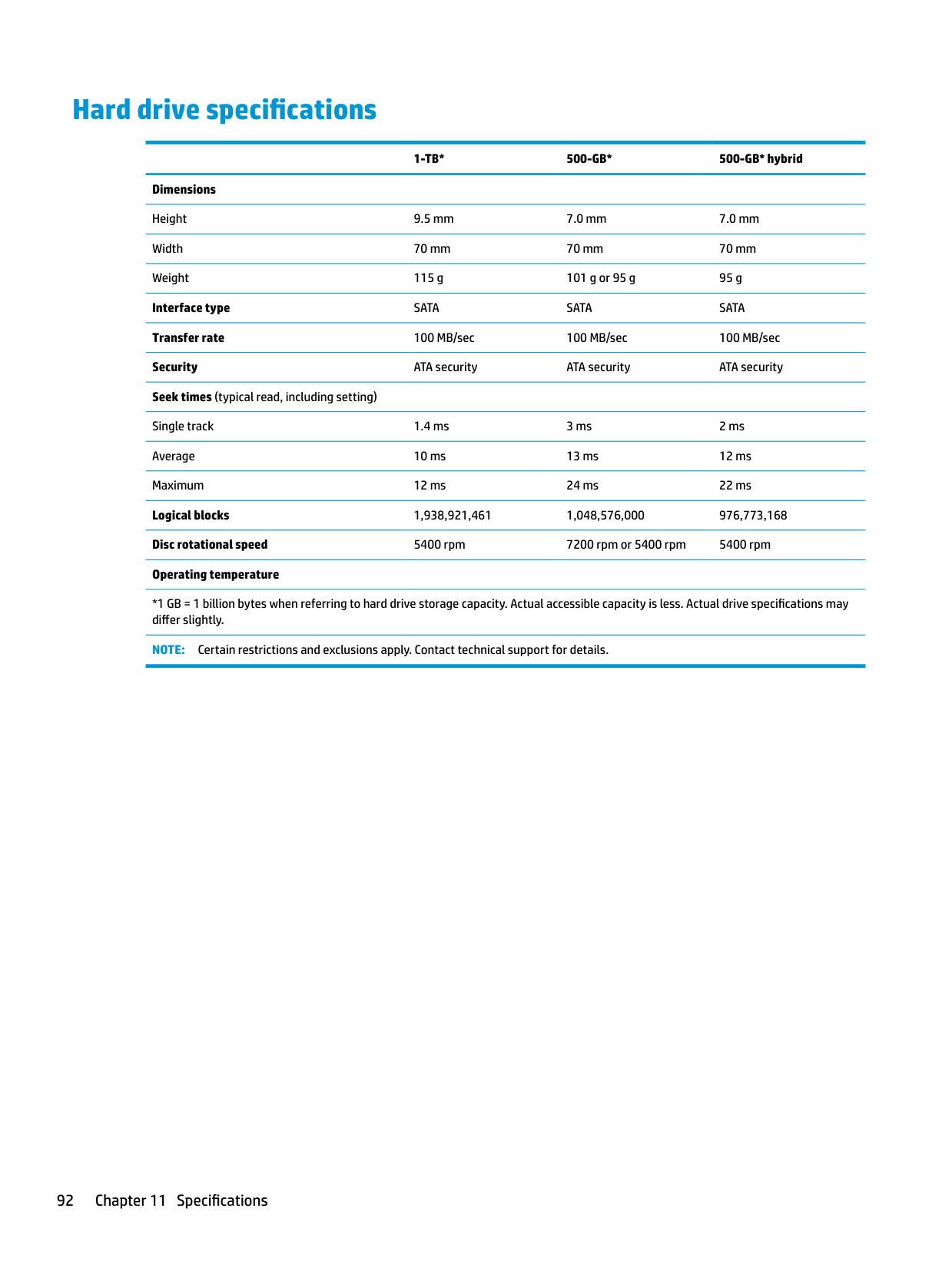
Hard drive specifications
######## 1-TB* 500-GB* 500-GB* hybrid
Dimensions Height 9.5 mm 7.0 mm 7.0 mm Width 70 mm 70 mm 70 mm Weight 115 g 101 g or 95 g 95 g Interface type SATA SATA SATA Transfer rate 100 MB/sec 100 MB/sec 100 MB/sec Security ATA security ATA security ATA security Seek times (typical read, including setting) Single track 1.4 ms 3 ms 2 ms Average 10 ms 13 ms 12 ms Maximum 12 ms 24 ms 22 ms Logical blocks 1,938,921,461 1,048,576,000 976,773,168 Disc rotational speed 5400 rpm 7200 rpm or 5400 rpm 5400 rpm Operating temperature
*1 GB = 1 billion bytes when referring to hard drive storage capacity. Actual accessible capacity is less. Actual drive specifications may differ slightly.
NOTE: Certain restrictions and exclusions apply. Contact technical support for details.
12 Power cord set requirements
The wide-range input feature of the computer permits it to operate from any line voltage from 100 to 120 volts AC, or from 220 to 240 volts AC.
The 3-conductor power cord set included with the computer meets the requirements for use in the country or region where the equipment is purchased.
Power cord sets for use in other countries and regions must meet the requirements of the country or region where the computer is used.
Requirements for all countries
The following requirements are applicable to all countries and regions:
Requirements for specific countries and regions
######## Country/region Accredited agency Applicable note number
Australia EANSW 1 Austria OVE 1 Belgium CEBC 1 Canada CSA 2 Denmark DEMKO 1 Finland FIMKO 1 France UTE 1 Germany VDE 1 Italy IMQ 1 Japan METI 3 The Netherlands KEMA 1 Norway NEMKO 1 The People's Republic of China COC 5 South Korea EK 4
Requirements for all countries 93
######## Country/region Accredited agency Applicable note number
Sweden SEMKO 1 Switzerland SEV 1 Taiwan BSMI 4 The United Kingdom BSI 1 The United States UL 2
94 Chapter 12 Power cord set requirements
13 Statement of memory volatility
The purpose of this chapter is to provide general information regarding nonvolatile memory in HP Business PCs. This chapter also provides general instructions for restoring nonvolatile memory that can contain personal data after the system has been powered off and the hard drive has been removed.
HP Business PC products that use Intel®-based or AMD®-based system boards contain volatile DDR memory. The amount of nonvolatile memory present in the system depends upon the system configuration. Intelbased and AMD-based system boards contain nonvolatile memory subcomponents as originally shipped from HP, assuming that no subsequent modifications have been made to the system and assuming that no applications, features, or functionality have been added to or installed on the system.
Following system shutdown and removal of all power sources from an HP Business PC system, personal data can remain on volatile system memory (DIMMs) for a finite period of time and will also remain in nonvolatile memory. Use the steps below to remove personal data from the PC, including the nonvolatile memory found in Intel-based and AMD-based system boards.
| | |---|
NOTE: If your tablet has a keyboard base, connect to the keyboard base before beginning steps in this chapter.
###### Current BIOS steps
IMPORTANT: If the Main menu displays Restore Defaults instead of Apply Factory Defaults and Exit, go to Legacy BIOS Steps on page 96.
NOTE: If the system has a BIOS administrator password, enter the password at the prompt.
| | |---|
| | |---|
| | |---|
| | |---|
| | |---|
● Clear the drive contents by using a third party utility designed to erase data from an SSD.
| | |---|
IMPORTANT: If you clear data using Secure Erase, it cannot be recovered.
Legacy BIOS Steps Use the steps for older versions of BIOS. NOTE: If you already completed the steps in Current BIOS steps on page 95, skip this section.
| | |---|
| | |---|
● Turn on or restart the computer, and then press esc while the “Press the ESC key for Startup Menu” message is displayed at the bottom of the screen.
| | |---|
NOTE: If the system has a BIOS administrator password, enter the password at the prompt.
● Clear the drive contents by using a third party utility designed to erase data from an SSD.
| | |---|
IMPORTANT: If you clear data using Secure Erase, it cannot be recovered.
– or –
| | |---|
● Clear the contents of the drive by using the following Disk Sanitizer command steps: IMPORTANT: If you clear data using Disk Sanitizer, it cannot be recovered.
| | |---|
NOTE: The amount of time it takes for Disk Sanitizer to run can take several hours. Plug the computer into an AC outlet before starting.
Nonvolatile memory usage
Nonvolatile Memory Type Amount (Size)
Does this memory store customer data?
Does this memory retain data when power is removed?
What is the purpose of this memory?
How is data input into this memory?
How is this memory write-protected?
HP Sure Start flash (select models only)
2 MBytes No Yes Provides protected backup of critical System BIOS code, EC firmware, and critical PC configuration data for select platforms that support HP Sure Start.
For more information, see Using HP Sure Start (select models only) on page 101.
Real Time Clock (RTC) battery backed-up CMOS configuration memory
Controller (NIC) EEPROM
256 Bytes No Yes Stores system date and time and noncritical data.
64 KBytes (not customer accessible)
No Yes Stores NIC configuration and NIC firmware.
DIMM Serial Presence Detect (SPD) configuration data
256 Bytes per memory module, 128 Bytes programmable
No Yes Stores memory module information.
Data cannot be written to this device via the host processor. The content is managed solely by the HP Sure Start Embedded Controller.
This memory is protected by the HP Sure Start Embedded Controller.
RTC battery backed-up CMOS is programmed using the Computer Setup (BIOS), or changing the Microsoft Windows date & time.
NIC EEPROM is programmed using a utility from the NIC vendor that can be run from DOS.
DIMM SPD is programmed by the memory vendor.
This memory is not writeprotected.
A utility is required to write data to this memory and is available from the NIC vendor. Writing data to this ROM in an inappropriate manner will render the NIC nonfunctional.
Data cannot be written to this memory when the module is installed in a PC. The specific writeprotection method varies by memory vendor.
(not customer accessible)
System BIOS 4 MBytes to 5 MBytes
Yes Yes Stores system BIOS code and PC configuration data.
System BIOS code is programmed at the factory. Code is updated when the system BIOS is updated. Configuration data and settings are input using the Computer Setup (BIOS) or a custom utility.
NOTE: Writing data to this ROM in an inappropriate manner can render the PC nonfunctional.
A utility is required for writing data to this memory and is available on the HP website; go to http://www.hp.com/ support. Select Find your product, and then follow the on-screen instructions.
Intel Management Engine Firmware (present in only specific ZBook and EliteBook models. For more information, go to http://www.hp.com/ support. Select Find your product, and then follow the onscreen instructions.)
1.5 MBytes or 5 MBytes
Yes Yes Stores Management Engine Code, Settings, Provisioning Data and iAMT third-party data store.
Management Engine Code is programmed at the factory. Code is updated via Intel secure firmware update utility. Unique Provisioning Data can be entered at the factory or by an administrator using the Management Engine (MEBx) setup utility. The third party data store contents can be populated by a remote management console or local applications that have been registered by an administrator to have access to the space.
Bluetooth flash 2 Mbit No Yes Stores Bluetooth configuration and firmware.
Bluetooth flash is programmed at the factory. Tools for writing data to this memory are not publicly available but can be obtained from the silicon vendor.
802.11 WLAN EEPROM
4 Kbit to 8 Kbit No Yes Stores configuration and calibration data.
802.11 WLAN EEPROM is programmed at the factory. Tools for writing data to this memory are not made public.
Web camera 64 Kbit No Yes Stores webcam configuration and firmware.
Webcam memory is programmed using a utility from the device manufacturer that can be run from Windows.
The Intel chipset is configured to enforce hardware protection to block all direct read/write access to this area. An Intel utility is required for updating the firmware. Only firmware updates digitally signed by Intel can be applied using this utility.
A utility is required for writing data to this memory and is made available through newer versions of the driver whenever the flash requires an upgrade.

A utility is required for writing data to this memory and is typically not made available to the public unless a firmware upgrade is necessary to address a unique issue.
A utility is required for writing data to this memory and is typically not made available to the public unless a firmware
Nonvolatile memory usage 99
Fingerprint reader 512 KByte flash Yes Yes Stores
fingerprint templates.
Fingerprint reader memory is programmed by user enrollment in HP ProtectTools Security Manager.
upgrade is necessary to address a unique issue.
Only a digitally signed application can make the call to write to the flash.
Questions and answers
IMPORTANT: Restore defaults does not securely erase any data on your hard drive. See question and answer 6 for steps to securely erase data. Restore defaults does not reset the Custom Secure Boot keys. See question and answer 7 for information about resetting the keys.
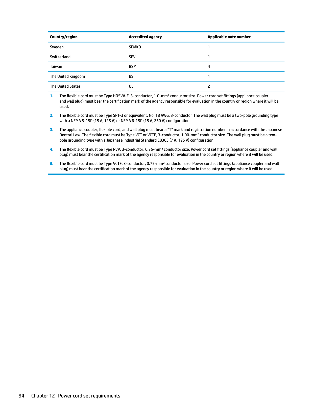
The Unified Extensible Firmware Interface (UEFI) BIOS is an industry-standard software interface between the platform firmware and an operating system (OS). It is a replacement for the older BIOS architecture, but supports much of the legacy BIOS functionality.
Like the legacy BIOS, the UEFI BIOS provides an interface to display the system information and configuration settings and to change the configuration of your computer before an OS is loaded. BIOS provides a secure run-time environment that supports a Graphic User Interface (GUI). In this environment, you can use either a pointing device (Touchscreen, TouchPad, pointing stick, or USB mouse) or the keyboard to navigate and make menu and configuration selections. The UEFI BIOS also contains basic system diagnostics.
The UEFI BIOS provides functionality beyond that of the legacy BIOS. In addition, the UEFI BIOS works to initialize the computer’s hardware before loading and executing the OS; the run-time environment allows the loading and execution of software programs from storage devices to provide more functionality, such as advanced hardware diagnostics (with the ability to display more detailed system information) and advanced firmware management and recovery software.
HP has provided options in Computer Setup (BIOS) to allow you to run in legacy BIOS, if required by the operating system. Examples of this requirement would be if you upgrade or downgrade the OS.
| | |---|
###### 4. What kind of configuration data is stored on the DIMM Serial Presence Detect (SPD) memorymodule? How would this data be written?
The DIMM SPD memory contains information about the memory module, such as size, serial number, data width, speed/timing, voltage, and thermal information. This information is written by the module manufacturer and stored on an EEPROM. This EEPROM cannot be written to when the memory module is installed in a PC. Third-party tools do exist that can write to the EEPROM when the memory module is not installed in a PC. Various third-party tools are available to read SPD memory.
###### 5. What is meant by “Restore the nonvolatile memory found in Intel-based system boards”?
This message relates to clearing the Real Time Clock (RTC) CMOS memory that contains PC configuration data.
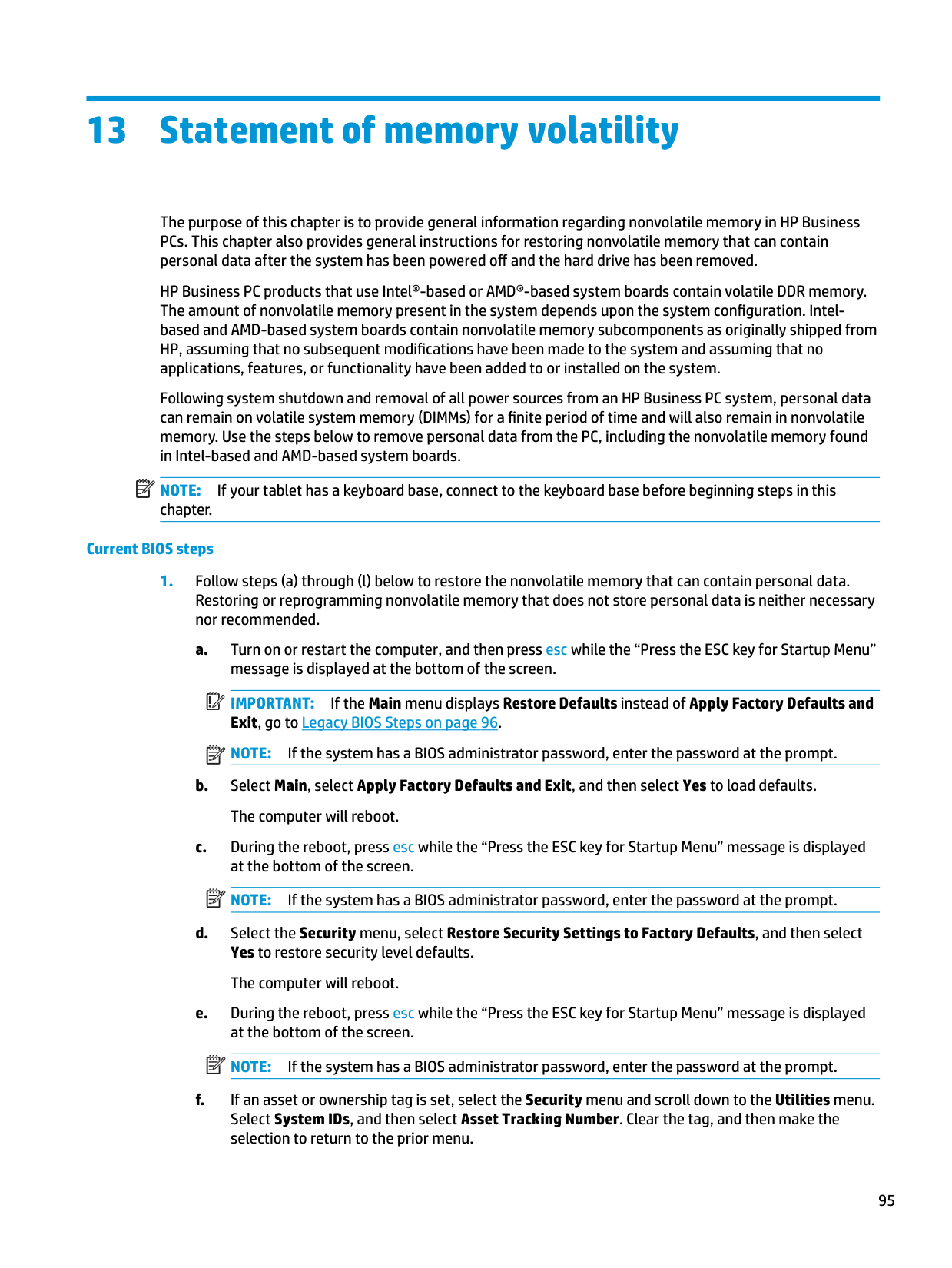
###### 6. How can the BIOS security be reset to factory defaults and data erased?IMPORTANT: Resetting will result in the loss of information.
| | |---|
These steps will not reset Custom Secure Boot Keys. See question and answer 7 for information about resetting the keys.
###### 7. How can the Custom Secure Boot Keys be reset?
Secure Boot is a feature to ensure that only authenticated code can start on a platform. If you enabled Secure Boot and created Custom Secure Boot Keys, simply disabling Secure Boot will not clear the keys. You must also select to clear the Custom Secure Boot Keys. Use the same Secure Boot access procedure you used to create the Custom Secure Boot Keys, but make the selection to clear or delete all Secure Boot Keys.
Using HP Sure Start (select models only)
Select computer models are configured with HP Sure Start, a technology that continuously monitors your computer's BIOS for attacks or corruption. If the BIOS becomes corrupted or is attacked, HP Sure Start restores the BIOS to its previously safe state, without user intervention. Those select computer models ship with HP Sure Start configured and enabled. HP Sure Start is configured and already enabled so that most users can use the HP Sure Start default configuration. The default configuration can be customized by advanced users.
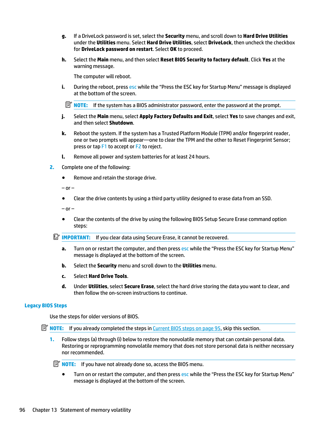
To access the latest documentation on HP Sure Start, go to http://www.hp.com/support. Select Find your product, and then follow the on-screen instructions.
Using HP Sure Start (select models only) 101
14 Recycling
When a non-rechargeable or rechargeable battery has reached the end of its useful life, do not dispose of the battery in general household waste. Follow the local laws and regulations in your area for battery disposal.
HP encourages customers to recycle used electronic hardware, HP original print cartridges, and rechargeable batteries. For more information about recycling programs, see the HP Web site at http://www.hp.com/recycle.
102 Chapter 14 Recycling
Index
Symbols/Numerics `product description
ethernet 2
disconnecting 42, 44 audible codes 76 audio, product description 2 audio-out (headphone)/audio-in
(microphone) combo jack, identifying 6
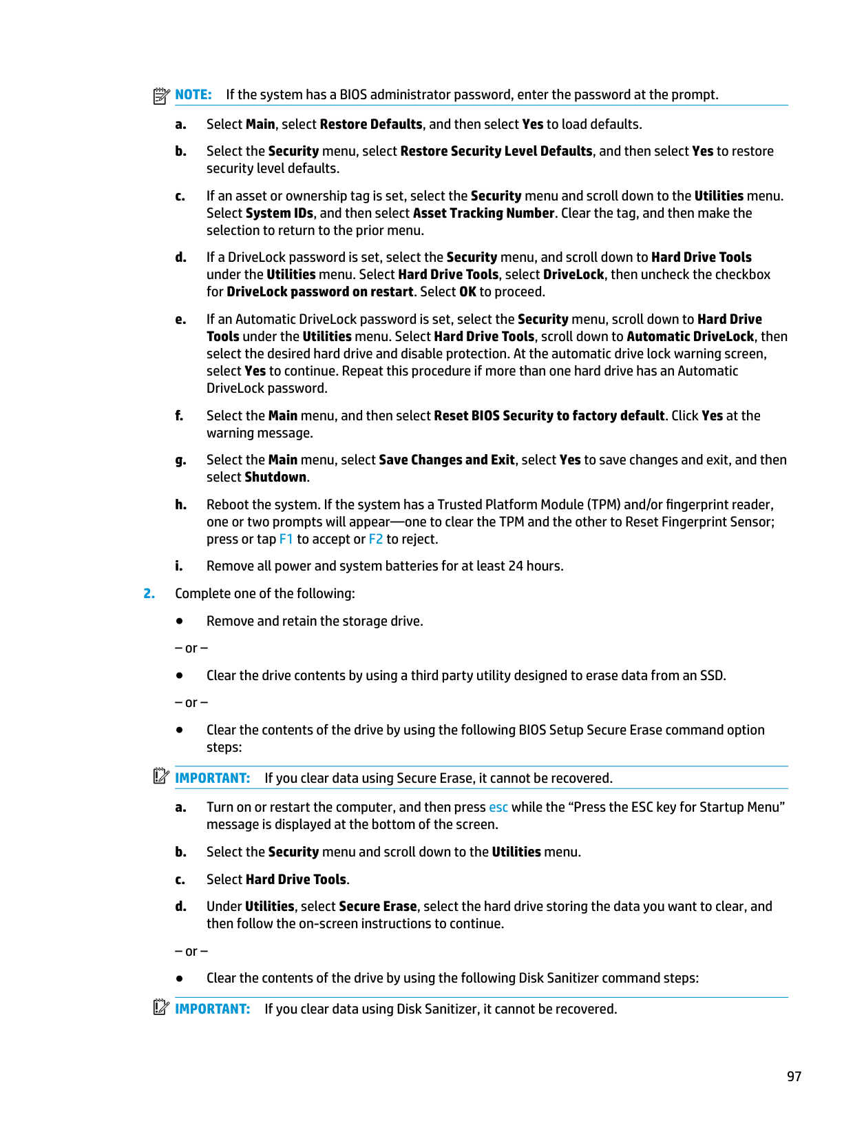
removing 36 spare part number 36 spare part numbers 20
battery light 16 beep codes 76 bezel
spare part number 21
BIOS determining version 79 downloading an update 80 updating 79
Bluetooth card
spare part number 42 Bluetooth label 17 boot order
changing 88 bottom 17 bottom cover
removing 32 spare part number 20, 32
buttons left pointing stick 9 left TouchPad 9 power 11 right pointing stick 9 right TouchPad 9
C Cable Kit
contents 24 spare part number 24
cables
spare part numbers 24 caps lock light, identifying 11 chipset, product description 1 components
bottom 15 display 8 front 16 left side 7 right side 6 top 9
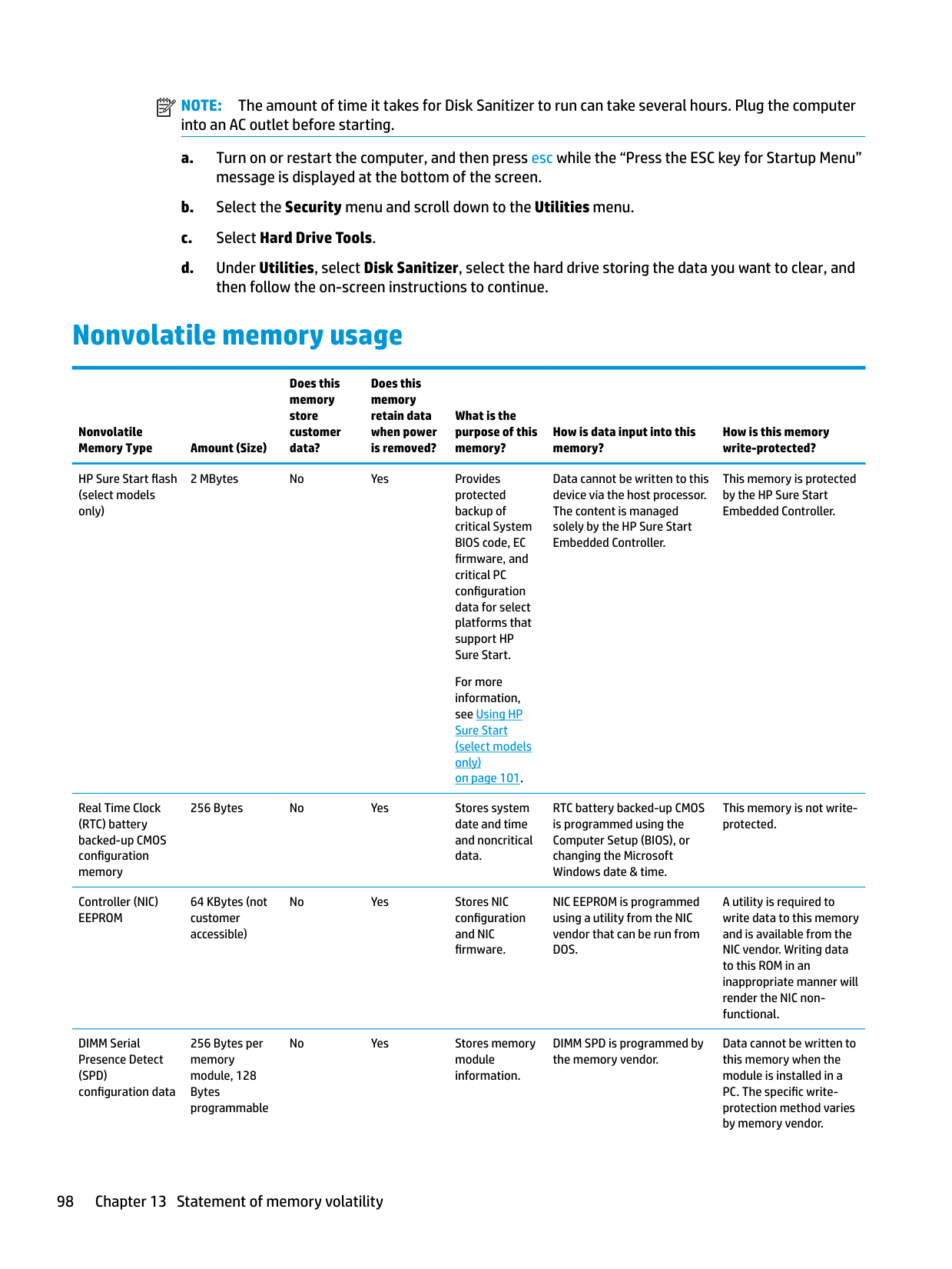
computer major components 18 Computer Setup
navigating and selecting 78 restoring factory settings 78
computer specifications 90 connector, power 7
D display assembly
removal 67 spare part numbers 67 subcomponents 21
display bezel
removal 68 display cable
display enclosure
display hinge
removal 70 display image, switching 14 display panel
product description 1 display specifications 91 docking
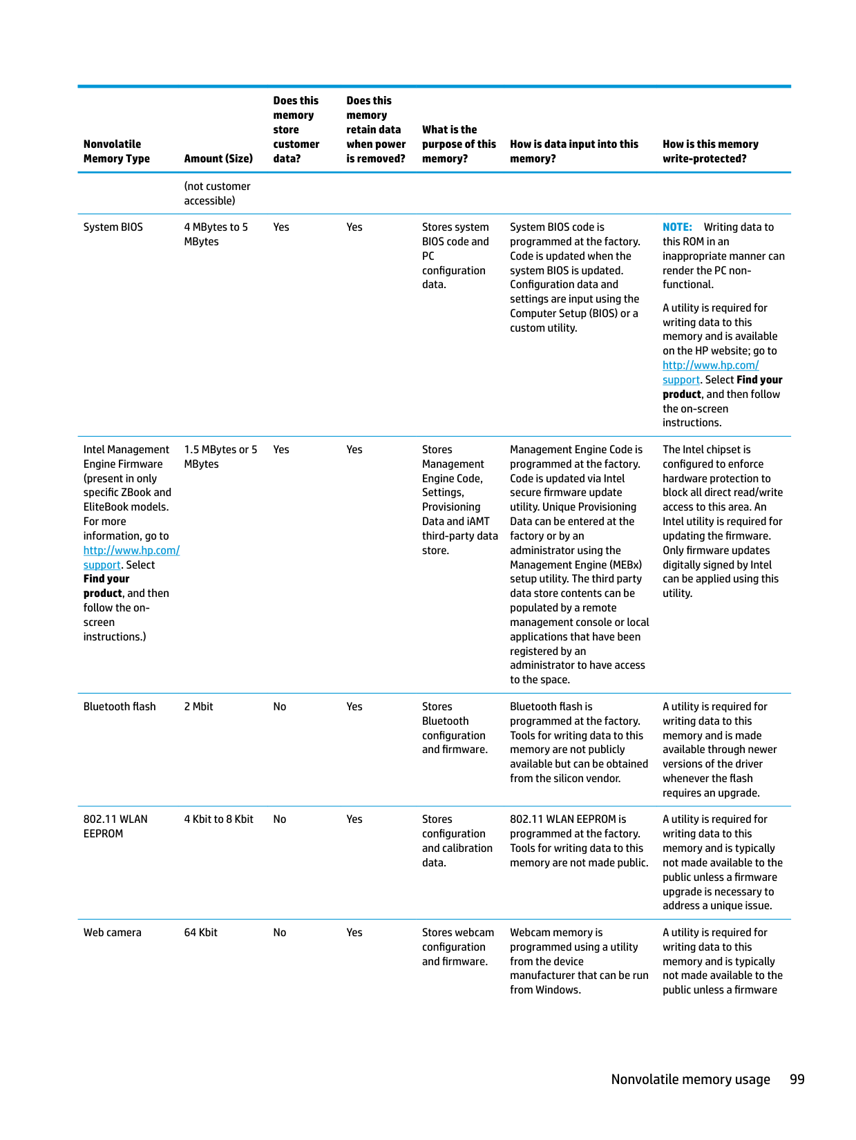
product description 3 docking connector, identifying 7, 15 drive light 16 Dual-Mode DisplayPort
identifying 6
identifying 13 error
codes 76 esc key, identifying 13 ethernet
product description 2 external monitor port 7
spare part number 19
fingerprint reader assembly removal 55 spare part number 55
fingerprint reader, identifying 12 flashing LEDs 76 fn key, identifying 13 function keys
identifying 13
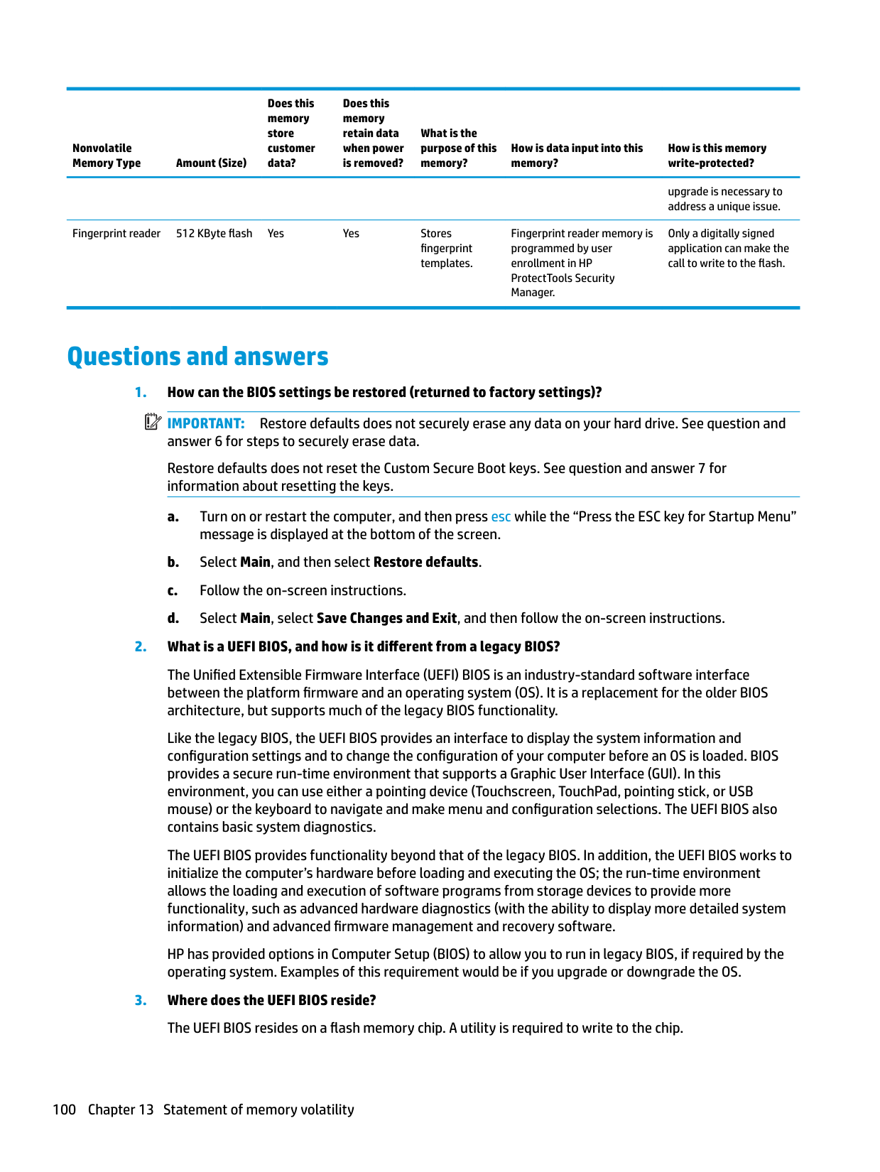
removing 37 spare part numbers 20, 23, 37 specifications 92
hard drive hardware kit spare part number 20, 23
heat sink removal 53 spare part numbers 53
heat sink/fan assembly
spare part number 20 hinge
removal 70 hinges
spare part number 21
hot keys microphone mute 14 Sleep 14
switching screen image 14 using 14
HP PC Hardware Diagnostics (UEFI) using 82
HP Recovery Manager correcting boot problems 88 starting 87 HP Recovery media creating 84 recovery 87
HP Recovery partition recovery 87 removing 89
HP Sure Start 101
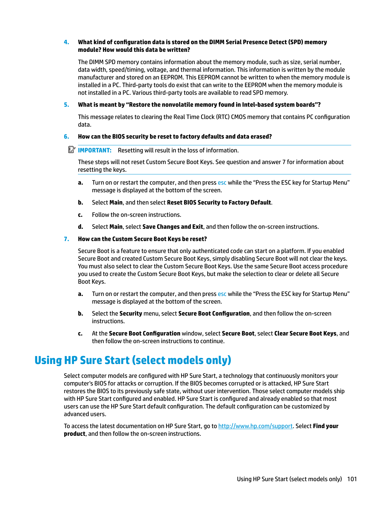
identifying 8 internal base plate removing 50 spare part number 20, 50
internal microphones, identifying 8
audio-out (headphone)/audio-in
(microphone) combo 6 network 7 RJ-45 (network) 7
product description 3 removal 47 spare part number 19 spare part numbers 47
keypad embedded numeric 13
keys esc 13 fn 13 function 13 Windows application 13 Windows key 13
Bluetooth 17 regulatory 17 serial number 17 service 17
wireless certification 17 WLAN 17
legacy support, USB 78 lights
battery 16 caps lock 11 drive 16 microphone mute 10 num lk 10 power 10, 16 privacy 10 RJ-45 (network) 7 TouchPad 11 webcam 8 wireless 10, 16
nonvolatile 95 product description 1 volatile 95
memory card reader, identifying 6 memory module
removal 40 spare part number 20 spare part numbers 40
microphone
product description 2 microphone module
spare part number 21 microphone mute key, identifying 14 microphone mute light, identifying 10
minimized image recovery 87 minimized image, creating 86 model name 1
tapping area
identifying 9 network jack, identifying 7 NFC module
removal 58 spare part number 19, 58
nonvolatile memory 95 num lk light 10
description 4 original system recovery 86
description 3 pointing stick 9 ports
Dual-Mode DisplayPort 6 external monitor 7 product description 3 USB 3.x 7 USB 3.x charging 7 USB Type-C charging 6
power button board
spare part number 19 power button board assembly removal 73 spare part number 73 power button, identifying 11 power connector, identifying 7 power cord
set requirements 93 power lights 10, 16 power requirements, product
description 4 primary storage
product description 1 privacy light 10 processors, product description 1 product description
audio 2 chipset 1 display panel 1 docking 3 external media cards 3 graphics 1 keyboard 3 memory 1 microphone 2 operating system 4 pointing device 3 ports 3 power requirements 4 primary storage 1 processors 1 product name 1 security 4
serviceability 4 video 2 wireless networking 2
product name 1 product name and number,
computer 17
spare part number 21 recover
options 86
recovery discs 85, 87 HP Recovery Manager 86 media 87 starting 87 supported discs 85 system 86 USB flash drive 87 using HP Recovery media 85
recovery media creating 84 creating using HP Recovery
Manager 85 recovery partition
removing 89
regulatory information regulatory label 17 wireless certification labels 17
removal/replacement procedures 32, 50 removing personal data from volatile
system memory 95 RJ-45 (network) jack, identifying 7 RJ-45 (network) lights, identifying
7
RTC battery removal 46 spare part number 20, 46
setup utility navigating and selecting 78 restoring factory settings 78
SIM card slot, identifying 7 slots
security cable 7 SIM card 7 smart card 7
smart card reader board removal 59 spare part number 59
smart card slot 7 solid-state drive
removal 39
solid–state drive spare part numbers 23
speaker assembly removal 66 spare part number 66
speakers, identifying 12 specifications

computer 90 display 91 hard drive 92 solid-state drive 91
supported discs, recovery 85 Sure Start
using 81
system board removal 62 spare part number 19 spare part numbers 62
system memory, removing personal
data from volatile 95 system recovery 86 system restore point creating 85
system restore point, creating 84
T top cover
removal 75 spare part number 19, 75
TouchPad buttons 9 spare part number 19
touchpad board removal 57 spare part number 57
TouchPad light, identifying 11 TouchPad zone
identifying 9 TPM settings 81 traveling with the computer 17
identifying 6 USB/audio board removal 61
removal 69
webcam, identifying 8 Windows
system restore point 84, 85 Windows application key,
identifying 13 Windows key, identifying 13 Windows tools
using 85 wireless antennas
disconnecting 42, 44 wireless antennas, identifying 8 wireless certification label 17 wireless light 10, 16 wireless networking
product description 2 WLAN antenna
spare part number 21 WLAN antennas, identifying 8 WLAN device 17 WLAN label 17
WLAN/Bluetooth combo card removal 42 spare part number 20, 42
WWAN antenna
spare part number 22 WWAN antennas, identifying 8 WWAN module
removal 44 spare part number 20, 44