Ask AI
— answers from the official manualAnswers from the official manual.
Common questions
Common Questions
10 totalHow do I perform a factory reset in BIOS?
Press and hold the F10 key during startup to enter Computer Setup, then select 'Restore Factory Settings' from within BIOS. Confirm by pressing Enter twice to reset the settings back to default values and restart the system. (Page 80)
What do I need to know about installing memory modules?
Ensure you have the latest BIOS before adding new memory; install in the socket labeled 1 if only one module is present. Follow disassembly preparation and bottom cover removal steps, then remove retaining tabs on each side of the memory slot to release and pull out the module at an angle (Page 43).
How can I clean my HP EliteBook properly?
Turn off your computer, disconnect AC power and external devices. Wipe exterior with a damp microfiber cloth; avoid use of paper towels or alcohol-based cleaners. Use pre-installed 'HP Easy Clean' software to disable input devices during cleaning process (Page 30).
How do I safely remove the WWAN module?
To remove the WWAN module, begin by disconnecting the battery cable and positioning the laptop upside down. Disconnect the antenna cables from the main and Aux terminals. Unscrew the securing screw and pull out the module at an angle (Page 46).
What should I do if my power light starts blinking rapidly?
A rapidly blinking battery light indicates a low battery level. Disconnect any unnecessary devices and plug in the charger immediately to prevent the computer from shutting down due to critical battery alert (Page 9).
How do I replace the solid-state drive (SSD)?
To replace an SSD, start by disconnecting AC power and external devices. Remove the bottom cover screws and lift it off. Disconnect battery cable if necessary, remove securing screw from SSD slot, pull away the module at an angle to take out old drive before installing a new one (Page 39).
Full Manual
118 pages

Maintenance and Service Guide
HP EliteBook 840 G6 Healthcare Edition Notebook PC HP EliteBook 846 G6 Healthcare Edition Notebook PC
© Copyright 2019 HP Development Company, L.P.
AMD and Radeon are trademarks of Advanced Micro Devices, Inc. Bluetooth is a trademark owned by its proprietor and used by HP Inc. under license. DisplayPort and the DisplayPort logo are trademarks owned by the Video Electronics Standards Association (VESA) in the United States and other countries. Intel, Core, Optane, XMM, and Thunderbolt are trademarks of Intel Corporation or its subsidiaries in the U.S. and/or other countries. Microsoft and Windows are either registered trademarks or trademarks of Microsoft Corporation in the United States and/or other countries. Miracast is a trademark of Wi-Fi Alliance.
The information contained herein is subject to change without notice. The only warranties for HP products and services are set forth in the express warranty statements accompanying such products and services. Nothing herein should be construed as constituting an additional warranty. HP shall not be liable for technical or editorial errors or omissions contained herein.
First Edition: May 2019 Document Part Number: L65467-001
######### Product notice
This guide describes features that are common to most models. Some features may not be available on your computer.
Not all features are available in all editions or versions of Windows. Systems may require upgraded and/or separately purchased hardware, drivers, software or BIOS update to take full advantage of Windows functionality. Windows 10 is automatically updated, which is always enabled. ISP fees may apply and additional requirements may apply over time for updates. Go to http://www.microsoft.com for details.
To access the latest user guides, go to http://www.hp.com/support, and follow the instructions to find your product. Then select User Guides.
######### Software terms
By installing, copying, downloading, or otherwise using any software product preinstalled on this computer, you agree to be bound by the terms of the HP End User License Agreement (EULA). If you do not accept these license terms, your sole remedy is to return the entire unused product (hardware and software) within 14 days for a full refund subject to the refund policy of your seller.
For any further information or to request a full refund of the price of the computer, please contact your seller.
#### Important Notice about Customer Self-Repair Parts
| | |---|
IMPORTANT: Your computer includes Customer Self-Repair parts and parts that should be accessed only by an authorized service provider. See Chapter 5, "Removal and replacement procedures for Customer SelfRepair parts," for details. Accessing parts described in Chapter 6, "Removal and replacement procedures for authorized service provider only parts," can damage the computer or void your warranty.
iii
####### iv Important Notice about Customer Self-Repair Parts
#### Safety warning notice
WARNING! To reduce the possibility of heat-related injuries or of overheating the device, do not place the device directly on your lap or obstruct the device air vents. Use the device only on a hard, flat surface. Do not allow another hard surface, such as an adjoining optional printer, or a soft surface, such as pillows or rugs or clothing, to block airflow. Also, do not allow the AC adapter to contact the skin or a soft surface, such as pillows or rugs or clothing, during operation. The device and the AC adapter comply with the user-accessible surface temperature limits defined by applicable safety standards.
v
####### vi Safety warning notice
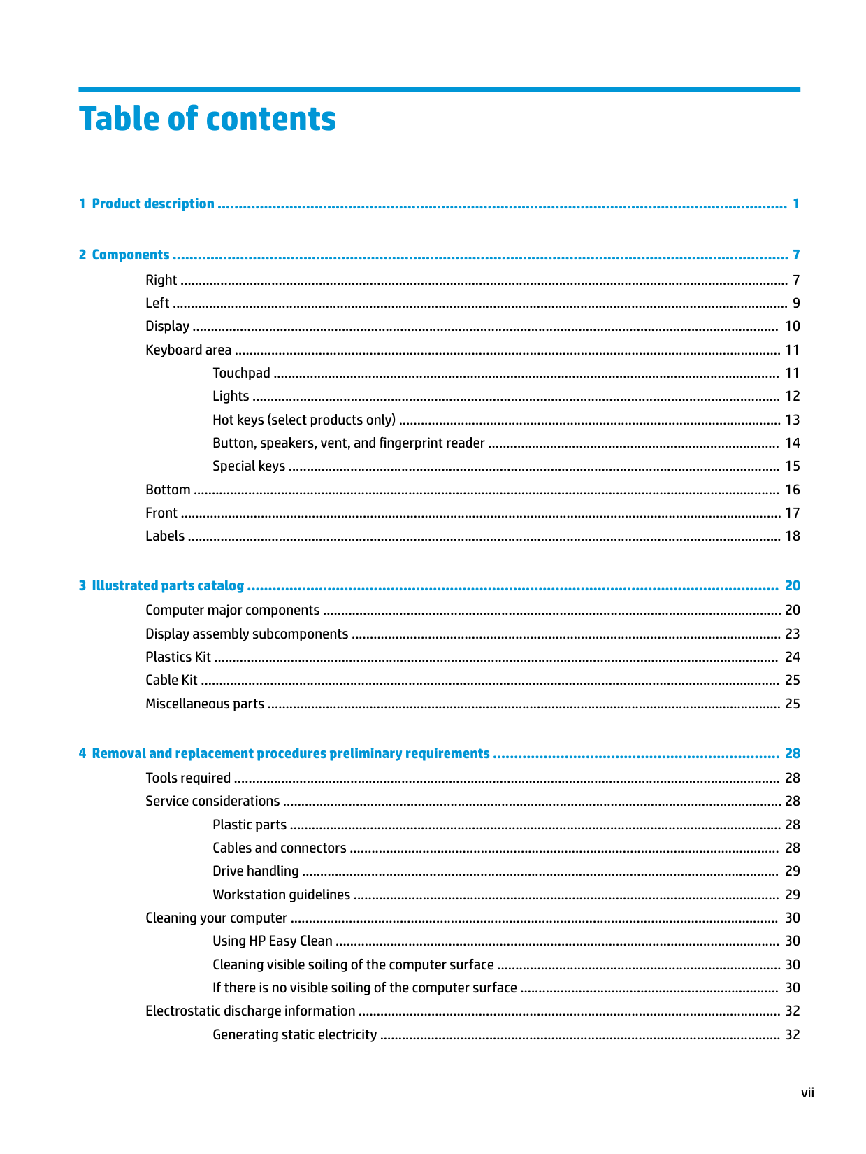
Table of contents
Touchpad ........................................................................................................................................... 11 Lights ................................................................................................................................................. 12 Hot keys (select products only) ......................................................................................................... 13 Button, speakers, vent, and fingerprint reader ................................................................................ 14 Special keys ....................................................................................................................................... 15
Bottom ................................................................................................................................................................. 16 Front ..................................................................................................................................................................... 17 Labels ................................................................................................................................................................... 18

Plastic parts ....................................................................................................................................... 28 Cables and connectors ...................................................................................................................... 28 Drive handling ................................................................................................................................... 29 Workstation guidelines ..................................................................................................................... 29
Cleaning your computer ...................................................................................................................................... 30 Using HP Easy Clean .......................................................................................................................... 30 Cleaning visible soiling of the computer surface .............................................................................. 30 If there is no visible soiling of the computer surface ....................................................................... 30
Electrostatic discharge information .................................................................................................................... 32 Generating static electricity .............................................................................................................. 32
vii
Preventing electrostatic damage to equipment ............................................................................... 32 Personal grounding methods and equipment .................................................................................. 33 Grounding the work area ................................................................................................................... 33 Recommended materials and equipment ........................................................................................ 34
Packaging and transporting guidelines .............................................................................................................. 34
Preparation for disassembly ............................................................................................................. 35 Bottom cover ..................................................................................................................................... 35 Solid-state drive (SSD) ...................................................................................................................... 37 Memory modules ............................................................................................................................... 38 WLAN/Bluetooth combo card ............................................................................................................ 39 WWAN module ................................................................................................................................... 41 Keyboard ........................................................................................................................................... 43
Battery ............................................................................................................................................... 47 Heat sink assembly ........................................................................................................................... 49 RTC battery ........................................................................................................................................ 52 USB board .......................................................................................................................................... 53 RJ-45 board with bracket .................................................................................................................. 54 Power button board .......................................................................................................................... 55 Speaker assembly ............................................................................................................................. 56 Touchpad ........................................................................................................................................... 57 Touchpad button board ..................................................................................................................... 59 NFC module ....................................................................................................................................... 60 RFID module ...................................................................................................................................... 61 Smart card reader .............................................................................................................................. 62 Fan ..................................................................................................................................................... 63 System board .................................................................................................................................... 65 Fingerprint reader assembly (FIPS and non-FIPS) ............................................................................ 68 Display assembly ............................................................................................................................... 70 Top cover ........................................................................................................................................... 77

viii
Starting Computer Setup .................................................................................................................. 80 Navigating and selecting in Computer Setup ................................................................................... 80 Restoring factory settings in Computer Setup ................................................................................. 80 Updating the BIOS ............................................................................................................................. 81
Determining the BIOS version ......................................................................................... 81 Downloading a BIOS update ........................................................................................... 81
Changing the boot order using the f9 prompt .................................................................................. 82 TPM BIOS settings (select products only) ........................................................................................................... 82 Using HP Sure Start (select products only) ......................................................................................................... 83
###### 9 Using HP PC Hardware Diagnostics ................................................................................................................ 84Using HP PC Hardware Diagnostics Windows (select products only) ................................................................. 84
Downloading HP PC Hardware Diagnostics Windows ....................................................................... 84 Downloading the latest HP PC Hardware Diagnostics Windows version ....................... 85 Downloading HP Hardware Diagnostics Windows by product name or number (select products only) ..................................................................................................... 85
Installing HP PC Hardware Diagnostics Windows ............................................................................. 85
Using HP PC Hardware Diagnostics UEFI ............................................................................................................. 85 Starting HP PC Hardware Diagnostics UEFI ....................................................................................... 86 Downloading HP PC Hardware Diagnostics UEFI to a USB flash drive .............................................. 86
Downloading the latest HP PC Hardware Diagnostics UEFI version .............................. 86 Downloading HP PC Hardware Diagnostics UEFI by product name or number (select products only) ..................................................................................................... 86
Using Remote HP PC Hardware Diagnostics UEFI settings (select products only) ............................................. 87
Downloading Remote HP PC Hardware Diagnostics UEFI ................................................................. 87 Downloading the latest Remote HP PC Hardware Diagnostics UEFI version ................. 87 Downloading Remote HP PC Hardware Diagnostics UEFI by product name or number ............................................................................................................................ 87
Customizing Remote HP PC Hardware Diagnostics UEFI settings .................................................... 87
###### 10 Backing up, restoring, and recovering ......................................................................................................... 89Backing up information and creating recovery media ........................................................................................ 89
Using Windows tools ......................................................................................................................... 89 Using the HP Cloud Recovery Download Tool to create recovery media (select products only) ..... 89

Restoring and recovery ........................................................................................................................................ 90 Restoring, resetting, and refreshing using Windows tools .............................................................. 90 Recovering using HP Recovery media ............................................................................................... 90 Changing the computer boot order ................................................................................................... 90
###### 11 Specifications ............................................................................................................................................ 91Computer specifications ...................................................................................................................................... 91
ix
35.6 cm (14.0 in.) display specifications ............................................................................................................. 92 M.2 PCIe solid-state drive specifications ............................................................................................................ 93 M.2 SATA solid-state drive specifications ............................................................................................................ 94
###### Index ........................................................................................................................................................... 105
x
1 Product description
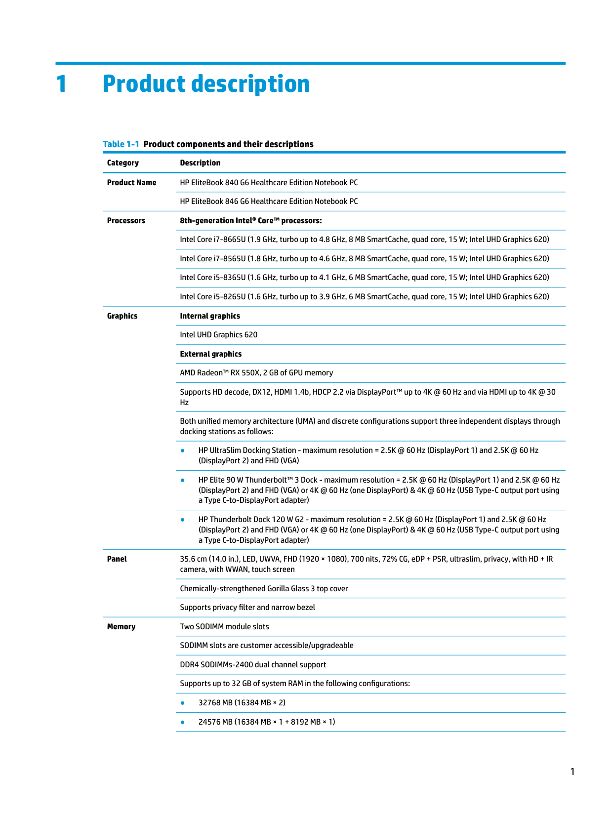
Table 1-1 Product components and their descriptions Category Description Product Name HP EliteBook 840 G6 Healthcare Edition Notebook PC
HP EliteBook 846 G6 Healthcare Edition Notebook PC Processors 8th-generation Intel® Core™ processors:
Intel Core i7-8665U (1.9 GHz, turbo up to 4.8 GHz, 8 MB SmartCache, quad core, 15 W; Intel UHD Graphics 620) Intel Core i7-8565U (1.8 GHz, turbo up to 4.6 GHz, 8 MB SmartCache, quad core, 15 W; Intel UHD Graphics 620) Intel Core i5-8365U (1.6 GHz, turbo up to 4.1 GHz, 6 MB SmartCache, quad core, 15 W; Intel UHD Graphics 620) Intel Core i5-8265U (1.6 GHz, turbo up to 3.9 GHz, 6 MB SmartCache, quad core, 15 W; Intel UHD Graphics 620)
Graphics Internal graphics Intel UHD Graphics 620 External graphics AMD Radeon™ RX 550X, 2 GB of GPU memory Supports HD decode, DX12, HDMI 1.4b, HDCP 2.2 via DisplayPort™ up to 4K @ 60 Hz and via HDMI up to 4K @ 30 Hz Both unified memory architecture (UMA) and discrete configurations support three independent displays through docking stations as follows:

Panel 35.6 cm (14.0 in.), LED, UWVA, FHD (1920 × 1080), 700 nits, 72% CG, eDP + PSR, ultraslim, privacy, with HD + IR camera, with WWAN, touch screen Chemically-strengthened Gorilla Glass 3 top cover Supports privacy filter and narrow bezel
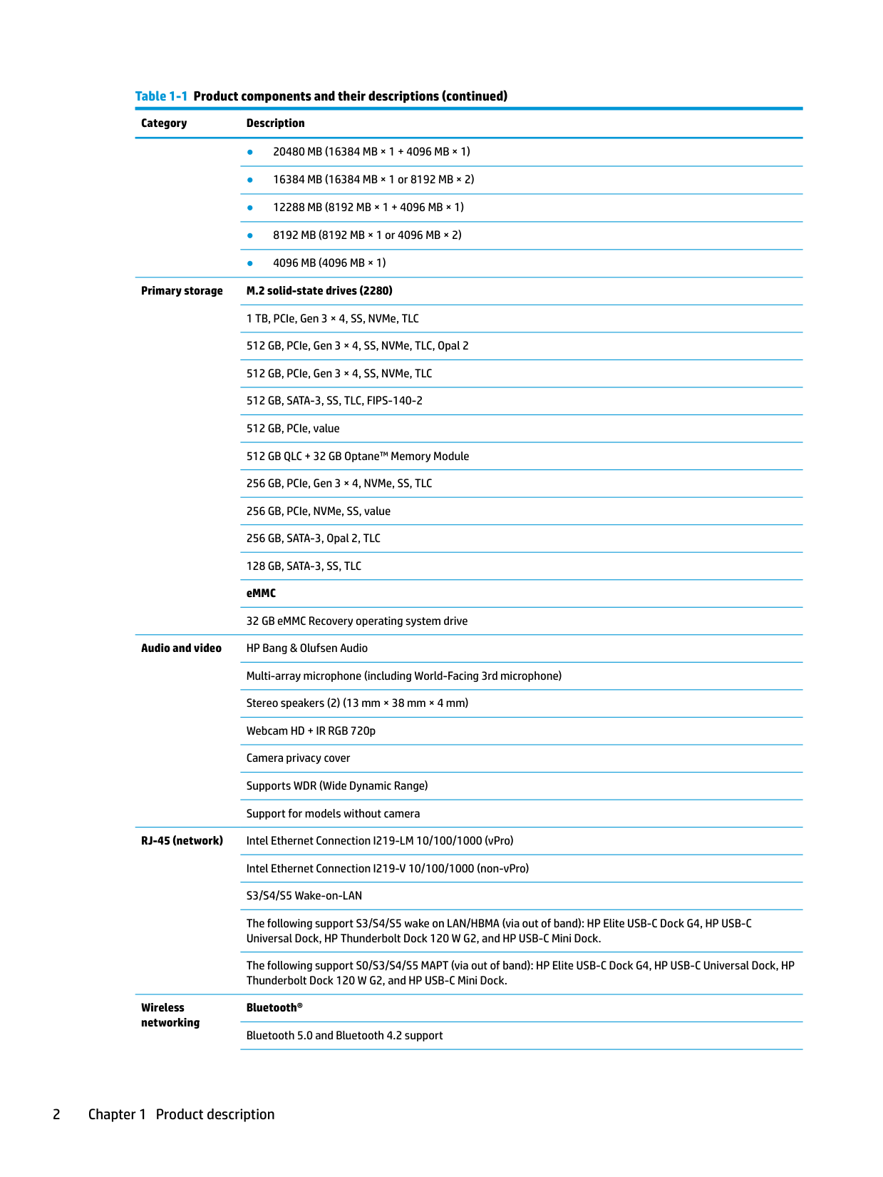
Memory Two SODIMM module slots SODIMM slots are customer accessible/upgradeable DDR4 SODIMMs-2400 dual channel support Supports up to 32 GB of system RAM in the following configurations:
Primary storage M.2 solid-state drives (2280) 1 TB, PCIe, Gen 3 × 4, SS, NVMe, TLC 512 GB, PCIe, Gen 3 × 4, SS, NVMe, TLC, Opal 2 512 GB, PCIe, Gen 3 × 4, SS, NVMe, TLC 512 GB, SATA-3, SS, TLC, FIPS-140-2 512 GB, PCIe, value 512 GB QLC + 32 GB Optane™ Memory Module 256 GB, PCIe, Gen 3 × 4, NVMe, SS, TLC 256 GB, PCIe, NVMe, SS, value 256 GB, SATA-3, Opal 2, TLC 128 GB, SATA-3, SS, TLC eMMC 32 GB eMMC Recovery operating system drive
Audio and video HP Bang & Olufsen Audio Multi-array microphone (including World-Facing 3rd microphone) Stereo speakers (2) (13 mm × 38 mm × 4 mm) Webcam HD + IR RGB 720p Camera privacy cover Supports WDR (Wide Dynamic Range) Support for models without camera
RJ-45 (network) Intel Ethernet Connection I219-LM 10/100/1000 (vPro) Intel Ethernet Connection I219-V 10/100/1000 (non-vPro) S3/S4/S5 Wake-on-LAN The following support S3/S4/S5 wake on LAN/HBMA (via out of band): HP Elite USB-C Dock G4, HP USB-C Universal Dock, HP Thunderbolt Dock 120 W G2, and HP USB-C Mini Dock. The following support S0/S3/S4/S5 MAPT (via out of band): HP Elite USB-C Dock G4, HP USB-C Universal Dock, HP Thunderbolt Dock 120 W G2, and HP USB-C Mini Dock.
Wireless networking
Bluetooth® Bluetooth 5.0 and Bluetooth 4.2 support
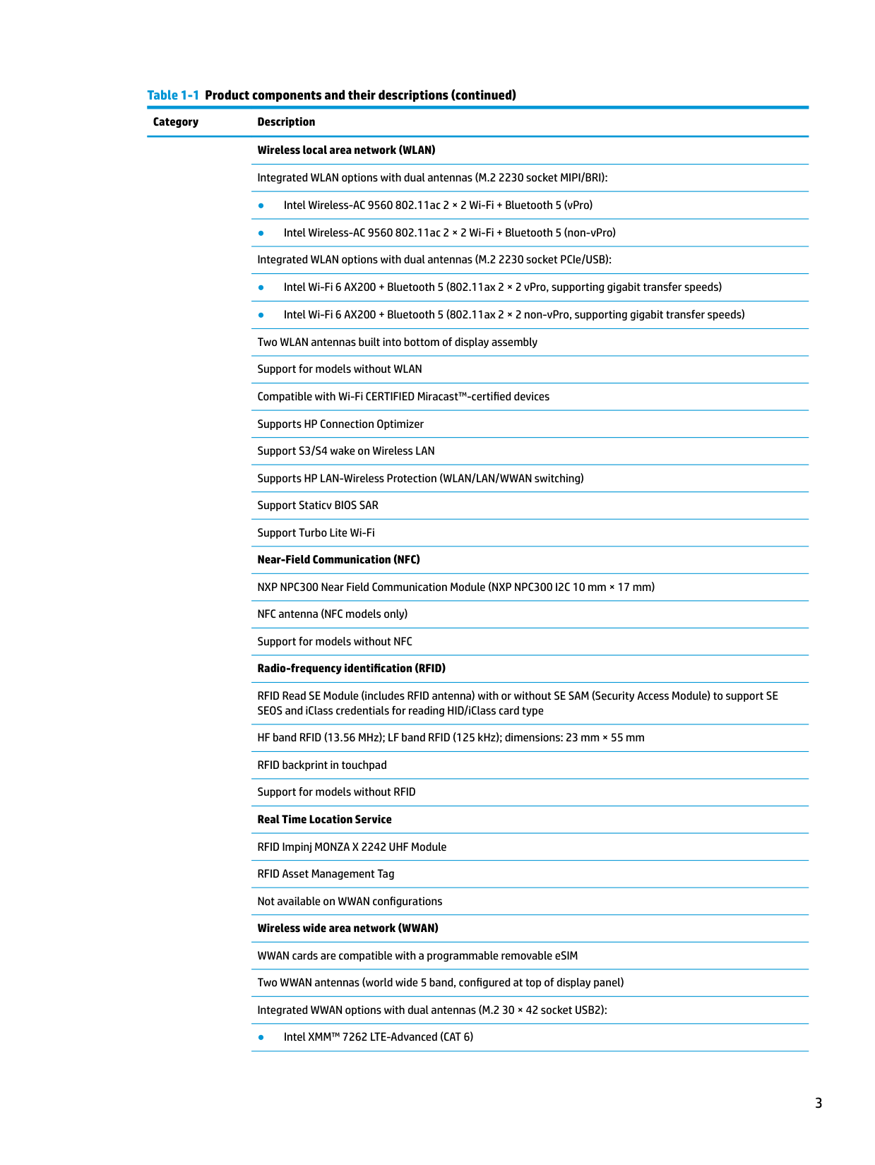
Wireless local area network (WLAN) Integrated WLAN options with dual antennas (M.2 2230 socket MIPI/BRI):
RFID Read SE Module (includes RFID antenna) with or without SE SAM (Security Access Module) to support SE SEOS and iClass credentials for reading HID/iClass card type
HF band RFID (13.56 MHz); LF band RFID (125 kHz); dimensions: 23 mm × 55 mm RFID backprint in touchpad Support for models without RFID Real Time Location Service RFID Impinj MONZA X 2242 UHF Module RFID Asset Management Tag Not available on WWAN configurations Wireless wide area network (WWAN) WWAN cards are compatible with a programmable removable eSIM Two WWAN antennas (world wide 5 band, configured at top of display panel) Integrated WWAN options with dual antennas (M.2 30 × 42 socket USB2):
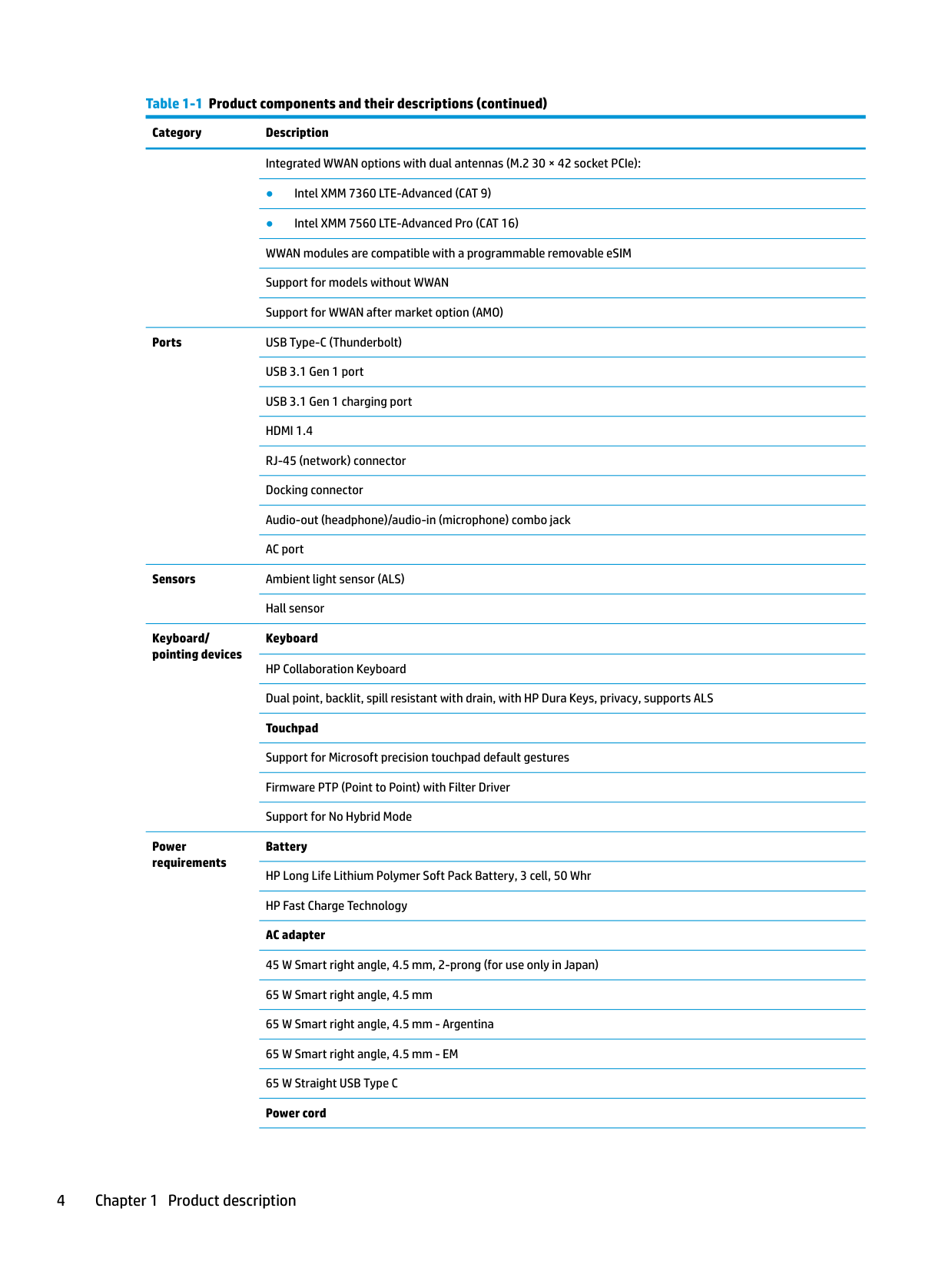
Ports USB Type-C (Thunderbolt) USB 3.1 Gen 1 port USB 3.1 Gen 1 charging port HDMI 1.4 RJ-45 (network) connector Docking connector Audio-out (headphone)/audio-in (microphone) combo jack AC port
Sensors Ambient light sensor (ALS)
Keyboard/ pointing devices
Power requirements
Hall sensor
Keyboard HP Collaboration Keyboard Dual point, backlit, spill resistant with drain, with HP Dura Keys, privacy, supports ALS Touchpad Support for Microsoft precision touchpad default gestures Firmware PTP (Point to Point) with Filter Driver Support for No Hybrid Mode
Battery HP Long Life Lithium Polymer Soft Pack Battery, 3 cell, 50 Whr HP Fast Charge Technology AC adapter 45 W Smart right angle, 4.5 mm, 2-prong (for use only in Japan) 65 W Smart right angle, 4.5 mm 65 W Smart right angle, 4.5 mm - Argentina 65 W Smart right angle, 4.5 mm - EM 65 W Straight USB Type C Power cord
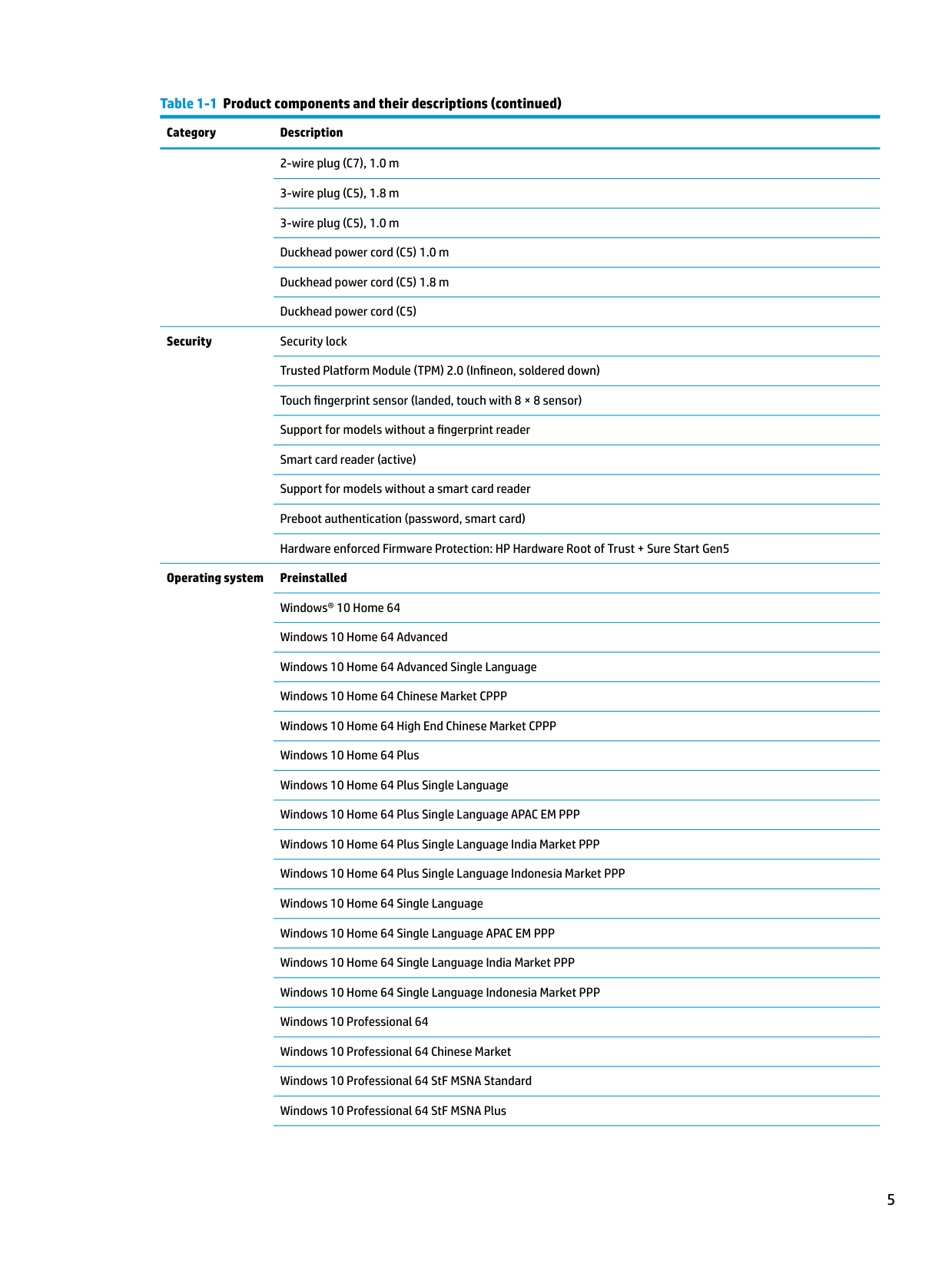
Security Security lock Trusted Platform Module (TPM) 2.0 (Infineon, soldered down) Touch fingerprint sensor (landed, touch with 8 × 8 sensor) Support for models without a fingerprint reader Smart card reader (active) Support for models without a smart card reader Preboot authentication (password, smart card) Hardware enforced Firmware Protection: HP Hardware Root of Trust + Sure Start Gen5
Operating system Preinstalled Windows® 10 Home 64 Windows 10 Home 64 Advanced Windows 10 Home 64 Advanced Single Language Windows 10 Home 64 Chinese Market CPPP Windows 10 Home 64 High End Chinese Market CPPP Windows 10 Home 64 Plus Windows 10 Home 64 Plus Single Language Windows 10 Home 64 Plus Single Language APAC EM PPP Windows 10 Home 64 Plus Single Language India Market PPP Windows 10 Home 64 Plus Single Language Indonesia Market PPP Windows 10 Home 64 Single Language Windows 10 Home 64 Single Language APAC EM PPP Windows 10 Home 64 Single Language India Market PPP Windows 10 Home 64 Single Language Indonesia Market PPP Windows 10 Professional 64 Windows 10 Professional 64 Chinese Market Windows 10 Professional 64 StF MSNA Standard Windows 10 Professional 64 StF MSNA Plus
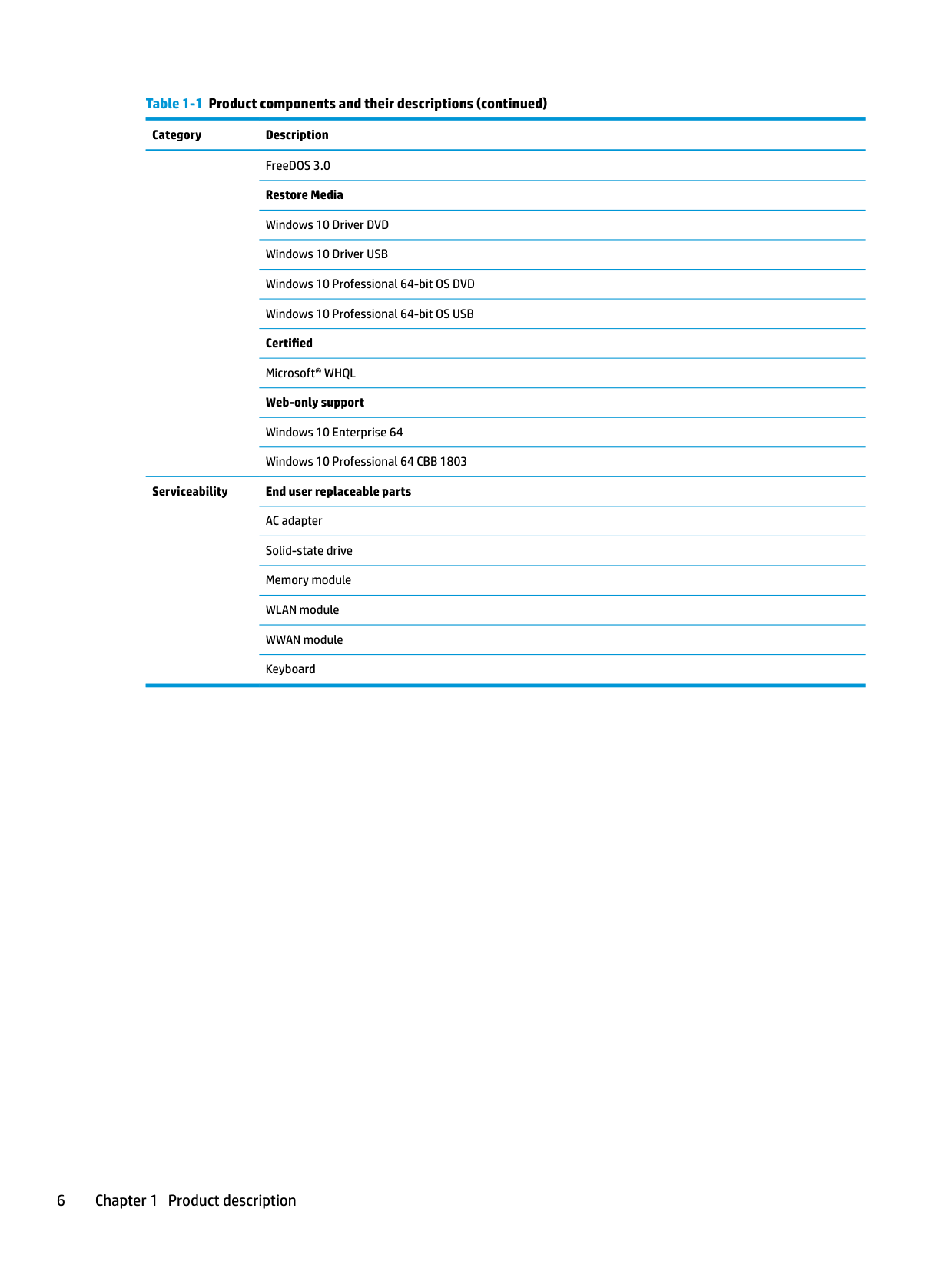
FreeDOS 3.0 Restore Media Windows 10 Driver DVD Windows 10 Driver USB Windows 10 Professional 64-bit OS DVD Windows 10 Professional 64-bit OS USB Certified Microsoft® WHQL Web-only support Windows 10 Enterprise 64 Windows 10 Professional 64 CBB 1803
Serviceability End user replaceable parts AC adapter Solid-state drive Memory module WLAN module WWAN module Keyboard
2 Components
Your computer features top-rated components. This chapter provides details about your components, where they are located, and how they work.
Right

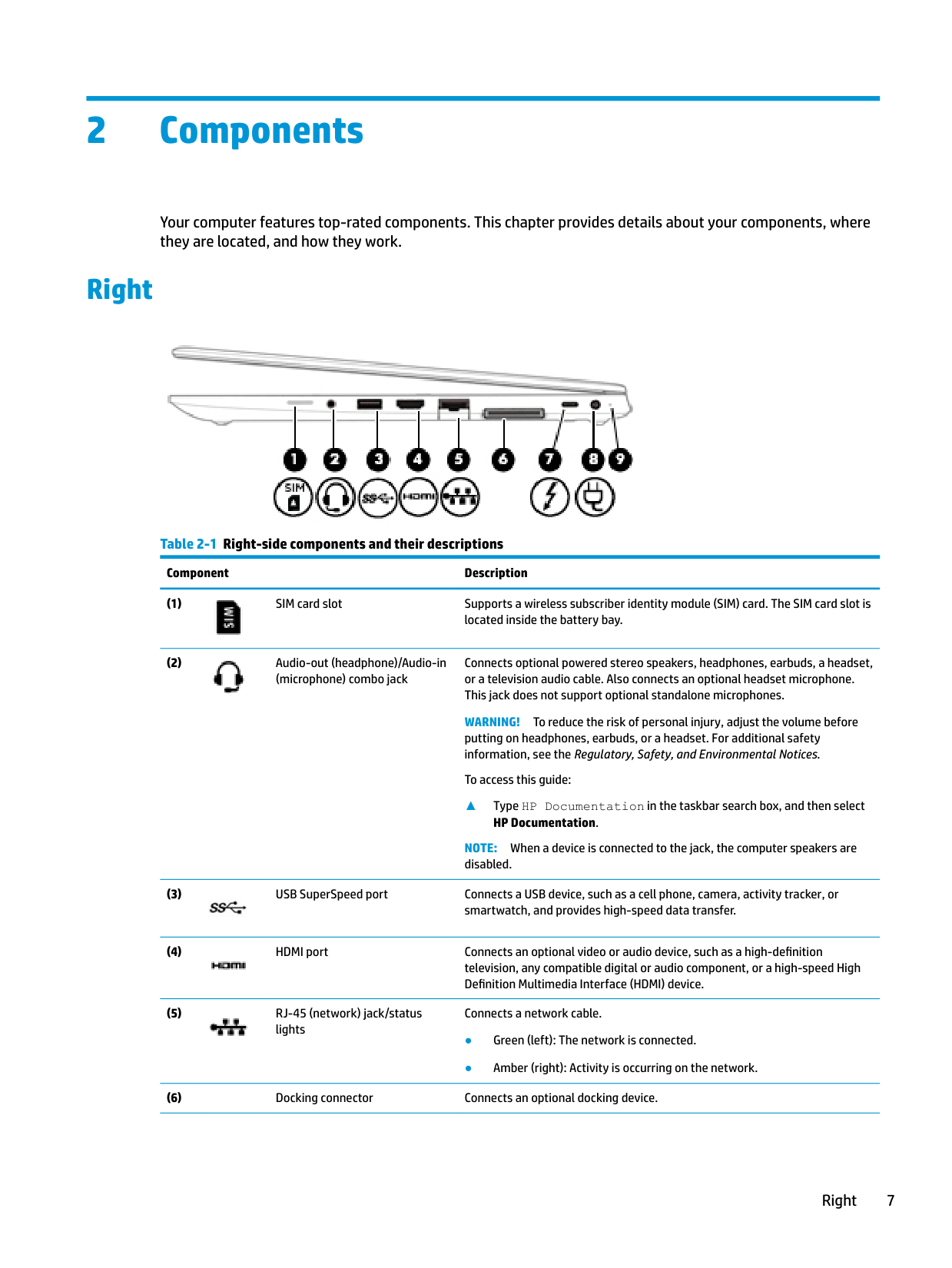
######## Table 2-1 Right-side components and their descriptions
######### Component Description


Connects optional powered stereo speakers, headphones, earbuds, a headset, or a television audio cable. Also connects an optional headset microphone. This jack does not support optional standalone microphones.
WARNING! To reduce the risk of personal injury, adjust the volume before
putting on headphones, earbuds, or a headset. For additional safety information, see the Regulatory, Safety, and Environmental Notices.
To access this guide:
▲ Type HP Documentation in the taskbar search box, and then select HP Documentation.
NOTE: When a device is connected to the jack, the computer speakers are disabled.


Connects a network cable.
Right 7
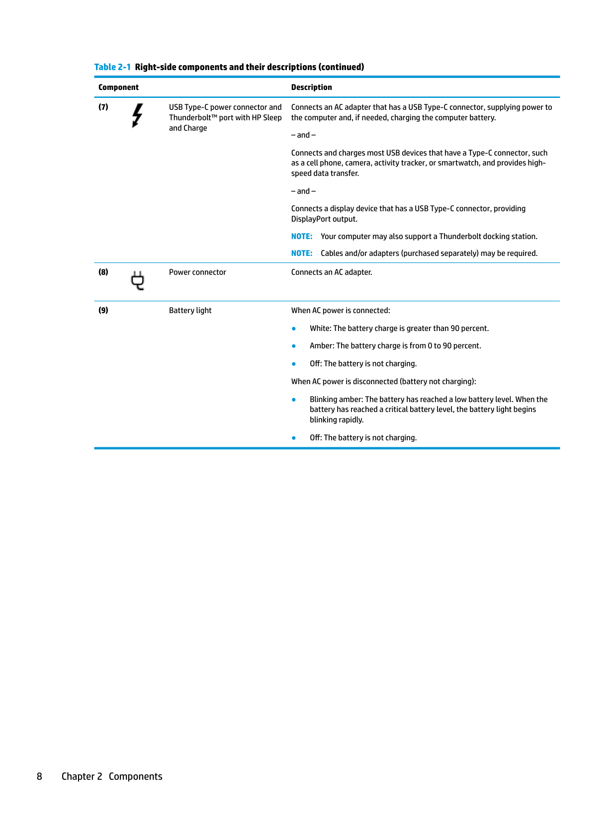
######## Table 2-1 Right-side components and their descriptions (continued)
######### Component Description

Connects an AC adapter that has a USB Type-C connector, supplying power to the computer and, if needed, charging the computer battery.
Connects and charges most USB devices that have a Type-C connector, such as a cell phone, camera, activity tracker, or smartwatch, and provides highspeed data transfer.
Connects a display device that has a USB Type-C connector, providing DisplayPort output.
NOTE: Your computer may also support a Thunderbolt docking station. NOTE: Cables and/or adapters (purchased separately) may be required.

Left

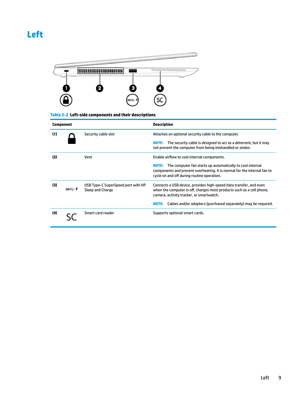
######## Table 2-2 Left-side components and their descriptions
######### Component Description

NOTE: The security cable is designed to act as a deterrent, but it may not prevent the computer from being mishandled or stolen.
NOTE: The computer fan starts up automatically to cool internal components and prevent overheating. It is normal for the internal fan to cycle on and off during routine operation.

Connects a USB device, provides high-speed data transfer, and even when the computer is off, charges most products such as a cell phone, camera, activity tracker, or smartwatch.
NOTE: Cables and/or adapters (purchased separately) may be required.

Left 9
Display

######## Table 2-3 Display components and their descriptions
######### Component Description
NOTE: Camera functions vary depending on the camera hardware and software installed on your product.
*The antennas are not visible from the outside of the computer. For optimal transmission, keep the areas immediately around the antennas free from obstructions.
For wireless regulatory notices, see the section of the Regulatory, Safety, and Environmental Notices that applies to your country or region. To access this guide:
▲ Type HP Documentation in the taskbar search box, and then select HP Documentation.
Keyboard area
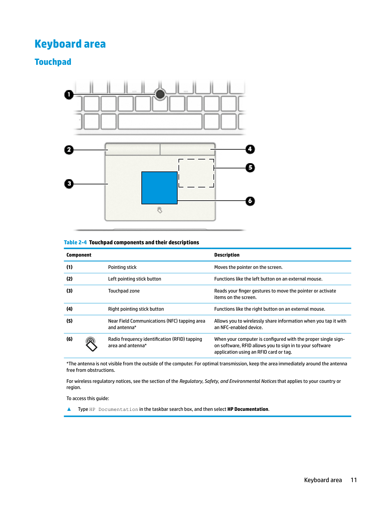
#### Touchpad

######## Table 2-4 Touchpad components and their descriptions
######### Component Description
Allows you to wirelessly share information when you tap it with an NFC-enabled device.
When your computer is configured with the proper single signon software, RFID allows you to sign in to your software application using an RFID card or tag.

*The antenna is not visible from the outside of the computer. For optimal transmission, keep the area immediately around the antenna free from obstructions.
For wireless regulatory notices, see the section of the Regulatory, Safety, and Environmental Notices that applies to your country or region.
To access this guide:
▲ Type HP Documentation in the taskbar search box, and then select HP Documentation.
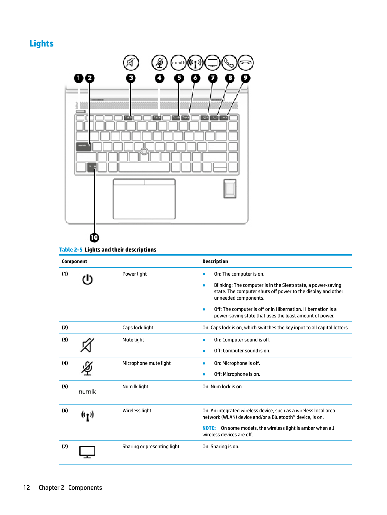
#### Lights

######## Table 2-5 Lights and their descriptions
######### Component Description


● Off: Computer sound is on.

● Off: Microphone is on.


NOTE: On some models, the wireless light is amber when all wireless devices are off.

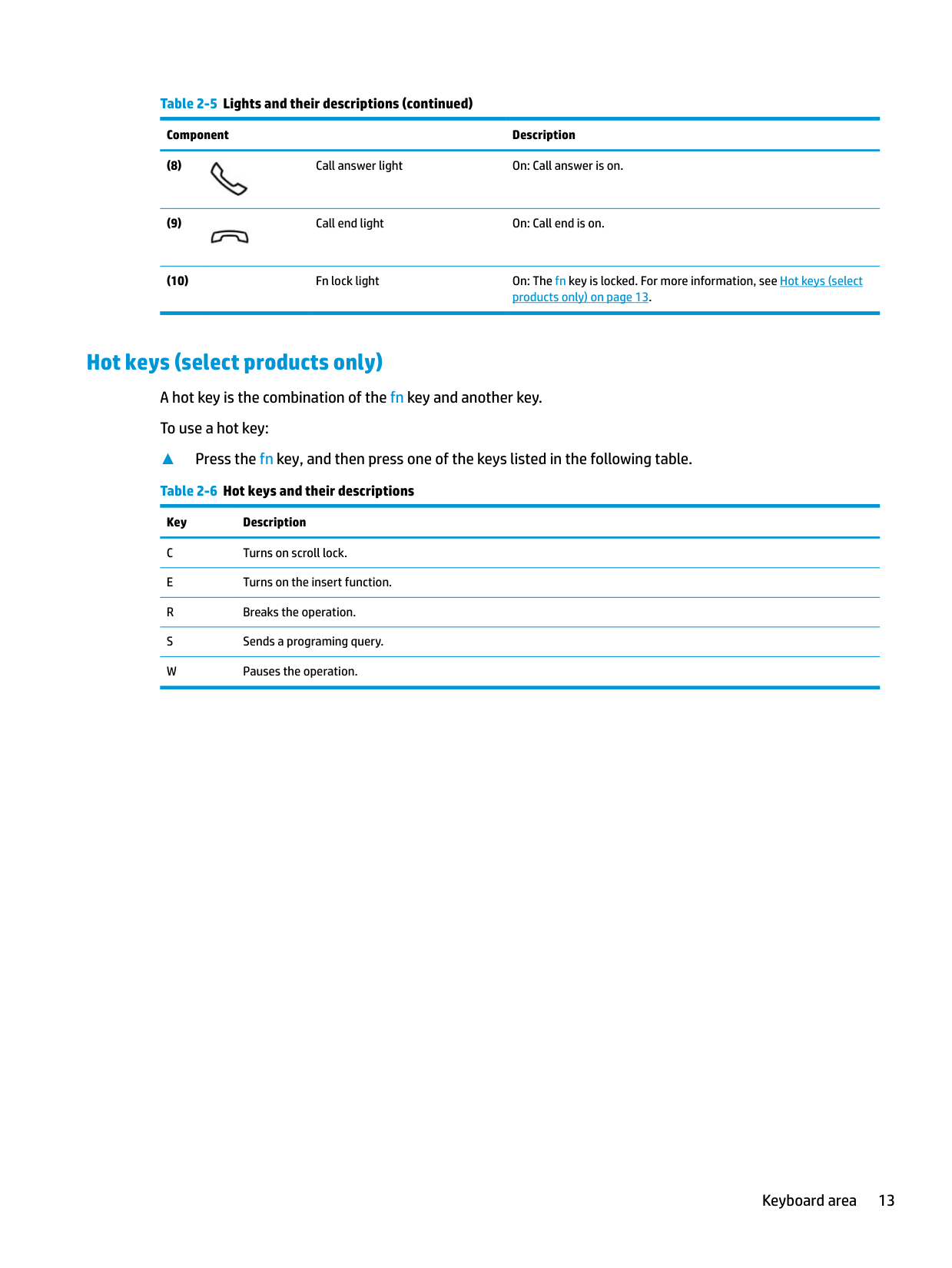
######## Table 2-5 Lights and their descriptions (continued)
######### Component Description


Hot keys (select products only) A hot key is the combination of the fn key and another key. To use a hot key:
▲ Press the fn key, and then press one of the keys listed in the following table. Table 2-6 Hot keys and their descriptions
Key Description C Turns on scroll lock. E Turns on the insert function.
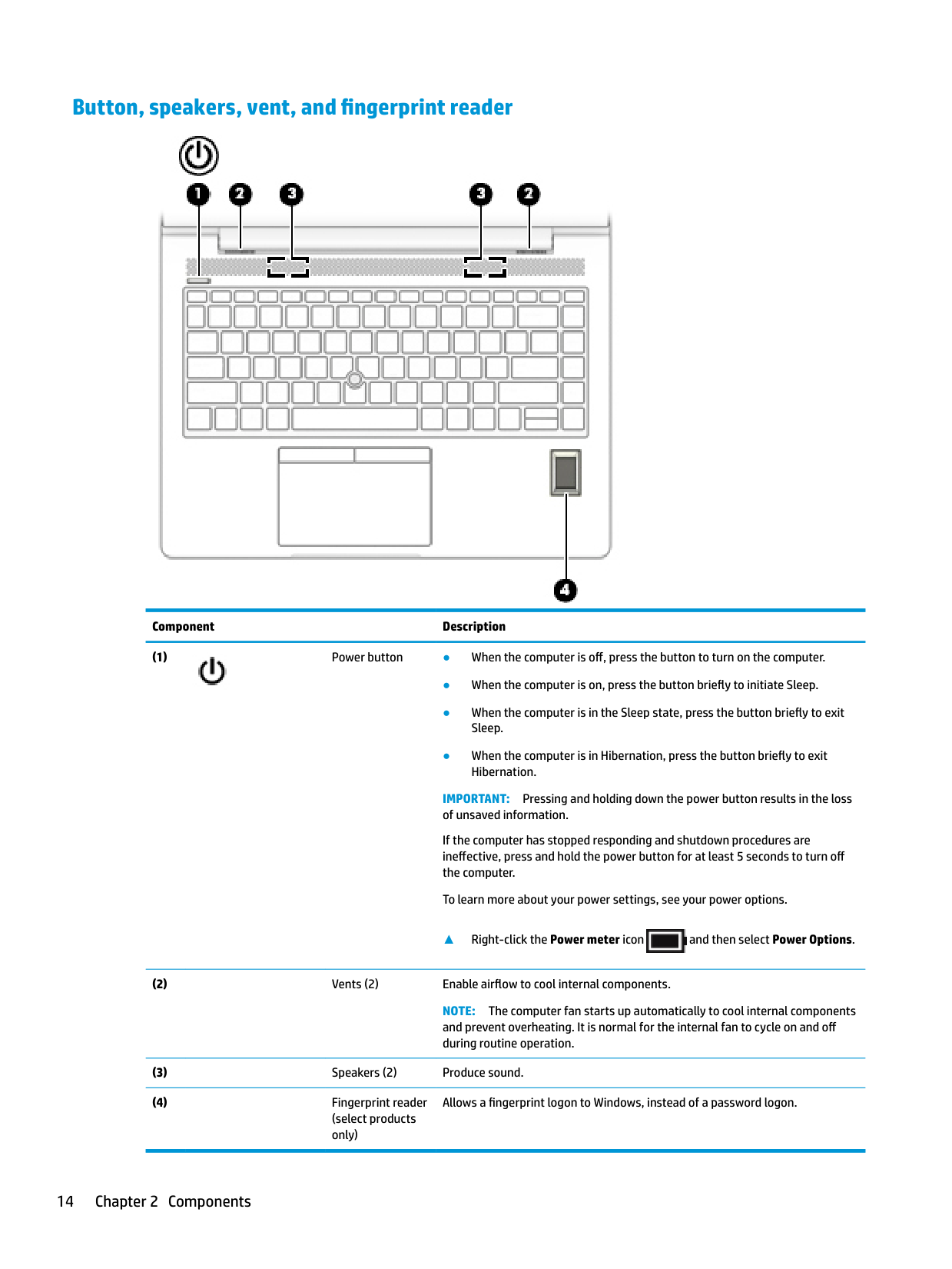
#### Button, speakers, vent, and fingerprint reader

######### Component Description

IMPORTANT: Pressing and holding down the power button results in the loss of unsaved information. If the computer has stopped responding and shutdown procedures are ineffective, press and hold the power button for at least 5 seconds to turn off the computer. To learn more about your power settings, see your power options.
▲ Right-click the Power meter icon and then select Power Options.

NOTE: The computer fan starts up automatically to cool internal components and prevent overheating. It is normal for the internal fan to cycle on and off during routine operation.
Allows a fingerprint logon to Windows, instead of a password logon.
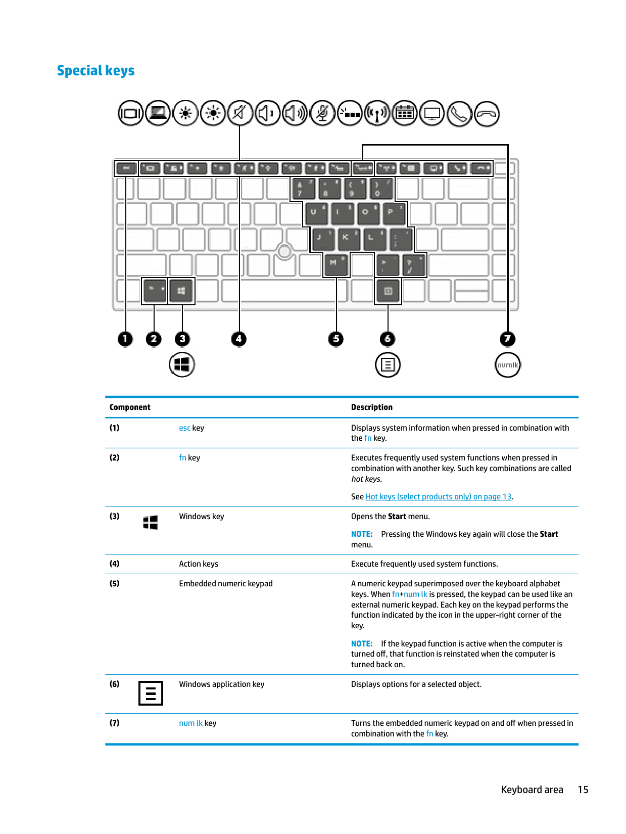
#### Special keys

######### Component Description

NOTE: Pressing the Windows key again will close the Start menu.
NOTE: If the keypad function is active when the computer is turned off, that function is reinstated when the computer is turned back on.

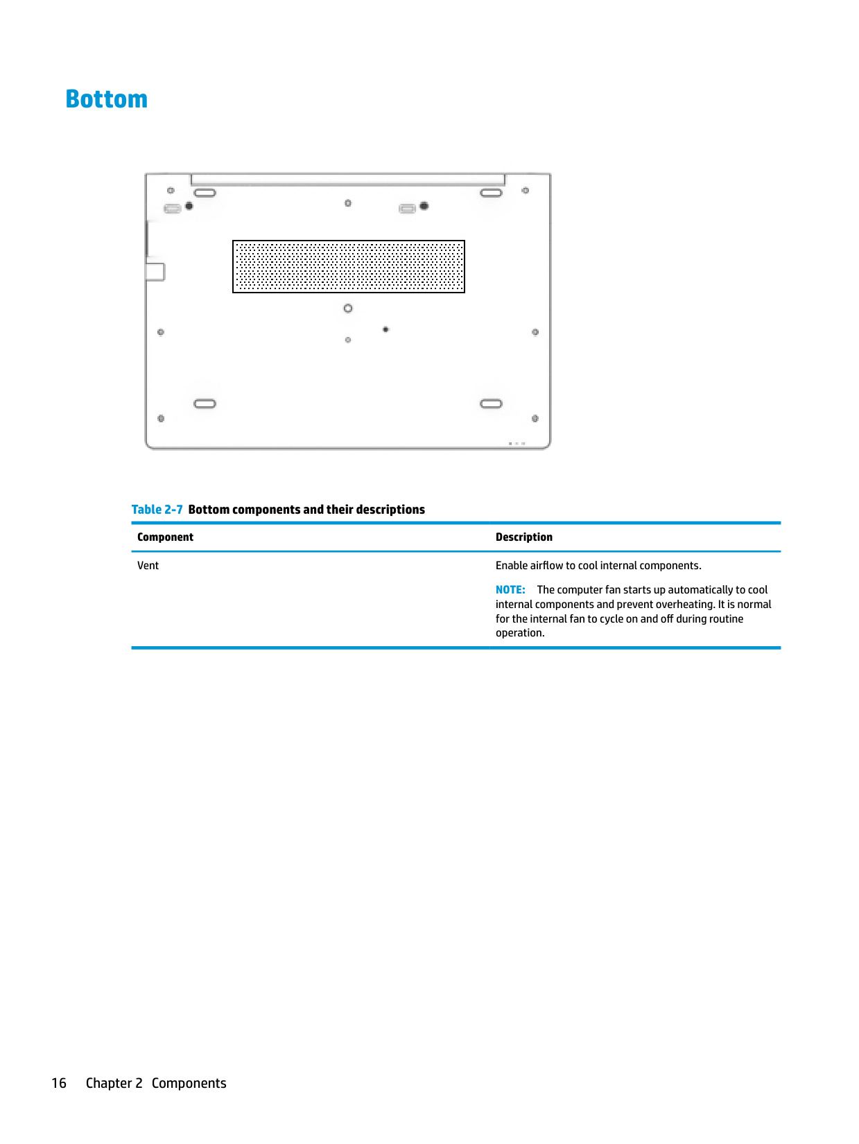
Bottom

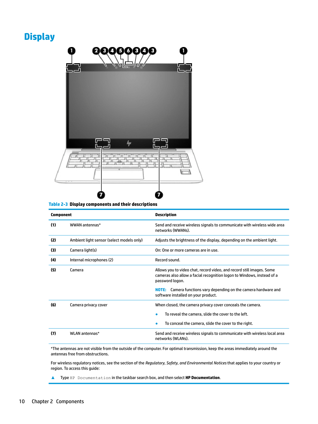
Table 2-7 Bottom components and their descriptions Component Description Vent Enable airflow to cool internal components.
NOTE: The computer fan starts up automatically to cool internal components and prevent overheating. It is normal for the internal fan to cycle on and off during routine operation.
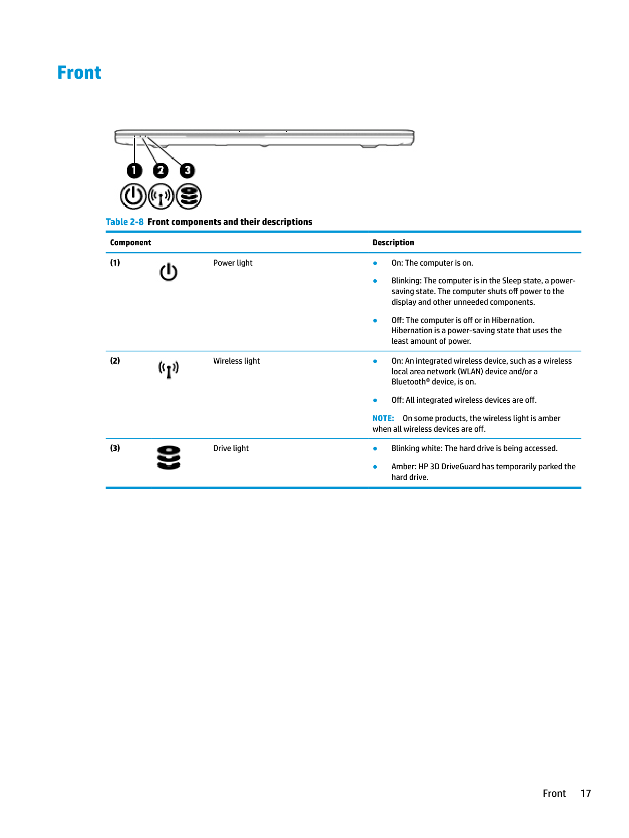
Front

######## Table 2-8 Front components and their descriptions
######### Component Description


● Off: All integrated wireless devices are off. NOTE: On some products, the wireless light is amber when all wireless devices are off.

● Amber: HP 3D DriveGuard has temporarily parked the hard drive.
Front 17
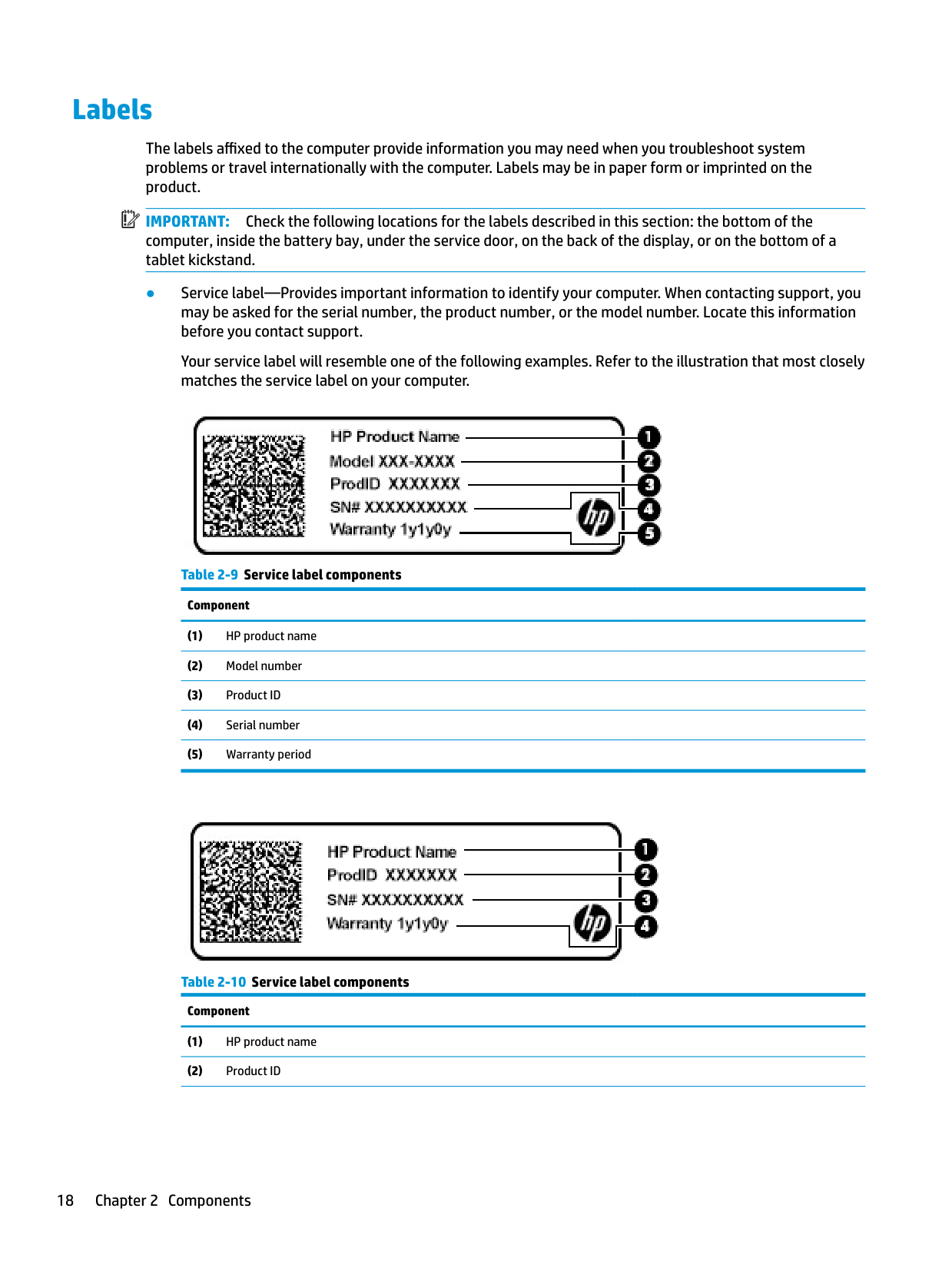
Labels
The labels affixed to the computer provide information you may need when you troubleshoot system problems or travel internationally with the computer. Labels may be in paper form or imprinted on the product.
| | |---|
IMPORTANT: Check the following locations for the labels described in this section: the bottom of the computer, inside the battery bay, under the service door, on the back of the display, or on the bottom of a tablet kickstand.
Your service label will resemble one of the following examples. Refer to the illustration that most closely matches the service label on your computer.


######## Table 2-10 Service label components (continued)
######### Component
Labels 19
3 Illustrated parts catalog
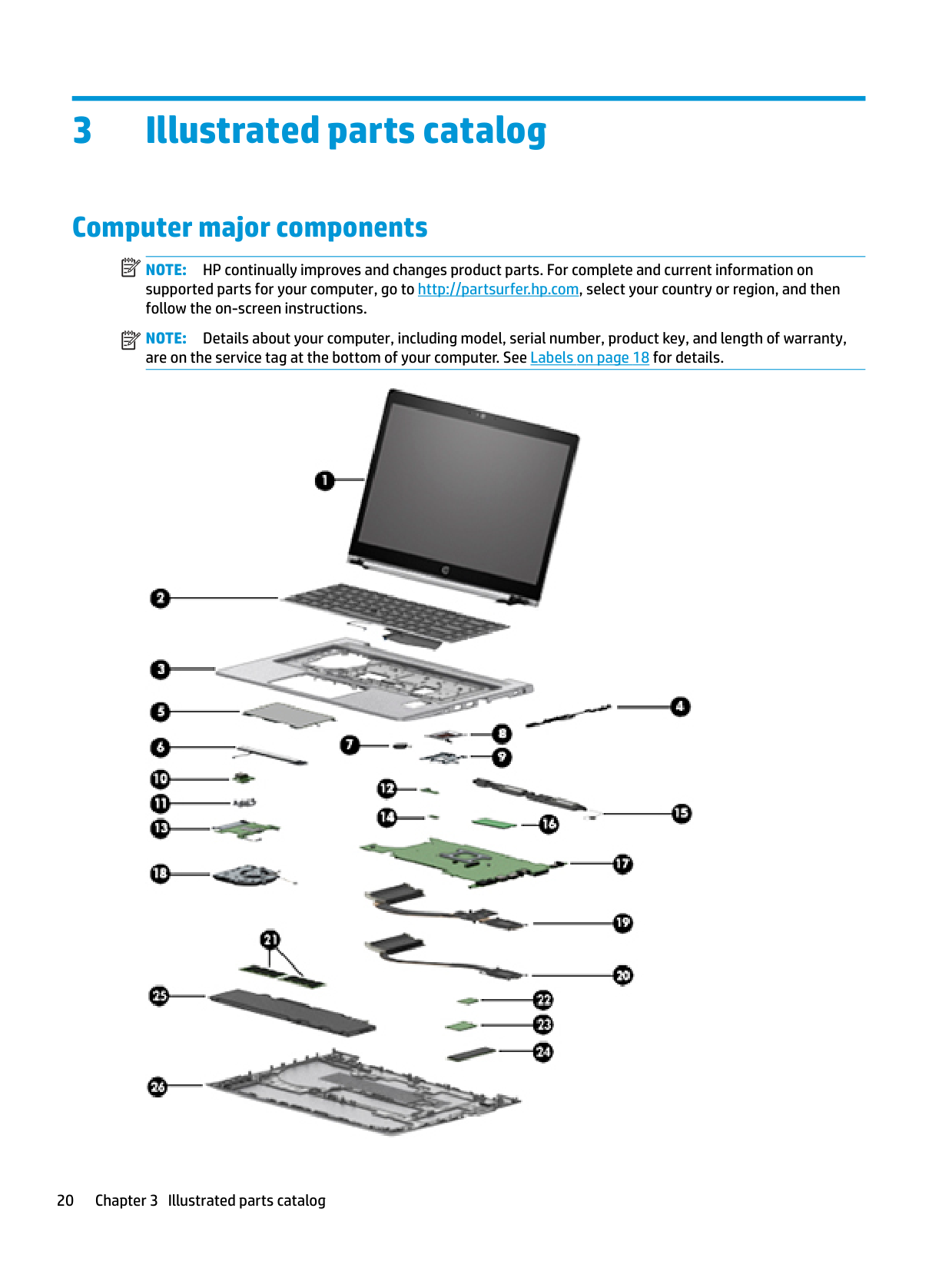
Computer major components
| | |---|
NOTE: HP continually improves and changes product parts. For complete and current information on supported parts for your computer, go to http://partsurfer.hp.com, select your country or region, and then follow the on-screen instructions.
| | |---|
NOTE: Details about your computer, including model, serial number, product key, and length of warranty, are on the service tag at the bottom of your computer. See Labels on page 18 for details.

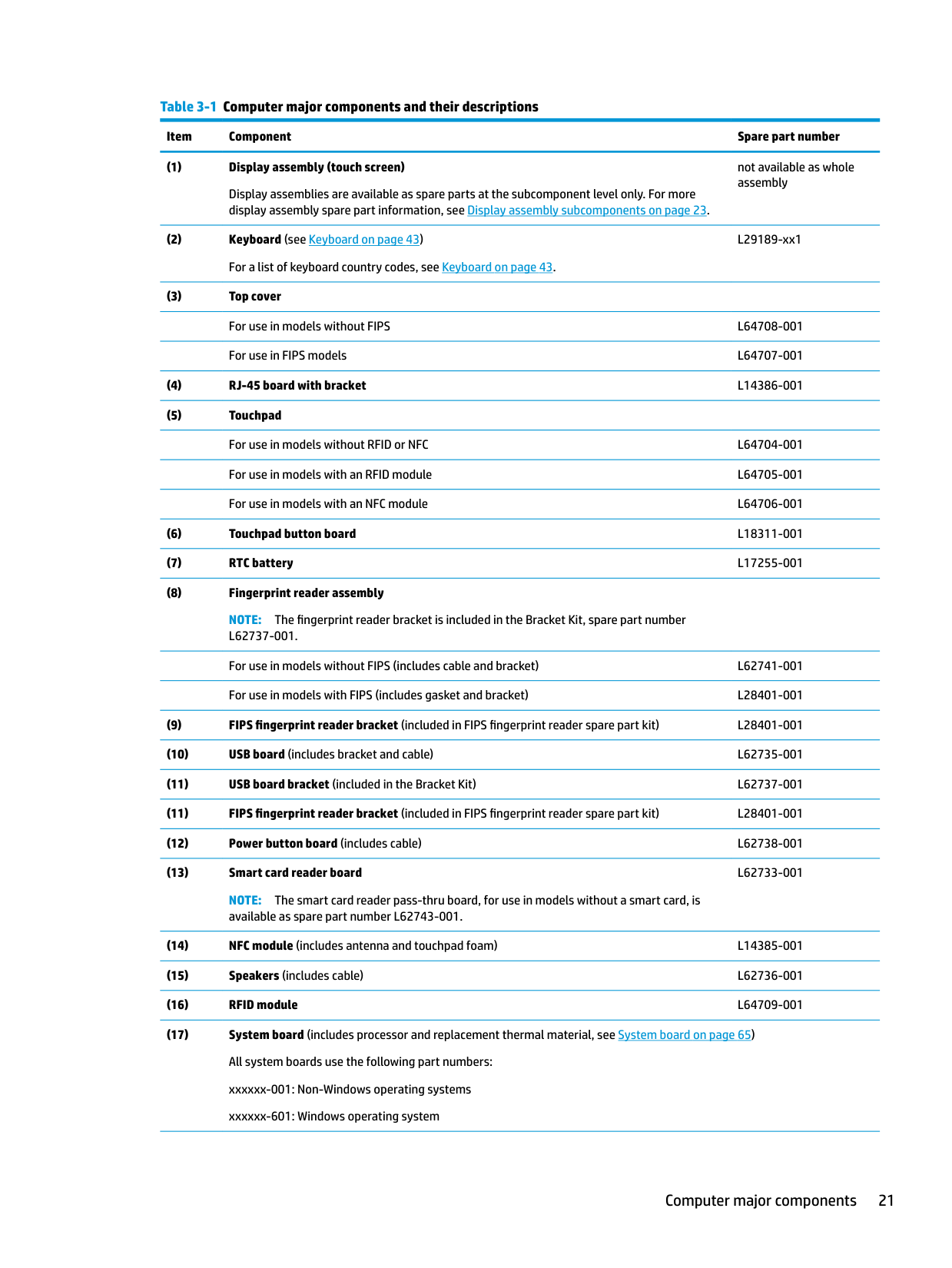
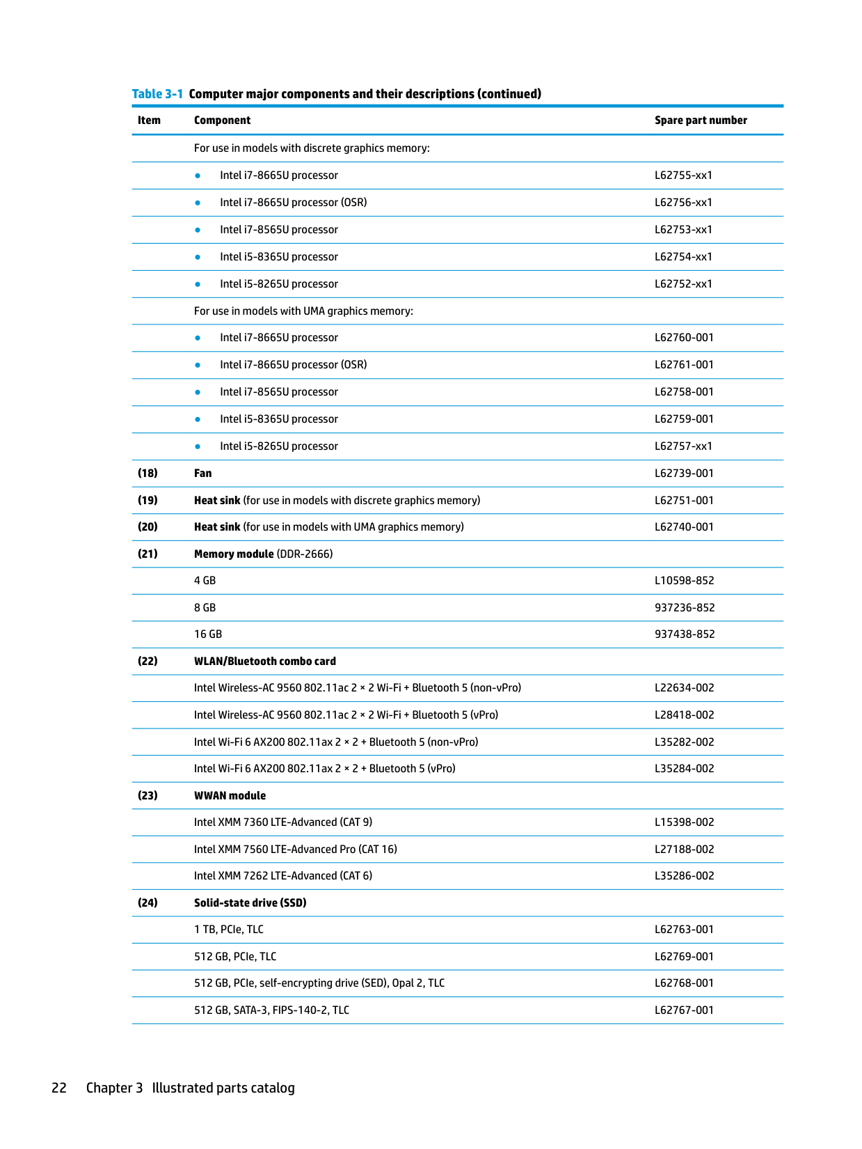
######## Table 3-1 Computer major components and their descriptions
Item Component Spare part number
Display assemblies are available as spare parts at the subcomponent level only. For more display assembly spare part information, see Display assembly subcomponents on page 23.
not available as whole assembly
L29189-xx1
NOTE: The fingerprint reader bracket is included in the Bracket Kit, spare part number L62737-001. For use in models without FIPS (includes cable and bracket) L62741-001 For use in models with FIPS (includes gasket and bracket) L28401-001
NOTE: The smart card reader pass-thru board, for use in models without a smart card, is available as spare part number L62743-001.
L62733-001
Computer major components 21
For use in models with discrete graphics memory:
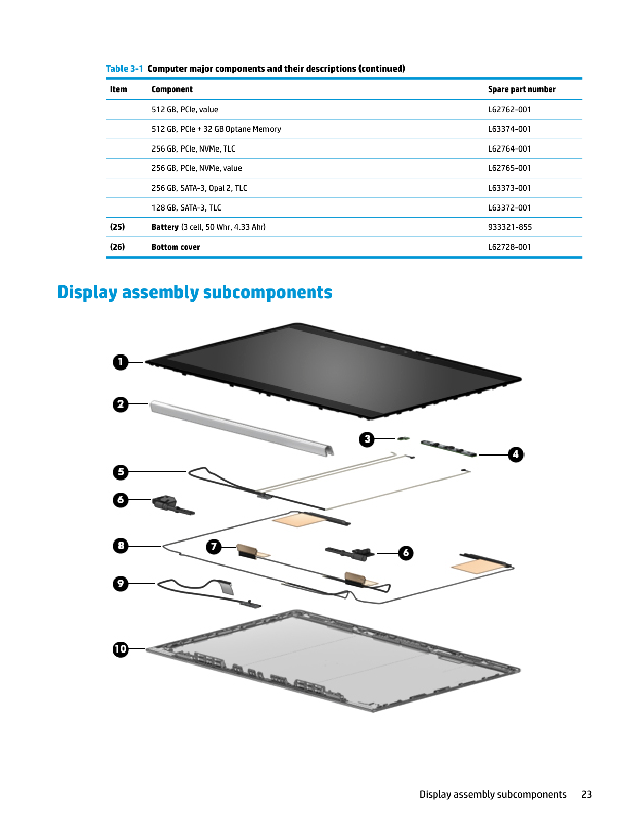
Display assembly subcomponents

Display assembly subcomponents 23
######## Table 3-2 Display components and their descriptions
Item Component Spare part number
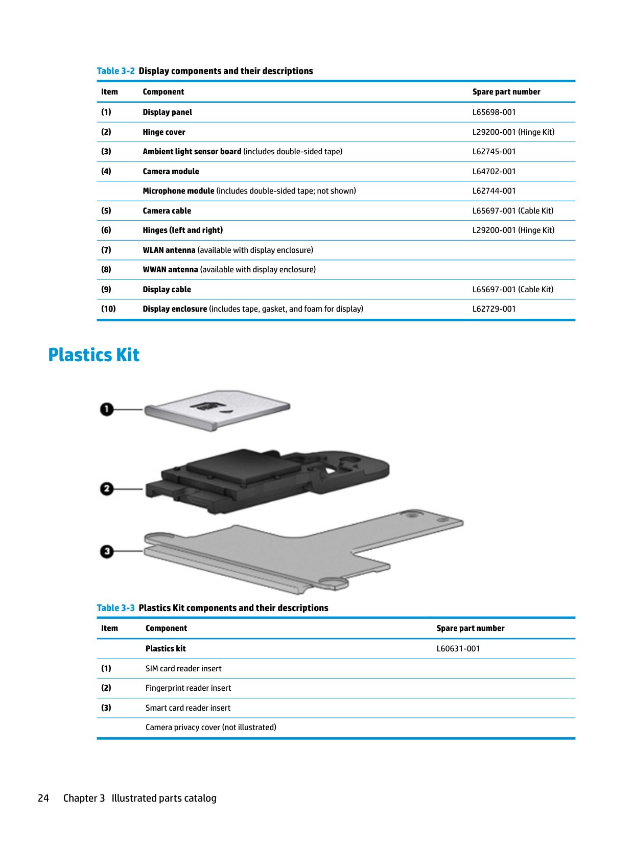
Plastics Kit

######## Table 3-3 Plastics Kit components and their descriptions
Item Component Spare part number Plastics kit L60631-001
Cable Kit
Table 3-4 Cable Kit components and their descriptions Description Spare part number Cable Kit, includes the following cables: L65697-001 Pointing stick cable USB board cable Card reader cable Touchpad cable Fingerprint reader cable NFC cable Power button board cable FIPS cable RFID cable FHD privacy display panel cable Webcam/microphone cable
Miscellaneous parts
Table 3-5 Miscellaneous parts and their descriptions Component Spare part number AC adapter (non-PFC, 4.5 mm):
65 W HP Smart AC adapter, 3 prong 710412-001 65 W USB Type-C, nPFC, 1.8 m L32392-001 65 W HP Smart AC adapter, EM 913691-850 45 W HP Smart AC adapter, 2 prong 742436-001 Power cord (3 pin, C5, black, 1.0 m, duckhead), for use in:
Australia L36816-001 Brazil L44789-001 Denmark L36817-001 Europe (Austria, Belgium, Finland, France, Germany, the Netherlands, Norway and Sweden) L36818-001 Israel L36819-001 Italy L44788-001 Japan L36821-001 North America L36822-001 People’s Republic of China L36823-001
Cable Kit 25
South Africa L36824-001 Switzerland L36825-001 Taiwan L36827-001 Thailand L36826-001 United Kingdom and Singapore L36828-001 Power cord (3 pin, C5, black, 1.8 m, duckhead), for use in:
Australia L45264-001 Brazil L48055-001 Denmark L50729-001 Europe (Austria, Belgium, Finland, France, Germany, the Netherlands, Norway and Sweden) L45265-001 Israel L45266-001 Italy L45267-001 Japan L45268-001 North America L45269-001 People’s Republic of China L45270-001 South Africa L45271-001 Switzerland L45272-001 Taiwan L45274-001 Thailand L45273-001 United Kingdom and Singapore L45275-001 Power cord (3 pin, C5, black, conventional, 1.8 m), for use in:
Argentina L19357-002 Brazil L19359-002 Denmark L19360-002 Europe (Austria, Belgium, Finland, France, Germany, the Netherlands, Norway and Sweden) L19361-002 India L19363-002 Israel L19362-002 Italy L19364-002 Japan L19365-002 North America L19367-002 The People’s Republic of China L19368-002 South Africa L19369-002 South Korea L19366-002
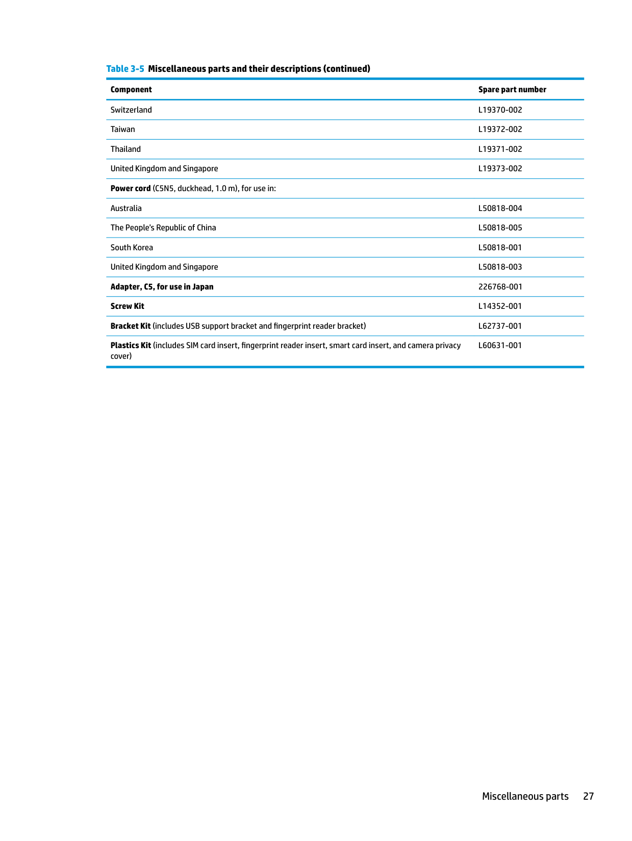
Switzerland L19370-002 Taiwan L19372-002 Thailand L19371-002 United Kingdom and Singapore L19373-002 Power cord (C5N5, duckhead, 1.0 m), for use in:
Australia L50818-004 The People’s Republic of China L50818-005 South Korea L50818-001 United Kingdom and Singapore L50818-003 Adapter, C5, for use in Japan 226768-001 Screw Kit L14352-001 Bracket Kit (includes USB support bracket and fingerprint reader bracket) L62737-001 Plastics Kit (includes SIM card insert, fingerprint reader insert, smart card insert, and camera privacy
L60631-001
cover)
Miscellaneous parts 27
4 Removal and replacement procedurespreliminary requirements
Tools required
You will need the following tools to complete the removal and replacement procedures:
Service considerations

The following sections include some of the considerations that you must keep in mind during disassembly and assembly procedures.
| | |---|
NOTE: As you remove each subassembly from the computer, place the subassembly (and all accompanying screws) away from the work area to prevent damage.
#### Plastic parts
| | |---|
IMPORTANT: Using excessive force during disassembly and reassembly can damage plastic parts.
#### Cables and connectors
| | |---|
IMPORTANT: When servicing the computer, be sure that cables are placed in their proper locations during the reassembly process. Improper cable placement can damage the computer.
Cables must be handled with extreme care to avoid damage. Apply only the tension required to unseat or seat the cables during removal and insertion. Handle cables by the connector whenever possible. In all cases, avoid bending, twisting, or tearing cables. Be sure that cables are routed in such a way that they cannot be caught or snagged by parts being removed or replaced. Handle flex cables with extreme care; these cables tear easily.
Drive handling IMPORTANT: Drives are fragile components that must be handled with care. To prevent damage to the computer, damage to a drive, or loss of information, observe these precautions: Before removing or inserting a hard drive, shut down the computer. If you are unsure whether the computer is off or in Hibernation, turn the computer on, and then shut it down through the operating system. Before handling a drive, be sure that you are discharged of static electricity. While handling a drive, avoid touching the connector. Before removing an optical drive, be sure that a disc is not in the drive and be sure that the optical drive tray is closed. Handle drives on surfaces covered with at least 2.54 cm (1 inch) of shock-proof foam. Avoid dropping drives from any height onto any surface. After removing a hard drive or an optical drive, place it in a static-proof bag. Avoid exposing an internal hard drive to products that have magnetic fields, such as monitors or speakers. Avoid exposing a drive to temperature extremes or liquids. If a drive must be mailed, place the drive in a bubble pack mailer or other suitable form of protective packaging and label the package “FRAGILE.”
| | |---|
#### Workstation guidelines
Follow these grounding workstation guidelines:
Service considerations 29
Cleaning your computer
#### Using HP Easy Clean
HP Easy Clean provides the ability to avoid accidental input while the notebook surfaces are being cleaned with germicidal wipes. HP Easy Clean disables computer input devices such as the keyboard, the touch screen, and the TouchPad for a set amount of time to allow cleaning all surfaces of the device.
You can start Easy Clean software in one of the following ways:
#### Cleaning visible soiling of the computer surface
#### If there is no visible soiling of the computer surface
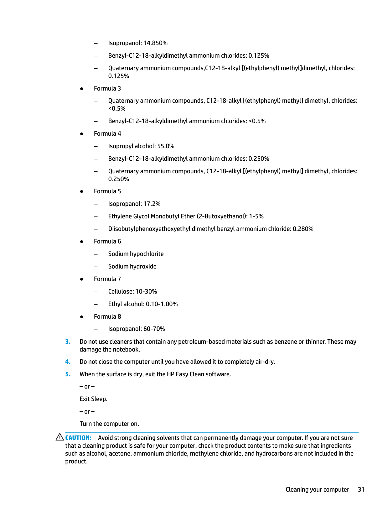
– Isopropanol: 60-70%
CAUTION: Avoid strong cleaning solvents that can permanently damage your computer. If you are not sure that a cleaning product is safe for your computer, check the product contents to make sure that ingredients such as alcohol, acetone, ammonium chloride, methylene chloride, and hydrocarbons are not included in the product.
Cleaning your computer 31
Electrostatic discharge information
A sudden discharge of static electricity from your finger or other conductor can destroy static-sensitive devices or microcircuitry. Often the spark is neither felt nor heard, but damage occurs. An electronic device exposed to electrostatic discharge (ESD) might not appear to be affected at all and can work perfectly throughout a normal cycle. The device might function normally for a while, but it has been degraded in the internal layers, reducing its life expectancy.
Networks built into many integrated circuits provide some protection, but in many cases, the discharge contains enough power to alter device parameters or melt silicon junctions.
| | |---|
IMPORTANT: To prevent damage to the device when you are removing or installing internal components, observe these precautions: Keep components in their electrostatic-safe containers until you are ready to install them. Before touching an electronic component, discharge static electricity by using the guidelines described in this section. Avoid touching pins, leads, and circuitry. Handle electronic components as little as possible. If you remove a component, place it in an electrostatic-safe container.
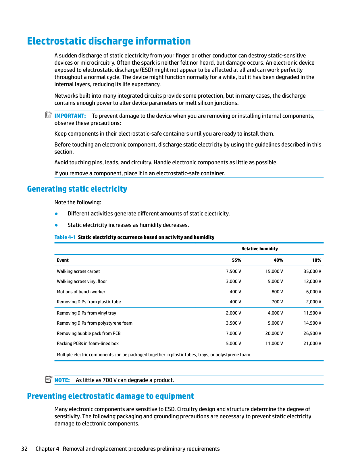
#### Generating static electricity
Note the following:
Relative humidity Event 55% 40% 10% Walking across carpet Walking across vinyl floor Motions of bench worker Removing DIPs from plastic tube
7,500 V 3,000 V
15,000 V
35,000 V 12,000 V
5,000 V 800 V 700 V
400 V 400 V
6,000 V 2,000 V
Removing DIPs from vinyl tray Removing DIPs from polystyrene foam Removing bubble pack from PCB Packing PCBs in foam-lined box
Multiple electric components can be packaged together in plastic tubes, trays, or polystyrene foam.
20,000 V 11,000 V
11,500 V 14,500 V 26,500 V 21,000 V
| | |---|
NOTE: As little as 700 V can degrade a product.
#### Preventing electrostatic damage to equipment
Many electronic components are sensitive to ESD. Circuitry design and structure determine the degree of sensitivity. The following packaging and grounding precautions are necessary to prevent static electricity damage to electronic components.
#### Personal grounding methods and equipment
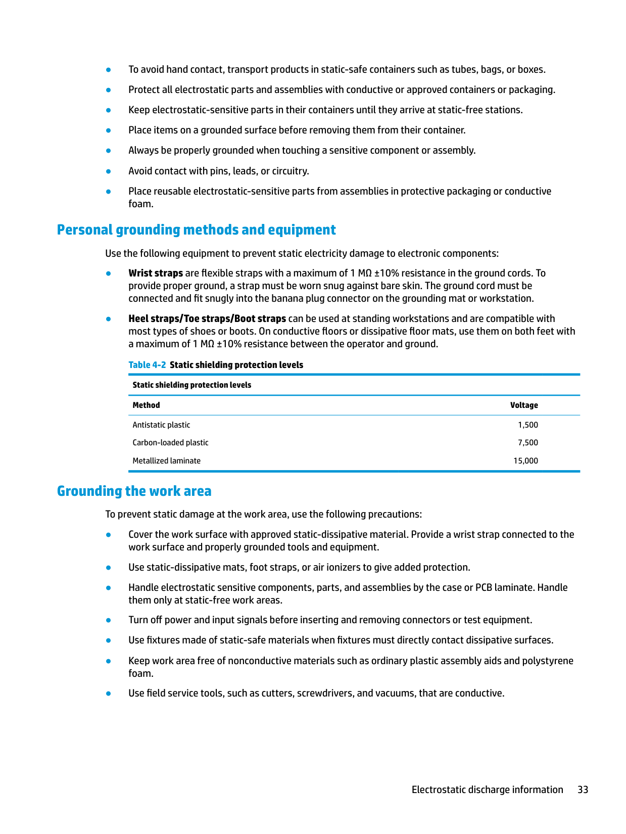
Use the following equipment to prevent static electricity damage to electronic components:
Static shielding protection levels Method Voltage
Antistatic plastic Carbon-loaded plastic Metallized laminate
1,500 7,500
15,000
#### Grounding the work area
To prevent static damage at the work area, use the following precautions:
Electrostatic discharge information 33
#### Recommended materials and equipment
HP recommends the following materials and equipment to prevent static electricity:
Packaging and transporting guidelines
Follow these grounding guidelines when packaging and transporting equipment:
5 Removal and replacement procedures forCustomer Self-Repair parts
| | |---|
This chapter provides removal and replacement procedures for Customer Self-Repair parts. NOTE: The Customer Self-Repair program is not available in all locations. Installing a part not supported by the Customer Self-Repair program may void your warranty. Check your warranty to determine if Customer Self-Repair is supported in your location.
Component replacement procedures
| | |---|
NOTE: Details about your computer, including model, serial number, product key, and length of warranty, are on the service tag at the bottom of your computer. See Labels on page 18 for details.
| | |---|
NOTE: HP continually improves and changes product parts. For complete and current information on supported parts for your computer, go to http://partsurfer.hp.com, select your country or region, and then follow the on-screen instructions.
There are as many as 12 screws that must be removed, replaced, and/or loosened when servicing Customer Self-Repair parts. Make special note of each screw size and location during removal and replacement.
#### Preparation for disassembly
See Removal and replacement procedures preliminary requirements on page 28 for initial safety procedures.
#### Bottom cover
Table 5-1 Bottom cover description and part number Description Spare part number Bottom cover L62728-001
Before removing the bottom cover, follow these steps:
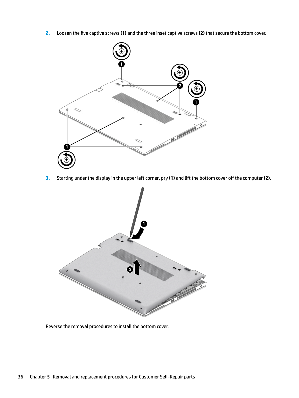
▲ Prepare the computer for disassembly (Preparation for disassembly on page 35). Remove the bottom cover:


Reverse the removal procedures to install the bottom cover.
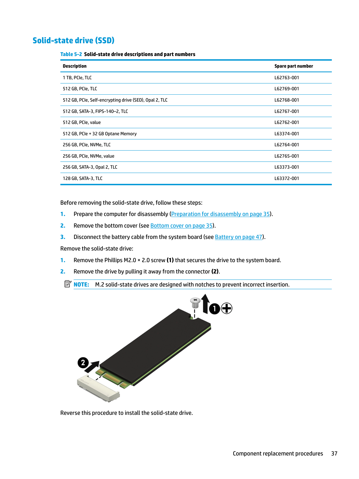
#### Solid-state drive (SSD)
######## Table 5-2 Solid-state drive descriptions and part numbers
######### Description Spare part number
1 TB, PCIe, TLC L62763-001 512 GB, PCIe, TLC L62769-001 512 GB, PCIe, Self-encrypting drive (SED), Opal 2, TLC L62768-001 512 GB, SATA-3, FIPS-140–2, TLC L62767-001 512 GB, PCIe, value L62762-001 512 GB, PCIe + 32 GB Optane Memory L63374-001 256 GB, PCIe, NVMe, TLC L62764-001 256 GB, PCIe, NVMe, value L62765-001 256 GB, SATA-3, Opal 2, TLC L63373-001 128 GB, SATA-3, TLC L63372-001
Before removing the solid-state drive, follow these steps:
| | |---|

Reverse this procedure to install the solid-state drive.
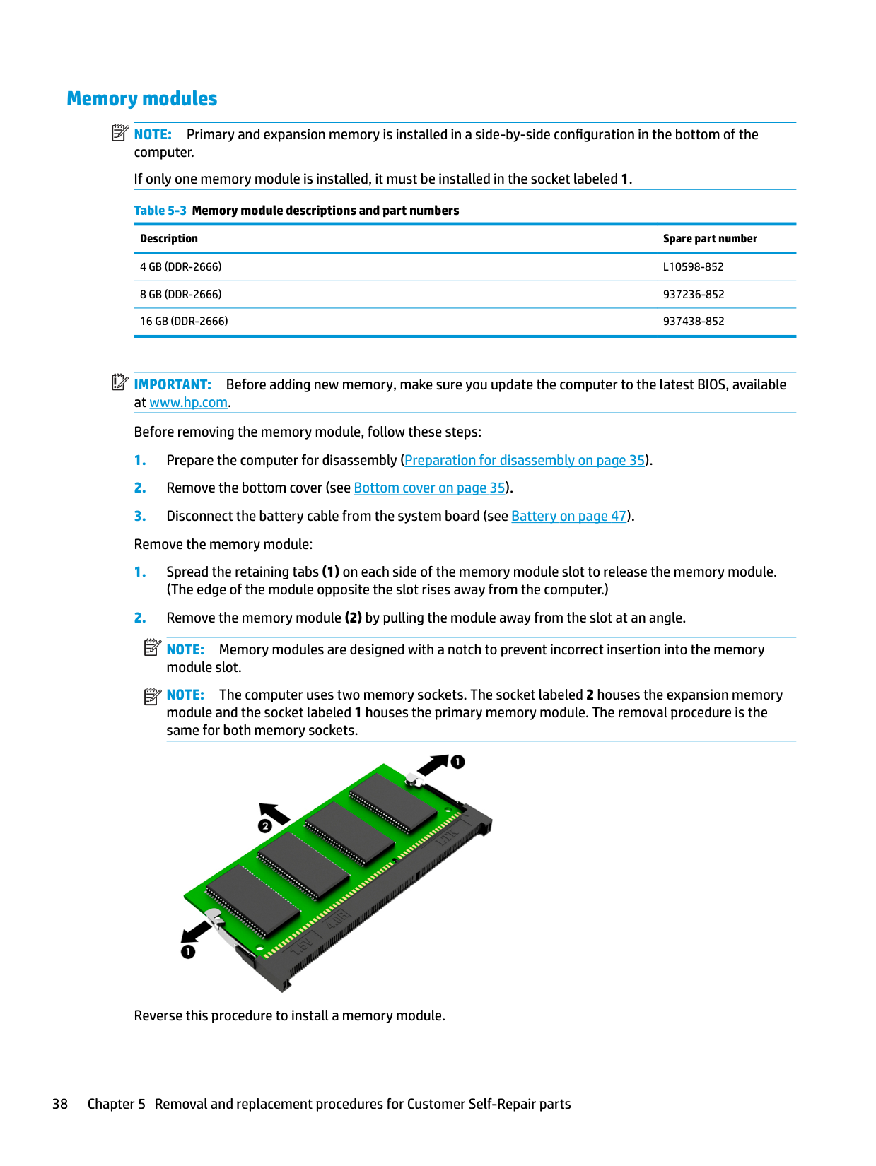
Memory modules NOTE: Primary and expansion memory is installed in a side-by-side configuration in the bottom of the computer. If only one memory module is installed, it must be installed in the socket labeled 1. Table 5-3 Memory module descriptions and part numbers
| | |---|
Description Spare part number
4 GB (DDR-2666) L10598-852 8 GB (DDR-2666) 937236-852 16 GB (DDR-2666) 937438-852
| | |---|
IMPORTANT: Before adding new memory, make sure you update the computer to the latest BIOS, available at www.hp.com. Before removing the memory module, follow these steps:
(The edge of the module opposite the slot rises away from the computer.)
| | |---|
NOTE: Memory modules are designed with a notch to prevent incorrect insertion into the memory module slot.
| | |---|
NOTE: The computer uses two memory sockets. The socket labeled 2 houses the expansion memory module and the socket labeled 1 houses the primary memory module. The removal procedure is the same for both memory sockets.

Reverse this procedure to install a memory module.
WLAN/Bluetooth combo card The computer uses a card that provides both WLAN and Bluetooth functionality. The WLAN module and WWAN module are not interchangeable. Table 5-4 WLAN module descriptions and part numbers
Description Spare part number
Intel Wireless-AC 9560 802.11ac 2 × 2 Wi-Fi + Bluetooth 5 (non-vPro) L22634-002 Intel Wireless-AC 9560 802.11ac 2 × 2 Wi-Fi + Bluetooth 5 (vPro) L28418-002 Intel Wi-Fi 6 AX200 802.11ax 2 × 2 + Bluetooth 5 (non-vPro) L35282-002 Intel Wi-Fi 6 AX200 802.11ax 2 × 2 + Bluetooth 5 (vPro) L35284-002
Before removing the WLAN module, follow these steps:
NOTE: The WLAN antenna cable labeled 1 connects to the WLAN module Main terminal labeled 1. The WLAN antenna cable labeled 2 connects to the WLAN module Aux terminal labeled 2. If the computer is equipped with an 802.11a/b/g/n WLAN module, the yellow WLAN antenna cable connects to the middle terminal on the WLAN module.
| | |---|
| | |---|
| | |---|

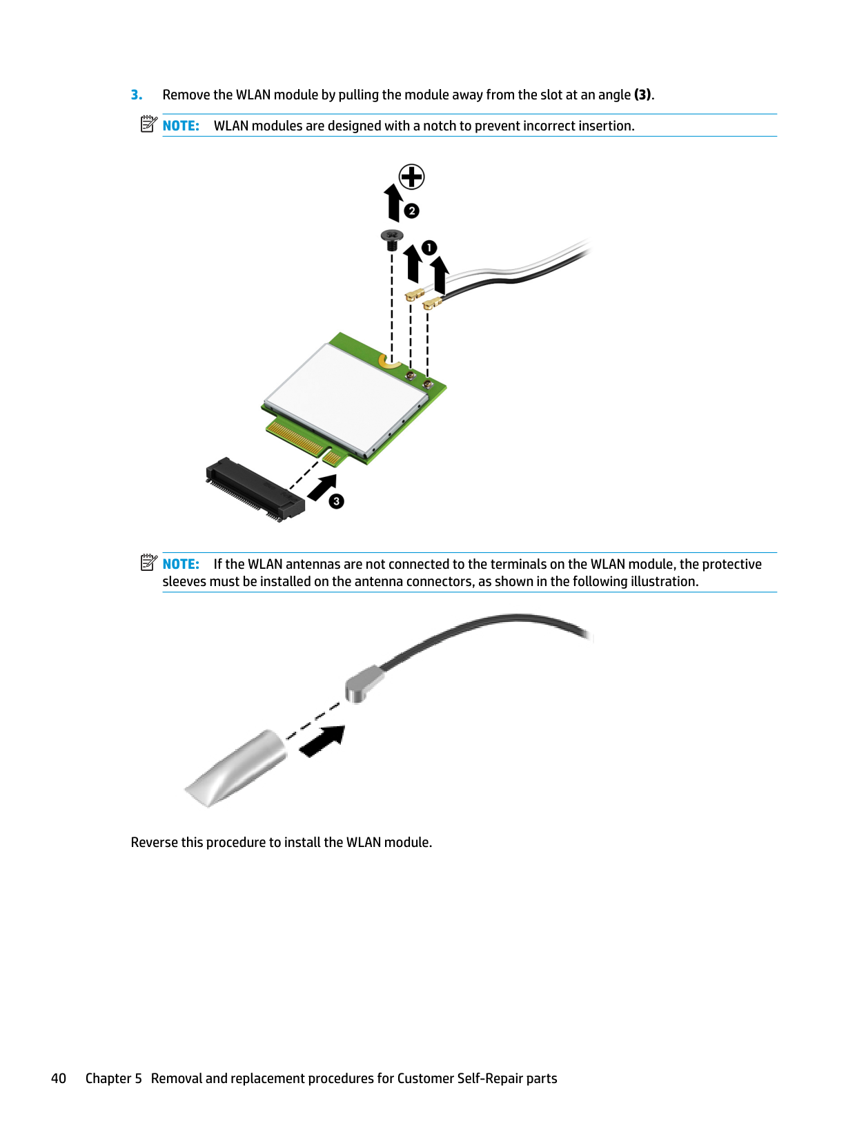
NOTE: If the WLAN antennas are not connected to the terminals on the WLAN module, the protective sleeves must be installed on the antenna connectors, as shown in the following illustration.

Reverse this procedure to install the WLAN module.
WWAN module The WLAN module and WWAN module are not interchangeable. The WWAN module is available on select models only. Table 5-5 WWAN module descriptions and part numbers
Description Spare part number
Intel XMM 7360 LTE-Advanced (CAT 9) L15398-002 Intel XMM 7560 LTE-Advanced Pro (CAT 16) L27188-002 Intel XMM 7262 LTE-Advanced (CAT 6) L35286-002
Before removing the WWAN module, follow these steps:
NOTE: The red WWAN antenna cable is connected to the WWAN module Main terminal. The blue WWAN antenna cable is connected to the WWAN module Aux terminal.
| | |---|
| | |---|
| | |---|

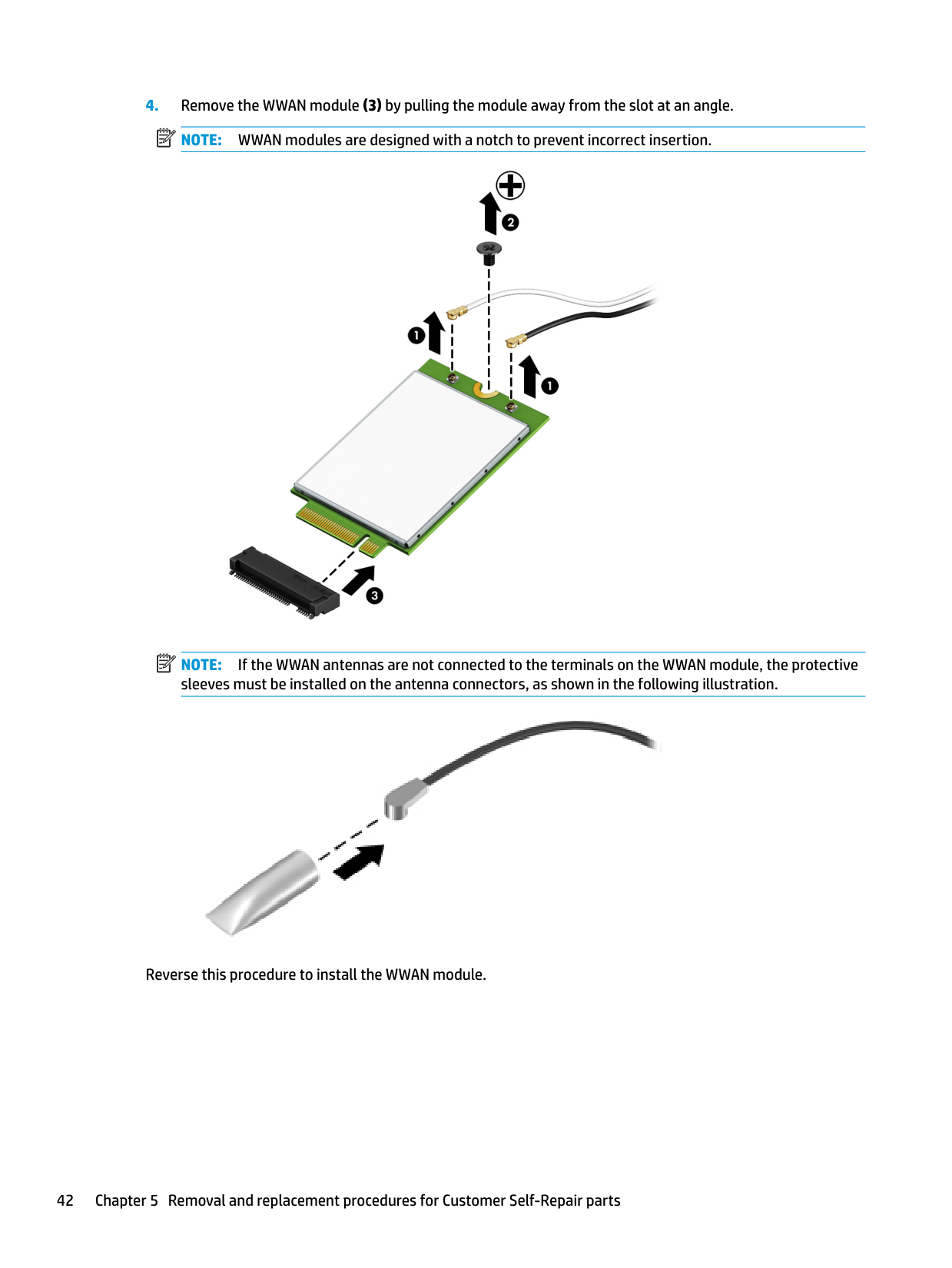
NOTE: If the WWAN antennas are not connected to the terminals on the WWAN module, the protective sleeves must be installed on the antenna connectors, as shown in the following illustration.

Reverse this procedure to install the WWAN module.
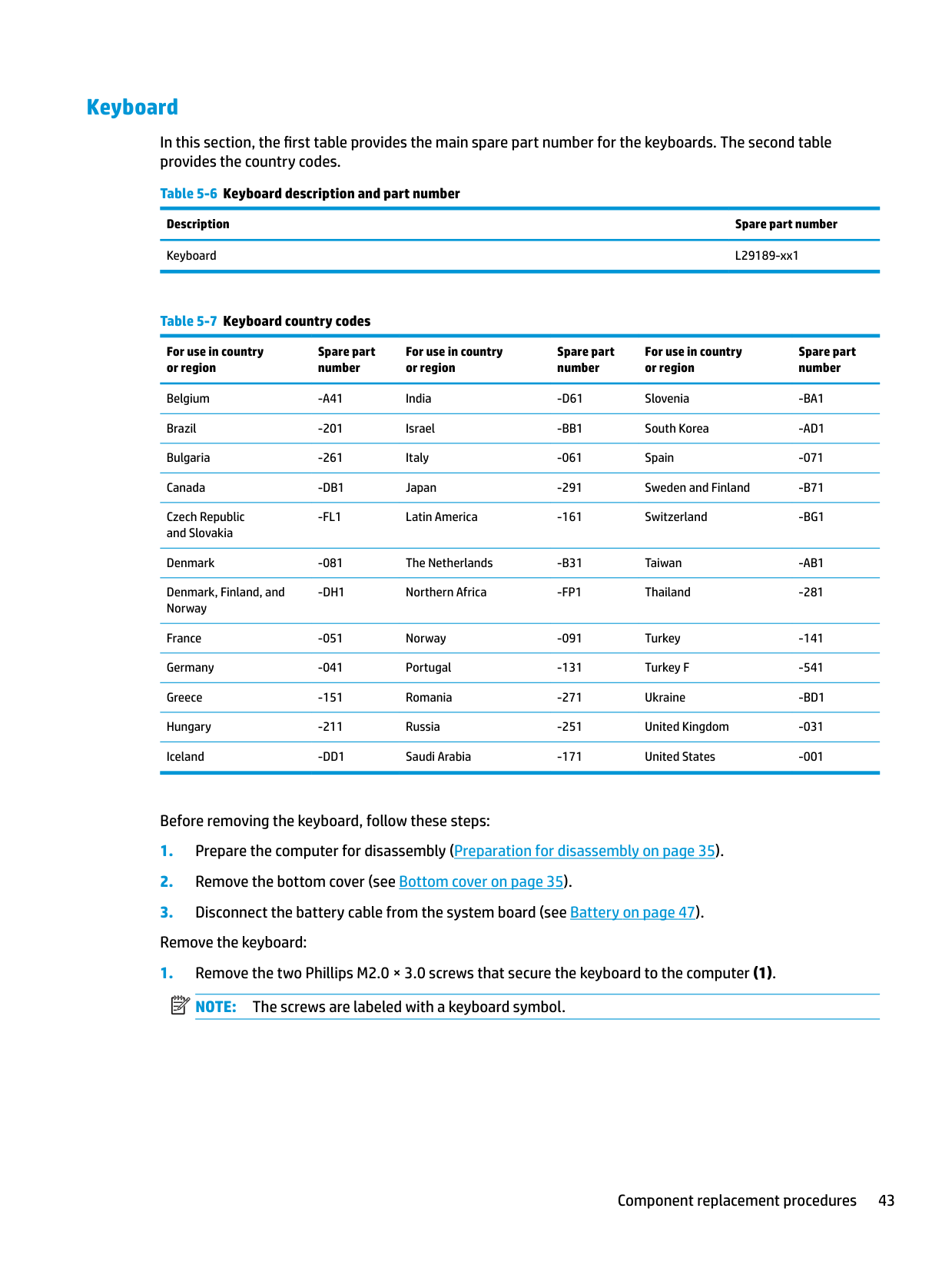
#### Keyboard
In this section, the first table provides the main spare part number for the keyboards. The second table provides the country codes.
For use in country or region
Spare part number
For use in country or region
Spare part number
For use in country or region
Spare part number
Belgium -A41 India -D61 Slovenia -BA1 Brazil -201 Israel -BB1 South Korea -AD1 Bulgaria -261 Italy -061 Spain -071 Canada -DB1 Japan -291 Sweden and Finland -B71 Czech Republic and Slovakia
-FL1 Latin America -161 Switzerland -BG1
Denmark -081 The Netherlands -B31 Taiwan -AB1 Denmark, Finland, and Norway
-DH1 Northern Africa -FP1 Thailand -281
France -051 Norway -091 Turkey -141 Germany -041 Portugal -131 Turkey F -541 Greece -151 Romania -271 Ukraine -BD1 Hungary -211 Russia -251 United Kingdom -031 Iceland -DD1 Saudi Arabia -171 United States -001
Before removing the keyboard, follow these steps:
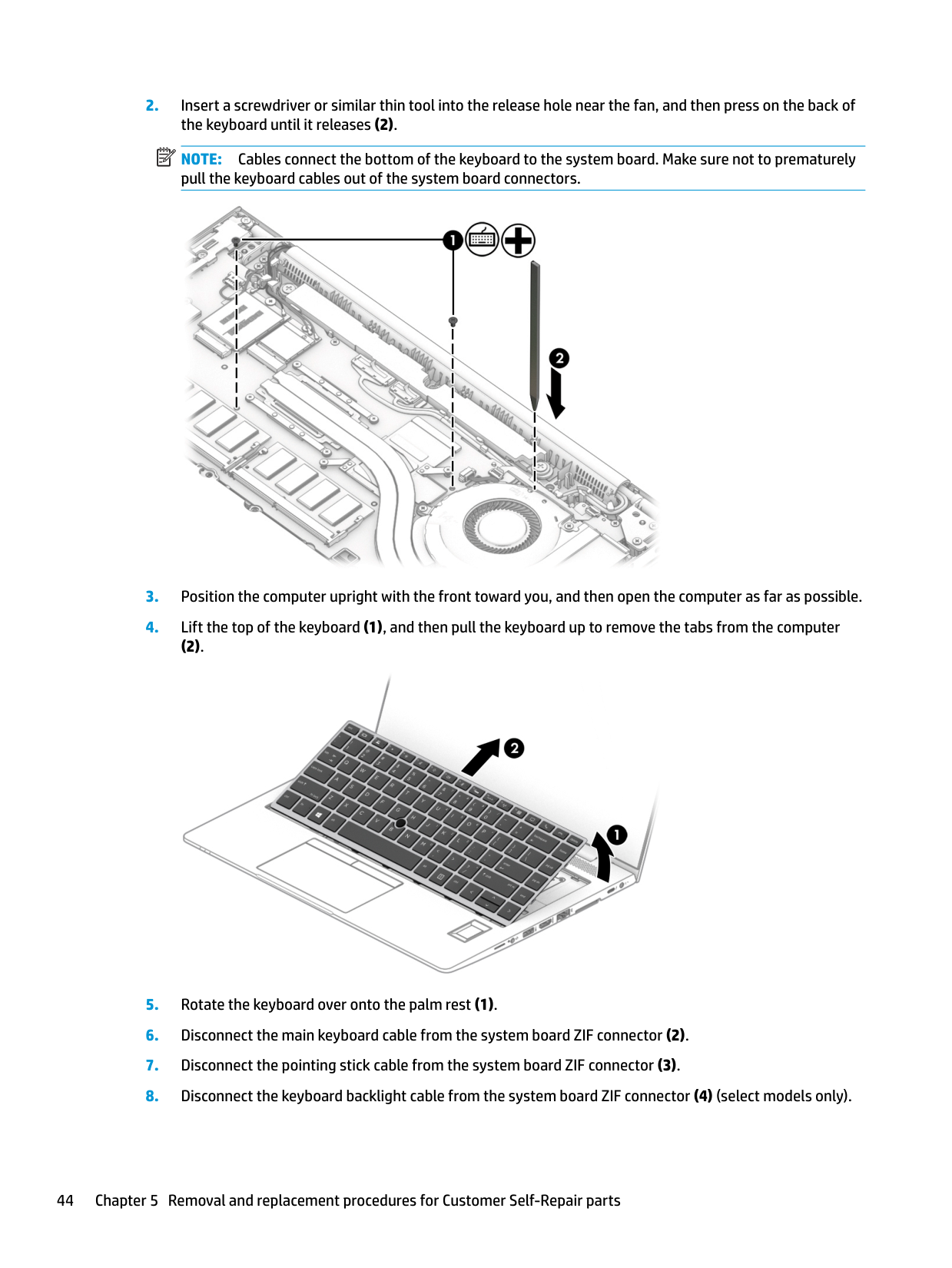
| | |---|
NOTE: Cables connect the bottom of the keyboard to the system board. Make sure not to prematurely pull the keyboard cables out of the system board connectors.

(2).

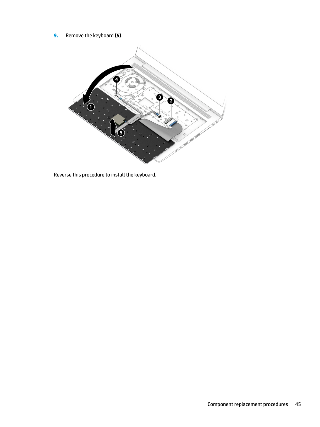
| | |---|

Reverse this procedure to install the keyboard.
6 Removal and replacement procedures forauthorized service provider parts
| | |---|
IMPORTANT: Components described in this chapter should be accessed only by an authorized service provider. Accessing these parts can damage the computer or void the warranty.
| | |---|
NOTE: Details about your computer, including model, serial number, product key, and length of warranty, are on the service tag at the bottom of your computer. See Labels on page 18 for details.
Component replacement procedures
| | |---|
NOTE: HP continually improves and changes product parts. For complete and current information on supported parts for your computer, go to http://partsurfer.hp.com, select your country or region, and then follow the on-screen instructions.
There are as many as 81 screws that must be removed, replaced, and/or loosened when servicing authorized service provider only parts. Make special note of each screw size and location during removal and replacement.
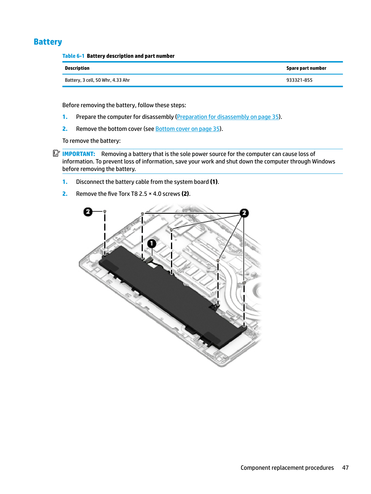
#### Battery
Table 6-1 Battery description and part number Description Spare part number Battery, 3 cell, 50 Whr, 4.33 Ahr 933321-855
Before removing the battery, follow these steps:
| | |---|
IMPORTANT: Removing a battery that is the sole power source for the computer can cause loss of information. To prevent loss of information, save your work and shut down the computer through Windows before removing the battery.

| | |---|
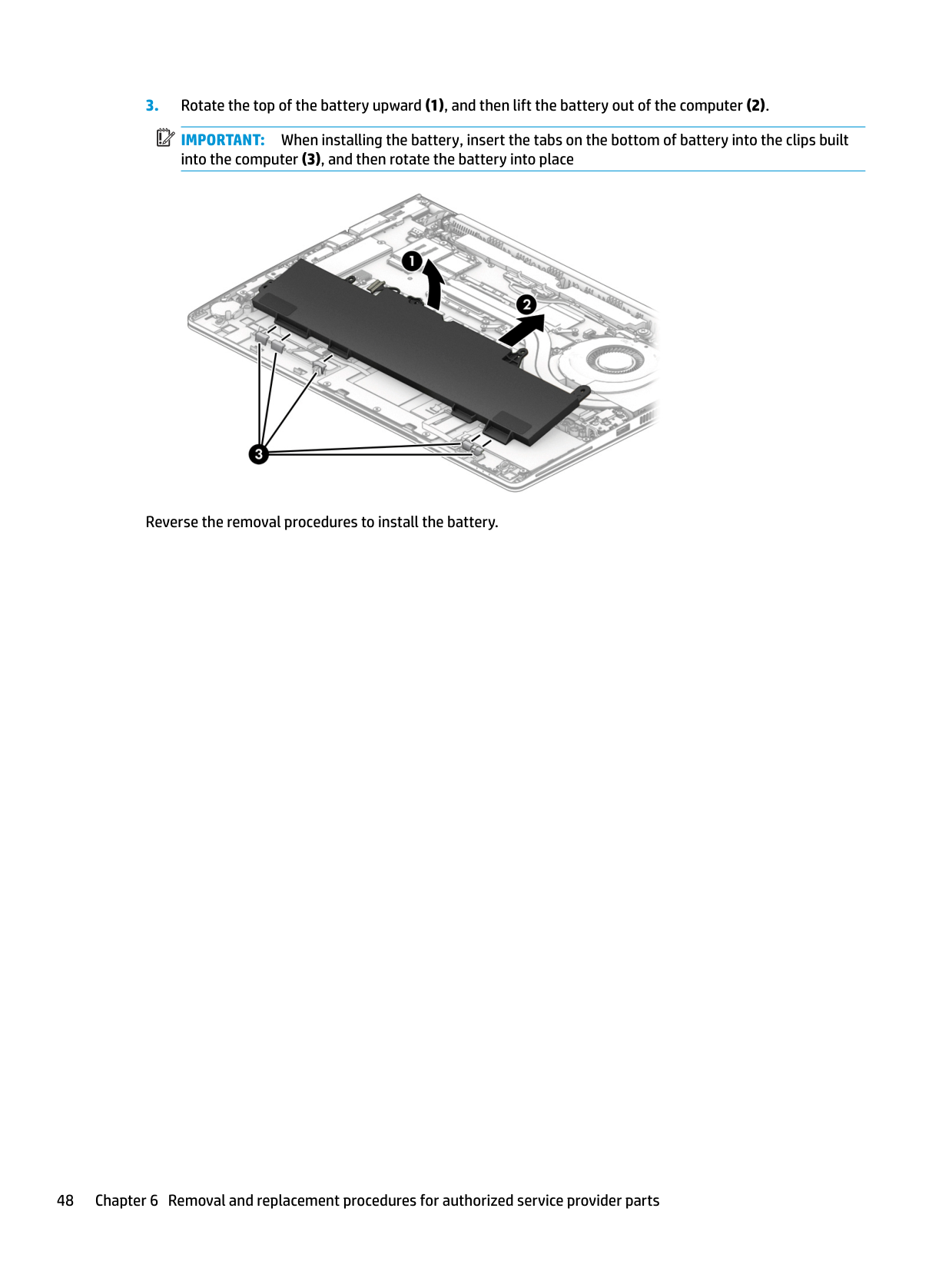
IMPORTANT: When installing the battery, insert the tabs on the bottom of battery into the clips built into the computer (3), and then rotate the battery into place

Reverse the removal procedures to install the battery.
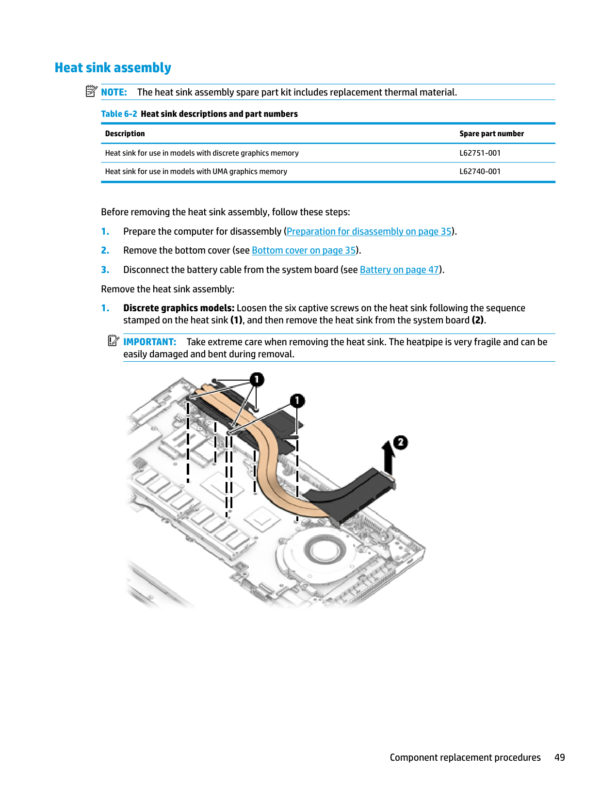
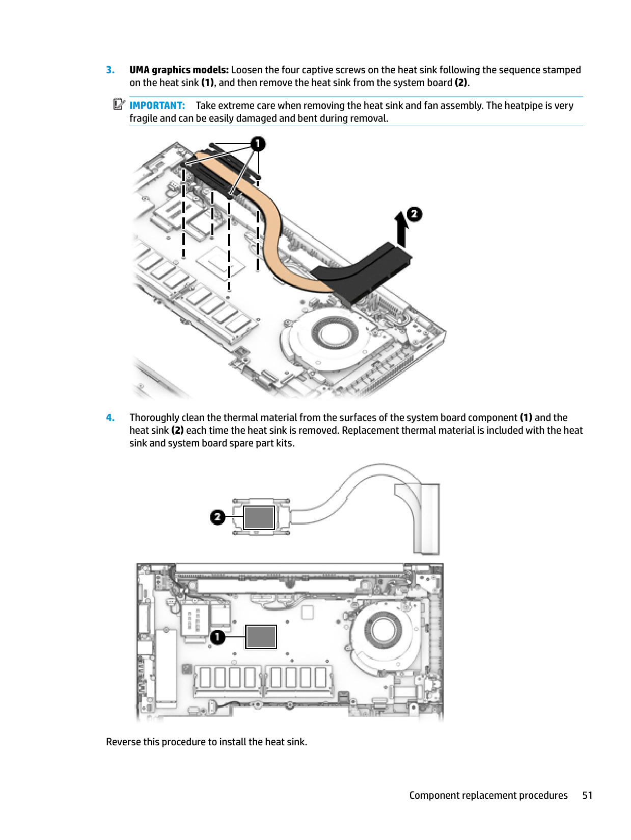
#### Heat sink assembly NOTE: The heat sink assembly spare part kit includes replacement thermal material. Table 6-2 Heat sink descriptions and part numbers
| | |---|
######### Description Spare part number
Heat sink for use in models with discrete graphics memory L62751-001 Heat sink for use in models with UMA graphics memory L62740-001
Before removing the heat sink assembly, follow these steps:
| | |---|
IMPORTANT: Take extreme care when removing the heat sink. The heatpipe is very fragile and can be easily damaged and bent during removal.


IMPORTANT: Take extreme care when removing the heat sink and fan assembly. The heatpipe is very fragile and can be easily damaged and bent during removal.

| | |---|

Reverse this procedure to install the heat sink.
#### RTC battery
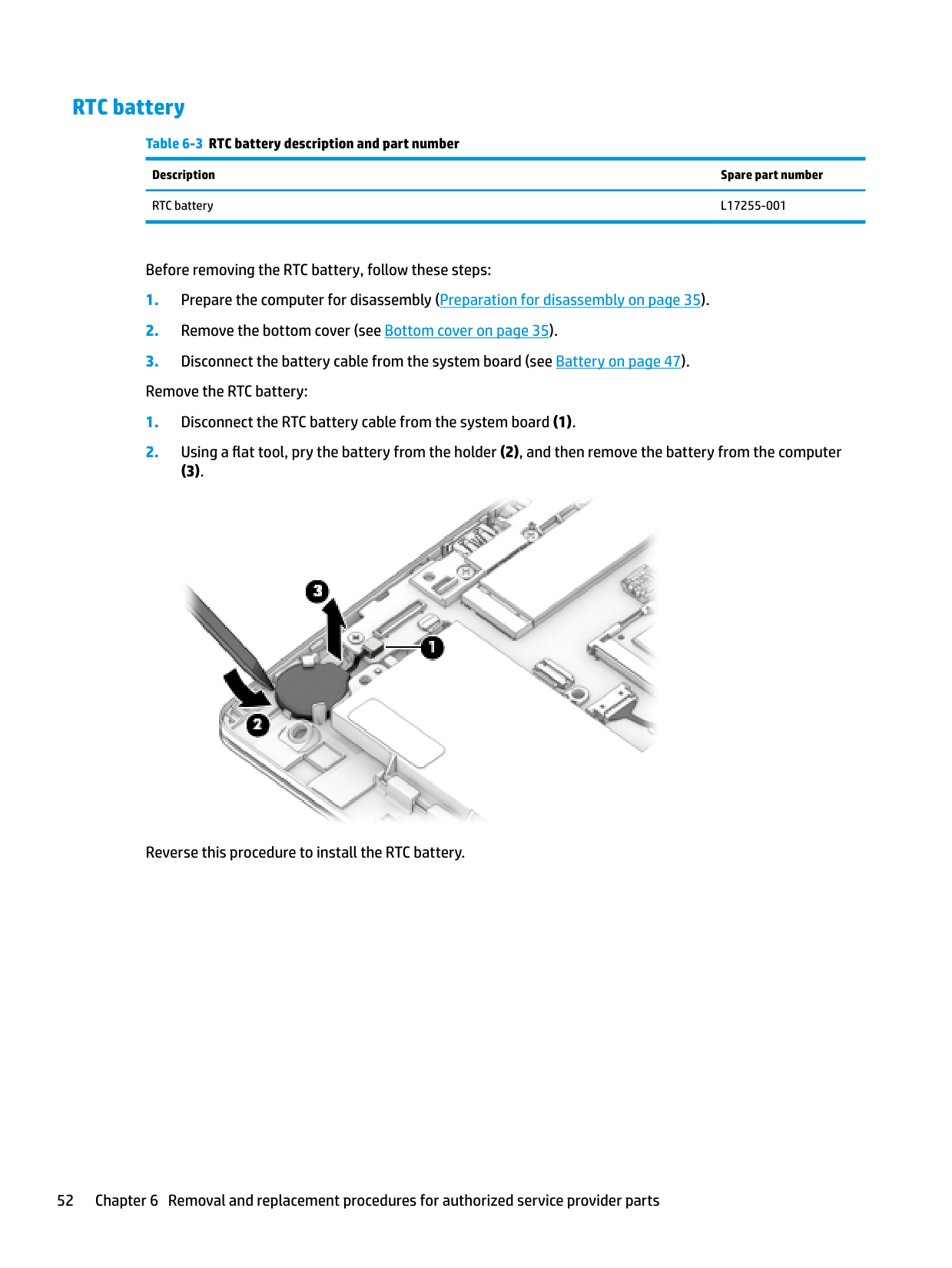
Table 6-3 RTC battery description and part number Description Spare part number RTC battery L17255-001
Before removing the RTC battery, follow these steps:
###### (3).

Reverse this procedure to install the RTC battery.
#### USB board
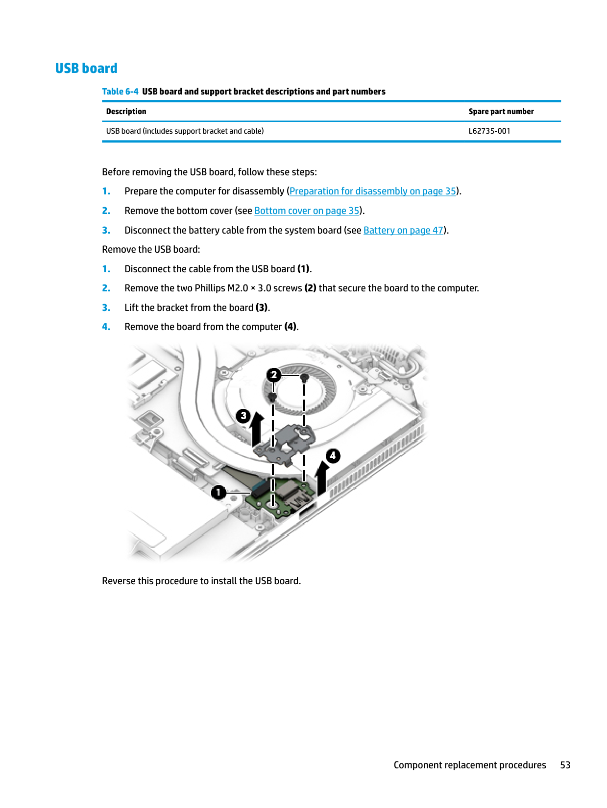
Table 6-4 USB board and support bracket descriptions and part numbers Description Spare part number USB board (includes support bracket and cable) L62735-001
Before removing the USB board, follow these steps:

Reverse this procedure to install the USB board.
#### RJ-45 board with bracket
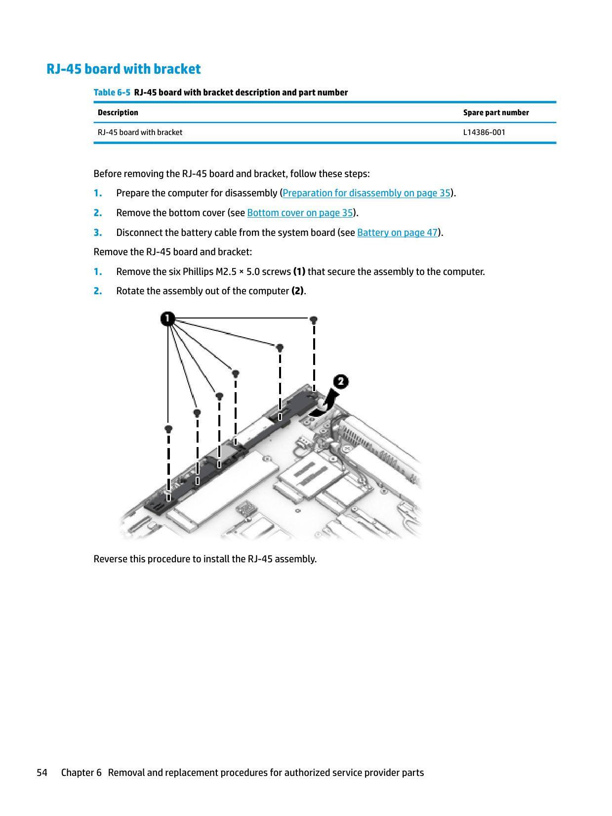
Table 6-5 RJ-45 board with bracket description and part number Description Spare part number RJ-45 board with bracket L14386-001
Before removing the RJ-45 board and bracket, follow these steps:

Reverse this procedure to install the RJ-45 assembly.
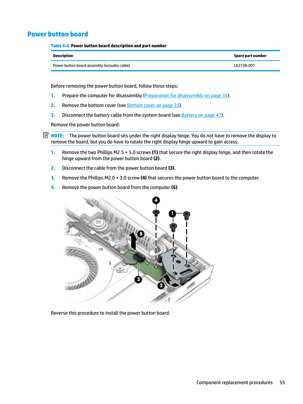
#### Power button board
Table 6-6 Power button board description and part number Description Spare part number Power button board assembly (includes cable) L62738-001
Before removing the power button board, follow these steps:
| | |---|

Reverse this procedure to install the power button board.
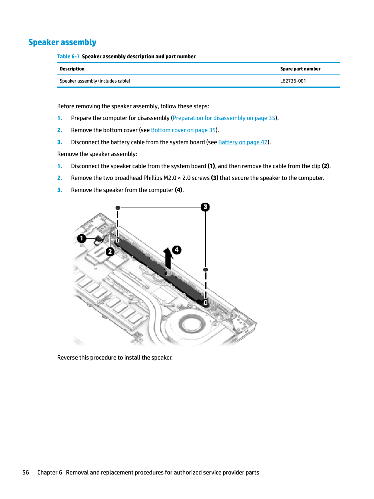
#### Speaker assembly
Table 6-7 Speaker assembly description and part number Description Spare part number Speaker assembly (includes cable) L62736-001
Before removing the speaker assembly, follow these steps:

Reverse this procedure to install the speaker.
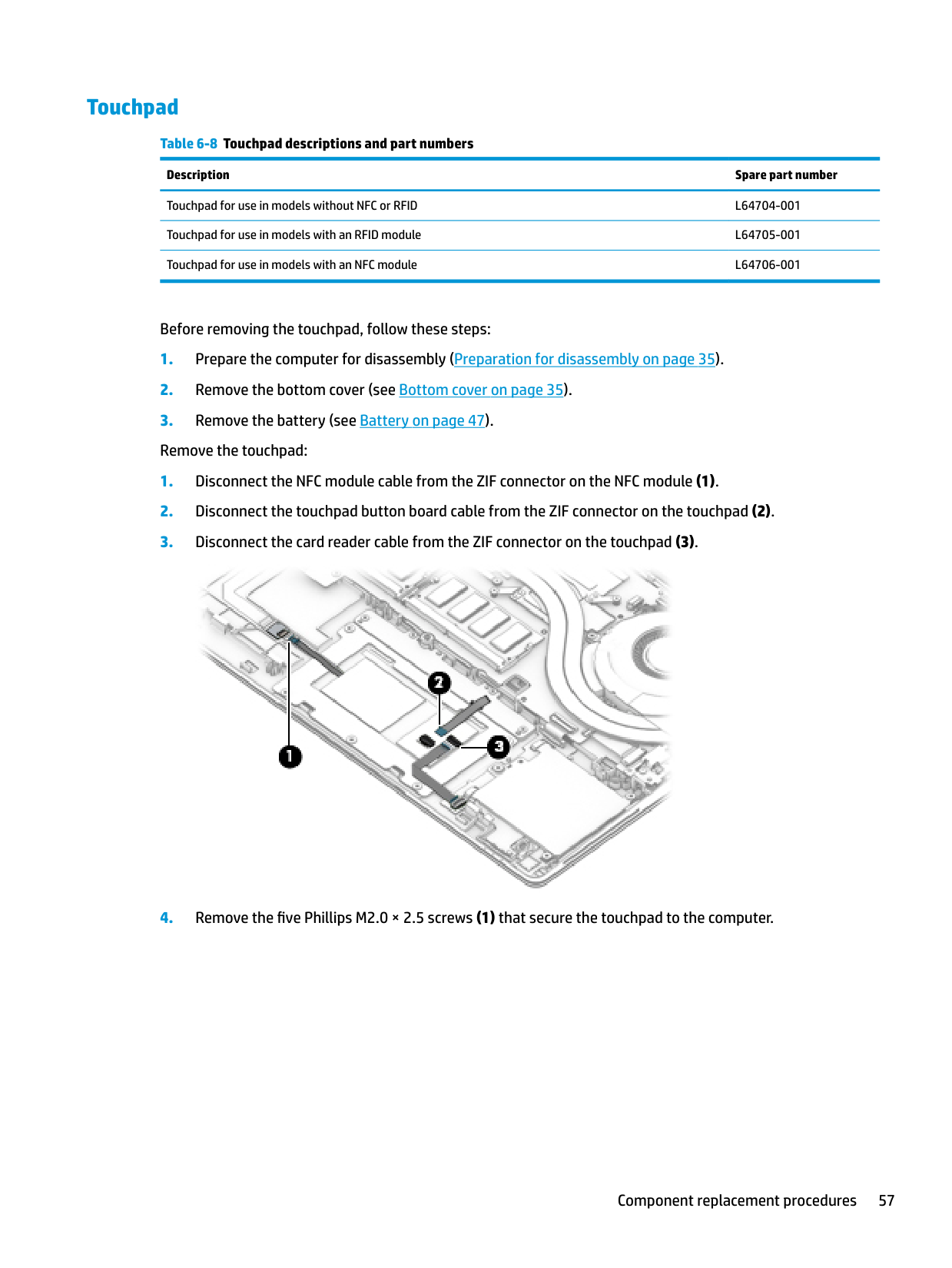
#### Touchpad
######## Table 6-8 Touchpad descriptions and part numbers
######### Description Spare part number
Touchpad for use in models without NFC or RFID L64704-001 Touchpad for use in models with an RFID module L64705-001 Touchpad for use in models with an NFC module L64706-001
Before removing the touchpad, follow these steps:


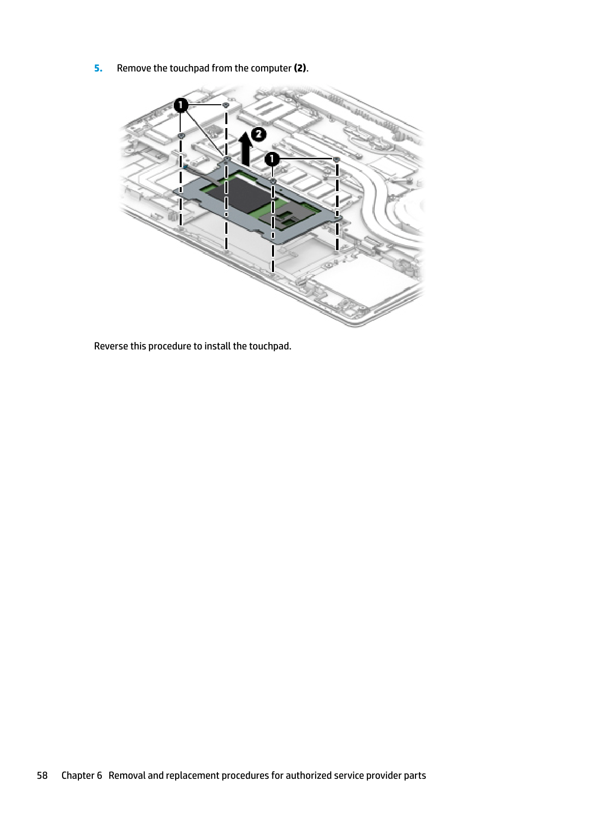
Reverse this procedure to install the touchpad.
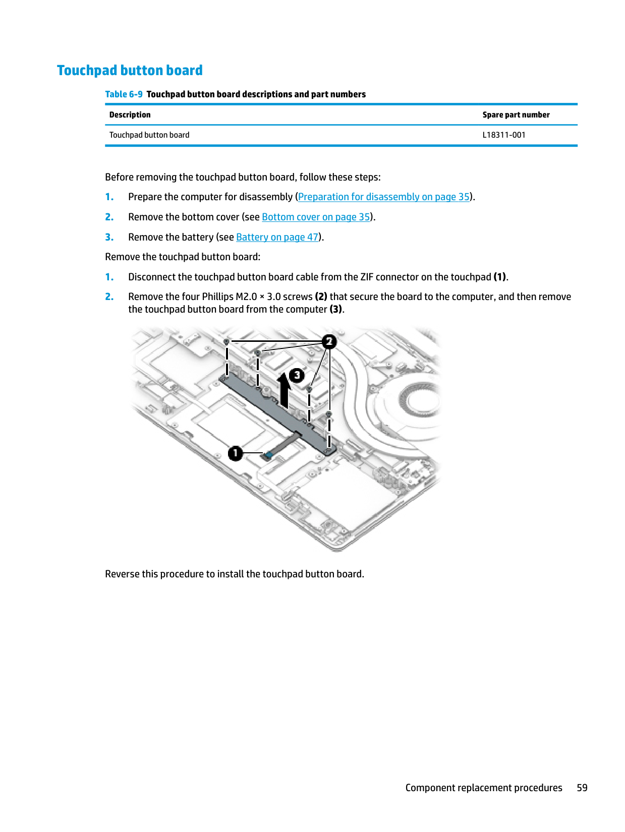
#### Touchpad button board
Table 6-9 Touchpad button board descriptions and part numbers Description Spare part number Touchpad button board L18311-001
Before removing the touchpad button board, follow these steps:
the touchpad button board from the computer (3).

Reverse this procedure to install the touchpad button board.
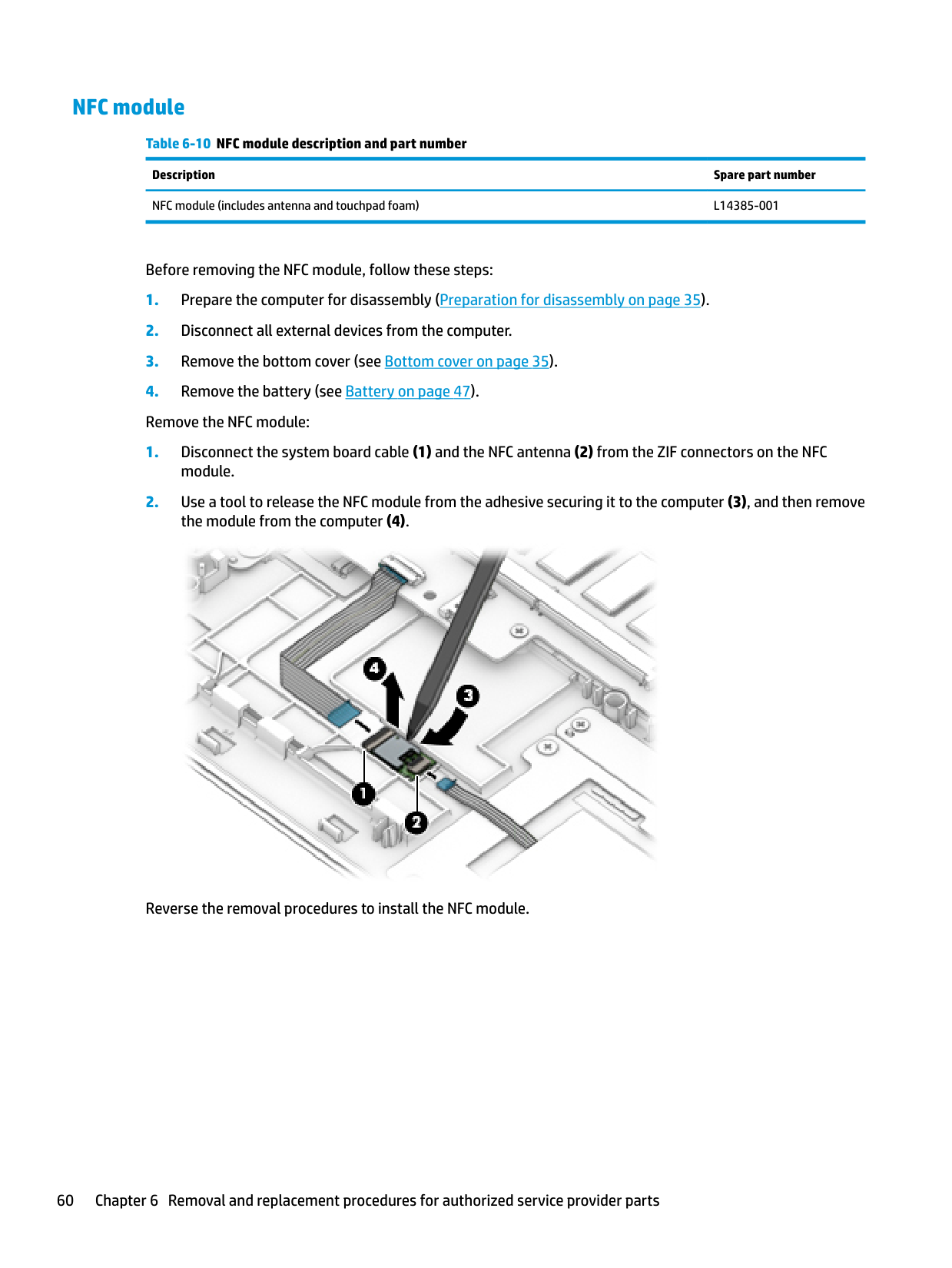
#### NFC module
Table 6-10 NFC module description and part number Description Spare part number NFC module (includes antenna and touchpad foam) L14385-001
Before removing the NFC module, follow these steps:

Reverse the removal procedures to install the NFC module.
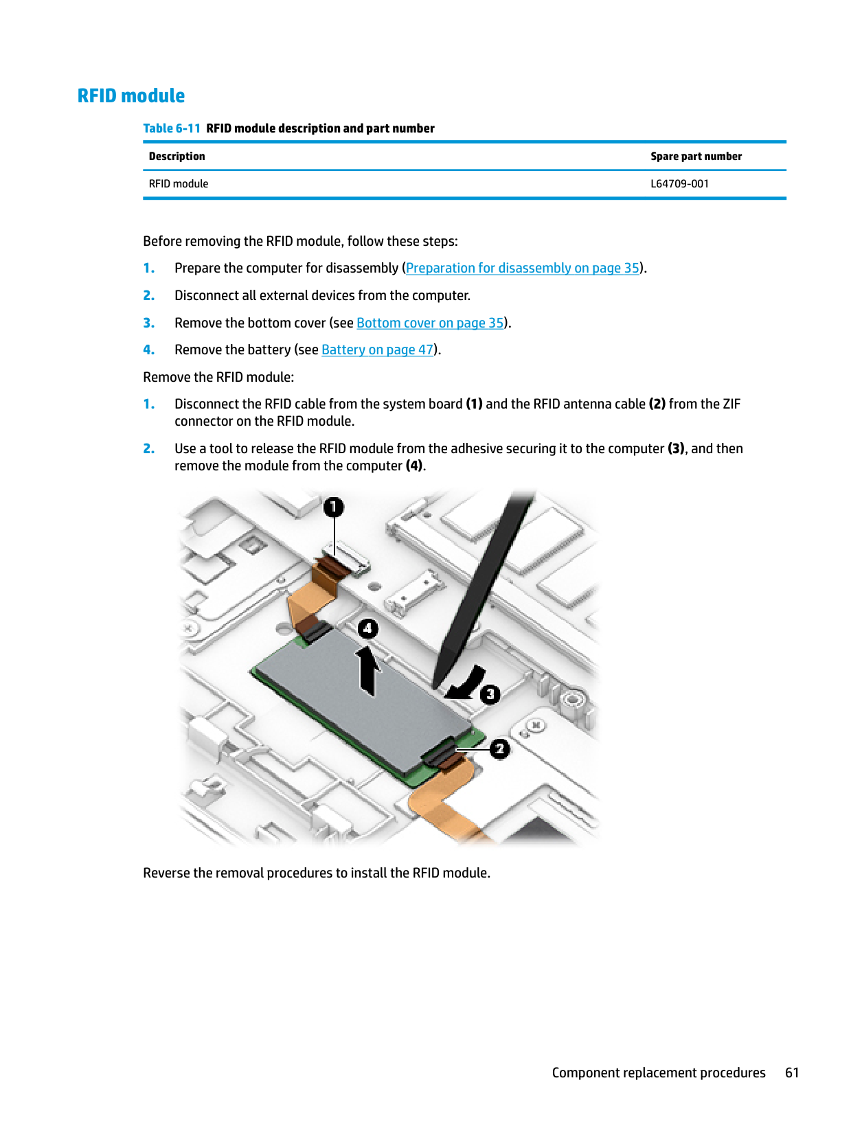
#### RFID module
Table 6-11 RFID module description and part number Description Spare part number RFID module L64709-001
Before removing the RFID module, follow these steps:
connector on the RFID module.
remove the module from the computer (4).

Reverse the removal procedures to install the RFID module.
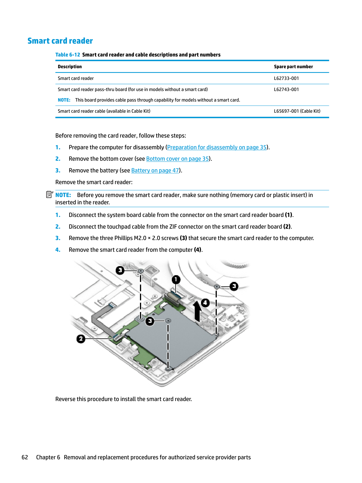
#### Smart card reader
Table 6-12 Smart card reader and cable descriptions and part numbers Description Spare part number Smart card reader L62733-001 Smart card reader pass-thru board (for use in models without a smart card) NOTE: This board provides cable pass through capability for models without a smart card.
L62743-001
Smart card reader cable (available in Cable Kit) L65697-001 (Cable Kit)
Before removing the card reader, follow these steps:
| | |---|

Reverse this procedure to install the smart card reader.
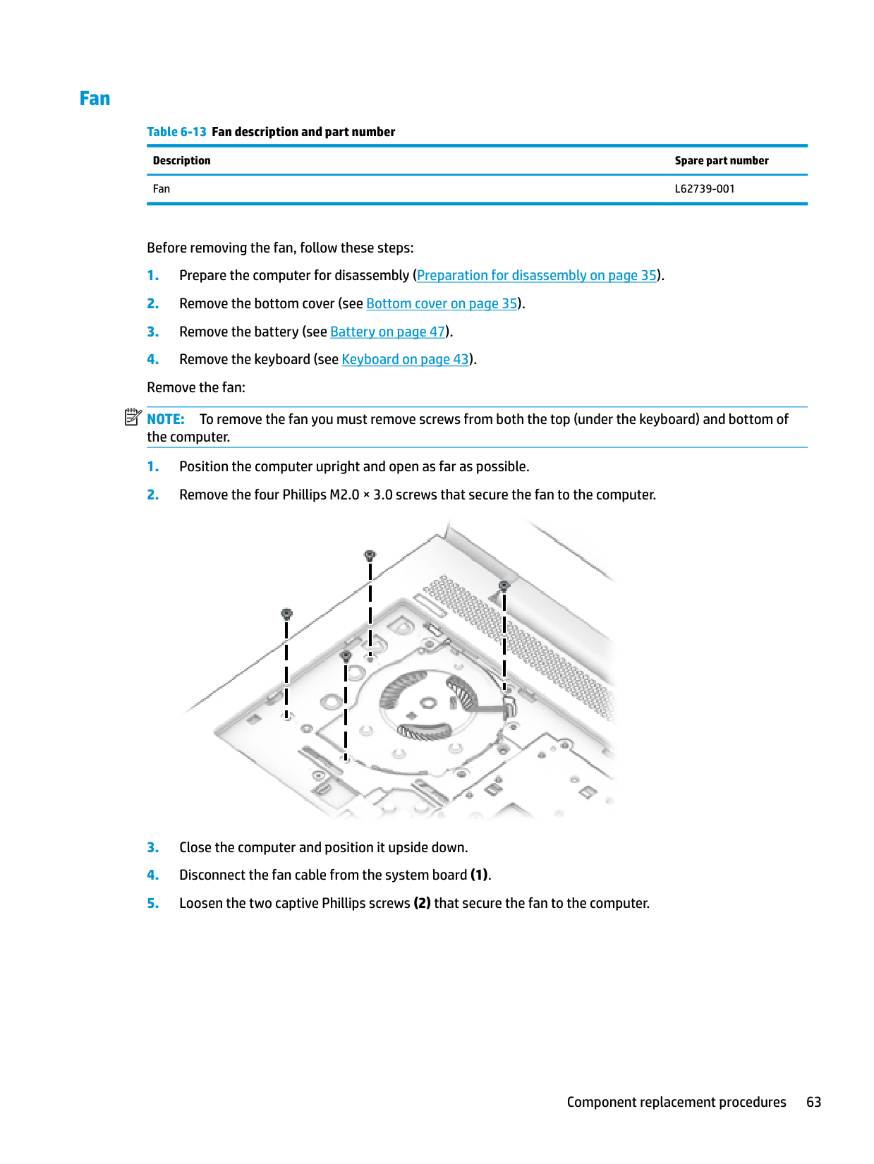
#### Fan
Table 6-13 Fan description and part number Description Spare part number Fan L62739-001
Before removing the fan, follow these steps:
| | |---|
NOTE: To remove the fan you must remove screws from both the top (under the keyboard) and bottom of the computer.


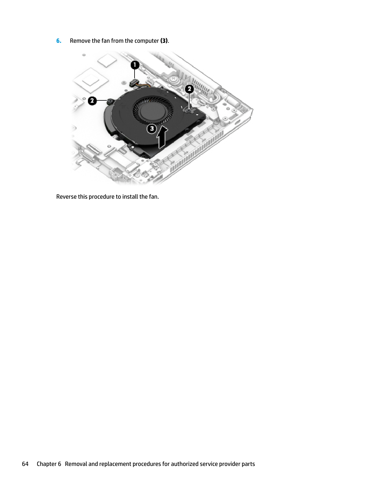
Reverse this procedure to install the fan.
System board NOTE: All system board spare part kits include replacement thermal material. All system boards use the following part numbers: xxxxxx-001: Non-Windows operating systems xxxxxx-601: Windows operating system Table 6-14 System board descriptions and part numbers
| | |---|
Description Spare part number System board for use in models with discrete graphics memory (includes integrated processor)
Intel i7-8665U processor L62755-xx1 Intel i7-8665U processor (OSR) L62756-xx1 Intel i7-8565U processor L62753-xx1 Intel i5-8365U processor L62754-xx1 Intel i5-8265U processor L62752-xx1 System board for use in models with UMA graphics memory (includes integrated processor)
Intel i7-8665U processor L62760-001 Intel i7-8665U processor (OSR) L62761-001 Intel i7-8565U processor L62758-001 Intel i5-8365U processor L62759-001 Intel i5-8265U processor L62757-xx1
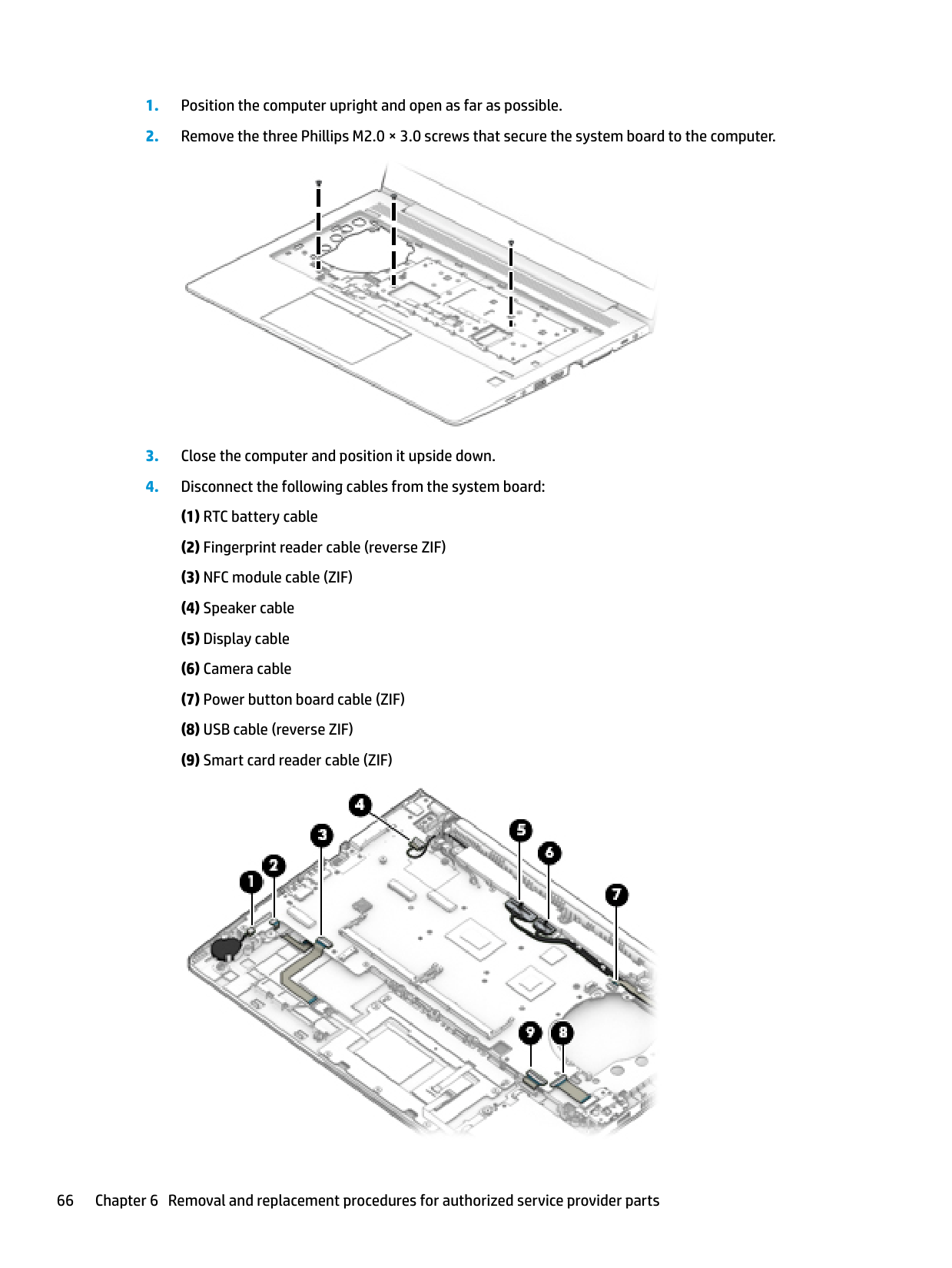
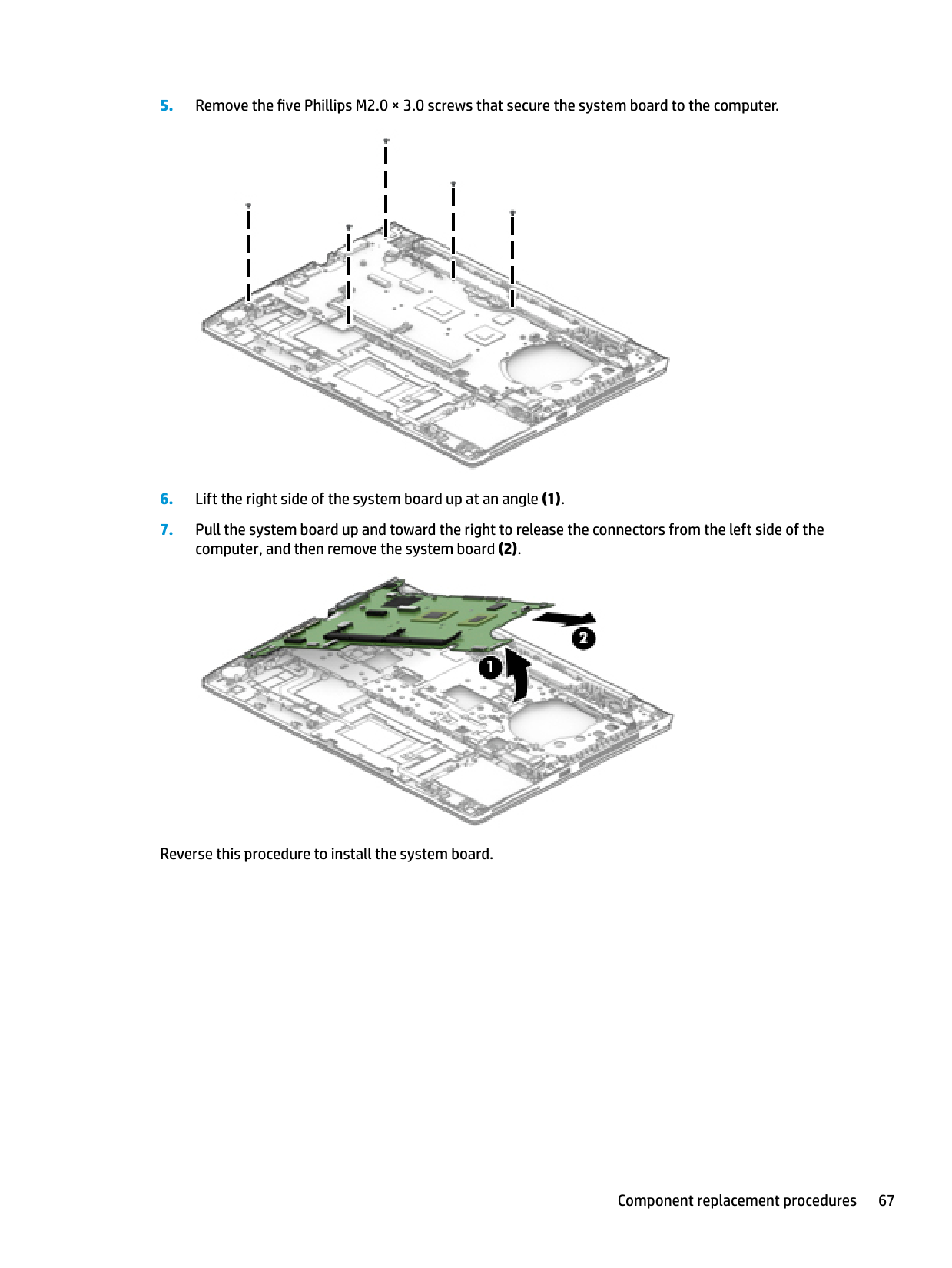
Before removing the system board, follow these steps:
When replacing the system board, be sure to remove the following components (as applicable) from the defective system board and install on the replacement system board:


Reverse this procedure to install the system board.
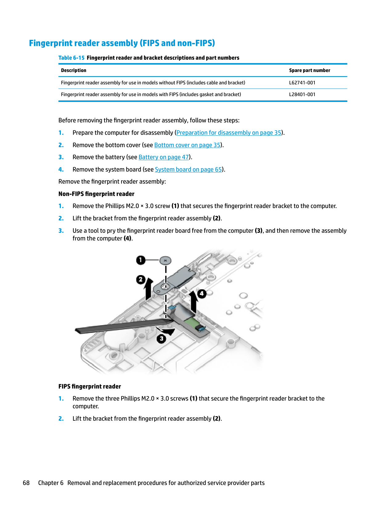
#### Fingerprint reader assembly (FIPS and non-FIPS)
######## Table 6-15 Fingerprint reader and bracket descriptions and part numbers
######### Description Spare part number
Fingerprint reader assembly for use in models without FIPS (includes cable and bracket) L62741-001 Fingerprint reader assembly for use in models with FIPS (includes gasket and bracket) L28401-001
Before removing the fingerprint reader assembly, follow these steps:

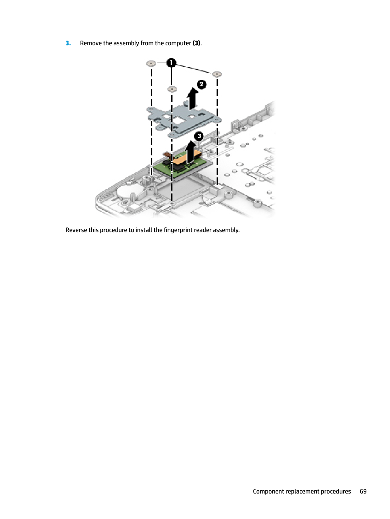
###### FIPS fingerprint reader

Reverse this procedure to install the fingerprint reader assembly.
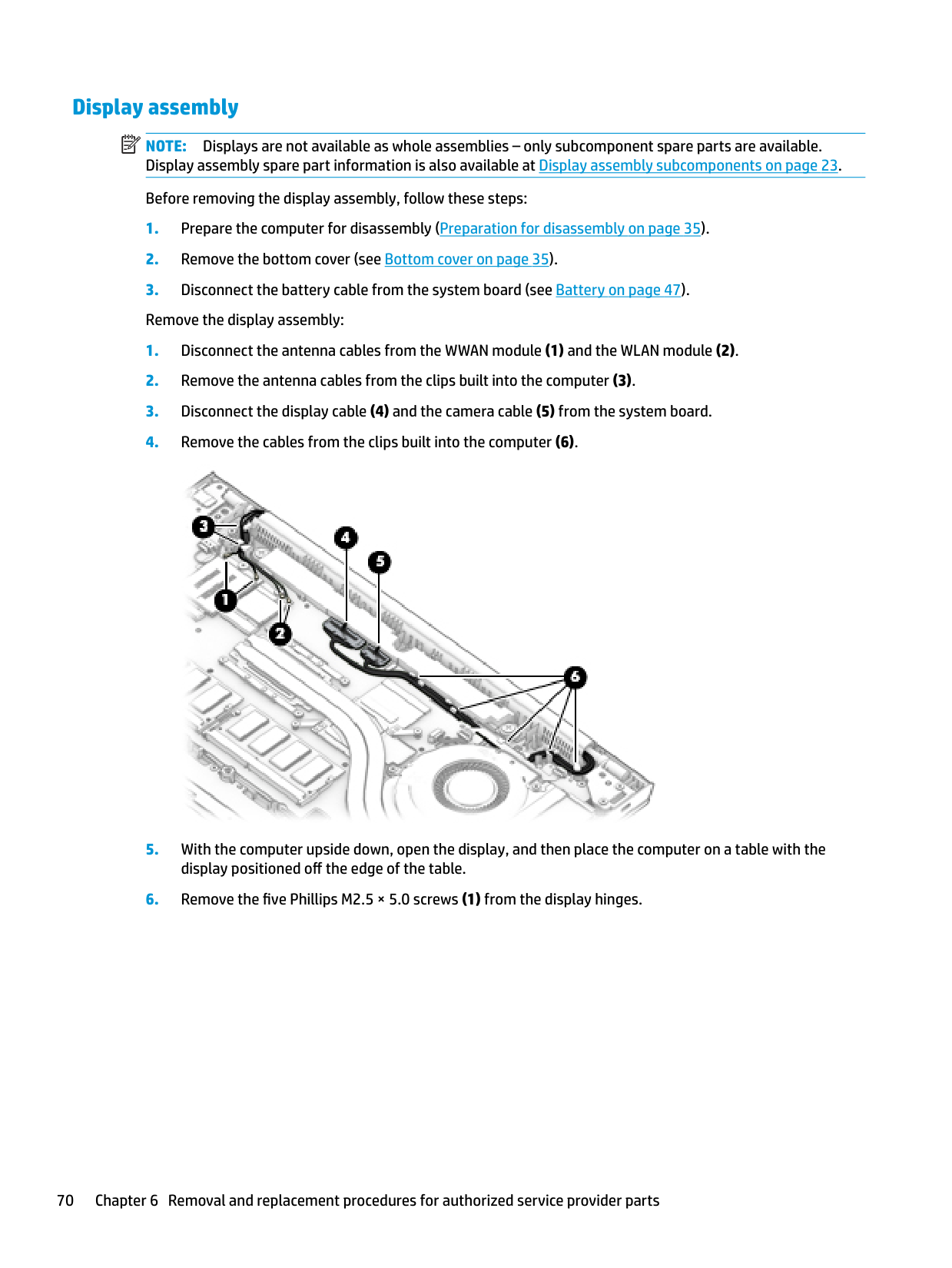
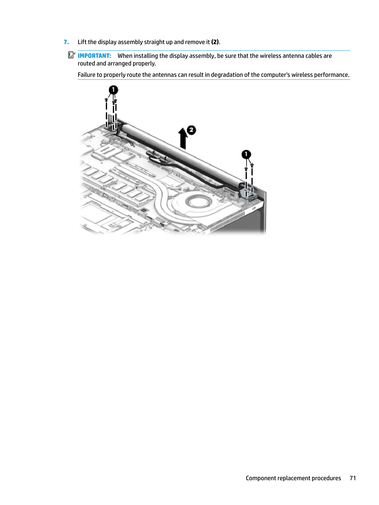
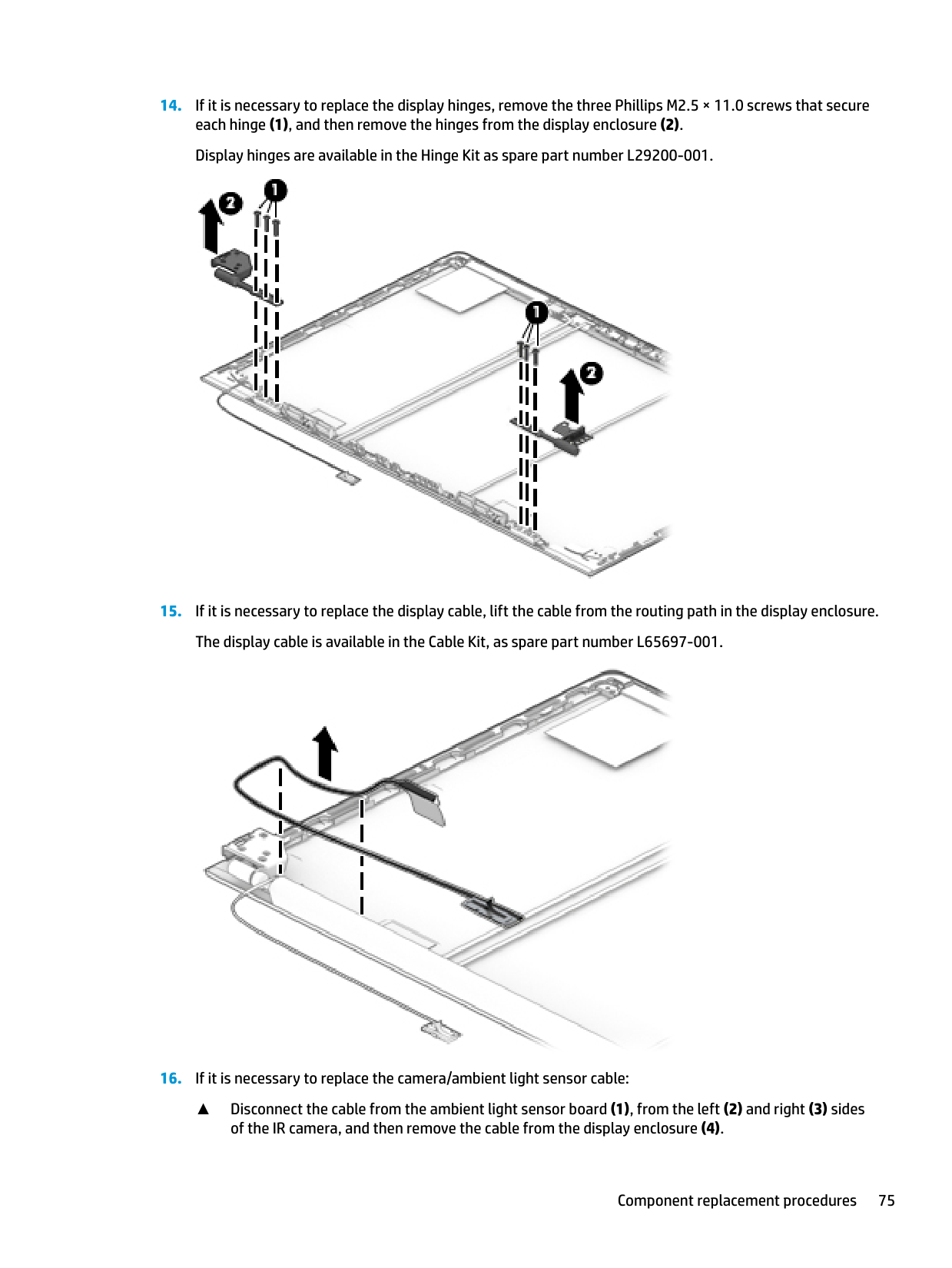
Display assembly NOTE: Displays are not available as whole assemblies – only subcomponent spare parts are available. Display assembly spare part information is also available at Display assembly subcomponents on page 23. Before removing the display assembly, follow these steps:
| | |---|

| | |---|
IMPORTANT: When installing the display assembly, be sure that the wireless antenna cables are routed and arranged properly. Failure to properly route the antennas can result in degradation of the computer's wireless performance.


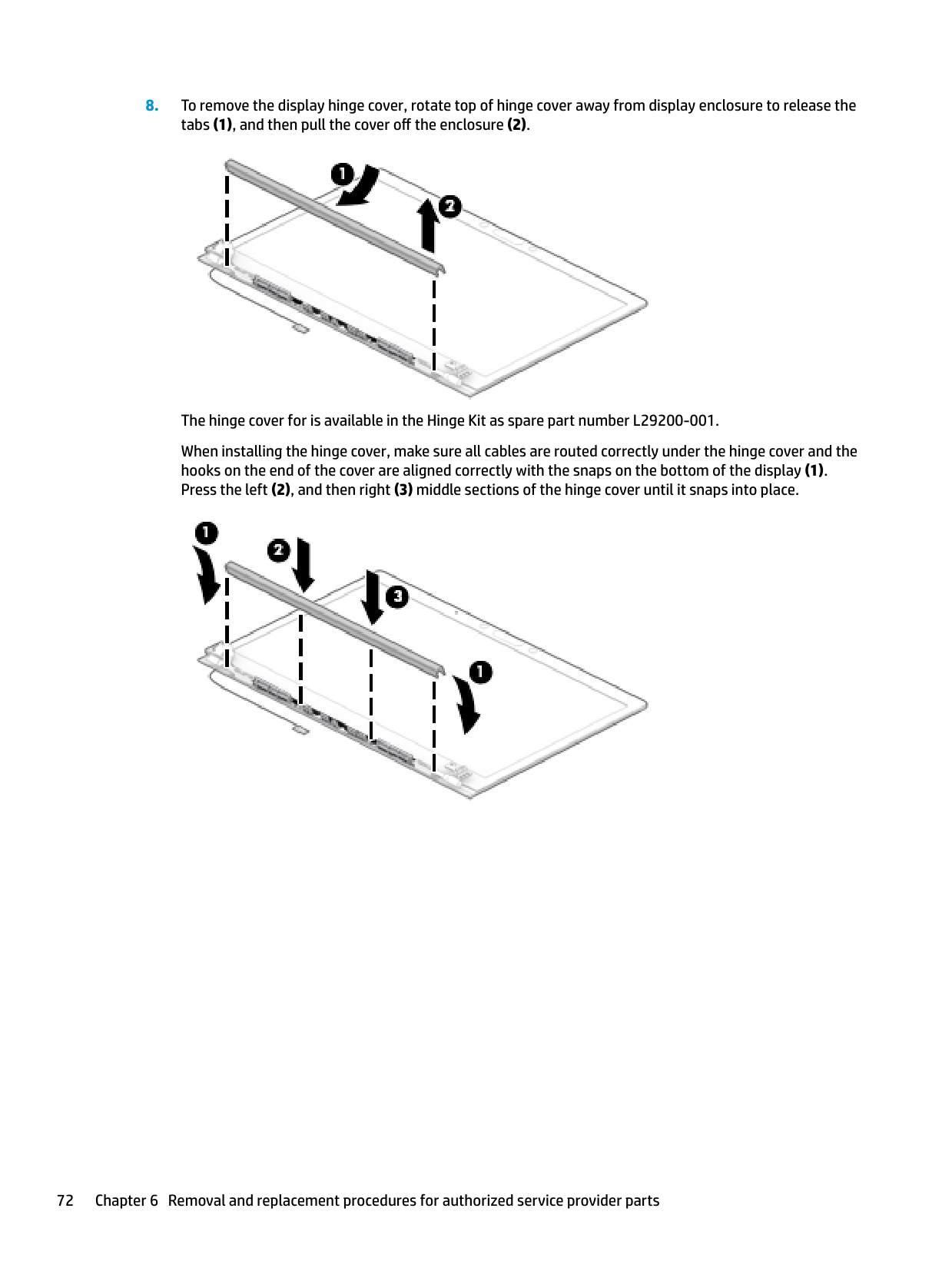
The hinge cover for is available in the Hinge Kit as spare part number L29200-001. When installing the hinge cover, make sure all cables are routed correctly under the hinge cover and the hooks on the end of the cover are aligned correctly with the snaps on the bottom of the display (1). Press the left (2), and then right (3) middle sections of the hinge cover until it snaps into place.


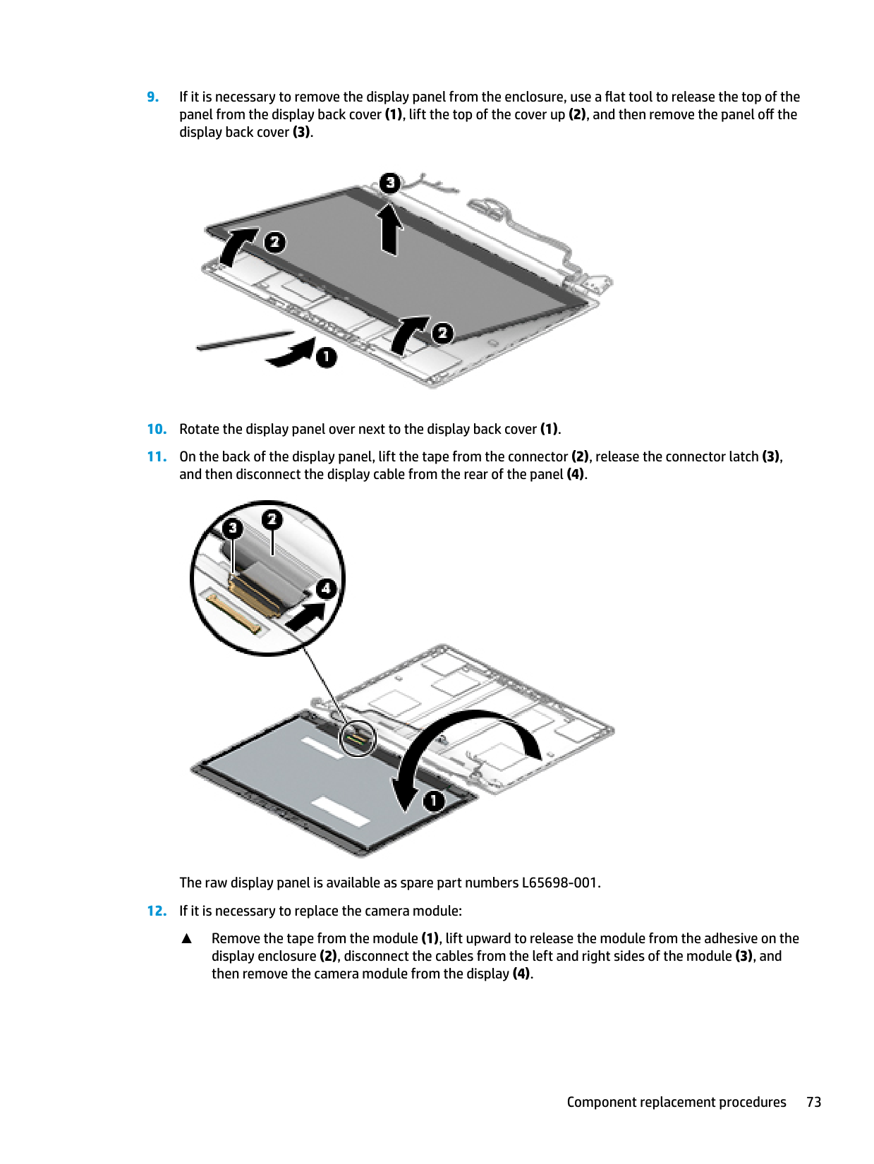
The raw display panel is available as spare part numbers L65698-001.
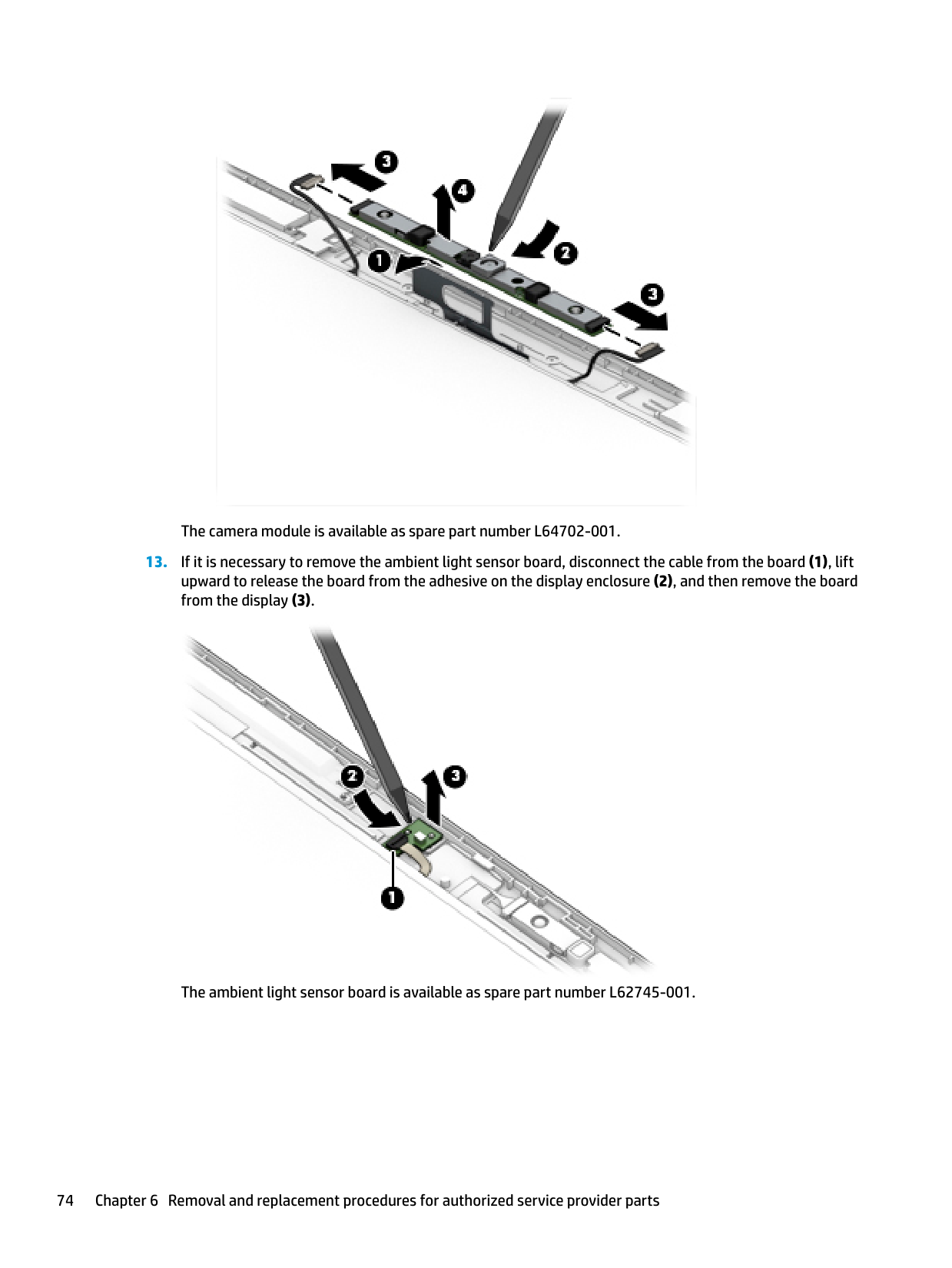
▲ Remove the tape from the module (1), lift upward to release the module from the adhesive on the display enclosure (2), disconnect the cables from the left and right sides of the module (3), and then remove the camera module from the display (4).

The camera module is available as spare part number L64702-001.

The ambient light sensor board is available as spare part number L62745-001.


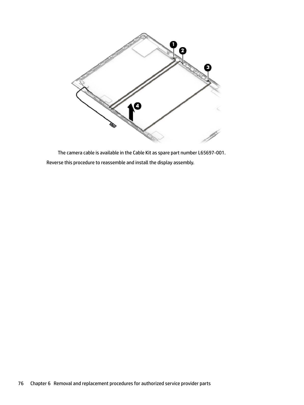
▲ Disconnect the cable from the ambient light sensor board (1), from the left (2) and right (3) sides
of the IR camera, and then remove the cable from the display enclosure (4).

####### The camera cable is available in the Cable Kit as spare part number L65697-001. Reverse this procedure to reassemble and install the display assembly.
#### Top cover
######## Table 6-16 Top cover description and part number
######### Description Spare part number
Top cover for use in models without FIPS L64708-001 Top cover for use in models withFIPS L64707-001
The top cover remains after removing all other spare parts from the computer.
7 Interpreting system validation diagnosticfront panel LEDs and audible codes
During the system validation phase that occurs at system startup, the BIOS validates the functionality of the following subsystems and conditions:
| | |---|
If an error is detected, specific patterns of long and short blinks, accompanied by long and short beeps (where applicable) are used to identify the error. These patterns will make up a two part code:
Number of long beeps/blinks Error category
Patterns of blink/beep codes are determined by using the following parameters:
| | |---|
78 Chapter 7 Interpreting system validation diagnostic front panel LEDs and audible codes
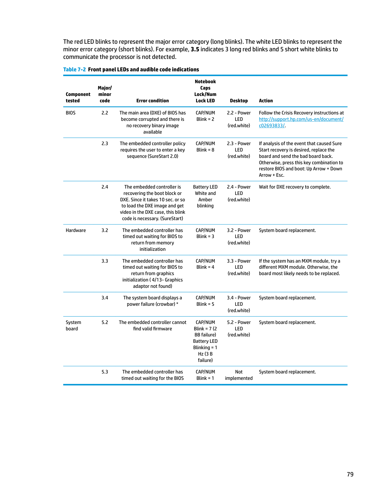
The red LED blinks to represent the major error category (long blinks). The white LED blinks to represent the minor error category (short blinks). For example, 3.5 indicates 3 long red blinks and 5 short white blinks to communicate the processor is not detected.
Table 7-2 Front panel LEDs and audible code indications
Notebook Caps Lock/Num
Major/ minor
Component tested
Lock LED Desktop Action BIOS 2.2 The main area (DXE) of BIOS has
code Error condition
CAP/NUM Blink = 2
2.2 - Power LED (red.white)
Follow the Crisis Recovery instructions at http://support.hp.com/us-en/document/ c02693833/.
become corrupted and there is no recovery binary image available
sequence (SureStart 2.0)
CAP/NUM Blink = 8
2.3 - Power LED (red.white)
If analysis of the event that caused Sure Start recovery is desired, replace the board and send the bad board back. Otherwise, press this key combination to restore BIOS and boot: Up Arrow + Down Arrow + Esc.
DXE. Since it takes 10 sec. or so to load the DXE image and get video in the DXE case, this blink code is necessary. (SureStart)
Hardware 3.2 The embedded controller has
timed out waiting for BIOS to return from memory initialization
return from graphics initialization ( 4/13- Graphics adaptor not found)
CAP/NUM Blink = 4
3.3 - Power LED (red.white)
If the system has an MXM module, try a different MXM module. Otherwise, the board most likely needs to be replaced.
Battery LED White and Amber blinking
CAP/NUM Blink = 3
CAP/NUM Blink = 5
System board
CAP/NUM Blink = 7 (2 BB failure) Battery LED Blinking = 1 Hz (3 B failure)
5.2 - Power LED (red.white)
System board replacement.
CAP/NUM Blink = 1
2.4 - Power LED (red.white)
Wait for DXE recovery to complete.
3.2 - Power LED (red.white)
System board replacement.
3.4 - Power LED (red.white)
System board replacement.
Not implemented
System board replacement.
79
8 Computer Setup (BIOS), TPM, and HP SureStart
Using Computer Setup
Computer Setup, or Basic Input/Output System (BIOS), controls communication between all the input and output devices on the system (such as disk drives, display, keyboard, mouse, and printer). Computer Setup includes settings for the types of devices installed, the startup sequence of the computer, and the amount of system and extended memory.
| | |---|
NOTE: Use extreme care when making changes in Computer Setup. Errors can prevent the computer from operating properly.
#### Starting Computer Setup
▲ Turn on or restart the computer, and when the HP logo appears, press f10 to enter Computer Setup.
#### Navigating and selecting in Computer Setup
To exit Computer Setup, choose one of the following methods:
| | |---|
| | |---|
Your changes go into effect when the computer restarts.
Restoring factory settings in Computer Setup NOTE: Restoring defaults will not change the hard drive mode. To return all settings in Computer Setup to the values that were set at the factory, follow these steps:
| | |---|
| | |---|
| | |---|
NOTE: On select products, the selections may display Restore Defaults instead of Apply Factory Defaults and Exit.
| | |---|
Your changes go into effect when the computer restarts. NOTE: Your password settings and security settings are not changed when you restore the factory settings.
Updating the BIOS Updated versions of the BIOS may be available on the HP website. Most BIOS updates on the HP website are packaged in compressed files called SoftPaqs. Some download packages contain a file named Readme.txt, which contains information regarding installing and troubleshooting the file.
##### Determining the BIOS version
To decide whether you need to update Computer Setup (BIOS), first determine the BIOS version on your computer.
BIOS version information (also known as ROM date and System BIOS) can be accessed by pressing fn+esc (if you are already in Windows) or by using Computer Setup.
| |
|---|
To check for later BIOS versions, see Downloading a BIOS update on page 81. Downloading a BIOS update
CAUTION: To reduce the risk of damage to the computer or an unsuccessful installation, download and install a BIOS update only when the computer is connected to reliable external power using the AC adapter. Do not download or install a BIOS update while the computer is running on battery power, docked in an optional docking device, or connected to an optional power source. During the download and installation, follow these instructions:
Do not disconnect power on the computer by unplugging the power cord from the AC outlet. Do not shut down the computer or initiate Sleep. Do not insert, remove, connect, or disconnect any device, cable, or cord.
– or – Select the question mark icon in the taskbar.
Using Computer Setup 81
Make a note of the path to the location on your hard drive where the BIOS update is downloaded. You will need to access this path when you are ready to install the update.
| | |---|
NOTE: If you connect your computer to a network, consult the network administrator before installing any software updates, especially system BIOS updates.
BIOS installation procedures vary. Follow any instructions that are displayed on the screen after the download is complete. If no instructions are displayed, follow these steps:
| | |---|
NOTE: After a message on the screen reports a successful installation, you can delete the downloaded file from your hard drive.
#### Changing the boot order using the f9 prompt
To dynamically choose a boot device for the current startup sequence, follow these steps:
● Turn on or restart the computer, and when the HP logo appears, press f9 to enter the Boot Device Options menu.
TPM BIOS settings (select products only)
| | |---|
IMPORTANT: Before enabling Trusted Platform Module (TPM) functionality on this system, you must ensure that your intended use of TPM complies with relevant local laws, regulations and policies, and approvals or licenses must be obtained if applicable. For any compliance issues arising from your operation/usage of TPM which violates the above mentioned requirement, you shall bear all the liabilities wholly and solely. HP will not be responsible for any related liabilities.
TPM provides additional security for your computer. You can modify the TPM settings in Computer Setup (BIOS).
| | |---|
NOTE: If you change the TPM setting to Hidden, TPM is not visible in the operating system. To access TPM settings in Computer Setup:
Using HP Sure Start (select products only)
Select computer models are configured with HP Sure Start, a technology that monitors the computer's BIOS for attacks or corruption. If the BIOS becomes corrupted or is attacked, HP Sure Start automatically restores the BIOS to its previously safe state, without user intervention.
HP Sure Start is configured and already enabled so that most users can use the HP Sure Start default configuration. The default configuration can be customized by advanced users.
To access the latest documentation on HP Sure Start, go to http://www.hp.com/support. Select Find your product, and then follow the on-screen instructions.
Using HP Sure Start (select products only) 83
9 Using HP PC Hardware Diagnostics
Using HP PC Hardware Diagnostics Windows (select products only)
HP PC Hardware Diagnostics Windows is a Windows-based utility that allows you to run diagnostic tests to determine whether the computer hardware is functioning properly. The tool runs within the Windows operating system in order to diagnose hardware failures.
If HP PC Hardware Diagnostics Windows is not installed on your computer, first you must download and install it. To download HP PC Hardware Diagnostics Windows, see Downloading HP PC Hardware Diagnostics Windows on page 84.
After HP PC Hardware Diagnostics Windows is installed, follow these steps to access it from HP Help and Support or HP Support Assistant.
– or – To access HP PC Hardware Diagnostics Windows from HP Support Assistant:
– or – Select the question mark icon in the taskbar.
| | |---|
When HP PC Hardware Diagnostics Windows detects a failure that requires hardware replacement, a 24-digit Failure ID code is generated. The screen displays one of the following options:
#### Downloading HP PC Hardware Diagnostics Windows
##### Downloading the latest HP PC Hardware Diagnostics Windows version
To download HP PC Hardware Diagnostics Windows, follow these steps:
The tool is downloaded to the selected location.
##### Downloading HP Hardware Diagnostics Windows by product name or number (select products only)
| | |---|
NOTE: For some products, it may be necessary to download the software to a USB flash drive by using the product name or number. To download HP PC Hardware Diagnostics Windows by product name or number, follow these steps:
The tool is downloaded to the selected location.
#### Installing HP PC Hardware Diagnostics Windows
To install HP PC Hardware Diagnostics Windows, follow these steps:
▲ Navigate to the folder on your computer or the USB flash drive where the .exe file was downloaded,
double-click the .exe file, and then follow the on-screen instructions.
Using HP PC Hardware Diagnostics UEFI
| | |---|
NOTE: For Windows 10 S computers, you must use a Windows computer and a USB flash drive to download and create the HP UEFI support environment because only .exe files are provided. For more information, see Downloading HP PC Hardware Diagnostics UEFI to a USB flash drive on page 86.
HP PC Hardware Diagnostics UEFI (Unified Extensible Firmware Interface) allows you to run diagnostic tests to determine whether the computer hardware is functioning properly. The tool runs outside the operating system so that it can isolate hardware failures from issues that are caused by the operating system or other software components.
If your PC will not boot into Windows, you can use HP PC Hardware Diagnostics UEFI to diagnose hardware issues.
When HP PC Hardware Diagnostics Windows detects a failure that requires hardware replacement, a 24-digit Failure ID code is generated. For assistance in solving the problem:
▲ Select Get Support, and then use a mobile device to scan the QR code that displays on the next screen. The HP Customer Support - Service Center page displays, with your Failure ID and product number automatically filled in. Follow the on-screen instructions.
– or – Contact support, and provide the Failure ID code.
Using HP PC Hardware Diagnostics UEFI 85
| | |---|
NOTE: To start diagnostics on a convertible computer, your computer must be in notebook mode, and you must use the attached keyboard.
| | |---|

NOTE: If you need to stop a diagnostic test, press esc.
#### Starting HP PC Hardware Diagnostics UEFI
To start HP PC Hardware Diagnostics UEFI, follow these steps:
| | |---|
#### Downloading HP PC Hardware Diagnostics UEFI to a USB flash drive
Downloading HP PC Hardware Diagnostics UEFI to a USB flash drive can be useful in the following situations:
| | |---|
NOTE: The HP PC Hardware Diagnostics UEFI download instructions are provided in English only, and you must use a Windows computer to download and create the HP UEFI support environment because only .exe files are provided.
##### Downloading the latest HP PC Hardware Diagnostics UEFI version
To download the latest HP PC Hardware Diagnostics UEFI version to a USB flash drive:
##### Downloading HP PC Hardware Diagnostics UEFI by product name or number (select products only)
| | |---|
NOTE: For some products, it may be necessary to download the software to a USB flash drive by using the product name or number. To download HP PC Hardware Diagnostics UEFI by product name or number (select products only) to a USB flash drive:
Using Remote HP PC Hardware Diagnostics UEFI settings (select products only)
Remote HP PC Hardware Diagnostics UEFI is a firmware (BIOS) feature that downloads HP PC Hardware Diagnostics UEFI to your computer. It can then execute the diagnostics on your computer, and it may upload results to a preconfigured server. For more information about Remote HP PC Hardware Diagnostics UEFI, go to http://www.hp.com/go/techcenter/pcdiags, and then select Find out more.
#### Downloading Remote HP PC Hardware Diagnostics UEFI
| | |---|
NOTE: HP Remote PC Hardware Diagnostics UEFI is also available as a Softpaq that can be downloaded to a server.
##### Downloading the latest Remote HP PC Hardware Diagnostics UEFI version
To download the latest Remote HP PC Hardware Diagnostics UEFI version, follow these steps:
Downloading Remote HP PC Hardware Diagnostics UEFI by product name or number NOTE: For some products, it may be necessary to download the software by using the product name or number. To download HP Remote PC Hardware Diagnostics UEFI by product name or number, follow these steps:
| |
|---|
#### Customizing Remote HP PC Hardware Diagnostics UEFI settings
Using the Remote HP PC Hardware Diagnostics setting in Computer Setup (BIOS), you can perform the following customizations:
Using Remote HP PC Hardware Diagnostics UEFI settings (select products only) 87
10 Backing up, restoring, and recovering
This chapter provides information about the following processes, which are standard procedure for most products:
| | |---|
IMPORTANT: If you will be performing recovery procedures on a tablet, the tablet battery must be at least 70% charged before you start the recovery process.
IMPORTANT: For a tablet with a detachable keyboard, connect the tablet to the keyboard base before beginning any recovery process.
Backing up information and creating recovery media
Using Windows tools IMPORTANT: Windows is the only option that allows you to back up your personal information. Schedule regular backups to avoid information loss. You can use Windows tools to back up personal information and create system restore points and recovery media. NOTE: If computer storage is 32 GB or less, Microsoft System Restore is disabled by default. For more information and steps, see the Get Help app.
| | |---|
| | |---|
| | |---|
#### Using the HP Cloud Recovery Download Tool to create recovery media (select products only)
You can use the HP Cloud Recovery Download Tool to create HP Recovery media on a bootable USB flash drive. To download the tool:
▲ Go to the Microsoft Store and search for HP Cloud Recovery.
For details, go to http://www.hp.com/support, search for HP Cloud Recovery, and then select "HP PCs – Using the Cloud Recovery Tool (Windows 10, 7)."
Backing up information and creating recovery media 89
| | |---|

NOTE: If you cannot create recovery media yourself, contact support to obtain recovery discs. Go to http://www.hp.com/support, select your country or region, and then follow the on-screen instructions.
Restoring and recovery
#### Restoring, resetting, and refreshing using Windows tools
Windows offers several options for restoring, resetting, and refreshing the computer. For details, see Using Windows tools on page 89.
#### Recovering using HP Recovery media
HP Recovery media is used to recover the original operating system and software programs that were installed at the factory. On select products, it can be created on a bootable USB flash drive using the HP Cloud Recovery Download Tool. For details, see Using the HP Cloud Recovery Download Tool to create recovery media (select products only) on page 89.
| | |---|
NOTE: If you cannot create recovery media yourself, contact support to obtain recovery discs. Go to http://www.hp.com/support, select your country or region, and then follow the on-screen instructions.
To recover your system:
▲ Insert the HP Recovery media, and then restart the computer.
#### Changing the computer boot order
If your computer does not restart using the HP Recovery media, you can change the computer boot order. This is the order of devices listed in BIOS where the computer looks for startup information. You can change the selection to an optical drive or a USB flash drive, depending on the location of your HP Recovery media.
| | |---|
To change the boot order: IMPORTANT: For a tablet with a detachable keyboard, connect the tablet to the keyboard base before beginning these steps.
▲ Turn on or restart the computer or tablet, quickly press esc, and then press f9 for boot options. For tablets without keyboards:
▲ Turn on or restart the tablet, quickly hold down the volume up button, and then select f9.
or – Turn on or restart the tablet, quickly hold down the volume down button, and then select f9.
90 Chapter 10 Backing up, restoring, and recovering
11 Specifications
Computer specifications
######## Table 11-1 Computer specifications
######### Metric U.S.
Dimensions Length 234.0 mm 9.22 in. Width 326.0 mm 12.84 in. Height 18.05 mm 0.72 in. Weight 1.62 kg 3.56 lbs Input power Operating voltage 19.0 V dc @ 4.74 A – 90 W or 18.5 V dc @ 3.5 A – 65 W or 45 W Operating current 4.74 A or 3.5 A Temperature Operating 0°C to 35°C 32°F to 95°F Nonoperating –20°C to 60°C –4°F to 140°F Relative humidity Operating 10% to 90% Nonoperating 5% to 95% Maximum altitude (unpressurized)
Operating (14.7 to 10.1 psia) –15 m to 3,048 m –50 ft to 10,000 ft Nonoperating (14.7 to 4.4 psia) –15 m to 12,192 m –50 ft to 40,000 ft Shock
Operating 125 g, 2 ms, half-sine Nonoperating 200 g, 2 ms, half-sine Random vibration
Operating 0.75 g zero-to-peak, 10 Hz to 500 Hz, 0.25 oct/min sweep rate Nonoperating 1.50 g zero-to-peak, 10 Hz to 500 Hz, 0.5 oct/min sweep rate NOTE: Applicable product safety standards specify thermal limits for plastic surfaces. The computer operates well within this range of temperatures.
Computer specifications 91
35.6 cm (14.0 in.) display specifications
######## Table 11-2 Display specifications
Metric U.S. Active diagonal size 35.6 cm 14.0 in. Resolution 1920 × 1080 Surface treatment Privacy panel Brightness 700 nits Viewing angle UWVA Backlight LED Aspect ratio 16:9 Display panel interface eDP + PSR
M.2 PCIe solid-state drive specifications
######## Table 11-3 M.2 PCIe solid-state drive specifications
######### 256 GB* 512 GB* 1 TB*
Dimensions Height 1 mm 1 mm 1 mm Length 50.8 mm 50.8 mm 50.8 mm Width 28.9 mm 28.9 mm 28.9 mm Weight < 10 g < 10 g < 10 g Interface type ATA-7 ATA-7 ATA-7 Transfer rate
Sequential Read Random Read
Up to 2150 MB/s Up to 300,000 IOPs
Up to 2150 MB/s Up to 300,000 IOPs
Up to 2150 MB/s Up to 300,000 IOPs
Sequential Write Random Write
Up to 1260 MB/s Up to 100,000 IOPs
Up to 1550 MB/s Up to 100,000 IOPs
Up to 1550 MB/s Up to 100,000 IOPs
Ready time, Maximum (to not busy) 1.0 sec 1.0 sec 1.0 sec Access times Logical 0.1 0.1 0.1 Total logical sectors 500,118,192 1,000,215,216 1,500,336,388 Operating temperature Operating 0° to 70°C (32°F to
0° to 70°C (32°F to 158°F)
0° to 70°C (32°F to 158°F)
158°F)
Non-operating –40° to 80°C (-40°F to 176°F)
–40° to 85°C (–40°F to 185°F)
–40° to 85°C (–40°F to 185°F)
*1 GB = 1 billion bytes when referring to hard drive storage capacity. Actual accessible capacity is less. NOTE: Certain restrictions and exclusions apply. Contact technical support for details.
M.2 PCIe solid-state drive specifications 93
M.2 SATA solid-state drive specifications
######## Table 11-4 M.2 SATA solid-state drive specifications
128 GB* 256 GB* 512 GB* Height 1.35 mm 1.35 mm 1.35 mm Weight < 10 g < 10 g < 10 g Form factor M.2 2280-D2-B-M M.2 2280-D2-B-M M.2 2280-D2-B-M Transfer rate up to 540 MB/sec up to 540 MB/sec up to 540 MB/sec Interface type SATA-3 SATA-3 SATA-3 Ready time, maximum (to not busy) 1.0 ms < 1.0 ms < 1.0 ms Access times, logical 0.1 ms 0.1 ms 0.1 ms Total logical sectors 234,441,648 468,883,296 937,766,592 Operating temperature 0°C to 70°C (32°F to 158°F)
*1 GB = 1 billion bytes when referring to hard drive storage capacity. Actual accessible capacity is less. Actual drive specifications may differ slightly.
NOTE: Certain restrictions and exclusions apply. Contact technical support for details.
12 Power cord set requirements
The wide-range input feature of the computer permits it to operate from any line voltage from 100 to 120 V ac, or from 220 to 240 V ac.
The 3-conductor power cord set included with the computer meets the requirements for use in the country or region where the equipment is purchased.
Power cord sets for use in other countries or regions must meet the requirements of the country and region where the computer is used.
Requirements for all countries
The following requirements are applicable to all countries and regions:
Requirements for all countries 95
Requirements for specific countries and regions
######## Table 12-1 Power cord requirements for specific countries and regions
######### Country/region Accredited agency Applicable note number
Argentina IRAM 1 Australia SAA 1 Austria OVE 1 Belgium CEBEC 1 Brazil ABNT 1 Canada CSA 2 Chile IMQ 1 Denmark DEMKO 1 Finland FIMKO 1 France UTE 1 Germany VDE 1 India BIS 1 Israel SII 1 Italy IMQ 1 Japan JIS 3 The Netherlands KEMA 1 New Zealand SANZ 1 Norway NEMKO 1 The People's Republic of China CCC 4 Saudi Arabia SASO 7 Singapore PSB 1 South Africa SABS 1 South Korea KTL 5 Sweden SEMKO 1 Switzerland SEV 1 Taiwan BSMI 6 Thailand TISI 1 The United Kingdom ASTA 1 The United States UL 2 1. The flexible cord must be Type HO5VV-F, 3-conductor, 0.75 mm² conductor size. Power cord set fittings (appliance coupler and
wall plug) must bear the certification mark of the agency responsible for evaluation in the country or region where it will be used.
96 Chapter 12 Power cord set requirements
######## Table 12-1 Power cord requirements for specific countries and regions (continued)
######### Country/region Accredited agency Applicable note number
Requirements for specific countries and regions 97
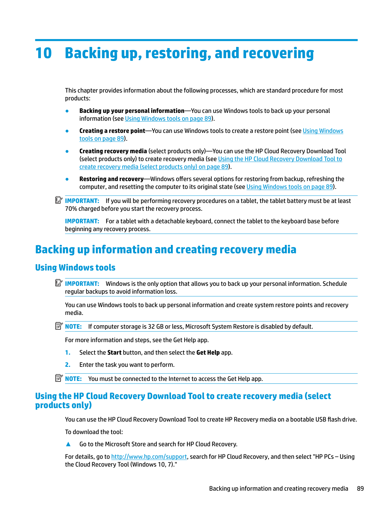
13 Statement of memory volatility
The purpose of this chapter is to provide general information regarding nonvolatile memory in HP Business computers. This chapter also provides general instructions for restoring nonvolatile memory that can contain personal data after the system has been powered off and the hard drive has been removed.
HP Business computer products that use Intel®-based or AMD®-based system boards contain volatile DDR memory. The amount of nonvolatile memory present in the system depends upon the system configuration. Intel-based and AMD-based system boards contain nonvolatile memory subcomponents as originally shipped from HP, assuming that no subsequent modifications have been made to the system and assuming that no applications, features, or functionality have been added to or installed on the system.
Following system shutdown and removal of all power sources from an HP Business computer system, personal data can remain on volatile system memory (DIMMs) for a finite period of time and will also remain in nonvolatile memory. Use the steps below to remove personal data from the computer, including the nonvolatile memory found in Intel-based and AMD-based system boards.
| | |---|
NOTE: If your tablet has a keyboard base, connect to the keyboard base before beginning steps in this chapter.
###### Current BIOS steps
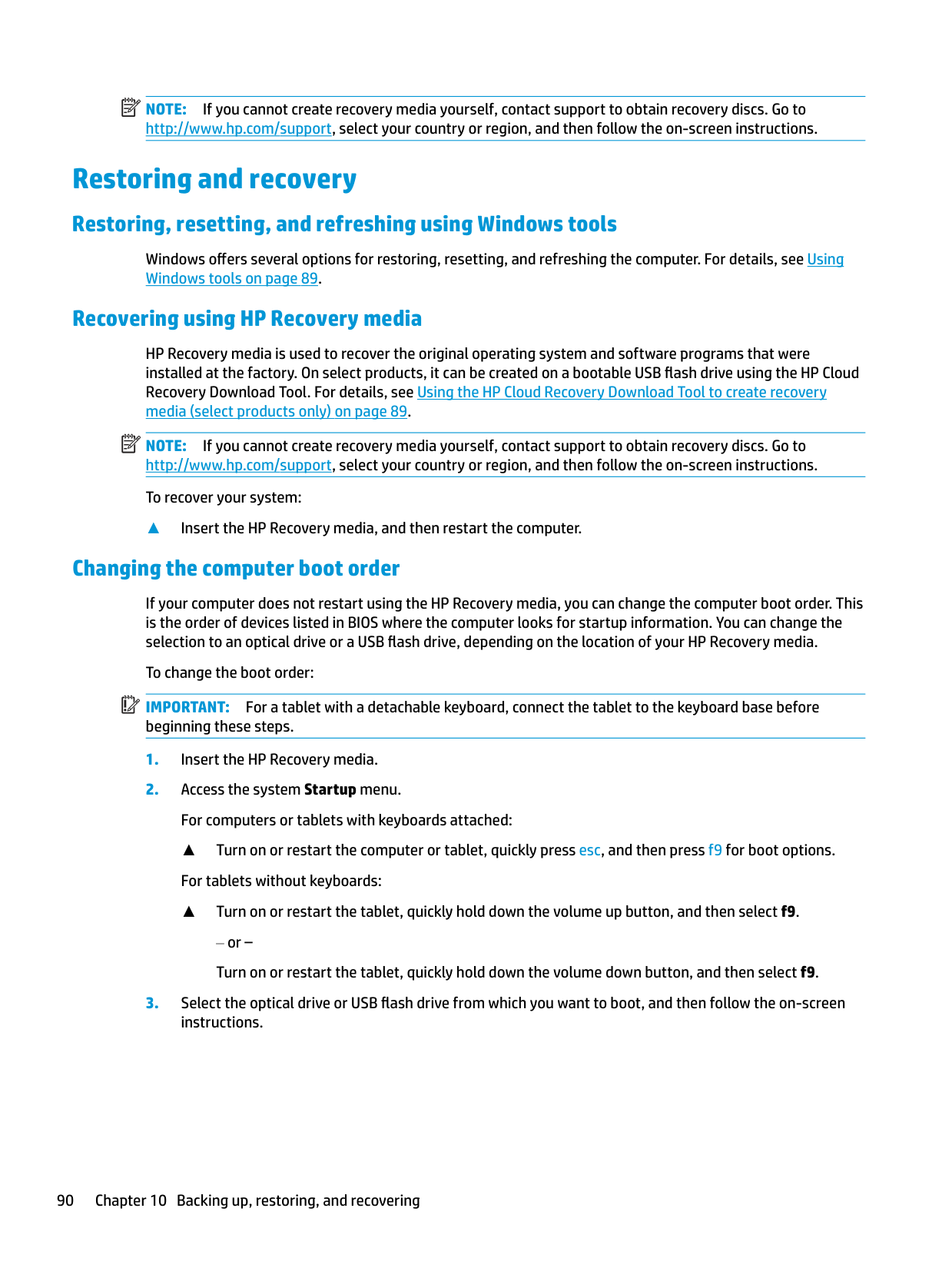
| | |---|
| | |---|
| | |---|
| | |---|
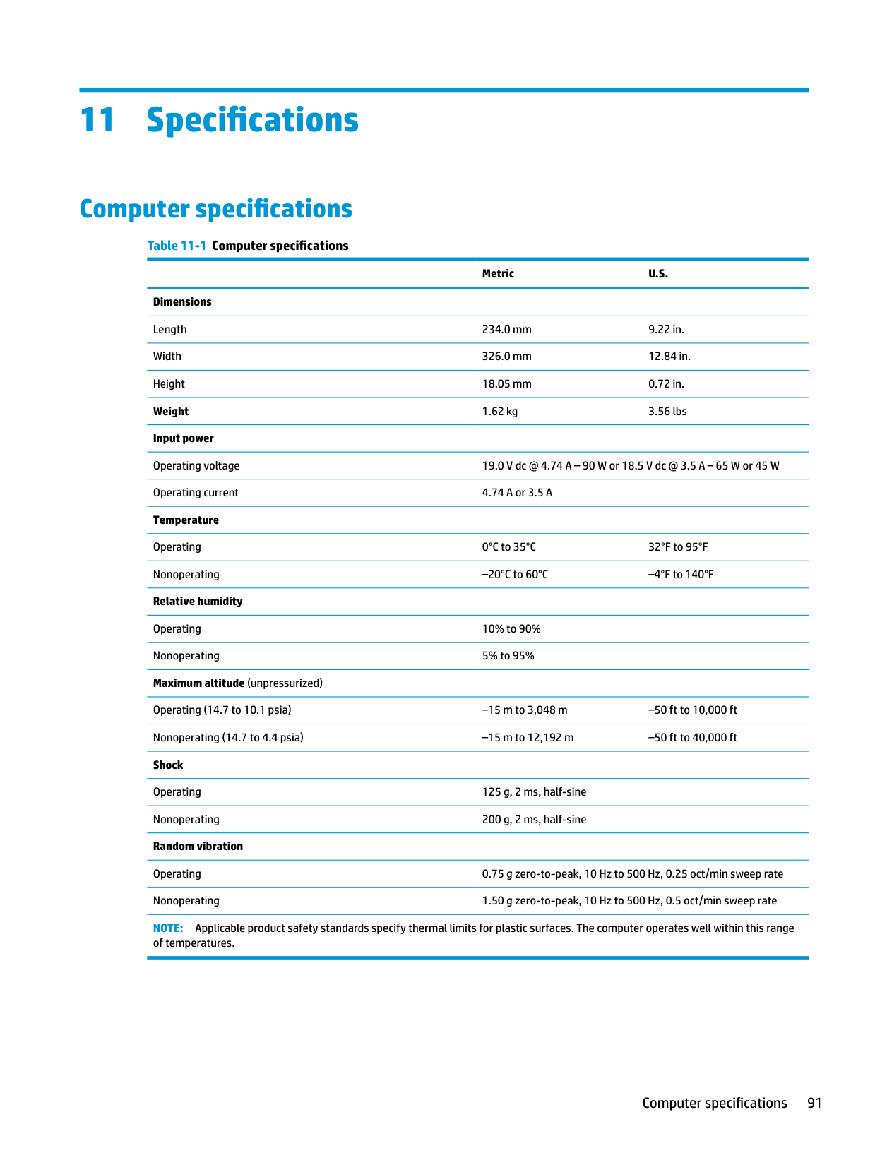
● Clear the drive contents by using a third-party utility designed to erase data from an SSD.
| | |---|
IMPORTANT: If you clear data using Secure Erase, it cannot be recovered.
– or –
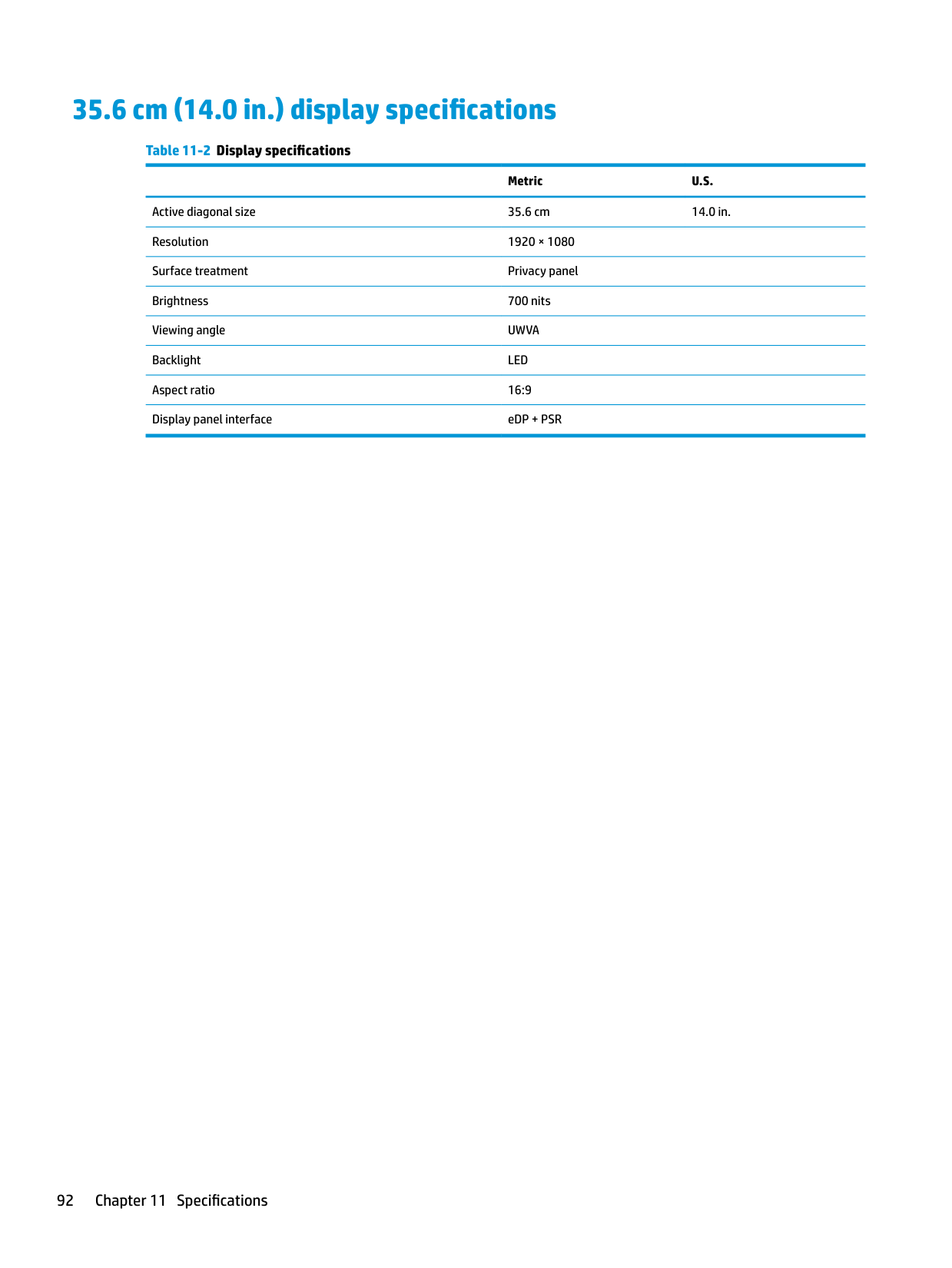
| | |---|
| | |---|
● Clear the contents of the drive using the following Disk Sanitizer commands steps: IMPORTANT: If you clear data using Disk Sanitizer, it cannot be recovered. NOTE: The amount of time it takes for Disk Sanitizer to run can take several hours. Plug the computer into an AC outlet before starting.
99
Nonvolatile memory usage
######## Table 13-1 Troubleshooting steps for nonvolatile memory usage
Nonvolatile memory type Amount (Size)
Does this memory store customer data?
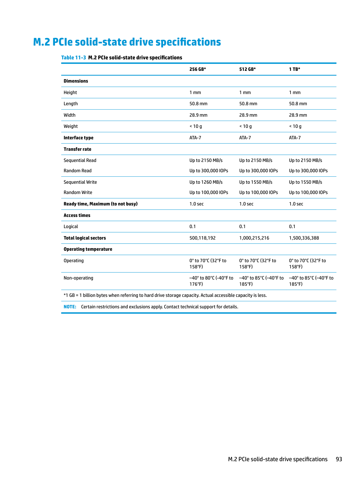
Does this memory retain data when power is removed?
What is the purpose of this memory?
How is data input into this memory?
How is this memory write-protected?
HP Sure Start flash (select models only)
8 MB No Yes Provides protected backup of critical System BIOS code, EC firmware, and critical computer configuration data for select platforms that support HP Sure Start.
For more information, see Using HP Sure Start (select models only) on page 103.
Real Time Clock (RTC) battery backed-up CMOS configuration memory
Controller (NIC) EEPROM
256 bytes No Yes Stores system date and time and noncritical data.
64 KB (not customer accessible)
No Yes Stores NIC configuration and NIC firmware.
DIMM Serial Presence Detect (SPD) configuration data
256 bytes per memory module, 128 bytes programmable (not customer accessible)
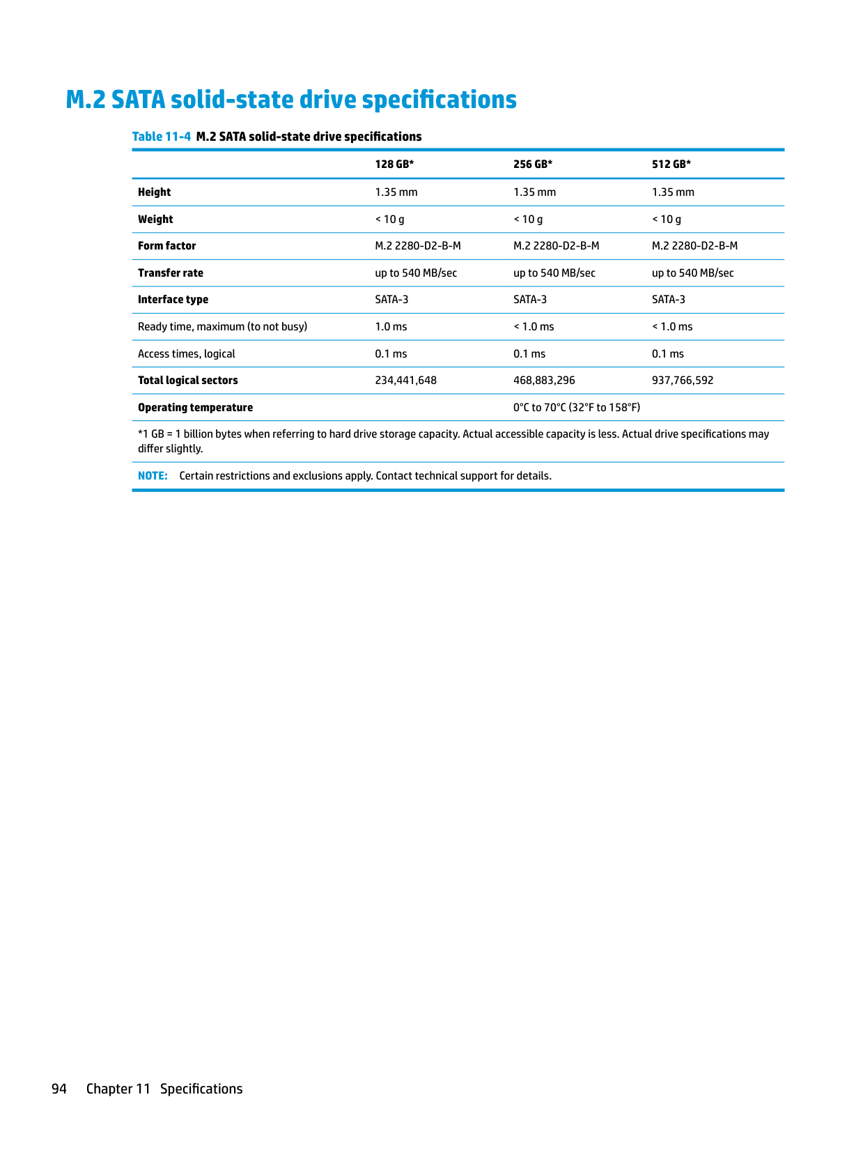
No Yes Stores memory module information.
Data cannot be written to this device via the host processor. The content is managed solely by the HP Sure Start Embedded Controller.
This memory is protected by the HP Sure Start Embedded Controller.
RTC battery backed-up CMOS is programmed using Computer Setup (BIOS), or by changing the Microsoft® Windows date & time.
NIC EEPROM is programmed using a utility from the NIC vendor that can be run from DOS.
DIMM SPD is programmed by the memory vendor.
This memory is not writeprotected.
A utility must be used to write data to this memory and is available from the NIC vendor. Writing data to this ROM in an inappropriate manner will render the NIC nonfunctional.
Data cannot be written to this memory when the module is installed in a computer. The specific write-protection method varies by memory vendor.
System BIOS 9 MB Yes Yes Stores system BIOS code and computer configuration data.
System BIOS code is programmed at the factory. Code is updated when the system BIOS is updated. Configuration data and settings are input using the Computer Setup (BIOS) or a custom utility.
NOTE: Writing data to this ROM in an inappropriate manner can render the computer nonfunctional.
A utility must be used for writing data to this memory and is available on the HP website; go to http://www.hp.com/ support. Select Find your product, and then follow the on-screen instructions.
Intel Management Engine Firmware (present only in select Elite or Z models. For more information, go to http://www.hp.com/ support. Select Find your product, and then follow the onscreen instructions.)
1.5 MB or 7 MB Yes Yes Stores Management Engine Code, Settings, Provisioning Data and iAMT third-party data store.
Management Engine Code is programmed at the factory. Code is updated via Intel secure firmware update utility. Unique Provisioning Data can be entered at the factory or by an administrator using the Management Engine (MEBx) setup utility. The third-party data store contents can be populated by a remote management console or local applications that have been registered by an administrator to have access to the space.
Bluetooth flash (select products only)
2 Mb No Yes Stores Bluetooth configuration and firmware.
Bluetooth flash is programmed at the factory. Tools for writing data to this memory are not publicly available but can be obtained from the silicon vendor.
802.11 WLAN EEPROM
4 Kb to 8 Kb No Yes Stores configuration and calibration data.
802.11 WLAN EEPROM is programmed at the factory. Tools for writing data to this memory are not made public.
Webcam (select products only)
64 Kb No Yes Stores webcam configuration and firmware.
Webcam memory is programmed using a utility from the device manufacturer that can be run from Windows.
The Intel chipset is configured to enforce hardware protection to block all direct read/write access to this area. An Intel utility must be used for updating the firmware. Only firmware updates digitally signed by Intel can be applied using this utility.
A utility must be used for writing data to this memory and is made available through newer versions of the driver whenever the flash requires an upgrade.
A utility must be used for writing data to this memory and is typically not made available to the public unless a firmware upgrade is necessary to address a unique issue.
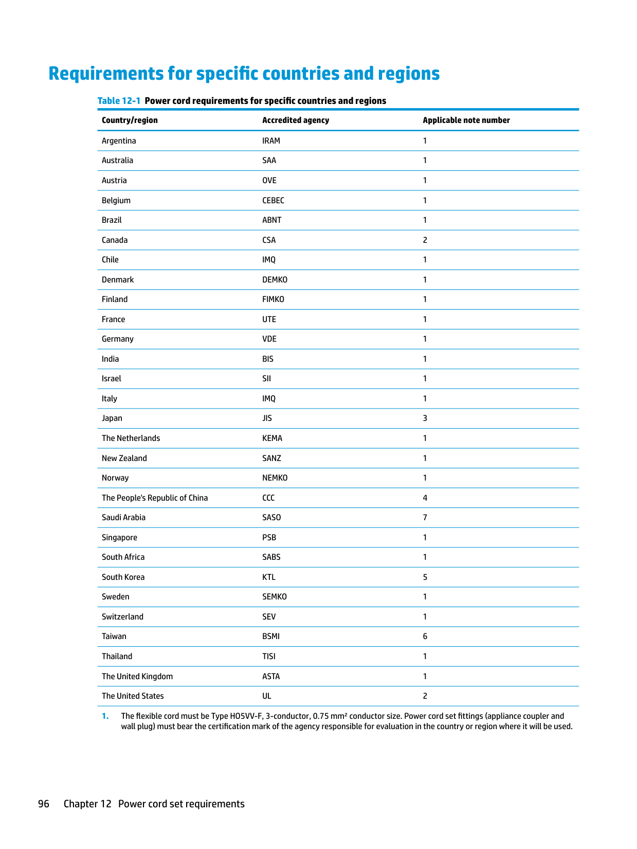
A utility must be used for writing data to this memory and is typically not made available to the public unless a firmware
Nonvolatile memory usage 101
Fingerprint reader (select products only)
512 KB flash Yes Yes Stores
fingerprint templates.
Fingerprint reader memory is programmed by user enrollment in HP ProtectTools Security Manager.
upgrade is necessary to address a unique issue.
Only a digitally signed application can make the call to write to the flash.
Questions and answers
IMPORTANT: Restore defaults does not securely erase any data on your hard drive. See question and answer 6 for steps to securely erase data. Restore defaults does not reset the Custom Secure Boot keys. See question and answer 7 for information about resetting the keys.
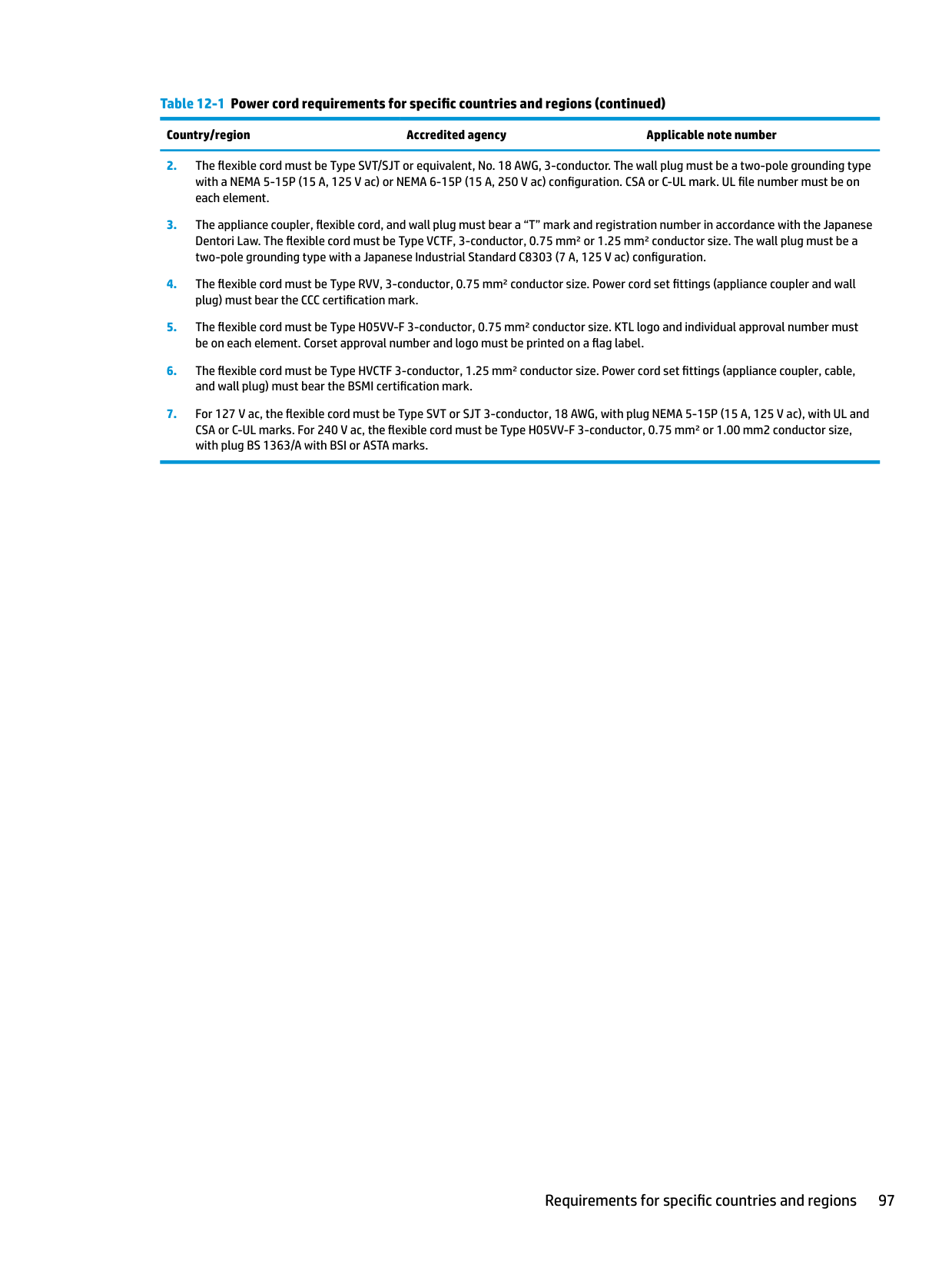
The Unified Extensible Firmware Interface (UEFI) BIOS is an industry-standard software interface between the platform firmware and an operating system (OS). It is a replacement for the older BIOS architecture, but supports much of the legacy BIOS functionality.
Like the legacy BIOS, the UEFI BIOS provides an interface to display the system information and configuration settings and to change the configuration of your computer before an OS is loaded. BIOS provides a secure run-time environment that supports a Graphic User Interface (GUI). In this environment, you can use either a pointing device (touch screen, touchpad, pointing stick, or USB mouse) or the keyboard to navigate and make menu and configuration selections. The UEFI BIOS also contains basic system diagnostics.
The UEFI BIOS provides functionality beyond that of the legacy BIOS. In addition, the UEFI BIOS works to initialize the computer’s hardware before loading and executing the OS; the run-time environment allows the loading and execution of software programs from storage devices to provide more functionality, such as advanced hardware diagnostics (with the ability to display more detailed system information) and advanced firmware management and recovery software.
HP has provided options in Computer Setup (BIOS) to allow you to run in legacy BIOS, if required by the operating system. Examples of this requirement would be if you upgrade or downgrade the OS.
| | |---|
###### 4. What kind of configuration data is stored on the DIMM Serial Presence Detect (SPD) memorymodule? How would this data be written?
The DIMM SPD memory contains information about the memory module, such as size, serial number, data width, speed/timing, voltage, and thermal information. This information is written by the module manufacturer and stored on an EEPROM. This EEPROM cannot be written to when the memory module is installed in a computer. Third-party tools do exist that can write to the EEPROM when the memory module is not installed in a computer. Various third-party tools are available to read SPD memory.
###### 5. What is meant by “Restore the nonvolatile memory found in Intel-based system boards”?
This message relates to clearing the Real Time Clock (RTC) CMOS memory that contains computer configuration data.
###### 6. How can the BIOS security be reset to factory defaults and data erased?IMPORTANT: Resetting will result in the loss of information.
| |
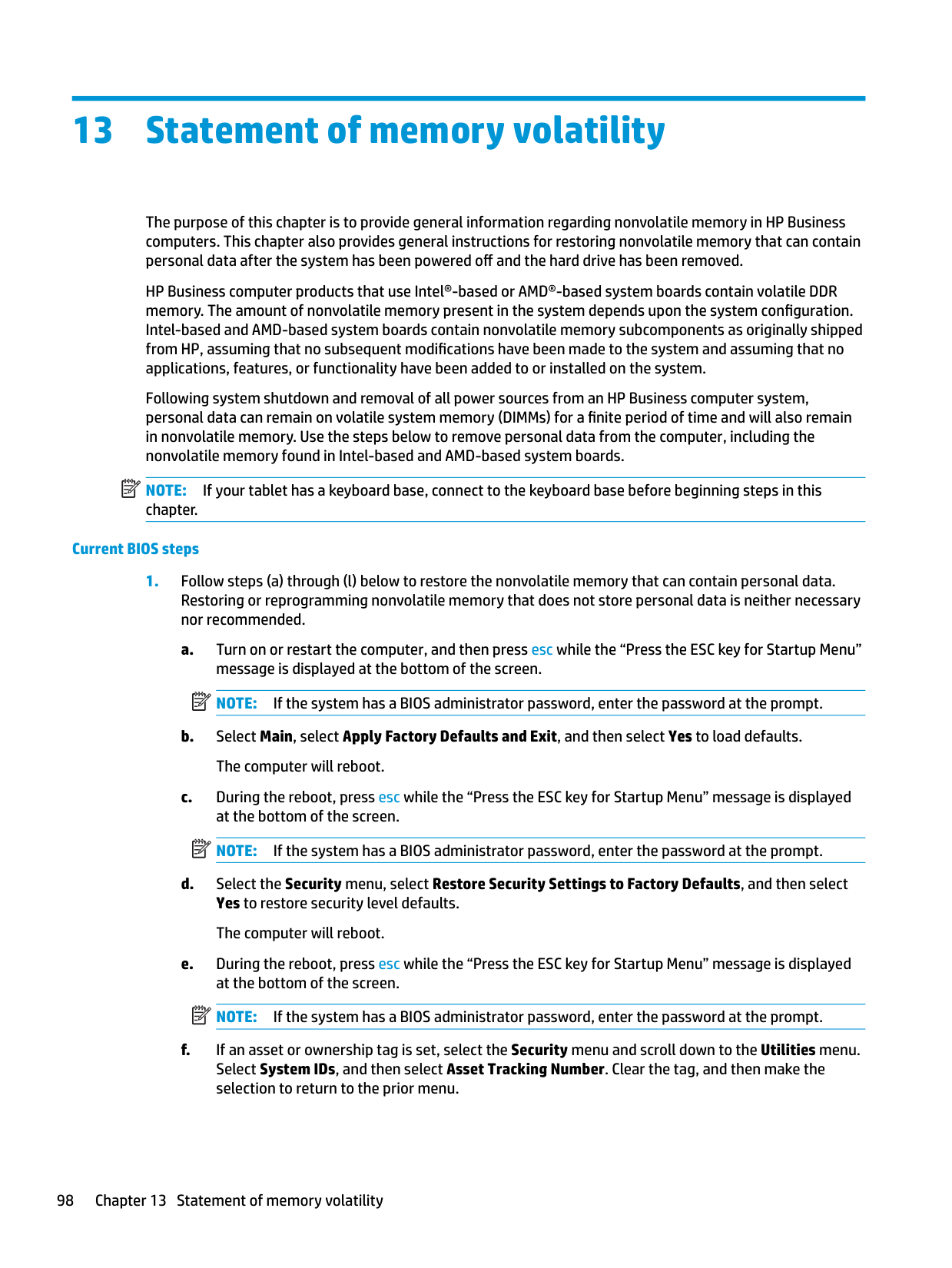
|---|
These steps will not reset Custom Secure Boot Keys. See question and answer 7 for information about resetting the keys.
###### 7. How can the Custom Secure Boot Keys be reset?
Secure Boot is a feature to ensure that only authenticated code can start on a platform. If you enabled Secure Boot and created Custom Secure Boot Keys, simply disabling Secure Boot will not clear the keys. You must also select to clear the Custom Secure Boot Keys. Use the same Secure Boot access procedure you used to create the Custom Secure Boot Keys, but make the selection to clear or delete all Secure Boot Keys.
Using HP Sure Start (select models only)
Select computer models are configured with HP Sure Start, a technology that continuously monitors your computer's BIOS for attacks or corruption. If the BIOS becomes corrupted or is attacked, HP Sure Start restores the BIOS to its previously safe state, without user intervention. Those select computer models ship with HP Sure Start configured and enabled. HP Sure Start is configured and already enabled so that most users can use the HP Sure Start default configuration. The default configuration can be customized by advanced users.
To access the latest documentation on HP Sure Start, go to http://www.hp.com/support. Select Find your product, and then follow the on-screen instructions.
Using HP Sure Start (select models only) 103
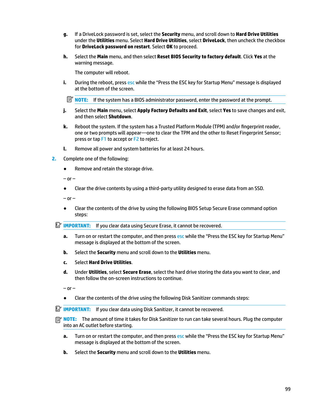
14 Recycling
When a non-rechargeable or rechargeable battery has reached the end of its useful life, do not dispose of the battery in general household waste. Follow the local laws and regulations in your area for battery disposal.
HP encourages customers to recycle used electronic hardware, HP original print cartridges, and rechargeable batteries. For more information about recycling programs, see the HP Web site at http://www.hp.com/recycle.
104 Chapter 14 Recycling
Index
Symbols/Numerics `product description
RJ-45 (network) 2
spare part number 24 ambient light sensor, identifying 10 antennas
disconnecting 39, 41 audible codes 78 audio, product description 2 audio-out (headphone)/audio-in
(microphone) combo jack, identifying 7
removing 47 spare part number 47 spare part numbers 23
battery light 8 beep codes 78 BIOS
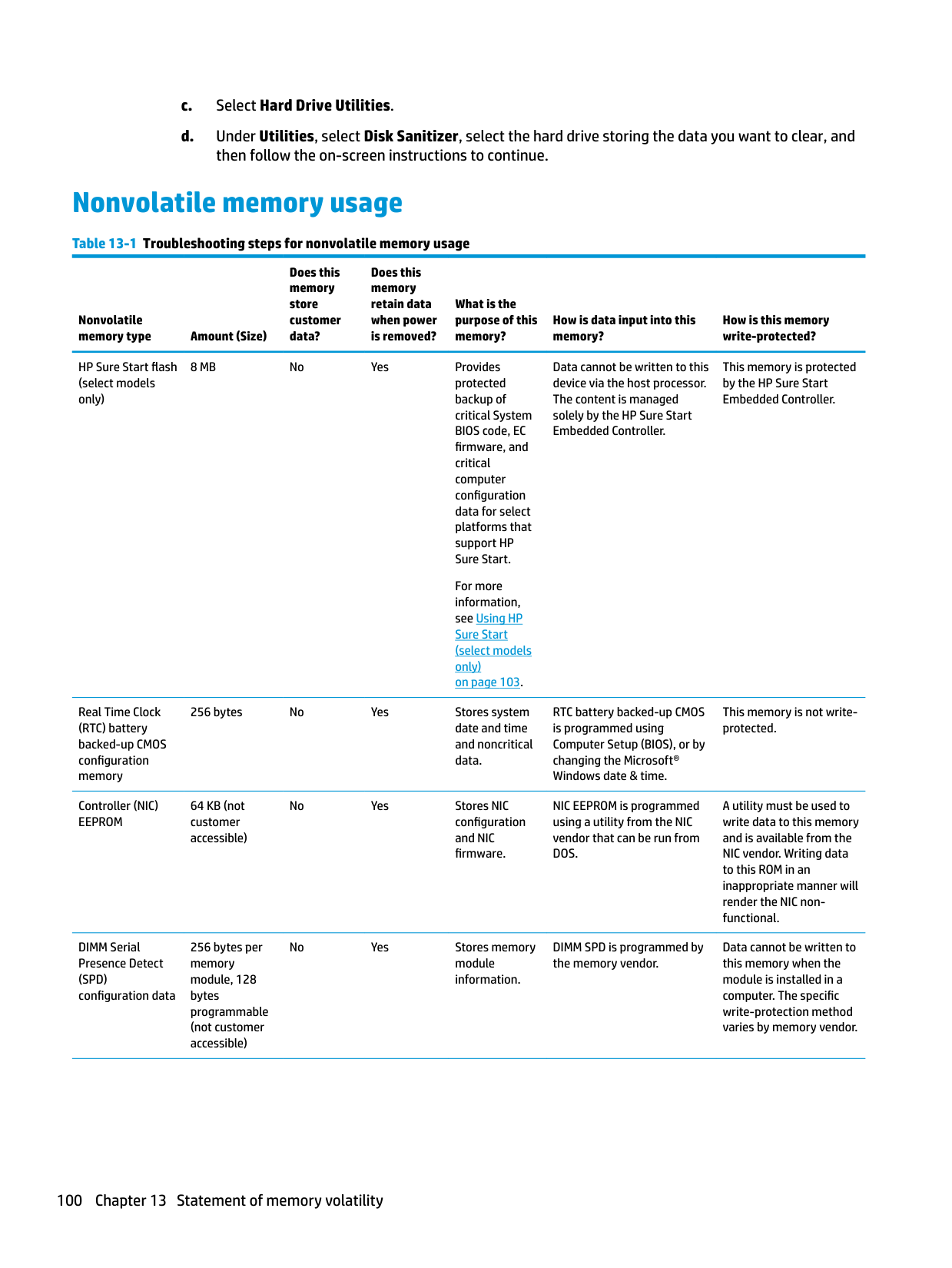
determining version 81 downloading an update 81 updating 81
Bluetooth card
spare part number 39 Bluetooth label 19 boot order
changing using the f9 prompt
82 boot order, changing 90 bottom 19 bottom cover
removing 35 spare part number 23, 35
bracket kit, spare part number 27 buttons
left touchpad 11
power 14 right touchpad 11
C Cable Kit
contents 25 spare part number 25
call answer light 13 call end light 13 camera 10
identifying 10 camera cable
spare part number 24 camera light, identifying 10 camera module
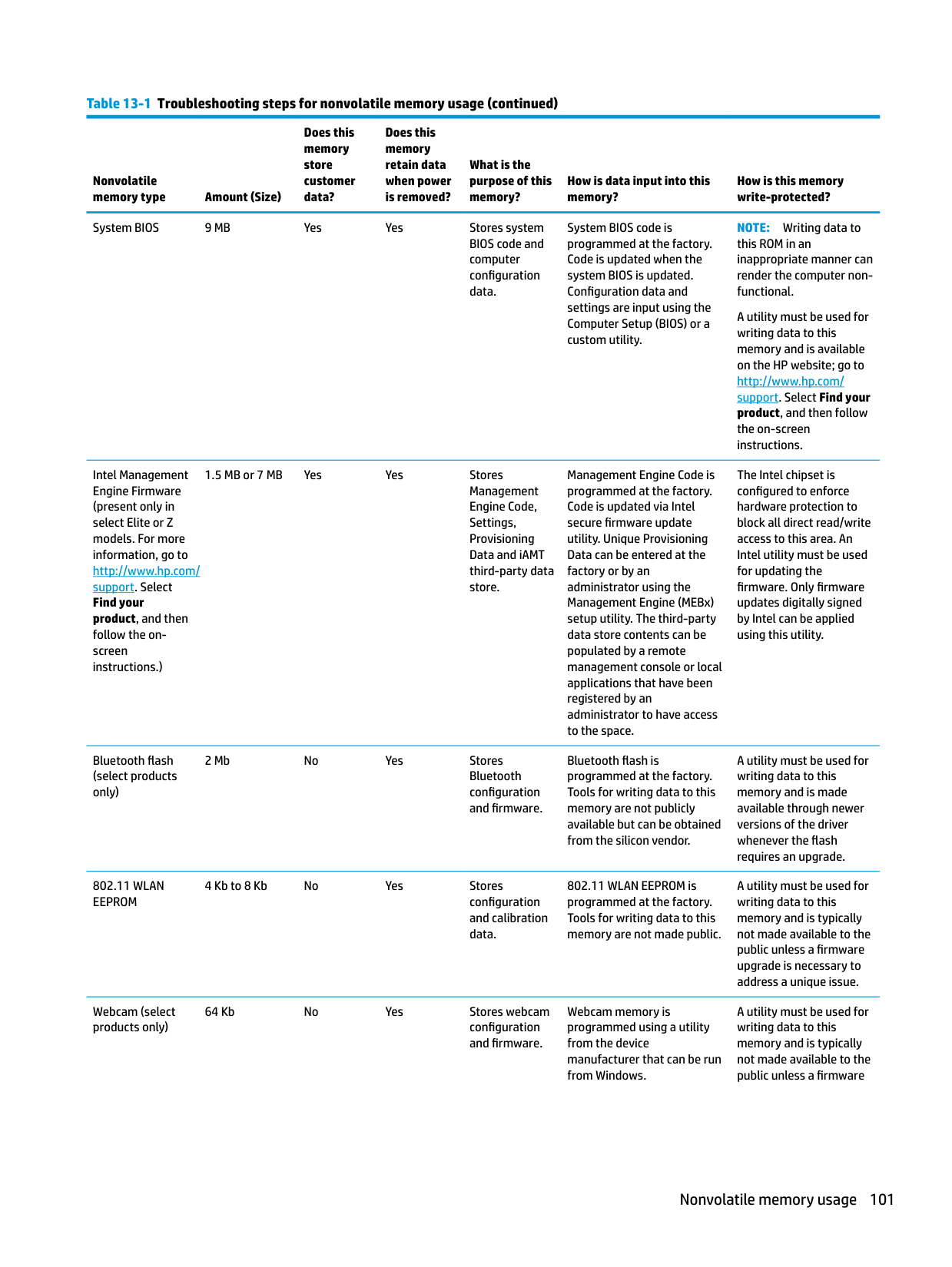
removal 73 spare part number 24 caps lock light, identifying 12 caring for your computer 30 cautions
electrostatic discharge 32 cleaning your computer 30 components
bottom 16 display 10 front 17 keyboard area 11 left side 9 right side 7
computer major components 20 Computer Setup
navigating and selecting 80 restoring factory settings 80 starting 80
computer setup 80 computer specifications 91 connector, power 8
D display assembly
removal 70 spare part numbers 70 subcomponents 23
display components 10
display enclosure spare part number 24
display panel product description 1 release 73 spare part number 24
display specifications 92 drive light, identifying 17
preventing damage 32 embedded numeric keypad,
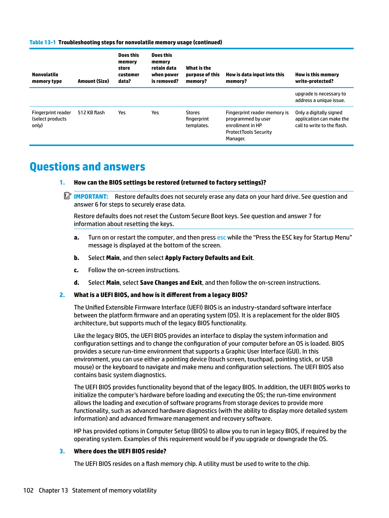
identifying 15 error
codes 78 esc key, identifying 15
removal 63 spare part number 22, 63
fingerprint reader spare part number 21
fingerprint reader assembly removal 68 spare part number 68
fingerprint reader, identifying 14 FIPS fingerprint reader bracket spare part number 21 flashing LEDs 78 fn key, identifying 15 fn lock light, identifying 13
packaging 34 transporting 34 workstation 29
heat sink removal 49 spare part number 22 spare part numbers 49
hot keys break 13 insert 13 pause 13 programming query 13 scroll lock 13 using 13
HP PC Hardware Diagnostics UEFI downloading 86 starting 86 using 85
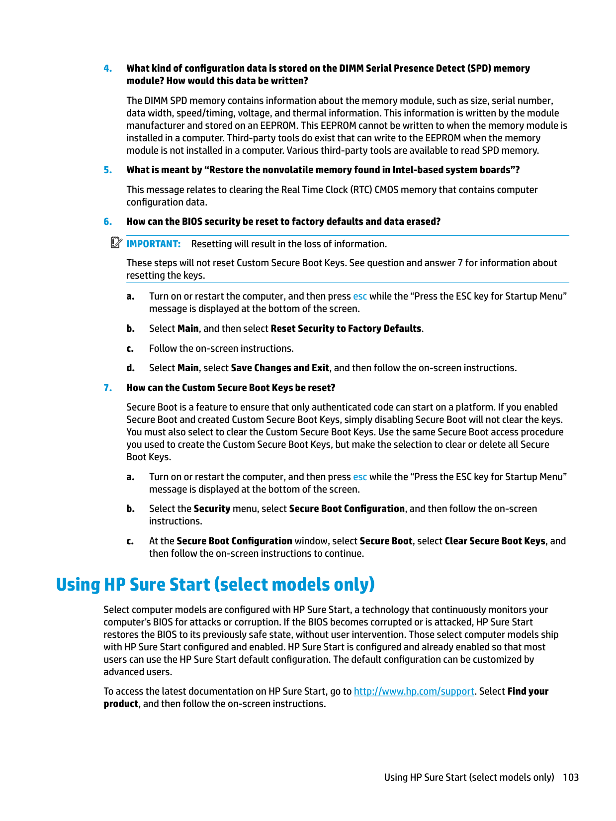
HP PC Hardware Diagnostics Windows downloading 84 installing 85 using 84
HP Recovery media
recovery 90 HP Sure Start 103
10
audio-out (headphone)/audio-in
(microphone) combo 7 network 7 RJ-45 (network) 7
product description 4 removal 43 spare part number 21 spare part numbers 43
keypad embedded numeric 15
keys esc 15 fn 15 num lock 15 Windows 15 Windows application 15
L labels
Bluetooth 19 regulatory 19 serial number 18 service 18 wireless certification 19 WLAN 19

left side components 9 lights
AC adapter and battery 8 battery 8 call answer 13 call end 13 camera 10 caps lock 12 drive 17 fn lock 13 microphone mute 12 num lock 12 power 12, 17 RJ-45 (network) 7 sharing or presenting 12 wireless 12, 17
###### M
memory nonvolatile 98 product description 1 volatile 98
memory module removal 38 spare part number 22 spare part numbers 38
microphone
product description 2 microphone module
spare part number 24 microphone mute light, identifying 12 model name 1
removal 60 spare part number 21, 60 NFC tapping area, identifying 11
nonvolatile memory 98 num lock light 12
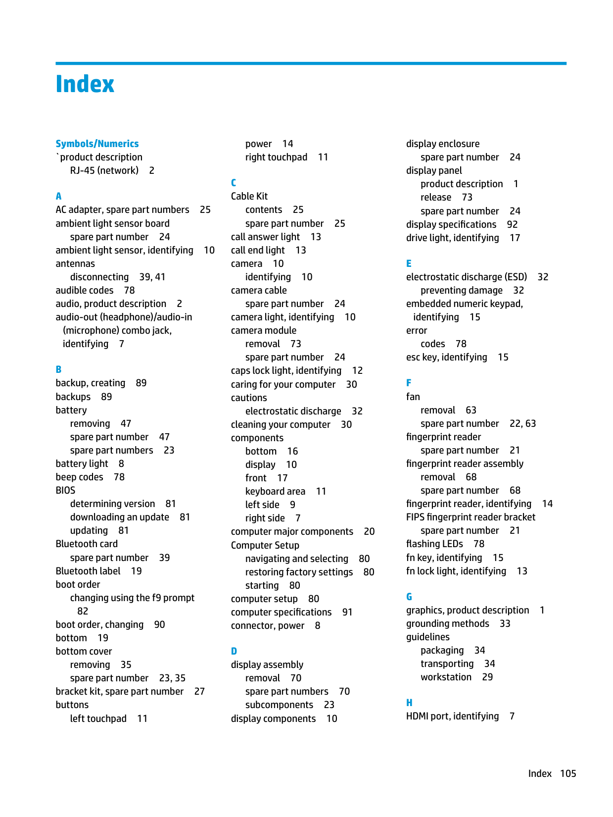
description 5
release 73 plastics kit, spare part number 27 pointing device, product
description 4 pointing stick, identifying 11 ports
HDMI 7 product description 4 USB SuperSpeed 7 USB Type-C power connector and
Thunderbolt port with HP Sleep and Charge 8
USB Type-C SuperSpeed with HP
Sleep and Charge 9 power button board
spare part number 21 power button board assembly removal 55 spare part number 55 power button, identifying 14 power connector
identifying 8 identifying USB Type-C 8
power cord requirements for all countries 95 requirements for specific
countries and regions 96 set requirements 95 spare part numbers 25, 26, 27
power lights 12, 17 power requirements, product
description 4 primary storage
product description 2 processors, product description 1 product description
audio 2 display panel 1 graphics 1
keyboard 4 memory 1 microphone 2 operating system 5 pointing device 4 ports 4 power requirements 4 primary storage 2 processors 1 product name 1 security 5 sensors 4 serviceability 6 video 2 wireless networking 2
product name 1 product name and number,
computer 18
R recovery 89
discs 90 HP Recovery partition 90 media 90 USB flash drive 90
recovery media creating using HP Cloud Recovery Download Tool 89 creating using Windows tools 89
regulatory information regulatory label 19 wireless certification labels 19
Remote HP PC Hardware Diagnostics
UEFI settings customizing 87 using 87
removal/replacement procedures 35, 46 removing personal data from volatile
system memory 98 restoring 89 RFID 11 RFID module
removal 61 spare part number 21, 61
right side components 7 RJ-45 (network)
product description 2 RJ-45 (network) jack, identifying 7
RJ-45 (network) lights, identifying 7
RJ-45 board with bracket removal 54 spare part number 21, 54
RTC battery removal 52 spare part number 21, 52
S screw kit, spare part number 27 security cable slot, identifying 9 security, product description 5 sensors
product description 4 serial number, computer 18 service labels, locating 18 serviceability, product description 6 setup utility
navigating and selecting 80 restoring factory settings 80
sharing or presenting light,
identifying 12 SIM card slot, identifying 7 slots
security cable 9 SIM card 7 smart card 9
smart card reader removal 62 spare part number 62
smart card reader board
smart card slot, identifying 9 solid-state drive
removal 37
speaker assembly removal 56 spare part number 56
speakers, identifying 14 special keys, using 15 specifications
computer 91 display 92 M.2 solid-state drive 93 solid-state drive 94
static electricity 32
Sure Start using 83
system board removal 65 spare part number 21 spare part numbers 65
system memory, removing personal data from volatile 98 system restore point, creating 89
Charge identifying USB Type-C 8
top cover removal 77 spare part number 21, 77
touchpad
buttons 11 removal 57 spare part number 21, 57
touchpad button board removal 59 spare part number 21, 59
touchpad zone
identifying 11 TPM settings 82 transporting guidelines 34 traveling with the computer 19
removal 53 spare part number 21, 53
USB SuperSpeed port, identifying 7 USB Type-C power connector and
Thunderbolt port with HP Sleep and Charge, identifying 8
USB Type-C SuperSpeed port with HP Sleep and Charge, identifying 9
backup 89 recovery media 89 system restore point 89
Windows application key,
identifying 15 Windows key, identifying 15 Windows tools, using 89 wireless antennas
disconnecting 39, 41 wireless antennas, identifying 10 wireless certification label 19 wireless light 17 wireless light, identifying 12 wireless networking
product description 2 WLAN antenna
spare part number 24 WLAN antennas, identifying 10 WLAN device 19 WLAN label 19 WLAN/Bluetooth combo card
removal 39 spare part number 22, 39
workstation guidelines 29 WWAN antenna
spare part number 24 WWAN antennas, identifying 10 WWAN module
removal 41 spare part number 22, 41