
Ask AI
— answers from the official manualAnswers from the official manual.
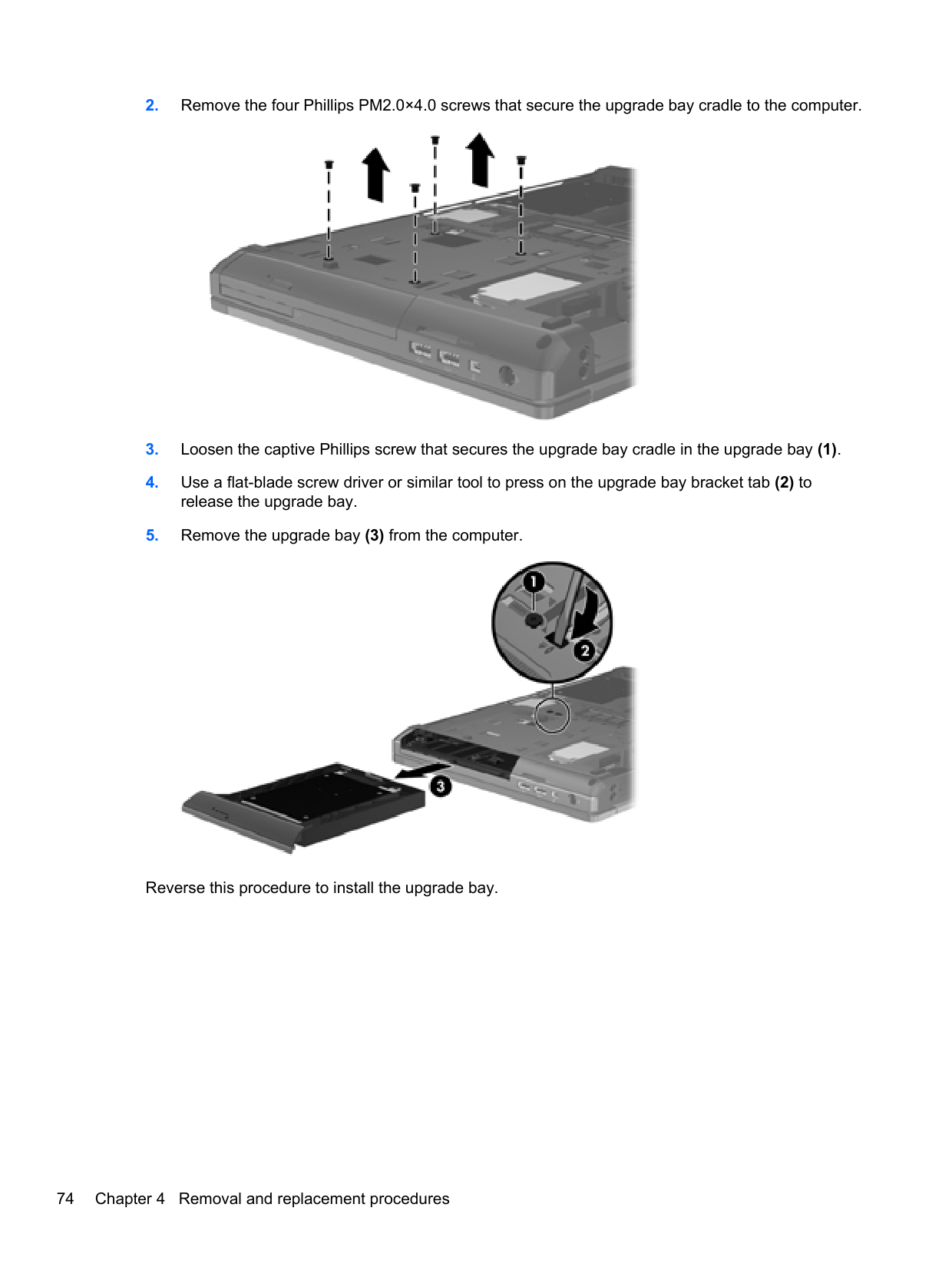
Common questions
Common Questions
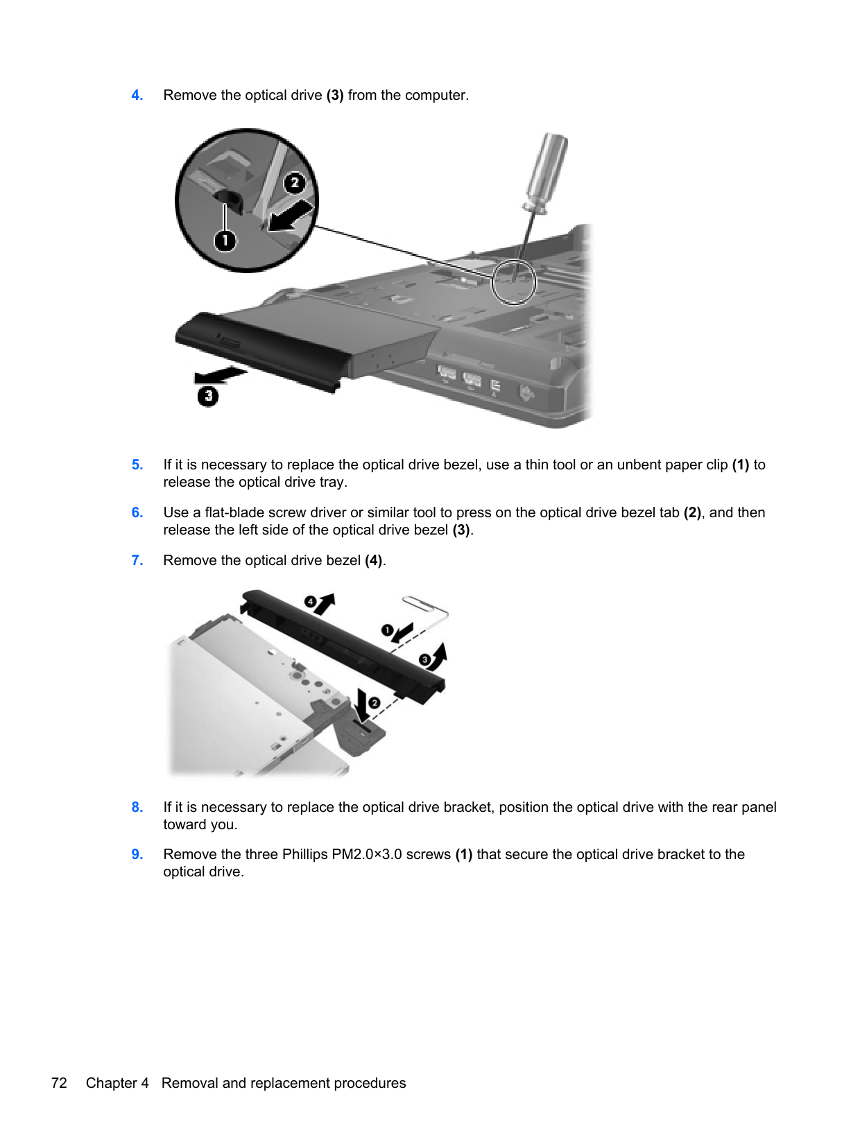
9 totalHow do I replace the battery on my HP EliteBook 8470p?
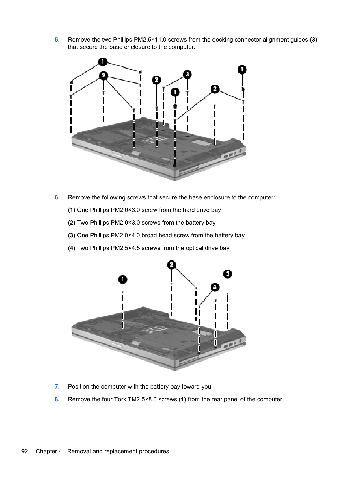
To remove the battery, use the service cover release latch to access it and then depress the battery release latch. Install a new battery by reversing these steps.
What power cords are required for my HP EliteBook 8470p?
The supported power cord types vary based on your country and can be found in the Power Cord Set Requirements section of the manual. It includes specific models like the 90-W and 65-W HP Smart AC adapter.
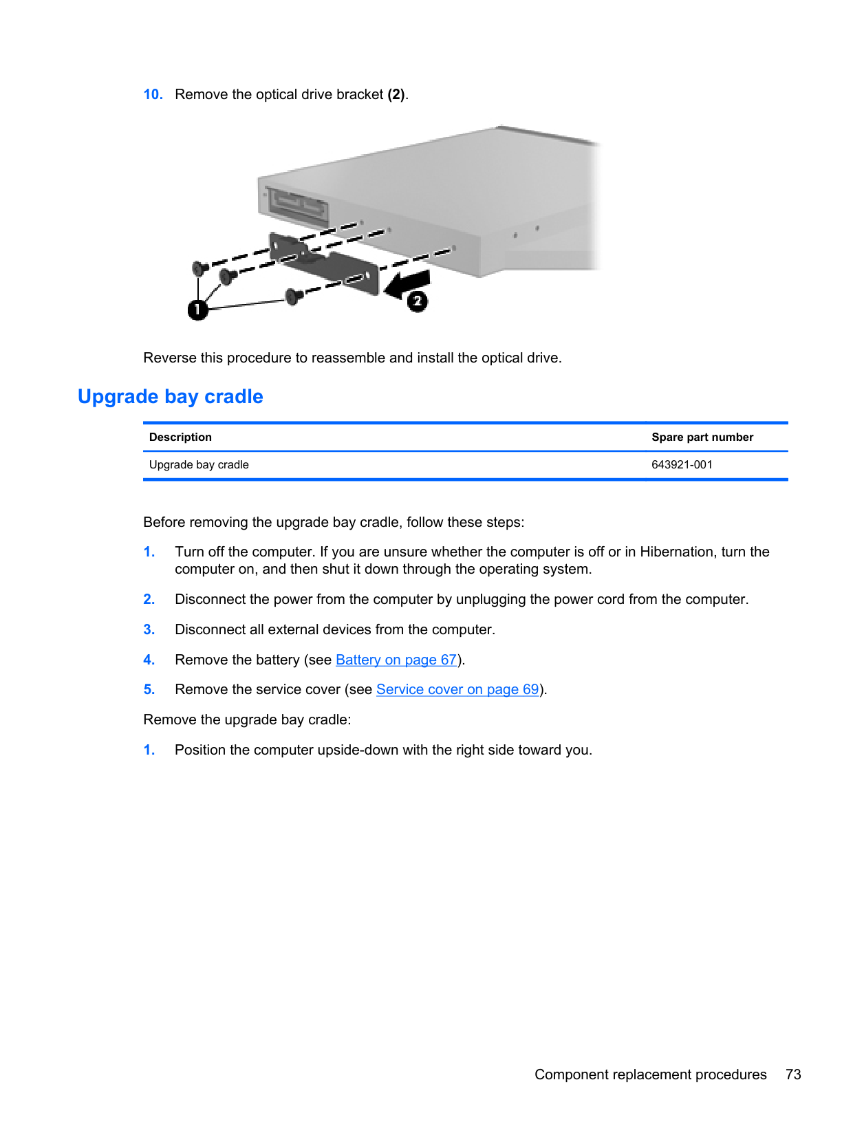
How do I replace the hard drive or SSD on my EliteBook?
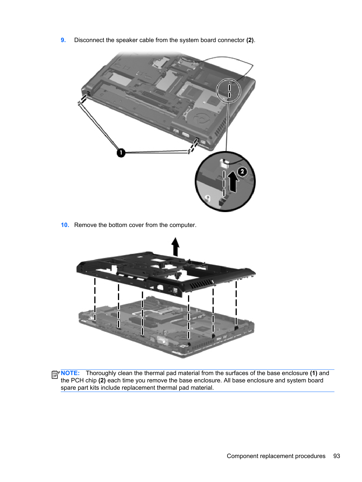
Remove the service cover and then unplug the cable connectors from the hard drive. Carefully extract the old drive and install a new one, ensuring correct orientation.
How do I access advanced system diagnostics on my HP EliteBook?
From Windows 8 or Windows 7, enter Computer Setup to access Advanced System Diagnostics. Steps vary by operating system and can be found in section 5 of the manual.
Where is the serial number located on my EliteBook?
The serial number, also known as s/n, is available under the service tag which you need to remove by taking out the battery. Detailed instructions for removal are provided.
What is a recommended maintenance schedule for my HP EliteBook?
Regularly check the battery, clean fan vents, ensure no obstructions block airflow, update firmware through BIOS updating as needed. Always follow safety precautions and guidelines.
Full Manual
173 pages
HP EliteBook 8470w Mobile Workstation and HP EliteBook 8470p Notebook PC
Maintenance and Service Guide IMPORTANT! This document is intended for HP authorized service providers only.
© Copyright 2012, 2013 Hewlett-Packard Development Company, L.P.
Bluetooth is a trademark owned by its proprietor and used by Hewlett-Packard Company under license. Intel and Core are U.S. registered trademarks of Intel Corporation. Microsoft, Windows, and Windows Vista are U.S. registered trademarks of Microsoft Corporation. SD Logo is a trademark of its proprietor.
The information contained herein is subject to change without notice. The only warranties for HP products and services are set forth in the express warranty statements accompanying such products and services. Nothing herein should be construed as constituting an additional warranty. HP shall not be liable for technical or editorial errors or omissions contained herein.
Third Edition: January 2013 First Edition: May 2012 Document Part Number: 677157-003
#### Safety warning notice
WARNING! To reduce the possibility of heat-related injuries or of overheating the device, do not place the device directly on your lap or obstruct the device air vents. Use the device only on a hard, flat surface. Do not allow another hard surface, such as an adjoining optional printer, or a soft surface, such as pillows or rugs or clothing, to block airflow. Also, do not allow the AC adapter to contact the skin or a soft surface, such as pillows or rugs or clothing, during operation. The device and the AC adapter comply with the user-accessible surface temperature limits defined by the International Standard for Safety of Information Technology Equipment (IEC 60950).
iii
####### iv Safety warning notice
Table of contents

Tools required .................................................................................................................... 60 Service considerations ....................................................................................................... 60
Plastic parts ....................................................................................................... 60 Cables and connectors ..................................................................................... 60 Drive handling ................................................................................................... 61
v
Grounding guidelines ......................................................................................................... 61 Electrostatic discharge damage ........................................................................ 61 Packaging and transporting guidelines ............................................. 63
Component replacement procedures ................................................................................................. 65 Service tag ......................................................................................................................... 65 Computer feet .................................................................................................................... 66 Battery ............................................................................................................................... 67 SIM .................................................................................................................................... 68 Service cover ..................................................................................................................... 69 Smart Card reader ............................................................................................................. 70 Optical drive ....................................................................................................................... 71 Upgrade bay cradle ........................................................................................................... 73 Hard drive .......................................................................................................................... 75 Memory module ................................................................................................................. 77 WWAN module .................................................................................................................. 79 WLAN module .................................................................................................................... 81 Bluetooth module ............................................................................................................... 83 Modem module .................................................................................................................. 84 Fan ..................................................................................................................................... 85 Keyboard ........................................................................................................................... 86 Base enclosure .................................................................................................................. 91 Speaker assembly ............................................................................................................. 94 RJ-11 jack cable ................................................................................................................ 96 Service cover release latch assembly ............................................................................... 97 Battery release latch assembly ........................................................................................ 100 Fingerprint reader board .................................................................................................. 102 RTC battery ..................................................................................................................... 104 Display lid switch board ................................................................................................... 105 System board ................................................................................................................... 107 Heat sink .......................................................................................................................... 110 Processor ......................................................................................................................... 114 ExpressCard assembly .................................................................................................... 117 Display assembly ............................................................................................................. 119
###### 5 Computer Setup (BIOS) and Advanced System Diagnostics ................................................................. 127Windows 8 ........................................................................................................................................ 127
Using Computer Setup .................................................................................................... 127 Starting Computer Setup ................................................................................. 127 Navigating and selecting in Computer Setup .................................................. 127 Restoring factory settings in Computer Setup ................................................. 129 Updating the BIOS .......................................................................................... 129
vi
Determining the BIOS version ........................................................ 129 Downloading a BIOS update .......................................................... 130
Using Advanced System Diagnostics .............................................................................. 131
Windows 7 ........................................................................................................................................ 132 Starting Computer Setup ................................................................................................. 132 Using Computer Setup .................................................................................................... 132
Navigating and selecting in Computer Setup .................................................. 132 Restoring factory settings in Computer Setup ................................................. 133
Updating the BIOS ........................................................................................................... 134 Determining the BIOS version ......................................................................... 134 Downloading a BIOS update ........................................................................... 134

Using Advanced System Diagnostics .............................................................................. 135
SuSE Linux (SLED) .......................................................................................................................... 136 Starting Computer Setup ................................................................................................. 136 Using Computer Setup .................................................................................................... 136
Navigating and selecting in Computer Setup .................................................. 136 Restoring factory settings in Computer Setup ................................................. 137
Updating the BIOS ........................................................................................................... 137 Determining the BIOS version ......................................................................... 138 Downloading a BIOS update ........................................................................... 138
Using Advanced System Diagnostics .............................................................................. 139
Backing up your information ............................................................................................ 144 Performing a system recovery ......................................................................................... 145
Using the Windows recovery tools .................................................................. 145 Using f11 recovery tools .................................................................................. 146 Using Windows 8 operating system media (purchased separately) ............... 147 Using Windows Refresh for quick and easy recovery ..................................... 147 Remove everything and reinstall Windows ..................................................... 148 Using HP Software Setup ............................................................................... 148
Windows 7 ........................................................................................................................................ 148 Creating recovery media with HP Recovery Disc Creator ............................................... 150 Creating recovery media ................................................................................. 150 Backing up your information ............................................................................................ 150
vii
Performing a system recovery ......................................................................................... 151 Using the Windows recovery tools .................................................................. 151 Using f11 recovery tools .................................................................................. 152 Using a Windows 7 operating system DVD (purchased separately) ............... 153
SuSE Linux (SLED) .......................................................................................................................... 154 Creating backups ............................................................................................................. 154 Backing up your information ............................................................................................ 154 Performing a system recovery ......................................................................................... 155 USB Recovery option (select models only) ..................................................................... 156 Remove everything and reinstall SLED ........................................................................... 157

###### Index ................................................................................................................................................................. 161
viii
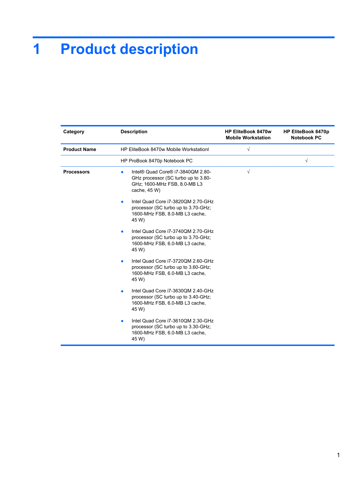
1 Product description
Category Description HP EliteBook 8470w Mobile Workstation
HP EliteBook 8470p Notebook PC Product Name HP EliteBook 8470w Mobile Workstationl √
HP ProBook 8470p Notebook PC √
Processors ● Intel® Quad Core® i7-3840QM 2.80GHz processor (SC turbo up to 3.80GHz; 1600-MHz FSB, 8.0-MB L3 cache, 45 W)
√
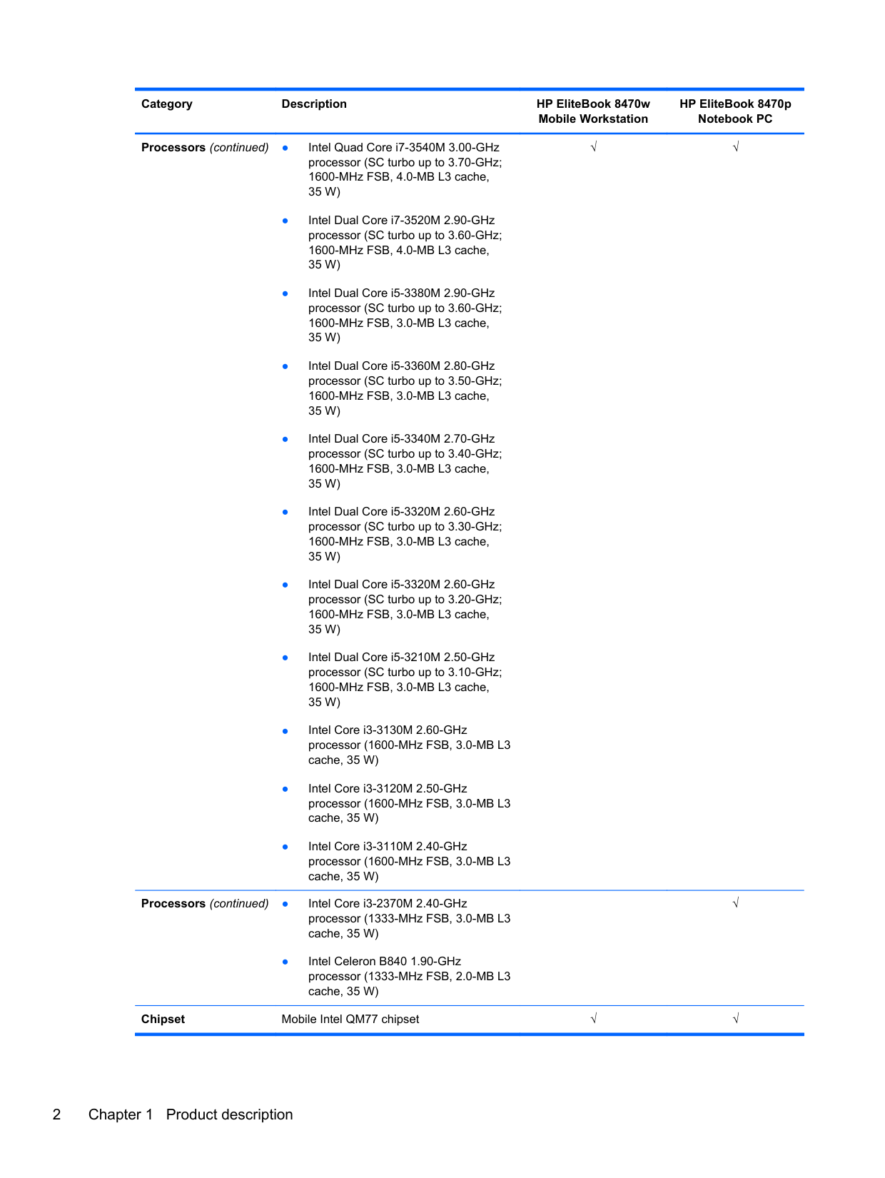
Processors (continued) ● Intel Quad Core i7-3540M 3.00-GHz processor (SC turbo up to 3.70-GHz; 1600-MHz FSB, 4.0-MB L3 cache, 35 W)
Processors (continued) ● Intel Core i3-2370M 2.40-GHz processor (1333-MHz FSB, 3.0-MB L3 cache, 35 W)
● Intel Celeron B840 1.90-GHz processor (1333-MHz FSB, 2.0-MB L3 cache, 35 W)
√√
√
Chipset Mobile Intel QM77 chipset √√
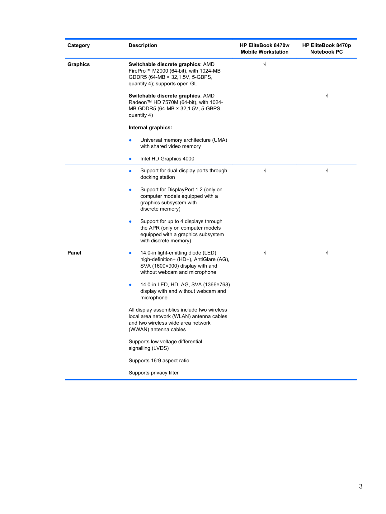
Graphics Switchable discrete graphics: AMD FirePro™ M2000 (64-bit), with 1024-MB GDDR5 (64-MB × 32,1.5V, 5-GBPS, quantity 4); supports open GL
Switchable discrete graphics: AMD Radeon™ HD 7570M (64-bit), with 1024MB GDDR5 (64-MB × 32,1.5V, 5-GBPS, quantity 4)
######## Internal graphics:
√
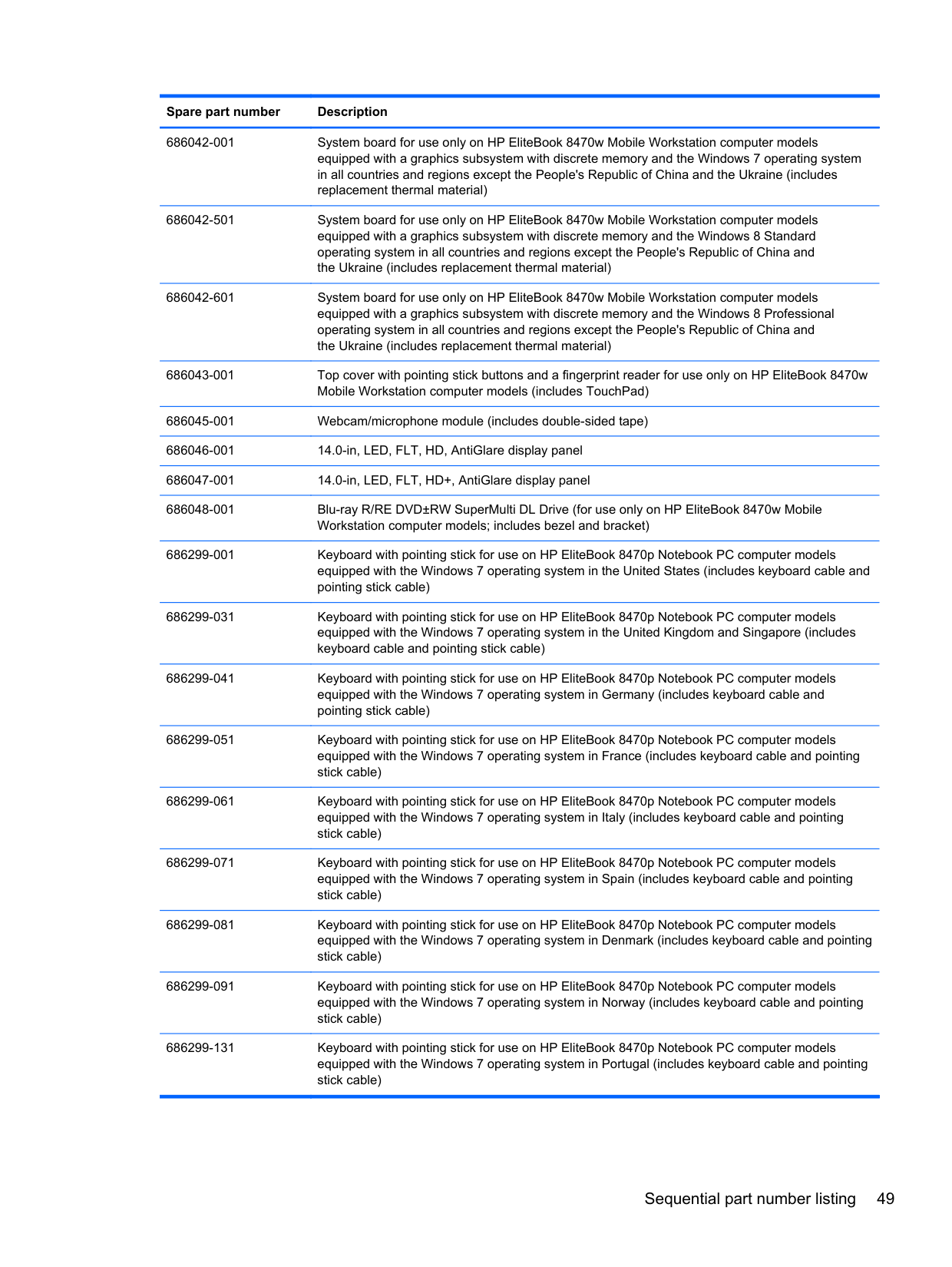
Panel ● 14.0-in light-emitting diode (LED), high-definition+ (HD+), AntiGlare (AG), SVA (1600×900) display with and without webcam and microphone
● 14.0-in LED, HD, AG, SVA (1366×768) display with and without webcam and microphone
All display assemblies include two wireless local area network (WLAN) antenna cables and two wireless wide area network (WWAN) antenna cables
Supports low voltage differential signalling (LVDS)
Supports 16:9 aspect ratio Supports privacy filter
√
√√
√√
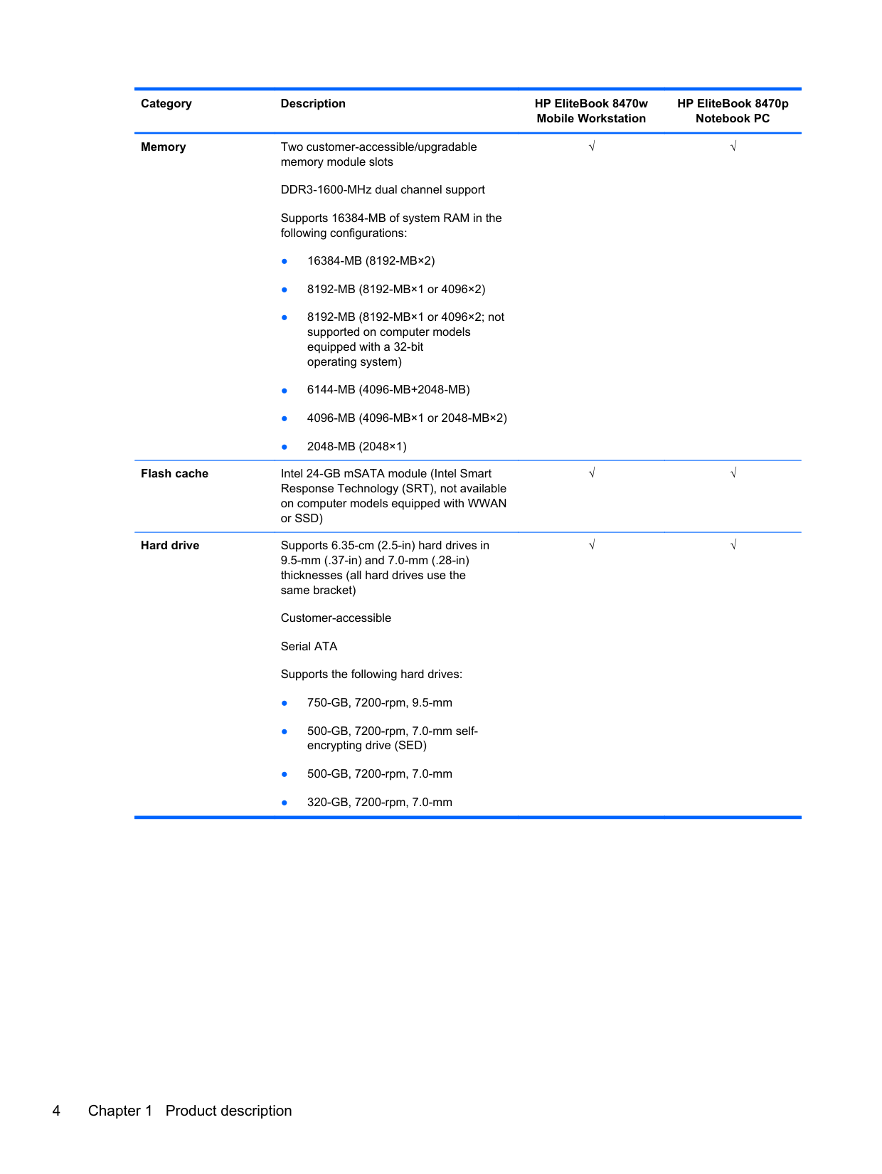
Memory Two customer-accessible/upgradable memory module slots DDR3-1600-MHz dual channel support Supports 16384-MB of system RAM in the following configurations:
Flash cache Intel 24-GB mSATA module (Intel Smart
Response Technology (SRT), not available on computer models equipped with WWAN or SSD)
Hard drive Supports 6.35-cm (2.5-in) hard drives in 9.5-mm (.37-in) and 7.0-mm (.28-in) thicknesses (all hard drives use the same bracket)
Customer-accessible Serial ATA Supports the following hard drives:
√√
√√
√√
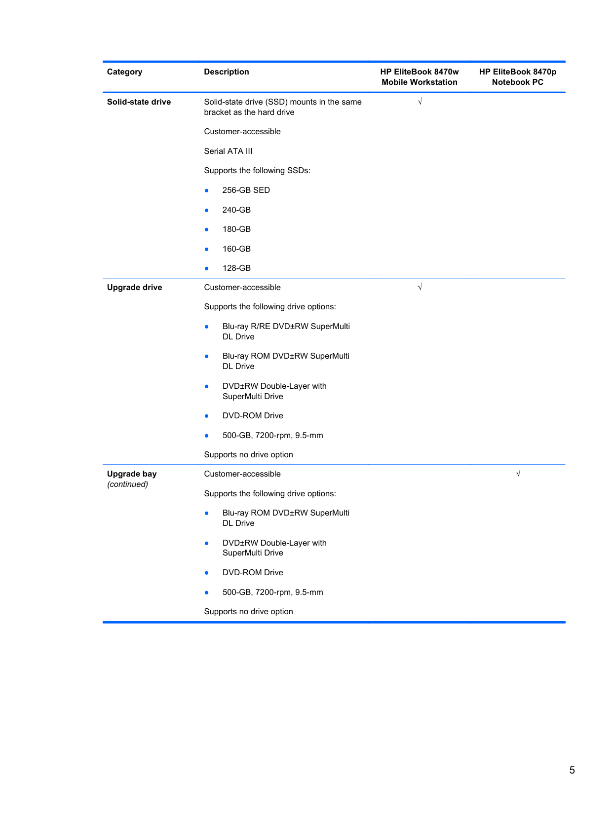
Solid-state drive Solid-state drive (SSD) mounts in the same bracket as the hard drive Customer-accessible Serial ATA III Supports the following SSDs:
Upgrade drive Customer-accessible
Upgrade bay (continued)
Supports the following drive options:
Customer-accessible Supports the following drive options:
√
√
√
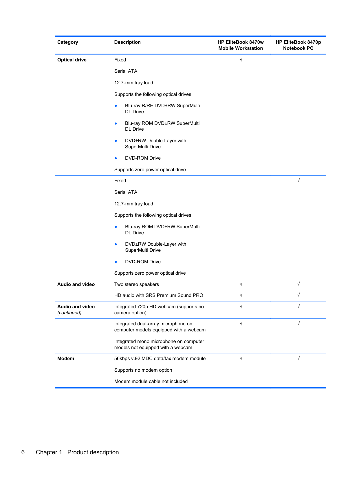
Optical drive Fixed Serial ATA 12.7-mm tray load Supports the following optical drives:
Fixed Serial ATA 12.7-mm tray load Supports the following optical drives:
√
√
Audio and video Two stereo speakers √√ HD audio with SRS Premium Sound PRO √√
Audio and video (continued)
Integrated 720p HD webcam (supports no camera option)
Integrated dual-array microphone on computer models equipped with a webcam
√√
√√
Integrated mono microphone on computer models not equipped with a webcam
Modem 56kbps v.92 MDC data/fax modem module Supports no modem option Modem module cable not included
√√
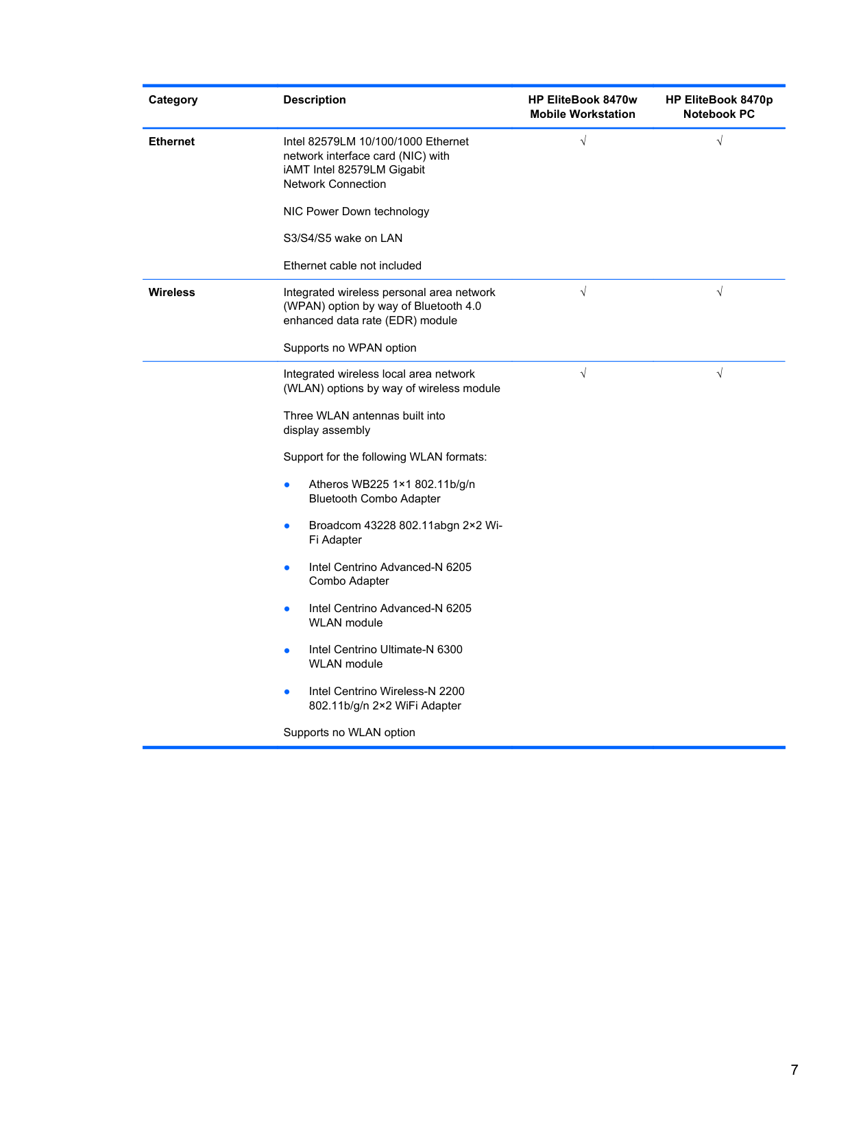
Ethernet Intel 82579LM 10/100/1000 Ethernet network interface card (NIC) with iAMT Intel 82579LM Gigabit Network Connection
NIC Power Down technology S3/S4/S5 wake on LAN Ethernet cable not included
Wireless Integrated wireless personal area network (WPAN) option by way of Bluetooth 4.0 enhanced data rate (EDR) module
Supports no WPAN option
Integrated wireless local area network (WLAN) options by way of wireless module
Three WLAN antennas built into display assembly
Support for the following WLAN formats:
Supports no WLAN option
√√
√√
√√
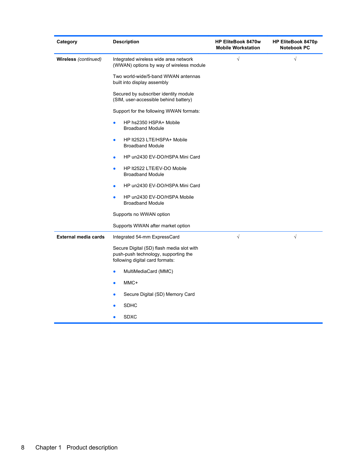
Wireless (continued) Integrated wireless wide area network (WWAN) options by way of wireless module Two world-wide/5-band WWAN antennas built into display assembly Secured by subscriber identity module (SIM, user-accessible behind battery) Support for the following WWAN formats:
Supports no WWAN option Supports WWAN after market option
External media cards Integrated 54-mm ExpressCard
Secure Digital (SD) flash media slot with push-push technology, supporting the following digital card formats:
√√
√√
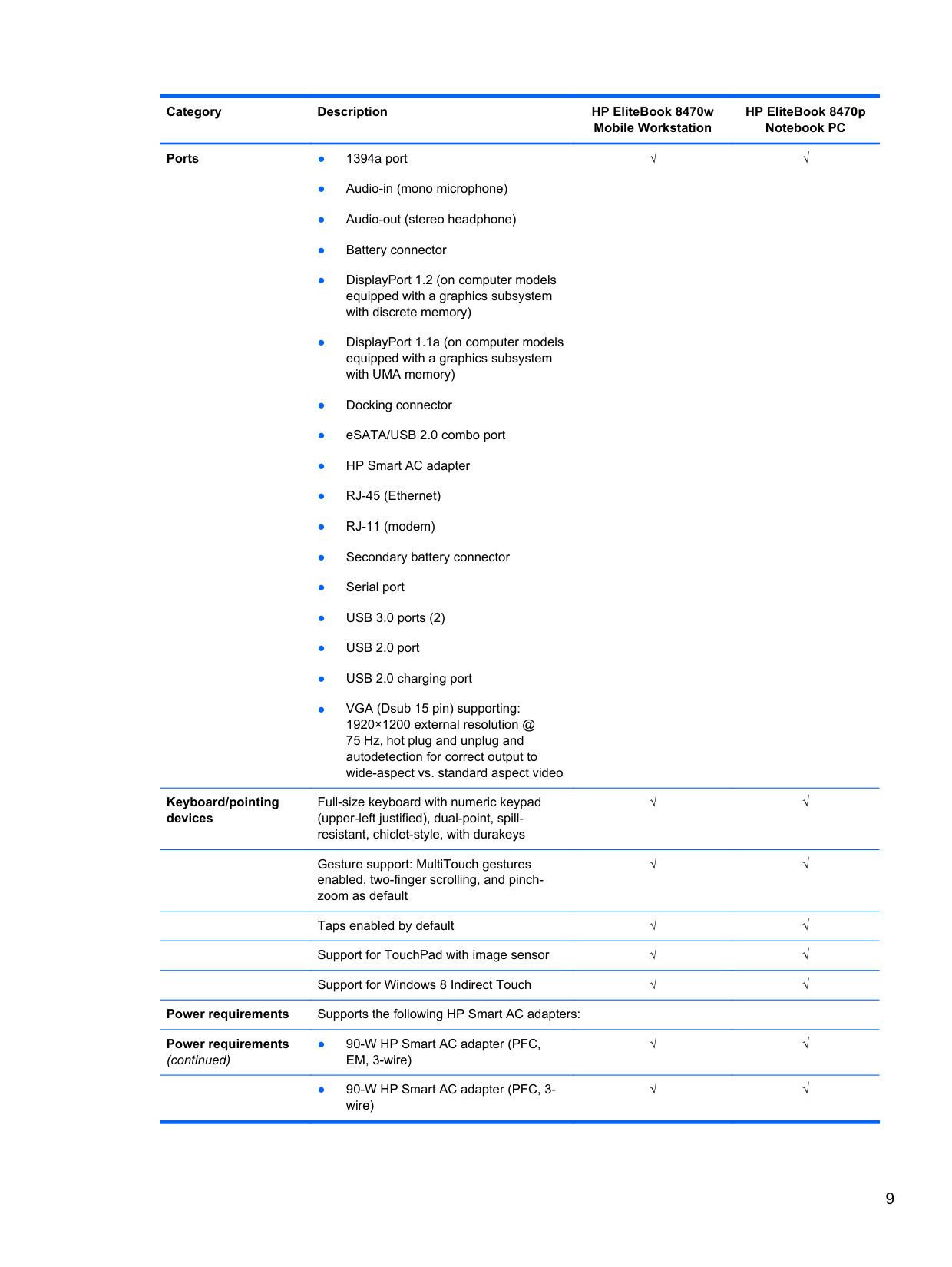
Ports ● 1394a port
Keyboard/pointing devices
Full-size keyboard with numeric keypad (upper-left justified), dual-point, spillresistant, chiclet-style, with durakeys
√√
√√
Gesture support: MultiTouch gestures enabled, two-finger scrolling, and pinchzoom as default
√√
Taps enabled by default √√ Support for TouchPad with image sensor √√ Support for Windows 8 Indirect Touch √√
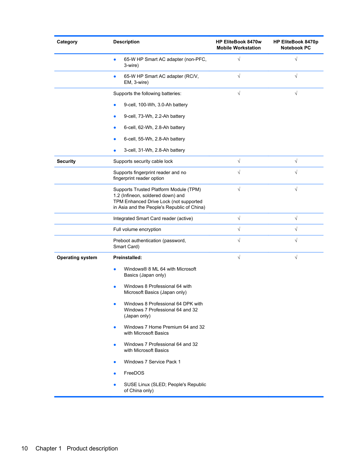
Power requirements Supports the following HP Smart AC adapters: Power requirements (continued)
√√
√√
√√
√√
Supports the following batteries:
√√
Security Supports security cable lock √√
Supports fingerprint reader and no fingerprint reader option
√√
Supports Trusted Platform Module (TPM) 1.2 (Infineon, soldered down) and TPM Enhanced Drive Lock (not supported in Asia and the People's Republic of China)
√√
Integrated Smart Card reader (active) √√ Full volume encryption √√ Preboot authentication (password, Smart Card)
√√
######## Operating system Preinstalled:
√√
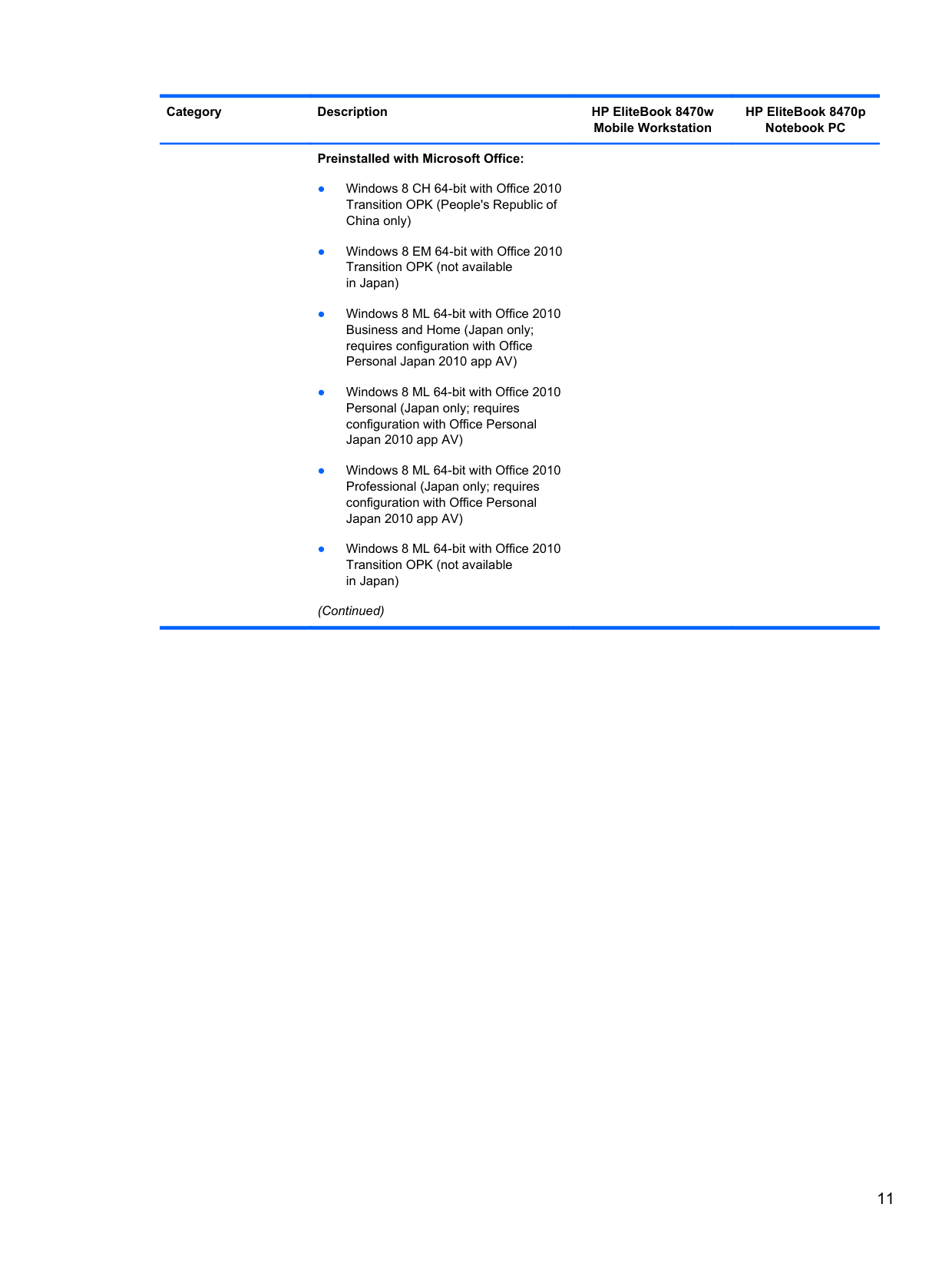
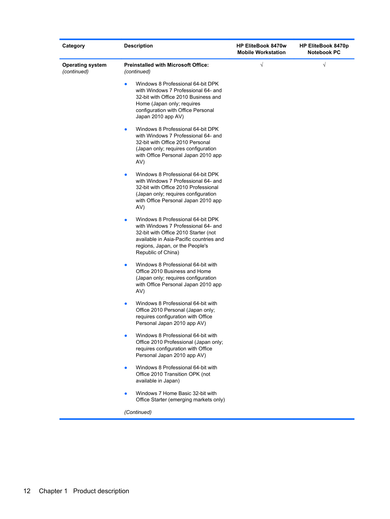
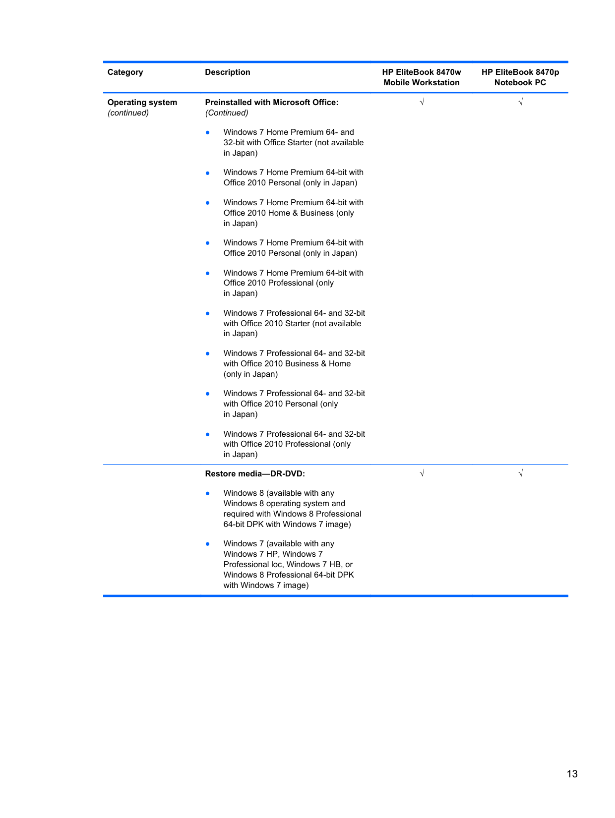
######## Preinstalled with Microsoft Office:
(Continued)
(continued)
(Continued)
(Continued)
######## Restore media—DR-DVD:
√√
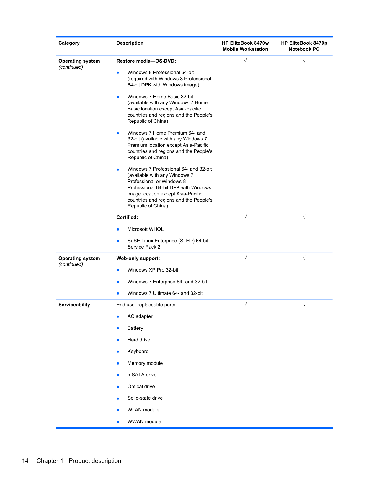
######## Restore media—OS-DVD:
√√
(continued)
######## Certified:
√√
Operating system (continued)
Web-only support:
Serviceability End user replaceable parts:
√√
√√
2 External component identification
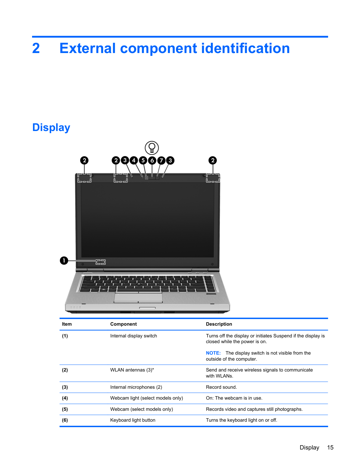
Display

######## Item Component Description
NOTE: The display switch is not visible from the outside of the computer.
Display 15
*The antennas are not visible from the outside of the computer. For optimal transmission, keep the areas immediately around the antennas free from obstructions. To see wireless regulatory notices, see the section of the Regulatory, Safety, and Environmental Notices that applies to your country or region.
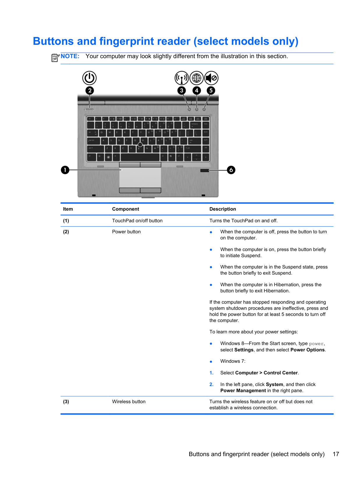
Buttons and fingerprint reader (select models only)
NOTE: Your computer may look slightly different from the illustration in this section.
| | |---|

Item Component Description
If the computer has stopped responding and operating system shutdown procedures are ineffective, press and hold the power button for at least 5 seconds to turn off the computer.
To learn more about your power settings:
Buttons and fingerprint reader (select models only) 17
● When the computer is off, in the Suspend state, or in Hibernation, the button does not perform any action or function.
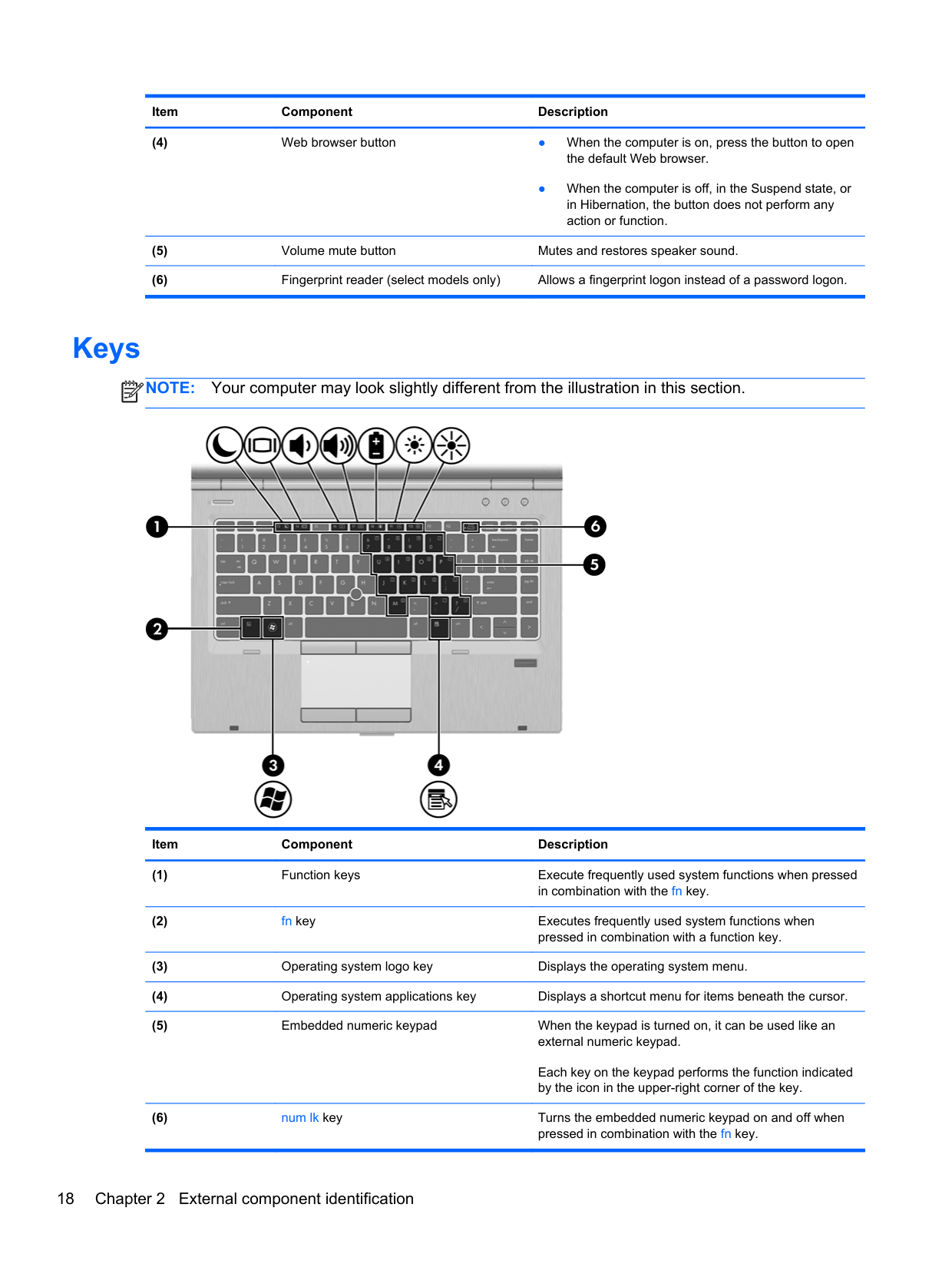
Keys
NOTE: Your computer may look slightly different from the illustration in this section.
| | |---|

Item Component Description
Each key on the keypad performs the function indicated by the icon in the upper-right corner of the key.
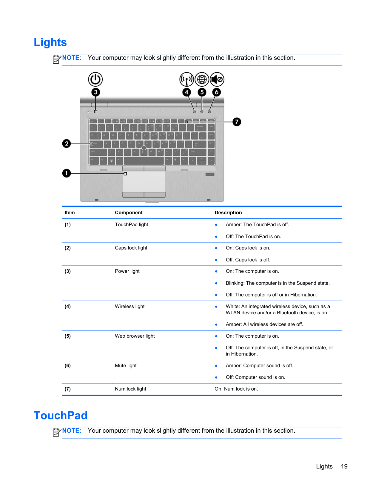
Lights
NOTE: Your computer may look slightly different from the illustration in this section.
| | |---|

Item Component Description
● Off: The TouchPad is on.
● Off: Caps lock is off.
● Amber: All wireless devices are off.
● Off: The computer is off, in the Suspend state, or in Hibernation.
● Off: Computer sound is on.
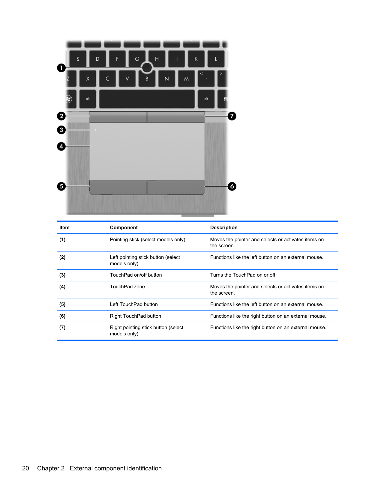
TouchPad
NOTE: Your computer may look slightly different from the illustration in this section.
| | |---|
Lights 19

######## Item Component Description
Functions like the left button on an external mouse.
Functions like the right button on an external mouse.
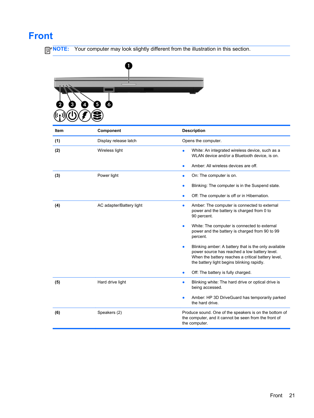
Front
NOTE: Your computer may look slightly different from the illustration in this section.
| | |---|

Item Component Description
● Amber: All wireless devices are off.
● Amber: HP 3D DriveGuard has temporarily parked the hard drive.
Front 21
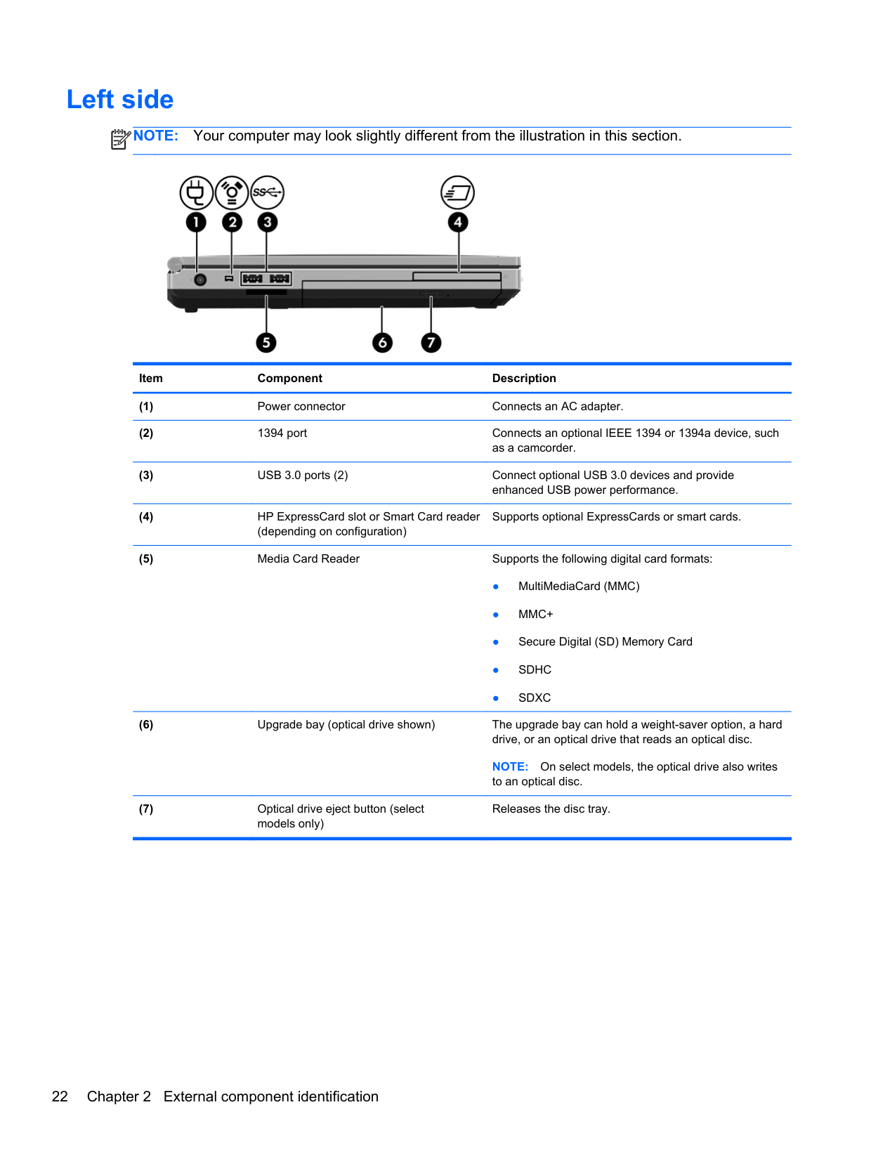
Left side
NOTE: Your computer may look slightly different from the illustration in this section.
| | |---|

Item Component Description
Supports optional ExpressCards or smart cards.
NOTE: On select models, the optical drive also writes to an optical disc.
Releases the disc tray.
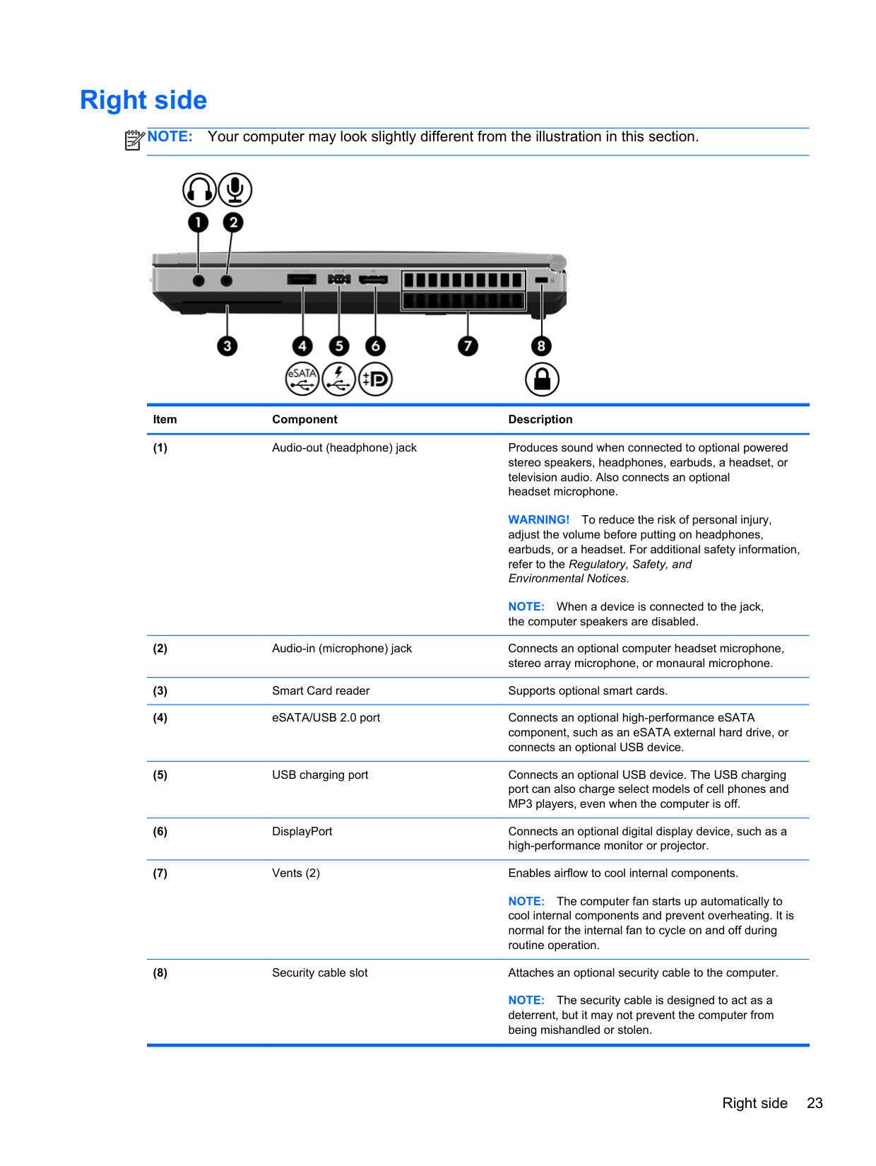
Right side
NOTE: Your computer may look slightly different from the illustration in this section.
| | |---|

Item Component Description
WARNING! To reduce the risk of personal injury, adjust the volume before putting on headphones, earbuds, or a headset. For additional safety information, refer to the Regulatory, Safety, and Environmental Notices.
NOTE: When a device is connected to the jack, the computer speakers are disabled.
NOTE: The computer fan starts up automatically to cool internal components and prevent overheating. It is normal for the internal fan to cycle on and off during routine operation.
NOTE: The security cable is designed to act as a deterrent, but it may not prevent the computer from being mishandled or stolen.
Right side 23
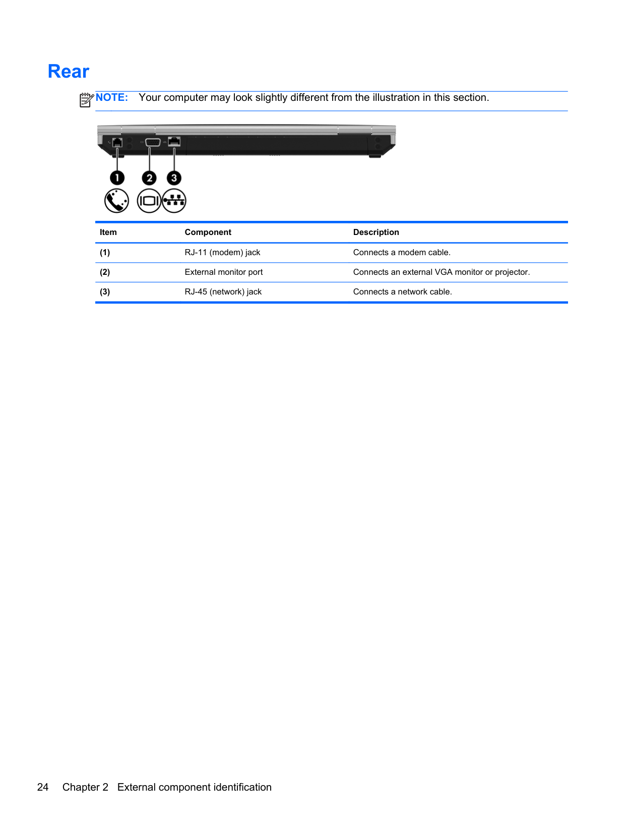
Rear
NOTE: Your computer may look slightly different from the illustration in this section.
| | |---|

Item Component Description
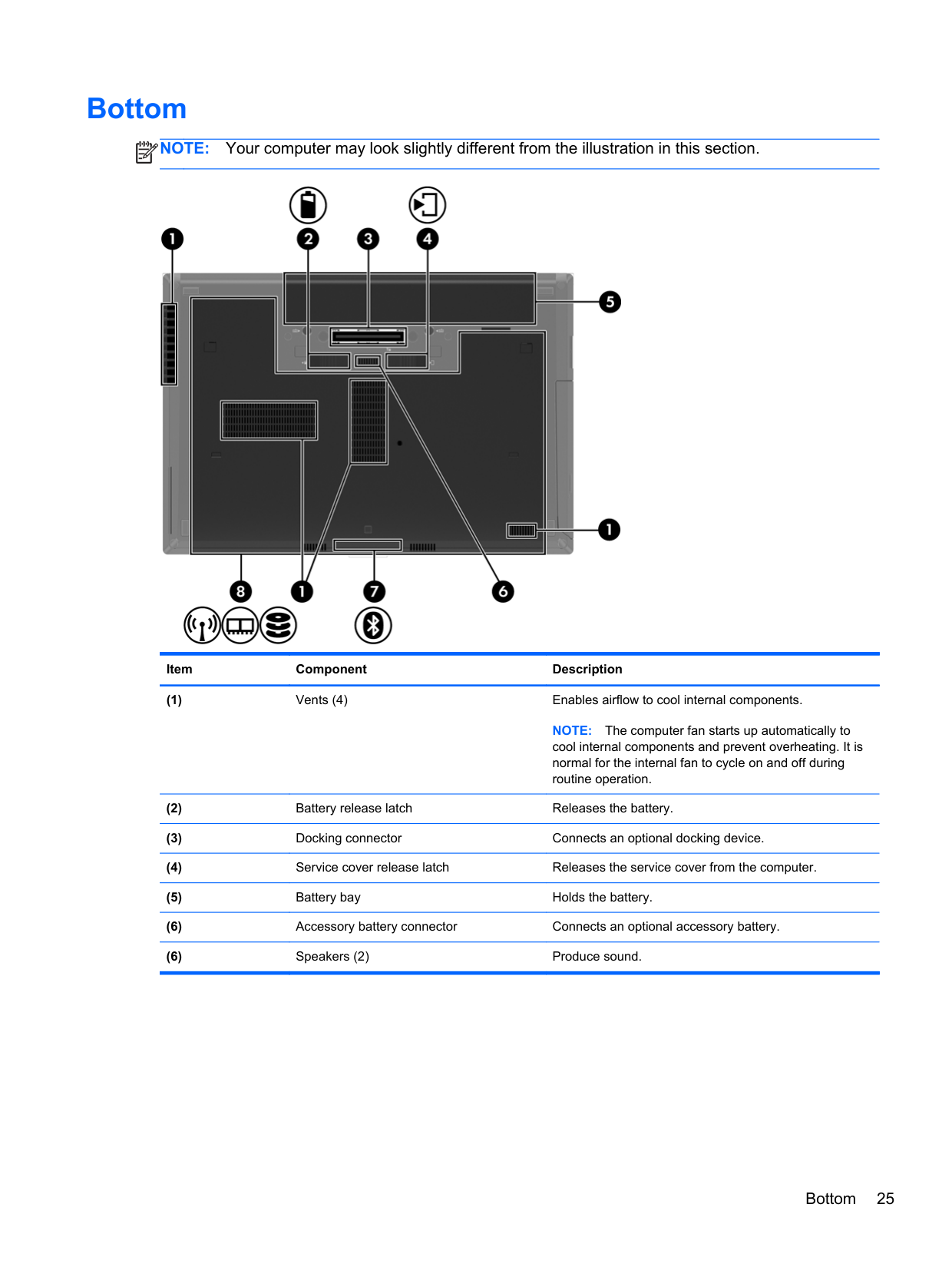
Bottom
NOTE: Your computer may look slightly different from the illustration in this section.
| |
|---|

Item Component Description
NOTE: The computer fan starts up automatically to cool internal components and prevent overheating. It is normal for the internal fan to cycle on and off during routine operation.
Bottom 25
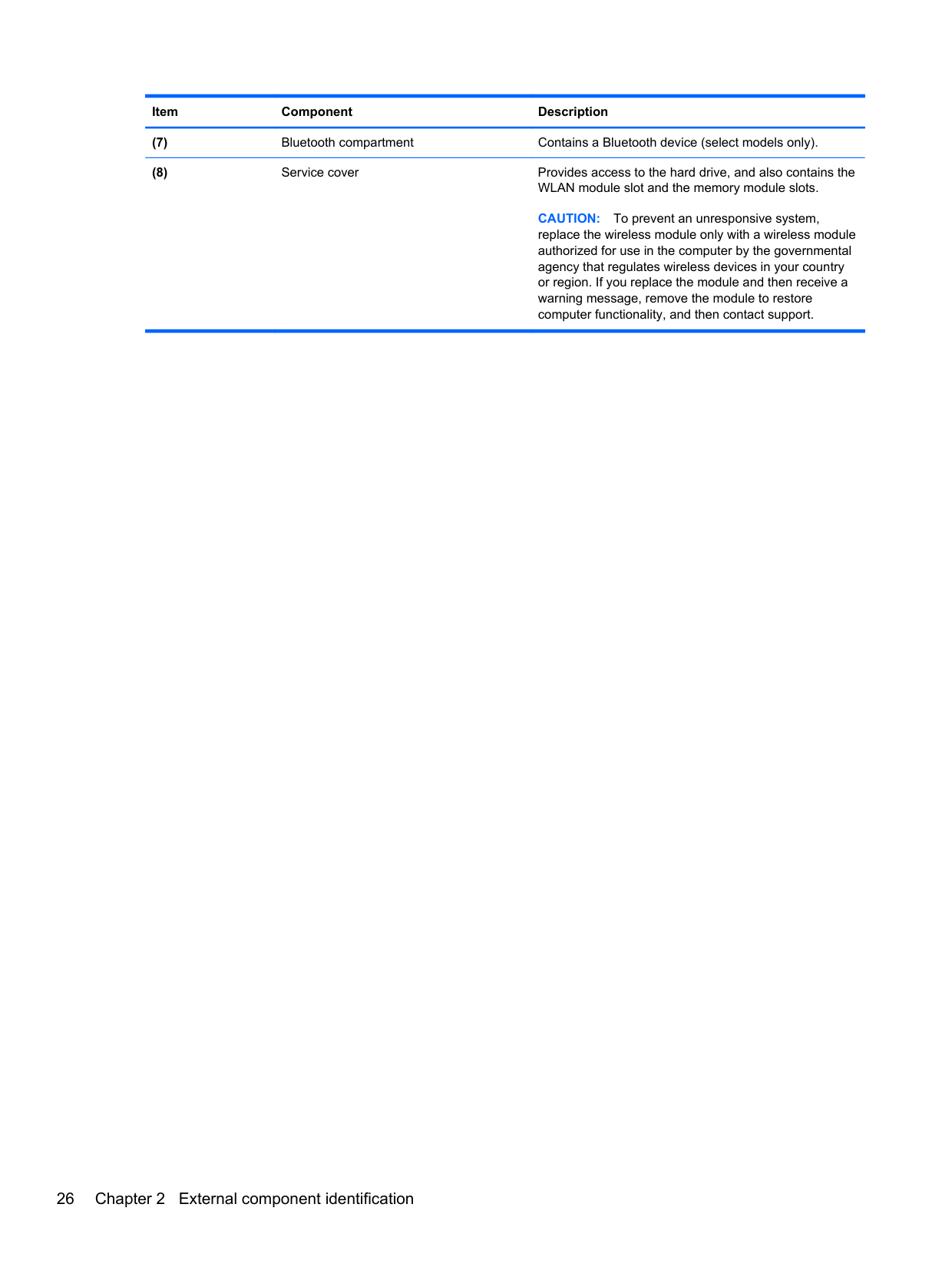
######## Item Component Description
CAUTION: To prevent an unresponsive system, replace the wireless module only with a wireless module authorized for use in the computer by the governmental agency that regulates wireless devices in your country or region. If you replace the module and then receive a warning message, remove the module to restore computer functionality, and then contact support.
3 Illustrated parts catalog
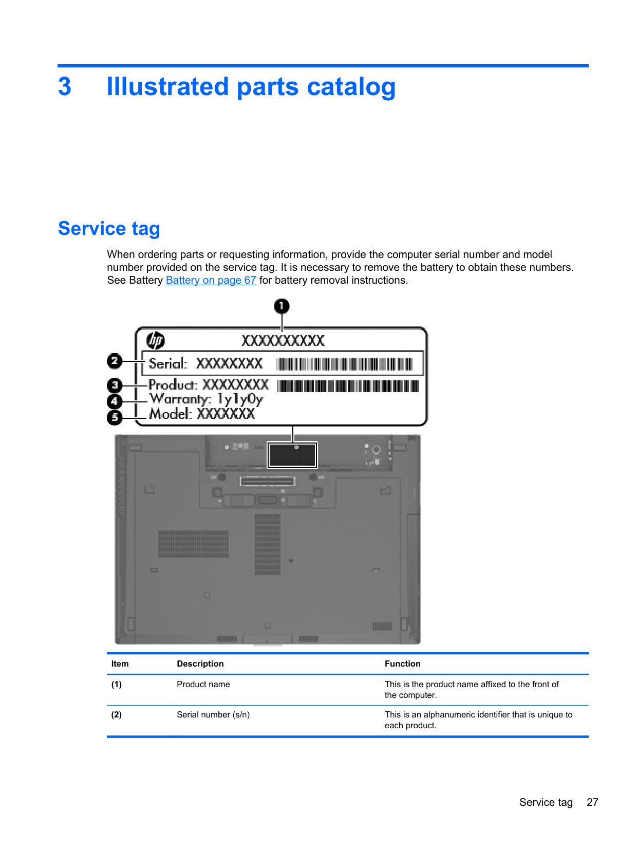
Service tag
When ordering parts or requesting information, provide the computer serial number and model number provided on the service tag. It is necessary to remove the battery to obtain these numbers. See Battery Battery on page 67 for battery removal instructions.

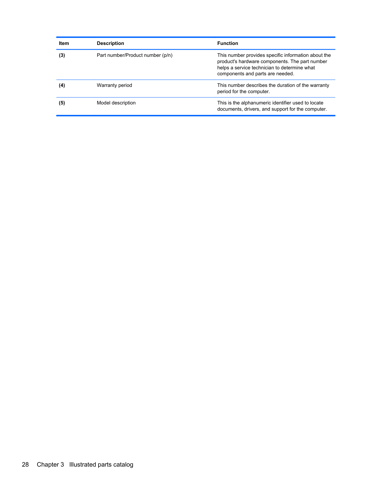
Item Description Function
Service tag 27
######## Item Description Function
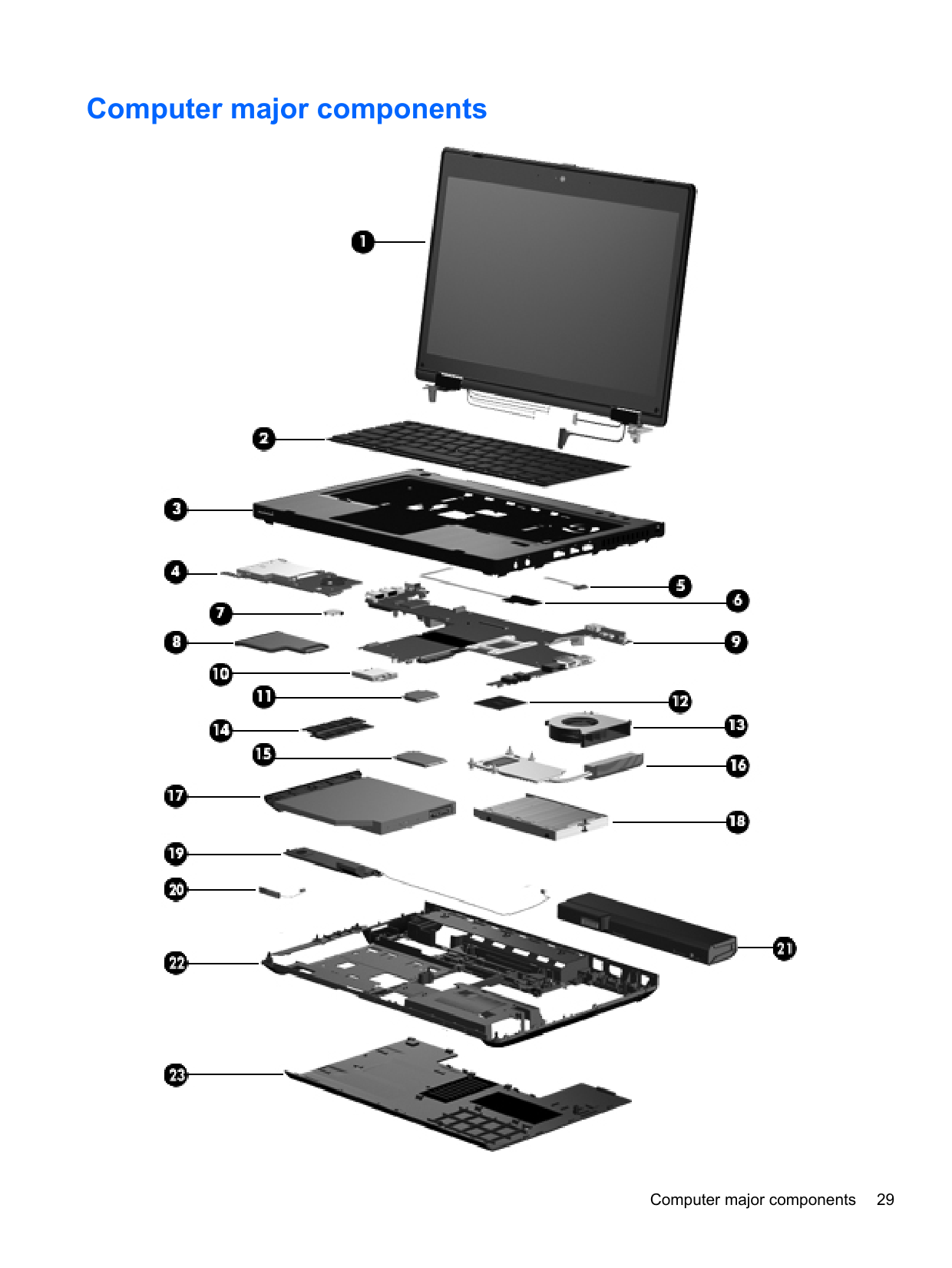
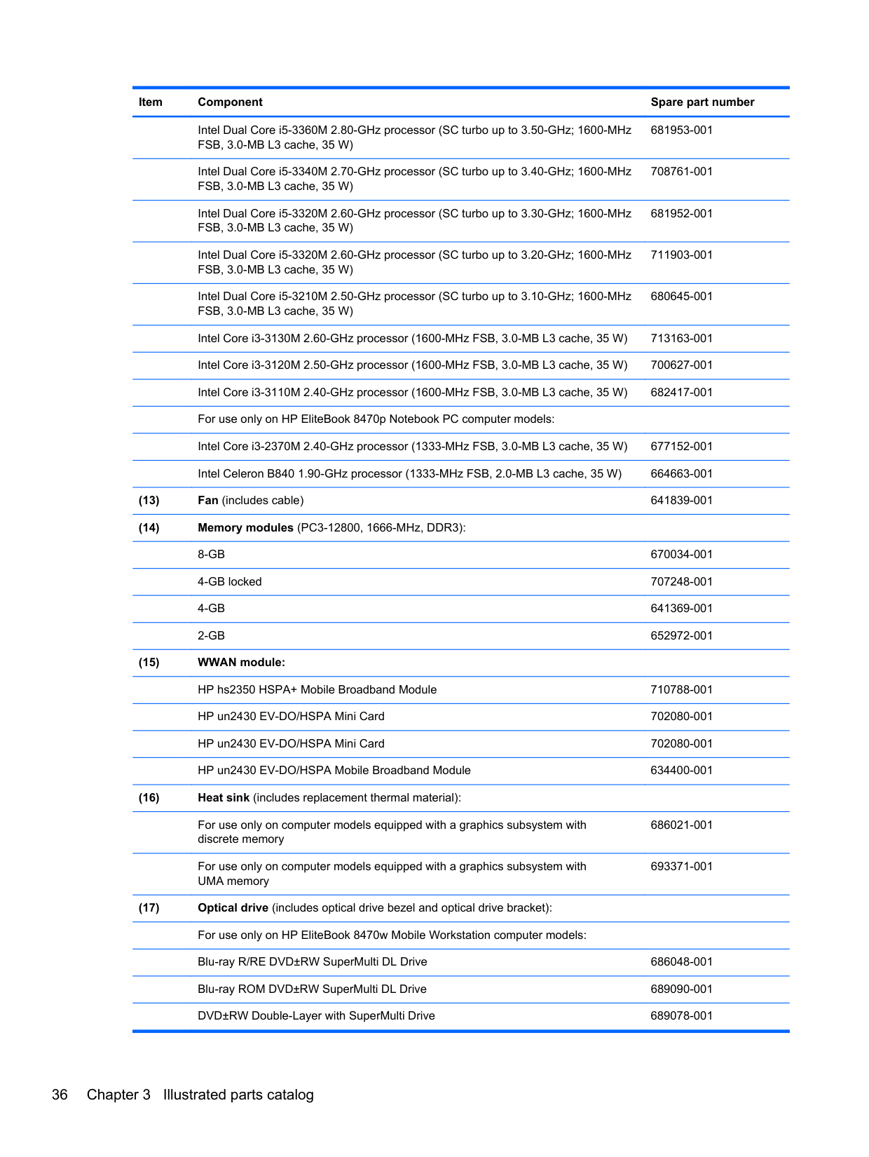
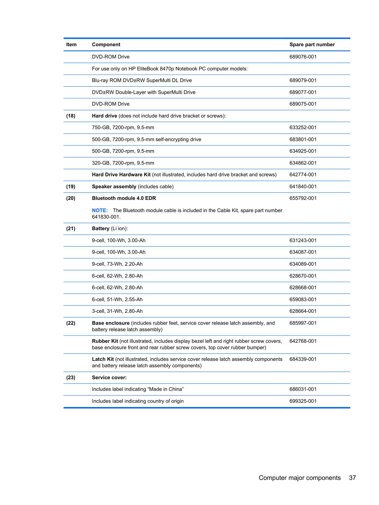
Computer major components

For use in Turkey 702649-141 For use in the United Kingdom and Singapore 702649-031 For use in the United States 702649-001
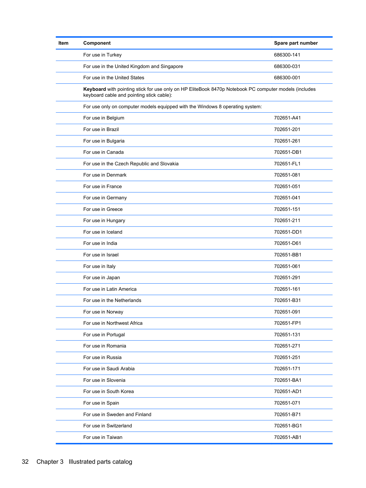
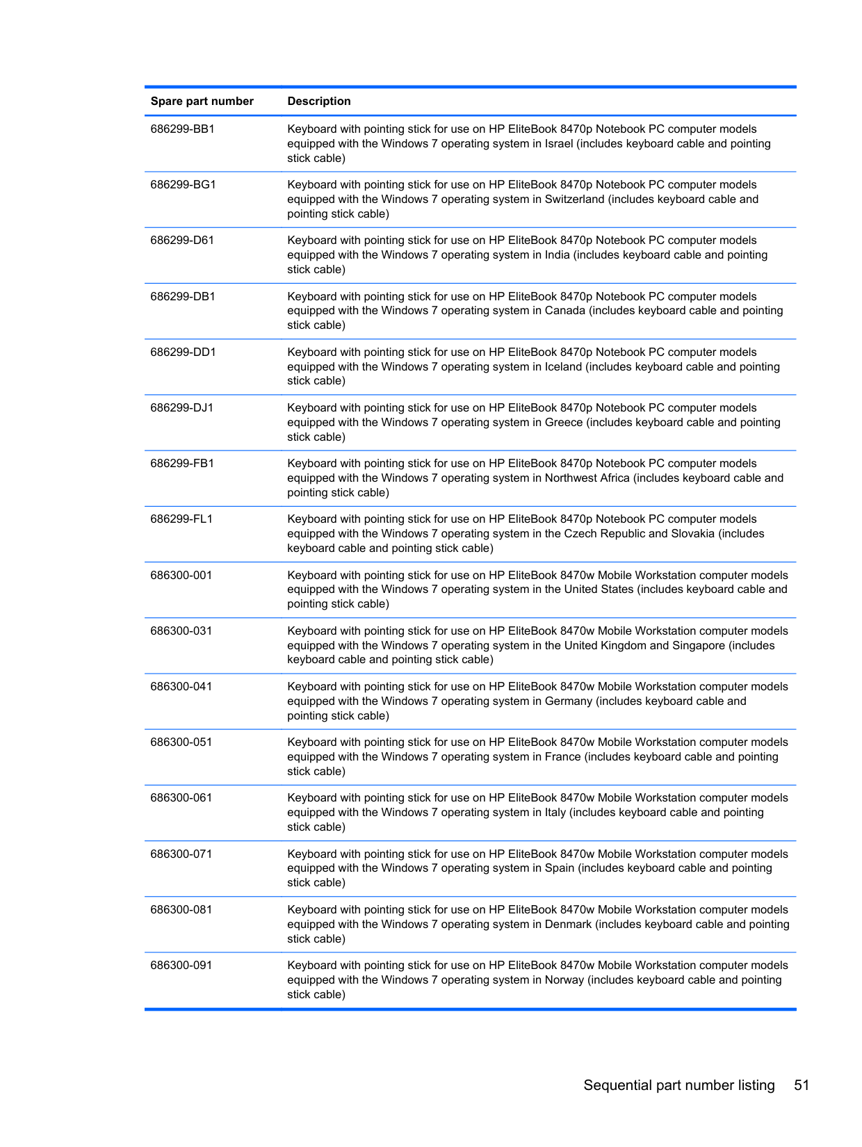
For use in Turkey 686300-141 For use in the United Kingdom and Singapore 686300-031 For use in the United States 686300-001 Keyboard with pointing stick for use only on HP EliteBook 8470p Notebook PC computer models (includes
keyboard cable and pointing stick cable):
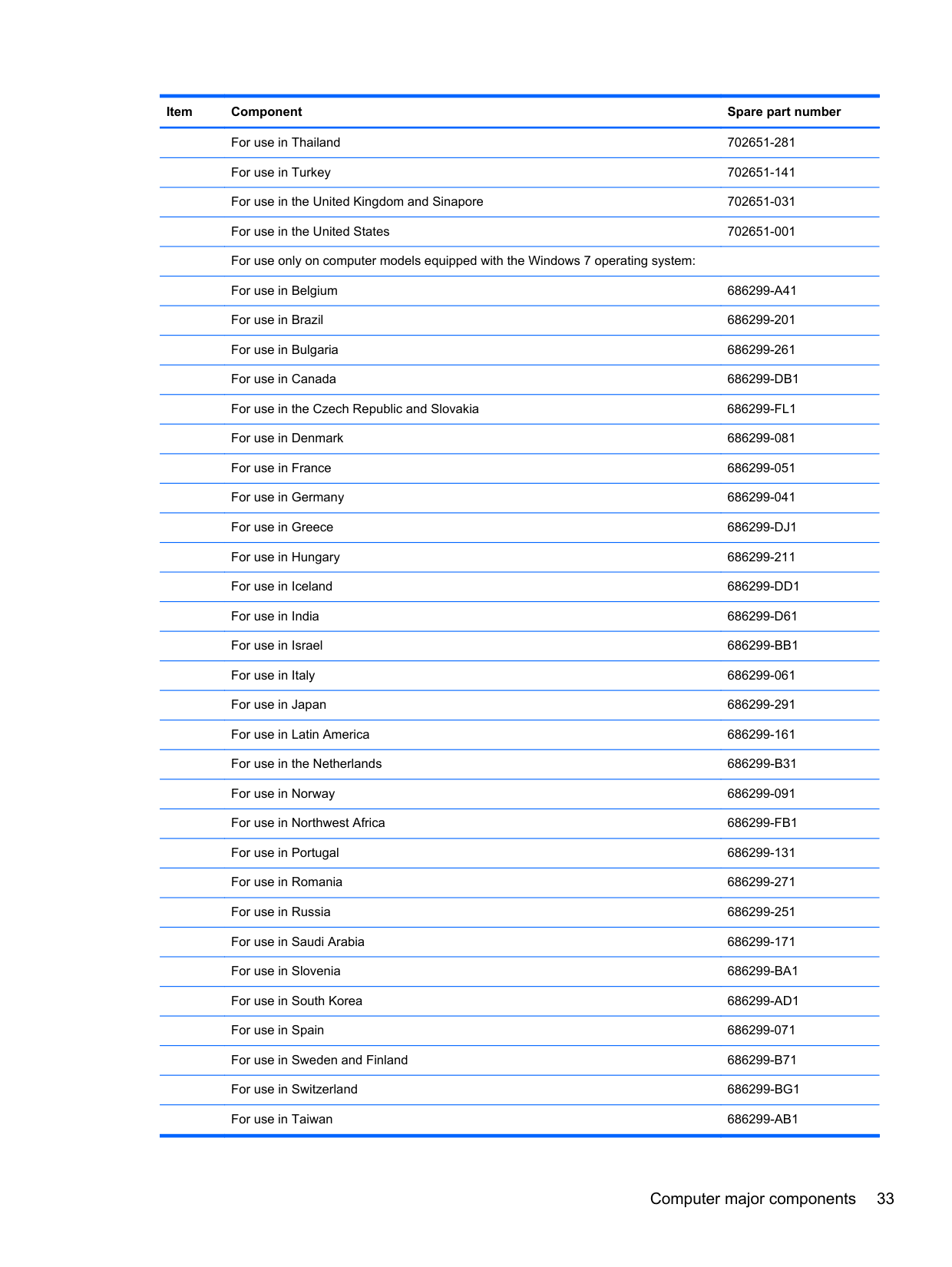
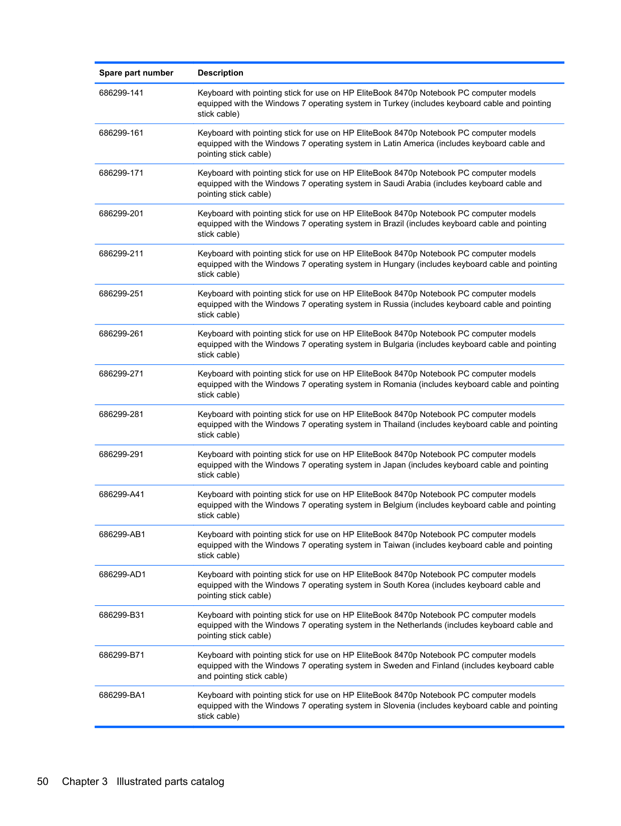
For use in Thailand 702651-281 For use in Turkey 702651-141 For use in the United Kingdom and Sinapore 702651-031 For use in the United States 702651-001 For use only on computer models equipped with the Windows 7 operating system: For use in Belgium 686299-A41 For use in Brazil 686299-201 For use in Bulgaria 686299-261 For use in Canada 686299-DB1 For use in the Czech Republic and Slovakia 686299-FL1 For use in Denmark 686299-081 For use in France 686299-051 For use in Germany 686299-041 For use in Greece 686299-DJ1 For use in Hungary 686299-211 For use in Iceland 686299-DD1 For use in India 686299-D61 For use in Israel 686299-BB1 For use in Italy 686299-061 For use in Japan 686299-291 For use in Latin America 686299-161 For use in the Netherlands 686299-B31 For use in Norway 686299-091 For use in Northwest Africa 686299-FB1 For use in Portugal 686299-131 For use in Romania 686299-271 For use in Russia 686299-251 For use in Saudi Arabia 686299-171 For use in Slovenia 686299-BA1 For use in South Korea 686299-AD1 For use in Spain 686299-071 For use in Sweden and Finland 686299-B71 For use in Switzerland 686299-BG1 For use in Taiwan 686299-AB1
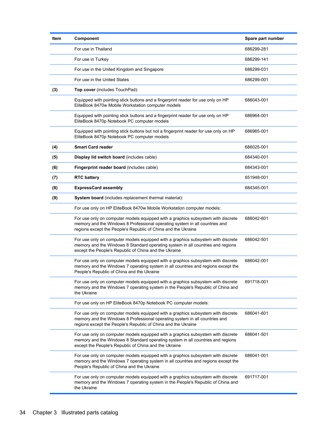
For use in Thailand 686299-281 For use in Turkey 686299-141 For use in the United Kingdom and Singapore 686299-031 For use in the United States 686299-001
Equipped with pointing stick buttons and a fingerprint reader for use only on HP EliteBook 8470w Mobile Workstation computer models
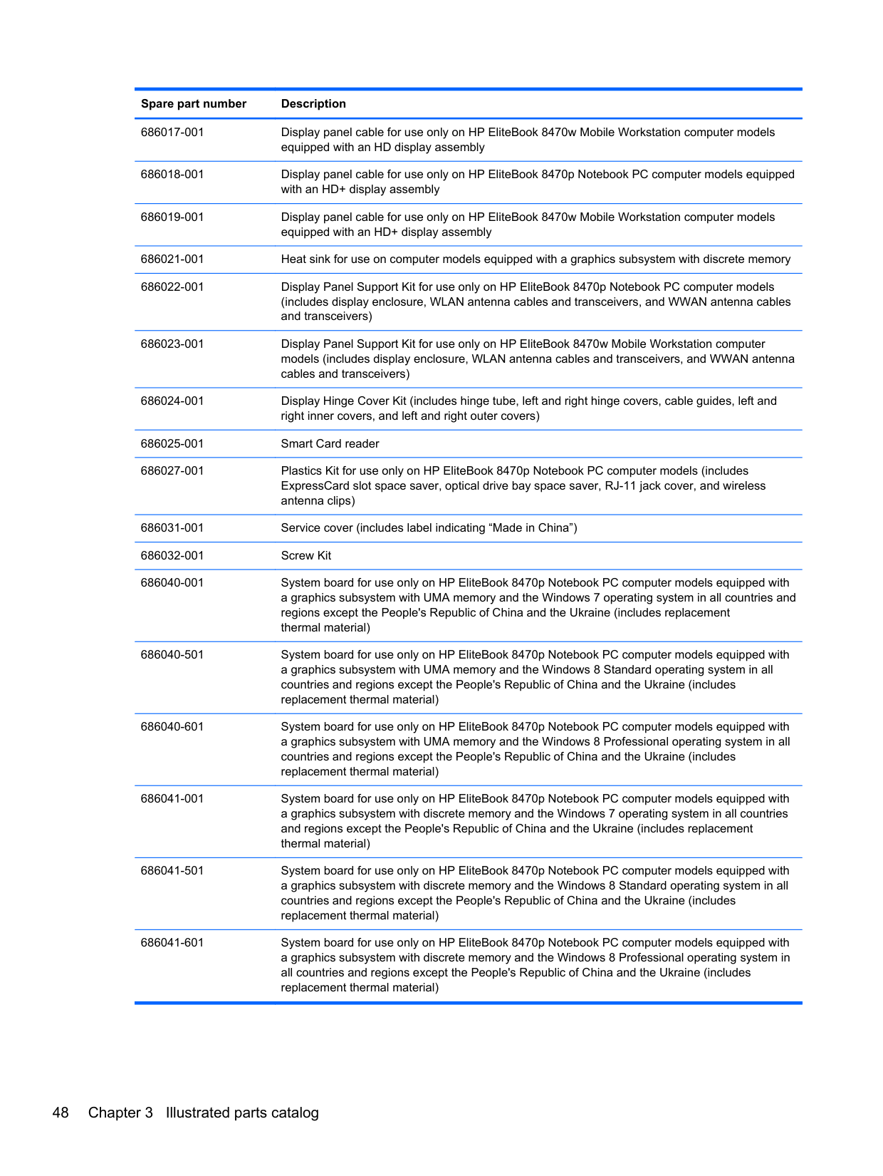
686043-001
Equipped with pointing stick buttons and a fingerprint reader for use only on HP EliteBook 8470p Notebook PC computer models
686964-001
Equipped with pointing stick buttons but not a fingerprint reader for use only on HP EliteBook 8470p Notebook PC computer models
686965-001
For use only on computer models equipped with a graphics subsystem with discrete memory and the Windows 8 Professional operating system in all countries and regions except the People's Republic of China and the Ukraine
686042-601
For use only on computer models equipped with a graphics subsystem with discrete memory and the Windows 8 Standard operating system in all countries and regions except the People's Republic of China and the Ukraine
For use only on computer models equipped with a graphics subsystem with discrete
686042-001
For use only on computer models equipped with a graphics subsystem with discrete
691718-001
For use only on HP EliteBook 8470p Notebook PC computer models: For use only on computer models equipped with a graphics subsystem with discrete
686041-601
For use only on computer models equipped with a graphics subsystem with discrete
For use only on computer models equipped with a graphics subsystem with discrete memory and the Windows 7 operating system in all countries and regions except the People's Republic of China and the Ukraine
For use only on computer models equipped with a graphics subsystem with discrete
686042-501
686041-501
686041-001
691717-001
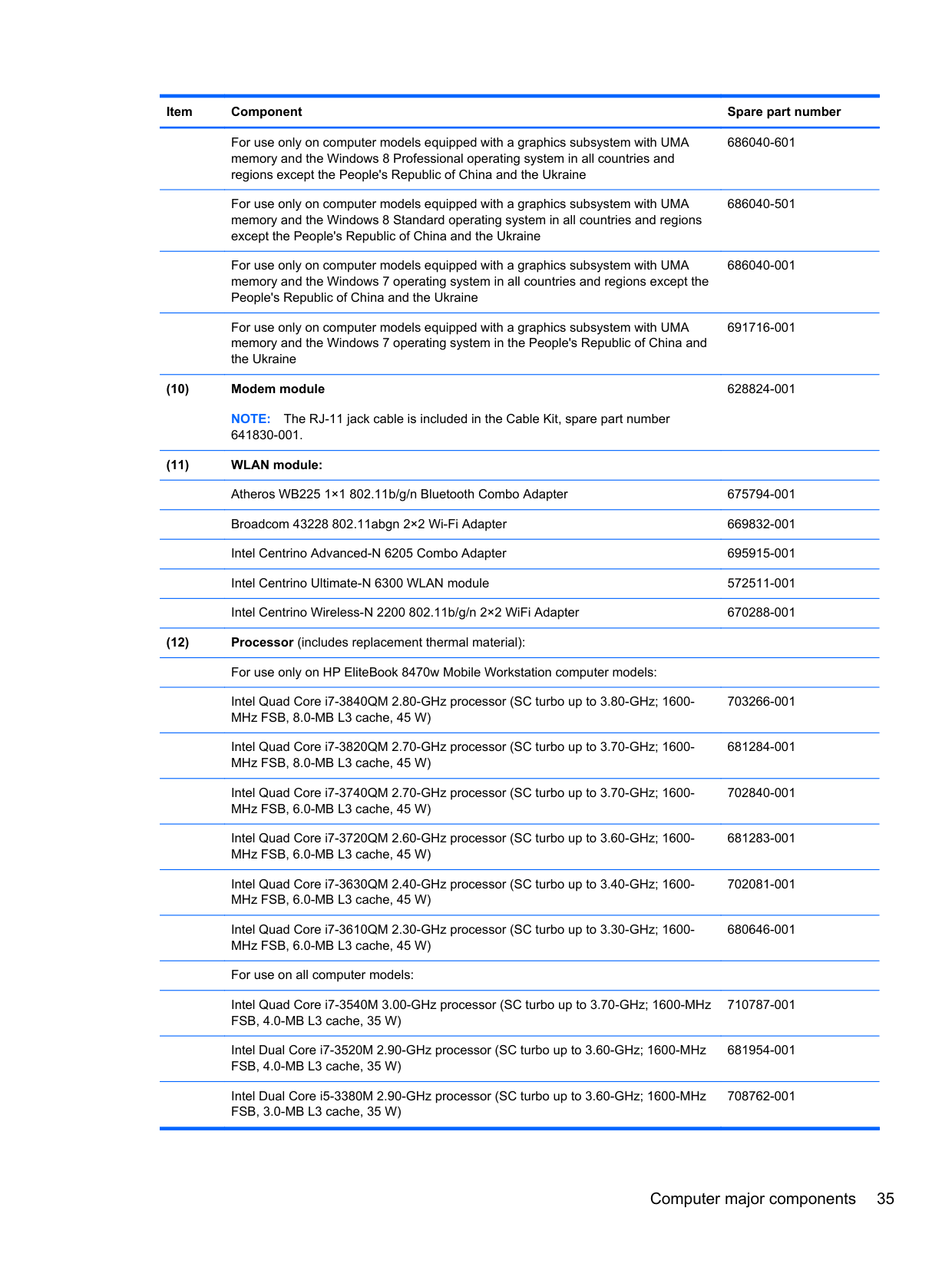
For use only on computer models equipped with a graphics subsystem with UMA
For use only on computer models equipped with a graphics subsystem with UMA memory and the Windows 8 Standard operating system in all countries and regions except the People's Republic of China and the Ukraine
For use only on computer models equipped with a graphics subsystem with UMA memory and the Windows 7 operating system in all countries and regions except the People's Republic of China and the Ukraine
For use only on computer models equipped with a graphics subsystem with UMA memory and the Windows 7 operating system in the People's Republic of China and the Ukraine
686040-601
686040-501
686040-001
691716-001
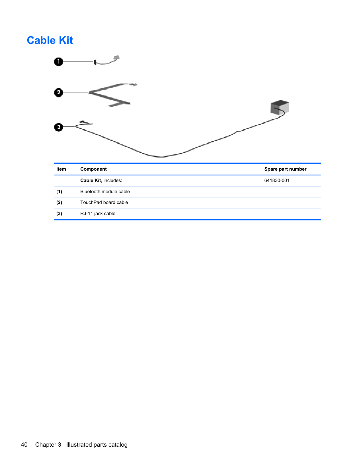
NOTE: The RJ-11 jack cable is included in the Cable Kit, spare part number 641830-001.
628824-001
Intel Quad Core i7-3840QM 2.80-GHz processor (SC turbo up to 3.80-GHz; 1600MHz FSB, 8.0-MB L3 cache, 45 W)
703266-001
Intel Quad Core i7-3820QM 2.70-GHz processor (SC turbo up to 3.70-GHz; 1600MHz FSB, 8.0-MB L3 cache, 45 W)
Intel Quad Core i7-3740QM 2.70-GHz processor (SC turbo up to 3.70-GHz; 1600MHz FSB, 6.0-MB L3 cache, 45 W)
Intel Quad Core i7-3720QM 2.60-GHz processor (SC turbo up to 3.60-GHz; 1600MHz FSB, 6.0-MB L3 cache, 45 W)
Intel Quad Core i7-3630QM 2.40-GHz processor (SC turbo up to 3.40-GHz; 1600MHz FSB, 6.0-MB L3 cache, 45 W)
Intel Quad Core i7-3610QM 2.30-GHz processor (SC turbo up to 3.30-GHz; 1600MHz FSB, 6.0-MB L3 cache, 45 W)
For use on all computer models: Intel Quad Core i7-3540M 3.00-GHz processor (SC turbo up to 3.70-GHz; 1600-MHz FSB, 4.0-MB L3 cache, 35 W)
Intel Dual Core i7-3520M 2.90-GHz processor (SC turbo up to 3.60-GHz; 1600-MHz FSB, 4.0-MB L3 cache, 35 W)
Intel Dual Core i5-3380M 2.90-GHz processor (SC turbo up to 3.60-GHz; 1600-MHz FSB, 3.0-MB L3 cache, 35 W)
681284-001
702840-001
681283-001
702081-001
680646-001
710787-001
681954-001
708762-001
Intel Dual Core i5-3360M 2.80-GHz processor (SC turbo up to 3.50-GHz; 1600-MHz FSB, 3.0-MB L3 cache, 35 W)
681953-001
Intel Dual Core i5-3340M 2.70-GHz processor (SC turbo up to 3.40-GHz; 1600-MHz FSB, 3.0-MB L3 cache, 35 W)
708761-001
Intel Dual Core i5-3320M 2.60-GHz processor (SC turbo up to 3.30-GHz; 1600-MHz FSB, 3.0-MB L3 cache, 35 W)
681952-001
Intel Dual Core i5-3320M 2.60-GHz processor (SC turbo up to 3.20-GHz; 1600-MHz FSB, 3.0-MB L3 cache, 35 W)
711903-001
Intel Dual Core i5-3210M 2.50-GHz processor (SC turbo up to 3.10-GHz; 1600-MHz FSB, 3.0-MB L3 cache, 35 W)
680645-001
Intel Core i3-3130M 2.60-GHz processor (1600-MHz FSB, 3.0-MB L3 cache, 35 W) 713163-001 Intel Core i3-3120M 2.50-GHz processor (1600-MHz FSB, 3.0-MB L3 cache, 35 W) 700627-001 Intel Core i3-3110M 2.40-GHz processor (1600-MHz FSB, 3.0-MB L3 cache, 35 W) 682417-001 For use only on HP EliteBook 8470p Notebook PC computer models: Intel Core i3-2370M 2.40-GHz processor (1333-MHz FSB, 3.0-MB L3 cache, 35 W) 677152-001 Intel Celeron B840 1.90-GHz processor (1333-MHz FSB, 2.0-MB L3 cache, 35 W) 664663-001
4-GB locked 707248-001 4-GB 641369-001 2-GB 652972-001
For use only on computer models equipped with a graphics subsystem with discrete memory
686021-001
For use only on computer models equipped with a graphics subsystem with UMA memory
693371-001
NOTE: The Bluetooth module cable is included in the Cable Kit, spare part number 641830-001.
655792-001
685997-001
Rubber Kit (not illustrated, includes display bezel left and right rubber screw covers, base enclosure front and rear rubber screw covers, top cover rubber bumper)
642768-001
Latch Kit (not illustrated, includes service cover release latch assembly components and battery release latch assembly components)
684339-001
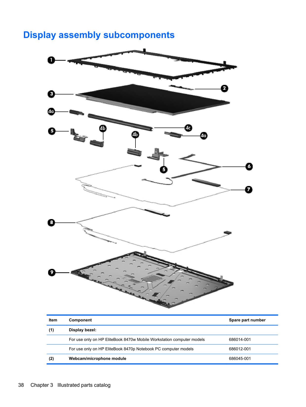
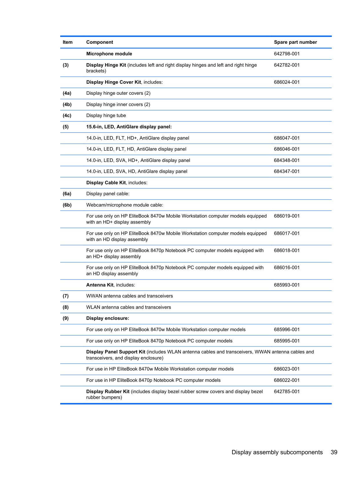
Display assembly subcomponents

######## Item Component Spare part number
642782-001
Display Hinge Cover Kit, includes: 686024-001
For use only on HP EliteBook 8470w Mobile Workstation computer models equipped with an HD+ display assembly
686019-001
For use only on HP EliteBook 8470w Mobile Workstation computer models equipped with an HD display assembly
686017-001
For use only on HP EliteBook 8470p Notebook PC computer models equipped with an HD+ display assembly
686018-001
For use only on HP EliteBook 8470p Notebook PC computer models equipped with an HD display assembly
686016-001
Antenna Kit, includes: 685993-001
Display Panel Support Kit (includes WLAN antenna cables and transceivers, WWAN antenna cables and transceivers, and display enclosure) For use in HP EliteBook 8470w Mobile Workstation computer models 686023-001 For use in HP EliteBook 8470p Notebook PC computer models 686022-001 Display Rubber Kit (includes display bezel rubber screw covers and display bezel rubber bumpers)
642785-001
Display assembly subcomponents 39
Cable Kit

Item Component Spare part number Cable Kit, includes: 641830-001
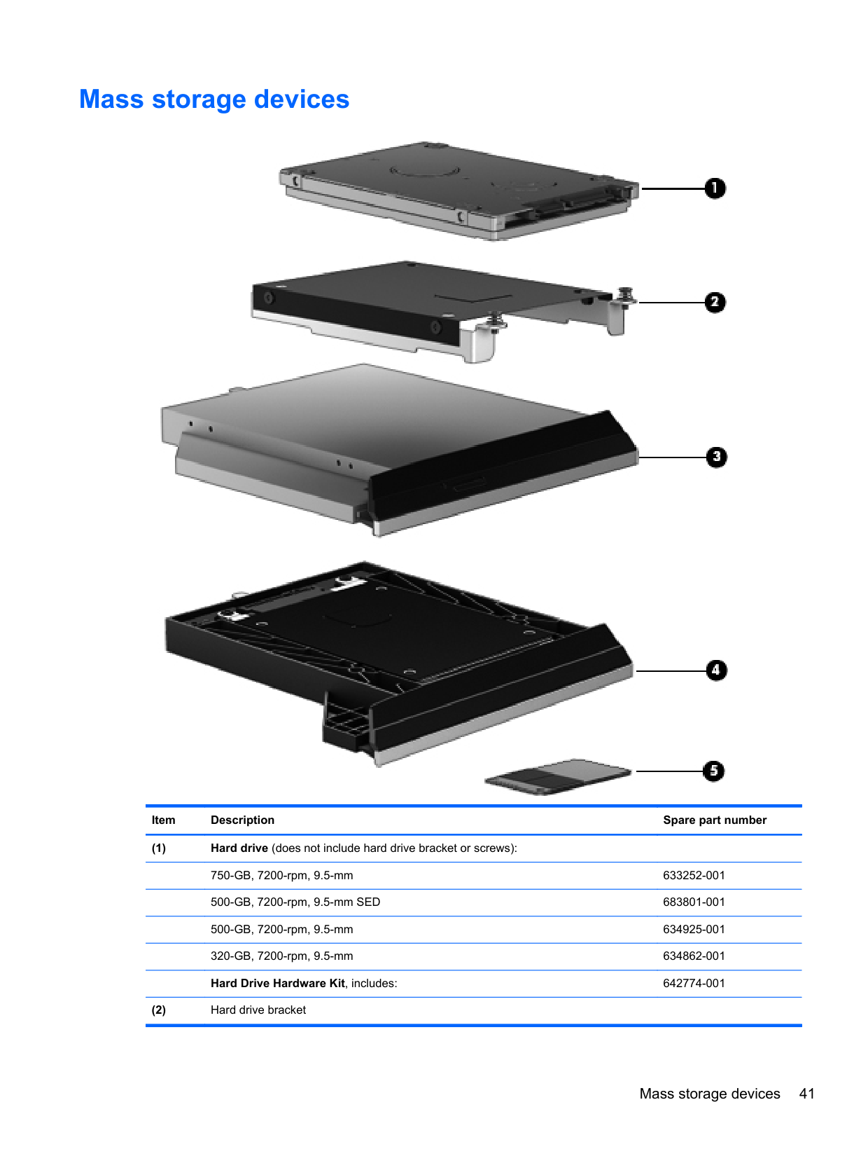
Mass storage devices

######## Item Description Spare part number
Mass storage devices 41
######## Item Description Spare part number
Hard drive bracket screws (not illustrated)
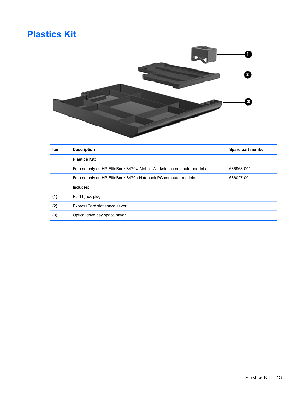
Plastics Kit

Item Description Spare part number Plastics Kit:
For use only on HP EliteBook 8470w Mobile Workstation computer models: 686963-001 For use only on HP EliteBook 8470p Notebook PC computer models: 686027-001 Includes:
Plastics Kit 43
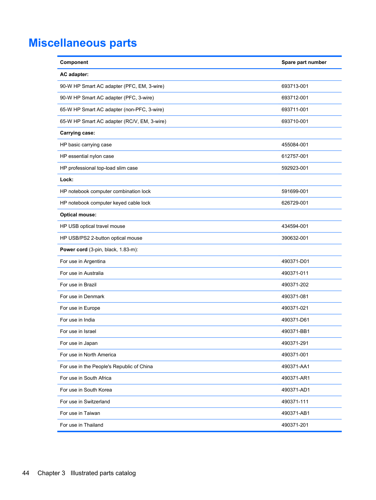
Miscellaneous parts
Component Spare part number AC adapter:
90-W HP Smart AC adapter (PFC, EM, 3-wire) 693713-001 90-W HP Smart AC adapter (PFC, 3-wire) 693712-001 65-W HP Smart AC adapter (non-PFC, 3-wire) 693711-001 65-W HP Smart AC adapter (RC/V, EM, 3-wire) 693710-001 Carrying case:
HP basic carrying case 455084-001 HP essential nylon case 612757-001 HP professional top-load slim case 592923-001 Lock:
HP notebook computer combination lock 591699-001 HP notebook computer keyed cable lock 626729-001 Optical mouse:
HP USB optical travel mouse 434594-001 HP USB/PS2 2-button optical mouse 390632-001 Power cord (3-pin, black, 1.83-m):
For use in Argentina 490371-D01 For use in Australia 490371-011 For use in Brazil 490371-202 For use in Denmark 490371-081 For use in Europe 490371-021 For use in India 490371-D61 For use in Israel 490371-BB1 For use in Japan 490371-291 For use in North America 490371-001 For use in the People's Republic of China 490371-AA1 For use in South Africa 490371-AR1 For use in South Korea 490371-AD1 For use in Switzerland 490371-111 For use in Taiwan 490371-AB1 For use in Thailand 490371-201
######## Component Spare part number
For use in the United Kingdom and Singapore 490371-031 Screw Kit 686032-001
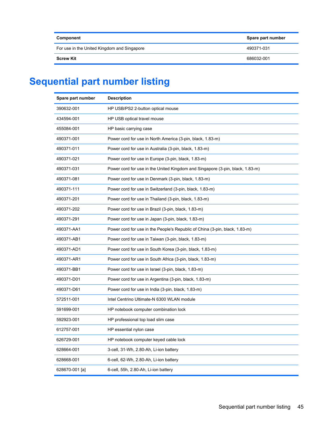
Sequential part number listing
Spare part number Description 390632-001 HP USB/PS2 2-button optical mouse 434594-001 HP USB optical travel mouse 455084-001 HP basic carrying case 490371-001 Power cord for use in North America (3-pin, black, 1.83-m) 490371-011 Power cord for use in Australia (3-pin, black, 1.83-m) 490371-021 Power cord for use in Europe (3-pin, black, 1.83-m) 490371-031 Power cord for use in the United Kingdom and Singapore (3-pin, black, 1.83-m) 490371-081 Power cord for use in Denmark (3-pin, black, 1.83-m) 490371-111 Power cord for use in Switzerland (3-pin, black, 1.83-m)
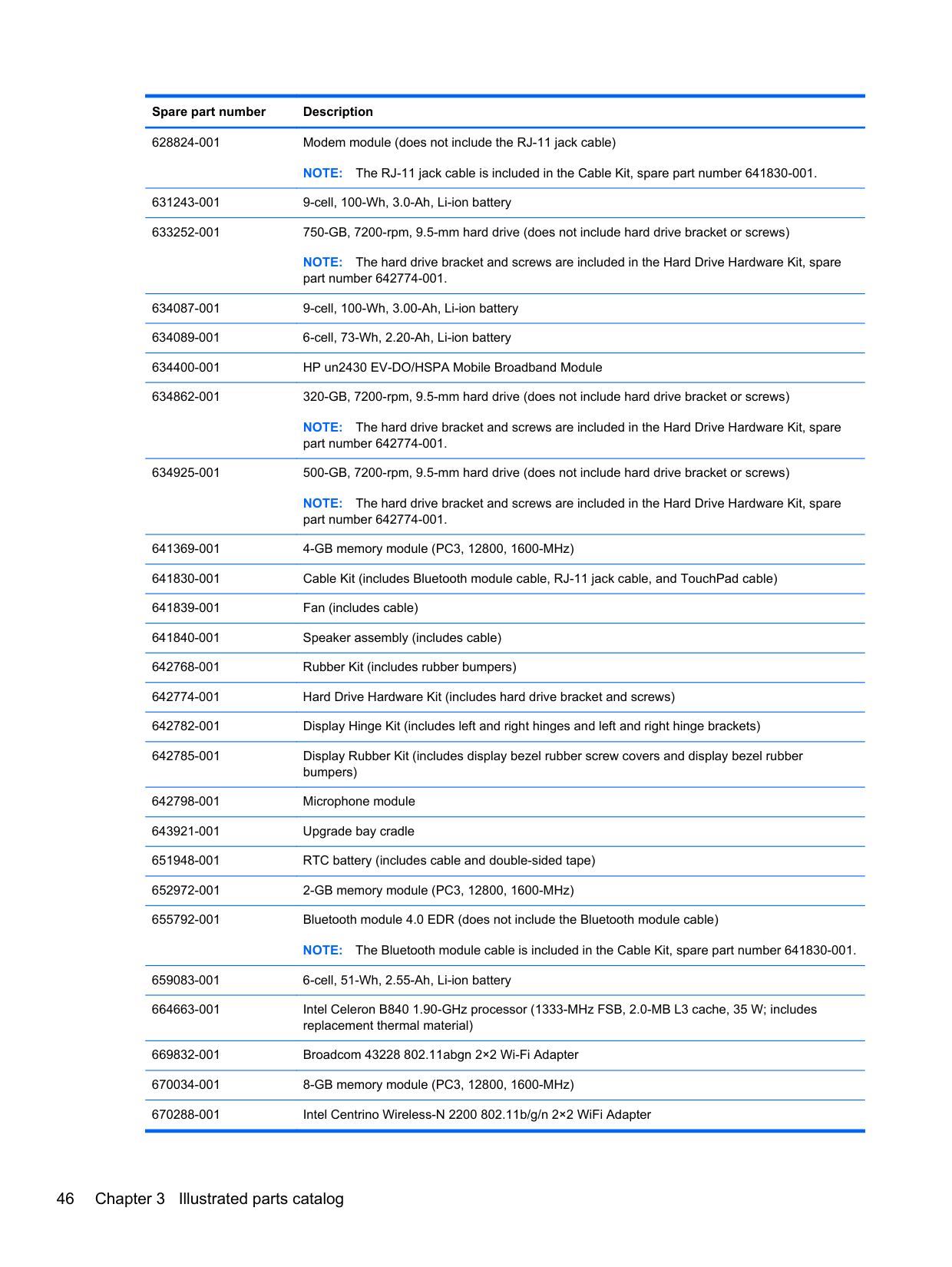
628824-001 Modem module (does not include the RJ-11 jack cable)
NOTE: The RJ-11 jack cable is included in the Cable Kit, spare part number 641830-001. 631243-001 9-cell, 100-Wh, 3.0-Ah, Li-ion battery 633252-001 750-GB, 7200-rpm, 9.5-mm hard drive (does not include hard drive bracket or screws)
NOTE: The hard drive bracket and screws are included in the Hard Drive Hardware Kit, spare part number 642774-001.
634087-001 9-cell, 100-Wh, 3.00-Ah, Li-ion battery 634089-001 6-cell, 73-Wh, 2.20-Ah, Li-ion battery 634400-001 HP un2430 EV-DO/HSPA Mobile Broadband Module 634862-001 320-GB, 7200-rpm, 9.5-mm hard drive (does not include hard drive bracket or screws)
NOTE: The hard drive bracket and screws are included in the Hard Drive Hardware Kit, spare part number 642774-001.
634925-001 500-GB, 7200-rpm, 9.5-mm hard drive (does not include hard drive bracket or screws)
NOTE: The hard drive bracket and screws are included in the Hard Drive Hardware Kit, spare part number 642774-001.
641369-001 4-GB memory module (PC3, 12800, 1600-MHz) 641830-001 Cable Kit (includes Bluetooth module cable, RJ-11 jack cable, and TouchPad cable) 641839-001 Fan (includes cable) 641840-001 Speaker assembly (includes cable) 642768-001 Rubber Kit (includes rubber bumpers) 642774-001 Hard Drive Hardware Kit (includes hard drive bracket and screws) 642782-001 Display Hinge Kit (includes left and right hinges and left and right hinge brackets) 642785-001 Display Rubber Kit (includes display bezel rubber screw covers and display bezel rubber
bumpers) 642798-001 Microphone module 643921-001 Upgrade bay cradle 651948-001 RTC battery (includes cable and double-sided tape) 652972-001 2-GB memory module (PC3, 12800, 1600-MHz) 655792-001 Bluetooth module 4.0 EDR (does not include the Bluetooth module cable)
NOTE: The Bluetooth module cable is included in the Cable Kit, spare part number 641830-001. 659083-001 6-cell, 51-Wh, 2.55-Ah, Li-ion battery 664663-001 Intel Celeron B840 1.90-GHz processor (1333-MHz FSB, 2.0-MB L3 cache, 35 W; includes
replacement thermal material) 669832-001 Broadcom 43228 802.11abgn 2×2 Wi-Fi Adapter 670034-001 8-GB memory module (PC3, 12800, 1600-MHz) 670288-001 Intel Centrino Wireless-N 2200 802.11b/g/n 2×2 WiFi Adapter
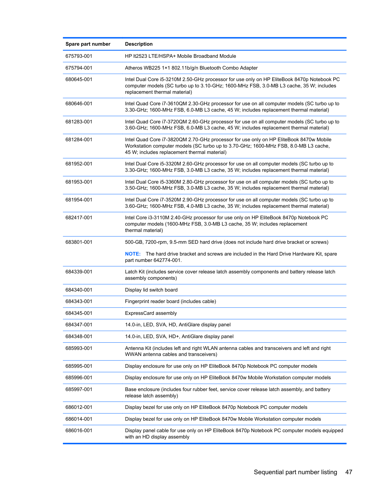
682417-001 Intel Core i3-3110M 2.40-GHz processor for use only on HP EliteBook 8470p Notebook PC computer models (1600-MHz FSB, 3.0-MB L3 cache, 35 W; includes replacement thermal material)
683801-001 500-GB, 7200-rpm, 9.5-mm SED hard drive (does not include hard drive bracket or screws)
NOTE: The hard drive bracket and screws are included in the Hard Drive Hardware Kit, spare part number 642774-001.
685993-001 Antenna Kit (includes left and right WLAN antenna cables and transceivers and left and right WWAN antenna cables and transceivers)
686012-001 Display bezel for use only on HP EliteBook 8470p Notebook PC computer models 686014-001 Display bezel for use only on HP EliteBook 8470w Mobile Workstation computer models
686027-001 Plastics Kit for use only on HP EliteBook 8470p Notebook PC computer models (includes ExpressCard slot space saver, optical drive bay space saver, RJ-11 jack cover, and wireless antenna clips)
686299-001 Keyboard with pointing stick for use on HP EliteBook 8470p Notebook PC computer models equipped with the Windows 7 operating system in the United States (includes keyboard cable and pointing stick cable)
686299-031 Keyboard with pointing stick for use on HP EliteBook 8470p Notebook PC computer models equipped with the Windows 7 operating system in the United Kingdom and Singapore (includes keyboard cable and pointing stick cable)
686299-041 Keyboard with pointing stick for use on HP EliteBook 8470p Notebook PC computer models equipped with the Windows 7 operating system in Germany (includes keyboard cable and pointing stick cable)
686299-051 Keyboard with pointing stick for use on HP EliteBook 8470p Notebook PC computer models equipped with the Windows 7 operating system in France (includes keyboard cable and pointing stick cable)
686299-061 Keyboard with pointing stick for use on HP EliteBook 8470p Notebook PC computer models equipped with the Windows 7 operating system in Italy (includes keyboard cable and pointing stick cable)
686299-071 Keyboard with pointing stick for use on HP EliteBook 8470p Notebook PC computer models equipped with the Windows 7 operating system in Spain (includes keyboard cable and pointing stick cable)
686299-081 Keyboard with pointing stick for use on HP EliteBook 8470p Notebook PC computer models equipped with the Windows 7 operating system in Denmark (includes keyboard cable and pointing stick cable)
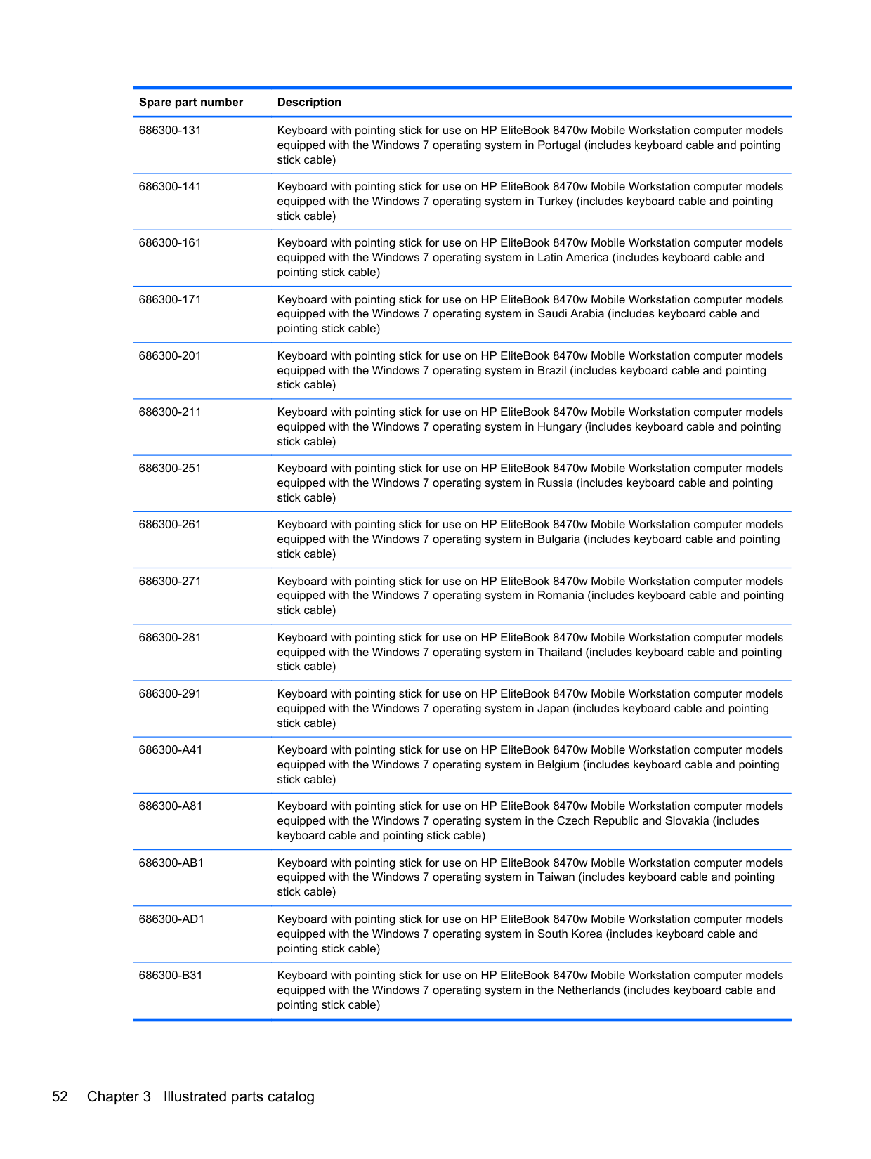
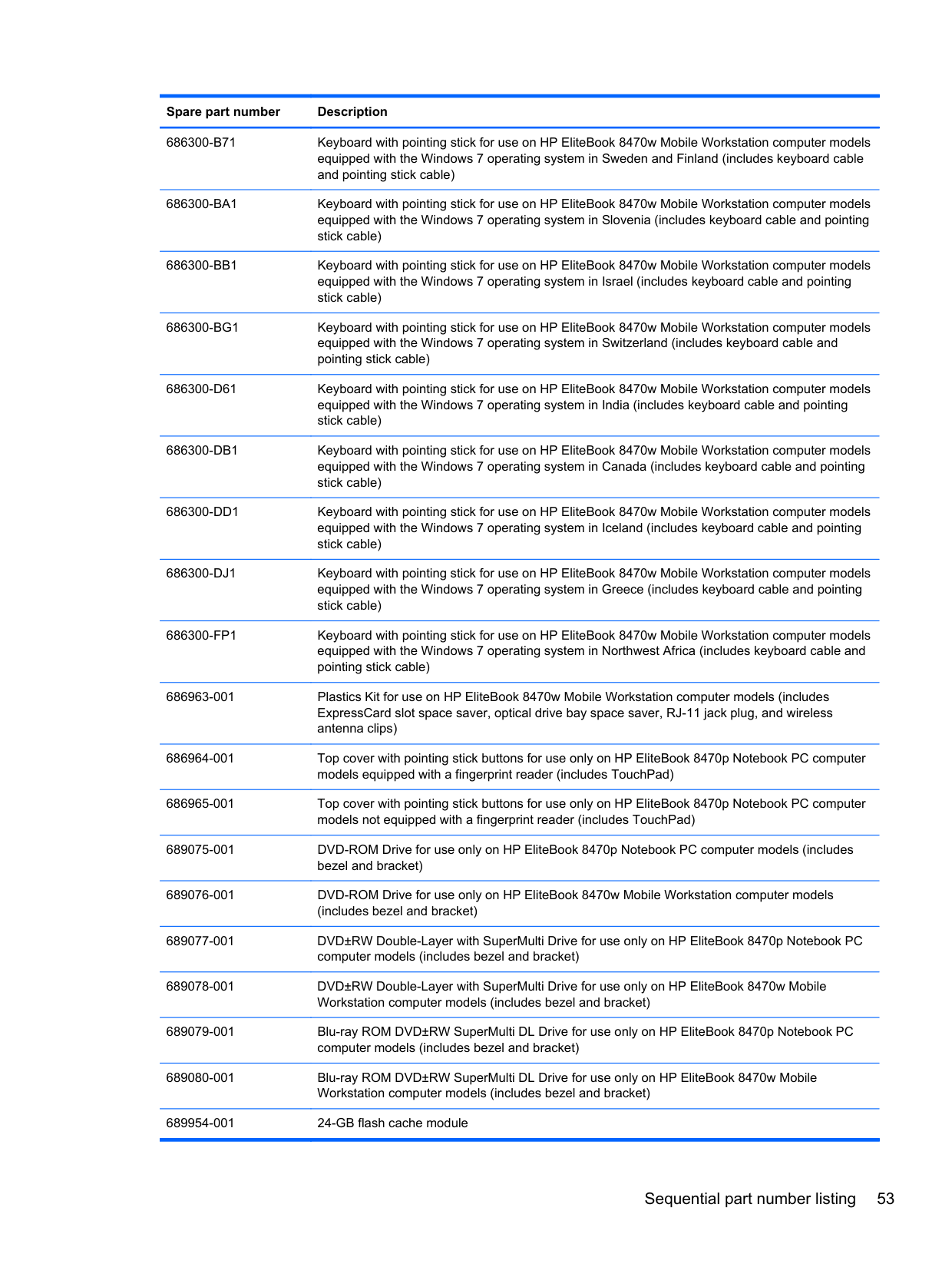
686300-B71 Keyboard with pointing stick for use on HP EliteBook 8470w Mobile Workstation computer models equipped with the Windows 7 operating system in Sweden and Finland (includes keyboard cable and pointing stick cable)
686300-BG1 Keyboard with pointing stick for use on HP EliteBook 8470w Mobile Workstation computer models equipped with the Windows 7 operating system in Switzerland (includes keyboard cable and pointing stick cable)
686300-D61 Keyboard with pointing stick for use on HP EliteBook 8470w Mobile Workstation computer models equipped with the Windows 7 operating system in India (includes keyboard cable and pointing stick cable)
686300-DB1 Keyboard with pointing stick for use on HP EliteBook 8470w Mobile Workstation computer models equipped with the Windows 7 operating system in Canada (includes keyboard cable and pointing stick cable)
686300-DD1 Keyboard with pointing stick for use on HP EliteBook 8470w Mobile Workstation computer models equipped with the Windows 7 operating system in Iceland (includes keyboard cable and pointing stick cable)
686300-DJ1 Keyboard with pointing stick for use on HP EliteBook 8470w Mobile Workstation computer models equipped with the Windows 7 operating system in Greece (includes keyboard cable and pointing stick cable)
686300-FP1 Keyboard with pointing stick for use on HP EliteBook 8470w Mobile Workstation computer models equipped with the Windows 7 operating system in Northwest Africa (includes keyboard cable and pointing stick cable)
689954-001 24-GB flash cache module
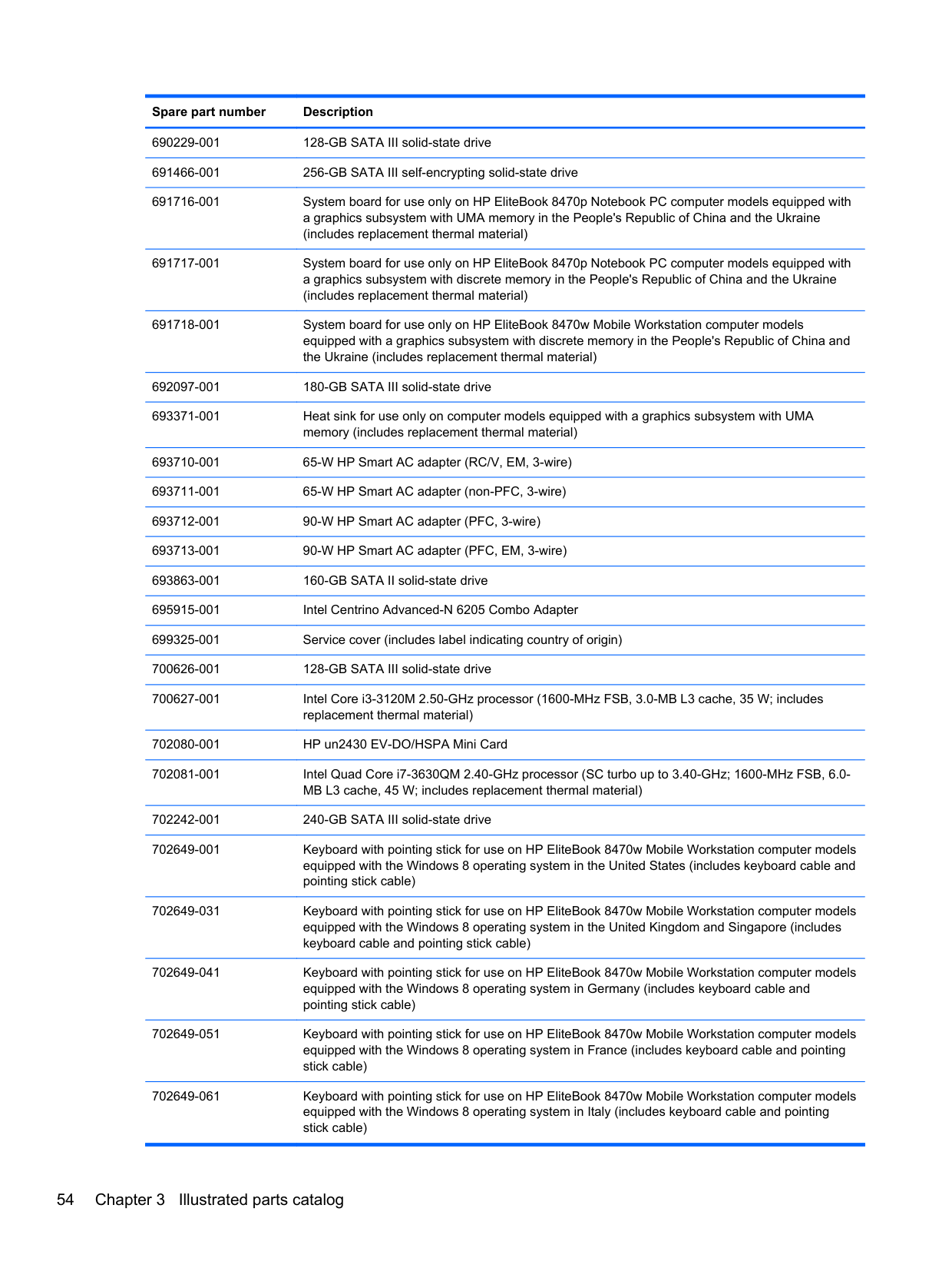
690229-001 128-GB SATA III solid-state drive 691466-001 256-GB SATA III self-encrypting solid-state drive
692097-001 180-GB SATA III solid-state drive 693371-001 Heat sink for use only on computer models equipped with a graphics subsystem with UMA
memory (includes replacement thermal material) 693710-001 65-W HP Smart AC adapter (RC/V, EM, 3-wire) 693711-001 65-W HP Smart AC adapter (non-PFC, 3-wire) 693712-001 90-W HP Smart AC adapter (PFC, 3-wire) 693713-001 90-W HP Smart AC adapter (PFC, EM, 3-wire) 693863-001 160-GB SATA II solid-state drive 695915-001 Intel Centrino Advanced-N 6205 Combo Adapter 699325-001 Service cover (includes label indicating country of origin)
702080-001 HP un2430 EV-DO/HSPA Mini Card 702081-001 Intel Quad Core i7-3630QM 2.40-GHz processor (SC turbo up to 3.40-GHz; 1600-MHz FSB, 6.0-
MB L3 cache, 45 W; includes replacement thermal material) 702242-001 240-GB SATA III solid-state drive 702649-001 Keyboard with pointing stick for use on HP EliteBook 8470w Mobile Workstation computer models
equipped with the Windows 8 operating system in the United States (includes keyboard cable and pointing stick cable)
702649-031 Keyboard with pointing stick for use on HP EliteBook 8470w Mobile Workstation computer models equipped with the Windows 8 operating system in the United Kingdom and Singapore (includes keyboard cable and pointing stick cable)
702649-041 Keyboard with pointing stick for use on HP EliteBook 8470w Mobile Workstation computer models equipped with the Windows 8 operating system in Germany (includes keyboard cable and pointing stick cable)
702649-051 Keyboard with pointing stick for use on HP EliteBook 8470w Mobile Workstation computer models equipped with the Windows 8 operating system in France (includes keyboard cable and pointing stick cable)
702649-061 Keyboard with pointing stick for use on HP EliteBook 8470w Mobile Workstation computer models equipped with the Windows 8 operating system in Italy (includes keyboard cable and pointing stick cable)
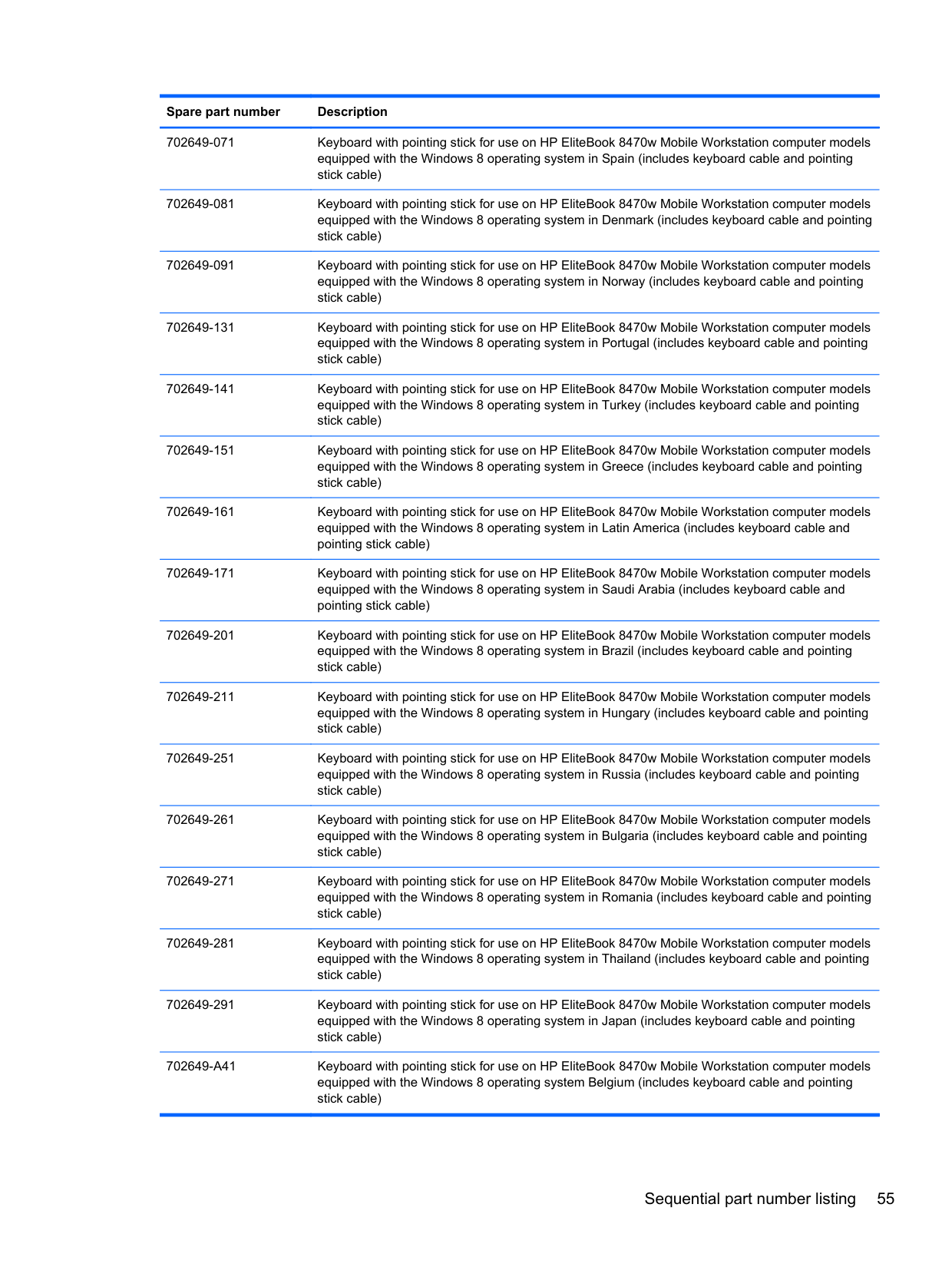
702649-071 Keyboard with pointing stick for use on HP EliteBook 8470w Mobile Workstation computer models equipped with the Windows 8 operating system in Spain (includes keyboard cable and pointing stick cable)
702649-081 Keyboard with pointing stick for use on HP EliteBook 8470w Mobile Workstation computer models equipped with the Windows 8 operating system in Denmark (includes keyboard cable and pointing stick cable)
702649-091 Keyboard with pointing stick for use on HP EliteBook 8470w Mobile Workstation computer models equipped with the Windows 8 operating system in Norway (includes keyboard cable and pointing stick cable)
702649-131 Keyboard with pointing stick for use on HP EliteBook 8470w Mobile Workstation computer models equipped with the Windows 8 operating system in Portugal (includes keyboard cable and pointing stick cable)
702649-141 Keyboard with pointing stick for use on HP EliteBook 8470w Mobile Workstation computer models equipped with the Windows 8 operating system in Turkey (includes keyboard cable and pointing stick cable)
702649-151 Keyboard with pointing stick for use on HP EliteBook 8470w Mobile Workstation computer models equipped with the Windows 8 operating system in Greece (includes keyboard cable and pointing stick cable)
702649-161 Keyboard with pointing stick for use on HP EliteBook 8470w Mobile Workstation computer models equipped with the Windows 8 operating system in Latin America (includes keyboard cable and pointing stick cable)
702649-171 Keyboard with pointing stick for use on HP EliteBook 8470w Mobile Workstation computer models equipped with the Windows 8 operating system in Saudi Arabia (includes keyboard cable and pointing stick cable)
702649-201 Keyboard with pointing stick for use on HP EliteBook 8470w Mobile Workstation computer models equipped with the Windows 8 operating system in Brazil (includes keyboard cable and pointing stick cable)
702649-211 Keyboard with pointing stick for use on HP EliteBook 8470w Mobile Workstation computer models equipped with the Windows 8 operating system in Hungary (includes keyboard cable and pointing stick cable)
702649-251 Keyboard with pointing stick for use on HP EliteBook 8470w Mobile Workstation computer models equipped with the Windows 8 operating system in Russia (includes keyboard cable and pointing stick cable)
702649-261 Keyboard with pointing stick for use on HP EliteBook 8470w Mobile Workstation computer models equipped with the Windows 8 operating system in Bulgaria (includes keyboard cable and pointing stick cable)
702649-271 Keyboard with pointing stick for use on HP EliteBook 8470w Mobile Workstation computer models equipped with the Windows 8 operating system in Romania (includes keyboard cable and pointing stick cable)
702649-281 Keyboard with pointing stick for use on HP EliteBook 8470w Mobile Workstation computer models equipped with the Windows 8 operating system in Thailand (includes keyboard cable and pointing stick cable)
702649-291 Keyboard with pointing stick for use on HP EliteBook 8470w Mobile Workstation computer models equipped with the Windows 8 operating system in Japan (includes keyboard cable and pointing stick cable)
702649-A41 Keyboard with pointing stick for use on HP EliteBook 8470w Mobile Workstation computer models equipped with the Windows 8 operating system Belgium (includes keyboard cable and pointing
702649-AB1 Keyboard with pointing stick for use on HP EliteBook 8470w Mobile Workstation computer models equipped with the Windows 8 operating system in Taiwan (includes keyboard cable and pointing stick cable)
702649-AD1 Keyboard with pointing stick for use on HP EliteBook 8470w Mobile Workstation computer models equipped with the Windows 8 operating system South Korea (includes keyboard cable and pointing stick cable)
702649-B31 Keyboard with pointing stick for use on HP EliteBook 8470w Mobile Workstation computer models equipped with the Windows 8 operating system in the Netherlands (includes keyboard cable and pointing stick cable)
702649-B71 Keyboard with pointing stick for use on HP EliteBook 8470w Mobile Workstation computer models equipped with the Windows 8 operating system in Sweden and Finland (includes keyboard cable and pointing stick cable)
702649-BG1 Keyboard with pointing stick for use on HP EliteBook 8470w Mobile Workstation computer models equipped with the Windows 8 operating system in Switzerland (includes keyboard cable and pointing stick cable)
702649-D61 Keyboard with pointing stick for use on HP EliteBook 8470w Mobile Workstation computer models equipped with the Windows 8 operating system in India (includes keyboard cable and pointing stick cable)
702649-DB1 Keyboard with pointing stick for use on HP EliteBook 8470w Mobile Workstation computer models equipped with the Windows 8 operating system in Canada (includes keyboard cable and pointing stick cable)
702649-DD1 Keyboard with pointing stick for use on HP EliteBook 8470w Mobile Workstation computer models equipped with the Windows 8 operating system in Iceland (includes keyboard cable and pointing stick cable)
702649-FL1 Keyboard with pointing stick for use on HP EliteBook 8470w Mobile Workstation computer models equipped with the Windows 8 operating system in the Czech Republic and Slovakia (includes keyboard cable and pointing stick cable)
702649-FP1 Keyboard with pointing stick for use on HP EliteBook 8470w Mobile Workstation computer models equipped with the Windows 8 operating system in Northwest Africa (includes keyboard cable and pointing stick cable)
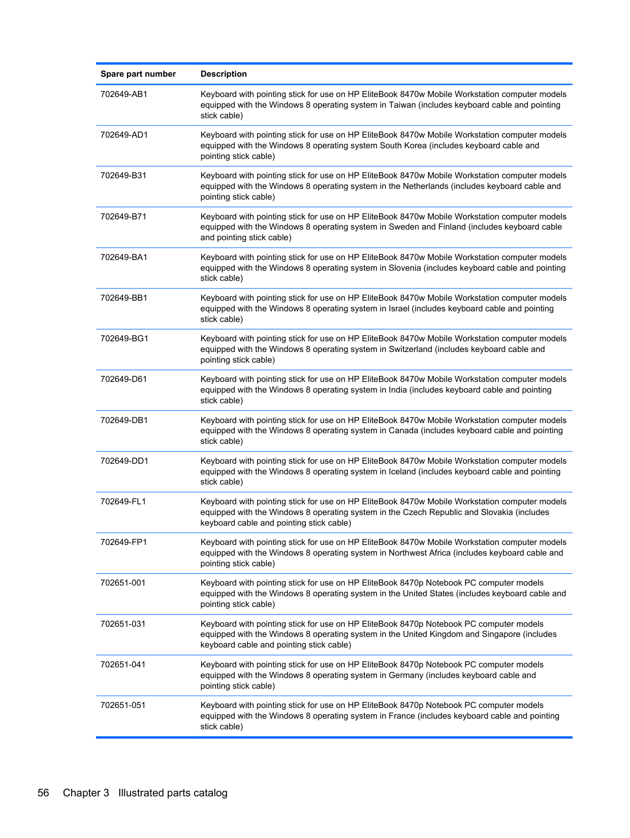
702651-001 Keyboard with pointing stick for use on HP EliteBook 8470p Notebook PC computer models equipped with the Windows 8 operating system in the United States (includes keyboard cable and pointing stick cable)
702651-031 Keyboard with pointing stick for use on HP EliteBook 8470p Notebook PC computer models equipped with the Windows 8 operating system in the United Kingdom and Singapore (includes keyboard cable and pointing stick cable)
702651-041 Keyboard with pointing stick for use on HP EliteBook 8470p Notebook PC computer models equipped with the Windows 8 operating system in Germany (includes keyboard cable and pointing stick cable)
702651-051 Keyboard with pointing stick for use on HP EliteBook 8470p Notebook PC computer models equipped with the Windows 8 operating system in France (includes keyboard cable and pointing
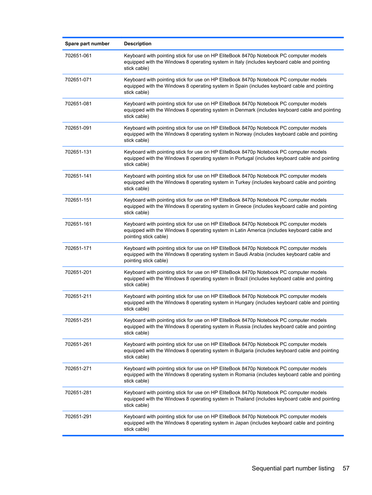
702651-061 Keyboard with pointing stick for use on HP EliteBook 8470p Notebook PC computer models equipped with the Windows 8 operating system in Italy (includes keyboard cable and pointing stick cable)
702651-071 Keyboard with pointing stick for use on HP EliteBook 8470p Notebook PC computer models equipped with the Windows 8 operating system in Spain (includes keyboard cable and pointing stick cable)
702651-081 Keyboard with pointing stick for use on HP EliteBook 8470p Notebook PC computer models equipped with the Windows 8 operating system in Denmark (includes keyboard cable and pointing stick cable)
702651-091 Keyboard with pointing stick for use on HP EliteBook 8470p Notebook PC computer models equipped with the Windows 8 operating system in Norway (includes keyboard cable and pointing stick cable)
702651-131 Keyboard with pointing stick for use on HP EliteBook 8470p Notebook PC computer models equipped with the Windows 8 operating system in Portugal (includes keyboard cable and pointing stick cable)
702651-141 Keyboard with pointing stick for use on HP EliteBook 8470p Notebook PC computer models equipped with the Windows 8 operating system in Turkey (includes keyboard cable and pointing stick cable)
702651-151 Keyboard with pointing stick for use on HP EliteBook 8470p Notebook PC computer models equipped with the Windows 8 operating system in Greece (includes keyboard cable and pointing stick cable)
702651-161 Keyboard with pointing stick for use on HP EliteBook 8470p Notebook PC computer models equipped with the Windows 8 operating system in Latin America (includes keyboard cable and pointing stick cable)
702651-171 Keyboard with pointing stick for use on HP EliteBook 8470p Notebook PC computer models equipped with the Windows 8 operating system in Saudi Arabia (includes keyboard cable and pointing stick cable)
702651-201 Keyboard with pointing stick for use on HP EliteBook 8470p Notebook PC computer models equipped with the Windows 8 operating system in Brazil (includes keyboard cable and pointing stick cable)
702651-211 Keyboard with pointing stick for use on HP EliteBook 8470p Notebook PC computer models equipped with the Windows 8 operating system in Hungary (includes keyboard cable and pointing stick cable)
702651-251 Keyboard with pointing stick for use on HP EliteBook 8470p Notebook PC computer models equipped with the Windows 8 operating system in Russia (includes keyboard cable and pointing stick cable)
702651-261 Keyboard with pointing stick for use on HP EliteBook 8470p Notebook PC computer models equipped with the Windows 8 operating system in Bulgaria (includes keyboard cable and pointing stick cable)
702651-271 Keyboard with pointing stick for use on HP EliteBook 8470p Notebook PC computer models equipped with the Windows 8 operating system in Romania (includes keyboard cable and pointing stick cable)
702651-281 Keyboard with pointing stick for use on HP EliteBook 8470p Notebook PC computer models equipped with the Windows 8 operating system in Thailand (includes keyboard cable and pointing stick cable)
702651-291 Keyboard with pointing stick for use on HP EliteBook 8470p Notebook PC computer models equipped with the Windows 8 operating system in Japan (includes keyboard cable and pointing
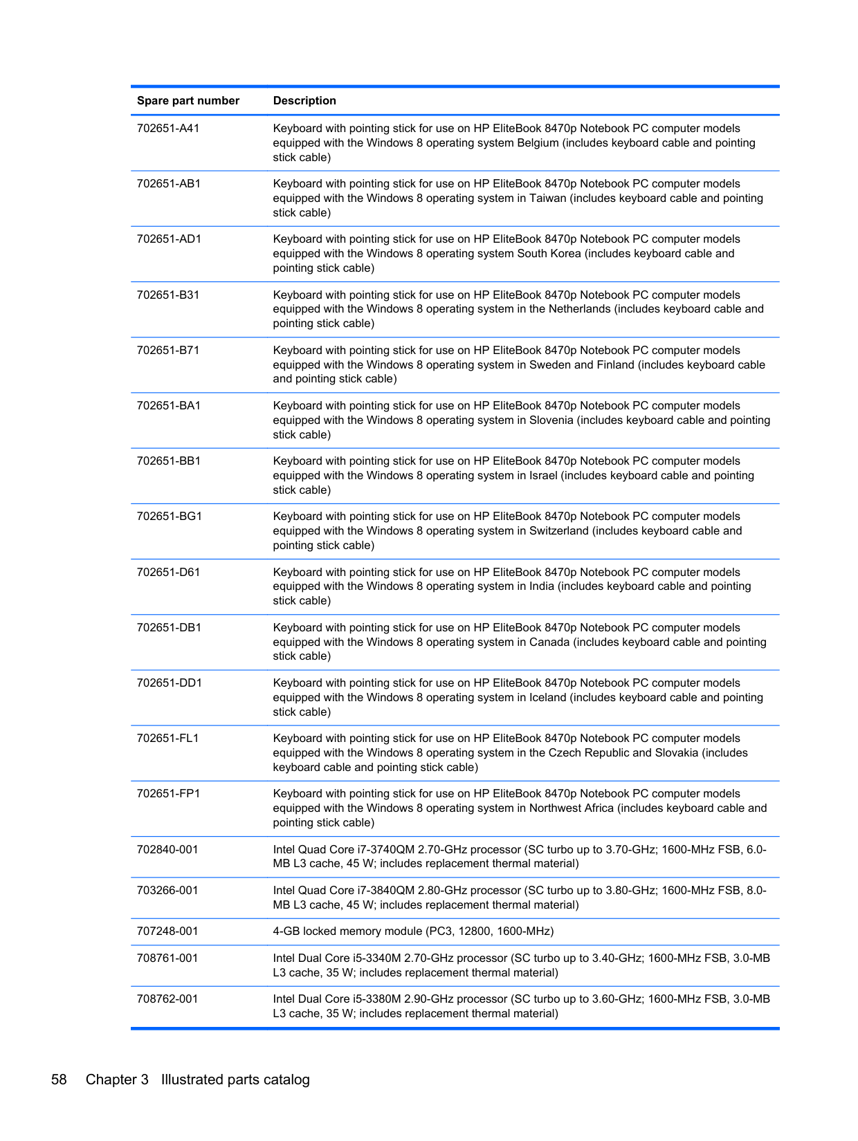
702651-A41 Keyboard with pointing stick for use on HP EliteBook 8470p Notebook PC computer models equipped with the Windows 8 operating system Belgium (includes keyboard cable and pointing stick cable)
702651-AB1 Keyboard with pointing stick for use on HP EliteBook 8470p Notebook PC computer models equipped with the Windows 8 operating system in Taiwan (includes keyboard cable and pointing stick cable)
702651-AD1 Keyboard with pointing stick for use on HP EliteBook 8470p Notebook PC computer models equipped with the Windows 8 operating system South Korea (includes keyboard cable and pointing stick cable)
702651-B31 Keyboard with pointing stick for use on HP EliteBook 8470p Notebook PC computer models equipped with the Windows 8 operating system in the Netherlands (includes keyboard cable and pointing stick cable)
702651-B71 Keyboard with pointing stick for use on HP EliteBook 8470p Notebook PC computer models equipped with the Windows 8 operating system in Sweden and Finland (includes keyboard cable and pointing stick cable)
702651-BG1 Keyboard with pointing stick for use on HP EliteBook 8470p Notebook PC computer models equipped with the Windows 8 operating system in Switzerland (includes keyboard cable and pointing stick cable)
702651-D61 Keyboard with pointing stick for use on HP EliteBook 8470p Notebook PC computer models equipped with the Windows 8 operating system in India (includes keyboard cable and pointing stick cable)
702651-DB1 Keyboard with pointing stick for use on HP EliteBook 8470p Notebook PC computer models equipped with the Windows 8 operating system in Canada (includes keyboard cable and pointing stick cable)
702651-DD1 Keyboard with pointing stick for use on HP EliteBook 8470p Notebook PC computer models equipped with the Windows 8 operating system in Iceland (includes keyboard cable and pointing stick cable)
702651-FL1 Keyboard with pointing stick for use on HP EliteBook 8470p Notebook PC computer models equipped with the Windows 8 operating system in the Czech Republic and Slovakia (includes keyboard cable and pointing stick cable)
702651-FP1 Keyboard with pointing stick for use on HP EliteBook 8470p Notebook PC computer models equipped with the Windows 8 operating system in Northwest Africa (includes keyboard cable and pointing stick cable)
702840-001 Intel Quad Core i7-3740QM 2.70-GHz processor (SC turbo up to 3.70-GHz; 1600-MHz FSB, 6.0MB L3 cache, 45 W; includes replacement thermal material)
703266-001 Intel Quad Core i7-3840QM 2.80-GHz processor (SC turbo up to 3.80-GHz; 1600-MHz FSB, 8.0-
MB L3 cache, 45 W; includes replacement thermal material) 707248-001 4-GB locked memory module (PC3, 12800, 1600-MHz)
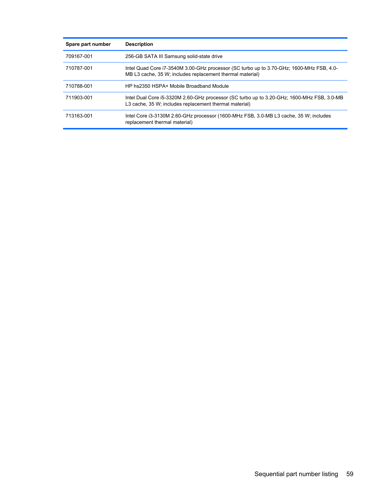
709167-001 256-GB SATA III Samsung solid-state drive
711903-001 Intel Dual Core i5-3320M 2.60-GHz processor (SC turbo up to 3.20-GHz; 1600-MHz FSB, 3.0-MB L3 cache, 35 W; includes replacement thermal material)
713163-001 Intel Core i3-3130M 2.60-GHz processor (1600-MHz FSB, 3.0-MB L3 cache, 35 W; includes replacement thermal material)
4 Removal and replacement procedures
Preliminary replacement requirements
#### Tools required
You will need the following tools to complete the removal and replacement procedures:
#### Service considerations
The following sections include some of the considerations that you must keep in mind during disassembly and assembly procedures.
NOTE: As you remove each subassembly from the computer, place the subassembly (and all accompanying screws) away from the work area to prevent damage.
| | |---|
##### Plastic parts
CAUTION: Using excessive force during disassembly and reassembly can damage plastic parts. Use care when handling the plastic parts. Apply pressure only at the points designated in the maintenance instructions.
##### Cables and connectors
CAUTION: When servicing the computer, be sure that cables are placed in their proper locations during the reassembly process. Improper cable placement can damage the computer. Cables must be handled with extreme care to avoid damage. Apply only the tension required to unseat or seat the cables during removal and insertion. Handle cables by the connector whenever possible. In all cases, avoid bending, twisting, or tearing cables. Be sure that cables are routed in such a way that they cannot be caught or snagged by parts being removed or replaced. Handle flex cables with extreme care; these cables tear easily.
##### Drive handling
CAUTION: Drives are fragile components that must be handled with care. To prevent damage to the computer, damage to a drive, or loss of information, observe these precautions: Before removing or inserting a hard drive, shut down the computer. If you are unsure whether the computer is off or in Hibernation, turn the computer on, and then shut it down through the operating system. Before handling a drive, be sure that you are discharged of static electricity. While handling a drive, avoid touching the connector. Before removing a diskette drive or optical drive, be sure that a diskette or disc is not in the drive and be sure that the optical drive tray is closed. Handle drives on surfaces covered with at least one inch of shock-proof foam. Avoid dropping drives from any height onto any surface. After removing a hard drive, an optical drive, or a diskette drive, place it in a static-proof bag. Avoid exposing an internal hard drive to products that have magnetic fields, such as monitors or speakers. Avoid exposing a drive to temperature extremes or liquids. If a drive must be mailed, place the drive in a bubble pack mailer or other suitable form of protective packaging and label the package “FRAGILE.”
#### Grounding guidelines Electrostatic discharge damage
Electronic components are sensitive to electrostatic discharge (ESD). Circuitry design and structure determine the degree of sensitivity. Networks built into many integrated circuits provide some protection, but in many cases, ESD contains enough power to alter device parameters or melt silicon junctions.
A discharge of static electricity from a finger or other conductor can destroy static-sensitive devices or microcircuitry. Even if the spark is neither felt nor heard, damage may have occurred.
An electronic device exposed to ESD may not be affected at all and can work perfectly throughout a normal cycle. Or the device may function normally for a while, then degrade in the internal layers, reducing its life expectancy.
CAUTION: To prevent damage to the computer when you are removing or installing internal components, observe these precautions: Keep components in their electrostatic-safe containers until you are ready to install them. Before touching an electronic component, discharge static electricity by using the guidelines described in this section. Avoid touching pins, leads, and circuitry. Handle electronic components as little as possible. If you remove a component, place it in an electrostatic-safe container. The following table shows how humidity affects the electrostatic voltage levels generated by different activities.
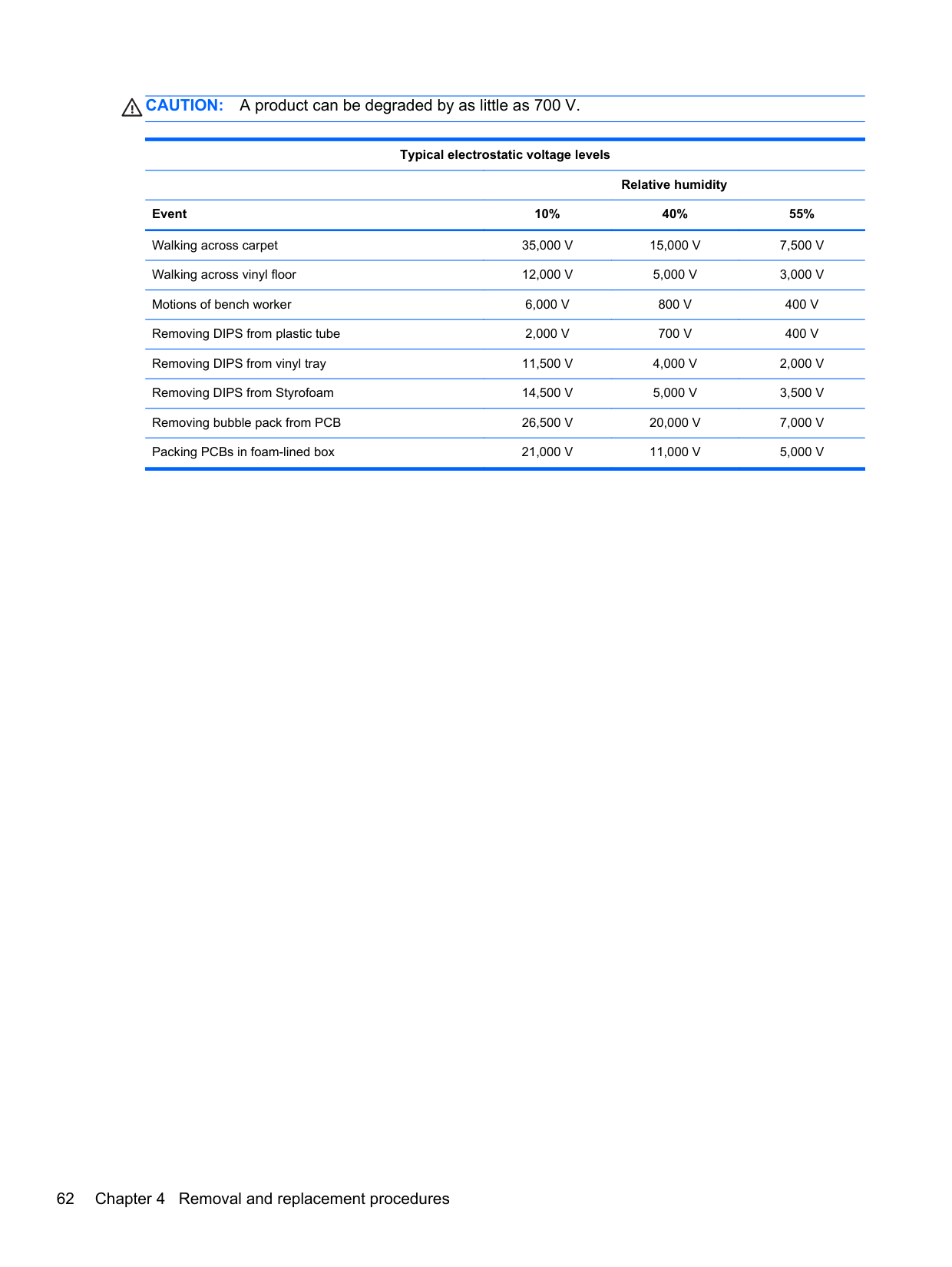
CAUTION: A product can be degraded by as little as 700 V.
Typical electrostatic voltage levels
Relative humidity Event 10% 40% 55% Walking across carpet 35,000 V 15,000 V 7,500 V Walking across vinyl floor 12,000 V 5,000 V 3,000 V Motions of bench worker 6,000 V 800 V 400 V Removing DIPS from plastic tube 2,000 V 700 V 400 V Removing DIPS from vinyl tray 11,500 V 4,000 V 2,000 V Removing DIPS from Styrofoam 14,500 V 5,000 V 3,500 V Removing bubble pack from PCB 26,500 V 20,000 V 7,000 V Packing PCBs in foam-lined box 21,000 V 11,000 V 5,000 V
###### Packaging and transporting guidelines
Follow these grounding guidelines when packaging and transporting equipment:
###### Workstation guidelines
Follow these grounding workstation guidelines:
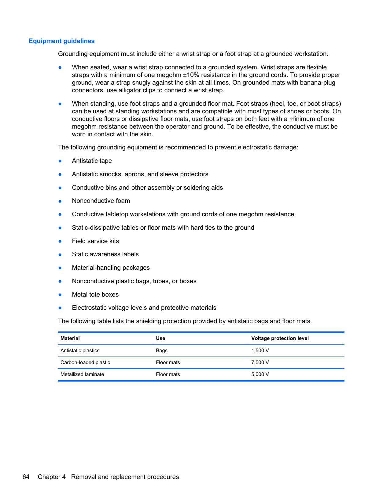
###### Equipment guidelines
Grounding equipment must include either a wrist strap or a foot strap at a grounded workstation.
Material Use Voltage protection level
Antistatic plastics Bags 1,500 V Carbon-loaded plastic Floor mats 7,500 V Metallized laminate Floor mats 5,000 V
Component replacement procedures
This chapter provides removal and replacement procedures.
There are as many as 73 screws that must be removed, replaced, and/or loosened when servicing the computer. Make special note of each screw size and location during removal and replacement.
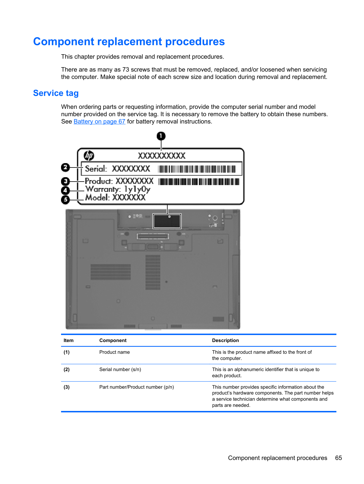
#### Service tag
When ordering parts or requesting information, provide the computer serial number and model number provided on the service tag. It is necessary to remove the battery to obtain these numbers. See Battery on page 67 for battery removal instructions.

Item Component Description
######## Item Component Description
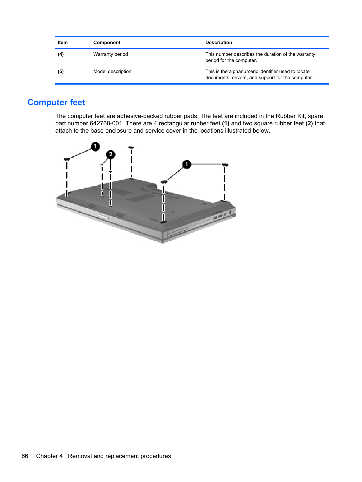
#### Computer feet
The computer feet are adhesive-backed rubber pads. The feet are included in the Rubber Kit, spare part number 642768-001. There are 4 rectangular rubber feet (1) and two square rubber feet (2) that attach to the base enclosure and service cover in the locations illustrated below.

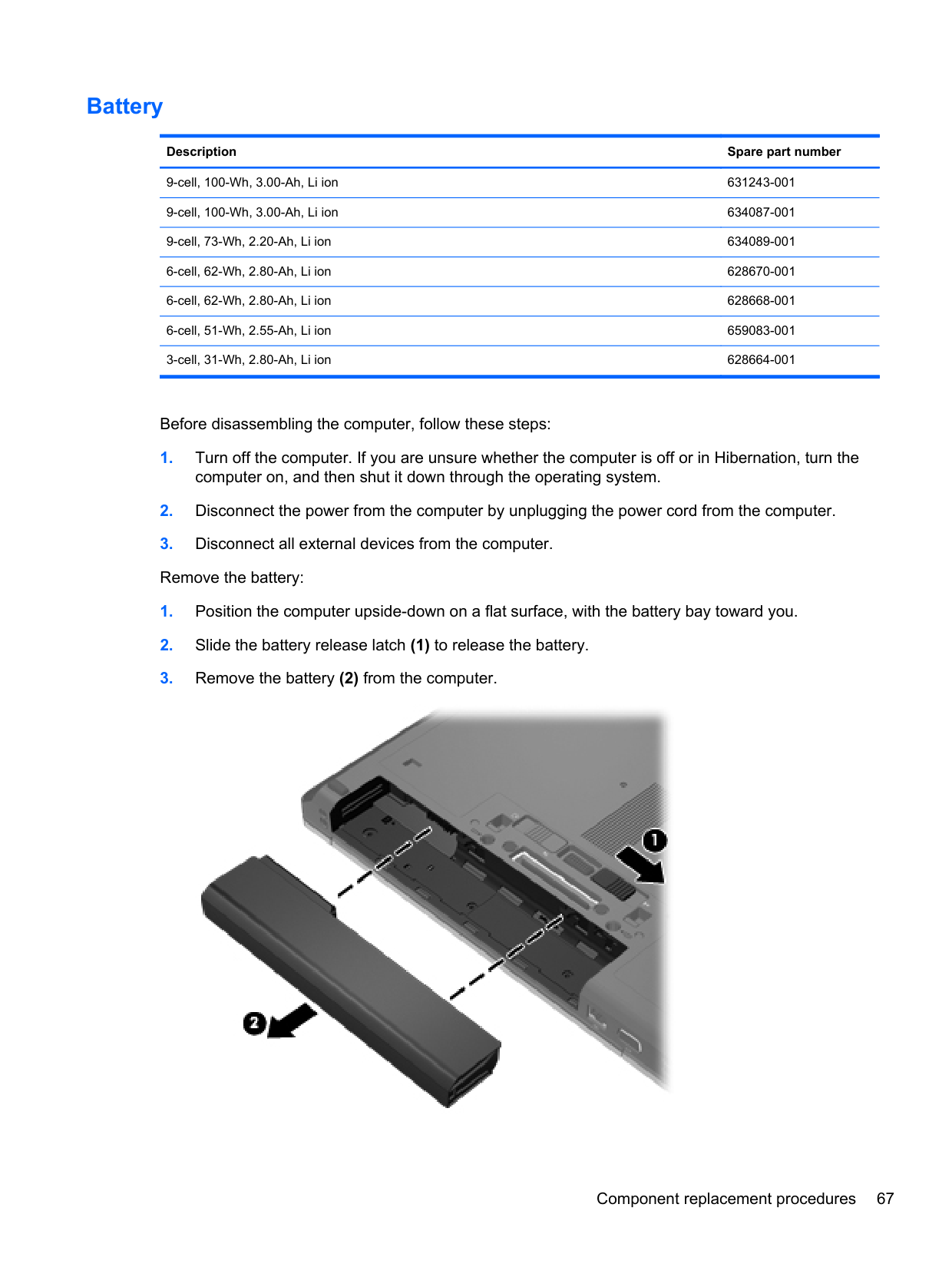
#### Battery
######## Description Spare part number
9-cell, 100-Wh, 3.00-Ah, Li ion 631243-001 9-cell, 100-Wh, 3.00-Ah, Li ion 634087-001 9-cell, 73-Wh, 2.20-Ah, Li ion 634089-001 6-cell, 62-Wh, 2.80-Ah, Li ion 628670-001 6-cell, 62-Wh, 2.80-Ah, Li ion 628668-001 6-cell, 51-Wh, 2.55-Ah, Li ion 659083-001 3-cell, 31-Wh, 2.80-Ah, Li ion 628664-001
Before disassembling the computer, follow these steps:

Install the battery by inserting it into the battery bay until you hear a click.
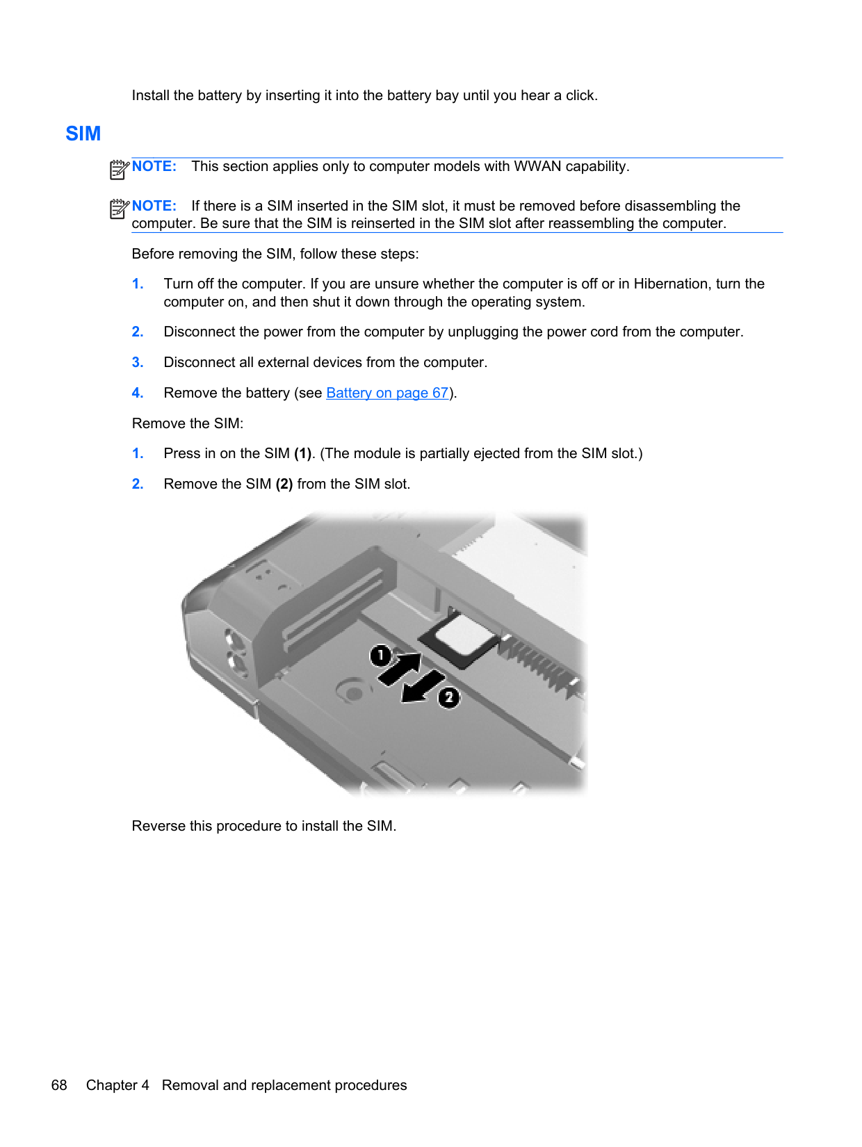
#### SIM
NOTE: This section applies only to computer models with WWAN capability. NOTE: If there is a SIM inserted in the SIM slot, it must be removed before disassembling the computer. Be sure that the SIM is reinserted in the SIM slot after reassembling the computer. Before removing the SIM, follow these steps:
| | |---|
| | |---|

Reverse this procedure to install the SIM.
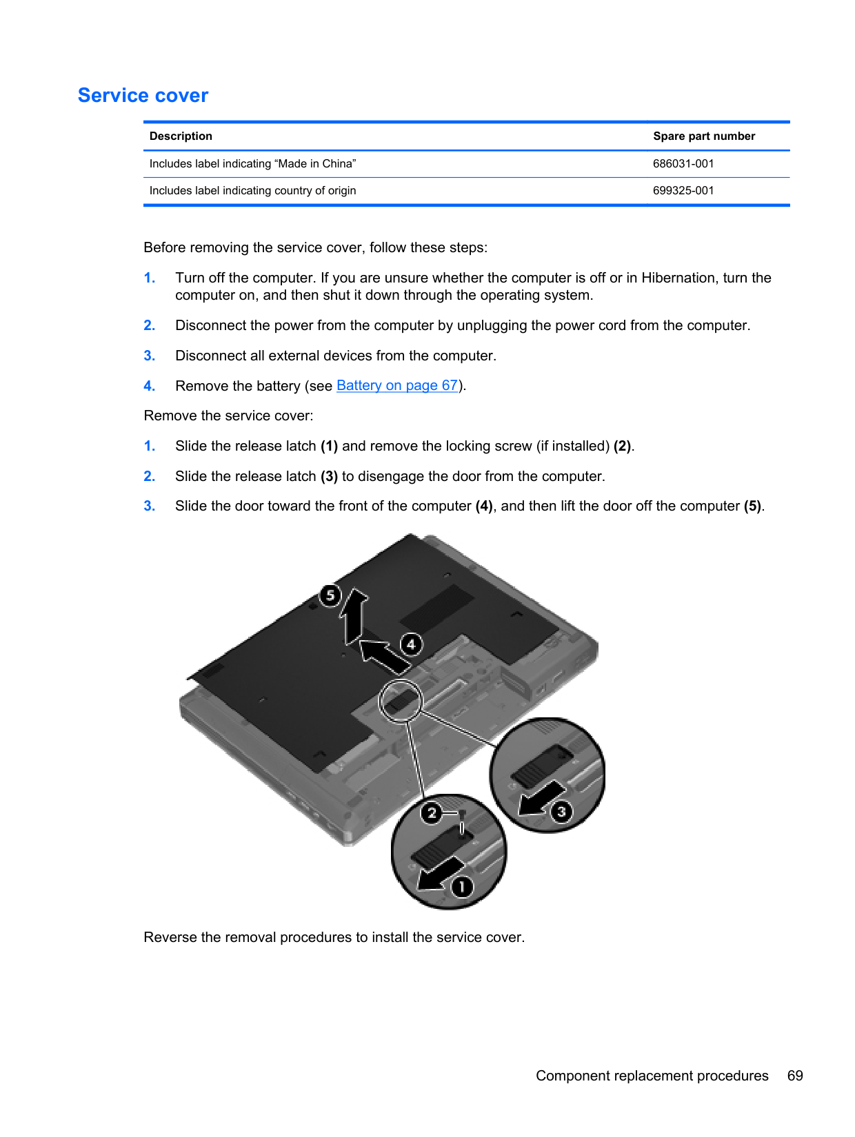
#### Service cover
######## Description Spare part number
Includes label indicating “Made in China” 686031-001 Includes label indicating country of origin 699325-001
Before removing the service cover, follow these steps:

Reverse the removal procedures to install the service cover.
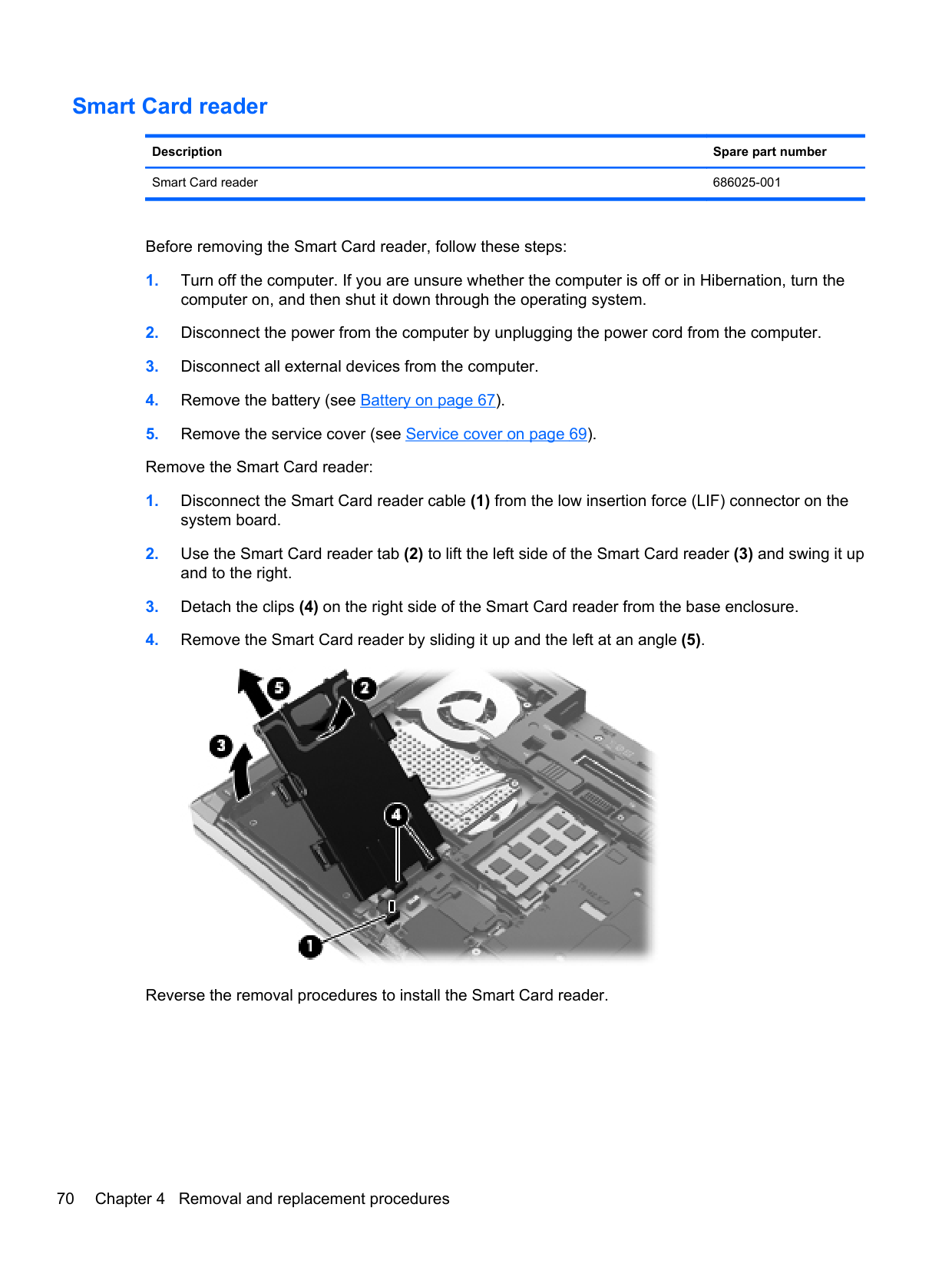
#### Smart Card reader
Description Spare part number Smart Card reader 686025-001
Before removing the Smart Card reader, follow these steps:

Reverse the removal procedures to install the Smart Card reader.
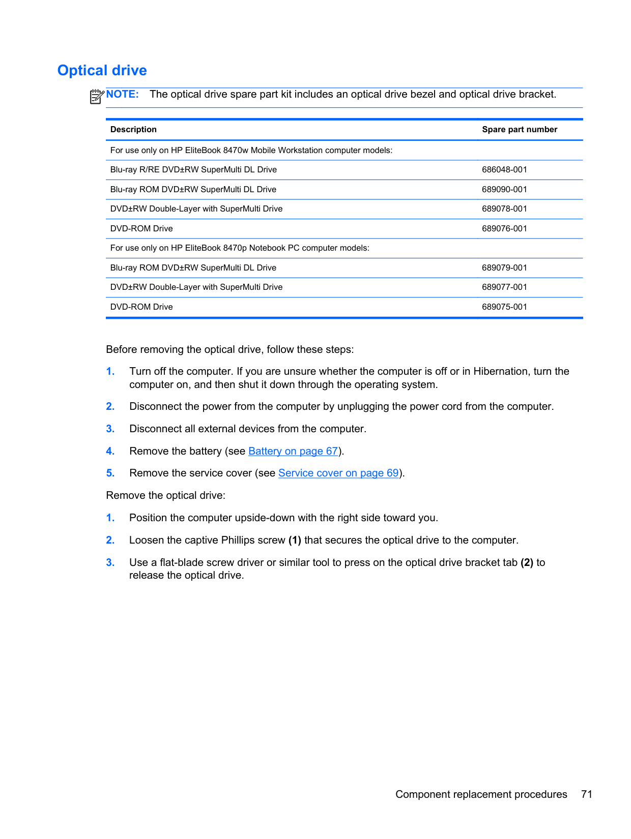
#### Optical drive
NOTE: The optical drive spare part kit includes an optical drive bezel and optical drive bracket.
| | |---|
Description Spare part number For use only on HP EliteBook 8470w Mobile Workstation computer models: Blu-ray R/RE DVD±RW SuperMulti DL Drive 686048-001 Blu-ray ROM DVD±RW SuperMulti DL Drive 689090-001 DVD±RW Double-Layer with SuperMulti Drive 689078-001 DVD-ROM Drive 689076-001 For use only on HP EliteBook 8470p Notebook PC computer models: Blu-ray ROM DVD±RW SuperMulti DL Drive 689079-001 DVD±RW Double-Layer with SuperMulti Drive 689077-001 DVD-ROM Drive 689075-001
Before removing the optical drive, follow these steps:


Reverse this procedure to reassemble and install the optical drive.
#### Upgrade bay cradle
Description Spare part number Upgrade bay cradle 643921-001
Before removing the upgrade bay cradle, follow these steps:


Reverse this procedure to install the upgrade bay.
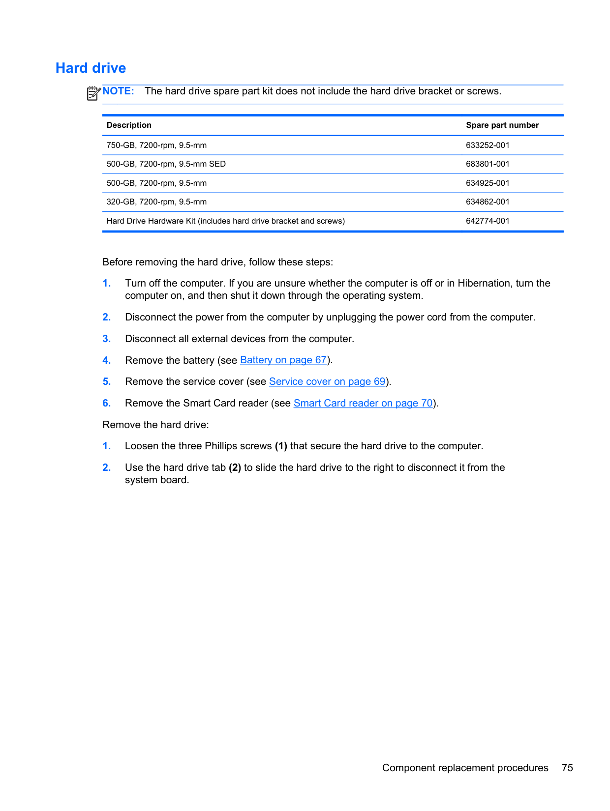
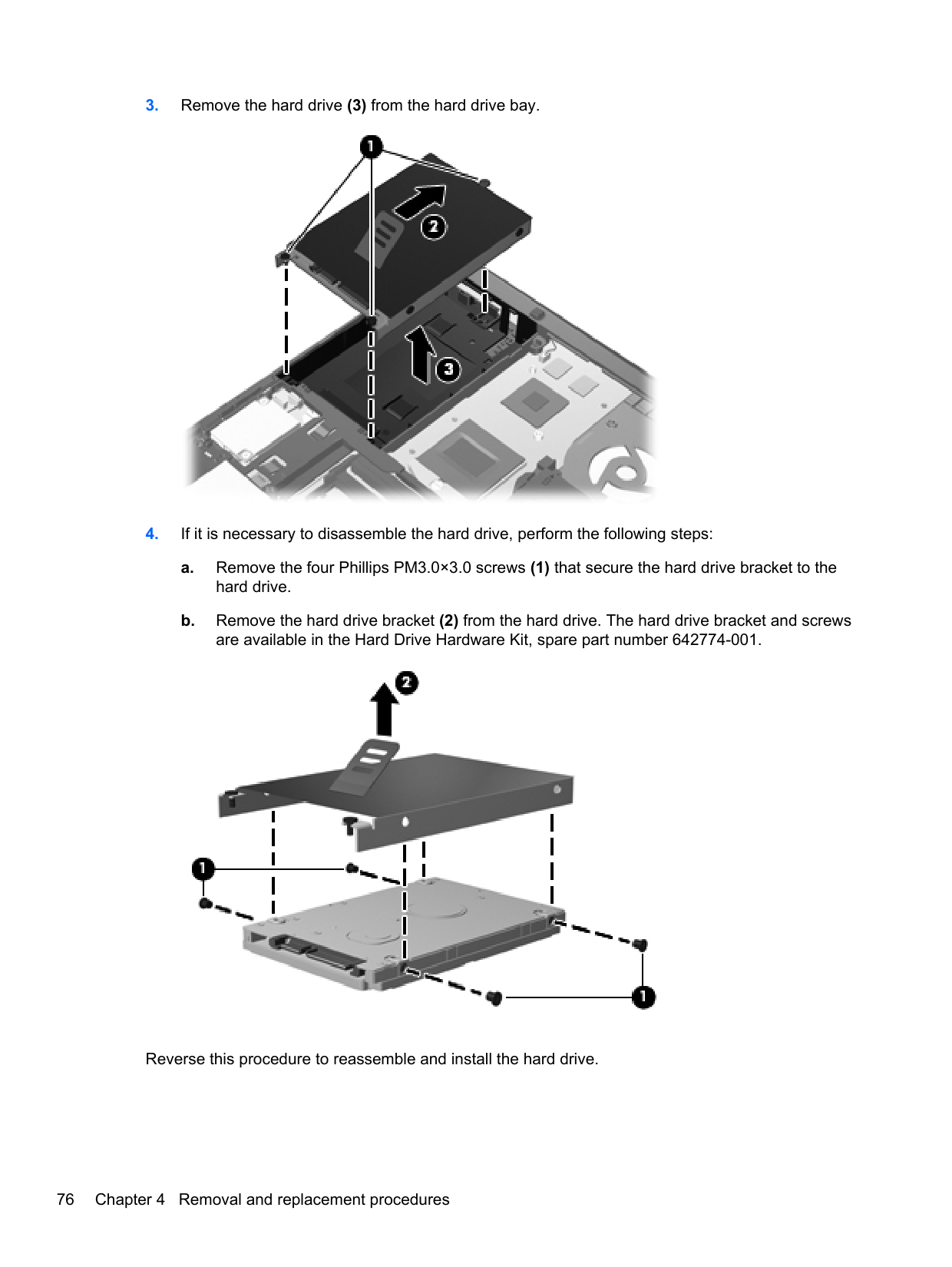
#### Hard drive
NOTE: The hard drive spare part kit does not include the hard drive bracket or screws.
| | |---|
Description Spare part number
750-GB, 7200-rpm, 9.5-mm 633252-001 500-GB, 7200-rpm, 9.5-mm SED 683801-001 500-GB, 7200-rpm, 9.5-mm 634925-001 320-GB, 7200-rpm, 9.5-mm 634862-001 Hard Drive Hardware Kit (includes hard drive bracket and screws) 642774-001
Before removing the hard drive, follow these steps:


Reverse this procedure to reassemble and install the hard drive.
#### Memory module
NOTE: Primary and expansion memory is installed in a stacked configuration in the bottom of the computer.
| | |---|
Description Spare part number
8-GB memory module (PC3, 12800, 1600-MHz) 670034-001 4-GB locked memory module (PC3, 12800, 1600-MHz) 707248-001 4-GB memory module (PC3, 12800, 1600-MHz) 641369-001 2-GB memory module (PC3, 12800, 1600-MHz) 652972-001
Update BIOS before adding memory modules Before adding new memory, make sure you update the computer to the latest BIOS.
CAUTION: Failure to update the computer to the latest BIOS prior to installing new memory may result in various system problems. To update BIOS:
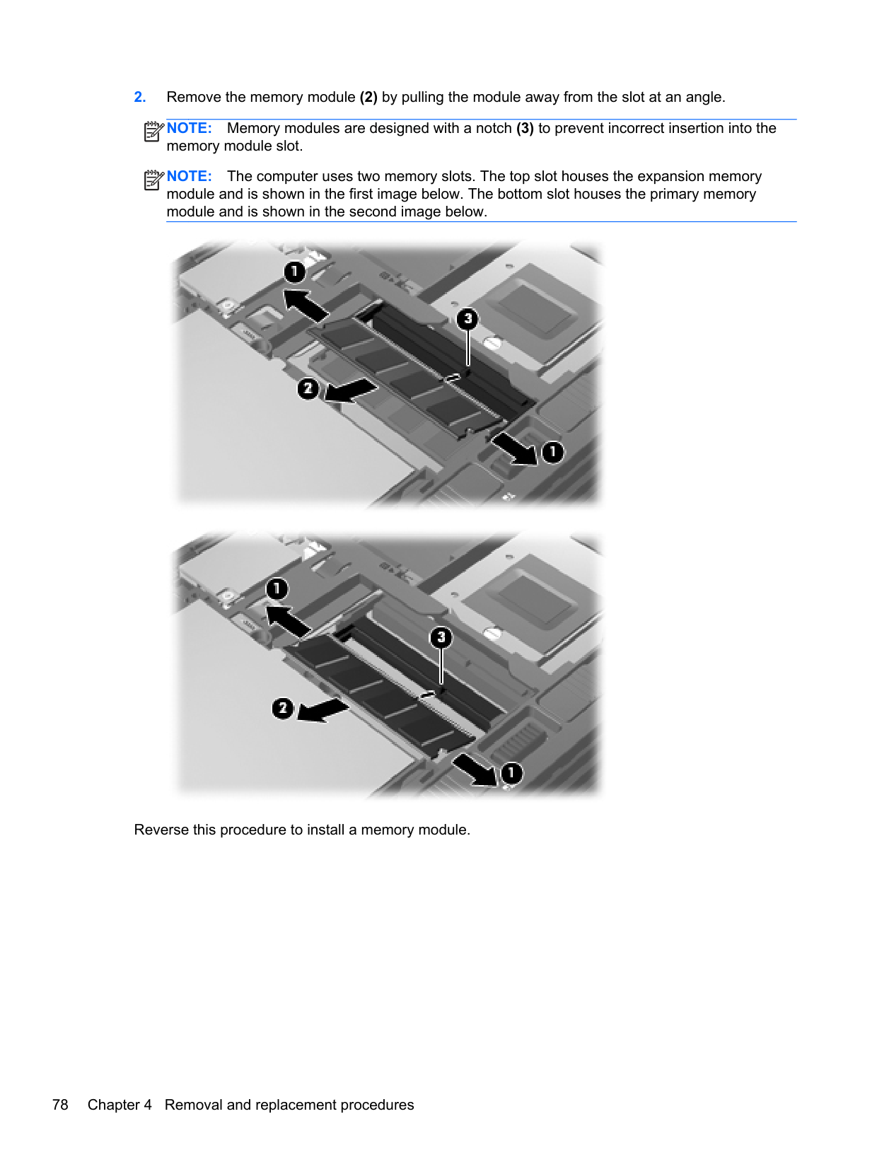
NOTE: Memory modules are designed with a notch (3) to prevent incorrect insertion into the memory module slot.
| | |---|
NOTE: The computer uses two memory slots. The top slot houses the expansion memory module and is shown in the first image below. The bottom slot houses the primary memory module and is shown in the second image below.
| | |---|


Reverse this procedure to install a memory module.
#### WWAN module
NOTE: The WWAN module and the WLAN module are not interchangeable.
| |
|---|
Description Spare part number
HP hs2350 HSPA+ Mobile Broadband Module 710788-001 HP un2430 EV-DO/HSPA Mini Card 702080-001 HP un2430 EV-DO/HSPA Mini Card 702080-001 HP un2430 EV-DO/HSPA Mobile Broadband Module 634400-001
Before removing the WWAN module, follow these steps:
| | |---|
NOTE: The red WWAN antenna cable is connected to the WWAN module “Main” terminal. The blue WWAN antenna cable is connected to the WWAN module “Aux” terminal.
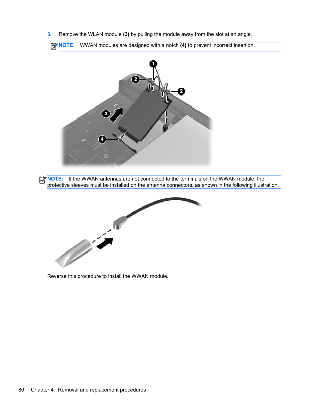
NOTE: WWAN modules are designed with a notch (4) to prevent incorrect insertion.
| | |---|

NOTE: If the WWAN antennas are not connected to the terminals on the WWAN module, the protective sleeves must be installed on the antenna connectors, as shown in the following illustration.
| | |---|

Reverse this procedure to install the WWAN module.
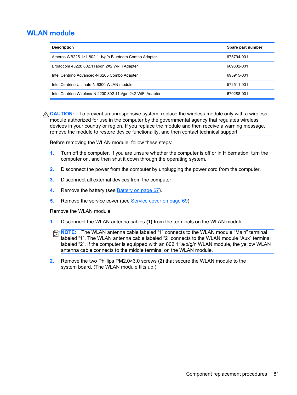
#### WLAN module
######## Description Spare part number
Atheros WB225 1×1 802.11b/g/n Bluetooth Combo Adapter 675794-001 Broadcom 43228 802.11abgn 2×2 Wi-Fi Adapter 669832-001 Intel Centrino Advanced-N 6205 Combo Adapter 695915-001 Intel Centrino Ultimate-N 6300 WLAN module 572511-001 Intel Centrino Wireless-N 2200 802.11b/g/n 2×2 WiFi Adapter 670288-001
CAUTION: To prevent an unresponsive system, replace the wireless module only with a wireless module authorized for use in the computer by the governmental agency that regulates wireless devices in your country or region. If you replace the module and then receive a warning message, remove the module to restore device functionality, and then contact technical support.
Before removing the WLAN module, follow these steps:
| | |---|
NOTE: The WLAN antenna cable labeled “1” connects to the WLAN module “Main” terminal
labeled “1”. The WLAN antenna cable labeled “2” connects to the WLAN module “Aux” terminal labeled “2”. If the computer is equipped with an 802.11a/b/g/n WLAN module, the yellow WLAN antenna cable connects to the middle terminal on the WLAN module.
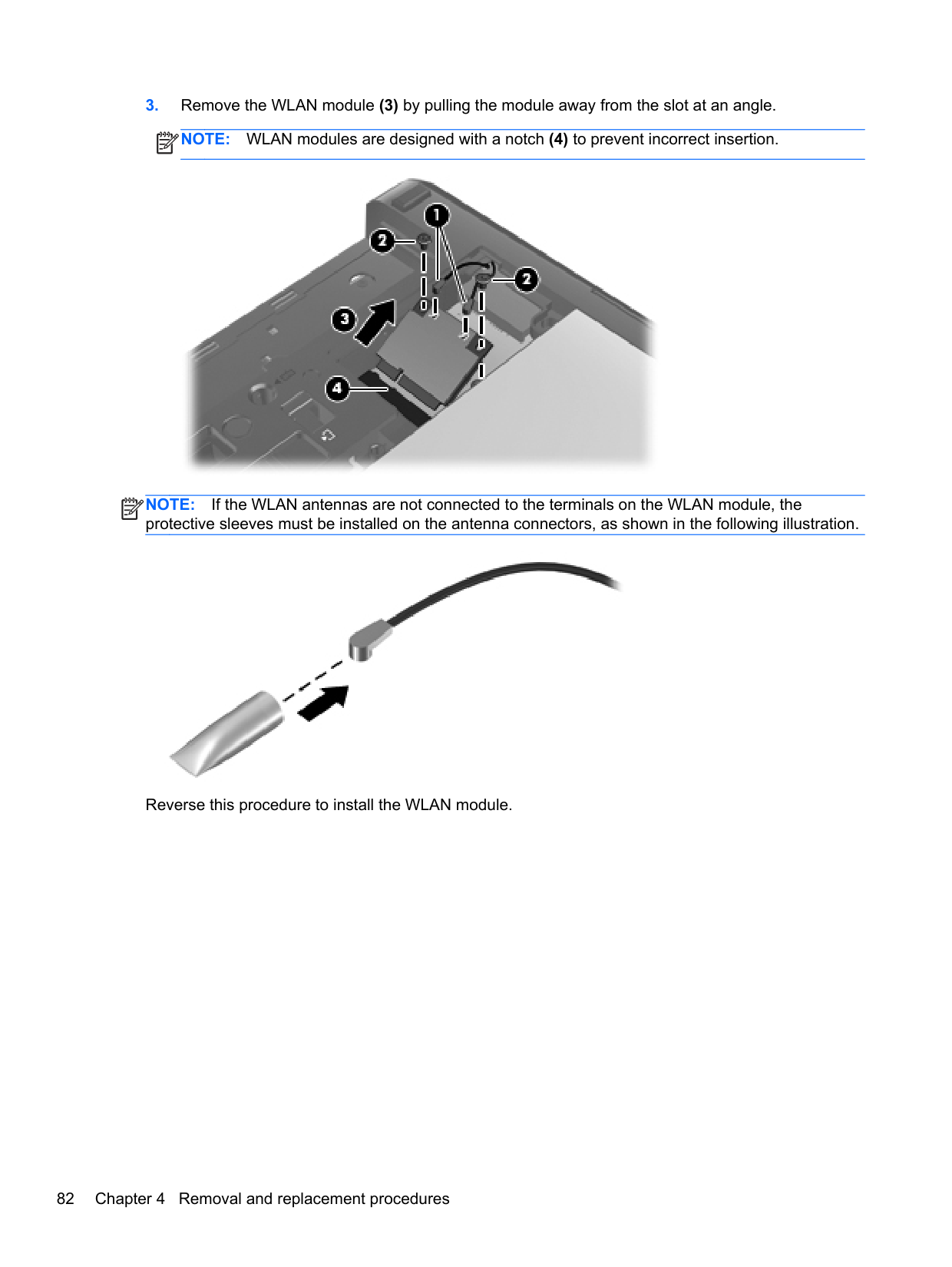
NOTE: WLAN modules are designed with a notch (4) to prevent incorrect insertion.
| | |---|

NOTE: If the WLAN antennas are not connected to the terminals on the WLAN module, the protective sleeves must be installed on the antenna connectors, as shown in the following illustration.
| | |---|

Reverse this procedure to install the WLAN module.
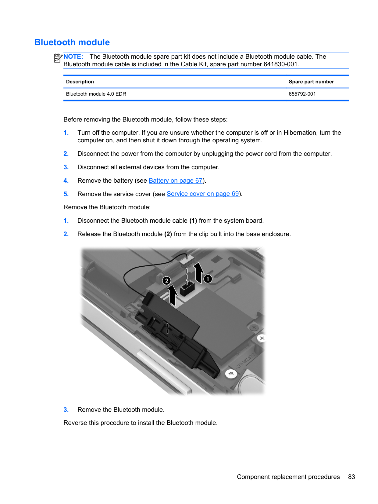
#### Bluetooth module
NOTE: The Bluetooth module spare part kit does not include a Bluetooth module cable. The Bluetooth module cable is included in the Cable Kit, spare part number 641830-001.
| | |---|
Description Spare part number Bluetooth module 4.0 EDR 655792-001
Before removing the Bluetooth module, follow these steps:

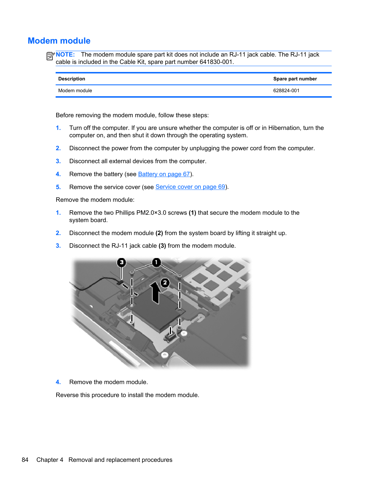
#### Modem module
NOTE: The modem module spare part kit does not include an RJ-11 jack cable. The RJ-11 jack cable is included in the Cable Kit, spare part number 641830-001.
| | |---|
Description Spare part number Modem module 628824-001
Before removing the modem module, follow these steps:
computer on, and then shut it down through the operating system.

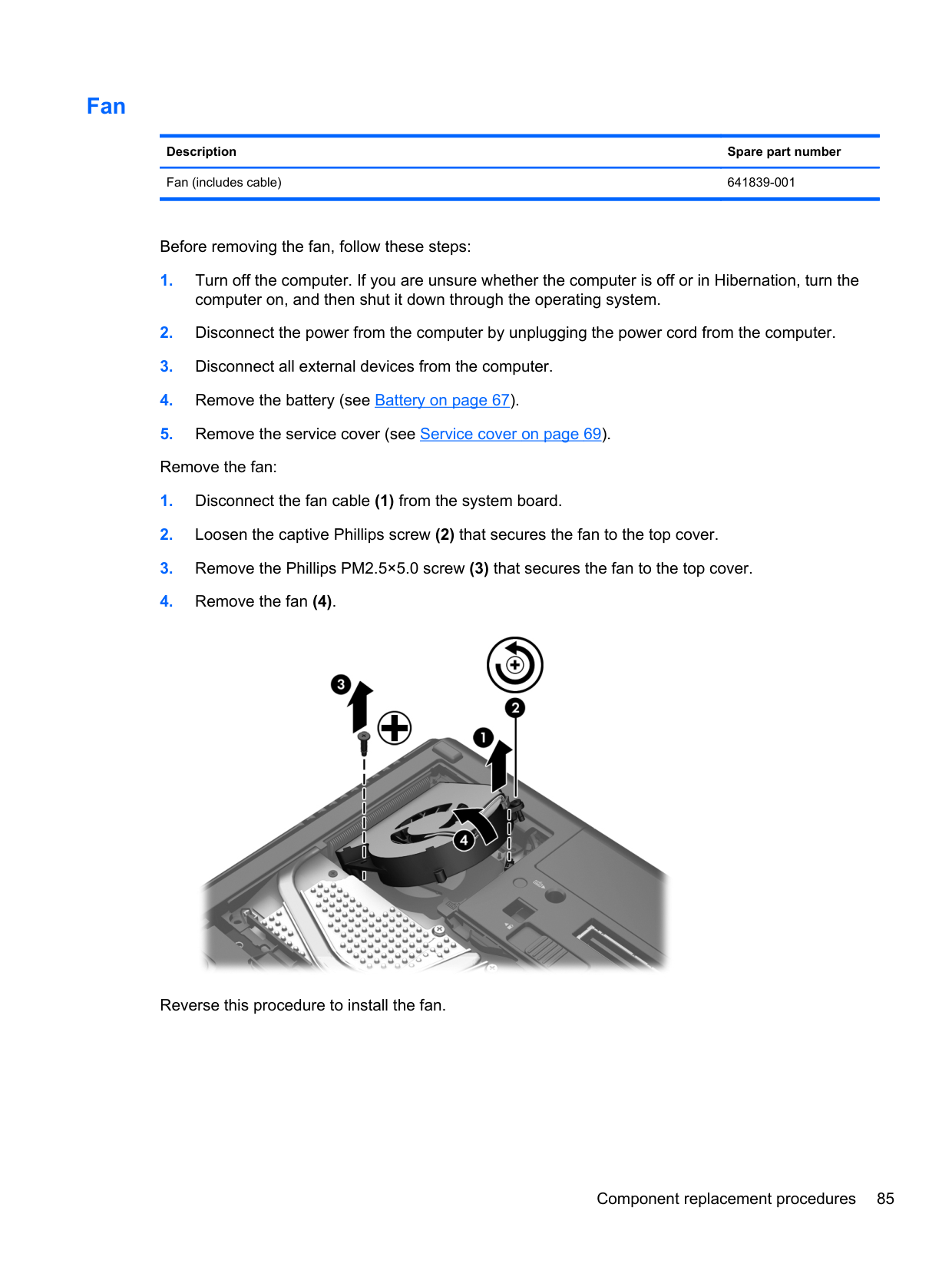
#### Fan
Description Spare part number Fan (includes cable) 641839-001
Before removing the fan, follow these steps:
computer on, and then shut it down through the operating system.

Reverse this procedure to install the fan.
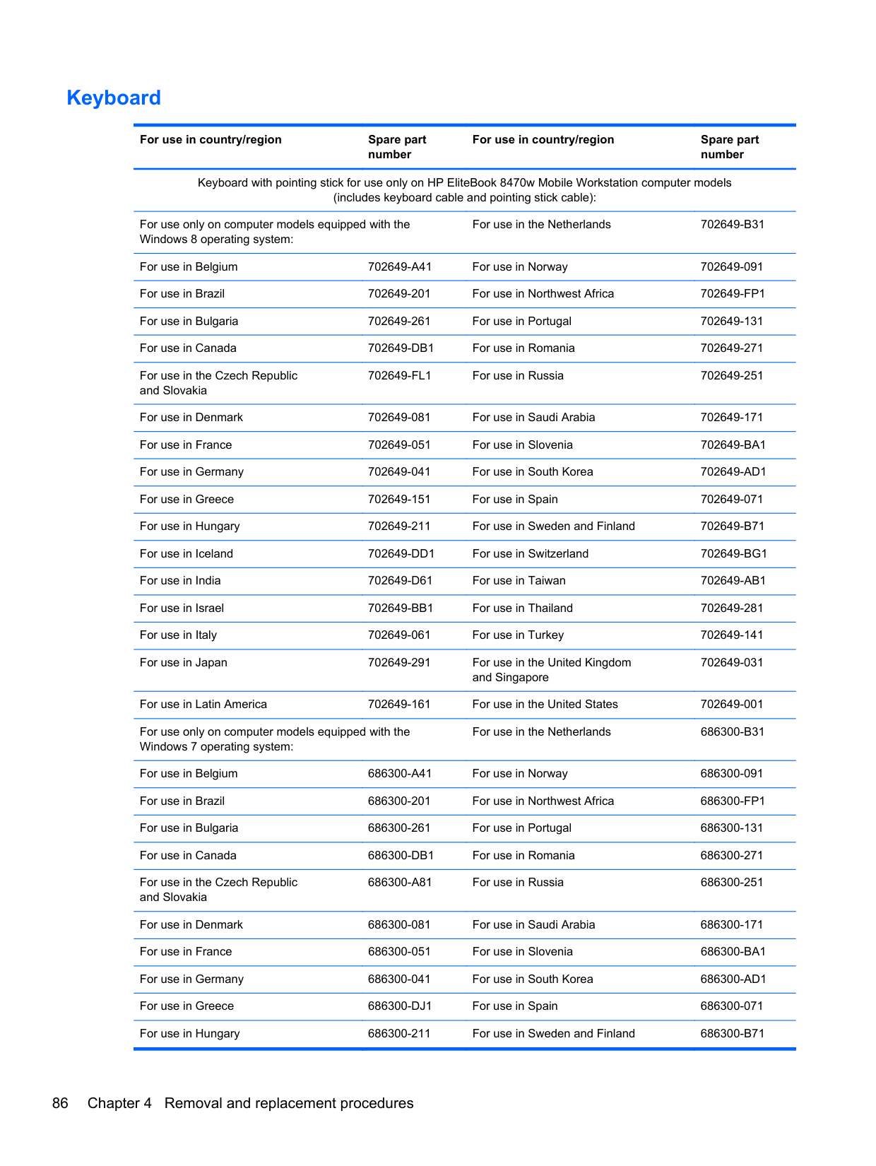
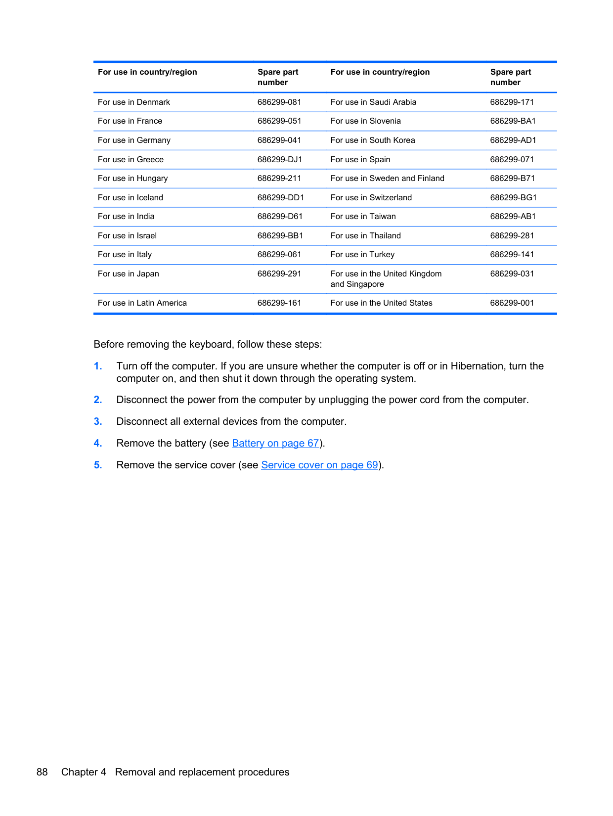
#### Keyboard
For use in country/region Spare part number
For use in country/region Spare part
number Keyboard with pointing stick for use only on HP EliteBook 8470w Mobile Workstation computer models (includes keyboard cable and pointing stick cable):
For use only on computer models equipped with the Windows 8 operating system:
For use in the Netherlands 702649-B31
For use in Belgium 702649-A41 For use in Norway 702649-091 For use in Brazil 702649-201 For use in Northwest Africa 702649-FP1 For use in Bulgaria 702649-261 For use in Portugal 702649-131 For use in Canada 702649-DB1 For use in Romania 702649-271 For use in the Czech Republic and Slovakia
702649-FL1 For use in Russia 702649-251
For use in Denmark 702649-081 For use in Saudi Arabia 702649-171 For use in France 702649-051 For use in Slovenia 702649-BA1 For use in Germany 702649-041 For use in South Korea 702649-AD1 For use in Greece 702649-151 For use in Spain 702649-071 For use in Hungary 702649-211 For use in Sweden and Finland 702649-B71 For use in Iceland 702649-DD1 For use in Switzerland 702649-BG1 For use in India 702649-D61 For use in Taiwan 702649-AB1 For use in Israel 702649-BB1 For use in Thailand 702649-281 For use in Italy 702649-061 For use in Turkey 702649-141 For use in Japan 702649-291 For use in the United Kingdom
702649-031
and Singapore
For use in Latin America 702649-161 For use in the United States 702649-001 For use only on computer models equipped with the Windows 7 operating system:
For use in the Netherlands 686300-B31
For use in Belgium 686300-A41 For use in Norway 686300-091 For use in Brazil 686300-201 For use in Northwest Africa 686300-FP1 For use in Bulgaria 686300-261 For use in Portugal 686300-131 For use in Canada 686300-DB1 For use in Romania 686300-271 For use in the Czech Republic and Slovakia
686300-A81 For use in Russia 686300-251
For use in Denmark 686300-081 For use in Saudi Arabia 686300-171 For use in France 686300-051 For use in Slovenia 686300-BA1 For use in Germany 686300-041 For use in South Korea 686300-AD1 For use in Greece 686300-DJ1 For use in Spain 686300-071 For use in Hungary 686300-211 For use in Sweden and Finland 686300-B71
For use in Iceland 686300-DD1 For use in Switzerland 686300-BG1 For use in India 686300-D61 For use in Taiwan 686300-AB1 For use in Israel 686300-BB1 For use in Thailand 686300-281 For use in Italy 686300-061 For use in Turkey 686300-141 For use in Japan 686300-291 For use in the United Kingdom
686300-031
and Singapore
For use in Latin America 686300-161 For use in the United States 686300-001
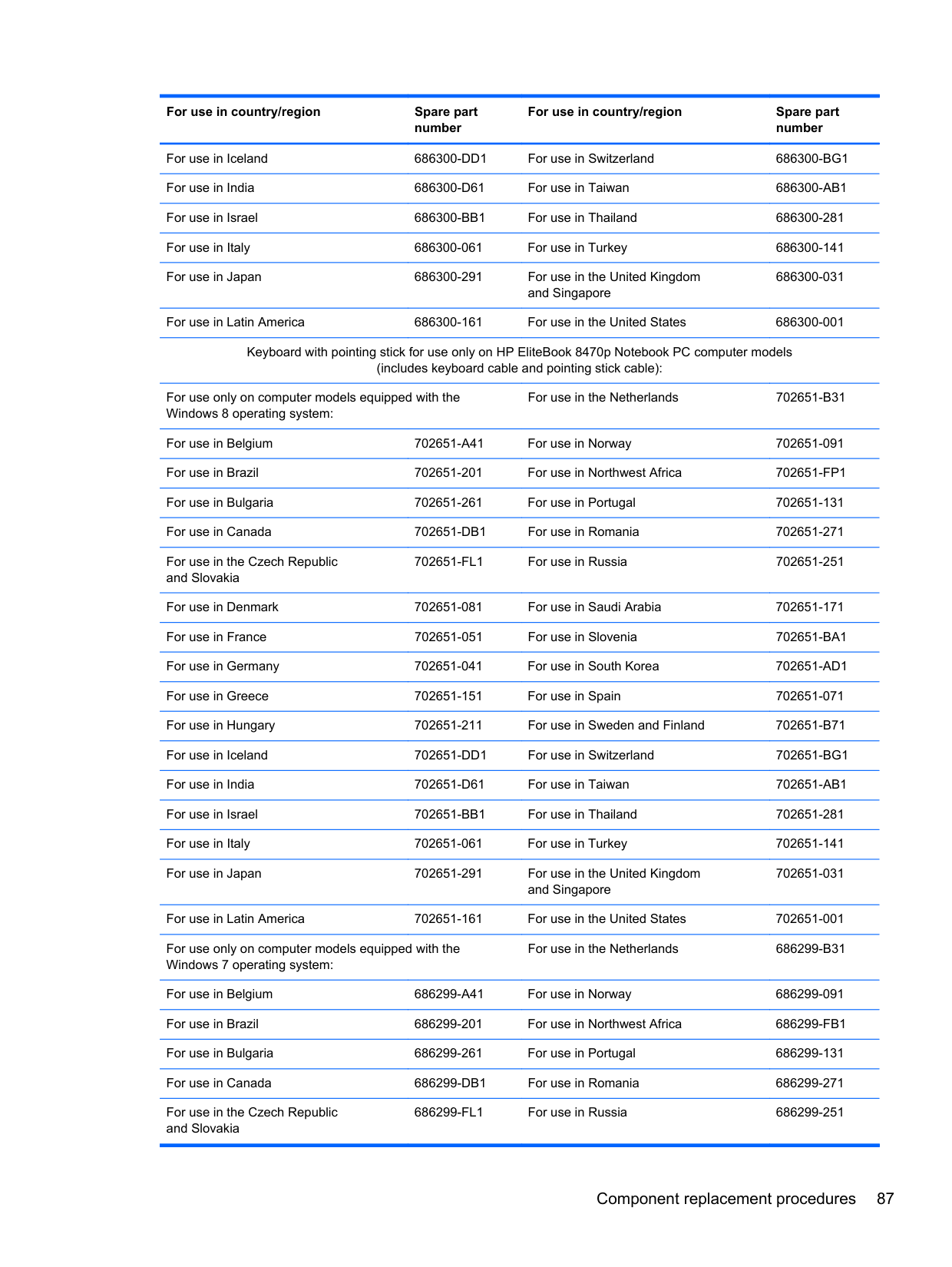
Keyboard with pointing stick for use only on HP EliteBook 8470p Notebook PC computer models (includes keyboard cable and pointing stick cable):
For use only on computer models equipped with the Windows 8 operating system:
For use in the Netherlands 702651-B31
For use in Belgium 702651-A41 For use in Norway 702651-091 For use in Brazil 702651-201 For use in Northwest Africa 702651-FP1 For use in Bulgaria 702651-261 For use in Portugal 702651-131 For use in Canada 702651-DB1 For use in Romania 702651-271 For use in the Czech Republic and Slovakia
702651-FL1 For use in Russia 702651-251
For use in Denmark 702651-081 For use in Saudi Arabia 702651-171 For use in France 702651-051 For use in Slovenia 702651-BA1 For use in Germany 702651-041 For use in South Korea 702651-AD1 For use in Greece 702651-151 For use in Spain 702651-071 For use in Hungary 702651-211 For use in Sweden and Finland 702651-B71 For use in Iceland 702651-DD1 For use in Switzerland 702651-BG1 For use in India 702651-D61 For use in Taiwan 702651-AB1 For use in Israel 702651-BB1 For use in Thailand 702651-281 For use in Italy 702651-061 For use in Turkey 702651-141 For use in Japan 702651-291 For use in the United Kingdom
702651-031
and Singapore
For use in Latin America 702651-161 For use in the United States 702651-001 For use only on computer models equipped with the Windows 7 operating system:
For use in the Netherlands 686299-B31
For use in Belgium 686299-A41 For use in Norway 686299-091 For use in Brazil 686299-201 For use in Northwest Africa 686299-FB1 For use in Bulgaria 686299-261 For use in Portugal 686299-131 For use in Canada 686299-DB1 For use in Romania 686299-271 For use in the Czech Republic and Slovakia
686299-FL1 For use in Russia 686299-251
For use in Denmark 686299-081 For use in Saudi Arabia 686299-171 For use in France 686299-051 For use in Slovenia 686299-BA1 For use in Germany 686299-041 For use in South Korea 686299-AD1 For use in Greece 686299-DJ1 For use in Spain 686299-071 For use in Hungary 686299-211 For use in Sweden and Finland 686299-B71 For use in Iceland 686299-DD1 For use in Switzerland 686299-BG1 For use in India 686299-D61 For use in Taiwan 686299-AB1 For use in Israel 686299-BB1 For use in Thailand 686299-281 For use in Italy 686299-061 For use in Turkey 686299-141 For use in Japan 686299-291 For use in the United Kingdom
686299-031
and Singapore
For use in Latin America 686299-161 For use in the United States 686299-001
Before removing the keyboard, follow these steps:
computer on, and then shut it down through the operating system.
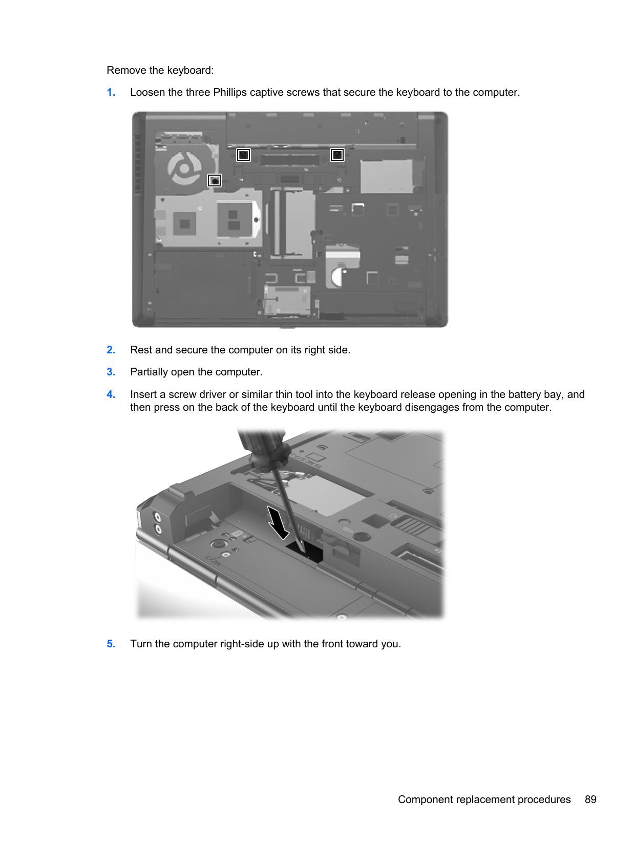
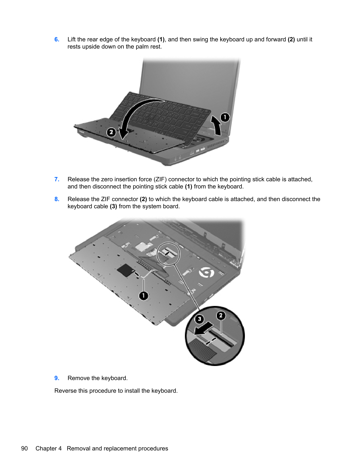
Remove the keyboard:


#### Base enclosure
######## Description Spare part number
Base enclosure (includes four rubber feet, service cover release latch assembly, and battery release latch assembly)
685997-001
Before removing the base enclosure, follow these steps:
NOTE: When replacing the base enclosure, be sure to remove the following components from the defective base enclosure and install them on the replacement base enclosure:
| | |---|


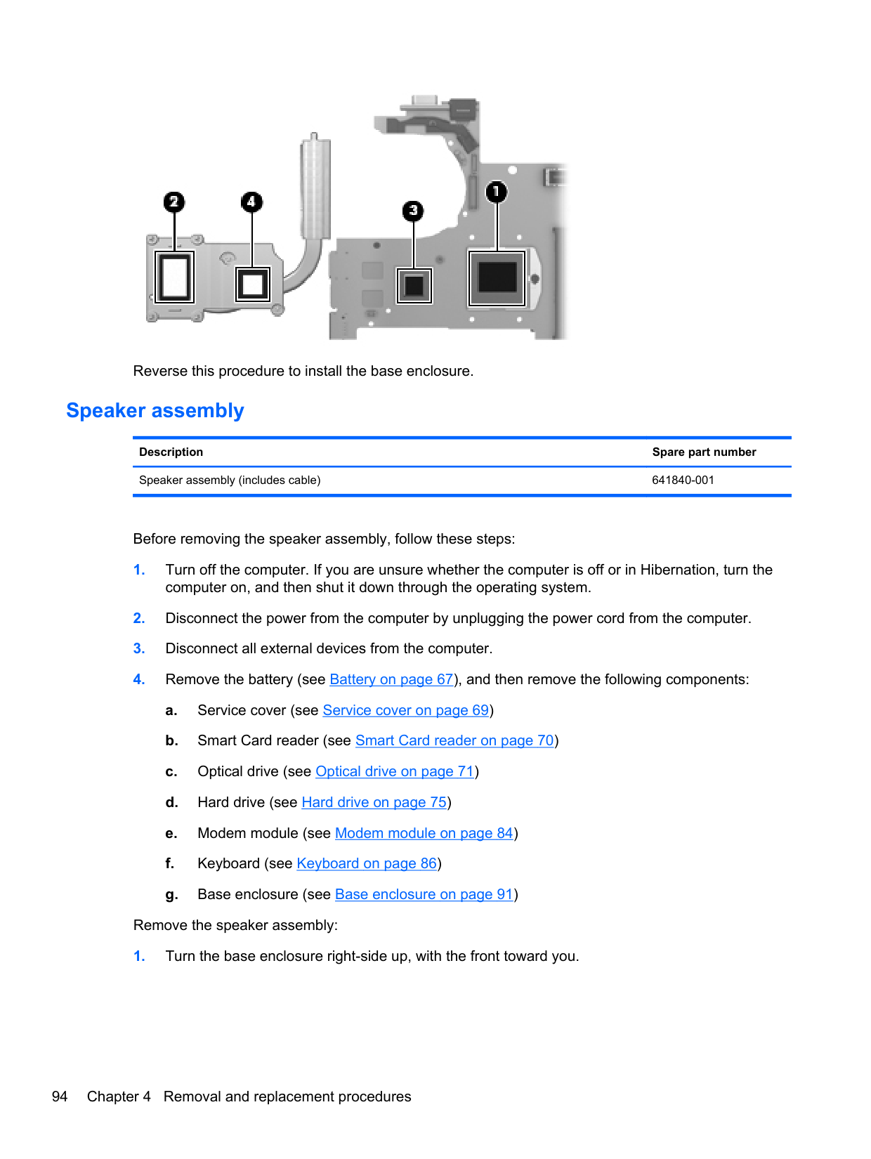
NOTE: Thoroughly clean the thermal pad material from the surfaces of the base enclosure (1) and the PCH chip (2) each time you remove the base enclosure. All base enclosure and system board spare part kits include replacement thermal pad material.
| | |---|

Reverse this procedure to install the base enclosure.
#### Speaker assembly
Description Spare part number Speaker assembly (includes cable) 641840-001
Before removing the speaker assembly, follow these steps:
computer on, and then shut it down through the operating system.
Remove the speaker assembly:


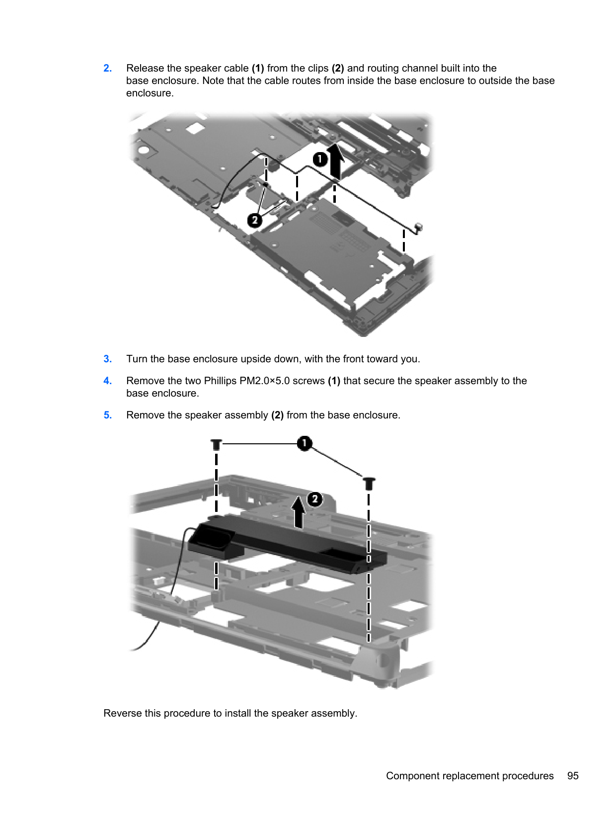
Reverse this procedure to install the speaker assembly.
#### RJ-11 jack cable
NOTE: The RJ-11 jack cable is included in the Cable Kit, spare part number 641830-001.
| |
|---|
Before removing the RJ-11 jack cable, follow these steps:
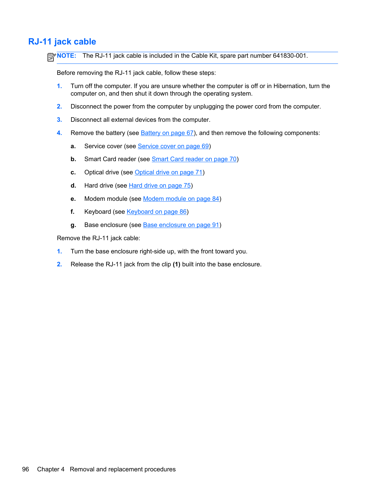
Remove the RJ-11 jack cable:

Service cover release latch assembly NOTE: The service cover release latch assembly components are included in the Latch Kit, spare part number 684339-001. Before removing the service cover release latch assembly, follow these steps:
| | |---|
Remove the service cover release latch assembly:


Battery release latch assembly NOTE: The battery release latch assembly components are included in the Latch Kit, spare part number 684339-001. Before removing the battery release latch assembly, follow these steps:
| | |---|
computer on, and then shut it down through the operating system.
Remove the battery release latch assembly:


#### Fingerprint reader board
Description Spare part number Fingerprint reader board (includes cable) 684343-001
Before removing the fingerprint reader board, follow these steps:
computer on, and then shut it down through the operating system.
Remove the fingerprint reader board:

#### RTC battery
Description Spare part number RTC battery (includes cable and double-sided tape) 652650-001
Before removing the RTC battery, follow these steps:
computer on, and then shut it down through the operating system.
Remove the RTC battery:

Reverse this procedure to install the RTC battery.
#### Display lid switch board
Description Spare part number Display lid switch board (includes cable) 684340-001
Before removing the display lid switch board, follow these steps:
computer on, and then shut it down through the operating system.
Remove the display lid switch board:
####### 3. Detach the display lid switch board (2) from the clips built into the top cover.

####### 4. Remove the display lid switch board and cable.Reverse this procedure to install the display lid switch board and cable.
#### System board
NOTE: The system board spare part kit includes replacement thermal material.
| | |---|
Description Spare part number For use only on HP EliteBook 8470w Mobile Workstation computer models: For use only on computer models equipped with a graphics subsystem with discrete memory and the Windows 8 Professional operating system in all countries and regions except the People's Republic of China and the Ukraine
686042-601
For use only on computer models equipped with a graphics subsystem with discrete memory and the Windows 8 Standard operating system in all countries and regions except the People's Republic of China and the Ukraine
686042-501
For use only on computer models equipped with a graphics subsystem with discrete memory
686042-001
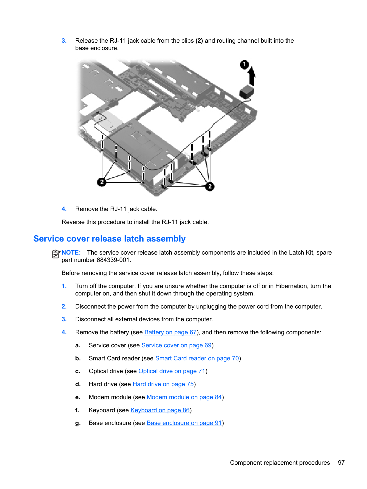
For use only on computer models equipped with a graphics subsystem with discrete memory
691718-001
For use only on HP EliteBook 8470p Notebook PC computer models: For use only on computer models equipped with a graphics subsystem with discrete memory
686041-601
For use only on computer models equipped with a graphics subsystem with discrete memory
686041-501
For use only on computer models equipped with a graphics subsystem with discrete memory and the Windows 7 operating system in all countries and regions except the People's Republic of China and the Ukraine
686041-001
For use only on computer models equipped with a graphics subsystem with discrete memory and the Windows 7 operating system in the People's Republic of China and the Ukraine
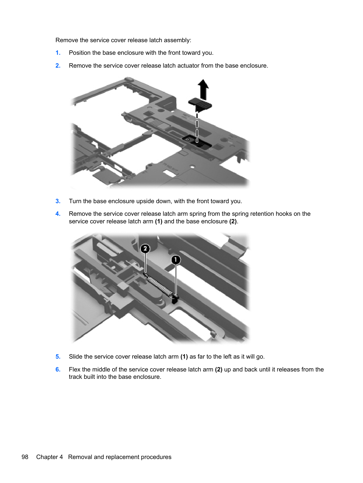
For use only on computer models equipped with a graphics subsystem with UMA memory and the Windows 8 Professional operating system in all countries and regions except the People's Republic of China and the Ukraine
691717-001
686040-601
For use only on computer models equipped with a graphics subsystem with UMA memory and the Windows 8 Standard operating system in all countries and regions except the People's Republic of China and the Ukraine
For use only on computer models equipped with a graphics subsystem with UMA memory and the Windows 7 operating system in all countries and regions except the People's Republic of China and the Ukraine
For use only on computer models equipped with a graphics subsystem with UMA memory and the Windows 7 operating system in the People's Republic of China and the Ukraine
686040-501
686040-001
691716-001
Before removing the system board, follow these steps:
NOTE: When replacing the system board, be sure that the following components are removed from the defective system board and installed on the replacement system board:
| | |---|
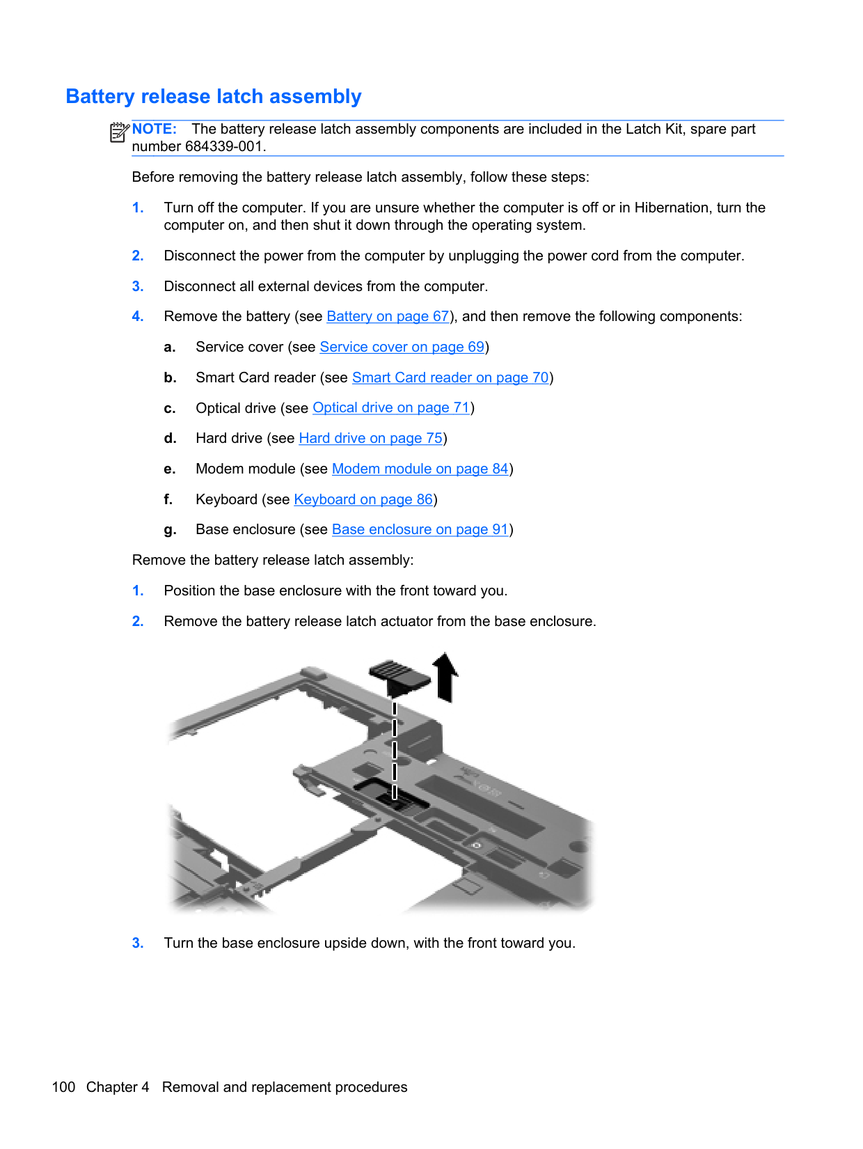

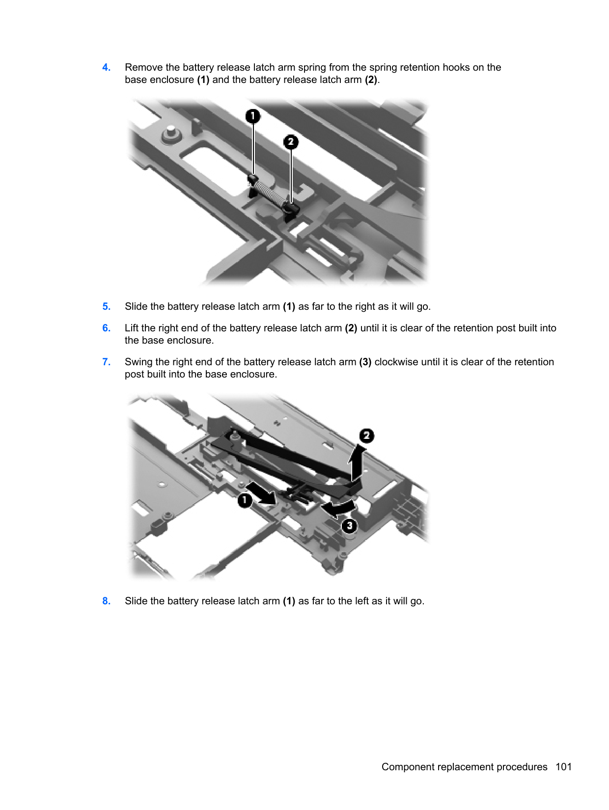


Reverse this procedure to install the system board.
#### Heat sink
NOTE: The heat sink spare part kit includes replacement thermal material.
| | |---|
Description Spare part number
For use only on computer models equipped with a graphics subsystem with discrete memory 686021-001 For use only on computer models equipped with a graphics subsystem with UMA memory 693371-001
Before removing the heat sink, follow these steps:
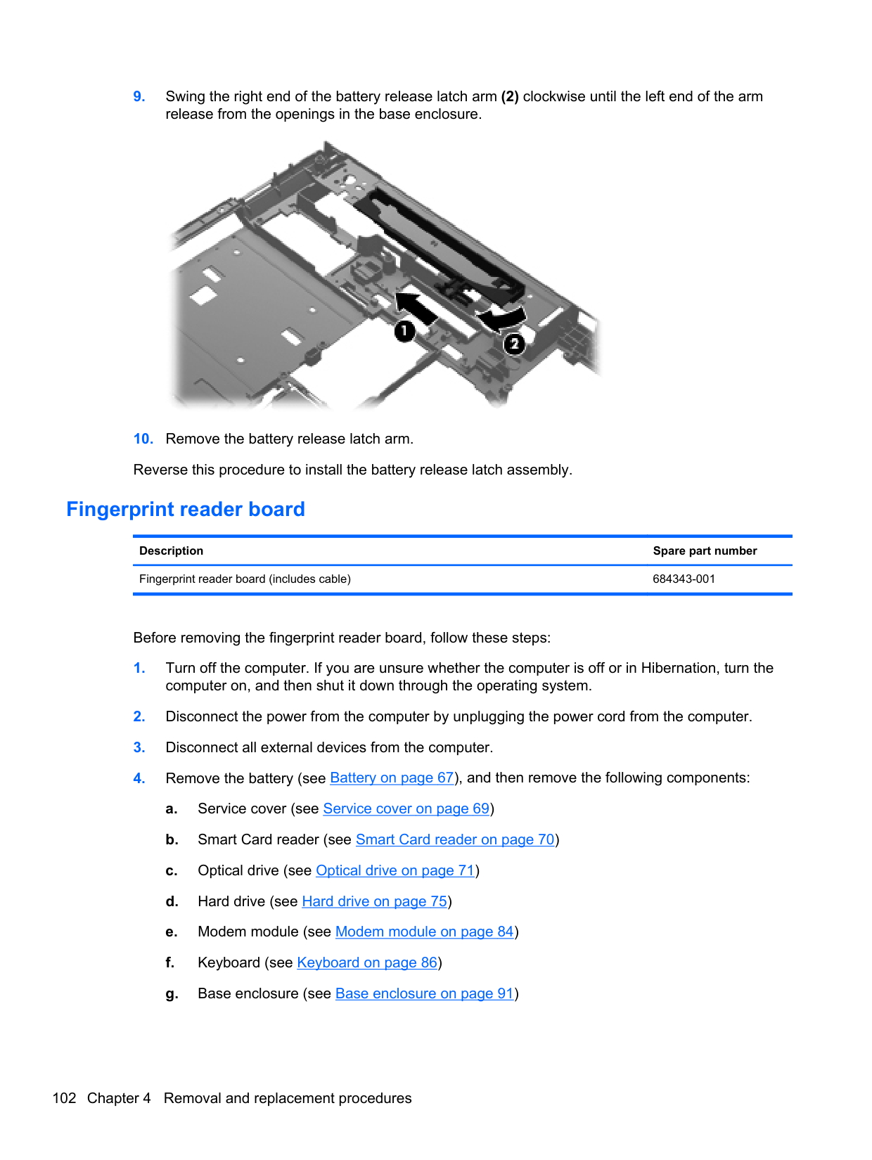
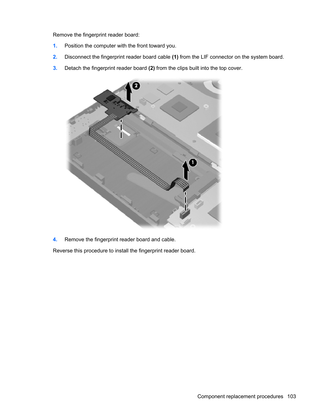
Remove the heat sink: NOTE: Steps 1 and 2 apply to computer models equipped with a graphics subsystem with discrete memory. See steps 3 and 4 for heat sink removal information for computer models equipped with a graphics subsystem with UMA memory.
| | |---|
| | |---|
NOTE: Due to the adhesive quality of the thermal material located between the heat sink and the system board components, it may be necessary to move the heat sink from side to side to detach it.

| | |---|
NOTE: Steps 3 and 4 apply to computer models equipped with a graphics subsystem with UMA memory. See steps 1 and 2 for heat sink removal information for computer models equipped with a graphics subsystem with discrete memory.
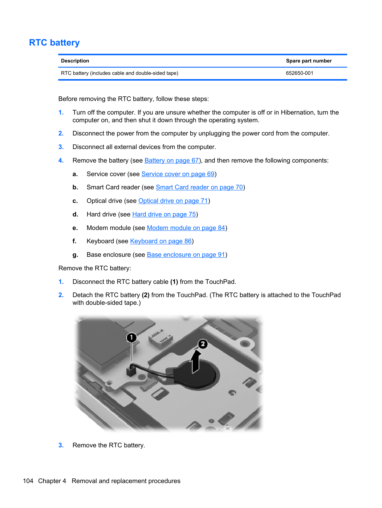
NOTE: Due to the adhesive quality of the thermal material located between the heat sink and the system board components, it may be necessary to move the heat sink from side to side to detach it.
| | |---|

NOTE: The thermal material must be thoroughly cleaned from the surfaces of the heat sink and the system board components each time the heat sink is removed. Replacement thermal material is included with the heat sink, processor, and system board spare part kits.
| | |---|
The following illustration shows the replacement thermal material locations on a computer model equipped with a graphics subsystem with discrete memory.

The following illustration shows the replacement thermal material locations on a computer model equipped with a graphics subsystem with UMA memory. Thermal paste is used on the processor (1) and the heat sink section (2) that services it.

####### Reverse this procedure to install the heat sink.
#### Processor
NOTE: The processor spare part kit includes replacement thermal material.
| | |---|
Description Spare part number For use only on HP EliteBook 8470w Mobile Workstation computer models: Intel Quad Core i7-3840QM 2.80-GHz processor (SC turbo up to 3.80-GHz; 1600-MHz FSB, 8.0MB L3 cache, 45 W)
703266-001
Intel Quad Core i7-3820QM 2.70-GHz processor (SC turbo up to 3.70-GHz; 1600-MHz FSB, 8.0MB L3 cache, 45 W)
681284-001
Intel Quad Core i7-3740QM 2.70-GHz processor (SC turbo up to 3.70-GHz; 1600-MHz FSB, 6.0MB L3 cache, 45 W)
702840-001
Intel Quad Core i7-3720QM 2.60-GHz processor (SC turbo up to 3.60-GHz; 1600-MHz FSB, 6.0MB L3 cache, 45 W)
681283-001
Intel Quad Core i7-3630QM 2.40-GHz processor (SC turbo up to 3.40-GHz; 1600-MHz FSB, 6.0MB L3 cache, 45 W)
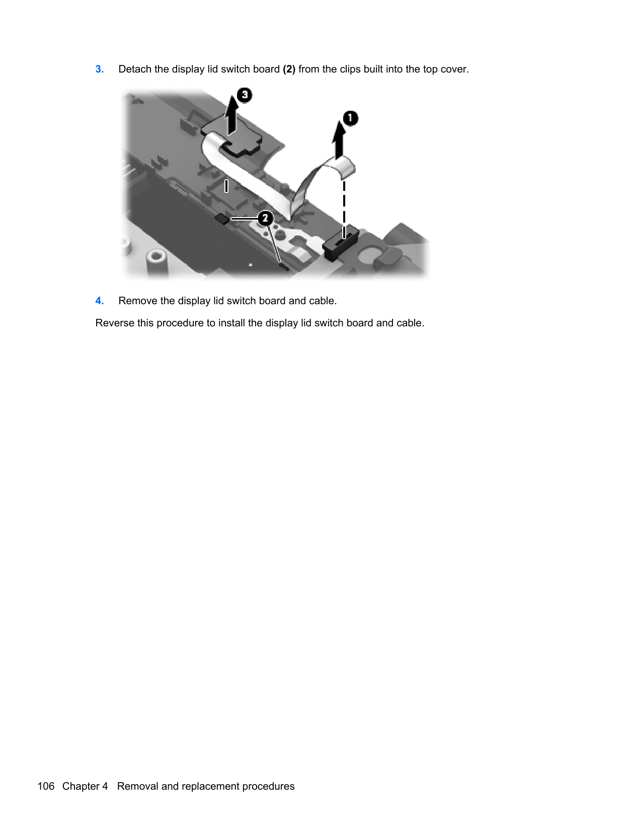
702081-001
Intel Quad Core i7-3610QM 2.30-GHz processor (SC turbo up to 3.30-GHz; 1600-MHz FSB, 6.0MB L3 cache, 45 W)
680646-001
For use on all computer models: Intel Quad Core i7-3540M 3.00-GHz processor (SC turbo up to 3.70-GHz; 1600-MHz FSB, 4.0MB L3 cache, 35 W)
Intel Dual Core i7-3520M 2.90-GHz processor (SC turbo up to 3.60-GHz; 1600-MHz FSB, 4.0MB L3 cache, 35 W)
Intel Dual Core i5-3380M 2.90-GHz processor (SC turbo up to 3.60-GHz; 1600-MHz FSB, 3.0MB L3 cache, 35 W)
Intel Dual Core i5-3360M 2.80-GHz processor (SC turbo up to 3.50-GHz; 1600-MHz FSB, 3.0MB L3 cache, 35 W)
Intel Dual Core i5-3340M 2.70-GHz processor (SC turbo up to 3.40-GHz; 1600-MHz FSB, 3.0MB L3 cache, 35 W)
Intel Dual Core i5-3320M 2.60-GHz processor (SC turbo up to 3.30-GHz; 1600-MHz FSB, 3.0MB L3 cache, 35 W)
Intel Dual Core i5-3320M 2.60-GHz processor (SC turbo up to 3.20-GHz; 1600-MHz FSB, 3.0MB L3 cache, 35 W)
710787-001
681954-001
708762-001
681953-001
708761-001
681952-001
711903-001
Intel Dual Core i5-3210M 2.50-GHz processor (SC turbo up to 3.10-GHz; 1600-MHz FSB, 3.0MB L3 cache, 35 W)
680645-001
Intel Core i3-3130M 2.60-GHz processor (1600-MHz FSB, 3.0-MB L3 cache, 35 W) 713163-001 Intel Core i3-3120M 2.50-GHz processor (1600-MHz FSB, 3.0-MB L3 cache, 35 W) 700627-001 Intel Core i3-3110M 2.40-GHz processor (1600-MHz FSB, 3.0-MB L3 cache, 35 W) 682417-001 For use only on HP EliteBook 8470p Notebook PC computer models: Intel Core i3-2370M 2.40-GHz processor (1333-MHz FSB, 3.0-MB L3 cache, 35 W) 677152-001 Intel Celeron B840 1.90-GHz processor (1333-MHz FSB, 2.0-MB L3 cache, 35 W) 664663-001
Before removing the processor, follow these steps:
Remove the processor:
NOTE: The gold triangle (3) on the processor must be aligned with the triangle icon (4) embossed on the processor socket when you install the processor.
| | |---|
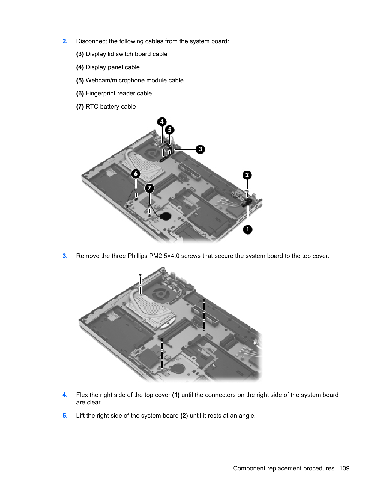

Reverse this procedure to install the processor.
#### ExpressCard assembly
Description Spare part number ExpressCard assembly 684345-001
Before removing the ExpressCard assembly, follow these steps:
computer on, and then shut it down through the operating system.
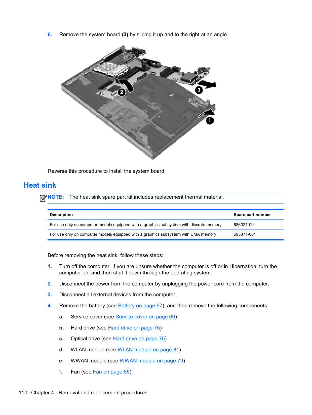
Remove the ExpressCard assembly:

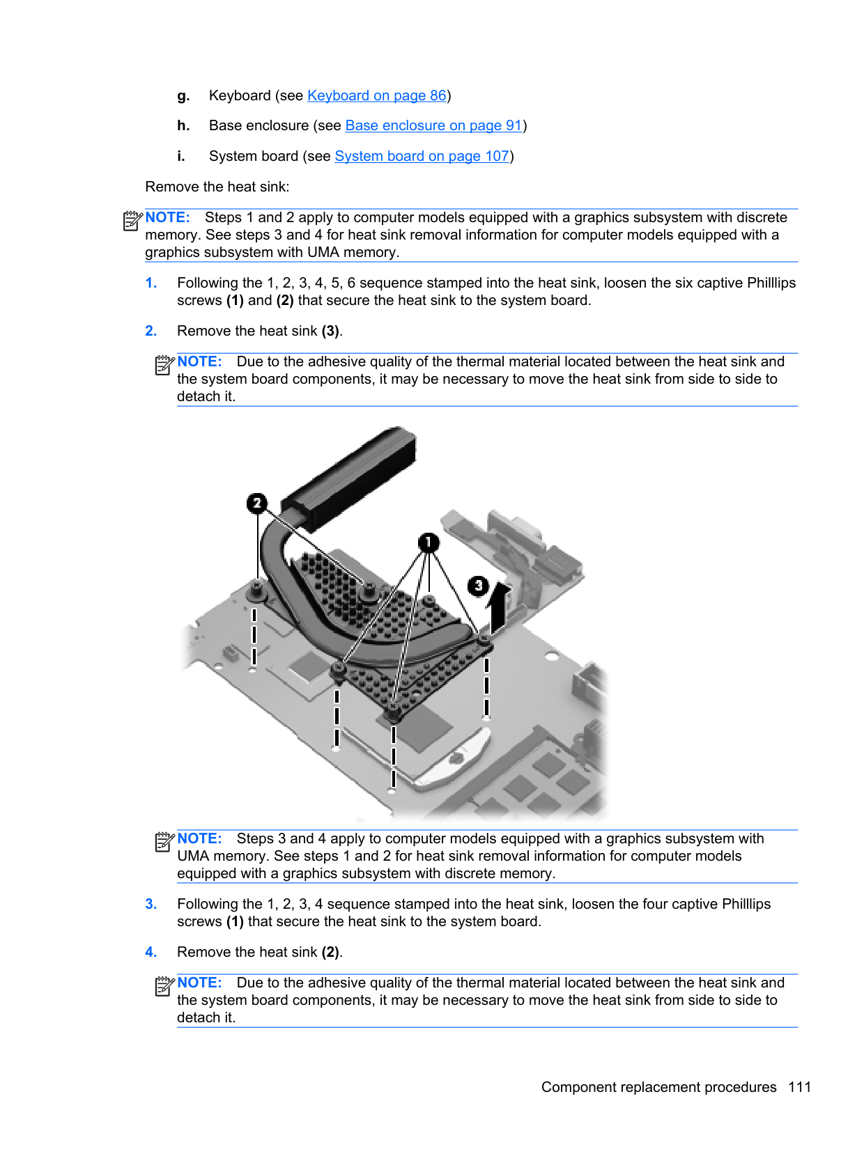

Reverse this procedure to install the ExpressCard assembly.
Display assembly NOTE: The display assembly is spared at the subcomponent level only. For more display assembly spare part information, see the individual removal subsections. Before removing the display assembly, follow these steps:
| | |---|
computer on, and then shut it down through the operating system.
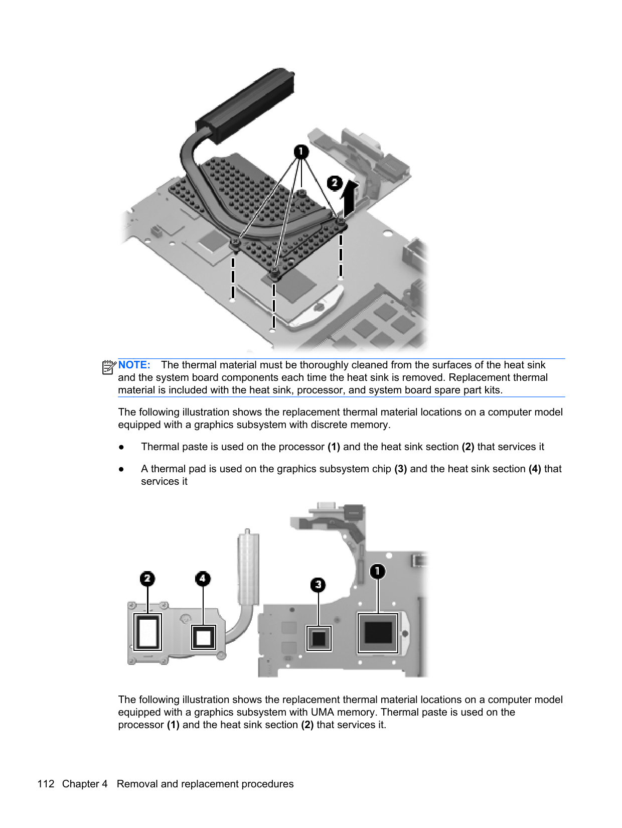
Remove the display assembly:


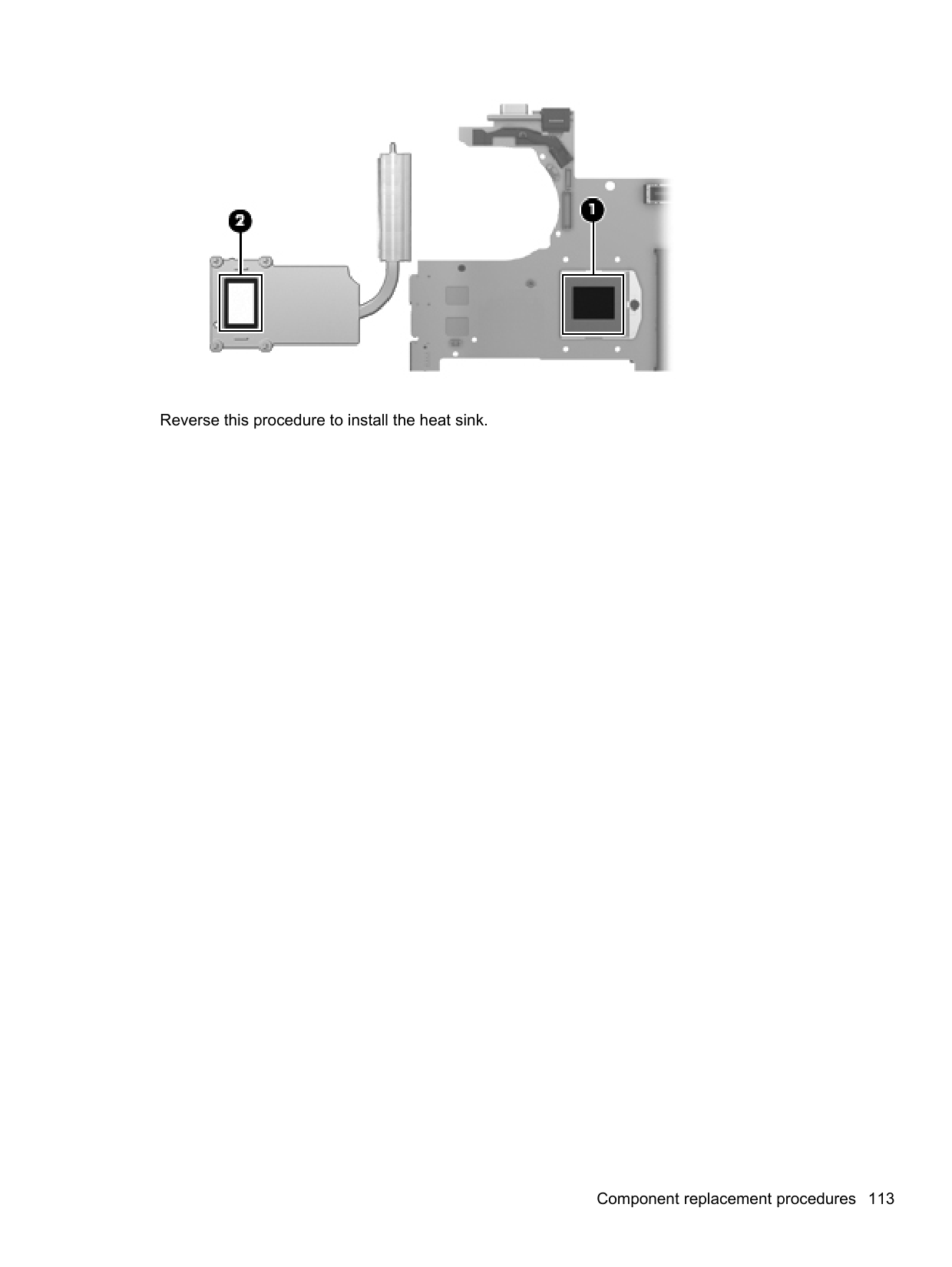


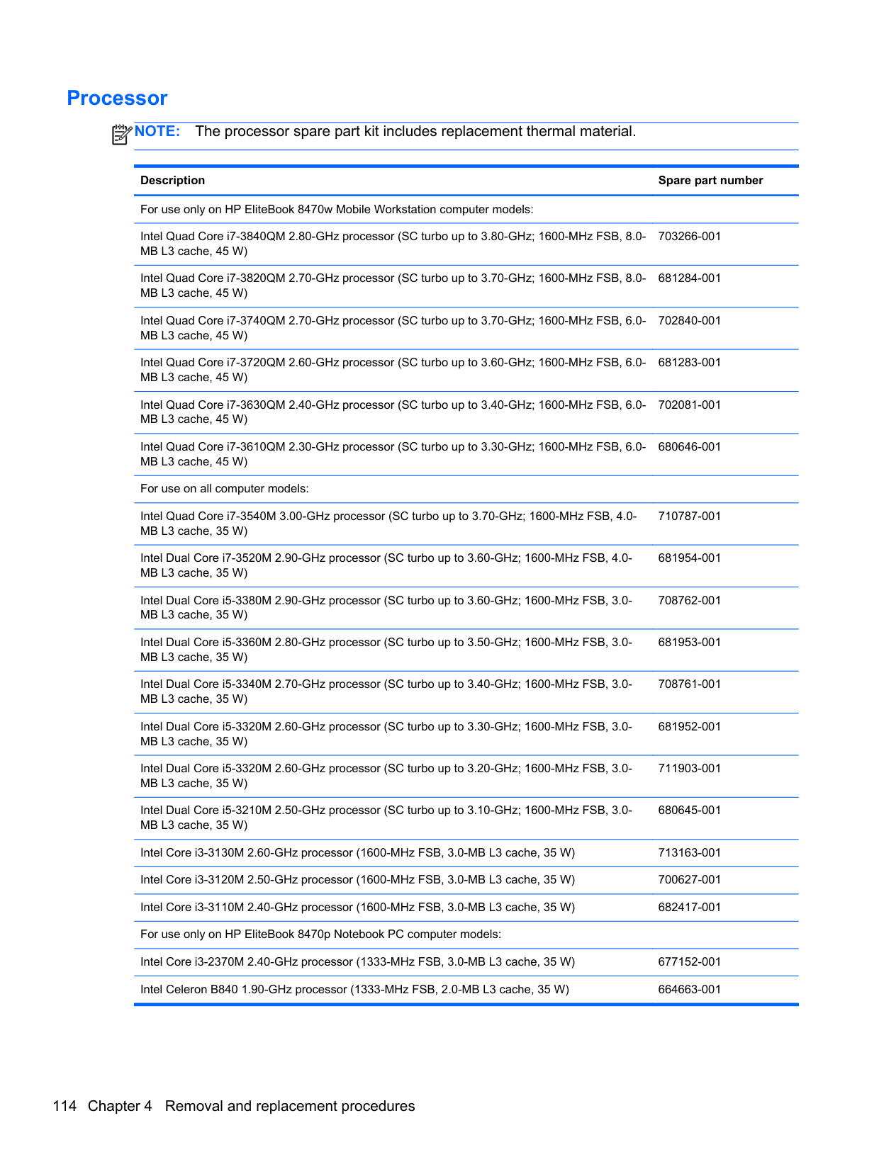


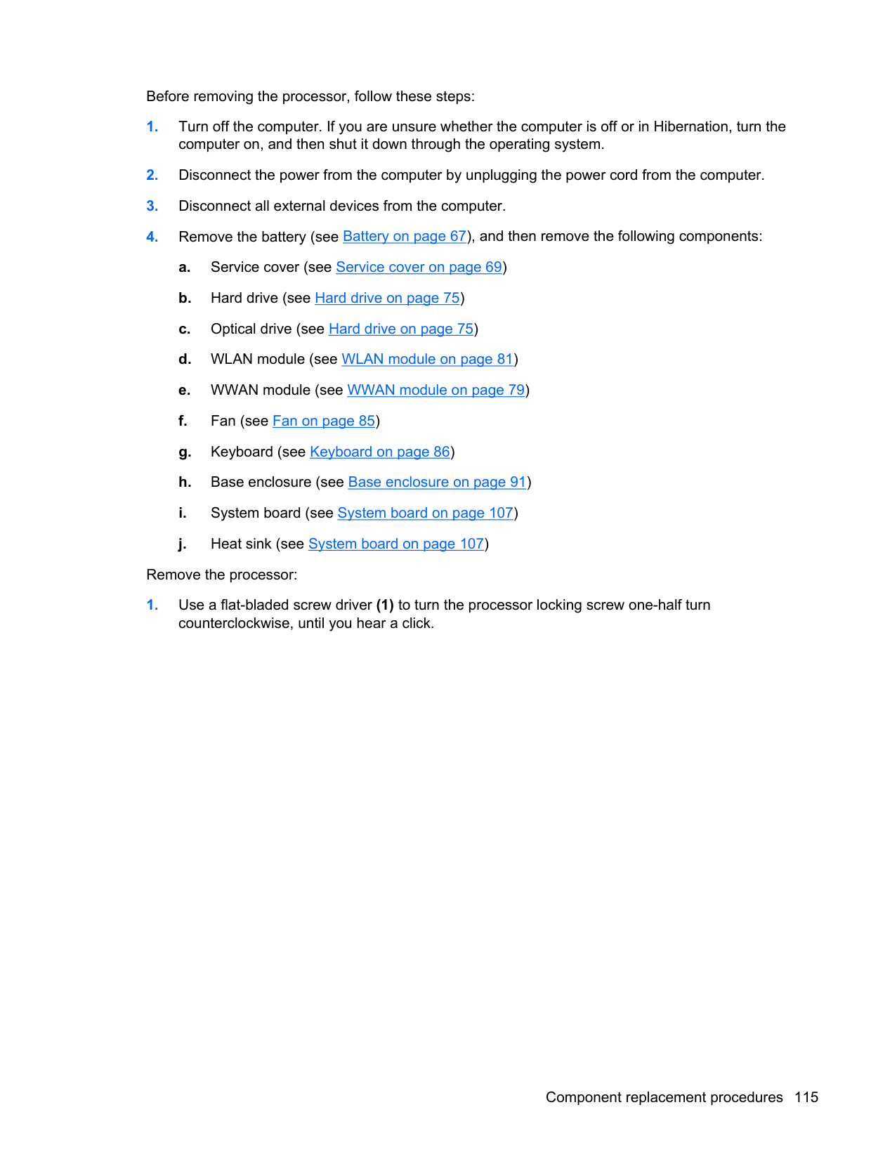

CAUTION: Handle the webcam/microphone module with caution. The module has a thin profile and is susceptible to damage when not handled carefully.
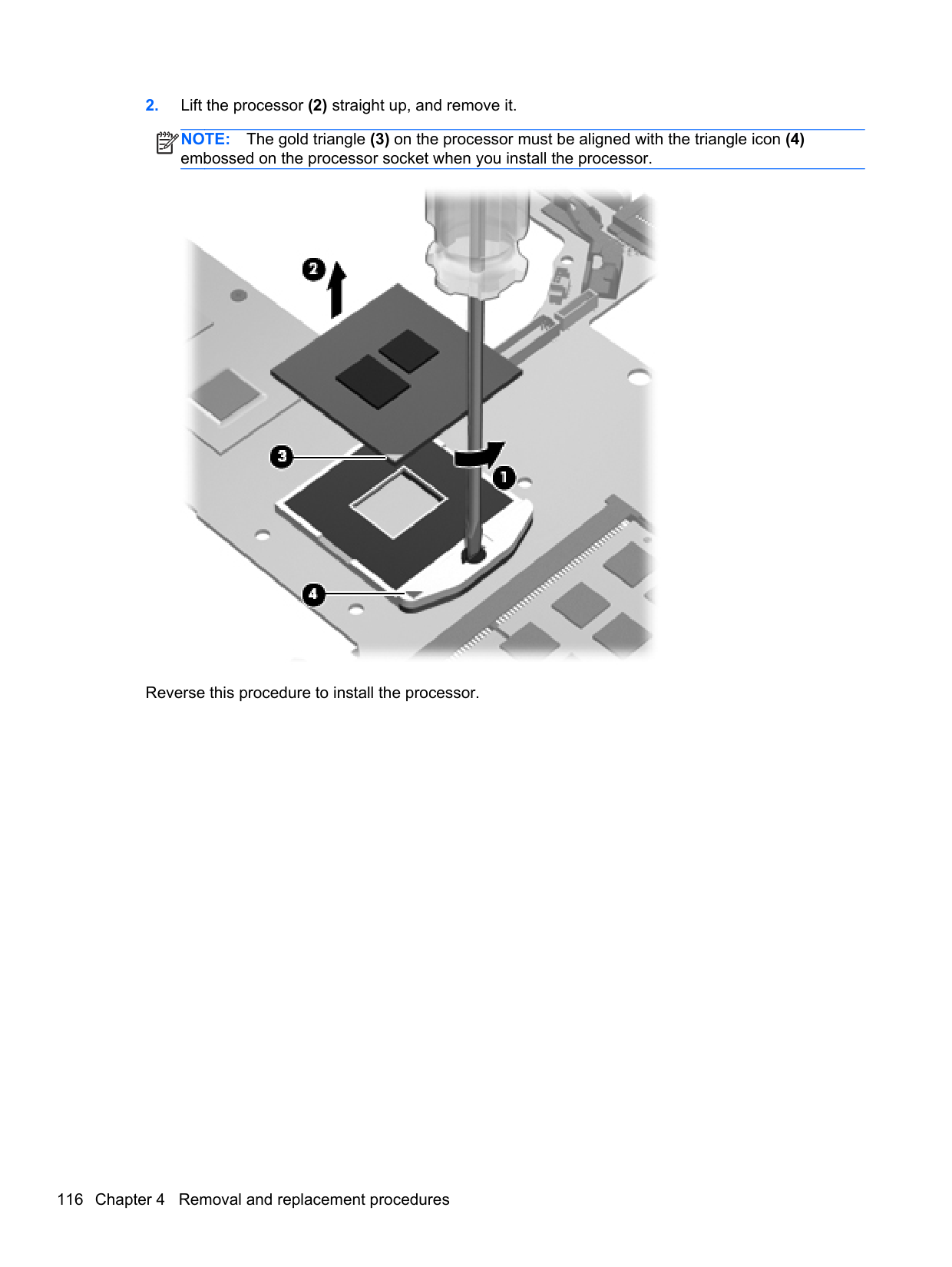


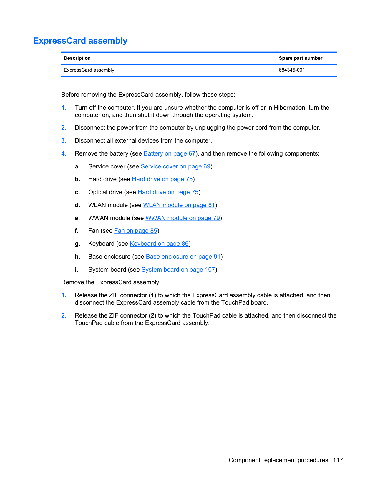
Reverse this procedure to reassemble and install the display assembly.
5 Computer Setup (BIOS) and AdvancedSystem Diagnostics
Windows 8
#### Using Computer Setup
Computer Setup, or Basic Input/Output System (BIOS), controls communication between all the input and output devices on the system (such as disk drives, display, keyboard, mouse, and printer). Computer Setup includes settings for the types of devices installed, the startup sequence of the computer, and the amount of system and extended memory.
NOTE: Use extreme care when making changes in Computer Setup. Errors can prevent the computer from operating properly.
| | |---|
##### Starting Computer Setup
NOTE: An external keyboard or mouse connected to a USB port can be used with Computer
| | |---|
Setup only if USB legacy support is enabled. To start Computer Setup, follow these steps:
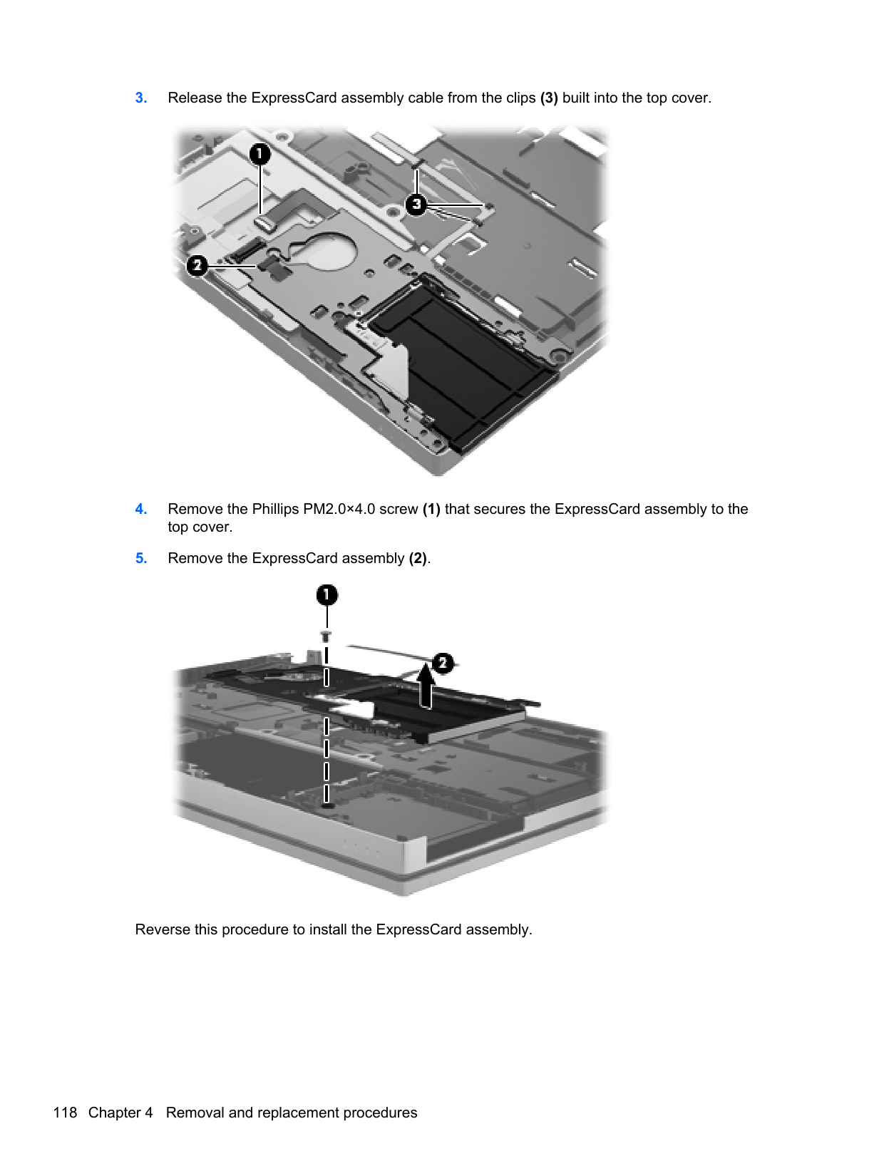
##### Navigating and selecting in Computer Setup
To navigate and select in Computer Setup, follow these steps:
NOTE: You can use either a pointing device (TouchPad, pointing stick, or USB mouse) or the keyboard to navigate and make selections in Computer Setup.
| | |---|
Click the Exit icon in the lower-left corner of the screen, and then follow the on-screen instructions.
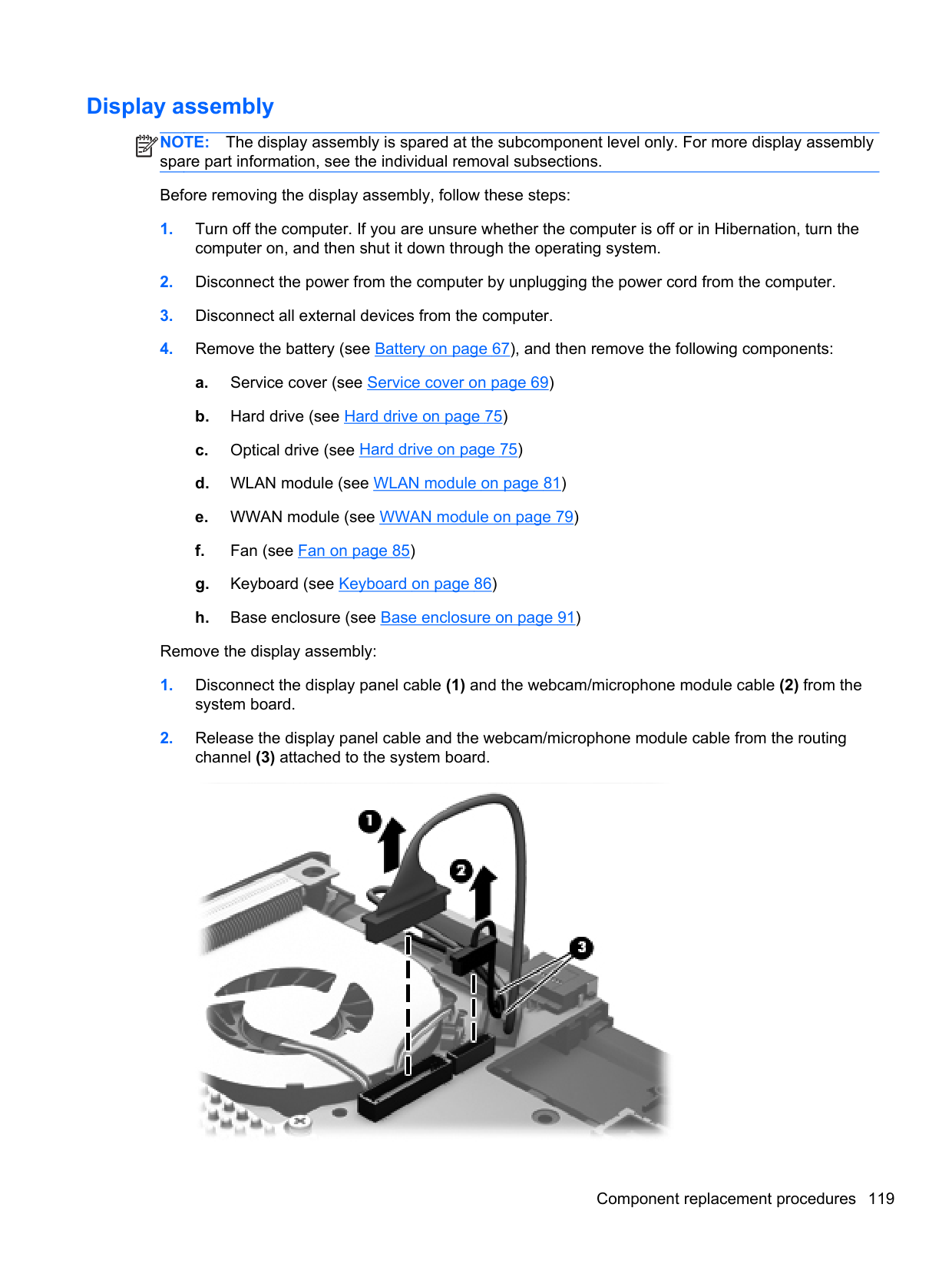
– or – Use the tab key and the arrow keys to select File > Ignore Changes and Exit, and then press enter.
Click the Save icon in the lower-left corner of the screen, and then follow the on-screen instructions.
– or – Use the tab key and the arrow keys to select File > Save Changes and Exit, and then press enter.
Your changes go into effect when the computer restarts.
##### Restoring factory settings in Computer Setup
NOTE: Restoring defaults will not change the hard drive mode.
| | |---|
To return all settings in Computer Setup to the values that were set at the factory, follow these steps:
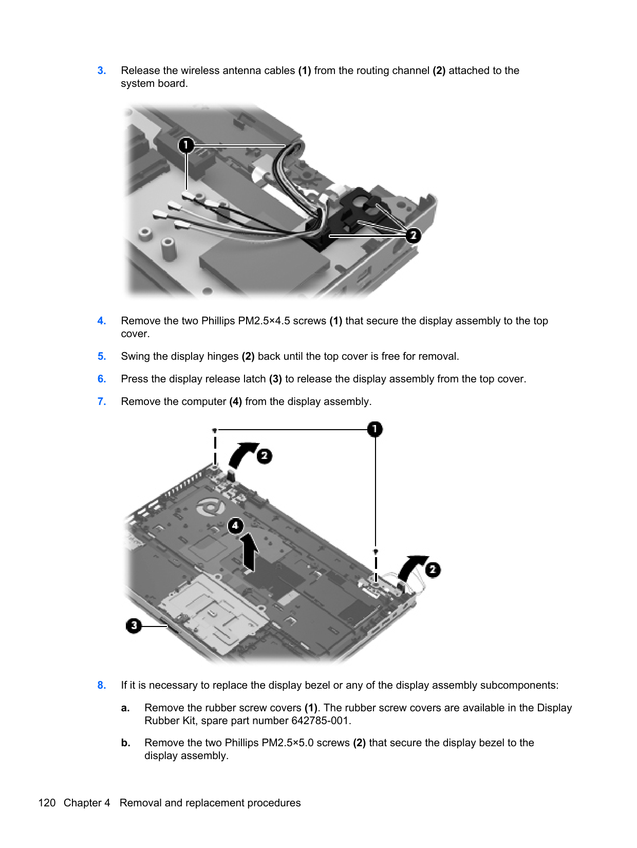
– or – Use the arrow keys to select File > Save Changes and Exit, and then press enter.
Your changes go into effect when the computer restarts. NOTE: Your password settings and security settings are not changed when you restore the factory settings.
| | |---|
Updating the BIOS Updated versions of the BIOS may be available on the HP website. Most BIOS updates on the HP website are packaged in compressed files called SoftPaqs. Some download packages contain a file named Readme.txt, which contains information regarding installing and troubleshooting the file.
###### Determining the BIOS version
To determine whether available BIOS updates contain later BIOS versions than those currently installed on the computer, you need to know the version of the system BIOS currently installed.
BIOS version information (also known as ROM date and System BIOS) can be displayed by pressing fn+esc (if you are already in Windows) or by using Computer Setup.
– or – Use the tab key and the arrow keys to select File > Ignore Changes and Exit, and then press enter.
###### Downloading a BIOS update
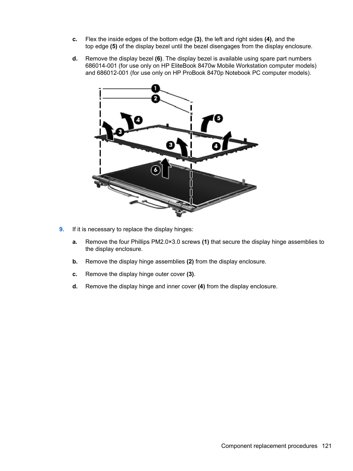
CAUTION: To reduce the risk of damage to the computer or an unsuccessful installation, download and install a BIOS update only when the computer is connected to reliable external power using the AC adapter. Do not download or install a BIOS update while the computer is running on battery power, docked in an optional docking device, or connected to an optional power source. During the download and installation, follow these instructions:
Do not disconnect power on the computer by unplugging the power cord from the AC outlet. Do not shut down the computer or initiate Sleep. Do not insert, remove, connect, or disconnect any device, cable, or cord.
Make a note of the path to the location on your hard drive where the BIOS update is downloaded. You will need to access this path when you are ready to install the update.
NOTE: If you connect your computer to a network, consult the network administrator before installing any software updates, especially system BIOS updates.
| | |---|
BIOS installation procedures vary. Follow any instructions that are displayed on the screen after the download is complete. If no instructions are displayed, follow these steps:
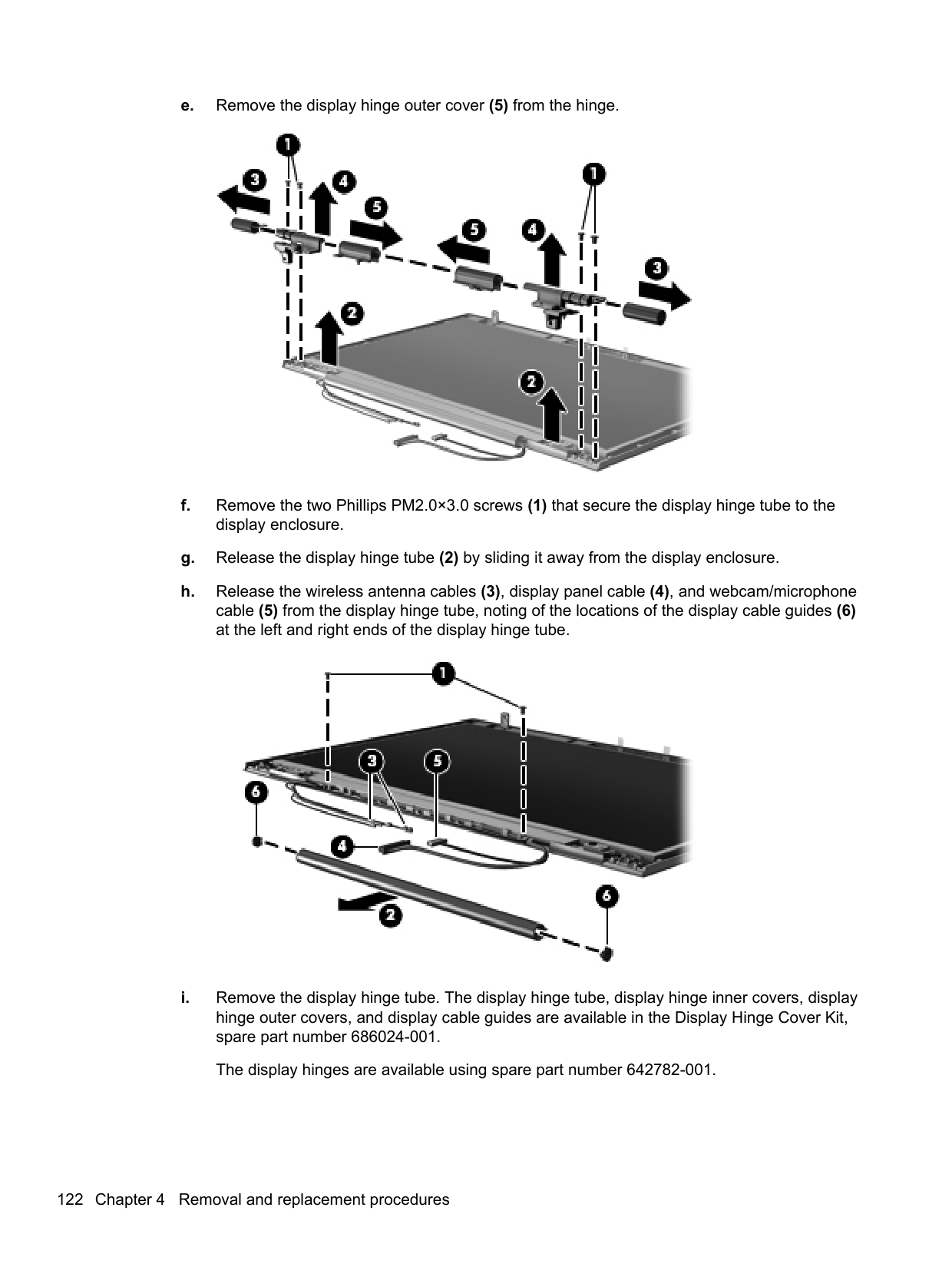
NOTE: After a message on the screen reports a successful installation, you can delete the downloaded file from your hard drive.
| | |---|
#### Using Advanced System Diagnostics
Advanced System Diagnostics allows you to run diagnostic tests to determine if the computer hardware is functioning properly. The following diagnostic tests are available in Advanced System Diagnostics:
You can view system information and error logs or select languages in the Advanced System Diagnostics window.
To start Advanced System Diagnostics:
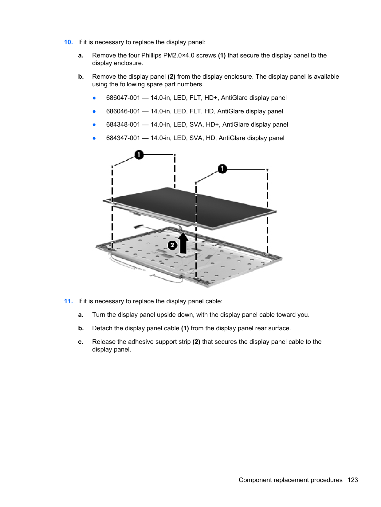
| | |---|
Windows 7
Computer Setup, or Basic Input/Output System (BIOS), controls communication between all the input and output devices on the system (such as disk drives, display, keyboard, mouse, and printer). Computer Setup includes settings for the types of peripherals installed, the startup sequence of the computer, and the amount of system and extended memory.
NOTE: Use extreme care when making changes in Computer Setup. Errors can prevent the computer from operating properly.
| | |---|
#### Starting Computer Setup
NOTE: An external keyboard or mouse connected to a USB port can be used with Computer
| | |---|
Setup only if USB legacy support is enabled. To start Computer Setup, follow these steps:
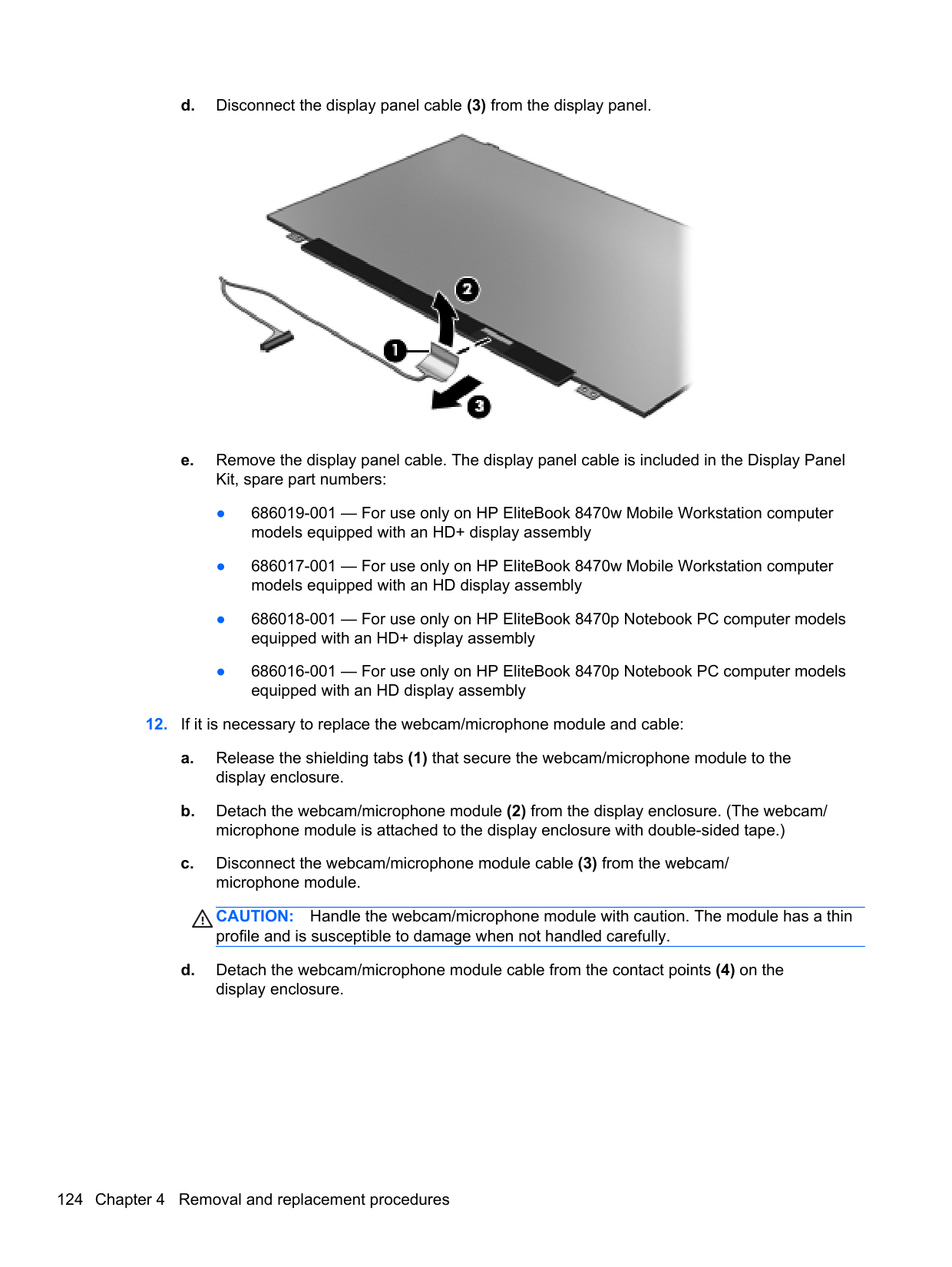
#### Using Computer Setup Navigating and selecting in Computer Setup
To navigate and select in Computer Setup, follow these steps:
| | |---|
NOTE: You can use either a pointing device (TouchPad, pointing stick, or USB mouse) or the keyboard to navigate and make selections in Computer Setup.
To exit Computer Setup menus, choose one of the following methods:
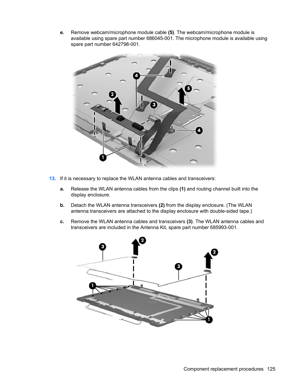
– or – Use the tab key and the arrow keys to select File > Save Changes and Exit, and then press enter.
##### Your changes go into effect when the computer restarts. Restoring factory settings in Computer Setup
NOTE: Restoring defaults will not change the hard drive mode.
| | |---|
To return all settings in Computer Setup to the values that were set at the factory, follow these steps:
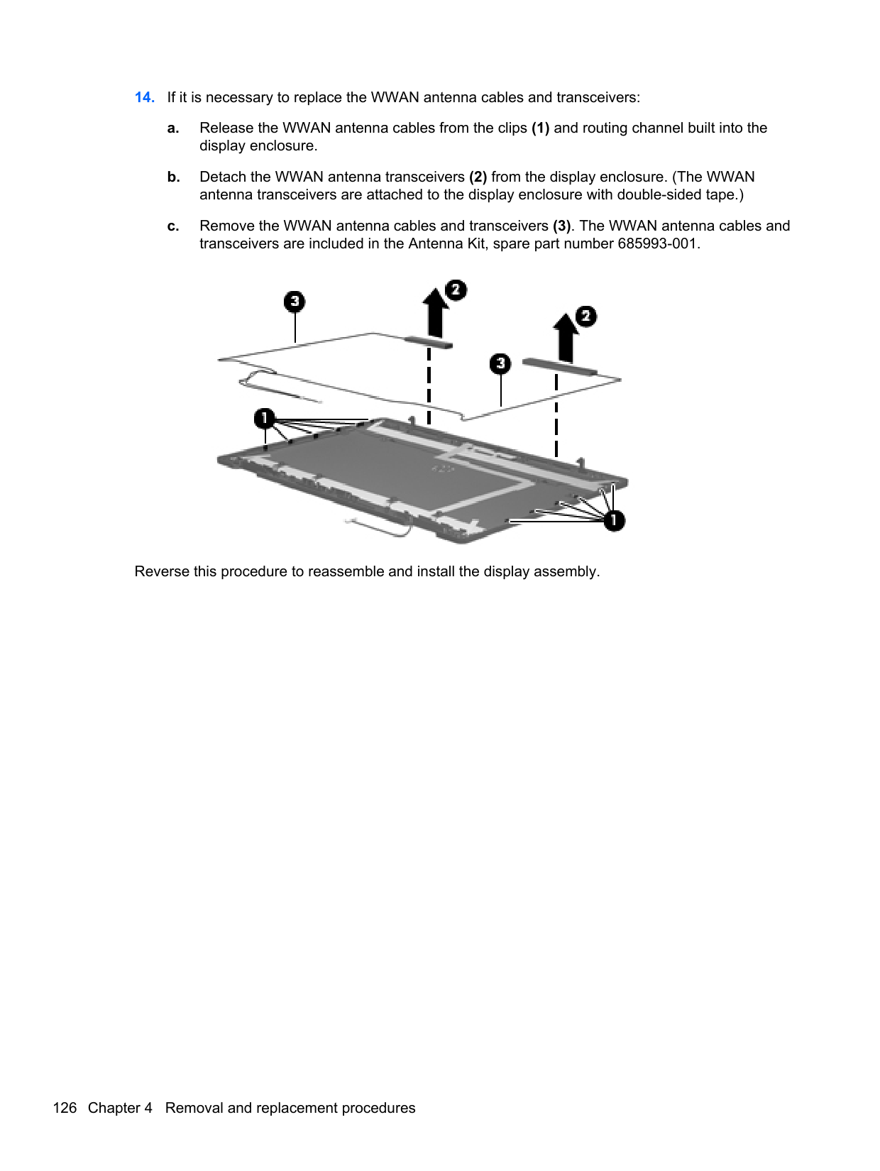
– or – Use the arrow keys to select File > Save Changes and Exit, and then press enter.
Your changes go into effect when the computer restarts. NOTE: Your password settings and security settings are not changed when you restore the factory settings.
| | |---|
Updating the BIOS Updated versions of the BIOS may be available on the HP Web site. Most BIOS updates on the HP Web site are packaged in compressed files called SoftPaqs. Some download packages contain a file named Readme.txt, which contains information regarding installing and troubleshooting the file.
##### Determining the BIOS version
To determine whether available BIOS updates contain later BIOS versions than those currently installed on the computer, you need to know the version of the system BIOS currently installed.
BIOS version information (also known as ROM date and System BIOS) can be displayed as follows:
– or – Use the tab key and the arrow keys to select File > Ignore Changes and Exit, and then press enter.
NOTE: You can also determine the BIOS version by turning on or restarting the computer, pressing the esc key while the “Press the ESC key for Startup Menu” message is displayed at the bottom of the screen, and then pressing the f1 key. Follow the on-screen instructions to exit this screen.
| | |---|
##### Downloading a BIOS update
CAUTION: CAUTION: To reduce the risk of damage to the computer or an unsuccessful installation, download and install a BIOS update only when the computer is connected to reliable external power using the AC adapter. Do not download or install a BIOS update while the computer is running on battery power, docked in an optional docking device, or connected to an optional power source. During the download and installation, follow these instructions:
Do not disconnect power from the computer by unplugging the power cord from the AC outlet. Do not shut down the computer or initiate Suspend or Hibernation. Do not insert, remove, connect, or disconnect any device, cable, or cord.
NOTE: After a message on the screen reports a successful installation, you can delete the downloaded file from your hard drive.
| | |---|
#### Using Advanced System Diagnostics
Advanced System Diagnostics allows you to run diagnostic tests to determine if the computer hardware is functioning properly. The following diagnostic tests are available in Advanced System Diagnostics:
You can view system information and error logs in the Advanced System Diagnostics window. To start Advanced System Diagnostics:
| | |---|
SuSE Linux (SLED)
Computer Setup, or Basic Input/Output System (BIOS), controls communication between all the input and output devices on the system (such as disk drives, display, keyboard, mouse, and printer). Computer Setup includes settings for the types of peripherals installed, the startup sequence of the computer, and the amount of system and extended memory.
NOTE: Use extreme care when making changes in Computer Setup. Errors can prevent the computer from operating properly.
| | |---|
Starting Computer Setup NOTE: An external keyboard or mouse connected to a USB port can be used with Computer Setup only if USB legacy support is enabled. To start Computer Setup, follow these steps:
| | |---|
Menu” message is displayed at the bottom of the screen.
#### 2. Press f10 to enter Computer Setup. Using Computer Setup Navigating and selecting in Computer Setup
To navigate and select in Computer Setup, follow these steps:
Menu” message is displayed at the bottom of the screen.
NOTE: You can use either a pointing device (TouchPad, pointing stick, or USB mouse) or the keyboard to navigate and make selections in Computer Setup.
| | |---|
– or – Use the tab key and the arrow keys to select File > Ignore Changes and Exit, and then press enter.
##### Your changes go into effect when the computer restarts. Restoring factory settings in Computer Setup
NOTE: Restoring defaults will not change the hard drive mode.
| | |---|
To return all settings in Computer Setup to the values that were set at the factory, follow these steps:
– or – Use the arrow keys to select File > Save Changes and Exit, and then press enter.
Your changes go into effect when the computer restarts. NOTE: Your password settings and security settings are not changed when you restore the factory settings.
| | |---|
Updating the BIOS Updated versions of the BIOS may be available on the HP Web site. Most BIOS updates on the HP Web site are packaged in compressed files called SoftPaqs. Some download packages contain a file named Readme.txt, which contains information regarding installing and troubleshooting the file.
##### Determining the BIOS version
To determine whether available BIOS updates contain later BIOS versions than those currently installed on the computer, you need to know the version of the system BIOS currently installed.
BIOS version information (also known as ROM date and System BIOS) can be displayed as follows:
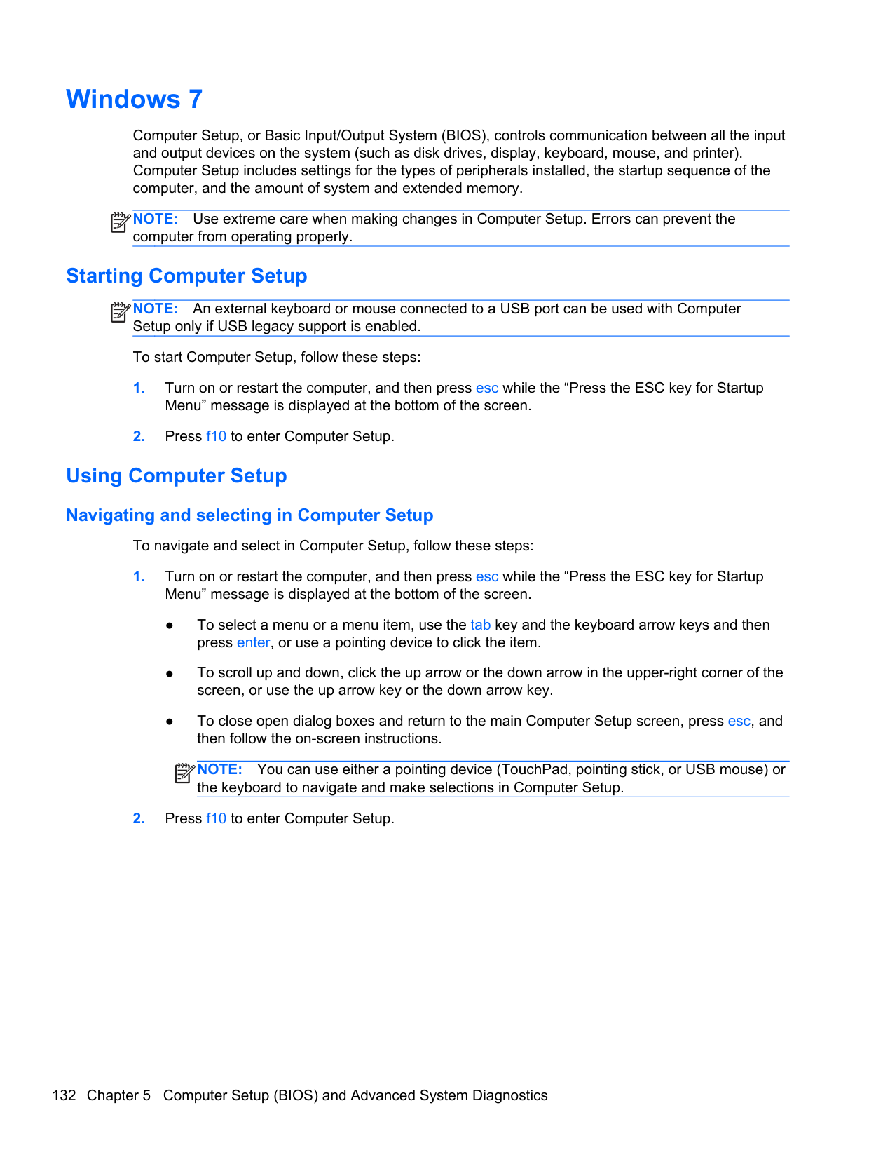
of the screen, and then follow the on-screen instructions.
– or – Use the tab key and the arrow keys to select File > Ignore Changes and Exit, and then press enter.
NOTE: You can also determine the BIOS version by turning on or restarting the computer, pressing the esc key while the “Press the ESC key for Startup Menu” message is displayed at the bottom of the screen, and then pressing the f1 key. Follow the on-screen instructions to exit this screen.
| | |---|
##### Downloading a BIOS update
CAUTION: CAUTION: To reduce the risk of damage to the computer or an unsuccessful installation, download and install a BIOS update only when the computer is connected to reliable external power using the AC adapter. Do not download or install a BIOS update while the computer is running on battery power, docked in an optional docking device, or connected to an optional power source. During the download and installation, follow these instructions:
Do not disconnect power from the computer by unplugging the power cord from the AC outlet. Do not shut down the computer or initiate Suspend or Hibernation. Do not insert, remove, connect, or disconnect any device, cable, or cord.
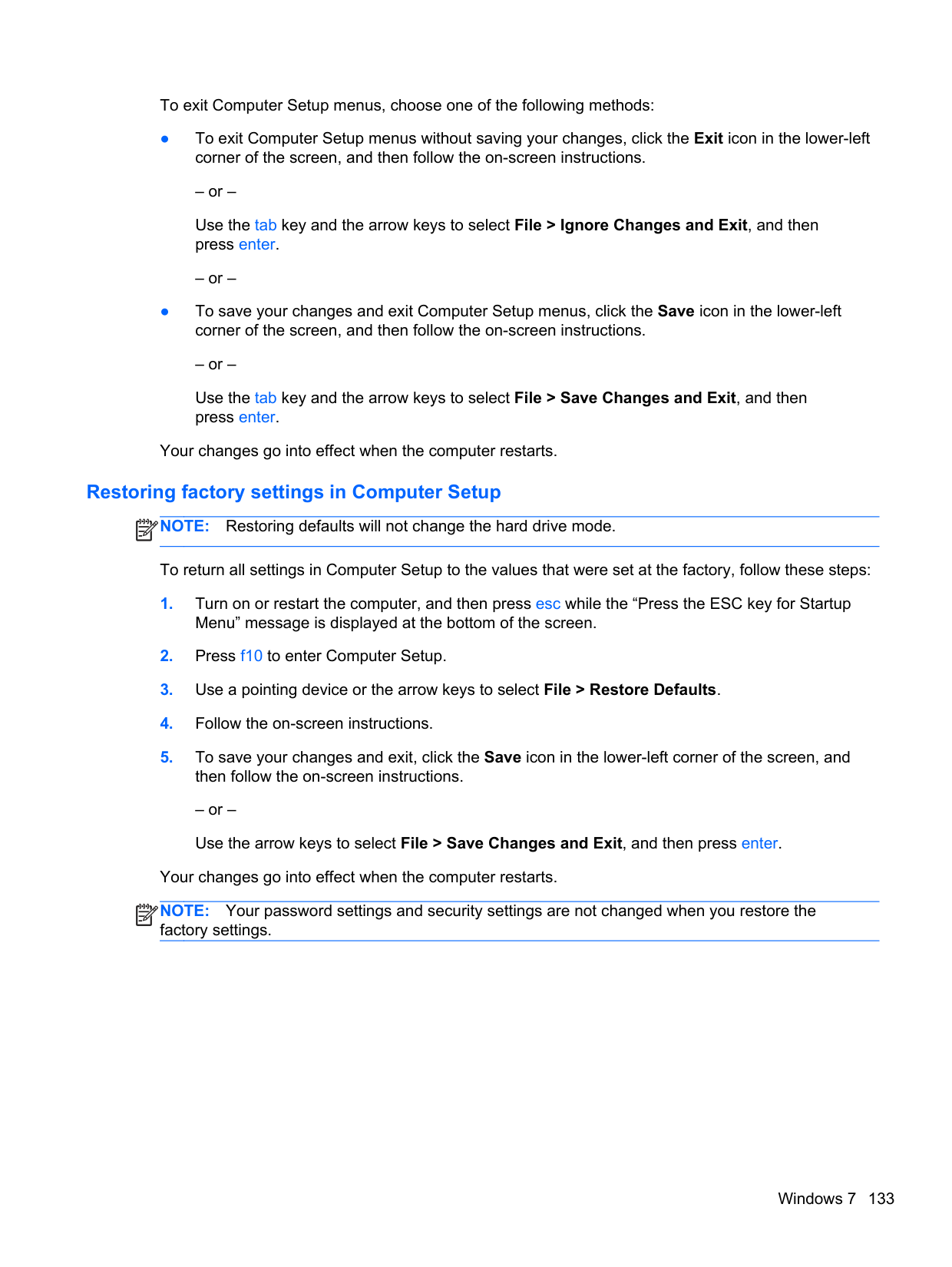
#### Using Advanced System Diagnostics
Advanced System Diagnostics allows you to run diagnostic tests to determine if the computer hardware is functioning properly. The following diagnostic tests are available in Advanced System Diagnostics:
You can view system information and error logs in the Advanced System Diagnostics window. To start Advanced System Diagnostics:
| | |---|
6 Specifications
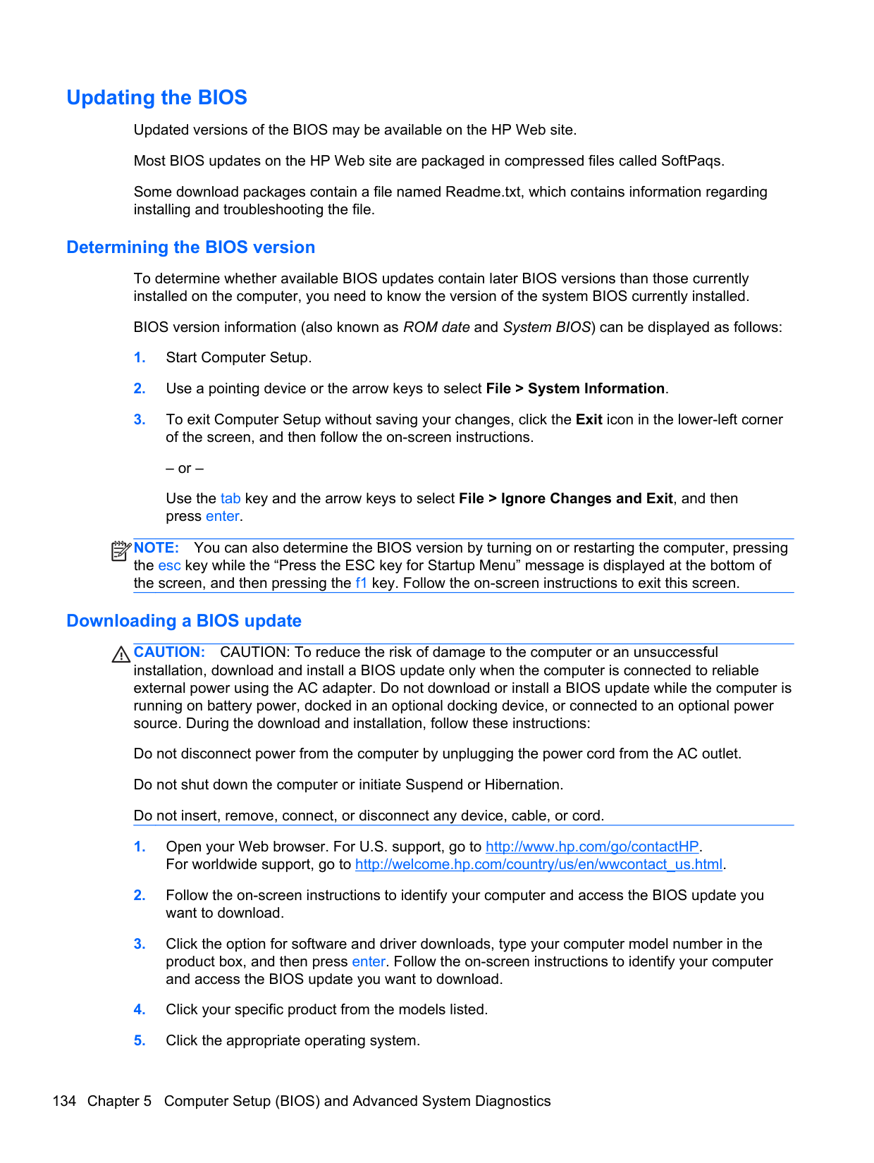
Computer specifications
######## Metric U.S.
Dimensions Width 33.80 cm 13.31 in Depth 23.13 cm 9.11 in Height (front to back) 3.18 to 3.38 cm 1.25 to 1.33 in Weight HP EliteBook 8470w Mobile Workstation: Equipped with 9-cell battery, optical drive, one memory module, WLAN module, and solid-state drive
2.25 kg 4.96 lbs
Equipped with 9-cell battery, one memory module, WLAN module, and solid-state drive
Equipped with 6-cell battery, optical drive, one memory module, WLAN module, and solid-state drive
Equipped with 6-cell battery, one memory module, WLAN module, and solid-state drive
HP EliteBook 8470w Mobile Workstation: Equipped with 9-cell battery, optical drive, graphics subsystem with UMA memory, one memory module, WLAN module, and solid-state drive
Equipped with 9-cell battery, graphics subsystem with UMA memory, one memory module, WLAN module, and solid-state drive
Equipped with 6-cell battery, optical drive, graphics subsystem with UMA memory, one memory module, WLAN module, and solid-state drive
Equipped with 6-cell battery, graphics subsystem with UMA memory, one memory module, WLAN module, and solid-state drive
Equipped with 3-cell battery, optical drive, graphics subsystem with UMA memory, one memory module, WLAN module, and solid-state drive
2.39 kg 5.27 lbs
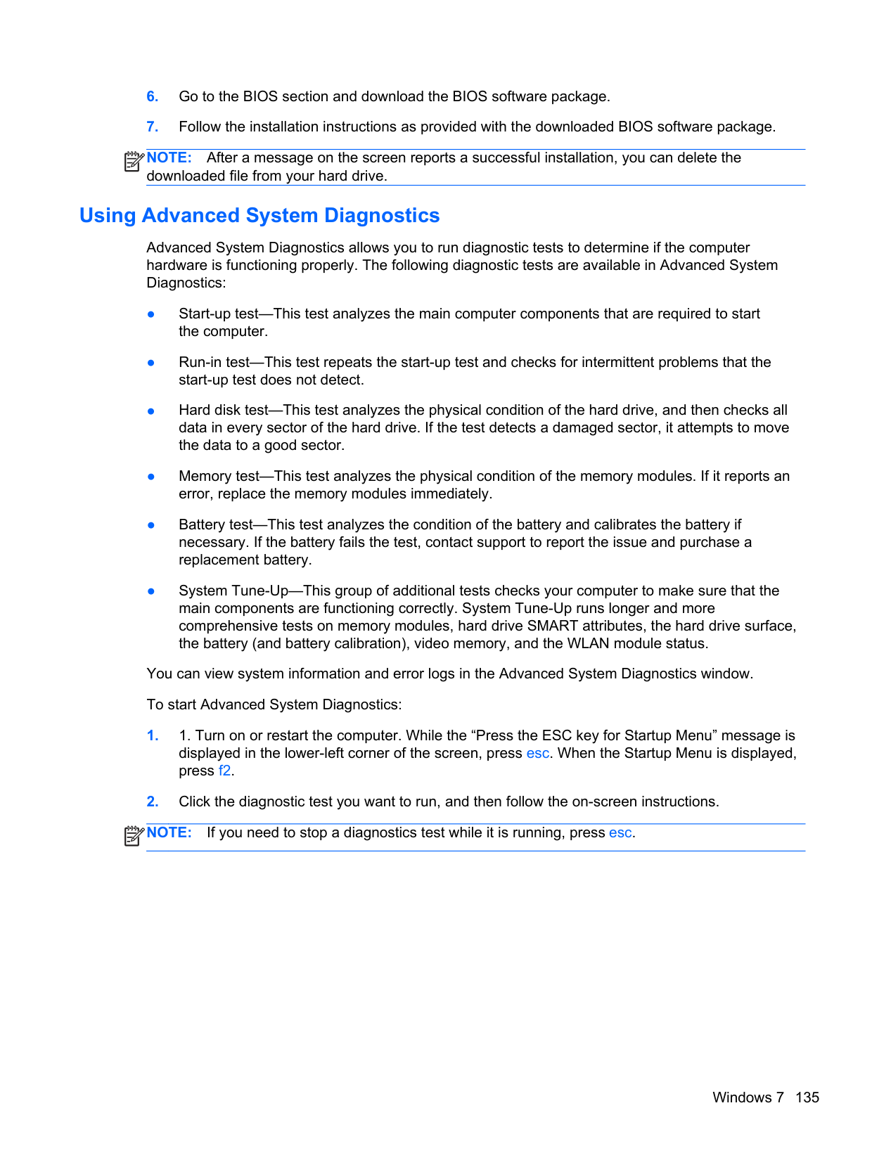
2.41 kg 5.31 lbs
2.55 kg 5.62 lbs
2.51 kg 5.53 lbs
2.37 kg 5.23 lbs
2.35 kg 5.18 lbs
2.21 kg 4.87 lbs
2.21 kg 4.87 lbs
######## Metric U.S.
Equipped with 3-cell battery, graphics subsystem with UMA memory, one memory module, WLAN module, and solid-state drive
2.07 kg 4.56 lbs
Input power Operating voltage and current 18.5 V dc @ 3.5 A - 65 W
– or – 19.0 V dc @ 4.74 A - 90 W
Temperature Operating 5°C to 35°C 41°F to 95°F Nonoperating -20°C to 60°C -4°F to 140°F Relative humidity (noncondensing) Operating 10% to 90% Nonoperating 5% to 95% Maximum altitude (unpressurized)
Operating -15 m to 3,048 m -50 ft to 10,000 ft Nonoperating -15 m to 12,192 m -50 ft to 40,000 ft NOTE: Applicable product safety standards specify thermal limits for plastic surfaces. The device operates well within this
range of temperatures.
Computer specifications 141
14.0-inch WGA display specifications
######## Metric U.S.
Dimensions Height 17.6 cm 6.93 in Width 31.2 cm 12.28 in Diagonal 35.7 cm 14.06 in Number of colors up to 16.8 million Contrast ratio 200:1 (typical) Brightness 200 nits (typical) Pixel resolution Pitch 0.197 × 0.197 mm Format HD+, WVA (1600 x 1900)
HD, SVA (1366 x 768) Configuration RGB vertical stripe Backlight LED Character display 80 × 25 Total power consumption 3.46 W Viewing angle ±65° horizontal, ±50° vertical (typical)
Hard drive specifications
######## 750-GB* 500-GB* 320-GB*
Dimensions Height 9.5 mm 9.5 mm 9.5 mm Length 100.2 mm 100.4 mm 100.4 mm Width 69.9 mm 69.9 mm 69.9 mm Weight 110 g 110 g 110 g Interface type SATA SATA SATA Transfer rate Synchronous (maximum) 1.1 GB/sec 1.1 GB/sec 1.1 GB/sec Security ATA security ATA security ATA security Seek times (typical read, including setting) Single track 2.0 ms 1.5 ms 1.5 ms Average (read/write) 12/16 ms 11/13 ms 11/13 ms Maximum 22 ms 22 ms 22 ms Logical blocks 1,465,149,168 976,773,168 628,142,448 Disk rotational speed 7200 rpm 7200 rpm 7200 rpm Operating temperature 0°C to 60°C (32°F to 140°F)
*1 GB = 1 billion bytes when referring to hard drive storage capacity. Actual accessible capacity is less. NOTE: Certain restrictions and exclusions apply. Contact technical support for details.
Hard drive specifications 143
7 Backup and recovery
Windows 8
To protect your information, use Windows backup and restore utilities to back up individual files and folders, back up your entire hard drive, create system repair media (select models only) by using the installed optical drive (select models only) or an optional external optical drive, or create system restore points. In case of system failure, you can use the backup files to restore the contents of your computer.
From the Start screen, type restore, click Settings, and then select from the list of displayed options.
NOTE: For detailed instructions on various backup and restore options, perform a search for these topics in Help and Support. From the Start screen, type h, and then select Help and Support. In case of system instability, HP recommends that you print the recovery procedures and save them for later use. NOTE: Windows includes the User Account Control feature to improve the security of your
| | |---|
| | |---|
computer. You may be prompted for your permission or password for tasks such as installing software, running utilities, or changing Windows settings. Refer to Help and Support for more information. From the Start screen, type h, and then select Help and Support.
#### Backing up your information
Recovery after a system failure is as good as your most recent backup. You should create system repair media and your initial backup immediately after initial system setup. As you add new software and data files, you should continue to back up your system on a regular basis to maintain a reasonably current backup. As you add new software and data files, you should continue to back up your system on a regular basis to maintain a reasonably current backup. The system repair media (select models only) are used to start up (boot) the computer and repair the operating system in case of system instability or failure. Your initial and subsequent backups allow you to restore your data and settings if a failure occurs.
From the Start screen, type backup, click Settings, and then select Save backup copies of your files with File History.
You can back up your information to an optional external hard drive or a network drive.
Note the following when backing up:
To create a backup using Backup and Restore: NOTE: Be sure that the computer is connected to AC power before you start the backup process. NOTE: The backup process may take over an hour, depending on file size and the speed of the computer.
| | |---|
| | |---|
#### Performing a system recovery
In case of system failure or instability, the computer provides the following tools to recover your files: ● Windows recovery tools: You can use Windows Backup and Restore to recover information you
have previously backed up. You can also use Windows Startup Repair to fix problems that might prevent Windows from starting correctly.
● f11 recovery tools: You can use the f11 recovery tools to recover your original hard drive image. The image includes the Windows operating system and software programs installed at the factory.
NOTE: If you are unable to boot (start up) your computer and you cannot use the system repair media you previously created (select models only), you must purchase Windows 8 operating system media to reboot the computer and repair the operating system. For additional information, see the “Using Windows 8 operating system media (purchased separately)” section.
| | |---|
##### Using the Windows recovery tools
To recover information you previously backed up:
▲ From the Start screen, type h, and then select Help and Support. To recover your information using Startup Repair, follow these steps:
CAUTION: Some Startup Repair options will completely erase and reformat the hard drive. All files you have created and any software installed on the computer are permanently removed. When reformatting is complete, the recovery process restores the operating system, as well as the drivers, software, and utilities from the backup used for recovery.
– or – From the Start screen, type c, and then select Computer. NOTE: If the Windows partition and the HP Recovery partition are not listed, you must recover your operating system and programs using the Windows 8 operating system DVD and the Driver Recovery media (both purchased separately). For additional information, see the “Using Windows 8 operating system media (purchased separately)” section.
| | |---|
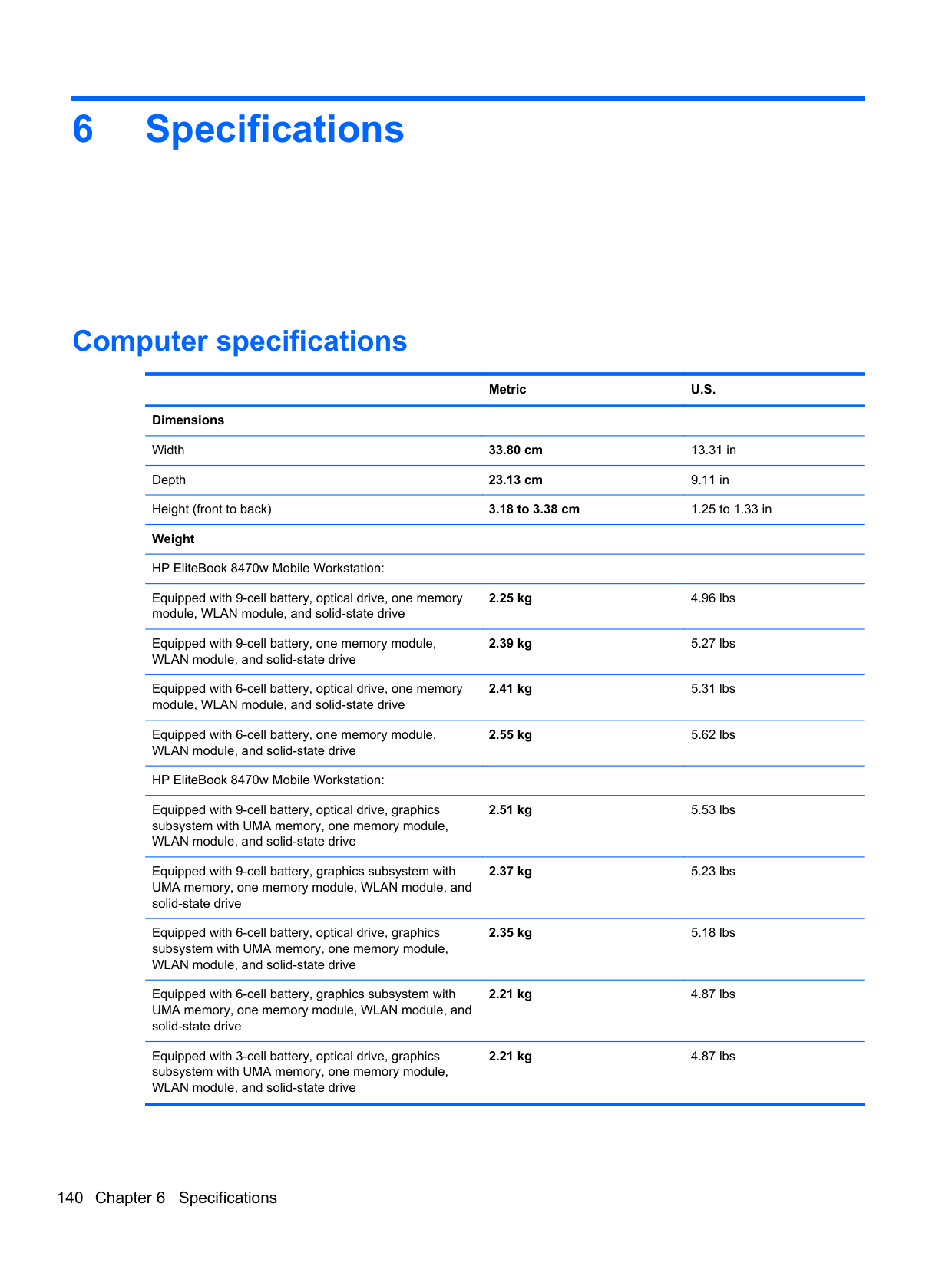
NOTE: For additional information on recovering information using the Windows tools, perform a search for these topics in Help and Support. From the Start screen, type h, and then select Help and Support.
| | |---|
##### Using f11 recovery tools
CAUTION: Using f11 completely erases hard drive contents and reformats the hard drive. All files
that you have created and any software that you have installed on the computer are permanently removed. The f11 recovery tool reinstalls the operating system and HP programs and drivers that were installed at the factory. Software not installed at the factory must be reinstalled.
To recover the original hard drive image using f11:
| | |---|
NOTE: If the HP Recovery partition is not listed, you must recover your operating system and programs using the Windows 8 operating system media and the Driver Recovery media (both purchased separately). For additional information, see the “Using Windows 8 operating system media (purchased separately)” section.
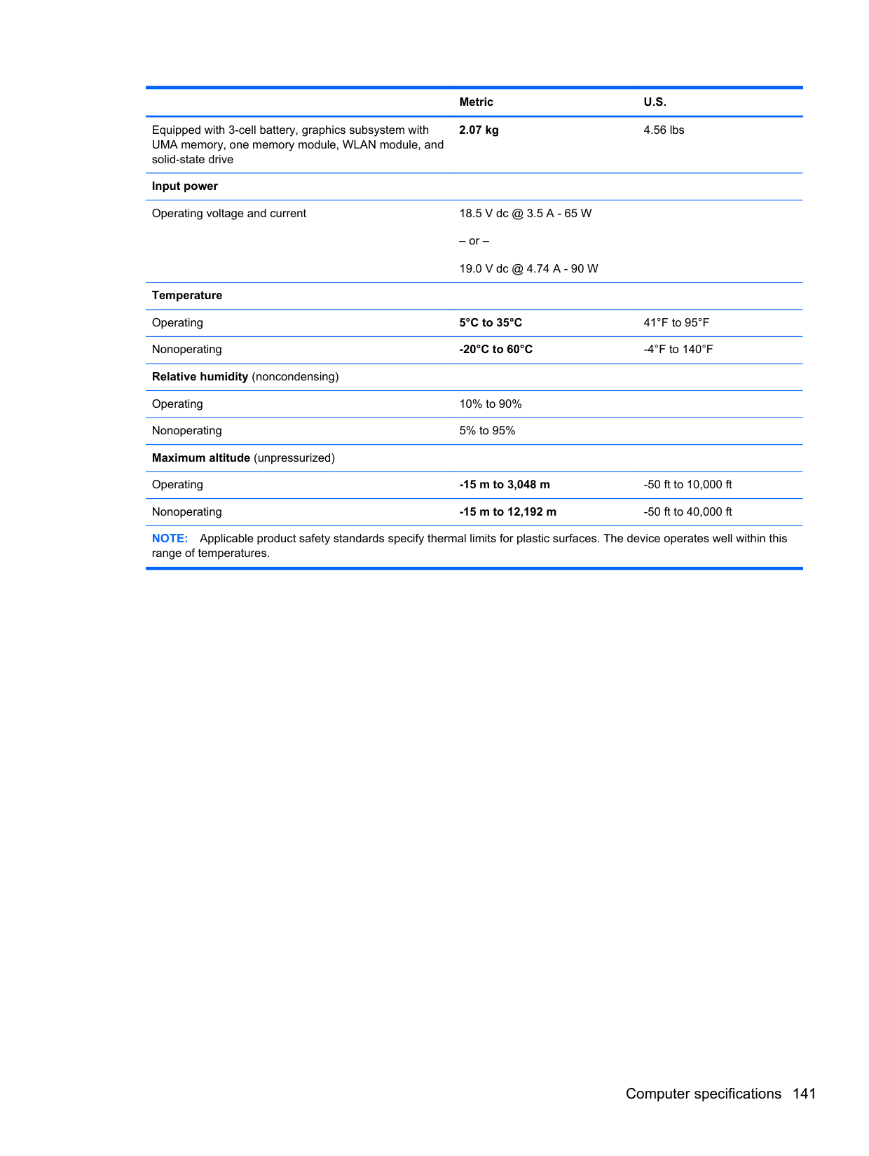
##### Using Windows 8 operating system media (purchased separately)
To order a Windows 8 operating system DVD, go to http://www.hp.com/support, select your country or region, and follow the on-screen instructions. You can also order the DVD by calling support. For contact information, see the Worldwide Telephone Numbers booklet included with the computer.
CAUTION: Using a Windows 8 operating system media completely erases hard drive contents and reformats the hard drive. All files that you have created and any software that you have installed on the computer are permanently removed. When reformatting is complete, the recovery process helps you restore the operating system, as well as drivers, software, and utilities.
To initiate recovery using a Windows 8 operating system DVD: NOTE: This process takes several minutes.
| | |---|
When your computer is not working properly and you need to regain system stability, the Windows Refresh option allows you to start fresh and keep what is important to you.
IMPORTANT: Refresh removes any traditional applications that were not originally installed on the system at the factory.
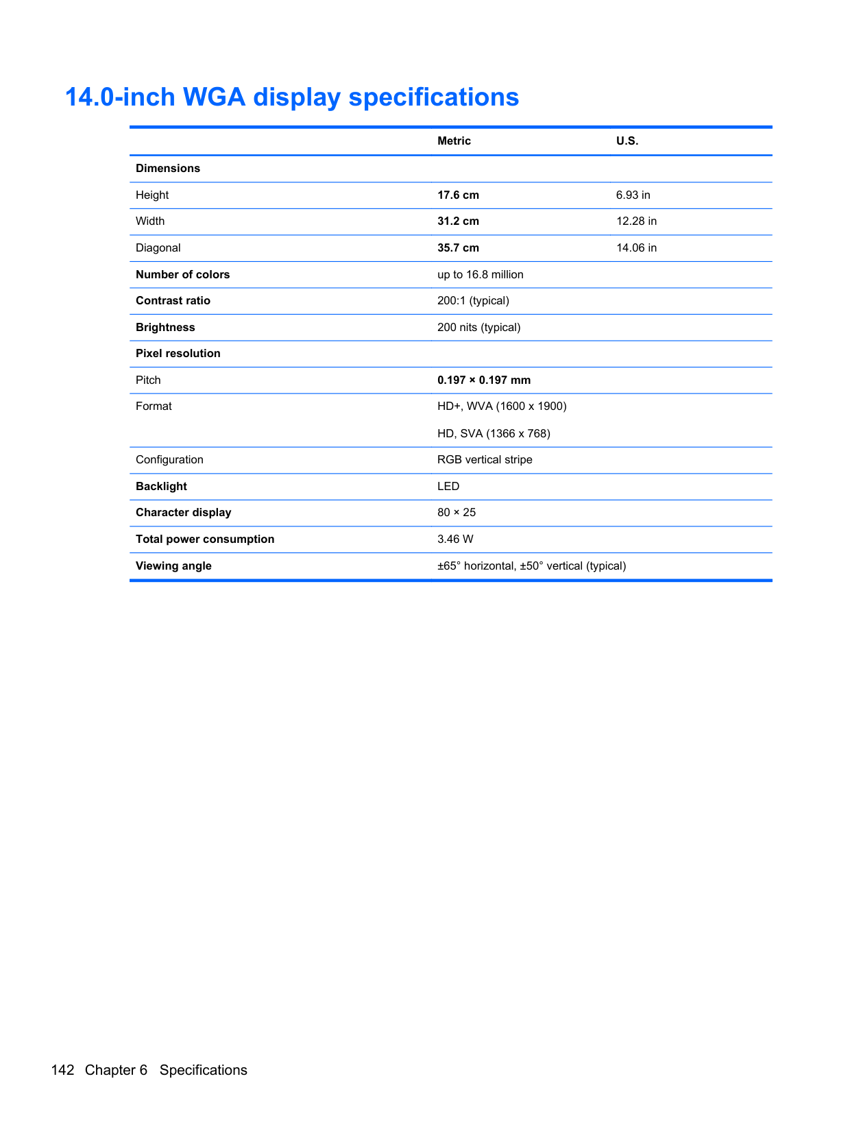
| | |---|
| | |---|
NOTE: During Refresh, a list of removed traditional applications will be saved so that you have a quick way to see what you might need to reinstall. See Help and Support for instructions on reinstalling traditional applications. From the Start screen, type h, and then select Help and Support.
NOTE: You may be prompted for your permission or password when using Refresh. See Windows Help and Support for more information. From the Start screen, type h, and then select Help and Support.
| | |---|
To start Refresh:
##### Remove everything and reinstall Windows
Sometimes you want to perform detailed reformatting of your computer, or you want to remove personal information before you give away or recycle your computer. The process described in this section provides a speedy, simple way to return the computer to its original state. This option removes all personal data, apps, and settings from your computer, and reinstalls Windows.
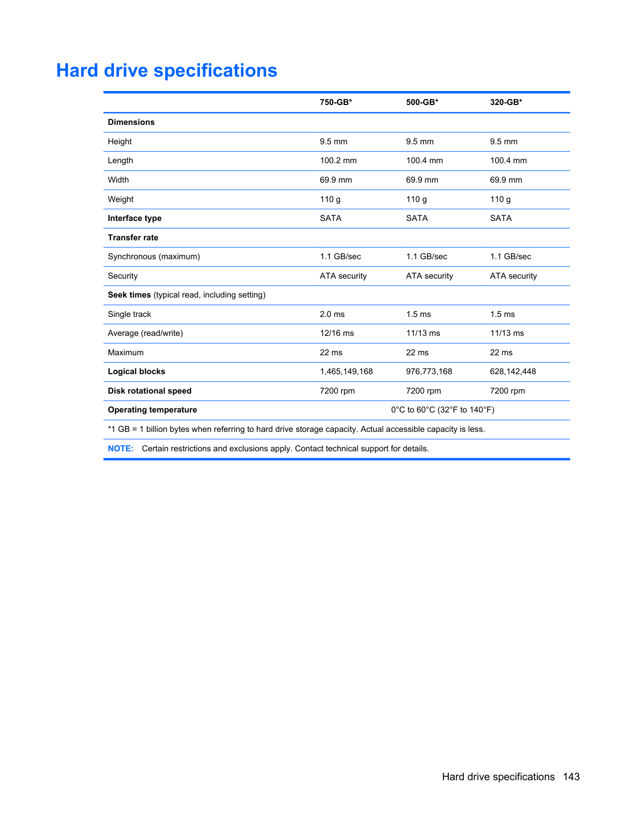
IMPORTANT: This option does not provide backups of your information. Before using this option, back up any personal information you wish to retain. You can initiate this option by using the f11 key or from the Start screen. To use the f11 key:
| | |---|
– or – Press and hold f11 as you press the power button.
##### Using HP Software Setup
HP Software Setup can be used to reinstall drivers or select software that has been corrupted or deleted from the system.
Windows 7
To protect your information, use Windows Backup and Restore to back up individual files and folders, back up your entire hard drive (select models only), create system repair discs (select models only) with the installed optical drive (select models only) or an optional external optical drive, or create system restore points. In case of system failure, you can use the backup files to restore the contents of your computer.
Windows Backup and Restore provides the following options:
| | |---|
In case of system instability, HP recommends that you print the recovery procedures and save them for later use.
NOTE: Windows includes the User Account Control feature to improve the security of your computer. You may be prompted for your permission or password for tasks such as installing software, running utilities, or changing Windows settings. See Help and Support for more information.
| | |---|
#### Creating recovery media with HP Recovery Disc Creator
HP Recovery Disc Creator is a software program that offers an alternative way to create recovery media. After you successfully set up the computer, you can create recovery media using HP Recovery Disc Creator. This recovery media allows you to reinstall your original operating system as well as select drivers and applications if the hard drive becomes corrupted.
HP Recovery Disc Creator can create two kinds of recovery DVDs as follows:
##### Creating recovery media
NOTE: The Windows DVD can be created only once. Thereafter, the option to create that media will not be available.
| | |---|
#### Backing up your information
Recovery after a system failure is as good as your most recent backup. Immediately after setting up the computer, you should create system repair discs (select models only) using the installed optical drive (select models only) or an optional external optical drive and back up your system. As you add new software and data files, you should continue to back up your system on a regular basis to maintain a reasonably current backup. The system repair discs (select models only) are used to start up (boot) the computer and repair the operating system in case of system instability or failure. Your initial and subsequent backups allow you to restore your data and settings if a failure occurs.
You can back up your information to an optional external hard drive, a network drive, or discs. Note the following when backing up:
| | |---|
NOTE: DVDs and DVDs with double-layer (DL) support store more information than CDs, so using them for backup reduces the number of recovery discs required.
NOTE: Be sure that the computer is connected to AC power before you start the backup process.
| | |---|
NOTE: The backup process may take over an hour, depending on file size and the speed of the computer.
| | |---|
models only), or create a system repair disc (select models only).
#### Performing a system recovery
In case of system failure or instability, the computer provides the following tools to recover your files:
NOTE: If you are unable to boot (start up) your computer and you cannot use the system repair discs you previously created (select models only), you must purchase a Windows 7 operating system DVD to reboot the computer and repair the operating system. For additional information, see the Using a Windows 7 operating system DVD (purchased separately) section.
| | |---|
##### Using the Windows recovery tools
To recover information you previously backed up:
To recover your information using Startup Repair, follow these steps:
CAUTION: Some Startup Repair options completely erase hard drive contents and reformat the hard drive. All files you have created and any software installed on the computer are permanently removed. When reformatting is complete, the recovery process restores the operating system, as well as the drivers, software, and utilities from the backup used for recovery.
NOTE: For additional information on recovering information using the Windows tools, perform a search for these topics in Help and Support.
| | |---|
##### Using f11 recovery tools
CAUTION: Using f11 recovery tools completely erases hard drive contents and reformats the hard drive. All files you have created and any software installed on the computer are permanently removed. The f11 recovery tool reinstalls the operating system and HP programs and drivers that were installed at the factory. Software not installed at the factory must be reinstalled.
To recover the original hard drive image using f11:
| | |---|
NOTE: If the HP Recovery partition has been deleted, the f11 restore option will not function. You must recover your operating system and programs using the Windows 7 operating system DVD and the Driver Recovery disc (both purchased separately) if the Windows partition and the HP Recovery partition are not listed. For additional information, see the Using a Windows 7 operating system DVD (purchased separately) section.
##### Using a Windows 7 operating system DVD (purchased separately)
To order a Windows 7 operating system DVD, go to the HP website. For U.S. support, go to http:// www.hp.com/go/contactHP. For worldwide support, go to http://welcome.hp.com/country/us/en/ wwcontact_us.html. You can also order the DVD by calling support. For contact information, see the Worldwide Telephone Numbers booklet included with the computer.
CAUTION: Using a Windows 7 operating system DVD completely erases hard drive contents and
reformats the hard drive. All files you have created and any software installed on the computer are permanently removed. When reformatting is complete, the recovery process helps you restore the operating system, as well as drivers, software, and utilities.
To initiate recovery using a Windows 7 operating system DVD: NOTE: This process takes several minutes.
| | |---|
SuSE Linux (SLED)
Recovery after a system failure is as good as your most recent backup. As you add new software and data files, you should continue to back up your system on a regular basis to maintain a reasonably current backup.
Your computer includes tools provided by HP to help you safeguard your information and retrieve it if ever needed.
#### Creating backups
#### Backing up your information
You should back up your computer files on a regular schedule to maintain a current backup. You can manually back up your information to an optional external drive, a network drive, or discs. Back up your system at the following times:
| | |---|
NOTE: Before you back up your information, be sure you have designated a location to save the backup files.
| | |---|
NOTE: If multiple backups have been performed, click Use the latest version to restore the latest version.
#### Performing a system recovery
Recovery allows you to repair or restore the computer to its original factory state. You can create an HP Factory Image Restore DVD, using an installed or an external DVD±RW optical drive.
CAUTION: CAUTION: Using Recovery completely erases hard drive contents and reformats the hard drive. All files you have created and any software installed on the computer are permanently removed. The recovery tool reinstalls the original operating system and HP programs and drivers that were installed at the factory. Software, drivers, and updates not installed by HP must be manually reinstalled. Personal files must be restored from a backup.
To restore the computer using the HP Factory Image Restore DVD, you must first create the recovery disc. To create the recovery disc:
NOTE: HP recommends that you create the HP Factory Image Restore DVD in the event of a system failure.
| | |---|
pane.
#### USB Recovery option (select models only)
The USB Recovery Disk On Key (flash drive) option allows you to create a backup image of the SLED operating system installed on select HP Business Notebooks. This Disk On Key may be used to restore the system to the original factory state when the F11 recovery option is not available. This process should be done on first obtaining the computer.
CAUTION: The USB recovery option does not preserve data present on the computer’s hard drive or on the Disk On Key used for the recovery process. Back up any data on the Disk on Key or the notebook that will be recovered before starting.
NOTE: HP recommends that you create the USB Recovery Disk in the event of a system failure. The Disk On Key used for this process should be 4 GB or larger. Creating a USB Recovery Disk On Key
| | |---|
NOTE: A file browser window with the Disk On Key Contents displayed will pop up when the key is mounted. You may close the file browser window if desired. Once the USB Recovery Key has been created, the status dialog will close. The USB Recovery Key is ready for use.
| | |---|
Recovering from a USB Recovery Disk On Key
CAUTION: Before starting the Recovery process, make sure any data on the system to be recovered has been backed up. The recovery process destroys all data on the system to be recovered.
| | |---|
NOTE: The description may vary from one USB key to another. Any entry other than Optical Disk Drive, Notebook Hard Drive or Notebook Ethernet should be the USB Recovery Disk On Key.
#### Remove everything and reinstall SLED
Sometimes you want to perform detailed reformatting of your computer, or you want to remove personal information before you give away or recycle your computer. The process described in this section provides a speedy, simple way to return the computer to its original state. This option removes all personal data, applications, and settings from your computer, and reinstalls the Linux operating system.
IMPORTANT: This option does not provide backups of your information. Before using this option, back up any personal information you wish to retain. You can initiate this option by using the f11 key. To use the f11 key: Press f11 while the computer boots.
| | |---|
– or – Press and hold f11 as you press the power button. The following options are available:
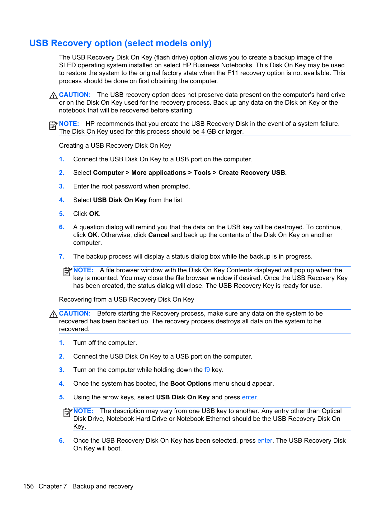
Select an option and follow the on-screen instructions.
8 Power cord set requirements
The wide-range input feature of the computer permits it to operate from any line voltage from 100 to 120 volts AC, or from 220 to 240 volts AC.
The 3-conductor power cord set included with the computer meets the requirements for use in the country or region where the equipment is purchased.
Power cord sets for use in other countries and regions must meet the requirements of the country or region where the computer is used.
Requirements for all countries
The following requirements are applicable to all countries and regions:
158 Chapter 8 Power cord set requirements
Requirements for specific countries and regions
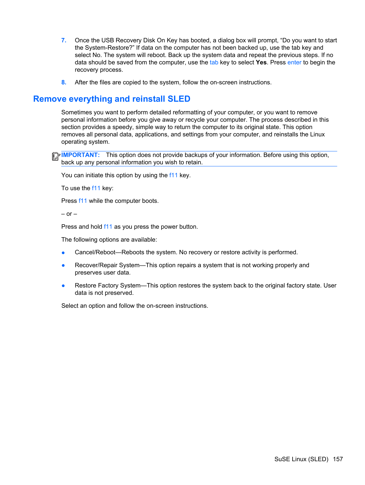
######## Country/region Accredited agency Applicable note number
Australia EANSW 1 Austria OVE 1 Belgium CEBC 1 Canada CSA 2 Denmark DEMKO 1 Finland FIMKO 1 France UTE 1 Germany VDE 1 Italy IMQ 1 Japan METI 3 The Netherlands KEMA 1 Norway NEMKO 1 The People's Republic of China COC 5 South Korea EK 4 Sweden SEMKO 1 Switzerland SEV 1 Taiwan BSMI 4 The United Kingdom BSI 1 The United States UL 2
Requirements for specific countries and regions 159
9 Recycling
When a non-rechargeable or rechargeable battery has reached the end of its useful life, do not dispose of the battery in general household waste. Follow the local laws and regulations in your area for battery disposal.
HP encourages customers to recycle used electronic hardware, HP original print cartridges, and rechargeable batteries. For more information about recycling programs, see the HP Web site at http://www.hp.com/recycle.
160 Chapter 9 Recycling
Index
###### Symbols/Numerics 1394 port 22

44, 54 AC adapter/battery light 21 accessory battery connector 25 antenna
locations 15 removal 125, 126 spare part number 39, 47,
125, 126 Antenna Kit, spare part number
39, 47, 126 audio, product description 6 audio-in jack 23 audio-out jack 23
removal 91 spare part number 37, 47, 91
battery removal 67 spare part numbers 37, 45,
46, 67 battery bay 25 battery release latch 25 battery release latch assembly
removal 100 spare part number 100
Blu-ray R/RE DVD±RW SuperMulti
DL Drive precautions 61 removal 71 spare part number 36, 42, 49,
71
Blu-ray ROM DVD±RW SuperMulti
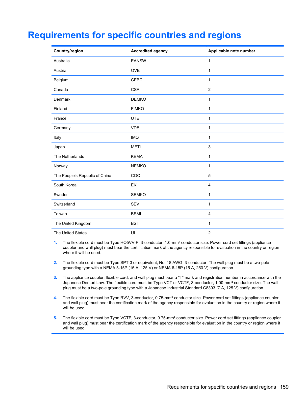
DL Drive precautions 61 removal 71 spare part numbers 36, 37,
42, 53, 71 Bluetooth compartment, location 26
Bluetooth module removal 83 spare part number 37, 46, 83
Bluetooth module cable,
illustrated 40 bottom components 25 button components 17 buttons
keyboard light 15 optical drive eject 22 pointing stick 20 power 17 TouchPad 20 TouchPad on/off 17, 20 volume mute 18 Web browser 18 wireless 17
C Cable Kit
components 40 spare part number 40, 46
cables, service considerations 60 caps lock light 19 carrying case, spare part
numbers 44, 45 chipset, product description 2 components
bottom 25 buttons 17 display 15
fingerprint reader 17 front 21 keys 18 left-side 22 lights 19 Rear 24 right-side 23 TouchPad 19
computer feet location 66 spare part number 66
computer major components 29 computer part number 65 computer specifications 140 connectors, service

considerations 60
D display
components 15 specifications 142
display assembly removal 119 subcomponents 38
display bezel removal 120 spare part numbers 38, 47,
121 Display Cable Kit, spare part numbers 39 display enclosure, spare part numbers 39, 47
display hinge removal 121 spare part number 39, 46,
122
display hinge cover removal 121 spare part number 48, 122
Display Hinge Cover Kit, spare part number 39, 122
Display Hinge Kit, spare part number 39, 46, 48, 122
display lid switch board removal 105 spare part number 34, 47,
105 display panel product description 3 removal 123 spare part numbers 39, 47,
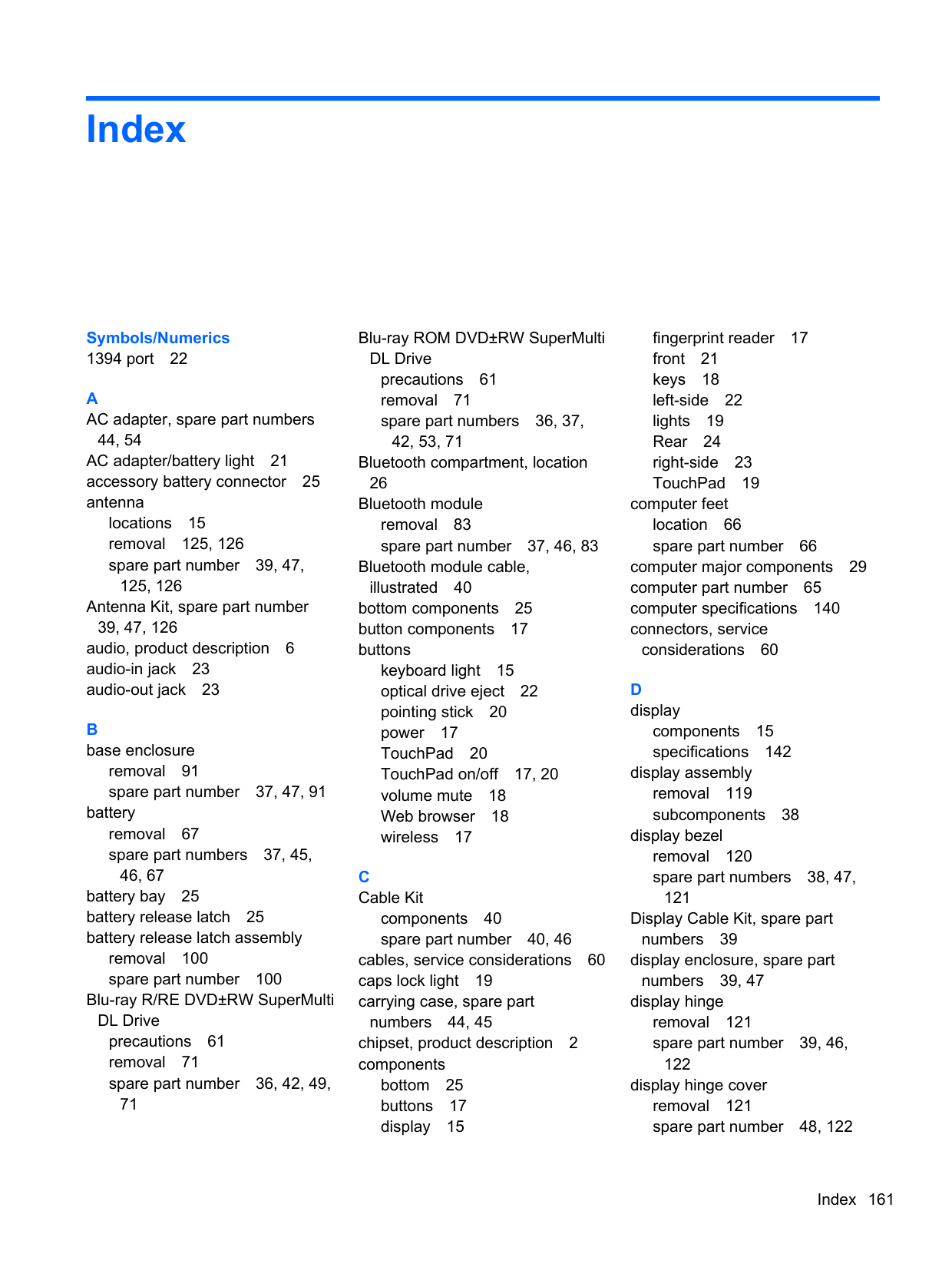
49, 123
display panel cable removal 123 spare part numbers 39, 47,
48, 124 Display Panel Kit, spare part numbers 124 Display Panel Support Kit, spare
part numbers 39, 48 display release latch 21 Display Rubber Kit, spare part
number 39, 46 display switch, location 15 DisplayPort 23 docking connector, location 25 drives, preventing damage 61 DVD-ROM Drive
precautions 61 removal 71 spare part numbers 37, 42,
53, 71 DVD±RW Double-Layer with
SuperMulti Drive precautions 61 removal 71 spare part numbers 36, 37,
42, 53, 71
E electrostatic discharge 61 equipment guidelines 64 eSATA port 23 Ethernet, product description 7 ExpressCard assembly
removal 117 spare part number 34, 47,
117 ExpressCard slot 22
ExpressCard slot space saver, illustrated 43 external monitor jack 24
removal 85 spare part number 36, 46, 85
feet
location 66 spare part number 66
fingerprint reader 18 fingerprint reader board
removal 102 spare part number 34, 47,
102 fingerprint reader component 17 flash cache module, spare part
number 53 flash cache, product description
4 fn key 18 front component 21 function keys 18
equipment 64 grounding 61 packaging 63 transporting 63 workstation 63
precautions 61 product description 4 removal 75 spare part numbers 37, 41,
46, 47, 75 specifications 143
hard drive bracket illustrated 41 removal 76
Hard Drive Hardware Kit spare part number 37, 41, 46,
75 hard drive light 21 headphone jack 23
heat sink removal 110 spare part numbers 36, 48,
54, 110
audio-in 23 audio-out 23 external monitor 24 headphone 23 microphone 23 modem 24 monitor 24 network 24 RJ-11 24 RJ-45 24
product description 9 remval 86 spare part numbers 30, 32,
49, 50, 51, 52, 53, 54, 55, 56, 57, 58, 86 keyboard light 16 keyboard light button 15 keys
fn 18 function 18 num lk 18 perating system applications
18 perating system logo 18
47, 97, 100 left-side components 22 light components 19 lights
AC adapter/battery 21 caps lock 19 hard drive 21 keyboard 16 mute 19 num lock 19 power 19, 21 TouchPad 19 Web browser 19
webcam 15 wireless 19, 21
lock, spare part numbers 44, 45
illustrated 41 precautions 61 spare part numbers 41
Media Card Reader, location 22 memory module
product description 4 removal 77 spare part numbers 46, 58, 77
microphone location 15 product description 6
microphone jack 23 microphone module removal 124 spare part number 39, 46,
125 model description 66 model name 1 modem jack 24 modem module
removal 84 spare part number 35, 46, 84
modem, product description 6 monitor jack 24 mouse, spare part numbers 44,

45 mute light 19
keys 18 operating system logo keys 18 operating system, product
description 10
optical drive precautions 61 product description 6
removal 71 spare part numbers 36, 42,
49, 53, 71 optical drive bay space saver, illustrated 43 optical drive eject button 22
P packaging guidelines 63 plastic parts, service
considerations 60
Plastics Kit contents 43 spare part numbers 43, 48, 53
pointing device, product
description 9 pointing stick 20 pointing stick button 20 ports
1394 22 DisplayPort 23 eSATA 23 product description 9 USB 22, 23
power button 17 power connector 22 power cord
set requirements 158 spare part numbers 44, 45
power light 19, 21 power requirements, product
description 9
processor product description 1 removal 114 spare part numbers 35, 46,
47, 54, 58, 59, 114
product description audio 6 chipset 2 display panel 3 Ethernet 7 external media cards 8 flash cache 4 graphics 3 hard drive 4 keyboard 9 memory module 4 microphone 6 modem 6
operating system 10 optical drive 6 pointing device 9 ports 9 power requirements 9 processors 1 product name 1 security 10 serviceability 14 solid-state drive 5 upgrade bay drive 5 video 6 wireless 7
product name 1, 65 product number 65
preliminaries 60 procedures 65
right-side components 23 RJ-11 jack 24 RJ-11 jack cable
illustrated 40 removal 96
RJ-11 jack plug, illustrated 43 RJ-45 jack 24 RTC battery
removal 104 spare part number 34, 46,
104 Rubber Kit, spare part number 37, 46
48 security cable slot 23 security, product description 10 serial number 65 service considerations
cables 60 connectors 60 plastic parts 60
service cover location 26 removal 69 spare part number 69 spare part numbers 37, 48, 54
service cover release latch 25 service cover release latch
assembly removal 97 spare part number 97
service tag 27, 65 serviceability, product
description 14 SIM, removal 68 Smart Card reader 22, 23
removal 70 spare part number 34, 48, 70
solid-state drive precautions 61 product description 5 spare part numbers 42, 54, 59
speaker assembly removal 94 spare part number 37, 46, 94
speakers 21 specifications
computer 140 display 142 hard drive 143
system board removal 107 spare part numbers 34, 48,
49, 54, 107
34, 49, 53 TouchPad board cable,
illustrated 40 TouchPad button 20 TouchPad components 19 TouchPad light 19 TouchPad on/off button 17, 20 TouchPad zone 20 transporting guidelines 63
removal 73 spare part number 42, 46, 73
upgrade bay drive, product
description 5 upgrade bay, location 22 USB port 22, 23
removal 124
wireless antenna locations 15 removal 125, 126
Wireless Antenna Kit, spare part
number 125 wireless button 17 wireless light 19, 21 wireless module compartment 25 wireless, product description 7 WLAN module
removal 81 spare part numbers 35, 45,
46, 47, 54, 81 workstation guidelines 63 WWAN module
removal 79 spare part numbers 36, 46,
47, 54, 59, 79
