
Ask AI
— answers from the official manualAnswers from the official manual.
Common questions
Common Questions
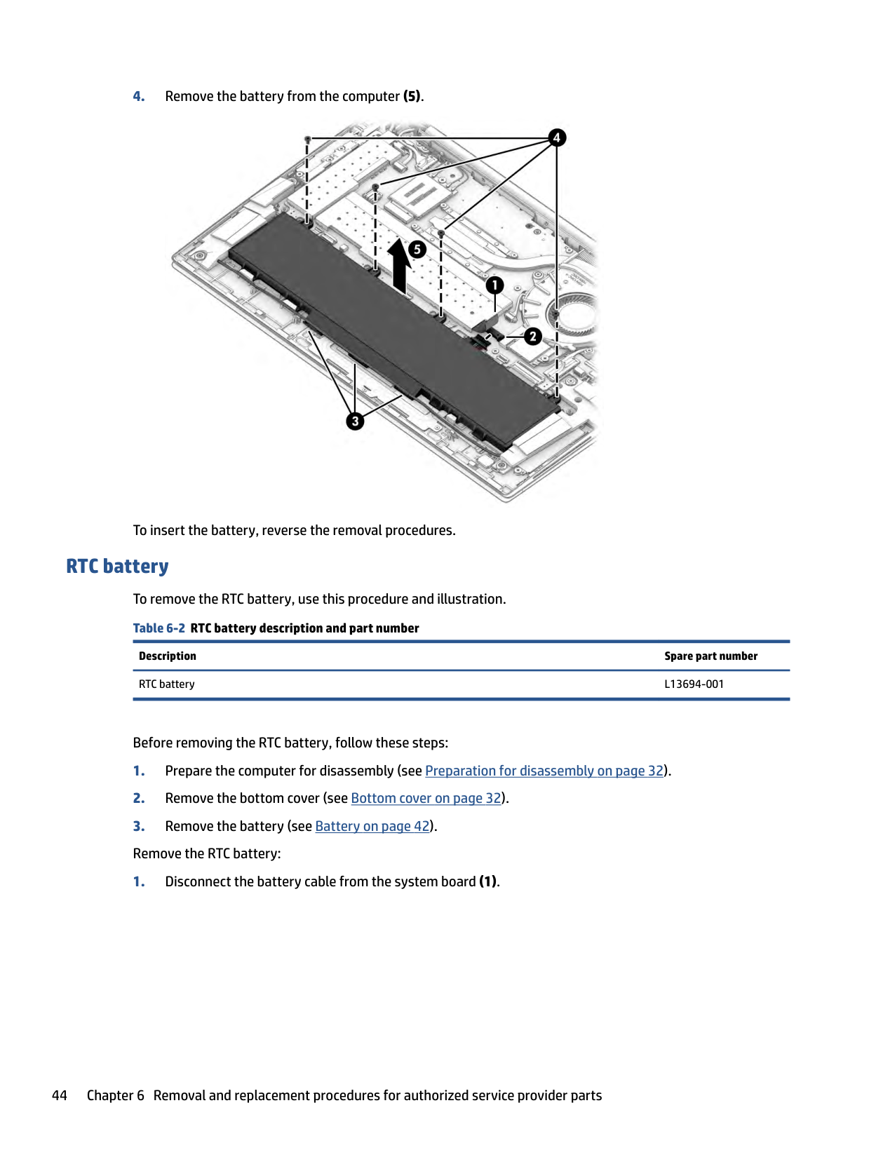
10 totalWhat safety precautions should I follow when replacing the battery in my HP EliteBook?
To avoid personal injury and damage to your computer when replacing a battery, do not puncture, twist, or crack it; handle with care avoiding metal tools near connectors due to risk of shorting. After disassembly preparation steps (off power, disconnect devices), carefully lift tape off battery cable connector, disconnect this from system board, remove speaker cable along battery's bottom edge, and unscrew retaining screws holding the battery before safely removing it from your device. Insert replacement using same care reversely detailed here (Pages 32-41).
How do I access the WWAN module for replacement?
After disassembly preparations and removing bottom cover and battery cable from system board as described, disconnect WWAN antenna cables, remove securing M2.0 x 2.0 screw to free up this module tilting it out slightly as you pull out. Protective sleeves must be installed on unconnected antenna connectors before removal/installation completion (Pages 39-42).
What is the best way to prevent static electricity damage during computer repairs?
To avoid electrostatic discharge (ESD) damage when repairing your device—wear an appropriate wrist strap; keep work surfaces covered with proper static-dissipative materials and use grounding circuits properly connected. Ensure you handle ESD-sensitive components only at designated clean benches free from non-conductive materials (Page 29).
What are the specific tools required for safely disassembling my HP EliteBook?
The essential tools needed include a magnetic Phillips P1 screwdriver, tweezers, and non-conductive pry tool with sharp edges avoided near plastic components due to risk of damage if too much force applied during removal or assembly (Page 27).
Can I perform customer self-repair on my HP EliteBook?
The Customer Self-Repair program is only available in some locations, and unauthorized replacement can void your warranty. Always refer to product documentation (page 32) or check the warranty for specific details before proceeding with repair actions (Pages 31-35).
How do I replace my solid-state drive in my HP EliteBook?
Following preparatory steps for disassembly, use the tab to lift off SSD cover held by clips on system board. Remove the securing M2.0 x 2.5 screw and gently pull the SSD from its socket at an angle. After removal of the solid-state drive component, replace the cover as outlined in instructions (Pages 39-41).
Full Manual
111 pages

Maintenance and Service Guide
SUMMARY This guide provides information about spare parts, removal and replacement of parts, security, backing up, and more.
© Copyright 2021 HP Development Company, L.P.
AMD, Ryzen, and Radeon are trademarks of Advanced Micro Devices, Inc. Bluetooth is a trademark owned by its proprietor and used by HP Inc. under license. Intel, Thunderbolt, and XMM are trademarks of Intel Corporation or its subsidiaries in the U.S. and/or other countries. Microsoft and Windows are either registered trademarks or trademarks of Microsoft Corporation in the United States and/or other countries. USB Type-C and USB-C are registered trademarks of USB Implementers Forum. DisplayPort™ and the DisplayPort™ logo are trademarks owned by the Video Electronics Standards Association (VESA®) in the United States and other countries. Miracast is a registered trademark of Wi-Fi Alliance.
The information contained herein is subject to change without notice. The only warranties for HP products and services are set forth in the express warranty statements accompanying such products and services. Nothing herein should be construed as constituting an additional warranty. HP shall not be liable for technical or editorial errors or omissions contained herein.
First Edition: April 2021 Document Part Number: M17149-001
######### Product notice
This guide describes features that are common to most models. Some features may not be available on your computer.
Not all features are available in all editions or versions of Windows. Systems may require upgraded and/or separately purchased hardware, drivers, software or BIOS update to take full advantage of Windows functionality. Windows 10 is automatically updated, which is always enabled. ISP fees may apply and additional requirements may apply over time for updates. Go to http://www.microsoft.com for details.
To access the latest user guides, go to http://www.hp.com/support, and follow the instructions to find your product. Then select Manuals.
######### Software terms
By installing, copying, downloading, or otherwise using any software product preinstalled on this computer, you agree to be bound by the terms of the HP End User License Agreement (EULA). If you do not accept these license terms, your sole remedy is to return the entire unused product (hardware and software) within 14 days for a full refund subject to the refund policy of your seller.
For any further information or to request a full refund of the price of the computer, please contact your seller.
#### Important notice about Customer Self-Repair parts
Your computer includes Customer Self-Repair parts and parts that should be accessed by only an authorized service provider.
| | |---|
IMPORTANT: See "Removal and replacement procedures for Customer Self-Repair parts" for details.
Accessing parts described in "Removal and replacement procedures for authorized service provider parts" can damage the computer or void your warranty.
iii
####### iv Important notice about Customer Self-Repair parts
#### Safety warning notice
Reduce the possibility of heat-related injuries or of overheating the computer by following the practices described.
WARNING! To reduce the possibility of heat-related injuries or of overheating the computer, do not place the computer directly on your lap or obstruct the computer air vents. Use the computer only on a hard, flat surface. Do not allow another hard surface, such as an adjoining optional printer, or a soft surface, such as pillows or rugs or clothing, to block airflow. Also, do not allow the AC adapter to come into contact with the skin or a soft surface, such as pillows or rugs or clothing, during operation. The computer and the AC adapter comply with the user-accessible surface temperature limits defined by applicable safety standards.
v
####### vi Safety warning notice

Table of contents
Touchpad ............................................................................................................................................. 9
Touchpad settings ............................................................................................................. 9 Adjusting touchpad settings .......................................................................... 9 Turning on the touchpad ................................................................................ 9
Touchpad components .................................................................................................... 10 Lights ................................................................................................................................................. 10 Button, speakers, vents, and fingerprint reader .............................................................................. 11 Special keys ....................................................................................................................................... 13
Bottom ................................................................................................................................................................. 14 Labels ................................................................................................................................................................... 15 Using a SIM card (select products only) ............................................................................................................... 16
Inserting a nano SIM card .................................................................................................................. 16 Removing a nano SIM card ................................................................................................................ 17
Plastic parts ....................................................................................................................................... 27 Cables and connectors ...................................................................................................................... 27 Drive handling ................................................................................................................................... 27
Electrostatic discharge information .................................................................................................................... 28
vii
Generating static electricity .............................................................................................................. 28 Preventing electrostatic damage to equipment ............................................................................... 29 Personal grounding methods and equipment .................................................................................. 29 Grounding the work area ................................................................................................................... 30 Recommended materials and equipment ........................................................................................ 30

Packaging and transporting guidelines .............................................................................................................. 31
###### 5 Removal and replacement procedures for Customer Self-Repair parts ............................................................. 32Component replacement procedures .................................................................................................................. 32
Preparation for disassembly ............................................................................................................. 32 Bottom cover ..................................................................................................................................... 32 Memory modules ............................................................................................................................... 33 WLAN module .................................................................................................................................... 36 WWAN module ................................................................................................................................... 37 Solid-state drive ................................................................................................................................ 39
###### 6 Removal and replacement procedures for authorized service provider parts .................................................... 42Component replacement procedures .................................................................................................................. 42
Preparation for disassembly ............................................................................................................. 42 Battery ............................................................................................................................................... 42 RTC battery ........................................................................................................................................ 44 Speakers ............................................................................................................................................ 45 Card reader board .............................................................................................................................. 46 Power connector cable ...................................................................................................................... 47 USB board .......................................................................................................................................... 48 Fingerprint reader board ................................................................................................................... 49 Touchpad ........................................................................................................................................... 50 NFC module ....................................................................................................................................... 52 Fan ..................................................................................................................................................... 52 Heat sink ............................................................................................................................................ 53 System board .................................................................................................................................... 55 Display assembly ............................................................................................................................... 58 Keyboard with top cover ................................................................................................................... 74
###### 7 Computer Setup (BIOS), TPM, and HP Sure Start ............................................................................................. 75Using Computer Setup ......................................................................................................................................... 75
Navigating and selecting in Computer Setup ................................................................................... 75 Restoring factory settings in Computer Setup ................................................................................. 75 Updating the BIOS ............................................................................................................................. 76
Determining the BIOS version ......................................................................................... 76
viii
Preparing for a BIOS update ........................................................................................... 76 Downloading a BIOS update ......................................................................... 76 Installing a BIOS update ............................................................................... 77
Changing the boot order using the f9 prompt .................................................................................. 77 TPM BIOS settings (select products only) ........................................................................................................... 77 Using HP Sure Start (select products only) ......................................................................................................... 78
###### 8 Backing up, restoring, and recovering ........................................................................................................... 79Backing up information and creating recovery media ........................................................................................ 79
Using Windows tools for backing up ................................................................................................. 79 Using the HP Cloud Recovery Download Tool to create recovery media (select products only) ..... 79
Restoring and recovering your system ............................................................................................................... 79 Creating a system restore ................................................................................................................. 80 Restoring and recovery methods ...................................................................................................... 80 Recovering using HP Recovery media ............................................................................................... 80 Changing the computer boot order ................................................................................................... 80 Using HP Sure Recover (select products only) .................................................................................. 81

###### 9 Using HP PC Hardware Diagnostics ................................................................................................................ 82Using HP PC Hardware Diagnostics Windows (select products only) ................................................................. 82
Using an HP PC Hardware Diagnostics Windows hardware failure ID code ...................................... 82 Accessing HP PC Hardware Diagnostics Windows ............................................................................ 82
Accessing HP PC Hardware Diagnostics Windows from HP Help and Support (select products only) ..................................................................................................... 82 Accessing HP PC Hardware Diagnostics Windows from Support Assistant ................... 83 Accessing HP PC Hardware Diagnostics Windows from the Start menu (select products only) ................................................................................................................. 83
Downloading HP PC Hardware Diagnostics Windows ....................................................................... 83 Downloading the latest HP PC Hardware Diagnostics Windows version from HP ......... 83 Downloading the HP PC Hardware Diagnostics Windows from the Microsoft Store ..... 83 Downloading HP Hardware Diagnostics Windows by product name or number (select products only) ..................................................................................................... 84
Installing HP PC Hardware Diagnostics Windows ............................................................................. 84
Using HP PC Hardware Diagnostics UEFI ............................................................................................................. 84 Using an HP PC Hardware Diagnostics UEFI hardware failure ID code ............................................. 84 Starting HP PC Hardware Diagnostics UEFI ....................................................................................... 85 Downloading HP PC Hardware Diagnostics UEFI to a USB flash drive .............................................. 85
Downloading the latest HP PC Hardware Diagnostics UEFI version .............................. 85 Downloading HP PC Hardware Diagnostics UEFI by product name or number (select products only) ..................................................................................................... 85
Using Remote HP PC Hardware Diagnostics UEFI settings (select products only) ............................................. 86
ix
Downloading Remote HP PC Hardware Diagnostics UEFI ................................................................. 86 Downloading the latest Remote HP PC Hardware Diagnostics UEFI version ................. 86 Downloading Remote HP PC Hardware Diagnostics UEFI by product name or number ............................................................................................................................ 86
Customizing Remote HP PC Hardware Diagnostics UEFI settings .................................................... 86

###### Index ........................................................................................................................................................... 100
x
1 Product description
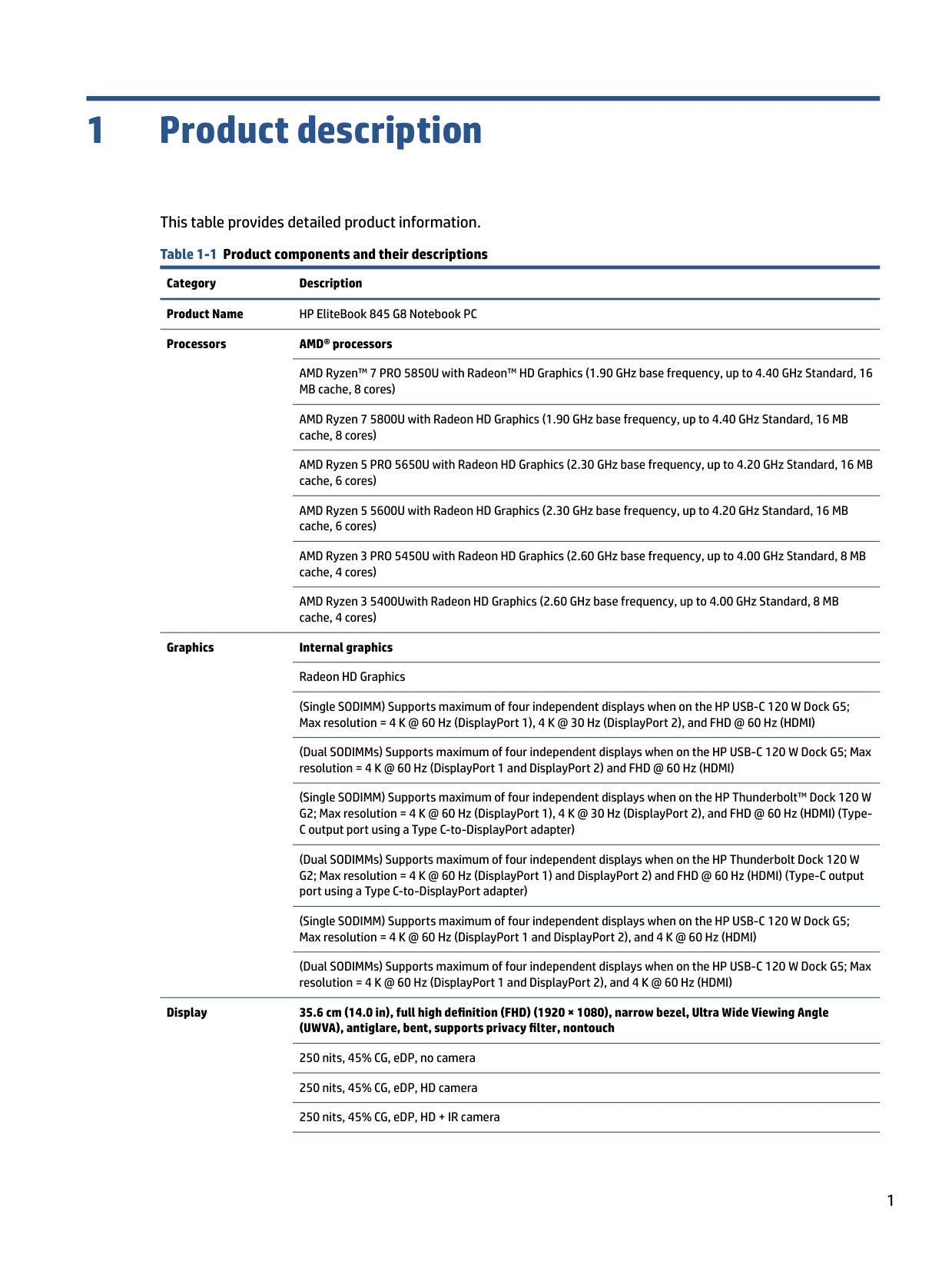
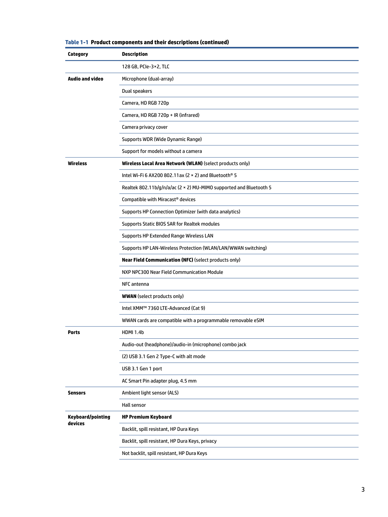
###### This table provides detailed product information. Table 1-1 Product components and their descriptions
Category Description Product Name HP EliteBook 845 G8 Notebook PC Processors AMD® processors
AMD Ryzen™ 7 PRO 5850U with Radeon™ HD Graphics (1.90 GHz base frequency, up to 4.40 GHz Standard, 16 MB cache, 8 cores)
AMD Ryzen 7 5800U with Radeon HD Graphics (1.90 GHz base frequency, up to 4.40 GHz Standard, 16 MB cache, 8 cores)
AMD Ryzen 5 PRO 5650U with Radeon HD Graphics (2.30 GHz base frequency, up to 4.20 GHz Standard, 16 MB cache, 6 cores)
AMD Ryzen 5 5600U with Radeon HD Graphics (2.30 GHz base frequency, up to 4.20 GHz Standard, 16 MB cache, 6 cores)
AMD Ryzen 3 PRO 5450U with Radeon HD Graphics (2.60 GHz base frequency, up to 4.00 GHz Standard, 8 MB cache, 4 cores)
AMD Ryzen 3 5400Uwith Radeon HD Graphics (2.60 GHz base frequency, up to 4.00 GHz Standard, 8 MB cache, 4 cores)
Graphics Internal graphics Radeon HD Graphics (Single SODIMM) Supports maximum of four independent displays when on the HP USB-C 120 W Dock G5; Max resolution = 4 K @ 60 Hz (DisplayPort 1), 4 K @ 30 Hz (DisplayPort 2), and FHD @ 60 Hz (HDMI) (Dual SODIMMs) Supports maximum of four independent displays when on the HP USB-C 120 W Dock G5; Max resolution = 4 K @ 60 Hz (DisplayPort 1 and DisplayPort 2) and FHD @ 60 Hz (HDMI)
(Single SODIMM) Supports maximum of four independent displays when on the HP Thunderbolt™ Dock 120 W G2; Max resolution = 4 K @ 60 Hz (DisplayPort 1), 4 K @ 30 Hz (DisplayPort 2), and FHD @ 60 Hz (HDMI) (TypeC output port using a Type C-to-DisplayPort adapter)
(Dual SODIMMs) Supports maximum of four independent displays when on the HP Thunderbolt Dock 120 W G2; Max resolution = 4 K @ 60 Hz (DisplayPort 1) and DisplayPort 2) and FHD @ 60 Hz (HDMI) (Type-C output port using a Type C-to-DisplayPort adapter)
(Single SODIMM) Supports maximum of four independent displays when on the HP USB-C 120 W Dock G5; Max resolution = 4 K @ 60 Hz (DisplayPort 1 and DisplayPort 2), and 4 K @ 60 Hz (HDMI)
(Dual SODIMMs) Supports maximum of four independent displays when on the HP USB-C 120 W Dock G5; Max resolution = 4 K @ 60 Hz (DisplayPort 1 and DisplayPort 2), and 4 K @ 60 Hz (HDMI)
Display 35.6 cm (14.0 in), full high definition (FHD) (1920 × 1080), narrow bezel, Ultra Wide Viewing Angle (UWVA), antiglare, bent, supports privacy filter, nontouch
250 nits, 45% CG, eDP, no camera 250 nits, 45% CG, eDP, HD camera 250 nits, 45% CG, eDP, HD + IR camera
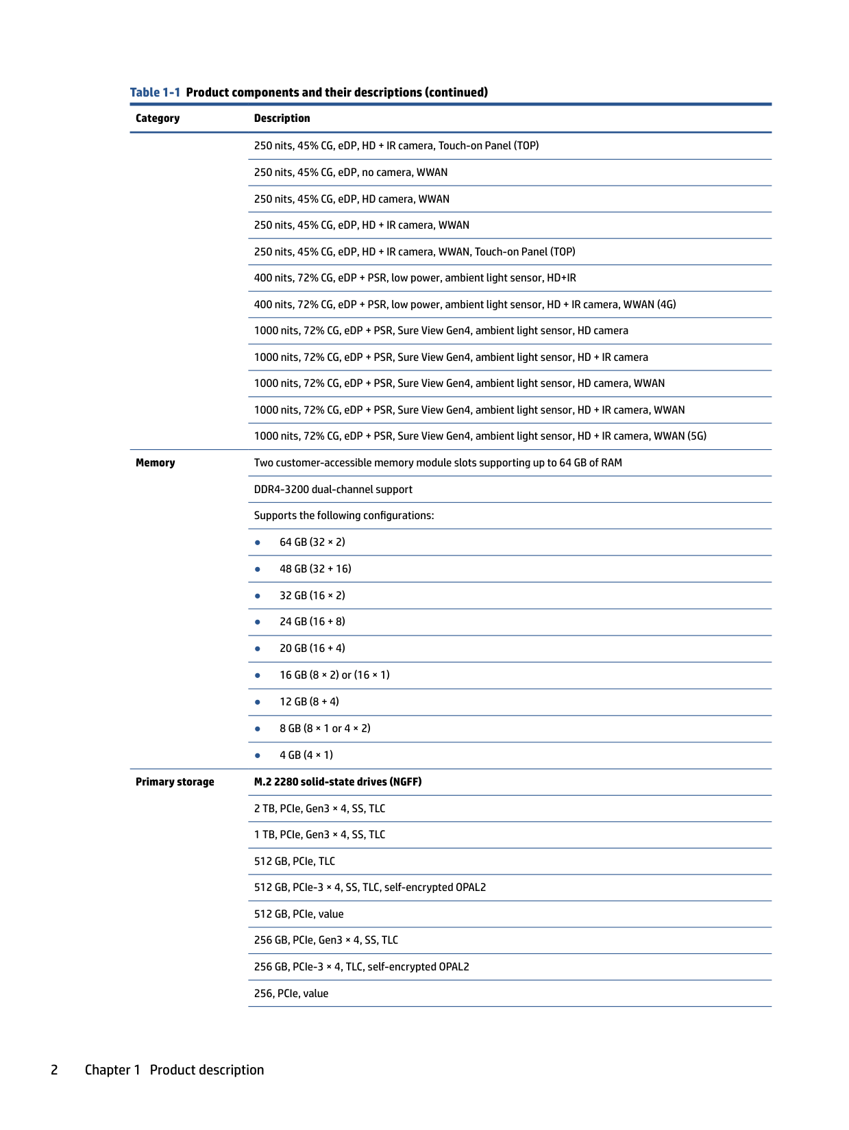
250 nits, 45% CG, eDP, HD + IR camera, Touch-on Panel (TOP) 250 nits, 45% CG, eDP, no camera, WWAN 250 nits, 45% CG, eDP, HD camera, WWAN 250 nits, 45% CG, eDP, HD + IR camera, WWAN 250 nits, 45% CG, eDP, HD + IR camera, WWAN, Touch-on Panel (TOP) 400 nits, 72% CG, eDP + PSR, low power, ambient light sensor, HD+IR 400 nits, 72% CG, eDP + PSR, low power, ambient light sensor, HD + IR camera, WWAN (4G) 1000 nits, 72% CG, eDP + PSR, Sure View Gen4, ambient light sensor, HD camera 1000 nits, 72% CG, eDP + PSR, Sure View Gen4, ambient light sensor, HD + IR camera 1000 nits, 72% CG, eDP + PSR, Sure View Gen4, ambient light sensor, HD camera, WWAN 1000 nits, 72% CG, eDP + PSR, Sure View Gen4, ambient light sensor, HD + IR camera, WWAN 1000 nits, 72% CG, eDP + PSR, Sure View Gen4, ambient light sensor, HD + IR camera, WWAN (5G)
Memory Two customer-accessible memory module slots supporting up to 64 GB of RAM DDR4-3200 dual-channel support Supports the following configurations:
Primary storage M.2 2280 solid-state drives (NGFF) 2 TB, PCIe, Gen3 × 4, SS, TLC 1 TB, PCIe, Gen3 × 4, SS, TLC 512 GB, PCIe, TLC 512 GB, PCIe-3 × 4, SS, TLC, self-encrypted OPAL2 512 GB, PCIe, value 256 GB, PCIe, Gen3 × 4, SS, TLC 256 GB, PCIe-3 × 4, TLC, self-encrypted OPAL2 256, PCIe, value
128 GB, PCIe-3×2, TLC
Audio and video Microphone (dual-array) Dual speakers Camera, HD RGB 720p Camera, HD RGB 720p + IR (infrared) Camera privacy cover Supports WDR (Wide Dynamic Range) Support for models without a camera
Wireless Wireless Local Area Network (WLAN) (select products only) Intel Wi-Fi 6 AX200 802.11ax (2 × 2) and Bluetooth® 5 Realtek 802.11b/g/n/a/ac (2 × 2) MU-MIMO supported and Bluetooth 5 Compatible with Miracast® devices Supports HP Connection Optimizer (with data analytics) Supports Static BIOS SAR for Realtek modules Supports HP Extended Range Wireless LAN Supports HP LAN-Wireless Protection (WLAN/LAN/WWAN switching) Near Field Communication (NFC) (select products only) NXP NPC300 Near Field Communication Module NFC antenna WWAN (select products only) Intel XMM™ 7360 LTE-Advanced (Cat 9) WWAN cards are compatible with a programmable removable eSIM
Ports HDMI 1.4b
Audio-out (headphone)/audio-in (microphone) combo jack
(2) USB 3.1 Gen 2 Type-C with alt mode USB 3.1 Gen 1 port AC Smart Pin adapter plug, 4.5 mm
Sensors Ambient light sensor (ALS)
Keyboard/pointing devices
Hall sensor
HP Premium Keyboard Backlit, spill resistant, HP Dura Keys Backlit, spill resistant, HP Dura Keys, privacy Not backlit, spill resistant, HP Dura Keys
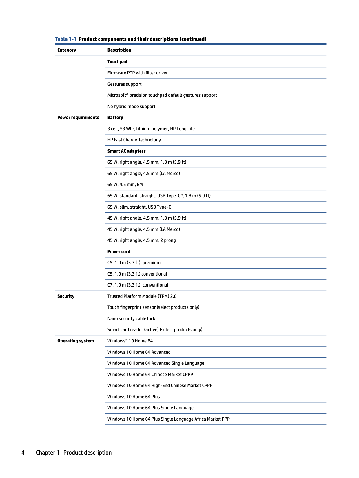
Touchpad Firmware PTP with filter driver Gestures support Microsoft® precision touchpad default gestures support No hybrid mode support
Power requirements Battery 3 cell, 53 Whr, lithium polymer, HP Long Life HP Fast Charge Technology Smart AC adapters 65 W, right angle, 4.5 mm, 1.8 m (5.9 ft) 65 W, right angle, 4.5 mm (LA Merco) 65 W, 4.5 mm, EM 65 W, standard, straight, USB Type-C®, 1.8 m (5.9 ft) 65 W, slim, straight, USB Type-C 45 W, right angle, 4.5 mm, 1.8 m (5.9 ft) 45 W, right angle, 4.5 mm (LA Merco) 45 W, right angle, 4.5 mm, 2 prong Power cord C5, 1.0 m (3.3 ft), premium C5, 1.0 m (3.3 ft) conventional C7, 1.0 m (3.3 ft), conventional
Security Trusted Platform Module (TPM) 2.0 Touch fingerprint sensor (select products only) Nano security cable lock Smart card reader (active) (select products only)
Operating system Windows® 10 Home 64 Windows 10 Home 64 Advanced Windows 10 Home 64 Advanced Single Language Windows 10 Home 64 Chinese Market CPPP Windows 10 Home 64 High-End Chinese Market CPPP Windows 10 Home 64 Plus Windows 10 Home 64 Plus Single Language Windows 10 Home 64 Plus Single Language Africa Market PPP
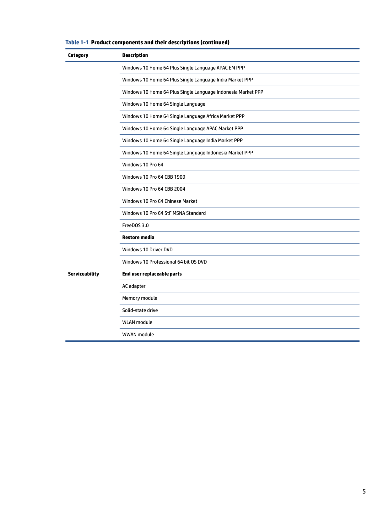
Windows 10 Home 64 Plus Single Language APAC EM PPP Windows 10 Home 64 Plus Single Language India Market PPP Windows 10 Home 64 Plus Single Language Indonesia Market PPP Windows 10 Home 64 Single Language Windows 10 Home 64 Single Language Africa Market PPP Windows 10 Home 64 Single Language APAC Market PPP Windows 10 Home 64 Single Language India Market PPP Windows 10 Home 64 Single Language Indonesia Market PPP Windows 10 Pro 64 Windows 10 Pro 64 CBB 1909 Windows 10 Pro 64 CBB 2004 Windows 10 Pro 64 Chinese Market Windows 10 Pro 64 StF MSNA Standard FreeDOS 3.0 Restore media Windows 10 Driver DVD Windows 10 Professional 64 bit OS DVD
Serviceability End user replaceable parts AC adapter Memory module Solid-state drive WLAN module WWAN module
2 Components
Your computer features top-rated components. This chapter provides details about your components, where they are located, and how they work.
Right side
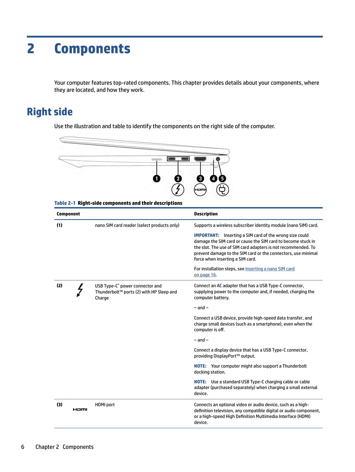
Use the illustration and table to identify the components on the right side of the computer.

Table 2-1 Right-side components and their descriptions
Component Description
IMPORTANT: Inserting a SIM card of the wrong size could damage the SIM card or cause the SIM card to become stuck in the slot. The use of SIM card adapters is not recommended. To prevent damage to the SIM card or the connectors, use minimal force when inserting a SIM card.
For installation steps, see Inserting a nano SIM card on page 16.

Connect an AC adapter that has a USB Type-C connector, supplying power to the computer and, if needed, charging the computer battery.
Connect a USB device, provide high-speed data transfer, and charge small devices (such as a smartphone), even when the computer is off.
Connect a display device that has a USB Type-C connector, providing DisplayPort™ output.
NOTE: Your computer might also support a Thunderbolt docking station.
NOTE: Use a standard USB Type-C charging cable or cable adapter (purchased separately) when charging a small external device.

######## Table 2-1 Right-side components and their descriptions (continued)
######### Component Description

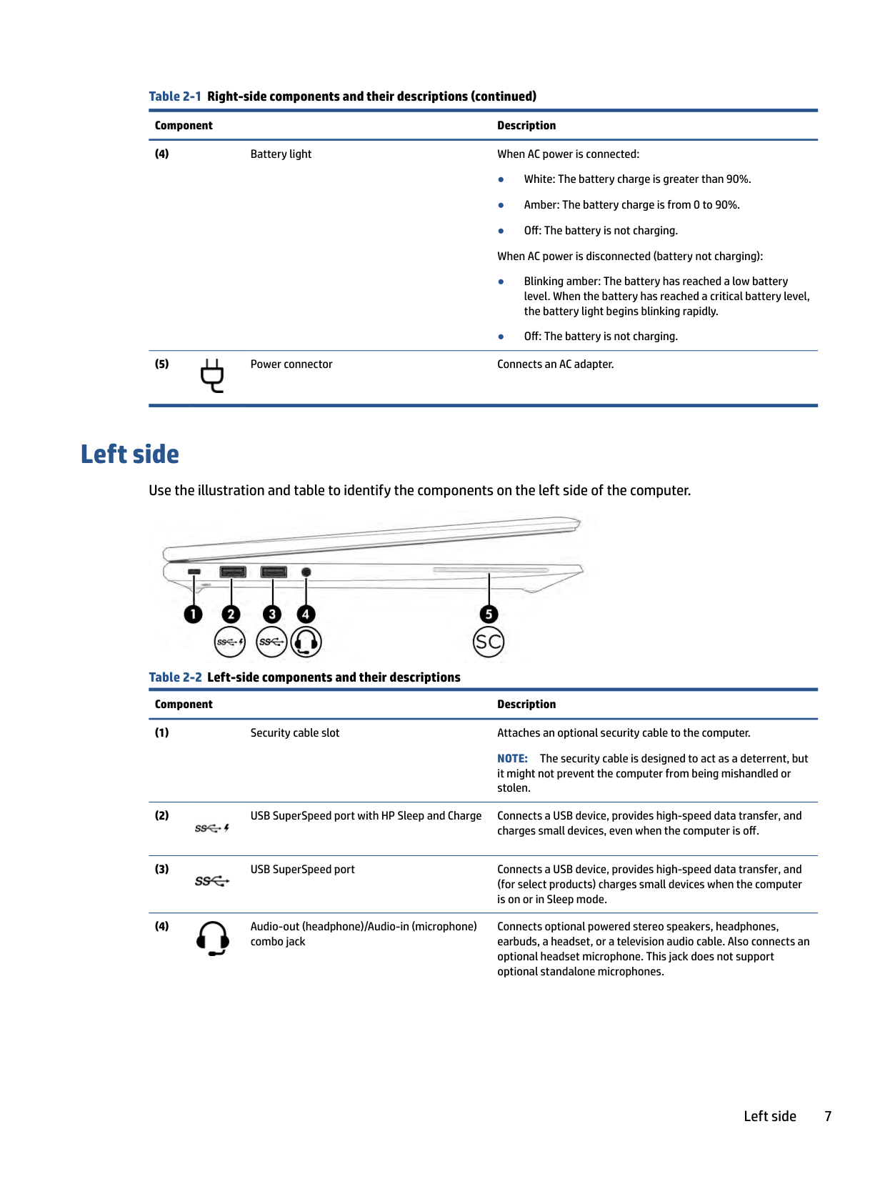
Left side
Use the illustration and table to identify the components on the left side of the computer.

Table 2-2 Left-side components and their descriptions
Component Description
NOTE: The security cable is designed to act as a deterrent, but it might not prevent the computer from being mishandled or stolen.


Connects optional powered stereo speakers, headphones, earbuds, a headset, or a television audio cable. Also connects an optional headset microphone. This jack does not support optional standalone microphones.

Left side 7
######## Table 2-2 Left-side components and their descriptions (continued)
######### Component Description
WARNING! To reduce the risk of personal injury, adjust the volume before putting on headphones, earbuds, or a headset. For additional safety information, see the Regulatory, Safety, and Environmental Notices.
To access this guide:
▲ Type HP Documentation in the taskbar search box,
######### and then select HP Documentation.
NOTE: When a device is connected to the jack, the computer speakers are disabled.
(5) Smart card reader Supports optional smart cards.

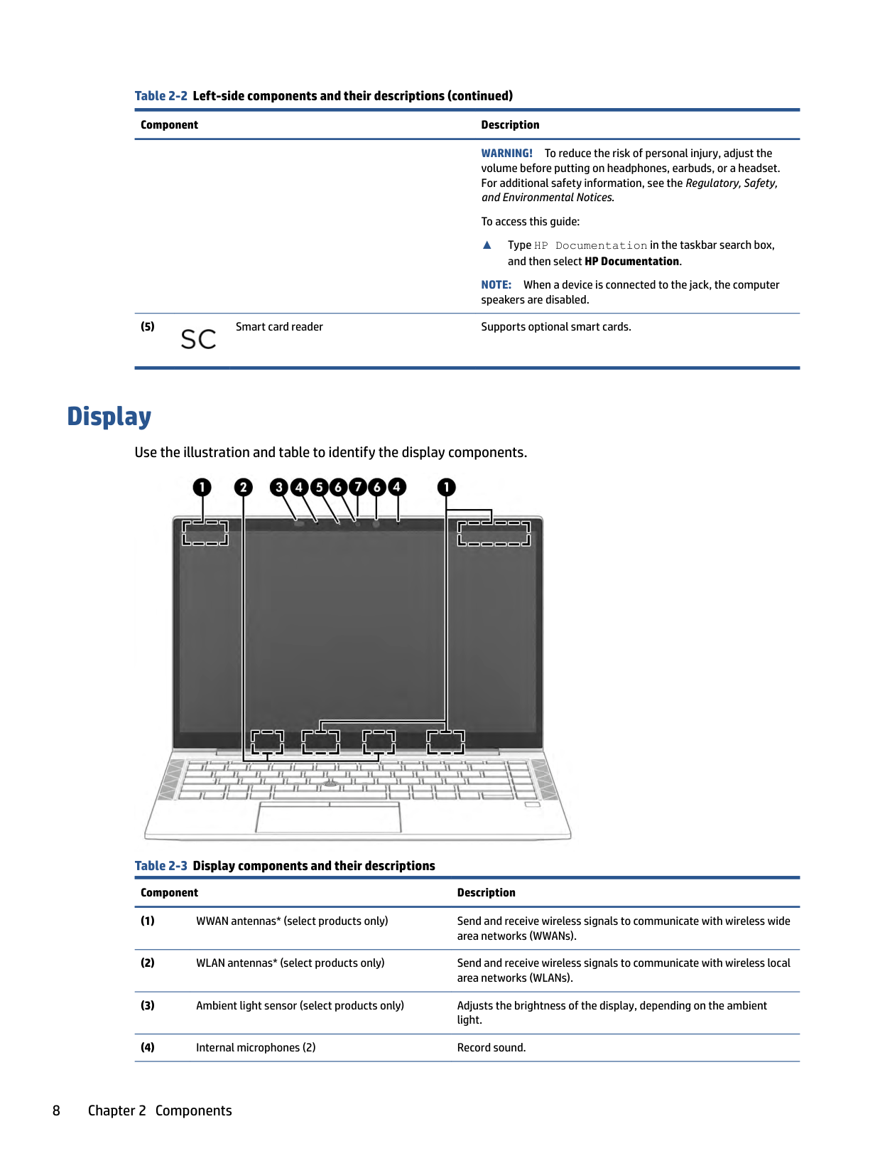
Display
Use the illustration and table to identify the display components.

Table 2-3 Display components and their descriptions
Component Description
######## Table 2-3 Display components and their descriptions (continued)
######### Component Description
NOTE: Camera functions vary depending on the camera hardware and software installed on your product.
NOTE: If you have both front-facing and rear-facing cameras, when one camera lens is revealed and ready to use, the other is concealed.
*The antennas are not visible from the outside of the computer. For optimal transmission, keep the areas immediately around the antennas free from obstructions.
For wireless regulatory notices, see the section of the Regulatory, Safety, and Environmental Notices that applies to your country or region.
To access this guide:
▲ Type HP Documentation in the taskbar search box, and then select HP Documentation.
Keyboard area
Keyboards can vary by language.
#### Touchpad
The touchpad settings and components are described here. Touchpad settings
You learn how to adjust the touchpad settings and components here. Adjusting touchpad settings
Use these steps to adjust touchpad settings and gestures.
###### Turning on the touchpad
Follow these steps to turn on the touchpad.
If you are not using an external mouse, press the Tab key repeatedly until the pointer rests on the touchpad button. Then press the spacebar to select the button.
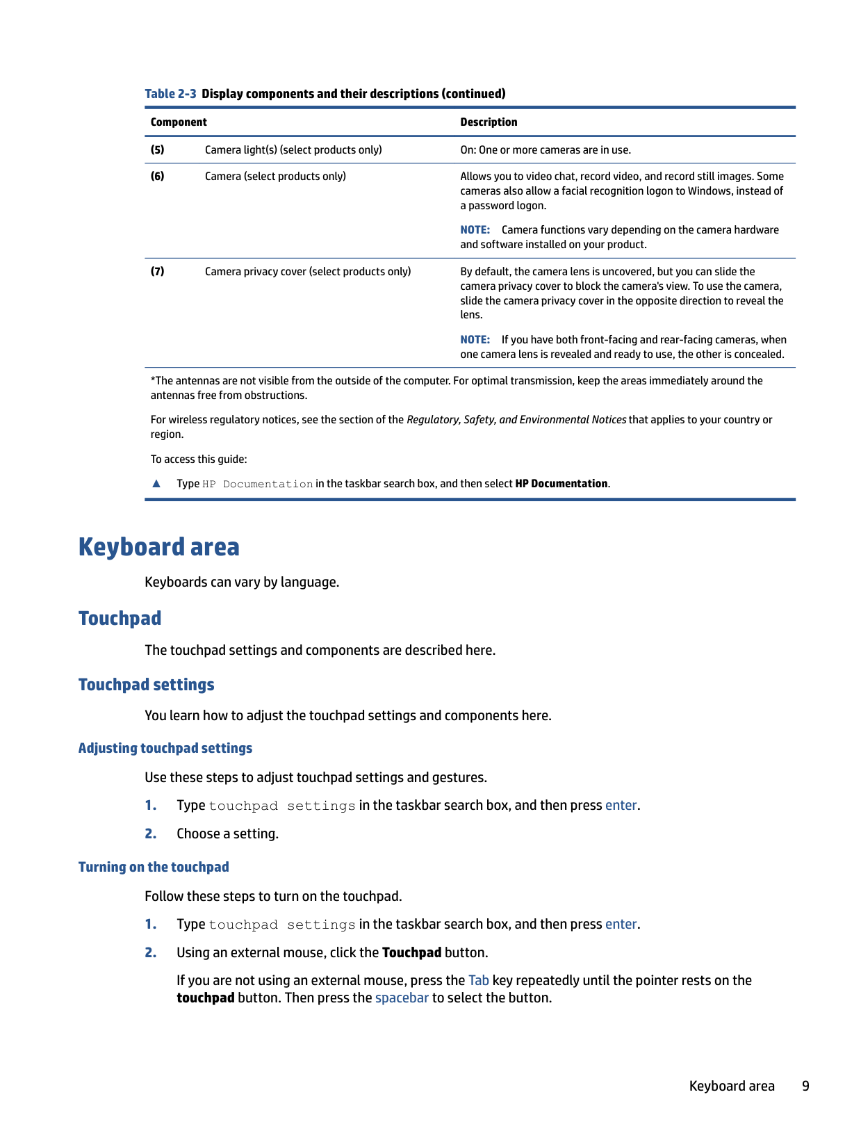
##### Touchpad components
Use the illustration and table to identify the touchpad components.

Table 2-4 Touchpad components and their descriptions
Component Description
Allows you to wirelessly share information when you tap it with an NFC-enabled device.
#### Lights
Use the illustration and table to identify the lights on the computer.

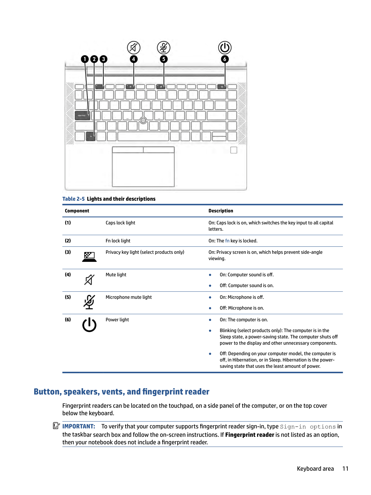
######## Table 2-5 Lights and their descriptions
######### Component Description


● Off: Computer sound is on.

● Off: Microphone is on.

#### Button, speakers, vents, and fingerprint reader
Fingerprint readers can be located on the touchpad, on a side panel of the computer, or on the top cover below the keyboard.
| | |---|
IMPORTANT: To verify that your computer supports fingerprint reader sign-in, type Sign-in options in the taskbar search box and follow the on-screen instructions. If Fingerprint reader is not listed as an option, then your notebook does not include a fingerprint reader.

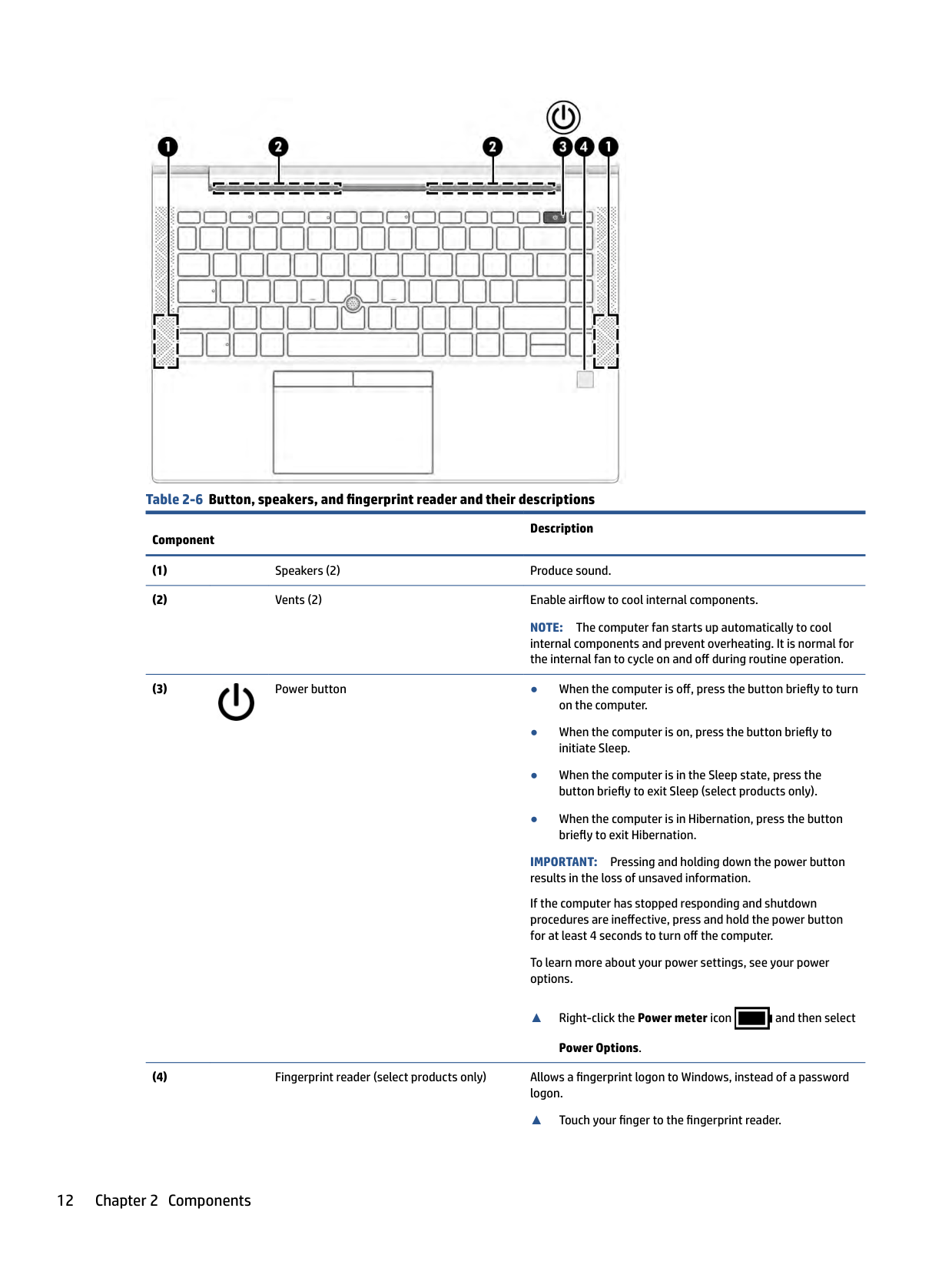
######## Table 2-6 Button, speakers, and fingerprint reader and their descriptions
Component
Description
NOTE: The computer fan starts up automatically to cool internal components and prevent overheating. It is normal for the internal fan to cycle on and off during routine operation.

IMPORTANT: Pressing and holding down the power button results in the loss of unsaved information. If the computer has stopped responding and shutdown procedures are ineffective, press and hold the power button for at least 4 seconds to turn off the computer. To learn more about your power settings, see your power options.
▲ Right-click the Power meter icon and then select Power Options.

▲ Touch your finger to the fingerprint reader.
######## Table 2-6 Button, speakers, and fingerprint reader and their descriptions (continued)
Description
Component
IMPORTANT: To prevent fingerprint logon issues, make sure when you register your fingerprint that all sides of your finger are registered by the fingerprint reader.
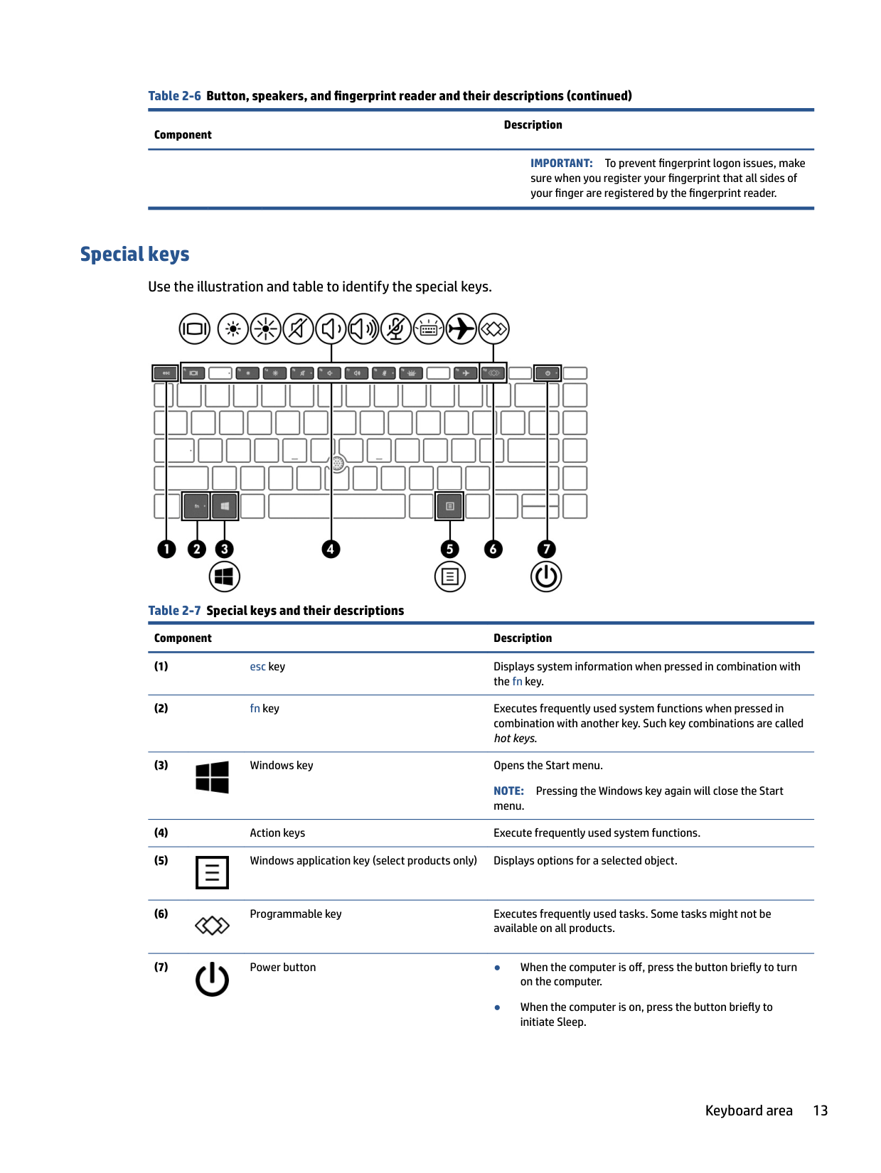
#### Special keys
Use the illustration and table to identify the special keys.

Table 2-7 Special keys and their descriptions
Component Description

NOTE: Pressing the Windows key again will close the Start menu.


● When the computer is on, press the button briefly to initiate Sleep.
######## Table 2-7 Special keys and their descriptions (continued)
######### Component Description
IMPORTANT: Pressing and holding down the power button results in the loss of unsaved information. If the computer has stopped responding and shutdown procedures are ineffective, press and hold the power button for at least 4 seconds to turn off the computer. To learn more about your power settings, see your power options.

▲ Right-click the Power meter icon and then select Power Options.
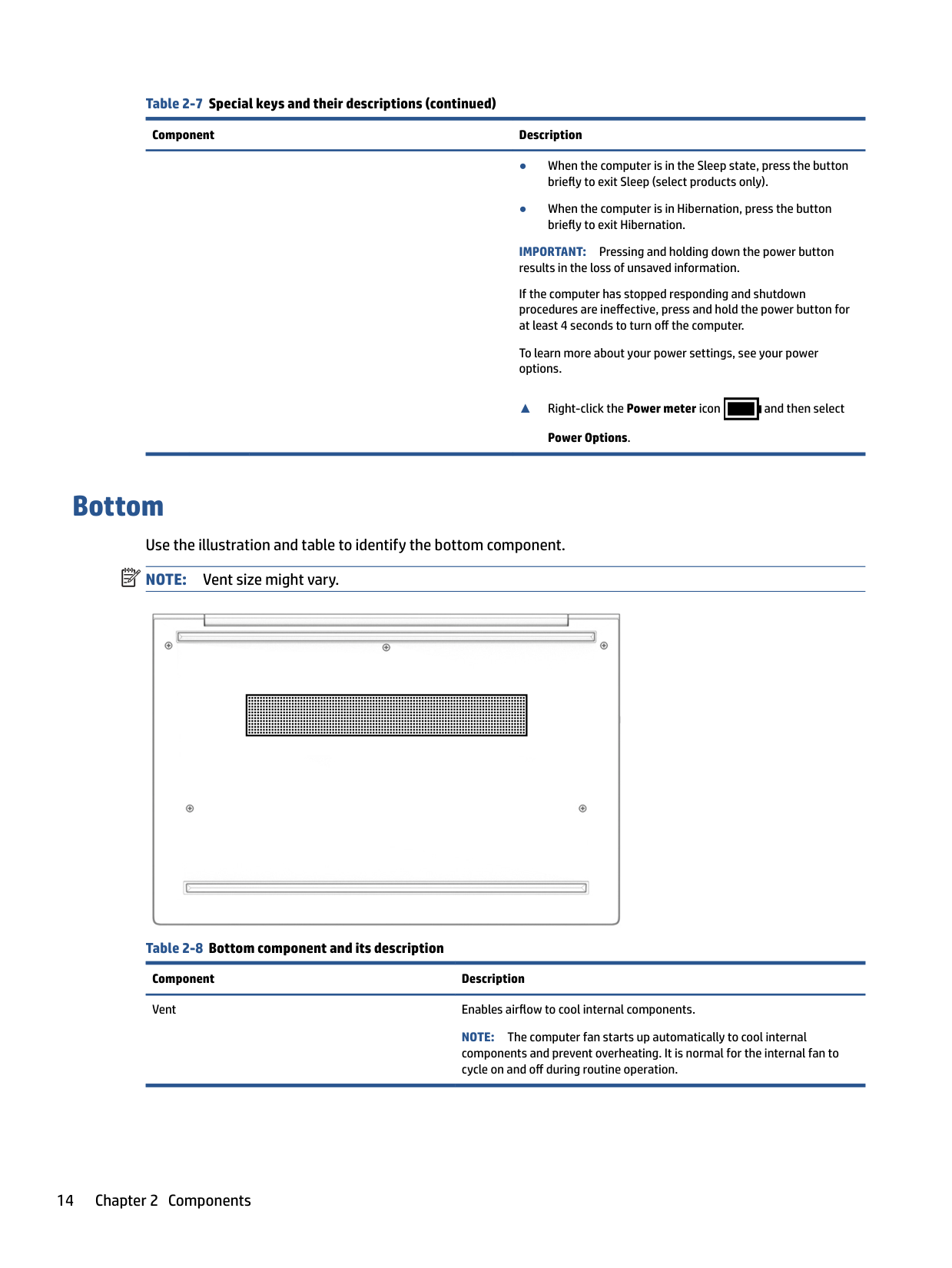
Bottom Use the illustration and table to identify the bottom component. NOTE: Vent size might vary.
| | |---|

Table 2-8 Bottom component and its description Component Description Vent Enables airflow to cool internal components.
NOTE: The computer fan starts up automatically to cool internal components and prevent overheating. It is normal for the internal fan to cycle on and off during routine operation.
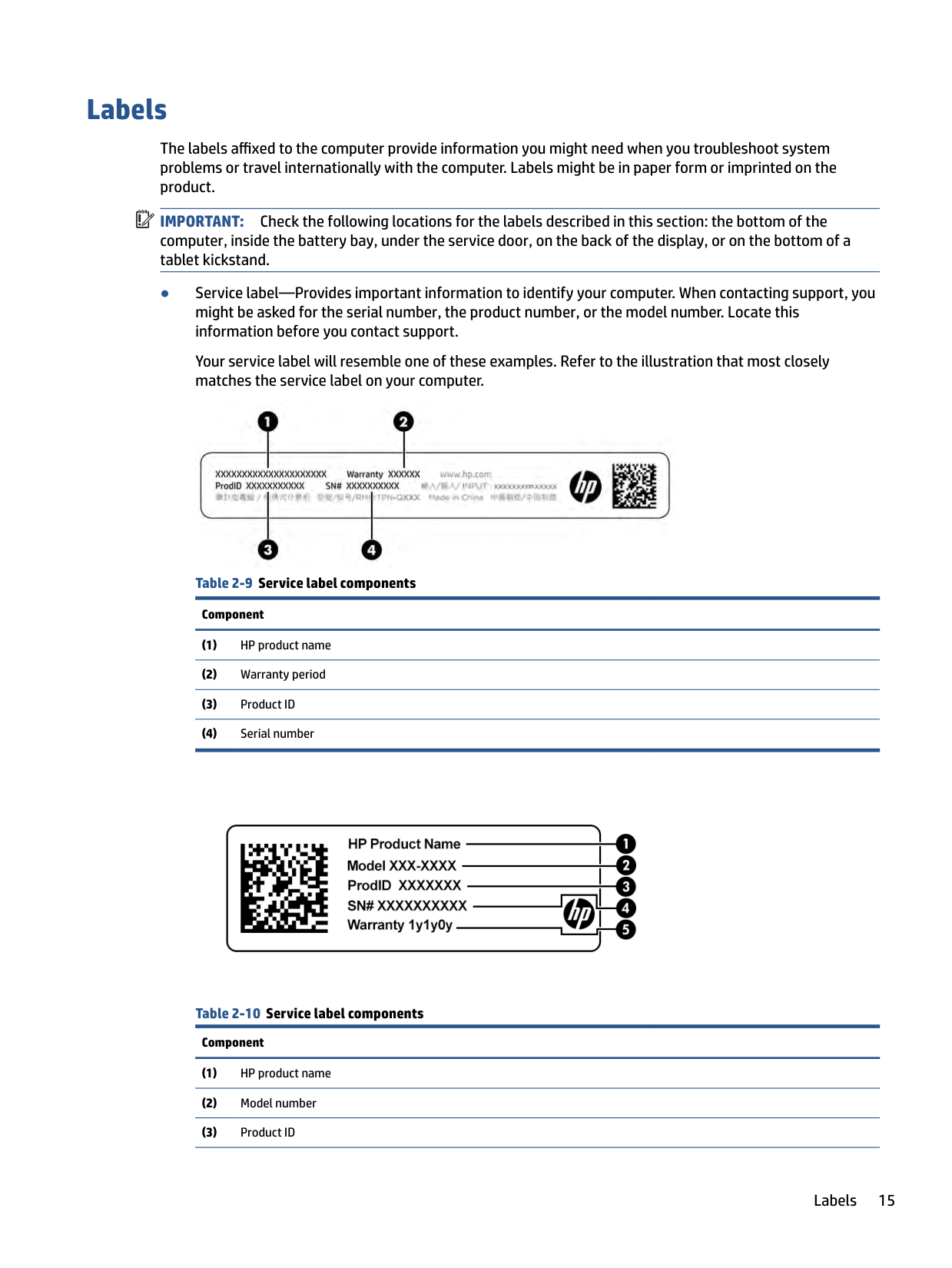
Labels
The labels affixed to the computer provide information you might need when you troubleshoot system problems or travel internationally with the computer. Labels might be in paper form or imprinted on the product.
| | |---|
IMPORTANT: Check the following locations for the labels described in this section: the bottom of the computer, inside the battery bay, under the service door, on the back of the display, or on the bottom of a tablet kickstand.
Your service label will resemble one of these examples. Refer to the illustration that most closely matches the service label on your computer.


Labels 15
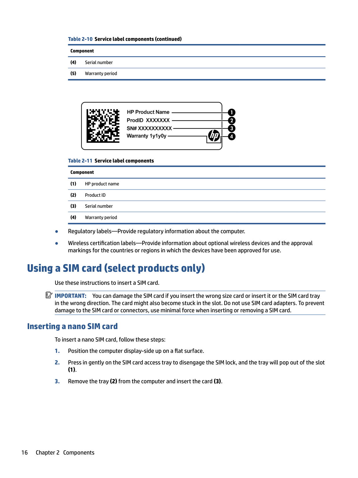
######## Table 2-10 Service label components (continued)Component

######## Table 2-11 Service label componentsComponent
Using a SIM card (select products only) Use these instructions to insert a SIM card. IMPORTANT: You can damage the SIM card if you insert the wrong size card or insert it or the SIM card tray in the wrong direction. The card might also become stuck in the slot. Do not use SIM card adapters. To prevent damage to the SIM card or connectors, use minimal force when inserting or removing a SIM card.
| | |---|
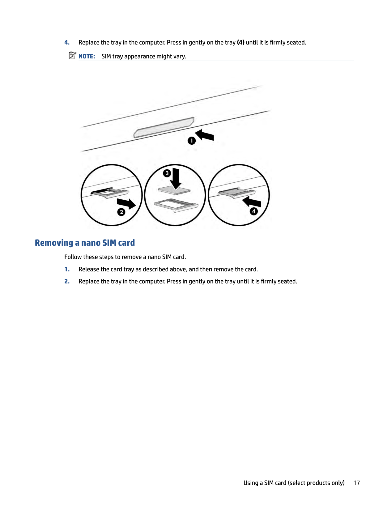
#### Inserting a nano SIM card
To insert a nano SIM card, follow these steps:
(1).
| | |---|

#### Removing a nano SIM card
Follow these steps to remove a nano SIM card.
Using a SIM card (select products only) 17
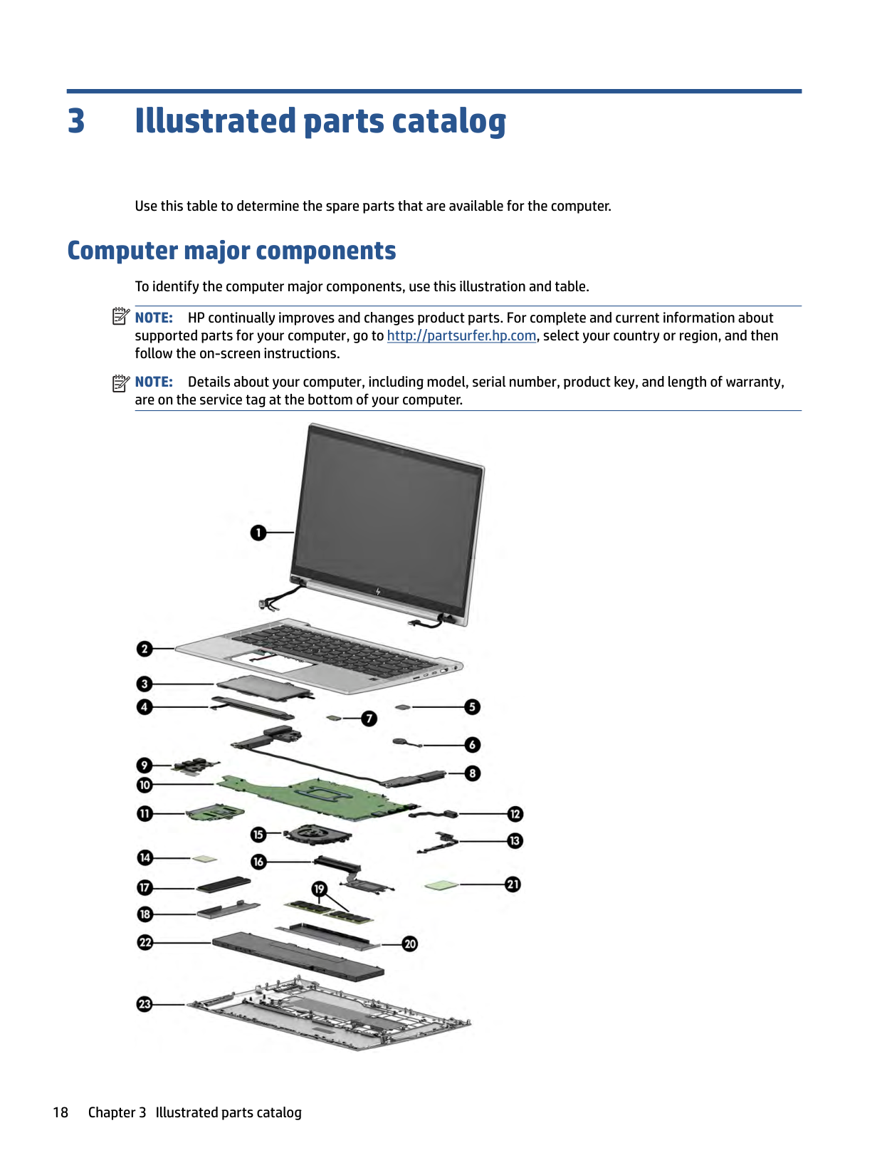
3 Illustrated parts catalog
Use this table to determine the spare parts that are available for the computer.
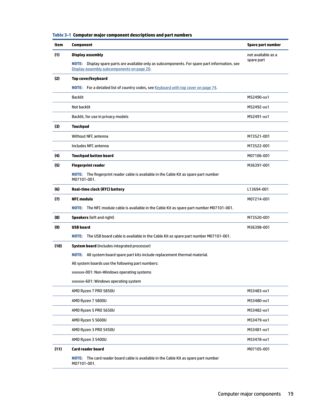
Computer major components To identify the computer major components, use this illustration and table. NOTE: HP continually improves and changes product parts. For complete and current information about supported parts for your computer, go to http://partsurfer.hp.com, select your country or region, and then follow the on-screen instructions. NOTE: Details about your computer, including model, serial number, product key, and length of warranty, are on the service tag at the bottom of your computer.
| | |---|
| | |---|

######## Table 3-1 Computer major component descriptions and part numbers
######### Item Component Spare part number
not available as a spare part
NOTE: The fingerprint reader cable is available in the Cable Kit as spare part number M07101-001.
M36397-001
M07214-001
M36398-001
M07105-001
NOTE: The card reader board cable is available in the Cable Kit as spare part number M07101-001.
Computer major components 19
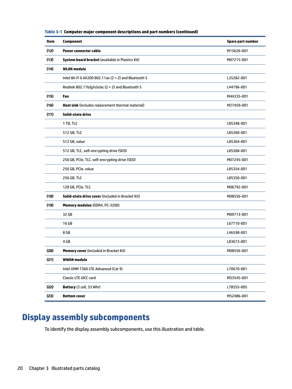
######## Table 3-1 Computer major component descriptions and part numbers (continued)
Item Component Spare part number
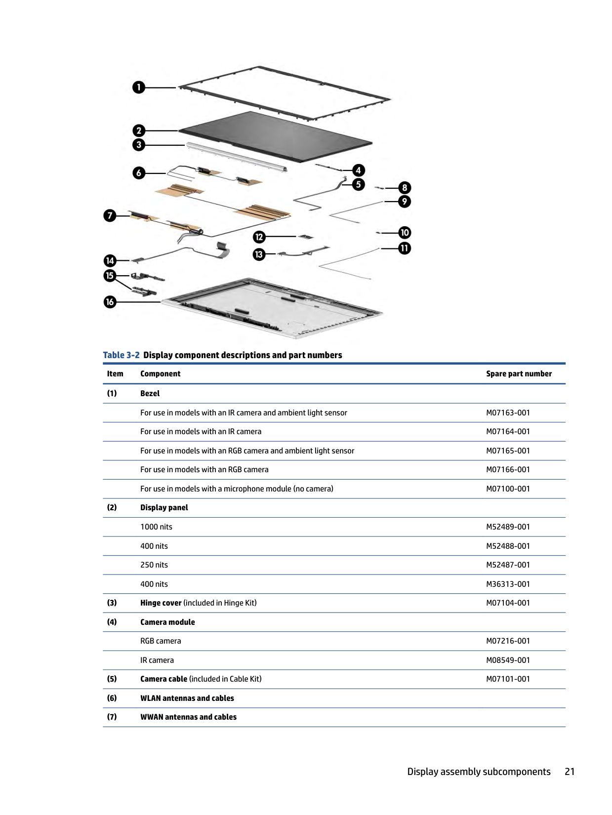
Display assembly subcomponents
To identify the display assembly subcomponents, use this illustration and table.

######## Table 3-2 Display component descriptions and part numbers
######### Item Component Spare part number
Display assembly subcomponents 21
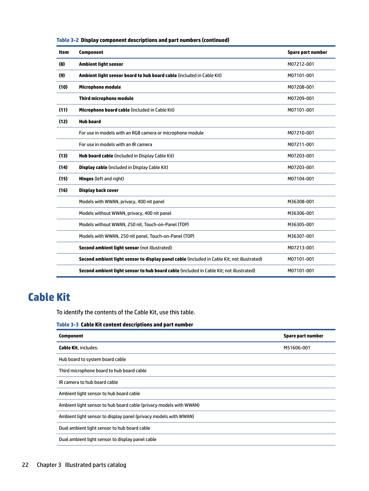
######## Table 3-2 Display component descriptions and part numbers (continued)
Item Component Spare part number
Cable Kit To identify the contents of the Cable Kit, use this table. Table 3-3 Cable Kit content descriptions and part number
Component Spare part number Cable Kit, includes: M51606-001 Hub board to system board cable Third microphone board to hub board cable IR camera to hub board cable Ambient light sensor to hub board cable Ambient light sensor to hub board cable (privacy models with WWAN) Ambient light sensor to display panel (privacy models with WWAN) Dual ambient light sensor to hub board cable Dual ambient light sensor to display panel cable
Table 3-3 Cable Kit content descriptions and part number (continued) Component Spare part number Touchpad cable Fingerprint reader board cable Smart card reader to system board cable NFC module to system board cable USB board to system board cable Camera/microphone module to hub board cable
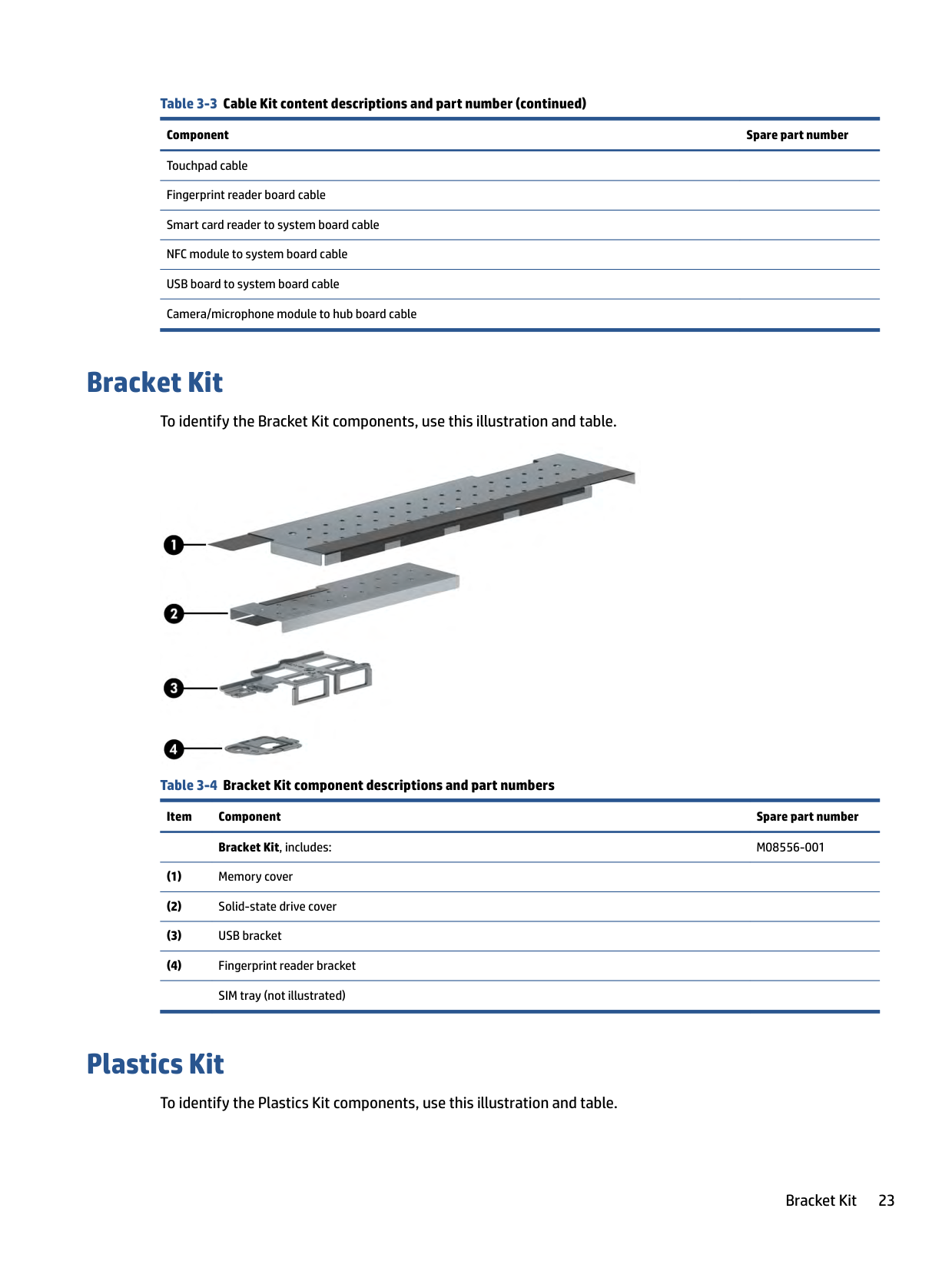
Bracket Kit
To identify the Bracket Kit components, use this illustration and table.

Table 3-4 Bracket Kit component descriptions and part numbers
Item Component Spare part number Bracket Kit, includes: M08556-001
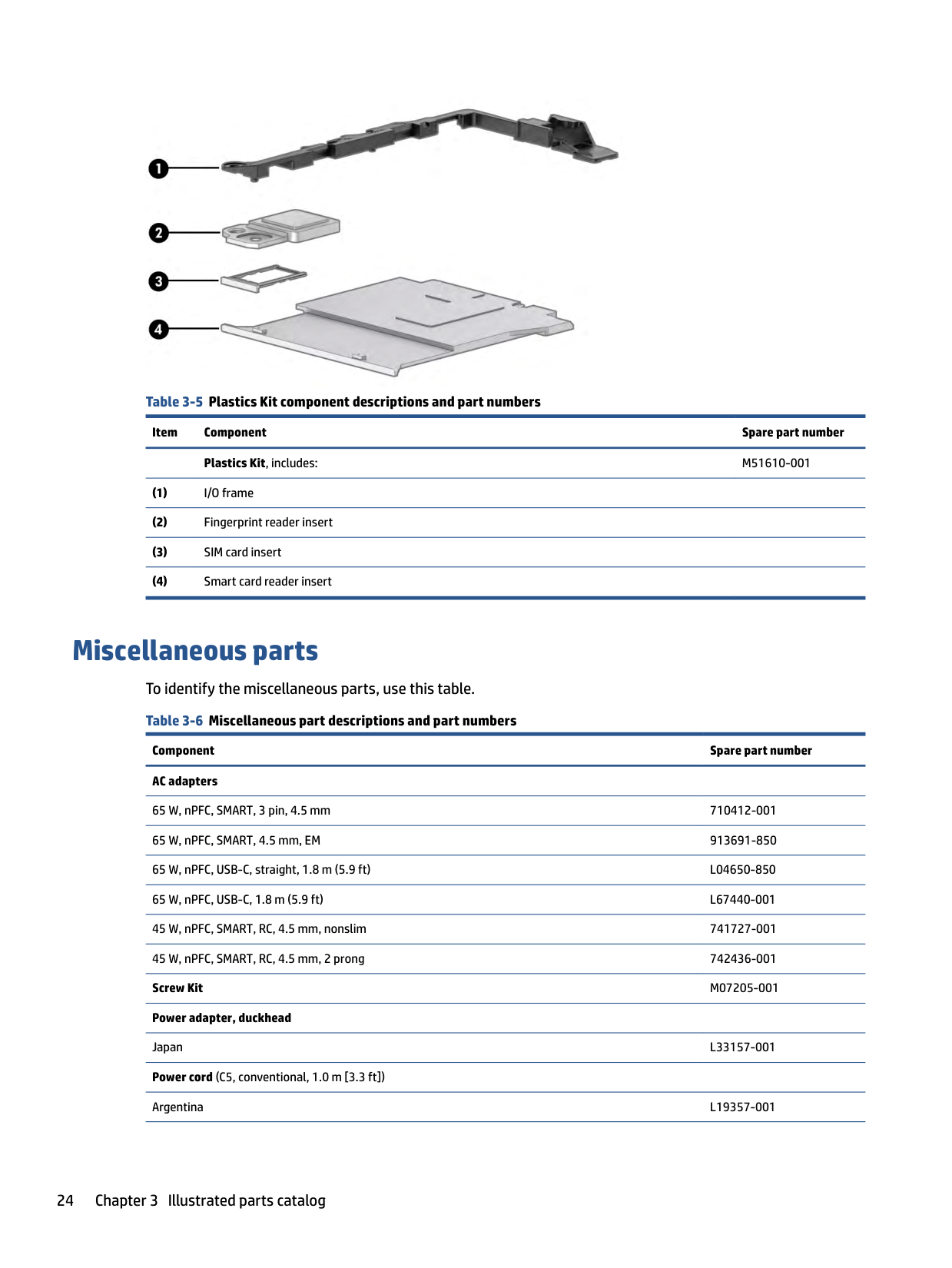
Plastics Kit
To identify the Plastics Kit components, use this illustration and table.
Bracket Kit 23

######## Table 3-5 Plastics Kit component descriptions and part numbers
Item Component Spare part number Plastics Kit, includes: M51610-001
Miscellaneous parts To identify the miscellaneous parts, use this table. Table 3-6 Miscellaneous part descriptions and part numbers
Component Spare part number AC adapters
65 W, nPFC, SMART, 3 pin, 4.5 mm 710412-001 65 W, nPFC, SMART, 4.5 mm, EM 913691-850 65 W, nPFC, USB-C, straight, 1.8 m (5.9 ft) L04650-850 65 W, nPFC, USB-C, 1.8 m (5.9 ft) L67440-001 45 W, nPFC, SMART, RC, 4.5 mm, nonslim 741727-001 45 W, nPFC, SMART, RC, 4.5 mm, 2 prong 742436-001 Screw Kit M07205-001 Power adapter, duckhead
Japan L33157-001 Power cord (C5, conventional, 1.0 m [3.3 ft]) Argentina L19357-001
Australia L19358-001 Brazil L19359-001 Denmark L19360-001 Europe (Austria, Belgium, Finland, France, Germany, the Netherlands, Norway, and Sweden) L19361-001 India L19363-001 Israel L19362-001 Italy L19364-001 Japan L19365-001 North America L19367-001 People's Republic of China L19368-001 South Africa L19369-001 South Korea L19366-001 Switzerland L19370-001 Taiwan L19372-001 Thailand L19371-001 The United Kingdom L19373-001 Power cord (C13, premium, 1.0 m [3.3 ft])
Italy/Chile L22103-001 South Korea L22340-001 United Kingdom L22332-001 Power cord (C5, 1.0 m [3.3 ft], premium)
Argentina L30811-001 Australia L22327-001 Brazil L30812-001 Denmark L22322-001 Europe (Austria, Belgium, Finland, France, Germany, the Netherlands, Norway, and Sweden) L22321-001 India L22624-001 Israel L22323-001 Italy L30813-001 Japan L22330-001 North America L22319-001 People's Republic of China L21930-001
920689-014
Miscellaneous parts 25
South Africa L22325-001 South Korea L22328-001 Switzerland L22324-001 Taiwan L22329-001 Thailand L22326-001 United Kingdom L22320-001
4 Removal and replacement procedures preliminary requirements
Use this information to properly prepare to disassemble and reassemble the computer.
Tools required
You need the following tools to complete the removal and replacement procedures:
Service considerations
The following sections include some of the considerations that you must keep in mind during disassembly and assembly procedures.
| | |---|
NOTE: As you remove each subassembly from the computer, place the subassembly (and all accompanying screws) away from the work area to prevent damage.
#### Plastic parts
Using excessive force during disassembly and reassembly can damage plastic parts.
Cables and connectors Handle cables with extreme care to avoid damage. IMPORTANT: When servicing the computer, be sure that cables are placed in their proper locations during the reassembly process. Improper cable placement can damage the computer. Apply only the tension required to unseat or seat the cables during removal and insertion. Handle cables by the connector whenever possible. In all cases, avoid bending, twisting, or tearing cables. Be sure that cables are routed so that they cannot be caught or snagged as you remove or replace parts. Handle flex cables with extreme care; these cables tear easily.
| | |---|
#### Drive handling
Note the following guidelines when handling drives.
Tools required 27
| | |---|
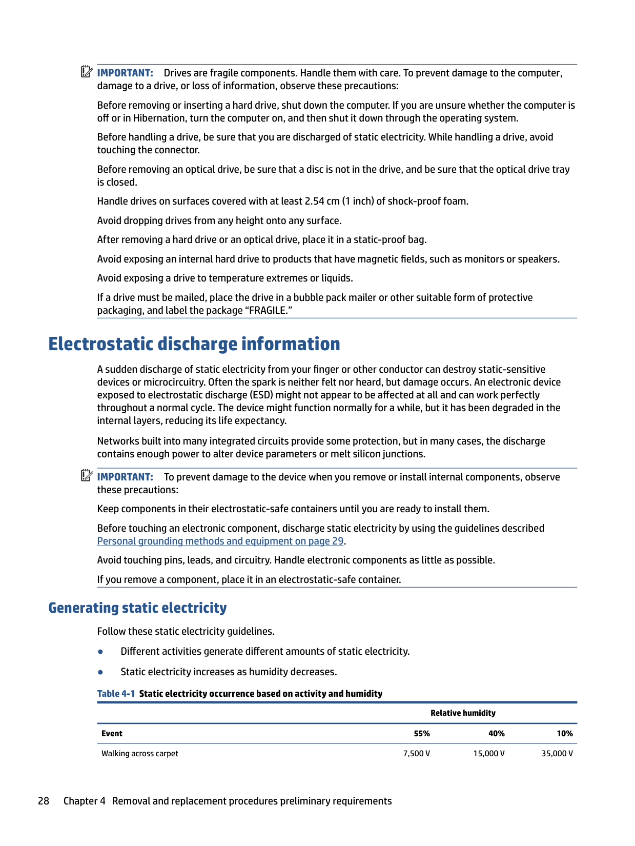
IMPORTANT: Drives are fragile components. Handle them with care. To prevent damage to the computer, damage to a drive, or loss of information, observe these precautions: Before removing or inserting a hard drive, shut down the computer. If you are unsure whether the computer is off or in Hibernation, turn the computer on, and then shut it down through the operating system. Before handling a drive, be sure that you are discharged of static electricity. While handling a drive, avoid touching the connector. Before removing an optical drive, be sure that a disc is not in the drive, and be sure that the optical drive tray is closed. Handle drives on surfaces covered with at least 2.54 cm (1 inch) of shock-proof foam. Avoid dropping drives from any height onto any surface. After removing a hard drive or an optical drive, place it in a static-proof bag. Avoid exposing an internal hard drive to products that have magnetic fields, such as monitors or speakers. Avoid exposing a drive to temperature extremes or liquids. If a drive must be mailed, place the drive in a bubble pack mailer or other suitable form of protective packaging, and label the package “FRAGILE.”
Electrostatic discharge information
A sudden discharge of static electricity from your finger or other conductor can destroy static-sensitive devices or microcircuitry. Often the spark is neither felt nor heard, but damage occurs. An electronic device exposed to electrostatic discharge (ESD) might not appear to be affected at all and can work perfectly throughout a normal cycle. The device might function normally for a while, but it has been degraded in the internal layers, reducing its life expectancy.
Networks built into many integrated circuits provide some protection, but in many cases, the discharge contains enough power to alter device parameters or melt silicon junctions.
| | |---|
IMPORTANT: To prevent damage to the device when you remove or install internal components, observe these precautions: Keep components in their electrostatic-safe containers until you are ready to install them. Before touching an electronic component, discharge static electricity by using the guidelines described Personal grounding methods and equipment on page 29. Avoid touching pins, leads, and circuitry. Handle electronic components as little as possible. If you remove a component, place it in an electrostatic-safe container.
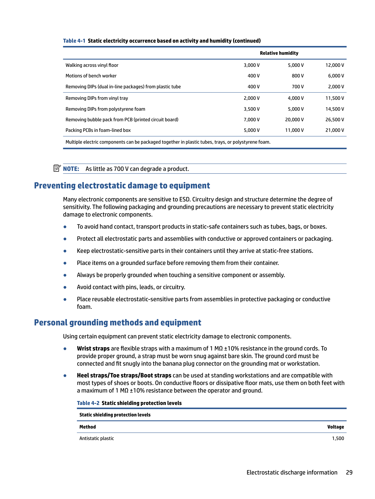
#### Generating static electricity
Follow these static electricity guidelines.
Relative humidity
Event 55% 40% 10% Walking across carpet 7,500 V 15,000 V 35,000 V
######## Table 4-1 Static electricity occurrence based on activity and humidity (continued)
######### Relative humidity
Walking across vinyl floor Motions of bench worker Removing DIPs (dual in-line packages) from plastic tube
3,000 V 400 V 400 V
Removing DIPs from vinyl tray Removing DIPs from polystyrene foam Removing bubble pack from PCB (printed circuit board) Packing PCBs in foam-lined box
Multiple electric components can be packaged together in plastic tubes, trays, or polystyrene foam.
5,000 V 800 V 700 V
20,000 V 11,000 V
12,000 V 6,000 V 2,000 V
11,500 V 14,500 V 26,500 V 21,000 V
| | |---|
NOTE: As little as 700 V can degrade a product.
#### Preventing electrostatic damage to equipment
Many electronic components are sensitive to ESD. Circuitry design and structure determine the degree of sensitivity. The following packaging and grounding precautions are necessary to prevent static electricity damage to electronic components.
#### Personal grounding methods and equipment
Using certain equipment can prevent static electricity damage to electronic components.

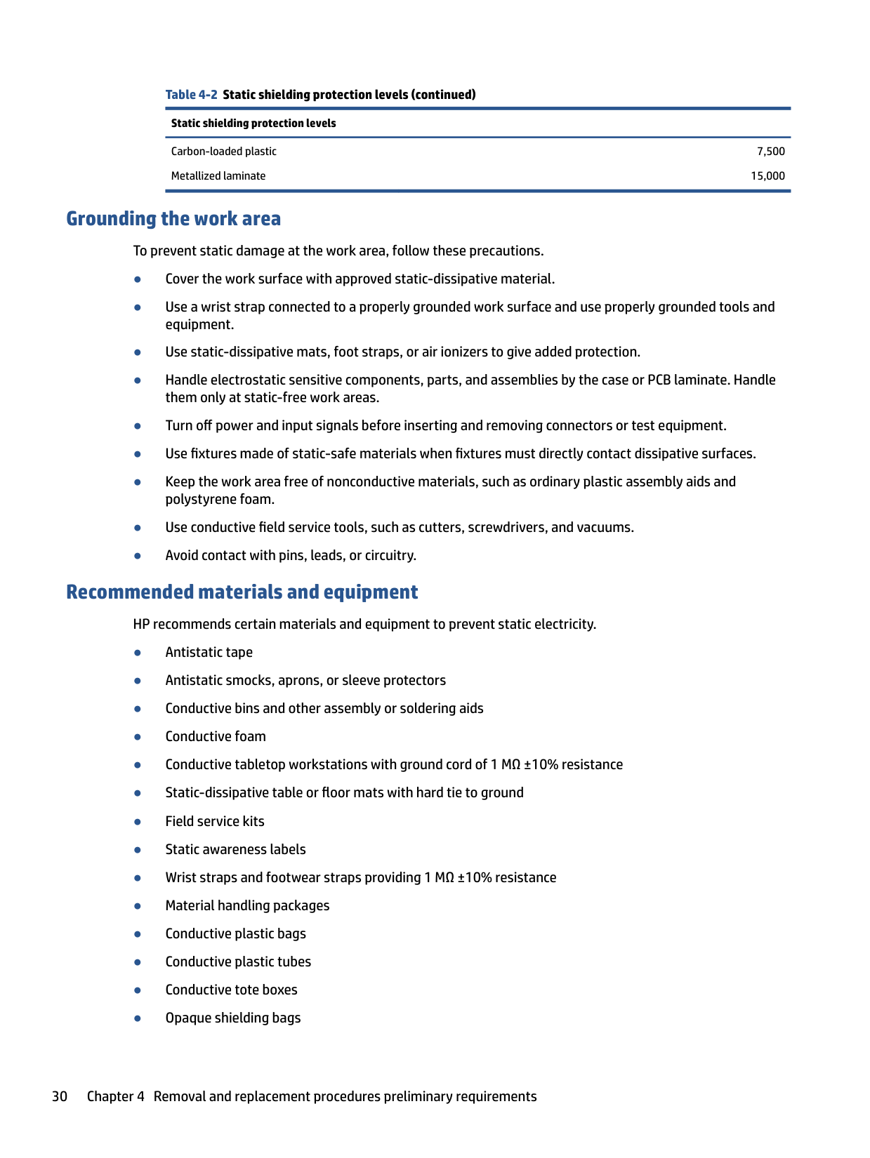
Static shielding protection levels Method Voltage Antistatic plastic 1,500
Electrostatic discharge information 29
Table 4-2 Static shielding protection levels (continued) Static shielding protection levels Carbon-loaded plastic Metallized laminate
7,500 15,000
#### Grounding the work area
To prevent static damage at the work area, follow these precautions.
#### Recommended materials and equipment
HP recommends certain materials and equipment to prevent static electricity.
Packaging and transporting guidelines
Follow these grounding guidelines when packaging and transporting equipment.
Packaging and transporting guidelines 31
5 Removal and replacement procedures for Customer Self-Repair parts
| | |---|
This chapter provides removal and replacement procedures for Customer Self-Repair parts. NOTE: The Customer Self-Repair program is not available in all locations. Installing a part that is not supported by the Customer Self-Repair program can void your warranty. Check your warranty to determine whether Customer Self-Repair is supported in your location.
Component replacement procedures To remove and replace computer components, use these procedures. NOTE: Details about your computer, including model, serial number, product key, and length of warranty, are on the service tag at the bottom of your computer. NOTE: HP continually improves and changes product parts. For complete and current information about supported parts for your computer, go to http://partsurfer.hp.com, select your country or region, and then follow the on-screen instructions.
| | |---|
| | |---|
You must remove, replace, or loosen as many as 8 screws when you service Customer Self-Repair parts. Make special note of each screw size and location during removal and replacement.
Preparation for disassembly To prepare to disassemble the computer, use these steps. See Removal and replacement procedures preliminary requirements on page 27 for initial safety procedures.
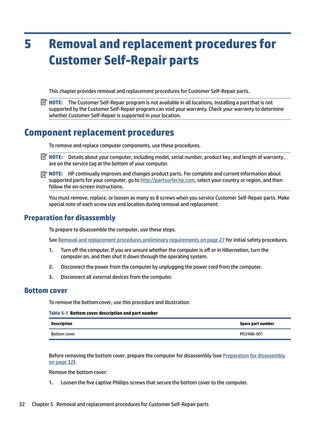
#### Bottom cover To remove the bottom cover, use this procedure and illustration. Table 5-1 Bottom cover description and part number
Description Spare part number Bottom cover M52486-001
Before removing the bottom cover, prepare the computer for disassembly (see Preparation for disassembly on page 32).
Remove the bottom cover:


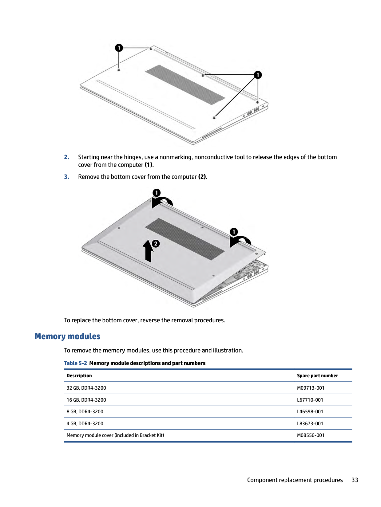
To replace the bottom cover, reverse the removal procedures.
Memory modules To remove the memory modules, use this procedure and illustration. Table 5-2 Memory module descriptions and part numbers
Description Spare part number 32 GB, DDR4-3200 M09713-001 16 GB, DDR4-3200 L67710-001 8 GB, DDR4-3200 L46598-001 4 GB, DDR4-3200 L83673-001 Memory module cover (included in Bracket Kit) M08556-001
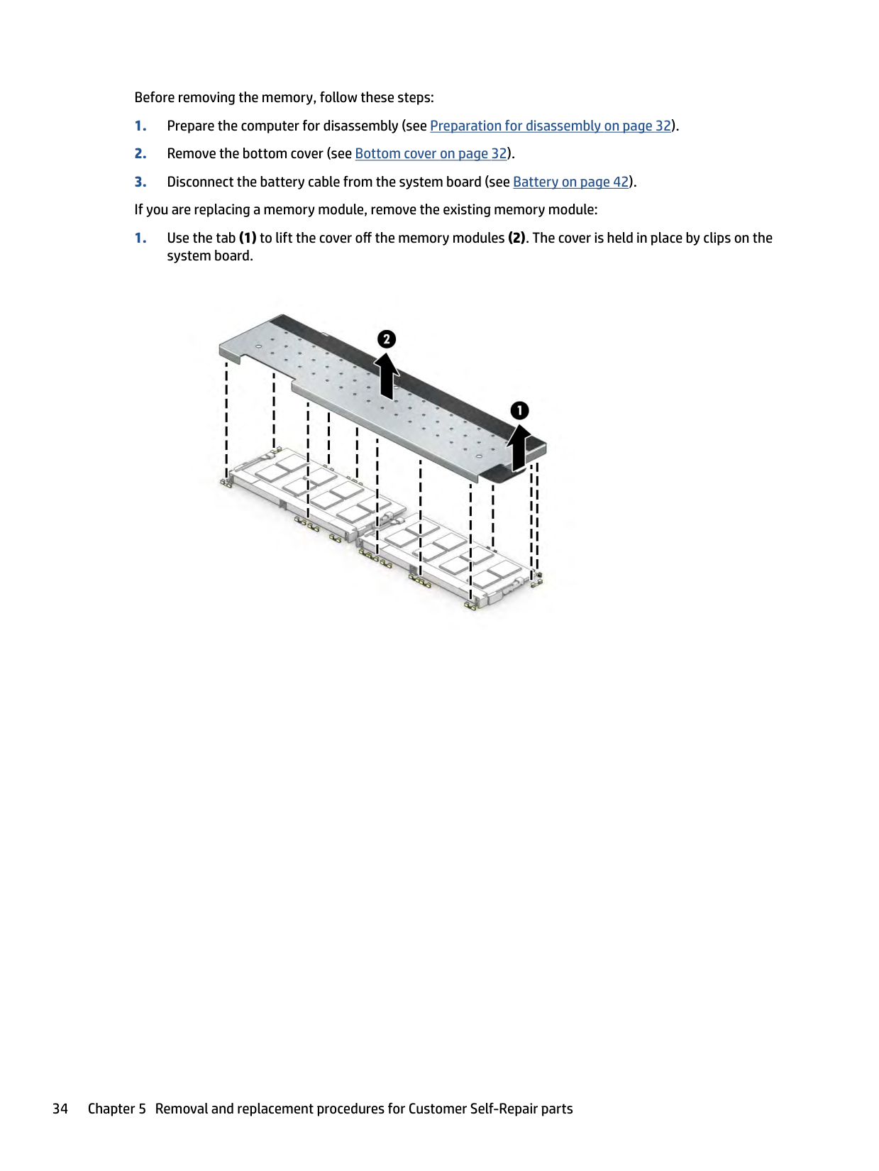
Before removing the memory, follow these steps:

| | |---|
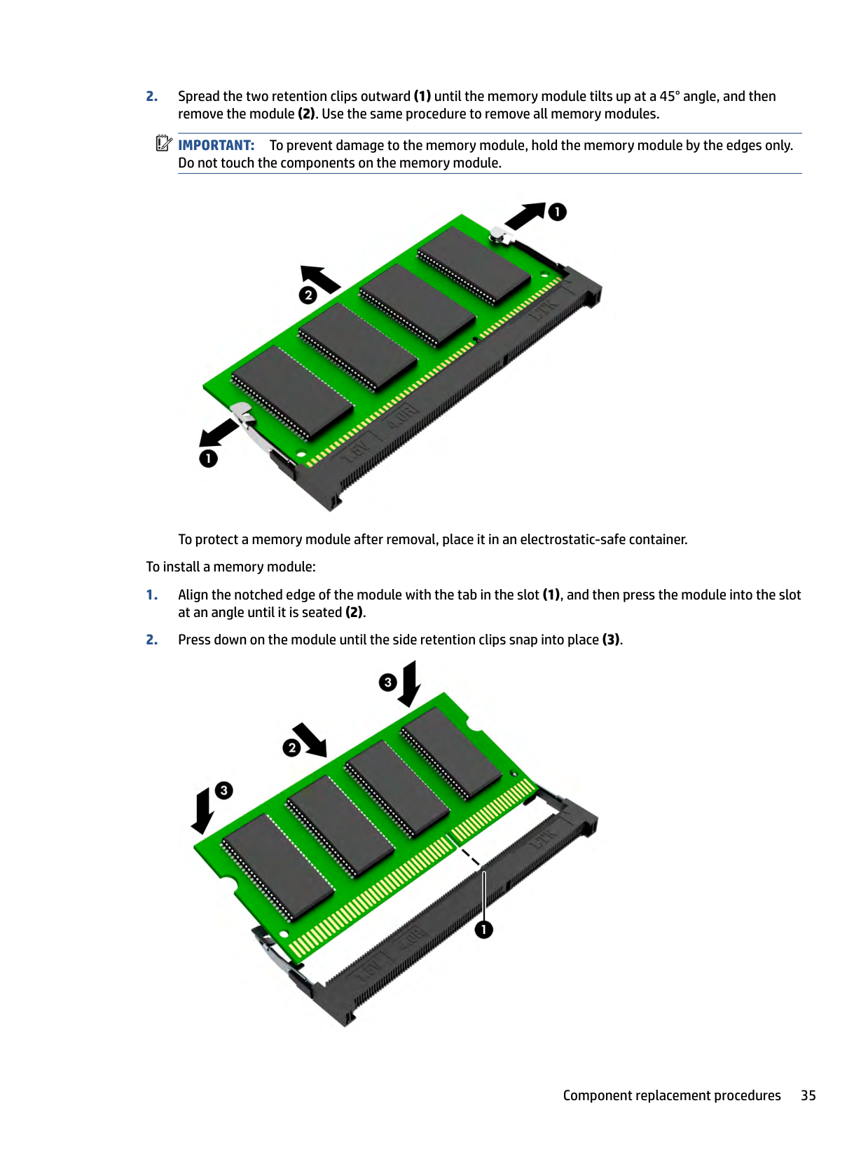
IMPORTANT: To prevent damage to the memory module, hold the memory module by the edges only. Do not touch the components on the memory module.

To protect a memory module after removal, place it in an electrostatic-safe container. To install a memory module:


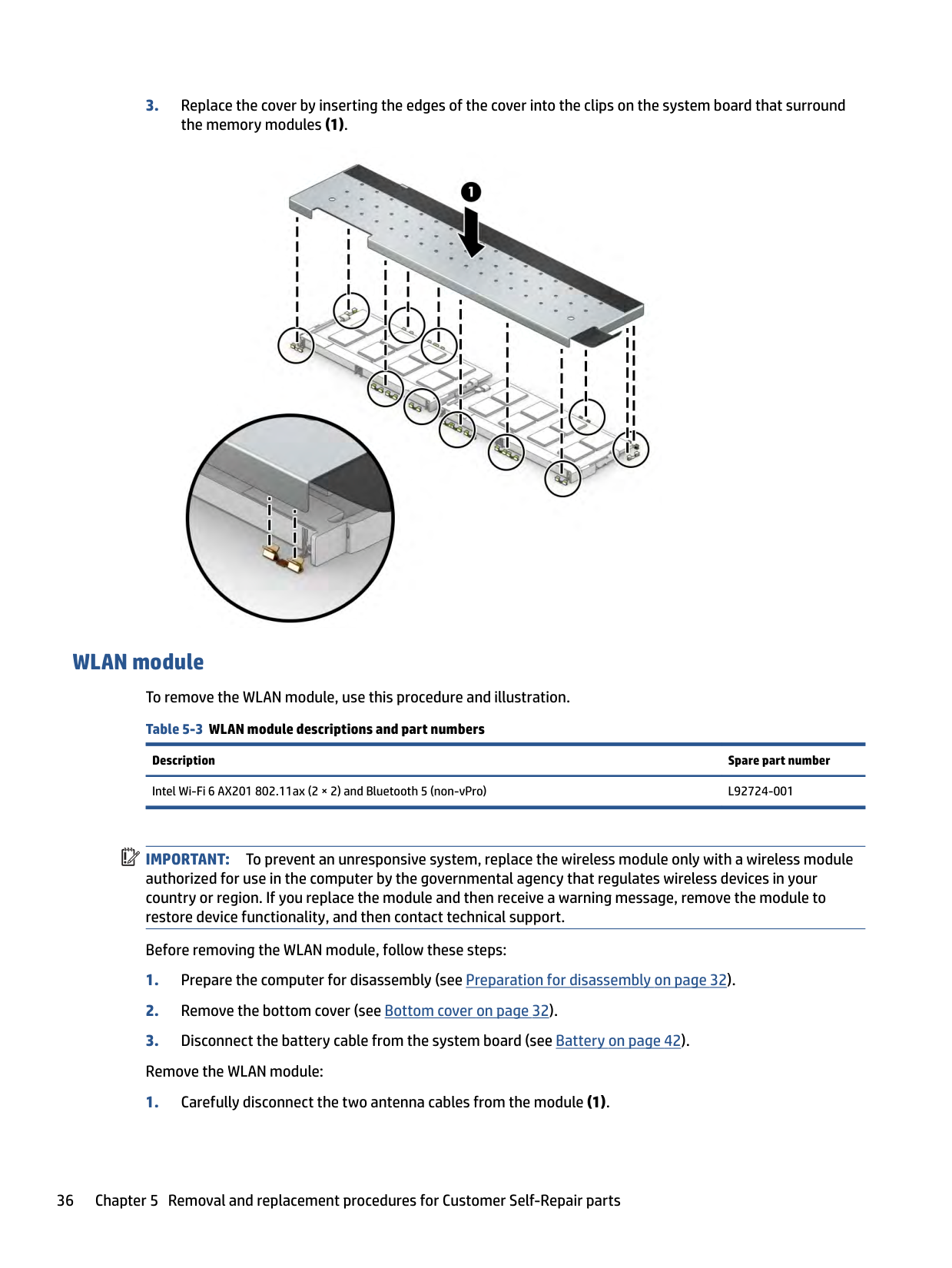
#### WLAN module To remove the WLAN module, use this procedure and illustration. Table 5-3 WLAN module descriptions and part numbers
Description Spare part number Intel Wi-Fi 6 AX201 802.11ax (2 × 2) and Bluetooth 5 (non-vPro) L92724-001
| |
|---|
IMPORTANT: To prevent an unresponsive system, replace the wireless module only with a wireless module authorized for use in the computer by the governmental agency that regulates wireless devices in your country or region. If you replace the module and then receive a warning message, remove the module to restore device functionality, and then contact technical support.
Before removing the WLAN module, follow these steps:
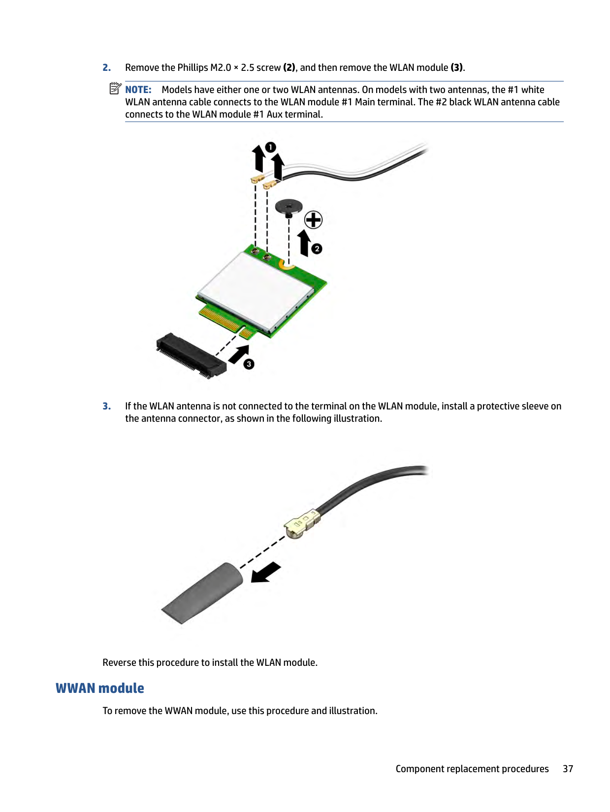
NOTE: Models have either one or two WLAN antennas. On models with two antennas, the #1 white WLAN antenna cable connects to the WLAN module #1 Main terminal. The #2 black WLAN antenna cable connects to the WLAN module #1 Aux terminal.

| |
|---|

Reverse this procedure to install the WLAN module.
#### WWAN module
To remove the WWAN module, use this procedure and illustration.
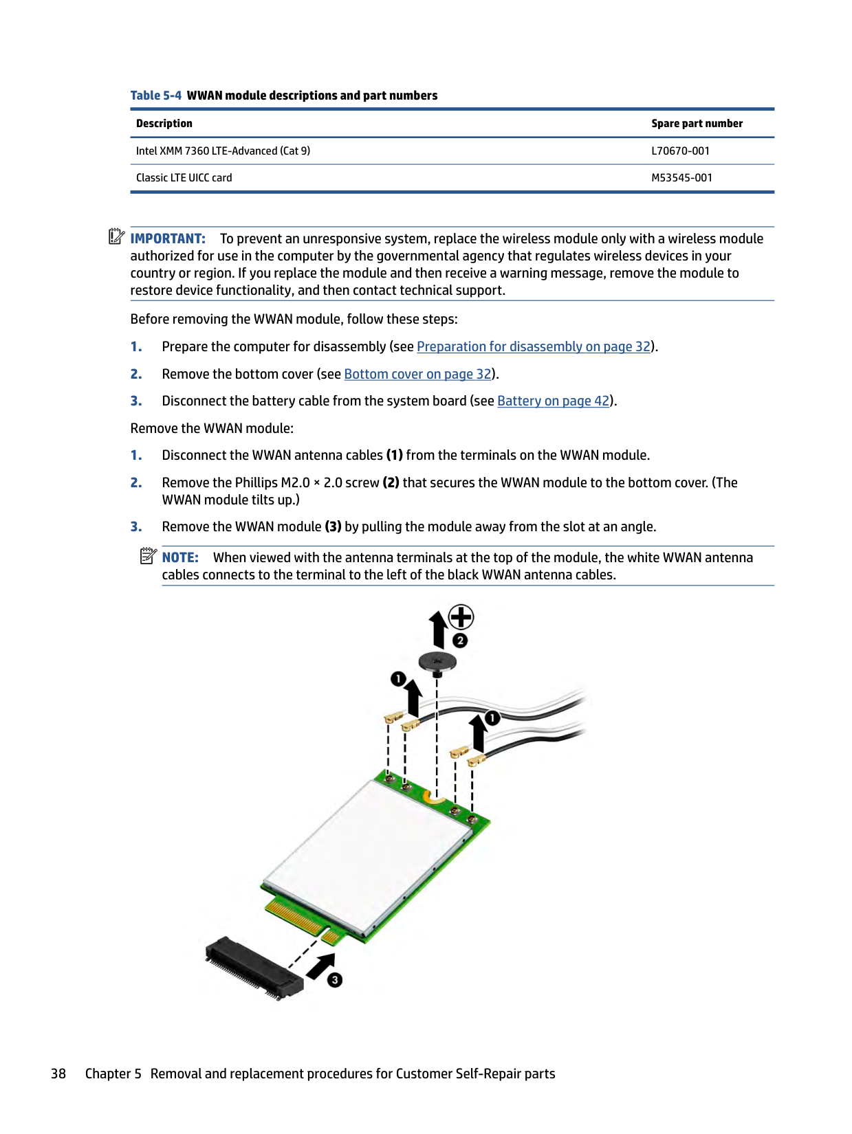
Table 5-4 WWAN module descriptions and part numbers Description Spare part number Intel XMM 7360 LTE-Advanced (Cat 9) L70670-001 Classic LTE UICC card M53545-001
| | |---|
IMPORTANT: To prevent an unresponsive system, replace the wireless module only with a wireless module authorized for use in the computer by the governmental agency that regulates wireless devices in your country or region. If you replace the module and then receive a warning message, remove the module to restore device functionality, and then contact technical support.
Before removing the WWAN module, follow these steps:
| | |---|
NOTE: When viewed with the antenna terminals at the top of the module, the white WWAN antenna cables connects to the terminal to the left of the black WWAN antenna cables.


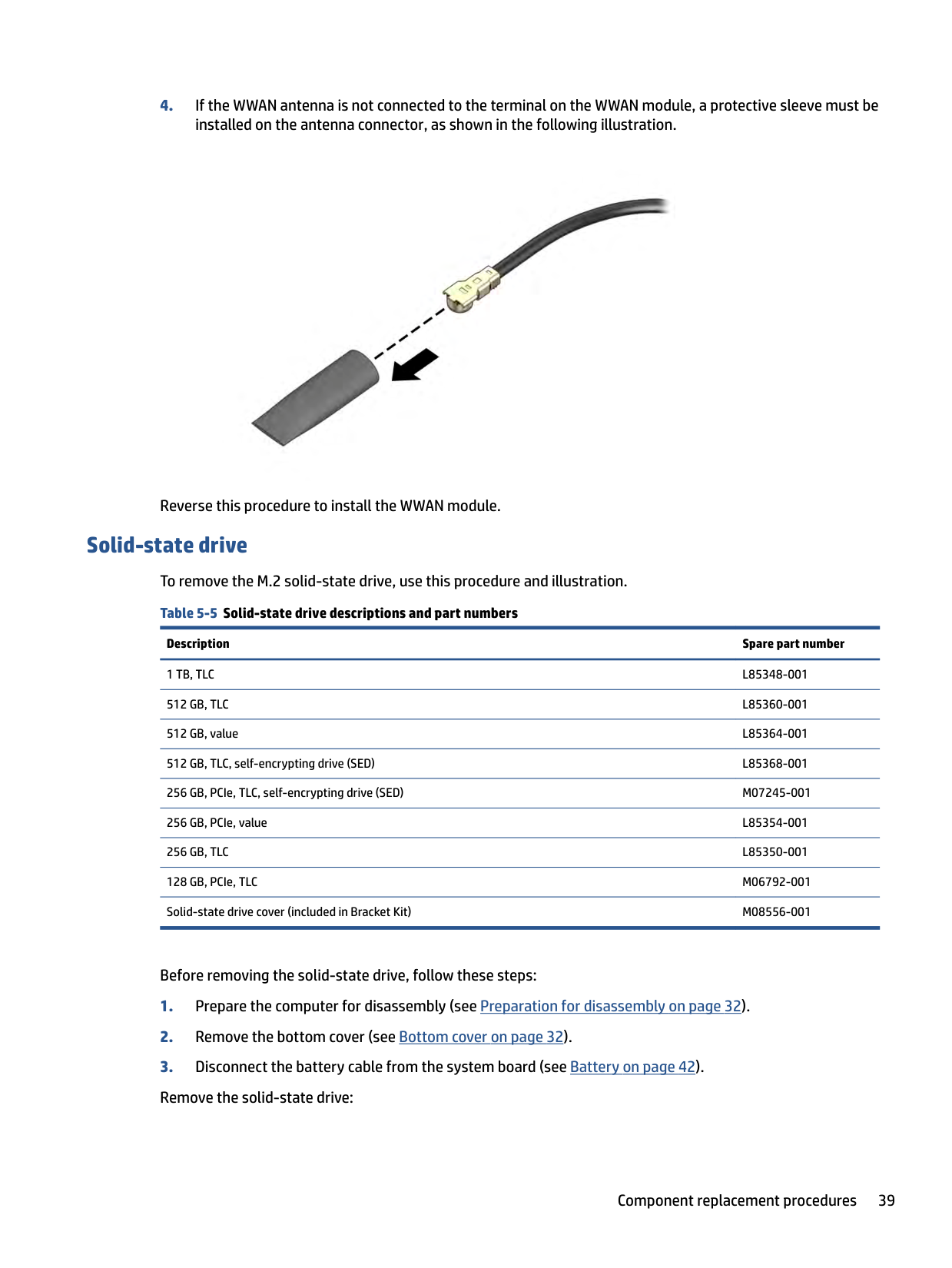
Reverse this procedure to install the WWAN module.
Solid-state drive To remove the M.2 solid-state drive, use this procedure and illustration. Table 5-5 Solid-state drive descriptions and part numbers
Description Spare part number 1 TB, TLC L85348-001 512 GB, TLC L85360-001 512 GB, value L85364-001 512 GB, TLC, self-encrypting drive (SED) L85368-001 256 GB, PCIe, TLC, self-encrypting drive (SED) M07245-001 256 GB, PCIe, value L85354-001 256 GB, TLC L85350-001 128 GB, PCIe, TLC M06792-001 Solid-state drive cover (included in Bracket Kit) M08556-001
Before removing the solid-state drive, follow these steps:
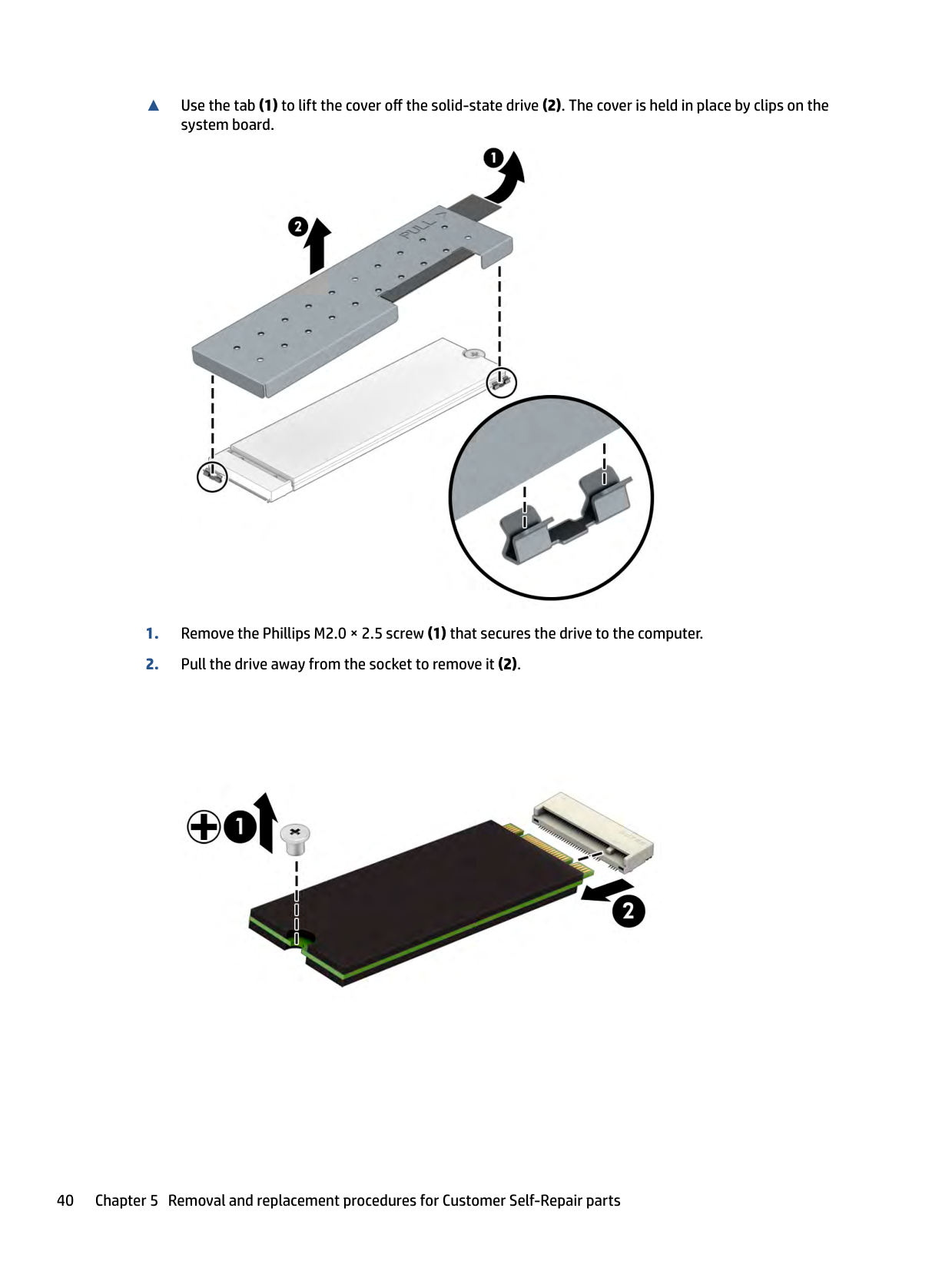
▲ Use the tab (1) to lift the cover off the solid-state drive (2). The cover is held in place by clips on the
system board.


| | |---|
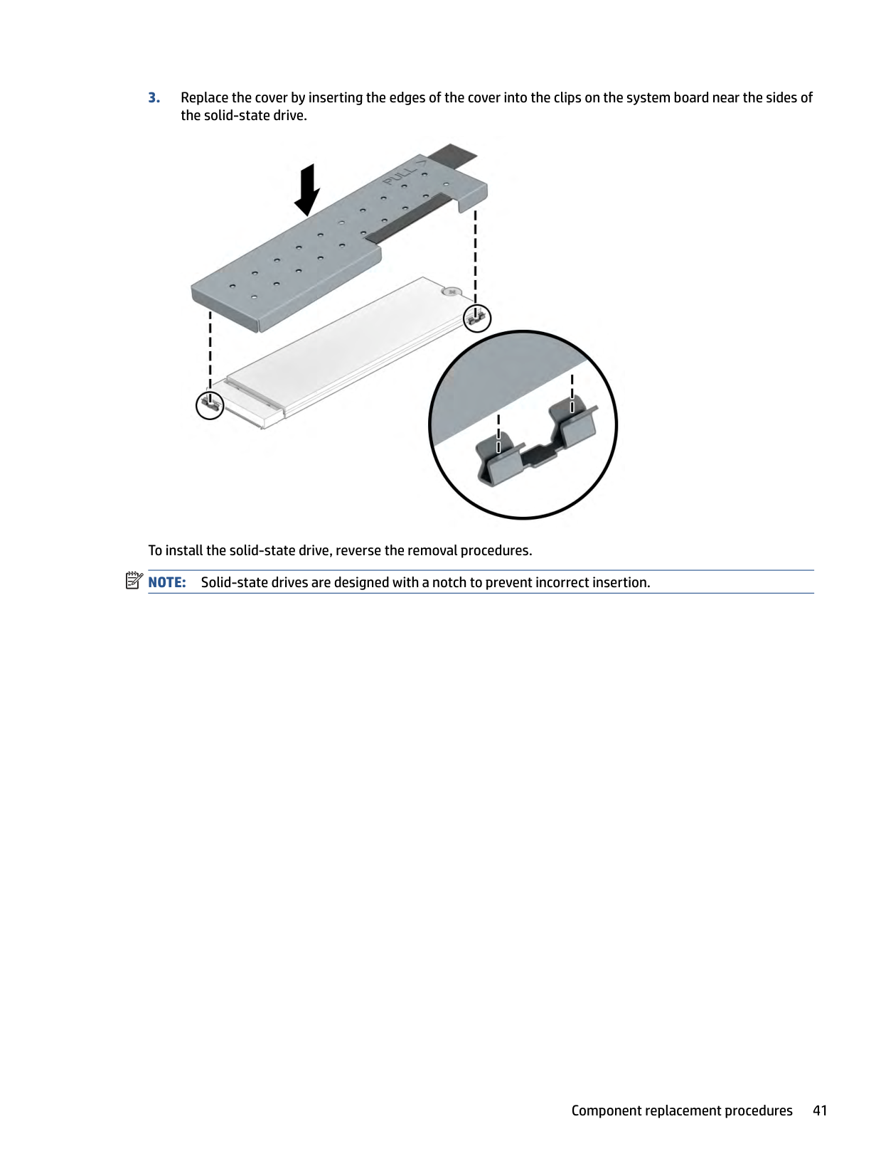
To install the solid-state drive, reverse the removal procedures. NOTE: Solid-state drives are designed with a notch to prevent incorrect insertion.
6 Removal and replacement procedures for authorized service provider parts
| | |---|
| | |---|
This chapter provides removal and replacement procedures for authorized service provider parts. IMPORTANT: Components described in this chapter should be accessed only by an authorized service provider. Accessing these parts can damage the computer or void the warranty. NOTE: Details about your computer, including model, serial number, product key, and length of warranty, are on the service tag at the bottom of your computer.
Component replacement procedures To remove and replace computer components, use these procedures. NOTE: HP continually improves and changes product parts. For complete and current information about supported parts for your computer, go to http://partsurfer.hp.com, select your country or region, and then follow the on-screen instructions.
| | |---|
You must remove, replace, or loosen as many as 53 screws when you service the parts described in this chapter. Make special note of each screw size and location during removal and replacement.
Preparation for disassembly To remove and replace computer components, use these procedures. See Removal and replacement procedures preliminary requirements on page 27 for initial safety procedures.
#### Battery
To remove the battery, use this procedure and illustration. Table 6-1 Battery description and part number
Description Spare part number Battery, 3 cell, 53 Whr L78555-005
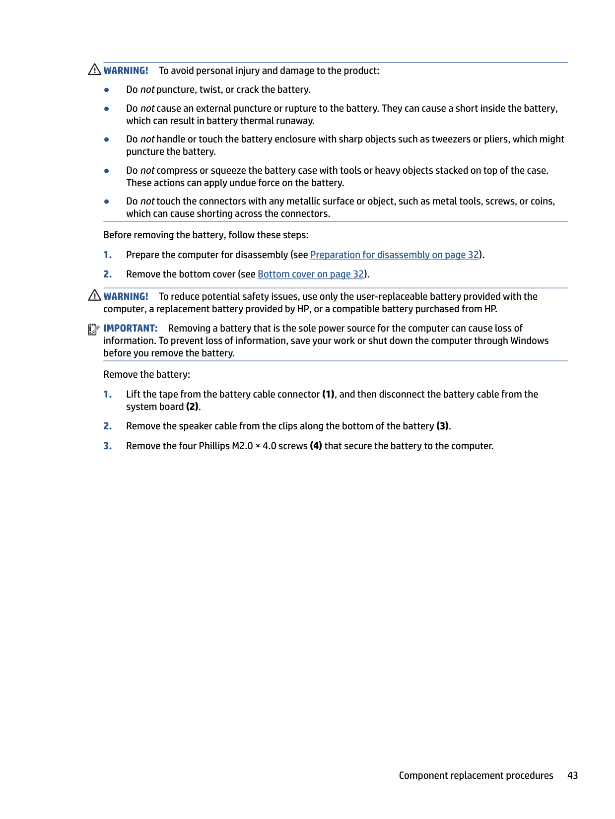
WARNING! To avoid personal injury and damage to the product:
Before removing the battery, follow these steps:
WARNING! To reduce potential safety issues, use only the user-replaceable battery provided with the computer, a replacement battery provided by HP, or a compatible battery purchased from HP.
| | |---|
IMPORTANT: Removing a battery that is the sole power source for the computer can cause loss of information. To prevent loss of information, save your work or shut down the computer through Windows before you remove the battery.
Remove the battery:

To insert the battery, reverse the removal procedures.
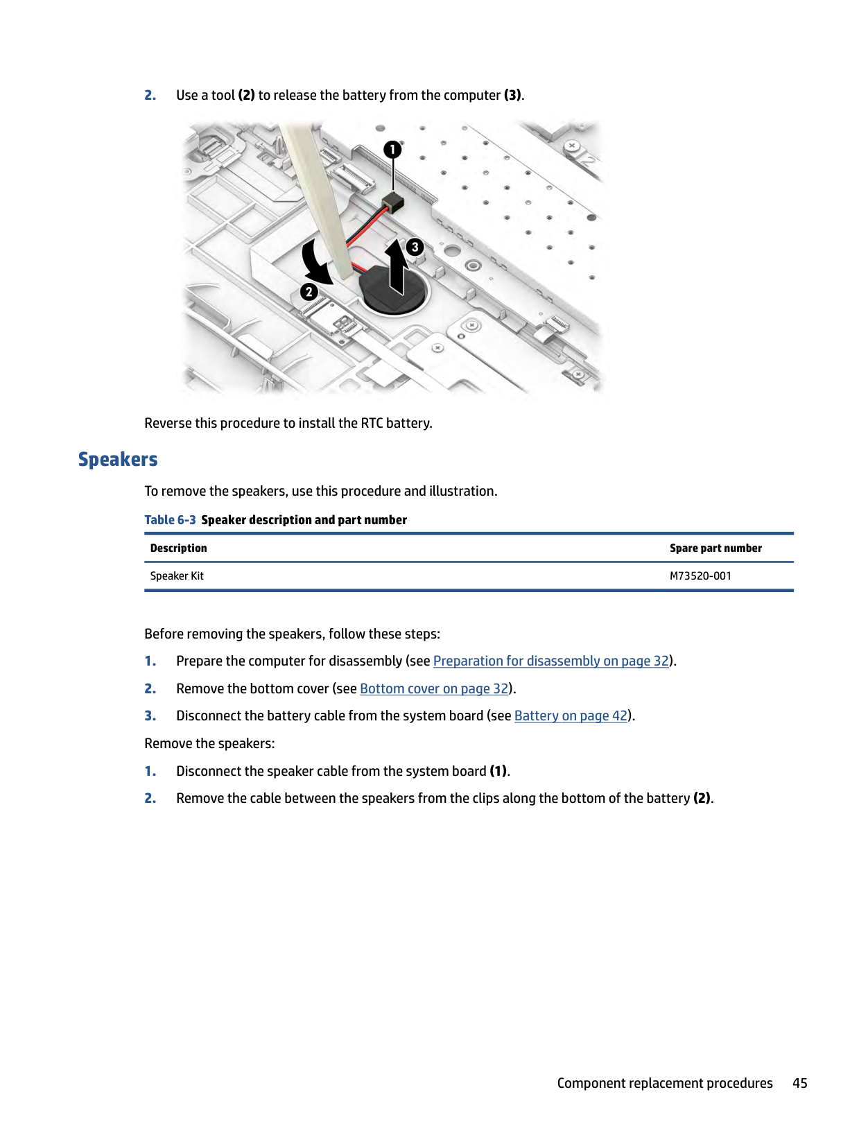
RTC battery To remove the RTC battery, use this procedure and illustration. Table 6-2 RTC battery description and part number
Description Spare part number RTC battery L13694-001
Before removing the RTC battery, follow these steps:

Reverse this procedure to install the RTC battery.
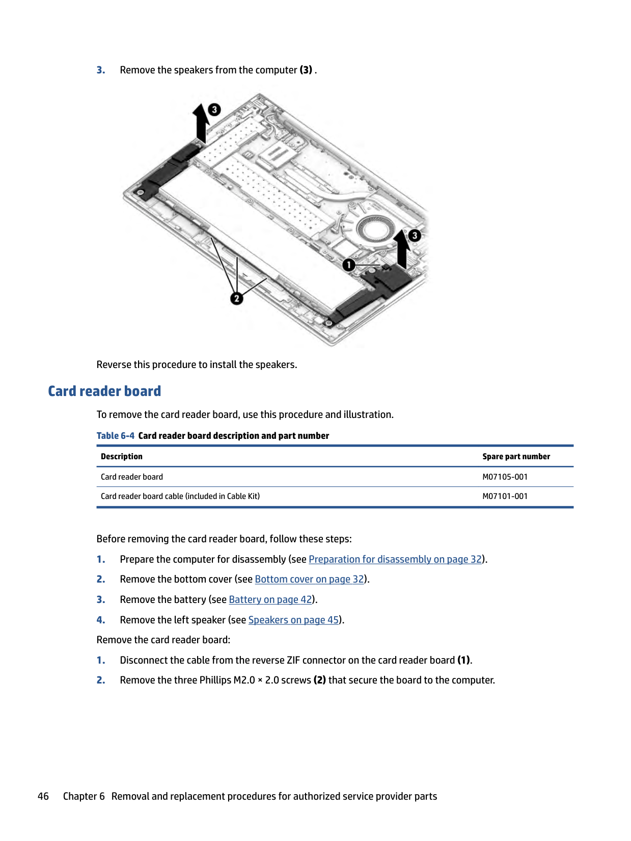
Speakers To remove the speakers, use this procedure and illustration. Table 6-3 Speaker description and part number
Description Spare part number Speaker Kit M73520-001
Before removing the speakers, follow these steps:

Reverse this procedure to install the speakers.
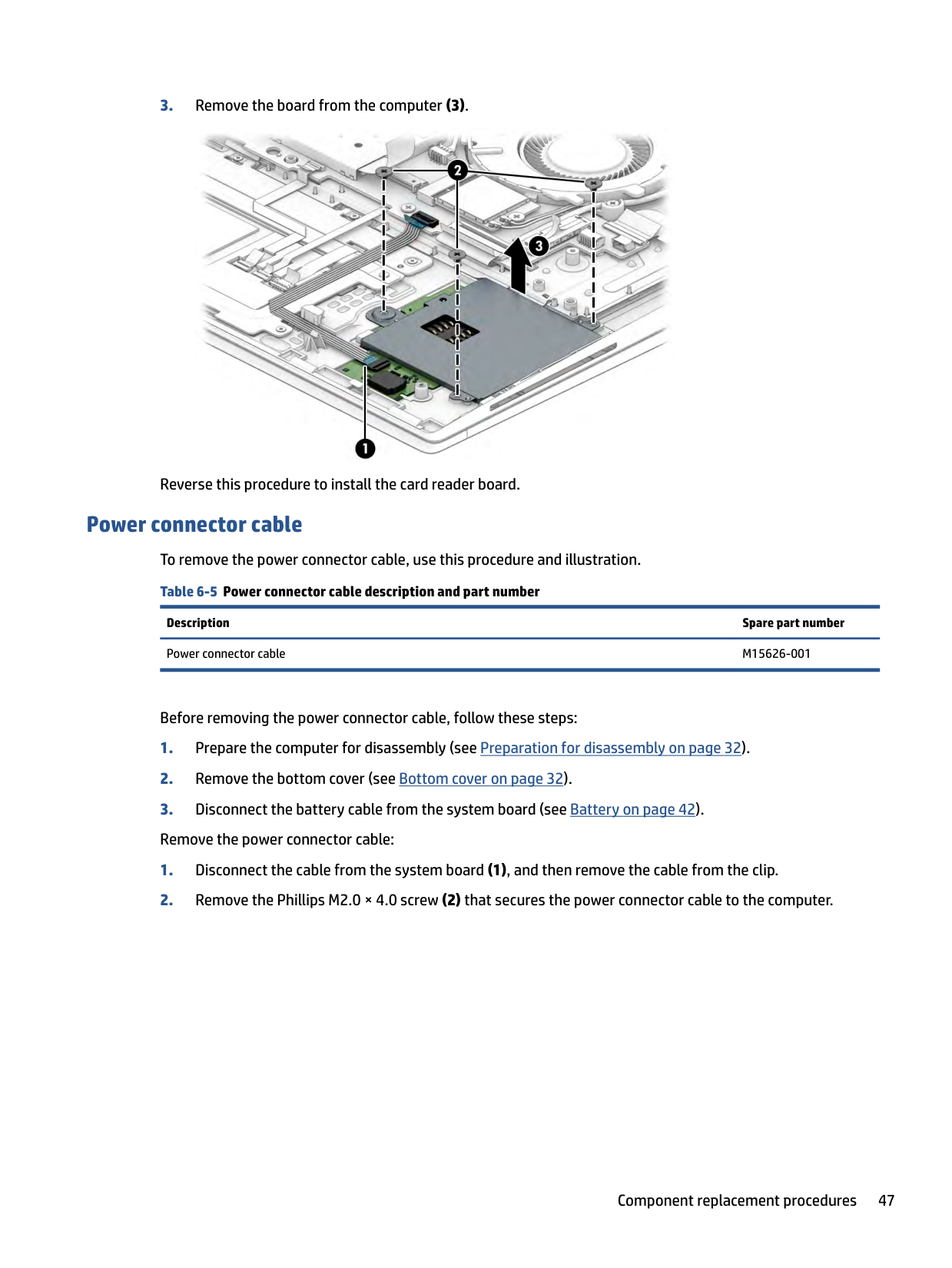
Card reader board To remove the card reader board, use this procedure and illustration. Table 6-4 Card reader board description and part number
Description Spare part number
Card reader board M07105-001 Card reader board cable (included in Cable Kit) M07101-001
Before removing the card reader board, follow these steps:

Reverse this procedure to install the card reader board.
Power connector cable To remove the power connector cable, use this procedure and illustration. Table 6-5 Power connector cable description and part number
Description Spare part number Power connector cable M15626-001
Before removing the power connector cable, follow these steps:

Reverse this procedure to install the power connector cable.
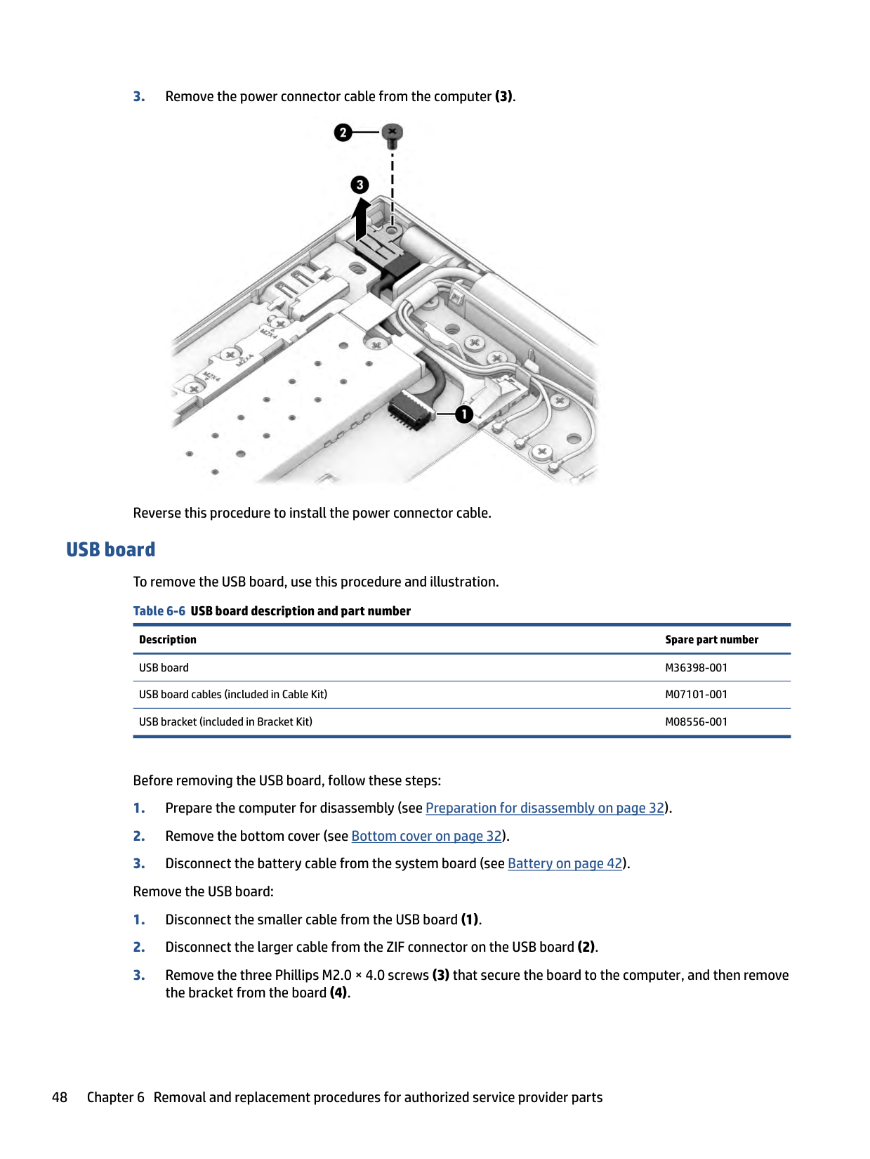
USB board To remove the USB board, use this procedure and illustration. Table 6-6 USB board description and part number
Description Spare part number
USB board M36398-001 USB board cables (included in Cable Kit) M07101-001 USB bracket (included in Bracket Kit) M08556-001
Before removing the USB board, follow these steps:

Reverse this procedure to install the USB board.
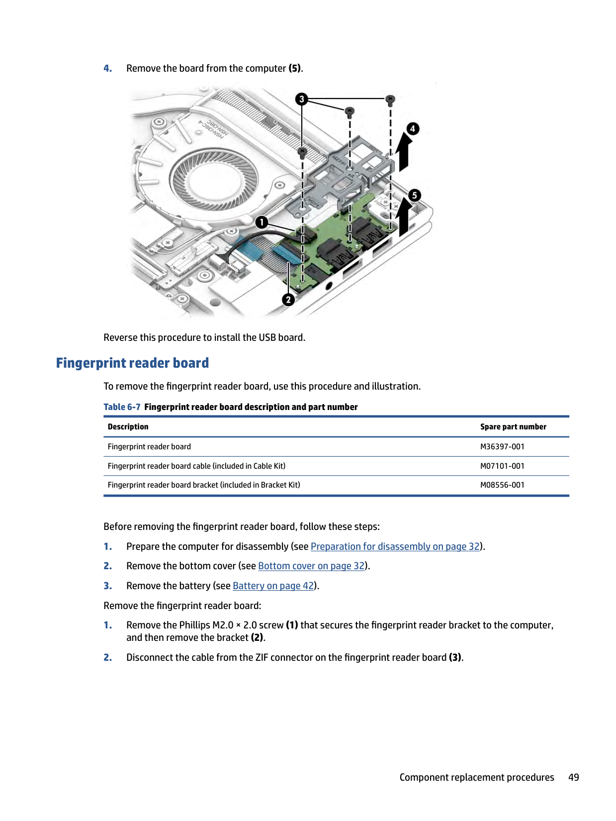
Fingerprint reader board To remove the fingerprint reader board, use this procedure and illustration. Table 6-7 Fingerprint reader board description and part number
Description Spare part number
Fingerprint reader board M36397-001 Fingerprint reader board cable (included in Cable Kit) M07101-001 Fingerprint reader board bracket (included in Bracket Kit) M08556-001
Before removing the fingerprint reader board, follow these steps:

Reverse this procedure to install the fingerprint reader board.
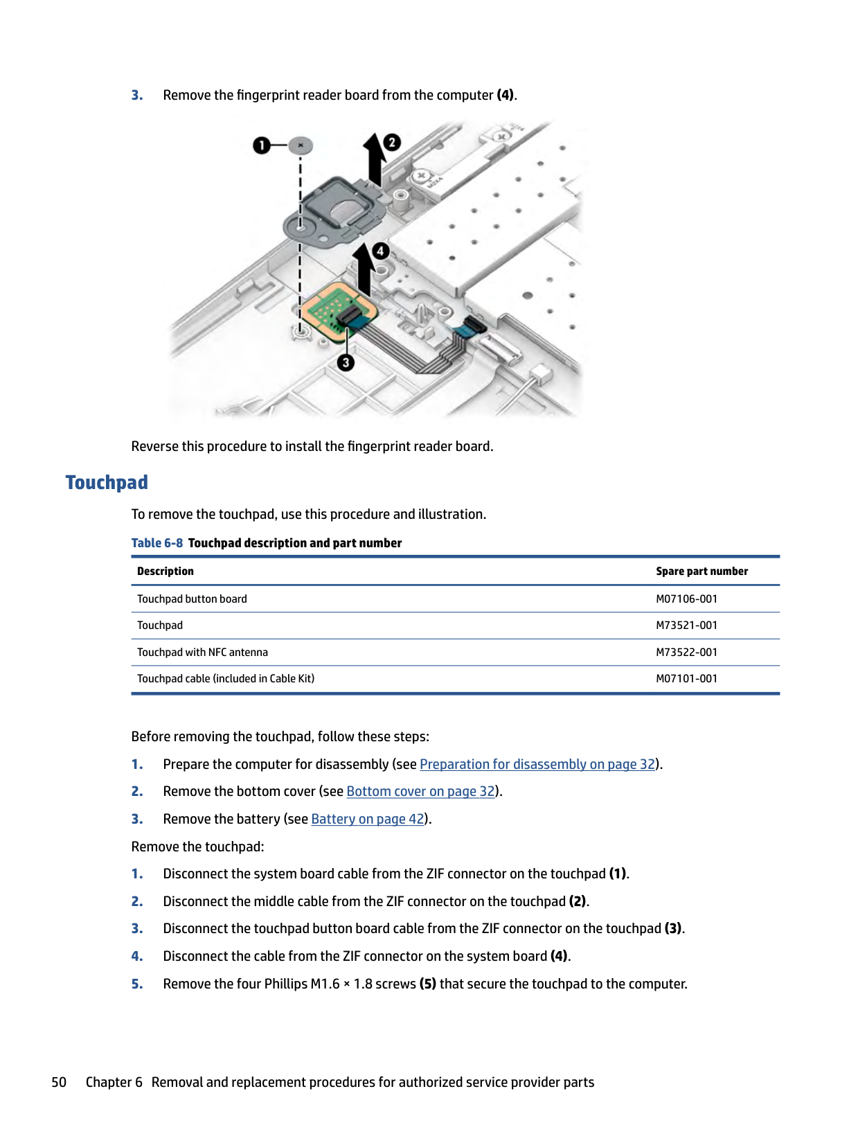
Touchpad To remove the touchpad, use this procedure and illustration. Table 6-8 Touchpad description and part number
Description Spare part number
Touchpad button board M07106-001 Touchpad M73521-001 Touchpad with NFC antenna M73522-001 Touchpad cable (included in Cable Kit) M07101-001
Before removing the touchpad, follow these steps:


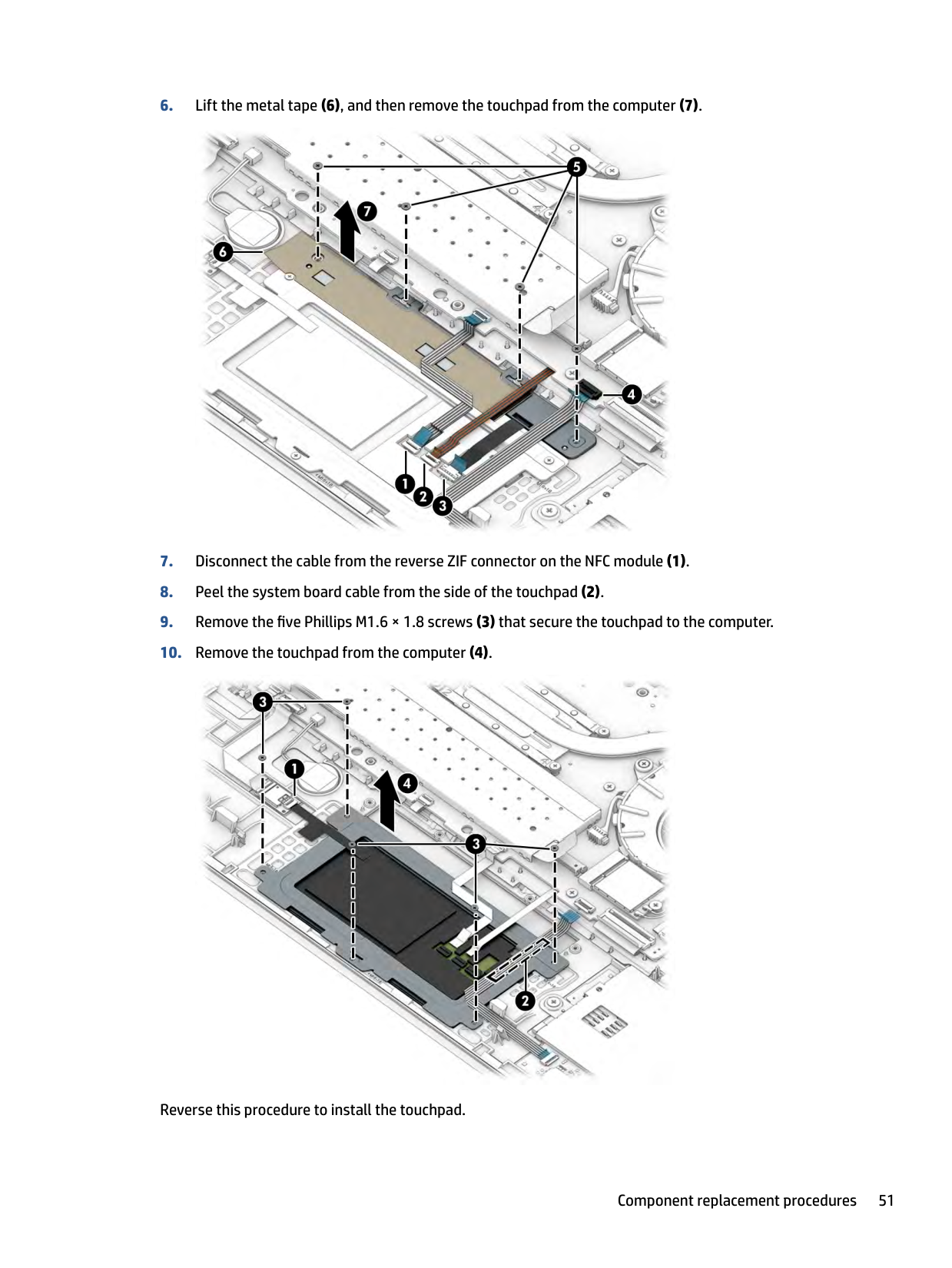
Reverse this procedure to install the touchpad.
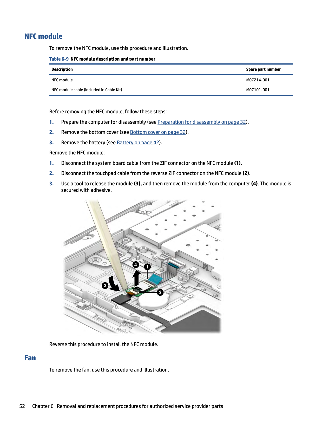
#### NFC module To remove the NFC module, use this procedure and illustration. Table 6-9 NFC module description and part number
######### Description Spare part number
NFC module M07214-001 NFC module cable (included in Cable Kit) M07101-001
#### Fan
Before removing the NFC module, follow these steps:

Reverse this procedure to install the NFC module.
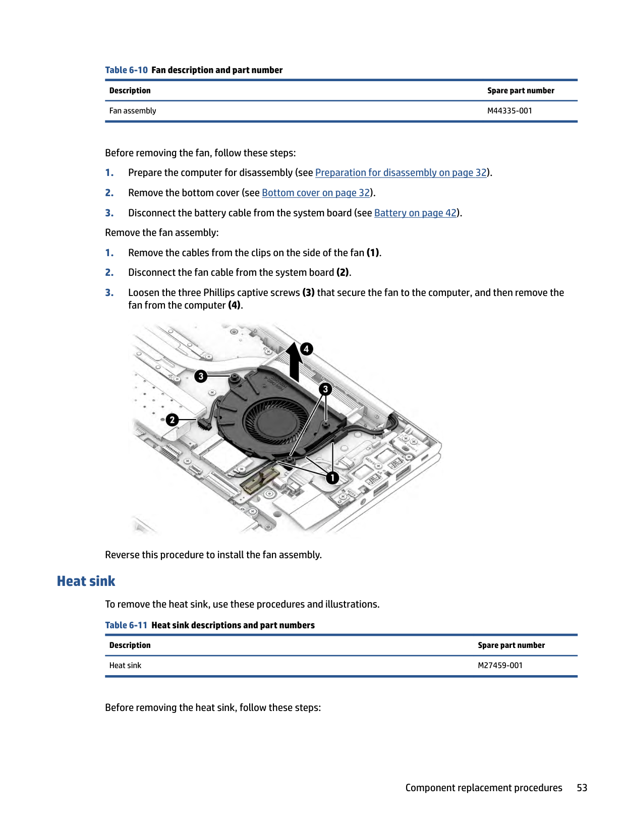
To remove the fan, use this procedure and illustration.
Table 6-10 Fan description and part number Description Spare part number Fan assembly M44335-001
Before removing the fan, follow these steps:

Reverse this procedure to install the fan assembly.
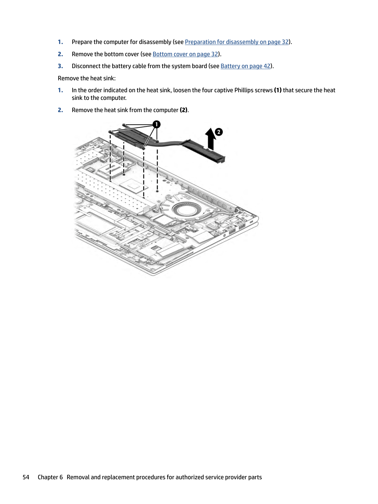
Heat sink To remove the heat sink, use these procedures and illustrations. Table 6-11 Heat sink descriptions and part numbers
Description Spare part number Heat sink M27459-001
Before removing the heat sink, follow these steps:


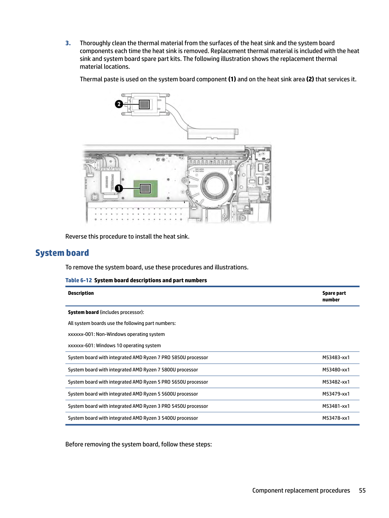
Reverse this procedure to install the heat sink.
System board To remove the system board, use these procedures and illustrations. Table 6-12 System board descriptions and part numbers
Description Spare part number
System board (includes processor): All system boards use the following part numbers: xxxxxx-001: Non-Windows operating system xxxxxx-601: Windows 10 operating system
System board with integrated AMD Ryzen 7 PRO 5850U processor M53483-xx1 System board with integrated AMD Ryzen 7 5800U processor M53480-xx1 System board with integrated AMD Ryzen 5 PRO 5650U processor M53482-xx1 System board with integrated AMD Ryzen 5 5600U processor M53479-xx1 System board with integrated AMD Ryzen 3 PRO 5450U processor M53481-xx1 System board with integrated AMD Ryzen 3 5400U processor M53478-xx1
Before removing the system board, follow these steps:
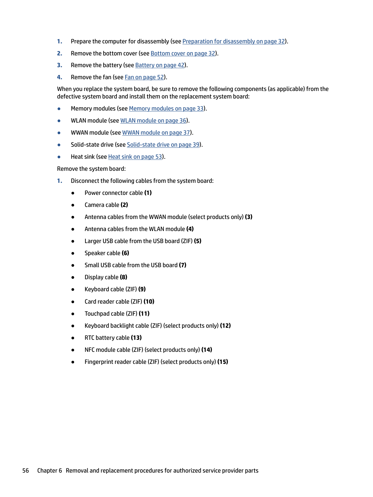
When you replace the system board, be sure to remove the following components (as applicable) from the defective system board and install them on the replacement system board:

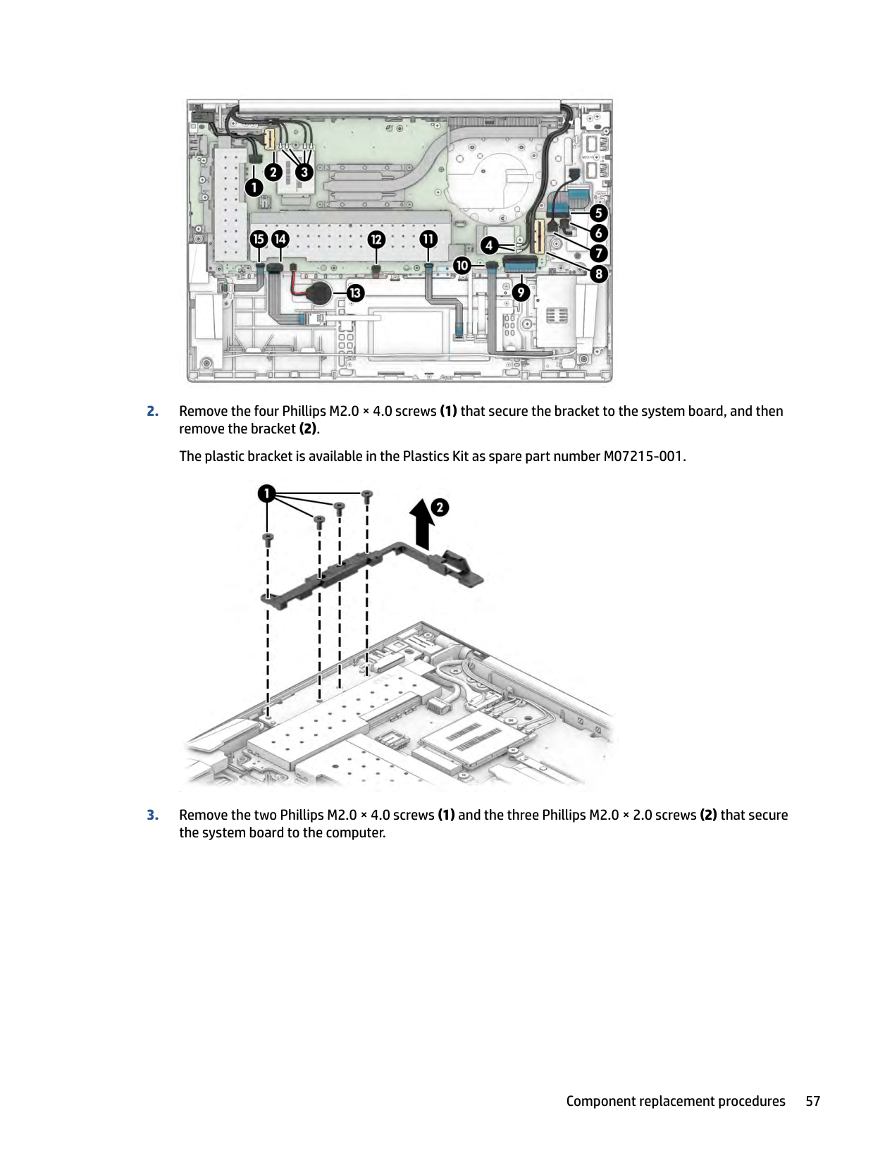
####### 2. Remove the four Phillips M2.0 × 4.0 screws (1) that secure the bracket to the system board, and thenremove the bracket (2).The plastic bracket is available in the Plastics Kit as spare part number M07215-001.

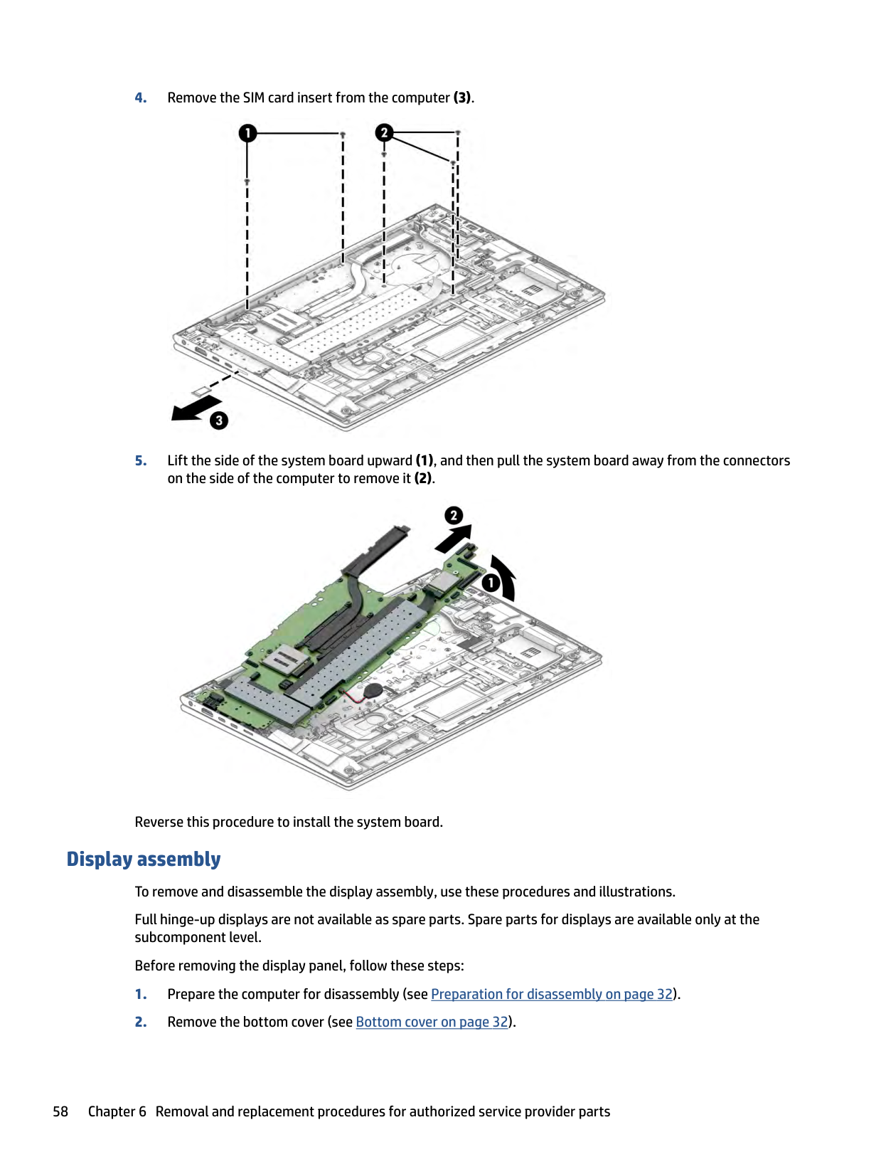
####### 3. Remove the two Phillips M2.0 × 4.0 screws (1) and the three Phillips M2.0 × 2.0 screws (2) that securethe system board to the computer.


Reverse this procedure to install the system board.
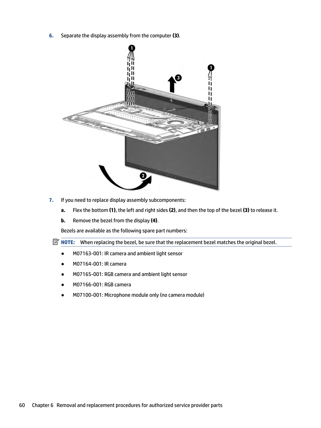
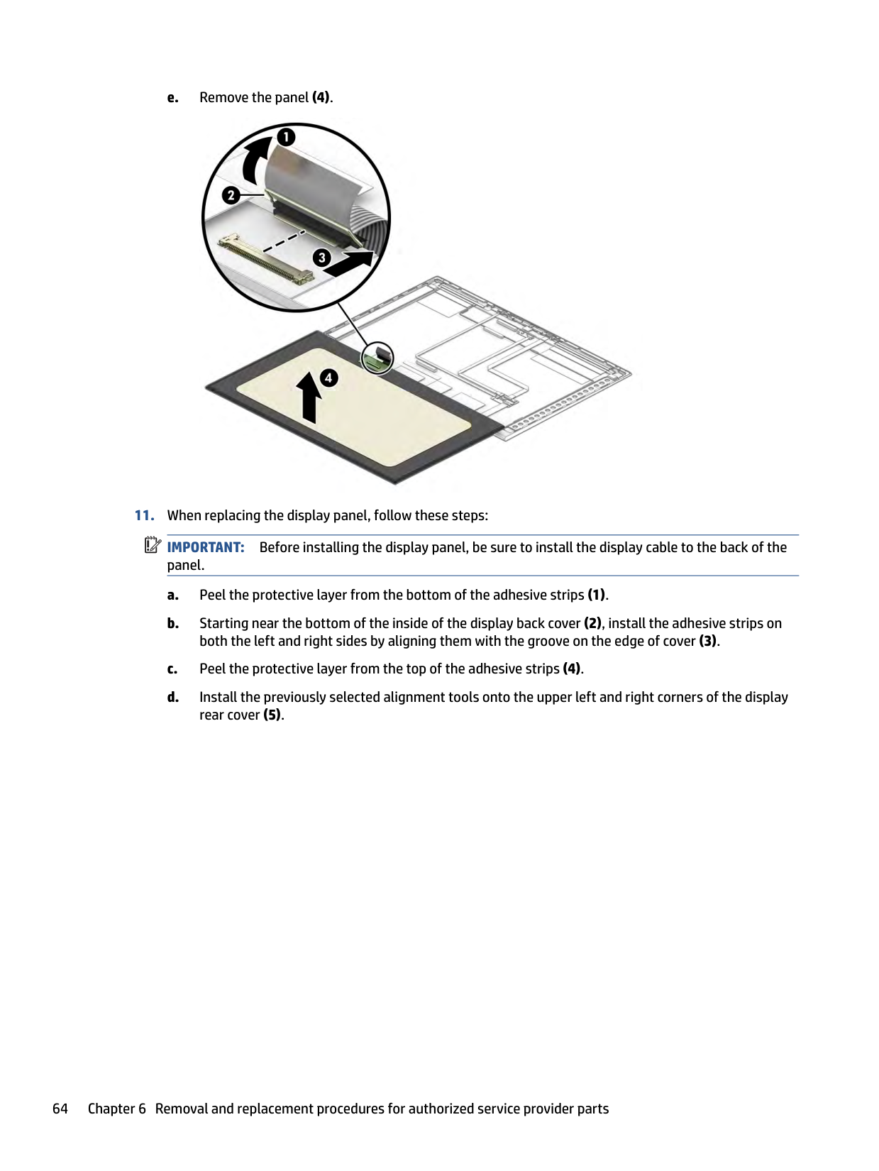
Display assembly To remove and disassemble the display assembly, use these procedures and illustrations. Full hinge-up displays are not available as spare parts. Spare parts for displays are available only at the subcomponent level. Before removing the display panel, follow these steps:
(4).


| | |---|

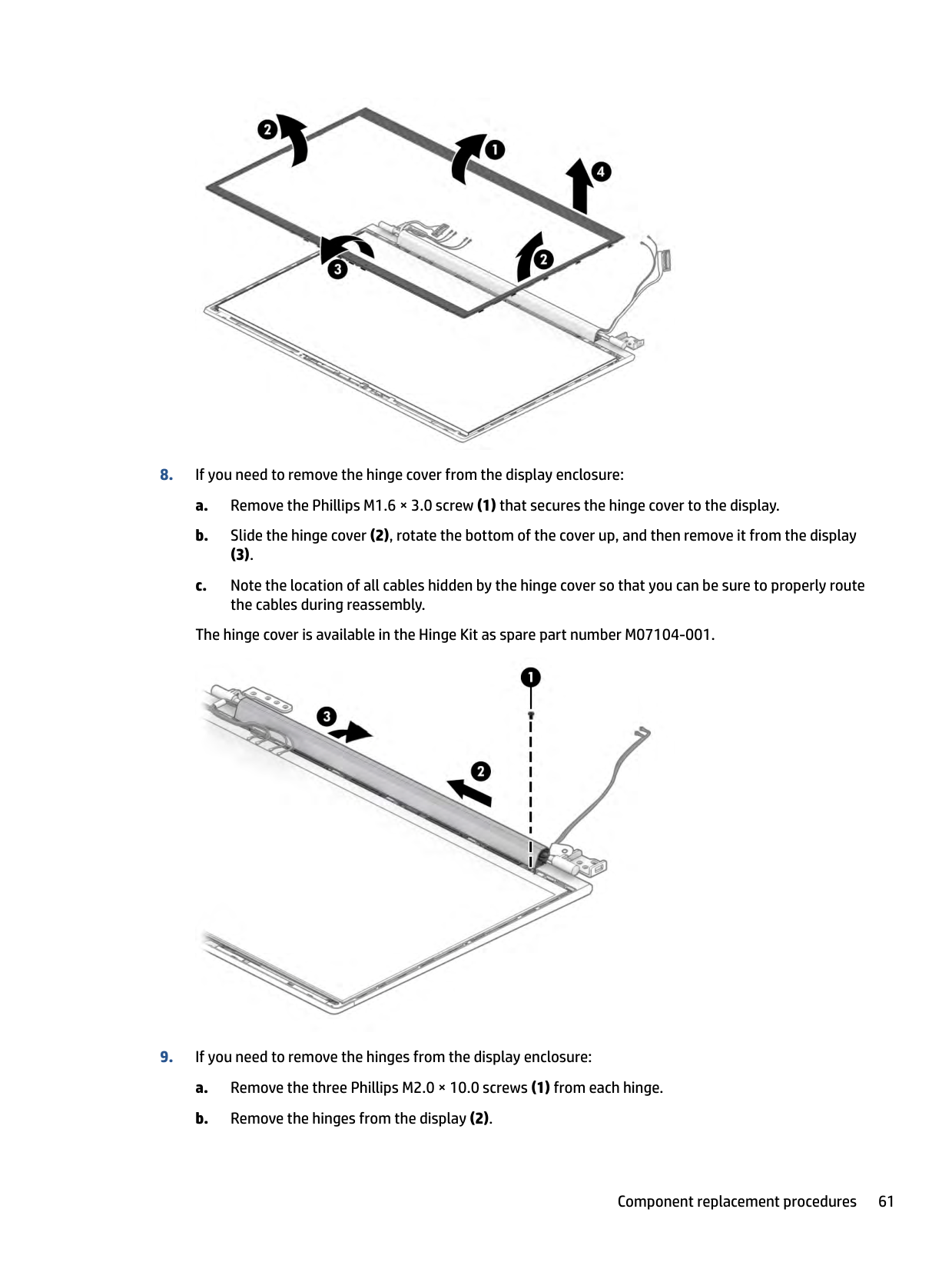
(3).
The hinge cover is available in the Hinge Kit as spare part number M07104-001.

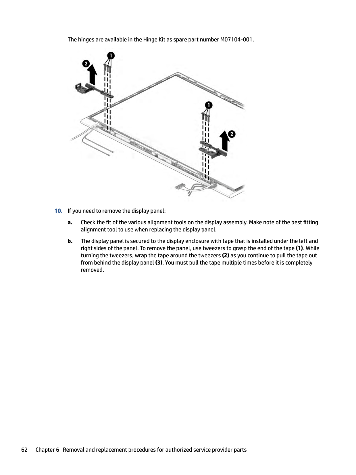
The hinges are available in the Hinge Kit as spare part number M07104-001.


| | |---|
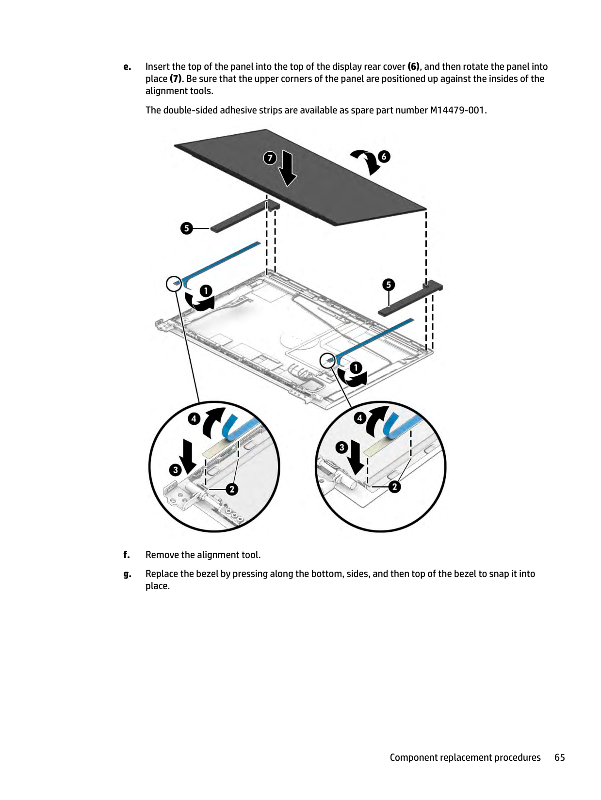
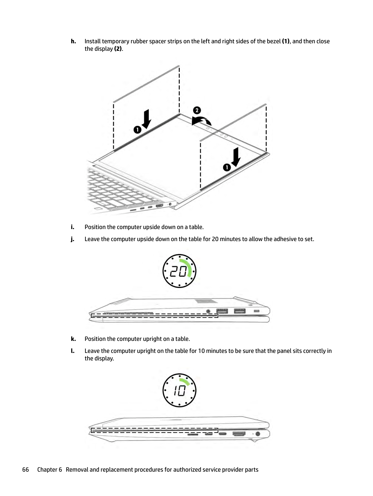
IMPORTANT: Before installing the display panel, be sure to install the display cable to the back of the panel.


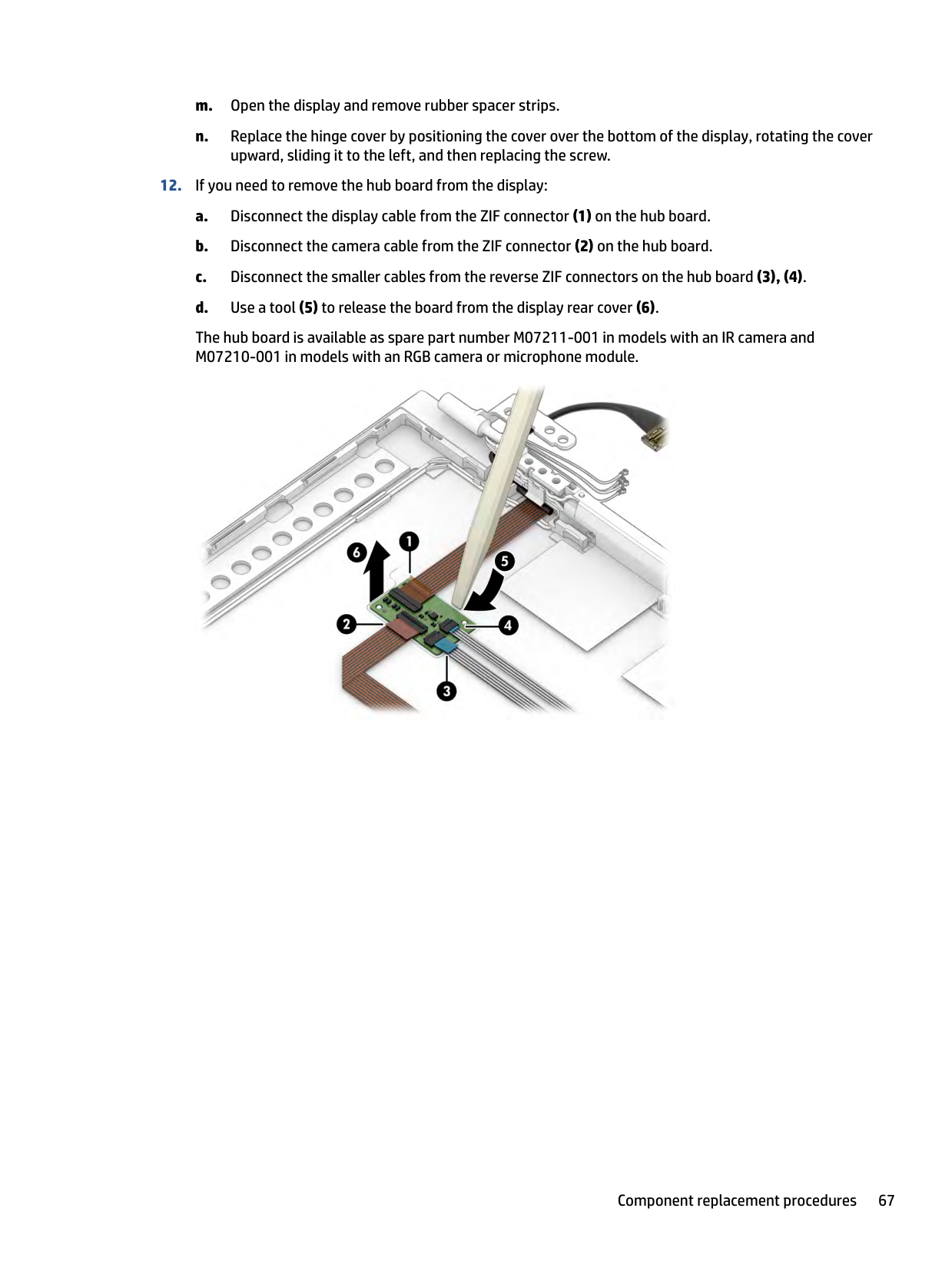
The hub board is available as spare part number M07211-001 in models with an IR camera and M07210-001 in models with an RGB camera or microphone module.

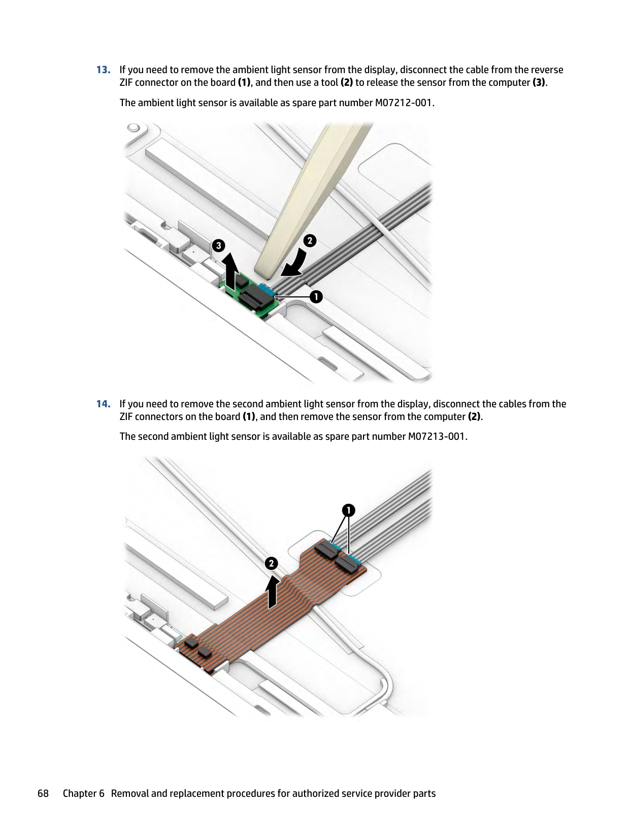
####### 13. If you need to remove the ambient light sensor from the display, disconnect the cable from the reverseZIF connector on the board (1), and then use a tool (2) to release the sensor from the computer (3).The ambient light sensor is available as spare part number M07212-001.

####### 14. If you need to remove the second ambient light sensor from the display, disconnect the cables from theZIF connectors on the board (1), and then remove the sensor from the computer (2).The second ambient light sensor is available as spare part number M07213-001.

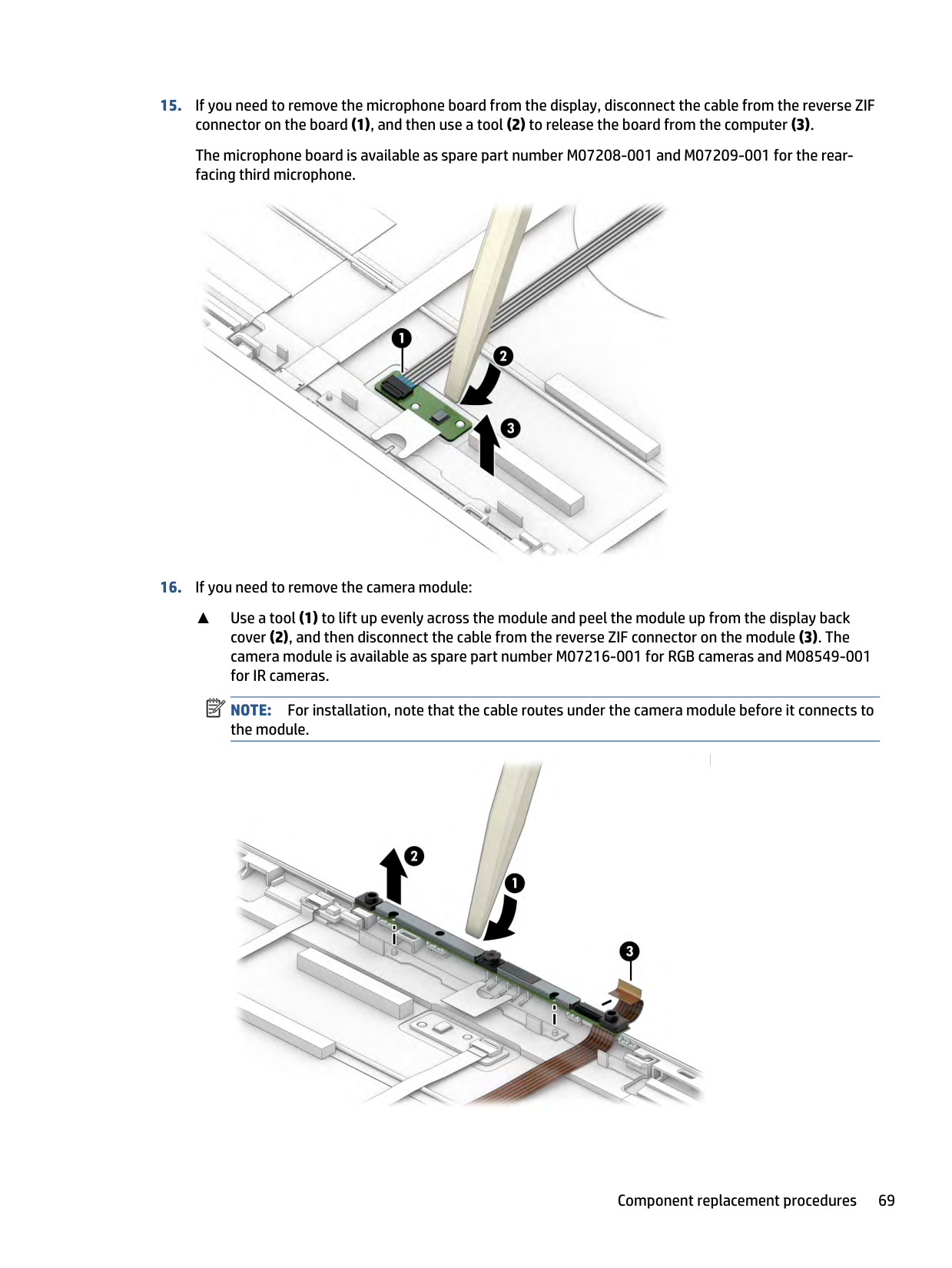
The microphone board is available as spare part number M07208-001 and M07209-001 for the rearfacing third microphone.

▲ Use a tool (1) to lift up evenly across the module and peel the module up from the display back cover (2), and then disconnect the cable from the reverse ZIF connector on the module (3). The camera module is available as spare part number M07216-001 for RGB cameras and M08549-001 for IR cameras.
| | |---|
NOTE: For installation, note that the cable routes under the camera module before it connects to the module.

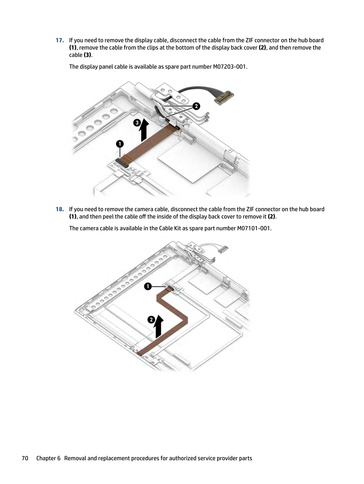
(1), remove the cable from the clips at the bottom of the display back cover (2), and then remove the cable (3). The display panel cable is available as spare part number M07203-001.

(1), and then peel the cable off the inside of the display back cover to remove it (2). The camera cable is available in the Cable Kit as spare part number M07101-001.


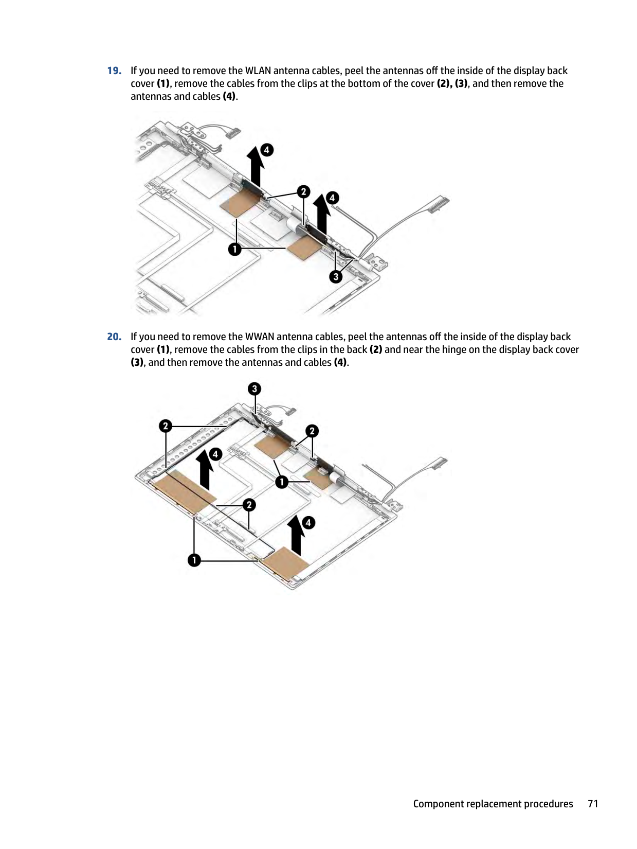
(3), and then remove the antennas and cables (4).

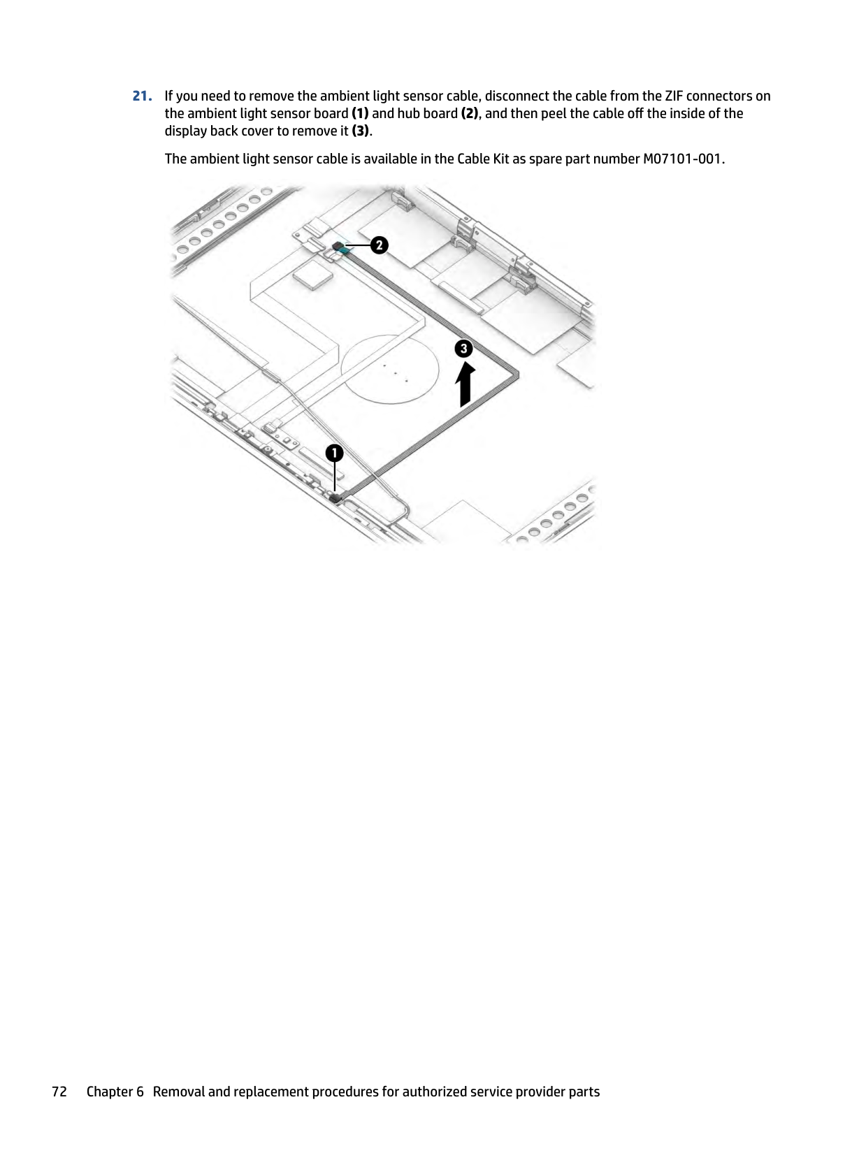
####### 21. If you need to remove the ambient light sensor cable, disconnect the cable from the ZIF connectors onthe ambient light sensor board (1) and hub board (2), and then peel the cable off the inside of thedisplay back cover to remove it (3).The ambient light sensor cable is available in the Cable Kit as spare part number M07101-001.

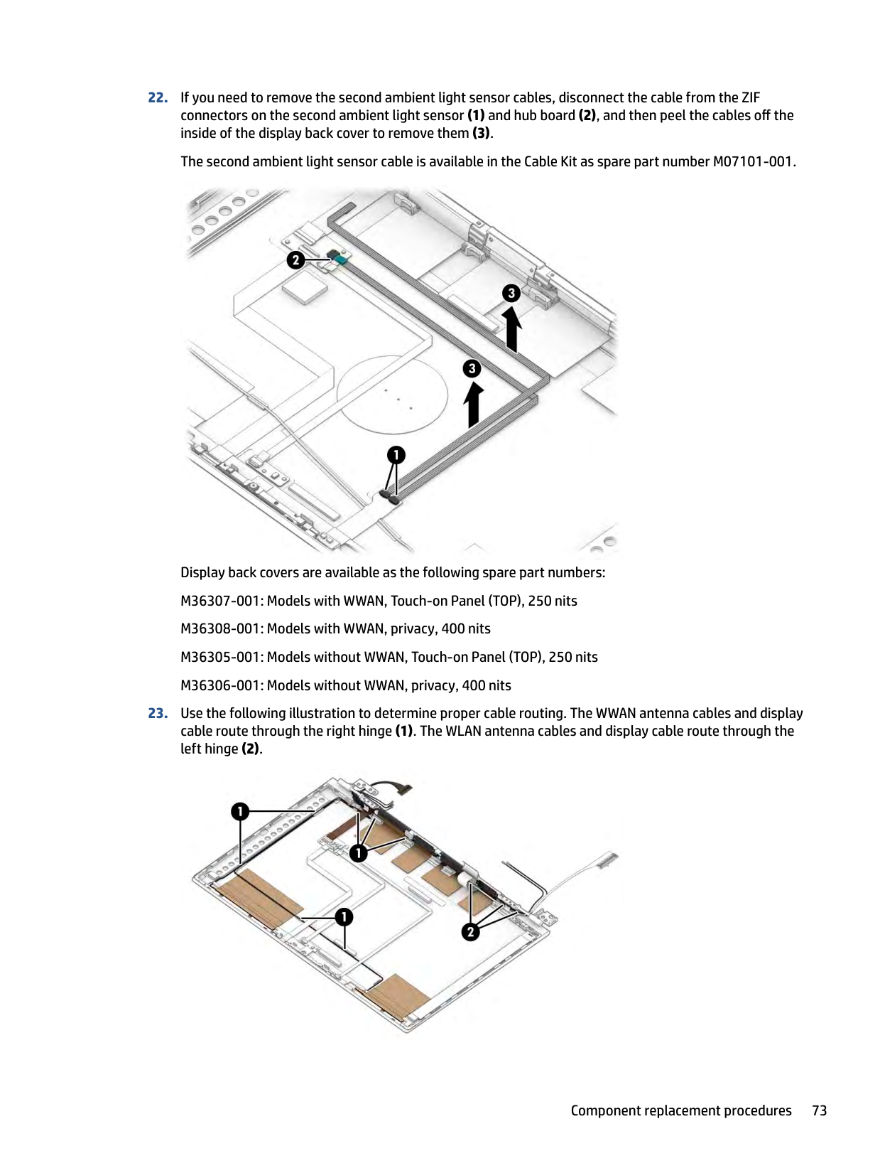
####### 22. If you need to remove the second ambient light sensor cables, disconnect the cable from the ZIFconnectors on the second ambient light sensor (1) and hub board (2), and then peel the cables off theinside of the display back cover to remove them (3).The second ambient light sensor cable is available in the Cable Kit as spare part number M07101-001.

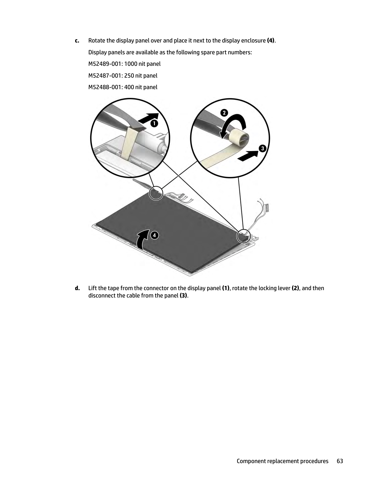
Display back covers are available as the following spare part numbers: M36307-001: Models with WWAN, Touch-on Panel (TOP), 250 nits M36308-001: Models with WWAN, privacy, 400 nits
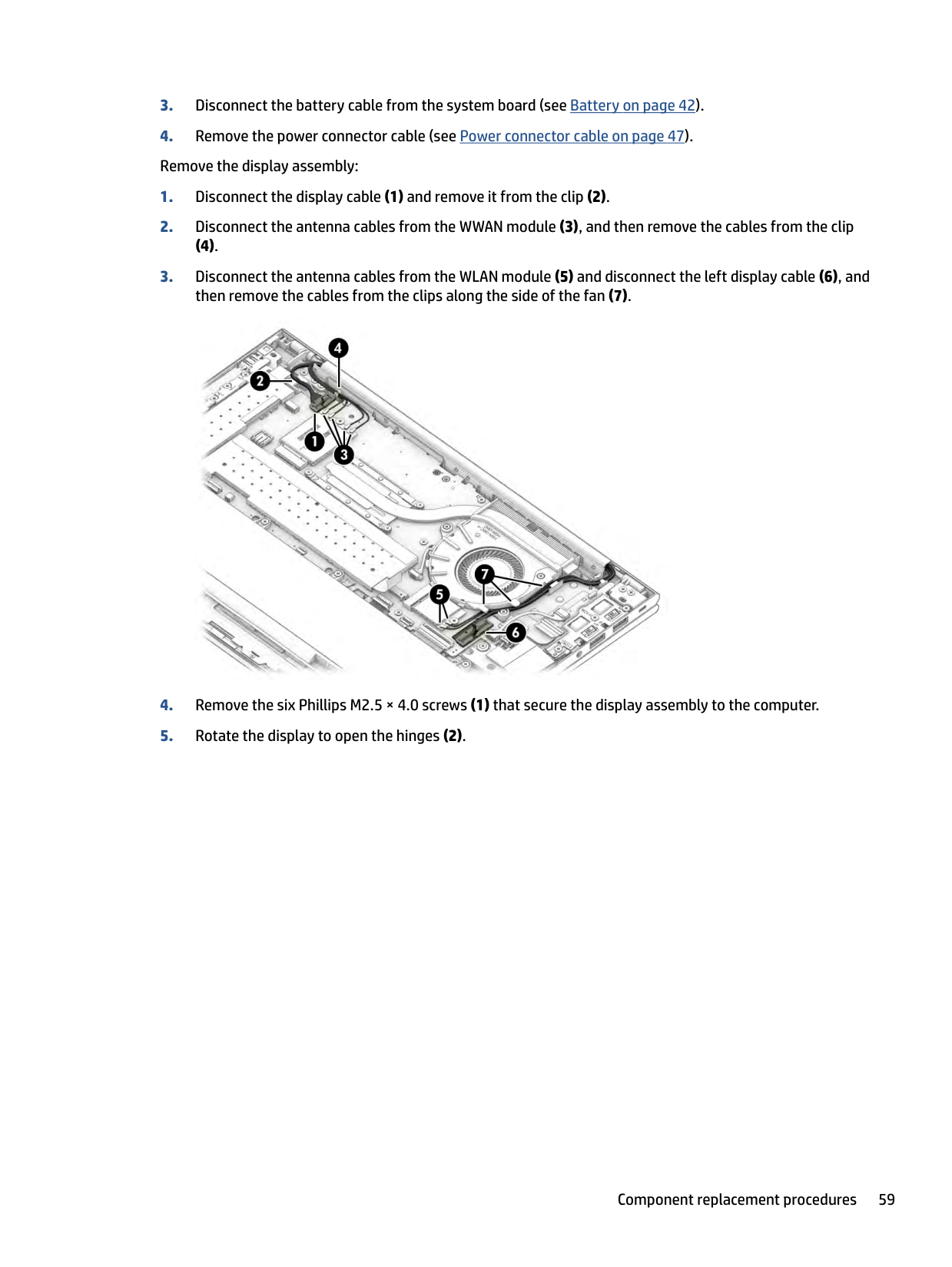
####### 23. Use the following illustration to determine proper cable routing. The WWAN antenna cables and displaycable route through the right hinge (1). The WLAN antenna cables and display cable route through theleft hinge (2).

Reverse this procedure to reassemble and replace the display assembly.
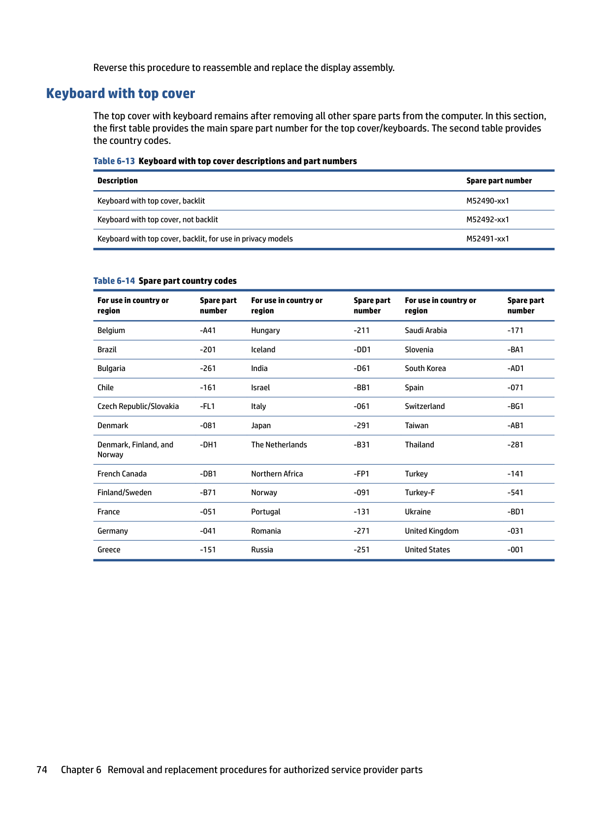
#### Keyboard with top cover
The top cover with keyboard remains after removing all other spare parts from the computer. In this section, the first table provides the main spare part number for the top cover/keyboards. The second table provides the country codes.
For use in country or region
Spare part number
For use in country or region
Spare part number
For use in country or region
Spare part number
Belgium -A41 Hungary -211 Saudi Arabia -171 Brazil -201 Iceland -DD1 Slovenia -BA1 Bulgaria -261 India -D61 South Korea -AD1 Chile -161 Israel -BB1 Spain -071 Czech Republic/Slovakia -FL1 Italy -061 Switzerland -BG1 Denmark -081 Japan -291 Taiwan -AB1 Denmark, Finland, and Norway
-DH1 The Netherlands -B31 Thailand -281
French Canada -DB1 Northern Africa -FP1 Turkey -141 Finland/Sweden -B71 Norway -091 Turkey-F -541 France -051 Portugal -131 Ukraine -BD1 Germany -041 Romania -271 United Kingdom -031 Greece -151 Russia -251 United States -001
7 Computer Setup (BIOS), TPM, and HP Sure Start
HP provides several tools to help set up and protect your computer.
Using Computer Setup
Computer Setup, or Basic Input/Output System (BIOS), controls communication between all the input and output devices on the system (such as hard drives, display, keyboard, mouse, and printer). Computer Setup includes settings for types of devices installed, the startup sequence of the computer, and amount of system and extended memory.
| | |---|
NOTE: Use extreme care when making changes in Computer Setup. Errors can prevent the computer from operating properly. To start Computer Setup, turn on or restart the computer, and when the HP logo appears, press f10 to enter Computer Setup.
#### Navigating and selecting in Computer Setup
You can navigate and select in Computer Setup using one or more methods.
To exit Computer Setup, choose one of the following methods:
| | |---|
| | |---|
Your changes go into effect when the computer restarts.
Restoring factory settings in Computer Setup To return all settings in Computer Setup to the values that were set at the factory, follow these steps. NOTE: Restoring defaults will not change the hard drive mode.
| | |---|
Using Computer Setup 75
| | |---|
| | |---|
NOTE: On select products, the selections might display Restore Defaults instead of Apply Factory Defaults and Exit.
| | |---|
Your changes go into effect when the computer restarts. NOTE: Your password settings and security settings are not changed when you restore the factory settings.
#### Updating the BIOS
Updated versions of the BIOS might be available on the HP website. Most BIOS updates on the HP website are packaged in compressed files called SoftPaqs.
Some download packages contain a file named Readme.txt, which contains information regarding installing and troubleshooting the file.
##### Determining the BIOS version
To decide whether you need to update Computer Setup (BIOS), first determine the BIOS version on your computer.
You can access BIOS version information (also known as ROM date and System BIOS) by pressing fn+esc (if you are already in Windows) or by using Computer Setup.
| | |---|
To check for later BIOS versions, see Preparing for a BIOS update on page 76.
Preparing for a BIOS update Be sure to follow all prerequisites before downloading and installing a BIOS update. IMPORTANT: To reduce the risk of damage to the computer or an unsuccessful installation, download and install a BIOS update only when the computer is connected to reliable external power using the AC adapter. Do not download or install a BIOS update while the computer is running on battery power, docked in an optional docking device, or connected to an optional power source. During the download and installation, follow these instructions: Do not disconnect power on the computer by unplugging the power cord from the AC outlet. Do not shut down the computer or initiate Sleep. Do not insert, remove, connect, or disconnect any device, cable, or cord.
| | |---|
###### Downloading a BIOS update
After you review the prerequisites, you can check for and download BIOS updates.
– or – Select the question mark icon in the taskbar.
Make a note of the path to the location on your hard drive where the BIOS update is downloaded. You will need to access this path when you are ready to install the update.
| |
|---|
NOTE: If you connect your computer to a network, consult the network administrator before installing any software updates, especially system BIOS updates.
###### Installing a BIOS update
BIOS installation procedures vary. Follow any instructions that are displayed on the screen after the download is complete. If no instructions are displayed, follow these steps.
| | |---|
NOTE: After a message on the screen reports a successful installation, you can delete the downloaded file from your hard drive.
#### Changing the boot order using the f9 prompt
To dynamically choose a boot device for the current startup sequence, follow these steps.
● Turn on or restart the computer, and when the HP logo appears, press f9 to enter the Boot Device Options menu.
TPM BIOS settings (select products only)
TPM provides additional security for your computer. You can modify the TPM settings in Computer Setup (BIOS).
TPM BIOS settings (select products only) 77
| | |---|
IMPORTANT: Before enabling Trusted Platform Module (TPM) functionality on this system, you must ensure that your intended use of TPM complies with relevant local laws, regulations and policies, and approvals or licenses must be obtained if applicable. For any compliance issues arising from your operation or usage of TPM that violates the previously mentioned requirement, you shall bear all the liabilities wholly and solely. HP will not be responsible for any related liabilities.
| | |---|
NOTE: If you change the TPM setting to Hidden, TPM is not visible in the operating system. To access TPM settings in Computer Setup:
Using HP Sure Start (select products only)
Select computer models are configured with HP Sure Start, a technology that monitors the computer's BIOS for attacks or corruption. If the BIOS becomes corrupted or is attacked, HP Sure Start automatically restores the BIOS to its previously safe state, without user intervention.
HP Sure Start is configured and already enabled so that most users can use the HP Sure Start default configuration. Advanced users can customize the default configuration.
To access the latest documentation on HP Sure Start, go to http://www.hp.com/support. Select Find your product, and then follow the on-screen instructions.
8 Backing up, restoring, and recovering
You can use Windows tools or HP software to back up your information, create a restore point, reset your computer, create recovery media, or restore your computer to its factory state. Performing these standard procedures can return your computer to a working state faster.
| | |---|
IMPORTANT: If you will be performing recovery procedures on a tablet, the tablet battery must be at least 70% charged before you start the recovery process.
IMPORTANT: For a tablet with a detachable keyboard, connect the tablet to the keyboard base before beginning any recovery process.
Backing up information and creating recovery media
These methods of creating recovery media and backups are available on select products only.
#### Using Windows tools for backing up
HP recommends that you back up your information immediately after initial setup. You can do this task either using Windows Backup locally with an external USB drive or using online tools.
| | |---|
IMPORTANT: Windows is the only option that allows you to back up your personal information. Schedule regular backups to avoid information loss.
| | |---|
NOTE: If computer storage is 32 GB or less, Microsoft® System Restore is disabled by default.
#### Using the HP Cloud Recovery Download Tool to create recovery media (select products only)
You can use the HP Cloud Recovery Download Tool to create HP Recovery media on a bootable USB flash drive. For details:
▲ Go to http://www.hp.com/support, search for HP Cloud Recovery, and then select the result that
matches the type of computer that you have.
| | |---|
NOTE: If you cannot create recovery media yourself, contact support to obtain recovery discs. Go to http://www.hp.com/support, select your country or region, and then follow the on-screen instructions.
| | |---|
IMPORTANT: HP recommends that you follow the Restoring and recovery methods on page 80 to restore your computer before you obtain and use the HP recovery discs. Using a recent backup can return your machine to a working state sooner than using the HP recovery discs. After the system is restored, reinstalling all the operating system software released since your initial purchase can be a lengthy process.
Restoring and recovering your system
You have several tools available to recover your system both within and outside of Windows if the desktop cannot load.
HP recommends that you attempt to restore your system using the Restoring and recovery methods on page 80.
79
#### Creating a system restore
System Restore is available in Windows. The System Restore software can automatically or manually create restore points, or snapshots, of the system files and settings on the computer at a particular point.
When you use System Restore, it returns your computer to its state at the time you made the restore point. Your personal files and documents should not be affected.
#### Restoring and recovery methods
After you run the first method, test to see whether the issue still exists before you proceed to the next method, which might now be unnecessary.
NOTE: The options Remove everything and then Fully clean the drive can take several hours to complete and leave no information on your computer. It is the safest way to reset your computer before you recycle it.
| | |---|
| | |---|
For more information about the first two methods, see the Get Help app: Select the Start button, select the Get Help app, and then enter the task you want to perform. NOTE: You must be connected to the internet to access the Get Help app.
#### Recovering using HP Recovery media
You can use HP Recovery media to recover the original operating system and software programs that were installed at the factory. On select products, it can be created on a bootable USB flash drive using the HP Cloud Recovery Download Tool.
For details, see Using the HP Cloud Recovery Download Tool to create recovery media (select products only) on page 79.
| | |---|
NOTE: If you cannot create recovery media yourself, contact support to obtain recovery discs. Go to http://www.hp.com/support, select your country or region, and then follow the on-screen instructions.
To recover your system:
| | |---|
▲ Insert the HP Recovery media, and then restart the computer. NOTE: HP recommends that you follow the Restoring and recovery methods on page 80 to restore your computer before you obtain and use the HP recovery discs. Using a recent backup can return your machine to a working state sooner than using the HP recovery discs. After the system is restored, reinstalling all the operating system software released since your initial purchase can be a lengthy process.
#### Changing the computer boot order
If your computer does not restart using the HP Recovery media, you can change the computer boot order, the order of devices listed in BIOS for startup information. You can select an optical drive or a USB flash drive, depending on the location of your HP Recovery media.
| | |---|
IMPORTANT: For a tablet with a detachable keyboard, connect the tablet to the keyboard base before beginning these steps.
80 Chapter 8 Backing up, restoring, and recovering
To change the boot order:
‒ or – Turn on or restart the tablet, quickly press and hold the volume down button, and then select f9.
#### Using HP Sure Recover (select products only)
Select computer models are configured with HP Sure Recover, a PC operating system (OS) recovery solution built into the hardware and software. HP Sure Recover can fully restore the HP OS image without installed recovery software.
Using HP Sure Recover, an administrator or user can restore the system and install:
To access the latest documentation for HP Sure Recover, go to http://www.hp.com/support. Follow the onscreen instructions to find your product and locate your documentation.
Restoring and recovering your system 81
9 Using HP PC Hardware Diagnostics
You can use the HP PC Hardware Diagnostics utility to determine whether your computer hardware is running properly. The three versions are HP PC Hardware Diagnostics Windows, HP PC Hardware Diagnostics UEFI (Unified Extensible Firmware Interface), and (for select products only) Remote HP PC Hardware Diagnostics UEFI, a firmware feature.
Using HP PC Hardware Diagnostics Windows (select products only)
HP PC Hardware Diagnostics Windows is a Windows-based utility that allows you to run diagnostic tests to determine whether the computer hardware is functioning properly. The tool runs within the Windows operating system to diagnose hardware failures.
If HP PC Hardware Diagnostics Windows is not installed on your computer, first you must download and install it. To download HP PC Hardware Diagnostics Windows, see Downloading HP PC Hardware Diagnostics Windows on page 83.
#### Using an HP PC Hardware Diagnostics Windows hardware failure ID code
When HP PC Hardware Diagnostics Windows detects a failure that requires hardware replacement, a 24-digit failure ID code is generated for select component tests. For interactive tests, such as keyboard, mouse, or audio and video palette, you must perform troubleshooting steps before you can receive a failure ID.
▲ You have several options after you receive a failure ID:
– or –
– or –
#### Accessing HP PC Hardware Diagnostics Windows
After HP PC Hardware Diagnostics Windows is installed, you can access it from HP Help and Support, HP Support Assistant, or the Start menu.
##### Accessing HP PC Hardware Diagnostics Windows from HP Help and Support (select products only)
After HP PC Hardware Diagnostics Windows is installed, follow these steps to access it from HP Help and Support.
| | |---|
NOTE: To stop a diagnostic test, select Cancel.
##### Accessing HP PC Hardware Diagnostics Windows from Support Assistant
After HP PC Hardware Diagnostics Windows is installed, follow these steps to access it from HP Support Assistant.
– or – Select the question mark icon in the taskbar.
| | |---|
NOTE: To stop a diagnostic test, select Cancel.
##### Accessing HP PC Hardware Diagnostics Windows from the Start menu (select products only)
After HP PC Hardware Diagnostics Windows is installed, follow these steps to access it from the Start menu.
| | |---|
NOTE: To stop a diagnostic test, select Cancel.
#### Downloading HP PC Hardware Diagnostics Windows
The HP PC Hardware Diagnostics Windows downloading instructions are provided in English only. You must use a Windows computer to download this tool because only .exe files are provided.
##### Downloading the latest HP PC Hardware Diagnostics Windows version from HP
To download HP PC Hardware Diagnostics Windows from HP, follow these steps.
The tool downloads to the selected location.
##### Downloading the HP PC Hardware Diagnostics Windows from the Microsoft Store
You can download the HP PC Hardware Diagnostics Windows from the Microsoft Store.
Using HP PC Hardware Diagnostics Windows (select products only) 83
The tool downloads to the selected location.
##### Downloading HP Hardware Diagnostics Windows by product name or number (select products only)
| |
|---|
You can download HP PC Hardware Diagnostics Windows by product name or number. NOTE: For some products, you might have to download the software to a USB flash drive by using the product name or number.
The tool downloads to the selected location.
#### Installing HP PC Hardware Diagnostics Windows
To install HP PC Hardware Diagnostics Windows, navigate to the folder on your computer or the USB flash drive where the .exe file downloaded, double-click the .exe file, and then follow the on-screen instructions.
Using HP PC Hardware Diagnostics UEFI
HP PC Hardware Diagnostics UEFI (Unified Extensible Firmware Interface) allows you to run diagnostic tests to determine whether the computer hardware is functioning properly. The tool runs outside the operating system so that it can isolate hardware failures from issues that are caused by the operating system or other software components.
| | |---|
NOTE: For Windows 10 S computers, you must use a Windows computer and a USB flash drive to download and create the HP UEFI support environment because only .exe files are provided. For more information, see Downloading HP PC Hardware Diagnostics UEFI to a USB flash drive on page 85.
If your PC does not start in Windows, you can use HP PC Hardware Diagnostics UEFI to diagnose hardware issues.
#### Using an HP PC Hardware Diagnostics UEFI hardware failure ID code
When HP PC Hardware Diagnostics UEFI detects a failure that requires hardware replacement, a 24-digit failure ID code is generated.
For assistance in solving the problem:
▲ Select Contact HP, accept the HP privacy disclaimer, and then use a mobile device to scan the failure ID code that appears on the next screen. The HP Customer Support - Service Center page appears with your failure ID and product number automatically filled in. Follow the on-screen instructions.
– or – Contact support, and provide the failure ID code.
| | |---|
NOTE: To start diagnostics on a convertible computer, your computer must be in notebook mode, and you must use the attached keyboard.
| | |---|
NOTE: If you need to stop a diagnostic test, press esc.
#### Starting HP PC Hardware Diagnostics UEFI
To start HP PC Hardware Diagnostics UEFI, follow this procedure.
| | |---|
#### Downloading HP PC Hardware Diagnostics UEFI to a USB flash drive
Downloading HP PC Hardware Diagnostics UEFI to a USB flash drive can be useful in some situations.
| | |---|
##### Downloading the latest HP PC Hardware Diagnostics UEFI version
To download the latest HP PC Hardware Diagnostics UEFI version to a USB flash drive, follow this procedure.
##### Downloading HP PC Hardware Diagnostics UEFI by product name or number (select products only)
You can download HP PC Hardware Diagnostics UEFI by product name or number (select products only) to a USB flash drive.
| | |---|
NOTE: For some products, you might have to download the software to a USB flash drive by using the product name or number.
Using HP PC Hardware Diagnostics UEFI 85
Using Remote HP PC Hardware Diagnostics UEFI settings (select products only)
Remote HP PC Hardware Diagnostics UEFI is a firmware (BIOS) feature that downloads HP PC Hardware Diagnostics UEFI to your computer. It can then execute the diagnostics on your computer, and it might upload results to a preconfigured server.
For more information about Remote HP PC Hardware Diagnostics UEFI, go to http://www.hp.com/go/ techcenter/pcdiags, and then select Find out more.
#### Downloading Remote HP PC Hardware Diagnostics UEFI
HP Remote PC Hardware Diagnostics UEFI is also available as a SoftPaq that you can download to a server. Downloading the latest Remote HP PC Hardware Diagnostics UEFI version
You can download the latest HP PC Hardware Diagnostics UEFI version to a USB flash drive.
Downloading Remote HP PC Hardware Diagnostics UEFI by product name or number You can download HP Remote PC Hardware Diagnostics UEFI by product name or number. NOTE: For some products, you might have to download the software by using the product name or number.
| | |---|
#### Customizing Remote HP PC Hardware Diagnostics UEFI settings
Using the Remote HP PC Hardware Diagnostics setting in Computer Setup (BIOS), you can perform several customizations.
Using Remote HP PC Hardware Diagnostics UEFI settings (select products only) 87
10 Specifications
This chapter provides specifications for your computer.
Computer specifications
This section provides specifications for your computer. When traveling with your computer, the computer dimensions and weights, as well as input power ratings and operating specifications, provide helpful information.
Table 10-1 Computer specifications
Metric U.S.
Dimensions Width 323.4 mm 12.73 in Depth 214.6 mm 8.45 in Height (400 nits and above, nontouch) 17.95 mm 0.71 in Height (250 nits, nontouch or touch) 19.2 mm 0.76 in Weight 400 nit nontouch panel 1.41 kg 3.1 lbs 250 nit touch panel 1.55 kg 3.41 lbs Input power Operating voltage and current 19.5 V dc @ 2.31 A – 45 W
19.5 V dc @ 3.33 A – 65 W
Temperature Operating 5°C to 35°C 41°F to 95°F Nonoperating –20°C to 60°C –4°F to 140°F Relative humidity (noncondensing) Operating 10% to 90% Nonoperating 5% to 95% Maximum altitude (unpressurized)
Operating –15 m to 3,048 m –50 ft to 10,000 ft Nonoperating –15 m to 12,192 m –50 ft to 40,000 ft NOTE: Applicable product safety standards specify thermal limits for plastic surfaces. The device operates well within this range of
temperatures.
35.6 cm (14.0 in) display specifications This section provides specifications for your display. Table 10-2 Display specifications
Metric U.S. Active diagonal size 35.6 cm 14.0 in Resolution 1920 × 1080 Surface treatment Antiglare Brightness 250 nits (45% CG panels, touch and nontouch)
400 nits (sRGB 100% panels) 1000 nits (72% CG panels)
Viewing angle UWVA Backlight LED Display panel interface eDP
Solid-state drive specifications This section provides specifications for your solid-state drives. Table 10-3 Solid-state drive specifications
128 GB* 256 GB* 512 GB* 1 TB* 2 TB*
Dimensions Height 1.0 mm 1.0 mm 1.0 mm 1.0 mm 1.0 mm Length 50.8 mm 50.8 mm 50.8 mm 50.8 mm 50.8 mm Width 28.9 mm 28.9 mm 28.9 mm 28.9 mm 28.9 mm Weight < 10 g < 10 g < 10 g < 10 g < 10 g Interface type PCIe PCIe PCIe PCIe PCIe
Ready time, maximum (to not busy) 1.0 ms 1.0 ms < 1.0 ms 1.0 ms 1.0 ms Access times, logical 1.0 ms 0.1 ms 0.1 ms 0.1 ms 0.1 ms Transfer rate
Sequential read up to 2150 MB/s
up to 2150 MB/s
up to 2150 MB/s up to 2150 MB/s up to 2150 MB/s
Random read Up to 300,000 IOPs
Up to 300,000 IOPs
Up to 300,000 IOPs
Up to 300,000 IOPs
Up to 300,000 IOPs
Sequential write up to 1550 MB/s
up to 1550 MB/s
up to 1550 MB/s up to 1550 MB/s up to 1550 MB/s
Random write Up to 100,000 IOPs
Up to 100,000 IOPs
Up to 100,000 IOPs
Up to 100,000 IOPs
Up to 100,000 IOPs
Total logical sectors 234,441,648 468,883,296 1,000,215,216 1,500,336,388 3,000,672,776
35.6 cm (14.0 in) display specifications 89
######## Table 10-3 Solid-state drive specifications (continued)
128 GB* 256 GB* 512 GB* 1 TB* 2 TB* Operating temperature 0°C to 70°C (32°F to 158°F)
*1 GB = 1 billion bytes when referring to hard drive storage capacity. Actual accessible capacity is less. Actual drive specifications can differ slightly.
NOTE: Certain restrictions and exclusions apply. Contact support for details.
11 Statement of memory volatility
For general information regarding nonvolatile memory in HP business computers, and to restore nonvolatile memory that can contain personal data after the system has been turned off and the hard drive has been removed, use these instructions.
HP business computer products that use Intel®-based or AMD®-based system boards contain volatile DDR memory. The amount of nonvolatile memory present in the system depends upon the system configuration. Intel-based and AMD-based system boards contain nonvolatile memory subcomponents as originally shipped from HP, with the following assumptions:
Following system shutdown and removal of all power sources from an HP business computer system, personal data can remain on volatile system memory (DIMMs) for a finite period of time and also remains in nonvolatile memory. Use the following steps to remove personal data from the computer, including the nonvolatile memory found in Intel-based and AMD-based system boards.
| | |---|
NOTE: If your tablet has a keyboard base, connect to the keyboard base before beginning steps in this chapter.
Current BIOS steps
Use these instructions to restore nonvolatile memory.
| | |---|
| | |---|
| | |---|
91

| | |---|
● Remove and retain the storage drive.
– or –
● Clear the drive contents by using a third-party utility designed to erase data from an SSD.
– or –
● Clear the contents of the drive by using the following BIOS Setup Secure Erase command option steps:
If you clear data using Secure Erase, you cannot recover it.
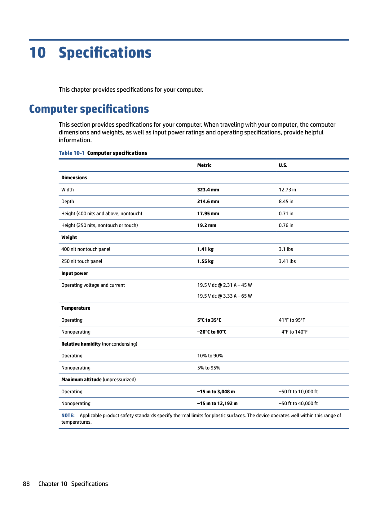
– or – Clear the contents of the drive using the following Disk Sanitizer commands steps:
| | |---|
NOTE: The amount of time it takes for Disk Sanitizer to run can take several hours. Plug the computer into an AC outlet before starting.
Nonvolatile memory usage
Use this table to troubleshooting nonvolatile memory usage. Table 11-1 Troubleshooting steps for nonvolatile memory usage
Nonvolatile memory type Amount (Size)
Does this memory store customer data?
Does this memory retain data when power is removed?
What is the purpose of this memory?
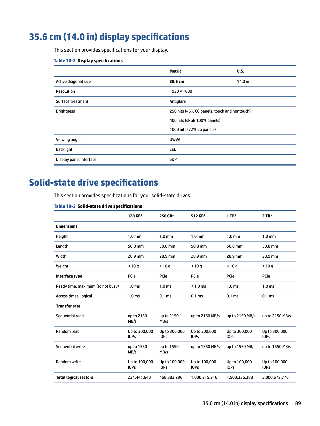
How is data entered into this memory?
How is this memory write-protected?
HP Sure Start flash (select models only)
8 MB No Yes Provides protected backup of critical System BIOS code, EC firmware, and critical computer configuration data for select platforms that support HP Sure Start.
For more information, see Using HP Sure Start (select products only) on page 96.
Data cannot be written to this device via the host processor. The content is managed solely by the HP Sure Start Embedded Controller.
This memory is protected by the HP Sure Start Embedded Controller.
Real Time Clock (RTC) battery backed-up CMOS configuration memory
Controller (NIC) EEPROM
256 bytes No Yes Stores system date and time and noncritical data.
64 KB (not customer accessible)
No Yes Stores NIC configuration and NIC firmware.
DIMM Serial Presence Detect (SPD) configuration data
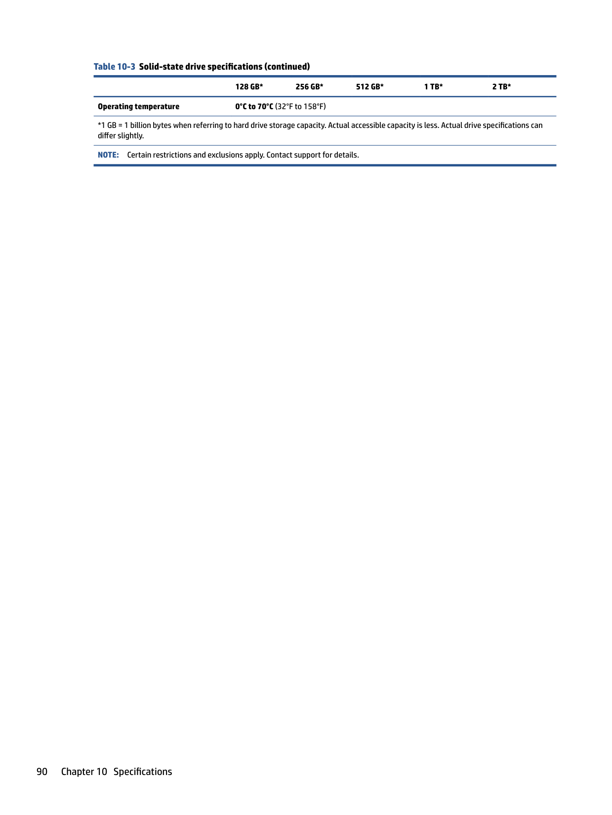
256 bytes per memory module, 128 bytes programmable (not customer accessible)
No Yes Stores memory module information.
System BIOS 9 MB Yes Yes Stores system BIOS code and computer configuration data.
RTC battery backed-up CMOS is programmed using Computer Setup (BIOS), or by changing the Windows date & time.
This memory is not writeprotected.
NIC EEPROM is programmed using a utility from the NIC vendor that can be run from DOS.
DIMM SPD is programmed by the memory vendor.
A utility must be used to write data to this memory and is available from the NIC vendor. Writing data to this ROM in an inappropriate manner will render the NIC nonfunctional.
Data cannot be written to this memory when the module is installed in a computer. The specific write-protection method varies by memory vendor.
System BIOS code is programmed at the factory. Code is updated when the system BIOS is updated. Configuration data and settings are entered using the Computer Setup (BIOS) or a custom utility.
NOTE: Writing data to this ROM in an inappropriate manner can render the computer nonfunctional.
A utility must be used for writing data to this memory and is available
Nonvolatile memory usage 93
######## Table 11-1 Troubleshooting steps for nonvolatile memory usage (continued)
Nonvolatile memory type Amount (Size)
Does this memory store customer data?
Does this memory retain data when power is removed?
What is the purpose of this memory?
How is data entered into this memory?
How is this memory write-protected?
on the HP website; go to http://www.hp.com/ support. Select Find your product, and then follow the on-screen instructions.
Intel Management Engine Firmware (present only in select Elite or Z models. For more information, go to http://www.hp.com/ support. Select Identify your product for manuals and specific product information, and then follow the on-screen instructions.)
1.5 MB or 7 MB Yes Yes Stores Management Engine Code, Settings, Provisioning Data and iAMT third-party data store.
Management Engine Code is programmed at the factory. Code is updated via Intel secure firmware update utility. Unique Provisioning Data can be entered at the factory or by an administrator using the Management Engine (MEBx) setup utility. The third-party data store contents can be populated by a remote management console or local applications that have been registered by an administrator to have access to the space.
Bluetooth flash (select products only)
2 megabits No Yes Stores Bluetooth configuration and firmware.
Bluetooth flash is programmed at the factory. Tools for writing data to this memory are not publicly available but can be obtained from the silicon vendor.
802.11 WLAN EEPROM
4 kilobits to 8 kilobits
No Yes Stores configuration and calibration data.
802.11 WLAN EEPROM is programmed at the factory. Tools for writing data to this memory are not made public.
Camera (select products only)
64 kilobits No Yes Stores camera configuration and firmware.
Camera memory is programmed using a utility from the device manufacturer that can be run from Windows.
Fingerprint reader (select products only)
512 KB flash Yes Yes Stores
fingerprint templates.
Fingerprint reader memory is programmed by user enrollment in HP ProtectTools Security Manager.
The Intel chipset is configured to enforce hardware protection to block all direct read-write access to this area. An Intel utility must be used for updating the firmware. Only firmware updates digitally signed by Intel can be applied using this utility.
A utility must be used for writing data to this memory and is made available through newer versions of the driver whenever the flash requires an upgrade.
A utility must be used for writing data to this memory and is typically not made available to the public unless a firmware upgrade is necessary to address a unique issue.
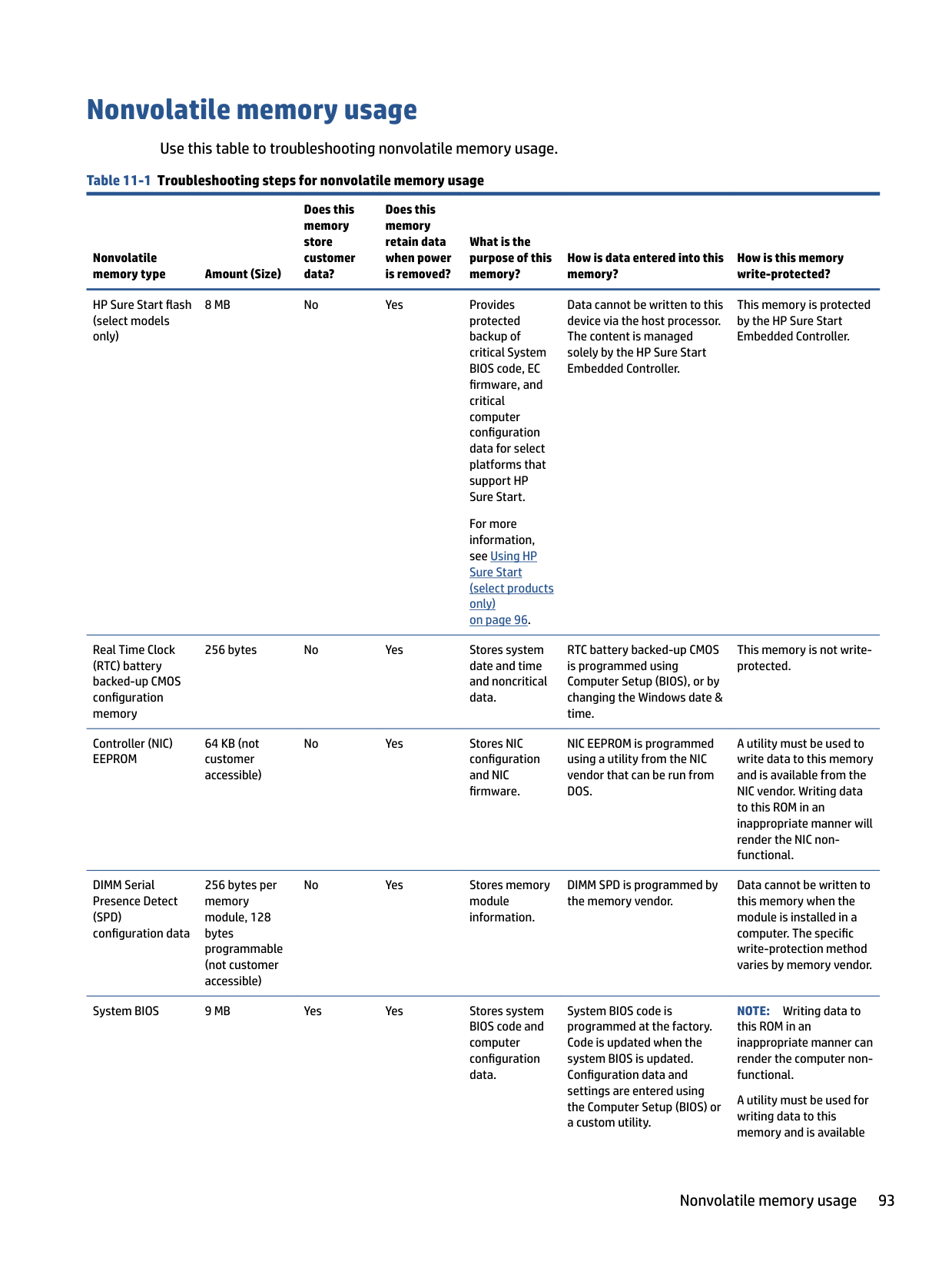
A utility must be used for writing data to this memory and is typically not made available to the public unless a firmware upgrade is necessary to address a unique issue.
Only a digitally signed application can make the call to write to the flash.
Questions and answers
Use this section to answer your questions about nonvolatile memory.
IMPORTANT: The restore defaults feature does not securely erase any information on your hard drive. See question and answer 6 for steps to securely erase information. The restore defaults feature does not reset the Custom Secure Boot keys. See question and answer 7 for information about resetting the keys.
a. Turn on or restart the computer, and then quickly press esc. b. Select Main, and then select Apply Factory Defaults and Exit. c. Follow the on-screen instructions. d. Select Main, select Save Changes and Exit, and then follow the on-screen instructions.
The Unified Extensible Firmware Interface (UEFI) BIOS is an industry-standard software interface between the platform firmware and an operating system (OS). It replaces the older BIOS architecture but supports much of the legacy BIOS functionality.
Like the legacy BIOS, the UEFI BIOS provides an interface to display the system information and configuration settings and to change the configuration of your computer before an OS is loaded. BIOS provides a secure runtime environment that supports a Graphic User Interface (GUI). In this environment, you can use either a pointing device (touch screen, touchpad, pointing stick, or USB mouse) or the keyboard to navigate and make menu and configuration selections. The UEFI BIOS also contains basic system diagnostics.
The UEFI BIOS provides functionality beyond that of the legacy BIOS. In addition, the UEFI BIOS works to initialize the computer’s hardware before loading and executing the OS; the runtime environment allows the loading and execution of software programs from storage devices to provide more functionality, such as advanced hardware diagnostics (with the ability to display more detailed system information) and advanced firmware management and recovery software.
HP has provided options in Computer Setup (BIOS) to allow you to run in legacy BIOS, if required by the operating system. Examples of this requirement would be if you upgrade or downgrade the OS.
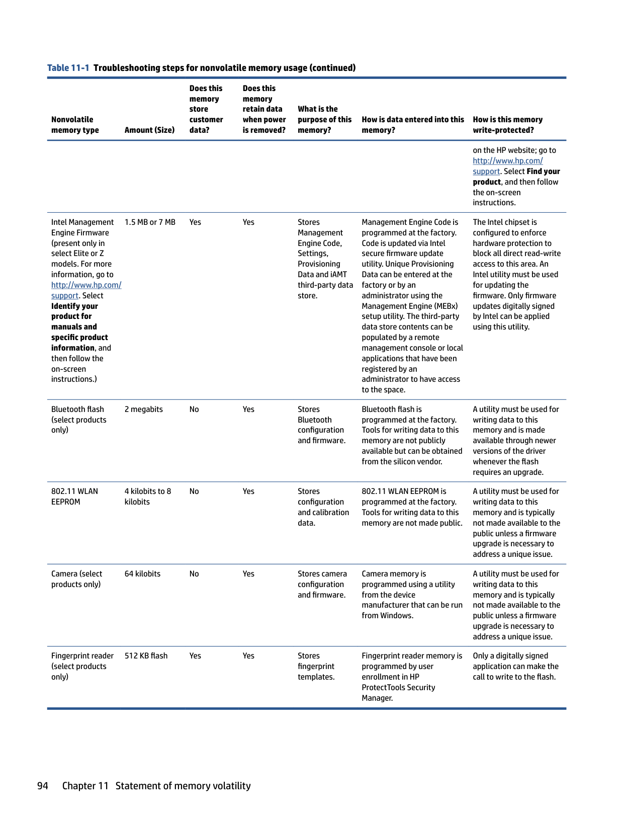
The DIMM SPD memory contains information about the memory module, such as size, serial number, data width, speed and timing, voltage, and thermal information. This information is written by the module manufacturer and stored on an EEPROM. You cannot write to this EEPROM when the memory module is installed in a computer. Third-party tools do exist that can write to the EEPROM when the memory module is not installed in a computer. Various third-party tools are available to read SPD memory.
This message relates to clearing the Real Time Clock (RTC) CMOS memory that contains computer configuration data.
| | |---|
Questions and answers 95
| | |---|
IMPORTANT: Resetting results in the loss of information.
These steps do not reset Custom Secure Boot Keys. See question and answer 7 for information about resetting the keys.
a. Turn on or restart the computer, and then quickly press esc. b. Select Main, and then select Reset Security to Factory Defaults. c. Follow the on-screen instructions. d. Select Main, select Save Changes and Exit, and then follow the on-screen instructions.
###### 7. How can the Custom Secure Boot Keys be reset?
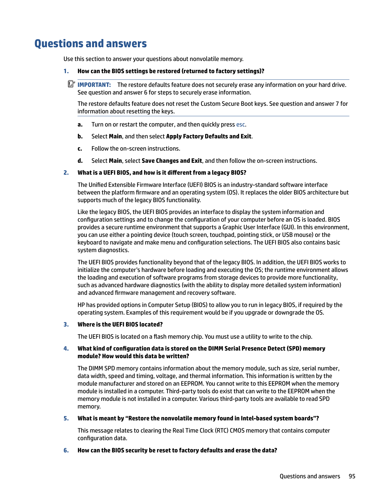
Secure Boot is a feature to ensure that only authenticated code can start on a platform. If you enabled Secure Boot and created Custom Secure Boot Keys, disabling Secure Boot does not clear the keys. You must also select to clear the Custom Secure Boot Keys. Use the same Secure Boot access procedure that you used to create the Custom Secure Boot Keys, but select to clear or delete all Secure Boot Keys.
Using HP Sure Start (select products only)
Select computer models are configured with HP Sure Start, a technology that continuously monitors your computer's BIOS for attacks or corruption.
If the BIOS becomes corrupted or is attacked, HP Sure Start restores the BIOS to its previously safe state, without user intervention. Those select computer models ship with HP Sure Start configured and enabled. HP Sure Start is configured and already enabled so that most users can use the HP Sure Start default configuration. Advanced users can customize the default configuration.
To access the latest documentation on HP Sure Start, go to http://www.hp.com/support.
12 Power cord set requirements
This chapter provides power cord requirements for countries and regions. The wide-range input feature of the computer permits it to operate from any line voltage from 100 V ac to 120 V ac, or from 220 V ac to 240 V ac. The three-conductor power cord set included with the computer meets the requirements for use in the country or region where the equipment is purchased. Power cord sets for use in other countries or regions must meet the requirements of the country and region where the computer is used.
Requirements for all countries
These power cord requirements are applicable to all countries and regions.
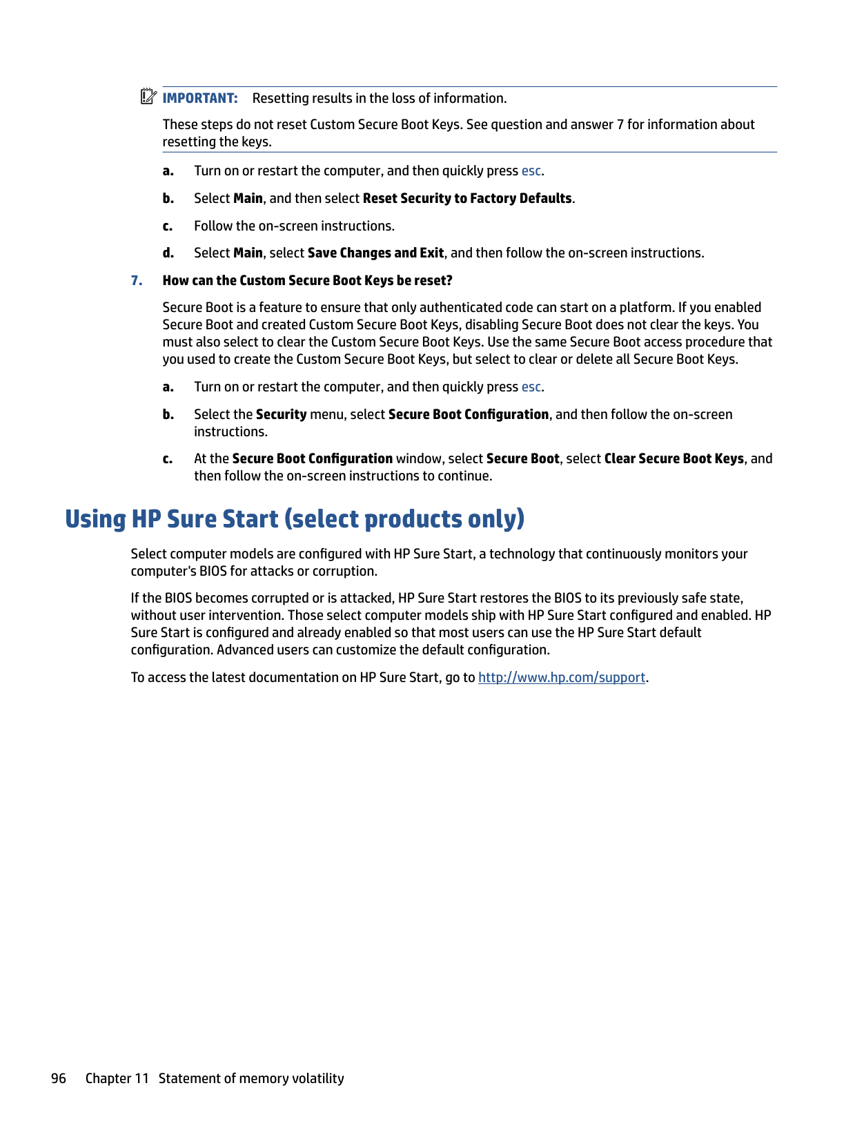
Requirements for specific countries and regions To determine power cord requirements for specific countries and regions, use this table. Table 12-1 Power cord requirements for specific countries and regions
######### Country/region Accredited agency Applicable note number
Argentina IRAM 1 Australia SAA 1 Austria OVE 1 Belgium CEBEC 1 Brazil ABNT 1 Canada CSA 2 Chile IMQ 1 Denmark DEMKO 1 Finland FIMKO 1 France UTE 1 Germany VDE 1
######## Table 12-1 Power cord requirements for specific countries and regions (continued)
######### Country/region Accredited agency Applicable note number
India BIS 1 Israel SII 1 Italy IMQ 1 Japan JIS 3 Netherlands KEMA 1 New Zealand SANZ 1 Norway NEMKO 1 People's Republic of China CCC 4 Saudi Arabia SASO 7 Singapore PSB 1 South Africa SABS 1 South Korea KTL 5 Sweden SEMKO 1 Switzerland SEV 1 Taiwan BSMI 6 Thailand TISI 1 United Kingdom ASTA 1 United States UL 2
98 Chapter 12 Power cord set requirements
13 Recycling
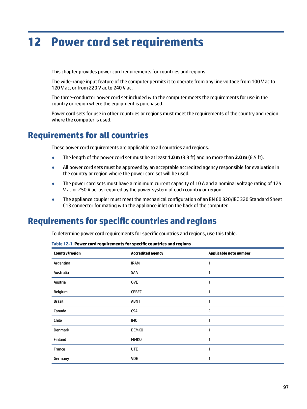
When a nonrechargeable or rechargeable battery has reached the end of its useful life, do not dispose of the battery in general household waste. Follow the local laws and regulations in your area for battery disposal.
HP encourages customers to recycle used electronic hardware, HP original print cartridges, and rechargeable batteries. For more information about recycling programs, see the HP website at http://www.hp.com/recycle.
Index
determining version 76 downloading an update 76, 77 updating 76 Bluetooth label 15 boot order
changing using the f9 prompt
77 boot order, changing 80 bottom 15 bottom components 14 bottom cover
removal 32 spare part number 32
Bracket Kit spare part number 23
spare part number 22
card reader board removal 46 spare part number 46
cautions
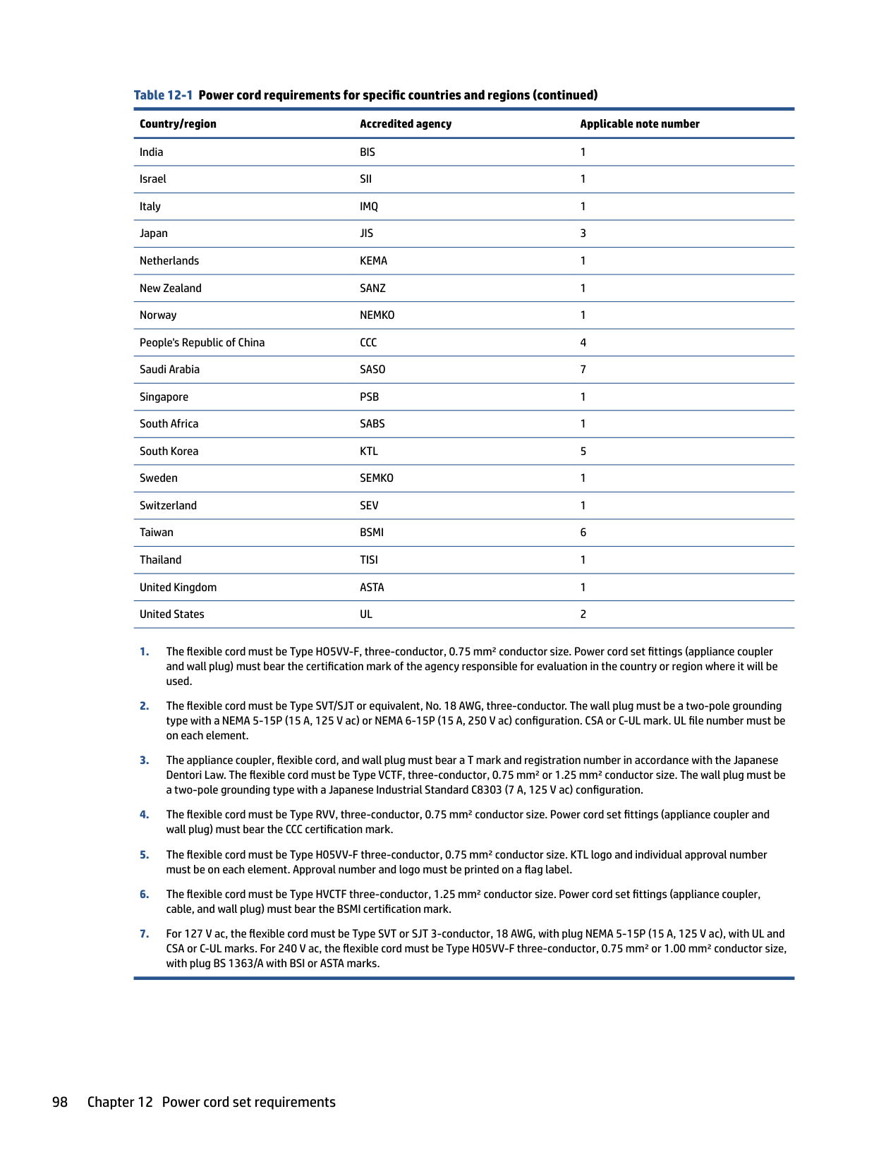
electrostatic discharge 27, 28 component
bottom 14
components display 8 keyboard area 9 left side 7 right side 6
computer major components 18 Computer Setup
navigating and selecting 75 restoring factory settings 75 starting 75
computer specifications 88
specifications 88, 89
100 Index
display assembly
subcomponents 20 display components 8
preventing damage 27, 28, 29

removal 52 spare part number 52
fingerprint reader board removal 49 spare part numbers 49
fingerprint reader bracket illustrated 23 fingerprint reader insert illustrated 23
packaging 27, 31 transporting 27, 31 workstation 27
specifications 88
heat sink removal 53 spare part numbers 53
HP PC Hardware Diagnostics UEFI downloading 85 failure ID code 84 starting 85 using 84
HP PC Hardware Diagnostics Windows accessing 82, 83 downloading 83 failure ID code 82 installing 84 using 82
HP Recovery media
recovery 80 HP Sure Recover 81 HP Sure Start 91, 96
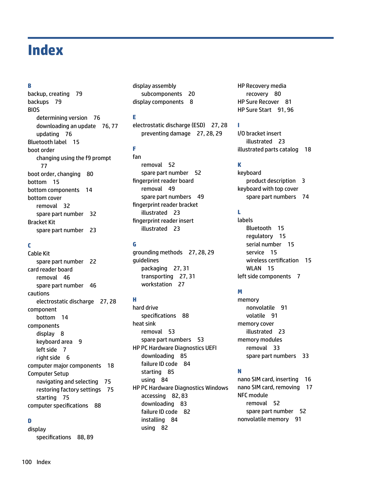
I I/O bracket insert
illustrated 23 illustrated parts catalog 18
product description 3 keyboard with top cover
spare part numbers 74
Bluetooth 15 regulatory 15 serial number 15 service 15 wireless certification 15 WLAN 15
left side components 7
nonvolatile 91 volatile 91
memory cover illustrated 23
memory modules removal 33 spare part numbers 33
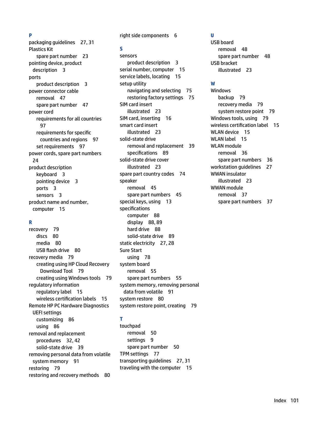
removal 52 spare part number 52
nonvolatile memory 91
P packaging guidelines 27, 31 Plastics Kit
spare part number 23 pointing device, product
description 3 ports
product description 3
power connector cable removal 47 spare part number 47
power cord requirements for all countries 97 requirements for specific
countries and regions 97 set requirements 97
power cords, spare part numbers 24
product description keyboard 3 pointing device 3 ports 3 sensors 3
product name and number, computer 15
R recovery 79
discs 80 media 80 USB flash drive 80
recovery media 79 creating using HP Cloud Recovery Download Tool 79 creating using Windows tools 79
regulatory information regulatory label 15 wireless certification labels 15
Remote HP PC Hardware Diagnostics
UEFI settings customizing 86 using 86
removal and replacement procedures 32, 42 solid-state drive 39
removing personal data from volatile
system memory 91 restoring 79 restoring and recovery methods 80
right side components 6
product description 3 serial number, computer 15 service labels, locating 15 setup utility
navigating and selecting 75 restoring factory settings 75
SIM card insert
illustrated 23 SIM card, inserting 16 smart card insert
illustrated 23
solid-state drive removal and replacement 39 specifications 89
solid-state drive cover illustrated 23 spare part country codes 74 speaker
removal 45 spare part numbers 45
special keys, using 13 specifications
computer 88 display 88, 89 hard drive 88 solid-state drive 89
static electricity 27, 28 Sure Start
using 78
system board removal 55 spare part numbers 55
system memory, removing personal
data from volatile 91 system restore 80 system restore point, creating 79
removal 50 settings 9 spare part number 50
TPM settings 77 transporting guidelines 27, 31 traveling with the computer 15
U USB board
removal 48 spare part number 48
USB bracket illustrated 23
W Windows
backup 79 recovery media 79 system restore point 79
Windows tools, using 79 wireless certification label 15 WLAN device 15 WLAN label 15 WLAN module
removal 36 spare part numbers 36
workstation guidelines 27 WWAN insulator
illustrated 23
WWAN module removal 37 spare part numbers 37
Index 101