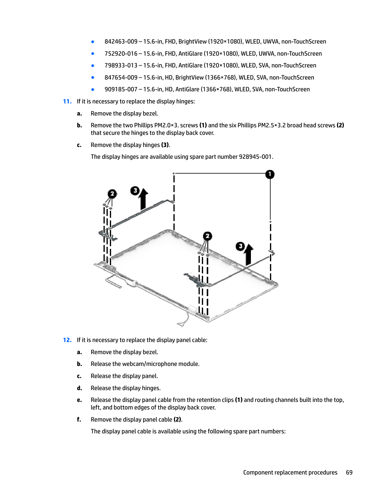
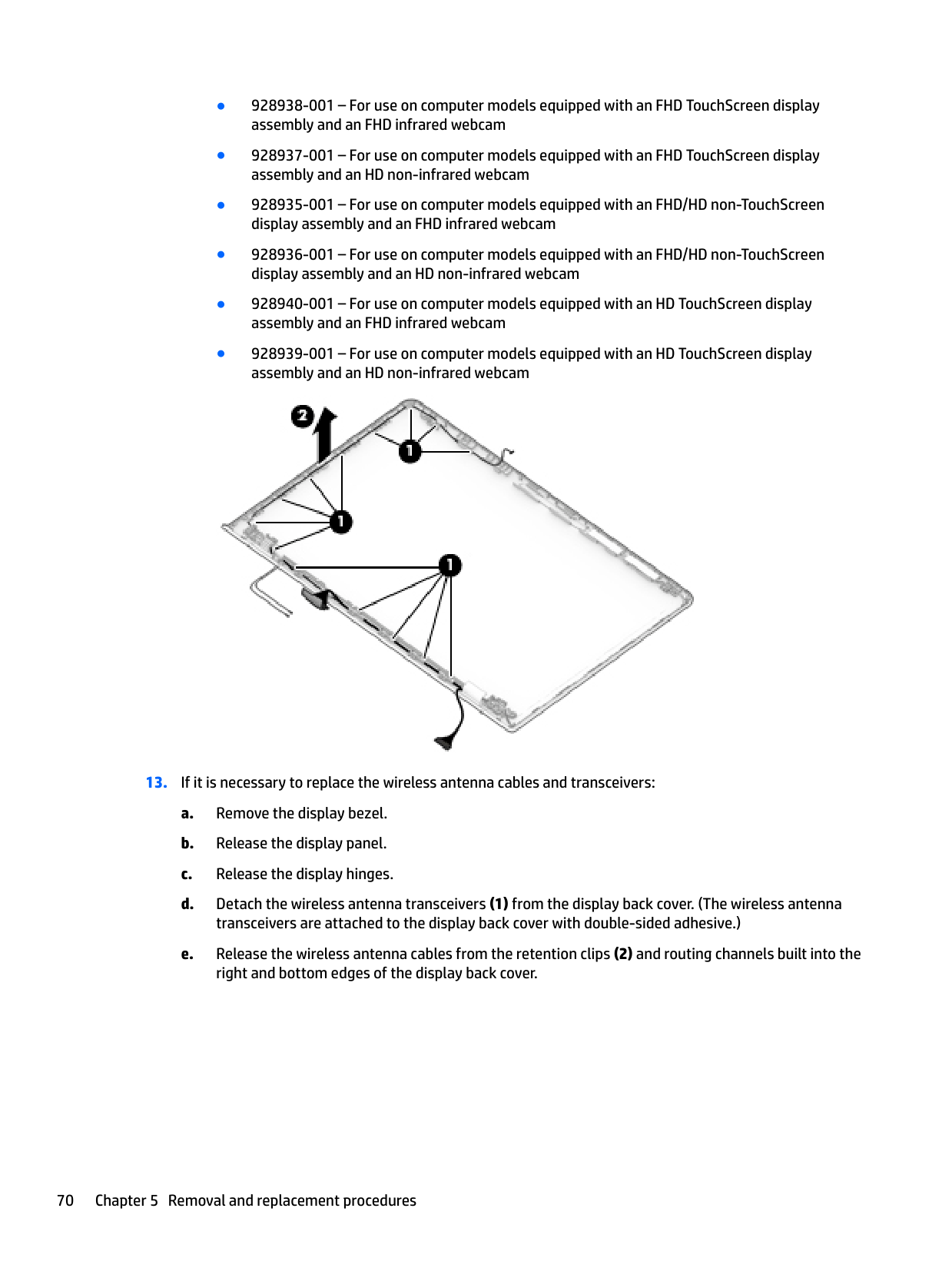
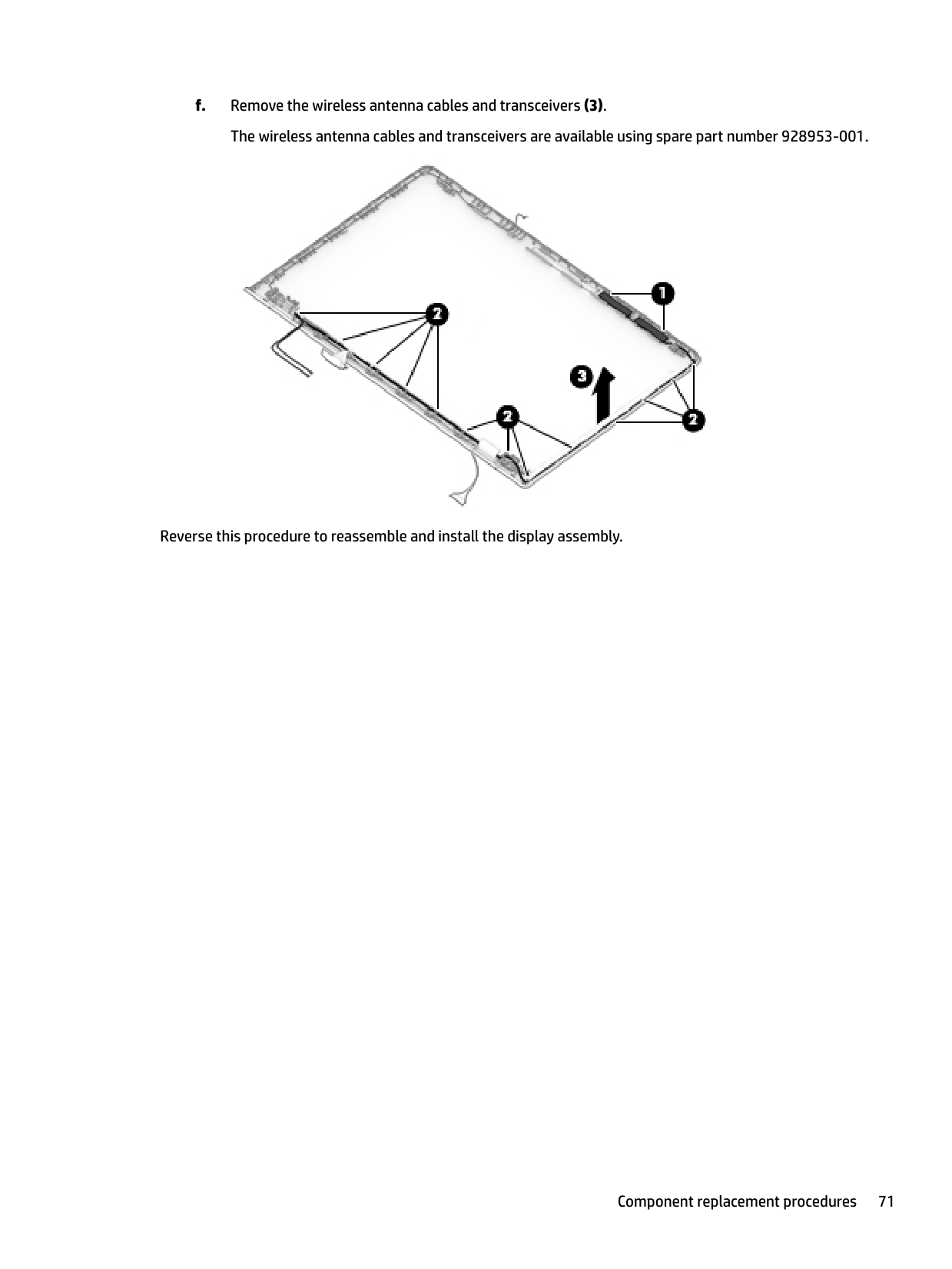
Ask AI
— answers from the official manualAnswers from the official manual.
Common questions
Common Questions
6 totalWhat type of memory modules can be installed on my HP Pavilion 15 CW1000?
The laptop supports up to 16 GB system memory with DDR4-2400 channel support and specific configurations like 8 GB x 2, 8GB + 4 GB, etc. Refer to Removal and Replacement Procedures section for detailed instructions.
How do I safely handle hard drives in my HP Pavilion 15 CW1000?
To remove a drive without damage, shut down the laptop first, then disconnect power and external devices. Remove the bottom cover, battery, and release the ZIF connector of the hard drive cable from system board to lift and release the right side of the hard drive.
Where can I find replacement parts and service information for my HP Pavilion 15 CW1000?
Visit http://partsurfer.hp.com, select your country or region, then follow the on-screen instructions for complete and current information on supported replacement parts specific to your model.
How do I safely remove a solid-state drive from my HP Pavilion 15 CW1000?
Shut down the laptop, disconnect power and external devices, then proceed to remove bottom cover (page 37) followed by battery. Finally, unscrew and lift out SSD from slot with careful handling.
How do I remove the fan assembly in my HP Pavilion 15 CW1000 for maintenance?
Turn off the laptop completely and disconnect power sources. Remove bottom cover (page 37) then battery. Disconnect fan cable from system board, unscrew holding it to keyboard/top cover, and carefully take out fan.
How do I safely transport my HP Pavilion 15 CW1000 laptop?
To avoid ESD (electrostatic discharge) damage during transportation - keep electronics in electrostatic-safe containers until assembled. Use anti-static bags or foam-lined boxes for protection and grounding straps.
Full Manual
96 pages

HP Pavilion 15 Laptop PC
Maintenance and Service Guide IMPORTANT! This document is intended for HP authorized service providers only.
© Copyright 2017 Hewlett-Packard Development Company, L.P.
Bluetooth is a trademark owned by its proprietor and used by HP Inc. under license. Intel, Core, and Pentium are U.S. registered trademarks of Intel Corporation. . Microsoft and Windows are either registered trademarks or trademarks of Microsoft Corporation in the United States and/or other countries. SD Logo is a trademark of its proprietor.
The information contained herein is subject to change without notice. The only warranties for HP products and services are set forth in the express warranty statements accompanying such products and services. Nothing herein should be construed as constituting an additional warranty. HP shall not be liable for technical or editorial errors or omissions contained herein.
Second Edition: August 2017 First Edition: May 2017 Document Part Number: 924965-002 Product notice
This guide describes features that are common to most models. Some features may not be available on your computer.
Not all features are available in all editions of Windows 10. This computer may require upgraded and/or separately purchased hardware, drivers and/or software to take full advantage of Windows 10 functionality. See for http://www.microsoft.com details.
#### Safety warning notice
WARNING! To reduce the possibility of heat-related injuries or of overheating the device, do not place the device directly on your lap or obstruct the device air vents. Use the device only on a hard, flat surface. Do not allow another hard surface, such as an adjoining optional printer, or a soft surface, such as pillows or rugs or clothing, to block airflow. Also, do not allow the AC adapter to contact the skin or a soft surface, such as pillows or rugs or clothing, during operation. The device and the AC adapter comply with the user-accessible surface temperature limits defined by the International Standard for Safety of Information Technology Equipment (IEC 60950).
iii
####### iv Safety warning notice
Table of contents
TouchPad ............................................................................................................................................. 9 Lights ................................................................................................................................................. 10 Button and speakers ......................................................................................................................... 11 Special keys ....................................................................................................................................... 12
Bottom ................................................................................................................................................................. 13
Plastic parts ....................................................................................................................................... 32 Cables and connectors ...................................................................................................................... 33 Drive handling ................................................................................................................................... 33
Grounding guidelines ........................................................................................................................................... 34 Electrostatic discharge damage ........................................................................................................ 34 Packaging and transporting guidelines .......................................................................... 35 Workstation guidelines ................................................................................ 35
Bottom cover ..................................................................................................................................... 37 Battery ............................................................................................................................................... 39
v
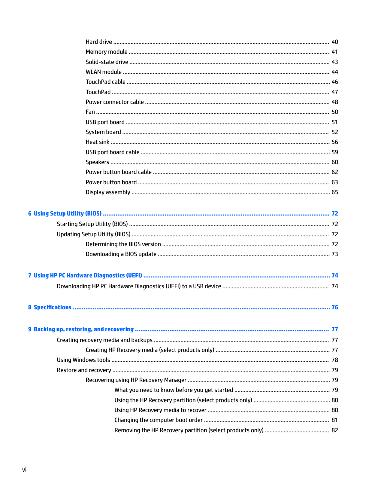
Hard drive .......................................................................................................................................... 40 Memory module ................................................................................................................................ 41 Solid-state drive ................................................................................................................................ 43 WLAN module .................................................................................................................................... 44 TouchPad cable .................................................................................................................................. 46 TouchPad ........................................................................................................................................... 47 Power connector cable ...................................................................................................................... 48 Fan ..................................................................................................................................................... 50 USB port board .................................................................................................................................. 51 System board .................................................................................................................................... 52 Heat sink ............................................................................................................................................ 56 USB port board cable ......................................................................................................................... 59 Speakers ............................................................................................................................................ 60 Power button board cable ................................................................................................................. 62 Power button board .......................................................................................................................... 63 Display assembly ............................................................................................................................... 65

Determining the BIOS version ........................................................................................................... 72 Downloading a BIOS update .............................................................................................................. 73
Creating HP Recovery media (select products only) ......................................................................... 77 Using Windows tools ........................................................................................................................................... 78 Restore and recovery ........................................................................................................................................... 79
Recovering using HP Recovery Manager ........................................................................................... 79 What you need to know before you get started ............................................................. 79 Using the HP Recovery partition (select products only) ................................................. 80 Using HP Recovery media to recover .............................................................................. 80 Changing the computer boot order ................................................................................ 81 Removing the HP Recovery partition (select products only) ......................................... 82
vi
###### Index ............................................................................................................................................................. 86
vii
####### viii

1 Product description
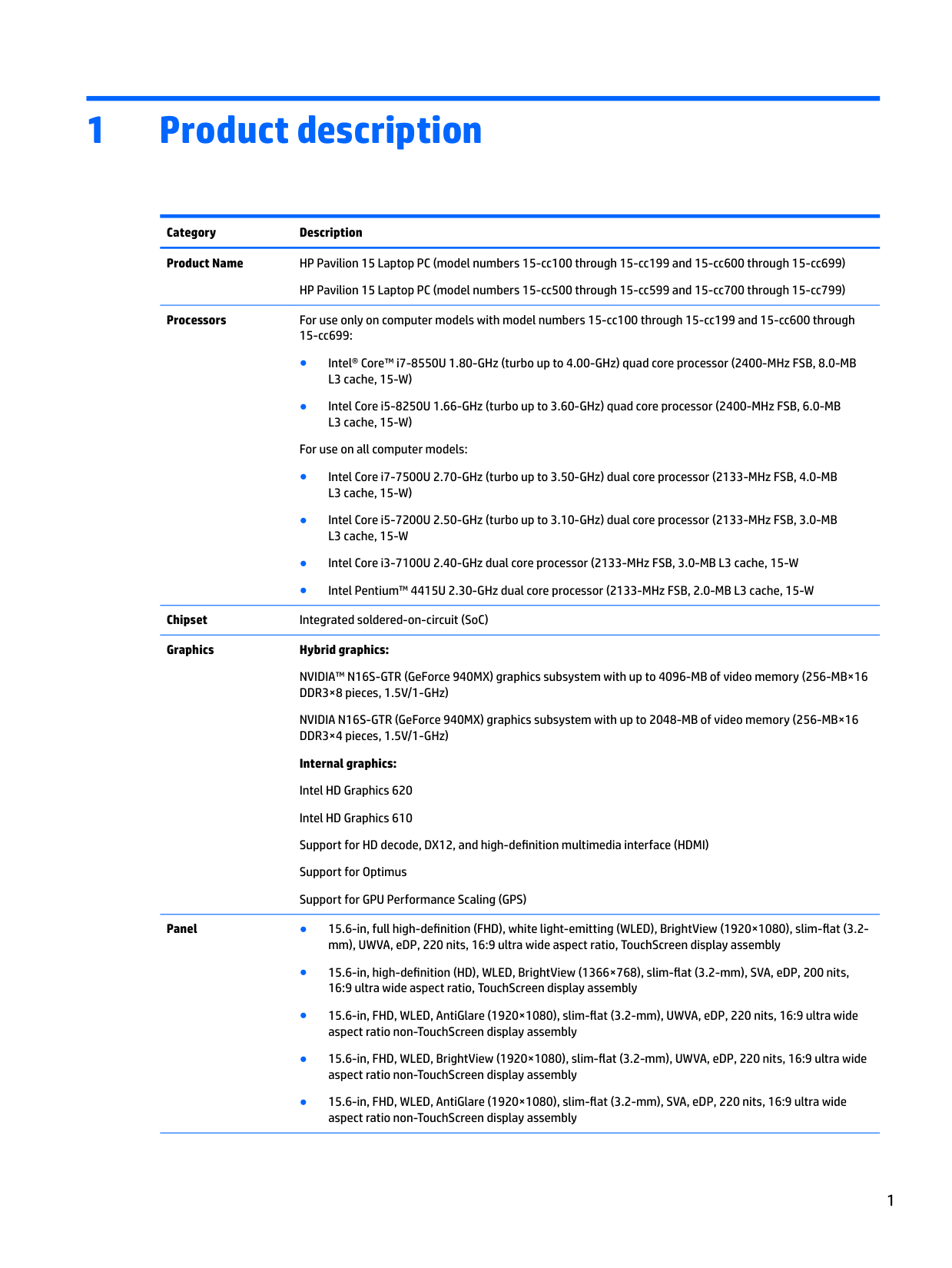
Category Description Product Name HP Pavilion 15 Laptop PC (model numbers 15-cc100 through 15-cc199 and 15-cc600 through 15-cc699)
HP Pavilion 15 Laptop PC (model numbers 15-cc500 through 15-cc599 and 15-cc700 through 15-cc799)
Processors For use only on computer models with model numbers 15-cc100 through 15-cc199 and 15-cc600 through
15-cc699:
For use on all computer models:
Chipset Integrated soldered-on-circuit (SoC) Graphics Hybrid graphics:
NVIDIA™ N16S-GTR (GeForce 940MX) graphics subsystem with up to 4096-MB of video memory (256-MB×16 DDR3×8 pieces, 1.5V/1-GHz)
NVIDIA N16S-GTR (GeForce 940MX) graphics subsystem with up to 2048-MB of video memory (256-MB×16 DDR3×4 pieces, 1.5V/1-GHz)
Internal graphics: Intel HD Graphics 620 Intel HD Graphics 610 Support for HD decode, DX12, and high-definition multimedia interface (HDMI) Support for Optimus Support for GPU Performance Scaling (GPS)
Panel ● 15.6-in, full high-definition (FHD), white light-emitting (WLED), BrightView (1920×1080), slim-flat (3.2-
mm), UWVA, eDP, 220 nits, 16:9 ultra wide aspect ratio, TouchScreen display assembly
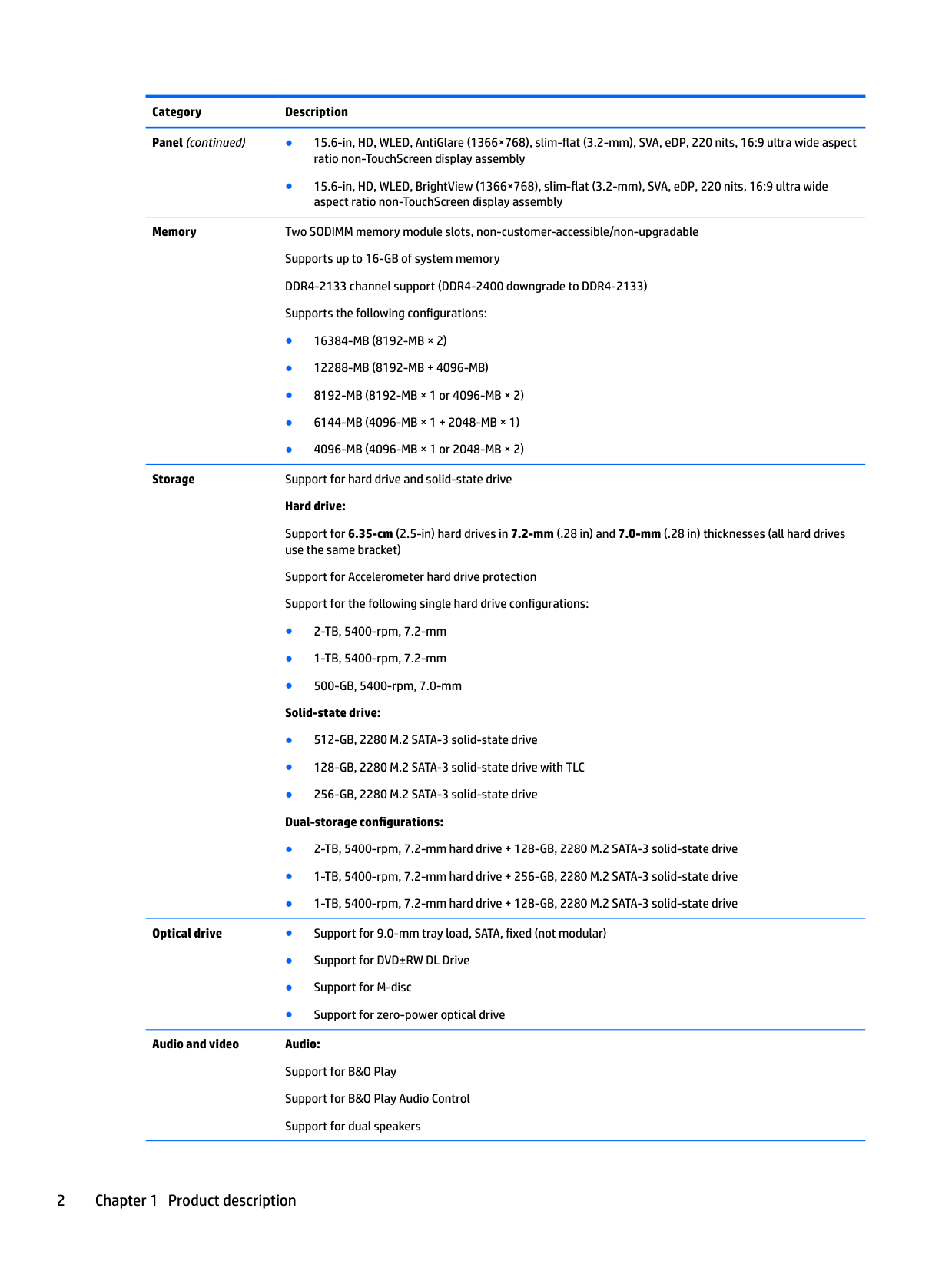
Panel (continued) ● 15.6-in, HD, WLED, AntiGlare (1366×768), slim-flat (3.2-mm), SVA, eDP, 220 nits, 16:9 ultra wide aspect
ratio non-TouchScreen display assembly
● 15.6-in, HD, WLED, BrightView (1366×768), slim-flat (3.2-mm), SVA, eDP, 220 nits, 16:9 ultra wide aspect ratio non-TouchScreen display assembly
Memory Two SODIMM memory module slots, non-customer-accessible/non-upgradable Supports up to 16-GB of system memory DDR4-2133 channel support (DDR4-2400 downgrade to DDR4-2133) Supports the following configurations:
Storage Support for hard drive and solid-state drive Hard drive:
Support for 6.35-cm (2.5-in) hard drives in 7.2-mm (.28 in) and 7.0-mm (.28 in) thicknesses (all hard drives use the same bracket)
Support for Accelerometer hard drive protection Support for the following single hard drive configurations:
Optical drive ● Support for 9.0-mm tray load, SATA, fixed (not modular)

Audio and video Audio: Support for B&O Play Support for B&O Play Audio Control Support for dual speakers
Audio and video (continued)
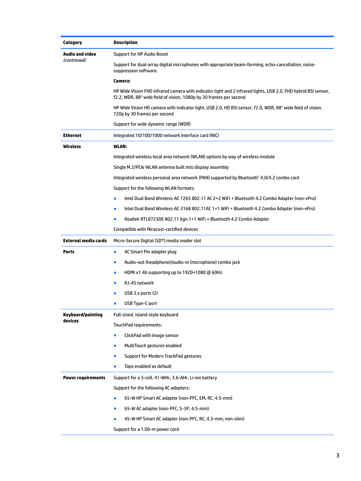
Support for HP Audio Boost Support for dual-array digital microphones with appropriate beam-forming, echo-cancellation, noisesuppression software. Camera:
HP Wide Vision FHD infrared camera with indicator light and 2 infrared lights, USB 2.0, FHD hybrid BSI sensor, f2.2, WDR, 88° wide field of vision, 1080p by 30 frames per second
HP Wide Vision HD camera with indicator light, USB 2.0, HD BSI sensor, f2.0, WDR, 88° wide field of vision, 720p by 30 frames per second
Support for wide dynamic range (WDR) Ethernet Integrated 10/100/1000 network interface card (NIC) Wireless WLAN:
Integrated wireless local area network (WLAN) options by way of wireless module Single M.2/PCIe WLAN antenna built into display assembly Integrated wireless personal area network (PAN) supported by Bluetooth® 4.0/4.2 combo card Support for the following WLAN formats:
External media cards Micro-Secure Digital (SD®) media reader slot Ports ● AC Smart Pin adapter plug

Keyboard/pointing devices
Full-sized, island-style keyboard TouchPad requirements:
Power requirements Support for a 3-cell, 41-WHr, 3.6-AHr, Li-ion battery
Support for the following AC adapters:
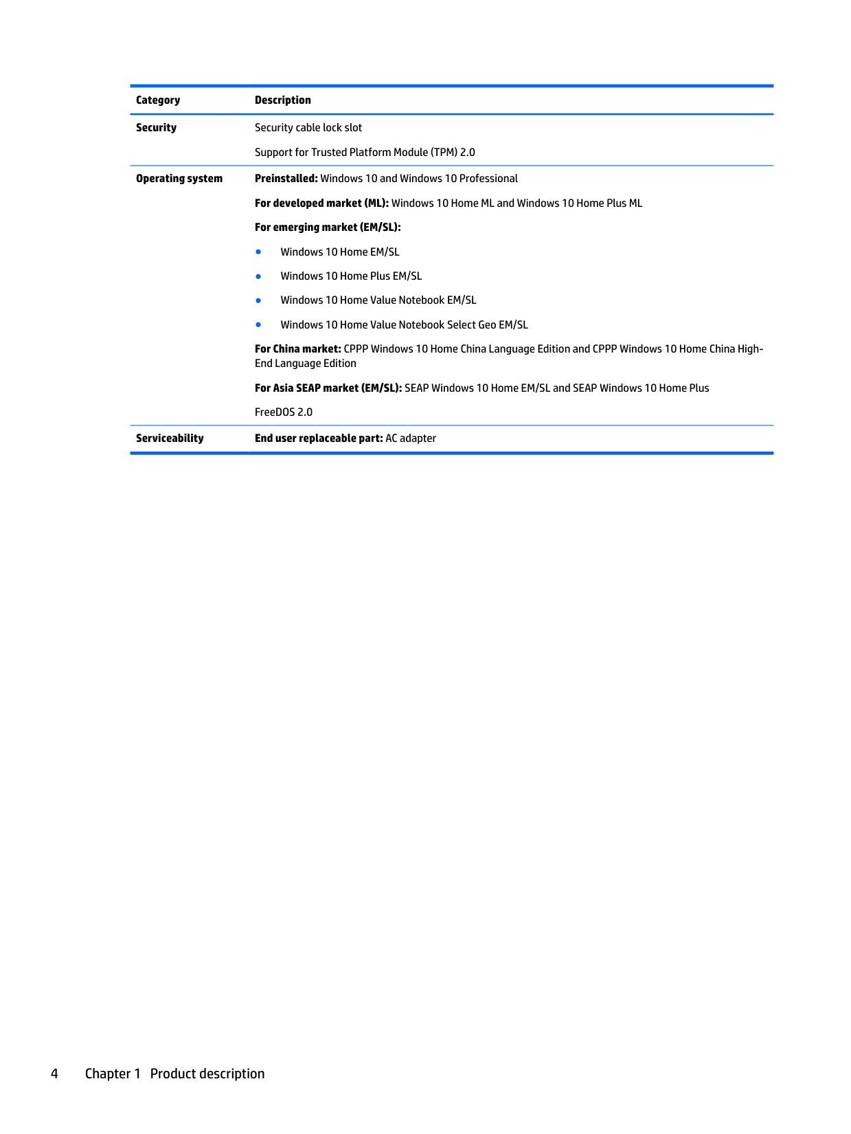
Security Security cable lock slot
Support for Trusted Platform Module (TPM) 2.0
Operating system Preinstalled: Windows 10 and Windows 10 Professional For developed market (ML): Windows 10 Home ML and Windows 10 Home Plus ML For emerging market (EM/SL):
For China market: CPPP Windows 10 Home China Language Edition and CPPP Windows 10 Home China HighEnd Language Edition
For Asia SEAP market (EM/SL): SEAP Windows 10 Home EM/SL and SEAP Windows 10 Home Plus FreeDOS 2.0
######## Serviceability End user replaceable part: AC adapter
2 Getting to know your computer
Locating hardware
To find out what hardware is installed on your computer:
▲ Type device manager in the taskbar search box, and then select the Device Manager app.
A list displays all the devices installed on your computer.
For information about system hardware components and the system BIOS version number, press fn+esc (select products only).
Locating software
To find out what software is installed on your computer:
▲ Select the Start button.
‒ or – Right-click the Start button, and then select Apps & features.
Locating hardware 5
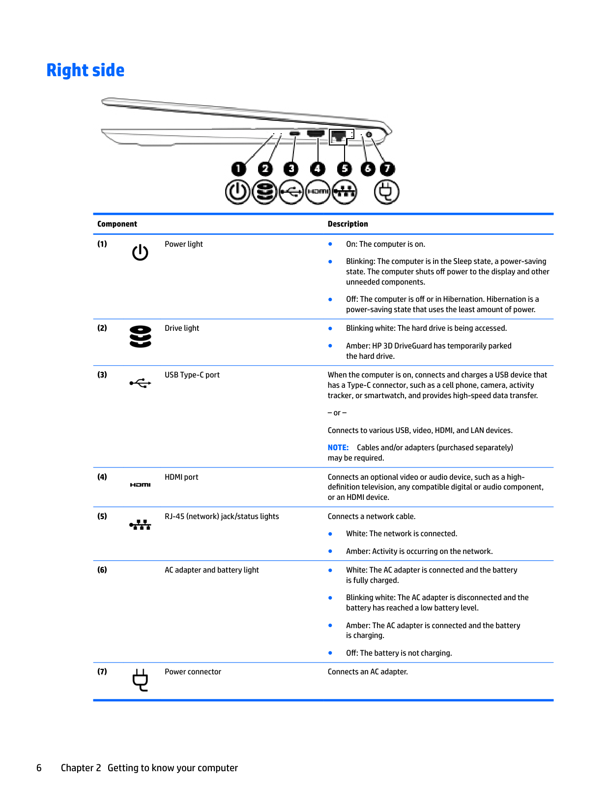
Right side

######## Component Description


● Amber: HP 3D DriveGuard has temporarily parked the hard drive.

– or – Connects to various USB, video, HDMI, and LAN devices. NOTE: Cables and/or adapters (purchased separately) may be required.


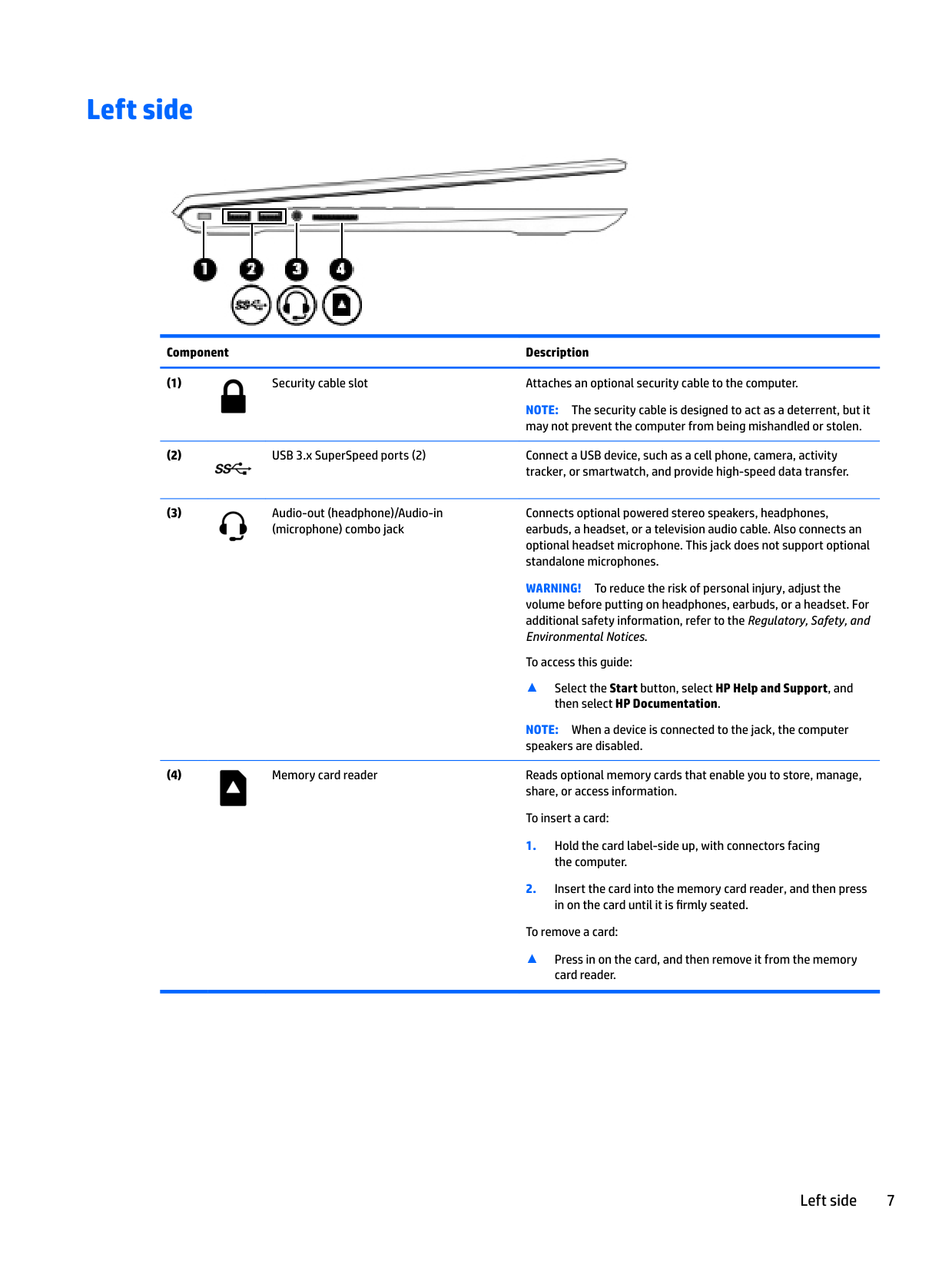
Left side

######## Component Description

NOTE: The security cable is designed to act as a deterrent, but it may not prevent the computer from being mishandled or stolen.


Connects optional powered stereo speakers, headphones, earbuds, a headset, or a television audio cable. Also connects an optional headset microphone. This jack does not support optional standalone microphones.
WARNING! To reduce the risk of personal injury, adjust the
volume before putting on headphones, earbuds, or a headset. For additional safety information, refer to the Regulatory, Safety, and Environmental Notices.
To access this guide:
▲ Select the Start button, select HP Help and Support, and then select HP Documentation.
NOTE: When a device is connected to the jack, the computer speakers are disabled.

To remove a card:
▲ Press in on the card, and then remove it from the memory card reader.
Left side 7
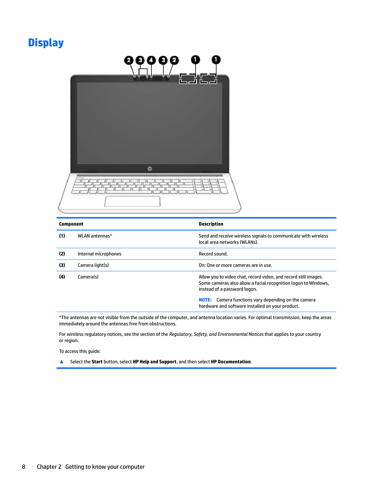
Display

######## Component Description
NOTE: Camera functions vary depending on the camera hardware and software installed on your product.
*The antennas are not visible from the outside of the computer, and antenna location varies. For optimal transmission, keep the areas immediately around the antennas free from obstructions.
For wireless regulatory notices, see the section of the Regulatory, Safety, and Environmental Notices that applies to your country or region.
To access this guide:
######## ▲ Select the Start button, select HP Help and Support, and then select HP Documentation.
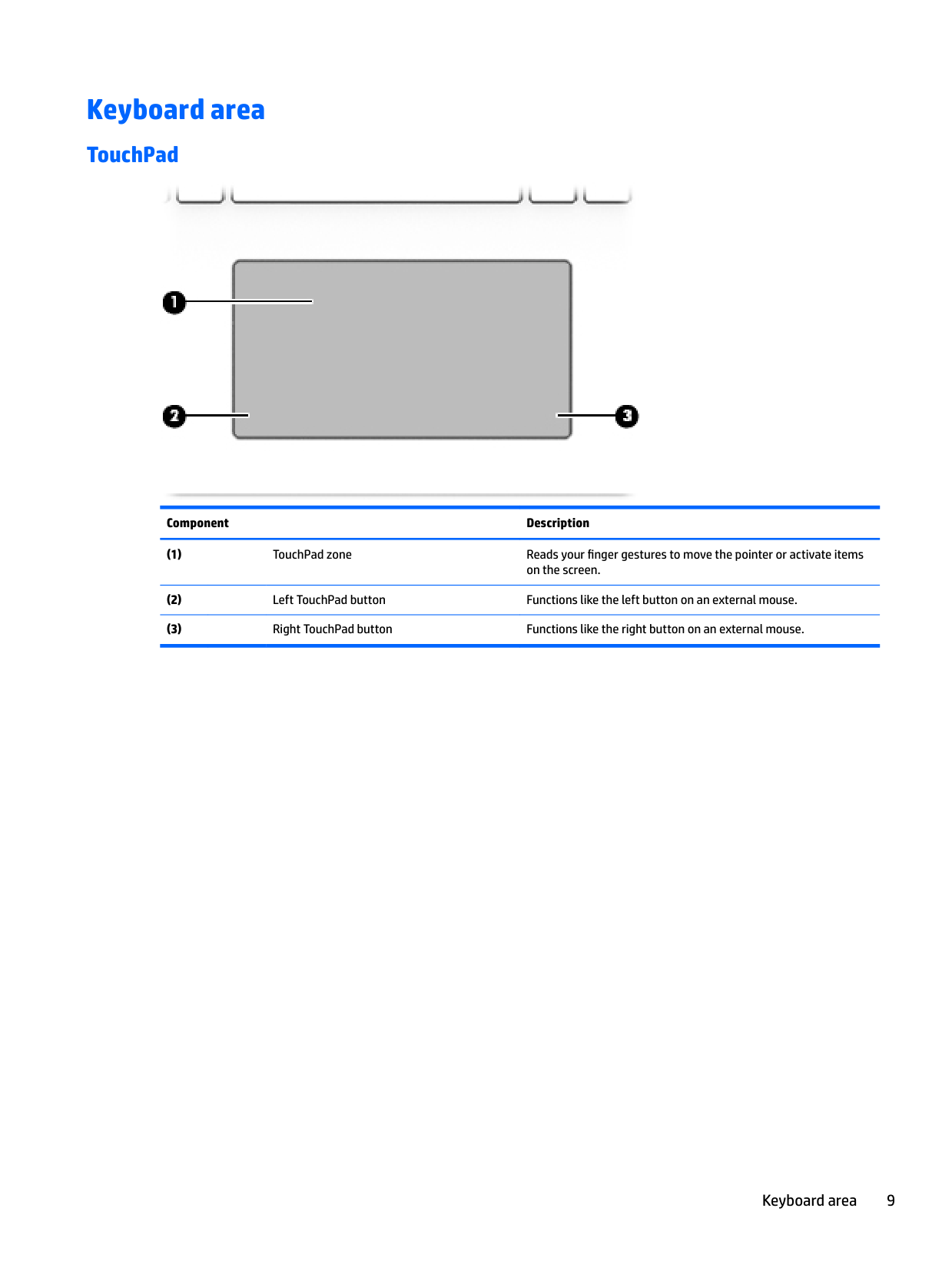
Keyboard area
#### TouchPad

######## Component Description
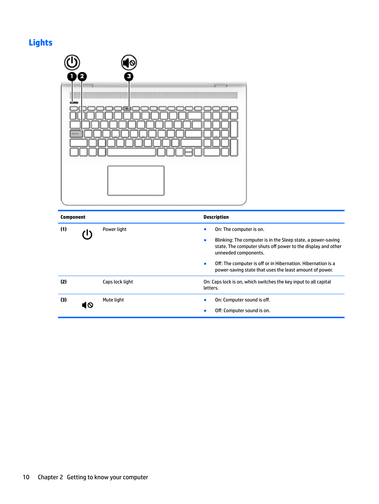
#### Lights

######## Component Description


● Off: Computer sound is on.
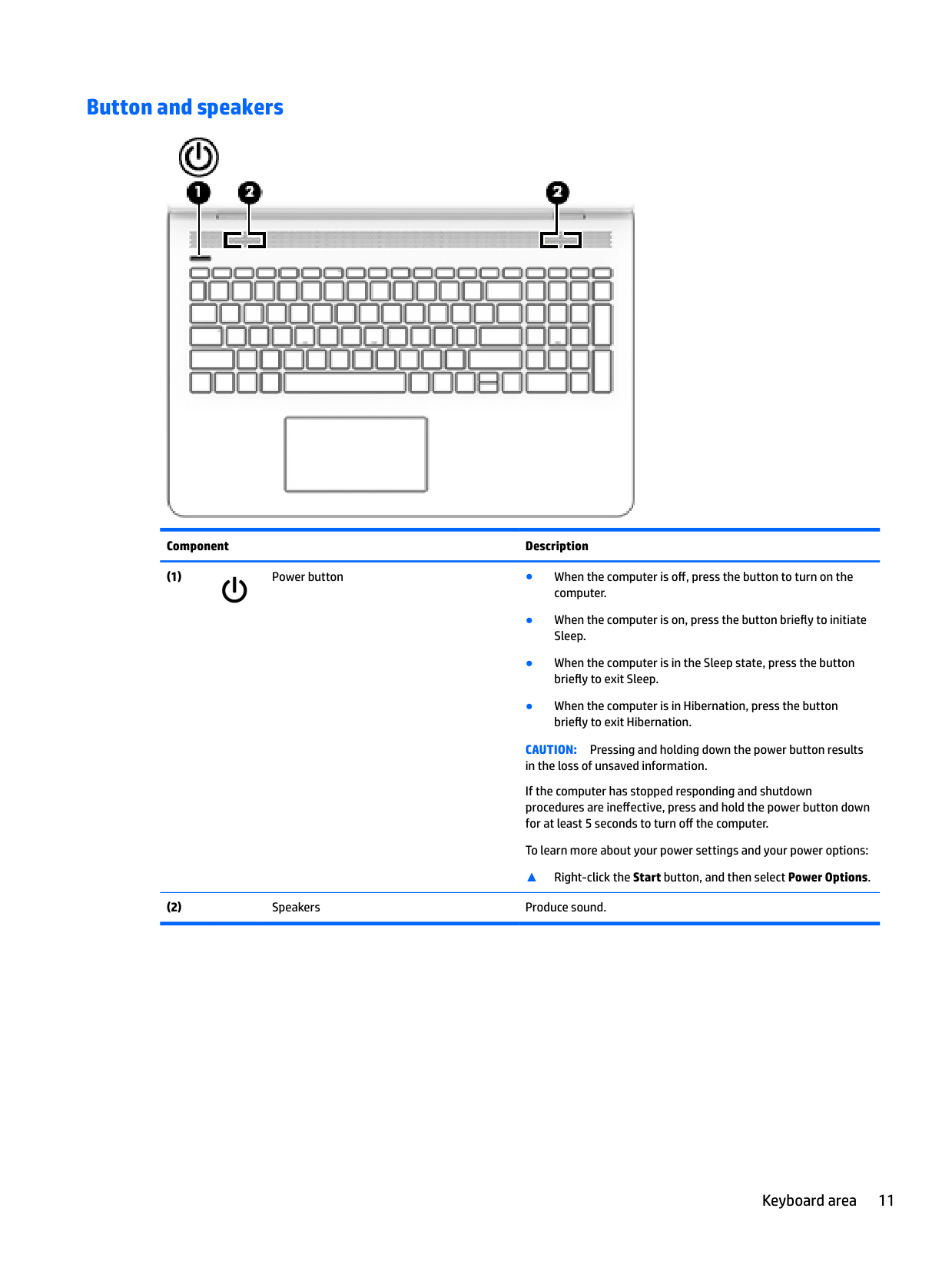
#### Button and speakers

######## Component Description

CAUTION: Pressing and holding down the power button results in the loss of unsaved information. If the computer has stopped responding and shutdown procedures are ineffective, press and hold the power button down for at least 5 seconds to turn off the computer.
To learn more about your power settings and your power options: ▲ Right-click the Start button, and then select Power Options.
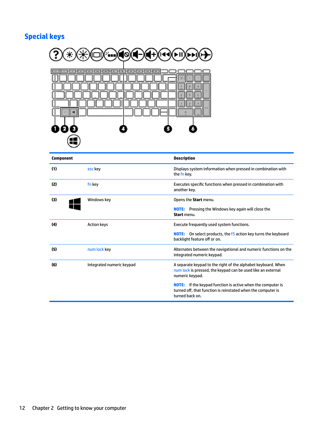
#### Special keys

######## Component Description

NOTE: Pressing the Windows key again will close the Start menu.
NOTE: On select products, the f5 action key turns the keyboard backlight feature off or on.
NOTE: If the keypad function is active when the computer is turned off, that function is reinstated when the computer is turned back on.
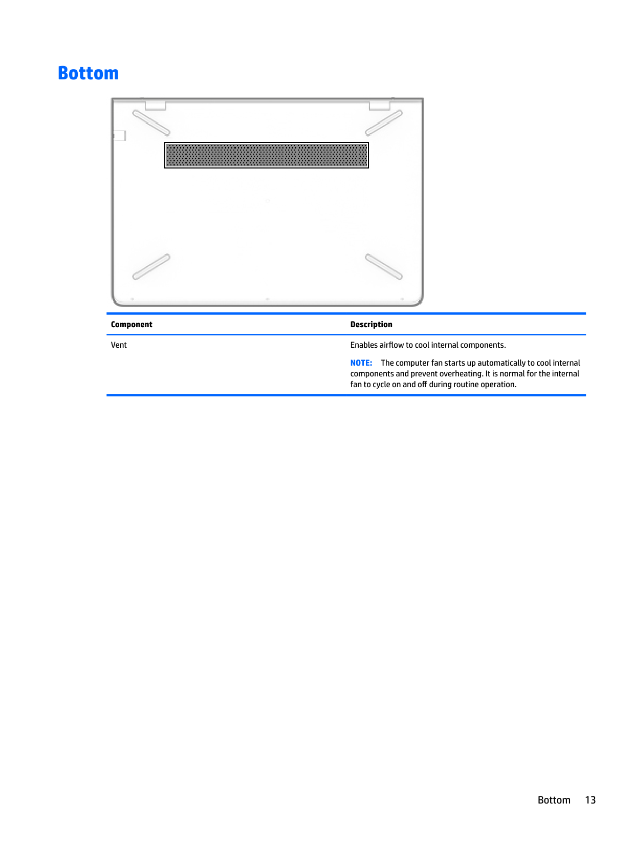
Bottom

Component Description Vent Enables airflow to cool internal components.
NOTE: The computer fan starts up automatically to cool internal components and prevent overheating. It is normal for the internal fan to cycle on and off during routine operation.
Bottom 13
3 Illustrated parts catalog
| | |---|
NOTE: HP continually improves and changes product parts. For complete and current information on supported parts for your computer, go to http://partsurfer.hp.com, select your country or region, and then follow the on-screen instructions.
Labels
The labels affixed to the computer provide information that may be needed when troubleshooting system problems or travelling internationally with the computer.
| | |---|
IMPORTANT: Check the following locations for the labels described in this section: the bottom of the computer, inside the battery bay, under the service door, on the back of the display, or on the bottom of a tablet kickstand.
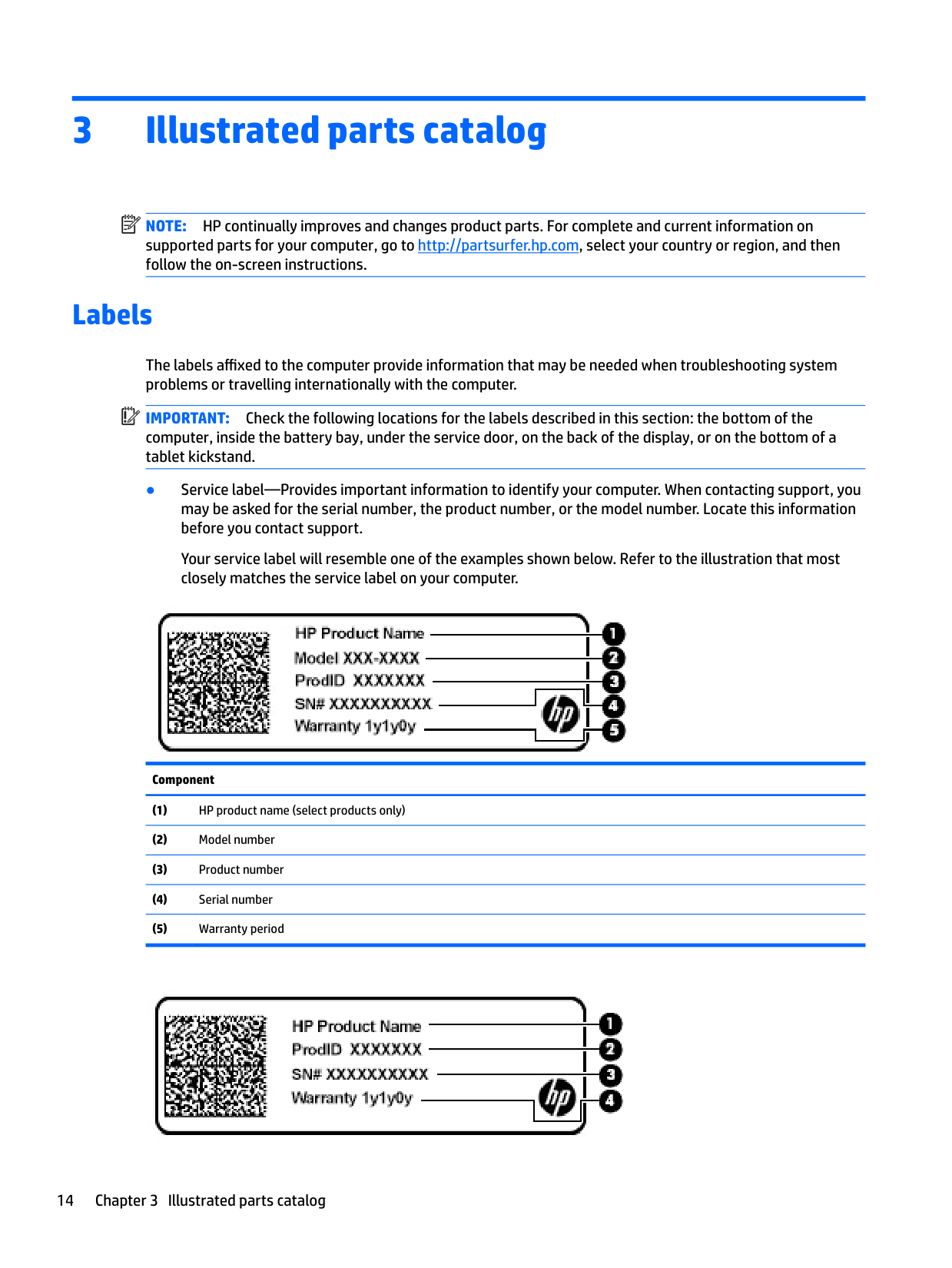
● Service label—Provides important information to identify your computer. When contacting support, you may be asked for the serial number, the product number, or the model number. Locate this information before you contact support.
Your service label will resemble one of the examples shown below. Refer to the illustration that most closely matches the service label on your computer.

Component

######## Component
Labels 15
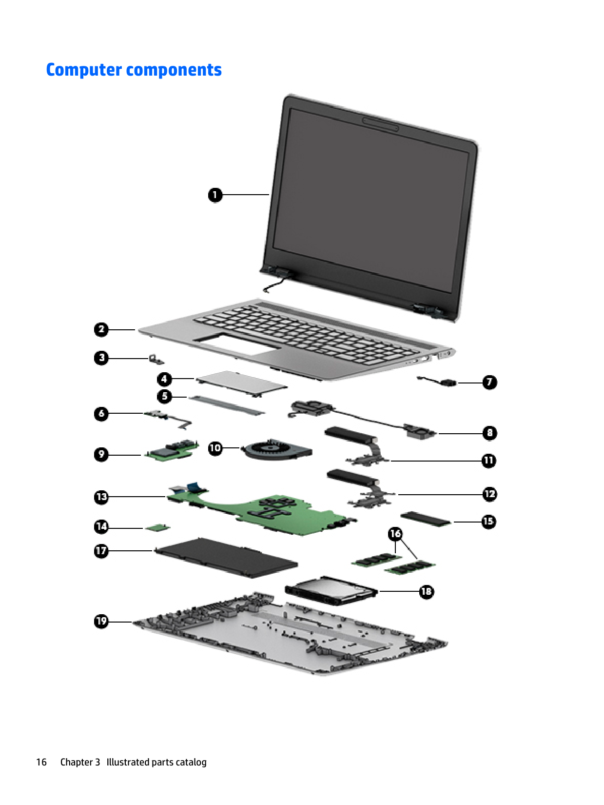
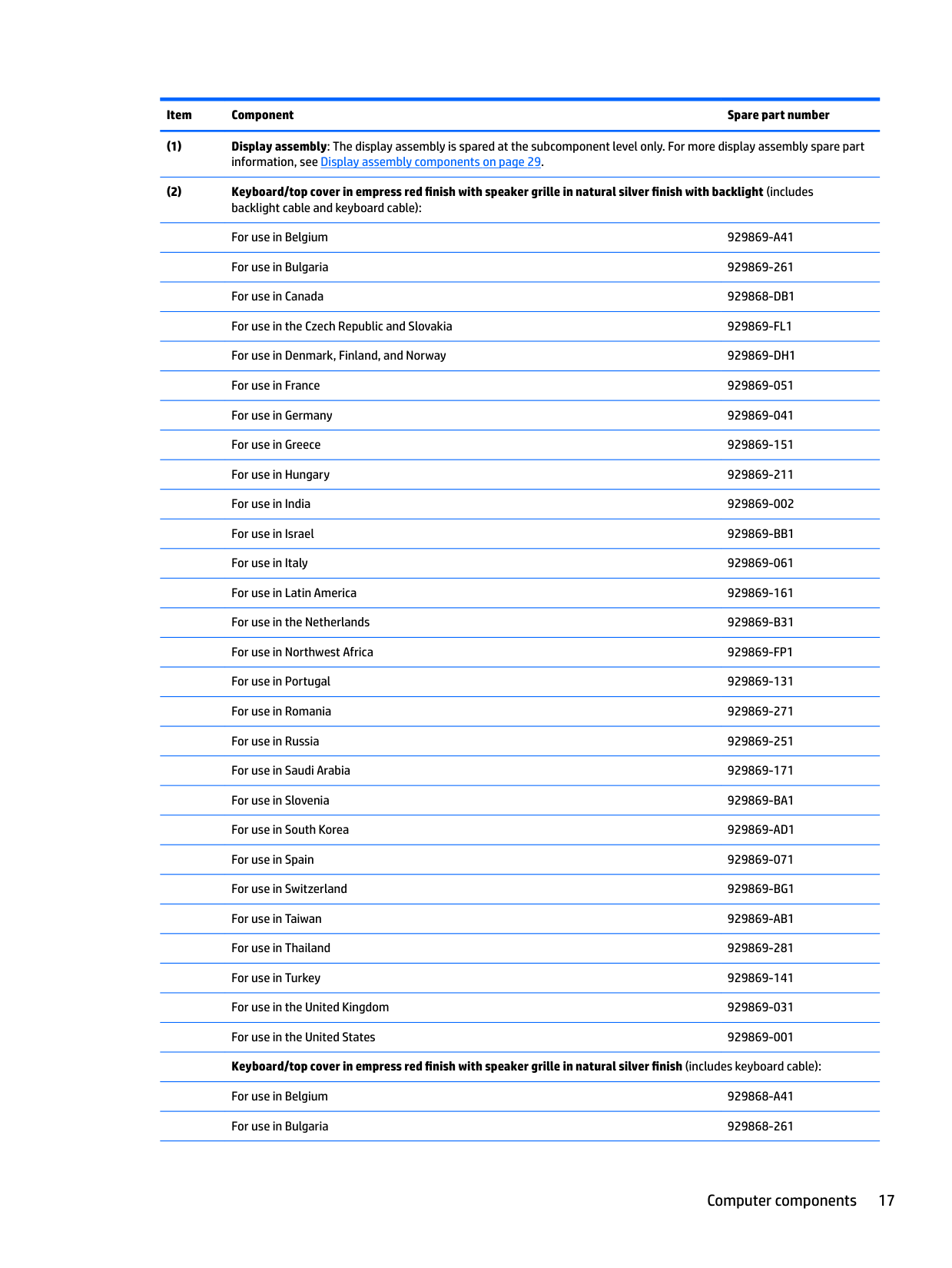
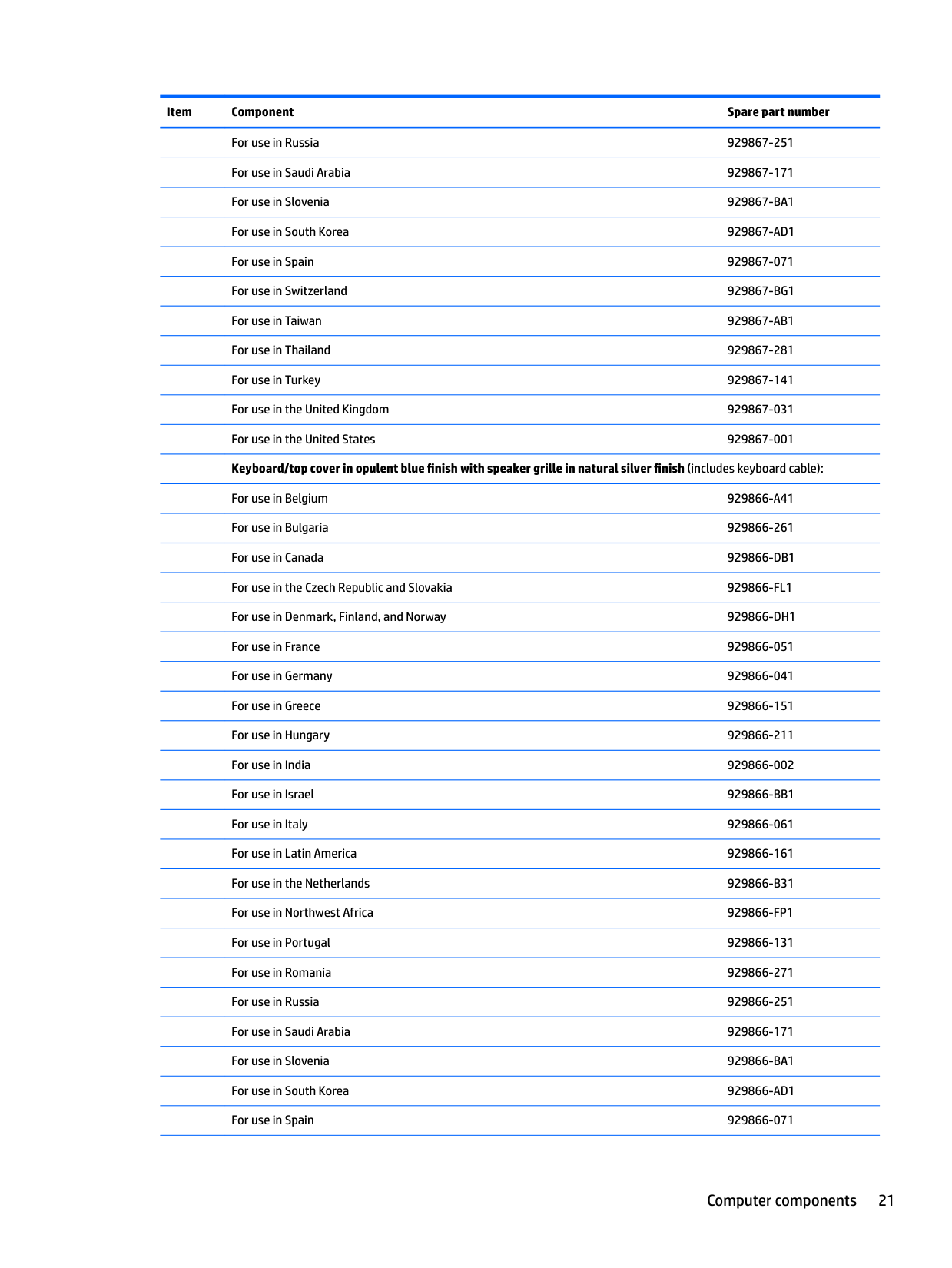
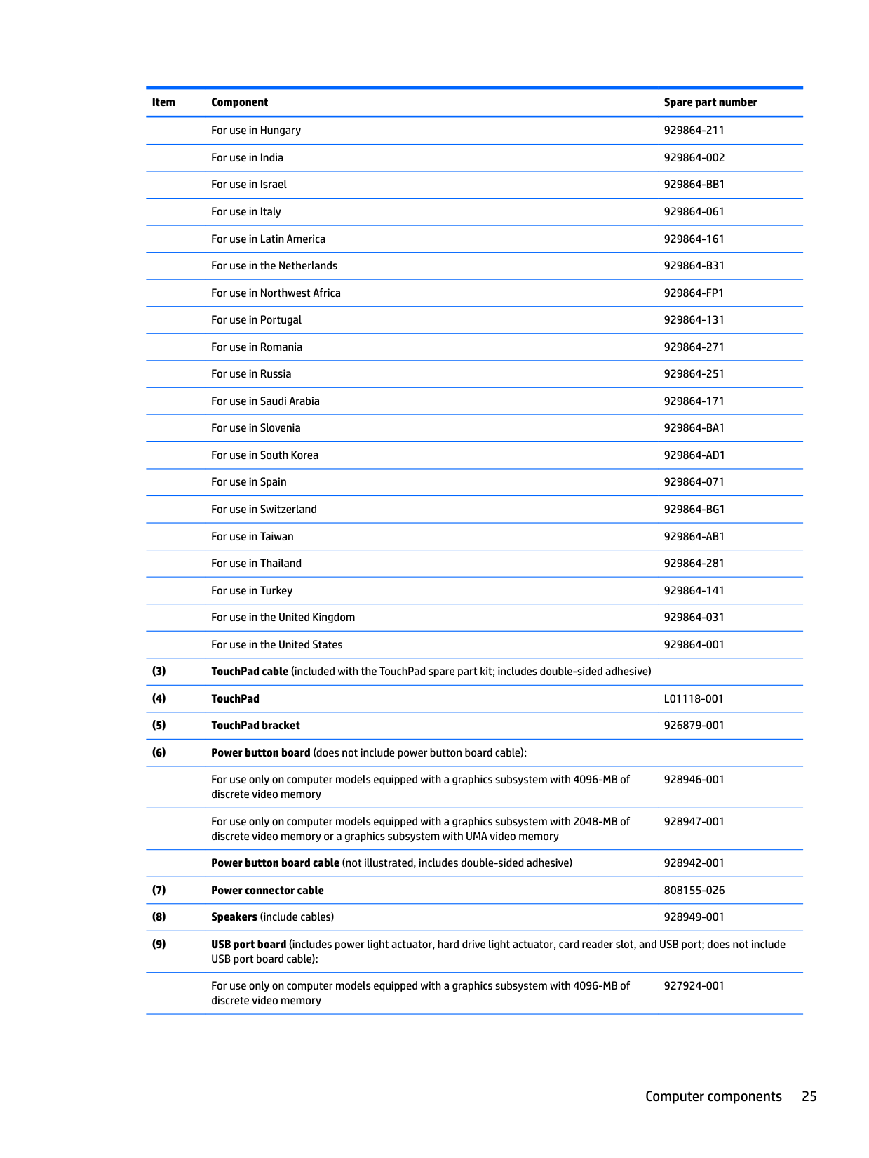
Computer components

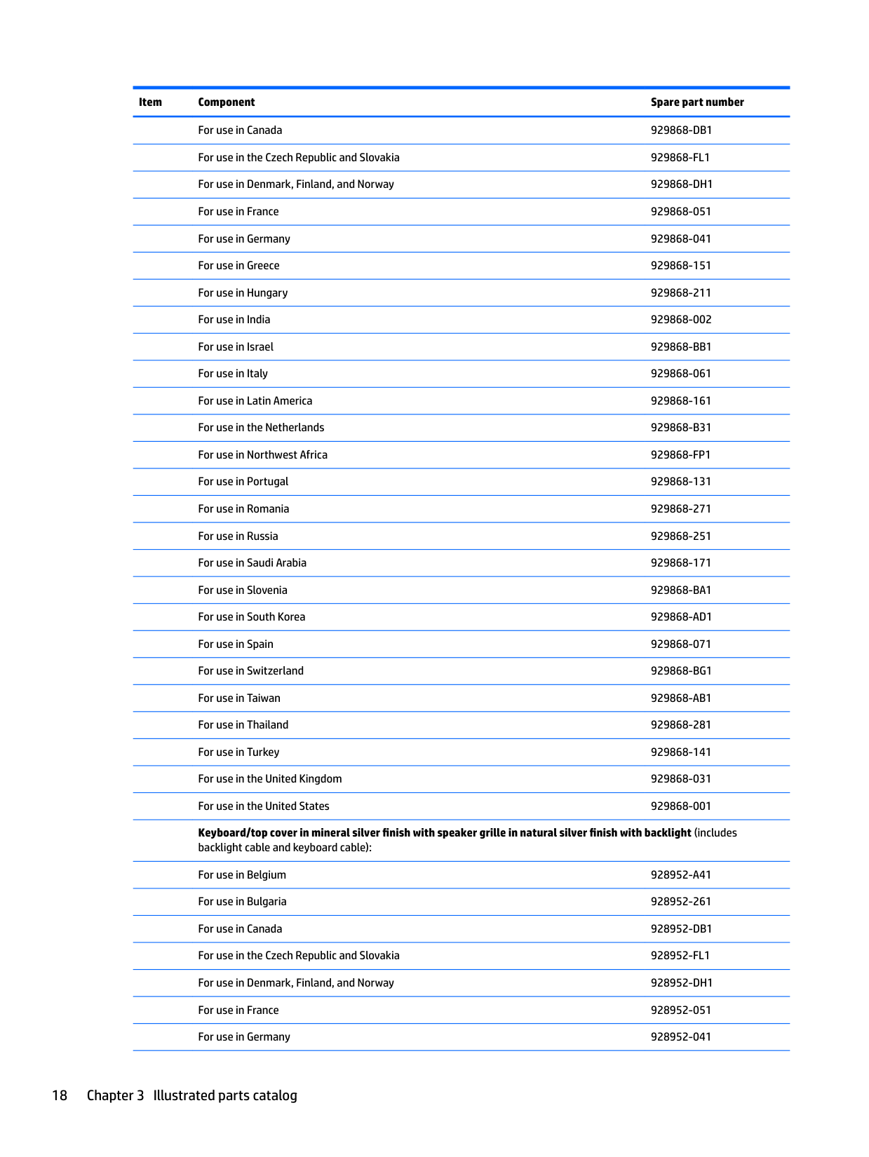
For use in Canada 929868-DB1 For use in the Czech Republic and Slovakia 929868-FL1 For use in Denmark, Finland, and Norway 929868-DH1 For use in France 929868-051 For use in Germany 929868-041 For use in Greece 929868-151 For use in Hungary 929868-211 For use in India 929868-002 For use in Israel 929868-BB1 For use in Italy 929868-061 For use in Latin America 929868-161 For use in the Netherlands 929868-B31 For use in Northwest Africa 929868-FP1 For use in Portugal 929868-131 For use in Romania 929868-271 For use in Russia 929868-251 For use in Saudi Arabia 929868-171 For use in Slovenia 929868-BA1 For use in South Korea 929868-AD1 For use in Spain 929868-071 For use in Switzerland 929868-BG1 For use in Taiwan 929868-AB1 For use in Thailand 929868-281 For use in Turkey 929868-141 For use in the United Kingdom 929868-031 For use in the United States 929868-001 Keyboard/top cover in mineral silver finish with speaker grille in natural silver finish with backlight (includes backlight cable and keyboard cable): For use in Belgium 928952-A41 For use in Bulgaria 928952-261 For use in Canada 928952-DB1 For use in the Czech Republic and Slovakia 928952-FL1 For use in Denmark, Finland, and Norway 928952-DH1 For use in France 928952-051 For use in Germany 928952-041
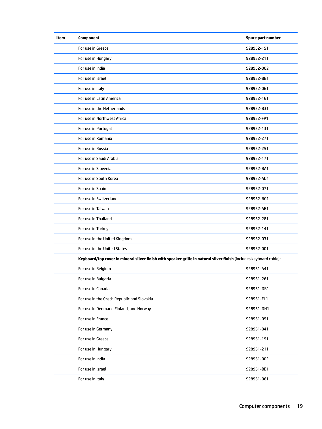
For use in Greece 928952-151 For use in Hungary 928952-211 For use in India 928952-002 For use in Israel 928952-BB1 For use in Italy 928952-061 For use in Latin America 928952-161 For use in the Netherlands 928952-B31 For use in Northwest Africa 928952-FP1 For use in Portugal 928952-131 For use in Romania 928952-271 For use in Russia 928952-251 For use in Saudi Arabia 928952-171 For use in Slovenia 928952-BA1 For use in South Korea 928952-AD1 For use in Spain 928952-071 For use in Switzerland 928952-BG1 For use in Taiwan 928952-AB1 For use in Thailand 928952-281 For use in Turkey 928952-141 For use in the United Kingdom 928952-031 For use in the United States 928952-001 Keyboard/top cover in mineral silver finish with speaker grille in natural silver finish (includes keyboard cable):
For use in Belgium 928951-A41 For use in Bulgaria 928951-261 For use in Canada 928951-DB1 For use in the Czech Republic and Slovakia 928951-FL1 For use in Denmark, Finland, and Norway 928951-DH1 For use in France 928951-051 For use in Germany 928951-041 For use in Greece 928951-151 For use in Hungary 928951-211 For use in India 928951-002 For use in Israel 928951-BB1 For use in Italy 928951-061
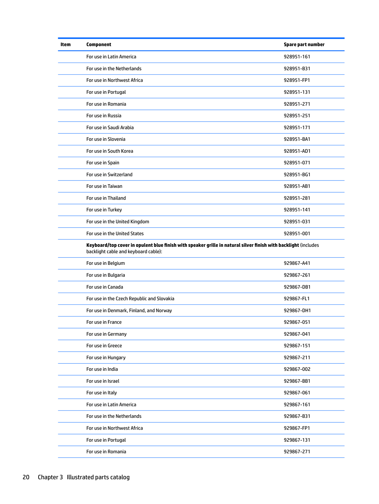
For use in Latin America 928951-161 For use in the Netherlands 928951-B31 For use in Northwest Africa 928951-FP1 For use in Portugal 928951-131 For use in Romania 928951-271 For use in Russia 928951-251 For use in Saudi Arabia 928951-171 For use in Slovenia 928951-BA1 For use in South Korea 928951-AD1 For use in Spain 928951-071 For use in Switzerland 928951-BG1 For use in Taiwan 928951-AB1 For use in Thailand 928951-281 For use in Turkey 928951-141 For use in the United Kingdom 928951-031 For use in the United States 928951-001 Keyboard/top cover in opulent blue finish with speaker grille in natural silver finish with backlight (includes
backlight cable and keyboard cable): For use in Belgium 929867-A41 For use in Bulgaria 929867-261 For use in Canada 929867-DB1 For use in the Czech Republic and Slovakia 929867-FL1 For use in Denmark, Finland, and Norway 929867-DH1 For use in France 929867-051 For use in Germany 929867-041 For use in Greece 929867-151 For use in Hungary 929867-211 For use in India 929867-002 For use in Israel 929867-BB1 For use in Italy 929867-061 For use in Latin America 929867-161 For use in the Netherlands 929867-B31 For use in Northwest Africa 929867-FP1 For use in Portugal 929867-131 For use in Romania 929867-271
For use in Russia 929867-251 For use in Saudi Arabia 929867-171 For use in Slovenia 929867-BA1 For use in South Korea 929867-AD1 For use in Spain 929867-071 For use in Switzerland 929867-BG1 For use in Taiwan 929867-AB1 For use in Thailand 929867-281 For use in Turkey 929867-141 For use in the United Kingdom 929867-031 For use in the United States 929867-001 Keyboard/top cover in opulent blue finish with speaker grille in natural silver finish (includes keyboard cable):
For use in Belgium 929866-A41 For use in Bulgaria 929866-261 For use in Canada 929866-DB1 For use in the Czech Republic and Slovakia 929866-FL1 For use in Denmark, Finland, and Norway 929866-DH1 For use in France 929866-051 For use in Germany 929866-041 For use in Greece 929866-151 For use in Hungary 929866-211 For use in India 929866-002 For use in Israel 929866-BB1 For use in Italy 929866-061 For use in Latin America 929866-161 For use in the Netherlands 929866-B31 For use in Northwest Africa 929866-FP1 For use in Portugal 929866-131 For use in Romania 929866-271 For use in Russia 929866-251 For use in Saudi Arabia 929866-171 For use in Slovenia 929866-BA1 For use in South Korea 929866-AD1 For use in Spain 929866-071
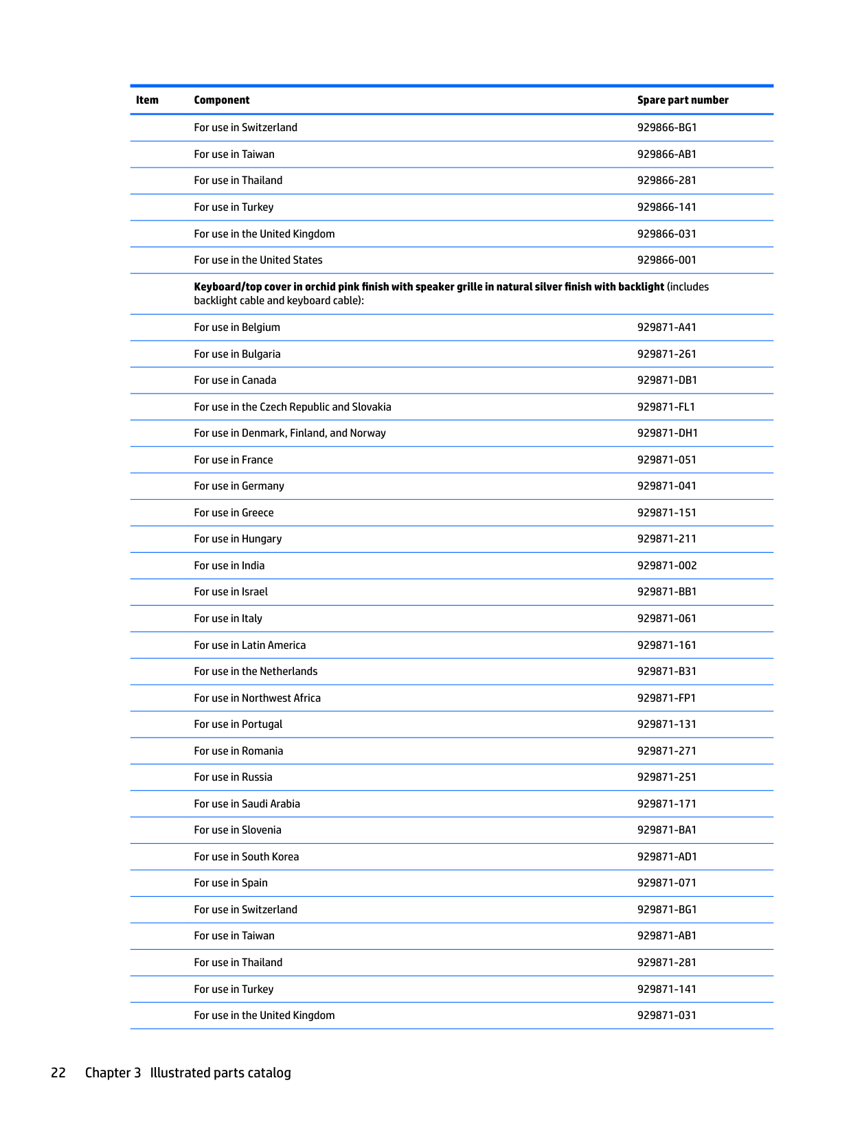
For use in Switzerland 929866-BG1 For use in Taiwan 929866-AB1 For use in Thailand 929866-281 For use in Turkey 929866-141 For use in the United Kingdom 929866-031 For use in the United States 929866-001 Keyboard/top cover in orchid pink finish with speaker grille in natural silver finish with backlight (includes
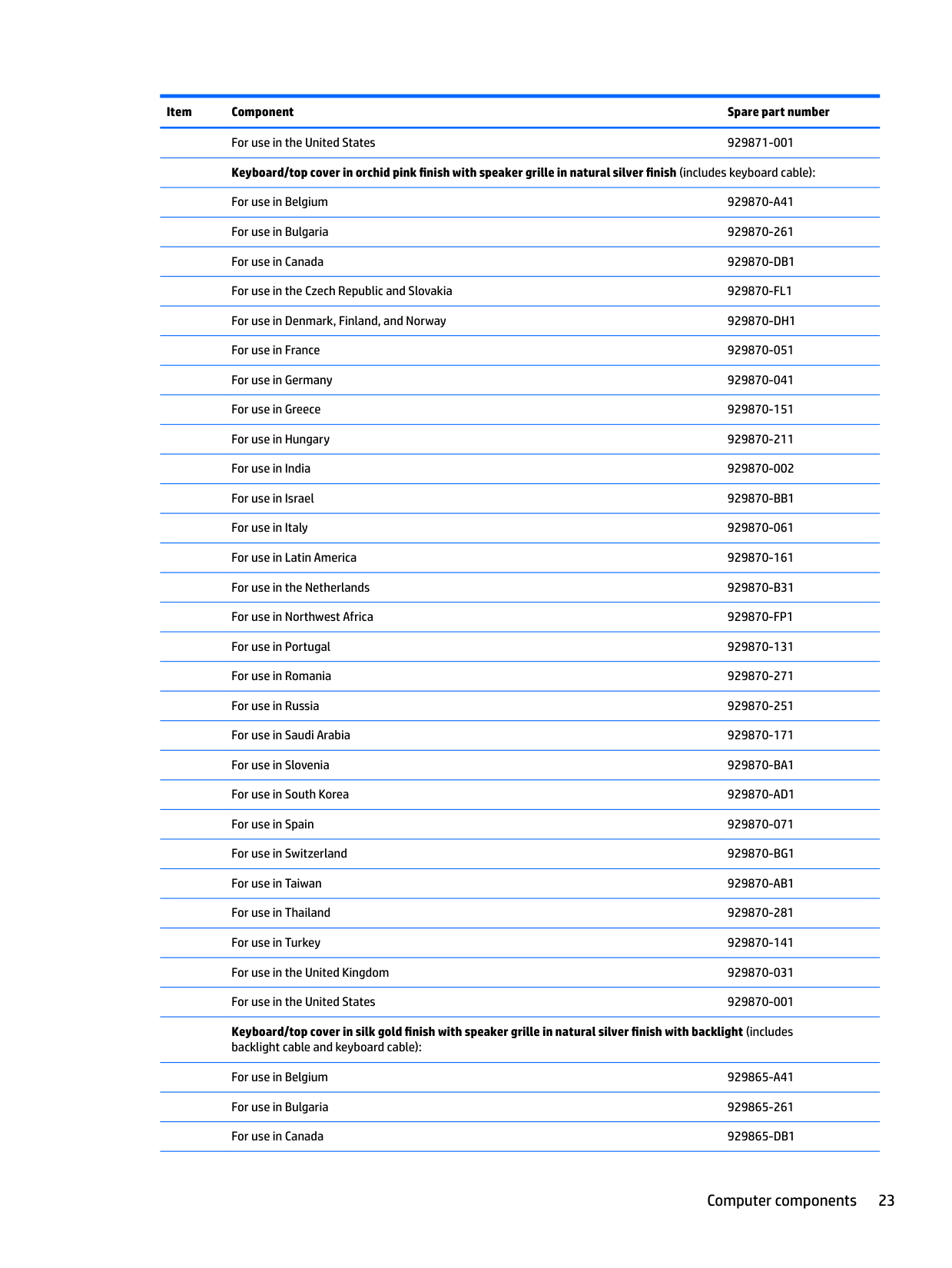
backlight cable and keyboard cable): For use in Belgium 929871-A41 For use in Bulgaria 929871-261 For use in Canada 929871-DB1 For use in the Czech Republic and Slovakia 929871-FL1 For use in Denmark, Finland, and Norway 929871-DH1 For use in France 929871-051 For use in Germany 929871-041 For use in Greece 929871-151 For use in Hungary 929871-211 For use in India 929871-002 For use in Israel 929871-BB1 For use in Italy 929871-061 For use in Latin America 929871-161 For use in the Netherlands 929871-B31 For use in Northwest Africa 929871-FP1 For use in Portugal 929871-131 For use in Romania 929871-271 For use in Russia 929871-251 For use in Saudi Arabia 929871-171 For use in Slovenia 929871-BA1 For use in South Korea 929871-AD1 For use in Spain 929871-071 For use in Switzerland 929871-BG1 For use in Taiwan 929871-AB1 For use in Thailand 929871-281 For use in Turkey 929871-141 For use in the United Kingdom 929871-031
For use in the United States 929871-001 Keyboard/top cover in orchid pink finish with speaker grille in natural silver finish (includes keyboard cable): For use in Belgium 929870-A41 For use in Bulgaria 929870-261 For use in Canada 929870-DB1 For use in the Czech Republic and Slovakia 929870-FL1 For use in Denmark, Finland, and Norway 929870-DH1 For use in France 929870-051 For use in Germany 929870-041 For use in Greece 929870-151 For use in Hungary 929870-211 For use in India 929870-002 For use in Israel 929870-BB1 For use in Italy 929870-061 For use in Latin America 929870-161 For use in the Netherlands 929870-B31 For use in Northwest Africa 929870-FP1 For use in Portugal 929870-131 For use in Romania 929870-271 For use in Russia 929870-251 For use in Saudi Arabia 929870-171 For use in Slovenia 929870-BA1 For use in South Korea 929870-AD1 For use in Spain 929870-071 For use in Switzerland 929870-BG1 For use in Taiwan 929870-AB1 For use in Thailand 929870-281 For use in Turkey 929870-141 For use in the United Kingdom 929870-031 For use in the United States 929870-001 Keyboard/top cover in silk gold finish with speaker grille in natural silver finish with backlight (includes backlight cable and keyboard cable): For use in Belgium 929865-A41 For use in Bulgaria 929865-261 For use in Canada 929865-DB1
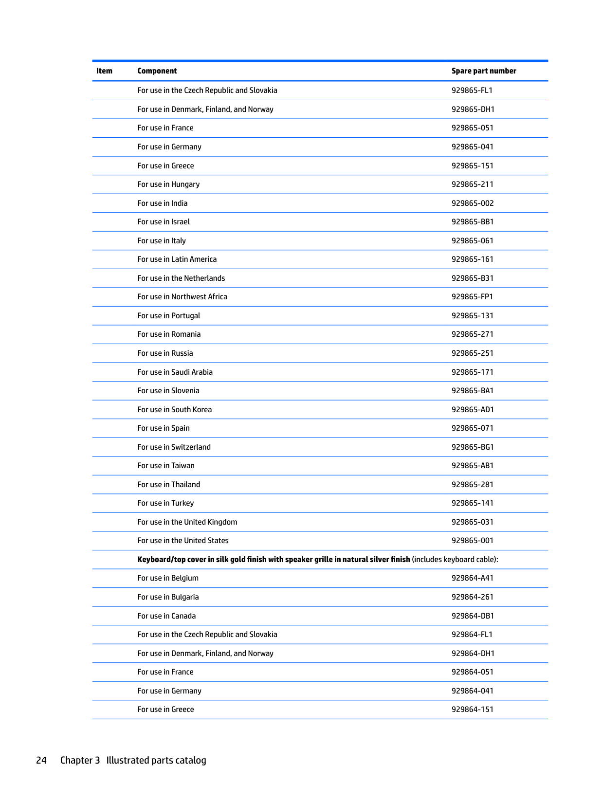
For use in the Czech Republic and Slovakia 929865-FL1 For use in Denmark, Finland, and Norway 929865-DH1 For use in France 929865-051 For use in Germany 929865-041 For use in Greece 929865-151 For use in Hungary 929865-211 For use in India 929865-002 For use in Israel 929865-BB1 For use in Italy 929865-061 For use in Latin America 929865-161 For use in the Netherlands 929865-B31 For use in Northwest Africa 929865-FP1 For use in Portugal 929865-131 For use in Romania 929865-271 For use in Russia 929865-251 For use in Saudi Arabia 929865-171 For use in Slovenia 929865-BA1 For use in South Korea 929865-AD1 For use in Spain 929865-071 For use in Switzerland 929865-BG1 For use in Taiwan 929865-AB1 For use in Thailand 929865-281 For use in Turkey 929865-141 For use in the United Kingdom 929865-031 For use in the United States 929865-001 Keyboard/top cover in silk gold finish with speaker grille in natural silver finish (includes keyboard cable): For use in Belgium 929864-A41 For use in Bulgaria 929864-261 For use in Canada 929864-DB1 For use in the Czech Republic and Slovakia 929864-FL1 For use in Denmark, Finland, and Norway 929864-DH1 For use in France 929864-051 For use in Germany 929864-041 For use in Greece 929864-151
For use in Hungary 929864-211 For use in India 929864-002 For use in Israel 929864-BB1 For use in Italy 929864-061 For use in Latin America 929864-161 For use in the Netherlands 929864-B31 For use in Northwest Africa 929864-FP1 For use in Portugal 929864-131 For use in Romania 929864-271 For use in Russia 929864-251 For use in Saudi Arabia 929864-171 For use in Slovenia 929864-BA1 For use in South Korea 929864-AD1 For use in Spain 929864-071 For use in Switzerland 929864-BG1 For use in Taiwan 929864-AB1 For use in Thailand 929864-281 For use in Turkey 929864-141 For use in the United Kingdom 929864-031 For use in the United States 929864-001
For use only on computer models equipped with a graphics subsystem with 4096-MB of discrete video memory
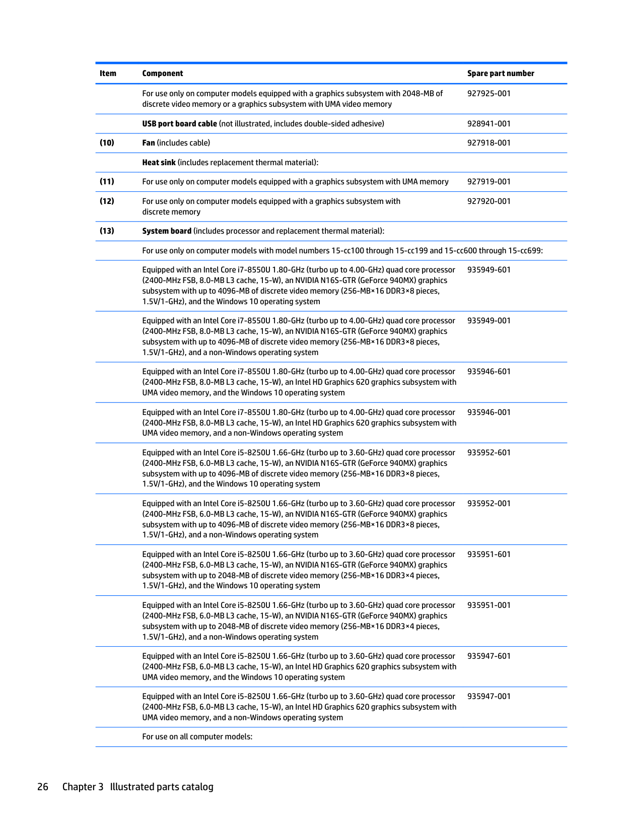
For use only on computer models equipped with a graphics subsystem with 2048-MB of discrete video memory or a graphics subsystem with UMA video memory
Power button board cable (not illustrated, includes double-sided adhesive) 928942-001

For use only on computer models equipped with a graphics subsystem with 4096-MB of discrete video memory
For use only on computer models equipped with a graphics subsystem with 2048-MB of discrete video memory or a graphics subsystem with UMA video memory
USB port board cable (not illustrated, includes double-sided adhesive) 928941-001
927920-001
Equipped with an Intel Core i7-8550U 1.80-GHz (turbo up to 4.00-GHz) quad core processor (2400-MHz FSB, 8.0-MB L3 cache, 15-W), an NVIDIA N16S-GTR (GeForce 940MX) graphics subsystem with up to 4096-MB of discrete video memory (256-MB×16 DDR3×8 pieces, 1.5V/1-GHz), and the Windows 10 operating system
Equipped with an Intel Core i7-8550U 1.80-GHz (turbo up to 4.00-GHz) quad core processor (2400-MHz FSB, 8.0-MB L3 cache, 15-W), an NVIDIA N16S-GTR (GeForce 940MX) graphics subsystem with up to 4096-MB of discrete video memory (256-MB×16 DDR3×8 pieces, 1.5V/1-GHz), and a non-Windows operating system
Equipped with an Intel Core i7-8550U 1.80-GHz (turbo up to 4.00-GHz) quad core processor (2400-MHz FSB, 8.0-MB L3 cache, 15-W), an Intel HD Graphics 620 graphics subsystem with UMA video memory, and the Windows 10 operating system
Equipped with an Intel Core i7-8550U 1.80-GHz (turbo up to 4.00-GHz) quad core processor (2400-MHz FSB, 8.0-MB L3 cache, 15-W), an Intel HD Graphics 620 graphics subsystem with UMA video memory, and a non-Windows operating system
Equipped with an Intel Core i5-8250U 1.66-GHz (turbo up to 3.60-GHz) quad core processor (2400-MHz FSB, 6.0-MB L3 cache, 15-W), an NVIDIA N16S-GTR (GeForce 940MX) graphics subsystem with up to 4096-MB of discrete video memory (256-MB×16 DDR3×8 pieces, 1.5V/1-GHz), and the Windows 10 operating system
Equipped with an Intel Core i5-8250U 1.66-GHz (turbo up to 3.60-GHz) quad core processor (2400-MHz FSB, 6.0-MB L3 cache, 15-W), an NVIDIA N16S-GTR (GeForce 940MX) graphics subsystem with up to 4096-MB of discrete video memory (256-MB×16 DDR3×8 pieces, 1.5V/1-GHz), and a non-Windows operating system
Equipped with an Intel Core i5-8250U 1.66-GHz (turbo up to 3.60-GHz) quad core processor (2400-MHz FSB, 6.0-MB L3 cache, 15-W), an NVIDIA N16S-GTR (GeForce 940MX) graphics subsystem with up to 2048-MB of discrete video memory (256-MB×16 DDR3×4 pieces, 1.5V/1-GHz), and the Windows 10 operating system
Equipped with an Intel Core i5-8250U 1.66-GHz (turbo up to 3.60-GHz) quad core processor (2400-MHz FSB, 6.0-MB L3 cache, 15-W), an NVIDIA N16S-GTR (GeForce 940MX) graphics subsystem with up to 2048-MB of discrete video memory (256-MB×16 DDR3×4 pieces, 1.5V/1-GHz), and a non-Windows operating system
Equipped with an Intel Core i5-8250U 1.66-GHz (turbo up to 3.60-GHz) quad core processor (2400-MHz FSB, 6.0-MB L3 cache, 15-W), an Intel HD Graphics 620 graphics subsystem with UMA video memory, and the Windows 10 operating system
Equipped with an Intel Core i5-8250U 1.66-GHz (turbo up to 3.60-GHz) quad core processor (2400-MHz FSB, 6.0-MB L3 cache, 15-W), an Intel HD Graphics 620 graphics subsystem with UMA video memory, and a non-Windows operating system
For use on all computer models:
935949-601
935949-001
935946-601
935946-001
935952-601
935952-001
935951-601
935951-001
935947-601
935947-001
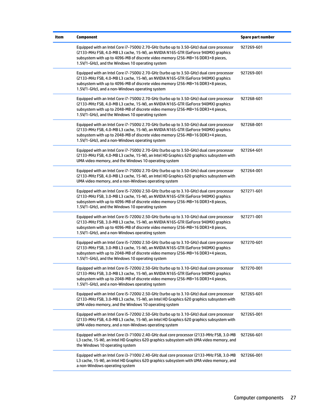
Equipped with an Intel Core i7-7500U 2.70-GHz (turbo up to 3.50-GHz) dual core processor (2133-MHz FSB, 4.0-MB L3 cache, 15-W), an NVIDIA N16S-GTR (GeForce 940MX) graphics subsystem with up to 4096-MB of discrete video memory (256-MB×16 DDR3×8 pieces, 1.5V/1-GHz), and the Windows 10 operating system
Equipped with an Intel Core i7-7500U 2.70-GHz (turbo up to 3.50-GHz) dual core processor (2133-MHz FSB, 4.0-MB L3 cache, 15-W), an NVIDIA N16S-GTR (GeForce 940MX) graphics subsystem with up to 4096-MB of discrete video memory (256-MB×16 DDR3×8 pieces, 1.5V/1-GHz), and a non-Windows operating system
Equipped with an Intel Core i7-7500U 2.70-GHz (turbo up to 3.50-GHz) dual core processor (2133-MHz FSB, 4.0-MB L3 cache, 15-W), an NVIDIA N16S-GTR (GeForce 940MX) graphics subsystem with up to 2048-MB of discrete video memory (256-MB×16 DDR3×4 pieces, 1.5V/1-GHz), and the Windows 10 operating system
Equipped with an Intel Core i7-7500U 2.70-GHz (turbo up to 3.50-GHz) dual core processor (2133-MHz FSB, 4.0-MB L3 cache, 15-W), an NVIDIA N16S-GTR (GeForce 940MX) graphics subsystem with up to 2048-MB of discrete video memory (256-MB×16 DDR3×4 pieces, 1.5V/1-GHz), and a non-Windows operating system
Equipped with an Intel Core i7-7500U 2.70-GHz (turbo up to 3.50-GHz) dual core processor (2133-MHz FSB, 4.0-MB L3 cache, 15-W), an Intel HD Graphics 620 graphics subsystem with UMA video memory, and the Windows 10 operating system
Equipped with an Intel Core i7-7500U 2.70-GHz (turbo up to 3.50-GHz) dual core processor (2133-MHz FSB, 4.0-MB L3 cache, 15-W), an Intel HD Graphics 620 graphics subsystem with UMA video memory, and a non-Windows operating system
Equipped with an Intel Core i5-7200U 2.50-GHz (turbo up to 3.10-GHz) dual core processor (2133-MHz FSB, 3.0-MB L3 cache, 15-W), an NVIDIA N16S-GTR (GeForce 940MX) graphics subsystem with up to 4096-MB of discrete video memory (256-MB×16 DDR3×8 pieces, 1.5V/1-GHz), and the Windows 10 operating system
Equipped with an Intel Core i5-7200U 2.50-GHz (turbo up to 3.10-GHz) dual core processor (2133-MHz FSB, 3.0-MB L3 cache, 15-W), an NVIDIA N16S-GTR (GeForce 940MX) graphics subsystem with up to 4096-MB of discrete video memory (256-MB×16 DDR3×8 pieces, 1.5V/1-GHz), and a non-Windows operating system
Equipped with an Intel Core i5-7200U 2.50-GHz (turbo up to 3.10-GHz) dual core processor (2133-MHz FSB, 3.0-MB L3 cache, 15-W), an NVIDIA N16S-GTR (GeForce 940MX) graphics subsystem with up to 2048-MB of discrete video memory (256-MB×16 DDR3×4 pieces, 1.5V/1-GHz), and the Windows 10 operating system
Equipped with an Intel Core i5-7200U 2.50-GHz (turbo up to 3.10-GHz) dual core processor (2133-MHz FSB, 3.0-MB L3 cache, 15-W), an NVIDIA N16S-GTR (GeForce 940MX) graphics subsystem with up to 2048-MB of discrete video memory (256-MB×16 DDR3×4 pieces, 1.5V/1-GHz), and a non-Windows operating system
Equipped with an Intel Core i5-7200U 2.50-GHz (turbo up to 3.10-GHz) dual core processor
927265-601
Equipped with an Intel Core i5-7200U 2.50-GHz (turbo up to 3.10-GHz) dual core processor
927269-601
927269-001
927268-601
927268-001
927264-601
927264-001
927271-601
927271-001
927270-601
927270-001
Equipped with an Intel Core i3-7100U 2.40-GHz dual core processor (2133-MHz FSB, 3.0-MB L3 cache, 15-W), an Intel HD Graphics 620 graphics subsystem with UMA video memory, and the Windows 10 operating system
Equipped with an Intel Core i3-7100U 2.40-GHz dual core processor (2133-MHz FSB, 3.0-MB L3 cache, 15-W), an Intel HD Graphics 620 graphics subsystem with UMA video memory, and a non-Windows operating system
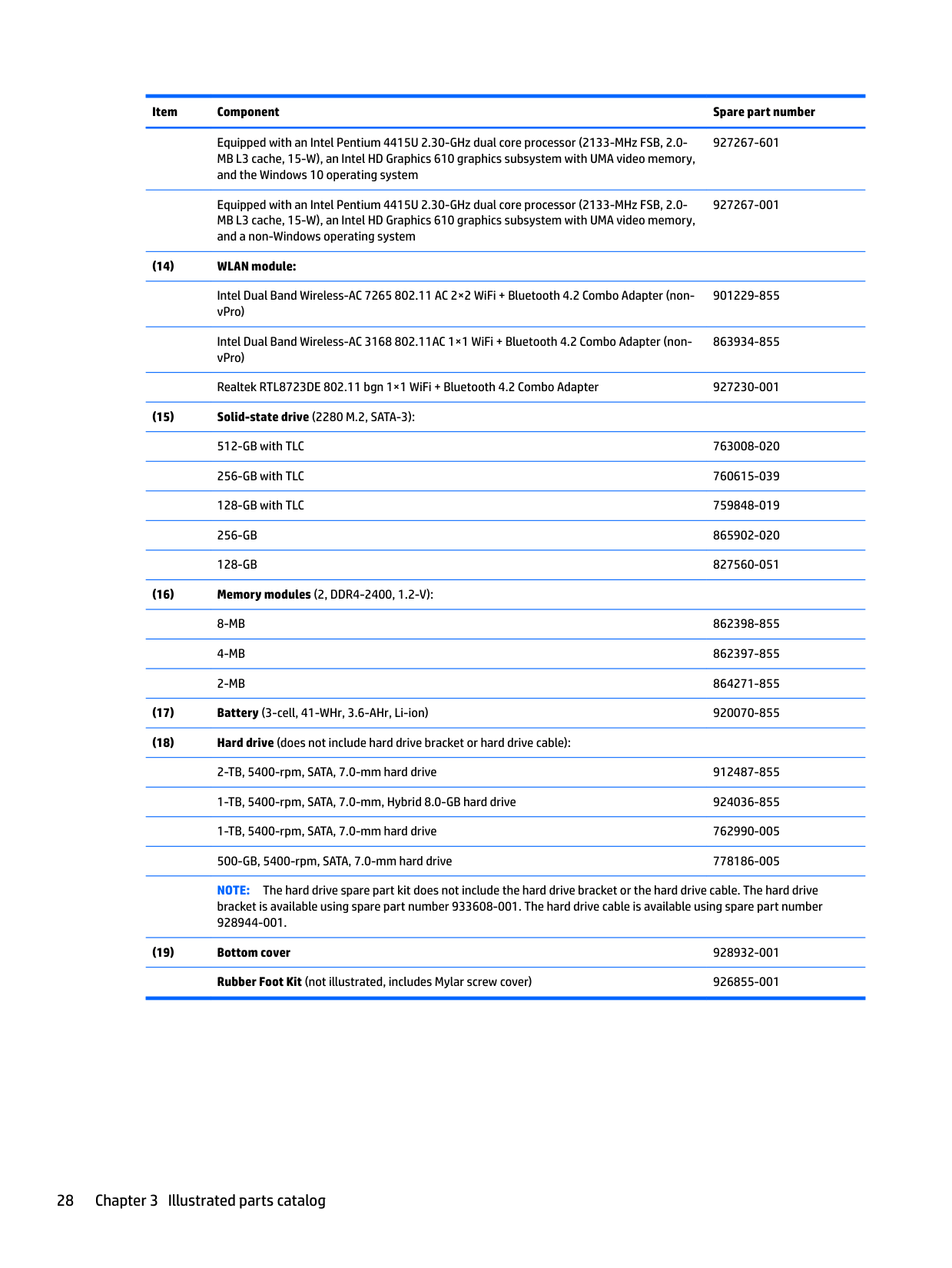
Equipped with an Intel Pentium 4415U 2.30-GHz dual core processor (2133-MHz FSB, 2.0MB L3 cache, 15-W), an Intel HD Graphics 610 graphics subsystem with UMA video memory, and the Windows 10 operating system
Equipped with an Intel Pentium 4415U 2.30-GHz dual core processor (2133-MHz FSB, 2.0MB L3 cache, 15-W), an Intel HD Graphics 610 graphics subsystem with UMA video memory, and a non-Windows operating system
927267-001
Intel Dual Band Wireless-AC 7265 802.11 AC 2×2 WiFi + Bluetooth 4.2 Combo Adapter (nonvPro)
901229-855
Intel Dual Band Wireless-AC 3168 802.11AC 1×1 WiFi + Bluetooth 4.2 Combo Adapter (nonvPro)
863934-855
Realtek RTL8723DE 802.11 bgn 1×1 WiFi + Bluetooth 4.2 Combo Adapter 927230-001
NOTE: The hard drive spare part kit does not include the hard drive bracket or the hard drive cable. The hard drive bracket is available using spare part number 933608-001. The hard drive cable is available using spare part number 928944-001.
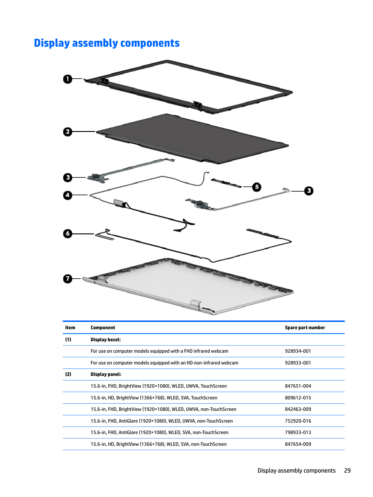
Display assembly components

######## Item Component Spare part number
Display assembly components 29
15.6-in, HD, AntiGlare (1366×768), WLED, SVA, non-TouchScreen 909185-007
For use on computer models equipped with an FHD TouchScreen display assembly and an FHD infrared webcam
928938-001
For use on computer models equipped with an FHD TouchScreen display assembly and an HD non-infrared webcam
928937-001
For use on computer models equipped with an FHD/HD non-TouchScreen display assembly and an FHD infrared webcam
For use on computer models equipped with an FHD/HD non-TouchScreen display assembly and an HD non-infrared webcam
For use on computer models equipped with an HD TouchScreen display assembly and an FHD infrared webcam
928940-001
For use on computer models equipped with an HD TouchScreen display assembly and an HD non-infrared webcam
928939-001
Miscellaneous parts
Component Spare part number AC adapter:
90-W AC adapter (PFC, S-3P, 4.5-mm) 710413-001 65-W HP Smart AC adapter (non-PFC, EM, RC, 4.5-mm) 913691-850 65-W AC adapter (non-PFC, S-3P, 4.5-mm) 710412-001 45-W HP Smart AC adapter (non-PFC, RC, 4.5-mm, non-slim) 741553-850 HP HDMI-to-VGA adapter 701943-001 HP USB–C-to-USB–A dongle 833960-001 Power cord (C5 connector, 1.00-m):
For use in Argentina 920688-003 For use in Australia 920688-011 For use in Denmark 920688-007 For use in Europe 920688-005 For use in India 920688-016 For use in Israel 920688-008 For use in Italy 920688-002 For use in North America 920688-001 For use in the People’s Republic of China 920688-014 For use in South Africa 920688-010 For use in South Korea 920688-013 For use in Switzerland 920688-009 For use in Taiwan 920688-015 For use in Thailand 920688-012 For use in the United Kingdom and Singapore 920688-006 Rubber Foot Kit (includes bottom cover rear feet) 926855-001 Screw Kit 928948-001
Miscellaneous parts 31
4 Removal and replacement preliminaryrequirements
Tools required
You will need the following tools to complete the removal and replacement procedures:
Service considerations
The following sections include some of the considerations that you must keep in mind during disassembly and assembly procedures.
| | |---|
NOTE: As you remove each subassembly from the computer, place the subassembly (and all accompanying screws) away from the work area to prevent damage.
#### Plastic parts
CAUTION: Using excessive force during disassembly and reassembly can damage plastic parts. Use care when handling the plastic parts. Apply pressure only at the points designated in the maintenance instructions.
#### Cables and connectors
CAUTION: When servicing the computer, be sure that cables are placed in their proper locations during the reassembly process. Improper cable placement can damage the computer.
Cables must be handled with extreme care to avoid damage. Apply only the tension required to unseat or seat the cables during removal and insertion. Handle cables by the connector whenever possible. In all cases, avoid bending, twisting, or tearing cables. Be sure that cables are routed in such a way that they cannot be caught or snagged by parts being removed or replaced. Handle flex cables with extreme care; these cables tear easily.
Drive handling CAUTION: Drives are fragile components that must be handled with care. To prevent damage to the computer, damage to a drive, or loss of information, observe these precautions: Before removing or inserting a drive, shut down the computer. If you are unsure whether the computer is off or in Hibernation, turn the computer on, and then shut it down through the operating system. Before handling a drive, be sure that you are discharged of static electricity. While handling a drive, avoid touching the connector. Before removing a diskette drive or optical drive, be sure that a diskette or disc is not in the drive and be sure that the optical drive tray is closed. Handle drives on surfaces covered with at least one inch of shock-proof foam. Avoid dropping drives from any height onto any surface. After removing drive, place it in a static-proof bag. Avoid exposing a drive to products that have magnetic fields, such as monitors or speakers. Avoid exposing a drive to temperature extremes or liquids. If a drive must be mailed, place the drive in a bubble pack mailer or other suitable form of protective packaging and label the package “FRAGILE.”
Service considerations 33
Grounding guidelines
#### Electrostatic discharge damage
Electronic components are sensitive to electrostatic discharge (ESD). Circuitry design and structure determine the degree of sensitivity. Networks built into many integrated circuits provide some protection, but in many cases, ESD contains enough power to alter device parameters or melt silicon junctions.
A discharge of static electricity from a finger or other conductor can destroy static-sensitive devices or microcircuitry. Even if the spark is neither felt nor heard, damage may have occurred.
An electronic device exposed to ESD may not be affected at all and can work perfectly throughout a normal cycle. Or the device may function normally for a while, then degrade in the internal layers, reducing its life expectancy.
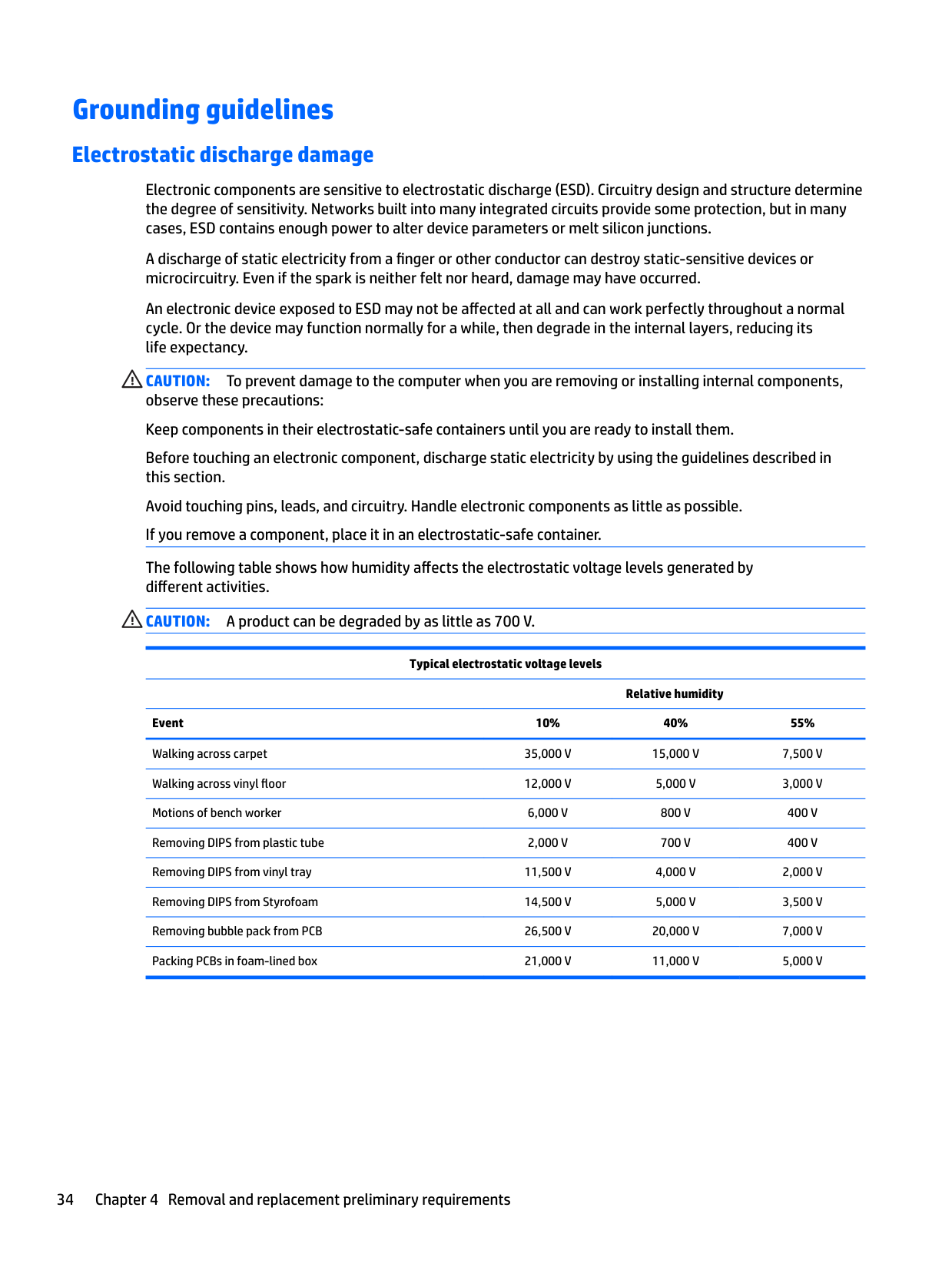
CAUTION: To prevent damage to the computer when you are removing or installing internal components, observe these precautions: Keep components in their electrostatic-safe containers until you are ready to install them. Before touching an electronic component, discharge static electricity by using the guidelines described in this section. Avoid touching pins, leads, and circuitry. Handle electronic components as little as possible. If you remove a component, place it in an electrostatic-safe container. The following table shows how humidity affects the electrostatic voltage levels generated by different activities. CAUTION: A product can be degraded by as little as 700 V.
Typical electrostatic voltage levels
Relative humidity Event 10% 40% 55% Walking across carpet 35,000 V 15,000 V 7,500 V Walking across vinyl floor 12,000 V 5,000 V 3,000 V Motions of bench worker 6,000 V 800 V 400 V Removing DIPS from plastic tube 2,000 V 700 V 400 V Removing DIPS from vinyl tray 11,500 V 4,000 V 2,000 V Removing DIPS from Styrofoam 14,500 V 5,000 V 3,500 V Removing bubble pack from PCB 26,500 V 20,000 V 7,000 V Packing PCBs in foam-lined box 21,000 V 11,000 V 5,000 V
##### Packaging and transporting guidelines
Follow these grounding guidelines when packaging and transporting equipment:
###### Workstation guidelines
Follow these grounding workstation guidelines:
Grounding guidelines 35
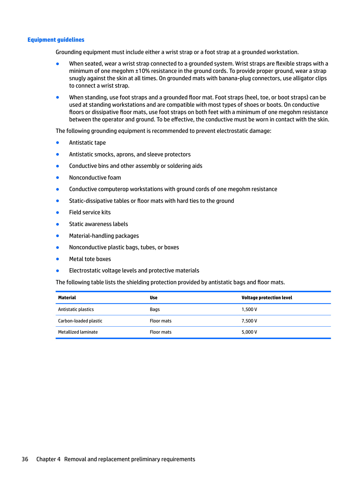
###### Equipment guidelines
Grounding equipment must include either a wrist strap or a foot strap at a grounded workstation.
Material Use Voltage protection level
Antistatic plastics Bags 1,500 V Carbon-loaded plastic Floor mats 7,500 V Metallized laminate Floor mats 5,000 V
5 Removal and replacement procedures
This chapter provides removal and replacement procedures for Authorized Service Provider only parts. CAUTION: Components described in this chapter should only be accessed by an authorized service provider. Accessing these parts can damage the computer or void the warranty. CAUTION: This computer does not have user-replaceable parts. Only HP authorized service providers should perform the removal and replacement procedures described here. Accessing the internal part could damage the computer or void the warranty.
Component replacement procedures
| | |---|
NOTE: Details about your computer, including model, serial number, product key, and length of warranty, are on the service tag at the bottom of your computer. See Labels on page 14 for details.
| | |---|
NOTE: HP continually improves and changes product parts. For complete and current information on supported parts for your computer, go to http://partsurfer.hp.com, select your country or region, and then follow the on-screen instructions.
There are as many as 56 screws that must be removed, replaced, and/or loosened when servicing Authorized Service Provider only parts. Make special note of each screw size and location during removal and replacement.
#### Bottom cover
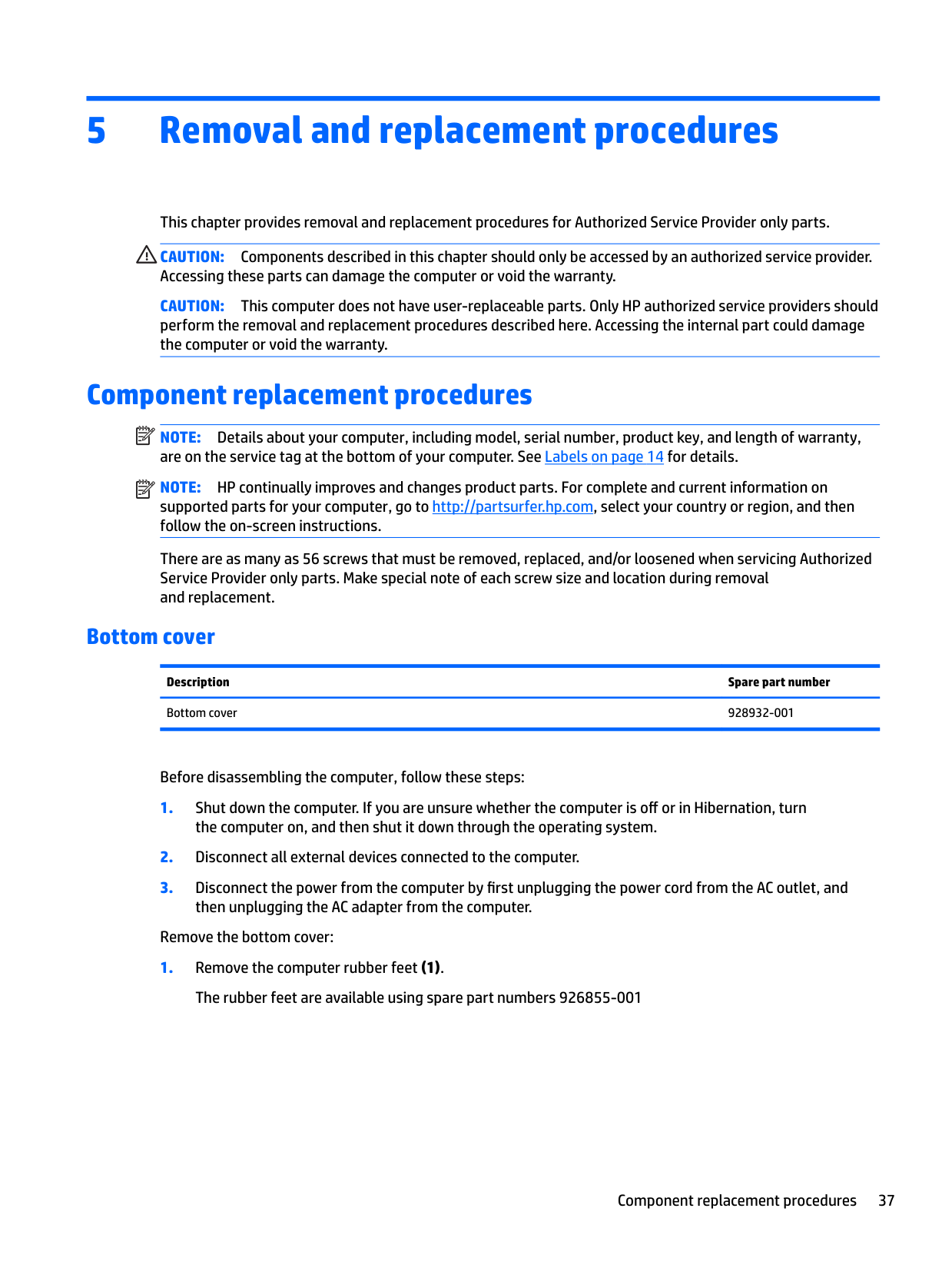
Description Spare part number Bottom cover 928932-001
Before disassembling the computer, follow these steps:
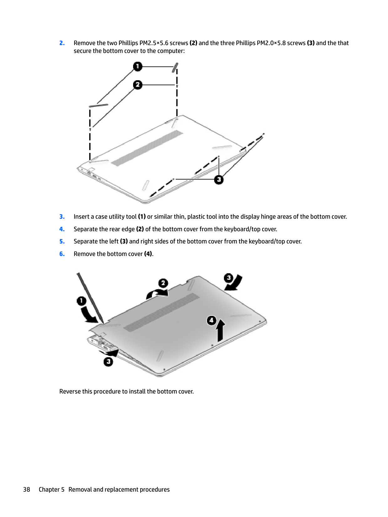
Remove the bottom cover:


Reverse this procedure to install the bottom cover.
#### Battery
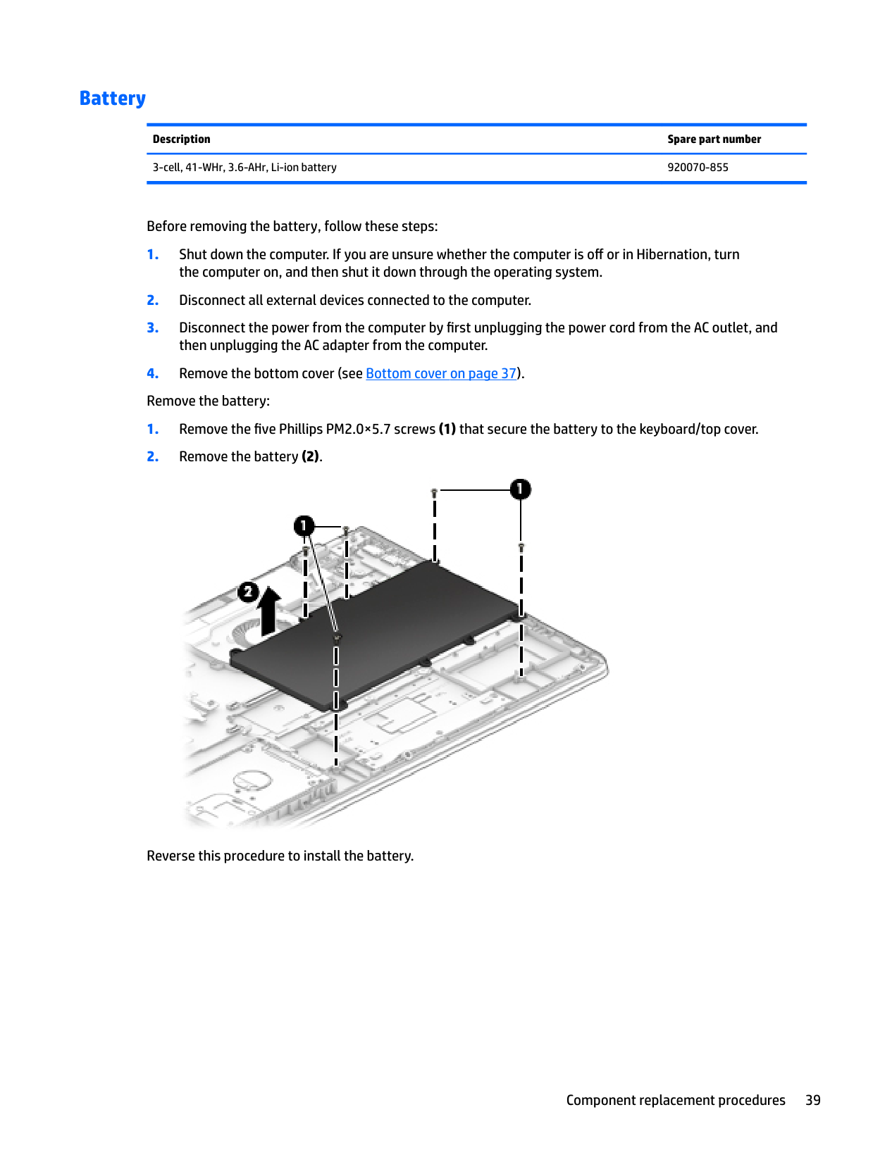
Description Spare part number 3-cell, 41-WHr, 3.6-AHr, Li-ion battery 920070-855
Before removing the battery, follow these steps:

Reverse this procedure to install the battery.
#### Hard drive
| | |---|
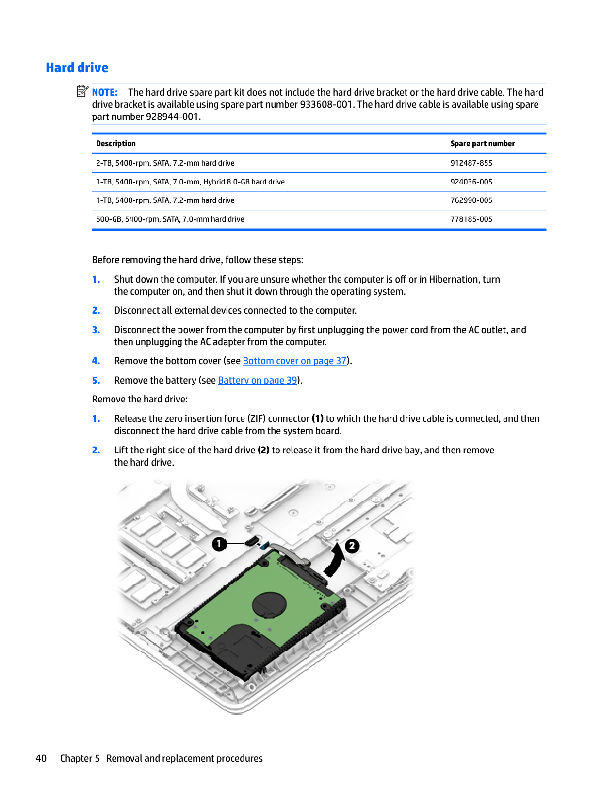
NOTE: The hard drive spare part kit does not include the hard drive bracket or the hard drive cable. The hard drive bracket is available using spare part number 933608-001. The hard drive cable is available using spare part number 928944-001.
Description Spare part number
2-TB, 5400-rpm, SATA, 7.2-mm hard drive 912487-855 1-TB, 5400-rpm, SATA, 7.0-mm, Hybrid 8.0-GB hard drive 924036-005 1-TB, 5400-rpm, SATA, 7.2-mm hard drive 762990-005 500-GB, 5400-rpm, SATA, 7.0-mm hard drive 778185-005
Before removing the hard drive, follow these steps:


Reverse this procedure to reassemble and install the hard drive.
#### Memory module
| | |---|
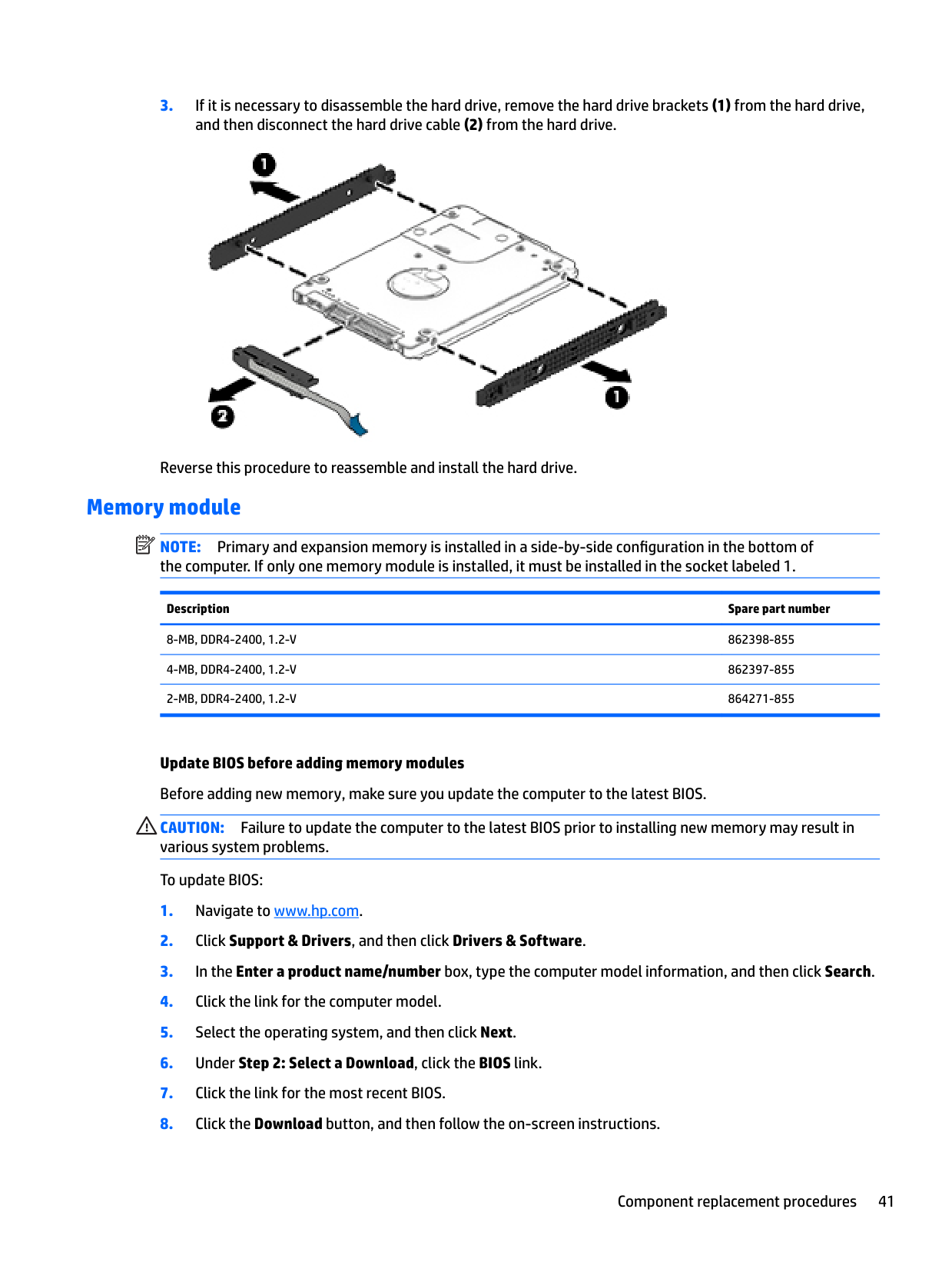
NOTE: Primary and expansion memory is installed in a side-by-side configuration in the bottom of the computer. If only one memory module is installed, it must be installed in the socket labeled 1.
Description Spare part number
8-MB, DDR4-2400, 1.2-V 862398-855 4-MB, DDR4-2400, 1.2-V 862397-855 2-MB, DDR4-2400, 1.2-V 864271-855
Update BIOS before adding memory modules Before adding new memory, make sure you update the computer to the latest BIOS. CAUTION: Failure to update the computer to the latest BIOS prior to installing new memory may result in various system problems. To update BIOS:
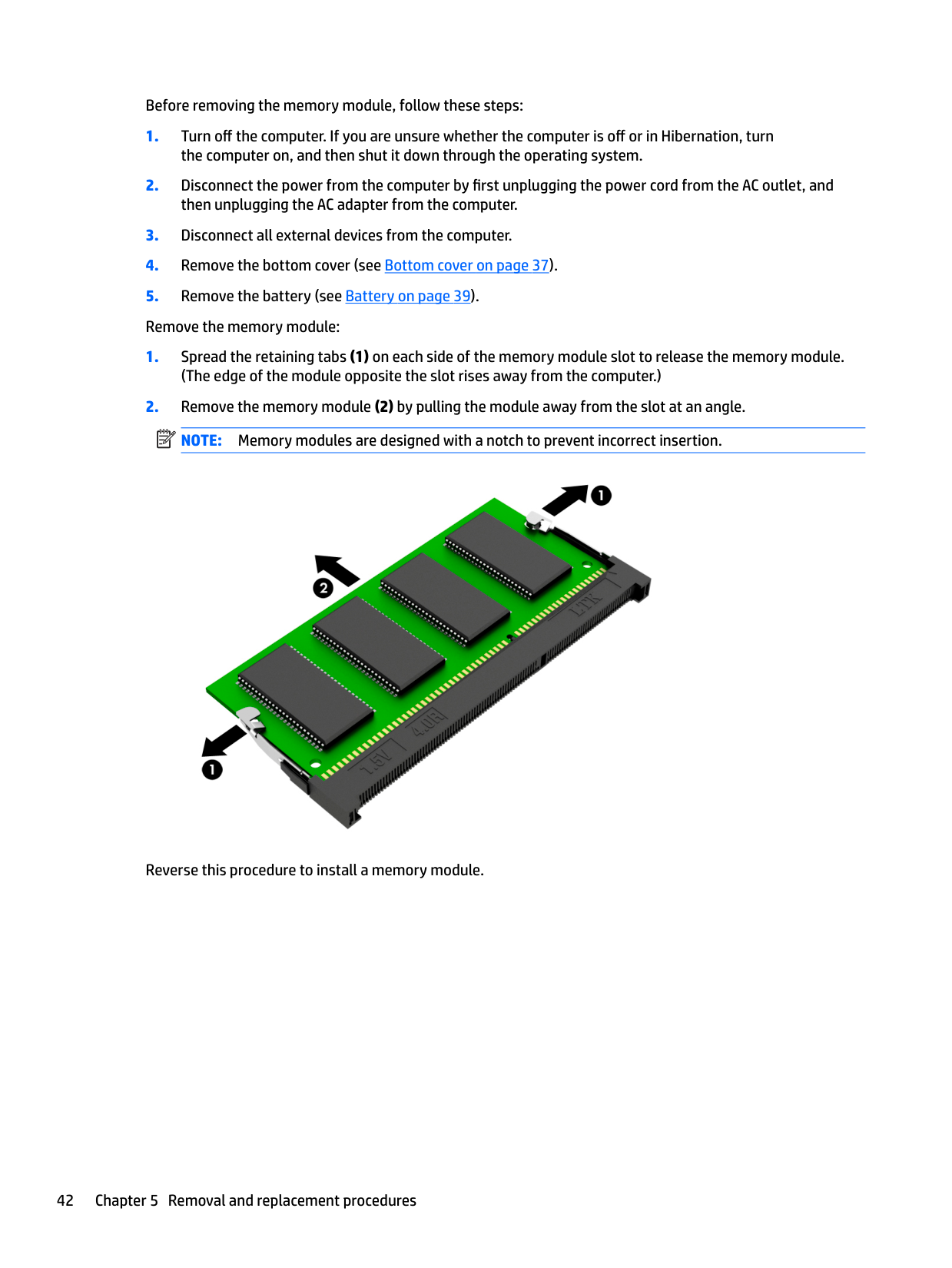
Before removing the memory module, follow these steps:
| | |---|

Reverse this procedure to install a memory module.
#### Solid-state drive
######## Description Spare part number
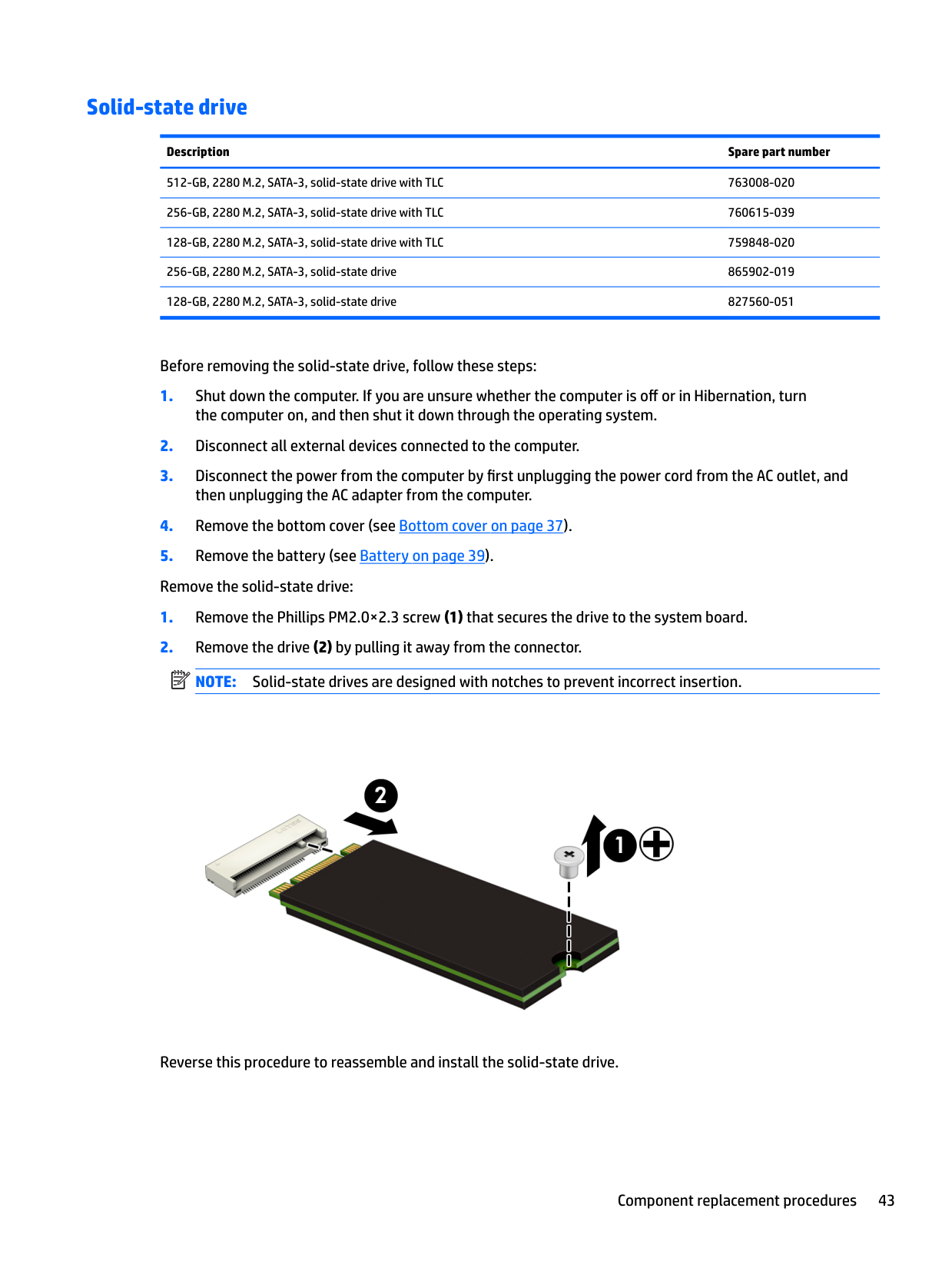
512-GB, 2280 M.2, SATA-3, solid-state drive with TLC 763008-020 256-GB, 2280 M.2, SATA-3, solid-state drive with TLC 760615-039 128-GB, 2280 M.2, SATA-3, solid-state drive with TLC 759848-020 256-GB, 2280 M.2, SATA-3, solid-state drive 865902-019 128-GB, 2280 M.2, SATA-3, solid-state drive 827560-051
Before removing the solid-state drive, follow these steps:
| | |---|

Reverse this procedure to reassemble and install the solid-state drive.
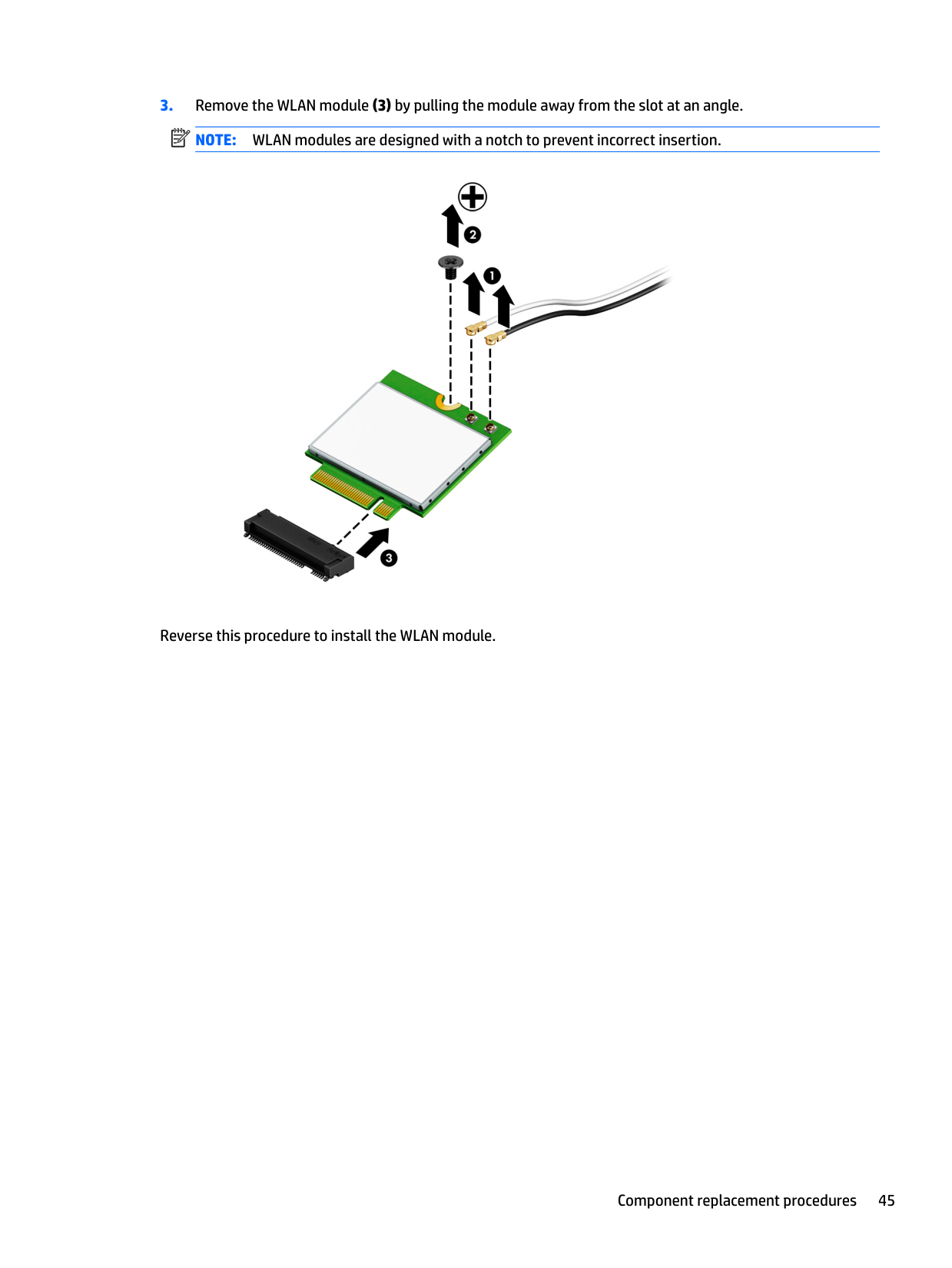
#### WLAN module
######## Description Spare part number
Intel Dual Band Wireless-AC 7265 802.11 AC 2×2 WiFi + Bluetooth 4.2 Combo Adapter (non-vPro) 901229-855 Intel Dual Band Wireless-AC 3168 802.11AC 1×1 WiFi + Bluetooth 4.2 Combo Adapter (non-vPro) 863934-855 Realtek RTL8723DE 802.11 bgn 1×1 WiFi + Bluetooth 4.2 Combo Adapter 927230-001
CAUTION: To prevent an unresponsive system, replace the wireless module only with a wireless module authorized for use in the computer by the governmental agency that regulates wireless devices in your country or region. If you replace the module and then receive a warning message, remove the module to restore device functionality, and then contact technical support.
Before removing the WLAN module, follow these steps:
NOTE: The WLAN antenna cable labeled "1/MAIN" connects to the WLAN module "Main" terminal. The WLAN antenna cable labeled "2/AUX" connects to the WLAN module "Aux" terminal.
| |
|---|
| | |---|

Reverse this procedure to install the WLAN module.
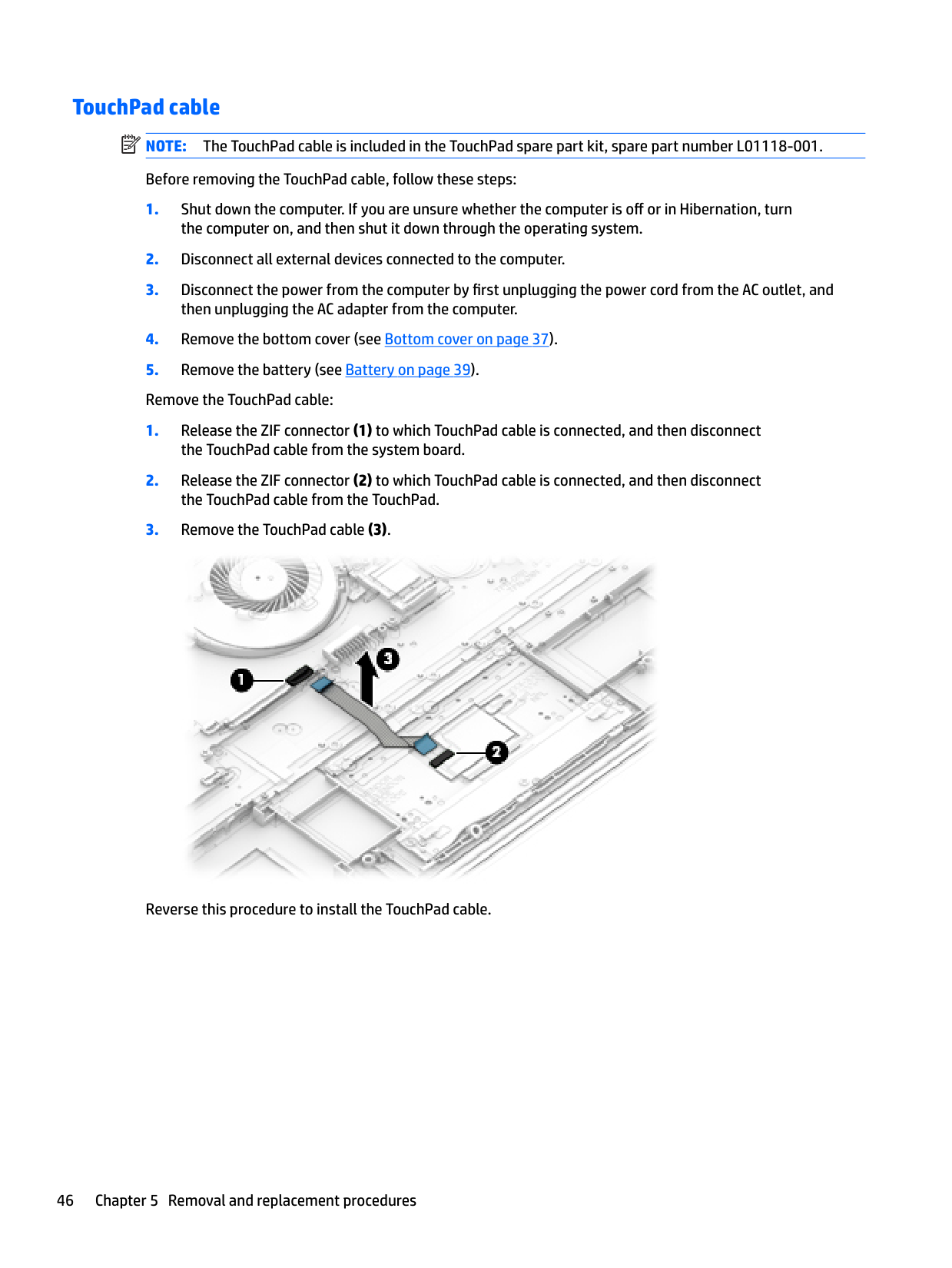
TouchPad cable NOTE: The TouchPad cable is included in the TouchPad spare part kit, spare part number L01118-001. Before removing the TouchPad cable, follow these steps:
| | |---|

Reverse this procedure to install the TouchPad cable.
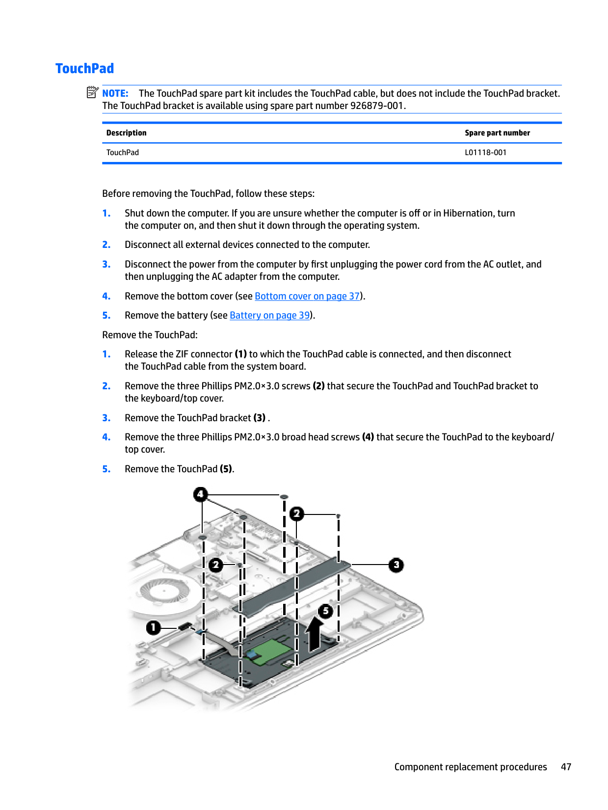
#### TouchPad
| | |---|
NOTE: The TouchPad spare part kit includes the TouchPad cable, but does not include the TouchPad bracket. The TouchPad bracket is available using spare part number 926879-001.
Description Spare part number TouchPad L01118-001
Before removing the TouchPad, follow these steps:
the computer on, and then shut it down through the operating system.
then unplugging the AC adapter from the computer. 4. Remove the bottom cover (see Bottom cover on page 37).

Reverse this procedure to install the TouchPad.
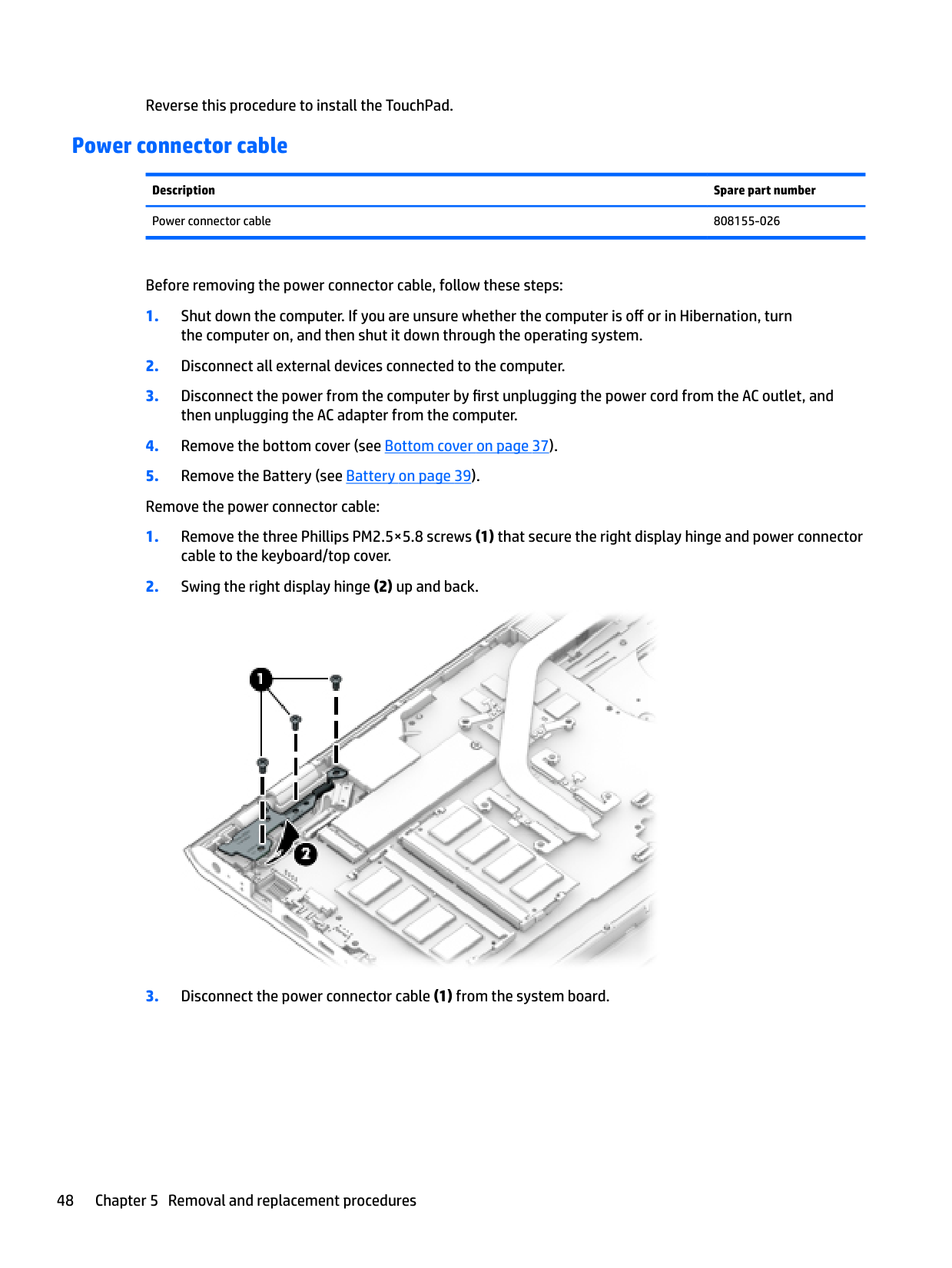
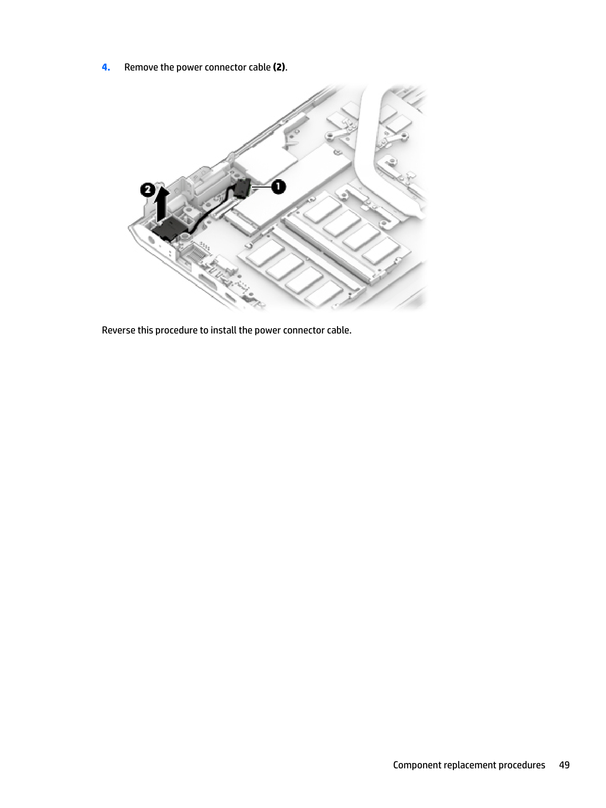
#### Power connector cable
Description Spare part number Power connector cable 808155-026
Before removing the power connector cable, follow these steps:


Reverse this procedure to install the power connector cable.
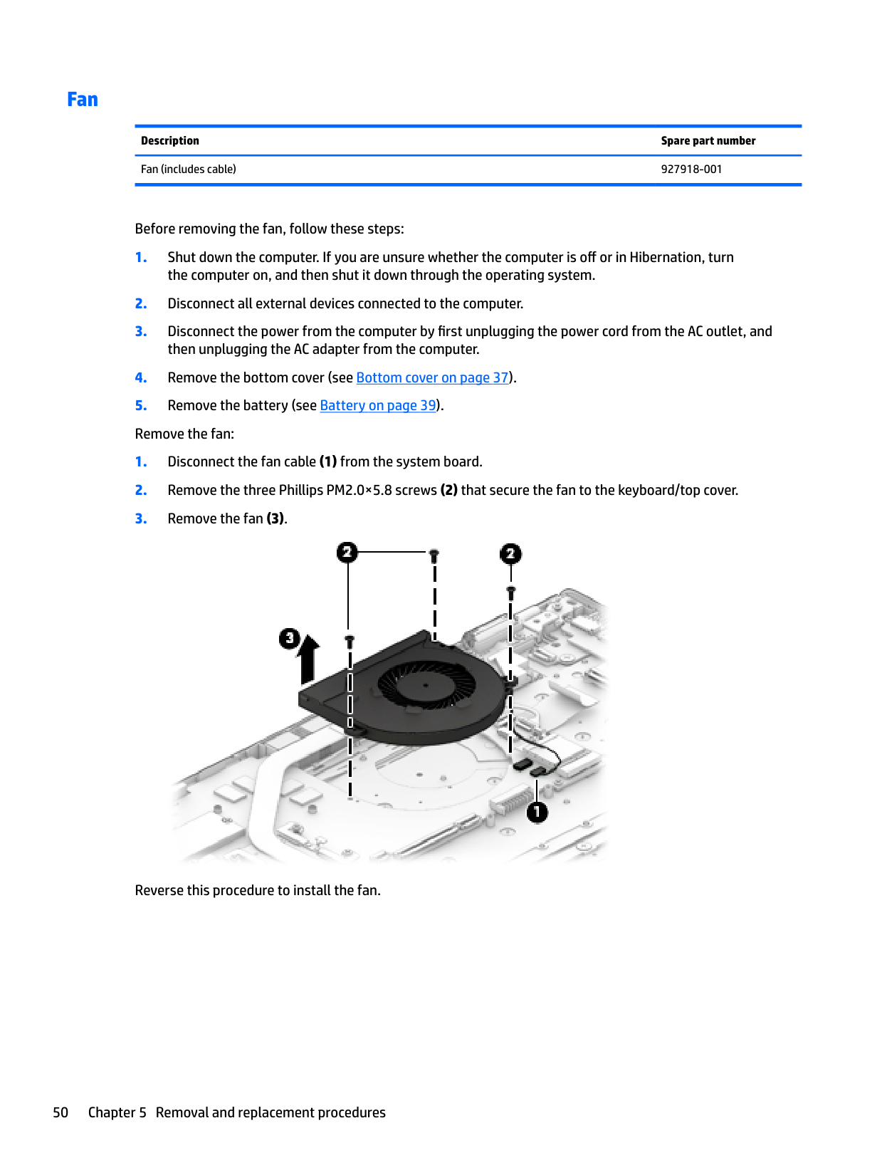
#### Fan
Description Spare part number Fan (includes cable) 927918-001
Before removing the fan, follow these steps:

Reverse this procedure to install the fan.
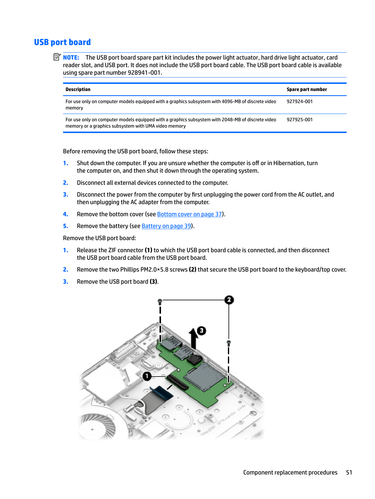
#### USB port board
| | |---|
NOTE: The USB port board spare part kit includes the power light actuator, hard drive light actuator, card reader slot, and USB port. It does not include the USB port board cable. The USB port board cable is available using spare part number 928941-001.
Description Spare part number
For use only on computer models equipped with a graphics subsystem with 4096-MB of discrete video memory
For use only on computer models equipped with a graphics subsystem with 2048-MB of discrete video memory or a graphics subsystem with UMA video memory
Before removing the USB port board, follow these steps:

Reverse this procedure to install the USB port board.
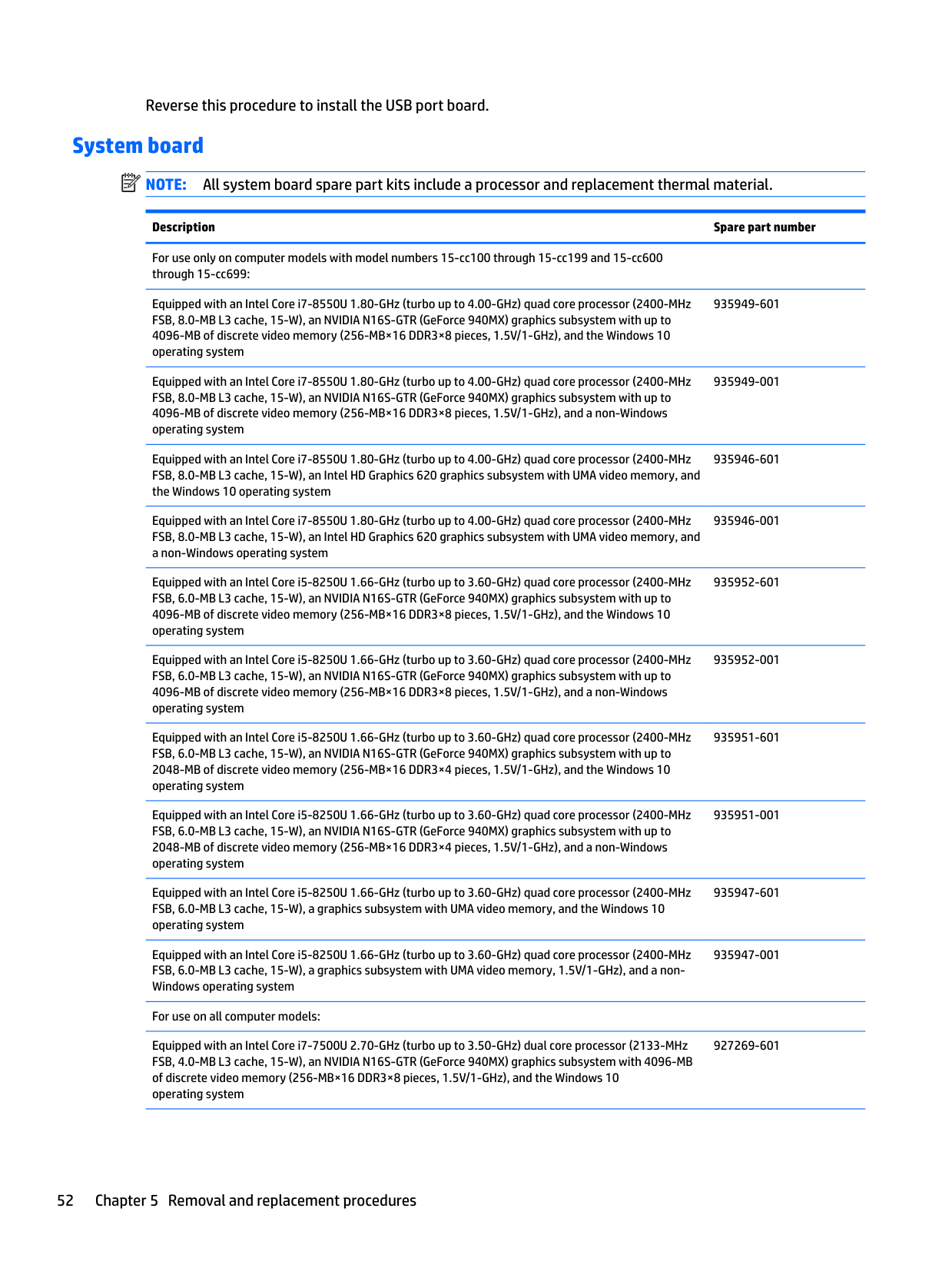
#### System board
| | |---|
NOTE: All system board spare part kits include a processor and replacement thermal material.
Description Spare part number
For use only on computer models with model numbers 15-cc100 through 15-cc199 and 15-cc600 through 15-cc699:
Equipped with an Intel Core i7-8550U 1.80-GHz (turbo up to 4.00-GHz) quad core processor (2400-MHz FSB, 8.0-MB L3 cache, 15-W), an NVIDIA N16S-GTR (GeForce 940MX) graphics subsystem with up to 4096-MB of discrete video memory (256-MB×16 DDR3×8 pieces, 1.5V/1-GHz), and the Windows 10 operating system
935949-601
Equipped with an Intel Core i7-8550U 1.80-GHz (turbo up to 4.00-GHz) quad core processor (2400-MHz FSB, 8.0-MB L3 cache, 15-W), an NVIDIA N16S-GTR (GeForce 940MX) graphics subsystem with up to 4096-MB of discrete video memory (256-MB×16 DDR3×8 pieces, 1.5V/1-GHz), and a non-Windows operating system
935949-001
Equipped with an Intel Core i7-8550U 1.80-GHz (turbo up to 4.00-GHz) quad core processor (2400-MHz FSB, 8.0-MB L3 cache, 15-W), an Intel HD Graphics 620 graphics subsystem with UMA video memory, and the Windows 10 operating system
935946-601
Equipped with an Intel Core i7-8550U 1.80-GHz (turbo up to 4.00-GHz) quad core processor (2400-MHz FSB, 8.0-MB L3 cache, 15-W), an Intel HD Graphics 620 graphics subsystem with UMA video memory, and a non-Windows operating system
935946-001
Equipped with an Intel Core i5-8250U 1.66-GHz (turbo up to 3.60-GHz) quad core processor (2400-MHz FSB, 6.0-MB L3 cache, 15-W), an NVIDIA N16S-GTR (GeForce 940MX) graphics subsystem with up to 4096-MB of discrete video memory (256-MB×16 DDR3×8 pieces, 1.5V/1-GHz), and the Windows 10 operating system
Equipped with an Intel Core i5-8250U 1.66-GHz (turbo up to 3.60-GHz) quad core processor (2400-MHz FSB, 6.0-MB L3 cache, 15-W), an NVIDIA N16S-GTR (GeForce 940MX) graphics subsystem with up to 4096-MB of discrete video memory (256-MB×16 DDR3×8 pieces, 1.5V/1-GHz), and a non-Windows operating system
Equipped with an Intel Core i5-8250U 1.66-GHz (turbo up to 3.60-GHz) quad core processor (2400-MHz FSB, 6.0-MB L3 cache, 15-W), an NVIDIA N16S-GTR (GeForce 940MX) graphics subsystem with up to 2048-MB of discrete video memory (256-MB×16 DDR3×4 pieces, 1.5V/1-GHz), and the Windows 10 operating system
Equipped with an Intel Core i5-8250U 1.66-GHz (turbo up to 3.60-GHz) quad core processor (2400-MHz FSB, 6.0-MB L3 cache, 15-W), an NVIDIA N16S-GTR (GeForce 940MX) graphics subsystem with up to 2048-MB of discrete video memory (256-MB×16 DDR3×4 pieces, 1.5V/1-GHz), and a non-Windows operating system
Equipped with an Intel Core i5-8250U 1.66-GHz (turbo up to 3.60-GHz) quad core processor (2400-MHz FSB, 6.0-MB L3 cache, 15-W), a graphics subsystem with UMA video memory, and the Windows 10 operating system
Equipped with an Intel Core i5-8250U 1.66-GHz (turbo up to 3.60-GHz) quad core processor (2400-MHz FSB, 6.0-MB L3 cache, 15-W), a graphics subsystem with UMA video memory, 1.5V/1-GHz), and a nonWindows operating system
For use on all computer models: Equipped with an Intel Core i7-7500U 2.70-GHz (turbo up to 3.50-GHz) dual core processor (2133-MHz FSB, 4.0-MB L3 cache, 15-W), an NVIDIA N16S-GTR (GeForce 940MX) graphics subsystem with 4096-MB of discrete video memory (256-MB×16 DDR3×8 pieces, 1.5V/1-GHz), and the Windows 10 operating system
935952-601
935952-001
935951-601
935951-001
935947-601
935947-001
927269-601
Equipped with an Intel Core i7-7500U 2.70-GHz (turbo up to 3.50-GHz) dual core processor (2133-MHz FSB, 4.0-MB L3 cache, 15-W), an NVIDIA N16S-GTR (GeForce 940MX) graphics subsystem with 4096-MB of discrete video memory (256-MB×16 DDR3×8 pieces, 1.5V/1-GHz), and a non-Windows operating system
927269-001
Equipped with an Intel Core i7-7500U 2.70-GHz (turbo up to 3.50-GHz) dual core processor (2133-MHz FSB, 4.0-MB L3 cache, 15-W), an NVIDIA N16S-GTR (GeForce 940MX) graphics subsystem with 2048-MB of discrete video memory (256-MB×16 DDR3×4 pieces, 1.5V/1-GHz), and the Windows 10 operating system
927268-601
Equipped with an Intel Core i7-7500U 2.70-GHz (turbo up to 3.50-GHz) dual core processor (2133-MHz FSB, 4.0-MB L3 cache, 15-W), an NVIDIA N16S-GTR (GeForce 940MX) graphics subsystem with 2048-MB of discrete video memory (256-MB×16 DDR3×4 pieces, 1.5V/1-GHz), and a non-Windows operating system
927268-001
Equipped with an Intel Core i7-7500U 2.70-GHz (turbo up to 3.50-GHz) dual core processor (2133-MHz FSB, 4.0-MB L3 cache, 15-W), an Intel HD Graphics 620 graphics subsystem with UMA video memory, and the Windows 10 operating system
927264-601
Equipped with an Intel Core i7-7500U 2.70-GHz (turbo up to 3.50-GHz) dual core processor (2133-MHz FSB, 4.0-MB L3 cache, 15-W), an Intel HD Graphics 620 graphics subsystem with UMA video memory, and a non-Windows operating system
927264-001
Equipped with an Intel Core i5-7200U 2.50-GHz (turbo up to 3.10-GHz) dual core processor (2133-MHz FSB, 3.0-MB L3 cache, 15-W), an NVIDIA N16S-GTR (GeForce 940MX) graphics subsystem with 4096-MB of discrete video memory (256-MB×16 DDR3×8 pieces, 1.5V/1-GHz), and the Windows 10 operating system
927271-601
Equipped with an Intel Core i5-7200U 2.50-GHz (turbo up to 3.10-GHz) dual core processor (2133-MHz FSB, 3.0-MB L3 cache, 15-W), an NVIDIA N16S-GTR (GeForce 940MX) graphics subsystem with 4096-MB of discrete video memory (256-MB×16 DDR3×4 pieces, 1.5V/1-GHz), and a non-Windows operating system
927271-001
Equipped with an Intel Core i5-7200U 2.50-GHz (turbo up to 3.10-GHz) dual core processor (2133-MHz FSB, 3.0-MB L3 cache, 15-W), an NVIDIA N16S-GTR (GeForce 940MX) graphics subsystem with 2048-MB of discrete video memory (256-MB×16 DDR3×4 pieces, 1.5V/1-GHz), and the Windows 10 operating system
927270-601
Equipped with an Intel Core i5-7200U 2.50-GHz (turbo up to 3.10-GHz) dual core processor (2133-MHz FSB, 3.0-MB L3 cache, 15-W), an NVIDIA N16S-GTR (GeForce 940MX) graphics subsystem with 2048-MB of discrete video memory (256-MB×16 DDR3×4 pieces, 1.5V/1-GHz), and a non-Windows operating system
927270-001
Equipped with an Intel Core i5-7200U 2.50-GHz (turbo up to 3.10-GHz) dual core processor (2133-MHz
927265-601
Equipped with an Intel Core i5-7200U 2.50-GHz (turbo up to 3.10-GHz) dual core processor (2133-MHz
Equipped with an Intel Core i3-7100U 2.40-GHz dual core processor (2133-MHz FSB, 3.0-MB L3 cache, 15-W), an Intel HD Graphics 620 graphics subsystem with UMA video memory, and the Windows 10 operating system
Equipped with an Intel Core i3-7100U 2.40-GHz dual core processor (2133-MHz FSB, 3.0-MB L3 cache, 15-W), an Intel HD Graphics 620 graphics subsystem with UMA video memory, and a non-Windows operating system
Equipped with an Intel Pentium 4415U 2.30-GHz dual core processor (2133-MHz FSB, 2.0-MB L3 cache, 15-W), an Intel HD Graphics 610 graphics subsystem with UMA video memory, and the Windows 10 operating system
Equipped with an Intel Pentium 4415U 2.30-GHz dual core processor (2133-MHz FSB, 2.0-MB L3 cache, 15-W), an Intel HD Graphics 610 graphics subsystem with UMA video memory, and a non-Windows operating system
927267-001
Before removing the system board, follow these steps:
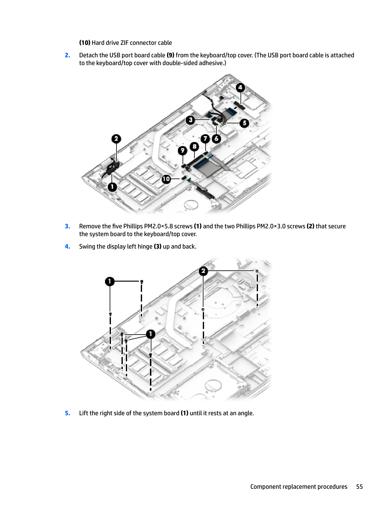
When replacing the system board, be sure to remove the following components from the defective system board and install them on the replacement system board:
| | |---|
NOTE: The #1/white WLAN antenna cable connects to the WLAN module "#1/Main" terminal. The #2/ black WLAN antenna cable connects to the WLAN module "#2/Aux" terminal.


Reverse this procedure to install the system board.
#### Heat sink
| | |---|
NOTE: The heat sink spare part kit includes replacement thermal material.
Description Spare part number
For use only on computer models equipped with a graphics subsystem with discrete memory 927920-001 For use only on computer models equipped with a graphics subsystem with UMA memory 927919-001
Before removing the heat sink, follow these steps:
| | |---|
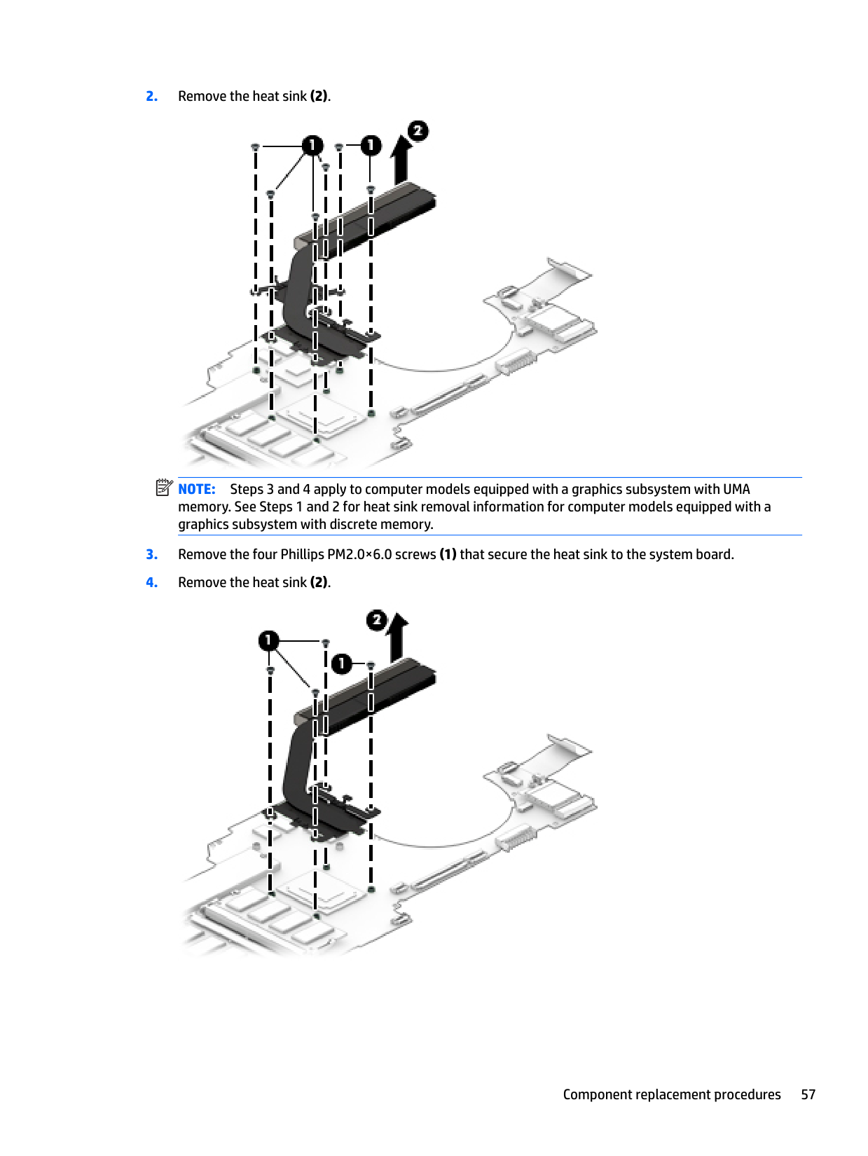
Remove the heat sink: NOTE: Steps 1 and 2 apply to computer models equipped with a graphics subsystem with discrete memory. See Steps 3 and 4 for heat sink removal information for computer models equipped with a graphics subsystem with UMA memory.

NOTE: Steps 3 and 4 apply to computer models equipped with a graphics subsystem with UMA memory. See Steps 1 and 2 for heat sink removal information for computer models equipped with a graphics subsystem with discrete memory.
| | |---|

| | |---|
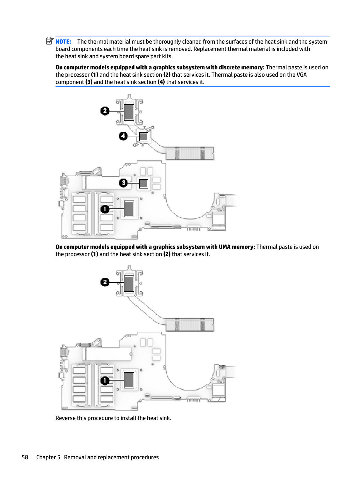
NOTE: The thermal material must be thoroughly cleaned from the surfaces of the heat sink and the system board components each time the heat sink is removed. Replacement thermal material is included with the heat sink and system board spare part kits.
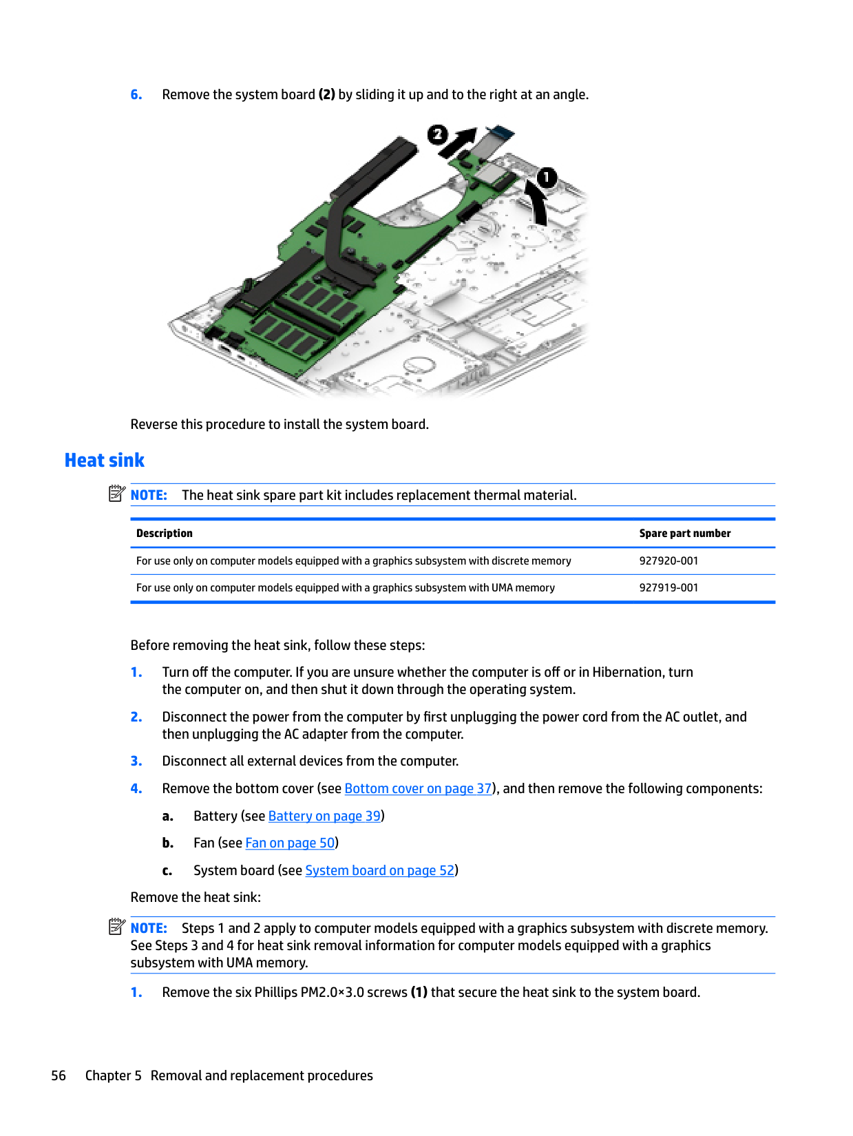
On computer models equipped with a graphics subsystem with discrete memory: Thermal paste is used on the processor (1) and the heat sink section (2) that services it. Thermal paste is also used on the VGA component (3) and the heat sink section (4) that services it.

###### On computer models equipped with a graphics subsystem with UMA memory: Thermal paste is used on the processor (1) and the heat sink section (2) that services it.

Reverse this procedure to install the heat sink.
#### USB port board cable
| |
|---|
NOTE: The USB port board spare part kit does not include the USB port board cable. The USB port
board cable is available using spare part number 928941-001. Before removing the USB port board cable, follow these steps: 1. Shut down the computer. If you are unsure whether the computer is off or in Hibernation, turn
the computer on, and then shut it down through the operating system.
then unplugging the AC adapter from the computer.
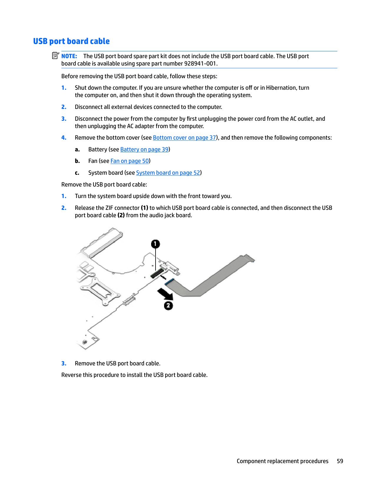
Remove the USB port board cable:

#### Speakers
Description Spare part number Speakers (includes cables) 928949-001
Before removing the speakers, follow these steps:
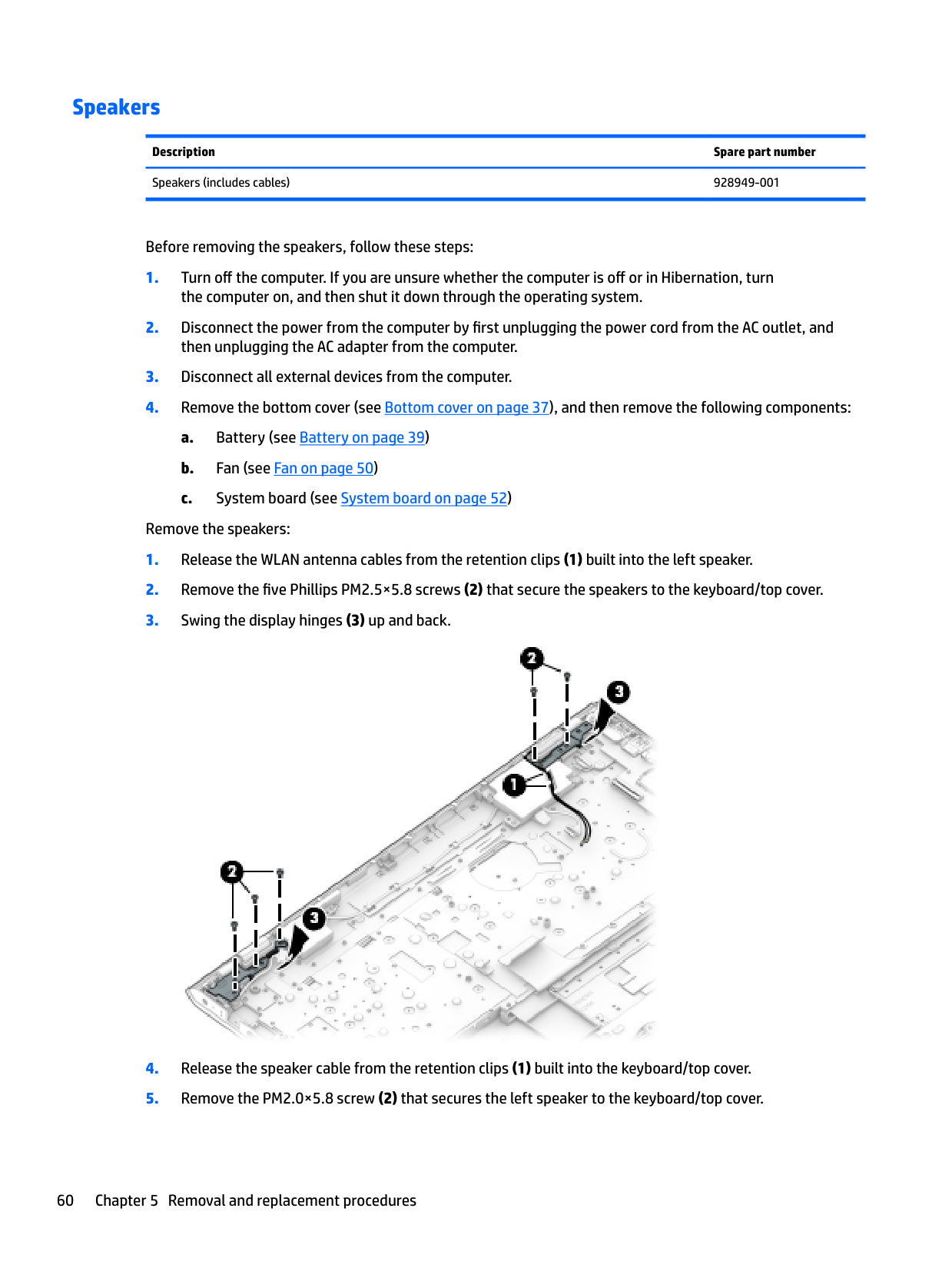
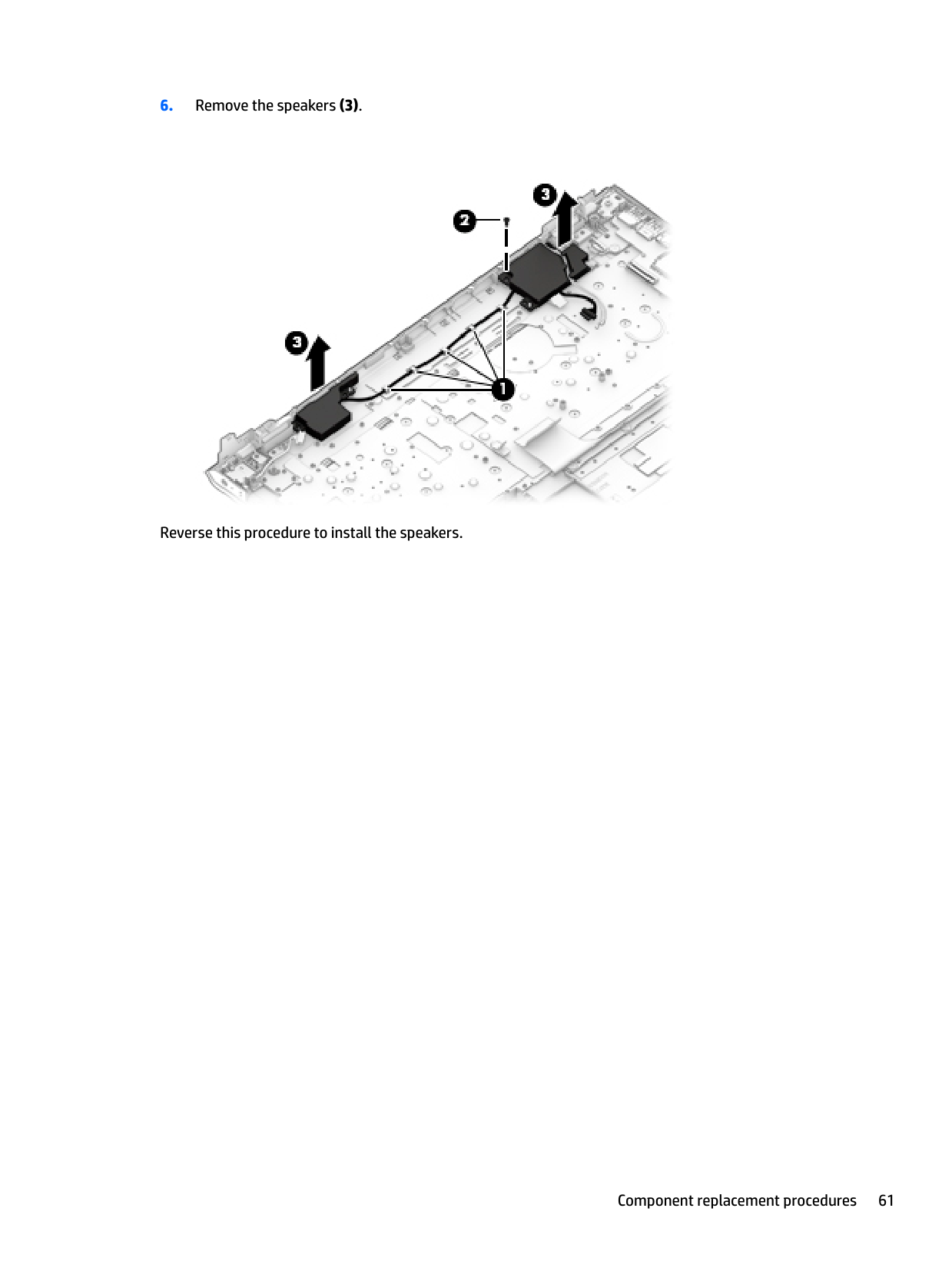
Remove the speakers:


Reverse this procedure to install the speakers.
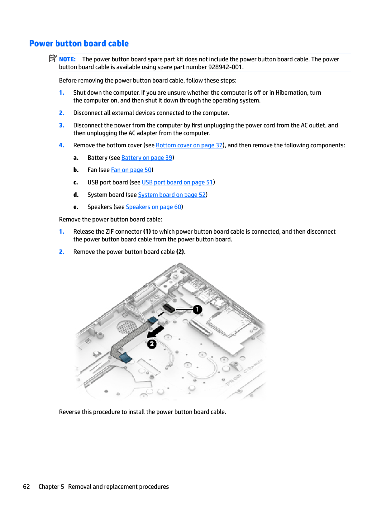
Power button board cable NOTE: The power button board spare part kit does not include the power button board cable. The power button board cable is available using spare part number 928942-001. Before removing the power button board cable, follow these steps:
| | |---|
the computer on, and then shut it down through the operating system.
then unplugging the AC adapter from the computer.
Remove the power button board cable:

Reverse this procedure to install the power button board cable.
#### Power button board
| | |---|
NOTE: The power button board spare part kit does not include the power button board cable. The power button board cable is available using spare part number 928942-001.
Description Spare part number
For use only on computer models equipped with a graphics subsystem with 4096-MB of discrete video memory
For use only on computer models equipped with a graphics subsystem with 2048-MB of discrete video memory or a graphics subsystem with UMA video memory
Before removing the TouchPad, follow these steps:
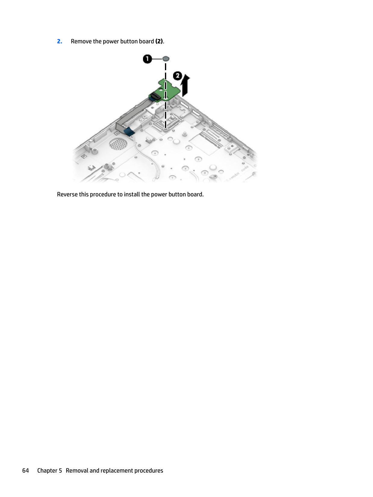
Remove the power button board:

Reverse this procedure to install the power button board.
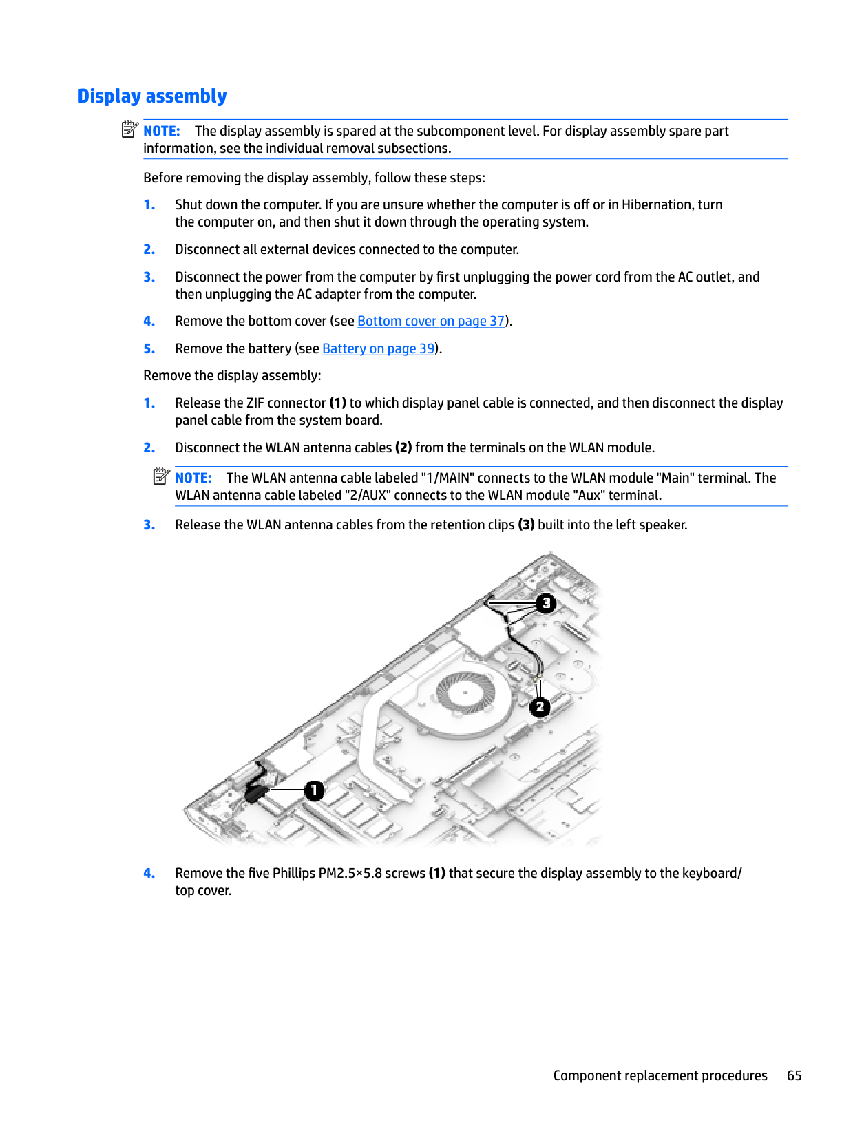
Display assembly NOTE: The display assembly is spared at the subcomponent level. For display assembly spare part information, see the individual removal subsections. Before removing the display assembly, follow these steps:
| | |---|
the computer on, and then shut it down through the operating system.
then unplugging the AC adapter from the computer. 4. Remove the bottom cover (see Bottom cover on page 37).
NOTE: The WLAN antenna cable labeled "1/MAIN" connects to the WLAN module "Main" terminal. The WLAN antenna cable labeled "2/AUX" connects to the WLAN module "Aux" terminal.

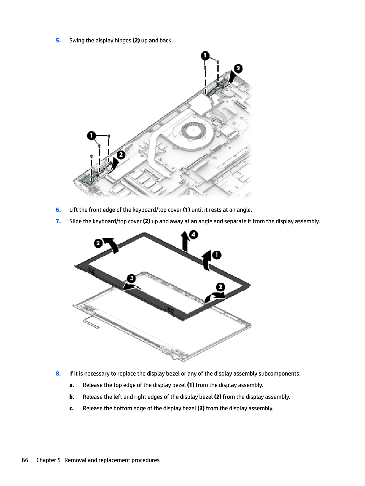
| | |---|


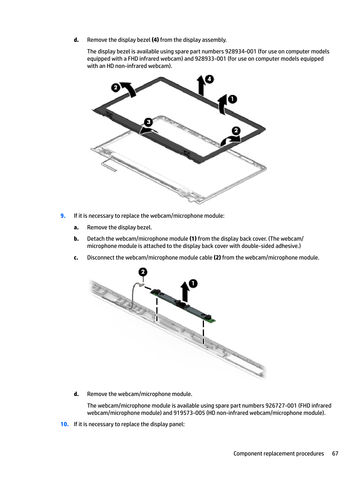
The display bezel is available using spare part numbers 928934-001 (for use on computer models equipped with a FHD infrared webcam) and 928933-001 (for use on computer models equipped with an HD non-infrared webcam).


The webcam/microphone module is available using spare part numbers 926727-001 (FHD infrared webcam/microphone module) and 919573-005 (HD non-infrared webcam/microphone module).

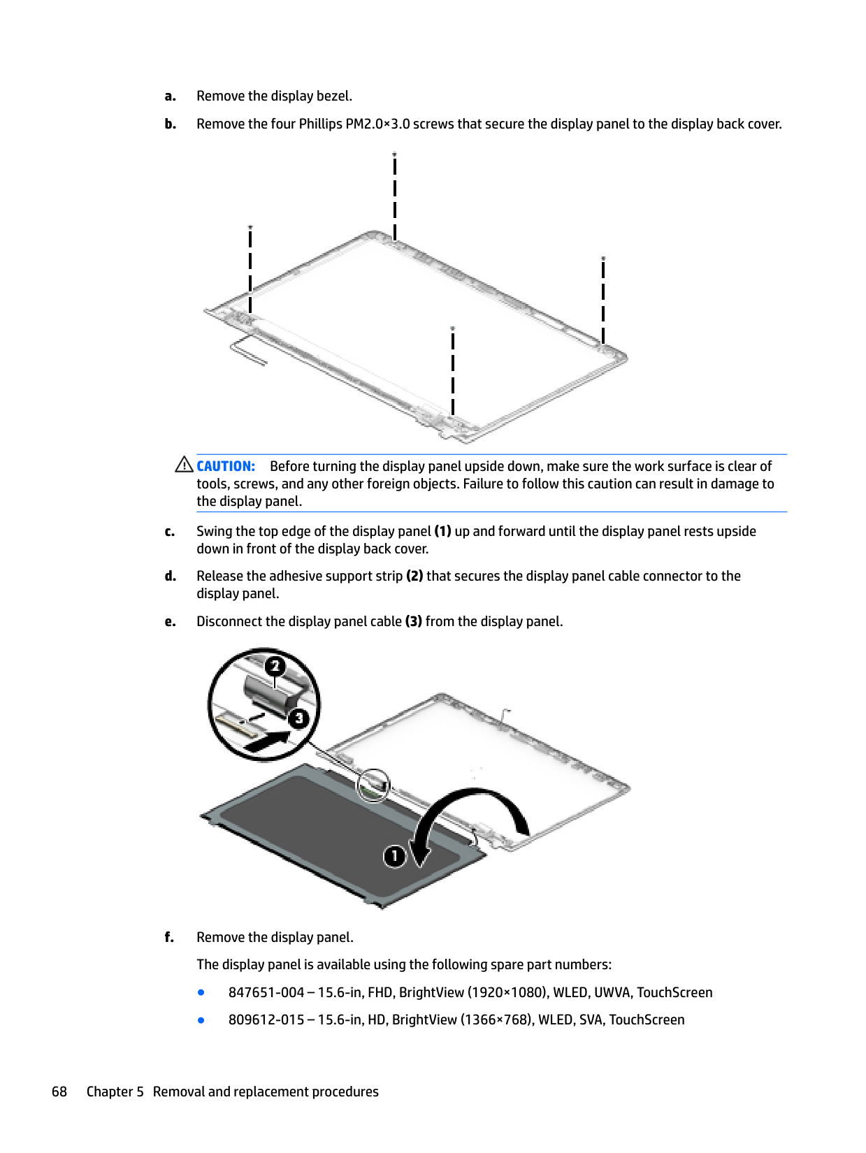
CAUTION: Before turning the display panel upside down, make sure the work surface is clear of tools, screws, and any other foreign objects. Failure to follow this caution can result in damage to the display panel.


Reverse this procedure to reassemble and install the display assembly.
6 Using Setup Utility (BIOS)
Setup Utility, or Basic Input/Output System (BIOS), controls communication between all the input and output devices on the system (such as disk drives, display, keyboard, mouse, and printer). Setup Utility (BIOS) includes settings for the types of devices installed, the startup sequence of the computer, and the amount of system and extended memory.
| | |---|
NOTE: To start Setup Utility on convertible computers, your computer must be in notebook mode and you must use the keyboard attached to your notebook.
Starting Setup Utility (BIOS)
CAUTION: Use extreme care when making changes in Setup Utility (BIOS). Errors can prevent the computer from operating properly.
▲ Turn on or restart the computer, quickly press esc, and then press f10.
Updating Setup Utility (BIOS) Updated versions of Setup Utility (BIOS) may be available on the HP website. Most BIOS updates on the HP website are packaged in compressed files called SoftPaqs. Some download packages contain a file named Readme.txt, which contains information regarding installing and troubleshooting the file.
Determining the BIOS version To decide whether you need to update Setup Utility (BIOS), first determine the BIOS version on your computer. To reveal the BIOS version information (also known as ROM date and System BIOS), use one of these options.
– or – Click the question mark icon in the taskbar.
To check for later BIOS versions, see Downloading a BIOS update on page 73.
72 Chapter 6 Using Setup Utility (BIOS)
#### Downloading a BIOS update
CAUTION: To reduce the risk of damage to the computer or an unsuccessful installation, download and install a BIOS update only when the computer is connected to reliable external power using the AC adapter. Do not download or install a BIOS update while the computer is running on battery power, docked in an optional docking device, or connected to an optional power source. During the download and installation, follow these instructions:
| | |---|
NOTE: If your computer is connected to a network, consult the network administrator before installing any software updates, especially system BIOS updates.
– or – Click the question mark icon in the taskbar.
Make a note of the path to the location on your hard drive where the BIOS update is downloaded. You will need to access this path when you are ready to install the update.
BIOS installation procedures vary. Follow any instructions that appear on the screen after the download is complete. If no instructions appear, follow these steps:
| | |---|
NOTE: After a message on the screen reports a successful installation, you can delete the downloaded file from your hard drive.
Updating Setup Utility (BIOS) 73
7 Using HP PC Hardware Diagnostics (UEFI)
HP PC Hardware Diagnostics is a Unified Extensible Firmware Interface (UEFI) that allows you to run diagnostic tests to determine whether the computer hardware is functioning properly. The tool runs outside the operating system so that it can isolate hardware failures from issues that are caused by the operating system or other software components.
When HP PC Hardware Diagnostics (UEFI) detects a failure that requires hardware replacement, a 24-digit Failure ID code is generated. This ID code can then be provided to support to help determine how to correct the problem.
| | |---|
NOTE: To start diagnostics on a convertible computer, your computer must be in notebook mode and you must use the keyboard attached. To start HP PC Hardware Diagnostics (UEFI), follow these steps:
| | |---|
| | |---|
NOTE: If you need to stop a diagnostic test, press esc.
Downloading HP PC Hardware Diagnostics (UEFI) to a USB device
| | |---|
NOTE: The HP PC Hardware Diagnostics (UEFI) download instructions are provided in English only, and you must use a Windows computer to download and create the HP UEFI support environment because only .exe files are offered.
There are two options to download HP PC Hardware Diagnostics to a USB device. Download the latest UEFI version
74 Chapter 7 Using HP PC Hardware Diagnostics (UEFI)
– or – Select Identify now to let HP automatically detect your product.
Downloading HP PC Hardware Diagnostics (UEFI) to a USB device 75
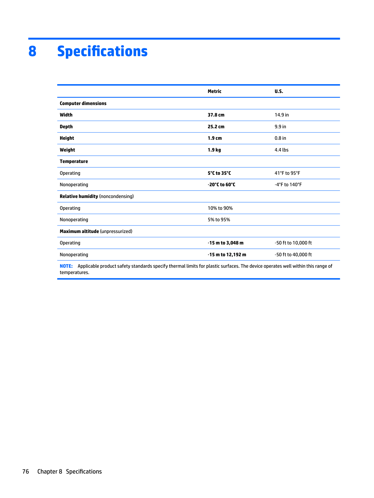
8 Specifications
Metric U.S.
Computer dimensions Width 37.8 cm 14.9 in Depth 25.2 cm 9.9 in Height 1.9 cm 0.8 in Weight 1.9 kg 4.4 lbs Temperature Operating 5°C to 35°C 41°F to 95°F Nonoperating ‑20°C to 60°C ‑4°F to 140°F Relative humidity (noncondensing) Operating 10% to 90% Nonoperating 5% to 95% Maximum altitude (unpressurized)
Operating ‑15 m to 3,048 m ‑50 ft to 10,000 ft Nonoperating ‑15 m to 12,192 m ‑50 ft to 40,000 ft NOTE: Applicable product safety standards specify thermal limits for plastic surfaces. The device operates well within this range of
temperatures.
76 Chapter 8 Specifications
9 Backing up, restoring, and recovering
This chapter provides information about the following processes. The information in the chapter is standard procedure for most products.
▲ Type support in the taskbar search box, and then select the HP Support Assistant app.
‒ or – Select the question mark icon in the taskbar.
| | |---|
IMPORTANT: If you will be performing recovery procedures on a tablet, the tablet battery must be at least 70% charged before you start the recovery process.
IMPORTANT: For a tablet with a detachable keyboard, connect the tablet to the keyboard base before beginning any recovery process.
Creating recovery media and backups
The following methods of creating recovery media and backups are available on select products only. Choose the available method according to your computer model.
| | |---|
#### Creating HP Recovery media (select products only)
If possible, check for the presence of the Recovery partition and the Windows partition. From the Start menu, select File Explorer, and then select This PC.
Creating recovery media and backups 77
You can use Windows tools to create system restore points and create backups of personal information, see Using Windows tools on page 78.
| | |---|
To create HP Recovery media: IMPORTANT: For a tablet with a detachable keyboard, connect the tablet to the keyboard base before beginning these steps.
Using Windows tools
You can create recovery media, system restore points, and backups of personal information using Windows tools.
| | |---|
NOTE: If storage is 32 GB or less, Microsoft System Restore is disabled by default. For more information and steps, see the Get started app.
▲ Select the Start button, and then select the Get started app.
Restore and recovery
There are several options for recovering your system. Choose the method that best matches your situation and level of expertise:
| | |---|
IMPORTANT: Not all methods are available on all products.
▲ Select the Start button, and then select the Get started app.
▲ Type recovery in the taskbar search box, select HP Recovery Manager, select Reinstall drivers
and/or applications, and then follow the on-screen instructions.
#### Recovering using HP Recovery Manager
HP Recovery Manager software allows you to recover the computer to its original factory state by using the HP Recovery media that you either created or that you obtained from HP, or by using the HP Recovery partition (select products only). If you have not already created recovery media, see Creating HP Recovery media (select products only) on page 77.
##### What you need to know before you get started
IMPORTANT: Recovery through HP Recovery Manager should be used as a final attempt to correct computer issues.
| | |---|
website. Go to http://www.hp.com/support, select your country or region, and follow the on-screen instructions.
| | |---|
| | |---|
IMPORTANT: HP Recovery Manager does not automatically provide backups of your personal data. Before beginning recovery, back up any personal data you want to retain. Using HP Recovery media, you can choose from one of the following recovery options: NOTE: Only the options available for your computer display when you start the recovery process.
The HP Recovery partition (select products only) allows System Recovery only. Using the HP Recovery partition (select products only)
The HP Recovery partition allows you to perform a system recovery without the need for recovery discs or a recovery USB flash drive. This type of recovery can be used only if the hard drive is still working.
| | |---|
To start HP Recovery Manager from the HP Recovery partition: IMPORTANT: For a tablet with a detachable keyboard, connect the tablet to the keyboard base before beginning these steps (select products only).
or –
For computers or tablets with keyboards attached, press f11 while the computer boots, or press and hold f11 as you press the power button.
For tablets without keyboards:
##### Using HP Recovery media to recover
You can use HP Recovery media to recover the original system. This method can be used if your system does not have an HP Recovery partition or if the hard drive is not working properly.
NOTE: If the computer does not automatically restart in HP Recovery Manager, change the computer boot order. See Changing the computer boot order on page 81.
| | |---|
##### Changing the computer boot order
If your computer does not restart in HP Recovery Manager, you can change the computer boot order, which is the order of devices listed in BIOS where the computer looks for startup information. You can change the selection to an optical drive or a USB flash drive.
| | |---|
To change the boot order: IMPORTANT: For a tablet with a detachable keyboard, connect the tablet to the keyboard base before beginning these steps.
▲ Turn on or restart the computer or tablet, quickly press esc, and then press f9 for boot options. For tablets without keyboards:
▲ Turn on or restart the tablet, and then quickly hold down the volume up button; then select f9.
or – Turn on or restart the tablet, and then quickly hold down the volume down button; then select f9.
Removing the HP Recovery partition (select products only) HP Recovery Manager software allows you to remove the HP Recovery partition to free up hard drive space. IMPORTANT: After you remove the HP Recovery partition, you will not be able to perform System Recovery or create HP Recovery media from the HP Recovery partition. So before you remove the Recovery partition, create HP Recovery media; see Creating HP Recovery media (select products only) on page 77. NOTE: The Remove Recovery Partition option is only available on products that support this function. Follow these steps to remove the HP Recovery partition:
| | |---|
| | |---|
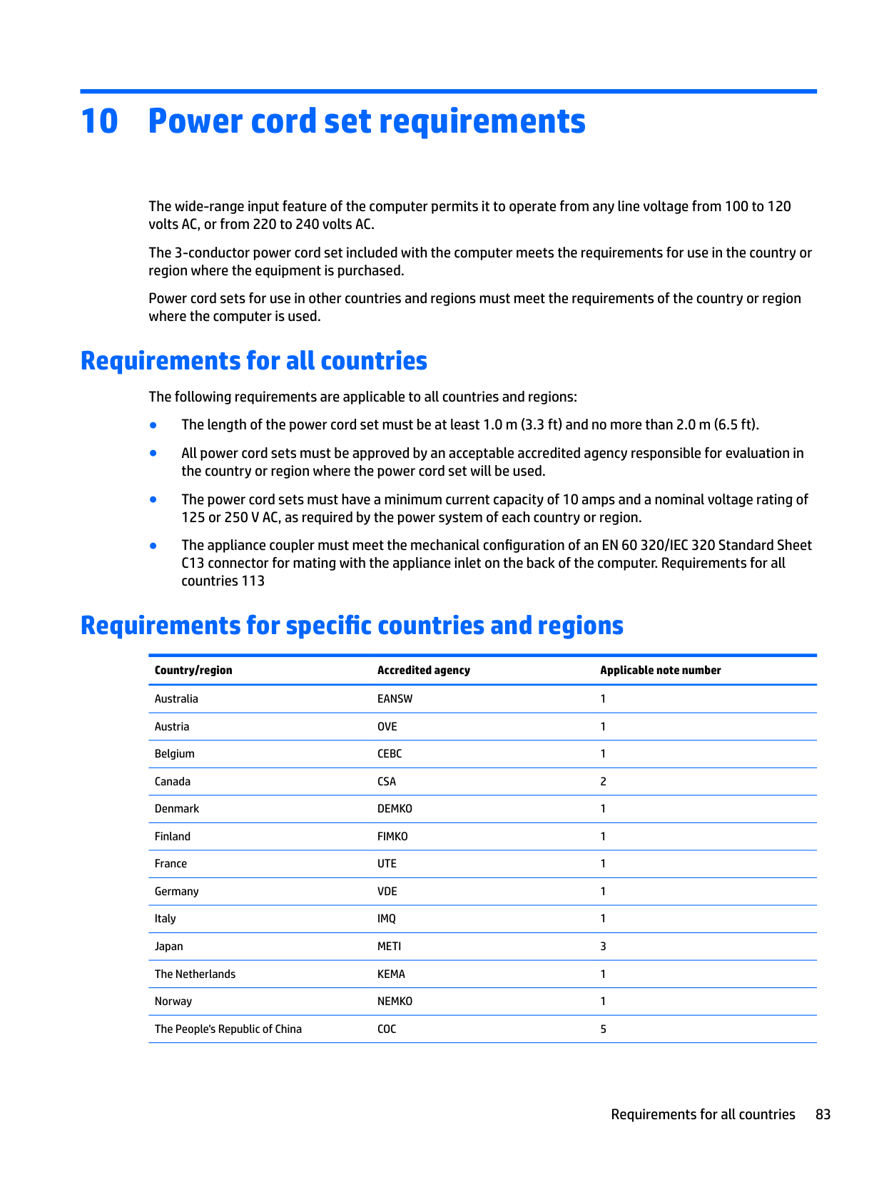
10 Power cord set requirements
The wide-range input feature of the computer permits it to operate from any line voltage from 100 to 120 volts AC, or from 220 to 240 volts AC.
The 3-conductor power cord set included with the computer meets the requirements for use in the country or region where the equipment is purchased.
Power cord sets for use in other countries and regions must meet the requirements of the country or region where the computer is used.
Requirements for all countries
The following requirements are applicable to all countries and regions:
Requirements for specific countries and regions
######## Country/region Accredited agency Applicable note number
Australia EANSW 1 Austria OVE 1 Belgium CEBC 1 Canada CSA 2 Denmark DEMKO 1 Finland FIMKO 1 France UTE 1 Germany VDE 1 Italy IMQ 1 Japan METI 3 The Netherlands KEMA 1 Norway NEMKO 1 The People's Republic of China COC 5
Requirements for all countries 83
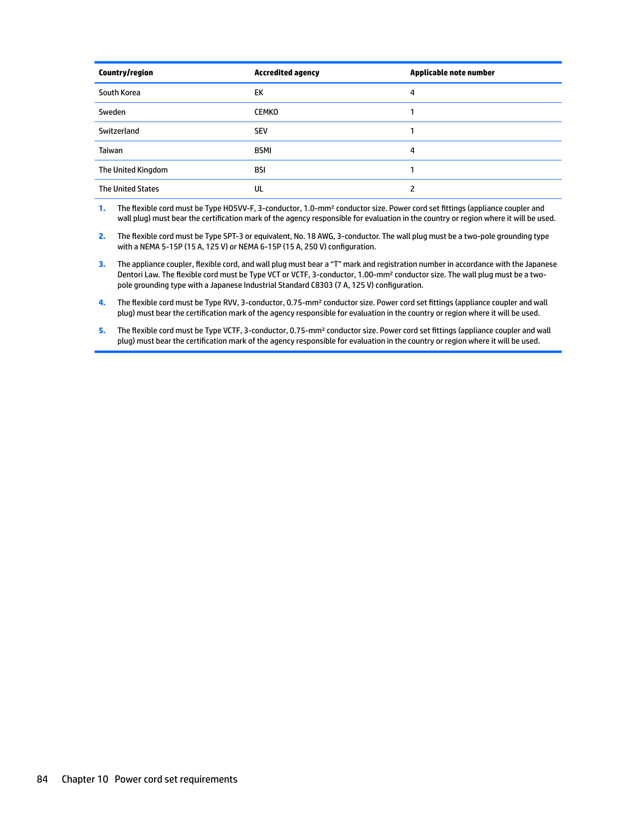
######## Country/region Accredited agency Applicable note number
South Korea EK 4 Sweden CEMKO 1 Switzerland SEV 1 Taiwan BSMI 4 The United Kingdom BSI 1 The United States UL 2
84 Chapter 10 Power cord set requirements
11 Recycling
When a non-rechargeable or rechargeable battery has reached the end of its useful life, do not dispose of the battery in general household waste. Follow the local laws and regulations in your area for battery disposal.
HP encourages customers to recycle used electronic hardware, HP original print cartridges, and rechargeable batteries. For more information about recycling programs, see the HP Web site at http://www.hp.com/recycle.
85
Index
identifying 12
antenna removal 70 spare part number 30, 71
audio, product description 2, 3 audio-out (headphone)/audio-in
(microphone) jack, identifying 7
removal 39 spare part number 28, 39
bezel removal 66 spare part numbers 29, 67
BIOS determining version 72 downloading an update 73 starting the Setup Utility 72 updating 72
boot order changing 81
bottom cover removal 37 spare part number 28, 37
buttons left TouchPad 9 power 11 right TouchPad 9
bottom 13 display 8
keyboard area 9 left side 7 right side 6
computer components 16 connector, power 6 connectors, service considerations
33
components 29 removal 65 spare part numbers 65
display back cover, spare part numbers 30
display panel product description 1, 2 removal 67
display panel cable removal 69
drive light 6 drives
precautions 33 preventing damage 33
removal 50 spare part number 26, 50
fn key, identifying 12

equipment 36 grounding 34
packaging 35 transporting 35 workstation 35
product description 2 removal 40 spare part numbers 28, 40
hard drive bracket removal 41 spare part number 28, 40
hard drive cable removal 41 spare part number 28, 40
HDMI port identifying 6 HDMI-to-VGA adapter, spare part number 31
heat sink removal 56 spare part numbers 26, 56
hinge removal 69 spare part number 30, 69 HP PC Hardware Diagnostics (UEFI)
using 74
HP Recovery Manager correcting boot problems 81 starting 80 HP Recovery media creating 77 recovery 80
HP Recovery partition recovery 80 removing 82
8 integrated numeric keypad, identifying 12 internal microphones, identifying 8
audio-out (headphone)/audio-in
(microphone) 7 network 6 RJ-45 (network) 6
spare part numbers 17, 18, 19, 20, 21, 22, 23, 24
keys action 12 esc 12 fn 12 Windows 12
AC adapter and battery light 6 camera 8 caps lock 10 drive 6 mute 10 power 6, 10 RJ-45 (network) status 6
locating information hardware 5 software 5
product description 2 removal 41 spare part numbers 28, 41
microphone
product description 2, 3 minimized image recovery 80 minimized image, creating 79 model name 1 mute light, identifying 10
description 4
optical drive
product description 2 original system recovery 79
P packaging guidelines 35 plastic parts, service
considerations 32 pointing device, product
description 3
ports HDMI 6 product description 3 USB 3.x SuperSpeed 7 USB Type-C SuperSpeed 6
power button board removal 63 spare part number 63 spare part numbers 25
power button board cable removal 62 spare part number 25, 62, 63
power button, identifying 11 power connector cable
removal 48 spare part number 25, 48
power connector, identifying 6 power cord
set requirements 83 spare part numbers 31 power lights, identifying 6, 10 power requirements, product
description 3 processor, product description 1 product description audio 2, 3 chipset 1 display panel 1, 2 Ethernet 3 external media cards 3 graphics 1 hard drive 2 keyboard 3 memory module 2 microphone 2, 3 operating system 4 optical drive 2 pointing device 3 ports 3 power requirements 3
processors 1 product name 1 security 4 serviceability 4 solid-state drive 2 storage 2 video 2, 3 wireless 3
product name 1
options 79
recovery discs 78, 80 HP Recovery Manager 79 media 80 starting 80 supported discs 78 system 79 USB flash drive 80 using HP Recovery media 78
recovery media creating 77 creating using HP Recovery
Manager 78 recovery partition
removing 82 removal/replacement
procedures 37 RJ-45 (network) jack, identifying 6 RJ-45 (network) status lights,
identifying 6
rubber feet removal 37 spare part number 37
Rubber Foot Kit, spare part number 28, 31
cables 33 connectors 33 plastic parts 32
serviceability, product description 4
Index 87
slots memory card reader 7 security cable 7
solid-state drive product description 2 removal 43 spare part numbers 28, 43
speakers identifying 11 removal 60 spare part number 25, 60
supported discs, recovery 78 system board
removal 52 spare part numbers 26, 52
system recovery 79 system restore point creating 78
system restore point, creating 77
buttons 9 removal 47 spare part number 25, 47
TouchPad bracket removal 47 spare part number 25, 47
TouchPad cable removal 46 spare part number 25, 46
TouchPad zone, identifying 9 transporting guidelines 35
identifying 7
USB port board removal 51 spare part number 51 spare part numbers 25
USB port board cable removal 59 spare part number 26, 51, 59
USB Type-C SuperSpeed port, identifying 6 USB–C-to-USB–A dongle, spare part number 31
removal 67 spare part numbers 30, 67 webcam/microphone module cable
spare part numbers 30 Windows
system restore point 77, 78 Windows key, identifying 12 Windows tools
using 78 wireless antenna removal 70 spare part number 30, 71
wireless, product description 3 WLAN antenna
removal 70 spare part number 30, 71
WLAN antennas, identifying 8 WLAN module
removal 44 spare part numbers 28, 44
workstation guidelines 35