
Ask AI
— answers from the official manualAnswers from the official manual.
Common questions
Common Questions
7 totalWhat can cause blinking power light?
A blinking power light indicates that the device enters Sleep mode. This state conserves battery by turning off display and other non-essential functions until manually resumed.
How do I safely remove the hard drive from my HP Notebook?
First shut down the computer, disconnect all devices, then power it off. Remove components in sequence: base enclosure (p.29), battery (p.31), optical drive (p.27), hard drive itself (p.32). Carefully follow each step to avoid accidental damage.
How should I handle the WLAN module?
Before removing, power down and disconnect the device from all external connections (p.45-6). Remove base enclosure first then proceed with components such as battery, optical drive to reach wireless LAN module part.
Where can I find warranty information for my HP notebook?
Warranty details are located on the service tag under the computer, or as mentioned in 'Locating system information' section which points to how to retrieve it through Windows - pressing fn + esc key.
What should I do if the keyboard backlight stops working?
To turn off or on the keyboard backlight, use the action key that displays an icon of a lamp. Press and hold this key to toggle between on/off states.
What’s the procedure for changing the SSD?
To replace an SSD, power off and unconnect all devices. Follow instructions from p.29 onwards: remove base enclosure, battery, optical drive, hard drive, memory in sequence until reaching M.2 slot where SSD resides (p.34).
Show 1 more questions
Full Manual
94 pages


HP Pavilion Notebook PC
Maintenance and Service Guide
© Copyright 2016 HP Development Company, L.P.
NVIDIA and Quadro are trademarks and/or registered trademarks of NVIDIA Corporation in the U.S. and other countries. Red Hat Enterprise Linux is a registered trademark of Red Hat, Inc. in the United States and other countries. Bluetooth is a trademark owned by its proprietor and used by HP Inc. under license. Intel, Pentium, and Core are trademarks of Intel Corporation in the U.S. and other countries. Windows is either a registered trademark or trademark of Microsoft Corporation in the United States and/or other countries.
Product notice This guide describes features that are common to most models. Some features may not be available on your computer. Not all features are available in all editions of Windows 8. This computer may require upgraded and/or separately purchased hardware, drivers and/or software to take full advantage of Windows 8 functionality. See http://www.microsoft.com for details.
The information contained herein is subject to change without notice. The only warranties for HP products and services are set forth in the express warranty statements accompanying such products and services. Nothing herein should be construed as constituting an additional warranty. HP shall not be liable for technical or editorial errors or omissions contained herein.
Second Edition: July 2016 First Edition: April 2016 Document Part Number: 854537-002
#### Important Notice about Customer Self-Repair Parts
CAUTION: Your computer includes Customer Self-Repair parts and parts that should only be accessed by an authorized service provider. See Chapter 5, "Removal and replacement procedures for Customer Self-Repair parts," for details. Accessing parts described in Chapter 6, "Removal and replacement procedures for authorized service provider parts," can damage the computer or void your warranty.
iii
####### iv Important Notice about Customer Self-Repair Parts
#### Safety warning notice
WARNING! To reduce the possibility of heat-related injuries or of overheating the device, do not place the device directly on your lap or obstruct the device air vents. Use the device only on a hard, flat surface. Do not allow another hard surface, such as an adjoining optional printer, or a soft surface, such as pillows or rugs or clothing, to block airflow. Also, do not allow the AC adapter to contact the skin or a soft surface, such as pillows or rugs or clothing, during operation. The device and the AC adapter comply with the user-accessible surface temperature limits defined by the International Standard for Safety of Information Technology Equipment (IEC 60950-1).
v
####### vi Safety warning notice
Table of contents
TouchPad ............................................................................................................................................................... 9 Lights ................................................................................................................................................................... 10 Button and speakers ......................................................................................................................................... 11 Keys ..................................................................................................................................................................... 12 Using the action keys ........................................................................................................................................ 12
Bottom ..................................................................................................................................................................................... 13 Rear .......................................................................................................................................................................................... 14 Locating system information ............................................................................................................................................... 14
Plastic parts ........................................................................................................................................................ 22 Cables and connectors ..................................................................................................................................... 23 Drive handling .................................................................................................................................................... 23
Grounding guidelines ............................................................................................................................................................. 24
Electrostatic discharge damage ...................................................................................................................... 24 Packaging and transporting guidelines ..................................................................................... 25 Workstation guidelines ................................................................................................................ 25 Equipment guidelines .................................................................................................................. 26

Optical drive ........................................................................................................................................................ 27
vii
Base enclosure ................................................................................................................................................... 29 Battery ................................................................................................................................................................. 31 Hard drive ........................................................................................................................................................... 32 SSD (M.2) ............................................................................................................................................................. 34 Memory ............................................................................................................................................................... 35 WLAN module .................................................................................................................................................... 38 Display assembly ............................................................................................................................................... 40 Fan ....................................................................................................................................................................... 42 Heat sink ............................................................................................................................................................. 43 I/O board ............................................................................................................................................................. 45 Power button board .......................................................................................................................................... 46 System board ..................................................................................................................................................... 48 SD card reader ................................................................................................................................................... 51 Speakers ............................................................................................................................................................. 53 Power connector ................................................................................................................................................ 54 TouchPad ............................................................................................................................................................ 55 Display panel ...................................................................................................................................................... 59 Webcam .............................................................................................................................................................. 63 WLAN cable ......................................................................................................................................................... 65
Creating HP Recovery media (select products only) .................................................................................... 69 Using Windows tools ............................................................................................................................................................. 70 Restore and recovery ............................................................................................................................................................ 71
Recovering using HP Recovery Manager ....................................................................................................... 71 What you need to know before you get started ...................................................................... 71 Using the HP Recovery partition (select products only) ......................................................... 72 Using HP Recovery media to recover ......................................................................................... 72 Changing the computer boot order ........................................................................................... 73 Removing the HP Recovery partition (select products only) ................................................. 74
viii
39.62 cm (15.6-in) display specifications .......................................................................................................................... 76 Hard drive specifications ....................................................................................................................................................... 76 Solid-state drive specifications ............................................................................................................................................ 77 DVD±RW SuperMulti DL Drive specifications ..................................................................................................................... 78

###### Index ............................................................................................................................................................................................................. 82
ix
####### x
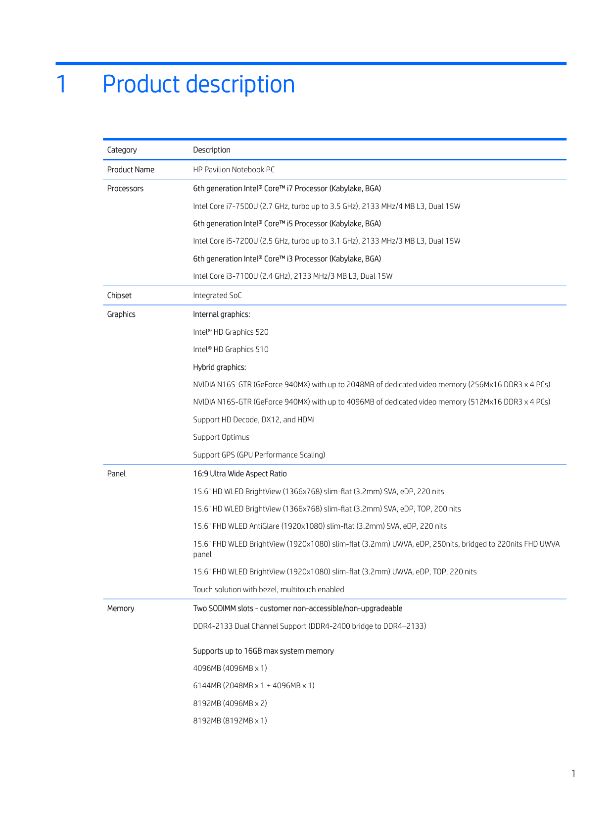
1 Product description
Category Description Product Name HP Pavilion Notebook PC Processors 6th generation Intel® Core™ i7 Processor (Kabylake, BGA)
Intel Core i7-7500U (2.7 GHz, turbo up to 3.5 GHz), 2133 MHz/4 MB L3, Dual 15W 6th generation Intel® Core™ i5 Processor (Kabylake, BGA) Intel Core i5-7200U (2.5 GHz, turbo up to 3.1 GHz), 2133 MHz/3 MB L3, Dual 15W 6th generation Intel® Core™ i3 Processor (Kabylake, BGA) Intel Core i3-7100U (2.4 GHz), 2133 MHz/3 MB L3, Dual 15W
Chipset Integrated SoC Graphics Internal graphics:
Intel® HD Graphics 520 Intel® HD Graphics 510 Hybrid graphics:
NVIDIA N16S-GTR (GeForce 940MX) with up to 2048MB of dedicated video memory (256Mx16 DDR3 x 4 PCs) NVIDIA N16S-GTR (GeForce 940MX) with up to 4096MB of dedicated video memory (512Mx16 DDR3 x 4 PCs) Support HD Decode, DX12, and HDMI Support Optimus Support GPS (GPU Performance Scaling)
Panel 16:9 Ultra Wide Aspect Ratio 15.6" HD WLED BrightView (1366x768) slim-flat (3.2mm) SVA, eDP, 220 nits 15.6" HD WLED BrightView (1366x768) slim-flat (3.2mm) SVA, eDP, TOP, 200 nits 15.6" FHD WLED AntiGlare (1920x1080) slim-flat (3.2mm) SVA, eDP, 220 nits 15.6" FHD WLED BrightView (1920x1080) slim-flat (3.2mm) UWVA, eDP, 250nits, bridged to 220nits FHD UWVA panel 15.6" FHD WLED BrightView (1920x1080) slim-flat (3.2mm) UWVA, eDP, TOP, 220 nits Touch solution with bezel, multitouch enabled
Memory Two SODIMM slots - customer non-accessible/non-upgradeable

DDR4-2133 Dual Channel Support (DDR4-2400 bridge to DDR4–2133)
Supports up to 16GB max system memory 4096MB (4096MB x 1) 6144MB (2048MB x 1 + 4096MB x 1) 8192MB (4096MB x 2) 8192MB (8192MB x 1)
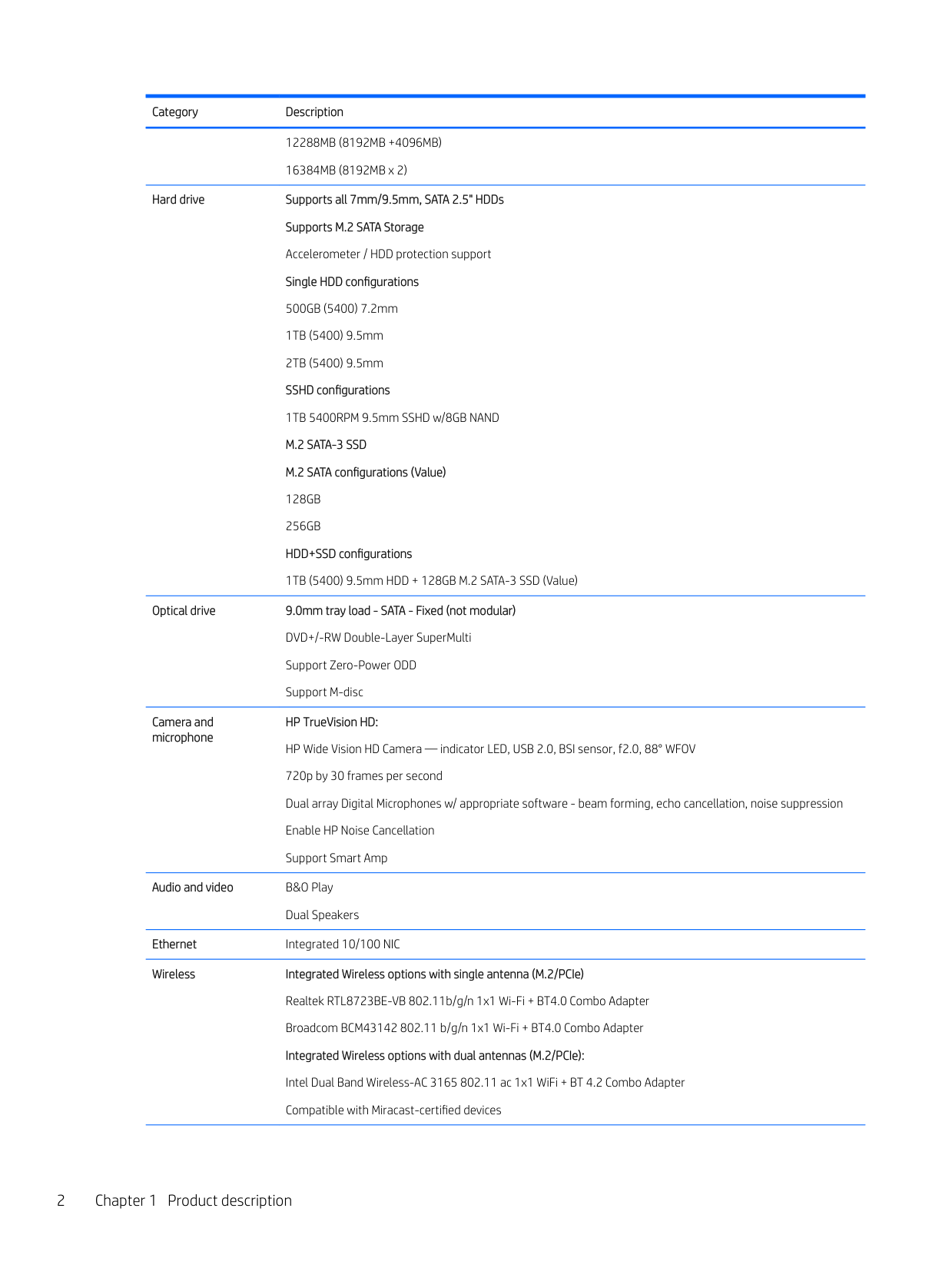
12288MB (8192MB +4096MB) 16384MB (8192MB x 2)
Hard drive Supports all 7mm/9.5mm, SATA 2.5" HDDs Supports M.2 SATA Storage Accelerometer / HDD protection support Single HDD configurations 500GB (5400) 7.2mm
Optical drive 9.0mm tray load - SATA - Fixed (not modular) DVD+/-RW Double-Layer SuperMulti Support Zero-Power ODD Support M-disc
Camera and microphone
HP TrueVision HD: HP Wide Vision HD Camera — indicator LED, USB 2.0, BSI sensor, f2.0, 88° WFOV 720p by 30 frames per second Dual array Digital Microphones w/ appropriate software - beam forming, echo cancellation, noise suppression Enable HP Noise Cancellation Support Smart Amp
Audio and video B&O Play
Dual Speakers Ethernet Integrated 10/100 NIC Wireless Integrated Wireless options with single antenna (M.2/PCIe)
Realtek RTL8723BE-VB 802.11b/g/n 1x1 Wi-Fi + BT4.0 Combo Adapter Broadcom BCM43142 802.11 b/g/n 1x1 Wi-Fi + BT4.0 Combo Adapter Integrated Wireless options with dual antennas (M.2/PCIe): Intel Dual Band Wireless-AC 3165 802.11 ac 1x1 WiFi + BT 4.2 Combo Adapter Compatible with Miracast-certified devices

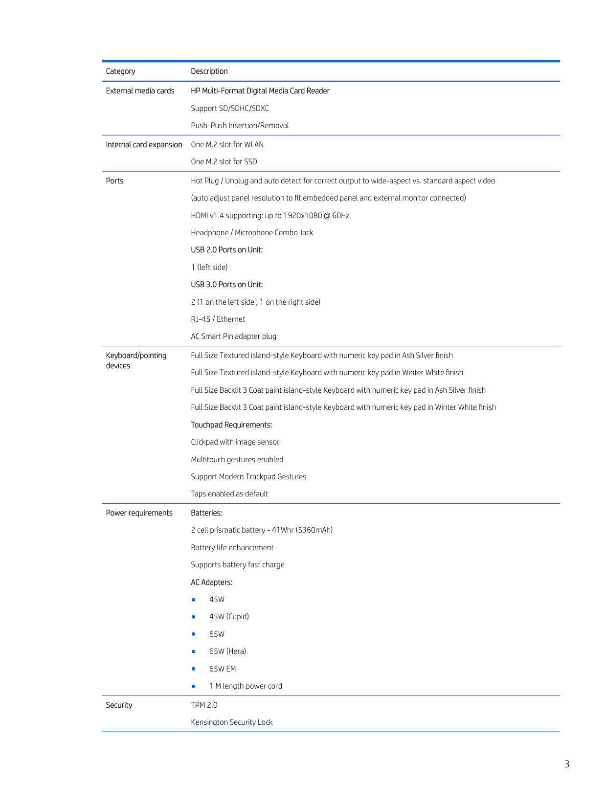
External media cards HP Multi-Format Digital Media Card Reader Support SD/SDHC/SDXC Push-Push Insertion/Removal
Internal card expansion One M.2 slot for WLAN
One M.2 slot for SSD
Ports Hot Plug / Unplug and auto detect for correct output to wide-aspect vs. standard aspect video (auto adjust panel resolution to fit embedded panel and external monitor connected) HDMI v1.4 supporting: up to 1920x1080 @ 60Hz Headphone / Microphone Combo Jack
USB 3.0 Ports on Unit:
Keyboard/pointing devices
Full Size Textured island-style Keyboard with numeric key pad in Ash Silver finish Full Size Textured island-style Keyboard with numeric key pad in Winter White finish Full Size Backlit 3 Coat paint island-style Keyboard with numeric key pad in Ash Silver finish Full Size Backlit 3 Coat paint island-style Keyboard with numeric key pad in Winter White finish Touchpad Requirements: Clickpad with image sensor Multitouch gestures enabled Support Modern Trackpad Gestures Taps enabled as default
Power requirements Batteries: 2 cell prismatic battery - 41Whr (5360mAh) Battery life enhancement Supports battery fast charge AC Adapters:
Security TPM 2.0
Kensington Security Lock
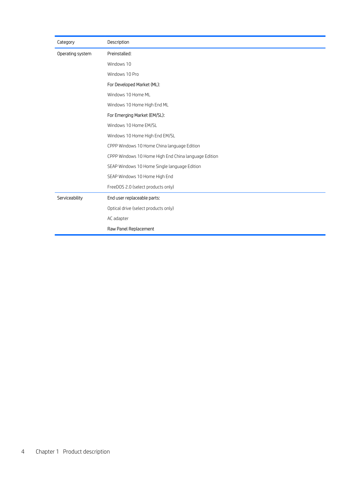
Operating system Preinstalled: Windows 10 Windows 10 Pro For Developed Market (ML): Windows 10 Home ML Windows 10 Home High End ML For Emerging Market (EM/SL): Windows 10 Home EM/SL Windows 10 Home High End EM/SL CPPP Windows 10 Home China language Edition CPPP Windows 10 Home High End China language Edition SEAP Windows 10 Home Single language Edition SEAP Windows 10 Home High End FreeDOS 2.0 (select products only)
Serviceability End user replaceable parts: Optical drive (select products only) AC adapter Raw Panel Replacement
2 External component identification
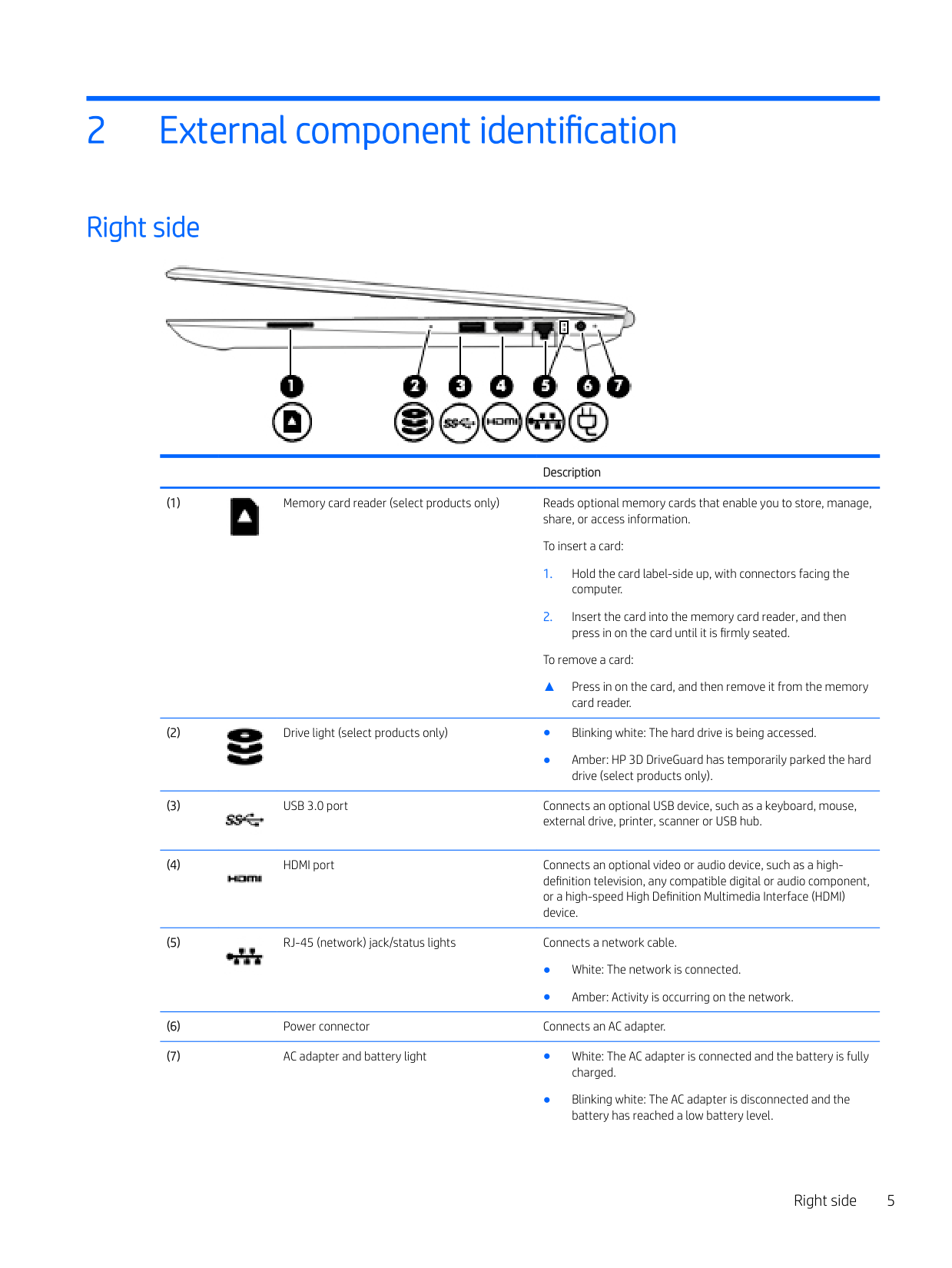
Right side

Description

To remove a card:
▲ Press in on the card, and then remove it from the memory
card reader.

● Amber: HP 3D DriveGuard has temporarily parked the hard
drive (select products only).


Right side 5

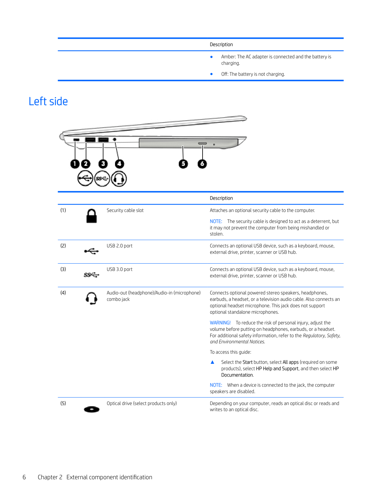
Left side

Description

NOTE: The security cable is designed to act as a deterrent, but it may not prevent the computer from being mishandled or stolen.


Connects optional powered stereo speakers, headphones, earbuds, a headset, or a television audio cable. Also connects an optional headset microphone. This jack does not support optional standalone microphones.
WARNING! To reduce the risk of personal injury, adjust the volume before putting on headphones, earbuds, or a headset. For additional safety information, refer to the Regulatory, Safety, and Environmental Notices.
To access this guide:
▲ Select the Start button, select All apps (required on some products), select HP Help and Support, and then select HP Documentation.
NOTE: When a device is connected to the jack, the computer speakers are disabled.


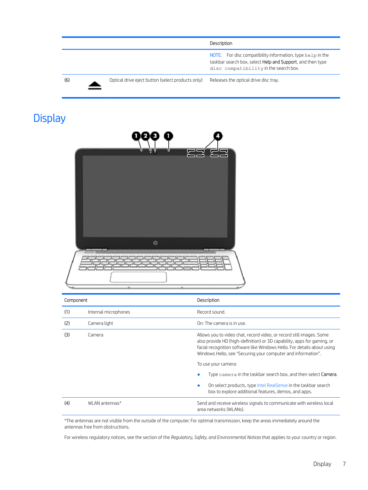
Display

Component Description
*The antennas are not visible from the outside of the computer. For optimal transmission, keep the areas immediately around the antennas free from obstructions.
For wireless regulatory notices, see the section of the Regulatory, Safety, and Environmental Notices that applies to your country or region.
Display 7
Component Description To access this guide:
▲ Select the Start button, select All apps (required on some products), select HP Help and Support, and then select HP Documentation.
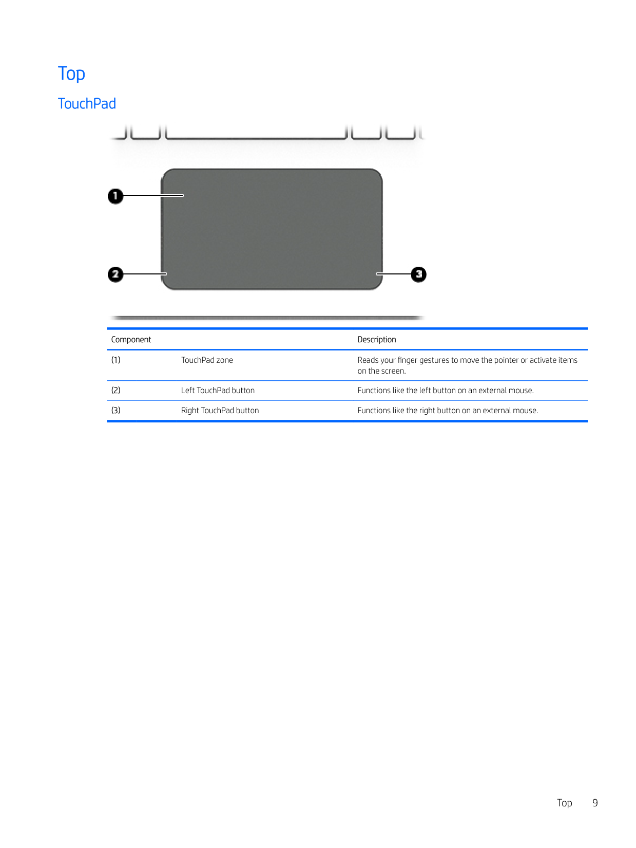
Top
#### TouchPad

Component Description
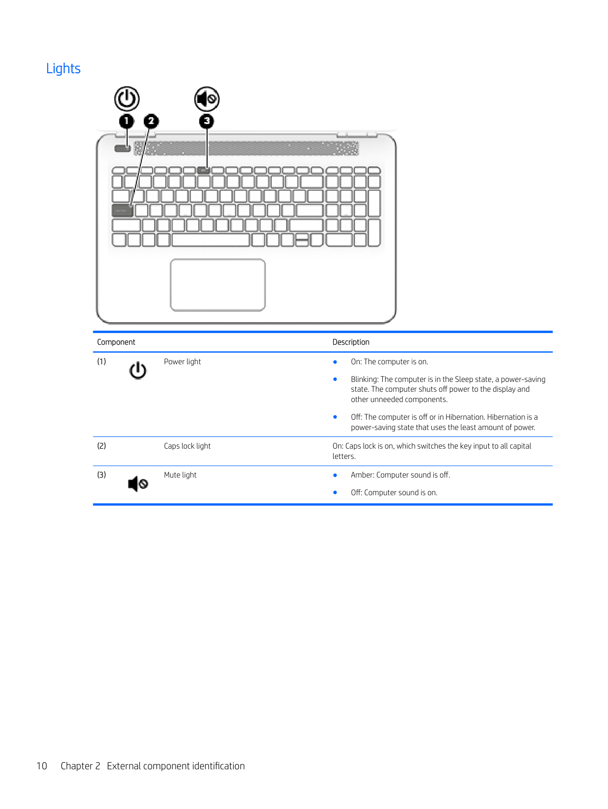
#### Lights

Component Description


● Off: Computer sound is on.
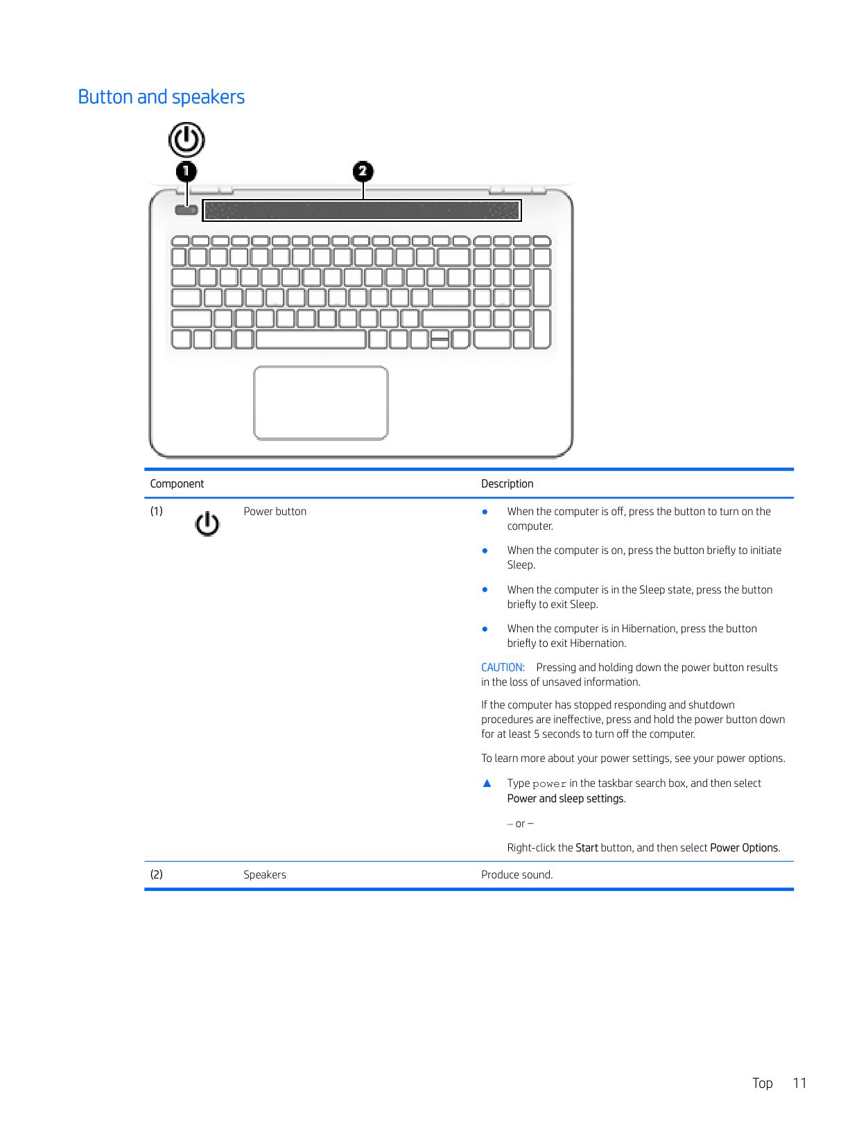
#### Button and speakers

Component Description

CAUTION: Pressing and holding down the power button results in the loss of unsaved information. If the computer has stopped responding and shutdown procedures are ineffective, press and hold the power button down for at least 5 seconds to turn off the computer. To learn more about your power settings, see your power options.
▲ Type power in the taskbar search box, and then select
Power and sleep settings.
or – Right-click the Start button, and then select Power Options.
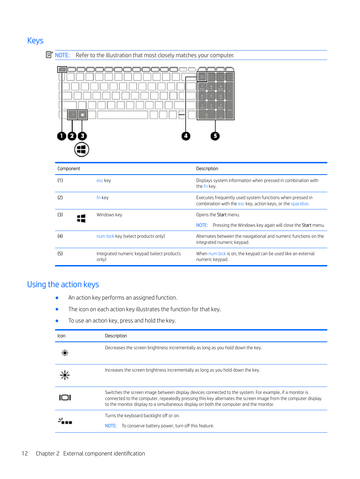
#### Keys
| | |---|
NOTE: Refer to the illustration that most closely matches your computer.

Component Description

When num lock is on, the keypad can be used like an external numeric keypad.
#### Using the action keys
Icon Description

Decreases the screen brightness incrementally as long as you hold down the key.


Increases the screen brightness incrementally as long as you hold down the key.
Switches the screen image between display devices connected to the system. For example, if a monitor is connected to the computer, repeatedly pressing this key alternates the screen image from the computer display to the monitor display to a simultaneous display on both the computer and the monitor.
Turns the keyboard backlight off or on. NOTE: To conserve battery power, turn off this feature.
Icon Description

Mutes or restores speaker sound.


Decreases speaker volume incrementally while you hold down the key.
Increases speaker volume incrementally while you hold down the key.


Plays the previous track of an audio CD or the previous section of a DVD or a Blu-ray Disc (BD).
Starts, pauses, or resumes playback of an audio CD, a DVD, or a BD.
Plays the next track of an audio CD or the next section of a DVD or a BD.
Turns the airplane mode and wireless feature on or off. NOTE: The airplane mode key is also referred to as the wireless button. NOTE: A wireless network must be set up before a wireless connection is possible.
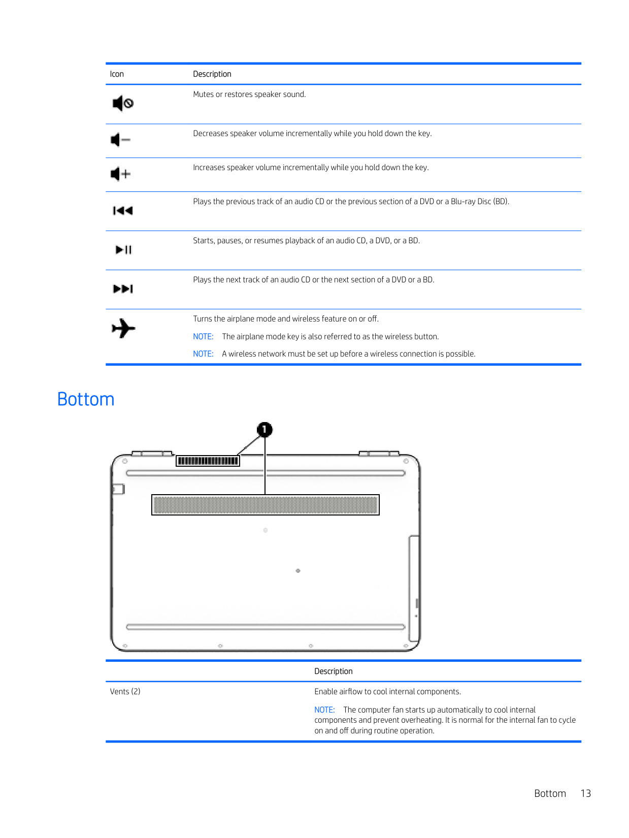
Bottom

Description
Vents (2) Enable airflow to cool internal components.
NOTE: The computer fan starts up automatically to cool internal components and prevent overheating. It is normal for the internal fan to cycle on and off during routine operation.
Bottom 13
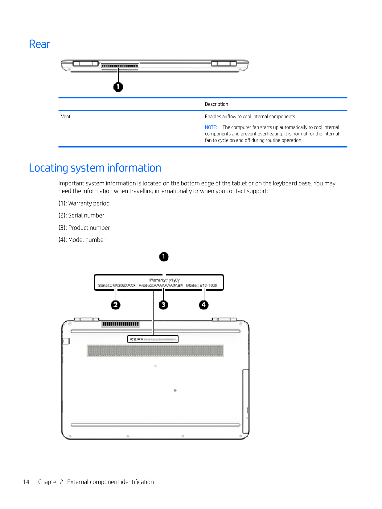
Rear

Description
Vent Enables airflow to cool internal components.
NOTE: The computer fan starts up automatically to cool internal components and prevent overheating. It is normal for the internal fan to cycle on and off during routine operation.
Locating system information
Important system information is located on the bottom edge of the tablet or on the keyboard base. You may need the information when travelling internationally or when you contact support:

Using Windows, briefly press the fn+esc key combination to display the System Information screen, which provides the product name and serial number of your computer, as well as information about the memory, processor, BIOS, and keyboard.
Locating system information 15
3 Illustrated parts catalog
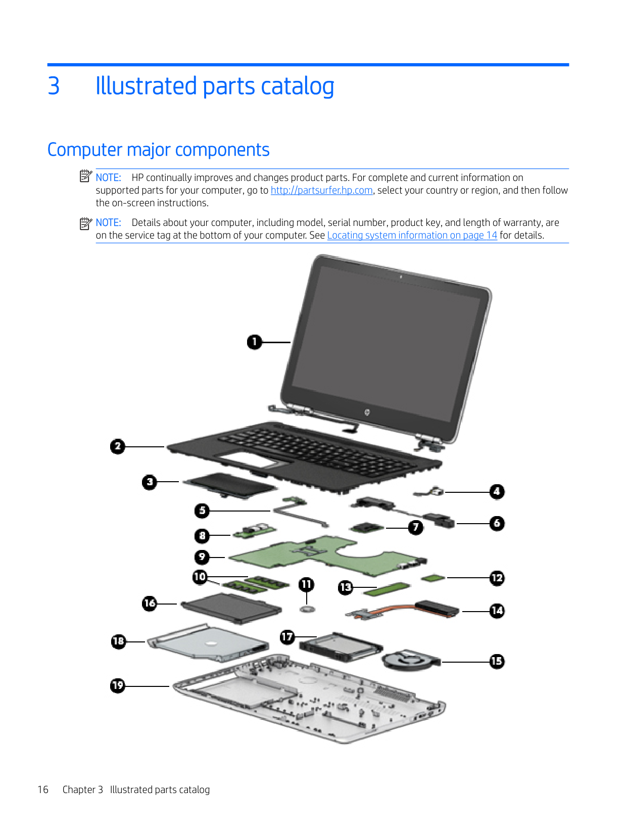
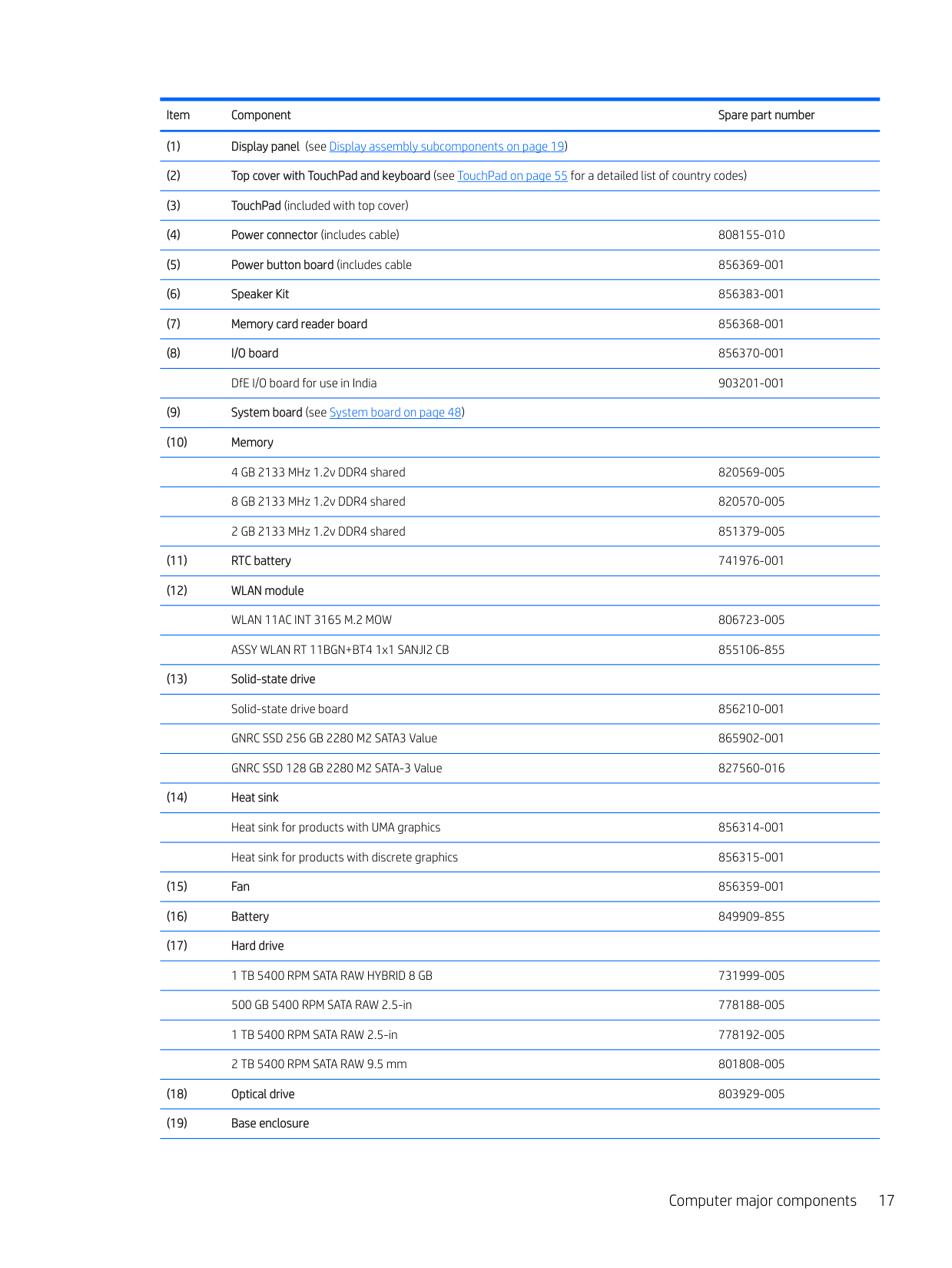
Computer major components
| | |---|
NOTE: HP continually improves and changes product parts. For complete and current information on supported parts for your computer, go to http://partsurfer.hp.com, select your country or region, and then follow the on-screen instructions.
| | |---|
NOTE: Details about your computer, including model, serial number, product key, and length of warranty, are on the service tag at the bottom of your computer. See Locating system information on page 14 for details.

####### Computer major components 17
In Natural Silver finish 856332-001 In Onyx Black finish 856333-001 In Modern Gold finish 856334-001 In Cardinal Red finish 856335-001 In Sport Purple finish 856336-001 In Dragonfly Blue finish 856337-001 In Blizzard White finish 856338-001
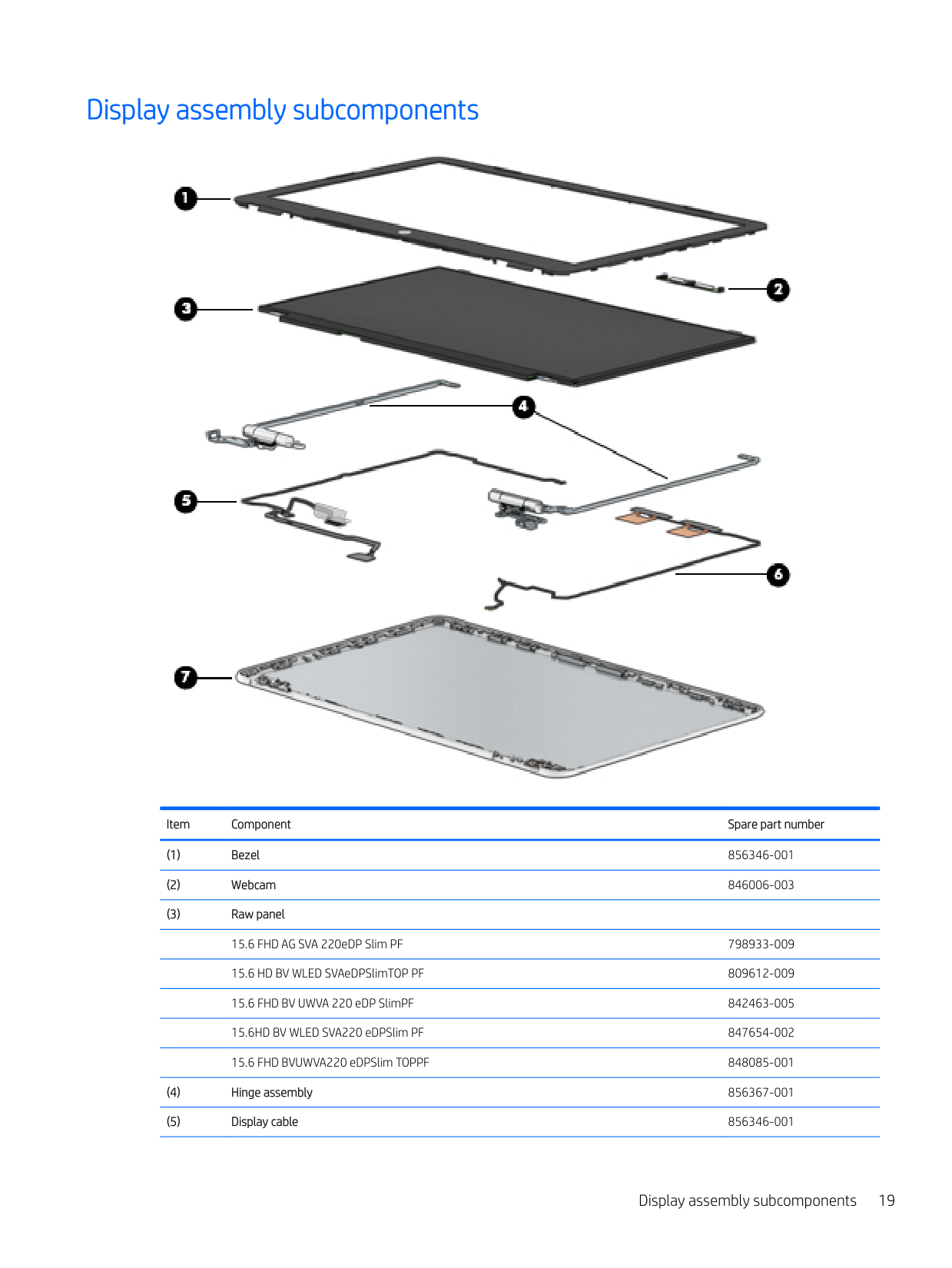
Display assembly subcomponents

Item Component Spare part number
Display assembly subcomponents 19
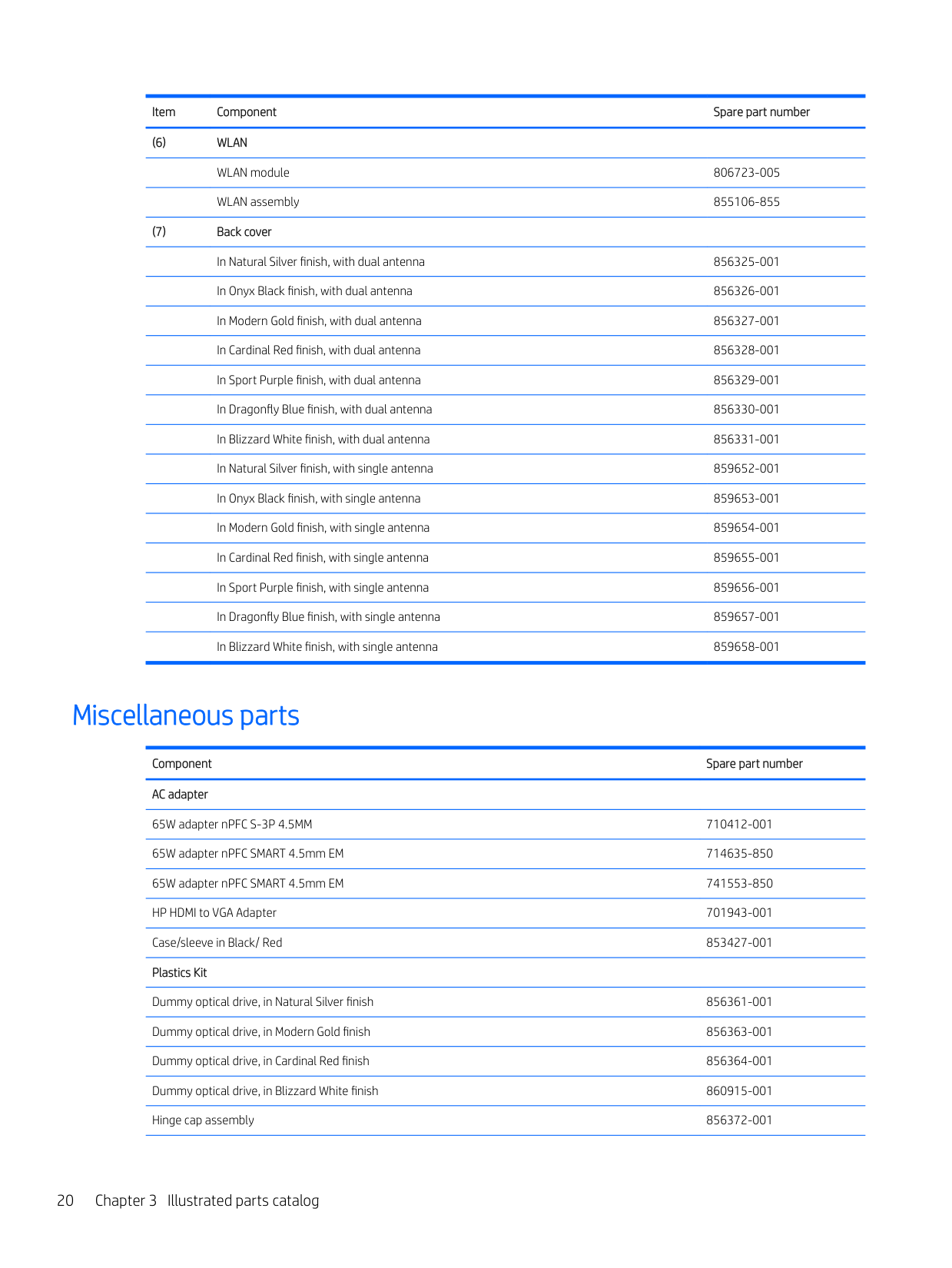
Miscellaneous parts
Component Spare part number AC adapter
65W adapter nPFC S-3P 4.5MM 710412-001 65W adapter nPFC SMART 4.5mm EM 714635-850 65W adapter nPFC SMART 4.5mm EM 741553-850 HP HDMI to VGA Adapter 701943-001 Case/sleeve in Black/ Red 853427-001 Plastics Kit
Dummy optical drive, in Natural Silver finish 856361-001 Dummy optical drive, in Modern Gold finish 856363-001 Dummy optical drive, in Cardinal Red finish 856364-001 Dummy optical drive, in Blizzard White finish 860915-001 Hinge cap assembly 856372-001
Component Spare part number
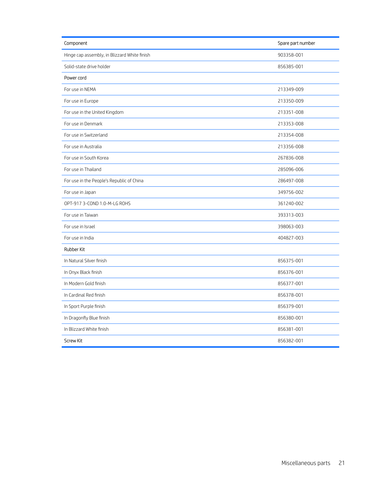
Hinge cap assembly, in Blizzard White finish 903358-001 Solid-state drive holder 856385-001 Power cord
For use in NEMA 213349-009 For use in Europe 213350-009 For use in the United Kingdom 213351-008 For use in Denmark 213353-008 For use in Switzerland 213354-008 For use in Australia 213356-008 For use in South Korea 267836-008 For use in Thailand 285096-006 For use in the People’s Republic of China 286497-008 For use in Japan 349756-002 OPT-917 3-COND 1.0-M-LG ROHS 361240-002 For use in Taiwan 393313-003 For use in Israel 398063-003 For use in India 404827-003 Rubber Kit
In Natural Silver finish 856375-001 In Onyx Black finish 856376-001 In Modern Gold finish 856377-001 In Cardinal Red finish 856378-001 In Sport Purple finish 856379-001 In Dragonfly Blue finish 856380-001 In Blizzard White finish 856381-001 Screw Kit 856382-001
Miscellaneous parts 21
4 Removal and replacement procedurespreliminary requirements
Tools required
You will need the following tools to complete the removal and replacement procedures:
Service considerations
The following sections include some of the considerations that you must keep in mind during disassembly and assembly procedures.
| | |---|
NOTE: As you remove each subassembly from the computer, place the subassembly (and all accompanying screws) away from the work area to prevent damage.
#### Plastic parts
CAUTION: Using excessive force during disassembly and reassembly can damage plastic parts. Use care when handling the plastic
#### Cables and connectors
CAUTION: When servicing the computer, be sure that cables are placed in their proper locations during the reassembly process. Improper cable placement can damage the computer.
Cables must be handled with extreme care to avoid damage. Apply only the tension required to unseat or seat the cables during removal and insertion. Handle cables by the connector whenever possible. In all cases, avoid bending, twisting, or tearing cables. Be sure that cables are routed in such a way that they cannot be caught or snagged by parts being removed or replaced. Handle flex cables with extreme care; these cables tear easily.
Drive handling CAUTION: Drives are fragile components that must be handled with care. To prevent damage to the computer, damage to a drive, or loss of information, observe these precautions: Before removing or inserting a hard drive, shut down the computer. If you are unsure whether the computer is off or in Hibernation, turn the computer on, and then shut it down through the operating system. Before handling a drive, be sure that you are discharged of static electricity. While handling a drive, avoid touching the connector. Before removing an optical drive, be sure that a disc is not in the drive and be sure that the optical drive tray is closed. Handle drives on surfaces covered with at least one inch of shock-proof foam. Avoid dropping drives from any height onto any surface. After removing a hard drive or an optical drive, place it in a static-proof bag. Avoid exposing an internal hard drive to products that have magnetic fields, such as monitors or speakers. Avoid exposing a drive to temperature extremes or liquids. If a drive must be mailed, place the drive in a bubble pack mailer or other suitable form of protective packaging and label the package “FRAGILE.”
Service considerations 23
Grounding guidelines

#### Electrostatic discharge damage
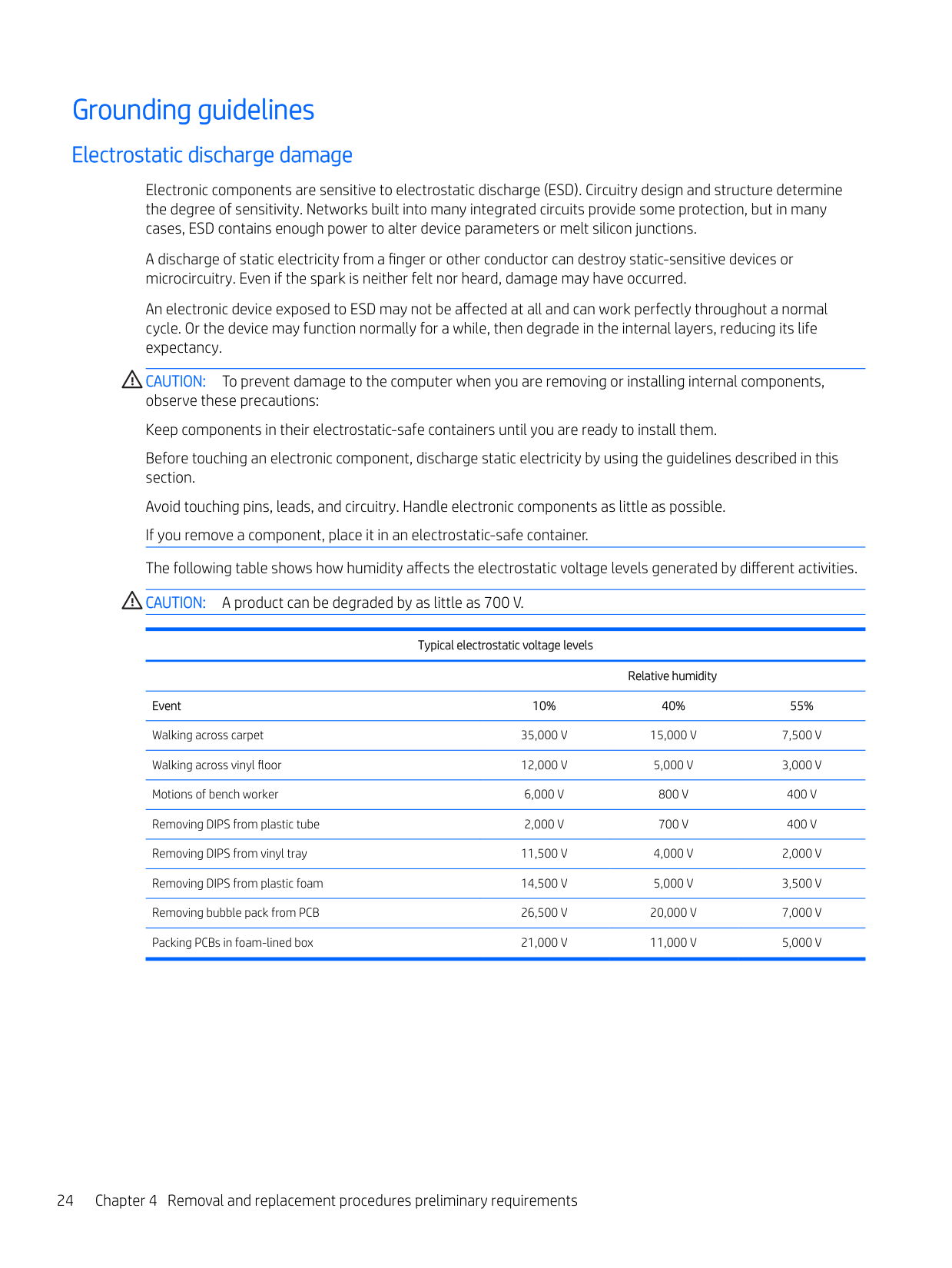
Electronic components are sensitive to electrostatic discharge (ESD). Circuitry design and structure determine the degree of sensitivity. Networks built into many integrated circuits provide some protection, but in many cases, ESD contains enough power to alter device parameters or melt silicon junctions.
A discharge of static electricity from a finger or other conductor can destroy static-sensitive devices or microcircuitry. Even if the spark is neither felt nor heard, damage may have occurred.
An electronic device exposed to ESD may not be affected at all and can work perfectly throughout a normal cycle. Or the device may function normally for a while, then degrade in the internal layers, reducing its life expectancy.
CAUTION: To prevent damage to the computer when you are removing or installing internal components, observe these precautions: Keep components in their electrostatic-safe containers until you are ready to install them. Before touching an electronic component, discharge static electricity by using the guidelines described in this section. Avoid touching pins, leads, and circuitry. Handle electronic components as little as possible. If you remove a component, place it in an electrostatic-safe container. The following table shows how humidity affects the electrostatic voltage levels generated by different activities. CAUTION: A product can be degraded by as little as 700 V.
Typical electrostatic voltage levels
Relative humidity Event 10% 40% 55% Walking across carpet 35,000 V 15,000 V 7,500 V Walking across vinyl floor 12,000 V 5,000 V 3,000 V Motions of bench worker 6,000 V 800 V 400 V Removing DIPS from plastic tube 2,000 V 700 V 400 V Removing DIPS from vinyl tray 11,500 V 4,000 V 2,000 V Removing DIPS from plastic foam 14,500 V 5,000 V 3,500 V Removing bubble pack from PCB 26,500 V 20,000 V 7,000 V Packing PCBs in foam-lined box 21,000 V 11,000 V 5,000 V
##### Packaging and transporting guidelines
Follow these grounding guidelines when packaging and transporting equipment:
##### Workstation guidelines
Follow these grounding workstation guidelines:
Grounding guidelines 25
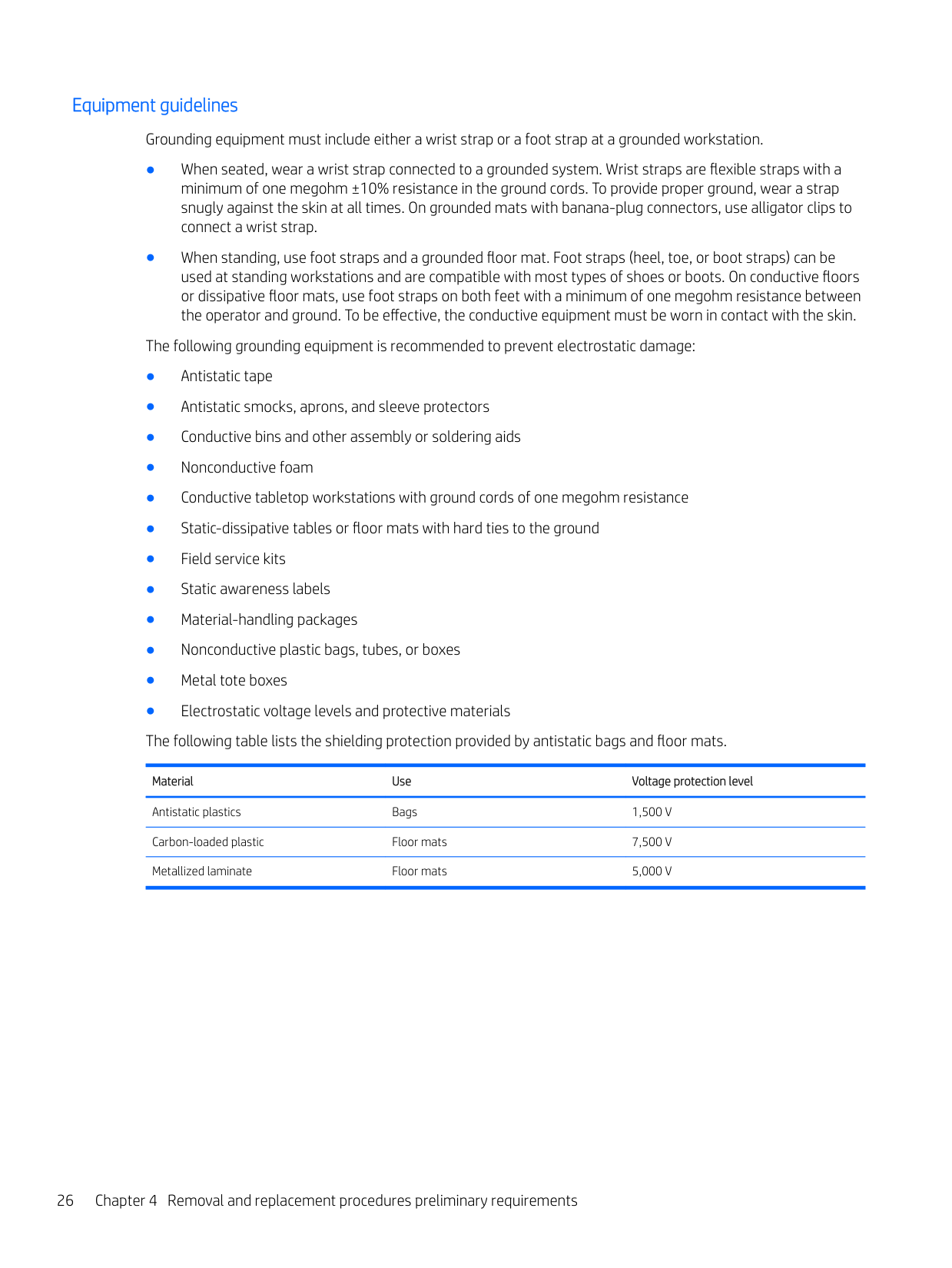
##### Equipment guidelines
Grounding equipment must include either a wrist strap or a foot strap at a grounded workstation.
Material Use Voltage protection level
Antistatic plastics Bags 1,500 V Carbon-loaded plastic Floor mats 7,500 V Metallized laminate Floor mats 5,000 V
5 Removal and replacement procedures for Customer Self-Repair parts
| | |---|
This chapter provides removal and replacement procedures for Customer Self-Repair parts. NOTE: The Customer Self-Repair program is not available in all locations. Installing a part not supported by the Customer Self-Repair program may void your warranty. Check your warranty to determine if Customer SelfRepair is supported in your location.

Component replacement procedures
| | |---|
NOTE: Details about your computer, including model, serial number, product key, and length of warranty, are on the service tag at the bottom of your computer. See Locating system information on page 14 for details.
| | |---|
NOTE: HP continually improves and changes product parts. For complete and current information on supported parts for your computer, go to http://partsurfer.hp.com, select your country or region, and then follow the on-screen instructions.
One screw must be removed, replaced, and/or loosened when servicing Customer Self-Repair parts. Make special note of each screw size and location during removal and replacement.
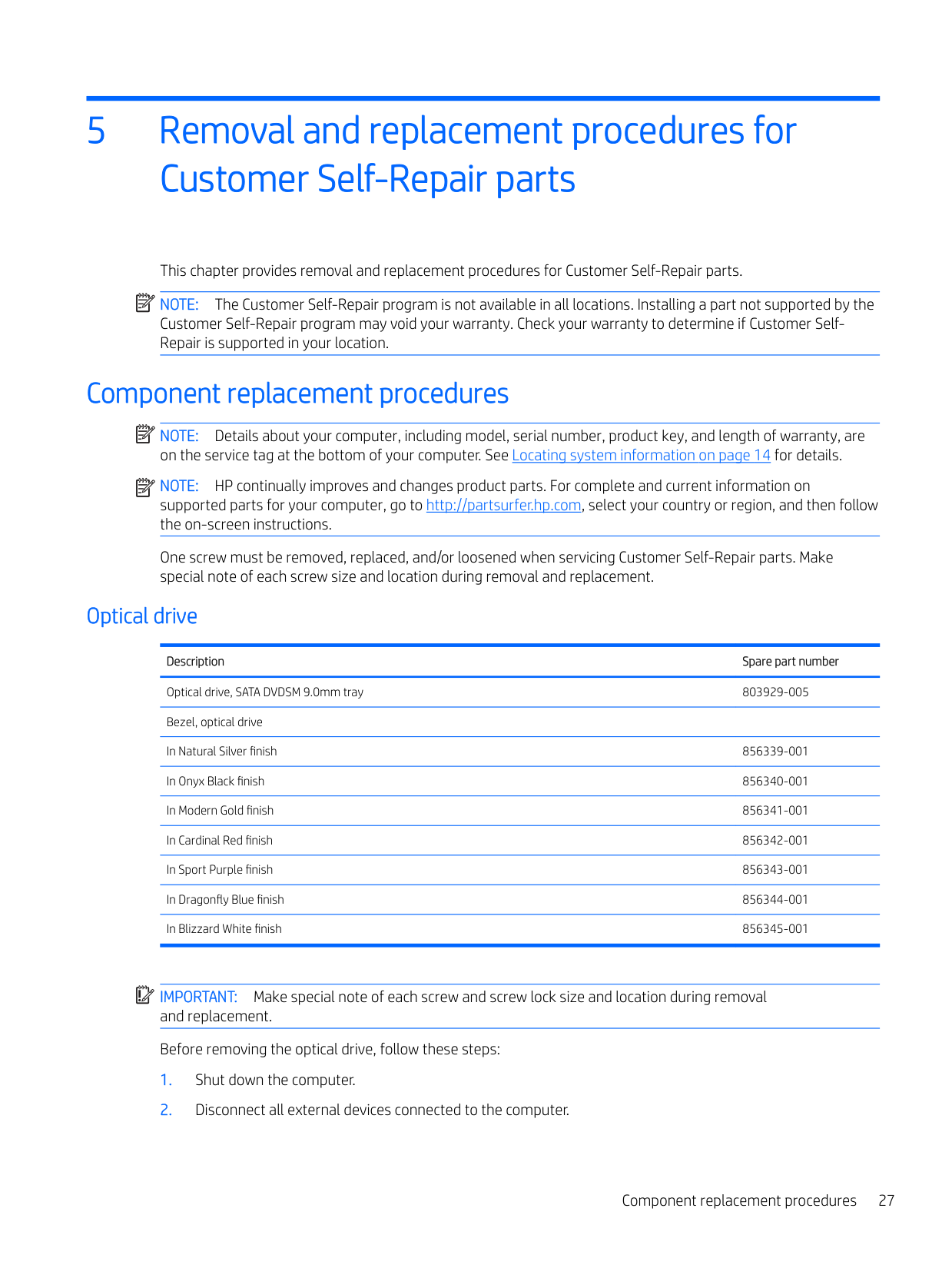
#### Optical drive
Description Spare part number Optical drive, SATA DVDSM 9.0mm tray 803929-005 Bezel, optical drive In Natural Silver finish 856339-001 In Onyx Black finish 856340-001 In Modern Gold finish 856341-001 In Cardinal Red finish 856342-001 In Sport Purple finish 856343-001 In Dragonfly Blue finish 856344-001 In Blizzard White finish 856345-001
| | |---|
IMPORTANT: Make special note of each screw and screw lock size and location during removal and replacement. Before removing the optical drive, follow these steps:
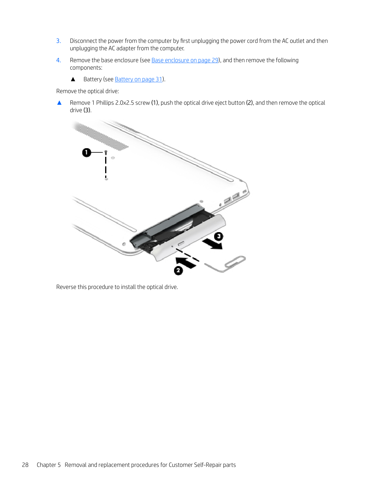
▲ Battery (see Battery on page 31). Remove the optical drive:
▲ Remove 1 Phillips 2.0x2.5 screw (1), push the optical drive eject button (2), and then remove the optical
drive (3).

Reverse this procedure to install the optical drive.
28 Chapter 5 Removal and replacement procedures for Customer Self-Repair parts
6 Removal and replacement procedures for authorized service provider parts
CAUTION: Components described in this chapter should be accessed only by an authorized service provider. Accessing these parts can damage the computer or void the warranty.
CAUTION: This computer does not have user-replaceable parts. Only HP authorized service providers should perform the removal and replacement procedures described here. Accessing the internal part could damage the computer or void the warranty.
Component replacement procedures
| | |---|
NOTE: Details about your computer, including model, serial number, product key, and length of warranty, are on the service tag at the bottom of your computer. See Locating system information on page 14 for details.
| | |---|
NOTE: HP continually improves and changes product parts. For complete and current information on supported parts for your computer, go to http://partsurfer.hp.com, select your country or region, and then follow the on-screen instructions.
There are as many as 61 screws that must be removed, replaced, and/or loosened when servicing the parts described in this chapter. Make special note of each screw size and location during removal and replacement.
#### Base enclosure
Description Spare part number Base enclosure In Natural Silver finish 856332-001 In Onyx Black finish 856333-001 In Modern Gold finish 856334-001 In Cardinal Red finish 856335-001 In Sport Purple finish 856336-001 In Dragonfly Blue finish 856337-001 In Blizzard White finish 856338-001
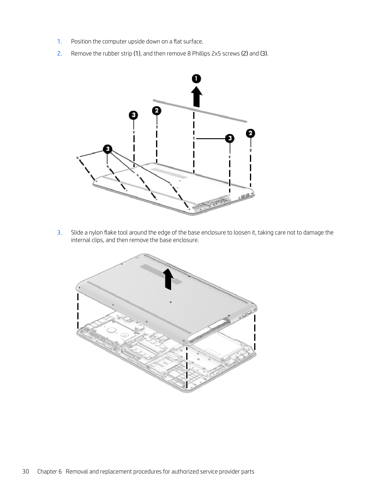
Before disassembling the computer, follow these steps:


#### Battery
Description Spare part number
Battery 2C 41WH 5.36Ah LI BP02042XL-PR 849909-855 Battery cable 856351-001
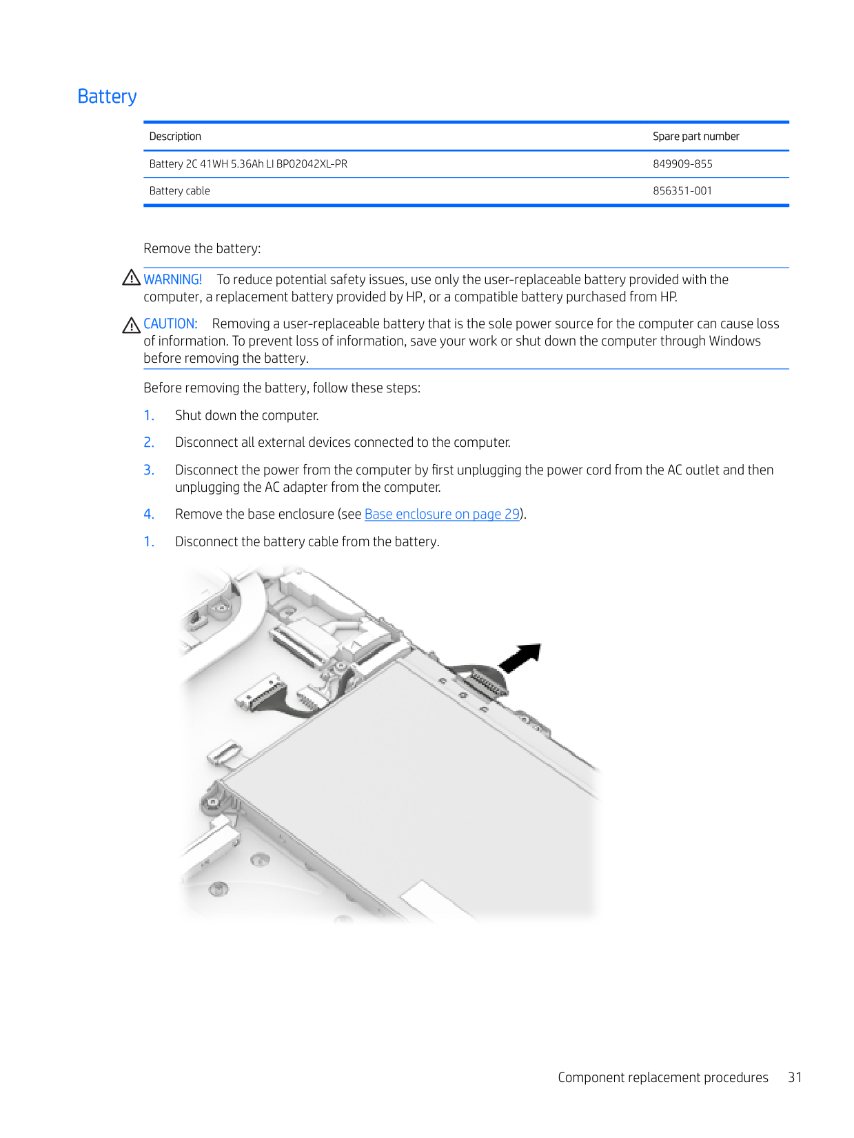
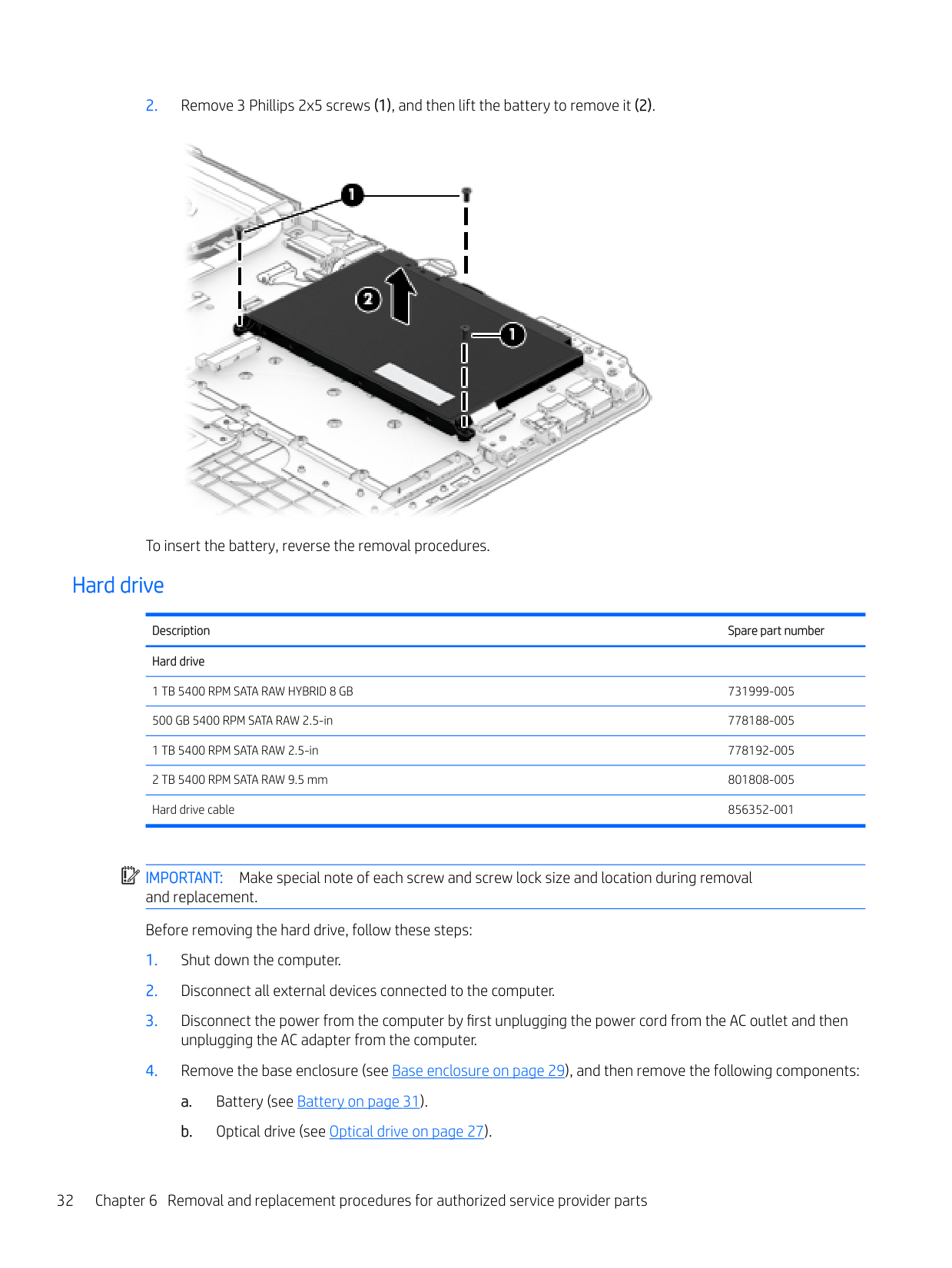
Remove the battery: WARNING! To reduce potential safety issues, use only the user-replaceable battery provided with the computer, a replacement battery provided by HP, or a compatible battery purchased from HP. CAUTION: Removing a user-replaceable battery that is the sole power source for the computer can cause loss of information. To prevent loss of information, save your work or shut down the computer through Windows before removing the battery. Before removing the battery, follow these steps:


To insert the battery, reverse the removal procedures.
#### Hard drive
Description Spare part number Hard drive
1 TB 5400 RPM SATA RAW HYBRID 8 GB 731999-005 500 GB 5400 RPM SATA RAW 2.5-in 778188-005 1 TB 5400 RPM SATA RAW 2.5-in 778192-005 2 TB 5400 RPM SATA RAW 9.5 mm 801808-005 Hard drive cable 856352-001
| | |---|
IMPORTANT: Make special note of each screw and screw lock size and location during removal and replacement. Before removing the hard drive, follow these steps:
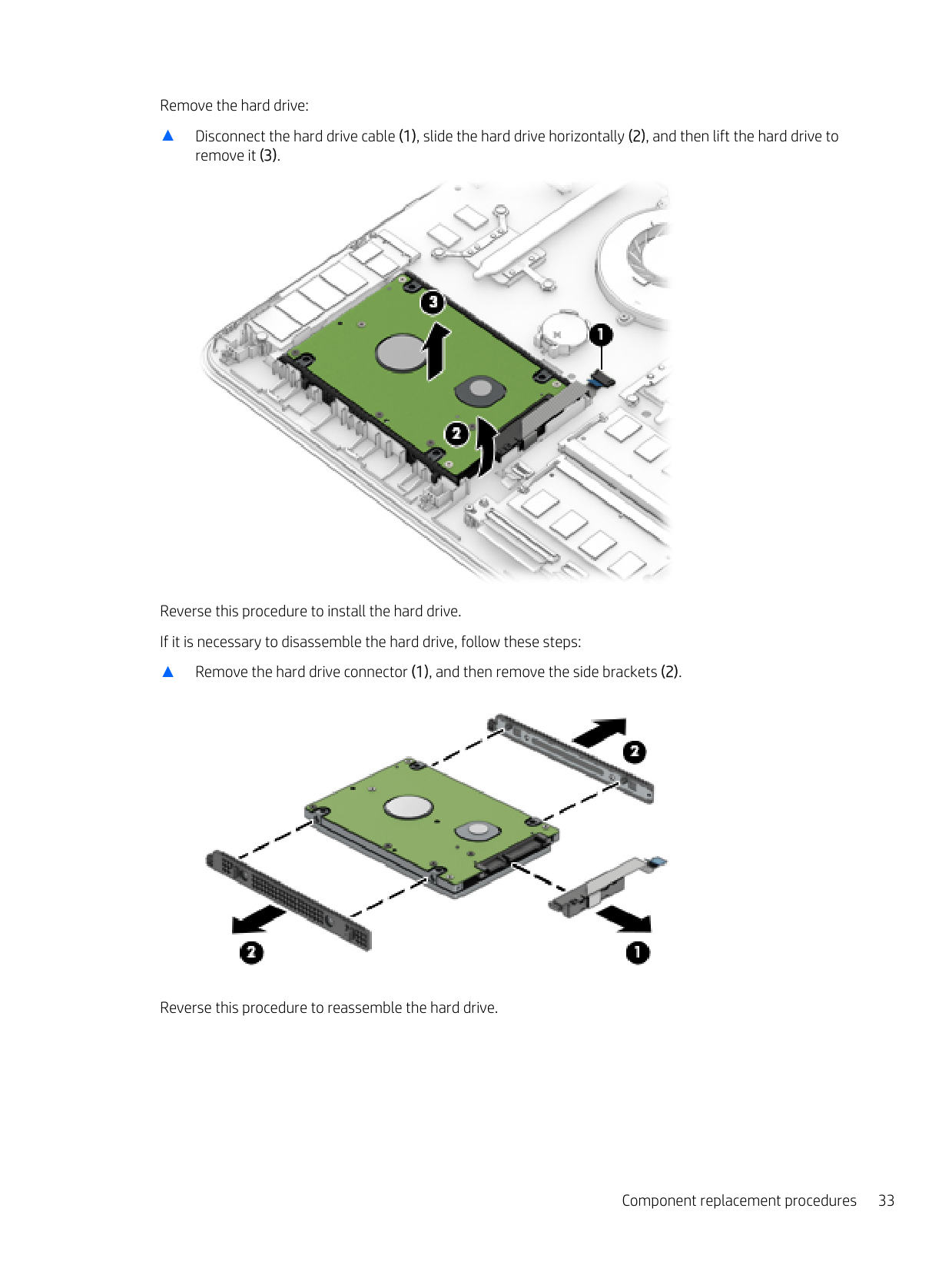
Remove the hard drive:
▲ Disconnect the hard drive cable (1), slide the hard drive horizontally (2), and then lift the hard drive to
remove it (3).

Reverse this procedure to install the hard drive. If it is necessary to disassemble the hard drive, follow these steps:
▲ Remove the hard drive connector (1), and then remove the side brackets (2).

Reverse this procedure to reassemble the hard drive.
#### SSD (M.2)
Description Spare part number
Solid-state drive board 856210-001 GNRC SSD 256GB 2280 M2 SATA-3 Value 865902-001 GNRC SSD 128GB 2280 M2 SATA-3 Value 847110-002 Solid-state drive cable 856353-001
Before removing the SSD, follow these steps:
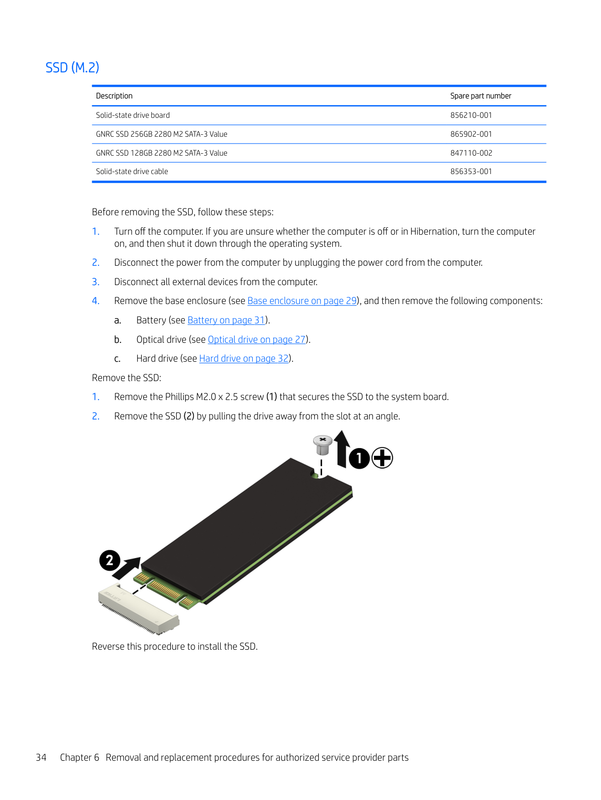
Remove the SSD:

Reverse this procedure to install the SSD.
#### Memory
Description Spare part number Memory
4 GB 2133 MHz 1.2v DDR4 shared 820569-005 8 GB 2133 MHz 1.2v DDR4 shared 820570-005 2 GB 2133 MHz 1.2v DDR4 shared 851379-005
| | |---|
IMPORTANT: Make special note of each screw and screw lock size and location during removal and replacement. Before removing the memory, follow these steps:
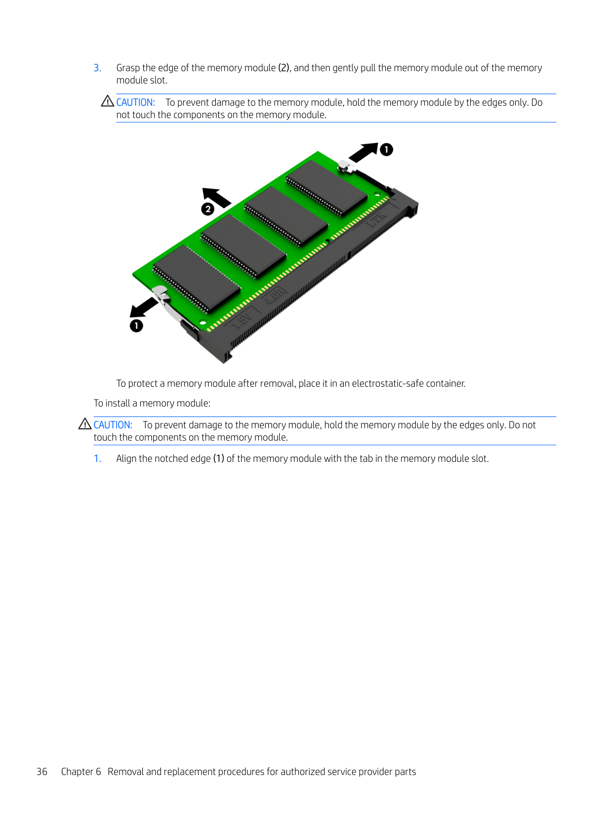
If you are replacing a memory module, remove the existing memory module:
CAUTION: To prevent damage to the memory module, hold the memory module by the edges only. Do not touch the components on the memory module.

To protect a memory module after removal, place it in an electrostatic-safe container. To install a memory module: CAUTION: To prevent damage to the memory module, hold the memory module by the edges only. Do not touch the components on the memory module.
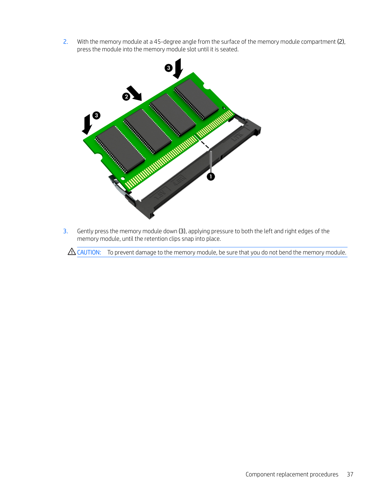
####### 2. With the memory module at a 45-degree angle from the surface of the memory module compartment (2),press the module into the memory module slot until it is seated.

####### 3. Gently press the memory module down (3), applying pressure to both the left and right edges of thememory module, until the retention clips snap into place.CAUTION: To prevent damage to the memory module, be sure that you do not bend the memory module.
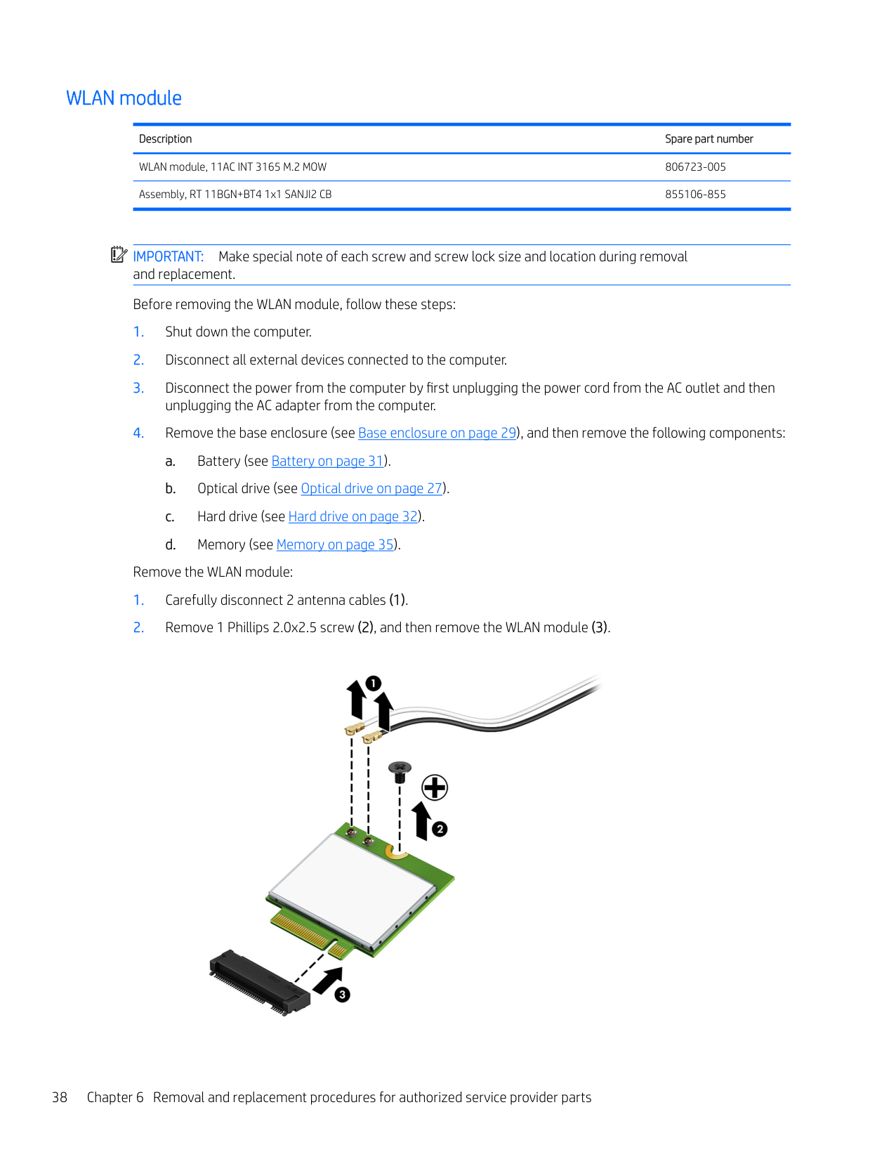
#### WLAN module
Description Spare part number
WLAN module, 11AC INT 3165 M.2 MOW 806723-005 Assembly, RT 11BGN+BT4 1x1 SANJI2 CB 855106-855
| | |---|
IMPORTANT: Make special note of each screw and screw lock size and location during removal and replacement. Before removing the WLAN module, follow these steps:
Remove the WLAN module:

####### Reverse this procedure to install the WLAN module.
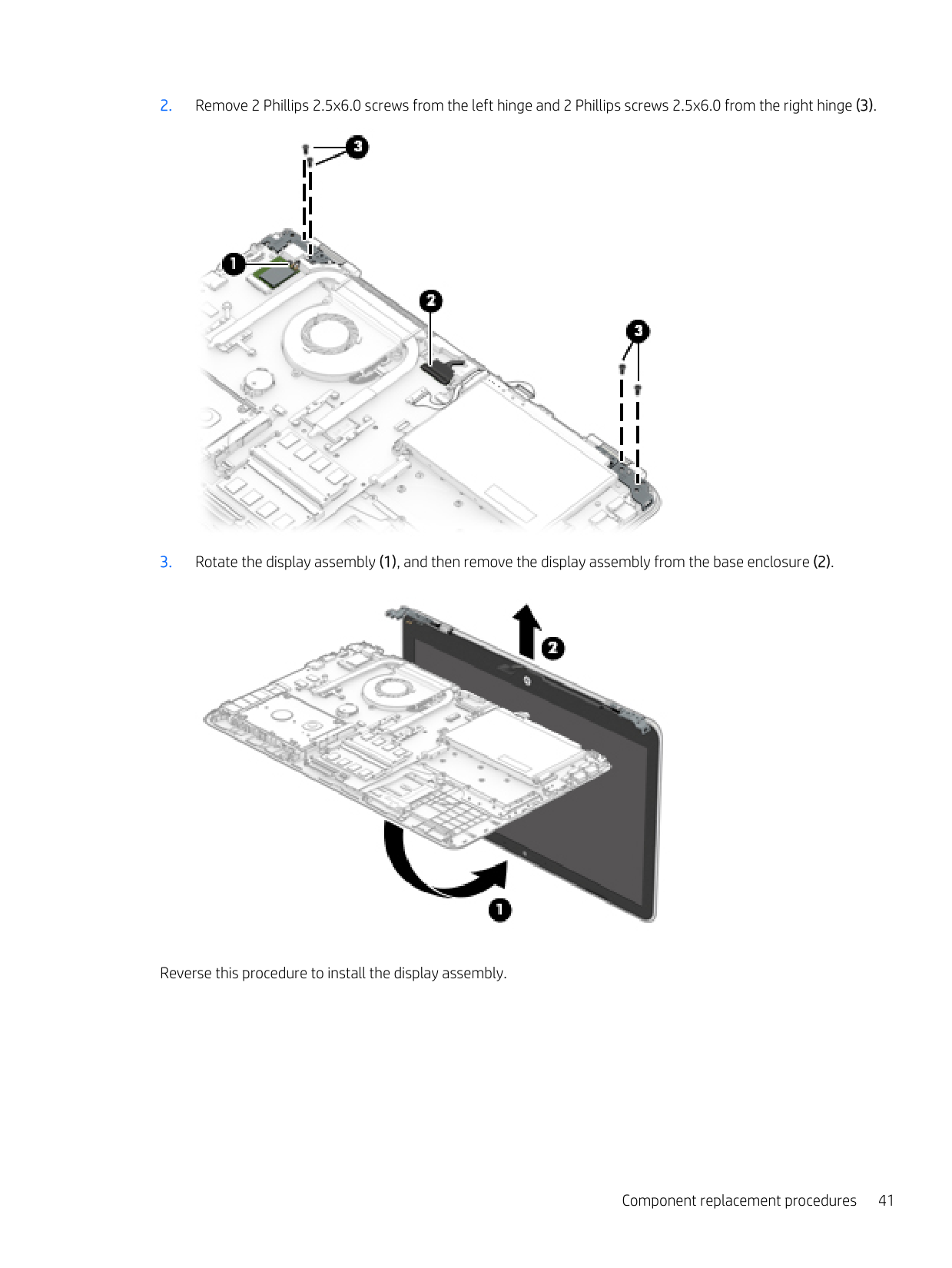
Display assembly IMPORTANT: Make special note of each screw and screw lock size and location during removal and replacement. Before removing the display assembly, follow these steps:
| | |---|
Remove the display assembly:


Reverse this procedure to install the display assembly.
#### Fan
Description Spare part number Fan 856359-001
| |
|---|
IMPORTANT: Make special note of each screw and screw lock size and location during removal and replacement. Before removing the fan, follow these steps:
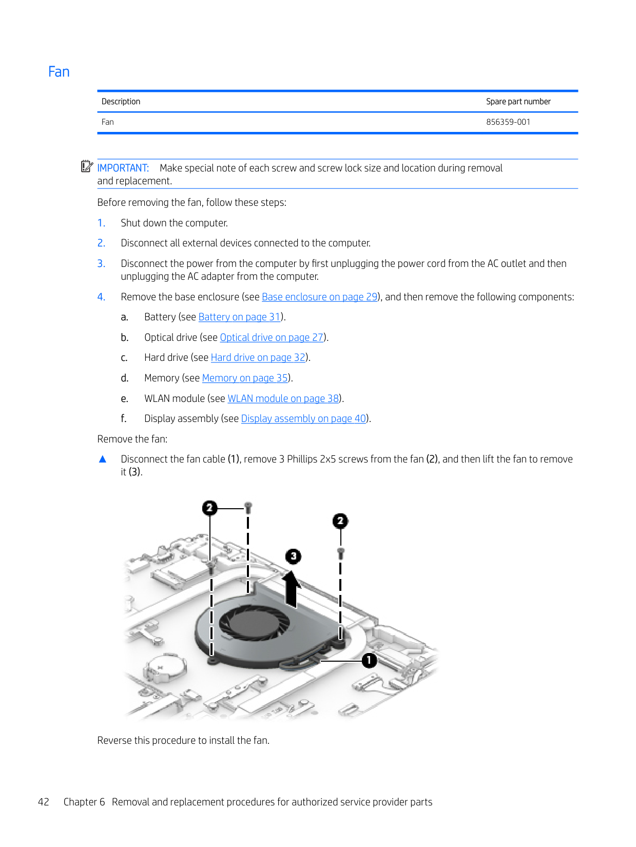
Remove the fan:
▲ Disconnect the fan cable (1), remove 3 Phillips 2x5 screws from the fan (2), and then lift the fan to remove
it (3).

Reverse this procedure to install the fan.
#### Heat sink
Description Spare part number
Heat sink for products with UMA graphics 856314-001 Heat sink for products with discrete graphics 856315-001
| | |---|
IMPORTANT: Make special note of each screw and screw lock size and location during removal and replacement. Before removing the heat sink, follow these steps:
unplugging the AC adapter from the computer.
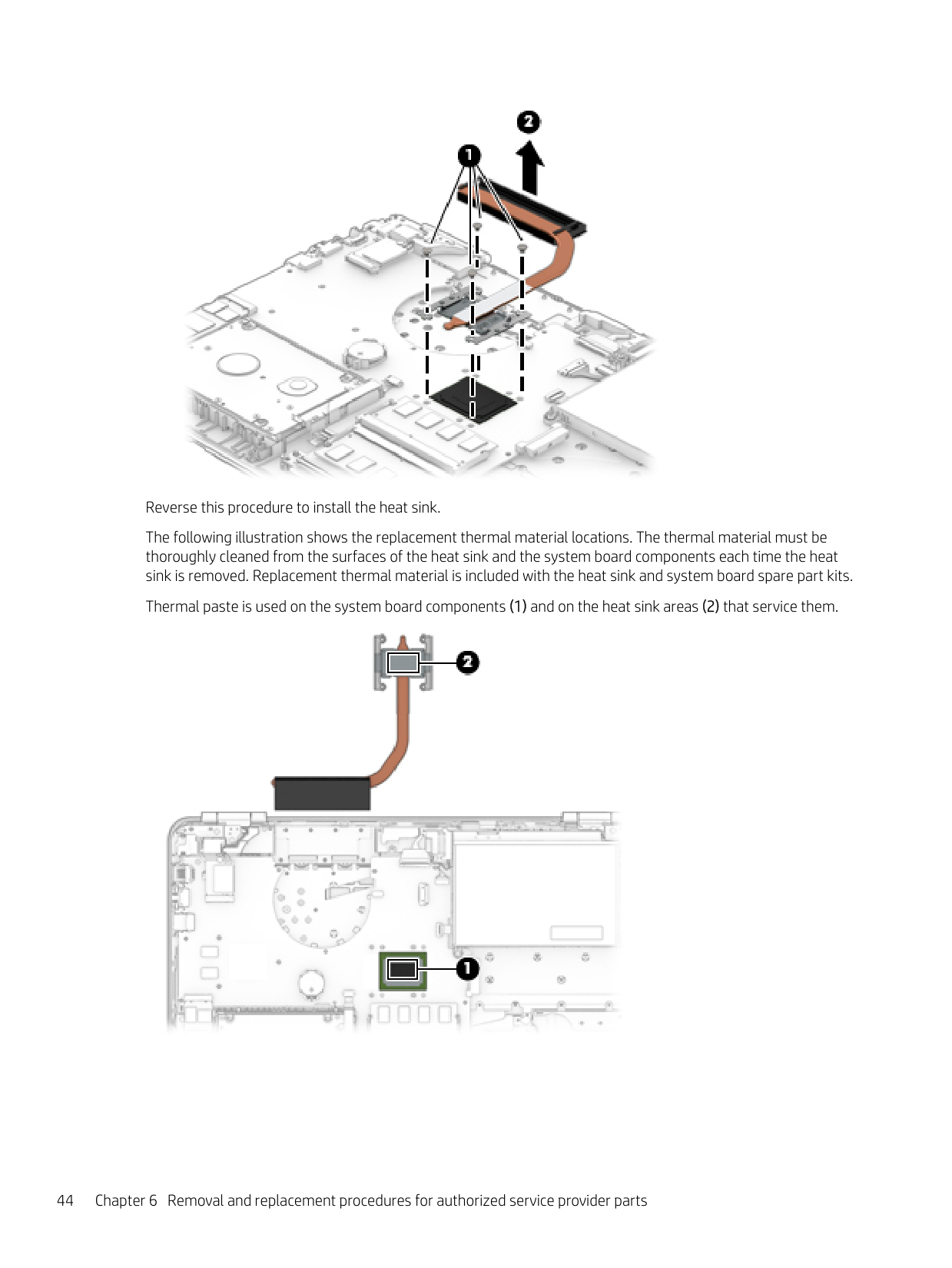
Remove the heat sink:
▲ Remove 7 Phillips 2.5x2.5 screws from the thermal module in numerical order (1), and lift the heat sink to
remove it (2).

Reverse this procedure to install the heat sink. The following illustration shows the replacement thermal material locations. The thermal material must be thoroughly cleaned from the surfaces of the heat sink and the system board components each time the heat sink is removed. Replacement thermal material is included with the heat sink and system board spare part kits. Thermal paste is used on the system board components (1) and on the heat sink areas (2) that service them.

#### I/O board
Description Spare part number
I/O board 856370-001 DfE I/O board for use in India 903201-001 I/O board cable 856349-001
| | |---|
IMPORTANT: Make special note of each screw and screw lock size and location during removal and replacement Before removing the I/O board, follow these steps:
unplugging the AC adapter from the computer.
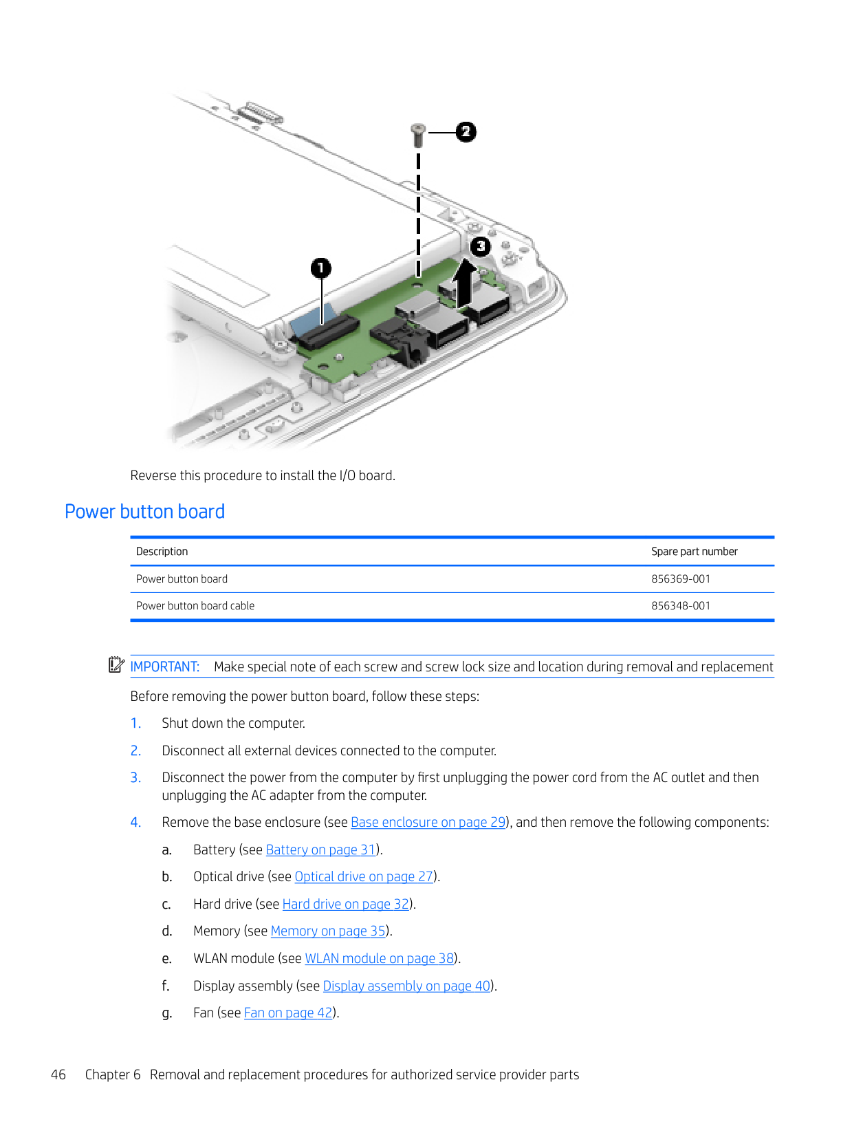
Remove the I/O board:
▲ Disconnect the I/O board cable (1), remove 1 Phillips 2.0x2.5 screw (2), and then lift the I/O board to
remove it (3).

Reverse this procedure to install the I/O board.
#### Power button board
Description Spare part number
Power button board 856369-001 Power button board cable 856348-001
| | |---|
IMPORTANT: Make special note of each screw and screw lock size and location during removal and replacement Before removing the power button board, follow these steps:
unplugging the AC adapter from the computer.
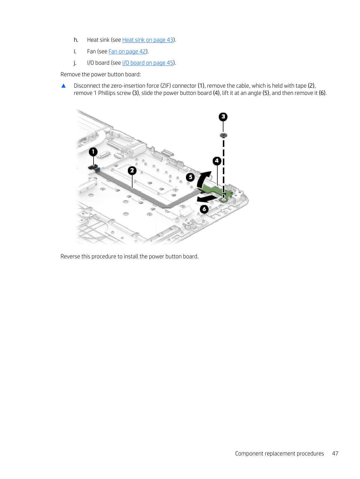
Remove the power button board:
▲ Disconnect the zero-insertion force (ZIF) connector (1), remove the cable, which is held with tape (2),
remove 1 Phillips screw (3), slide the power button board (4), lift it at an angle (5), and then remove it (6).

Reverse this procedure to install the power button board.
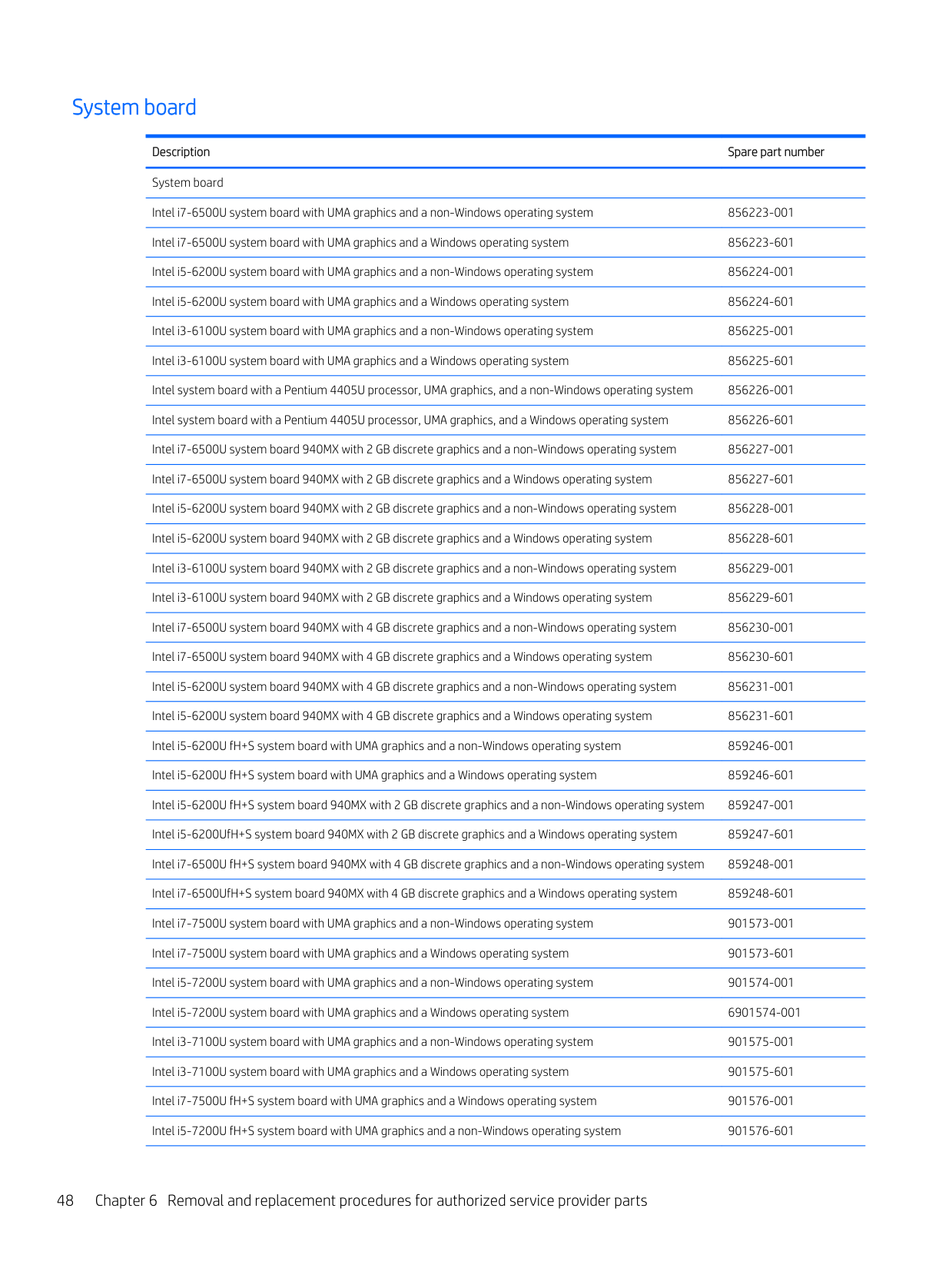
#### System board
Description Spare part number System board Intel i7-6500U system board with UMA graphics and a non-Windows operating system 856223-001 Intel i7-6500U system board with UMA graphics and a Windows operating system 856223-601 Intel i5-6200U system board with UMA graphics and a non-Windows operating system 856224-001 Intel i5-6200U system board with UMA graphics and a Windows operating system 856224-601 Intel i3-6100U system board with UMA graphics and a non-Windows operating system 856225-001 Intel i3-6100U system board with UMA graphics and a Windows operating system 856225-601 Intel system board with a Pentium 4405U processor, UMA graphics, and a non-Windows operating system 856226-001 Intel system board with a Pentium 4405U processor, UMA graphics, and a Windows operating system 856226-601 Intel i7-6500U system board 940MX with 2 GB discrete graphics and a non-Windows operating system 856227-001 Intel i7-6500U system board 940MX with 2 GB discrete graphics and a Windows operating system 856227-601 Intel i5-6200U system board 940MX with 2 GB discrete graphics and a non-Windows operating system 856228-001 Intel i5-6200U system board 940MX with 2 GB discrete graphics and a Windows operating system 856228-601 Intel i3-6100U system board 940MX with 2 GB discrete graphics and a non-Windows operating system 856229-001 Intel i3-6100U system board 940MX with 2 GB discrete graphics and a Windows operating system 856229-601 Intel i7-6500U system board 940MX with 4 GB discrete graphics and a non-Windows operating system 856230-001 Intel i7-6500U system board 940MX with 4 GB discrete graphics and a Windows operating system 856230-601 Intel i5-6200U system board 940MX with 4 GB discrete graphics and a non-Windows operating system 856231-001 Intel i5-6200U system board 940MX with 4 GB discrete graphics and a Windows operating system 856231-601 Intel i5-6200U fH+S system board with UMA graphics and a non-Windows operating system 859246-001 Intel i5-6200U fH+S system board with UMA graphics and a Windows operating system 859246-601 Intel i5-6200U fH+S system board 940MX with 2 GB discrete graphics and a non-Windows operating system 859247-001 Intel i5-6200UfH+S system board 940MX with 2 GB discrete graphics and a Windows operating system 859247-601 Intel i7-6500U fH+S system board 940MX with 4 GB discrete graphics and a non-Windows operating system 859248-001 Intel i7-6500UfH+S system board 940MX with 4 GB discrete graphics and a Windows operating system 859248-601 Intel i7-7500U system board with UMA graphics and a non-Windows operating system 901573-001 Intel i7-7500U system board with UMA graphics and a Windows operating system 901573-601 Intel i5-7200U system board with UMA graphics and a non-Windows operating system 901574-001 Intel i5-7200U system board with UMA graphics and a Windows operating system 6901574-001 Intel i3-7100U system board with UMA graphics and a non-Windows operating system 901575-001 Intel i3-7100U system board with UMA graphics and a Windows operating system 901575-601 Intel i7-7500U fH+S system board with UMA graphics and a Windows operating system 901576-001 Intel i5-7200U fH+S system board with UMA graphics and a non-Windows operating system 901576-601
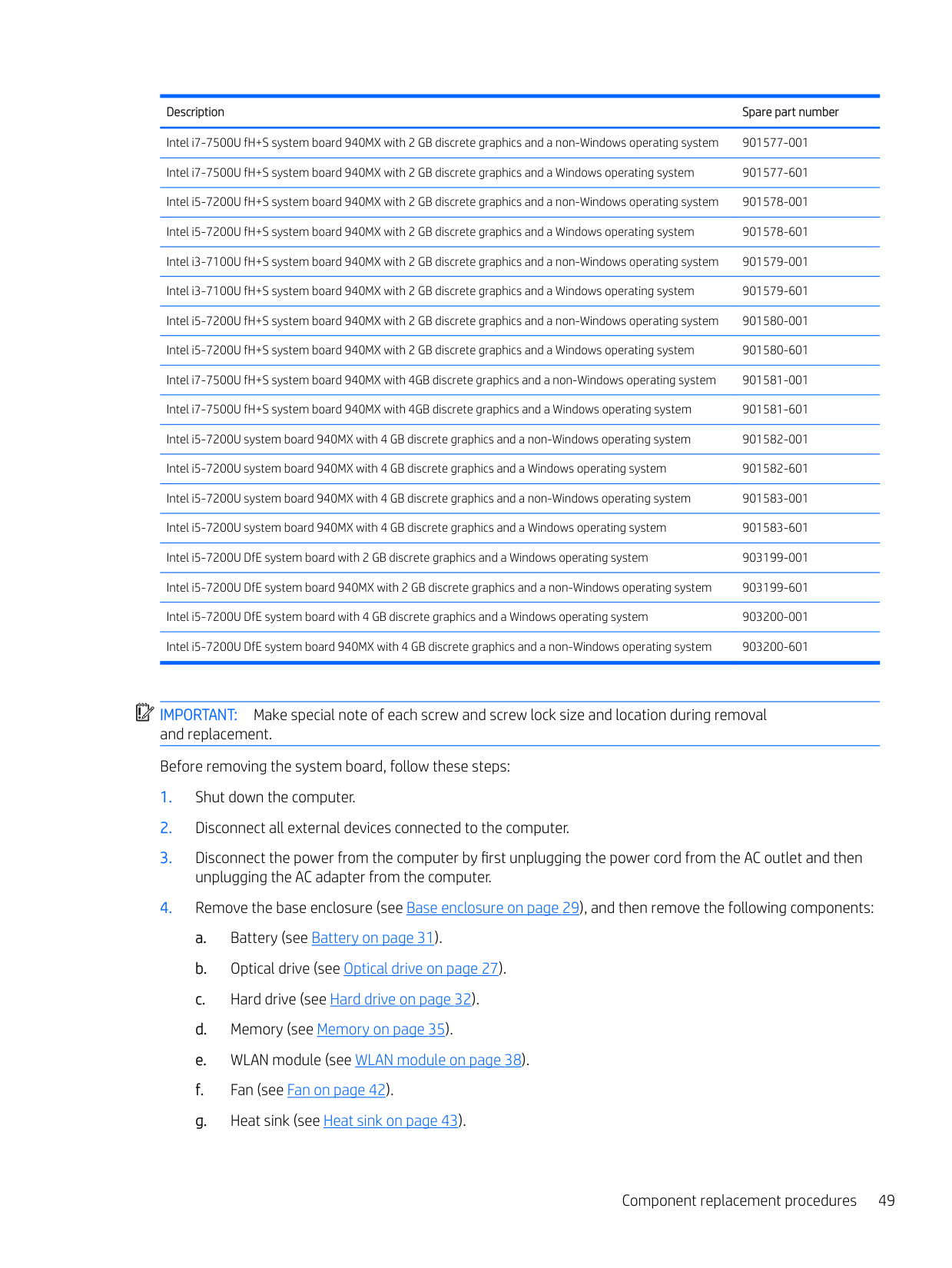
Description Spare part number
Intel i7-7500U fH+S system board 940MX with 2 GB discrete graphics and a non-Windows operating system 901577-001 Intel i7-7500U fH+S system board 940MX with 2 GB discrete graphics and a Windows operating system 901577-601 Intel i5-7200U fH+S system board 940MX with 2 GB discrete graphics and a non-Windows operating system 901578-001 Intel i5-7200U fH+S system board 940MX with 2 GB discrete graphics and a Windows operating system 901578-601 Intel i3-7100U fH+S system board 940MX with 2 GB discrete graphics and a non-Windows operating system 901579-001 Intel i3-7100U fH+S system board 940MX with 2 GB discrete graphics and a Windows operating system 901579-601 Intel i5-7200U fH+S system board 940MX with 2 GB discrete graphics and a non-Windows operating system 901580-001 Intel i5-7200U fH+S system board 940MX with 2 GB discrete graphics and a Windows operating system 901580-601 Intel i7-7500U fH+S system board 940MX with 4GB discrete graphics and a non-Windows operating system 901581-001 Intel i7-7500U fH+S system board 940MX with 4GB discrete graphics and a Windows operating system 901581-601 Intel i5-7200U system board 940MX with 4 GB discrete graphics and a non-Windows operating system 901582-001
| | |---|
IMPORTANT: Make special note of each screw and screw lock size and location during removal and replacement. Before removing the system board, follow these steps:

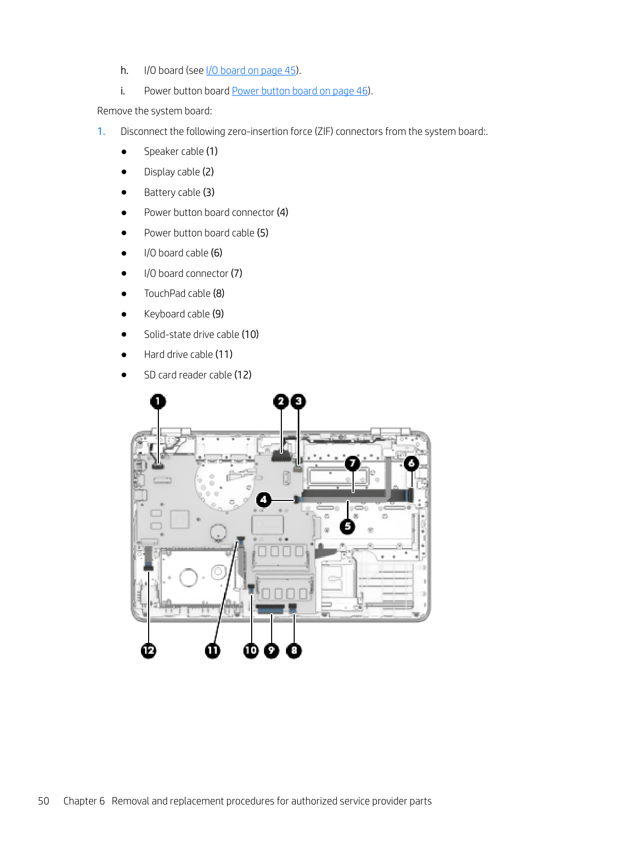
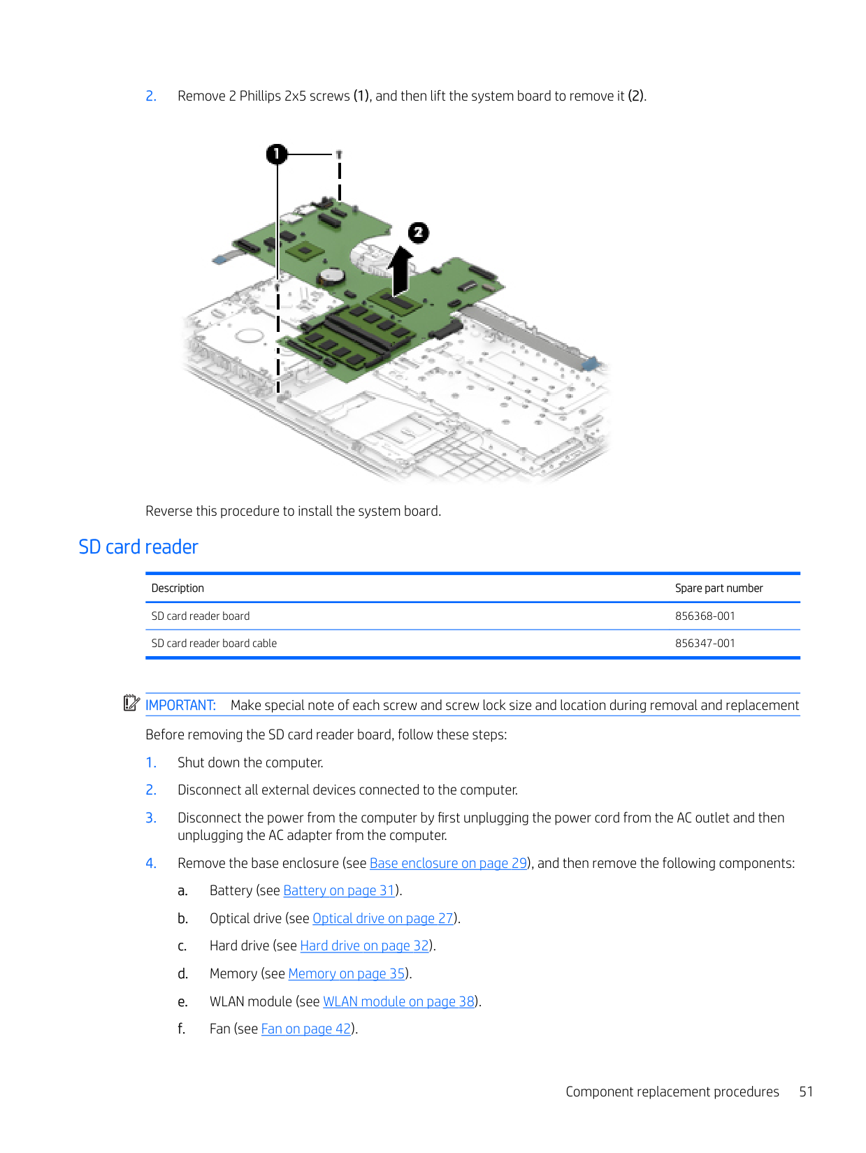
Remove the system board:


Reverse this procedure to install the system board.
#### SD card reader
Description Spare part number
SD card reader board 856368-001 SD card reader board cable 856347-001
| | |---|
IMPORTANT: Make special note of each screw and screw lock size and location during removal and replacement Before removing the SD card reader board, follow these steps:
Remove the SD card reader board:
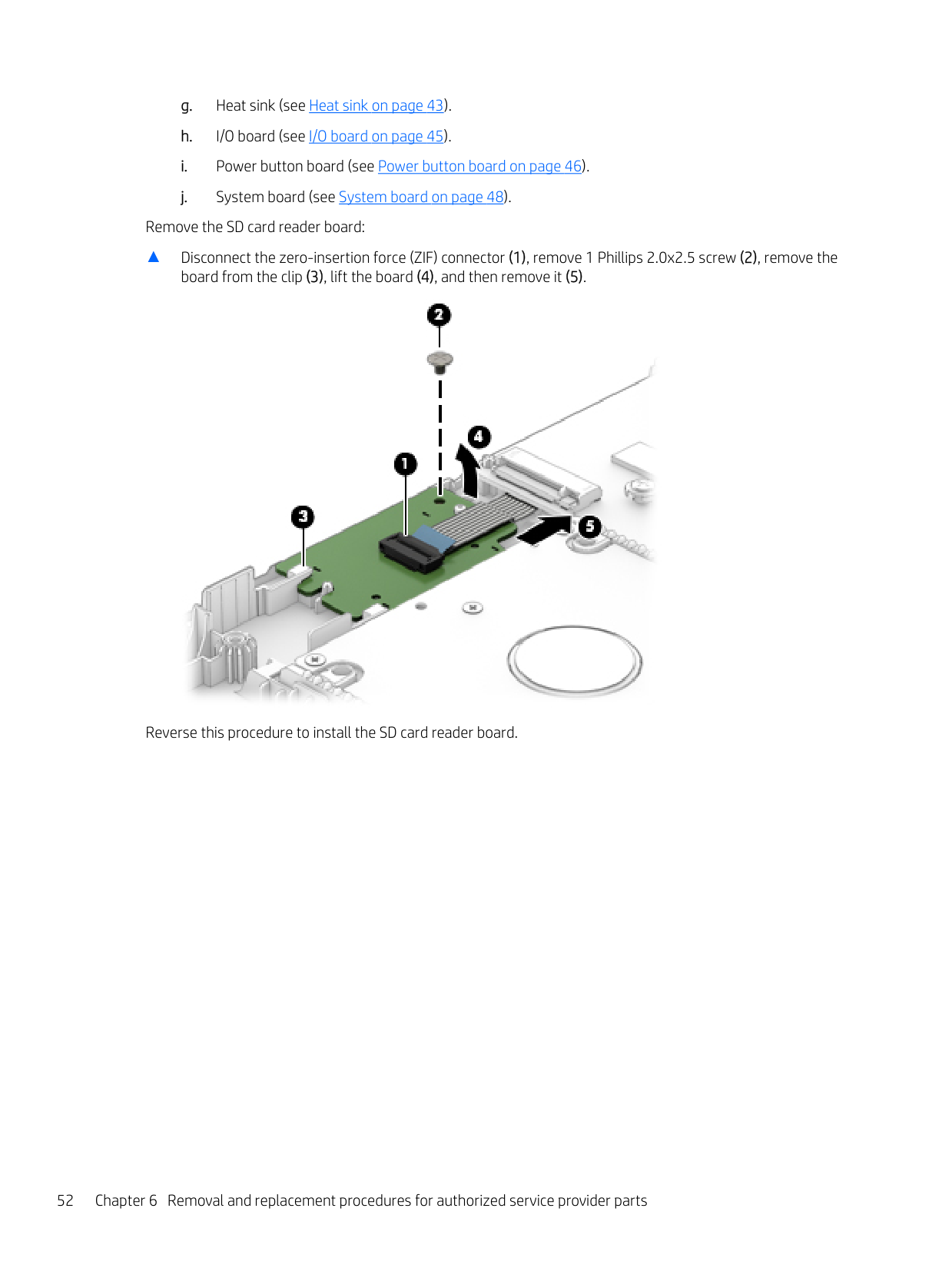
▲ Disconnect the zero-insertion force (ZIF) connector (1), remove 1 Phillips 2.0x2.5 screw (2), remove the
board from the clip (3), lift the board (4), and then remove it (5).

Reverse this procedure to install the SD card reader board.
#### Speakers
| | |---|
NOTE: The speaker spare part kit includes the cable.
Description Spare part number Speaker Kit 856383-001
| | |---|
IMPORTANT: Make special note of each screw and screw lock size and location during removal and replacement. Before removing the speaker, follow these steps:
unplugging the AC adapter from the computer.
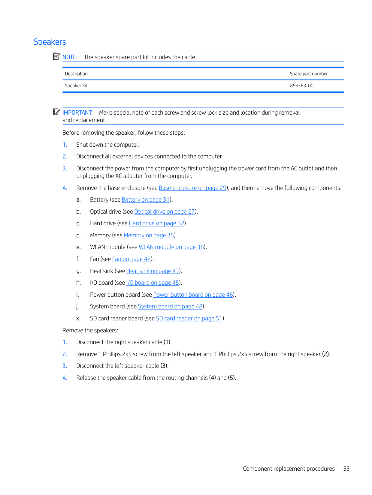
Remove the speakers:

Reverse this procedure to install the speakers.
#### Power connector
Description Spare part number Power connector, DCIN CAL50 8p 4.5mm90W 8P15 SF 808155-010
| | |---|
IMPORTANT: Make special note of each screw and screw lock size and location during removal and replacement Before removing the power connector, follow these steps:
unplugging the AC adapter from the computer.
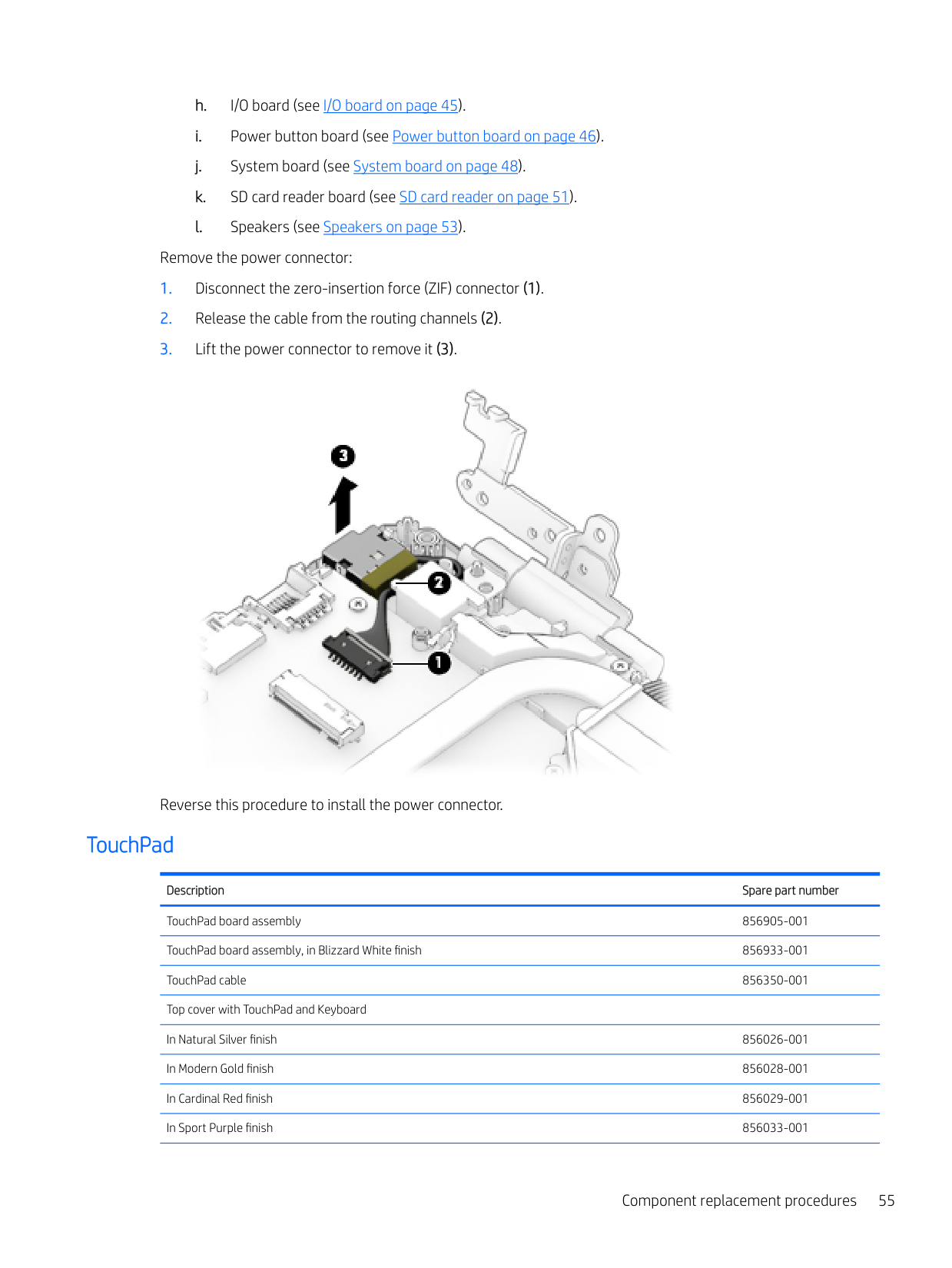
Remove the power connector:

Reverse this procedure to install the power connector.
#### TouchPad
Description Spare part number TouchPad board assembly 856905-001 TouchPad board assembly, in Blizzard White finish 856933-001 TouchPad cable 856350-001 Top cover with TouchPad and Keyboard In Natural Silver finish 856026-001 In Modern Gold finish 856028-001 In Cardinal Red finish 856029-001 In Sport Purple finish 856033-001
Description Spare part number In Dragonfly Blue finish 856034-001 Top cover with TouchPad and Backlit Keyboard In Natural Silver finish 856035-001 In Onyx Black finish 856036-001 In Modern Gold finish 856040-001 In Cardinal Red finish 856041-001 In Sport Purple finish 856042-001 In Dragonfly Blue finish 856043-001 In Blizzard White finish 856044-001 Top cover with TouchPad and Backlit Keyboard in Blizzard White finish 860585-001
For use in country or region
Spare part number
For use in country or region
Spare part number
For use in country or region Spare part
number Belgium -A41 India -D61 Saudi Arabia -171 Bulgaria -261 Israel -BB1 Slovenia -BA1 Canada -DB1 Italy -061 South Korea -AD1 Czech Republic and Slovakia
-FL1 Japan -291 Spain -071
Denmark -081 Latin America -161 Sweden and Finland -B71 Denmark, Norway, Finland, and Sweden
-DH1 The Netherlands -B31 Switzerland -BG1
France -051 Northern Africa -FP1 Taiwan -AB1 Germany -041 Norway -091 Thailand -281 Greece -151 Portugal -131 Turkey -141 Hungary -211 Romania -271 United Kingdom -031 Iceland -DD1 Russia -251 United States -001
| | |---|
IMPORTANT: Make special note of each screw and screw lock size and location during removal and replacement Before removing the TouchPad, follow these steps:
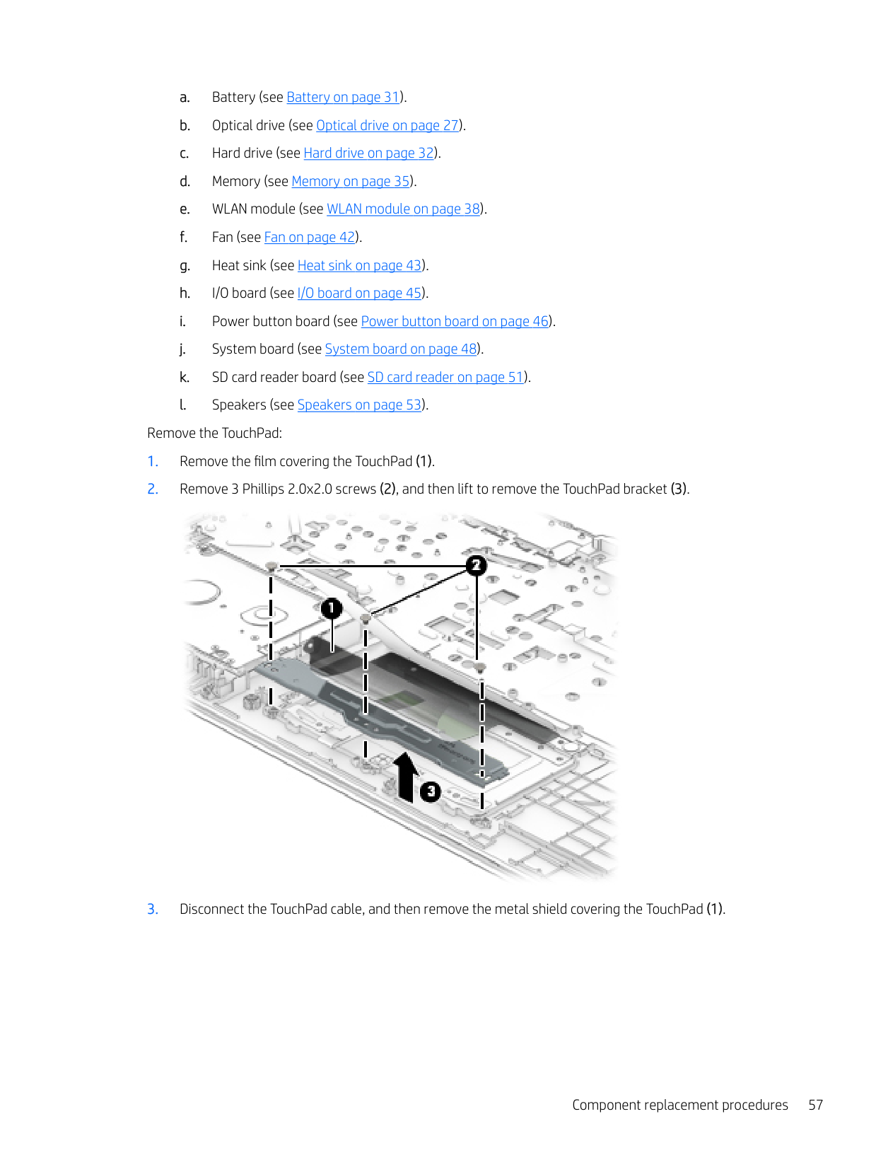
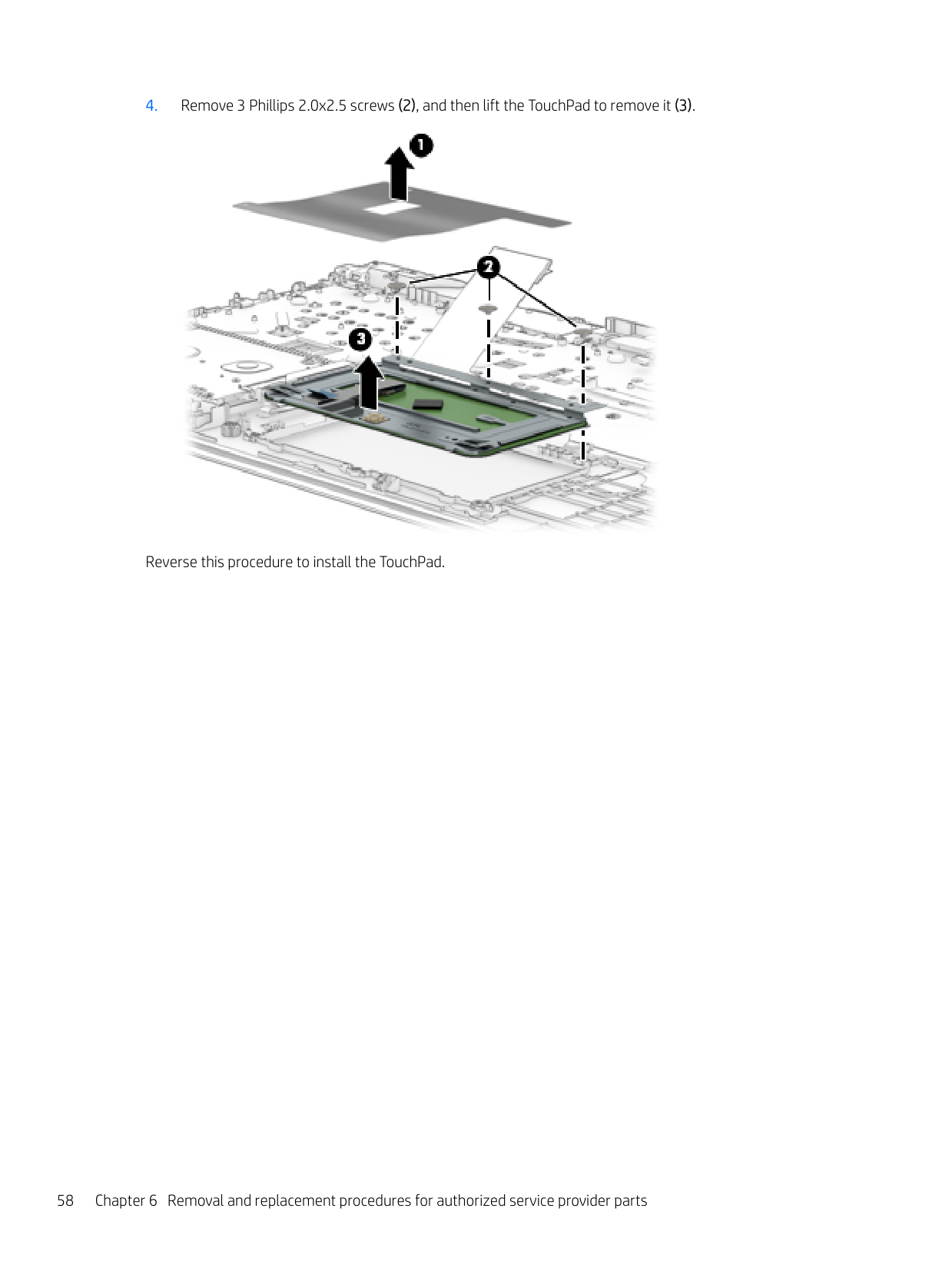
Remove the TouchPad:


Reverse this procedure to install the TouchPad.
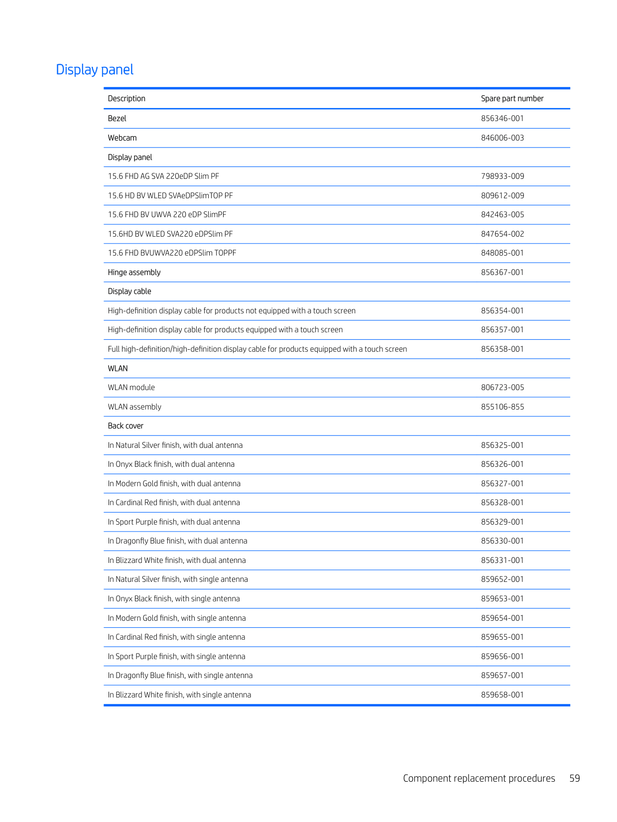
#### Display panel
Description Spare part number Bezel 856346-001 Webcam 846006-003 Display panel
15.6 FHD AG SVA 220eDP Slim PF 798933-009 15.6 HD BV WLED SVAeDPSlimTOP PF 809612-009 15.6 FHD BV UWVA 220 eDP SlimPF 842463-005 15.6HD BV WLED SVA220 eDPSlim PF 847654-002 15.6 FHD BVUWVA220 eDPSlim TOPPF 848085-001 Hinge assembly 856367-001 Display cable
High-definition display cable for products not equipped with a touch screen 856354-001 High-definition display cable for products equipped with a touch screen 856357-001 Full high-definition/high-definition display cable for products equipped with a touch screen 856358-001 WLAN
WLAN module 806723-005 WLAN assembly 855106-855 Back cover
In Natural Silver finish, with dual antenna 856325-001 In Onyx Black finish, with dual antenna 856326-001 In Modern Gold finish, with dual antenna 856327-001 In Cardinal Red finish, with dual antenna 856328-001 In Sport Purple finish, with dual antenna 856329-001 In Dragonfly Blue finish, with dual antenna 856330-001 In Blizzard White finish, with dual antenna 856331-001 In Natural Silver finish, with single antenna 859652-001 In Onyx Black finish, with single antenna 859653-001 In Modern Gold finish, with single antenna 859654-001 In Cardinal Red finish, with single antenna 859655-001 In Sport Purple finish, with single antenna 859656-001 In Dragonfly Blue finish, with single antenna 859657-001 In Blizzard White finish, with single antenna 859658-001
| | |---|
IMPORTANT: Make special note of each screw and screw lock size and location during removal and replacement. Before removing the display assembly, follow these steps:
Remove the display panel:
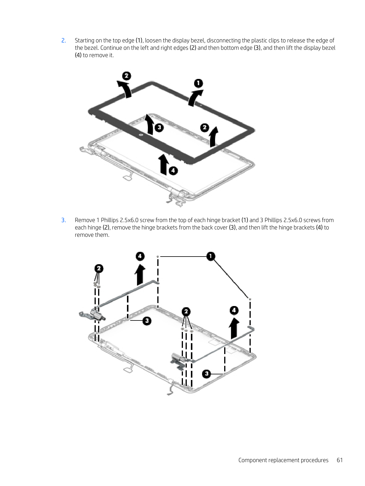
####### 2. Starting on the top edge (1), loosen the display bezel, disconnecting the plastic clips to release the edge ofthe bezel. Continue on the left and right edges (2) and then bottom edge (3), and then lift the display bezel
(4) to remove it.

####### 3. Remove 1 Phillips 2.5x6.0 screw from the top of each hinge bracket (1) and 3 Phillips 2.5x6.0 screws fromeach hinge (2), remove the hinge brackets from the back cover (3), and then lift the hinge brackets (4) toremove them.


Reverse this procedure to install the display assembly.
#### Webcam
Description Spare part number Webcam 846006-003
| | |---|
IMPORTANT: Make special note of each screw and screw lock size and location during removal and replacement. Before removing the webcam, follow these steps:
unplugging the AC adapter from the computer.
Remove the webcam:
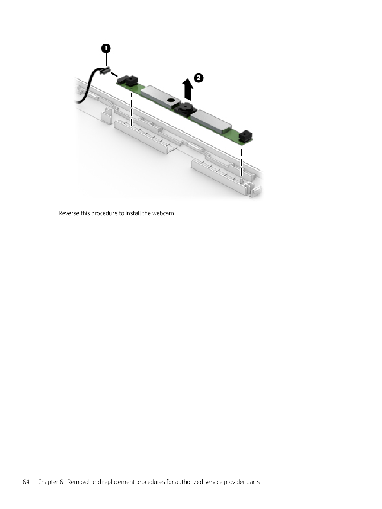
▲ Disconnect the webcam cable (1), and then lift the webcam board to remove it (2).

####### Reverse this procedure to install the webcam.
#### WLAN cable
Description Spare part number WLAN cable 792505-855 Antenna
Antenna, dual 856324-001 Antenna, single 859651-001
| | |---|
IMPORTANT: Make special note of each screw and screw lock size and location during removal and replacement. Before removing the WLAN cable, follow these steps:
unplugging the AC adapter from the computer.
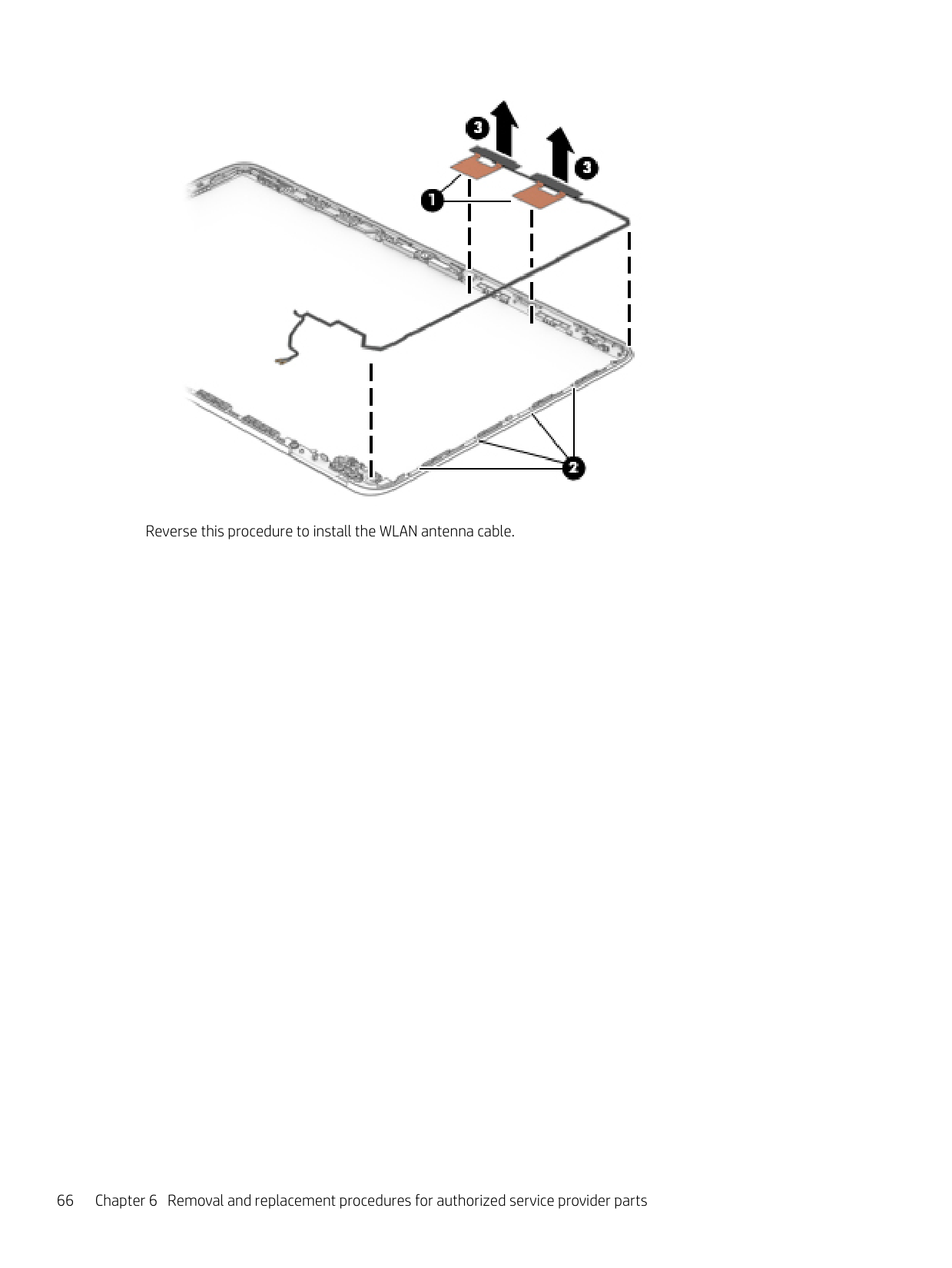
Remove the WLAN antenna cable:
▲ Remove the WLAN antennas from the back cover (1), release the WLAN cable from the routing channels
(2), and then lift the antennas and cable to remove them(3).

####### Reverse this procedure to install the WLAN antenna cable.
7 Using HP PC Hardware Diagnostics (UEFI)
HP PC Hardware Diagnostics is a Unified Extensible Firmware Interface (UEFI) that allows you to run diagnostic tests to determine whether the computer hardware is functioning properly. The tool runs outside the operating system so that it can isolate hardware failures from issues that are caused by the operating system or other software components.
When HP PC Hardware Diagnostics (UEFI) detects a failure that requires hardware replacement, a 24-digit Failure ID code is generated. This ID code can then be provided to support to help determine how to correct the problem.
| | |---|
NOTE: To start diagnostics on a convertible computer, your computer must be in notebook mode and you must use the keyboard attached. To start HP PC Hardware Diagnostics (UEFI), follow these steps:
| | |---|
| | |---|
NOTE: If you need to stop a diagnostic test, press esc.
Downloading HP PC Hardware Diagnostics (UEFI) to a USB device
| | |---|
NOTE: The HP PC Hardware Diagnostics (UEFI) download instructions are provided in English only, and you must use a Windows computer to download and create the HP UEFI support environment because only .exe files are offered.
There are two options to download HP PC Hardware Diagnostics to a USB device. Download the latest UEFI version
Downloading HP PC Hardware Diagnostics (UEFI) to a USB device 67
– or – Select Identify now to let HP automatically detect your product.
68 Chapter 7 Using HP PC Hardware Diagnostics (UEFI)
8 Backing up, restoring, and recovering
This chapter provides information about the following processes. The information in the chapter is standard procedure for most products.
▲ Type support in the taskbar search box, and then select the HP Support Assistant app.
or – Click the question mark icon in the taskbar.
| | |---|
IMPORTANT: If you will be performing recovery procedures on a tablet, the tablet battery must be at least 70% charged before you start the recovery process.
IMPORTANT: For a tablet with a detachable keyboard, connect the keyboard to the keyboard dock before beginning any recovery process.
Creating recovery media and backups
The following methods of creating recovery media and backups are available on select products only. Choose the available method according to your computer model.
| | |---|
#### Creating HP Recovery media (select products only)
If possible, check for the presence of the Recovery partition and the Windows partition. From the Start menu, select File Explorer, and then select This PC.
Creating recovery media and backups 69
You can use Windows tools to create system restore points and create backups of personal information, see Using Windows tools on page 70.
— Only one set of recovery media can be created. Handle these recovery tools carefully, and keep them
in a safe place.
— HP Recovery Manager examines the computer and determines the required storage capacity for the
media that will be required.
— To create recovery discs, your computer must have an optical drive with DVD writer capability, and you must use only high-quality blank DVD-R, DVD+R, DVD-R DL, or DVD+R DL discs. Do not use rewritable discs such as CD±RW, DVD±RW, double-layer DVD±RW, or BD-RE (rewritable Blu-ray) discs; they are not compatible with HP Recovery Manager software. Or, instead, you can use a high-quality blank USB flash drive.
— If your computer does not include an integrated optical drive with DVD writer capability, but you would like to create DVD recovery media, you can use an external optical drive (purchased separately) to create recovery discs. If you use an external optical drive, it must be connected directly to a USB port on the computer; the drive cannot be connected to a USB port on an external device, such as a USB hub. If you cannot create DVD media yourself, you can obtain recovery discs for your computer from HP. See the Worldwide Telephone Numbers booklet included with the computer. You can also find contact information on the HP website. Go to http://www.hp.com/support, select your country or region, and follow the on-screen instructions.
— Be sure that the computer is connected to AC power before you begin creating the recovery media.
— The creation process can take an hour or more. Do not interrupt the creation process.
— If necessary, you can exit the program before you have finished creating all of the recovery DVDs. HP Recovery Manager will finish burning the current DVD. The next time you start HP Recovery Manager, you will be prompted to continue.
| | |---|
To create HP Recovery media: IMPORTANT: For a tablet with a detachable keyboard, connect the keyboard to the keyboard dock before beginning these steps.
Using Windows tools
You can create recovery media, system restore points, and backups of personal information using Windows tools.
| | |---|
NOTE: If storage is 32 GB or less, Microsoft System Restore is disabled by default. For more information and steps, see the Get started app.
▲ Select the Start button, and then select the Get started app.
Restore and recovery
There are several options for recovering your system. Choose the method that best matches your situation and level of expertise:
| | |---|
IMPORTANT: Not all methods are available on all products.
▲ Select the Start button, and then select the Get started app.
▲ Type recovery in the taskbar search box, select HP Recovery Manager, select Reinstall drivers
and/or applications, and then follow the on-screen instructions.
#### Recovering using HP Recovery Manager
HP Recovery Manager software allows you to recover the computer to its original factory state by using the HP Recovery media that you either created or that you obtained from HP, or by using the HP Recovery partition (select products only). If you have not already created recovery media, see Creating HP Recovery media (select products only) on page 69.
##### What you need to know before you get started
IMPORTANT: Recovery through HP Recovery Manager should be used as a final attempt to correct computer issues.
| | |---|
| | |---|
| | |---|
IMPORTANT: HP Recovery Manager does not automatically provide backups of your personal data. Before beginning recovery, back up any personal data you want to retain. Using HP Recovery media, you can choose from one of the following recovery options: NOTE: Only the options available for your computer display when you start the recovery process.
The HP Recovery partition (select products only) allows System Recovery only. Using the HP Recovery partition (select products only)
The HP Recovery partition allows you to perform a system recovery without the need for recovery discs or a recovery USB flash drive. This type of recovery can be used only if the hard drive is still working.
| | |---|
To start HP Recovery Manager from the HP Recovery partition: IMPORTANT: For a tablet with a detachable keyboard, connect the keyboard to the keyboard dock before beginning these steps (select products only).
For computers or tablets with keyboards attached, press f11 while the computer boots, or press and hold f11 as you press the power button.
For tablets without keyboards: Turn on or restart the tablet, and then quickly hold down the volume down button; then select f11.
##### Using HP Recovery media to recover
You can use HP Recovery media to recover the original system. This method can be used if your system does not have an HP Recovery partition or if the hard drive is not working properly.
NOTE: If the computer does not automatically restart in HP Recovery Manager, change the computer boot order. See Changing the computer boot order on page 73.
| |
|---|
##### Changing the computer boot order
If your computer does not restart in HP Recovery Manager, you can change the computer boot order, which is the order of devices listed in BIOS where the computer looks for startup information. You can change the selection to an optical drive or a USB flash drive.
| | |---|
To change the boot order: IMPORTANT: For a tablet with a detachable keyboard, connect the keyboard to the keyboard dock before beginning these steps.
▲ Turn on or restart the computer or tablet, quickly press esc, and then press f9 for boot options. For tablets without keyboards:
▲ Turn on or restart the tablet, and then quickly hold down the volume down button; then select f9.
##### Removing the HP Recovery partition (select products only)
HP Recovery Manager software allows you to remove the HP Recovery partition to free up hard drive space.
| | |---|
IMPORTANT: After you remove the HP Recovery partition, you will not be able to perform System Recovery or create HP recovery media from the HP Recovery partition. So before you remove the Recovery partition, create HP Recovery media; see Creating HP Recovery media (select products only) on page 69.
| | |---|
NOTE: The Remove Recovery Partition option is only available on products that support this function. Follow these steps to remove the HP Recovery partition:
9 Specifications
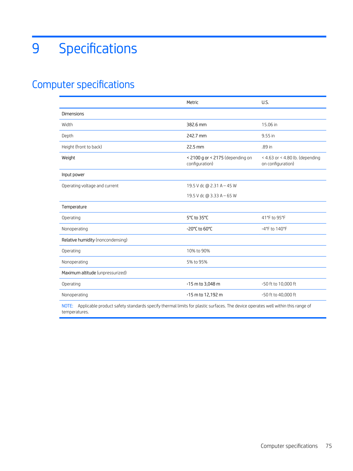
Computer specifications
Metric U.S.
Dimensions Width 382.6 mm 15.06 in Depth 242.7 mm 9.55 in Height (front to back) 22.5 mm .89 in Weight < 2100 g or < 2175 (depending on
< 4.63 or < 4.80 lb. (depending on configuration)
configuration)
Input power Operating voltage and current 19.5 V dc @ 2.31 A – 45 W
19.5 V dc @ 3.33 A – 65 W
Temperature Operating 5°C to 35°C 41°F to 95°F Nonoperating ‑20°C to 60°C ‑4°F to 140°F Relative humidity (noncondensing) Operating 10% to 90% Nonoperating 5% to 95% Maximum altitude (unpressurized)
Operating ‑15 m to 3,048 m ‑50 ft to 10,000 ft Nonoperating ‑15 m to 12,192 m ‑50 ft to 40,000 ft NOTE: Applicable product safety standards specify thermal limits for plastic surfaces. The device operates well within this range of
temperatures.
Computer specifications 75
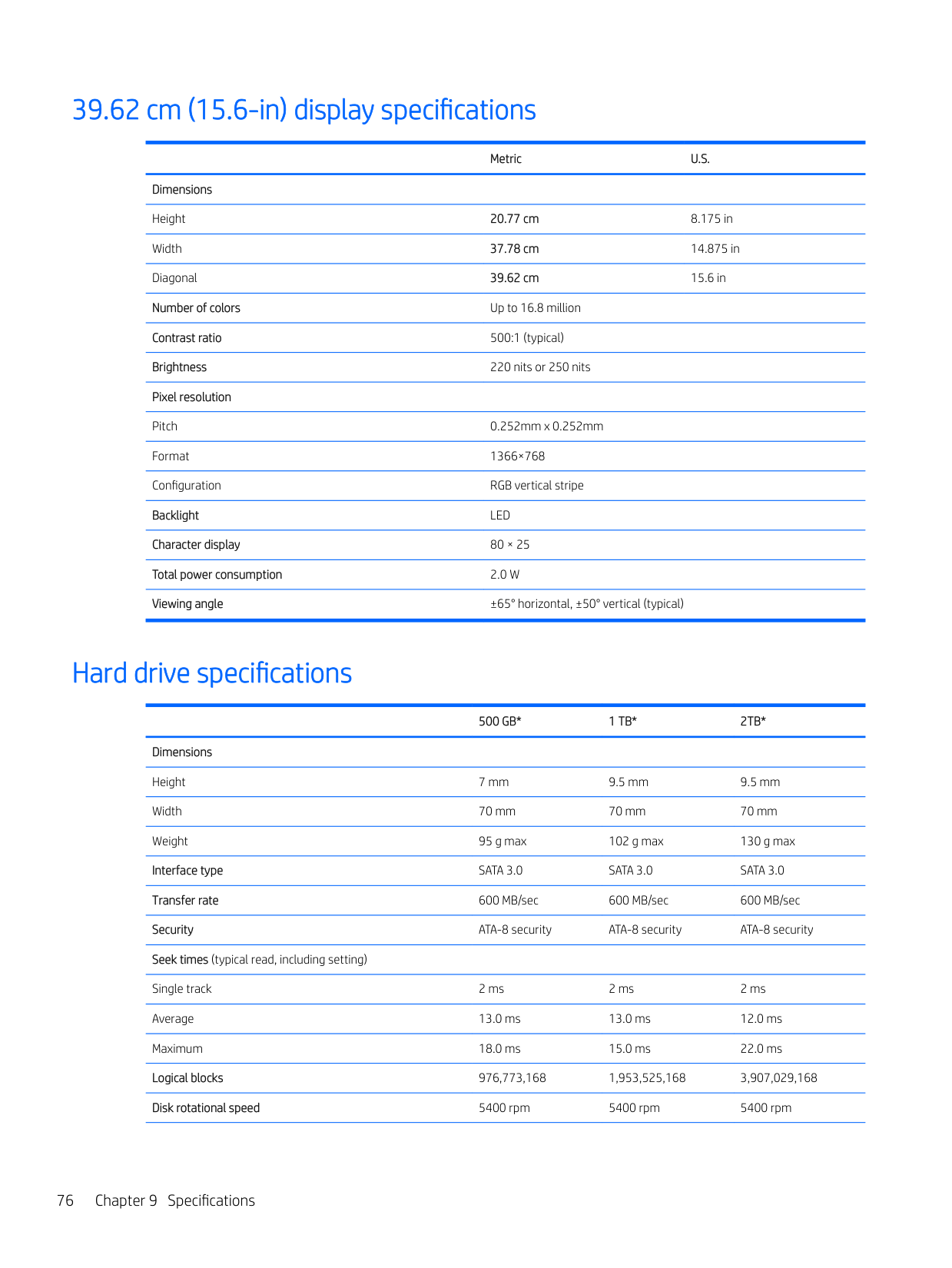
39.62 cm (15.6-in) display specifications
Metric U.S.
Dimensions Height 20.77 cm 8.175 in Width 37.78 cm 14.875 in Diagonal 39.62 cm 15.6 in Number of colors Up to 16.8 million Contrast ratio 500:1 (typical) Brightness 220 nits or 250 nits Pixel resolution Pitch 0.252mm x 0.252mm Format 1366×768 Configuration RGB vertical stripe Backlight LED Character display 80 × 25 Total power consumption 2.0 W Viewing angle ±65° horizontal, ±50° vertical (typical)
Hard drive specifications
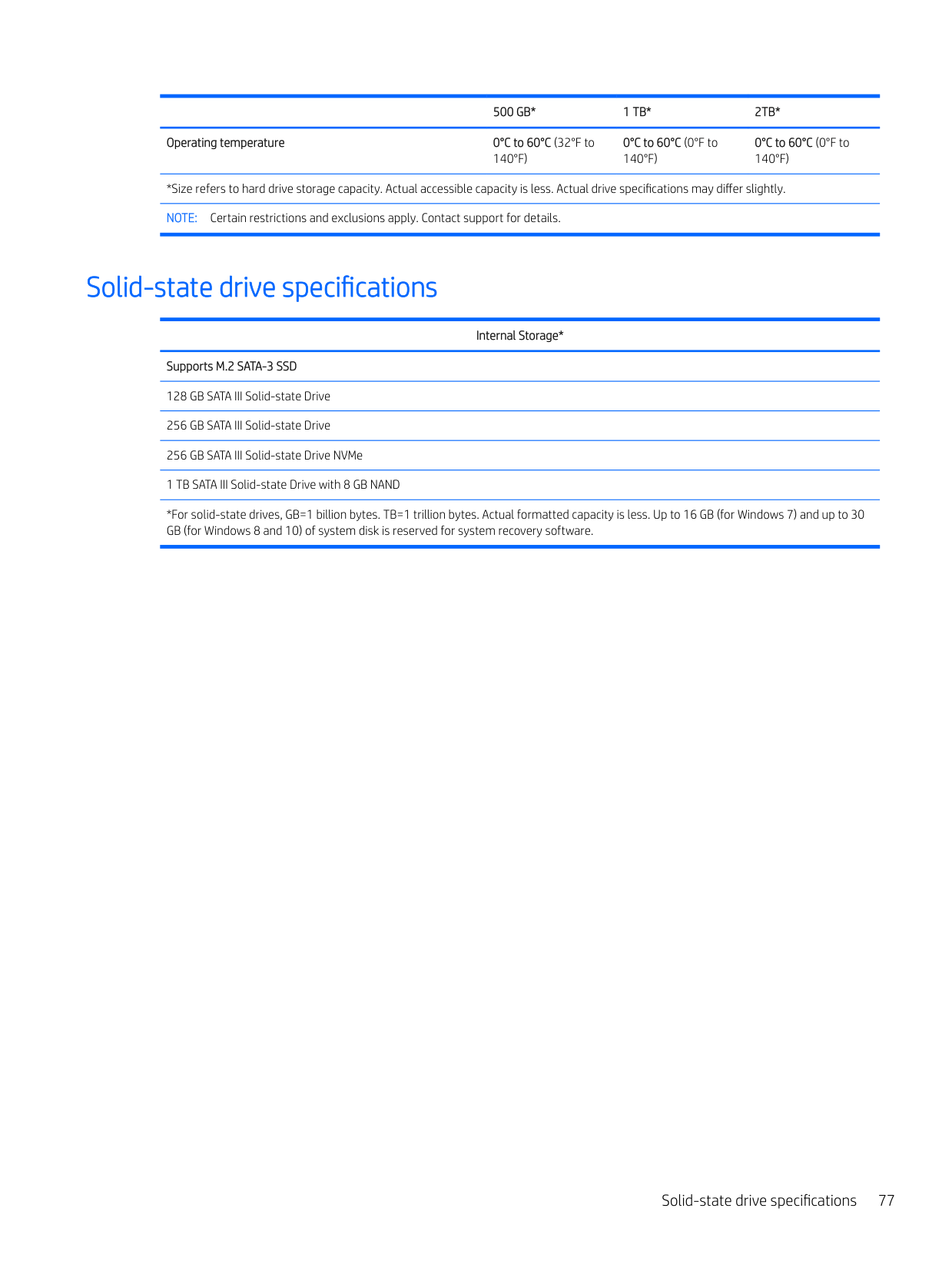
######## 500 GB* 1 TB* 2TB*
Dimensions Height 7 mm 9.5 mm 9.5 mm Width 70 mm 70 mm 70 mm Weight 95 g max 102 g max 130 g max Interface type SATA 3.0 SATA 3.0 SATA 3.0 Transfer rate 600 MB/sec 600 MB/sec 600 MB/sec Security ATA-8 security ATA-8 security ATA-8 security Seek times (typical read, including setting) Single track 2 ms 2 ms 2 ms Average 13.0 ms 13.0 ms 12.0 ms Maximum 18.0 ms 15.0 ms 22.0 ms Logical blocks 976,773,168 1,953,525,168 3,907,029,168 Disk rotational speed 5400 rpm 5400 rpm 5400 rpm
500 GB* 1 TB* 2TB* Operating temperature 0°C to 60°C (32°F to
0°C to 60°C (0°F to 140°F)
0°C to 60°C (0°F to 140°F)
140°F)
*Size refers to hard drive storage capacity. Actual accessible capacity is less. Actual drive specifications may differ slightly. NOTE: Certain restrictions and exclusions apply. Contact support for details.
Solid-state drive specifications
Internal Storage*
Supports M.2 SATA-3 SSD 128 GB SATA III Solid-state Drive 256 GB SATA III Solid-state Drive 256 GB SATA III Solid-state Drive NVMe 1 TB SATA III Solid-state Drive with 8 GB NAND
*For solid-state drives, GB=1 billion bytes. TB=1 trillion bytes. Actual formatted capacity is less. Up to 16 GB (for Windows 7) and up to 30 GB (for Windows 8 and 10) of system disk is reserved for system recovery software.
Solid-state drive specifications 77
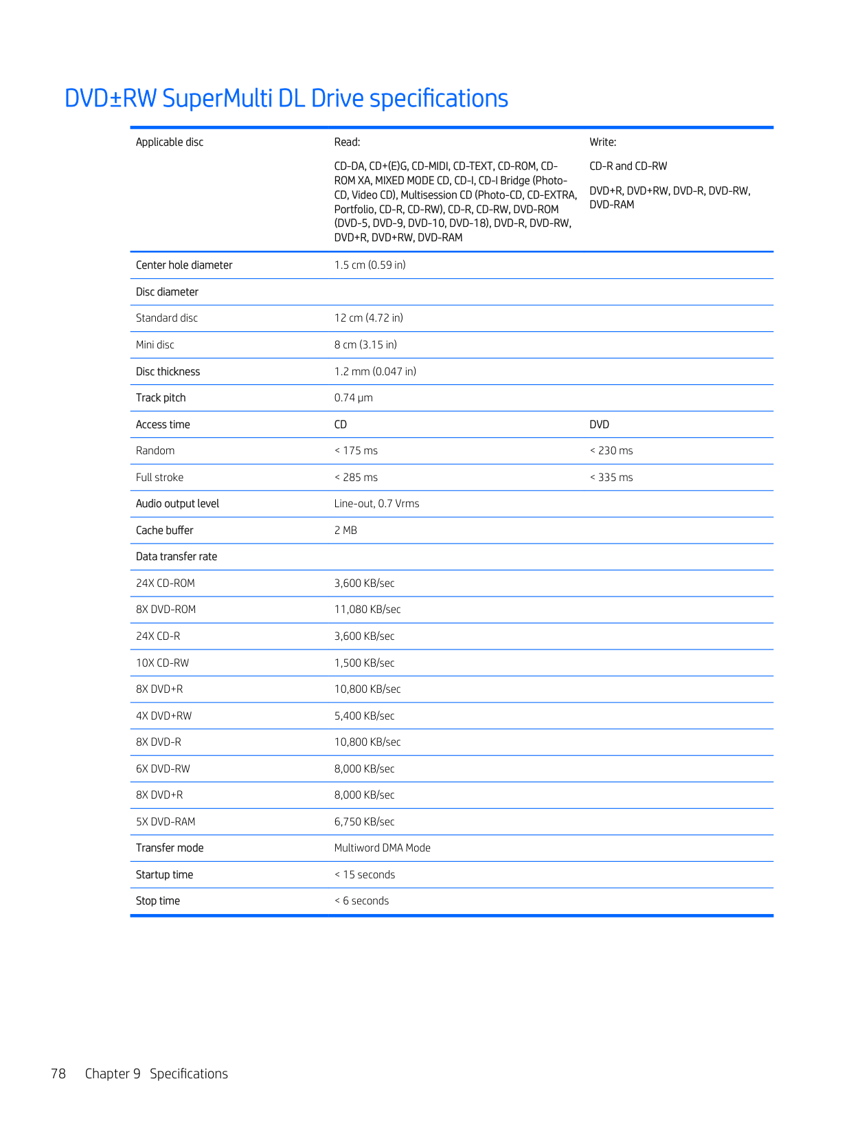
DVD±RW SuperMulti DL Drive specifications
Applicable disc Read:
CD-DA, CD+(E)G, CD-MIDI, CD-TEXT, CD-ROM, CDROM XA, MIXED MODE CD, CD-I, CD-I Bridge (PhotoCD, Video CD), Multisession CD (Photo-CD, CD-EXTRA, Portfolio, CD-R, CD-RW), CD-R, CD-RW, DVD-ROM (DVD-5, DVD-9, DVD-10, DVD-18), DVD-R, DVD-RW, DVD+R, DVD+RW, DVD-RAM
Write: CD-R and CD-RW DVD+R, DVD+RW, DVD-R, DVD-RW, DVD-RAM
Center hole diameter 1.5 cm (0.59 in) Disc diameter Standard disc 12 cm (4.72 in) Mini disc 8 cm (3.15 in) Disc thickness 1.2 mm (0.047 in) Track pitch 0.74 µm Access time CD DVD Random < 175 ms < 230 ms Full stroke < 285 ms < 335 ms Audio output level Line-out, 0.7 Vrms Cache buffer 2 MB Data transfer rate 24X CD-ROM 3,600 KB/sec 8X DVD-ROM 11,080 KB/sec 24X CD-R 3,600 KB/sec 10X CD-RW 1,500 KB/sec 8X DVD+R 10,800 KB/sec
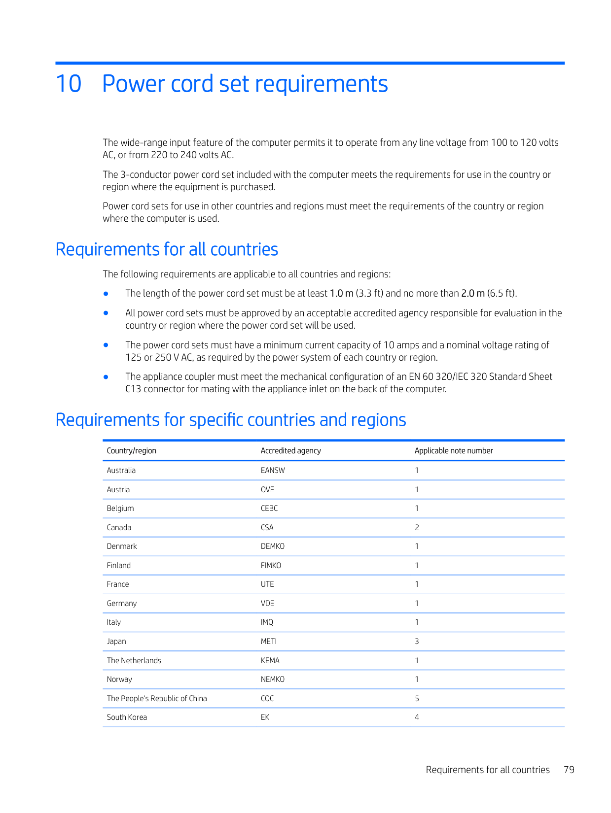
10 Power cord set requirements
The wide-range input feature of the computer permits it to operate from any line voltage from 100 to 120 volts AC, or from 220 to 240 volts AC.
The 3-conductor power cord set included with the computer meets the requirements for use in the country or region where the equipment is purchased.
Power cord sets for use in other countries and regions must meet the requirements of the country or region where the computer is used.
Requirements for all countries
The following requirements are applicable to all countries and regions:
Requirements for specific countries and regions
Country/region Accredited agency Applicable note number
Australia EANSW 1 Austria OVE 1 Belgium CEBC 1 Canada CSA 2 Denmark DEMKO 1 Finland FIMKO 1 France UTE 1 Germany VDE 1 Italy IMQ 1 Japan METI 3 The Netherlands KEMA 1 Norway NEMKO 1 The People's Republic of China COC 5 South Korea EK 4
Requirements for all countries 79
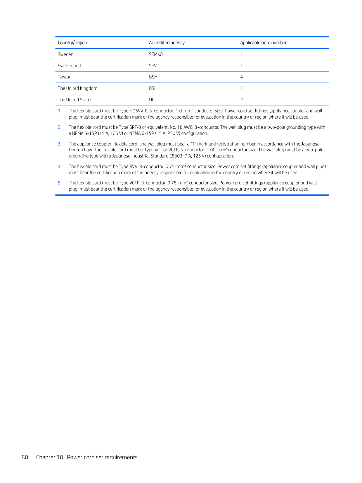
Country/region Accredited agency Applicable note number
Sweden SEMKO 1 Switzerland SEV 1 Taiwan BSMI 4 The United Kingdom BSI 1 The United States UL 2
80 Chapter 10 Power cord set requirements
11 Recycling
When a non-rechargeable or rechargeable battery has reached the end of its useful life, do not dispose of the battery in general household waste. Follow the local laws and regulations in your area for battery disposal.
HP encourages customers to recycle used electronic hardware, HP original print cartridges, and rechargeable batteries. For more information about recycling programs, see the HP Web site at http://www.hp.com/recycle.
81
Index
(microphone) jack, identifying 6
spare part number 20, 59 backups 69 base enclosure
removal 29 spare part number 17
base enclosure, spare part number 29
battery removal 31 spare part number 17, 31
bezel
spare part number 19, 59 boot order
changing 73
buttons left TouchPad 9 power 11 right TouchPad 9
identifying 7 product description 2
camera light, identifying 7 caps lock light, identifying 10 chipset, product description 1 components
bottom 13 display 7 left side 6 rear 14 right side 5 top 9
computer major components 16 computer specifications 75 connector, power 5
specifications 76
display assembly removal 40, 59 spare part numbers 40, 59 subcomponents 19
display cable
spare part number 19, 59 Display panel
spare part numbers 17
display panel product description 1 spare part number 59
drive light 5 DVD±RW SuperMulti DL Drive
specifications 78
removal 42 spare part number 17 spare part numbers 42
fn key, identifying 12
product description 2 removal 32 spare part number 17 spare part numbers 32 specifications 76 HDMI port, identifying 5
heat sink removal 43 spare part number 17 spare part numbers 43
hinge assembly
spare part number 19, 59 HP PC Hardware Diagnostics (UEFI)
using 67
HP Recovery Manager correcting boot problems 73 starting 72 HP Recovery media creating 69 recovery 72 HP Recovery partition recovery 72 removing 74
###### I
integrated numeric keypad, identifying 12 internal microphones, identifying 7
audio-out (headphone)/audio-in
(microphone) 6 network 5 RJ-45 (network) 5
spare part numbers 17 keyboard
product description 3
keys airplane mode 13 esc 12 fn 12 Windows 12
L labels
serial number 14
lights AC adapter and battery light 5 caps lock 10 drive 5 mute 10 power 10 RJ-45 (network) status 5
removal 35 spare part numbers 17, 35
Memory card reader board
spare part number 17 memory card reader, identifying 5 memory card, identifying 5 memory module
microphone
minimized image recovery 72 minimized image, creating 71 model name 1 mute light, identifying 10
description 4
optical drive product description 2 removal 27 spare part number 17 spare part numbers 27 specifications 78
optical drive eject button, identifying
7 optical drive, identifying 6 original system recovery 71
3 ports
HDMI 5

product description 3
power button board removal 46 spare part number 17 spare part numbers 46
power button, identifying 11 power connector
removal 54 spare part number 17 spare part numbers 54 power connector, identifying 5 power cord
set requirements 79 spare part numbers 21
power lights, identifying 10 power requirements, product
description 3 processor
product description 1
product description audio 2 chipset 1 display panel 1 Ethernet 2 external media cards 3 graphics 1 hard drive 2 keyboard 3 memory module 1 microphone 2 operating system 4 optical drive 2 pointing device 3 ports 3 power requirements 3 processors 1 product name 1 security 3 serviceability 4 video 2 wireless 2
product name 1 product name and number,
computer 14
R raw panel
spare part number 19
recover options 71
recovery discs 70, 72 HP Recovery Manager 71 media 72 starting 72 supported discs 70 system 71 USB flash drive 72 using HP Recovery media 70
recovery media creating 69 creating using HP Recovery
Manager 70 recovery partition
removing 74 regulatory information 14 removal/replacement
procedures 27, 29 RJ-45 (network) jack, identifying 5 RJ-45 (network) status lights,
identifying 5 RTC battery
spare part number 17 Rubber Kit, spare part numbers 21
S screw kit 21 SD card reader
removal 51 spare part numbers 51

security cable slot, identifying 6 security, product description 3 serial number 14 serial number, computer 14 serviceability, product description 4 slots
memory card reader 5 security cable 6
solid-state drive spare part numbers 17 specifications 77
speaker removal 53 spare part numbers 53
speakers identifying 11 spare part number 17
Index 83
specifications computer 75 display 76 DVD±RW SuperMulti DL Drive 78 hard drive 76 optical drive 78 solid-state drive 77
SSD
removal 34 spare part numbers 34
supported discs, recovery 70 system board
removal 48 spare part numbers 17, 48
system information locating 14 system recovery 71 system restore point creating 70
system restore point, creating 69
buttons 9 removal 55 spare part numbers 17, 55
TouchPad zone, identifying 9
removal 63 spare part number 19, 59 spare part numbers 63
Windows
system restore point 69, 70 Windows key, identifying 12 Windows tools
using 70 wireless, product description 2
WLAN antenna, spare part number
20, 59 WLAN antennas, identifying 7 WLAN assembly
spare part number 20, 59
WLAN cable removal 65 spare part numbers 65
WLAN module removal 38 spare part number 17 spare part numbers 38