HP Pro X360 Fortis 11 Inch G11 Notebook PC
Ask AI
— answers from the official manualAnswers from the official manual.
Common questions
Common Questions
8 totalWhat is the purpose of the Setup Utility?
Setup Utility (BIOS) manages communication between all input/output devices of your computer and includes settings like device type, startup sequence, and memory allocation. Refer to page 54 for additional details.
How do I set up the BIOS update?
To update the BIOS, use HP Support Assistant: Open it by typing 'support' in taskbar search, navigate updates section. Follow on-screen instructions, and proceed with downloading a new BIOS version if available.
How do I replace the keyboard/top cover?
To remove the keyboard/top cover, first turn off the computer, disconnect external devices and power cord. Then open the computer as described starting from page 20 in the maintenance section to release screws and connectors.
What is the correct procedure for replacing a solid state drive?
First, turn off your device and disconnect all power sources. Then remove keyboard/top cover and battery before proceeding as detailed starting from page 30 on how to handle screws and lift out replacement.
How do I change the RTC battery?
To replace the RTC battery, first turn off your computer and disconnect external devices. Follow steps outlined starting from page 31: Remove keyboard/top cover followed by battery before accessing and detaching old RTC battery.
What are safety precautions for working with the WLAN module?
When replacing the WLAN module, disconnect wireless antennas (label 'MAIN' and 'AUX') from terminals on the module. Also, follow steps starting from page 30 to avoid any system malfunction.
Full Manual
77 pages

HP ProBook x360 11 G2 Education Edition and HP ProBook x360 11 G1 Education Edition
Maintenance and Service Guide IMPORTANT! This document is intended for HP authorized service providers only.
© Copyright 2017 HP Development Company, L.P.
Product notice Bluetooth is a trademark owned by its proprietor and used by HP Inc. under license. Intel, Core, Celeron, and Pentium are U.S. registered trademarks of Intel Corporation. Microsoft and Windows are either registered trademarks or trademarks of Microsoft Corporation in the United States and/or other countries. SD Logo is a trademark of its proprietor. This guide describes features that are common to most models. Some features may not be available on your computer. Not all features are available in all editions of Windows 10. This computer may require upgraded and/or separately purchased hardware, drivers and/or software to take full advantage of Windows 10 functionality. See http://www.microsoft.com for details.
The information contained herein is subject to change without notice. The only warranties for HP products and services are set forth in the express warranty statements accompanying such products and services. Nothing herein should be construed as constituting an additional warranty. HP shall not be liable for technical or editorial errors or omissions contained herein.
Second Edition: June 2017 First Edition: December 2016 Document Part Number: 903906-002
HP Confidential
#### Safety warning notice
WARNING! To reduce the possibility of heat-related injuries or of overheating the device, do not place the device directly on your lap or obstruct the device air vents. Use the device only on a hard, flat surface. Do not allow another hard surface, such as an adjoining optional printer, or a soft surface, such as pillows or rugs or clothing, to block airflow. Also, do not allow the AC adapter to contact the skin or a soft surface, such as pillows or rugs or clothing, during operation. The device and the AC adapter comply with the user-accessible surface temperature limits defined by the International Standard for Safety of Information Technology Equipment (IEC 60950).
iii
HP Confidential
iv Safety warning notice
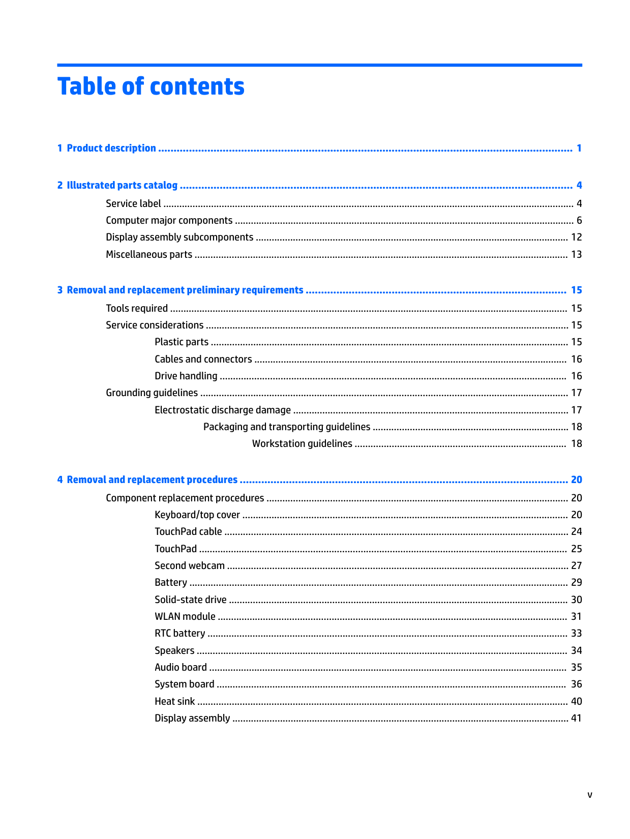
Table of contents

Plastic parts ....................................................................................................................................... 15 Cables and connectors ...................................................................................................................... 16 Drive handling ................................................................................................................................... 16
Grounding guidelines ........................................................................................................................................... 17 Electrostatic discharge damage ........................................................................................................ 17 Packaging and transporting guidelines .......................................................................... 18 Workstation guidelines ................................................................................ 18
Keyboard/top cover ........................................................................................................................... 20 TouchPad cable .................................................................................................................................. 24 TouchPad ........................................................................................................................................... 25 Second webcam ................................................................................................................................. 27 Battery ............................................................................................................................................... 29 Solid-state drive ................................................................................................................................ 30 WLAN module .................................................................................................................................... 31 RTC battery ........................................................................................................................................ 33 Speakers ............................................................................................................................................ 34 Audio board ....................................................................................................................................... 35 System board .................................................................................................................................... 36 Heat sink ............................................................................................................................................ 40 Display assembly ............................................................................................................................... 41
v
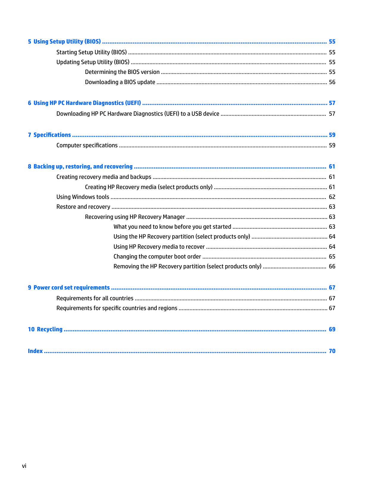
Determining the BIOS version ........................................................................................................... 55 Downloading a BIOS update .............................................................................................................. 56
Creating HP Recovery media (select products only) ......................................................................... 61 Using Windows tools ........................................................................................................................................... 62 Restore and recovery ........................................................................................................................................... 63
Recovering using HP Recovery Manager ........................................................................................... 63 What you need to know before you get started ............................................................. 63 Using the HP Recovery partition (select products only) ................................................. 64 Using HP Recovery media to recover .............................................................................. 64 Changing the computer boot order ................................................................................ 65 Removing the HP Recovery partition (select products only) ......................................... 66

###### Index ............................................................................................................................................................. 70
vi
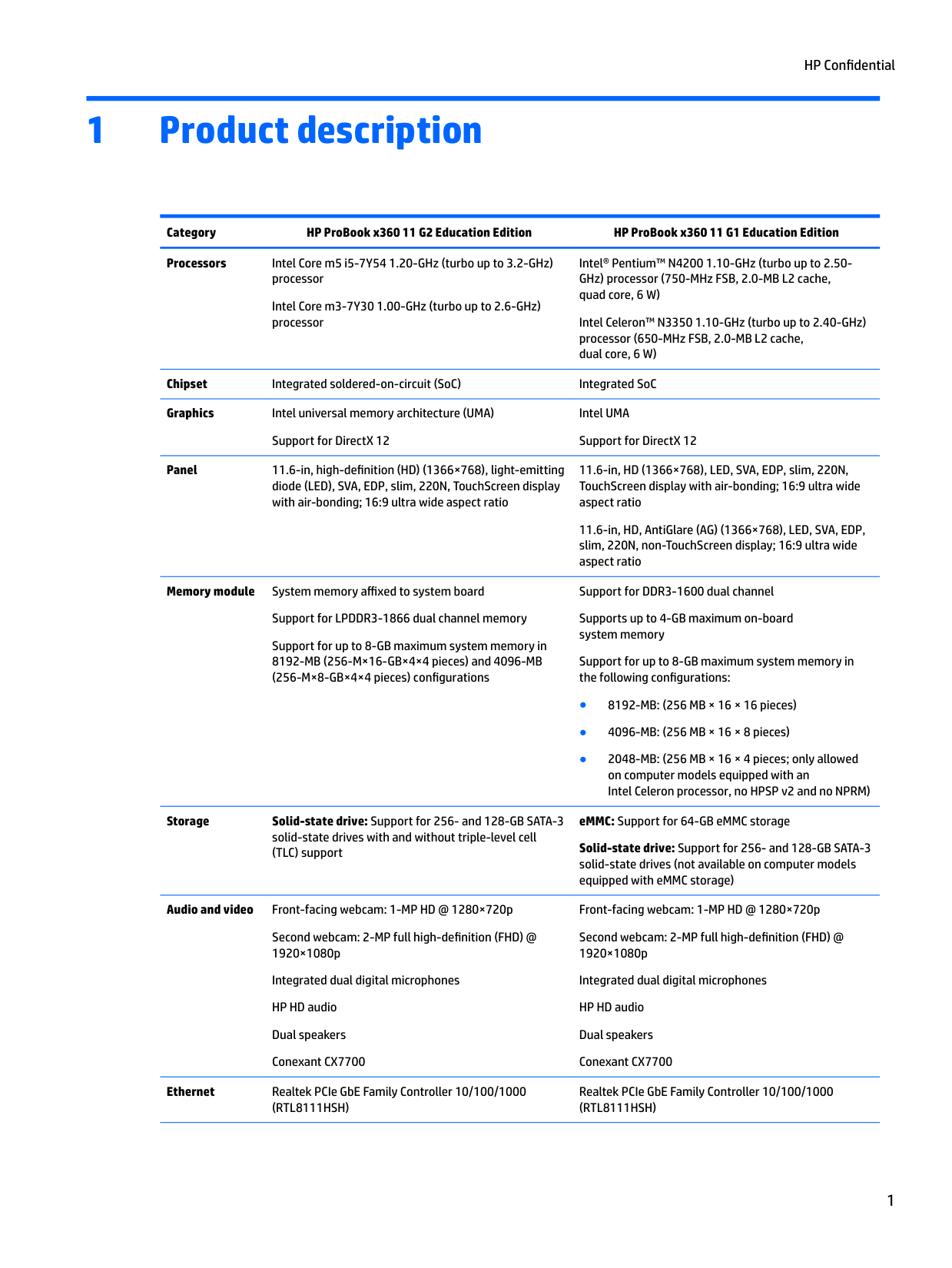
1 Product description
Category HP ProBook x360 11 G2 Education Edition HP ProBook x360 11 G1 Education Edition Processors Intel Core m5 i5-7Y54 1.20-GHz (turbo up to 3.2-GHz)
Intel® Pentium™ N4200 1.10-GHz (turbo up to 2.50GHz) processor (750-MHz FSB, 2.0-MB L2 cache, quad core, 6 W)
processor Intel Core m3-7Y30 1.00-GHz (turbo up to 2.6-GHz) processor
Intel Celeron™ N3350 1.10-GHz (turbo up to 2.40-GHz) processor (650-MHz FSB, 2.0-MB L2 cache, dual core, 6 W)
Chipset Integrated soldered-on-circuit (SoC) Integrated SoC Graphics Intel universal memory architecture (UMA) Support for DirectX 12
Intel UMA Support for DirectX 12
Panel 11.6-in, high-definition (HD) (1366×768), light-emitting diode (LED), SVA, EDP, slim, 220N, TouchScreen display with air-bonding; 16:9 ultra wide aspect ratio
11.6-in, HD (1366×768), LED, SVA, EDP, slim, 220N, TouchScreen display with air-bonding; 16:9 ultra wide aspect ratio
11.6-in, HD, AntiGlare (AG) (1366×768), LED, SVA, EDP, slim, 220N, non-TouchScreen display; 16:9 ultra wide aspect ratio
Memory module System memory affixed to system board Support for LPDDR3-1866 dual channel memory Support for up to 8-GB maximum system memory in 8192-MB (256-M×16-GB×4×4 pieces) and 4096-MB (256-M×8-GB×4×4 pieces) configurations

Storage Solid-state drive: Support for 256- and 128-GB SATA-3 solid-state drives with and without triple-level cell (TLC) support
Audio and video Front-facing webcam: 1-MP HD @ 1280×720p
Second webcam: 2-MP full high-definition (FHD) @ 1920×1080p
Integrated dual digital microphones HP HD audio Dual speakers Conexant CX7700
Ethernet Realtek PCIe GbE Family Controller 10/100/1000
(RTL8111HSH)
Support for DDR3-1600 dual channel Supports up to 4-GB maximum on-board system memory Support for up to 8-GB maximum system memory in the following configurations:
eMMC: Support for 64-GB eMMC storage Solid-state drive: Support for 256- and 128-GB SATA-3 solid-state drives (not available on computer models equipped with eMMC storage)
Front-facing webcam: 1-MP HD @ 1280×720p Second webcam: 2-MP full high-definition (FHD) @ 1920×1080p Integrated dual digital microphones HP HD audio Dual speakers Conexant CX7700
Realtek PCIe GbE Family Controller 10/100/1000 (RTL8111HSH)
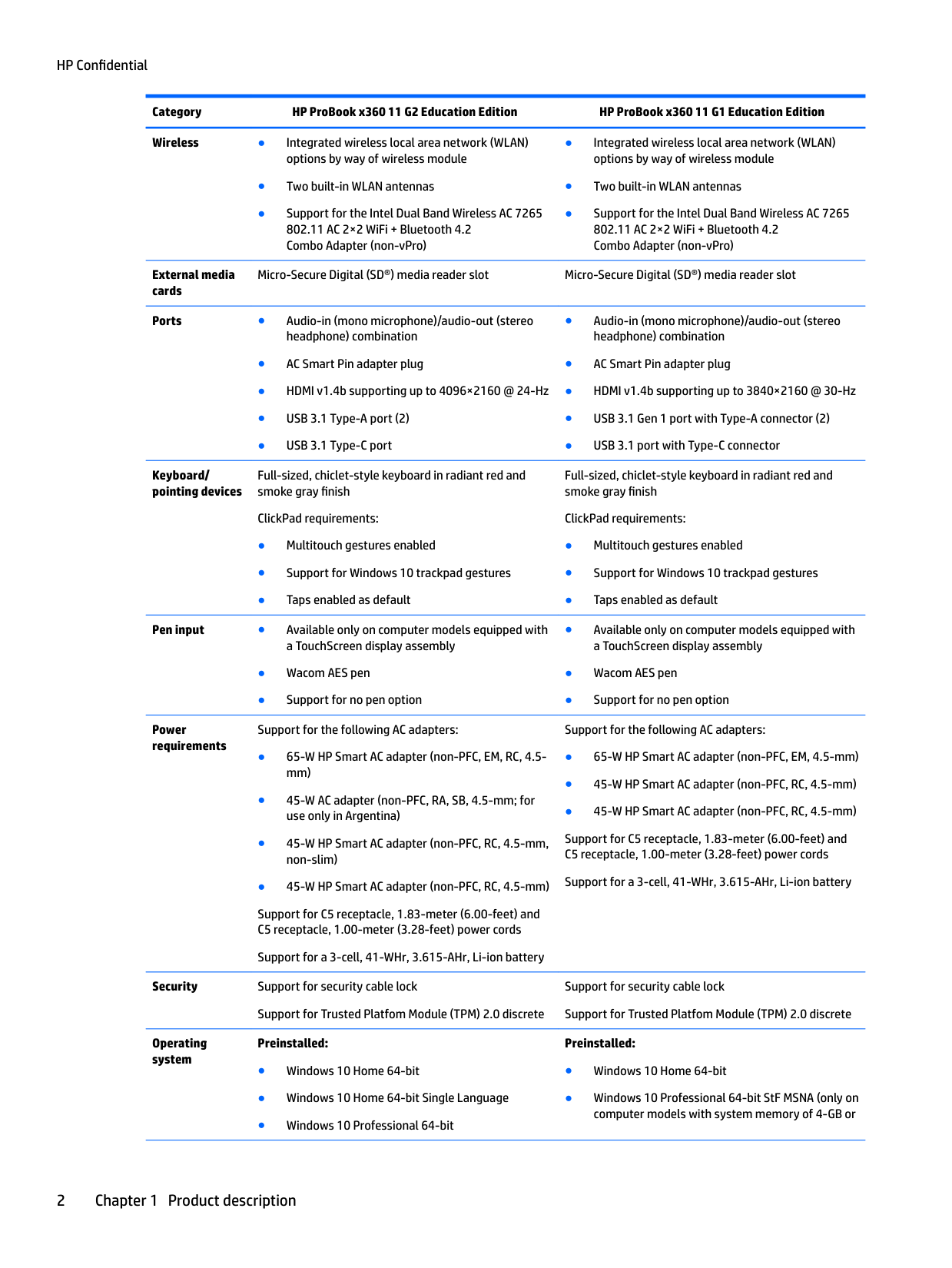
Wireless ● Integrated wireless local area network (WLAN)
options by way of wireless module
External media cards
Micro-Secure Digital (SD®) media reader slot Micro-Secure Digital (SD®) media reader slot
Ports ● Audio-in (mono microphone)/audio-out (stereo
headphone) combination
Keyboard/ pointing devices
Full-sized, chiclet-style keyboard in radiant red and smoke gray finish
ClickPad requirements:
Pen input ● Available only on computer models equipped with
a TouchScreen display assembly
Power requirements
Support for the following AC adapters:
Support for C5 receptacle, 1.83-meter (6.00-feet) and C5 receptacle, 1.00-meter (3.28-feet) power cords
Support for a 3-cell, 41-WHr, 3.615-AHr, Li-ion battery
Security Support for security cable lock
Support for Trusted Platfom Module (TPM) 2.0 discrete
Operating system
Preinstalled:
Full-sized, chiclet-style keyboard in radiant red and smoke gray finish
ClickPad requirements:
Support for the following AC adapters:
Support for C5 receptacle, 1.83-meter (6.00-feet) and C5 receptacle, 1.00-meter (3.28-feet) power cords
Support for a 3-cell, 41-WHr, 3.615-AHr, Li-ion battery
Support for security cable lock Support for Trusted Platfom Module (TPM) 2.0 discrete
######### Preinstalled:
2 Chapter 1 Product description
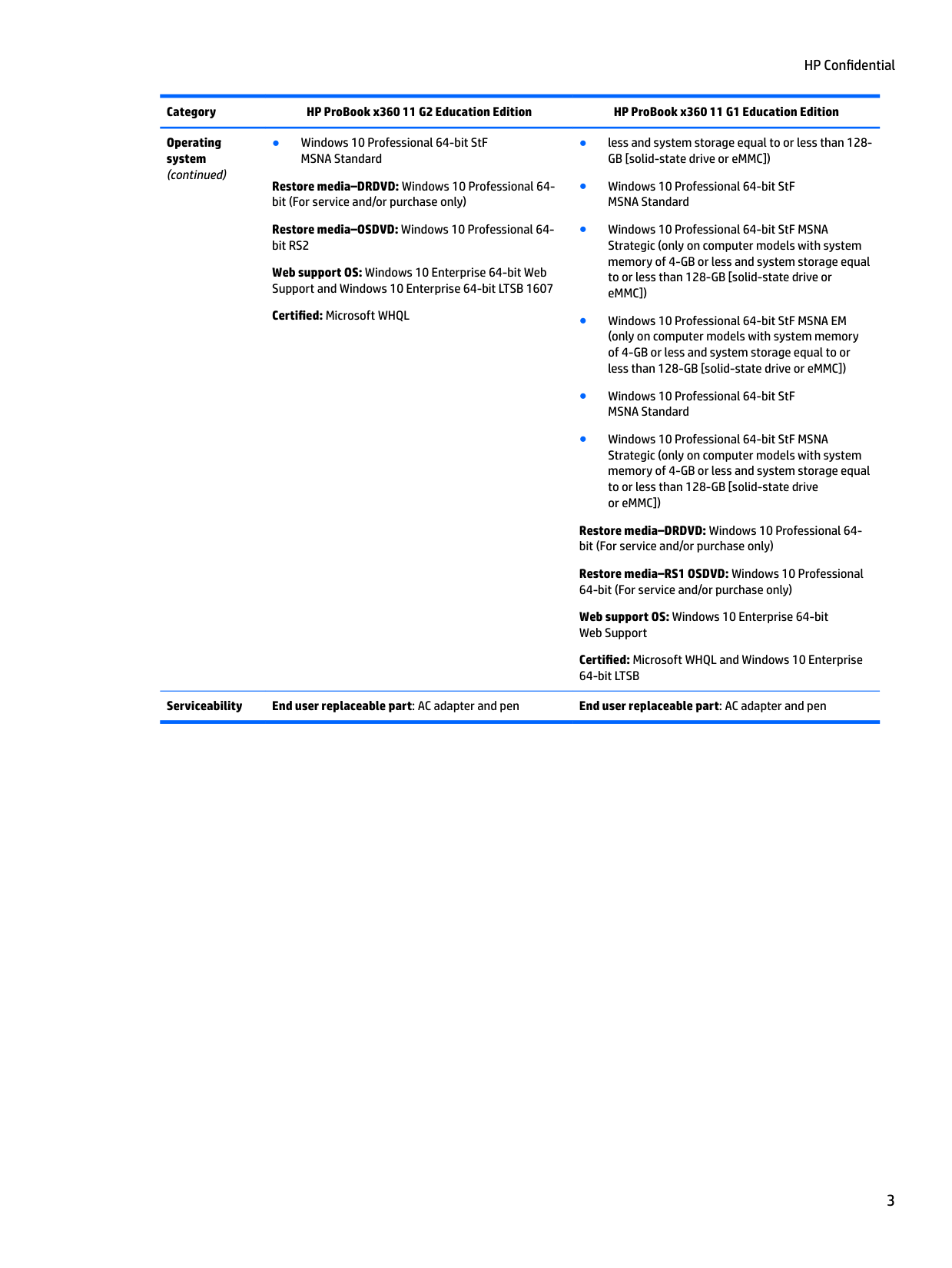
Operating system (continued)
● Windows 10 Professional 64-bit StF MSNA Standard
Restore media–DRDVD: Windows 10 Professional 64bit (For service and/or purchase only)
Restore media–OSDVD: Windows 10 Professional 64bit RS2
Web support OS: Windows 10 Enterprise 64-bit Web Support and Windows 10 Enterprise 64-bit LTSB 1607
Certified: Microsoft WHQL
Restore media–DRDVD: Windows 10 Professional 64bit (For service and/or purchase only)
Restore media–RS1 OSDVD: Windows 10 Professional 64-bit (For service and/or purchase only)
Web support OS: Windows 10 Enterprise 64-bit Web Support
Certified: Microsoft WHQL and Windows 10 Enterprise 64-bit LTSB
######### Serviceability End user replaceable part: AC adapter and pen End user replaceable part: AC adapter and pen
2 Illustrated parts catalog
| | |---|
NOTE: HP continually improves and changes product parts. For complete and current information on supported parts for the computer , go to http://partsurfer.hp.com, select the country or region, and then follow the on-screen instructions.
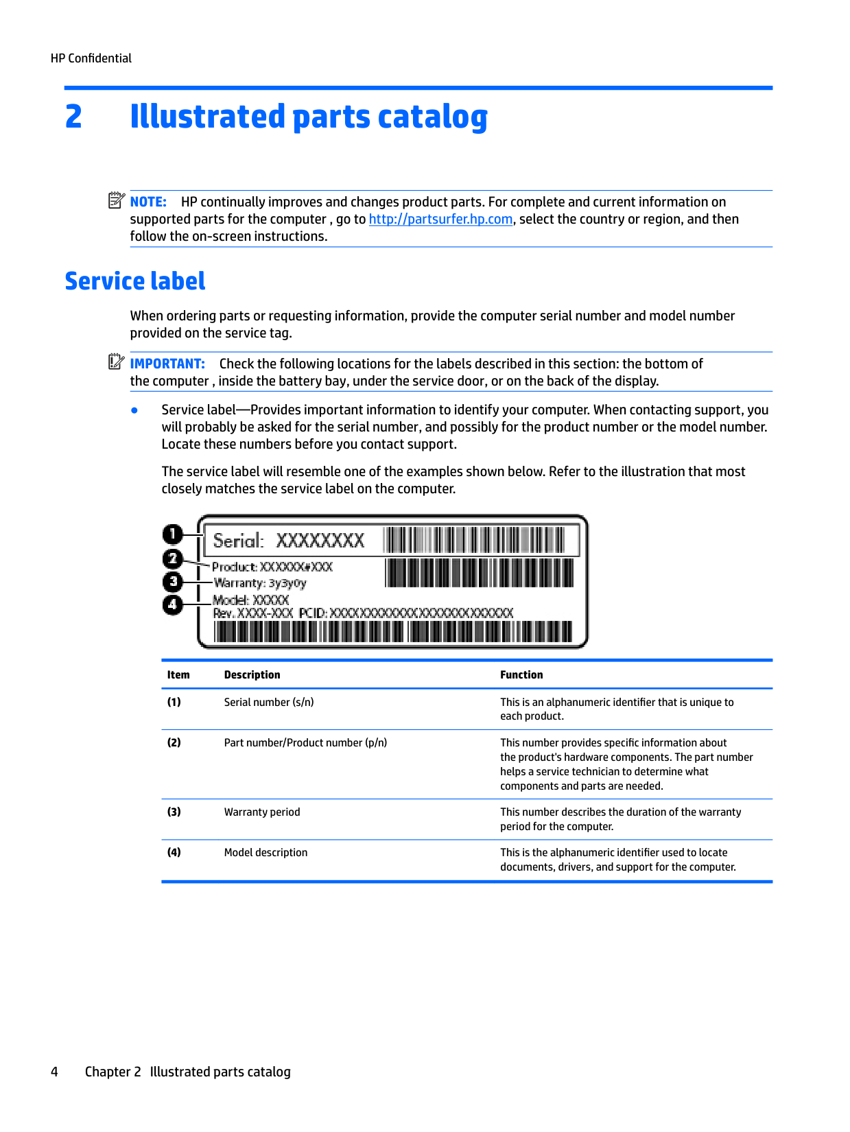
Service label
When ordering parts or requesting information, provide the computer serial number and model number provided on the service tag.
| | |---|
IMPORTANT: Check the following locations for the labels described in this section: the bottom of the computer , inside the battery bay, under the service door, or on the back of the display.
The service label will resemble one of the examples shown below. Refer to the illustration that most closely matches the service label on the computer.

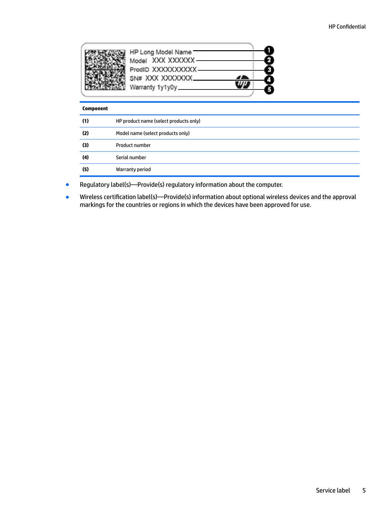
Item Description Function

######### Component
Service label 5
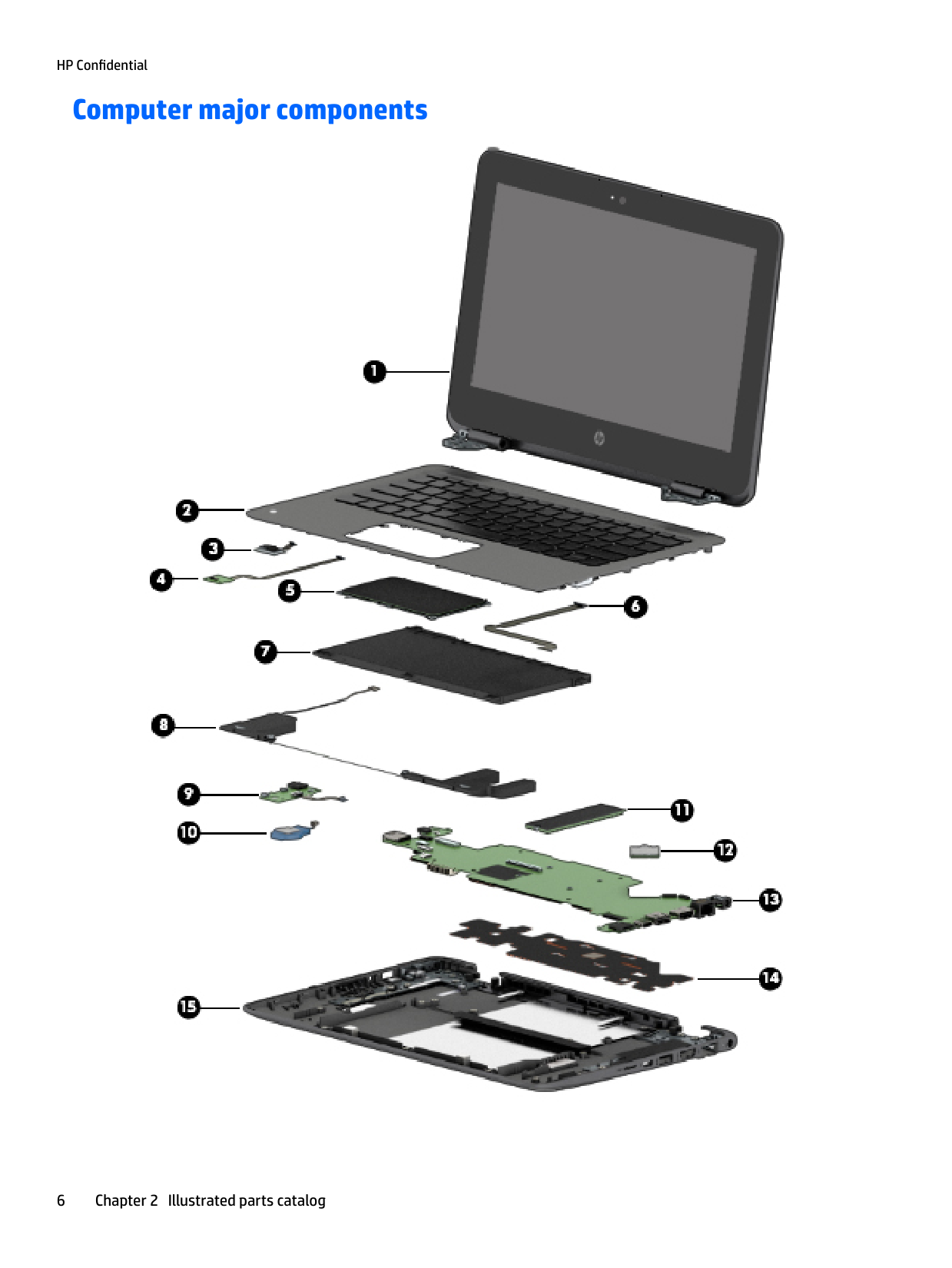
Computer major components

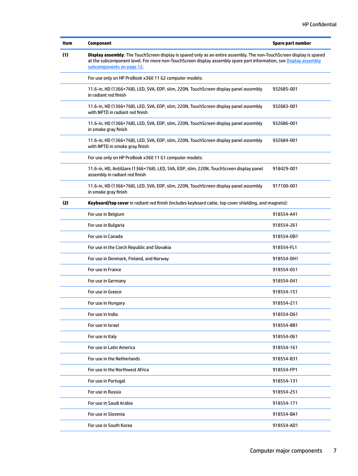
11.6-in, HD (1366×768), LED, SVA, EDP, slim, 220N, TouchScreen display panel assembly in radiant red finish
932685-001
11.6-in, HD (1366×768), LED, SVA, EDP, slim, 220N, TouchScreen display panel assembly with NPTD in radiant red finish
932683-001
11.6-in, HD (1366×768), LED, SVA, EDP, slim, 220N, TouchScreen display panel assembly in smoke gray finish
932686-001
11.6-in, HD (1366×768), LED, SVA, EDP, slim, 220N, TouchScreen display panel assembly with NPTD in smoke gray finish
932684-001
For use only on HP ProBook x360 11 G1 computer models: 11.6-in, HD, AntiGlare (1366×768), LED, SVA, EDP, slim, 220N, TouchScreen display panel assembly in radiant red finish
918429-001
11.6-in, HD (1366×768), LED, SVA, EDP, slim, 220N, TouchScreen display panel assembly in smoke gray finish
917100-001
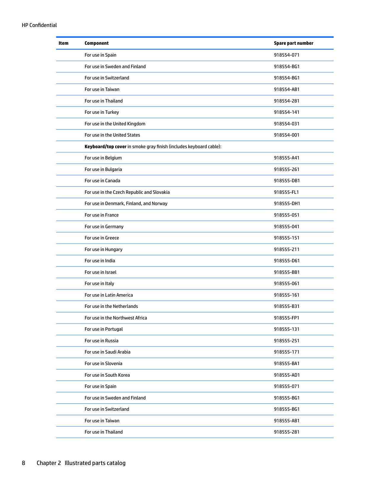
########## For use in Spain 918554-071
For use in Belgium 918555-A41 For use in Bulgaria 918555-261 For use in Canada 918555-DB1 For use in the Czech Republic and Slovakia 918555-FL1 For use in Denmark, Finland, and Norway 918555-DH1 For use in France 918555-051 For use in Germany 918555-041 For use in Greece 918555-151 For use in Hungary 918555-211 For use in India 918555-D61 For use in Israel 918555-BB1 For use in Italy 918555-061 For use in Latin America 918555-161 For use in the Netherlands 918555-B31 For use in the Northwest Africa 918555-FP1 For use in Portugal 918555-131 For use in Russia 918555-251 For use in Saudi Arabia 918555-171 For use in Slovenia 918555-BA1 For use in South Korea 918555-AD1 For use in Spain 918555-071 For use in Sweden and Finland 918555-BG1 For use in Switzerland 918555-BG1 For use in Taiwan 918555-AB1
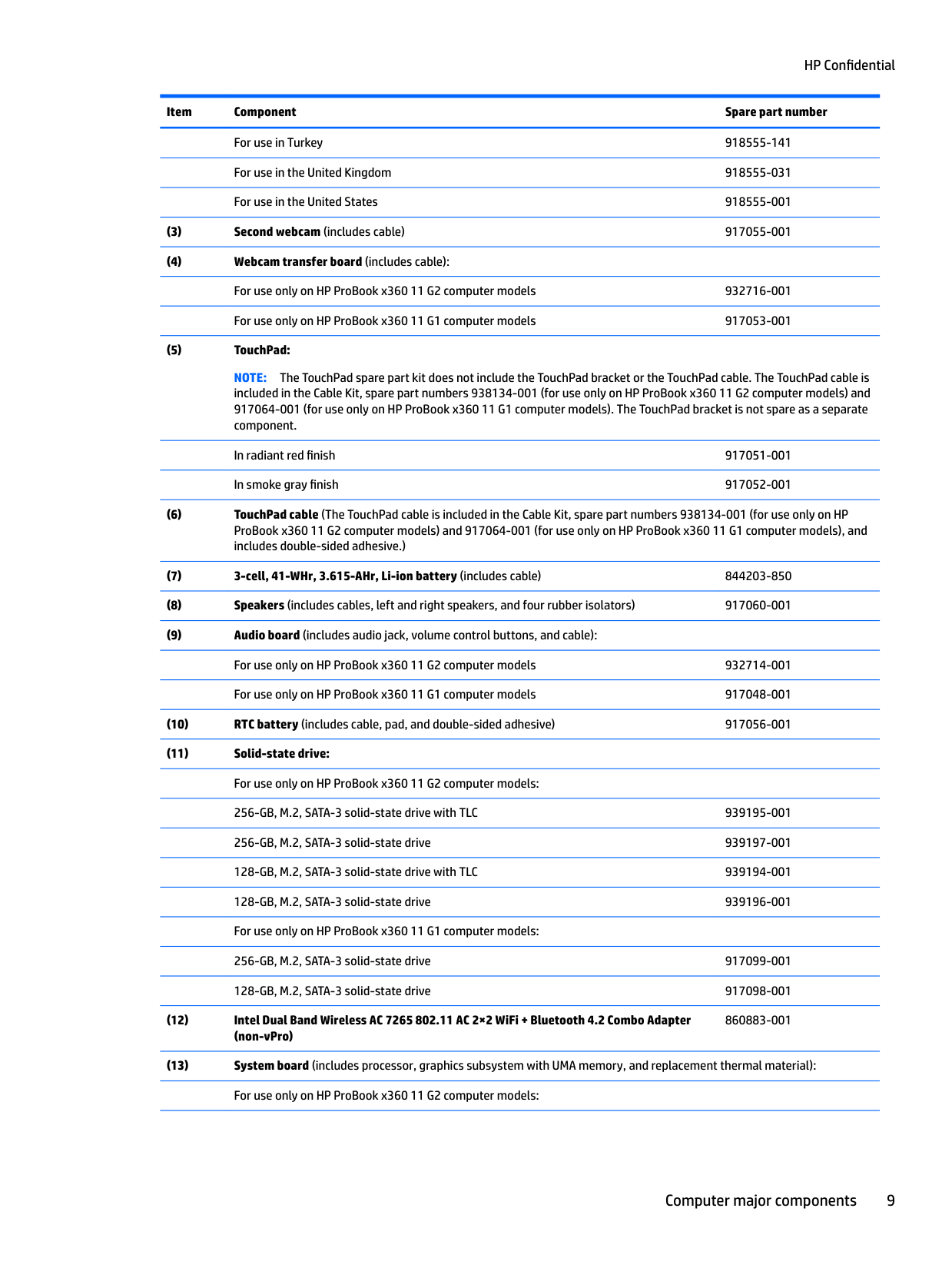
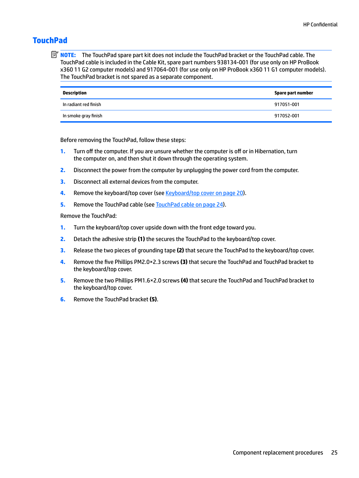
NOTE: The TouchPad spare part kit does not include the TouchPad bracket or the TouchPad cable. The TouchPad cable is included in the Cable Kit, spare part numbers 938134-001 (for use only on HP ProBook x360 11 G2 computer models) and 917064-001 (for use only on HP ProBook x360 11 G1 computer models). The TouchPad bracket is not spare as a separate component.
In radiant red finish 917051-001 In smoke gray finish 917052-001
860883-001
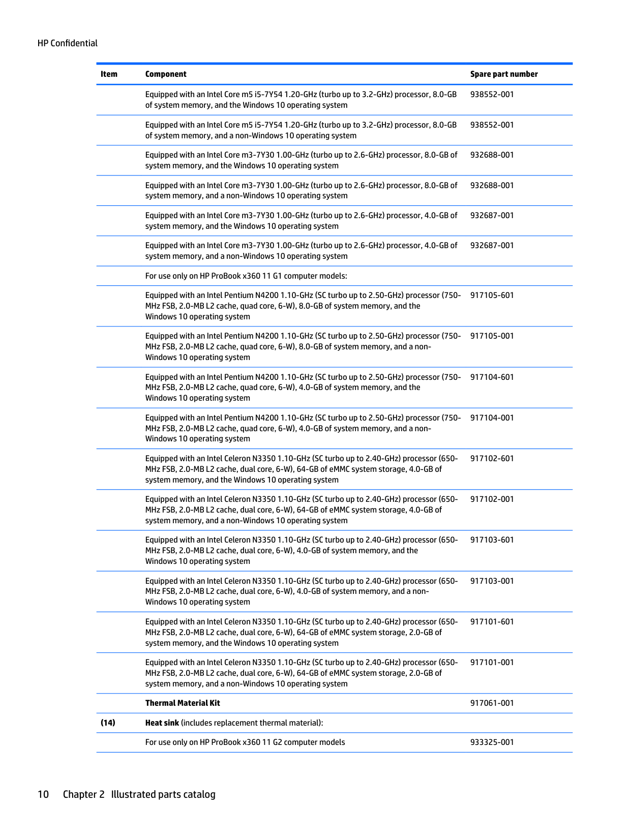
Equipped with an Intel Core m5 i5-7Y54 1.20-GHz (turbo up to 3.2-GHz) processor, 8.0-GB of system memory, and the Windows 10 operating system
938552-001
Equipped with an Intel Core m5 i5-7Y54 1.20-GHz (turbo up to 3.2-GHz) processor, 8.0-GB of system memory, and a non-Windows 10 operating system
938552-001
Equipped with an Intel Core m3-7Y30 1.00-GHz (turbo up to 2.6-GHz) processor, 8.0-GB of system memory, and the Windows 10 operating system
932688-001
Equipped with an Intel Core m3-7Y30 1.00-GHz (turbo up to 2.6-GHz) processor, 8.0-GB of system memory, and a non-Windows 10 operating system
932688-001
Equipped with an Intel Core m3-7Y30 1.00-GHz (turbo up to 2.6-GHz) processor, 4.0-GB of system memory, and the Windows 10 operating system
932687-001
Equipped with an Intel Core m3-7Y30 1.00-GHz (turbo up to 2.6-GHz) processor, 4.0-GB of system memory, and a non-Windows 10 operating system
932687-001
For use only on HP ProBook x360 11 G1 computer models: Equipped with an Intel Pentium N4200 1.10-GHz (SC turbo up to 2.50-GHz) processor (750MHz FSB, 2.0-MB L2 cache, quad core, 6-W), 8.0-GB of system memory, and the Windows 10 operating system
917105-601
Equipped with an Intel Pentium N4200 1.10-GHz (SC turbo up to 2.50-GHz) processor (750MHz FSB, 2.0-MB L2 cache, quad core, 6-W), 8.0-GB of system memory, and a nonWindows 10 operating system
917105-001
Equipped with an Intel Pentium N4200 1.10-GHz (SC turbo up to 2.50-GHz) processor (750MHz FSB, 2.0-MB L2 cache, quad core, 6-W), 4.0-GB of system memory, and the Windows 10 operating system
917104-601
Equipped with an Intel Pentium N4200 1.10-GHz (SC turbo up to 2.50-GHz) processor (750MHz FSB, 2.0-MB L2 cache, quad core, 6-W), 4.0-GB of system memory, and a nonWindows 10 operating system
917104-001
Equipped with an Intel Celeron N3350 1.10-GHz (SC turbo up to 2.40-GHz) processor (650MHz FSB, 2.0-MB L2 cache, dual core, 6-W), 64-GB of eMMC system storage, 4.0-GB of system memory, and the Windows 10 operating system
Equipped with an Intel Celeron N3350 1.10-GHz (SC turbo up to 2.40-GHz) processor (650MHz FSB, 2.0-MB L2 cache, dual core, 6-W), 64-GB of eMMC system storage, 4.0-GB of system memory, and a non-Windows 10 operating system
917102-601
Equipped with an Intel Celeron N3350 1.10-GHz (SC turbo up to 2.40-GHz) processor (650MHz FSB, 2.0-MB L2 cache, dual core, 6-W), 4.0-GB of system memory, and the Windows 10 operating system
Equipped with an Intel Celeron N3350 1.10-GHz (SC turbo up to 2.40-GHz) processor (650MHz FSB, 2.0-MB L2 cache, dual core, 6-W), 4.0-GB of system memory, and a nonWindows 10 operating system
Equipped with an Intel Celeron N3350 1.10-GHz (SC turbo up to 2.40-GHz) processor (650MHz FSB, 2.0-MB L2 cache, dual core, 6-W), 64-GB of eMMC system storage, 2.0-GB of system memory, and the Windows 10 operating system
Equipped with an Intel Celeron N3350 1.10-GHz (SC turbo up to 2.40-GHz) processor (650MHz FSB, 2.0-MB L2 cache, dual core, 6-W), 64-GB of eMMC system storage, 2.0-GB of system memory, and a non-Windows 10 operating system
917103-001
917101-601
917101-001
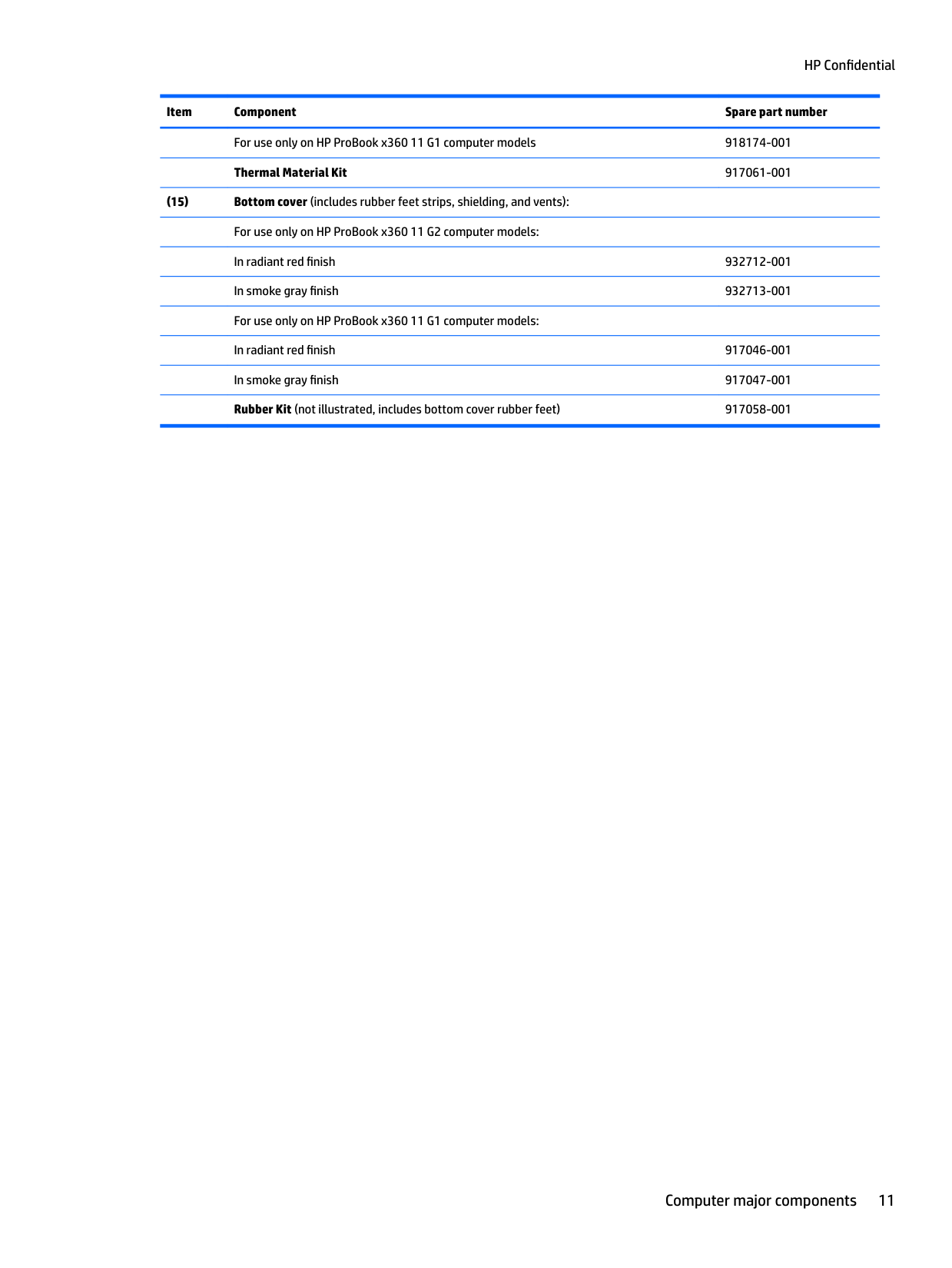
######### Thermal Material Kit 917061-001
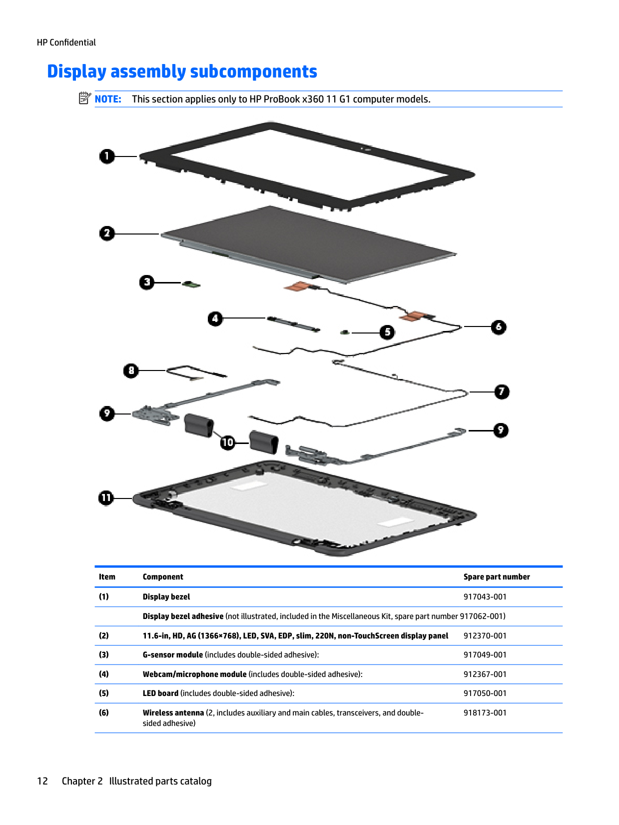
Display assembly subcomponents
| | |---|
NOTE: This section applies only to HP ProBook x360 11 G1 computer models.

Item Component Spare part number
918173-001
Miscellaneous parts
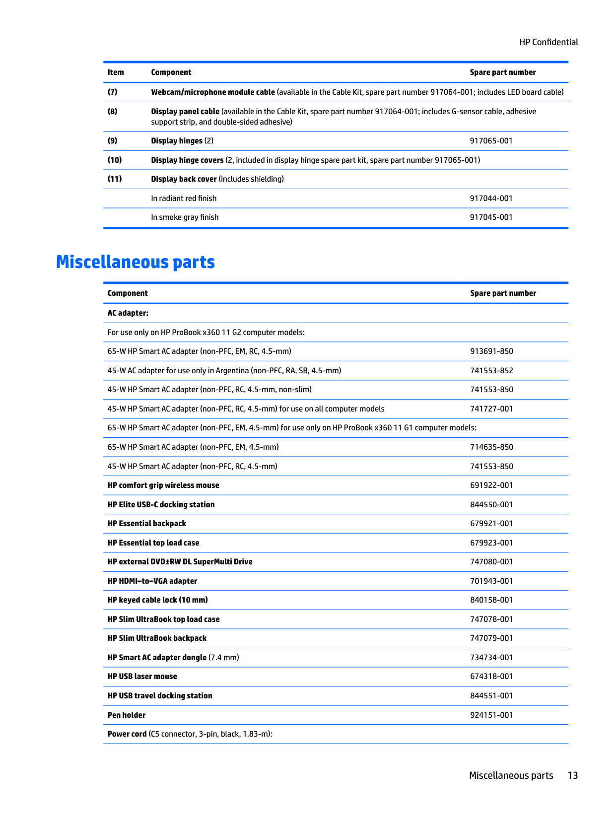
Component Spare part number AC adapter: For use only on HP ProBook x360 11 G2 computer models: 65-W HP Smart AC adapter (non-PFC, EM, RC, 4.5-mm) 913691-850 45-W AC adapter for use only in Argentina (non-PFC, RA, SB, 4.5-mm) 741553-852 45-W HP Smart AC adapter (non-PFC, RC, 4.5-mm, non-slim) 741553-850 45-W HP Smart AC adapter (non-PFC, RC, 4.5-mm) for use on all computer models 741727-001 65-W HP Smart AC adapter (non-PFC, EM, 4.5-mm) for use only on HP ProBook x360 11 G1 computer models: 65-W HP Smart AC adapter (non-PFC, EM, 4.5-mm) 714635-850 45-W HP Smart AC adapter (non-PFC, RC, 4.5-mm) 741553-850 HP comfort grip wireless mouse 691922-001 HP Elite USB-C docking station 844550-001 HP Essential backpack 679921-001 HP Essential top load case 679923-001 HP external DVD±RW DL SuperMulti Drive 747080-001 HP HDMI–to–VGA adapter 701943-001 HP keyed cable lock (10 mm) 840158-001 HP Slim UltraBook top load case 747078-001 HP Slim UltraBook backpack 747079-001 HP Smart AC adapter dongle (7.4 mm) 734734-001 HP USB laser mouse 674318-001 HP USB travel docking station 844551-001 Pen holder 924151-001 Power cord (C5 connector, 3-pin, black, 1.83-m):
Miscellaneous parts 13
######### Component Spare part number
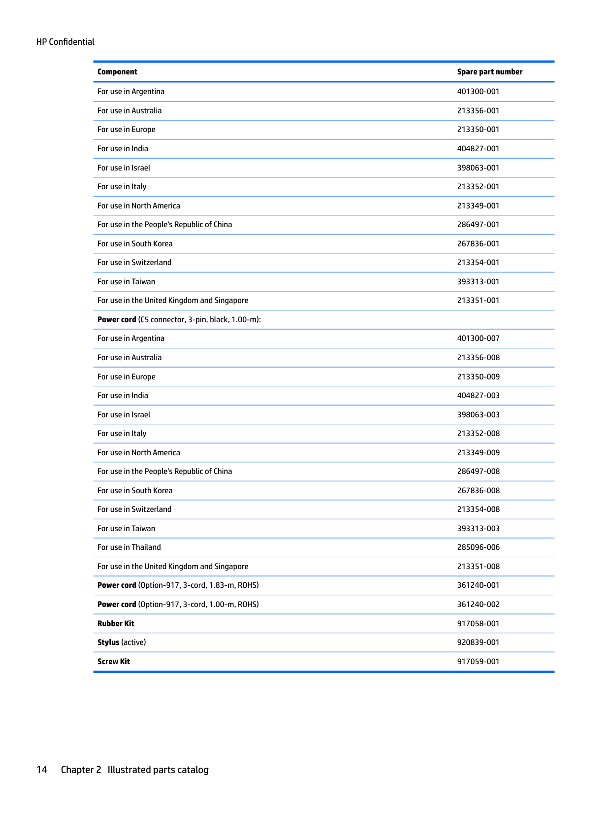
For use in Argentina 401300-001 For use in Australia 213356-001 For use in Europe 213350-001 For use in India 404827-001 For use in Israel 398063-001 For use in Italy 213352-001 For use in North America 213349-001 For use in the People’s Republic of China 286497-001 For use in South Korea 267836-001 For use in Switzerland 213354-001 For use in Taiwan 393313-001 For use in the United Kingdom and Singapore 213351-001 Power cord (C5 connector, 3-pin, black, 1.00-m):
For use in Argentina 401300-007 For use in Australia 213356-008 For use in Europe 213350-009 For use in India 404827-003 For use in Israel 398063-003 For use in Italy 213352-008 For use in North America 213349-009 For use in the People’s Republic of China 286497-008 For use in South Korea 267836-008 For use in Switzerland 213354-008 For use in Taiwan 393313-003 For use in Thailand 285096-006 For use in the United Kingdom and Singapore 213351-008 Power cord (Option-917, 3-cord, 1.83-m, ROHS) 361240-001 Power cord (Option-917, 3-cord, 1.00-m, ROHS) 361240-002 Rubber Kit 917058-001 Stylus (active) 920839-001 Screw Kit 917059-001
3 Removal and replacement preliminaryrequirements
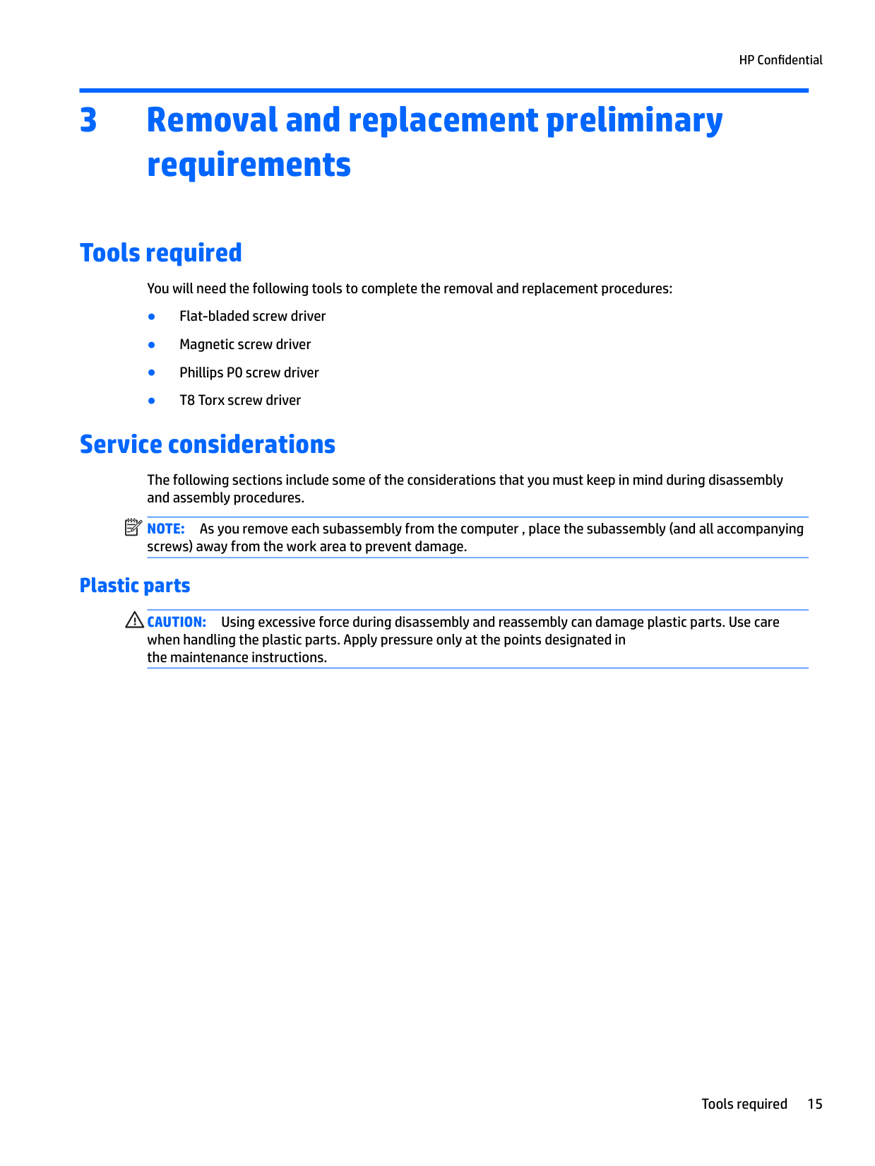
Tools required
You will need the following tools to complete the removal and replacement procedures:
Service considerations
The following sections include some of the considerations that you must keep in mind during disassembly and assembly procedures.
| | |---|
NOTE: As you remove each subassembly from the computer , place the subassembly (and all accompanying screws) away from the work area to prevent damage.
#### Plastic parts
CAUTION: Using excessive force during disassembly and reassembly can damage plastic parts. Use care when handling the plastic parts. Apply pressure only at the points designated in the maintenance instructions.
Tools required 15
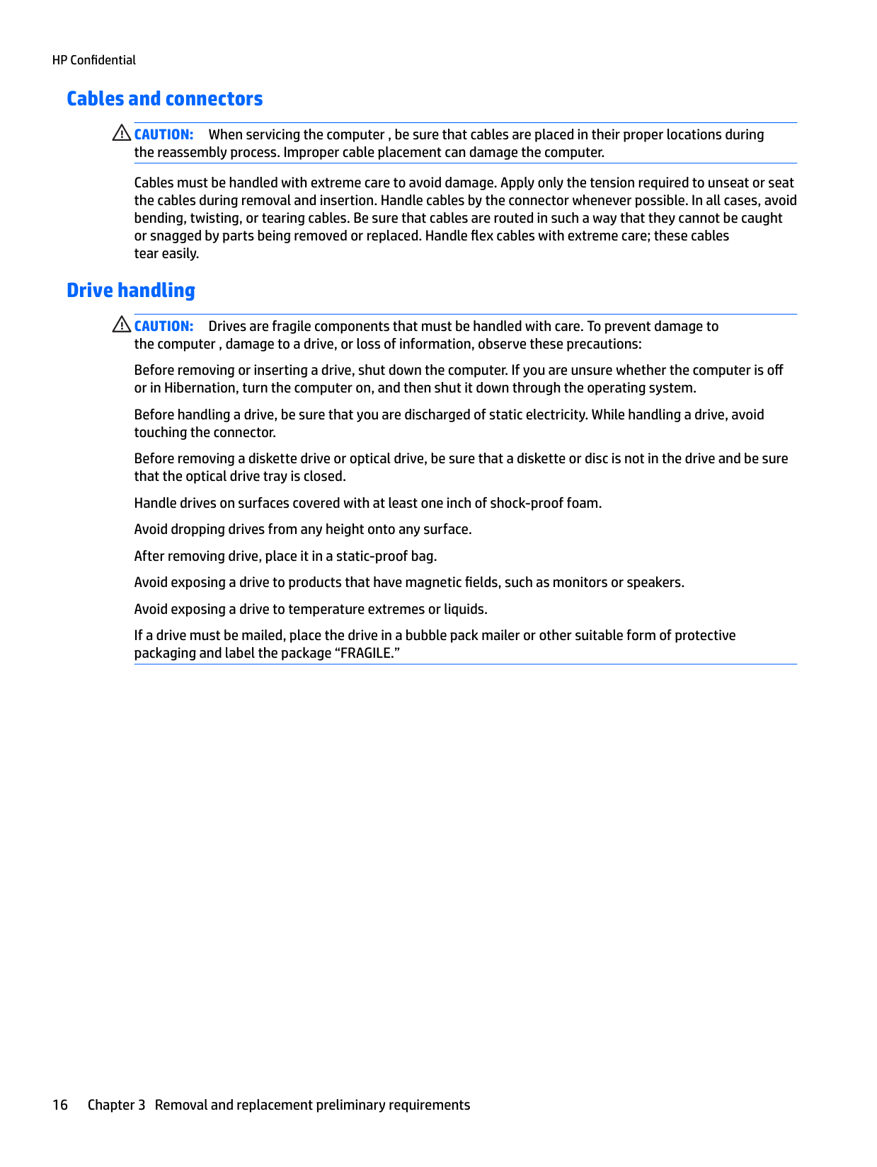
#### Cables and connectors
CAUTION: When servicing the computer , be sure that cables are placed in their proper locations during the reassembly process. Improper cable placement can damage the computer.
Cables must be handled with extreme care to avoid damage. Apply only the tension required to unseat or seat the cables during removal and insertion. Handle cables by the connector whenever possible. In all cases, avoid bending, twisting, or tearing cables. Be sure that cables are routed in such a way that they cannot be caught or snagged by parts being removed or replaced. Handle flex cables with extreme care; these cables tear easily.
Drive handling CAUTION: Drives are fragile components that must be handled with care. To prevent damage to the computer , damage to a drive, or loss of information, observe these precautions: Before removing or inserting a drive, shut down the computer. If you are unsure whether the computer is off or in Hibernation, turn the computer on, and then shut it down through the operating system. Before handling a drive, be sure that you are discharged of static electricity. While handling a drive, avoid touching the connector. Before removing a diskette drive or optical drive, be sure that a diskette or disc is not in the drive and be sure that the optical drive tray is closed. Handle drives on surfaces covered with at least one inch of shock-proof foam. Avoid dropping drives from any height onto any surface. After removing drive, place it in a static-proof bag. Avoid exposing a drive to products that have magnetic fields, such as monitors or speakers. Avoid exposing a drive to temperature extremes or liquids. If a drive must be mailed, place the drive in a bubble pack mailer or other suitable form of protective packaging and label the package “FRAGILE.”
Grounding guidelines
#### Electrostatic discharge damage
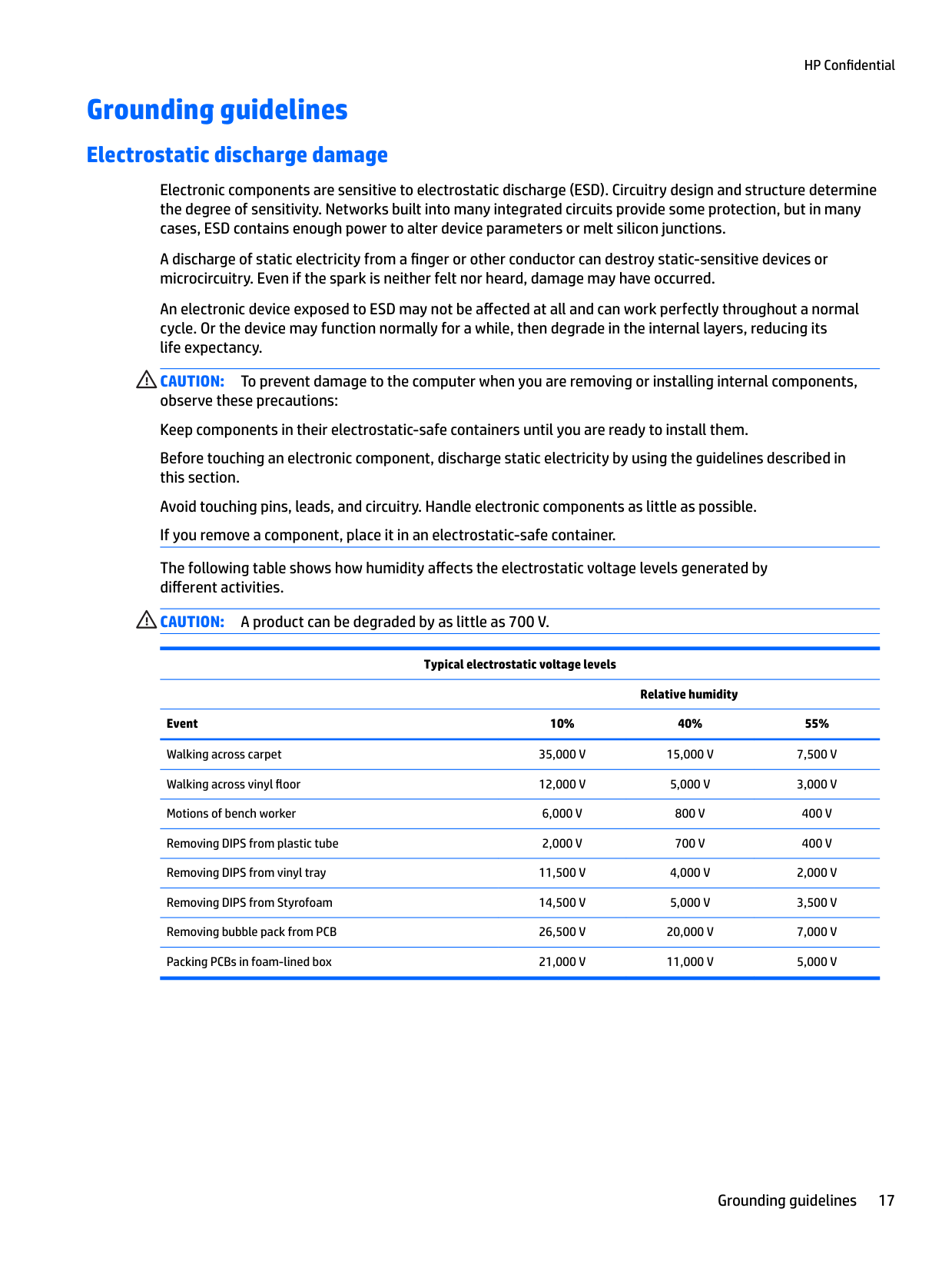
Electronic components are sensitive to electrostatic discharge (ESD). Circuitry design and structure determine the degree of sensitivity. Networks built into many integrated circuits provide some protection, but in many cases, ESD contains enough power to alter device parameters or melt silicon junctions.
A discharge of static electricity from a finger or other conductor can destroy static-sensitive devices or microcircuitry. Even if the spark is neither felt nor heard, damage may have occurred.
An electronic device exposed to ESD may not be affected at all and can work perfectly throughout a normal cycle. Or the device may function normally for a while, then degrade in the internal layers, reducing its life expectancy.
CAUTION: To prevent damage to the computer when you are removing or installing internal components, observe these precautions: Keep components in their electrostatic-safe containers until you are ready to install them. Before touching an electronic component, discharge static electricity by using the guidelines described in this section. Avoid touching pins, leads, and circuitry. Handle electronic components as little as possible. If you remove a component, place it in an electrostatic-safe container. The following table shows how humidity affects the electrostatic voltage levels generated by different activities. CAUTION: A product can be degraded by as little as 700 V.
Typical electrostatic voltage levels
Relative humidity Event 10% 40% 55% Walking across carpet 35,000 V 15,000 V 7,500 V Walking across vinyl floor 12,000 V 5,000 V 3,000 V Motions of bench worker 6,000 V 800 V 400 V Removing DIPS from plastic tube 2,000 V 700 V 400 V Removing DIPS from vinyl tray 11,500 V 4,000 V 2,000 V Removing DIPS from Styrofoam 14,500 V 5,000 V 3,500 V Removing bubble pack from PCB 26,500 V 20,000 V 7,000 V Packing PCBs in foam-lined box 21,000 V 11,000 V 5,000 V
##### Packaging and transporting guidelines
Follow these grounding guidelines when packaging and transporting equipment:
###### Workstation guidelines
Follow these grounding workstation guidelines:
###### Equipment guidelines
Grounding equipment must include either a wrist strap or a foot strap at a grounded workstation.
Material Use Voltage protection level
Antistatic plastics Bags 1,500 V Carbon-loaded plastic Floor mats 7,500 V Metallized laminate Floor mats 5,000 V
4 Removal and replacement procedures
CAUTION: Components described in this chapter should only be accessed by an authorized service provider. Accessing these parts can damage the computer or void the warranty.
Component replacement procedures NOTE: Details about the computer , including model, serial number, product key, and length of warranty, are on the service tag on the bottom of the computer. See Service label on page 4 for details. This chapter provides removal and replacement procedures.
| | |---|
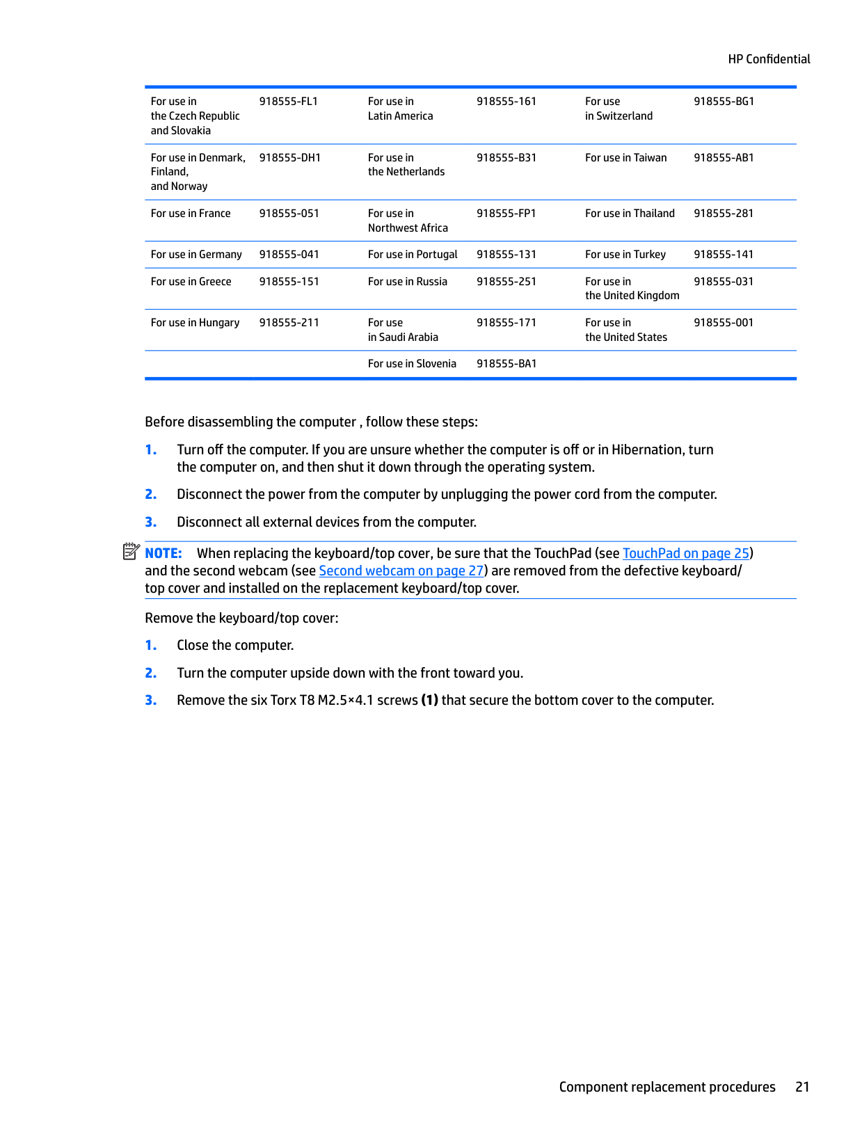
There are as many as 68 screws that must be removed, replaced, and/or loosened when servicing the computer. Make special note of each screw size and location during removal and replacement.
#### Keyboard/top cover
Keyboard/top cover in radiant red finish (includes keyboard cable, top cover shielding, and magnets):
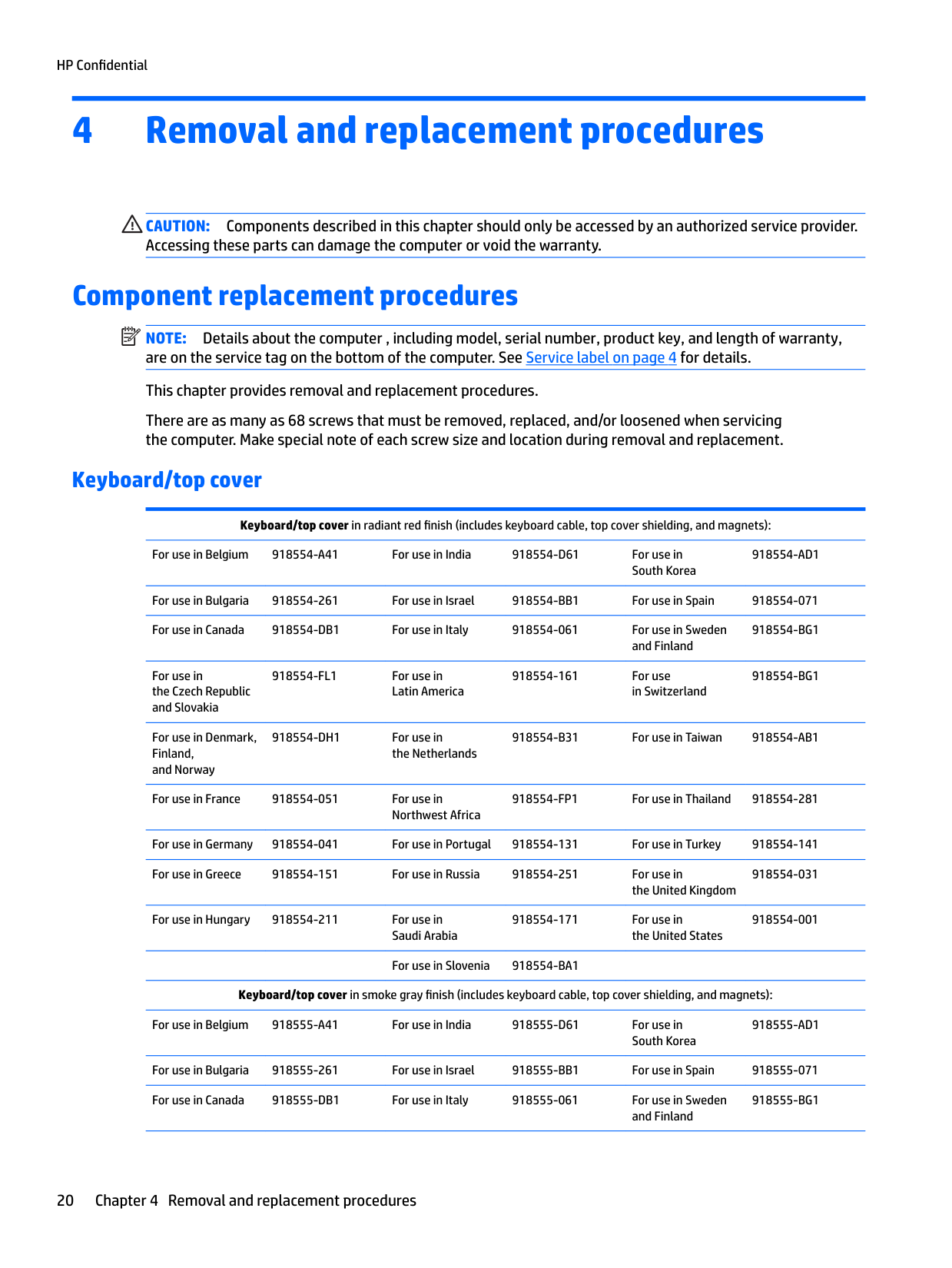
918554-AD1
918554-BG1
For use in the Czech Republic and Slovakia
918554-FL1 For use in Latin America
918554-161 For use in Switzerland
918554-BG1
For use in Denmark, Finland, and Norway
918554-DH1 For use in the Netherlands
918554-B31 For use in Taiwan 918554-AB1
For use in France 918554-051 For use in Northwest Africa
918554-FP1 For use in Thailand 918554-281
For use in Germany 918554-041 For use in Portugal 918554-131 For use in Turkey 918554-141 For use in Greece 918554-151 For use in Russia 918554-251 For use in
the United Kingdom
918554-031
For use in Hungary 918554-211 For use in Saudi Arabia
918554-171 For use in the United States
918554-001
For use in Slovenia 918554-BA1
Keyboard/top cover in smoke gray finish (includes keyboard cable, top cover shielding, and magnets): For use in Belgium 918555-A41 For use in India 918555-D61 For use in
South Korea
918555-AD1
For use in Bulgaria 918555-261 For use in Israel 918555-BB1 For use in Spain 918555-071
918555-BG1
For use in the Czech Republic and Slovakia
918555-FL1 For use in Latin America
918555-161 For use in Switzerland
918555-BG1
For use in Denmark, Finland, and Norway
918555-DH1 For use in the Netherlands
918555-B31 For use in Taiwan 918555-AB1
For use in France 918555-051 For use in Northwest Africa
918555-FP1 For use in Thailand 918555-281
For use in Germany 918555-041 For use in Portugal 918555-131 For use in Turkey 918555-141 For use in Greece 918555-151 For use in Russia 918555-251 For use in
918555-031
the United Kingdom
For use in Hungary 918555-211 For use in Saudi Arabia
918555-171 For use in the United States
For use in Slovenia 918555-BA1
918555-001
Before disassembling the computer , follow these steps:
| | |---|
NOTE: When replacing the keyboard/top cover, be sure that the TouchPad (see TouchPad on page 25) and the second webcam (see Second webcam on page 27) are removed from the defective keyboard/ top cover and installed on the replacement keyboard/top cover.
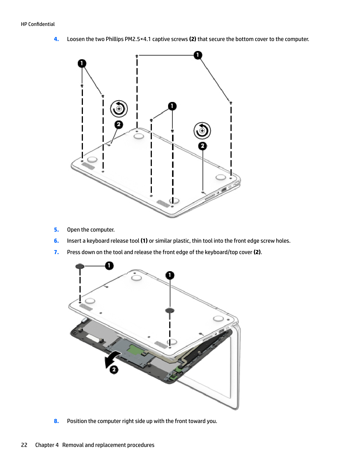
Remove the keyboard/top cover:


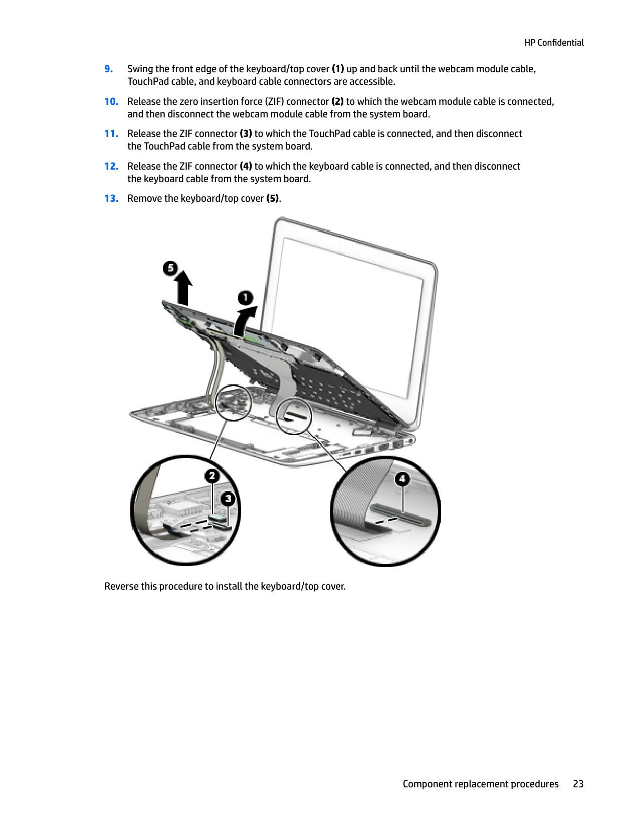
Reverse this procedure to install the keyboard/top cover.
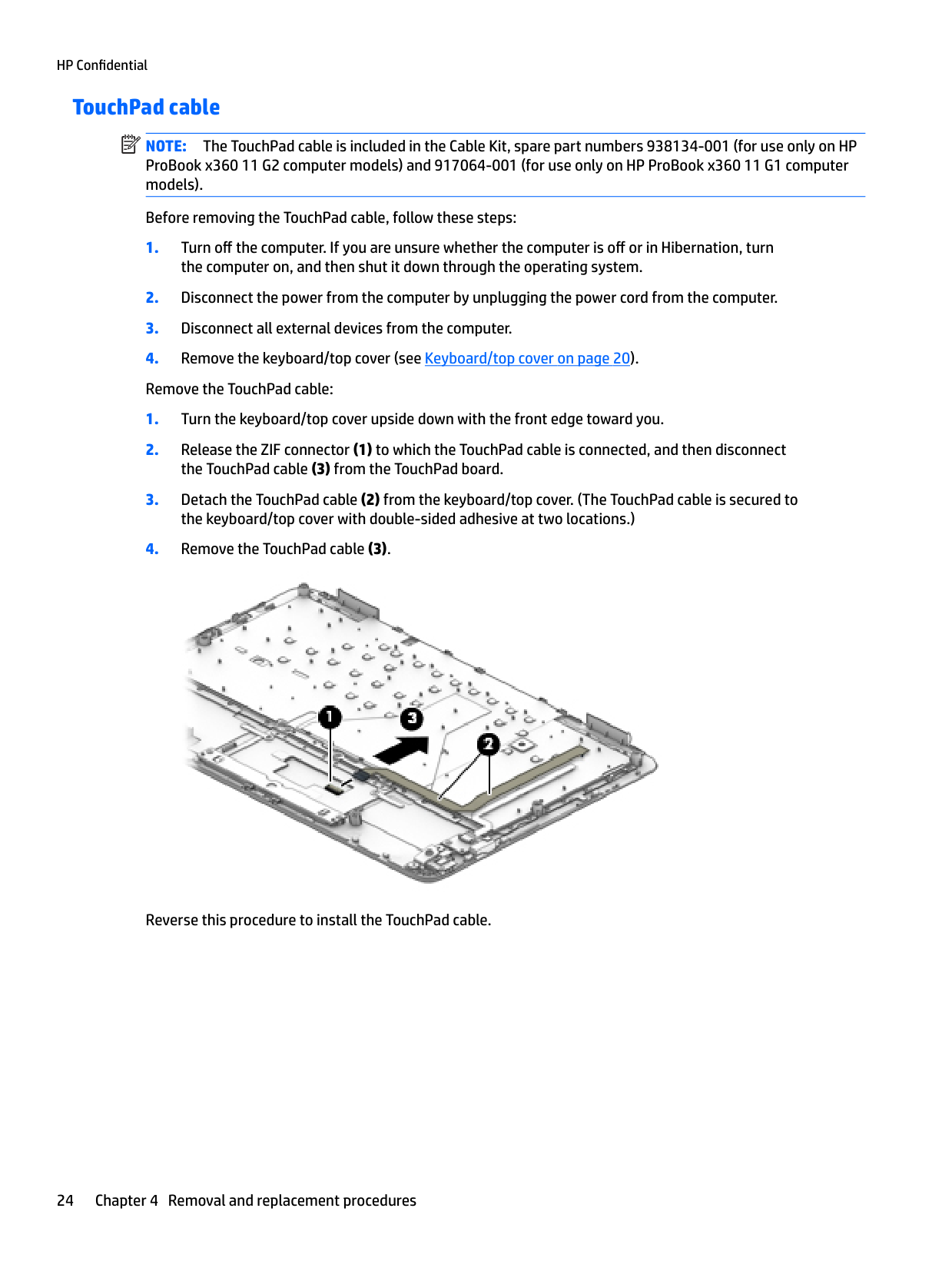
#### TouchPad cable
| | |---|
NOTE: The TouchPad cable is included in the Cable Kit, spare part numbers 938134-001 (for use only on HP ProBook x360 11 G2 computer models) and 917064-001 (for use only on HP ProBook x360 11 G1 computer models).
Before removing the TouchPad cable, follow these steps:

Reverse this procedure to install the TouchPad cable.
#### TouchPad
| | |---|
NOTE: The TouchPad spare part kit does not include the TouchPad bracket or the TouchPad cable. The TouchPad cable is included in the Cable Kit, spare part numbers 938134-001 (for use only on HP ProBook x360 11 G2 computer models) and 917064-001 (for use only on HP ProBook x360 11 G1 computer models). The TouchPad bracket is not spared as a separate component.
Description Spare part number
In radiant red finish 917051-001 In smoke gray finish 917052-001
Before removing the TouchPad, follow these steps:

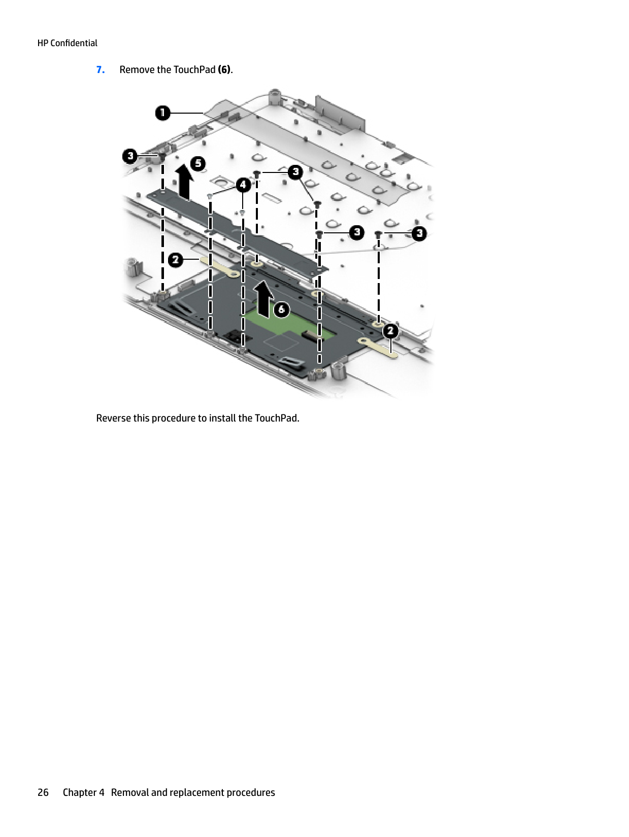
Reverse this procedure to install the TouchPad.
#### Second webcam
| | |---|
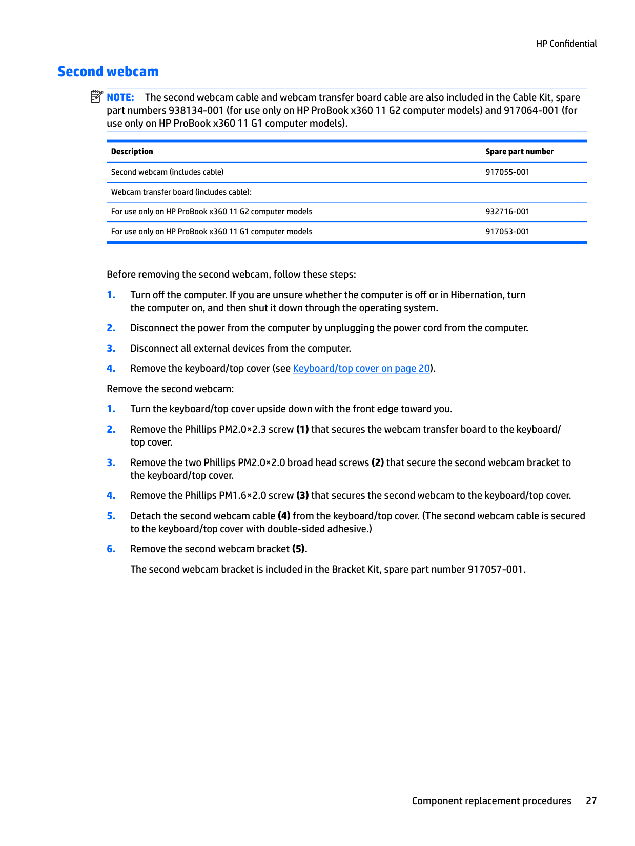
NOTE: The second webcam cable and webcam transfer board cable are also included in the Cable Kit, spare part numbers 938134-001 (for use only on HP ProBook x360 11 G2 computer models) and 917064-001 (for use only on HP ProBook x360 11 G1 computer models).
Description Spare part number Second webcam (includes cable) 917055-001 Webcam transfer board (includes cable): For use only on HP ProBook x360 11 G2 computer models 932716-001 For use only on HP ProBook x360 11 G1 computer models 917053-001
Before removing the second webcam, follow these steps:
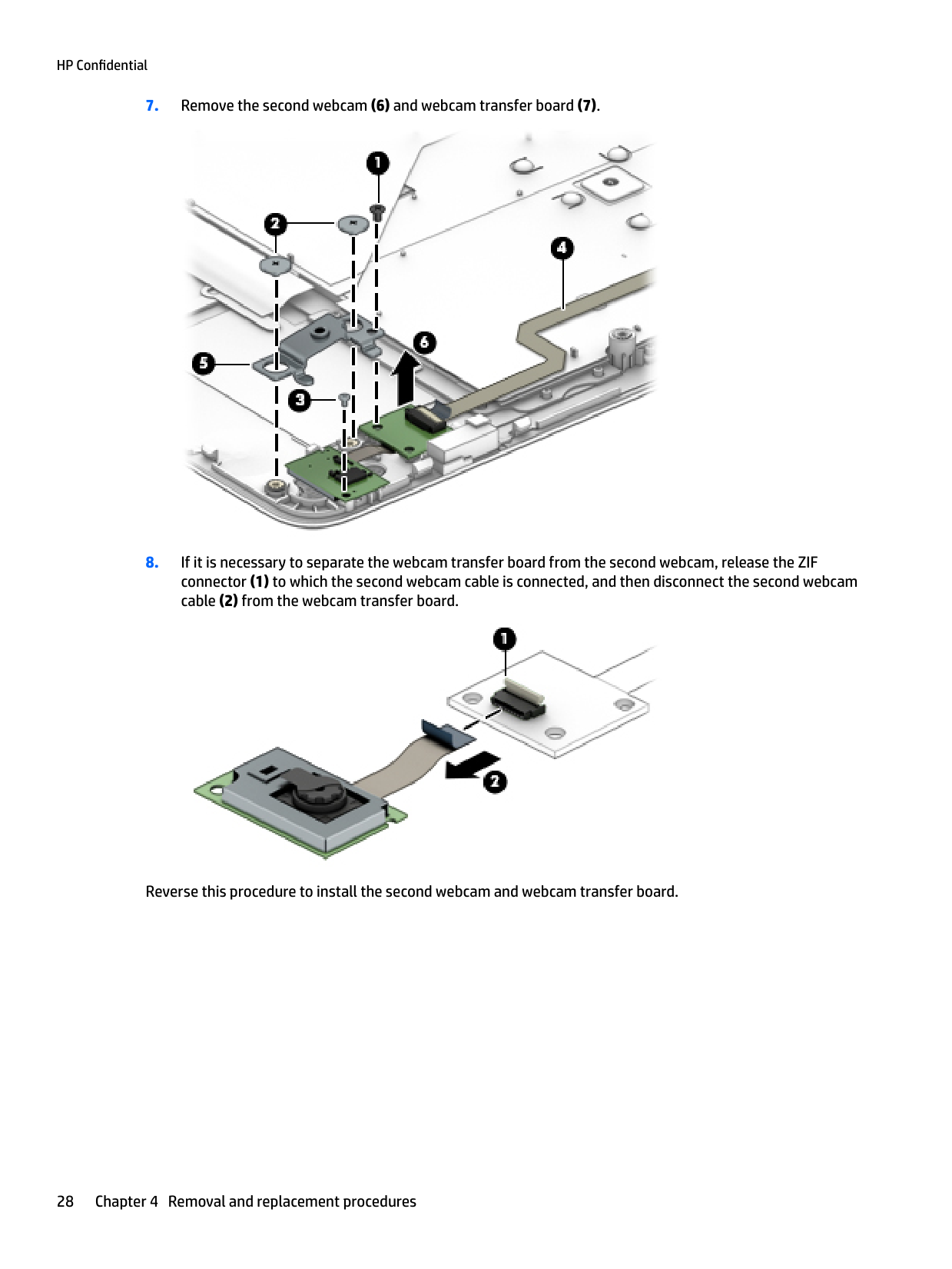


Reverse this procedure to install the second webcam and webcam transfer board.
#### Battery
Description Spare part number 3-cell, 41-WHr, 3.615-AHr, Li-ion battery (includes cable) 844203-850
Before removing the battery, follow these steps:
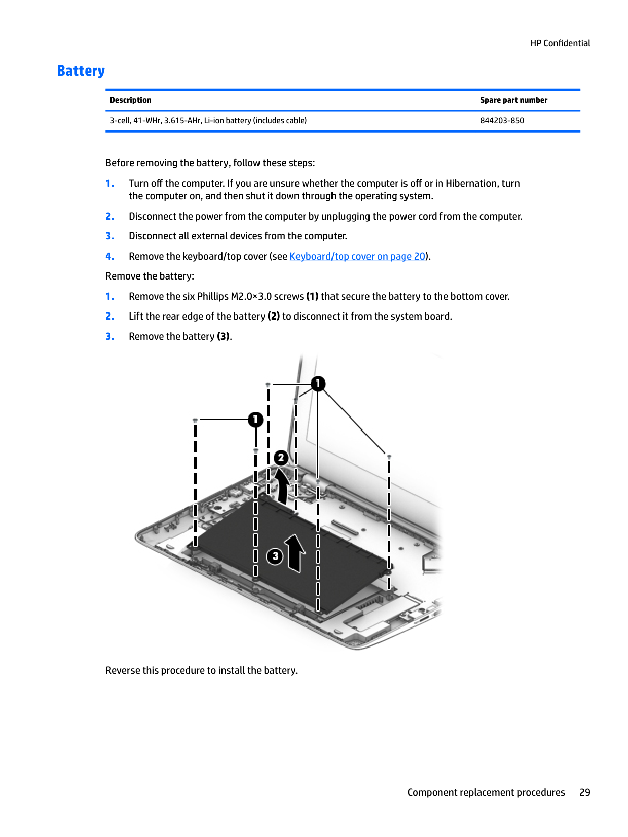

Reverse this procedure to install the battery.
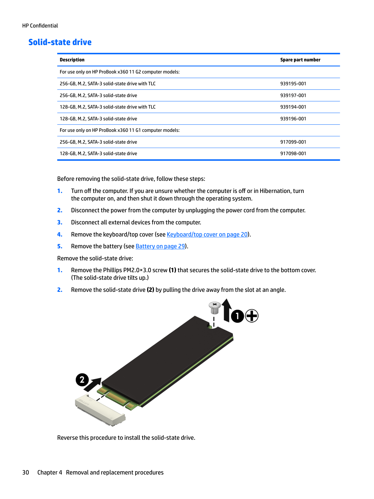
#### Solid-state drive
Description Spare part number For use only on HP ProBook x360 11 G2 computer models: 256-GB, M.2, SATA-3 solid-state drive with TLC 939195-001 256-GB, M.2, SATA-3 solid-state drive 939197-001 128-GB, M.2, SATA-3 solid-state drive with TLC 939194-001 128-GB, M.2, SATA-3 solid-state drive 939196-001 For use only on HP ProBook x360 11 G1 computer models: 256-GB, M.2, SATA-3 solid-state drive 917099-001 128-GB, M.2, SATA-3 solid-state drive 917098-001
Before removing the solid-state drive, follow these steps:
the computer on, and then shut it down through the operating system.

Reverse this procedure to install the solid-state drive.
#### WLAN module
Description Spare part number Intel Dual Band Wireless AC 7265 802.11 AC 2×2 WiFi + Bluetooth 4.2 Combo Adapter (non-vPro) 860883-001
CAUTION: To prevent an unresponsive system, replace the wireless module only with a wireless module authorized for use in the computer by the governmental agency that regulates wireless devices in your country or region. If you replace the module and then receive a warning message, remove the module to restore device functionality, and then contact technical support.
Before removing the WLAN module, follow these steps:
NOTE: The wireless antenna cable labeled “1/MAIN” connects to the WLAN module “Main” terminal. The wireless antenna cable labeled “2/AUX” connects to the WLAN module “Aux” terminal.
| | |---|

| | |---|
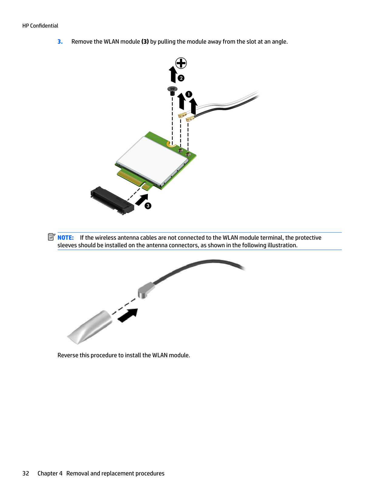
NOTE: If the wireless antenna cables are not connected to the WLAN module terminal, the protective sleeves should be installed on the antenna connectors, as shown in the following illustration.

Reverse this procedure to install the WLAN module.
#### RTC battery
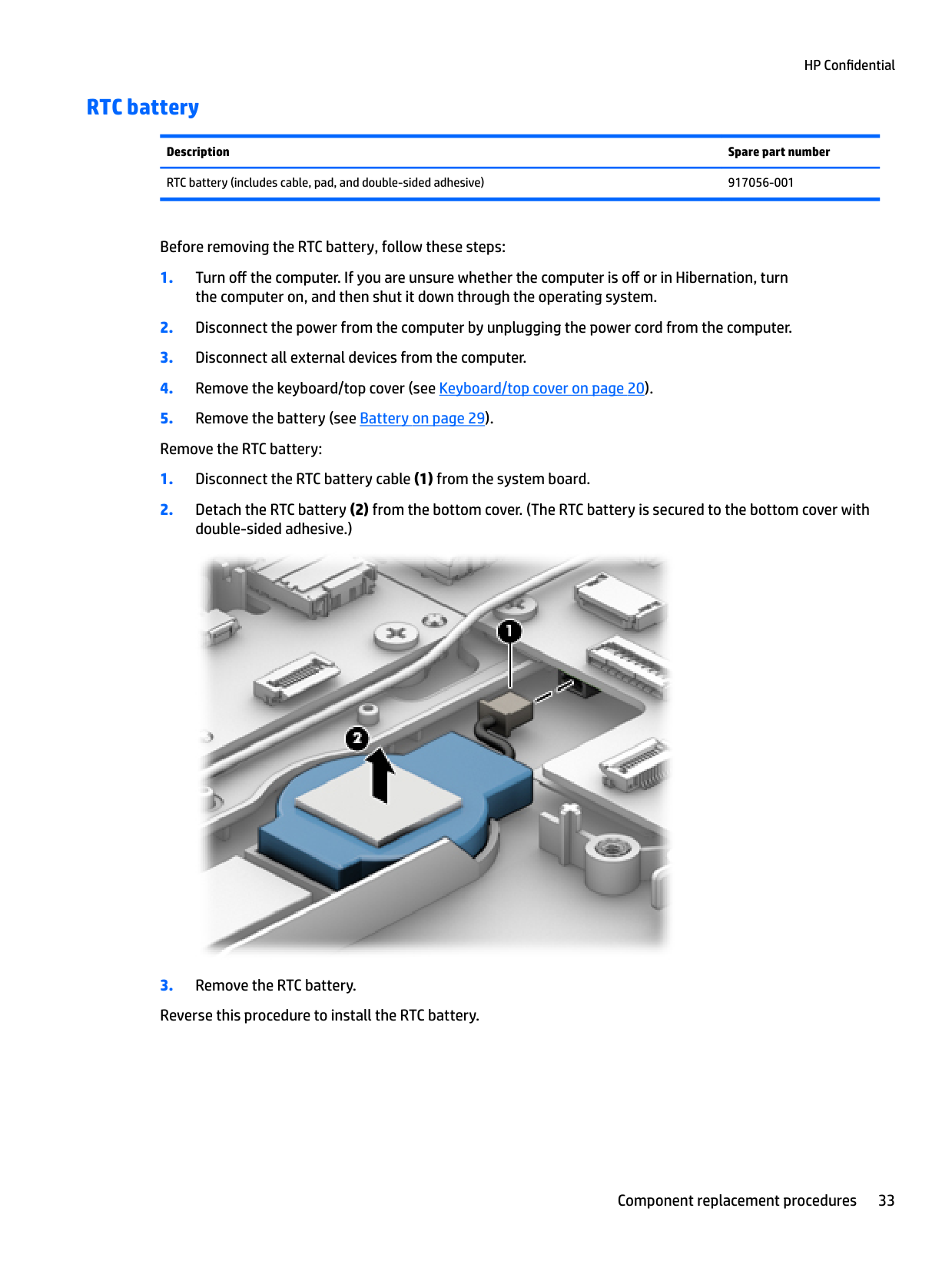
Description Spare part number RTC battery (includes cable, pad, and double-sided adhesive) 917056-001
Before removing the RTC battery, follow these steps:

#### Speakers
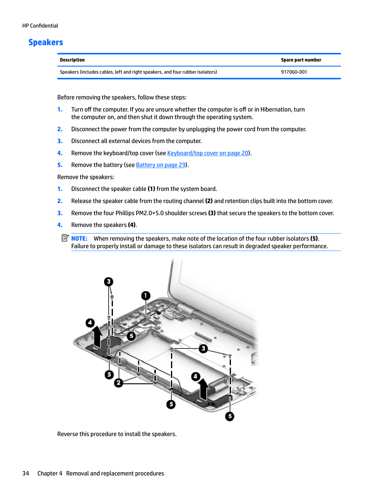
Description Spare part number Speakers (includes cables, left and right speakers, and four rubber isolators) 917060-001
Before removing the speakers, follow these steps:
the computer on, and then shut it down through the operating system.
| | |---|
NOTE: When removing the speakers, make note of the location of the four rubber isolators (5). Failure to properly install or damage to these isolators can result in degraded speaker performance.

Reverse this procedure to install the speakers.
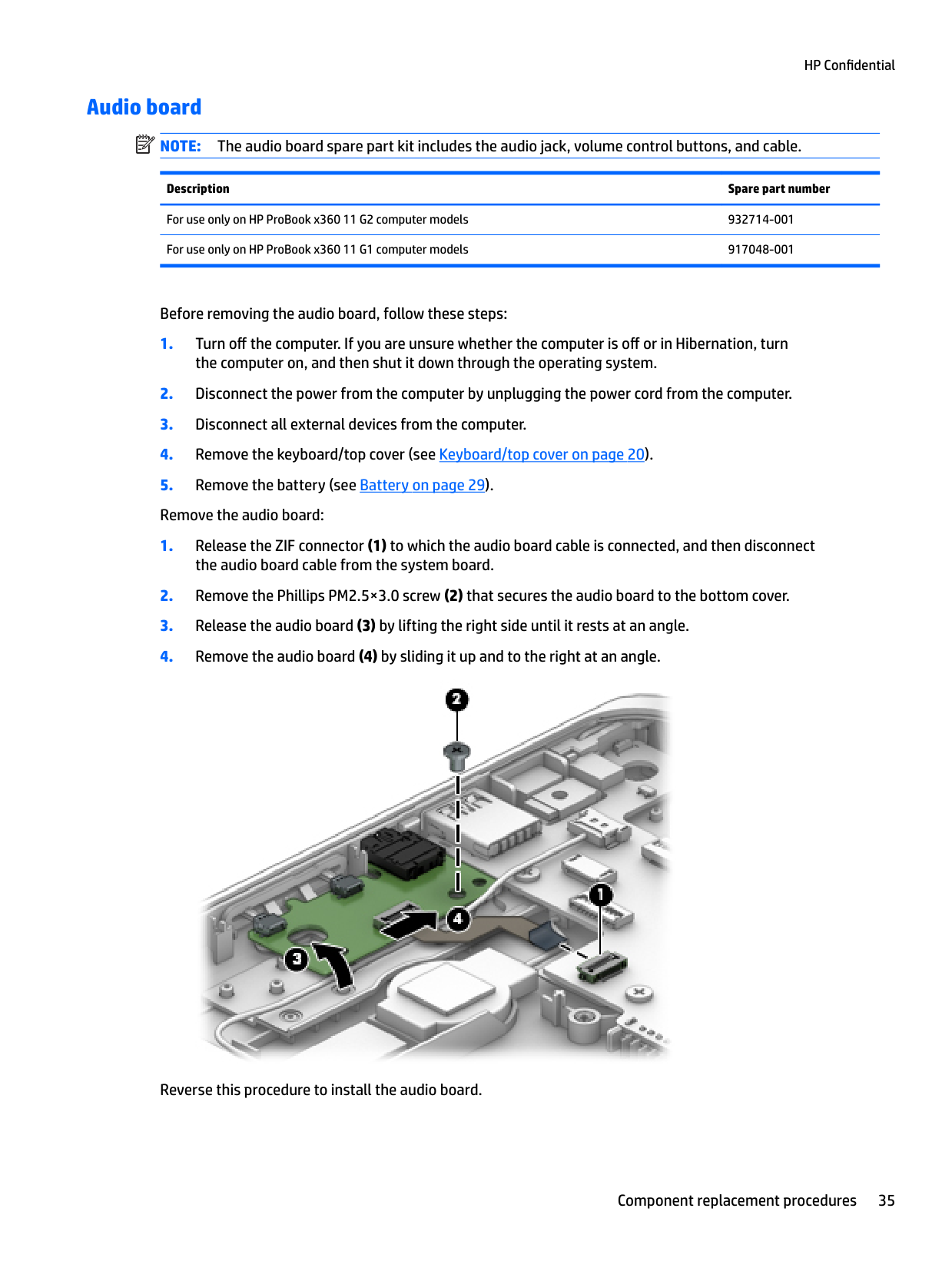
#### Audio board
| | |---|
NOTE: The audio board spare part kit includes the audio jack, volume control buttons, and cable.
Description Spare part number
For use only on HP ProBook x360 11 G2 computer models 932714-001 For use only on HP ProBook x360 11 G1 computer models 917048-001
Before removing the audio board, follow these steps:

Reverse this procedure to install the audio board.
#### System board
| | |---|
NOTE: The system board spare part kit includes the processor, a graphics subsystem with UMA memory, and replacement thermal material. Replacement thermal material is also available in the Thermal Material Kit, spare part number 917061-001.
Description Spare part number For use only on HP ProBook x360 11 G2 computer models: Equipped with an Intel Core m5 i5-7Y54 1.20-GHz (turbo up to 3.2-GHz) processor, 8.0-GB of system memory, and the Windows 10 operating system
938552-001
Equipped with an Intel Core m5 i5-7Y54 1.20-GHz (turbo up to 3.2-GHz) processor, 8.0-GB of system memory, and a non-Windows 10 operating system
Equipped with an Intel Core m3-7Y30 1.00-GHz (turbo up to 2.6-GHz) processor, 8.0-GB of system memory, and the Windows 10 operating system
Equipped with an Intel Core m3-7Y30 1.00-GHz (turbo up to 2.6-GHz) processor, 8.0-GB of system memory, and a non-Windows 10 operating system
Equipped with an Intel Core m3-7Y30 1.00-GHz (turbo up to 2.6-GHz) processor, 4.0-GB of system memory, and the Windows 10 operating system
Equipped with an Intel Core m3-7Y30 1.00-GHz (turbo up to 2.6-GHz) processor, 4.0-GB of system memory, and a non-Windows 10 operating system
For use only on HP ProBook x360 11 G1 computer models:
Equipped with an Intel Pentium N4200 1.10-GHz (SC turbo up to 2.50-GHz) processor (750-MHz FSB, 2.0-MB L2 cache, quad core, 6-W), 8.0-GB of system memory, and the Windows 10 operating system
Equipped with an Intel Pentium N4200 1.10-GHz (SC turbo up to 2.50-GHz) processor (750-MHz FSB, 2.0-MB L2 cache, quad core, 6-W), 8.0-GB of system memory, and a non-Windows 10 operating system
Equipped with an Intel Pentium N4200 1.10-GHz (SC turbo up to 2.50-GHz) processor (750-MHz FSB, 2.0-MB L2 cache, quad core, 6-W), 4.0-GB of system memory, and the Windows 10 operating system
Equipped with an Intel Pentium N4200 1.10-GHz (SC turbo up to 2.50-GHz) processor (750-MHz FSB, 2.0-MB L2 cache, quad core, 6-W), 4.0-GB of system memory, and a non-Windows 10 operating system
Equipped with an Intel Celeron N3350 1.10-GHz (SC turbo up to 2.40-GHz) processor (650-MHz FSB, 2.0MB L2 cache, dual core, 6-W), 64-GB of eMMC system storage, 4.0-GB of system memory, and the Windows 10 operating system
Equipped with an Intel Celeron N3350 1.10-GHz (SC turbo up to 2.40-GHz) processor (650-MHz FSB, 2.0MB L2 cache, dual core, 6-W), 64-GB of eMMC system storage, 4.0-GB of system memory, and a nonWindows 10 operating system
938552-001
932688-001
932688-001
932687-001
932687-001
917105-601
917105-001
917104-601
917104-001
917102-601
Equipped with an Intel Celeron N3350 1.10-GHz (SC turbo up to 2.40-GHz) processor (650-MHz FSB, 2.0MB L2 cache, dual core, 6-W), 4.0-GB of system memory, and the Windows 10 operating system
Equipped with an Intel Celeron N3350 1.10-GHz (SC turbo up to 2.40-GHz) processor (650-MHz FSB, 2.0MB L2 cache, dual core, 6-W), 4.0-GB of system memory, and a non-Windows 10 operating system
Equipped with an Intel Celeron N3350 1.10-GHz (SC turbo up to 2.40-GHz) processor (650-MHz FSB, 2.0MB L2 cache, dual core, 6-W), 64-GB of eMMC system storage, 2.0-GB of system memory, and the Windows 10 operating system
Equipped with an Intel Celeron N3350 1.10-GHz (SC turbo up to 2.40-GHz) processor (650-MHz FSB, 2.0MB L2 cache, dual core, 6-W), 64-GB of eMMC system storage, 2.0-GB of system memory, and a nonWindows 10 operating system
917103-001
917101-601
917101-001
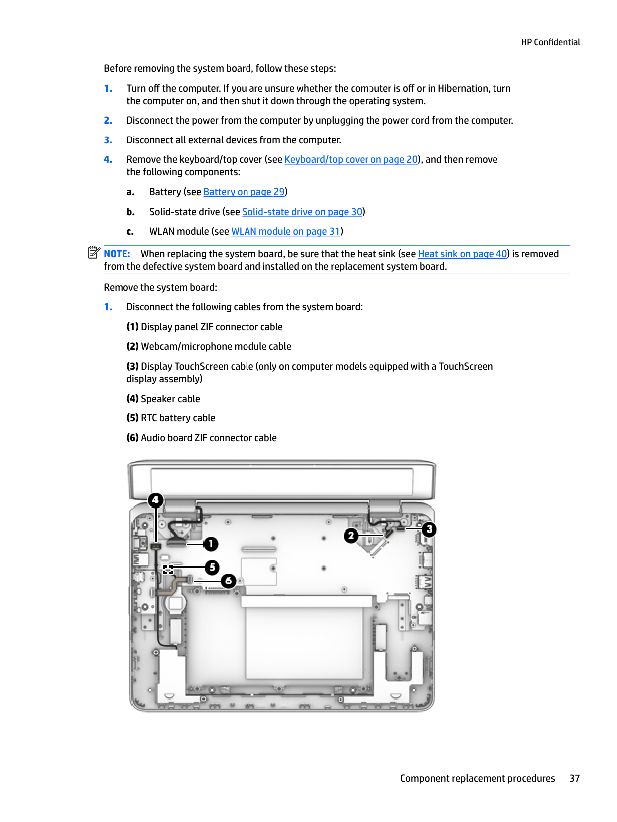
Before removing the system board, follow these steps:
| | |---|
NOTE: When replacing the system board, be sure that the heat sink (see Heat sink on page 40) is removed from the defective system board and installed on the replacement system board. Remove the system board:

| | |---|
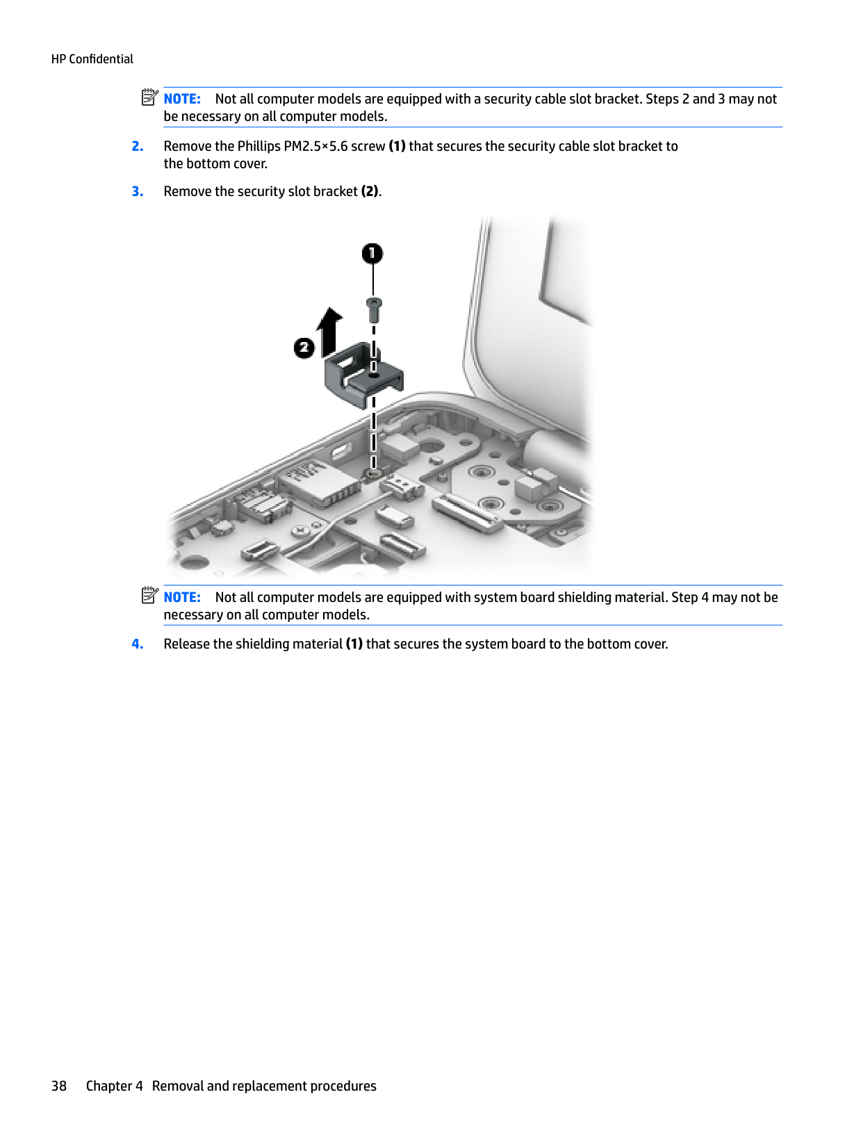
NOTE: Not all computer models are equipped with a security cable slot bracket. Steps 2 and 3 may not be necessary on all computer models.

NOTE: Not all computer models are equipped with system board shielding material. Step 4 may not be necessary on all computer models.
| | |---|


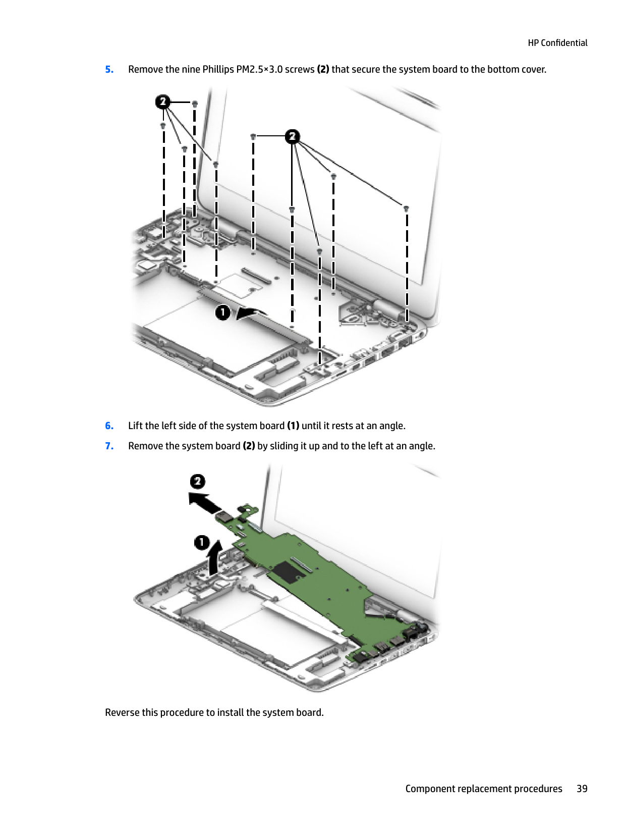
Reverse this procedure to install the system board.
#### Heat sink
| | |---|
NOTE: The heat sink spare part kit includes replacement thermal material. Replacement thermal material is also available in the Thermal Material Kit, spare part number 917061-001.
Description Spare part number
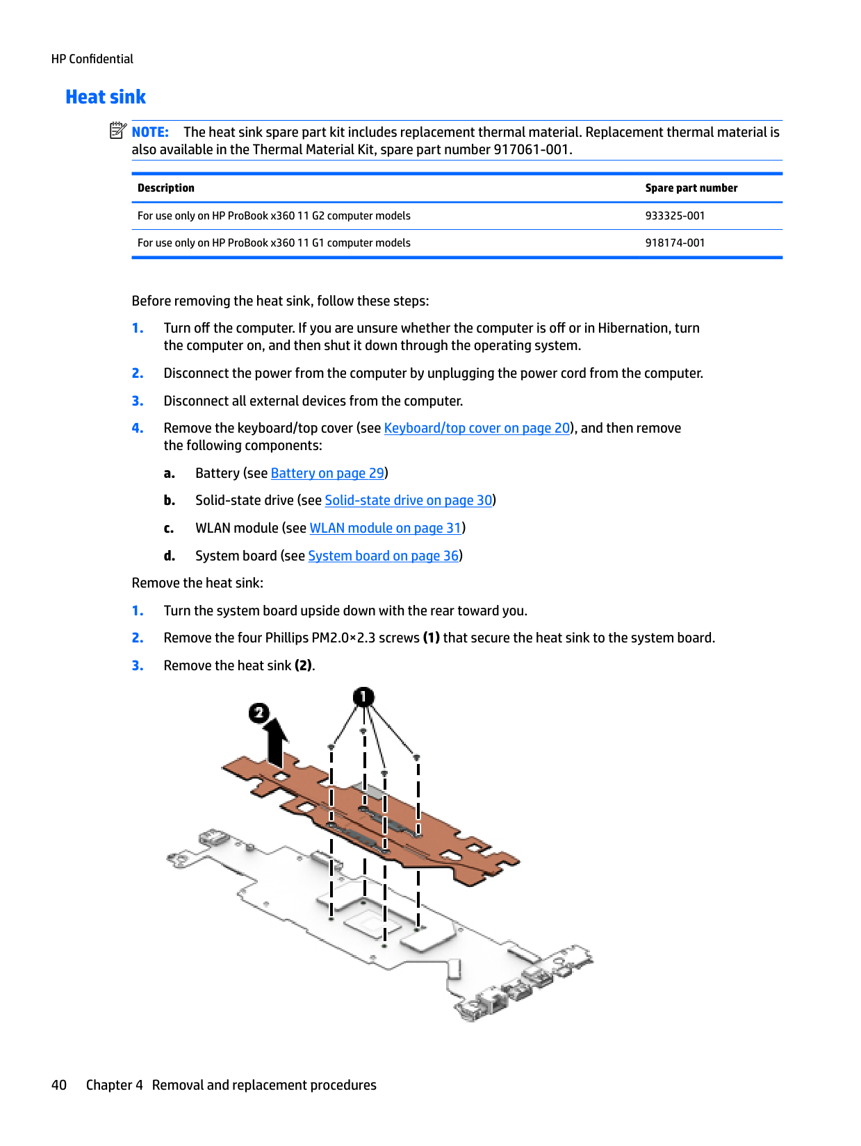
For use only on HP ProBook x360 11 G2 computer models 933325-001 For use only on HP ProBook x360 11 G1 computer models 918174-001
Before removing the heat sink, follow these steps:
Remove the heat sink:

| | |---|
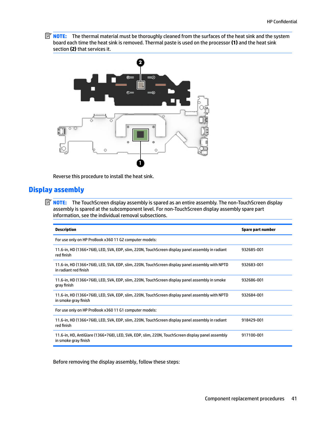
NOTE: The thermal material must be thoroughly cleaned from the surfaces of the heat sink and the system board each time the heat sink is removed. Thermal paste is used on the processor (1) and the heat sink section (2) that services it.

Reverse this procedure to install the heat sink.
#### Display assembly
| | |---|
NOTE: The TouchScreen display assembly is spared as an entire assembly. The non-TouchScreen display assembly is spared at the subcomponent level. For non-TouchScreen display assembly spare part information, see the individual removal subsections.
Description Spare part number For use only on HP ProBook x360 11 G2 computer models: 11.6-in, HD (1366×768), LED, SVA, EDP, slim, 220N, TouchScreen display panel assembly in radiant red finish
932685-001
11.6-in, HD (1366×768), LED, SVA, EDP, slim, 220N, TouchScreen display panel assembly with NPTD in radiant red finish
11.6-in, HD (1366×768), LED, SVA, EDP, slim, 220N, TouchScreen display panel assembly in smoke gray finish
11.6-in, HD (1366×768), LED, SVA, EDP, slim, 220N, TouchScreen display panel assembly with NPTD in smoke gray finish
For use only on HP ProBook x360 11 G1 computer models: 11.6-in, HD (1366×768), LED, SVA, EDP, slim, 220N, TouchScreen display panel assembly in radiant red finish
11.6-in, HD, AntiGlare (1366×768), LED, SVA, EDP, slim, 220N, TouchScreen display panel assembly in smoke gray finish
932683-001
932686-001
932684-001
918429-001
917100-001
Before removing the display assembly, follow these steps:
NOTE: The wireless antenna cable labeled “1/MAIN” connects to the WLAN module “Main” terminal. The wireless antenna cable labeled “2/AUX” connects to the WLAN module “Aux” terminal.
| | |---|
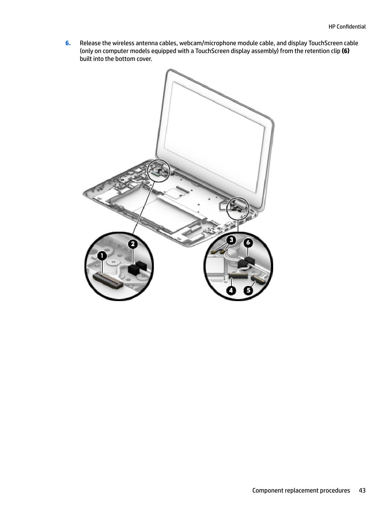
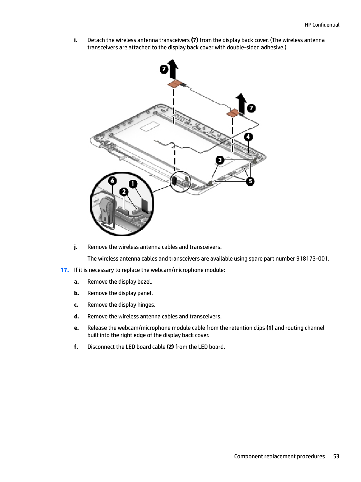
####### 6. Release the wireless antenna cables, webcam/microphone module cable, and display TouchScreen cable(only on computer models equipped with a TouchScreen display assembly) from the retention clip (6)built into the bottom cover.

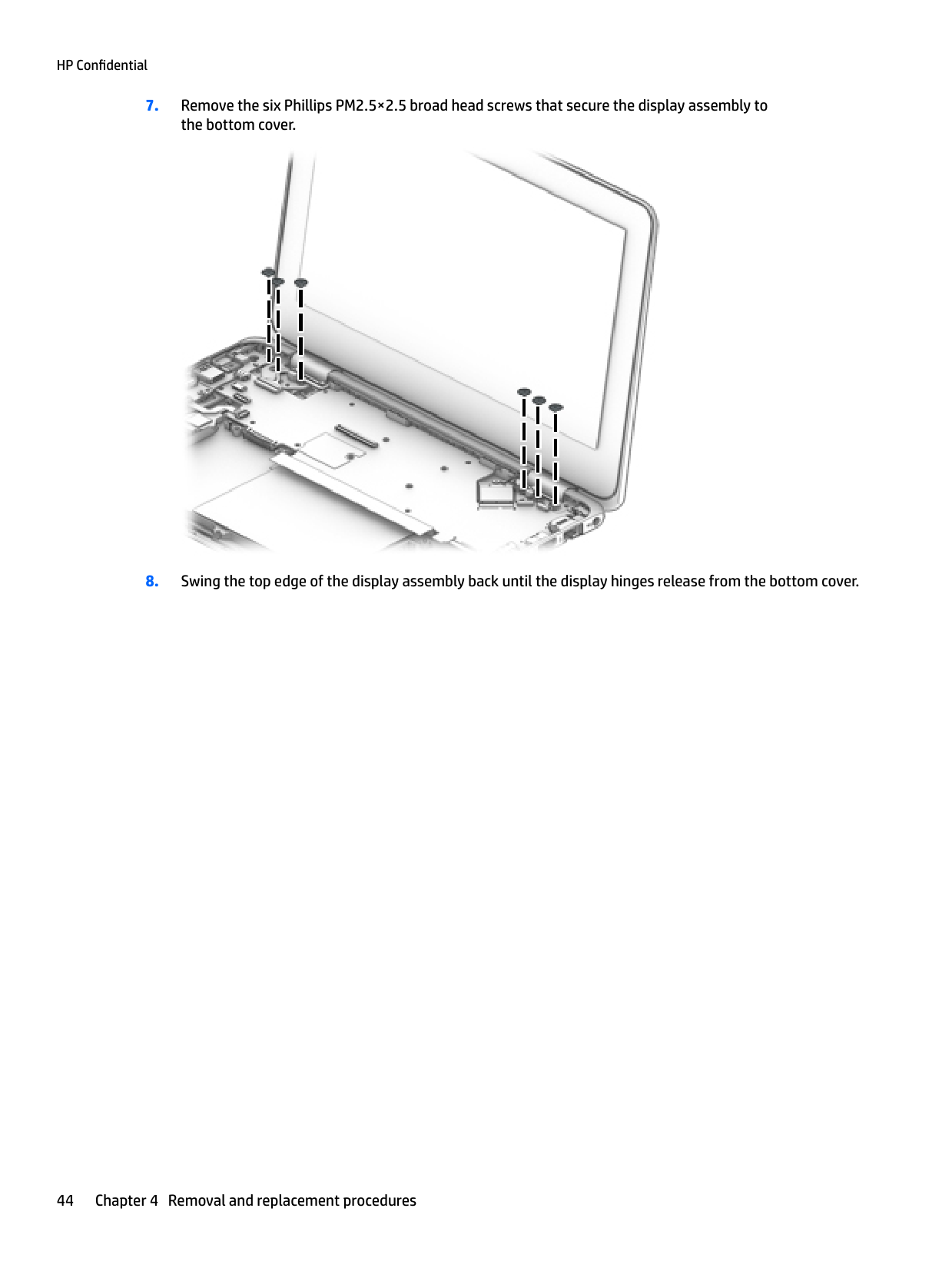
####### 7. Remove the six Phillips PM2.5×2.5 broad head screws that secure the display assembly tothe bottom cover.

####### 8. Swing the top edge of the display assembly back until the display hinges release from the bottom cover.

NOTE: Steps 10 through 16 apply only to computer models equipped with a non-TouchScreen display assembly.
| | |---|


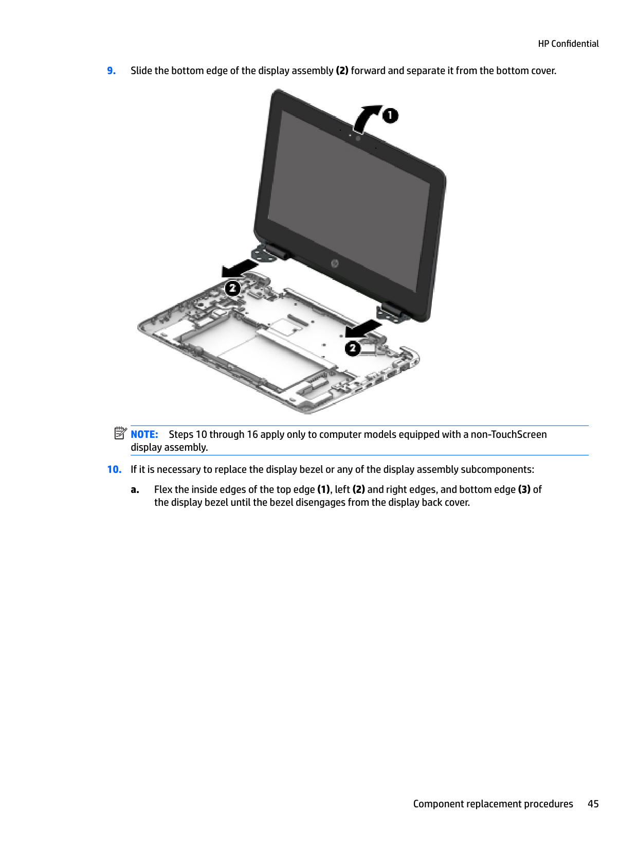

CAUTION: Before turning the display panel upside down, make sure the work surface is clear of tools, screws, and any other foreign objects. Failure to follow this caution can result in damage to the display panel.


The display hinge cover is included in the display hinge spare part kit, spare part number 917064-001.


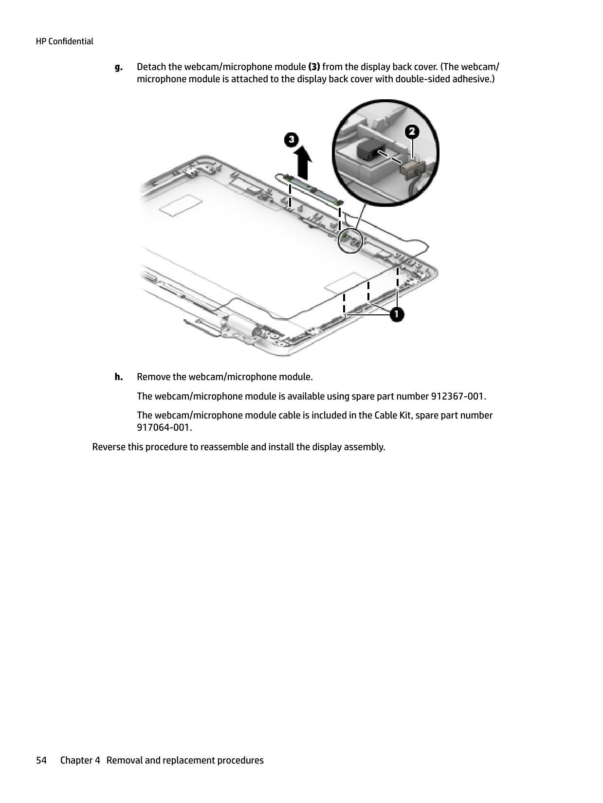
The webcam/microphone module cable is included in the Cable Kit, spare part number 917064-001.
Reverse this procedure to reassemble and install the display assembly.
5 Using Setup Utility (BIOS)
Setup Utility, or Basic Input/Output System (BIOS), controls communication between all the input and output devices on the system (such as disk drives, display, keyboard, mouse, and printer). Setup Utility (BIOS) includes settings for the types of devices installed, the startup sequence of the computer, and the amount of system and extended memory.
| | |---|
NOTE: To start Setup Utility on convertible computers, your computer must be in notebook mode and you must use the keyboard attached to your notebook.
Starting Setup Utility (BIOS)
CAUTION: Use extreme care when making changes in Setup Utility (BIOS). Errors can prevent the computer from operating properly.
▲ Turn on or restart the computer, quickly press esc, and then press f10.
Updating Setup Utility (BIOS) Updated versions of Setup Utility (BIOS) may be available on the HP website. Most BIOS updates on the HP website are packaged in compressed files called SoftPaqs. Some download packages contain a file named Readme.txt, which contains information regarding installing and troubleshooting the file.
Determining the BIOS version To decide whether you need to update Setup Utility (BIOS), first determine the BIOS version on your computer. To reveal the BIOS version information (also known as ROM date and System BIOS), use one of these options.
– or – Click the question mark icon in the taskbar.
To check for later BIOS versions, see Downloading a BIOS update on page 56.
Starting Setup Utility (BIOS) 55
#### Downloading a BIOS update
CAUTION: To reduce the risk of damage to the computer or an unsuccessful installation, download and install a BIOS update only when the computer is connected to reliable external power using the AC adapter. Do not download or install a BIOS update while the computer is running on battery power, docked in an optional docking device, or connected to an optional power source. During the download and installation, follow these instructions:
| | |---|
NOTE: If your computer is connected to a network, consult the network administrator before installing any software updates, especially system BIOS updates.
– or – Click the question mark icon in the taskbar.
Make a note of the path to the location on your hard drive where the BIOS update is downloaded. You will need to access this path when you are ready to install the update.
BIOS installation procedures vary. Follow any instructions that appear on the screen after the download is complete. If no instructions appear, follow these steps:
| |
|---|
NOTE: After a message on the screen reports a successful installation, you can delete the downloaded file from your hard drive.
56 Chapter 5 Using Setup Utility (BIOS)
6 Using HP PC Hardware Diagnostics (UEFI)
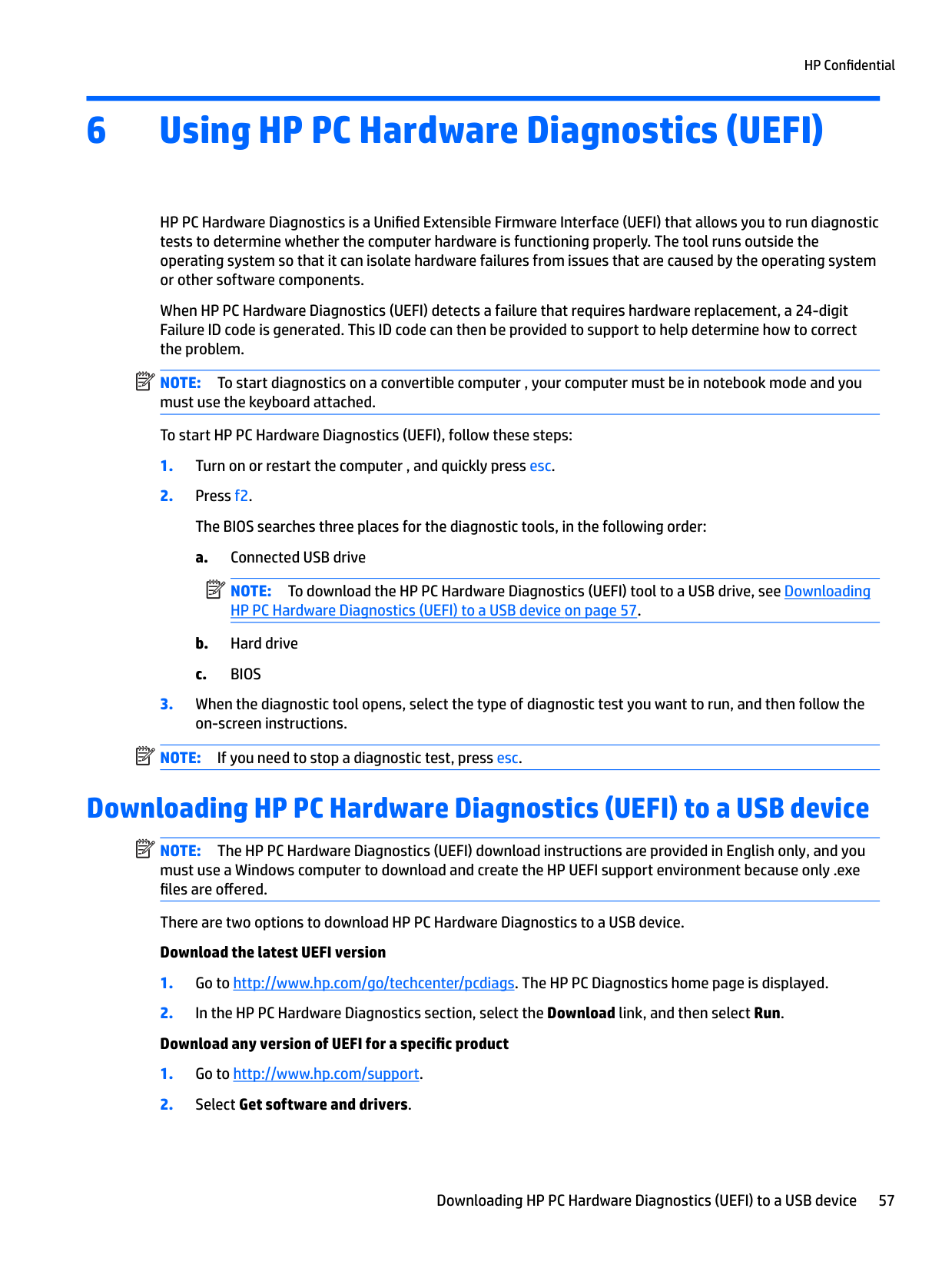
HP PC Hardware Diagnostics is a Unified Extensible Firmware Interface (UEFI) that allows you to run diagnostic tests to determine whether the computer hardware is functioning properly. The tool runs outside the operating system so that it can isolate hardware failures from issues that are caused by the operating system or other software components.
When HP PC Hardware Diagnostics (UEFI) detects a failure that requires hardware replacement, a 24-digit Failure ID code is generated. This ID code can then be provided to support to help determine how to correct the problem.
| | |---|
NOTE: To start diagnostics on a convertible computer , your computer must be in notebook mode and you must use the keyboard attached. To start HP PC Hardware Diagnostics (UEFI), follow these steps:
| | |---|
| | |---|
NOTE: If you need to stop a diagnostic test, press esc.
Downloading HP PC Hardware Diagnostics (UEFI) to a USB device
| | |---|
NOTE: The HP PC Hardware Diagnostics (UEFI) download instructions are provided in English only, and you must use a Windows computer to download and create the HP UEFI support environment because only .exe files are offered.
There are two options to download HP PC Hardware Diagnostics to a USB device. Download the latest UEFI version
Downloading HP PC Hardware Diagnostics (UEFI) to a USB device 57
– or – Select Identify now to let HP automatically detect your product.
58 Chapter 6 Using HP PC Hardware Diagnostics (UEFI)
7 Specifications
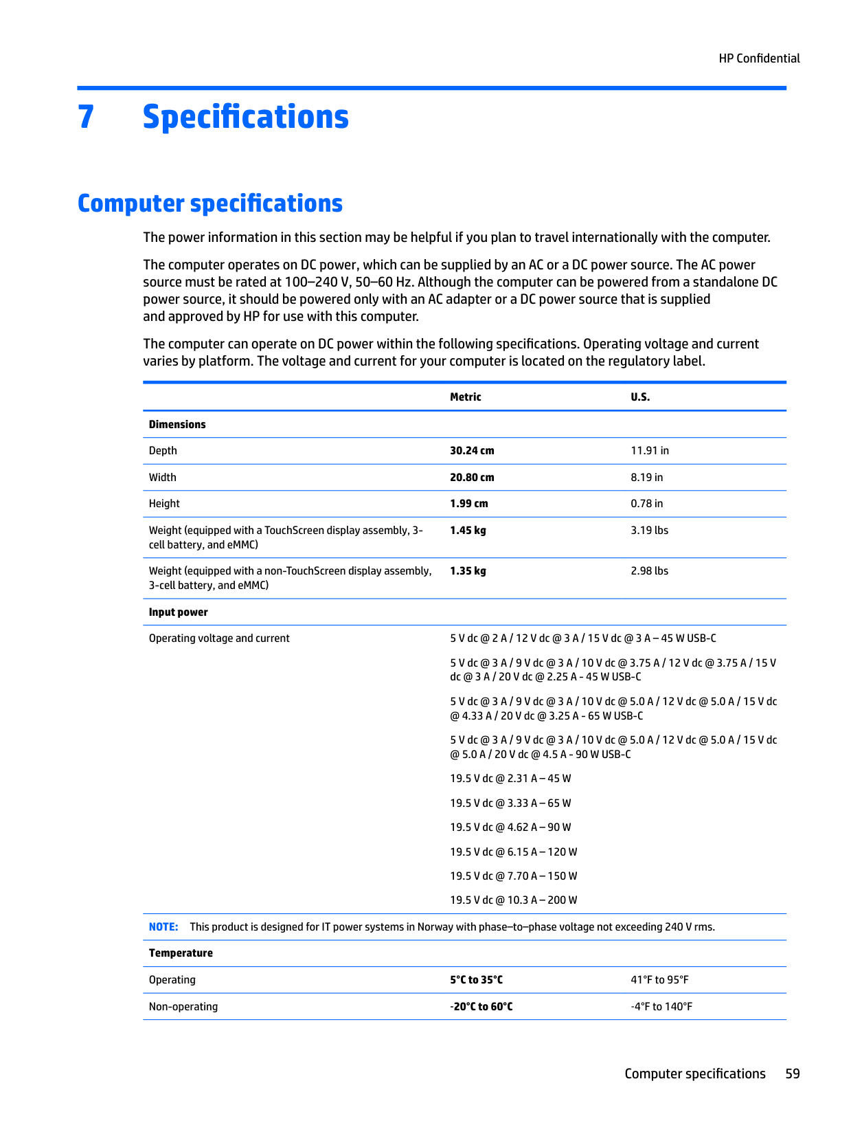
Computer specifications The power information in this section may be helpful if you plan to travel internationally with the computer. The computer operates on DC power, which can be supplied by an AC or a DC power source. The AC power source must be rated at 100–240 V, 50–60 Hz. Although the computer can be powered from a standalone DC power source, it should be powered only with an AC adapter or a DC power source that is supplied and approved by HP for use with this computer. The computer can operate on DC power within the following specifications. Operating voltage and current varies by platform. The voltage and current for your computer is located on the regulatory label.
Metric U.S.
Dimensions Depth 30.24 cm 11.91 in Width 20.80 cm 8.19 in Height 1.99 cm 0.78 in Weight (equipped with a TouchScreen display assembly, 3cell battery, and eMMC)
1.45 kg 3.19 lbs
Weight (equipped with a non-TouchScreen display assembly, 3-cell battery, and eMMC)
1.35 kg 2.98 lbs
Input power Operating voltage and current 5 V dc @ 2 A / 12 V dc @ 3 A / 15 V dc @ 3 A – 45 W USB-C
5 V dc @ 3 A / 9 V dc @ 3 A / 10 V dc @ 3.75 A / 12 V dc @ 3.75 A / 15 V dc @ 3 A / 20 V dc @ 2.25 A - 45 W USB-C
5 V dc @ 3 A / 9 V dc @ 3 A / 10 V dc @ 5.0 A / 12 V dc @ 5.0 A / 15 V dc
NOTE: This product is designed for IT power systems in Norway with phase–to–phase voltage not exceeding 240 V rms. Temperature Operating 5°C to 35°C 41°F to 95°F Non-operating ‑20°C to 60°C ‑4°F to 140°F
Computer specifications 59
######### Metric U.S.
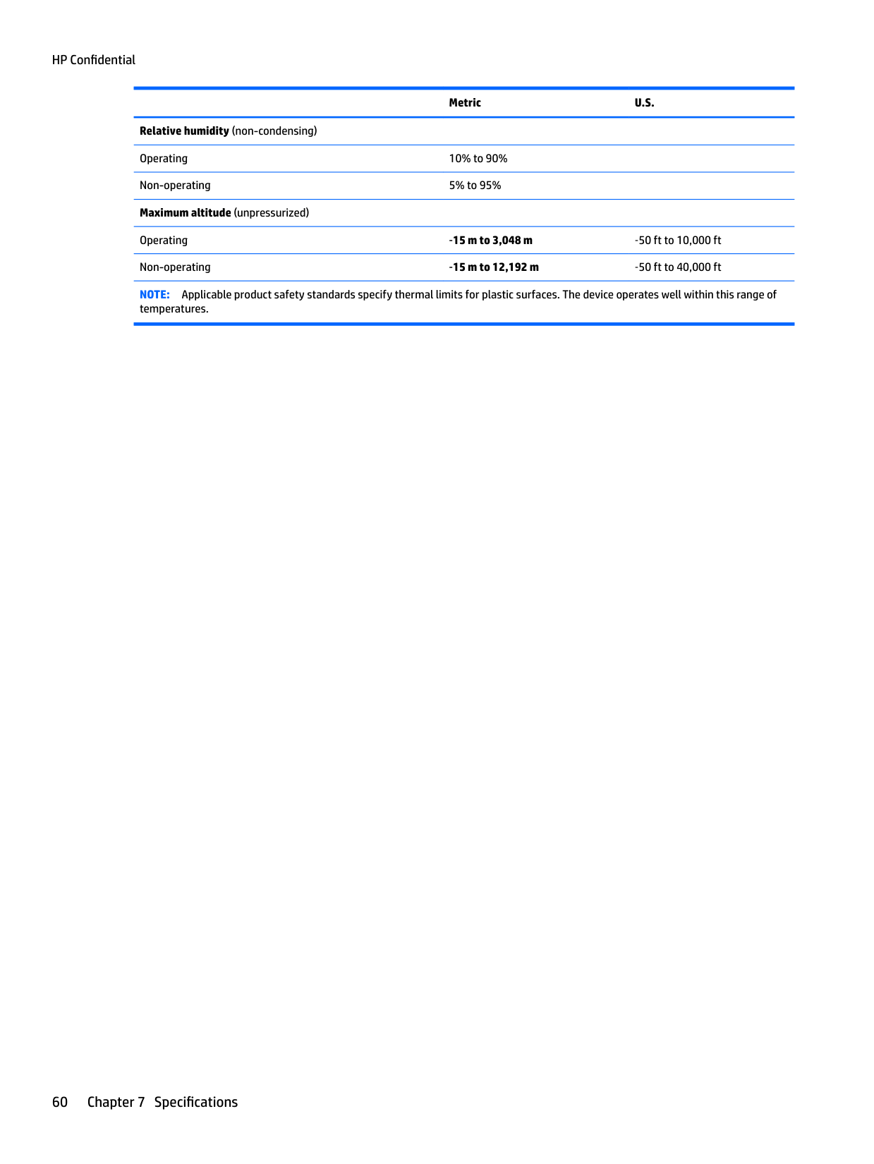
Relative humidity (non-condensing) Operating 10% to 90% Non-operating 5% to 95% Maximum altitude (unpressurized)
Operating ‑15 m to 3,048 m ‑50 ft to 10,000 ft Non-operating ‑15 m to 12,192 m ‑50 ft to 40,000 ft NOTE: Applicable product safety standards specify thermal limits for plastic surfaces. The device operates well within this range of
temperatures.
60 Chapter 7 Specifications
8 Backing up, restoring, and recovering
This chapter provides information about the following processes. The information in the chapter is standard procedure for most products.
▲ Type support in the taskbar search box, and then select the HP Support Assistant app.
‒ or – Click the question mark icon in the taskbar.
| | |---|
IMPORTANT: If you will be performing recovery procedures on a tablet, the tablet battery must be at least 70% charged before you start the recovery process.
IMPORTANT: For a tablet with a detachable keyboard, connect the keyboard to the keyboard dock before beginning any recovery process.
Creating recovery media and backups
The following methods of creating recovery media and backups are available on select products only. Choose the available method according to your computer model.
| | |---|
#### Creating HP Recovery media (select products only)
If possible, check for the presence of the Recovery partition and the Windows partition. From the Start menu, select File Explorer, and then select This PC.
Creating recovery media and backups 61
You can use Windows tools to create system restore points and create backups of personal information, see Using Windows tools on page 62.
| | |---|
To create HP Recovery media: IMPORTANT: For a tablet with a detachable keyboard, connect the keyboard to the keyboard dock before beginning these steps.
Using Windows tools
You can create recovery media, system restore points, and backups of personal information using Windows tools.
| | |---|
NOTE: If storage is 32 GB or less, Microsoft System Restore is disabled by default. For more information and steps, see the Get started app.
▲ Select the Start button, and then select the Get started app.
Restore and recovery
There are several options for recovering your system. Choose the method that best matches your situation and level of expertise:
| | |---|
IMPORTANT: Not all methods are available on all products.
▲ Select the Start button, and then select the Get started app.
▲ Type recovery in the taskbar search box, select HP Recovery Manager, select Reinstall drivers
and/or applications, and then follow the on-screen instructions.
#### Recovering using HP Recovery Manager
HP Recovery Manager software allows you to recover the computer to its original factory state by using the HP Recovery media that you either created or that you obtained from HP, or by using the HP Recovery partition (select products only). If you have not already created recovery media, see Creating HP Recovery media (select products only) on page 61.
##### What you need to know before you get started
IMPORTANT: Recovery through HP Recovery Manager should be used as a final attempt to correct computer issues.
| | |---|
website. Go to http://www.hp.com/support, select your country or region, and follow the on-screen instructions.
| | |---|
| | |---|
IMPORTANT: HP Recovery Manager does not automatically provide backups of your personal data. Before beginning recovery, back up any personal data you want to retain. Using HP Recovery media, you can choose from one of the following recovery options: NOTE: Only the options available for your computer display when you start the recovery process.
The HP Recovery partition (select products only) allows System Recovery only. Using the HP Recovery partition (select products only)
The HP Recovery partition allows you to perform a system recovery without the need for recovery discs or a recovery USB flash drive. This type of recovery can be used only if the hard drive is still working.
| | |---|
To start HP Recovery Manager from the HP Recovery partition: IMPORTANT: For a tablet with a detachable keyboard, connect the keyboard to the keyboard dock before beginning these steps (select products only).
For computers or tablets with keyboards attached, press f11 while the computer boots, or press and hold f11 as you press the power button.
For tablets without keyboards: Turn on or restart the tablet, and then quickly hold down the volume down button; then select f11.
##### Using HP Recovery media to recover
You can use HP Recovery media to recover the original system. This method can be used if your system does not have an HP Recovery partition or if the hard drive is not working properly.
NOTE: If the computer does not automatically restart in HP Recovery Manager, change the computer boot order. See Changing the computer boot order on page 65.
| | |---|
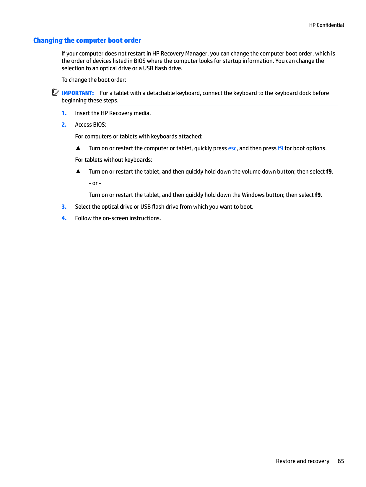
##### Changing the computer boot order
If your computer does not restart in HP Recovery Manager, you can change the computer boot order, which is the order of devices listed in BIOS where the computer looks for startup information. You can change the selection to an optical drive or a USB flash drive.
| | |---|
To change the boot order: IMPORTANT: For a tablet with a detachable keyboard, connect the keyboard to the keyboard dock before beginning these steps.
▲ Turn on or restart the computer or tablet, quickly press esc, and then press f9 for boot options. For tablets without keyboards:
▲ Turn on or restart the tablet, and then quickly hold down the volume down button; then select f9.
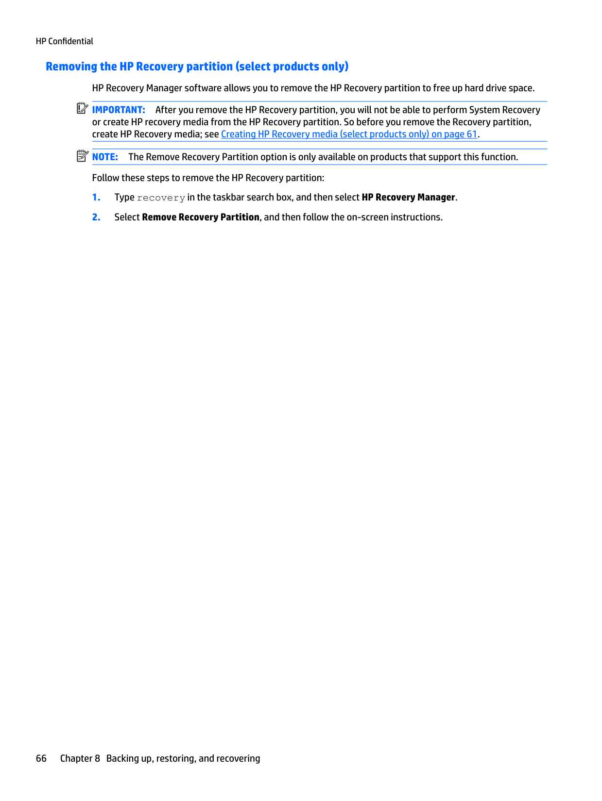
Removing the HP Recovery partition (select products only) HP Recovery Manager software allows you to remove the HP Recovery partition to free up hard drive space. IMPORTANT: After you remove the HP Recovery partition, you will not be able to perform System Recovery or create HP recovery media from the HP Recovery partition. So before you remove the Recovery partition, create HP Recovery media; see Creating HP Recovery media (select products only) on page 61. NOTE: The Remove Recovery Partition option is only available on products that support this function. Follow these steps to remove the HP Recovery partition:
| | |---|
| | |---|
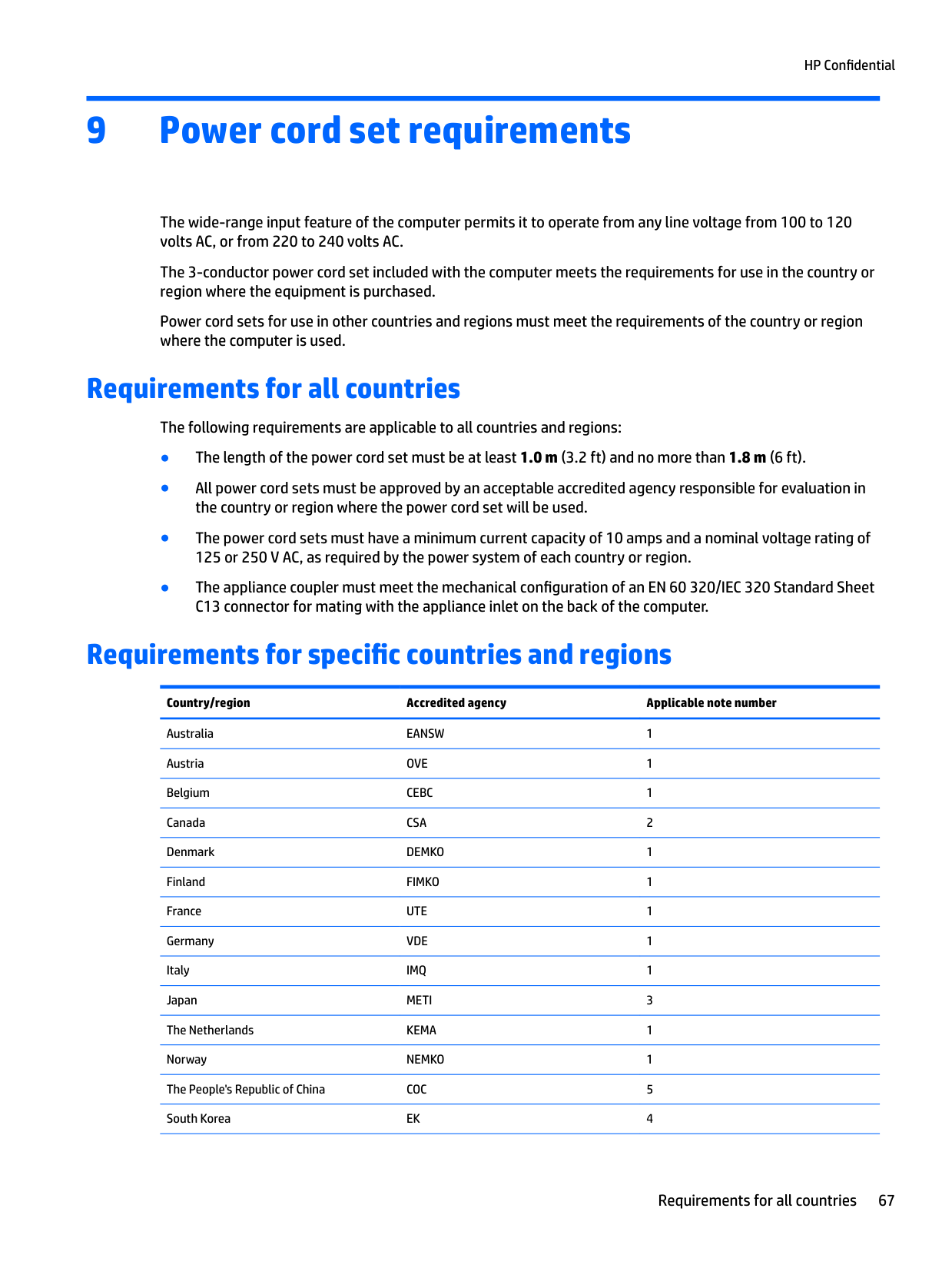
9 Power cord set requirements
The wide-range input feature of the computer permits it to operate from any line voltage from 100 to 120 volts AC, or from 220 to 240 volts AC.
The 3-conductor power cord set included with the computer meets the requirements for use in the country or region where the equipment is purchased.
Power cord sets for use in other countries and regions must meet the requirements of the country or region where the computer is used.
Requirements for all countries
The following requirements are applicable to all countries and regions:
Requirements for specific countries and regions
######### Country/region Accredited agency Applicable note number
Australia EANSW 1 Austria OVE 1 Belgium CEBC 1 Canada CSA 2 Denmark DEMKO 1 Finland FIMKO 1 France UTE 1 Germany VDE 1 Italy IMQ 1 Japan METI 3 The Netherlands KEMA 1 Norway NEMKO 1 The People's Republic of China COC 5 South Korea EK 4
Requirements for all countries 67
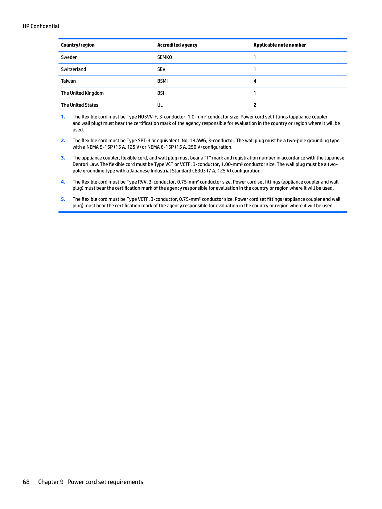
######### Country/region Accredited agency Applicable note number
Sweden SEMKO 1 Switzerland SEV 1 Taiwan BSMI 4 The United Kingdom BSI 1 The United States UL 2
68 Chapter 9 Power cord set requirements
10 Recycling
When a non-rechargeable or rechargeable battery has reached the end of its useful life, do not dispose of the battery in general household waste. Follow the local laws and regulations in your area for battery disposal.
HP encourages customers to recycle used electronic hardware, HP original print cartridges, and rechargeable batteries. For more information about recycling programs, see the HP Web site at http://www.hp.com/recycle.
69
Index
number 13 AC adapter, spare part numbers 13 antenna
removal 52 spare part number 12, 53
audio board removal 35 spare part numbers 9, 35
removal 29 spare part number 9, 29
BIOS determining version 55 downloading an update 56 starting the Setup Utility 55 updating 55
Bluetooth label 5 boot order
changing 65 bottom cover, spare part numbers 11
major components 6 specifications 59
connectors, service considerations 16
removal 41
spare part numbers 41 subcomponents 12
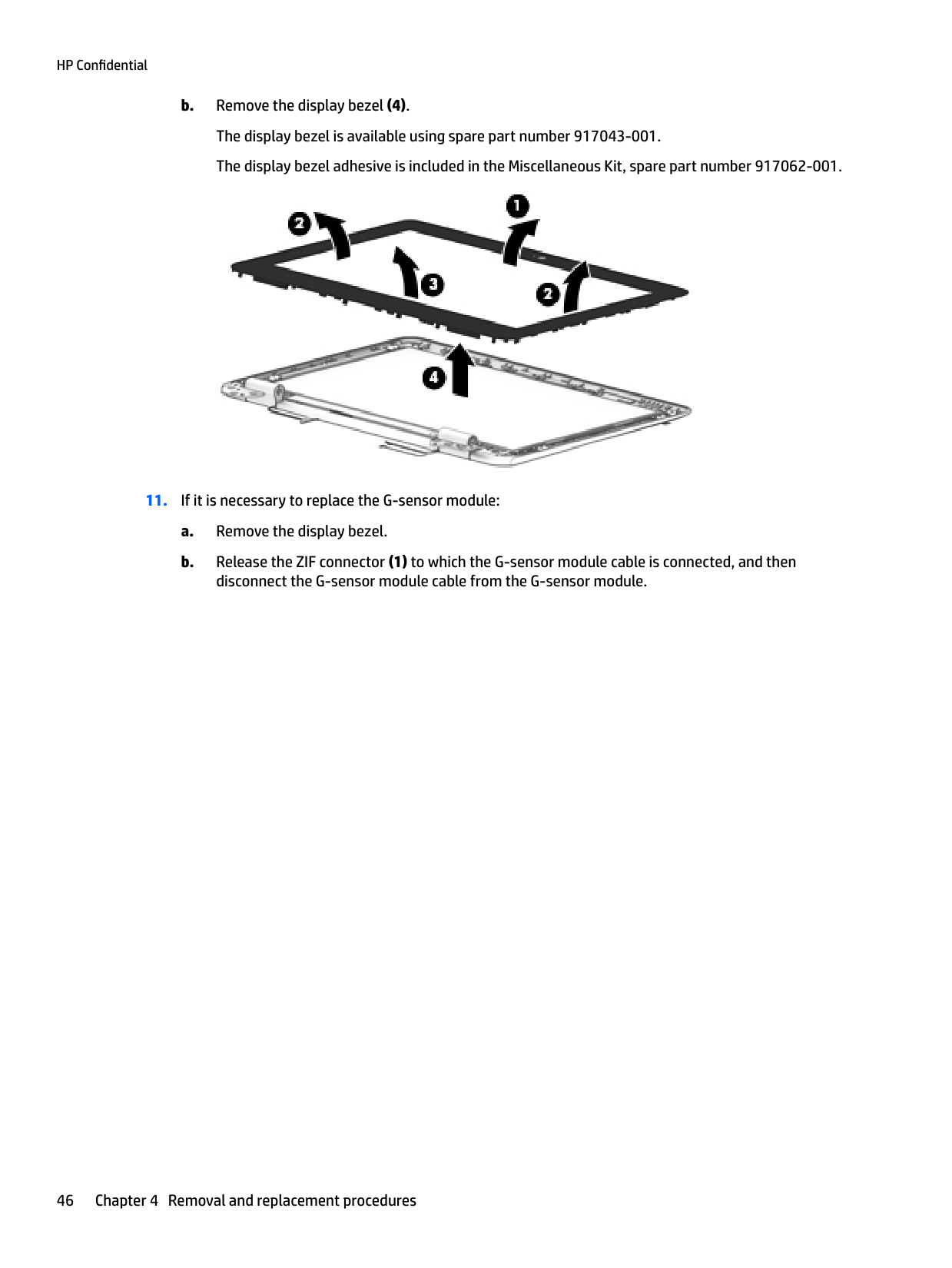
display bezel removal 45 spare part number 12, 46 display bezel adhesive, spare part
number 12, 46
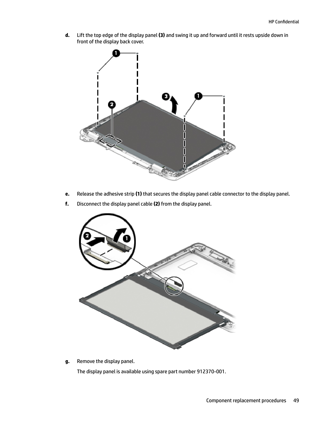
display panel product description 1 removal 48
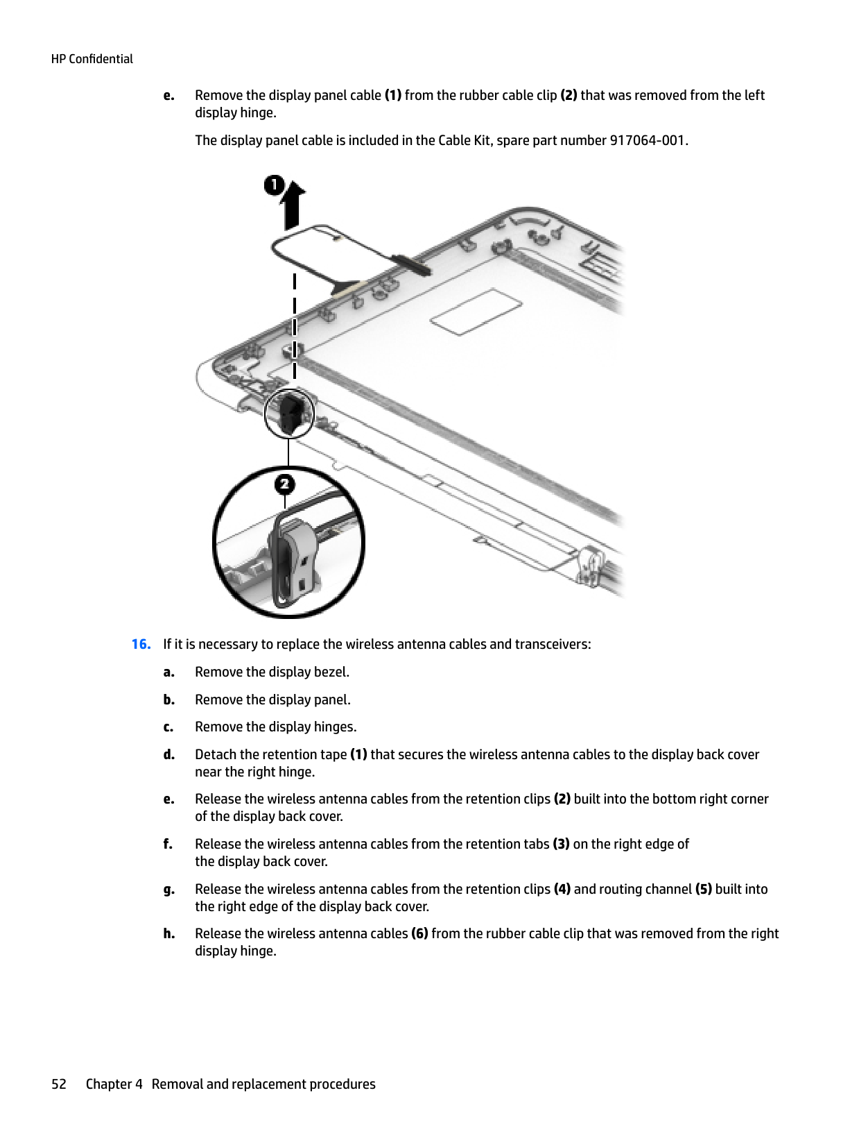
display panel cable removal 51
docking station, spare part numbers 13
drives precautions 16 preventing damage 16
E electrostatic discharge 17 equipment guidelines 19 Ethernet, product description 1
###### G
graphics, product description 1 grounding guidelines 17 guidelines
equipment 19 grounding 17 packaging 18 transporting 18 workstation 18
number 13
heat sink removal 40 spare part numbers 10, 40
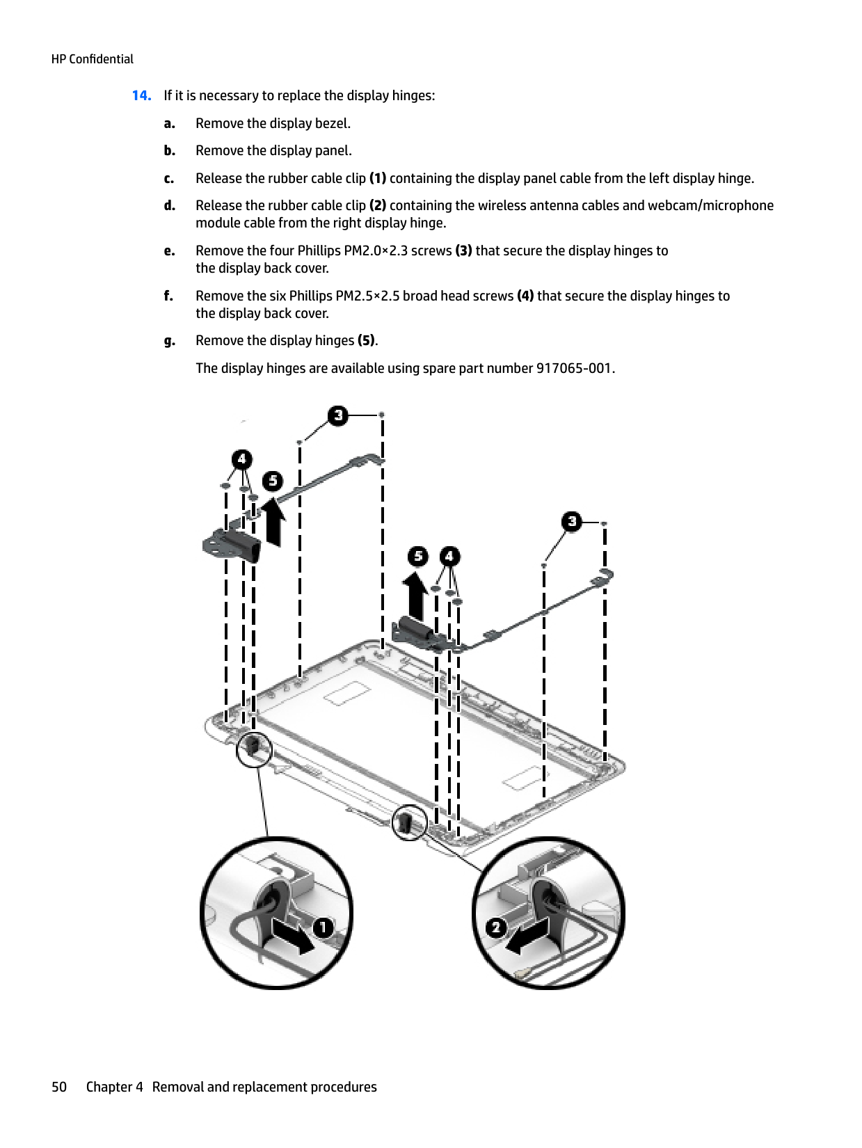
hinge removal 50
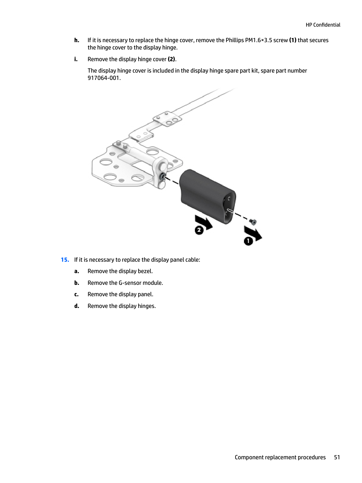
hinge cover removal 51
HP PC Hardware Diagnostics (UEFI) using 57
HP Recovery Manager correcting boot problems 65 starting 64 HP Recovery media creating 61 recovery 64
HP Recovery partition recovery 64 removing 66
removal 20 spare part numbers 7, 8, 20

Bluetooth 5 regulatory 5 serial number 4 wireless certification 5 WLAN 5
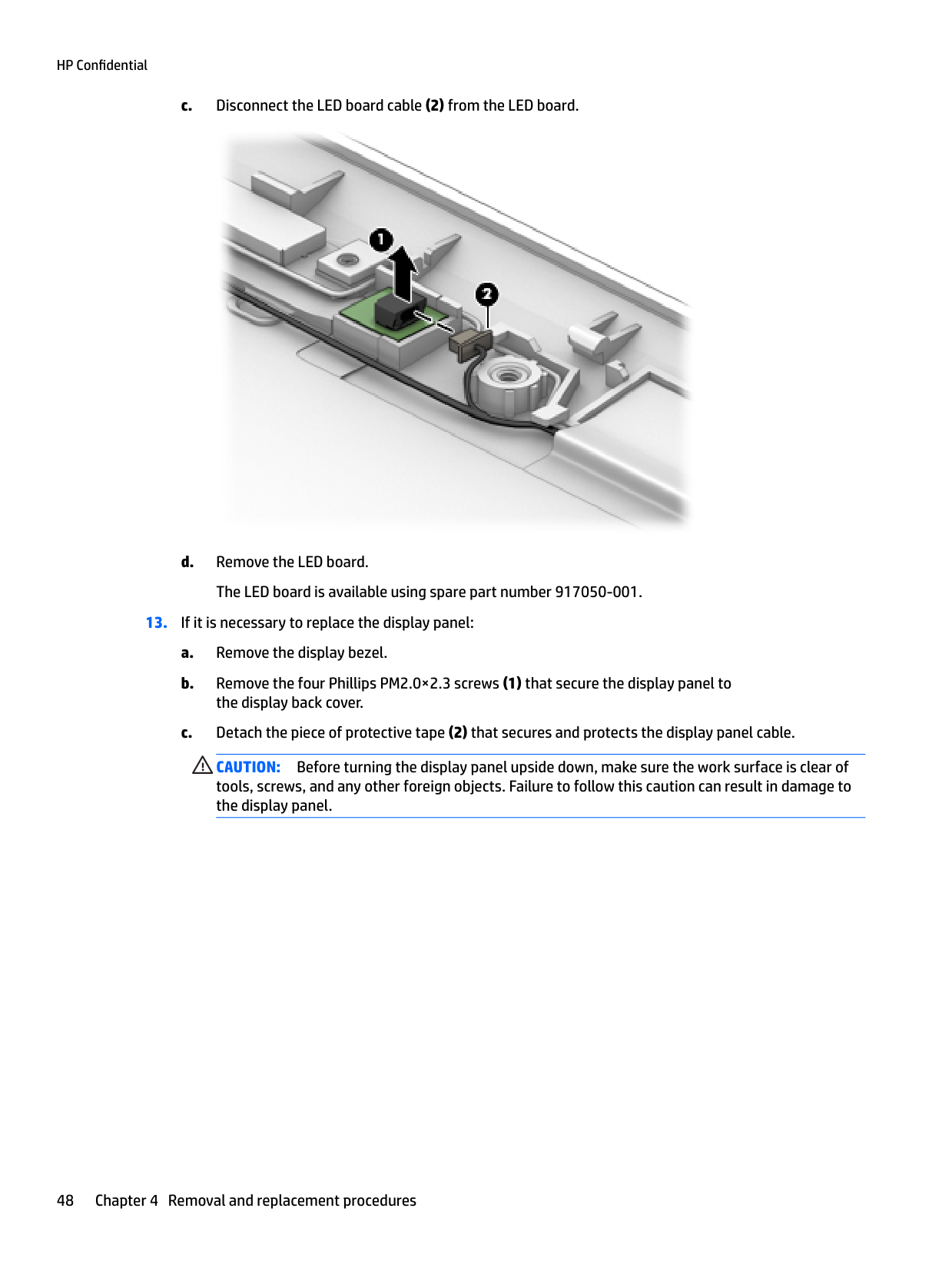
LED board removal 47 spare part number 12, 48
description 1 minimized image recovery 64 minimized image, creating 63 miscellaneous parts 13 mouse, spare part numbers 13
70 Index
description 2, 3 optical drive, spare part number 13 original system recovery 63
considerations 15 pointing device, product
description 2 ports
product description 2
power cord set requirements 67 spare part numbers 13, 14
power requirements, product
description 2 processor, product description 1 product description
chipset 1 display panel 1 Ethernet 1 external media cards 2 graphics 1 keyboard 2 memory module 1 operating system 2, 3 pen input 2 pointing device 2 ports 2 power requirements 2 processors 1 security 2 serviceability 3 solid-state drive 1 video 1 wireless 2
product name and number 4
R recover
options 63
recovery discs 62, 64 HP Recovery Manager 63 media 64
starting 64 supported discs 62 system 63 USB flash drive 64 using HP Recovery media 62
recovery media creating 61 creating using HP Recovery
Manager 62 recovery partition
removing 66
regulatory information regulatory label 5 wireless certification labels 5
removal/replacement procedures 20
RTC battery removal 33 spare part number 9, 33
Rubber Kit, spare part number 11, 14
S Screw Kit, spare part number 14 second webcam
removal 27 spare part number 9, 27 security, product description 2 serial number 4 service considerations
cables 16 connectors 16 plastic parts 15
service label 4 serviceability, product description 3 solid-state drive
product description 1 removal 30 spare part numbers 9, 30
speakers removal 34 spare part number 9, 34
specifications 59 stylus, spare part number 14 supported discs, recovery 62 system board
removal 36 spare part numbers 9, 36
system recovery 63
system restore point creating 62
system restore point, creating 61
T Thermal Material Kit, spare part
number 10, 11 tools required 15 TouchPad
removal 25 spare part numbers 9, 25
TouchPad cable removal 24 spare part number 24 spare part numbers 9
transporting guidelines 18 traveling with the computer 5
removal 27 spare part numbers 9, 27
webcam/microphone module removal 53
webcam/microphone module cable
Windows
system restore point 61, 62 Windows tools
using 62 wireless antenna removal 52 spare part number 12, 53
wireless certification label 5 wireless, product description 2 WLAN antenna
removal 52 spare part number 12, 53
WLAN label 5 WLAN module
removal 31 spare part number 9, 31
workstation guidelines 18
Index 71