Ask AI
— answers from the official manualAnswers from the official manual.
Common questions
Common Questions
9 totalHow do I replace the battery in my HP ProBook 640 G2 notebook?
To remove the battery: 1. Shut down the computer and disconnect all external devices and power cord. 2. Remove the service door, followed by the battery cover. 3. Loosen 6 Phillips P1 captive screws on the battery. Lift it out of the slot for removal. (Page 38)
What steps are required to replace the hard drive in my HP ProBook 640 G2 notebook?
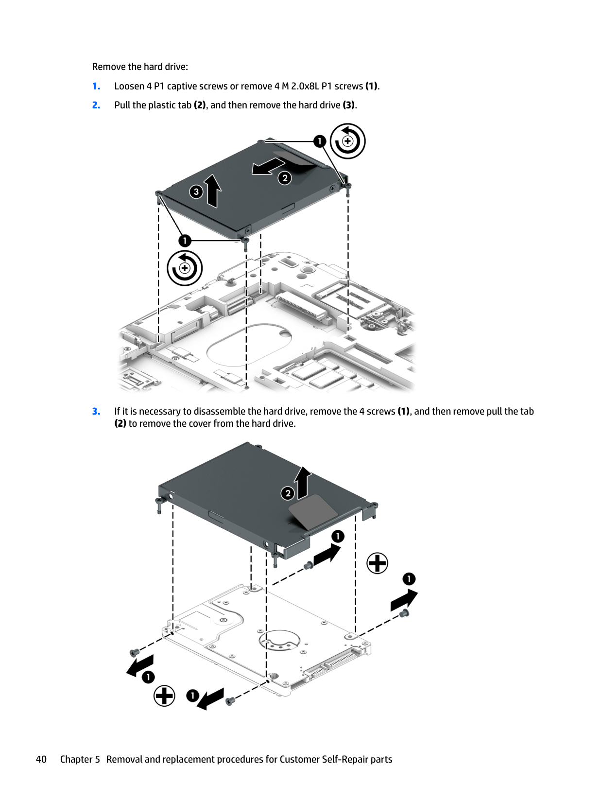
To remove the hard drive: 1. Shut down the computer and disconnect all devices and power. 2. Remove service door, battery, and solid-state drive (if applicable). 3. Loosen or remove 4 P1 screws securing the hard drive. Pull plastic tab to release hard drive from slot for removal. For disassembly of the drive: 4. Remove additional screws holding the top cover on. Lift off the top cover to access internal components inside the drive. (Page 39)
How do I install a new solid-state drive in my HP ProBook 640 G2?
To replace an SSD: 1. Turn off the computer and disconnect all devices, including power supply. 2. Remove service door, battery, hard drive (if present), WWAN module, WLAN card, optical drive, keyboard, then memory cards. 3. Unscrew 1 M2 screw securing the current SSD. Disconnect the cables first if necessary. Carefully remove the SSD for replacement. Install new SSD by aligning and pressing it firmly into place until secure. Reverse these steps to install a new unit. (Pages 40-45)
What is the procedure to replace the WLAN module in my HP ProBook 640 G2?
To remove the module: 1. Power off computer and disconnect all devices, then power source. 2. Open cover access door and carefully uninstall the battery, hard drive, solid-state drive (if applicable), WWAN module and optical drive in sequence. Disconnect 2 ribbon cable ends from WLAN card and unscrew the mounting screw to release it completely for replacement/reinstallation. Ensure you reconnect the cables then replace the cover components back in reverse order afterward. (Page 44)
How can I properly remove and install an optical drive from my HP ProBook 640 G2?
To remove the optical drive: Power down laptop, disconnect devices/wires, and then sequentially take out service door, battery, hard drive, SSD (if present), WWAN module, WLAN card. Loosen a single Phillips M2 screw securing it in place and carefully lift off the drive from its slot for replacement or repair needs. To install: Align new drive accurately into bay, secure with relevant screws, reassemble all previously removed laptop components in reverse order afterward. (Page 46)
What are the recommended steps to replace the keyboard on an HP ProBook 640 G2 notebook?
Replacing the keyboard involves shutting down the system, disconnecting power and accessories. After removing the service door and battery in sequence according to instructions provided, including other hardware like SSD/HDD/Optical drive/WLAN/WWAN modules, proceed by unfastening 3 mounting screws beneath the keyboard and use a tool for keyboard detaching mechanism by gently pressing into release button area behind memory slots. Follow this with cable disconnect steps before taking off the mainboard attached unit for replacement or repair needs. Ensure reinstallation adheres to reverse sequence of these directions. (Page 48)
Full Manual
146 pages

HP ProBook 640 G2 Notebook PC HP ProBook 645 G2 Notebook PC HP ProBook 650 G2 Notebook PC HP ProBook 655 G2 Notebook PC
Maintenance and Service Guide
© Copyright 2015 HP Development Company, L.P.
AMD and AMD Litho Pro are trademarks of Advanced Micro Devices, Inc. Bluetooth is a trademark owned by its proprietor and used by Hewlett-Packard Company under license. Intel, Skylake, and Core are trademarks of Intel Corporation in the U.S. and other countries. Microsoft and Windows are registered trademarks or trademarks of Microsoft Corporation in the United States and/or other countries.
Product notice This guide describes features that are common to most models. Some features may not be available on your computer. Not all features are available in all editions of Windows 8. This computer may require upgraded and/or separately purchased hardware, drivers and/or software to take full advantage of Windows 8 functionality. See http://www.microsoft.com for details.
The information contained herein is subject to change without notice. The only warranties for HP products and services are set forth in the express warranty statements accompanying such products and services. Nothing herein should be construed as constituting an additional warranty. HP shall not be liable for technical or editorial errors or omissions contained herein.
For DTS patents, see http://patents.dts.com. Manufactured under license from DTS Licensing Limited. DTS, the Symbol, & DTS and the Symbol together are registered trademarks, and DTS Sound+ is a trademark of DTS, Inc. © DTS, Inc. All Rights Reserved .

First Edition: December 2015 Document Part Number: 839485-001
#### Important Notice about Customer Self-Repair Parts
CAUTION: Your computer includes Customer Self-Repair parts and parts that should only be accessed by an authorized service provider. See Chapter 5, "Removal and replacement procedures for Customer Self-Repair parts," for details. Accessing parts described in Chapter 6, "Removal and replacement procedures for Authorized Service Provider only parts," can damage the computer or void your warranty.
iii
####### iv Important Notice about Customer Self-Repair Parts
#### Safety warning notice
WARNING! To reduce the possibility of heat-related injuries or of overheating the device, do not place the device directly on your lap or obstruct the device air vents. Use the device only on a hard, flat surface. Do not allow another hard surface, such as an adjoining optional printer, or a soft surface, such as pillows or rugs or clothing, to block airflow. Also, do not allow the AC adapter to contact the skin or a soft surface, such as pillows or rugs or clothing, during operation. The device and the AC adapter comply with the user-accessible surface temperature limits defined by the International Standard for Safety of Information Technology Equipment (IEC 60950-1).

v
####### vi Safety warning notice
Table of contents
TouchPad ........................................................................................................................................... 10 Lights ................................................................................................................................................. 11 Buttons, speakers, and fingerprint reader ........................................................................................ 12 Special function keys ........................................................................................................................ 14 Using the hot keys ............................................................................................................................. 15
Bottom ................................................................................................................................................................. 17 Front ..................................................................................................................................................................... 17 Rear ...................................................................................................................................................................... 19 Locating system information .............................................................................................................................. 19
Plastic parts ....................................................................................................................................... 32 Cables and connectors ...................................................................................................................... 33 Drive handling ................................................................................................................................... 33
Grounding guidelines ........................................................................................................................................... 34
Electrostatic discharge damage ........................................................................................................ 34 Packaging and transporting guidelines .......................................................................... 35 Workstation guidelines ................................................................................................... 35 Equipment guidelines ..................................................................................................... 36
vii
###### 5 Removal and replacement procedures for Customer Self-Repair parts ............................................................. 37Component replacement procedures .................................................................................................................. 37
Service door ....................................................................................................................................... 37 Battery ............................................................................................................................................... 38 Hard drive .......................................................................................................................................... 39 Solid-state drive (select products only) ............................................................................................ 41 WWAN module (select products only) ............................................................................................... 42 WLAN module .................................................................................................................................... 44 Optical drive ....................................................................................................................................... 46 Keyboard ........................................................................................................................................... 48 Memory .............................................................................................................................................. 51
###### 6 Removal and replacement procedures for Authorized Service Provider parts ................................................... 54Component replacement procedures .................................................................................................................. 54

Hinge cover ........................................................................................................................................ 55 Base enclosure .................................................................................................................................. 57 System board .................................................................................................................................... 59 Fan and heat sink assembly .............................................................................................................. 61 Optical drive board ............................................................................................................................ 64 Top cover and TouchPad .................................................................................................................... 65 RTC battery ........................................................................................................................................ 68 Speaker .............................................................................................................................................. 70 Power button board .......................................................................................................................... 71 Fingerprint reader (select products only) ......................................................................................... 72 Smart card reader .............................................................................................................................. 74 Near Field Communication module ................................................................................................... 76 Audio board ....................................................................................................................................... 78 Serial .................................................................................................................................................. 80
Display assembly ................................................................................................................................................. 82
###### 7 Computer Setup (BIOS), TPM, and HP Sure Start in Windows 10 ........................................................................ 88Using Computer Setup ......................................................................................................................................... 88
Starting Computer Setup .................................................................................................................. 88 Navigating and selecting in Computer Setup ................................................................................... 88 Restoring factory settings in Computer Setup ................................................................................. 89 Updating the BIOS ............................................................................................................................. 90
Determining the BIOS version ......................................................................................... 90 Downloading a BIOS update ........................................................................................... 90
Changing the boot order using the f9 prompt .................................................................................. 91 TPM BIOS settings (select products only) ........................................................................................................... 91
viii
Using HP Sure Start (select products only) ......................................................................................................... 92
Starting Computer Setup .................................................................................................................. 93 Navigating and selecting in Computer Setup ................................................................................... 93 Restoring factory settings in Computer Setup ................................................................................. 94 Updating the BIOS ............................................................................................................................. 95
Determining the BIOS version ......................................................................................... 95 Downloading a BIOS update ........................................................................................... 95
Changing the boot order using the f9 prompt .................................................................................. 96 TPM BIOS settings (select products only) ........................................................................................................... 96 Using HP Sure Start (select products only) ......................................................................................................... 97
Starting Computer Setup .................................................................................................................. 98 Navigating and selecting in Computer Setup ................................................................................... 98 Restoring factory settings in Computer Setup ................................................................................. 99 Updating the BIOS ........................................................................................................................... 100
Determining the BIOS version ...................................................................................... 100 Downloading a BIOS update ......................................................................................... 100

Changing the boot order using the f9 prompt ................................................................................ 101 TPM BIOS settings (select products only) ......................................................................................................... 101 Using HP Sure Start (select products only) ....................................................................................................... 102
Creating HP Recovery media (select products only) ....................................................................... 105 Using Windows tools ......................................................................................................................................... 106 Restore and recovery ......................................................................................................................................... 107
Recovering using HP Recovery Manager ........................................................................................ 107 What you need to know before you get started ........................................................... 107 Using the HP Recovery partition (select products only) .............................................. 108 Using HP Recovery media to recover ............................................................................ 108 Changing the computer boot order .............................................................................. 109 Removing the HP Recovery partition (select products only) ....................................... 110
ix
Using the Windows recovery tools .................................................................................................. 111 Using f11 recovery tools ................................................................................................................. 112 Using Windows operating system media (purchased separately) ................................................. 113 Using Windows Refresh or Windows Reset .................................................................................... 113 Using HP Software Setup ................................................................................................................ 113
Guidelines ........................................................................................................................................ 114 Creating recovery media with HP Recovery Disc Creator ............................................................... 114
Creating recovery media ............................................................................................... 115 Backing up your information .......................................................................................................... 115
Performing a system recovery .......................................................................................................................... 116 Using the Windows recovery tools .................................................................................................. 116 Using f11 recovery tools (select products only) ............................................................................. 117 Using Windows 7 operating system media ..................................................................................... 117
###### Index ........................................................................................................................................................... 133

x
1 Product description
######## Category Description
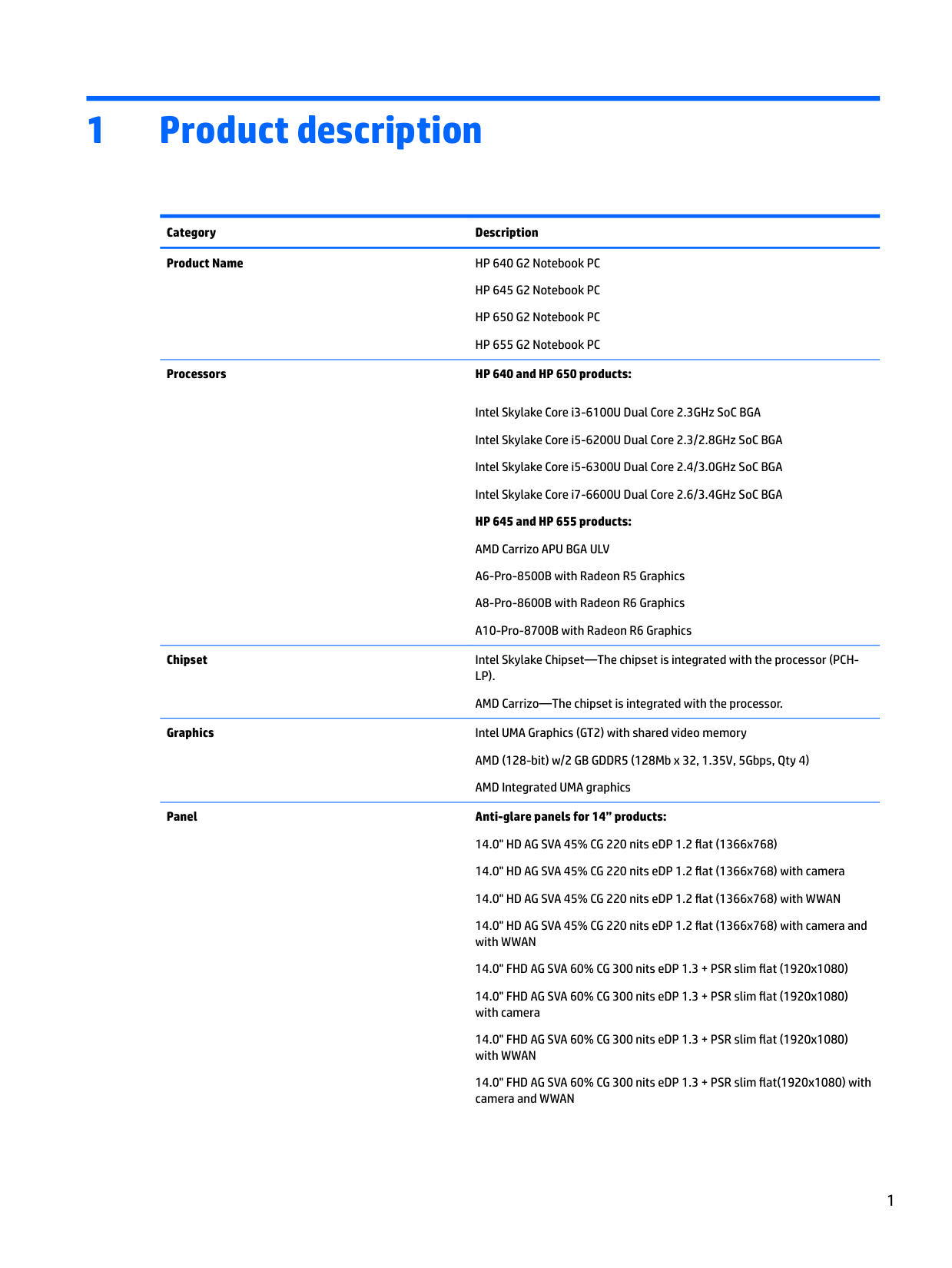
Product Name HP 640 G2 Notebook PC HP 645 G2 Notebook PC HP 650 G2 Notebook PC HP 655 G2 Notebook PC
######## Processors HP 640 and HP 650 products:
Intel Skylake Core i3-6100U Dual Core 2.3GHz SoC BGA Intel Skylake Core i5-6200U Dual Core 2.3/2.8GHz SoC BGA Intel Skylake Core i5-6300U Dual Core 2.4/3.0GHz SoC BGA Intel Skylake Core i7-6600U Dual Core 2.6/3.4GHz SoC BGA HP 645 and HP 655 products: AMD Carrizo APU BGA ULV A6-Pro-8500B with Radeon R5 Graphics A8-Pro-8600B with Radeon R6 Graphics A10-Pro-8700B with Radeon R6 Graphics
Chipset Intel Skylake Chipset—The chipset is integrated with the processor (PCHLP). AMD Carrizo—The chipset is integrated with the processor.
Graphics Intel UMA Graphics (GT2) with shared video memory AMD (128-bit) w/2 GB GDDR5 (128Mb x 32, 1.35V, 5Gbps, Qty 4) AMD Integrated UMA graphics
######## Panel Anti-glare panels for 14” products:
14.0" HD AG SVA 45% CG 220 nits eDP 1.2 flat (1366x768)

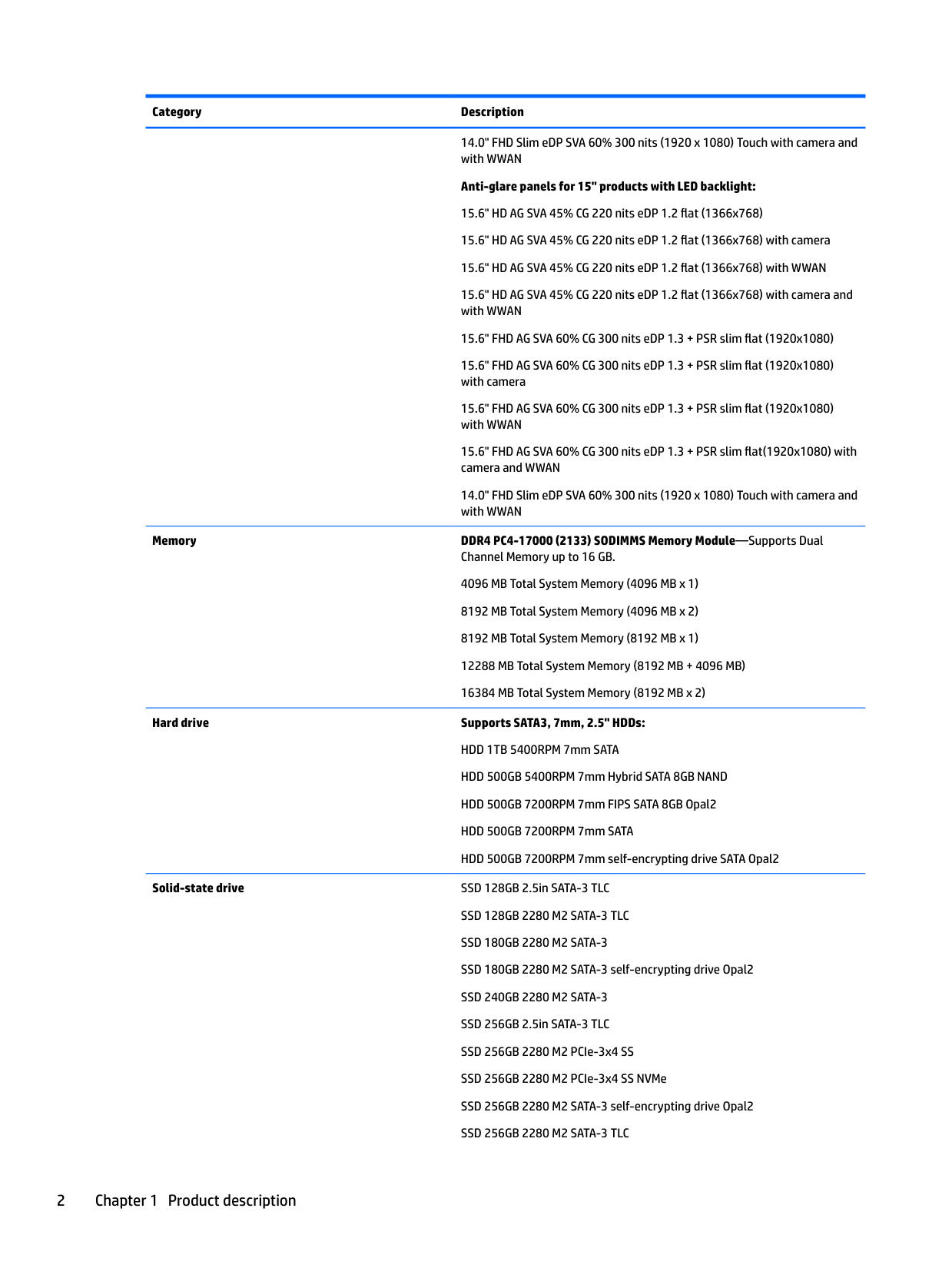
14.0" FHD Slim eDP SVA 60% 300 nits (1920 x 1080) Touch with camera and with WWAN
Memory DDR4 PC4-17000 (2133) SODIMMS Memory Module—Supports Dual Channel Memory up to 16 GB. 4096 MB Total System Memory (4096 MB x 1) 8192 MB Total System Memory (4096 MB x 2) 8192 MB Total System Memory (8192 MB x 1) 12288 MB Total System Memory (8192 MB + 4096 MB) 16384 MB Total System Memory (8192 MB x 2)
Hard drive Supports SATA3, 7mm, 2.5" HDDs: HDD 1TB 5400RPM 7mm SATA HDD 500GB 5400RPM 7mm Hybrid SATA 8GB NAND HDD 500GB 7200RPM 7mm FIPS SATA 8GB Opal2 HDD 500GB 7200RPM 7mm SATA HDD 500GB 7200RPM 7mm self-encrypting drive SATA Opal2
Solid-state drive SSD 128GB 2.5in SATA-3 TLC SSD 128GB 2280 M2 SATA-3 TLC SSD 180GB 2280 M2 SATA-3 SSD 180GB 2280 M2 SATA-3 self-encrypting drive Opal2 SSD 240GB 2280 M2 SATA-3 SSD 256GB 2.5in SATA-3 TLC SSD 256GB 2280 M2 PCIe-3x4 SS SSD 256GB 2280 M2 PCIe-3x4 SS NVMe SSD 256GB 2280 M2 SATA-3 self-encrypting drive Opal2 SSD 256GB 2280 M2 SATA-3 TLC
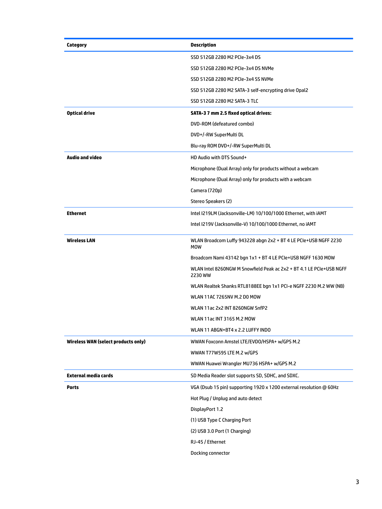
SSD 512GB 2280 M2 PCIe-3x4 DS SSD 512GB 2280 M2 PCIe-3x4 DS NVMe SSD 512GB 2280 M2 PCIe-3x4 SS NVMe SSD 512GB 2280 M2 SATA-3 self-encrypting drive Opal2 SSD 512GB 2280 M2 SATA-3 TLC
Optical drive SATA-3 7 mm 2.5 fixed optical drives: DVD-ROM (defeatured combo) DVD+/-RW SuperMulti DL Blu-ray ROM DVD+/-RW SuperMulti DL
Audio and video HD Audio with DTS Sound+ Microphone (Dual Array) only for products without a webcam Microphone (Dual Array) only for products with a webcam Camera (720p) Stereo Speakers (2)
Ethernet Intel I219LM (Jacksonville-LM) 10/100/1000 Ethernet, with iAMT
Intel I219V (Jacksonville-V) 10/100/1000 Ethernet, no iAMT
Wireless LAN WLAN Broadcom Luffy 943228 abgn 2x2 + BT 4 LE PCIe+USB NGFF 2230 MOW Broadcom Nami 43142 bgn 1x1 + BT 4 LE PCIe+USB NGFF 1630 MOW WLAN Intel 8260NGW M Snowfield Peak ac 2x2 + BT 4.1 LE PCIe+USB NGFF 2230 WW WLAN Realtek Shanks RTL8188EE bgn 1x1 PCI-e NGFF 2230 M.2 WW (NB) WLAN 11AC 7265NV M.2 D0 MOW WLAN 11ac 2x2 INT 8260NGW SnfP2 WLAN 11ac INT 3165 M.2 MOW WLAN 11 ABGN+BT4 x 2.2 LUFFY INDO
Wireless WAN (select products only) WWAN Foxconn Amstel LTE/EVDO/HSPA+ w/GPS M.2 WWAN T77W595 LTE M.2 w/GPS WWAN Huawei Wrangler MU736 HSPA+ w/GPS M.2
External media cards SD Media Reader slot supports SD, SDHC, and SDXC. Ports VGA (Dsub 15 pin) supporting 1920 x 1200 external resolution @ 60Hz
Hot Plug / Unplug and auto detect DisplayPort 1.2
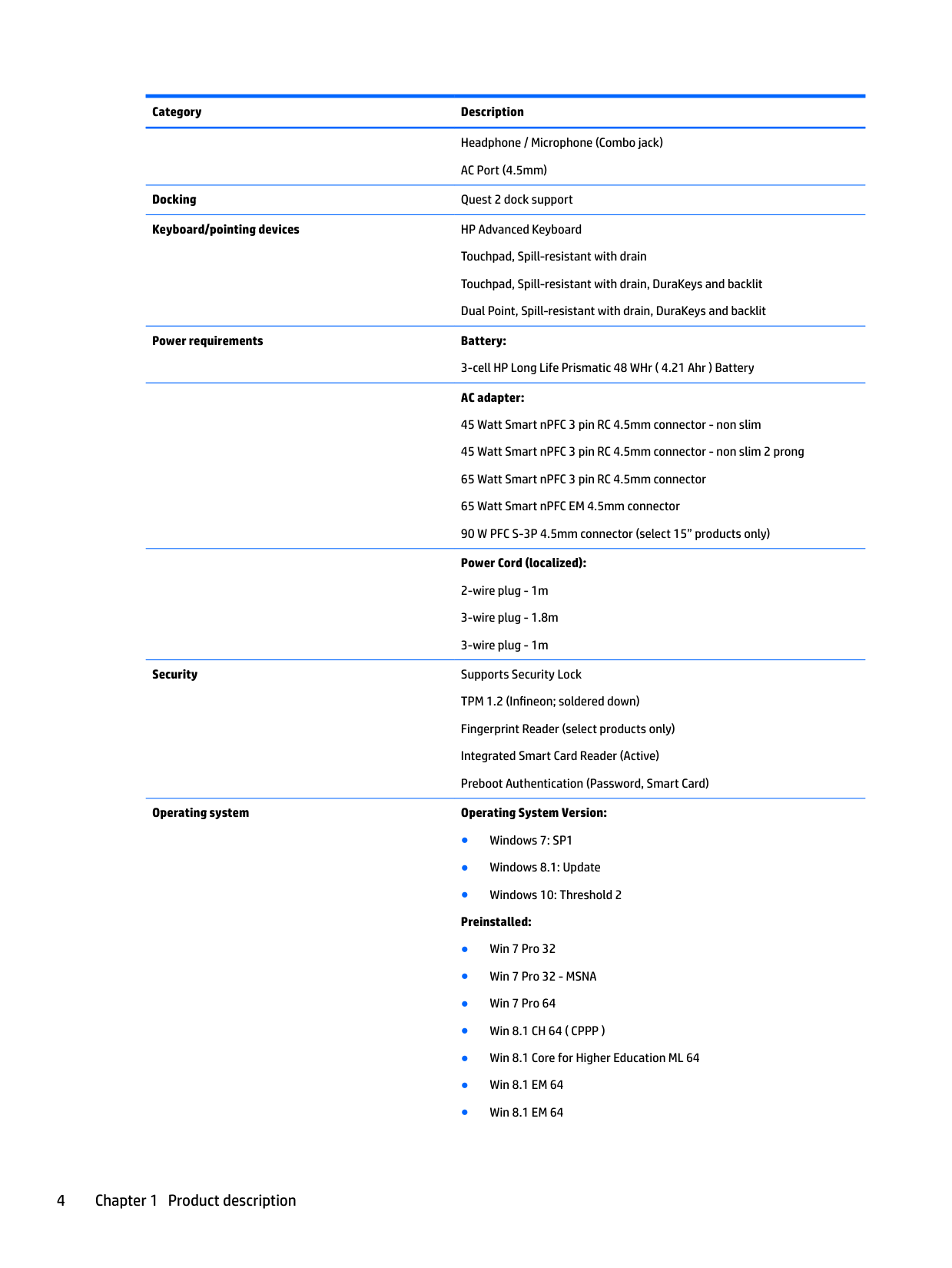
Headphone / Microphone (Combo jack) AC Port (4.5mm)
Docking Quest 2 dock support Keyboard/pointing devices HP Advanced Keyboard
Touchpad, Spill-resistant with drain Touchpad, Spill-resistant with drain, DuraKeys and backlit Dual Point, Spill-resistant with drain, DuraKeys and backlit
Power requirements Battery: 3-cell HP Long Life Prismatic 48 WHr ( 4.21 Ahr ) Battery AC adapter: 45 Watt Smart nPFC 3 pin RC 4.5mm connector - non slim 45 Watt Smart nPFC 3 pin RC 4.5mm connector - non slim 2 prong 65 Watt Smart nPFC 3 pin RC 4.5mm connector 65 Watt Smart nPFC EM 4.5mm connector 90 W PFC S-3P 4.5mm connector (select 15” products only) Power Cord (localized):
Security Supports Security Lock TPM 1.2 (Infineon; soldered down) Fingerprint Reader (select products only) Integrated Smart Card Reader (Active) Preboot Authentication (Password, Smart Card)
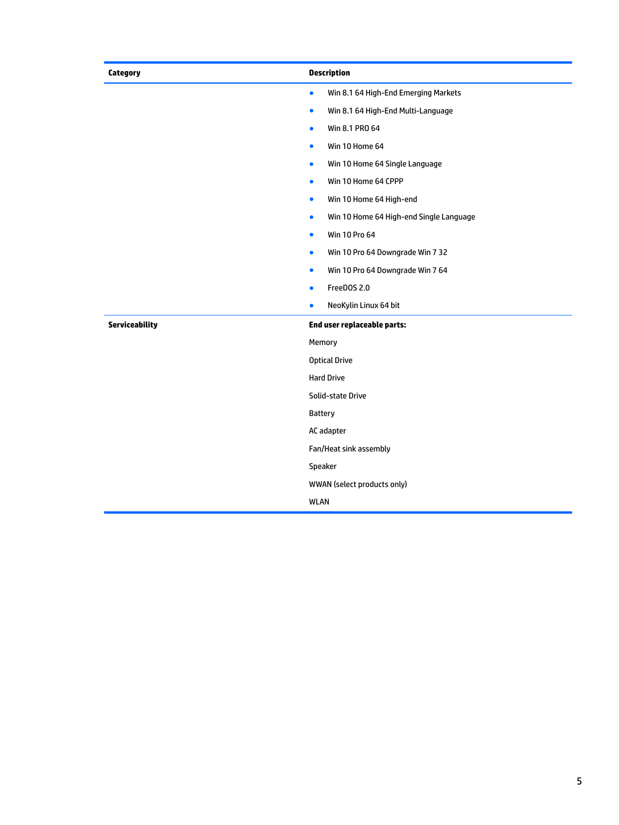
######## Operating system Operating System Version:
Serviceability End user replaceable parts: Memory Optical Drive Hard Drive Solid-state Drive Battery AC adapter Fan/Heat sink assembly Speaker WWAN (select products only) WLAN
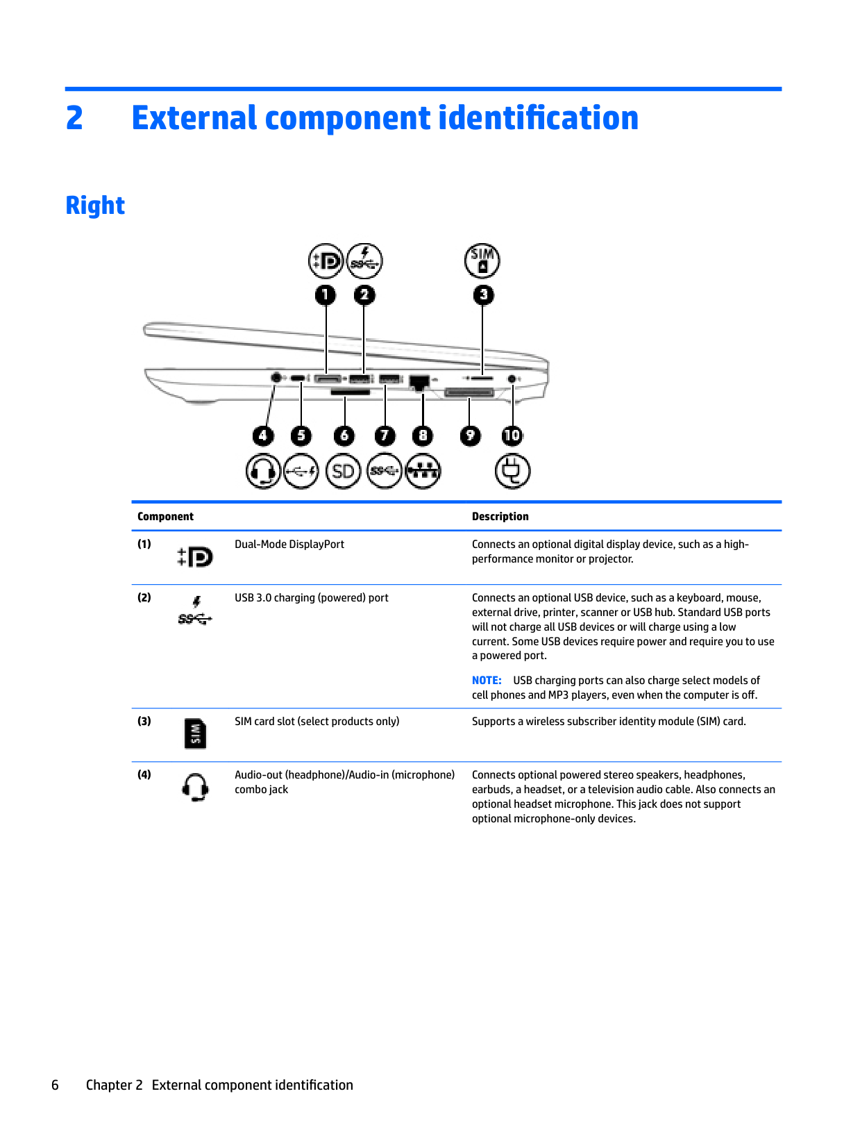
2 External component identification
Right

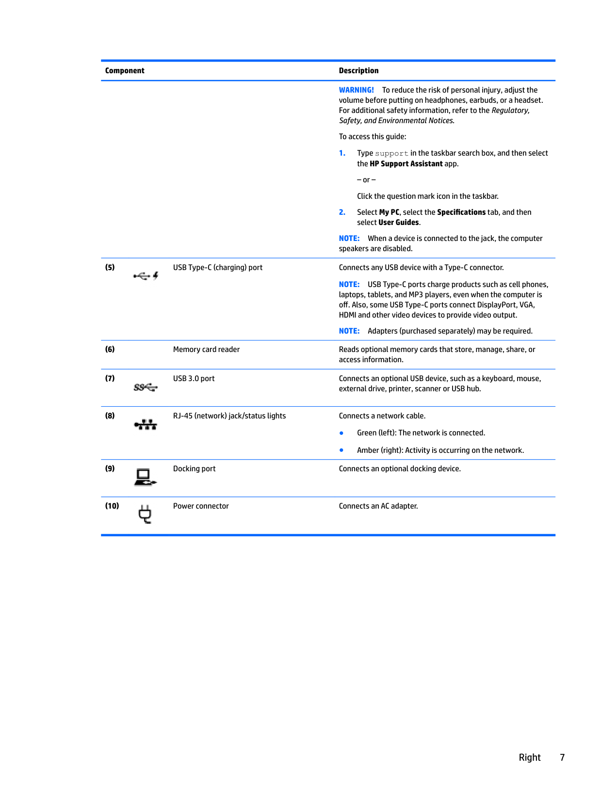
######## Component Description


NOTE: USB charging ports can also charge select models of cell phones and MP3 players, even when the computer is off.

Connects optional powered stereo speakers, headphones, earbuds, a headset, or a television audio cable. Also connects an optional headset microphone. This jack does not support optional microphone-only devices.

######## Component Description
WARNING! To reduce the risk of personal injury, adjust the volume before putting on headphones, earbuds, or a headset. For additional safety information, refer to the Regulatory, Safety, and Environmental Notices.
To access this guide:
– or – Click the question mark icon in the taskbar.
NOTE: When a device is connected to the jack, the computer speakers are disabled.

NOTE: USB Type-C ports charge products such as cell phones, laptops, tablets, and MP3 players, even when the computer is off. Also, some USB Type-C ports connect DisplayPort, VGA, HDMI and other video devices to provide video output.
NOTE: Adapters (purchased separately) may be required.


Right 7
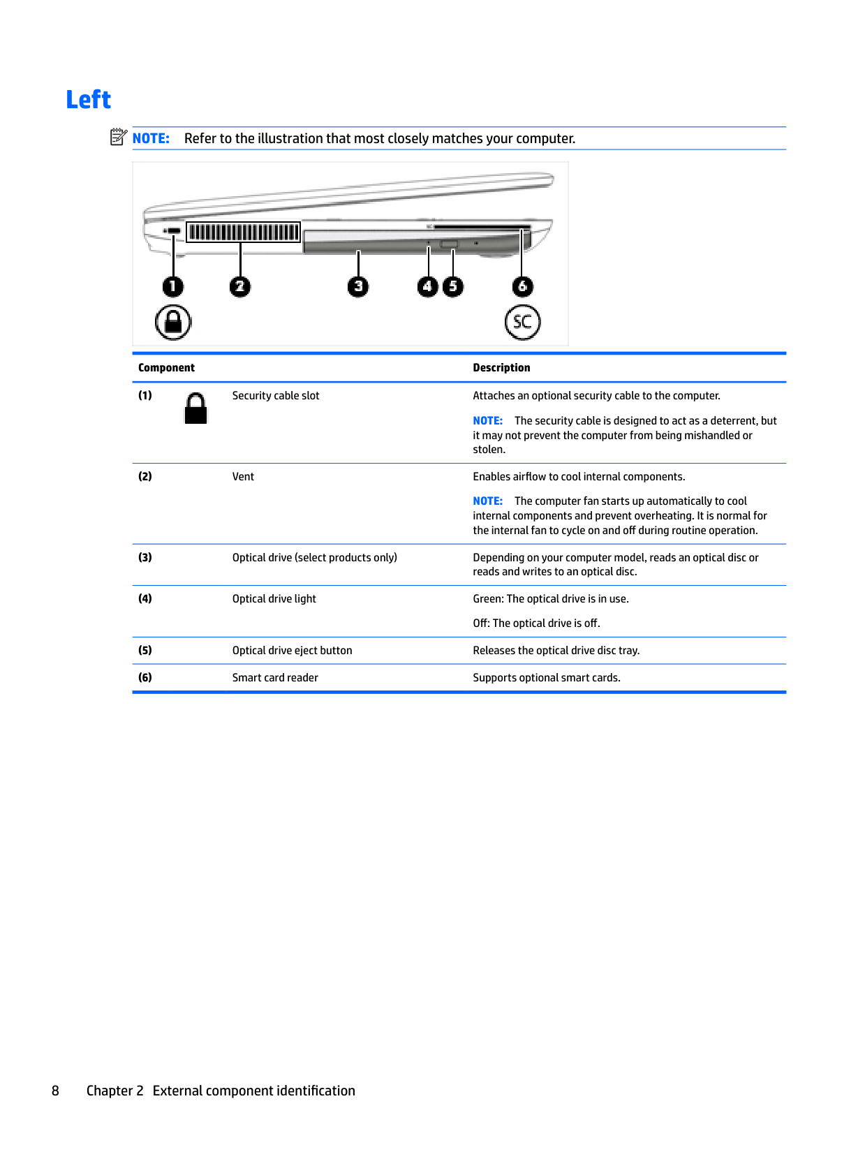
Left
| | |---|
NOTE: Refer to the illustration that most closely matches your computer.

Component Description

NOTE: The security cable is designed to act as a deterrent, but it may not prevent the computer from being mishandled or stolen.
NOTE: The computer fan starts up automatically to cool internal components and prevent overheating. It is normal for the internal fan to cycle on and off during routine operation.
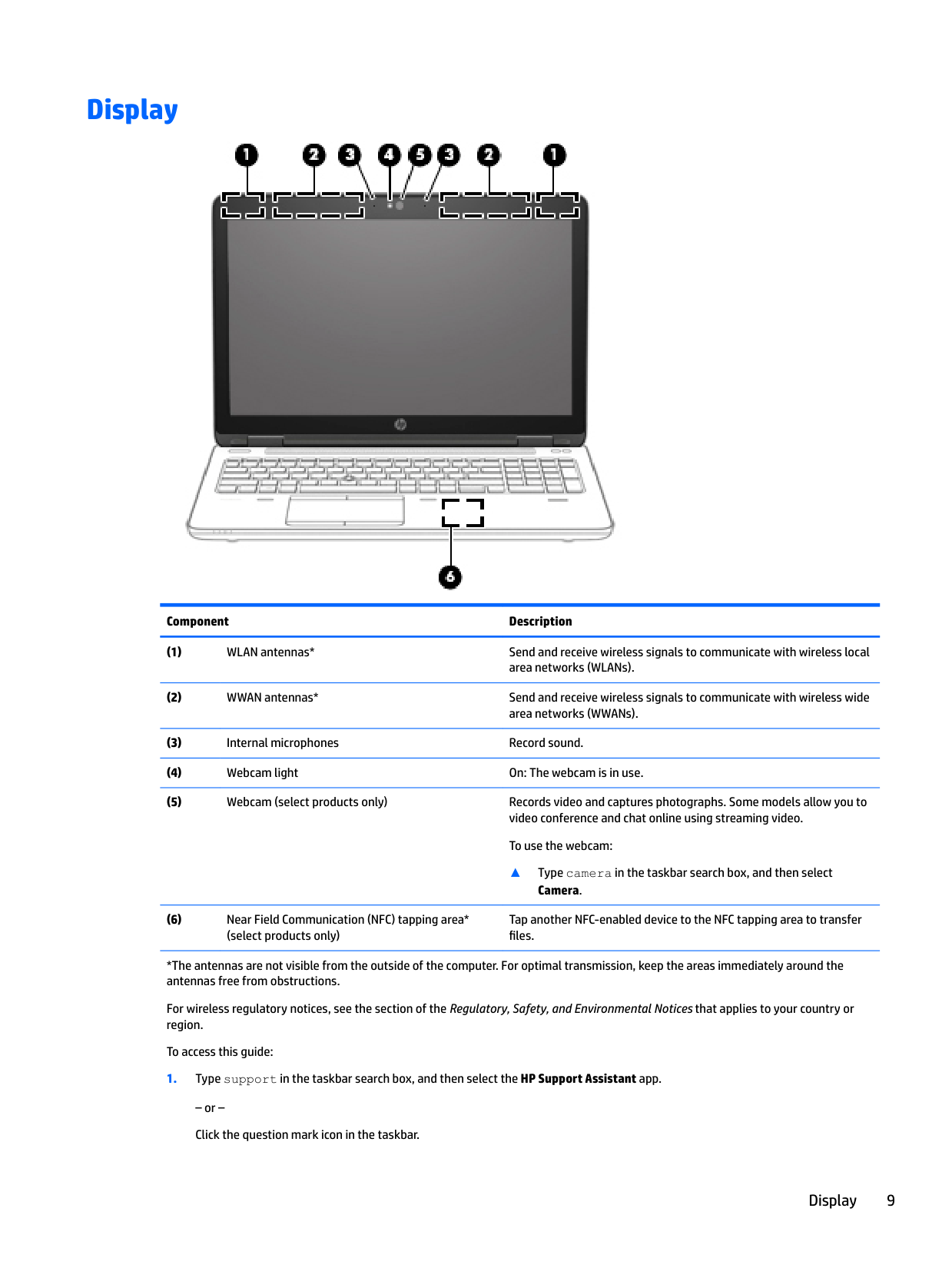
Display

######## Component Description
▲ Type camera in the taskbar search box, and then select
Camera.
Tap another NFC-enabled device to the NFC tapping area to transfer files.
*The antennas are not visible from the outside of the computer. For optimal transmission, keep the areas immediately around the antennas free from obstructions.
For wireless regulatory notices, see the section of the Regulatory, Safety, and Environmental Notices that applies to your country or region.
To access this guide:
– or – Click the question mark icon in the taskbar.
Display 9
######## Component Description
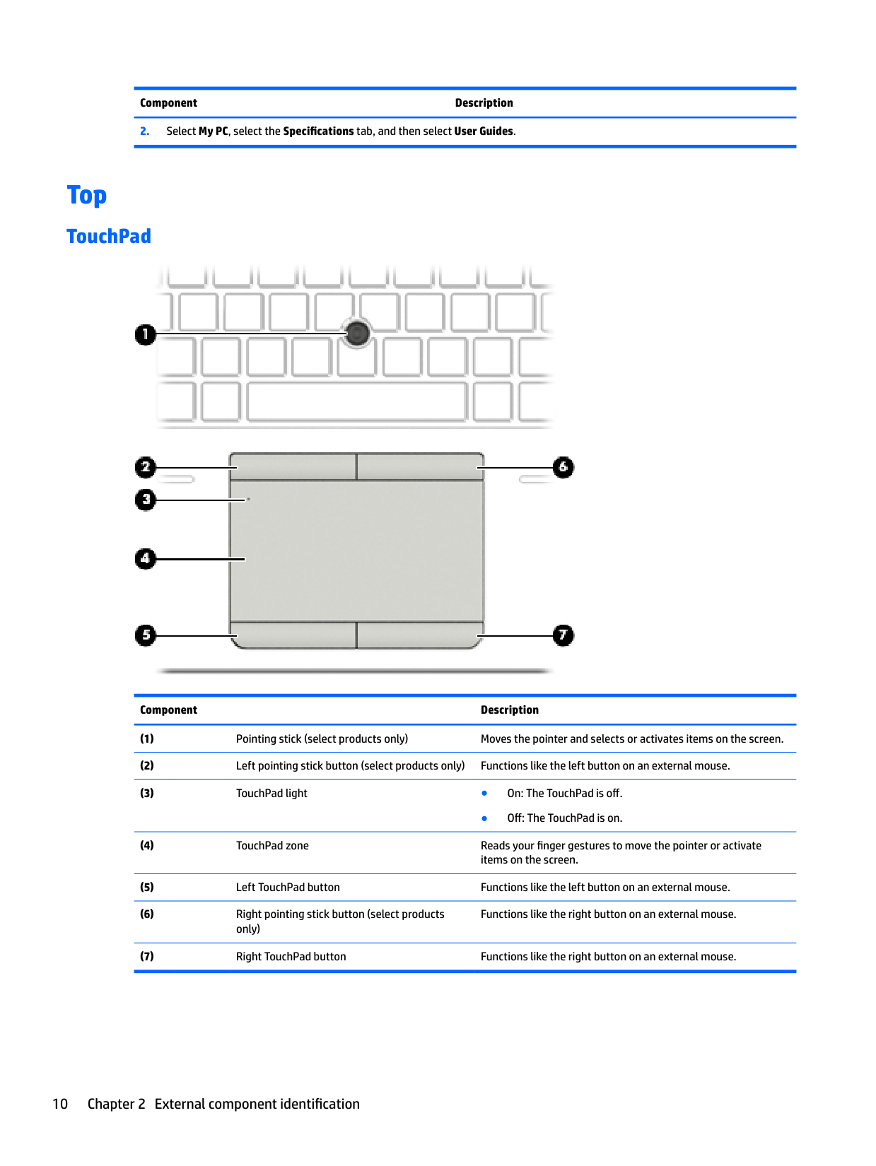
Top
#### TouchPad

######## Component Description
● Off: The TouchPad is on.
Functions like the right button on an external mouse.
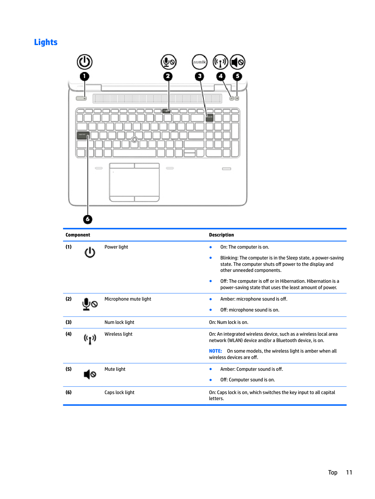
#### Lights

######## Component Description


● Off: microphone sound is on.

NOTE: On some models, the wireless light is amber when all wireless devices are off.

● Off: Computer sound is on.
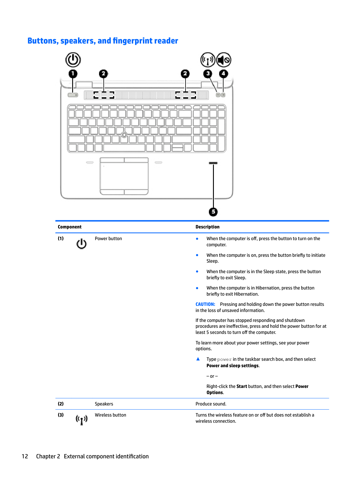
#### Buttons, speakers, and fingerprint reader

######## Component Description

CAUTION: Pressing and holding down the power button results in the loss of unsaved information. If the computer has stopped responding and shutdown procedures are ineffective, press and hold the power button for at least 5 seconds to turn off the computer. To learn more about your power settings, see your power options.
▲ Type power in the taskbar search box, and then select
Power and sleep settings.
– or – Right-click the Start button, and then select Power Options.

######## Component Description
A wireless network must be set up before a wireless connection is possible.

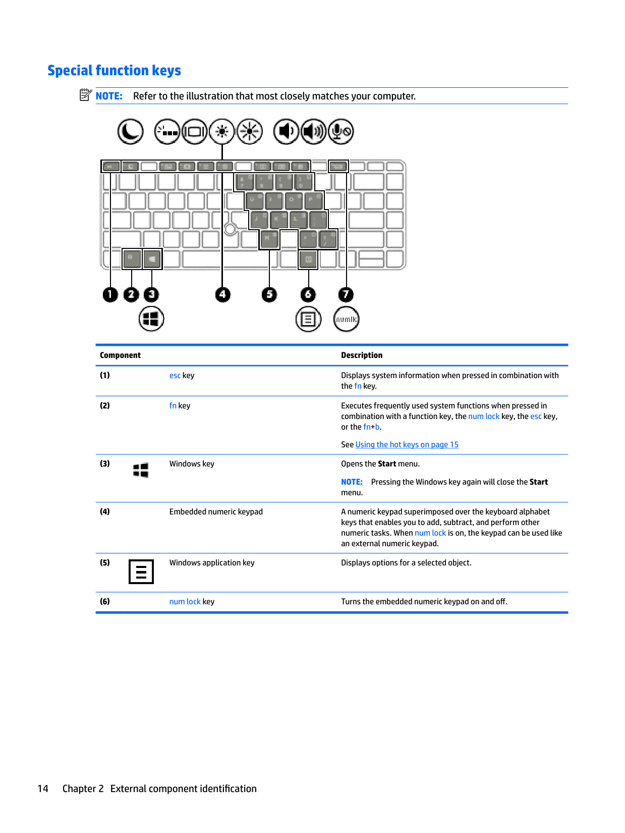
#### Special function keys
| | |---|
NOTE: Refer to the illustration that most closely matches your computer.

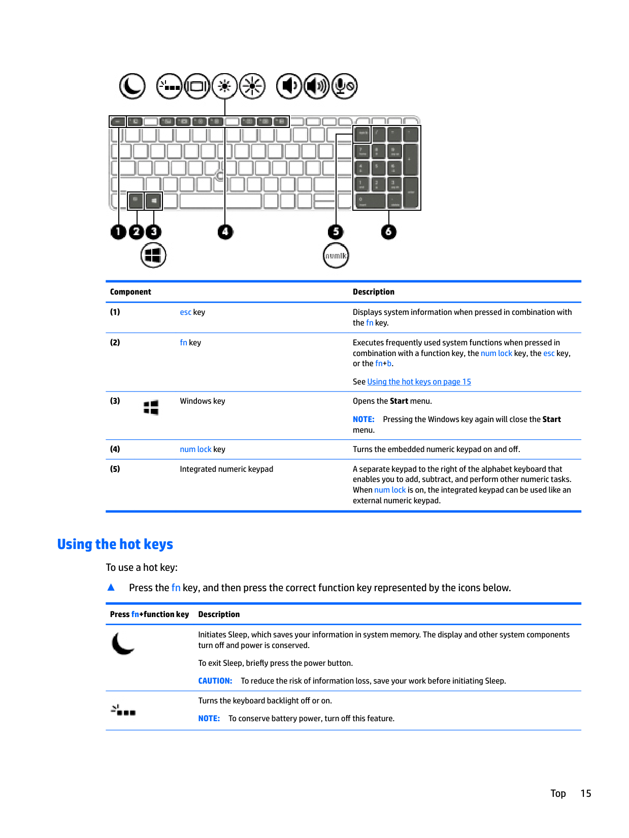
Component Description

NOTE: Pressing the Windows key again will close the Start menu.


######## Component Description

NOTE: Pressing the Windows key again will close the Start menu.
#### Using the hot keys
To use a hot key:
▲ Press the fn key, and then press the correct function key represented by the icons below.
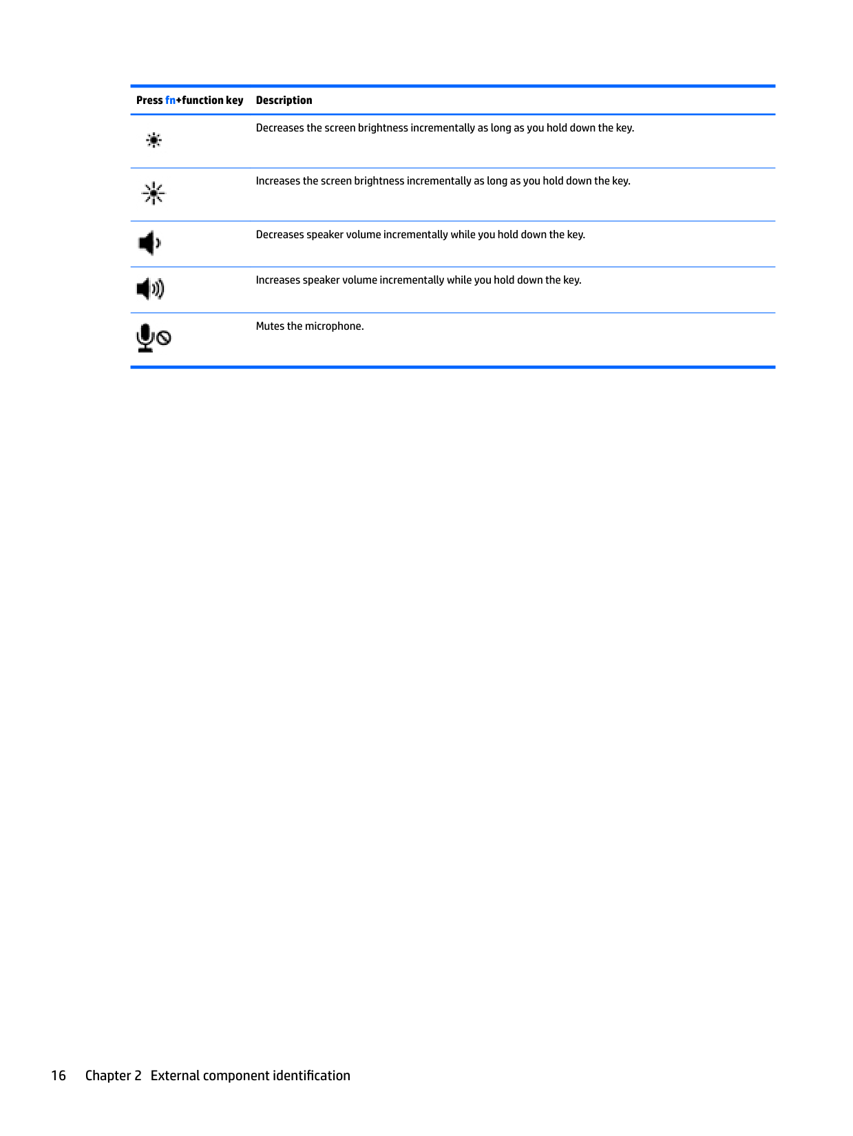
Press fn+function key Description


Initiates Sleep, which saves your information in system memory. The display and other system components turn off and power is conserved.
To exit Sleep, briefly press the power button. CAUTION: To reduce the risk of information loss, save your work before initiating Sleep. Turns the keyboard backlight off or on. NOTE: To conserve battery power, turn off this feature.
######## Press fn+function key Description

Decreases the screen brightness incrementally as long as you hold down the key.


Increases the screen brightness incrementally as long as you hold down the key.
Decreases speaker volume incrementally while you hold down the key.


Increases speaker volume incrementally while you hold down the key.
Mutes the microphone.
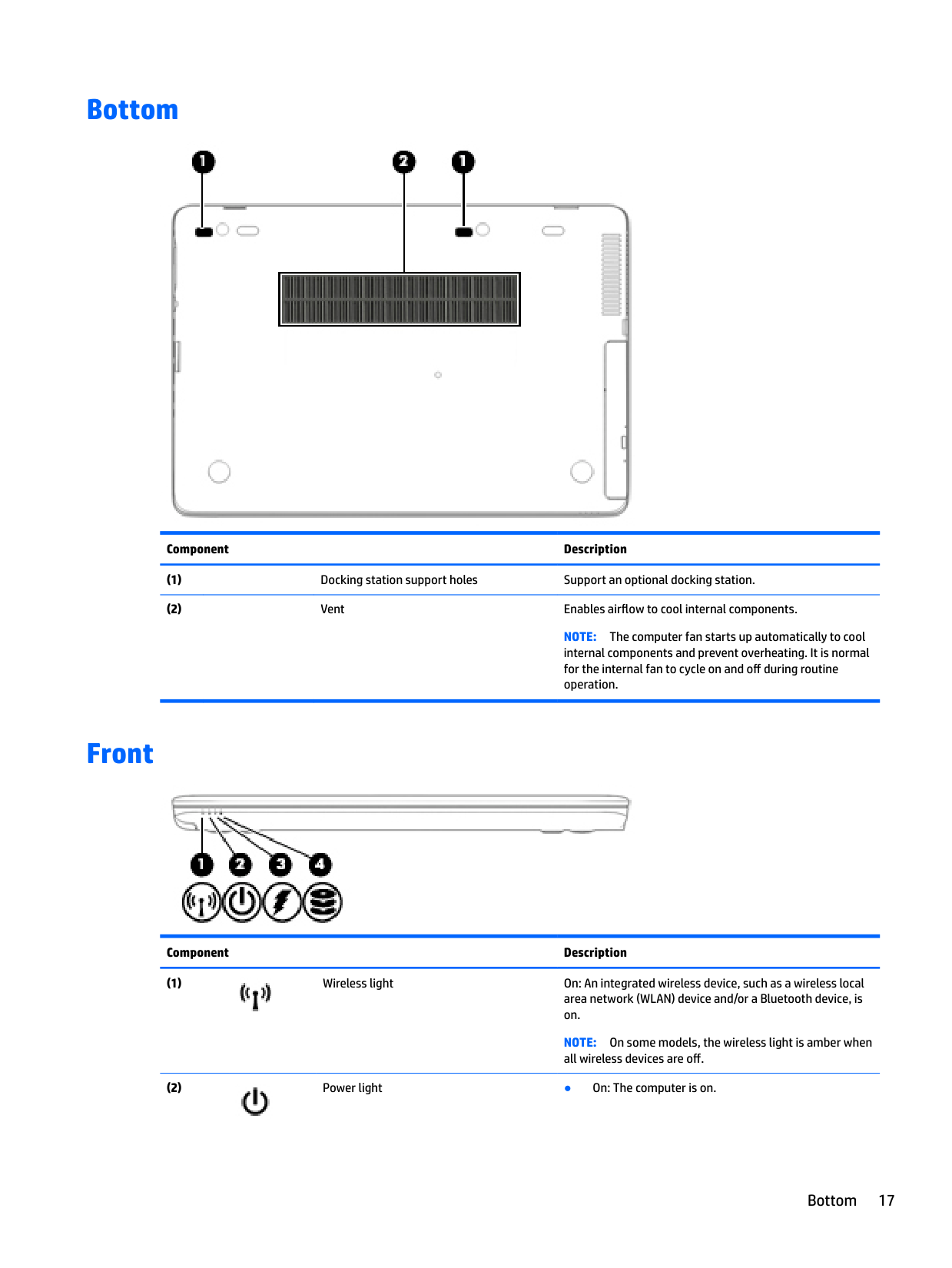
Bottom

######## Component Description
NOTE: The computer fan starts up automatically to cool internal components and prevent overheating. It is normal for the internal fan to cycle on and off during routine operation.
Front

######## Component Description

NOTE: On some models, the wireless light is amber when all wireless devices are off.

Bottom 17
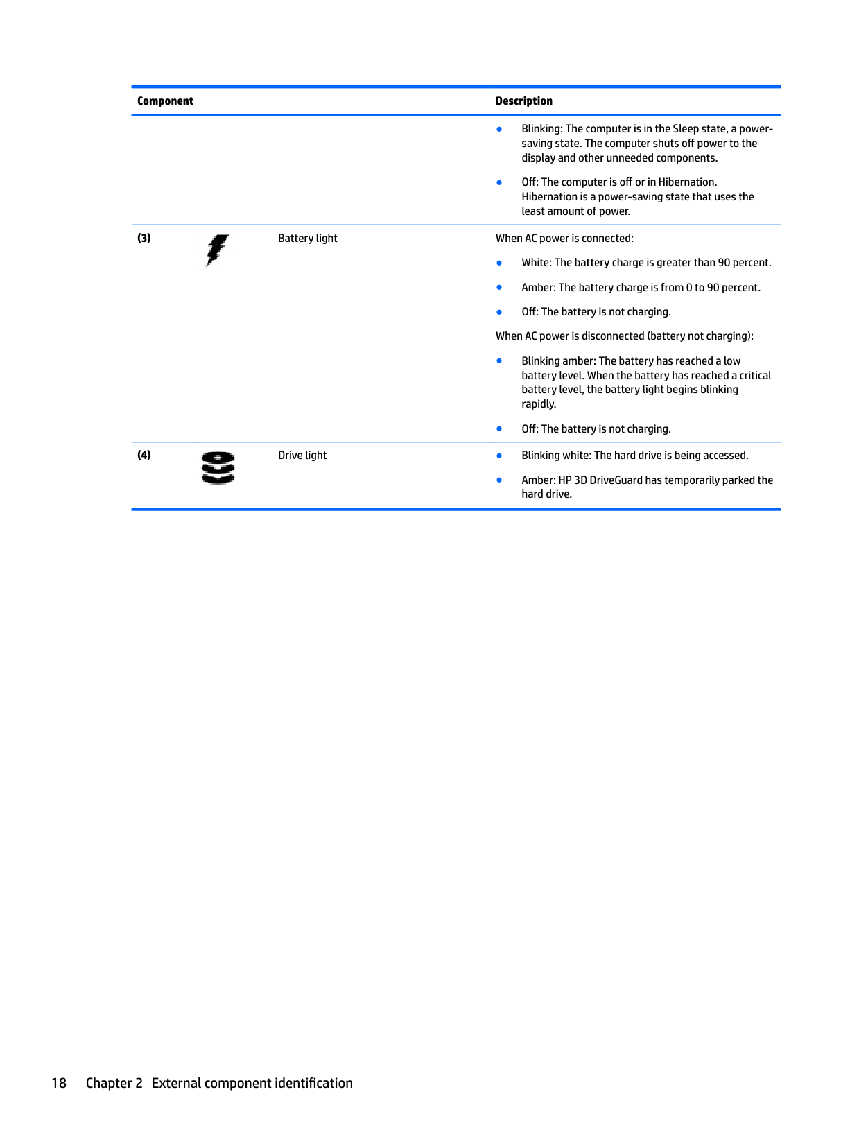
######## Component Description


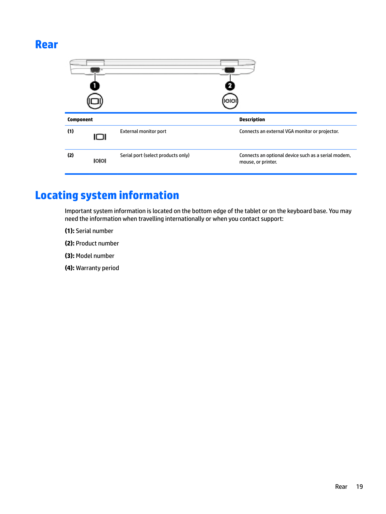
Rear

######## Component Description


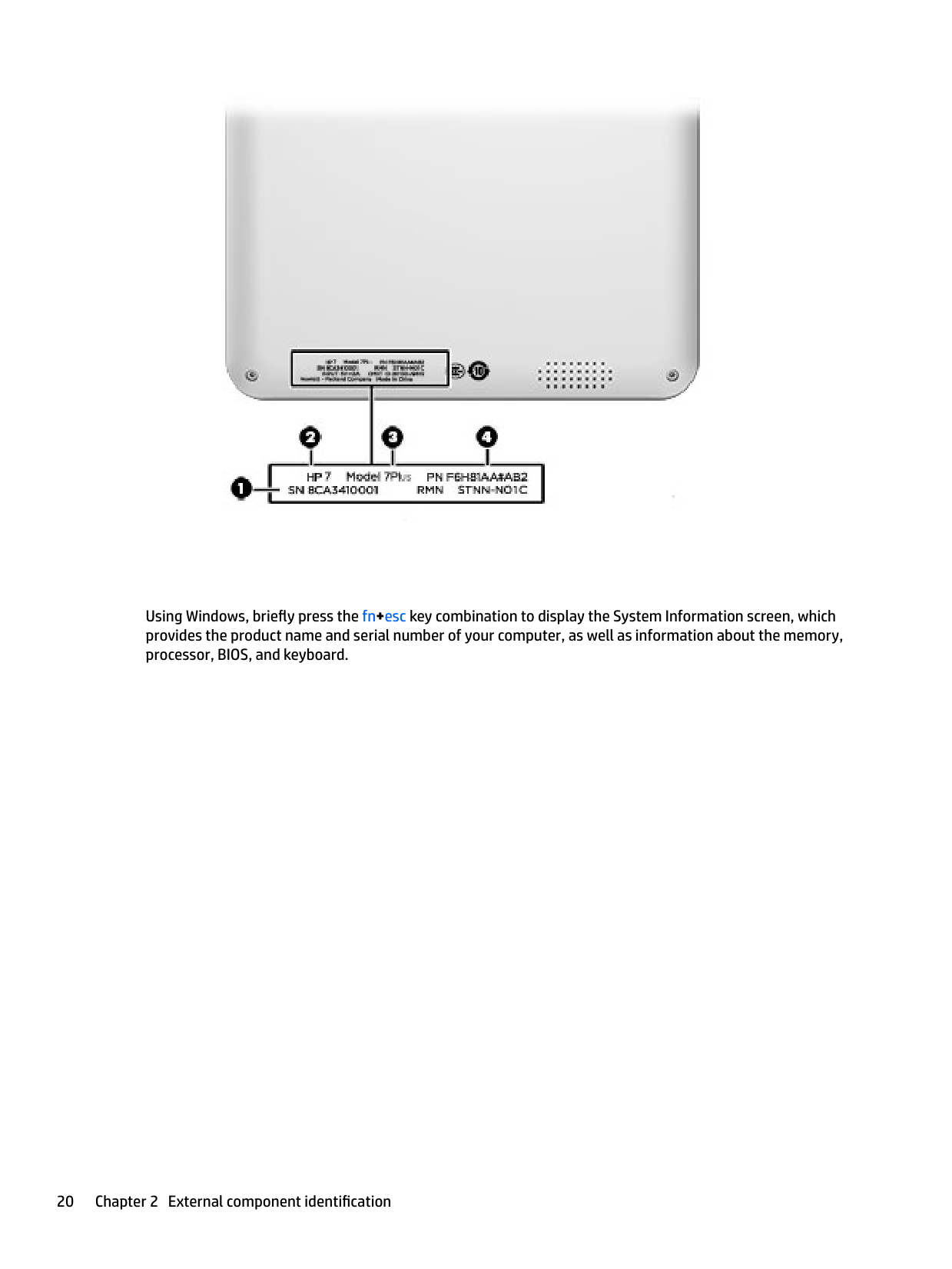
Locating system information
Important system information is located on the bottom edge of the tablet or on the keyboard base. You may need the information when travelling internationally or when you contact support:
Rear 19

####### Using Windows, briefly press the fn+esc key combination to display the System Information screen, which provides the product name and serial number of your computer, as well as information about the memory, processor, BIOS, and keyboard.
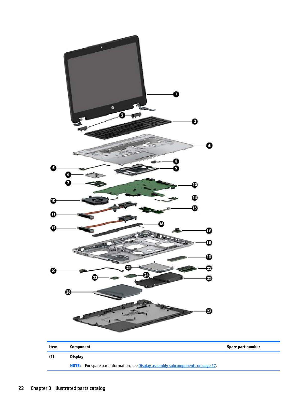
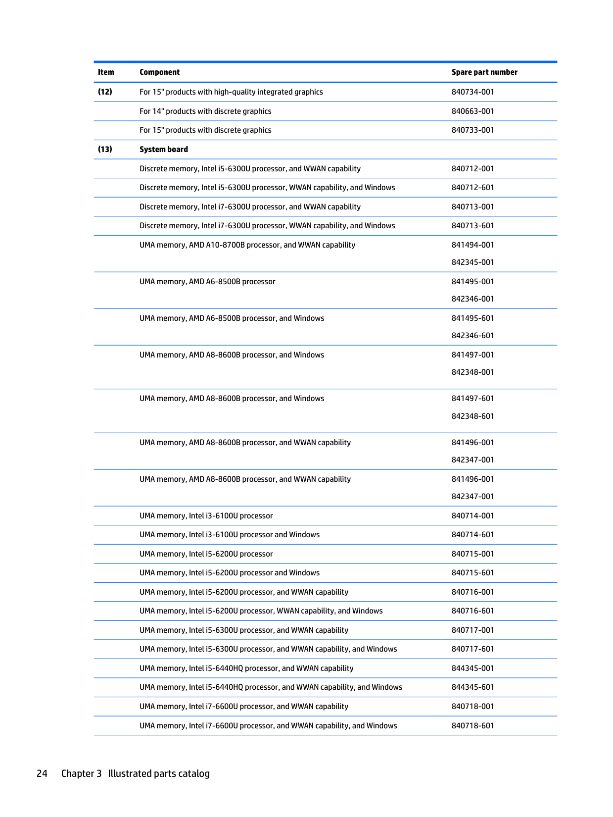
3 Illustrated parts catalog
Computer major components

| | |---|
NOTE: HP continually improves and changes product parts. For complete and current information on supported parts for your computer, go to http://partsurfer.hp.com, select your country or region, and then follow the on-screen instructions.
| | |---|
NOTE: Details about your computer, including model, serial number, product key, and length of warranty, are on the service tag at the bottom of your computer. See Locating system information on page 19 for details.

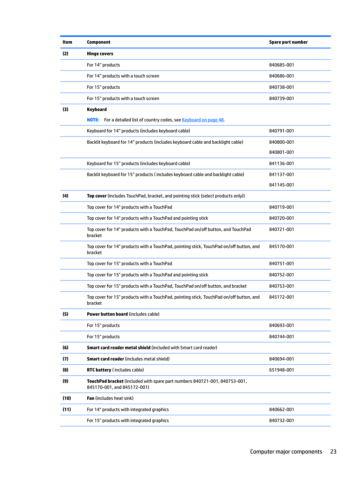
######## Item Component Spare part number
Keyboard for 15” products (includes keyboard cable) 841136-001
840721-001
845170-001
845172-001
UMA memory, AMD A6-8500B processor 841495-001
UMA memory, AMD A6-8500B processor, and Windows 841495-601
842346-601 UMA memory, AMD A8-8600B processor, and Windows 841497-001
842348-001
UMA memory, AMD A8-8600B processor, and Windows 841497-601 842348-601
UMA memory, AMD A8-8600B processor, and WWAN capability 841496-001
842347-001 UMA memory, AMD A8-8600B processor, and WWAN capability 841496-001
842347-001 UMA memory, Intel i3-6100U processor 840714-001 UMA memory, Intel i3-6100U processor and Windows 840714-601 UMA memory, Intel i5-6200U processor 840715-001 UMA memory, Intel i5-6200U processor and Windows 840715-601 UMA memory, Intel i5-6200U processor, and WWAN capability 840716-001 UMA memory, Intel i5-6200U processor, WWAN capability, and Windows 840716-601 UMA memory, Intel i5-6300U processor, and WWAN capability 840717-001 UMA memory, Intel i5-6300U processor, and WWAN capability, and Windows 840717-601 UMA memory, Intel i5-6440HQ processor, and WWAN capability 844345-001 UMA memory, Intel i5-6440HQ processor, and WWAN capability, and Windows 844345-601 UMA memory, Intel i7-6600U processor, and WWAN capability 840718-001 UMA memory, Intel i7-6600U processor, and WWAN capability, and Windows 840718-601
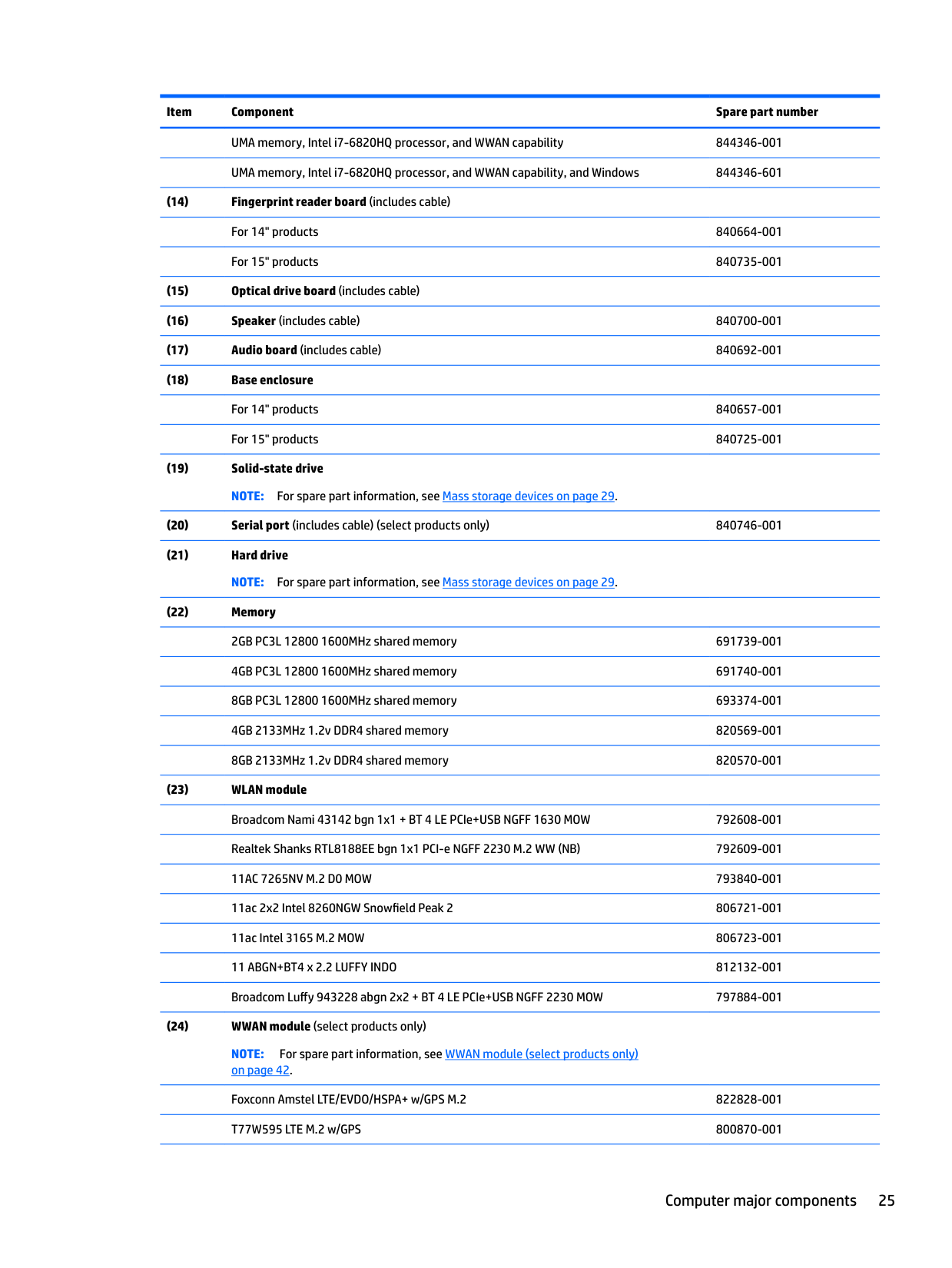
UMA memory, Intel i7-6820HQ processor, and WWAN capability 844346-001 UMA memory, Intel i7-6820HQ processor, and WWAN capability, and Windows 844346-601
NOTE: For spare part information, see WWAN module (select products only) on page 42.
Foxconn Amstel LTE/EVDO/HSPA+ w/GPS M.2 822828-001 T77W595 LTE M.2 w/GPS 800870-001
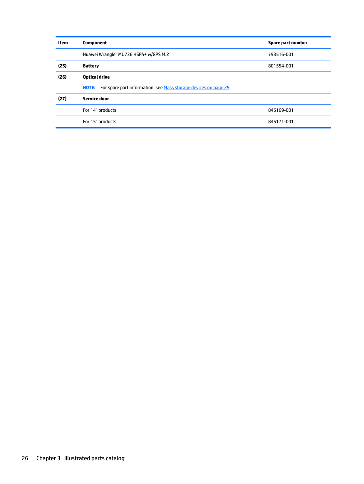
Huawei Wrangler MU736 HSPA+ w/GPS M.2 793516-001
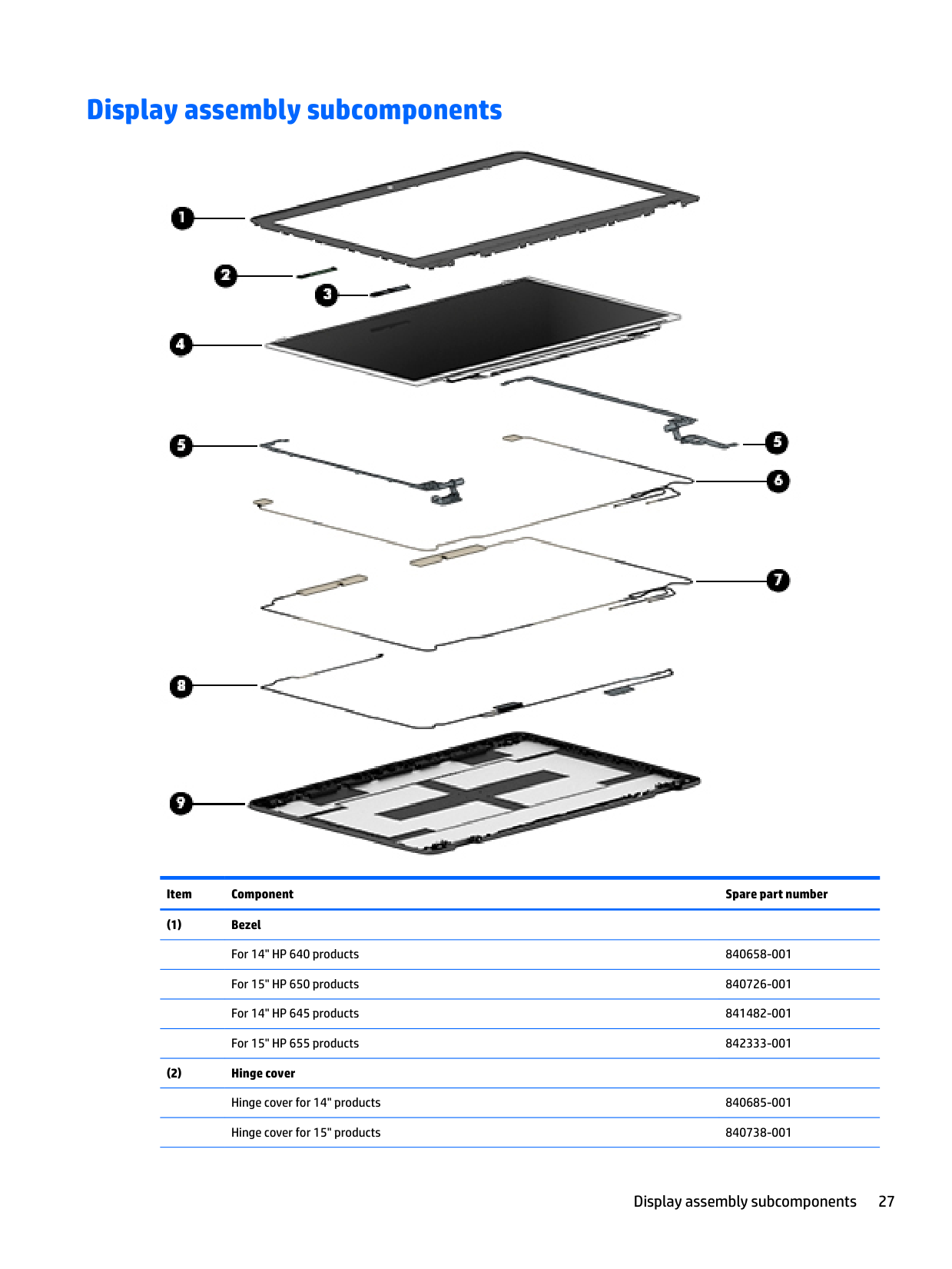
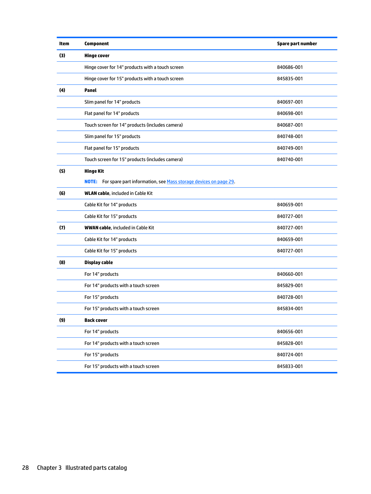
Display assembly subcomponents

######## Item Component Spare part number
Display assembly subcomponents 27
Flat panel for 15" products 840749-001
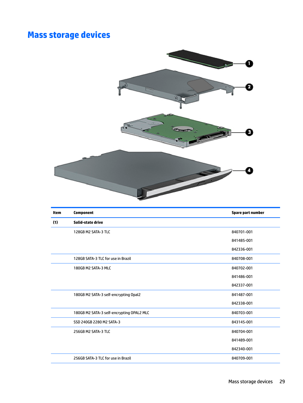
Mass storage devices

######## Item Component Spare part number
841485-001
128GB SATA-3 TLC for use in Brazil 840708-001 180GB M2 SATA-3 MLC 840702-001
841486-001
180GB M2 SATA-3 self-encrypting Opal2 841487-001
180GB M2 SATA-3 self-encrypting OPAL2 MLC 840703-001 SSD 240GB 2280 M2 SATA-3 843145-001 256GB M2 SATA-3 TLC 840704-001
841489-001 842340-001
256GB SATA-3 TLC for use in Brazil 840709-001
Mass storage devices 29
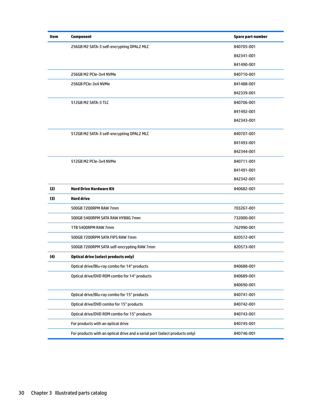
256GB M2 SATA-3 self-encrypting OPAL2 MLC 840705-001 842341-001 841490-001
256GB M2 PCIe-3x4 NVMe 840710-001 256GB PCIe-3x4 NVMe 841488-001
842339-001 512GB M2 SATA-3 TLC 840706-001
841492-001
512GB M2 SATA-3 self-encrypting OPAL2 MLC 840707-001 841493-001
512GB M2 PCIe-3x4 NVMe 840711-001 841491-001 842342-001
Optical drive/Blu-ray combo for 15" products 840741-001 Optical drive/DVD combo for 15" products 840742-001
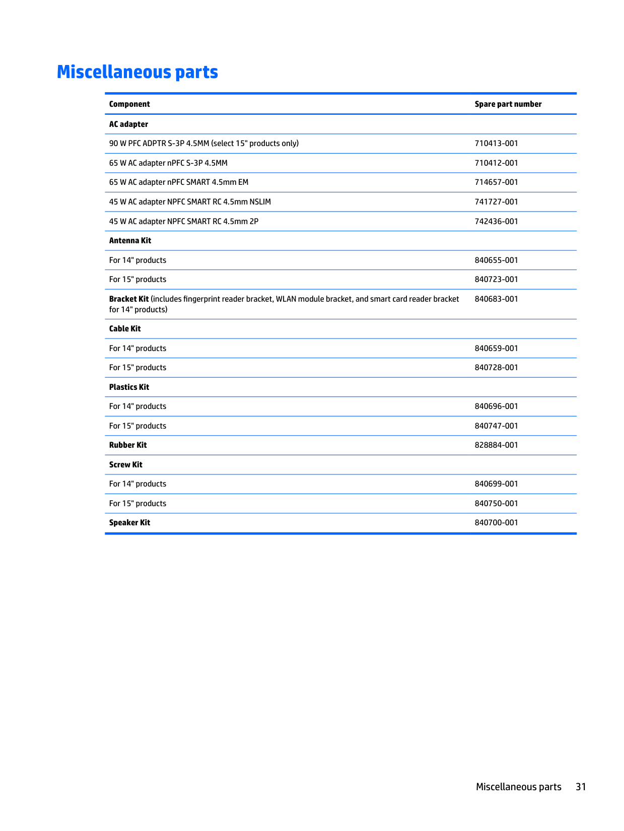
Miscellaneous parts
Component Spare part number AC adapter
90 W PFC ADPTR S-3P 4.5MM (select 15" products only) 710413-001 65 W AC adapter nPFC S-3P 4.5MM 710412-001 65 W AC adapter nPFC SMART 4.5mm EM 714657-001 45 W AC adapter NPFC SMART RC 4.5mm NSLIM 741727-001 45 W AC adapter NPFC SMART RC 4.5mm 2P 742436-001 Antenna Kit
For 14" products 840655-001 For 15" products 840723-001 Bracket Kit (includes fingerprint reader bracket, WLAN module bracket, and smart card reader bracket
840683-001
for 14" products)
######## Cable Kit
Miscellaneous parts 31
4 Removal and replacement procedures preliminary requirements
Tools required
You will need the following tools to complete the removal and replacement procedures:
Service considerations
The following sections include some of the considerations that you must keep in mind during disassembly and assembly procedures.
| | |---|
NOTE: As you remove each subassembly from the computer, place the subassembly (and all accompanying screws) away from the work area to prevent damage.
#### Plastic parts
CAUTION: Using excessive force during disassembly and reassembly can damage plastic parts. Use care when handling the plastic
#### Cables and connectors
CAUTION: When servicing the computer, be sure that cables are placed in their proper locations during the reassembly process. Improper cable placement can damage the computer.
Cables must be handled with extreme care to avoid damage. Apply only the tension required to unseat or seat the cables during removal and insertion. Handle cables by the connector whenever possible. In all cases, avoid bending, twisting, or tearing cables. Be sure that cables are routed in such a way that they cannot be caught or snagged by parts being removed or replaced. Handle flex cables with extreme care; these cables tear easily.
Drive handling CAUTION: Drives are fragile components that must be handled with care. To prevent damage to the computer, damage to a drive, or loss of information, observe these precautions: Before removing or inserting a hard drive, shut down the computer. If you are unsure whether the computer is off or in Hibernation, turn the computer on, and then shut it down through the operating system. Before handling a drive, be sure that you are discharged of static electricity. While handling a drive, avoid touching the connector. Before removing a diskette drive or optical drive, be sure that a diskette or disc is not in the drive and be sure that the optical drive tray is closed. Handle drives on surfaces covered with at least one inch of shock-proof foam. Avoid dropping drives from any height onto any surface. Avoid exposing an internal hard drive to products that have magnetic fields, such as monitors or speakers. Avoid exposing an internal hard drive to products that have magnetic fields, such as monitors or speakers. Avoid exposing a drive to temperature extremes or liquids. If a drive must be mailed, place the drive in a bubble pack mailer or other suitable form of protective packaging and label the package “FRAGILE."
Service considerations 33
Grounding guidelines
#### Electrostatic discharge damage
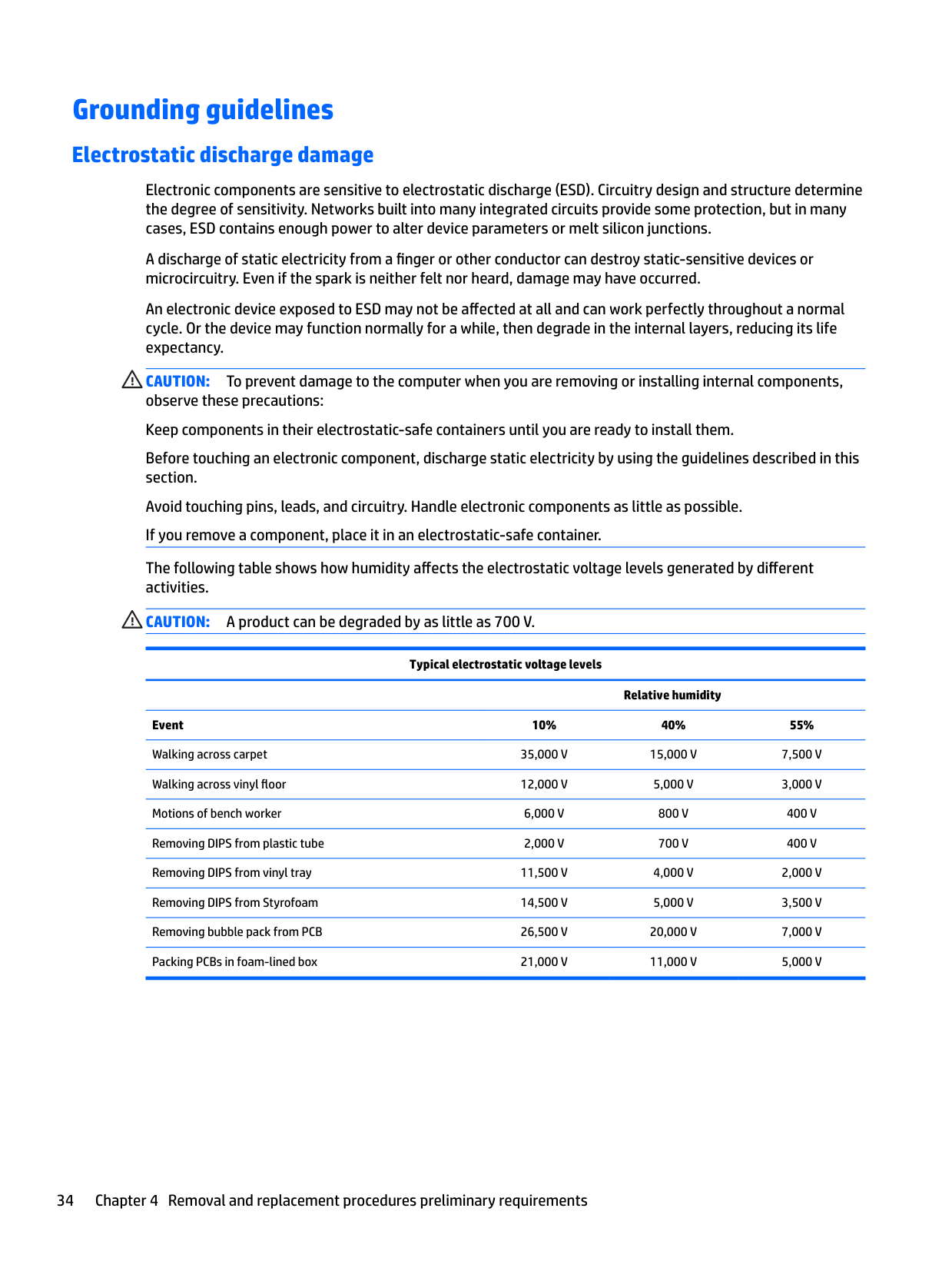
Electronic components are sensitive to electrostatic discharge (ESD). Circuitry design and structure determine the degree of sensitivity. Networks built into many integrated circuits provide some protection, but in many cases, ESD contains enough power to alter device parameters or melt silicon junctions.
A discharge of static electricity from a finger or other conductor can destroy static-sensitive devices or microcircuitry. Even if the spark is neither felt nor heard, damage may have occurred.
An electronic device exposed to ESD may not be affected at all and can work perfectly throughout a normal cycle. Or the device may function normally for a while, then degrade in the internal layers, reducing its life expectancy.
CAUTION: To prevent damage to the computer when you are removing or installing internal components, observe these precautions: Keep components in their electrostatic-safe containers until you are ready to install them. Before touching an electronic component, discharge static electricity by using the guidelines described in this section. Avoid touching pins, leads, and circuitry. Handle electronic components as little as possible. If you remove a component, place it in an electrostatic-safe container. The following table shows how humidity affects the electrostatic voltage levels generated by different activities. CAUTION: A product can be degraded by as little as 700 V.
Typical electrostatic voltage levels
Relative humidity Event 10% 40% 55% Walking across carpet 35,000 V 15,000 V 7,500 V Walking across vinyl floor 12,000 V 5,000 V 3,000 V Motions of bench worker 6,000 V 800 V 400 V Removing DIPS from plastic tube 2,000 V 700 V 400 V Removing DIPS from vinyl tray 11,500 V 4,000 V 2,000 V Removing DIPS from Styrofoam 14,500 V 5,000 V 3,500 V Removing bubble pack from PCB 26,500 V 20,000 V 7,000 V Packing PCBs in foam-lined box 21,000 V 11,000 V 5,000 V
##### Packaging and transporting guidelines
Follow these grounding guidelines when packaging and transporting equipment:
##### Workstation guidelines
Follow these grounding workstation guidelines:
Grounding guidelines 35
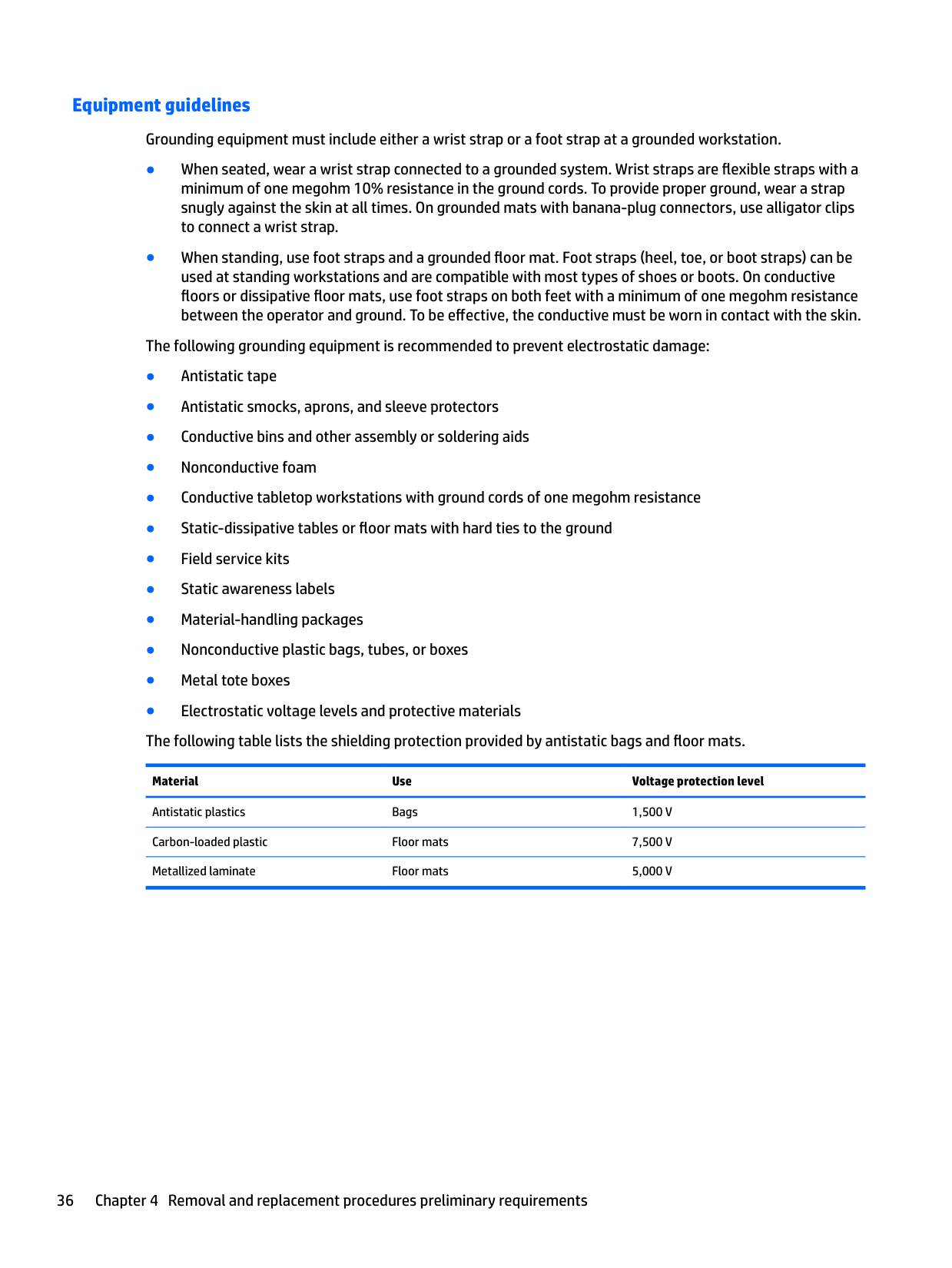
##### Equipment guidelines
Grounding equipment must include either a wrist strap or a foot strap at a grounded workstation.
Material Use Voltage protection level
Antistatic plastics Bags 1,500 V Carbon-loaded plastic Floor mats 7,500 V Metallized laminate Floor mats 5,000 V
5 Removal and replacement procedures forCustomer Self-Repair parts
| | |---|
This chapter provides removal and replacement procedures for Customer Self-Repair parts. NOTE: The Customer Self-Repair program is not available in all locations. Installing a part not supported by the Customer Self-Repair program may void your warranty. Check your warranty to determine if Customer Self-Repair is supported in your location.
Component replacement procedures
| | |---|
NOTE: Details about your computer, including model, serial number, product key, and length of warranty, are on the service tag at the bottom of your computer. See Locating system information on page 19 for details.
| | |---|
NOTE: HP continually improves and changes product parts. For complete and current information on supported parts for your computer, go to http://partsurfer.hp.com, select your country or region, and then follow the on-screen instructions.
There are as many as xx screws that must be removed, replaced, and/or loosened when servicing Customer Self-Repair parts. Make special note of each screw size and location during removal and replacement.
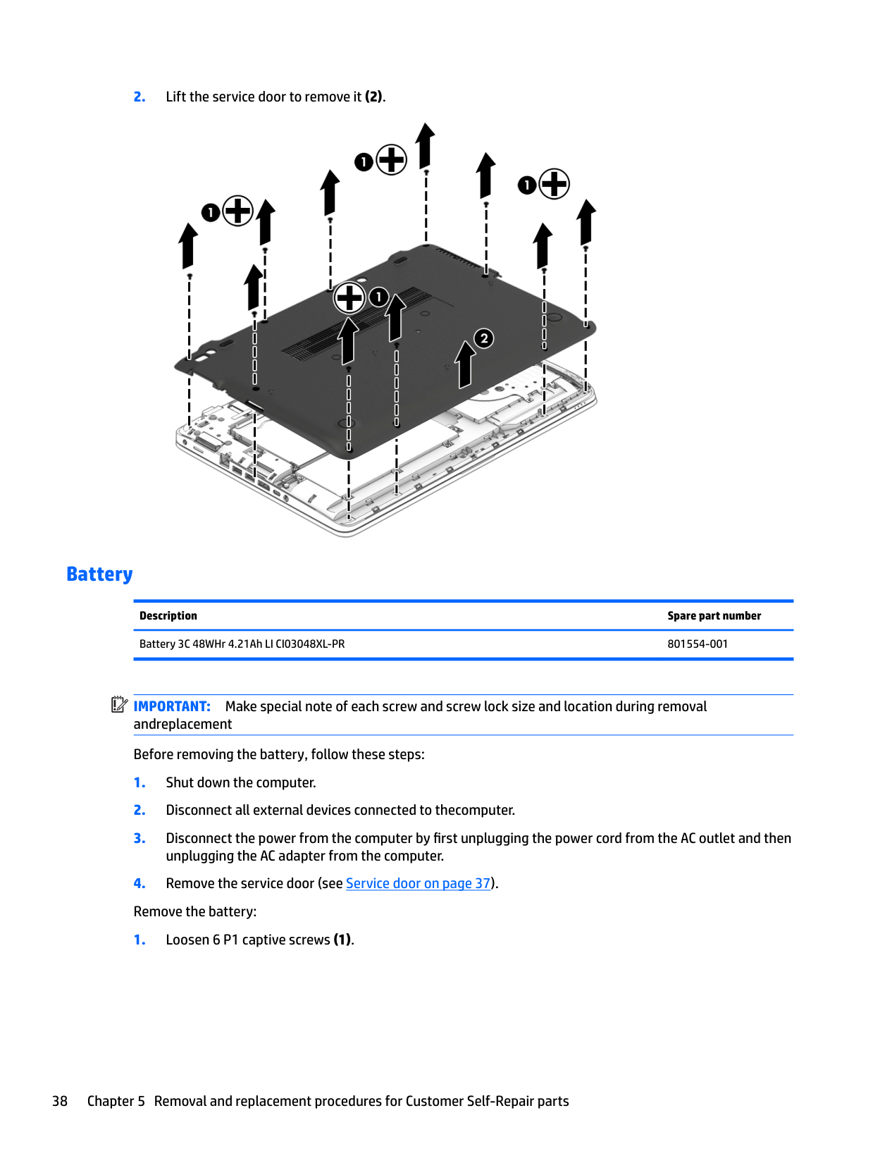
#### Service door
Description Spare part number Service door

#### Battery
Description Spare part number Battery 3C 48WHr 4.21Ah LI CI03048XL-PR 801554-001
| | |---|
IMPORTANT: Make special note of each screw and screw lock size and location during removal andreplacement Before removing the battery, follow these steps:

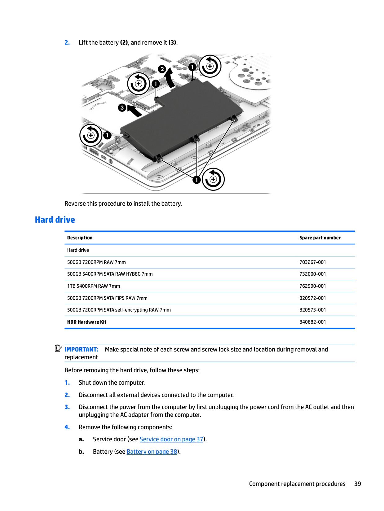
Reverse this procedure to install the battery.
#### Hard drive
Description Spare part number Hard drive 500GB 7200RPM RAW 7mm 703267-001 500GB 5400RPM SATA RAW HYB8G 7mm 732000-001 1TB 5400RPM RAW 7mm 762990-001 500GB 7200RPM SATA FIPS RAW 7mm 820572-001 500GB 7200RPM SATA self-encrypting RAW 7mm 820573-001 HDD Hardware Kit 840682-001
| | |---|
IMPORTANT: Make special note of each screw and screw lock size and location during removal and replacement Before removing the hard drive, follow these steps:
Remove the hard drive:

(2) to remove the cover from the hard drive.

Reverse this procedure to reassemble and install the hard drive.
#### Solid-state drive (select products only)
Description Spare part number Solid-state drive
128GB M2 SATA-3 TLC 840701-001 841485-001 842336-001
128GB SATA-3 TLC for use in Brazil 840708-001 180GB M2 SATA-3 MLC 840702-001
841486-001 842337-001
180GB M2 SATA-3 self-encrypting Opal2 841487-001
842338-001 180GB M2 SATA-3 self-encrypting OPAL2 MLC 840703-001 SSD 240GB 2280 M2 SATA-3 843145-001 256GB M2 SATA-3 TLC 840704-001
841489-001
256GB SATA-3 TLC for use in Brazil 840709-001 256GB M2 SATA-3 self-encrypting OPAL2 MLC 840705-001
256GB M2 PCIe-3x4 NVMe 840710-001 256GB PCIe-3x4 NVMe 841488-001
842339-001 512GB M2 SATA-3 TLC 840706-001
841492-001
512GB M2 SATA-3 self-encrypting OPAL2 MLC 840707-001 841493-001
512GB M2 PCIe-3x4 NVMe 840711-001 841491-001 842342-001
| | |---|
IMPORTANT: Make special note of each screw and screw lock size and location during removal and replacement Before removing the solid-state drive, follow these steps:
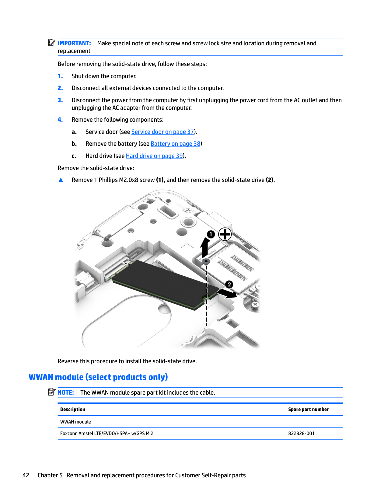
Remove the solid-state drive:
▲ Remove 1 Phillips M2.0x8 screw (1), and then remove the solid-state drive (2).

Reverse this procedure to install the solid-state drive.
#### WWAN module (select products only)
| | |---|
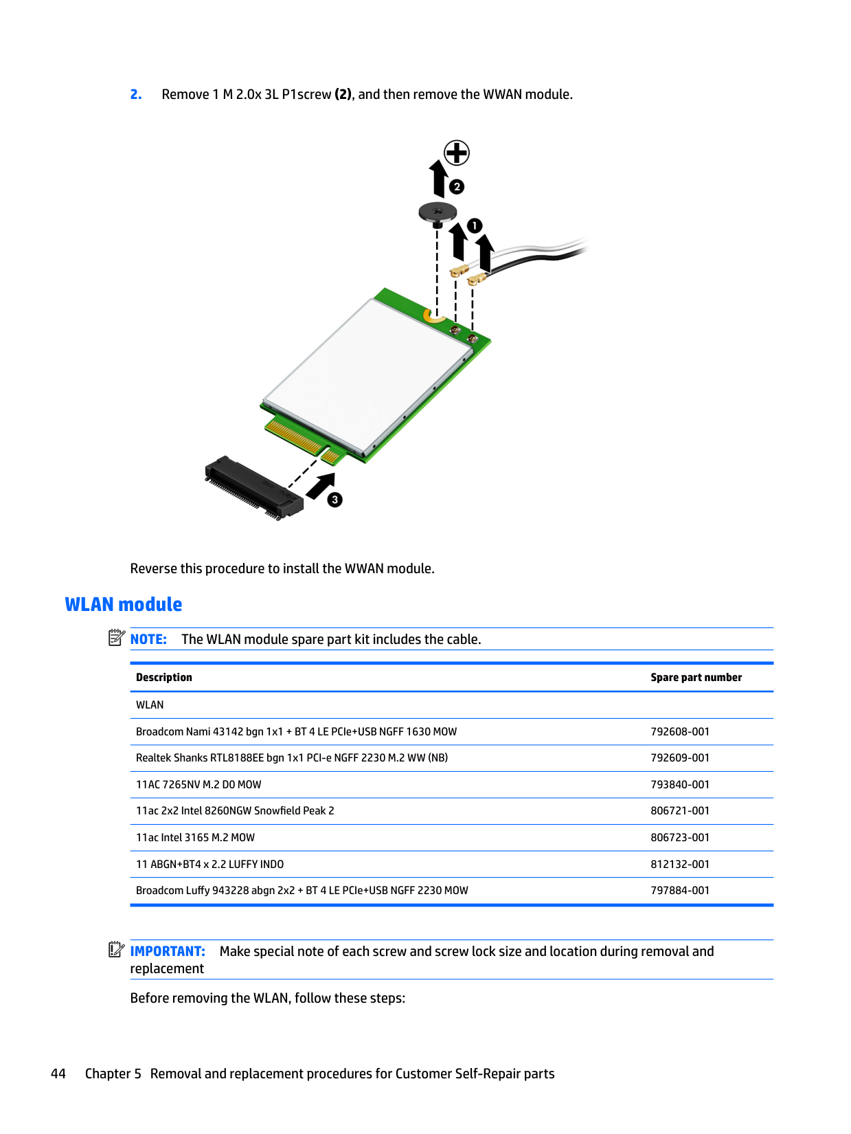
NOTE: The WWAN module spare part kit includes the cable.
Description Spare part number WWAN module Foxconn Amstel LTE/EVDO/HSPA+ w/GPS M.2 822828-001
######## Description Spare part number
T77W595 LTE M.2 w/GPS 800870-001 Huawei Wrangler MU736 HSPA+ w/GPS M.2 793516-001
| | |---|
IMPORTANT: Make special note of each screw and screw lock size and location during removal and replacement Before removing the WWAN module, follow these steps:
Remove the WWAN module:

Reverse this procedure to install the WWAN module.
#### WLAN module
| | |---|
NOTE: The WLAN module spare part kit includes the cable.
Description Spare part number WLAN Broadcom Nami 43142 bgn 1x1 + BT 4 LE PCIe+USB NGFF 1630 MOW 792608-001 Realtek Shanks RTL8188EE bgn 1x1 PCI-e NGFF 2230 M.2 WW (NB) 792609-001 11AC 7265NV M.2 D0 MOW 793840-001 11ac 2x2 Intel 8260NGW Snowfield Peak 2 806721-001 11ac Intel 3165 M.2 MOW 806723-001 11 ABGN+BT4 x 2.2 LUFFY INDO 812132-001 Broadcom Luffy 943228 abgn 2x2 + BT 4 LE PCIe+USB NGFF 2230 MOW 797884-001
| | |---|
IMPORTANT: Make special note of each screw and screw lock size and location during removal and replacement Before removing the WLAN, follow these steps:
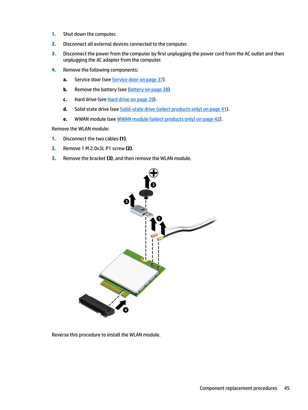
Remove the WLAN module:

Reverse this procedure to install the WLAN module.
#### Optical drive
Description Spare part number Optical drive Optical drive/Blu-ray combo for 14” products 840688-001
| | |---|
IMPORTANT: Make special note of each screw and screw lock size and location during removal and replacement Before removing the optical drive, follow these steps:
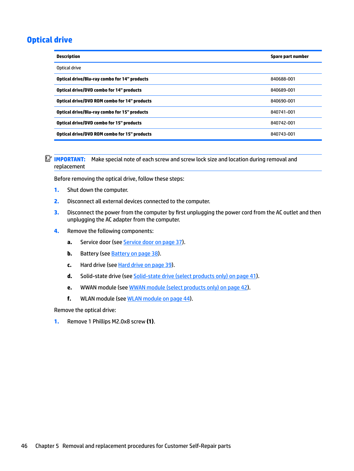
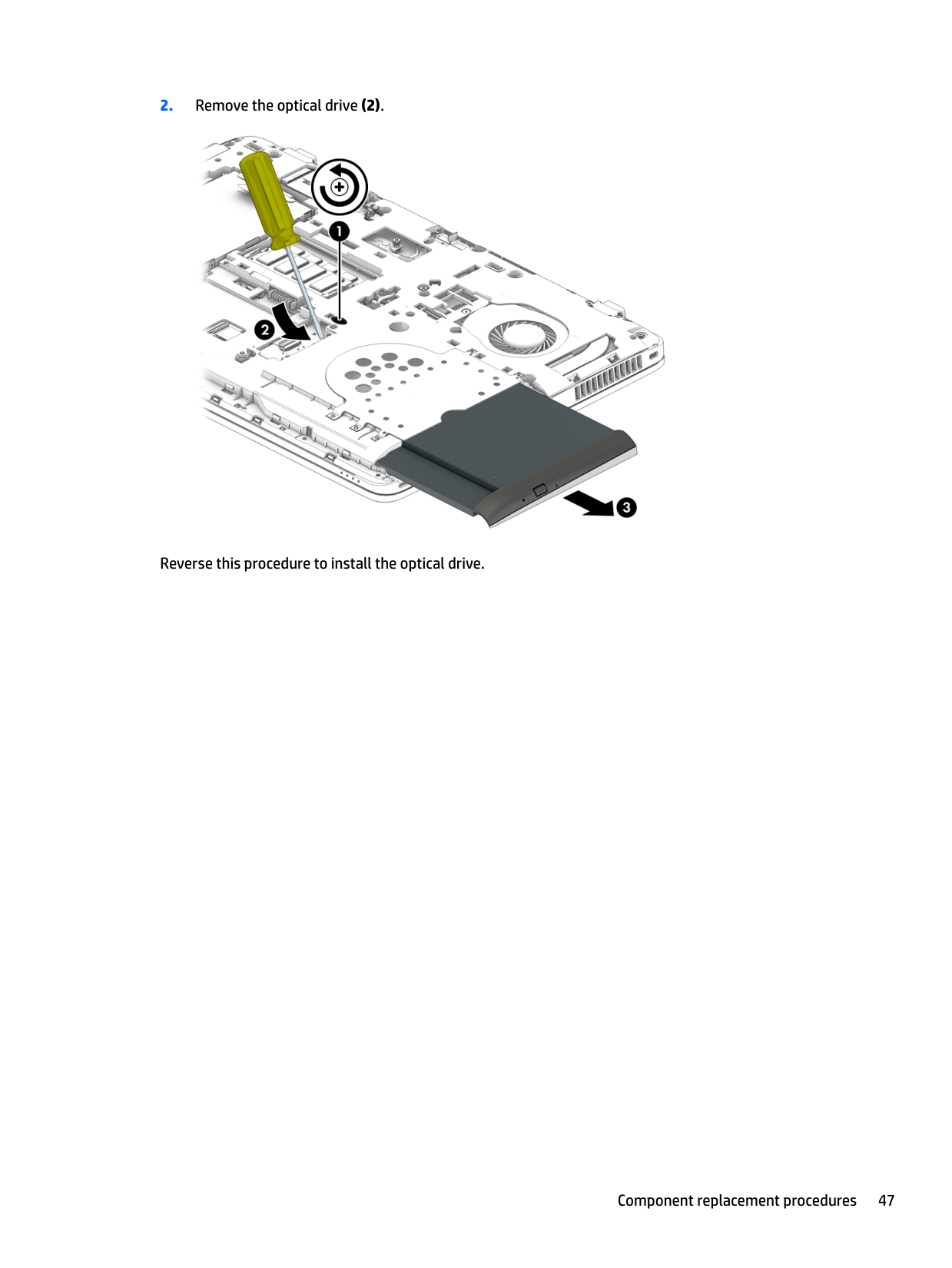
Remove the optical drive:

Reverse this procedure to install the optical drive.
#### Keyboard
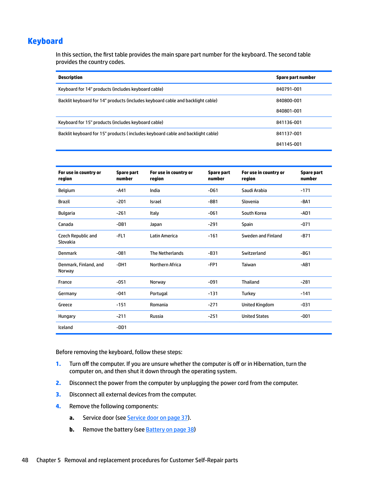
In this section, the first table provides the main spare part number for the keyboard. The second table provides the country codes.
Description Spare part number
Keyboard for 14" products (includes keyboard cable) 840791-001 Backlit keyboard for 14" products (includes keyboard cable and backlight cable) 840800-001
840801-001 Keyboard for 15" products (includes keyboard cable) 841136-001 Backlit keyboard for 15" products ( includes keyboard cable and backlight cable) 841137-001
841145-001
For use in country or region
Spare part number
For use in country or region
Spare part number
For use in country or region
Spare part number
Belgium -A41 India -D61 Saudi Arabia -171 Brazil -201 Israel -BB1 Slovenia -BA1 Bulgaria -261 Italy -061 South Korea -AD1 Canada -DB1 Japan -291 Spain -071 Czech Republic and Slovakia
-FL1 Latin America -161 Sweden and Finland -B71
Denmark -081 The Netherlands -B31 Switzerland -BG1 Denmark, Finland, and Norway
-DH1 Northern Africa -FP1 Taiwan -AB1
France -051 Norway -091 Thailand -281 Germany -041 Portugal -131 Turkey -141 Greece -151 Romania -271 United Kingdom -031 Hungary -211 Russia -251 United States -001 Iceland -DD1
Before removing the keyboard, follow these steps:
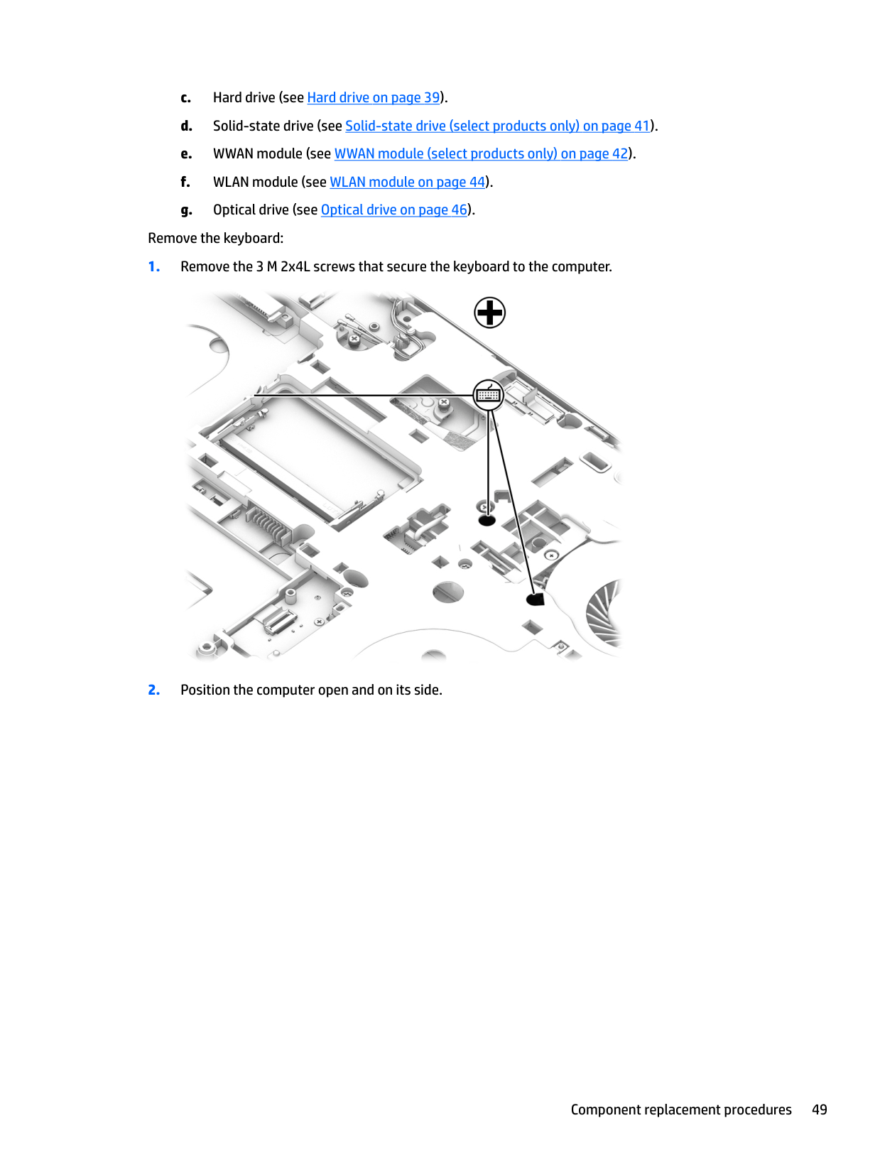
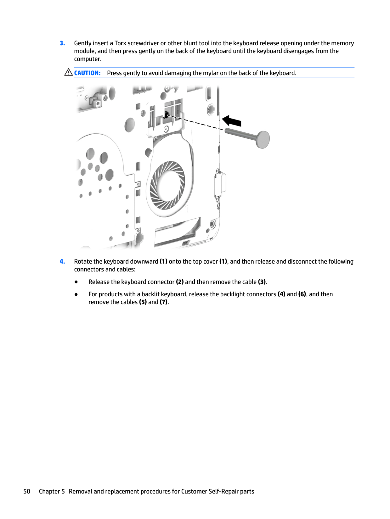
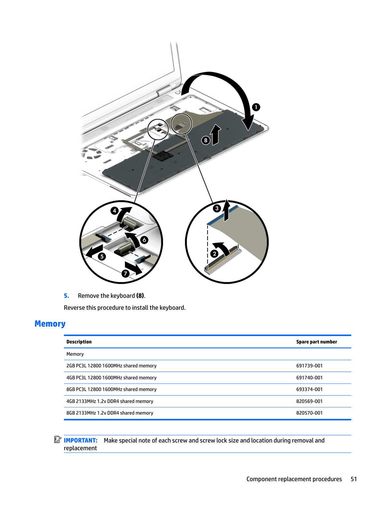
Remove the keyboard:


#### Memory
Description Spare part number Memory 2GB PC3L 12800 1600MHz shared memory 691739-001 4GB PC3L 12800 1600MHz shared memory 691740-001 8GB PC3L 12800 1600MHz shared memory 693374-001 4GB 2133MHz 1.2v DDR4 shared memory 820569-001 8GB 2133MHz 1.2v DDR4 shared memory 820570-001
| | |---|
IMPORTANT: Make special note of each screw and screw lock size and location during removal and replacement
Before removing the memory module, follow these steps:
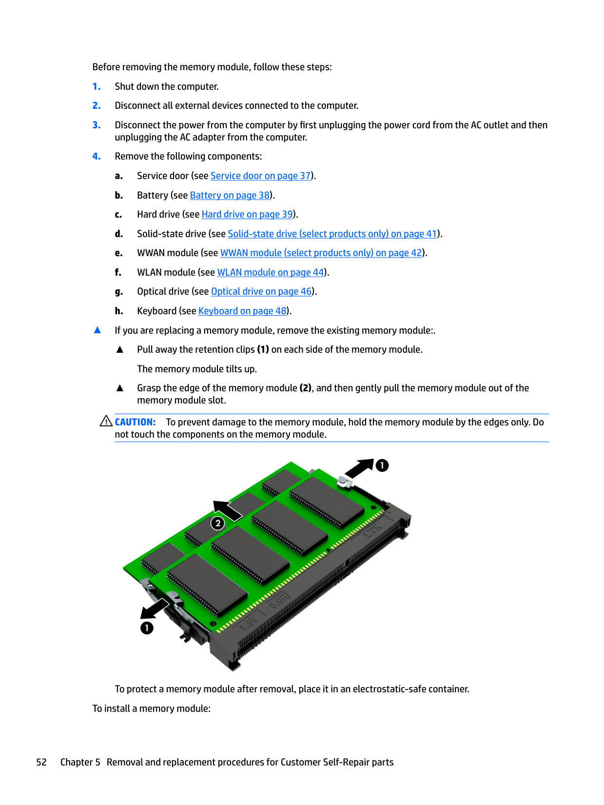
▲ If you are replacing a memory module, remove the existing memory module:.
▲ Pull away the retention clips (1) on each side of the memory module.
The memory module tilts up.
▲ Grasp the edge of the memory module (2), and then gently pull the memory module out of the
memory module slot.
CAUTION: To prevent damage to the memory module, hold the memory module by the edges only. Do not touch the components on the memory module.

To protect a memory module after removal, place it in an electrostatic-safe container. To install a memory module:
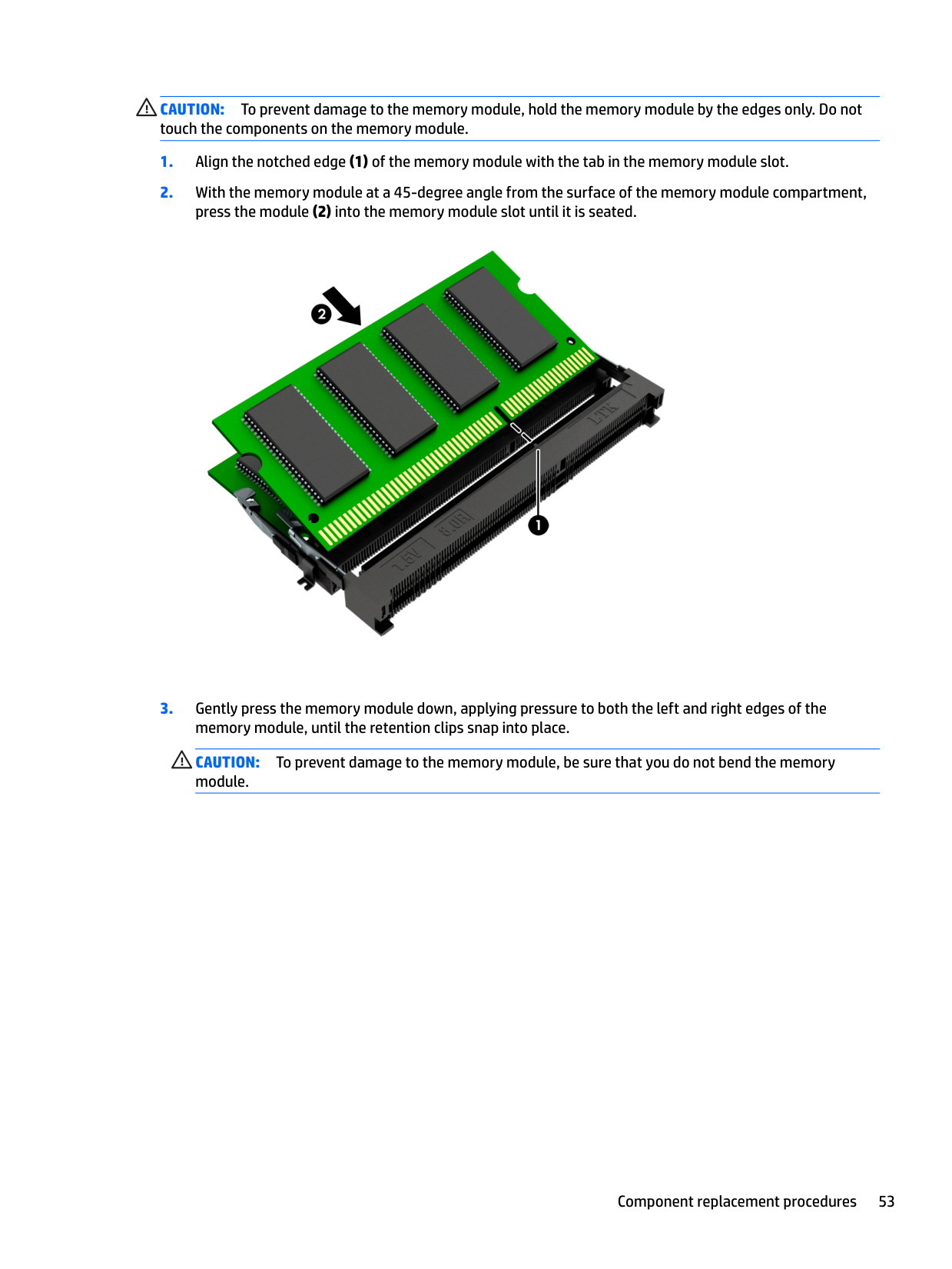
CAUTION: To prevent damage to the memory module, hold the memory module by the edges only. Do not touch the components on the memory module.

CAUTION: To prevent damage to the memory module, be sure that you do not bend the memory module.
6 Removal and replacement procedures forAuthorized Service Provider parts
This chapter provides removal and replacement procedures for Authorized Service Provider only parts. CAUTION: Components described in this chapter should only be accessed by an authorized service provider. Accessing these parts can damage the computer or void the warranty. CAUTION: This computer does not have user-replaceable parts. Only HP authorized service providers should perform the removal and replacement procedures described here. Accessing the internal part could damage the computer or void the warranty.
Component replacement procedures
| | |---|
NOTE: Details about your computer, including model, serial number, product key, and length of warranty, are on the service tag at the bottom of your computer. See Locating system information on page 19 for details.
| | |---|
NOTE: HP continually improves and changes product parts. For complete and current information on supported parts for your computer, go to http://partsurfer.hp.com, select your country or region, and then follow the on-screen instructions.
There are as many as xx screws that must be removed, replaced, and/or loosened when servicing Authorized Service Provider only parts. Make special note of each screw size and location during removal and replacement.
#### Hinge cover
######## Description Spare part number
Hinge Kit for 14" products 840684-001 Hinge Kit for 15" products 840737-001 Hinge Kit for 14" products with a touch screen 845830-001 Hinge Kit for 15" products with a touch screen 845835-001 Hinge cover for 14" products 840685-001 Hinge cover for 15" products 840738-001 Hinge cover for 14" products with a touch screen 840686-001 Hinge cover for 15" products with a touch screen 845835-001
| | |---|
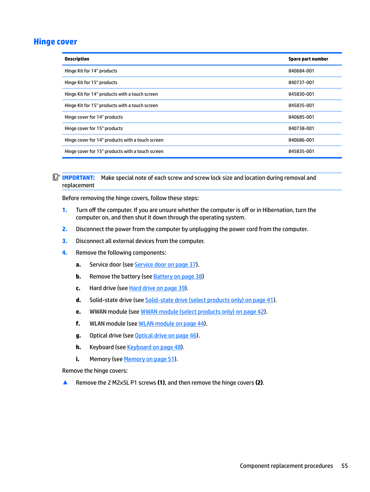
IMPORTANT: Make special note of each screw and screw lock size and location during removal and replacement Before removing the hinge covers, follow these steps:
Remove the hinge covers:
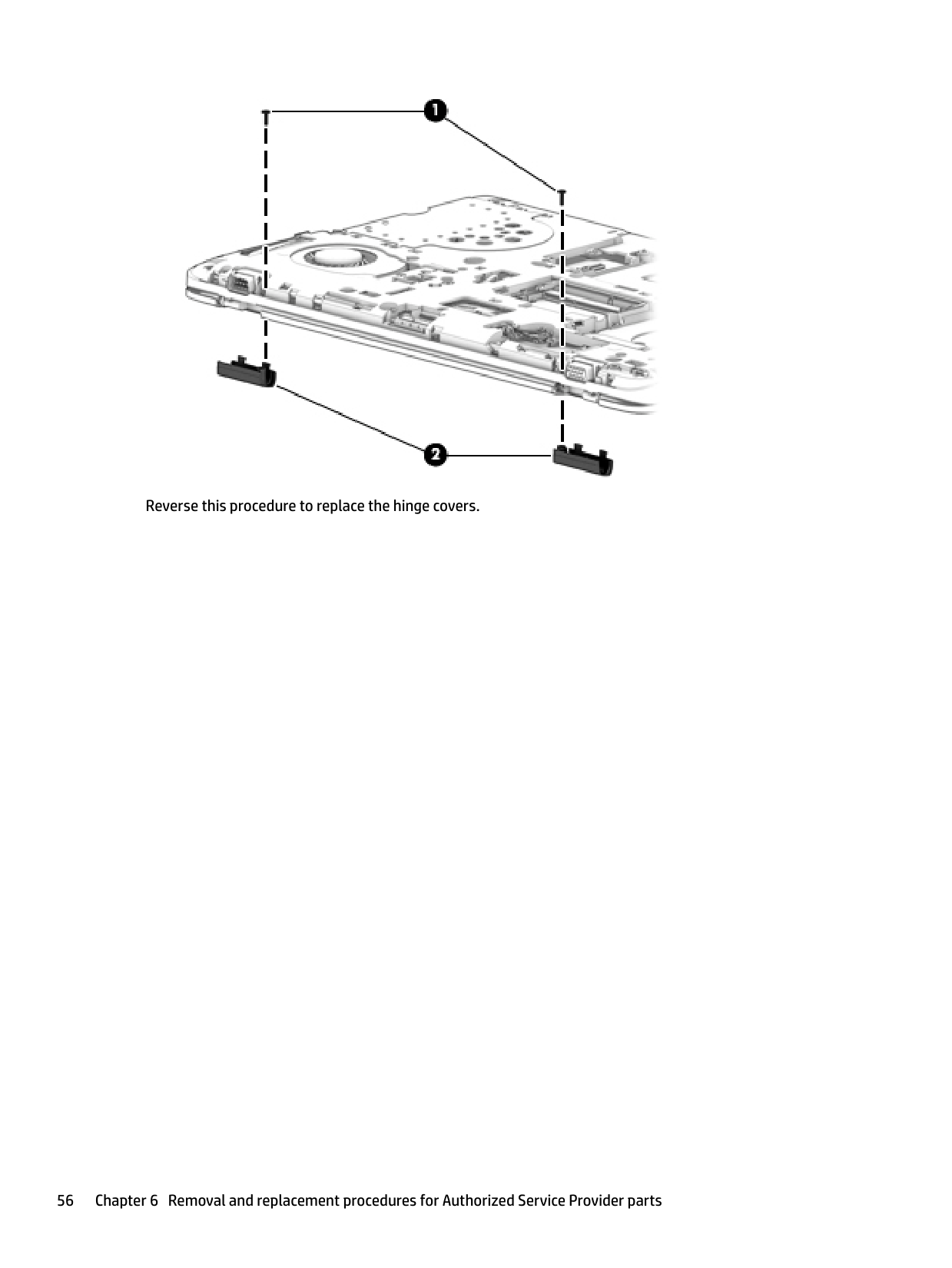
▲ Remove the 2 M2x5L P1 screws (1), and then remove the hinge covers (2).

####### Reverse this procedure to replace the hinge covers.
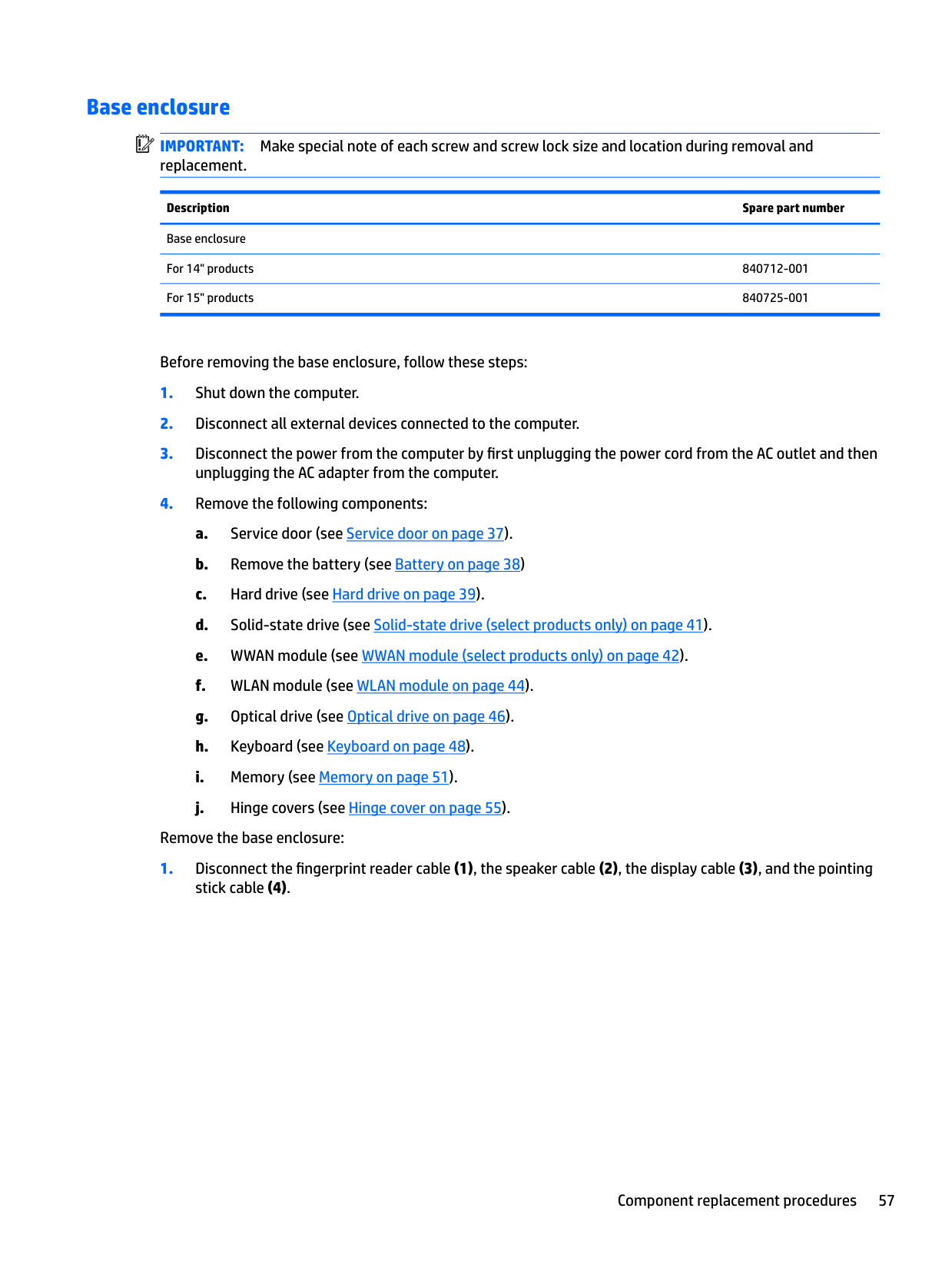
#### Base enclosure
| | |---|
IMPORTANT: Make special note of each screw and screw lock size and location during removal and replacement.
Description Spare part number Base enclosure For 14" products 840712-001 For 15" products 840725-001
Before removing the base enclosure, follow these steps:
unplugging the AC adapter from the computer.
Remove the base enclosure:


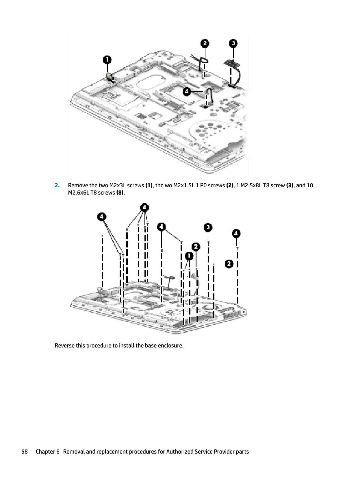
Reverse this procedure to install the base enclosure.
#### System board
Description Spare part number System board Discrete memory, Intel i5-6300U processor, and WWAN capability 840712-001 Discrete memory, Intel i5-6300U processor, WWAN capability, and Windows 840712-601 Discrete memory, Intel i7-6300U processor, and WWAN capability 840713-001 Discrete memory, Intel i7-6300U processor, WWAN capability, and Windows 840713-601 UMA memory, AMD A10-8700B processor, and WWAN capability 841494-001
UMA memory, AMD A6-8500B processor 841495-001
UMA memory, AMD A6-8500B processor, and Windows 841495-601
842346-601 UMA memory, AMD A8-8600B processor, and Windows 841497-001
842348-001
UMA memory, AMD A8-8600B processor, and Windows 841497-601 842348-601
UMA memory, AMD A8-8600B processor, and WWAN capability 841496-001
842347-001 UMA memory, AMD A8-8600B processor, and WWAN capability 841496-001
842347-001 UMA memory, Intel i3-6100U processor 840714-001 UMA memory, Intel i3-6100U processor and Windows 840714-601 UMA memory, Intel i5-6200U processor 840715-001 UMA memory, Intel i5-6200U processor and Windows 840715-601 UMA memory, Intel i5-6200U processor, and WWAN capability 840716-001 UMA memory, Intel i5-6200U processor, WWAN capability, and Windows 840716-601 UMA memory, Intel i5-6300U processor, and WWAN capability 840717-001 UMA memory, Intel i5-6300U processor, and WWAN capability, and Windows 840717-601 UMA memory, Intel i5-6440HQ processor, and WWAN capability 844345-001 UMA memory, Intel i5-6440HQ processor, and WWAN capability, and Windows 844345-601 UMA memory, Intel i7-6600U processor, and WWAN capability 840718-001 UMA memory, Intel i7-6600U processor, and WWAN capability, and Windows 840718-601 UMA memory, Intel i7-6820HQ processor, and WWAN capability 844346-001 UMA memory, Intel i7-6820HQ processor, and WWAN capability, and Windows 844346-601
| | |---|
IMPORTANT: Make special note of each screw and screw lock size and location during removal and replacement Before removing the system board, follow these steps:
unplugging the AC adapter from the computer.
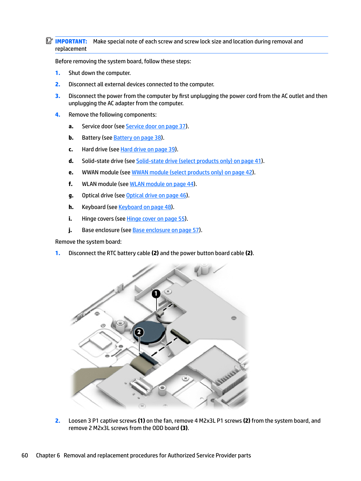
Remove the system board:


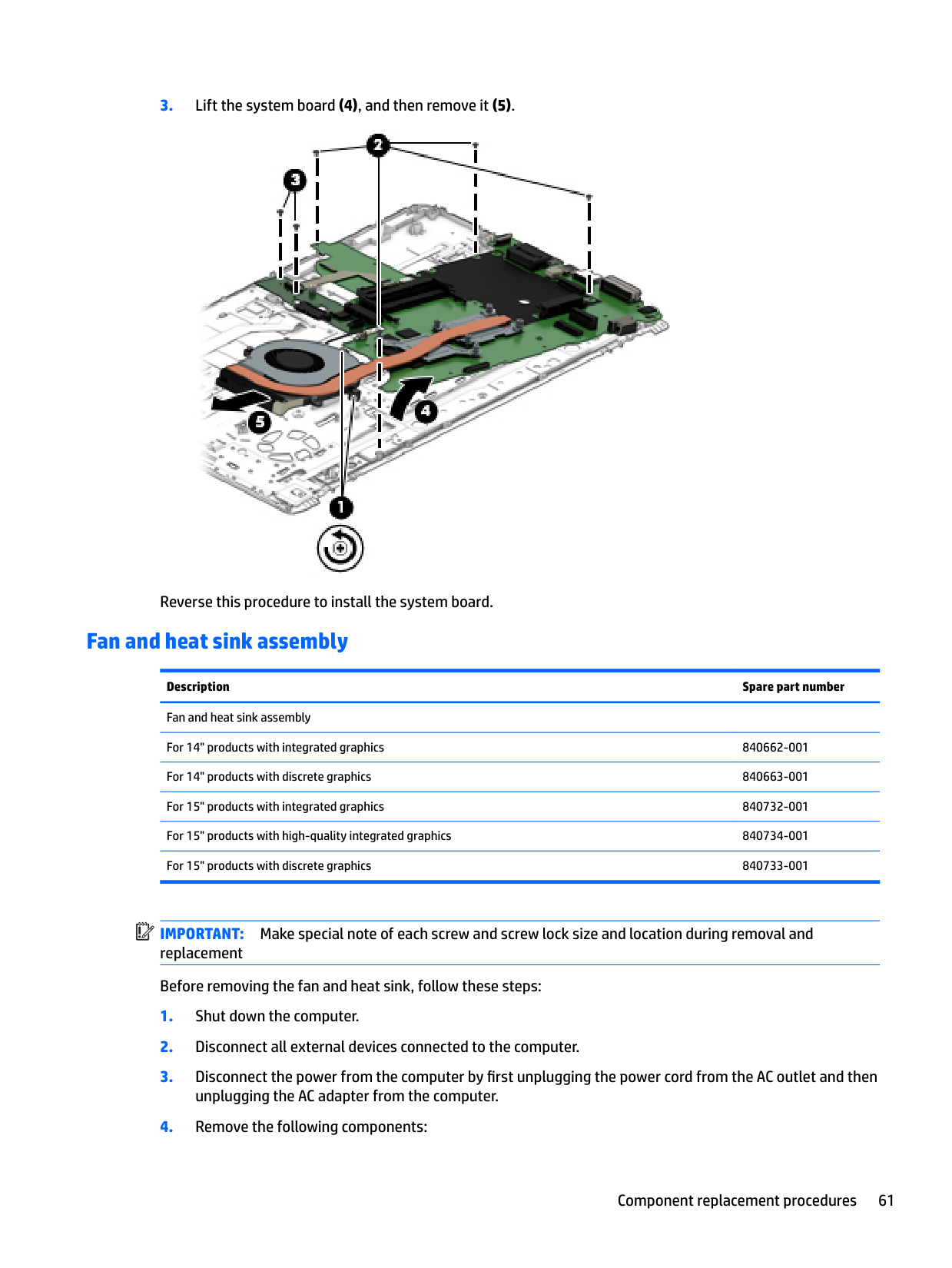
Reverse this procedure to install the system board.
#### Fan and heat sink assembly
Description Spare part number Fan and heat sink assembly For 14" products with integrated graphics 840662-001
| | |---|
IMPORTANT: Make special note of each screw and screw lock size and location during removal and replacement Before removing the fan and heat sink, follow these steps:
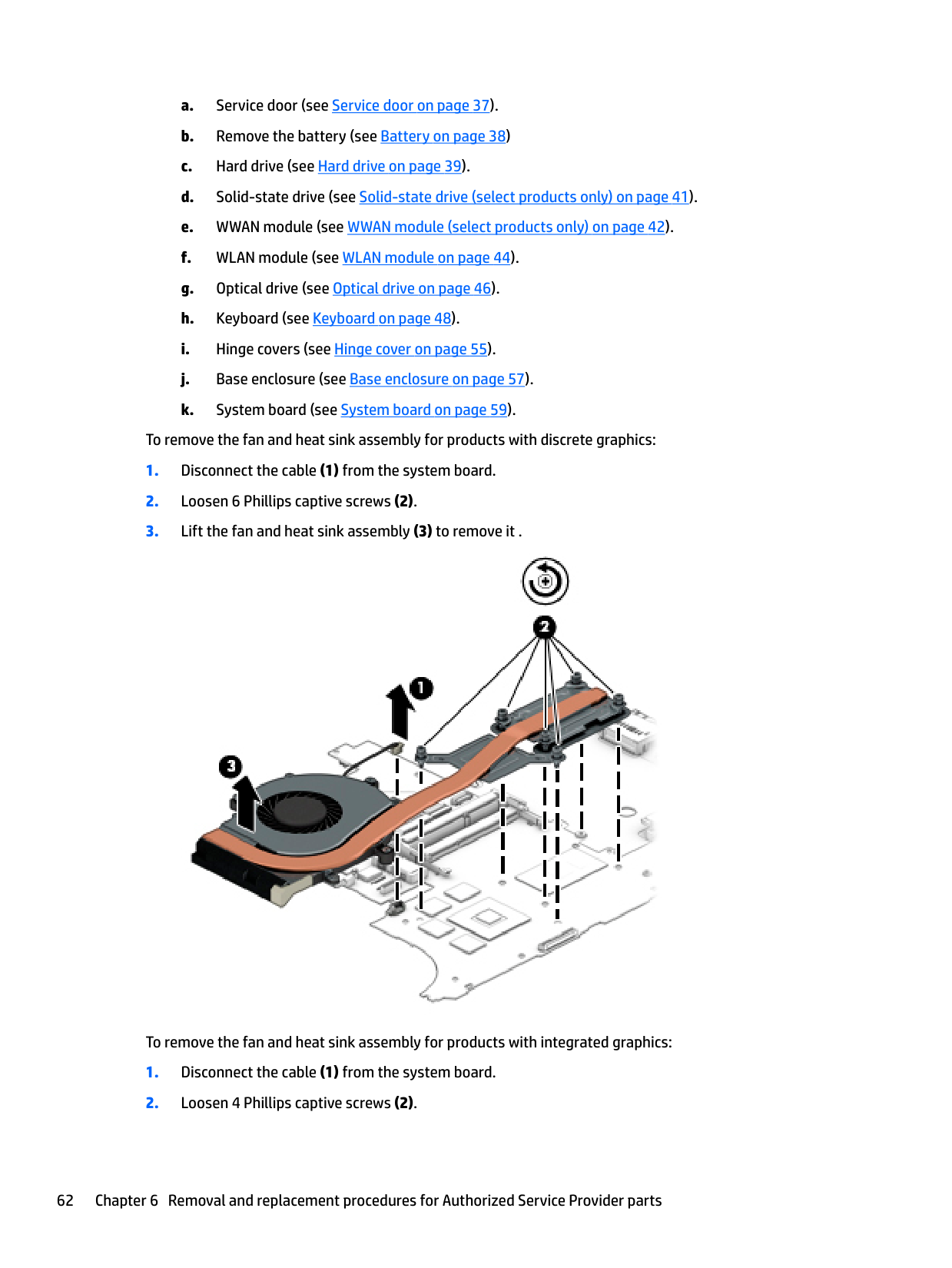
To remove the fan and heat sink assembly for products with discrete graphics:

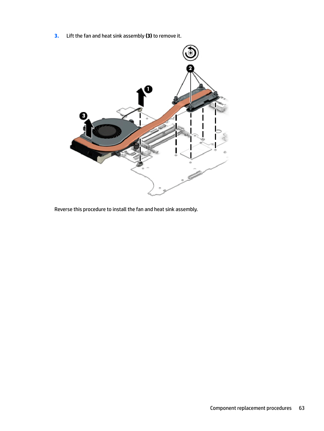
To remove the fan and heat sink assembly for products with integrated graphics:

Reverse this procedure to install the fan and heat sink assembly.
#### Optical drive board
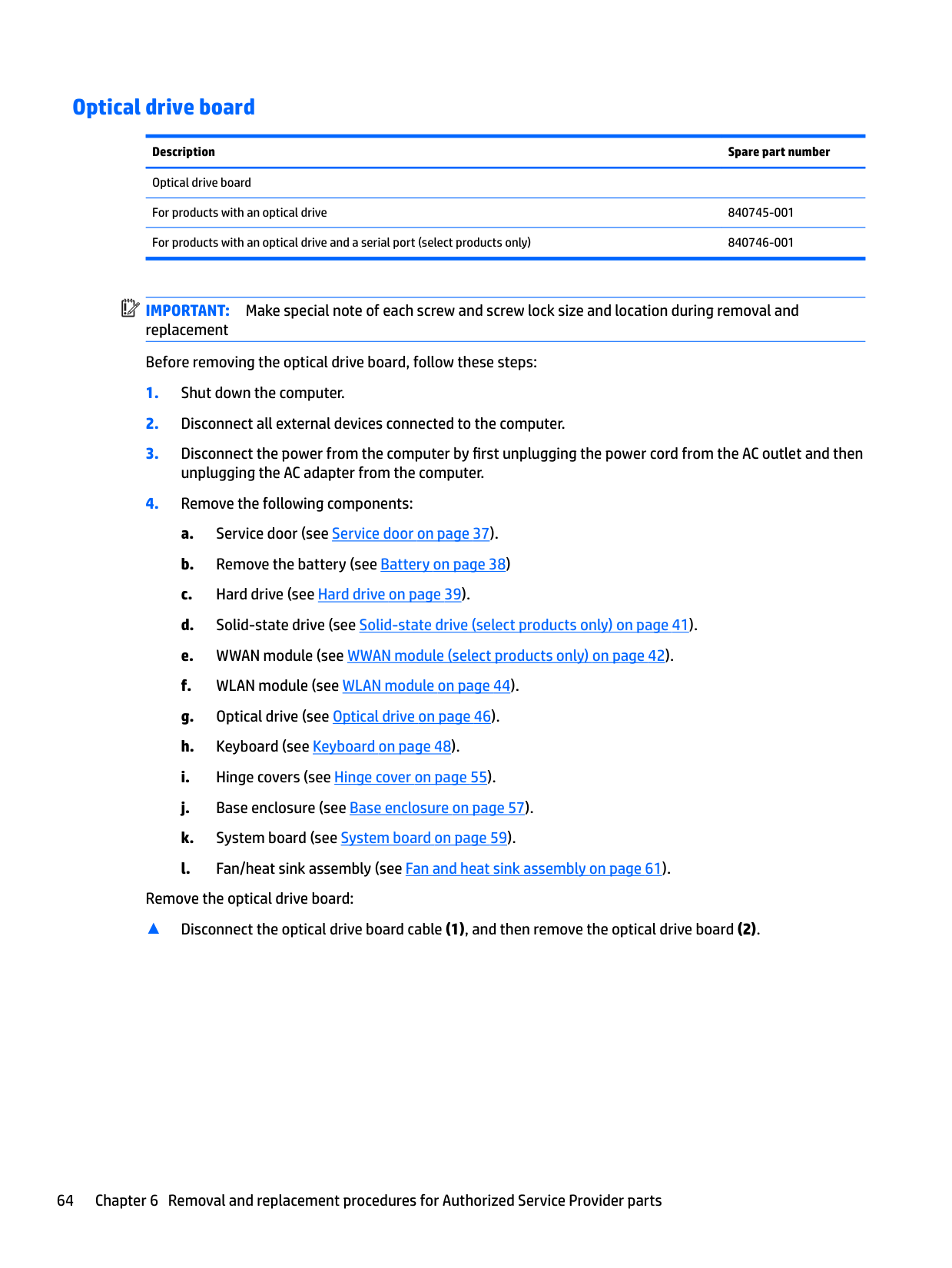
Description Spare part number Optical drive board For products with an optical drive 840745-001 For products with an optical drive and a serial port (select products only) 840746-001
| | |---|
IMPORTANT: Make special note of each screw and screw lock size and location during removal and replacement Before removing the optical drive board, follow these steps:
unplugging the AC adapter from the computer.
Remove the optical drive board:
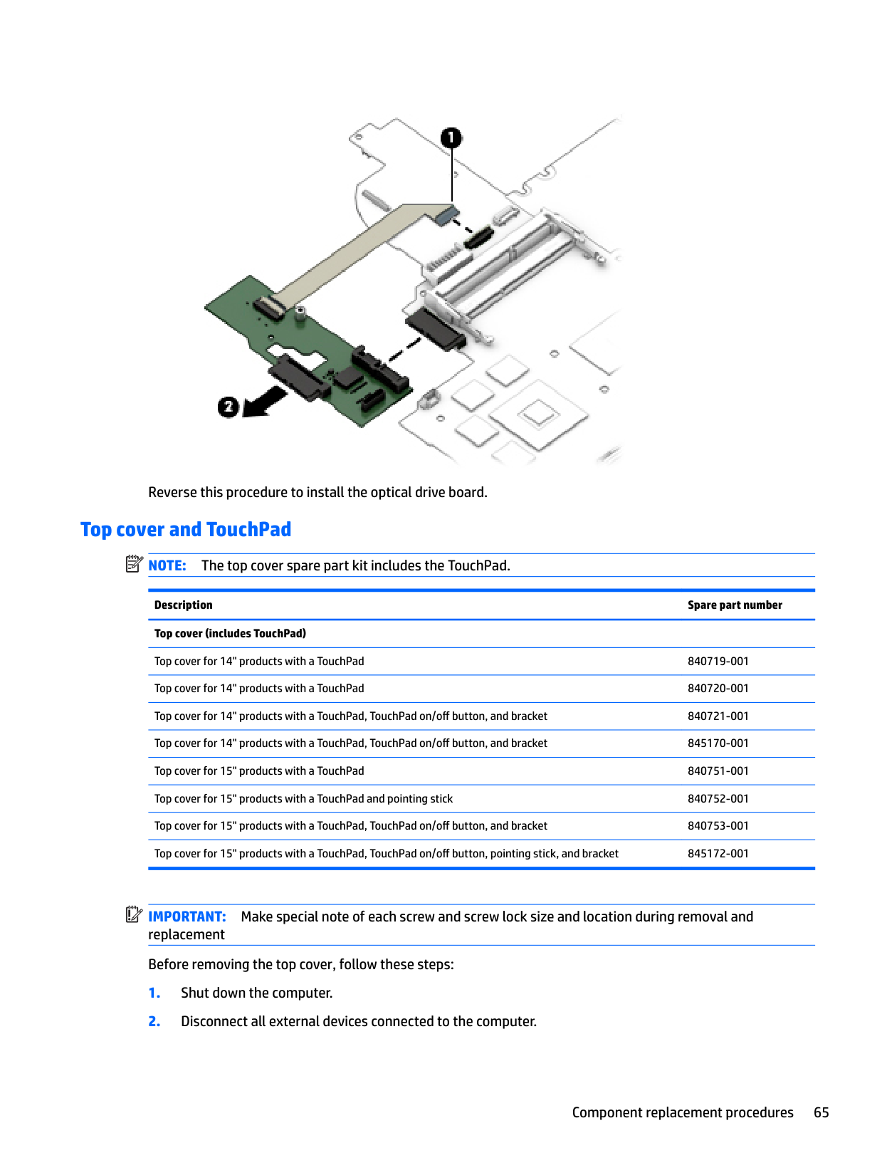
▲ Disconnect the optical drive board cable (1), and then remove the optical drive board (2).

Reverse this procedure to install the optical drive board.
#### Top cover and TouchPad
| | |---|
NOTE: The top cover spare part kit includes the TouchPad.
Description Spare part number Top cover (includes TouchPad)
Top cover for 14" products with a TouchPad 840719-001 Top cover for 14" products with a TouchPad 840720-001 Top cover for 14" products with a TouchPad, TouchPad on/off button, and bracket 840721-001 Top cover for 14" products with a TouchPad, TouchPad on/off button, and bracket 845170-001 Top cover for 15" products with a TouchPad 840751-001 Top cover for 15" products with a TouchPad and pointing stick 840752-001 Top cover for 15" products with a TouchPad, TouchPad on/off button, and bracket 840753-001 Top cover for 15" products with a TouchPad, TouchPad on/off button, pointing stick, and bracket 845172-001
| | |---|
IMPORTANT: Make special note of each screw and screw lock size and location during removal and replacement Before removing the top cover, follow these steps:
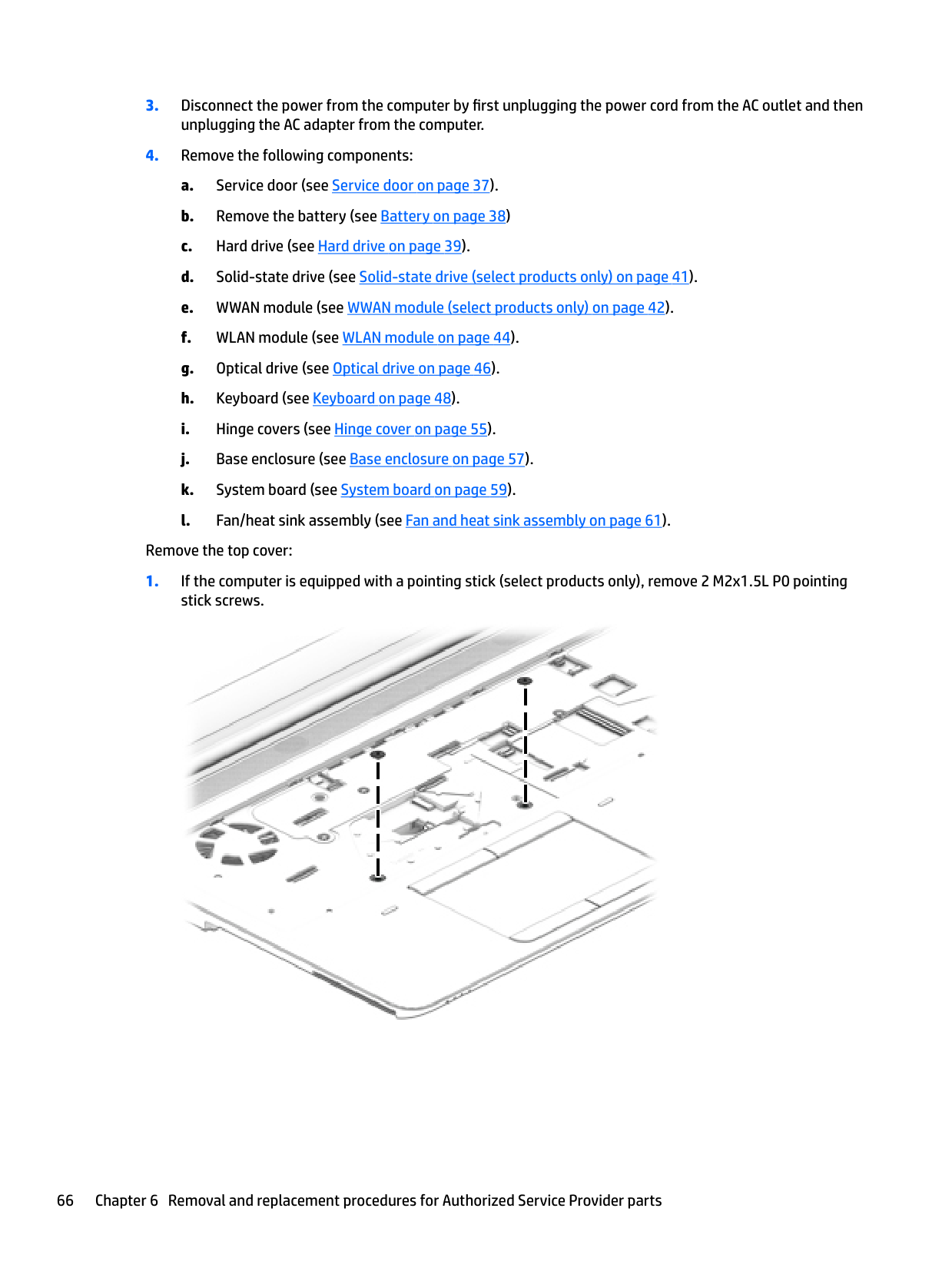
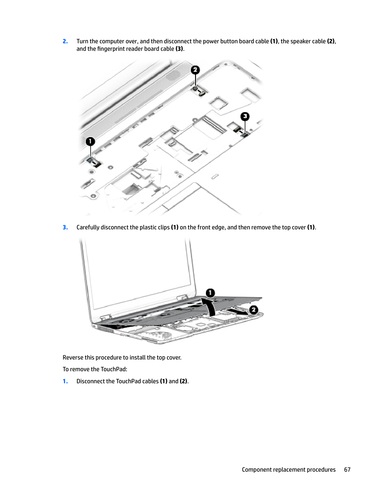
Remove the top cover:


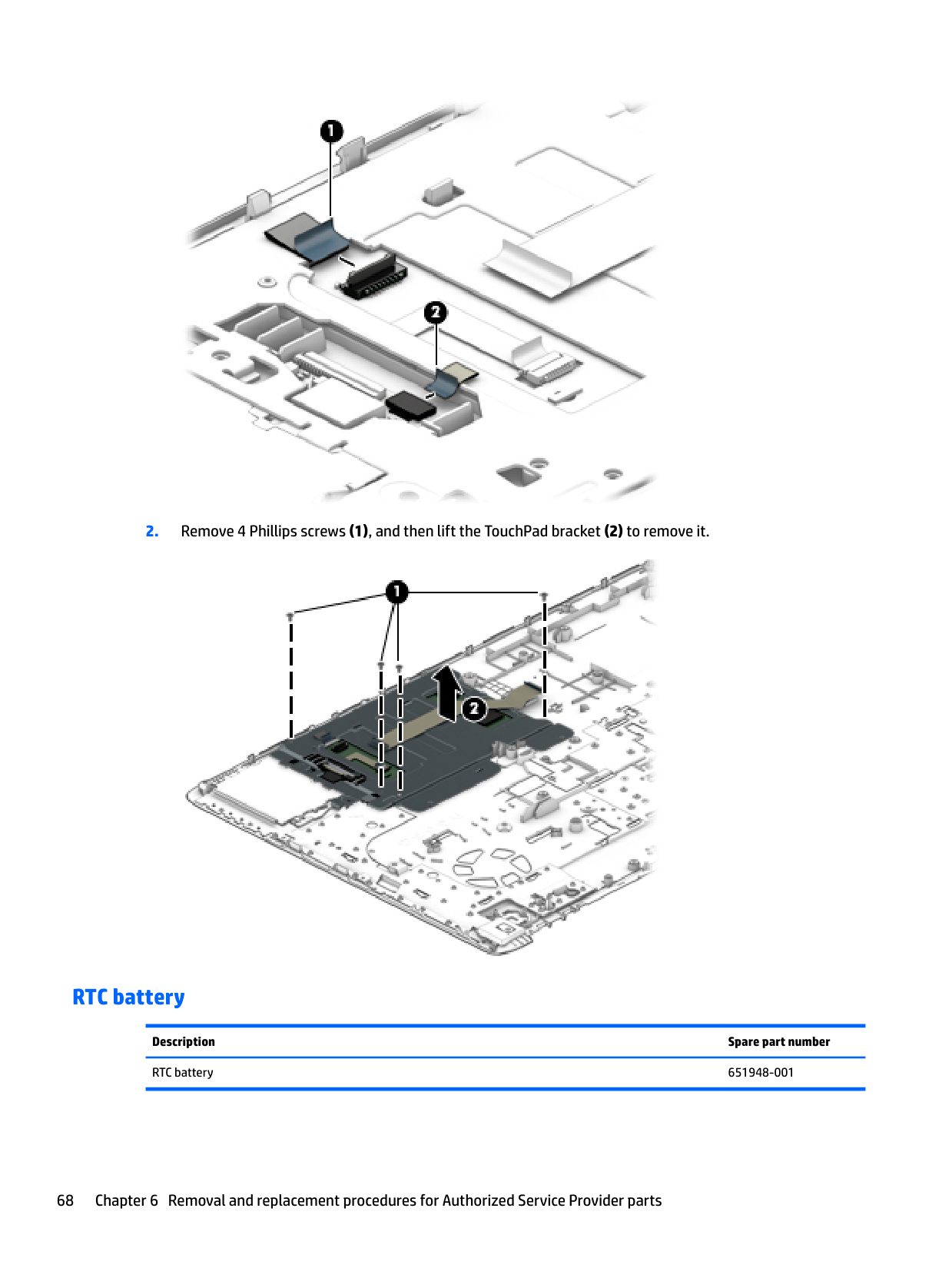
Reverse this procedure to install the top cover. To remove the TouchPad:


#### RTC battery
Description Spare part number RTC battery 651948-001
| | |---|
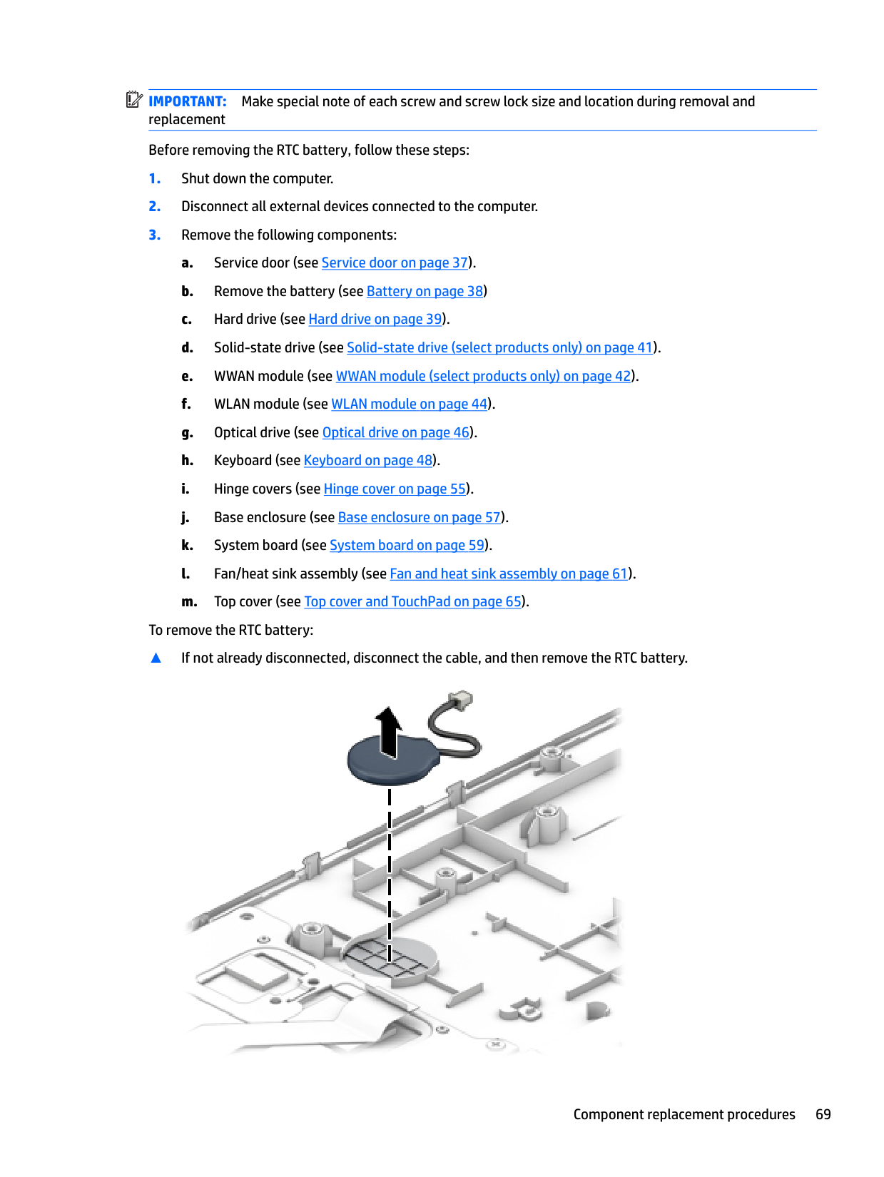
IMPORTANT: Make special note of each screw and screw lock size and location during removal and replacement Before removing the RTC battery, follow these steps:
To remove the RTC battery:
▲ If not already disconnected, disconnect the cable, and then remove the RTC battery.

Reverse this procedure to install the RTC battery.
#### Speaker
| | |---|
NOTE: The speaker spare part kit includes the speaker cable.
Description Spare part number Speaker Kit 840700-001
| | |---|
IMPORTANT: Make special note of each screw and screw lock size and location during removal and replacement Before removing the speaker, follow these steps:
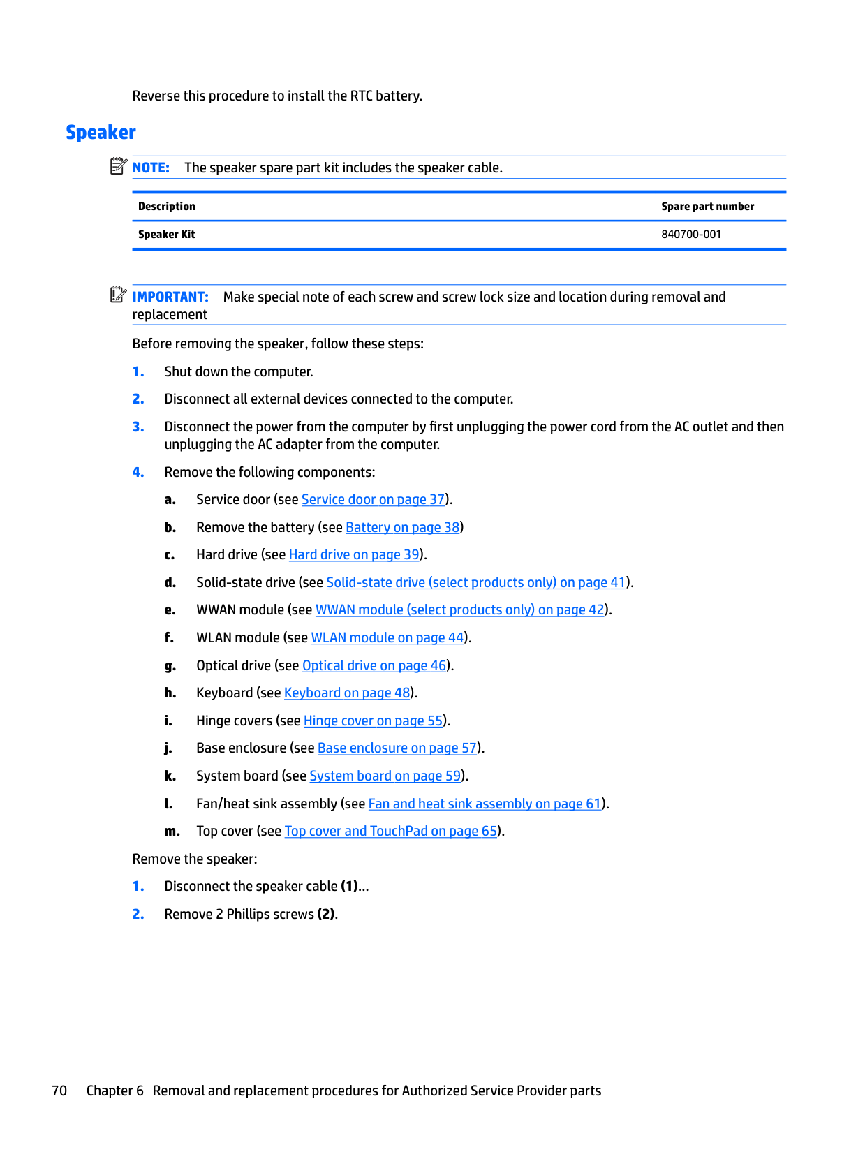
Remove the speaker:

Reverse this procedure to install the speaker.
#### Power button board
| | |---|
NOTE: The power button board spare part kit includes the cable.
Description Spare part number Power button board For 14" products 840694-001 For 15" products 840744-001
| | |---|
IMPORTANT: Make special note of each screw and screw lock size and location during removal and replacement. Before removing the power button board, follow these steps:
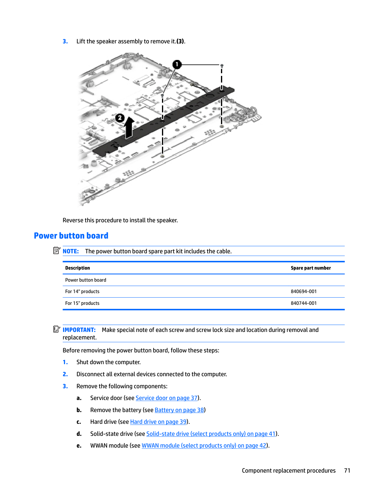
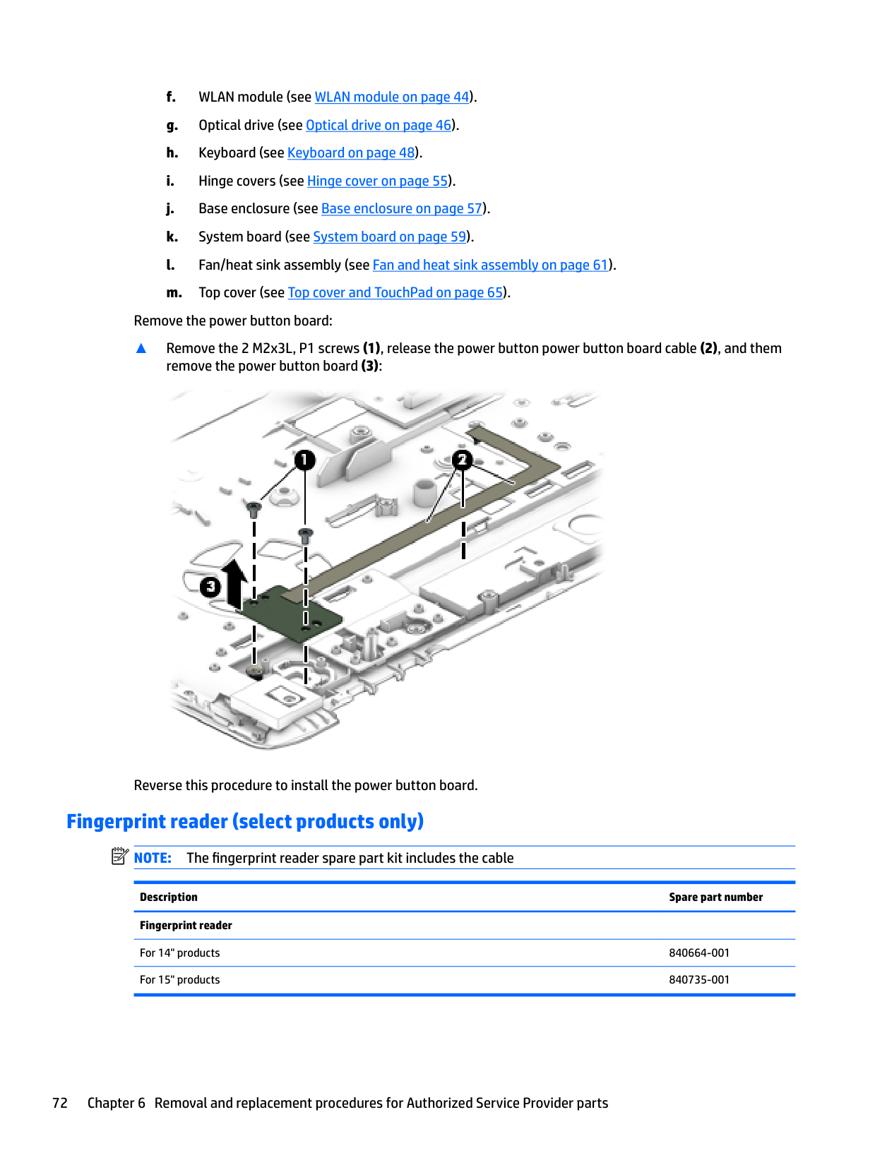
Remove the power button board:
▲ Remove the 2 M2x3L, P1 screws (1), release the power button power button board cable (2), and them
remove the power button board (3):

Reverse this procedure to install the power button board.
#### Fingerprint reader (select products only)
| |
|---|
NOTE: The fingerprint reader spare part kit includes the cable
Description Spare part number Fingerprint reader
| | |---|
IMPORTANT: Make special note of each screw and screw lock size and location during removal and replacement Before removing the fingerprint reader, follow these steps:
unplugging the AC adapter from the computer.
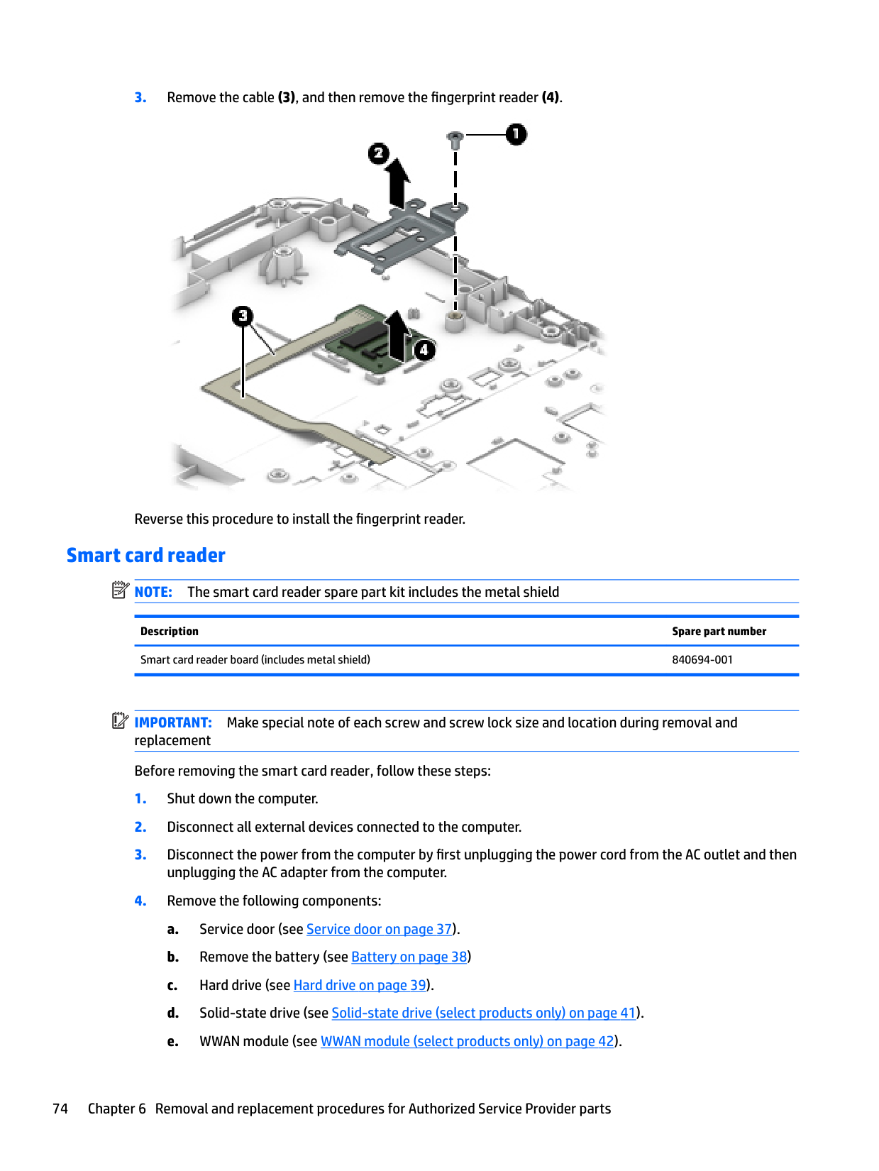
Remove the fingerprint reader:

Reverse this procedure to install the fingerprint reader.
#### Smart card reader
| | |---|
NOTE: The smart card reader spare part kit includes the metal shield
Description Spare part number Smart card reader board (includes metal shield) 840694-001
| | |---|
IMPORTANT: Make special note of each screw and screw lock size and location during removal and replacement Before removing the smart card reader, follow these steps:
unplugging the AC adapter from the computer.
f. WLAN module (see WLAN module on page 44). g. Optical drive (see Optical drive on page 46). h. Keyboard (see Keyboard on page 48). i. Hinge covers (see Hinge cover on page 55). j. Base enclosure (see Base enclosure on page 57). k. System board (see System board on page 59). l. Fan/heat sink assembly (see Fan and heat sink assembly on page 61). m. Top cover (see Top cover and TouchPad on page 65).
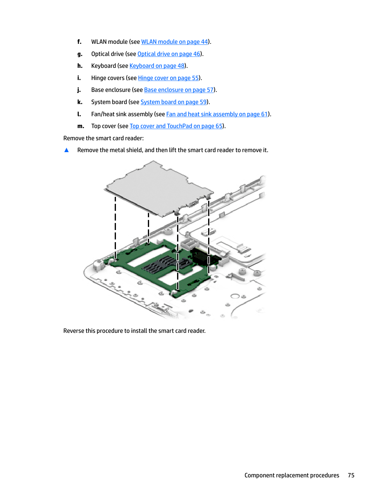
Remove the smart card reader:
▲ Remove the metal shield, and then lift the smart card reader to remove it.

Reverse this procedure to install the smart card reader.
#### Near Field Communication module
Description Spare part number Near Field Communication (NFC) module 840661-001 For 14" products 840661-001 For 15" products 840729-001 Near Field Communication (NFC) cable
For 14" products 840661-001 For 15" products 840729-001
| | |---|
IMPORTANT: Make special note of each screw and screw lock size and location during removal and replacement Before removing the NFC module, follow these steps:
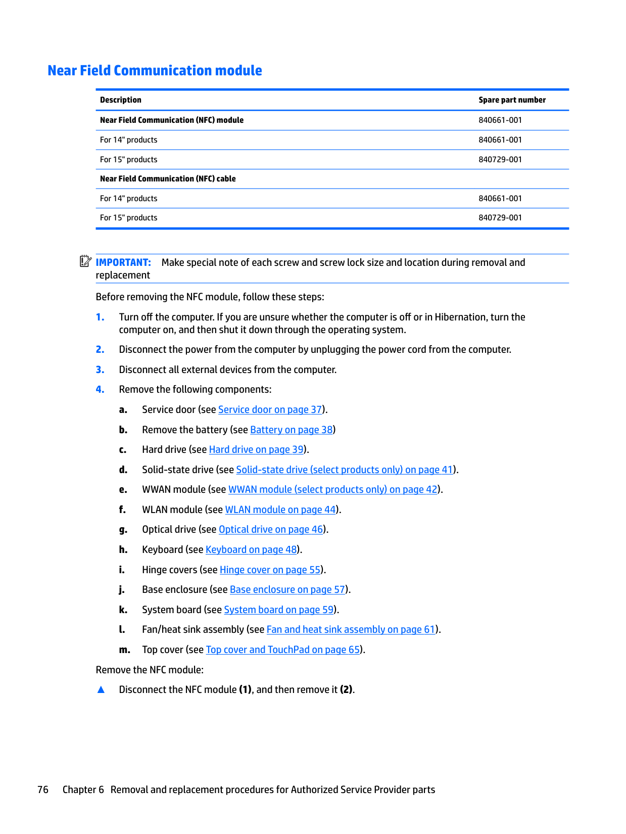
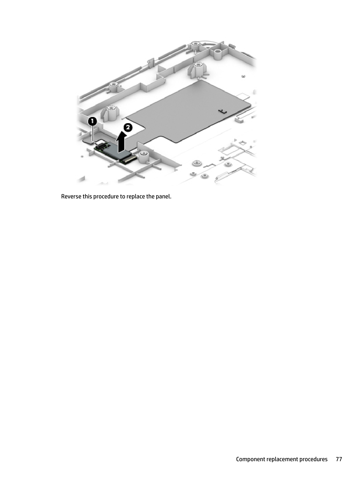
Remove the NFC module:
▲ Disconnect the NFC module (1), and then remove it (2).

####### Reverse this procedure to replace the panel.
#### Audio board
Description Spare part number Audio board 840692-001
| | |---|
IMPORTANT: Make special note of each screw and screw lock size and location during removal and replacement Before removing the audio board, follow these steps:
Remove the audio board:
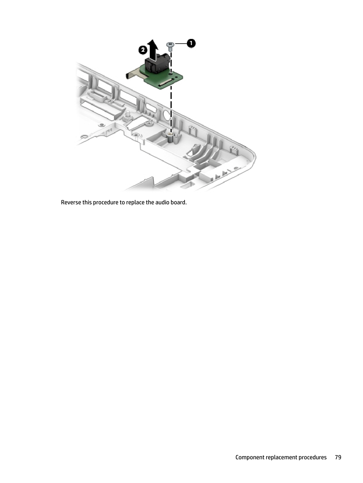
▲ Remove 2 M2x3L P1 screws (1), and then remove the audio board (2).

####### Reverse this procedure to replace the audio board.
#### Serial
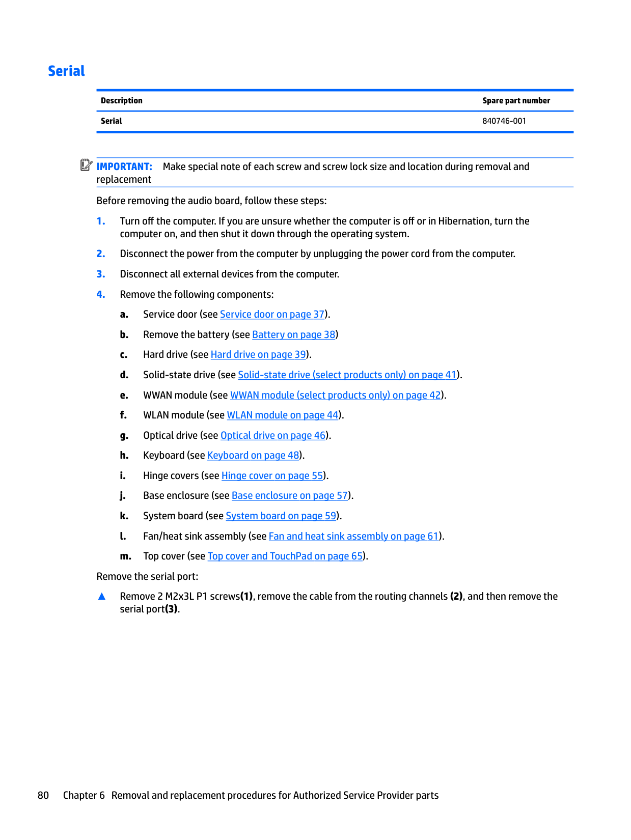
Description Spare part number Serial 840746-001
| | |---|
IMPORTANT: Make special note of each screw and screw lock size and location during removal and replacement Before removing the audio board, follow these steps:
computer on, and then shut it down through the operating system.
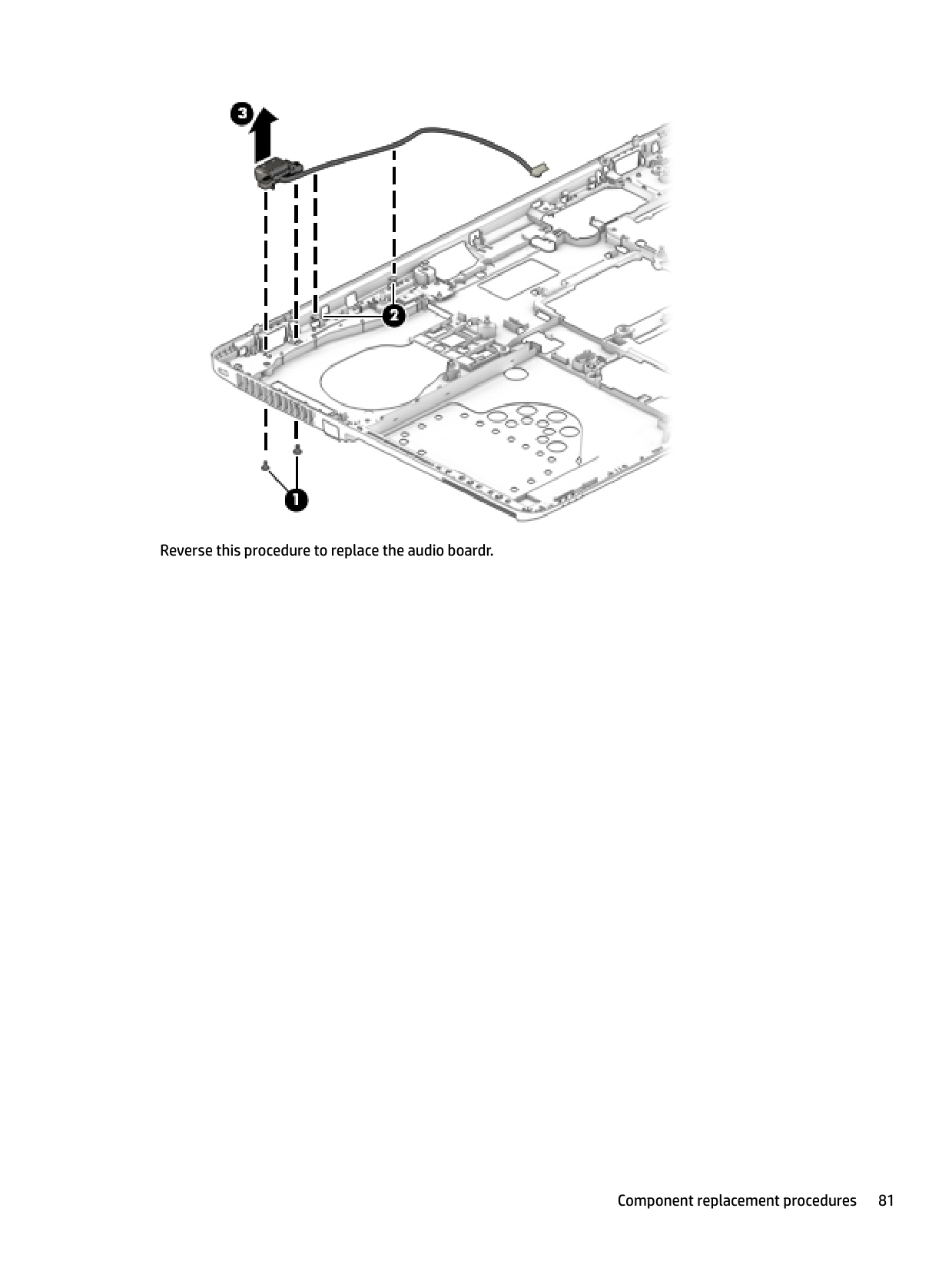
Remove the serial port:
▲ Remove 2 M2x3L P1 screws(1), remove the cable from the routing channels (2), and then remove the
serial port(3).

####### Reverse this procedure to replace the audio boardr.
Display assembly
All display assemblies include WLAN antenna transceivers and cables. WWAN models also include 2 WWAN antenna transceivers and cables.
Full hinge-up displays are not spared. This section describes removing components that do not require that you entirely remove the display assembly from the computer. You can remove the display bezel, webcam/microphone module, and display panel with the display assembly still attached to the computer. To remove the remaining display components, including the display brackets, antennas, and enclosure, you must remove the entire display assembly from the computer. See Display assembly subcomponents on page 27 for more information about removing the remaining components.
Description Spare part number Display panels ( [14.0-in], anti-glare, LED)
Slim panel for 15" products 840748-001
Before removing the display panel, follow these steps:


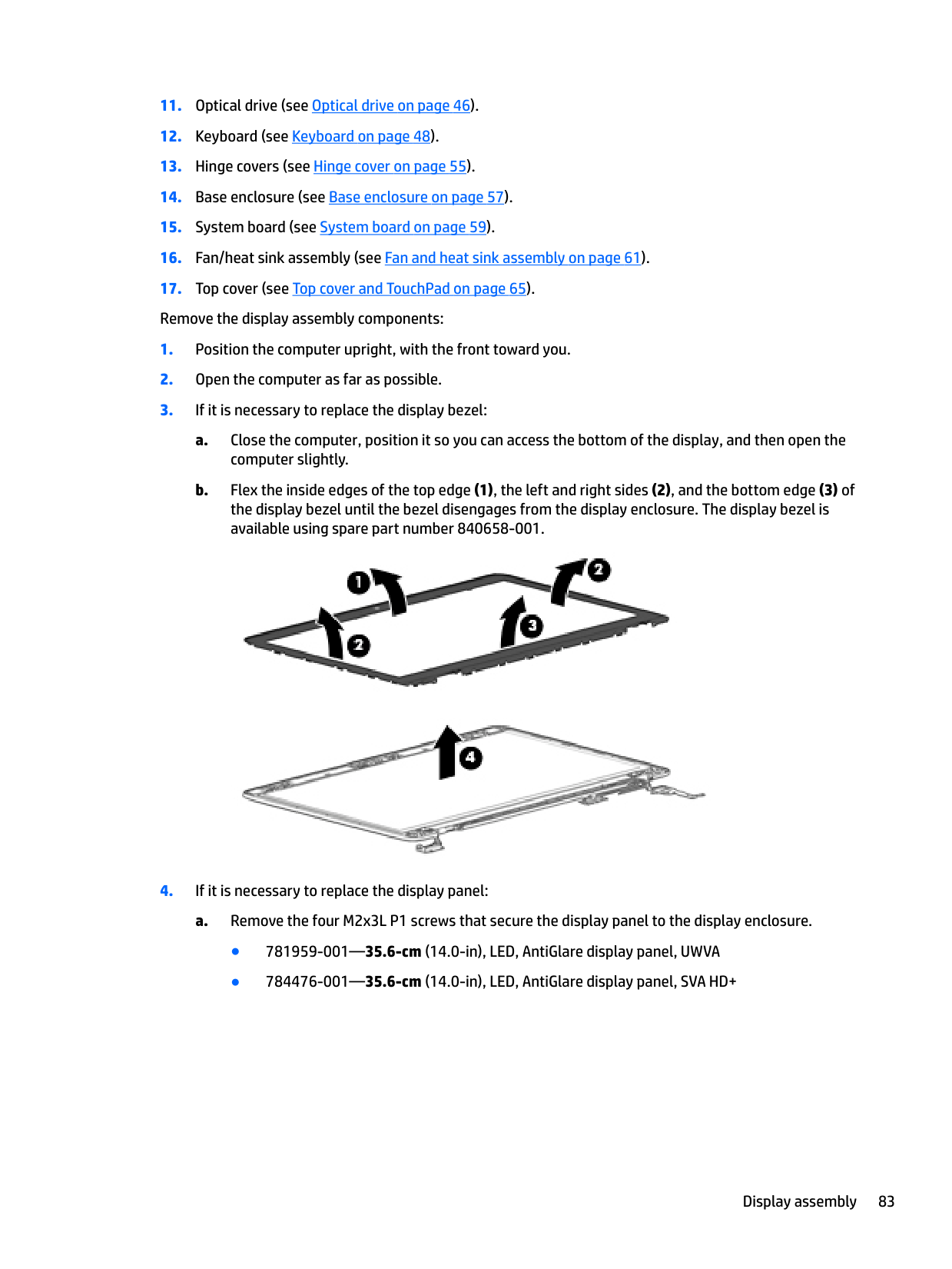
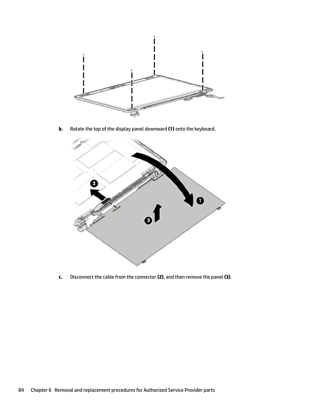
####### b. Rotate the top of the display panel downward (1) onto the keyboard.

####### c. Disconnect the cable from the connector (2), and then remove the panel (3).
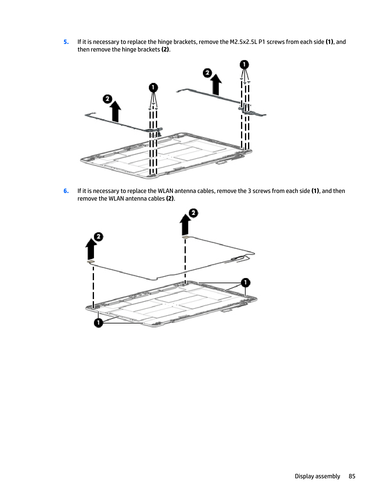
####### 5. If it is necessary to replace the hinge brackets, remove the M2.5x2.5L P1 screws from each side (1), andthen remove the hinge brackets (2).

####### 6. If it is necessary to replace the WLAN antenna cables, remove the 3 screws from each side (1), and thenremove the WLAN antenna cables (2).


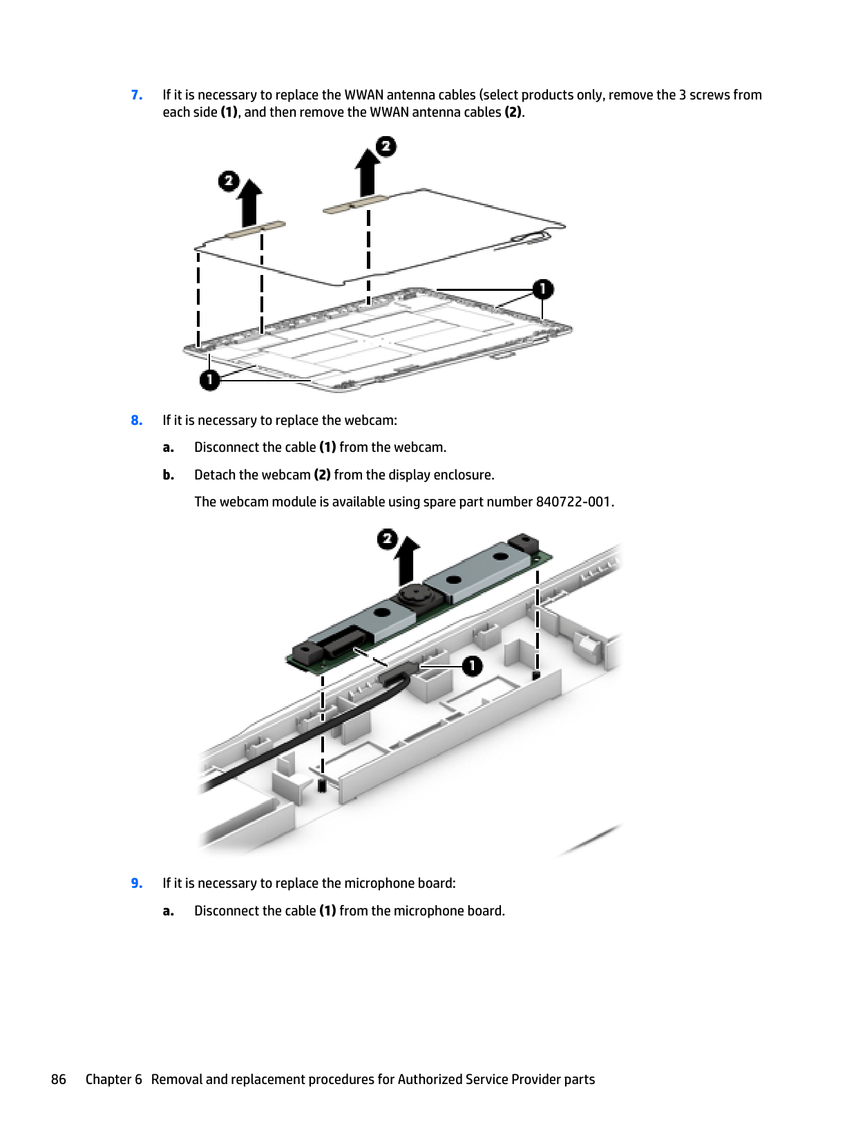
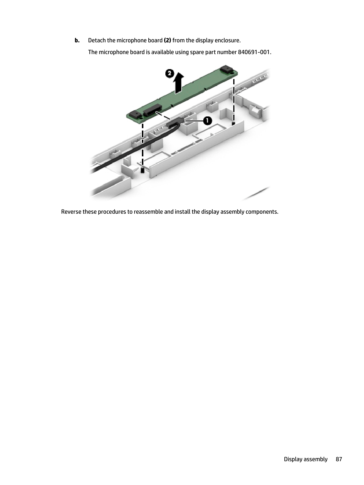
The webcam module is available using spare part number 840722-001.


Reverse these procedures to reassemble and install the display assembly components.
7 Computer Setup (BIOS), TPM, and HP SureStart in Windows 10
Using Computer Setup
Computer Setup, or Basic Input/Output System (BIOS), controls communication between all the input and output devices on the system (such as disk drives, display, keyboard, mouse, and printer). Computer Setup includes settings for the types of devices installed, the startup sequence of the computer, and the amount of system and extended memory.
| | |---|
NOTE: Use extreme care when making changes in Computer Setup. Errors can prevent the computer from operating properly.
Starting Computer Setup NOTE: An external keyboard or mouse connected to a USB port can be used with Computer Setup only if USB legacy support is enabled. To start Computer Setup, follow these steps:
| | |---|
▲ Start Computer Setup.
● Computers or tablets with keyboards:
▲ Turn on or restart the computer, and when the HP logo appears, press f10 to enter Computer Setup.
● Tablets without keyboards:
▲ Turn off the tablet. Press the power button in combination with the volume down button until the Startup menu is displayed, and then tap F10 to enter Computer Setup.
#### Navigating and selecting in Computer Setup
| | |---|
To exit Computer Setup menus, choose one of the following methods:
– or – Select Main, select Ignore Changes and Exit, and then press enter.
– or – Select Main, select Save Changes and Exit, and then press enter.
Your changes go into effect when the computer restarts.
Restoring factory settings in Computer Setup NOTE: Restoring defaults will not change the hard drive mode. To return all settings in Computer Setup to the values that were set at the factory, follow these steps:
| | |---|
NOTE: On select products, the selections may display Restore Defaults instead of Apply Factory Defaults and Exit.
| | |---|
– or – Select Main, select Save Changes and Exit, and then press enter.
| | |---|
Your changes go into effect when the computer restarts. NOTE: Your password settings and security settings are not changed when you restore the factory settings.
Using Computer Setup 89
Updating the BIOS Updated versions of the BIOS may be available on the HP website. Most BIOS updates on the HP website are packaged in compressed files called SoftPaqs. Some download packages contain a file named Readme.txt, which contains information regarding installing and troubleshooting the file.
##### Determining the BIOS version
To decide whether you need to update Computer Setup (BIOS), first determine the BIOS version on your computer.
BIOS version information (also known as ROM date and System BIOS) can be accessed by pressing fn+esc (if you are already in Windows) or by using Computer Setup.
– or – Select Main, select Ignore Changes and Exit, and then press enter.
To check for later BIOS versions, see Downloading a BIOS update on page 90. Downloading a BIOS update
CAUTION: To reduce the risk of damage to the computer or an unsuccessful installation, download and install a BIOS update only when the computer is connected to reliable external power using the AC adapter. Do not download or install a BIOS update while the computer is running on battery power, docked in an optional docking device, or connected to an optional power source. During the download and installation, follow these instructions:
Do not disconnect power on the computer by unplugging the power cord from the AC outlet. Do not shut down the computer or initiate Sleep. Do not insert, remove, connect, or disconnect any device, cable, or cord.
– or – Select the question mark icon in the taskbar.
Make a note of the path to the location on your hard drive where the BIOS update is downloaded. You will need to access this path when you are ready to install the update.
| | |---|
NOTE: If you connect your computer to a network, consult the network administrator before installing any software updates, especially system BIOS updates.
BIOS installation procedures vary. Follow any instructions that are revealed on the screen after the download is complete. If no instructions are revealed, follow these steps:
| | |---|
NOTE: After a message on the screen reports a successful installation, you can delete the downloaded file from your hard drive.
#### Changing the boot order using the f9 prompt
To dynamically choose a boot device for the current startup sequence, follow these steps:
● Computers or tablets with keyboards:
▲ Turn on or restart the computer, and when the HP logo appears, press f9 to enter the Boot
Device Options menu. ● Tablets without keyboards:
▲ Turn off the tablet. Press the power button in combination with the volume down button until the Startup menu is displayed, and then tap F9 to enter the Boot Device Options menu.
TPM BIOS settings (select products only)
| | |---|
IMPORTANT: Before enabling Trusted Platform Module (TPM) functionality on this system, you must ensure that your intended use of TPM complies with relevant local laws, regulations and policies, and approvals or licenses must be obtained if applicable. For any compliance issues arising from your operation/usage of TPM which violates the above mentioned requirement, you shall bear all the liabilities wholly and solely. HP will not be responsible for any related liabilities.
TPM provides additional security for your computer. You can modify the TPM settings in Computer Setup (BIOS).
| | |---|
NOTE: If you change the TPM setting to Hidden, TPM is not visible in the operating system. To access TPM settings in Computer Setup:
TPM BIOS settings (select products only) 91
Using HP Sure Start (select products only)
Select computer models are configured with HP Sure Start, a technology that continuously monitors the computer's BIOS for attacks or corruption. If the BIOS becomes corrupted or is attacked, HP Sure Start automatically restores the BIOS to its previously safe state, without user intervention.
HP Sure Start is configured and already enabled so that most users can use the HP Sure Start default configuration. The default configuration can be customized by advanced users.
To access the latest documentation on HP Sure Start, go to http://www.hp.com/support. Select Find your product, and then follow the on-screen instructions.
8 Computer Setup (BIOS), TPM, and HP Sure Start in Windows 8.1
Using Computer Setup
Computer Setup, or Basic Input/Output System (BIOS), controls communication between all the input and output devices on the system (such as disk drives, display, keyboard, mouse, and printer). Computer Setup includes settings for the types of devices installed, the startup sequence of the computer, and the amount of system and extended memory.
| | |---|
NOTE: Use extreme care when making changes in Computer Setup. Errors can prevent the computer from operating properly.
Starting Computer Setup NOTE: An external keyboard or mouse connected to a USB port can be used with Computer Setup only if USB legacy support is enabled. To start Computer Setup, follow these steps:
| | |---|
▲ Start Computer Setup.
● Computers or tablets with keyboards:
▲ Turn on or restart the computer, and when the HP logo appears, press f10 to enter Computer Setup.
● Tablets without keyboards:
▲ Turn off the tablet. Press the power button in combination with the volume down button until the Startup menu is displayed, and then tap F10 to enter Computer Setup.
#### Navigating and selecting in Computer Setup
| | |---|
To exit Computer Setup menus, choose one of the following methods:
● To exit Computer Setup menus without saving your changes: Select the Exit icon in the lower-right corner of the screen, and then follow the on-screen instructions.
– or – Select Main, select Ignore Changes and Exit, and then press enter.
● To save your changes and exit Computer Setup menus: Select the Save icon in the lower-right corner of the screen, and then follow the on-screen instructions.
– or – Select Main, select Save Changes and Exit, and then press enter.
Your changes go into effect when the computer restarts.
Restoring factory settings in Computer Setup NOTE: Restoring defaults will not change the hard drive mode. To return all settings in Computer Setup to the values that were set at the factory, follow these steps:
| | |---|
| | |---|
follow the on-screen instructions.
– or – Select Main, select Save Changes and Exit, and then press enter.
| | |---|
Your changes go into effect when the computer restarts. NOTE: Your password settings and security settings are not changed when you restore the factory settings.
Updating the BIOS Updated versions of the BIOS may be available on the HP website. Most BIOS updates on the HP website are packaged in compressed files called SoftPaqs. Some download packages contain a file named Readme.txt, which contains information regarding installing and troubleshooting the file.
##### Determining the BIOS version
To decide whether you need to update Computer Setup (BIOS), first determine the BIOS version on your computer.
BIOS version information (also known as ROM date and System BIOS) can be accessed by pressing fn+esc (if you are already in Windows) or by using Computer Setup.
screen, and then follow the on-screen instructions.
– or – Select Main, select Ignore Changes and Exit, and then press enter.
To check for later BIOS versions, see Downloading a BIOS update on page 95. Downloading a BIOS update
CAUTION: To reduce the risk of damage to the computer or an unsuccessful installation, download and install a BIOS update only when the computer is connected to reliable external power using the AC adapter. Do not download or install a BIOS update while the computer is running on battery power, docked in an optional docking device, or connected to an optional power source. During the download and installation, follow these instructions:
Do not disconnect power on the computer by unplugging the power cord from the AC outlet. Do not shut down the computer or initiate Sleep. Do not insert, remove, connect, or disconnect any device, cable, or cord.
Make a note of the path to the location on your hard drive where the BIOS update is downloaded. You will need to access this path when you are ready to install the update.
| | |---|
NOTE: If you connect your computer to a network, consult the network administrator before installing any software updates, especially system BIOS updates.
BIOS installation procedures vary. Follow any instructions that are revealed on the screen after the download is complete. If no instructions are revealed, follow these steps:
| | |---|
NOTE: After a message on the screen reports a successful installation, you can delete the downloaded file from your hard drive.
#### Changing the boot order using the f9 prompt
To dynamically choose a boot device for the current startup sequence, follow these steps:
▲ Turn on or restart the computer, and when the HP logo appears, press f9 to enter the Boot Device Options menu.
▲ Turn off the tablet. Press the power button in combination with the volume down button until the Startup menu is displayed, and then tap F9 to enter the Boot Device Options menu.
TPM BIOS settings (select products only)
| | |---|
IMPORTANT: Before enabling Trusted Platform Module (TPM) functionality on this system, you must ensure that your intended use of TPM complies with relevant local laws, regulations and policies, and approvals or licenses must be obtained if applicable. For any compliance issues arising from your operation/usage of TPM which violates the above mentioned requirement, you shall bear all the liabilities wholly and solely. HP will not be responsible for any related liabilities.
TPM provides additional security for your computer. You can modify the TPM settings in Computer Setup (BIOS).
| | |---|
NOTE: If you change the TPM setting to Hidden, TPM is not visible in the operating system. To access TPM settings in Computer Setup:
Using HP Sure Start (select products only)
Select computer models are configured with HP Sure Start, a technology that continuously monitors the computer's BIOS for attacks or corruption. If the BIOS becomes corrupted or is attacked, HP Sure Start automatically restores the BIOS to its previously safe state, without user intervention.
HP Sure Start is configured and already enabled so that most users can use the HP Sure Start default configuration. The default configuration can be customized by advanced users.
To access the latest documentation on HP Sure Start, go to http://www.hp.com/support. Select Find your product, and then follow the on-screen instructions.
Using HP Sure Start (select products only) 97
9 Computer Setup (BIOS), TPM, and HP Sure Start in Windows 7
Using Computer Setup
Computer Setup, or Basic Input/Output System (BIOS), controls communication between all the input and output devices on the system (such as disk drives, display, keyboard, mouse, and printer). Computer Setup includes settings for the types of devices installed, the startup sequence of the computer, and the amount of system and extended memory.
| | |---|
NOTE: Use extreme care when making changes in Computer Setup. Errors can prevent the computer from operating properly.
Starting Computer Setup NOTE: An external keyboard or mouse connected to a USB port can be used with Computer Setup only if USB legacy support is enabled. To start Computer Setup, follow these steps:
| | |---|
▲ Start Computer Setup.
● Computers or tablets with keyboards:
▲ Turn on or restart the computer, and when the HP logo appears, press f10 to enter Computer Setup.
● Tablets without keyboards:
▲ Turn off the tablet. Press the power button in combination with the volume down button until the Startup menu is displayed, and then tap F10 to enter Computer Setup.
#### Navigating and selecting in Computer Setup
| | |---|
To exit Computer Setup menus, choose one of the following methods:
● To exit Computer Setup menus without saving your changes: Select the Exit icon in the lower-right corner of the screen, and then follow the on-screen instructions.
– or – Select Main, select Ignore Changes and Exit, and then press enter.
● To save your changes and exit Computer Setup menus: Select the Save icon in the lower-right corner of the screen, and then follow the on-screen instructions.
– or – Select Main, select Save Changes and Exit, and then press enter.
Your changes go into effect when the computer restarts.
Restoring factory settings in Computer Setup NOTE: Restoring defaults will not change the hard drive mode. To return all settings in Computer Setup to the values that were set at the factory, follow these steps:
| | |---|
| | |---|
follow the on-screen instructions.
– or – Select Main, select Save Changes and Exit, and then press enter.
| | |---|
Your changes go into effect when the computer restarts. NOTE: Your password settings and security settings are not changed when you restore the factory settings.
Using Computer Setup 99
Updating the BIOS Updated versions of the BIOS may be available on the HP website. Most BIOS updates on the HP website are packaged in compressed files called SoftPaqs. Some download packages contain a file named Readme.txt, which contains information regarding installing and troubleshooting the file.
##### Determining the BIOS version
To decide whether you need to update Computer Setup (BIOS), first determine the BIOS version on your computer.
BIOS version information (also known as ROM date and System BIOS) can be accessed by pressing fn+esc (if you are already in Windows) or by using Computer Setup.
screen, and then follow the on-screen instructions.
– or – Select Main, select Ignore Changes and Exit, and then press enter. To check for later BIOS versions, see Downloading a BIOS update on page 100. Downloading a BIOS update
CAUTION: To reduce the risk of damage to the computer or an unsuccessful installation, download and install a BIOS update only when the computer is connected to reliable external power using the AC adapter. Do not download or install a BIOS update while the computer is running on battery power, docked in an optional docking device, or connected to an optional power source. During the download and installation, follow these instructions:
Do not disconnect power on the computer by unplugging the power cord from the AC outlet. Do not shut down the computer or initiate Sleep. Do not insert, remove, connect, or disconnect any device, cable, or cord.
Make a note of the path to the location on your hard drive where the BIOS update is downloaded. You will need to access this path when you are ready to install the update.
| | |---|
NOTE: If you connect your computer to a network, consult the network administrator before installing any software updates, especially system BIOS updates.
BIOS installation procedures vary. Follow any instructions that are revealed on the screen after the download is complete. If no instructions are revealed, follow these steps:
The BIOS installation begins.
| | |---|
#### Changing the boot order using the f9 prompt
To dynamically choose a boot device for the current startup sequence, follow these steps:
● Computers or tablets with keyboards:
▲ Turn on or restart the computer, and when the HP logo appears, press f9 to enter the Boot
Device Options menu. ● Tablets without keyboards:
▲ Turn off the tablet. Press the power button in combination with the volume down button until the Startup menu is displayed, and then tap F9 to enter the Boot Device Options menu.
TPM BIOS settings (select products only)
| | |---|
IMPORTANT: Before enabling Trusted Platform Module (TPM) functionality on this system, you must ensure that your intended use of TPM complies with relevant local laws, regulations and policies, and approvals or licenses must be obtained if applicable. For any compliance issues arising from your operation/usage of TPM which violates the above mentioned requirement, you shall bear all the liabilities wholly and solely. HP will not be responsible for any related liabilities.
TPM provides additional security for your computer. You can modify the TPM settings in Computer Setup (BIOS).
| | |---|
NOTE: If you change the TPM setting to Hidden, TPM is not visible in the operating system. To access TPM settings in Computer Setup:
TPM BIOS settings (select products only) 101
Using HP Sure Start (select products only)
Select computer models are configured with HP Sure Start, a technology that continuously monitors the computer's BIOS for attacks or corruption. If the BIOS becomes corrupted or is attacked, HP Sure Start automatically restores the BIOS to its previously safe state, without user intervention.

HP Sure Start is configured and already enabled so that most users can use the HP Sure Start default configuration. The default configuration can be customized by advanced users.
To access the latest documentation on HP Sure Start, go to http://www.hp.com/support. Select Find your product, and then follow the on-screen instructions.
10 Using HP PC Hardware Diagnostics (UEFI)
HP PC Hardware Diagnostics is a Unified Extensible Firmware Interface (UEFI) that allows you to run diagnostic tests to determine whether the computer hardware is functioning properly. The tool runs outside the operating system so that it can isolate hardware failures from issues that are caused by the operating system or other software components.
When HP PC Hardware Diagnostics (UEFI) detects a failure that requires hardware replacement, a 24-digit Failure ID code is generated. This ID code can then be provided to support to help determine how to correct the problem.
| | |---|
NOTE: To start diagnostics on a convertible computer, your computer must be in notebook mode and you must use the keyboard attached. To start HP PC Hardware Diagnostics (UEFI), follow these steps:
| | |---|
| | |---|
NOTE: If you need to stop a diagnostic test, press esc.
Downloading HP PC Hardware Diagnostics (UEFI) to a USB device
| | |---|
NOTE: The HP PC Hardware Diagnostics (UEFI) download instructions are provided in English only, and you must use a Windows computer to download and create the HP UEFI support environment because only .exe files are offered.
There are two options to download HP PC Hardware Diagnostics to a USB device. Download the latest UEFI version
Downloading HP PC Hardware Diagnostics (UEFI) to a USB device 103
– or – Click Find Now to let HP automatically detect your product.
104 Chapter 10 Using HP PC Hardware Diagnostics (UEFI)
11 Backup and recovery
This chapter provides information about the following processes. The information in the chapter is standard procedure for most products.
▲ Type support in the taskbar search box, and then select the HP Support Assistant app.
‒ or – Click the question mark icon in the taskbar.
| | |---|
IMPORTANT: If you will be performing recovery procedures on a tablet, the tablet battery must be at least 70% charged before you start the recovery process.
IMPORTANT: For a tablet with a detachable keyboard, connect the keyboard to the keyboard dock before beginning any recovery process.
Creating recovery media and backups

The following methods of creating recovery media and backups are available on select products only. Choose the available method according to your computer model.
| | |---|
#### Creating HP Recovery media (select products only)
If possible, check for the presence of the Recovery partition and the Windows partition. From the Start menu, select File Explorer, and then select This PC.
Creating recovery media and backups 105
You can use Windows tools to create system restore points and create backups of personal information, see Using Windows tools on page 106.
| | |---|
To create HP Recovery media: IMPORTANT: For a tablet with a detachable keyboard, connect the keyboard to the keyboard dock before beginning these steps.
Using Windows tools
You can create recovery media, system restore points, and backups of personal information using Windows tools.
| | |---|
NOTE: If storage is 32 GB or less, Microsoft System Restore is disabled by default. For more information and steps, see the Get started app.
▲ Select the Start button, and then select the Get started app.
Restore and recovery
There are several options for recovering your system. Choose the method that best matches your situation and level of expertise:
| |
|---|
IMPORTANT: Not all methods are available on all products.
▲ Select the Start button, and then select the Get started app.
▲ Type recovery in the taskbar search box, select HP Recovery Manager, select Reinstall drivers
and/or applications, and then follow the on-screen instructions.
#### Recovering using HP Recovery Manager
HP Recovery Manager software allows you to recover the computer to its original factory state by using the HP Recovery media that you either created or that you obtained from HP, or by using the HP Recovery partition (select products only). If you have not already created recovery media, see Creating HP Recovery media (select products only) on page 105.
##### What you need to know before you get started
IMPORTANT: Recovery through HP Recovery Manager should be used as a final attempt to correct computer issues.
| | |---|
website. Go to http://www.hp.com/support, select your country or region, and follow the on-screen instructions.
| | |---|
| | |---|
IMPORTANT: HP Recovery Manager does not automatically provide backups of your personal data. Before beginning recovery, back up any personal data you want to retain. Using HP Recovery media, you can choose from one of the following recovery options: NOTE: Only the options available for your computer display when you start the recovery process.
The HP Recovery partition (select products only) allows System Recovery only. Using the HP Recovery partition (select products only)
The HP Recovery partition allows you to perform a system recovery without the need for recovery discs or a recovery USB flash drive. This type of recovery can be used only if the hard drive is still working.
| | |---|
To start HP Recovery Manager from the HP Recovery partition: IMPORTANT: For a tablet with a detachable keyboard, connect the keyboard to the keyboard dock before beginning these steps (select products only).
For computers or tablets with keyboards attached, press f11 while the computer boots, or press and hold f11 as you press the power button.
For tablets without keyboards: Turn on or restart the tablet, and then quickly hold down the volume down button; then select f11.
##### Using HP Recovery media to recover
You can use HP Recovery media to recover the original system. This method can be used if your system does not have an HP Recovery partition or if the hard drive is not working properly.
NOTE: If the computer does not automatically restart in HP Recovery Manager, change the computer boot order. See Changing the computer boot order on page 109.

| | |---|
##### Changing the computer boot order
If your computer does not restart in HP Recovery Manager, you can change the computer boot order, which is the order of devices listed in BIOS where the computer looks for startup information. You can change the selection to an optical drive or a USB flash drive.
| | |---|
To change the boot order: IMPORTANT: For a tablet with a detachable keyboard, connect the keyboard to the keyboard dock before beginning these steps.
▲ Turn on or restart the computer or tablet, quickly press esc, and then press f9 for boot options. For tablets without keyboards:
▲ Turn on or restart the tablet, and then quickly hold down the volume down button; then select f9.
Removing the HP Recovery partition (select products only) HP Recovery Manager software allows you to remove the HP Recovery partition to free up hard drive space. IMPORTANT: After you remove the HP Recovery partition, you will not be able to perform System Recovery or create HP recovery media from the HP Recovery partition. So before you remove the Recovery partition, create HP Recovery media; see Creating HP Recovery media (select products only) on page 105. NOTE: The Remove Recovery Partition option is only available on products that support this function. Follow these steps to remove the HP Recovery partition:
| | |---|
| | |---|
12 Backup and recovery in Windows 8.1
To protect your information, use Windows backup and restore utilities to back up individual files and folders, back up your entire hard drive, create system repair media (select products only) by using the installed optical drive (select products only) or an optional external optical drive, or create system restore points. In case of system failure, you can use the backup files to restore the contents of your computer.
| | |---|
| | |---|
From the Start screen, type restore, and then select from the list of displayed options. NOTE: For detailed instructions on various backup and restore options, perform a search for these topics in Windows Help and Support. In case of system instability, HP recommends that you print the recovery procedures and save them for later use. NOTE: Windows includes the User Account Control feature to improve the security of your computer. You may be prompted for your permission or password for tasks such as installing software, running utilities, or changing Windows settings. For more information, see Windows Help and Support.
Backing up your information
Recovery after a system failure is as good as your most recent backup. You should create system repair media and your initial backup immediately after initial system setup. As you add new software and data files, you should continue to back up your system on a regular basis to maintain a reasonably current backup.
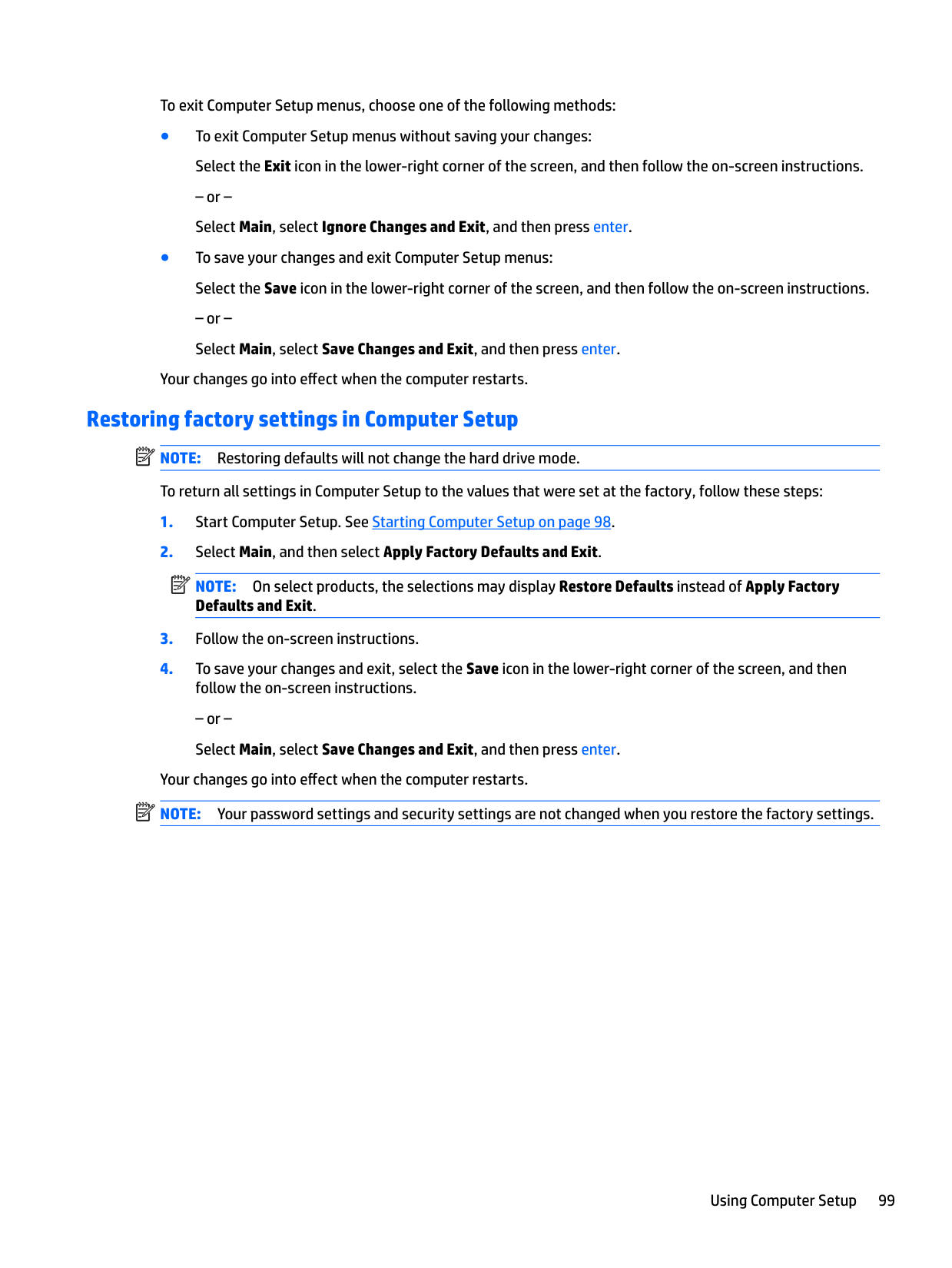
For more information on the Windows backup features, see Windows Help and Support.
Performing a system recovery
In case of system failure or instability, the computer provides the following tools to recover your files:
| | |---|
NOTE: If you are unable to boot (start up) your computer and you cannot use the system repair media you previously created (select products only), you must purchase Windows operating system media to reboot the computer and repair the operating system. For additional information, see Using Windows operating system media (purchased separately) on page 113.
#### Using the Windows recovery tools
To recover information you previously backed up, see Windows Help and Support for steps on restoring files and folders.
To recover your information using Automatic Repair, follow these steps:
Backing up your information 111
CAUTION: Some Startup Repair options will completely erase and reformat the hard drive. All files you have created and any software installed on the computer are permanently removed. When reformatting is complete, the recovery process restores the operating system, as well as the drivers, software, and utilities from the backup used for recovery.
– or – From the Start screen, type pc, and then select This PC. NOTE: If the Windows partition and the Recovery Image partition are not listed, you must recover your operating system and programs using the Windows operating system DVD and the Driver Recovery media (both purchased separately). For additional information, see Using Windows operating system media (purchased separately) on page 113.
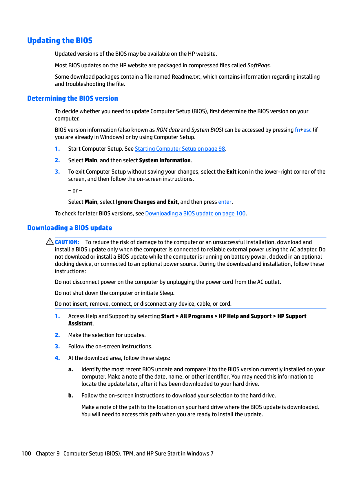
| | |---|
| | |---|
NOTE: For additional information on recovering information using the Windows tools, perform a search for these topics in Windows Help and Support.
#### Using f11 recovery tools
CAUTION: Using f11 completely erases hard drive contents and reformats the hard drive. All files that you have created and any software that you have installed on the computer are permanently removed. The f11 recovery tool reinstalls the operating system and HP programs and drivers that were installed at the factory. Software not installed at the factory must be reinstalled.
To recover the original hard drive image using f11:
NOTE: If the Recovery Image partition is not listed, you must recover your operating system and programs using the Windows operating system media and the Driver Recovery media (both purchased separately). For additional information, see Using Windows operating system media (purchased separately) on page 113.
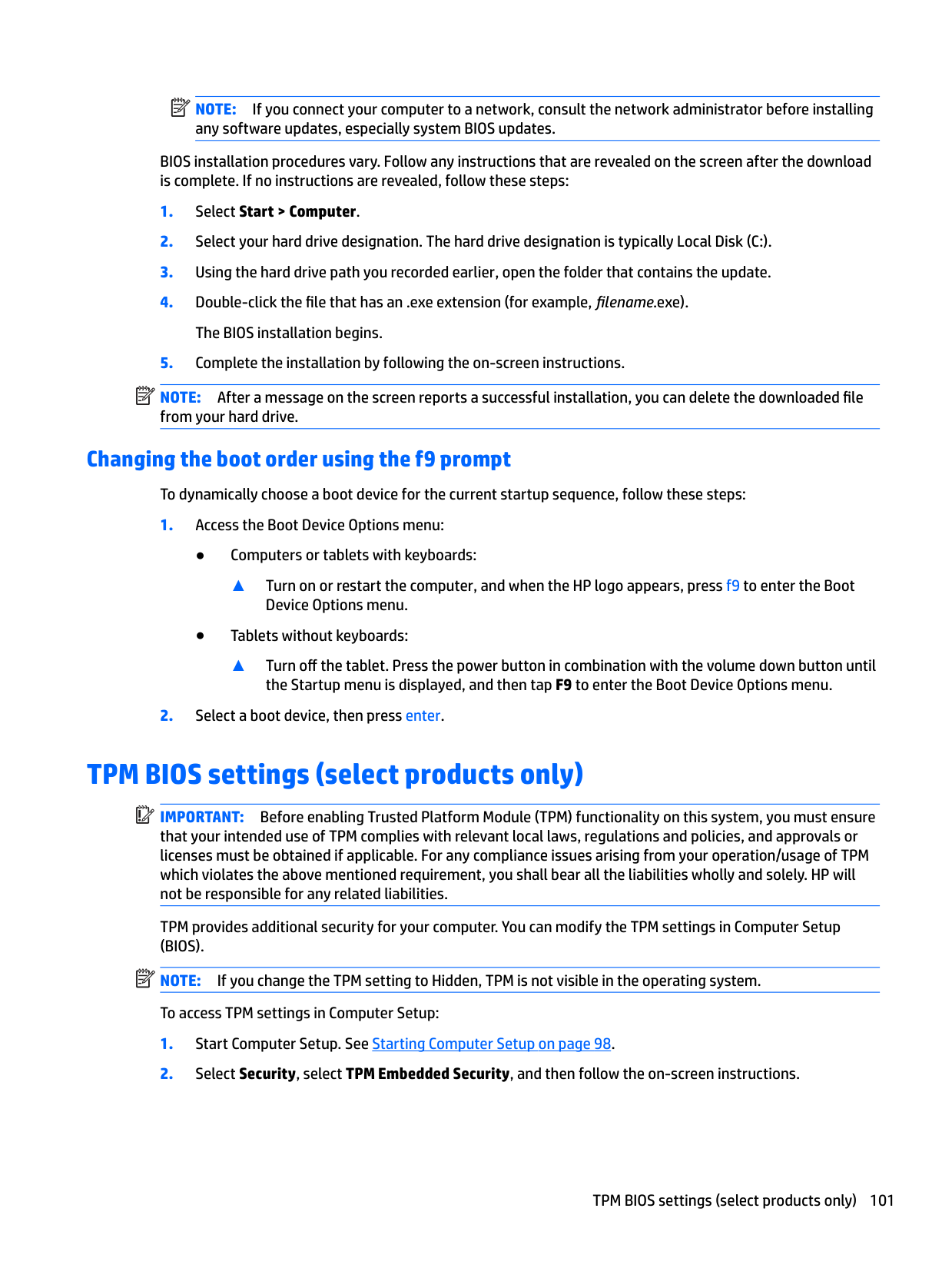
| | |---|
112 Chapter 12 Backup and recovery in Windows 8.1
#### Using Windows operating system media (purchased separately)
To order a Windows operating system DVD, contact support. See the Worldwide Telephone Numbers booklet included with the computer. You can also find contact information from the HP website. Go to http://www.hp.com/support, select your country or region, and follow the on-screen instructions.
CAUTION: Using a Windows operating system media completely erases hard drive contents and reformats the hard drive. All files that you have created and any software that you have installed on the computer are permanently removed. When reformatting is complete, the recovery process helps you restore the operating system, as well as drivers, software, and utilities.
| | |---|
To initiate a full install of the operating system using a Windows operating system DVD: NOTE: This process takes several minutes.
#### Using Windows Refresh or Windows Reset
When your computer is not working properly and you need to regain system stability, the Windows Refresh option allows you to start fresh and keep what is important to you.

The Windows Reset option allows you to perform detailed reformatting of your computer, or remove personal information before you give away or recycle your computer. For more information on these features, see Windows Help and Support.
#### Using HP Software Setup
HP Software Setup can be used to reinstall drivers or select software that has been corrupted or deleted from the system.
Performing a system recovery 113
13 Backup and recovery in Windows 7
Your computer includes HP and Windows tools to help you safeguard your information and retrieve it if you ever need to. These tools will help you return your computer to a proper working state, all with simple steps. This section provides information about the following processes:
Creating recovery media and backups
Recovery after a system failure is only as good as your most recent backup.
| | |---|
NOTE: This guide describes an overview of backing up, restoring, and recovering options. For more details about the tools provided, see Help and Support. To access Help and Support, select Start > Help and Support.
| | |---|
NOTE: HP recommends that you print the recovery procedures and save them for later use, in case of system instability. In case of system failure, you can use the backup files to restore the contents of your computer. See Backing up your information on page 115.
#### Guidelines
#### Creating recovery media with HP Recovery Disc Creator
HP Recovery Disc Creator is a software program that offers an alternative way to create recovery media. After you successfully set up the computer, you can create recovery media using HP Recovery Disc Creator. This recovery media allows you to reinstall your original operating system as well as select drivers and
applications if the hard drive becomes corrupted. HP Recovery Disc Creator can create two kinds of recovery DVDs:

Creating recovery media NOTE: The Windows 7 operating system DVD can be created only once. Thereafter, the option to create that media will not be available after you create a Windows DVD. To create the Windows DVD:
| | |---|
#### Backing up your information
You should create system repair media and your initial backup immediately after initial system setup. As you add new software and data files, you should continue to back up your system on a regular basis to maintain a reasonably current backup. You should also create Windows system repair media (select products only) which can be used to start up (boot) the computer and repair the operating system in case of system instability or failure. Your initial and subsequent backups allow you to restore your data and settings if a failure occurs.
You can back up your information to an optional external hard drive, a network drive, or discs. Note the following when backing up:
| | |---|
NOTE: For detailed instructions on various backup and restore options, perform a search for these topics in Help and Support. To access Help and Support, select Start > Help and Support.
| | |---|
NOTE: Windows includes the User Account Control feature to improve the security of your computer. You
may be prompted for your permission or password for tasks such as installing software, running utilities, or changing Windows settings. Refer to Help and Support. To access Help and Support, select Start > Help and Support.
Creating recovery media and backups 115
| | |---|
To create a backup using Windows Backup and Restore: NOTE: The backup process may take over an hour, depending on file size and the speed of the computer.
or create system repair media (select products only).
Performing a system recovery
In case of system failure or instability, the computer provides the following tools to recover your files:
| | |---|
NOTE: If you are unable to boot (start up) your computer and you cannot use the system repair media you previously created (select products only), you must purchase Windows 7 operating system media to reboot the computer and repair the operating system. For additional information, see Using Windows 7 operating
system media on page 117.
#### Using the Windows recovery tools
Using the Windows recovery tools, you can:
| | |---|
NOTE: For detailed instructions on various recovery and restore options, perform a search for these topics in Help and Support. To access Help and Support, select Start > Help and Support.
| |
|---|
NOTE: Windows includes the User Account Control feature to improve the security of your computer. You
may be prompted for your permission or password for tasks such as installing software, running utilities, or changing Windows settings. Refer to Help and Support. To access Help and Support, select Start > Help and Support.
To recover information you previously backed up:
To recover your information using Startup Repair, follow these steps: CAUTION: Some Startup Repair options will completely erase and reformat the hard drive. All files you have created and any software installed on the computer are permanently removed. When reformatting is complete, the recovery process restores the operating system, as well as the drivers, software, and utilities from the backup used for recovery.
NOTE: If the Windows partition is not listed, you must recover your operating system and programs using the Windows 7 operating system DVD and the Driver Recovery media. For additional information, see Using Windows 7 operating system media on page 117.
| | |---|
| | |---|
NOTE: For additional information on recovering information using the Windows tools, select Start > Help and Support.
#### Using f11 recovery tools (select products only)
CAUTION: Using f11 completely erases hard drive contents and reformats the hard drive. All files that you have created and any software that you have installed on the computer are permanently removed. The f11 recovery tool reinstalls the operating system and HP programs and drivers that were installed at the factory. Software not installed at the factory must be reinstalled.
To recover the original hard drive image using f11:
NOTE: If the HP Recovery partition is not listed, you must recover your operating system and programs using the Windows 7 operating system media and the Driver Recovery media. For additional information, see Using Windows 7 operating system media on page 117.
| | |---|
#### Using Windows 7 operating system media
If you cannot use the recovery media you previously created using the HP Recovery Disc Creator (select products only), you must purchase a Windows 7 operating system DVD to reboot the computer and repair the operating system.
To order a Windows 7 operating system DVD, go to the HP website. For U.S. support, go to http://www.hp.com/support. For worldwide support, go to http://welcome.hp.com/country/us/en/ wwcontact_us.html. You can also order the DVD by calling support. For contact information, see the Worldwide Telephone Numbers booklet included with the computer.
CAUTION: Using a Windows 7 operating system DVD completely erases hard drive contents and reformats the hard drive. All files that you have created and any software that you have installed on the computer are permanently removed. When reformatting is complete, the recovery process helps you restore the operating system, as well as drivers, software, and utilities.
Performing a system recovery 117
| | |---|
To initiate recovery using a Windows 7 operating system DVD: NOTE: This process takes several minutes.
14 Specifications
Computer specifications
######## 15" products 14" products
Dimensions Width 378 (14.88 in) 340 (13.39 in) Depth 257 (10.11 in) 237 (9.33 in) Height (front to back) 27.4 (1.07 in) 27 (1.06 in) Weight 5.1 or 5.37 lbs(depending on
4.3 or 4.57 lbs (depending on configuration)

configuration)
Input power Operating voltage and current 19.5 V dc @ 2.3 – 45 W (select products only)
19.5 V dc @ 3.33 A – 65 W 19 V dc @ 4.6 A – 90 W (only for products with an Intel quadcore processor)
Temperature Operating 5°C to 35°C (41°F to 95°F) Nonoperating –20°C to 60°C (–4°F to
140°F)
Relative humidity (noncondensing) Operating 10% to 90% Nonoperating 5% to 95% Maximum altitude (unpressurized) Operating –15 m to 3,048 m (–50 ft to
10,000 ft)
Nonoperating –15 m to 12,192 m (–50 ft to
40,000 ft)
NOTE: Applicable product safety standards specify thermal limits for plastic surfaces. The device operates well within this range of temperatures.
Computer specifications 119
Hard drive specifications
1-TB, 5400-rpm SATA*
750-GB, 5400-rpm Hybrid SATA 8GB NAND **
500-GB, 7200-rpm FIPS SATA Opal2 **
500-GB, 7200-rpm SATA **
Dimensions Height 7.2 mm (0.28 in) Width 69.85 mm (2.75 in) Weight 99 g max Interface type SATA Transfer rate Synchronous (maximum) 600 MB/s Security ATA security Seek times (typical read, including setting) Single track 1.5 ms Average (read/write) 12.0 ms Maximum 22 ms Logical blocks 1,953,525,168 976,773,168 Disk rotational speed 5400 rpm 7200 rpm Operating temperature 0°C to 60°C (32°F to 140°F)
500-GB, 7200-rpm selfencrypting SATA Opal2 **
Solid-state drive specifications
128 GB 2280 M2 SATA-3 TLC*
180 GB 2280 M2 SATA-3 MLC*
180 GB 2280 M2 SATA-3 selfencryptin g MLC (Opal 2 *
240 GB 2280 M2 SATA-3 MLC*
256 GB 2280 M2 PCIe-3x4 NVMe MLC*
256 GB 2280 M2 SATA-3 selfencryptin g MLC (Opal 2)*
Dimensions Weight 10 g Height 2.38 mm (0.09 in) Width 22 mm (0.87 in) Interface type SATA Gen 3.0 (6 Gb/s)
256 GB 2280 M2 SATA-3 TLC*
512 GB SATA - 3 TLC*
120 Chapter 14 Specifications
128 GB 2280 M2 SATA-3 TLC*
180 GB 2280 M2 SATA-3 MLC*
180 GB 2280 M2 SATA-3 selfencryptin g MLC (Opal 2 *
240 GB 2280 M2 SATA-3 MLC*
256 GB 2280 M2 PCIe-3x4 NVMe MLC*
256 GB 2280 M2 SATA-3 selfencryptin g MLC (Opal 2)*
256 GB 2280 M2 SATA-3 TLC*
Performance
Maximum sequential read
Up to 540 MB/s
Up to 540 MB/s (Compress ible Performan ce)
Up to 540 MB/s (Compress ible Performa nce)
Up to 540 MB/s (Compress ible Performan ce)
Up to 2260 MB/s
Up to 540 MB/s
Maximum sequential write
Up to 300 MB/s
Up to 490 MB/s (Compress ible Performan ce)
Up to 490 MB/s (Compress ible Performa nce)
Up to 490 MB/s (Compress ible Performan ce)
Up to 1260 MB/s
Up to 460 MB/s
Security ATA-8 security Logical blocks 250,069,68
351,651,8 88
351,651,8 88
468,862,1 28
500,118,19 2
0
500,118,1 92
Operating temperature 0°C to 70° C (32° F to 158° F) [ambient temp] Features DIPM; TRIM;
DIPM; TRIM; DEVSLP
TCG OPAL 2.x; DIPM; TRIM; DEVSLP
TCG OPAL 2.x; DIPM; TRIM; DEVSLP
PCIe Gen3x4 , TRIM, L1.2
TCG OPAL 2.x, DIPM; TRIM; DEVSLP
DVESLP
*1 TB = 1 trillion bytes when referring to hard drive storage capacity. Actual accessible capacity is less. NOTE: Certain restrictions and exclusions apply. Contact technical support for details.
Up to 540 MB/s
Up to 455 MB/s
500,118,1 92
DIPM; TRIM; DEVSLP
512 GB SATA - 3 TLC*
Up to 540 MB/s
Up to 500 MB/s
1,000,215, 216
DIPM; TRIM; DEVSLP
Solid-state drive specifications 121
15 Power cord set requirements
The wide-range input feature of the computer permits it to operate from any line voltage from 100 to 120 volts AC, or from 220 to 240 volts AC.
The 3-conductor power cord set included with the computer meets the requirements for use in the country or region where the equipment is purchased.
Power cord sets for use in other countries and regions must meet the requirements of the country or region where the computer is used.
Requirements for all countries
The following requirements are applicable to all countries and regions:
Requirements for specific countries and regions
######## Country/region Accredited agency Applicable note number
Australia EANSW 1 Austria OVE 1 Belgium CEBC 1 Canada CSA 2 Denmark DEMKO 1 Finland FIMKO 1 France UTE 1 Germany VDE 1 Italy IMQ 1 Japan METI 3 The Netherlands KEMA 1 Norway NEMKO 1 The People's Republic of China COC 5 South Korea EK 4
122 Chapter 15 Power cord set requirements
######## Country/region Accredited agency Applicable note number
Sweden SEMKO 1 Switzerland SEV 1 Taiwan BSMI 4 The United Kingdom BSI 1 The United States UL 2
Requirements for specific countries and regions 123
16 Statement of memory volatility
The purpose of this chapter is to provide general information regarding nonvolatile memory in HP Business PCs. This chapter also provides general instructions for restoring nonvolatile memory that can contain personal data after the system has been powered off and the hard drive has been removed.
HP Business PC products that use Intel -based or AMD -based system boards contain volatile DDR memory. The amount of nonvolatile memory present in the system depends upon the system configuration. Intelbased and AMD-based system boards contain nonvolatile memory subcomponents as originally shipped from HP, assuming that no subsequent modifications have been made to the system and assuming that no applications, features, or functionality have been added to or installed on the system.
Following system shutdown and removal of all power sources from an HP Business PC system, personal data can remain on volatile system memory (DIMMs) for a finite period of time and will also remain in nonvolatile memory. Use the steps below to remove personal data from the PC, including the nonvolatile memory found in Intel-based and AMD-based system boards.
| | |---|
NOTE: If your tablet has a keyboard base, connect to the keyboard base before beginning steps in this chapter.
###### Current BIOS steps
IMPORTANT: If the Main menu displays Restore Defaults instead of Apply Factory Defaults and Exit, go to Legacy BIOS Steps on page 125.
NOTE: If the system has a BIOS administrator password, enter the password at the prompt.
| | |---|
| | |---|
| | |---|
| | |---|
| | |---|
● Clear the drive contents by using a third party utility designed to erase data from an SSD.
| | |---|
IMPORTANT: If you clear data using Secure Erase, it cannot be recovered.
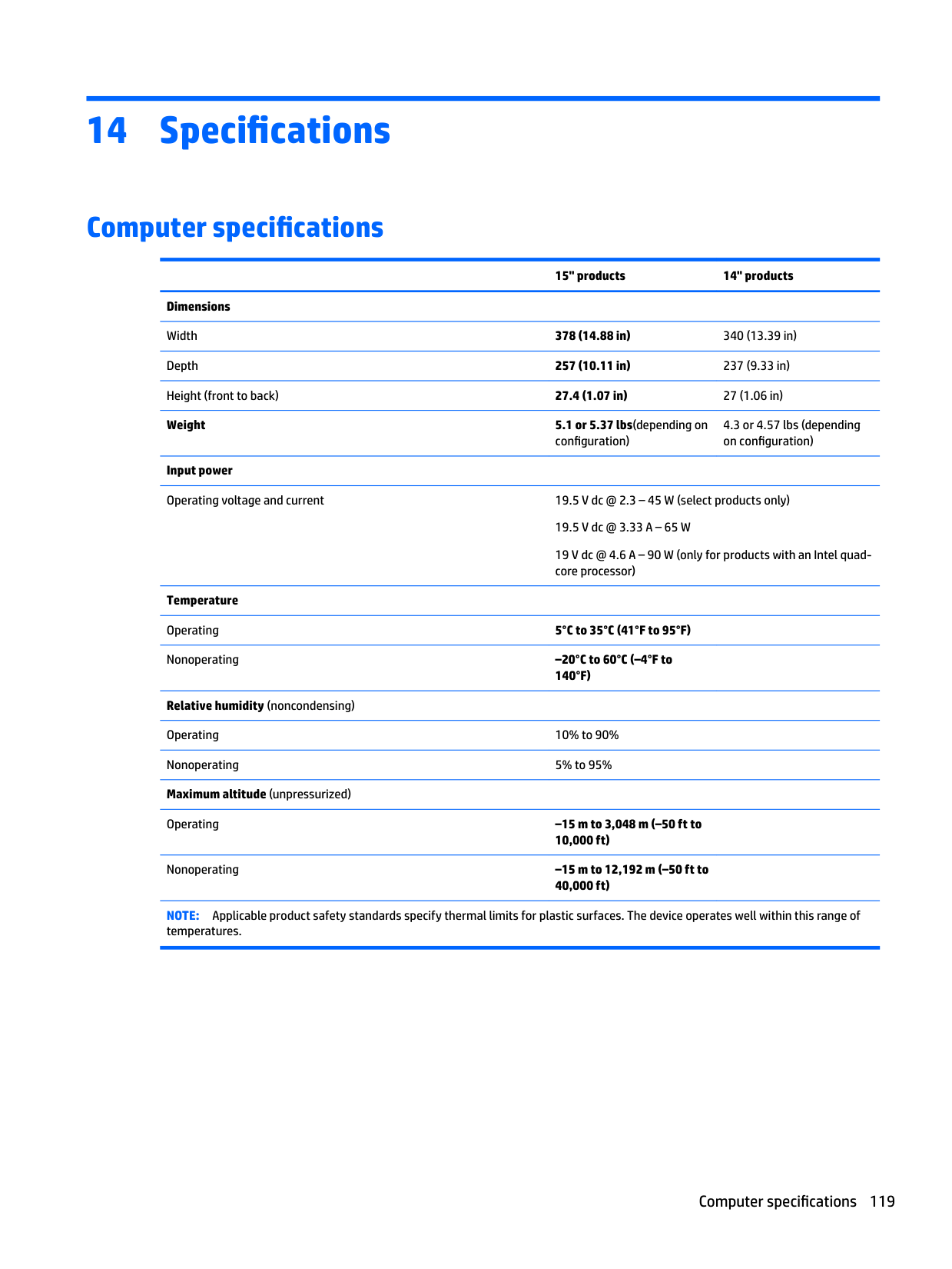
Legacy BIOS Steps Use the steps for older versions of BIOS. NOTE: If you already completed the steps in Current BIOS steps on page 124, skip this section.
| | |---|
| | |---|
● Turn on or restart the computer, and then press esc while the “Press the ESC key for Startup Menu” “message is displayed at the bottom of the screen.
| | |---|
NOTE: If the system has a BIOS administrator password, enter the password at the prompt.
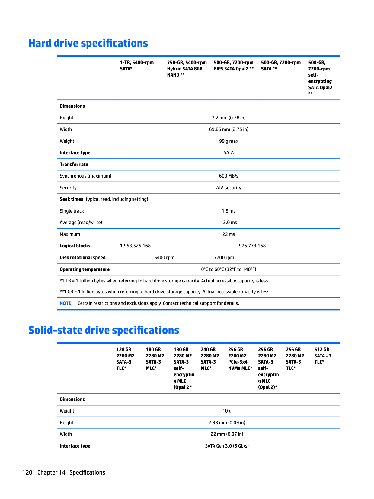
● Clear the drive contents by using a third party utility designed to erase data from an SSD.
| | |---|
IMPORTANT: If you clear data using Secure Erase, it cannot be recovered.
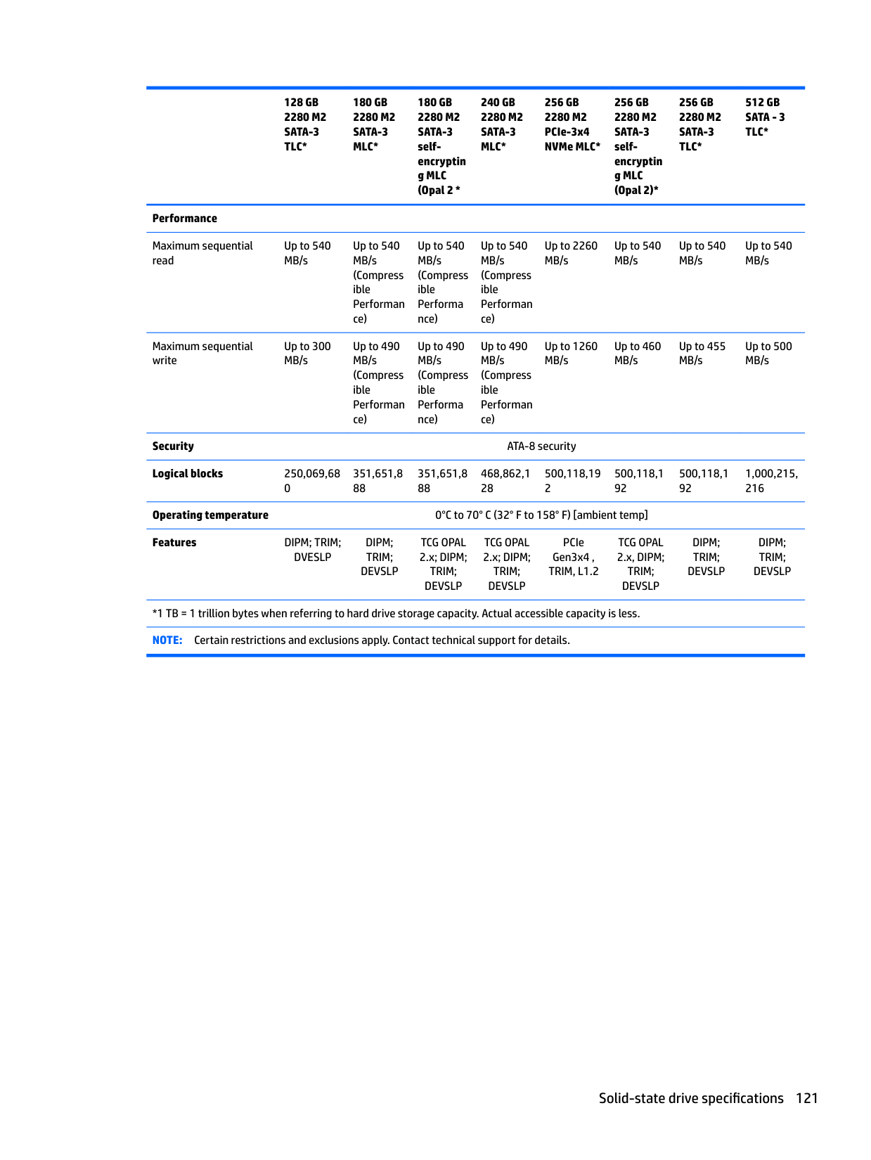
– or –
| | |---|
● Clear the contents of the drive by using the following Disk Sanitizer command steps: IMPORTANT: If you clear data using Disk Sanitizer, it cannot be recovered.
| | |---|
NOTE: The amount of time it takes for Disk Sanitizer to run can take several hours. Plug the computer into an AC outlet before starting.
Nonvolatile memory usage
Nonvolatile Memory Type
Amount (Size) Does this memory store customer data?
Does this memory retain data when power is removed?
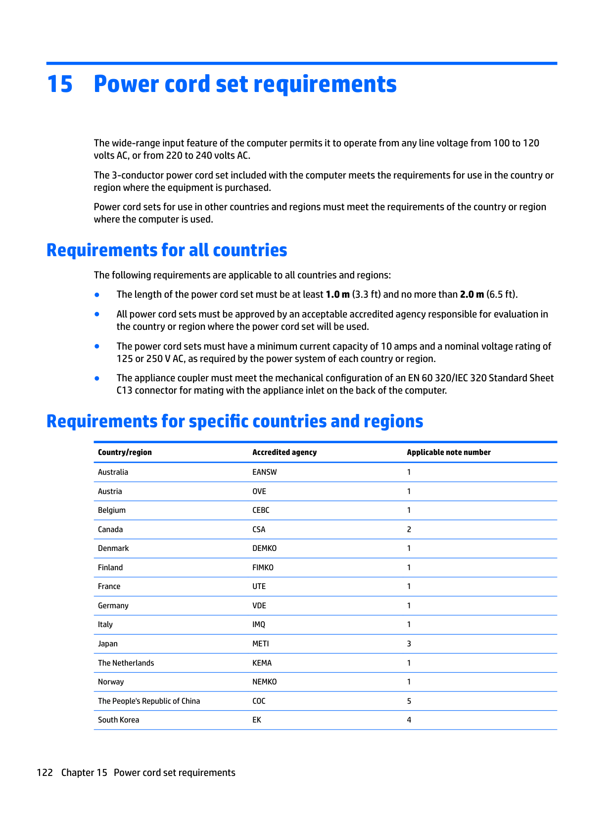
What is the purpose of this memory?
How is data input into this memory?
How is this memory write-protected?
HP Sure Start flash (select models only)
2 MBytes No Yes Provides protected backup of critical System BIOS code, EC firmware, and critical PC configuration data for select platforms that support HP Sure Start.
For more information, see Using HP Sure Start (select models only) on page 131.
Real Time Clock (RTC) battery backed-up CMOS configuration memory
Controller (NIC) EEPROM
256 Bytes No Yes Stores system date and time and noncritical data.
64 KBytes (not customer accessible)
No Yes Stores NIC configuration and NIC firmware.
DIMM Serial Presence Detect (SPD) configuration data
256 Bytes per memory module, 128 Bytes programmable (not customer accessible)
System BIOS 4 MBytes to 5 MBytes
No Yes Stores memory module information.
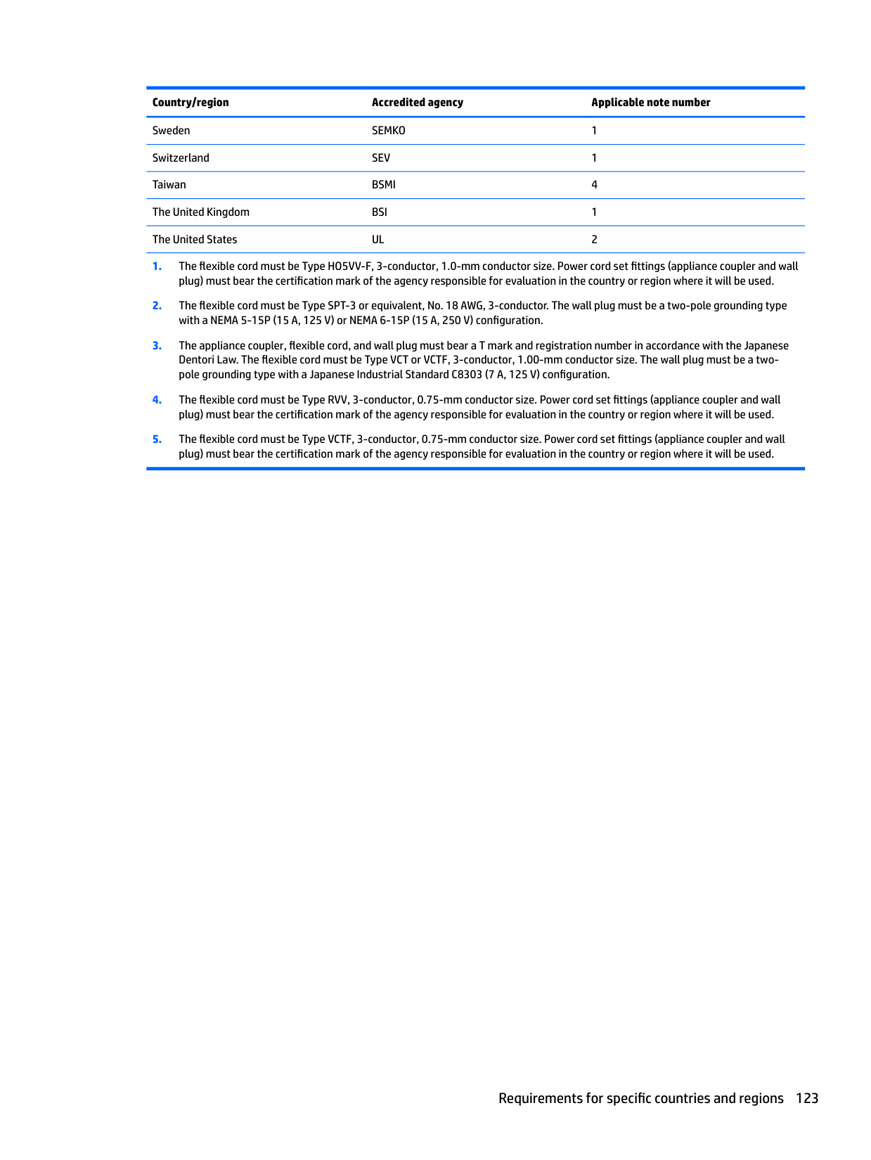
Yes Yes Stores system BIOS code and PC configuration data.
Data cannot be written to this device via the host processor. The content is managed solely by the HP Sure Start Embedded Controller.
This memory is protected by the HP Sure Start Embedded Controller.
RTC battery backed-up CMOS is programmed using the Computer Setup (BIOS), or changing the Microsoft Windows date & time.
NIC EEPROM is programmed using a utility from the NIC vendor that can be run from DOS.
DIMM SPD is programmed by the memory vendor.
This memory is not writeprotected.
A utility is required to write data to this memory and is available from the NIC vendor. Writing data to this ROM in an inappropriate manner will render the NIC nonfunctional.
Data cannot be written to this memory when the module is installed in a PC. The specific writeprotection method varies by memory vendor.
System BIOS code is programmed at the factory. Code is updated when the system BIOS is updated. Configuration data and settings are input using the Computer Setup (BIOS) or a custom utility.
NOTE: Writing data to this ROM in an inappropriate manner can render the PC nonfunctional.
A utility is required for writing data to this memory and is available on the HP website; go to http://www.hp.com/ support. Select Find your product, and then follow
Nonvolatile Memory Type
Amount (Size) Does this memory store customer data?
Does this memory retain data when power is removed?
What is the purpose of this memory?
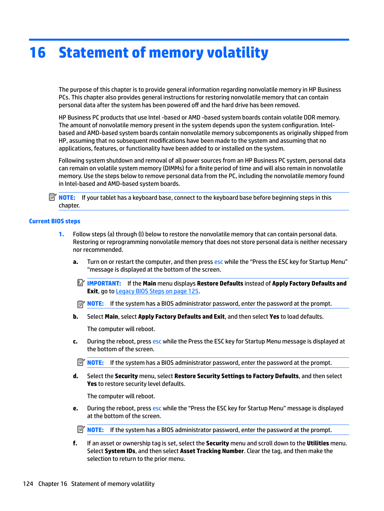
How is data input into this memory?
How is this memory write-protected?
Intel Management Engine Firmware (present in only specific ZBook and EliteBook models. For more information, go to http://www.hp.com/ support. Select Find your product, and then follow the onscreen instructions.)
1.5 MBytes or 5 MBytes
Yes Yes Stores Management Engine Code, Settings, Provisioning Data and iAMT third-party data store.
Management Engine Code is programmed at the factory. Code is updated via Intel secure firmware update utility. Unique Provisioning Data can be entered at the factory or by an administrator using the Management Engine (MEBx) setup utility. The third party data store contents can be populated by a remote management console or local applications that have been registered by an administrator to have access to the space.
Bluetooth flash 2 Mbit No Yes Stores Bluetooth configuration and firmware.
Bluetooth flash is programmed at the factory. Tools for writing data to this memory are not publicly available but can be obtained from the silicon vendor.
802.11 WLAN EEPROM
4 Kbit to 8 Kbit No Yes Stores configuration and calibration data.
802.11 WLAN EEPROM is programmed at the factory. Tools for writing data to this memory are not made public.
Web camera 64 Kbit No Yes Stores webcam configuration and firmware.
Webcam memory is programmed using a utility from the device manufacturer that can be run from Windows.
Fingerprint reader 512 KByte flash Yes Yes Stores
fingerprint templates.
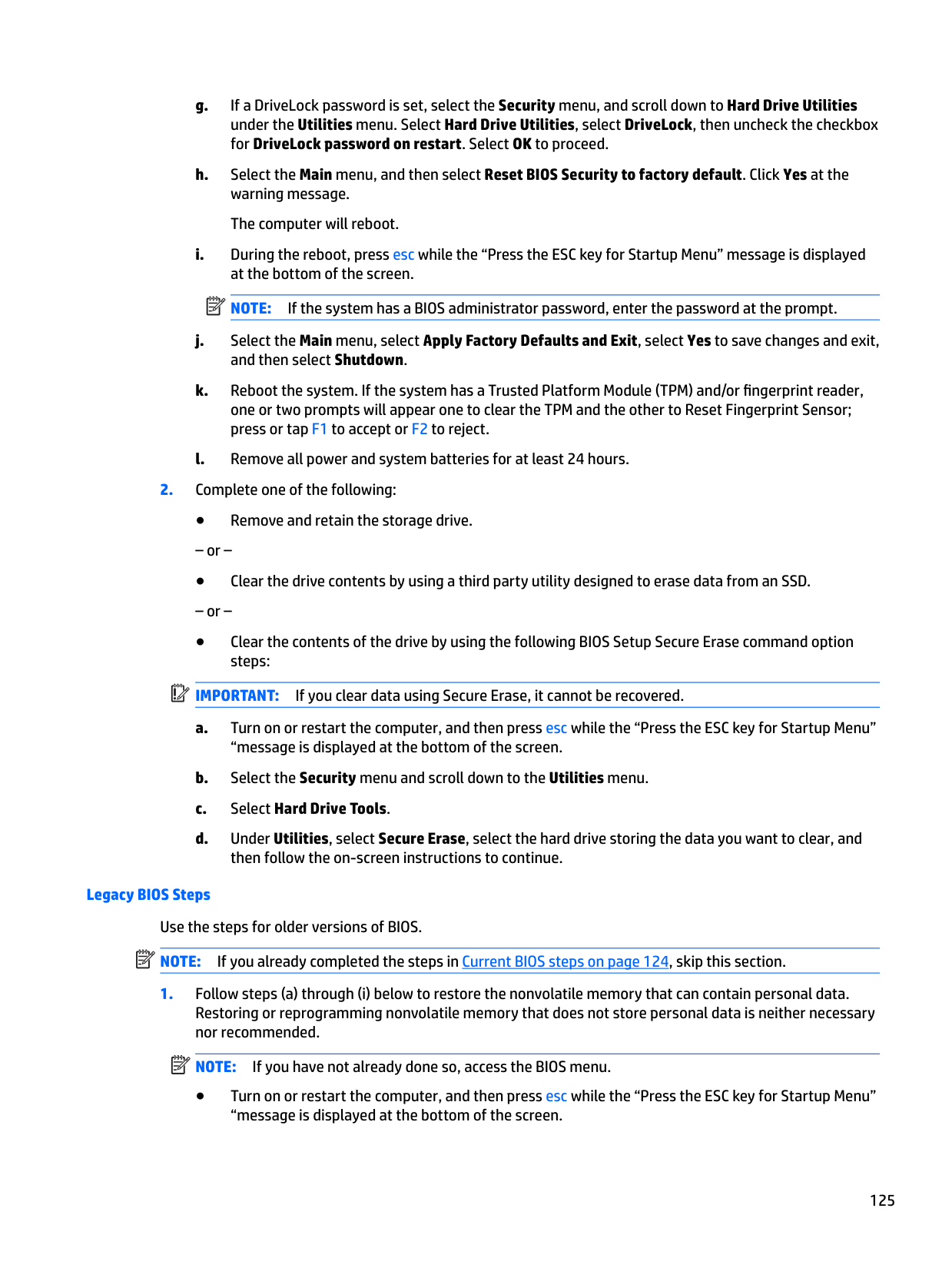
Fingerprint reader memory is programmed by user enrollment in HP ProtectTools Security Manager.
the on-screen instructions.
The Intel chipset is configured to enforce hardware protection to block all direct read/write access to this area. An Intel utility is required for updating the firmware. Only firmware updates digitally signed by Intel can be applied using this utility.
A utility is required for writing data to this memory and is made available through newer versions of the driver whenever the flash requires an upgrade.
A utility is required for writing data to this memory and is typically not made available to the public unless a firmware upgrade is necessary to address a unique issue.
A utility is required for writing data to this memory and is typically not made available to the public unless a firmware upgrade is necessary to address a unique issue.
Only a digitally signed application can make the call to write to the flash.
Nonvolatile memory usage 129
Questions and answers
IMPORTANT: Restore defaults does not securely erase any data on your hard drive. See question and answer 6 for steps to securely erase data. Restore defaults does not reset the Custom Secure Boot keys. See question and answer 7 for information about resetting the keys.
The Unified Extensible Firmware Interface (UEFI) BIOS is an industry-standard software interface between the platform firmware and an operating system (OS). It is a replacement for the older BIOS architecture, but supports much of the legacy BIOS functionality.
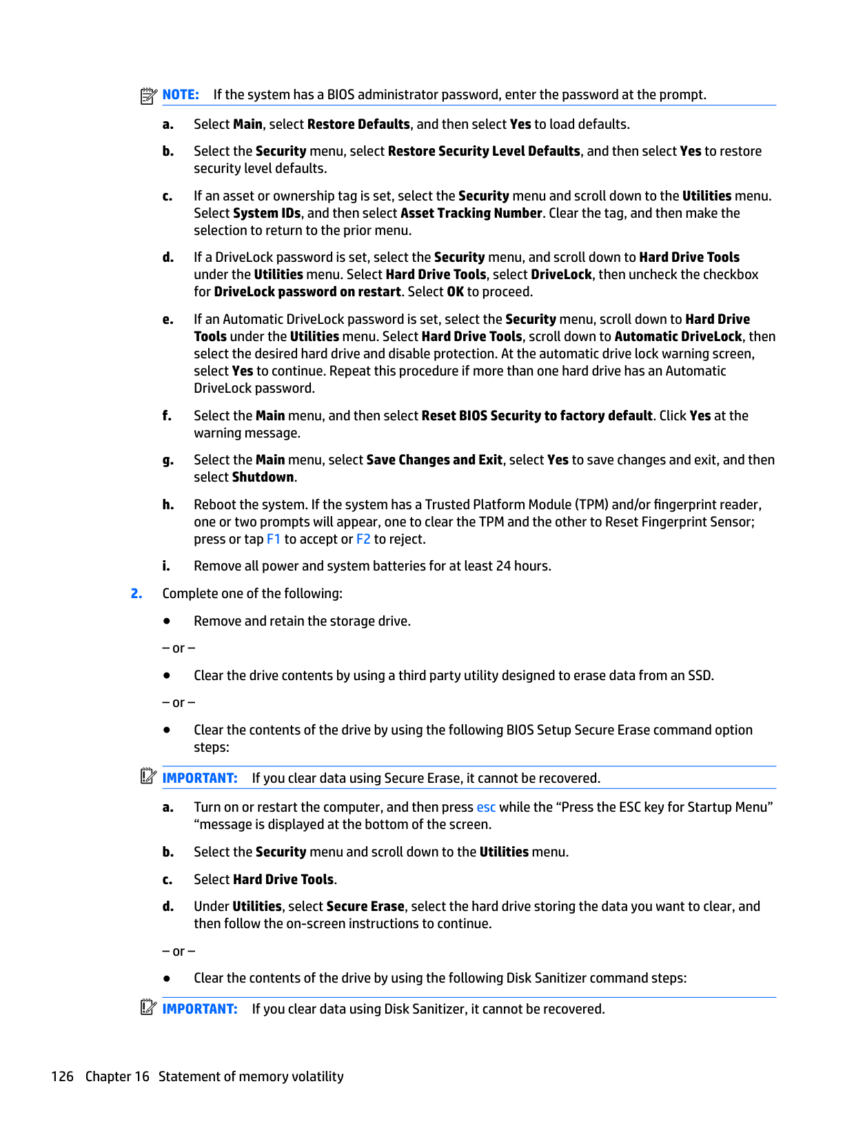
Like the legacy BIOS, the UEFI BIOS provides an interface to display the system information and configuration settings and to change the configuration of your computer before an OS is loaded. BIOS provides a secure run-time environment that supports a Graphic User Interface (GUI). In this environment, you can use either a pointing device (Touchscreen, TouchPad, pointing stick, or USB mouse) or the keyboard to navigate and make menu and configuration selections. The UEFI BIOS also contains basic system diagnostics.
The UEFI BIOS provides functionality beyond that of the legacy BIOS. In addition, the UEFI BIOS works to initialize the computer’s hardware before loading and executing the OS; the run-time environment allows the loading and execution of software programs from storage devices to provide more functionality, such as advanced hardware diagnostics (with the ability to display more detailed system information) and advanced firmware management and recovery software.
HP has provided options in Computer Setup (BIOS) to allow you to run in legacy BIOS, if required by the operating system. Examples of this requirement would be if you upgrade or downgrade the OS.
The DIMM SPD memory contains information about the memory module, such as size, serial number, data width, speed/timing, voltage, and thermal information. This information is written by the module manufacturer and stored on an EEPROM. This EEPROM cannot be written to when the memory module is installed in a PC. Third-party tools do exist that can write to the EEPROM when the memory module is not installed in a PC. Various third-party tools are available to read SPD memory.
This message relates to clearing the Real Time Clock (RTC) CMOS memory that contains PC configuration data.
| | |---|
| | |---|
IMPORTANT: Resetting will result in the loss of information.
These steps will not reset Custom Secure Boot Keys. See question and answer 7 for information about resetting the keys.

###### 7. How can the Custom Secure Boot Keys be reset?
Secure Boot is a feature to ensure that only authenticated code can start on a platform. If you enabled Secure Boot and created Custom Secure Boot Keys, simply disabling Secure Boot will not clear the keys. You must also select to clear the Custom Secure Boot Keys. Use the same Secure Boot access procedure you used to create the Custom Secure Boot Keys, but make the selection to clear or delete all Secure Boot Keys.
Using HP Sure Start (select models only)
Select computer models are configured with HP Sure Start, a technology that continuously monitors your computer's BIOS for attacks or corruption. If the BIOS becomes corrupted or is attacked, HP Sure Start restores the BIOS to its previously safe state, without user intervention. Those select computer models ship with HP Sure Start configured and enabled. HP Sure Start is configured and already enabled so that most users can use the HP Sure Start default configuration. The default configuration can be customized by advanced users.
To access the latest documentation on HP Sure Start, go to http://www.hp.com/support. Select Find your product, and then follow the on-screen instructions.
Using HP Sure Start (select models only) 131
17 Recycling
When a non-rechargeable or rechargeable battery has reached the end of its useful life, do not dispose of the battery in general household waste. Follow the local laws and regulations in your area for battery disposal.
HP encourages customers to recycle used electronic hardware, HP original print cartridges, and rechargeable batteries. For more information about recycling programs, see the HP Web site at http://www.hp.com/recycle.
132 Chapter 17 Recycling
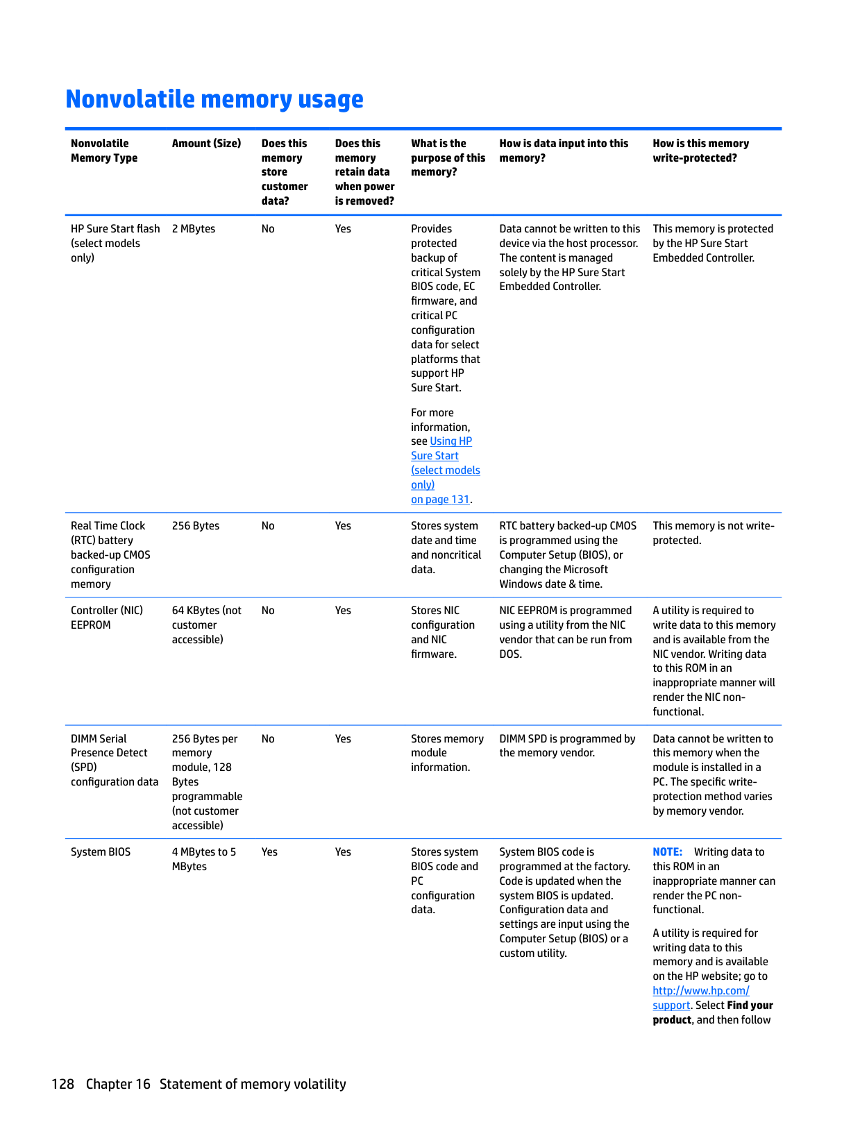
Index
removal 78 spare part number 25, 78 spare part numbers 78
audio, product description 3 audio-out (headphone)/audio-in
(microphone) combo jack, identifying 6
spare part number 28 Backup and Restore 116 backup tools 114 backups 105
creating 115 recovering 116
Base enclosure
removal 57 base enclosure
spare part number 25
battery removal 38 spare part number 26 spare part numbers 38
battery light 18 bezel
spare part number 27
BIOS determining version 90, 95, 100 downloading an update 90, 95,
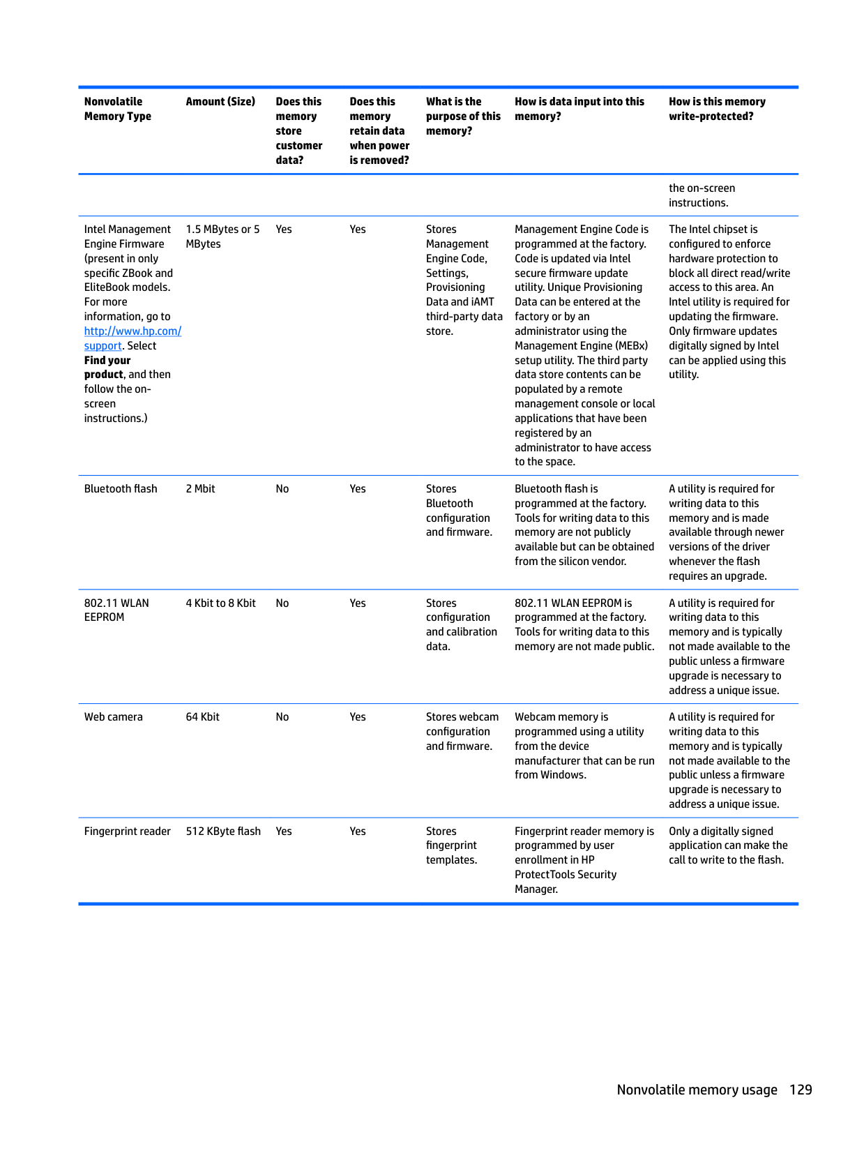
100
updating 90, 95, 100 boot order
changing 109
buttons left pointing stick 10 left TouchPad 10 optical drive eject 8 power 12 right pointing stick 10 right TouchPad 10
C Cable Kit, spare part numbers 31 caps lock light, identifying 11 chipset, product description 1 components
bottom 17 display 9 front 17 left side 8 rear 19 right side 6 top 10
computer major components 21 Computer Setup
navigating and selecting 88, 93, 98 restoring factory settings 89,
94, 99 computer specifications 119 connector, power 7
D Display assembly
spare part numbers 22, 23 display assembly
subcomponents 27
display assembly components removal 82 spare part numbers 82
display bezel removal 83
display cable, spare part number 28 display panel
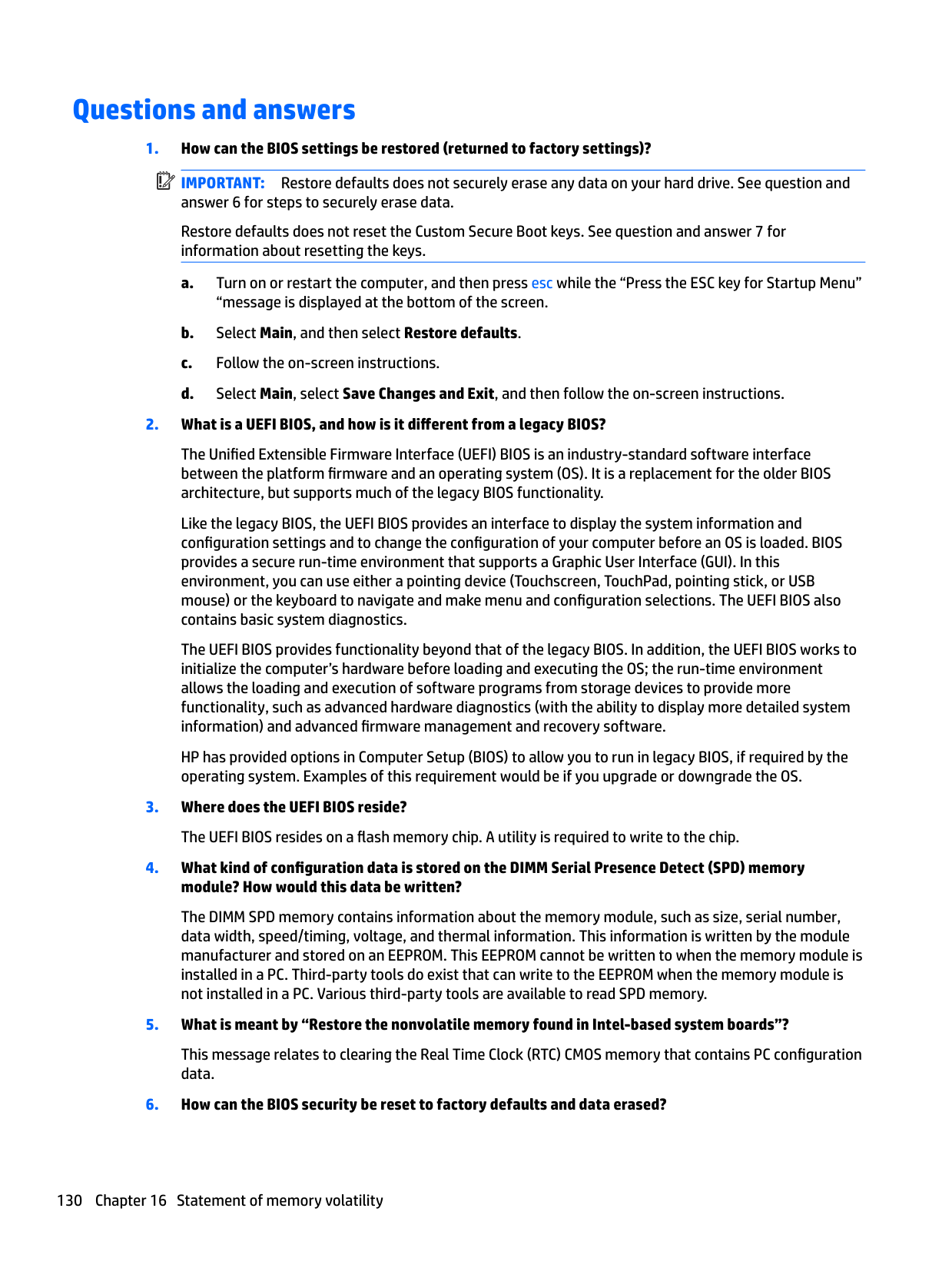
product description 1 removal 83 spare part number 82
docking
product description 4 docking port, identifying 7 docking station support holes,
identifying 17 drive light 18
Driver Recovery DVD, creating 114 using for restore 117
Dual-Mode DisplayPort, identifying 6
identifying 14 esc key, identifying 14, 15 Ethernet, product description 3 external monitor port 19
spare part numbers 23 fan and heat sink assembly
spare part numbers 61 Ffan and heat sink assembly
removal 61
fingerprint reader removal 72 spare part numbers 72
fingerprint reader, identifying 13 fn key, identifying 14, 15
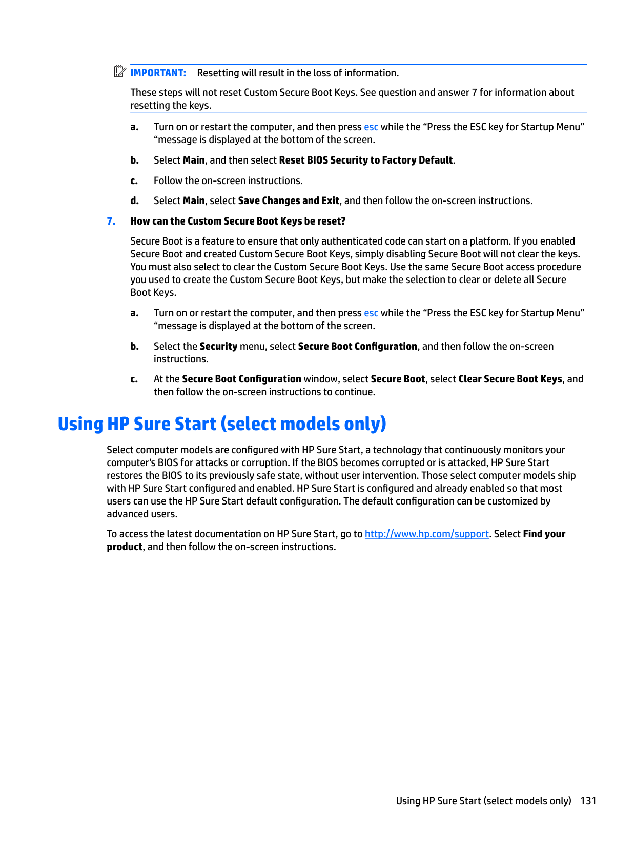
product description 2 removal 39 spare part number 25, 30 spare part numbers 39 specifications 120
hard drive hardware kit
spare part number 30 hard drive recovery 112, 117 heat sink
spare part numbers 23 hinge
spare part number 27, 28
hinge brackets removal 85
hinge cover removal 55 spare part numbers 55
Hinge Kit spare part number 28
hot keys microphone mute 16 using 15
HP PC Hardware Diagnostics (UEFI)
using 103 HP Recovery Disc Creator, using 114 HP Recovery Manager
correcting boot problems 109 starting 108
HP Recovery media

creating 105 recovery 108 HP Recovery partition checking for presence 117 recovery 108 removing 110 using for recovery 117
HP Sure Start 131
identifying 15 integrated webcam light, identifying 9 internal microphones, identifying 9
audio-out (headphone)/audio-in
(microphone) combo 6 network 7 RJ-45 (network) 7
spare part numbers 23
keyboard product description 4 remval 48 spare part numbers 48
keypad
embedded numeric 14 integrated numeric 15
keys esc 14, 15 fn 14, 15 Windows application 14 Windows key 14, 15
L labels
serial number 19 legacy support, USB 88, 93, 98 lights

battery 18 caps lock 11 drive 18 microphone mute 11 num lock 11 power 11, 17 RJ-45 (network) 7 webcam 9 wireless 11, 17
nonvolatile 124 removal 51 spare part number 25 spare part numbers 51 volatile 124
memory card reader, identifying 7 memory module
microphone
microphone board removal 86 microphone mute key, identifying 16 microphone mute light, identifying 11
minimized image recovery 108 minimized image, creating 107 model name 1
spare part number 76 near field communication (NFC)
module spare part number 76 network jack, identifying 7
NFC
removal 76 spare part numbers 76
NFC antenna, identifying 9 NFC antennas, identifying 9 nonvolatile memory 124 num lock light 11
description 4
optical drive product description 3 removal 46 spare part number 26 spare part numbers 30, 46
optical drive board removal 64 spare part number 25 spare part numbers 64
optical drive eject button,
identifying 8 optical drive light, identifying 8 optical drive, identifying 8 optical drive/Blu-ray combo
spare part number 25, 30, 46, 51 optical drive/DVD combo
spare part number 30, 46 original system recovery 107
spare part number 28 plastics kit, spare part numbers 31 pointing device, product
description 4 pointing stick 10 ports
Dual-Mode DisplayPort 6 external monitor 19 product description 3 serial 19 USB 3.0 charging (powered) 6 USB Type-C (charging) 7
power button board removal 71 spare part number 23 spare part numbers 25, 71
power button, identifying 12
power connector, identifying 7 power cord

set requirements 122 power lights 11, 17 power requirements, product
description 4 processor
product description 1
product description audio 3 chipset 1 display panel 1 docking 4 Ethernet 3 external media cards 3 graphics 1 hard drive 2 keyboard 4 memory module 2 microphone 3 operating system 4 optical drive 3 pointing device 4 ports 3 power requirements 4 processors 1 product name 1 security 4 serviceability 5 solid-state drive 2 video 3 wireless 3
product name 1 product name and number,
computer 19
R recover
options 107
recovery 113 discs 106, 108 HP Recovery Manager 107 media 108 starting 108 supported discs 106 system 107 USB flash drive 108 using HP Recovery media 106
recovery media creating 105 creating using HP Recovery
Manager 106 recovery media, creating 114 recovery media, using for restore
117 recovery partition 112, 117
removing 110 recovery tools 114 recovery tools, Windows 116 recovery, system 116 refresh 113 regulatory information 19 removal/replacement
procedures 37, 54 removing personal data from volatile
system memory 124 reset 113 restoring the hard drive 112, 117 RJ-45 (network) jack, identifying 7 RJ-45 (network) lights, identifying
7
RTC battery removal 68 spare part number 23 spare part numbers 68
Rubber Kit, spare part number 31
S Screw Kit, spare part numbers 31 security cable slot, identifying 8 security, product description 4 serial
removal 80 spare part number 80 spare part numbers 80
serial number 19 serial number, computer 19 serial port
serial port, identifying 19 service door
removal 37
service door, spare part number 37 serviceability, product description 5
setup utility navigating and selecting 88, 93, 98 restoring factory settings 89,
94, 99 SIM card slot, identifying 6 slots
security cable 8 smart card 8
smart card reader removal 74 spare part numbers 74
smart card reader board
spare part number 23 smart card slot 8 solid-state drive
removal 41 spare part number 25, 29 spare part numbers 41
speaker removal 70 spare part number 25 spare part numbers 70
Speaker Kit, spare part number 31 speakers, identifying 12 specifications
computer 119 hard drive 120
SSD
product description 2 Startup Repair, using 116 supported discs, recovery 106 Sure Start
using 92, 97, 102
system board removal 59 spare part number 24 spare part numbers 59
system information locating 19
system memory, removing personal
data from volatile 124 system recovery 107 system restore point creating 106
system restore point, creating 105
removal 65 spare part numbers 23, 65
TouchPad buttons 10 removal 65 spare part number 23 spare part numbers 23, 65
TouchPad light, identifying 10 TouchPad zone
identifying 10 TPM settings 91, 96, 101
USB 3.0 port 7 USB legacy support 88, 93, 98 USB ports, identifying 7 USB Type-C (charging) port,
removal 86 webcam light, identifying 9 webcam, identifying 9 webcam/microphone module
removal 86
Windows Refresh 113 Reset 113 system restore point 105, 106
Windows 7 operating system DVD creating 114 using for restore 117
Windows 7 operating system media creating 114 using for restore 117
Windows application key,
identifying 14 Windows key, identifying 14, 15 Windows operating system DVD
113 Windows Startup Repair, using 116
Windows tools
using 106 wireless antennas, identifying 9 wireless light 11, 17 wireless, product description 3 WLAN
removal 44 spare part numbers 44
WLAN antenna cables
removal 85 WLAN antennas, identifying 9 WLAN cable
spare part number 28 WLAN cable, spare part number 28 WLAN module
spare part number 25
WWAN removal 42 spare part numbers 42
WWAN antenna cables
removal 86 WWAN antennas, identifying 9 WWAN cable
spare part number 28 WWAN module (select products only) spare part number 25