
Ask AI
— answers from the official manualAnswers from the official manual.
Common questions
Common Questions
20 totalWhat are the safety precautions for using the HP ProBook 650 G1 on my lap?
Do not place the computer directly on your lap or obstruct the computer air vents to reduce the possibility of heat-related injuries or overheating. Use the computer only on a hard, flat surface, and do not allow soft surfaces such as pillows, rugs, or clothing to block airflow. The AC adapter should also not contact skin or soft surfaces during operation, as both the computer and AC adapter comply with IEC 60950 user-accessible surface temperature limits. (Page 3)
How much RAM can the HP ProBook 650 G1 support, and what type of memory does it use?
The HP ProBook 650 G1 supports up to 16,384 MB (16 GB) of system RAM across two customer-accessible memory module slots. It uses DDR3L 1600-MHz PC3-12800 dual channel memory. Supported configurations range from a single 2,048 MB module up to dual 8,192 MB modules. (Page 11)
What does it mean when the AC adapter/battery light is blinking amber?
A blinking amber AC adapter/battery light indicates that a battery that is the only available power source has reached a low battery level. When the battery reaches a critical battery level, the battery light begins blinking rapidly. When the light is solid amber, it means the computer is connected to external power and the battery is charged from 0 to 90 percent. (Page 18)
What does the amber light on the TouchPad indicate?
An amber TouchPad light indicates that the TouchPad is turned off. When the TouchPad light is off (not illuminated), it means the TouchPad is on and active. (Page 15)
Which parts on the HP ProBook 650 G1 can I replace myself without an authorized service provider?
End user replaceable parts include the AC adapter, battery, hard drive, keyboard, memory modules (one primary and one expansion), optical drive, solid-state drive, WLAN module, and WWAN module. All other component replacements should be performed by an authorized service provider. (Page 18)
How do I access the BIOS setup (Computer Setup) on the HP ProBook 650 G1?
To start Computer Setup, turn on or restart the computer and press f10 while the HP logo is displayed. You can navigate and select in Computer Setup using keyboard commands, and you can restore factory settings from within the Computer Setup utility. (Page 109)
Show 14 more questions
What should I do if I need to update the BIOS on the HP ProBook 650 G1?
What wireless connectivity options are available on the HP ProBook 650 G1?
What is the warning when pressing and holding the power button on the HP ProBook 650 G1?
How do I perform a system recovery on the HP ProBook 650 G1 running Windows 10?
What is the safety warning regarding placement and usage of the HP ProBook 650 G1 Notebook PC?
How can I access the User guides for my HP ProBook model?
How do I turn on/off wireless features?
How do I set up the fingerprint reader on my HP ProBook?
What do the different lights and their colors indicate on the keyboard of my ProBook?
Where can I find a description of all the keys available on my ProBook's keyboard?
How do I manage power settings on my ProBook?
What additional considerations should I be aware of when replacing components on my ProBook?
What steps should I take to troubleshoot a non-responsive power button?
What actions can I perform with HP Sure Start?
Full Manual
169 pages
HP ProBook 640 G1 Notebook PC HP ProBook 645 G1 Notebook PC HP ProBook 650 G1 Notebook PC HP ProBook 655 G1 Notebook PC Maintenance and Service Guide IMPORTANT! This document is intended for HP authorized service providers only.
© Copyright 2015 HP Development Company,
L.P.
Bluetooth is a trademark owned by its proprietor and used by HP Inc. under license. DTS, the Symbol, & DTS and the Symbol together are registered trademarks, and DTS Sound is a trademark of DTS, Inc. © DTS, Inc. All Rights Reserved. Intel, Celeron, and Core are U.S. registered trademarks of Intel Corporation. AMD is a trademark of Advanced Micro Devices, Inc. Microsoft and Windows are U.S. registered trademarks of the Microsoft group of companies. SD Logo is a trademark of its proprietor. The information contained herein is subject to change without notice. The only warranties for HP products and services are set forth in the express warranty statements accompanying such products and services. Nothing herein should be construed as constituting an additional warranty. HP shall not be liable for technical or editorial errors or omissions contained herein. Third Edition: October 2015 Second Edition: April 2015 First Edition: November 2013 Document Part number: 728342-003 Product notice This guide describes features that are common to most models. Some features may not be available on your computer. Not all features are available in all editions of Windows 10 or Windows 8. This computer may require upgraded and/or separately purchased hardware, drivers, and/or software to take full advantage of Windows 10 or Windows 8 functionality. See http://www.microsoft.com for details. Software terms By installing, copying, downloading, or otherwise using any software product preinstalled on this computer, you agree to be bound by the terms of the HP End User License Agreement (EULA). If you do not accept these license terms, your sole remedy is to return the entire unused product (hardware and software) within 14 days for a refund subject to the refund policy of your place of purchase. For any further information or to request a full refund of the computer, please contact your local point of sale (the seller).
Safety warning notice
Warning!
To reduce the possibility of heat-related injuries or of overheating the computer, do not place the computer directly on your lap or obstruct the computer air vents. Use the computer only on a hard, flat surface. Do not allow another hard surface, such as an adjoining optional printer, or a soft surface, such as pillows or rugs or clothing, to block airflow. Also, do not allow the AC adapter to contact the skin or a soft surface, such as pillows or rugs or clothing, during operation. The computer and the AC adapter comply with the user-accessible surface temperature limits defined by the International Standard for Safety of Information Technology Equipment (IEC 60950). iii
iv Safety warning notice
Table of contents 1 Product description ....................................................................................................................................... 1 2 External component identification ................................................................................................................. 9 Display ................................................................................................................................................................... 9 Buttons and fingerprint reader (select models only) ......................................................................................... 11 Keys ...................................................................................................................................................................... 13 Lights ................................................................................................................................................................... 15 TouchPad ............................................................................................................................................................. 17 Front ..................................................................................................................................................................... 18 Left side ............................................................................................................................................................... 19 Right side ............................................................................................................................................................. 21 Rear (select models only) .................................................................................................................................... 22 Bottom ................................................................................................................................................................. 23 3 Illustrated parts catalog .............................................................................................................................. 25 Service tag ........................................................................................................................................................... 25 Computer major components ............................................................................................................................. 27 Display assembly subcomponents ..................................................................................................................... 43 Cables ................................................................................................................................................................... 45 Plastics Kit ........................................................................................................................................................... 46 Mass storage devices .......................................................................................................................................... 47 Miscellaneous parts ............................................................................................................................................. 49 4 Removal and replacement procedures preliminary requirements .................................................................... 51 Tools required ...................................................................................................................................................... 51 Service considerations ........................................................................................................................................ 51 Plastic parts ....................................................................................................................................... 51 Cables and connectors ...................................................................................................................... 52 Drive handling ................................................................................................................................... 52 Grounding guidelines ........................................................................................................................................... 52 Electrostatic discharge damage ....................................................................................................... 52 Packaging and transporting guidelines ......................................................................... 54 Workstation guidelines ................................................................................ 54 5 Removal and replacement procedures for Customer Self-Repair parts ............................................................. 56 Component replacement procedures ................................................................................................................. 56 v
Battery ............................................................................................................................................... 56 Service cover ..................................................................................................................................... 57 Hard drive .......................................................................................................................................... 58 Modem module (select models only) ............................................................................................... 61 Primary memory module .................................................................................................................. 62 Expansion memory module .............................................................................................................. 64 WWAN module (select models only) ................................................................................................. 65 WLAN module .................................................................................................................................... 67 Optical drive ...................................................................................................................................... 69 Solid-state drive ................................................................................................................................ 70 Keyboard ........................................................................................................................................... 72 6 Removal and replacement procedures for Authorized Service Provider parts ................................................... 79 Fan and heat sink assembly ................................................................................................................................ 79 Base enclosure ..................................................................................................................................................... 82 USB board ............................................................................................................................................................ 85 Power button board ............................................................................................................................................. 86 Fingerprint reader board ..................................................................................................................................... 87 Smart card reader ................................................................................................................................................ 88 System board ....................................................................................................................................................... 89 Speakers .............................................................................................................................................................. 95 Function button board ......................................................................................................................................... 96 Processor ............................................................................................................................................................. 98 TouchPad ........................................................................................................................................................... 100 Power connector cable ...................................................................................................................................... 101 RTC battery ........................................................................................................................................................ 103 Display assembly ............................................................................................................................................... 104 7 Computer Setup (BIOS), TPM, and HP Sure Start – Windows 10 ....................................................................... 109 Using Computer Setup ....................................................................................................................................... 109 Starting Computer Setup ................................................................................................................ 109 Navigating and selecting in Computer Setup ................................................................................. 110 Restoring factory settings in Computer Setup ............................................................................... 110 Updating the BIOS ........................................................................................................................... 111 Determining the BIOS ................................................................................................... 111 Downloading a BIOS update ......................................................................................... 111 Changing the boot order using the f9 prompt ................................................................................ 112 TPM BIOS settings (select products only) ......................................................................................................... 113 Using HP Sure Start (select products only) ....................................................................................................... 113 vi
8 Using HP PC Hardware Diagnostics (UEFI) – Windows 10 ................................................................................ 114 Downloading HP PC Hardware Diagnostics (UEFI) to a USB device .................................................................. 115 9 Computer Setup ......................................................................................................................................... 116 Windows 8 — Computer Setup (BIOS), MultiBoot, and System Diagnostics ................................................... 116 Using Computer Setup .................................................................................................................... 116 Starting Computer Setup .............................................................................................. 116 Navigating and selecting in Computer Setup ............................................................... 116 Restoring default settings in Computer Setup ............................................................ 117 Updating the BIOS ......................................................................................................... 117 Determining the BIOS version .................................................................... 117 Downloading a BIOS update ....................................................................... 118 Using MultiBoot ............................................................................................................................... 119 About the boot device order ......................................................................................... 119 Choosing MultiBoot preferences .................................................................................. 119 Setting a new boot order in Computer Setup ............................................ 119 Dynamically choosing a boot device using the f9 prompt ........................ 120 Setting a MultiBoot Express prompt .......................................................... 120 Entering MultiBoot Express preferences ................................................... 120 Using HP PC Hardware Diagnostics (UEFI) (select models only) .................................................... 120 Downloading HP PC Hardware Diagnostics (UEFI) to a USB device ............................................... 121 Windows 7 — Computer Setup (BIOS), MultiBoot, and HP PC Hardware Diagnostics (UEFI) .......................... 121 Using Computer Setup .................................................................................................................... 121 Starting Computer Setup .............................................................................................. 121 Navigating and selecting in Computer Setup ............................................................... 121 Restoring factory settings in Computer Setup ............................................................ 122 Updating the BIOS ......................................................................................................... 123 Determining the BIOS version .................................................................... 123 Downloading a BIOS update ....................................................................... 123 Using MultiBoot ............................................................................................................................... 124 About the boot device order ......................................................................................... 124 Choosing MultiBoot preferences .................................................................................. 124 Setting a new boot order in Computer Setup ............................................ 124 Dynamically choosing a boot device using the f9 prompt ........................ 125 Setting a MultiBoot Express prompt .......................................................... 125 Entering MultiBoot Express preferences ................................................... 125 Using HP PC Hardware Diagnostics (UEFI) (select models only) .................................................... 127 Downloading HP PC Hardware Diagnostics (UEFI) to a USB device ............................. 127 vii
10 Specifications .......................................................................................................................................... 128 Computer specifications .................................................................................................................................... 128 Hard drive specifications ................................................................................................................................... 128 Hard drive specifications (continued) ............................................................................................................... 129 11 Backup and recovery – Windows 10 ........................................................................................................... 131 Creating recovery media and backups .............................................................................................................. 131 Creating HP Recovery media (select products only) ...................................................................... 132 Using Windows Tools ........................................................................................................................................ 133 Restore and recovery ........................................................................................................................................ 133 Recovering using HP Recovery Manager ........................................................................................ 134 What you need to know before you get started .......................................................... 134 Using the HP Recovery partition (select products only) .............................................. 135 Using HP Recovery media to recover ........................................................................... 135 Changing the computer boot order .............................................................................. 136 Removing the HP Recovery partition (select products only) ....................................... 136 12 Backup and recovery ................................................................................................................................ 137 Windows 8 ......................................................................................................................................................... 137 Backing up your information .......................................................................................................... 137 Performing a system recovery ....................................................................................................... 137 Using the Windows recovery tools ............................................................................... 137 Using f11 recovery tools .............................................................................................. 138 Using Windows operating system media (purchased separately) .............................. 139 Using Windows Refresh or Windows Reset .................................................................. 140 Using HP Software Setup .............................................................................................. 140 Windows 7 ......................................................................................................................................................... 141 Creating recovery media and backups ........................................................................................... 141 Guidelines ..................................................................................................................... 141 Creating recovery media with HP Recovery Disc Creator (select models only) .......... 141 Creating recovery media ............................................................................ 142 Backing up your information ........................................................................................ 142 Performing a system recovery ....................................................................................................... 143 Using the Windows recovery tools ............................................................................... 144 Using f11 recovery tools (select models only) ............................................................ 144 Using Windows 7 operating system media .................................................................. 145 SUSE Linux - Backup and recovery .................................................................................................................... 146 Creating backups ............................................................................................................................. 146 Backing up your information .......................................................................................................... 146 Performing a system recovery ....................................................................................................... 147 viii
Remove everything and reinstall SLED .......................................................................................... 147 13 Statement of Volatility ............................................................................................................................ 149 Non-volatile memory usage ............................................................................................................................. 150 Questions and answers ..................................................................................................................................... 152 14 Power cord set requirements .................................................................................................................... 154 Requirements for all countries ......................................................................................................................... 154 Requirements for specific countries and regions ............................................................................................. 154 15 Recycling ................................................................................................................................................ 156 Index ........................................................................................................................................................... 157 ix
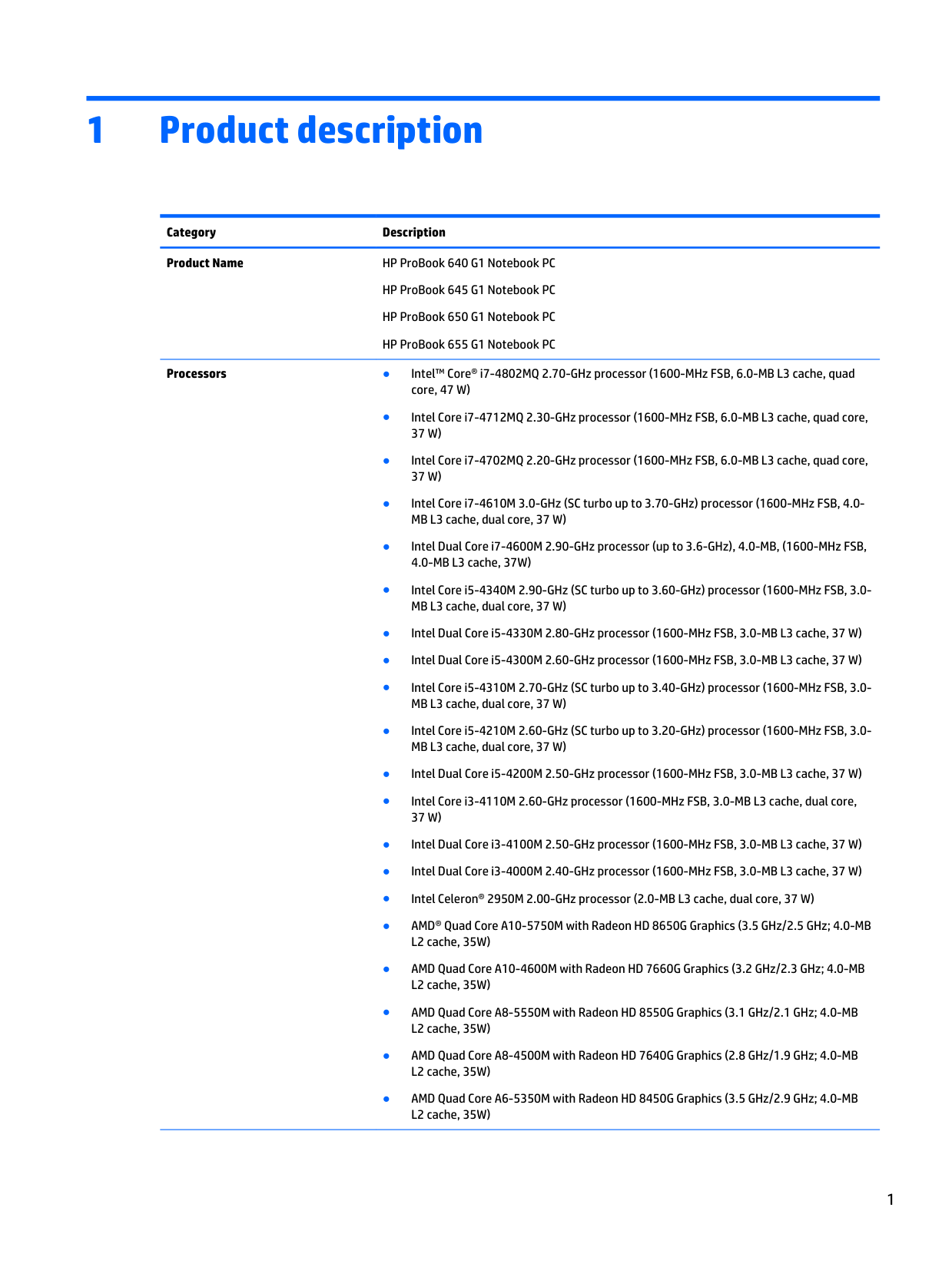
1 Product description Category Description Product Name HP ProBook 640 G1 Notebook PC HP ProBook 645 G1 Notebook PC HP ProBook 650 G1 Notebook PC HP ProBook 655 G1 Notebook PC Processors ● Intel™ Core® i7-4802MQ 2.70-GHz processor (1600-MHz FSB, 6.0-MB L3 cache, quad core, 47 W) ● Intel Core i7-4712MQ 2.30-GHz processor (1600-MHz FSB, 6.0-MB L3 cache, quad core,
37 W)
● Intel Core i7-4702MQ 2.20-GHz processor (1600-MHz FSB, 6.0-MB L3 cache, quad core,37 W)
● Intel Core i7-4610M 3.0-GHz (SC turbo up to 3.70-GHz) processor (1600-MHz FSB, 4.0- MB L3 cache, dual core, 37 W) ● Intel Dual Core i7-4600M 2.90-GHz processor (up to 3.6-GHz), 4.0-MB, (1600-MHz FSB, 4.0-MB L3 cache, 37W) ● Intel Core i5-4340M 2.90-GHz (SC turbo up to 3.60-GHz) processor (1600-MHz FSB, 3.0- MB L3 cache, dual core, 37 W) ● Intel Dual Core i5-4330M 2.80-GHz processor (1600-MHz FSB, 3.0-MB L3 cache, 37 W) ● Intel Dual Core i5-4300M 2.60-GHz processor (1600-MHz FSB, 3.0-MB L3 cache, 37 W) ● Intel Core i5-4310M 2.70-GHz (SC turbo up to 3.40-GHz) processor (1600-MHz FSB, 3.0- MB L3 cache, dual core, 37 W) ● Intel Core i5-4210M 2.60-GHz (SC turbo up to 3.20-GHz) processor (1600-MHz FSB, 3.0- MB L3 cache, dual core, 37 W) ● Intel Dual Core i5-4200M 2.50-GHz processor (1600-MHz FSB, 3.0-MB L3 cache, 37 W) ● Intel Core i3-4110M 2.60-GHz processor (1600-MHz FSB, 3.0-MB L3 cache, dual core,37 W)
● Intel Dual Core i3-4100M 2.50-GHz processor (1600-MHz FSB, 3.0-MB L3 cache, 37 W) ● Intel Dual Core i3-4000M 2.40-GHz processor (1600-MHz FSB, 3.0-MB L3 cache, 37 W) ● Intel Celeron® 2950M 2.00-GHz processor (2.0-MB L3 cache, dual core, 37 W) ● AMD® Quad Core A10-5750M with Radeon HD 8650G Graphics (3.5 GHz/2.5 GHz; 4.0-MB L2 cache, 35W) ● AMD Quad Core A10-4600M with Radeon HD 7660G Graphics (3.2 GHz/2.3 GHz; 4.0-MB L2 cache, 35W) ● AMD Quad Core A8-5550M with Radeon HD 8550G Graphics (3.1 GHz/2.1 GHz; 4.0-MB L2 cache, 35W) ● AMD Quad Core A8-4500M with Radeon HD 7640G Graphics (2.8 GHz/1.9 GHz; 4.0-MB L2 cache, 35W) ● AMD Quad Core A6-5350M with Radeon HD 8450G Graphics (3.5 GHz/2.9 GHz; 4.0-MB L2 cache, 35W) 1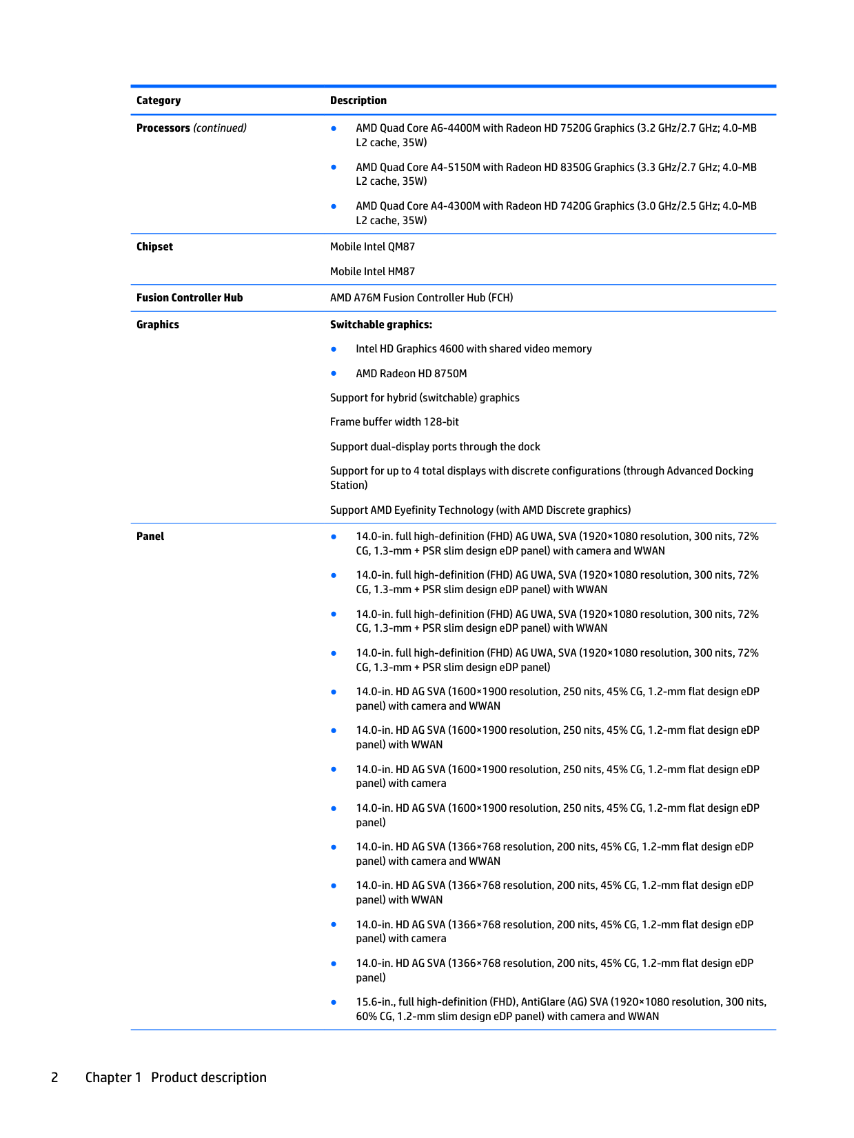
Category Description Processors (continued) ● AMD Quad Core A6-4400M with Radeon HD 7520G Graphics (3.2 GHz/2.7 GHz; 4.0-MB L2 cache, 35W) ● AMD Quad Core A4-5150M with Radeon HD 8350G Graphics (3.3 GHz/2.7 GHz; 4.0-MB L2 cache, 35W) ● AMD Quad Core A4-4300M with Radeon HD 7420G Graphics (3.0 GHz/2.5 GHz; 4.0-MB L2 cache, 35W) Chipset Mobile Intel QM87 Mobile Intel HM87 Fusion Controller Hub AMD A76M Fusion Controller Hub (FCH) Graphics Switchable graphics: ● Intel HD Graphics 4600 with shared video memory ● AMD Radeon HD 8750M Support for hybrid (switchable) graphics Frame buffer width 128-bit Support dual-display ports through the dock Support for up to 4 total displays with discrete configurations (through Advanced Docking Station) Support AMD Eyefinity Technology (with AMD Discrete graphics) Panel ● 14.0-in. full high-definition (FHD) AG UWA, SVA (1920×1080 resolution, 300 nits, 72% CG, 1.3-mm + PSR slim design eDP panel) with camera and WWAN ● 14.0-in. full high-definition (FHD) AG UWA, SVA (1920×1080 resolution, 300 nits, 72% CG, 1.3-mm + PSR slim design eDP panel) with WWAN ● 14.0-in. full high-definition (FHD) AG UWA, SVA (1920×1080 resolution, 300 nits, 72% CG, 1.3-mm + PSR slim design eDP panel) with WWAN ● 14.0-in. full high-definition (FHD) AG UWA, SVA (1920×1080 resolution, 300 nits, 72% CG, 1.3-mm + PSR slim design eDP panel) ● 14.0-in. HD AG SVA (1600×1900 resolution, 250 nits, 45% CG, 1.2-mm flat design eDP panel) with camera and WWAN ● 14.0-in. HD AG SVA (1600×1900 resolution, 250 nits, 45% CG, 1.2-mm flat design eDP panel) with WWAN ● 14.0-in. HD AG SVA (1600×1900 resolution, 250 nits, 45% CG, 1.2-mm flat design eDP panel) with camera ● 14.0-in. HD AG SVA (1600×1900 resolution, 250 nits, 45% CG, 1.2-mm flat design eDP panel) ● 14.0-in. HD AG SVA (1366×768 resolution, 200 nits, 45% CG, 1.2-mm flat design eDP panel) with camera and WWAN ● 14.0-in. HD AG SVA (1366×768 resolution, 200 nits, 45% CG, 1.2-mm flat design eDP panel) with WWAN ● 14.0-in. HD AG SVA (1366×768 resolution, 200 nits, 45% CG, 1.2-mm flat design eDP panel) with camera ● 14.0-in. HD AG SVA (1366×768 resolution, 200 nits, 45% CG, 1.2-mm flat design eDP panel) ● 15.6-in., full high-definition (FHD), AntiGlare (AG) SVA (1920×1080 resolution, 300 nits, 60% CG, 1.2-mm slim design eDP panel) with camera and WWAN 2 Chapter 1 Product description
Category Description Panel (continued) ● 15.6-in. FHD AG SVA (1920×1080 resolution, 300 nits, 60% CG, 1.2-mm slim design eDP panel) with WWAN ● 15.6-in. FHD AG SVA (1920×1080 resolution, 300 nits, 60% CG, 1.2-mm slim design eDP panel) with camera ● 15.6-in. FHD AG SVA (1920×1080 resolution, 300 nits, 60% CG, 1.2-mm slim design eDP panel) ● 15.6-in. (1366×768 resolution) 200 nits, 45% CG, 1.2-mm flat design eDP panel) with camera and WWAN ● 15.6-in. (1366×768 resolution) 200 nits, 45% CG, 1.2-mm flat design eDP panel) with
Wwan
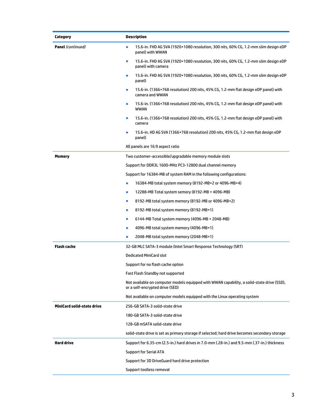
● 15.6-in. (1366×768 resolution) 200 nits, 45% CG, 1.2-mm flat design eDP panel) with camera ● 15.6-in. HD AG SVA (1366×768 resolution) 200 nits, 45% CG, 1.2-mm flat design eDP panel) All panels are 16:9 aspect ratio Memory Two customer-accessible/upgradable memory module slots Support for DDR3L 1600-MHz PC3-12800 dual channel memory Support for 16384-MB of system RAM in the following configurations: ● 16384-MB total system memory (8192-MB×2 or 4096-MB×4) ● 12288-MB Total system semory (8192-MB + 4096-MB) ● 8192-MB total system memory (8192-MB or 4096-MB×2) ● 8192-MB total system memory (8192-MB×1) ● 6144-MB Total system memory (4096-MB + 2048-MB) ● 4096-MB total system memory (4096-MB×1) ● 2048-MB total system memory (2048-MB×1) Flash cache 32-GB MLC SATA-3 module (Intel Smart Response Technology (SRT) Dedicated MiniCard slot Support for no flash cache option Fast Flash Standby not supported Not available on computer models equipped with WWAN capability, a solid-state drive (SSD), or a self-encrypted drive (SED) Not available on computer models equipped with the Linux operating system MiniCard solid-state drive 256-GB SATA-3 solid-state drive 180-GB SATA-3 solid-state drive 128-GB mSATA solid-state drive solid-state drive is set as primary storage if selected; hard drive becomes secondary storage Hard drive Support for 6.35-cm (2.5-in.) hard drives in 7.0-mm (.28-in.) and 9.5-mm (.37-in.) thickness Support for Serial ATA Support for 3D DriveGuard hard drive protection Support toolless removal 3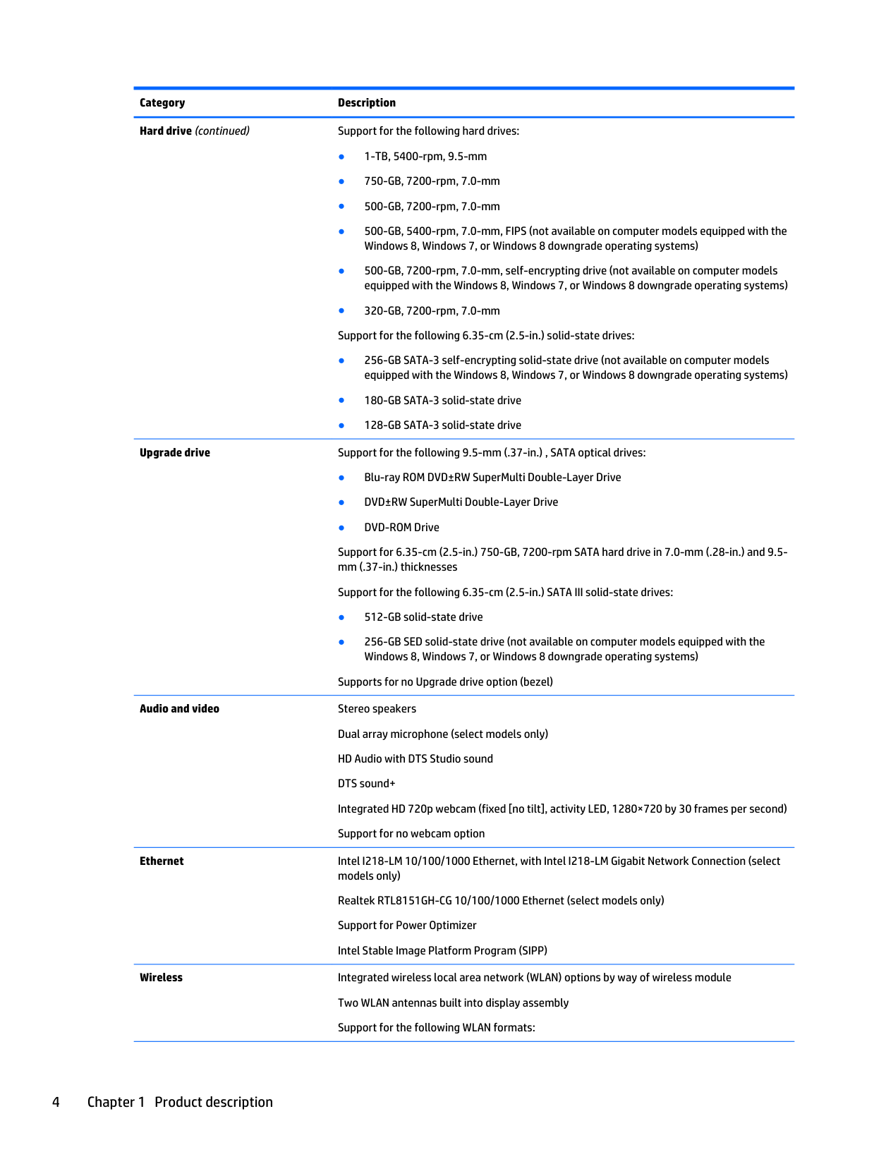
Category Description Hard drive (continued) Support for the following hard drives: ● 1-TB, 5400-rpm, 9.5-mm ● 750-GB, 7200-rpm, 7.0-mm ● 500-GB, 7200-rpm, 7.0-mm ● 500-GB, 5400-rpm, 7.0-mm, FIPS (not available on computer models equipped with the Windows 8, Windows 7, or Windows 8 downgrade operating systems) ● 500-GB, 7200-rpm, 7.0-mm, self-encrypting drive (not available on computer models equipped with the Windows 8, Windows 7, or Windows 8 downgrade operating systems) ● 320-GB, 7200-rpm, 7.0-mm Support for the following 6.35-cm (2.5-in.) solid-state drives: ● 256-GB SATA-3 self-encrypting solid-state drive (not available on computer models equipped with the Windows 8, Windows 7, or Windows 8 downgrade operating systems) ● 180-GB SATA-3 solid-state drive ● 128-GB SATA-3 solid-state drive Upgrade drive Support for the following 9.5-mm (.37-in.) , SATA optical drives: ● Blu-ray ROM DVD±RW SuperMulti Double-Layer Drive ● DVD±RW SuperMulti Double-Layer Drive ● DVD-ROM Drive Support for 6.35-cm (2.5-in.) 750-GB, 7200-rpm SATA hard drive in 7.0-mm (.28-in.) and 9.5- mm (.37-in.) thicknesses Support for the following 6.35-cm (2.5-in.) SATA III solid-state drives: ● 512-GB solid-state drive ● 256-GB SED solid-state drive (not available on computer models equipped with the Windows 8, Windows 7, or Windows 8 downgrade operating systems) Supports for no Upgrade drive option (bezel) Audio and video Stereo speakers Dual array microphone (select models only) HD Audio with DTS Studio sound DTS sound+ Integrated HD 720p webcam (fixed [no tilt], activity LED, 1280×720 by 30 frames per second) Support for no webcam option Ethernet Intel I218-LM 10/100/1000 Ethernet, with Intel I218-LM Gigabit Network Connection (select models only) Realtek RTL8151GH-CG 10/100/1000 Ethernet (select models only) Support for Power Optimizer Intel Stable Image Platform Program (SIPP) Wireless Integrated wireless local area network (WLAN) options by way of wireless module Two WLAN antennas built into display assembly Support for the following WLAN formats: 4 Chapter 1 Product description
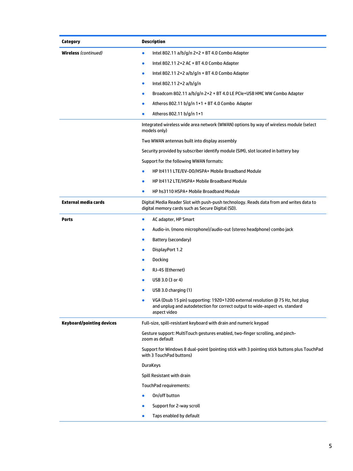
Category Description Wireless (continued) ● Intel 802.11 a/b/g/n 2×2 + BT 4.0 Combo Adapter ● Intel 802.11 2×2 AC + BT 4.0 Combo Adapter ● Intel 802.11 2×2 a/b/g/n + BT 4.0 Combo Adapter ● Intel 802.11 2×2 a/b/g/n ● Broadcom 802.11 a/b/g/n 2×2 + BT 4.0 LE PCIe+USB HMC WW Combo Adapter ● Atheros 802.11 b/g/n 1×1 + BT 4.0 Combo Adapter ● Atheros 802.11 b/g/n 1×1
Integrated wireless wide area network (WWAN) options by way of wireless module (select models only) Two WWAN antennas built into display assembly Security provided by subscriber identify module (SIM), slot located in battery bay Support for the following WWAN formats: ● HP lt4111 LTE/EV-DO/HSPA+ Mobile Broadband Module ● HP lt4112 LTE/HSPA+ Mobile Broadband Module ● HP hs3110 HSPA+ Mobile Broadband Module External media cards Digital Media Reader Slot with push-push technology. Reads data from and writes data to digital memory cards such as Secure Digital (SD). Ports ● AC adapter, HP Smart ● Audio-in. (mono microphone)/audio-out (stereo headphone) combo jack ● Battery (secondary) ● DisplayPort 1.2 ● Docking ● RJ-45 (Ethernet) ● USB 3.0 (3 or 4) ● USB 3.0 charging (1) ● VGA (Dsub 15 pin) supporting: 1920×1200 external resolution @ 75 Hz, hot plug and unplug and autodetection for correct output to wide-aspect vs. standard aspect video Keyboard/pointing devices Full-size, spill-resistant keyboard with drain and numeric keypad Gesture support: MultiTouch gestures enabled, two-finger scrolling, and pinch- zoom as default Support for Windows 8 dual-point (pointing stick with 3 pointing stick buttons plus TouchPad with 3 TouchPad buttons) DuraKeys Spill Resistant with drain TouchPad requirements: ● On/off button ● Support for 2-way scroll ● Taps enabled by default 5
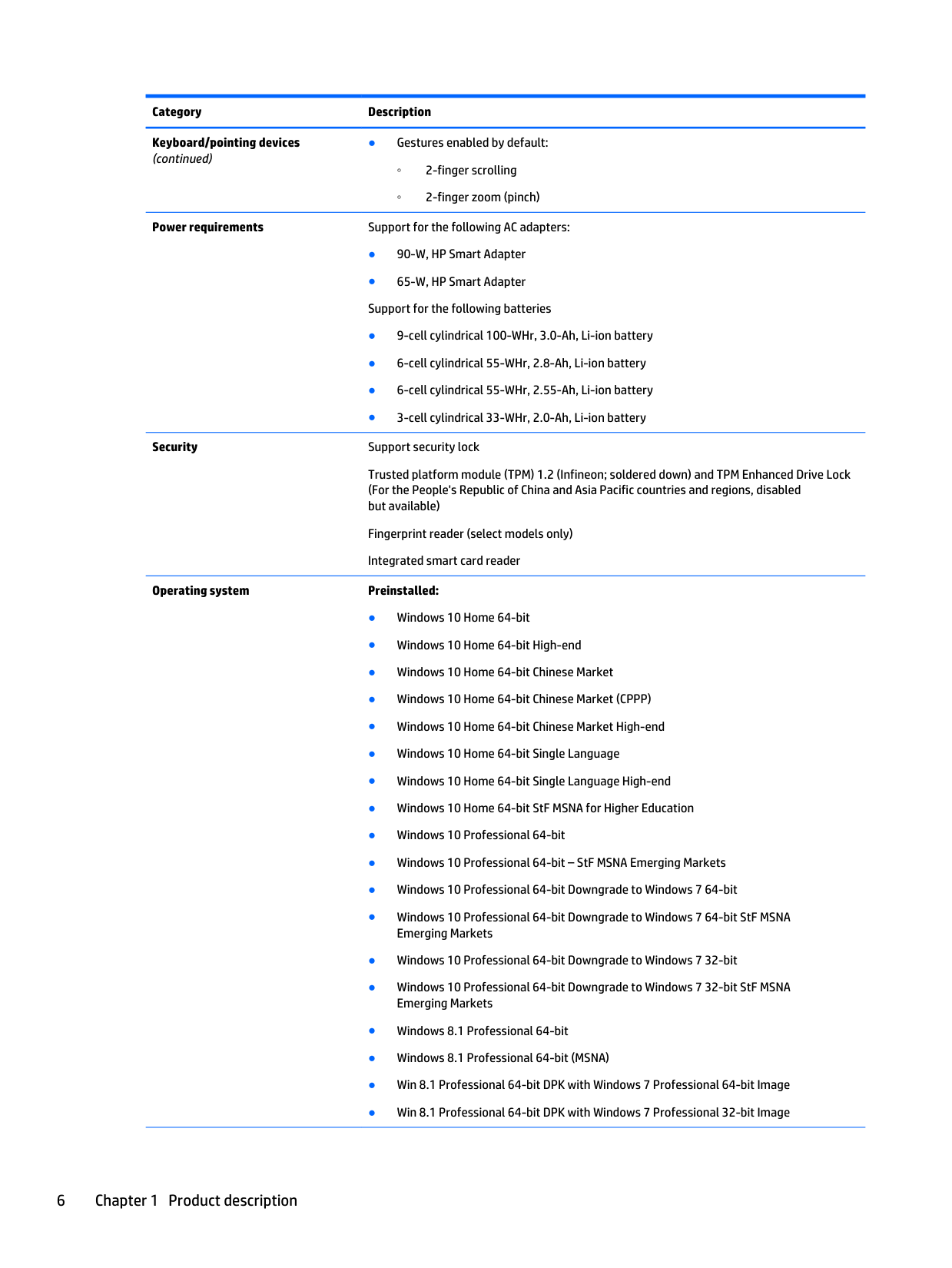
Category Description Keyboard/pointing devices (continued) ● Gestures enabled by default: ◦ 2-finger scrolling ◦ 2-finger zoom (pinch) Power requirements Support for the following AC adapters: ● 90-W, HP Smart Adapter ● 65-W, HP Smart Adapter Support for the following batteries ● 9-cell cylindrical 100-WHr, 3.0-Ah, Li-ion battery ● 6-cell cylindrical 55-WHr, 2.8-Ah, Li-ion battery ● 6-cell cylindrical 55-WHr, 2.55-Ah, Li-ion battery ● 3-cell cylindrical 33-WHr, 2.0-Ah, Li-ion battery Security Support security lock Trusted platform module (TPM) 1.2 (Infineon; soldered down) and TPM Enhanced Drive Lock (For the People's Republic of China and Asia Pacific countries and regions, disabled but available) Fingerprint reader (select models only) Integrated smart card reader Operating system Preinstalled: ● Windows 10 Home 64-bit ● Windows 10 Home 64-bit High-end ● Windows 10 Home 64-bit Chinese Market ● Windows 10 Home 64-bit Chinese Market (CPPP) ● Windows 10 Home 64-bit Chinese Market High-end ● Windows 10 Home 64-bit Single Language ● Windows 10 Home 64-bit Single Language High-end ● Windows 10 Home 64-bit StF MSNA for Higher Education ● Windows 10 Professional 64-bit ● Windows 10 Professional 64-bit – StF MSNA Emerging Markets ● Windows 10 Professional 64-bit Downgrade to Windows 7 64-bit ● Windows 10 Professional 64-bit Downgrade to Windows 7 64-bit StF MSNA Emerging Markets ● Windows 10 Professional 64-bit Downgrade to Windows 7 32-bit ● Windows 10 Professional 64-bit Downgrade to Windows 7 32-bit StF MSNA Emerging Markets ● Windows 8.1 Professional 64-bit ● Windows 8.1 Professional 64-bit (MSNA) ● Win 8.1 Professional 64-bit DPK with Windows 7 Professional 64-bit Image ● Win 8.1 Professional 64-bit DPK with Windows 7 Professional 32-bit Image 6 Chapter 1 Product description
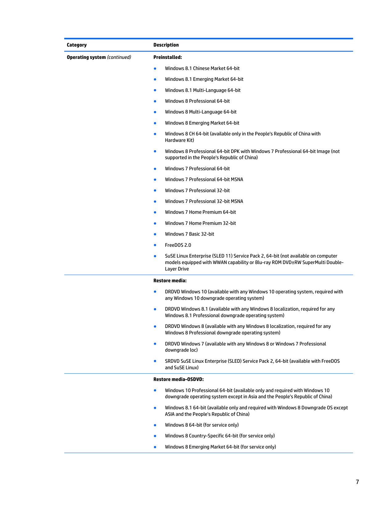
Category Description Operating system (continued) Preinstalled: ● Windows 8.1 Chinese Market 64-bit ● Windows 8.1 Emerging Market 64-bit ● Windows 8.1 Multi-Language 64-bit ● Windows 8 Professional 64-bit ● Windows 8 Multi-Language 64-bit ● Windows 8 Emerging Market 64-bit ● Windows 8 CH 64-bit (available only in the People's Republic of China with Hardware Kit) ● Windows 8 Professional 64-bit DPK with Windows 7 Professional 64-bit Image (not supported in the People's Republic of China) ● Windows 7 Professional 64-bit ● Windows 7 Professional 64-bit MSNA ● Windows 7 Professional 32-bit ● Windows 7 Professional 32-bit MSNA ● Windows 7 Home Premium 64-bit ● Windows 7 Home Premium 32-bit ● Windows 7 Basic 32-bit ● FreeDOS 2.0 ● SuSE Linux Enterprise (SLED 11) Service Pack 2, 64-bit (not available on computer models equipped with WWAN capability or Blu-ray ROM DVD±RW SuperMulti Double- Layer Drive
Restore media: ● DRDVD Windows 10 (available with any Windows 10 operating system, required with any Windows 10 downgrade operating system) ● DRDVD Windows 8.1 (available with any Windows 8 localization, required for any Windows 8.1 Professional downgrade operating system) ● DRDVD Windows 8 (available with any Windows 8 localization, required for any Windows 8 Professional downgrade operating system) ● DRDVD Windows 7 (available with any Windows 8 or Windows 7 Professional downgrade loc) ● SRDVD SuSE Linux Enterprise (SLED) Service Pack 2, 64-bit (available with FreeDOS and SuSE Linux)
Restore media-OSDVD: ● Windows 10 Professional 64-bit (available only and required with Windows 10 downgrade operating system except in Asia and the People's Republic of China) ● Windows 8.1 64-bit (available only and required with Windows 8 Downgrade OS except ASIA and the People's Republic of China) ● Windows 8 64-bit (for service only) ● Windows 8 Country-Specific 64-bit (for service only) ● Windows 8 Emerging Market 64-bit (for service only) 7
Category Description Operating system (continued) Restore media-OSDVD: ● Windows 8 Professional 64-bit (available only and required with Windows 8 downgrade operating systems) ● Windows 7 Professional 64 -bit (available with any Windows 8 Professional or Windows 7 Professional downgrade loc, not available in the People's Republic of China)
Certified: ● Microsoft WHQL ● SuSE Linux Enterprise (SLED) Service Pack 2, 64-bit
Web-only support: ● Windows 10 Enterprise 64-bit ● Windows 8.1 Professional 64-bit ● Windows 8.1 Enterprise 64-bit ● Windows 8.1 Multi-Language 64-bit ● Windows 8.1 Emerging Market 64-bit ● Windows 8.1 Chinese Market 64-bit ● Windows 8 Enterprise 64-bit ● Windows 7 Ultimate 64-bit ● Windows 7 Ultimate 32-bit ● Windows 7 Enterprise 64-bit ● Windows 7 Enterprise 32-bit ● Windows 7 Professional 32-bit ● Windows 7 Basic 64-bit ● Windows 7 Basic 32-bit Serviceability End user replaceable parts: ● AC adapter ● Battery (system) ● Hard drive ● Keyboard ● Memory modules (2, one primary and one expansion) ● Optical drive ● solid-state drive ● WLAN module ● WWAN module 8 Chapter 1 Product description
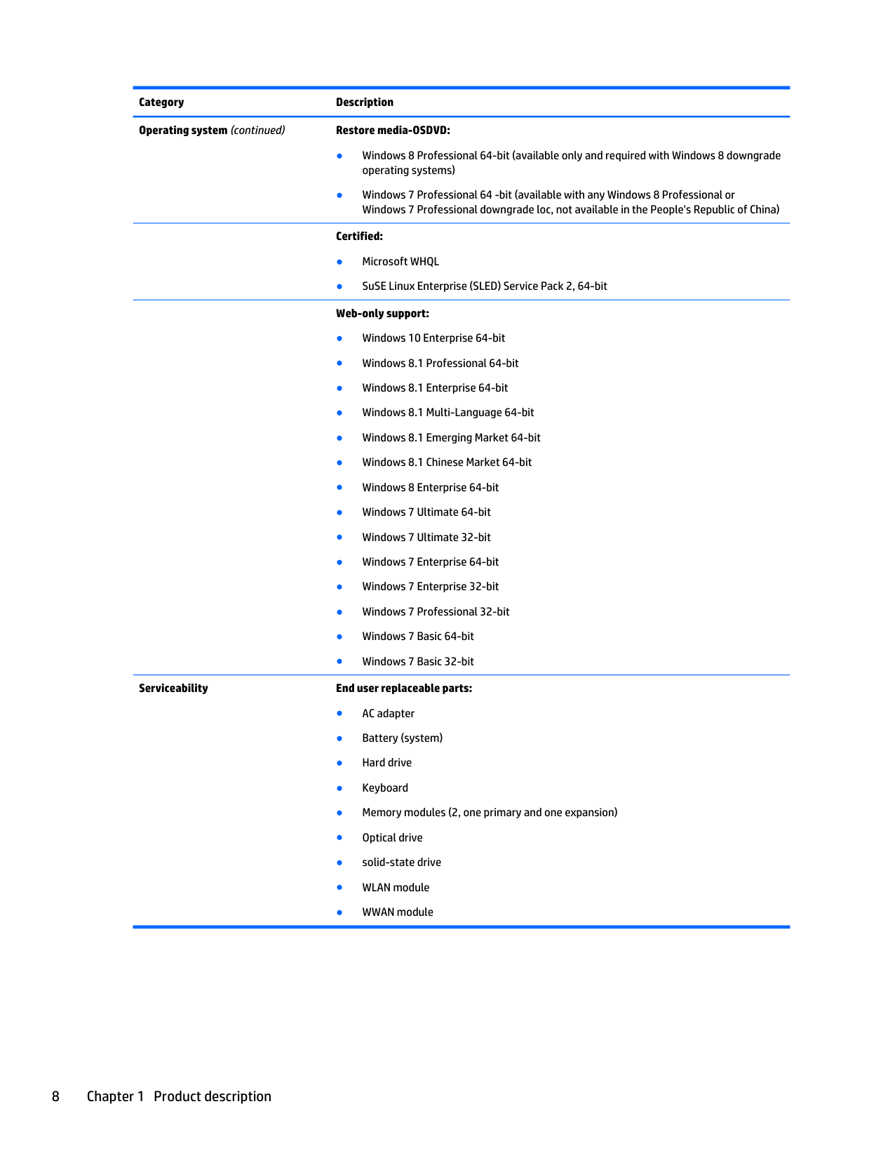
2 External component identification Display
Note:
Your computer may look slightly different from the illustration in this section. Component Description (1) WLAN antennas (2)* Send and receive wireless signals to communicate with wireless local area networks (WLAN). (2) WWAN antennas (2)* (select models only) Send and receive wireless signals to communicate with wireless wide area networks (WWAN). (3) Internal microphones (2) Record sound. (4) Webcam light On: The webcam is in use. (5) Webcam Records video and captures still photographs. For information on using the webcam: ● Windows 10 – Type camera in the taskbar search box, and then select Camera. ● Windows 8 – Access HP Support Assistant. To access HP Support Assistant on the Start screen, select the HP Support Assistant app. ● Windows 7 – Select Start > All Programs > Communication and Chat > HP WebCam. Display 9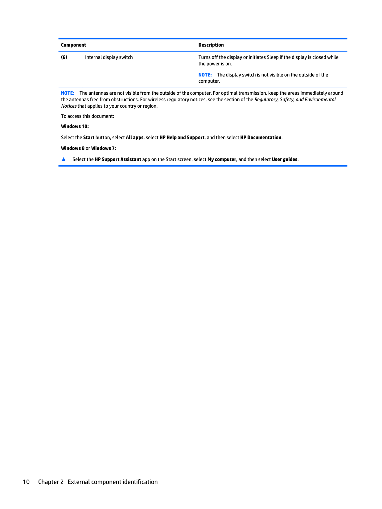
Component Description (6) Internal display switch Turns off the display or initiates Sleep if the display is closed while the power is on.
Note:
The display switch is not visible on the outside of the computer.Note:
The antennas are not visible from the outside of the computer. For optimal transmission, keep the areas immediately around the antennas free from obstructions. For wireless regulatory notices, see the section of the Regulatory, Safety, and Environmental Notices that applies to your country or region. To access this document: Windows 10: Select the Start button, select All apps, select HP Help and Support, and then select HP Documentation. Windows 8 or Windows 7: ▲ Select the HP Support Assistant app on the Start screen, select My computer, and then select User guides. 10 Chapter 2 External component identification
Buttons and fingerprint reader (select models only)
Note:
Your computer may look slightly different from the illustration in this section. Component Description (1)Power button ● When the computer is off, press the button to turn on the computer. ● When the computer is on, press the button briefly to initiate Sleep. ● When the computer is in the Sleep state, press the button briefly to exit Sleep. ● When the computer is in Hibernation, press the button briefly to exit Hibernation.
Caution:
Pressing and holding down the power button will result in the loss of unsaved information. To learn more about your power settings: Windows 10: Type power in the taskbar search box, and then select Power and sleep settings. – or – Right-click the Start button, and then select Power Options. Windows 8: See your power options. From the Start screen, type power, select Settings, and then select Power Options. Windows 7: See your power options. Select Start > Control Panel > System and Settings > Power Options. (2)Speakers (2) Produce sound. Buttons and fingerprint reader (select models only) 11
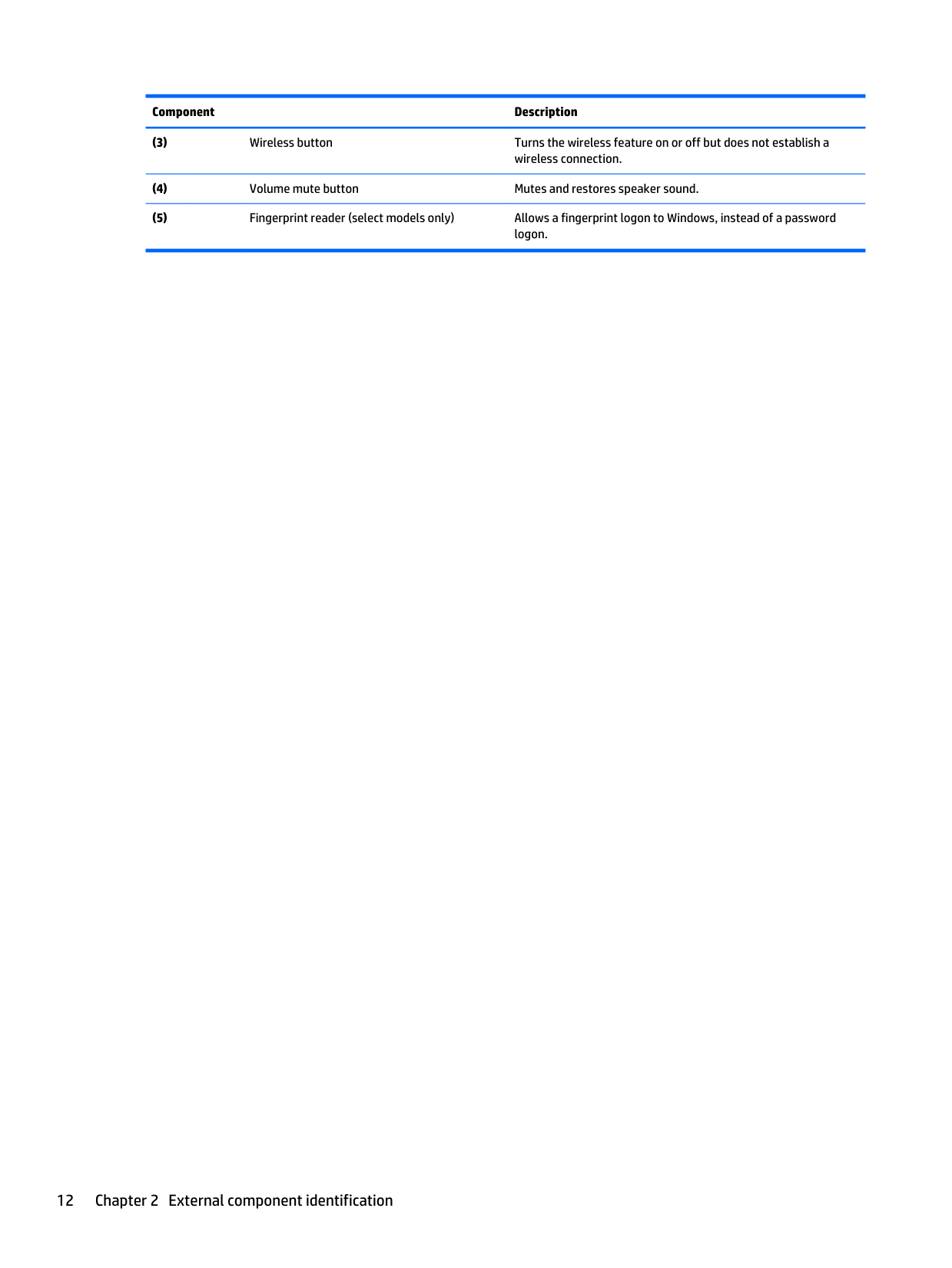
Component Description (3)
Wireless button Turns the wireless feature on or off but does not establish a wireless connection. (4)
Volume mute button Mutes and restores speaker sound. (5)
Fingerprint reader (select models only) Allows a fingerprint logon to Windows, instead of a password logon. 12 Chapter 2 External component identification
Keys
Note:
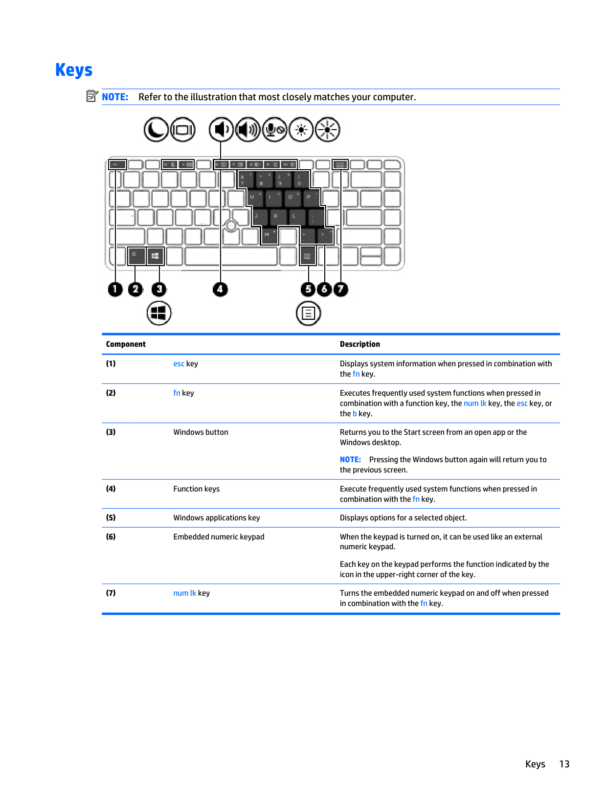
Refer to the illustration that most closely matches your computer. Component Description (1)esc key Displays system information when pressed in combination with the fn key. (2)
fn key Executes frequently used system functions when pressed in combination with a function key, the num lk key, the esc key, or the b key. (3)
Windows button Returns you to the Start screen from an open app or the Windows desktop.
Note:
Pressing the Windows button again will return you to the previous screen. (4)Function keys Execute frequently used system functions when pressed in combination with the fn key. (5)
Windows applications key Displays options for a selected object. (6)
Embedded numeric keypad When the keypad is turned on, it can be used like an external numeric keypad. Each key on the keypad performs the function indicated by the icon in the upper-right corner of the key. (7)
num lk key Turns the embedded numeric keypad on and off when pressed in combination with the fn key. Keys 13
Component Description (1)
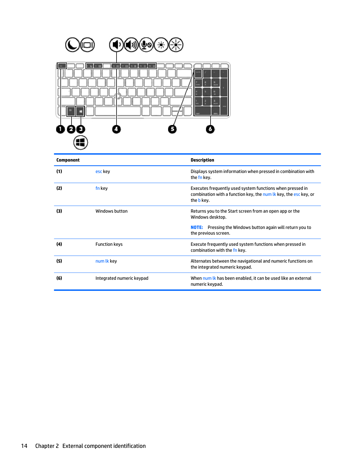
esc key Displays system information when pressed in combination with the fn key. (2)
fn key Executes frequently used system functions when pressed in combination with a function key, the num lk key, the esc key, or the b key. (3)
Windows button Returns you to the Start screen from an open app or the Windows desktop.
Note:
Pressing the Windows button again will return you to the previous screen. (4)Function keys Execute frequently used system functions when pressed in combination with the fn key. (5)
num lk key Alternates between the navigational and numeric functions on the integrated numeric keypad. (6)
Integrated numeric keypad When num lk has been enabled, it can be used like an external numeric keypad. 14 Chapter 2 External component identification
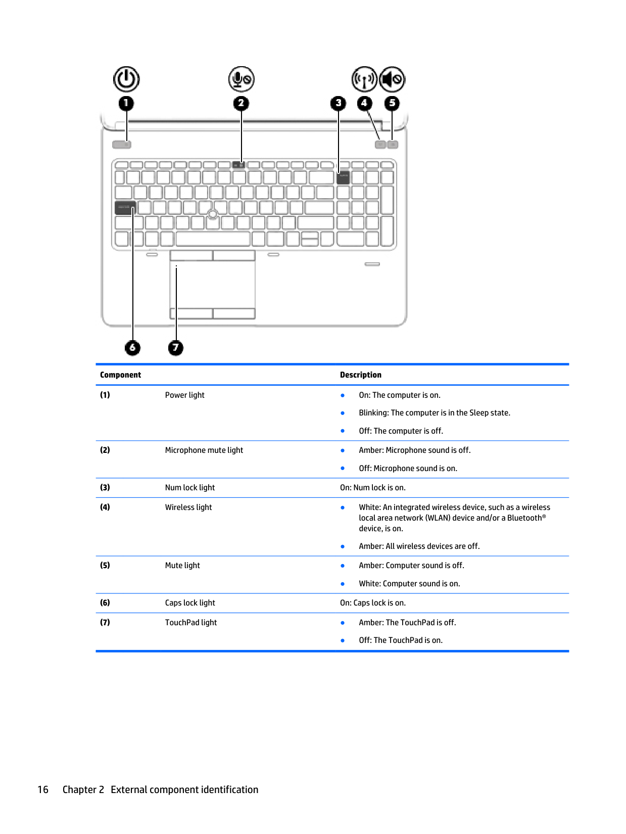
Lights
Note:
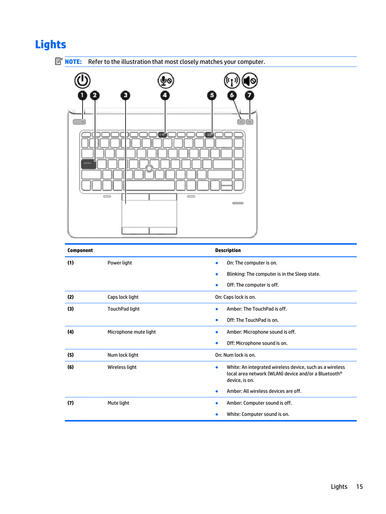
Refer to the illustration that most closely matches your computer. Component Description (1)Power light ● On: The computer is on. ● Blinking: The computer is in the Sleep state. ● Off: The computer is off. (2)
Caps lock light On: Caps lock is on. (3)
TouchPad light ● Amber: The TouchPad is off. ● Off: The TouchPad is on. (4)
Microphone mute light ● Amber: Microphone sound is off. ● Off: Microphone sound is on. (5)
Num lock light On: Num lock is on. (6)
Wireless light ● White: An integrated wireless device, such as a wireless local area network (WLAN) device and/or a Bluetooth® device, is on. ● Amber: All wireless devices are off. (7)
Mute light ● Amber: Computer sound is off. ● White: Computer sound is on. Lights 15
Component Description (1)
Power light ● On: The computer is on. ● Blinking: The computer is in the Sleep state. ● Off: The computer is off. (2)
Microphone mute light ● Amber: Microphone sound is off. ● Off: Microphone sound is on. (3)
Num lock light On: Num lock is on. (4)
Wireless light ● White: An integrated wireless device, such as a wireless local area network (WLAN) device and/or a Bluetooth® device, is on. ● Amber: All wireless devices are off. (5)
Mute light ● Amber: Computer sound is off. ● White: Computer sound is on. (6)
Caps lock light On: Caps lock is on. (7)
TouchPad light ● Amber: The TouchPad is off. ● Off: The TouchPad is on. 16 Chapter 2 External component identification
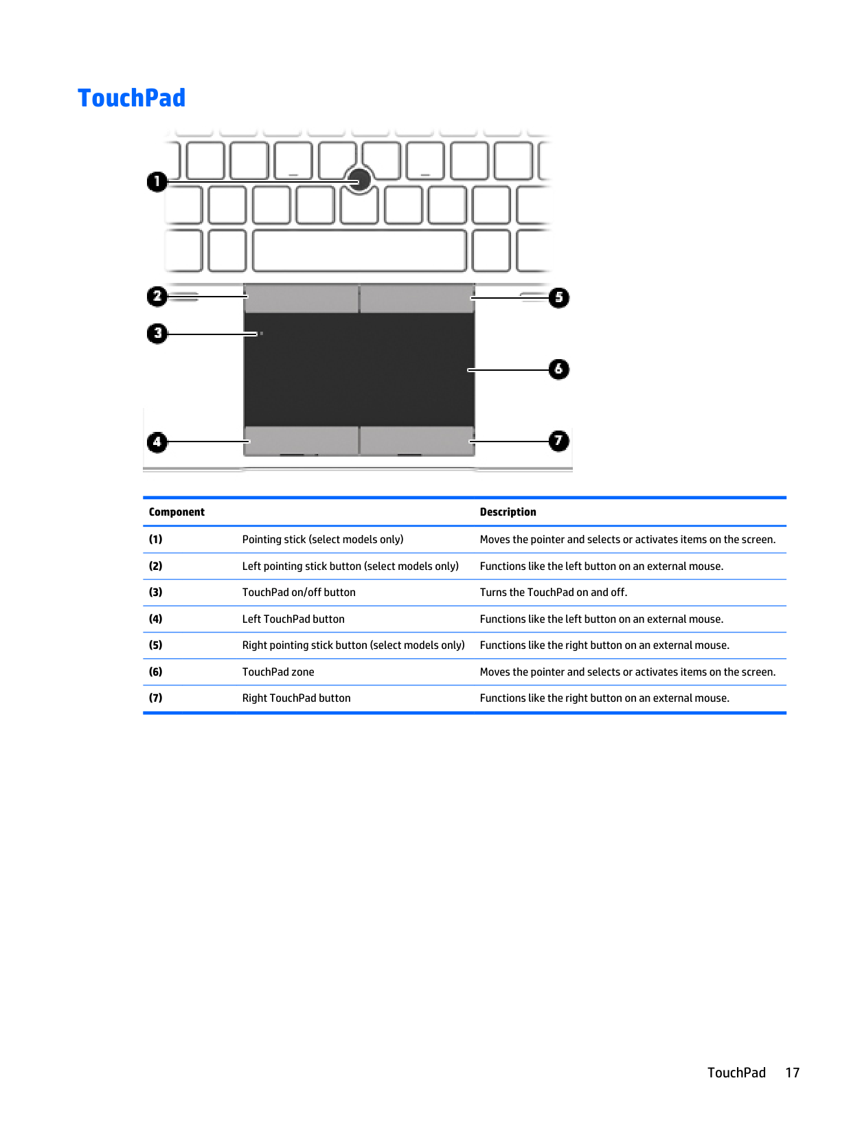
TouchPad Component Description (1)
Pointing stick (select models only) Moves the pointer and selects or activates items on the screen. (2)
Left pointing stick button (select models only) Functions like the left button on an external mouse. (3)
TouchPad on/off button Turns the TouchPad on and off. (4)
Left TouchPad button Functions like the left button on an external mouse. (5)
Right pointing stick button (select models only) Functions like the right button on an external mouse. (6)
TouchPad zone Moves the pointer and selects or activates items on the screen. (7)
Right TouchPad button Functions like the right button on an external mouse. TouchPad 17
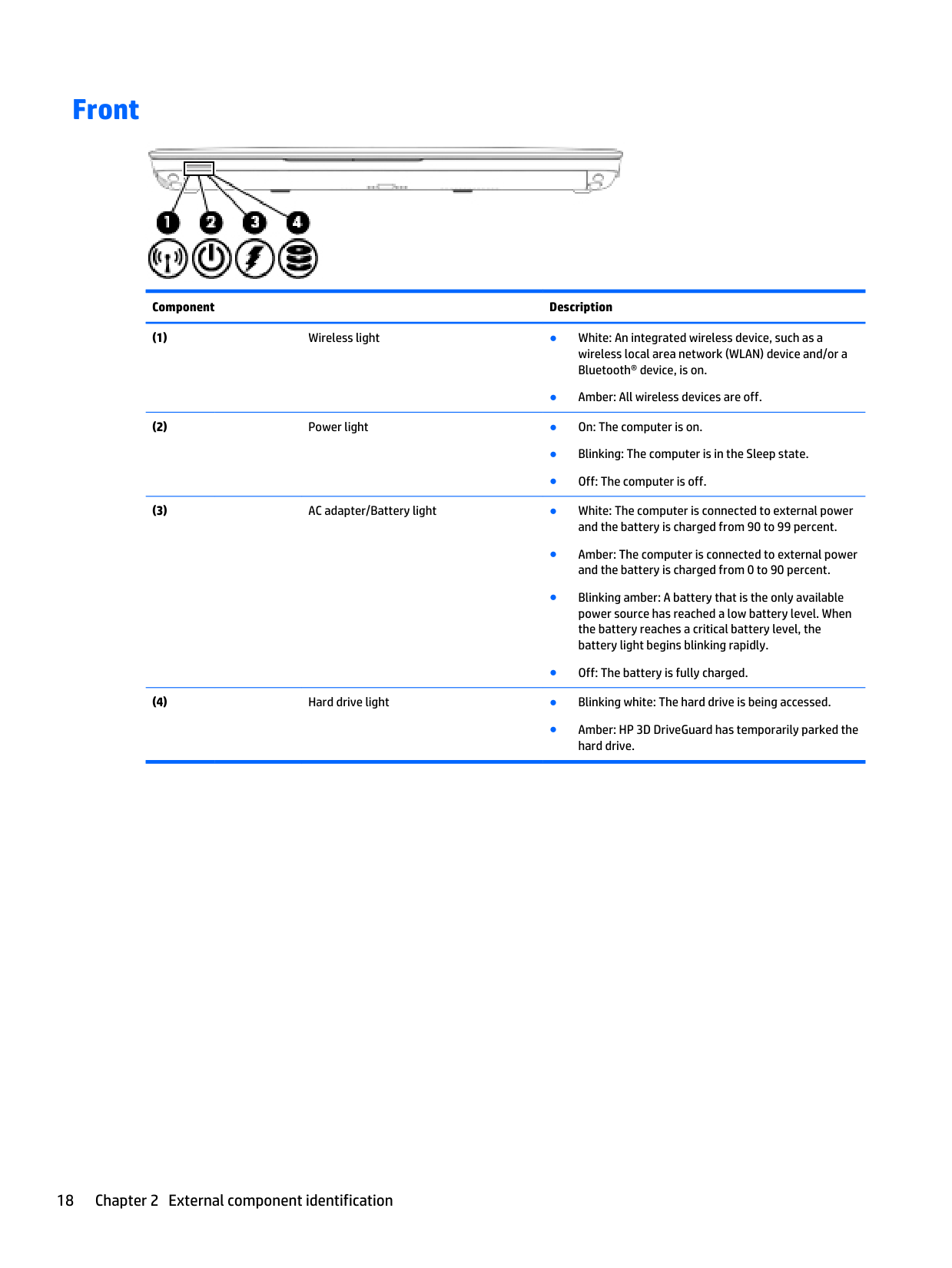
Front Component Description (1)
Wireless light ● White: An integrated wireless device, such as a wireless local area network (WLAN) device and/or a Bluetooth® device, is on. ● Amber: All wireless devices are off. (2)
Power light ● On: The computer is on. ● Blinking: The computer is in the Sleep state. ● Off: The computer is off. (3)
AC adapter/Battery light ● White: The computer is connected to external power and the battery is charged from 90 to 99 percent. ● Amber: The computer is connected to external power and the battery is charged from 0 to 90 percent. ● Blinking amber: A battery that is the only available power source has reached a low battery level. When the battery reaches a critical battery level, the battery light begins blinking rapidly. ● Off: The battery is fully charged. (4)
Hard drive light ● Blinking white: The hard drive is being accessed. ● Amber: HP 3D DriveGuard has temporarily parked the hard drive. 18 Chapter 2 External component identification
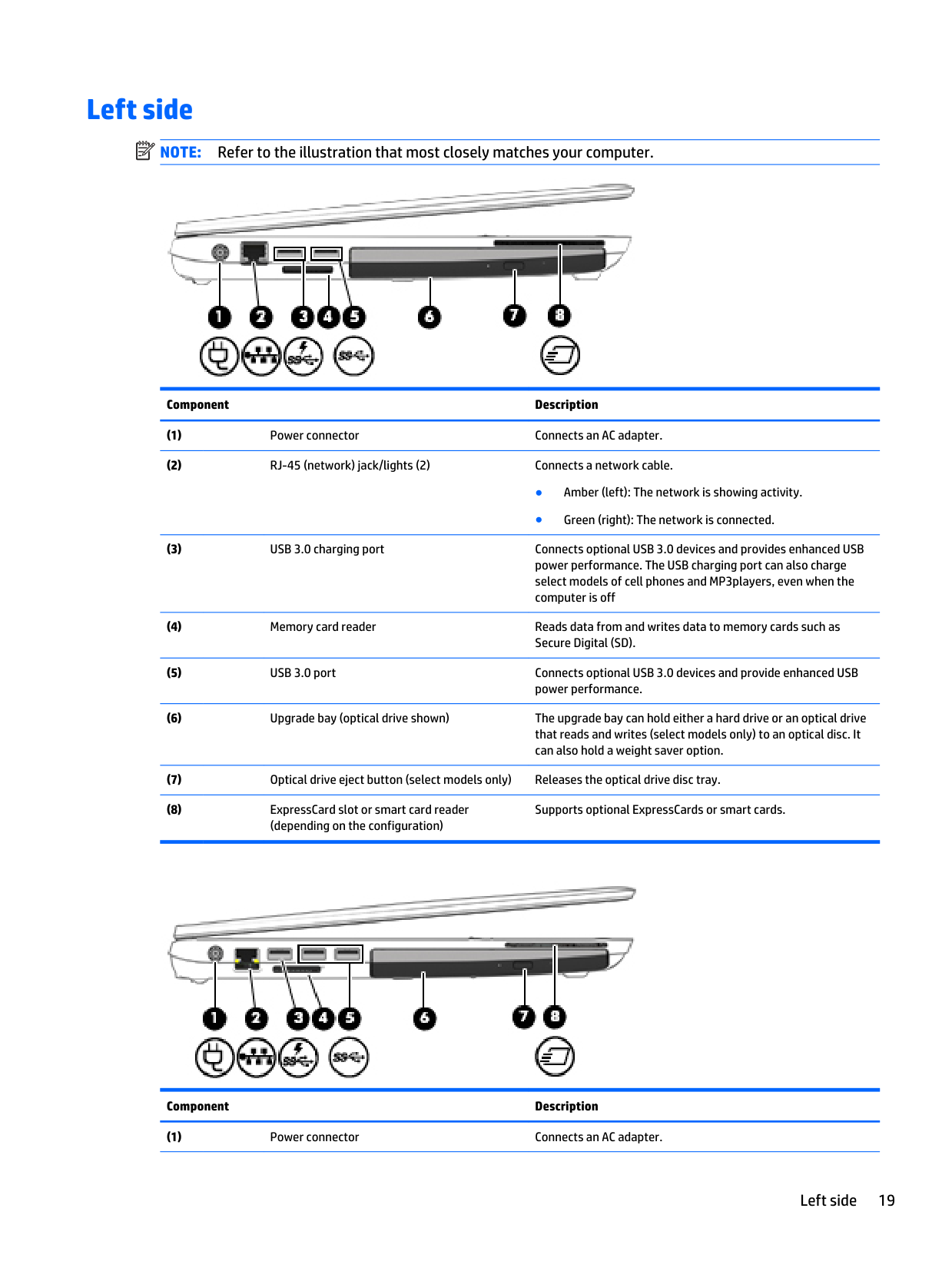
Left side
Note:
Refer to the illustration that most closely matches your computer. Component Description (1)Power connector Connects an AC adapter. (2)
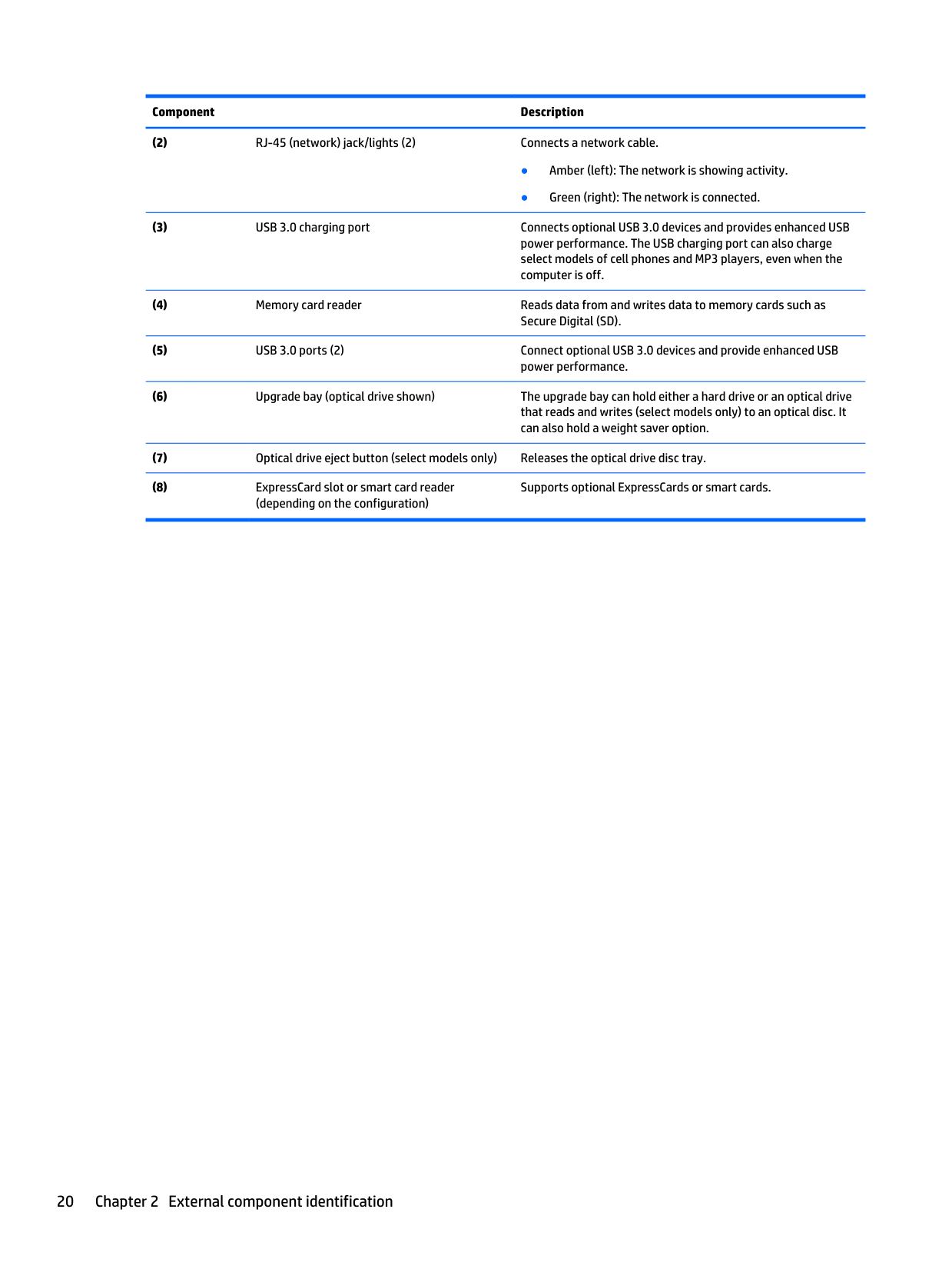
RJ-45 (network) jack/lights (2) Connects a network cable. ● Amber (left): The network is showing activity. ● Green (right): The network is connected. (3)
USB 3.0 charging port Connects optional USB 3.0 devices and provides enhanced USB power performance. The USB charging port can also charge select models of cell phones and MP3players, even when the computer is off (4)
Memory card reader Reads data from and writes data to memory cards such as Secure Digital (SD). (5)
USB 3.0 port Connects optional USB 3.0 devices and provide enhanced USB power performance. (6)
Upgrade bay (optical drive shown) The upgrade bay can hold either a hard drive or an optical drive that reads and writes (select models only) to an optical disc. It can also hold a weight saver option. (7)
Optical drive eject button (select models only) Releases the optical drive disc tray. (8)
ExpressCard slot or smart card reader (depending on the configuration) Supports optional ExpressCards or smart cards. Component Description (1)
Power connector Connects an AC adapter. Left side 19
Component Description (2)
RJ-45 (network) jack/lights (2) Connects a network cable. ● Amber (left): The network is showing activity. ● Green (right): The network is connected. (3)
USB 3.0 charging port Connects optional USB 3.0 devices and provides enhanced USB power performance. The USB charging port can also charge select models of cell phones and MP3 players, even when the computer is off. (4)
Memory card reader Reads data from and writes data to memory cards such as Secure Digital (SD). (5)
USB 3.0 ports (2) Connect optional USB 3.0 devices and provide enhanced USB power performance. (6)
Upgrade bay (optical drive shown) The upgrade bay can hold either a hard drive or an optical drive that reads and writes (select models only) to an optical disc. It can also hold a weight saver option. (7)
Optical drive eject button (select models only) Releases the optical drive disc tray. (8)
ExpressCard slot or smart card reader (depending on the configuration) Supports optional ExpressCards or smart cards. 20 Chapter 2 External component identification
Right side
Note:
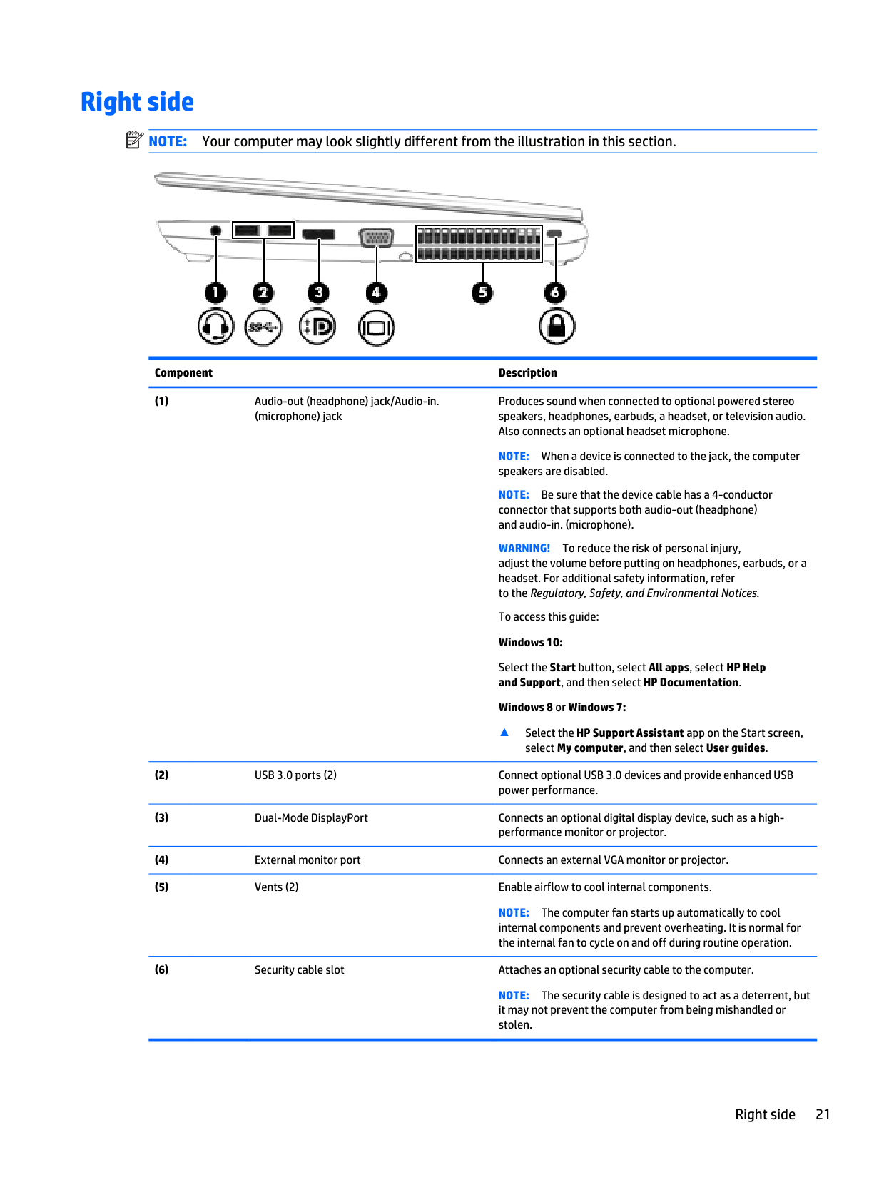
Your computer may look slightly different from the illustration in this section. Component Description (1)Audio-out (headphone) jack/Audio-in. (microphone) jack Produces sound when connected to optional powered stereo speakers, headphones, earbuds, a headset, or television audio. Also connects an optional headset microphone.
Note:
When a device is connected to the jack, the computer speakers are disabled.Note:
Be sure that the device cable has a 4-conductor connector that supports both audio-out (headphone) and audio-in. (microphone).Warning!
To reduce the risk of personal injury, adjust the volume before putting on headphones, earbuds, or a headset. For additional safety information, refer to the Regulatory, Safety, and Environmental Notices. To access this guide: Windows 10: Select the Start button, select All apps, select HP Help and Support, and then select HP Documentation. Windows 8 or Windows 7: ▲ Select the HP Support Assistant app on the Start screen, select My computer, and then select User guides. (2)USB 3.0 ports (2) Connect optional USB 3.0 devices and provide enhanced USB power performance. (3)
Dual-Mode DisplayPort Connects an optional digital display device, such as a high- performance monitor or projector. (4)
External monitor port Connects an external VGA monitor or projector. (5)
Vents (2) Enable airflow to cool internal components.
Note:
The computer fan starts up automatically to cool internal components and prevent overheating. It is normal for the internal fan to cycle on and off during routine operation. (6)Security cable slot Attaches an optional security cable to the computer.
Note:
The security cable is designed to act as a deterrent, but it may not prevent the computer from being mishandled or stolen. Right side 21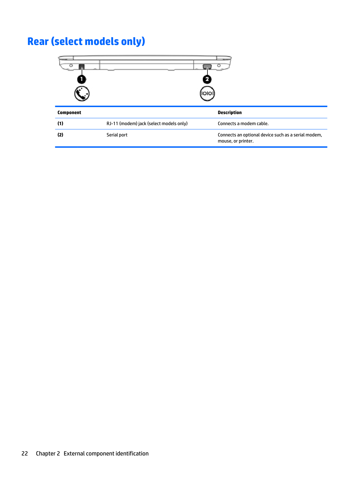
Rear (select models only) Component Description (1)
RJ-11 (modem) jack (select models only) Connects a modem cable. (2)
Serial port Connects an optional device such as a serial modem, mouse, or printer. 22 Chapter 2 External component identification
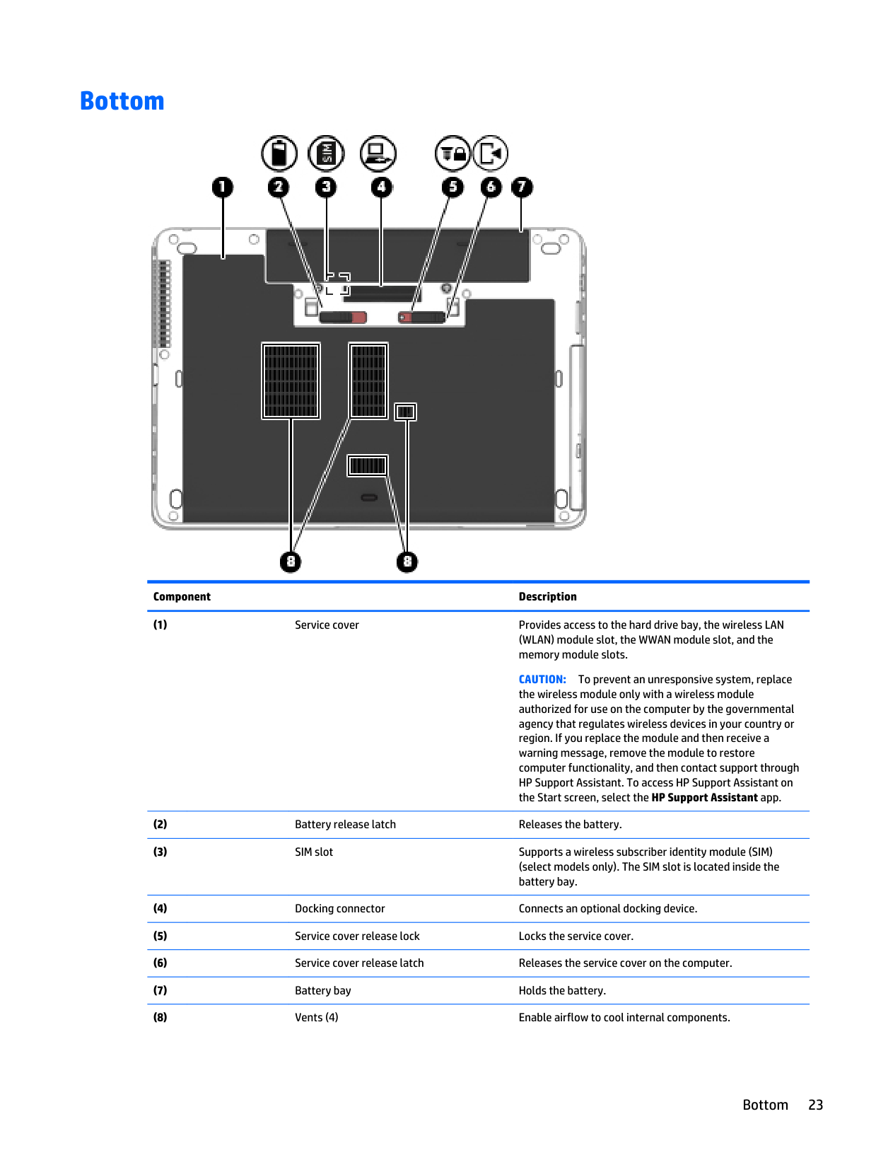
Bottom Component Description (1)
Service cover Provides access to the hard drive bay, the wireless LAN (WLAN) module slot, the WWAN module slot, and the memory module slots.
Caution:
To prevent an unresponsive system, replace the wireless module only with a wireless module authorized for use on the computer by the governmental agency that regulates wireless devices in your country or region. If you replace the module and then receive a warning message, remove the module to restore computer functionality, and then contact support through HP Support Assistant. To access HP Support Assistant on the Start screen, select the HP Support Assistant app. (2)Battery release latch Releases the battery. (3)
SIM slot Supports a wireless subscriber identity module (SIM) (select models only). The SIM slot is located inside the battery bay. (4)
Docking connector Connects an optional docking device. (5)
Service cover release lock Locks the service cover. (6)
Service cover release latch Releases the service cover on the computer. (7)
Battery bay Holds the battery. (8)
Vents (4) Enable airflow to cool internal components. Bottom 23

Component Description
Note:
The computer fan starts up automatically to cool internal components and prevent overheating. It is normal for the internal fan to cycle on and off during routine operation. 24 Chapter 2 External component identification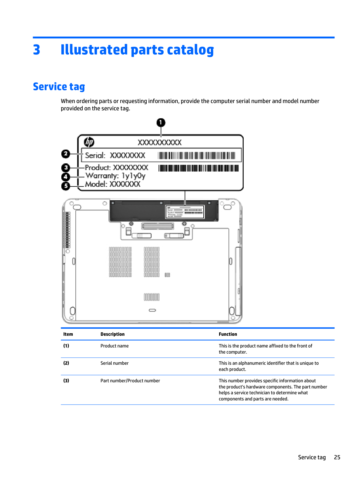
3 Illustrated parts catalog Service tag When ordering parts or requesting information, provide the computer serial number and model number provided on the service tag. Item Description Function (1) Product name This is the product name affixed to the front of the computer. (2) Serial number This is an alphanumeric identifier that is unique to each product. (3) Part number/Product number This number provides specific information about the product's hardware components. The part number helps a service technician to determine what components and parts are needed. Service tag 25
Item Description Function (4) Warranty period This number describes the duration of the warranty period for the computer. (5) Model description This is the alphanumeric identifier used to locate documents, drivers, and support for the computer. 26 Chapter 3 Illustrated parts catalog
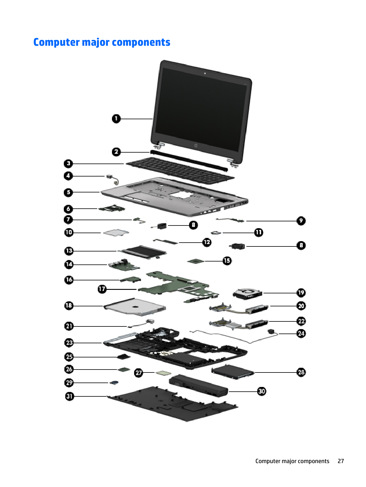
Computer major components Computer major components 27
Item Component Spare part number (1) Display panel:
15.6-in., FHD, WLED UWVA 15.6-in., HD, WLED UWVA 739998-001 739997-001
14-in., HD WLED 14-in., HD+ WLED 14-in., FHD, WLED UWVA 747751-001 747752-001 747753-001
Display Panel Support Kit (includes LCD back cover and wireless antennas and transceivers):
For use on models equipped with a 15.6-in. display assembly 738691-001
For use on models equipped with a 14-in. display assembly 738680-001 (2) Top hinge cover for 15.6-in. models
(3) Keyboard (includes keyboard cable):
Keyboard for 15.6-in. models with pointing stick (includes keyboard cable and pointing stick cable):
For use on Belgium
738697-A41
For use on Brazil 738697-201
For use on Bulgaria 738697-261
For use on Canada
738697-Db1
For use on the Czech Republic and Slovakia
738697-Fl1
For use on Denmark 738697-081
For use on France 738697-051
For use on Germany 738697-041
For use on Greece 738697-151
For use on Hungary 738697-211
For use on Iceland
738697-Dd1
For use on India
738697-D61
For use on Israel
738697-Bb1
For use on Italy 738697-061
For use on Japan 738697-291
For use on Latin America 738697-161
For use on the Netherlands
738697-B31
For use on Northwest Africa
738697-Fp1
For use on Norway 738697-091
For use on Portugal 738697-131
For use on Romania 738697-271
For use on Russia 738697-251 28 Chapter 3 Illustrated parts catalog
Item Component Spare part number
For use on Saudi Arabia 738697-171
For use on Slovenia
738697-Ba1
For use on South Korea
738697-Ad1
For use on Spain 738697-071
For use on Sweden and Finland
738697-B71
For use on Switzerland
738697-Bg1
For use on Taiwan
738697-Ab1
For use on Thailand 738697-281
For use on Turkey 738697-141
For use on Turkey, F-type keyboard 738697-541
For use on the United Kingdom and Singapore 738697-031
For use on the United States 738697-001
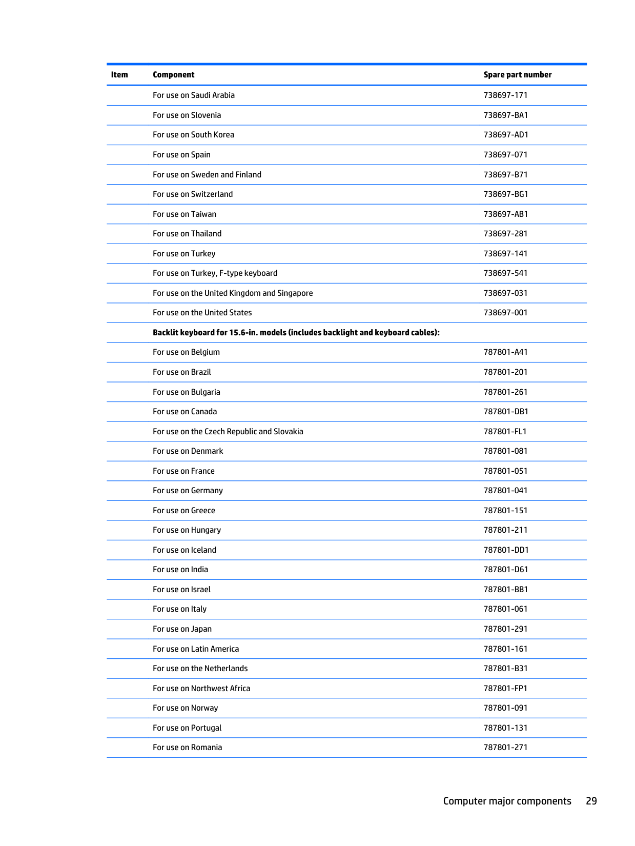
Backlit keyboard for 15.6-in. models (includes backlight and keyboard cables):
For use on Belgium
787801-A41
For use on Brazil 787801-201
For use on Bulgaria 787801-261
For use on Canada
787801-Db1
For use on the Czech Republic and Slovakia
787801-Fl1
For use on Denmark 787801-081
For use on France 787801-051
For use on Germany 787801-041
For use on Greece 787801-151
For use on Hungary 787801-211
For use on Iceland
787801-Dd1
For use on India
787801-D61
For use on Israel
787801-Bb1
For use on Italy 787801-061
For use on Japan 787801-291
For use on Latin America 787801-161
For use on the Netherlands
787801-B31
For use on Northwest Africa
787801-Fp1
For use on Norway 787801-091
For use on Portugal 787801-131
For use on Romania 787801-271 Computer major components 29
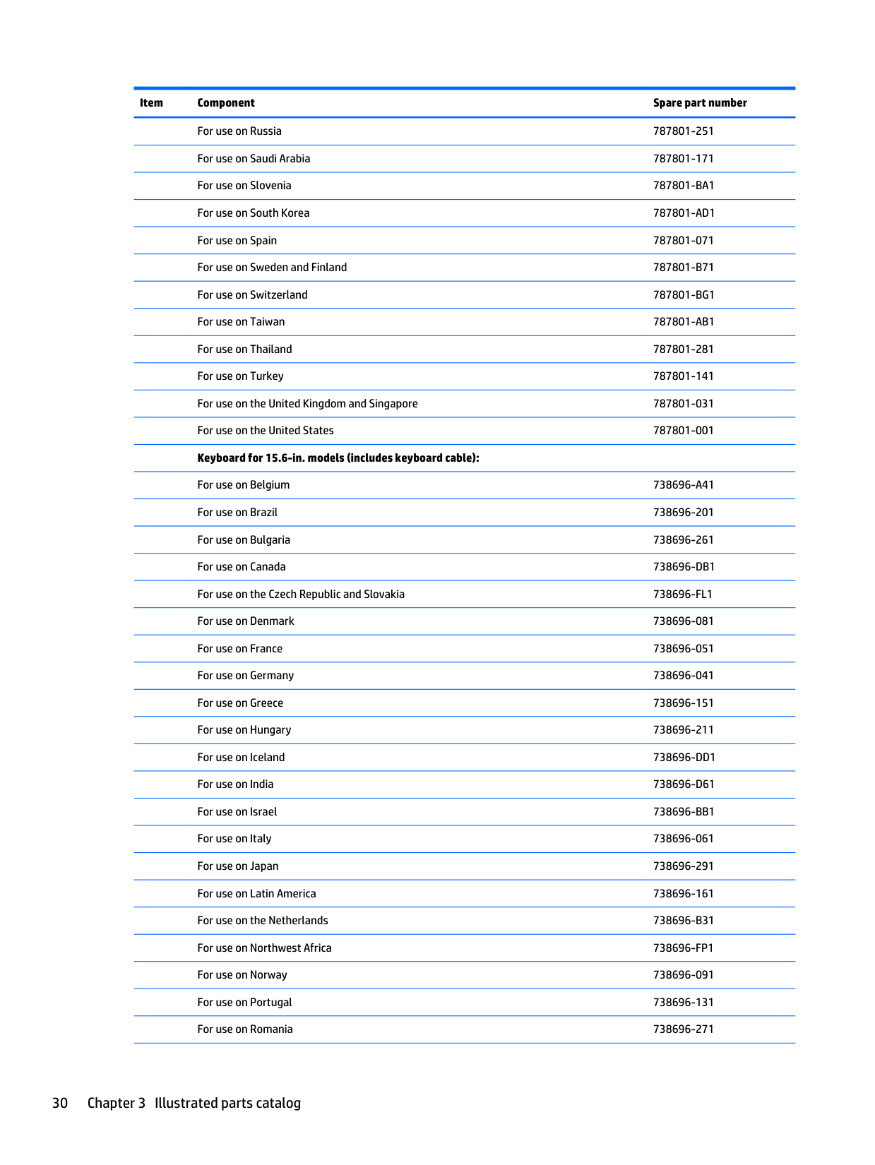
Item Component Spare part number
For use on Russia 787801-251
For use on Saudi Arabia 787801-171
For use on Slovenia
787801-Ba1
For use on South Korea
787801-Ad1
For use on Spain 787801-071
For use on Sweden and Finland
787801-B71
For use on Switzerland
787801-Bg1
For use on Taiwan
787801-Ab1
For use on Thailand 787801-281
For use on Turkey 787801-141
For use on the United Kingdom and Singapore 787801-031
For use on the United States 787801-001
Keyboard for 15.6-in. models (includes keyboard cable):
For use on Belgium
738696-A41
For use on Brazil 738696-201
For use on Bulgaria 738696-261
For use on Canada
738696-Db1
For use on the Czech Republic and Slovakia
738696-Fl1
For use on Denmark 738696-081
For use on France 738696-051
For use on Germany 738696-041
For use on Greece 738696-151
For use on Hungary 738696-211
For use on Iceland
738696-Dd1
For use on India
738696-D61
For use on Israel
738696-Bb1
For use on Italy 738696-061
For use on Japan 738696-291
For use on Latin America 738696-161
For use on the Netherlands
738696-B31
For use on Northwest Africa
738696-Fp1
For use on Norway 738696-091
For use on Portugal 738696-131
For use on Romania 738696-271 30 Chapter 3 Illustrated parts catalog
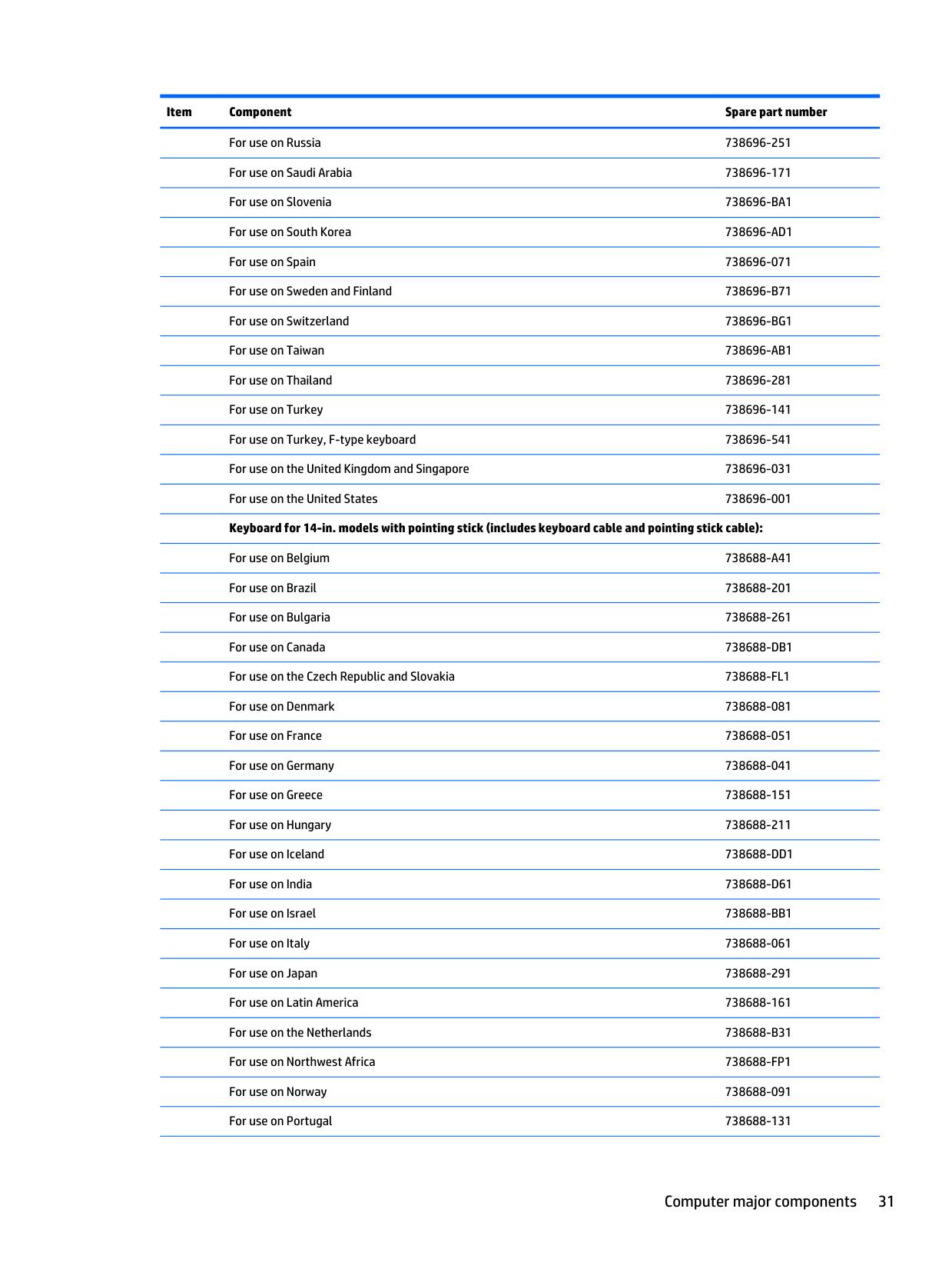
Item Component Spare part number
For use on Russia 738696-251
For use on Saudi Arabia 738696-171
For use on Slovenia
738696-Ba1
For use on South Korea
738696-Ad1
For use on Spain 738696-071
For use on Sweden and Finland
738696-B71
For use on Switzerland
738696-Bg1
For use on Taiwan
738696-Ab1
For use on Thailand 738696-281
For use on Turkey 738696-141
For use on Turkey, F-type keyboard 738696-541
For use on the United Kingdom and Singapore 738696-031
For use on the United States 738696-001
Keyboard for 14-in. models with pointing stick (includes keyboard cable and pointing stick cable):
For use on Belgium
738688-A41
For use on Brazil 738688-201
For use on Bulgaria 738688-261
For use on Canada
738688-Db1
For use on the Czech Republic and Slovakia
738688-Fl1
For use on Denmark 738688-081
For use on France 738688-051
For use on Germany 738688-041
For use on Greece 738688-151
For use on Hungary 738688-211
For use on Iceland
738688-Dd1
For use on India
738688-D61
For use on Israel
738688-Bb1
For use on Italy 738688-061
For use on Japan 738688-291
For use on Latin America 738688-161
For use on the Netherlands
738688-B31
For use on Northwest Africa
738688-Fp1
For use on Norway 738688-091
For use on Portugal 738688-131 Computer major components 31
Item Component Spare part number
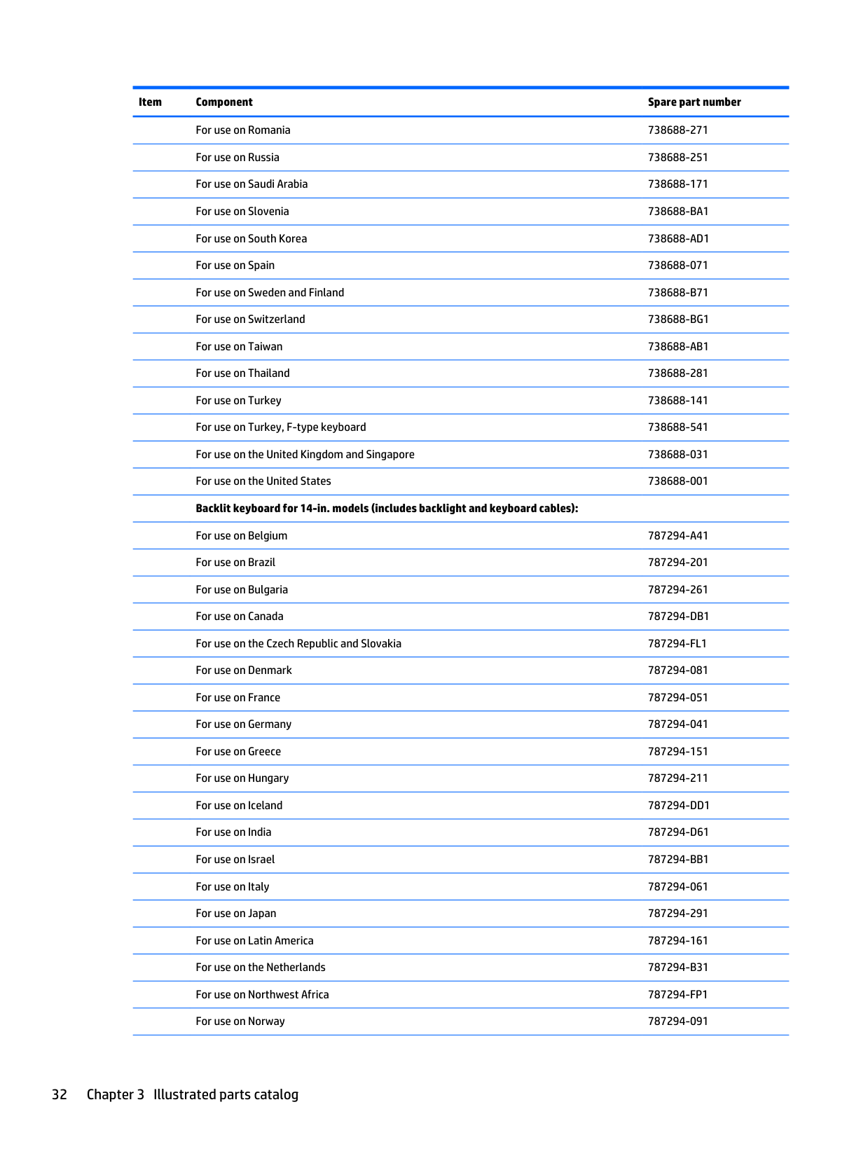
For use on Romania 738688-271
For use on Russia 738688-251
For use on Saudi Arabia 738688-171
For use on Slovenia
738688-Ba1
For use on South Korea
738688-Ad1
For use on Spain 738688-071
For use on Sweden and Finland
738688-B71
For use on Switzerland
738688-Bg1
For use on Taiwan
738688-Ab1
For use on Thailand 738688-281
For use on Turkey 738688-141
For use on Turkey, F-type keyboard 738688-541
For use on the United Kingdom and Singapore 738688-031
For use on the United States 738688-001
Backlit keyboard for 14-in. models (includes backlight and keyboard cables):
For use on Belgium
787294-A41
For use on Brazil 787294-201
For use on Bulgaria 787294-261
For use on Canada
787294-Db1
For use on the Czech Republic and Slovakia
787294-Fl1
For use on Denmark 787294-081
For use on France 787294-051
For use on Germany 787294-041
For use on Greece 787294-151
For use on Hungary 787294-211
For use on Iceland
787294-Dd1
For use on India
787294-D61
For use on Israel
787294-Bb1
For use on Italy 787294-061
For use on Japan 787294-291
For use on Latin America 787294-161
For use on the Netherlands
787294-B31
For use on Northwest Africa
787294-Fp1
For use on Norway 787294-091 32 Chapter 3 Illustrated parts catalog
Item Component Spare part number
For use on Portugal 787294-131
For use on Romania 787294-271
For use on Russia 787294-251
For use on Saudi Arabia 787294-171
For use on Slovenia
787294-Ba1
For use on South Korea
787294-Ad1
For use on Spain 787294-071
For use on Sweden and Finland
787294-B71
For use on Switzerland
787294-Bg1
For use on Taiwan
787294-Ab1
For use on Thailand 787294-281
For use on Turkey 787294-141
For use on the United Kingdom and Singapore 787294-031
For use on the United States 787294-001
Keyboard for 14-in. models (includes keyboard cable):
For use on Belgium
738687-A41
For use on Bulgaria 738687-261
For use on Canada
738687-Db1
For use on the Czech Republic and Slovakia
738687-Fl1
For use on Denmark 738687-081
For use on France 738687-051
For use on Germany 738687-041
For use on Greece 738687-151
For use on Hungary 738687-211
For use on Iceland
738687-Dd1
For use on India
738687-D61
For use on Israel
738687-Bb1
For use on Italy 738687-061
For use on Japan 738687-291
For use on Latin America 738687-161
For use on the Netherlands
738687-B31
For use on Northwest Africa
738687-Fp1
For use on Norway 738687-091
For use on Portugal 738687-131 Computer major components 33
Item Component Spare part number
For use on Romania 738687-271
For use on Russia 738687-251
For use on Saudi Arabia 738687-171
For use on Slovenia
738687-Ba1
For use on South Korea
738687-Ad1
For use on Spain 738687-071
For use on Sweden and Finland
738687-B71
For use on Switzerland
738687-Bg1
For use on Taiwan
738687-Ab1
For use on Thailand 738687-281
For use on Turkey 738687-141
For use on Turkey, F-type keyboard 738687-541
For use on the United Kingdom and Singapore 738687-031
For use on the United States 738687-001
Pointing stick covers (black, 20 pieces) 804089-001 (4) Power connector cable:
For use on models equipped with a 15.6-in. display assembly 738694-001
For use on models equipped with a 14-in. display assembly 738683-001 (5) Top cover:
Top cover and 2-button TouchPad for HP ProBook 655 G1 models 745889-001
Top cover and 4-button TouchPad for HP ProBook 655 G1 models 745890-001
Top cover and 2-button TouchPad for HP ProBook 655 G1 models equipped with a backlit keyboard 805782-001
Top cover and 2-button TouchPad for HP ProBook 650 G1 models 738708-001
Top cover and 4-button TouchPad for HP ProBook 650 G1 models 738709-001
Top cover and 2-button TouchPad for HP ProBook 650 G1 models equipped with a backlit keyboard 805787-001
Top cover and 2-button TouchPad for models equipped with a 14-in. display assembly 738405-001
Top cover and 4-button TouchPad for models equipped with a 14-in. display assembly 738406-001
Top cover and 2-button TouchPad for models equipped with a 14-in. display assembly and a backlit keyboard 805783-001 (6) Smart card reader (includes cable)
For use on models equipped with a 15.6-in. display assembly 748958-001
Smart Card reader for models equipped with a 2-button TouchPad and a 14-in. display assembly 738398-001 34 Chapter 3 Illustrated parts catalog
Item Component Spare part number
Smart Card reader for models equipped with a 4-button TouchPad and a 14-in. display assembly 744005-001 (7) Power button board (includes cable)
For 15.6-in. models 738701-001
For 14-in. models 738399-001 (8) Speakers (include cables) 738404-001 (9) Function button board (includes cable and double-sided adhesive):
For use on computer models equipped with a 14-in. display assembly 738401-001
For use on computer models equipped with a 15.6-in. display assembly 738703-001 (10) Smart card reader shield (select models only, included with smart card reader) (11) Fingerprint reader bracket (included with fingerprint reader) (12) Fingerprint reader board (includes cable and double-sided adhesive) 738394-001 (13) TouchPad (includes TouchPad, TouchPad cable, and TouchPad bracket)
For 15.6-in. models with 2-button TouchPad 738710-001
For 15.6-in. models with 4-button TouchPad 738711-001
TouchPad with 4 buttons for use on computer models with equipped with a 14.0-in. display assembly 738408-001
TouchPad with 2 buttons for use on computer models with equipped with a 14.0-in. display assembly 738407-001
Top cover and 2-button TouchPad for models equipped with a 14-in. display assembly 738405-001
Top cover and 4-button TouchPad for models equipped with a 14-in. display assembly 738406-001 (14) Audio/USB board
For use on ProBook 655 G1 models equipped with a 15.6-in. display assembly 745891-001
For use on ProBook 650 G1 models equipped with a 15.6-in. display assembly 738702-001
For use on computer models equipped with a 14-in. display assembly 738400-001 (15) Processor (includes replacement thermal material):
Intel Core i7-4802MQ 2.70-GHz processor (1600-MHz FSB, 6.0-MB L3 cache, quad core, 47 W; for use only on computer models equipped with a 14.0-inch display assembly) 723524-001
Intel Core i7-4712MQ 2.30-GHz processor (1600-MHz FSB, 6.0-MB L3 cache, quad core,
37 W)
773213-001Intel Core i7-4702MQ 2.20-GHz processor (1600-MHz FSB, 6.0-MB L3 cache, quad core,
37 W)
723522-001Intel Core i7-4610M 3.0-GHz (SC turbo up to 3.70-GHz) processor (1600-MHz FSB, 4.0-MB L3 cache, dual core, 37 W) 765141-001
Intel Dual Core i7-4600M 2.80-GHz processor (4.0-MB L3 cache, 37 W) 737330-001
Intel Core i5-4340M 2.90-GHz (SC turbo up to 3.60-GHz) processor (1600-MHz FSB, 3.0-MB L3 cache, dual core, 37 W) 765142-001
Intel Dual Core i5-4330M 2.80-GHz processor (3.0-MB L3 cache, 37 W) 738201-001 Computer major components 35
Item Component Spare part number
Intel Core i5-4310M 2.70-GHz (SC turbo up to 3.40-GHz) processor (1600-MHz FSB, 3.0-MB L3 cache, dual core, 37 W) 765143-001
Intel Dual Core i5-4300M 2.60-GHz processor (3.0-MB L3 cache, 37 W) 738309-001
Intel Core i5-4210M 2.60-GHz (SC turbo up to 3.20-GHz) processor (1600-MHz FSB, 3.0-MB L3 cache, dual core, 37 W) 768420-001
Intel Dual Core i5-4200M 2.50-GHz processor (3.0-MB L3 cache, 37 W) 737328-001
Intel Core i3-4110M 2.60-GHz processor (1600-MHz FSB, 3.0-MB L3 cache, dual core, 37 W) 768744-001
Intel Dual Core i3-4100M 2.50-GHz processor (3.0-MB L3 cache, 37 W) 737474-001
Intel Dual Core i3-4000M 2.40-GHz processor (3.0-MB L3 cache, 37 W) 737327-001
Intel Celeron 2950M 2.00-GHz processor (2.0-MB L3 cache, dual core, 37 W) 737326-001
AMD A10-5750M with Radeon HD 8650G Graphics (quad-core; 3.5 GHz/2.5 GHz; 35W, 4 MB L2 cache) 713548-001
AMD A10-4600M with Radeon HD 7660G Graphics (quad-core; 3.2 GHz/2.3 GHz; 35W; 4 MB L2 cache) 683046-001
AMD A8-4500M with Radeon HD 7640G Graphics (quad-core; 2.8 GHz/1.9 GHz; 35W; 4 MB L2 cache) 683048-001
AMD A6-4400M with Radeon HD 7520G Graphics (dual-core; 3.2 GHz/2.7 GHz; 35W; 1 MB L2 cache) 683047-001
AMD A6-5350M with Radeon HD 8450G Graphics (dual-core; 3.5 GHz/2.9 GHz; 35W; 1 MB L2 cache) 713550-001
AMD A4-4300M with Radeon HD 7420G Graphics (dual-core; 3.0 GHz/2.5 GHz; 35W; 1 MB L2 cache) 685990-001
AMD A4-5150M with Radeon HD 8350G Graphics (dual-core; 3.3 GHz/2.7 GHz; 35W; 1 MB L2 cache) 713549-001
AMD A8-5550M Quad Core 3.1 GHz/2.1 GHz 713551-001 (16) Optical drive connector board (for use only on computer models equipped with a 15.6-in. display assembly) 738704-001 (17) System board (includes battery connector bracket and replacement thermal material):
For use on computer models equipped with an Intel processor, the QM87 chipset, a graphics subsystem with discrete memory, a 15.6-in. display assembly, a backlit keyboard, and the Windows 10 or Windows 8 Professional operating system 801636-601
For use on computer models equipped with an Intel processor, the QM87 chipset, a graphics subsystem with discrete memory, a 15.6-in. display assembly, a backlit keyboard, and the Windows 10 or Windows 8 Standard operating system 801636-501
For use on computer models equipped with an Intel processor, the QM87 chipset, a graphics subsystem with discrete memory, a 15.6-in. display assembly, a backlit keyboard, and a non-Windows operating system 801636-001
For use on computer models equipped with an Intel processor, the QM87 chipset, a graphics subsystem with UMA memory, a 15.6-in. display assembly, a backlit keyboard, and the Windows 10 or Windows 8 Professional operating system 801635-601
For use on computer models equipped with an Intel processor, the QM87 chipset, a graphics subsystem with UMA memory, a 15.6-in. display assembly, a backlit keyboard, and the Windows 10 or Windows 8 Standard operating system 801635-501 36 Chapter 3 Illustrated parts catalog
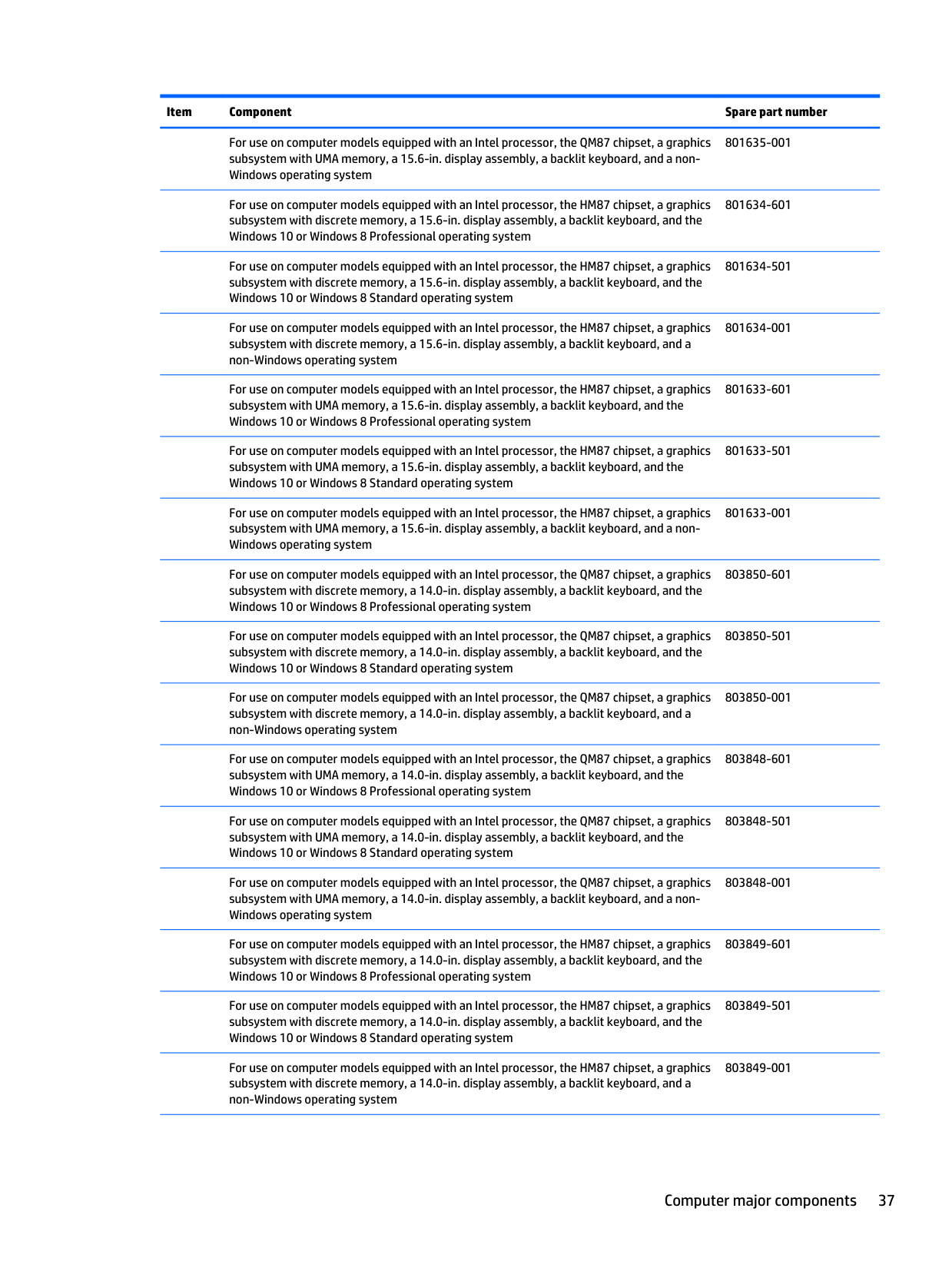
Item Component Spare part number
For use on computer models equipped with an Intel processor, the QM87 chipset, a graphics subsystem with UMA memory, a 15.6-in. display assembly, a backlit keyboard, and a non- Windows operating system 801635-001
For use on computer models equipped with an Intel processor, the HM87 chipset, a graphics subsystem with discrete memory, a 15.6-in. display assembly, a backlit keyboard, and the Windows 10 or Windows 8 Professional operating system 801634-601
For use on computer models equipped with an Intel processor, the HM87 chipset, a graphics subsystem with discrete memory, a 15.6-in. display assembly, a backlit keyboard, and the Windows 10 or Windows 8 Standard operating system 801634-501
For use on computer models equipped with an Intel processor, the HM87 chipset, a graphics subsystem with discrete memory, a 15.6-in. display assembly, a backlit keyboard, and a non-Windows operating system 801634-001
For use on computer models equipped with an Intel processor, the HM87 chipset, a graphics subsystem with UMA memory, a 15.6-in. display assembly, a backlit keyboard, and the Windows 10 or Windows 8 Professional operating system 801633-601
For use on computer models equipped with an Intel processor, the HM87 chipset, a graphics subsystem with UMA memory, a 15.6-in. display assembly, a backlit keyboard, and the Windows 10 or Windows 8 Standard operating system 801633-501
For use on computer models equipped with an Intel processor, the HM87 chipset, a graphics subsystem with UMA memory, a 15.6-in. display assembly, a backlit keyboard, and a non- Windows operating system 801633-001
For use on computer models equipped with an Intel processor, the QM87 chipset, a graphics subsystem with discrete memory, a 14.0-in. display assembly, a backlit keyboard, and the Windows 10 or Windows 8 Professional operating system 803850-601
For use on computer models equipped with an Intel processor, the QM87 chipset, a graphics subsystem with discrete memory, a 14.0-in. display assembly, a backlit keyboard, and the Windows 10 or Windows 8 Standard operating system 803850-501
For use on computer models equipped with an Intel processor, the QM87 chipset, a graphics subsystem with discrete memory, a 14.0-in. display assembly, a backlit keyboard, and a non-Windows operating system 803850-001
For use on computer models equipped with an Intel processor, the QM87 chipset, a graphics subsystem with UMA memory, a 14.0-in. display assembly, a backlit keyboard, and the Windows 10 or Windows 8 Professional operating system 803848-601
For use on computer models equipped with an Intel processor, the QM87 chipset, a graphics subsystem with UMA memory, a 14.0-in. display assembly, a backlit keyboard, and the Windows 10 or Windows 8 Standard operating system 803848-501
For use on computer models equipped with an Intel processor, the QM87 chipset, a graphics subsystem with UMA memory, a 14.0-in. display assembly, a backlit keyboard, and a non- Windows operating system 803848-001
For use on computer models equipped with an Intel processor, the HM87 chipset, a graphics subsystem with discrete memory, a 14.0-in. display assembly, a backlit keyboard, and the Windows 10 or Windows 8 Professional operating system 803849-601
For use on computer models equipped with an Intel processor, the HM87 chipset, a graphics subsystem with discrete memory, a 14.0-in. display assembly, a backlit keyboard, and the Windows 10 or Windows 8 Standard operating system 803849-501
For use on computer models equipped with an Intel processor, the HM87 chipset, a graphics subsystem with discrete memory, a 14.0-in. display assembly, a backlit keyboard, and a non-Windows operating system 803849-001 Computer major components 37
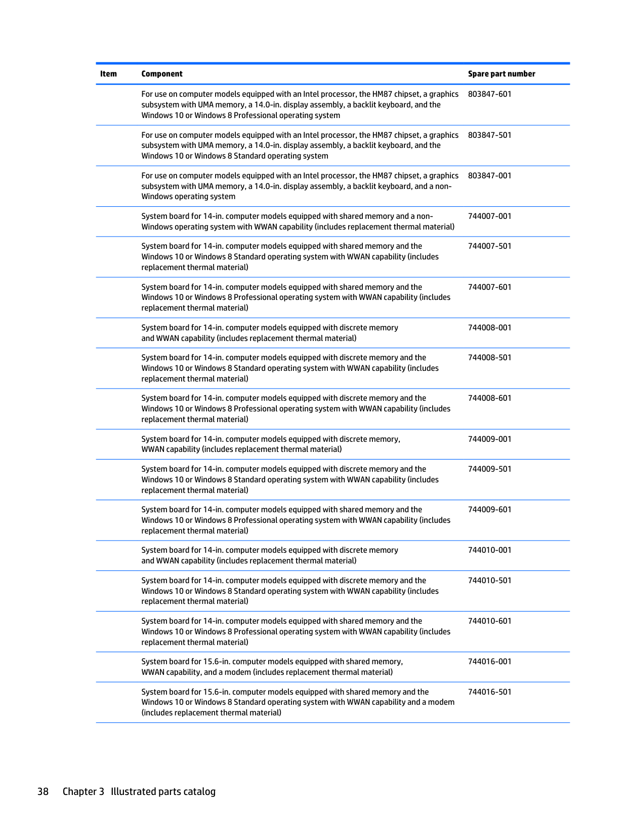
Item Component Spare part number
For use on computer models equipped with an Intel processor, the HM87 chipset, a graphics subsystem with UMA memory, a 14.0-in. display assembly, a backlit keyboard, and the Windows 10 or Windows 8 Professional operating system 803847-601
For use on computer models equipped with an Intel processor, the HM87 chipset, a graphics subsystem with UMA memory, a 14.0-in. display assembly, a backlit keyboard, and the Windows 10 or Windows 8 Standard operating system 803847-501
For use on computer models equipped with an Intel processor, the HM87 chipset, a graphics subsystem with UMA memory, a 14.0-in. display assembly, a backlit keyboard, and a non- Windows operating system 803847-001
System board for 14-in. computer models equipped with shared memory and a non- Windows operating system with WWAN capability (includes replacement thermal material) 744007-001
System board for 14-in. computer models equipped with shared memory and the Windows 10 or Windows 8 Standard operating system with WWAN capability (includes replacement thermal material) 744007-501
System board for 14-in. computer models equipped with shared memory and the Windows 10 or Windows 8 Professional operating system with WWAN capability (includes replacement thermal material) 744007-601
System board for 14-in. computer models equipped with discrete memory and WWAN capability (includes replacement thermal material) 744008-001
System board for 14-in. computer models equipped with discrete memory and the Windows 10 or Windows 8 Standard operating system with WWAN capability (includes replacement thermal material) 744008-501
System board for 14-in. computer models equipped with discrete memory and the Windows 10 or Windows 8 Professional operating system with WWAN capability (includes replacement thermal material) 744008-601
System board for 14-in. computer models equipped with discrete memory, WWAN capability (includes replacement thermal material) 744009-001
System board for 14-in. computer models equipped with discrete memory and the Windows 10 or Windows 8 Standard operating system with WWAN capability (includes replacement thermal material) 744009-501
System board for 14-in. computer models equipped with shared memory and the Windows 10 or Windows 8 Professional operating system with WWAN capability (includes replacement thermal material) 744009-601
System board for 14-in. computer models equipped with discrete memory and WWAN capability (includes replacement thermal material) 744010-001
System board for 14-in. computer models equipped with discrete memory and the Windows 10 or Windows 8 Standard operating system with WWAN capability (includes replacement thermal material) 744010-501
System board for 14-in. computer models equipped with shared memory and the Windows 10 or Windows 8 Professional operating system with WWAN capability (includes replacement thermal material) 744010-601
System board for 15.6-in. computer models equipped with shared memory, WWAN capability, and a modem (includes replacement thermal material) 744016-001
System board for 15.6-in. computer models equipped with shared memory and the Windows 10 or Windows 8 Standard operating system with WWAN capability and a modem (includes replacement thermal material) 744016-501 38 Chapter 3 Illustrated parts catalog
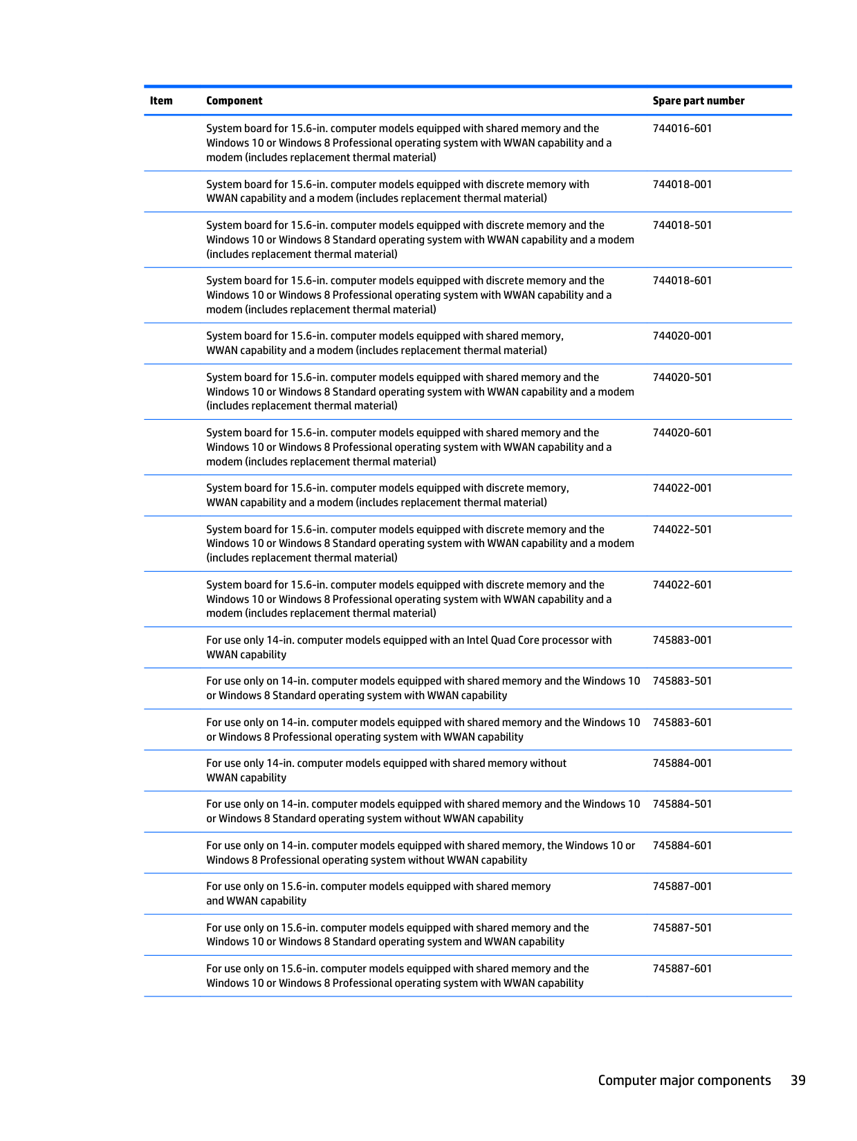
Item Component Spare part number
System board for 15.6-in. computer models equipped with shared memory and the Windows 10 or Windows 8 Professional operating system with WWAN capability and a modem (includes replacement thermal material) 744016-601
System board for 15.6-in. computer models equipped with discrete memory with WWAN capability and a modem (includes replacement thermal material) 744018-001
System board for 15.6-in. computer models equipped with discrete memory and the Windows 10 or Windows 8 Standard operating system with WWAN capability and a modem (includes replacement thermal material) 744018-501
System board for 15.6-in. computer models equipped with discrete memory and the Windows 10 or Windows 8 Professional operating system with WWAN capability and a modem (includes replacement thermal material) 744018-601
System board for 15.6-in. computer models equipped with shared memory, WWAN capability and a modem (includes replacement thermal material) 744020-001
System board for 15.6-in. computer models equipped with shared memory and the Windows 10 or Windows 8 Standard operating system with WWAN capability and a modem (includes replacement thermal material) 744020-501
System board for 15.6-in. computer models equipped with shared memory and the Windows 10 or Windows 8 Professional operating system with WWAN capability and a modem (includes replacement thermal material) 744020-601
System board for 15.6-in. computer models equipped with discrete memory, WWAN capability and a modem (includes replacement thermal material) 744022-001
System board for 15.6-in. computer models equipped with discrete memory and the Windows 10 or Windows 8 Standard operating system with WWAN capability and a modem (includes replacement thermal material) 744022-501
System board for 15.6-in. computer models equipped with discrete memory and the Windows 10 or Windows 8 Professional operating system with WWAN capability and a modem (includes replacement thermal material) 744022-601
For use only 14-in. computer models equipped with an Intel Quad Core processor with WWAN capability 745883-001
For use only on 14-in. computer models equipped with shared memory and the Windows 10 or Windows 8 Standard operating system with WWAN capability 745883-501
For use only on 14-in. computer models equipped with shared memory and the Windows 10 or Windows 8 Professional operating system with WWAN capability 745883-601
For use only 14-in. computer models equipped with shared memory without WWAN capability 745884-001
For use only on 14-in. computer models equipped with shared memory and the Windows 10 or Windows 8 Standard operating system without WWAN capability 745884-501
For use only on 14-in. computer models equipped with shared memory, the Windows 10 or Windows 8 Professional operating system without WWAN capability 745884-601
For use only on 15.6-in. computer models equipped with shared memory and WWAN capability 745887-001
For use only on 15.6-in. computer models equipped with shared memory and the Windows 10 or Windows 8 Standard operating system and WWAN capability 745887-501
For use only on 15.6-in. computer models equipped with shared memory and the Windows 10 or Windows 8 Professional operating system with WWAN capability 745887-601 Computer major components 39
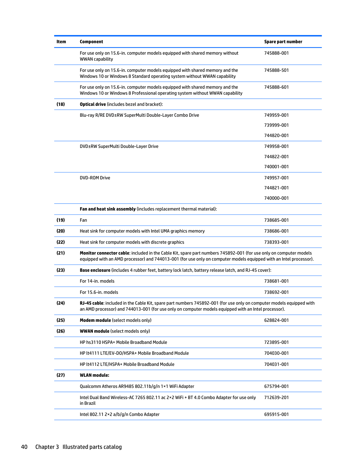
Item Component Spare part number
For use only on 15.6-in. computer models equipped with shared memory without WWAN capability 745888-001
For use only on 15.6-in. computer models equipped with shared memory and the Windows 10 or Windows 8 Standard operating system without WWAN capability 745888-501
For use only on 15.6-in. computer models equipped with shared memory and the Windows 10 or Windows 8 Professional operating system without WWAN capability 745888-601 (18) Optical drive (includes bezel and bracket):
Blu-ray R/RE DVD±RW SuperMulti Double-Layer Combo Drive 749959-001 739999-001 744820-001
DVD±RW SuperMulti Double-Layer Drive 749958-001 744822-001 740001-001
DVD-ROM Drive 749957-001 744821-001 740000-001
Fan and heat sink assembly (includes replacement thermal material): (19) Fan 738685-001 (20) Heat sink for computer models with Intel UMA graphics memory 738686-001 (22) Heat sink for computer models with discrete graphics 738393-001 (21) Monitor connector cable: included in the Cable Kit, spare part numbers 745892-001 (for use only on computer models equipped with an AMD processor) and 744013-001 (for use only on computer models equipped with an Intel processor). (23) Base enclosure (includes 4 rubber feet, battery lock latch, battery release latch, and RJ-45 cover):
For 14-in. models 738681-001
For 15.6-in. models 738692-001 (24) RJ-45 cable: included in the Cable Kit, spare part numbers 745892-001 (for use only on computer models equipped with an AMD processor) and 744013-001 (for use only on computer models equipped with an Intel processor). (25) Modem module (select models only) 628824-001 (26) WWAN module (select models only)
HP hs3110 HSPA+ Mobile Broadband Module 723895-001
HP lt4111 LTE/EV-DO/HSPA+ Mobile Broadband Module 704030-001
HP lt4112 LTE/HSPA+ Mobile Broadband Module 704031-001 (27) WLAN module:
Qualcomm Atheros AR9485 802.11b/g/n 1×1 WiFi Adapter 675794-001
Intel Dual Band Wireless-AC 7265 802.11 ac 2×2 WiFi + BT 4.0 Combo Adapter for use only in Brazil 712639-201
Intel 802.11 2×2 a/b/g/n Combo Adapter 695915-001 40 Chapter 3 Illustrated parts catalog
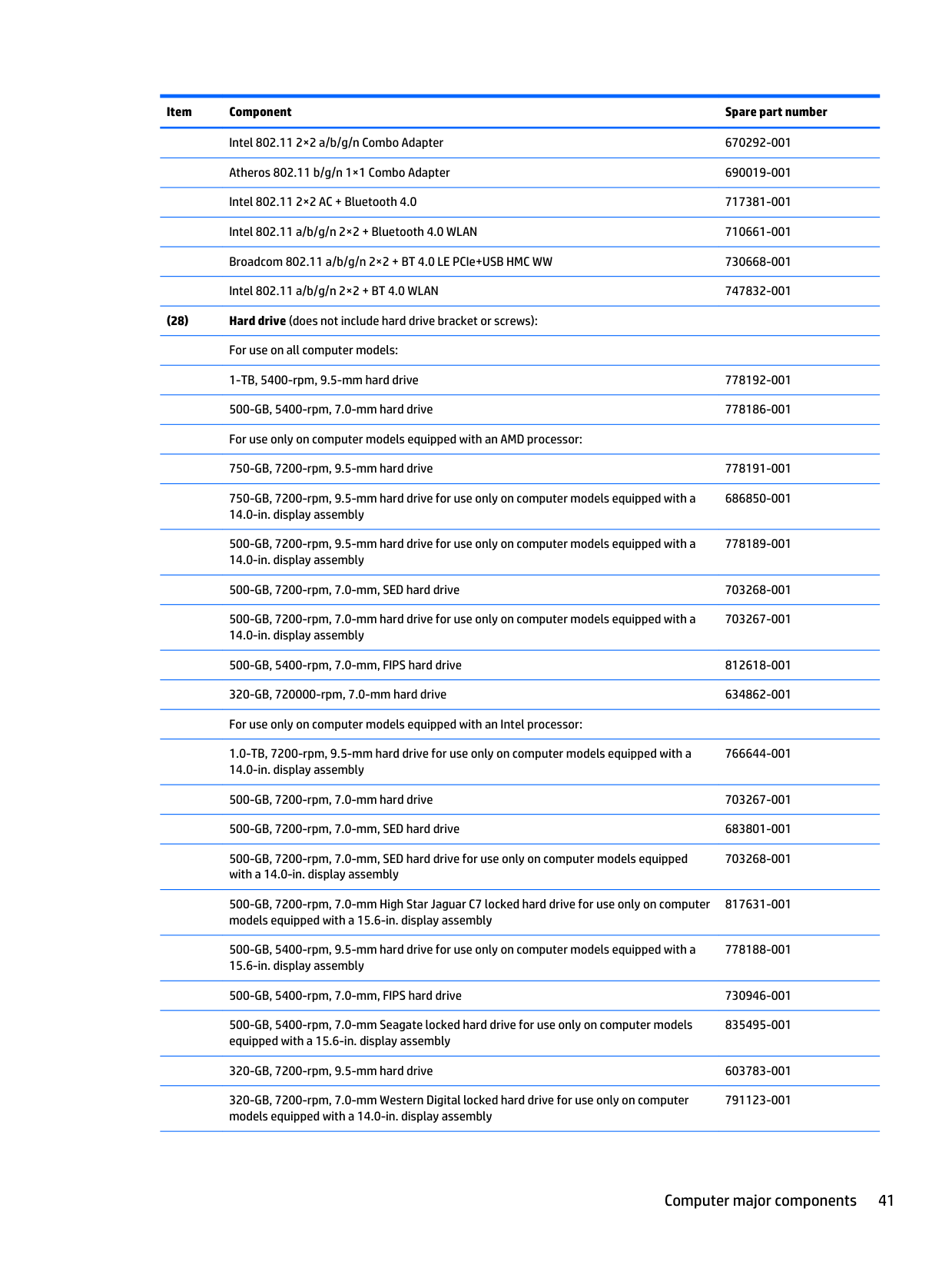
Item Component Spare part number
Intel 802.11 2×2 a/b/g/n Combo Adapter 670292-001
Atheros 802.11 b/g/n 1×1 Combo Adapter 690019-001
Intel 802.11 2×2 AC + Bluetooth 4.0 717381-001
Intel 802.11 a/b/g/n 2×2 + Bluetooth 4.0 WLAN 710661-001
Broadcom 802.11 a/b/g/n 2×2 + BT 4.0 LE PCIe+USB HMC WW 730668-001
Intel 802.11 a/b/g/n 2×2 + BT 4.0 WLAN 747832-001 (28) Hard drive (does not include hard drive bracket or screws):
For use on all computer models:
1-TB, 5400-rpm, 9.5-mm hard drive 778192-001
500-GB, 5400-rpm, 7.0-mm hard drive 778186-001
For use only on computer models equipped with an AMD processor:
750-GB, 7200-rpm, 9.5-mm hard drive 778191-001
750-GB, 7200-rpm, 9.5-mm hard drive for use only on computer models equipped with a 14.0-in. display assembly 686850-001
500-GB, 7200-rpm, 9.5-mm hard drive for use only on computer models equipped with a 14.0-in. display assembly 778189-001
500-GB, 7200-rpm, 7.0-mm, SED hard drive 703268-001
500-GB, 7200-rpm, 7.0-mm hard drive for use only on computer models equipped with a 14.0-in. display assembly 703267-001
500-GB, 5400-rpm, 7.0-mm, FIPS hard drive 812618-001
320-GB, 720000-rpm, 7.0-mm hard drive 634862-001
For use only on computer models equipped with an Intel processor:
1.0-TB, 7200-rpm, 9.5-mm hard drive for use only on computer models equipped with a 14.0-in. display assembly 766644-001
500-GB, 7200-rpm, 7.0-mm hard drive 703267-001
500-GB, 7200-rpm, 7.0-mm, SED hard drive 683801-001
500-GB, 7200-rpm, 7.0-mm, SED hard drive for use only on computer models equipped with a 14.0-in. display assembly 703268-001
500-GB, 7200-rpm, 7.0-mm High Star Jaguar C7 locked hard drive for use only on computer models equipped with a 15.6-in. display assembly 817631-001
500-GB, 5400-rpm, 9.5-mm hard drive for use only on computer models equipped with a 15.6-in. display assembly 778188-001
500-GB, 5400-rpm, 7.0-mm, FIPS hard drive 730946-001
500-GB, 5400-rpm, 7.0-mm Seagate locked hard drive for use only on computer models equipped with a 15.6-in. display assembly 835495-001
320-GB, 7200-rpm, 9.5-mm hard drive 603783-001
320-GB, 7200-rpm, 7.0-mm Western Digital locked hard drive for use only on computer models equipped with a 14.0-in. display assembly 791123-001 Computer major components 41
Item Component Spare part number
320-GB, 7200-rpm, 7.0-mm Toshiba locked hard drive for use only on computer models equipped with a 14.0-in. display assembly 794699-001
Hard Drive Hardware Kit (not illustrated, includes hard drive bracket and screws) 738395-001 (29) RTC battery (includes cable and double-sided adhesive) 651948-001 (30) Battery:
9-cell, 100-WHr, 3.0-AHr, Li-ion battery 718757-001
6-cell, 55-WHr, 2.8-AHr, Li-ion battery 718756-001
6-cell, 55-WHr, 2.5-AHr, Li-ion battery 718755-001
3-cell, 33-WHr, 2.0-AHr, Li-ion battery 718754-001 (31) Service cover
Service cover for use on computer models equipped with a 15.6-in. display assembly 738693-001
Service cover for use on computer models equipped with a 15.6-in. display assembly and which meet regional configure to order (RCTO) specifications 748358-001
Service cover for use on computer models equipped with a 14-in. display assembly 738682-001
Service cover for use on computer models equipped with a 14-in. display assembly and which meet regional configure to order (RCTO) specifications 748357-001
Rubber Kit (not illustrated) 738403-001 42 Chapter 3 Illustrated parts catalog
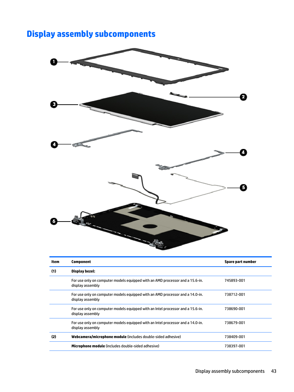
Display assembly subcomponents Item Component Spare part number (1) Display bezel:
For use only on computer models equipped with an AMD processor and a 15.6-in. display assembly 745893-001
For use only on computer models equipped with an AMD processor and a 14.0-in. display assembly 738712-001
For use only on computer models equipped with an Intel processor and a 15.6-in. display assembly 738690-001
For use only on computer models equipped with an Intel processor and a 14.0-in. display assembly 738679-001 (2) Webcamera/microphone module (includes double-sided adhesive) 738409-001
Microphone module (includes double-sided adhesive) 738397-001 Display assembly subcomponents 43
Item Component Spare part number (3) Display panel:
15.6-in., FHD, SVA, AntiGlare, slim display panel for use only on computer models equipped with an AMD processor 749610-001
15.6-in., FHD, SVA, AntiGlare, slim display panel for use only on computer models equipped with an Intel processor 739998-001
15.6-in., FHD, SVA, AntiGlare, flat display panel for use only on computer models equipped with an AMD processor 749609-001
15.6-in., FHD, SVA, AntiGlare, flat display panel for use only on computer models equipped with an Intel processor 739997-001
14-in. WLED FHD, UWVA 747753-001
14-in. WLED HD, SVA 747752-001
14-in. WLED HD, SVA 747751-001
Display Panel Support Kit (includes LCD back cover and wireless antennas and transceivers):
For use on computer models equipped with a 15.6-in. display assembly 738691-001
For use on computer models equipped with a 14-in. display assembly 738680-001 (4) Display Hinge Kit (includes left and right hinges and display panel cable bracket)
For 15.6-in. computer models 738699-001
For 14.0-in. computer models 738396-001 (5) Display Cable Kit (includes display panel cable):
For use on computer models equipped with a 15.6-in. display assembly 738695-001
For use on computer models equipped with a 14.0-in. display assembly 738684-001 (6) Display back cover: included in the Display Panel Support Kit (includes wireless antenna cables and transceivers):
For use on computer models equipped with a 15.6-in. display assembly 738691-001
For use on computer models equipped with a 14.0-in. display assembly 738680-001 44 Chapter 3 Illustrated parts catalog
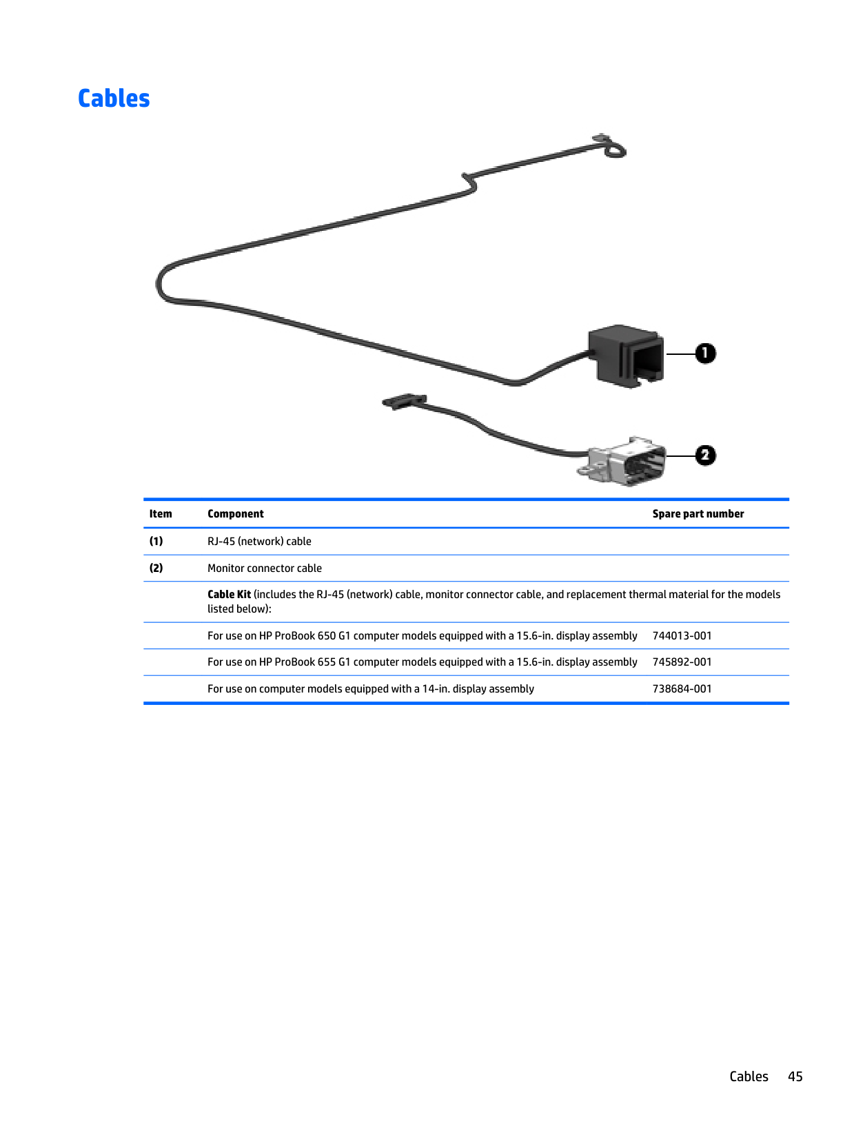
Cables Item Component Spare part number (1) RJ-45 (network) cable (2) Monitor connector cable
Cable Kit (includes the RJ-45 (network) cable, monitor connector cable, and replacement thermal material for the models listed below):
For use on HP ProBook 650 G1 computer models equipped with a 15.6-in. display assembly 744013-001
For use on HP ProBook 655 G1 computer models equipped with a 15.6-in. display assembly 745892-001
For use on computer models equipped with a 14-in. display assembly 738684-001 Cables 45
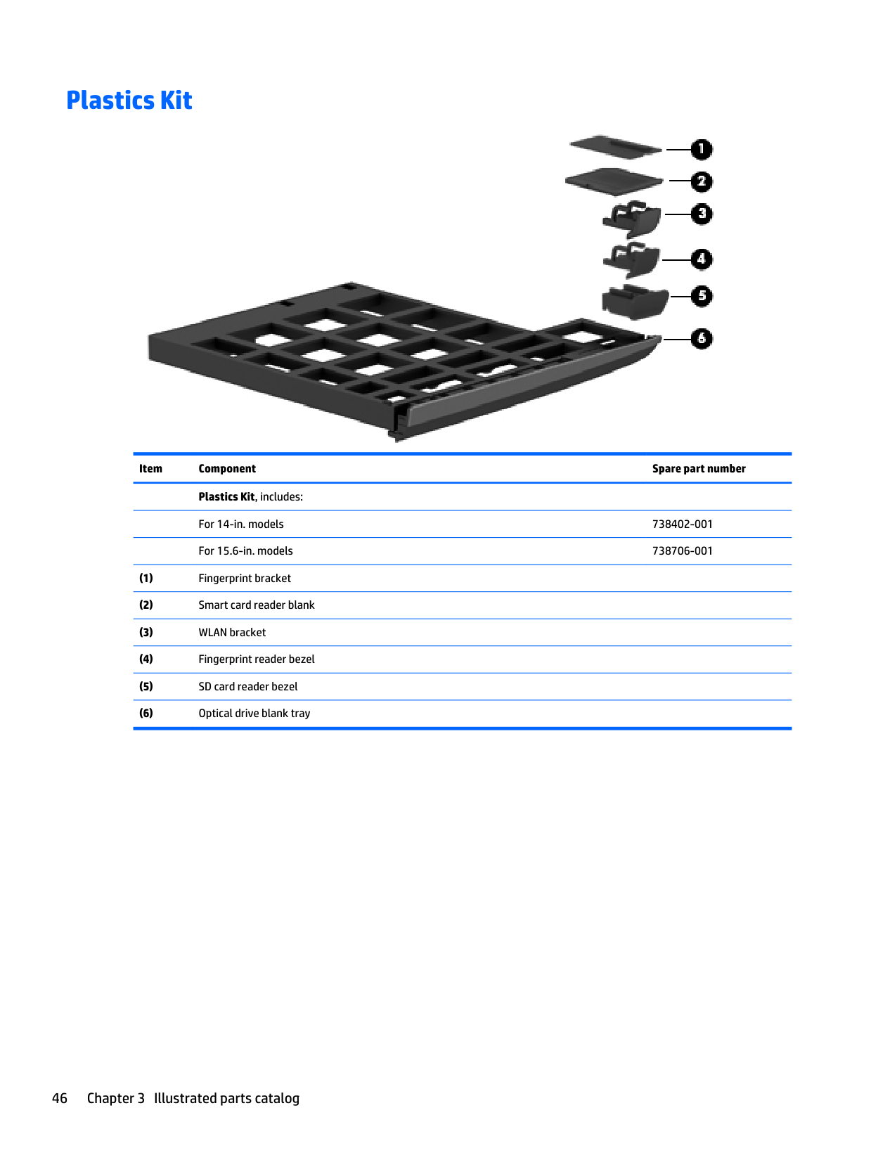
Plastics Kit Item Component Spare part number
Plastics Kit, includes:
For 14-in. models 738402-001
For 15.6-in. models 738706-001 (1) Fingerprint bracket (2) Smart card reader blank (3) WLAN bracket (4) Fingerprint reader bezel (5) SD card reader bezel (6) Optical drive blank tray 46 Chapter 3 Illustrated parts catalog
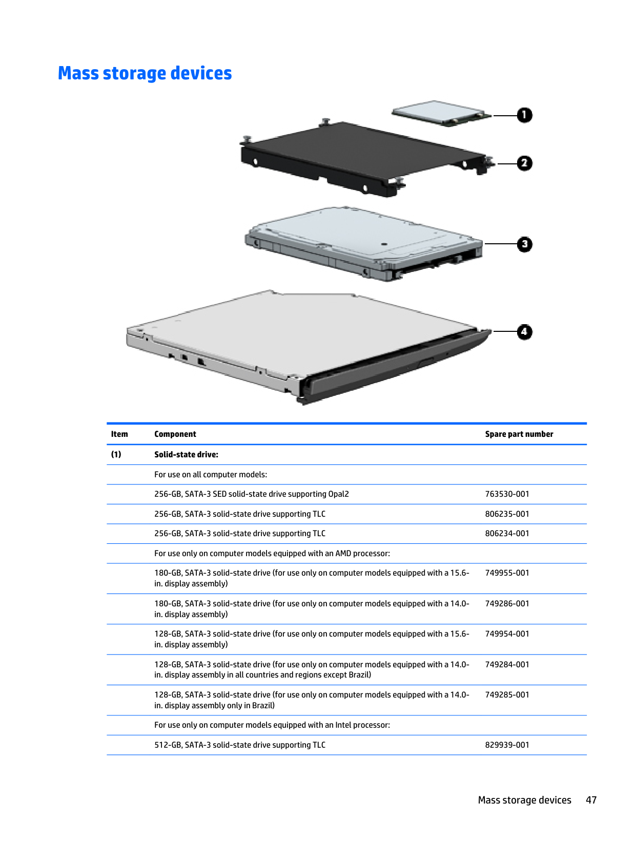
Mass storage devices Item Component Spare part number (1) Solid-state drive:
For use on all computer models:
256-GB, SATA-3 SED solid-state drive supporting Opal2 763530-001
256-GB, SATA-3 solid-state drive supporting TLC 806235-001
256-GB, SATA-3 solid-state drive supporting TLC 806234-001
For use only on computer models equipped with an AMD processor:
180-GB, SATA-3 solid-state drive (for use only on computer models equipped with a 15.6- in. display assembly) 749955-001
180-GB, SATA-3 solid-state drive (for use only on computer models equipped with a 14.0- in. display assembly) 749286-001
128-GB, SATA-3 solid-state drive (for use only on computer models equipped with a 15.6- in. display assembly) 749954-001
128-GB, SATA-3 solid-state drive (for use only on computer models equipped with a 14.0- in. display assembly in all countries and regions except Brazil) 749284-001
128-GB, SATA-3 solid-state drive (for use only on computer models equipped with a 14.0- in. display assembly only in Brazil) 749285-001
For use only on computer models equipped with an Intel processor:
512-GB, SATA-3 solid-state drive supporting TLC 829939-001 Mass storage devices 47
Item Component Spare part number
256-GB, SM841 Samsung locked solid-state drive supporting Opal2 (for use only on computer models equipped with a 15.6-in. display assembly) 834423-001
256-GB, SM841 Samsung locked solid-state drive supporting Opal2 (for use only on computer models equipped with a 14.0-in. display assembly) 834422-001
180-GB, SATA-3 solid-state drive (for use only on computer models equipped with a 15.6- in. display assembly) 749262-001
180-GB, SATA-3 solid-state drive (for use only on computer models equipped with a 14.0- in. display assembly) 749278-001
128-GB, SATA-3 solid-state drive (for use only on computer models equipped with a 15.6- in. display assembly) 749261-001
128-GB, SATA-3 solid-state drive (for use only on computer models equipped with a 14.0- in. display assembly in all countries and regions except Brazil 749277-001
128-GB, SATA-3 solid-state drive (for use only on computer models equipped with a 14.0- in. display assembly in Brazil) 749280-001
Hard Drive Hardware Kit, includes: 738395-001 (2) Hard drive bracket
Screws (not illustrated) (3) Hard drive (does not include hard drive bracket or screws):
For use on all computer models:
1-TB, 5400-rpm, 9.5-mm hard drive 778192-001
500-GB, 5400-rpm, 7.0-mm hard drive 778186-001
For use only on computer models equipped with an AMD processor:
750-GB, 7200-rpm, 9.5-mm hard drive 778191-001
750-GB, 7200-rpm, 9.5-mm hard drive for use only on computer models equipped with a 14.0-in. display assembly 686850-001
500-GB, 7200-rpm, 9.5-mm hard drive for use only on computer models equipped with a 14.0-in. display assembly 778189-001
500-GB, 7200-rpm, 7.0-mm, SED hard drive 703268-001
500-GB, 7200-rpm, 7.0-mm hard drive for use only on computer models equipped with a 14.0-in. display assembly 703267-001
500-GB, 5400-rpm, 7.0-mm, FIPS hard drive 812618-001
320-GB, 720000-rpm, 7.0-mm hard drive 634862-001
For use only on computer models equipped with an Intel processor:
1.0-TB, 7200-rpm, 9.5-mm hard drive for use only on computer models equipped with a 14.0-in. display assembly 766644-001
500-GB, 7200-rpm, 7.0-mm hard drive 703267-001
500-GB, 7200-rpm, 7.0-mm, SED hard drive 683801-001
500-GB, 7200-rpm, 7.0-mm, SED hard drive for use only on computer models equipped with a 14.0-in. display assembly 703268-001 48 Chapter 3 Illustrated parts catalog
Item Component Spare part number
500-GB, 7200-rpm, 7.0-mm High Star Jaguar C7 locked hard drive for use only on computer models equipped with a 15.6-in. display assembly 817631-001
500-GB, 5400-rpm, 9.5-mm hard drive for use only on computer models equipped with a 15.6-in. display assembly 778188-001
500-GB, 5400-rpm, 7.0-mm, FIPS hard drive 730946-001
500-GB, 5400-rpm, 7.0-mm Seagate locked hard drive for use only on computer models equipped with a 15.6-in. display assembly 835495-001
320-GB, 7200-rpm, 9.5-mm hard drive 603783-001
320-GB, 7200-rpm, 7.0-mm Western Digital locked hard drive for use only on computer models equipped with a 14.0-in. display assembly 791123-001
320-GB, 7200-rpm, 7.0-mm Toshiba locked hard drive for use only on computer models equipped with a 14.0-in. display assembly 794699-001 (4) Optical drive (includes bezel and bracket):
Blu-ray R/RE DVD±RW SuperMulti Double-Layer Combo Drive 749959-001 739999-001 744820-001
DVD±RW SuperMulti Double-Layer Drive 749958-001 744822-001 740000-001
DVD-ROM Drive 749957-001 744821-001 740001-001 735601-001 Miscellaneous parts Component Spare part number AC adapter: 90-W HP Smart adapter (PFC, 3-wire, 4.5-mm) for use only on computer models equipped with an Intel processor 693712-001 90-W HP Smart adapter (PFC, EM, 3-wire, 4.5-mm) for use only on computer models equipped with an Intel processor 693713-001 65-W HP Smart adapter (non-PFC, 3-wire, 4.5-mm, locked) for use only on computer models equipped with a 15.6-in. display assembly and an Intel processor 835498-001 65-W HP Smart adapter (PFC, 3-wire, 4.5-mm) for use on all computer models 693710-001 65-W HP Smart adapter (PFC, 3-wire, 4.5-mm) for use on all computer models 693711-001 HP DisplayPort-to-HDMI 1.4 adapter 749288-001 HP Mobile Connect SIM (for use only on computer models equipped with an Intel processor) 714749-001 Miscellaneous parts 49
Component Spare part number Power cord (3-pin, black, 1.83-m): For use on all computer models: For use on Australia 490371-011 For use on Brazil 490371-202 For use on Europe 490371-021 For use on India
490371-D61
For use on Israel490371-Bb1
For use on North America 490371-001 For use on the People's Republic of China490371-Aa1
For use on South Africa490371-Ar1
For use on South Korea490371-Ad1
For use on Switzerland 490371-111 For use on Taiwan490371-Ab1
For use on Thailand 490371-201 For use on the United Kingdom and Singapore 490371-031 Power cord (3-pin, black, 1.83-m) for use on Argentina only on computer models equipped with an AMD processor and computer models equipped with a 15.6-in. display assembly and an Intel processor490371-D01
Power cord (3-pin, black, 1.83-m) for use on Italy only on computer models equipped with an AMD processor 490371-061 Power cord (3-pin, black, 1.00-m) for use on use on Japan only on computer models equipped with a 15.6-in. display assembly and an Intel processor 755530-291 Screw Kit 738689-001 50 Chapter 3 Illustrated parts catalog
4 Removal and replacement procedures preliminary requirements Tools required You will need the following tools to complete the removal and replacement procedures: ● Flat-bladed screw driver ● Magnetic screw driver ● Phillips P0 and P1 screw drivers Service considerations The following sections include some of the considerations that you must keep in mind during disassembly and assembly procedures.
Note:
As you remove each subassembly from the computer, place the subassembly (and all accompanying screws) away from the work area to prevent damage. Plastic partsCaution:
Using excessive force during disassembly and reassembly can damage plastic parts. Use care when handling the plastic parts. Apply pressure only at the points designated in the maintenance instructions. Tools required 51
Cables and connectors
Caution:
When servicing the computer, be sure that cables are placed in their proper locations during the reassembly process. Improper cable placement can damage the computer. Cables must be handled with extreme care to avoid damage. Apply only the tension required to unseat or seat the cables during removal and insertion. Handle cables by the connector whenever possible. In all cases, avoid bending, twisting, or tearing cables. Be sure that cables are routed in such a way that they cannot be caught or snagged by parts being removed or replaced. Handle flex cables with extreme care; these cables tear easily. Drive handlingCaution:
Drives are fragile components that must be handled with care. To prevent damage to the computer, damage to a drive, or loss of information, observe these precautions: Before removing or inserting a hard drive, shut down the computer. If you are unsure whether the computer is off or in Hibernation, turn the computer on, and then shut it down through the operating system. Before handling a drive, be sure that you are discharged of static electricity. While handling a drive, avoid touching the connector. Before removing a diskette drive or optical drive, be sure that a diskette or disc is not in the drive and be sure that the optical drive tray is closed. Handle drives on surfaces covered with at least one inch of shock-proof foam. Avoid dropping drives from any height onto any surface. After removing a hard drive, an optical drive, or a diskette drive, place it in a static-proof bag. Avoid exposing an internal hard drive to products that have magnetic fields, such as monitors or speakers. Avoid exposing a drive to temperature extremes or liquids. If a drive must be mailed, place the drive in a bubble pack mailer or other suitable form of protective packaging and label the package “FRAGILE.” Grounding guidelines Electrostatic discharge damage Electronic components are sensitive to electrostatic discharge (ESD). Circuitry design and structure determine the degree of sensitivity. Networks built into many integrated circuits provide some protection, but in many cases, ESD contains enough power to alter device parameters or melt silicon junctions. A discharge of static electricity from a finger or other conductor can destroy static-sensitive devices or microcircuitry. Even if the spark is neither felt nor heard, damage may have occurred. An electronic device exposed to ESD may not be affected at all and can work perfectly throughout a normal cycle. Or the device may function normally for a while, and then degrade in the internal layers, reducing its life expectancy. 52 Chapter 4 Removal and replacement procedures preliminary requirements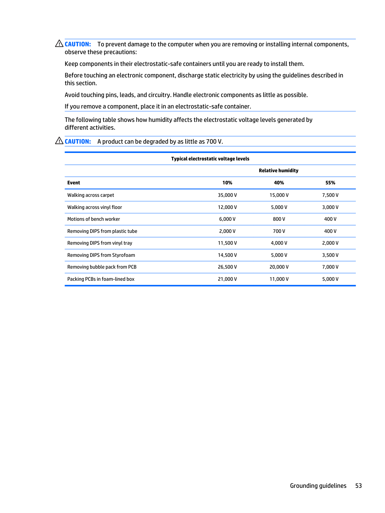
Caution:
To prevent damage to the computer when you are removing or installing internal components, observe these precautions: Keep components in their electrostatic-safe containers until you are ready to install them. Before touching an electronic component, discharge static electricity by using the guidelines described in this section. Avoid touching pins, leads, and circuitry. Handle electronic components as little as possible. If you remove a component, place it in an electrostatic-safe container. The following table shows how humidity affects the electrostatic voltage levels generated by different activities.Caution:
A product can be degraded by as little as 700 V. Typical electrostatic voltage levelsRelative humidity Event 10% 40% 55% Walking across carpet
35,000 V
15,000 V
7,500 V
Walking across vinyl floor12,000 V
5,000 V
3,000 V
Motions of bench worker6,000 V
800 V
400 V
Removing DIPS from plastic tube2,000 V
700 V
400 V
Removing DIPS from vinyl tray11,500 V
4,000 V
2,000 V
Removing DIPS from Styrofoam14,500 V
5,000 V
3,500 V
Removing bubble pack from PCB26,500 V
20,000 V
7,000 V
Packing PCBs in foam-lined box21,000 V
11,000 V
5,000 V
Grounding guidelines 53
Packaging and transporting guidelines Follow these grounding guidelines when packaging and transporting equipment: ● To avoid hand contact, transport products in static-safe tubes, bags, or boxes. ● Protect ESD-sensitive parts and assemblies with conductive or approved containers or packaging. ● Keep ESD-sensitive parts in their containers until the parts arrive at static-free workstations. ● Place items on a grounded surface before removing items from their containers. ● Always be properly grounded when touching a component or assembly. ● Store reusable ESD-sensitive parts from assemblies in protective packaging or nonconductive foam. ● Use transporters and conveyors made of antistatic belts and roller bushings. Be sure that mechanized equipment used for moving materials is wired to ground and that proper materials are selected to avoid static charging. When grounding is not possible, use an ionizer to dissipate electric charges. Workstation guidelines Follow these grounding workstation guidelines: ● Cover the workstation with approved static-shielding material. ● Use a wrist strap connected to a properly grounded work surface and use properly grounded tools and equipment. ● Use conductive field service tools, such as cutters, screw drivers, and vacuums. ● When fixtures must directly contact dissipative surfaces, use fixtures made only of static- safe materials. ● Keep the work area free of nonconductive materials, such as ordinary plastic assembly aids and Styrofoam. ● Handle ESD-sensitive components, parts, and assemblies by the case or PCM laminate. Handle these items only at static-free workstations. ● Avoid contact with pins, leads, or circuitry. ● Turn off power and input signals before inserting or removing connectors or test equipment. 54 Chapter 4 Removal and replacement procedures preliminary requirements
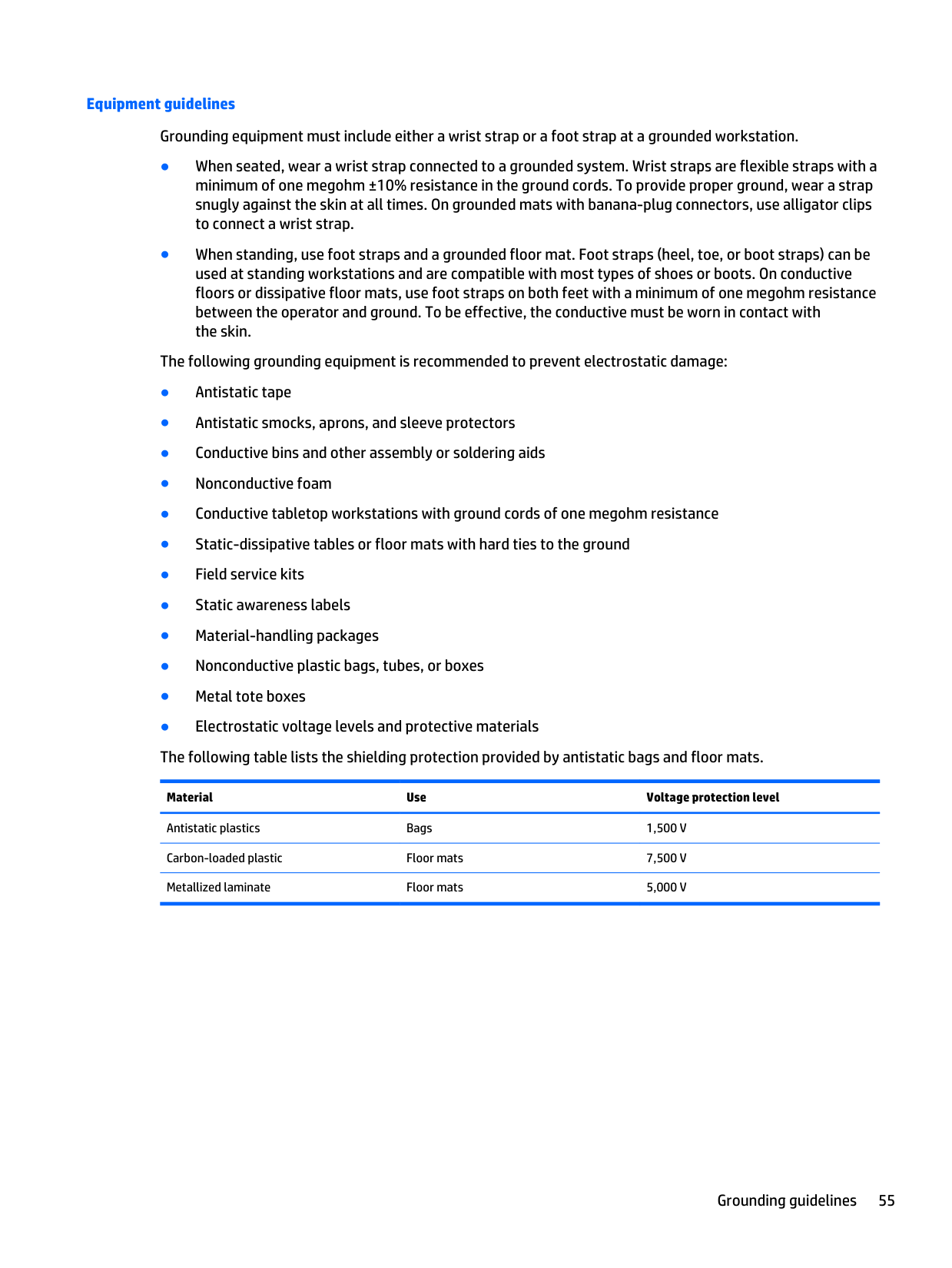
Equipment guidelines Grounding equipment must include either a wrist strap or a foot strap at a grounded workstation. ● When seated, wear a wrist strap connected to a grounded system. Wrist straps are flexible straps with a minimum of one megohm ±10% resistance in the ground cords. To provide proper ground, wear a strap snugly against the skin at all times. On grounded mats with banana-plug connectors, use alligator clips to connect a wrist strap. ● When standing, use foot straps and a grounded floor mat. Foot straps (heel, toe, or boot straps) can be used at standing workstations and are compatible with most types of shoes or boots. On conductive floors or dissipative floor mats, use foot straps on both feet with a minimum of one megohm resistance between the operator and ground. To be effective, the conductive must be worn in contact with the skin. The following grounding equipment is recommended to prevent electrostatic damage: ● Antistatic tape ● Antistatic smocks, aprons, and sleeve protectors ● Conductive bins and other assembly or soldering aids ● Nonconductive foam ● Conductive tabletop workstations with ground cords of one megohm resistance ● Static-dissipative tables or floor mats with hard ties to the ground ● Field service kits ● Static awareness labels ● Material-handling packages ● Nonconductive plastic bags, tubes, or boxes ● Metal tote boxes ● Electrostatic voltage levels and protective materials The following table lists the shielding protection provided by antistatic bags and floor mats. Material Use Voltage protection level Antistatic plastics Bags
1,500 V
Carbon-loaded plastic Floor mats7,500 V
Metallized laminate Floor mats5,000 V
Grounding guidelines 55
5 Removal and replacement procedures for Customer Self-Repair parts
Note:
The Customer Self-Repair program is not available in all locations. Installing a part not supported by the Customer Self-Repair program may void your warranty. Check your warranty to determine if Customer Self-Repair is supported in your location. Component replacement proceduresNote:
Please read and follow the procedures described here to access and replace Customer Self-Repair parts successfully.Note:
Details about your computer, including model, serial number, product key, and length of warranty, are on the service tag at the bottom of your computer. See Service tag on page 16 for details. This chapter provides removal and replacement procedures for Customer Self-Repair parts. There are as many as 16 screws that must be removed, replaced, and/or loosened when servicing Customer Self-Repair parts. Make special note of each screw size and location during removal and replacement. Battery Description Spare part number 9-cell, 100-WHr, 3.0-AHr, Li-ion battery 718757-001 9-cell, 73-WHr, 2.2-AHr, Li-ion battery 718756-001 8-cell, 83-WHr, 2.8-AHr, Li-ion battery 718755-001 8-cell, 75-WHr, 2.8-AHr, Li-ion battery 718754-001 Before removing the battery, follow these steps:Warning!
To reduce potential safety issues, use only the user-replaceable battery provided with the computer, a replacement battery provided by HP, or a compatible battery purchased from HP.Caution:
Removing a user-replaceable battery that is the sole power source for the computer can cause loss of information. To prevent loss of information, save your work or shut down the computer through Windows before removing the battery. 56 Chapter 5 Removal and replacement procedures for Customer Self-Repair parts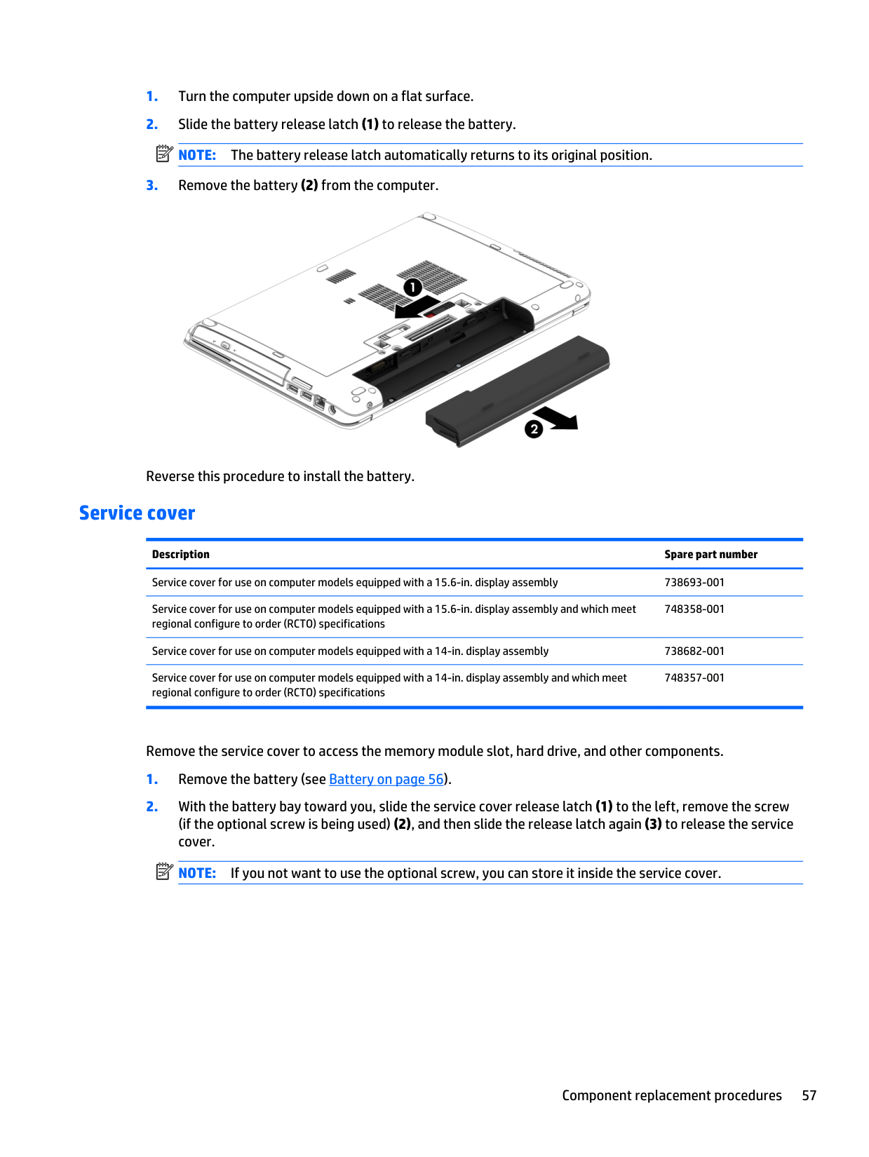
Note:
The battery release latch automatically returns to its original position.Note:
If you not want to use the optional screw, you can store it inside the service cover. Component replacement procedures 57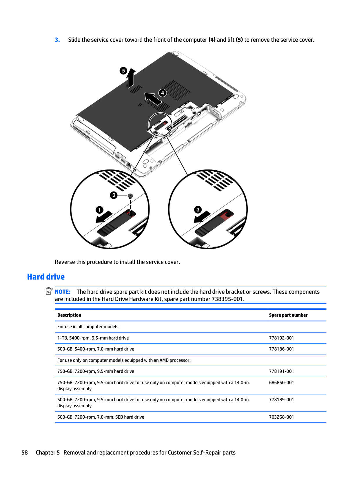
Note:
The hard drive spare part kit does not include the hard drive bracket or screws. These components are included in the Hard Drive Hardware Kit, spare part number 738395-001. Description Spare part number For use in all computer models: 1-TB, 5400-rpm, 9.5-mm hard drive 778192-001 500-GB, 5400-rpm, 7.0-mm hard drive 778186-001 For use only on computer models equipped with an AMD processor: 750-GB, 7200-rpm, 9.5-mm hard drive 778191-001 750-GB, 7200-rpm, 9.5-mm hard drive for use only on computer models equipped with a 14.0-in. display assembly 686850-001 500-GB, 7200-rpm, 9.5-mm hard drive for use only on computer models equipped with a 14.0-in. display assembly 778189-001 500-GB, 7200-rpm, 7.0-mm, SED hard drive 703268-001 58 Chapter 5 Removal and replacement procedures for Customer Self-Repair parts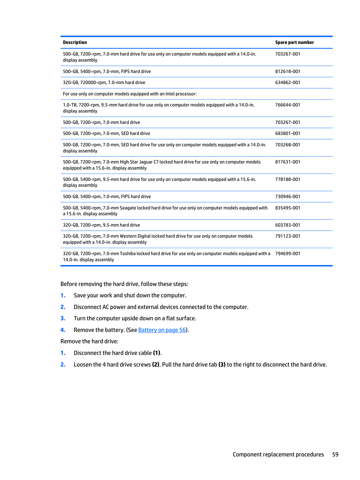
Description Spare part number 500-GB, 7200-rpm, 7.0-mm hard drive for use only on computer models equipped with a 14.0-in. display assembly 703267-001 500-GB, 5400-rpm, 7.0-mm, FIPS hard drive 812618-001 320-GB, 720000-rpm, 7.0-mm hard drive 634862-001 For use only on computer models equipped with an Intel processor: 1.0-TB, 7200-rpm, 9.5-mm hard drive for use only on computer models equipped with a 14.0-in. display assembly 766644-001 500-GB, 7200-rpm, 7.0-mm hard drive 703267-001 500-GB, 7200-rpm, 7.0-mm, SED hard drive 683801-001 500-GB, 7200-rpm, 7.0-mm, SED hard drive for use only on computer models equipped with a 14.0-in. display assembly 703268-001 500-GB, 7200-rpm, 7.0-mm High Star Jaguar C7 locked hard drive for use only on computer models equipped with a 15.6-in. display assembly 817631-001 500-GB, 5400-rpm, 9.5-mm hard drive for use only on computer models equipped with a 15.6-in. display assembly 778188-001 500-GB, 5400-rpm, 7.0-mm, FIPS hard drive 730946-001 500-GB, 5400-rpm, 7.0-mm Seagate locked hard drive for use only on computer models equipped with a 15.6-in. display assembly 835495-001 320-GB, 7200-rpm, 9.5-mm hard drive 603783-001 320-GB, 7200-rpm, 7.0-mm Western Digital locked hard drive for use only on computer models equipped with a 14.0-in. display assembly 791123-001 320-GB, 7200-rpm, 7.0-mm Toshiba locked hard drive for use only on computer models equipped with a 14.0-in. display assembly 794699-001 Before removing the hard drive, follow these steps:
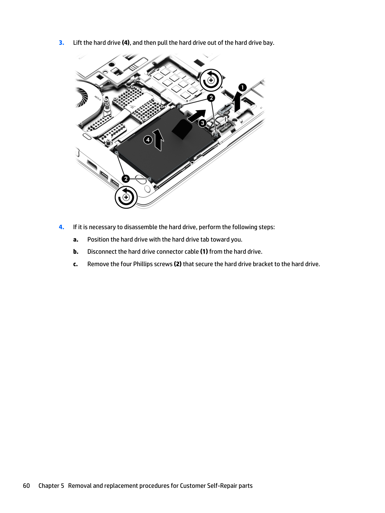
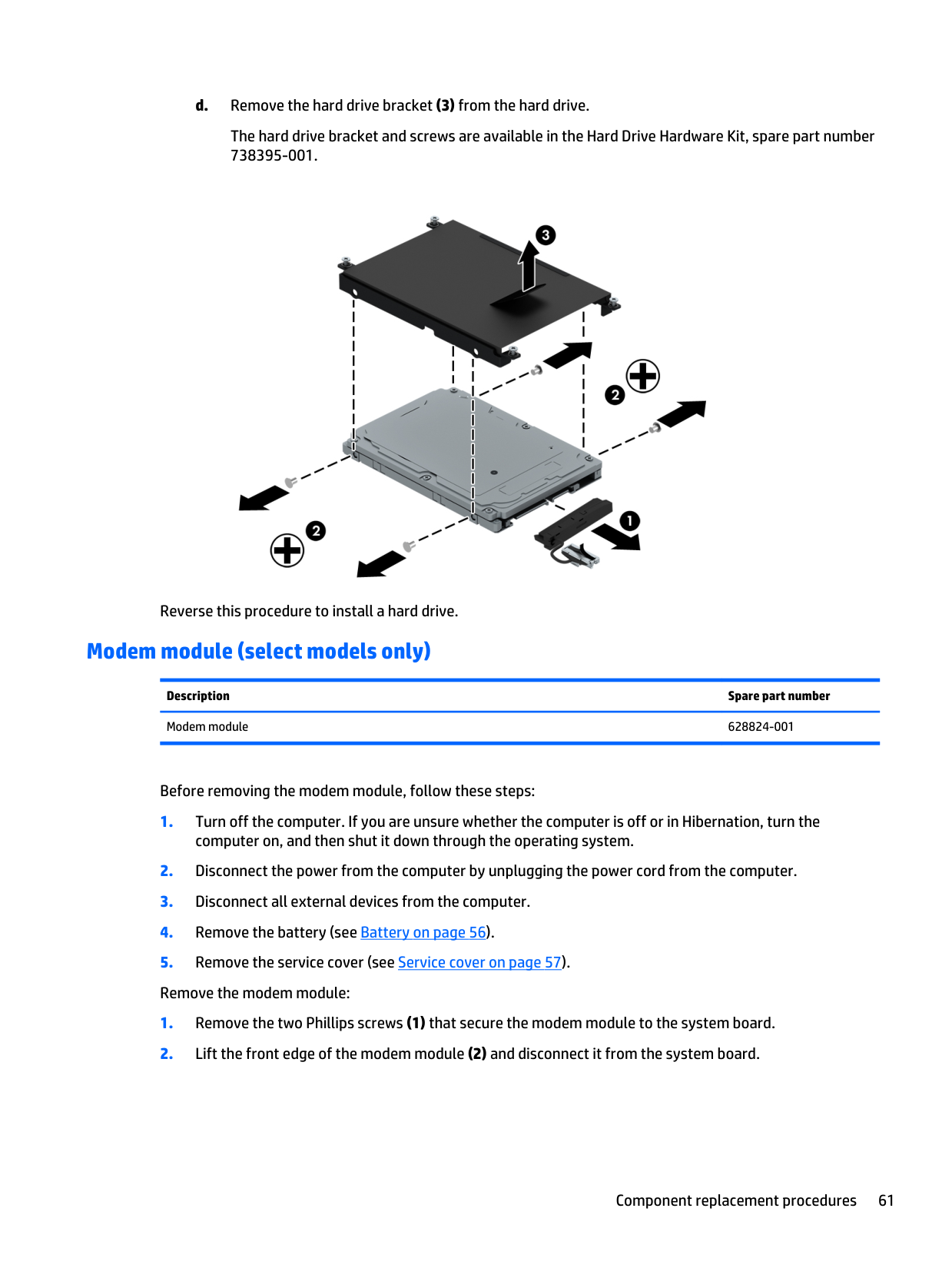
d. Remove the hard drive bracket (3) from the hard drive. The hard drive bracket and screws are available in the Hard Drive Hardware Kit, spare part number 738395-001. Reverse this procedure to install a hard drive. Modem module (select models only) Description Spare part number Modem module 628824-001 Before removing the modem module, follow these steps:
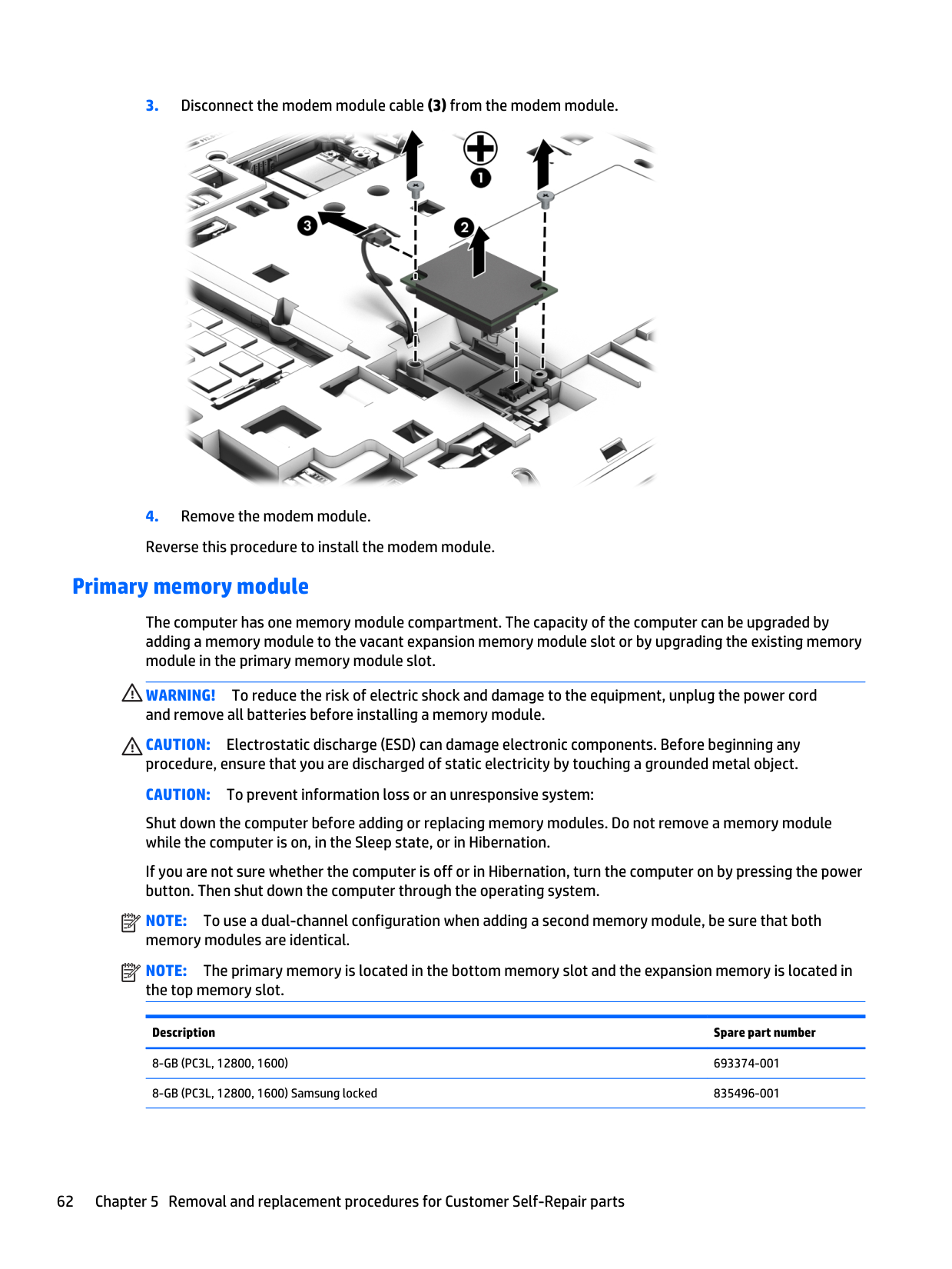
Warning!
To reduce the risk of electric shock and damage to the equipment, unplug the power cord and remove all batteries before installing a memory module.Caution:
Electrostatic discharge (ESD) can damage electronic components. Before beginning any procedure, ensure that you are discharged of static electricity by touching a grounded metal object.Caution:
To prevent information loss or an unresponsive system: Shut down the computer before adding or replacing memory modules. Do not remove a memory module while the computer is on, in the Sleep state, or in Hibernation. If you are not sure whether the computer is off or in Hibernation, turn the computer on by pressing the power button. Then shut down the computer through the operating system.Note:
To use a dual-channel configuration when adding a second memory module, be sure that both memory modules are identical.Note:
The primary memory is located in the bottom memory slot and the expansion memory is located in the top memory slot. Description Spare part number8-Gb (Pc3L, 12800, 1600)
693374-001 8-GB (PC3L, 12800, 1600) Samsung locked 835496-001 62 Chapter 5 Removal and replacement procedures for Customer Self-Repair parts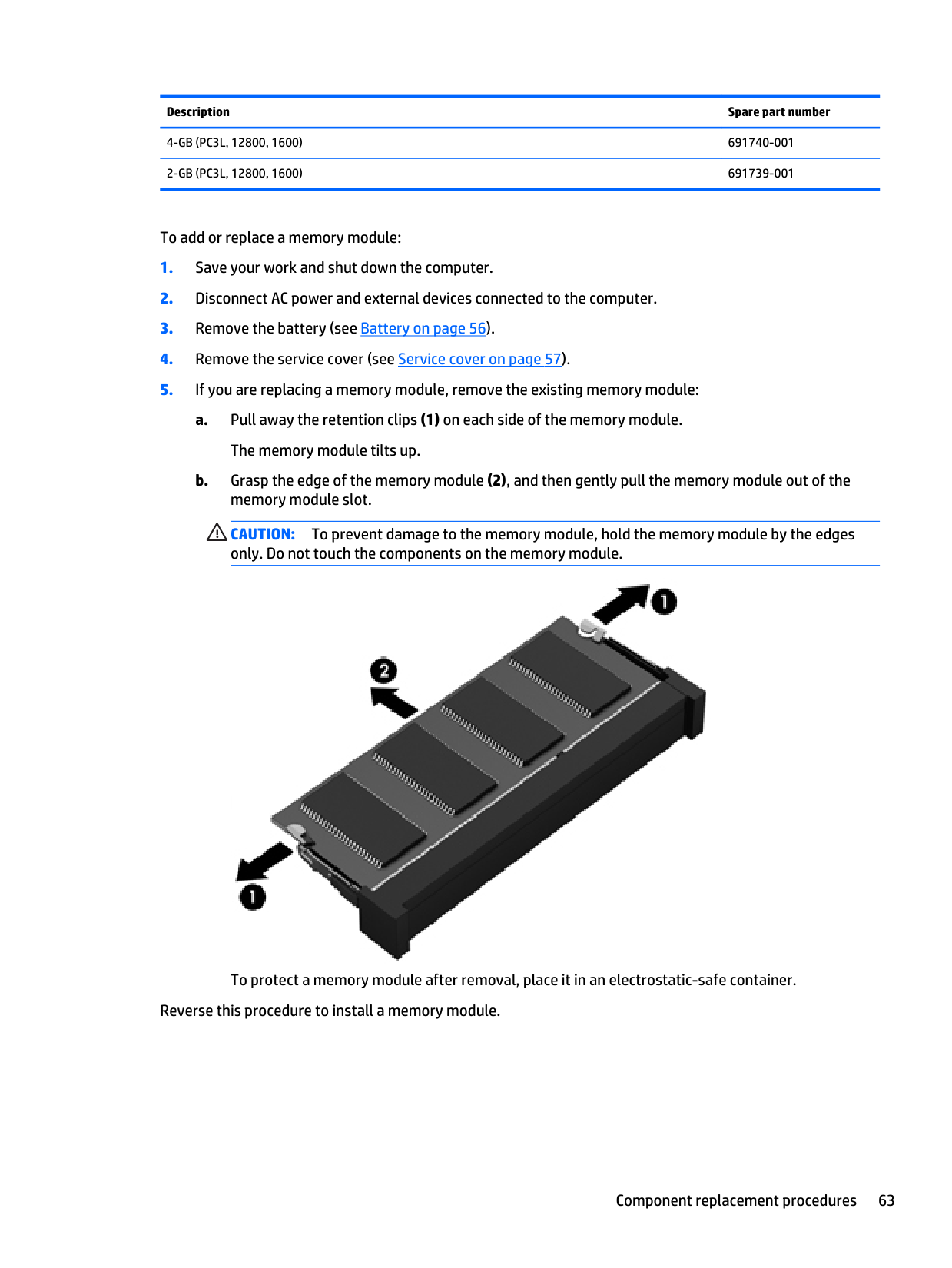
Description Spare part number
4-Gb (Pc3L, 12800, 1600)
691740-0012-Gb (Pc3L, 12800, 1600)
691739-001 To add or replace a memory module:Caution:
To prevent damage to the memory module, hold the memory module by the edges only. Do not touch the components on the memory module. To protect a memory module after removal, place it in an electrostatic-safe container. Reverse this procedure to install a memory module. Component replacement procedures 63
Expansion memory module Update BIOS before adding memory modules Before adding new memory, make sure you update the computer to the latest BIOS.
Caution:
Failure to update the computer to the latest BIOS prior to installing new memory may result in various system problems. To update BIOS: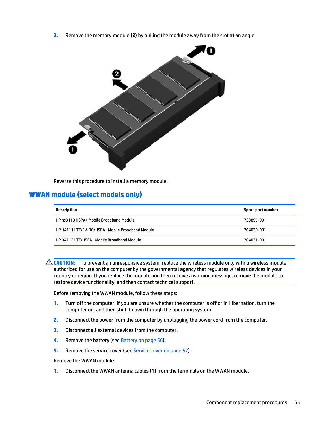
Caution:
To prevent an unresponsive system, replace the wireless module only with a wireless module authorized for use on the computer by the governmental agency that regulates wireless devices in your country or region. If you replace the module and then receive a warning message, remove the module to restore device functionality, and then contact technical support. Before removing the WWAN module, follow these steps: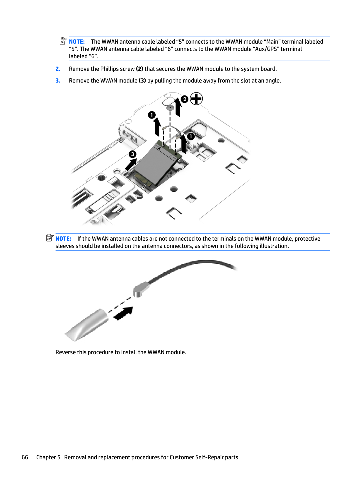
Note:
The WWAN antenna cable labeled “5” connects to the WWAN module “Main” terminal labeled “5”. The WWAN antenna cable labeled “6” connects to the WWAN module “Aux/GPS” terminal labeled “6”.Note:
If the WWAN antenna cables are not connected to the terminals on the WWAN module, protective sleeves should be installed on the antenna connectors, as shown in the following illustration. Reverse this procedure to install the WWAN module. 66 Chapter 5 Removal and replacement procedures for Customer Self-Repair parts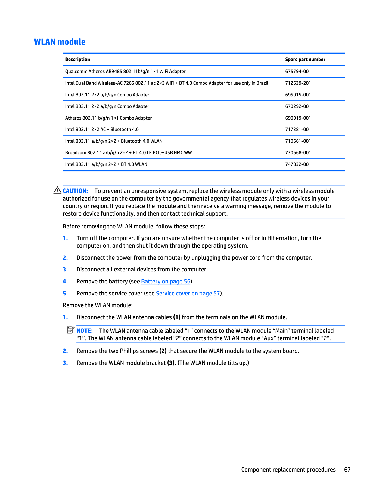
WLAN module Description Spare part number Qualcomm Atheros AR9485 802.11b/g/n 1×1 WiFi Adapter 675794-001 Intel Dual Band Wireless-AC 7265 802.11 ac 2×2 WiFi + BT 4.0 Combo Adapter for use only in Brazil 712639-201 Intel 802.11 2×2 a/b/g/n Combo Adapter 695915-001 Intel 802.11 2×2 a/b/g/n Combo Adapter 670292-001 Atheros 802.11 b/g/n 1×1 Combo Adapter 690019-001 Intel 802.11 2×2 AC + Bluetooth 4.0 717381-001 Intel 802.11 a/b/g/n 2×2 + Bluetooth 4.0 WLAN 710661-001 Broadcom 802.11 a/b/g/n 2×2 + BT 4.0 LE PCIe+USB HMC WW 730668-001 Intel 802.11 a/b/g/n 2×2 + BT 4.0 WLAN 747832-001
Caution:
To prevent an unresponsive system, replace the wireless module only with a wireless module authorized for use on the computer by the governmental agency that regulates wireless devices in your country or region. If you replace the module and then receive a warning message, remove the module to restore device functionality, and then contact technical support. Before removing the WLAN module, follow these steps:Note:
The WLAN antenna cable labeled “1” connects to the WLAN module “Main” terminal labeled “1”. The WLAN antenna cable labeled “2” connects to the WLAN module “Aux” terminal labeled “2”.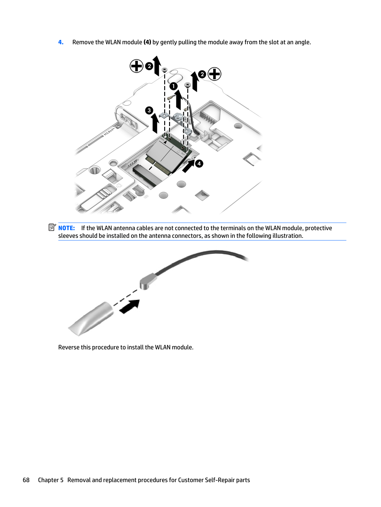
Note:
If the WLAN antenna cables are not connected to the terminals on the WLAN module, protective sleeves should be installed on the antenna connectors, as shown in the following illustration. Reverse this procedure to install the WLAN module. 68 Chapter 5 Removal and replacement procedures for Customer Self-Repair parts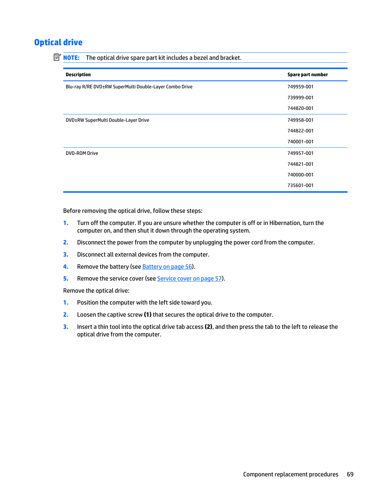
Optical drive
Note:
The optical drive spare part kit includes a bezel and bracket. Description Spare part number Blu-ray R/RE DVD±RW SuperMulti Double-Layer Combo Drive 749959-001 739999-001 744820-001 DVD±RW SuperMulti Double-Layer Drive 749958-001 744822-001 740001-001 DVD-ROM Drive 749957-001 744821-001 740000-001 735601-001 Before removing the optical drive, follow these steps: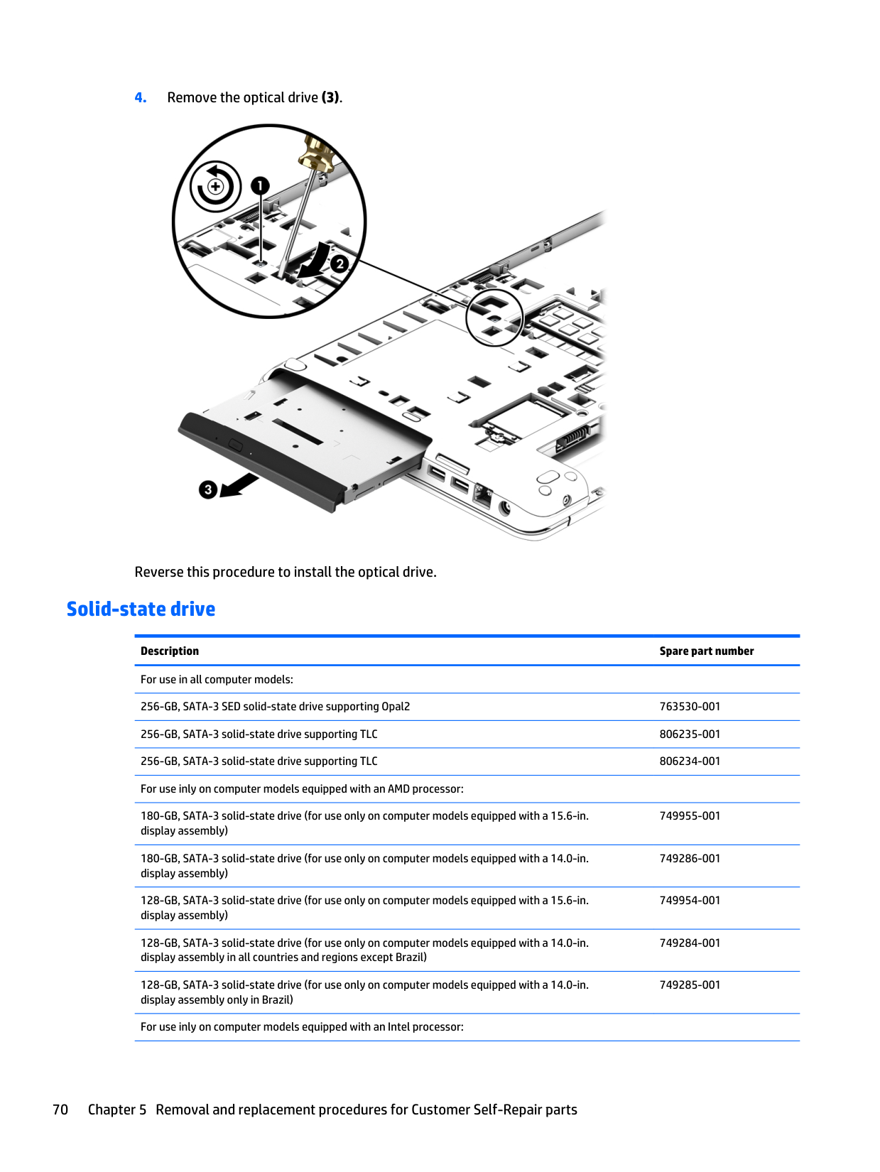

Description Spare part number 512-GB, SATA-3 solid-state drive supporting TLC 829939-001 256-GB, SM841 Samsung locked solid-state drive supporting Opal2 (for use only on computer models equipped with a 15.6-in. display assembly) 834423-001 256-GB, SM841 Samsung locked solid-state drive supporting Opal2 (for use only on computer models equipped with a 14.0-in. display assembly) 834422-001 180-GB, SATA-3 solid-state drive (for use only on computer models equipped with a 15.6-in. display assembly) 749262-001 180-GB, SATA-3 solid-state drive (for use only on computer models equipped with a 14.0-in. display assembly) 749278-001 128-GB, SATA-3 solid-state drive (for use only on computer models equipped with a 15.6-in. display assembly) 749261-001 128-GB, SATA-3 solid-state drive (for use only on computer models equipped with a 14.0-in. display assembly in all countries and regions except Brazil 749277-001 128-GB, SATA-3 solid-state drive (for use only on computer models equipped with a 14.0-in. display assembly in Brazil) 749280-001 Before removing the solid-state drive, follow these steps:
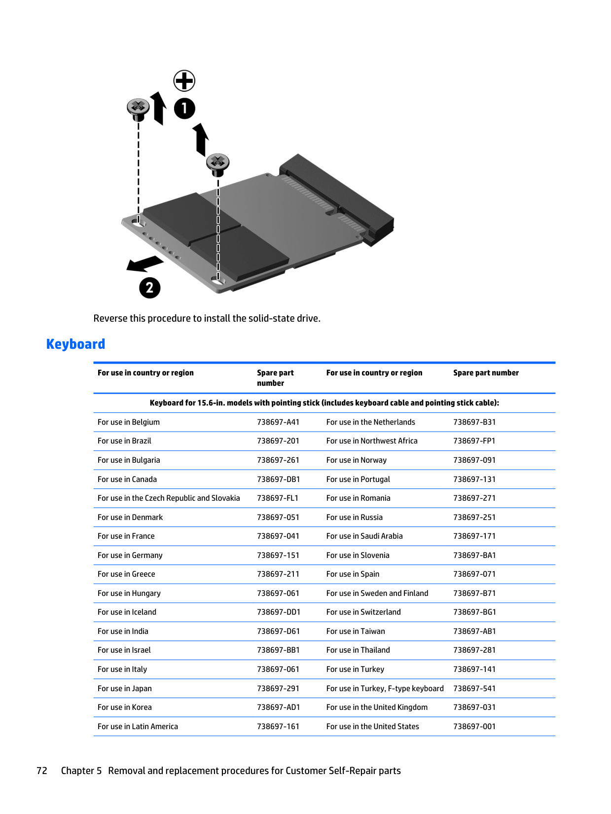
Reverse this procedure to install the solid-state drive. Keyboard For use in country or region Spare part number For use in country or region Spare part number Keyboard for 15.6-in. models with pointing stick (includes keyboard cable and pointing stick cable): For use in Belgium
738697-A41
For use in the Netherlands738697-B31
For use in Brazil 738697-201 For use in Northwest Africa738697-Fp1
For use in Bulgaria 738697-261 For use in Norway 738697-091 For use in Canada738697-Db1
For use in Portugal 738697-131 For use in the Czech Republic and Slovakia738697-Fl1
For use in Romania 738697-271 For use in Denmark 738697-051 For use in Russia 738697-251 For use in France 738697-041 For use in Saudi Arabia 738697-171 For use in Germany 738697-151 For use in Slovenia738697-Ba1
For use in Greece 738697-211 For use in Spain 738697-071 For use in Hungary 738697-061 For use in Sweden and Finland738697-B71
For use in Iceland738697-Dd1
For use in Switzerland738697-Bg1
For use in India738697-D61
For use in Taiwan738697-Ab1
For use in Israel738697-Bb1
For use in Thailand 738697-281 For use in Italy 738697-061 For use in Turkey 738697-141 For use in Japan 738697-291 For use in Turkey, F-type keyboard 738697-541 For use in Korea738697-Ad1
For use in the United Kingdom 738697-031 For use in Latin America 738697-161 For use in the United States 738697-001 72 Chapter 5 Removal and replacement procedures for Customer Self-Repair parts
For use in country or region Spare part number For use in country or region Spare part number Keyboard for 15.6-in. models with backlight (includes backlight and keyboard cables): For use in Latin America 787801-161 For use in Belgium
787801-A41
For use in the Netherlands787801-B31
For use in Brazil 787801-201 For use in Northwest Africa787801-Fp1
For use in Bulgaria 787801-261 For use in Norway 787801-091 For use in Canada787801-Db1
For use in Portugal 787801-131 For use in the Czech Republic and Slovakia787801-Fl1
For use in Romania 787801-271 For use in Denmark 787801-051 For use in Russia 787801-251 For use in France 787801-041 For use in Saudi Arabia 787801-171 For use in Germany 787801-151 For use in Slovenia787801-Ba1
For use in Greece 787801-211 For use in Spain 787801-071 For use in Hungary 787801-061 For use in Sweden and Finland787801-B71
For use in Iceland787801-Dd1
For use in Switzerland787801-Bg1
For use in India787801-D61
For use in Taiwan787801-Ab1
For use in Israel787801-Bb1
For use in Thailand 787801-281 For use in Italy 787801-061 For use in Turkey 787801-141 For use in Japan 787801-291 For use in the United Kingdom 787801-031 For use in Korea787801-Ad1
For use in the United States 787801-001 Keyboard for 15.6-in. models (includes keyboard cable): For use in Northwest Africa738696-Fp1
For use in Belgium738696-A41
For use in Norway 738696-091 For use in Bulgaria 738696-261 For use in Portugal 738696-131 For use in Canada738696-Db1
For use in Romania 738696-271 For use in the Czech Republic and Slovakia738696-Fl1
For use in Russia 738696-251 For use in Denmark 738696-081 For use in Saudi Arabia 738696-171 For use in France 738696-051 For use in Slovenia738696-Ba1
For use in Germany 738696-041 For use in South Korea738696-Ad1
For use in Greece 738696-151 For use in Spain 738696-071 For use in Hungary 738696-211 For use in Sweden and Finland738696-B71
For use in Iceland738696-Dd1
For use in Switzerland738696-Bg1
For use in India738696-D61
For use in Taiwan738696-Ab1
For use in Israel738696-Bb1
For use in Thailand 738696-281 For use in Italy 738696-061 For use in Turkey 738696-141 For use in Japan 738696-291 For use in Turkey, F-type keyboard 738696-541 Component replacement procedures 73
For use in country or region Spare part number For use in country or region Spare part number For use in Latin America 738696-161 For use in the United Kingdom and Singapore 738696-031 For use in the Netherlands
738696-B31
For use in the United States 738696-001 Keyboard for 14-in. models with pointing stick (includes keyboard cable and pointing stick cable): For use in Belgium738688-A41
For use in Northwest Africa738688-Fp1
For use in Brazil 738688-201 For use in Norway 738688-091 For use in Bulgaria 738688-261 For use in Portugal 738688-131 For use in Canada738688-Db1
For use in Romania 738688-271 For use in the Czech Republic and Slovakia738688-Fl1
For use in Russia 738688-251 For use in Denmark 738688-081 For use in Saudi Arabia 738688-171 For use in France 738688-051 For use in Slovenia738688-Ba1
For use in Germany 738688-041 For use in South Korea738688-Ad1
For use in Greece 738688-151 For use in Spain 738688-071 For use in Hungary 738688-211 For use in Sweden and Finland738688-B71
For use in Iceland738688-Dd1
For use in Switzerland738688-Bg1
For use in India738688-D61
For use in Taiwan738688-Ab1
For use in Israel738688-Bb1
For use in Thailand 738688-281 For use in Italy 738688-061 For use in Turkey 738688-141 For use in Japan 738688-291 For use in Turkey, F-type keyboard 738688-541 For use in Latin America 738688-161 For use in the United Kingdom and Singapore 738688-031 For use in the Netherlands738688-B31
For use in the United States 738688-001 Keyboard for 14-in. models with backlight (includes backlight and keyboard cables): For use in Latin America 787294-161 For use in Belgium787294-A41
For use in the Netherlands787294-B31
For use in Brazil 787294-201 For use in Northwest Africa787294-Fp1
For use in Bulgaria 787294-261 For use in Norway 787294-091 For use in Canada787294-Db1
For use in Portugal 787294-131 For use in the Czech Republic and Slovakia787294-Fl1
For use in Romania 787294-271 For use in Denmark 787294-051 For use in Russia 787294-251 For use in France 787294-041 For use in Saudi Arabia 787294-171 For use in Germany 787294-151 For use in Slovenia787294-Ba1
For use in Greece 787294-211 For use in Spain 787294-071 For use in Hungary 787294-061 For use in Sweden and Finland787294-B71
For use in Iceland787294-Dd1
For use in Switzerland787294-Bg1
74 Chapter 5 Removal and replacement procedures for Customer Self-Repair parts
For use in country or region Spare part number For use in country or region Spare part number For use in India
787294-D61
For use in Taiwan787294-Ab1
For use in Israel787294-Bb1
For use in Thailand 787294-281 For use in Italy 787294-061 For use in Turkey 787294-141 For use in Japan 787294-291 For use in the United Kingdom 787294-031 For use in Korea787294-Ad1
For use in the United States 787294-001 Keyboard for 14-in. models (includes keyboard cable): For use in Belgium738687-A41
For use in the Netherlands738687-B31
For use in Brazil 738687-201 For use in Northwest Africa738687-Fp1
For use in Bulgaria 738687-261 For use in Norway 738687-091 For use in Canada738687-Db1
For use in Portugal 738687-131 For use in the Czech Republic and Slovakia738687-Fl1
For use in Romania 738687-271 For use in Denmark 738687-051 For use in Russia 738687-251 For use in France 738687-041 For use in Saudi Arabia 738687-171 For use in Germany 738687-151 For use in Slovenia738687-Ba1
For use in Greece 738687-211 For use in Spain 738687-071 For use in Hungary 738687-061 For use in Sweden and Finland738687-B71
For use in Iceland738687-Dd1
For use in Switzerland738687-Bg1
For use in India738687-D61
For use in Taiwan738687-Ab1
For use in Israel738687-Bb1
For use in Thailand 738687-281 For use in Italy 738687-061 For use in Turkey 738687-141 For use in Japan 738687-291 For use in Turkey, F-type keyboard 738687-541 For use in Korea738687-Ad1
For use in the United Kingdom 738687-031 For use in Latin America 738687-161 For use in the United States 738687-001 Before removing the keyboard, follow these steps: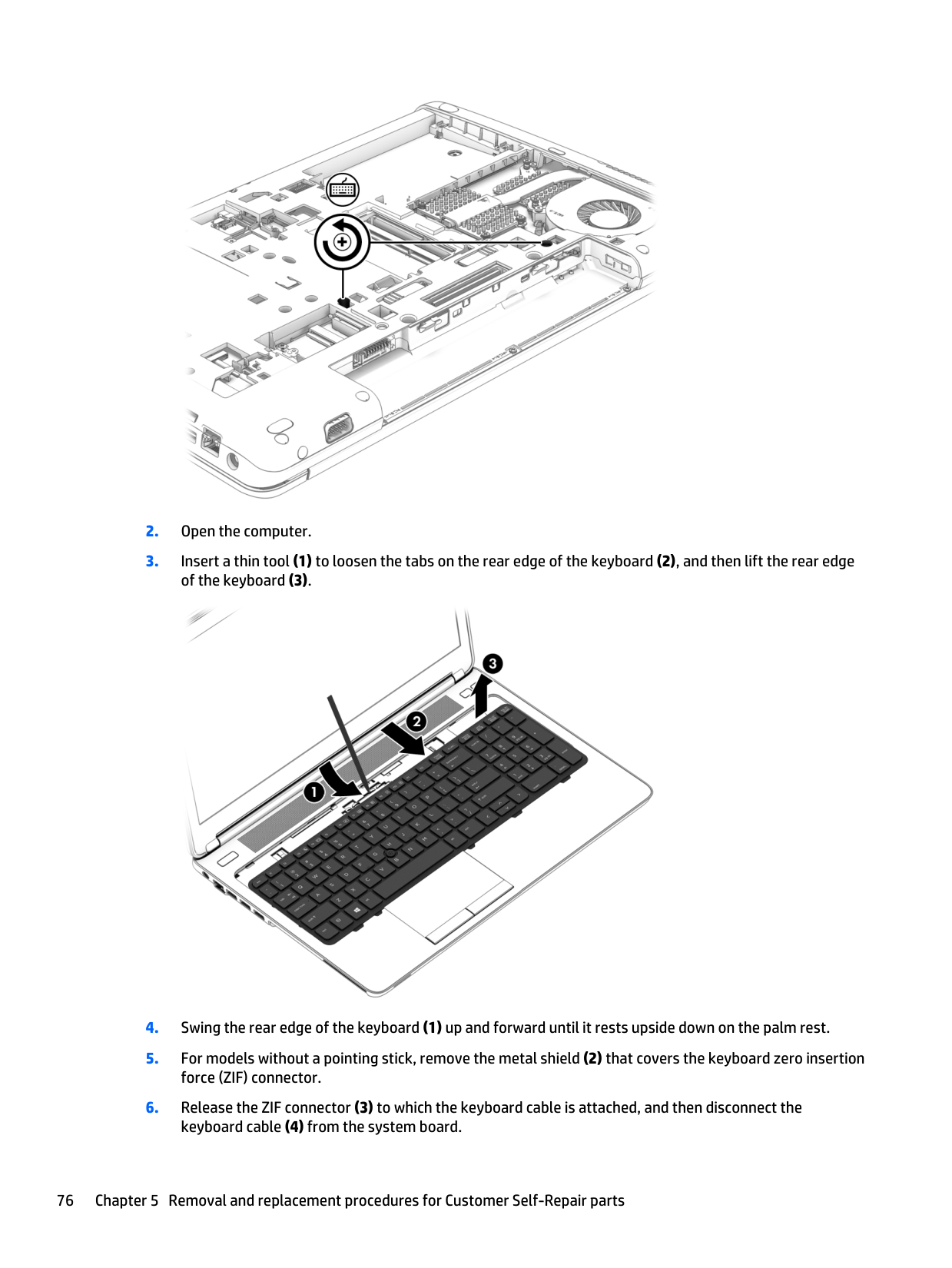
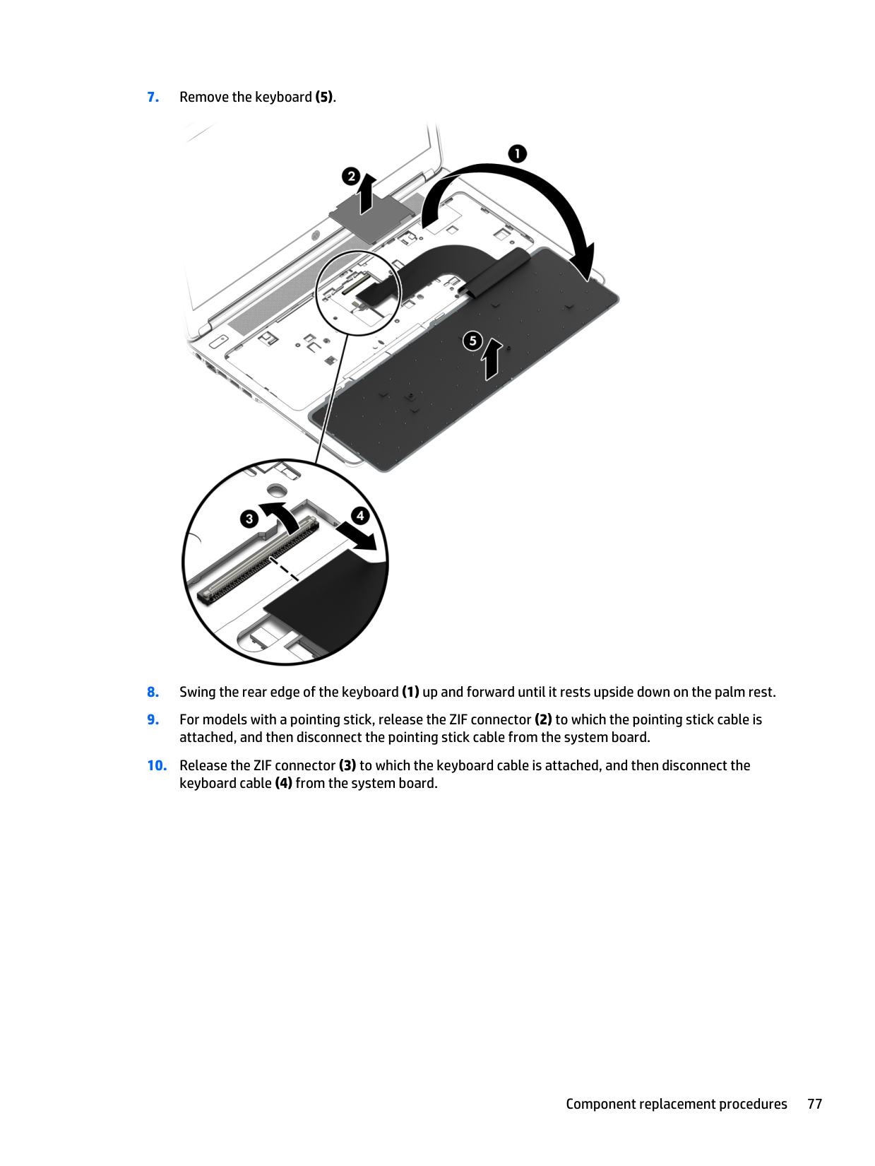
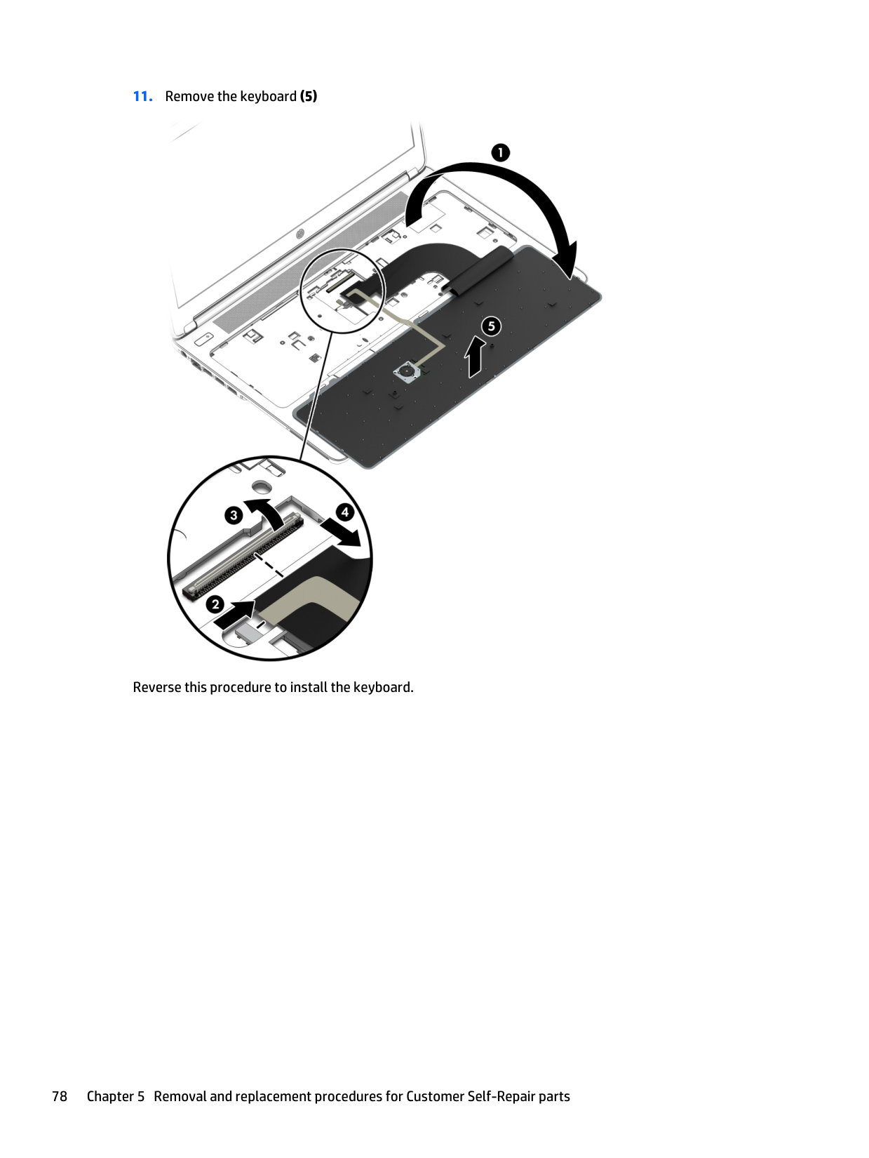
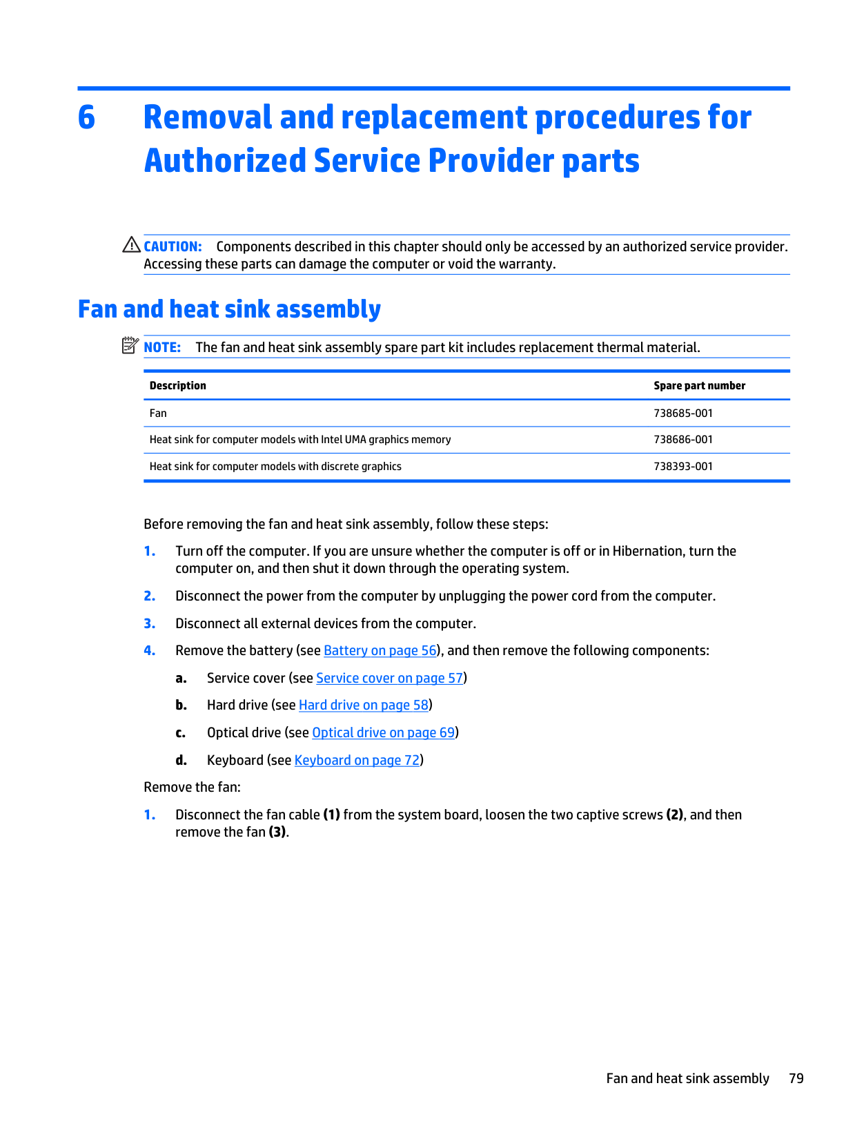
6 Removal and replacement procedures for Authorized Service Provider parts
Caution:
Components described in this chapter should only be accessed by an authorized service provider. Accessing these parts can damage the computer or void the warranty. Fan and heat sink assemblyNote:
The fan and heat sink assembly spare part kit includes replacement thermal material. Description Spare part number Fan 738685-001 Heat sink for computer models with Intel UMA graphics memory 738686-001 Heat sink for computer models with discrete graphics 738393-001 Before removing the fan and heat sink assembly, follow these steps: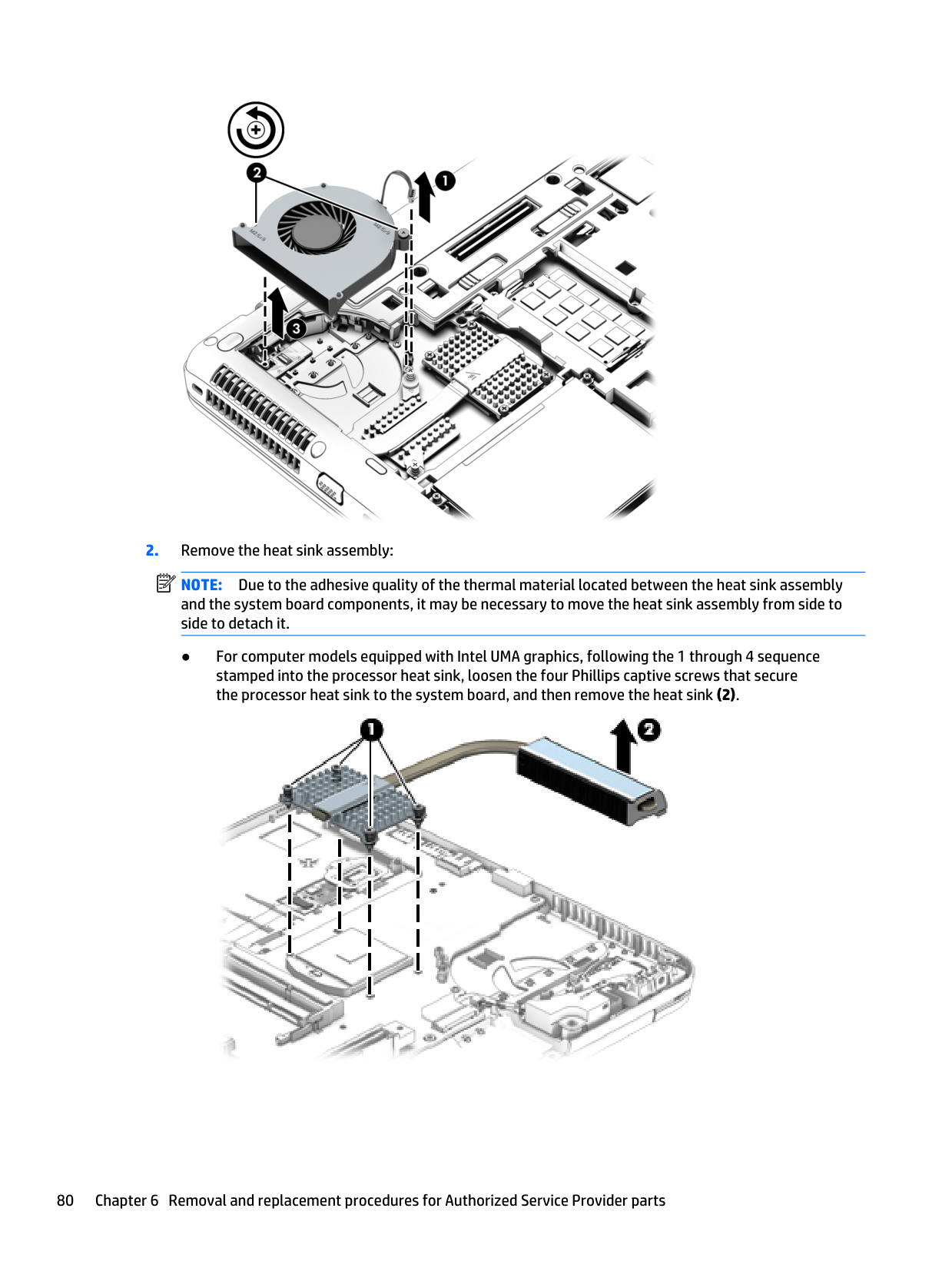
Note:
Due to the adhesive quality of the thermal material located between the heat sink assembly and the system board components, it may be necessary to move the heat sink assembly from side to side to detach it. ● For computer models equipped with Intel UMA graphics, following the 1 through 4 sequence stamped into the processor heat sink, loosen the four Phillips captive screws that secure the processor heat sink to the system board, and then remove the heat sink (2). 80 Chapter 6 Removal and replacement procedures for Authorized Service Provider parts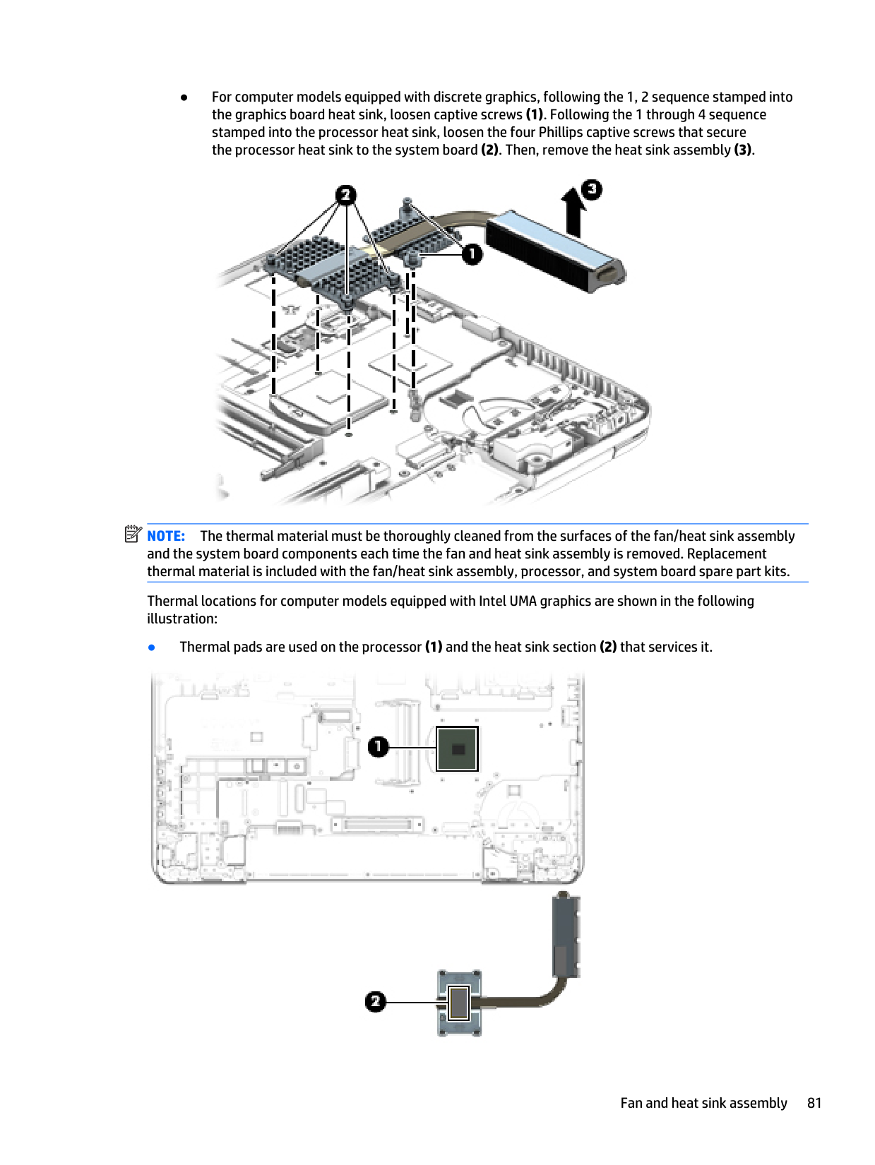
● For computer models equipped with discrete graphics, following the 1, 2 sequence stamped into the graphics board heat sink, loosen captive screws (1). Following the 1 through 4 sequence stamped into the processor heat sink, loosen the four Phillips captive screws that secure the processor heat sink to the system board (2). Then, remove the heat sink assembly (3).
Note:
The thermal material must be thoroughly cleaned from the surfaces of the fan/heat sink assembly and the system board components each time the fan and heat sink assembly is removed. Replacement thermal material is included with the fan/heat sink assembly, processor, and system board spare part kits. Thermal locations for computer models equipped with Intel UMA graphics are shown in the following illustration: ● Thermal pads are used on the processor (1) and the heat sink section (2) that services it. Fan and heat sink assembly 81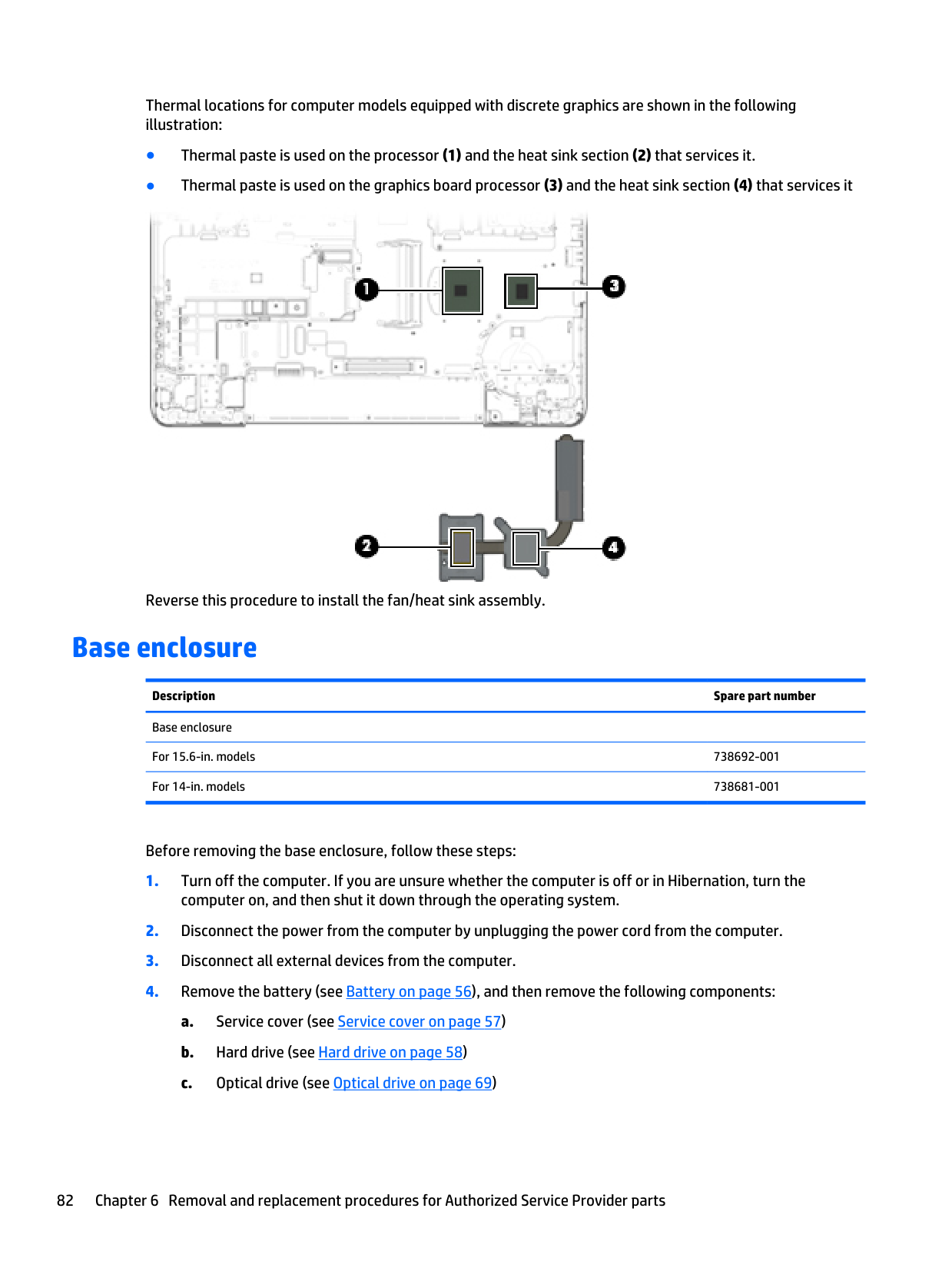
Thermal locations for computer models equipped with discrete graphics are shown in the following illustration: ● Thermal paste is used on the processor (1) and the heat sink section (2) that services it. ● Thermal paste is used on the graphics board processor (3) and the heat sink section (4) that services it Reverse this procedure to install the fan/heat sink assembly. Base enclosure Description Spare part number Base enclosure
For 15.6-in. models 738692-001 For 14-in. models 738681-001 Before removing the base enclosure, follow these steps:
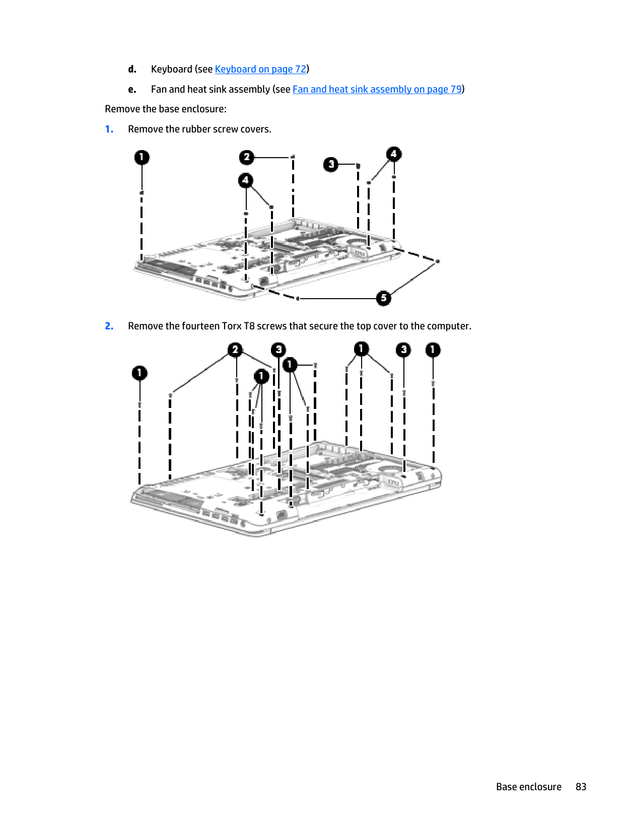
d. Keyboard (see Keyboard on page 72) e. Fan and heat sink assembly (see Fan and heat sink assembly on page 79) Remove the base enclosure:
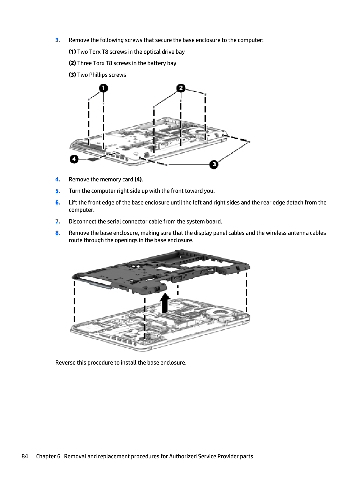
USB board Description Spare part number USB board (includes cable)
For use in ProBook 650 G1 models equipped with a 15.6-in. display assembly 738702-001 For use in ProBook 655 G1 models equipped with a 15.6-in. display assembly 745891-001 For use in computer models equipped with a 14-in. display assembly 738400-001 Before removing the USB board, follow these steps:
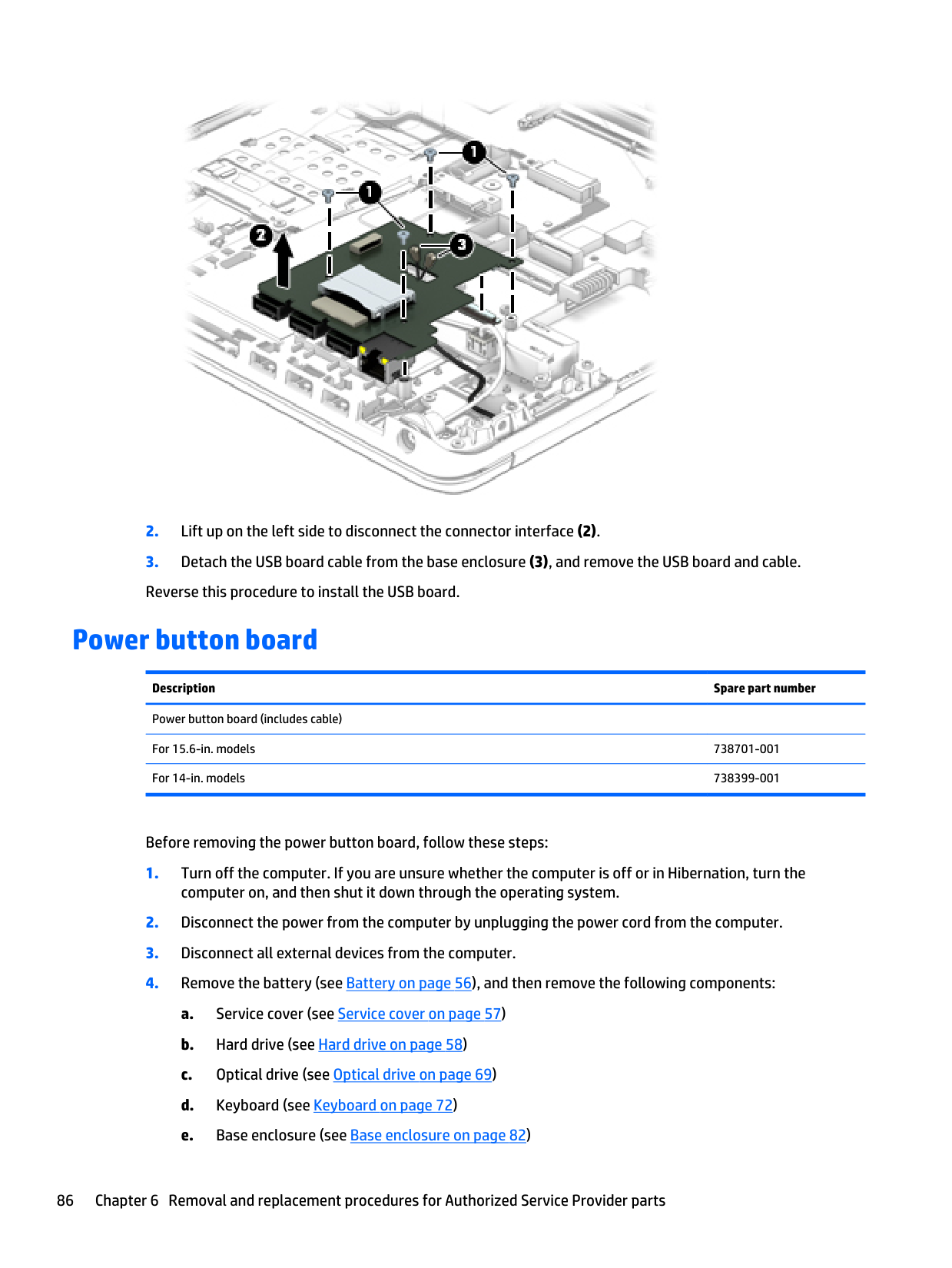
For 15.6-in. models 738701-001 For 14-in. models 738399-001 Before removing the power button board, follow these steps:
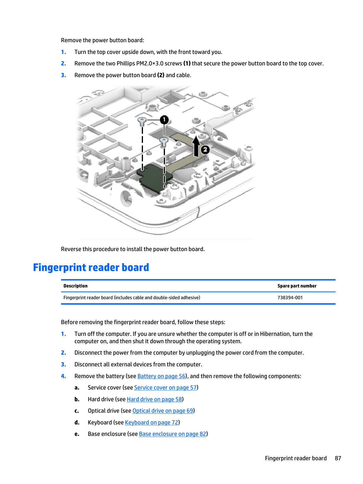
Remove the power button board:
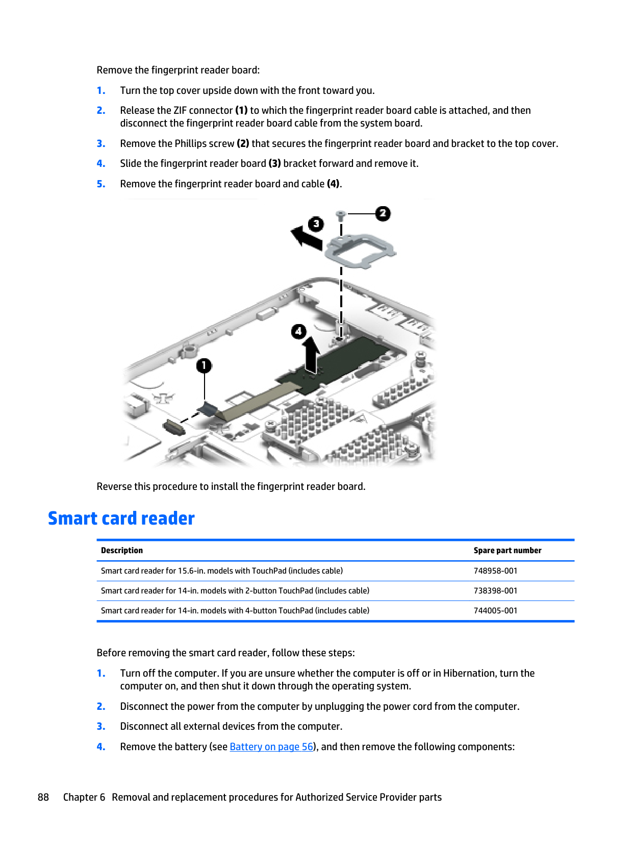
Remove the fingerprint reader board:
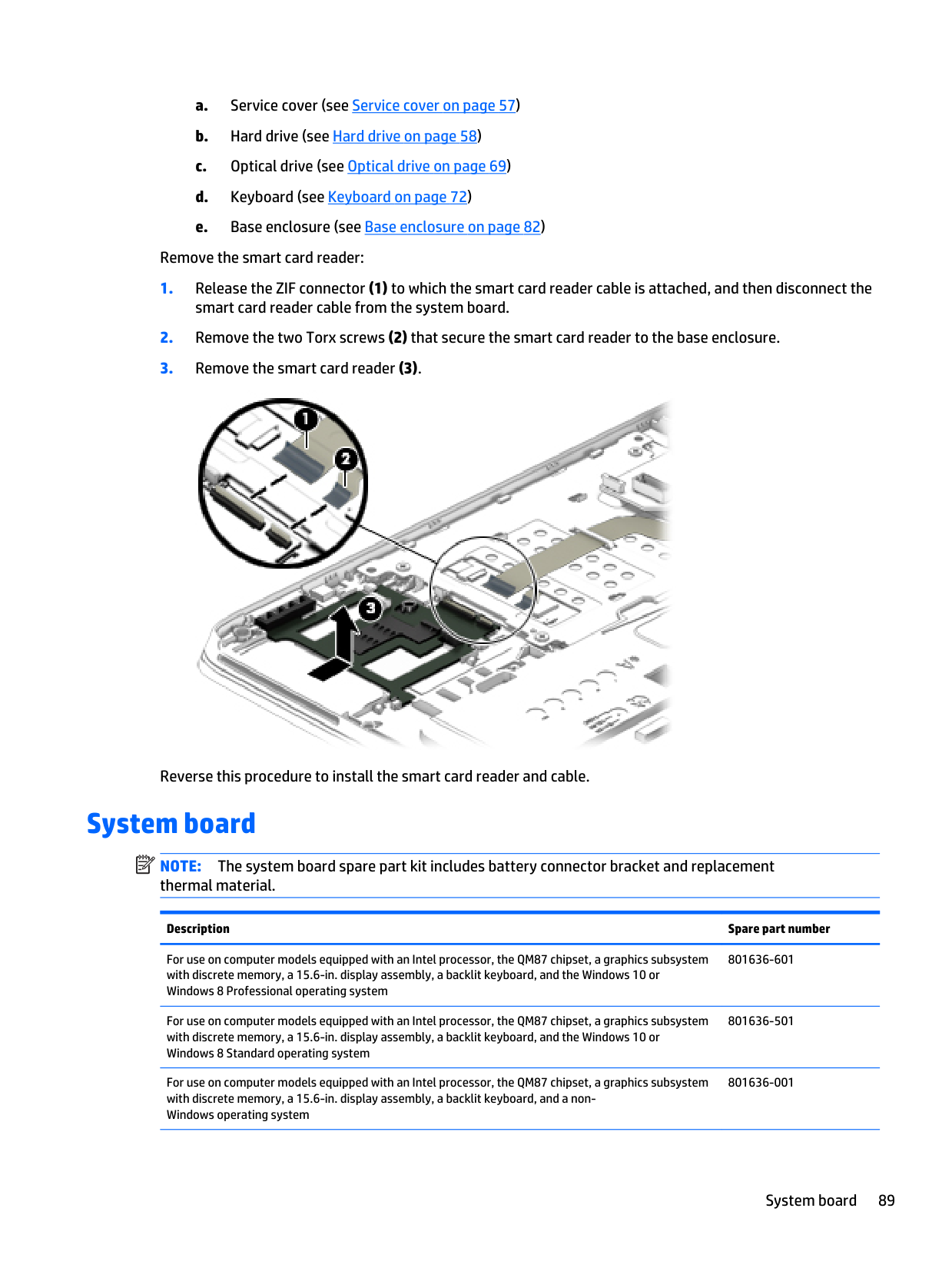
a. Service cover (see Service cover on page 57) b. Hard drive (see Hard drive on page 58) c. Optical drive (see Optical drive on page 69) d. Keyboard (see Keyboard on page 72) e. Base enclosure (see Base enclosure on page 82) Remove the smart card reader:
Note:
The system board spare part kit includes battery connector bracket and replacement thermal material. Description Spare part number For use on computer models equipped with an Intel processor, the QM87 chipset, a graphics subsystem with discrete memory, a 15.6-in. display assembly, a backlit keyboard, and the Windows 10 or Windows 8 Professional operating system 801636-601 For use on computer models equipped with an Intel processor, the QM87 chipset, a graphics subsystem with discrete memory, a 15.6-in. display assembly, a backlit keyboard, and the Windows 10 or Windows 8 Standard operating system 801636-501 For use on computer models equipped with an Intel processor, the QM87 chipset, a graphics subsystem with discrete memory, a 15.6-in. display assembly, a backlit keyboard, and a non- Windows operating system 801636-001 System board 89
Description Spare part number For use on computer models equipped with an Intel processor, the QM87 chipset, a graphics subsystem with UMA memory, a 15.6-in. display assembly, a backlit keyboard, and the Windows 10 or Windows 8 Professional operating system 801635-601 For use on computer models equipped with an Intel processor, the QM87 chipset, a graphics subsystem with UMA memory, a 15.6-in. display assembly, a backlit keyboard, and the Windows 10 or Windows 8 Standard operating system 801635-501 For use on computer models equipped with an Intel processor, the QM87 chipset, a graphics subsystem with UMA memory, a 15.6-in. display assembly, a backlit keyboard, and a non- Windows operating system 801635-001 For use on computer models equipped with an Intel processor, the HM87 chipset, a graphics subsystem with discrete memory, a 15.6-in. display assembly, a backlit keyboard, and the Windows 10 or Windows 8 Professional operating system 801634-601 For use on computer models equipped with an Intel processor, the HM87 chipset, a graphics subsystem with discrete memory, a 15.6-in. display assembly, a backlit keyboard, and the Windows 10 or Windows 8 Standard operating system 801634-501 For use on computer models equipped with an Intel processor, the HM87 chipset, a graphics subsystem with discrete memory, a 15.6-in. display assembly, a backlit keyboard, and a non- Windows operating system 801634-001 For use on computer models equipped with an Intel processor, the HM87 chipset, a graphics subsystem with UMA memory, a 15.6-in. display assembly, a backlit keyboard, and the Windows 10 or Windows 8 Professional operating system 801633-601 For use on computer models equipped with an Intel processor, the HM87 chipset, a graphics subsystem with UMA memory, a 15.6-in. display assembly, a backlit keyboard, and the Windows 10 or Windows 8 Standard operating system 801633-501 For use on computer models equipped with an Intel processor, the HM87 chipset, a graphics subsystem with UMA memory, a 15.6-in. display assembly, a backlit keyboard, and a non- Windows operating system 801633-001 For use on computer models equipped with an Intel processor, the QM87 chipset, a graphics subsystem with discrete memory, a 14.0-in. display assembly, a backlit keyboard, and the Windows 10 or Windows 8 Professional operating system 803850-601 For use on computer models equipped with an Intel processor, the QM87 chipset, a graphics subsystem with discrete memory, a 14.0-in. display assembly, a backlit keyboard, and the Windows 10 or Windows 8 Standard operating system 803850-501 For use on computer models equipped with an Intel processor, the QM87 chipset, a graphics subsystem with discrete memory, a 14.0-in. display assembly, a backlit keyboard, and a non- Windows operating system 803850-001 For use on computer models equipped with an Intel processor, the QM87 chipset, a graphics subsystem with UMA memory, a 14.0-in. display assembly, a backlit keyboard, and the Windows 10 or Windows 8 Professional operating system 803848-601 For use on computer models equipped with an Intel processor, the QM87 chipset, a graphics subsystem with UMA memory, a 14.0-in. display assembly, a backlit keyboard, and the Windows 10 or Windows 8 Standard operating system 803848-501 For use on computer models equipped with an Intel processor, the QM87 chipset, a graphics subsystem with UMA memory, a 14.0-in. display assembly, a backlit keyboard, and a non- Windows operating system 803848-001 For use on computer models equipped with an Intel processor, the HM87 chipset, a graphics subsystem with discrete memory, a 14.0-in. display assembly, a backlit keyboard, and the Windows 10 or Windows 8 Professional operating system 803849-601 90 Chapter 6 Removal and replacement procedures for Authorized Service Provider parts
Description Spare part number For use on computer models equipped with an Intel processor, the HM87 chipset, a graphics subsystem with discrete memory, a 14.0-in. display assembly, a backlit keyboard, and the Windows 10 or Windows 8 Standard operating system 803849-501 For use on computer models equipped with an Intel processor, the HM87 chipset, a graphics subsystem with discrete memory, a 14.0-in. display assembly, a backlit keyboard, and a non- Windows operating system 803849-001 For use on computer models equipped with an Intel processor, the HM87 chipset, a graphics subsystem with UMA memory, a 14.0-in. display assembly, a backlit keyboard, and the Windows 10 or Windows 8 Professional operating system 803847-601 For use on computer models equipped with an Intel processor, the HM87 chipset, a graphics subsystem with UMA memory, a 14.0-in. display assembly, a backlit keyboard, and the Windows 10 or Windows 8 Standard operating system 803847-501 For use on computer models equipped with an Intel processor, the HM87 chipset, a graphics subsystem with UMA memory, a 14.0-in. display assembly, a backlit keyboard, and a non- Windows operating system 803847-001 For 14-in. computer models with shared memory and WWAN capability (includes replacement thermal material) 744007-001 For 14-in. computer models with shared memory and the Windows 8 Standard operating system with WWAN capability (includes replacement thermal material) 744007-501 For 14-in. computer models with shared memory and the Windows 8 Professional operating system with WWAN capability (includes replacement thermal material) 744007-601 For 14-in. computer models with discrete memory and WWAN capability (includes replacement thermal material) 744008-001 For 14-in. computer models with discrete memory and the Windows 8 Standard operating system with WWAN capability (includes replacement thermal material) 744008-501 For 14-in. computer models with discrete memory and the Windows 8 Professional operating system with WWAN capability (includes replacement thermal material) 744008-601 For 14-in. computer models with discrete memory, WWAN capability (includes replacement thermal material) 744009-001 For 14-in. computer models with discrete memory and the Windows 8 Standard operating system with WWAN capability (includes replacement thermal material) 744009-501 For 14-in. computer models with shared memory and the Windows 8 Professional operating system with WWAN capability (includes replacement thermal material) 744009-601 For 14-in. computer models with discrete memory and WWAN capability (includes replacement thermal material) 744010-001 For 14-in. computer models with discrete memory and the Windows 8 Standard operating system with WWAN capability (includes replacement thermal material) 744010-501 For 14-in. computer models with shared memory and the Windows 8 Professional operating system with WWAN capability (includes replacement thermal material) 744010-601 For 15.6-in. computer models with discrete memory, WWAN capability (includes replacement thermal material) 744015-001 For 15.6-in. computer models with discrete memory and the Windows 8 Standard operating system with WWAN capability (includes replacement thermal material) 744015-501 For 15.6-in. computer models with discrete memory and the Windows 8 Professional operating system with WWAN capability (includes replacement thermal material) 744015-601 System board 91
Description Spare part number For 15.6-in. computer models with shared memory, WWAN capability (includes replacement thermal material) 744016-001 For 15.6-in. computer models with shared memory and the Windows 8 Standard operating system with WWAN capability (includes replacement thermal material) 744016-501 For 15.6-in. computer models with shared memory and the Windows 8 Professional operating system with WWAN capability (includes replacement thermal material) 744016-601 For 15.6-in. computer models with shared memory, WWAN capability (includes replacement thermal material) 744017-001 For 15.6-in. computer models with shared memory and the Windows 8 Standard operating system with WWAN capability (includes replacement thermal material) 744017-501 For 15.6-in. computer models with shared memory and the Windows 8 Professional operating system with WWAN capability (includes replacement thermal material) 744017-601 For 14-in. computer models equipped with shared memory with WWAN capability 745883-001 For 14-in. computer models equipped with shared memory and the Windows 8 Standard operating system with WWAN capability 745883-501 For 14-in. computer models with shared memory and the Windows 8 Professional operating system with WWAN capability 745883-601 For 14-in. computer models shared memory without WWAN capability 745884-001 For computer models equipped with shared memory and the Windows 8 Standard operating system without WWAN capability 745884-501 For use inly on computer models shared memory and the Windows 8 Professional operating system without WWAN capability 745884-601 For use inly on 15.6-in. computer models equipped with an Intel Quad Core processor with WWAN capability 745887-001 For use inly on 15.6-in. computer models shared memory and the Windows 8 Standard operating system with WWAN capability 745887-501 For use inly on 15.6-in. computer models with shared memory and the Windows 8 Professional operating system with WWAN capability 745887-601 For use inly on 15.6-in. computer models with shared memory and the Windows 8 Standard operating system without WWAN capability 745888-501 For use inly on 15.6-in. computer models with shared memory and the Windows 8 Professional operating system without WWAN capability 745888-601 For use inly on 15.6-in. computer models with shared memory and without WWAN capability 745888-001 Before removing the system board, follow these steps:
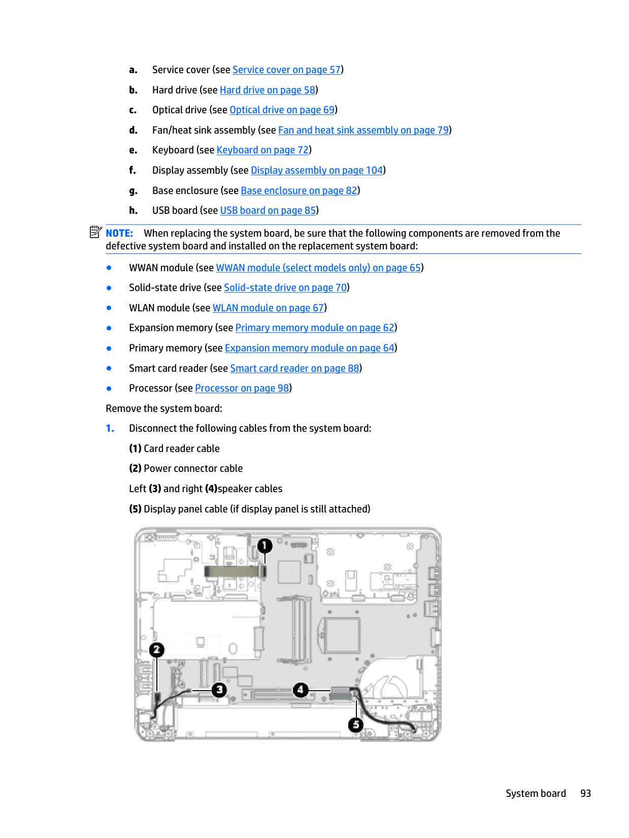
a. Service cover (see Service cover on page 57) b. Hard drive (see Hard drive on page 58) c. Optical drive (see Optical drive on page 69) d. Fan/heat sink assembly (see Fan and heat sink assembly on page 79) e. Keyboard (see Keyboard on page 72) f. Display assembly (see Display assembly on page 104) g. Base enclosure (see Base enclosure on page 82) h. USB board (see USB board on page 85)
Note:
When replacing the system board, be sure that the following components are removed from the defective system board and installed on the replacement system board: ● WWAN module (see WWAN module (select models only) on page 65) ● Solid-state drive (see Solid-state drive on page 70) ● WLAN module (see WLAN module on page 67) ● Expansion memory (see Primary memory module on page 62) ● Primary memory (see Expansion memory module on page 64) ● Smart card reader (see Smart card reader on page 88) ● Processor (see Processor on page 98) Remove the system board: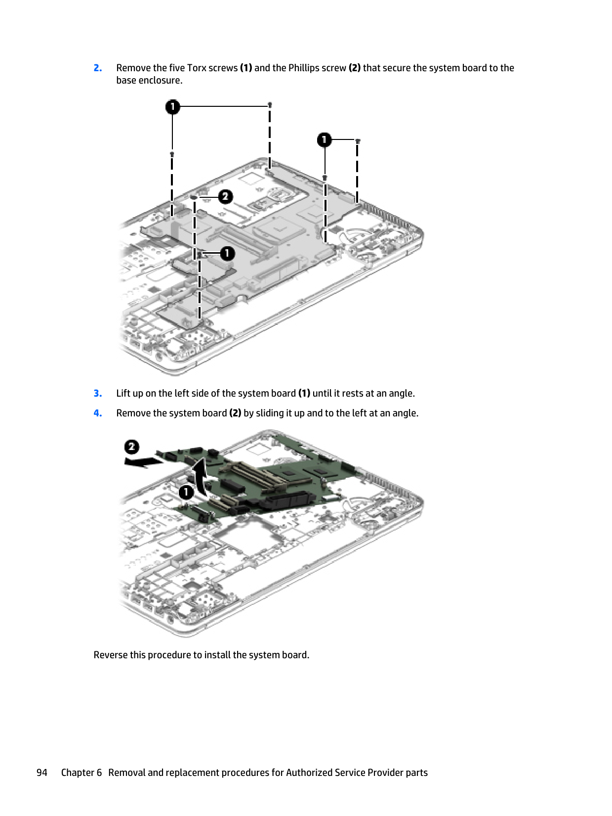
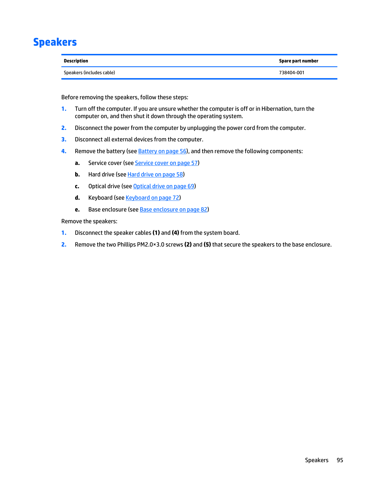
Speakers Description Spare part number Speakers (includes cable) 738404-001 Before removing the speakers, follow these steps:
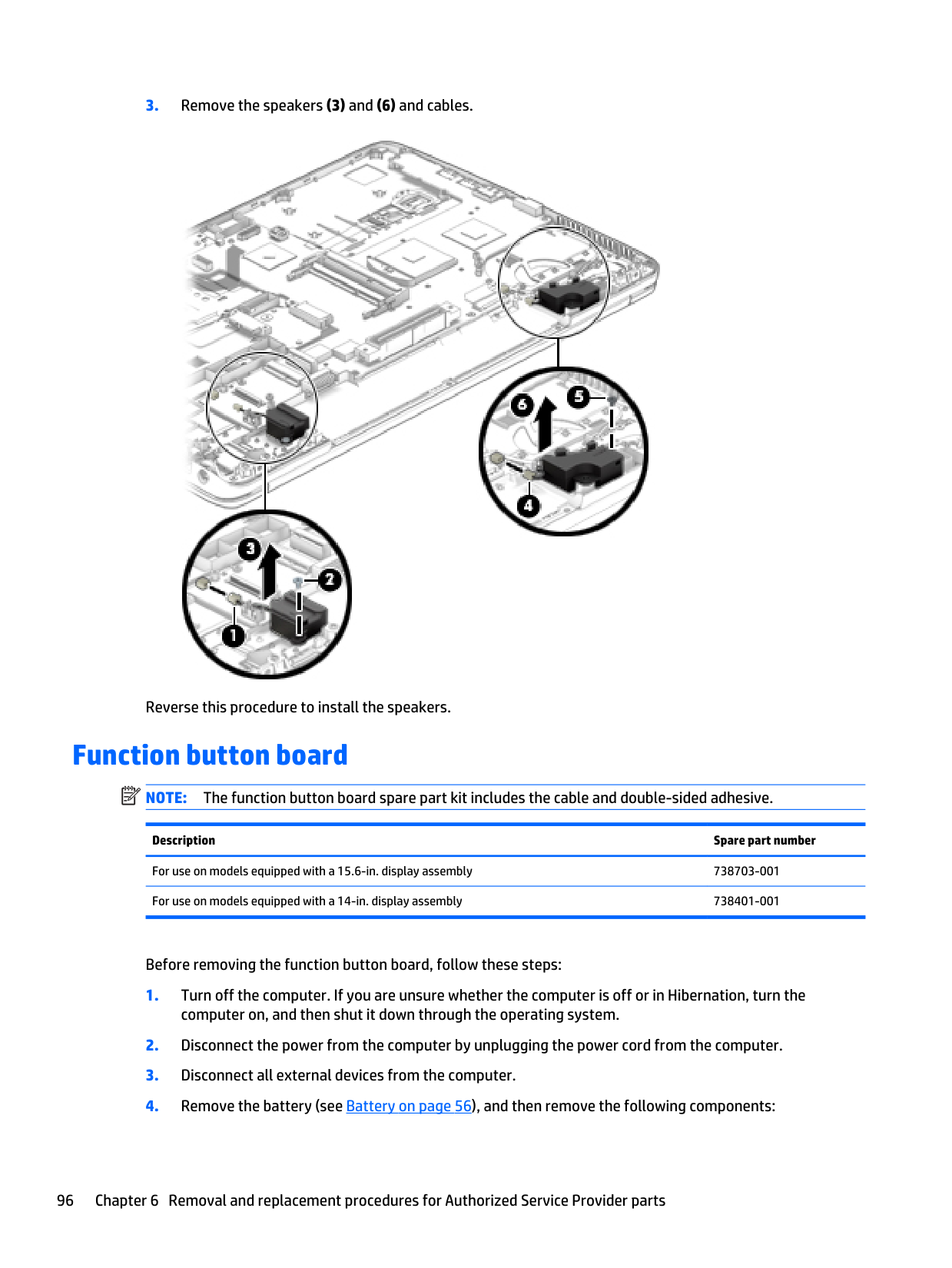
Note:
The function button board spare part kit includes the cable and double-sided adhesive. Description Spare part number For use on models equipped with a 15.6-in. display assembly 738703-001 For use on models equipped with a 14-in. display assembly 738401-001 Before removing the function button board, follow these steps: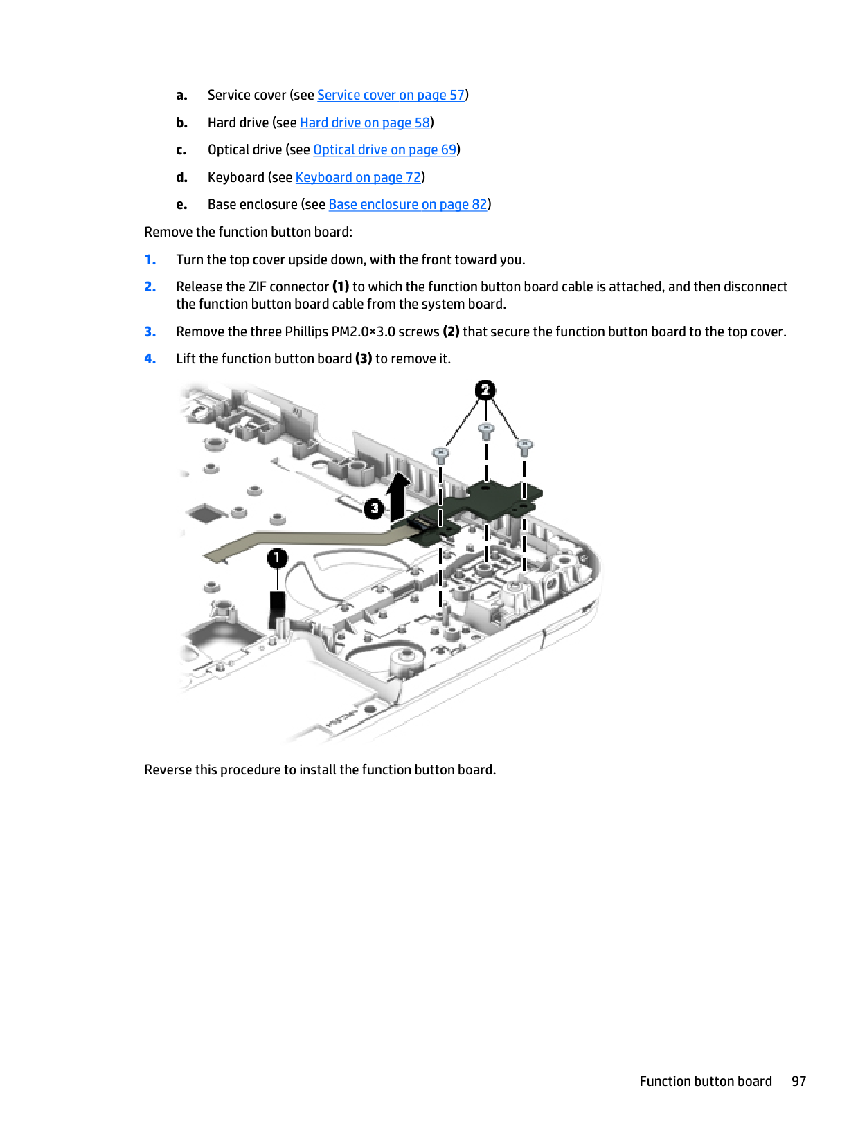
a. Service cover (see Service cover on page 57) b. Hard drive (see Hard drive on page 58) c. Optical drive (see Optical drive on page 69) d. Keyboard (see Keyboard on page 72) e. Base enclosure (see Base enclosure on page 82) Remove the function button board:
Processor
Note:
The processor spare part kit includes replacement thermal material. Description Spare part number Intel Core i7-4802MQ 2.70-GHz processor (1600-MHz FSB, 6.0-MB L3 cache, quad core, 47 W; for use only on computer models equipped with a 14.0-inch display assembly) 723524-001 Intel Core i7-4712MQ 2.30-GHz processor (1600-MHz FSB, 6.0-MB L3 cache, quad core, 37 W) 773213-001 Intel Core i7-4702MQ 2.20-GHz processor (1600-MHz FSB, 6.0-MB L3 cache, quad core, 37 W) 723522-001 Intel Core i7-4610M 3.0-GHz (SC turbo up to 3.70-GHz) processor (1600-MHz FSB, 4.0-MB L3 cache, dual core, 37 W) 765141-001 Intel Dual Core i7-4600M 2.80-GHz processor (3.0-MB L3 cache, 37 W) 737330-001 Intel Core i5-4340M 2.90-GHz (SC turbo up to 3.60-GHz) processor (1600-MHz FSB, 3.0-MB L3 cache, dual core, 37 W) 765142-001 Intel Dual Core i5-4330M 2.80-GHz processor (3.0-MB L3 cache, 37 W) 738201-001 Intel Core i5-4310M 2.70-GHz (SC turbo up to 3.40-GHz) processor (1600-MHz FSB, 3.0-MB L3 cache, dual core, 37 W) 765143-001 Intel Dual Core i5-4300M 2.60-GHz processor (3.0-MB L3 cache, 37 W) 738309-001 Intel Core i5-4210M 2.60-GHz (SC turbo up to 3.20-GHz) processor (1600-MHz FSB, 3.0-MB L3 cache, dual core, 37 W) 768420-001 Intel Dual Core i5-4200M 2.50-GHz processor (3.0-MB L3 cache, 37 W) 737328-001 Intel Core i3-4110M 2.60-GHz processor (1600-MHz FSB, 3.0-MB L3 cache, dual core, 37 W) 768744-001 Intel Dual Core i3-4100M 2.50-GHz processor (3.0-MB L3 cache, 37 W) 737474-001 Intel Dual Core i3-4000M 2.40-GHz (SC turbo up to 3.30-GHz) processor (1600-MHz FSB, 3.0-MB L3 cache, 37 W) 737327-001 Intel Celeron 2950M 2.00-GHz processor (2.0-MB L3 cache, dual core, 37 W) 737326-001 AMD A10-5750M with Radeon HD 8650G Graphics (quad-core; 3.5 GHz/2.5 GHz; 35W, 4 MB L2 cache) 713548-001 AMD A10-4600M with Radeon HD 7660G Graphics (quad-core; 3.2 GHz/2.3 GHz; 35W; 4 MB L2 cache) 683046-001 AMD A8-4500M with Radeon HD 7640G Graphics (quad-core; 2.8 GHz/1.9 GHz; 35W; 4 MB L2 cache) 683048-001 AMD A6-4400M with Radeon HD 7520G Graphics (dual-core; 3.2 GHz/2.7 GHz; 35W; 1 MB L2 cache) 683047-001 A6-5350M with Radeon HD 8450G Graphics (dual-core; 3.5 GHz/2.9 GHz; 35W; 1 MB L2 cache) 713550-001 AMD A4-4300M with Radeon HD 7420G Graphics (dual-core; 3.0 GHz/2.5 GHz; 35W; 1 MB L2 cache) 685990-001 AMD A4-5150M with Radeon HD 8350G Graphics (dual-core; 3.3 GHz/2.7 GHz; 35W; 1 MB L2 cache) 713549-001 AMD A8-5550M 3.1 GHz/2.1 GHz 4M 35W 713551-001 Before removing the processor, follow these steps: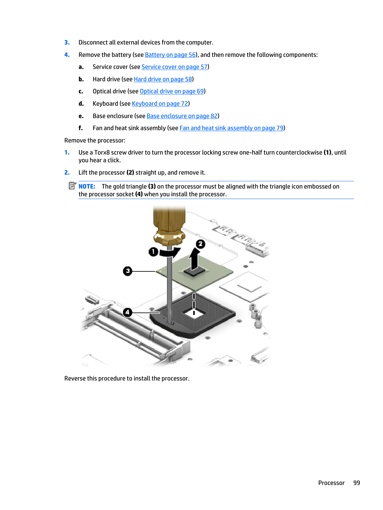
Note:
The gold triangle (3) on the processor must be aligned with the triangle icon embossed on the processor socket (4) when you install the processor. Reverse this procedure to install the processor. Processor 99
TouchPad Description Spare part number Top cover
For use in HP ProBook 655 G1 models:
Top cover with 2-button TouchPad Top cover with 2-button TouchPad and bracket Top cover with 4-button TouchPad Top cover with 4-button TouchPad and bracket Top cover with 2-button TouchPad and backlit keyboard 745889-001 738710-001 745890-001 738711-001 805782-001 For use in HP ProBook 650 G1 models:
Top cover with 2-button TouchPad Top cover with 2-button TouchPad and bracket Top cover with 4-button TouchPad Top cover with 4-button TouchPad and bracket Top cover with 2-button TouchPad and backlit keyboard 738708-001 738710-001 738709-001 738711-001 805782-001 For use on models equipped with a 14-in. display assembly:
Top cover with 2-button TouchPad Top cover with 2-button TouchPad and bracket Top cover with 4-button TouchPad Top cover with 4-button TouchPad and bracket Top cover with 2-button TouchPad and backlit keyboard 738405-001 738407-001 738406-001 738408-001 805783-001 Before removing the top cover, follow these steps:
Note:
When replacing the top cover, be sure to remove the following components from the defective top cover and install them on the replacement top cover: 100 Chapter 6 Removal and replacement procedures for Authorized Service Provider parts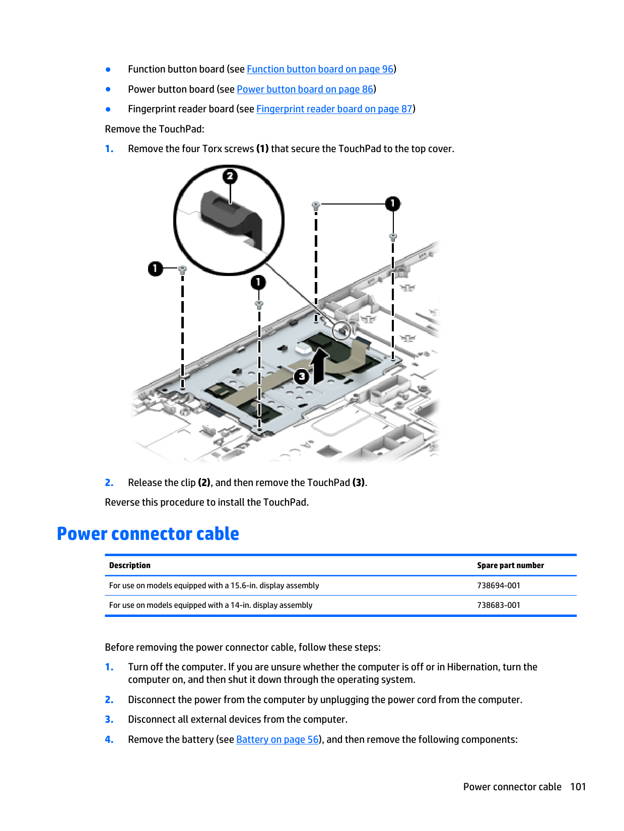
● Function button board (see Function button board on page 96) ● Power button board (see Power button board on page 86) ● Fingerprint reader board (see Fingerprint reader board on page 87) Remove the TouchPad:
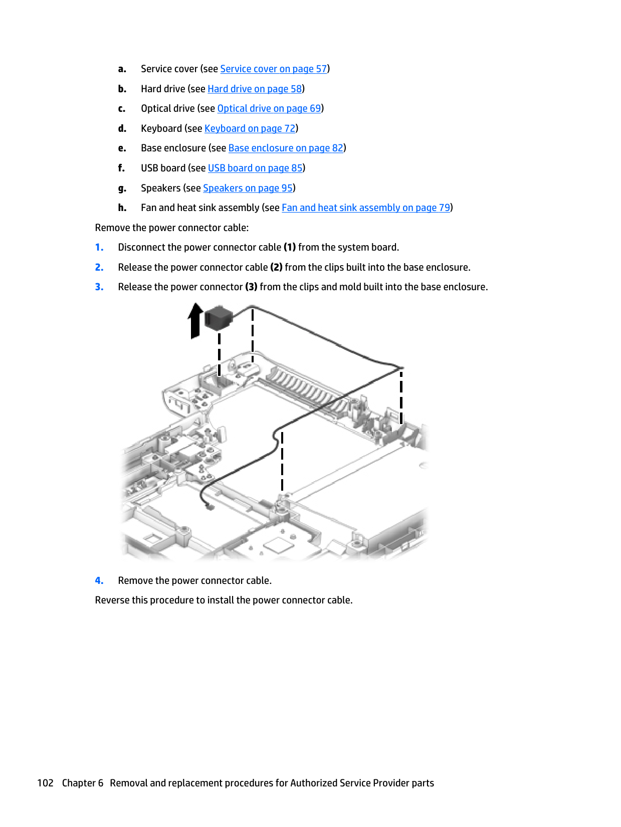
a. Service cover (see Service cover on page 57) b. Hard drive (see Hard drive on page 58) c. Optical drive (see Optical drive on page 69) d. Keyboard (see Keyboard on page 72) e. Base enclosure (see Base enclosure on page 82) f. USB board (see USB board on page 85) g. Speakers (see Speakers on page 95) h. Fan and heat sink assembly (see Fan and heat sink assembly on page 79) Remove the power connector cable:
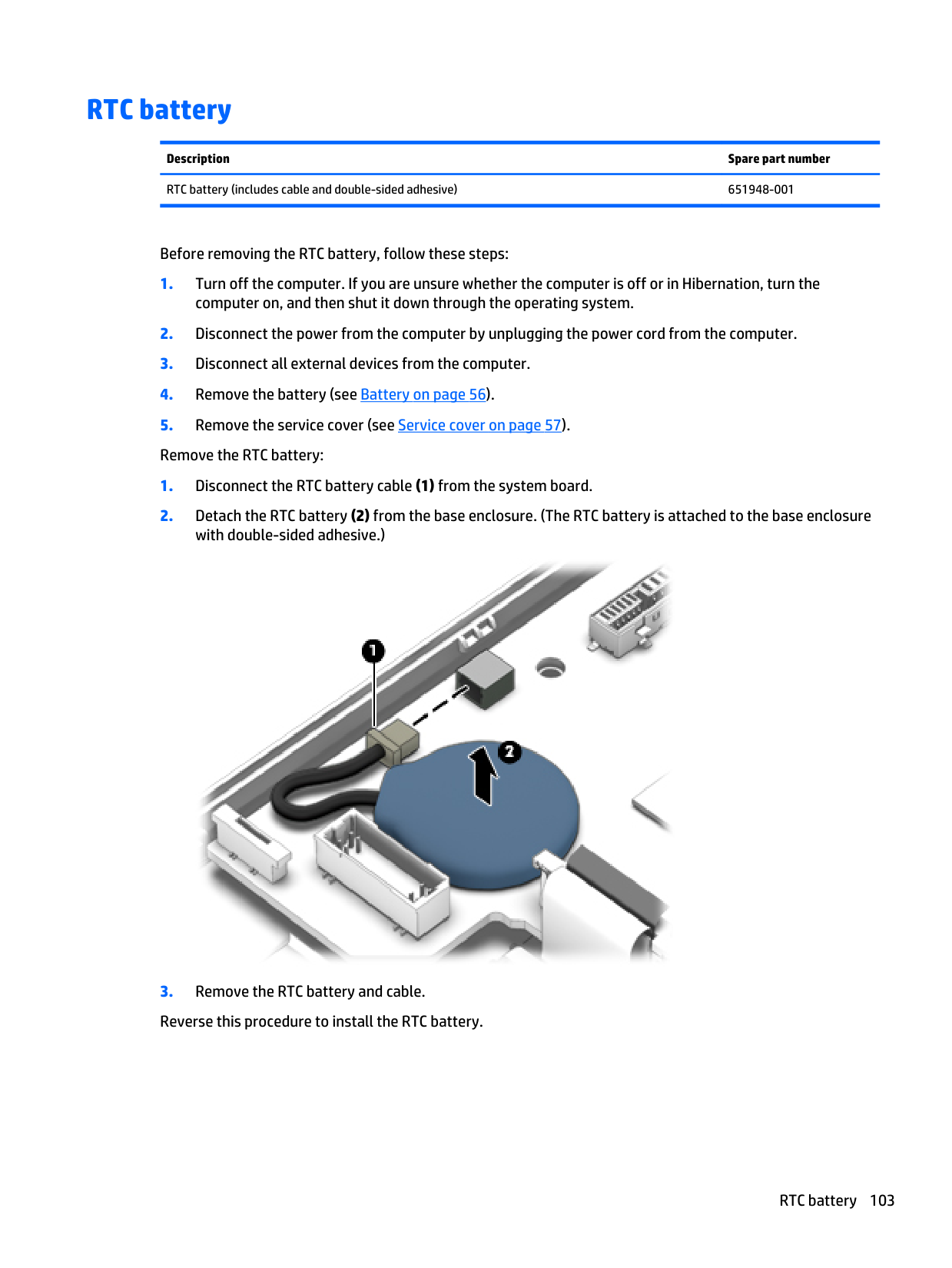
RTC battery Description Spare part number RTC battery (includes cable and double-sided adhesive) 651948-001 Before removing the RTC battery, follow these steps:
Display assembly
Note:
The Display Panel Support Kit is also required for full display assembly replacement. Description Spare part number 15.6-in. WLED FHD, UWVA display panel 15.6-in. WLED HD, UWVA display panel 739998-001 739997-001 14-in. HD AG WLED SVA eDP FLT display panel 14-in. HD+ AG WLED SVA eDP FLT display panel 14-in. FHD AG WLED UWVA eDPslim PSR display panel 747751-001 747752-001 747753-001 Display Panel Support Kit (includes LCD back cover and wireless antennas and transceivers):For use on models equipped with a 15.6-in. display assembly 738691-001 For use on models equipped with a 14-in. display assembly 738680-001 To remove the display assembly and access the display assembly subcomponents, follow these steps:
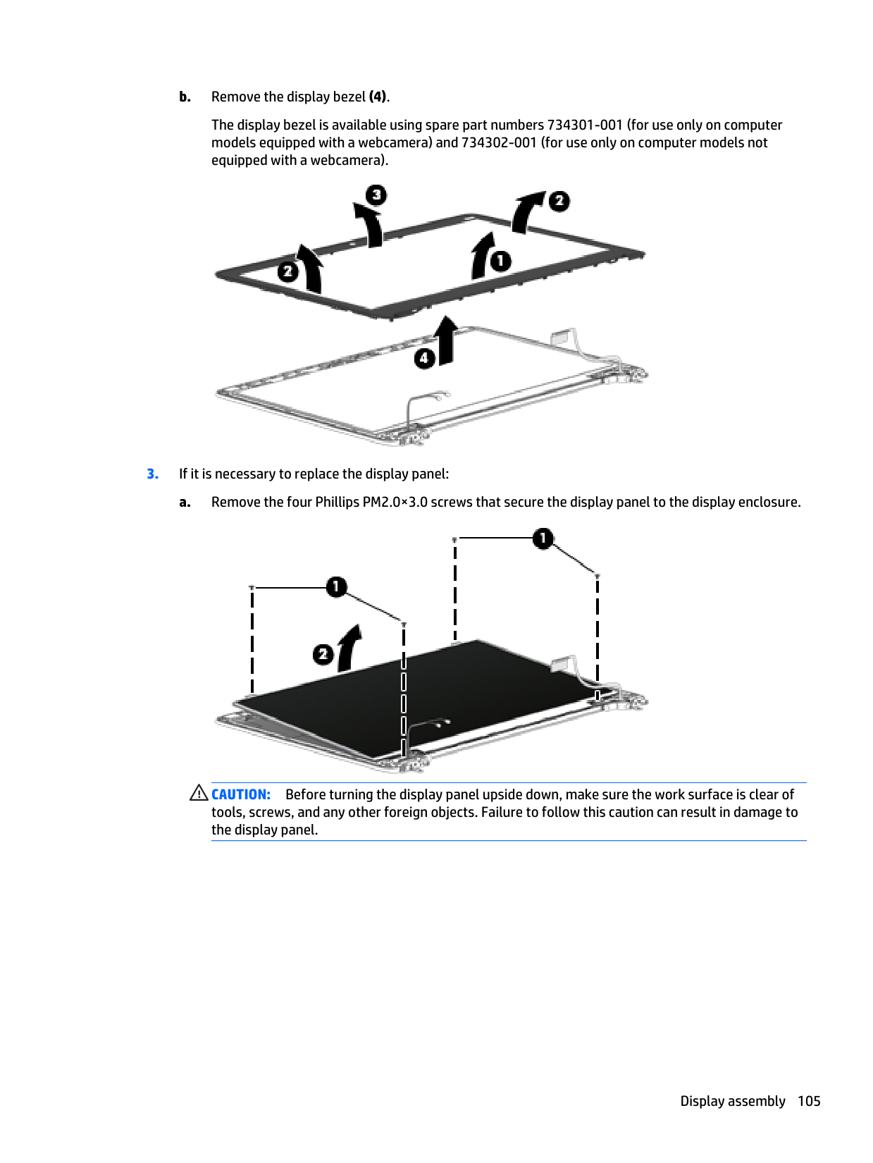
b. Remove the display bezel (4). The display bezel is available using spare part numbers 734301-001 (for use only on computer models equipped with a webcamera) and 734302-001 (for use only on computer models not equipped with a webcamera).
Caution:
Before turning the display panel upside down, make sure the work surface is clear of tools, screws, and any other foreign objects. Failure to follow this caution can result in damage to the display panel. Display assembly 105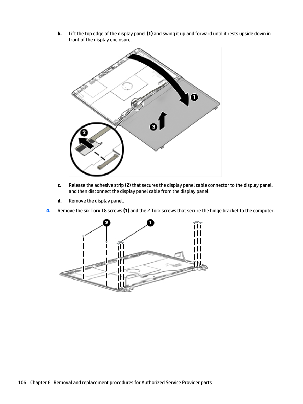
b. Lift the top edge of the display panel (1) and swing it up and forward until it rests upside down in front of the display enclosure. c. Release the adhesive strip (2) that secures the display panel cable connector to the display panel, and then disconnect the display panel cable from the display panel. d. Remove the display panel.
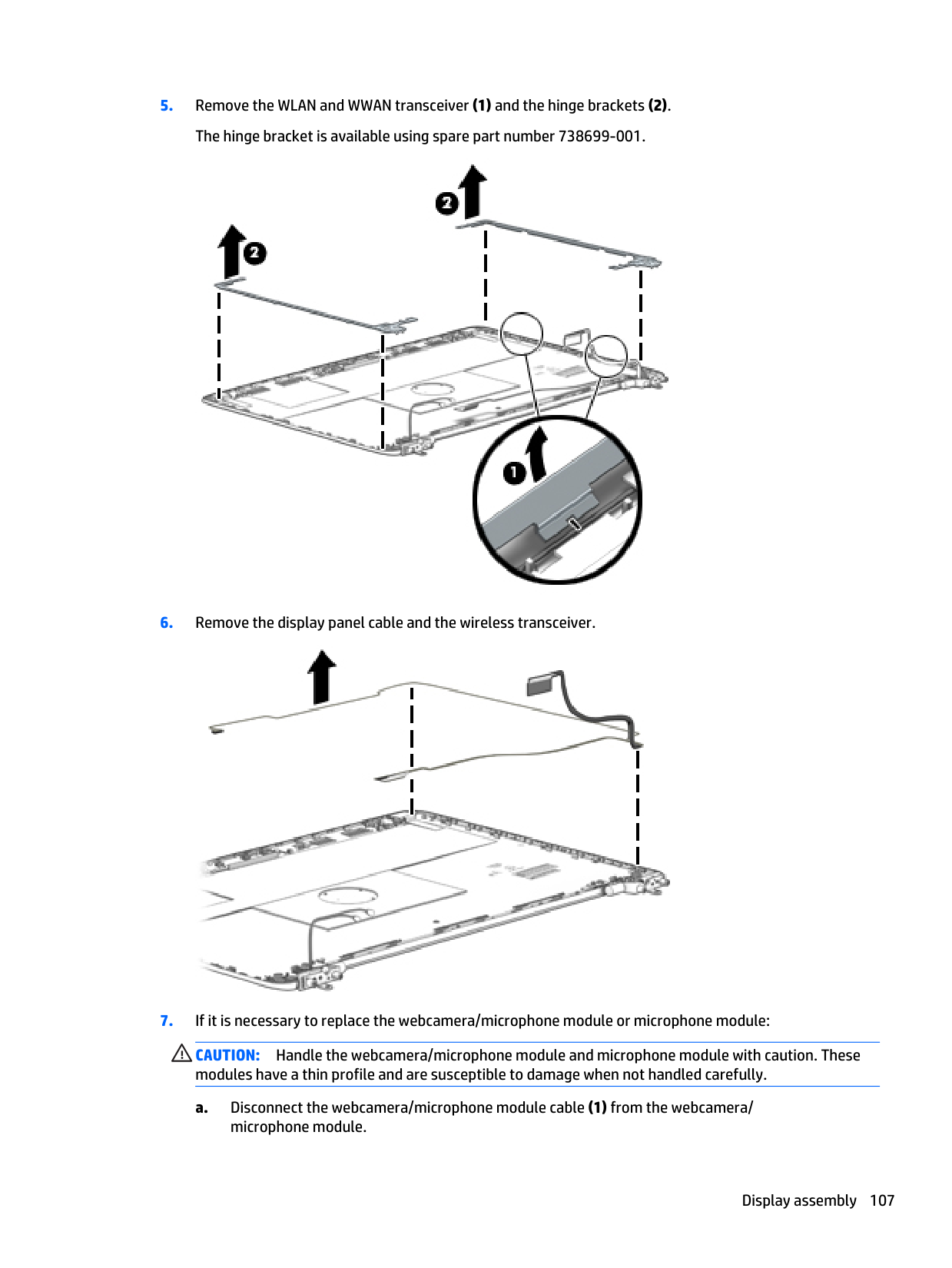
Caution:
Handle the webcamera/microphone module and microphone module with caution. These modules have a thin profile and are susceptible to damage when not handled carefully. a. Disconnect the webcamera/microphone module cable (1) from the webcamera/ microphone module. Display assembly 107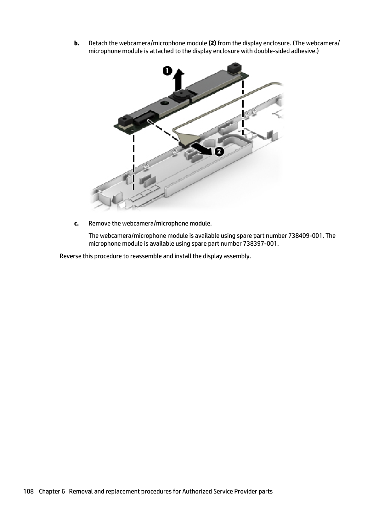
b. Detach the webcamera/microphone module (2) from the display enclosure. (The webcamera/ microphone module is attached to the display enclosure with double-sided adhesive.) c. Remove the webcamera/microphone module. The webcamera/microphone module is available using spare part number 738409-001. The microphone module is available using spare part number 738397-001. Reverse this procedure to reassemble and install the display assembly. 108 Chapter 6 Removal and replacement procedures for Authorized Service Provider parts
7 Computer Setup (BIOS), TPM, and HP Sure Start – Windows 10 Using Computer Setup Computer Setup, or Basic Input/Output System (BIOS), controls communication between all the input and output devices on the system (such as disk drives, display, keyboard, mouse, and printer). Computer Setup includes settings for the types of devices installed, the startup sequence of the computer, and the amount of system and extended memory.
Note:
Use extreme care when making changes in Computer Setup. Errors can prevent the computer from operating properly. Starting Computer SetupNote:
An external keyboard or mouse connected to a USB port can be used with Computer Setup only if USB legacy support is enabled. To start Computer Setup, follow these steps: ▲ Start Computer Setup. ● Computers or tablets with keyboards: ▲ Turn on or restart the computer, and when the HP logo appears, press f10 to enter Computer Setup. ● Tablets without keyboards: ▲ Turn off the tablet. Press the power button in combination with the volume down button until the Startup menu is displayed, and then tap F10 to enter Computer Setup. Using Computer Setup 109
Navigating and selecting in Computer Setup ● To select a menu or a menu item, use the tab key and the keyboard arrow keys and then press enter, or use a pointing device to select the item.
Note:
On tablets without keyboards, you can use your finger to make selections. ● To scroll up and down, select the up arrow or the down arrow in the upper-right corner of the screen, or use the up arrow key or the down arrow key on the keyboard. ● To close open dialog boxes and return to the main Computer Setup screen, press esc, and then follow the on-screen instructions. To exit Computer Setup menus, choose one of the following methods: ● To exit Computer Setup menus without saving your changes: Select the Exit icon in the lower-right corner of the screen, and then follow the on-screen instructions. ‒ or – Select Main, select Ignore Changes and Exit, and then press enter. ● To save your changes and exit Computer Setup menus: Select the Save icon in the lower-right corner of the screen, and then follow the on-screen instructions. ‒ or – Select Main, select Save Changes and Exit, and then press enter. Your changes go into effect when the computer restarts. Restoring factory settings in Computer SetupNote:
Restoring defaults will not change the hard drive mode. To return all settings in Computer Setup to the values that were set at the factory, follow these steps:Note:
On select products, the selections may display Restore Defaults instead of Apply Factory Defaults and Exit.Note:
Your password settings and security settings are not changed when you restore the factory settings. 110 Chapter 7 Computer Setup (BIOS), TPM, and HP Sure Start – Windows 10
Updating the BIOS Updated versions of the BIOS may be available on the HP website. Most BIOS updates on the HP website are packaged in compressed files called SoftPaqs. Some download packages contain a file named Readme.txt, which contains information regarding installing and troubleshooting the file. Determining the BIOS To decide whether you need to update Computer Setup (BIOS), first determine the BIOS version on your computer. BIOS version information (also known as ROM date and System BIOS) can be accessed by pressing fn+esc (if you are already in Windows) or by using Computer Setup.
Caution:
To reduce the risk of damage to the computer or an unsuccessful installation, download and install a BIOS update only when the computer is connected to reliable external power using the AC adapter. Do not download or install a BIOS update while the computer is running on battery power, docked in an optional docking device, or connected to an optional power source. During the download and installation, follow these instructions: Do not disconnect power on the computer by unplugging the power cord from the AC outlet. Do not shut down the computer or initiate Sleep. Do not insert, remove, connect, or disconnect any device, cable, or cord.
Note:
If you connect your computer to a network, consult the network administrator before installing any software updates, especially system BIOS updates. BIOS installation procedures vary. Follow any instructions that are revealed on the screen after the download is complete. If no instructions are revealed, follow these steps:Note:
After a message on the screen reports a successful installation, you can delete the downloaded file from your hard drive. Changing the boot order using the f9 prompt To dynamically choose a boot device for the current startup sequence, follow these steps:
TPM BIOS settings (select products only)
Important:
Before enabling Trusted Platform Module (TPM) functionality on this system, you must ensure that your intended use of TPM complies with relevant local laws, regulations and policies, and approvals or licenses must be obtained if applicable. For any compliance issues arising from your operation/usage of TPM which violates the above mentioned requirement, you shall bear all the liabilities wholly and solely. HP will not be responsible for any related liabilities. TPM provides additional security for your computer. You can modify the TPM settings in Computer Setup(Bios).
Note:
If you change the TPM setting to Hidden, TPM is not visible in the operating system. To access TPM settings in Computer Setup:
8 Using HP PC Hardware Diagnostics (UEFI) – Windows 10 HP PC Hardware Diagnostics is a Unified Extensible Firmware Interface (UEFI) that allows you to run diagnostic tests to determine whether the computer hardware is functioning properly. The tool runs outside the operating system so that it can isolate hardware failures from issues that are caused by the operating system or other software components. When HP PC Hardware Diagnostics (UEFI) detects a failure that requires hardware replacement, a 24-digit Failure ID code is generated. This ID code can then be provided to support to help determine how to correct the problem.
Note:
To start diagnostics on a convertible computer, your computer must be in notebook mode and you must use the keyboard attached. To start HP PC Hardware Diagnostics (UEFI), follow these steps:Note:
To download the HP PC Hardware Diagnostics (UEFI) tool to a USB drive, see Downloading HP PC Hardware Diagnostics (UEFI) to a USB device on page 115. b. Hard drive c.Bios
Note:
If you need to stop a diagnostic test, press esc. 114 Chapter 8 Using HP PC Hardware Diagnostics (UEFI) – Windows 10
Downloading HP PC Hardware Diagnostics (UEFI) to a USB device
Note:
The HP PC Hardware Diagnostics (UEFI) download instructions are provided in English only, and you must use a Windows computer to download and create the HP UEFI support environment because only .exe files are offered. There are two options to download HP PC Hardware Diagnostics to a USB device: Download the latest UEFI version:
9 Computer Setup Windows 8 — Computer Setup (BIOS), MultiBoot, and System Diagnostics Using Computer Setup Computer Setup, or Basic Input/Output System (BIOS), controls communication between all the input and output devices on the system (such as disk drives, display, keyboard, mouse, and printer). Computer Setup includes settings for the types of devices installed, the startup sequence of the computer, and the amount of system and extended memory.
Note:
Use extreme care when making changes in Computer Setup. Errors can prevent the computer from operating properly. Starting Computer SetupNote:
An external keyboard or mouse connected to a USB port can be used with Computer Setup only if USB legacy support is enabled. To start Computer Setup, follow these steps:Note:
You can use either a pointing device (TouchPad, pointing stick, or USB mouse) or the keyboard to navigate and make selections in Computer Setup.
Use the tab key and the arrow keys to select Main > Ignore Changes and Exit, and then press enter. ● To save your changes and exit Computer Setup menus: Click the Save icon in the lower-right corner of the screen, and then follow the on-screen instructions.
Note:
Restoring default will not change the hard drive mode. To return all settings in Computer Setup to the values that were set at the factory, follow these steps:Note:
Your password settings and security settings are not changed when you restore the default settings. Updating the BIOS Updated versions of the BIOS may be available on the HP website. Most BIOS updates on the HP website are packaged in compressed files called SoftPaqs. Some download packages contain a file named Readme.txt, which contains information regarding installing and troubleshooting the file. Determining the BIOS version To determine whether available BIOS updates contain later BIOS versions than those currently installed on the computer, you need to know the version of the system BIOS currently installed. BIOS version information (also known as ROM date and System BIOS) can be displayed by pressing fn+esc (if you are already in Windows) or by using Computer Setup.
Use the tab key and the arrow keys to select Main > Ignore Changes and Exit, and then press enter. Downloading a BIOS update
Caution:
To reduce the risk of damage to the computer or an unsuccessful installation, download and install a BIOS update only when the computer is connected to reliable external power using the AC adapter. Do not download or install a BIOS update while the computer is running on battery power, docked in an optional docking device, or connected to an optional power source. During the download and installation, follow these instructions: Do not disconnect power on the computer by unplugging the power cord from the AC outlet. Do not shut down the computer or initiate Sleep. Do not insert, remove, connect, or disconnect any device, cable, or cord.Note:
If you connect your computer to a network, consult the network administrator before installing any software updates, especially system BIOS updates. BIOS installation procedures vary. Follow any instructions that are displayed on the screen after the download is complete. If no instructions are displayed, follow these steps:Note:
After a message on the screen reports a successful installation, you can delete the downloaded file from your hard drive. 118 Chapter 9 Computer Setup
Using MultiBoot About the boot device order As the computer starts, the system attempts to boot from enabled devices. The MultiBoot utility, which is enabled at the factory, controls the order in which the system selects a boot device. Boot devices can include optical drives, diskette drives, a network interface card (NIC), hard drives, and USB devices. Boot devices contain bootable media or files that the computer needs to start and operate properly.
Note:
Some boot devices must be enabled in Computer Setup before they can be included in the boot order. You can change the order in which the computer searches for a boot device by changing the boot order in Computer Setup. You can also press esc while the “press the ESC key for Startup Menu” message is displayed at the bottom of the screen, and then press f9. Pressing f9 displays a menu that shows the current boot devices and allows you to select a boot device. Or, you can use MultiBoot Express to set the computer to prompt you for a boot location each time the computer turns on or restarts. Choosing MultiBoot preferences You can use MultiBoot in the following ways: ● To set a new boot order that the computer uses each time it is turned on, by changing the boot order in Computer Setup. ● To dynamically choose the boot device, by pressing esc while the “press the ESC key for Startup Menu” message is displayed at the bottom of the screen, and then pressing f9 to enter the Boot Device Options menu. ● To use MultiBoot Express to set variable boot orders. This feature prompts you for a boot device each time the computer is turned on or restarted. Setting a new boot order in Computer Setup To start Computer Setup and set a boot device order that the computer uses each time it is turned on or restarted, follow these steps:
Dynamically choosing a boot device using the f9 prompt To dynamically choose a boot device for the current startup sequence, follow these steps:
a. Connected USB drive
Note:
To download the HP PC Hardware Diagnostics (UEFI) tool to a USB drive, see . b. Hard drive c.Bios
Note:
If you need to stop a diagnostics test while it is running, press esc. Downloading HP PC Hardware Diagnostics (UEFI) to a USB deviceNote:
The HP PC Hardware Diagnostics (UEFI) download instructions are provided in English only.Note:
Use extreme care when making changes in Computer Setup. Errors can prevent the computer from operating properly. Starting Computer SetupNote:
An external keyboard or mouse connected to a USB port can be used with Computer Setup only if USB legacy support is enabled. To start Computer Setup, follow these steps:
Note:
You can use either a pointing device (TouchPad, pointing stick, or USB mouse) or the keyboard to navigate and make selections in Computer Setup.Note:
Restoring defaults will not change the hard drive mode. To return all settings in Computer Setup to the values that were set at the factory, follow these steps:Note:
Your password settings and security settings are not changed when you restore the default settings. 122 Chapter 9 Computer Setup
Updating the BIOS Updated versions of the BIOS may be available on the HP website. Most BIOS updates on the HP website are packaged in compressed files called SoftPaqs. Some download packages contain a file named Readme.txt, which contains information regarding installing and troubleshooting the file. Determining the BIOS version To determine whether available BIOS updates contain later BIOS versions than those currently installed on the computer, you need to know the version of the system BIOS currently installed. BIOS version information (also known as ROM date and System BIOS) can be displayed by pressing fn+esc (if you are already in Windows) or by using Computer Setup.
Caution:
CAUTION: To reduce the risk of damage to the computer or an unsuccessful installation, download and install a BIOS update only when the computer is connected to reliable external power using the AC adapter. Do not download or install a BIOS update while the computer is running on battery power, docked in an optional docking device, or connected to an optional power source. During the download and installation, follow these instructions: Do not disconnect power on the computer by unplugging the power cord from the AC outlet. Do not shut down the computer or initiate Sleep. Do not insert, remove, connect, or disconnect any device, cable, or cord.Note:
If you connect your computer to a network, consult the network administrator before installing any software updates, especially system BIOS updates. Windows 7 — Computer Setup (BIOS), MultiBoot, and HP PC Hardware Diagnostics (UEFI) 123
BIOS installation procedures vary. Follow any instructions that are displayed on the screen after the download is complete. If no instructions are displayed, follow these steps:
Note:
After a message on the screen reports a successful installation, you can delete the downloaded file from your hard drive. Using MultiBoot About the boot device order As the computer starts, the system attempts to boot from enabled devices. The MultiBoot utility, which is enabled at the factory, controls the order in which the system selects a boot device. Boot devices can include optical drives, diskette drives, a network interface card (NIC), hard drives, and USB devices. Boot devices contain bootable media or files that the computer needs to start and operate properly.Note:
Some boot devices must be enabled in Computer Setup before they can be included in the boot order. You can change the order in which the computer searches for a boot device by changing the boot order in Computer Setup. You can also press esc while the “press the ESC key for Startup Menu” message is displayed at the bottom of the screen, and then press f9. Pressing f9 displays a menu that shows the current boot devices and allows you to select a boot device. Or, you can use MultiBoot Express to set the computer to prompt you for a boot location each time the computer turns on or restarts. Choosing MultiBoot preferences You can use MultiBoot in the following ways: ● To set a new boot order that the computer uses each time it is turned on, by changing the boot order in Computer Setup. ● To dynamically choose the boot device, by pressing esc while the “press the ESC key for Startup Menu” message is displayed at the bottom of the screen, and then pressing f9 to enter the Boot Device Options menu. ● To use MultiBoot Express to set variable boot orders. This feature prompts you for a boot device each time the computer is turned on or restarted. Setting a new boot order in Computer Setup To start Computer Setup and set a boot device order that the computer uses each time it is turned on or restarted, follow these steps:

● To specify a boot device from the Express Boot menu, select your preference within the allotted time, and then press enter. ● To prevent the computer from defaulting to the current MultiBoot setting, press any key before the allotted time expires. The computer will not start until you select a boot device and press enter. ● To allow the computer to start according to the current MultiBoot settings, wait for the allotted time to expire. 126 Chapter 9 Computer Setup
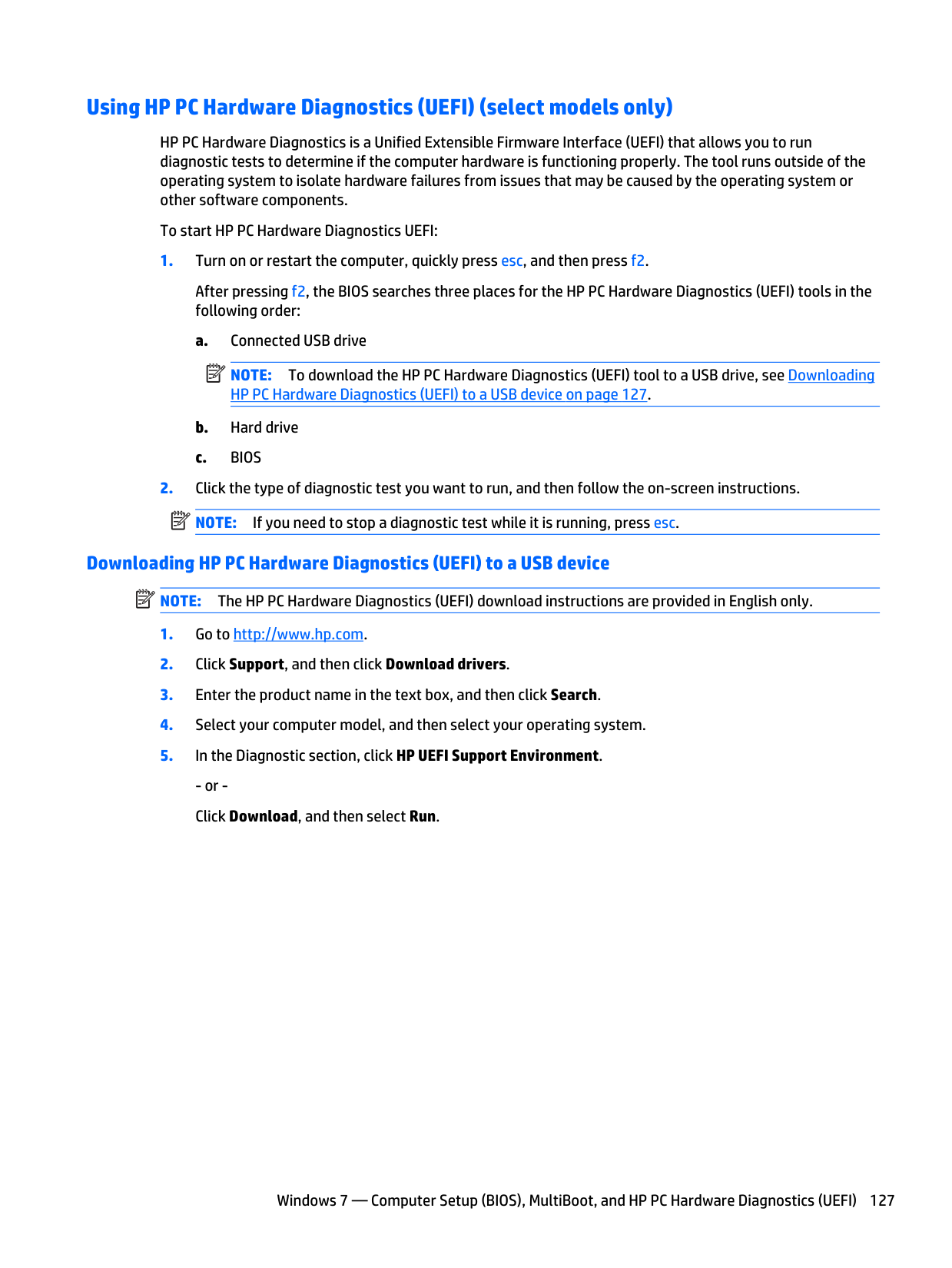
Using HP PC Hardware Diagnostics (UEFI) (select models only) HP PC Hardware Diagnostics is a Unified Extensible Firmware Interface (UEFI) that allows you to run diagnostic tests to determine if the computer hardware is functioning properly. The tool runs outside of the operating system to isolate hardware failures from issues that may be caused by the operating system or other software components. To start HP PC Hardware Diagnostics UEFI:
Note:
To download the HP PC Hardware Diagnostics (UEFI) tool to a USB drive, see Downloading HP PC Hardware Diagnostics (UEFI) to a USB device on page 127. b. Hard drive c.Bios
Note:
If you need to stop a diagnostic test while it is running, press esc. Downloading HP PC Hardware Diagnostics (UEFI) to a USB deviceNote:
The HP PC Hardware Diagnostics (UEFI) download instructions are provided in English only.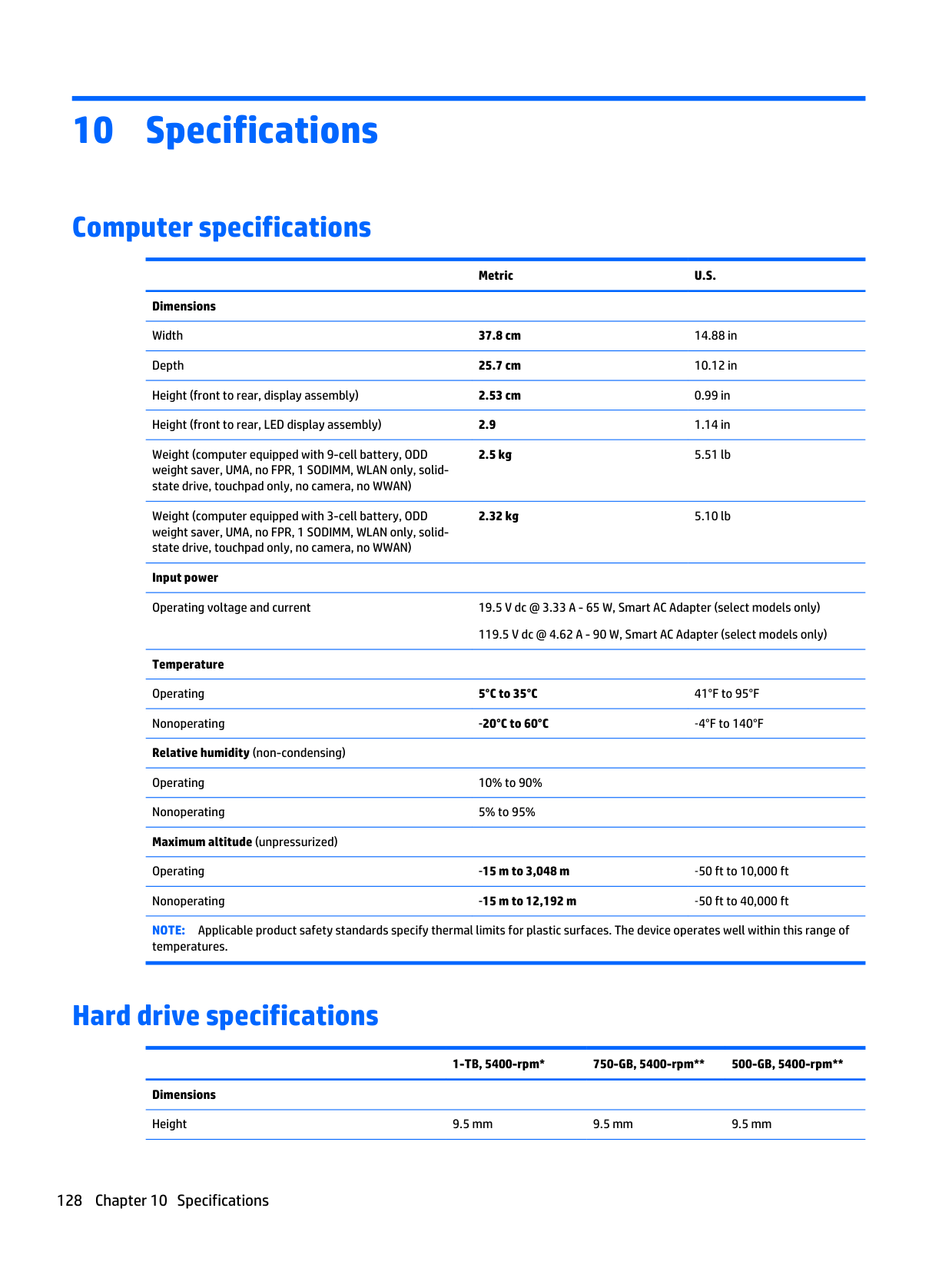
10 Specifications Computer specifications
Metric
U.S.
Dimensions Width 37.8 cm 14.88 in Depth 25.7 cm 10.12 in Height (front to rear, display assembly) 2.53 cm 0.99 in Height (front to rear, LED display assembly) 2.9 1.14 in Weight (computer equipped with 9-cell battery, ODD weight saver, UMA, no FPR, 1 SODIMM, WLAN only, solid- state drive, touchpad only, no camera, no WWAN) 2.5 kg 5.51 lb Weight (computer equipped with 3-cell battery, ODD weight saver, UMA, no FPR, 1 SODIMM, WLAN only, solid- state drive, touchpad only, no camera, no WWAN) 2.32 kg 5.10 lb Input power Operating voltage and current 19.5 V dc @ 3.33 A - 65 W, Smart AC Adapter (select models only) 119.5 V dc @ 4.62 A - 90 W, Smart AC Adapter (select models only) Temperature Operating 5°C to 35°C 41°F to 95°F Nonoperating ‑20°C to 60°C ‑4°F to 140°F Relative humidity (non-condensing) Operating 10% to 90% Nonoperating 5% to 95% Maximum altitude (unpressurized) Operating ‑15 m to 3,048 m ‑50 ft to 10,000 ft Nonoperating ‑15 m to 12,192 m ‑50 ft to 40,000 ftNote:
Applicable product safety standards specify thermal limits for plastic surfaces. The device operates well within this range of temperatures. Hard drive specifications1-TB, 5400-rpm* 750-GB, 5400-rpm** 500-GB, 5400-rpm** Dimensions Height 9.5 mm 9.5 mm 9.5 mm 128 Chapter 10 Specifications
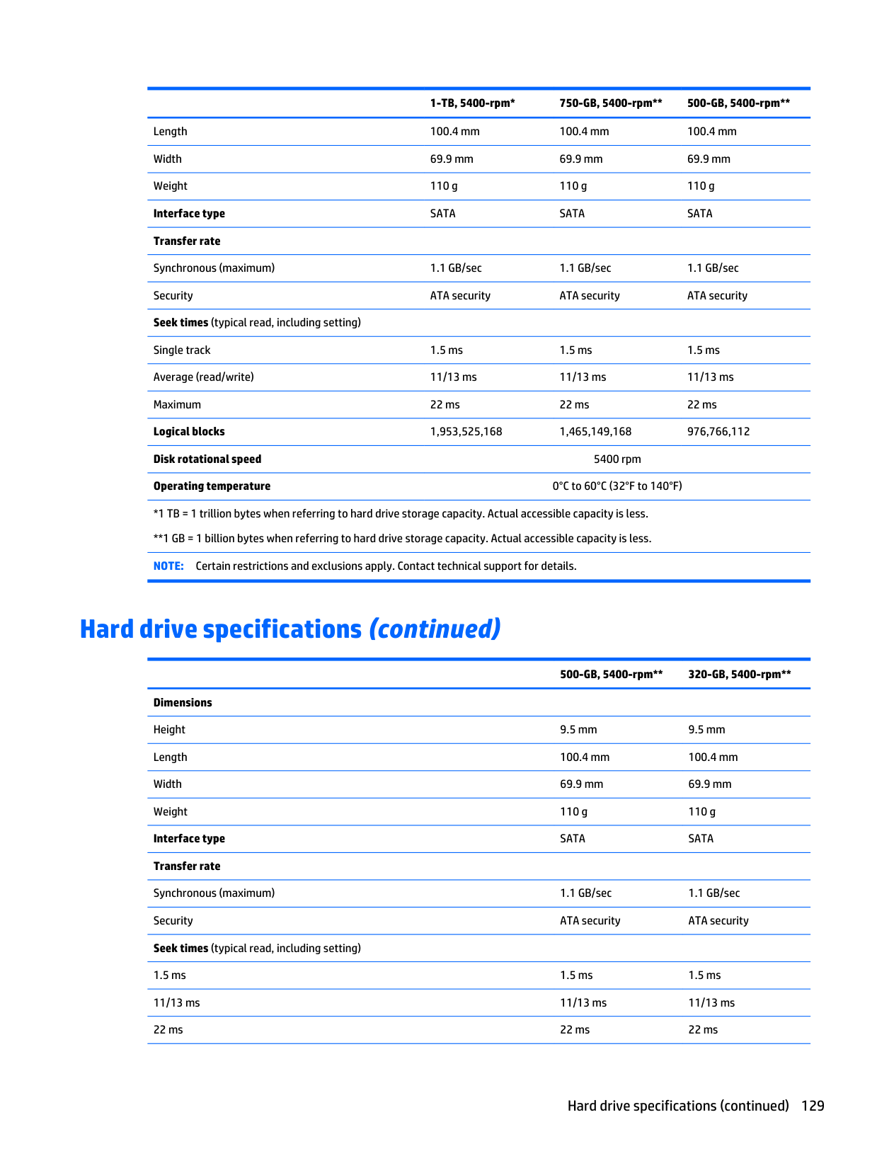
1-TB, 5400-rpm* 750-GB, 5400-rpm** 500-GB, 5400-rpm** Length 100.4 mm 100.4 mm 100.4 mm Width 69.9 mm 69.9 mm 69.9 mm Weight 110 g 110 g 110 g Interface type
Sata
Sata
Sata
Transfer rate Synchronous (maximum) 1.1 GB/sec 1.1 GB/sec 1.1 GB/sec Security ATA security ATA security ATA security Seek times (typical read, including setting) Single track 1.5 ms 1.5 ms 1.5 ms Average (read/write) 11/13 ms 11/13 ms 11/13 ms Maximum 22 ms 22 ms 22 ms Logical blocks 1,953,525,168 1,465,149,168 976,766,112 Disk rotational speed 5400 rpm Operating temperature 0°C to 60°C (32°F to 140°F) *1 TB = 1 trillion bytes when referring to hard drive storage capacity. Actual accessible capacity is less. **1 GB = 1 billion bytes when referring to hard drive storage capacity. Actual accessible capacity is less.Note:
Certain restrictions and exclusions apply. Contact technical support for details. Hard drive specifications (continued)500-GB, 5400-rpm** 320-GB, 5400-rpm** Dimensions Height 9.5 mm 9.5 mm Length 100.4 mm 100.4 mm Width 69.9 mm 69.9 mm Weight 110 g 110 g Interface type
Sata
Sata
Transfer rate Synchronous (maximum) 1.1 GB/sec 1.1 GB/sec Security ATA security ATA security Seek times (typical read, including setting) 1.5 ms 1.5 ms 1.5 ms 11/13 ms 11/13 ms 11/13 ms 22 ms 22 ms 22 ms Hard drive specifications (continued) 129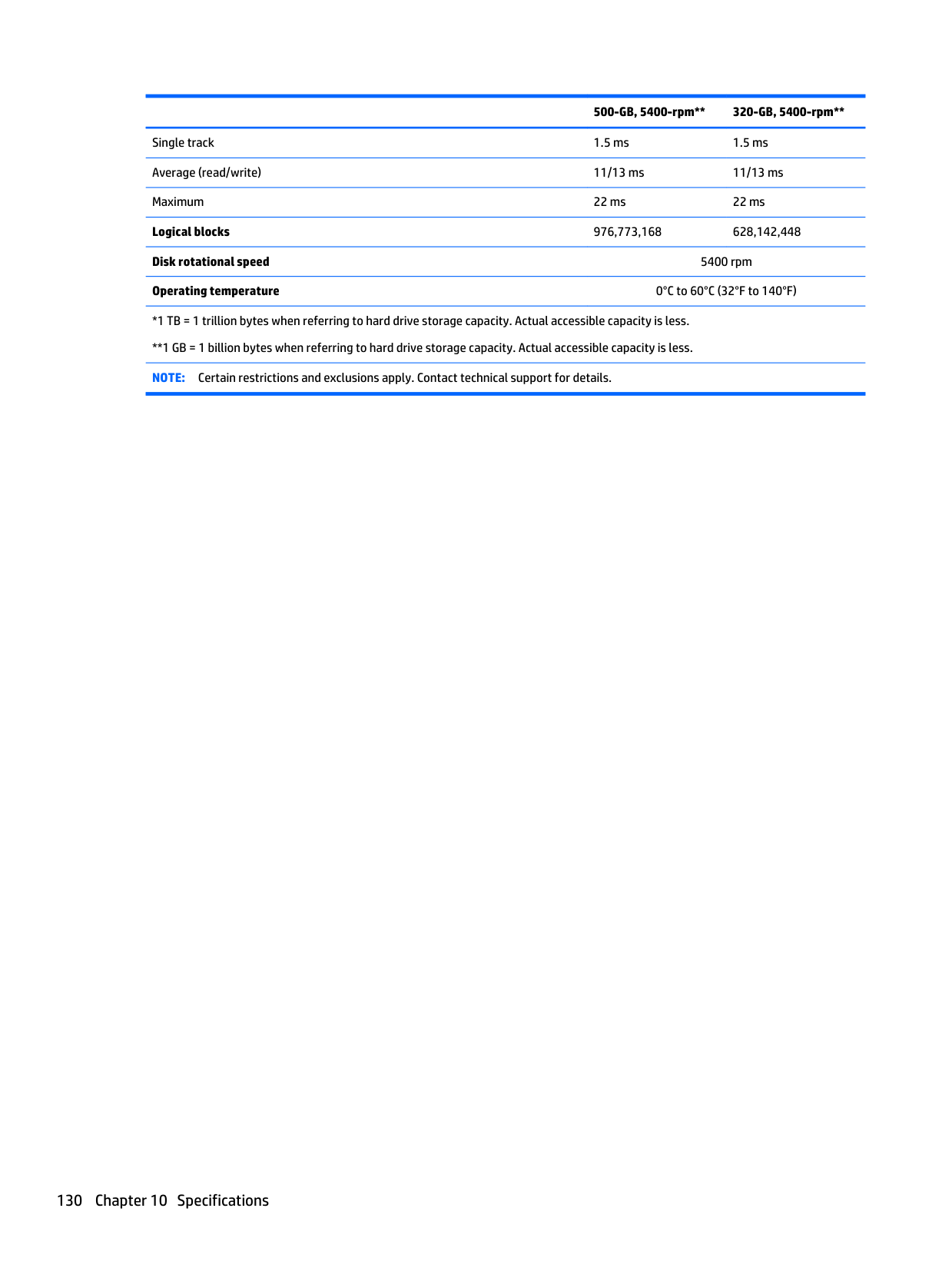
500-GB, 5400-rpm** 320-GB, 5400-rpm** Single track 1.5 ms 1.5 ms Average (read/write) 11/13 ms 11/13 ms Maximum 22 ms 22 ms Logical blocks 976,773,168 628,142,448 Disk rotational speed 5400 rpm Operating temperature 0°C to 60°C (32°F to 140°F) *1 TB = 1 trillion bytes when referring to hard drive storage capacity. Actual accessible capacity is less. **1 GB = 1 billion bytes when referring to hard drive storage capacity. Actual accessible capacity is less.
Note:
Certain restrictions and exclusions apply. Contact technical support for details. 130 Chapter 10 Specifications
11 Backup and recovery – Windows 10 This chapter provides information about the following processes. The information in the chapter is standard procedure for most products. ● Creating recovery media and backups ● Restoring and recovering your system For additional information, refer to the HP support assistant app. ▲ Type support in the taskbar search box, and then select the HP Support Assistant app. ‒ or – Click the question mark icon in the taskbar.
Important:
If you will be performing recovery procedures on a tablet, the tablet battery must be at least 70% charged before you start the recovery process.Important:
For a tablet with a detachable keyboard, connect the keyboard to the keyboard dock before beginning any recovery process. Creating recovery media and backups The following methods of creating recovery media and backups are available on select products only. Choose the available method according to your computer model. ● Use HP Recovery Manager to create HP Recovery media after you successfully set up the computer. This step creates a backup of the HP Recovery partition on the computer. The backup can be used to reinstall the original operating system in cases where the hard drive is corrupted or has been replaced. For information on creating recovery media, see Creating HP Recovery media (select products only) on page 132. For information on the recovery options that are available using the recovery media, see Using Windows Tools on page 133. ● Use Windows tools to create system restore points and create backups of personal information. For more information, see Recovering using HP Recovery Manager on page 134.Note:
If storage is 32 GB or less, Microsoft System Restore is disabled by default. Creating recovery media and backups 131
Creating HP Recovery media (select products only) If possible, check for the presence of the Recovery partition and the Windows partition. From the Start menu, select File Explorer, and then select This PC. ● If your computer does not list the Windows partition and the Recovery partition, you can obtain recovery media for your system from support. See the Worldwide Telephone Numbers booklet included with the computer. You can also find contact information on the HP website. Go to http://www.hp.com/ support, select your country or region, and follow the on-screen instructions. You can use Windows tools to create system restore points and create backups of personal information, see Using Windows tools on page 61. ● If your computer does list the Recovery partition and the Windows partition, you can use HP Recovery Manager to create recovery media after you successfully set up the computer. HP Recovery media can be used to perform system recovery if the hard drive becomes corrupted. System recovery reinstalls the original operating system and software programs that were installed at the factory and then configures the settings for the programs. HP Recovery media can also be used to customize the system or restore the factory image if you replace the hard drive. ◦ Only one set of recovery media can be created. Handle these recovery tools carefully, and keep them in a safe place. ◦ HP Recovery Manager examines the computer and determines the required storage capacity for the media that will be required. ◦ To create recovery discs, your computer must have an optical drive with DVD writer capability, and you must use only high-quality blank DVD-R, DVD+R, DVD-R DL, or DVD+R DL discs. Do not use rewritable discs such as CD±RW, DVD±RW, double-layer DVD±RW, or BD-RE (rewritable Blu-ray) discs; they are not compatible with HP Recovery Manager software. Or, instead, you can use a high-quality blank USB flash drive. ◦ If your computer does not include an integrated optical drive with DVD writer capability, but you would like to create DVD recovery media, you can use an external optical drive (purchased separately) to create recovery discs. If you use an external optical drive, it must be connected directly to a USB port on the computer; the drive cannot be connected to a USB port on an external device, such as a USB hub. If you cannot create DVD media yourself, you can obtain recovery discs for your computer from HP. See the Worldwide Telephone Numbers booklet included with the computer. You can also find contact information on the HP website. Go to http://www.hp.com/ support, select your country or region, and follow the on-screen instructions. ◦ Be sure that the computer is connected to AC power before you begin creating the recovery media. ◦ The creation process can take an hour or more. Do not interrupt the creation process. ◦ If necessary, you can exit the program before you have finished creating all of the recovery DVDs. HP Recovery Manager will finish burning the current DVD. The next time you start HP Recovery Manager, you will be prompted to continue. To create HP Recovery media:
Important:
For a tablet with a detachable keyboard, connect the keyboard to the keyboard dock before beginning these steps.
Using Windows Tools You can create recovery media, system restore points, and backups of personal information using Windows tools.
Note:
If storage is 32 GB or less, Microsoft System Restore is disabled by default. For more information and steps, see the Get started app. ▲ Select the Start button, and then select the Get started app. Restore and recovery There are several options for recovering your system. Choose the method that best matches your situation and level of expertise:Important:
Not all methods are available on all products. ● Windows offers several options for restoring from backup, refreshing the computer, and resetting the computer to its original state. For more information see the Get started app. ▲ Select the Start button, and then select the Get started app. ● If you need to correct a problem with a preinstalled application or driver, use the Reinstall drivers and/or applications option (select products only) of HP Recovery Manager to reinstall the individual application or driver. ▲ Type recovery in the taskbar search box, select HP Recovery Manager, select Reinstall drivers and/or applications, and then follow the on-screen instructions. ● If you want to recover the Windows partition to original factory content, you can choose the System Recovery option from the HP Recovery partition (select products only) or use the HP Recovery media. For more information, see Recovering using Recovering using HP Recovery Manager on page 134. If you have not already created recovery media, see Creating HP Recovery media (select products only) on page 132. ● On select products, if you want to recover the computer's original factory partition and content, or if you have replaced the hard drive, you can use the Factory Reset option of HP Recovery media. For more information, see Recovering using HP Recovery Manager on page 134. ● On select products, if you want to remove the recovery partition to reclaim hard drive space, HP Recovery Manager offers the Remove Recovery Partition option. For more information, see Removing the Removing the HP Recovery partition (select products only) on page 136. Using Windows Tools 133
Recovering using HP Recovery Manager HP Recovery Manager software allows you to recover the computer to its original factory state by using the HP Recovery media that you either created or that you obtained from HP, or by using the HP Recovery partition (select products only). If you have not already created recovery media, see Creating HP Recovery media (select products only) on page 132. What you need to know before you get started ● HP Recovery Manager recovers only software that was installed at the factory. For software not provided with this computer, you must either download the software from the manufacturer's website or reinstall the software from the media provided by the manufacturer.
Important:
Recovery through HP Recovery Manager should be used as a final attempt to correct computer issues. ● To use the Factory Reset option (select products only), you must use HP Recovery media. If you have not already created recovery media, see Creating HP Recovery media (select products only) on page 132. ● If your computer does not allow the creation of HP Recovery media or if the HP Recovery media does not work, you can obtain recovery media for your system from support. See the Worldwide Telephone Numbers booklet included with the computer. You can also find contact information from the HP website. Go to http://www.hp.com/support, select your country or region, and follow the on- screen instructions.Important:
HP Recovery Manager does not automatically provide backups of your personal data. Before beginning recovery, back up any personal data you want to retain. Using HP Recovery media, you can choose from one of the following recovery options:Note:
Only the options available for your computer display when you start the recovery process. ● System Recovery—Reinstalls the original operating system, and then configures the settings for the programs that were installed at the factory. ● Factory Reset—Restores the computer to its original factory state by deleting all information from the hard drive and re-creating the partitions. Then it reinstalls the operating system and the software that was installed at the factory. The HP Recovery partition (select products only) allows System Recovery only. 134 Chapter 11 Backup and recovery – Windows 10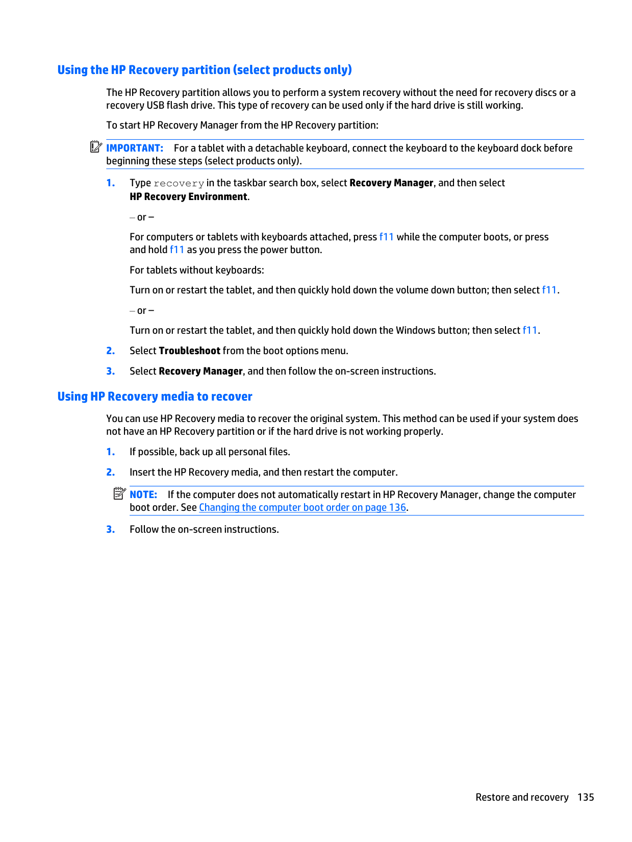
Using the HP Recovery partition (select products only) The HP Recovery partition allows you to perform a system recovery without the need for recovery discs or a recovery USB flash drive. This type of recovery can be used only if the hard drive is still working. To start HP Recovery Manager from the HP Recovery partition:
Important:
For a tablet with a detachable keyboard, connect the keyboard to the keyboard dock before beginning these steps (select products only).Note:
If the computer does not automatically restart in HP Recovery Manager, change the computer boot order. See Changing the computer boot order on page 136.
Changing the computer boot order If your computer does not restart in HP Recovery Manager, you can change the computer boot order, which is the order of devices listed in BIOS where the computer looks for startup information. You can change the selection to an optical drive or a USB flash drive. To change the boot order:
Important:
For a tablet with a detachable keyboard, connect the keyboard to the keyboard dock before beginning these steps.Important:
After you remove the HP Recovery partition, you will not be able to perform System Recovery or create HP recovery media from the HP Recovery partition. So before you remove the Recovery partition, create HP Recovery media; see Creating HP Recovery media (select products only) on page 132.Note:
The Remove Recovery Partition option is only available on products that support this function. Follow these steps to remove the HP Recovery partition:
12 Backup and recovery Windows 8 To protect your information, use Windows backup and restore utilities to back up individual files and folders, back up your entire hard drive, create system repair media (select models only) by using the installed optical drive (select models only) or an optional external optical drive, or create system restore points. In case of system failure, you can use the backup files to restore the contents of your computer. From the Start screen, type restore, click Settings, and then select from the list of displayed options.
Note:
For detailed instructions on various backup and restore options, perform a search for these topics in Windows Help and Support. In case of system instability, HP recommends that you print the recovery procedures and save them for later use.Note:
Windows includes the User Account Control feature to improve the security of your computer. You may be prompted for your permission or password for tasks such as installing software, running utilities, or changing Windows settings. For more information, see Windows Help and Support. Backing up your information Recovery after a system failure is as good as your most recent backup. You should create system repair media and your initial backup immediately after initial system setup. As you add new software and data files, you should continue to back up your system on a regular basis to maintain a reasonably current backup. The system repair media (select models only) are used to start up (boot) the computer and repair the operating system in case of system instability or failure. Your initial and subsequent backups allow you to restore your data and settings if a failure occurs. For more information on the Windows backup features, see Windows Help and Support. Performing a system recovery In case of system failure or instability, the computer provides the following tools to recover your files: ● Windows recovery tools: You can use Windows Backup and Restore to recover information you have previously backed up. You can also use Windows Automatic Repair to fix problems that might prevent Windows from starting correctly. ● f11 recovery tools: You can use the f11 recovery tools to recover your original hard drive image. The image includes the Windows operating system and software programs installed at the factory.Note:
If you are unable to boot (start up) your computer and you cannot use the system repair media you previously created (select models only), you must purchase Windows operating system media to reboot the computer and repair the operating system. For additional information, see Using Windows operating system media (purchased separately) on page 139. Using the Windows recovery tools To recover information you previously backed up, see Windows Help and Support for steps on restoring files and folders. To recover your information using Automatic Repair, follow these steps: Windows 8 137
Caution:
Some Startup Repair options will completely erase and reformat the hard drive. All files you have created and any software installed on the computer are permanently removed. When reformatting is complete, the recovery process restores the operating system, as well as the drivers, software, and utilities from the backup used for recovery.Note:
If the Windows partition and the Recovery Image partition are not listed, you must recover your operating system and programs using the Windows operating system DVD and the Driver Recovery media (both purchased separately). For additional information, see Using Windows operating system media (purchased separately) on page 139.Note:
For additional information on recovering information using the Windows tools, perform a search for these topics in Windows Help and Support. Using f11 recovery toolsCaution:
Using f11 completely erases hard drive contents and reformats the hard drive. All files that you have created and any software that you have installed on the computer are permanently removed. The f11 recovery tool reinstalls the operating system and HP programs and drivers that were installed at the factory. Software not installed at the factory must be reinstalled. To recover the original hard drive image using f11:Note:
If the Recovery Image partition is not listed, you must recover your operating system and programs using the Windows operating system media and the Driver Recovery media (both purchased separately). For additional information, see Using Windows operating system media (purchased separately) on page 139.
Using Windows operating system media (purchased separately) To order a Windows operating system DVD, contact support. See the Worldwide Telephone Numbers booklet included with the computer. You can also find contact information from the HP website. Go to http://www.hp.com/support, select your country or region, and follow the on-screen instructions. .
Caution:
Using a Windows operating system media completely erases hard drive contents and reformats the hard drive. All files that you have created and any software that you have installed on the computer are permanently removed. When reformatting is complete, the recovery process helps you restore the operating system, as well as drivers, software, and utilities. To initiate a full install of the operating system using a Windows operating system DVD:Note:
This process takes several minutes.
Using Windows Refresh or Windows Reset When your computer is not working properly and you need to regain system stability, the Windows Refresh option allows you to start fresh and keep what is important to you. The Windows Reset option allows you to perform detailed reformatting of your computer, or remove personal information before you give away or recycle your computer. For more information on these features, see Windows Help and Support. Using HP Software Setup HP Software Setup can be used to reinstall drivers or select software that has been corrupted or deleted from the system.
Windows 7 Your computer includes HP and Windows tools to help you safeguard your information and retrieve it if you ever need to. These tools will help you return your computer to a proper working state, all with simple steps. This section provides information about the following processes: ● Creating recovery media and backups ● Restoring and recovering your system Creating recovery media and backups Recovery after a system failure is only as good as your most recent backup.
Note:
This guide describes an overview of backing up, restoring, and recovering options. For more details about the tools provided, see Help and Support. To access Help and Support, select Start > Help and Support.Note:
HP recommends that you print the recovery procedures and save them for later use, in case of system instability. In case of system failure, you can use the backup files to restore the contents of your computer. See Backing up your information on page 142. Guidelines ● When creating recovery media or backing up to discs, use any of the following types of discs (purchased separately): DVD+R, DVD+R DL, DVD-R, DVD-R DL, or DVD±RW. The discs you use will depend on the type of optical drive you are using. ● Be sure that the computer is connected to AC power before you start the recovery media creation process or the backup process. Creating recovery media with HP Recovery Disc Creator (select models only) HP Recovery Disc Creator is a software program that offers an alternative way to create recovery media. After you successfully set up the computer, you can create recovery media using HP Recovery Disc Creator. This recovery media allows you to reinstall your original operating system as well as select drivers and applications if the hard drive becomes corrupted. HP Recovery Disc Creator can create two kinds of recovery DVDs: Windows 7 141
● Windows 7 operating system DVD—Installs the operating system without additional drivers or applications. ● Driver Recovery DVD—Installs specific drivers and applications only, in the same way that the HP Software Setup utility installs drivers and applications. Creating recovery media
Note:
The Windows 7 operating system DVD can be created only once. Thereafter, the option to create that media will not be available after you create a Windows DVD. To create the Windows DVD:Note:
For detailed instructions on various backup and restore options, perform a search for these topics in Help and Support. To access Help and Support, select Start > Help and Support.Note:
Windows includes the User Account Control feature to improve the security of your computer. You may be prompted for your permission or password for tasks such as installing software, running utilities, or changing Windows settings. Refer to Help and Support. To access Help and Support, select Start > Help and Support. To create a backup using Windows Backup and Restore:Note:
The backup process may take over an hour, depending on file size and the speed of the computer. 142 Chapter 12 Backup and recovery
Note:
If you are unable to boot (start up) your computer and you cannot use the system repair media you previously created (select models only), you must purchase Windows 7 operating system media to reboot the computer and repair the operating system. For additional information, see Using Windows 7 operating system media on page 145. Windows 7 143
Using the Windows recovery tools Using the Windows recovery tools, you can: ● Recover individual files ● Restore the computer to a previous system restore point ● Recover information using recovery tools
Note:
For detailed instructions on various recovery and restore options, perform a search for these topics in Help and Support. To access Help and Support, select Start > Help and Support.Note:
Windows includes the User Account Control feature to improve the security of your computer. You may be prompted for your permission or password for tasks such as installing software, running utilities, or changing Windows settings. Refer to Help and Support. To access Help and Support, select Start > Help and Support. To recover information you previously backed up:Caution:
Some Startup Repair options will completely erase and reformat the hard drive. All files you have created and any software installed on the computer are permanently removed. When reformatting is complete, the recovery process restores the operating system, as well as the drivers, software, and utilities from the backup used for recovery.Note:
If the Windows partition is not listed, you must recover your operating system and programs using the Windows 7 operating system DVD and the Driver Recovery media. For additional information, see Using Windows 7 operating system media on page 145.Note:
For additional information on recovering information using the Windows tools, select Start > Help and Support. Using f11 recovery tools (select models only)Caution:
Using f11 completely erases hard drive contents and reformats the hard drive. All files that you have created and any software that you have installed on the computer are permanently removed. The f11 recovery tool reinstalls the operating system and HP programs and drivers that were installed at the factory. Software not installed at the factory must be reinstalled. To recover the original hard drive image using f11: 144 Chapter 12 Backup and recovery
Note:
If the HP Recovery partition is not listed, you must recover your operating system and programs using the Windows 7 operating system media and the Driver Recovery media. For additional information, see Using Windows 7 operating system media on page 145.Caution:
Using a Windows 7 operating system DVD completely erases hard drive contents and reformats the hard drive. All files that you have created and any software that you have installed on the computer are permanently removed. When reformatting is complete, the recovery process helps you restore the operating system, as well as drivers, software, and utilities. To initiate recovery using a Windows 7 operating system DVD:Note:
This process takes several minutes.
SUSE Linux - Backup and recovery Recovery after a system failure is as good as your most recent backup. As you add new software and data files, you should continue to back up your system on a regular basis to maintain a reasonably current backup. Your computer includes tools provided by HP to help you safeguard your information and retrieve it if ever needed. Creating backups
Note:
Before you back up your information, be sure you have designated a location to save the backup files.Note:
If multiple backups have been performed, click Use the latest version to restore the latest version.
Performing a system recovery Recovery allows you to repair or restore the computer to its original factory state. You can create an HP Factory Image Restore DVD, using an installed or an external DVD±RW optical drive.
Caution:
Using Recovery completely erases hard drive contents and reformats the hard drive. All files you have created and any software installed on the computer are permanently removed. The recovery tool reinstalls the original operating system and HP programs and drivers that were installed at the factory. Software, drivers, and updates not installed by HP must be manually reinstalled. Personal files must be restored from a backup. To restore the computer using the HP Factory Image Restore DVD, you must first create the recovery disc. To create the recovery disc:Note:
HP recommends that you create the HP Factory Image Restore DVD in the event of a system failure.Important:
This option does not provide backups of your information. Before using this option, back up any personal information you wish to retain. You can initiate this option by using the f11 key. To use the f11 key: Press f11 while the computer boots.
● Recover/Repair System—This option repairs a system that is not working properly and preserves user data. ● Restore Factory System—This option restores the system back to the original factory state. User data is not preserved. Select an option and follow the on-screen instructions. 148 Chapter 12 Backup and recovery
13 Statement of Volatility The purpose of this document is to provide general information regarding non-volatile memory in industry- standards based HP Business Notebook PC systems and provide general instructions for restoring nonvolatile memory that can contain personal data after the system has been powered off and the hard drive has been removed. HP Business Notebook PC products that use Intel®-based or AMD®-based system boards contain volatile DDR memory. The amount of nonvolatile memory present in the system depends upon the system configuration. Intel-based and AMD-based system boards contain nonvolatile memory subcomponents as originally shipped from HP assuming that no subsequent modifications have been made to the system and assuming that no applications, features, or functionality have been added to or installed on the system. Following system shutdown and removal of all power sources from an HP Business Notebook PC system, personal data can remain on volatile system memory (DIMMs) for a finite period of time and will also remain in nonvolatile memory. The steps below will remove personal data from the notebook PC, including the nonvolatile memory found in Intel-based and AMD-based system boards. Some of these steps are disclosed in the Maintenance & Service Guides available for HP PC products available on the product support pages at www.hp.com.
Configuration, select AMT Options, and then select Un-configure AMT on next boot. Select Save, and then select Yes. Select the File menu, and then select Save Changes and Exit. Reboot the system and confirm that you want to un-configure AMT. j. If the optional Intel® Anti-Theft Technology (AT) was activated, contact the provider to de-activate it. k. If the optional Absolute® Software Computrace® management and tracking service was activated on the notebook PC, contact the provider to deactivate it. l. Remove all power and system batteries for at least 24 hours.
Note:
This process will take a long time, and the amount of time varies based on the hard drive capacity. b. Solid State Drive (SSD) Clear the SSD contents by using the BIOS Setup Secure Erase command option, or by using a third party utility designed to erase data from an SSD. To run Secure Erase, enter BIOS Setup by powering on the system and pressing F10 when prompted near the bottom of the display. Select the Security menu and scroll down to the Utilities menu. Select Secure Erase and select the desired hard drive. Non-volatile memory usage Non Volatile Memory Type Amount (Size) Does this memory store customer data? Does this memory retain data when power is removed? What is the purpose of this memory? How is data input into this memory? How is this memory write protected? Real Time Clock (RTC) battery backed-up CMOS configuration memory (CMOS) 256 Bytes No Yes Stores system date and time and limited key board controller data. Using the F10 Setup utility or changing the Microsoft® Windows® date & time. This memory is not write- protected. HP recommends password protecting the F10 Setup utility. Controller (NIC)Eeprom
64 Kbytes (not customer accessible) No Yes Store NIC configuration and NIC firmware. Using a utility from the NIC vendor that can be run fromDos.
A utility is required to write data to this memory and is available from NIC vendor. Writing data to this ROM in an inappropriate manner will render the NIC non- functional. 150 Chapter 13 Statement of Volatility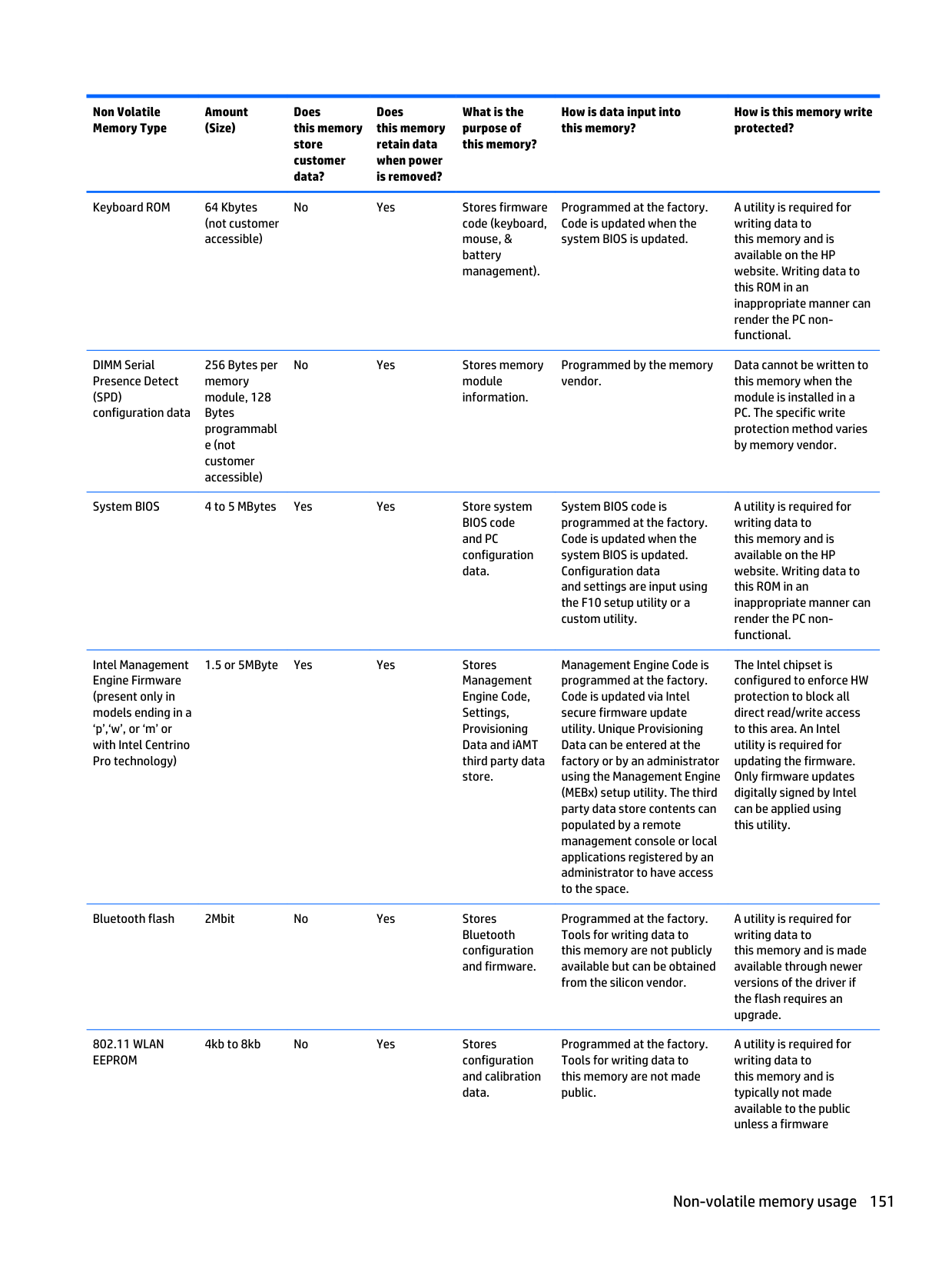
Non Volatile Memory Type Amount (Size) Does this memory store customer data? Does this memory retain data when power is removed? What is the purpose of this memory? How is data input into this memory? How is this memory write protected? Keyboard ROM 64 Kbytes (not customer accessible) No Yes Stores firmware code (keyboard, mouse, & battery management). Programmed at the factory. Code is updated when the system BIOS is updated. A utility is required for writing data to this memory and is available on the HP website. Writing data to this ROM in an inappropriate manner can render the PC non- functional. DIMM Serial Presence Detect
(Spd)
configuration data 256 Bytes per memory module, 128 Bytes programmabl e (not customer accessible) No Yes Stores memory module information. Programmed by the memory vendor. Data cannot be written to this memory when the module is installed in a PC. The specific write protection method varies by memory vendor. System BIOS 4 to 5 MBytes Yes Yes Store system BIOS code and PC configuration data. System BIOS code is programmed at the factory. Code is updated when the system BIOS is updated. Configuration data and settings are input using the F10 setup utility or a custom utility. A utility is required for writing data to this memory and is available on the HP website. Writing data to this ROM in an inappropriate manner can render the PC non- functional. Intel Management Engine Firmware (present only in models ending in a ‘p’,‘w’, or ‘m’ or with Intel Centrino Pro technology) 1.5 or 5MByte Yes Yes Stores Management Engine Code, Settings, Provisioning Data and iAMT third party data store. Management Engine Code is programmed at the factory. Code is updated via Intel secure firmware update utility. Unique Provisioning Data can be entered at the factory or by an administrator using the Management Engine (MEBx) setup utility. The third party data store contents can populated by a remote management console or local applications registered by an administrator to have access to the space. The Intel chipset is configured to enforce HW protection to block all direct read/write access to this area. An Intel utility is required for updating the firmware. Only firmware updates digitally signed by Intel can be applied using this utility. Bluetooth flash 2Mbit No Yes Stores Bluetooth configuration and firmware. Programmed at the factory. Tools for writing data to this memory are not publicly available but can be obtained from the silicon vendor. A utility is required for writing data to this memory and is made available through newer versions of the driver if the flash requires an upgrade.802.11 Wlan
Eeprom
4kb to 8kb No Yes Stores configuration and calibration data. Programmed at the factory. Tools for writing data to this memory are not made public. A utility is required for writing data to this memory and is typically not made available to the public unless a firmware Non-volatile memory usage 151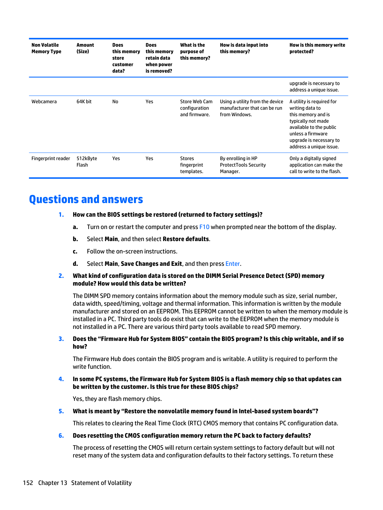
Non Volatile Memory Type Amount (Size) Does this memory store customer data? Does this memory retain data when power is removed? What is the purpose of this memory? How is data input into this memory? How is this memory write protected? upgrade is necessary to address a unique issue. Webcamera 64K bit No Yes Store Web Cam configuration and firmware. Using a utility from the device manufacturer that can be run from Windows. A utility is required for writing data to this memory and is typically not made available to the public unless a firmware upgrade is necessary to address a unique issue. Fingerprint reader 512kByte Flash Yes Yes Stores fingerprint templates. By enrolling in HP ProtectTools Security Manager. Only a digitally signed application can make the call to write to the flash. Questions and answers

system data and configuration defaults to factory settings, refer to question and answer 1 and follow the instructions for returning the BIOS settings to factory defaults. Questions and answers 153
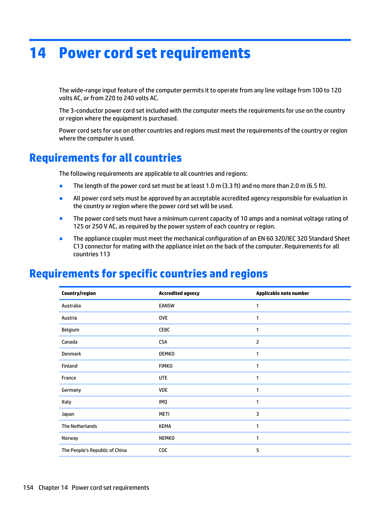
14 Power cord set requirements The wide-range input feature of the computer permits it to operate from any line voltage from 100 to 120 volts AC, or from 220 to 240 volts AC. The 3-conductor power cord set included with the computer meets the requirements for use on the country or region where the equipment is purchased. Power cord sets for use on other countries and regions must meet the requirements of the country or region where the computer is used. Requirements for all countries The following requirements are applicable to all countries and regions: ● The length of the power cord set must be at least 1.0 m (3.3 ft) and no more than 2.0 m (6.5 ft). ● All power cord sets must be approved by an acceptable accredited agency responsible for evaluation in the country or region where the power cord set will be used. ● The power cord sets must have a minimum current capacity of 10 amps and a nominal voltage rating of 125 or 250 V AC, as required by the power system of each country or region. ● The appliance coupler must meet the mechanical configuration of an EN 60 320/IEC 320 Standard Sheet C13 connector for mating with the appliance inlet on the back of the computer. Requirements for all countries 113 Requirements for specific countries and regions Country/region Accredited agency Applicable note number Australia
Eansw
1 AustriaOve
1 BelgiumCebc
1 CanadaCsa
2 DenmarkDemko
1 FinlandFimko
1 FranceUte
1 GermanyVde
1 ItalyImq
1 JapanMeti
3 The NetherlandsKema
1 NorwayNemko
1 The People's Republic of ChinaCoc
5 154 Chapter 14 Power cord set requirements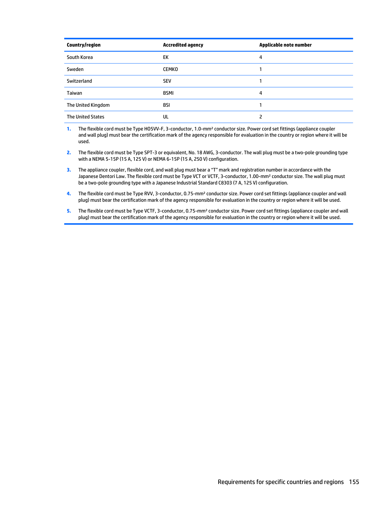
Country/region Accredited agency Applicable note number South Korea
Ek
4 SwedenCemko
1 SwitzerlandSev
1 TaiwanBsmi
4 The United KingdomBsi
1 The United StatesUl
2
15 Recycling When a non-rechargeable or rechargeable battery has reached the end of its useful life, do not dispose of the battery in general household waste. Follow the local laws and regulations in your area for battery disposal. HP encourages customers to recycle used electronic hardware, HP original print cartridges, and rechargeable batteries. For more information about recycling programs, see the HP Web site at http://www.hp.com/ recycle. 156 Chapter 15 Recycling
Index
A
AC adapter, spare part numbers 49 AC adapter/battery light 18 audio, product description 4 audio-in. (microphone) jack, identifying 21 audio-out (headphone) jack, identifying 21 audio/USB board spare part numbers 35B
Backup and Restore 142 backups creating 142 base enclosure removal 82 spare part number 82 base enclosure, spare part numbers 40 battery removal 56 spare part numbers 42, 56 battery bay, identifying 23 battery release latch 23 Blu-ray R/RE DVD±RW SuperMulti Double-Layer Combo Drive removal 69 spare part number 49 Blu-ray R/RE DVD±RW SuperMulti Double-Layer Drive precautions 52 spare part number 40 Blu-ray ROM DVD±RW Combo Drive spare part number 69 Blu-ray ROM DVD±RW SuperMulti Double-Layer Drive precautions 52 bottom components 23 buttons left pointing stick 17 left TouchPad 17 optical drive eject 19, 20 power 11 right pointing stick 17 right TouchPad 17 Windows button 13, 14C
Cable Kit components 45 spare part number 45 cables, service considerations 52 caps lock light, identifying 15, 16 chipset, product description 2 components bottom 23 display 9 front 18 left-side 19 rear 22 right-side 21 computer major components 27 specifications 128 computer reset 147 connector, power 19 connectors, service considerations 52D
display assembly removal 104 spare part numbers 104 display back cover spare part numbers 44 display bezel removal 104 spare part numbers 43, 105 display panel product description 2, 3 removal 105 spare part numbers 44 display panel cable spare part numbers 44 Display Panel Support Kit spare part number 28, 104 spare part numbers 44 DisplayPort-to-HDMI adapter, spare part number 49 docking connector, identifying 23 Driver Recovery DVD, creating 141 drives, preventing damage 52 Dual-Mode DisplayPort, identifying 21 DVD-ROM Drive precautions 52 removal 69 spare part number 40, 49, 69 DVD±RW SuperMulti Double-Layer Drive precautions 52 removal 69 spare part number 40, 49, 69E
electrostatic discharge 52 embedded numeric keypad, identifying 13 equipment guidelines 55 esc key, identifying 13, 14 Ethernet, product description 4 ExpressCard slot 19, 20 external monitor port 21F
f11 recovery 138 fan removal 79 spare part numbers 79 fan and heat sink assembly spare part numbers 40 Fingerprint bracket, illustrated 46 fingerprint reader bezel, illustrated 46 fingerprint reader board removal 87 spare part number 35, 87 fingerprint reader board bracket removal 88 fingerprint reader, identifying 12 flash cache, product description 3 fn key, identifying 13, 14 front components 18 Index 157
function button board removal 96 spare part number 96 spare part numbers 35 function keys, identifying 13, 14 fusion controller hub, product description 2
G
graphics, product description 2 grounding guidelines 52 guidelines equipment 55 grounding 52 packaging 54 transporting 54 workstation 54H
hard drive precautions 52 product description 3, 4 removal 58 spare part numbers 41, 48, 58 specifications 128 Hard Drive Hardware Kit spare part number 42, 48 hard drive light 18 hard drive recovery 138 hard drive, identifying 23 headphone (audio-out) jack 21 heat sink removal 79 spare part numbers 79 hinge spare part number 44 hinge bracket removal 106 hinge cover spare part number 107 HP Recovery Disc Creator, using 141I
integrated numeric keypad, identifying 14 integrated webcam light, identifying 9 internal display switch 10 internal microphones, identifying 9J
jacks audio-in. (microphone) 21 audio-out (headphone) 21 network 19, 20 RJ-11 (modem) 22 RJ-45 (network) 19, 20K
keyboard product description 5, 6 removal 72 spare part numbers 28, 72 keypad embedded numeric 13 integrated numeric 14 keys esc 13, 14 fn 13, 14 function 13, 14 Windows applications 13L
latch, battery release 23 latches, service cover release 23 left-side components 19 lights AC adapter/battery 18 caps lock 15, 16 hard drive 18 microphone mute 15, 16 num lock 15, 16 power 15, 16, 18 TouchPad 15, 16 webcam 9 wireless 15, 16, 18M
mass storage device illustrated 47 precautions 52 spare part numbers 47 Memory card reader, identifying 19, 20 memory module identifying 23 product description 3 removal 62, 64 removing 63 spare part numbers 62, 64 microphone product description 4 microphone (audio-in.) jack, identifying 21 microphone module removal 107 spare part number 43, 108 microphone mute light 15, 16 model name 1 modem module removal 61 spare part number 40, 61 spare part numbers 61 monitor connector cable illustrated 45 spare part number 40N
network cable illustrated 45 network jack, identifying 19, 20 num lock light 15, 16O
operating system, product description 6, 7, 8 optical drive precautions 52 removal 69 spare part numbers 40, 49, 69 optical drive blank tray illustrated 46 optical drive connector board spare part number 36 optical drive eject button, identifying 19, 20P
packaging guidelines 54 plastic parts, service considerations 51 Plastics Kit components 46 spare part number 46 pointing device, product description 5, 6 pointing stick 17 pointing stick cover, spare part number 34 ports Dual-Mode DisplayPort 21 158 Index
external monitor 21 product description 5 serial 22 power button board removal 86 spare part number 86 spare part numbers 35 power button, identifying 11 power connector cable removal 101 spare part numbers 34 power connector, identifying 19 power cord set requirements 154 spare part numbers 50 power lights 15, 16, 18 power requirements, product description 6 processor product description 1, 2 removal 98 spare part numbers 35, 98 product description audio 4 chipset 2 display panel 2, 3 Ethernet 4 external media cards 5 flash cache 3 fusion controller hub 2 graphics 2 hard drive 3, 4 keyboard 5, 6 memory module 3 microphone 4 operating system 6, 7, 8 pointing device 5, 6 ports 5 power requirements 6 processor 1, 2 product name 1 security 6 serviceability 8 solid-state drive 3 Upgrade drive 4 video 4 wireless 4, 5 product name 1
R
recovery 140 recovery media, creating 141 recovery partition 138 refresh 140 removal/replacement procedures 56 reset computer 147 steps 147 restoring the hard drive 138 right-side components 21 RJ-11 (modem) jack, identifying 22 RJ-45 (network) jack, identifying 19, 20 RJ-45 cable illustrated 45 spare part number 40 RTC battery removal 103 spare part number 42, 103 Rubber Kit, spare part number 42S
Screw Kit, spare part number 50 SD card reader bezel, illustrated 46 security cable slot, identifying 21 security, product description 6 serial port, identifying 22 service considerations cables 52 connectors 52 plastic parts 51 service cover removal 57 spare part number 42, 57 service cover release latch 23 service cover release lock, identifying 23 service tag 25 serviceability, product description 8 SIM slot, identifying 23 SIM, spare part number 49Sled
remove everything and reinstall option 147 slots ExpressCard 19, 20 security cable 21Sim
23 smart card 19, 20 smart card reader removal 88 spare part number 88 spare part numbers 34 Smart card reader blank, illustrated 46 smart card slot 19, 20 solid-state drive precautions 52 product description 3 removal 70 spare part numbers 47, 70 Speaker Kit, spare part number 35 speakers removal 95 spare part number 35, 95 speakers, identifying 11 specifications computer 128 hard drive 128 system board removal 89 spare part numbers 36, 89T
tools required 51 top cover spare part numbers 34 top hinge cover, spare part number 28 TouchPad buttons 17 removal 100 spare part number 100 spare part numbers 35 TouchPad light, identifying 15, 16 TouchPad zone identifying 17 transporting guidelines 54U
upgrade bay 19, 20 Upgrade drive, product description 4 USB 3.0 charging port 19, 20 USB 3.0 port 19, 20, 21 Index 159
USB board removal 85 spare part number 85 USB ports, identifying 19, 20, 21