
Ask AI
— answers from the official manualAnswers from the official manual.
Common questions
Common Questions
8 totalHow do I turn on the HP Z27x monitor?
Press and hold the Power button on the front of the monitor until it lights up, ensuring that the master power switch located on the rear panel is in the ON position. (Page 15)
What are the setup steps to connect my HP Z27x display?
Locate and route the cables through the cable management hole on the stand, connect the DisplayPort or HDMI cable from your computer to the monitor's corresponding port (depending if you're using DisplayPort or HDMI for video), and plug in the USB hub and power cord. Power the system up after ensuring all connections are secure and cables are routed properly. (Pages 8-9)
How do I mount the HP Z27x monitor to a wall using VESA mounting holes?
Remove the four screws from the rear of the monitor panel and install them on a third-party mount supporting the VESA standard to attach the monitor. Ensure the manufacturer's solution complies with the VESA standard and can handle the display's weight. (Page 23)
What safety measures should I take while setting up my HP Z27x monitor?
Ensure you do not touch the LCD panel or apply pressure on it, lay the monitor face down on a soft area if removing its stand, and route cables so they cannot be pulled or tripped over. Keep the monitor away from direct sunlight, avoid excessive heat or moisture exposure, and use a clean antistatic cloth for dusting. (Pages 6-7)
How do I adjust luminance levels on my HP Z27x display?
Press any front bezel button, then press the Open Menu button to bring up the OSD menu. Go to Color Space > Adjust Luminance and use the increase or decrease buttons to set it to your desired level between 48-250 cd/m^2 (Native preset supports a wider range). (Page 32)
How do I select a color space preset on my HP Z27x monitor?
Activate the OSD menu by pressing any front bezel button and then the Open Menu button. Navigate to Color Space, use the Up/Down buttons for your preferred preset (sRGB, AdobeRGB), and press Select when highlighted. (Page 30)
Full Manual
71 pages

HP DreamColor Z27x Display
User Guide
© 2014 Hewlett-Packard Development Company, L.P.
ENERGY STAR and the ENERGY STAR mark are registered U.S. marks. HDMI, the HDMI Logo and High-Definition Multimedia Interface are trademarks or registered trademarks of HDMI Licensing LLC. Microsoft and Windows are U.S. registered trademarks of the Microsoft group of companies.
The information contained herein is subject to change without notice. The only warranties for HP products and services are set forth in the express warranty statements accompanying such products and services. Nothing herein should be construed as constituting an additional warranty. HP shall not be liable for technical or editorial errors or omissions contained herein.
Second Edition: May 2014 First Edition: April 2014 Document Part Number: 748432-002
#### About This Guide
This guide provides information on monitor features, setting up the monitor, and technical specifications.
WARNING! Text set off in this manner indicates that failure to follow directions could result in bodily harm or loss of life.
CAUTION: Text set off in this manner indicates that failure to follow directions could result in damage to equipment or loss of information.
| | |---|
NOTE: Text set off in this manner provides important supplemental information.

This product incorporates HDMI technology.
iii
####### iv About This Guide
Table of contents
Cleaning the Monitor ............................................................................................................ 4 Shipping the Monitor ............................................................................................................ 4
Mounting the Monitor Using the Quick Release 2 Mounting Bracket ................................ 19 Mounting the Monitor Without Using the Quick Release 2 Mounting Bracket ................... 22
Installing an Optional HP Hood Kit ..................................................................................................... 23 Locating the Serial Number and Product Number .............................................................................. 24 Locating the Information Card ............................................................................................................ 24 Attaching a Device to the Rear of the Monitor .................................................................................... 25 Installing a Cable Lock ....................................................................................................................... 26
The Information File ........................................................................................................... 27 The Image Color Matching File .......................................................................................... 27
Installing the .INF and .ICM Files ....................................................................................................... 28 Installing from the Disc ...................................................................................................... 28 Downloading from the Internet ........................................................................................... 28
v
vi
Updating the Firmware ....................................................................................................................... 28 Selecting a Color Space Preset ......................................................................................................... 30 Adjusting Luminance .......................................................................................................................... 30 Understanding the Z27x Image Adjustment Options .......................................................................... 31
Use Video Levels (16–235) ................................................................................................ 31 Overscan the Frame .......................................................................................................... 31 Show Only the Blue Channel ............................................................................................. 32
Using the Z27x Aspect Ratio Management Options .......................................................................... 32
The “Fill To” Options .......................................................................................................... 32 Fill to Source Aspect Ratio (Proportional) ......................................................... 32 Fill to Entire Screen (Non-Proportional) ............................................................ 32 Fill to Screen Width (Proportional) .................................................................... 33 Fill to Screen Height (Proportional) ................................................................... 33 Pixel-for-Pixel .................................................................................................... 33 “Fill To” Examples ............................................................................................. 33
Working with 2K and 4K Digital Cinema Image Formats ................................................................... 35 Using the Digital Cinema Display Options ......................................................................... 36 Show Entire DCI Container ............................................................................... 36
Next 4K Corner ................................................................................. 38 Scroll 4K Region ............................................................................... 38
Using Picture-in-Picture (PIP) and Picture-beside-Picture (PBP) ...................................................... 38
Using PIP as a Confidence Monitor ................................................................................... 39 Use Video Levels (16–235) ............................................................................... 39 Overscan Within PIP ......................................................................................... 39 Digital Cinema Options ..................................................................................... 39
Changing the Bezel Button Functions ................................................................................................ 39 Changing the Bezel Function Button Mode ........................................................................................ 40 Adjusting the Bezel Button LEDs ....................................................................................................... 41 Using Auto-Sleep Mode ..................................................................................................................... 41 Using the On-Screen Display Menu ................................................................................................... 42

Color Space Menu ............................................................................................................. 42
Video Input Menu ............................................................................................................... 43 Image Adjustment Menu .................................................................................................... 43 PIP Control Menu .............................................................................................................. 45 Language Menu ................................................................................................................. 46 Management Menu ............................................................................................................ 46 Menu and Message Control Menu ..................................................................................... 50 Information and Factory Reset Menus ............................................................................... 51
Introduction to Color Calibration ......................................................................................................... 52 Preparing to Calibrate ........................................................................................................ 53 Calibrating the Z27x Using the Onscreen Menus .............................................................. 53
Recalibrate the Current Preset .......................................................................... 54 Select and Modify a Preset ............................................................................... 54
Auto EDID Update .............................................................................................................................. 55
Z27x Model ........................................................................................................................ 58
vii
####### viii
1 Product Features
HP Z27x Monitor
The LCD (liquid crystal display) monitor has an active matrix, thin-film transistor (TFT) panel. The monitor features include:
HP Z27x Monitor 1
2 Chapter 1 Product Features
2 Safety and Maintenance Guidelines
Important Safety Information
A power cord is included with the monitor. If another cord is used, use only a power source and connection appropriate for this monitor. For information on the correct power cord set to use with the monitor, refer to the Product Noticesprovided on your media disc, if one is included, or in your documentation kit.
WARNING! To reduce the risk of electric shock or damage to the equipment:
For your safety, do not place anything on power cords or cables. Arrange them so that no one may accidentally step on or trip over them. Do not pull on a cord or cable. When unplugging from the electrical outlet, grasp the cord by the plug.
To reduce the risk of serious injury, read the Safety and Comfort Guide. It describes proper workstation, setup, posture, and health and work habits for computer users, and provides important electrical and mechanical safety information. This guide is located on the Web at http://www.hp.com/ ergo.
CAUTION: For the protection of the monitor, as well as the computer, connect all power cords for the computer and its peripheral devices (such as a monitor, printer, scanner) to some form of surge protection device such as a power strip or Uninterruptible Power Supply (UPS). Not all power strips provide surge protection; the power strips must be specifically labeled as having this ability. Use a power strip whose manufacturer offers a Damage Replacement Policy so you can replace the equipment, if surge protection fails.
Use the appropriate and correctly sized furniture designed to properly support your HP LCD monitor.
WARNING! LCD monitors that are inappropriately situated on dressers, bookcases, shelves, desks, speakers, chests, or carts may fall over and cause personal injury. Care should be taken to route all cords and cables connected to the LCD monitor so that they can not be pulled, grabbed, or tripped over.
Maintenance Guidelines
To enhance the performance and extend the life of the monitor:
Important Safety Information 3

| | |---|
#### Cleaning the Monitor
CAUTION: Spray the cleaner onto a cloth and use the damp cloth to gently wipe the screen surface. Never spray the cleaner directly on the screen surface. It may run behind the bezel and damage the electronics.
CAUTION: Do not use cleaners that contain any petroleum based materials such as benzene, thinner, or any volatile substance to clean the monitor screen or cabinet. These chemicals may damage the monitor.
#### Shipping the Monitor
Keep the original packing box in a storage area. You may need it later if you move or ship the monitor.
4 Chapter 2 Safety and Maintenance Guidelines
3 Setting Up the Monitor
To set up the monitor, ensure that the power is turned off to the monitor, computer system, and other attached devices, then follow the instructions below.
| | |---|
NOTE: Be sure the master power switch, located on the rear panel of the monitor, is in the off position. The master power switch turns off all power to the monitor.
Use Caution When Setting Up the Monitor
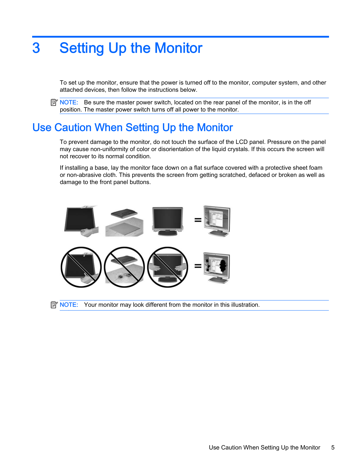
To prevent damage to the monitor, do not touch the surface of the LCD panel. Pressure on the panel may cause non-uniformity of color or disorientation of the liquid crystals. If this occurs the screen will not recover to its normal condition.
If installing a base, lay the monitor face down on a flat surface covered with a protective sheet foam or non-abrasive cloth. This prevents the screen from getting scratched, defaced or broken as well as damage to the front panel buttons.
| | |---|

NOTE: Your monitor may look different from the monitor in this illustration.
Use Caution When Setting Up the Monitor 5
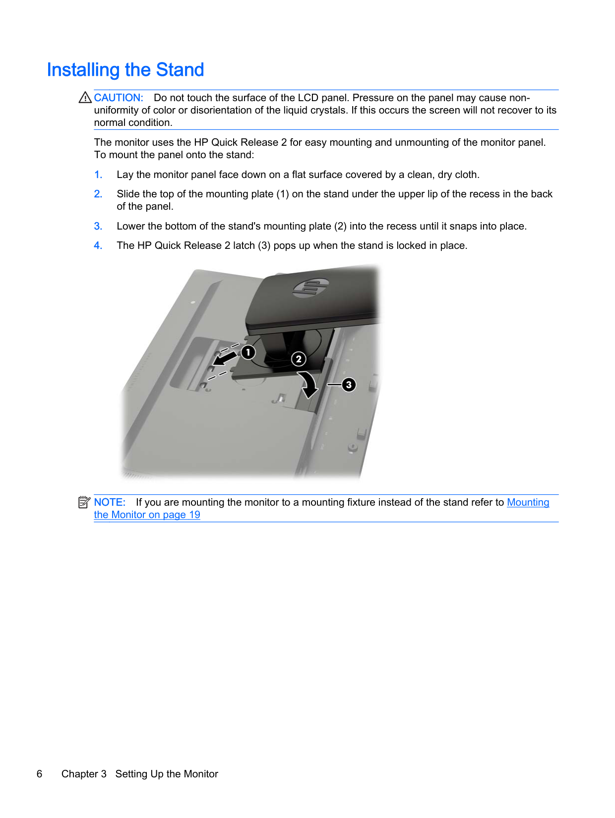
Installing the Stand
CAUTION: Do not touch the surface of the LCD panel. Pressure on the panel may cause nonuniformity of color or disorientation of the liquid crystals. If this occurs the screen will not recover to its normal condition.
The monitor uses the HP Quick Release 2 for easy mounting and unmounting of the monitor panel. To mount the panel onto the stand:


| | |---|

NOTE: If you are mounting the monitor to a mounting fixture instead of the stand refer to Mounting the Monitor on page 19
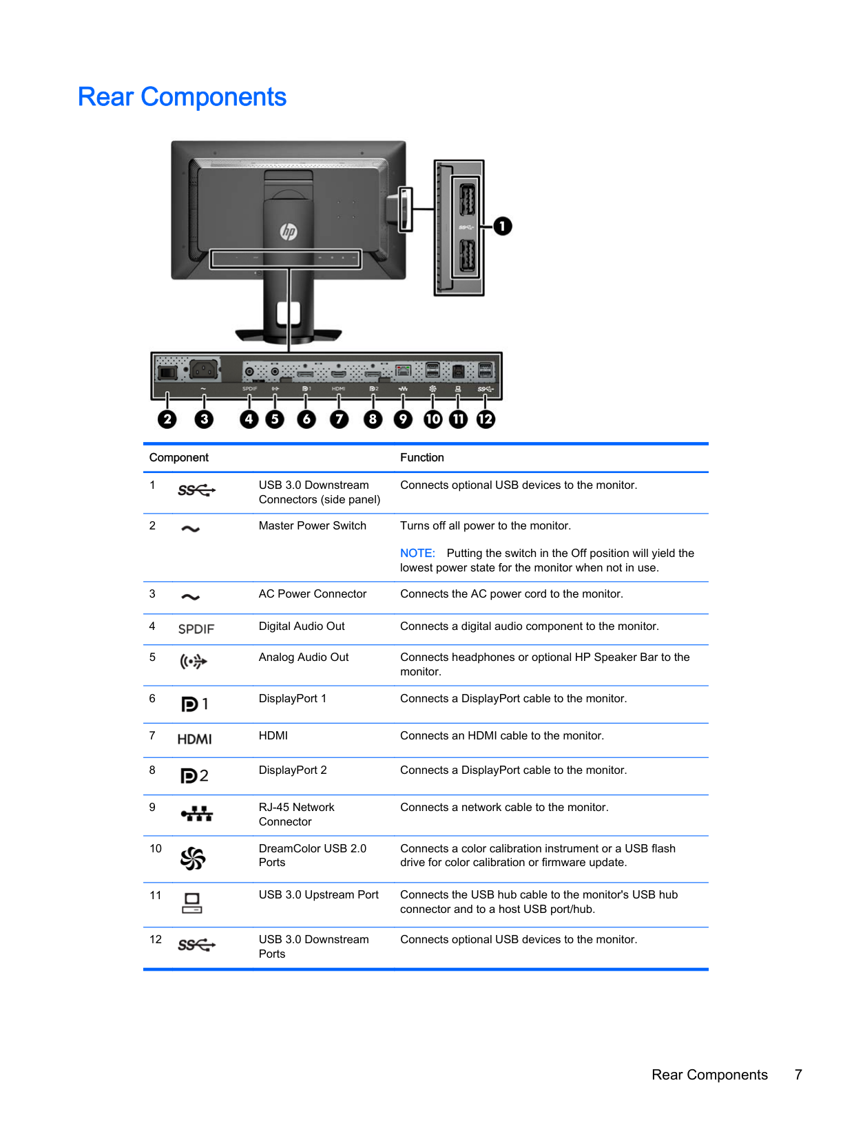
Rear Components


######### Component Function

Connects optional USB devices to the monitor.

NOTE: Putting the switch in the Off position will yield the lowest power state for the monitor when not in use.


Connects a network cable to the monitor.

Connects a color calibration instrument or a USB flash drive for color calibration or firmware update.

Connects optional USB devices to the monitor.

Rear Components 7
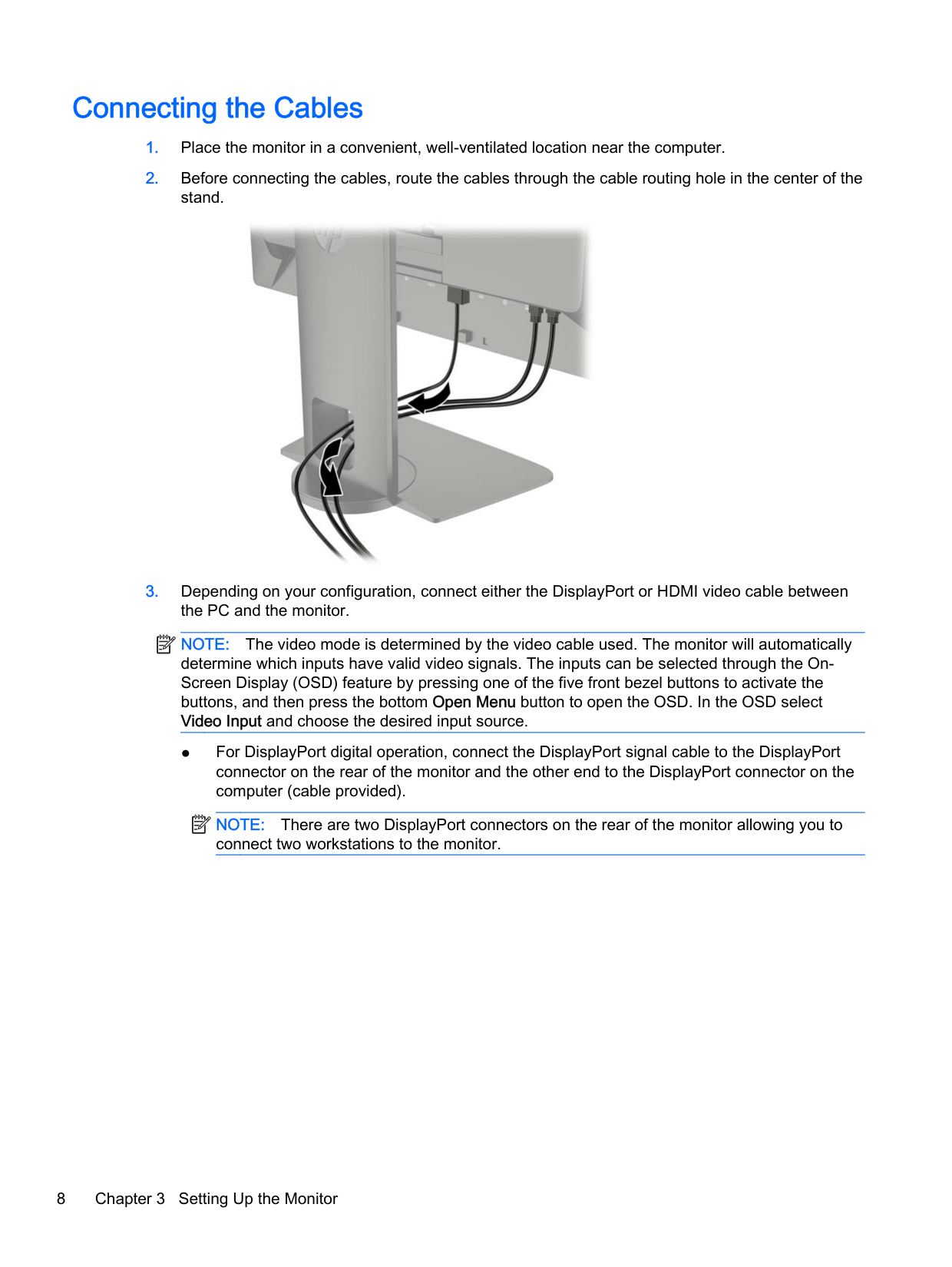
Connecting the Cables

| | |---|
NOTE: The video mode is determined by the video cable used. The monitor will automatically determine which inputs have valid video signals. The inputs can be selected through the OnScreen Display (OSD) feature by pressing one of the five front bezel buttons to activate the buttons, and then press the bottom Open Menu button to open the OSD. In the OSD select Video Input and choose the desired input source.
| | |---|
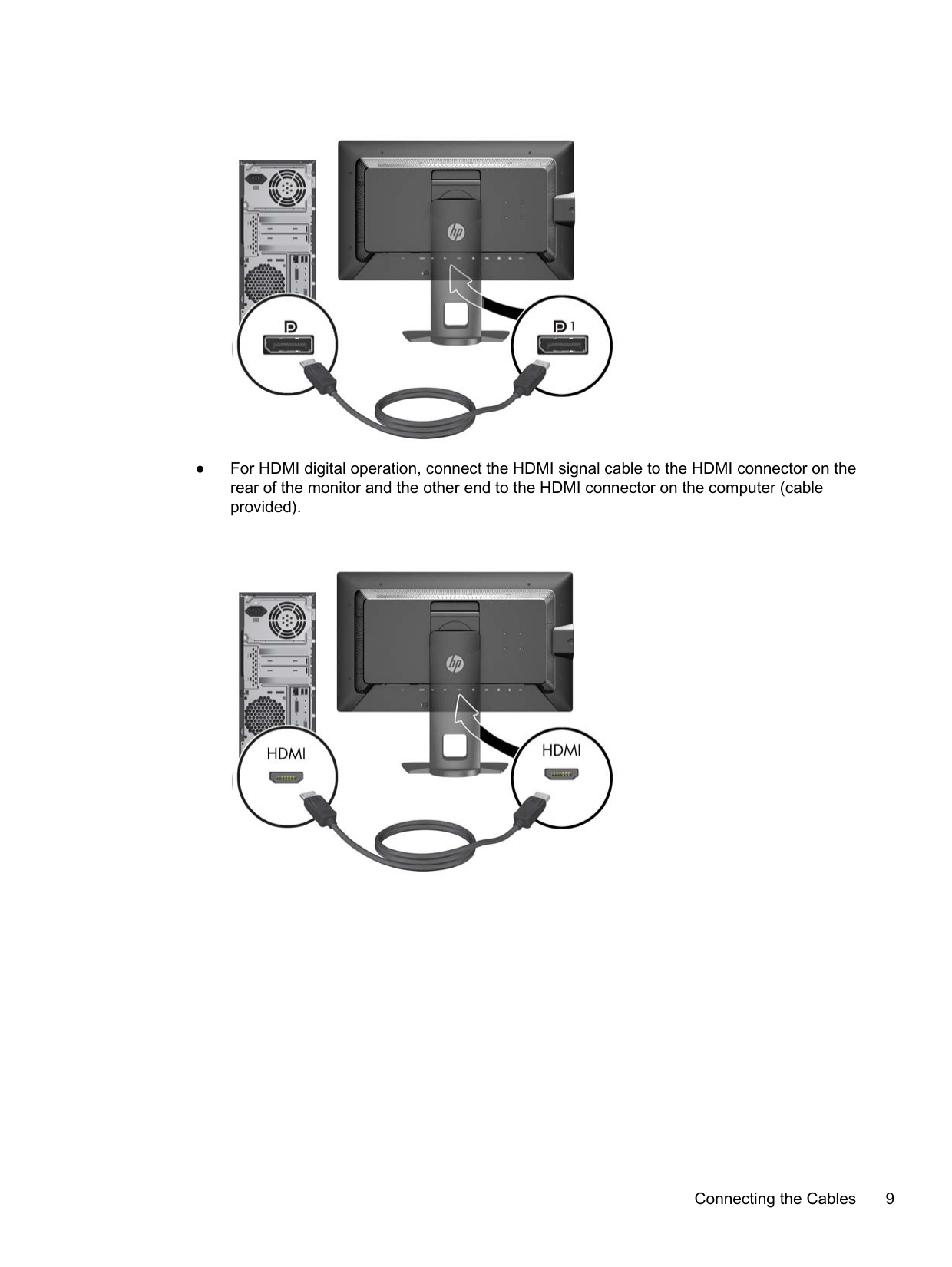
NOTE: There are two DisplayPort connectors on the rear of the monitor allowing you to connect two workstations to the monitor.

####### ● For HDMI digital operation, connect the HDMI signal cable to the HDMI connector on therear of the monitor and the other end to the HDMI connector on the computer (cableprovided).

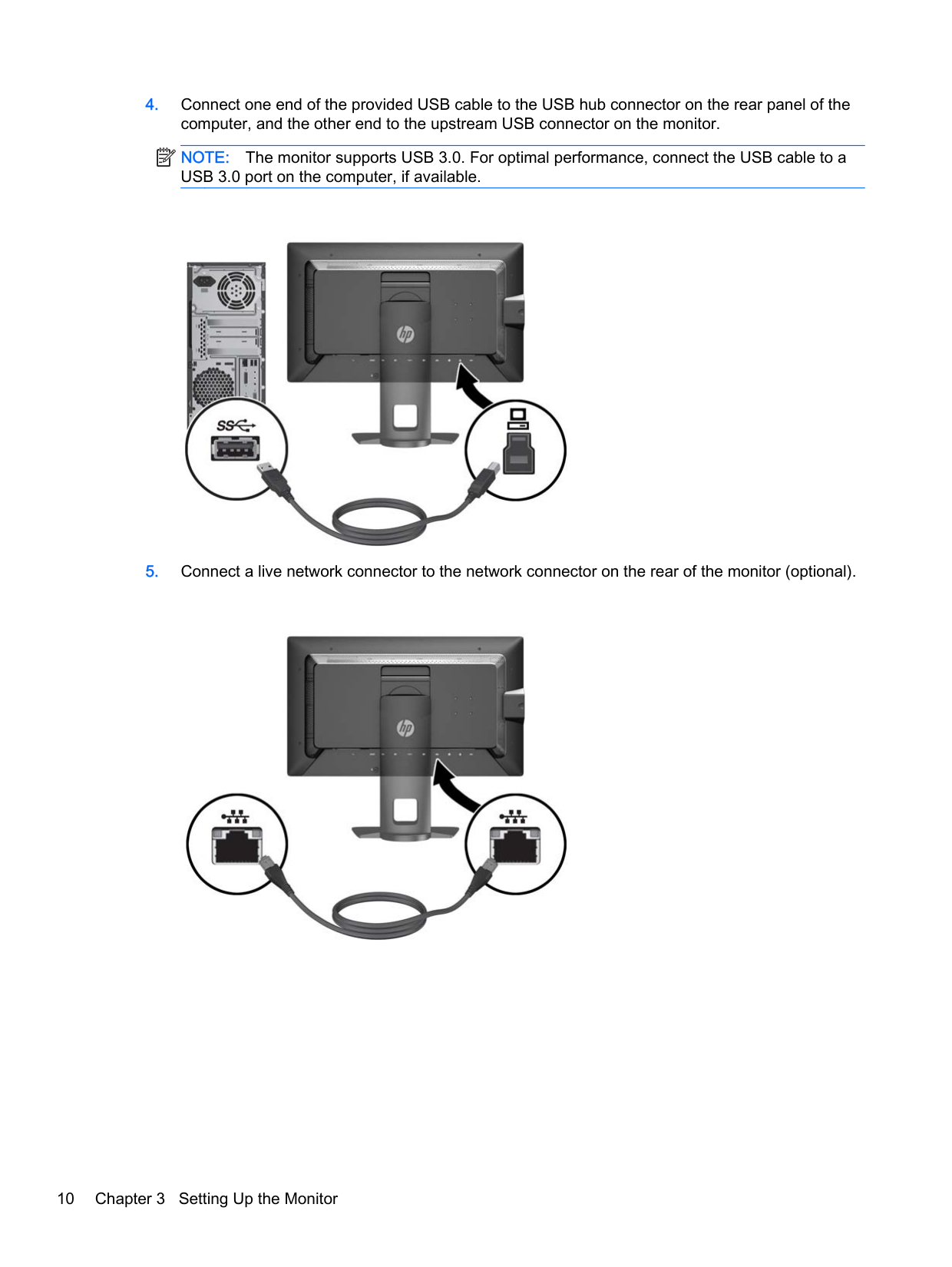
####### 4. Connect one end of the provided USB cable to the USB hub connector on the rear panel of thecomputer, and the other end to the upstream USB connector on the monitor.
| |
|---|
NOTE: The monitor supports USB 3.0. For optimal performance, connect the USB cable to a USB 3.0 port on the computer, if available.

####### 5. Connect a live network connector to the network connector on the rear of the monitor (optional).

| | |---|
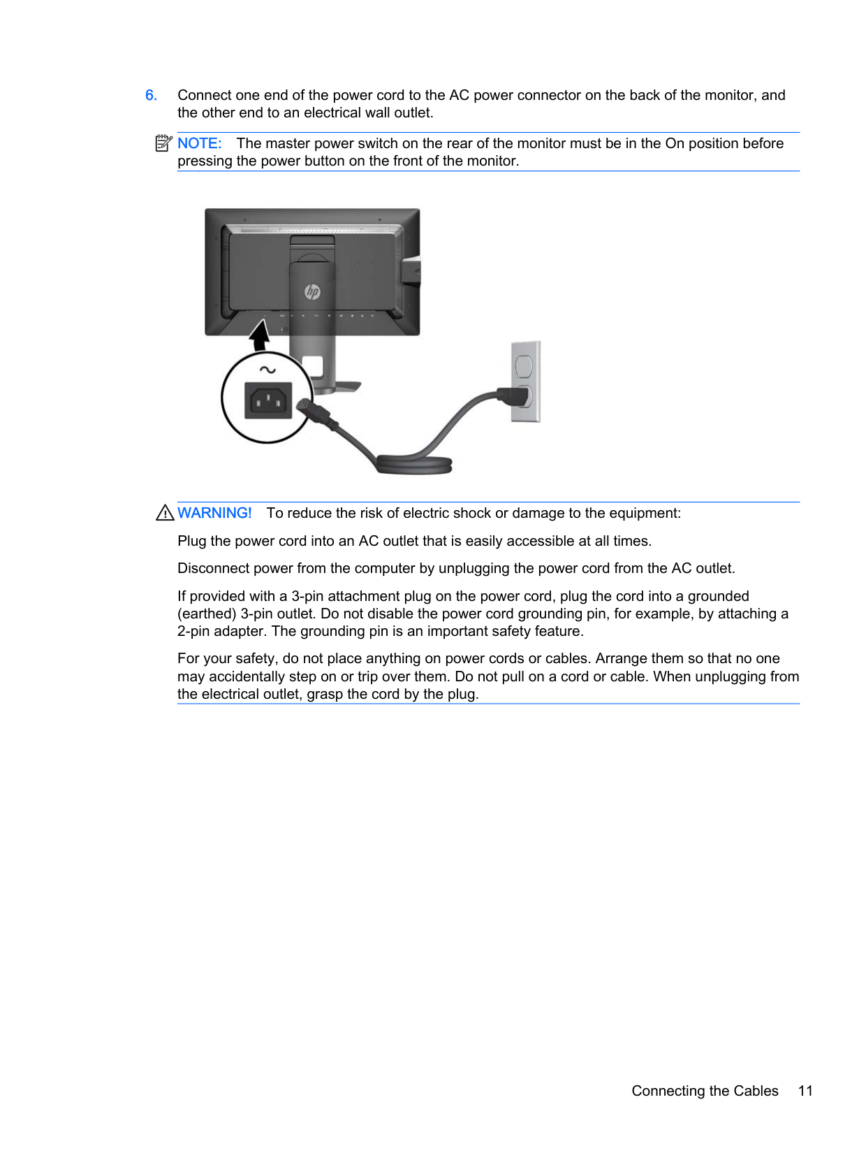
NOTE: The master power switch on the rear of the monitor must be in the On position before pressing the power button on the front of the monitor.

WARNING! To reduce the risk of electric shock or damage to the equipment: Plug the power cord into an AC outlet that is easily accessible at all times. Disconnect power from the computer by unplugging the power cord from the AC outlet. If provided with a 3-pin attachment plug on the power cord, plug the cord into a grounded (earthed) 3-pin outlet. Do not disable the power cord grounding pin, for example, by attaching a 2-pin adapter. The grounding pin is an important safety feature. For your safety, do not place anything on power cords or cables. Arrange them so that no one may accidentally step on or trip over them. Do not pull on a cord or cable. When unplugging from the electrical outlet, grasp the cord by the plug.
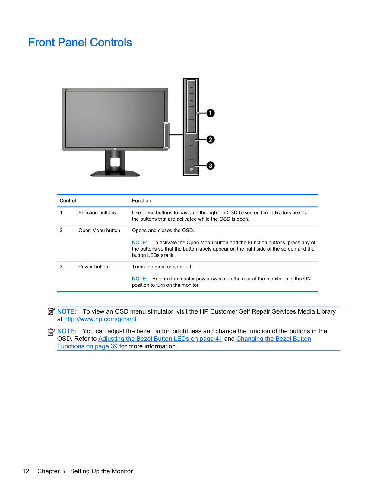
Front Panel Controls


######### Control Function
NOTE: To activate the Open Menu button and the Function buttons, press any of the buttons so that the button labels appear on the right side of the screen and the button LEDs are lit.
NOTE: Be sure the master power switch on the rear of the monitor is in the ON position to turn on the monitor.
| | |---|
| | |---|
NOTE: To view an OSD menu simulator, visit the HP Customer Self Repair Services Media Library at http://www.hp.com/go/sml.
NOTE: You can adjust the bezel button brightness and change the function of the buttons in the OSD. Refer to Adjusting the Bezel Button LEDs on page 41 and Changing the Bezel Button Functions on page 39 for more information.
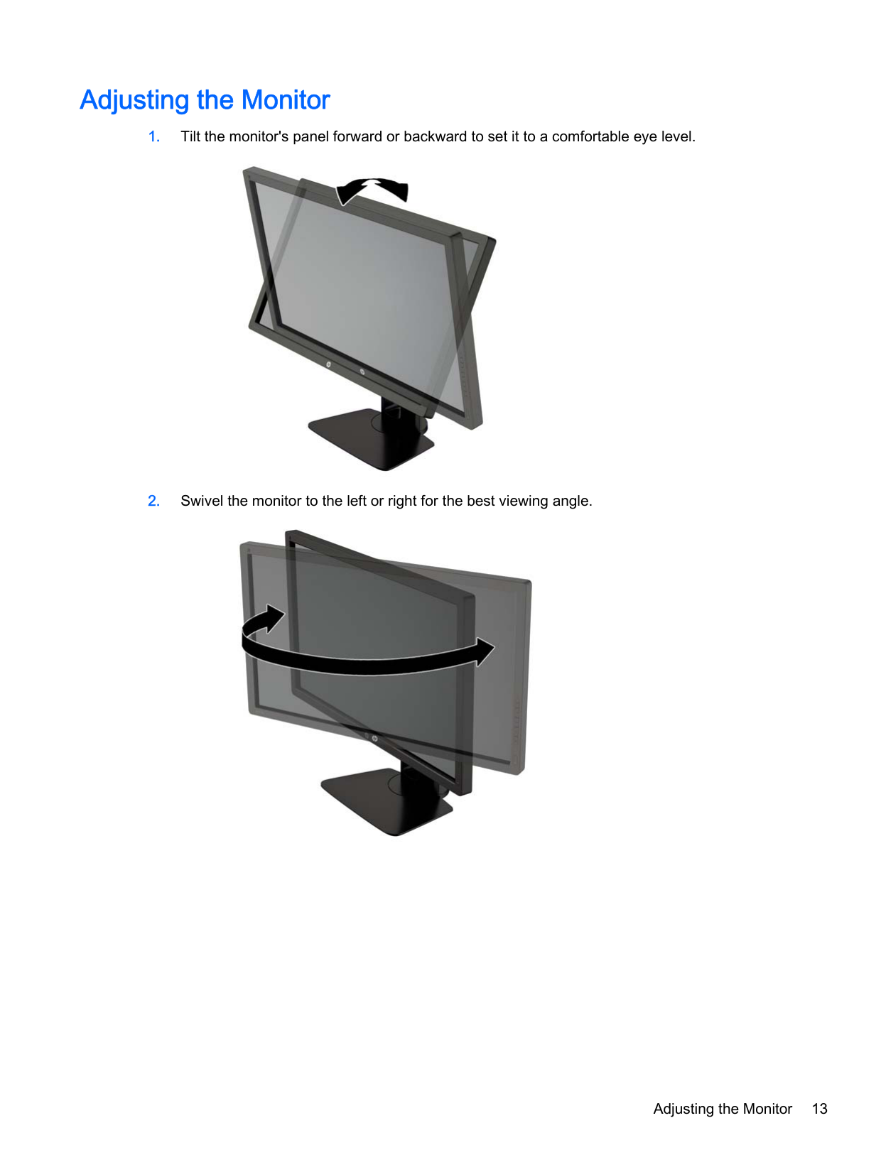
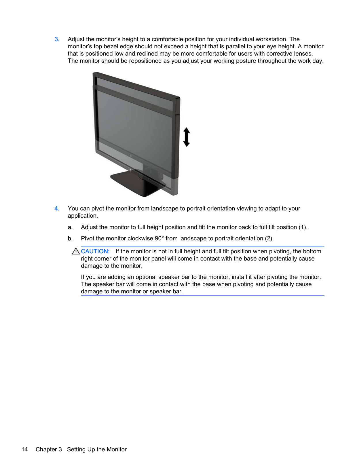
Adjusting the Monitor


Adjusting the Monitor 13

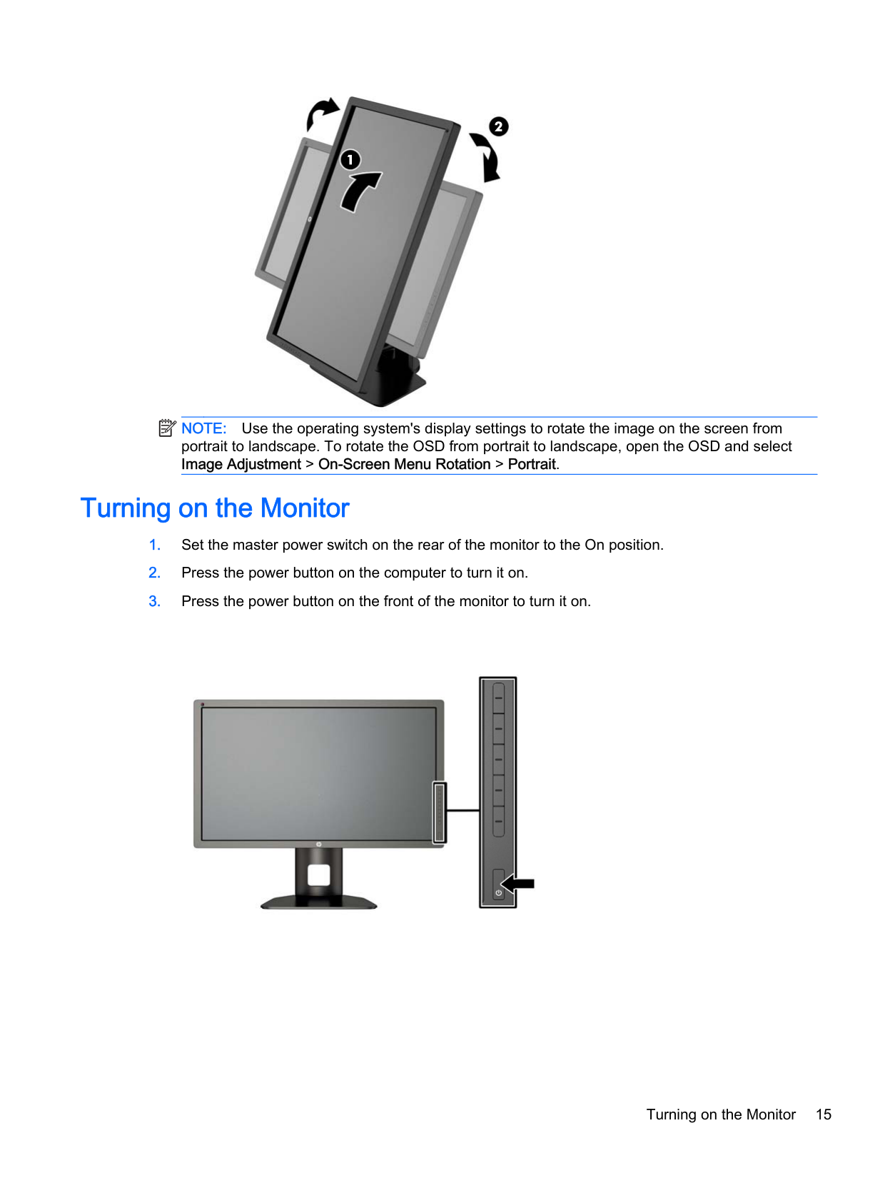
CAUTION: If the monitor is not in full height and full tilt position when pivoting, the bottom right corner of the monitor panel will come in contact with the base and potentially cause damage to the monitor.
If you are adding an optional speaker bar to the monitor, install it after pivoting the monitor. The speaker bar will come in contact with the base when pivoting and potentially cause damage to the monitor or speaker bar.
| | |---|


NOTE: Use the operating system's display settings to rotate the image on the screen from portrait to landscape. To rotate the OSD from portrait to landscape, open the OSD and select Image Adjustment > On-Screen Menu Rotation > Portrait.
Turning on the Monitor


Turning on the Monitor 15
CAUTION: Burn-in image damage may occur on monitors that display the same static image on screen for a prolonged period of time.* To avoid burn-in image damage on the monitor screen, you should always activate a screen saver application or turn off the monitor when it is not in use for a prolonged period of time. Image retention is a condition that may occur on all LCD screens. Monitors with a “burned-in image” are not covered under the HP warranty.
| | |---|
HP Watermark and Image Retention Policy
The IPS monitor models are designed with IPS (In-Plane Switching) display technology which provides ultra-wide viewing angles and advanced image quality. IPS monitors are suitable for a wide variety of advanced image quality applications. This panel technology, however, is not suitable for applications that exhibit static, stationary or fixed images for long periods of time without the use of screen savers. These types of applications may include camera surveillance, video games, marketing logos, and templates that are displayed on the screen for a prolonged period of time. Static images may cause image retention damage that could look like stains or watermarks on the monitor's screen.
Monitors in use for 24 hours per day that result in image retention damage are not covered under the HP warranty. To avoid image retention damage, always turn off the monitor when it is not in use or use the power management setting, if supported on your system, to turn off the display when the system is idle.
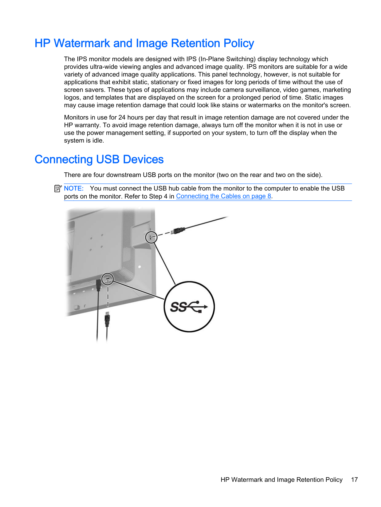
Connecting USB Devices There are four downstream USB ports on the monitor (two on the rear and two on the side). NOTE: You must connect the USB hub cable from the monitor to the computer to enable the USB ports on the monitor. Refer to Step 4 in Connecting the Cables on page 8.
| |
|---|

HP Watermark and Image Retention Policy 17
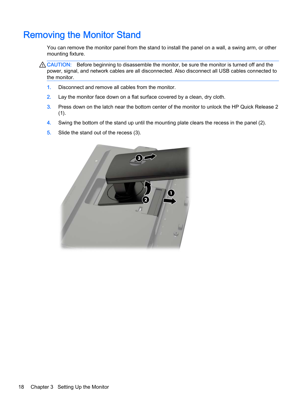
Removing the Monitor Stand
You can remove the monitor panel from the stand to install the panel on a wall, a swing arm, or other mounting fixture.
CAUTION: Before beginning to disassemble the monitor, be sure the monitor is turned off and the power, signal, and network cables are all disconnected. Also disconnect all USB cables connected to the monitor.
(1).


Mounting the Monitor The monitor panel can be attached to a wall, swing arm, or other mounting fixture. You can attach the monitor panel to a mounting fixture using the HP Quick Release 2 mounting bracket or you can attach the monitor panel to a mounting fixture without the HP Quick Release 2 mounting bracket. NOTE: This apparatus is intended to be supported by UL or CSA Listed wall mount bracket.
| | |---|
CAUTION: This monitor supports the VESA industry standard 100 mm mounting holes. To attach a third-party mounting solution to the monitor, four 4 mm, 0.7 pitch, and 10 mm long screws are required. Longer screws must not be used because they may damage the monitor. It is important to verify that the manufacturer’s mounting solution is compliant with the VESA standard and is rated to support the weight of the monitor display panel. For best performance, it is important to use the power and video cables provided with the monitor.
#### Mounting the Monitor Using the Quick Release 2 Mounting Bracket
To mount the monitor panel to a mounting fixture using the Quick Release 2 mounting bracket:

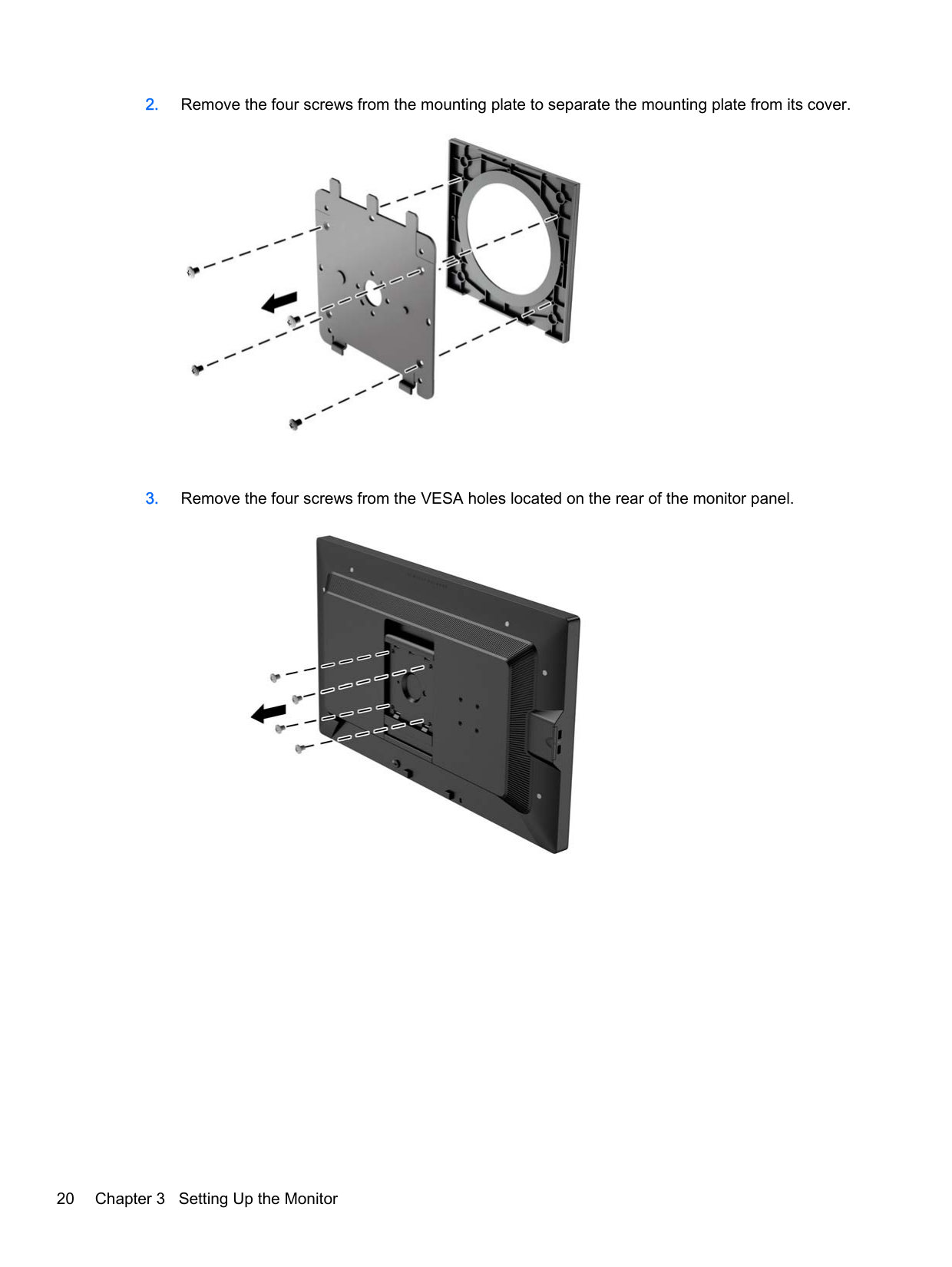
####### 2. Remove the four screws from the mounting plate to separate the mounting plate from its cover.

####### 3. Remove the four screws from the VESA holes located on the rear of the monitor panel.

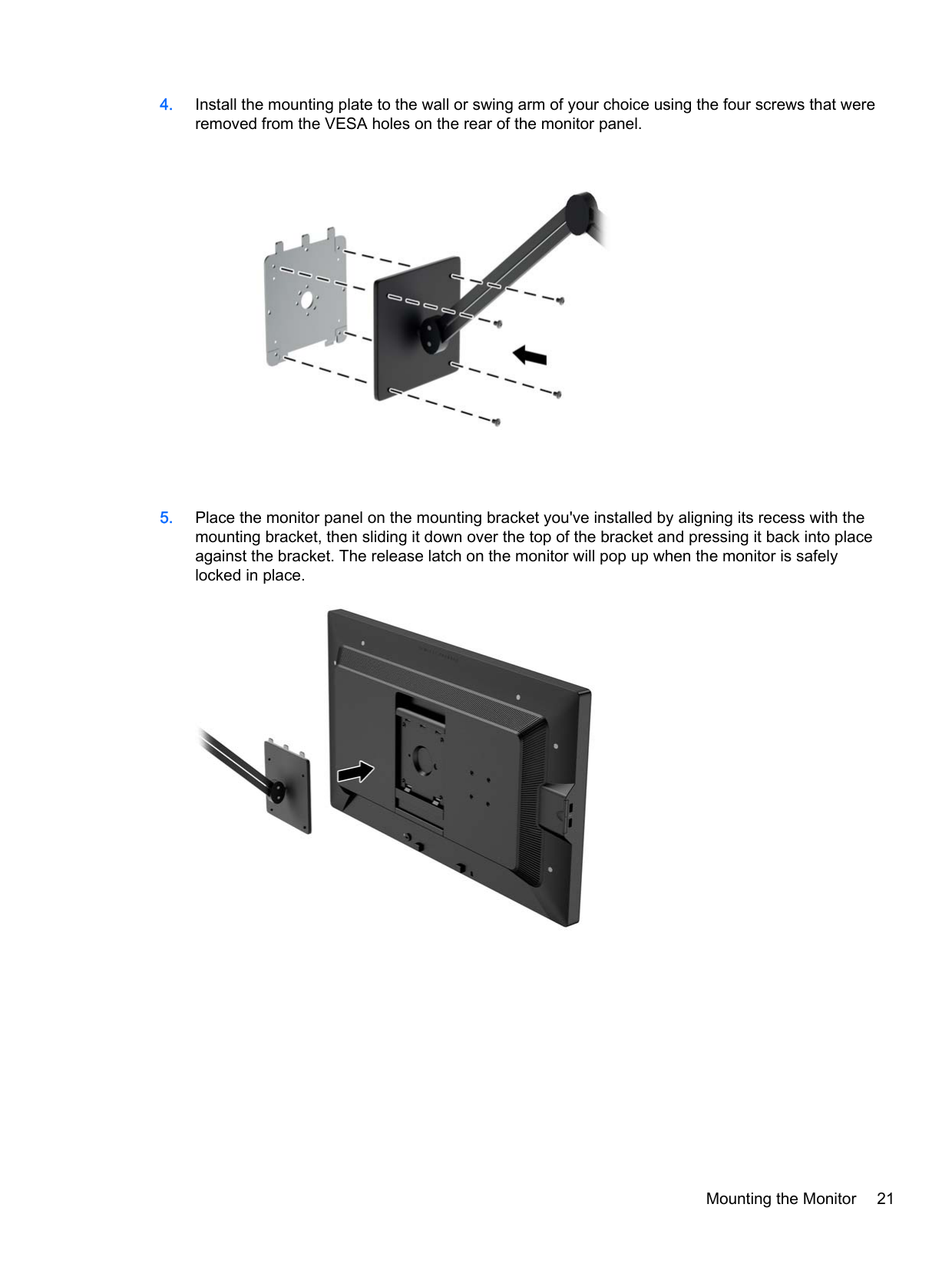
####### 4. Install the mounting plate to the wall or swing arm of your choice using the four screws that wereremoved from the VESA holes on the rear of the monitor panel.

####### 5. Place the monitor panel on the mounting bracket you've installed by aligning its recess with themounting bracket, then sliding it down over the top of the bracket and pressing it back into placeagainst the bracket. The release latch on the monitor will pop up when the monitor is safelylocked in place.

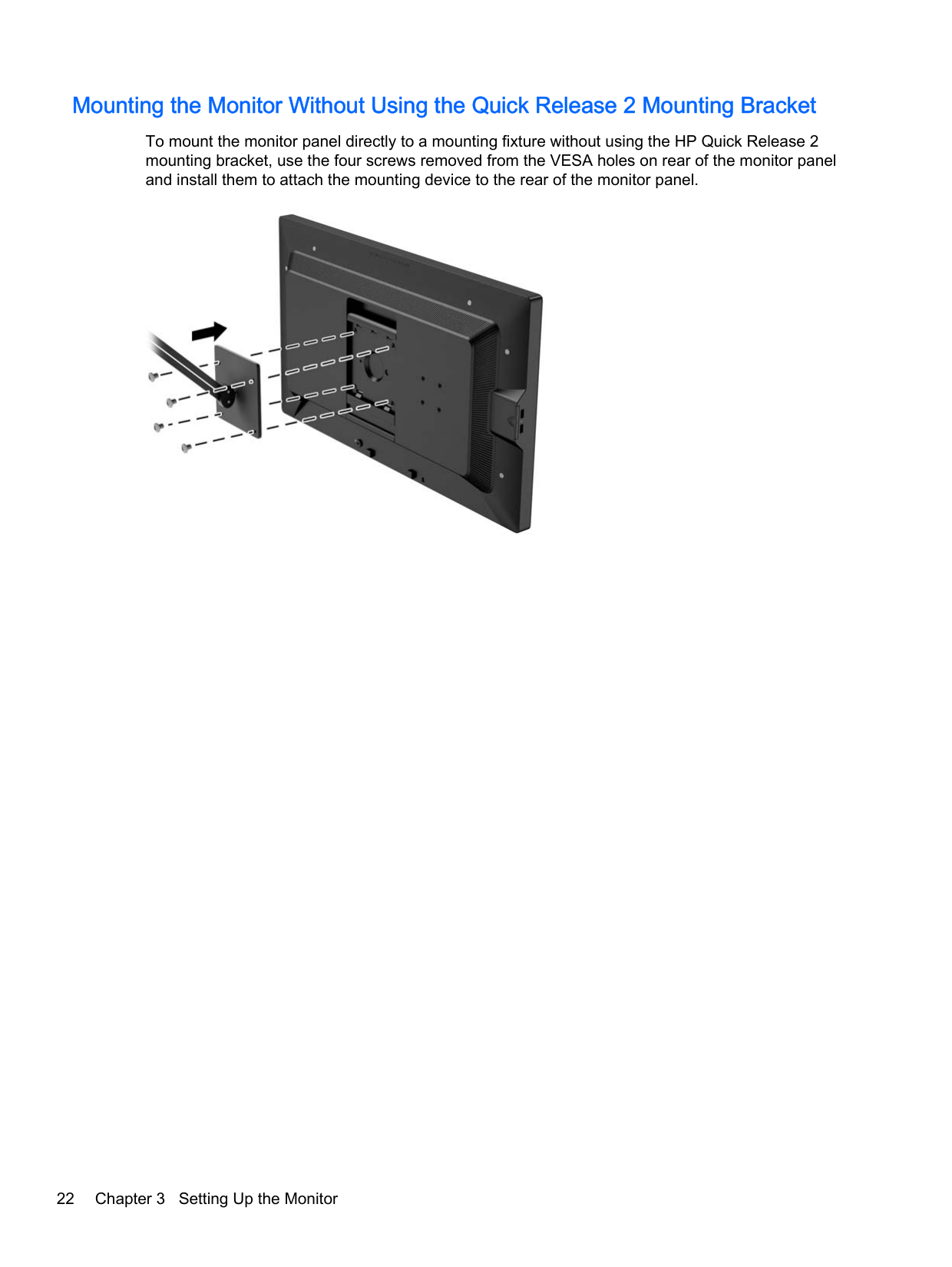
#### Mounting the Monitor Without Using the Quick Release 2 Mounting Bracket
To mount the monitor panel directly to a mounting fixture without using the HP Quick Release 2 mounting bracket, use the four screws removed from the VESA holes on rear of the monitor panel and install them to attach the mounting device to the rear of the monitor panel.

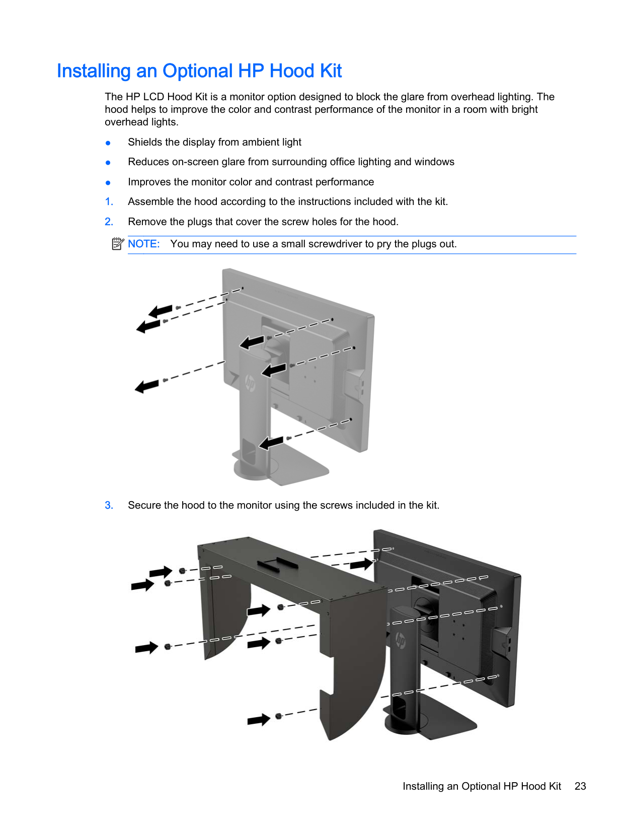
Installing an Optional HP Hood Kit
The HP LCD Hood Kit is a monitor option designed to block the glare from overhead lighting. The hood helps to improve the color and contrast performance of the monitor in a room with bright overhead lights.
| | |---|


Installing an Optional HP Hood Kit 23
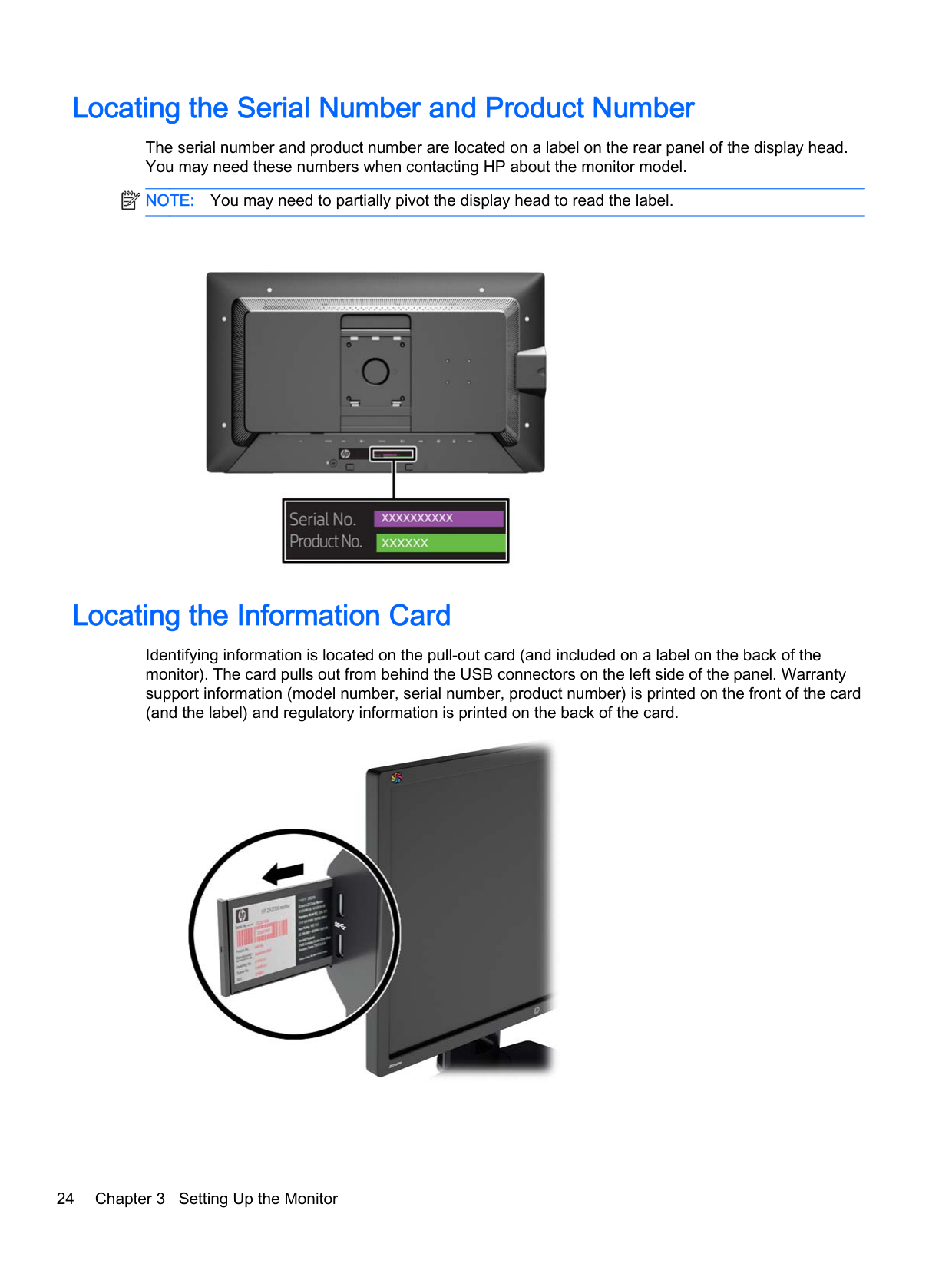
Locating the Serial Number and Product Number
The serial number and product number are located on a label on the rear panel of the display head. You may need these numbers when contacting HP about the monitor model.
| | |---|
NOTE: You may need to partially pivot the display head to read the label.

Locating the Information Card
Identifying information is located on the pull-out card (and included on a label on the back of the monitor). The card pulls out from behind the USB connectors on the left side of the panel. Warranty support information (model number, serial number, product number) is printed on the front of the card (and the label) and regulatory information is printed on the back of the card.

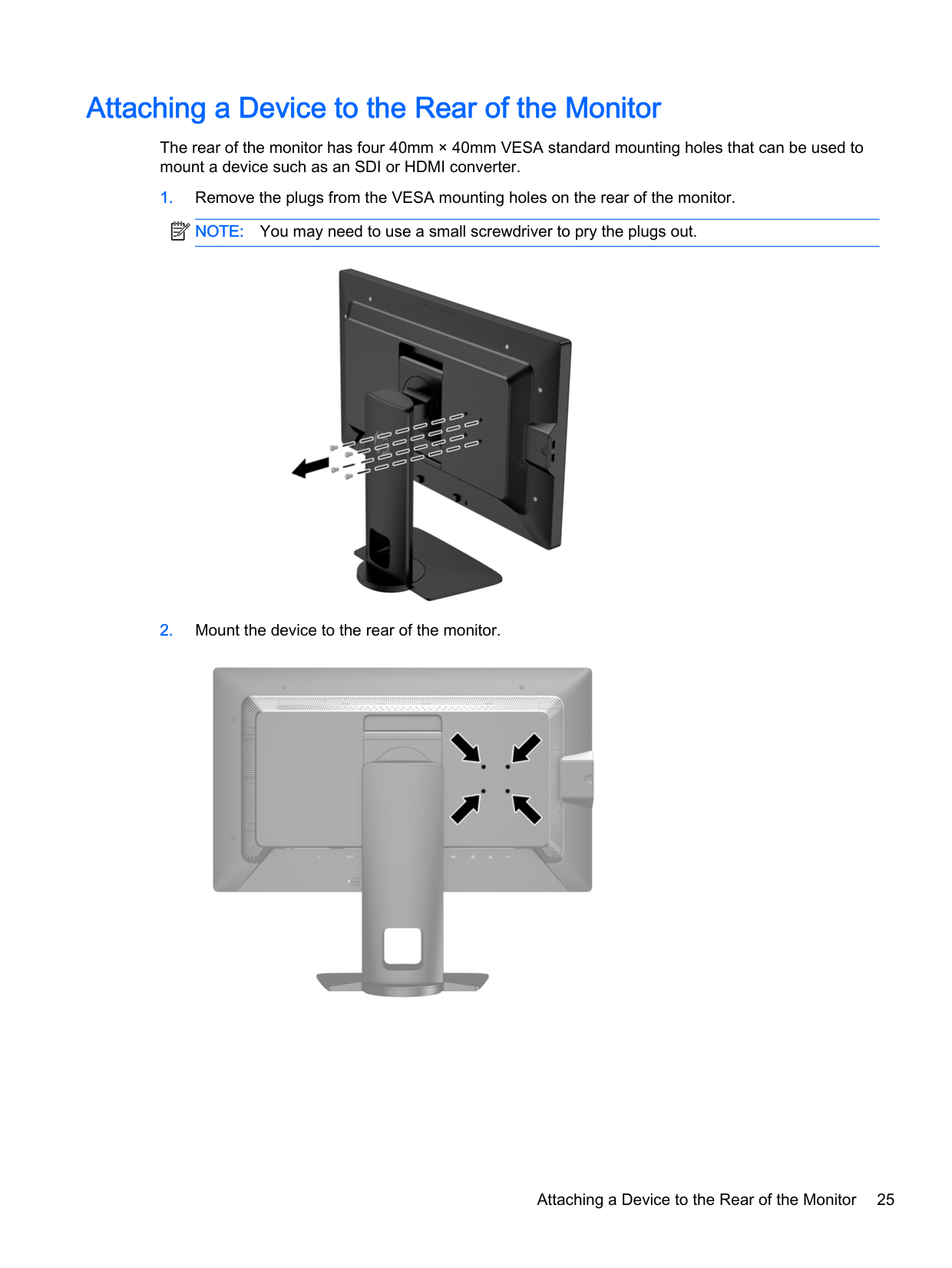
Attaching a Device to the Rear of the Monitor
The rear of the monitor has four 40mm × 40mm VESA standard mounting holes that can be used to mount a device such as an SDI or HDMI converter.
| | |---|


Attaching a Device to the Rear of the Monitor 25
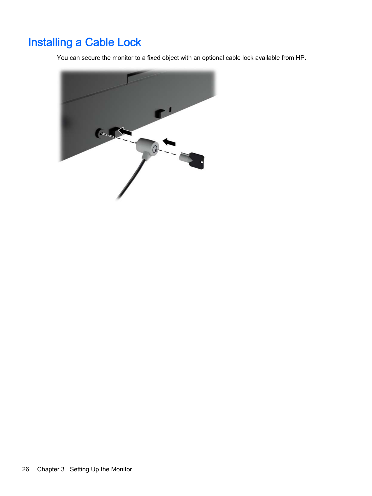
Installing a Cable Lock
You can secure the monitor to a fixed object with an optional cable lock available from HP.

4 Operating the Monitor
Software and Utilities
The disc that comes with the monitor contains files you can install on the computer:
| | |---|
NOTE: If the monitor does not include a disc, the items listed above can be downloaded from the HP monitors support Web site. See Downloading from the Internet on page 28 in this chapter.

#### The Information File
The .INF file defines monitor resources used by Microsoft Windows operating systems to ensure monitor compatibility with the computer’s graphics adapter.
This monitor is Microsoft Windows Plug and Play compatible and the monitor will work correctly without installing the .INF file. Monitor Plug and Play compatibility requires that the computer’s graphic card is VESA DDC2–compliant and that the monitor connects directly to the graphics card. Plug and Play does not work through separate BNC type connectors or through distribution buffers/ boxes.
#### The Image Color Matching File
The .ICM files are data files that are used in conjunction with graphics programs to provide consistent color matching from monitor screen to printer, or from scanner to monitor screen. This file is activated from within graphics programs that support this feature.
| | |---|
NOTE: The ICM color profile is written in accordance with the International Color Consortium (ICC) Profile Format specification.
Software and Utilities 27
Installing the .INF and .ICM Files
After you determine that you need to update, you can install the .INF and .ICM files from the disc or download them.
#### Installing from the Disc
To install the .INF and .ICM files on the computer from the disc:
| | |---|
NOTE: You may need to install the digitally signed monitor .INF and .ICM files manually from the disc in the event of an installation error. Refer to the HP Monitor Software Information file on the disc.
#### Downloading from the Internet
To download the latest version of .INF and .ICM files from the HP monitors support Web site:
Updating the Firmware HP recommends that you check for updated display firmware and install newer firmware if available. NOTE: By default, the monitor’s internal processor – which is required for firmware updating – is disabled. You must enable the processor before you can update the monitor firmware. In the OSD select Management > Manage Internal Processor and choose Enable to turn the processor on. If turning on just before attempting to update the firmware, wait approximately one minute for the internal processor to fully boot. To update the firmware via USB:
| | |---|
TIP: A bezel button shortcut, Display Info..., is provided on the fourth bezel button in the Z27x factory configuration. You can access this information page via this shortcut, unless the bezel button has been remapped. This information page also indicates whether the internal processor is on or off.
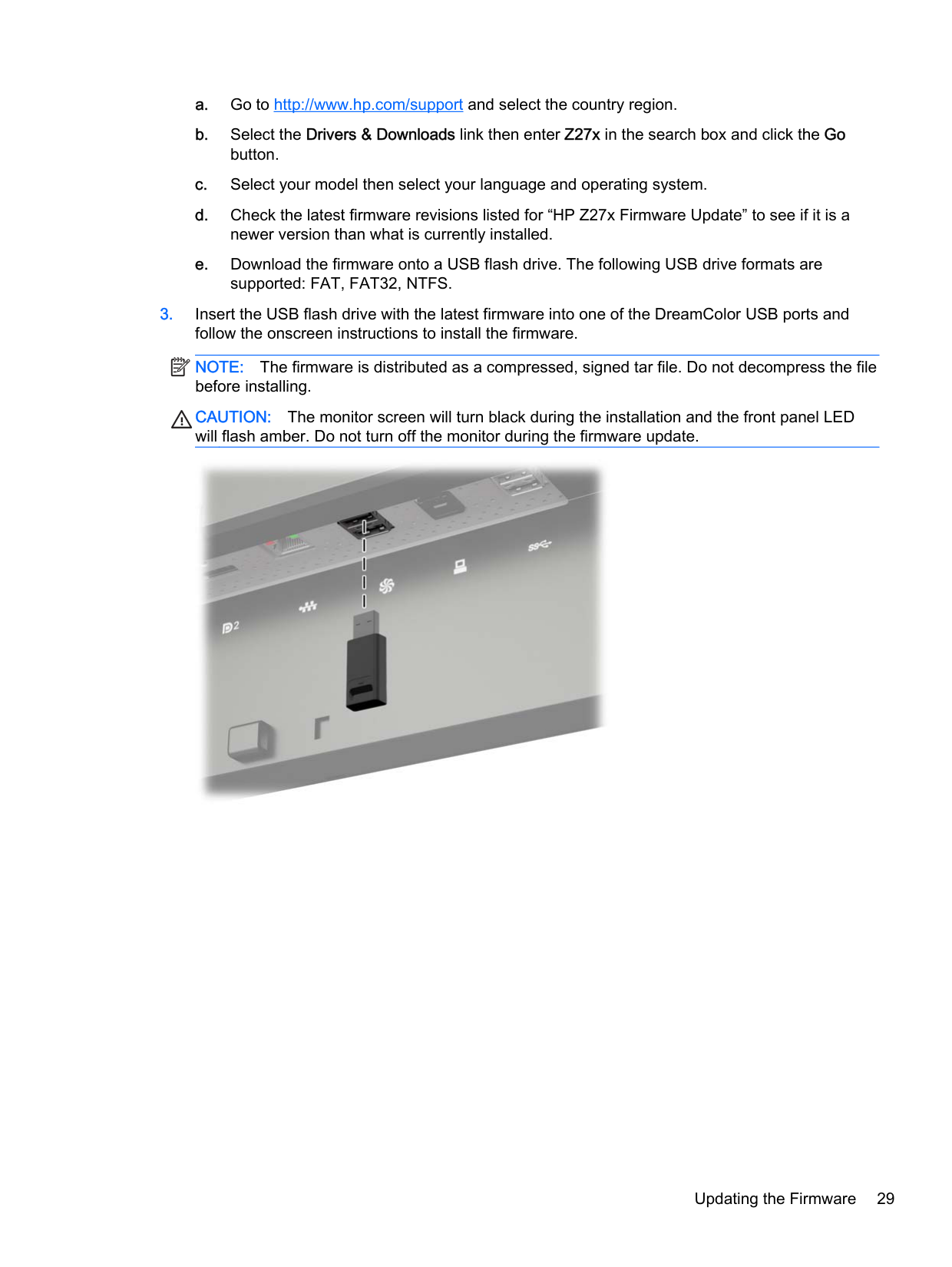
| | |---|
NOTE: The firmware is distributed as a compressed, signed tar file. Do not decompress the file before installing.
CAUTION: The monitor screen will turn black during the installation and the front panel LED will flash amber. Do not turn off the monitor during the firmware update.

Updating the Firmware 29
Selecting a Color Space Preset
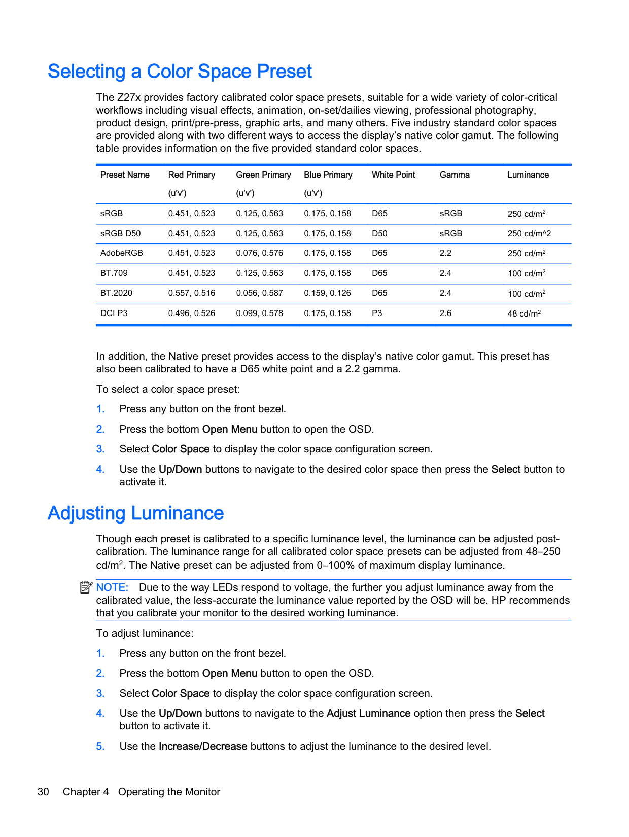
The Z27x provides factory calibrated color space presets, suitable for a wide variety of color-critical workflows including visual effects, animation, on-set/dailies viewing, professional photography, product design, print/pre-press, graphic arts, and many others. Five industry standard color spaces are provided along with two different ways to access the display’s native color gamut. The following table provides information on the five provided standard color spaces.
Preset Name Red Primary (u’v’)
Green Primary (u’v’)
Blue Primary (u’v’)
White Point Gamma Luminance
sRGB 0.451, 0.523 0.125, 0.563 0.175, 0.158 D65 sRGB 250 cd/m2 sRGB D50 0.451, 0.523 0.125, 0.563 0.175, 0.158 D50 sRGB 250 cd/m^2 AdobeRGB 0.451, 0.523 0.076, 0.576 0.175, 0.158 D65 2.2 250 cd/m2 BT.709 0.451, 0.523 0.125, 0.563 0.175, 0.158 D65 2.4 100 cd/m2 BT.2020 0.557, 0.516 0.056, 0.587 0.159, 0.126 D65 2.4 100 cd/m2 DCI P3 0.496, 0.526 0.099, 0.578 0.175, 0.158 P3 2.6 48 cd/m2
In addition, the Native preset provides access to the display’s native color gamut. This preset has also been calibrated to have a D65 white point and a 2.2 gamma.
To select a color space preset:
Adjusting Luminance
Though each preset is calibrated to a specific luminance level, the luminance can be adjusted postcalibration. The luminance range for all calibrated color space presets can be adjusted from 48–250 cd/m2. The Native preset can be adjusted from 0–100% of maximum display luminance.
| | |---|
NOTE: Due to the way LEDs respond to voltage, the further you adjust luminance away from the calibrated value, the less-accurate the luminance value reported by the OSD will be. HP recommends that you calibrate your monitor to the desired working luminance.
To adjust luminance:
| | |---|
NOTE: The Adjust Luminance option displays the current luminance value to the right of the menu option.
Understanding the Z27x Image Adjustment Options
The Z27x contains a number of special image adjustment options that are designed to fit specific workflows in the media and entertainment industry. The following section describes these functions from the perspective of their application in these workflows.
#### Use Video Levels (16–235)
This option is designed to support the accurate display of “video legal” signals that include footroom below black and headroom above white. These types of signals are typically encountered when working with video signals that conform to the complete ITU-R BT.709 standard as this standard allows for excursions beyond black and white, rather than treating black and white as absolutes.
These signals are typically encountered in the following situations:
In all of these situations the video signal usually includes the BT.709 headroom and footroom. Without this option enabled when viewed in a computer monitor the blacks and shadows are lighter, the whites are darker, and colors have less saturation than the signal actually contains.
When this option is enabled the blacks will be clipped at the 8-bit value of 16 and the whites at the 8bit value of 235 (for 10-bit, the clipping will occur at the values of 64 and 960). The signal is then remapped to display the signal in the correct visual range.
It is important to note that the source and pre-processing of the source video will impact whether this setting should be enabled, but in many cases you will see a more-accurate image if you enable this option. Note that you may need to adjust the lightness of your editing application interface after enabling this setting.
To use video levels:
#### Overscan the Frame
Though by default the Z27x displays all pixels in the image, when screening video dailies or an edit revision it may be desirable to view the image in an overscanned mode, similar to how it is viewed on a consumer digital television. The Overscan Frame by 5% option will enlarge the image so that only that portion of the frame within the Action Safe region is displayed. Action Safe is defined as an area that begins 5% inside the edge of the frame.
To use the Overscan Frame mode:
Understanding the Z27x Image Adjustment Options 31
#### Show Only the Blue Channel
As the human is least-sensitive to changes in blue, most compression and encoding algorithms assign the least amount of bandwidth to the blue channel. Because of this, compression/encoding errors are most-easily seen when viewing the blue channel. The Z27x allows the user to view just the blue channel, temporarily turning the red and green channels off, so that the image can be inspected for these errors.
To view only the blue channel:
Using the Z27x Aspect Ratio Management Options
The Z27x includes a number of special aspect ratio management options that go far beyond what is typically found in a computer monitor. This section discusses these options, with a focus of how these options are integrated into specific workflows.
#### The “Fill To” Options
These options are used to determine how the source input is displayed onscreen if its resolution is different from the monitor’s native resolution of 2560×1440.
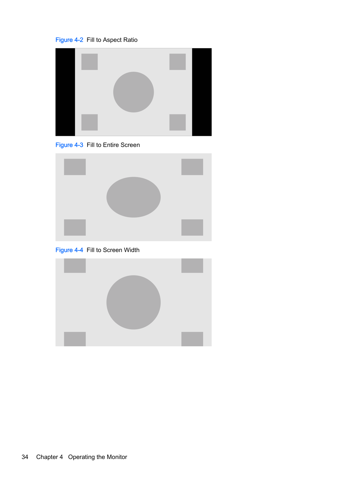
##### Fill to Source Aspect Ratio (Proportional)
This option will maintain the aspect ratio of the source input, making the image as large as possible, centering it in the monitor, and using 0% black to fill the unused areas of the screen. For example, a source input that is narrower than 16×9 will be displayed at full height with black bars to the left and right of the source image, and a source input that is wider than 16×9 will be the displayed at full width with black bars above and below the source image.
Fill to Source Aspect Ratio is the default and is the option most-suitable to the majority of workflows. Fill to Entire Screen (Non-Proportional)
This option will distort non-16×9 source aspect ratios to force them to fit within the monitor’s 16×9 aspect ratio. The resulting image will take up the entire display and will either be stretched horizontally (for narrower aspect ratios) or vertically (for wider aspect ratios).
Use Fill to Entire Screen if the source aspect ratio is irrelevant and you want the entire screen to be filled, regardless of the distortion that may be caused.
##### Fill to Screen Width (Proportional)
This option is to be used for specific workflows with source video that is narrower than the monitor’s native 16×9 aspect ratio. In some film workflows it is desired to render the animation or visual effects at a 4×3 aspect ratio and perform a “center extraction” for widescreen delivery. If enabled, this option will resize the source image so that the width matches the monitor width. Then the source image is centered vertically and the top and bottom of the image are cropped off, leaving a 16×9 “center extraction” of the 4×3 frame. The proportions of the source image are maintained.
The Fill to Screen Width option should be used when vertical center extractions are desired as part of the dailies or review screening process.
##### Fill to Screen Height (Proportional)
This option is to be used for specific workflows with source video that is wider than the monitor’s native 16×9 aspect ratio. In some film workflows it is desired to see a 16×9 horizontal extraction of a wider source aspect ratio. If enabled, this option will resize the source image so that the height matches the monitor height. Then the source image is centered horizontally and the top and bottom of the image are cropped off, leaving a 16×9 “center extraction” of the wider frame. The proportions of the source image are maintained.
The Fill to Screen Height option should be used when horizontal center extractions are desired as part of the dailies or review screening process.
##### Pixel-for-Pixel
This option is to be used for source video that has a lower resolution than the monitor’s native resolution of 2560×1440 and you wish to view the image without any scaling applied. For example, if your source image has a 1920×1080 resolution and you wish to inspect the pixels to ensure that there are no rendering issues in the displayed content, you may want to use this option.
This option has a specific functionality when the source video has a higher resolution than 2560×1440. This functionality will be covered in the next section.
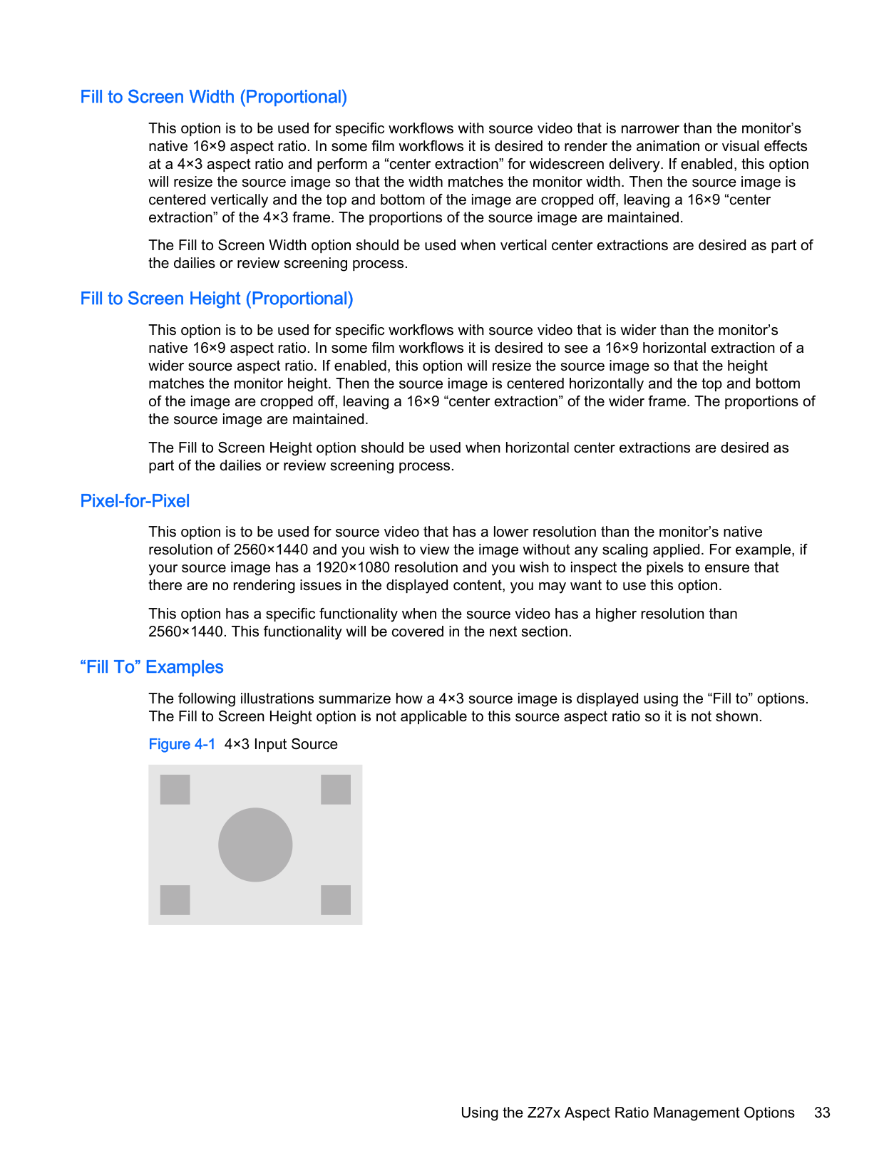
##### “Fill To” Examples
The following illustrations summarize how a 4×3 source image is displayed using the “Fill to” options. The Fill to Screen Height option is not applicable to this source aspect ratio so it is not shown.
Using the Z27x Aspect Ratio Management Options 33
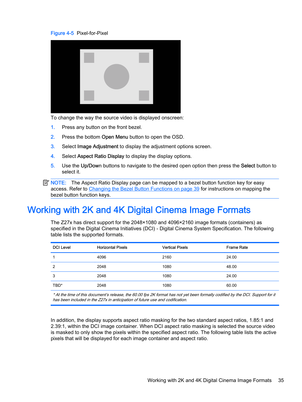
To change the way the source video is displayed onscreen:
| | |---|
NOTE: The Aspect Ratio Display page can be mapped to a bezel button function key for easy access. Refer to Changing the Bezel Button Functions on page 39 for instructions on mapping the bezel button function keys.
Working with 2K and 4K Digital Cinema Image Formats
The Z27x has direct support for the 2048×1080 and 4096×2160 image formats (containers) as specified in the Digital Cinema Initiatives (DCI) - Digital Cinema System Specification. The following table lists the supported formats.
DCI Level Horizontal Pixels Vertical Pixels Frame Rate
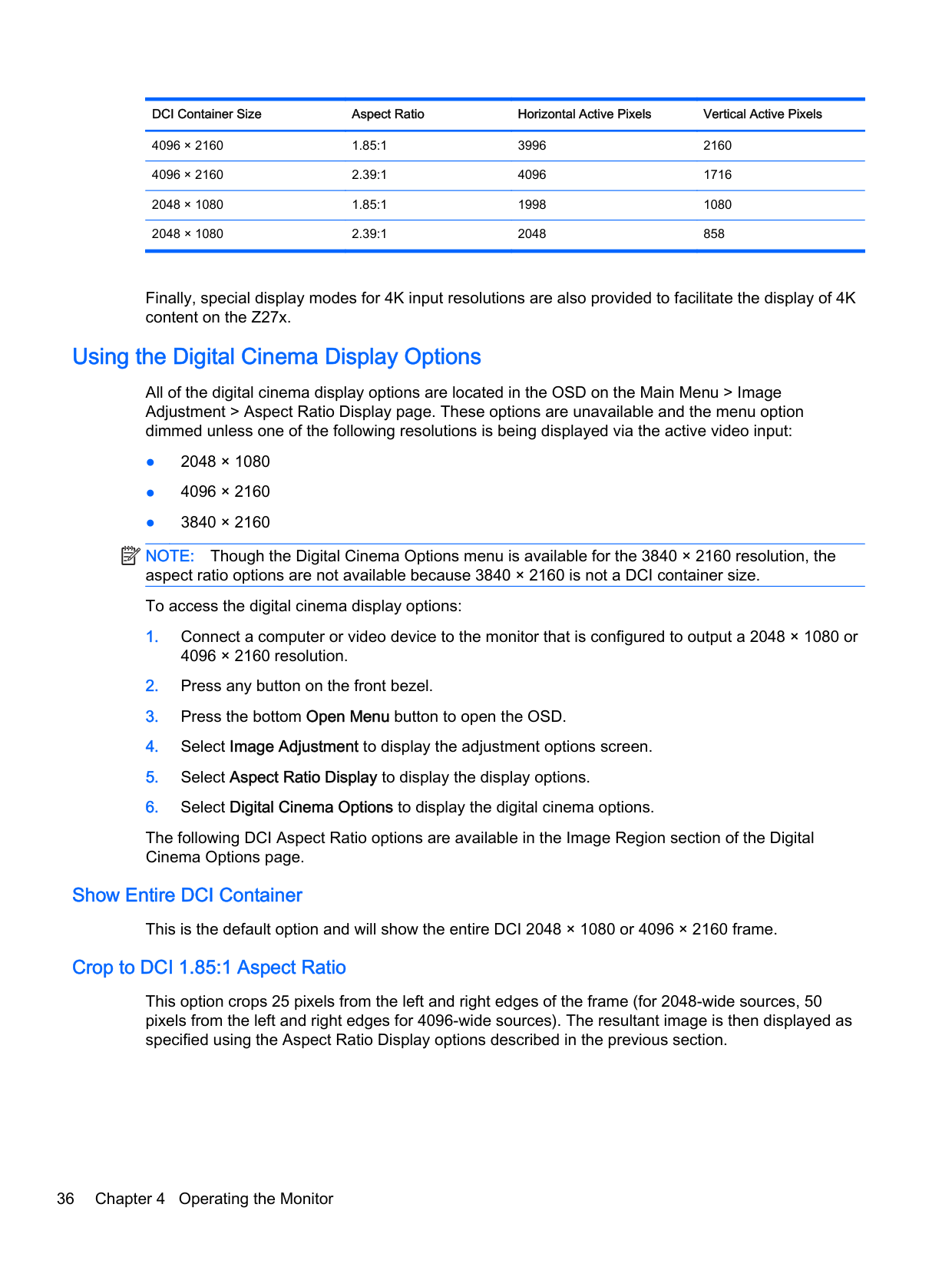
In addition, the display supports aspect ratio masking for the two standard aspect ratios, 1.85:1 and 2.39:1, within the DCI image container. When DCI aspect ratio masking is selected the source video is masked to only show the pixels within the specified aspect ratio. The following table lists the active pixels that will be displayed for each image container and aspect ratio.
######### DCI Container Size Aspect Ratio Horizontal Active Pixels Vertical Active Pixels
Finally, special display modes for 4K input resolutions are also provided to facilitate the display of 4K content on the Z27x.
#### Using the Digital Cinema Display Options
All of the digital cinema display options are located in the OSD on the Main Menu > Image Adjustment > Aspect Ratio Display page. These options are unavailable and the menu option dimmed unless one of the following resolutions is being displayed via the active video input:
| | |---|
NOTE: Though the Digital Cinema Options menu is available for the 3840 × 2160 resolution, the aspect ratio options are not available because 3840 × 2160 is not a DCI container size. To access the digital cinema display options:
The following DCI Aspect Ratio options are available in the Image Region section of the Digital Cinema Options page.
##### Show Entire DCI Container
This is the default option and will show the entire DCI 2048 × 1080 or 4096 × 2160 frame.
##### Crop to DCI 1.85:1 Aspect Ratio
This option crops 25 pixels from the left and right edges of the frame (for 2048-wide sources, 50 pixels from the left and right edges for 4096-wide sources). The resultant image is then displayed as specified using the Aspect Ratio Display options described in the previous section.
##### Crop to DCI 2.39:1 Aspect Ratio
This option crops 111 pixels from the top and bottom edges of the frame (for 2048-wide sources, 222 pixels from the top and bottom edges for 4096-wide sources). The resultant image is then displayed as specified using the Aspect Ratio Display options described in the previous section.
##### Show Cropped Region
When this option is enabled, rather than cropping and resizing the image to the selected aspect ratio, the image is not resized, but the region outside the desired aspect ratio is instead overlaid with a partially-transparent black mask. This option is useful, for example to check the top line in a 2.39:1 aspect ratio and see what information may be available, if the headroom needs to be adjusted via reframing.
##### Set Cropped Region Opacity
This option is available when Show Cropped Region is active and allows you to specify the amount of opacity applied to the cropped region. Adjust as needed to achieve the desired balance between the active and cropped regions of the frame.
##### Displaying 4K Source Video
Though it only has a native resolution of 2560 × 1440, the Z27x can receive and display a 4096 × 2160 or 3840 × 2160 input signal. Multiple scaling and display options are provided. To provide the highest quality display of 4K source video on the Z27x the scaling algorithm has been specifically tuned to provide a naturalistic scaling without any sharpness or edge enhancement.
When a 4096 × 2160 or 3840 × 2160 signal is input into the monitor, the following scaling options are available via the 4K Sources section of the Digital Cinema Options page. If DCI aspect ratio cropping has been selecting, these options are applied after the image is cropped.
##### Obey Aspect Ratio Display Option
This default option will display the image according to the selected “Fill to” Aspect Ratio Display option. Refer to Using the Z27x Aspect Ratio Management Options on page 32 for information on these options.
##### Scale and Show Center Extraction
If selected, the center 16×9 region of the frame will be displayed with the areas outside of this center region cropped, similar to the Fill to Screen Height option discussed previously. The amount of the image shown in the center extraction is dependent on whether the entire container or an aspect ratio is displayed.
##### Scale and Show Left Side of Frame
If selected, the left-most 16×9 region of the frame will be displayed with the areas outside of this left side region cropped, similar to the Fill to Screen Height option discussed previously. The amount of the image shown in the left extraction is dependent on whether the entire container or an aspect ratio is displayed.
##### Scale and Show Right Side of Frame
If selected, the right-most 16×9 region of the frame will be displayed with the areas outside of this right side region cropped, similar to the Fill to Screen Height option discussed previously. The amount of the image shown in the right extraction is dependent on whether the entire container or an aspect ratio is displayed.
##### Show 4K Source Video Pixel-for-Pixel
If the Aspect Ratio Display is set to Pixel-for-Pixel and the 4K Source option is set to Obey Aspect Ration Display Option, 4096 × 2160 and 3840 × 2160 source video can be displayed pixel-for-pixel. Two different display options are available, Show 4K Corner and Scroll 4K Region. Accessing these two options require that a specific function be mapped to one of the four bezel function buttons. Refer to Changing the Bezel Button Functions on page 39 for information on mapping the bezel function buttons. The following sections describe the usage of these two options.
###### Next 4K Corner
When viewing a 4K source as pixel-for-pixel, press the Next 4K Corner button to move, in order, between the following five positions:
The image will continue to switch between the five positions for each button press until Pixel-for-Pixel display is disabled.
###### Scroll 4K Region
When viewing a 4K source as pixel-for-pixel, press the Scroll 4K Region button to display navigation arrows, allowing you to move around the frame to the desired area. When this option is enabled, a pop-up window will appear in lower right region of the monitor that shows the entire 4K image and indicates the area of interest being show full-screen. Use the directional bezel buttons to shift the area of interest. When this option is turned off the pop-up will vanish, but the area of interest will continue to be displayed.
Using Picture-in-Picture (PIP) and Picture-beside-Picture (PBP)
The monitor supports both PIP, where one source is overlaid over another, and PBP, where one source is positioned adjacent to one another either horizontally (for landscape orientation) or vertically (for portrait orientation).
To use PIP or PBP:
Using PIP as a Confidence Monitor As the PIP is primarily designed to be used at as a confidence monitor – at 100% size for 1080- or 720-line content, including DCI 2K content – many of the Image Adjustments available for the main input are also available for use within the PIP. Refer to Understanding the Z27x Image Adjustment Options on page 31 and Working with 2K and 4K Digital Cinema Image Formats on page 35 for further information on these adjustments. The following adjustments are available within the PIP. None are enabled by default.
##### Use Video Levels (16–235)
If monitoring a video signal output from a video capture card such as an AJA Kona or Blackmagic Design Decklink, this option should usually be enabled as video levels are typically used in video post-production workflows.
##### Overscan Within PIP
Use this option if you wish to see how your video output will be displayed on a consumer television. This is especially useful when ensuring that the margins for lower third graphics are correct and nothing will be cut off on a consumer television.
##### Digital Cinema Options
If you display a 2048 × 1080 signal as a PIP, you can instruct the monitor to display either the full DCI container or crop the PIP to either the 1.85:1 or 2.39:1 aspect ratio. If cropping to an aspect ratio, the shape of the PIP will change to the chosen aspect ratio. Black bars will not be visible at the edges of the PIP.
Changing the Bezel Button Functions
You can change the top-level front bezel button functions from their default values so that when the buttons are activated you can quickly access commonly used commands.
The following commands can be mapped:
Changing the Bezel Button Functions 39
Changing the Bezel Function Button Mode
By default when any bezel button is pressed a menu appears to the left of the buttons, indicating the command assigned to each button. When the menu is displayed, you can press the desired button to execute an assigned command. Once you are familiar with the menu configuration you can disable
the function button label display and simply press the desired bezel button to execute the desired command. This will only disable the function button label display for the function button commands. Once you have opened the OSD the function labels will display.
To change the bezel function button mode:
Adjusting the Bezel Button LEDs
The bezel button LEDs have an automatic fade-out feature that is active by default. The LEDs will fade after the OSD timeout period. You can change the LED behavior so that they do not fade out and you can also adjust the brightness of the LEDs if the fade-out feature is disabled.
To disable the bezel button fade-out feature:
If the bezel button fade-out feature has been disabled (as described above), you can adjust the brightness of the buttons on the front bezel to different levels of ambient lighting.
To change the bezel button brightness:
You can also change the color of the button LEDs on the front bezel. You can make the button LEDs white or red, or set them to automatically change from white to red when ambient lighting is reduced. Red should be used when operating the monitor in low-light environments. The white LED color can negatively impact your eye's color sensitivity while red will not.
To change the bezel button color:
Using Auto-Sleep Mode
The display supports an OSD (On-Screen Display) option called Auto-Sleep Mode, that allows you to enable or disable a reduced power state for the display. When Auto-Sleep Mode is enabled (enabled
Adjusting the Bezel Button LEDs 41
by default), the monitor will enter a reduced power state when the host PC signals low power mode (absence of either horizontal or vertical sync signal).
Upon entering this reduced power state sleep mode, the monitor screen is blanked, the backlight is turned off and the power LED indicator turns amber. The monitor draws less than 0.5W of power when in this reduced power mode. The monitor will wake from the sleep mode when the host PC sends an active signal to the monitor (for example, if you activate the mouse or keyboard).
You can disable the Auto-Sleep Mode in the OSD. Press one of the five front bezel buttons to activate the buttons, and then press the bottom Open Menu button to open the OSD. In the OSD press Management > Auto-Sleep > Disable.
Using the On-Screen Display Menu
Use the On-Screen Display (OSD) to adjust the screen image based on your viewing preferences. To access the OSD, do the following:
| | |---|
NOTE: OSD menu items that are grayed out are not supported with the selected video input and settings. The tables in the following sections list the On-Screen Display (OSD) menu selections and their functional descriptions.
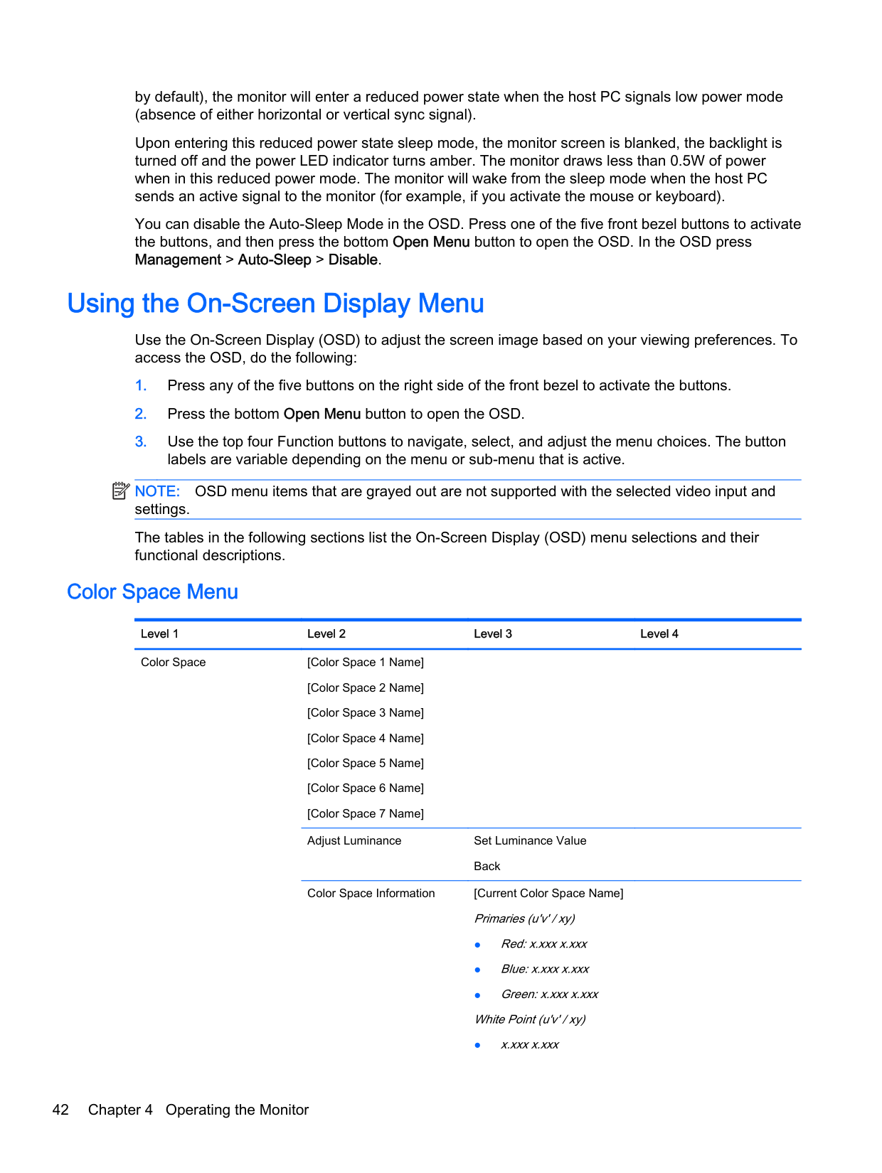
#### Color Space Menu
######### Level 1 Level 2 Level 3 Level 4 Color Space [Color Space 1 Name]
Back Color Space Information [Current Color Space Name]
Primaries (u'v' / xy)
Reset to Last Calibration Reset to Factory Calibration Back
Gamma (x.x or sRGB)
Switch coordinate display to xy/u'v' (allows you to switch the information to display as either CIE 1931 xy or CIE 1976 u'v')
Back
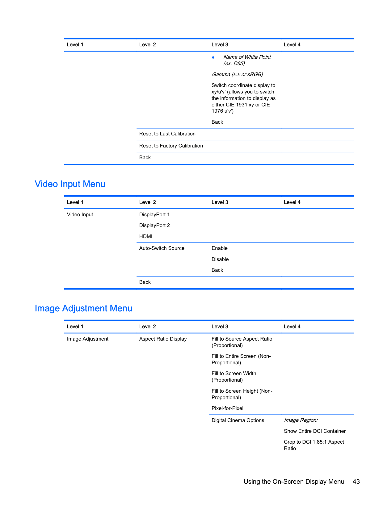
#### Video Input Menu
######### Level 1 Level 2 Level 3 Level 4 Video Input DisplayPort 1
DisplayPort 2 HDMI Auto-Switch Source Enable
Disable Back
Back
#### Image Adjustment Menu
######### Level 1 Level 2 Level 3 Level 4 Image Adjustment Aspect Ratio Display Fill to Source Aspect Ratio
(Proportional) Fill to Entire Screen (NonProportional) Fill to Screen Width (Proportional) Fill to Screen Height (NonProportional) Pixel-for-Pixel Digital Cinema Options Image Region:
Show Entire DCI Container
Obey Aspect Ratio Display Option
Scale and Show Center Extraction
Scale and Show Left Side of Frame
Scale and Show Right Side of Frame
Back Back
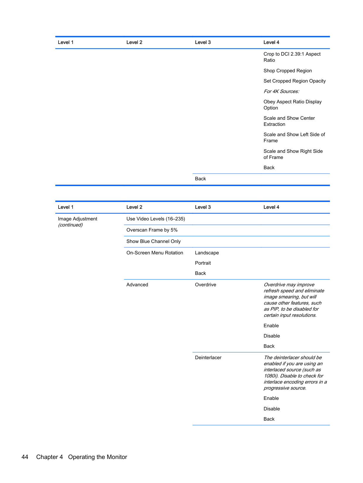
######## Level 1 Level 2 Level 3 Level 4 Image Adjustment (continued)
Use Video Levels (16–235) Overscan Frame by 5% Show Blue Channel Only On-Screen Menu Rotation Landscape
Portrait Back
Advanced Overdrive Overdrive may improve refresh speed and eliminate image smearing, but will cause other features, such as PIP, to be disabled for certain input resolutions.
Enable Disable Back
Deinterlacer The deinterlacer should be enabled if you are using an interlaced source (such as 1080i). Disable to check for interlace encoding errors in a progressive source.
Enable Disable Back
Back Display Mode Information
Cadence Detection The cadence detector will decode film cadences in video rate sources (ex: 2:3 pulldown). Disable to check for cadence errors in the source.
Enable Disable Back
Back
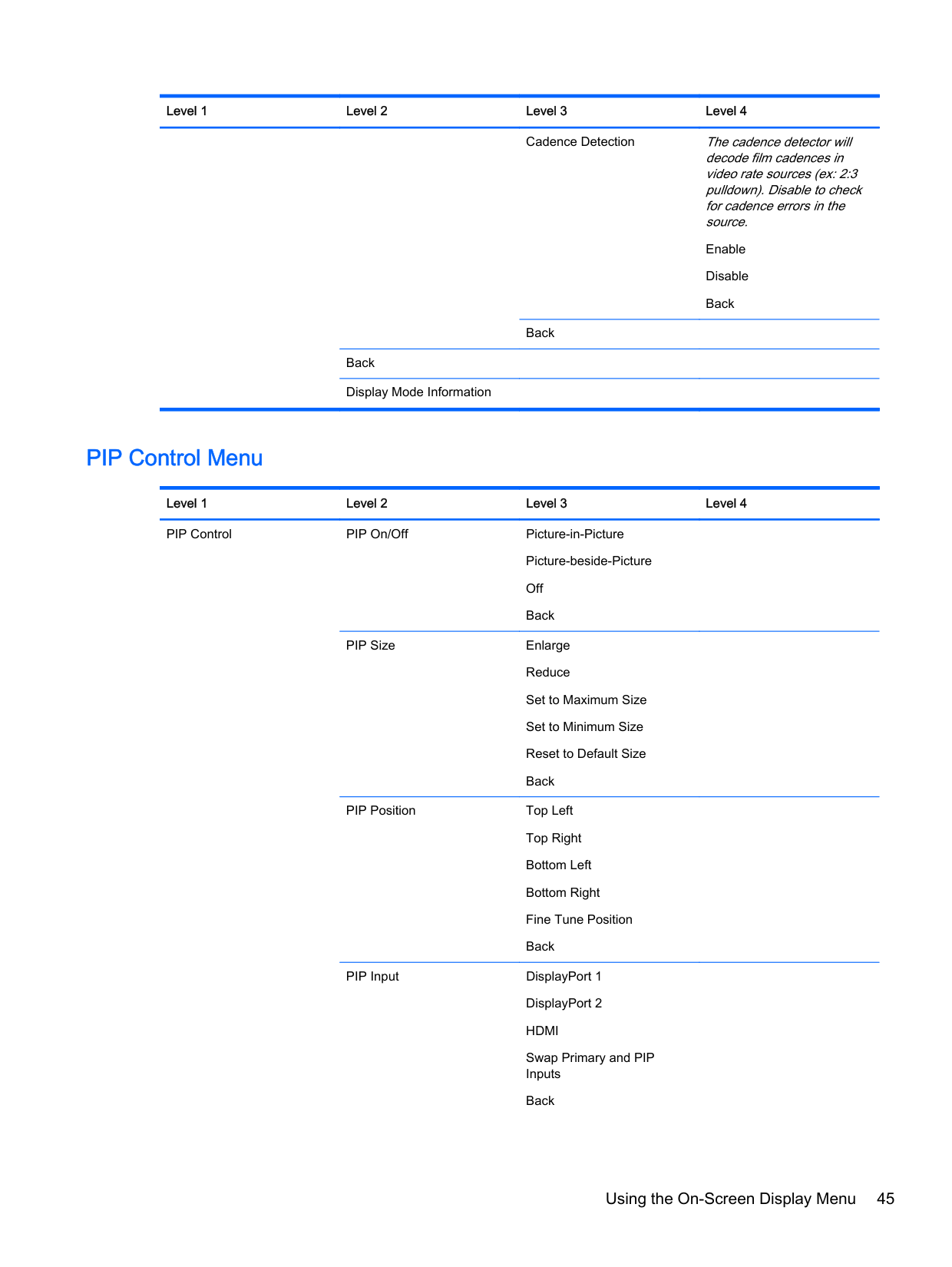
#### PIP Control Menu
######### Level 1 Level 2 Level 3 Level 4 PIP Control PIP On/Off Picture-in-Picture
Picture-beside-Picture Off Back
PIP Size Enlarge Reduce Set to Maximum Size Set to Minimum Size Reset to Default Size Back
PIP Position Top Left Top Right Bottom Left Bottom Right Fine Tune Position Back
PIP Input DisplayPort 1 DisplayPort 2 HDMI Swap Primary and PIP Inputs
Primary / PIP Source Information
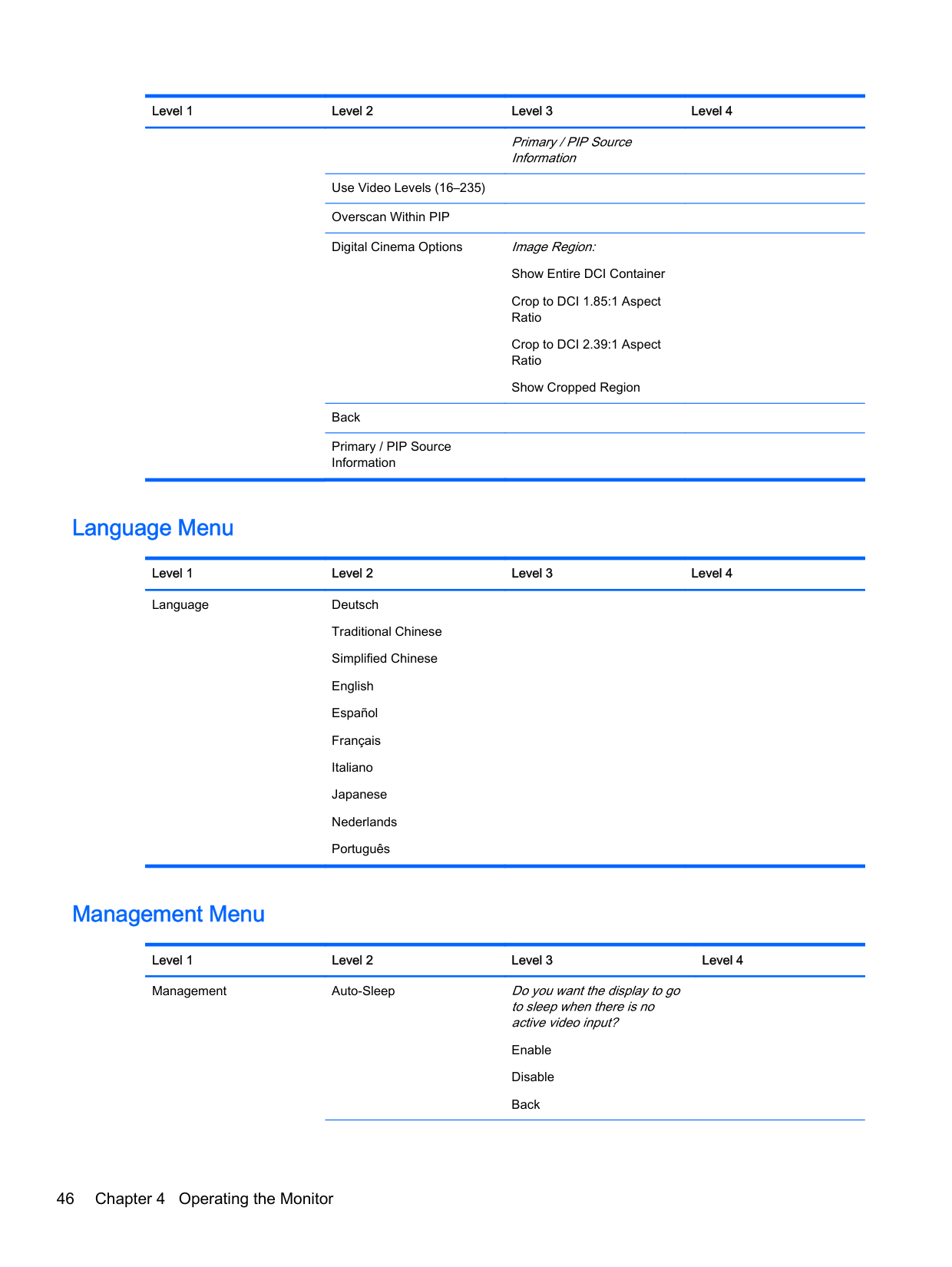
Use Video Levels (16–235) Overscan Within PIP Digital Cinema Options Image Region:
Show Entire DCI Container
Back Primary / PIP Source Information
#### Language Menu
######### Level 1 Level 2 Level 3 Level 4 Language Deutsch
Traditional Chinese Simplified Chinese English Español Français Italiano Japanese Nederlands Português
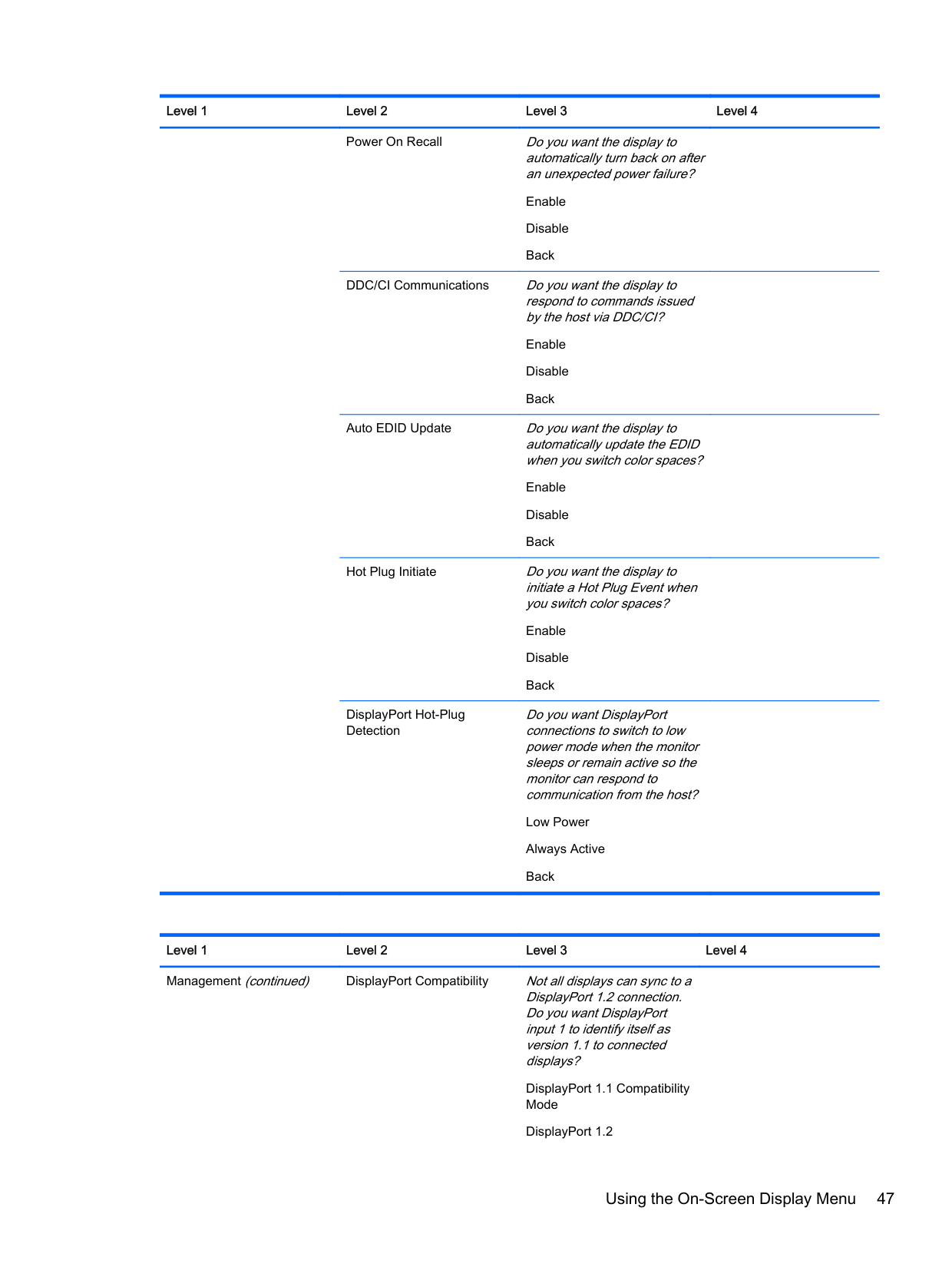
#### Management Menu
Level 1 Level 2 Level 3 Level 4 Management Auto-Sleep Do you want the display to go
to sleep when there is no active video input?
Enable Disable
Power On Recall Do you want the display to automatically turn back on after an unexpected power failure?
Enable Disable Back
DDC/CI Communications Do you want the display to respond to commands issued by the host via DDC/CI?
Enable Disable Back
Auto EDID Update Do you want the display to automatically update the EDID when you switch color spaces?
Enable Disable Back
Hot Plug Initiate Do you want the display to initiate a Hot Plug Event when you switch color spaces?
Enable Disable Back
DisplayPort Hot-Plug Detection
Do you want DisplayPort connections to switch to low power mode when the monitor sleeps or remain active so the monitor can respond to communication from the host?
Low Power Always Active Back
Level 1 Level 2 Level 3 Level 4 Management (continued) DisplayPort Compatibility Not all displays can sync to a
DisplayPort 1.2 connection. Do you want DisplayPort input 1 to identify itself as version 1.1 to connected displays?
Back
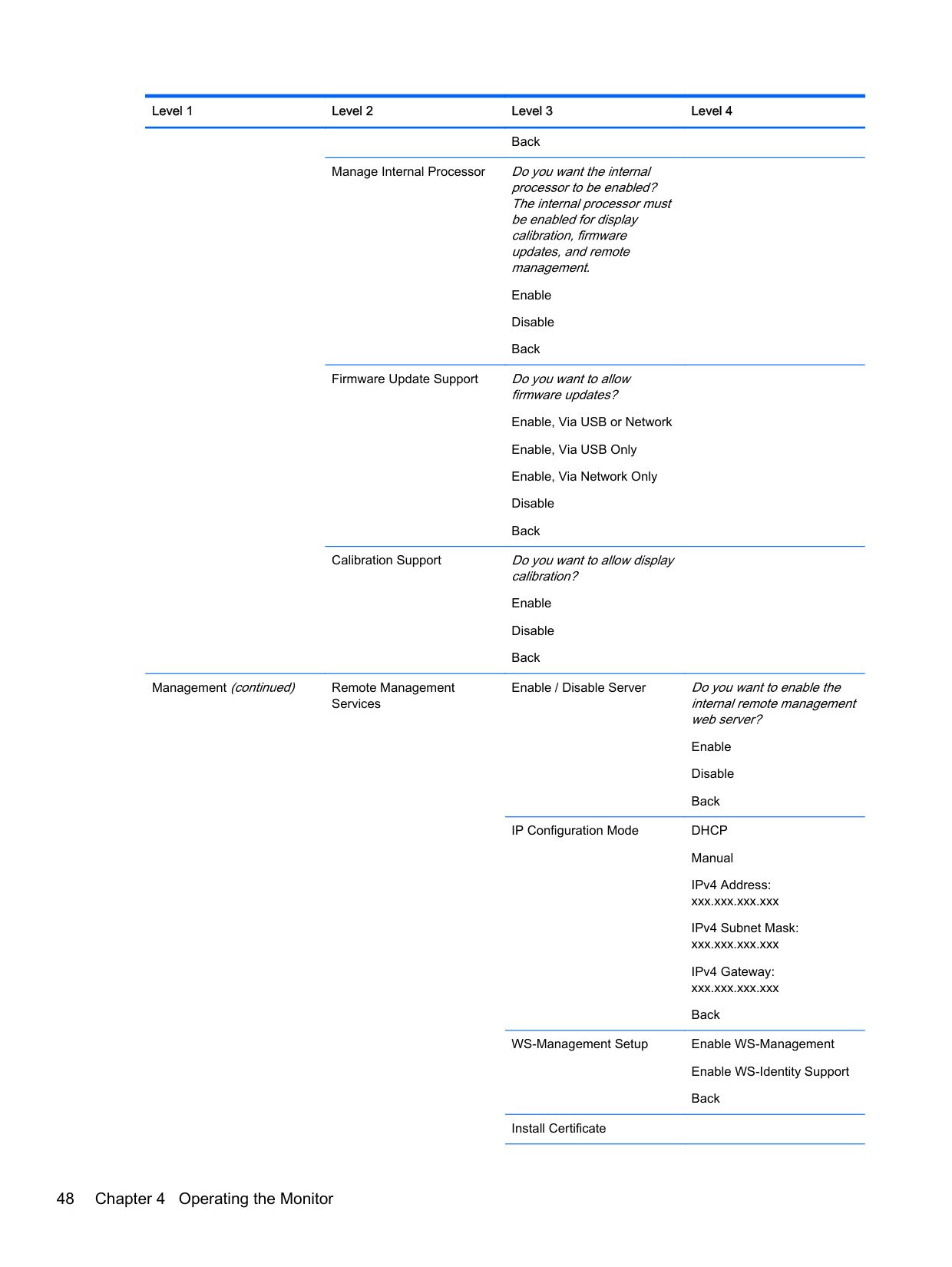
Manage Internal Processor Do you want the internal processor to be enabled? The internal processor must be enabled for display calibration, firmware updates, and remote management.
Enable Disable Back
Firmware Update Support Do you want to allow firmware updates? Enable, Via USB or Network Enable, Via USB Only Enable, Via Network Only Disable Back
Calibration Support Do you want to allow display calibration? Enable Disable Back
Management (continued) Remote Management
Services
Enable / Disable Server Do you want to enable the internal remote management web server?
Enable Disable Back
IP Configuration Mode DHCP Manual IPv4 Address: xxx.xxx.xxx.xxx IPv4 Subnet Mask: xxx.xxx.xxx.xxx IPv4 Gateway: xxx.xxx.xxx.xxx Back
WS-Management Setup Enable WS-Management Enable WS-Identity Support Back
Install Certificate
Reset Administrator Password
Back
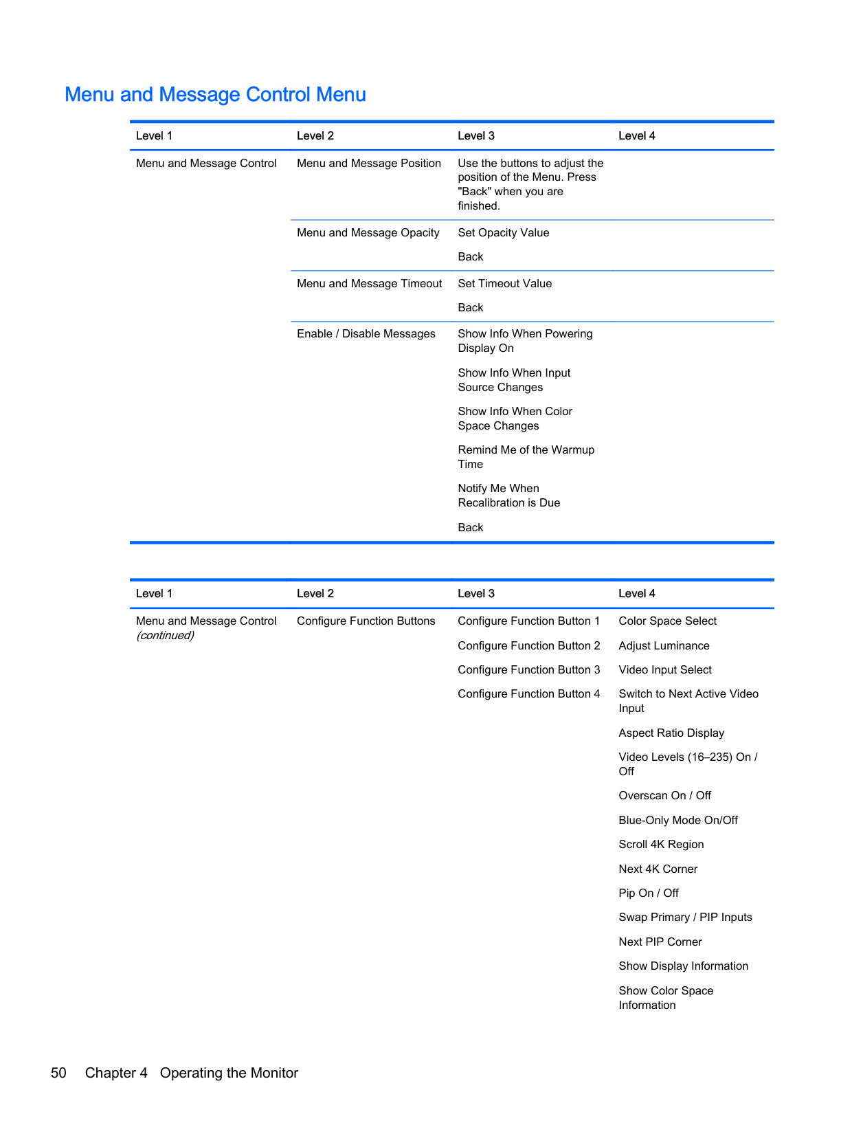
#### Menu and Message Control Menu
######### Level 1 Level 2 Level 3 Level 4 Menu and Message Control Menu and Message Position Use the buttons to adjust the
position of the Menu. Press "Back" when you are finished.
Menu and Message Opacity Set Opacity Value Back Menu and Message Timeout Set Timeout Value Back
Enable / Disable Messages Show Info When Powering Display On Show Info When Input Source Changes Show Info When Color Space Changes Remind Me of the Warmup Time Notify Me When Recalibration is Due Back
######## Level 1 Level 2 Level 3 Level 4 Menu and Message Control (continued)
Color Space Select Adjust Luminance Video Input Select Switch to Next Active Video Input Aspect Ratio Display Video Levels (16–235) On / Off Overscan On / Off Blue-Only Mode On/Off Scroll 4K Region Next 4K Corner Pip On / Off Swap Primary / PIP Inputs Next PIP Corner Show Display Information Show Color Space Information
Configure Function Buttons Configure Function Button 1
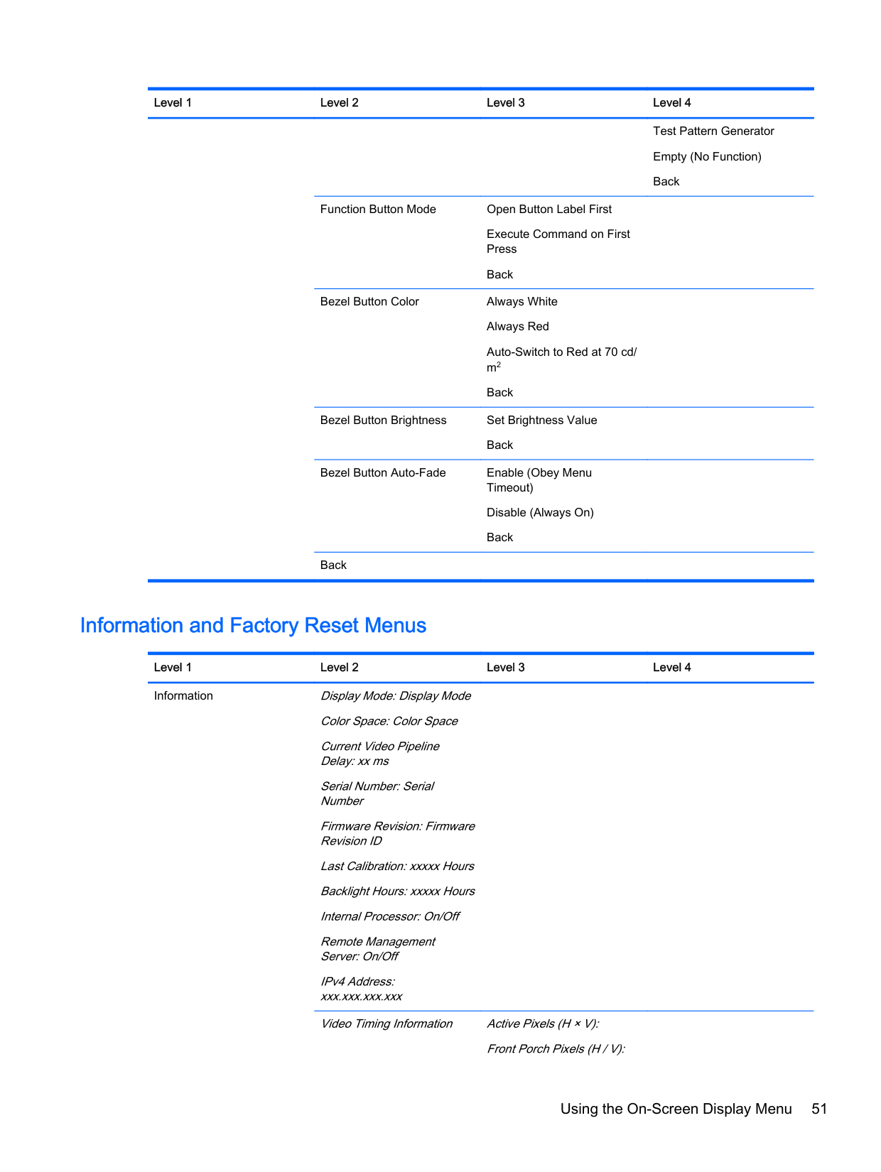
Function Button Mode Open Button Label First
Execute Command on First Press
Back
Bezel Button Color Always White Always Red Auto-Switch to Red at 70 cd/ m2 Back
Bezel Button Brightness Set Brightness Value Back
Bezel Button Auto-Fade Enable (Obey Menu Timeout) Disable (Always On) Back
Back
Test Pattern Generator Empty (No Function) Back
#### Information and Factory Reset Menus
Level 1 Level 2 Level 3 Level 4 Information Display Mode: Display Mode
Color Space: Color Space Current Video Pipeline Delay: xx ms Serial Number: Serial Number Firmware Revision: Firmware Revision ID Last Calibration: xxxxx Hours Backlight Hours: xxxxx Hours Internal Processor: On/Off Remote Management Server: On/Off IPv4 Address: xxx.xxx.xxx.xxx Video Timing Information Active Pixels (H × V):
Front Porch Pixels (H / V):
Back Factory Reset
Sync Width Pixels (H / V): Total Pixels (H × V): Horizontal Rate (KHz): Vertical Refresh Rate (Hz): Pixel Clock (MHz): Polarity (H / V): Format: Scan Mode:
Introduction to Color Calibration
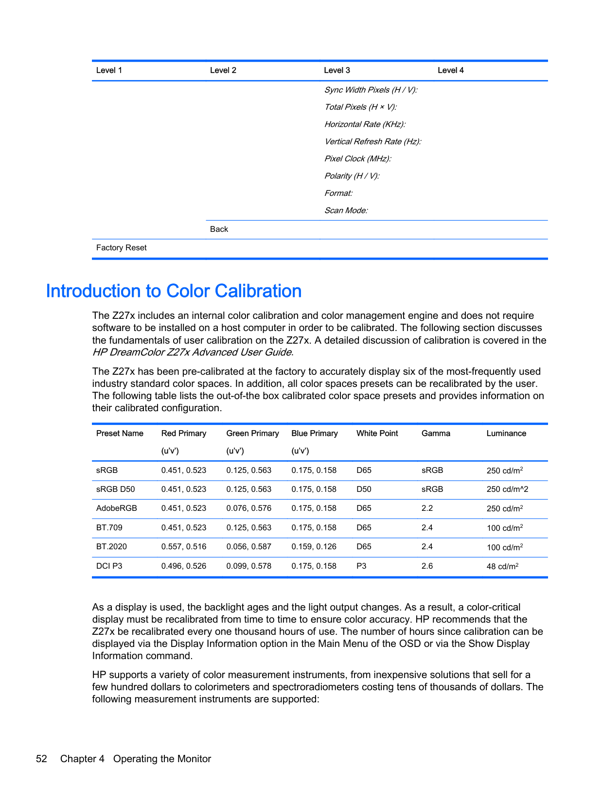
The Z27x includes an internal color calibration and color management engine and does not require software to be installed on a host computer in order to be calibrated. The following section discusses the fundamentals of user calibration on the Z27x. A detailed discussion of calibration is covered in the HP DreamColor Z27x Advanced User Guide.
The Z27x has been pre-calibrated at the factory to accurately display six of the most-frequently used industry standard color spaces. In addition, all color spaces presets can be recalibrated by the user. The following table lists the out-of-the box calibrated color space presets and provides information on their calibrated configuration.
Preset Name Red Primary (u’v’)
Green Primary (u’v’)
Blue Primary (u’v’)
White Point Gamma Luminance
sRGB 0.451, 0.523 0.125, 0.563 0.175, 0.158 D65 sRGB 250 cd/m2 sRGB D50 0.451, 0.523 0.125, 0.563 0.175, 0.158 D50 sRGB 250 cd/m^2 AdobeRGB 0.451, 0.523 0.076, 0.576 0.175, 0.158 D65 2.2 250 cd/m2 BT.709 0.451, 0.523 0.125, 0.563 0.175, 0.158 D65 2.4 100 cd/m2 BT.2020 0.557, 0.516 0.056, 0.587 0.159, 0.126 D65 2.4 100 cd/m2 DCI P3 0.496, 0.526 0.099, 0.578 0.175, 0.158 P3 2.6 48 cd/m2
As a display is used, the backlight ages and the light output changes. As a result, a color-critical display must be recalibrated from time to time to ensure color accuracy. HP recommends that the Z27x be recalibrated every one thousand hours of use. The number of hours since calibration can be displayed via the Display Information option in the Main Menu of the OSD or via the Show Display Information command.
HP supports a variety of color measurement instruments, from inexpensive solutions that sell for a few hundred dollars to colorimeters and spectroradiometers costing tens of thousands of dollars. The following measurement instruments are supported:

Please refer to the HP DreamColor Z27x Advanced User Guideor the Calibration Best Practices white paper for the recommended configuration of these instruments.
The HP DreamColor Calibration solution is available directly from HP.com and HP resellers. Contact the manufacturers of the other supported instruments for pricing and availability.
| | |---|
NOTE: As the connection to the Z27x is made via USB, the Photo Research and Konica Minolta units must have USB connection, which is optional on some models. Two different calibration workflows are supported:
This user guide only covers the onscreen menu-driven calibration option. Please refer to the HP DreamColor Z27x Advanced User Guideor the Calibration Best Practiceswhite paper for information on the XML-driven option.
#### Preparing to Calibrate
In order to calibrate, the Z27x internal processor must be enabled. To meet the energy savings requirements of Energy Star 6.0, the internal processor is disabled at the factory.
To enable the Z27x internal processor:
Once enabled, wait approximately one minute for the processor to fully boot before beginning calibration.
CAUTION: It is strongly recommended that calibration be performed in a darkened room. Stray light bouncing off the monitor will negatively impact calibration accuracy.
#### Calibrating the Z27x Using the Onscreen Menus
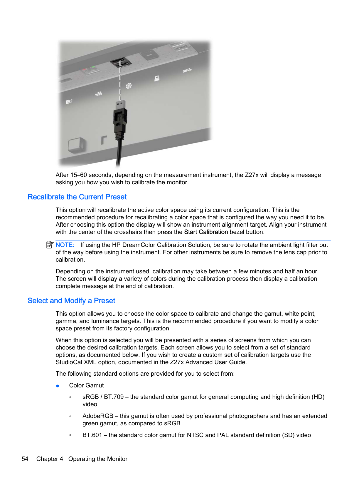
Once the internal processor has booted, connect the measurement instrument to one of the DreamColor USB ports on the bottom of the Z27x.
Introduction to Color Calibration 53

After 15–60 seconds, depending on the measurement instrument, the Z27x will display a message asking you how you wish to calibrate the monitor.
##### Recalibrate the Current Preset
This option will recalibrate the active color space using its current configuration. This is the recommended procedure for recalibrating a color space that is configured the way you need it to be. After choosing this option the display will show an instrument alignment target. Align your instrument with the center of the crosshairs then press the Start Calibration bezel button.
| | |---|
NOTE: If using the HP DreamColor Calibration Solution, be sure to rotate the ambient light filter out of the way before using the instrument. For other instruments be sure to remove the lens cap prior to calibration.
Depending on the instrument used, calibration may take between a few minutes and half an hour. The screen will display a variety of colors during the calibration process then display a calibration complete message at the end of calibration.
##### Select and Modify a Preset
This option allows you to choose the color space to calibrate and change the gamut, white point, gamma, and luminance targets. This is the recommended procedure if you want to modify a color space preset from its factory configuration
When this option is selected you will be presented with a series of screens from which you can choose the desired calibration targets. Each screen allows you to select from a set of standard options, as documented below. If you wish to create a custom set of calibration targets use the StudioCal XML option, documented in the Z27x Advanced User Guide.
The following standard options are provided for you to select from:
| | |---|
NOTE: Further information on these standard values is provided in the Z27x Advanced User Guide.
Once all of the options are selected the display will show a calibration target. Align your instrument with the center of the crosshairs then press the Start Calibration bezel button.
Depending on the instrument used, calibration may take between a few minutes and half an hour. The screen will display a variety of colors during the calibration process then display a calibration complete message at the end of calibration.
Auto EDID Update By default, the display automatically updates the display EDID when you switch color spaces. If Auto EDID Update is enabled, the EDID will be updated for all inputs every time you change the active color space preset. If Auto EDID Update is disabled, each input will be set to the factory default values for the Native color space. You can enable or disable Auto EDID Update in the OSD:
Auto EDID Update 55
A Technical Specifications
| | |---|
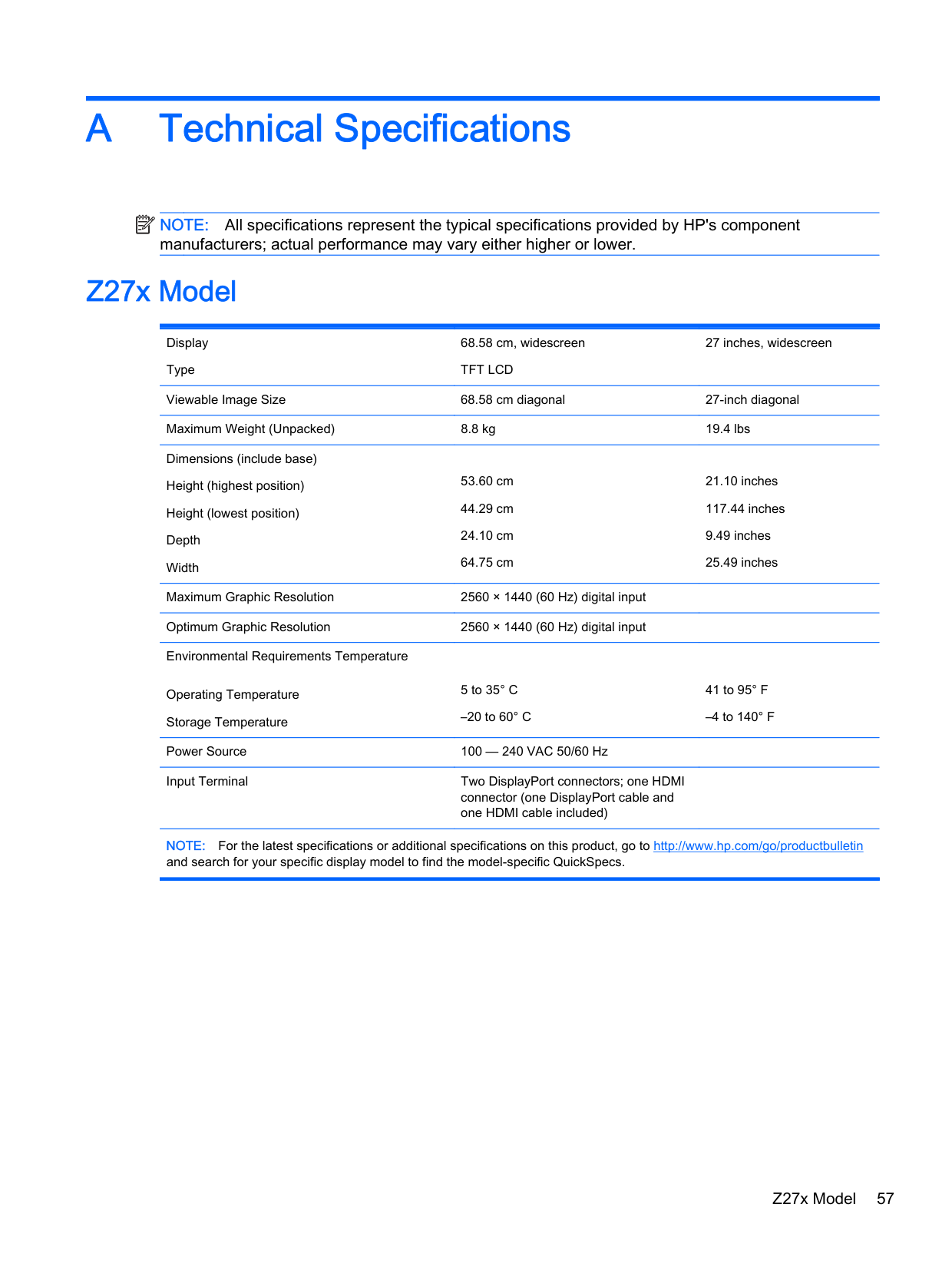
NOTE: All specifications represent the typical specifications provided by HP's component manufacturers; actual performance may vary either higher or lower.
Z27x Model
Display Type
68.58 cm, widescreen TFT LCD
27 inches, widescreen
Viewable Image Size 68.58 cm diagonal 27-inch diagonal Maximum Weight (Unpacked) 8.8 kg 19.4 lbs Dimensions (include base) Height (highest position) Height (lowest position) Depth Width
53.60 cm 44.29 cm 24.10 cm 64.75 cm
21.10 inches 117.44 inches 9.49 inches 25.49 inches
Maximum Graphic Resolution 2560 × 1440 (60 Hz) digital input Optimum Graphic Resolution 2560 × 1440 (60 Hz) digital input Environmental Requirements Temperature
Operating Temperature Storage Temperature
5 to 35° C
–20 to 60° C
Power Source 100 — 240 VAC 50/60 Hz Input Terminal Two DisplayPort connectors; one HDMI
connector (one DisplayPort cable and one HDMI cable included)
41 to 95° F
–4 to 140° F
NOTE: For the latest specifications or additional specifications on this product, go to http://www.hp.com/go/productbulletin and search for your specific display model to find the model-specific QuickSpecs.
Z27x Model 57
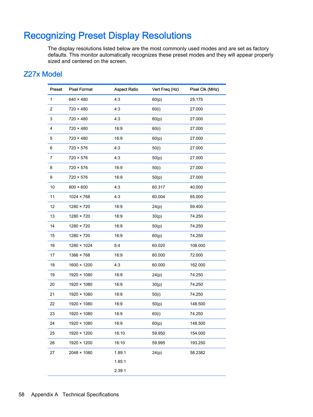
Recognizing Preset Display Resolutions
The display resolutions listed below are the most commonly used modes and are set as factory defaults. This monitor automatically recognizes these preset modes and they will appear properly sized and centered on the screen.
#### Z27x Model
######### Preset Pixel Format Aspect Ratio Vert Freq (Hz) Pixel Clk (MHz)

24(p) 58.2382
58 Appendix A Technical Specifications
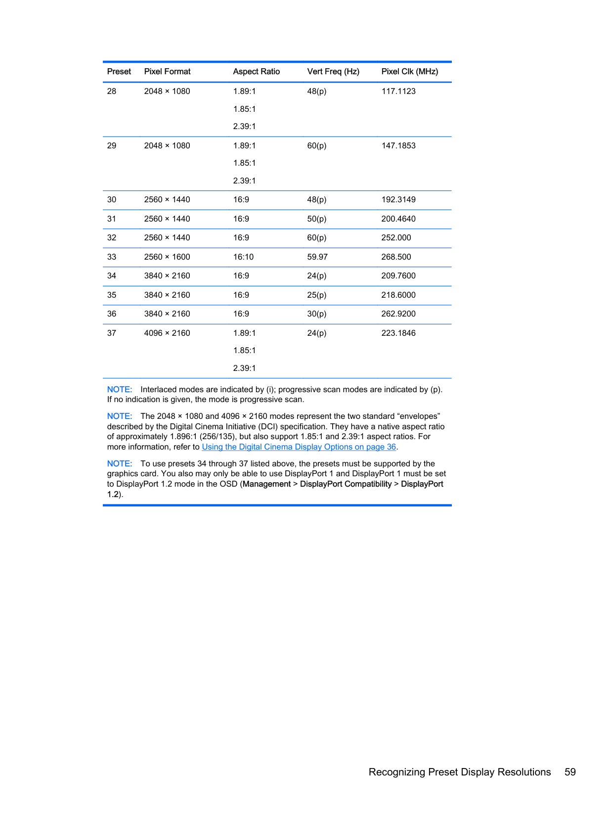
######### Preset Pixel Format Aspect Ratio Vert Freq (Hz) Pixel Clk (MHz)
48(p) 117.1123
60(p) 147.1853
24(p) 223.1846
NOTE: Interlaced modes are indicated by (i); progressive scan modes are indicated by (p). If no indication is given, the mode is progressive scan.
NOTE: The 2048 × 1080 and 4096 × 2160 modes represent the two standard “envelopes” described by the Digital Cinema Initiative (DCI) specification. They have a native aspect ratio of approximately 1.896:1 (256/135), but also support 1.85:1 and 2.39:1 aspect ratios. For more information, refer to Using the Digital Cinema Display Options on page 36.
NOTE: To use presets 34 through 37 listed above, the presets must be supported by the graphics card. You also may only be able to use DisplayPort 1 and DisplayPort 1 must be set to DisplayPort 1.2 mode in the OSD (Management > DisplayPort Compatibility > DisplayPort 1.2).
Recognizing Preset Display Resolutions 59
B Support and Troubleshooting
Solving Common Problems
The following table lists possible problems, the possible cause of each problem, and the recommended solutions.
Problem Possible Cause Solution
Screen is blank or video is flashing.
Power cord is disconnected. Connect the power cord.
Power button on front panel of the monitor is turned off.
Press the front panel power button. NOTE: If pressing the power button has no effect, press and hold the power button for 10 seconds to disable the power button lockout feature.
Video cable is improperly connected.
Connect the video cable properly. Refer to Setting Up the Monitor on page 5 for more information.
System is in sleep mode. Press any key on the keyboard or move the mouse to inactivate the screen blanking utility.
Video card compatibility. Open the OSD menu and select the Video Input menu. Set Input Auto-Switch Source to Disable and manually select the input.
Monitor will not turn on. Master power switch on rear panel of the monitor is turned Off.
Turn the master power switch to On.
Image appears blurred, indistinct, or too dark.
Check Video Cable is displayed on screen.
######### Input Signal Out of Range is displayed on screen.
The monitor is off but it did not seem to enter into a low-power sleep mode.
Brightness is too low. Open the OSD menu and select Color Space > Adjust Luminance to adjust the luminance scale as needed.
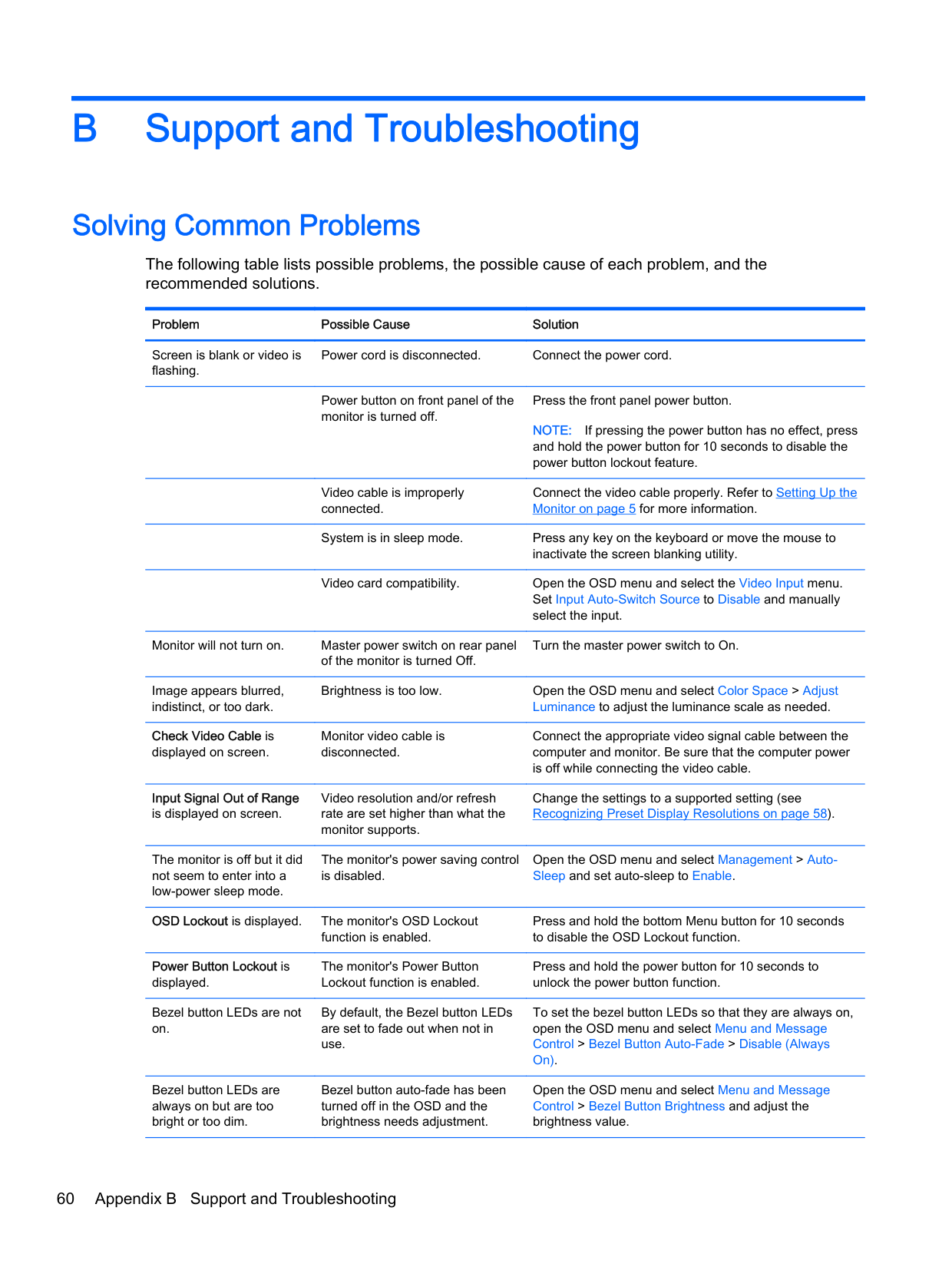
Monitor video cable is disconnected.
Video resolution and/or refresh rate are set higher than what the monitor supports.
The monitor's power saving control is disabled.
Connect the appropriate video signal cable between the computer and monitor. Be sure that the computer power is off while connecting the video cable.
Change the settings to a supported setting (see Recognizing Preset Display Resolutions on page 58).
Open the OSD menu and select Management > AutoSleep and set auto-sleep to Enable.
OSD Lockout is displayed. The monitor's OSD Lockout
function is enabled.
######### Power Button Lockout is displayed.
Bezel button LEDs are not on.
The monitor's Power Button Lockout function is enabled.
By default, the Bezel button LEDs are set to fade out when not in use.
Bezel button LEDs are always on but are too bright or too dim.
Bezel button auto-fade has been turned off in the OSD and the brightness needs adjustment.
Press and hold the bottom Menu button for 10 seconds to disable the OSD Lockout function.
Press and hold the power button for 10 seconds to unlock the power button function.
To set the bezel button LEDs so that they are always on, open the OSD menu and select Menu and Message Control > Bezel Button Auto-Fade > Disable (Always On).
Open the OSD menu and select Menu and Message Control > Bezel Button Brightness and adjust the brightness value.
######### Problem Possible Cause Solution
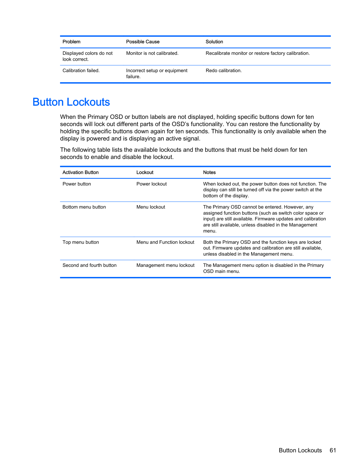
Displayed colors do not look correct.
Monitor is not calibrated. Recalibrate monitor or restore factory calibration.
Calibration failed. Incorrect setup or equipment failure.
Redo calibration.
Button Lockouts
When the Primary OSD or button labels are not displayed, holding specific buttons down for ten seconds will lock out different parts of the OSD’s functionality. You can restore the functionality by holding the specific buttons down again for ten seconds. This functionality is only available when the display is powered and is displaying an active signal.
The following table lists the available lockouts and the buttons that must be held down for ten seconds to enable and disable the lockout.
Activation Button Lockout Notes Power button Power lockout When locked out, the power button does not function. The
display can still be turned off via the power switch at the bottom of the display.
Bottom menu button Menu lockout The Primary OSD cannot be entered. However, any assigned function buttons (such as switch color space or input) are still available. Firmware updates and calibration are still available, unless disabled in the Management menu.
Top menu button Menu and Function lockout Both the Primary OSD and the function keys are locked out. Firmware updates and calibration are still available, unless disabled in the Management menu.
Second and fourth button Management menu lockout The Management menu option is disabled in the Primary OSD main menu.
Button Lockouts 61
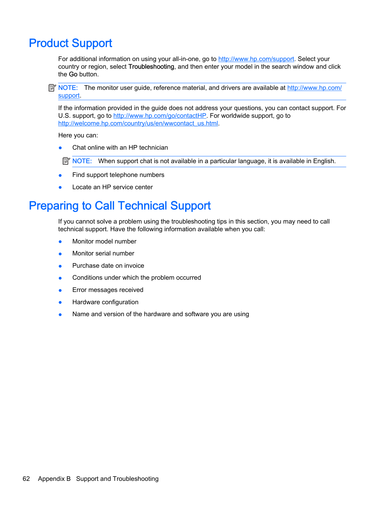
Product Support
For additional information on using your all-in-one, go to http://www.hp.com/support. Select your country or region, select Troubleshooting, and then enter your model in the search window and click the Go button.
| | |---|
NOTE: The monitor user guide, reference material, and drivers are available at http://www.hp.com/ support.
If the information provided in the guide does not address your questions, you can contact support. For U.S. support, go to http://www.hp.com/go/contactHP. For worldwide support, go to http://welcome.hp.com/country/us/en/wwcontact_us.html.
Here you can:
| | |---|
Preparing to Call Technical Support
If you cannot solve a problem using the troubleshooting tips in this section, you may need to call technical support. Have the following information available when you call:
C LCD Monitor Quality and Pixel Policy
The TFT monitor uses high-precision technology, manufactured according to HP standards, to guarantee trouble-free performance. Nevertheless, the display may have cosmetic imperfections that appear as small bright or dark spots. This is common to all LCD displays used in products supplied by all vendors and is not specific to the HP LCD. These imperfections are caused by one or more defective pixels or sub-pixels.
To locate defective pixels, the monitor should be viewed under normal operating conditions, in normal operating mode at a supported resolution and refresh rate, from a distance of approximately 50 cm (20 in).
HP expects that, over time, the industry will continue to improve its ability to produce LCDs with fewer cosmetic imperfections and HP will adjust guidelines as improvements are made.
63