
Ask AI
— answers from the official manualAnswers from the official manual.
Common questions
Common Questions
9 totalHow do I factory reset the Renogy Wanderer 30A?
Press and hold the gray button for approximately 7 seconds until the LED flashes. Once flashing, press the gray button again to select a battery type and let it set until the flashing stops (approximately 10 seconds). This restores the default settings.
What should I do if my battery is overheating?
When heat exceeds controller specification, it will automatically shut down. Ensure tight and correct wire connections from battery to charge controller and solar panels. Use a multi-meter to check for reversed polarity of the solar modules on the charge controller’s terminals.
How do I change the battery type selection?
Hold the gray button for approximately 7 seconds until the LED flashes. Then press once to set a new battery type; leave the controller alone until flashing stops (indicating settings are saved).
What happens during equalization charge?
Equalization charge, carried out every 28 days for non-sealed batteries only, increases battery voltage above standard compensation to stir electrolyte, balance voltages, and complete chemical reactions. Ensure no loads are on the battery during this stage.
Why doesn't the controller charge during daytime?
Check for loose or incorrect connections between controller and solar panels. Also ensure there’s sufficient sunlight hitting solar panel modules.
How do I set up temperature compensation?
Connect a remote temperature sensor to the charge controller, measure battery temperature accurately, then use this data for precise temperature compensation. Sensor comes with a 9.8 ft cable length.
Full Manual
43 pages
User Manual of Product 1:
Renogy Wanderer Li 30A 12V PWM Negative Ground Solar Charge Controller Solar Panel Regulator w/ Temp Sensor Function Fit for Lithium, Sealed, Gel, and Flooded Batteries, Wanderer Li 30A
User Manual of Product 2:
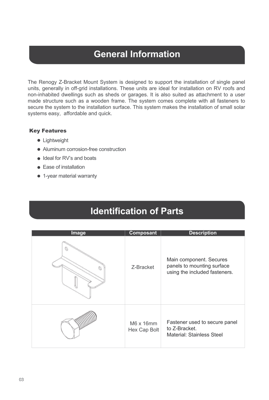
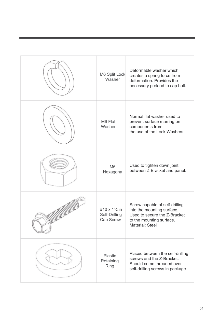
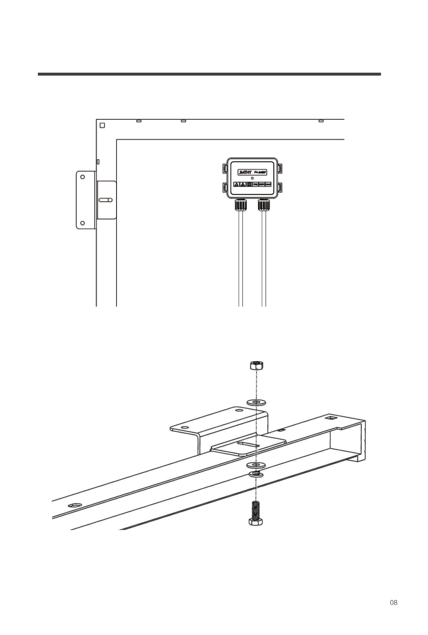
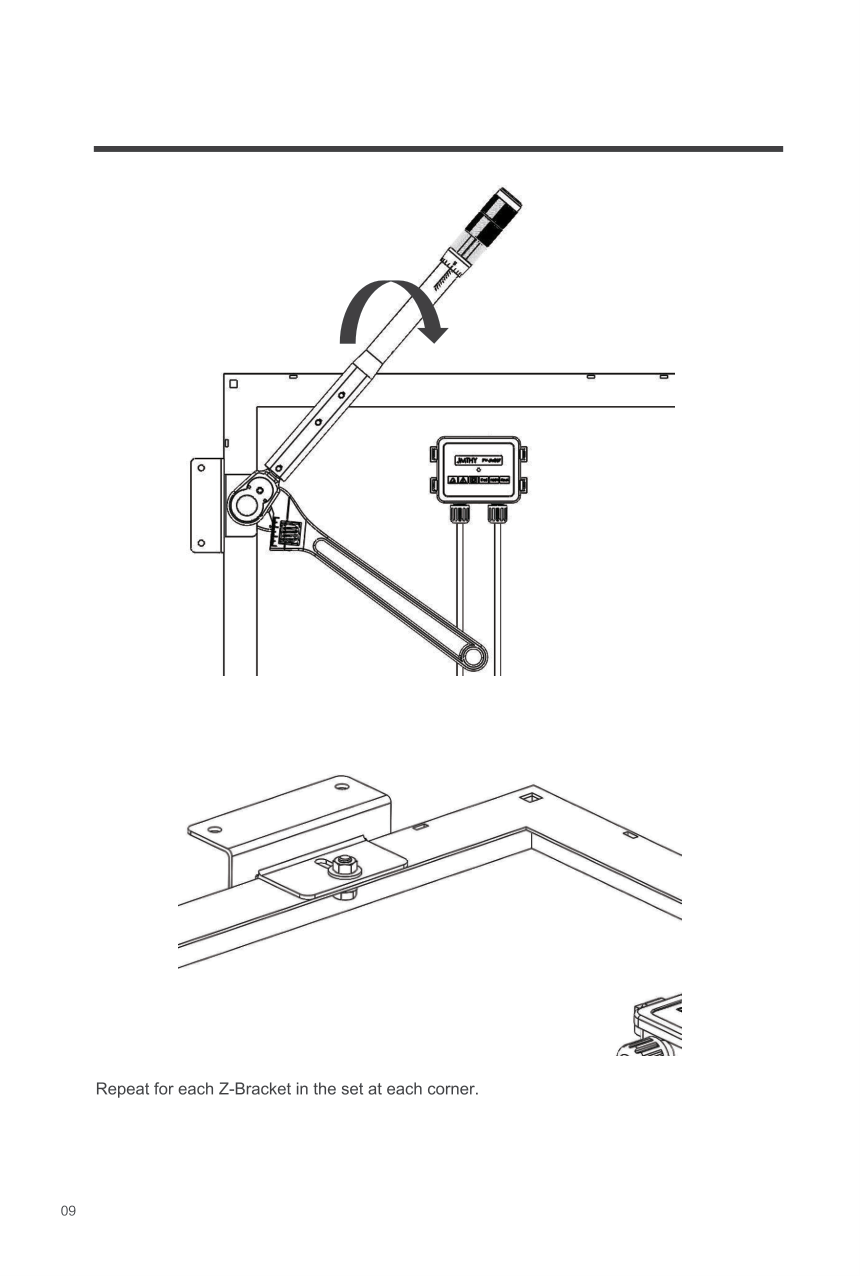
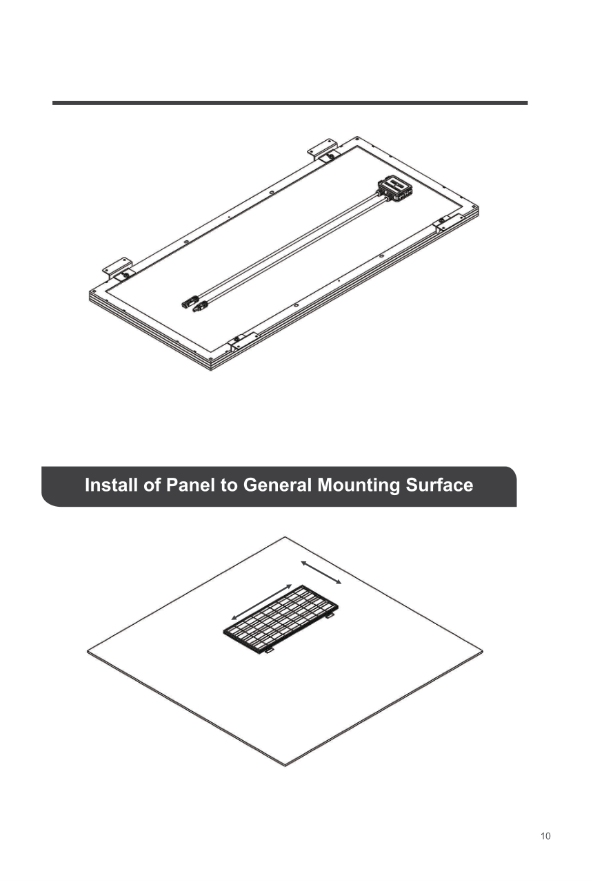
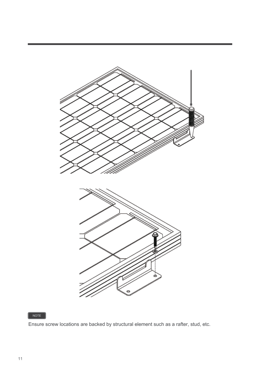
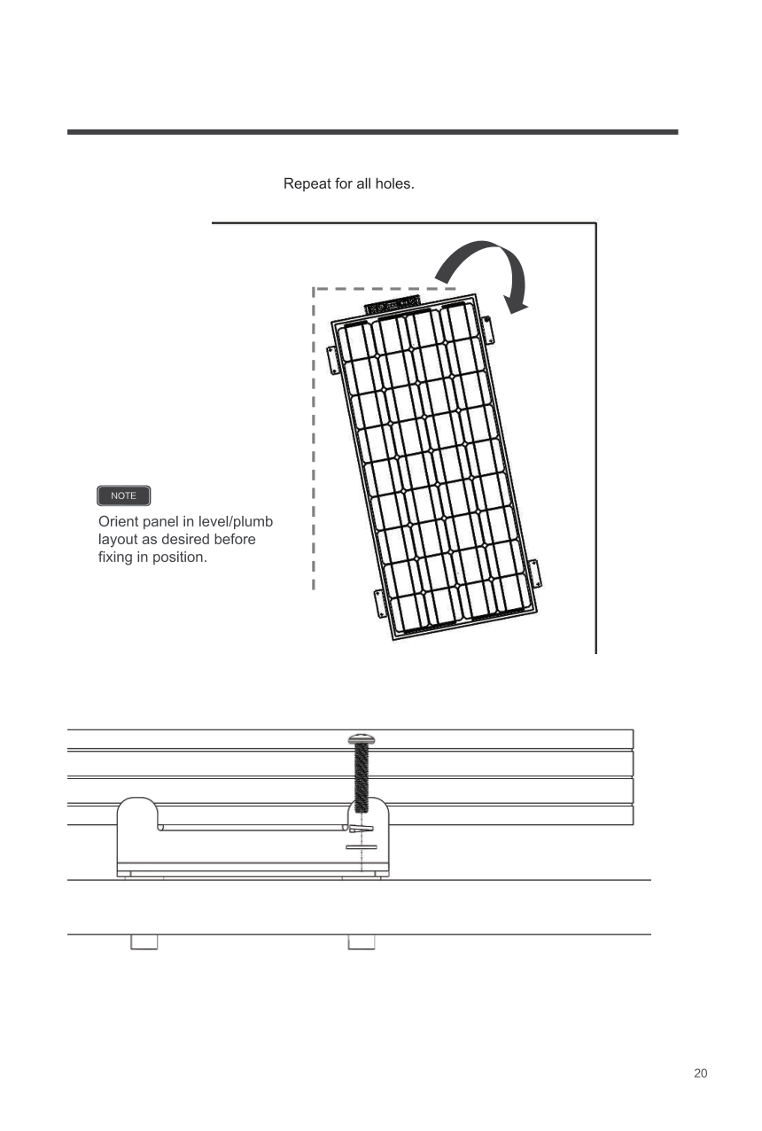
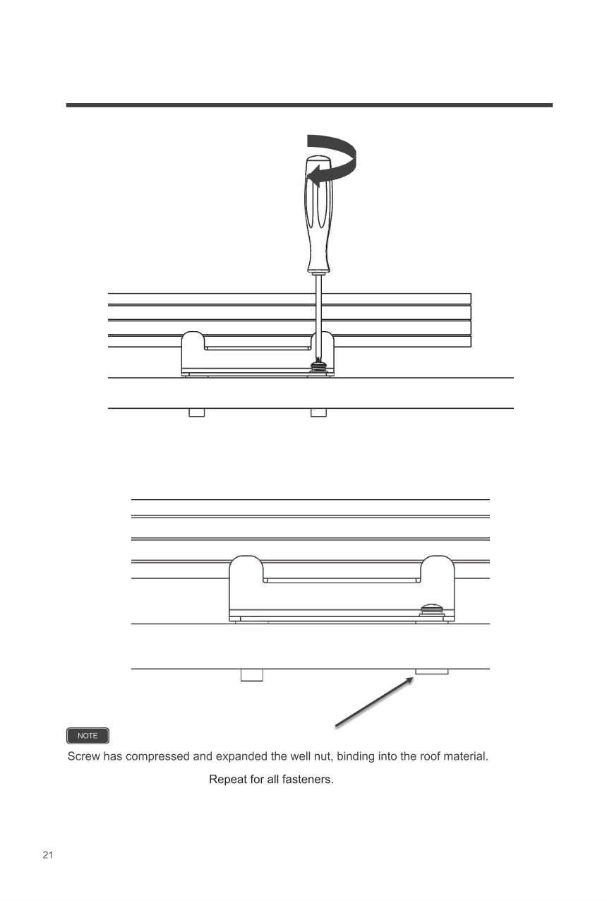
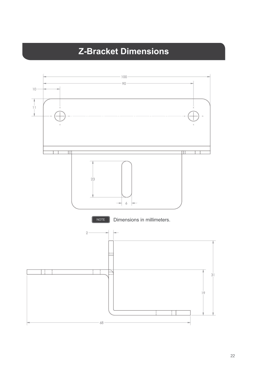
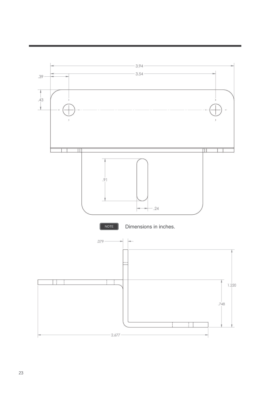
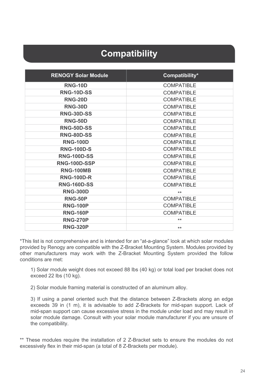
Renogy Solar Panel Mounting Z Brackets Lightweight Aluminum Corrosion-Free Construction for RVs, Trailers, Boats, Yachts, Wall and Other Off Gird Roof Installation, one set of 4 Units,Gray
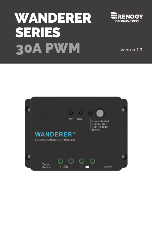
WANDERER 30A PWM
SERIES
Version 1.3

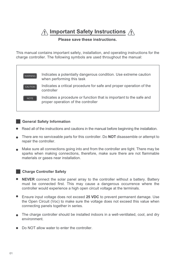
#### Important Safety Instructions Please save these instructions.
This manual contains important safety, installation, and operating instructions for the charge controller. The following symbols are used throughout the manual:
|Indicates a potentially dangerous condition. Use extreme caution when performing this task
Indicates a critical procedure for safe and proper operation of the controller
Indicates a procedure or function that is important to the safe and proper operation of the controller
NOTE
CAUTION
WARNING| |---|
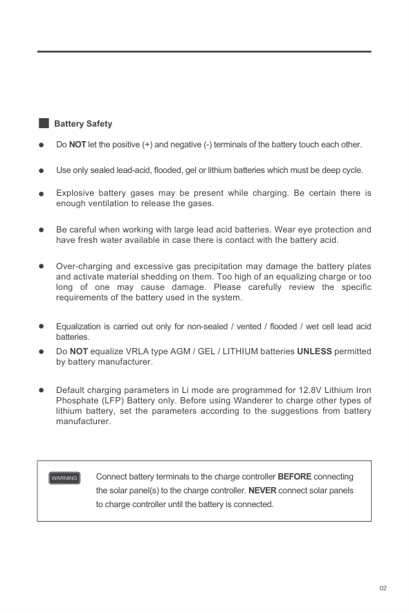
General Safety Information
Read all of the instructions and cautions in the manual before beginning the installation.
There are no serviceable parts for this controller. Do NOT disassemble or attempt to repair the controller.
Make sure all connections going into and from the controller are tight. There may be sparks when making connections, therefore, make sure there are not flammable materials or gases near installation.
Charge Controller Safety
NEVER connect the solar panel array to the controller without a battery. Battery must be connected first. This may cause a dangerous occurrence where the controller would experience a high open circuit voltage at the terminals.
Ensure input voltage does not exceed 25 VDC to prevent permanent damage. Use the Open Circuit (Voc) to make sure the voltage does not exceed this value when connecting panels together in series.
The charge controller should be installed indoors in a well-ventilated, cool, and dry environment.
Do NOT allow water to enter the controller.
######## Battery Safety
Do NOT let the positive (+) and negative (-) terminals of the battery touch each other.
Use only sealed lead-acid, flooded, gel or lithium batteries which must be deep cycle.
Explosive battery gases may be present while charging. Be certain there is enough ventilation to release the gases.
Be careful when working with large lead acid batteries. Wear eye protection and have fresh water available in case there is contact with the battery acid.
Over-charging and excessive gas precipitation may damage the battery plates and activate material shedding on them. Too high of an equalizing charge or too long of one may cause damage. Please carefully review the specific requirements of the battery used in the system.
Equalization is carried out only for non-sealed / vented / flooded / wet cell lead acid batteries.
Do NOT equalize VRLA type AGM / GEL / LITHIUM batteries UNLESS permitted by battery manufacturer.
Default charging parameters in Li mode are programmed for 12.8V Lithium Iron Phosphate (LFP) Battery only. Before using Wanderer to charge other types of lithium battery, set the parameters according to the suggestions from battery manufacturer.
|Connect battery terminals to the charge controller BEFORE connecting the solar panel(s) to the charge controller. NEVER connect solar panels to charge controller until the battery is connected.
WARNING| |---|
Table of Contents
General Information 04
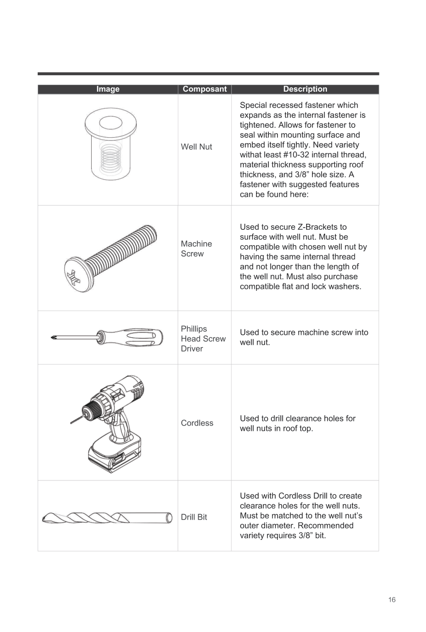
Optional Components 06
Identification of Parts 07
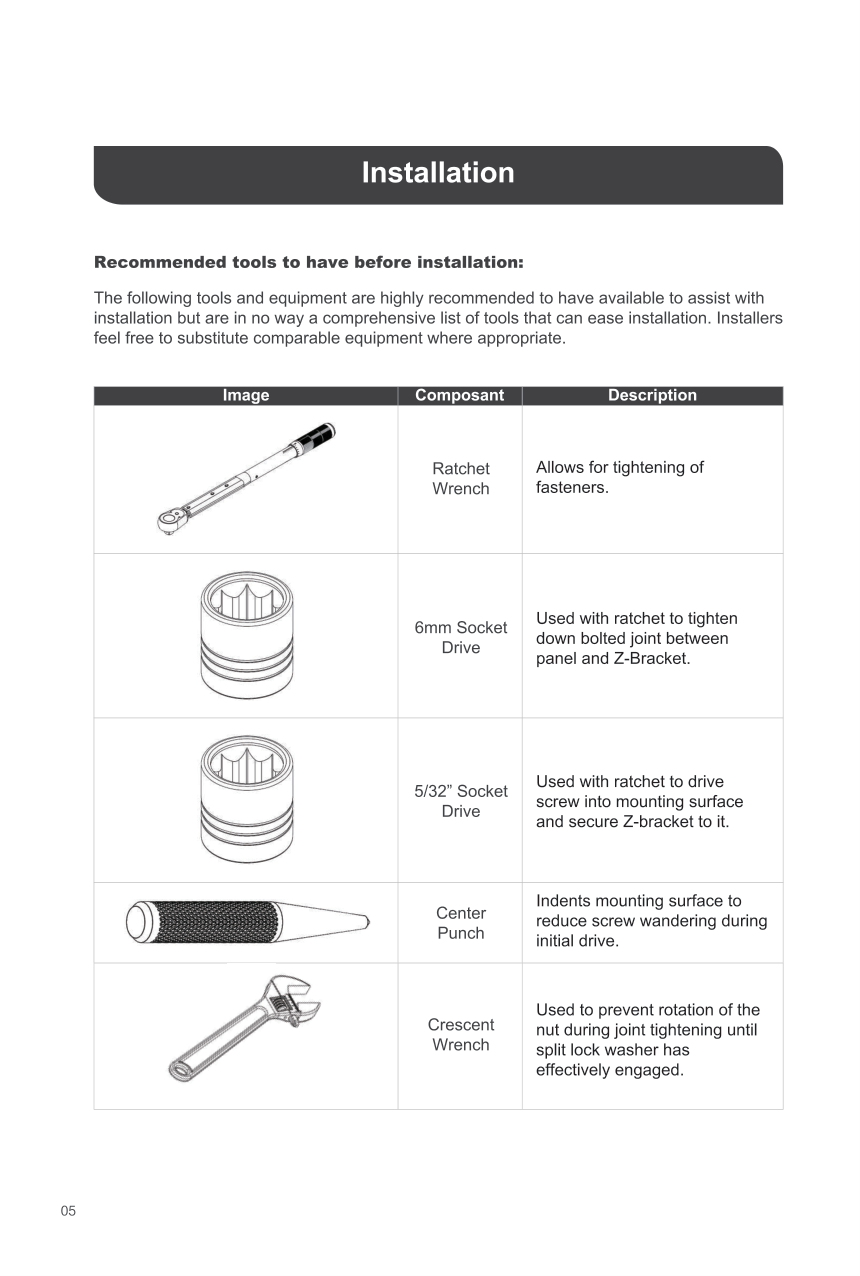
Installation 07
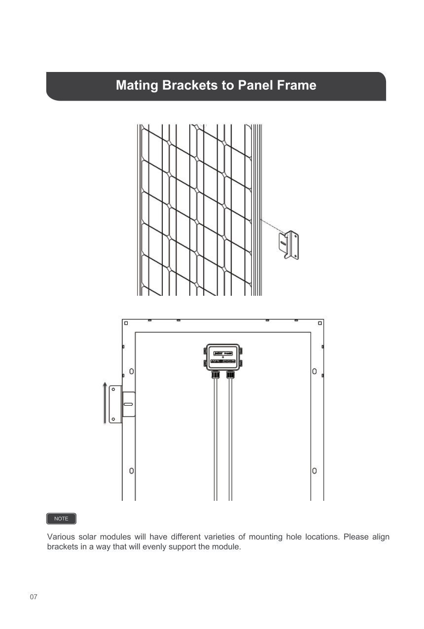
Mounting Recommendations 07
Operation 10
LED Indicators 10
System Status Troubleshooting 11
Maintenance 12
Fusing 12
Technical Specifications 13
13Electrical Specifications
Battery Charging Parameters 13
Dimensions 14
General Information
The Wanderer is an advanced charge controller for off-grid solar applications and can be used with a 12V battery or battery bank. Integrating highly efficient PWM charging, the Wanderer increases battery life and improves system performance. The controller comes equipped with fully comprehensive self-diagnostics and electronic protection functions to prevent damage from installation mistakes or system faults.
####### Key Features
Optimized for 12 VDC system voltage
30A charging capacity.
Deep Cycle Sealed, Gel, Flooded and Lithium battery options. 4 Stage PWM charging: Bulk, Boost. Float, and Equalization
Temperature compensation and correcting the charging and discharging parameters automatically, improving battery lifetime.
Protection against: reverse current, overcharging, short-circuit and reverse polarity.
Negative ground controller
Multiple LED indicators for easy to read charge status and battery information.
Remote temperature compensation compatible (accessory sold separately)
Integrated communication port for remote monitoring.
Charges over-discharged lithium batteries.
####### PWM Technology
The Wanderer utilizes Pulse Width Modulation (PWM) technology for battery charging. Battery charging is a current based process so controlling the current will control the battery voltage. For the most accurate return of capacity, and for the prevention of excessive gassing pressure, the battery is required to be controlled by specified voltage regulation set points for Absorption, Float, and Equalization charging stages. The charge controller uses automatic duty cycle conversion, creating pulses of current to charge the battery. The duty cycle is proportional to the difference between the sensed battery voltage and the specified voltage regulation set point. Once the battery reached the specified voltage range, pulse current charging mode allows the battery to react and allows for an acceptable rate of charge for the battery level. The Wanderer has a 4-stage battery charging algorithm for a rapid, efficient, and safe battery charging. They include: Bulk Charge, Boost Charge, Float Charge, and Equalization.
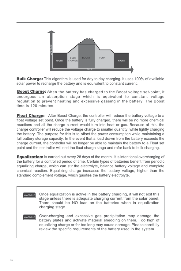
VOLTAGE
BULK CHARGE
BOOST FLOAT
NIGHT
NIGHT
TIME
Bulk Charge: This algorithm is used for day to day charging. It uses 100% of available solar power to recharge the battery and is equivalent to constant current.
Boost Charge:
When the battery has charged to the Boost voltage set-point, it undergoes an absorption stage which is equivalent to constant voltage regulation to prevent heating and excessive gassing in the battery. The Boost time is 120 minutes.
Float Charge: After Boost Charge, the controller will reduce the battery voltage to a float voltage set point. Once the battery is fully charged, there will be no more chemical reactions and all the charge current would turn into heat or gas. Because of this, the charge controller will reduce the voltage charge to smaller quantity, while lightly charging the battery. The purpose for this is to offset the power consumption while maintaining a full battery storage capacity. In the event that a load drawn from the battery exceeds the charge current, the controller will no longer be able to maintain the battery to a Float set point and the controller will end the float charge stage and refer back to bulk charging.
Equalization: Is carried out every 28 days of the month. It is intentional overcharging of the battery for a controlled period of time. Certain types of batteries benefit from periodic equalizing charge, which can stir the electrolyte, balance battery voltage and complete chemical reaction. Equalizing charge increases the battery voltage, higher than the standard complement voltage, which gasifies the battery electrolyte.
|Once equalization is active in the battery charging, it will not exit this stage unless there is adequate charging current from the solar panel. There should be NO load on the batteries when in equalization charging stage.
Over-charging and excessive gas precipitation may damage the battery plates and activate material shedding on them. Too high of equalizing charge or for too long may cause damage. Please carefully review the specific requirements of the battery used in the system.
WARNING
WARNING| |---|
Lithium Battery Activation
The Wanderer PWM charge controller has a reactivation feature to awaken a sleeping lithium battery. The protection circuit of lithium battery will typically turn the battery off and make it unusable if over-discharged. This can happen when storing a lithium battery pack in a discharged state for any length of time as self-discharge would gradually deplete the remaining charge. Without the wake-up feature to reactivate and recharge batteries, these batteries would become unserviceable and the packs would be discarded. The Wanderer will apply a small charge current to activate the protection circuit and if a correct cell voltage can be reached, it starts a normal charge.
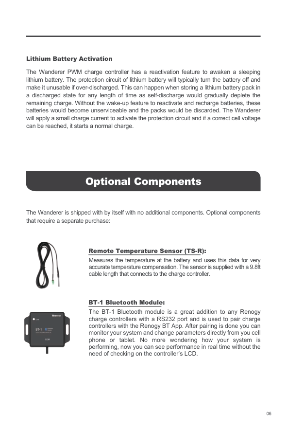
Optional Components
The Wanderer is shipped with by itself with no additional components. Optional components that require a separate purchase:


Remote Temperature Sensor (TS-R):
Measures the temperature at the battery and uses this data for very accurate temperature compensation. The sensor is supplied with a 9.8ft cable length that connects to the charge controller.
####### BT-1 Bluetooth Module:
The BT-1 Bluetooth module is a great addition to any Renogy charge controllers with a RS232 port and is used to pair charge controllers with the Renogy BT App. After pairing is done you can monitor your system and change parameters directly from you cell phone or tablet. No more wondering how your system is performing, now you can see performance in real time without the need of checking on the controller’s LCD.
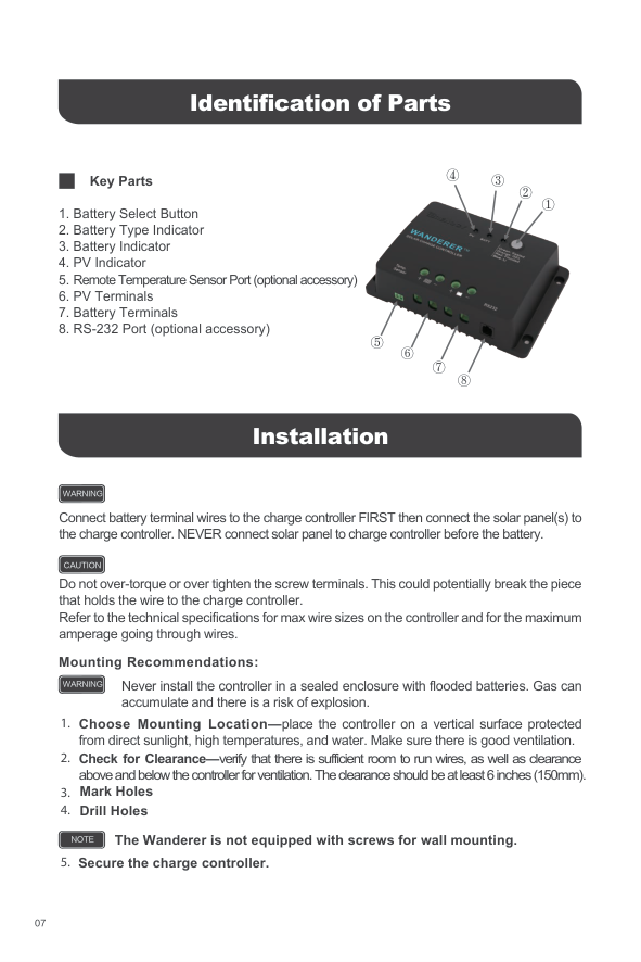
Identification of Parts

③④
Key Parts
②
①
⑤
⑥
⑦
⑧
Installation
WARNING
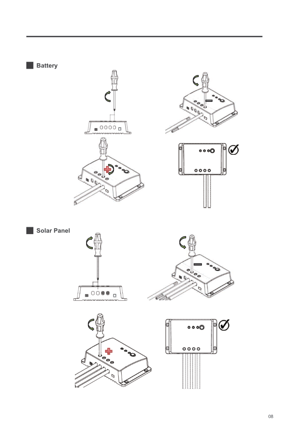
Connect battery terminal wires to the charge controller FIRST then connect the solar panel(s) to the charge controller. NEVER connect solar panel to charge controller before the battery.
CAUTION
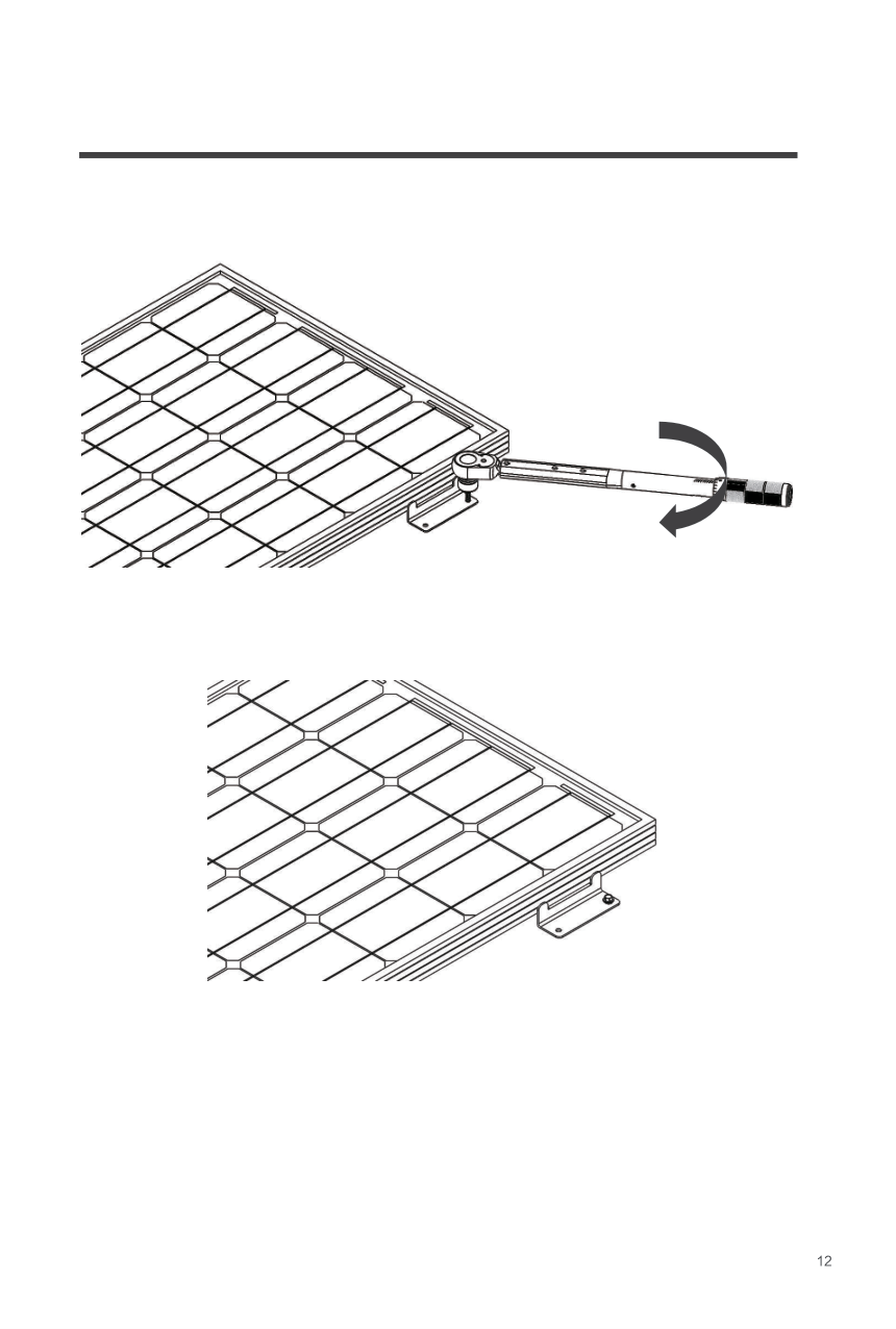
Do not over-torque or over tighten the screw terminals. This could potentially break the piece that holds the wire to the charge controller. Refer to the technical specifications for max wire sizes on the controller and for the maximum amperage going through wires.
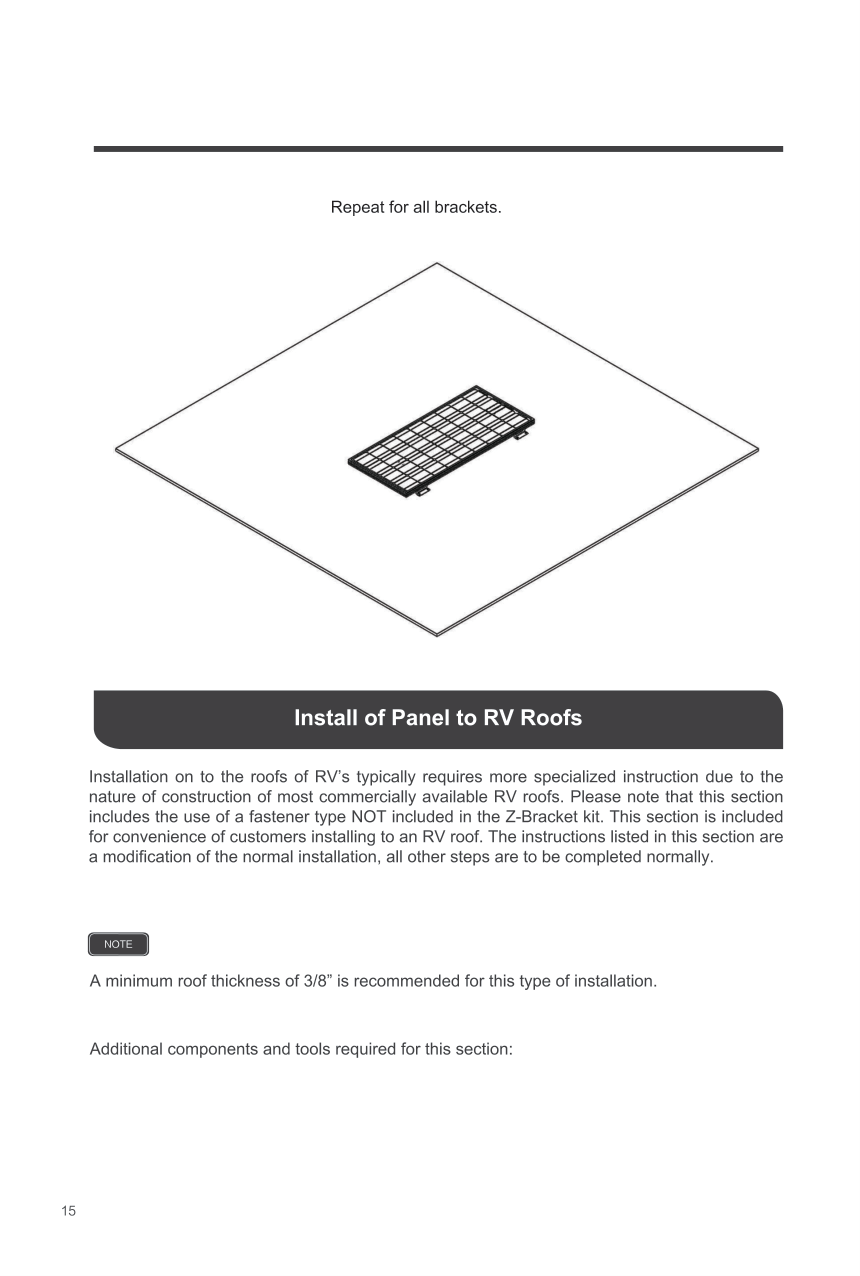
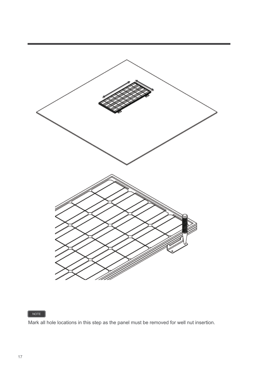
######## Mounting Recommendations:
Never install the controller in a sealed enclosure with flooded batteries. Gas can accumulate and there is a risk of explosion.
WARNING
Choose Mounting Location—place the controller on a vertical surface protected from direct sunlight, high temperatures, and water. Make sure there is good ventilation.
Check for Clearance—verify that there is sufficient room to run wires, as well as clearance above and below the controller for ventilation. The clearance should be at least 6 inches (150mm).

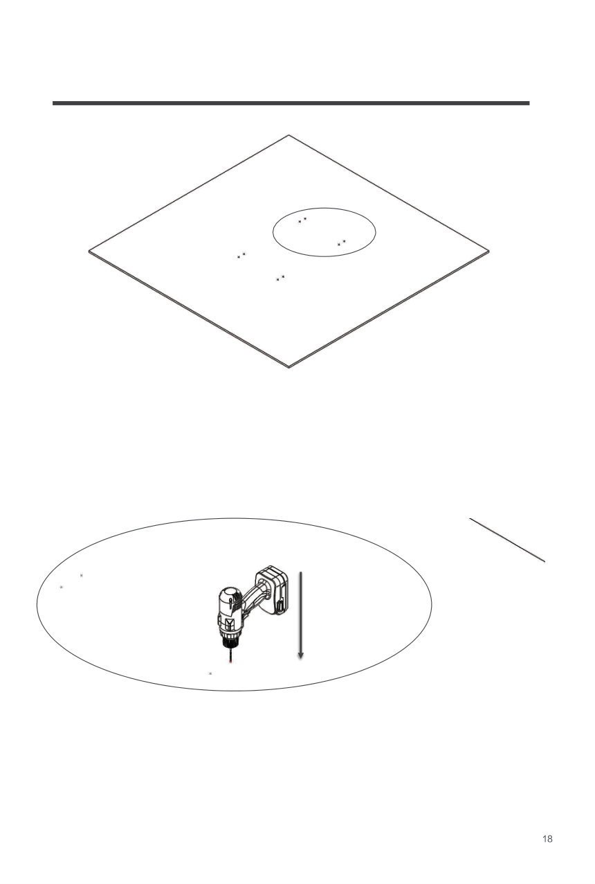
Mark Holes Drill Holes
The Wanderer is not equipped with screws for wall mounting.
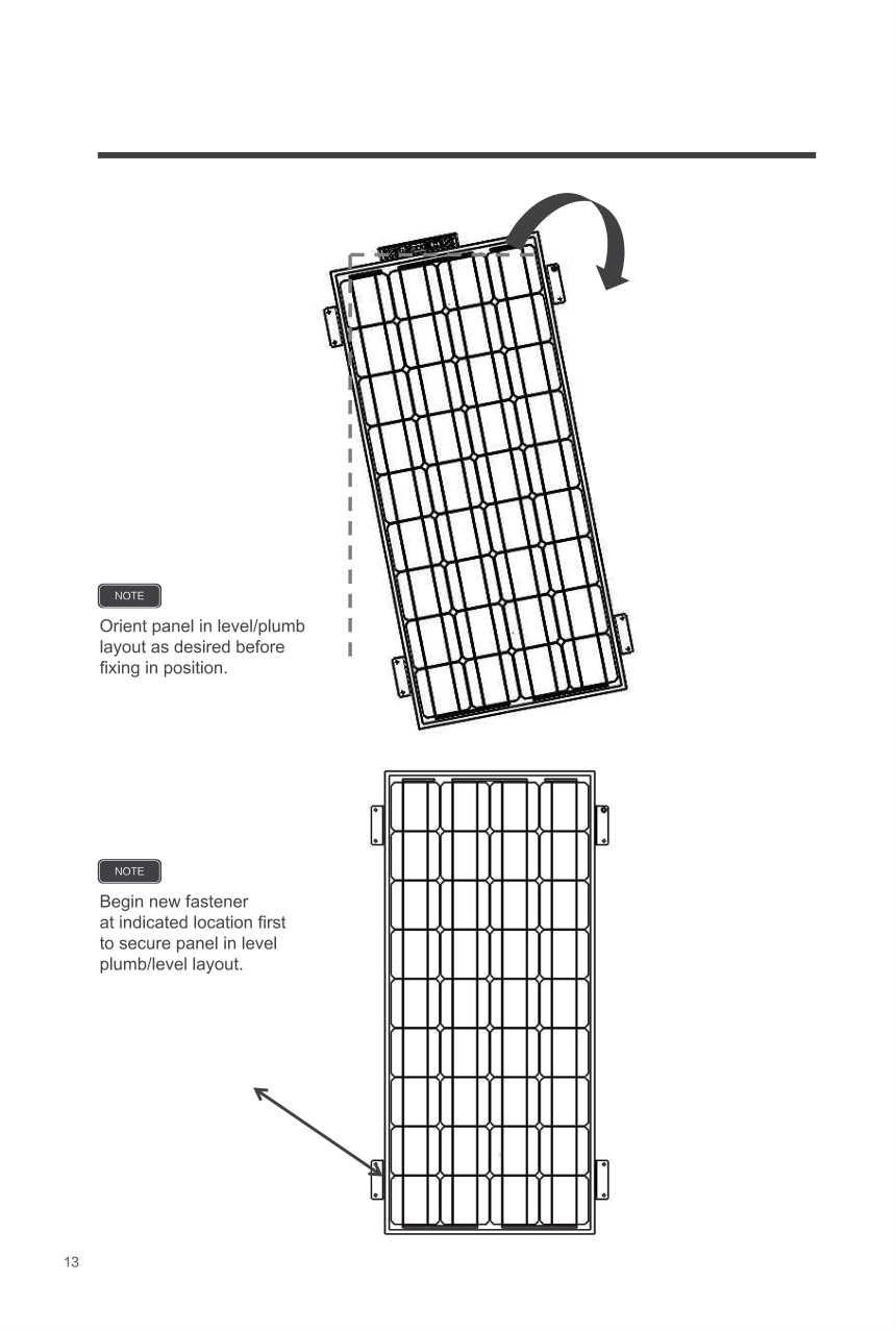
NOTE
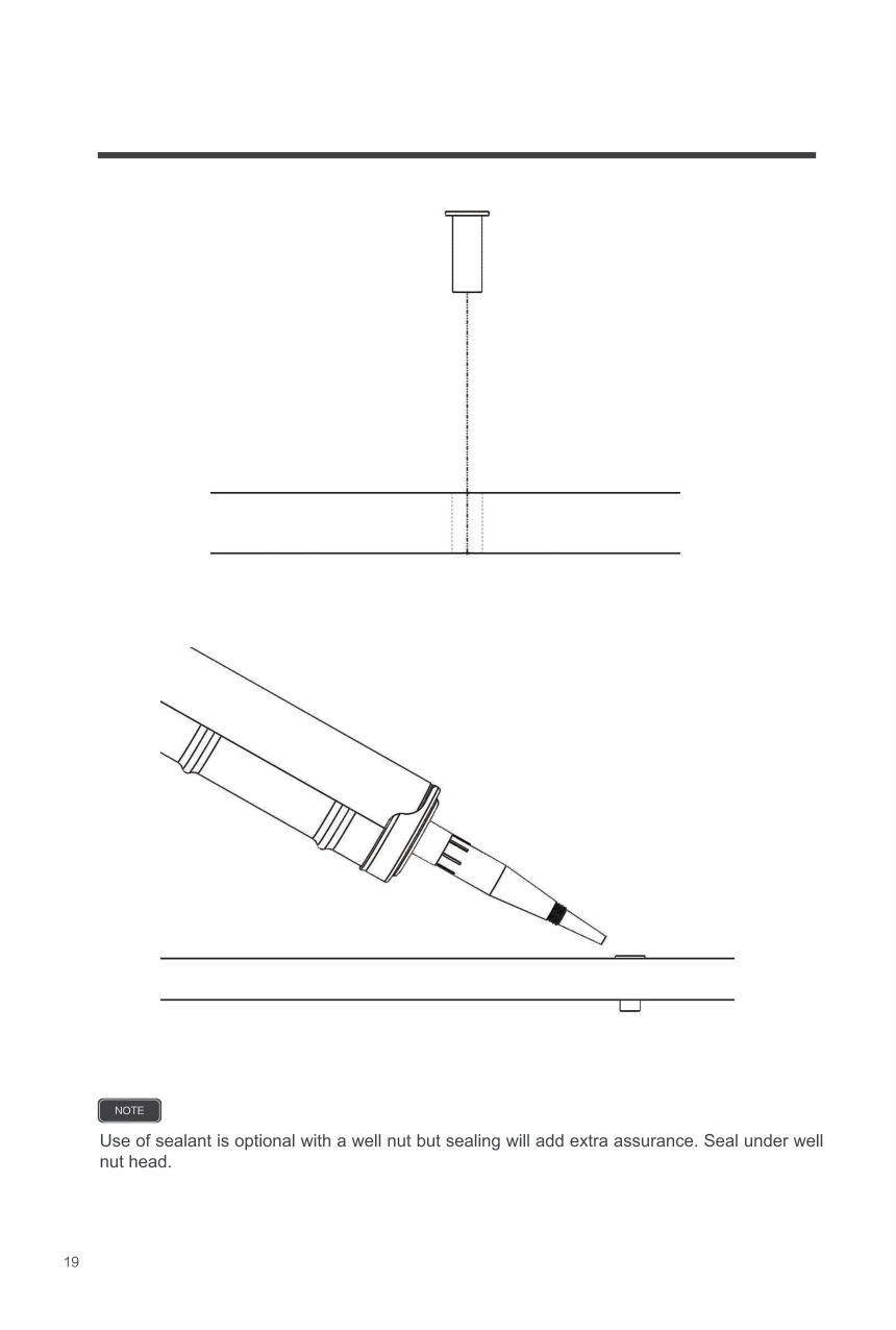
Secure the charge controller.

Battery


Solar Panel


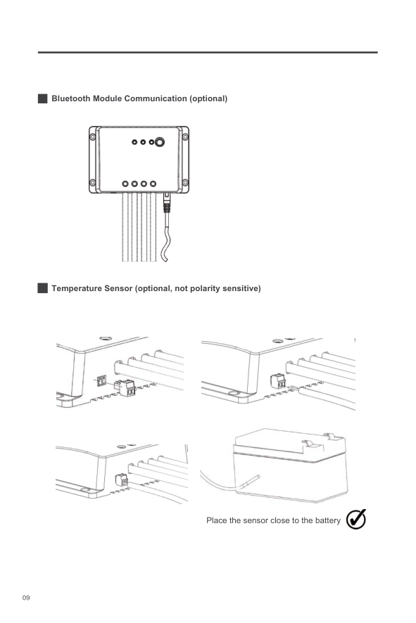
Bluetooth Module Communication (optional)

Temperature Sensor (optional, not polarity sensitive)


Place the sensor close to the battery
Operation
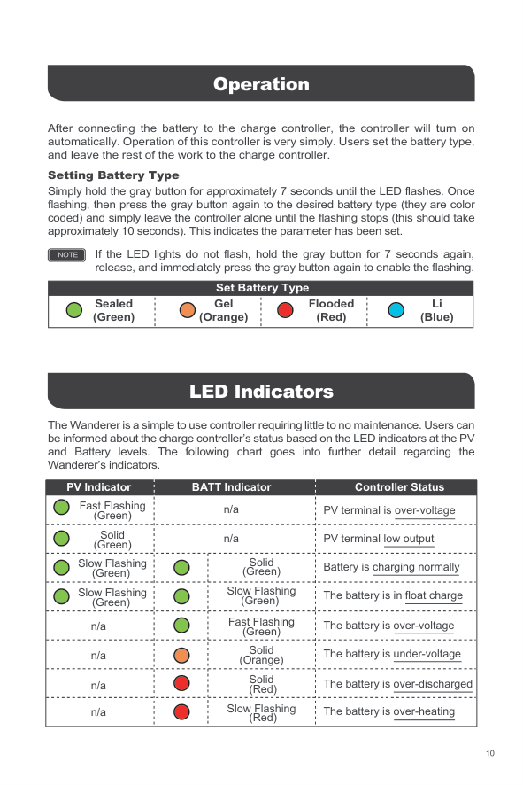
After connecting the battery to the charge controller, the controller will turn on automatically. Operation of this controller is very simply. Users set the battery type, and leave the rest of the work to the charge controller.
####### Setting Battery Type
Simply hold the gray button for approximately 7 seconds until the LED flashes. Once flashing, then press the gray button again to the desired battery type (they are color coded) and simply leave the controller alone until the flashing stops (this should take approximately 10 seconds). This indicates the parameter has been set.
If the LED lights do not flash, hold the gray button for 7 seconds again, release, and immediately press the gray button again to enable the flashing.
NOTE
######## Set Battery Type
Sealed (Green)
Gel (Orange)
Flooded (Red)
Li (Blue)
LED Indicators
The Wanderer is a simple to use controller requiring little to no maintenance. Users can be informed about the charge controller’s status based on the LED indicators at the PV and Battery levels. The following chart goes into further detail regarding the Wanderer’s indicators.
|Fast Flashing (Green)
PV Indicator|n/a
BATT Indicator
|n/a
BATT Indicator
|PV terminal is over-voltage
Controller Status| |---|---|---|---| |Solid (Green)|n/a|n/a|PV terminal low output| |Slow Flashing (Green)| |Solid (Green)|Battery is charging normally| |Slow Flashing (Green)| |Slow Flashing (Green)|The battery is in float charge| |n/a| |Fast Flashing (Green)|The battery is over-voltage|
|n/a| |Solid (Orange)|The battery is under-voltage| |n/a| |Solid (Red)|The battery is over-discharged| |n/a| |Slow Flashing (Red)|The battery is over-heating|
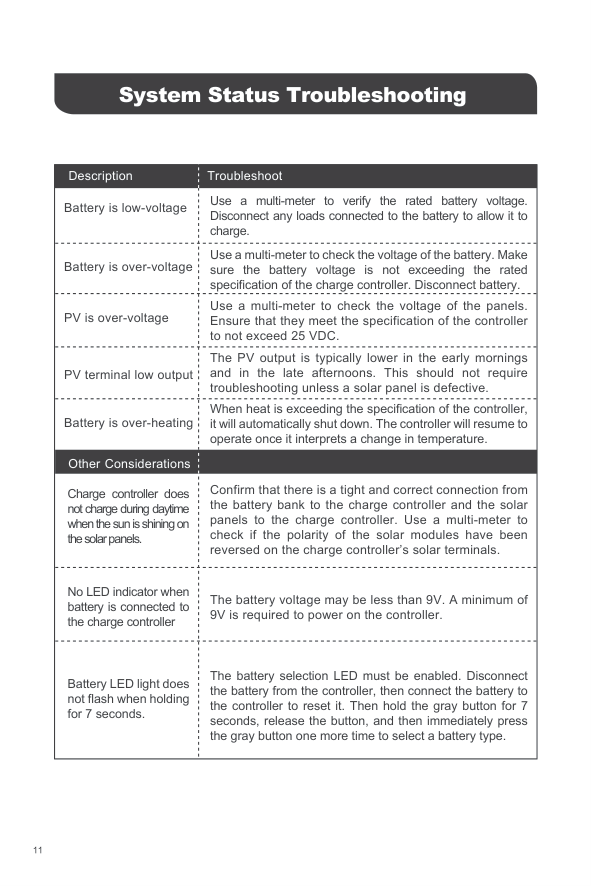
System Status Troubleshooting
|Description
Battery is low-voltage|Troubleshoot
Use a multi-meter to verify the rated battery voltage. Disconnect any loads connected to the battery to allow it to charge.
| |---|---| |Battery is over-voltage|Use a multi-meter to check the voltage of the battery. Make sure the battery voltage is not exceeding the rated specification of the charge controller. Disconnect battery.| |PV is over-voltage|Use a multi-meter to check the voltage of the panels. Ensure that they meet the specification of the controller to not exceed 25 VDC.| |PV terminal low output|The PV output is typically lower in the early mornings and in the late afternoons. This should not require troubleshooting unless a solar panel is defective.| |Other Considerations Charge controller does not charge during daytime when the sun is shining on the solar panels.
Battery is over-heating|When heat is exceeding the specification of the controller, it will automatically shut down. The controller will resume to operate once it interprets a change in temperature.
Confirm that there is a tight and correct connection from the battery bank to the charge controller and the solar panels to the charge controller. Use a multi-meter to check if the polarity of the solar modules have been reversed on the charge controller’s solar terminals.| |No LED indicator when battery is connected to the charge controller|The battery voltage may be less than 9V. A minimum of 9V is required to power on the controller.|
|Battery LED light does not flash when holding for 7 seconds.|The battery selection LED must be enabled. Disconnect the battery from the controller, then connect the battery to the controller to reset it. Then hold the gray button for 7 seconds, release the button, and then immediately press the gray button one more time to select a battery type.|
Maintenance
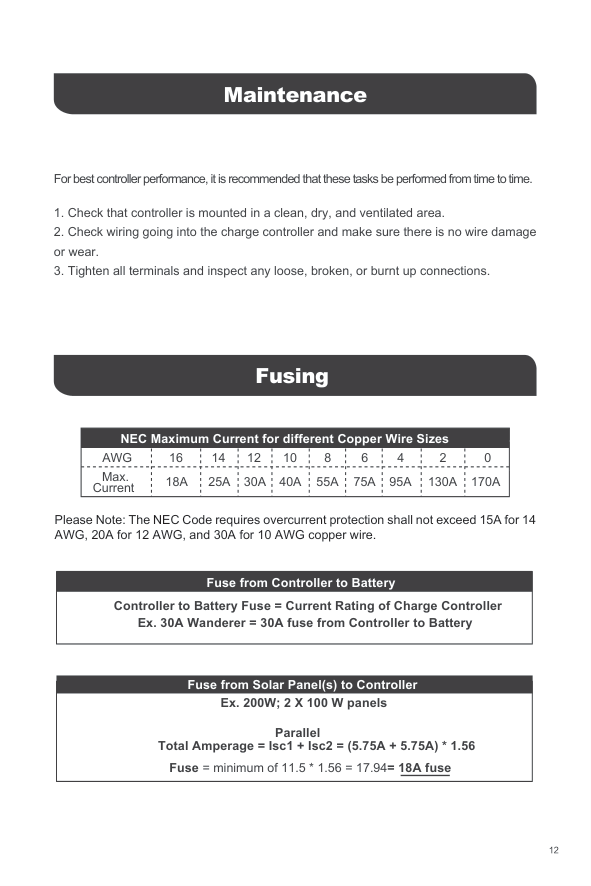
For best controller performance, it is recommended that these tasks be performed from time to time.
Fusing
######## NEC Maximum Current for different Copper Wire Sizes
AWG 16 14 12 10 8 6 4 2 0 Max.
Current 55A40A30A25A18A 75A 95A 130A 170A
Please Note: The NEC Code requires overcurrent protection shall not exceed 15A for 14 AWG, 20A for 12 AWG, and 30A for 10 AWG copper wire.
|Fuse from Controller to Battery
Ex. 30A Wanderer = 30A fuse from Controller to Battery
Controller to Battery Fuse = Current Rating of Charge Controller| |---|
|Parallel
Fuse from Solar Panel(s) to Controller Ex. 200W; 2 X 100 W panels
Fuse = minimum of 11.5 * 1.56 = 17.94= 18A fuse
Total Amperage = Isc1 + Isc2 = (5.75A + 5.75A) * 1.56| |---|
Technical Specifications
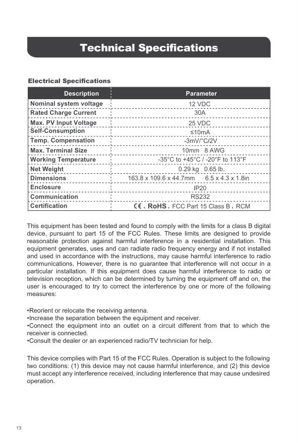
####### Electrical Specifications
|Description Nominal system voltage|Parameter
12 VDC| |---|---| |Rated Charge Current|30A| |Max. PV Input Voltage|25 VDC| |Self-Consumption|≤10mA| |Temp. Compensation|-3mV/°C/2V2| |Max. Terminal Size|10mm 8 AWG| |Working Temperature|-35°C to +45°C / -20°F to 113°F|
|Net Weight|0.29 kg 0.65 lb.| |Dimensions|163.8 x 109.6 x 44.7mm 6.5 x 4.3 x 1.8in| |Enclosure|IP20| |Communication|RS232| |Certification|FCC Part 15 Class B RCM,,,|
This equipment has been tested and found to comply with the limits for a class B digital device, pursuant to part 15 of the FCC Rules. These limits are designed to provide reasonable protection against harmful interference in a residential installation. This equipment generates, uses and can radiate radio frequency energy and if not installed and used in accordance with the instructions, may cause harmful interference to radio communications. However, there is no guarantee that interference will not occur in a particular installation. If this equipment does cause harmful interference to radio or television reception, which can be determined by turning the equipment off and on, the user is encouraged to try to correct the interference by one or more of the following measures:
This device complies with Part 15 of the FCC Rules. Operation is subject to the following two conditions: (1) this device may not cause harmful interference, and (2) this device must accept any interference received, including interference that may cause undesired operation.
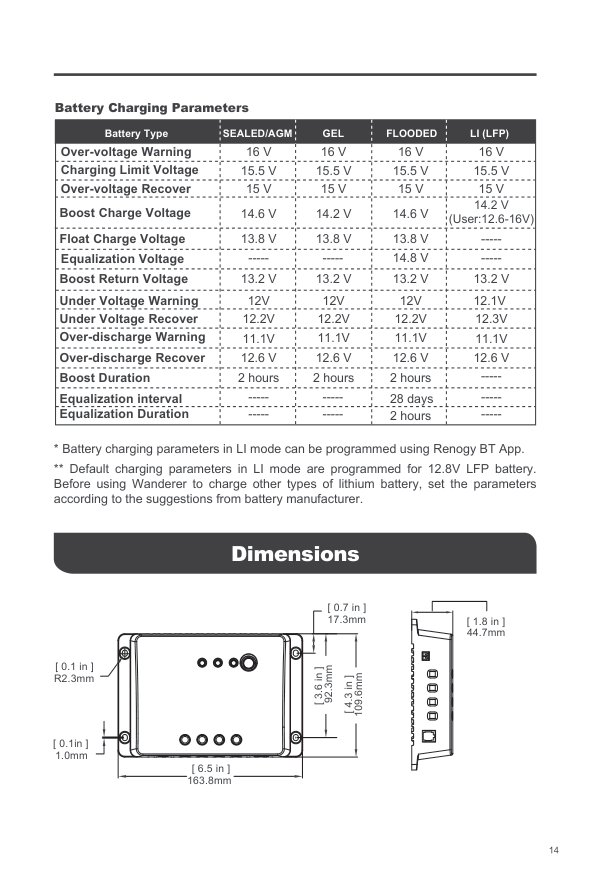
Battery Charging Parameters
|Battery Type
Over-voltage Warning|16 V
SEALED/AGM|GEL 16 V|FLOODED 16 V|LI (LFP) 16 V| |---|---|---|---|---| |Charging Limit Voltage|15.5 V|15.5 V|15.5 V|15.5 V| |Over-voltage Recover|15 V|15 V|15 V|15 V| |Boost Charge Voltage|14.6 V|14.2 V|14.6 V|14.2 V (User:12.6-16V)| |Float Charge Voltage|13.8 V|13.8 V|13.8 V|-----| |Equalization Voltage|-----|-----|14.8 V|-----| |Boost Return Voltage|13.2 V|13.2 V|13.2 V|13.2 V| |Under Voltage Warning|12V|12V|12V|12.1V|
|Under Voltage Recover|12.2V|12.2V|12.2V|12.3V| |Over-discharge Warning|11.1V|11.1V|11.1V|11.1V| |Over-discharge Recover|12.6 V|12.6 V|12.6 V|12.6 V| |Boost Duration|2 hours|2 hours|2 hours|-----| |Equalization interval|-----|-----|28 days|-----| |Equalization Duration|-----|-----|2 hours|-----|
Dimensions
[ 0.1 in ] R2.3mm
[ 0.1in ] 1.0mm
[ 6.5 in ] 163.8mm
[ 0.7 in ] 17.3mm
92.3mm
[ 3.6 in ]
109.6mm
[ 4.3 in ]
[ 1.8 in ] 44.7mm
##### RENOGY.COM
Renogy reserves the right to change the contents of this manual without notice.
US 2775 E Philadelphia St, Ontario, CA 91761, USA 909-287-7111 www.renogy.com support@renogy.com
###### CN
苏州高新区科技城培源路1号5号楼-4
400-6636-695
https://www.renogy.cn support@renogy.cn
JP https://www.renogy.jp
supportjp@renogy.com
CA https://ca.renogy.comsupportca@renogy.com
supportau@renogy.comAU
https://au.renogy.com
supportuk@renogy.comUK
https://uk.renogy.com
supportde@renogy.comDE
https://de.renogy.com

| | | | |---|---|---| || | | || | |
|| | | |---|---|---| || | | || | | || | | || | |
| | | | |---|---|---| || | | || | |
|| | | || | | || | |
|| | | |---|---|---| || | | || | | || | |


| | | | |---|---|---| || | | || | | || | | || | |
|| | |


| | | |---|---| | | | | | | | | | | | | | | | | | | | | | | | | | | | | | | | | | | | | | | | | | | | | | | | | | | | | | | | | | | | | | | |