
Ask AI
— answers from the official manualAnswers from the official manual.
Common questions
Common Questions
17 totalWhat is the maximum print width supported by the Canon imagePROGRAF iPF825?
The printer supports a maximum print width of 44 inches (1117.6 mm). It is a stand-mounted large-format bubble jet printer capable of output to either roll media or cut sheet. Roll media width ranges from 254mm (10") to 1118mm (44").
What ink tank capacities are available for this printer, and what colors are offered?
Ink tanks are available in two capacities: 330 ml and 700 ml. The available colors are mat black (pigment ink), black, cyan, magenta, and yellow (dye inks). Ink tanks compatible with this printer are labeled "A" on their side, printed in a white letter enclosed in a black circle.
How do I replace an ink tank on the iPF825?
To replace an ink tank, open the ink tank cover of the printer. Ink tanks are furnished with a notch for preventing incorrect installation, allowing them to be installed only at the position marked with the correct color. Replace a tank when an ink tank replacement prompt message appears on the display.
What does the ink lamp indicate when it is fast blinking?
A fast blinking ink lamp (red) indicates that the inks are out. A slow blinking lamp means the printer is low on ink, while the lamp being on means an ink tank is properly loaded. If the lamp is off, no ink tank is loaded or the remaining ink sensor is disabled.
What are the operating environment requirements for the iPF825?
The operating environment requires a temperature of 5 to 35 degrees centigrade and humidity of 10% to 90% RH. For guaranteed print quality, the environment should be maintained at 15 to 30 degrees centigrade and 10% to 80% RH. Power supply is 100–240 VAC (50/60 Hz).
How do I perform printhead cleaning from the operation panel?
To execute printhead cleaning (Head Cleaning A), hold the Information button depressed for 3 seconds. Head cleaning can also be accessed through the Main Menu under the [Head Cleaning] option, which offers both [Head Cleaning A] and [Head Cleaning B]. If print quality does not improve after the specified cleaning, the printhead must be replaced with a new one.
Show 11 more questions
What paper tube diameters does the roll holder accept?
What interface connections does the iPF825 support?
How large is the hard disk drive in the iPF825, and what are its benefits?
Where do I find detailed instructions for disassembling and reassembling the Canon Imageprograf iPF850?
What should I do if the printer encounters an error during a print job?
Where can I find specific printer error messages and their meanings?
How often should ink tanks be replaced, according to the Canon Imageprograf iPF850 maintenance schedule?
What safety precautions are important to follow when servicing the Canon Imageprograf printer iPF850?
How can I configure the paper source on my Canon Imageprograf iPF850?
What safety precautions should be taken when moving the iPF825 printer?
What consumable parts does the Canon Imageprograf iPF850 require regular replacement for maintenance?
Full Manual
292 pages

Service
Manual
imagePROGRAF iPF825Copyright © 2017 Canon Inc.
CANON imagePROGRAF iPF825 Rev.2 PRINTED IN U.S.A. February 27, 2017 Rev. 2
Application This manual has been issued by Canon Inc. for qualified persons to learn technical theory, installation, maintenance, and repair of products. This manual covers all localities where the products are sold. For this reason, there may be information in this manual that does not apply to your locality. Corrections This manual may contain technical inaccuracies or typographical errors due to improvements or changes in products. When changes occur in applicable products or in the contents of this manual, Canon will release technical information as the need arises. In the event of major changes in the contents of this manual over a long or short period, Canon will issue a new edition of this manual. The following paragraph does not apply to any countries where such provisions are inconsistent with local law. Trademarks The product names and company names used in this manual are the registered trademarks of the individual companies. Copyright This manual is copyrighted with all rights reserved. Under the copyright laws, this manual may not be copied, reproduced or translated into another language, in whole or in part, without the written consent of Canon Inc.
Copyright © 2001 Canon Inc.
Printed in Japan Caution Use of this manual should be strictly supervised to avoid disclosure of confidential information.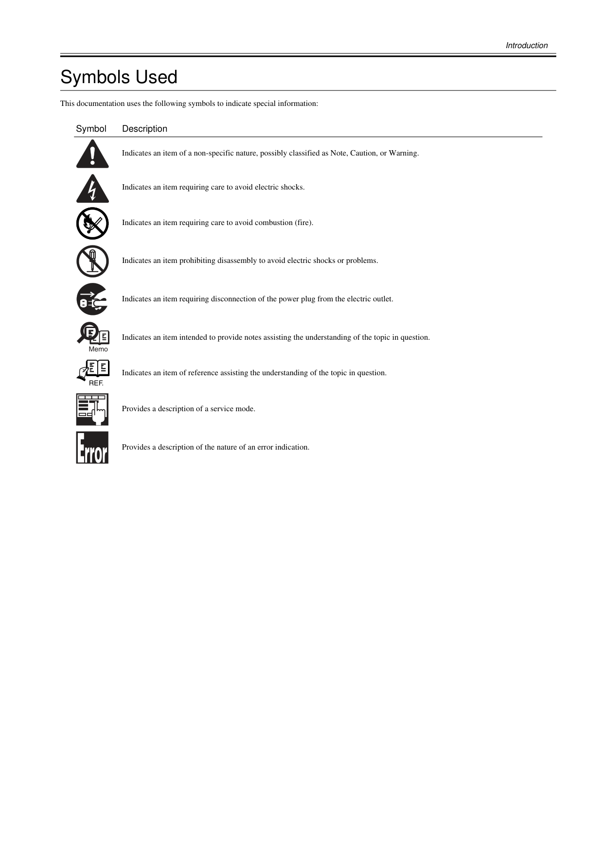
Introduction Symbols Used This documentation uses the following symbols to indicate special information: Symbol Description Indicates an item of a non-specific nature, possibly classified as Note, Caution, or Warning. Indicates an item requiring care to avoid electric shocks. Indicates an item requiring care to avoid combustion (fire). Indicates an item prohibiting disassembly to avoid electric shocks or problems. Indicates an item requiring disconnection of the power plug from the electric outlet. Indicates an item intended to provide notes assisting the understanding of the topic in question. Indicates an item of reference assisting the understanding of the topic in question. Provides a description of a service mode. Provides a description of the nature of an error indication. Memo
Ref.

Introduction The following rules apply throughout this Service Manual:
Contents Contents Chapter 1 PRODUCT DESCRIPTION 1.1 Product Overview .......................................................................................................................................1- 1 1.1.1 Product Overview ....................................................................................................................................................1- 1 1.2 Features .....................................................................................................................................................1- 3 1.2.1 Features ..................................................................................................................................................................1- 3 1.2.2 Printhead .................................................................................................................................................................1- 3 1.2.3 Ink Tank...................................................................................................................................................................1- 3 1.2.4 Cutter.......................................................................................................................................................................1- 4 1.2.5 Roll Holder...............................................................................................................................................................1- 4 1.2.6 Stand .......................................................................................................................................................................1- 5 1.2.7 Wheeled Output Stacker .........................................................................................................................................1- 5 1.2.8 Hard Disk Drive .......................................................................................................................................................1- 5 1.2.9 Consumables...........................................................................................................................................................1- 6 1.3 Product Specifications ................................................................................................................................1- 7 1.3.1 Product Specifications.............................................................................................................................................1- 7 1.4 Detailed Specifications ...............................................................................................................................1- 9 1.4.1 Print Speed and Direction........................................................................................................................................1- 9 1.4.2 Interface Specifications .........................................................................................................................................1- 15 1.5 Names and Functions of Components .....................................................................................................1- 16 1.5.1 Front ......................................................................................................................................................................1- 16 1.5.2 Rear.......................................................................................................................................................................1- 17 1.5.3 Top Cover (Inside).................................................................................................................................................1- 18 1.5.4 Carriage.................................................................................................................................................................1- 19 1.5.5 Ink Tank Cover (Inside) .........................................................................................................................................1- 19 1.6 Basic Operation ........................................................................................................................................1- 20 1.6.1 Operation Panel.....................................................................................................................................................1- 20 1.6.2 Main Menu.............................................................................................................................................................1- 21 1.7 Safety and Precautions ............................................................................................................................1- 43 1.7.1 Safety Precautions ................................................................................................................................................1- 43 1.7.1.1 Moving Parts.......................................................................................................................................................................... 1- 43 1.7.1.2 Adhesion of Ink ...................................................................................................................................................................... 1- 44 1.7.1.3 Electric Parts.......................................................................................................................................................................... 1- 46 1.7.2 Other Precautions..................................................................................................................................................1- 47 1.7.2.1 Printhead................................................................................................................................................................................ 1- 47 1.7.2.2 Ink Tank ................................................................................................................................................................................. 1- 48 1.7.2.3 Handling the Printer ............................................................................................................................................................... 1- 49 1.7.3 Precautions When Servicing Printer......................................................................................................................1- 51 1.7.3.1 Notes on the Data Stored in the Printer................................................................................................................................. 1- 51 1.7.3.2 Confirming the Firmware Version .......................................................................................................................................... 1- 51 1.7.3.3 Precautions against Static Electricity..................................................................................................................................... 1- 51 1.7.3.4 Precautions for Disassembly/Reassembly............................................................................................................................. 1- 51 1.7.3.5 Self-diagnostic Feature.......................................................................................................................................................... 1- 51 1.7.3.6 Disposing of the Lithium Battery ............................................................................................................................................ 1- 52 Chapter 2 TECHNICAL REFERENCE 2.1 Basic Operation Outline..............................................................................................................................2- 1 2.1.1 Printer Diagram .......................................................................................................................................................2- 1 2.1.2 Print Signal Sequence.............................................................................................................................................2- 2 2.1.3 Print Driving.............................................................................................................................................................2- 3 2.2 Firmware.....................................................................................................................................................2- 5
Contents 2.2.1 Operation Sequence at Power-on............................................................................................................................2- 5 2.2.2 Operation Sequence at Power-off............................................................................................................................2- 6 2.2.3 Print Control.............................................................................................................................................................2- 7 2.2.4 Print Position Adjustment Function........................................................................................................................2- 16 2.2.5 Head Management ................................................................................................................................................2- 16 2.2.6 Printhead Overheating Protection Control .............................................................................................................2- 16 2.2.7 Pause between Pages...........................................................................................................................................2- 16 2.2.8 White Raster Skip ..................................................................................................................................................2- 16 2.2.9 Sleep Mode............................................................................................................................................................2- 16 2.2.10 Hard Disk Drive....................................................................................................................................................2- 16 2.3 Printer Mechanical System.......................................................................................................................2- 18 2.3.1 Outline....................................................................................................................................................................2- 18 2.3.1.1 Outline.................................................................................................................................................................................... 2- 18 2.3.2 Ink Passage ...........................................................................................................................................................2- 19 2.3.2.1 Ink Passage ........................................................................................................................................................................... 2- 19 2.3.2.2 Ink Tank Unit.......................................................................................................................................................................... 2- 20 2.3.2.3 Carriage Unit.......................................................................................................................................................................... 2- 22 2.3.2.4 Printhead................................................................................................................................................................................ 2- 25 2.3.2.5 Purge Unit.............................................................................................................................................................................. 2- 26 2.3.2.6 Maintenance Cartridge........................................................................................................................................................... 2- 30 2.3.2.7 Air Flow.................................................................................................................................................................................. 2- 31 2.3.3 Paper Path.............................................................................................................................................................2- 32 2.3.3.1 Outline.................................................................................................................................................................................... 2- 32 2.3.3.2 Paper Path............................................................................................................................................................................. 2- 33 2.3.3.3 Cutter Unit.............................................................................................................................................................................. 2- 36 2.4 Printer Electrical System ..........................................................................................................................2- 37 2.4.1 Outline....................................................................................................................................................................2- 37 2.4.1.1 Overview................................................................................................................................................................................ 2- 37 2.4.2 Main Controller.......................................................................................................................................................2- 39 2.4.2.1 Main controller PCB components .......................................................................................................................................... 2- 39 2.4.3 Carriage Relay PCB...............................................................................................................................................2- 41 2.4.3.1 Carriage relay PCB components ........................................................................................................................................... 2- 41 2.4.4 Head Relay PCB....................................................................................................................................................2- 41 2.4.4.1 Head relay PCB components................................................................................................................................................. 2- 41 2.4.5 Motor Driver ...........................................................................................................................................................2- 42 2.4.5.1 Lower roll unit PCB components............................................................................................................................................ 2- 42 2.4.6 Maintenance Cartridge Relay PCB........................................................................................................................2- 42 2.4.6.1 Maintenance cartridge relay PCB components...................................................................................................................... 2- 42 2.4.7 Power Supply.........................................................................................................................................................2- 42 2.4.7.1 Power supply block diagram.................................................................................................................................................. 2- 42 2.5 Detection Functions with Sensors ............................................................................................................2- 43 2.5.1 Covers....................................................................................................................................................................2- 43 2.5.2 Ink passage system ...............................................................................................................................................2- 44 2.5.3 Carriage system.....................................................................................................................................................2- 46 2.5.4 Paper path system.................................................................................................................................................2- 48 2.5.5 Others ....................................................................................................................................................................2- 50 Chapter 3 INSTALLATION 3.1 Transporting the Printer..............................................................................................................................3- 1 3.1.1 Transporting the Printer ...........................................................................................................................................3- 1 3.1.1.1 Transporting the Printer ........................................................................................................................................................... 3- 1 3.1.2 Reinstalling the Printer...........................................................................................................................................3- 13 3.1.2.1 Reinstalling the Printer........................................................................................................................................................... 3- 13 Chapter 4 DISASSEMBLY/REASSEMBLY 4.1 Service Parts ..............................................................................................................................................4- 1
Contents 4.1.1 Service Parts ...........................................................................................................................................................4- 1 4.2 Disassembly/Reassembly...........................................................................................................................4- 2 4.2.1 Disassembly/Reassembly .......................................................................................................................................4- 2 4.3 Points to Note on Disassembly and Reassembly.......................................................................................4- 2 4.3.1 Note: Items that should never be disassembled......................................................................................................4- 2 4.3.2 Moving the carriage manually..................................................................................................................................4- 2 4.3.3 Units requiring draining of ink..................................................................................................................................4- 2 4.3.4 External Covers.......................................................................................................................................................4- 4 4.3.5 Drive Unit...............................................................................................................................................................4- 17 4.3.6 Cutter.....................................................................................................................................................................4- 19 4.3.7 Carriage Unit .........................................................................................................................................................4- 21 4.3.8 Ink Tube Unit .........................................................................................................................................................4- 26 4.3.9 Pick-up/Feed Unit..................................................................................................................................................4- 29 4.3.10 Purge Unit............................................................................................................................................................4- 32 4.3.11 Waste Ink Collection Unit.....................................................................................................................................4- 33 4.3.12 Ink Tank Unit........................................................................................................................................................4- 43 4.3.13 Multi Sensor.........................................................................................................................................................4- 45 4.3.14 Linear Encoder Sensor........................................................................................................................................4- 48 4.3.15 Head Management Sensor..................................................................................................................................4- 49 4.3.16 PCBs....................................................................................................................................................................4- 50 4.3.17 Opening the Cap/Moving the Wiper Unit .............................................................................................................4- 51 4.3.18 Opening and closing ink supply valves................................................................................................................4- 52 4.3.19 Draining the ink....................................................................................................................................................4- 53 4.4 Applying the Grease .................................................................................................................................4- 54 4.4.1 Applying the Grease..............................................................................................................................................4- 54 4.5 Adjustment and Setup Items ....................................................................................................................4- 57 4.5.1 Adjustment Item List..............................................................................................................................................4- 57 4.5.2 Procedure after Replacing the Carriage Unit or Multi Sensor ...............................................................................4- 57 4.5.3 Procedure after Replacing the Feed Roller or Feed Roller Encoder .....................................................................4- 57 4.5.4 Procedure after Replacing the Head Management Sensor...................................................................................4- 57 Chapter 5 MAINTENANCE 5.1 Periodic Replacement Parts .......................................................................................................................5- 1 5.1.1 Periodic Replacement Parts....................................................................................................................................5- 1 5.2 Consumable Parts ......................................................................................................................................5- 1 5.2.1 Consumable Parts...................................................................................................................................................5- 1 5.3 Periodic Maintenance .................................................................................................................................5- 2 5.3.1 Periodic Maintenance..............................................................................................................................................5- 2 Chapter 6 TROUBLESHOOTING 6.1 Troubleshooting..........................................................................................................................................6- 1 6.1.1 Outline .....................................................................................................................................................................6- 1 6.1.1.1 Outline of Troubleshooting....................................................................................................................................................... 6- 1 6.2 Location of Connectors and Pin Arrangement............................................................................................6- 2 6.2.1 Main controller PCB.................................................................................................................................................6- 2 6.2.2 Carriage relay PCB................................................................................................................................................6- 12 6.2.3 Head relay PCB.....................................................................................................................................................6- 17 6.3 Version Up................................................................................................................................................6- 21 6.3.1 Firmware Update Tool...........................................................................................................................................6- 21 6.4 Service Tools............................................................................................................................................6- 26 6.4.1 Tool List.................................................................................................................................................................6- 26 Chapter 7 SERVICE MODE

Contents 7.1 Service Mode .............................................................................................................................................7- 1 7.1.1 Service Mode Operation ..........................................................................................................................................7- 1 7.1.2 Map of the Service Mode.........................................................................................................................................7- 2 7.1.3 Details of Service Mode...........................................................................................................................................7- 8 7.1.4 Sample Printout .....................................................................................................................................................7- 16 7.2 Special Mode............................................................................................................................................7- 20 7.2.1 Special Modes for Servicing ..................................................................................................................................7- 20 Chapter 8 ERROR CODE 8.1 Outline ........................................................................................................................................................8- 1 8.1.1 Outline......................................................................................................................................................................8- 1 8.2 Warning/Error/Service Call Error................................................................................................................8- 2 8.2.1 Code Table ..............................................................................................................................................................8- 2

Chapter 1 PRODUCT DESCRIPTION
Contents Contents 1.1 Product Overview ....................................................................................................................................... 1-1 1.1.1 Product Overview .................................................................................................................................................... 1-1 1.2 Features ..................................................................................................................................................... 1-3 1.2.1 Features .................................................................................................................................................................. 1-3 1.2.2 Printhead ................................................................................................................................................................. 1-3 1.2.3 Ink Tank................................................................................................................................................................... 1-3 1.2.4 Cutter....................................................................................................................................................................... 1-4 1.2.5 Roll Holder............................................................................................................................................................... 1-4 1.2.6 Stand ....................................................................................................................................................................... 1-5 1.2.7 Wheeled Output Stacker ......................................................................................................................................... 1-5 1.2.8 Hard Disk Drive ....................................................................................................................................................... 1-5 1.2.9 Consumables........................................................................................................................................................... 1-6 1.3 Product Specifications ................................................................................................................................ 1-7 1.3.1 Product Specifications............................................................................................................................................. 1-7 1.4 Detailed Specifications ............................................................................................................................... 1-9 1.4.1 Print Speed and Direction........................................................................................................................................ 1-9 1.4.2 Interface Specifications .......................................................................................................................................... 1-15 1.5 Names and Functions of Components ..................................................................................................... 1-16 1.5.1 Front ....................................................................................................................................................................... 1-16 1.5.2 Rear........................................................................................................................................................................ 1-17 1.5.3 Top Cover (Inside).................................................................................................................................................. 1-18 1.5.4 Carriage.................................................................................................................................................................. 1-19 1.5.5 Ink Tank Cover (Inside) .......................................................................................................................................... 1-19 1.6 Basic Operation ........................................................................................................................................ 1-20 1.6.1 Operation Panel...................................................................................................................................................... 1-20 1.6.2 Main Menu.............................................................................................................................................................. 1-21 1.7 Safety and Precautions ............................................................................................................................ 1-43 1.7.1 Safety Precautions ................................................................................................................................................. 1-43 1.7.1.1 Moving Parts........................................................................................................................................................................... 1-43 1.7.1.2 Adhesion of Ink ....................................................................................................................................................................... 1-44 1.7.1.3 Electric Parts........................................................................................................................................................................... 1-46 1.7.2 Other Precautions................................................................................................................................................... 1-47 1.7.2.1 Printhead................................................................................................................................................................................. 1-47 1.7.2.2 Ink Tank .................................................................................................................................................................................. 1-48 1.7.2.3 Handling the Printer ................................................................................................................................................................ 1-49 1.7.3 Precautions When Servicing Printer....................................................................................................................... 1-51 1.7.3.1 Notes on the Data Stored in the Printer.................................................................................................................................. 1-51 1.7.3.2 Confirming the Firmware Version ........................................................................................................................................... 1-51 1.7.3.3 Precautions against Static Electricity...................................................................................................................................... 1-51 1.7.3.4 Precautions for Disassembly/Reassembly.............................................................................................................................. 1-51 1.7.3.5 Self-diagnostic Feature........................................................................................................................................................... 1-51 1.7.3.6 Disposing of the Lithium Battery ............................................................................................................................................. 1-52
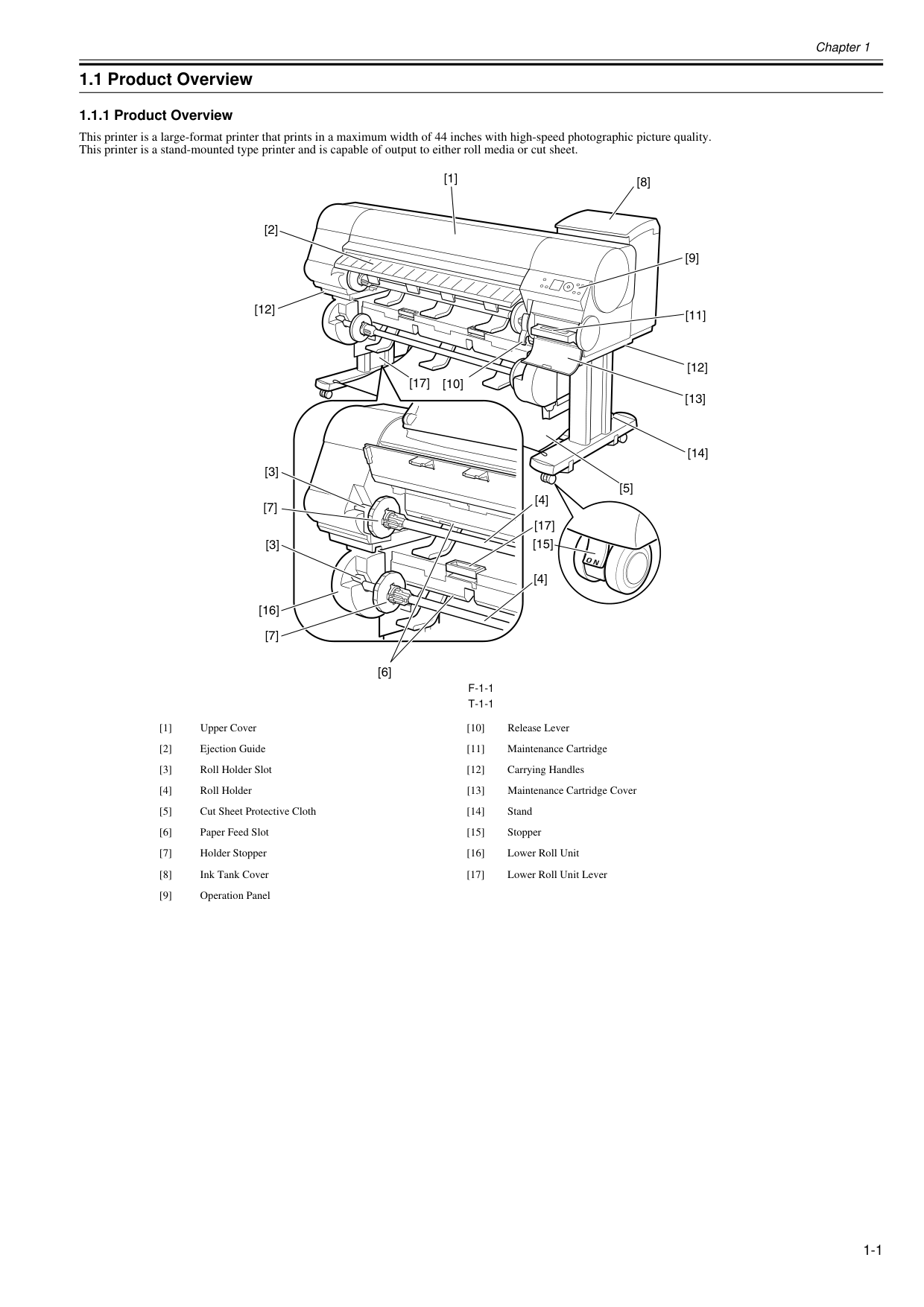
Chapter 1 1-1 1.1 Product Overview 1.1.1 Product Overview 0025-9205 This printer is a large-format printer that prints in a maximum width of 44 inches with high-speed photographic picture quality. This printer is a stand-mounted type printer and is capable of output to either roll media or cut sheet.
F-1-1
T-1-1
[1] Upper Cover [10] Release Lever [2] Ejection Guide [11] Maintenance Cartridge [3] Roll Holder Slot [12] Carrying Handles [4] Roll Holder [13] Maintenance Cartridge Cover [5] Cut Sheet Protective Cloth [14] Stand [6] Paper Feed Slot [15] Stopper [7] Holder Stopper [16] Lower Roll Unit [8] Ink Tank Cover [17] Lower Roll Unit Lever [9] Operation Panel [1] [9] [8] [10] [2] [3] [3] [4] [4] [12] [5] [17] [7] [16] [7] [11] [12] [17] [13] [14] [15] [6]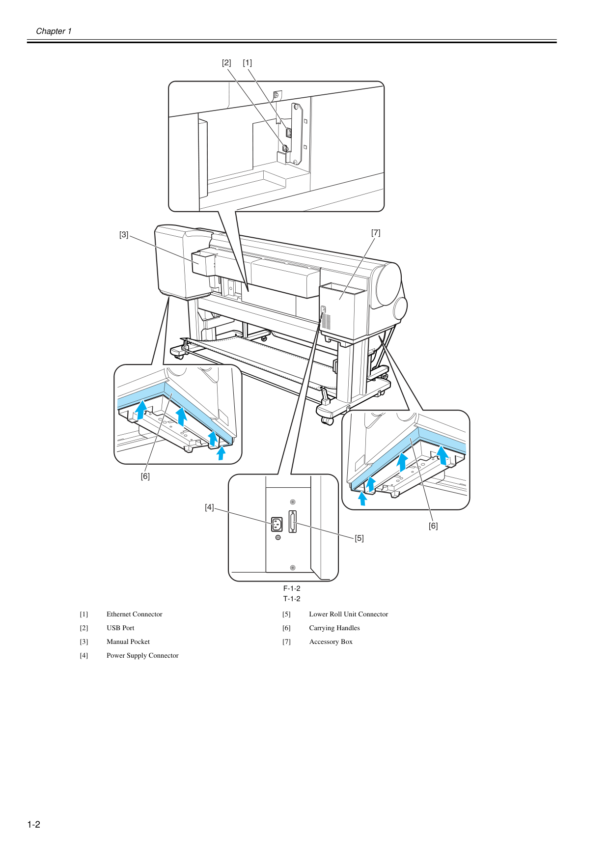
Chapter 1 1-2
F-1-2
T-1-2
[1] Ethernet Connector [5] Lower Roll Unit Connector [2] USB Port [6] Carrying Handles [3] Manual Pocket [7] Accessory Box [4] Power Supply Connector [2] [1] [3] [4] [5] [7] [6] [6]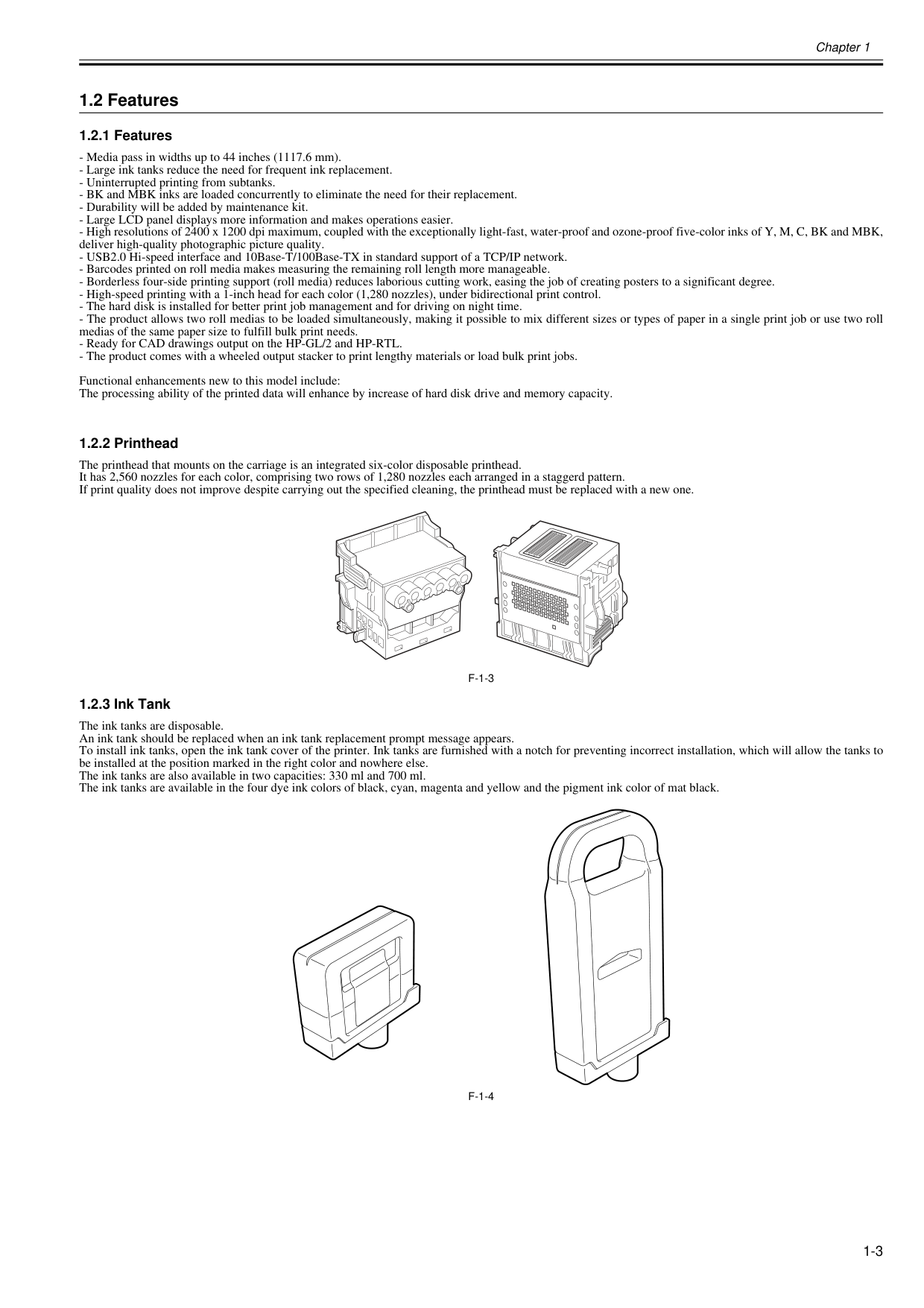
Chapter 1 1-3 1.2 Features 1.2.1 Features 0025-9206
F-1-3
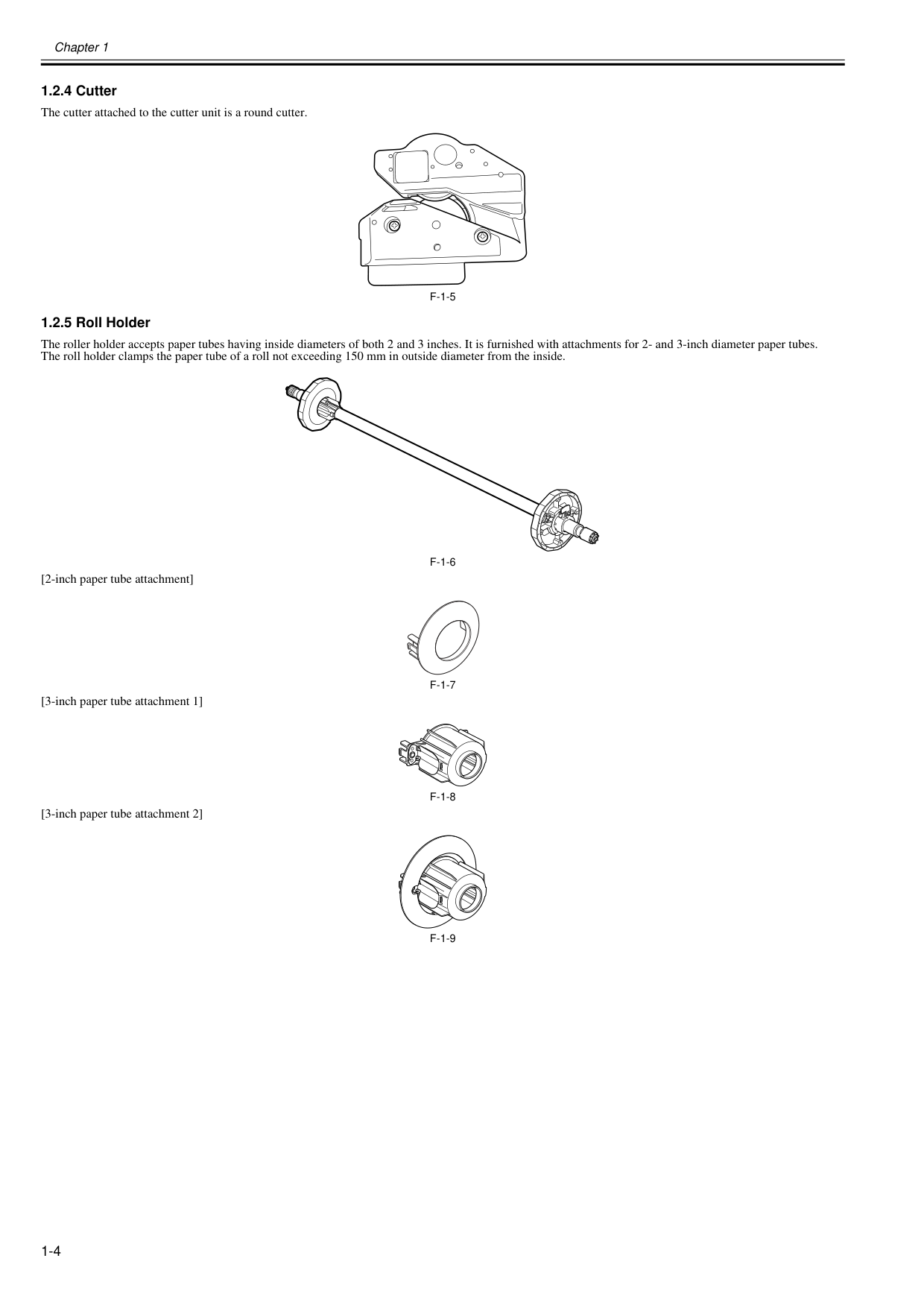
1.2.3 Ink Tank 0020-5419 The ink tanks are disposable. An ink tank should be replaced when an ink tank replacement prompt message appears. To install ink tanks, open the ink tank cover of the printer. Ink tanks are furnished with a notch for preventing incorrect installation, which will allow the tanks to be installed at the position marked in the right color and nowhere else. The ink tanks are also available in two capacities: 330 ml and 700 ml. The ink tanks are available in the four dye ink colors of black, cyan, magenta and yellow and the pigment ink color of mat black.F-1-4
Chapter 1 1-4 1.2.4 Cutter 0020-5420 The cutter attached to the cutter unit is a round cutter.
F-1-5
1.2.5 Roll Holder 0020-5421 The roller holder accepts paper tubes having inside diameters of both 2 and 3 inches. It is furnished with attachments for 2- and 3-inch diameter paper tubes. The roll holder clamps the paper tube of a roll not exceeding 150 mm in outside diameter from the inside.F-1-6
[2-inch paper tube attachment]F-1-7
[3-inch paper tube attachment 1]F-1-8
[3-inch paper tube attachment 2]F-1-9
Chapter 1 1-5 1.2.6 Stand 0020-6040 The stand is equipped with casters so that the printer can be easily moved.
F-1-10
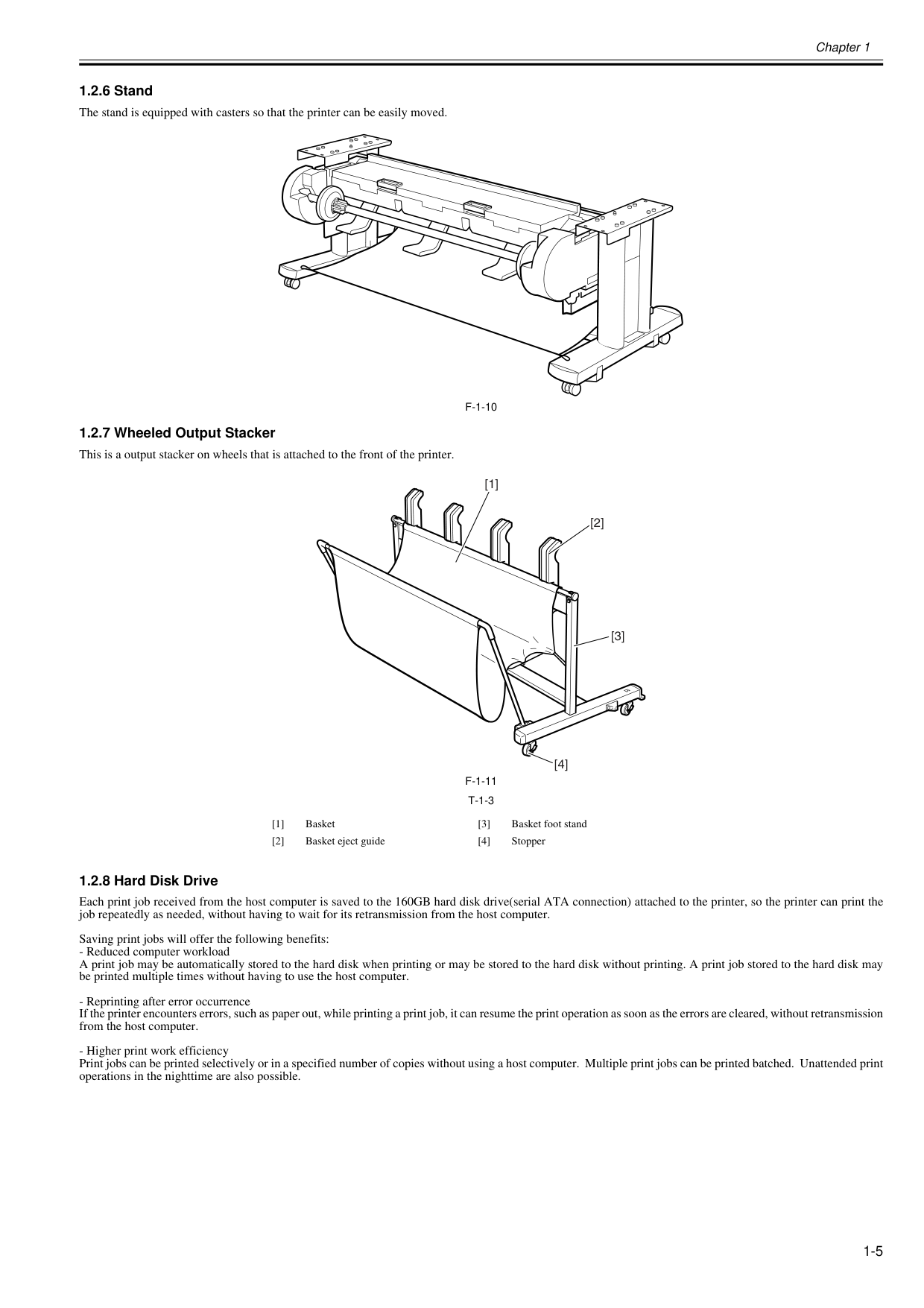
1.2.7 Wheeled Output Stacker 0020-5422 This is a output stacker on wheels that is attached to the front of the printer.F-1-11
T-1-3
1.2.8 Hard Disk Drive 0025-9220 Each print job received from the host computer is saved to the 160GB hard disk drive(serial ATA connection) attached to the printer, so the printer can print the job repeatedly as needed, without having to wait for its retransmission from the host computer. Saving print jobs will offer the following benefits: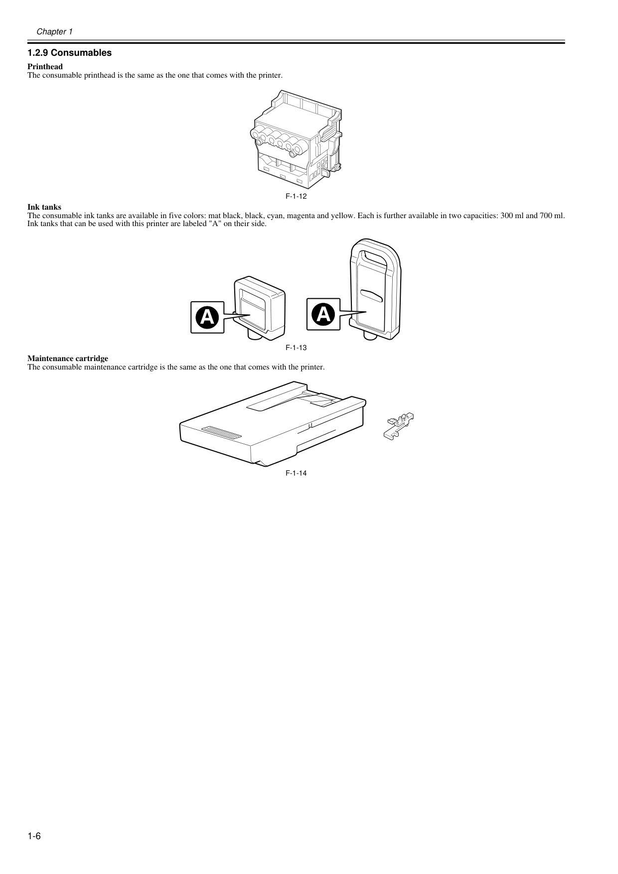
Chapter 1 1-6 1.2.9 Consumables 0020-5424 Printhead The consumable printhead is the same as the one that comes with the printer.
F-1-12
Ink tanks The consumable ink tanks are available in five colors: mat black, black, cyan, magenta and yellow. Each is further available in two capacities: 300 ml and 700 ml. Ink tanks that can be used with this printer are labeled "A" on their side.F-1-13
Maintenance cartridge The consumable maintenance cartridge is the same as the one that comes with the printer.F-1-14
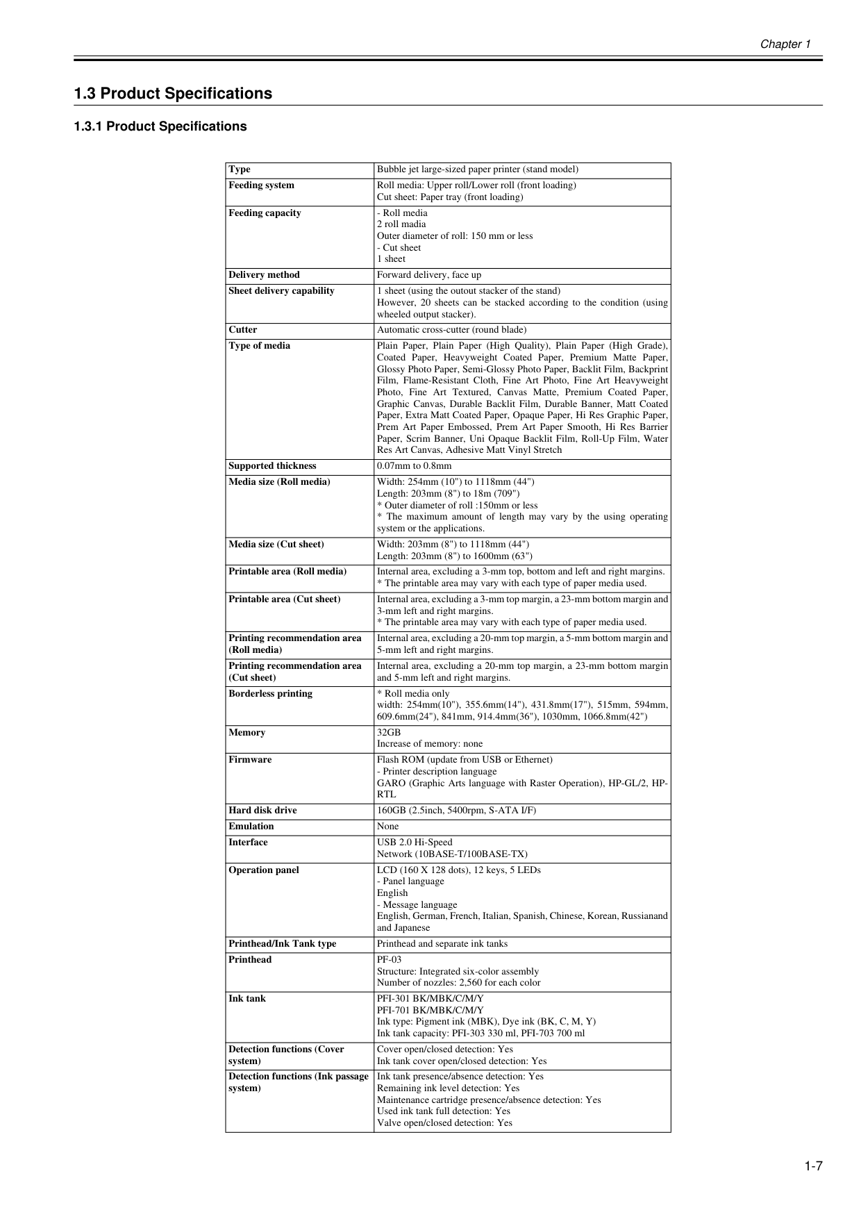
Chapter 1 1-7 1.3 Product Specifications 1.3.1 Product Specifications 0025-9231 Type Bubble jet large-sized paper printer (stand model) Feeding system Roll media: Upper roll/Lower roll (front loading) Cut sheet: Paper tray (front loading) Feeding capacity
32Gb
Increase of memory: none Firmware Flash ROM (update from USB or Ethernet)Rtl
Hard disk drive 160GB (2.5inch, 5400rpm, S-ATA I/F) Emulation None Interface USB 2.0 Hi-Speed Network (10BASE-T/100BASE-TX) Operation panel LCD (160 X 128 dots), 12 keys, 5 LEDsPf-03
Structure: Integrated six-color assembly Number of nozzles: 2,560 for each color Ink tankPfi-301 Bk/Mbk/C/M/Y
Pfi-701 Bk/Mbk/C/M/Y
Ink type: Pigment ink (MBK), Dye ink (BK, C, M, Y) Ink tank capacity: PFI-303 330 ml, PFI-703 700 ml Detection functions (Cover system) Cover open/closed detection: Yes Ink tank cover open/closed detection: Yes Detection functions (Ink passage system) Ink tank presence/absence detection: Yes Remaining ink level detection: Yes Maintenance cartridge presence/absence detection: Yes Used ink tank full detection: Yes Valve open/closed detection: Yes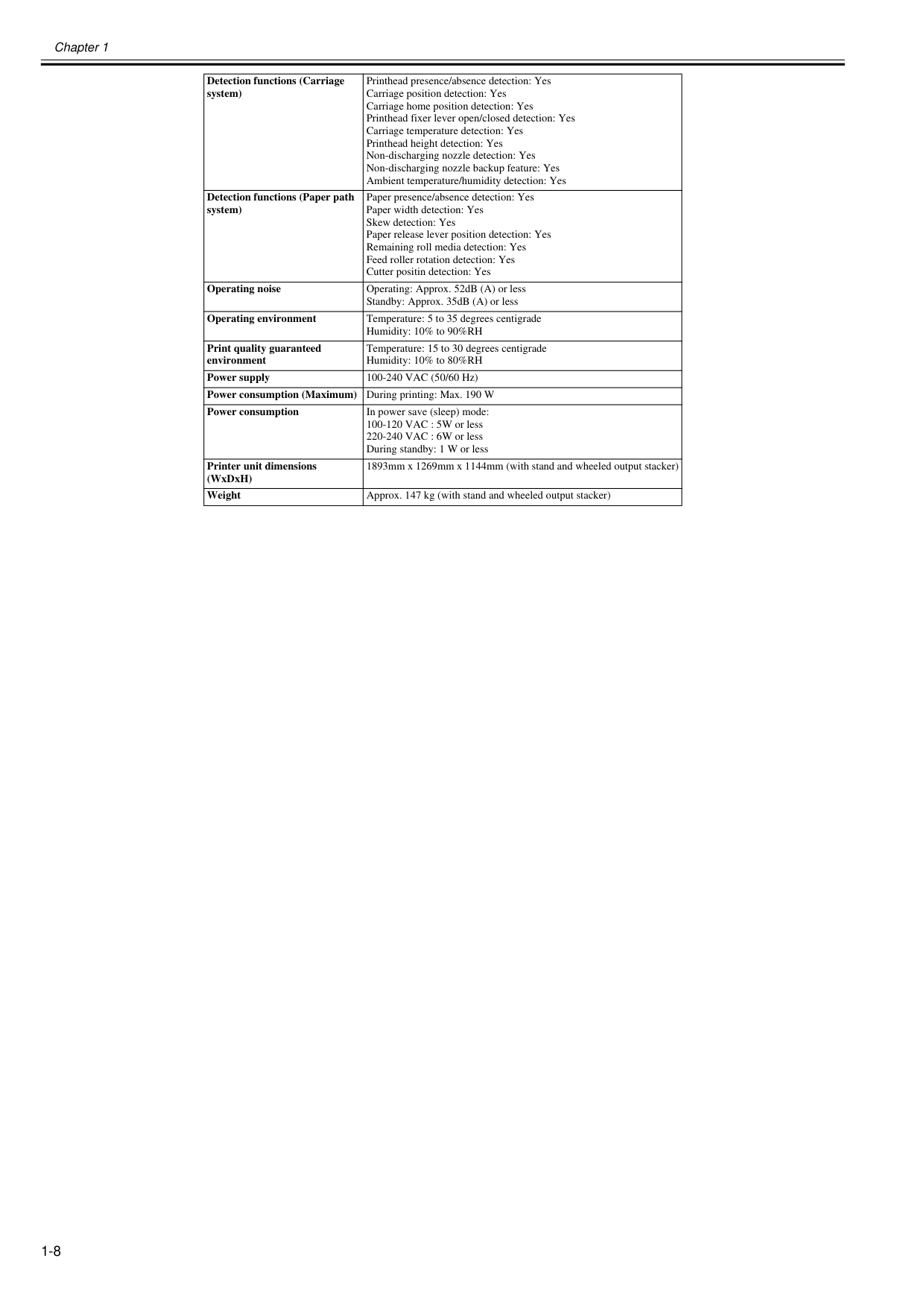
Chapter 1 1-8 Detection functions (Carriage system) Printhead presence/absence detection: Yes Carriage position detection: Yes Carriage home position detection: Yes Printhead fixer lever open/closed detection: Yes Carriage temperature detection: Yes Printhead height detection: Yes Non-discharging nozzle detection: Yes Non-discharging nozzle backup feature: Yes Ambient temperature/humidity detection: Yes Detection functions (Paper path system) Paper presence/absence detection: Yes Paper width detection: Yes Skew detection: Yes Paper release lever position detection: Yes Remaining roll media detection: Yes Feed roller rotation detection: Yes Cutter positin detection: Yes Operating noise Operating: Approx. 52dB (A) or less Standby: Approx. 35dB (A) or less Operating environment Temperature: 5 to 35 degrees centigrade Humidity: 10% to 90%RH Print quality guaranteed environment Temperature: 15 to 30 degrees centigrade Humidity: 10% to 80%RH Power supply 100-240 VAC (50/60 Hz) Power consumption (Maximum) During printing: Max. 190 W Power consumption In power save (sleep) mode: 100-120 VAC : 5W or less 220-240 VAC : 6W or less During standby: 1 W or less Printer unit dimensions (WxDxH) 1893mm x 1269mm x 1144mm (with stand and wheeled output stacker) Weight Approx. 147 kg (with stand and wheeled output stacker)
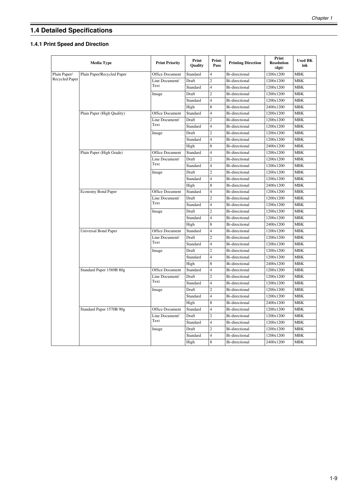
Chapter 1 1-9 1.4 Detailed Specifications 1.4.1 Print Speed and Direction 0020-5441 Media Type Print Priority Print Quality Print- Pass Printing Direction Print Resolution (dpi) Used BK ink Plain Paper/ Recycled Paper Plain Paper/Recycled Paper Office Document Standard 4 Bi-directional 1200x1200
Mbk
Line Document/ Text Draft 2 Bi-directional 1200x1200Mbk
Standard 4 Bi-directional 1200x1200Mbk
Image Draft 2 Bi-directional 1200x1200Mbk
Standard 4 Bi-directional 1200x1200Mbk
High 8 Bi-directional 2400x1200Mbk
Plain Paper (High Quality) Office Document Standard 4 Bi-directional 1200x1200Mbk
Line Document/ Text Draft 2 Bi-directional 1200x1200Mbk
Standard 4 Bi-directional 1200x1200Mbk
Image Draft 2 Bi-directional 1200x1200Mbk
Standard 4 Bi-directional 1200x1200Mbk
High 8 Bi-directional 2400x1200Mbk
Plain Paper (High Grade) Office Document Standard 4 Bi-directional 1200x1200Mbk
Line Document/ Text Draft 2 Bi-directional 1200x1200Mbk
Standard 4 Bi-directional 1200x1200Mbk
Image Draft 2 Bi-directional 1200x1200Mbk
Standard 4 Bi-directional 1200x1200Mbk
High 8 Bi-directional 2400x1200Mbk
Economy Bond Paper Office Document Standard 4 Bi-directional 1200x1200Mbk
Line Document/ Text Draft 2 Bi-directional 1200x1200Mbk
Standard 4 Bi-directional 1200x1200Mbk
Image Draft 2 Bi-directional 1200x1200Mbk
Standard 4 Bi-directional 1200x1200Mbk
High 8 Bi-directional 2400x1200Mbk
Universal Bond Paper Office Document Standard 4 Bi-directional 1200x1200Mbk
Line Document/ Text Draft 2 Bi-directional 1200x1200Mbk
Standard 4 Bi-directional 1200x1200Mbk
Image Draft 2 Bi-directional 1200x1200Mbk
Standard 4 Bi-directional 1200x1200Mbk
High 8 Bi-directional 2400x1200Mbk
Standard Paper 1569B 80g Office Document Standard 4 Bi-directional 1200x1200Mbk
Line Document/ Text Draft 2 Bi-directional 1200x1200Mbk
Standard 4 Bi-directional 1200x1200Mbk
Image Draft 2 Bi-directional 1200x1200Mbk
Standard 4 Bi-directional 1200x1200Mbk
High 8 Bi-directional 2400x1200Mbk
Standard Paper 1570B 90g Office Document Standard 4 Bi-directional 1200x1200Mbk
Line Document/ Text Draft 2 Bi-directional 1200x1200Mbk
Standard 4 Bi-directional 1200x1200Mbk
Image Draft 2 Bi-directional 1200x1200Mbk
Standard 4 Bi-directional 1200x1200Mbk
High 8 Bi-directional 2400x1200Mbk
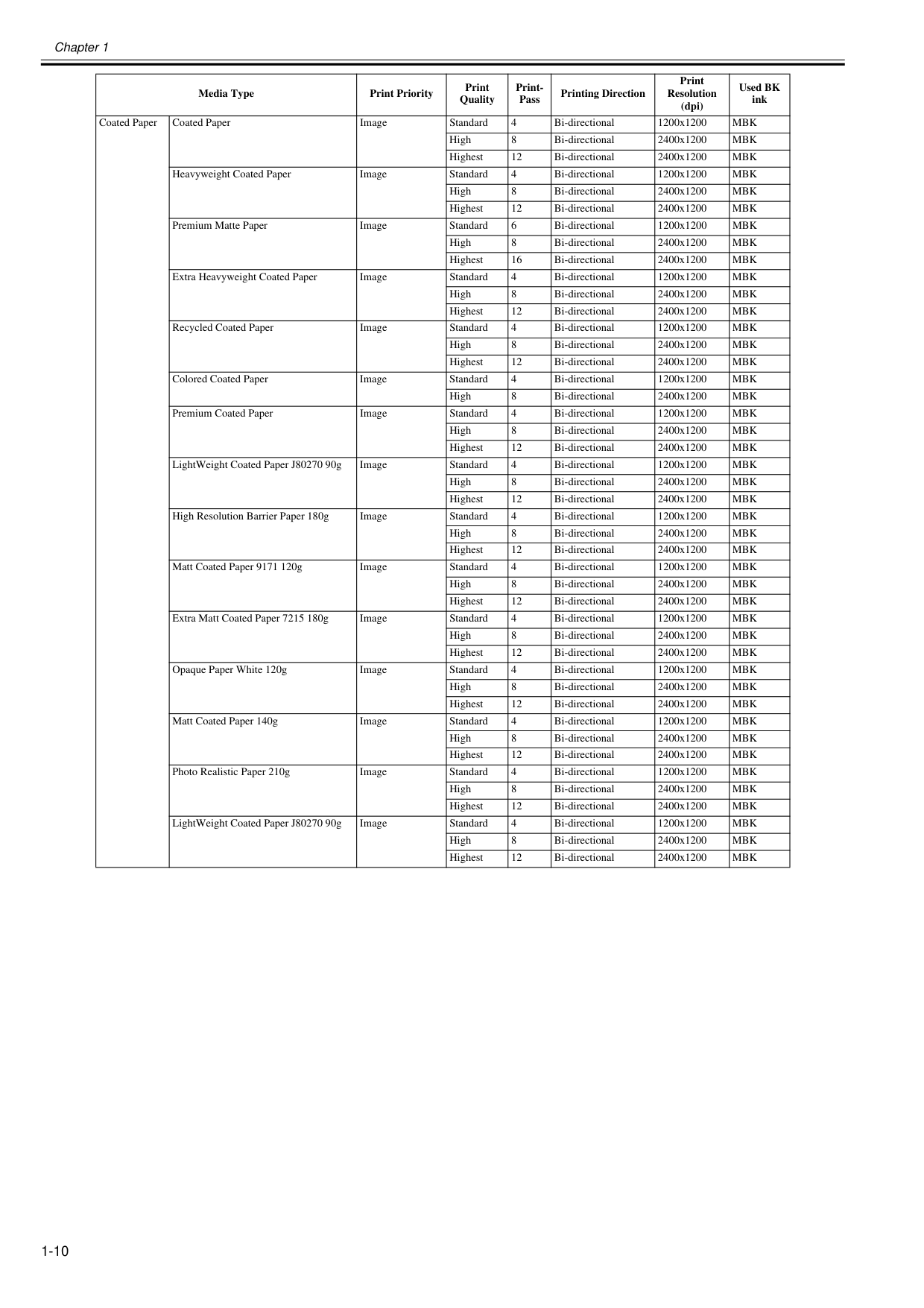
Chapter 1 1-10 Coated Paper Coated Paper Image Standard 4 Bi-directional 1200x1200
Mbk
High 8 Bi-directional 2400x1200Mbk
Highest 12 Bi-directional 2400x1200Mbk
Heavyweight Coated Paper Image Standard 4 Bi-directional 1200x1200Mbk
High 8 Bi-directional 2400x1200Mbk
Highest 12 Bi-directional 2400x1200Mbk
Premium Matte Paper Image Standard 6 Bi-directional 1200x1200Mbk
High 8 Bi-directional 2400x1200Mbk
Highest 16 Bi-directional 2400x1200Mbk
Extra Heavyweight Coated Paper Image Standard 4 Bi-directional 1200x1200Mbk
High 8 Bi-directional 2400x1200Mbk
Highest 12 Bi-directional 2400x1200Mbk
Recycled Coated Paper Image Standard 4 Bi-directional 1200x1200Mbk
High 8 Bi-directional 2400x1200Mbk
Highest 12 Bi-directional 2400x1200Mbk
Colored Coated Paper Image Standard 4 Bi-directional 1200x1200Mbk
High 8 Bi-directional 2400x1200Mbk
Premium Coated Paper Image Standard 4 Bi-directional 1200x1200Mbk
High 8 Bi-directional 2400x1200Mbk
Highest 12 Bi-directional 2400x1200Mbk
LightWeight Coated Paper J80270 90g Image Standard 4 Bi-directional 1200x1200Mbk
High 8 Bi-directional 2400x1200Mbk
Highest 12 Bi-directional 2400x1200Mbk
High Resolution Barrier Paper 180g Image Standard 4 Bi-directional 1200x1200Mbk
High 8 Bi-directional 2400x1200Mbk
Highest 12 Bi-directional 2400x1200Mbk
Matt Coated Paper 9171 120g Image Standard 4 Bi-directional 1200x1200Mbk
High 8 Bi-directional 2400x1200Mbk
Highest 12 Bi-directional 2400x1200Mbk
Extra Matt Coated Paper 7215 180g Image Standard 4 Bi-directional 1200x1200Mbk
High 8 Bi-directional 2400x1200Mbk
Highest 12 Bi-directional 2400x1200Mbk
Opaque Paper White 120g Image Standard 4 Bi-directional 1200x1200Mbk
High 8 Bi-directional 2400x1200Mbk
Highest 12 Bi-directional 2400x1200Mbk
Matt Coated Paper 140g Image Standard 4 Bi-directional 1200x1200Mbk
High 8 Bi-directional 2400x1200Mbk
Highest 12 Bi-directional 2400x1200Mbk
Photo Realistic Paper 210g Image Standard 4 Bi-directional 1200x1200Mbk
High 8 Bi-directional 2400x1200Mbk
Highest 12 Bi-directional 2400x1200Mbk
LightWeight Coated Paper J80270 90g Image Standard 4 Bi-directional 1200x1200Mbk
High 8 Bi-directional 2400x1200Mbk
Highest 12 Bi-directional 2400x1200Mbk
Media Type Print Priority Print Quality Print- Pass Printing Direction Print Resolution (dpi) Used BK ink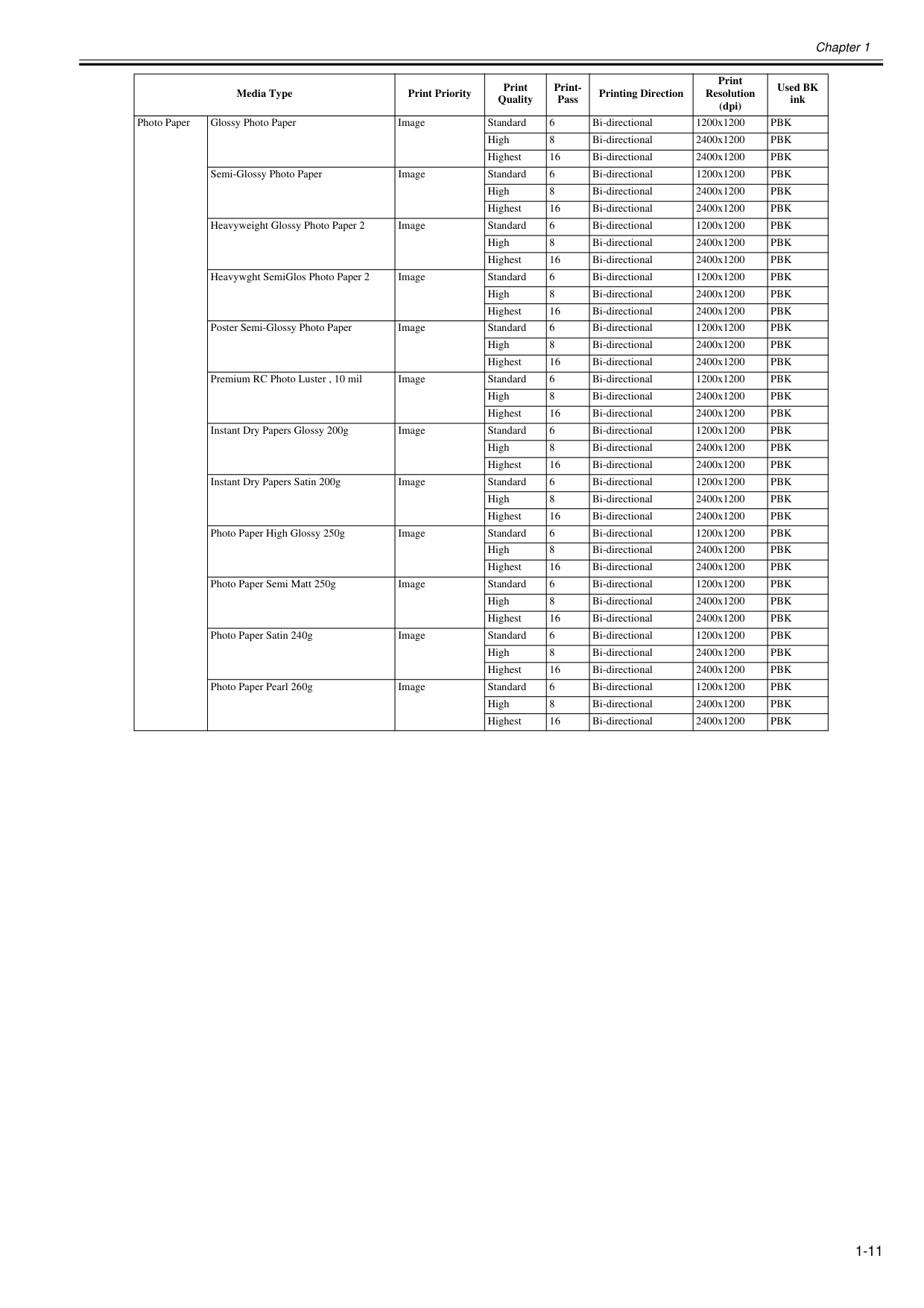
Chapter 1 1-11 Photo Paper Glossy Photo Paper Image Standard 6 Bi-directional 1200x1200
Pbk
High 8 Bi-directional 2400x1200Pbk
Highest 16 Bi-directional 2400x1200Pbk
Semi-Glossy Photo Paper Image Standard 6 Bi-directional 1200x1200Pbk
High 8 Bi-directional 2400x1200Pbk
Highest 16 Bi-directional 2400x1200Pbk
Heavyweight Glossy Photo Paper 2 Image Standard 6 Bi-directional 1200x1200Pbk
High 8 Bi-directional 2400x1200Pbk
Highest 16 Bi-directional 2400x1200Pbk
Heavywght SemiGlos Photo Paper 2 Image Standard 6 Bi-directional 1200x1200Pbk
High 8 Bi-directional 2400x1200Pbk
Highest 16 Bi-directional 2400x1200Pbk
Poster Semi-Glossy Photo Paper Image Standard 6 Bi-directional 1200x1200Pbk
High 8 Bi-directional 2400x1200Pbk
Highest 16 Bi-directional 2400x1200Pbk
Premium RC Photo Luster , 10 mil Image Standard 6 Bi-directional 1200x1200Pbk
High 8 Bi-directional 2400x1200Pbk
Highest 16 Bi-directional 2400x1200Pbk
Instant Dry Papers Glossy 200g Image Standard 6 Bi-directional 1200x1200Pbk
High 8 Bi-directional 2400x1200Pbk
Highest 16 Bi-directional 2400x1200Pbk
Instant Dry Papers Satin 200g Image Standard 6 Bi-directional 1200x1200Pbk
High 8 Bi-directional 2400x1200Pbk
Highest 16 Bi-directional 2400x1200Pbk
Photo Paper High Glossy 250g Image Standard 6 Bi-directional 1200x1200Pbk
High 8 Bi-directional 2400x1200Pbk
Highest 16 Bi-directional 2400x1200Pbk
Photo Paper Semi Matt 250g Image Standard 6 Bi-directional 1200x1200Pbk
High 8 Bi-directional 2400x1200Pbk
Highest 16 Bi-directional 2400x1200Pbk
Photo Paper Satin 240g Image Standard 6 Bi-directional 1200x1200Pbk
High 8 Bi-directional 2400x1200Pbk
Highest 16 Bi-directional 2400x1200Pbk
Photo Paper Pearl 260g Image Standard 6 Bi-directional 1200x1200Pbk
High 8 Bi-directional 2400x1200Pbk
Highest 16 Bi-directional 2400x1200Pbk
Media Type Print Priority Print Quality Print- Pass Printing Direction Print Resolution (dpi) Used BK ink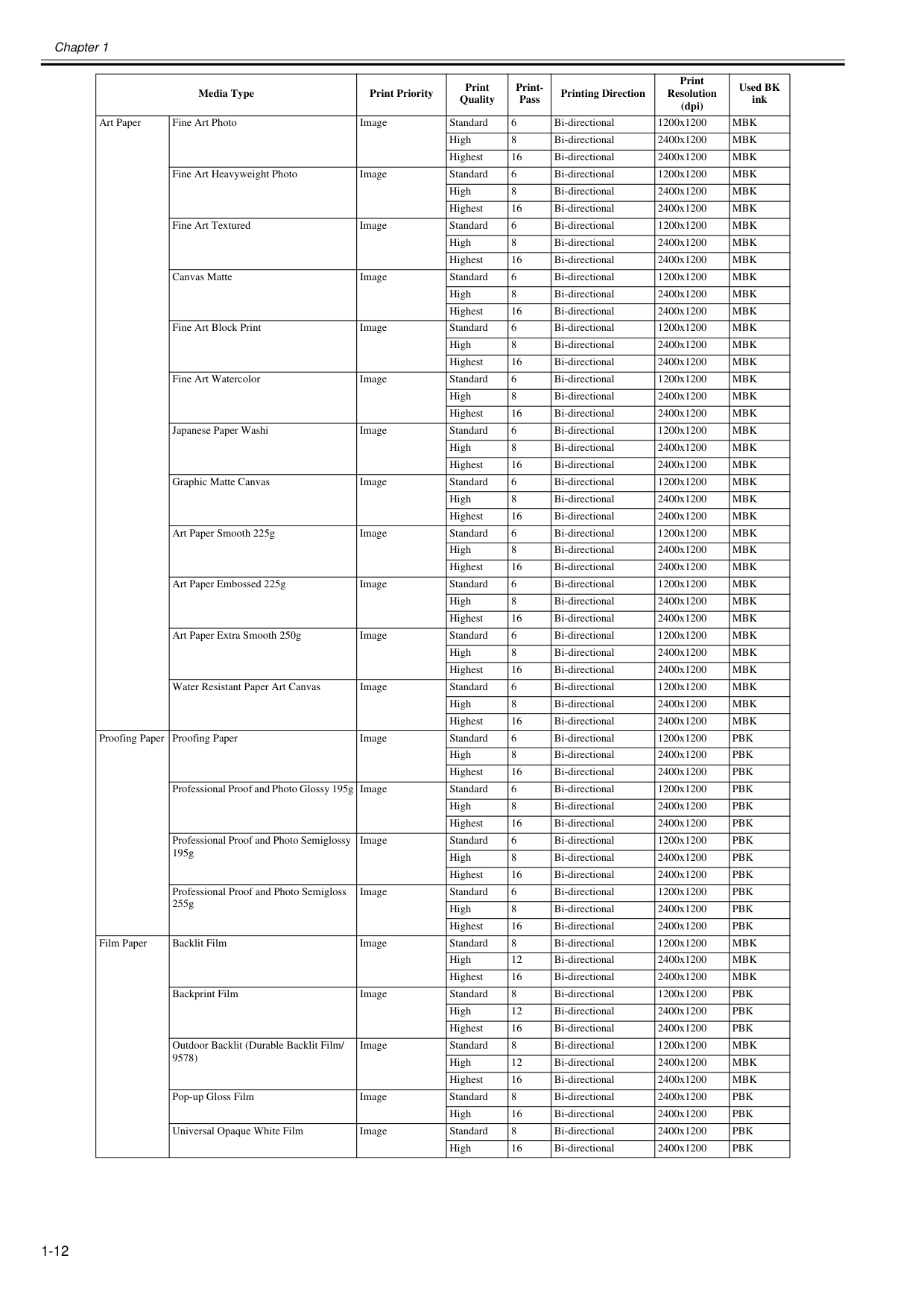
Chapter 1 1-12 Art Paper Fine Art Photo Image Standard 6 Bi-directional 1200x1200
Mbk
High 8 Bi-directional 2400x1200Mbk
Highest 16 Bi-directional 2400x1200Mbk
Fine Art Heavyweight Photo Image Standard 6 Bi-directional 1200x1200Mbk
High 8 Bi-directional 2400x1200Mbk
Highest 16 Bi-directional 2400x1200Mbk
Fine Art Textured Image Standard 6 Bi-directional 1200x1200Mbk
High 8 Bi-directional 2400x1200Mbk
Highest 16 Bi-directional 2400x1200Mbk
Canvas Matte Image Standard 6 Bi-directional 1200x1200Mbk
High 8 Bi-directional 2400x1200Mbk
Highest 16 Bi-directional 2400x1200Mbk
Fine Art Block Print Image Standard 6 Bi-directional 1200x1200Mbk
High 8 Bi-directional 2400x1200Mbk
Highest 16 Bi-directional 2400x1200Mbk
Fine Art Watercolor Image Standard 6 Bi-directional 1200x1200Mbk
High 8 Bi-directional 2400x1200Mbk
Highest 16 Bi-directional 2400x1200Mbk
Japanese Paper Washi Image Standard 6 Bi-directional 1200x1200Mbk
High 8 Bi-directional 2400x1200Mbk
Highest 16 Bi-directional 2400x1200Mbk
Graphic Matte Canvas Image Standard 6 Bi-directional 1200x1200Mbk
High 8 Bi-directional 2400x1200Mbk
Highest 16 Bi-directional 2400x1200Mbk
Art Paper Smooth 225g Image Standard 6 Bi-directional 1200x1200Mbk
High 8 Bi-directional 2400x1200Mbk
Highest 16 Bi-directional 2400x1200Mbk
Art Paper Embossed 225g Image Standard 6 Bi-directional 1200x1200Mbk
High 8 Bi-directional 2400x1200Mbk
Highest 16 Bi-directional 2400x1200Mbk
Art Paper Extra Smooth 250g Image Standard 6 Bi-directional 1200x1200Mbk
High 8 Bi-directional 2400x1200Mbk
Highest 16 Bi-directional 2400x1200Mbk
Water Resistant Paper Art Canvas Image Standard 6 Bi-directional 1200x1200Mbk
High 8 Bi-directional 2400x1200Mbk
Highest 16 Bi-directional 2400x1200Mbk
Proofing Paper Proofing Paper Image Standard 6 Bi-directional 1200x1200Pbk
High 8 Bi-directional 2400x1200Pbk
Highest 16 Bi-directional 2400x1200Pbk
Professional Proof and Photo Glossy 195g Image Standard 6 Bi-directional 1200x1200Pbk
High 8 Bi-directional 2400x1200Pbk
Highest 16 Bi-directional 2400x1200Pbk
Professional Proof and Photo Semiglossy 195g Image Standard 6 Bi-directional 1200x1200Pbk
High 8 Bi-directional 2400x1200Pbk
Highest 16 Bi-directional 2400x1200Pbk
Professional Proof and Photo Semigloss 255g Image Standard 6 Bi-directional 1200x1200Pbk
High 8 Bi-directional 2400x1200Pbk
Highest 16 Bi-directional 2400x1200Pbk
Film Paper Backlit Film Image Standard 8 Bi-directional 1200x1200Mbk
High 12 Bi-directional 2400x1200Mbk
Highest 16 Bi-directional 2400x1200Mbk
Backprint Film Image Standard 8 Bi-directional 1200x1200Pbk
High 12 Bi-directional 2400x1200Pbk
Highest 16 Bi-directional 2400x1200Pbk
Outdoor Backlit (Durable Backlit Film/ 9578) Image Standard 8 Bi-directional 1200x1200Mbk
High 12 Bi-directional 2400x1200Mbk
Highest 16 Bi-directional 2400x1200Mbk
Pop-up Gloss Film Image Standard 8 Bi-directional 2400x1200Pbk
High 16 Bi-directional 2400x1200Pbk
Universal Opaque White Film Image Standard 8 Bi-directional 2400x1200Pbk
High 16 Bi-directional 2400x1200Pbk
Media Type Print Priority Print Quality Print- Pass Printing Direction Print Resolution (dpi) Used BK ink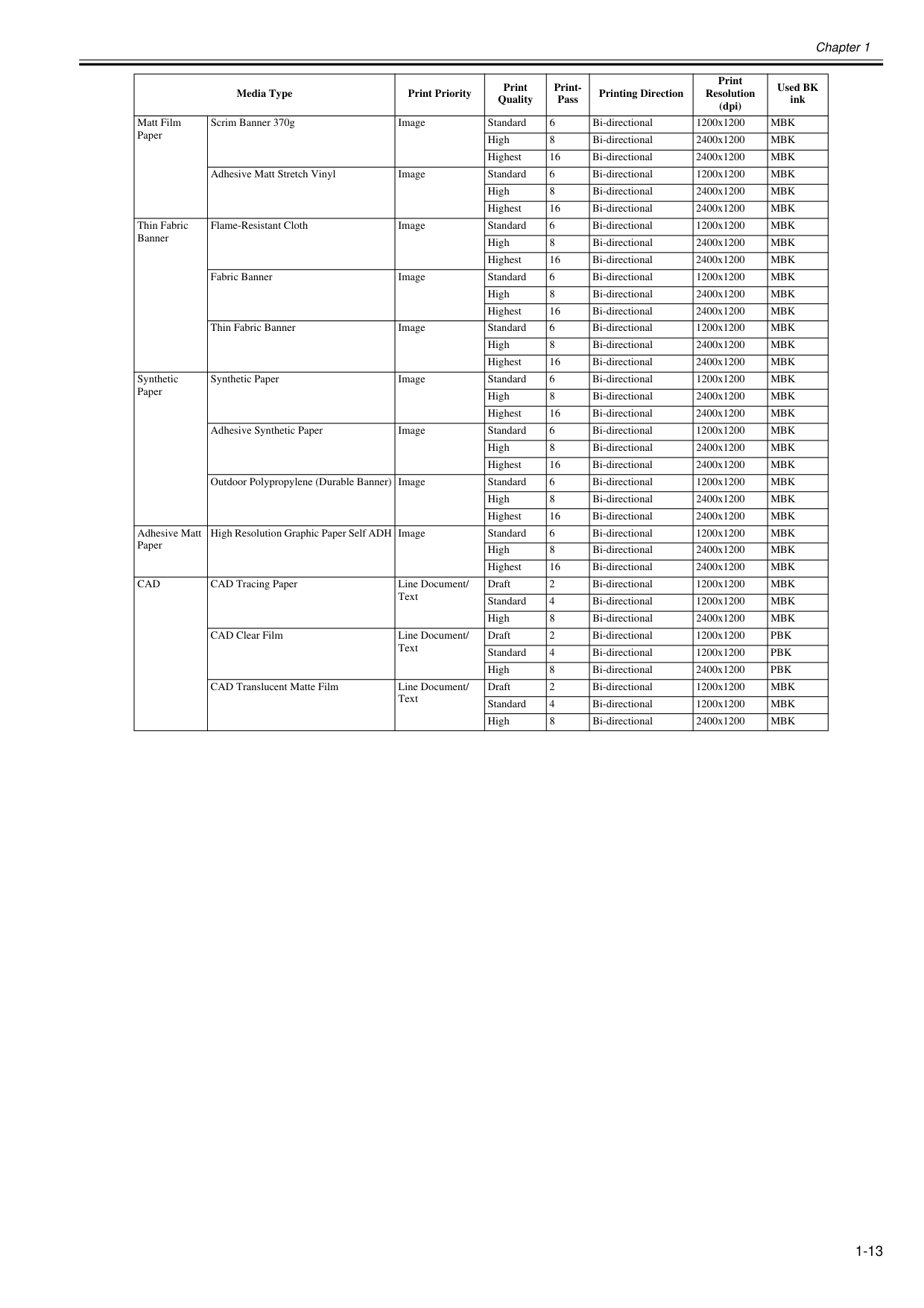
Chapter 1 1-13 Matt Film Paper Scrim Banner 370g Image Standard 6 Bi-directional 1200x1200
Mbk
High 8 Bi-directional 2400x1200Mbk
Highest 16 Bi-directional 2400x1200Mbk
Adhesive Matt Stretch Vinyl Image Standard 6 Bi-directional 1200x1200Mbk
High 8 Bi-directional 2400x1200Mbk
Highest 16 Bi-directional 2400x1200Mbk
Thin Fabric Banner Flame-Resistant Cloth Image Standard 6 Bi-directional 1200x1200Mbk
High 8 Bi-directional 2400x1200Mbk
Highest 16 Bi-directional 2400x1200Mbk
Fabric Banner Image Standard 6 Bi-directional 1200x1200Mbk
High 8 Bi-directional 2400x1200Mbk
Highest 16 Bi-directional 2400x1200Mbk
Thin Fabric Banner Image Standard 6 Bi-directional 1200x1200Mbk
High 8 Bi-directional 2400x1200Mbk
Highest 16 Bi-directional 2400x1200Mbk
Synthetic Paper Synthetic Paper Image Standard 6 Bi-directional 1200x1200Mbk
High 8 Bi-directional 2400x1200Mbk
Highest 16 Bi-directional 2400x1200Mbk
Adhesive Synthetic Paper Image Standard 6 Bi-directional 1200x1200Mbk
High 8 Bi-directional 2400x1200Mbk
Highest 16 Bi-directional 2400x1200Mbk
Outdoor Polypropylene (Durable Banner) Image Standard 6 Bi-directional 1200x1200Mbk
High 8 Bi-directional 2400x1200Mbk
Highest 16 Bi-directional 2400x1200Mbk
Adhesive Matt Paper High Resolution Graphic Paper Self ADH Image Standard 6 Bi-directional 1200x1200Mbk
High 8 Bi-directional 2400x1200Mbk
Highest 16 Bi-directional 2400x1200Mbk
Cad
CAD Tracing Paper Line Document/ Text Draft 2 Bi-directional 1200x1200Mbk
Standard 4 Bi-directional 1200x1200Mbk
High 8 Bi-directional 2400x1200Mbk
CAD Clear Film Line Document/ Text Draft 2 Bi-directional 1200x1200Pbk
Standard 4 Bi-directional 1200x1200Pbk
High 8 Bi-directional 2400x1200Pbk
CAD Translucent Matte Film Line Document/ Text Draft 2 Bi-directional 1200x1200Mbk
Standard 4 Bi-directional 1200x1200Mbk
High 8 Bi-directional 2400x1200Mbk
Media Type Print Priority Print Quality Print- Pass Printing Direction Print Resolution (dpi) Used BK ink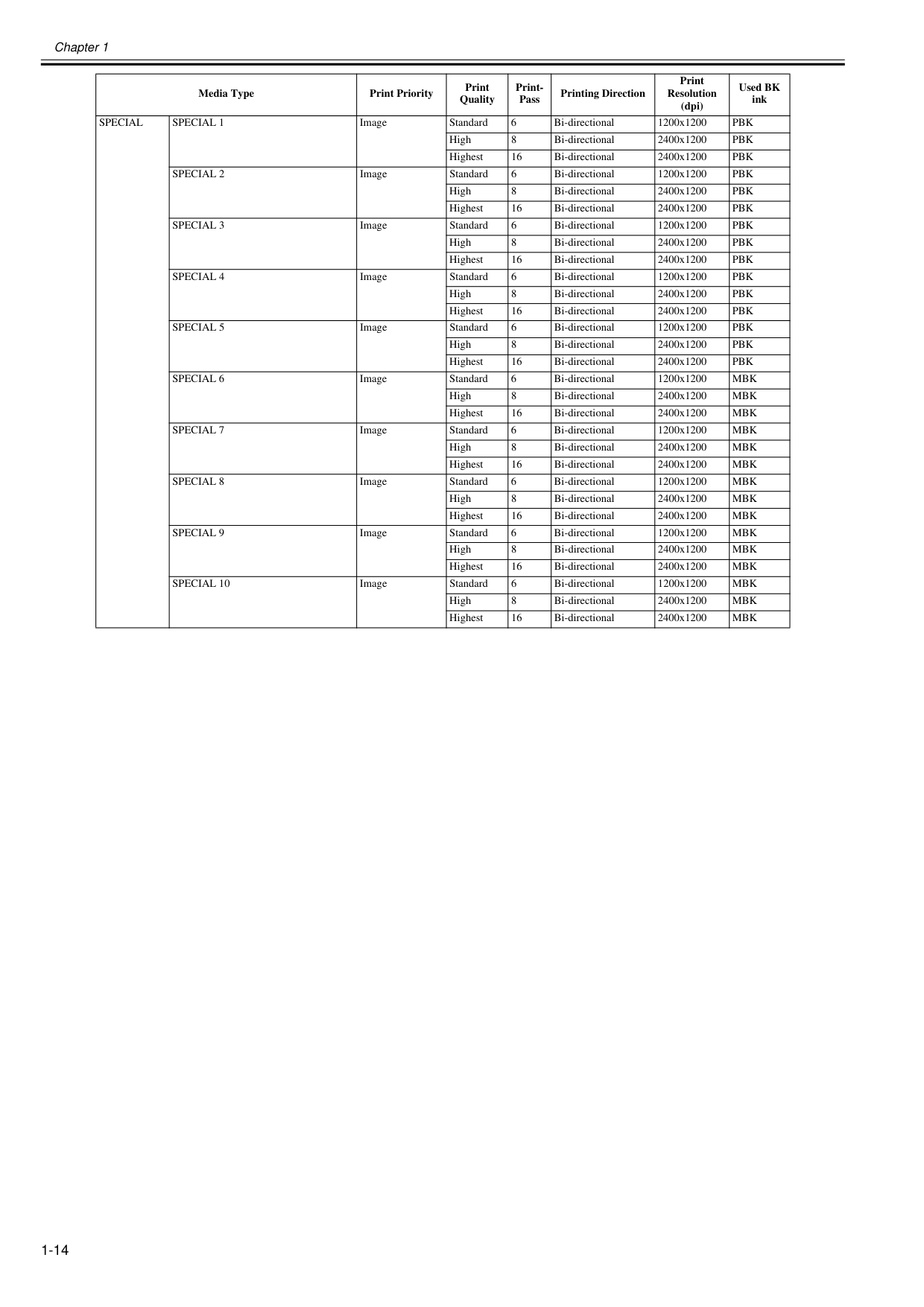
Chapter 1 1-14
Special
Special 1
Image Standard 6 Bi-directional 1200x1200Pbk
High 8 Bi-directional 2400x1200Pbk
Highest 16 Bi-directional 2400x1200Pbk
Special 2
Image Standard 6 Bi-directional 1200x1200Pbk
High 8 Bi-directional 2400x1200Pbk
Highest 16 Bi-directional 2400x1200Pbk
Special 3
Image Standard 6 Bi-directional 1200x1200Pbk
High 8 Bi-directional 2400x1200Pbk
Highest 16 Bi-directional 2400x1200Pbk
Special 4
Image Standard 6 Bi-directional 1200x1200Pbk
High 8 Bi-directional 2400x1200Pbk
Highest 16 Bi-directional 2400x1200Pbk
Special 5
Image Standard 6 Bi-directional 1200x1200Pbk
High 8 Bi-directional 2400x1200Pbk
Highest 16 Bi-directional 2400x1200Pbk
Special 6
Image Standard 6 Bi-directional 1200x1200Mbk
High 8 Bi-directional 2400x1200Mbk
Highest 16 Bi-directional 2400x1200Mbk
Special 7
Image Standard 6 Bi-directional 1200x1200Mbk
High 8 Bi-directional 2400x1200Mbk
Highest 16 Bi-directional 2400x1200Mbk
Special 8
Image Standard 6 Bi-directional 1200x1200Mbk
High 8 Bi-directional 2400x1200Mbk
Highest 16 Bi-directional 2400x1200Mbk
Special 9
Image Standard 6 Bi-directional 1200x1200Mbk
High 8 Bi-directional 2400x1200Mbk
Highest 16 Bi-directional 2400x1200Mbk
Special 10
Image Standard 6 Bi-directional 1200x1200Mbk
High 8 Bi-directional 2400x1200Mbk
Highest 16 Bi-directional 2400x1200Mbk
Media Type Print Priority Print Quality Print- Pass Printing Direction Print Resolution (dpi) Used BK ink
Chapter 1 1-15 1.4.2 Interface Specifications 0032-0977 a. USB (standard) (1) Interface type USB 2.0 Hi-Speed (Full speed (12 Mbits/sec), High speed (480 Mbits/sec)) (2) Data transfer system Control transfer Bulk transfer (3) Signal level Compliant with the USB standard. (4) Interface cable Twisted-pair shielded cable, 5.0 m max. Compliant with the USB standard. Wire materials: AWG No.28, data wire pair (AWF: American Wire Gauge) AWG No.20 to No.28, power distribution wire pair (5) Interface connector Printer side: Series B receptacle compliant with USB standard Cable side: Series B plug compliant with USB standard b. Network (standard) (1) Interface type Interface compliant with IEEE802.3 (2) Data transfer system IEEE802.0 10Base-T, IEEE802.3u 100Base-TX/Auto-Negotiation, IEEE802.3ab 1000Base-T/Auto-Negotiation, IEEE802.3x Full Duplex, IEEEE802.3az EEE (3) Interface cable Category 5 (UTP or FTP) cable, 100 m or shorter Compliant with ANSI/EIA/TIA-568A or ANSI/EIA/TIA-568B (4) Interface connector Printer side: Compliant with IEEE802.3, ANSI X3.263, ISO/IEC60603-7 (5) Protocol IPX/SPX (Netware4.2(J), 5.1(J), 6.0(J)), SNMP, TCP/IP(IPv4/IPv6), HTTP
Chapter 1 1-16 1.5 Names and Functions of Components 1.5.1 Front 0020-5443
F-1-15
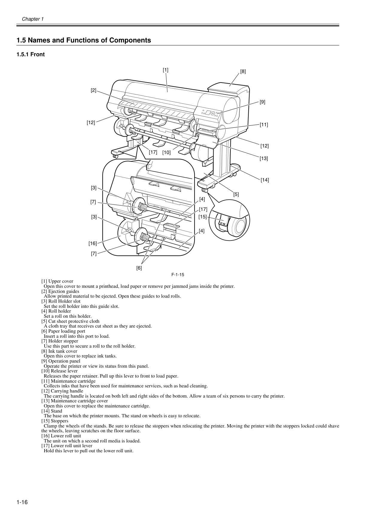
[1] Upper cover Open this cover to mount a printhead, load paper or remove per jammed jams inside the printer. [2] Ejection guides Allow printed material to be ejected. Open these guides to load rolls. [3] Roll Holder slot Set the roll holder into this guide slot. [4] Roll holder Set a roll on this holder. [5] Cut sheet protective cloth A cloth tray that receives cut sheet as they are ejected. [6] Paper loading port Insert a roll into this port to load. [7] Holder stopper Use this part to secure a roll to the roll holder. [8] Ink tank cover Open this cover to replace ink tanks. [9] Operation panel Operate the printer or view its status from this panel. [10] Release lever Releases the paper retainer. Pull up this lever to front to load paper. [11] Maintenance cartridge Collects inks that have been used for maintenance services, such as head cleaning. [12] Carrying handle The carrying handle is located on both left and right sides of the bottom. Allow a team of six persons to carry the printer. [13] Maintenance cartridge cover Open this cover to replace the maintenance cartridge. [14] Stand The base on which the printer mounts. The stand on wheels is easy to relocate. [15] Stoppers Clamp the wheels of the stands. Be sure to release the stoppers when relocating the printer. Moving the printer with the stoppers locked could shave the wheels, leaving scratches on the floor surface. [16] Lower roll unit The unit on which a second roll media is loaded. [17] Lower roll unit lever Hold this lever to pull out the lower roll unit. [1] [9] [8] [10] [2] [3] [3] [4] [4] [12] [5] [17] [7] [16] [7] [11] [12] [17] [13] [14] [15] [6]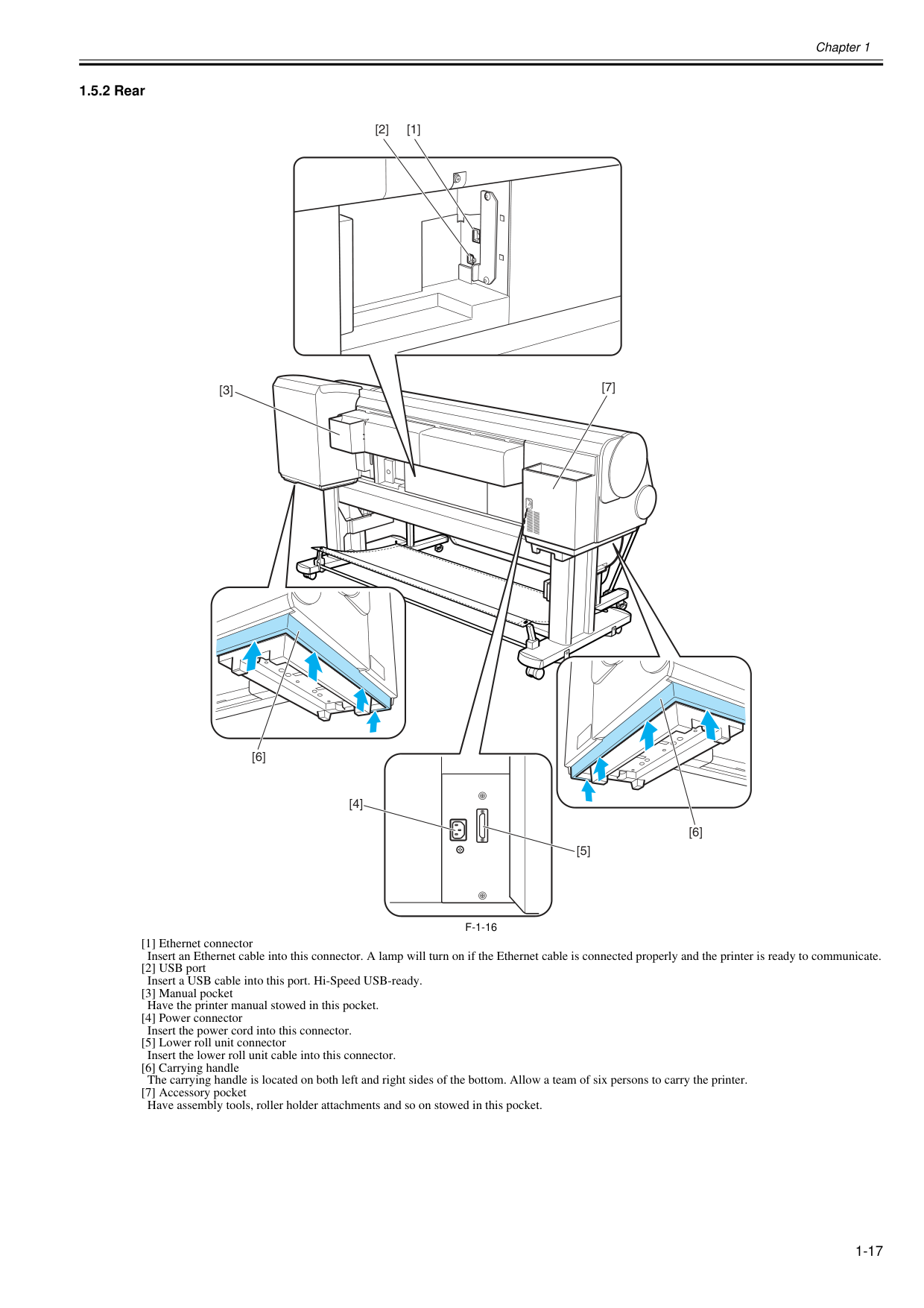
Chapter 1 1-17 1.5.2 Rear 0025-9282
F-1-16
[1] Ethernet connector Insert an Ethernet cable into this connector. A lamp will turn on if the Ethernet cable is connected properly and the printer is ready to communicate. [2] USB port Insert a USB cable into this port. Hi-Speed USB-ready. [3] Manual pocket Have the printer manual stowed in this pocket. [4] Power connector Insert the power cord into this connector. [5] Lower roll unit connector Insert the lower roll unit cable into this connector. [6] Carrying handle The carrying handle is located on both left and right sides of the bottom. Allow a team of six persons to carry the printer. [7] Accessory pocket Have assembly tools, roller holder attachments and so on stowed in this pocket. [2] [1] [3] [4] [5] [7] [6] [6]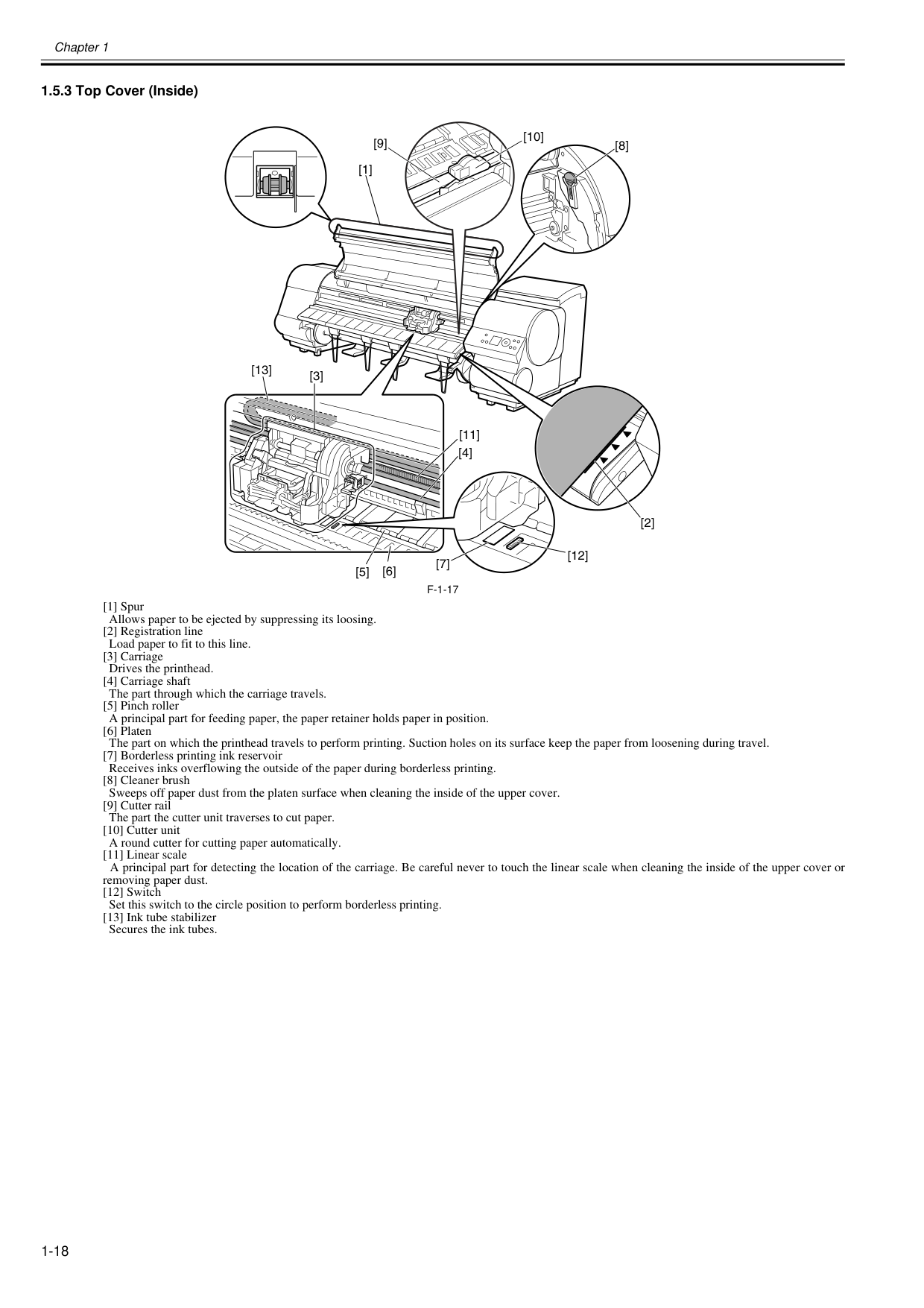
Chapter 1 1-18 1.5.3 Top Cover (Inside) 0020-5454
F-1-17
[1] Spur Allows paper to be ejected by suppressing its loosing. [2] Registration line Load paper to fit to this line. [3] Carriage Drives the printhead. [4] Carriage shaft The part through which the carriage travels. [5] Pinch roller A principal part for feeding paper, the paper retainer holds paper in position. [6] Platen The part on which the printhead travels to perform printing. Suction holes on its surface keep the paper from loosening during travel. [7] Borderless printing ink reservoir Receives inks overflowing the outside of the paper during borderless printing. [8] Cleaner brush Sweeps off paper dust from the platen surface when cleaning the inside of the upper cover. [9] Cutter rail The part the cutter unit traverses to cut paper. [10] Cutter unit A round cutter for cutting paper automatically. [11] Linear scale A principal part for detecting the location of the carriage. Be careful never to touch the linear scale when cleaning the inside of the upper cover or removing paper dust. [12] Switch Set this switch to the circle position to perform borderless printing. [13] Ink tube stabilizer Secures the ink tubes. [1] [7] [12] [6] [5] [3] [11] [2] [13] [4] [8] [9] [10]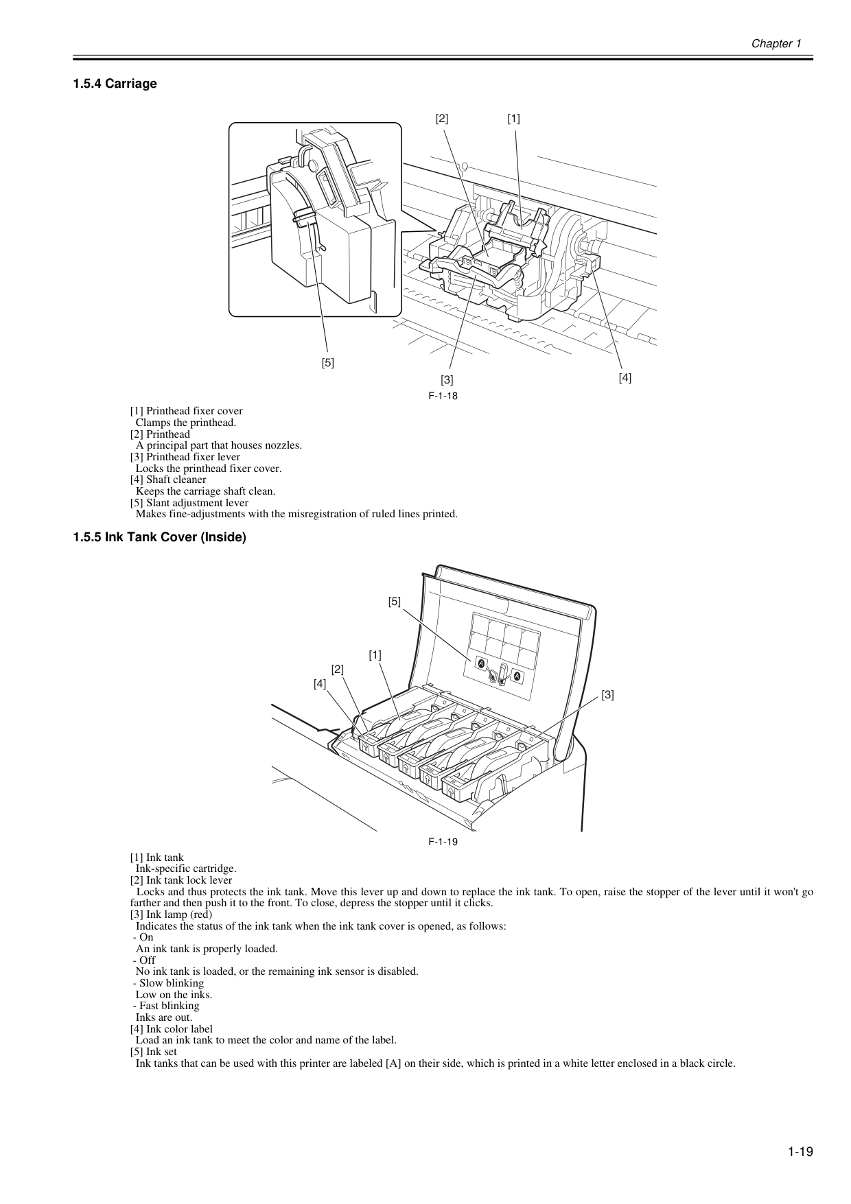
Chapter 1 1-19 1.5.4 Carriage 0020-5456
F-1-18
[1] Printhead fixer cover Clamps the printhead. [2] Printhead A principal part that houses nozzles. [3] Printhead fixer lever Locks the printhead fixer cover. [4] Shaft cleaner Keeps the carriage shaft clean. [5] Slant adjustment lever Makes fine-adjustments with the misregistration of ruled lines printed. 1.5.5 Ink Tank Cover (Inside) 0020-5457F-1-19
[1] Ink tank Ink-specific cartridge. [2] Ink tank lock lever Locks and thus protects the ink tank. Move this lever up and down to replace the ink tank. To open, raise the stopper of the lever until it won't go farther and then push it to the front. To close, depress the stopper until it clicks. [3] Ink lamp (red) Indicates the status of the ink tank when the ink tank cover is opened, as follows:A
A
Mbk
Bk
M
C
Y
[3] [2] [1] [4] [5]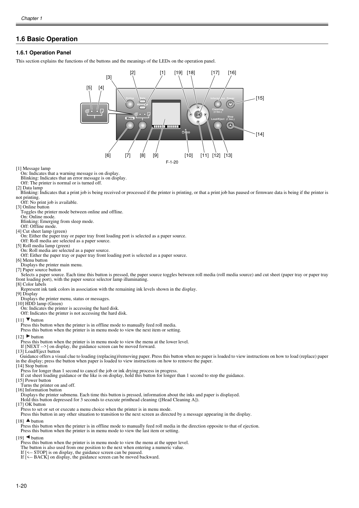
Chapter 1 1-20 1.6 Basic Operation 1.6.1 Operation Panel 0012-6277 This section explains the functions of the buttons and the meanings of the LEDs on the operation panel.
F-1-20
[1] Message lamp On: Indicates that a warning message is on display. Blinking: Indicates that an error message is on display. Off: The printer is normal or is turned off. [2] Data lamp Blinking: Indicates that a print job is being received or processed if the printer is printing, or that a print job has paused or firmware data is being if the printer is not printing. Off: No print job is available. [3] Online button Toggles the printer mode between online and offline. On: Online mode. Blinking: Emerging from sleep mode. Off: Offline mode. [4] Cut sheet lamp (green) On: Either the paper tray or paper tray front loading port is selected as a paper source. Off: Roll media are selected as a paper source. [5] Roll media lamp (green) On: Roll media are selected as a paper source. Off: Either the paper tray or paper tray front loading port is selected as a paper source. [6] Menu button Displays the printer main menu. [7] Paper source button Selects a paper source. Each time this button is pressed, the paper source toggles between roll media (roll media source) and cut sheet (paper tray or paper tray front loading port), with the paper source selector lamp illuminating. [8] Color labels Represent ink tank colors in association with the remaining ink levels shown in the display. [9] Display Displays the printer menu, status or messages. [10] HDD lamp (Green) On: Indicates the printer is accessing the hard disk. Off: Indicates the printer is not accessing the hard disk. [11] button Press this button when the printer is in offline mode to manually feed roll media. Press this button when the printer is in menu mode to view the next item or setting. [12] button Press this button when the printer is in menu mode to view the menu at the lower level. If [NEXT -->] on display, the guidance screen can be moved forward. [13] Load/Eject button Guidance offers a visual clue to loading (replacing)/removing paper. Press this button when no paper is loaded to view instructions on how to load (replace) paper in the display; press the button when paper is loaded to view instructions on how to remove the paper. [14] Stop button Press for longer than 1 second to cancel the job or ink drying process in progress. If cut sheet loading guidance or the like is on display, hold this button for longer than 1 second to stop the guidance. [15] Power button Turns the printer on and off. [16] Information button Displays the printer submenu. Each time this button is pressed, information about the inks and paper is displayed. Hold this button depressed for 3 seconds to execute printhead cleaning ([Head Cleaning A]). [17] OK button Press to set or set or execute a menu choice when the printer is in menu mode. Press this button in any other situation to transition to the next screen as directed by a message appearing in the display. [18] button Press this button when the printer is in offline mode to manually feed roll media in the direction opposite to that of ejection. Press this button when the printer is in menu mode to view the last item or setting. [19] button Press this button when the printer is in menu mode to view the menu at the upper level. The button is also used from one position to the next when entering a numeric value. If [<-- STOP] is on display, the guidance screen can be paused. If [<-- BACK] on display, the guidance screen can be moved backward. [16] [17] [18] [19] [1] [2] [3] [4] [5] [11] [12] [13] [10] [6] [7] [8] [9] [14] [15]
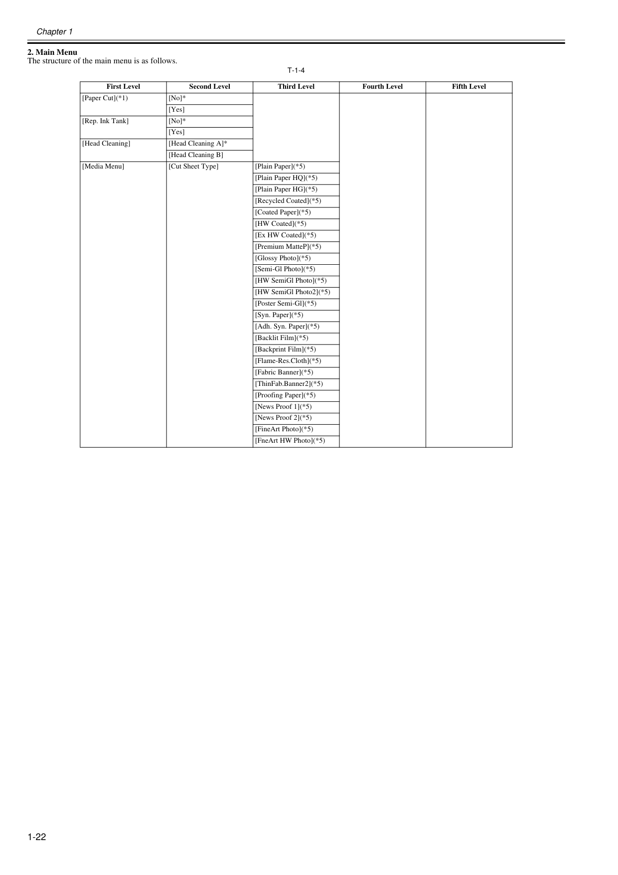
Chapter 1 1-21 1.6.2 Main Menu 0025-9293 The printer has a Main menu which includes a menu related to maintenance such as adjustment of ink ejection position of each nozzle and head cleaning, a menu related to printing settings such as auto cutting and ink drying time, and a menu related to parameters such as a message language.
Chapter 1 1-22
T-1-4
First Level Second Level Third Level Fourth Level Fifth Level [Paper Cut](*1) [No]* [Yes] [Rep. Ink Tank] [No]* [Yes] [Head Cleaning] [Head Cleaning A]* [Head Cleaning B] [Media Menu] [Cut Sheet Type] [Plain Paper](*5) [Plain Paper HQ](*5) [Plain Paper HG](*5) [Recycled Coated](*5) [Coated Paper](*5) [HW Coated](*5) [Ex HW Coated](*5) [Premium MatteP](*5) [Glossy Photo](*5) [Semi-Gl Photo](*5) [HW SemiGl Photo](*5) [HW SemiGl Photo2](*5) [Poster Semi-Gl](*5) [Syn. Paper](*5) [Adh. Syn. Paper](*5) [Backlit Film](*5) [Backprint Film](*5) [Flame-Res.Cloth](*5) [Fabric Banner](*5) [ThinFab.Banner2](*5) [Proofing Paper](*5) [News Proof 1](*5) [News Proof 2](*5) [FineArt Photo](*5) [FneArt HW Photo](*5)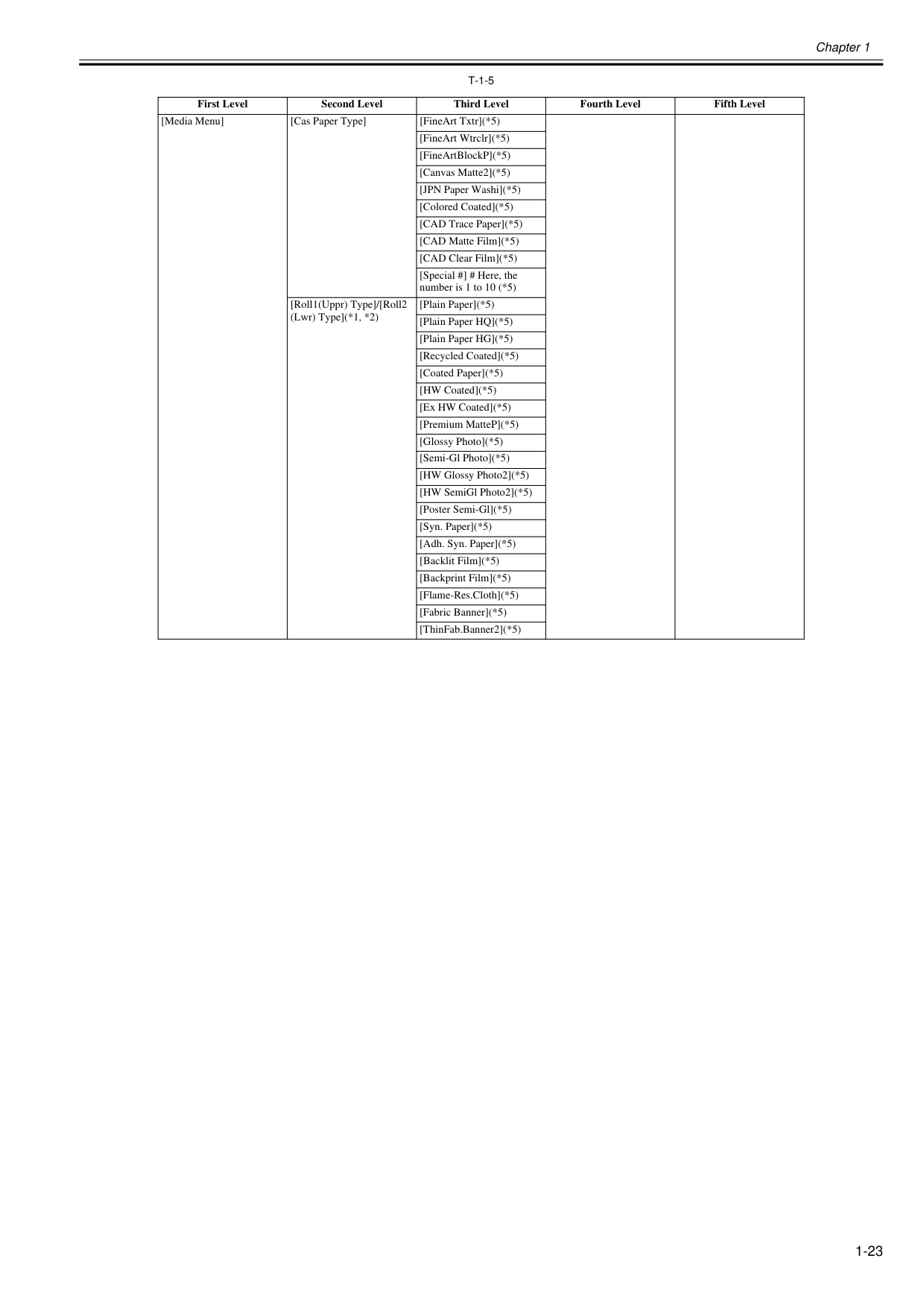
Chapter 1 1-23
T-1-5
First Level Second Level Third Level Fourth Level Fifth Level [Media Menu] [Cas Paper Type] [FineArt Txtr](*5) [FineArt Wtrclr](*5) [FineArtBlockP](*5) [Canvas Matte2](*5) [JPN Paper Washi](*5) [Colored Coated](*5) [CAD Trace Paper](*5) [CAD Matte Film](*5) [CAD Clear Film](*5) [Special #] # Here, the number is 1 to 10 (*5) [Roll1(Uppr) Type]/[Roll2 (Lwr) Type](*1, *2) [Plain Paper](*5) [Plain Paper HQ](*5) [Plain Paper HG](*5) [Recycled Coated](*5) [Coated Paper](*5) [HW Coated](*5) [Ex HW Coated](*5) [Premium MatteP](*5) [Glossy Photo](*5) [Semi-Gl Photo](*5) [HW Glossy Photo2](*5) [HW SemiGl Photo2](*5) [Poster Semi-Gl](*5) [Syn. Paper](*5) [Adh. Syn. Paper](*5) [Backlit Film](*5) [Backprint Film](*5) [Flame-Res.Cloth](*5) [Fabric Banner](*5) [ThinFab.Banner2](*5)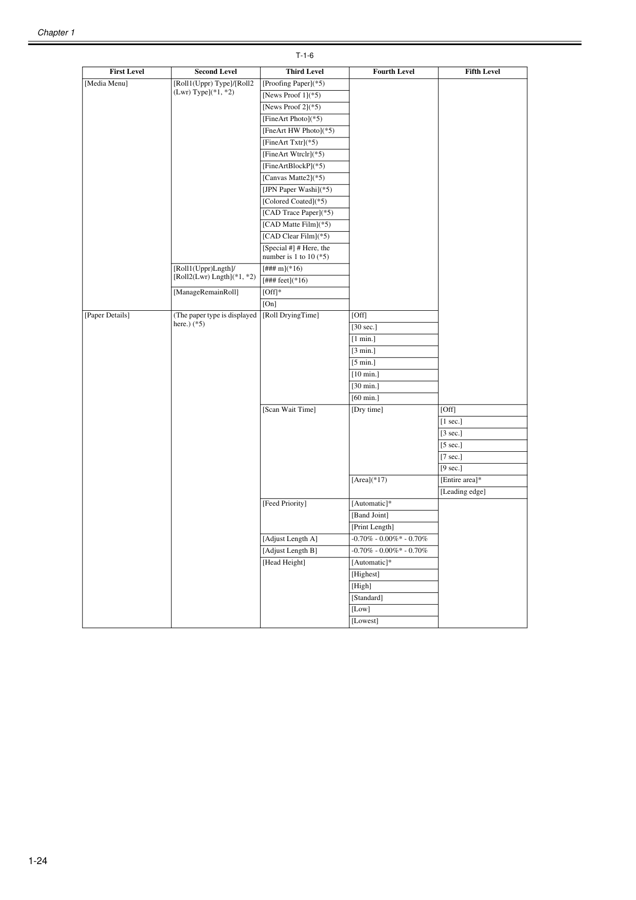
Chapter 1 1-24
T-1-6
First Level Second Level Third Level Fourth Level Fifth Level [Media Menu] [Roll1(Uppr) Type]/[Roll2 (Lwr) Type](*1, *2) [Proofing Paper](*5) [News Proof 1](*5) [News Proof 2](*5) [FineArt Photo](*5) [FneArt HW Photo](*5) [FineArt Txtr](*5) [FineArt Wtrclr](*5) [FineArtBlockP](*5) [Canvas Matte2](*5) [JPN Paper Washi](*5) [Colored Coated](*5) [CAD Trace Paper](*5) [CAD Matte Film](*5) [CAD Clear Film](*5) [Special #] # Here, the number is 1 to 10 (*5) [Roll1(Uppr)Lngth]/ [Roll2(Lwr) Lngth](*1, *2) [### m](*16) [### feet](*16) [ManageRemainRoll] [Off]* [On] [Paper Details] (The paper type is displayed here.) (*5) [Roll DryingTime] [Off] [30 sec.] [1 min.] [3 min.] [5 min.] [10 min.] [30 min.] [60 min.] [Scan Wait Time] [Dry time] [Off] [1 sec.] [3 sec.] [5 sec.] [7 sec.] [9 sec.] [Area](*17) [Entire area]* [Leading edge] [Feed Priority] [Automatic]* [Band Joint] [Print Length] [Adjust Length A] -0.70% - 0.00%* - 0.70% [Adjust Length B] -0.70% - 0.00%* - 0.70% [Head Height] [Automatic]* [Highest] [High] [Standard] [Low] [Lowest]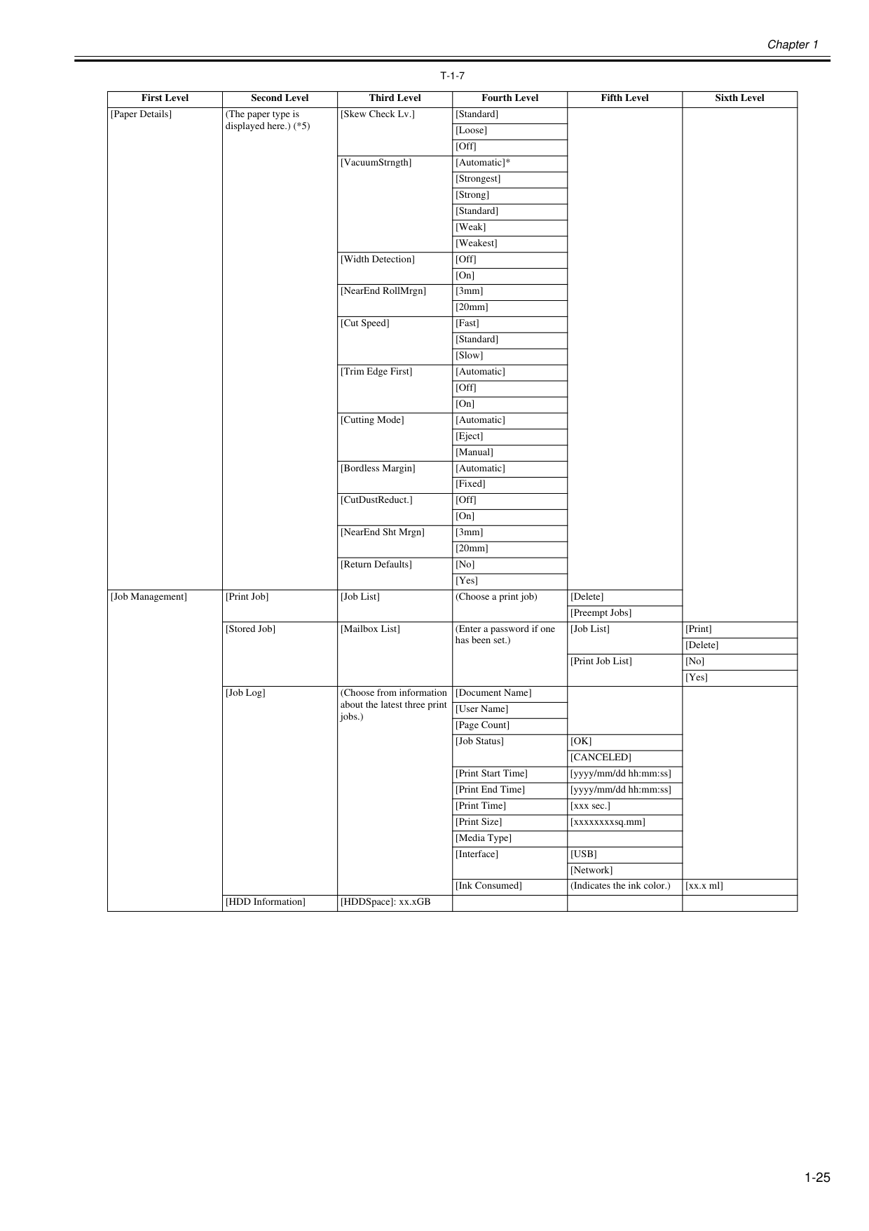
Chapter 1 1-25
T-1-7
First Level Second Level Third Level Fourth Level Fifth Level Sixth Level [Paper Details] (The paper type is displayed here.) (*5) [Skew Check Lv.] [Standard] [Loose] [Off] [VacuumStrngth] [Automatic]* [Strongest] [Strong] [Standard] [Weak] [Weakest] [Width Detection] [Off] [On] [NearEnd RollMrgn] [3mm] [20mm] [Cut Speed] [Fast] [Standard] [Slow] [Trim Edge First] [Automatic] [Off] [On] [Cutting Mode] [Automatic] [Eject] [Manual] [Bordless Margin] [Automatic] [Fixed] [CutDustReduct.] [Off] [On] [NearEnd Sht Mrgn] [3mm] [20mm] [Return Defaults] [No] [Yes] [Job Management] [Print Job] [Job List] (Choose a print job) [Delete] [Preempt Jobs] [Stored Job] [Mailbox List] (Enter a password if one has been set.) [Job List] [Print] [Delete] [Print Job List] [No] [Yes] [Job Log] (Choose from information about the latest three print jobs.) [Document Name] [User Name] [Page Count] [Job Status][Ok]
[Canceled]
[Print Start Time] [yyyy/mm/dd hh:mm:ss] [Print End Time] [yyyy/mm/dd hh:mm:ss] [Print Time] [xxx sec.] [Print Size] [xxxxxxxxsq.mm] [Media Type] [Interface][Usb]
[Network] [Ink Consumed] (Indicates the ink color.) [xx.x ml] [HDD Information] [HDDSpace]: xx.xGB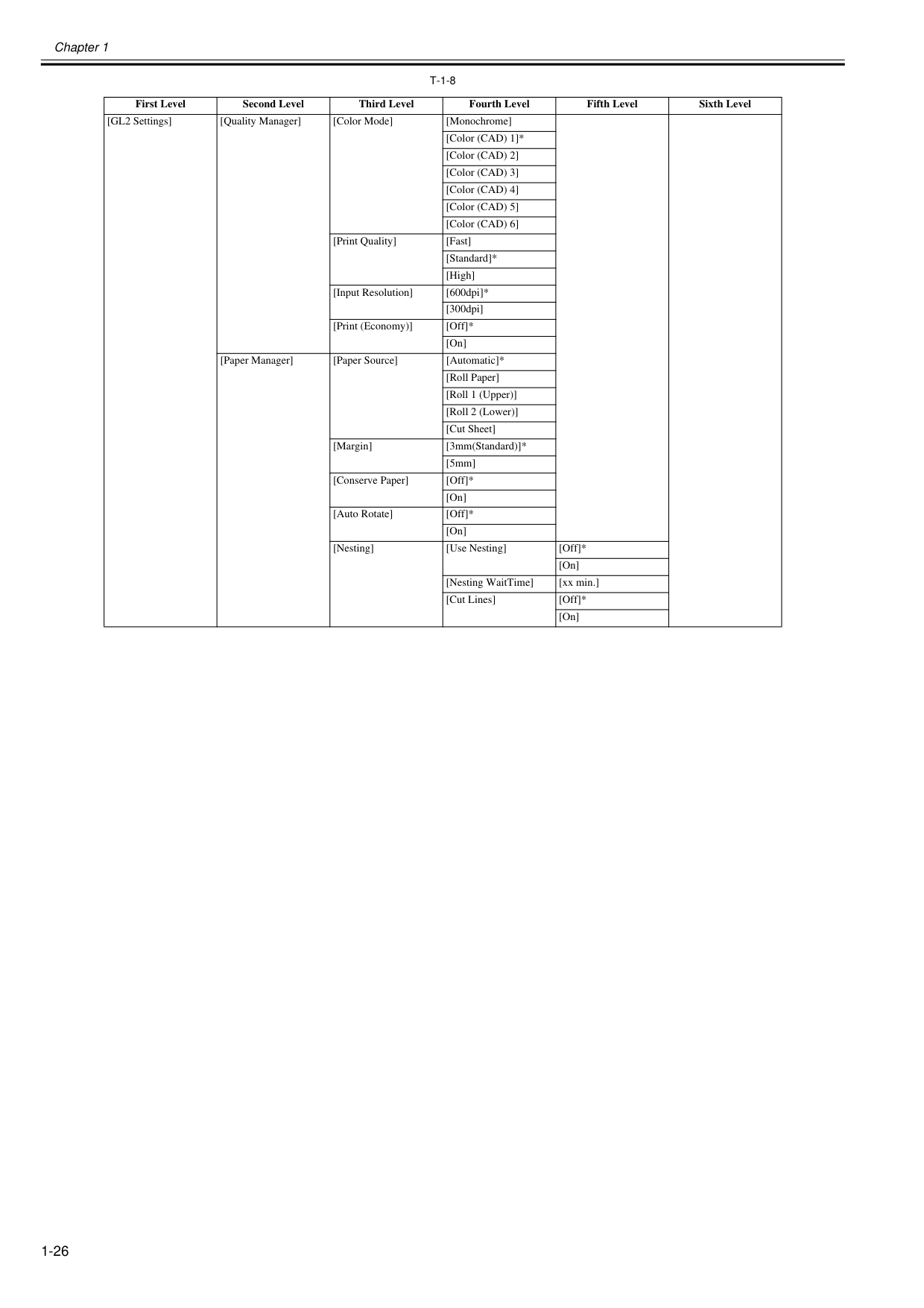
Chapter 1 1-26
T-1-8
First Level Second Level Third Level Fourth Level Fifth Level Sixth Level [GL2 Settings] [Quality Manager] [Color Mode] [Monochrome] [Color (CAD) 1]* [Color (CAD) 2] [Color (CAD) 3] [Color (CAD) 4] [Color (CAD) 5] [Color (CAD) 6] [Print Quality] [Fast] [Standard]* [High] [Input Resolution] [600dpi]* [300dpi] [Print (Economy)] [Off]* [On] [Paper Manager] [Paper Source] [Automatic]* [Roll Paper] [Roll 1 (Upper)] [Roll 2 (Lower)] [Cut Sheet] [Margin] [3mm(Standard)]* [5mm] [Conserve Paper] [Off]* [On] [Auto Rotate] [Off]* [On] [Nesting] [Use Nesting] [Off]* [On] [Nesting WaitTime] [xx min.] [Cut Lines] [Off]* [On]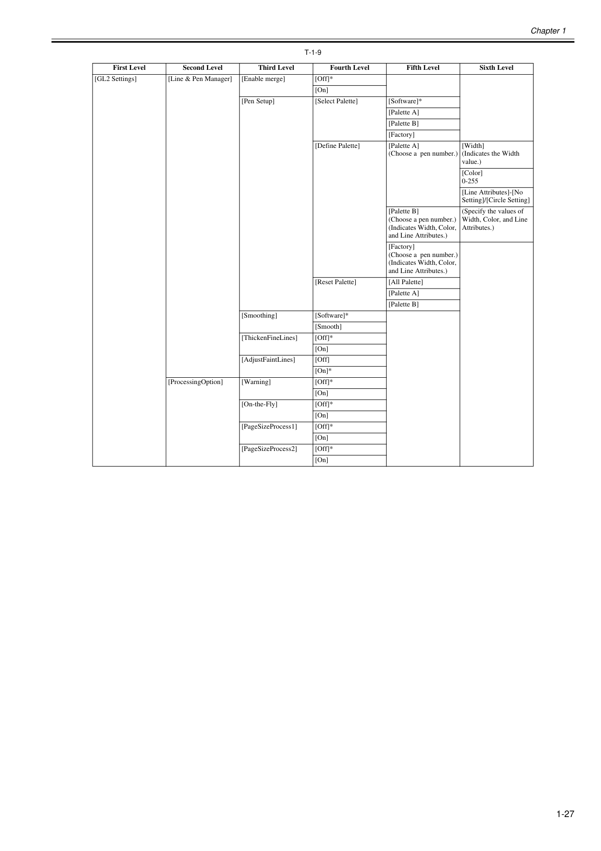
Chapter 1 1-27
T-1-9
First Level Second Level Third Level Fourth Level Fifth Level Sixth Level [GL2 Settings] [Line & Pen Manager] [Enable merge] [Off]* [On] [Pen Setup] [Select Palette] [Software]* [Palette A] [Palette B] [Factory] [Define Palette] [Palette A] (Choose a pen number.) [Width] (Indicates the Width value.) [Color] 0-255 [Line Attributes]-[No Setting]/[Circle Setting] [Palette B] (Choose a pen number.) (Indicates Width, Color, and Line Attributes.) (Specify the values of Width, Color, and Line Attributes.) [Factory] (Choose a pen number.) (Indicates Width, Color, and Line Attributes.) [Reset Palette] [All Palette] [Palette A] [Palette B] [Smoothing] [Software]* [Smooth] [ThickenFineLines] [Off]* [On] [AdjustFaintLines] [Off] [On]* [ProcessingOption] [Warning] [Off]* [On] [On-the-Fly] [Off]* [On] [PageSizeProcess1] [Off]* [On] [PageSizeProcess2] [Off]* [On]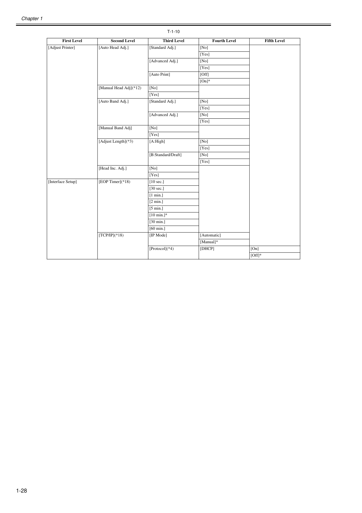
Chapter 1 1-28
T-1-10
First Level Second Level Third Level Fourth Level Fifth Level [Adjust Printer] [Auto Head Adj.] [Standard Adj.] [No] [Yes] [Advanced Adj.] [No] [Yes] [Auto Print] [Off] [On]* [Manual Head Adj](*12) [No] [Yes] [Auto Band Adj.] [Standard Adj.] [No] [Yes] [Advanced Adj.] [No] [Yes] [Manual Band Adj] [No] [Yes] [Adjust Length](*3) [A:High] [No] [Yes] [B:Standard/Draft] [No] [Yes] [Head Inc. Adj.] [No] [Yes] [Interface Setup] [EOP Timer](*18) [10 sec.] [30 sec.] [1 min.] [2 min.] [5 min.] [10 min.]* [30 min.] [60 min.][Tcp/Ip](*18)
[IP Mode] [Automatic] [Manual]* [Protocol](*4)[Dhcp]
[On] [Off]*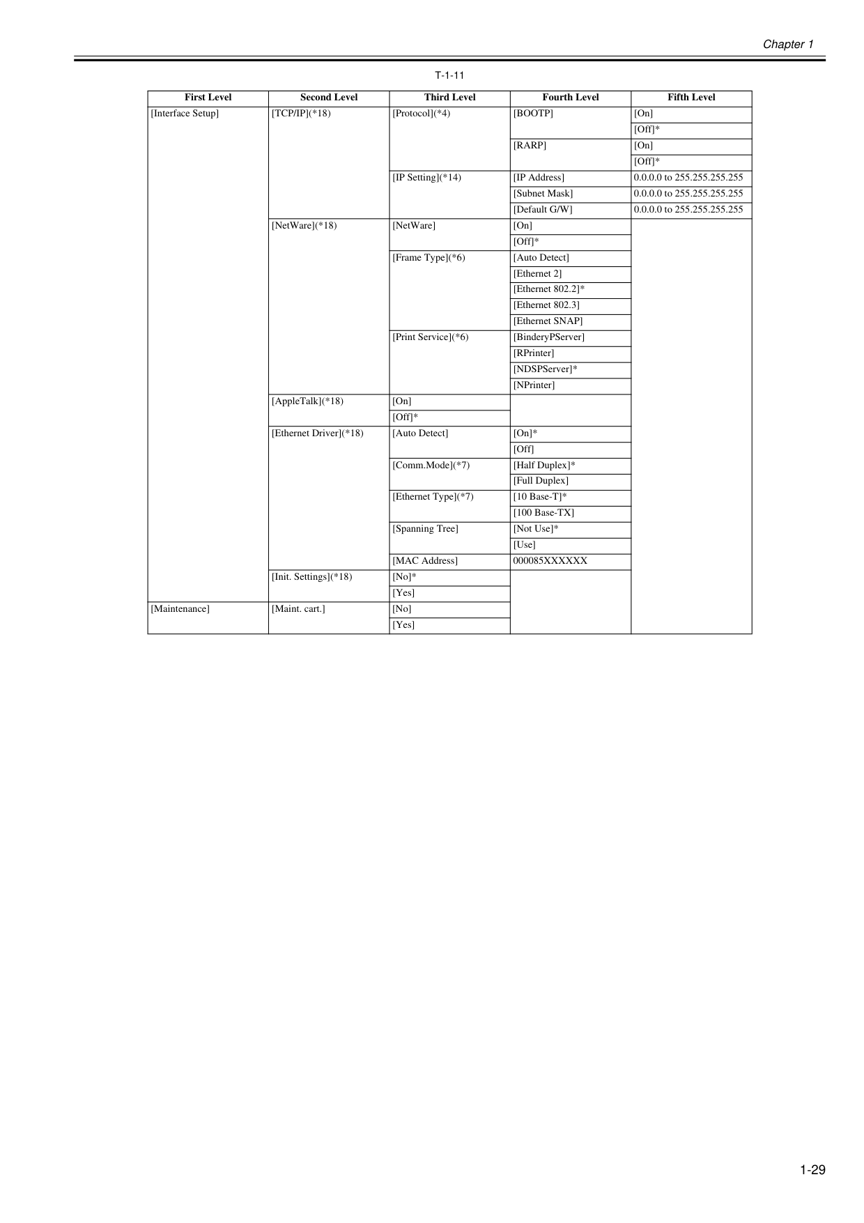
Chapter 1 1-29
T-1-11
First Level Second Level Third Level Fourth Level Fifth Level [Interface Setup][Tcp/Ip](*18)
[Protocol](*4)[Bootp]
[On] [Off]*[Rarp]
[On] [Off]* [IP Setting](*14) [IP Address] 0.0.0.0 to 255.255.255.255 [Subnet Mask] 0.0.0.0 to 255.255.255.255 [Default G/W] 0.0.0.0 to 255.255.255.255 [NetWare](*18) [NetWare] [On] [Off]* [Frame Type](*6) [Auto Detect] [Ethernet 2] [Ethernet 802.2]* [Ethernet 802.3] [Ethernet SNAP] [Print Service](*6) [BinderyPServer] [RPrinter] [NDSPServer]* [NPrinter] [AppleTalk](*18) [On] [Off]* [Ethernet Driver](*18) [Auto Detect] [On]* [Off] [Comm.Mode](*7) [Half Duplex]* [Full Duplex] [Ethernet Type](*7) [10 Base-T]* [100 Base-TX] [Spanning Tree] [Not Use]* [Use] [MAC Address]000085Xxxxxx
[Init. Settings](*18) [No]* [Yes] [Maintenance] [Maint. cart.] [No] [Yes]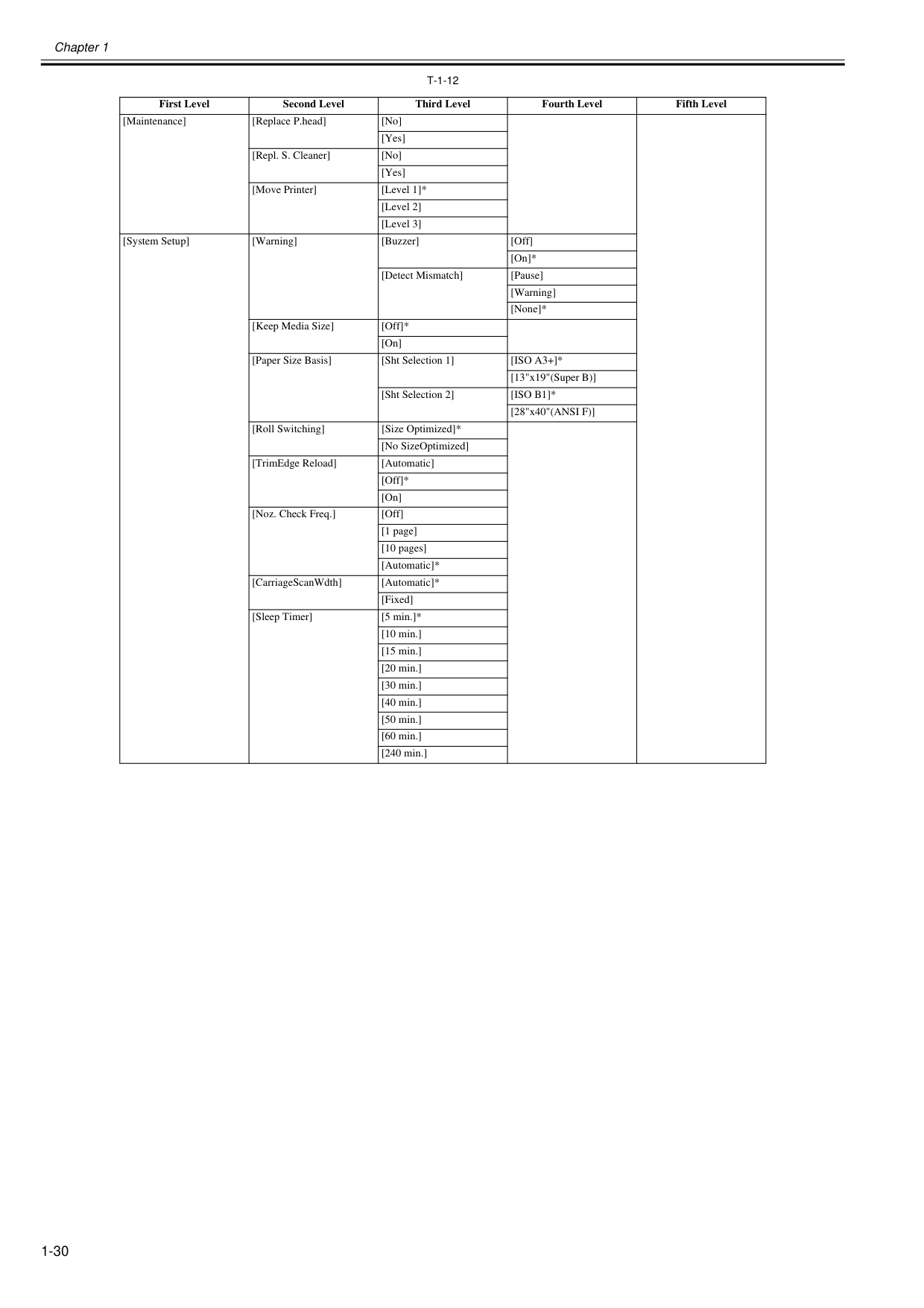
Chapter 1 1-30
T-1-12
First Level Second Level Third Level Fourth Level Fifth Level [Maintenance] [Replace P.head] [No] [Yes] [Repl. S. Cleaner] [No] [Yes] [Move Printer] [Level 1]* [Level 2] [Level 3] [System Setup] [Warning] [Buzzer] [Off] [On]* [Detect Mismatch] [Pause] [Warning] [None]* [Keep Media Size] [Off]* [On] [Paper Size Basis] [Sht Selection 1][Iso A3+]*
[13"x19"(Super B)] [Sht Selection 2][Iso B1]*
[28"x40"(ANSI F)] [Roll Switching] [Size Optimized]* [No SizeOptimized] [TrimEdge Reload] [Automatic] [Off]* [On] [Noz. Check Freq.] [Off] [1 page] [10 pages] [Automatic]* [CarriageScanWdth] [Automatic]* [Fixed] [Sleep Timer] [5 min.]* [10 min.] [15 min.] [20 min.] [30 min.] [40 min.] [50 min.] [60 min.] [240 min.]
Chapter 1 1-31
T-1-13
First Level Second Level Third Level Fourth Level Fifth Level [System Setup] [Length Unit] [meter]* [feet/inch] [Time Zone](*18) [0: London (GMT)] [+1: Paris, Rome] [+2: Athens, Cairo] [+3: Moscow] [+4: Eerevan, Baku] [+5: Islamabad] [+6: Dacca] [+7: Bangkok] [+8: Hong Kong] [+9: Tokyo, Seoul] [+10: Canberra] [+11: NewCaledonia] [+12: Wellington] [-12: Eniwetok] [-11: Midway is.] [-10: Hawaii (AHST)] [-9: Alaska (AKST)] [-8: Oregon (PST)] [-7: Arizona (MST)] [-6: Texas (CST)] [-5: NewYork (EST)] [-4: Santiago] [-3: Buenos Aires] [-2: ] [-1: Cape Verde] [Date Format](*18) [yyyy/mm/dd]* [dd/mm/yyyy] [mm/dd/yyyy] [Date & Time](*18) [Date] [yyyy/mm/dd](*8) [Time] [hh:mm]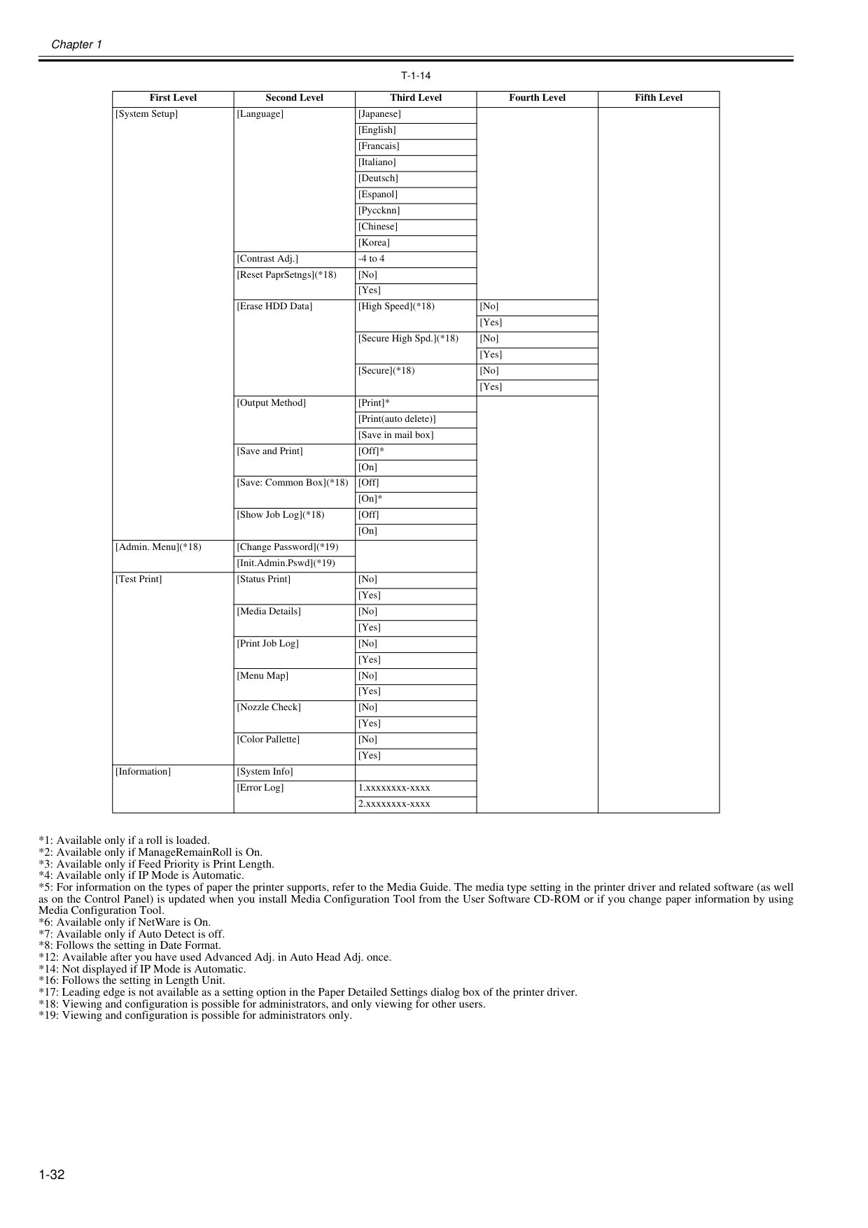
Chapter 1 1-32
T-1-14
*1: Available only if a roll is loaded. *2: Available only if ManageRemainRoll is On. *3: Available only if Feed Priority is Print Length. *4: Available only if IP Mode is Automatic. *5: For information on the types of paper the printer supports, refer to the Media Guide. The media type setting in the printer driver and related software (as well as on the Control Panel) is updated when you install Media Configuration Tool from the User Software CD-ROM or if you change paper information by using Media Configuration Tool. *6: Available only if NetWare is On. *7: Available only if Auto Detect is off. *8: Follows the setting in Date Format. *12: Available after you have used Advanced Adj. in Auto Head Adj. once. *14: Not displayed if IP Mode is Automatic. *16: Follows the setting in Length Unit. *17: Leading edge is not available as a setting option in the Paper Detailed Settings dialog box of the printer driver. *18: Viewing and configuration is possible for administrators, and only viewing for other users. *19: Viewing and configuration is possible for administrators only. First Level Second Level Third Level Fourth Level Fifth Level [System Setup] [Language] [Japanese] [English] [Francais] [Italiano] [Deutsch] [Espanol] [Pyccknn] [Chinese] [Korea] [Contrast Adj.] -4 to 4 [Reset PaprSetngs](*18) [No] [Yes] [Erase HDD Data] [High Speed](*18) [No] [Yes] [Secure High Spd.](*18) [No] [Yes] [Secure](*18) [No] [Yes] [Output Method] [Print]* [Print(auto delete)] [Save in mail box] [Save and Print] [Off]* [On] [Save: Common Box](*18) [Off] [On]* [Show Job Log](*18) [Off] [On] [Admin. Menu](*18) [Change Password](*19) [Init.Admin.Pswd](*19) [Test Print] [Status Print] [No] [Yes] [Media Details] [No] [Yes] [Print Job Log] [No] [Yes] [Menu Map] [No] [Yes] [Nozzle Check] [No] [Yes] [Color Pallette] [No] [Yes] [Information] [System Info] [Error Log] 1.xxxxxxxx-xxxx 2.xxxxxxxx-xxxx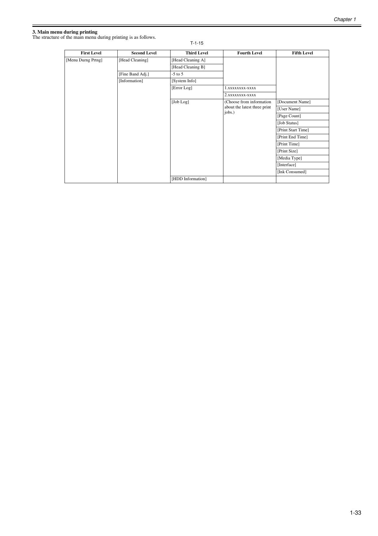
Chapter 1 1-33
T-1-15
First Level Second Level Third Level Fourth Level Fifth Level [Menu Durng Prtng] [Head Cleaning] [Head Cleaning A] [Head Cleaning B] [Fine Band Adj.] -5 to 5 [Information] [System Info] [Error Log] 1.xxxxxxxx-xxxx 2.xxxxxxxx-xxxx [Job Log] (Choose from information about the latest three print jobs.) [Document Name] [User Name] [Page Count] [Job Status] [Print Start Time] [Print End Time] [Print Time] [Print Size] [Media Type] [Interface] [Ink Consumed] [HDD Information]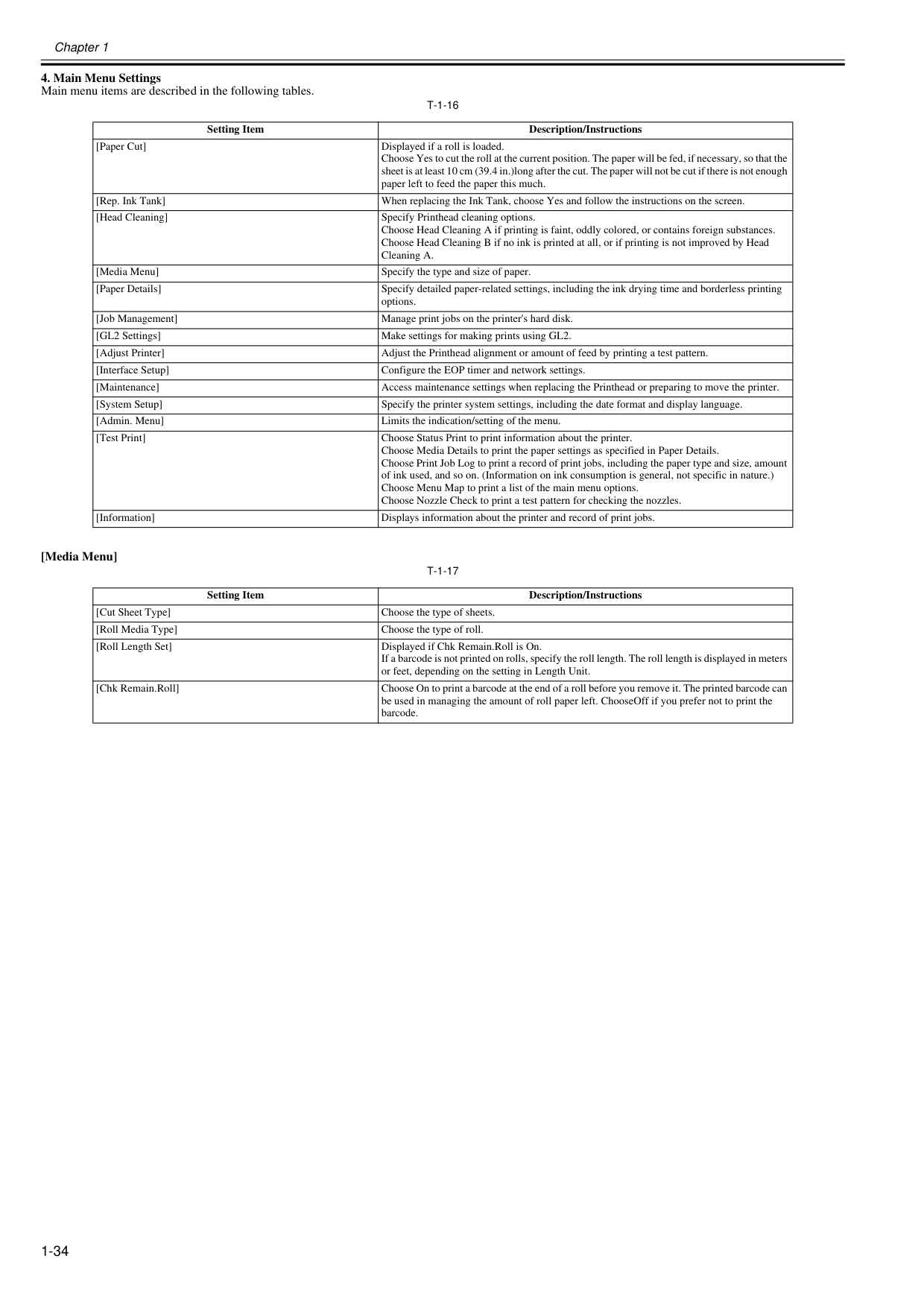
Chapter 1 1-34
T-1-16
[Media Menu]T-1-17
Setting Item Description/Instructions [Paper Cut] Displayed if a roll is loaded. Choose Yes to cut the roll at the current position. The paper will be fed, if necessary, so that the sheet is at least 10 cm (39.4 in.)long after the cut. The paper will not be cut if there is not enough paper left to feed the paper this much. [Rep. Ink Tank] When replacing the Ink Tank, choose Yes and follow the instructions on the screen. [Head Cleaning] Specify Printhead cleaning options. Choose Head Cleaning A if printing is faint, oddly colored, or contains foreign substances. Choose Head Cleaning B if no ink is printed at all, or if printing is not improved by Head Cleaning A. [Media Menu] Specify the type and size of paper. [Paper Details] Specify detailed paper-related settings, including the ink drying time and borderless printing options. [Job Management] Manage print jobs on the printer's hard disk. [GL2 Settings] Make settings for making prints using GL2. [Adjust Printer] Adjust the Printhead alignment or amount of feed by printing a test pattern. [Interface Setup] Configure the EOP timer and network settings. [Maintenance] Access maintenance settings when replacing the Printhead or preparing to move the printer. [System Setup] Specify the printer system settings, including the date format and display language. [Admin. Menu] Limits the indication/setting of the menu. [Test Print] Choose Status Print to print information about the printer. Choose Media Details to print the paper settings as specified in Paper Details. Choose Print Job Log to print a record of print jobs, including the paper type and size, amount of ink used, and so on. (Information on ink consumption is general, not specific in nature.) Choose Menu Map to print a list of the main menu options. Choose Nozzle Check to print a test pattern for checking the nozzles. [Information] Displays information about the printer and record of print jobs. Setting Item Description/Instructions [Cut Sheet Type] Choose the type of sheets. [Roll Media Type] Choose the type of roll. [Roll Length Set] Displayed if Chk Remain.Roll is On. If a barcode is not printed on rolls, specify the roll length. The roll length is displayed in meters or feet, depending on the setting in Length Unit. [Chk Remain.Roll] Choose On to print a barcode at the end of a roll before you remove it. The printed barcode can be used in managing the amount of roll paper left. ChooseOff if you prefer not to print the barcode.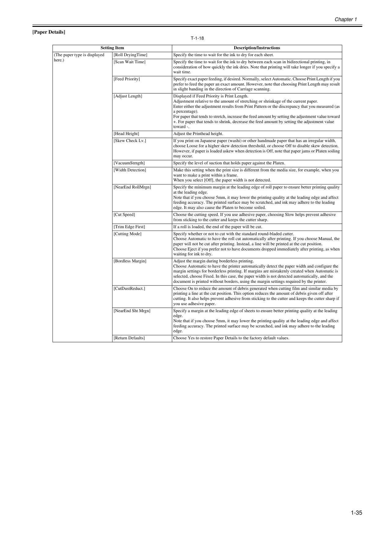
Chapter 1 1-35 [Paper Details]
T-1-18
Setting Item Description/Instructions (The paper type is displayed here.) [Roll DryingTime] Specify the time to wait for the ink to dry for each sheet. [Scan Wait Time] Specify the time to wait for the ink to dry between each scan in bidirectional printing, in consideration of how quickly the ink dries. Note that printing will take longer if you specify a wait time. [Feed Priority] Specify exact paper feeding, if desired. Normally, select Automatic. Choose Print Length if you prefer to feed the paper an exact amount. However, note that choosing Print Length may result in slight banding in the direction of Carriage scanning. [Adjust Length] Displayed if Feed Priority is Print Length. Adjustment relative to the amount of stretching or shrinkage of the current paper. Enter either the adjustment results from Print Pattern or the discrepancy that you measured (as a percentage). For paper that tends to stretch, increase the feed amount by setting the adjustment value toward +. For paper that tends to shrink, decrease the feed amount by setting the adjustment value toward -. [Head Height] Adjust the Printhead height. [Skew Check Lv.] If you print on Japanese paper (washi) or other handmade paper that has an irregular width, choose Loose for a higher skew detection threshold, or choose Off to disable skew detection. However, if paper is loaded askew when detection is Off, note that paper jams or Platen soiling may occur. [VacuumStrngth] Specify the level of suction that holds paper against the Platen. [Width Detection] Make this setting when the print size is different from the media size, for example, when you want to make a print within a frame. When you select [Off], the paper width is not detected. [NearEnd RollMrgn] Specify the minimum margin at the leading edge of roll paper to ensure better printing quality at the leading edge. Note that if you choose 5mm, it may lower the printing quality at the leading edge and affect feeding accuracy. The printed surface may be scratched, and ink may adhere to the leading edge. It may also cause the Platen to become soiled. [Cut Speed] Choose the cutting speed. If you use adhesive paper, choosing Slow helps prevent adhesive from sticking to the cutter and keeps the cutter sharp. [Trim Edge First] If a roll is loaded, the end of the paper will be cut. [Cutting Mode] Specify whether or not to cut with the standard round-bladed cutter. Choose Automatic to have the roll cut automatically after printing. If you choose Manual, the paper will not be cut after printing. Instead, a line will be printed at the cut position. Choose Eject if you prefer not to have documents dropped immediately after printing, as when waiting for ink to dry. [Bordless Margin] Adjust the margin during borderless printing. Choose Automatic to have the printer automatically detect the paper width and configure the margin settings for borderless printing. If margins are mistakenly created when Automatic is selected, choose Fixed. In this case, the paper width is not detected automatically, and the document is printed without borders, using the margin settings required by the printer. [CutDustReduct.] Choose On to reduce the amount of debris generated when cutting film and similar media by printing a line at the cut position. This option reduces the amount of debris given off after cutting. It also helps prevent adhesive from sticking to the cutter and keeps the cutter sharp if you use adhesive paper. [NearEnd Sht Mrgn] Specify a margin at the leading edge of sheets to ensure better printing quality at the leading edge. Note that if you choose 5mm, it may lower the printing quality at the leading edge and affect feeding accuracy. The printed surface may be scratched, and ink may adhere to the leading edge. [Return Defaults] Choose Yes to restore Paper Details to the factory default values.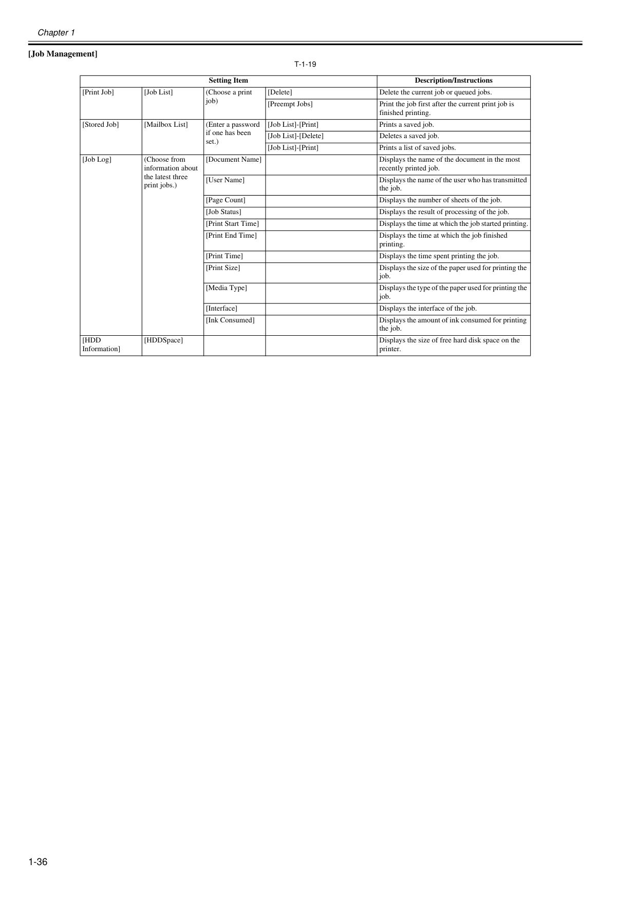
Chapter 1 1-36 [Job Management]
T-1-19
Setting Item Description/Instructions [Print Job] [Job List] (Choose a print job) [Delete] Delete the current job or queued jobs. [Preempt Jobs] Print the job first after the current print job is finished printing. [Stored Job] [Mailbox List] (Enter a password if one has been set.) [Job List]-[Print] Prints a saved job. [Job List]-[Delete] Deletes a saved job. [Job List]-[Print] Prints a list of saved jobs. [Job Log] (Choose from information about the latest three print jobs.) [Document Name] Displays the name of the document in the most recently printed job. [User Name] Displays the name of the user who has transmitted the job. [Page Count] Displays the number of sheets of the job. [Job Status] Displays the result of processing of the job. [Print Start Time] Displays the time at which the job started printing. [Print End Time] Displays the time at which the job finished printing. [Print Time] Displays the time spent printing the job. [Print Size] Displays the size of the paper used for printing the job. [Media Type] Displays the type of the paper used for printing the job. [Interface] Displays the interface of the job. [Ink Consumed] Displays the amount of ink consumed for printing the job.[Hdd
Information] [HDDSpace] Displays the size of free hard disk space on the printer.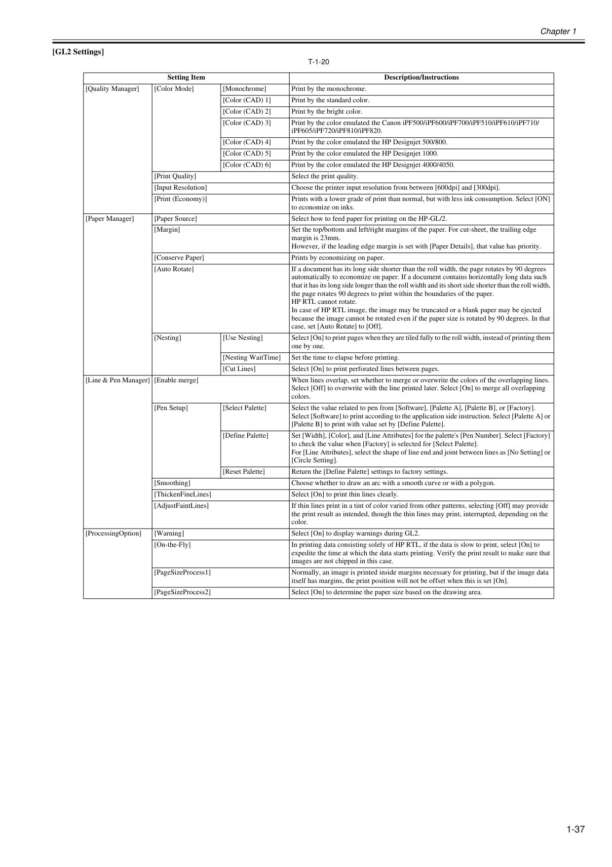
Chapter 1 1-37 [GL2 Settings]
T-1-20
Setting Item Description/Instructions [Quality Manager] [Color Mode] [Monochrome] Print by the monochrome. [Color (CAD) 1] Print by the standard color. [Color (CAD) 2] Print by the bright color. [Color (CAD) 3] Print by the color emulated the Canon iPF500/iPF600/iPF700/iPF510/iPF610/iPF710/ iPF605/iPF720/iPF810/iPF820. [Color (CAD) 4] Print by the color emulated the HP Designjet 500/800. [Color (CAD) 5] Print by the color emulated the HP Designjet 1000. [Color (CAD) 6] Print by the color emulated the HP Designjet 4000/4050. [Print Quality] Select the print quality. [Input Resolution] Choose the printer input resolution from between [600dpi] and [300dpi]. [Print (Economy)] Prints with a lower grade of print than normal, but with less ink consumption. Select [ON] to economize on inks. [Paper Manager] [Paper Source] Select how to feed paper for printing on the HP-GL/2. [Margin] Set the top/bottom and left/right margins of the paper. For cut-sheet, the trailing edge margin is 23mm. However, if the leading edge margin is set with [Paper Details], that value has priority. [Conserve Paper] Prints by economizing on paper. [Auto Rotate] If a document has its long side shorter than the roll width, the page rotates by 90 degrees automatically to economize on paper. If a document contains horizontally long data such that it has its long side longer than the roll width and its short side shorter than the roll width, the page rotates 90 degrees to print within the boundaries of the paper. HP RTL cannot rotate. In case of HP RTL image, the image may be truncated or a blank paper may be ejected because the image cannot be rotated even if the paper size is rotated by 90 degrees. In that case, set [Auto Rotate] to [Off]. [Nesting] [Use Nesting] Select [On] to print pages when they are tiled fully to the roll width, instead of printing them one by one. [Nesting WaitTime] Set the time to elapse before printing. [Cut Lines] Select [On] to print perforated lines between pages. [Line & Pen Manager] [Enable merge] When lines overlap, set whether to merge or overwrite the colors of the overlapping lines. Select [Off] to overwrite with the line printed later. Select [On] to merge all overlapping colors. [Pen Setup] [Select Palette] Select the value related to pen from [Software], [Palette A], [Palette B], or [Factory]. Select [Software] to print according to the application side instruction. Select [Palette A] or [Palette B] to print with value set by [Define Palette]. [Define Palette] Set [Width], [Color], and [Line Attributes] for the palette's [Pen Number]. Select [Factory] to check the value when [Factory] is selected for [Select Palette]. For [Line Attributes], select the shape of line end and joint between lines as [No Setting] or [Circle Setting]. [Reset Palette] Return the [Define Palette] settings to factory settings. [Smoothing] Choose whether to draw an arc with a smooth curve or with a polygon. [ThickenFineLines] Select [On] to print thin lines clearly. [AdjustFaintLines] If thin lines print in a tint of color varied from other patterns, selecting [Off] may provide the print result as intended, though the thin lines may print, interrupted, depending on the color. [ProcessingOption] [Warning] Select [On] to display warnings during GL2. [On-the-Fly] In printing data consisting solely of HP RTL, if the data is slow to print, select [On] to expedite the time at which the data starts printing. Verify the print result to make sure that images are not chipped in this case. [PageSizeProcess1] Normally, an image is printed inside margins necessary for printing, but if the image data itself has margins, the print position will not be offset when this is set [On]. [PageSizeProcess2] Select [On] to determine the paper size based on the drawing area.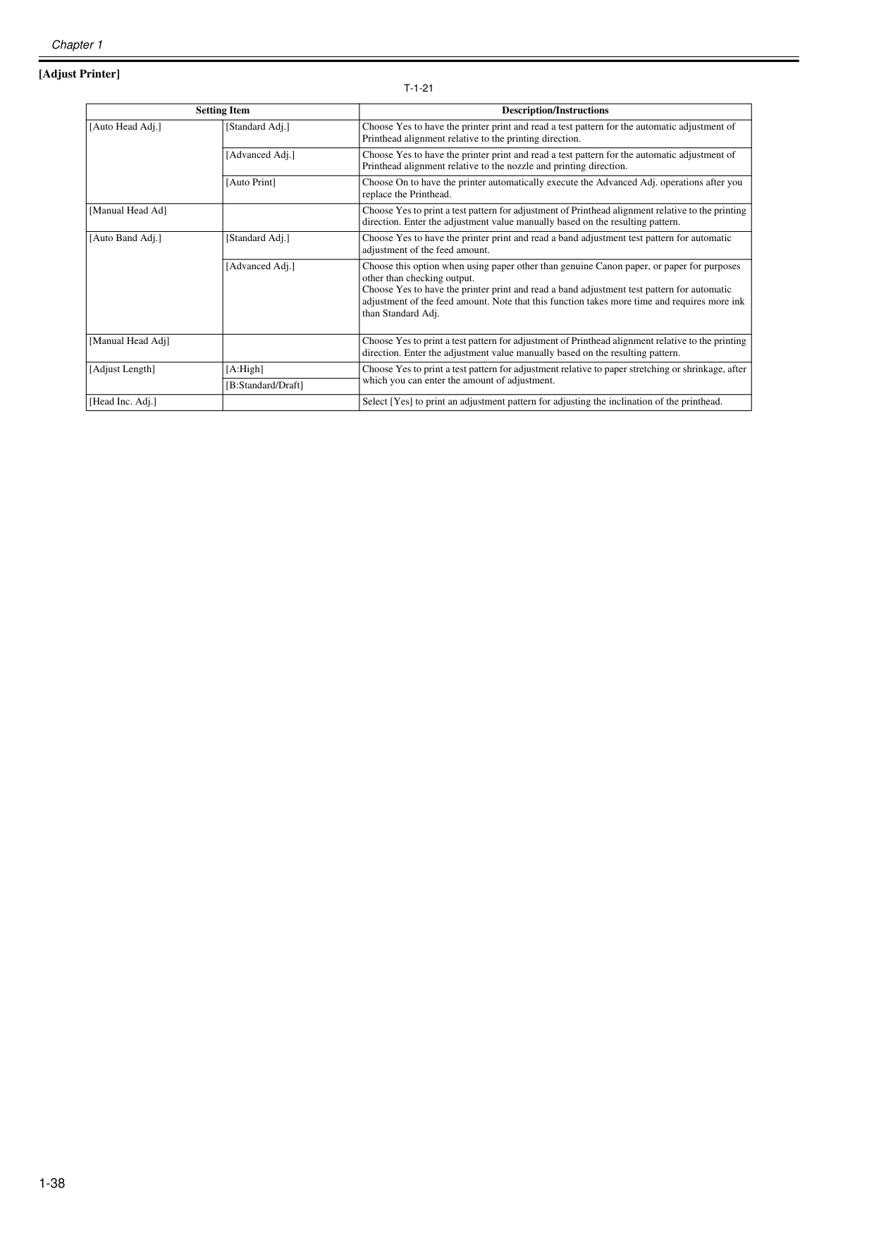
Chapter 1 1-38 [Adjust Printer]
T-1-21
Setting Item Description/Instructions [Auto Head Adj.] [Standard Adj.] Choose Yes to have the printer print and read a test pattern for the automatic adjustment of Printhead alignment relative to the printing direction. [Advanced Adj.] Choose Yes to have the printer print and read a test pattern for the automatic adjustment of Printhead alignment relative to the nozzle and printing direction. [Auto Print] Choose On to have the printer automatically execute the Advanced Adj. operations after you replace the Printhead. [Manual Head Ad] Choose Yes to print a test pattern for adjustment of Printhead alignment relative to the printing direction. Enter the adjustment value manually based on the resulting pattern. [Auto Band Adj.] [Standard Adj.] Choose Yes to have the printer print and read a band adjustment test pattern for automatic adjustment of the feed amount. [Advanced Adj.] Choose this option when using paper other than genuine Canon paper, or paper for purposes other than checking output. Choose Yes to have the printer print and read a band adjustment test pattern for automatic adjustment of the feed amount. Note that this function takes more time and requires more ink than Standard Adj. [Manual Head Adj] Choose Yes to print a test pattern for adjustment of Printhead alignment relative to the printing direction. Enter the adjustment value manually based on the resulting pattern. [Adjust Length] [A:High] Choose Yes to print a test pattern for adjustment relative to paper stretching or shrinkage, after which you can enter the amount of adjustment. [B:Standard/Draft] [Head Inc. Adj.] Select [Yes] to print an adjustment pattern for adjusting the inclination of the printhead.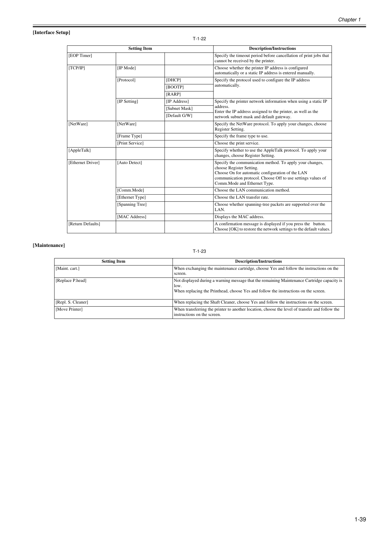
Chapter 1 1-39 [Interface Setup]
T-1-22
[Maintenance]T-1-23
Setting Item Description/Instructions [EOP Timer] Specify the timeout period before cancellation of print jobs that cannot be received by the printer.[Tcp/Ip]
[IP Mode] Choose whether the printer IP address is configured automatically or a static IP address is entered manually. [Protocol][Dhcp]
Specify the protocol used to configure the IP address automatically.[Bootp]
[Rarp]
[IP Setting] [IP Address] Specify the printer network information when using a static IP address. Enter the IP address assigned to the printer, as well as the network subnet mask and default gateway. [Subnet Mask] [Default G/W] [NetWare] [NetWare] Specify the NetWare protocol. To apply your changes, choose Register Setting. [Frame Type] Specify the frame type to use. [Print Service] Choose the print service. [AppleTalk] Specify whether to use the AppleTalk protocol. To apply your changes, choose Register Setting. [Ethernet Driver] [Auto Detect] Specify the communication method. To apply your changes, choose Register Setting. Choose On for automatic configuration of the LAN communication protocol. Choose Off to use settings values of Comm.Mode and Ethernet Type. [Comm.Mode] Choose the LAN communication method. [Ethernet Type] Choose the LAN transfer rate. [Spanning Tree] Choose whether spanning-tree packets are supported over theLan.
[MAC Address] Displays the MAC address. [Return Defaults] A confirmation message is displayed if you press the button. Choose [OK] to restore the network settings to the default values. Setting Item Description/Instructions [Maint. cart.] When exchanging the maintenance cartridge, choose Yes and follow the instructions on the screen. [Replace P.head] Not displayed during a warning message that the remaining Maintenance Cartridge capacity is low. When replacing the Printhead, choose Yes and follow the instructions on the screen. [Repl. S. Cleaner] When replacing the Shaft Cleaner, choose Yes and follow the instructions on the screen. [Move Printer] When transferring the printer to another location, choose the level of transfer and follow the instructions on the screen.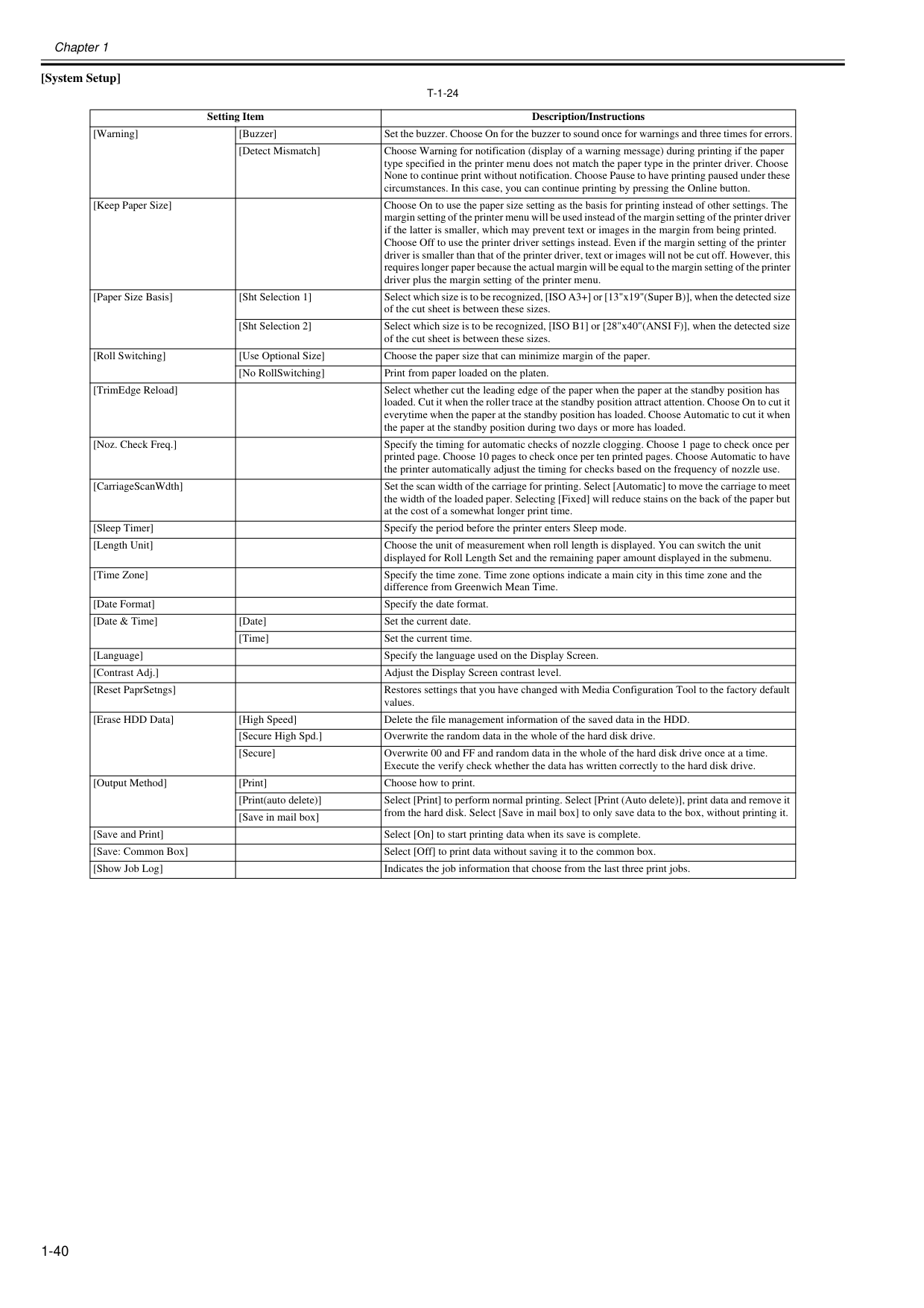
Chapter 1 1-40 [System Setup]
T-1-24
Setting Item Description/Instructions [Warning] [Buzzer] Set the buzzer. Choose On for the buzzer to sound once for warnings and three times for errors. [Detect Mismatch] Choose Warning for notification (display of a warning message) during printing if the paper type specified in the printer menu does not match the paper type in the printer driver. Choose None to continue print without notification. Choose Pause to have printing paused under these circumstances. In this case, you can continue printing by pressing the Online button. [Keep Paper Size] Choose On to use the paper size setting as the basis for printing instead of other settings. The margin setting of the printer menu will be used instead of the margin setting of the printer driver if the latter is smaller, which may prevent text or images in the margin from being printed. Choose Off to use the printer driver settings instead. Even if the margin setting of the printer driver is smaller than that of the printer driver, text or images will not be cut off. However, this requires longer paper because the actual margin will be equal to the margin setting of the printer driver plus the margin setting of the printer menu. [Paper Size Basis] [Sht Selection 1] Select which size is to be recognized, [ISO A3+] or [13"x19"(Super B)], when the detected size of the cut sheet is between these sizes. [Sht Selection 2] Select which size is to be recognized, [ISO B1] or [28"x40"(ANSI F)], when the detected size of the cut sheet is between these sizes. [Roll Switching] [Use Optional Size] Choose the paper size that can minimize margin of the paper. [No RollSwitching] Print from paper loaded on the platen. [TrimEdge Reload] Select whether cut the leading edge of the paper when the paper at the standby position has loaded. Cut it when the roller trace at the standby position attract attention. Choose On to cut it everytime when the paper at the standby position has loaded. Choose Automatic to cut it when the paper at the standby position during two days or more has loaded. [Noz. Check Freq.] Specify the timing for automatic checks of nozzle clogging. Choose 1 page to check once per printed page. Choose 10 pages to check once per ten printed pages. Choose Automatic to have the printer automatically adjust the timing for checks based on the frequency of nozzle use. [CarriageScanWdth] Set the scan width of the carriage for printing. Select [Automatic] to move the carriage to meet the width of the loaded paper. Selecting [Fixed] will reduce stains on the back of the paper but at the cost of a somewhat longer print time. [Sleep Timer] Specify the period before the printer enters Sleep mode. [Length Unit] Choose the unit of measurement when roll length is displayed. You can switch the unit displayed for Roll Length Set and the remaining paper amount displayed in the submenu. [Time Zone] Specify the time zone. Time zone options indicate a main city in this time zone and the difference from Greenwich Mean Time. [Date Format] Specify the date format. [Date & Time] [Date] Set the current date. [Time] Set the current time. [Language] Specify the language used on the Display Screen. [Contrast Adj.] Adjust the Display Screen contrast level. [Reset PaprSetngs] Restores settings that you have changed with Media Configuration Tool to the factory default values. [Erase HDD Data] [High Speed] Delete the file management information of the saved data in the HDD. [Secure High Spd.] Overwrite the random data in the whole of the hard disk drive. [Secure] Overwrite 00 and FF and random data in the whole of the hard disk drive once at a time. Execute the verify check whether the data has written correctly to the hard disk drive. [Output Method] [Print] Choose how to print. [Print(auto delete)] Select [Print] to perform normal printing. Select [Print (Auto delete)], print data and remove it from the hard disk. Select [Save in mail box] to only save data to the box, without printing it. [Save in mail box] [Save and Print] Select [On] to start printing data when its save is complete. [Save: Common Box] Select [Off] to print data without saving it to the common box. [Show Job Log] Indicates the job information that choose from the last three print jobs.
Chapter 1 1-41 [Admin Menu]
T-1-25
Setting Item Description/Instructions [Change Password] By setting a password, you can restrict menu display and configuration as follows. You can input between 0 and 9999999.
Chapter 1 1-42 [Information]
T-1-26
Setting Item Description/Instructions [System Info] [Version] [Firmware] Displays the version of the printer and firmware. [Boot] Displays the version of the boot ROM.[Mit]
Displays the version of the MIT database format. [s/n] Displays the printer's serial number.[Mac]
Displays the MAC address of the printer.[Ip]
Displays the printer IP address. [Error Log] [########-####] Displays the most recent error messages (up to two).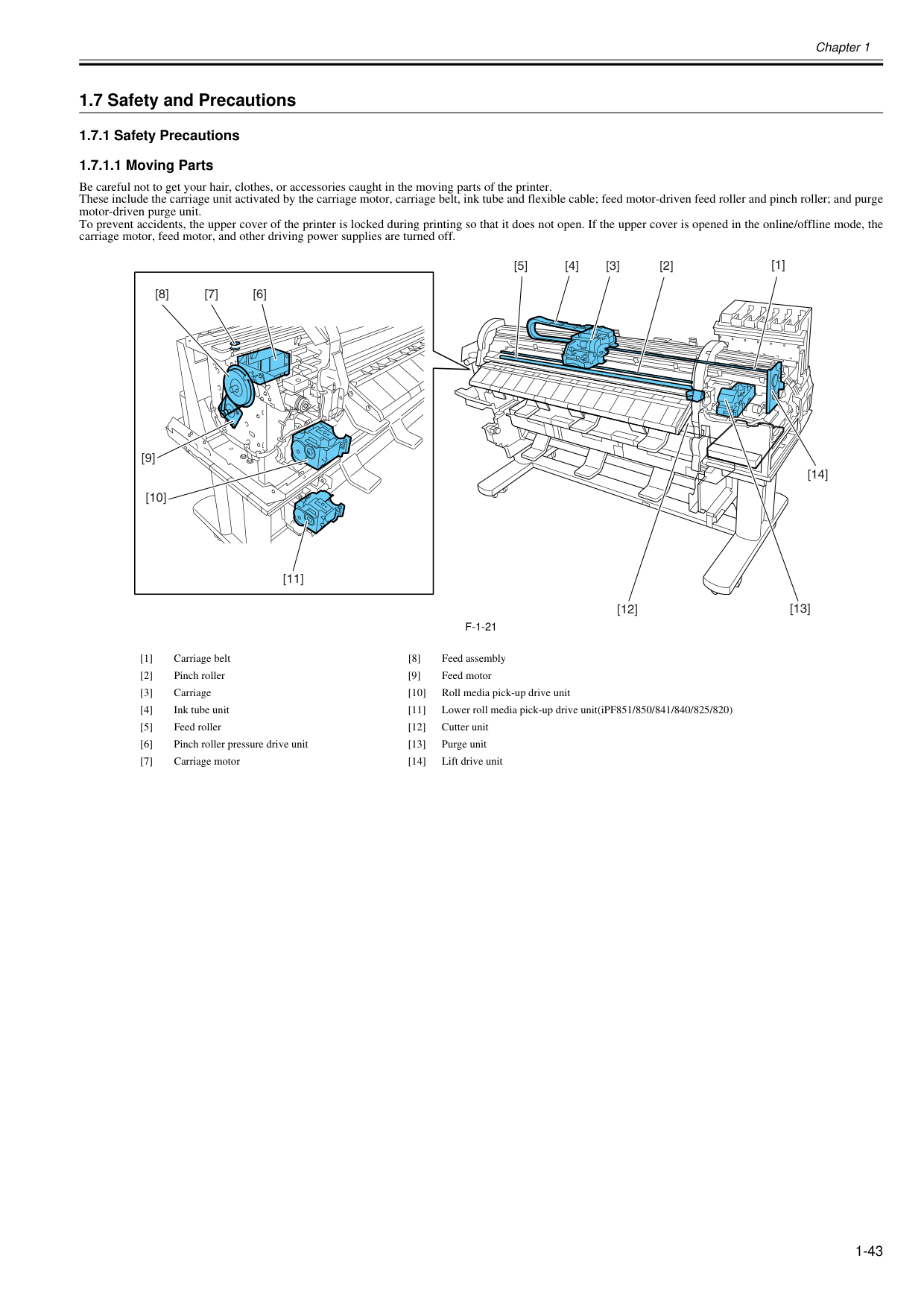
Chapter 1 1-43 1.7 Safety and Precautions 1.7.1 Safety Precautions 1.7.1.1 Moving Parts 0020-5470 Be careful not to get your hair, clothes, or accessories caught in the moving parts of the printer. These include the carriage unit activated by the carriage motor, carriage belt, ink tube and flexible cable; feed motor-driven feed roller and pinch roller; and purge motor-driven purge unit. To prevent accidents, the upper cover of the printer is locked during printing so that it does not open. If the upper cover is opened in the online/offline mode, the carriage motor, feed motor, and other driving power supplies are turned off.
F-1-21
[1] Carriage belt [8] Feed assembly [2] Pinch roller [9] Feed motor [3] Carriage [10] Roll media pick-up drive unit [4] Ink tube unit [11] Lower roll media pick-up drive unit(iPF851/850/841/840/825/820) [5] Feed roller [12] Cutter unit [6] Pinch roller pressure drive unit [13] Purge unit [7] Carriage motor [14] Lift drive unit [1] [3] [13] [12] [11] [2] [4] [5] [7] [6] [8] [9] [10] [14]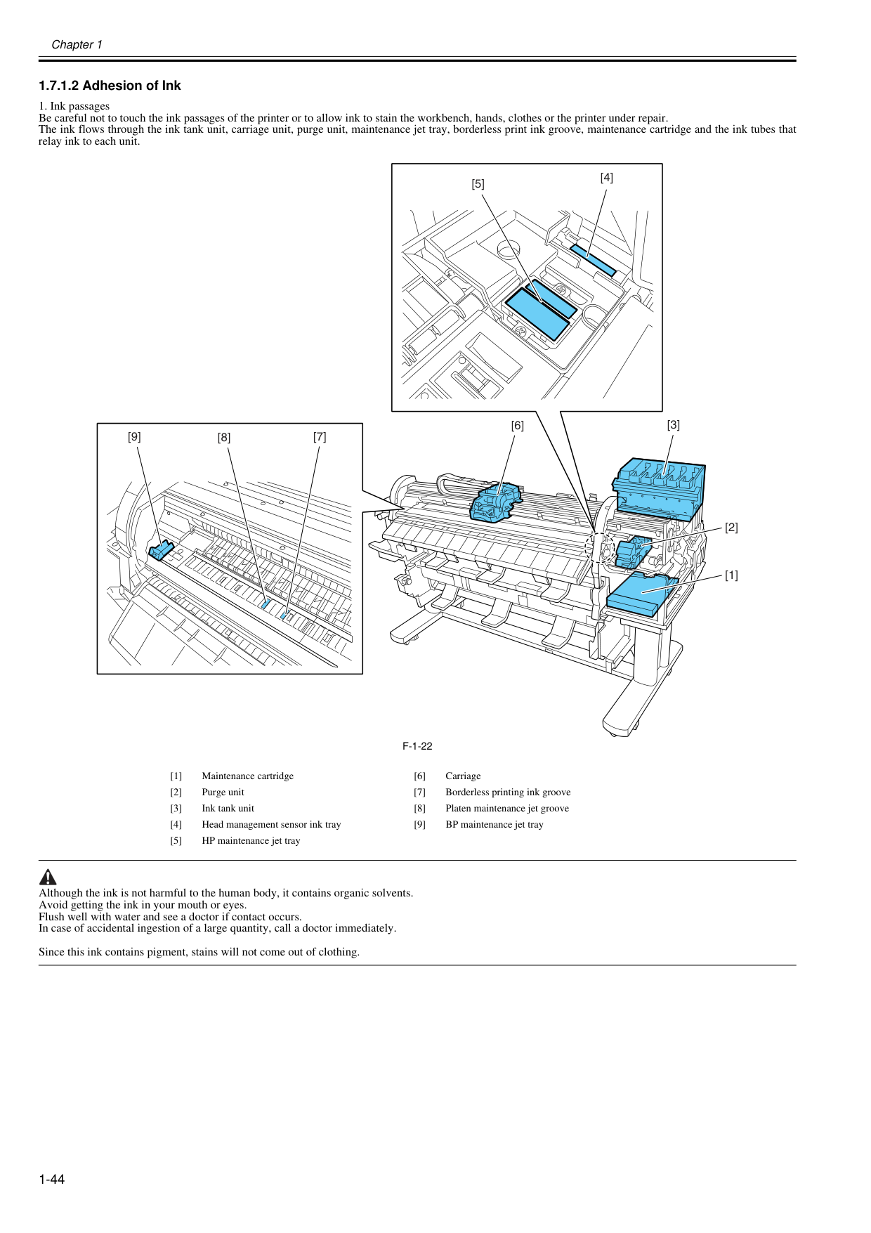
Chapter 1 1-44 1.7.1.2 Adhesion of Ink 0020-5471
F-1-22
Although the ink is not harmful to the human body, it contains organic solvents. Avoid getting the ink in your mouth or eyes. Flush well with water and see a doctor if contact occurs. In case of accidental ingestion of a large quantity, call a doctor immediately. Since this ink contains pigment, stains will not come out of clothing. [1] Maintenance cartridge [6] Carriage [2] Purge unit [7] Borderless printing ink groove [3] Ink tank unit [8] Platen maintenance jet groove [4] Head management sensor ink tray [9] BP maintenance jet tray [5] HP maintenance jet tray [3] [6] [2] [1] [4] [5] [7] [8] [9]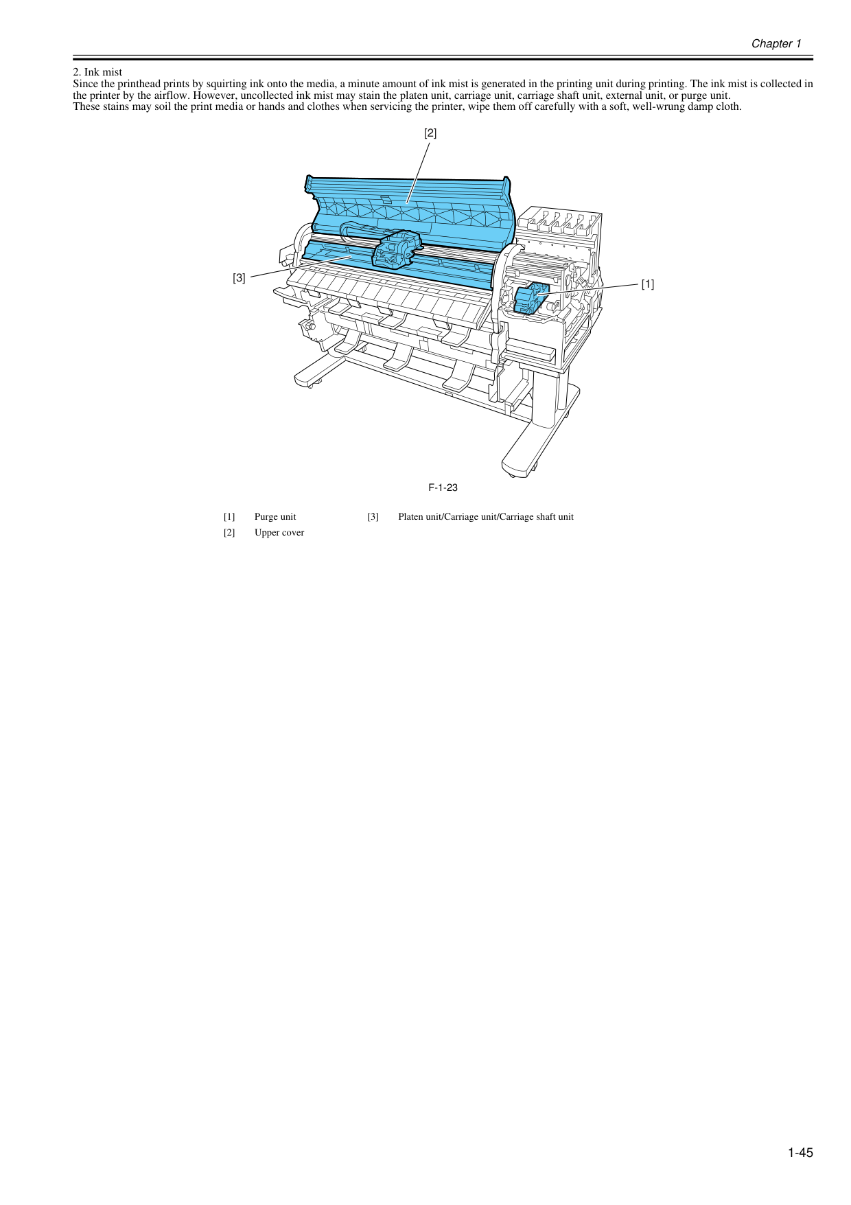
Chapter 1 1-45
F-1-23
[1] Purge unit [3] Platen unit/Carriage unit/Carriage shaft unit [2] Upper cover [1] [2] [3]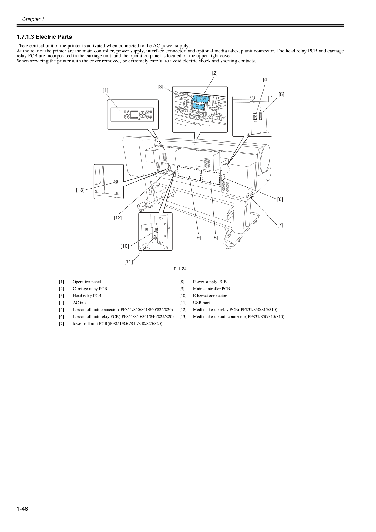
Chapter 1 1-46 1.7.1.3 Electric Parts 0020-5474 The electrical unit of the printer is activated when connected to the AC power supply. At the rear of the printer are the main controller, power supply, interface connector, and optional media take-up unit connector. The head relay PCB and carriage relay PCB are incorporated in the carriage unit, and the operation panel is located on the upper right cover. When servicing the printer with the cover removed, be extremely careful to avoid electric shock and shorting contacts.
F-1-24
[1] Operation panel [8] Power supply PCB [2] Carriage relay PCB [9] Main controller PCB [3] Head relay PCB [10] Ethernet connector [4] AC inlet [11] USB port [5] Lower roll unit connector(iPF851/850/841/840/825/820) [12] Media take-up relay PCB(iPF831/830/815/810) [6] Lower roll unit relay PCB(iPF851/850/841/840/825/820) [13] Media take-up unit connector(iPF831/830/815/810) [7] lower roll unit PCB(iPF851/850/841/840/825/820) Power Online Data Menu Message Information Load/Eject Cleaning (3sec.) Stop (1sec.) [8] [9] [12] [11] [7] [6] [4] [2] [3] [5] [1] [13] [10]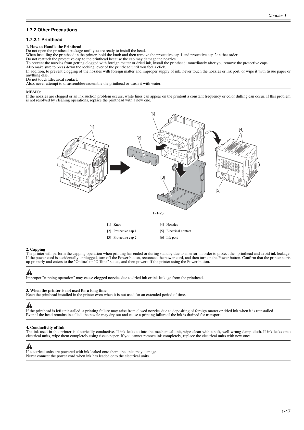
Chapter 1 1-47 1.7.2 Other Precautions 1.7.2.1 Printhead 0020-1924
Memo:
If the nozzles are clogged or an ink suction problem occurs, white lines can appear on the printout a constant frequency or color dulling can occur. If this problem is not resolved by cleaning operations, replace the printhead with a new one.F-1-25
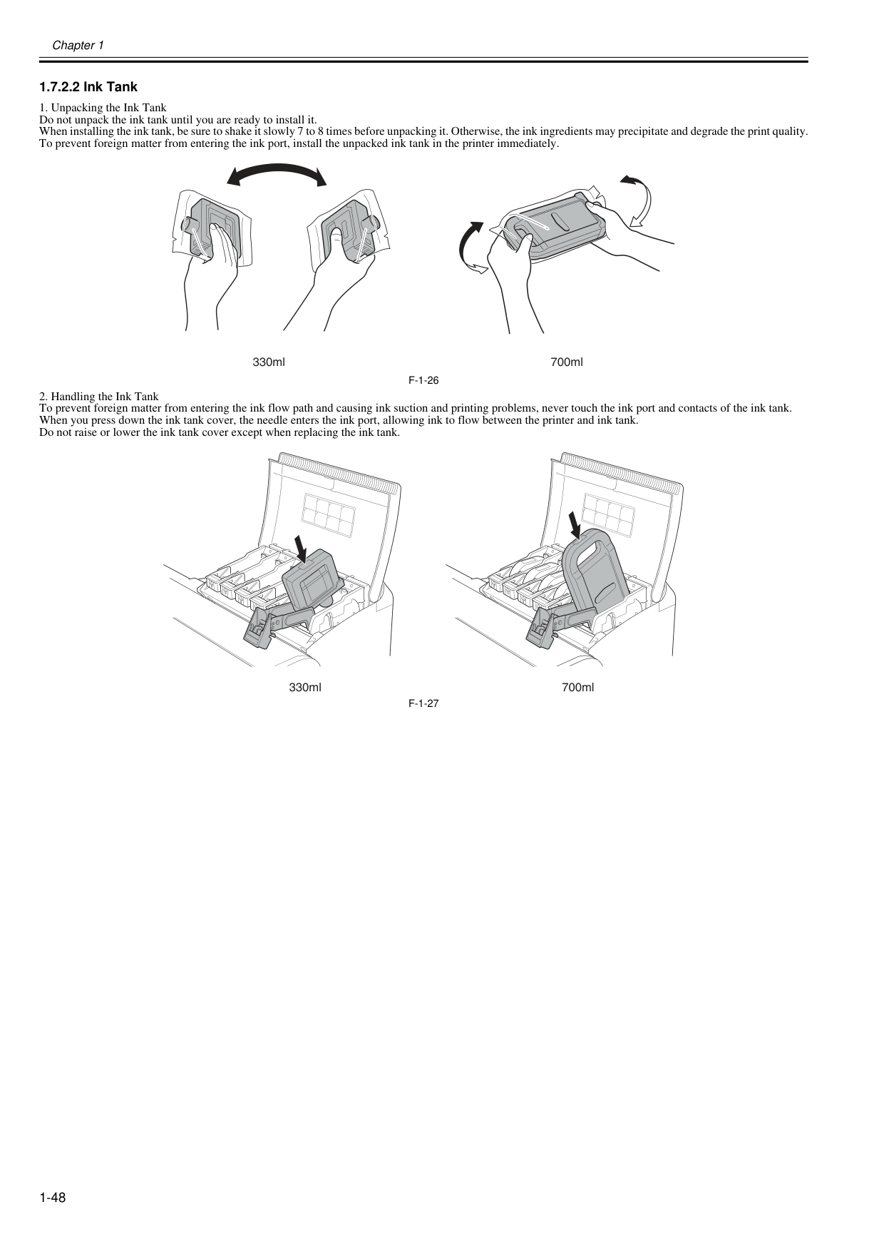
Chapter 1 1-48 1.7.2.2 Ink Tank 0012-6292
F-1-26
F-1-27
700ml 330mlG
G
700ml 330ml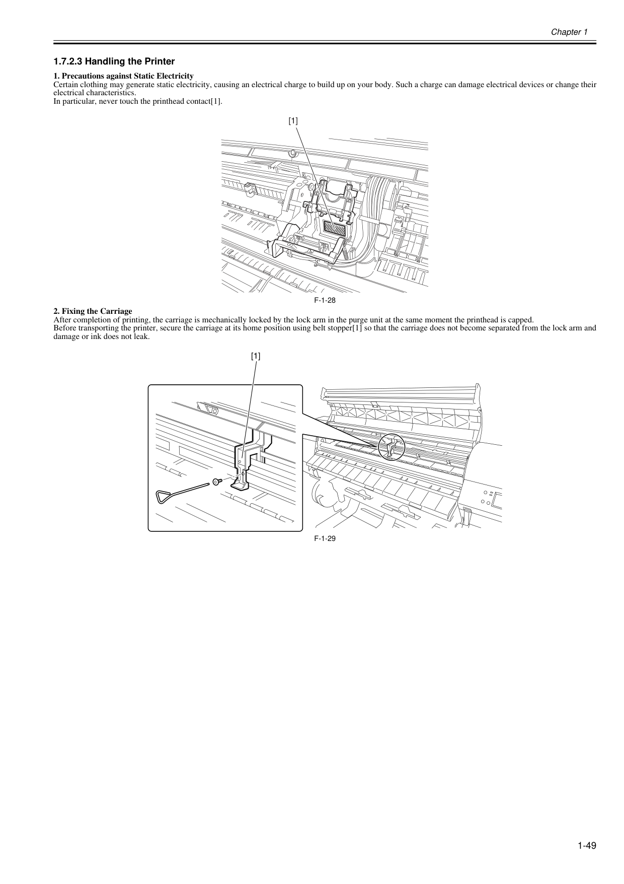
Chapter 1 1-49 1.7.2.3 Handling the Printer 0020-5475
F-1-28
F-1-29
[1] [1]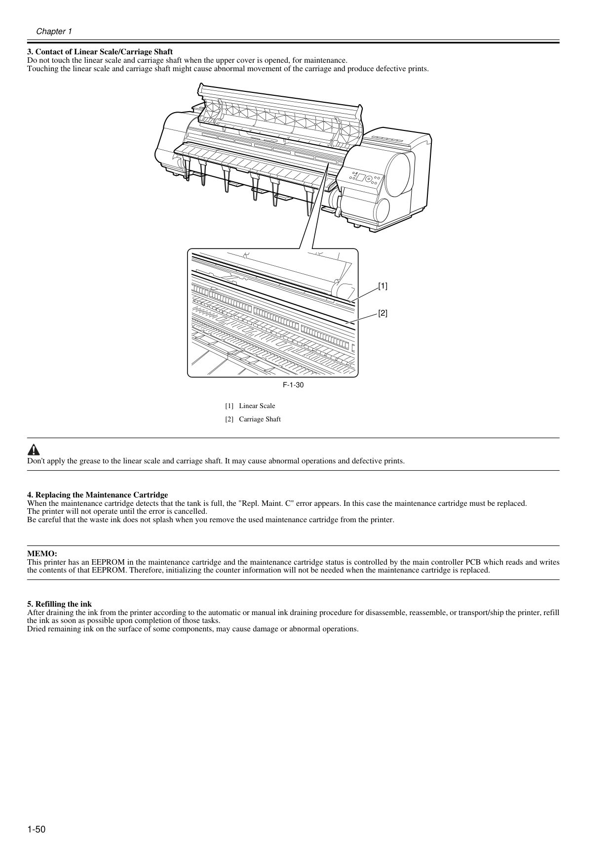
Chapter 1 1-50
F-1-30
Don't apply the grease to the linear scale and carriage shaft. It may cause abnormal operations and defective prints.Memo:
This printer has an EEPROM in the maintenance cartridge and the maintenance cartridge status is controlled by the main controller PCB which reads and writes the contents of that EEPROM. Therefore, initializing the counter information will not be needed when the maintenance cartridge is replaced.
Chapter 1 1-51 1.7.3 Precautions When Servicing Printer 1.7.3.1 Notes on the Data Stored in the Printer 0013-5942 This printer counts the print length, number of ink tank replacements, carriage driving time, number of cleaning operations, number of cutter operations, and so on and stores them in the main controller's EEPROM as a COUNTER in Service mode. COUNTER provides important information about the printer usage status. You can check this information by printing it in the service mode or displaying it on the display. Follow the precautions below when servicing the printer. (1) Repairing/replacing the PCB When replacing the main controller, follow the specified replacement procedure. For the main controller replacement procedure, see "DISASSEMBLY/REASSEMBLY" > "Points to Note on Disassembly and Reassembly" > "PCBs". (2) After replacing the carriage unit The information about the carriage driving time resides in the carriage unit. After replacing the carriage unit, select [INITIALIZE] > [CARRIAGE] in the service mode to initialize the information about the carriage driving time. (3) After replacing the purge unit The information about the number of cleanings resides in the purge unit. After replacing the purge unit, select [INITIALIZE] > [PURGE] in the service mode to initialize (clear) the information about the number of cleanings. (4) On replacement of supplies After supplies have been replaced, execute [INITIALIZE] > [PARTS COUNTER] > [PARTS xx] in service mode to initialize (clear) the parts counter information. For the consumable parts, see "MAINTENANCE" > "Periodic Replacement Parts". You cannot check the counter information once it is initialized (cleared). Be careful not to initialize the counter information before checking it. You cannot modify the counter information from the operation panel. 1.7.3.2 Confirming the Firmware Version 0013-5945 Firmware has been downloaded to the main controller. When you have replaced the main controller, check that the firmware is the latest version. If not, update it to the latest version. Reference: For instruction on how to update the main controller, refer to "TROUBLESHOOTING" > "Version Up". 1.7.3.3 Precautions against Static Electricity 0013-5947 Certain clothing may generate static electricity, causing an electrical charge to build up on your body. Such a charge can damage electrical devices. To prevent this, discharge any static buildup by touching a grounded metal fitting before you start disassembling the printer. 1.7.3.4 Precautions for Disassembly/Reassembly 0013-5948 The precautions for disassembly/reassembly are described in "DISASSEMBLY/REASSEMBLY". 1.7.3.5 Self-diagnostic Feature 0013-5950 The printer has a self-diagnostic feature to analyze hardware problems. The self-diagnosis result is shown on the display and indicated by lamps. For detailed information, see "ERROR CODE".
Chapter 1 1-52 1.7.3.6 Disposing of the Lithium Battery 0013-5952 The main controller PCB of this printer is equipped with a lithium battery to back up various data. Risk of explosion if battery is replaced by an incorrect type. Dispose of used batteries according to the instructions. "For CA, USA Only Included battery contains Perchlorate Material-special handling may apply. See http://www.dtsc.ca.gov/hazardouswaste/perchlorate/ for detail."

Chapter 2 TECHNICAL REFERENCE
Contents Contents 2.1 Basic Operation Outline.............................................................................................................................. 2-1 2.1.1 Printer Diagram ....................................................................................................................................................... 2-1 2.1.2 Print Signal Sequence............................................................................................................................................. 2-2 2.1.3 Print Driving............................................................................................................................................................. 2-3 2.2 Firmware..................................................................................................................................................... 2-5 2.2.1 Operation Sequence at Power-on ........................................................................................................................... 2-5 2.2.2 Operation Sequence at Power-off ........................................................................................................................... 2-6 2.2.3 Print Control............................................................................................................................................................. 2-7 2.2.4 Print Position Adjustment Function......................................................................................................................... 2-16 2.2.5 Head Management................................................................................................................................................. 2-16 2.2.6 Printhead Overheating Protection Control.............................................................................................................. 2-16 2.2.7 Pause between Pages............................................................................................................................................ 2-16 2.2.8 White Raster Skip................................................................................................................................................... 2-16 2.2.9 Sleep Mode ............................................................................................................................................................ 2-16 2.2.10 Hard Disk Drive..................................................................................................................................................... 2-16 2.3 Printer Mechanical System....................................................................................................................... 2-18 2.3.1 Outline .................................................................................................................................................................... 2-18 2.3.1.1 Outline..................................................................................................................................................................................... 2-18 2.3.2 Ink Passage............................................................................................................................................................ 2-19 2.3.2.1 Ink Passage ............................................................................................................................................................................ 2-19 2.3.2.1.1 Overview of Ink Passage ................................................................................................................................................. 2-19 2.3.2.2 Ink Tank Unit........................................................................................................................................................................... 2-20 2.3.2.2.1 Structure of Ink Tank Unit ................................................................................................................................................ 2-20 2.3.2.3 Carriage Unit........................................................................................................................................................................... 2-22 2.3.2.3.1 Functions of Carriage Unit ............................................................................................................................................... 2-22 2.3.2.3.2 Structure of Carriage Unit ................................................................................................................................................ 2-23 2.3.2.4 Printhead................................................................................................................................................................................. 2-25 2.3.2.4.1 Structure of Printhead...................................................................................................................................................... 2-25 2.3.2.5 Purge Unit............................................................................................................................................................................... 2-26 2.3.2.5.1 Functions of Purge Unit ................................................................................................................................................... 2-26 2.3.2.5.2 Structure of Purge Unit .................................................................................................................................................... 2-28 2.3.2.6 Maintenance Cartridge............................................................................................................................................................ 2-30 2.3.2.6.1 Maintenance Cartridge .................................................................................................................................................... 2-30 2.3.2.7 Air Flow................................................................................................................................................................................... 2-31 2.3.2.7.1 Air Flow............................................................................................................................................................................ 2-31 2.3.3 Paper Path.............................................................................................................................................................. 2-32 2.3.3.1 Outline..................................................................................................................................................................................... 2-32 2.3.3.1.1 Overview of Paper Path................................................................................................................................................... 2-32 2.3.3.2 Paper Path.............................................................................................................................................................................. 2-33 2.3.3.2.1 Structure of Pick-up/Feed Unit......................................................................................................................................... 2-33 2.3.3.3 Cutter Unit............................................................................................................................................................................... 2-36 2.3.3.3.1 Structure of Cutter Unit .................................................................................................................................................... 2-36 2.4 Printer Electrical System........................................................................................................................... 2-37 2.4.1 Outline .................................................................................................................................................................... 2-37 2.4.1.1 Overview................................................................................................................................................................................. 2-37 2.4.2 Main Controller ....................................................................................................................................................... 2-39 2.4.2.1 Main controller PCB components ........................................................................................................................................... 2-39 2.4.3 Carriage Relay PCB ............................................................................................................................................... 2-41 2.4.3.1 Carriage relay PCB components ............................................................................................................................................ 2-41 2.4.4 Head Relay PCB .................................................................................................................................................... 2-41 2.4.4.1 Head relay PCB components.................................................................................................................................................. 2-41 2.4.5 Motor Driver............................................................................................................................................................ 2-42 2.4.5.1 Lower roll unit PCB components............................................................................................................................................. 2-42

Contents 2.4.6 Maintenance Cartridge Relay PCB........................................................................................................................ 2-42 2.4.6.1 Maintenance cartridge relay PCB components....................................................................................................................... 2-42 2.4.7 Power Supply......................................................................................................................................................... 2-42 2.4.7.1 Power supply block diagram................................................................................................................................................... 2-42 2.5 Detection Functions with Sensors ............................................................................................................. 2-43 2.5.1 Covers.................................................................................................................................................................... 2-43 2.5.2 Ink passage system ............................................................................................................................................... 2-44 2.5.3 Carriage system..................................................................................................................................................... 2-46 2.5.4 Paper path system................................................................................................................................................. 2-48 2.5.5 Others .................................................................................................................................................................... 2-50
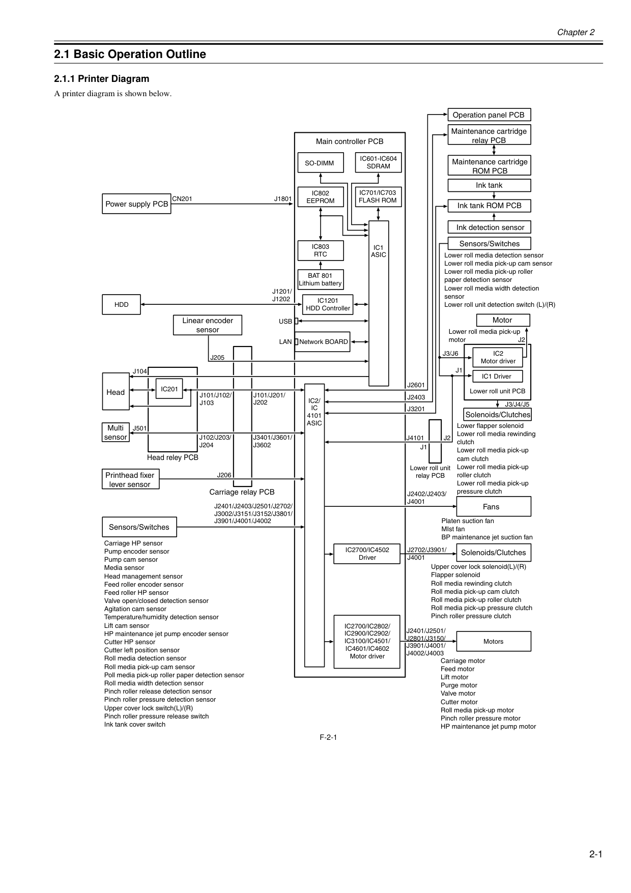
Chapter 2 2-1 2.1 Basic Operation Outline 2.1.1 Printer Diagram 0025-9729 A printer diagram is shown below.
F-2-1
Ic1
Asic
Ic2/
Ic
4101Asic
Ic201
Usb
Lan
Cn201
J1801
J2601
J3201
J1
J1
J2
J2402/J2403/
J4001
J2401/J2501/
J2801/J3150/
J3901/J4001/
J4002/J4003
J2401/J2403/J2501/J2702/
J3002/J3151/J3152/J3801/
J3901/J4001/J4002
J2
J3/J6
J3/J4/J5
J2403
Ic802
Eeprom
Ic803
Rtc
Ic1201
HDD ControllerHdd
Ic701/Ic703
Flash Rom
Ic601-Ic604
Sdram
So-Dimm
J101/J201/
J202
J1201/
J1202
J3401/J3601/
J3602
J102/J203/
J204
J101/J102/
J103
J205
J206
J501
J104
Lower roll media detection sensor Lower roll media pick-up cam sensor Lower roll media pick-up roller paper detection sensor Lower roll media width detection sensor Lower roll unit detection switch (L)/(R) Lower roll media pick-up motorIc2
Motor driver IC1 Driver Motors Lower roll unit PCB Lower roll unit relay PCBIc2700/Ic2802/
Ic2900/Ic2902/
Ic3100/Ic4501/
Ic4601/Ic4602
Motor driverJ2702/J3901/
J4001
Lower flapper solenoid Lower roll media rewinding clutch Lower roll media pick-up cam clutch Lower roll media pick-up roller clutch Lower roll media pick-up pressure clutchIc2700/Ic4502
Driver Network BOARDJ4101
Power supply PCB Linear encoder sensor Main controller PCBBat 801
Lithium battery Operation panel PCB Maintenance cartridge relay PCB Maintenance cartridgeRom Pcb
Ink tank Ink tank ROM PCB Ink detection sensor Sensors/Switches Motor Solenoids/Clutches Fans Solenoids/Clutches Carriage motor Feed motor Lift motor Purge motor Valve motor Cutter motor Roll media pick-up motor Pinch roller pressure motor HP maintenance jet pump motor Carriage HP sensor Pump encoder sensor Pump cam sensor Media sensor Head management sensor Feed roller encoder sensor Feed roller HP sensor Valve open/closed detection sensor Agitation cam sensor Temperature/humidity detection sensor Lift cam sensor HP maintenance jet pump encoder sensor Cutter HP sensor Cutter left position sensor Roll media detection sensor Roll media pick-up cam sensor Poll media pick-up roller paper detection sensor Roll media width detection sensor Pinch roller release detection sensor Pinch roller pressure detection sensor Upper cover lock switch(L)/(R) Pinch roller pressure release switch Ink tank cover switch Sensors/Switches Printhead fixer lever sensor Head reley PCB Head Multi sensor Carriage relay PCB Platen suction fan MIst fan BP maintenance jet suction fan Upper cover lock solenoid(L)/(R) Flapper solenoid Roll media rewinding clutch Roll media pick-up cam clutch Roll media pick-up roller clutch Roll media pick-up pressure clutch Pinch roller pressure clutch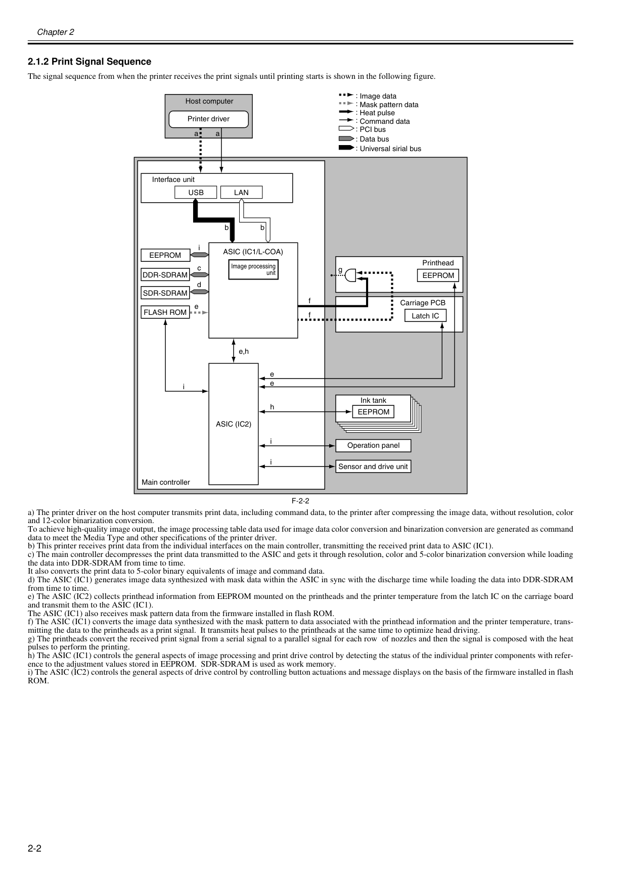
Chapter 2 2-2 2.1.2 Print Signal Sequence 0025-9730 The signal sequence from when the printer receives the print signals until printing starts is shown in the following figure.
F-2-2
a) The printer driver on the host computer transmits print data, including command data, to the printer after compressing the image data, without resolution, color and 12-color binarization conversion. To achieve high-quality image output, the image processing table data used for image data color conversion and binarization conversion are generated as command data to meet the Media Type and other specifications of the printer driver. b) This printer receives print data from the individual interfaces on the main controller, transmitting the received print data to ASIC (IC1). c) The main controller decompresses the print data transmitted to the ASIC and gets it through resolution, color and 5-color binarization conversion while loading the data into DDR-SDRAM from time to time. It also converts the print data to 5-color binary equivalents of image and command data. d) The ASIC (IC1) generates image data synthesized with mask data within the ASIC in sync with the discharge time while loading the data into DDR-SDRAM from time to time. e) The ASIC (IC2) collects printhead information from EEPROM mounted on the printheads and the printer temperature from the latch IC on the carriage board and transmit them to the ASIC (IC1). The ASIC (IC1) also receives mask pattern data from the firmware installed in flash ROM. f) The ASIC (IC1) converts the image data synthesized with the mask pattern to data associated with the printhead information and the printer temperature, trans- mitting the data to the printheads as a print signal. It transmits heat pulses to the printheads at the same time to optimize head driving. g) The printheads convert the received print signal from a serial signal to a parallel signal for each row of nozzles and then the signal is composed with the heat pulses to perform the printing. h) The ASIC (IC1) controls the general aspects of image processing and print drive control by detecting the status of the individual printer components with refer- ence to the adjustment values stored in EEPROM. SDR-SDRAM is used as work memory. i) The ASIC (IC2) controls the general aspects of drive control by controlling button actuations and message displays on the basis of the firmware installed in flashRom.
a aUsb
Lan
b bAsic (Ic1/L-Coa)
Eeprom
Ddr-Sdram
Eeprom
gFlash Rom
Asic (Ic2)
Eeprom
e e e,h e f f h i i iSdr-Sdram
i c d : : : : : : : Image data Mask pattern data Heat pulse Command data PCI bus Data bus Host computer Printer driver Interface unit Image processing unit Operation panel Latch IC Printhead Carriage PCB Ink tank Sensor and drive unit Main controller Universal sirial bus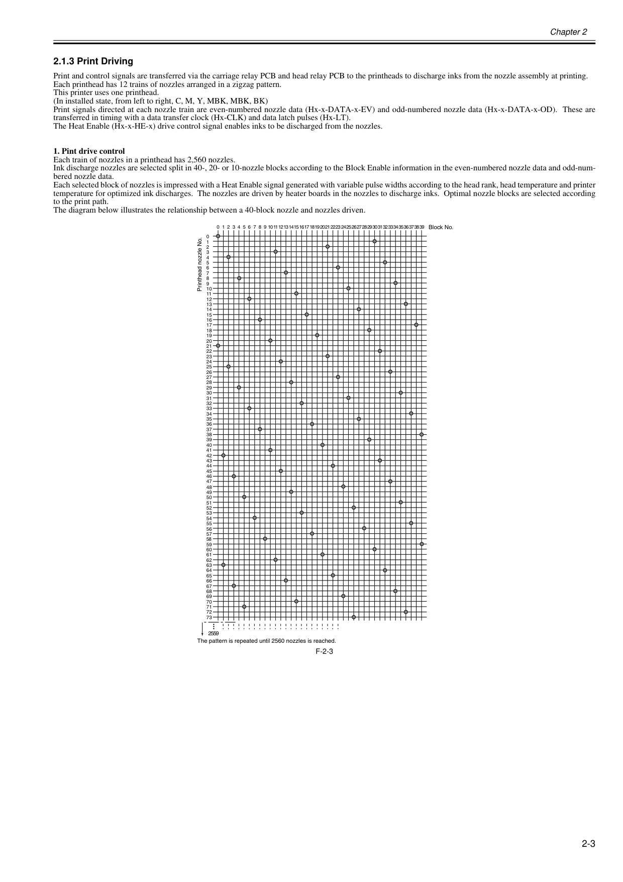
Chapter 2 2-3 2.1.3 Print Driving 0013-5398 Print and control signals are transferred via the carriage relay PCB and head relay PCB to the printheads to discharge inks from the nozzle assembly at printing. Each printhead has 12 trains of nozzles arranged in a zigzag pattern. This printer uses one printhead. (In installed state, from left to right, C, M, Y, MBK, MBK, BK) Print signals directed at each nozzle train are even-numbered nozzle data (Hx-x-DATA-x-EV) and odd-numbered nozzle data (Hx-x-DATA-x-OD). These are transferred in timing with a data transfer clock (Hx-CLK) and data latch pulses (Hx-LT). The Heat Enable (Hx-x-HE-x) drive control signal enables inks to be discharged from the nozzles.
F-2-3
23 22 21 20 19 18 17 16 15 14 13 12 11 10 9 8 7 6 5 4 3 2 1 0 2559 0 1 2 3 4 5 6 7 8 9 10 11 12 13 14 15 16 17 18 19 20 21 22 23 24 25 26 27 28 29 30 31 32 33 34 35 36 37 38 39 40 41 42 43 44 45 46 47 39 38 37 36 35 34 33 32 31 30 29 28 27 26 25 24 48 49 50 51 52 53 54 55 56 57 58 59 60 61 62 63 64 65 66 67 68 69 70 71 72 73 The pattern is repeated until 2560 nozzles is reached. Printhead nozzle No. Block No.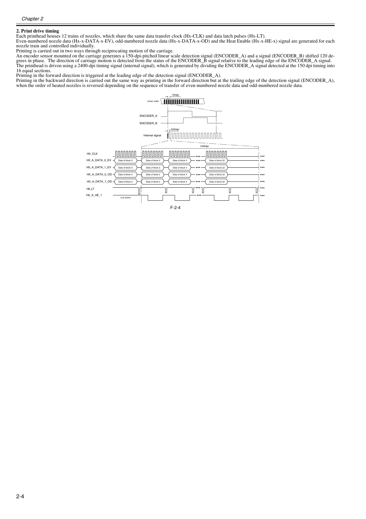
Chapter 2 2-4
F-2-4
150dpi 2400dpi Internal signal 2400dpi Low active Linear scale Data of block 0 Data of block 0 Data of block 0 Data of block 0 Data of block 2 Data of block 2 Data of block 2 Data of block 2 Data of block 4 Data of block 4 Data of block 4 Data of block 4 Data of block 22 Data of block 22 Data of block 22 Data of block 22Encoder_A
Encoder_B
H0_Clk
H0_A_Data_0_Ev
H0_A_Data_1_Ev
H0_Lt
H0_A_He_1
H0_A_Data_0_Od
H0_A_Data_1_Od
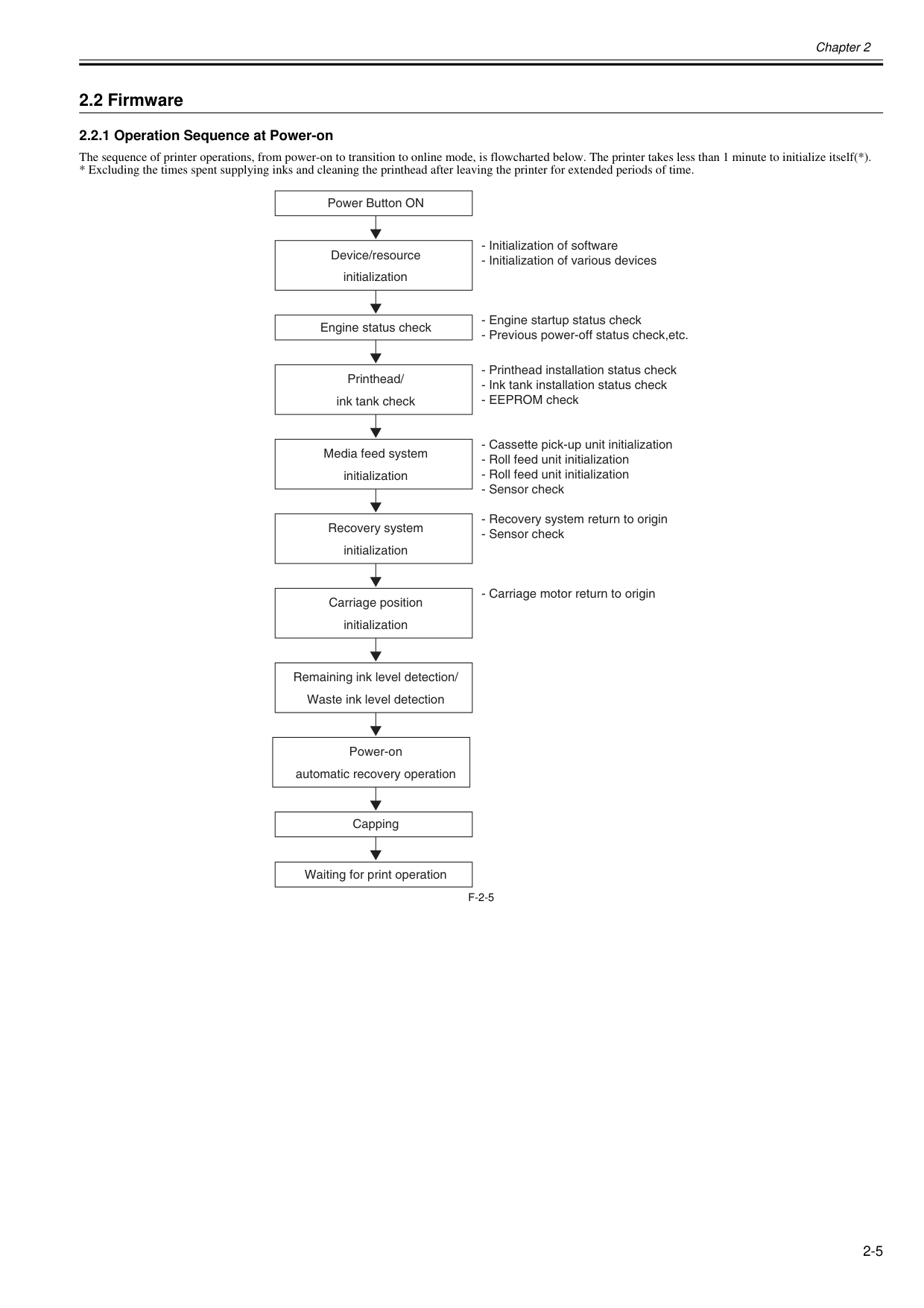
Chapter 2 2-5 2.2 Firmware 2.2.1 Operation Sequence at Power-on 0012-6310 The sequence of printer operations, from power-on to transition to online mode, is flowcharted below. The printer takes less than 1 minute to initialize itself(*).
F-2-5
Power Button ON Device/resource initialization Printhead/ ink tank check Media feed system initialization Recovery system initialization Carriage position initialization Remaining ink level detection/ Waste ink level detection Power-on automatic recovery operation Capping Waiting for print operation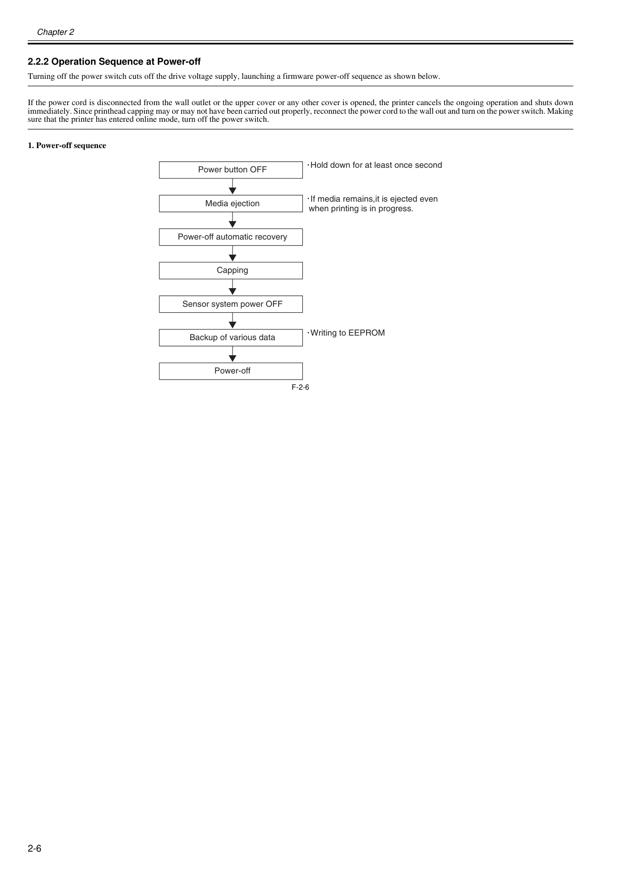
Chapter 2 2-6 2.2.2 Operation Sequence at Power-off 0012-6311 Turning off the power switch cuts off the drive voltage supply, launching a firmware power-off sequence as shown below. If the power cord is disconnected from the wall outlet or the upper cover or any other cover is opened, the printer cancels the ongoing operation and shuts down immediately. Since printhead capping may or may not have been carried out properly, reconnect the power cord to the wall out and turn on the power switch. Making sure that the printer has entered online mode, turn off the power switch.
F-2-6
Power button OFF If media remains,it is ejected even when printing is in progress. Media ejection Power-off automatic recovery Capping Sensor system power OFF Backup of various data Power-off Hold down for at least once second Writing to EEPROM
Chapter 2 2-7 2.2.3 Print Control 0020-5482

Chapter 2 2-8 Printing Modes

Chapter 2 2-9
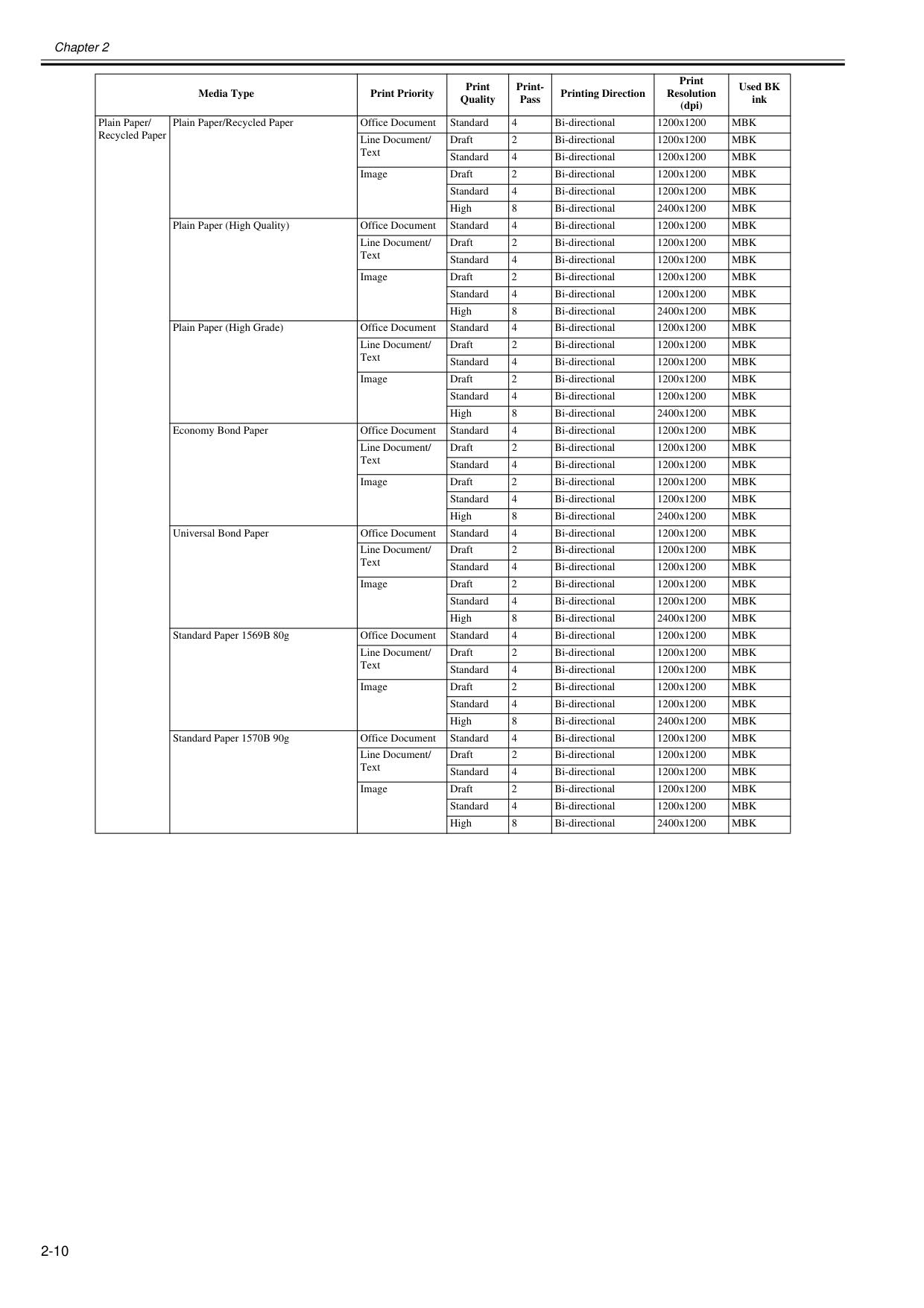
Chapter 2 2-10 Media Type Print Priority Print Quality Print- Pass Printing Direction Print Resolution (dpi) Used BK ink Plain Paper/ Recycled Paper Plain Paper/Recycled Paper Office Document Standard 4 Bi-directional 1200x1200
Mbk
Line Document/ Text Draft 2 Bi-directional 1200x1200Mbk
Standard 4 Bi-directional 1200x1200Mbk
Image Draft 2 Bi-directional 1200x1200Mbk
Standard 4 Bi-directional 1200x1200Mbk
High 8 Bi-directional 2400x1200Mbk
Plain Paper (High Quality) Office Document Standard 4 Bi-directional 1200x1200Mbk
Line Document/ Text Draft 2 Bi-directional 1200x1200Mbk
Standard 4 Bi-directional 1200x1200Mbk
Image Draft 2 Bi-directional 1200x1200Mbk
Standard 4 Bi-directional 1200x1200Mbk
High 8 Bi-directional 2400x1200Mbk
Plain Paper (High Grade) Office Document Standard 4 Bi-directional 1200x1200Mbk
Line Document/ Text Draft 2 Bi-directional 1200x1200Mbk
Standard 4 Bi-directional 1200x1200Mbk
Image Draft 2 Bi-directional 1200x1200Mbk
Standard 4 Bi-directional 1200x1200Mbk
High 8 Bi-directional 2400x1200Mbk
Economy Bond Paper Office Document Standard 4 Bi-directional 1200x1200Mbk
Line Document/ Text Draft 2 Bi-directional 1200x1200Mbk
Standard 4 Bi-directional 1200x1200Mbk
Image Draft 2 Bi-directional 1200x1200Mbk
Standard 4 Bi-directional 1200x1200Mbk
High 8 Bi-directional 2400x1200Mbk
Universal Bond Paper Office Document Standard 4 Bi-directional 1200x1200Mbk
Line Document/ Text Draft 2 Bi-directional 1200x1200Mbk
Standard 4 Bi-directional 1200x1200Mbk
Image Draft 2 Bi-directional 1200x1200Mbk
Standard 4 Bi-directional 1200x1200Mbk
High 8 Bi-directional 2400x1200Mbk
Standard Paper 1569B 80g Office Document Standard 4 Bi-directional 1200x1200Mbk
Line Document/ Text Draft 2 Bi-directional 1200x1200Mbk
Standard 4 Bi-directional 1200x1200Mbk
Image Draft 2 Bi-directional 1200x1200Mbk
Standard 4 Bi-directional 1200x1200Mbk
High 8 Bi-directional 2400x1200Mbk
Standard Paper 1570B 90g Office Document Standard 4 Bi-directional 1200x1200Mbk
Line Document/ Text Draft 2 Bi-directional 1200x1200Mbk
Standard 4 Bi-directional 1200x1200Mbk
Image Draft 2 Bi-directional 1200x1200Mbk
Standard 4 Bi-directional 1200x1200Mbk
High 8 Bi-directional 2400x1200Mbk
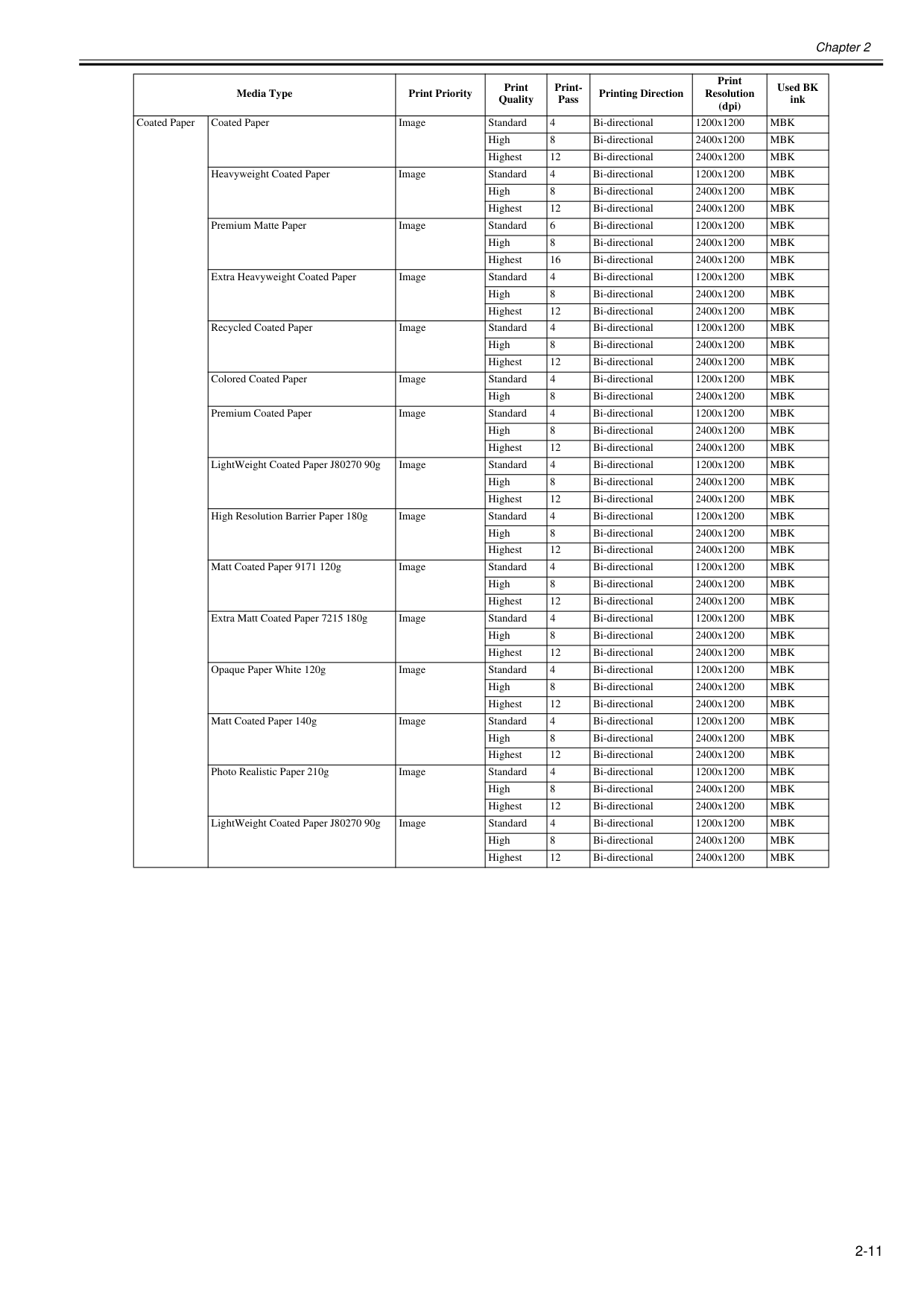
Chapter 2 2-11 Coated Paper Coated Paper Image Standard 4 Bi-directional 1200x1200
Mbk
High 8 Bi-directional 2400x1200Mbk
Highest 12 Bi-directional 2400x1200Mbk
Heavyweight Coated Paper Image Standard 4 Bi-directional 1200x1200Mbk
High 8 Bi-directional 2400x1200Mbk
Highest 12 Bi-directional 2400x1200Mbk
Premium Matte Paper Image Standard 6 Bi-directional 1200x1200Mbk
High 8 Bi-directional 2400x1200Mbk
Highest 16 Bi-directional 2400x1200Mbk
Extra Heavyweight Coated Paper Image Standard 4 Bi-directional 1200x1200Mbk
High 8 Bi-directional 2400x1200Mbk
Highest 12 Bi-directional 2400x1200Mbk
Recycled Coated Paper Image Standard 4 Bi-directional 1200x1200Mbk
High 8 Bi-directional 2400x1200Mbk
Highest 12 Bi-directional 2400x1200Mbk
Colored Coated Paper Image Standard 4 Bi-directional 1200x1200Mbk
High 8 Bi-directional 2400x1200Mbk
Premium Coated Paper Image Standard 4 Bi-directional 1200x1200Mbk
High 8 Bi-directional 2400x1200Mbk
Highest 12 Bi-directional 2400x1200Mbk
LightWeight Coated Paper J80270 90g Image Standard 4 Bi-directional 1200x1200Mbk
High 8 Bi-directional 2400x1200Mbk
Highest 12 Bi-directional 2400x1200Mbk
High Resolution Barrier Paper 180g Image Standard 4 Bi-directional 1200x1200Mbk
High 8 Bi-directional 2400x1200Mbk
Highest 12 Bi-directional 2400x1200Mbk
Matt Coated Paper 9171 120g Image Standard 4 Bi-directional 1200x1200Mbk
High 8 Bi-directional 2400x1200Mbk
Highest 12 Bi-directional 2400x1200Mbk
Extra Matt Coated Paper 7215 180g Image Standard 4 Bi-directional 1200x1200Mbk
High 8 Bi-directional 2400x1200Mbk
Highest 12 Bi-directional 2400x1200Mbk
Opaque Paper White 120g Image Standard 4 Bi-directional 1200x1200Mbk
High 8 Bi-directional 2400x1200Mbk
Highest 12 Bi-directional 2400x1200Mbk
Matt Coated Paper 140g Image Standard 4 Bi-directional 1200x1200Mbk
High 8 Bi-directional 2400x1200Mbk
Highest 12 Bi-directional 2400x1200Mbk
Photo Realistic Paper 210g Image Standard 4 Bi-directional 1200x1200Mbk
High 8 Bi-directional 2400x1200Mbk
Highest 12 Bi-directional 2400x1200Mbk
LightWeight Coated Paper J80270 90g Image Standard 4 Bi-directional 1200x1200Mbk
High 8 Bi-directional 2400x1200Mbk
Highest 12 Bi-directional 2400x1200Mbk
Media Type Print Priority Print Quality Print- Pass Printing Direction Print Resolution (dpi) Used BK ink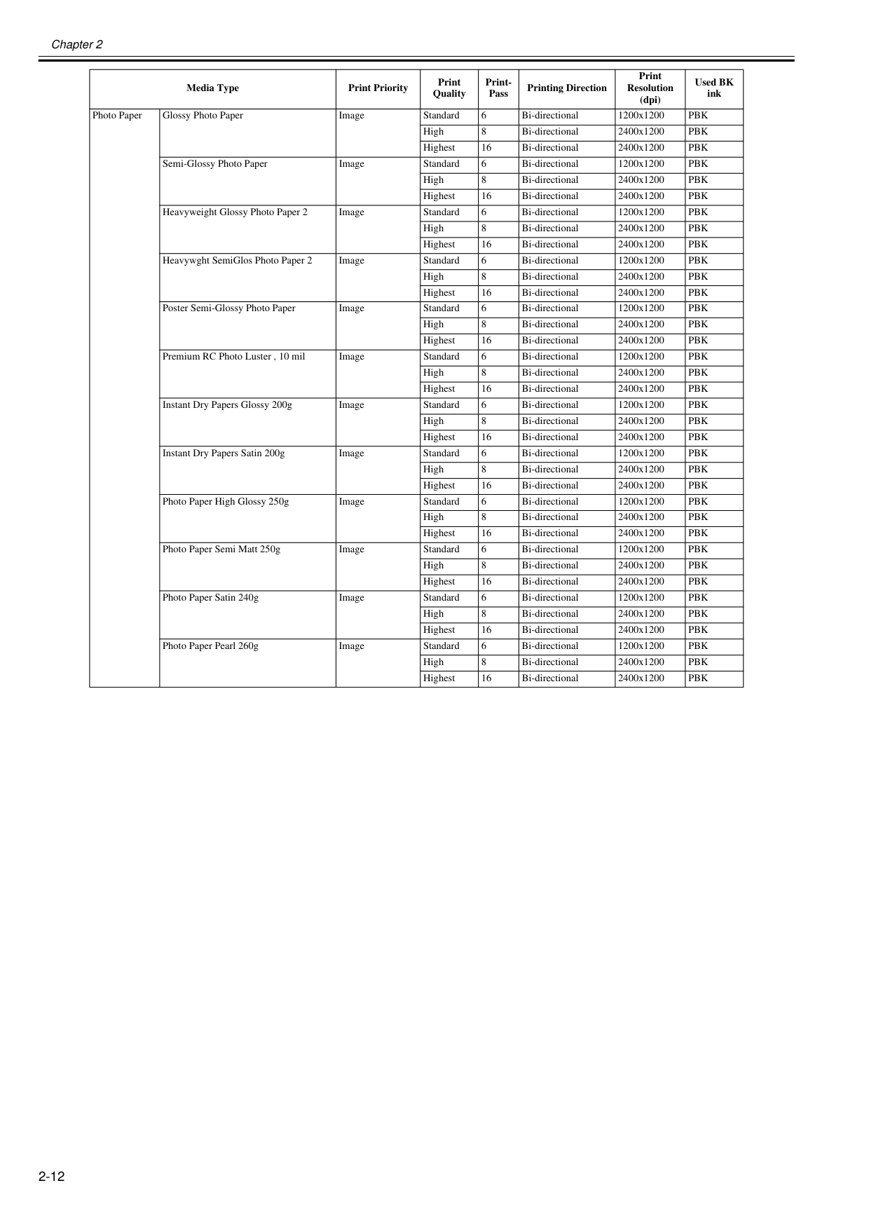
Chapter 2 2-12 Photo Paper Glossy Photo Paper Image Standard 6 Bi-directional 1200x1200
Pbk
High 8 Bi-directional 2400x1200Pbk
Highest 16 Bi-directional 2400x1200Pbk
Semi-Glossy Photo Paper Image Standard 6 Bi-directional 1200x1200Pbk
High 8 Bi-directional 2400x1200Pbk
Highest 16 Bi-directional 2400x1200Pbk
Heavyweight Glossy Photo Paper 2 Image Standard 6 Bi-directional 1200x1200Pbk
High 8 Bi-directional 2400x1200Pbk
Highest 16 Bi-directional 2400x1200Pbk
Heavywght SemiGlos Photo Paper 2 Image Standard 6 Bi-directional 1200x1200Pbk
High 8 Bi-directional 2400x1200Pbk
Highest 16 Bi-directional 2400x1200Pbk
Poster Semi-Glossy Photo Paper Image Standard 6 Bi-directional 1200x1200Pbk
High 8 Bi-directional 2400x1200Pbk
Highest 16 Bi-directional 2400x1200Pbk
Premium RC Photo Luster , 10 mil Image Standard 6 Bi-directional 1200x1200Pbk
High 8 Bi-directional 2400x1200Pbk
Highest 16 Bi-directional 2400x1200Pbk
Instant Dry Papers Glossy 200g Image Standard 6 Bi-directional 1200x1200Pbk
High 8 Bi-directional 2400x1200Pbk
Highest 16 Bi-directional 2400x1200Pbk
Instant Dry Papers Satin 200g Image Standard 6 Bi-directional 1200x1200Pbk
High 8 Bi-directional 2400x1200Pbk
Highest 16 Bi-directional 2400x1200Pbk
Photo Paper High Glossy 250g Image Standard 6 Bi-directional 1200x1200Pbk
High 8 Bi-directional 2400x1200Pbk
Highest 16 Bi-directional 2400x1200Pbk
Photo Paper Semi Matt 250g Image Standard 6 Bi-directional 1200x1200Pbk
High 8 Bi-directional 2400x1200Pbk
Highest 16 Bi-directional 2400x1200Pbk
Photo Paper Satin 240g Image Standard 6 Bi-directional 1200x1200Pbk
High 8 Bi-directional 2400x1200Pbk
Highest 16 Bi-directional 2400x1200Pbk
Photo Paper Pearl 260g Image Standard 6 Bi-directional 1200x1200Pbk
High 8 Bi-directional 2400x1200Pbk
Highest 16 Bi-directional 2400x1200Pbk
Media Type Print Priority Print Quality Print- Pass Printing Direction Print Resolution (dpi) Used BK ink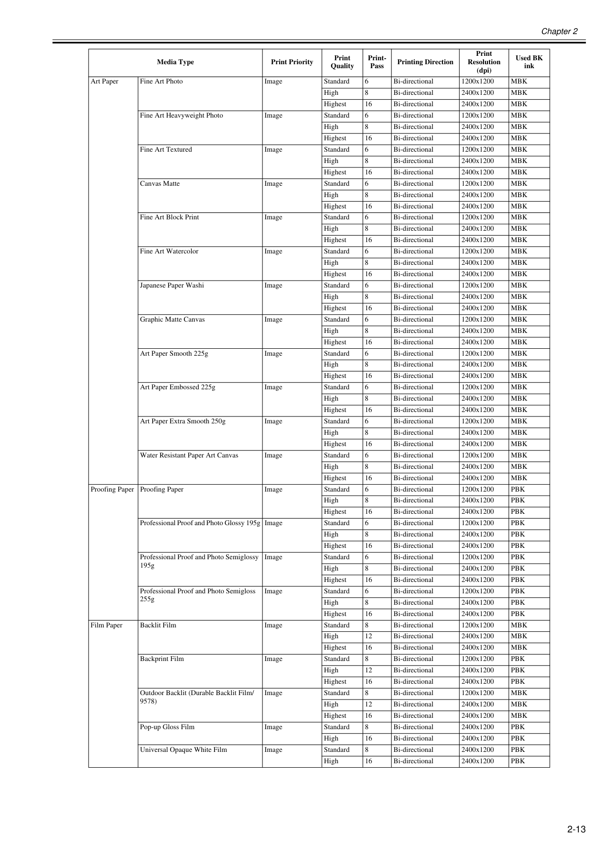
Chapter 2 2-13 Art Paper Fine Art Photo Image Standard 6 Bi-directional 1200x1200
Mbk
High 8 Bi-directional 2400x1200Mbk
Highest 16 Bi-directional 2400x1200Mbk
Fine Art Heavyweight Photo Image Standard 6 Bi-directional 1200x1200Mbk
High 8 Bi-directional 2400x1200Mbk
Highest 16 Bi-directional 2400x1200Mbk
Fine Art Textured Image Standard 6 Bi-directional 1200x1200Mbk
High 8 Bi-directional 2400x1200Mbk
Highest 16 Bi-directional 2400x1200Mbk
Canvas Matte Image Standard 6 Bi-directional 1200x1200Mbk
High 8 Bi-directional 2400x1200Mbk
Highest 16 Bi-directional 2400x1200Mbk
Fine Art Block Print Image Standard 6 Bi-directional 1200x1200Mbk
High 8 Bi-directional 2400x1200Mbk
Highest 16 Bi-directional 2400x1200Mbk
Fine Art Watercolor Image Standard 6 Bi-directional 1200x1200Mbk
High 8 Bi-directional 2400x1200Mbk
Highest 16 Bi-directional 2400x1200Mbk
Japanese Paper Washi Image Standard 6 Bi-directional 1200x1200Mbk
High 8 Bi-directional 2400x1200Mbk
Highest 16 Bi-directional 2400x1200Mbk
Graphic Matte Canvas Image Standard 6 Bi-directional 1200x1200Mbk
High 8 Bi-directional 2400x1200Mbk
Highest 16 Bi-directional 2400x1200Mbk
Art Paper Smooth 225g Image Standard 6 Bi-directional 1200x1200Mbk
High 8 Bi-directional 2400x1200Mbk
Highest 16 Bi-directional 2400x1200Mbk
Art Paper Embossed 225g Image Standard 6 Bi-directional 1200x1200Mbk
High 8 Bi-directional 2400x1200Mbk
Highest 16 Bi-directional 2400x1200Mbk
Art Paper Extra Smooth 250g Image Standard 6 Bi-directional 1200x1200Mbk
High 8 Bi-directional 2400x1200Mbk
Highest 16 Bi-directional 2400x1200Mbk
Water Resistant Paper Art Canvas Image Standard 6 Bi-directional 1200x1200Mbk
High 8 Bi-directional 2400x1200Mbk
Highest 16 Bi-directional 2400x1200Mbk
Proofing Paper Proofing Paper Image Standard 6 Bi-directional 1200x1200Pbk
High 8 Bi-directional 2400x1200Pbk
Highest 16 Bi-directional 2400x1200Pbk
Professional Proof and Photo Glossy 195g Image Standard 6 Bi-directional 1200x1200Pbk
High 8 Bi-directional 2400x1200Pbk
Highest 16 Bi-directional 2400x1200Pbk
Professional Proof and Photo Semiglossy 195g Image Standard 6 Bi-directional 1200x1200Pbk
High 8 Bi-directional 2400x1200Pbk
Highest 16 Bi-directional 2400x1200Pbk
Professional Proof and Photo Semigloss 255g Image Standard 6 Bi-directional 1200x1200Pbk
High 8 Bi-directional 2400x1200Pbk
Highest 16 Bi-directional 2400x1200Pbk
Film Paper Backlit Film Image Standard 8 Bi-directional 1200x1200Mbk
High 12 Bi-directional 2400x1200Mbk
Highest 16 Bi-directional 2400x1200Mbk
Backprint Film Image Standard 8 Bi-directional 1200x1200Pbk
High 12 Bi-directional 2400x1200Pbk
Highest 16 Bi-directional 2400x1200Pbk
Outdoor Backlit (Durable Backlit Film/ 9578) Image Standard 8 Bi-directional 1200x1200Mbk
High 12 Bi-directional 2400x1200Mbk
Highest 16 Bi-directional 2400x1200Mbk
Pop-up Gloss Film Image Standard 8 Bi-directional 2400x1200Pbk
High 16 Bi-directional 2400x1200Pbk
Universal Opaque White Film Image Standard 8 Bi-directional 2400x1200Pbk
High 16 Bi-directional 2400x1200Pbk
Media Type Print Priority Print Quality Print- Pass Printing Direction Print Resolution (dpi) Used BK ink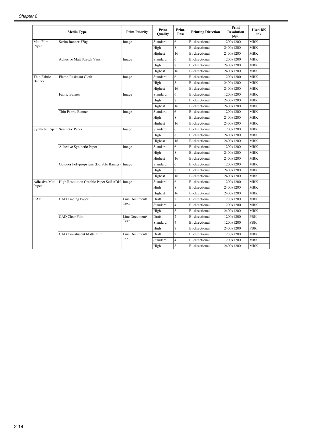
Chapter 2 2-14 Matt Film Paper Scrim Banner 370g Image Standard 6 Bi-directional 1200x1200
Mbk
High 8 Bi-directional 2400x1200Mbk
Highest 16 Bi-directional 2400x1200Mbk
Adhesive Matt Stretch Vinyl Image Standard 6 Bi-directional 1200x1200Mbk
High 8 Bi-directional 2400x1200Mbk
Highest 16 Bi-directional 2400x1200Mbk
Thin Fabric Banner Flame-Resistant Cloth Image Standard 6 Bi-directional 1200x1200Mbk
High 8 Bi-directional 2400x1200Mbk
Highest 16 Bi-directional 2400x1200Mbk
Fabric Banner Image Standard 6 Bi-directional 1200x1200Mbk
High 8 Bi-directional 2400x1200Mbk
Highest 16 Bi-directional 2400x1200Mbk
Thin Fabric Banner Image Standard 6 Bi-directional 1200x1200Mbk
High 8 Bi-directional 2400x1200Mbk
Highest 16 Bi-directional 2400x1200Mbk
Synthetic Paper Synthetic Paper Image Standard 6 Bi-directional 1200x1200Mbk
High 8 Bi-directional 2400x1200Mbk
Highest 16 Bi-directional 2400x1200Mbk
Adhesive Synthetic Paper Image Standard 6 Bi-directional 1200x1200Mbk
High 8 Bi-directional 2400x1200Mbk
Highest 16 Bi-directional 2400x1200Mbk
Outdoor Polypropylene (Durable Banner) Image Standard 6 Bi-directional 1200x1200Mbk
High 8 Bi-directional 2400x1200Mbk
Highest 16 Bi-directional 2400x1200Mbk
Adhesive Matt Paper High Resolution Graphic Paper Self ADH Image Standard 6 Bi-directional 1200x1200Mbk
High 8 Bi-directional 2400x1200Mbk
Highest 16 Bi-directional 2400x1200Mbk
Cad
CAD Tracing Paper Line Document/ Text Draft 2 Bi-directional 1200x1200Mbk
Standard 4 Bi-directional 1200x1200Mbk
High 8 Bi-directional 2400x1200Mbk
CAD Clear Film Line Document/ Text Draft 2 Bi-directional 1200x1200Pbk
Standard 4 Bi-directional 1200x1200Pbk
High 8 Bi-directional 2400x1200Pbk
CAD Translucent Matte Film Line Document/ Text Draft 2 Bi-directional 1200x1200Mbk
Standard 4 Bi-directional 1200x1200Mbk
High 8 Bi-directional 2400x1200Mbk
Media Type Print Priority Print Quality Print- Pass Printing Direction Print Resolution (dpi) Used BK ink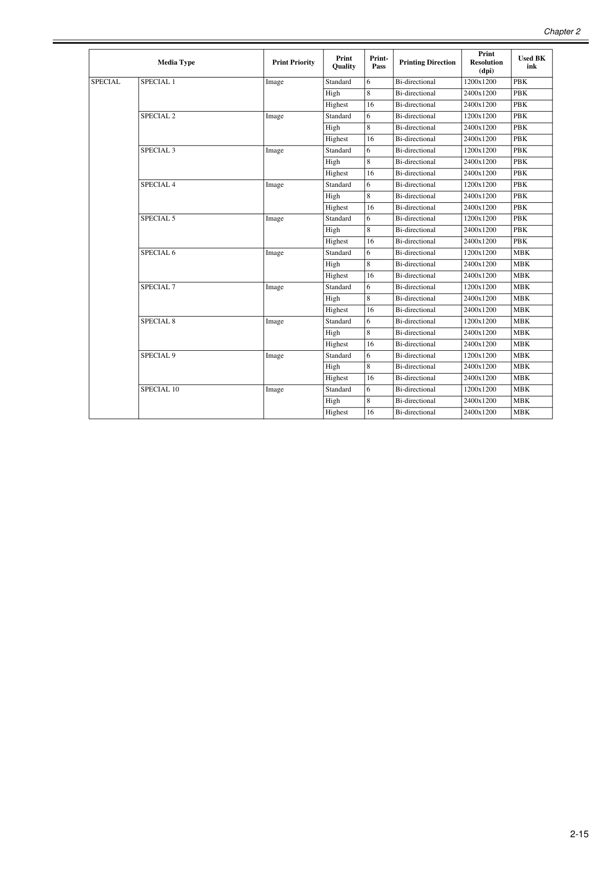
Chapter 2 2-15
Special
Special 1
Image Standard 6 Bi-directional 1200x1200Pbk
High 8 Bi-directional 2400x1200Pbk
Highest 16 Bi-directional 2400x1200Pbk
Special 2
Image Standard 6 Bi-directional 1200x1200Pbk
High 8 Bi-directional 2400x1200Pbk
Highest 16 Bi-directional 2400x1200Pbk
Special 3
Image Standard 6 Bi-directional 1200x1200Pbk
High 8 Bi-directional 2400x1200Pbk
Highest 16 Bi-directional 2400x1200Pbk
Special 4
Image Standard 6 Bi-directional 1200x1200Pbk
High 8 Bi-directional 2400x1200Pbk
Highest 16 Bi-directional 2400x1200Pbk
Special 5
Image Standard 6 Bi-directional 1200x1200Pbk
High 8 Bi-directional 2400x1200Pbk
Highest 16 Bi-directional 2400x1200Pbk
Special 6
Image Standard 6 Bi-directional 1200x1200Mbk
High 8 Bi-directional 2400x1200Mbk
Highest 16 Bi-directional 2400x1200Mbk
Special 7
Image Standard 6 Bi-directional 1200x1200Mbk
High 8 Bi-directional 2400x1200Mbk
Highest 16 Bi-directional 2400x1200Mbk
Special 8
Image Standard 6 Bi-directional 1200x1200Mbk
High 8 Bi-directional 2400x1200Mbk
Highest 16 Bi-directional 2400x1200Mbk
Special 9
Image Standard 6 Bi-directional 1200x1200Mbk
High 8 Bi-directional 2400x1200Mbk
Highest 16 Bi-directional 2400x1200Mbk
Special 10
Image Standard 6 Bi-directional 1200x1200Mbk
High 8 Bi-directional 2400x1200Mbk
Highest 16 Bi-directional 2400x1200Mbk
Media Type Print Priority Print Quality Print- Pass Printing Direction Print Resolution (dpi) Used BK ink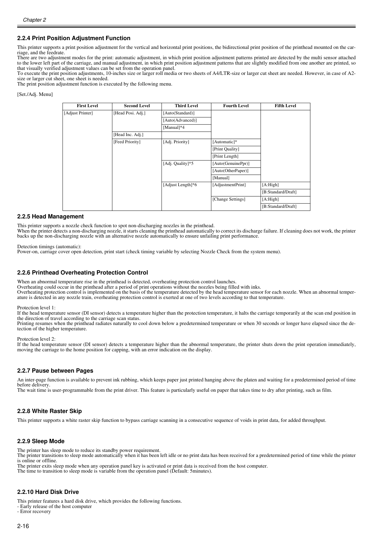
Chapter 2 2-16 2.2.4 Print Position Adjustment Function 0012-6313 This printer supports a print position adjustment for the vertical and horizontal print positions, the bidirectional print position of the printhead mounted on the car- riage, and the feedrate. There are two adjustment modes for the print: automatic adjustment, in which print position adjustment patterns printed are detected by the multi sensor attached to the lower left part of the carriage, and manual adjustment, in which print position adjustment patterns that are slightly modified from one another are printed, so that visually verified adjustment values can be set from the operation panel. To execute the print position adjustments, 10-inches size or larger roll media or two sheets of A4/LTR-size or larger cut sheet are needed. However, in case of A2- size or larger cut sheet, one sheet is needed. The print position adjustment function is executed by the following menu. [Set./Adj. Menu] 2.2.5 Head Management 0012-6314 This printer supports a nozzle check function to spot non-discharging nozzles in the printhead. When the printer detects a non-discharging nozzle, it starts cleaning the printhead automatically to correct its discharge failure. If cleaning does not work, the printer backs up the non-discharging nozzle with an alternative nozzle automatically to ensure unfailing print performance. Detection timings (automatic): Power-on, carriage cover open detection, print start (check timing variable by selecting Nozzle Check from the system menu). 2.2.6 Printhead Overheating Protection Control 0012-6315 When an abnormal temperature rise in the printhead is detected, overheating protection control launches. Overheating could occur in the printhead after a period of print operations without the nozzles being filled with inks. Overheating protection control is implemented on the basis of the temperature detected by the head temperature sensor for each nozzle. When an abnormal temper- ature is detected in any nozzle train, overheating protection control is exerted at one of two levels according to that temperature. Protection level 1: If the head temperature sensor (DI sensor) detects a temperature higher than the protection temperature, it halts the carriage temporarily at the scan end position in the direction of travel according to the carriage scan status. Printing resumes when the printhead radiates naturally to cool down below a predetermined temperature or when 30 seconds or longer have elapsed since the de- tection of the higher temperature. Protection level 2: If the head temperature sensor (DI sensor) detects a temperature higher than the abnormal temperature, the printer shuts down the print operation immediately, moving the carriage to the home position for capping, with an error indication on the display. 2.2.7 Pause between Pages 0012-6320 An inter-page function is available to prevent ink rubbing, which keeps paper just printed hanging above the platen and waiting for a predetermined period of time before delivery. The wait time is user-programmable from the print driver. This feature is particularly useful on paper that takes time to dry after printing, such as film. 2.2.8 White Raster Skip 0012-6322 This printer supports a white raster skip function to bypass carriage scanning in a consecutive sequence of voids in print data, for added throughput. 2.2.9 Sleep Mode 0012-6324 The printer has sleep mode to reduce its standby power requirement. The printer transitions to sleep mode automatically when it has been left idle or no print data has been received for a predetermined period of time while the printer is online or offline. The printer exits sleep mode when any operation panel key is activated or print data is received from the host computer. The time to transition to sleep mode is variable from the operation panel (Default: 5minutes). 2.2.10 Hard Disk Drive 0013-9239 This printer features a hard disk drive, which provides the following functions.

Chapter 2 2-17
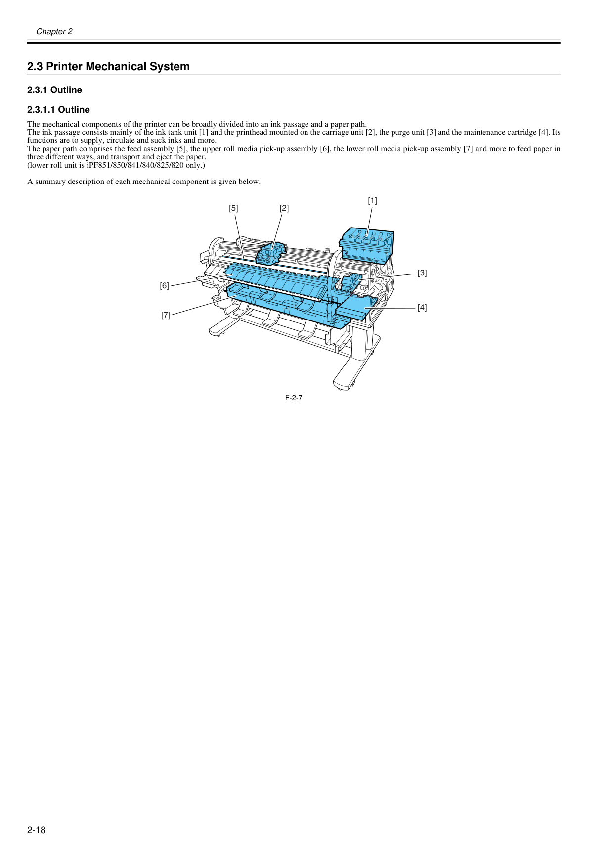
Chapter 2 2-18 2.3 Printer Mechanical System 2.3.1 Outline 2.3.1.1 Outline 0020-5485 The mechanical components of the printer can be broadly divided into an ink passage and a paper path. The ink passage consists mainly of the ink tank unit [1] and the printhead mounted on the carriage unit [2], the purge unit [3] and the maintenance cartridge [4]. Its functions are to supply, circulate and suck inks and more. The paper path comprises the feed assembly [5], the upper roll media pick-up assembly [6], the lower roll media pick-up assembly [7] and more to feed paper in three different ways, and transport and eject the paper. (lower roll unit is iPF851/850/841/840/825/820 only.) A summary description of each mechanical component is given below.
F-2-7
[1] [2] [5] [6] [7] [3] [4]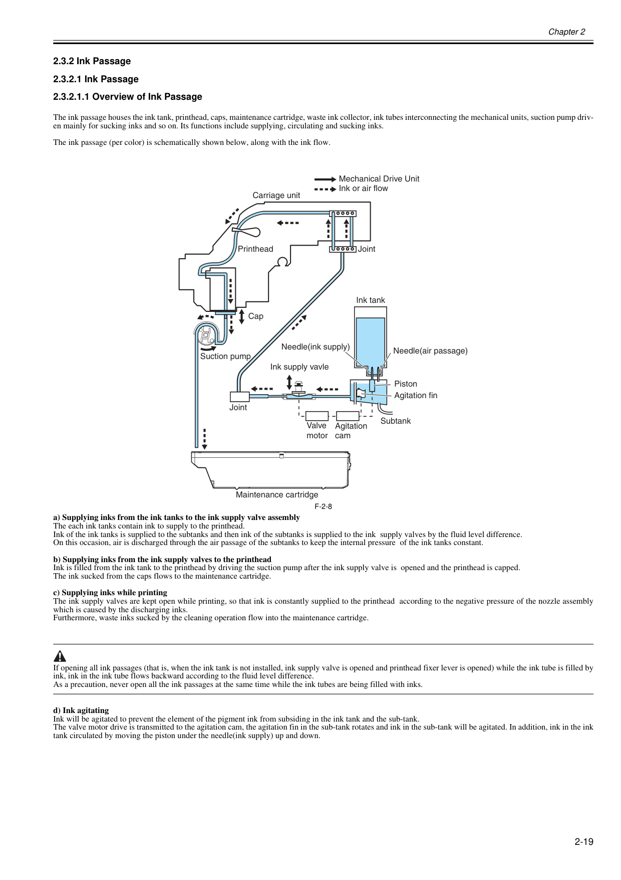
Chapter 2 2-19 2.3.2 Ink Passage 2.3.2.1 Ink Passage 2.3.2.1.1 Overview of Ink Passage 0020-5486 The ink passage houses the ink tank, printhead, caps, maintenance cartridge, waste ink collector, ink tubes interconnecting the mechanical units, suction pump driv- en mainly for sucking inks and so on. Its functions include supplying, circulating and sucking inks. The ink passage (per color) is schematically shown below, along with the ink flow.
F-2-8
a) Supplying inks from the ink tanks to the ink supply valve assembly The each ink tanks contain ink to supply to the printhead. Ink of the ink tanks is supplied to the subtanks and then ink of the subtanks is supplied to the ink supply valves by the fluid level difference. On this occasion, air is discharged through the air passage of the subtanks to keep the internal pressure of the ink tanks constant. b) Supplying inks from the ink supply valves to the printhead Ink is filled from the ink tank to the printhead by driving the suction pump after the ink supply valve is opened and the printhead is capped. The ink sucked from the caps flows to the maintenance cartridge. c) Supplying inks while printing The ink supply valves are kept open while printing, so that ink is constantly supplied to the printhead according to the negative pressure of the nozzle assembly which is caused by the discharging inks. Furthermore, waste inks sucked by the cleaning operation flow into the maintenance cartridge. If opening all ink passages (that is, when the ink tank is not installed, ink supply valve is opened and printhead fixer lever is opened) while the ink tube is filled by ink, ink in the ink tube flows backward according to the fluid level difference. As a precaution, never open all the ink passages at the same time while the ink tubes are being filled with inks. d) Ink agitating Ink will be agitated to prevent the element of the pigment ink from subsiding in the ink tank and the sub-tank. The valve motor drive is transmitted to the agitation cam, the agitation fin in the sub-tank rotates and ink in the sub-tank will be agitated. In addition, ink in the ink tank circulated by moving the piston under the needle(ink supply) up and down. Maintenance cartridge Ink tank Ink supply vavle Joint Joint Carriage unit Printhead Cap Suction pump Mechanical Drive Unit Ink or air flow Subtank Agitation fin Needle(ink supply) Piston Needle(air passage) Valve motor Agitation cam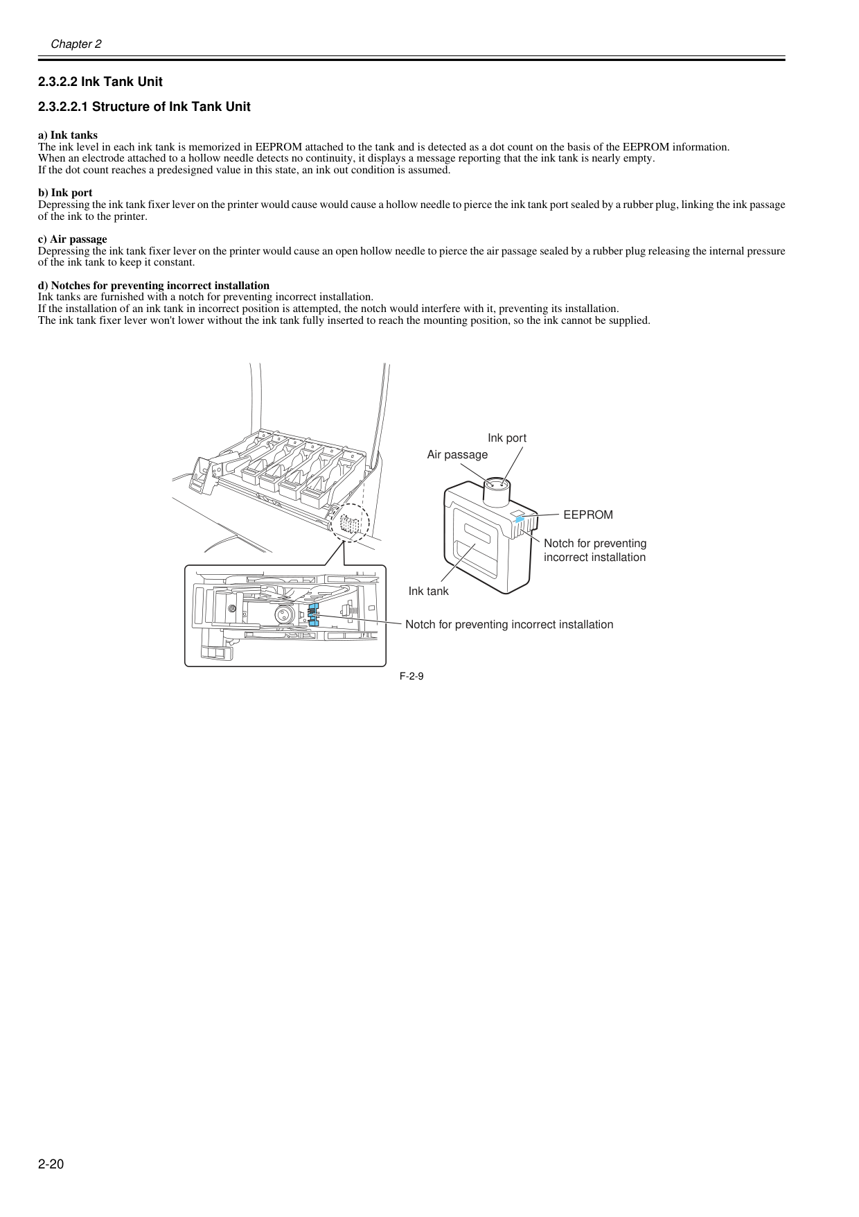
Chapter 2 2-20 2.3.2.2 Ink Tank Unit 2.3.2.2.1 Structure of Ink Tank Unit 0020-5487 a) Ink tanks The ink level in each ink tank is memorized in EEPROM attached to the tank and is detected as a dot count on the basis of the EEPROM information. When an electrode attached to a hollow needle detects no continuity, it displays a message reporting that the ink tank is nearly empty. If the dot count reaches a predesigned value in this state, an ink out condition is assumed. b) Ink port Depressing the ink tank fixer lever on the printer would cause would cause a hollow needle to pierce the ink tank port sealed by a rubber plug, linking the ink passage of the ink to the printer. c) Air passage Depressing the ink tank fixer lever on the printer would cause an open hollow needle to pierce the air passage sealed by a rubber plug releasing the internal pressure of the ink tank to keep it constant. d) Notches for preventing incorrect installation Ink tanks are furnished with a notch for preventing incorrect installation. If the installation of an ink tank in incorrect position is attempted, the notch would interfere with it, preventing its installation. The ink tank fixer lever won't lower without the ink tank fully inserted to reach the mounting position, so the ink cannot be supplied.
F-2-9
Ink tank Ink port Air passage Notch for preventing incorrect installationEeprom
Notch for preventing incorrect installation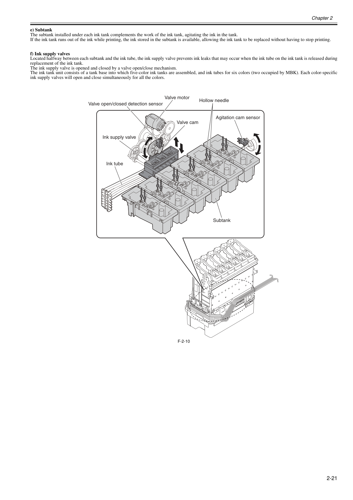
Chapter 2 2-21 e) Subtank The subtank installed under each ink tank complements the work of the ink tank, agitating the ink in the tank. If the ink tank runs out of the ink while printing, the ink stored in the subtank is available, allowing the ink tank to be replaced without having to stop printing. f) Ink supply valves Located halfway between each subtank and the ink tube, the ink supply valve prevents ink leaks that may occur when the ink tube on the ink tank is released during replacement of the ink tank. The ink supply valve is opened and closed by a valve open/close mechanism. The ink tank unit consists of a tank base into which five-color ink tanks are assembled, and ink tubes for six colors (two occupied by MBK). Each color-specific ink supply valves will open and close simultaneously for all the colors.
F-2-10
Subtank Agitation cam sensor Hollow needle Valve motor Valve open/closed detection sensor Ink tube Ink supply valve Valve cam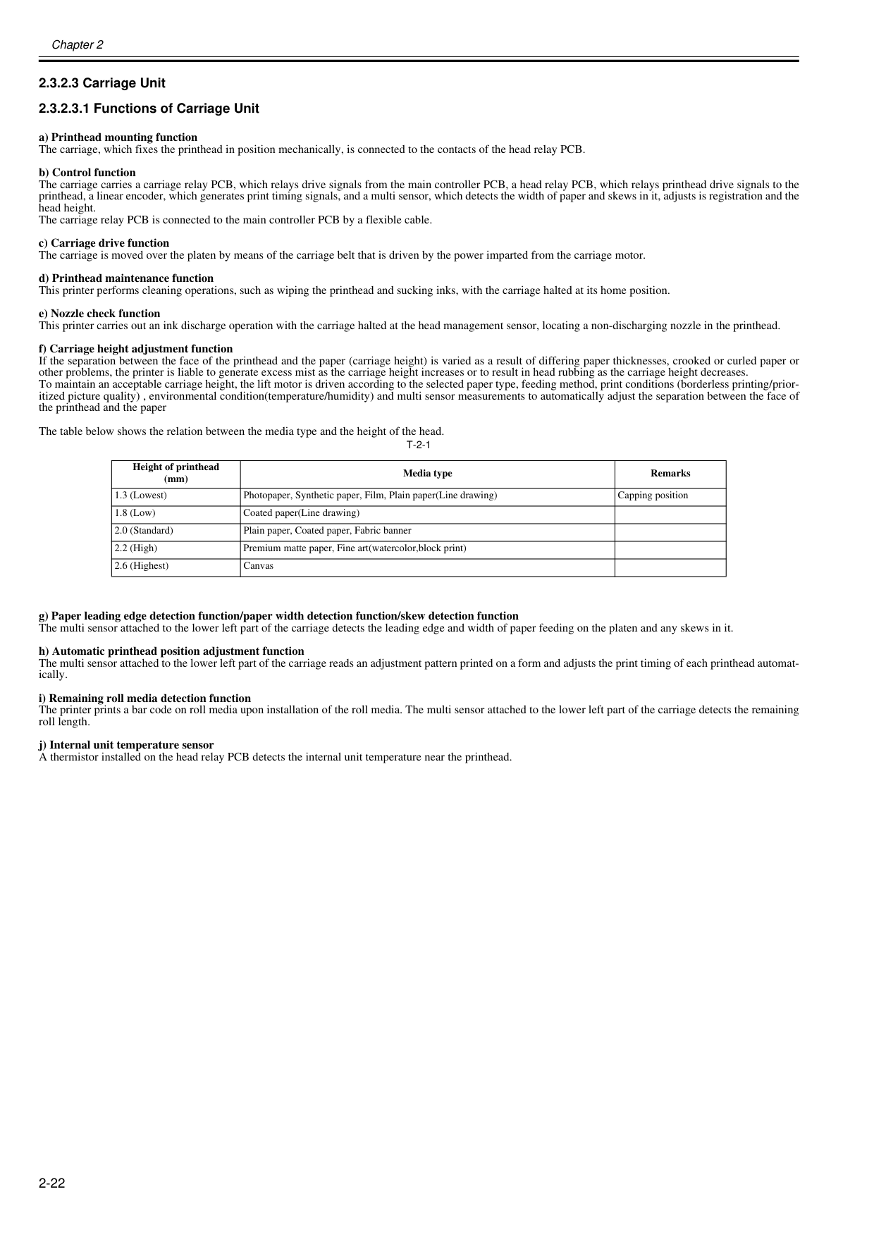
Chapter 2 2-22 2.3.2.3 Carriage Unit 2.3.2.3.1 Functions of Carriage Unit 0020-5488 a) Printhead mounting function The carriage, which fixes the printhead in position mechanically, is connected to the contacts of the head relay PCB. b) Control function The carriage carries a carriage relay PCB, which relays drive signals from the main controller PCB, a head relay PCB, which relays printhead drive signals to the printhead, a linear encoder, which generates print timing signals, and a multi sensor, which detects the width of paper and skews in it, adjusts is registration and the head height. The carriage relay PCB is connected to the main controller PCB by a flexible cable. c) Carriage drive function The carriage is moved over the platen by means of the carriage belt that is driven by the power imparted from the carriage motor. d) Printhead maintenance function This printer performs cleaning operations, such as wiping the printhead and sucking inks, with the carriage halted at its home position. e) Nozzle check function This printer carries out an ink discharge operation with the carriage halted at the head management sensor, locating a non-discharging nozzle in the printhead. f) Carriage height adjustment function If the separation between the face of the printhead and the paper (carriage height) is varied as a result of differing paper thicknesses, crooked or curled paper or other problems, the printer is liable to generate excess mist as the carriage height increases or to result in head rubbing as the carriage height decreases. To maintain an acceptable carriage height, the lift motor is driven according to the selected paper type, feeding method, print conditions (borderless printing/prior- itized picture quality) , environmental condition(temperature/humidity) and multi sensor measurements to automatically adjust the separation between the face of the printhead and the paper The table below shows the relation between the media type and the height of the head.
T-2-1
g) Paper leading edge detection function/paper width detection function/skew detection function The multi sensor attached to the lower left part of the carriage detects the leading edge and width of paper feeding on the platen and any skews in it. h) Automatic printhead position adjustment function The multi sensor attached to the lower left part of the carriage reads an adjustment pattern printed on a form and adjusts the print timing of each printhead automat- ically. i) Remaining roll media detection function The printer prints a bar code on roll media upon installation of the roll media. The multi sensor attached to the lower left part of the carriage detects the remaining roll length. j) Internal unit temperature sensor A thermistor installed on the head relay PCB detects the internal unit temperature near the printhead. Height of printhead (mm) Media type Remarks 1.3 (Lowest) Photopaper, Synthetic paper, Film, Plain paper(Line drawing) Capping position 1.8 (Low) Coated paper(Line drawing) 2.0 (Standard) Plain paper, Coated paper, Fabric banner 2.2 (High) Premium matte paper, Fine art(watercolor,block print) 2.6 (Highest) Canvas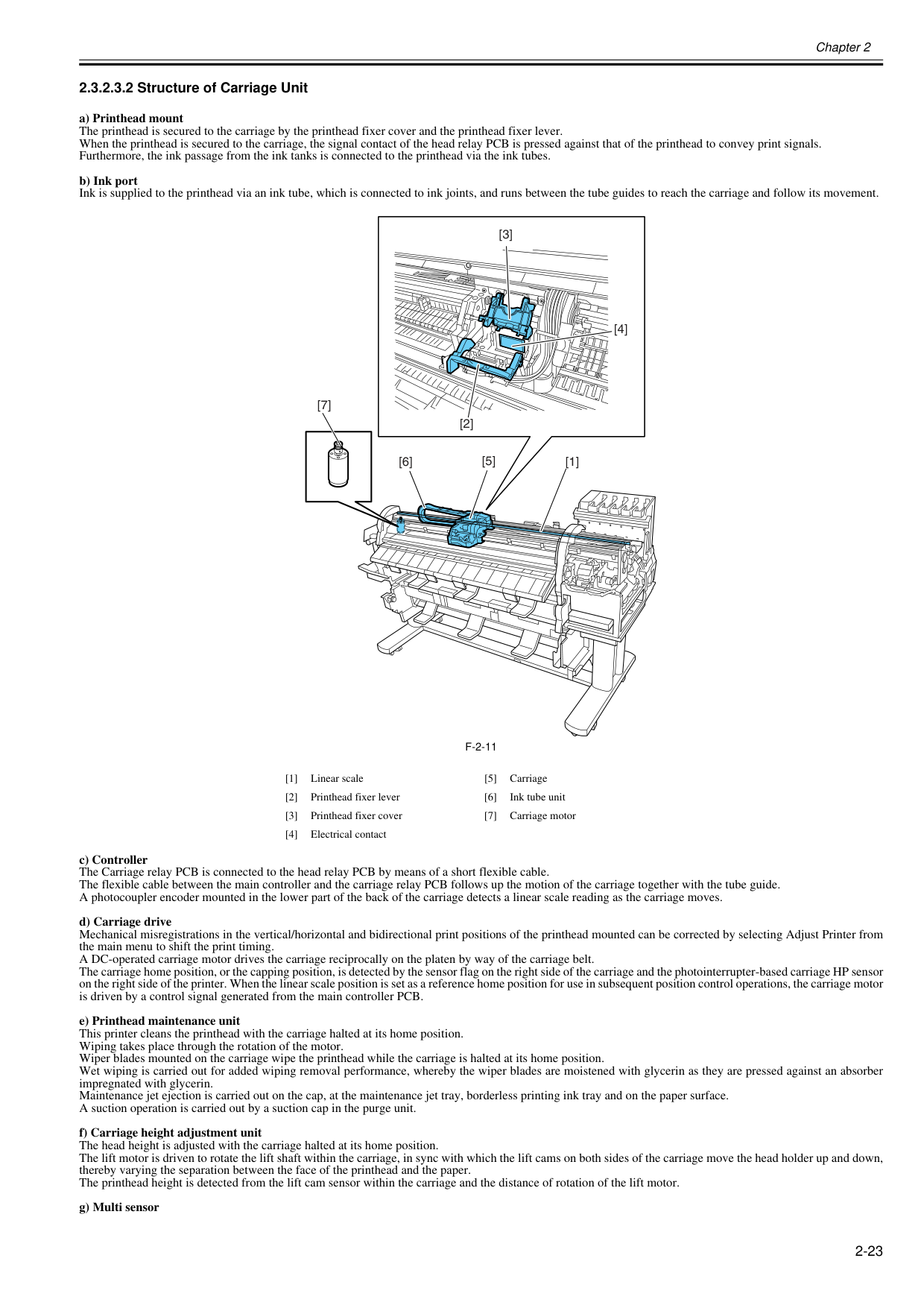
Chapter 2 2-23 2.3.2.3.2 Structure of Carriage Unit 0020-5492 a) Printhead mount The printhead is secured to the carriage by the printhead fixer cover and the printhead fixer lever. When the printhead is secured to the carriage, the signal contact of the head relay PCB is pressed against that of the printhead to convey print signals. Furthermore, the ink passage from the ink tanks is connected to the printhead via the ink tubes. b) Ink port Ink is supplied to the printhead via an ink tube, which is connected to ink joints, and runs between the tube guides to reach the carriage and follow its movement.
F-2-11
c) Controller The Carriage relay PCB is connected to the head relay PCB by means of a short flexible cable. The flexible cable between the main controller and the carriage relay PCB follows up the motion of the carriage together with the tube guide. A photocoupler encoder mounted in the lower part of the back of the carriage detects a linear scale reading as the carriage moves. d) Carriage drive Mechanical misregistrations in the vertical/horizontal and bidirectional print positions of the printhead mounted can be corrected by selecting Adjust Printer from the main menu to shift the print timing. A DC-operated carriage motor drives the carriage reciprocally on the platen by way of the carriage belt. The carriage home position, or the capping position, is detected by the sensor flag on the right side of the carriage and the photointerrupter-based carriage HP sensor on the right side of the printer. When the linear scale position is set as a reference home position for use in subsequent position control operations, the carriage motor is driven by a control signal generated from the main controller PCB. e) Printhead maintenance unit This printer cleans the printhead with the carriage halted at its home position. Wiping takes place through the rotation of the motor. Wiper blades mounted on the carriage wipe the printhead while the carriage is halted at its home position. Wet wiping is carried out for added wiping removal performance, whereby the wiper blades are moistened with glycerin as they are pressed against an absorber impregnated with glycerin. Maintenance jet ejection is carried out on the cap, at the maintenance jet tray, borderless printing ink tray and on the paper surface. A suction operation is carried out by a suction cap in the purge unit. f) Carriage height adjustment unit The head height is adjusted with the carriage halted at its home position. The lift motor is driven to rotate the lift shaft within the carriage, in sync with which the lift cams on both sides of the carriage move the head holder up and down, thereby varying the separation between the face of the printhead and the paper. The printhead height is detected from the lift cam sensor within the carriage and the distance of rotation of the lift motor. g) Multi sensor [1] Linear scale [5] Carriage [2] Printhead fixer lever [6] Ink tube unit [3] Printhead fixer cover [7] Carriage motor [4] Electrical contact [7] [3] [5] [2] [1] [4] [6]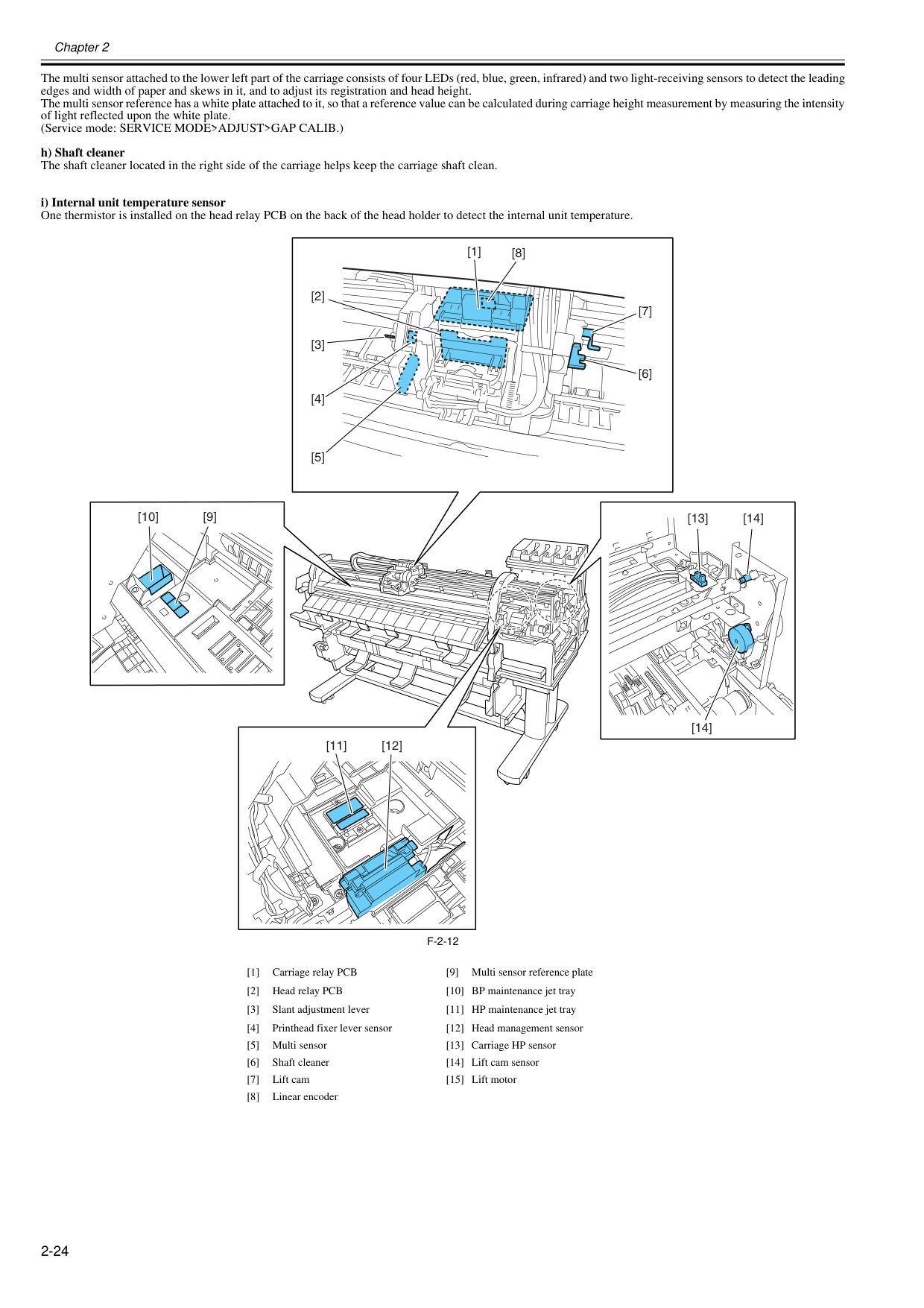
Chapter 2 2-24 The multi sensor attached to the lower left part of the carriage consists of four LEDs (red, blue, green, infrared) and two light-receiving sensors to detect the leading edges and width of paper and skews in it, and to adjust its registration and head height. The multi sensor reference has a white plate attached to it, so that a reference value can be calculated during carriage height measurement by measuring the intensity of light reflected upon the white plate. (Service mode: SERVICE MODE>ADJUST>GAP CALIB.) h) Shaft cleaner The shaft cleaner located in the right side of the carriage helps keep the carriage shaft clean. i) Internal unit temperature sensor One thermistor is installed on the head relay PCB on the back of the head holder to detect the internal unit temperature.
F-2-12
[1] Carriage relay PCB [9] Multi sensor reference plate [2] Head relay PCB [10] BP maintenance jet tray [3] Slant adjustment lever [11] HP maintenance jet tray [4] Printhead fixer lever sensor [12] Head management sensor [5] Multi sensor [13] Carriage HP sensor [6] Shaft cleaner [14] Lift cam sensor [7] Lift cam [15] Lift motor [8] Linear encoder [13] [14] [11] [12] [14] [10] [9] [1] [7] [6] [2] [3] [4] [5] [8]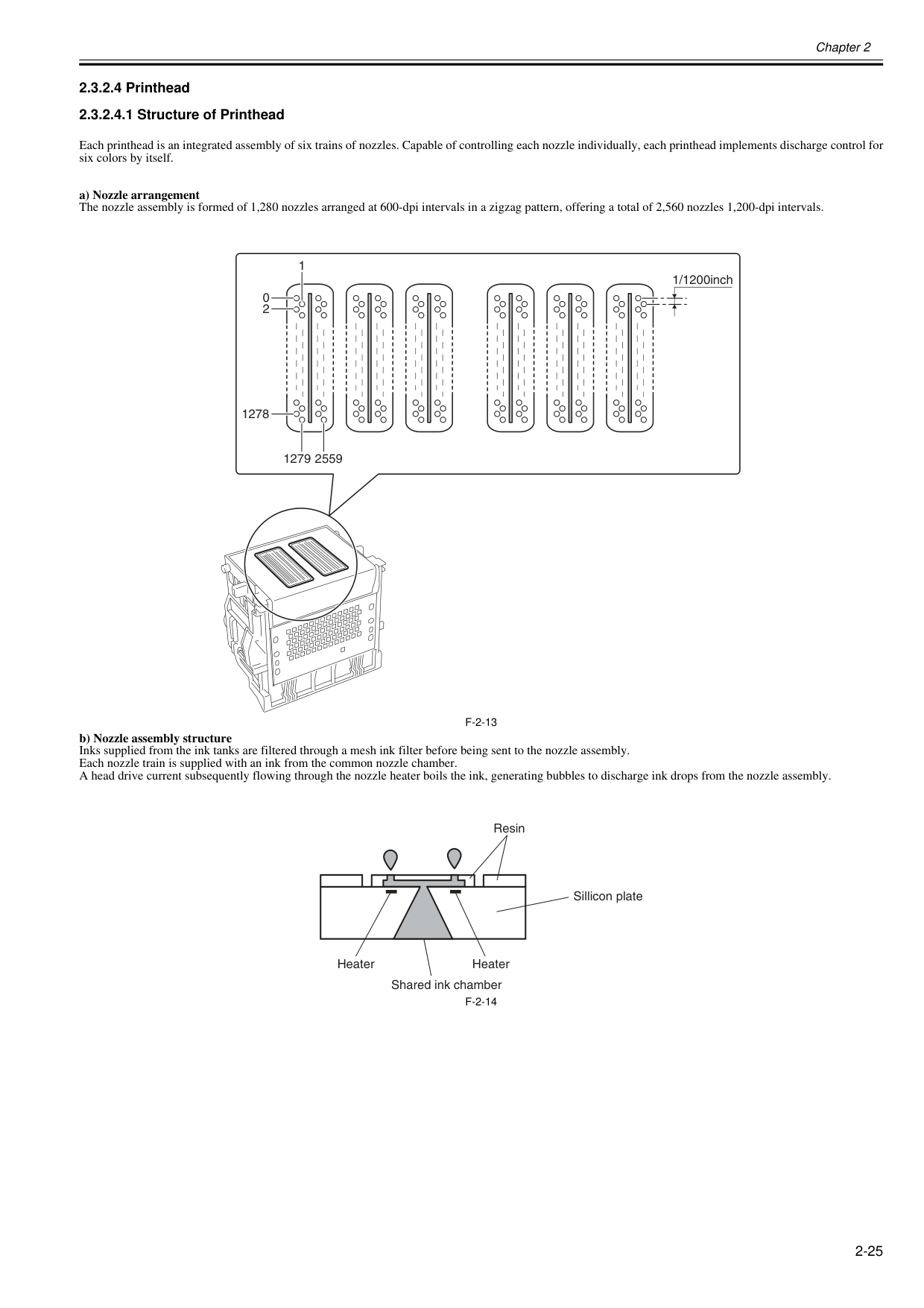
Chapter 2 2-25 2.3.2.4 Printhead 2.3.2.4.1 Structure of Printhead 0013-8015 Each printhead is an integrated assembly of six trains of nozzles. Capable of controlling each nozzle individually, each printhead implements discharge control for six colors by itself. a) Nozzle arrangement The nozzle assembly is formed of 1,280 nozzles arranged at 600-dpi intervals in a zigzag pattern, offering a total of 2,560 nozzles 1,200-dpi intervals.
F-2-13
b) Nozzle assembly structure Inks supplied from the ink tanks are filtered through a mesh ink filter before being sent to the nozzle assembly. Each nozzle train is supplied with an ink from the common nozzle chamber. A head drive current subsequently flowing through the nozzle heater boils the ink, generating bubbles to discharge ink drops from the nozzle assembly.F-2-14
1279 1278 0 2 1 1/1200inch 2559 Resin Sillicon plate Heater Shared ink chamber Heater
Chapter 2 2-26 2.3.2.5 Purge Unit 2.3.2.5.1 Functions of Purge Unit 0020-5700 To maintain high print quality, the purge unit performs maintenance of the nozzles of the printhead. The purge unit supports a capping function, cleaning function, and ink supply function. a) Capping function The capping function presses the cap of the purge unit against the face plate on the nozzle section of the printhead to prevent nozzle drying and dust adhesion. Capping is performed when printing is complete, at the start of the suction operation, and when switching to the standby state due to an error. The capping function also establishes the ink passage between the printhead and purge unit. b) Cleaning function The cleaning function restores the printhead to the state where ink can be easily discharged from nozzles. This function includes the following three types of oper- ations.
Print Inf
(Name of Main Menu) Operation Description of cleaning Cleaning 1Cln-A-1/Cln-M-1
(Head Cleaning A) Normal cleaning Removes dried ink from nozzles, thick ink accumulated on the face, and paper particles. Cleaning 2Cln-A-2
Ink level adjustment and cleaning Adjust the ink level in the head by suction, and then performs normal cleaning. Cleaning 3Cln-A-3
Initial filling ink Fills the empty tube (during initial installation) with ink, and then performs normal cleaning. Cleaning 4Cln-M-4
(Replace P.head) Ink drainage for head replacement Drains ink to replace the head (drains only the ink in the head). Cleaning 5Cln-M-5
(Move Printer) Ink drainage for secondary transport Drains ink from the head and tube for secondary transport. Cleaning 6Cln-A-6/Cln-M-6
(Head Cleaning B) Normal (strong) cleaning Performs suction stronger than when adjusting the ink filling amount in the head or normal cleaning to unclog nozzles. Cleaning 7Cln-A-7
Aging Performs idle ejection after replacement of the head. Cleaning 10Cln-A-10
(Move Printer) Ink filling after secondary transport Fills the empty tube (during installation after secondary transport) with ink, and performs normal cleaning. Cleaning 11Cln-A-11
Ink filling after head replacement Performs normal cleaning after head replacement and ink filling. Cleaning 15Cln-A-15
Dot count suction Performs suction to remove ink adhered to dried nozzles and thick ink accumulated on the face when the dot count reaches the prescribed value. Cleaning 16Cln-A-16
Precipitated ink agitation Performs the agitation (ink supply valve open/close) operation to prevent the ink ingredient from precipitating. Cleaning 17Cln-A-17
Cleaning (weak) Performs cleaning weaker than normal cleaning to unclog nozzles.
Chapter 2 2-27 Cleaning operation timings are as follows. Printer status Cleaning operation Ink consumption (typ.)*1 Standby 168 hours elapsed capped Cleaning 1 (Normal Cleaning) 1g At least 720 to 960 hours elapsed since the last session of Cleaning 2, 3, 6 or 10 (480 hours after initial installation) Cleaning 6 (Normal (strong) Cleaning) 5g At initial installation and 96 hours elapsed since the last session of Cleaning 16 Cleaning 16 (Precipitated ink agitation)
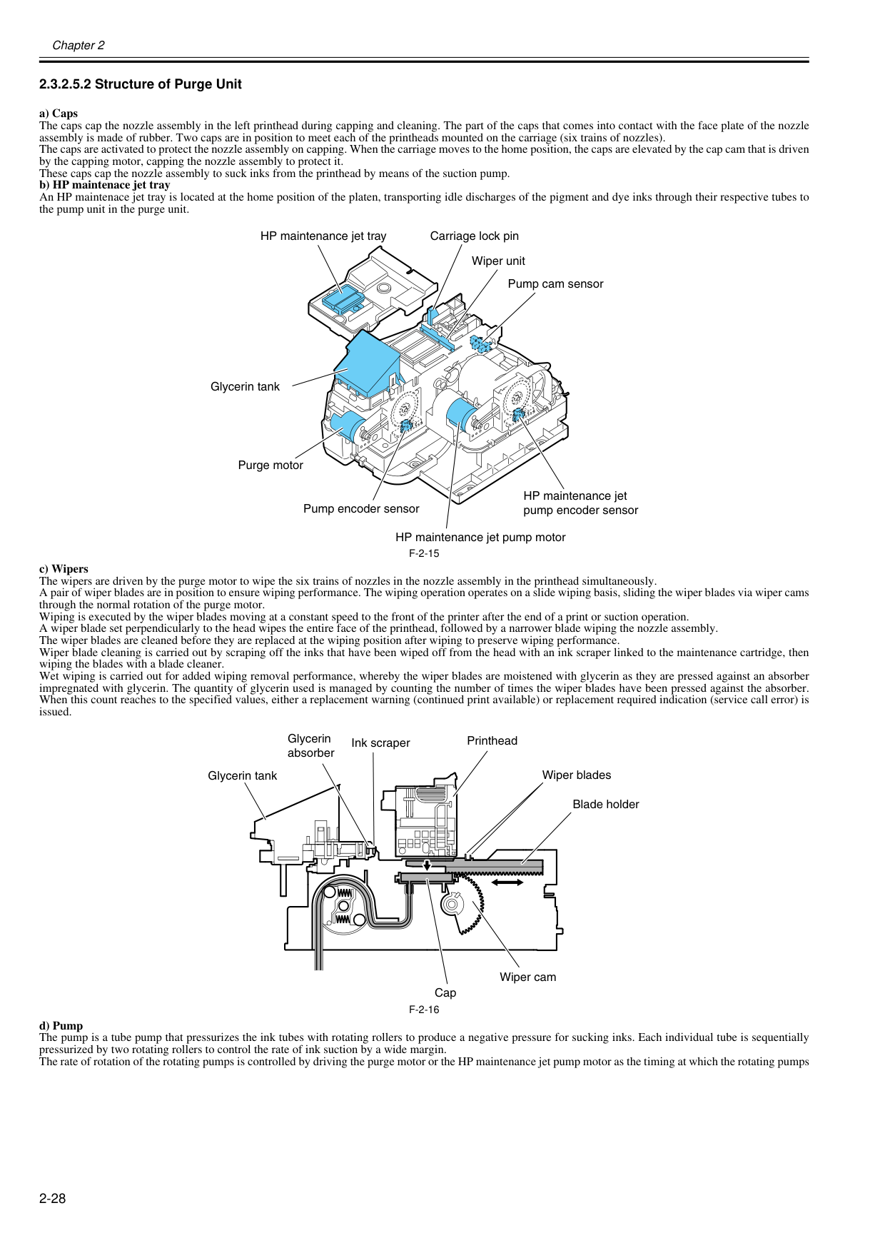
Chapter 2 2-28 2.3.2.5.2 Structure of Purge Unit 0020-5494 a) Caps The caps cap the nozzle assembly in the left printhead during capping and cleaning. The part of the caps that comes into contact with the face plate of the nozzle assembly is made of rubber. Two caps are in position to meet each of the printheads mounted on the carriage (six trains of nozzles). The caps are activated to protect the nozzle assembly on capping. When the carriage moves to the home position, the caps are elevated by the cap cam that is driven by the capping motor, capping the nozzle assembly to protect it. These caps cap the nozzle assembly to suck inks from the printhead by means of the suction pump. b) HP maintenace jet tray An HP maintenace jet tray is located at the home position of the platen, transporting idle discharges of the pigment and dye inks through their respective tubes to the pump unit in the purge unit.
F-2-15
c) Wipers The wipers are driven by the purge motor to wipe the six trains of nozzles in the nozzle assembly in the printhead simultaneously. A pair of wiper blades are in position to ensure wiping performance. The wiping operation operates on a slide wiping basis, sliding the wiper blades via wiper cams through the normal rotation of the purge motor. Wiping is executed by the wiper blades moving at a constant speed to the front of the printer after the end of a print or suction operation. A wiper blade set perpendicularly to the head wipes the entire face of the printhead, followed by a narrower blade wiping the nozzle assembly. The wiper blades are cleaned before they are replaced at the wiping position after wiping to preserve wiping performance. Wiper blade cleaning is carried out by scraping off the inks that have been wiped off from the head with an ink scraper linked to the maintenance cartridge, then wiping the blades with a blade cleaner. Wet wiping is carried out for added wiping removal performance, whereby the wiper blades are moistened with glycerin as they are pressed against an absorber impregnated with glycerin. The quantity of glycerin used is managed by counting the number of times the wiper blades have been pressed against the absorber. When this count reaches to the specified values, either a replacement warning (continued print available) or replacement required indication (service call error) is issued.F-2-16
d) Pump The pump is a tube pump that pressurizes the ink tubes with rotating rollers to produce a negative pressure for sucking inks. Each individual tube is sequentially pressurized by two rotating rollers to control the rate of ink suction by a wide margin. The rate of rotation of the rotating pumps is controlled by driving the purge motor or the HP maintenance jet pump motor as the timing at which the rotating pumps Wiper unit Carriage lock pin Purge motor HP maintenance jet pump motor HP maintenance jet pump encoder sensor HP maintenance jet tray Glycerin tank Pump encoder sensor Pump cam sensor Cap Ink scraper Glycerin absorber Printhead Wiper blades Blade holder Glycerin tank Wiper cam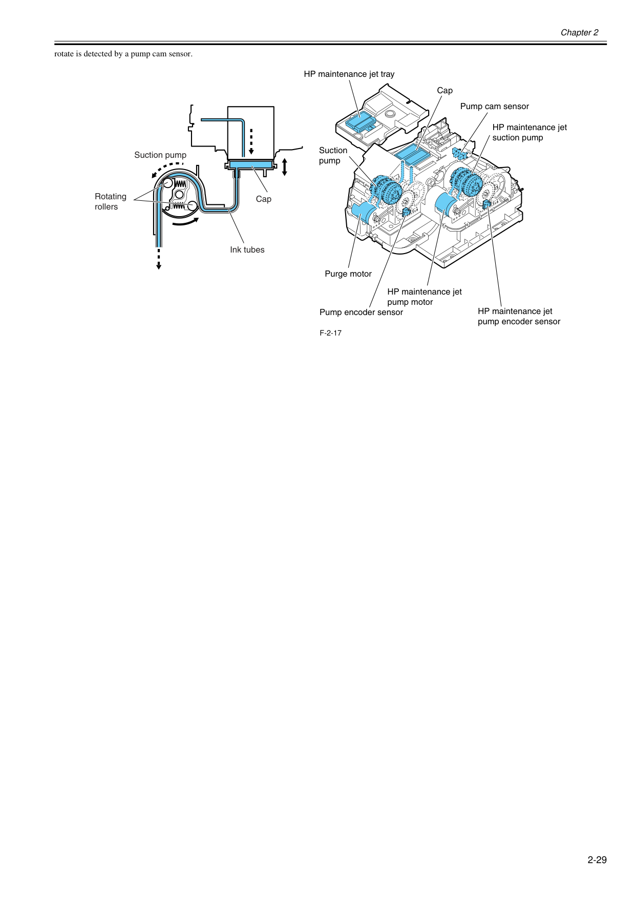
Chapter 2 2-29 rotate is detected by a pump cam sensor.
F-2-17
Purge motor HP maintenance jet pump motor HP maintenance jet suction pump HP maintenance jet pump encoder sensor HP maintenance jet tray Pump encoder sensor Suction pump Pump cam sensor Cap Cap Ink tubes Suction pump Rotating rollers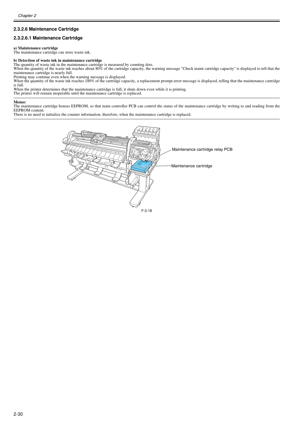
Chapter 2 2-30 2.3.2.6 Maintenance Cartridge 2.3.2.6.1 Maintenance Cartridge 0020-5497 a) Maintenance cartridge The maintenance cartridge can store waste ink. b) Detection of waste ink in maintenance cartridge The quantity of waste ink in the maintenance cartridge is measured by counting dots. When the quantity of the waste ink reaches about 80% of the cartridge capacity, the warning message "Check maint cartridge capacity" is displayed to tell that the maintenance cartridge is nearly full. Printing may continue even when the warning message is displayed. When the quantity of the waste ink reaches 100% of the cartridge capacity, a replacement prompt error message is displayed, telling that the maintenance cartridge is full. When the printer determines that the maintenance cartridge is full, it shuts down even while it is printing. The printer will remain inoperable until the maintenance cartridge is replaced. Memo: The maintenance cartridge houses EEPROM, so that main controller PCB can control the status of the maintenance cartridge by writing to and reading from the EEPROM content. There is no need to initialize the counter information, therefore, when the maintenance cartridge is replaced.
F-2-18
Maintenance cartridge Maintenance cartridge relay PCB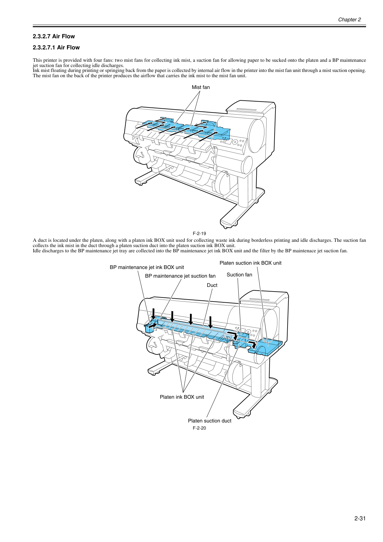
Chapter 2 2-31 2.3.2.7 Air Flow 2.3.2.7.1 Air Flow 0020-5500 This printer is provided with four fans: two mist fans for collecting ink mist, a suction fan for allowing paper to be sucked onto the platen and a BP maintenance jet suction fan for collecting idle discharges. Ink mist floating during printing or springing back from the paper is collected by internal air flow in the printer into the mist fan unit through a mist suction opening. The mist fan on the back of the printer produces the airflow that carries the ink mist to the mist fan unit.
F-2-19
A duct is located under the platen, along with a platen ink BOX unit used for collecting waste ink during borderless printing and idle discharges. The suction fan collects the ink mist in the duct through a platen suction duct into the platen suction ink BOX unit. Idle discharges to the BP maintenance jet tray are collected into the BP maintenance jet ink BOX unit and the filter by the BP maintenace jet suction fan.F-2-20
Mist fan BP maintenance jet suction fan Suction fan Duct BP maintenance jet ink BOX unit Platen ink BOX unit Platen suction duct Platen suction ink BOX unit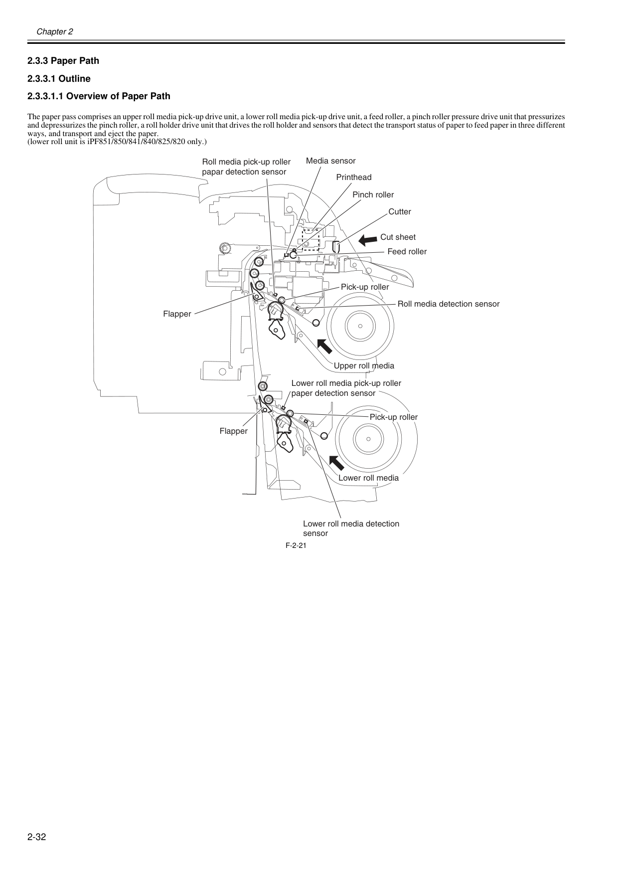
Chapter 2 2-32 2.3.3 Paper Path 2.3.3.1 Outline 2.3.3.1.1 Overview of Paper Path 0020-5503 The paper pass comprises an upper roll media pick-up drive unit, a lower roll media pick-up drive unit, a feed roller, a pinch roller pressure drive unit that pressurizes and depressurizes the pinch roller, a roll holder drive unit that drives the roll holder and sensors that detect the transport status of paper to feed paper in three different ways, and transport and eject the paper. (lower roll unit is iPF851/850/841/840/825/820 only.)
F-2-21
Roll media pick-up roller papar detection sensor Media sensor Printhead Cutter Pinch roller Feed roller Cut sheet Pick-up roller Pick-up roller Roll media detection sensor Flapper Flapper Lower roll media detection sensor Upper roll media Lower roll media pick-up roller paper detection sensor Lower roll media
Chapter 2 2-33 2.3.3.2 Paper Path 2.3.3.2.1 Structure of Pick-up/Feed Unit 0020-5505 a) Roll media pick-up The components of the roll media pick-up consists include a pick-up roller driven by a roll media pick-up motor, a roller that follows the motion of the pick-up roller, a roll media pick-up roller clutch that controls the driving of the pick-up roller and a roll media pick-up cam clutch that controls the rise and fall of the roller. When the roll media detection sensor detects a roll media being loaded at the paper loading port, the roll media pick-up motor (rotating in the normal direction), the roll media pick-up roller clutch and the roll media pick-up cam clutch turn on respectively to rotate the pick-up roller. When the roll media thus fed is detected by the roll media pick-up roller sensor, it is moved 5 mm before it comes to a standby position. Pressing the [OK] button on the operator console turns on the flapper solenoid, with the pick-up roller and the feed roller carrying the paper to the platen for paper sag correction, leading paper end detection, skew detection/correction, paper width detection and more. When the paper is carried to the feed roller, the roll media pick-up motor, roll media pick-up roller clutch and roll media pick-up cam clutch turn off to release the pick-up roller. b) Switching between upper and lower roll media pick-up (iPF851/850/841/840/825/815 only) While a roll media has been carried to the platen, if the transport of a roll media from another roll media pick-up is specified, the roll media pick-up motor (rotating in the reverse direction), the roll media pick-up roller clutch, the roll media pick-up cam clutch and the roll media rewinding clutch turn on respectively, driving the pick-up roller, the feed roller and the roller holder to rewind the roll media from the platen to the standby position before the transport of a roller from the other roll media pick-up specified starts. c) Rewinding rolls While a roll media has been carried to the platen, if the transport of a cut form is specified, the roll media pick-up motor (rotating in the reverse direction), the roll media pick-up roller clutch, the roll media pick-up cam clutch and the roll media rewinding clutch turn on respectively, driving the pick-up roller, the feed roller and the roller holder to rewind the roll media from the platen to the standby position. d) Pick-up roller sag/skew correction When a roll media feeds, it is iteratively driven and spooled about 75mm by the pick-up roller to correct sags and skews in the roll media. If the roll media width detection sensor detects paper (media width: about 24 inches), the roll media pick-up pressure clutch turns on to actuate the torque limiter in the roll holder drive unit, with the result of increased back tension (about 2.6 times higher than before). The increased back tension augments the effects of sag/skew correction on wide media. e) Skew correction on the platen When a roll media feeds to the platen, it is carried in the direction of paper ejection for skew detection and correction. At this time, the pinch roller pressure motor and the pinch roller pressure clutch turn on respectively to place the pinch roller in a weakly pressurized state (under about one third of the normal pressure), thereby reducing paper nip force acting on the feed roller for enhanced skew correction. The status of pinch roller pressure/release is detected by the pinch roller pressure detection sensor and the pinch roller release detection sensor, with the rate of pressurization being controlled by drives from the pinch roller pressure motor. Skew correction on the platen is run up to three times. If skews in the roller remain uncorrected after three runs of skew correction, the roll is subjected to user skew correction (by releasing the release lever).
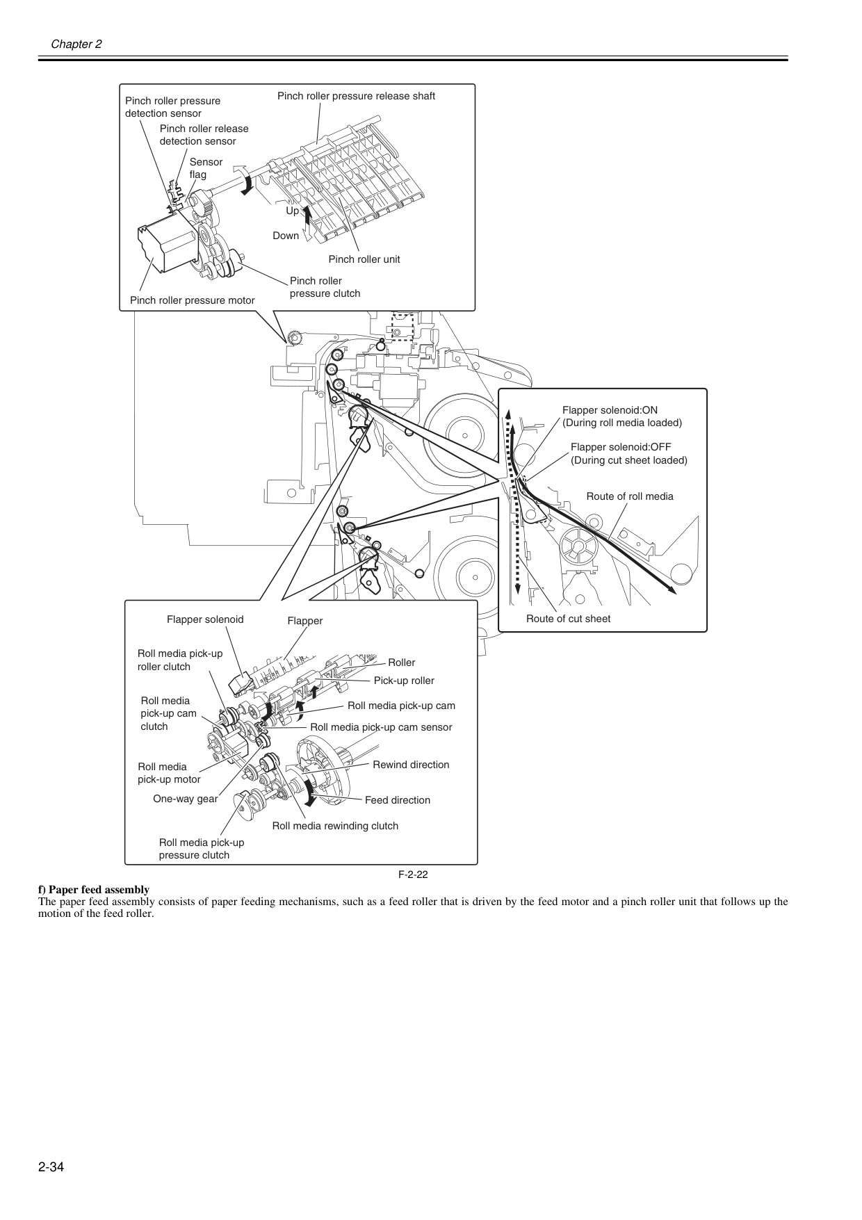
Chapter 2 2-34
F-2-22
f) Paper feed assembly The paper feed assembly consists of paper feeding mechanisms, such as a feed roller that is driven by the feed motor and a pinch roller unit that follows up the motion of the feed roller. Flapper solenoid:ON (During roll media loaded) Flapper solenoid:OFF (During cut sheet loaded) Route of roll media Route of cut sheet Pinch roller pressure release shaft Pinch roller release detection sensor Pinch roller pressure detection sensor Pinch roller pressure motor Pinch roller pressure clutch Pinch roller unit Up Down Sensor flag Flapper Flapper solenoid Roll media pick-up roller clutch Roll media pick-up cam clutch Roll media pick-up motor Roll media rewinding clutch Roll media pick-up pressure clutch Rewind direction Feed direction Roll media pick-up cam Roll media pick-up cam sensor One-way gear Pick-up roller Roller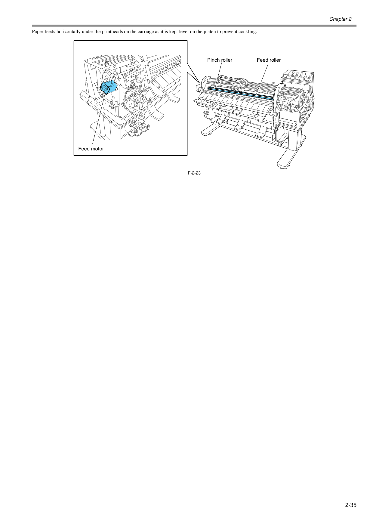
Chapter 2 2-35 Paper feeds horizontally under the printheads on the carriage as it is kept level on the platen to prevent cockling.
F-2-23
Pinch roller Feed roller Feed motor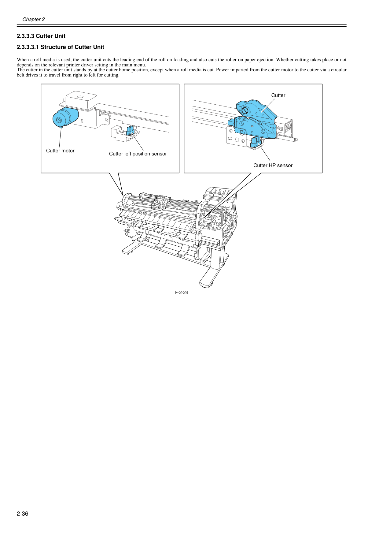
Chapter 2 2-36 2.3.3.3 Cutter Unit 2.3.3.3.1 Structure of Cutter Unit 0020-5538 When a roll media is used, the cutter unit cuts the leading end of the roll on loading and also cuts the roller on paper ejection. Whether cutting takes place or not depends on the relevant printer driver setting in the main menu. The cutter in the cutter unit stands by at the cutter home position, except when a roll media is cut. Power imparted from the cutter motor to the cutter via a circular belt drives it to travel from right to left for cutting.
F-2-24
Cutter motor Cutter left position sensor Cutter HP sensor Cutter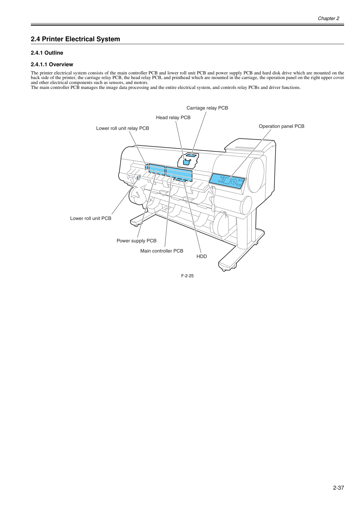
Chapter 2 2-37 2.4 Printer Electrical System 2.4.1 Outline 2.4.1.1 Overview 0020-5539 The printer electrical system consists of the main controller PCB and lower roll unit PCB and power supply PCB and hard disk drive which are mounted on the back side of the printer, the carriage relay PCB, the head relay PCB, and printhead which are mounted in the carriage, the operation panel on the right upper cover and other electrical components such as sensors, and motors. The main controller PCB manages the image data processing and the entire electrical system, and controls relay PCBs and driver functions.
F-2-25
Main controller PCB Operation panel PCB Lower roll unit PCB Lower roll unit relay PCB Carriage relay PCB Head relay PCB Power supply PCBHdd
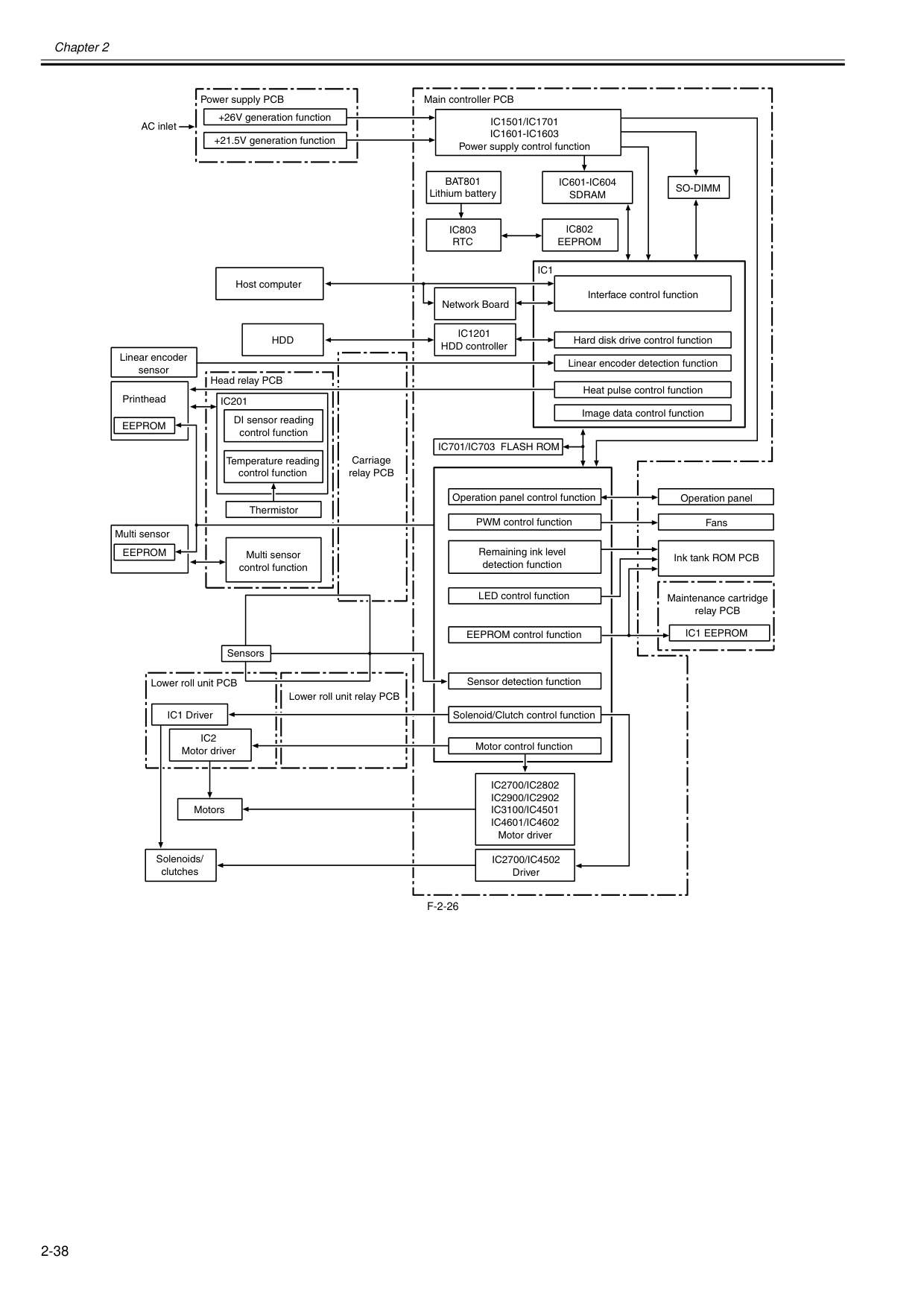
Chapter 2 2-38
F-2-26
Operation panel Operation panel control function EEPROM control function Solenoid/Clutch control function Remaining ink level detection function LED control function PWM control function Sensor detection function Fans Maintenance cartridge relay PCB Linear encoder detection function Motor control function Ink tank ROM PCB Image data control function Heat pulse control function Interface control function Hard disk drive control function Carriage relay PCBIc1501/Ic1701
Ic1601-Ic1603
Power supply control functionBat801
Lithium batteryIc1201
HDD controllerIc803
Rtc
Ic802
Eeprom
Ic601-Ic604
Sdram
Ic701/Ic703 Flash Rom
Ic2700/Ic4502
DriverIc2700/Ic2802
Ic2900/Ic2902
Ic3100/Ic4501
Ic4601/Ic4602
Motor driverIc1 Eeprom
Eeprom
Eeprom
Ic201
Ic1
So-Dimm
Network BoardHdd
Ic2
Motor driver IC1 Driver Lower roll unit PCB Lower roll unit relay PCB AC inlet +26V generation function +21.5V generation function Power supply PCB Solenoids/ clutches Sensors Motors Host computer DI sensor reading control function Temperature reading control function Thermistor Multi sensor Printhead Head relay PCB Linear encoder sensor Main controller PCB Multi sensor control function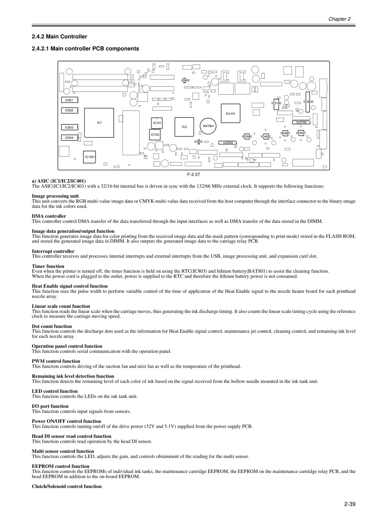
Chapter 2 2-39 2.4.2 Main Controller 2.4.2.1 Main controller PCB components 0020-5546
F-2-27
a) ASIC (IC1/IC2/IC401) The ASIC(IC1/IC2/IC401) with a 32/16-bit internal bus is driven in sync with the 132/66 MHz external clock. It supports the following functions: Image processing unit This unit converts the RGB multi-value image data or CMYK multi-value data received from the host computer through the interface connector to the binary image data for the ink colors used. DMA controller This controller control DMA transfer of the data transferred through the input interfaces as well as DMA transfer of the data stored in the DIMM. Image data generation/output function This function generates image data for color printing from the received image data and the mask pattern (corresponding to print mode) stored in the FLASH ROM, and stored the generated image data in DIMM. It also outputs the generated image data to the carriage relay PCB. Interrupt controller This controller receives and processes internal interrupts and external interrupts from the USB, image processing unit, and expansion card slot. Timer function Even when the printer is turned off, the timer function is held on using the RTC(IC803) and lithium battery(BAT801) to assist the cleaning function. When the power cord is plugged to the outlet, power is supplied to the RTC and therefore the lithium battery power is not consumed. Heat Enable signal control function This function uses the pulse width to perform variable control of the time of application of the Heat Enable signal to the nozzle heater board for each printhead nozzle array. Linear scale count function This function reads the linear scale when the carriage moves, thus generating the ink discharge timing. It also counts the linear scale timing cycle using the reference clock to measure the carriage moving speed. Dot count function This function controls the discharge dots used as the information for Heat Enable signal control, maintenance jet control, cleaning control, and remaining ink level for each nozzle array. Operation panel control function This function controls serial communication with the operation panel. PWM control function This function controls driving of the suction fan and mist fan as well as the temperature of the printhead. Remaining ink level detection function This function detects the remaining level of each color of ink based on the signal received from the hollow needle mounted in the ink tank unit. LED control function This function controls the LEDs on the ink tank unit. I/O port function This function controls input signals from sensors. Power ON/OFF control function This function controls turning on/off of the drive power (32V and 5.1V) supplied from the power supply PCB. Head DI sensor read control function This function controls read operation by the head DI sensor. Multi sensor control function This function controls the LED, adjusts the gain, and controls obtainment of the reading for the multi sensor. EEPROM control function This function controls the EEPROMs of individual ink tanks, the maintenance cartridge EEPROM, the EEPROM on the maintenance cartridge relay PCB, and the head EEPROM in addition to the on-board EEPROM. Clutch/Solenoid control functionIc2802
Ic3100
Ic2700
Ic4501
Ic4601
Ic4602
Ic2900
Ic2902
Ic4101
Bat801
Ic803
Ic2
Ic701
Ic703
Ic1
Ic1201
Ic604
Ic603
Ic602
Ic601
Ic802
Ic2802
Ic3100
Ic2700
Ic4501
Ic4601
Ic4602
Ic2900
Ic2902
Ic4101
Bat801
Ic803
Ic2
Ic701
Ic703
Ic1
Ic1201
Ic604
Ic603
Ic602
Ic601
Ic802
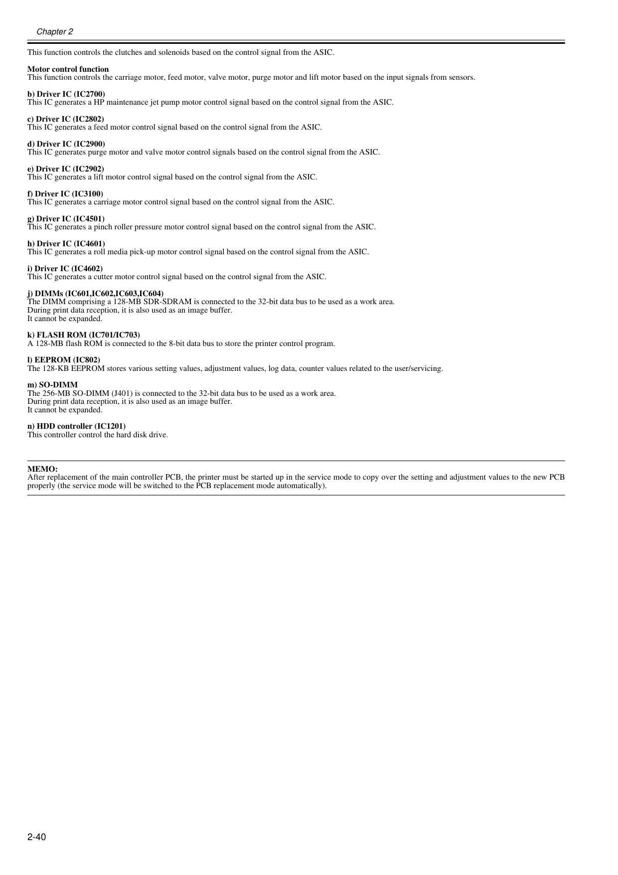
Chapter 2 2-40 This function controls the clutches and solenoids based on the control signal from the ASIC. Motor control function This function controls the carriage motor, feed motor, valve motor, purge motor and lift motor based on the input signals from sensors. b) Driver IC (IC2700) This IC generates a HP maintenance jet pump motor control signal based on the control signal from the ASIC. c) Driver IC (IC2802) This IC generates a feed motor control signal based on the control signal from the ASIC. d) Driver IC (IC2900) This IC generates purge motor and valve motor control signals based on the control signal from the ASIC. e) Driver IC (IC2902) This IC generates a lift motor control signal based on the control signal from the ASIC. f) Driver IC (IC3100) This IC generates a carriage motor control signal based on the control signal from the ASIC. g) Driver IC (IC4501) This IC generates a pinch roller pressure motor control signal based on the control signal from the ASIC. h) Driver IC (IC4601) This IC generates a roll media pick-up motor control signal based on the control signal from the ASIC. i) Driver IC (IC4602) This IC generates a cutter motor control signal based on the control signal from the ASIC. j) DIMMs (IC601,IC602,IC603,IC604) The DIMM comprising a 128-MB SDR-SDRAM is connected to the 32-bit data bus to be used as a work area. During print data reception, it is also used as an image buffer. It cannot be expanded. k) FLASH ROM (IC701/IC703) A 128-MB flash ROM is connected to the 8-bit data bus to store the printer control program. l) EEPROM (IC802) The 128-KB EEPROM stores various setting values, adjustment values, log data, counter values related to the user/servicing. m) SO-DIMM The 256-MB SO-DIMM (J401) is connected to the 32-bit data bus to be used as a work area. During print data reception, it is also used as an image buffer. It cannot be expanded. n) HDD controller (IC1201) This controller control the hard disk drive.
Memo:
After replacement of the main controller PCB, the printer must be started up in the service mode to copy over the setting and adjustment values to the new PCB properly (the service mode will be switched to the PCB replacement mode automatically).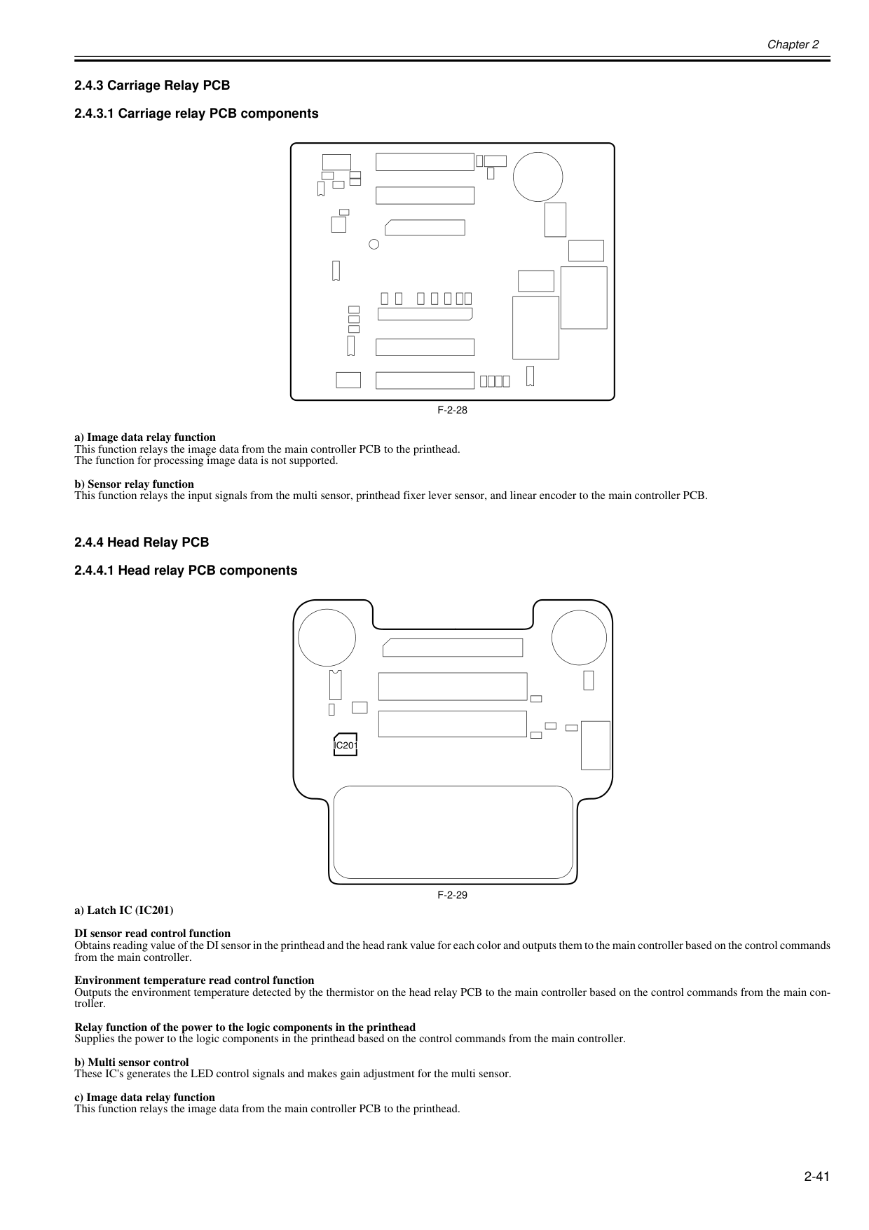
Chapter 2 2-41 2.4.3 Carriage Relay PCB 2.4.3.1 Carriage relay PCB components 0020-5553
F-2-28
a) Image data relay function This function relays the image data from the main controller PCB to the printhead. The function for processing image data is not supported. b) Sensor relay function This function relays the input signals from the multi sensor, printhead fixer lever sensor, and linear encoder to the main controller PCB. 2.4.4 Head Relay PCB 2.4.4.1 Head relay PCB components 0020-5555F-2-29
a) Latch IC (IC201) DI sensor read control function Obtains reading value of the DI sensor in the printhead and the head rank value for each color and outputs them to the main controller based on the control commands from the main controller. Environment temperature read control function Outputs the environment temperature detected by the thermistor on the head relay PCB to the main controller based on the control commands from the main con- troller. Relay function of the power to the logic components in the printhead Supplies the power to the logic components in the printhead based on the control commands from the main controller. b) Multi sensor control These IC's generates the LED control signals and makes gain adjustment for the multi sensor. c) Image data relay function This function relays the image data from the main controller PCB to the printhead.Ic201
Ic201
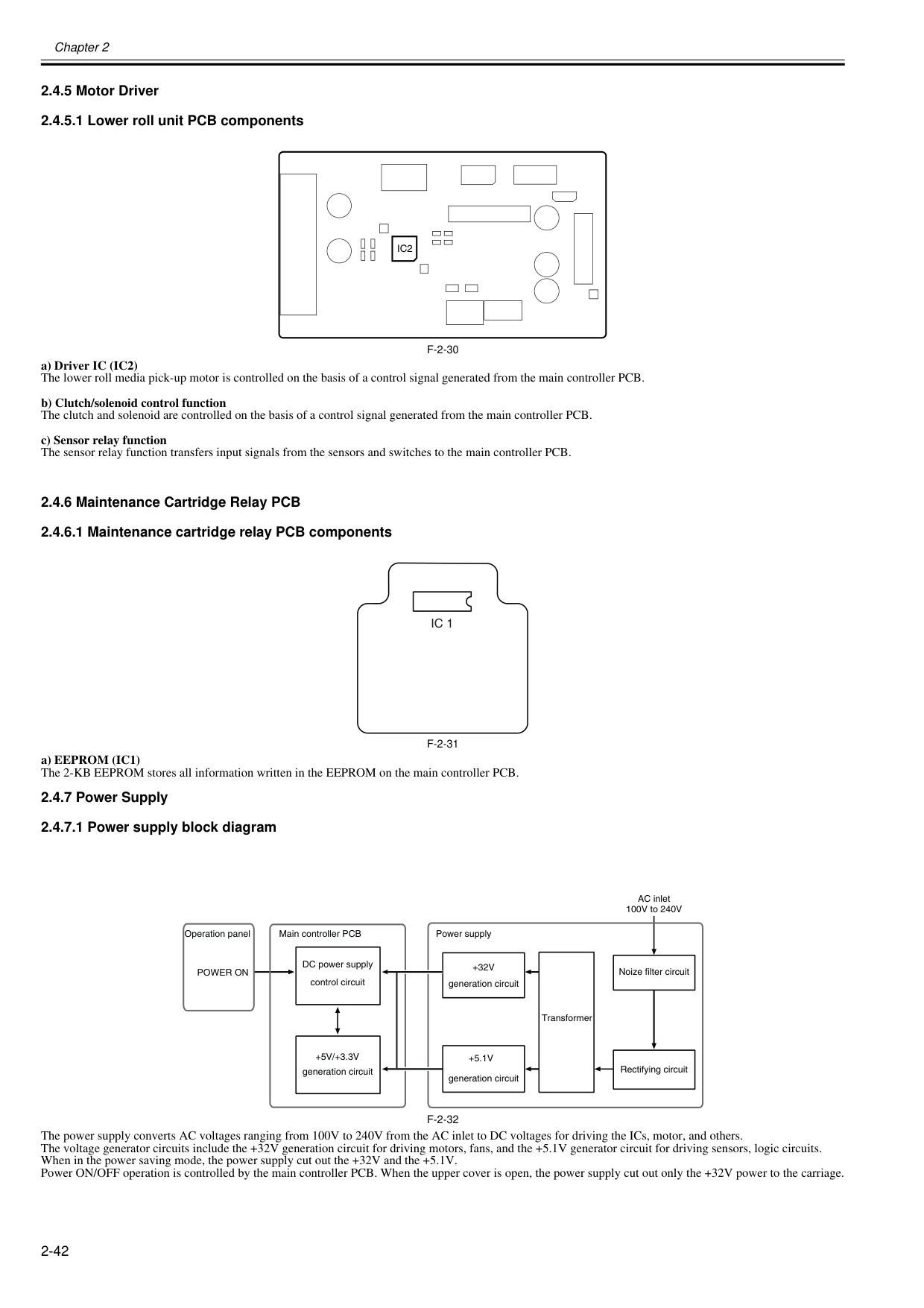
Chapter 2 2-42 2.4.5 Motor Driver 2.4.5.1 Lower roll unit PCB components 0020-5556
F-2-30
a) Driver IC (IC2) The lower roll media pick-up motor is controlled on the basis of a control signal generated from the main controller PCB.b) Clutch/solenoid control function The clutch and solenoid are controlled on the basis of a control signal generated from the main controller PCB. c) Sensor relay function The sensor relay function transfers input signals from the sensors and switches to the main controller PCB. 2.4.6 Maintenance Cartridge Relay PCB 2.4.6.1 Maintenance cartridge relay PCB components 0013-6532
F-2-31
a) EEPROM (IC1) The 2-KB EEPROM stores all information written in the EEPROM on the main controller PCB. 2.4.7 Power Supply 2.4.7.1 Power supply block diagram 0012-6414F-2-32
The power supply converts AC voltages ranging from 100V to 240V from the AC inlet to DC voltages for driving the ICs, motor, and others. The voltage generator circuits include the +32V generation circuit for driving motors, fans, and the +5.1V generator circuit for driving sensors, logic circuits. When in the power saving mode, the power supply cut out the +32V and the +5.1V. Power ON/OFF operation is controlled by the main controller PCB. When the upper cover is open, the power supply cut out only the +32V power to the carriage.Ic2
Ic 1
Operation panel Transformer DC power supply control circuit+5.1V
generation circuit+32V
generation circuitPower On
Rectifying circuit Noize filter circuit AC inlet 100V to 240V Power supply Main controller PCB+5V/+3.3V
generation circuit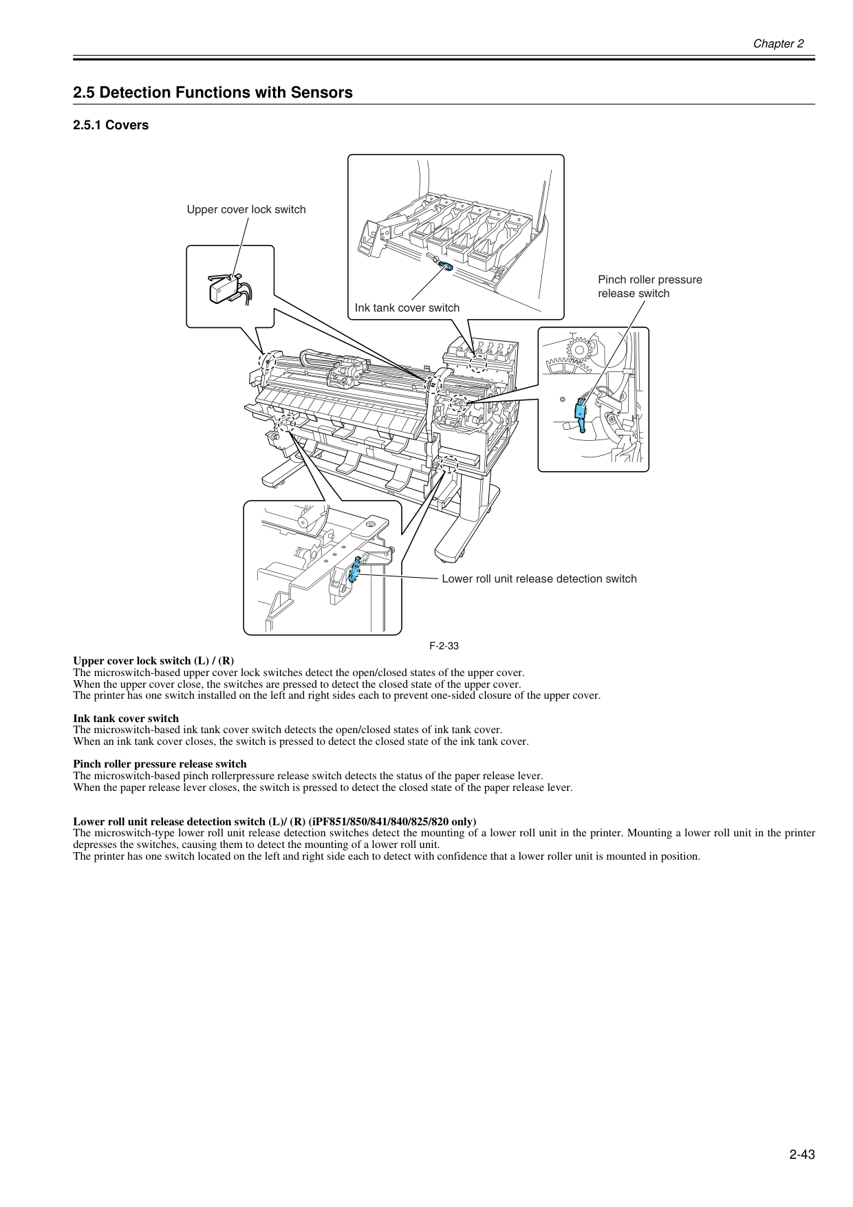
Chapter 2 2-43 2.5 Detection Functions with Sensors 2.5.1 Covers 0020-5557
F-2-33
Upper cover lock switch (L) / (R) The microswitch-based upper cover lock switches detect the open/closed states of the upper cover. When the upper cover close, the switches are pressed to detect the closed state of the upper cover. The printer has one switch installed on the left and right sides each to prevent one-sided closure of the upper cover. Ink tank cover switch The microswitch-based ink tank cover switch detects the open/closed states of ink tank cover. When an ink tank cover closes, the switch is pressed to detect the closed state of the ink tank cover. Pinch roller pressure release switch The microswitch-based pinch rollerpressure release switch detects the status of the paper release lever. When the paper release lever closes, the switch is pressed to detect the closed state of the paper release lever. Lower roll unit release detection switch (L)/ (R) (iPF851/850/841/840/825/820 only) The microswitch-type lower roll unit release detection switches detect the mounting of a lower roll unit in the printer. Mounting a lower roll unit in the printer depresses the switches, causing them to detect the mounting of a lower roll unit. The printer has one switch located on the left and right side each to detect with confidence that a lower roller unit is mounted in position. Upper cover lock switch Ink tank cover switch Pinch roller pressure release switch Lower roll unit release detection switch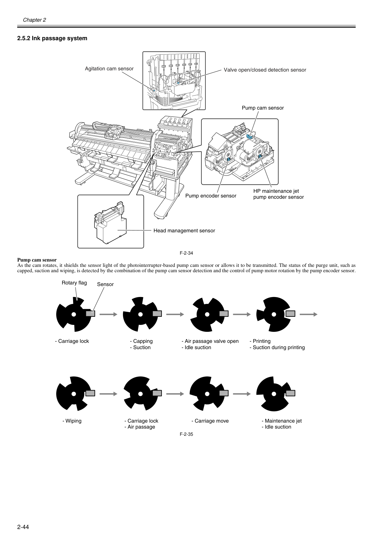
Chapter 2 2-44 2.5.2 Ink passage system 0020-5560
F-2-34
Pump cam sensor As the cam rotates, it shields the sensor light of the photointerrupter-based pump cam sensor or allows it to be transmitted. The status of the purge unit, such as capped, suction and wiping, is detected by the combination of the pump cam sensor detection and the control of pump motor rotation by the pump encoder sensor.F-2-35
Valve open/closed detection sensor Agitation cam sensor HP maintenance jet pump encoder sensor Pump encoder sensor Head management sensor Pump cam sensor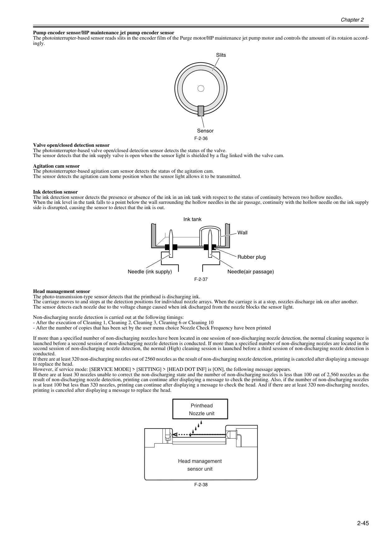
Chapter 2 2-45 Pump encoder sensor/HP maintenance jet pump encoder sensor The photointerrupter-based sensor reads slits in the encoder film of the Purge motor/HP maintenance jet pump motor and controls the amount of its rotaion accord- ingly.
F-2-36
Valve open/closed detection sensor The photointerrupter-based valve open/closed detection sensor detects the status of the valve. The sensor detects that the ink supply valve is open when the sensor light is shielded by a flag linked with the valve cam. Agitation cam sensor The photointerrupter-based agitation cam sensor detects the status of the agitation cam. The sensor detects the agitation cam home position when the sensor light allows it to be transmitted. Ink detection sensor The ink detection sensor detects the presence or absence of the ink in an ink tank with respect to the status of continuity between two hollow needles. When the ink level in the tank falls to a point below the wall surrounding the hollow needles in the air passage, continuity with the hollow needle on the ink supply side is disrupted, causing the sensor to detect that the ink is out.F-2-37
Head management sensor The photo-transmission-type sensor detects that the printhead is discharging ink. The carriage moves to and stops at the detection positions for individual nozzle arrays. When the carriage is at a stop, nozzles discharge ink on after another. The sensor detects each nozzle due to the voltage change caused when ink discharged from the nozzle blocks the sensor light. Non-discharging nozzle detection is carried out at the following timings:F-2-38
Sensor Slits Ink tank Wall Rubber plug Needle(air passage) Needle (ink supply) Printhead Nozzle unit Head management sensor unit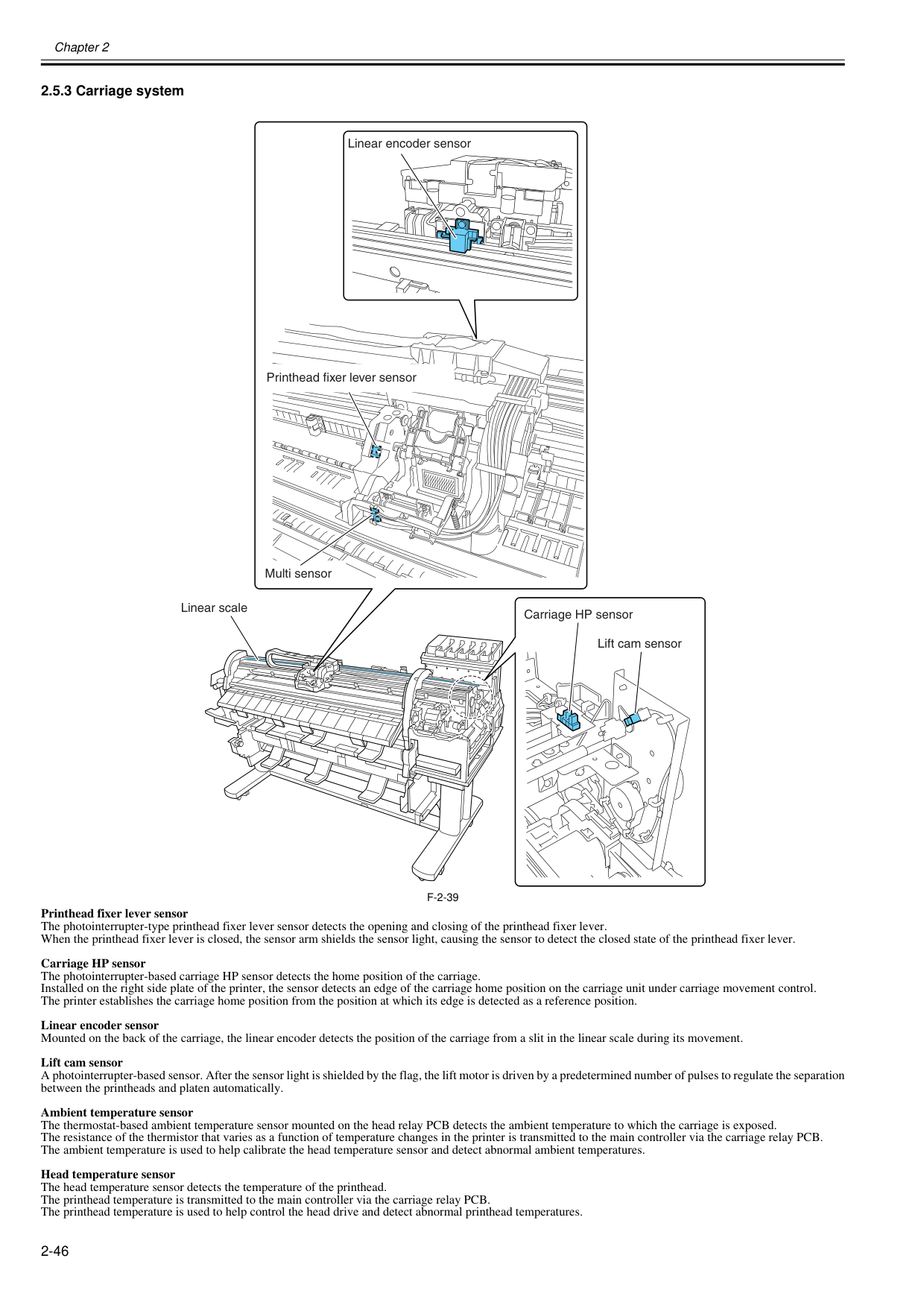
Chapter 2 2-46 2.5.3 Carriage system 0020-5567
F-2-39
Printhead fixer lever sensor The photointerrupter-type printhead fixer lever sensor detects the opening and closing of the printhead fixer lever. When the printhead fixer lever is closed, the sensor arm shields the sensor light, causing the sensor to detect the closed state of the printhead fixer lever. Carriage HP sensor The photointerrupter-based carriage HP sensor detects the home position of the carriage. Installed on the right side plate of the printer, the sensor detects an edge of the carriage home position on the carriage unit under carriage movement control. The printer establishes the carriage home position from the position at which its edge is detected as a reference position. Linear encoder sensor Mounted on the back of the carriage, the linear encoder detects the position of the carriage from a slit in the linear scale during its movement. Lift cam sensor A photointerrupter-based sensor. After the sensor light is shielded by the flag, the lift motor is driven by a predetermined number of pulses to regulate the separation between the printheads and platen automatically. Ambient temperature sensor The thermostat-based ambient temperature sensor mounted on the head relay PCB detects the ambient temperature to which the carriage is exposed. The resistance of the thermistor that varies as a function of temperature changes in the printer is transmitted to the main controller via the carriage relay PCB. The ambient temperature is used to help calibrate the head temperature sensor and detect abnormal ambient temperatures. Head temperature sensor The head temperature sensor detects the temperature of the printhead. The printhead temperature is transmitted to the main controller via the carriage relay PCB. The printhead temperature is used to help control the head drive and detect abnormal printhead temperatures. Multi sensor Lift cam sensor Carriage HP sensor Linear scale Linear encoder sensor Printhead fixer lever sensor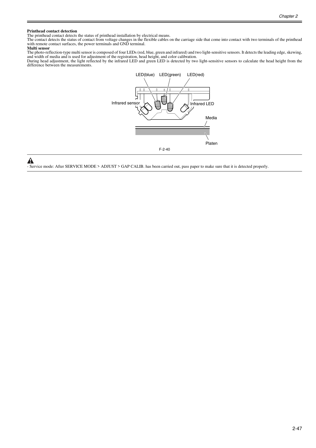
Chapter 2 2-47 Printhead contact detection The printhead contact detects the status of printhead installation by electrical means. The contact detects the status of contact from voltage changes in the flexible cables on the carriage side that come into contact with two terminals of the printhead with remote contact surfaces, the power terminals and GND terminal. Multi sensor The photo-reflection-type multi sensor is composed of four LEDs (red, blue, green and infrared) and two light-sensitive sensors. It detects the leading edge, skewing, and width of media and is used for adjustment of the registration, head height, and color calibration. During head adjustment, the light reflected by the infrared LED and green LED is detected by two light-sensitive sensors to calculate the head height from the difference between the measurements.
F-2-40
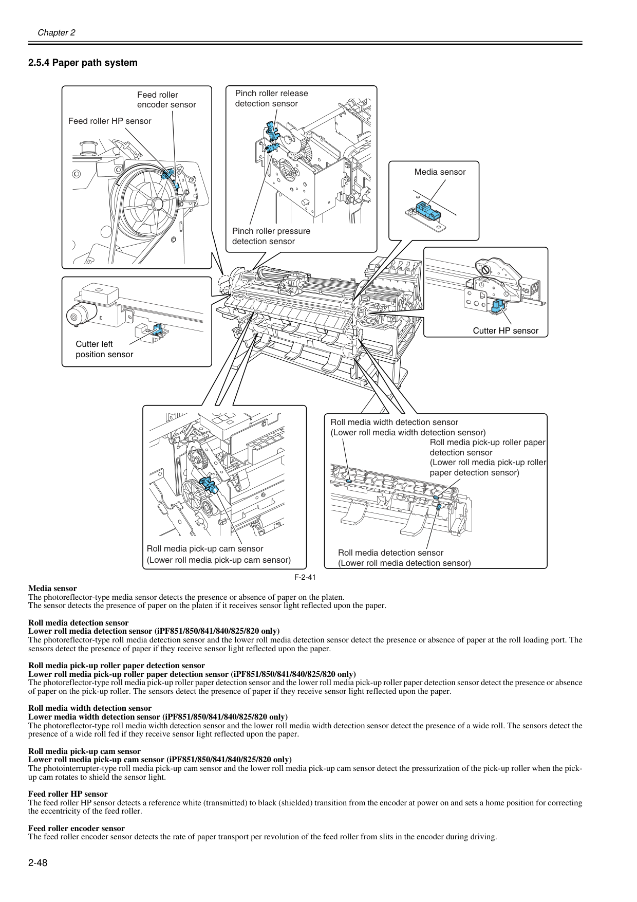
Chapter 2 2-48 2.5.4 Paper path system 0020-5570
F-2-41
Media sensor The photoreflector-type media sensor detects the presence or absence of paper on the platen. The sensor detects the presence of paper on the platen if it receives sensor light reflected upon the paper. Roll media detection sensor Lower roll media detection sensor (iPF851/850/841/840/825/820 only) The photoreflector-type roll media detection sensor and the lower roll media detection sensor detect the presence or absence of paper at the roll loading port. The sensors detect the presence of paper if they receive sensor light reflected upon the paper. Roll media pick-up roller paper detection sensor Lower roll media pick-up roller paper detection sensor (iPF851/850/841/840/825/820 only) The photoreflector-type roll media pick-up roller paper detection sensor and the lower roll media pick-up roller paper detection sensor detect the presence or absence of paper on the pick-up roller. The sensors detect the presence of paper if they receive sensor light reflected upon the paper. Roll media width detection sensor Lower media width detection sensor (iPF851/850/841/840/825/820 only) The photoreflector-type roll media width detection sensor and the lower roll media width detection sensor detect the presence of a wide roll. The sensors detect the presence of a wide roll fed if they receive sensor light reflected upon the paper. Roll media pick-up cam sensor Lower roll media pick-up cam sensor (iPF851/850/841/840/825/820 only) The photointerrupter-type roll media pick-up cam sensor and the lower roll media pick-up cam sensor detect the pressurization of the pick-up roller when the pick- up cam rotates to shield the sensor light. Feed roller HP sensor The feed roller HP sensor detects a reference white (transmitted) to black (shielded) transition from the encoder at power on and sets a home position for correcting the eccentricity of the feed roller. Feed roller encoder sensor The feed roller encoder sensor detects the rate of paper transport per revolution of the feed roller from slits in the encoder during driving. Media sensor Feed roller HP sensor Feed roller encoder sensor Cutter left position sensor Cutter HP sensor (Lower roll media pick-up cam sensor) Roll media pick-up cam sensor Roll media pick-up roller paper detection sensor (Lower roll media pick-up roller paper detection sensor) Roll media detection sensor (Lower roll media detection sensor) Roll media width detection sensor (Lower roll media width detection sensor) Pinch roller pressure detection sensor Pinch roller release detection sensor
Pinch roller pressure detection sensor The photointerrupter-type pinch roller pressure detection sensor detects the pressurization of the pinch roller if the pinch roller pressure cam rotates to shield the sensor light. Pinch roller release detection sensor The photointerrupter-type pinch roller release detection sensor detects the depressurization of the pinch roller if the pinch roller pressure cam rotates to shield the sensor light. Cutter HP sensor The photointerrupter-type sensor detects the presence of the cutter at the home (rightmost) position. Cutter left position sensor The photointerrupter-type sensor detects the presence of the cutter at the leftmost position.
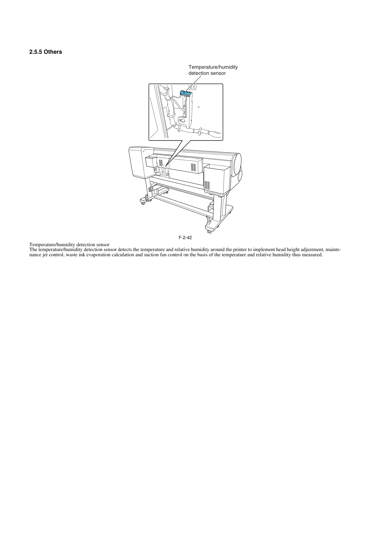
2.5.5 Others 0020-5569
F-2-42
Temperature/humidity detection sensor The temperature/humidity detection sensor detects the temperature and relative humidity around the printer to implement head height adjustment, mainte- nance jet control, waste ink evaporation calculation and suction fan control on the basis of the temperature and relative humidity thus measured. Temperature/humidity detection sensor
Chapter 3 INSTALLATION

Contents Contents 3.1 Transporting the Printer.............................................................................................................................. 3-1 3.1.1 Transporting the Printer........................................................................................................................................... 3-1 3.1.1.1 Transporting the Printer ........................................................................................................................................................... 3-1 3.1.2 Reinstalling the Printer ........................................................................................................................................... 3-13 3.1.2.1 Reinstalling the Printer............................................................................................................................................................ 3-13
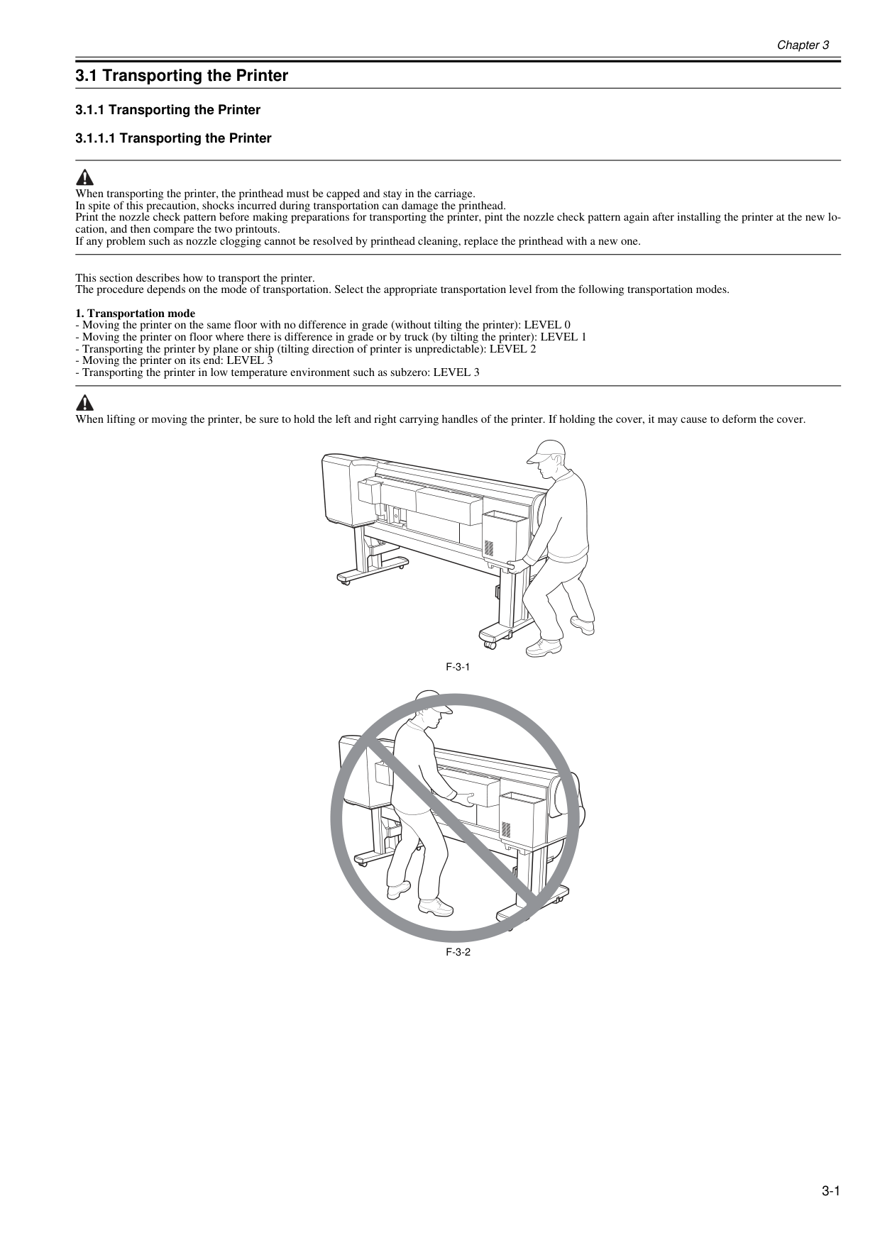
Chapter 3 3-1 3.1 Transporting the Printer 3.1.1 Transporting the Printer 3.1.1.1 Transporting the Printer 0020-5610 When transporting the printer, the printhead must be capped and stay in the carriage. In spite of this precaution, shocks incurred during transportation can damage the printhead. Print the nozzle check pattern before making preparations for transporting the printer, pint the nozzle check pattern again after installing the printer at the new lo- cation, and then compare the two printouts. If any problem such as nozzle clogging cannot be resolved by printhead cleaning, replace the printhead with a new one. This section describes how to transport the printer. The procedure depends on the mode of transportation. Select the appropriate transportation level from the following transportation modes.
F-3-1
F-3-2
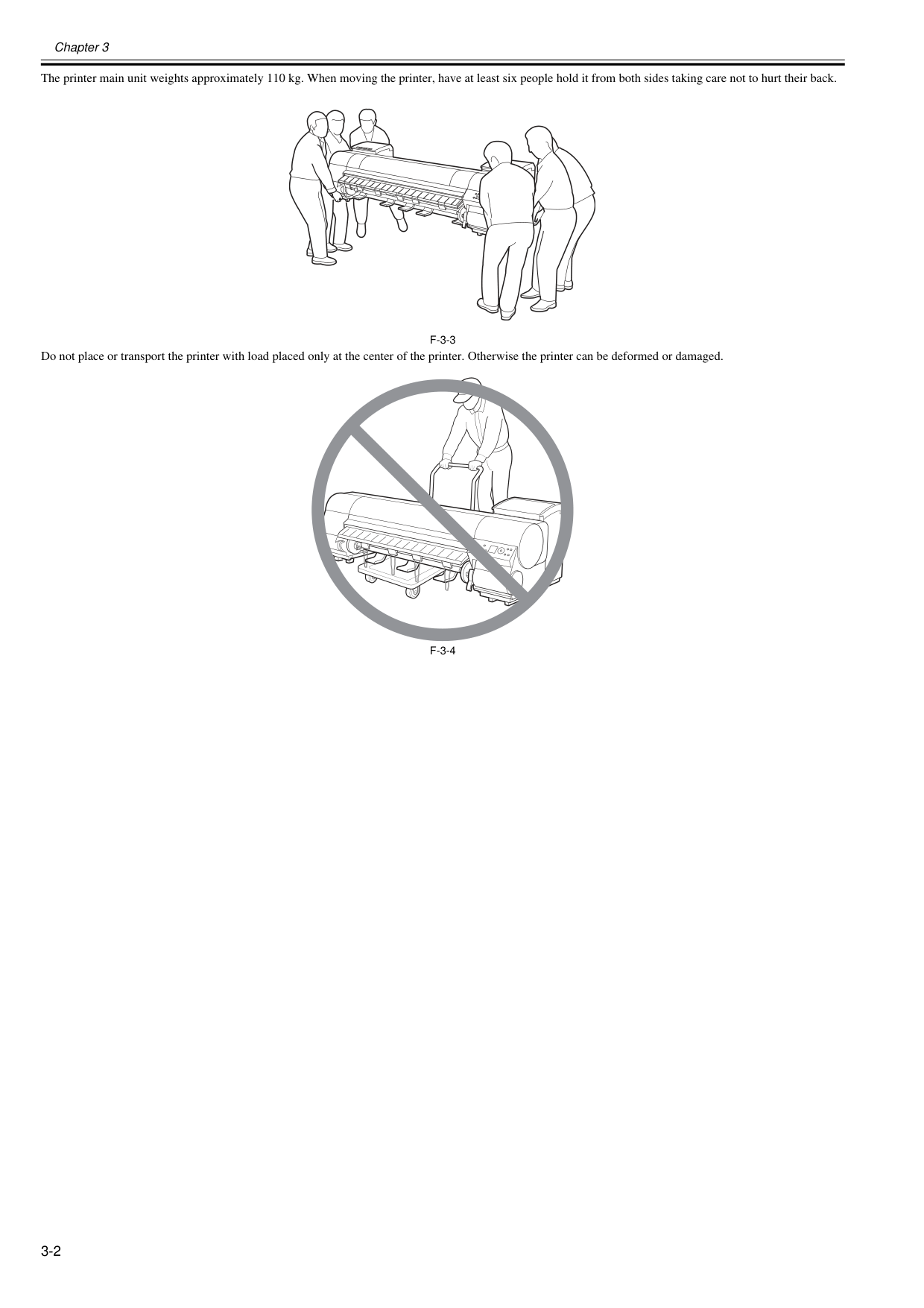
Chapter 3 3-2 The printer main unit weights approximately 110 kg. When moving the printer, have at least six people hold it from both sides taking care not to hurt their back.
F-3-3
Do not place or transport the printer with load placed only at the center of the printer. Otherwise the printer can be deformed or damaged.F-3-4
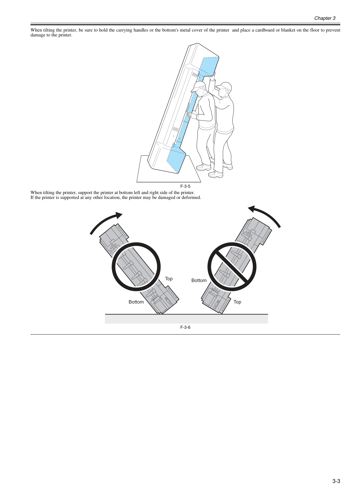
Chapter 3 3-3 When tilting the printer, be sure to hold the carrying handles or the bottom's metal cover of the printer and place a cardboard or blanket on the floor to prevent damage to the printer.
F-3-5
When tilting the printer, support the printer at bottom left and right side of the printer. If the printer is supported at any other location, the printer may be damaged or deformed.F-3-6
Bottom Top Top Bottom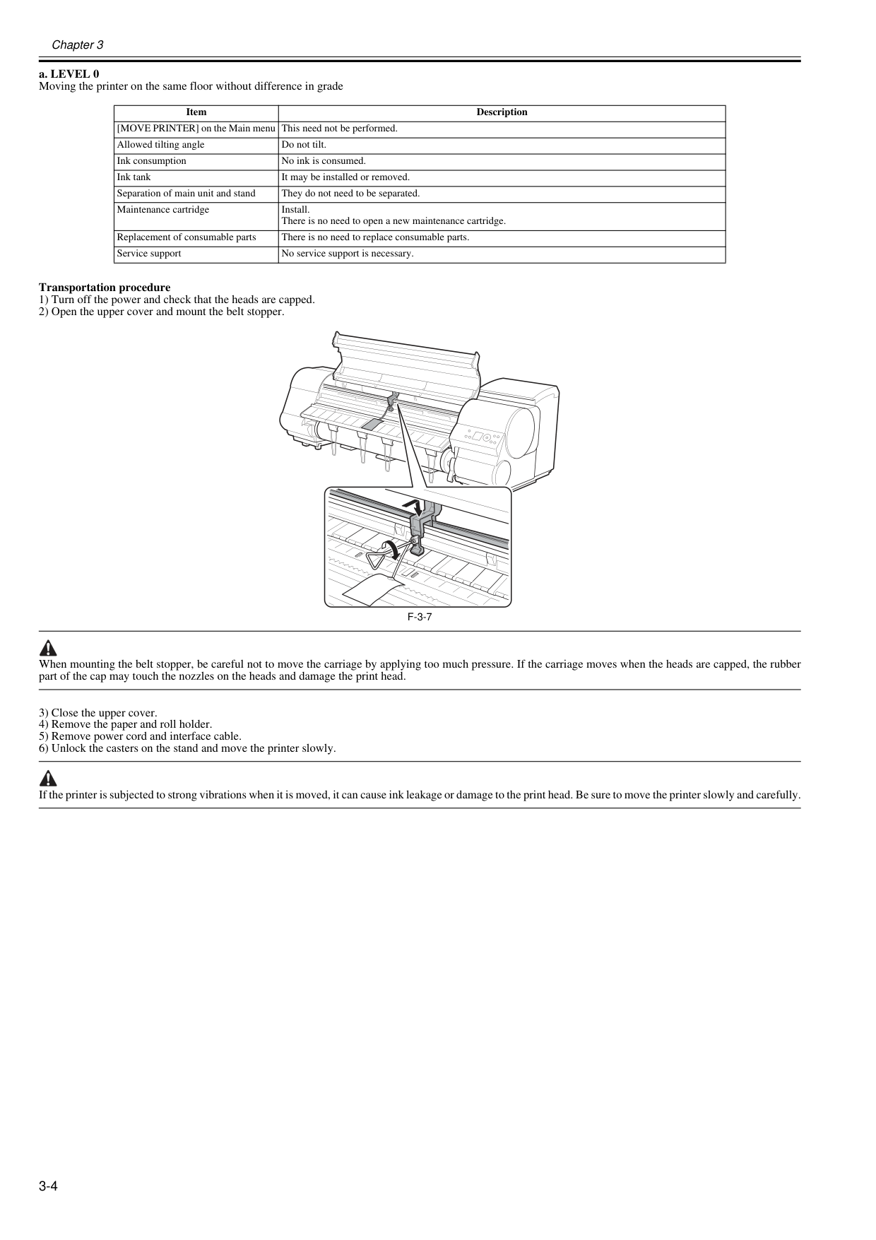
Chapter 3 3-4 a. LEVEL 0 Moving the printer on the same floor without difference in grade Transportation procedure 1) Turn off the power and check that the heads are capped. 2) Open the upper cover and mount the belt stopper.
F-3-7
When mounting the belt stopper, be careful not to move the carriage by applying too much pressure. If the carriage moves when the heads are capped, the rubber part of the cap may touch the nozzles on the heads and damage the print head. 3) Close the upper cover. 4) Remove the paper and roll holder. 5) Remove power cord and interface cable. 6) Unlock the casters on the stand and move the printer slowly. If the printer is subjected to strong vibrations when it is moved, it can cause ink leakage or damage to the print head. Be sure to move the printer slowly and carefully. Item Description [MOVE PRINTER] on the Main menu This need not be performed. Allowed tilting angle Do not tilt. Ink consumption No ink is consumed. Ink tank It may be installed or removed. Separation of main unit and stand They do not need to be separated. Maintenance cartridge Install. There is no need to open a new maintenance cartridge. Replacement of consumable parts There is no need to replace consumable parts. Service support No service support is necessary.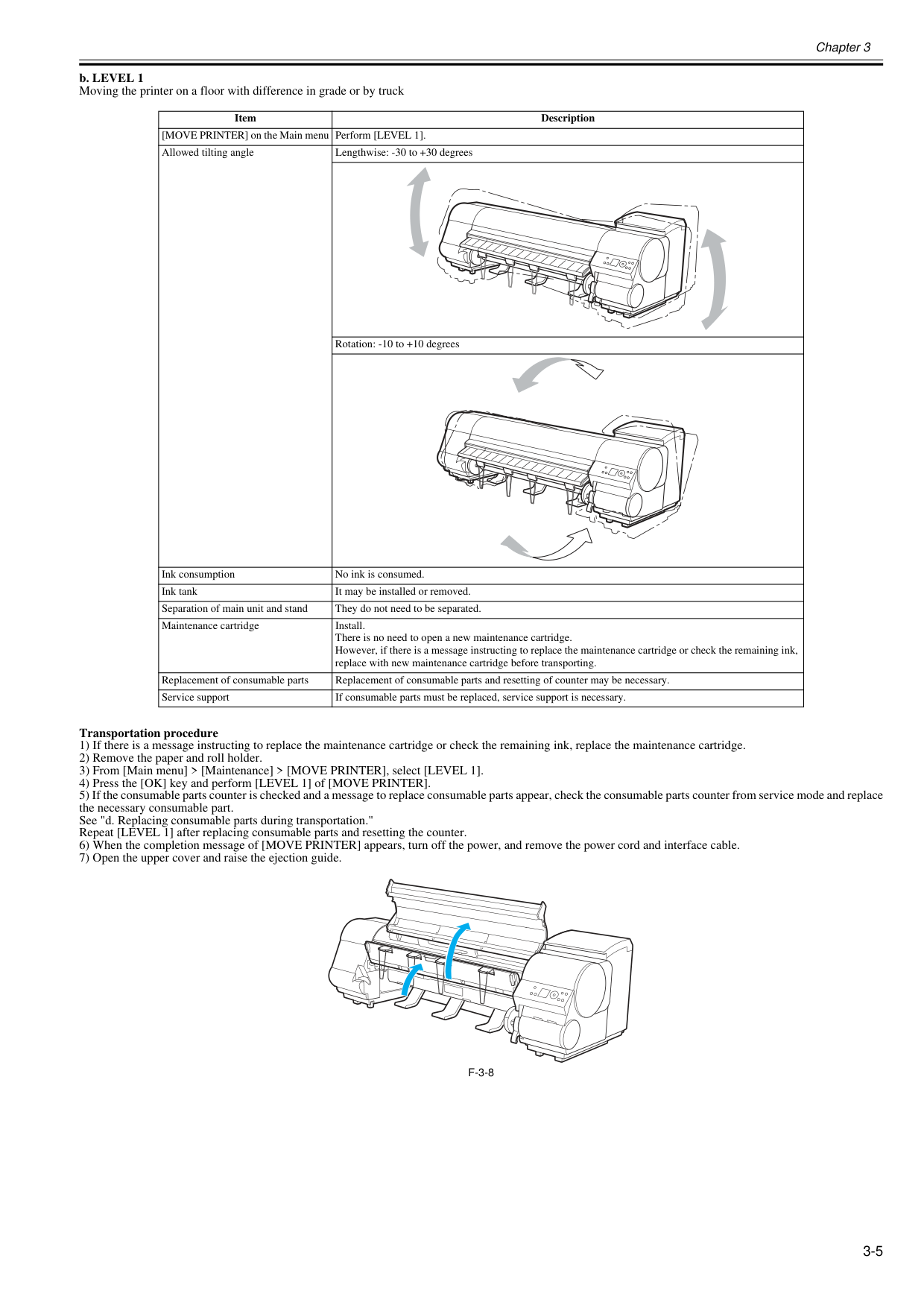
Chapter 3 3-5 b. LEVEL 1 Moving the printer on a floor with difference in grade or by truck Transportation procedure 1) If there is a message instructing to replace the maintenance cartridge or check the remaining ink, replace the maintenance cartridge. 2) Remove the paper and roll holder. 3) From [Main menu] > [Maintenance] > [MOVE PRINTER], select [LEVEL 1]. 4) Press the [OK] key and perform [LEVEL 1] of [MOVE PRINTER]. 5) If the consumable parts counter is checked and a message to replace consumable parts appear, check the consumable parts counter from service mode and replace the necessary consumable part. See "d. Replacing consumable parts during transportation." Repeat [LEVEL 1] after replacing consumable parts and resetting the counter. 6) When the completion message of [MOVE PRINTER] appears, turn off the power, and remove the power cord and interface cable. 7) Open the upper cover and raise the ejection guide.
F-3-8
Item Description [MOVE PRINTER] on the Main menu Perform [LEVEL 1]. Allowed tilting angle Lengthwise: -30 to +30 degrees Rotation: -10 to +10 degrees Ink consumption No ink is consumed. Ink tank It may be installed or removed. Separation of main unit and stand They do not need to be separated. Maintenance cartridge Install. There is no need to open a new maintenance cartridge. However, if there is a message instructing to replace the maintenance cartridge or check the remaining ink, replace with new maintenance cartridge before transporting. Replacement of consumable parts Replacement of consumable parts and resetting of counter may be necessary. Service support If consumable parts must be replaced, service support is necessary.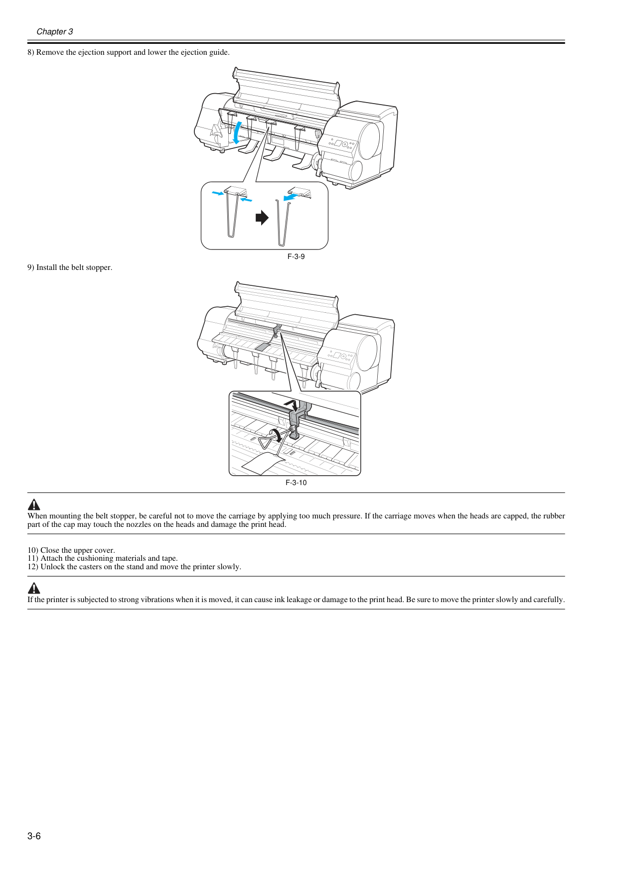
Chapter 3 3-6 8) Remove the ejection support and lower the ejection guide.
F-3-9
9) Install the belt stopper.F-3-10
When mounting the belt stopper, be careful not to move the carriage by applying too much pressure. If the carriage moves when the heads are capped, the rubber part of the cap may touch the nozzles on the heads and damage the print head. 10) Close the upper cover. 11) Attach the cushioning materials and tape. 12) Unlock the casters on the stand and move the printer slowly. If the printer is subjected to strong vibrations when it is moved, it can cause ink leakage or damage to the print head. Be sure to move the printer slowly and carefully.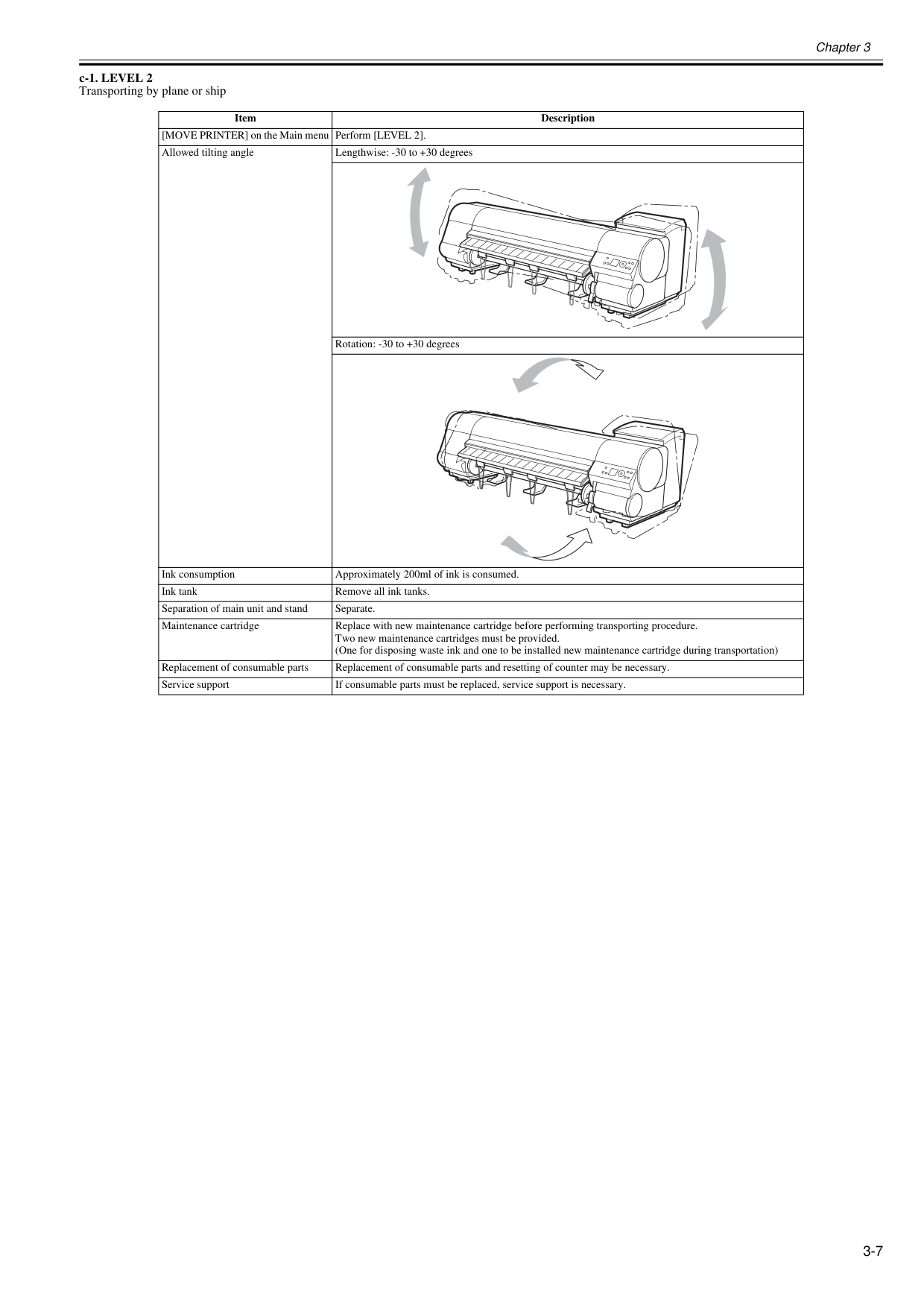
Chapter 3 3-7 c-1. LEVEL 2 Transporting by plane or ship Item Description [MOVE PRINTER] on the Main menu Perform [LEVEL 2]. Allowed tilting angle Lengthwise: -30 to +30 degrees Rotation: -30 to +30 degrees Ink consumption Approximately 200ml of ink is consumed. Ink tank Remove all ink tanks. Separation of main unit and stand Separate. Maintenance cartridge Replace with new maintenance cartridge before performing transporting procedure. Two new maintenance cartridges must be provided. (One for disposing waste ink and one to be installed new maintenance cartridge during transportation) Replacement of consumable parts Replacement of consumable parts and resetting of counter may be necessary. Service support If consumable parts must be replaced, service support is necessary.
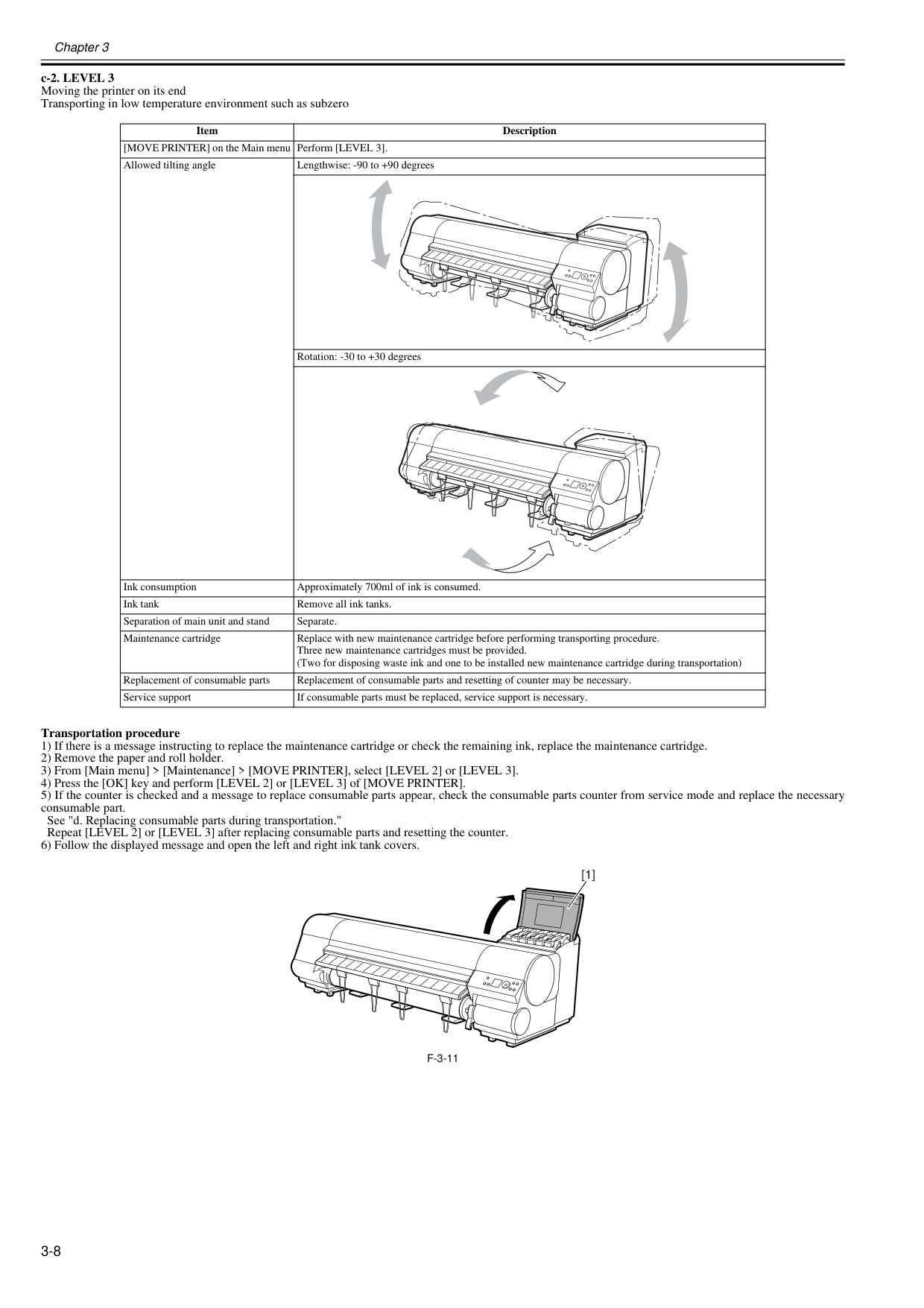
Chapter 3 3-8 c-2. LEVEL 3 Moving the printer on its end Transporting in low temperature environment such as subzero Transportation procedure 1) If there is a message instructing to replace the maintenance cartridge or check the remaining ink, replace the maintenance cartridge. 2) Remove the paper and roll holder. 3) From [Main menu] > [Maintenance] > [MOVE PRINTER], select [LEVEL 2] or [LEVEL 3]. 4) Press the [OK] key and perform [LEVEL 2] or [LEVEL 3] of [MOVE PRINTER]. 5) If the counter is checked and a message to replace consumable parts appear, check the consumable parts counter from service mode and replace the necessary consumable part. See "d. Replacing consumable parts during transportation." Repeat [LEVEL 2] or [LEVEL 3] after replacing consumable parts and resetting the counter. 6) Follow the displayed message and open the left and right ink tank covers.
F-3-11
Item Description [MOVE PRINTER] on the Main menu Perform [LEVEL 3]. Allowed tilting angle Lengthwise: -90 to +90 degrees Rotation: -30 to +30 degrees Ink consumption Approximately 700ml of ink is consumed. Ink tank Remove all ink tanks. Separation of main unit and stand Separate. Maintenance cartridge Replace with new maintenance cartridge before performing transporting procedure. Three new maintenance cartridges must be provided. (Two for disposing waste ink and one to be installed new maintenance cartridge during transportation) Replacement of consumable parts Replacement of consumable parts and resetting of counter may be necessary. Service support If consumable parts must be replaced, service support is necessary. [1]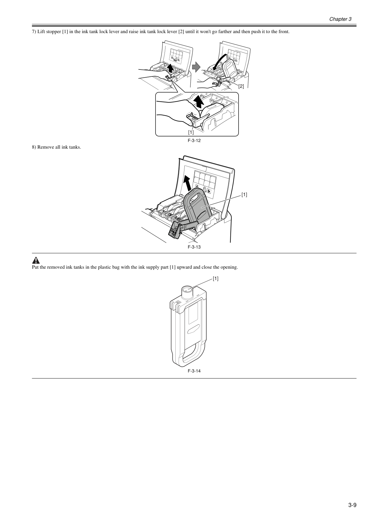
Chapter 3 3-9 7) Lift stopper [1] in the ink tank lock lever and raise ink tank lock lever [2] until it won't go farther and then push it to the front.
F-3-12
8) Remove all ink tanks.F-3-13
Put the removed ink tanks in the plastic bag with the ink supply part [1] upward and close the opening.F-3-14
A
A
A
A
Gg
B
B
B
[1] [2]Bk
A
A
Mbk
Gy
Y
M
[1] [1]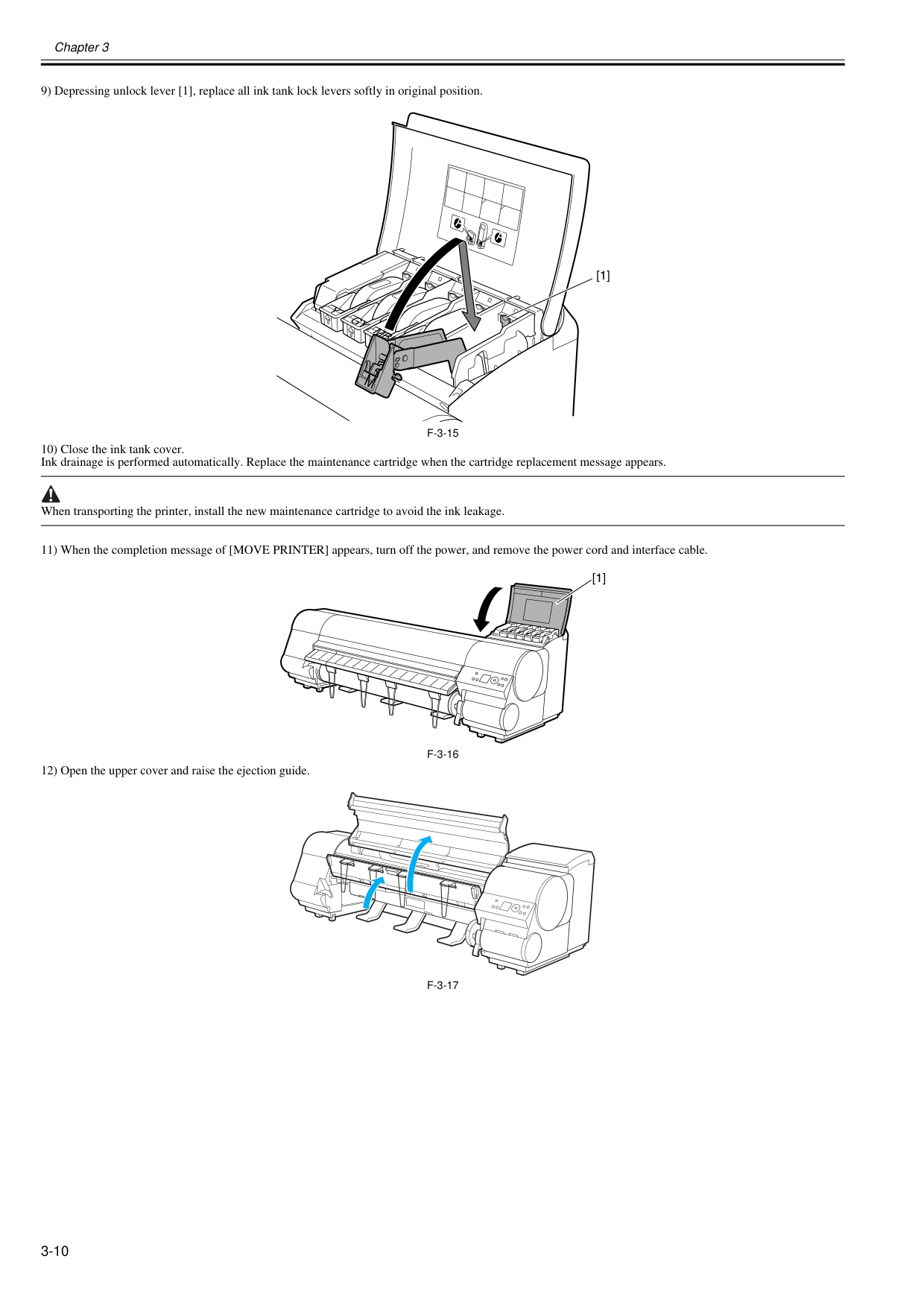
Chapter 3 3-10 9) Depressing unlock lever [1], replace all ink tank lock levers softly in original position.
F-3-15
10) Close the ink tank cover. Ink drainage is performed automatically. Replace the maintenance cartridge when the cartridge replacement message appears. When transporting the printer, install the new maintenance cartridge to avoid the ink leakage. 11) When the completion message of [MOVE PRINTER] appears, turn off the power, and remove the power cord and interface cable.F-3-16
12) Open the upper cover and raise the ejection guide.F-3-17
Bk
A
A
Mbk
Gy
Y
M
[1] [1]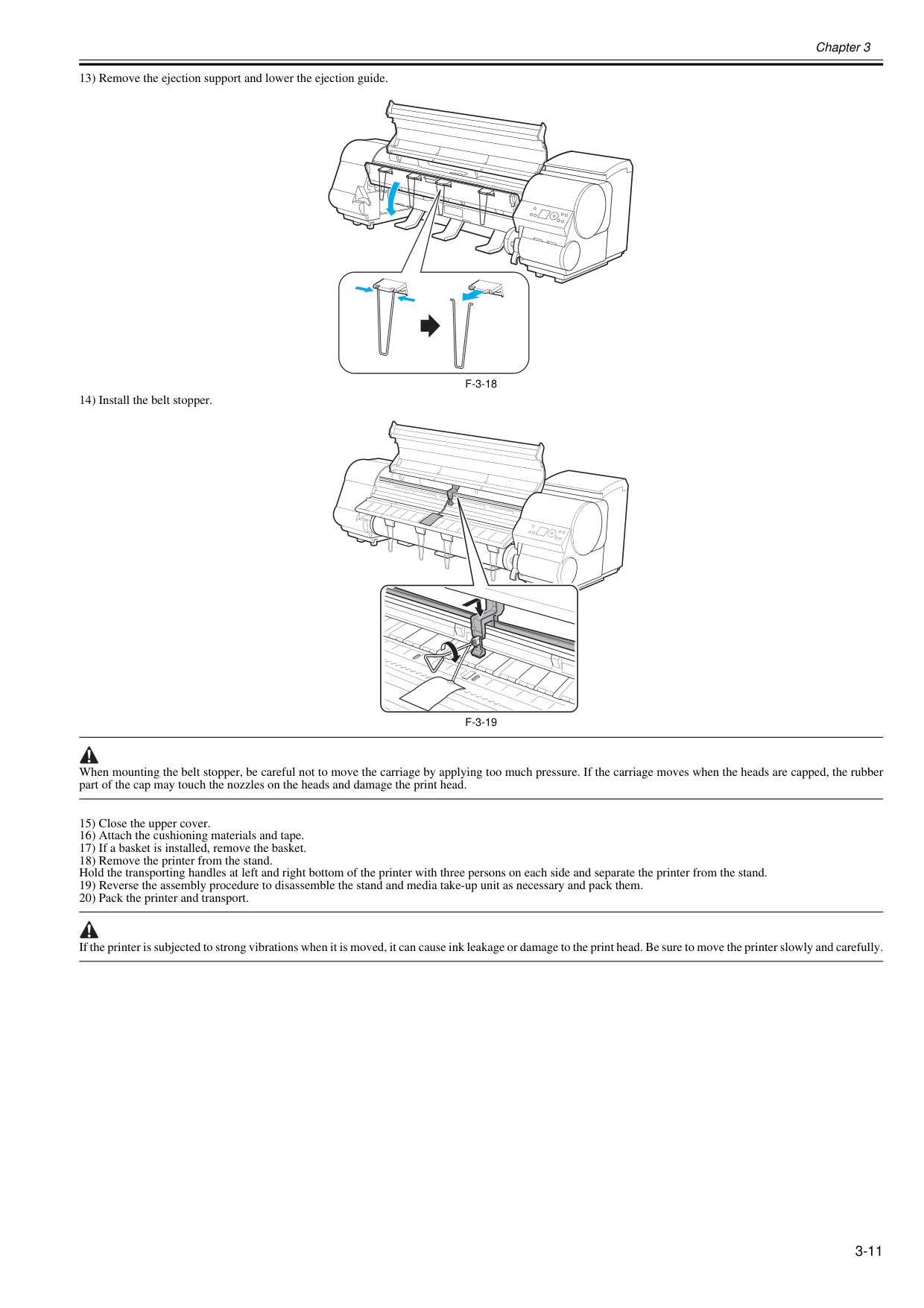
Chapter 3 3-11 13) Remove the ejection support and lower the ejection guide.
F-3-18
14) Install the belt stopper.F-3-19
When mounting the belt stopper, be careful not to move the carriage by applying too much pressure. If the carriage moves when the heads are capped, the rubber part of the cap may touch the nozzles on the heads and damage the print head. 15) Close the upper cover. 16) Attach the cushioning materials and tape. 17) If a basket is installed, remove the basket. 18) Remove the printer from the stand. Hold the transporting handles at left and right bottom of the printer with three persons on each side and separate the printer from the stand. 19) Reverse the assembly procedure to disassemble the stand and media take-up unit as necessary and pack them. 20) Pack the printer and transport. If the printer is subjected to strong vibrations when it is moved, it can cause ink leakage or damage to the print head. Be sure to move the printer slowly and carefully.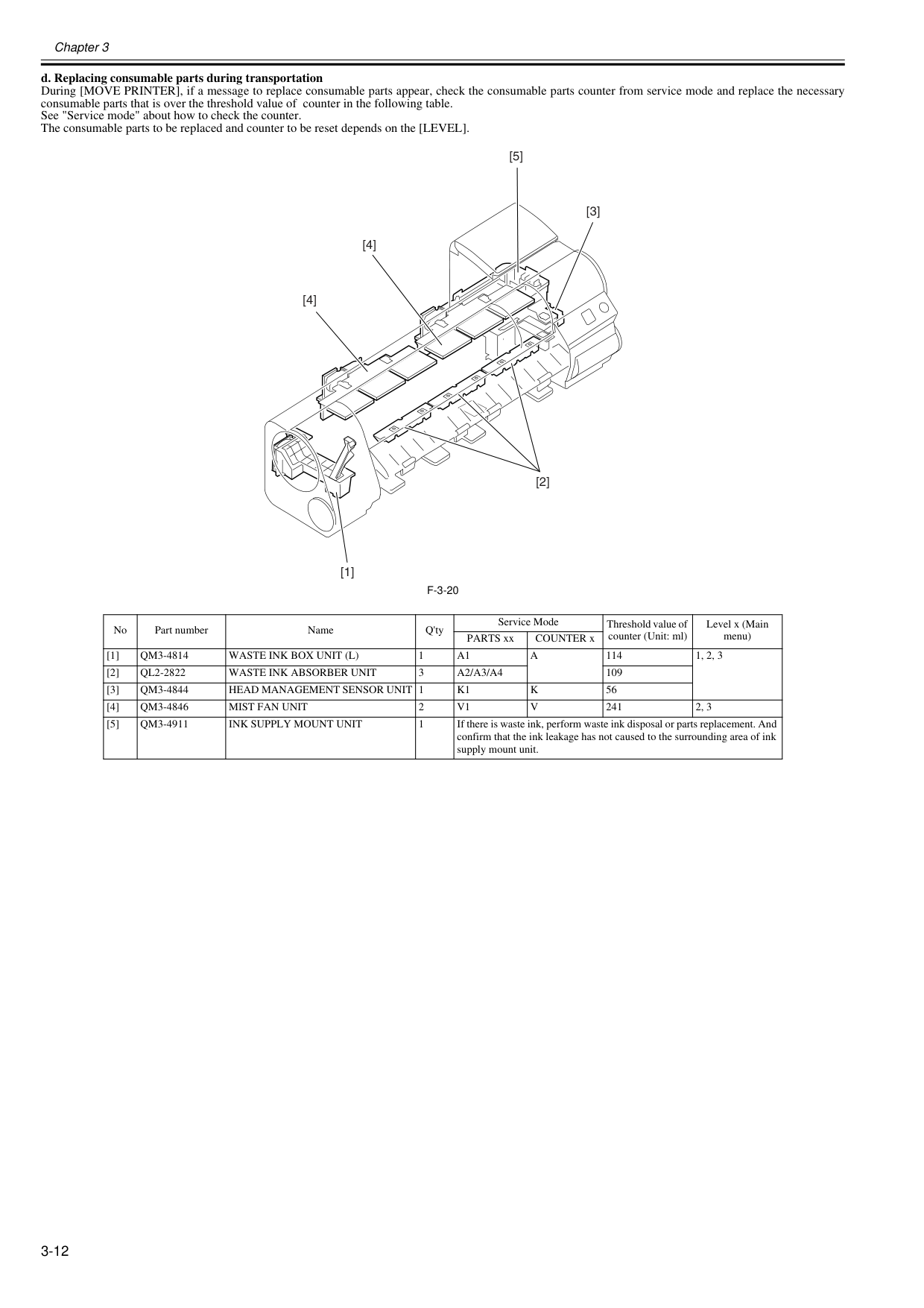
Chapter 3 3-12 d. Replacing consumable parts during transportation During [MOVE PRINTER], if a message to replace consumable parts appear, check the consumable parts counter from service mode and replace the necessary consumable parts that is over the threshold value of counter in the following table. See "Service mode" about how to check the counter. The consumable parts to be replaced and counter to be reset depends on the [LEVEL].
F-3-20
No Part number Name Q'ty Service Mode Threshold value of counter (Unit: ml) Level x (Main menu) PARTS xx COUNTER x [1]Qm3-4814
Waste Ink Box Unit (L)
1A1
A
114 1, 2, 3 [2]Ql2-2822
Waste Ink Absorber Unit
3A2/A3/A4
109 [3]Qm3-4844
Head Management Sensor Unit 1
K1
K
56 [4]Qm3-4846
Mist Fan Unit
2V1
V
241 2, 3 [5]Qm3-4911
Ink Supply Mount Unit
1 If there is waste ink, perform waste ink disposal or parts replacement. And confirm that the ink leakage has not caused to the surrounding area of ink supply mount unit. [1] [5] [4] [4] [3] [2]
Chapter 3 3-13 3.1.2 Reinstalling the Printer 3.1.2.1 Reinstalling the Printer 0020-5722

Chapter 3 3-14

Chapter 4 DISASSEMBLY/REASSEMBLY
Contents Contents 4.1 Service Parts .............................................................................................................................................. 4-1 4.1.1 Service Parts ........................................................................................................................................................... 4-1 4.2 Disassembly/Reassembly........................................................................................................................... 4-2 4.2.1 Disassembly/Reassembly ....................................................................................................................................... 4-2 4.3 Points to Note on Disassembly and Reassembly....................................................................................... 4-2 4.3.1 Note: Items that should never be disassembled...................................................................................................... 4-2 4.3.2 Moving the carriage manually.................................................................................................................................. 4-2 4.3.3 Units requiring draining of ink.................................................................................................................................. 4-2 4.3.4 External Covers....................................................................................................................................................... 4-4 4.3.5 Drive Unit................................................................................................................................................................ 4-17 4.3.6 Cutter...................................................................................................................................................................... 4-19 4.3.7 Carriage Unit .......................................................................................................................................................... 4-21 4.3.8 Ink Tube Unit .......................................................................................................................................................... 4-26 4.3.9 Pick-up/Feed Unit................................................................................................................................................... 4-29 4.3.10 Purge Unit............................................................................................................................................................. 4-32 4.3.11 Waste Ink Collection Unit...................................................................................................................................... 4-33 4.3.12 Ink Tank Unit......................................................................................................................................................... 4-43 4.3.13 Multi Sensor.......................................................................................................................................................... 4-45 4.3.14 Linear Encoder Sensor......................................................................................................................................... 4-48 4.3.15 Head Management Sensor................................................................................................................................... 4-49 4.3.16 PCBs..................................................................................................................................................................... 4-50 4.3.17 Opening the Cap/Moving the Wiper Unit .............................................................................................................. 4-51 4.3.18 Opening and closing ink supply valves................................................................................................................. 4-52 4.3.19 Draining the ink..................................................................................................................................................... 4-53 4.4 Applying the Grease ................................................................................................................................. 4-54 4.4.1 Applying the Grease............................................................................................................................................... 4-54 4.5 Adjustment and Setup Items .................................................................................................................... 4-57 4.5.1 Adjustment Item List............................................................................................................................................... 4-57 4.5.2 Procedure after Replacing the Carriage Unit or Multi Sensor ................................................................................ 4-57 4.5.3 Procedure after Replacing the Feed Roller or Feed Roller Encoder ...................................................................... 4-57 4.5.4 Procedure after Replacing the Head Management Sensor.................................................................................... 4-57

Chapter 4 4-1 4.1 Service Parts 4.1.1 Service Parts 0012-6508 The service parts indicated below require careful handling.
F-4-1
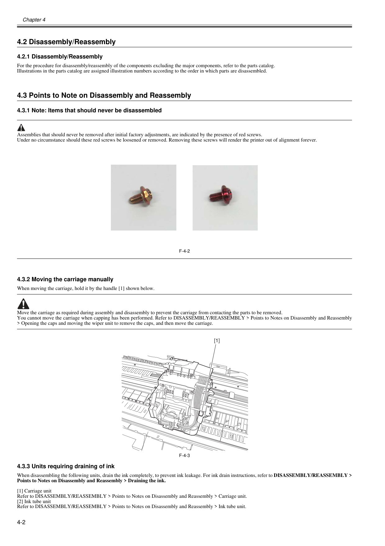
Chapter 4 4-2 4.2 Disassembly/Reassembly 4.2.1 Disassembly/Reassembly 0016-9451 For the procedure for disassembly/reassembly of the components excluding the major components, refer to the parts catalog. Illustrations in the parts catalog are assigned illustration numbers according to the order in which parts are disassembled. 4.3 Points to Note on Disassembly and Reassembly 4.3.1 Note: Items that should never be disassembled 0012-6514 Assemblies that should never be removed after initial factory adjustments, are indicated by the presence of red screws. Under no circumstance should these red screws be loosened or removed. Removing these screws will render the printer out of alignment forever.
F-4-2
4.3.2 Moving the carriage manually 0020-5644 When moving the carriage, hold it by the handle [1] shown below. Move the carriage as required during assembly and disassembly to prevent the carriage from contacting the parts to be removed. You cannot move the carriage when capping has been performed. Refer to DISASSEMBLY/REASSEMBLY > Points to Notes on Disassembly and Reassembly > Opening the caps and moving the wiper unit to remove the caps, and then move the carriage.F-4-3
4.3.3 Units requiring draining of ink 0014-8953 When disassembling the following units, drain the ink completely, to prevent ink leakage. For ink drain instructions, refer to DISASSEMBLY/REASSEMBLY > Points to Notes on Disassembly and Reassembly > Draining the ink. [1] Carriage unit Refer to DISASSEMBLY/REASSEMBLY > Points to Notes on Disassembly and Reassembly > Carriage unit. [2] Ink tube unit Refer to DISASSEMBLY/REASSEMBLY > Points to Notes on Disassembly and Reassembly > Ink tube unit. [1]
Chapter 4 4-3 [3] Ink tank unit Refer to DISASSEMBLY/REASSEMBLY > Points to Notes on Disassembly and Reassembly >Ink tank unit.
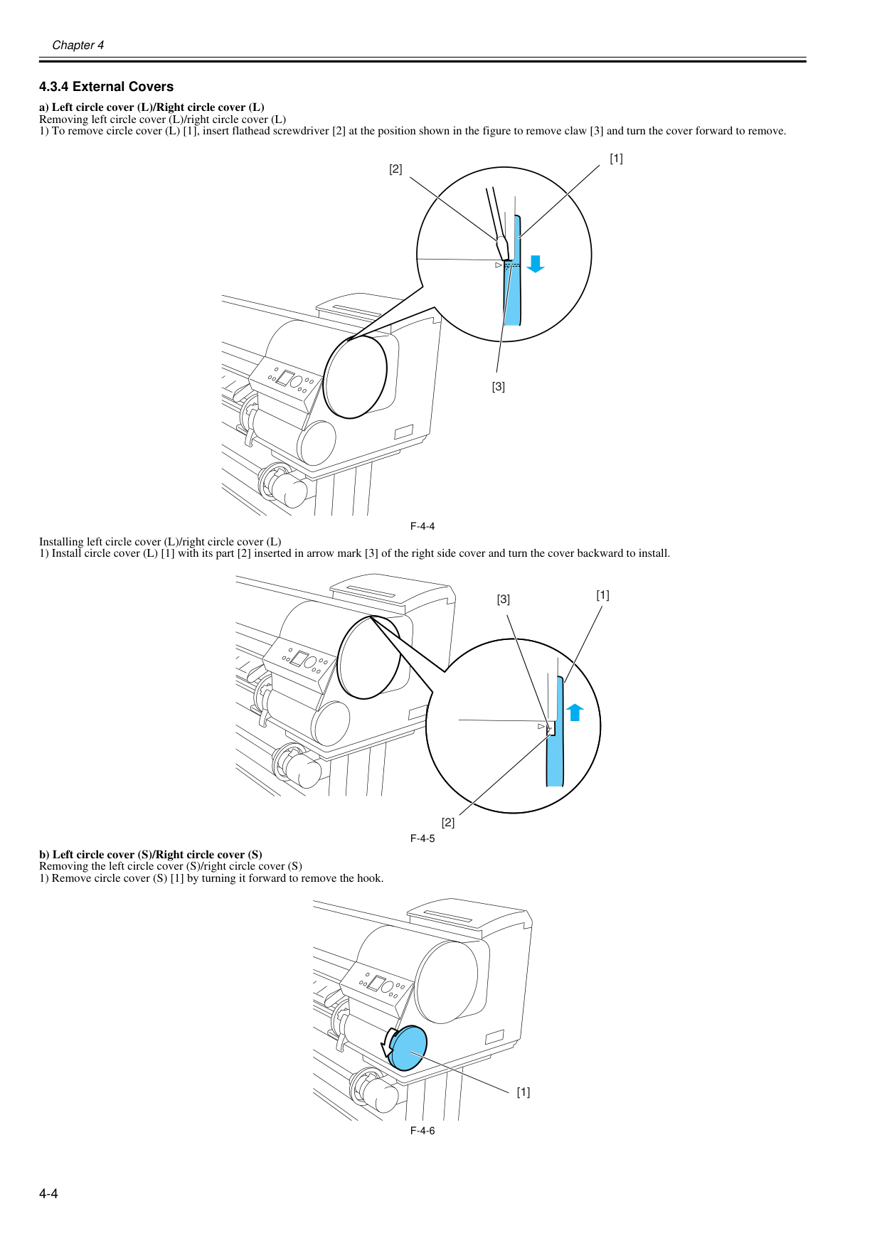
Chapter 4 4-4 4.3.4 External Covers 0020-5646 a) Left circle cover (L)/Right circle cover (L) Removing left circle cover (L)/right circle cover (L) 1) To remove circle cover (L) [1], insert flathead screwdriver [2] at the position shown in the figure to remove claw [3] and turn the cover forward to remove.
F-4-4
Installing left circle cover (L)/right circle cover (L) 1) Install circle cover (L) [1] with its part [2] inserted in arrow mark [3] of the right side cover and turn the cover backward to install.F-4-5
b) Left circle cover (S)/Right circle cover (S) Removing the left circle cover (S)/right circle cover (S) 1) Remove circle cover (S) [1] by turning it forward to remove the hook.F-4-6
[2] [1] [3] [2] [1] [3] [1]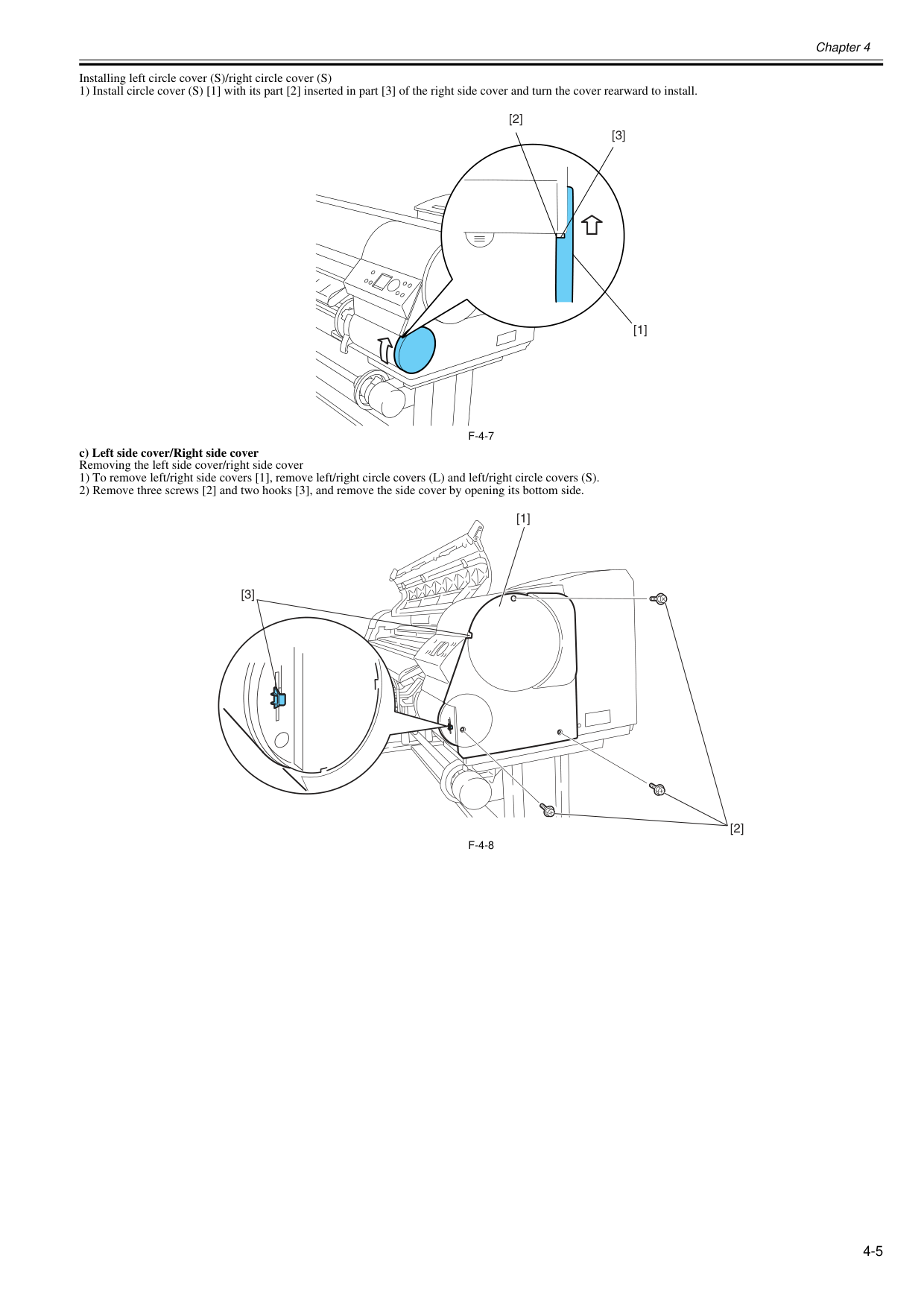
Chapter 4 4-5 Installing left circle cover (S)/right circle cover (S) 1) Install circle cover (S) [1] with its part [2] inserted in part [3] of the right side cover and turn the cover rearward to install.
F-4-7
c) Left side cover/Right side cover Removing the left side cover/right side cover 1) To remove left/right side covers [1], remove left/right circle covers (L) and left/right circle covers (S). 2) Remove three screws [2] and two hooks [3], and remove the side cover by opening its bottom side.F-4-8
[2] [3] [1] [1] [3] [2]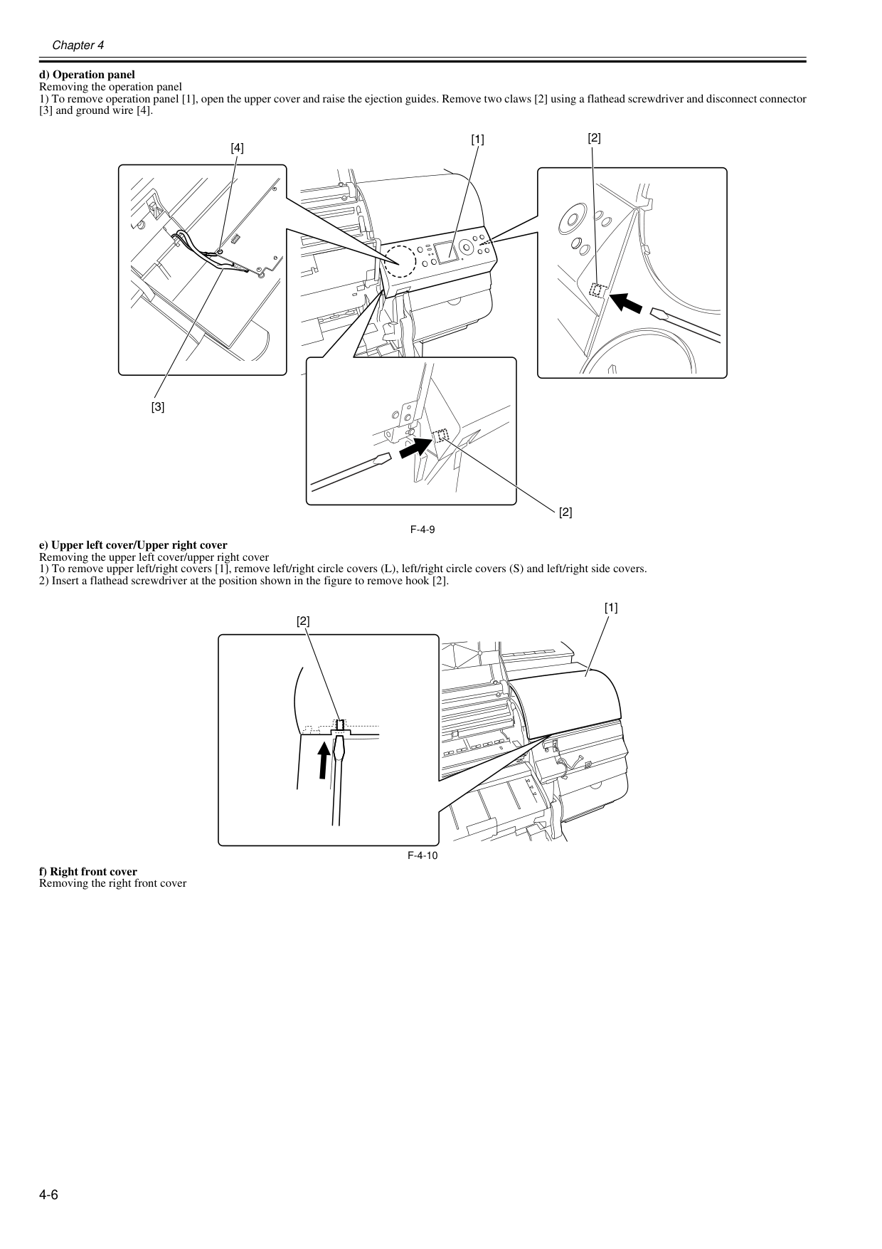
Chapter 4 4-6 d) Operation panel Removing the operation panel 1) To remove operation panel [1], open the upper cover and raise the ejection guides. Remove two claws [2] using a flathead screwdriver and disconnect connector [3] and ground wire [4].
F-4-9
e) Upper left cover/Upper right cover Removing the upper left cover/upper right cover 1) To remove upper left/right covers [1], remove left/right circle covers (L), left/right circle covers (S) and left/right side covers. 2) Insert a flathead screwdriver at the position shown in the figure to remove hook [2].F-4-10
f) Right front cover Removing the right front cover [3] [4] [1] [2] [2] [1] [2]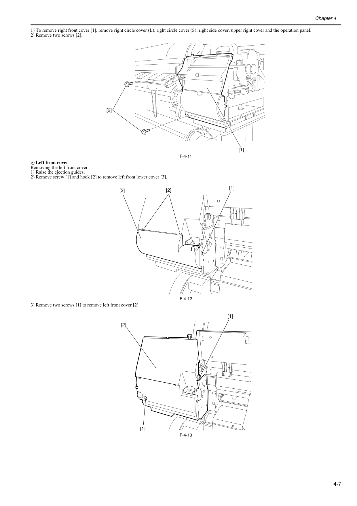
Chapter 4 4-7 1) To remove right front cover [1], remove right circle cover (L), right circle cover (S), right side cover, upper right cover and the operation panel. 2) Remove two screws [2].
F-4-11
g) Left front cover Removing the left front cover 1) Raise the ejection guides. 2) Remove screw [1] and hook [2] to remove left front lower cover [3].F-4-12
3) Remove two screws [1] to remove left front cover [2].F-4-13
[1] [2] [2] [1] [3] [1] [1] [2]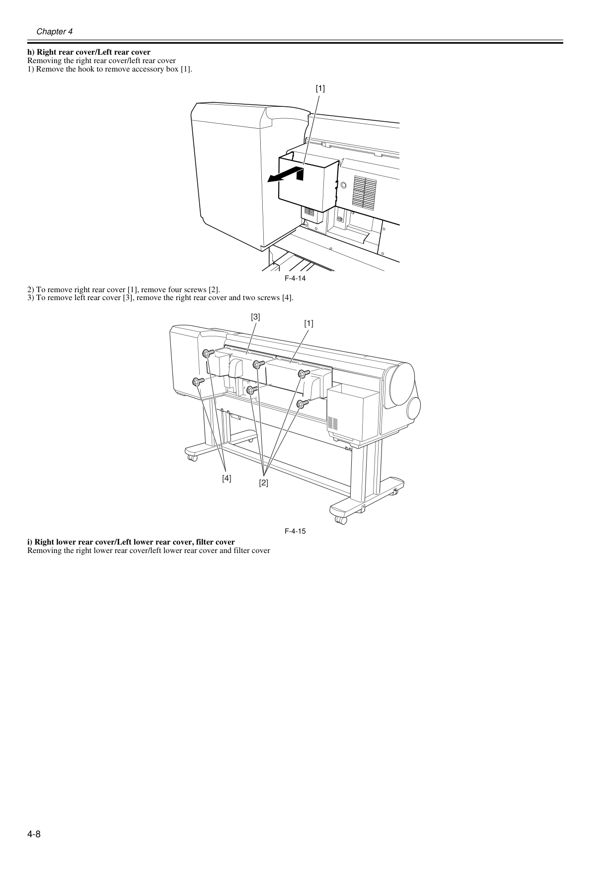
Chapter 4 4-8 h) Right rear cover/Left rear cover Removing the right rear cover/left rear cover 1) Remove the hook to remove accessory box [1].
F-4-14
2) To remove right rear cover [1], remove four screws [2]. 3) To remove left rear cover [3], remove the right rear cover and two screws [4].F-4-15
i) Right lower rear cover/Left lower rear cover, filter cover Removing the right lower rear cover/left lower rear cover and filter cover [1] [1] [3] [2] [4]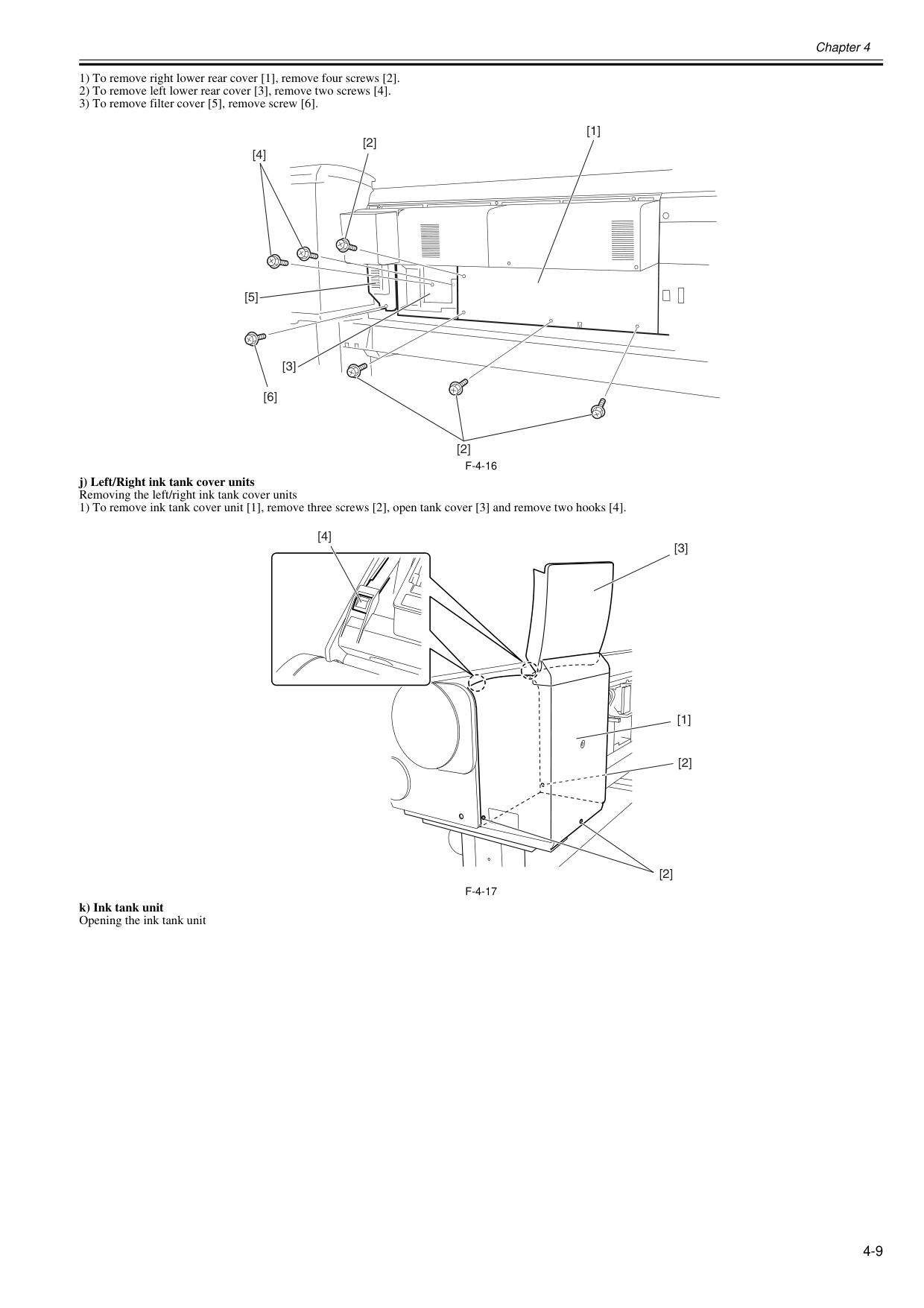
Chapter 4 4-9 1) To remove right lower rear cover [1], remove four screws [2]. 2) To remove left lower rear cover [3], remove two screws [4]. 3) To remove filter cover [5], remove screw [6].
F-4-16
j) Left/Right ink tank cover units Removing the left/right ink tank cover units 1) To remove ink tank cover unit [1], remove three screws [2], open tank cover [3] and remove two hooks [4].F-4-17
k) Ink tank unit Opening the ink tank unit [2] [4] [6] [2] [1] [3] [5] [4] [2] [2] [1] [3]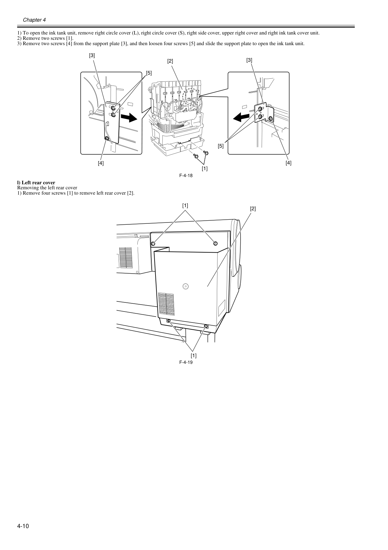
Chapter 4 4-10 1) To open the ink tank unit, remove right circle cover (L), right circle cover (S), right side cover, upper right cover and right ink tank cover unit. 2) Remove two screws [1]. 3) Remove two screws [4] from the support plate [3], and then loosen four screws [5] and slide the support plate to open the ink tank unit.
F-4-18
l) Left rear cover Removing the left rear cover 1) Remove four screws [1] to remove left rear cover [2].F-4-19
[1] [3] [3] [5] [5] [4] [4] [2] [1] [1] [2]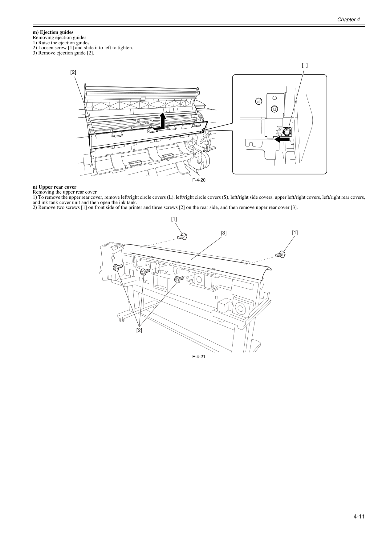
Chapter 4 4-11 m) Ejection guides Removing ejection guides 1) Raise the ejection guides. 2) Loosen screw [1] and slide it to left to tighten. 3) Remove ejection guide [2].
F-4-20
n) Upper rear cover Removing the upper rear cover 1) To remove the upper rear cover, remove left/right circle covers (L), left/right circle covers (S), left/right side covers, upper left/right covers, left/right rear covers, and ink tank cover unit and then open the ink tank. 2) Remove two screws [1] on front side of the printer and three screws [2] on the rear side, and then remove upper rear cover [3].F-4-21
[2] [1] [1] [1] [2] [3]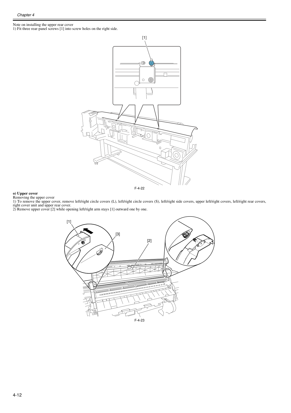
Chapter 4 4-12 Note on installing the upper rear cover 1) Fit three rear-panel screws [1] into screw holes on the right side.
F-4-22
o) Upper cover Removing the upper cover 1) To remove the upper cover, remove left/right circle covers (L), left/right circle covers (S), left/right side covers, upper left/right covers, left/right rear covers, right cover unit and upper rear cover. 2) Remove upper cover [2] while opening left/right arm stays [1] outward one by one.F-4-23
[1] [2] [1] [3]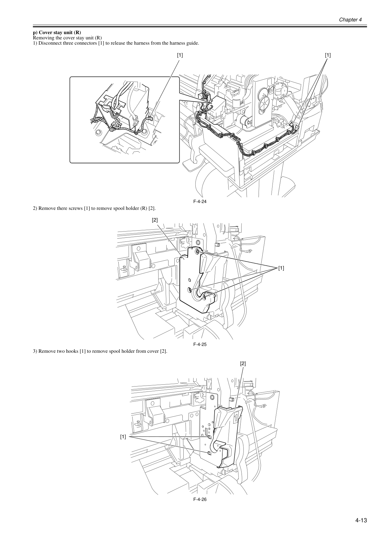
Chapter 4 4-13 p) Cover stay unit (R) Removing the cover stay unit (R) 1) Disconnect three connectors [1] to release the harness from the harness guide.
F-4-24
2) Remove there screws [1] to remove spool holder (R) [2].F-4-25
3) Remove two hooks [1] to remove spool holder from cover [2].F-4-26
[1] [1] [1] [2] [1] [2]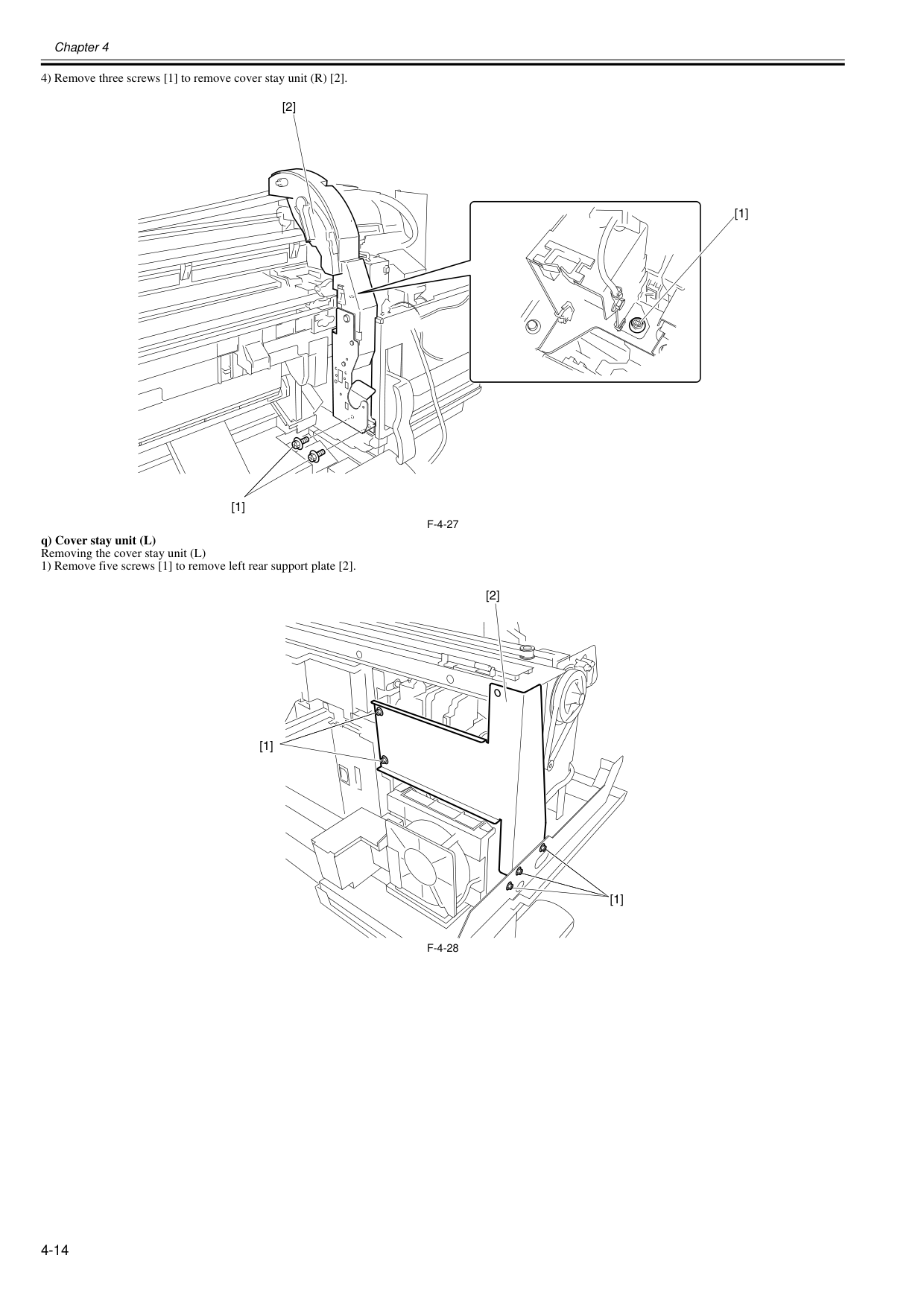
Chapter 4 4-14 4) Remove three screws [1] to remove cover stay unit (R) [2].
F-4-27
q) Cover stay unit (L) Removing the cover stay unit (L) 1) Remove five screws [1] to remove left rear support plate [2].F-4-28
[1] [1] [2] [1] [1] [2]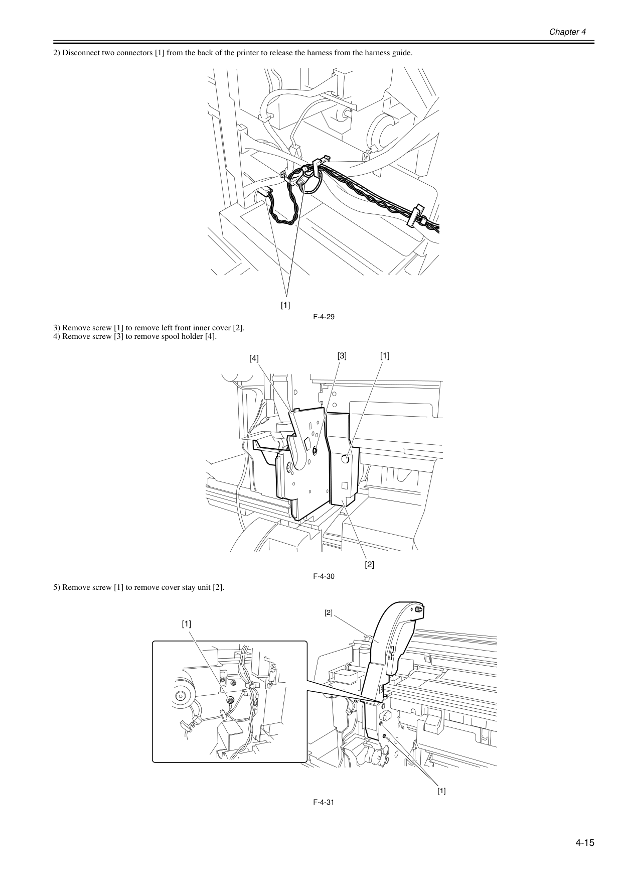
Chapter 4 4-15 2) Disconnect two connectors [1] from the back of the printer to release the harness from the harness guide.
F-4-29
3) Remove screw [1] to remove left front inner cover [2]. 4) Remove screw [3] to remove spool holder [4].F-4-30
5) Remove screw [1] to remove cover stay unit [2].F-4-31
[1] [3] [4] [1] [2] [1] [1] [2]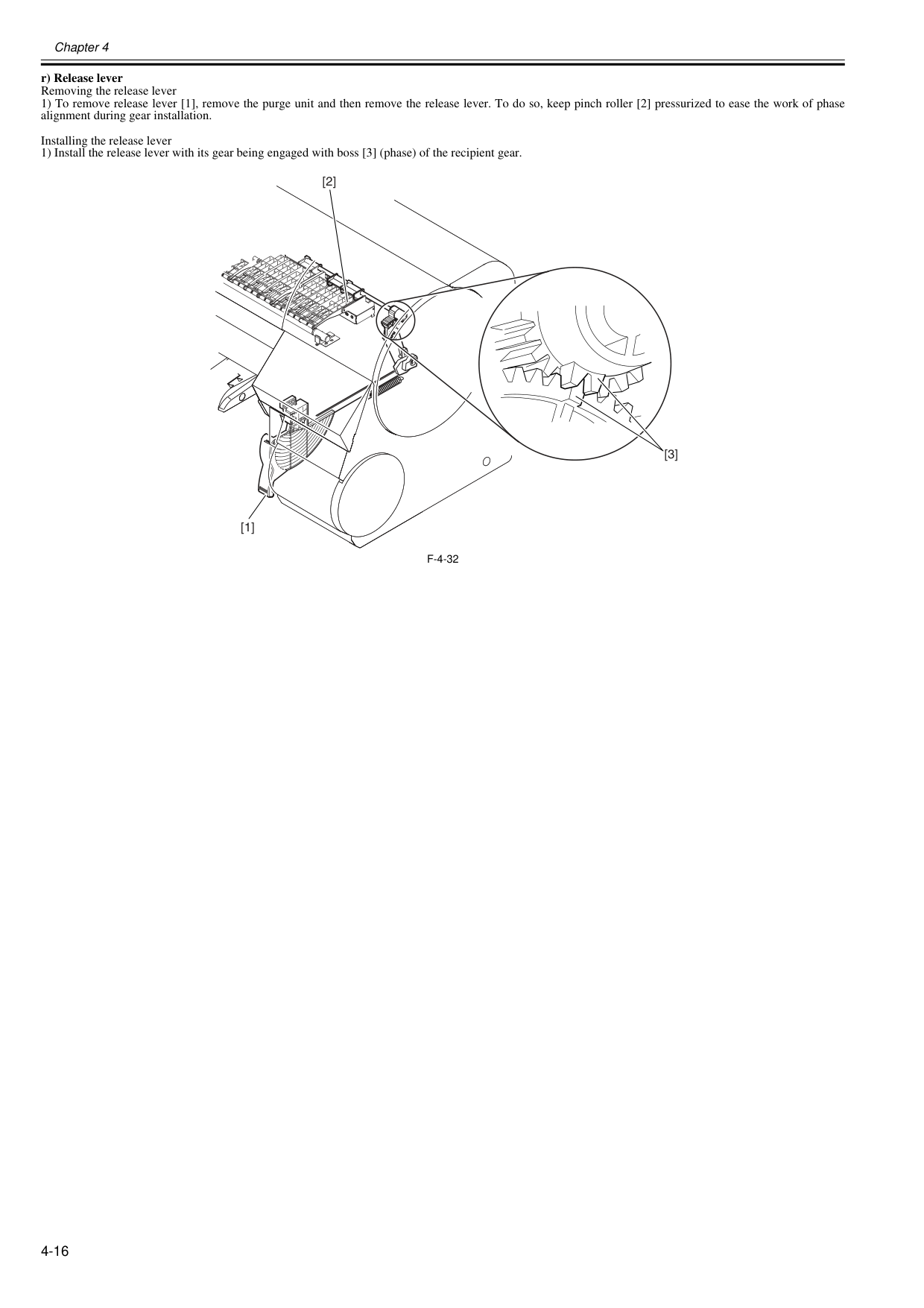
Chapter 4 4-16 r) Release lever Removing the release lever 1) To remove release lever [1], remove the purge unit and then remove the release lever. To do so, keep pinch roller [2] pressurized to ease the work of phase alignment during gear installation. Installing the release lever 1) Install the release lever with its gear being engaged with boss [3] (phase) of the recipient gear.
F-4-32
[1] [2] [3]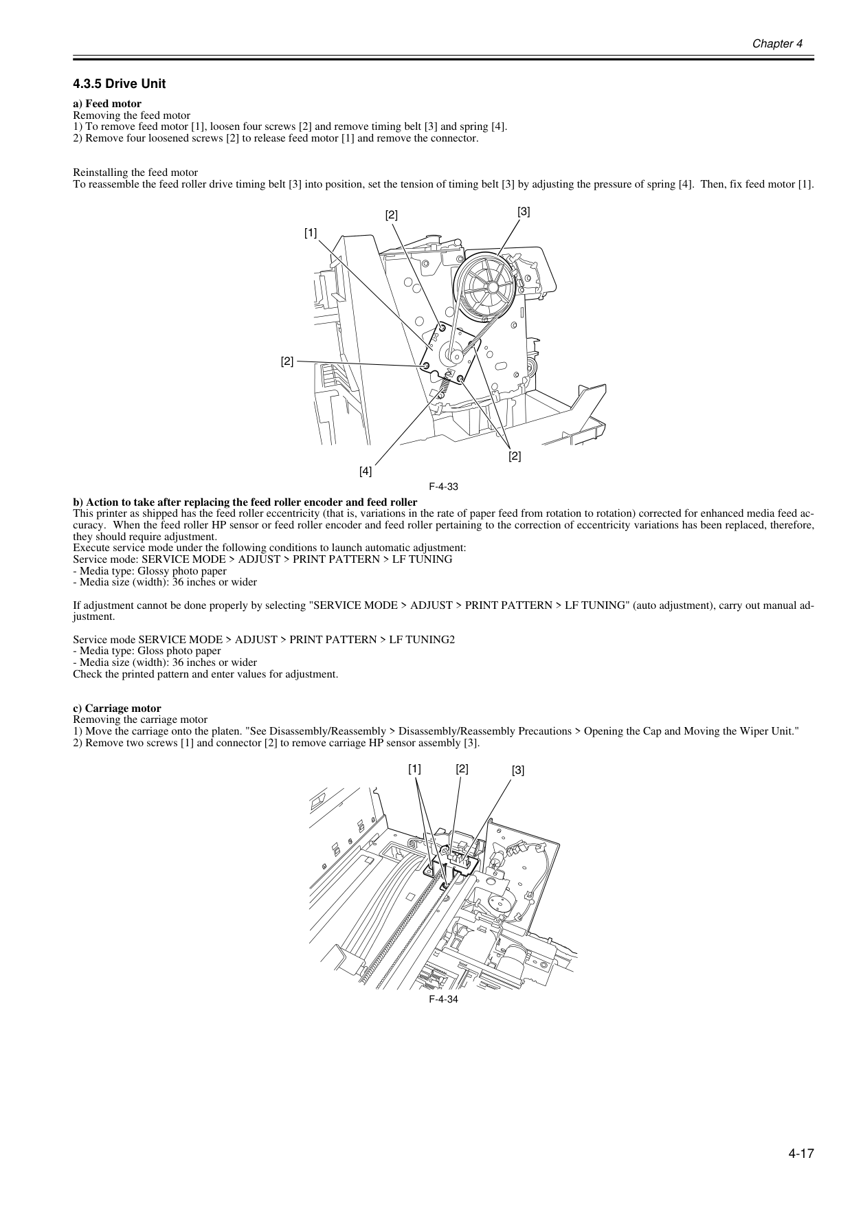
Chapter 4 4-17 4.3.5 Drive Unit 0020-5659 a) Feed motor Removing the feed motor 1) To remove feed motor [1], loosen four screws [2] and remove timing belt [3] and spring [4]. 2) Remove four loosened screws [2] to release feed motor [1] and remove the connector. Reinstalling the feed motor To reassemble the feed roller drive timing belt [3] into position, set the tension of timing belt [3] by adjusting the pressure of spring [4]. Then, fix feed motor [1].
F-4-33
b) Action to take after replacing the feed roller encoder and feed roller This printer as shipped has the feed roller eccentricity (that is, variations in the rate of paper feed from rotation to rotation) corrected for enhanced media feed ac- curacy. When the feed roller HP sensor or feed roller encoder and feed roller pertaining to the correction of eccentricity variations has been replaced, therefore, they should require adjustment. Execute service mode under the following conditions to launch automatic adjustment: Service mode: SERVICE MODE > ADJUST > PRINT PATTERN > LF TUNINGF-4-34
[2] [3] [1] [2] [4] [2] [3] [1] [2]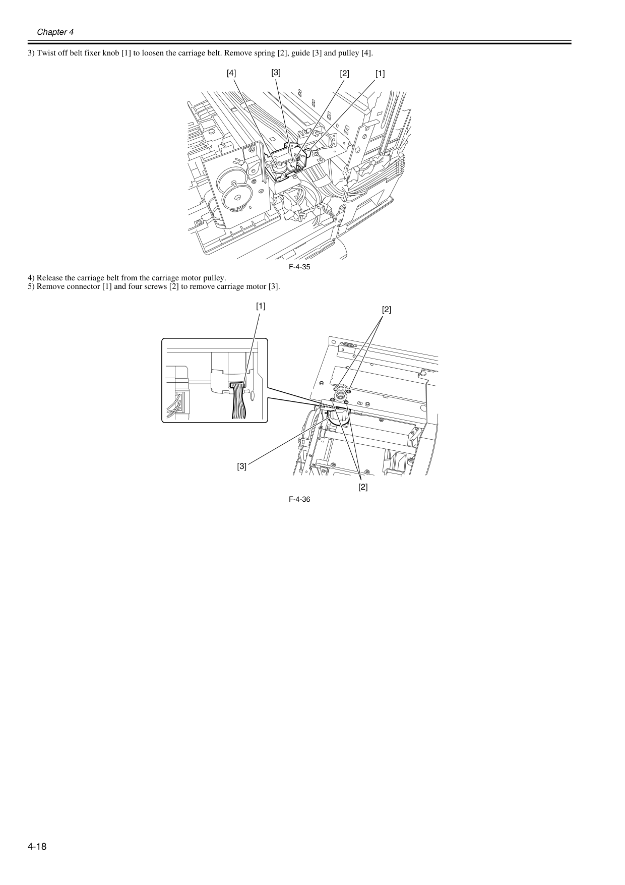
Chapter 4 4-18 3) Twist off belt fixer knob [1] to loosen the carriage belt. Remove spring [2], guide [3] and pulley [4].
F-4-35
4) Release the carriage belt from the carriage motor pulley. 5) Remove connector [1] and four screws [2] to remove carriage motor [3].F-4-36
[1] [2] [4] [3] [1] [2] [2] [3]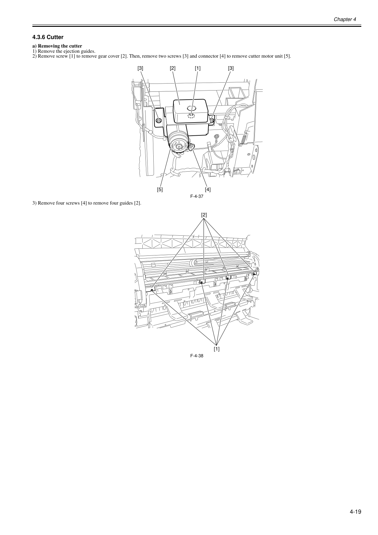
Chapter 4 4-19 4.3.6 Cutter 0020-5669 a) Removing the cutter 1) Remove the ejection guides. 2) Remove screw [1] to remove gear cover [2]. Then, remove two screws [3] and connector [4] to remove cutter motor unit [5].
F-4-37
3) Remove four screws [4] to remove four guides [2].F-4-38
[2] [4] [5] [1] [3] [3] [1] [2]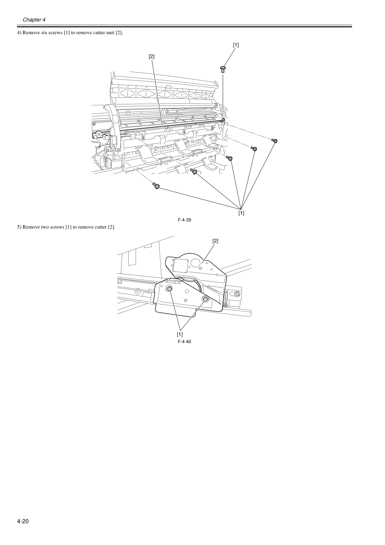
Chapter 4 4-20 4) Remove six screws [1] to remove cutter unit [2].
F-4-39
5) Remove two screws [1] to remove cutter [2].F-4-40
[1] [1] [2] [1] [2]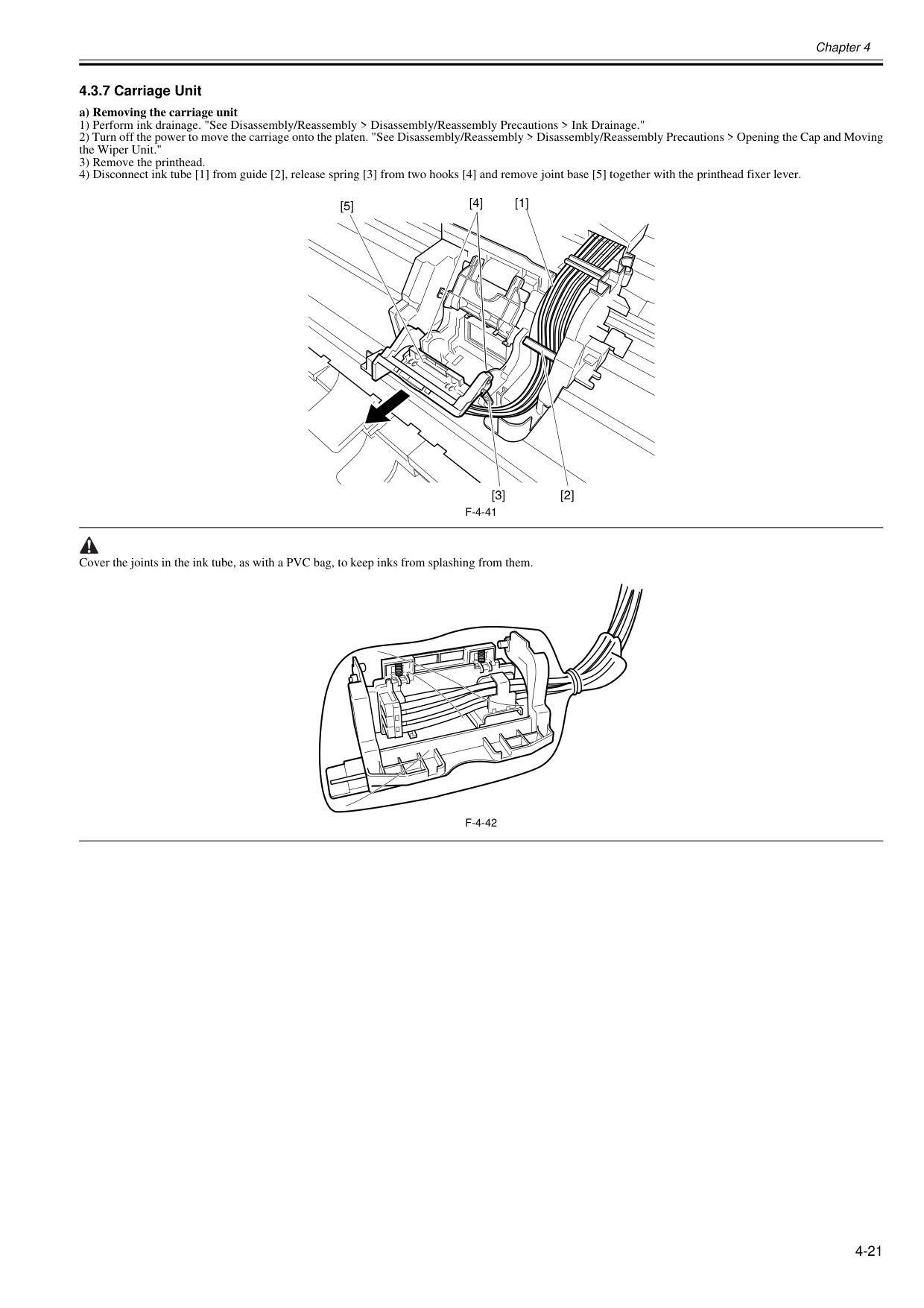
Chapter 4 4-21 4.3.7 Carriage Unit 0020-5661 a) Removing the carriage unit 1) Perform ink drainage. "See Disassembly/Reassembly > Disassembly/Reassembly Precautions > Ink Drainage." 2) Turn off the power to move the carriage onto the platen. "See Disassembly/Reassembly > Disassembly/Reassembly Precautions > Opening the Cap and Moving the Wiper Unit." 3) Remove the printhead. 4) Disconnect ink tube [1] from guide [2], release spring [3] from two hooks [4] and remove joint base [5] together with the printhead fixer lever.
F-4-41
Cover the joints in the ink tube, as with a PVC bag, to keep inks from splashing from them.F-4-42
[1] [2] [3] [4] [5]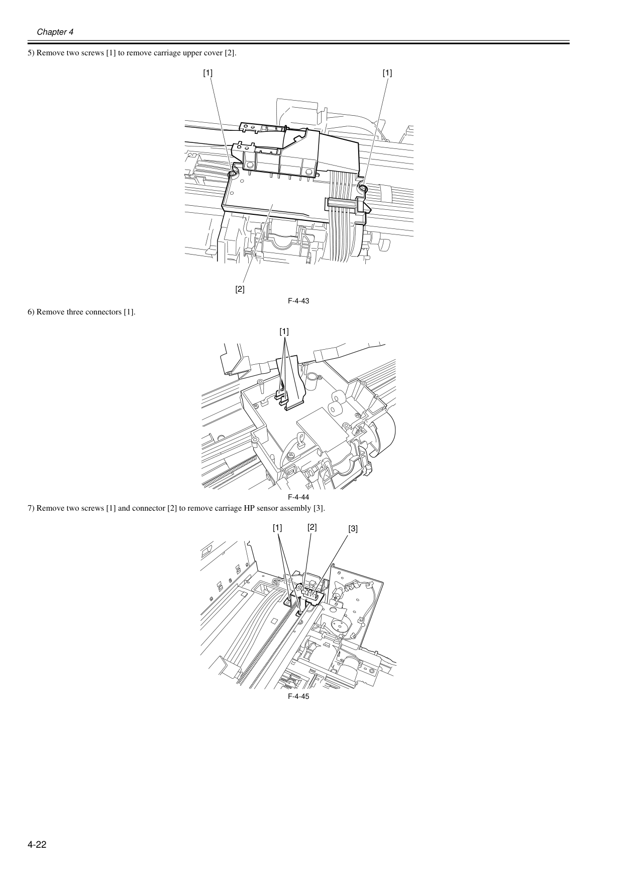
Chapter 4 4-22 5) Remove two screws [1] to remove carriage upper cover [2].
F-4-43
6) Remove three connectors [1].F-4-44
7) Remove two screws [1] and connector [2] to remove carriage HP sensor assembly [3].F-4-45
[1] [1] [2] [1] [3] [1] [2]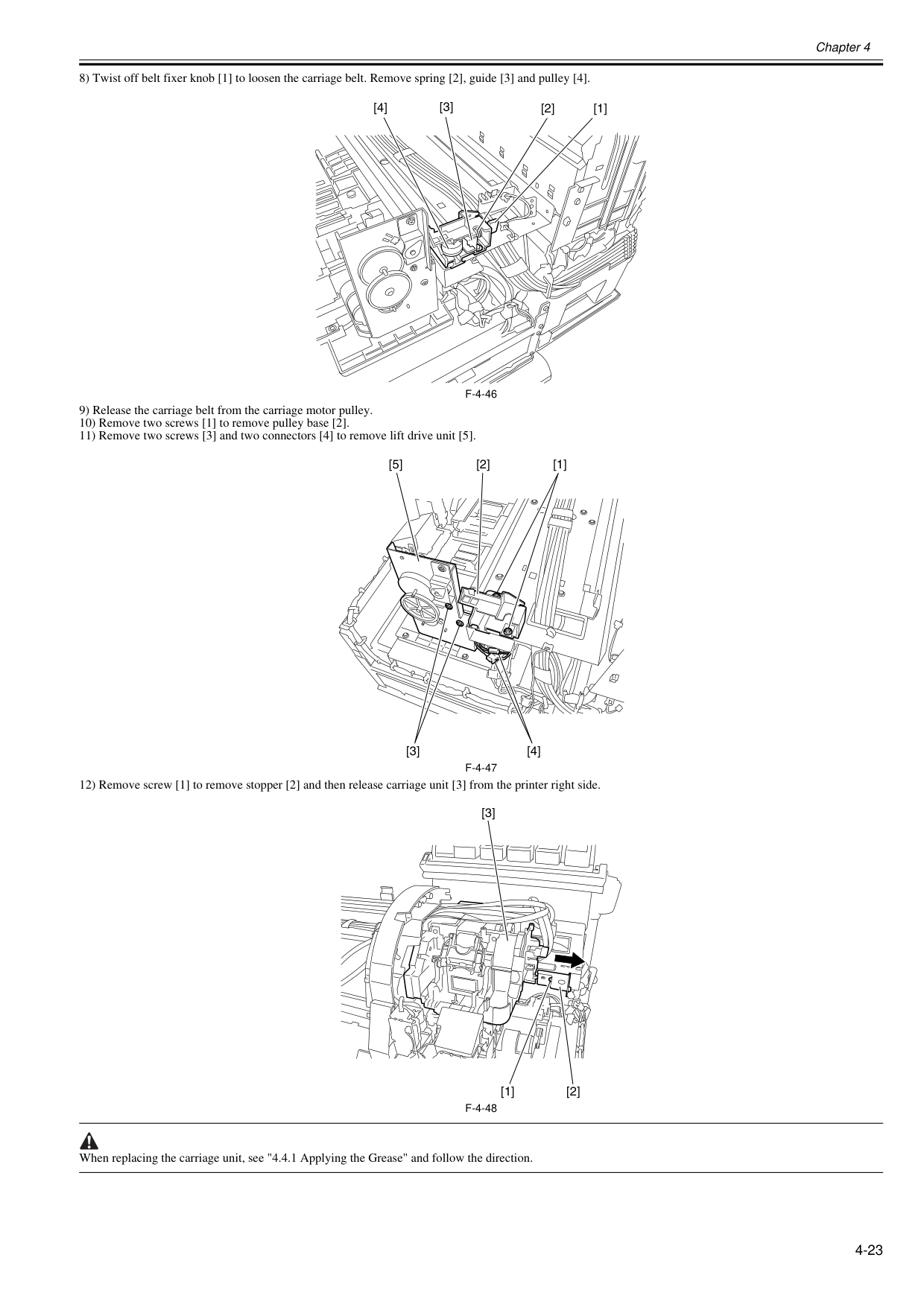
Chapter 4 4-23 8) Twist off belt fixer knob [1] to loosen the carriage belt. Remove spring [2], guide [3] and pulley [4].
F-4-46
9) Release the carriage belt from the carriage motor pulley. 10) Remove two screws [1] to remove pulley base [2]. 11) Remove two screws [3] and two connectors [4] to remove lift drive unit [5].F-4-47
12) Remove screw [1] to remove stopper [2] and then release carriage unit [3] from the printer right side.F-4-48
When replacing the carriage unit, see "4.4.1 Applying the Grease" and follow the direction. [1] [2] [4] [3] [5] [3] [4] [2] [1] [3] [2] [1]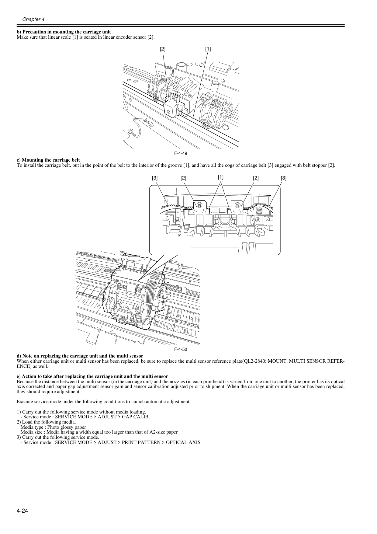
Chapter 4 4-24 b) Precaution in mounting the carriage unit Make sure that linear scale [1] is seated in linear encoder sensor [2].
F-4-49
c) Mounting the carriage belt To install the carriage belt, put in the point of the belt to the interior of the groove [1], and have all the cogs of carriage belt [3] engaged with belt stopper [2].F-4-50
d) Note on replacing the carriage unit and the multi sensor When either carriage unit or multi sensor has been replaced, be sure to replace the multi sensor reference plate(QL2-2840: MOUNT, MULTI SENSOR REFER- ENCE) as well. e) Action to take after replacing the carriage unit and the multi sensor Because the distance between the multi sensor (in the carriage unit) and the nozzles (in each printhead) is varied from one unit to another, the printer has its optical axis corrected and paper gap adjustment sensor gain and sensor calibration adjusted prior to shipment. When the carriage unit or multi sensor has been replaced, they should require adjustment. Execute service mode under the following conditions to launch automatic adjustment: 1) Carry out the following service mode without media loading.
Chapter 4 4-25 f) Precautions against handling the carriage shaft The carriage shaft is functionally important part. Therefore, be sure to note the following points.
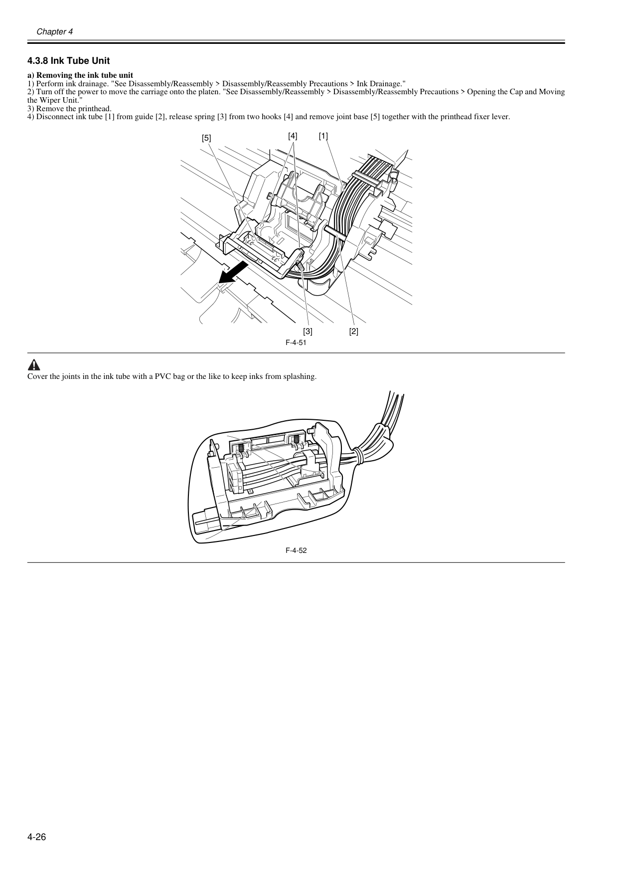
Chapter 4 4-26 4.3.8 Ink Tube Unit 0020-5666 a) Removing the ink tube unit 1) Perform ink drainage. "See Disassembly/Reassembly > Disassembly/Reassembly Precautions > Ink Drainage." 2) Turn off the power to move the carriage onto the platen. "See Disassembly/Reassembly > Disassembly/Reassembly Precautions > Opening the Cap and Moving the Wiper Unit." 3) Remove the printhead. 4) Disconnect ink tube [1] from guide [2], release spring [3] from two hooks [4] and remove joint base [5] together with the printhead fixer lever.
F-4-51
Cover the joints in the ink tube with a PVC bag or the like to keep inks from splashing.F-4-52
[1] [2] [3] [4] [5]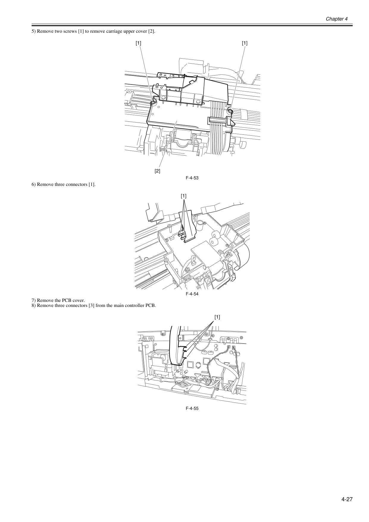
Chapter 4 4-27 5) Remove two screws [1] to remove carriage upper cover [2].
F-4-53
6) Remove three connectors [1].F-4-54
7) Remove the PCB cover. 8) Remove three connectors [3] from the main controller PCB.F-4-55
[1] [1] [2] [1] [1]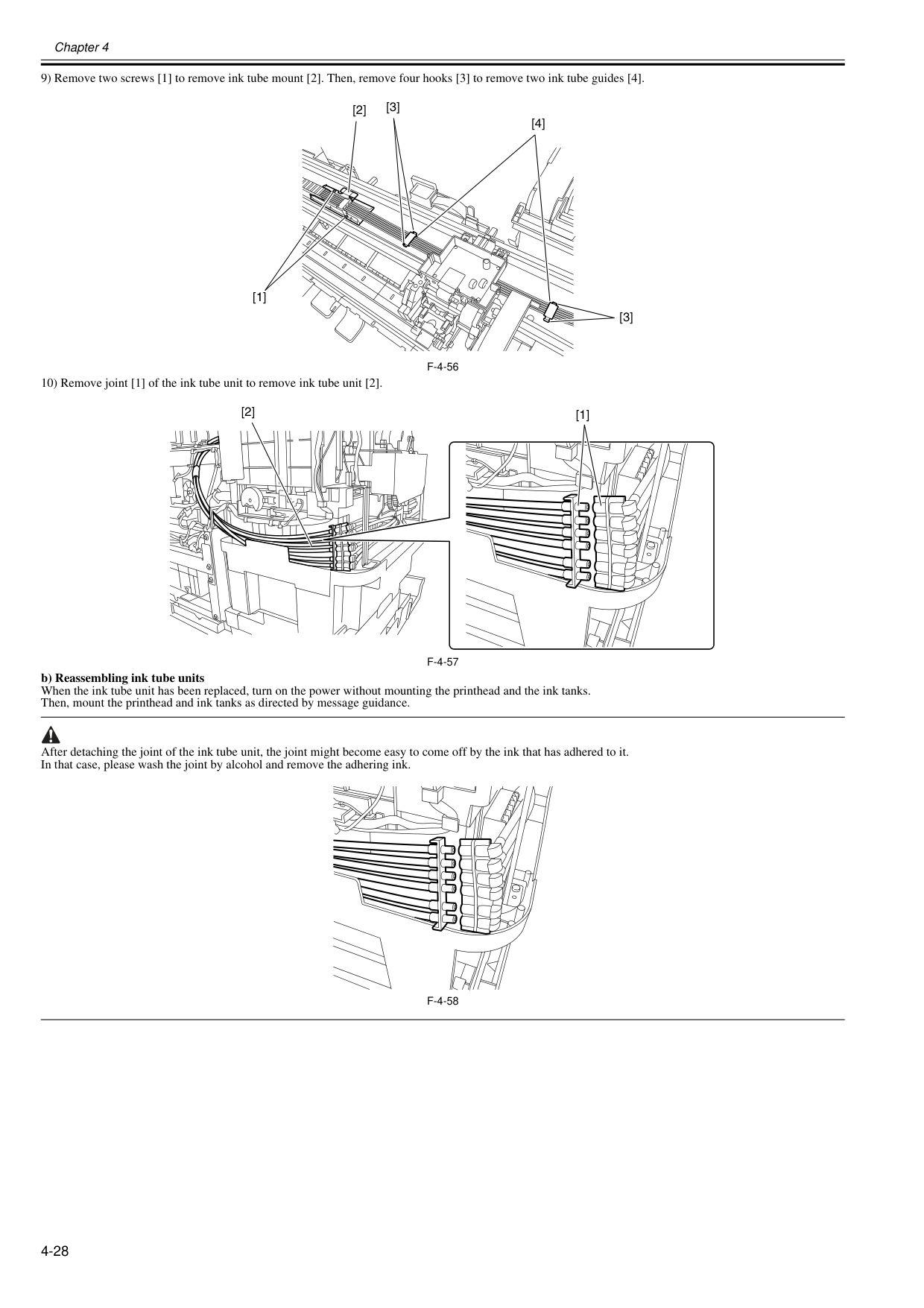
Chapter 4 4-28 9) Remove two screws [1] to remove ink tube mount [2]. Then, remove four hooks [3] to remove two ink tube guides [4].
F-4-56
10) Remove joint [1] of the ink tube unit to remove ink tube unit [2].F-4-57
b) Reassembling ink tube units When the ink tube unit has been replaced, turn on the power without mounting the printhead and the ink tanks. Then, mount the printhead and ink tanks as directed by message guidance. After detaching the joint of the ink tube unit, the joint might become easy to come off by the ink that has adhered to it. In that case, please wash the joint by alcohol and remove the adhering ink.F-4-58
[3] [4] [3] [2] [1] [1] [2]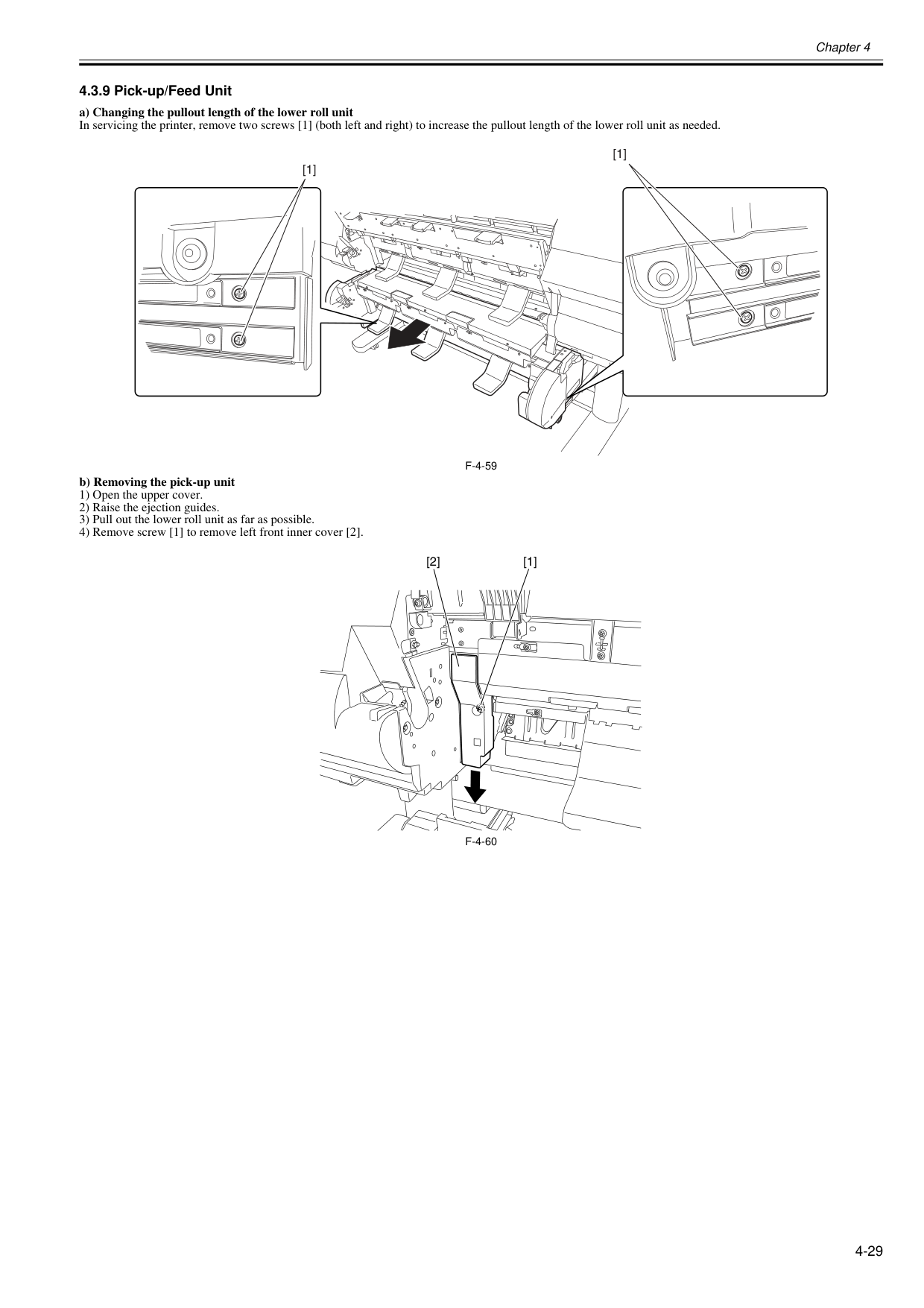
Chapter 4 4-29 4.3.9 Pick-up/Feed Unit 0020-5681 a) Changing the pullout length of the lower roll unit In servicing the printer, remove two screws [1] (both left and right) to increase the pullout length of the lower roll unit as needed.
F-4-59
b) Removing the pick-up unit 1) Open the upper cover. 2) Raise the ejection guides. 3) Pull out the lower roll unit as far as possible. 4) Remove screw [1] to remove left front inner cover [2].F-4-60
[1] [1] [1] [2]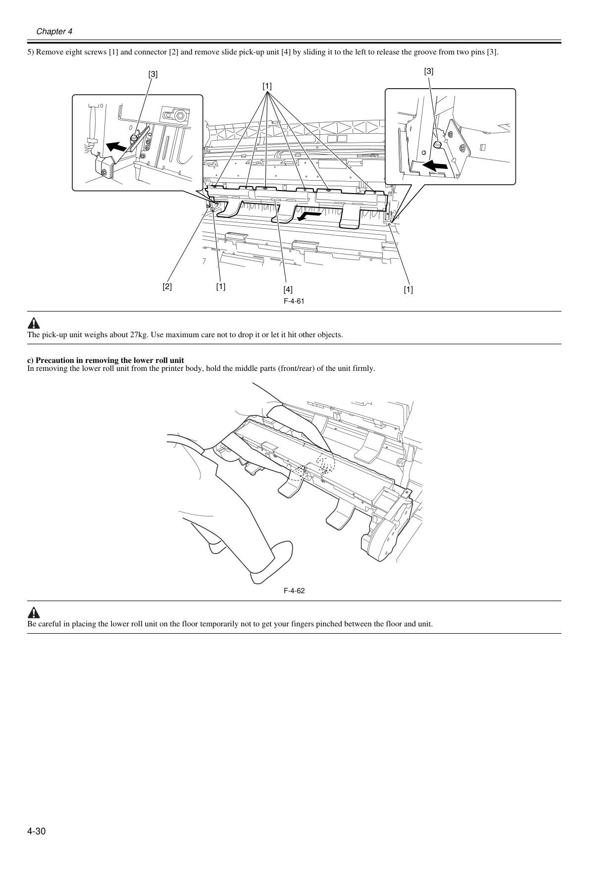
Chapter 4 4-30 5) Remove eight screws [1] and connector [2] and remove slide pick-up unit [4] by sliding it to the left to release the groove from two pins [3].
F-4-61
The pick-up unit weighs about 27kg. Use maximum care not to drop it or let it hit other objects. c) Precaution in removing the lower roll unit In removing the lower roll unit from the printer body, hold the middle parts (front/rear) of the unit firmly.F-4-62
Be careful in placing the lower roll unit on the floor temporarily not to get your fingers pinched between the floor and unit. [1] [1] [2] [3] [1] [4] [3]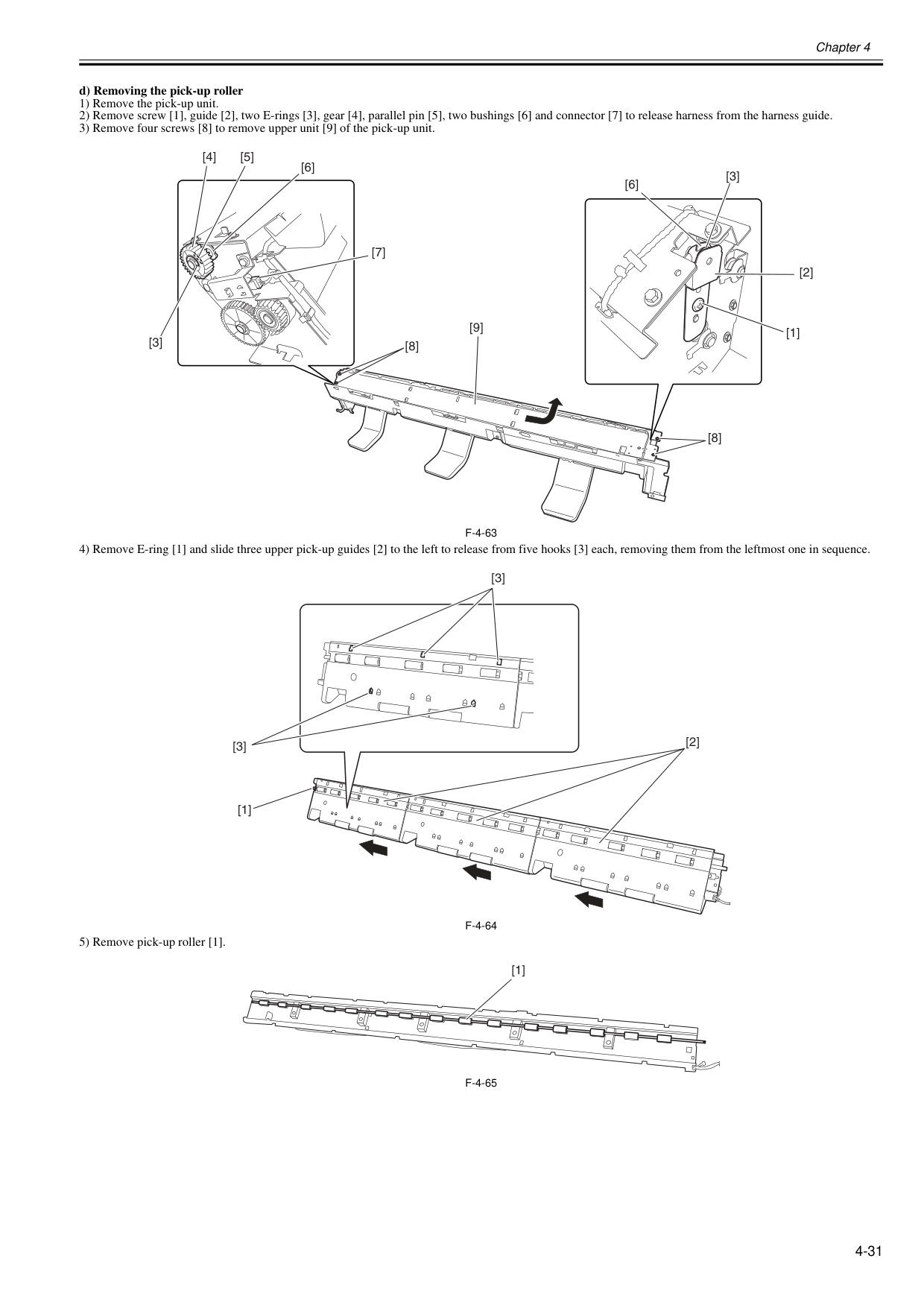
Chapter 4 4-31 d) Removing the pick-up roller 1) Remove the pick-up unit. 2) Remove screw [1], guide [2], two E-rings [3], gear [4], parallel pin [5], two bushings [6] and connector [7] to release harness from the harness guide. 3) Remove four screws [8] to remove upper unit [9] of the pick-up unit.
F-4-63
4) Remove E-ring [1] and slide three upper pick-up guides [2] to the left to release from five hooks [3] each, removing them from the leftmost one in sequence.F-4-64
5) Remove pick-up roller [1].F-4-65
[3] [6] [3] [2] [1] [4] [5] [7] [6] [8] [9] [8] [2] [1] [3] [3] [1]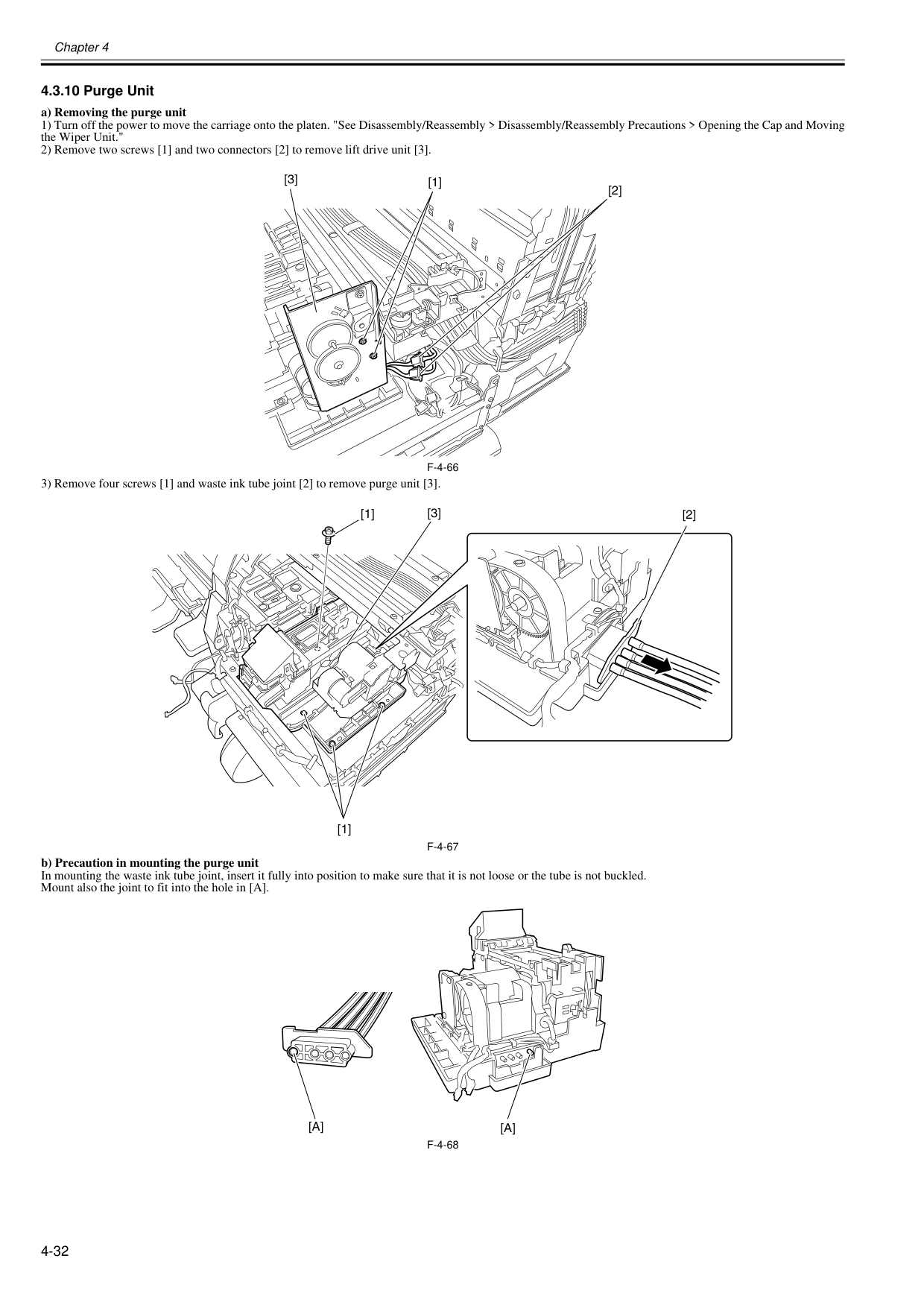
Chapter 4 4-32 4.3.10 Purge Unit 0020-5671 a) Removing the purge unit 1) Turn off the power to move the carriage onto the platen. "See Disassembly/Reassembly > Disassembly/Reassembly Precautions > Opening the Cap and Moving the Wiper Unit." 2) Remove two screws [1] and two connectors [2] to remove lift drive unit [3].
F-4-66
3) Remove four screws [1] and waste ink tube joint [2] to remove purge unit [3].F-4-67
b) Precaution in mounting the purge unit In mounting the waste ink tube joint, insert it fully into position to make sure that it is not loose or the tube is not buckled. Mount also the joint to fit into the hole in [A].F-4-68
[1] [2] [3] [2] [1] [1] [3][A]
[A]
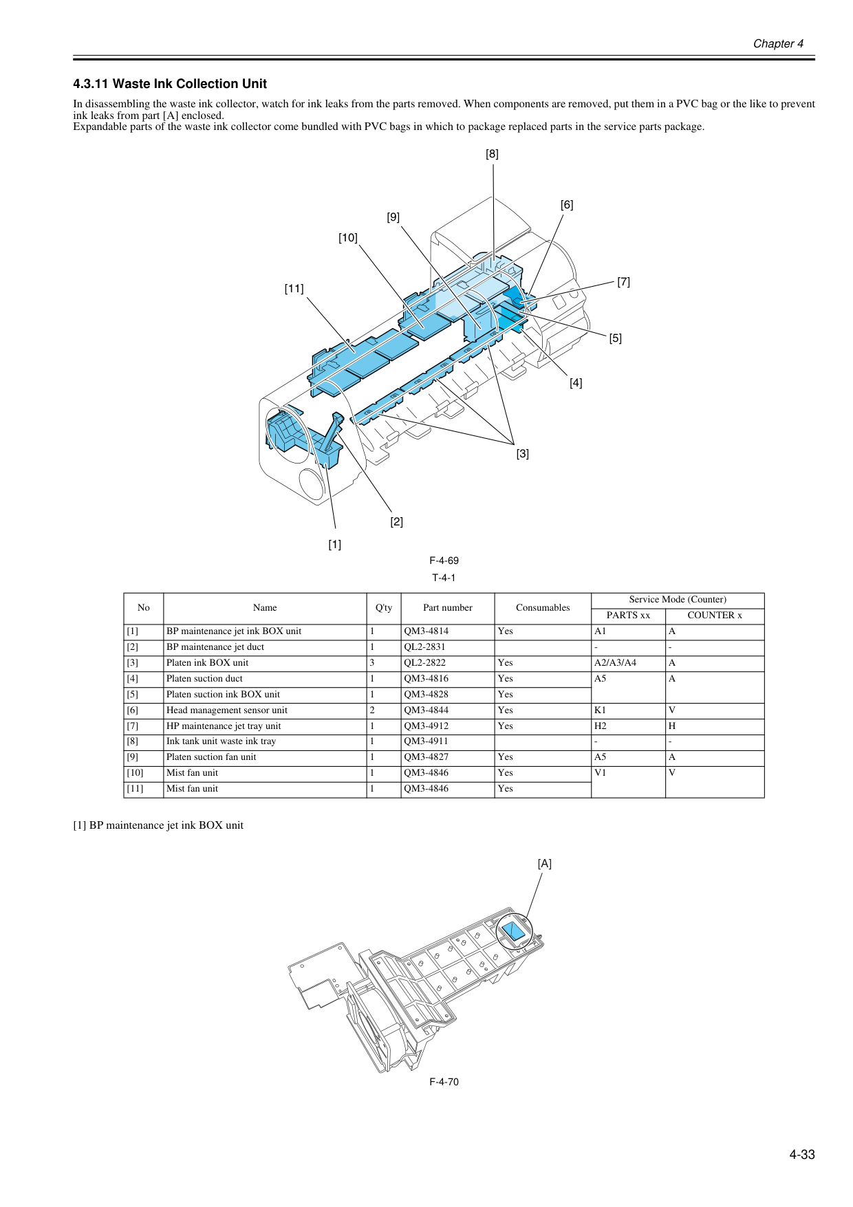
Chapter 4 4-33 4.3.11 Waste Ink Collection Unit 0020-5682 In disassembling the waste ink collector, watch for ink leaks from the parts removed. When components are removed, put them in a PVC bag or the like to prevent ink leaks from part [A] enclosed. Expandable parts of the waste ink collector come bundled with PVC bags in which to package replaced parts in the service parts package.
F-4-69
T-4-1
[1] BP maintenance jet ink BOX unitF-4-70
No Name Q'ty Part number Consumables Service Mode (Counter) PARTS xx COUNTER x [1] BP maintenance jet ink BOX unit 1Qm3-4814
YesA1
A
[2] BP maintenance jet duct 1Ql2-2831
Ql2-2822
YesA2/A3/A4
A
[4] Platen suction duct 1Qm3-4816
YesA5
A
[5] Platen suction ink BOX unit 1Qm3-4828
Yes [6] Head management sensor unit 2Qm3-4844
YesK1
V
[7] HP maintenance jet tray unit 1Qm3-4912
YesH2
H
[8] Ink tank unit waste ink tray 1Qm3-4911
Qm3-4827
YesA5
A
[10] Mist fan unit 1Qm3-4846
YesV1
V
[11] Mist fan unit 1Qm3-4846
Yes [1] [2] [4] [8] [5] [9] [10] [7] [11] [6] [3][A]
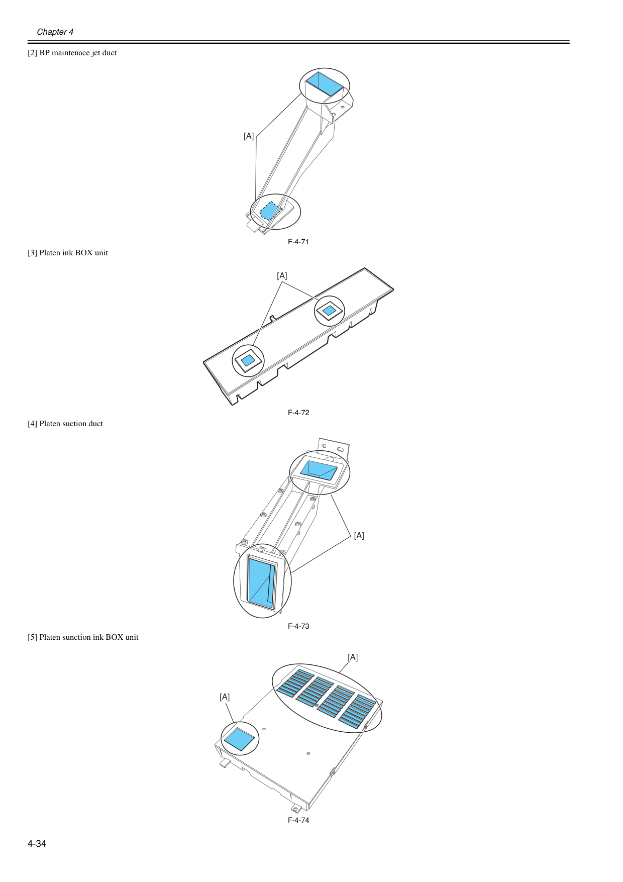
Chapter 4 4-34 [2] BP maintenace jet duct
F-4-71
[3] Platen ink BOX unitF-4-72
[4] Platen suction ductF-4-73
[5] Platen sunction ink BOX unitF-4-74
[A]
[A]
[A]
[A]
[A]
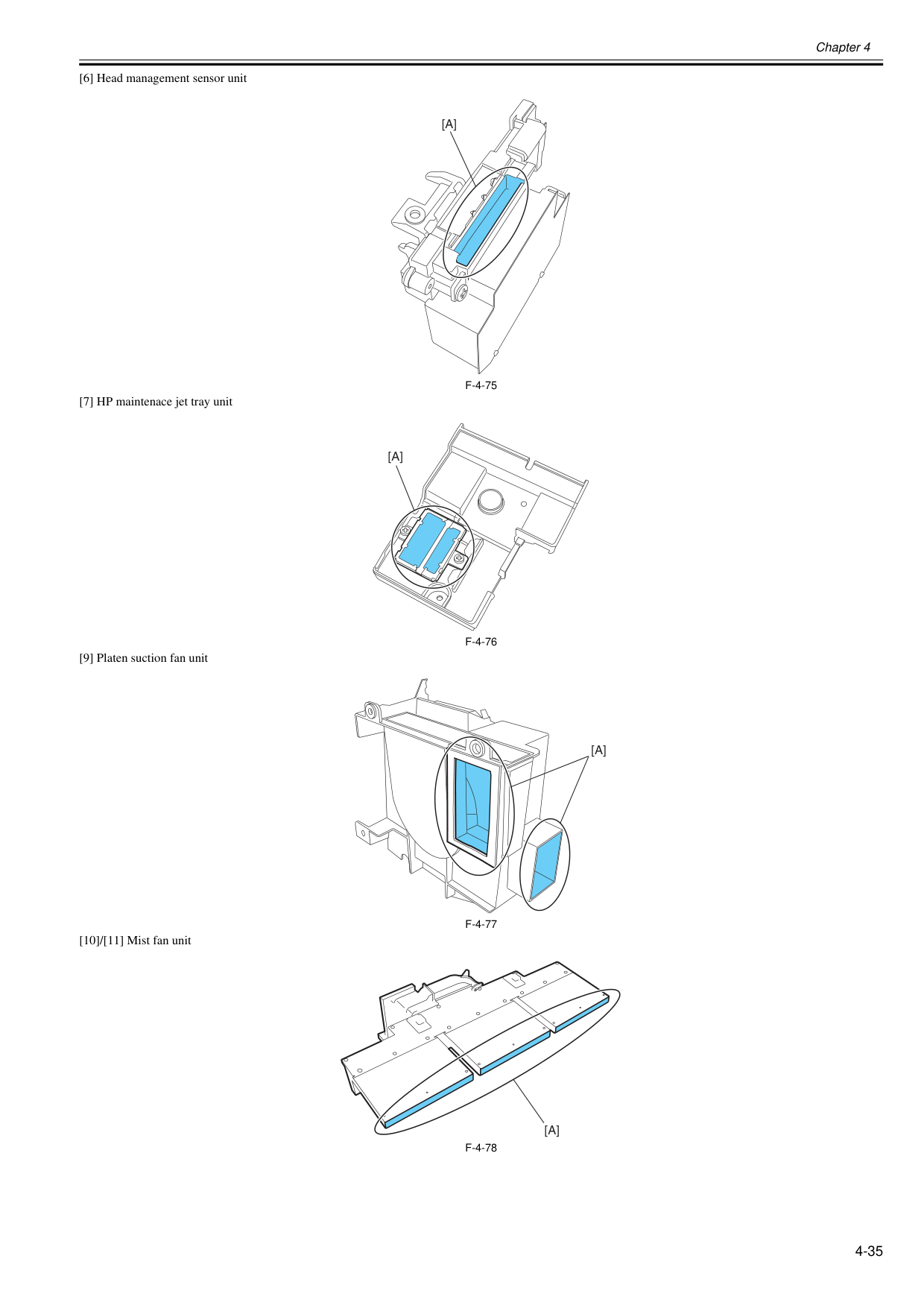
Chapter 4 4-35 [6] Head management sensor unit
F-4-75
[7] HP maintenace jet tray unitF-4-76
[9] Platen suction fan unitF-4-77
[10]/[11] Mist fan unitF-4-78
[A]
[A]
[A]
[A]
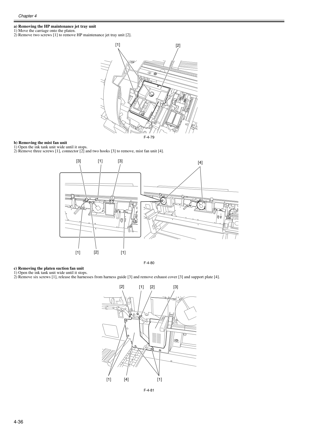
Chapter 4 4-36 a) Removing the HP maintenance jet tray unit 1) Move the carriage onto the platen. 2) Remove two screws [1] to remove HP maintenance jet tray unit [2].
F-4-79
b) Removing the mist fan unit 1) Open the ink tank unit wide until it stops. 2) Remove three screws [1], connector [2] and two hooks [3] to remove, mist fan unit [4].F-4-80
c) Removing the platen suction fan unit 1) Open the ink tank unit wide until it stops. 2) Remove six screws [1], release the harnesses from harness guide [3] and remove exhaust cover [3] and support plate [4].F-4-81
[1] [2] [4] [3] [1] [3] [1] [2] [1] [2] [1] [2] [3] [1] [4] [1]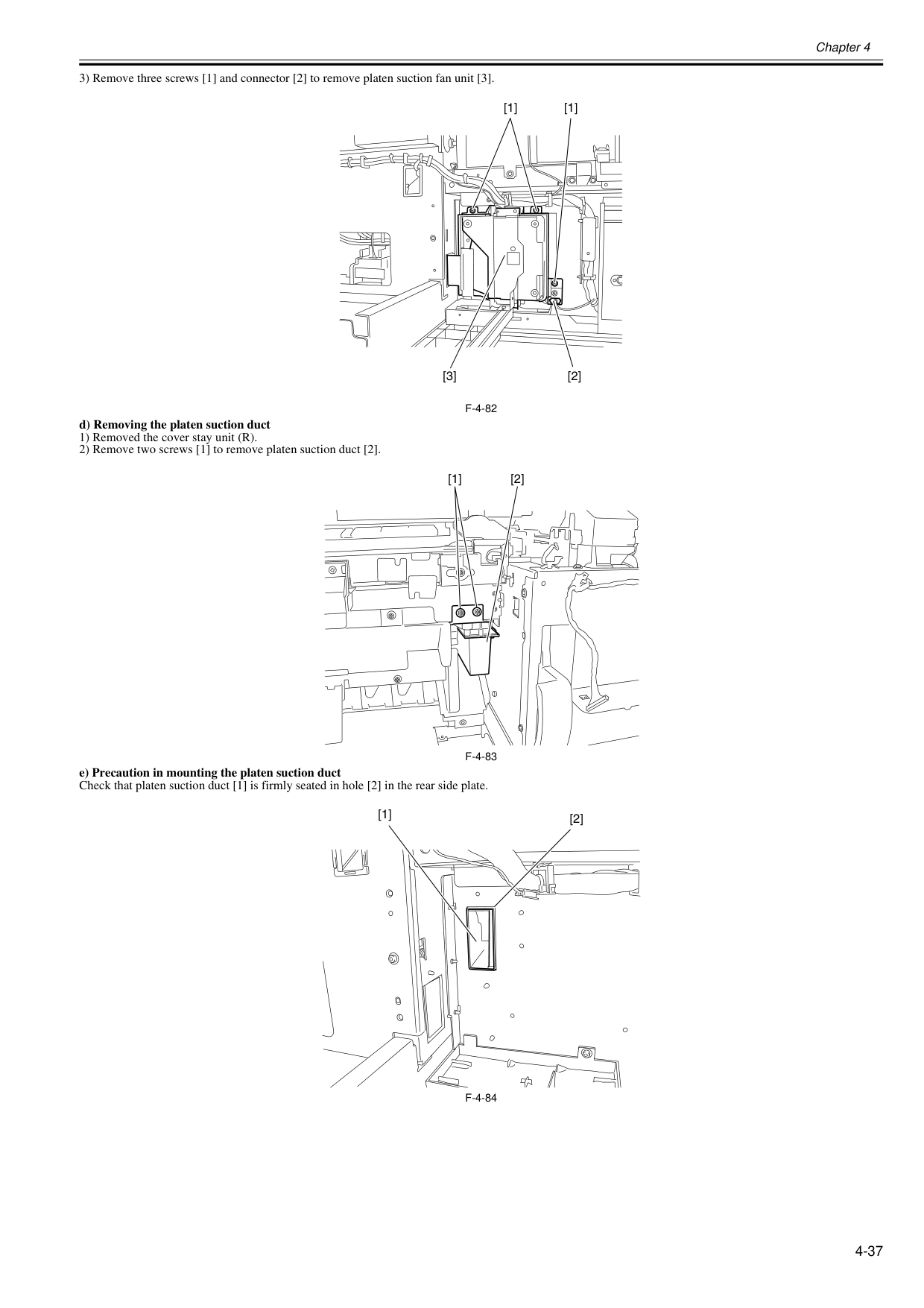
Chapter 4 4-37 3) Remove three screws [1] and connector [2] to remove platen suction fan unit [3].
F-4-82
d) Removing the platen suction duct 1) Removed the cover stay unit (R). 2) Remove two screws [1] to remove platen suction duct [2].F-4-83
e) Precaution in mounting the platen suction duct Check that platen suction duct [1] is firmly seated in hole [2] in the rear side plate.F-4-84
[1] [1] [2] [3] [1] [2] [1] [2]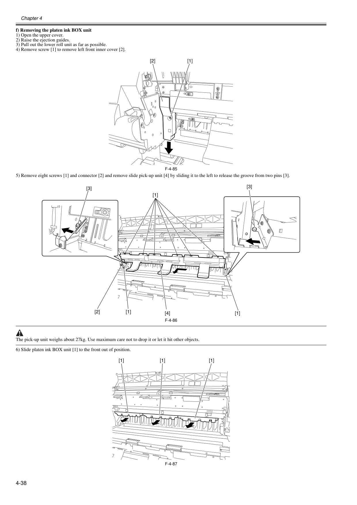
Chapter 4 4-38 f) Removing the platen ink BOX unit 1) Open the upper cover. 2) Raise the ejection guides. 3) Pull out the lower roll unit as far as possible. 4) Remove screw [1] to remove left front inner cover [2].
F-4-85
5) Remove eight screws [1] and connector [2] and remove slide pick-up unit [4] by sliding it to the left to release the groove from two pins [3].F-4-86
The pick-up unit weighs about 27kg. Use maximum care not to drop it or let it hit other objects. 6) Slide platen ink BOX unit [1] to the front out of position.F-4-87
[1] [2] [1] [1] [2] [3] [1] [4] [3] [1] [1] [1]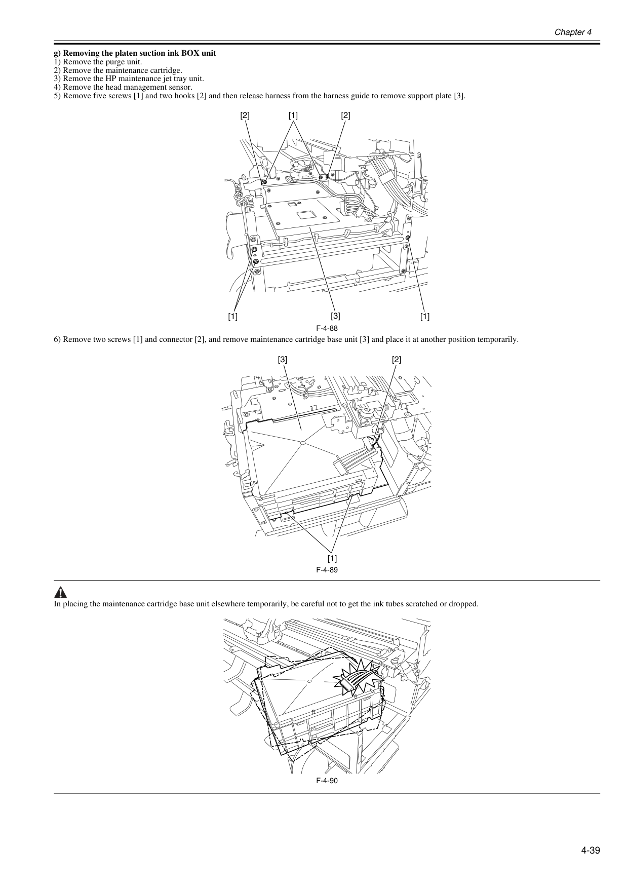
Chapter 4 4-39 g) Removing the platen suction ink BOX unit 1) Remove the purge unit. 2) Remove the maintenance cartridge. 3) Remove the HP maintenance jet tray unit. 4) Remove the head management sensor. 5) Remove five screws [1] and two hooks [2] and then release harness from the harness guide to remove support plate [3].
F-4-88
6) Remove two screws [1] and connector [2], and remove maintenance cartridge base unit [3] and place it at another position temporarily.F-4-89
In placing the maintenance cartridge base unit elsewhere temporarily, be careful not to get the ink tubes scratched or dropped.F-4-90
[1] [1] [1] [2] [2] [3] [1] [2] [3]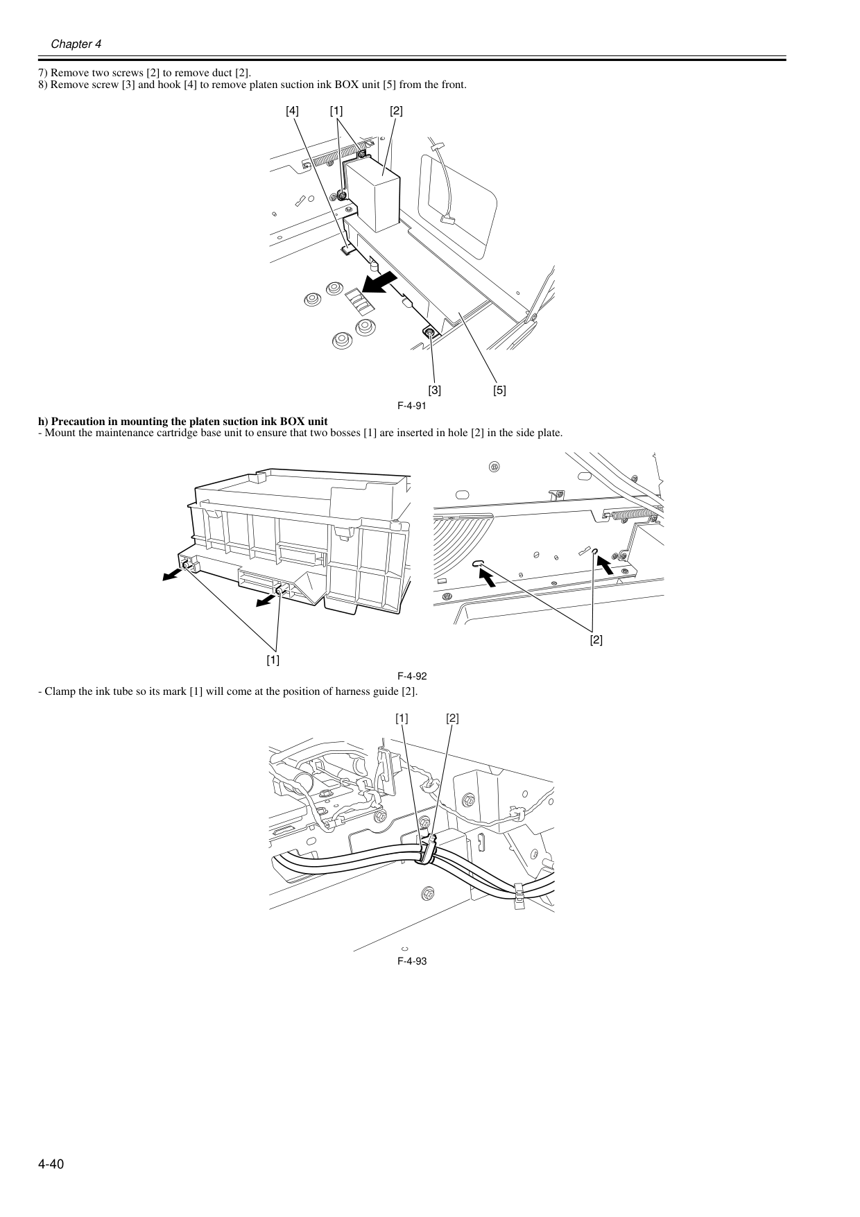
Chapter 4 4-40 7) Remove two screws [2] to remove duct [2]. 8) Remove screw [3] and hook [4] to remove platen suction ink BOX unit [5] from the front.
F-4-91
h) Precaution in mounting the platen suction ink BOX unitF-4-92
F-4-93
[4] [1] [2] [3] [5] [2] [1] [2] [1]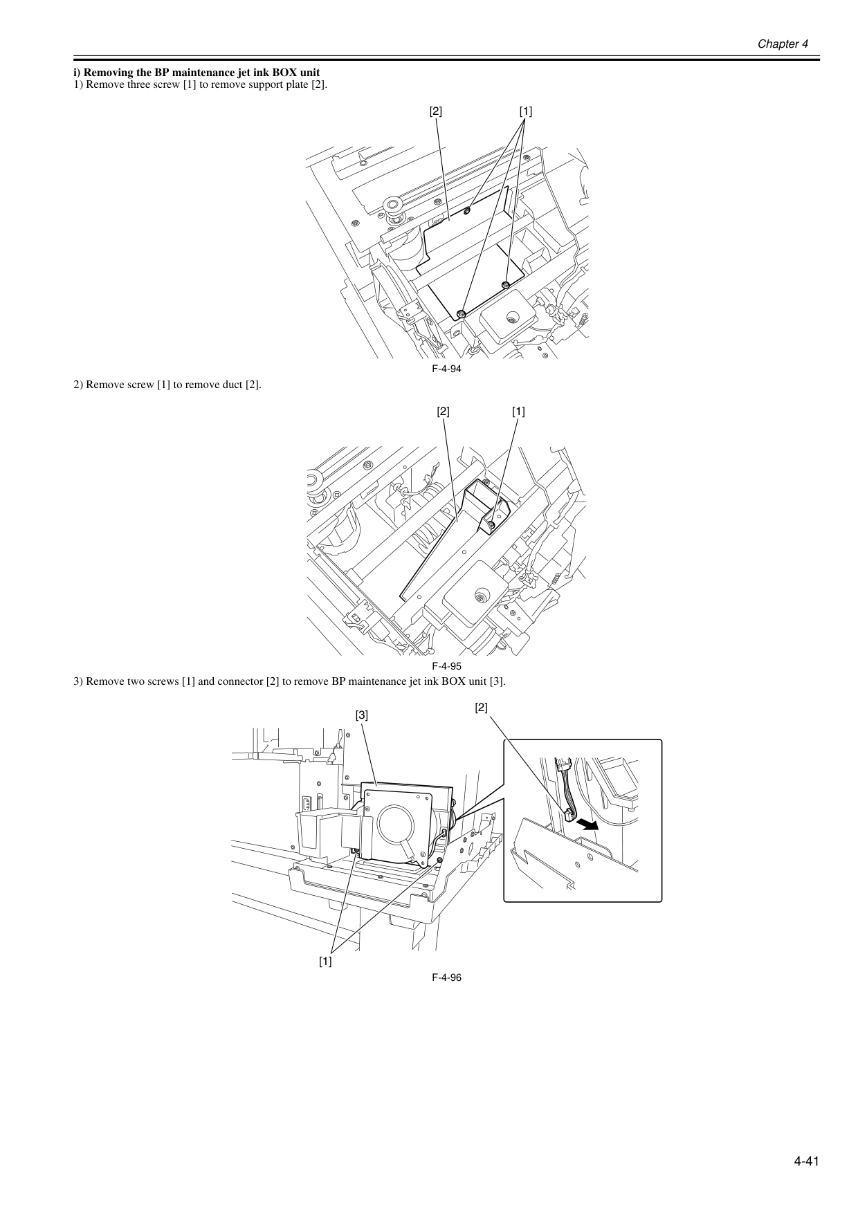
Chapter 4 4-41 i) Removing the BP maintenance jet ink BOX unit 1) Remove three screw [1] to remove support plate [2].
F-4-94
2) Remove screw [1] to remove duct [2].F-4-95
3) Remove two screws [1] and connector [2] to remove BP maintenance jet ink BOX unit [3].F-4-96
[1] [2] [2] [1] [2] [1] [3]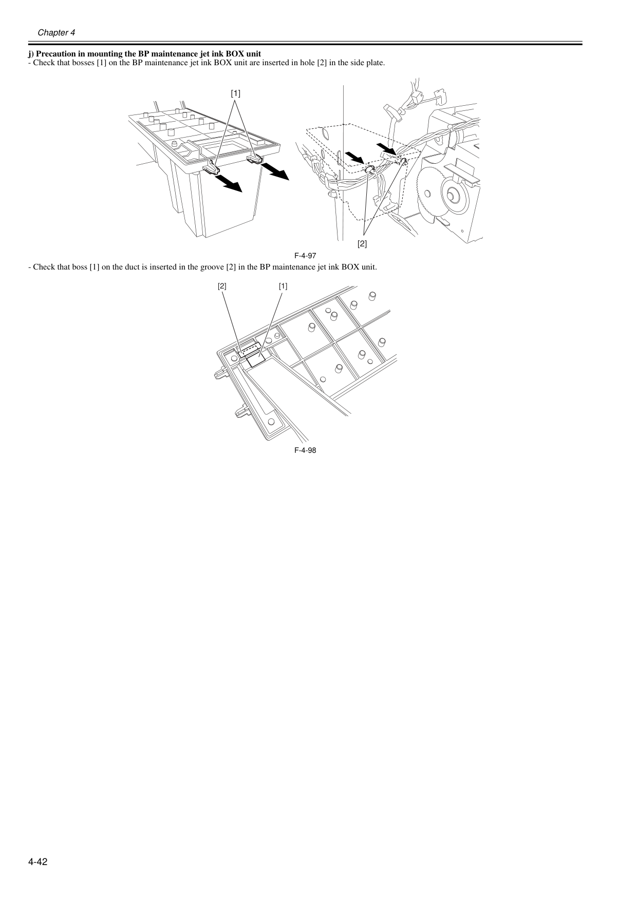
Chapter 4 4-42 j) Precaution in mounting the BP maintenance jet ink BOX unit
F-4-97
F-4-98
[1] [2] [1] [2]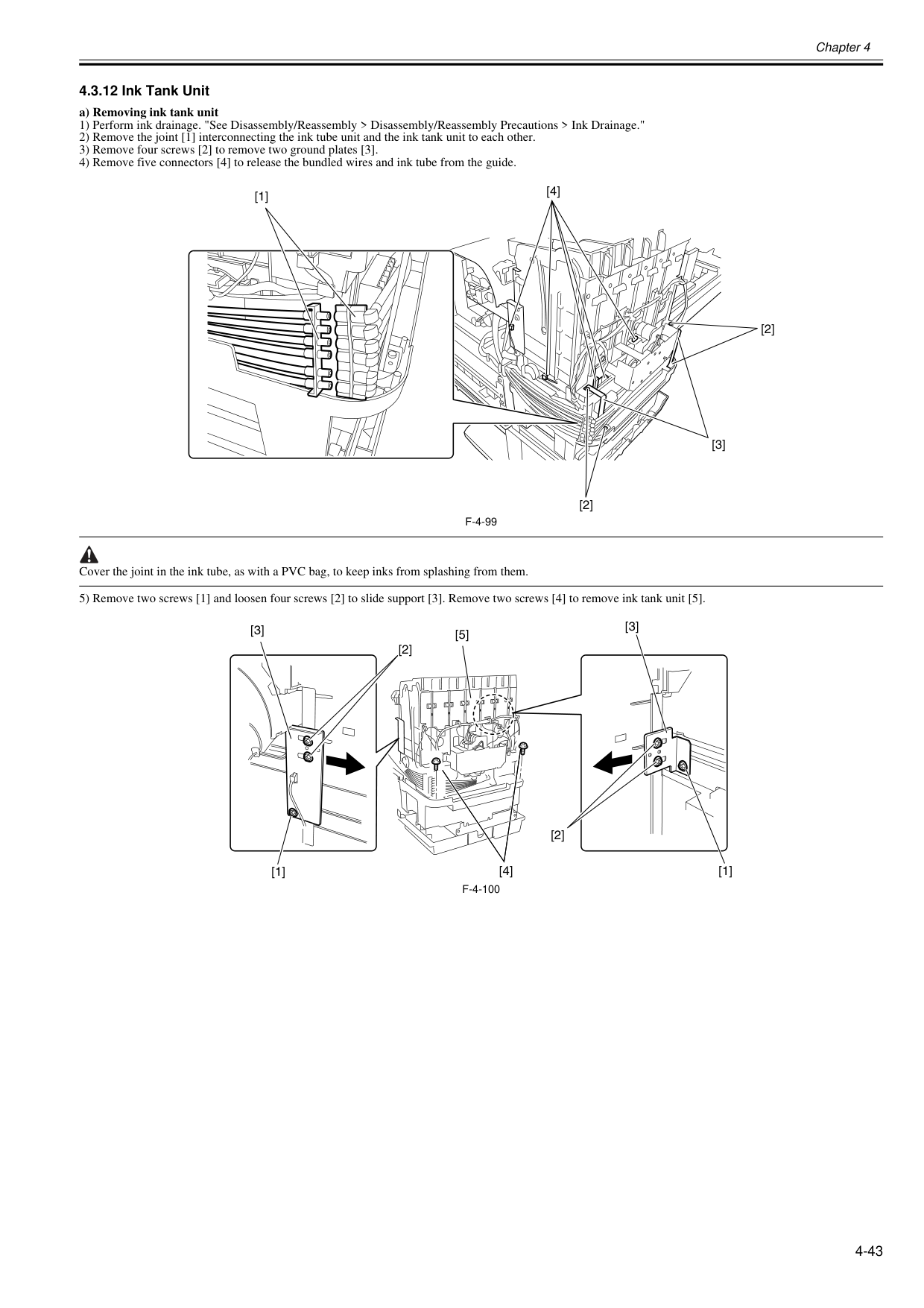
Chapter 4 4-43 4.3.12 Ink Tank Unit 0020-5673 a) Removing ink tank unit 1) Perform ink drainage. "See Disassembly/Reassembly > Disassembly/Reassembly Precautions > Ink Drainage." 2) Remove the joint [1] interconnecting the ink tube unit and the ink tank unit to each other. 3) Remove four screws [2] to remove two ground plates [3]. 4) Remove five connectors [4] to release the bundled wires and ink tube from the guide.
F-4-99
Cover the joint in the ink tube, as with a PVC bag, to keep inks from splashing from them. 5) Remove two screws [1] and loosen four screws [2] to slide support [3]. Remove two screws [4] to remove ink tank unit [5].F-4-100
[1] [2] [4] [2] [3] [4] [3] [3] [2] [2] [1] [1] [5]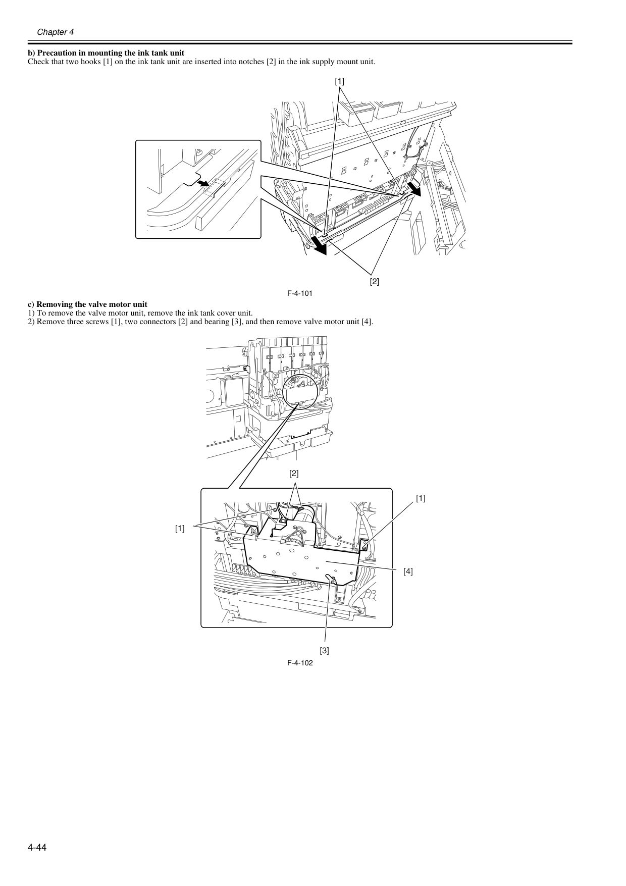
Chapter 4 4-44 b) Precaution in mounting the ink tank unit Check that two hooks [1] on the ink tank unit are inserted into notches [2] in the ink supply mount unit.
F-4-101
c) Removing the valve motor unit 1) To remove the valve motor unit, remove the ink tank cover unit. 2) Remove three screws [1], two connectors [2] and bearing [3], and then remove valve motor unit [4].F-4-102
[1] [2] [1] [1] [3] [2] [4]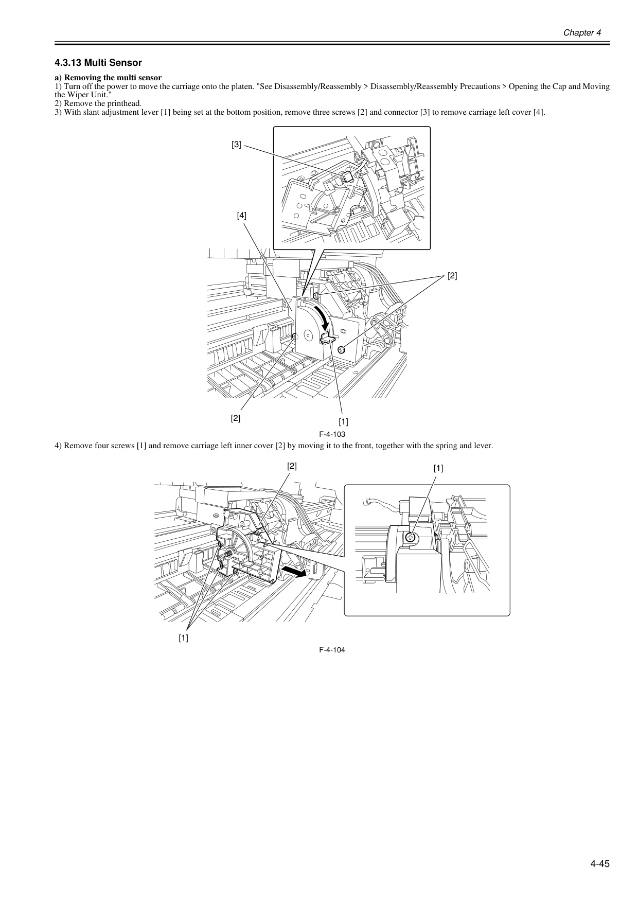
Chapter 4 4-45 4.3.13 Multi Sensor 0020-5680 a) Removing the multi sensor 1) Turn off the power to move the carriage onto the platen. "See Disassembly/Reassembly > Disassembly/Reassembly Precautions > Opening the Cap and Moving the Wiper Unit." 2) Remove the printhead. 3) With slant adjustment lever [1] being set at the bottom position, remove three screws [2] and connector [3] to remove carriage left cover [4].
F-4-103
4) Remove four screws [1] and remove carriage left inner cover [2] by moving it to the front, together with the spring and lever.F-4-104
[1] [2] [4] [2] [3] [1] [1] [2]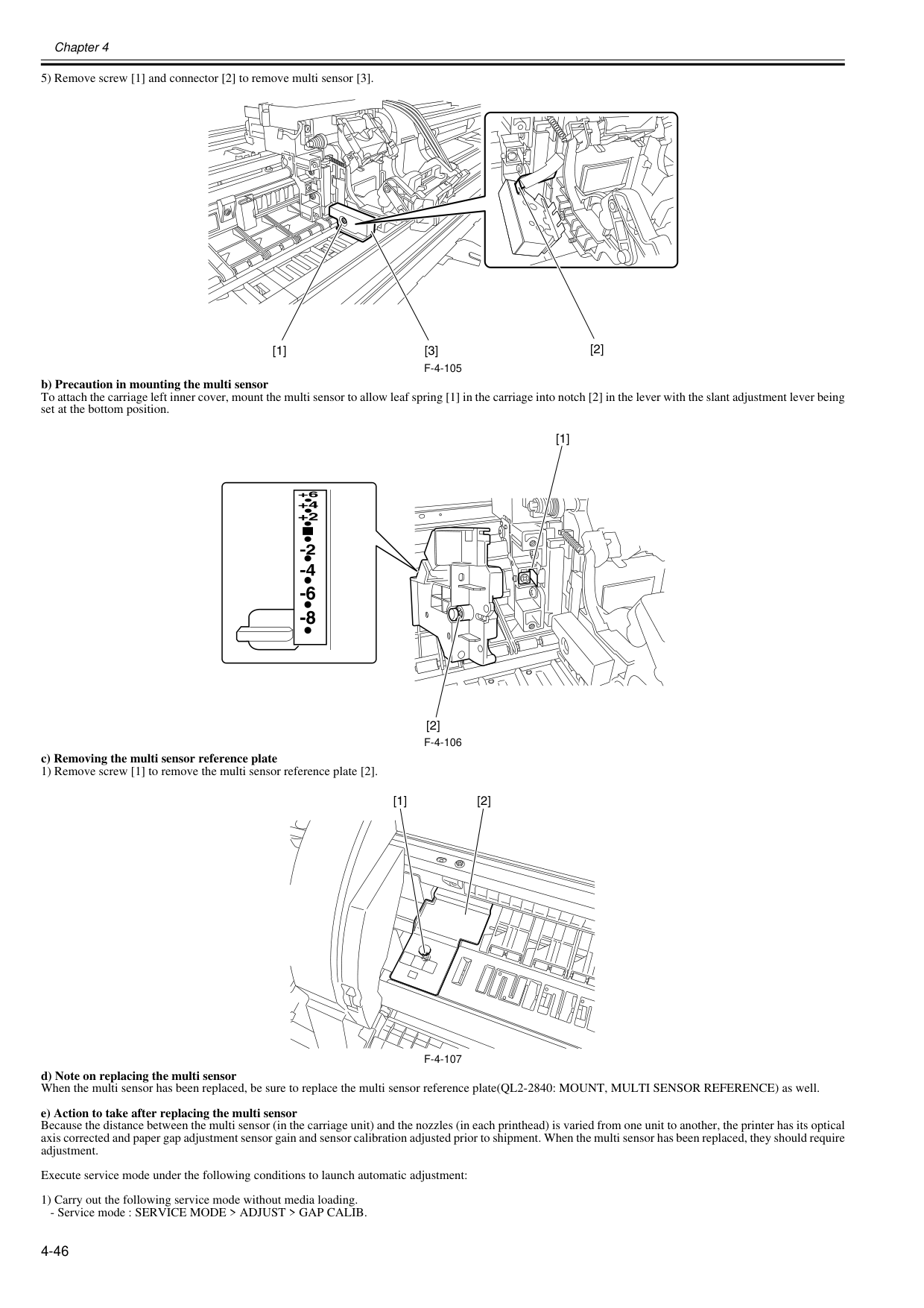
Chapter 4 4-46 5) Remove screw [1] and connector [2] to remove multi sensor [3].
F-4-105
b) Precaution in mounting the multi sensor To attach the carriage left inner cover, mount the multi sensor to allow leaf spring [1] in the carriage into notch [2] in the lever with the slant adjustment lever being set at the bottom position.F-4-106
c) Removing the multi sensor reference plate 1) Remove screw [1] to remove the multi sensor reference plate [2].F-4-107
d) Note on replacing the multi sensor When the multi sensor has been replaced, be sure to replace the multi sensor reference plate(QL2-2840: MOUNT, MULTI SENSOR REFERENCE) as well. e) Action to take after replacing the multi sensor Because the distance between the multi sensor (in the carriage unit) and the nozzles (in each printhead) is varied from one unit to another, the printer has its optical axis corrected and paper gap adjustment sensor gain and sensor calibration adjusted prior to shipment. When the multi sensor has been replaced, they should require adjustment. Execute service mode under the following conditions to launch automatic adjustment: 1) Carry out the following service mode without media loading.
Chapter 4 4-47 2) Load the following media. Media type : Photo glossy paper Media size : Media having a width equal or larger than that of A2-size paper 3) Carry out the following service mode.
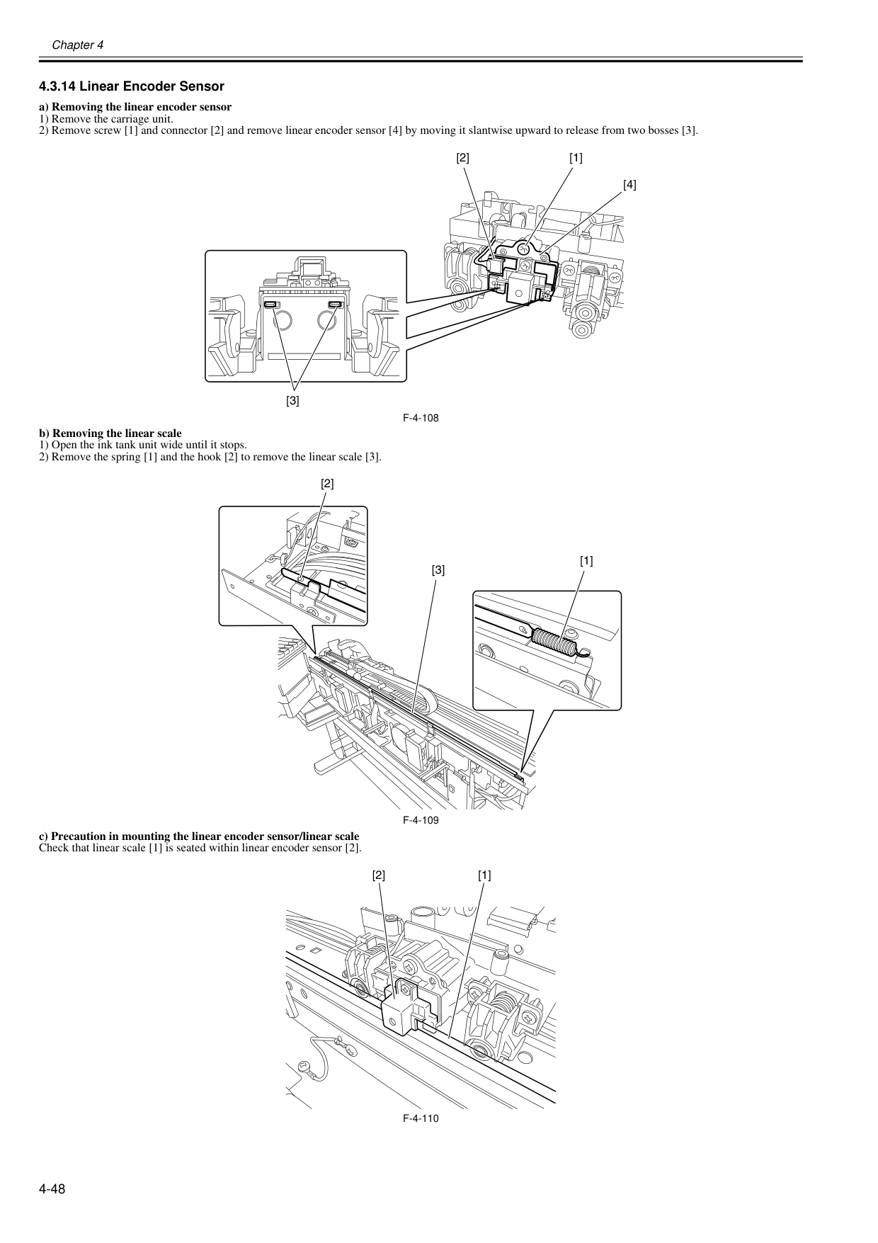
Chapter 4 4-48 4.3.14 Linear Encoder Sensor 0020-5676 a) Removing the linear encoder sensor 1) Remove the carriage unit. 2) Remove screw [1] and connector [2] and remove linear encoder sensor [4] by moving it slantwise upward to release from two bosses [3].
F-4-108
b) Removing the linear scale 1) Open the ink tank unit wide until it stops. 2) Remove the spring [1] and the hook [2] to remove the linear scale [3].F-4-109
c) Precaution in mounting the linear encoder sensor/linear scale Check that linear scale [1] is seated within linear encoder sensor [2].F-4-110
[1] [3] [4] [2] [3] [1] [2] [2] [1]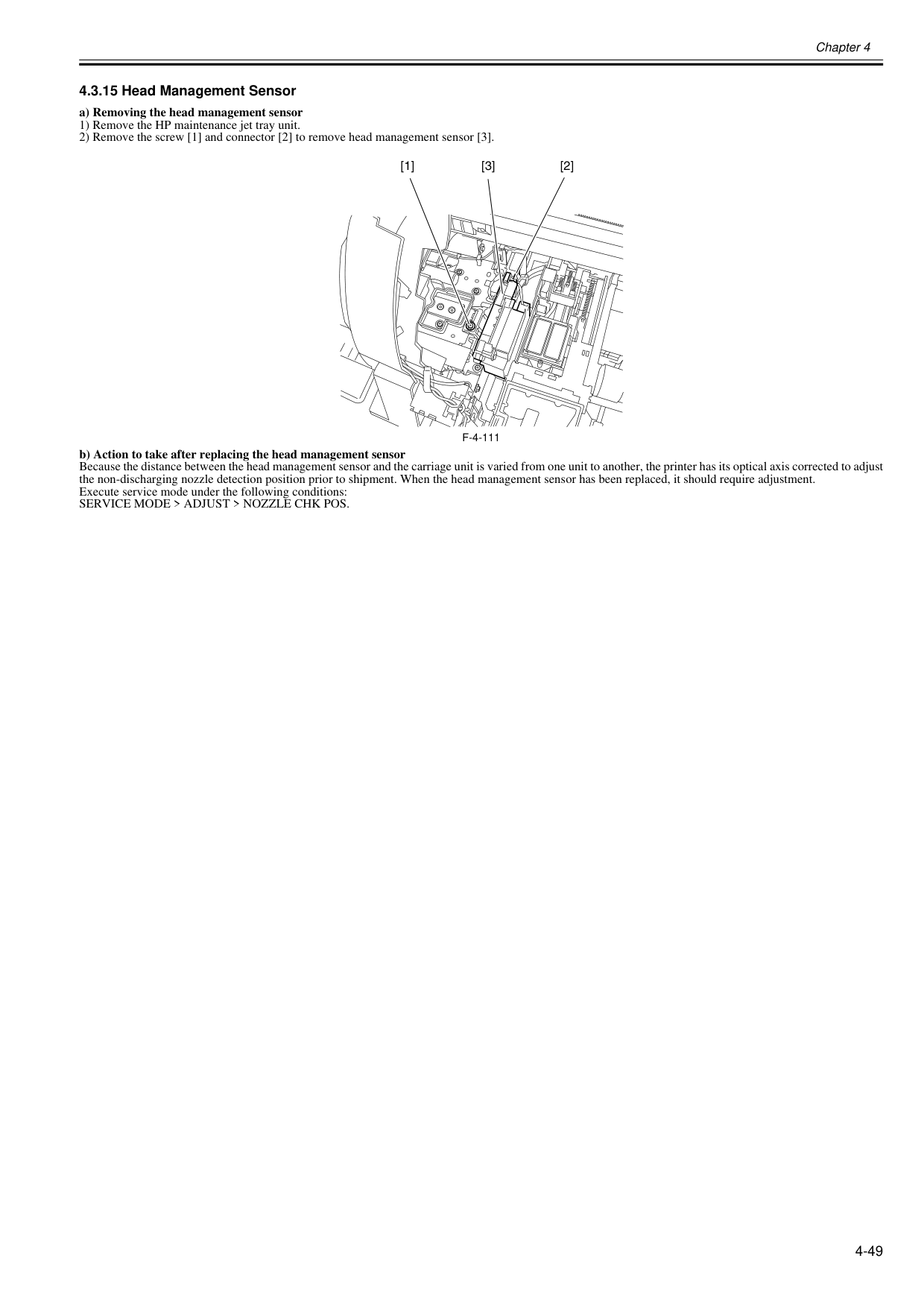
Chapter 4 4-49 4.3.15 Head Management Sensor 0020-5674 a) Removing the head management sensor 1) Remove the HP maintenance jet tray unit. 2) Remove the screw [1] and connector [2] to remove head management sensor [3].
F-4-111
b) Action to take after replacing the head management sensor Because the distance between the head management sensor and the carriage unit is varied from one unit to another, the printer has its optical axis corrected to adjust the non-discharging nozzle detection position prior to shipment. When the head management sensor has been replaced, it should require adjustment. Execute service mode under the following conditions:Service Mode > Adjust > Nozzle Chk Pos.
[1] [3] [2]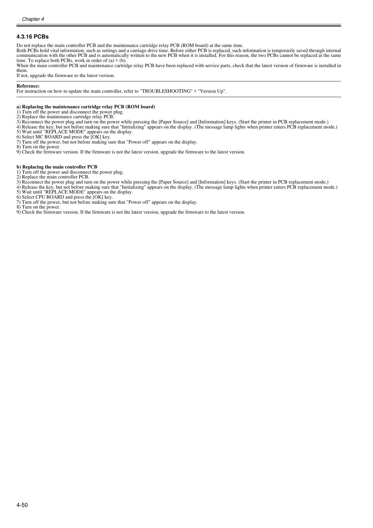
Chapter 4 4-50 4.3.16 PCBs 0014-8989 Do not replace the main controller PCB and the maintenance cartridge relay PCB (ROM board) at the same time. Both PCBs hold vital information, such as settings and a carriage drive time. Before either PCB is replaced, such information is temporarily saved through internal communication with the other PCB and is automatically written to the new PCB when it is installed. For this reason, the two PCBs cannot be replaced at the same time. To replace both PCBs, work in order of (a) > (b). When the main controller PCB and maintenance cartridge relay PCB have been replaced with service parts, check that the latest version of firmware is installed in them. If not, upgrade the firmware to the latest version. Reference: For instruction on how to update the main controller, refer to "TROUBLESHOOTING" > "Version Up". a) Replacing the maintenance cartridge relay PCB (ROM board) 1) Turn off the power and disconnect the power plug. 2) Replace the maintenance cartridge relay PCB. 3) Reconnect the power plug and turn on the power while pressing the [Paper Source] and [Information] keys. (Start the printer in PCB replacement mode.) 4) Release the key, but not before making sure that "Initializing" appears on the display. (The message lamp lights when printer enters PCB replacement mode.) 5) Wait until "REPLACE MODE" appears on the display. 6) Select MC BOARD and press the [OK] key. 7) Turn off the power, but not before making sure that "Power off" appears on the display. 8) Turn on the power. 9) Check the firmware version. If the firmware is not the latest version, upgrade the firmware to the latest version. b) Replacing the main controller PCB 1) Turn off the power and disconnect the power plug. 2) Replace the main controller PCB. 3) Reconnect the power plug and turn on the power while pressing the [Paper Source] and [Information] keys. (Start the printer in PCB replacement mode.) 4) Release the key, but not before making sure that "Initializing" appears on the display. (The message lamp lights when printer enters PCB replacement mode.) 5) Wait until "REPLACE MODE" appears on the display. 6) Select CPU BOARD and press the [OK] key. 7) Turn off the power, but not before making sure that "Power off" appears on the display. 8) Turn on the power. 9) Check the firmware version. If the firmware is not the latest version, upgrade the firmware to the latest version.
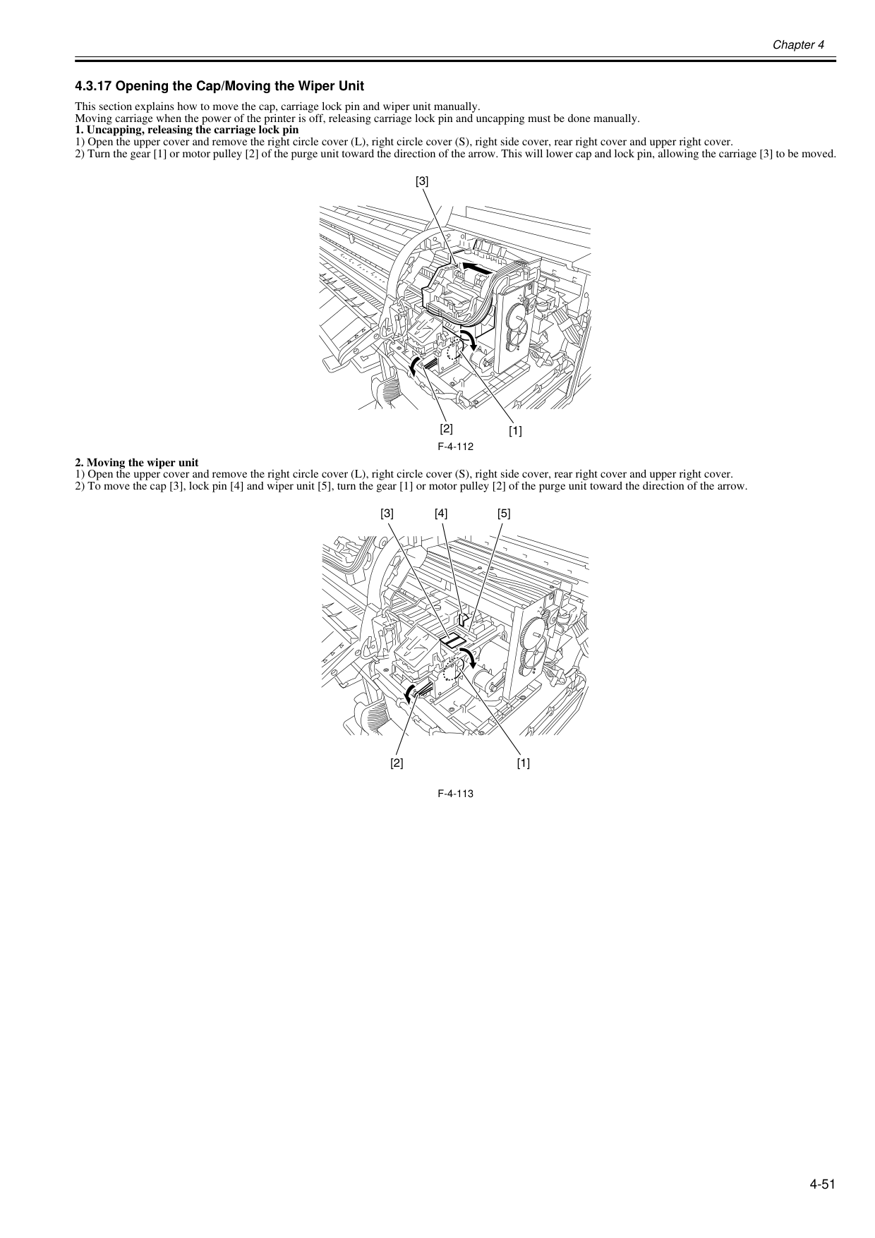
Chapter 4 4-51 4.3.17 Opening the Cap/Moving the Wiper Unit 0020-5706 This section explains how to move the cap, carriage lock pin and wiper unit manually. Moving carriage when the power of the printer is off, releasing carriage lock pin and uncapping must be done manually.
F-4-112
F-4-113
[2] [3] [1] [4] [3] [5] [1] [2]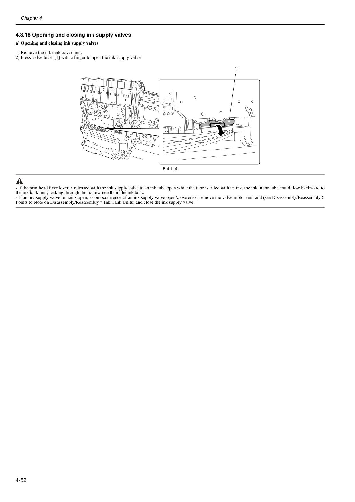
Chapter 4 4-52 4.3.18 Opening and closing ink supply valves 0020-5708 a) Opening and closing ink supply valves 1) Remove the ink tank cover unit. 2) Press valve lever [1] with a finger to open the ink supply valve.
F-4-114
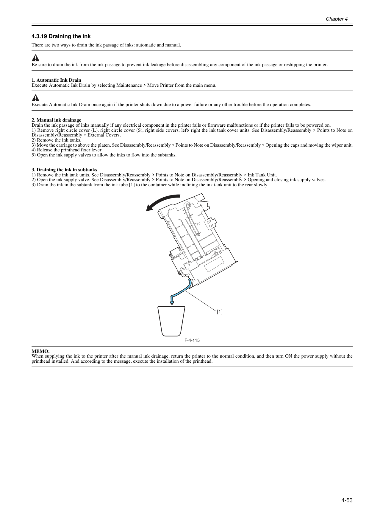
Chapter 4 4-53 4.3.19 Draining the ink 0020-5710 There are two ways to drain the ink passage of inks: automatic and manual. Be sure to drain the ink from the ink passage to prevent ink leakage before disassembling any component of the ink passage or reshipping the printer.
F-4-115
Memo:
When supplying the ink to the printer after the manual ink drainage, return the printer to the normal condition, and then turn ON the power supply without the printhead installed. And according to the message, execute the installation of the printhead. [1]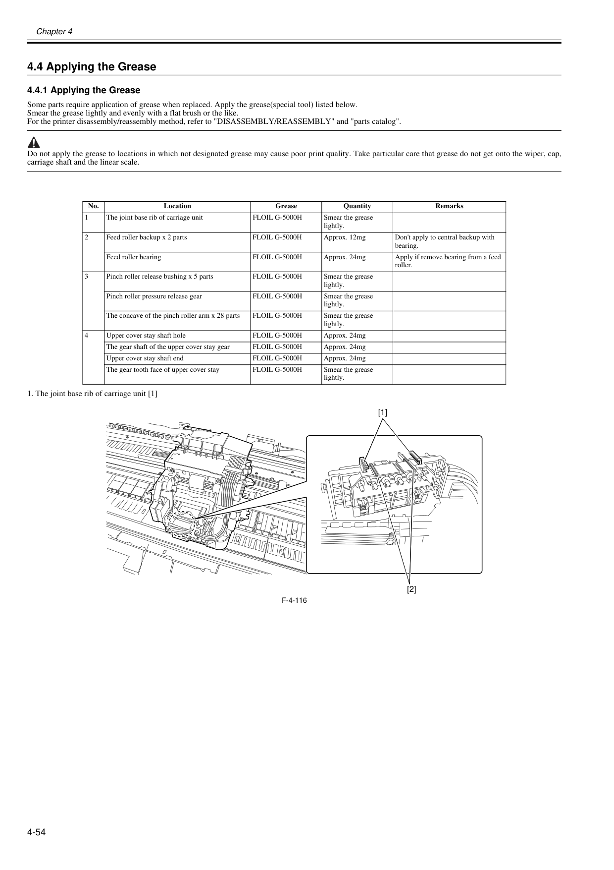
Chapter 4 4-54 4.4 Applying the Grease 4.4.1 Applying the Grease 0020-5711 Some parts require application of grease when replaced. Apply the grease(special tool) listed below. Smear the grease lightly and evenly with a flat brush or the like. For the printer disassembly/reassembly method, refer to "DISASSEMBLY/REASSEMBLY" and "parts catalog". Do not apply the grease to locations in which not designated grease may cause poor print quality. Take particular care that grease do not get onto the wiper, cap, carriage shaft and the linear scale.
F-4-116
No. Location Grease Quantity Remarks 1 The joint base rib of carriage unitFloil G-5000H
Smear the grease lightly. 2 Feed roller backup x 2 partsFloil G-5000H
Approx. 12mg Don't apply to central backup with bearing. Feed roller bearingFloil G-5000H
Approx. 24mg Apply if remove bearing from a feed roller. 3 Pinch roller release bushing x 5 partsFloil G-5000H
Smear the grease lightly. Pinch roller pressure release gearFloil G-5000H
Smear the grease lightly. The concave of the pinch roller arm x 28 partsFloil G-5000H
Smear the grease lightly. 4 Upper cover stay shaft holeFloil G-5000H
Approx. 24mg The gear shaft of the upper cover stay gearFloil G-5000H
Approx. 24mg Upper cover stay shaft endFloil G-5000H
Approx. 24mg The gear tooth face of upper cover stayFloil G-5000H
Smear the grease lightly. [1] [2]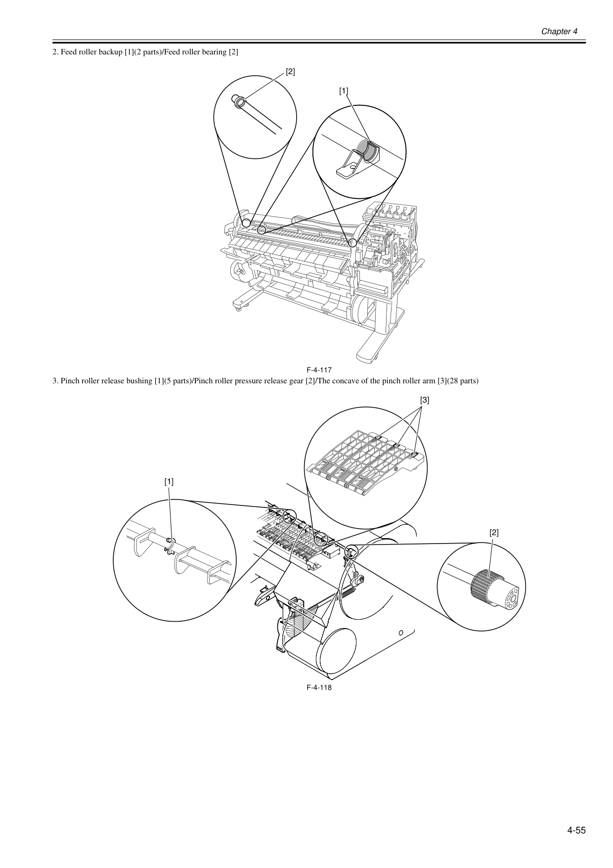
Chapter 4 4-55
F-4-117
F-4-118
[1] [2] [1] [3] [2]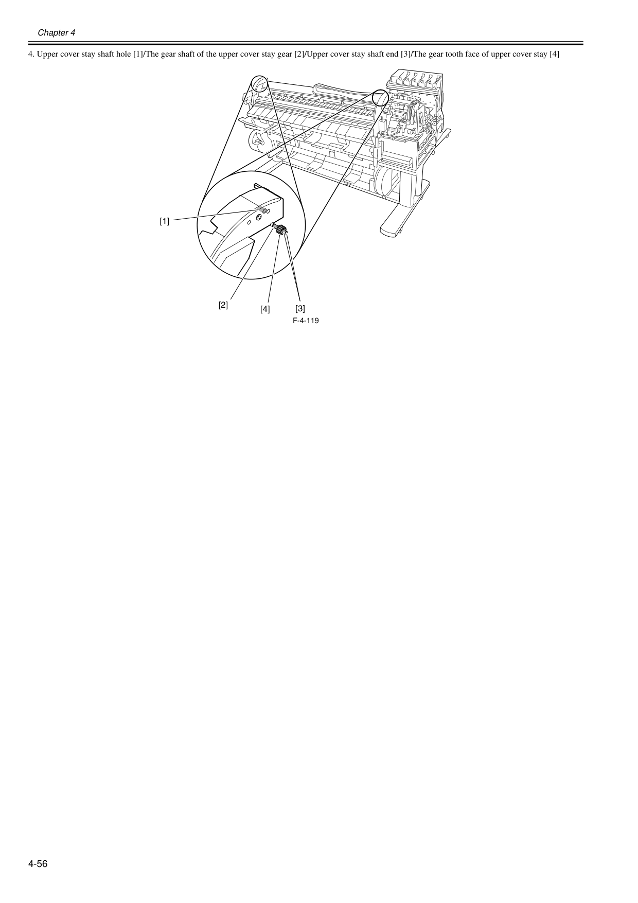
Chapter 4 4-56
F-4-119
[1] [2] [4] [3]
Chapter 4 4-57 4.5 Adjustment and Setup Items 4.5.1 Adjustment Item List 0017-8323 The following adjustment procedures need to be performed when parts have been replaced or remove and then reinstalled:
T-4-2
4.5.2 Procedure after Replacing the Carriage Unit or Multi Sensor 0020-5714 a) Note on replacing the carriage unit and the multi sensor The multi sensor reference plate(QL2-2840: MOUNT, MULTI SENSOR REFERENCE) must be replaced at the same time whenever the carriage or the multi sen- sor is being replaced. b) Multi Sensor Recalibration Because the distance between the multi sensor (in the carriage unit) and the nozzles (in each printhead) is varied from one unit to another, the printer has its optical axis corrected and paper gap adjustment sensor gain and calibration adjusted prior to shipment. When the carriage unit or multi sensor has been replaced, they should require adjustment. Execute service mode under the following conditions to launch automatic adjustment: 1) Carry out the following service mode without media loading.
Chapter 5 MAINTENANCE

Contents Contents 5.1 Periodic Replacement Parts ....................................................................................................................... 5-1 5.1.1 Periodic Replacement Parts.................................................................................................................................... 5-1 5.2 Consumable Parts ...................................................................................................................................... 5-1 5.2.1 Consumable Parts................................................................................................................................................... 5-1 5.3 Periodic Maintenance ................................................................................................................................. 5-2 5.3.1 Periodic Maintenance.............................................................................................................................................. 5-2
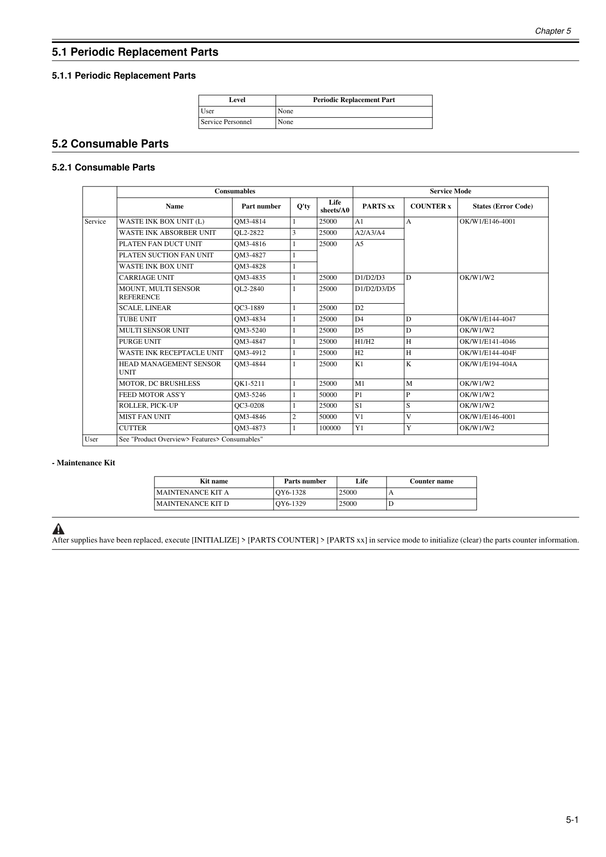
Chapter 5 5-1 5.1 Periodic Replacement Parts 5.1.1 Periodic Replacement Parts 0012-6595 5.2 Consumable Parts 5.2.1 Consumable Parts 0020-5716
Waste Ink Box Unit (L)
Qm3-4814
1 25000A1
A
Ok/W1/E146-4001
Waste Ink Absorber Unit
Ql2-2822
3 25000A2/A3/A4
Platen Fan Duct Unit
Qm3-4816
1 25000A5
Platen Suction Fan Unit
Qm3-4827
1Waste Ink Box Unit
Qm3-4828
1Carriage Unit
Qm3-4835
1 25000D1/D2/D3
D
Ok/W1/W2
Mount, Multi Sensor
Reference
Ql2-2840
1 25000D1/D2/D3/D5
Scale, Linear
Qc3-1889
1 25000D2
Tube Unit
Qm3-4834
1 25000D4
D
Ok/W1/E144-4047
Multi Sensor Unit
Qm3-5240
1 25000D5
D
Ok/W1/W2
Purge Unit
Qm3-4847
1 25000H1/H2
H
Ok/W1/E141-4046
Waste Ink Receptacle Unit
Qm3-4912
1 25000H2
H
Ok/W1/E144-404F
Head Management Sensor
Unit
Qm3-4844
1 25000K1
K
Ok/W1/E194-404A
Motor, Dc Brushless
Qk1-5211
1 25000M1
M
Ok/W1/W2
Feed Motor Ass'Y
Qm3-5246
1 50000P1
P
Ok/W1/W2
Roller, Pick-Up
Qc3-0208
1 25000S1
S
Ok/W1/W2
Mist Fan Unit
Qm3-4846
2 50000V1
V
Ok/W1/E146-4001
Cutter
Qm3-4873
1 100000Y1
Y
Ok/W1/W2
User See "Product Overview> Features> Consumables" Kit name Parts number Life Counter nameMaintenance Kit A
Qy6-1328
25000A
Maintenance Kit D
Qy6-1329
25000D
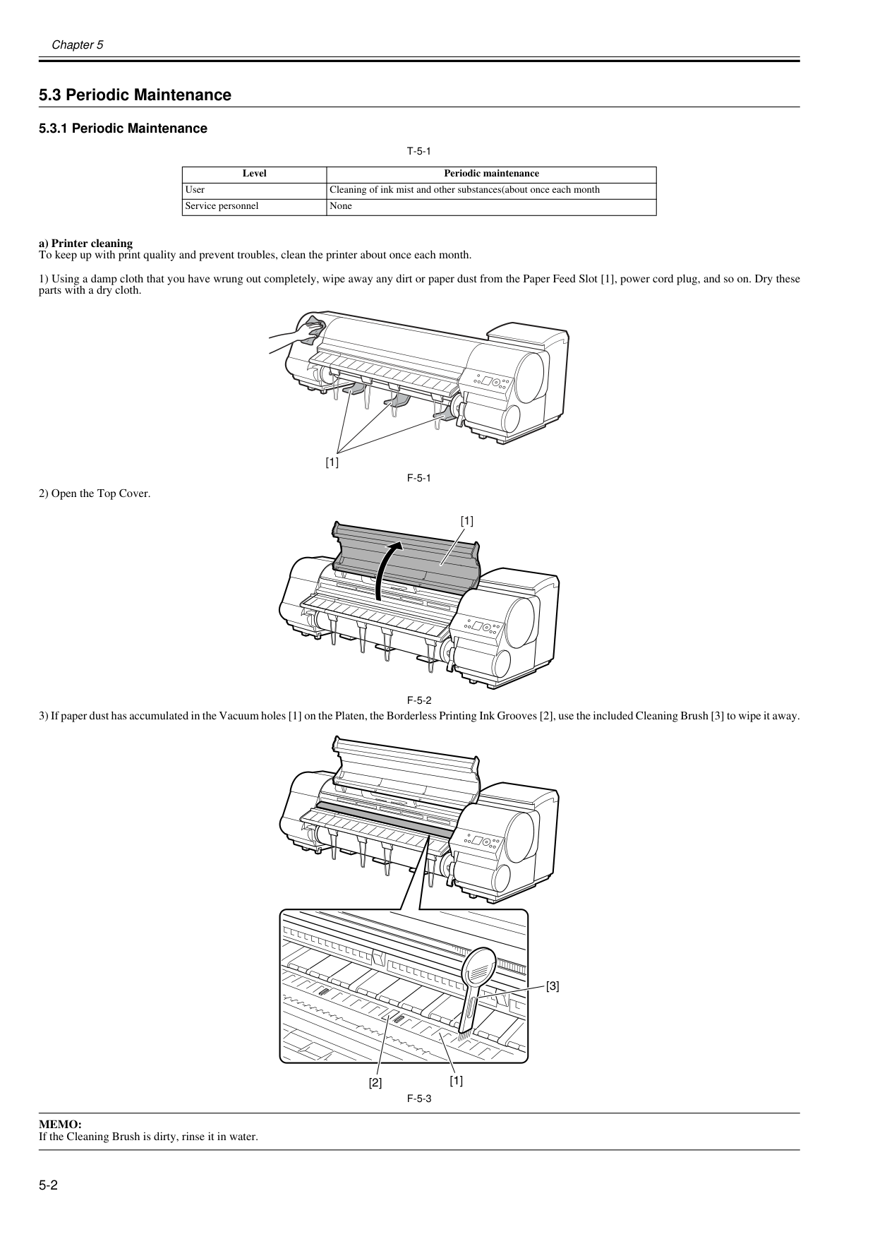
Chapter 5 5-2 5.3 Periodic Maintenance 5.3.1 Periodic Maintenance 0020-5718
T-5-1
a) Printer cleaning To keep up with print quality and prevent troubles, clean the printer about once each month. 1) Using a damp cloth that you have wrung out completely, wipe away any dirt or paper dust from the Paper Feed Slot [1], power cord plug, and so on. Dry these parts with a dry cloth.F-5-1
2) Open the Top Cover.F-5-2
3) If paper dust has accumulated in the Vacuum holes [1] on the Platen, the Borderless Printing Ink Grooves [2], use the included Cleaning Brush [3] to wipe it away.F-5-3
Memo:
If the Cleaning Brush is dirty, rinse it in water. Level Periodic maintenance User Cleaning of ink mist and other substances(about once each month Service personnel None [1] [1] [3] [2] [1]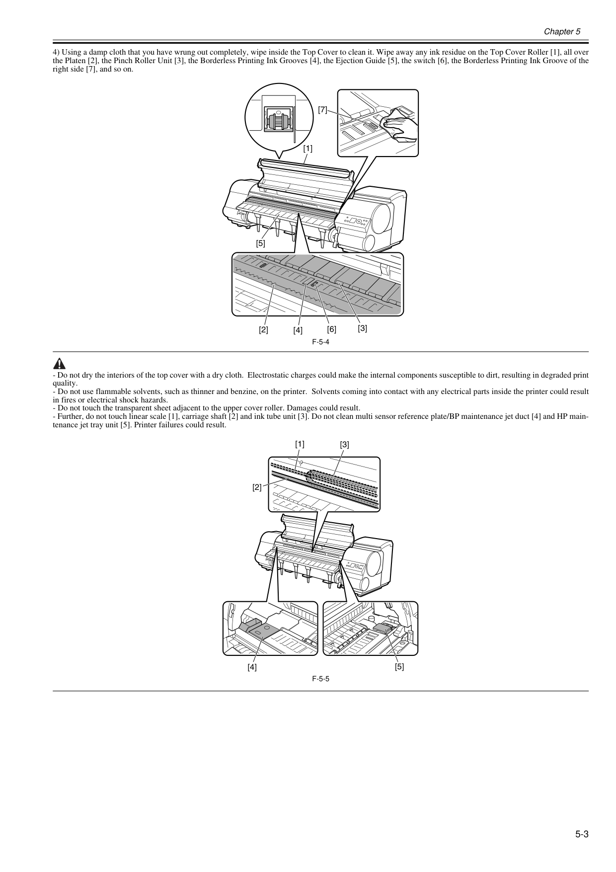
Chapter 5 5-3 4) Using a damp cloth that you have wrung out completely, wipe inside the Top Cover to clean it. Wipe away any ink residue on the Top Cover Roller [1], all over the Platen [2], the Pinch Roller Unit [3], the Borderless Printing Ink Grooves [4], the Ejection Guide [5], the switch [6], the Borderless Printing Ink Groove of the right side [7], and so on.
F-5-4
F-5-5
[3] [2] [6] [4] [5] [1] [7] [3] [1] [2] [4] [5]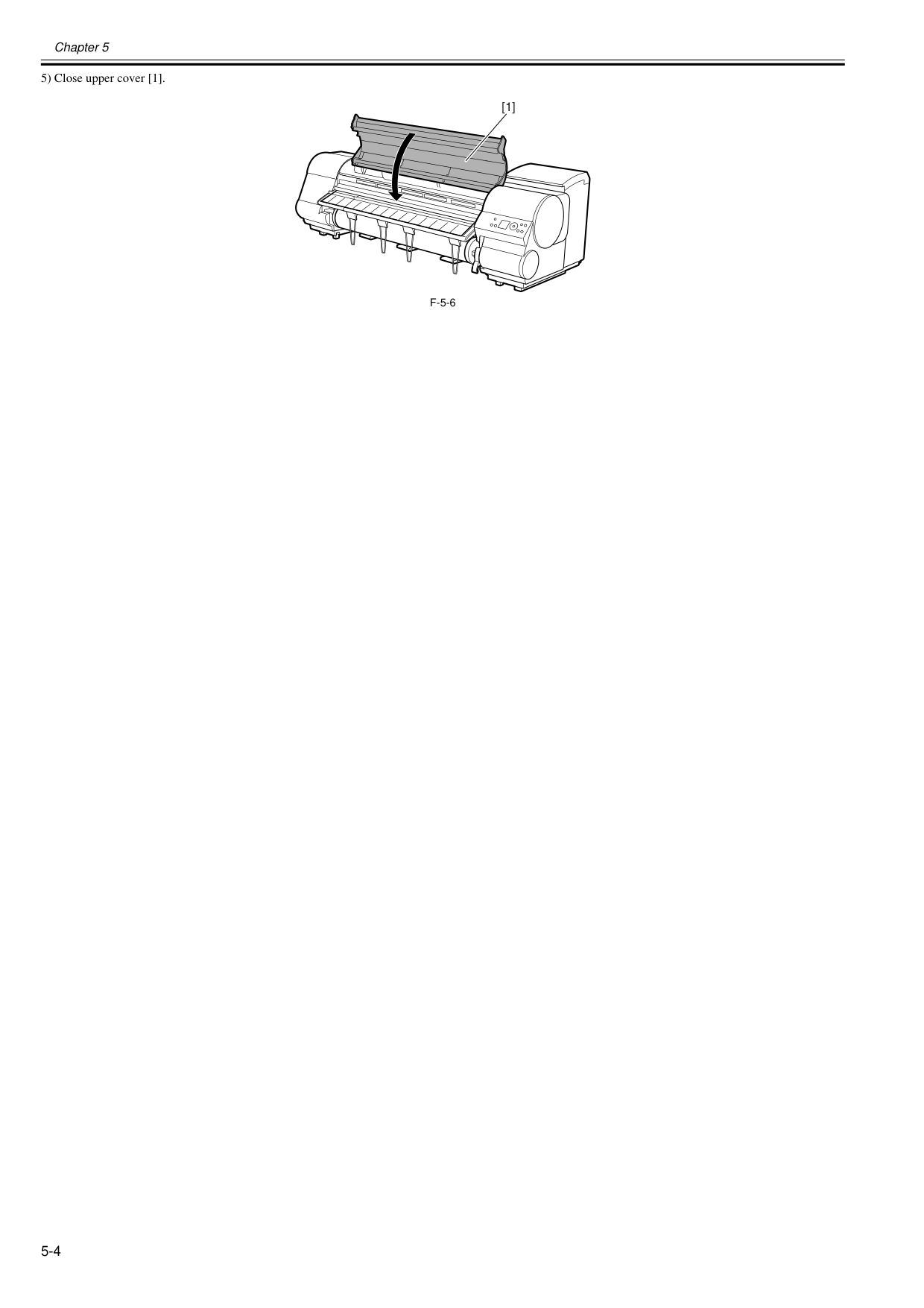
Chapter 5 5-4 5) Close upper cover [1].
F-5-6
[1]
Chapter 5 5-5

Chapter 6 TROUBLESHOOTING

Contents Contents 6.1 Troubleshooting.......................................................................................................................................... 6-1 6.1.1 Outline ..................................................................................................................................................................... 6-1 6.1.1.1 Outline of Troubleshooting....................................................................................................................................................... 6-1 6.2 Location of Connectors and Pin Arrangement............................................................................................ 6-2 6.2.1 Main controller PCB................................................................................................................................................. 6-2 6.2.2 Carriage relay PCB................................................................................................................................................. 6-12 6.2.3 Head relay PCB...................................................................................................................................................... 6-17 6.3 Version Up................................................................................................................................................ 6-21 6.3.1 Firmware Update Tool............................................................................................................................................ 6-21 6.4 Service Tools............................................................................................................................................ 6-26 6.4.1 Tool List.................................................................................................................................................................. 6-26
Chapter 6 6-1 6.1 Troubleshooting 6.1.1 Outline 6.1.1.1 Outline of Troubleshooting 0013-1940
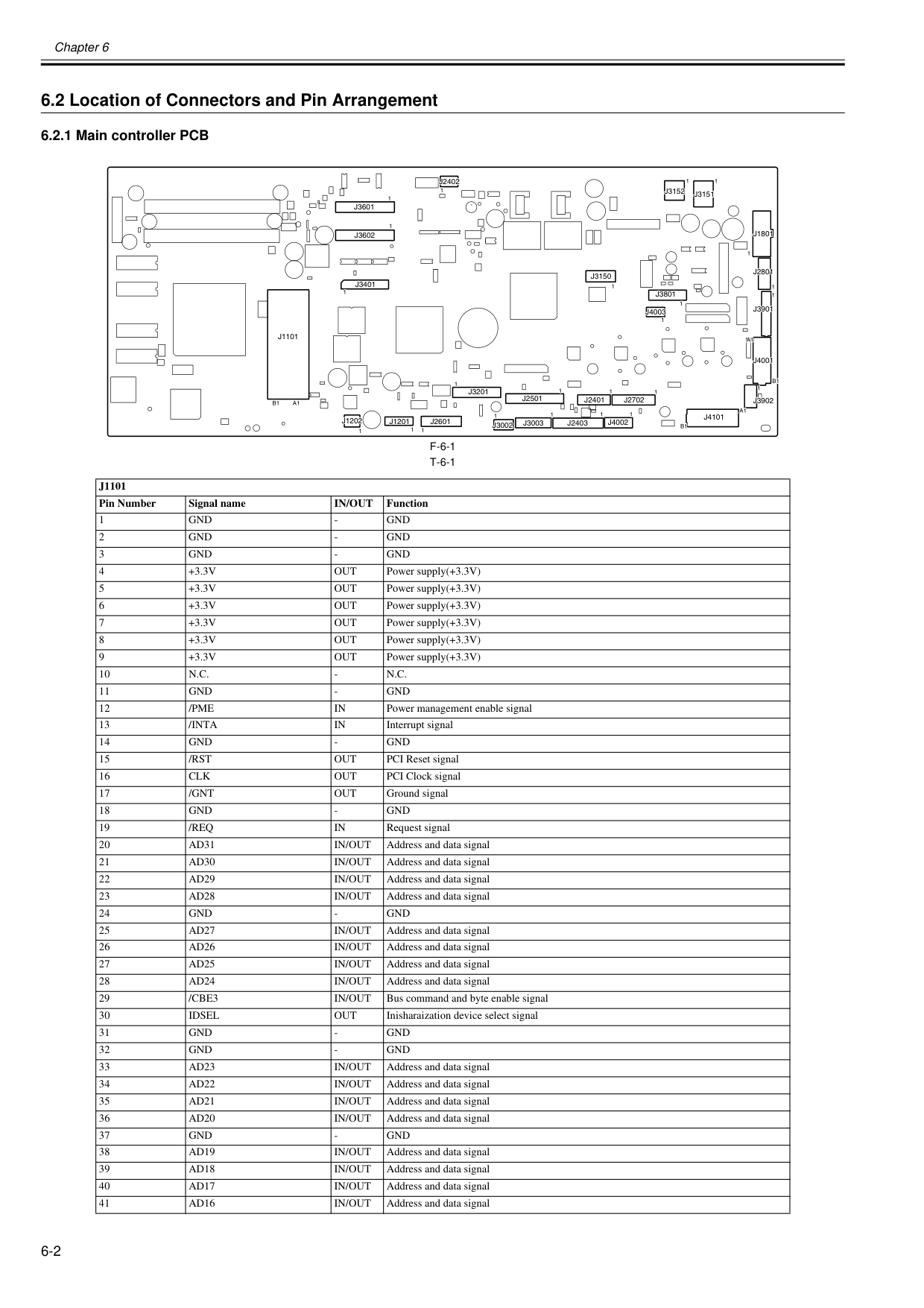
Chapter 6 6-2 6.2 Location of Connectors and Pin Arrangement 6.2.1 Main controller PCB 0020-5726
F-6-1
T-6-1
J1101
Pin Number Signal nameIn/Out
Function 1Gnd
Gnd
Gnd
Gnd
Gnd
Gnd
+3.3V
Out
Power supply(+3.3V) 5+3.3V
Out
Power supply(+3.3V) 6+3.3V
Out
Power supply(+3.3V) 7+3.3V
Out
Power supply(+3.3V) 8+3.3V
Out
Power supply(+3.3V) 9+3.3V
Out
Power supply(+3.3V) 10N.C.
N.C.
Gnd
Gnd
/Pme
In
Power management enable signal 13/Inta
In
Interrupt signal 14Gnd
Gnd
/Rst
Out
PCI Reset signal 16Clk
Out
PCI Clock signal 17/Gnt
Out
Ground signal 18Gnd
Gnd
/Req
In
Request signal 20Ad31
In/Out
Address and data signal 21Ad30
In/Out
Address and data signal 22Ad29
In/Out
Address and data signal 23Ad28
In/Out
Address and data signal 24Gnd
Gnd
Ad27
In/Out
Address and data signal 26Ad26
In/Out
Address and data signal 27Ad25
In/Out
Address and data signal 28Ad24
In/Out
Address and data signal 29/Cbe3
In/Out
Bus command and byte enable signal 30Idsel
Out
Inisharaization device select signal 31Gnd
Gnd
Gnd
Gnd
Ad23
In/Out
Address and data signal 34Ad22
In/Out
Address and data signal 35Ad21
In/Out
Address and data signal 36Ad20
In/Out
Address and data signal 37Gnd
Gnd
Ad19
In/Out
Address and data signal 39Ad18
In/Out
Address and data signal 40Ad17
In/Out
Address and data signal 41Ad16
In/Out
Address and data signalJ1101
J3201
J2601
J2501
J3003
J2403
J3002
J4002
J2702
J3902
J4001
J3901
J2801
J1801
J3151
J3152
J3150
J3801
J4003
J3601
J4101
B1
A1
1J1201
1 1 1 1 1 1 1 1 1 1 1 1 1 1 1 1 1 1J3602
J2402
J3401
1 1 1 1B1
A1
J2401
A1
B1
J1202
J1101
J3201
J2601
J2501
J3003
J2403
J3002
J4002
J2702
J3902
J4001
J3901
J2801
J1801
J3151
J3152
J3150
J3801
J4003
J3601
J4101
B1
A1
1J1201
1 1 1 1 1 1 1 1 1 1 1 1 11 1 1 1 1 1 1J3602
J2402
J3401
1 1 1 1B1
A1
J2401
A1
B1
J1202
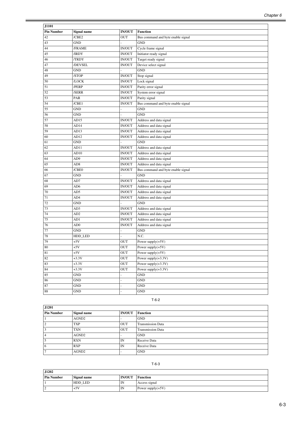
Chapter 6 6-3
T-6-2
T-6-3
42/Cbe2
Out
Bus command and byte enable signal 43Gnd
Gnd
/Frame
In/Out
Cycle frame signal 45/Irdy
In/Out
Initiator ready signal 46/Trdy
In/Out
Target ready signal 47/Devsel
In/Out
Device select signal 48Gnd
Gnd
/Stop
In/Out
Stop signal 50/Lock
In/Out
Lock signal 51/Perp
In/Out
Parity error signal 52/Serr
In/Out
System error signal 53Par
In/Out
Parity signal 54/Cbe1
In/Out
Bus command and byte enable signal 55Gnd
Gnd
Gnd
Gnd
Ad15
In/Out
Address and data signal 58Ad14
In/Out
Address and data signal 59Ad13
In/Out
Address and data signal 60Ad12
In/Out
Address and data signal 61Gnd
Gnd
Ad11
In/Out
Address and data signal 63Ad10
In/Out
Address and data signal 64Ad9
In/Out
Address and data signal 65Ad8
In/Out
Address and data signal 66/Cbe0
In/Out
Bus command and byte enable signal 67Gnd
Gnd
Ad7
In/Out
Address and data signal 69Ad6
In/Out
Address and data signal 70Ad5
In/Out
Address and data signal 71Ad4
In/Out
Address and data signal 72Gnd
Gnd
Ad3
In/Out
Address and data signal 74Ad2
In/Out
Address and data signal 75Ad1
In/Out
Address and data signal 76Ad0
In/Out
Address and data signal 77Gnd
Gnd
Hdd_Led
N.C.
+5V
Out
Power supply(+5V) 80+5V
Out
Power supply(+5V) 81+5V
Out
Power supply(+5V) 82+3.3V
Out
Power supply(+3.3V) 83+3.3V
Out
Power supply(+3.3V) 84+3.3V
Out
Power supply(+3.3V) 85Gnd
Gnd
Gnd
Gnd
Gnd
Gnd
Gnd
Gnd
J1201
Pin Number Signal nameIn/Out
Function 1Agnd2
Gnd
Txp
Out
Transmission Data 3Txn
Out
Transmission Data 4Agnd2
Gnd
Rxn
In
Receive Data 6Rxp
In
Receive Data 7Agnd2
Gnd
J1202
Pin Number Signal nameIn/Out
Function 1Hdd_Led
In
Access signal 2+5V
In
Power supply(+5V)J1101
Pin Number Signal nameIn/Out
Function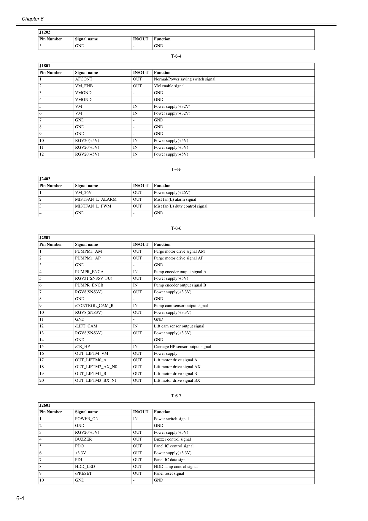
Chapter 6 6-4
T-6-4
T-6-5
T-6-6
T-6-7
3Gnd
Gnd
J1801
Pin Number Signal nameIn/Out
Function 1Afcont
Out
Normal/Power saving switch signal 2Vm_Enb
Out
VM enable signal 3Vmgnd
Gnd
Vmgnd
Gnd
Vm
In
Power supply(+32V) 6Vm
In
Power supply(+32V) 7Gnd
Gnd
Gnd
Gnd
Gnd
Gnd
Rgv20(+5V)
In
Power supply(+5V) 11Rgv20(+5V)
In
Power supply(+5V) 12Rgv20(+5V)
In
Power supply(+5V)J2402
Pin Number Signal nameIn/Out
Function 1Vm_26V
Out
Power supply(+26V) 2Mistfan_L_Alarm
Out
Mist fan(L) alarm signal 3Mistfan_L_Pwm
Out
Mist fan(L) duty control signal 4Gnd
Gnd
J2501
Pin Number Signal nameIn/Out
Function 1Pumpm1_Am
Out
Purge motor drive signal AM 2Pumpm1_Ap
Out
Purge motor drive signal AP 3Gnd
Gnd
Pumpr_Enca
In
Pump encoder output signal A 5Rgv31(Sns5V_Fu)
Out
Power supply(+5V) 6Pumpr_Encb
In
Pump encoder output signal B 7Rgv8(Sns3V)
Out
Power supply(+3.3V) 8Gnd
Gnd
/Control_Cam_R
In
Pump cam sensor output signal 10Rgv8(Sns3V)
Out
Power supply(+3.3V) 11Gnd
Gnd
/Lift_Cam
In
Lift cam sensor output signal 13Rgv8(Sns3V)
Out
Power supply(+3.3V) 14Gnd
Gnd
/Cr_Hp
In
Carriage HP sensor output signal 16Out_Liftm_Vm
Out
Power supply 17Out_Liftm0_A
Out
Lift motor drive signal A 18Out_Liftm2_Ax_N0
Out
Lift motor drive signal AX 19Out_Liftm1_B
Out
Lift motor drive signal B 20Out_Liftm3_Bx_N1
Out
Lift motor drive signal BXJ2601
Pin Number Signal nameIn/Out
Function 1Power_On
In
Power switch signal 2Gnd
Gnd
Rgv20(+5V)
Out
Power supply(+5V) 4Buzzer
Out
Buzzer control signal 5Pdo
Out
Panel IC control signal 6+3.3V
Out
Power supply(+3.3V) 7Pdi
Out
Panel IC data signal 8Hdd_Led
Out
HDD lamp control signal 9/Preset
Out
Panel reset signal 10Gnd
Gnd
J1202
Pin Number Signal nameIn/Out
Function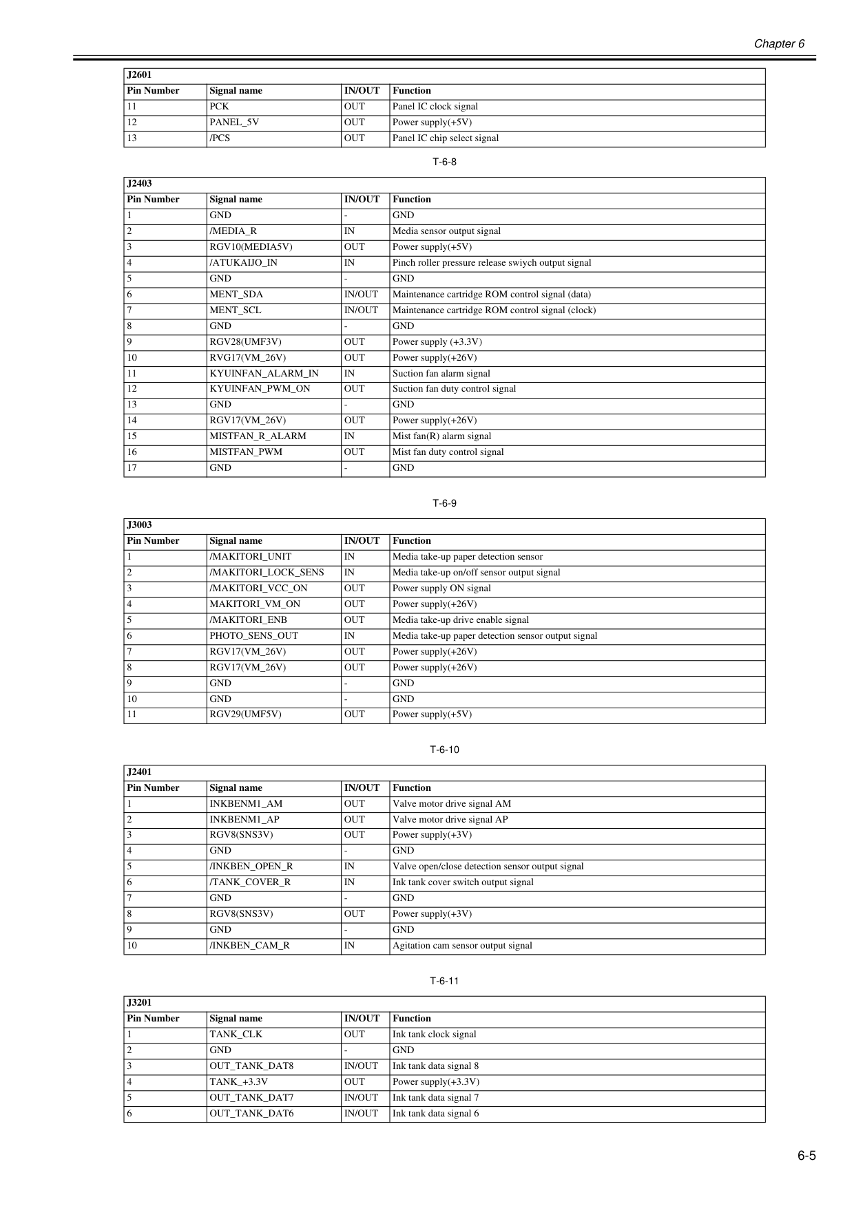
Chapter 6 6-5
T-6-8
T-6-9
T-6-10
T-6-11
11Pck
Out
Panel IC clock signal 12Panel_5V
Out
Power supply(+5V) 13/Pcs
Out
Panel IC chip select signalJ2403
Pin Number Signal nameIn/Out
Function 1Gnd
Gnd
/Media_R
In
Media sensor output signal 3Rgv10(Media5V)
Out
Power supply(+5V) 4/Atukaijo_In
In
Pinch roller pressure release swiych output signal 5Gnd
Gnd
Ment_Sda
In/Out
Maintenance cartridge ROM control signal (data) 7Ment_Scl
In/Out
Maintenance cartridge ROM control signal (clock) 8Gnd
Gnd
Rgv28(Umf3V)
Out
Power supply (+3.3V) 10Rvg17(Vm_26V)
Out
Power supply(+26V) 11Kyuinfan_Alarm_In
In
Suction fan alarm signal 12Kyuinfan_Pwm_On
Out
Suction fan duty control signal 13Gnd
Gnd
Rgv17(Vm_26V)
Out
Power supply(+26V) 15Mistfan_R_Alarm
In
Mist fan(R) alarm signal 16Mistfan_Pwm
Out
Mist fan duty control signal 17Gnd
Gnd
J3003
Pin Number Signal nameIn/Out
Function 1/Makitori_Unit
In
Media take-up paper detection sensor 2/Makitori_Lock_Sens
In
Media take-up on/off sensor output signal 3/Makitori_Vcc_On
Out
Power supply ON signal 4Makitori_Vm_On
Out
Power supply(+26V) 5/Makitori_Enb
Out
Media take-up drive enable signal 6Photo_Sens_Out
In
Media take-up paper detection sensor output signal 7Rgv17(Vm_26V)
Out
Power supply(+26V) 8Rgv17(Vm_26V)
Out
Power supply(+26V) 9Gnd
Gnd
Gnd
Gnd
Rgv29(Umf5V)
Out
Power supply(+5V)J2401
Pin Number Signal nameIn/Out
Function 1Inkbenm1_Am
Out
Valve motor drive signal AM 2Inkbenm1_Ap
Out
Valve motor drive signal AP 3Rgv8(Sns3V)
Out
Power supply(+3V) 4Gnd
Gnd
/Inkben_Open_R
In
Valve open/close detection sensor output signal 6/Tank_Cover_R
In
Ink tank cover switch output signal 7Gnd
Gnd
Rgv8(Sns3V)
Out
Power supply(+3V) 9Gnd
Gnd
/Inkben_Cam_R
In
Agitation cam sensor output signalJ3201
Pin Number Signal nameIn/Out
Function 1Tank_Clk
Out
Ink tank clock signal 2Gnd
Gnd
Out_Tank_Dat8
In/Out
Ink tank data signal 8 4Tank_+3.3V
Out
Power supply(+3.3V) 5Out_Tank_Dat7
In/Out
Ink tank data signal 7 6Out_Tank_Dat6
In/Out
Ink tank data signal 6J2601
Pin Number Signal nameIn/Out
Function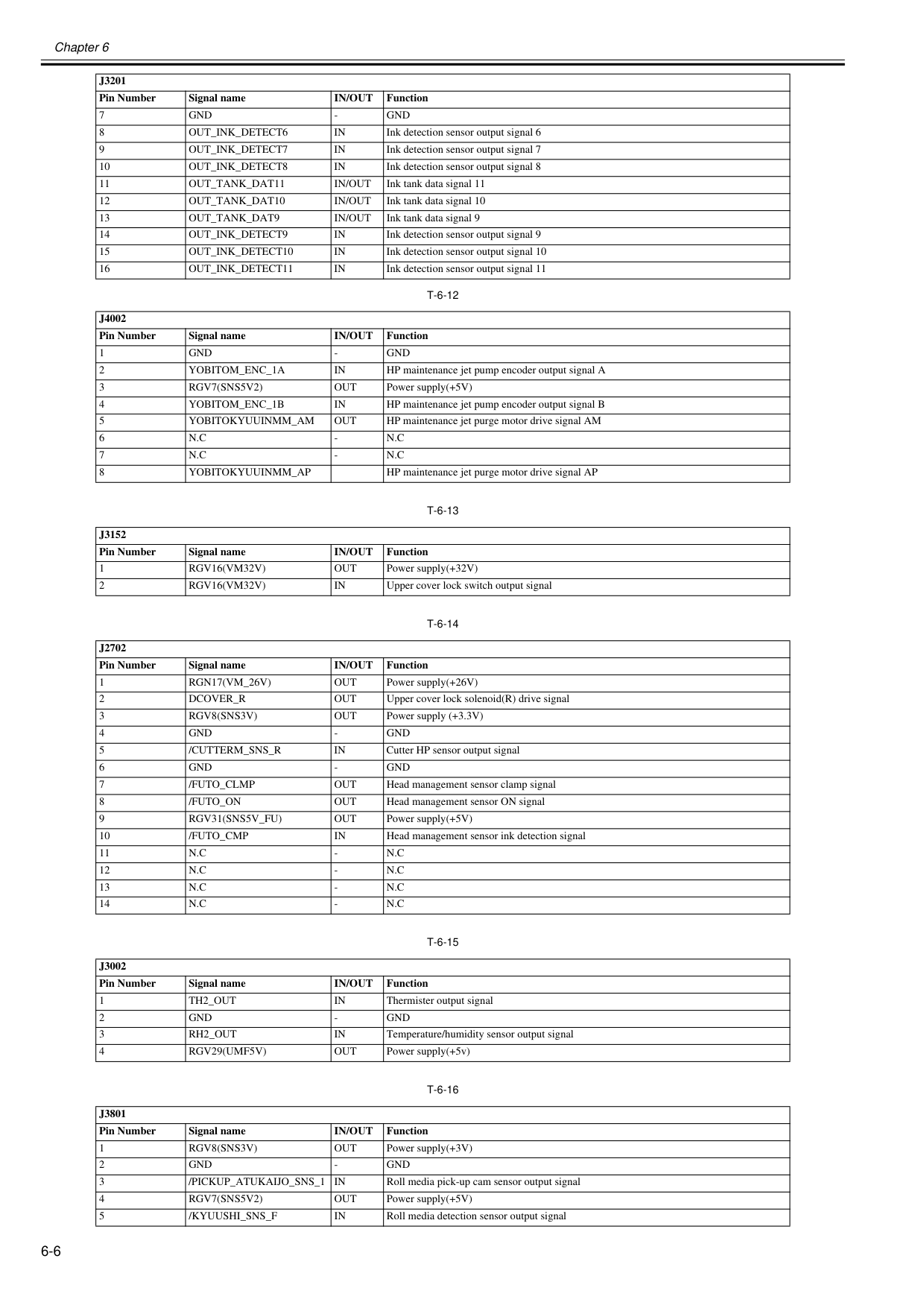
Chapter 6 6-6
T-6-12
T-6-13
T-6-14
T-6-15
T-6-16
7Gnd
Gnd
Out_Ink_Detect6
In
Ink detection sensor output signal 6 9Out_Ink_Detect7
In
Ink detection sensor output signal 7 10Out_Ink_Detect8
In
Ink detection sensor output signal 8 11Out_Tank_Dat11
In/Out
Ink tank data signal 11 12Out_Tank_Dat10
In/Out
Ink tank data signal 10 13Out_Tank_Dat9
In/Out
Ink tank data signal 9 14Out_Ink_Detect9
In
Ink detection sensor output signal 9 15Out_Ink_Detect10
In
Ink detection sensor output signal 10 16Out_Ink_Detect11
In
Ink detection sensor output signal 11J4002
Pin Number Signal nameIn/Out
Function 1Gnd
Gnd
Yobitom_Enc_1A
In
HP maintenance jet pump encoder output signal A 3Rgv7(Sns5V2)
Out
Power supply(+5V) 4Yobitom_Enc_1B
In
HP maintenance jet pump encoder output signal B 5Yobitokyuuinmm_Am
Out
HP maintenance jet purge motor drive signal AM 6N.C
N.C
N.C
N.C
Yobitokyuuinmm_Ap
HP maintenance jet purge motor drive signal APJ3152
Pin Number Signal nameIn/Out
Function 1Rgv16(Vm32V)
Out
Power supply(+32V) 2Rgv16(Vm32V)
In
Upper cover lock switch output signalJ2702
Pin Number Signal nameIn/Out
Function 1Rgn17(Vm_26V)
Out
Power supply(+26V) 2Dcover_R
Out
Upper cover lock solenoid(R) drive signal 3Rgv8(Sns3V)
Out
Power supply (+3.3V) 4Gnd
Gnd
/Cutterm_Sns_R
In
Cutter HP sensor output signal 6Gnd
Gnd
/Futo_Clmp
Out
Head management sensor clamp signal 8/Futo_On
Out
Head management sensor ON signal 9Rgv31(Sns5V_Fu)
Out
Power supply(+5V) 10/Futo_Cmp
In
Head management sensor ink detection signal 11N.C
N.C
N.C
N.C
N.C
N.C
N.C
N.C
J3002
Pin Number Signal nameIn/Out
Function 1Th2_Out
In
Thermister output signal 2Gnd
Gnd
Rh2_Out
In
Temperature/humidity sensor output signal 4Rgv29(Umf5V)
Out
Power supply(+5v)J3801
Pin Number Signal nameIn/Out
Function 1Rgv8(Sns3V)
Out
Power supply(+3V) 2Gnd
Gnd
/Pickup_Atukaijo_Sns_1
In
Roll media pick-up cam sensor output signal 4Rgv7(Sns5V2)
Out
Power supply(+5V) 5/Kyuushi_Sns_F
In
Roll media detection sensor output signalJ3201
Pin Number Signal nameIn/Out
Function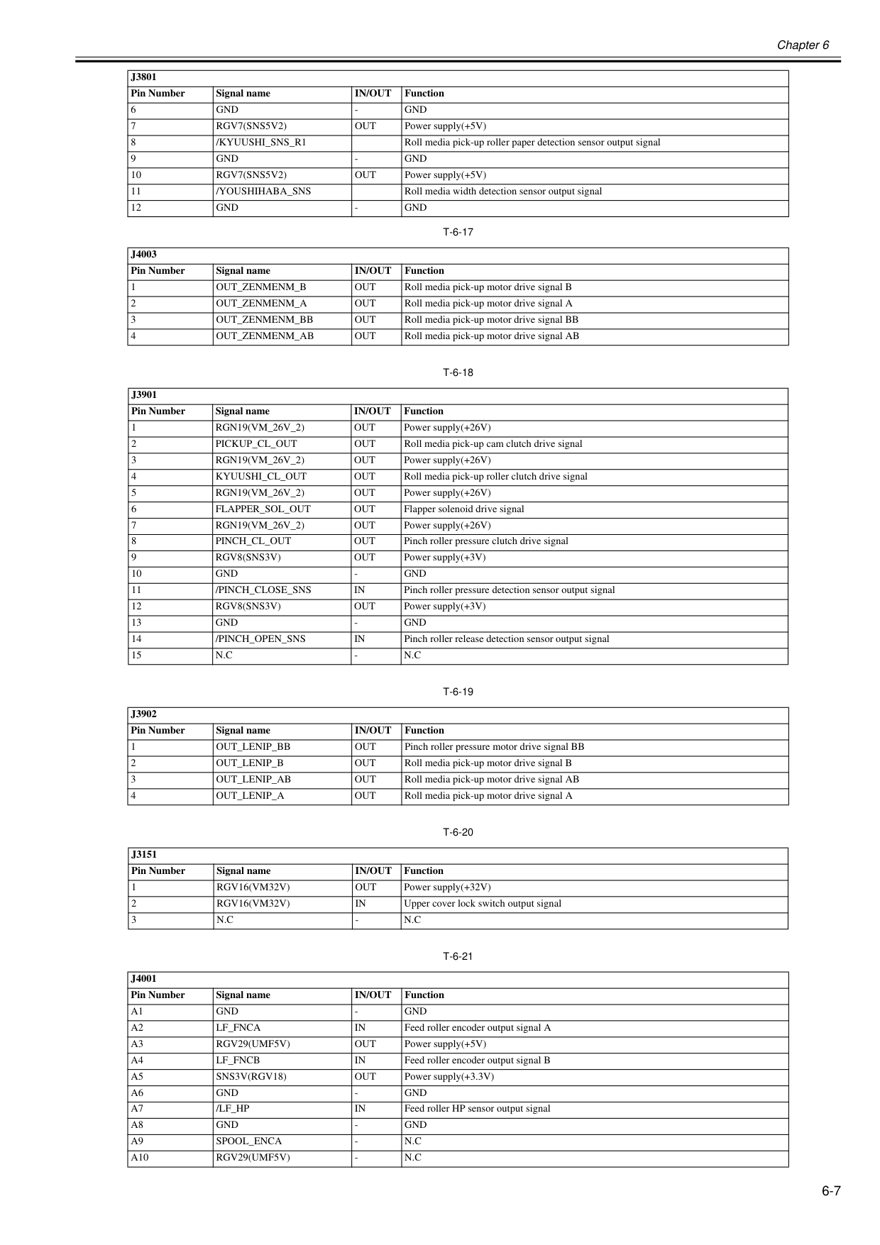
Chapter 6 6-7
T-6-17
T-6-18
T-6-19
T-6-20
T-6-21
6Gnd
Gnd
Rgv7(Sns5V2)
Out
Power supply(+5V) 8/Kyuushi_Sns_R1
Roll media pick-up roller paper detection sensor output signal 9Gnd
Gnd
Rgv7(Sns5V2)
Out
Power supply(+5V) 11/Youshihaba_Sns
Roll media width detection sensor output signal 12Gnd
Gnd
J4003
Pin Number Signal nameIn/Out
Function 1Out_Zenmenm_B
Out
Roll media pick-up motor drive signal B 2Out_Zenmenm_A
Out
Roll media pick-up motor drive signal A 3Out_Zenmenm_Bb
Out
Roll media pick-up motor drive signal BB 4Out_Zenmenm_Ab
Out
Roll media pick-up motor drive signal ABJ3901
Pin Number Signal nameIn/Out
Function 1Rgn19(Vm_26V_2)
Out
Power supply(+26V) 2Pickup_Cl_Out
Out
Roll media pick-up cam clutch drive signal 3Rgn19(Vm_26V_2)
Out
Power supply(+26V) 4Kyuushi_Cl_Out
Out
Roll media pick-up roller clutch drive signal 5Rgn19(Vm_26V_2)
Out
Power supply(+26V) 6Flapper_Sol_Out
Out
Flapper solenoid drive signal 7Rgn19(Vm_26V_2)
Out
Power supply(+26V) 8Pinch_Cl_Out
Out
Pinch roller pressure clutch drive signal 9Rgv8(Sns3V)
Out
Power supply(+3V) 10Gnd
Gnd
/Pinch_Close_Sns
In
Pinch roller pressure detection sensor output signal 12Rgv8(Sns3V)
Out
Power supply(+3V) 13Gnd
Gnd
/Pinch_Open_Sns
In
Pinch roller release detection sensor output signal 15N.C
N.C
J3902
Pin Number Signal nameIn/Out
Function 1Out_Lenip_Bb
Out
Pinch roller pressure motor drive signal BB 2Out_Lenip_B
Out
Roll media pick-up motor drive signal B 3Out_Lenip_Ab
Out
Roll media pick-up motor drive signal AB 4Out_Lenip_A
Out
Roll media pick-up motor drive signal AJ3151
Pin Number Signal nameIn/Out
Function 1Rgv16(Vm32V)
Out
Power supply(+32V) 2Rgv16(Vm32V)
In
Upper cover lock switch output signal 3N.C
N.C
J4001
Pin Number Signal nameIn/Out
FunctionA1
Gnd
Gnd
A2
Lf_Fnca
In
Feed roller encoder output signal AA3
Rgv29(Umf5V)
Out
Power supply(+5V)A4
Lf_Fncb
In
Feed roller encoder output signal BA5
Sns3V(Rgv18)
Out
Power supply(+3.3V)A6
Gnd
Gnd
A7
/Lf_Hp
In
Feed roller HP sensor output signalA8
Gnd
Gnd
A9
Spool_Enca
N.C
A10
Rgv29(Umf5V)
N.C
J3801
Pin Number Signal nameIn/Out
Function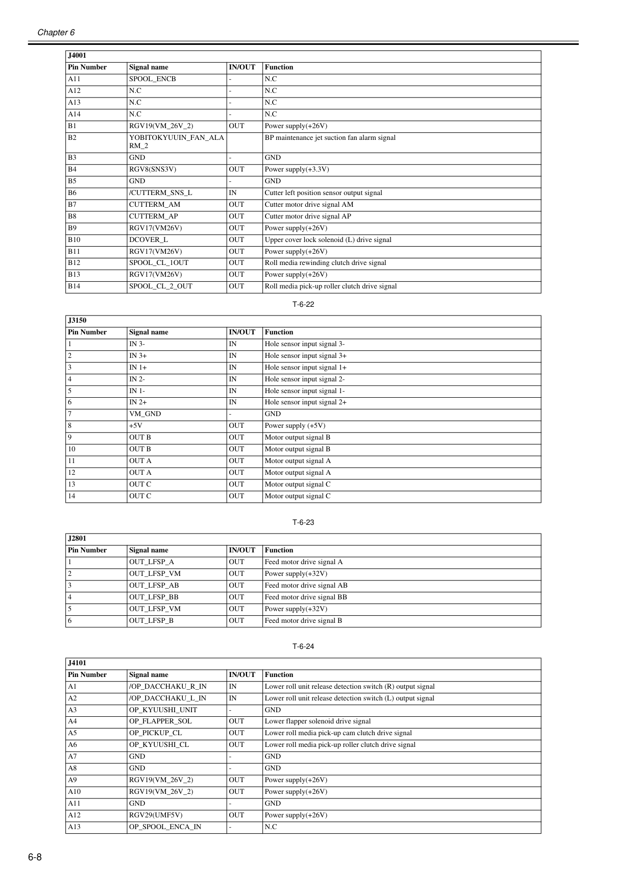
Chapter 6 6-8
T-6-22
T-6-23
T-6-24
A11
Spool_Encb
N.C
A12
N.C
N.C
A13
N.C
N.C
A14
N.C
N.C
B1
Rgv19(Vm_26V_2)
Out
Power supply(+26V)B2
Yobitokyuuin_Fan_Ala
Rm_2
BP maintenance jet suction fan alarm signalB3
Gnd
Gnd
B4
Rgv8(Sns3V)
Out
Power supply(+3.3V)B5
Gnd
Gnd
B6
/Cutterm_Sns_L
In
Cutter left position sensor output signalB7
Cutterm_Am
Out
Cutter motor drive signal AMB8
Cutterm_Ap
Out
Cutter motor drive signal APB9
Rgv17(Vm26V)
Out
Power supply(+26V)B10
Dcover_L
Out
Upper cover lock solenoid (L) drive signalB11
Rgv17(Vm26V)
Out
Power supply(+26V)B12
Spool_Cl_1Out
Out
Roll media rewinding clutch drive signalB13
Rgv17(Vm26V)
Out
Power supply(+26V)B14
Spool_Cl_2_Out
Out
Roll media pick-up roller clutch drive signalJ3150
Pin Number Signal nameIn/Out
Function 1In 3-
In
Hole sensor input signal 3- 2In 3+
In
Hole sensor input signal 3+ 3In 1+
In
Hole sensor input signal 1+ 4In 2-
In
Hole sensor input signal 2- 5In 1-
In
Hole sensor input signal 1- 6In 2+
In
Hole sensor input signal 2+ 7Vm_Gnd
Gnd
+5V
Out
Power supply (+5V) 9Out B
Out
Motor output signal B 10Out B
Out
Motor output signal B 11Out A
Out
Motor output signal A 12Out A
Out
Motor output signal A 13Out C
Out
Motor output signal C 14Out C
Out
Motor output signal CJ2801
Pin Number Signal nameIn/Out
Function 1Out_Lfsp_A
Out
Feed motor drive signal A 2Out_Lfsp_Vm
Out
Power supply(+32V) 3Out_Lfsp_Ab
Out
Feed motor drive signal AB 4Out_Lfsp_Bb
Out
Feed motor drive signal BB 5Out_Lfsp_Vm
Out
Power supply(+32V) 6Out_Lfsp_B
Out
Feed motor drive signal BJ4101
Pin Number Signal nameIn/Out
FunctionA1
/Op_Dacchaku_R_In
In
Lower roll unit release detection switch (R) output signalA2
/Op_Dacchaku_L_In
In
Lower roll unit release detection switch (L) output signalA3
Op_Kyuushi_Unit
Gnd
A4
Op_Flapper_Sol
Out
Lower flapper solenoid drive signalA5
Op_Pickup_Cl
Out
Lower roll media pick-up cam clutch drive signalA6
Op_Kyuushi_Cl
Out
Lower roll media pick-up roller clutch drive signalA7
Gnd
Gnd
A8
Gnd
Gnd
A9
Rgv19(Vm_26V_2)
Out
Power supply(+26V)A10
Rgv19(Vm_26V_2)
Out
Power supply(+26V)A11
Gnd
Gnd
A12
Rgv29(Umf5V)
Out
Power supply(+26V)A13
Op_Spool_Enca_In
N.C
J4001
Pin Number Signal nameIn/Out
Function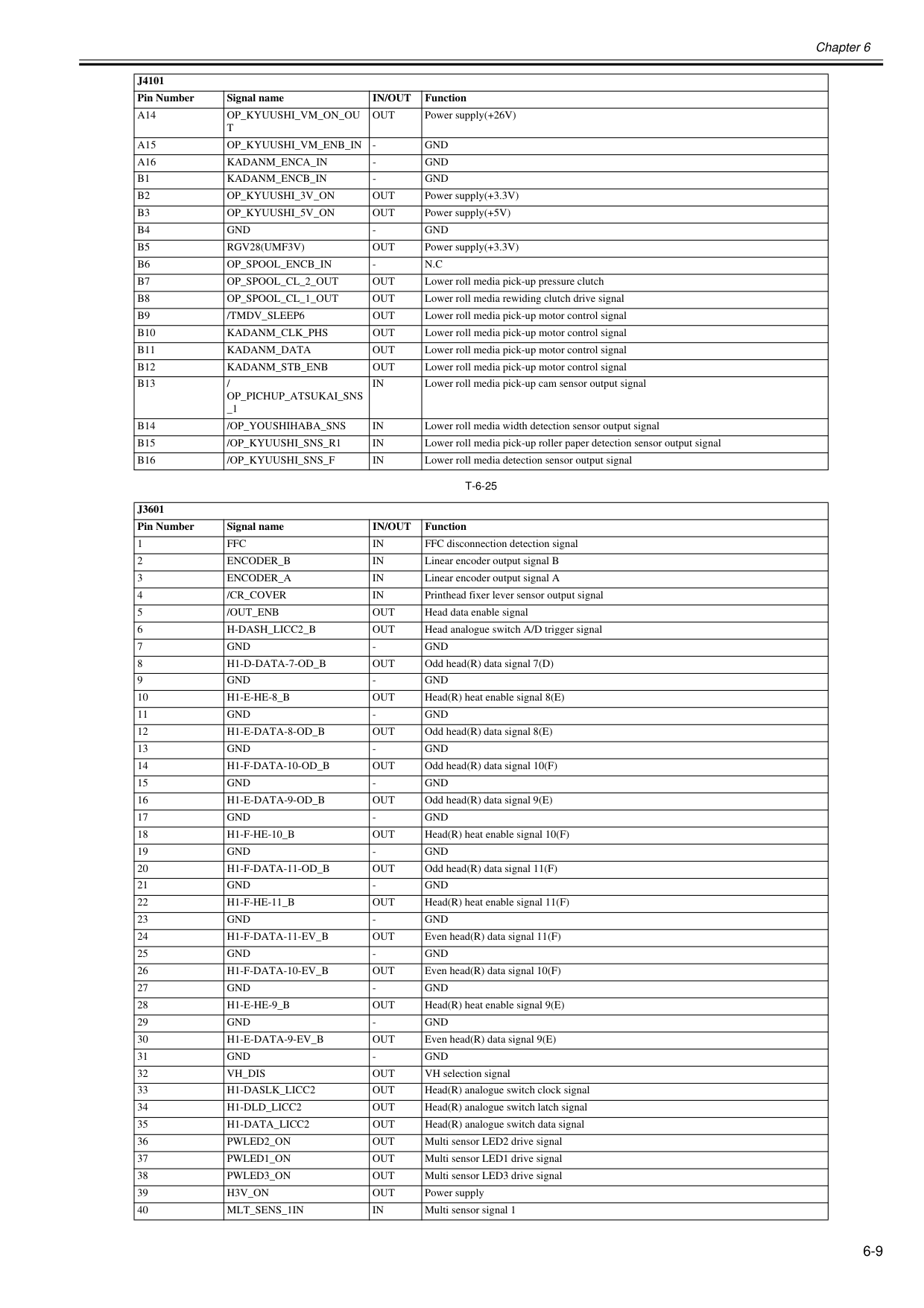
Chapter 6 6-9
T-6-25
A14
Op_Kyuushi_Vm_On_Ou
T
Out
Power supply(+26V)A15
Op_Kyuushi_Vm_Enb_In
Gnd
A16
Kadanm_Enca_In
Gnd
B1
Kadanm_Encb_In
Gnd
B2
Op_Kyuushi_3V_On
Out
Power supply(+3.3V)B3
Op_Kyuushi_5V_On
Out
Power supply(+5V)B4
Gnd
Gnd
B5
Rgv28(Umf3V)
Out
Power supply(+3.3V)B6
Op_Spool_Encb_In
N.C
B7
Op_Spool_Cl_2_Out
Out
Lower roll media pick-up pressure clutchB8
Op_Spool_Cl_1_Out
Out
Lower roll media rewiding clutch drive signalB9
/Tmdv_Sleep6
Out
Lower roll media pick-up motor control signalB10
Kadanm_Clk_Phs
Out
Lower roll media pick-up motor control signalB11
Kadanm_Data
Out
Lower roll media pick-up motor control signalB12
Kadanm_Stb_Enb
Out
Lower roll media pick-up motor control signalB13
/Op_Pichup_Atsukai_Sns
_1In
Lower roll media pick-up cam sensor output signalB14
/Op_Youshihaba_Sns
In
Lower roll media width detection sensor output signalB15
/Op_Kyuushi_Sns_R1
In
Lower roll media pick-up roller paper detection sensor output signalB16
/Op_Kyuushi_Sns_F
In
Lower roll media detection sensor output signalJ3601
Pin Number Signal nameIn/Out
Function 1Ffc
In
FFC disconnection detection signal 2Encoder_B
In
Linear encoder output signal B 3Encoder_A
In
Linear encoder output signal A 4/Cr_Cover
In
Printhead fixer lever sensor output signal 5/Out_Enb
Out
Head data enable signal 6H-Dash_Licc2_B
Out
Head analogue switch A/D trigger signal 7Gnd
Gnd
H1-D-Data-7-Od_B
Out
Odd head(R) data signal 7(D) 9Gnd
Gnd
H1-E-He-8_B
Out
Head(R) heat enable signal 8(E) 11Gnd
Gnd
H1-E-Data-8-Od_B
Out
Odd head(R) data signal 8(E) 13Gnd
Gnd
H1-F-Data-10-Od_B
Out
Odd head(R) data signal 10(F) 15Gnd
Gnd
H1-E-Data-9-Od_B
Out
Odd head(R) data signal 9(E) 17Gnd
Gnd
H1-F-He-10_B
Out
Head(R) heat enable signal 10(F) 19Gnd
Gnd
H1-F-Data-11-Od_B
Out
Odd head(R) data signal 11(F) 21Gnd
Gnd
H1-F-He-11_B
Out
Head(R) heat enable signal 11(F) 23Gnd
Gnd
H1-F-Data-11-Ev_B
Out
Even head(R) data signal 11(F) 25Gnd
Gnd
H1-F-Data-10-Ev_B
Out
Even head(R) data signal 10(F) 27Gnd
Gnd
H1-E-He-9_B
Out
Head(R) heat enable signal 9(E) 29Gnd
Gnd
H1-E-Data-9-Ev_B
Out
Even head(R) data signal 9(E) 31Gnd
Gnd
Vh_Dis
Out
VH selection signal 33H1-Daslk_Licc2
Out
Head(R) analogue switch clock signal 34H1-Dld_Licc2
Out
Head(R) analogue switch latch signal 35H1-Data_Licc2
Out
Head(R) analogue switch data signal 36Pwled2_On
Out
Multi sensor LED2 drive signal 37Pwled1_On
Out
Multi sensor LED1 drive signal 38Pwled3_On
Out
Multi sensor LED3 drive signal 39H3V_On
Out
Power supply 40Mlt_Sens_1In
In
Multi sensor signal 1J4101
Pin Number Signal nameIn/Out
Function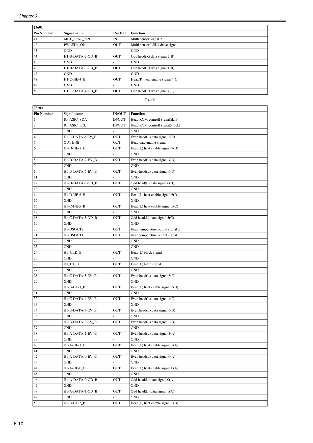
Chapter 6 6-10
T-6-26
41Mlt_Sens_2In
In
Multi sensor signal 2 42Pwled4_On
Out
Multi sensor LED4 drive signal 43Gnd
Gnd
H1-B-Data-2-Od_B
Out
Odd head(R) data signal 2(B) 45Gnd
Gnd
H1-B-Data-3-Od_B
Out
Odd head(R) data signal 1(B) 47Gnd
Gnd
H1-C-He-4_B
Out
Head(R) heat enable signal 4(C) 49Gnd
Gnd
H1-C-Data-4-Od_B
Out
Odd head(R) data signal 4(C)J3602
Pin Number Signal nameIn/Out
Function 1Io_Asic_Sda
In/Out
Head ROM controll signal(data) 2Io_Asic_Scl
In/Out
Head ROM controll signal(clock) 3Gnd
Gnd
H1-E-Data-8-Ev_B
Out
Even head(L) data signal 8(E) 5Out Enb
Out
Head data enable signal 6H1-D-He-7_B
Out
Head(L) heat enable signal 7(D) 7Gnd
Gnd
H1-D-Data-7-Ev_B
Out
Even head(L) data signal 7(D) 9Gnd
Gnd
H1-D-Data-6-Ev_B
Out
Even head(L) data signal 6(D) 11Gnd
Gnd
H1-D-Data-6-Od_B
Out
Odd head(L) data signal 6(D) 13Gnd
Gnd
H1-D-He-6_B
Out
Head(L) heat enable signal 6(D) 15Gnd
Gnd
H1-C-He-5_B
Out
Head(L) heat enable signal 5(C) 17Gnd
Gnd
H1-C-Data-5-Od_B
Out
Odd head(L) data signal 5(C) 19Gnd
Gnd
H1-Dsout2
Out
Head temperature output signal 2 21H1-Dsout1
Out
Head temperature output signal 1 22Gnd
Gnd
Gnd
Gnd
H1_Clk_B
Out
Head(L) clock signal 25Gnd
Gnd
H1_Lt_B
Out
Head(L) latch signal 27Gnd
Gnd
H1-C-Data-5-Ev_B
Out
Even head(L) data signal 5(C) 29Gnd
Gnd
H1-B-He-3_B
Out
Head(L) heat enable signal 3(B) 31Gnd
Gnd
H1-C-Data-4-Ev_B
Out
Even head(L) data signal 4(C) 33Gnd
Gnd
H1-B-Data-3-Ev_B
Out
Even head(L) data signal 3(B) 35Gnd
Gnd
H1-B-Data-2-Ev_B
Out
Even head(L) data signal 2(B) 37Gnd
Gnd
H1-A-Data-1-Ev_B
Out
Even head(L) data signal 1(A) 39Gnd
Gnd
H1-A-He-1_B
Out
Head(L) heat enable signal 1(A) 41Gnd
Gnd
H1-A-Data-0-Ev_B
Out
Even head(L) data signal 0(A) 43Gnd
Gnd
H1-A-He-0_B
Out
Head(L) heat enable signal 0(A) 45Gnd
Gnd
H1-A-Data-0-Od_B
Out
Odd head(L) data signal 0(A) 47Gnd
Gnd
H1-A-Data-1-Od_B
Out
Odd head(L) data signal 1(A) 49Gnd
Gnd
H1-B-He-2_B
Out
Head(L) heat enable signal 2(B)J3601
Pin Number Signal nameIn/Out
Function
Chapter 6 6-11
T-6-27
J3401
Pin Number Signal nameIn/Out
Function 1Vmgnd
Gnd
Vmgnd
Gnd
Vmgnd
Gnd
Vmgnd
Gnd
Vh_Moni1
In
VH controll signal 1 6Vh_Enb
Out
VH power supply ON/OFF signal 7Vh_Moni2
In
VH controll signal 2 8Gnd
Gnd
+3.3V
Out
Power supply(+3.3V) 10+3.3V
Out
Power supply(+3.3V) 11Gnd
Gnd
Sns5V
Out
Power supply(+5V) 13Sns5V
Out
Power supply(+5V) 14Vm
Out
Power supply(+32V) 15Vm
Out
Power supply(+32V) 16Vm
Out
Power supply(+32V) 17Vm
Out
Power supply(+32V) 18Vm
Out
Power supply(+32V) 19Vm
Out
Power supply(+32V) 20Vm
Out
Power supply(+32V) 21Vm
Out
Power supply(+32V) 22Vmgnd
Gnd
Vmgnd
Gnd
Vmgnd
Gnd
Vmgnd
Gnd
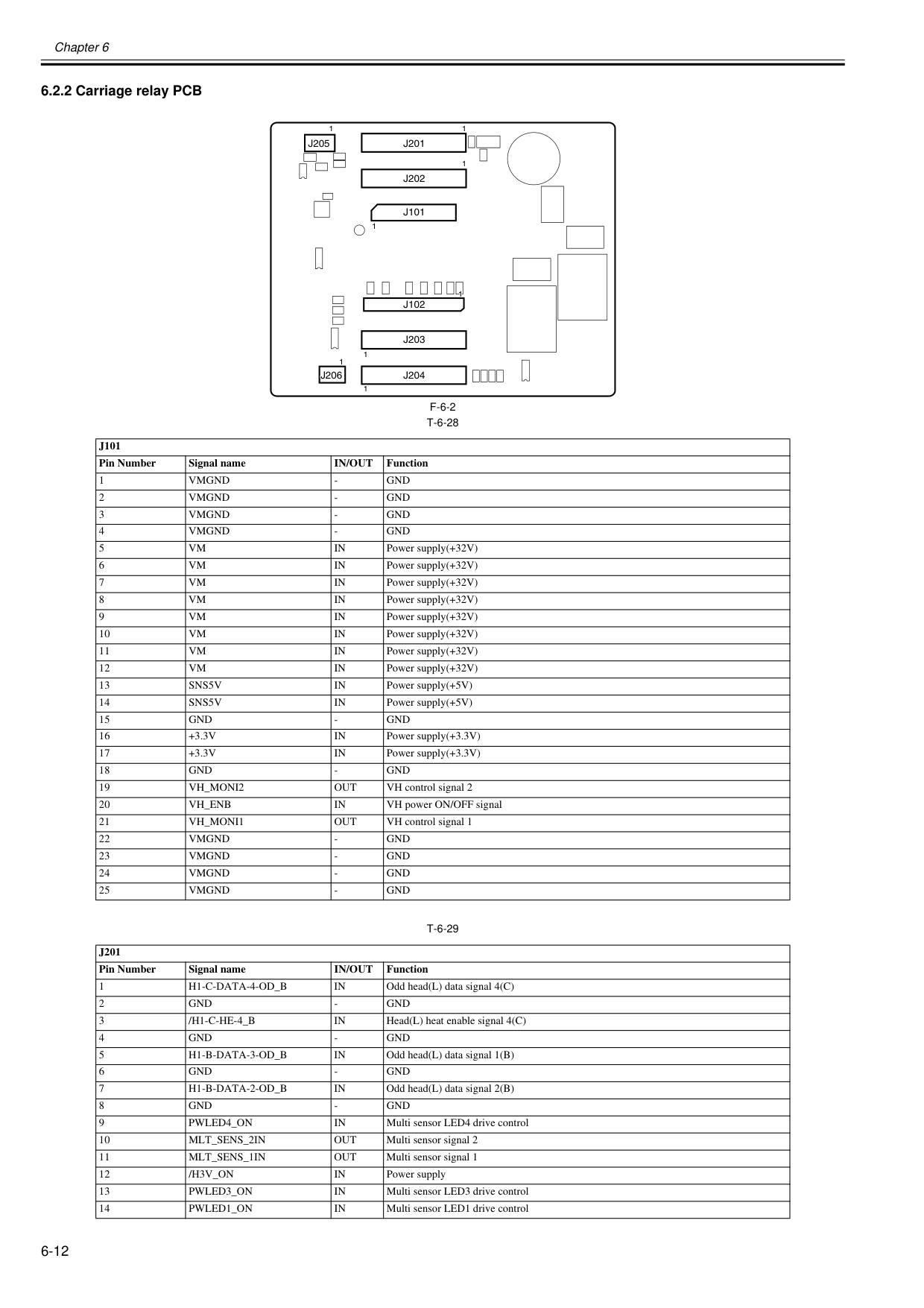
Chapter 6 6-12 6.2.2 Carriage relay PCB 0020-5730
F-6-2
T-6-28
T-6-29
J101
Pin Number Signal nameIn/Out
Function 1Vmgnd
Gnd
Vmgnd
Gnd
Vmgnd
Gnd
Vmgnd
Gnd
Vm
In
Power supply(+32V) 6Vm
In
Power supply(+32V) 7Vm
In
Power supply(+32V) 8Vm
In
Power supply(+32V) 9Vm
In
Power supply(+32V) 10Vm
In
Power supply(+32V) 11Vm
In
Power supply(+32V) 12Vm
In
Power supply(+32V) 13Sns5V
In
Power supply(+5V) 14Sns5V
In
Power supply(+5V) 15Gnd
Gnd
+3.3V
In
Power supply(+3.3V) 17+3.3V
In
Power supply(+3.3V) 18Gnd
Gnd
Vh_Moni2
Out
VH control signal 2 20Vh_Enb
In
VH power ON/OFF signal 21Vh_Moni1
Out
VH control signal 1 22Vmgnd
Gnd
Vmgnd
Gnd
Vmgnd
Gnd
Vmgnd
Gnd
J201
Pin Number Signal nameIn/Out
Function 1H1-C-Data-4-Od_B
In
Odd head(L) data signal 4(C) 2Gnd
Gnd
/H1-C-He-4_B
In
Head(L) heat enable signal 4(C) 4Gnd
Gnd
H1-B-Data-3-Od_B
In
Odd head(L) data signal 1(B) 6Gnd
Gnd
H1-B-Data-2-Od_B
In
Odd head(L) data signal 2(B) 8Gnd
Gnd
Pwled4_On
In
Multi sensor LED4 drive control 10Mlt_Sens_2In
Out
Multi sensor signal 2 11Mlt_Sens_1In
Out
Multi sensor signal 1 12/H3V_On
In
Power supply 13Pwled3_On
In
Multi sensor LED3 drive control 14Pwled1_On
In
Multi sensor LED1 drive control 1 1 1 1 1J205
1J201
1J202
1J101
J102
J203
J204
J206
1 1 1 1 1J205
1J201
1J202
1J101
J102
J203
J204
J206
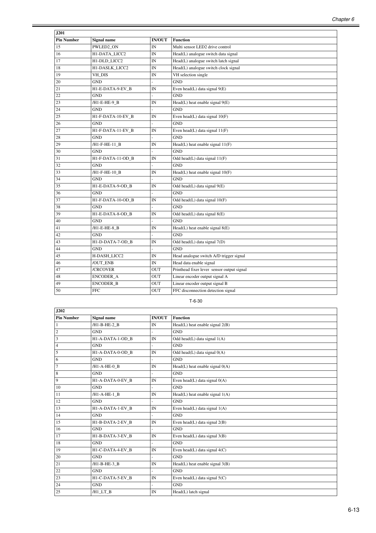
Chapter 6 6-13
T-6-30
15Pwled2_On
In
Multi sensor LED2 drive control 16H1-Data_Licc2
In
Head(L) analogue switch data signal 17H1-Dld_Licc2
In
Head(L) analogue switch latch signal 18H1-Daslk_Licc2
In
Head(L) analogue switch clock signal 19Vh_Dis
In
VH selection single 20Gnd
Gnd
H1-E-Data-9-Ev_B
In
Even head(L) data signal 9(E) 22Gnd
Gnd
/H1-E-He-9_B
In
Head(L) heat enable signal 9(E) 24Gnd
Gnd
H1-F-Data-10-Ev_B
In
Even head(L) data signal 10(F) 26Gnd
Gnd
H1-F-Data-11-Ev_B
In
Even head(L) data signal 11(F) 28Gnd
Gnd
/H1-F-He-11_B
In
Head(L) heat enable signal 11(F) 30Gnd
Gnd
H1-F-Data-11-Od_B
In
Odd head(L) data signal 11(F) 32Gnd
Gnd
/H1-F-He-10_B
In
Head(L) heat enable signal 10(F) 34Gnd
Gnd
H1-E-Data-9-Od_B
In
Odd head(L) data signal 9(E) 36Gnd
Gnd
H1-F-Data-10-Od_B
In
Odd head(L) data signal 10(F) 38Gnd
Gnd
H1-E-Data-8-Od_B
In
Odd head(L) data signal 8(E) 40Gnd
Gnd
/H1-E-He-8_B
In
Head(L) heat enable signal 8(E) 42Gnd
Gnd
H1-D-Data-7-Od_B
In
Odd head(L) data signal 7(D) 44Gnd
Gnd
H-Dash_Licc2
In
Head analogue switch A/D trigger signal 46/Out_Enb
In
Head data enable signal 47/Crcover
Out
Printhead fixer lever sensor output signal 48Encoder_A
Out
Linear encoder output signal A 49Encoder_B
Out
Linear encoder output signal B 50Ffc
Out
FFC disconnection detection signalJ202
Pin Number Signal nameIn/Out
Function 1/H1-B-He-2_B
In
Head(L) heat enable signal 2(B) 2Gnd
Gnd
H1-A-Data-1-Od_B
In
Odd head(L) data signal 1(A) 4Gnd
Gnd
H1-A-Data-0-Od_B
In
Odd head(L) data signal 0(A) 6Gnd
Gnd
/H1-A-He-0_B
In
Head(L) heat enable signal 0(A) 8Gnd
Gnd
H1-A-Data-0-Ev_B
In
Even head(L) data signal 0(A) 10Gnd
Gnd
/H1-A-He-1_B
In
Head(L) heat enable signal 1(A) 12Gnd
Gnd
H1-A-Data-1-Ev_B
In
Even head(L) data signal 1(A) 14Gnd
Gnd
H1-B-Data-2-Ev_B
In
Even head(L) data signal 2(B) 16Gnd
Gnd
H1-B-Data-3-Ev_B
In
Even head(L) data signal 3(B) 18Gnd
Gnd
H1-C-Data-4-Ev_B
In
Even head(L) data signal 4(C) 20Gnd
Gnd
/H1-B-He-3_B
In
Head(L) heat enable signal 3(B) 22Gnd
Gnd
H1-C-Data-5-Ev_B
In
Even head(L) data signal 5(C) 24Gnd
Gnd
/H1_Lt_B
In
Head(L) latch signalJ201
Pin Number Signal nameIn/Out
Function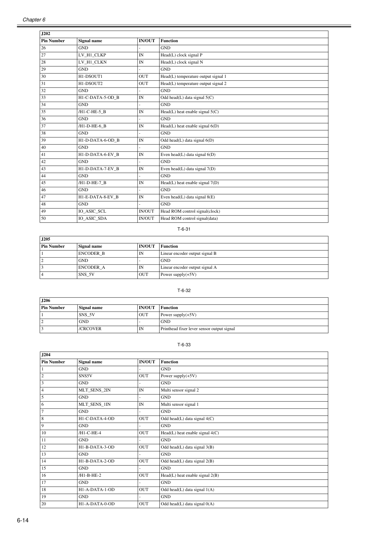
Chapter 6 6-14
T-6-31
T-6-32
T-6-33
26Gnd
Gnd
Lv_H1_Clkp
In
Head(L) clock signal P 28Lv_H1_Clkn
In
Head(L) clock signal N 29Gnd
Gnd
H1-Dsout1
Out
Head(L) temperature output signal 1 31H1-Dsout2
Out
Head(L) temperature output signal 2 32Gnd
Gnd
H1-C-Data-5-Od_B
In
Odd head(L) data signal 5(C) 34Gnd
Gnd
/H1-C-He-5_B
In
Head(L) heat enable signal 5(C) 36Gnd
Gnd
/H1-D-He-6_B
In
Head(L) heat enable signal 6(D) 38Gnd
Gnd
H1-D-Data-6-Od_B
In
Odd head(L) data signal 6(D) 40Gnd
Gnd
H1-D-Data-6-Ev_B
In
Even head(L) data signal 6(D) 42Gnd
Gnd
H1-D-Data-7-Ev_B
In
Even head(L) data signal 7(D) 44Gnd
Gnd
/H1-D-He-7_B
In
Head(L) heat enable signal 7(D) 46Gnd
Gnd
H1-E-Data-8-Ev_B
In
Even head(L) data signal 8(E) 48Gnd
Gnd
Io_Asic_Scl
In/Out
Head ROM control signal(clock) 50Io_Asic_Sda
In/Out
Head ROM control signal(data)J205
Pin Number Signal nameIn/Out
Function 1Encoder_B
In
Linear encoder output signal B 2Gnd
Gnd
Encoder_A
In
Linear encoder output signal A 4Sns_5V
Out
Power supply(+5V)J206
Pin Number Signal nameIn/Out
Function 1Sns_5V
Out
Power supply(+5V) 2Gnd
Gnd
/Crcover
In
Printhead fixer lever sensor output signalJ204
Pin Number Signal nameIn/Out
Function 1Gnd
Gnd
Sns5V
Out
Power supply(+5V) 3Gnd
Gnd
Mlt_Sens_2In
In
Multi sensor signal 2 5Gnd
Gnd
Mlt_Sens_1In
In
Multi sensor signal 1 7Gnd
Gnd
H1-C-Data-4-Od
Out
Odd head(L) data signal 4(C) 9Gnd
Gnd
/H1-C-He-4
Out
Head(L) heat enable signal 4(C) 11Gnd
Gnd
H1-B-Data-3-Od
Out
Odd head(L) data signal 3(B) 13Gnd
Gnd
H1-B-Data-2-Od
Out
Odd head(L) data signal 2(B) 15Gnd
Gnd
/H1-B-He-2
Out
Head(L) heat enable signal 2(B) 17Gnd
Gnd
H1-A-Data-1-Od
Out
Odd head(L) data signal 1(A) 19Gnd
Gnd
H1-A-Data-0-Od
Out
Odd head(L) data signal 0(A)J202
Pin Number Signal nameIn/Out
Function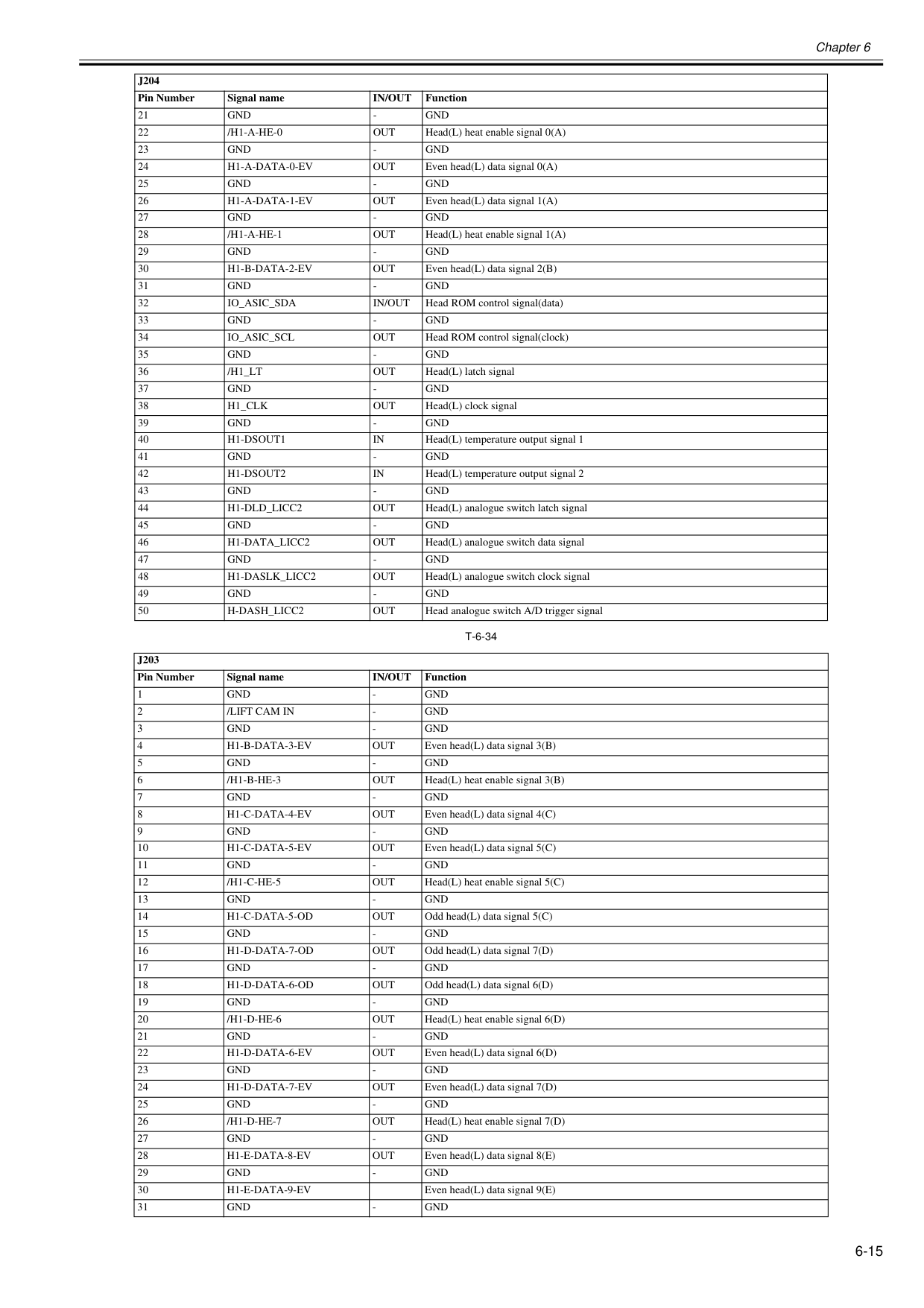
Chapter 6 6-15
T-6-34
21Gnd
Gnd
/H1-A-He-0
Out
Head(L) heat enable signal 0(A) 23Gnd
Gnd
H1-A-Data-0-Ev
Out
Even head(L) data signal 0(A) 25Gnd
Gnd
H1-A-Data-1-Ev
Out
Even head(L) data signal 1(A) 27Gnd
Gnd
/H1-A-He-1
Out
Head(L) heat enable signal 1(A) 29Gnd
Gnd
H1-B-Data-2-Ev
Out
Even head(L) data signal 2(B) 31Gnd
Gnd
Io_Asic_Sda
In/Out
Head ROM control signal(data) 33Gnd
Gnd
Io_Asic_Scl
Out
Head ROM control signal(clock) 35Gnd
Gnd
/H1_Lt
Out
Head(L) latch signal 37Gnd
Gnd
H1_Clk
Out
Head(L) clock signal 39Gnd
Gnd
H1-Dsout1
In
Head(L) temperature output signal 1 41Gnd
Gnd
H1-Dsout2
In
Head(L) temperature output signal 2 43Gnd
Gnd
H1-Dld_Licc2
Out
Head(L) analogue switch latch signal 45Gnd
Gnd
H1-Data_Licc2
Out
Head(L) analogue switch data signal 47Gnd
Gnd
H1-Daslk_Licc2
Out
Head(L) analogue switch clock signal 49Gnd
Gnd
H-Dash_Licc2
Out
Head analogue switch A/D trigger signalJ203
Pin Number Signal nameIn/Out
Function 1Gnd
Gnd
/Lift Cam In
Gnd
Gnd
Gnd
H1-B-Data-3-Ev
Out
Even head(L) data signal 3(B) 5Gnd
Gnd
/H1-B-He-3
Out
Head(L) heat enable signal 3(B) 7Gnd
Gnd
H1-C-Data-4-Ev
Out
Even head(L) data signal 4(C) 9Gnd
Gnd
H1-C-Data-5-Ev
Out
Even head(L) data signal 5(C) 11Gnd
Gnd
/H1-C-He-5
Out
Head(L) heat enable signal 5(C) 13Gnd
Gnd
H1-C-Data-5-Od
Out
Odd head(L) data signal 5(C) 15Gnd
Gnd
H1-D-Data-7-Od
Out
Odd head(L) data signal 7(D) 17Gnd
Gnd
H1-D-Data-6-Od
Out
Odd head(L) data signal 6(D) 19Gnd
Gnd
/H1-D-He-6
Out
Head(L) heat enable signal 6(D) 21Gnd
Gnd
H1-D-Data-6-Ev
Out
Even head(L) data signal 6(D) 23Gnd
Gnd
H1-D-Data-7-Ev
Out
Even head(L) data signal 7(D) 25Gnd
Gnd
/H1-D-He-7
Out
Head(L) heat enable signal 7(D) 27Gnd
Gnd
H1-E-Data-8-Ev
Out
Even head(L) data signal 8(E) 29Gnd
Gnd
H1-E-Data-9-Ev
Even head(L) data signal 9(E) 31Gnd
Gnd
J204
Pin Number Signal nameIn/Out
Function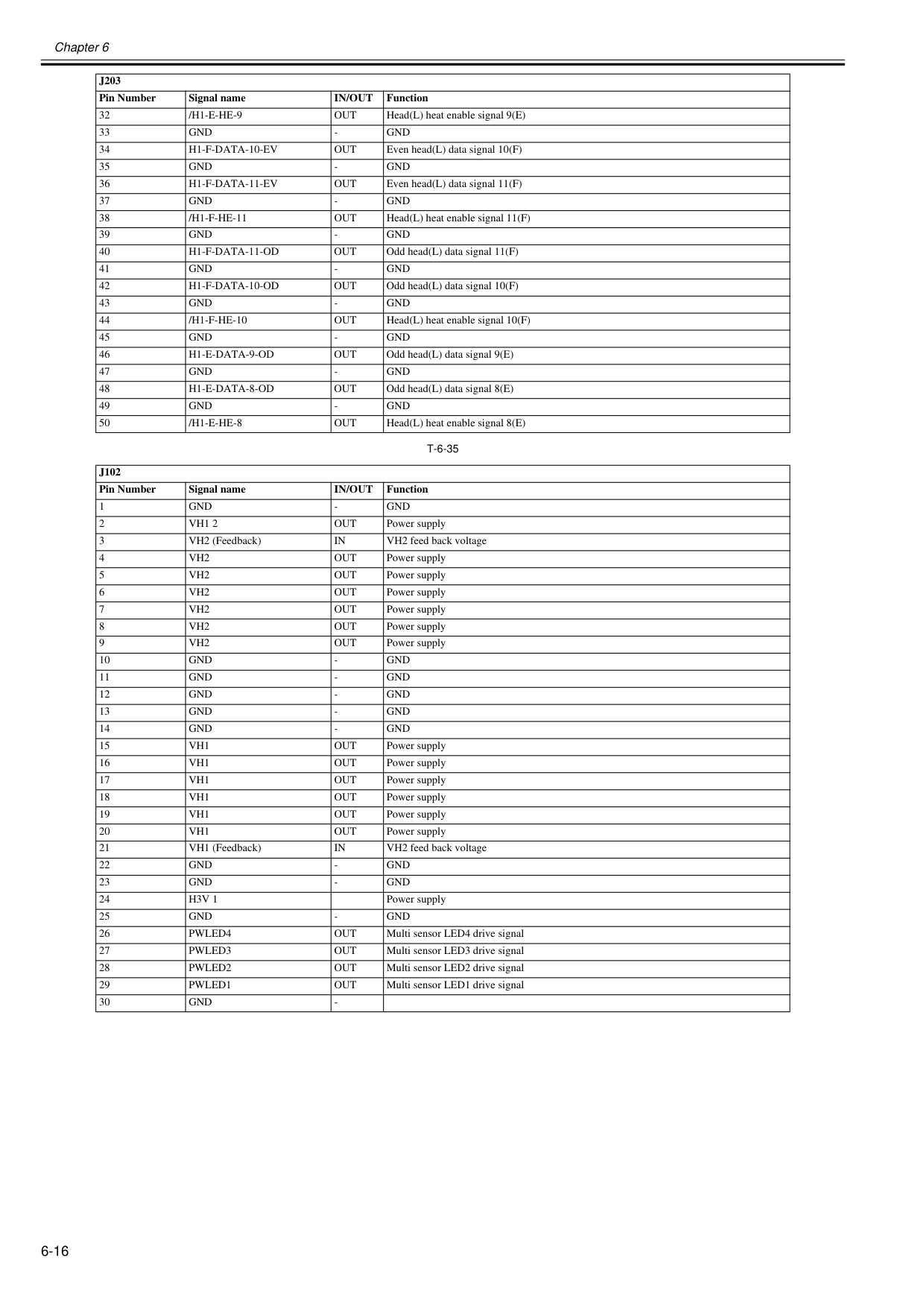
Chapter 6 6-16
T-6-35
32/H1-E-He-9
Out
Head(L) heat enable signal 9(E) 33Gnd
Gnd
H1-F-Data-10-Ev
Out
Even head(L) data signal 10(F) 35Gnd
Gnd
H1-F-Data-11-Ev
Out
Even head(L) data signal 11(F) 37Gnd
Gnd
/H1-F-He-11
Out
Head(L) heat enable signal 11(F) 39Gnd
Gnd
H1-F-Data-11-Od
Out
Odd head(L) data signal 11(F) 41Gnd
Gnd
H1-F-Data-10-Od
Out
Odd head(L) data signal 10(F) 43Gnd
Gnd
/H1-F-He-10
Out
Head(L) heat enable signal 10(F) 45Gnd
Gnd
H1-E-Data-9-Od
Out
Odd head(L) data signal 9(E) 47Gnd
Gnd
H1-E-Data-8-Od
Out
Odd head(L) data signal 8(E) 49Gnd
Gnd
/H1-E-He-8
Out
Head(L) heat enable signal 8(E)J102
Pin Number Signal nameIn/Out
Function 1Gnd
Gnd
Vh1 2
Out
Power supply 3 VH2 (Feedback)In
VH2 feed back voltage 4Vh2
Out
Power supply 5Vh2
Out
Power supply 6Vh2
Out
Power supply 7Vh2
Out
Power supply 8Vh2
Out
Power supply 9Vh2
Out
Power supply 10Gnd
Gnd
Gnd
Gnd
Gnd
Gnd
Gnd
Gnd
Gnd
Gnd
Vh1
Out
Power supply 16Vh1
Out
Power supply 17Vh1
Out
Power supply 18Vh1
Out
Power supply 19Vh1
Out
Power supply 20Vh1
Out
Power supply 21 VH1 (Feedback)In
VH2 feed back voltage 22Gnd
Gnd
Gnd
Gnd
H3V 1
Power supply 25Gnd
Gnd
Pwled4
Out
Multi sensor LED4 drive signal 27Pwled3
Out
Multi sensor LED3 drive signal 28Pwled2
Out
Multi sensor LED2 drive signal 29Pwled1
Out
Multi sensor LED1 drive signal 30Gnd
J203
In/Out
Function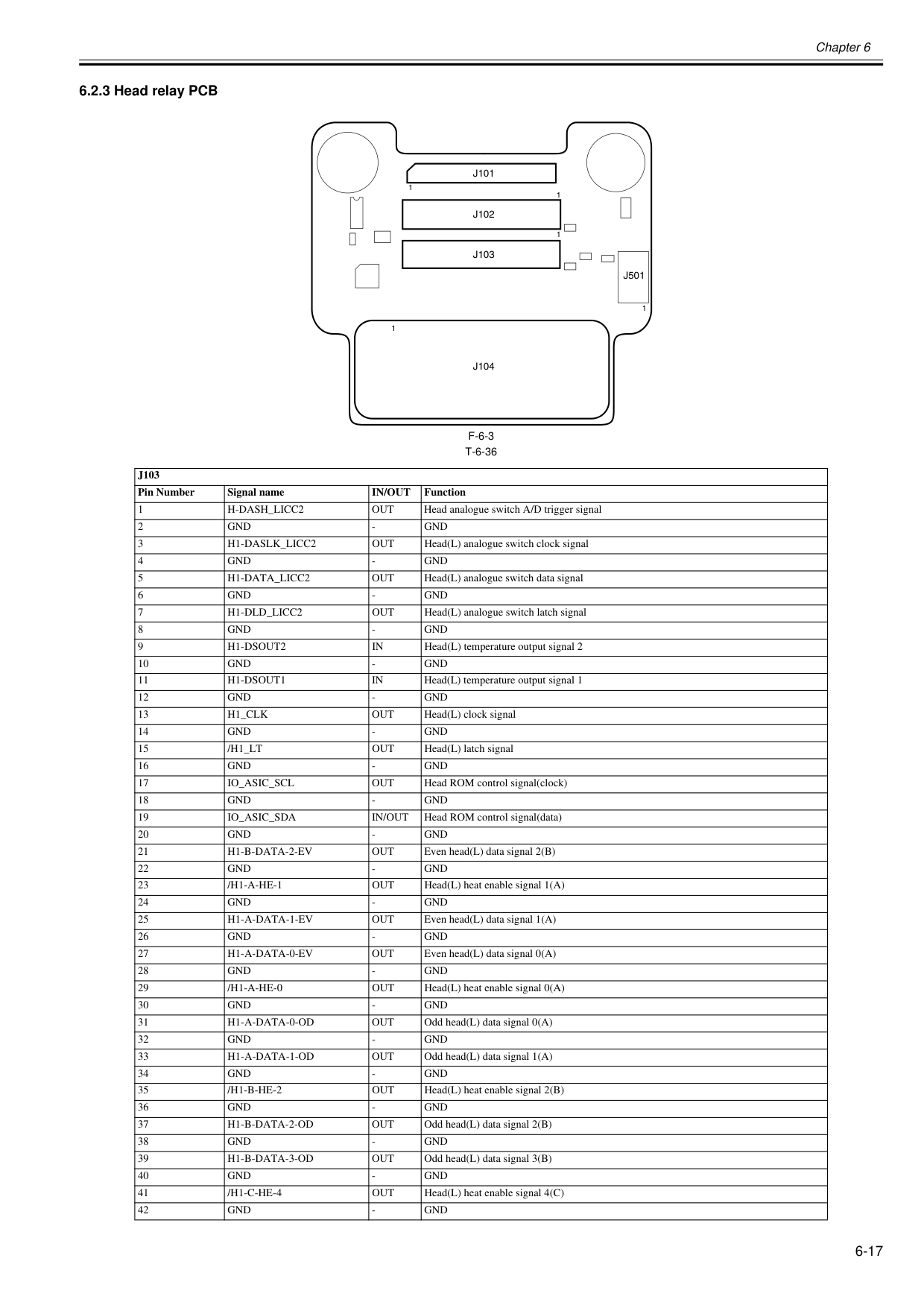
Chapter 6 6-17 6.2.3 Head relay PCB 0020-5732
F-6-3
T-6-36
J103
Pin Number Signal nameIn/Out
Function 1H-Dash_Licc2
Out
Head analogue switch A/D trigger signal 2Gnd
Gnd
H1-Daslk_Licc2
Out
Head(L) analogue switch clock signal 4Gnd
Gnd
H1-Data_Licc2
Out
Head(L) analogue switch data signal 6Gnd
Gnd
H1-Dld_Licc2
Out
Head(L) analogue switch latch signal 8Gnd
Gnd
H1-Dsout2
In
Head(L) temperature output signal 2 10Gnd
Gnd
H1-Dsout1
In
Head(L) temperature output signal 1 12Gnd
Gnd
H1_Clk
Out
Head(L) clock signal 14Gnd
Gnd
/H1_Lt
Out
Head(L) latch signal 16Gnd
Gnd
Io_Asic_Scl
Out
Head ROM control signal(clock) 18Gnd
Gnd
Io_Asic_Sda
In/Out
Head ROM control signal(data) 20Gnd
Gnd
H1-B-Data-2-Ev
Out
Even head(L) data signal 2(B) 22Gnd
Gnd
/H1-A-He-1
Out
Head(L) heat enable signal 1(A) 24Gnd
Gnd
H1-A-Data-1-Ev
Out
Even head(L) data signal 1(A) 26Gnd
Gnd
H1-A-Data-0-Ev
Out
Even head(L) data signal 0(A) 28Gnd
Gnd
/H1-A-He-0
Out
Head(L) heat enable signal 0(A) 30Gnd
Gnd
H1-A-Data-0-Od
Out
Odd head(L) data signal 0(A) 32Gnd
Gnd
H1-A-Data-1-Od
Out
Odd head(L) data signal 1(A) 34Gnd
Gnd
/H1-B-He-2
Out
Head(L) heat enable signal 2(B) 36Gnd
Gnd
H1-B-Data-2-Od
Out
Odd head(L) data signal 2(B) 38Gnd
Gnd
H1-B-Data-3-Od
Out
Odd head(L) data signal 3(B) 40Gnd
Gnd
/H1-C-He-4
Out
Head(L) heat enable signal 4(C) 42Gnd
Gnd
J101
J102
J103
J104
J501
1 1 1 1 1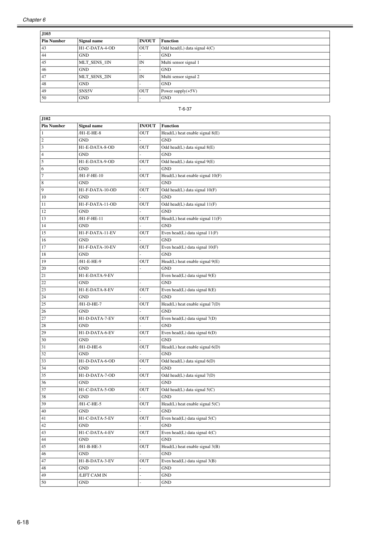
Chapter 6 6-18
T-6-37
43H1-C-Data-4-Od
Out
Odd head(L) data signal 4(C) 44Gnd
Gnd
Mlt_Sens_1In
In
Multi sensor signal 1 46Gnd
Gnd
Mlt_Sens_2In
In
Multi sensor signal 2 48Gnd
Gnd
Sns5V
Out
Power supply(+5V) 50Gnd
Gnd
J102
Pin Number Signal nameIn/Out
Function 1/H1-E-He-8
Out
Head(L) heat enable signal 8(E) 2Gnd
Gnd
H1-E-Data-8-Od
Out
Odd head(L) data signal 8(E) 4Gnd
Gnd
H1-E-Data-9-Od
Out
Odd head(L) data signal 9(E) 6Gnd
Gnd
/H1-F-He-10
Out
Head(L) heat enable signal 10(F) 8Gnd
Gnd
H1-F-Data-10-Od
Out
Odd head(L) data signal 10(F) 10Gnd
Gnd
H1-F-Data-11-Od
Out
Odd head(L) data signal 11(F) 12Gnd
Gnd
/H1-F-He-11
Out
Head(L) heat enable signal 11(F) 14Gnd
Gnd
H1-F-Data-11-Ev
Out
Even head(L) data signal 11(F) 16Gnd
Gnd
H1-F-Data-10-Ev
Out
Even head(L) data signal 10(F) 18Gnd
Gnd
/H1-E-He-9
Out
Head(L) heat enable signal 9(E) 20Gnd
Gnd
H1-E-Data-9-Ev
Even head(L) data signal 9(E) 22Gnd
Gnd
H1-E-Data-8-Ev
Out
Even head(L) data signal 8(E) 24Gnd
Gnd
/H1-D-He-7
Out
Head(L) heat enable signal 7(D) 26Gnd
Gnd
H1-D-Data-7-Ev
Out
Even head(L) data signal 7(D) 28Gnd
Gnd
H1-D-Data-6-Ev
Out
Even head(L) data signal 6(D) 30Gnd
Gnd
/H1-D-He-6
Out
Head(L) heat enable signal 6(D) 32Gnd
Gnd
H1-D-Data-6-Od
Out
Odd head(L) data signal 6(D) 34Gnd
Gnd
H1-D-Data-7-Od
Out
Odd head(L) data signal 7(D) 36Gnd
Gnd
H1-C-Data-5-Od
Out
Odd head(L) data signal 5(C) 38Gnd
Gnd
/H1-C-He-5
Out
Head(L) heat enable signal 5(C) 40Gnd
Gnd
H1-C-Data-5-Ev
Out
Even head(L) data signal 5(C) 42Gnd
Gnd
H1-C-Data-4-Ev
Out
Even head(L) data signal 4(C) 44Gnd
Gnd
/H1-B-He-3
Out
Head(L) heat enable signal 3(B) 46Gnd
Gnd
H1-B-Data-3-Ev
Out
Even head(L) data signal 3(B) 48Gnd
Gnd
/Lift Cam In
Gnd
Gnd
Gnd
J103
Pin Number Signal nameIn/Out
Function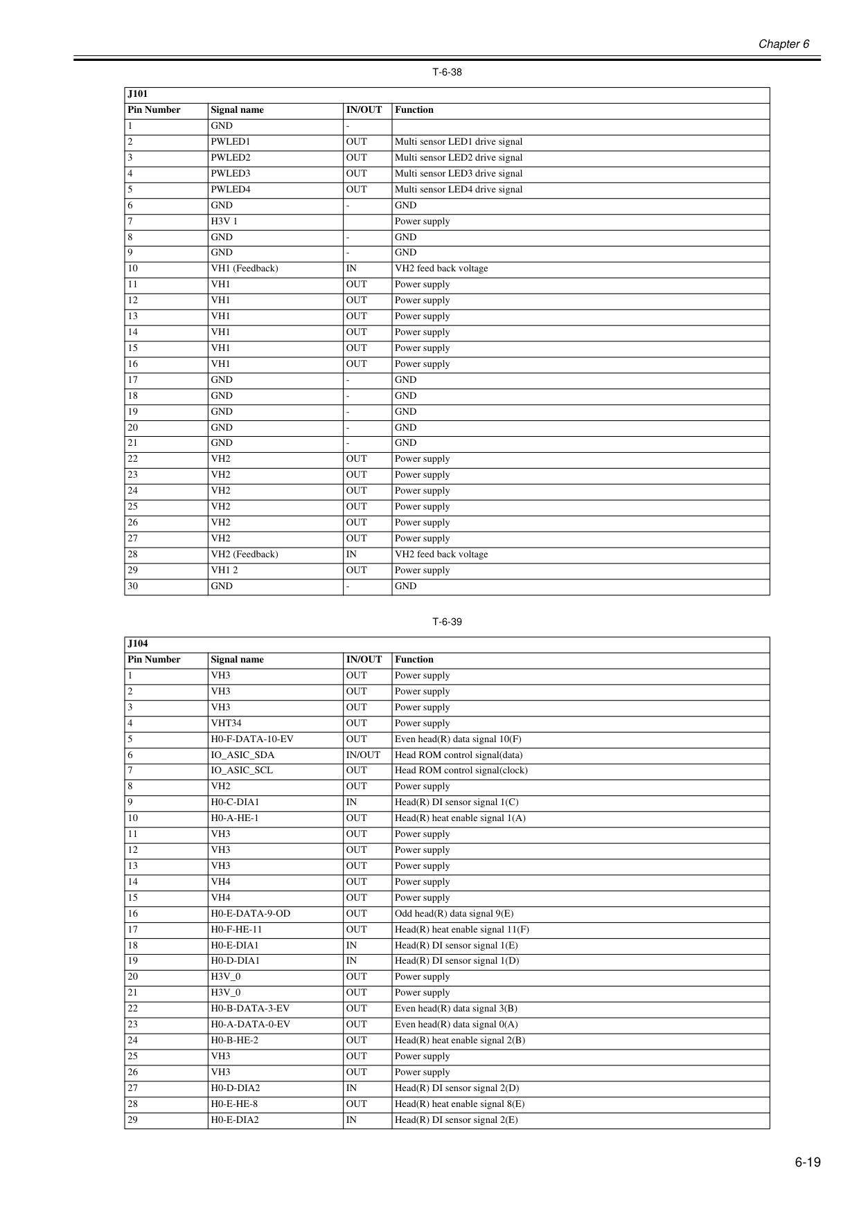
Chapter 6 6-19
T-6-38
T-6-39
J101
Pin Number Signal nameIn/Out
Function 1Gnd
Pwled1
Out
Multi sensor LED1 drive signal 3Pwled2
Out
Multi sensor LED2 drive signal 4Pwled3
Out
Multi sensor LED3 drive signal 5Pwled4
Out
Multi sensor LED4 drive signal 6Gnd
Gnd
H3V 1
Power supply 8Gnd
Gnd
Gnd
Gnd
In
VH2 feed back voltage 11Vh1
Out
Power supply 12Vh1
Out
Power supply 13Vh1
Out
Power supply 14Vh1
Out
Power supply 15Vh1
Out
Power supply 16Vh1
Out
Power supply 17Gnd
Gnd
Gnd
Gnd
Gnd
Gnd
Gnd
Gnd
Gnd
Gnd
Vh2
Out
Power supply 23Vh2
Out
Power supply 24Vh2
Out
Power supply 25Vh2
Out
Power supply 26Vh2
Out
Power supply 27Vh2
Out
Power supply 28 VH2 (Feedback)In
VH2 feed back voltage 29Vh1 2
Out
Power supply 30Gnd
Gnd
J104
Pin Number Signal nameIn/Out
Function 1Vh3
Out
Power supply 2Vh3
Out
Power supply 3Vh3
Out
Power supply 4Vht34
Out
Power supply 5H0-F-Data-10-Ev
Out
Even head(R) data signal 10(F) 6Io_Asic_Sda
In/Out
Head ROM control signal(data) 7Io_Asic_Scl
Out
Head ROM control signal(clock) 8Vh2
Out
Power supply 9H0-C-Dia1
In
Head(R) DI sensor signal 1(C) 10H0-A-He-1
Out
Head(R) heat enable signal 1(A) 11Vh3
Out
Power supply 12Vh3
Out
Power supply 13Vh3
Out
Power supply 14Vh4
Out
Power supply 15Vh4
Out
Power supply 16H0-E-Data-9-Od
Out
Odd head(R) data signal 9(E) 17H0-F-He-11
Out
Head(R) heat enable signal 11(F) 18H0-E-Dia1
In
Head(R) DI sensor signal 1(E) 19H0-D-Dia1
In
Head(R) DI sensor signal 1(D) 20H3V_0
Out
Power supply 21H3V_0
Out
Power supply 22H0-B-Data-3-Ev
Out
Even head(R) data signal 3(B) 23H0-A-Data-0-Ev
Out
Even head(R) data signal 0(A) 24H0-B-He-2
Out
Head(R) heat enable signal 2(B) 25Vh3
Out
Power supply 26Vh3
Out
Power supply 27H0-D-Dia2
In
Head(R) DI sensor signal 2(D) 28H0-E-He-8
Out
Head(R) heat enable signal 8(E) 29H0-E-Dia2
In
Head(R) DI sensor signal 2(E)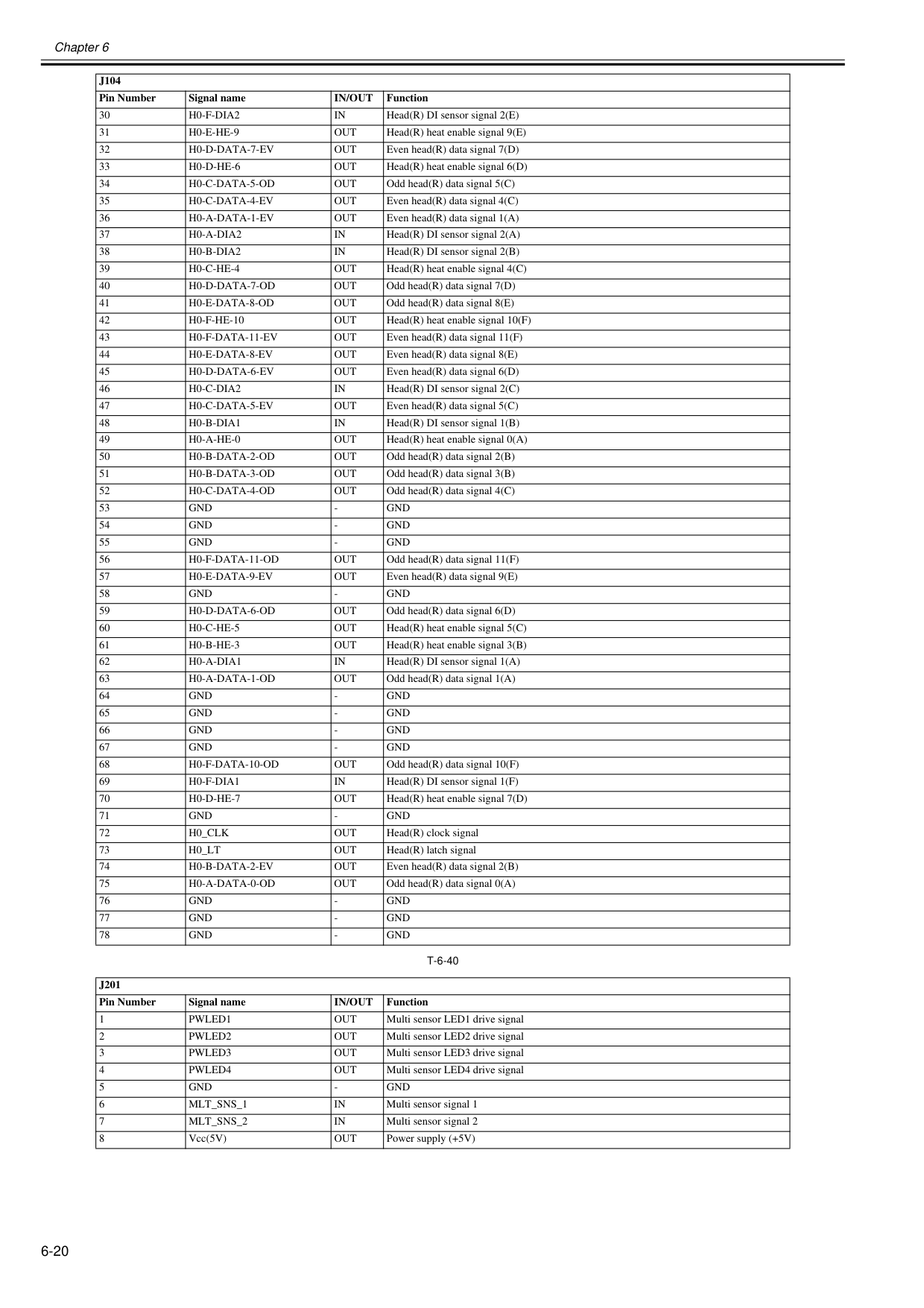
Chapter 6 6-20
T-6-40
30H0-F-Dia2
In
Head(R) DI sensor signal 2(E) 31H0-E-He-9
Out
Head(R) heat enable signal 9(E) 32H0-D-Data-7-Ev
Out
Even head(R) data signal 7(D) 33H0-D-He-6
Out
Head(R) heat enable signal 6(D) 34H0-C-Data-5-Od
Out
Odd head(R) data signal 5(C) 35H0-C-Data-4-Ev
Out
Even head(R) data signal 4(C) 36H0-A-Data-1-Ev
Out
Even head(R) data signal 1(A) 37H0-A-Dia2
In
Head(R) DI sensor signal 2(A) 38H0-B-Dia2
In
Head(R) DI sensor signal 2(B) 39H0-C-He-4
Out
Head(R) heat enable signal 4(C) 40H0-D-Data-7-Od
Out
Odd head(R) data signal 7(D) 41H0-E-Data-8-Od
Out
Odd head(R) data signal 8(E) 42H0-F-He-10
Out
Head(R) heat enable signal 10(F) 43H0-F-Data-11-Ev
Out
Even head(R) data signal 11(F) 44H0-E-Data-8-Ev
Out
Even head(R) data signal 8(E) 45H0-D-Data-6-Ev
Out
Even head(R) data signal 6(D) 46H0-C-Dia2
In
Head(R) DI sensor signal 2(C) 47H0-C-Data-5-Ev
Out
Even head(R) data signal 5(C) 48H0-B-Dia1
In
Head(R) DI sensor signal 1(B) 49H0-A-He-0
Out
Head(R) heat enable signal 0(A) 50H0-B-Data-2-Od
Out
Odd head(R) data signal 2(B) 51H0-B-Data-3-Od
Out
Odd head(R) data signal 3(B) 52H0-C-Data-4-Od
Out
Odd head(R) data signal 4(C) 53Gnd
Gnd
Gnd
Gnd
Gnd
Gnd
H0-F-Data-11-Od
Out
Odd head(R) data signal 11(F) 57H0-E-Data-9-Ev
Out
Even head(R) data signal 9(E) 58Gnd
Gnd
H0-D-Data-6-Od
Out
Odd head(R) data signal 6(D) 60H0-C-He-5
Out
Head(R) heat enable signal 5(C) 61H0-B-He-3
Out
Head(R) heat enable signal 3(B) 62H0-A-Dia1
In
Head(R) DI sensor signal 1(A) 63H0-A-Data-1-Od
Out
Odd head(R) data signal 1(A) 64Gnd
Gnd
Gnd
Gnd
Gnd
Gnd
Gnd
Gnd
H0-F-Data-10-Od
Out
Odd head(R) data signal 10(F) 69H0-F-Dia1
In
Head(R) DI sensor signal 1(F) 70H0-D-He-7
Out
Head(R) heat enable signal 7(D) 71Gnd
Gnd
H0_Clk
Out
Head(R) clock signal 73H0_Lt
Out
Head(R) latch signal 74H0-B-Data-2-Ev
Out
Even head(R) data signal 2(B) 75H0-A-Data-0-Od
Out
Odd head(R) data signal 0(A) 76Gnd
Gnd
Gnd
Gnd
Gnd
Gnd
J201
Pin Number Signal nameIn/Out
Function 1Pwled1
Out
Multi sensor LED1 drive signal 2Pwled2
Out
Multi sensor LED2 drive signal 3Pwled3
Out
Multi sensor LED3 drive signal 4Pwled4
Out
Multi sensor LED4 drive signal 5Gnd
Gnd
Mlt_Sns_1
In
Multi sensor signal 1 7Mlt_Sns_2
In
Multi sensor signal 2 8 Vcc(5V)Out
Power supply (+5V)J104
Pin Number Signal nameIn/Out
Function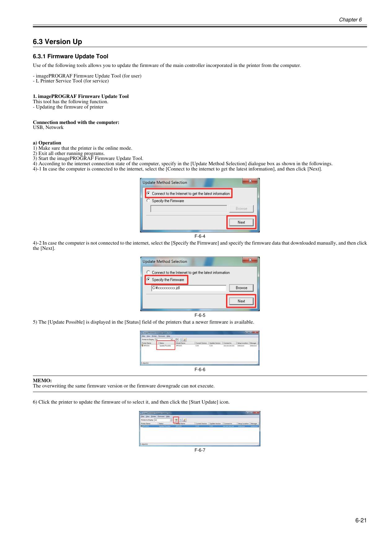
Chapter 6 6-21 6.3 Version Up 6.3.1 Firmware Update Tool 0023-5295 Use of the following tools allows you to update the firmware of the main controller incorporated in the printer from the computer.
F-6-4
4)-2 In case the computer is not connected to the internet, select the [Specify the Firmware] and specify the firmware data that downloaded manually, and then click the [Next].F-6-5
5) The [Update Possible] is displayed in the [Status] field of the printers that a newer firmware is available.F-6-6
Memo:
The overwriting the same firmware version or the firmware downgrade can not execute. 6) Click the printer to update the firmware of to select it, and then click the [Start Update] icon.F-6-7
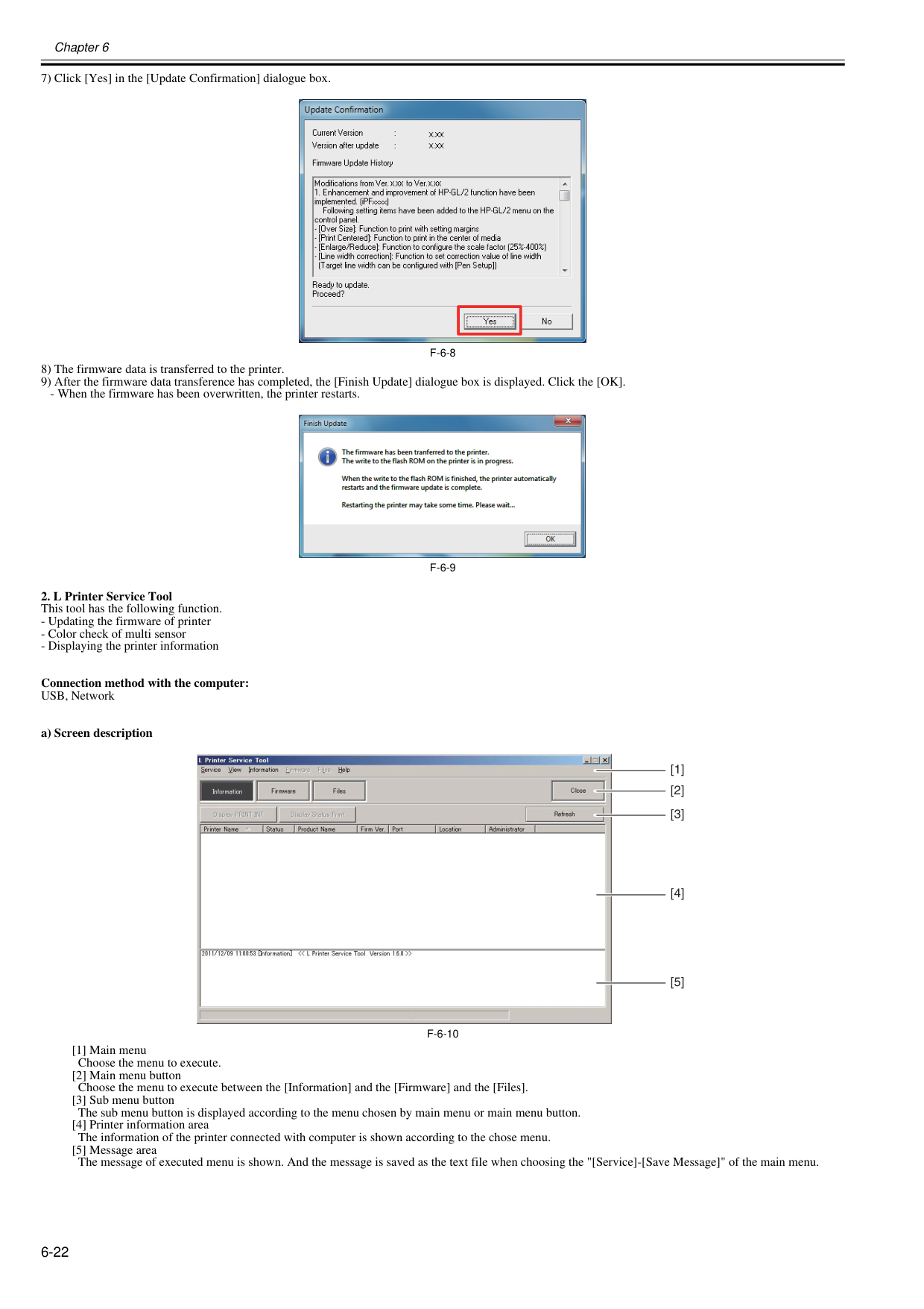
Chapter 6 6-22 7) Click [Yes] in the [Update Confirmation] dialogue box.
F-6-8
8) The firmware data is transferred to the printer. 9) After the firmware data transference has completed, the [Finish Update] dialogue box is displayed. Click the [OK].F-6-9
F-6-10
[1] Main menu Choose the menu to execute. [2] Main menu button Choose the menu to execute between the [Information] and the [Firmware] and the [Files]. [3] Sub menu button The sub menu button is displayed according to the menu chosen by main menu or main menu button. [4] Printer information area The information of the printer connected with computer is shown according to the chose menu. [5] Message area The message of executed menu is shown. And the message is saved as the text file when choosing the "[Service]-[Save Message]" of the main menu. [1] [2] [3] [4] [5]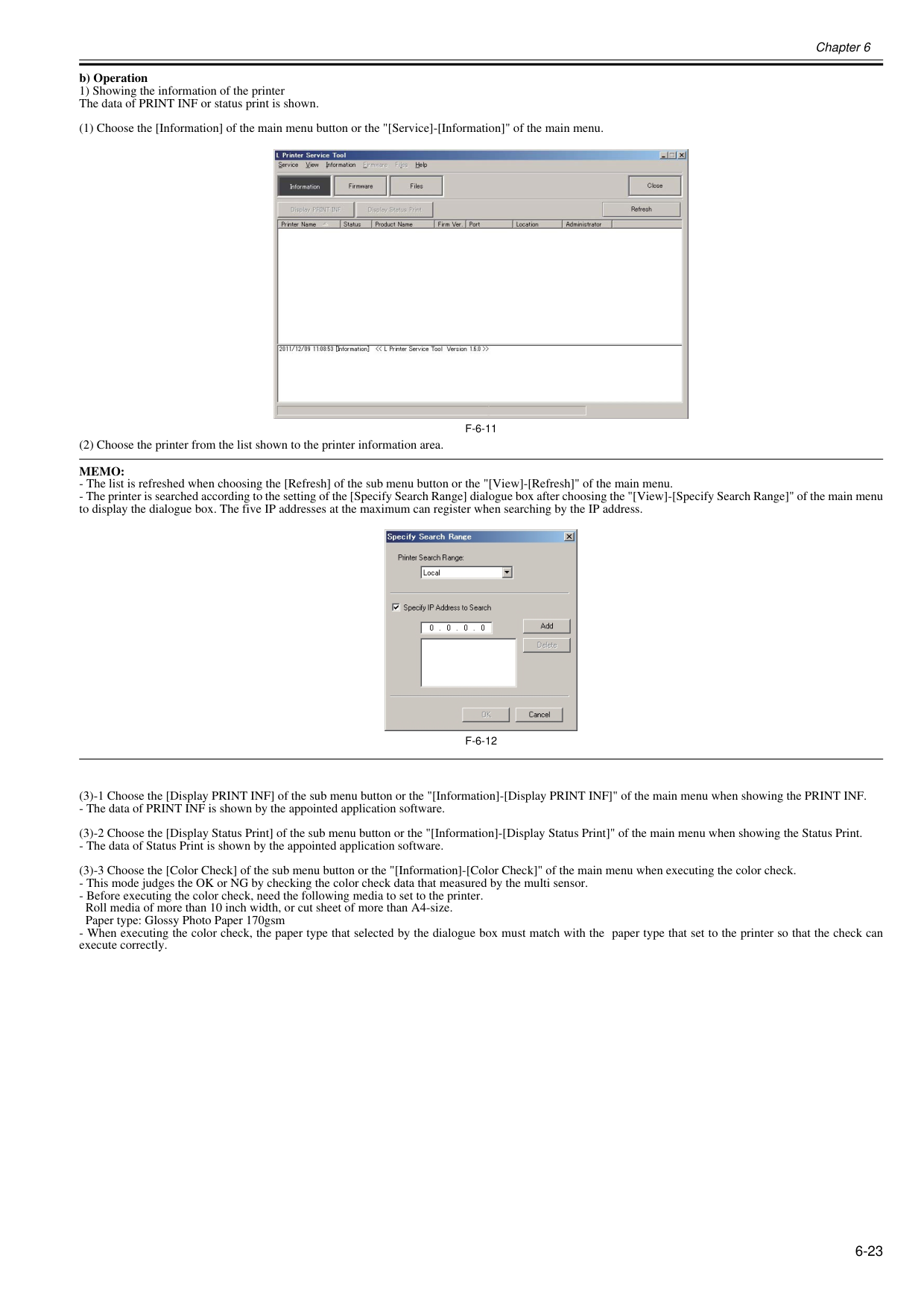
Chapter 6 6-23 b) Operation 1) Showing the information of the printer The data of PRINT INF or status print is shown. (1) Choose the [Information] of the main menu button or the "[Service]-[Information]" of the main menu.
F-6-11
(2) Choose the printer from the list shown to the printer information area.Memo:
F-6-12
(3)-1 Choose the [Display PRINT INF] of the sub menu button or the "[Information]-[Display PRINT INF]" of the main menu when showing the PRINT INF.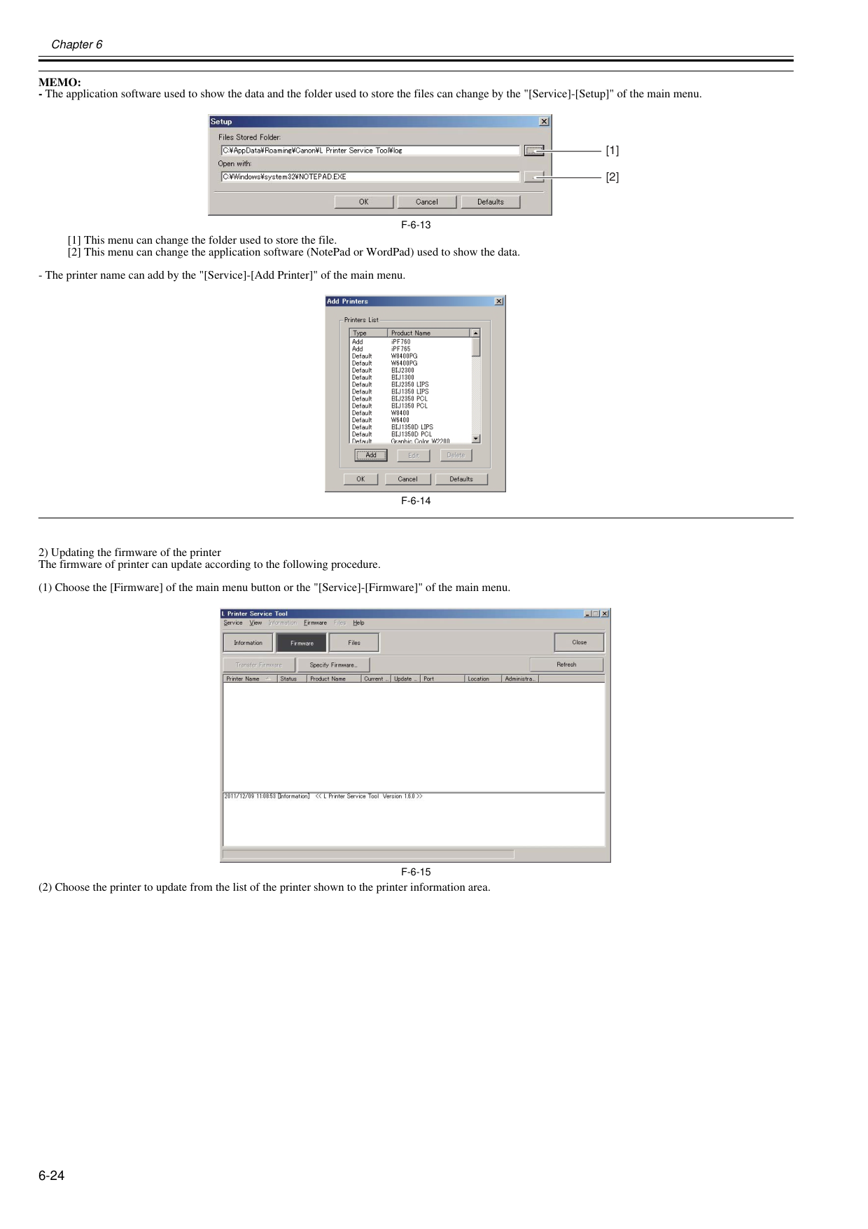
Chapter 6 6-24
Memo:
F-6-13
[1] This menu can change the folder used to store the file. [2] This menu can change the application software (NotePad or WordPad) used to show the data.F-6-14
2) Updating the firmware of the printer The firmware of printer can update according to the following procedure. (1) Choose the [Firmware] of the main menu button or the "[Service]-[Firmware]" of the main menu.F-6-15
(2) Choose the printer to update from the list of the printer shown to the printer information area. [1] [2]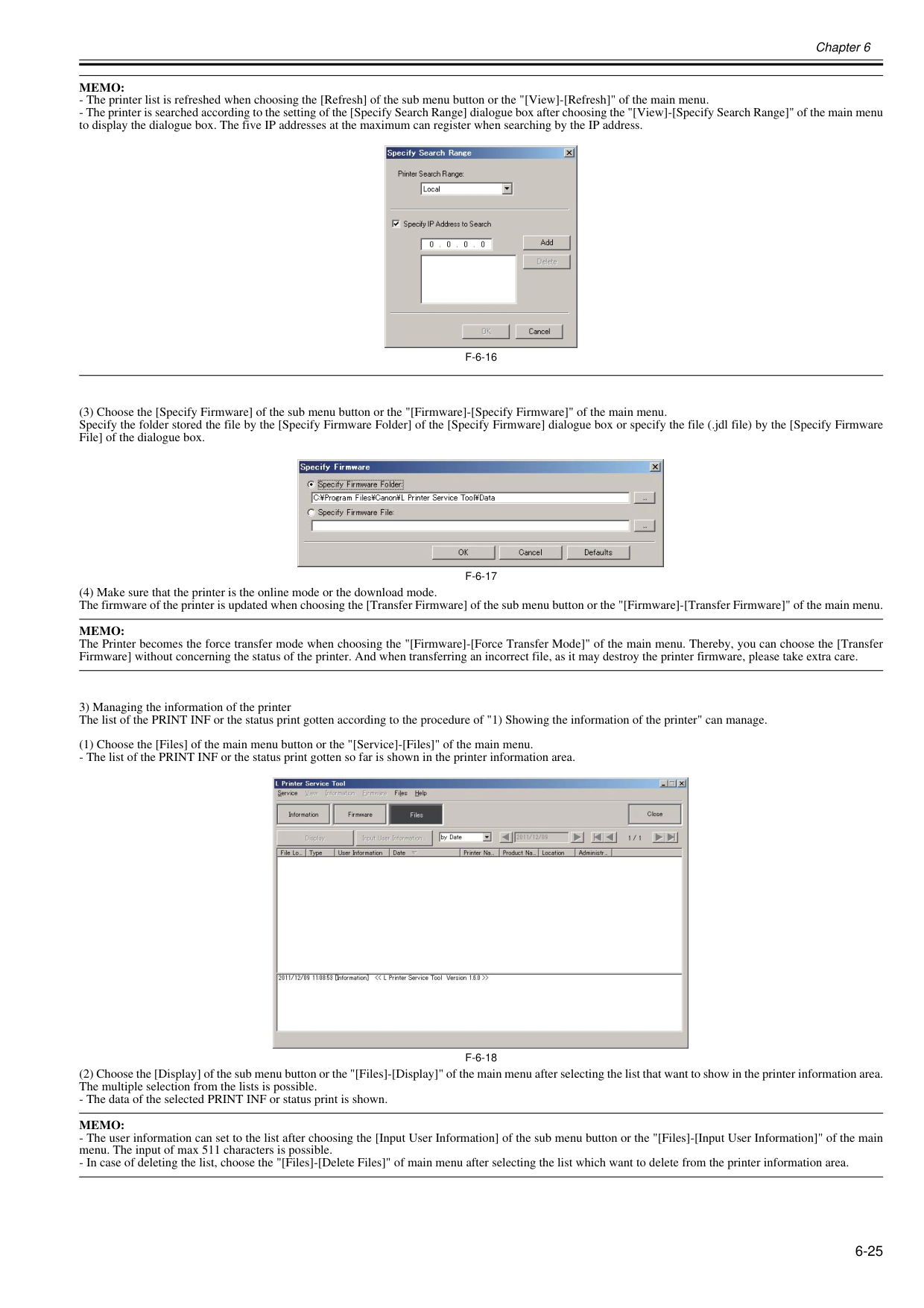
Chapter 6 6-25
Memo:
F-6-16
(3) Choose the [Specify Firmware] of the sub menu button or the "[Firmware]-[Specify Firmware]" of the main menu. Specify the folder stored the file by the [Specify Firmware Folder] of the [Specify Firmware] dialogue box or specify the file (.jdl file) by the [Specify Firmware File] of the dialogue box.F-6-17
(4) Make sure that the printer is the online mode or the download mode. The firmware of the printer is updated when choosing the [Transfer Firmware] of the sub menu button or the "[Firmware]-[Transfer Firmware]" of the main menu.Memo:
The Printer becomes the force transfer mode when choosing the "[Firmware]-[Force Transfer Mode]" of the main menu. Thereby, you can choose the [Transfer Firmware] without concerning the status of the printer. And when transferring an incorrect file, as it may destroy the printer firmware, please take extra care. 3) Managing the information of the printer The list of the PRINT INF or the status print gotten according to the procedure of "1) Showing the information of the printer" can manage. (1) Choose the [Files] of the main menu button or the "[Service]-[Files]" of the main menu.F-6-18
(2) Choose the [Display] of the sub menu button or the "[Files]-[Display]" of the main menu after selecting the list that want to show in the printer information area. The multiple selection from the lists is possible.Memo:
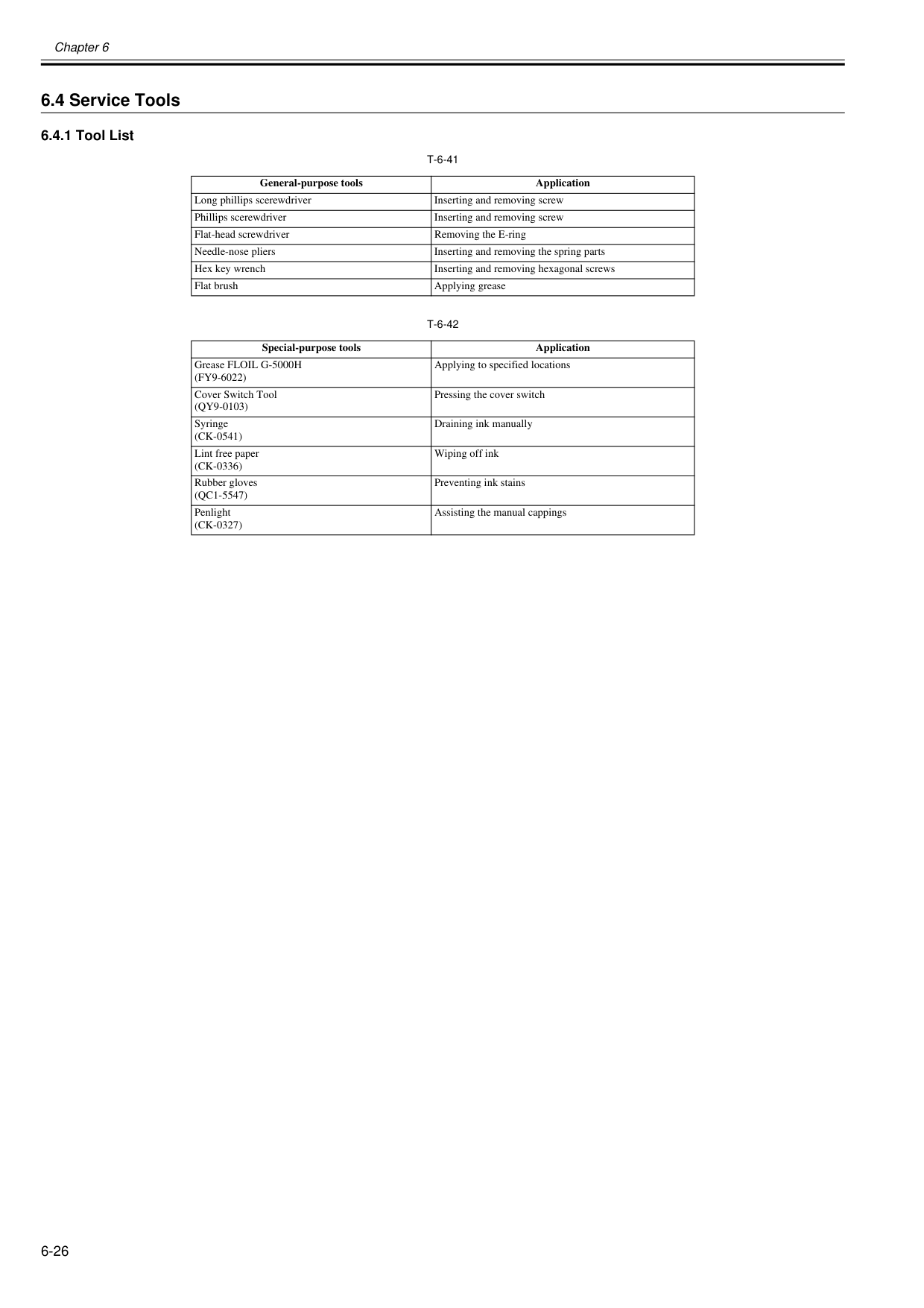
Chapter 6 6-26 6.4 Service Tools 6.4.1 Tool List 0012-6675
T-6-41
T-6-42
General-purpose tools Application Long phillips scerewdriver Inserting and removing screw Phillips scerewdriver Inserting and removing screw Flat-head screwdriver Removing the E-ring Needle-nose pliers Inserting and removing the spring parts Hex key wrench Inserting and removing hexagonal screws Flat brush Applying grease Special-purpose tools Application Grease FLOIL G-5000H(Fy9-6022)
Applying to specified locations Cover Switch Tool(Qy9-0103)
Pressing the cover switch Syringe(Ck-0541)
Draining ink manually Lint free paper(Ck-0336)
Wiping off ink Rubber gloves(Qc1-5547)
Preventing ink stains Penlight(Ck-0327)
Assisting the manual cappings
Chapter 7 SERVICE MODE

Contents Contents 7.1 Service Mode.............................................................................................................................................. 7-1 7.1.1 Service Mode Operation.......................................................................................................................................... 7-1 7.1.2 Map of the Service Mode......................................................................................................................................... 7-2 7.1.3 Details of Service Mode........................................................................................................................................... 7-8 7.1.4 Sample Printout...................................................................................................................................................... 7-16 7.2 Special Mode............................................................................................................................................ 7-20 7.2.1 Special Modes for Servicing................................................................................................................................... 7-20

Chapter 7 7-1 7.1 Service Mode 7.1.1 Service Mode Operation 0013-9799 a. How to enter the Service mode Enter the Service mode following the procedure below. 1) Turn off the printer. 2) Turn on the printer while holding down the [Paper Source]key and [Information]key. 3) "S" will be displayed in the upper right corner of the display showing the firmware version of the printer. 4) After display of "Online", pressing the [Menu] key displays the SERVICE MODE top menu and the MESSAGE LED flashes.
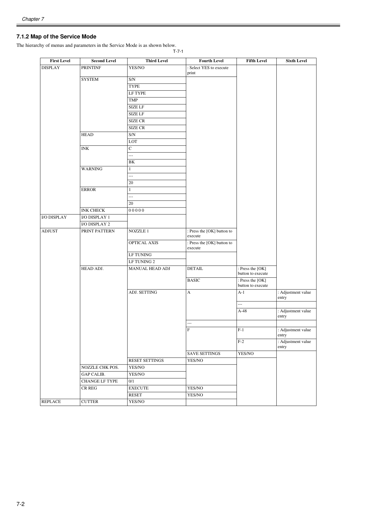
Chapter 7 7-2 7.1.2 Map of the Service Mode 0020-5734 The hierarchy of menus and parameters in the Service Mode is as shown below.
T-7-1
First Level Second Level Third Level Fourth Level Fifth Level Sixth LevelDisplay
Printinf
Yes/No
: Select YES to execute printSystem
S/N
Type
Lf Type
Tmp
Size Lf
Size Lf
Size Cr
Size Cr
Head
S/N
Lot
Ink
C
---Bk
Warning
1 --- 20Error
1 --- 20Ink Check
0 0 0 0 0I/O Display
I/O Display 1
I/O Display 2
Adjust
Print Pattern
Nozzle 1
: Press the [OK] button to executeOptical Axis
: Press the [OK] button to executeLf Tuning
Lf Tuning 2
Head Adj.
Manual Head Adj
Detail
: Press the [OK] button to executeBasic
: Press the [OK] button to executeAdj. Setting
A
A-1
: Adjustment value entry ---A-48
: Adjustment value entry ---F
F-1
: Adjustment value entryF-2
: Adjustment value entrySave Settings
Yes/No
Reset Settings
Yes/No
Nozzle Chk Pos.
Yes/No
Gap Calib.
Yes/No
Change Lf Type
0/1Cr Reg
Execute
Yes/No
Reset
Yes/No
Replace
Cutter
Yes/No
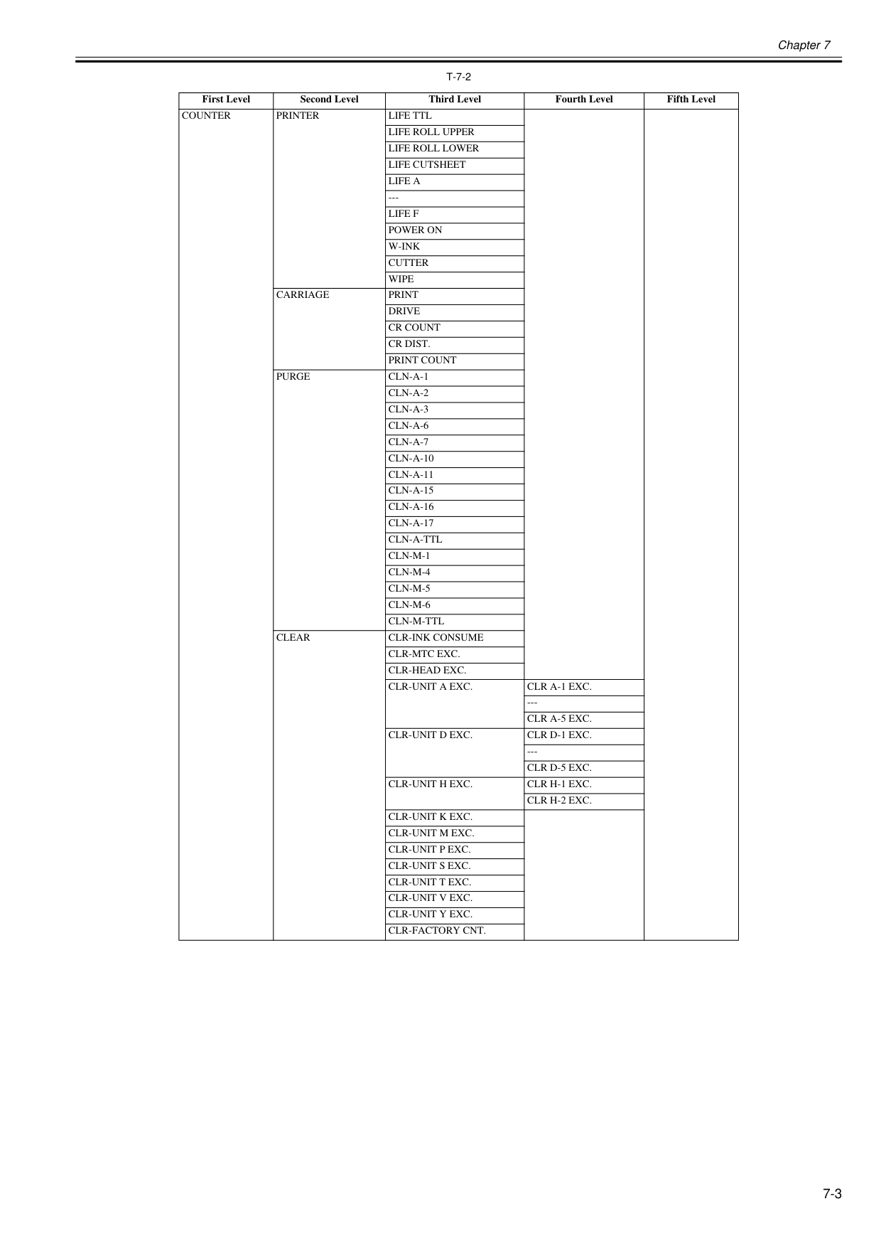
Chapter 7 7-3
T-7-2
First Level Second Level Third Level Fourth Level Fifth LevelCounter
Printer
Life Ttl
Life Roll Upper
Life Roll Lower
Life Cutsheet
Life A
---Life F
Power On
W-Ink
Cutter
Wipe
Carriage
Drive
Cr Count
Cr Dist.
Print Count
Purge
Cln-A-1
Cln-A-2
Cln-A-3
Cln-A-6
Cln-A-7
Cln-A-10
Cln-A-11
Cln-A-15
Cln-A-16
Cln-A-17
Cln-A-Ttl
Cln-M-1
Cln-M-4
Cln-M-5
Cln-M-6
Cln-M-Ttl
Clear
Clr-Ink Consume
Clr-Mtc Exc.
Clr-Head Exc.
Clr-Unit A Exc.
Clr A-1 Exc.
---Clr A-5 Exc.
Clr-Unit D Exc.
Clr D-1 Exc.
---Clr D-5 Exc.
Clr-Unit H Exc.
Clr H-1 Exc.
Clr H-2 Exc.
Clr-Unit K Exc.
Clr-Unit M Exc.
Clr-Unit P Exc.
Clr-Unit S Exc.
Clr-Unit T Exc.
Clr-Unit V Exc.
Clr-Unit Y Exc.
Clr-Factory Cnt.
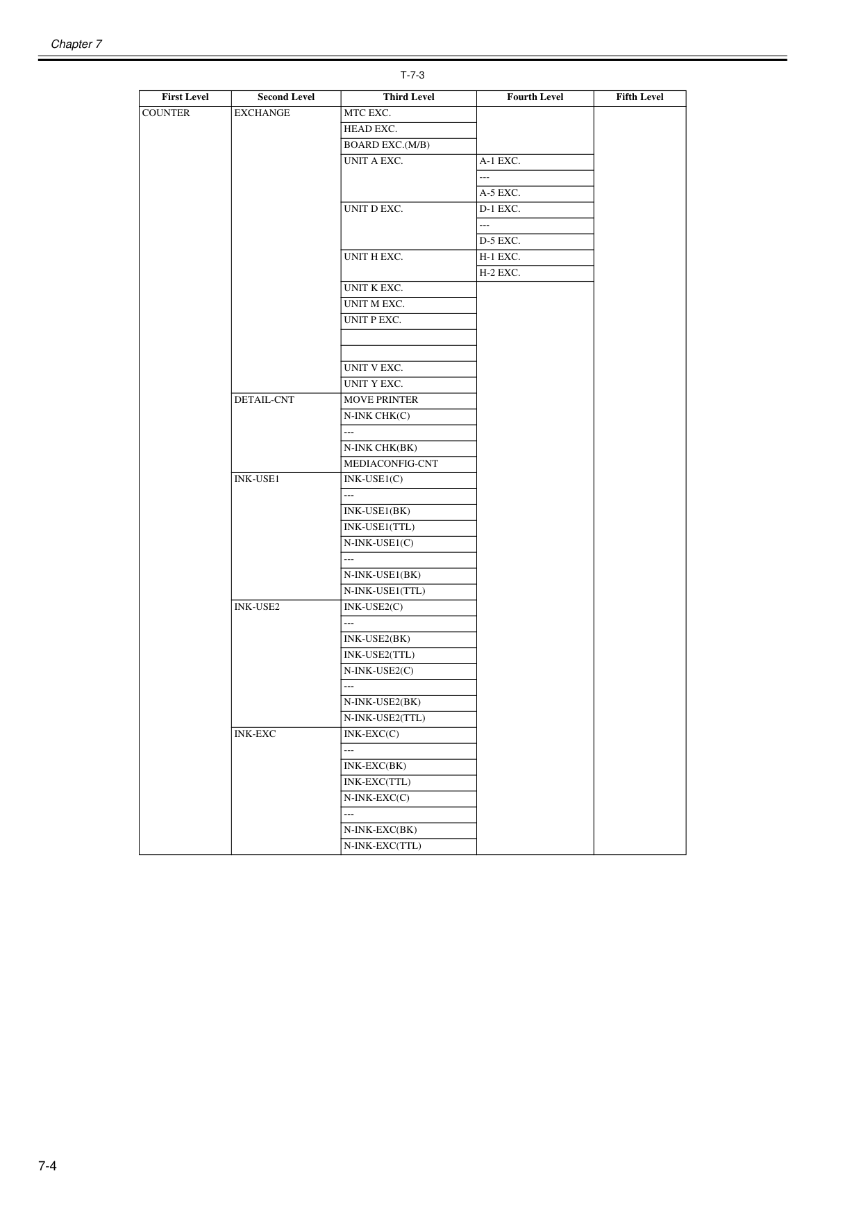
Chapter 7 7-4
T-7-3
First Level Second Level Third Level Fourth Level Fifth LevelCounter
Exchange
Mtc Exc.
Head Exc.
Board Exc.(M/B)
Unit A Exc.
A-1 Exc.
---A-5 Exc.
Unit D Exc.
D-1 Exc.
---D-5 Exc.
Unit H Exc.
H-1 Exc.
H-2 Exc.
Unit K Exc.
Unit M Exc.
Unit P Exc.
Unit V Exc.
Unit Y Exc.
Detail-Cnt
Move Printer
N-Ink Chk(C)
---N-Ink Chk(Bk)
Mediaconfig-Cnt
Ink-Use1
Ink-Use1(C)
---Ink-Use1(Bk)
Ink-Use1(Ttl)
N-Ink-Use1(C)
---N-Ink-Use1(Bk)
N-Ink-Use1(Ttl)
Ink-Use2
Ink-Use2(C)
---Ink-Use2(Bk)
Ink-Use2(Ttl)
N-Ink-Use2(C)
---N-Ink-Use2(Bk)
N-Ink-Use2(Ttl)
Ink-Exc
Ink-Exc(C)
---Ink-Exc(Bk)
Ink-Exc(Ttl)
N-Ink-Exc(C)
---N-Ink-Exc(Bk)
N-Ink-Exc(Ttl)
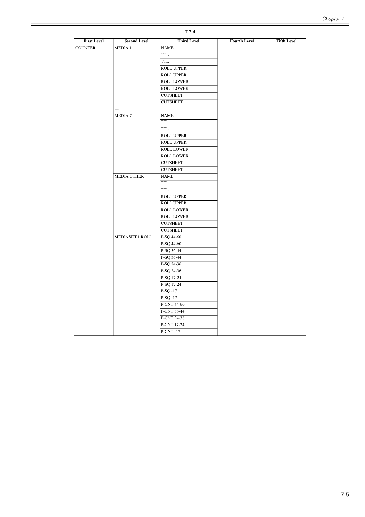
Chapter 7 7-5
T-7-4
First Level Second Level Third Level Fourth Level Fifth LevelCounter
Media 1
Name
Ttl
Ttl
Roll Upper
Roll Upper
Roll Lower
Roll Lower
Cutsheet
Cutsheet
---Media 7
Name
Ttl
Ttl
Roll Upper
Roll Upper
Roll Lower
Roll Lower
Cutsheet
Cutsheet
Media Other
Name
Ttl
Ttl
Roll Upper
Roll Upper
Roll Lower
Roll Lower
Cutsheet
Cutsheet
Mediasize1 Roll
P-Sq 44-60
P-Sq 44-60
P-Sq 36-44
P-Sq 36-44
P-Sq 24-36
P-Sq 24-36
P-Sq 17-24
P-Sq 17-24
P-Sq -17
P-Sq -17
P-Cnt 44-60
P-Cnt 36-44
P-Cnt 24-36
P-Cnt 17-24
P-Cnt -17
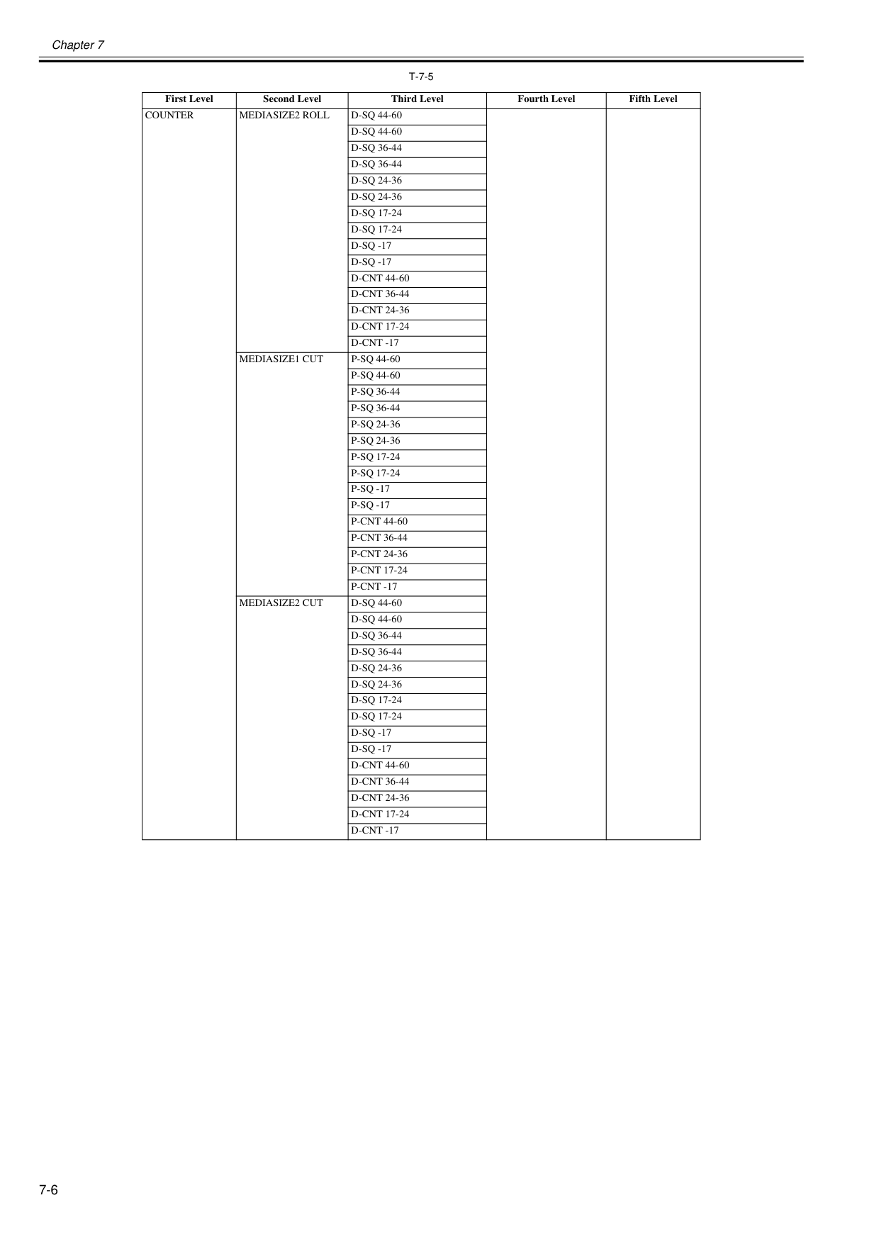
Chapter 7 7-6
T-7-5
First Level Second Level Third Level Fourth Level Fifth LevelCounter
Mediasize2 Roll
D-Sq 44-60
D-Sq 44-60
D-Sq 36-44
D-Sq 36-44
D-Sq 24-36
D-Sq 24-36
D-Sq 17-24
D-Sq 17-24
D-Sq -17
D-Sq -17
D-Cnt 44-60
D-Cnt 36-44
D-Cnt 24-36
D-Cnt 17-24
D-Cnt -17
Mediasize1 Cut
P-Sq 44-60
P-Sq 44-60
P-Sq 36-44
P-Sq 36-44
P-Sq 24-36
P-Sq 24-36
P-Sq 17-24
P-Sq 17-24
P-Sq -17
P-Sq -17
P-Cnt 44-60
P-Cnt 36-44
P-Cnt 24-36
P-Cnt 17-24
P-Cnt -17
Mediasize2 Cut
D-Sq 44-60
D-Sq 44-60
D-Sq 36-44
D-Sq 36-44
D-Sq 24-36
D-Sq 24-36
D-Sq 17-24
D-Sq 17-24
D-Sq -17
D-Sq -17
D-Cnt 44-60
D-Cnt 36-44
D-Cnt 24-36
D-Cnt 17-24
D-Cnt -17
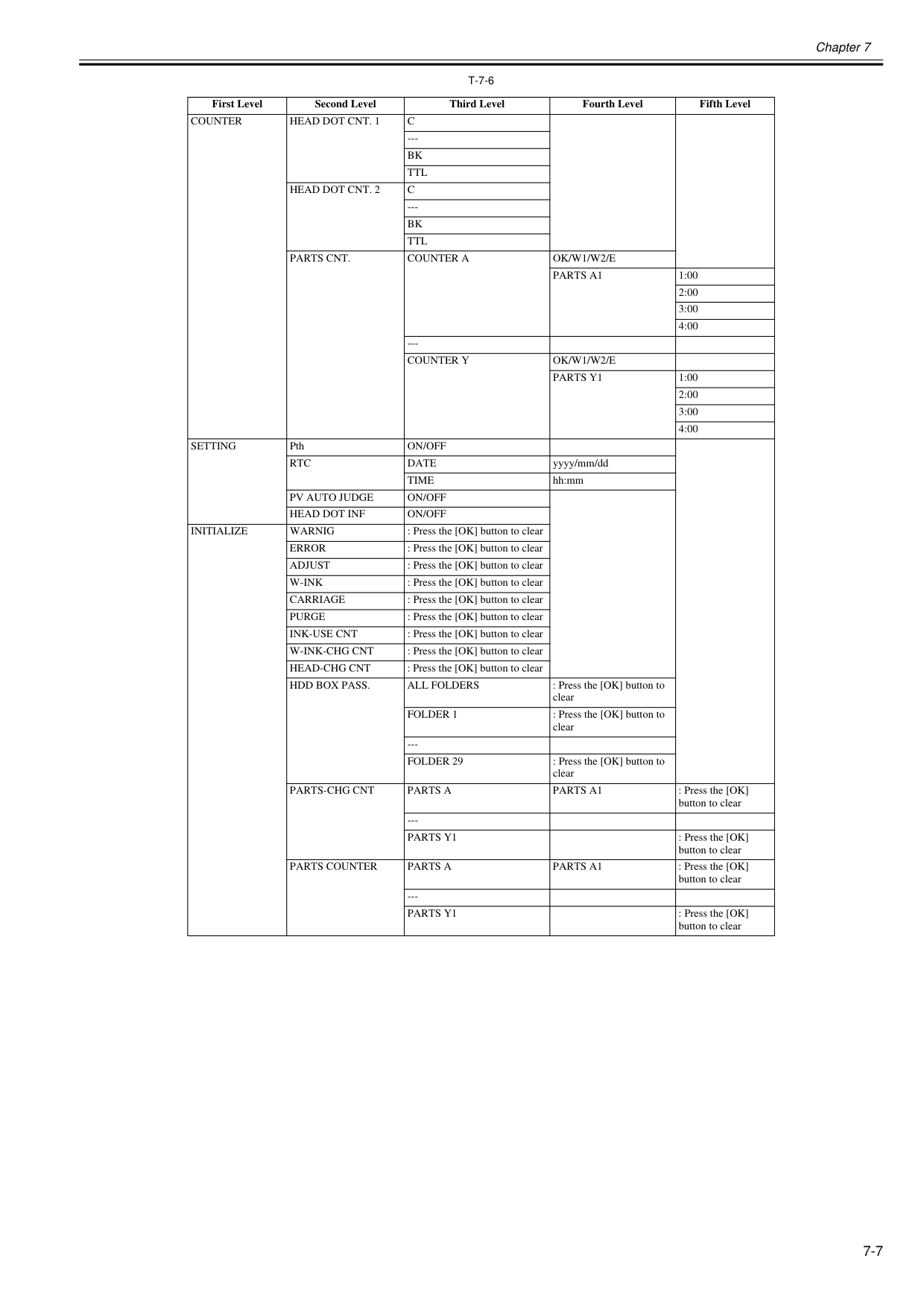
Chapter 7 7-7
T-7-6
First Level Second Level Third Level Fourth Level Fifth LevelCounter
Head Dot Cnt. 1
C
---Bk
Ttl
Head Dot Cnt. 2
C
---Bk
Ttl
Parts Cnt.
Counter A
Ok/W1/W2/E
Parts A1
1:00 2:00 3:00 4:00 ---Counter Y
Ok/W1/W2/E
Parts Y1
1:00 2:00 3:00 4:00Setting
PthOn/Off
Rtc
Date
yyyy/mm/ddTime
hh:mmPv Auto Judge
On/Off
Head Dot Inf
On/Off
Initialize
Warnig
: Press the [OK] button to clearError
: Press the [OK] button to clearAdjust
: Press the [OK] button to clearW-Ink
: Press the [OK] button to clearCarriage
: Press the [OK] button to clearPurge
: Press the [OK] button to clearInk-Use Cnt
: Press the [OK] button to clearW-Ink-Chg Cnt
: Press the [OK] button to clearHead-Chg Cnt
: Press the [OK] button to clearHdd Box Pass.
All Folders
: Press the [OK] button to clearFolder 1
: Press the [OK] button to clear ---Folder 29
: Press the [OK] button to clearParts-Chg Cnt
Parts A
Parts A1
: Press the [OK] button to clear ---Parts Y1
: Press the [OK] button to clearParts Counter
Parts A
Parts A1
: Press the [OK] button to clear ---Parts Y1
: Press the [OK] button to clear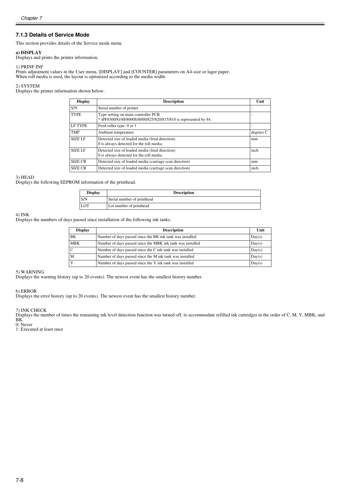
Chapter 7 7-8 7.1.3 Details of Service Mode 0020-5736 This section provides details of the Service mode menu. a) DISPLAY Displays and prints the printer information.
1) Prinf Inf
Prints adjustment values in the User menu, [DISPLAY] and [COUNTER] parameters on A4-size or lager paper. When roll media is used, the layout is optimized according to the media width.2) System
Displays the printer information shown below.3) Head
Displays the following EEPROM information of the printhead.4) Ink
Displays the numbers of days passed since installation of the following ink tanks.5) Warning
Displays the warning history (up to 20 events). The newest event has the smallest history number.6) Error
Displays the error history (up to 20 events). The newest event has the smallest history number.7) Ink Check
Displays the number of times the remaining ink level detection function was turned off, to accommodate refilled ink cartridges in the order of C, M, Y, MBK, andBk.
0: Never 1: Executed at least once Display Description UnitS/N
Serial number of printerType
Lf Type
Tmp
Size Lf
Detected size of loaded media (feed direction) 0 is always detected for the roll media. mmSize Lf
Detected size of loaded media (feed direction) 0 is always detected for the roll media. inchSize Cr
Detected size of loaded media (carriage scan direction) mmSize Cr
Detected size of loaded media (carriage scan direction) inch Display DescriptionS/N
Serial number of printheadLot
Lot number of printhead Display Description UnitBk
Number of days passed since the BK ink tank was installed Day(s)Mbk
Number of days passed since the MBK ink tank was installed Day(s)C
Number of days passed since the C ink tank was installed Day(s)M
Number of days passed since the M ink tank was installed Day(s)Y
Number of days passed since the Y ink tank was installed Day(s)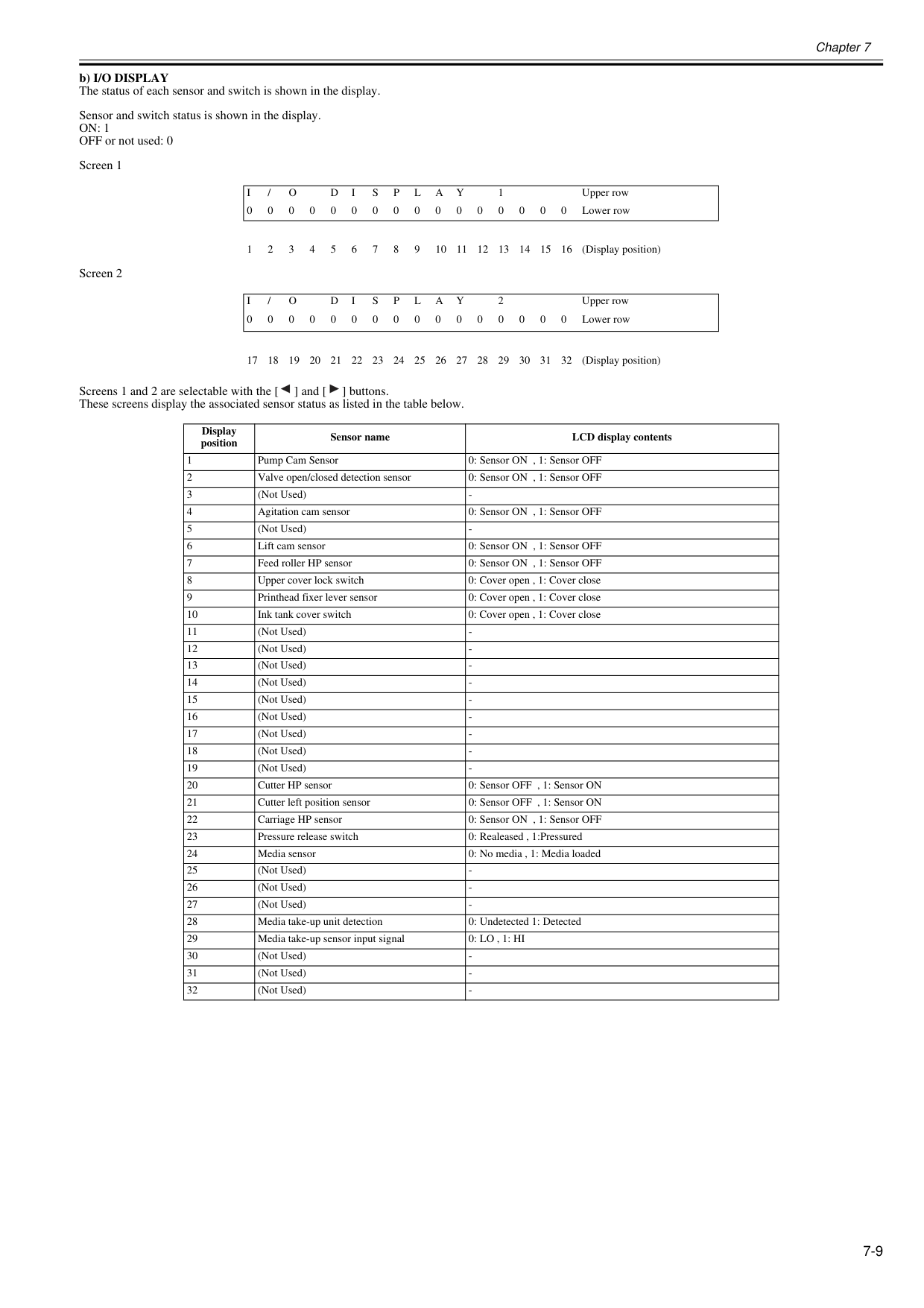
Chapter 7 7-9 b) I/O DISPLAY The status of each sensor and switch is shown in the display. Sensor and switch status is shown in the display.
On: 1
OFF or not used: 0 Screen 1 Screen 2 Screens 1 and 2 are selectable with the [ ] and [ ] buttons. These screens display the associated sensor status as listed in the table below.I
/O
D
I
S
P
L
A
Y
1 Upper row 0 0 0 0 0 0 0 0 0 0 0 0 0 0 0 0 Lower row 1 2 3 4 5 6 7 8 9 10 11 12 13 14 15 16 (Display position)I
/O
D
I
S
P
L
A
Y
2 Upper row 0 0 0 0 0 0 0 0 0 0 0 0 0 0 0 0 Lower row 17 18 19 20 21 22 23 24 25 26 27 28 29 30 31 32 (Display position) Display position Sensor name LCD display contents 1 Pump Cam Sensor 0: Sensor ON , 1: Sensor OFF 2 Valve open/closed detection sensor 0: Sensor ON , 1: Sensor OFF 3 (Not Used)0: Lo , 1: Hi
30 (Not Used)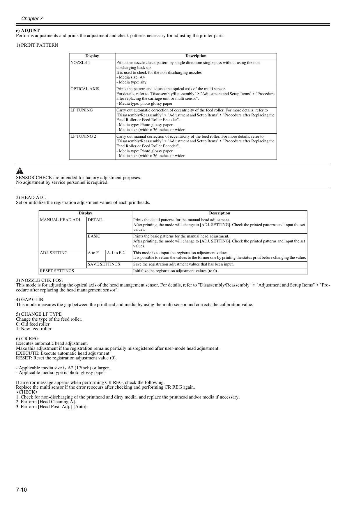
Chapter 7 7-10 c) ADJUST Performs adjustments and prints the adjustment and check patterns necessary for adjusting the printer parts.
1) Print Pattern
SENSOR CHECK are intended for factory adjustment purposes. No adjustment by service personnel is required.2) Head Adj.
Set or initialize the registration adjustment values of each printheads.3) Nozzle Chk Pos.
This mode is for adjusting the optical axis of the head management sensor. For details, refer to "Disassembly/Reassembly" > "Adjustment and Setup Items" > "Pro- cedure after replacing the head management sensor".4) Gap Clib.
This mode measures the gap between the printhead and media by using the multi sensor and corrects the calibration value.5) Change Lf Type
Change the type of the feed roller. 0: Old feed roller 1: New feed roller6) Cr Reg
Executes automatic head adjustment. Make this adjustment if the registration remains partially misregistered after user-mode head adjustment. EXECUTE: Execute automatic head adjustment. RESET: Reset the registration adjustment value (0).Nozzle 1
Prints the nozzle check pattern by single direction/ single pass without using the non- discharging back up. It is used to check for the non-discharging nozzles.Optical Axis
Prints the pattern and adjusts the optical axis of the multi sensor. For details, refer to "Disassembly/Reassembly" > "Adjustment and Setup Items" > "Procedure after replacing the carriage unit or multi sensor".Lf Tuning
Carry out automatic correction of eccentricity of the feed roller. For more details, refer to "Disassembly/Reassembly" > "Adjustment and Setup Items" > "Procedure after Replacing the Feed Roller or Feed Roller Encoder".Lf Tuning 2
Carry out manual correction of eccentricity of the feed roller. For more details, refer to "Disassembly/Reassembly" > "Adjustment and Setup Items" > "Procedure after Replacing the Feed Roller or Feed Roller Encoder".Manual Head Adj
Detail
Prints the detail patterns for the manual head adjustment. After printing, the mode will change to [ADJ. SETTING]. Check the printed patterns and input the set values.Basic
Prints the basic patterns for the manual head adjustment. After printing, the mode will change to [ADJ. SETTING]. Check the printed patterns and input the set values.Adj. Setting
A to F A-1 to F-2 This mode is to input the registration adjustment values. It is possible to return the values to the former one by printing the status print before changing the value.Save Settings
Save the registration adjustment values that has been input.Reset Settings
Initialize the registration adjustment values (to 0).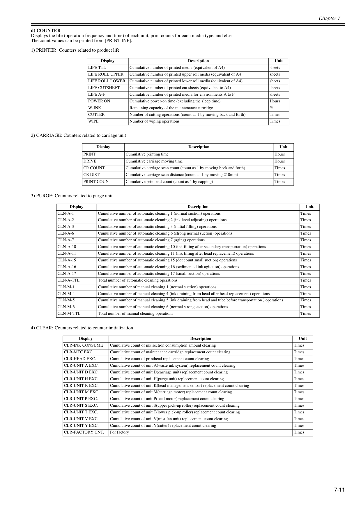
Chapter 7 7-11 d) COUNTER Displays the life (operation frequency and time) of each unit, print counts for each media type, and else. The count values can be printed from [PRINT INF]. 1) PRINTER: Counters related to product life 2) CARRIAGE: Counters related to carriage unit 3) PURGE: Counters related to purge unit 4) CLEAR: Counters related to counter initialization Display Description Unit
Life Ttl
Cumulative number of printed media (equivalent of A4) sheetsLife Roll Upper
Cumulative number of printed upper roll media (equivalent of A4) sheetsLife Roll Lower
Cumulative number of printed lower roll media (equivalent of A4) sheetsLife Cutsheet
Cumulative number of printed cut sheets (equivalent to A4) sheetsLife A-F
Cumulative number of printed media for environments A to F sheetsPower On
Cumulative power-on time (excluding the sleep time) HoursW-Ink
Remaining capacity of the maintenance cartridge %Cutter
Number of cutting operations (count as 1 by moving back and forth) TimesWipe
Number of wiping operations Times Display Description UnitDrive
Cumulative carriage moving time HoursCr Count
Cumulative carriage scan count (count as 1 by moving back and forth) TimesCr Dist.
Cumulative carriage scan distance (count as 1 by moving 210mm) TimesPrint Count
Cumulative print end count (count as 1 by capping) Times Display Description UnitCln-A-1
Cumulative number of automatic cleaning 1 (normal suction) operations TimesCln-A-2
Cumulative number of automatic cleaning 2 (ink level adjusting) operations TimesCln-A-3
Cumulative number of automatic cleaning 3 (initial filling) operations TimesCln-A-6
Cumulative number of automatic cleaning 6 (strong normal suction) operations TimesCln-A-7
Cumulative number of automatic cleaning 7 (aging) operations TimesCln-A-10
Cumulative number of automatic cleaning 10 (ink filling after secondary transportation) operations TimesCln-A-11
Cumulative number of automatic cleaning 11 (ink filling after head replacement) operations TimesCln-A-15
Cumulative number of automatic cleaning 15 (dot count small suction) operations TimesCln-A-16
Cumulative number of automatic cleaning 16 (sedimented ink agitation) operations TimesCln-A-17
Cumulative number of automatic cleaning 17 (small suction) operations TimesCln-A-Ttl
Total number of automatic cleaning operations TimesCln-M-1
Cumulative number of manual cleaning 1 (normal suction) operations TimesCln-M-4
Cumulative number of manual cleaning 4 (ink draining from head after head replacement) operations TimesCln-M-5
Cumulative number of manual cleaning 5 (ink draining from head and tube before transportation ) operations TimesCln-M-6
Cumulative number of manual cleaning 6 (normal strong suction) operations TimesCln-M-Ttl
Total number of manual cleaning operations Times Display Description UnitClr-Ink Consume
Cumulative count of ink section consumption amount clearing TimesClr-Mtc Exc.
Cumulative count of maintenance cartridge replacement count clearing TimesClr-Head Exc.
Cumulative count of printhead replacement count clearing TimesClr-Unit A Exc.
Cumulative count of unit A(waste ink system) replacement count clearing TimesClr-Unit D Exc.
Cumulative count of unit D(carriage unit) replacement count clearing TimesClr-Unit H Exc.
Cumulative count of unit H(purge unit) replacement count clearing TimesClr-Unit K Exc.
Cumulative count of unit K(head management sensor) replacement count clearing TimesClr-Unit M Exc.
Cumulative count of unit M(carriage motor) replacement count clearing TimesClr-Unit P Exc.
Cumulative count of unit P(feed motor) replacement count clearing TimesClr-Unit S Exc.
Cumulative count of unit S(upper pick-up roller) replacement count clearing TimesClr-Unit T Exc.
Cumulative count of unit T(lower pick-up roller) replacement count clearing TimesClr-Unit V Exc.
Cumulative count of unit V(mist fan unit) replacement count clearing TimesClr-Unit Y Exc.
Cumulative count of unit Y(cutter) replacement count clearing TimesClr-Factory Cnt.
For factory Times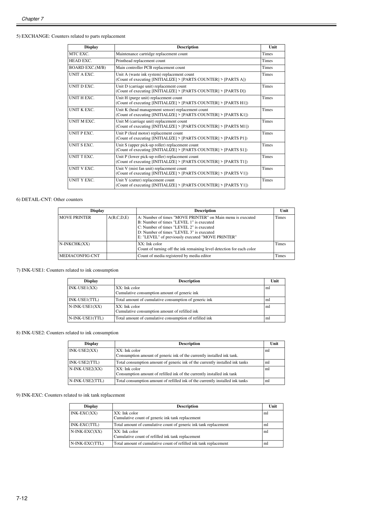
Chapter 7 7-12 5) EXCHANGE: Counters related to parts replacement 6) DETAIL-CNT: Other counters 7) INK-USE1: Counters related to ink consumption 8) INK-USE2: Counters related to ink consumption 9) INK-EXC: Counters related to ink tank replacement Display Description Unit
Mtc Exc.
Maintenance cartridge replacement count TimesHead Exc.
Printhead replacement count TimesBoard Exc.(M/B)
Main controller PCB replacement count TimesUnit A Exc.
Unit A (waste ink system) replacement count (Count of executing [INITIALIZE] > [PARTS COUNTER] > [PARTS A]) TimesUnit D Exc.
Unit D (carriage unit) replacement count (Count of executing [INITIALIZE] > [PARTS COUNTER] > [PARTS D]) TimesUnit H Exc.
Unit H (purge unit) replacement count (Count of executing [INITIALIZE] > [PARTS COUNTER] > [PARTS H1]) TimesUnit K Exc.
Unit K (head management sensor) replacement count (Count of executing [INITIALIZE] > [PARTS COUNTER] > [PARTS K1]) TimesUnit M Exc.
Unit M (carriage unit) replacement count (Count of executing [INITIALIZE] > [PARTS COUNTER] > [PARTS M1]) TimesUnit P Exc.
Unit P (feed motor) replacement count (Count of executing [INITIALIZE] > [PARTS COUNTER] > [PARTS P1]) TimesUnit S Exc.
Unit S (upper pick-up roller) replacement count (Count of executing [INITIALIZE] > [PARTS COUNTER] > [PARTS S1]) TimesUnit T Exc.
Unit P (lower pick-up roller) replacement count (Count of executing [INITIALIZE] > [PARTS COUNTER] > [PARTS T1]) TimesUnit V Exc.
Unit V (mist fan unit) replacement count (Count of executing [INITIALIZE] > [PARTS COUNTER] > [PARTS V1]) TimesUnit Y Exc.
Unit Y (cutter) replacement count (Count of executing [INITIALIZE] > [PARTS COUNTER] > [PARTS Y1]) Times Display Description UnitMove Printer
A(B,C,D,E)
A: Number of times "MOVE PRINTER" on Main menu is executed B: Number of times "LEVEL 1" is executed C: Number of times "LEVEL 2" is executed D: Number of times "LEVEL 3" is executed E: "LEVEL" of previously executed "MOVE PRINTER" TimesN-Inkchk(Xx)
XX: Ink color Count of turning off the ink remaining level detection for each color TimesMediaconfig-Cnt
Count of media registered by media editor Times Display Description UnitInk-Use1(Xx)
XX: Ink color Cumulative consumption amount of generic ink mlInk-Use1(Ttl)
Total amount of cumulative consumption of generic ink mlN-Ink-Use1(Xx)
XX: Ink color Cumulative consumption amount of refilled ink mlN-Ink-Use1(Ttl)
Total amount of cumulative consumption of refilled ink ml Display Description UnitInk-Use2(Xx)
XX: Ink color Consumption amount of generic ink of the currently installed ink tank. mlInk-Use2(Ttl)
Total consumption amount of generic ink of the currently installed ink tanks mlN-Ink-Use2(Xx)
XX: Ink color Consumption amount of refilled ink of the currently installed ink tank mlN-Ink-Use2(Ttl)
Total consumption amount of refilled ink of the currently installed ink tanks ml Display Description UnitInk-Exc(Xx)
XX: Ink color Cumulative count of generic ink tank replacement mlInk-Exc(Ttl)
Total amount of cumulative count of generic ink tank replacement mlN-Ink-Exc(Xx)
XX: Ink color Cumulative count of refilled ink tank replacement mlN-Ink-Exc(Ttl)
Total amount of cumulative count of refilled ink tank replacement ml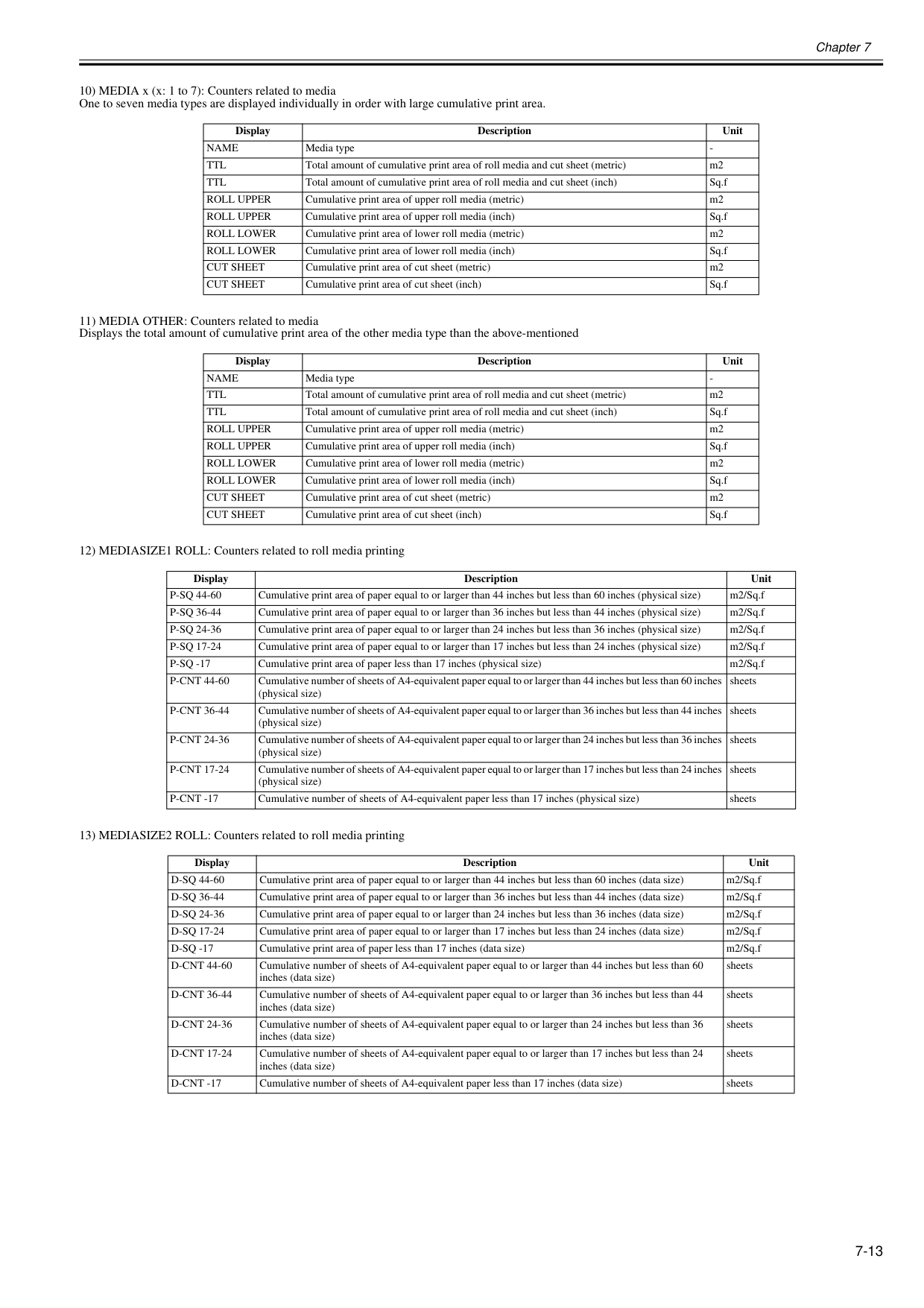
Chapter 7 7-13 10) MEDIA x (x: 1 to 7): Counters related to media One to seven media types are displayed individually in order with large cumulative print area. 11) MEDIA OTHER: Counters related to media Displays the total amount of cumulative print area of the other media type than the above-mentioned 12) MEDIASIZE1 ROLL: Counters related to roll media printing 13) MEDIASIZE2 ROLL: Counters related to roll media printing Display Description Unit
Name
Media typeTtl
Ttl
Total amount of cumulative print area of roll media and cut sheet (inch) Sq.fRoll Upper
Cumulative print area of upper roll media (metric) m2Roll Upper
Cumulative print area of upper roll media (inch) Sq.fRoll Lower
Cumulative print area of lower roll media (metric) m2Roll Lower
Cumulative print area of lower roll media (inch) Sq.fCut Sheet
Cumulative print area of cut sheet (metric) m2Cut Sheet
Cumulative print area of cut sheet (inch) Sq.f Display Description UnitName
Media typeTtl
Ttl
Total amount of cumulative print area of roll media and cut sheet (inch) Sq.fRoll Upper
Cumulative print area of upper roll media (metric) m2Roll Upper
Cumulative print area of upper roll media (inch) Sq.fRoll Lower
Cumulative print area of lower roll media (metric) m2Roll Lower
Cumulative print area of lower roll media (inch) Sq.fCut Sheet
Cumulative print area of cut sheet (metric) m2Cut Sheet
Cumulative print area of cut sheet (inch) Sq.f Display Description UnitP-Sq 44-60
Cumulative print area of paper equal to or larger than 44 inches but less than 60 inches (physical size) m2/Sq.fP-Sq 36-44
Cumulative print area of paper equal to or larger than 36 inches but less than 44 inches (physical size) m2/Sq.fP-Sq 24-36
Cumulative print area of paper equal to or larger than 24 inches but less than 36 inches (physical size) m2/Sq.fP-Sq 17-24
Cumulative print area of paper equal to or larger than 17 inches but less than 24 inches (physical size) m2/Sq.fP-Sq -17
Cumulative print area of paper less than 17 inches (physical size) m2/Sq.fP-Cnt 44-60
Cumulative number of sheets of A4-equivalent paper equal to or larger than 44 inches but less than 60 inches (physical size) sheetsP-Cnt 36-44
Cumulative number of sheets of A4-equivalent paper equal to or larger than 36 inches but less than 44 inches (physical size) sheetsP-Cnt 24-36
Cumulative number of sheets of A4-equivalent paper equal to or larger than 24 inches but less than 36 inches (physical size) sheetsP-Cnt 17-24
Cumulative number of sheets of A4-equivalent paper equal to or larger than 17 inches but less than 24 inches (physical size) sheetsP-Cnt -17
Cumulative number of sheets of A4-equivalent paper less than 17 inches (physical size) sheets Display Description UnitD-Sq 44-60
Cumulative print area of paper equal to or larger than 44 inches but less than 60 inches (data size) m2/Sq.fD-Sq 36-44
Cumulative print area of paper equal to or larger than 36 inches but less than 44 inches (data size) m2/Sq.fD-Sq 24-36
Cumulative print area of paper equal to or larger than 24 inches but less than 36 inches (data size) m2/Sq.fD-Sq 17-24
Cumulative print area of paper equal to or larger than 17 inches but less than 24 inches (data size) m2/Sq.fD-Sq -17
Cumulative print area of paper less than 17 inches (data size) m2/Sq.fD-Cnt 44-60
Cumulative number of sheets of A4-equivalent paper equal to or larger than 44 inches but less than 60 inches (data size) sheetsD-Cnt 36-44
Cumulative number of sheets of A4-equivalent paper equal to or larger than 36 inches but less than 44 inches (data size) sheetsD-Cnt 24-36
Cumulative number of sheets of A4-equivalent paper equal to or larger than 24 inches but less than 36 inches (data size) sheetsD-Cnt 17-24
Cumulative number of sheets of A4-equivalent paper equal to or larger than 17 inches but less than 24 inches (data size) sheetsD-Cnt -17
Cumulative number of sheets of A4-equivalent paper less than 17 inches (data size) sheets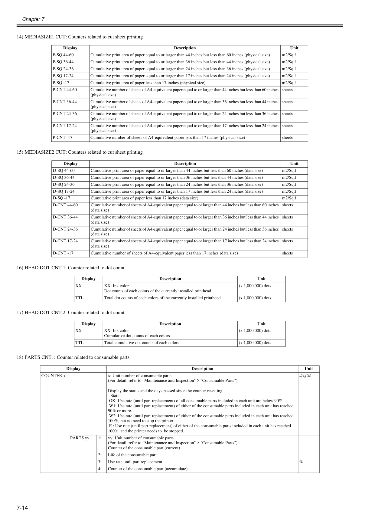
Chapter 7 7-14 14) MEDIASIZE1 CUT: Counters related to cut sheet printing 15) MEDIASIZE2 CUT: Counters related to cut sheet printing 16) HEAD DOT CNT.1: Counter related to dot count 17) HEAD DOT CNT.2: Counter related to dot count 18) PARTS CNT. : Counter related to consumable parts Display Description Unit
P-Sq 44-60
Cumulative print area of paper equal to or larger than 44 inches but less than 60 inches (physical size) m2/Sq.fP-Sq 36-44
Cumulative print area of paper equal to or larger than 36 inches but less than 44 inches (physical size) m2/Sq.fP-Sq 24-36
Cumulative print area of paper equal to or larger than 24 inches but less than 36 inches (physical size) m2/Sq.fP-Sq 17-24
Cumulative print area of paper equal to or larger than 17 inches but less than 24 inches (physical size) m2/Sq.fP-Sq -17
Cumulative print area of paper less than 17 inches (physical size) m2/Sq.fP-Cnt 44-60
Cumulative number of sheets of A4-equivalent paper equal to or larger than 44 inches but less than 60 inches (physical size) sheetsP-Cnt 36-44
Cumulative number of sheets of A4-equivalent paper equal to or larger than 36 inches but less than 44 inches (physical size) sheetsP-Cnt 24-36
Cumulative number of sheets of A4-equivalent paper equal to or larger than 24 inches but less than 36 inches (physical size) sheetsP-Cnt 17-24
Cumulative number of sheets of A4-equivalent paper equal to or larger than 17 inches but less than 24 inches (physical size) sheetsP-Cnt -17
Cumulative number of sheets of A4-equivalent paper less than 17 inches (physical size) sheets Display Description UnitD-Sq 44-60
Cumulative print area of paper equal to or larger than 44 inches but less than 60 inches (data size) m2/Sq.fD-Sq 36-44
Cumulative print area of paper equal to or larger than 36 inches but less than 44 inches (data size) m2/Sq.fD-Sq 24-36
Cumulative print area of paper equal to or larger than 24 inches but less than 36 inches (data size) m2/Sq.fD-Sq 17-24
Cumulative print area of paper equal to or larger than 17 inches but less than 24 inches (data size) m2/Sq.fD-Sq -17
Cumulative print area of paper less than 17 inches (data size) m2/Sq.fD-Cnt 44-60
Cumulative number of sheets of A4-equivalent paper equal to or larger than 44 inches but less than 60 inches (data size) sheetsD-Cnt 36-44
Cumulative number of sheets of A4-equivalent paper equal to or larger than 36 inches but less than 44 inches (data size) sheetsD-Cnt 24-36
Cumulative number of sheets of A4-equivalent paper equal to or larger than 24 inches but less than 36 inches (data size) sheetsD-Cnt 17-24
Cumulative number of sheets of A4-equivalent paper equal to or larger than 17 inches but less than 24 inches (data size) sheetsD-Cnt -17
Cumulative number of sheets of A4-equivalent paper less than 17 inches (data size) sheets Display Description UnitXx
XX: Ink color Dot counts of each colors of the currently installed printhead (x 1,000,000) dotsTtl
Total dot counts of each colors of the currently installed printhead (x 1,000,000) dots Display Description UnitXx
XX: Ink color Cumulative dot counts of each colors (x 1,000,000) dotsTtl
Total cumulative dot counts of each colors (x 1,000,000) dots Display Description Unit COUNTER x x: Unit number of consumable parts (For detail, refer to "Maintenance and Inspection" > "Consumable Parts") Display the status and the days passed since the counter resetting.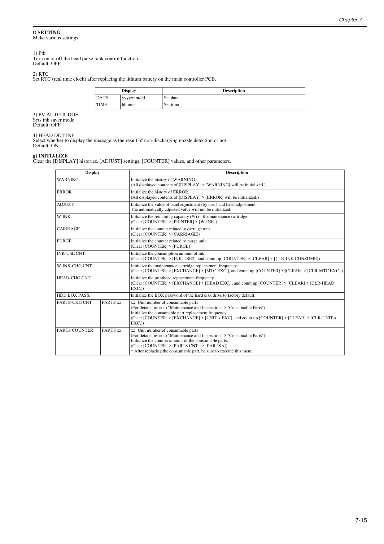
Chapter 7 7-15 f) SETTING Make various settings. 1) Pth Turn on or off the head pulse rank control function. Default: OFF
2) Rtc
Set RTC (real time clock) after replacing the lithium battery on the main controller PCB.3) Pv Auto Judge
Sets ink saver mode. Default: OFF4) Head Dot Inf
Select whether to display the message as the result of non-discharging nozzle detection or not. Default: ON g) INITIALIZE Clear the [DISPLAY] histories, [ADJUST] settings, [COUNTER] values, and other parameters. Display DescriptionDate
yyyy/mm/dd Set dateTime
hh:mm Set time Display DescriptionWarning
Initialize the history of WARNING. (All displayed contents of [DISPLAY] > [WARNING] will be initialized.)Error
Initialize the history of ERROR. (All displayed contents of [DISPLAY] > [ERROR] will be initialized.)Adjust
Initialize the value of band adjustment (by user) and head adjustment. The automatically adjusted value will not be initialized.W-Ink
Initialize the remaining capacity (%) of the maitenance cartridge. (Clear [COUNTER] > [PRINTER] > [W-INK])Carriage
Initialize the counter related to carriage unit. (Clear [COUNTER] > [CARRIAGE])Purge
Initialize the counter related to purge unit. (Clear [COUNTER] > [PURGE])Ink-Use Cnt
Initialize the consumption amount of ink. (Clear [COUNTER] > [INK-USE2], and count up [COUNTER] > [CLEAR] > [CLR-INK CONSUME])W-Ink-Chg Cnt
Initialize the maintenance cartridge replacement frequency. (Clear [COUNTER] > [EXCHANGE] > [MTC EXC.], and count up [COUNTER] > [CLEAR] > [CLR-MTC EXC.])Head-Chg Cnt
Initialize the printhead replacement frequency. (Clear [COUNTER] > [EXCHANGE] > [HEAD EXC.], and count up [COUNTER] > [CLEAR] > [CLR-HEADExc.])
Hdd Box Pass.
Initialize the BOX password of the hard disk drive to factory default.Parts-Chg Cnt
PARTS xx xx: Unit number of consumable parts (For details, refer to "Maintenance and Inspection" > "Consumable Parts") Initialize the consumable part replacement frequency. (Clear [COUNTER] > [EXCHANGE] > [UNIT x EXC], and count up [COUNTER] > [CLEAR] > [CLR-UNIT xExc.])
Parts Counter
PARTS xx xx: Unit number of consumable parts (For details, refer to "Maintenance and Inspection" > "Consumable Parts") Initialize the counter amount of the consumable parts. (Clear [COUNTER] > [PARTS CNT.] > [PARTS x])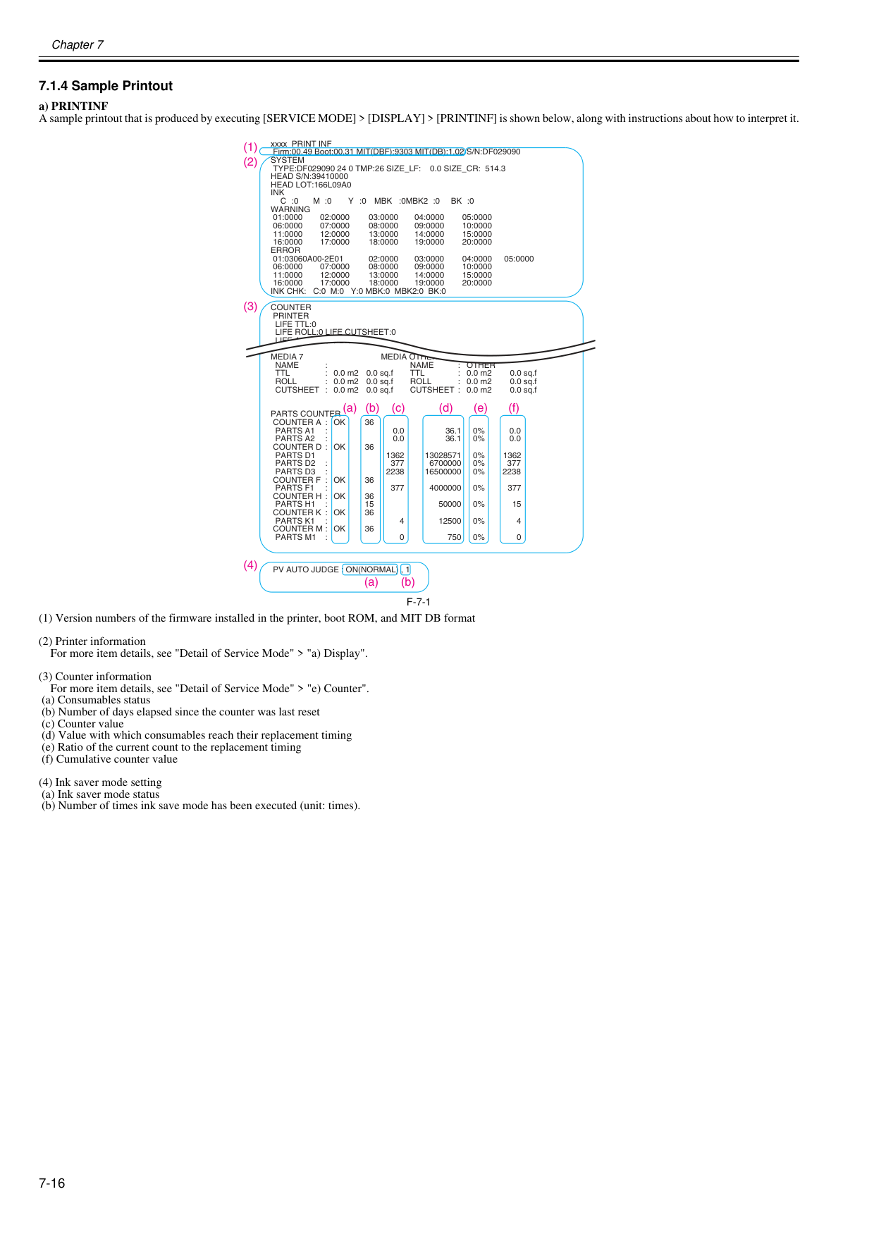
Chapter 7 7-16 7.1.4 Sample Printout 0020-5737 a) PRINTINF A sample printout that is produced by executing [SERVICE MODE] > [DISPLAY] > [PRINTINF] is shown below, along with instructions about how to interpret it.
F-7-1
(1) Version numbers of the firmware installed in the printer, boot ROM, and MIT DB format (2) Printer information For more item details, see "Detail of Service Mode" > "a) Display". (3) Counter information For more item details, see "Detail of Service Mode" > "e) Counter". (a) Consumables status (b) Number of days elapsed since the counter was last reset (c) Counter value (d) Value with which consumables reach their replacement timing (e) Ratio of the current count to the replacement timing (f) Cumulative counter value (4) Ink saver mode setting (a) Ink saver mode status (b) Number of times ink save mode has been executed (unit: times). xxxx PRINT INF Firm:00.49 Boot:00.31 MIT(DBF):9303 MIT(DB):1.02 S/N:DF029090System
Type:Df029090 24 0 Tmp:26 Size_Lf: 0.0 Size_Cr: 514.3
Head S/N:39410000
Head Lot:166L09A0
Ink
C :0
M :0
Y :0
Mbk
:0Mbk2 :0
Bk :0
Warning
01:0000 02:0000 03:0000 04:0000 05:0000 06:0000 07:0000 08:0000 09:0000 10:0000 11:0000 12:0000 13:0000 14:0000 15:0000 16:0000 17:0000 18:0000 19:0000 20:0000Error
01:03060A00-2E01
02:0000 03:0000 04:0000 05:0000 06:0000 07:0000 08:0000 09:0000 10:0000 11:0000 12:0000 13:0000 14:0000 15:0000 16:0000 17:0000 18:0000 19:0000 20:0000Ink Chk: C:0 M:0 Y:0 Mbk:0 Mbk2:0 Bk:0
Counter
Printer
Life Ttl:0
Life Roll:0 Life Cutsheet:0
Life A:0 B:0 C:0 D:0 E:0 F:0
Media 7 Media Other
Name
:Name
: Other
Ttl
: 0.0 m2 0.0 sq.fTtl
: 0.0 m2 0.0 sq.fRoll
: 0.0 m2 0.0 sq.fRoll
: 0.0 m2 0.0 sq.f CUTSHEET : 0.0 m2 0.0 sq.f CUTSHEET : 0.0 m2 0.0 sq.fParts Counter
Counter A : Ok
36Parts A1
: 0.0 36.1 0% 0.0Parts A2
: 0.0 36.1 0% 0.0Counter D : Ok
36Parts D1
1362 13028571 0% 1362Parts D2
: 377 6700000 0% 377Parts D3
: 2238 16500000 0% 2238Counter F : Ok
36Parts F1
: 377 4000000 0% 377Counter H : Ok
36Parts H1
: 15 50000 0% 15Counter K : Ok
36Parts K1
: 4 12500 0% 4Counter M : Ok
36Parts M1
: 0 750 0% 0Pv Auto Judge : On(Normal) , 1
(1) (2) (3) (a) (b) (c) (d) (e) (f) (4) (a) (b)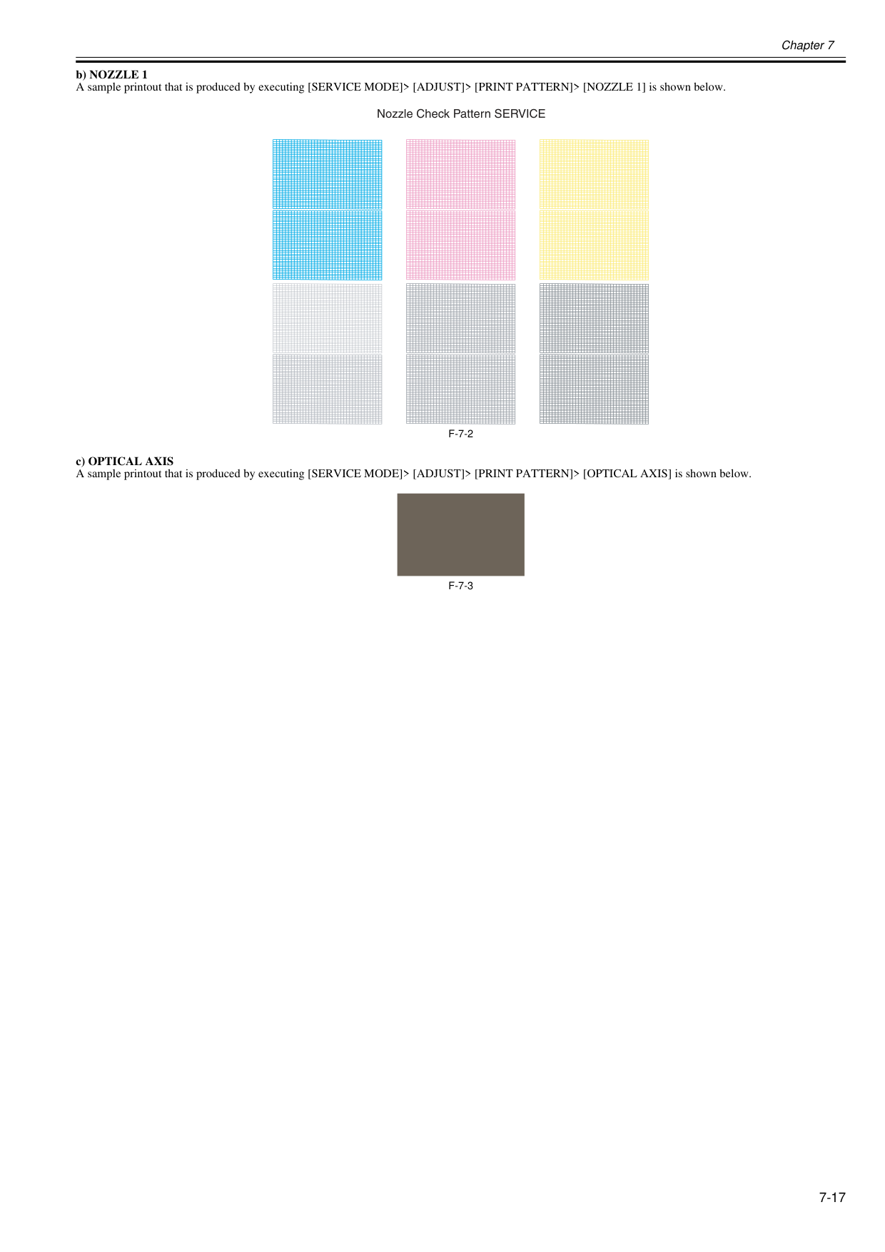
Chapter 7 7-17 b) NOZZLE 1 A sample printout that is produced by executing [SERVICE MODE]> [ADJUST]> [PRINT PATTERN]> [NOZZLE 1] is shown below.
F-7-2
c) OPTICAL AXIS A sample printout that is produced by executing [SERVICE MODE]> [ADJUST]> [PRINT PATTERN]> [OPTICAL AXIS] is shown below.F-7-3
Nozzle Check Pattern SERVICE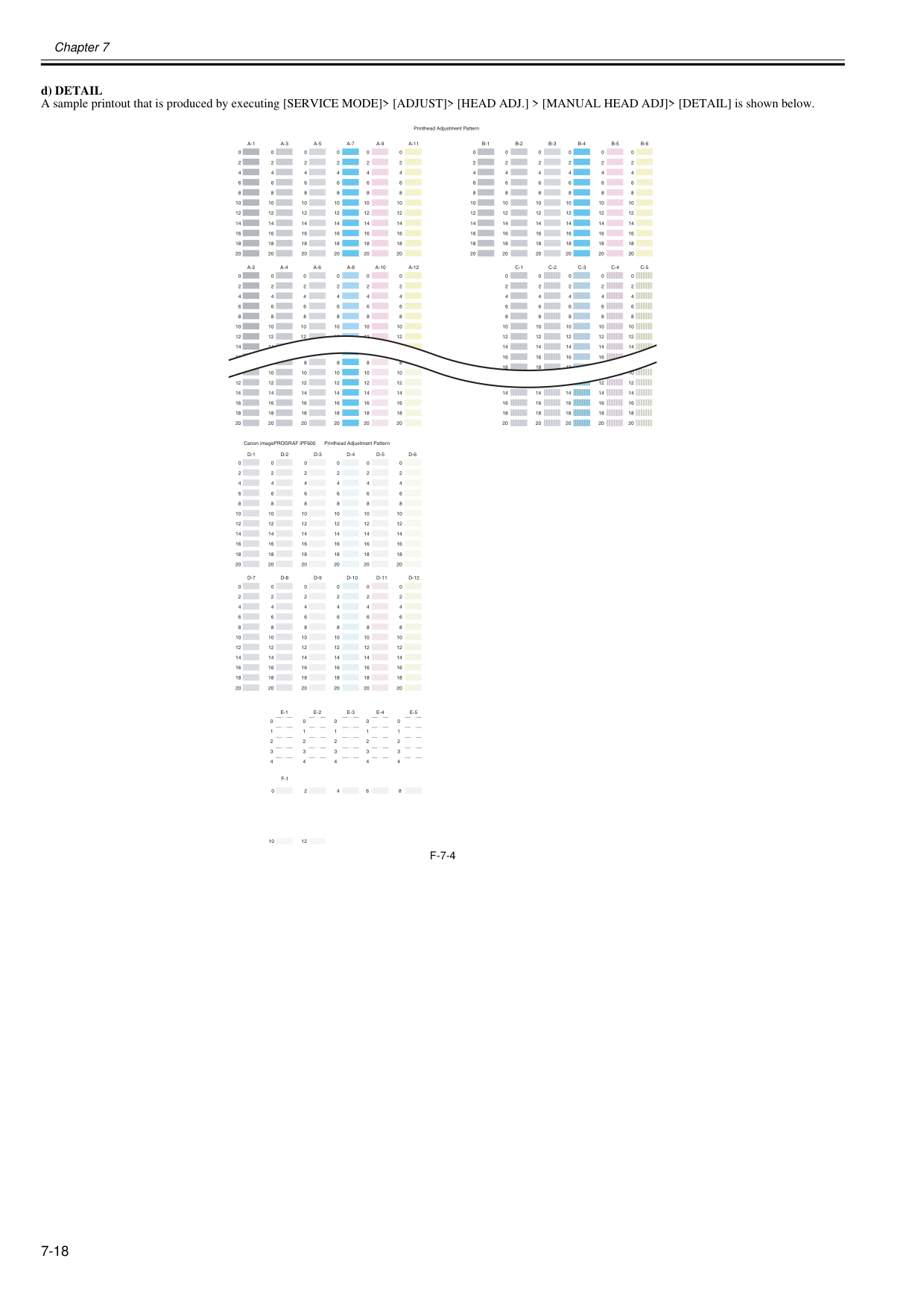
Chapter 7 7-18 d) DETAIL A sample printout that is produced by executing [SERVICE MODE]> [ADJUST]> [HEAD ADJ.] > [MANUAL HEAD ADJ]> [DETAIL] is shown below.
F-7-4
A-1
A-3
A-5
A-7
A-9
A-11
B-1
B-2
B-3
B-4
B-5
B-6
0 2 4 6 8 10 12 14 16 18 20 0 2 4 6 8 10 12 14 16 18 20 0 2 4 6 8 10 12 14 16 18 20 0 2 4 6 8 10 12 14 16 18 20 0 2 4 6 8 10 12 14 16 18 20 0 2 4 6 8 10 12 14 16 18 20D-1
D-2
D-3
D-4
D-5
D-6
0 2 4 6 8 10 12 14 16 18 20 0 2 4 6 8 10 12 14 16 18 20 0 2 4 6 8 10 12 14 16 18 20 0 2 4 6 8 10 12 14 16 18 20 0 2 4 6 8 10 12 14 16 18 20 0 2 4 6 8 10 12 14 16 18 20D-7
D-8
D-9
D-10
D-11
D-12
0 2 4 6 8 10 12 14 16 18 20 0 2 4 6 8 10 12 14 16 18 20 0 2 4 6 8 10 12 14 16 18 20 0 2 4 6 8 10 12 14 16 18 20 0 2 4 6 8 10 12 14 16 18 20 0 2 4 6 8 10 12 14 16 18 20 0 2 4 6 8 10 12 14 16 18 20 0 2 4 6 8 10 12 14 16 18 20 0 2 4 6 8 10 12 14 16 18 20 0 2 4 6 8 10 12 14 16 18 20 0 2 4 6 8 10 12 14 16 18 20 0 2 4 6 8 10 12 14 16 18 20A-2
A-4
A-6
A-8
A-10
A-12
C-1
C-2
C-3
C-4
C-5
0 2 4 6 8 10 12 0 2 4 6 8 10 12 0 2 4 6 8 10 12 0 2 4 6 8 10 12 0 2 4 6 8 10 12 14 0 2 4 6 8 10 12 14 16 0 2 4 6 8 10 12 14 0 2 4 6 8 10 12 14 16 0 2 4 6 8 10 12 14 16 18 0 2 4 6 8 10 12 14 16 18 0 2 4 6 8 10 12 14 16 18E-1
E-2
E-3
E-4
E-5
0 1 2 3 4 0 1 2 3 4 0 1 2 3 4 0 1 2 3 4 0 1 2 3 4F-1
0 10 Printhead Adjustment Pattern Canon imagePROGRAF iPF600 2 12 4 6 8 20 10 12 14 16 18 20 14 16 18 20 14 16 18 20 14 16 18 20 8 10 12 14 16 18 20 6 8 10 12 14 16 18 20 6 8 10 12 14 16 18 20 8 10 12 14 16 18 20 8 10 12 14 16 18 20 10 12 14 16 18 20 12 14 16 18 Printhead Adjustment Pattern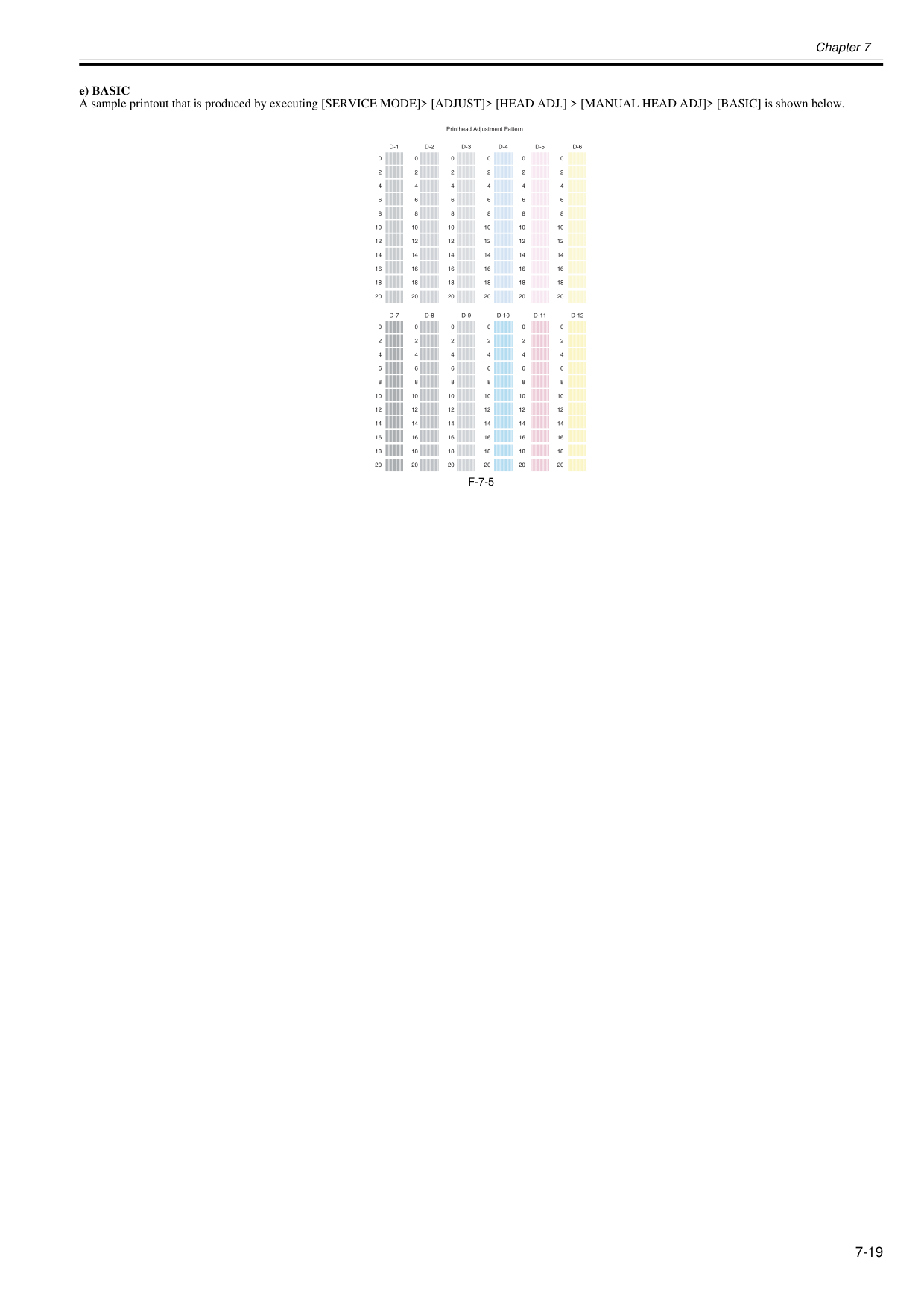
Chapter 7 7-19 e) BASIC A sample printout that is produced by executing [SERVICE MODE]> [ADJUST]> [HEAD ADJ.] > [MANUAL HEAD ADJ]> [BASIC] is shown below.
F-7-5
D-6
0 2 4 6 8 10 12 14 16 18 20 0 2 4 6 8 10 12 14 16 18 20 0 2 4 6 8 10 12 14 16 18 20 0 2 4 6 8 10 12 14 16 18 20 0 2 4 6 8 10 12 14 16 18 20 0 2 4 6 8 10 12 14 16 18 20D-12
D-5
D-11
D-4
D-10
D-3
D-9
D-2
D-8
D-1
D-7
0 2 4 6 8 10 12 14 16 18 20 0 2 4 6 8 10 12 14 16 18 20 0 2 4 6 8 10 12 14 16 18 20 0 2 4 6 8 10 12 14 16 18 20 0 2 4 6 8 10 12 14 16 18 20 0 2 4 6 8 10 12 14 16 18 20 Printhead Adjustment Pattern
Chapter 7 7-20 7.2 Special Mode 7.2.1 Special Modes for Servicing 0013-9804 This printer supports the following special modes in addition to the service mode:
- Cpu Board
Select this after replacing the main PCB. The data in the MC relay PCB is copied to the main PCB.- Mc Board
Select this before replacing the MC relay PCB. The data in the main controller PCB is copied to the MC relay PCB. c) Exiting the PCB replacement mode Turning off the [Power] button of the printer allows you to exit the PCB replacement mode. For details on how to replace the PCB, see DISASSEMBLY/REASSEMBLY > Points to Note on Disassembly and Reassembly > PCBs.
Chapter 7 7-21

Chapter 8 ERROR CODE

Contents Contents 8.1 Outline ........................................................................................................................................................ 8-1 8.1.1 Outline ..................................................................................................................................................................... 8-1 8.2 Warning/Error/Service Call Error ................................................................................................................ 8-2 8.2.1 Code Table.............................................................................................................................................................. 8-2
Chapter 8 8-1 8.1 Outline 8.1.1 Outline 0020-5742 The printer indicates errors using the display and LEDs. If an error occurs during printing, the printer status is also displayed on the status monitor of the printer driver. The following three types of errors are displayed on the display:
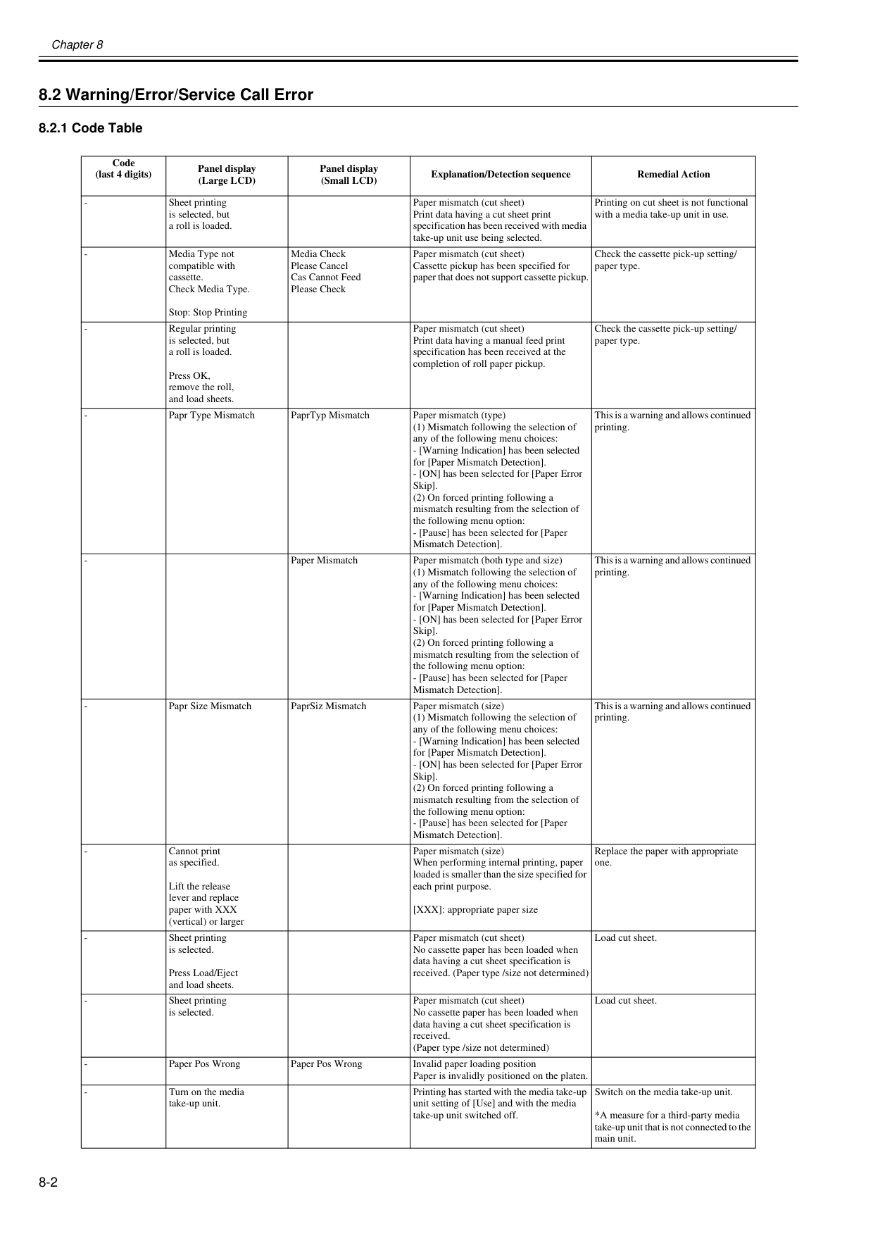
Chapter 8 8-2 8.2 Warning/Error/Service Call Error 8.2.1 Code Table 0032-0886 Code (last 4 digits) Panel display (Large LCD) Panel display (Small LCD) Explanation/Detection sequence Remedial Action
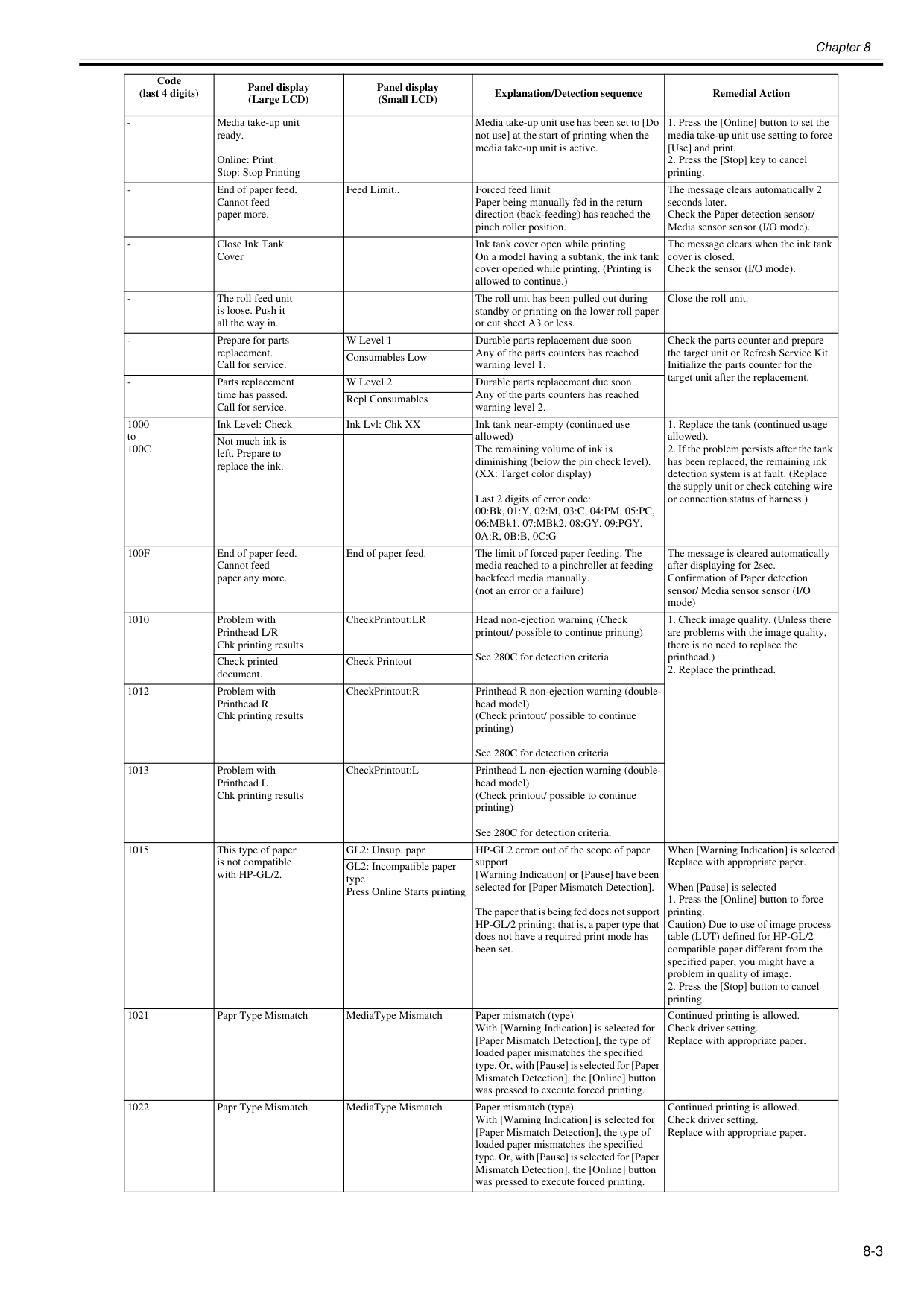
Chapter 8 8-3
100C
Ink Level: Check Ink Lvl: Chk XX Ink tank near-empty (continued use allowed) The remaining volume of ink is diminishing (below the pin check level). (XX: Target color display) Last 2 digits of error code: 00:Bk, 01:Y, 02:M, 03:C, 04:PM, 05:PC, 06:MBk1, 07:MBk2, 08:GY, 09:PGY,0A:R, 0B:B, 0C:G
100F
End of paper feed. Cannot feed paper any more. End of paper feed. The limit of forced paper feeding. The media reached to a pinchroller at feeding backfeed media manually. (not an error or a failure) The message is cleared automatically after displaying for 2sec. Confirmation of Paper detection sensor/ Media sensor sensor (I/O mode) 1010 Problem with Printhead L/R Chk printing results CheckPrintout:LR Head non-ejection warning (Check printout/ possible to continue printing) See 280C for detection criteria.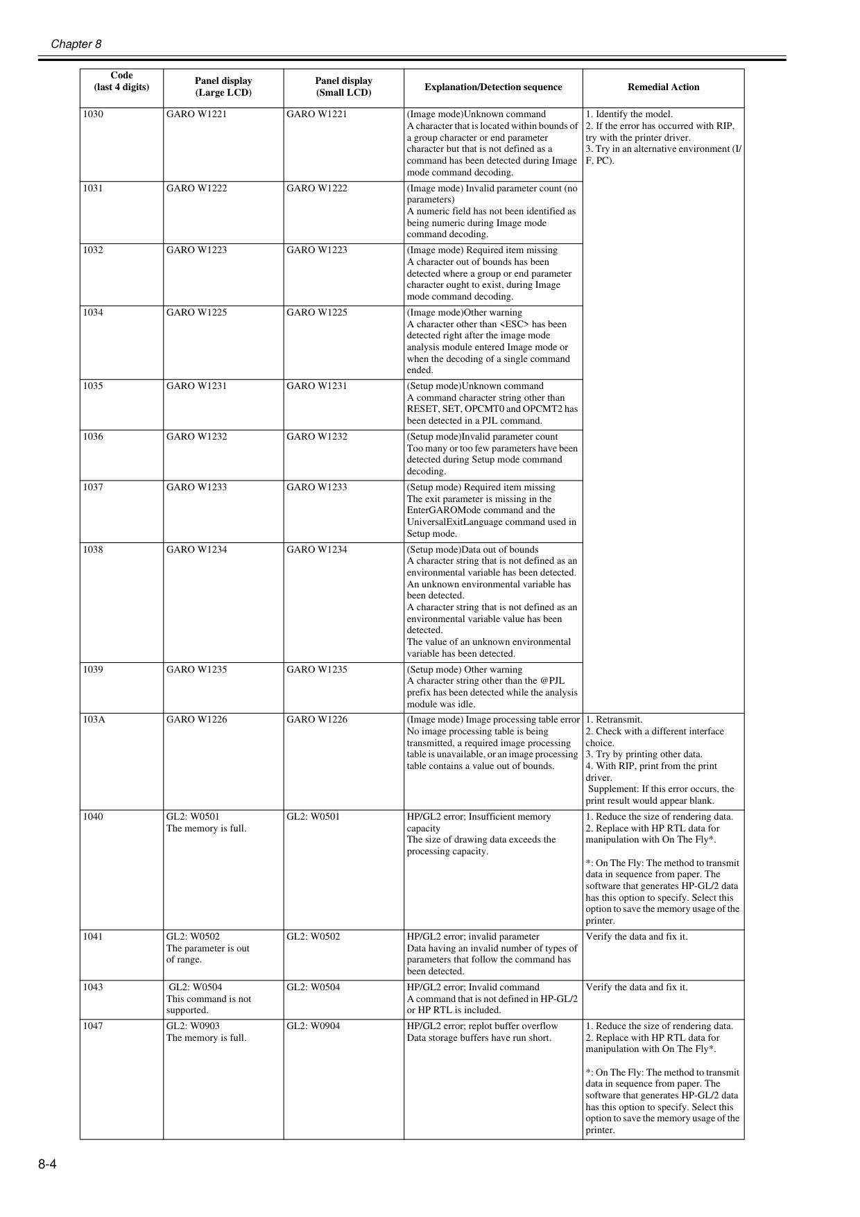
Chapter 8 8-4 1030
Garo W1221
Garo W1221
(Image mode)Unknown command A character that is located within bounds of a group character or end parameter character but that is not defined as a command has been detected during Image mode command decoding.F, Pc).
1031Garo W1222
Garo W1222
(Image mode) Invalid parameter count (no parameters) A numeric field has not been identified as being numeric during Image mode command decoding. 1032Garo W1223
Garo W1223
(Image mode) Required item missing A character out of bounds has been detected where a group or end parameter character ought to exist, during Image mode command decoding. 1034Garo W1225
Garo W1225
(Image mode)Other warning A character other thanGaro W1231
Garo W1231
(Setup mode)Unknown command A command character string other than RESET, SET, OPCMT0 and OPCMT2 has been detected in a PJL command. 1036Garo W1232
Garo W1232
(Setup mode)Invalid parameter count Too many or too few parameters have been detected during Setup mode command decoding. 1037Garo W1233
Garo W1233
(Setup mode) Required item missing The exit parameter is missing in the EnterGAROMode command and the UniversalExitLanguage command used in Setup mode. 1038Garo W1234
Garo W1234
(Setup mode)Data out of bounds A character string that is not defined as an environmental variable has been detected. An unknown environmental variable has been detected. A character string that is not defined as an environmental variable value has been detected. The value of an unknown environmental variable has been detected. 1039Garo W1235
Garo W1235
(Setup mode) Other warning A character string other than the @PJL prefix has been detected while the analysis module was idle.103A
Garo W1226
Garo W1226
(Image mode) Image processing table error No image processing table is being transmitted, a required image processing table is unavailable, or an image processing table contains a value out of bounds.Gl2: W0501
The memory is full.Gl2: W0501
HP/GL2 error; Insufficient memory capacity The size of drawing data exceeds the processing capacity.Gl2: W0502
The parameter is out of range.Gl2: W0502
HP/GL2 error; invalid parameter Data having an invalid number of types of parameters that follow the command has been detected. Verify the data and fix it. 1043Gl2: W0504
This command is not supported.Gl2: W0504
HP/GL2 error; Invalid command A command that is not defined in HP-GL/2 or HP RTL is included. Verify the data and fix it. 1047Gl2: W0903
The memory is full.Gl2: W0904
HP/GL2 error; replot buffer overflow Data storage buffers have run short.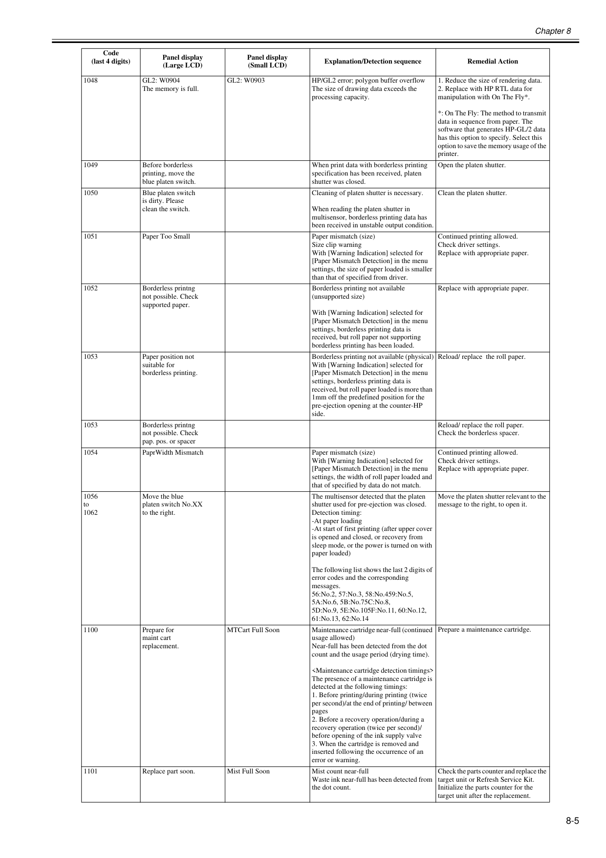
Chapter 8 8-5 1048
Gl2: W0904
The memory is full.Gl2: W0903
HP/GL2 error; polygon buffer overflow The size of drawing data exceeds the processing capacity.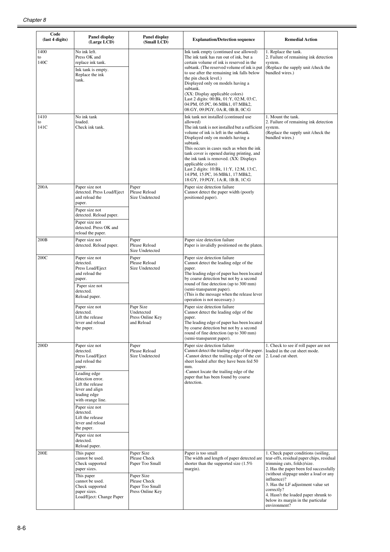
Chapter 8 8-6 1400 to
140C
No ink left. Press OK and replace ink tank. Ink tank empty (continued use allowed) The ink tank has run out of ink, but a certain volume of ink is reserved in the subtank. (The reserved volume of ink is put to use after the remaining ink falls below the pin check level.) Displayed only on models having a subtank. (XX: Display applicable colors) Last 2 digits: 00:Bk, 01:Y, 02:M, 03:C, 04:PM, 05:PC, 06:MBk1, 07:MBk2,08:Gy, 09:Pgy, 0A:R, 0B:B, 0C:G
141C
No ink tank loaded. Check ink tank. Ink tank not installed (continued use allowed) The ink tank is not installed but a sufficient volume of ink is left in the subtank. Displayed only on models having a subtank. This occurs in cases such as when the ink tank cover is opened during printing, and the ink tank is removed. (XX: Displays applicable colors) Last 2 digits: 10:Bk, 11:Y, 12:M, 13:C, 14:PM, 15:PC, 16:MBk1, 17:MBk2,18:Gy, 19:Pgy, 1A:R, 1B:B, 1C:G
200A
Paper size not detected. Press Load/Eject and reload the paper. Paper Please Reload Size Undetected Paper size detection failure Cannot detect the paper width (poorly positioned paper). Paper size not detected. Reload paper. Paper size not detected. Press OK and reload the paper.200B
Paper size not detected. Reload paper. Paper Please Reload Size Undetected Paper size detection failure Paper is invalidly positioned on the platen.200C
Paper size not detected. Press Load/Eject and reload the paper. Paper Please Reload Size Undetected Paper size detection failure Cannot detect the leading edge of the paper. The leading edge of paper has been located by coarse detection but not by a second round of fine detection (up to 300 mm) (semi-transparent paper). (This is the message when the release lever operation is not necessary.) Paper size not detected. Reload paper. Paper size not detected. Lift the release lever and reload the paper. Papr Size Undetected Press Online Key and Reload Paper size detection failure Cannot detect the leading edge of the paper. The leading edge of paper has been located by coarse detection but not by a second round of fine detection (up to 300 mm) (semi-transparent paper).200D
Paper size not detected. Press Load/Eject and reload the paper. Paper Please Reload Size Undetected Paper size detection failure Cannot detect the trailing edge of the paper. -Cannot detect the trailing edge of the cut sheet loaded after they have been fed 50 mm. -Cannot locate the trailing edge of the paper that has been found by coarse detection.200E
This paper cannot be used. Check supported paper sizes. Paper Size Please Check Paper Too Small Paper is too small The width and length of paper detected are shorter than the supported size (1.5% margin).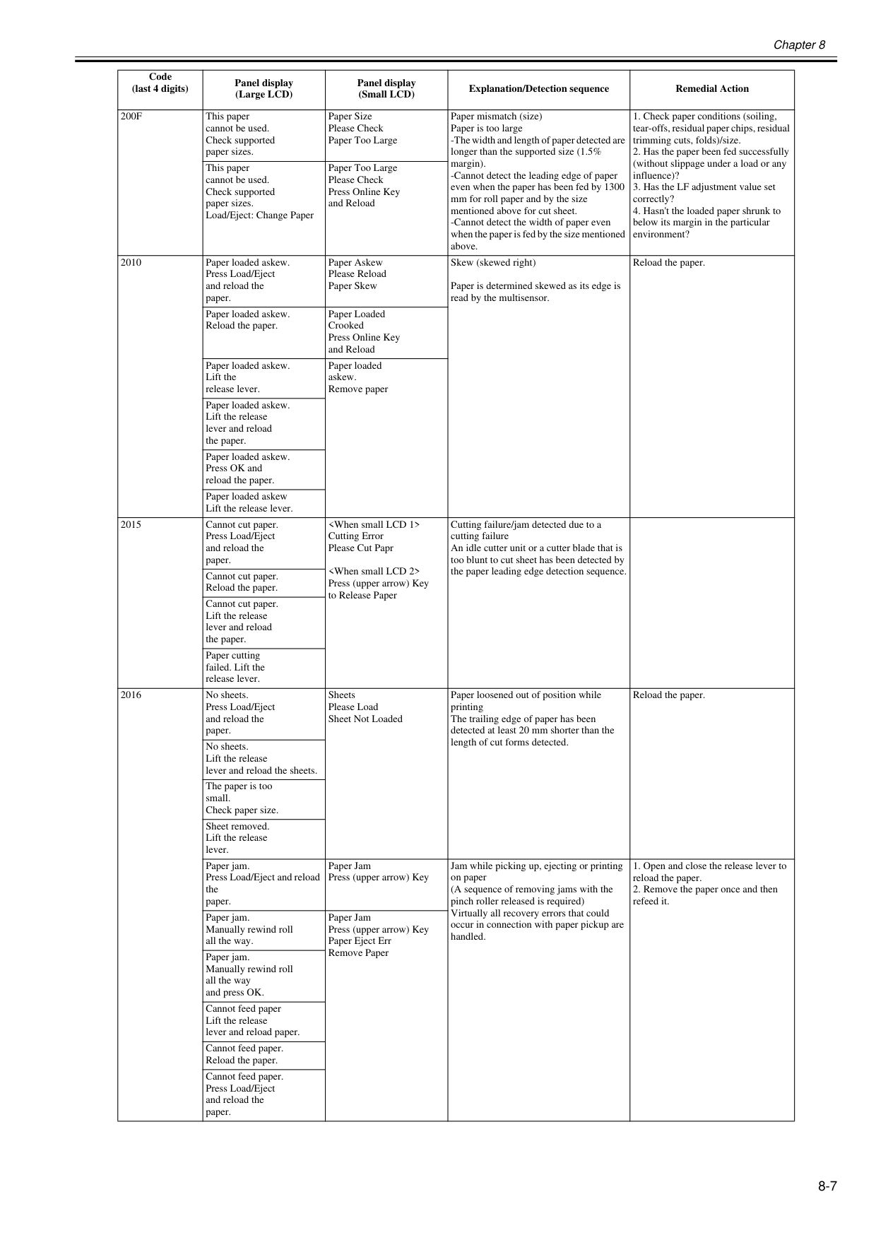
Chapter 8 8-7
200F
This paper cannot be used. Check supported paper sizes. Paper Size Please Check Paper Too Large Paper mismatch (size) Paper is too large -The width and length of paper detected are longer than the supported size (1.5% margin). -Cannot detect the leading edge of paper even when the paper has been fed by 1300 mm for roll paper and by the size mentioned above for cut sheet. -Cannot detect the width of paper even when the paper is fed by the size mentioned above.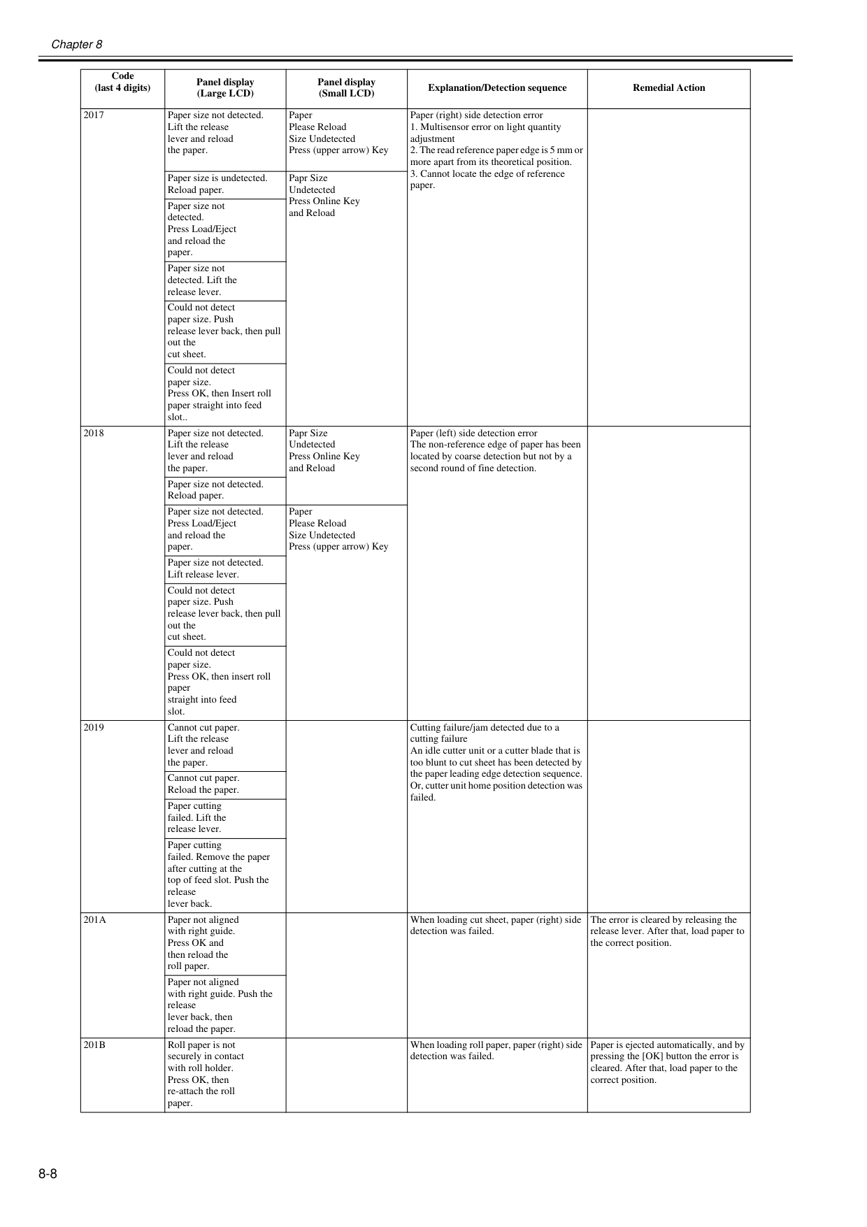
Chapter 8 8-8 2017 Paper size not detected. Lift the release lever and reload the paper. Paper Please Reload Size Undetected Press (upper arrow) Key Paper (right) side detection error
201A
Paper not aligned with right guide. Press OK and then reload the roll paper. When loading cut sheet, paper (right) side detection was failed. The error is cleared by releasing the release lever. After that, load paper to the correct position. Paper not aligned with right guide. Push the release lever back, then reload the paper.201B
Roll paper is not securely in contact with roll holder. Press OK, then re-attach the roll paper. When loading roll paper, paper (right) side detection was failed. Paper is ejected automatically, and by pressing the [OK] button the error is cleared. After that, load paper to the correct position. Code (last 4 digits) Panel display (Large LCD) Panel display (Small LCD) Explanation/Detection sequence Remedial Action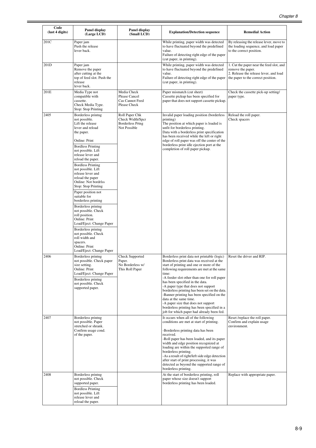
Chapter 8 8-9
201C
Paper jam Push the release lever back. While printing, paper width was detected to have fluctuated beyond the predefined value. Failure of detecting right edge of the paper (cut paper, in printing). By releasing the release lever, move to the loading sequence, and load paper to the correct position.201D
Paper jam Remove the paper after cutting at the top of feed slot. Push the release lever back. While printing, paper width was detected to have fluctuated beyond the predefined value. Failure of detecting right edge of the paper (cut paper, in printing).201E
Media Type not compatible with cassette. Check Media Type. Stop: Stop Printing Media Check Please Cancel Cas Cannot Feed Please Check Paper mismatch (cut sheet) Cassette pickup has been specified for paper that does not support cassette pickup. Check the cassette pick-up setting/ paper type. 2405 Borderless printng not possible. Lift the release lever and reload the paper. Online: Print Roll Paper Chk Check Width/Spcr Borderless Prtng Not Possible Invalid paper loading position (borderless printing) The position at which paper is loaded is unfit for borderless printing. Data with a borderless print specification has been received while the left or right edge of roll paper was off the center of the borderless print idle ejection port at the completion of roll paper pickup. Reload the roll paper. Check spacers Bordless Printing not possible. Lift release lever and reload the paper. Bordless Printing not possible. Lift release lever and reload the paper Online: Not bordrlss Stop: Stop Printing Paper position not suitable for borderless printing Borderless printng not possible. Check roll position. Online: Print Load/Eject: Change Paper Borderless printng not possible. Check roll width and spacers. Online: Print Load/Eject: Change Paper 2406 Borderless printng not possible. Check paper size setting. Online: Print Load/Eject: Change Paper Check Supported Paper. No Borderless w/ This Roll Paper Borderless print data not printable (logic) Borderless print data was received at the start of printing and one or more of the following requirements are met at the same time: -A feeder slot other than one for roll paper has been specified in the data. -A paper type that does not support borderless printing has been set on the data. -Banner printing has been specified on the data at the same time. -A paper size that does not support borderless printing has been specified in a job for which paper had already been fed. Reset the driver and RIP. Borderless printng not possible. Check supported paper. 2407 Borderless printng not possible. Paper stretched or shrank. Confirm usage cond. of the paper. It occurs when all of the following conditions are met at start of printing. -Borderless printing data has been received. -Roll paper has been loaded, and its paper width and edge position recognized at loading are within the supported range of borderless printing. -As a result of right/left side edge detection after start of print processing, it was detected as beyond the supported range of borderless printing. Reset /replace the roll paper. Confirm and explain usage environment. 2408 Borderless printng not possible. Check supported paper. At the start of borderless printing, roll paper whose size doesn't support borderless printing has been loaded. Replace with appropriate paper. Bordless Printing not possible. Lift release lever and reload the paper. Code (last 4 digits) Panel display (Large LCD) Panel display (Small LCD) Explanation/Detection sequence Remedial Action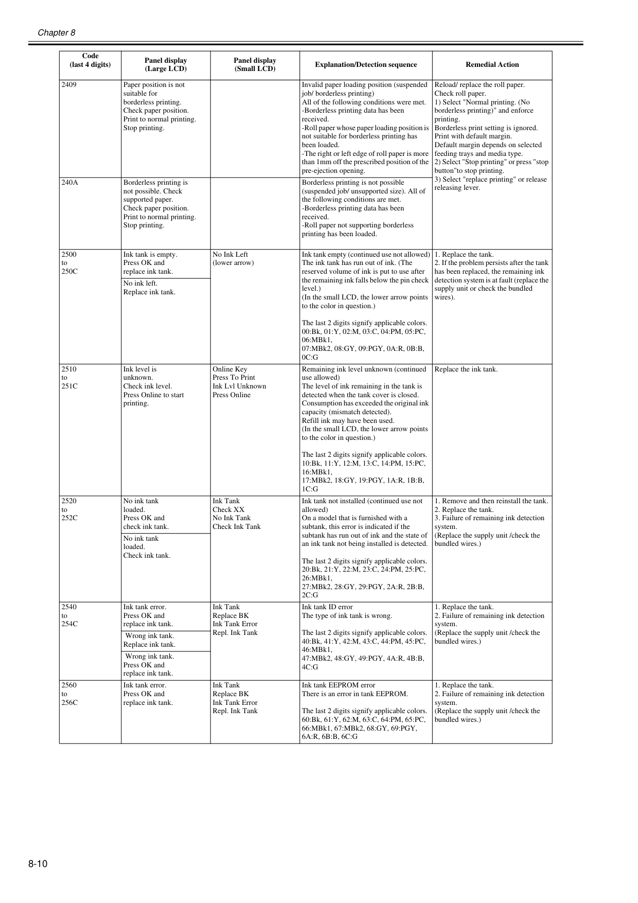
Chapter 8 8-10 2409 Paper position is not suitable for borderless printing. Check paper position. Print to normal printing. Stop printing. Invalid paper loading position (suspended job/ borderless printing) All of the following conditions were met. -Borderless printing data has been received. -Roll paper whose paper loading position is not suitable for borderless printing has been loaded. -The right or left edge of roll paper is more than 1mm off the prescribed position of the pre-ejection opening. Reload/ replace the roll paper. Check roll paper. 1) Select "Normal printing. (No borderless printing)" and enforce printing. Borderless print setting is ignored. Print with default margin. Default margin depends on selected feeding trays and media type. 2) Select "Stop printing" or press "stop button"to stop printing. 3) Select "replace printing" or release releasing lever.
240A
Borderless printing is not possible. Check supported paper. Check paper position. Print to normal printing. Stop printing. Borderless printing is not possible (suspended job/ unsupported size). All of the following conditions are met. -Borderless printing data has been received. -Roll paper not supporting borderless printing has been loaded. 2500 to250C
Ink tank is empty. Press OK and replace ink tank. No Ink Left (lower arrow) Ink tank empty (continued use not allowed) The ink tank has run out of ink. (The reserved volume of ink is put to use after the remaining ink falls below the pin check level.) (In the small LCD, the lower arrow points to the color in question.) The last 2 digits signify applicable colors. 00:Bk, 01:Y, 02:M, 03:C, 04:PM, 05:PC, 06:MBk1, 07:MBk2, 08:GY, 09:PGY, 0A:R, 0B:B,0C:G
251C
Ink level is unknown. Check ink level. Press Online to start printing. Online Key Press To Print Ink Lvl Unknown Press Online Remaining ink level unknown (continued use allowed) The level of ink remaining in the tank is detected when the tank cover is closed. Consumption has exceeded the original ink capacity (mismatch detected). Refill ink may have been used. (In the small LCD, the lower arrow points to the color in question.) The last 2 digits signify applicable colors. 10:Bk, 11:Y, 12:M, 13:C, 14:PM, 15:PC, 16:MBk1, 17:MBk2, 18:GY, 19:PGY, 1A:R, 1B:B,1C:G
Replace the ink tank. 2520 to252C
No ink tank loaded. Press OK and check ink tank. Ink Tank Check XX No Ink Tank Check Ink Tank Ink tank not installed (continued use not allowed) On a model that is furnished with a subtank, this error is indicated if the subtank has run out of ink and the state of an ink tank not being installed is detected. The last 2 digits signify applicable colors. 20:Bk, 21:Y, 22:M, 23:C, 24:PM, 25:PC, 26:MBk1, 27:MBk2, 28:GY, 29:PGY, 2A:R, 2B:B,2C:G
254C
Ink tank error. Press OK and replace ink tank. Ink Tank Replace BK Ink Tank Error Repl. Ink Tank Ink tank ID error The type of ink tank is wrong. The last 2 digits signify applicable colors. 40:Bk, 41:Y, 42:M, 43:C, 44:PM, 45:PC, 46:MBk1, 47:MBk2, 48:GY, 49:PGY, 4A:R, 4B:B,4C:G
256C
Ink tank error. Press OK and replace ink tank. Ink Tank Replace BK Ink Tank Error Repl. Ink Tank Ink tank EEPROM error There is an error in tank EEPROM. The last 2 digits signify applicable colors. 60:Bk, 61:Y, 62:M, 63:C, 64:PM, 65:PC, 66:MBk1, 67:MBk2, 68:GY, 69:PGY,6A:R, 6B:B, 6C:G
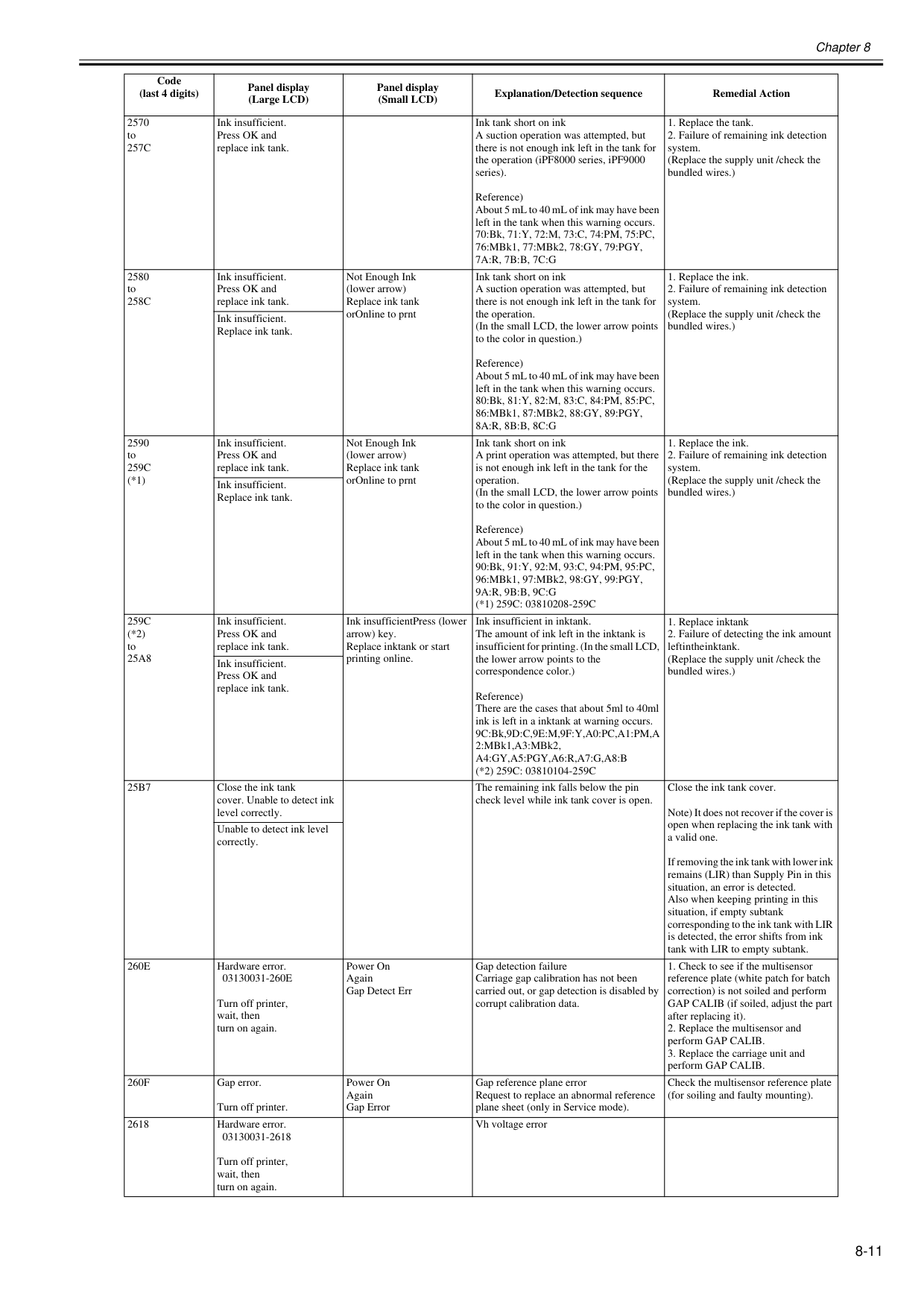
Chapter 8 8-11 2570 to
257C
Ink insufficient. Press OK and replace ink tank. Ink tank short on ink A suction operation was attempted, but there is not enough ink left in the tank for the operation (iPF8000 series, iPF9000 series). Reference) About 5 mL to 40 mL of ink may have been left in the tank when this warning occurs. 70:Bk, 71:Y, 72:M, 73:C, 74:PM, 75:PC, 76:MBk1, 77:MBk2, 78:GY, 79:PGY,7A:R, 7B:B, 7C:G
258C
Ink insufficient. Press OK and replace ink tank. Not Enough Ink (lower arrow) Replace ink tank orOnline to prnt Ink tank short on ink A suction operation was attempted, but there is not enough ink left in the tank for the operation. (In the small LCD, the lower arrow points to the color in question.) Reference) About 5 mL to 40 mL of ink may have been left in the tank when this warning occurs. 80:Bk, 81:Y, 82:M, 83:C, 84:PM, 85:PC, 86:MBk1, 87:MBk2, 88:GY, 89:PGY,8A:R, 8B:B, 8C:G
259C
(*1) Ink insufficient. Press OK and replace ink tank. Not Enough Ink (lower arrow) Replace ink tank orOnline to prnt Ink tank short on ink A print operation was attempted, but there is not enough ink left in the tank for the operation. (In the small LCD, the lower arrow points to the color in question.) Reference) About 5 mL to 40 mL of ink may have been left in the tank when this warning occurs. 90:Bk, 91:Y, 92:M, 93:C, 94:PM, 95:PC, 96:MBk1, 97:MBk2, 98:GY, 99:PGY,9A:R, 9B:B, 9C:G
(*1) 259C: 03810208-259C
259C
(*2) to25A8
Ink insufficient. Press OK and replace ink tank. Ink insufficientPress (lower arrow) key. Replace inktank or start printing online. Ink insufficient in inktank. The amount of ink left in the inktank is insufficient for printing. (In the small LCD, the lower arrow points to the correspondence color.) Reference) There are the cases that about 5ml to 40ml ink is left in a inktank at warning occurs. 9C:Bk,9D:C,9E:M,9F:Y,A0:PC,A1:PM,A 2:MBk1,A3:MBk2,A4:Gy,A5:Pgy,A6:R,A7:G,A8:B
(*2) 259C: 03810104-259C
25B7
Close the ink tank cover. Unable to detect ink level correctly. The remaining ink falls below the pin check level while ink tank cover is open. Close the ink tank cover. Note) It does not recover if the cover is open when replacing the ink tank with a valid one. If removing the ink tank with lower ink remains (LIR) than Supply Pin in this situation, an error is detected. Also when keeping printing in this situation, if empty subtank corresponding to the ink tank with LIR is detected, the error shifts from ink tank with LIR to empty subtank. Unable to detect ink level correctly.260E
Hardware error.03130031-260E
Turn off printer, wait, then turn on again. Power On Again Gap Detect Err Gap detection failure Carriage gap calibration has not been carried out, or gap detection is disabled by corrupt calibration data.260F
Gap error. Turn off printer. Power On Again Gap Error Gap reference plane error Request to replace an abnormal reference plane sheet (only in Service mode). Check the multisensor reference plate (for soiling and faulty mounting). 2618 Hardware error. 03130031-2618 Turn off printer, wait, then turn on again. Vh voltage error Code (last 4 digits) Panel display (Large LCD) Panel display (Small LCD) Explanation/Detection sequence Remedial Action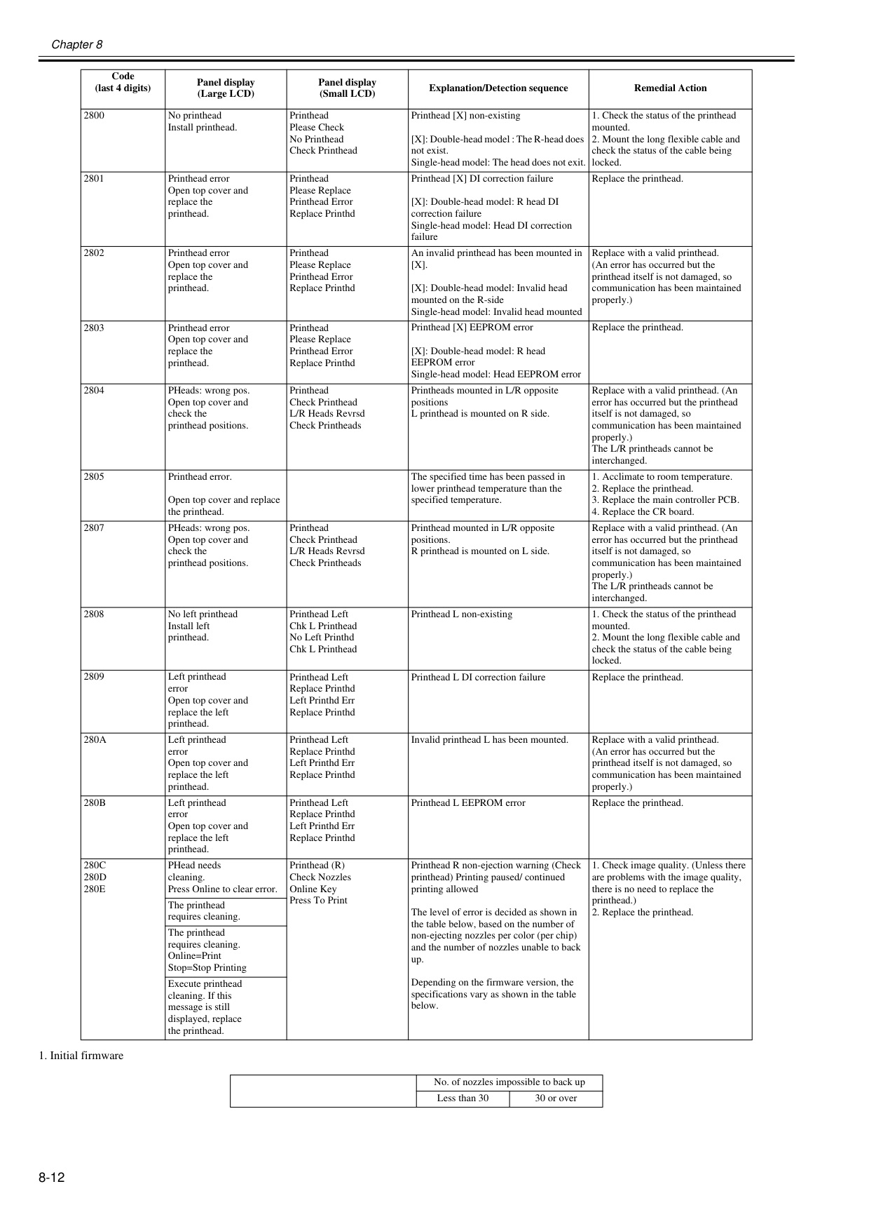
Chapter 8 8-12
[X].
[X]: Double-head model: Invalid head mounted on the R-side Single-head model: Invalid head mounted Replace with a valid printhead. (An error has occurred but the printhead itself is not damaged, so communication has been maintained properly.) 2803 Printhead error Open top cover and replace the printhead. Printhead Please Replace Printhead Error Replace Printhd Printhead [X] EEPROM error [X]: Double-head model: R head EEPROM error Single-head model: Head EEPROM error Replace the printhead. 2804 PHeads: wrong pos. Open top cover and check the printhead positions. Printhead Check Printhead L/R Heads Revrsd Check Printheads Printheads mounted in L/R opposite positions L printhead is mounted on R side. Replace with a valid printhead. (An error has occurred but the printhead itself is not damaged, so communication has been maintained properly.) The L/R printheads cannot be interchanged. 2805 Printhead error. Open top cover and replace the printhead. The specified time has been passed in lower printhead temperature than the specified temperature.280A
Left printhead error Open top cover and replace the left printhead. Printhead Left Replace Printhd Left Printhd Err Replace Printhd Invalid printhead L has been mounted. Replace with a valid printhead. (An error has occurred but the printhead itself is not damaged, so communication has been maintained properly.)280B
Left printhead error Open top cover and replace the left printhead. Printhead Left Replace Printhd Left Printhd Err Replace Printhd Printhead L EEPROM error Replace the printhead.280C
280D
280E
PHead needs cleaning. Press Online to clear error. Printhead (R) Check Nozzles Online Key Press To Print Printhead R non-ejection warning (Check printhead) Printing paused/ continued printing allowed The level of error is decided as shown in the table below, based on the number of non-ejecting nozzles per color (per chip) and the number of nozzles unable to back up. Depending on the firmware version, the specifications vary as shown in the table below.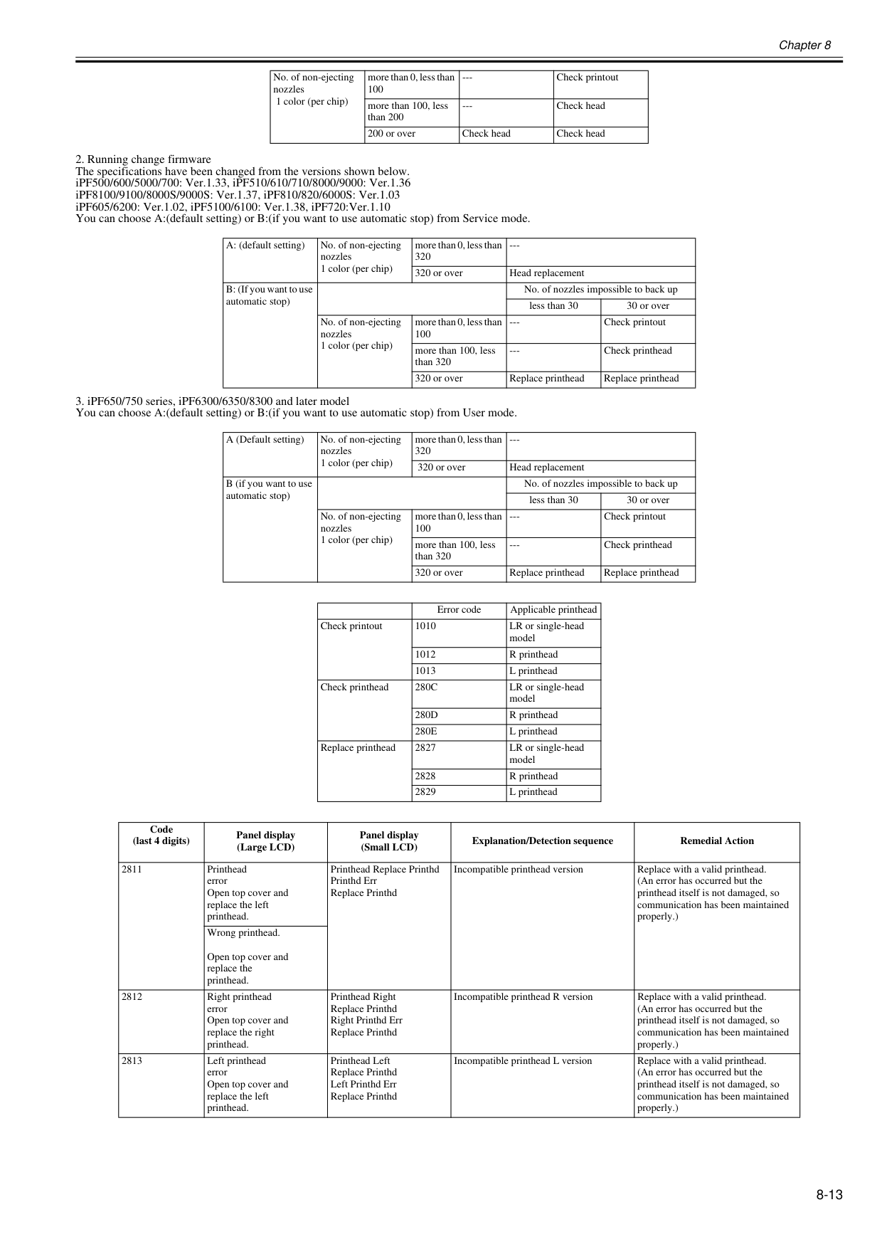
Chapter 8 8-13
280C
LR or single-head model280D
R printhead280E
L printhead Replace printhead 2827 LR or single-head model 2828 R printhead 2829 L printhead Code (last 4 digits) Panel display (Large LCD) Panel display (Small LCD) Explanation/Detection sequence Remedial Action 2811 Printhead error Open top cover and replace the left printhead. Printhead Replace Printhd Printhd Err Replace Printhd Incompatible printhead version Replace with a valid printhead. (An error has occurred but the printhead itself is not damaged, so communication has been maintained properly.) Wrong printhead. Open top cover and replace the printhead. 2812 Right printhead error Open top cover and replace the right printhead. Printhead Right Replace Printhd Right Printhd Err Replace Printhd Incompatible printhead R version Replace with a valid printhead. (An error has occurred but the printhead itself is not damaged, so communication has been maintained properly.) 2813 Left printhead error Open top cover and replace the left printhead. Printhead Left Replace Printhd Left Printhd Err Replace Printhd Incompatible printhead L version Replace with a valid printhead. (An error has occurred but the printhead itself is not damaged, so communication has been maintained properly.)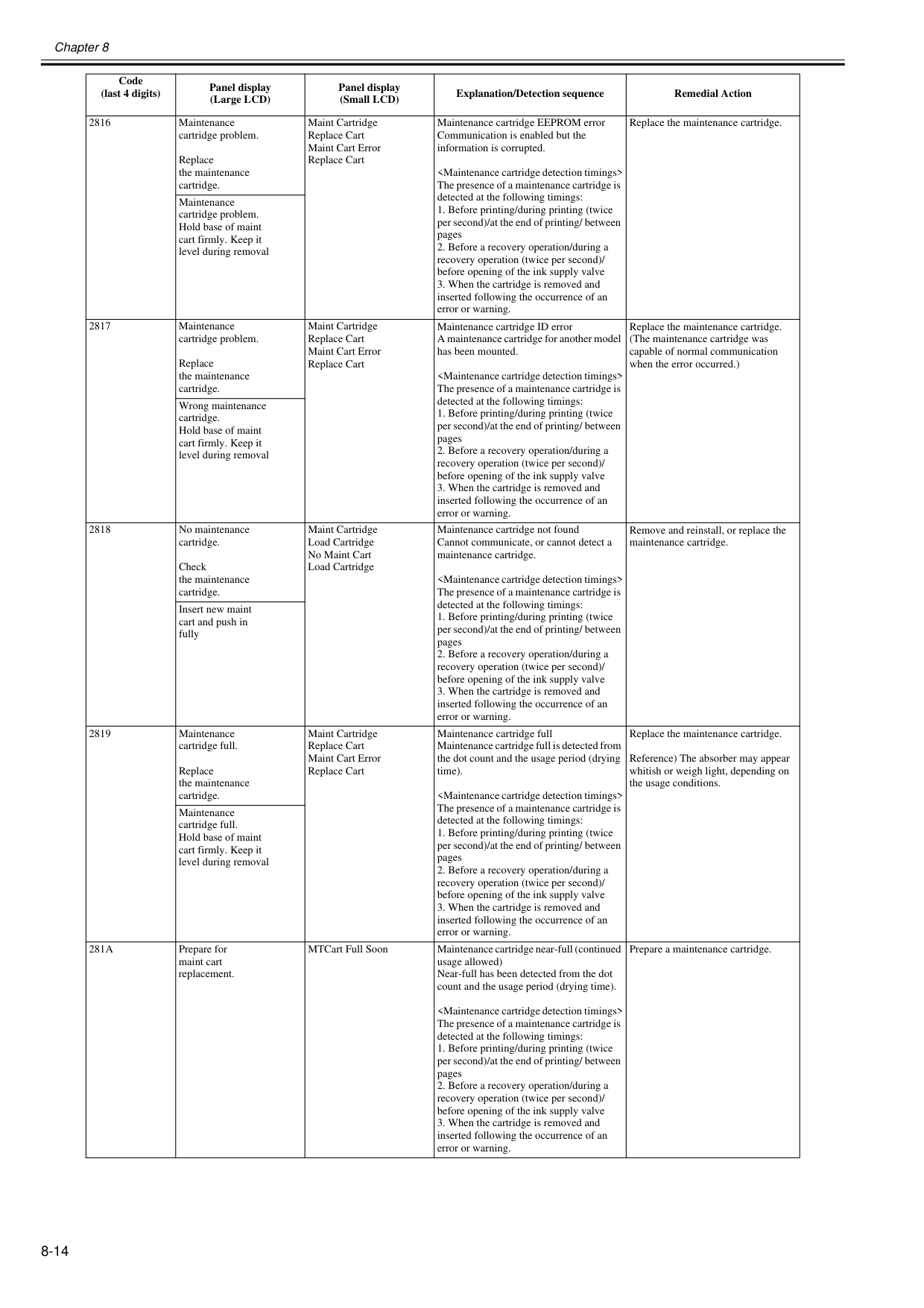
Chapter 8 8-14 2816 Maintenance cartridge problem. Replace the maintenance cartridge. Maint Cartridge Replace Cart Maint Cart Error Replace Cart Maintenance cartridge EEPROM error Communication is enabled but the information is corrupted. 281A
Prepare for maint cart replacement. MTCart Full Soon Maintenance cartridge near-full (continued usage allowed) Near-full has been detected from the dot count and the usage period (drying time).
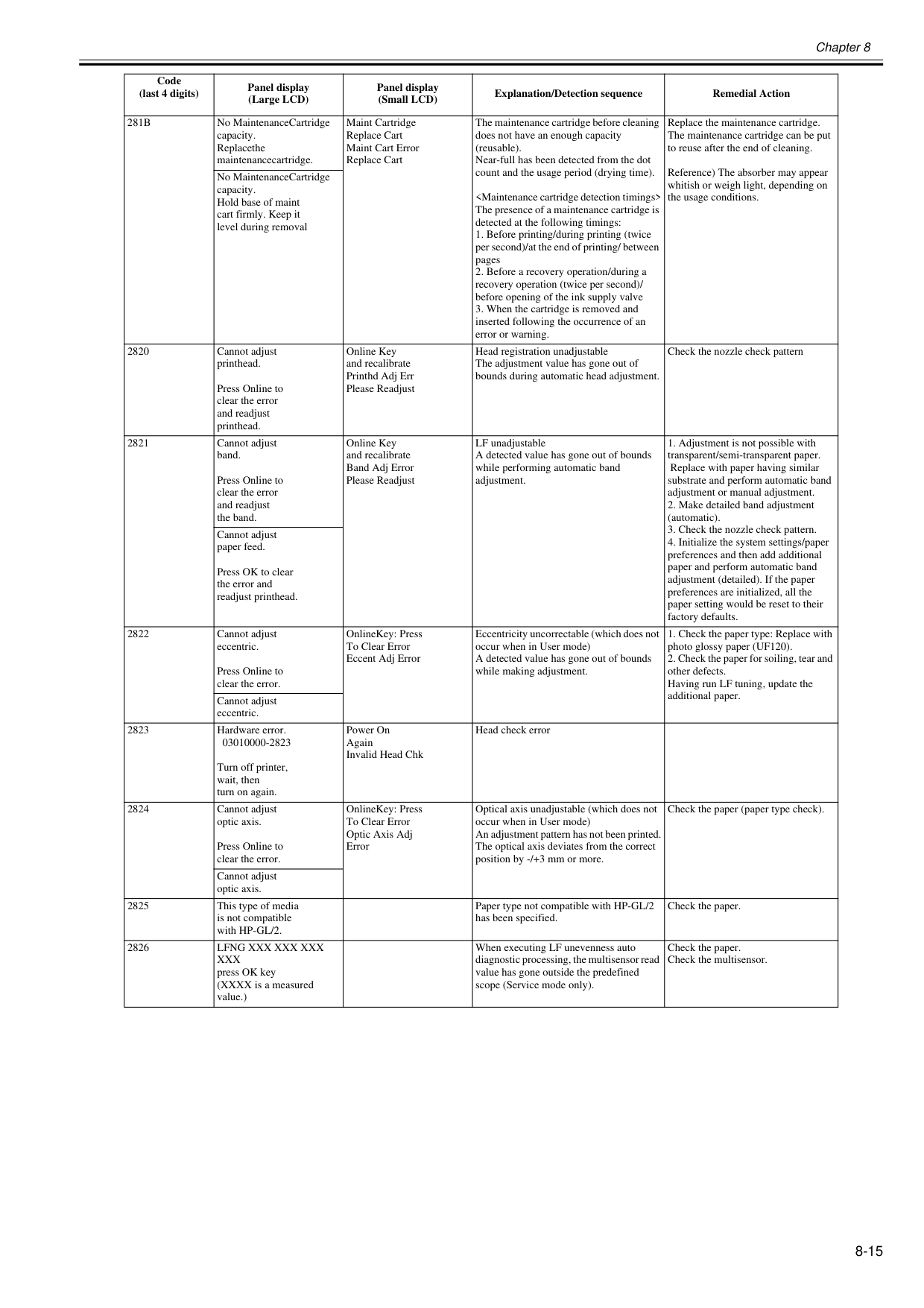
Chapter 8 8-15
281B
No MaintenanceCartridge capacity. Replacethe maintenancecartridge. Maint Cartridge Replace Cart Maint Cart Error Replace Cart The maintenance cartridge before cleaning does not have an enough capacity (reusable). Near-full has been detected from the dot count and the usage period (drying time).Lfng Xxx Xxx Xxx
Xxx
press OK key (XXXX is a measured value.) When executing LF unevenness auto diagnostic processing, the multisensor read value has gone outside the predefined scope (Service mode only). Check the paper. Check the multisensor. Code (last 4 digits) Panel display (Large LCD) Panel display (Small LCD) Explanation/Detection sequence Remedial Action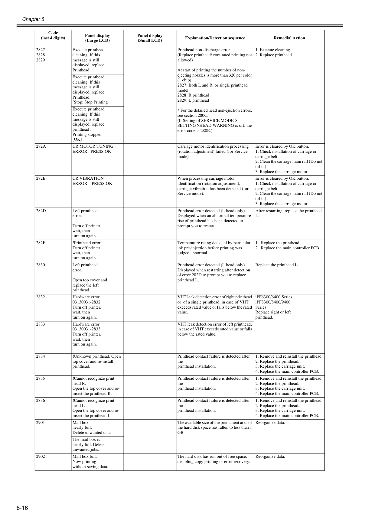
Chapter 8 8-16 2827 2828 2829 Execute printhead cleaning. If this message is still displayed, replace Printhead. Printhead non-discharge error (Replace printhead/ continued printing not allowed) At start of printing the number of non- ejecting nozzles is more than 320 per color (1 chip). 2827: Both L and R, or single printhead model 2828: R printhead 2829: L printhead
[Ok]
282A
Cr Motor Tuning
Error :Press Ok
Carriage motor identification processing (rotation adjustment) failed (for Service mode) Error is cleared by OK button.282B
Cr Vibration
Error :Press Ok
When processing carriage motor identification (rotation adjustment), carriage vibration has been detected (for Service mode). Error is cleared by OK button.282D
Left printhead error. Turn off printer, wait, then turn on again. Printhead error detected (L head only). Displayed when an abnormal temperature rise of printhead has been detected to prompt you to restart. After restarting, replace the printheadL.
282E
!Printhead error Turn off printer, wait, then turn on again. Temperature rising detected by particular ink pre-injection before printing was judged abnormal.Gb.
Reorganize data. The mail box is nearly full. Delete unwanted jobs. 2902 Mail box full. Now printing without saving data. The hard disk has run out of free space, disabling copy printing or error recovery. Reorganize data. Code (last 4 digits) Panel display (Large LCD) Panel display (Small LCD) Explanation/Detection sequence Remedial Action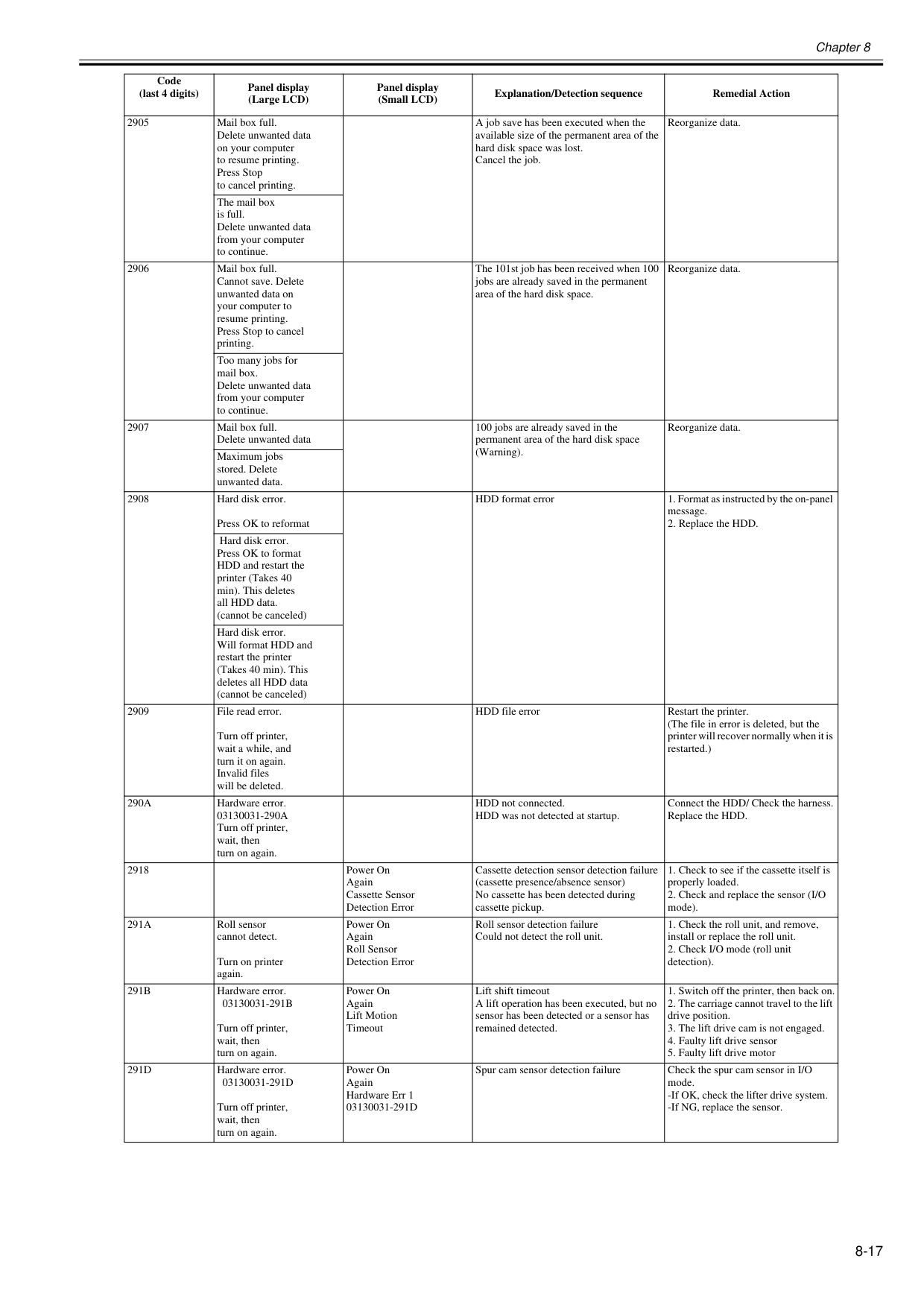
Chapter 8 8-17 2905 Mail box full. Delete unwanted data on your computer to resume printing. Press Stop to cancel printing. A job save has been executed when the available size of the permanent area of the hard disk space was lost. Cancel the job. Reorganize data. The mail box is full. Delete unwanted data from your computer to continue. 2906 Mail box full. Cannot save. Delete unwanted data on your computer to resume printing. Press Stop to cancel printing. The 101st job has been received when 100 jobs are already saved in the permanent area of the hard disk space. Reorganize data. Too many jobs for mail box. Delete unwanted data from your computer to continue. 2907 Mail box full. Delete unwanted data 100 jobs are already saved in the permanent area of the hard disk space (Warning). Reorganize data. Maximum jobs stored. Delete unwanted data. 2908 Hard disk error. Press OK to reformat HDD format error
290A
Hardware error.03130031-290A
Turn off printer, wait, then turn on again. HDD not connected. HDD was not detected at startup. Connect the HDD/ Check the harness. Replace the HDD. 2918 Power On Again Cassette Sensor Detection Error Cassette detection sensor detection failure (cassette presence/absence sensor) No cassette has been detected during cassette pickup.291A
Roll sensor cannot detect. Turn on printer again. Power On Again Roll Sensor Detection Error Roll sensor detection failure Could not detect the roll unit.291B
Hardware error.03130031-291B
Turn off printer, wait, then turn on again. Power On Again Lift Motion Timeout Lift shift timeout A lift operation has been executed, but no sensor has been detected or a sensor has remained detected.291D
Hardware error.03130031-291D
Turn off printer, wait, then turn on again. Power On Again Hardware Err 103130031-291D
Spur cam sensor detection failure Check the spur cam sensor in I/O mode. -If OK, check the lifter drive system. -If NG, replace the sensor. Code (last 4 digits) Panel display (Large LCD) Panel display (Small LCD) Explanation/Detection sequence Remedial Action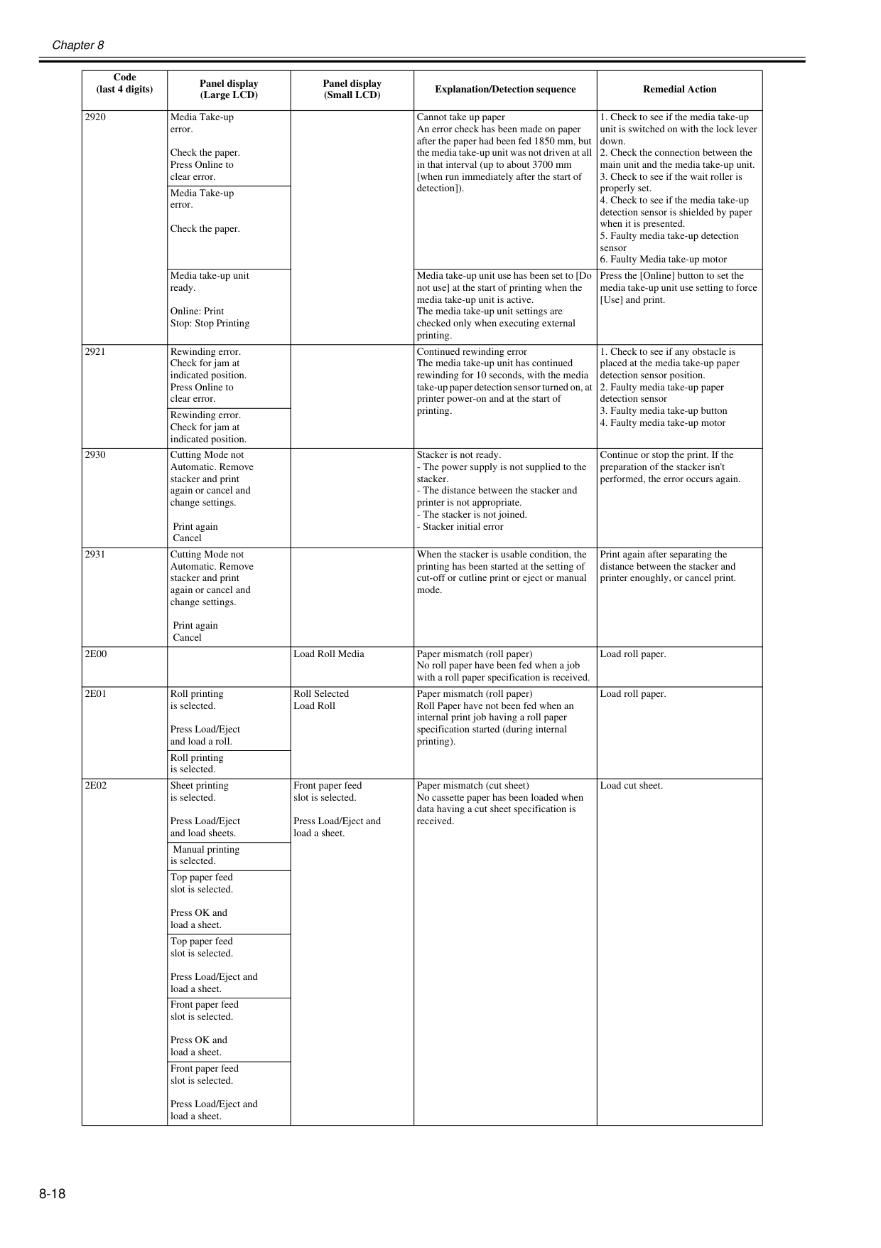
Chapter 8 8-18 2920 Media Take-up error. Check the paper. Press Online to clear error. Cannot take up paper An error check has been made on paper after the paper had been fed 1850 mm, but the media take-up unit was not driven at all in that interval (up to about 3700 mm [when run immediately after the start of detection]).
2E00
Load Roll Media Paper mismatch (roll paper) No roll paper have been fed when a job with a roll paper specification is received. Load roll paper.2E01
Roll printing is selected. Press Load/Eject and load a roll. Roll Selected Load Roll Paper mismatch (roll paper) Roll Paper have not been fed when an internal print job having a roll paper specification started (during internal printing). Load roll paper. Roll printing is selected.2E02
Sheet printing is selected. Press Load/Eject and load sheets. Front paper feed slot is selected. Press Load/Eject and load a sheet. Paper mismatch (cut sheet) No cassette paper has been loaded when data having a cut sheet specification is received. Load cut sheet. Manual printing is selected. Top paper feed slot is selected. Press OK and load a sheet. Top paper feed slot is selected. Press Load/Eject and load a sheet. Front paper feed slot is selected. Press OK and load a sheet. Front paper feed slot is selected. Press Load/Eject and load a sheet. Code (last 4 digits) Panel display (Large LCD) Panel display (Small LCD) Explanation/Detection sequence Remedial Action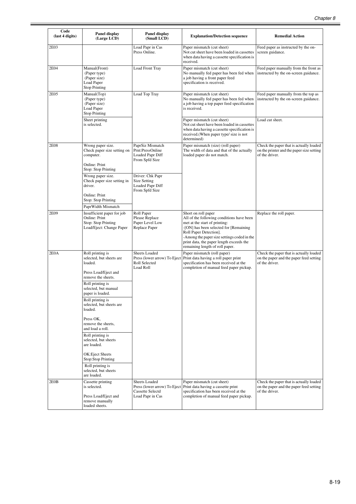
Chapter 8 8-19
2E03
Load Papr in Cas Press Online. Paper mismatch (cut sheet) Not cut sheet have been loaded in cassettes when data having a cassette specification is received. Feed paper as instructed by the on- screen guidance.2E04
Manual(Front) (Paper type) (Paper size) Load Paper Stop Printing Load Front Tray Paper mismatch (cut sheet) No manually fed paper has been fed when a job having a front paper feed specification is received. Feed paper manually from the front as instructed by the on-screen guidance.2E05
Manual(Top) (Paper type) (Paper size) Load Paper Stop Printing Load Top Tray Paper mismatch (cut sheet) No manually fed paper has been fed when a job having a top paper feed specification is received. Feed paper manually from the top as instructed by the on-screen guidance. Sheet printing is selected. Paper mismatch (cut sheet) Not cut sheet have been loaded in cassettes when data having a cassette specification is received.(When paper type/ size is not determined) Load cut sheet.2E08
Wrong paper size. Check paper size setting on computer. Online: Print Stop: Stop Printing PaprSiz Mismatch Prnt:PressOnline Loaded Papr Diff From Spfd Size Paper mismatch (size) (roll paper) The width of data and that of the actually loaded paper do not match. Check the paper that is actually loaded on the printer and the paper size setting of the driver. Wrong paper size. Check paper size setting in driver. Online: Print Stop: Stop Printing Driver: Chk Papr Size Setting Loaded Papr Diff From Spfd Size PaprWidth Mismatch2E09
Insufficient paper for job Online: Print Stop: Stop Printing Load/Eject: Change Paper Roll Paper Please Replace Paper Level Low Replace Paper Short on roll paper All of the following conditions have been met at the start of printing: -[ON] has been selected for [Remaining Roll Paper Detection]. -Among the paper size settings coded in the print data, the paper length exceeds the remaining length of roll paper. Replace the roll paper.2E0A
Roll printing is selected, but sheets are loaded. Press Load/Eject and remove the sheets. Sheets Loaded Press (lower arrow) To Eject Roll Selected Load Roll Paper mismatch (roll paper) Print data having a roll paper print specification has been received at the completion of manual feed paper pickup. Check the paper that is actually loaded on the paper and the paper feed setting of the driver. Roll printing is selected, but manual paper is loaded. Roll printing is selected, but sheets are loaded. Press OK, remove the sheets, and load a roll. Roll printing is selected, but sheets are loaded. OK:Eject Sheets Stop:Stop Printing Roll printing is selected, but sheets are loaded.2E0B
Cassette printing is selected. Press Load/Eject and remove manually loaded sheets. Sheets Loaded Press (lower arrow) To Eject Cassette Selectd Load Papr in Cas Paper mismatch (cut sheet) Print data having a cassette print specification has been received at the completion of manual feed paper pickup. Check the paper that is actually loaded on the paper and the paper feed setting of the driver. Code (last 4 digits) Panel display (Large LCD) Panel display (Small LCD) Explanation/Detection sequence Remedial Action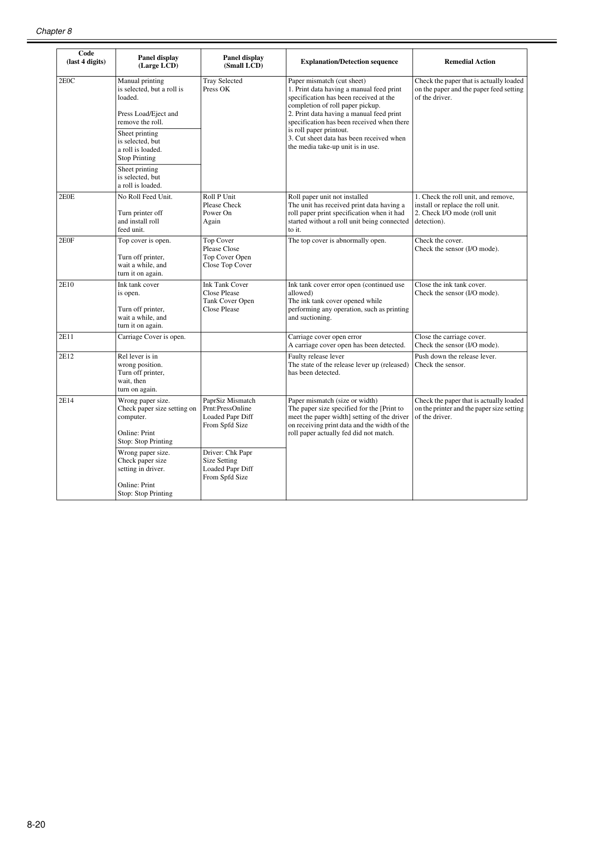
Chapter 8 8-20
2E0C
Manual printing is selected, but a roll is loaded. Press Load/Eject and remove the roll. Tray Selected Press OK Paper mismatch (cut sheet)2E0E
No Roll Feed Unit. Turn printer off and install roll feed unit. Roll P Unit Please Check Power On Again Roll paper unit not installed The unit has received print data having a roll paper print specification when it had started without a roll unit being connected to it.2E0F
Top cover is open. Turn off printer, wait a while, and turn it on again. Top Cover Please Close Top Cover Open Close Top Cover The top cover is abnormally open. Check the cover. Check the sensor (I/O mode).2E10
Ink tank cover is open. Turn off printer, wait a while, and turn it on again. Ink Tank Cover Close Please Tank Cover Open Close Please Ink tank cover error open (continued use allowed) The ink tank cover opened while performing any operation, such as printing and suctioning. Close the ink tank cover. Check the sensor (I/O mode).2E11
Carriage Cover is open. Carriage cover open error A carriage cover open has been detected. Close the carriage cover. Check the sensor (I/O mode).2E12
Rel lever is in wrong position. Turn off printer, wait, then turn on again. Faulty release lever The state of the release lever up (released) has been detected. Push down the release lever. Check the sensor.2E14
Wrong paper size. Check paper size setting on computer. Online: Print Stop: Stop Printing PaprSiz Mismatch Prnt:PressOnline Loaded Papr Diff From Spfd Size Paper mismatch (size or width) The paper size specified for the [Print to meet the paper width] setting of the driver on receiving print data and the width of the roll paper actually fed did not match. Check the paper that is actually loaded on the printer and the paper size setting of the driver. Wrong paper size. Check paper size setting in driver. Online: Print Stop: Stop Printing Driver: Chk Papr Size Setting Loaded Papr Diff From Spfd Size Code (last 4 digits) Panel display (Large LCD) Panel display (Small LCD) Explanation/Detection sequence Remedial Action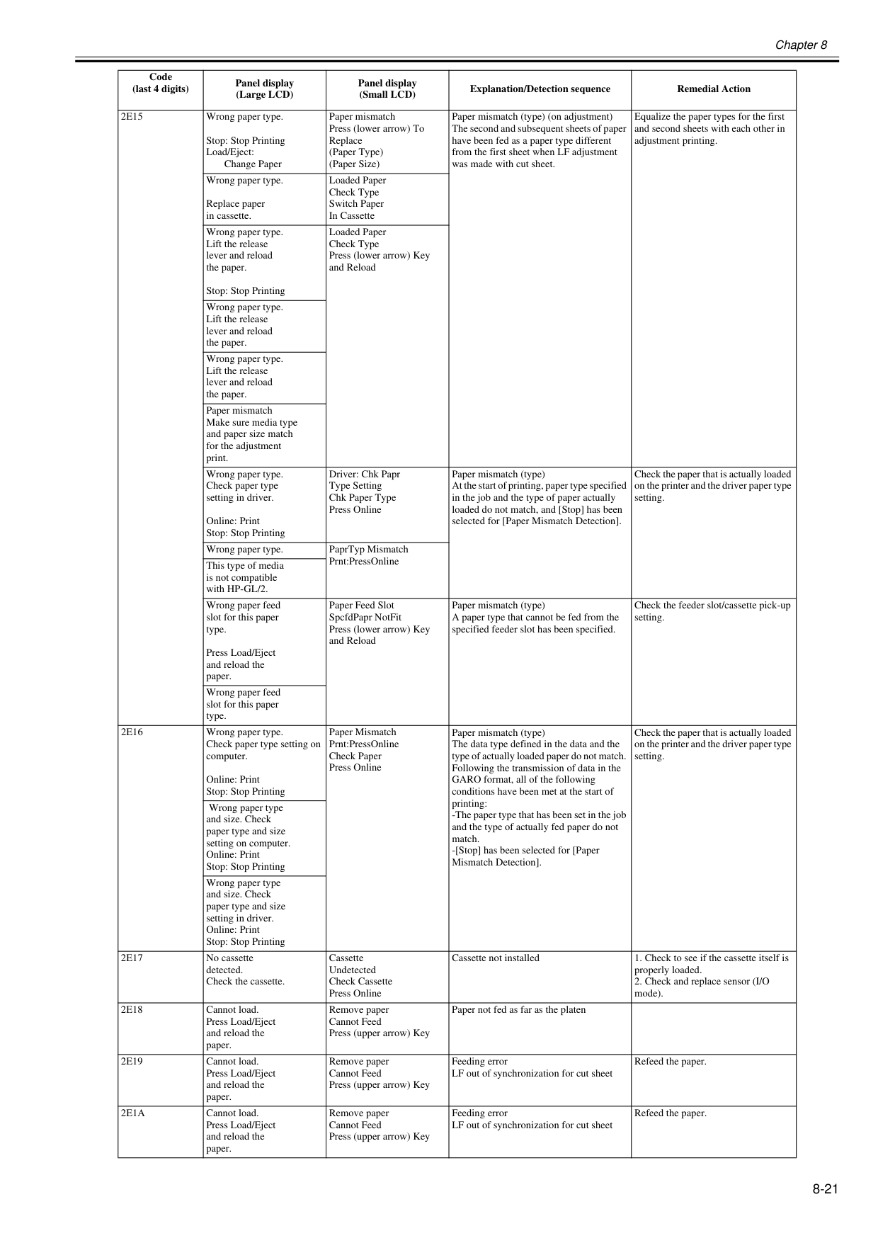
Chapter 8 8-21
2E15
Wrong paper type. Stop: Stop Printing Load/Eject: Change Paper Paper mismatch Press (lower arrow) To Replace (Paper Type) (Paper Size) Paper mismatch (type) (on adjustment) The second and subsequent sheets of paper have been fed as a paper type different from the first sheet when LF adjustment was made with cut sheet. Equalize the paper types for the first and second sheets with each other in adjustment printing. Wrong paper type. Replace paper in cassette. Loaded Paper Check Type Switch Paper In Cassette Wrong paper type. Lift the release lever and reload the paper. Stop: Stop Printing Loaded Paper Check Type Press (lower arrow) Key and Reload Wrong paper type. Lift the release lever and reload the paper. Wrong paper type. Lift the release lever and reload the paper. Paper mismatch Make sure media type and paper size match for the adjustment print. Wrong paper type. Check paper type setting in driver. Online: Print Stop: Stop Printing Driver: Chk Papr Type Setting Chk Paper Type Press Online Paper mismatch (type) At the start of printing, paper type specified in the job and the type of paper actually loaded do not match, and [Stop] has been selected for [Paper Mismatch Detection]. Check the paper that is actually loaded on the printer and the driver paper type setting. Wrong paper type. PaprTyp Mismatch Prnt:PressOnline This type of media is not compatible with HP-GL/2. Wrong paper feed slot for this paper type. Press Load/Eject and reload the paper. Paper Feed Slot SpcfdPapr NotFit Press (lower arrow) Key and Reload Paper mismatch (type) A paper type that cannot be fed from the specified feeder slot has been specified. Check the feeder slot/cassette pick-up setting. Wrong paper feed slot for this paper type.2E16
Wrong paper type. Check paper type setting on computer. Online: Print Stop: Stop Printing Paper Mismatch Prnt:PressOnline Check Paper Press Online Paper mismatch (type) The data type defined in the data and the type of actually loaded paper do not match. Following the transmission of data in the GARO format, all of the following conditions have been met at the start of printing: -The paper type that has been set in the job and the type of actually fed paper do not match. -[Stop] has been selected for [Paper Mismatch Detection]. Check the paper that is actually loaded on the printer and the driver paper type setting. Wrong paper type and size. Check paper type and size setting on computer. Online: Print Stop: Stop Printing Wrong paper type and size. Check paper type and size setting in driver. Online: Print Stop: Stop Printing2E17
No cassette detected. Check the cassette. Cassette Undetected Check Cassette Press Online Cassette not installed2E18
Cannot load. Press Load/Eject and reload the paper. Remove paper Cannot Feed Press (upper arrow) Key Paper not fed as far as the platen2E19
Cannot load. Press Load/Eject and reload the paper. Remove paper Cannot Feed Press (upper arrow) Key Feeding error LF out of synchronization for cut sheet Refeed the paper.2E1A
Cannot load. Press Load/Eject and reload the paper. Remove paper Cannot Feed Press (upper arrow) Key Feeding error LF out of synchronization for cut sheet Refeed the paper. Code (last 4 digits) Panel display (Large LCD) Panel display (Small LCD) Explanation/Detection sequence Remedial Action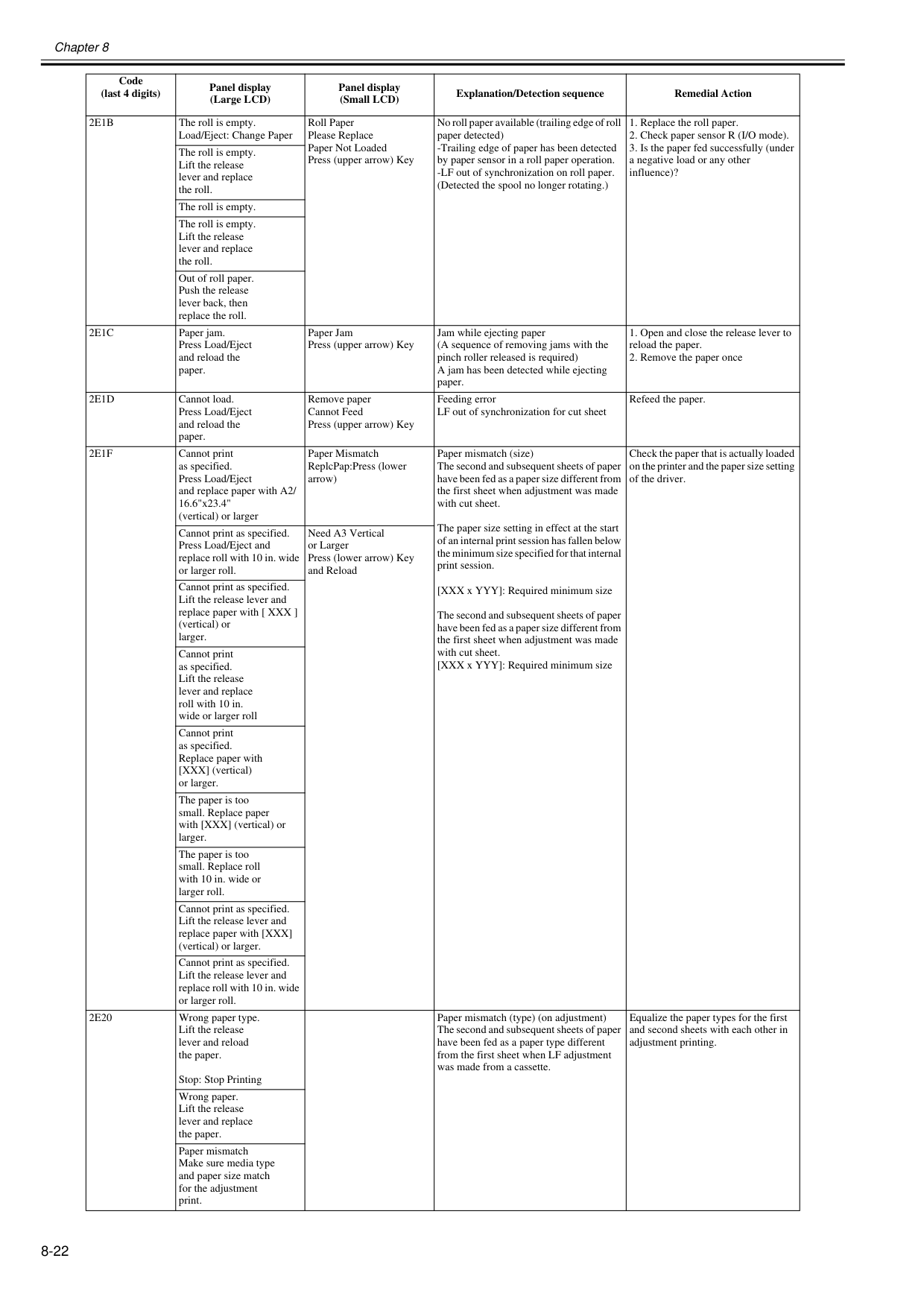
Chapter 8 8-22
2E1B
The roll is empty. Load/Eject: Change Paper Roll Paper Please Replace Paper Not Loaded Press (upper arrow) Key No roll paper available (trailing edge of roll paper detected) -Trailing edge of paper has been detected by paper sensor in a roll paper operation. -LF out of synchronization on roll paper. (Detected the spool no longer rotating.)2E1C
Paper jam. Press Load/Eject and reload the paper. Paper Jam Press (upper arrow) Key Jam while ejecting paper (A sequence of removing jams with the pinch roller released is required) A jam has been detected while ejecting paper.2E1D
Cannot load. Press Load/Eject and reload the paper. Remove paper Cannot Feed Press (upper arrow) Key Feeding error LF out of synchronization for cut sheet Refeed the paper.2E1F
Cannot print as specified. Press Load/Eject and replace paper with A2/ 16.6"x23.4" (vertical) or larger Paper Mismatch ReplcPap:Press (lower arrow) Paper mismatch (size) The second and subsequent sheets of paper have been fed as a paper size different from the first sheet when adjustment was made with cut sheet. The paper size setting in effect at the start of an internal print session has fallen below the minimum size specified for that internal print session. [XXX x YYY]: Required minimum size The second and subsequent sheets of paper have been fed as a paper size different from the first sheet when adjustment was made with cut sheet. [XXX x YYY]: Required minimum size Check the paper that is actually loaded on the printer and the paper size setting of the driver. Cannot print as specified. Press Load/Eject and replace roll with 10 in. wide or larger roll. Need A3 Vertical or Larger Press (lower arrow) Key and Reload Cannot print as specified. Lift the release lever and replace paper with [ XXX ] (vertical) or larger. Cannot print as specified. Lift the release lever and replace roll with 10 in. wide or larger roll Cannot print as specified. Replace paper with [XXX] (vertical) or larger. The paper is too small. Replace paper with [XXX] (vertical) or larger. The paper is too small. Replace roll with 10 in. wide or larger roll. Cannot print as specified. Lift the release lever and replace paper with [XXX] (vertical) or larger. Cannot print as specified. Lift the release lever and replace roll with 10 in. wide or larger roll.2E20
Wrong paper type. Lift the release lever and reload the paper. Stop: Stop Printing Paper mismatch (type) (on adjustment) The second and subsequent sheets of paper have been fed as a paper type different from the first sheet when LF adjustment was made from a cassette. Equalize the paper types for the first and second sheets with each other in adjustment printing. Wrong paper. Lift the release lever and replace the paper. Paper mismatch Make sure media type and paper size match for the adjustment print. Code (last 4 digits) Panel display (Large LCD) Panel display (Small LCD) Explanation/Detection sequence Remedial Action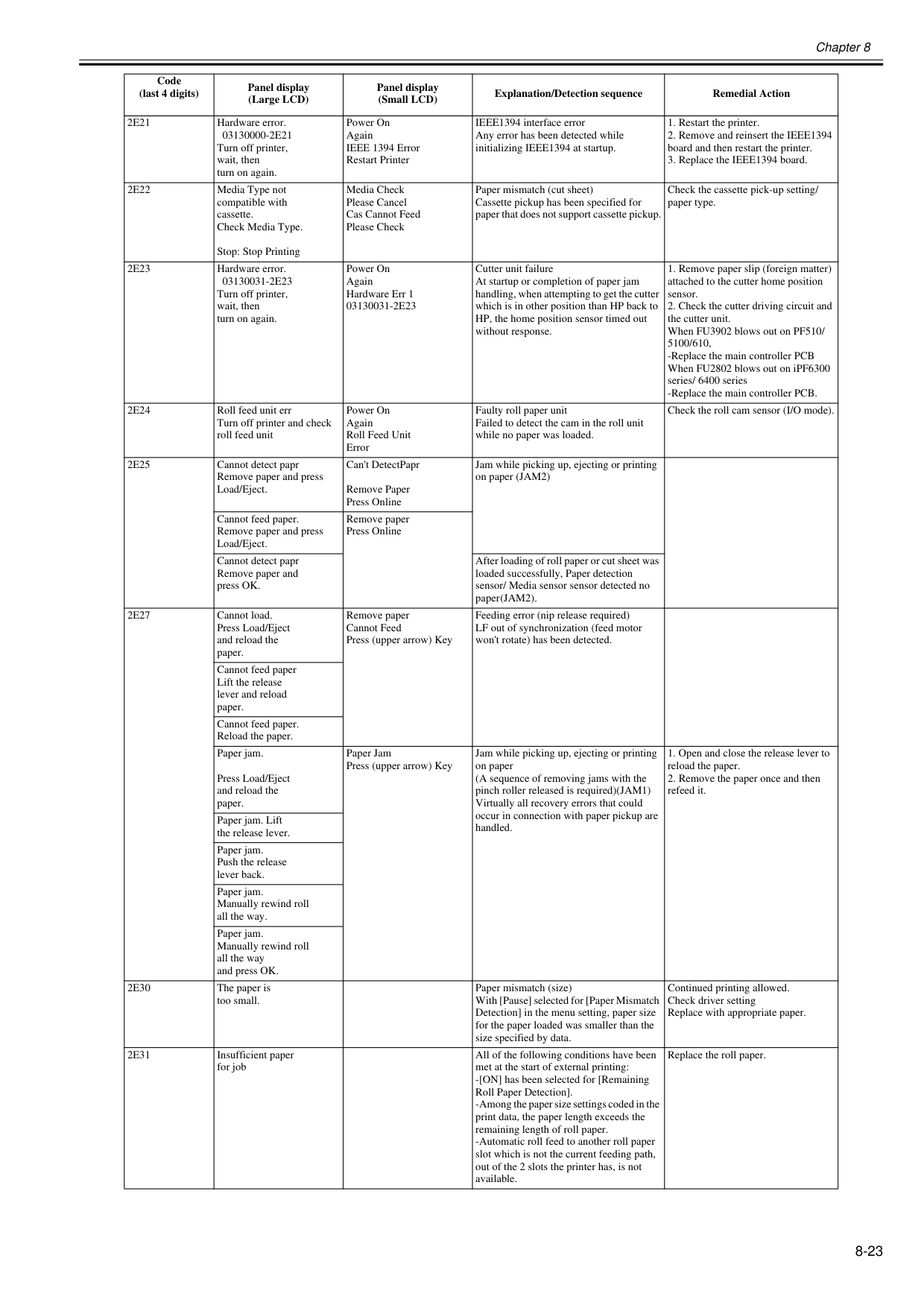
Chapter 8 8-23
2E21
Hardware error.03130000-2E21
Turn off printer, wait, then turn on again. Power On Again IEEE 1394 Error Restart Printer IEEE1394 interface error Any error has been detected while initializing IEEE1394 at startup.2E22
Media Type not compatible with cassette. Check Media Type. Stop: Stop Printing Media Check Please Cancel Cas Cannot Feed Please Check Paper mismatch (cut sheet) Cassette pickup has been specified for paper that does not support cassette pickup. Check the cassette pick-up setting/ paper type.2E23
Hardware error.03130031-2E23
Turn off printer, wait, then turn on again. Power On Again Hardware Err 103130031-2E23
Cutter unit failure At startup or completion of paper jam handling, when attempting to get the cutter which is in other position than HP back to HP, the home position sensor timed out without response.2E24
Roll feed unit err Turn off printer and check roll feed unit Power On Again Roll Feed Unit Error Faulty roll paper unit Failed to detect the cam in the roll unit while no paper was loaded. Check the roll cam sensor (I/O mode).2E25
Cannot detect papr Remove paper and press Load/Eject. Can't DetectPapr Remove Paper Press Online Jam while picking up, ejecting or printing on paper (JAM2) Cannot feed paper. Remove paper and press Load/Eject. Remove paper Press Online Cannot detect papr Remove paper and press OK. After loading of roll paper or cut sheet was loaded successfully, Paper detection sensor/ Media sensor sensor detected no paper (JAM2).2E27
Cannot load. Press Load/Eject and reload the paper. Remove paper Cannot Feed Press (upper arrow) Key Feeding error (nip release required) LF out of synchronization (feed motor won't rotate) has been detected. Cannot feed paper Lift the release lever and reload paper. Cannot feed paper. Reload the paper. Paper jam. Press Load/Eject and reload the paper. Paper Jam Press (upper arrow) Key Jam while picking up, ejecting or printing on paper (A sequence of removing jams with the pinch roller released is required)(JAM1) Virtually all recovery errors that could occur in connection with paper pickup are handled.2E30
The paper is too small. Paper mismatch (size) With [Pause] selected for [Paper Mismatch Detection] in the menu setting, paper size for the paper loaded was smaller than the size specified by data. Continued printing allowed. Check driver setting Replace with appropriate paper.2E31
Insufficient paper for job All of the following conditions have been met at the start of external printing: -[ON] has been selected for [Remaining Roll Paper Detection]. -Among the paper size settings coded in the print data, the paper length exceeds the remaining length of roll paper. -Automatic roll feed to another roll paper slot which is not the current feeding path, out of the 2 slots the printer has, is not available. Replace the roll paper. Code (last 4 digits) Panel display (Large LCD) Panel display (Small LCD) Explanation/Detection sequence Remedial Action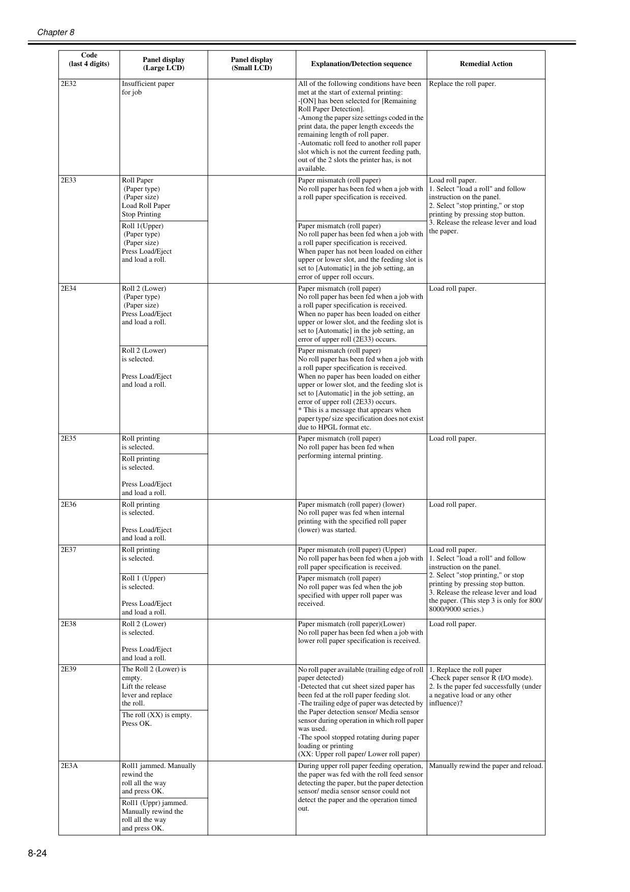
Chapter 8 8-24
2E32
Insufficient paper for job All of the following conditions have been met at the start of external printing: -[ON] has been selected for [Remaining Roll Paper Detection]. -Among the paper size settings coded in the print data, the paper length exceeds the remaining length of roll paper. -Automatic roll feed to another roll paper slot which is not the current feeding path, out of the 2 slots the printer has, is not available. Replace the roll paper.2E33
Roll Paper (Paper type) (Paper size) Load Roll Paper Stop Printing Paper mismatch (roll paper) No roll paper has been fed when a job with a roll paper specification is received. Load roll paper.2E34
Roll 2 (Lower) (Paper type) (Paper size) Press Load/Eject and load a roll. Paper mismatch (roll paper) No roll paper has been fed when a job with a roll paper specification is received. When no paper has been loaded on either upper or lower slot, and the feeding slot is set to [Automatic] in the job setting, an error of upper roll (2E33) occurs. Load roll paper. Roll 2 (Lower) is selected. Press Load/Eject and load a roll. Paper mismatch (roll paper) No roll paper has been fed when a job with a roll paper specification is received. When no paper has been loaded on either upper or lower slot, and the feeding slot is set to [Automatic] in the job setting, an error of upper roll (2E33) occurs.2E35
Roll printing is selected. Paper mismatch (roll paper) No roll paper has been fed when performing internal printing. Load roll paper. Roll printing is selected. Press Load/Eject and load a roll.2E36
Roll printing is selected. Press Load/Eject and load a roll. Paper mismatch (roll paper) (lower) No roll paper was fed when internal printing with the specified roll paper (lower) was started. Load roll paper.2E37
Roll printing is selected. Paper mismatch (roll paper) (Upper) No roll paper has been fed when a job with roll paper specification is received. Load roll paper.2E38
Roll 2 (Lower) is selected. Press Load/Eject and load a roll. Paper mismatch (roll paper)(Lower) No roll paper has been fed when a job with lower roll paper specification is received. Load roll paper.2E39
The Roll 2 (Lower) is empty. Lift the release lever and replace the roll. No roll paper available (trailing edge of roll paper detected) -Detected that cut sheet sized paper has been fed at the roll paper feeding slot. -The trailing edge of paper was detected by the Paper detection sensor/ Media sensor sensor during operation in which roll paper was used. -The spool stopped rotating during paper loading or printing (XX: Upper roll paper/ Lower roll paper)2E3A
Roll1 jammed. Manually rewind the roll all the way and press OK. During upper roll paper feeding operation, the paper was fed with the roll feed sensor detecting the paper, but the paper detection sensor/ media sensor sensor could not detect the paper and the operation timed out. Manually rewind the paper and reload. Roll1 (Uppr) jammed. Manually rewind the roll all the way and press OK. Code (last 4 digits) Panel display (Large LCD) Panel display (Small LCD) Explanation/Detection sequence Remedial Action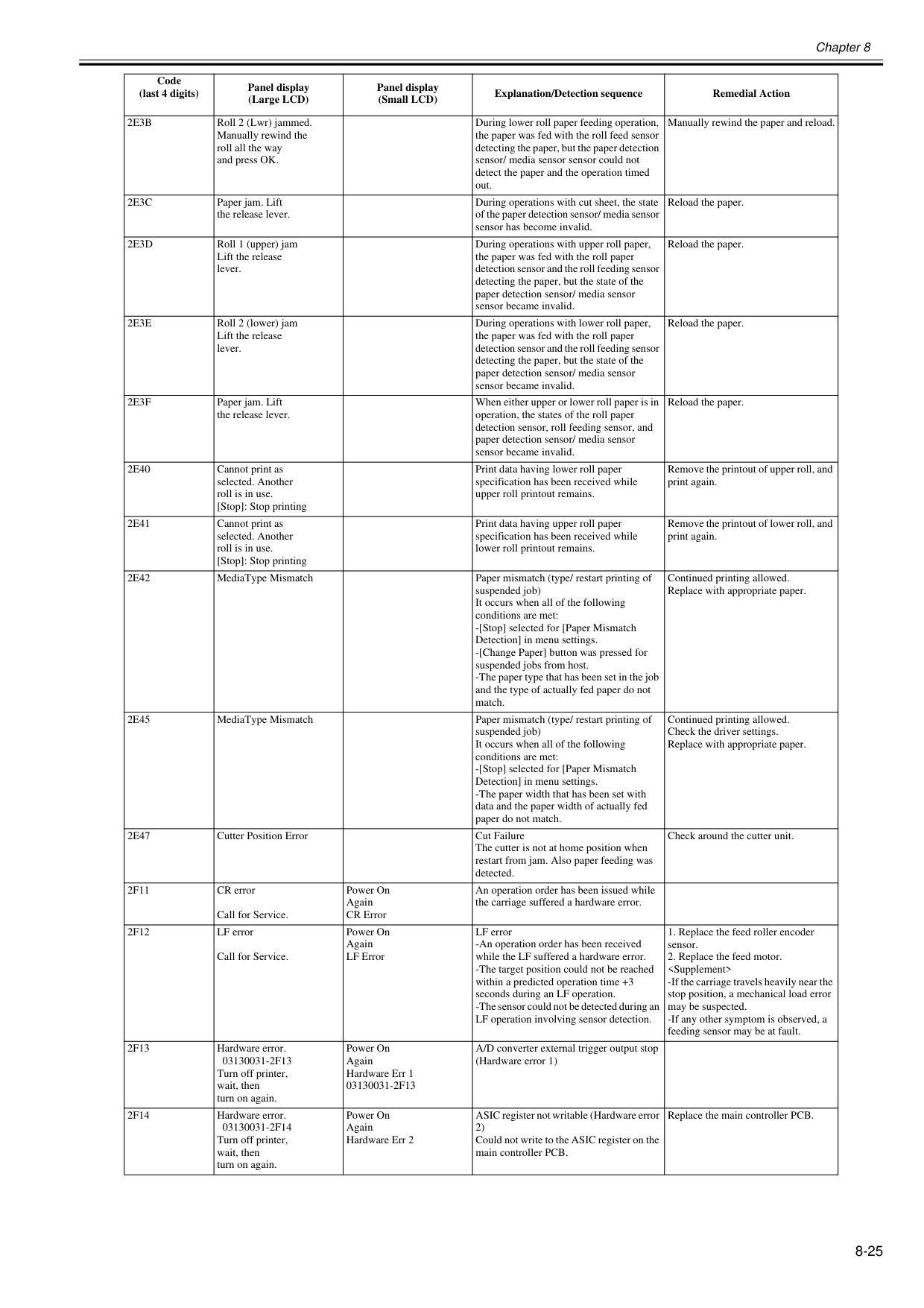
Chapter 8 8-25
2E3B
Roll 2 (Lwr) jammed. Manually rewind the roll all the way and press OK. During lower roll paper feeding operation, the paper was fed with the roll feed sensor detecting the paper, but the paper detection sensor/ media sensor sensor could not detect the paper and the operation timed out. Manually rewind the paper and reload.2E3C
Paper jam. Lift the release lever. During operations with cut sheet, the state of the paper detection sensor/ media sensor sensor has become invalid. Reload the paper.2E3D
Roll 1 (upper) jam Lift the release lever. During operations with upper roll paper, the paper was fed with the roll paper detection sensor and the roll feeding sensor detecting the paper, but the state of the paper detection sensor/ media sensor sensor became invalid. Reload the paper.2E3E
Roll 2 (lower) jam Lift the release lever. During operations with lower roll paper, the paper was fed with the roll paper detection sensor and the roll feeding sensor detecting the paper, but the state of the paper detection sensor/ media sensor sensor became invalid. Reload the paper.2E3F
Paper jam. Lift the release lever. When either upper or lower roll paper is in operation, the states of the roll paper detection sensor, roll feeding sensor, and paper detection sensor/ media sensor sensor became invalid. Reload the paper.2E40
Cannot print as selected. Another roll is in use. [Stop]: Stop printing Print data having lower roll paper specification has been received while upper roll printout remains. Remove the printout of upper roll, and print again.2E41
Cannot print as selected. Another roll is in use. [Stop]: Stop printing Print data having upper roll paper specification has been received while lower roll printout remains. Remove the printout of lower roll, and print again.2E42
MediaType Mismatch Paper mismatch (type/ restart printing of suspended job) It occurs when all of the following conditions are met: -[Stop] selected for [Paper Mismatch Detection] in menu settings. -[Change Paper] button was pressed for suspended jobs from host. -The paper type that has been set in the job and the type of actually fed paper do not match. Continued printing allowed. Replace with appropriate paper.2E45
MediaType Mismatch Paper mismatch (type/ restart printing of suspended job) It occurs when all of the following conditions are met: -[Stop] selected for [Paper Mismatch Detection] in menu settings. -The paper width that has been set with data and the paper width of actually fed paper do not match. Continued printing allowed. Check the driver settings. Replace with appropriate paper.2E47
Cutter Position Error Cut Failure The cutter is not at home position when restart from jam. Also paper feeding was detected. Check around the cutter unit.2F11
CR error Call for Service. Power On Again CR Error An operation order has been issued while the carriage suffered a hardware error.2F12
LF error Call for Service. Power On Again LF Error LF error -An operation order has been received while the LF suffered a hardware error. -The target position could not be reached within a predicted operation time +3 seconds during an LF operation. -The sensor could not be detected during an LF operation involving sensor detection.2F13
Hardware error.03130031-2F13
Turn off printer, wait, then turn on again. Power On Again Hardware Err 103130031-2F13
A/D converter external trigger output stop (Hardware error 1)2F14
Hardware error.03130031-2F14
Turn off printer, wait, then turn on again. Power On Again Hardware Err 2 ASIC register not writable (Hardware error 2) Could not write to the ASIC register on the main controller PCB. Replace the main controller PCB. Code (last 4 digits) Panel display (Large LCD) Panel display (Small LCD) Explanation/Detection sequence Remedial Action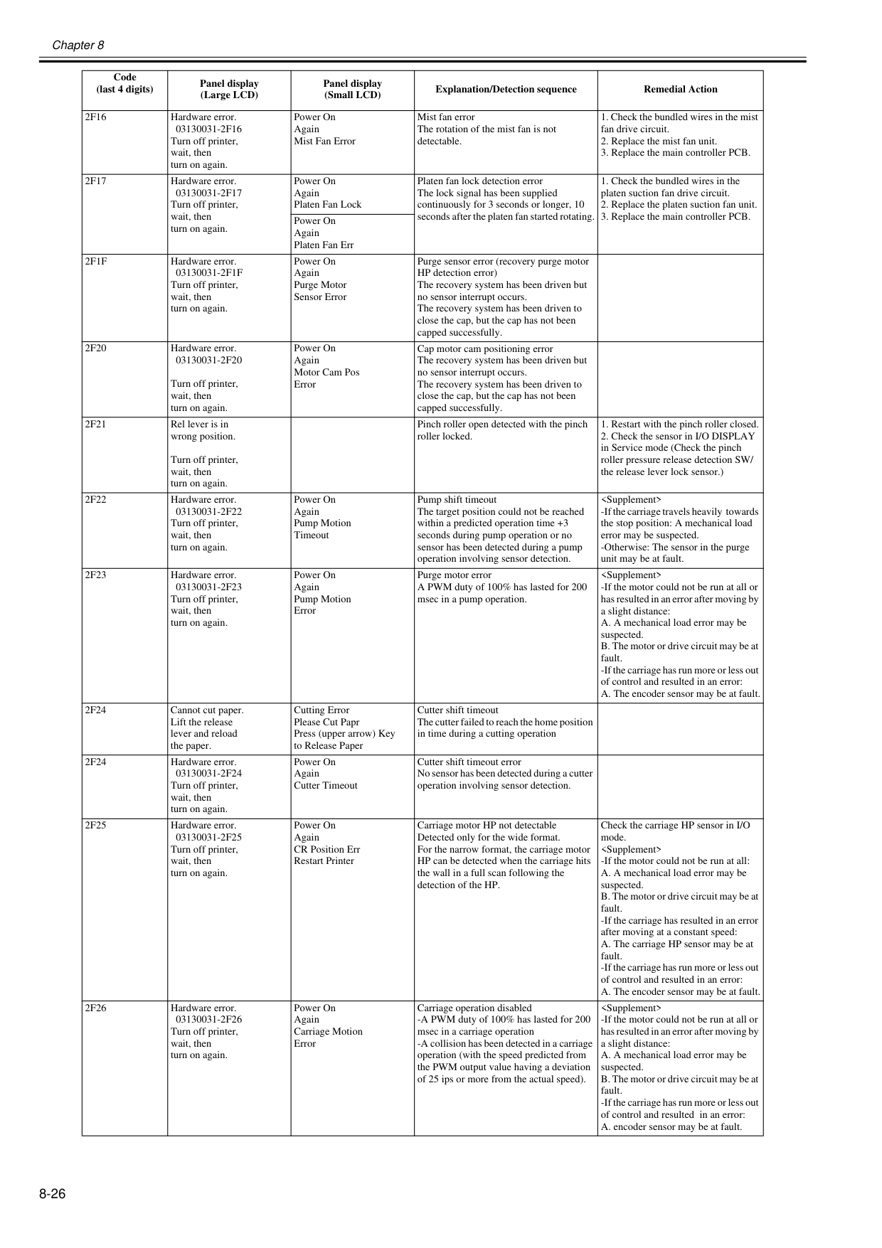
Chapter 8 8-26
2F16
Hardware error.03130031-2F16
Turn off printer, wait, then turn on again. Power On Again Mist Fan Error Mist fan error The rotation of the mist fan is not detectable.2F17
Hardware error.03130031-2F17
Turn off printer, wait, then turn on again. Power On Again Platen Fan Lock Platen fan lock detection error The lock signal has been supplied continuously for 3 seconds or longer, 10 seconds after the platen fan started rotating.2F1F
Hardware error.03130031-2F1F
Turn off printer, wait, then turn on again. Power On Again Purge Motor Sensor Error Purge sensor error (recovery purge motor HP detection error) The recovery system has been driven but no sensor interrupt occurs. The recovery system has been driven to close the cap, but the cap has not been capped successfully.2F20
Hardware error.03130031-2F20
Turn off printer, wait, then turn on again. Power On Again Motor Cam Pos Error Cap motor cam positioning error The recovery system has been driven but no sensor interrupt occurs. The recovery system has been driven to close the cap, but the cap has not been capped successfully.2F21
Rel lever is in wrong position. Turn off printer, wait, then turn on again. Pinch roller open detected with the pinch roller locked.2F22
Hardware error.03130031-2F22
Turn off printer, wait, then turn on again. Power On Again Pump Motion Timeout Pump shift timeout The target position could not be reached within a predicted operation time +3 seconds during pump operation or no sensor has been detected during a pump operation involving sensor detection.2F23
Hardware error.03130031-2F23
Turn off printer, wait, then turn on again. Power On Again Pump Motion Error Purge motor error A PWM duty of 100% has lasted for 200 msec in a pump operation.2F24
Cannot cut paper. Lift the release lever and reload the paper. Cutting Error Please Cut Papr Press (upper arrow) Key to Release Paper Cutter shift timeout The cutter failed to reach the home position in time during a cutting operation2F24
Hardware error.03130031-2F24
Turn off printer, wait, then turn on again. Power On Again Cutter Timeout Cutter shift timeout error No sensor has been detected during a cutter operation involving sensor detection.2F25
Hardware error.03130031-2F25
Turn off printer, wait, then turn on again. Power On Again CR Position Err Restart Printer Carriage motor HP not detectable Detected only for the wide format. For the narrow format, the carriage motor HP can be detected when the carriage hits the wall in a full scan following the detection of the HP. Check the carriage HP sensor in I/O mode.2F26
Hardware error.03130031-2F26
Turn off printer, wait, then turn on again. Power On Again Carriage Motion Error Carriage operation disabled -A PWM duty of 100% has lasted for 200 msec in a carriage operation -A collision has been detected in a carriage operation (with the speed predicted from the PWM output value having a deviation of 25 ips or more from the actual speed).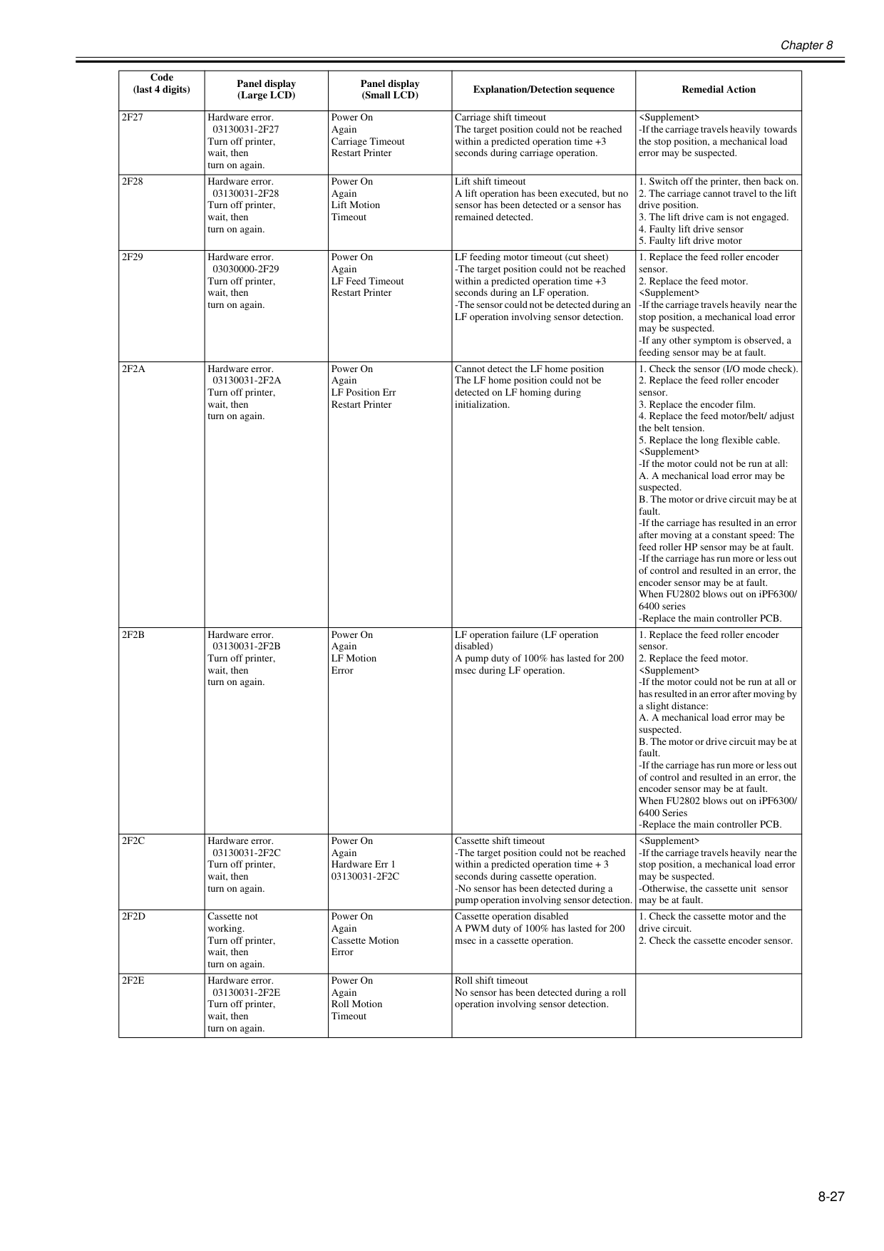
Chapter 8 8-27
2F27
Hardware error.03130031-2F27
Turn off printer, wait, then turn on again. Power On Again Carriage Timeout Restart Printer Carriage shift timeout The target position could not be reached within a predicted operation time +3 seconds during carriage operation.2F28
Hardware error.03130031-2F28
Turn off printer, wait, then turn on again. Power On Again Lift Motion Timeout Lift shift timeout A lift operation has been executed, but no sensor has been detected or a sensor has remained detected.2F29
Hardware error.03030000-2F29
Turn off printer, wait, then turn on again. Power On Again LF Feed Timeout Restart Printer LF feeding motor timeout (cut sheet) -The target position could not be reached within a predicted operation time +3 seconds during an LF operation. -The sensor could not be detected during an LF operation involving sensor detection.2F2A
Hardware error.03130031-2F2A
Turn off printer, wait, then turn on again. Power On Again LF Position Err Restart Printer Cannot detect the LF home position The LF home position could not be detected on LF homing during initialization.2F2B
Hardware error.03130031-2F2B
Turn off printer, wait, then turn on again. Power On Again LF Motion Error LF operation failure (LF operation disabled) A pump duty of 100% has lasted for 200 msec during LF operation.2F2C
Hardware error.03130031-2F2C
Turn off printer, wait, then turn on again. Power On Again Hardware Err 103130031-2F2C
Cassette shift timeout -The target position could not be reached within a predicted operation time + 3 seconds during cassette operation. -No sensor has been detected during a pump operation involving sensor detection.2F2D
Cassette not working. Turn off printer, wait, then turn on again. Power On Again Cassette Motion Error Cassette operation disabled A PWM duty of 100% has lasted for 200 msec in a cassette operation.2F2E
Hardware error.03130031-2F2E
Turn off printer, wait, then turn on again. Power On Again Roll Motion Timeout Roll shift timeout No sensor has been detected during a roll operation involving sensor detection. Code (last 4 digits) Panel display (Large LCD) Panel display (Small LCD) Explanation/Detection sequence Remedial Action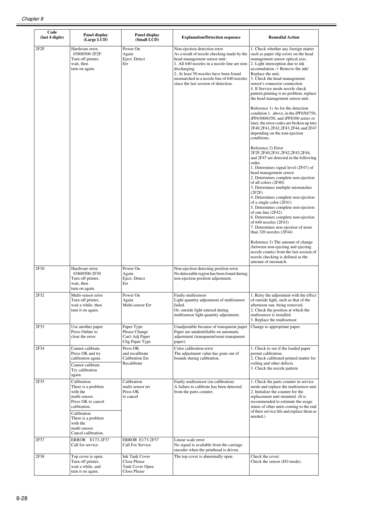
Chapter 8 8-28
2F2F
Hardware error.03800500-2F2F
Turn off printer, wait, then turn on again. Power On Again Eject. Detect Err Non-ejection detection error As a result of nozzle checking made by the head management sensor unit:2F2F,2F40,2F41,2F42,2F43,2F44,
and 2F47 are detected in the following order.(2F2F)
2F30
Hardware error.03800500-2F30
Turn off printer, wait, then turn on again. Power On Again Eject. Detect Err Non-ejection detecting position error No detectable region has been found during non-ejection position adjustment.2F32
Multi-sensor error Turn off printer, wait a while, then turn it on again. Power On Again Multi-sensor Err Faulty multisensor Light quantity adjustment of multisensor failed. Or, outside light entered during multisensor light quantity adjustment.2F33
Use another paper. Press Online to clear the error. Paper Type Please Change Can't Adj Paper Chg Paper Type Unadjustable because of transparent paper Paper are unidentifiable on automatic adjustment (transparent/semi-transparent paper). Change to appropriate paper.2F34
Cannot calibrate. Press OK and try calibration again. Press OK and recalibrate Calibration Err Recalibrate Color calibration error The adjustment value has gone out of bounds during calibration.2F35
Calibration There is a problem with the multi-sensor. Press OK to cancel calibration. Calibration multi-sensor err Press OK to cancel Faulty multisensor (on calibration) A failure to calibrate has been detected from the parts counter.2F37
Error E173-2F37
Call for service.Error E173-2F37
Call For Service Linear scale error No signal is available from the carriage encoder when the printhead is driven.2F38
Top cover is open. Turn off printer, wait a while, and turn it on again. Ink Tank Cover Close Please Tank Cover Open Close Please The top cover is abnormally open. Check the cover. Check the sensor (I/O mode). Code (last 4 digits) Panel display (Large LCD) Panel display (Small LCD) Explanation/Detection sequence Remedial Action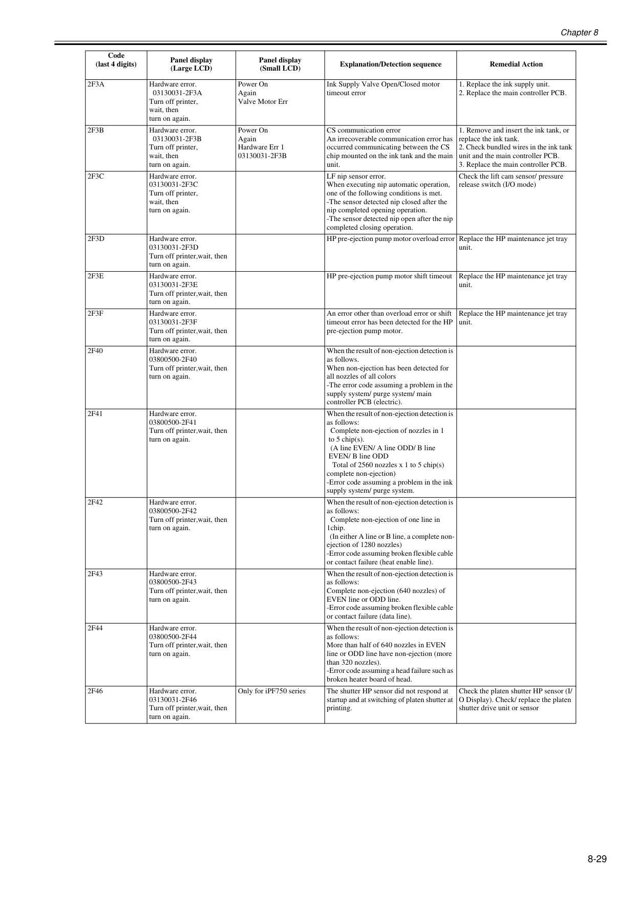
Chapter 8 8-29
2F3A
Hardware error.03130031-2F3A
Turn off printer, wait, then turn on again. Power On Again Valve Motor Err Ink Supply Valve Open/Closed motor timeout error2F3B
Hardware error.03130031-2F3B
Turn off printer, wait, then turn on again. Power On Again Hardware Err 103130031-2F3B
CS communication error An irrecoverable communication error has occurred communicating between the CS chip mounted on the ink tank and the main unit.2F3C
Hardware error.03130031-2F3C
Turn off printer, wait, then turn on again. LF nip sensor error. When executing nip automatic operation, one of the following conditions is met. -The sensor detected nip closed after the nip completed opening operation. -The sensor detected nip open after the nip completed closing operation. Check the lift cam sensor/ pressure release switch (I/O mode)2F3D
Hardware error.03130031-2F3D
Turn off printer,wait, then turn on again. HP pre-ejection pump motor overload error Replace the HP maintenance jet tray unit.2F3E
Hardware error.03130031-2F3E
Turn off printer,wait, then turn on again. HP pre-ejection pump motor shift timeout Replace the HP maintenance jet tray unit.2F3F
Hardware error.03130031-2F3F
Turn off printer,wait, then turn on again. An error other than overload error or shift timeout error has been detected for the HP pre-ejection pump motor. Replace the HP maintenance jet tray unit.2F40
Hardware error.03800500-2F40
Turn off printer,wait, then turn on again. When the result of non-ejection detection is as follows. When non-ejection has been detected for all nozzles of all colors -The error code assuming a problem in the supply system/ purge system/ main controller PCB (electric).2F41
Hardware error.03800500-2F41
Turn off printer,wait, then turn on again. When the result of non-ejection detection is as follows: Complete non-ejection of nozzles in 1 to 5 chip(s). (A line EVEN/ A line ODD/ B line EVEN/ B line ODD Total of 2560 nozzles x 1 to 5 chip(s) complete non-ejection) -Error code assuming a problem in the ink supply system/ purge system.2F42
Hardware error.03800500-2F42
Turn off printer,wait, then turn on again. When the result of non-ejection detection is as follows: Complete non-ejection of one line in 1chip. (In either A line or B line, a complete non- ejection of 1280 nozzles) -Error code assuming broken flexible cable or contact failure (heat enable line).2F43
Hardware error.03800500-2F43
Turn off printer,wait, then turn on again. When the result of non-ejection detection is as follows: Complete non-ejection (640 nozzles) of EVEN line or ODD line. -Error code assuming broken flexible cable or contact failure (data line).2F44
Hardware error.03800500-2F44
Turn off printer,wait, then turn on again. When the result of non-ejection detection is as follows: More than half of 640 nozzles in EVEN line or ODD line have non-ejection (more than 320 nozzles). -Error code assuming a head failure such as broken heater board of head.2F46
Hardware error.03130031-2F46
Turn off printer,wait, then turn on again. Only for iPF750 series The shutter HP sensor did not respond at startup and at switching of platen shutter at printing. Check the platen shutter HP sensor (I/ O Display). Check/ replace the platen shutter drive unit or sensor Code (last 4 digits) Panel display (Large LCD) Panel display (Small LCD) Explanation/Detection sequence Remedial Action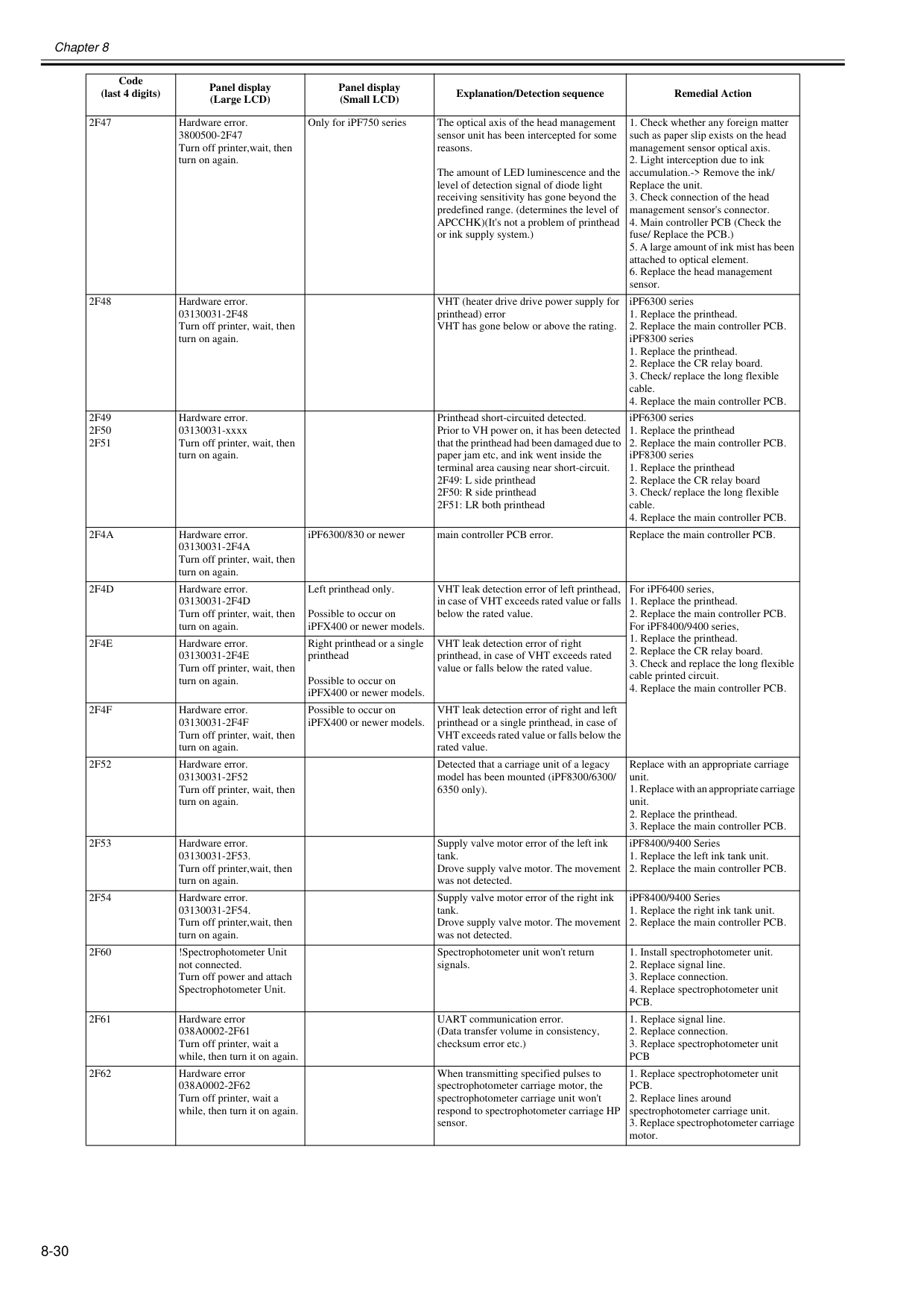
Chapter 8 8-30
2F47
Hardware error.3800500-2F47
Turn off printer,wait, then turn on again. Only for iPF750 series The optical axis of the head management sensor unit has been intercepted for some reasons. The amount of LED luminescence and the level of detection signal of diode light receiving sensitivity has gone beyond the predefined range. (determines the level of APCCHK)(It's not a problem of printhead or ink supply system.)2F48
Hardware error.03130031-2F48
Turn off printer, wait, then turn on again. VHT (heater drive drive power supply for printhead) error VHT has gone below or above the rating. iPF6300 series2F49
2F50
2F51
Hardware error. 03130031-xxxx Turn off printer, wait, then turn on again. Printhead short-circuited detected. Prior to VH power on, it has been detected that the printhead had been damaged due to paper jam etc, and ink went inside the terminal area causing near short-circuit. 2F49: L side printhead 2F50: R side printhead 2F51: LR both printhead iPF6300 series2F4A
Hardware error.03130031-2F4A
Turn off printer, wait, then turn on again. iPF6300/830 or newer main controller PCB error. Replace the main controller PCB.2F4D
Hardware error.03130031-2F4D
Turn off printer, wait, then turn on again. Left printhead only. Possible to occur on iPFX400 or newer models. VHT leak detection error of left printhead, in case of VHT exceeds rated value or falls below the rated value. For iPF6400 series,2F4E
Hardware error.03130031-2F4E
Turn off printer, wait, then turn on again. Right printhead or a single printhead Possible to occur on iPFX400 or newer models. VHT leak detection error of right printhead, in case of VHT exceeds rated value or falls below the rated value.2F4F
Hardware error.03130031-2F4F
Turn off printer, wait, then turn on again. Possible to occur on iPFX400 or newer models. VHT leak detection error of right and left printhead or a single printhead, in case of VHT exceeds rated value or falls below the rated value.2F52
Hardware error.03130031-2F52
Turn off printer, wait, then turn on again. Detected that a carriage unit of a legacy model has been mounted (iPF8300/6300/ 6350 only). Replace with an appropriate carriage unit.2F53
Hardware error.03130031-2F53.
Turn off printer,wait, then turn on again. Supply valve motor error of the left ink tank. Drove supply valve motor. The movement was not detected. iPF8400/9400 Series2F54
Hardware error.03130031-2F54.
Turn off printer,wait, then turn on again. Supply valve motor error of the right ink tank. Drove supply valve motor. The movement was not detected. iPF8400/9400 Series2F60
!Spectrophotometer Unit not connected. Turn off power and attach Spectrophotometer Unit. Spectrophotometer unit won't return signals.Pcb.
2F61
Hardware error038A0002-2F61
Turn off printer, wait a while, then turn it on again. UART communication error. (Data transfer volume in consistency, checksum error etc.)Pcb
2F62
Hardware error038A0002-2F62
Turn off printer, wait a while, then turn it on again. When transmitting specified pulses to spectrophotometer carriage motor, the spectrophotometer carriage unit won't respond to spectrophotometer carriage HP sensor.Pcb.
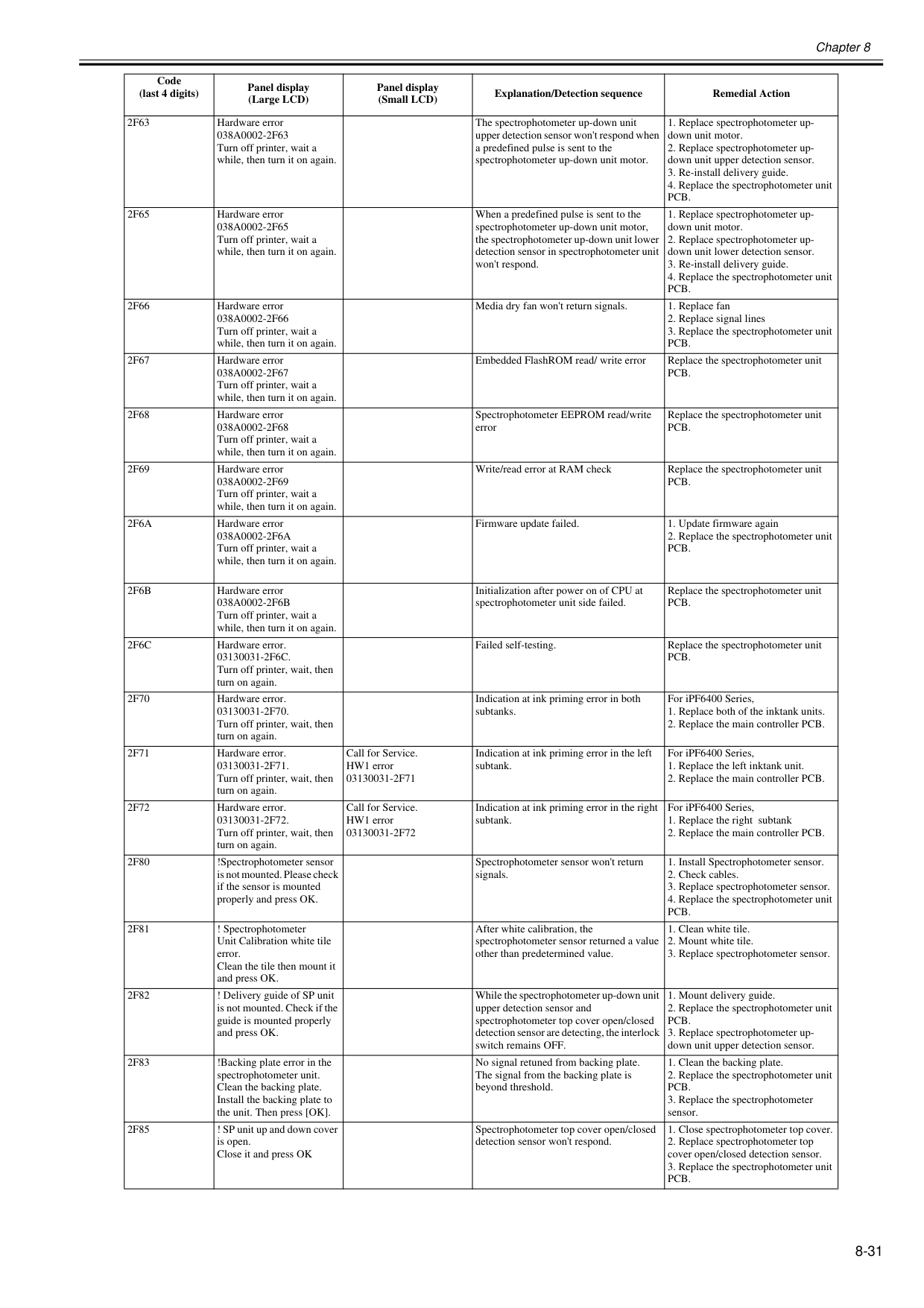
Chapter 8 8-31
2F63
Hardware error038A0002-2F63
Turn off printer, wait a while, then turn it on again. The spectrophotometer up-down unit upper detection sensor won't respond when a predefined pulse is sent to the spectrophotometer up-down unit motor.Pcb.
2F65
Hardware error038A0002-2F65
Turn off printer, wait a while, then turn it on again. When a predefined pulse is sent to the spectrophotometer up-down unit motor, the spectrophotometer up-down unit lower detection sensor in spectrophotometer unit won't respond.Pcb.
2F66
Hardware error038A0002-2F66
Turn off printer, wait a while, then turn it on again. Media dry fan won't return signals.Pcb.
2F67
Hardware error038A0002-2F67
Turn off printer, wait a while, then turn it on again. Embedded FlashROM read/ write error Replace the spectrophotometer unitPcb.
2F68
Hardware error038A0002-2F68
Turn off printer, wait a while, then turn it on again. Spectrophotometer EEPROM read/write error Replace the spectrophotometer unitPcb.
2F69
Hardware error038A0002-2F69
Turn off printer, wait a while, then turn it on again. Write/read error at RAM check Replace the spectrophotometer unitPcb.
2F6A
Hardware error038A0002-2F6A
Turn off printer, wait a while, then turn it on again. Firmware update failed.Pcb.
2F6B
Hardware error038A0002-2F6B
Turn off printer, wait a while, then turn it on again. Initialization after power on of CPU at spectrophotometer unit side failed. Replace the spectrophotometer unitPcb.
2F6C
Hardware error.03130031-2F6C.
Turn off printer, wait, then turn on again. Failed self-testing. Replace the spectrophotometer unitPcb.
2F70
Hardware error.03130031-2F70.
Turn off printer, wait, then turn on again. Indication at ink priming error in both subtanks. For iPF6400 Series,2F71
Hardware error.03130031-2F71.
Turn off printer, wait, then turn on again. Call for Service. HW1 error03130031-2F71
Indication at ink priming error in the left subtank. For iPF6400 Series,2F72
Hardware error.03130031-2F72.
Turn off printer, wait, then turn on again. Call for Service. HW1 error03130031-2F72
Indication at ink priming error in the right subtank. For iPF6400 Series,2F80
!Spectrophotometer sensor is not mounted. Please check if the sensor is mounted properly and press OK. Spectrophotometer sensor won't return signals.Pcb.
2F81
! Spectrophotometer Unit Calibration white tile error. Clean the tile then mount it and press OK. After white calibration, the spectrophotometer sensor returned a value other than predetermined value.2F82
! Delivery guide of SP unit is not mounted. Check if the guide is mounted properly and press OK. While the spectrophotometer up-down unit upper detection sensor and spectrophotometer top cover open/closed detection sensor are detecting, the interlock switch remains OFF.Pcb.
2F83
!Backing plate error in the spectrophotometer unit. Clean the backing plate. Install the backing plate to the unit. Then press [OK]. No signal retuned from backing plate. The signal from the backing plate is beyond threshold.Pcb.
2F85
! SP unit up and down cover is open. Close it and press OK Spectrophotometer top cover open/closed detection sensor won't respond.Pcb.
Code (last 4 digits) Panel display (Large LCD) Panel display (Small LCD) Explanation/Detection sequence Remedial Action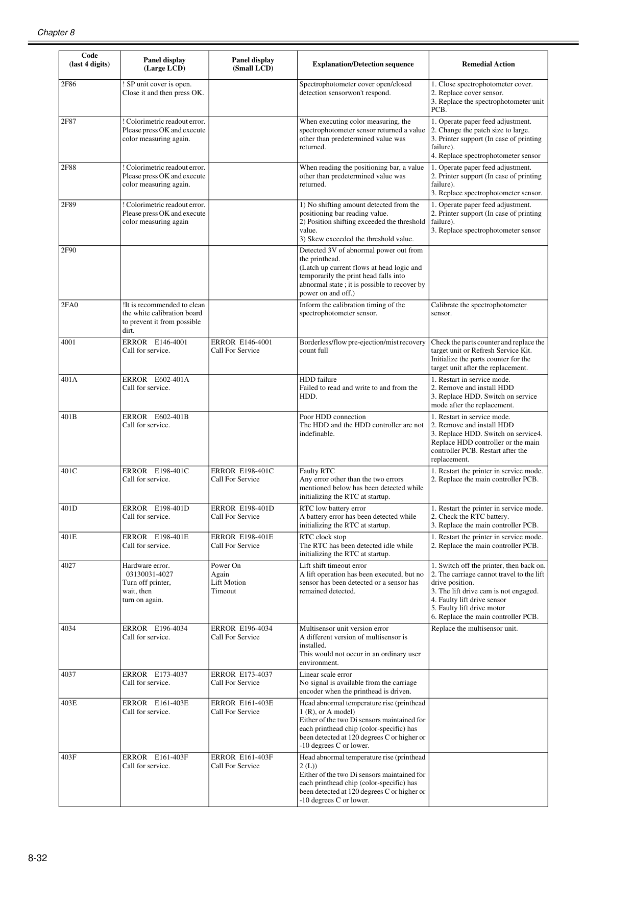
Chapter 8 8-32
2F86
! SP unit cover is open. Close it and then press OK. Spectrophotometer cover open/closed detection sensorwon't respond.Pcb.
2F87
! Colorimetric readout error. Please press OK and execute color measuring again. When executing color measuring, the spectrophotometer sensor returned a value other than predetermined value was returned.2F88
! Colorimetric readout error. Please press OK and execute color measuring again. When reading the positioning bar, a value other than predetermined value was returned.2F89
! Colorimetric readout error. Please press OK and execute color measuring again 1) No shifting amount detected from the positioning bar reading value. 2) Position shifting exceeded the threshold value. 3) Skew exceeded the threshold value.2F90
Detected 3V of abnormal power out from the printhead. (Latch up current flows at head logic and temporarily the print head falls into abnormal state ; it is possible to recover by power on and off.)2Fa0
!It is recommended to clean the white calibration board to prevent it from possible dirt. Inform the calibration timing of the spectrophotometer sensor. Calibrate the spectrophotometer sensor. 4001Error E146-4001
Call for service.Error E146-4001
Call For Service Borderless/flow pre-ejection/mist recovery count full Check the parts counter and replace the target unit or Refresh Service Kit. Initialize the parts counter for the target unit after the replacement.401A
Error E602-401A
Call for service. HDD failure Failed to read and write to and from theHdd.
401B
Error E602-401B
Call for service. Poor HDD connection The HDD and the HDD controller are not indefinable.401C
Error E198-401C
Call for service.Error E198-401C
Call For Service Faulty RTC Any error other than the two errors mentioned below has been detected while initializing the RTC at startup.401D
Error E198-401D
Call for service.Error E198-401D
Call For Service RTC low battery error A battery error has been detected while initializing the RTC at startup.401E
Error E198-401E
Call for service.Error E198-401E
Call For Service RTC clock stop The RTC has been detected idle while initializing the RTC at startup.Error E196-4034
Call for service.Error E196-4034
Call For Service Multisensor unit version error A different version of multisensor is installed. This would not occur in an ordinary user environment. Replace the multisensor unit. 4037Error E173-4037
Call for service.Error E173-4037
Call For Service Linear scale error No signal is available from the carriage encoder when the printhead is driven.403E
Error E161-403E
Call for service.Error E161-403E
Call For Service Head abnormal temperature rise (printhead 1 (R), or A model) Either of the two Di sensors maintained for each printhead chip (color-specific) has been detected at 120 degrees C or higher or -10 degrees C or lower.403F
Error E161-403F
Call for service.Error E161-403F
Call For Service Head abnormal temperature rise (printhead2 (L))
Either of the two Di sensors maintained for each printhead chip (color-specific) has been detected at 120 degrees C or higher or -10 degrees C or lower. Code (last 4 digits) Panel display (Large LCD) Panel display (Small LCD) Explanation/Detection sequence Remedial Action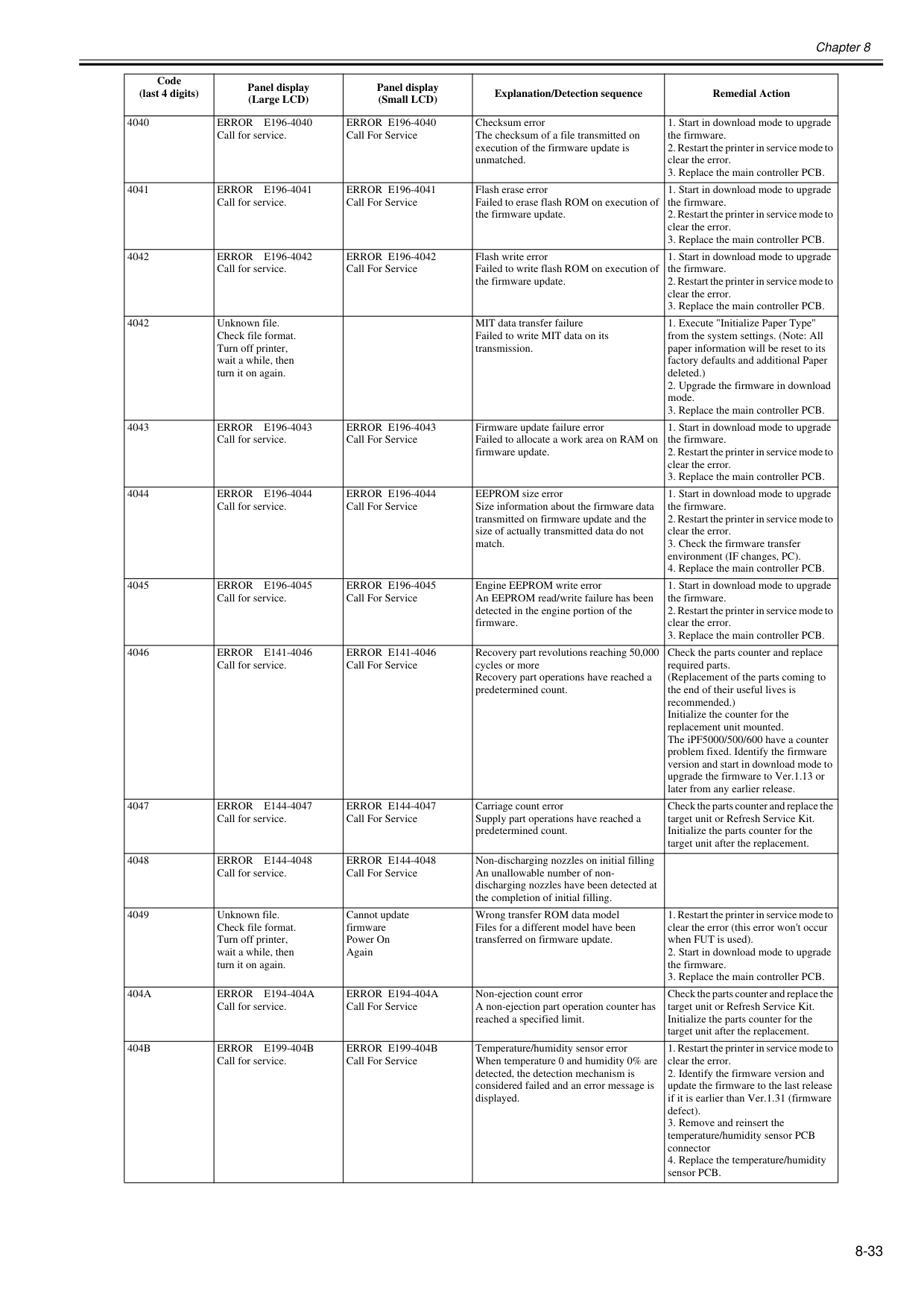
Chapter 8 8-33 4040
Error E196-4040
Call for service.Error E196-4040
Call For Service Checksum error The checksum of a file transmitted on execution of the firmware update is unmatched.Error E196-4041
Call for service.Error E196-4041
Call For Service Flash erase error Failed to erase flash ROM on execution of the firmware update.Error E196-4042
Call for service.Error E196-4042
Call For Service Flash write error Failed to write flash ROM on execution of the firmware update.Error E196-4043
Call for service.Error E196-4043
Call For Service Firmware update failure error Failed to allocate a work area on RAM on firmware update.Error E196-4044
Call for service.Error E196-4044
Call For Service EEPROM size error Size information about the firmware data transmitted on firmware update and the size of actually transmitted data do not match.Error E196-4045
Call for service.Error E196-4045
Call For Service Engine EEPROM write error An EEPROM read/write failure has been detected in the engine portion of the firmware.Error E141-4046
Call for service.Error E141-4046
Call For Service Recovery part revolutions reaching 50,000 cycles or more Recovery part operations have reached a predetermined count. Check the parts counter and replace required parts. (Replacement of the parts coming to the end of their useful lives is recommended.) Initialize the counter for the replacement unit mounted. The iPF5000/500/600 have a counter problem fixed. Identify the firmware version and start in download mode to upgrade the firmware to Ver.1.13 or later from any earlier release. 4047Error E144-4047
Call for service.Error E144-4047
Call For Service Carriage count error Supply part operations have reached a predetermined count. Check the parts counter and replace the target unit or Refresh Service Kit. Initialize the parts counter for the target unit after the replacement. 4048Error E144-4048
Call for service.Error E144-4048
Call For Service Non-discharging nozzles on initial filling An unallowable number of non- discharging nozzles have been detected at the completion of initial filling. 4049 Unknown file. Check file format. Turn off printer, wait a while, then turn it on again. Cannot update firmware Power On Again Wrong transfer ROM data model Files for a different model have been transferred on firmware update.404A
Error E194-404A
Call for service.Error E194-404A
Call For Service Non-ejection count error A non-ejection part operation counter has reached a specified limit. Check the parts counter and replace the target unit or Refresh Service Kit. Initialize the parts counter for the target unit after the replacement.404B
Error E199-404B
Call for service.Error E199-404B
Call For Service Temperature/humidity sensor error When temperature 0 and humidity 0% are detected, the detection mechanism is considered failed and an error message is displayed.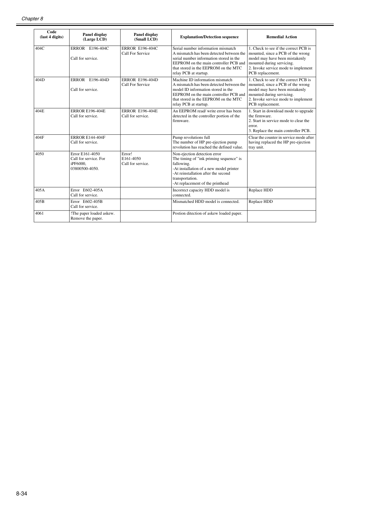
Chapter 8 8-34
404C
Error E196-404C
Call for service.Error E196-404C
Call For Service Serial number information mismatch A mismatch has been detected between the serial number information stored in the EEPROM on the main controller PCB and that stored in the EEPROM on the MTC relay PCB at startup.404D
Error E196-404D
Call for service.Error E196-404D
Call For Service Machine ID information mismatch A mismatch has been detected between the model ID information stored in the EEPROM on the main controller PCB and that stored in the EEPROM on the MTC relay PCB at startup.404E
Error E196-404E
Call for service.Error E196-404E
Call for service. An EEPROM read/ write error has been detected in the controller portion of the firmware.404F
Error E144-404F
Call for service. Pump revolutions full The number of HP pre-ejection pump revolution has reached the defined value. Clear the counter in service mode after having replaced the HP pre-ejection tray unit. 4050 Error E161-4050 Call for service. For iPF6000, 03800500-4050. Error!E161-4050
Call for service. Non-ejection detection error The timing of "ink priming sequence" is fallowing. -At installation of a new model printer -At reinstallation after the second transportation. -At replacement of the printhead405A
Error E602-405A Call for service. Incorrect capacity HDD model is connected. Replace HDD405B
Error E602-405B Call for service. Mismatched HDD model is connected. Replace HDD 4061 !The paper loaded askew. Remove the paper. Postion ditection of askew loaded paper. Code (last 4 digits) Panel display (Large LCD) Panel display (Small LCD) Explanation/Detection sequence Remedial Action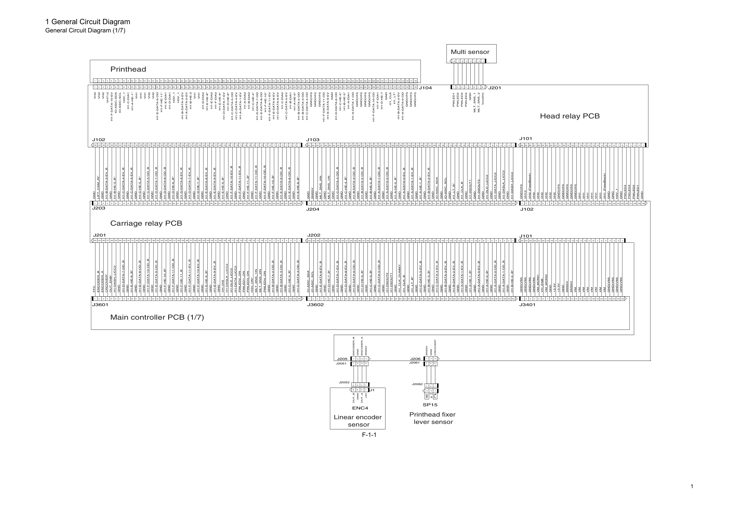
1 1 General Circuit Diagram General Circuit Diagram (1/7)
F-1-1
8 7 6 5 4 3 2 1 1 2 3 4 5 6 7 8Mlt_Sns_2
Mlt_Sns_1
Vcc(5V)Pwled4
Pwled3
Pwled2
Gnd
Pwled1
Gnd
Sns5V
1 2 3 4 1 2 3 1 2 3 4 1 2 3+3.3V
Sns5V
Vm
Vm
Vm
Vm
Vm
Vm
Vm
Gnd(Vm)
Gnd(Vm)
Gnd(Vm)
Gnd(Vm)
Gnd(Vm)
Gnd(Vm)
Gnd(Vm)
Gnd
Gnd
Gnd
Gnd
Gnd
Gnd
Gnd
Gnd
Gnd
Gnd
Gnd
Gnd
Gnd
Gnd
Gnd
Gnd
Gnd
Gnd
Gnd
Gnd
Gnd
Gnd
Gnd
Gnd
Gnd
Gnd
Gnd
Gnd
Gnd
Gnd
Gnd
Gnd
Gnd
Gnd
Gnd
Gnd
Gnd
Gnd
Gnd
Gnd
Gnd
Gnd
Gnd
Gnd
Gnd
Gnd
Gnd
Gnd
Gnd
Gnd
Gnd
Gnd
Gnd
Gnd
Gnd
Gnd
Gnd
Gnd
Gnd
Gnd
Gnd
Gnd
Gnd
Gnd
Gnd
Gnd
Gnd
Gnd
Gnd
Gnd
Gnd
Gnd
Gnd
Gnd
Gnd
Gnd
Gnd
Gnd
Gnd
Gnd
Gnd
Gnd
Gnd
Gnd
Vh2
Vh2
Vh2
Vh2
Vh2
Vh2
Vh1
Vh1
Vh1
Vh1
Vh1
Gnd(Vh)
Gnd(Vh)
Gnd(Vh)
Gnd(Vh)
Gnd
Gnd
Gnd
Gnd(Vh)
Gnd(Vh)
Gnd(Vh)
Gnd(Vh)
Gnd(Vh)
Gnd(Vh)
Gnd(Vh)
H3V_1
H3V_1
Vh1
Vh1
Vh1
Vh1
Vh2
Vh2
Vh2
Vh2
1 2 3 4 5 6 7 8 9 10 11 12 13 14 15 16 17 18 19 20 21 22 23 24 25 26 27 28 29 30 31 32 33 34 35 36 37 38 39 40 41 42 43 44 45 46 47 48 49 50 51 52 53 54 55 56 57 58 59 60 61 62 63 64 65 66 67 68 69 70 71 72 73 74 75 76 77 78 1 2 3 4 5 6 7 8 9 10 11 12 13 14 15 16 17 18 19 20 21 22 23 24 25 26 27 28 29 30 31 32 33 34 35 36 37 38 39 40 41 42 43 44 45 46 47 48 49 50 51 52 53 54 55 56 57 58 59 60 61 62 63 64 65 66 67 68 69 70 71 72 73 74 75 76 77 78 1 2 3 4 5 6 7 8 9 10 11 12 13 14 15 16 17 18 19 20 21 22 23 24 25 26 27 28 29 30 31 32 33 34 35 36 37 38 39 40 41 42 43 44 45 46 47 48 49 50 1 2 3 4 5 6 7 8 9 10 11 12 13 14 15 16 17 18 19 20 21 22 23 24 25 26 27 28 29 30 31 32 33 34 35 36 37 38 39 40 41 42 43 44 45 46 47 48 49 50 1 2 3 4 5 6 7 8 9 10 11 12 13 14 15 16 17 18 19 20 21 22 23 24 25 26 27 28 29 30 1 2 3 4 5 6 7 8 9 10 11 12 13 14 15 16 17 18 19 20 21 22 23 24 25 26 27 28 29 30 31 32 33 34 35 36 37 38 39 40 41 42 43 44 45 46 47 48 49 50 1 2 3 4 5 6 7 8 9 10 11 12 13 14 15 16 17 18 19 20 21 22 23 24 25 26 27 28 29 30 31 32 33 34 35 36 37 38 39 40 41 42 43 44 45 46 47 48 49 50 1 2 3 4 5 6 7 8 9 10 11 12 13 14 15 16 17 18 19 20 21 22 23 24 25 1 2 3 4 5 6 7 8 9 10 11 12 13 14 15 16 17 18 19 20 21 22 23 24 25 26 27 28 29 30 1 2 3 4 5 6 7 8 9 10 11 12 13 14 15 16 17 18 19 20 21 22 23 24 25 1 2 3 4 5 6 7 8 9 10 11 12 13 14 15 16 17 18 19 20 21 22 23 24 25 26 27 28 29 30 31 32 33 34 35 36 37 38 39 40 41 42 43 44 45 46 47 48 49 50 1 2 3 4 5 6 7 8 9 10 11 12 13 14 15 16 17 18 19 20 21 22 23 24 25 26 27 28 29 30 31 32 33 34 35 36 37 38 39 40 41 42 43 44 45 46 47 48 49 50 1 2 3 4 5 6 7 8 9 10 11 12 13 14 15 16 17 18 19 20 21 22 23 24 25 26 27 28 29 30 31 32 33 34 35 36 37 38 39 40 41 42 43 44 45 46 47 48 49 50 1 2 3 4 5 6 7 8 9 10 11 12 13 14 15 16 17 18 19 20 21 22 23 24 25 26 27 28 29 30 31 32 33 34 35 36 37 38 39 40 41 42 43 44 45 46 47 48 49 50Vh2
Vht12
Vh1
H3V_1
Gnd
H1-F-Data-10-Ev
Io-Asic-Sda
H1-C-Dia1
H1-A-He-1*
Io-Asic-Scl
H1-F-He-11*
H1-E-Dia1
H1-D-Dia1
H1-A-Data-0-Ev
H1-B-He-2
H1-D-Dia2
H1-E-He-8*
H1-E-Dia2
H1-F-Dia2
H1-E-He-9*
H1-D-Data-7-Ev
H1-D-He-6*
H1-C-Data-5-Od
H1-C-Data-4-Ev
H1-A-Data-1-Ev
H1-A-Dia2
H1-B-Dia2
H1-C-He-4*
H1-D-Data-7-Od
H1-E-Data-8-Od
H1-F-He-10*
H1-E-Data-8-Ev
H1-C-Dia2
H1-C-Data-5-Ev
H1-B-Data-2-Od
H1-B-Data-3-Od
H1-F-Data-11-Ev
H1-C-Data-4-Od
H1-F-Data-11-Od
H1-E-Data-9-Ev
H1-D-Data-6-Ev
H1-A-He-0*
H1-B-Dia1
H1-D-Data-6-Od
H1-C-He-5*
H1-B-He-3*
H1-F-Dia1
H1-F-Data-10-Od
H1-D-He-7
Gnd(Vh)
Gnd(Vh)
H1-A-Data-1-Od
H1-A-Dia1
H1-B-Data-2-Ev
H1-A-Data-0-Od
H1_Clk
H1_Lt*
J101
J103
Pwled1
Pwled2
Pwled3
Pwled4
Gnd(Vh)
Vh1
Gnd(Vh)
Vh1
Vh2
Gnd(Vh)
(FeedBack) (FeedBack)Gnd
Gnd
H3V_1
Vh12
J104
J102
H1-E-Data-9-Od
H1-B-Data-3-Ev
H1-B-Data-3-Ev_B
H1-B-He-3_B*
H1-C-Data-4-Ev_B
H1-C-Data-5-Ev_B
H1-C-He-5_B*
H1-C-Data-5-Od_B
H1-D-Data-7-Od_B
H1-D-Data-6-Od_B
H1-D-He-6_B*
H1-D-Data-6-Ev_B
H1-D-Data-7-Ev_B
H1-D-He-7_B*
H1-E-Data-8-Ev_B
H1-E-Data-9-Ev_B
H1-E-He-9_B*
H1-F-Data-10-Ev_B
H1-F-Data-11-Ev_B
H1-F-He-11_B*
H1-F-Data-11-Od_B
H1-F-Data-10-Od_B
H1-F-He-10_B*
H1-E-Data-9-Od_B
H1-E-Data-8-Od_B
J102
Gnd
H1-E-He-8_B*
Mlt_Sns_1In
H1-C-Data-4-Od_B
H1-C-He-4_B*
H1-B-Data-3-Od_B
Mlt_Sns_2In
Sns5V
H1-B-Data-2-Od_B
H1-B-He-2_B*
H1-A-Data-1-Od_B
H1-A-Data-0-Od_B
H1-A-He-0_B*
H1-A-Data-0-Ev_B
H1-A-Data-1-Ev_B
H1-A-He-1_B*
H1-B-Data-2-Ev_B
Io-Asic_Sda
Io-Asic_Scl
H1_Lt_B*
H1_Clk_B
H1-Dsout1
H1-Dsout2
H1-Dld_Licc2
H1-Data_Licc2
H1-Daslk_Licc2
H1-Dash_Licc2
J203
J201
J3601
Gnd
Lift_Cam_In*
Ffc
Encoder_B
Crcover*
Out_Enb*
H1-Dash_Licc2
H1-D-Data-7-Od_B
H1-E-He-8_B*
H1-E-Data-8-Od_B
H1-F-Data-10-Od_B
H1-E-Data-9-Od_B
H1-F-He-10_B*
H1-F-Data-11-Od_B
H1-F-He-11_B
H1-F-Data-11-Ev_B
H1-F-Data-10-Ev_B
H1-E-He-9_B*
H1-E-Data-9-Ev_B
Vh_Dis
H1-Daslk_Licc2
H1-Dld_Licc2
H1-Data_Licc2
Pwled2_On
Pwled1_On
Pwled3_On
H3V_On*
Mlt_Sns_2In
Pwled4_On
Gnd
H1-B-Data-3-Od_B
H1-B-Data-2-Od_B
H1-C-He-4_B*
H1-C-Data-4-Od_B
Gnd
Gnd
Gnd
H1-A-Data-1-Od_B
H1-A-Data-0-Od_B
H1-A-Data-0-Ev_B
H1-A-He-1_B*
H1-A-He-0_B*
H1-A-Data-1-Ev_B
H1-B-Data-2-Ev_B
H1-B-Data-3-Ev_B
H1-C-Data-4-Ev_B
H1-B-He-3_B*
H1-C-Data-5-Ev_B
H1_Lt_B*
H1_Clk_B
H1_Clk_Dummy
H1-Dsout1
H1-Dsout2
H1-C-Data-5-Od_B
H1-C-He-5_B*
H1-D-He-6_B*
H1-D-Data-6-Od_B
H1-D-Data-6-Ev_B
H1-D-Data-7-Ev_B
H1-D-He-7_B*
H1-E-Data-8-Ev_B
Io-Asic_Scl
Io-Asic_Sda
J202
J101
J3401
H1-B-He-2_B*
Gnd(Vm)
Vm
Sns5V
Gnd
Gnd
+3.3V
Vm_Moni2
Vm_Moni1
Vh_Enb
Mlt_Sns_1In
J3602
J204
+5V
Gnd
Out_A
Out_B
Encoder_A
Sns5V
Crcover*
J1
J205
J206
J201
Encoder_B
Gnd
Sp15
Enc4
1 2 3J2062
1 2 3J2061
1 2 3 4J2052
1 2 3 4J2051
Encoder_A
Multi sensor Head relay PCB Carriage relay PCB Main controller PCB (1/7) Linear encoder sensor Printhead fixer lever sensor Printhead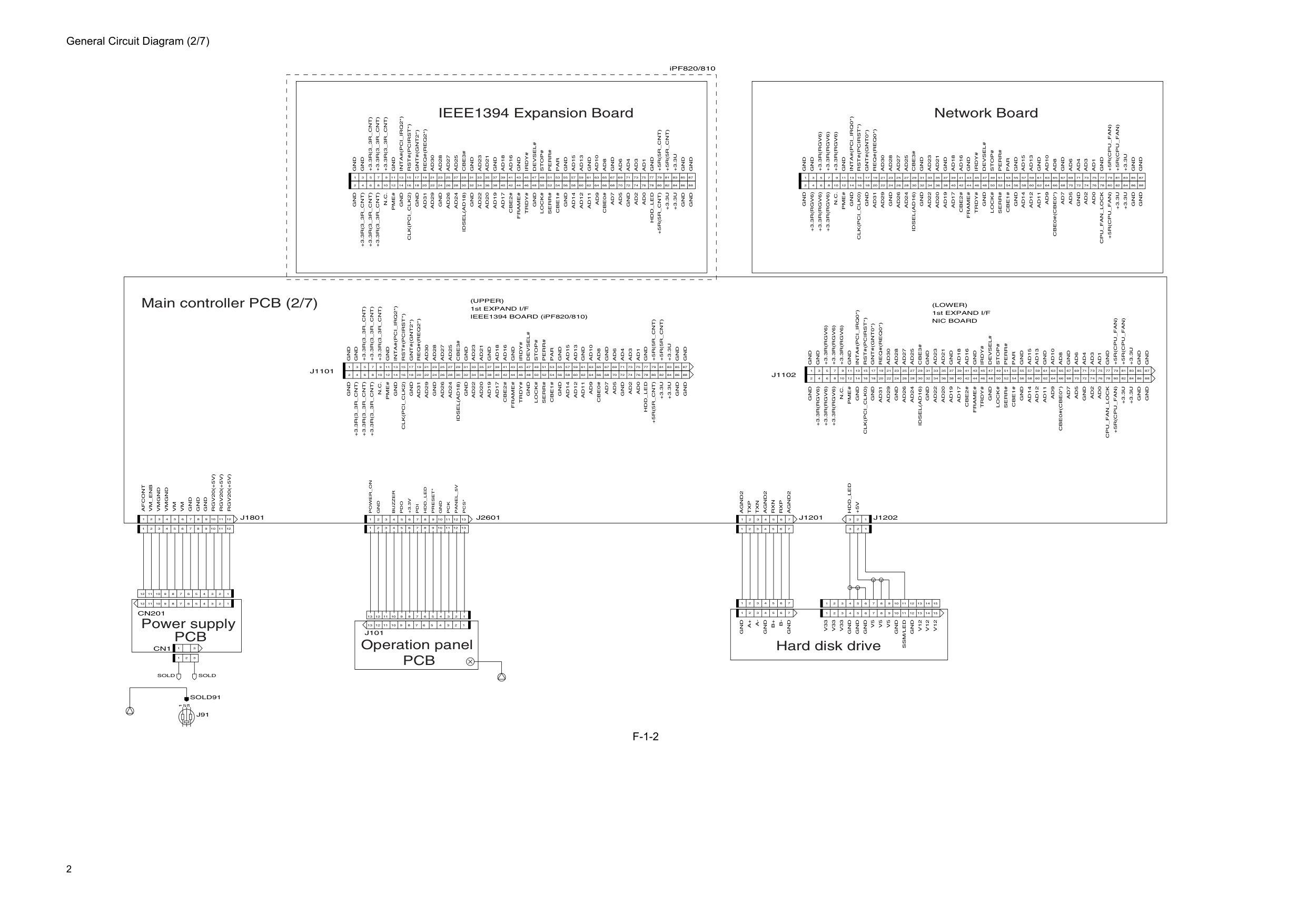
2 General Circuit Diagram (2/7)
F-1-2
1 2 3 4 5 6 7 8 9 10 11 12 1 2 3 4 5 6 7 8 9 10 11 12 1 2 3Gnd
Gnd
Gnd
Gnd
Gnd
Gnd
Gnd
Gnd
Gnd
1 3 5 7 9 11 13 15 17 19 21 23 25 27 29 31 33 35 37 39 41 43 45 47 49 51 53 55 57 59 61 63 65 67 69 71 73 75 77 79 81 83 85 87 2 4 6 8 10 12 14 16 18 20 22 24 26 28 30 32 34 36 38 40 42 44 46 48 50 52 54 56 58 60 62 64 66 68 70 72 74 76 78 80 82 84 86 88Gnd
Gnd
Rst#(Pcirst*)
Gnd
N.C.
Pme#
Ad24
Ad26
Gnd
Ad29
Ad31
Gnd
Gnd
Ad22
Ad20
Ad19
Ad17
Cbe2#
Frame#
Trdy#
Lock#
Gnd
Serr#
Cbe1#
Ad14
Ad12
Ad11
Ad9
Ad7
Ad5
Gnd
Ad2
Ad0
+3.3U
+3.3U
Ad30
Ad28
Ad27
Ad25
Cbe3#
Gnd
Ad23
Ad21
Gnd
Ad18
Ad16
Gnd
Irdy#
Par
Perr#
Stop#
Devsel#
Gnd
Ad15
Ad13
Ad10
Ad8
Ad4
Ad6
Gnd
Ad3
Ad1
+3.3U
+3.3R(Rgv6)
+3.3R(Rgv6)
+3.3R(Rgv6)
Inta#(Pci_Irq0*)
Gnt#(Gnt0*)
Req#(Req0*)
+5R(Cpu_Fan)
+5R(Cpu_Fan)
+5R(Cpu_Fan)
Cpu_Fan_Lock
Cbe0#(Cbe0*)
Idsel(Ad16)
Clk(Pci_Clk0)
+3.3R(Rgv6)
+3.3R(Rgv6)
+3.3R(Rgv6)
Gnd
Gnd
Gnd
Gnd
Gnd
Gnd
Gnd
Gnd
Gnd
1 3 5 7 9 11 13 15 17 19 21 23 25 27 29 31 33 35 37 39 41 43 45 47 49 51 53 55 57 59 61 63 65 67 69 71 73 75 77 79 81 83 85 87 2 4 6 8 10 12 14 16 18 20 22 24 26 28 30 32 34 36 38 40 42 44 46 48 50 52 54 56 58 60 62 64 66 68 70 72 74 76 78 80 82 84 86 88Gnd
+3.3R(3_3R_Cnt)
+3.3R(3_3R_Cnt)
+3.3R(3_3R_Cnt)
Gnd
Inta#(Pci_Irq2*)
Rst#(Pcirst*)
Gnt#(Gnt2*)
Gnd
+3.3R(3_3R_Cnt)
+3.3R(3_3R_Cnt)
+3.3R(3_3R_Cnt)
N.C.
Pme#
Idsel(Ad18)
Ad24
Ad26
Gnd
Ad29
Ad31
Clk(Pci_Clk2)
Gnd
Gnd
Ad22
Ad20
Ad19
Ad17
Cbe2#
Frame#
Trdy#
Lock#
Gnd
Serr#
Cbe1#
Ad14
Ad12
Ad11
Ad9
Cbe0#
Ad7
Ad5
Gnd
Ad2
Ad0
Hdd_Led
+3.3U
+3.3U
+5R(5R_Cnt)
Req#(Req2*)
Ad30
Ad28
Ad27
Ad25
Cbe3#
Gnd
Ad23
Ad21
Gnd
Ad18
Ad16
Gnd
Irdy#
Par
Perr#
Stop#
Devsel#
Gnd
Ad15
Ad13
Ad10
Ad8
Ad4
Ad6
Gnd
Ad3
Ad1
+5R(5R_Cnt)
+5R(5R_Cnt)
+3.3U
Gnd
Gnd
Gnd
Gnd
Gnd
Gnd
Gnd
Gnd
Gnd
1 3 5 7 9 11 13 15 17 19 21 23 25 27 29 31 33 35 37 39 41 43 45 47 49 51 53 55 57 59 61 63 65 67 69 71 73 75 77 79 81 83 85 87 2 4 6 8 10 12 14 16 18 20 22 24 26 28 30 32 34 36 38 40 42 44 46 48 50 52 54 56 58 60 62 64 66 68 70 72 74 76 78 80 82 84 86 88Gnd
Gnd
Rst#(Pcirst*)
Gnd
N.C.
Pme#
Ad24
Ad26
Gnd
Ad29
Ad31
Gnd
Gnd
Ad22
Ad20
Ad19
Ad17
Cbe2#
Frame#
Trdy#
Lock#
Gnd
Serr#
Cbe1#
Ad14
Ad12
Ad11
Ad9
Ad7
Ad5
Gnd
Ad2
Ad0
+3.3U
+3.3U
Ad30
Ad28
Ad27
Ad25
Cbe3#
Gnd
Ad23
Ad21
Gnd
Ad18
Ad16
Gnd
Irdy#
Par
Perr#
Stop#
Devsel#
Gnd
Ad15
Ad13
Ad10
Ad8
Ad4
Ad6
Gnd
Ad3
Ad1
+3.3U
1st EXPAND I/F(Upper)
Gnd
Gnd
Gnd
Gnd
1 2 3 4 5 6 7 8 9 10 11 12 13 14 15 1 2 3 1 2 3 4 5 6 7 1 2 3 4 5 6 7V12
V12
Gnd
V5
V5
Gnd
Gnd
V33
V33
Gnd
Gnd
1 2 3 4 5 6 7 8 9 10 11 12 13 14 1 2 3 4 5 6 7 1 2 3 1 2 3 4 5 6 7 15Agnd2
Txp
Txn
Rxn
Rxp
Agnd2
Hdd_Led
J1201
Gnd
A+
A-
B+
B-
V33
Gnd
V5
Ssm/Led
Gnd
V12
J1202
Agnd2
Gnd
Gnd
Gnd
Gnd
Gnd
1Gnd
Buzzer
Pdo
+3.3V
Pdi
Hdd_Led
Preset*
Gnd
Pck
Panel_5V
1 2 3 4 5 6 7 8 9 10 11 12 13Pcs*
J101
1 3 1 2 3 4 5 6 7 8 9 10 11 12 1 2 3 4 5 6 7 8 9 10 11 12Rgv20(+5V)
Rgv20(+5V)
Gnd
Gnd
Cn201
Cn1
3 5 7 9 11 13 15 17 19 21 23 25 27 29 31 33 35 37 39 41 43 45 47 49 51 53 55 57 59 61 63 65 67 69 71 73 75 77 79 81 83 85 87 2 4 6 8 10 12 14 16 18 20 22 24 26 28 30 32 34 36 38 40 42 44 46 48 50 52 54 56 58 60 62 64 66 68 70 72 74 76 78 80 82 84 86 88Gnd
+3.3R(3_3R_Cnt)
+3.3R(3_3R_Cnt)
+3.3R(3_3R_Cnt)
Gnd
Inta#(Pci_Irq2*)
Rst#(Pcirst*)
Gnt#(Gnt2*)
Gnd
+3.3R(3_3R_Cnt)
+3.3R(3_3R_Cnt)
+3.3R(3_3R_Cnt)
N.C.
Pme#
Idsel(Ad18)
Ad24
Ad26
Gnd
Ad29
Ad31
Clk(Pci_Clk2)
Gnd
Gnd
Ad22
Ad20
Ad19
Ad17
Cbe2#
Frame#
Trdy#
Lock#
Gnd
Serr#
Cbe1#
Ad14
Ad12
Ad11
Ad9
Cbe0#
Ad7
Ad5
Gnd
Ad2
Ad0
Hdd_Led
+3.3U
+3.3U
+5R(5R_Cnt)
Req#(Req2*)
Ad30
Ad28
Ad27
Ad25
Cbe3#
Gnd
Ad23
Ad21
Gnd
Ad18
Ad16
Gnd
Irdy#
Par
Perr#
Stop#
Devsel#
Gnd
Ad15
Ad13
Ad10
Ad8
Ad4
Ad6
Gnd
Ad3
Ad1
+5R(5R_Cnt)
+5R(5R_Cnt)
+3.3U
J2601
J1101
1st EXPAND I/F IEEE1394 BOARD (iPF820/810)(Lower)
Nic Board
+3.3R(Rgv6)
+3.3R(Rgv6)
+3.3R(Rgv6)
Inta#(Pci_Irq0*)
Gnt#(Gnt0*)
Req#(Req0*)
+5R(Cpu_Fan)
+5R(Cpu_Fan)
+5R(Cpu_Fan)
Cpu_Fan_Lock
Cbe0#(Cbe0*)
Idsel(Ad16)
Clk(Pci_Clk0)
+3.3R(Rgv6)
+3.3R(Rgv6)
+3.3R(Rgv6)
J1102
+5V
Rgv20(+5V)
Power_On
Sold
Sold
Gnd
Vm
Vmgnd
Vmgnd
Vm
J1801
Afcont
Vm_Enb
3 1 2J91
Sold91
13 12 11 10 9 8 2 3 4 5 6 1 7 13 12 11 10 9 8 2 3 4 5 6 1 7 13 12 11 10 9 8 2 3 4 5 6 1 7 Network Board Main controller PCB (2/7) IEEE1394 Expansion Board Power supplyPcb
Operation panelPcb
Hard disk drive iPF820/810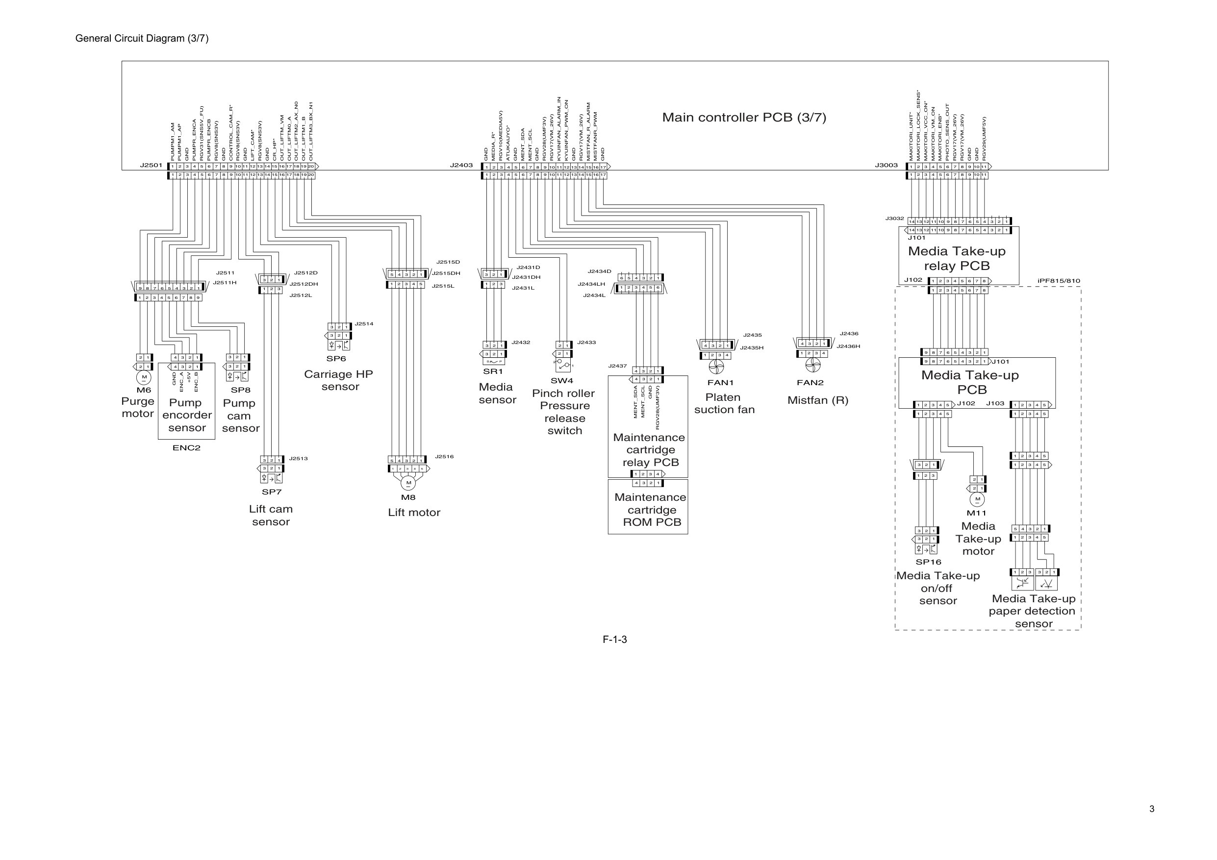
3 General Circuit Diagram (3/7)
F-1-3
1 2 3 4 1Gnd
Gnd
1 2 3 1 2 3 4 2 1 2 3 4 5 6 7 8 9 1 2 3 1 2 3 2 1 1 2 3 4 5 1 2 3 4 5 1 2 3 4 5 1 2 3 4 5 1 2 3 4 5 1 2 3 1 2 3 1 2 3 1 2 3 4 5 1 2 3 4 5 6 7 8 9 1 2 3 4 5 6 7 8J102
J101
2M
1 1 2 3 1 2 3 4 5 1 2 3 4 5 1 2 3 4 5 6 7 8 9 1 2 3 4 5 6 7 8Makitori_Unit*
Makitori_Lock_Sens*
Makitori_Vcc_On*
Makitori_Vm_On
Makitori_Enb*
Photo_Sens_Out
Rgv17(Vm_26V)
Rgv17(Vm_26V)
J101
J103
J102
1 2 3 4 1 2 3 4 1 2 3 4 1 2 3 4 14 15 16 17 1 2 3 4 5 6 7 8 9 10 11 12 13 14 15 16 17 18 19 20Gnd
1 2 3 4Enc_A
+5V
Enc_B
1 2 3 1 2 3 1 2 3 2M
1 1 2 1 2 1 2 3 4 5M
1 2 3 1 2 3 4 5 6 7 8 9 10 11P
S
Gnd
Pumpr_Enca
Rgv31(Sns5V_Fu)
Pumpr_Encb
Control_Cam_R*
12 13M8
Sr1
Sw4
Fan1
Fan2
Sp16
M11
Media_R*
Gnd
Mistfan_R_Alarm
Rgv8(Sns3V)
Gnd
Lift_Cam*
Rgv8(Sns3V)
Gnd
Rgv8(Sns3V)
Cr_Hp*
Out_Liftm_Vm
Out_Liftm0_A
Out_Liftm2_Ax_N0
Out_Liftm1_B
Out_Liftm3_Bx_N1
Gnd
Rgv29(Umf5V)
Gnd
Rgv10(Media5V)
Atukaijyo*
Kyuinfan_Alarm_In
Rgv17(Vm_26V)
Gnd
J2403
Pumpm1_Am
Pumpm1_Ap
J2501
Ment_Sda
Ment_Scl
Gnd
Rgv28(Umf3V)
Rgv17(Vm_26V)
Gnd
Kyuinfan_Pwm_On
Mistfanr_Pwm
J3003
Sp6
Sp7
Sp8
M6
Enc2
Ment_Sda
Rgv28(Umf3V)
Ment_Scl
Gnd
1 2 3 4J2437
J2434Lh
1 2 3 4 5 6J2434L
1 2 3 4 5 6J2434D
1 2 3 4J2435
J2435H
J2511H
9 8 2 3 4 5 6 1 7J2511
1 2 3J2513
1 2 3J2514
1 2 3J2512L
J2512Dh
1 2 3J2512D
1 2 3J2431L
J2431Dh
1 2 3J2431D
J2515Dh
1 2 3 4 5J2515L
1 2 3 4 5J2515D
14 13 12 11 10 9 8 2 3 4 5 6 1 7 14 13 12 11 10 9 8 2 3 4 5 6 1 7J3032
1 2 3J2432
1 2J2433
1 2 3 4 5J2516
11 10 9 8 2 3 4 5 6 1 7 11 10 9 8 2 3 4 5 6 1 7 20 18 17 16 15 14 13 12 11 10 9 8 2 3 4 5 6 1 7 19 17 16 15 14 13 12 11 10 9 8 2 3 4 5 6 1 7 1 2 3 4J2436
J2436H
iPF815/810 Main controller PCB (3/7) Purge motor Pump encorder sensor Pump cam sensor Lift cam sensor Lift motor Carriage HP sensor Media sensor Pinch roller Pressure release switch Platen suction fan Mistfan (R) Maintenance cartridge relay PCB Media Take-up relay PCB Media Take-upPcb
Media Take-up motor Media Take-up paper detection sensor Media Take-up on/off sensor Maintenance cartridgeRom Pcb
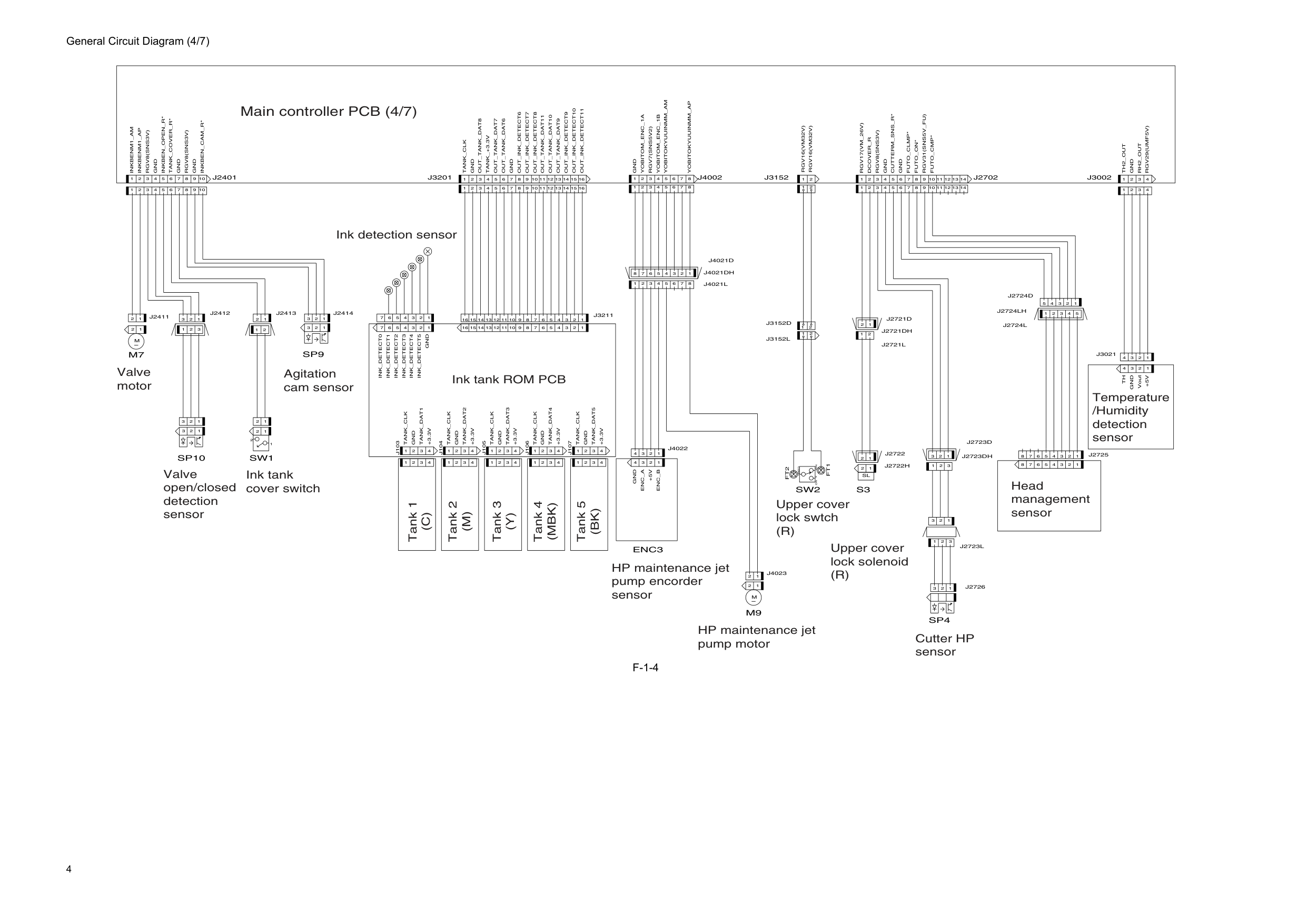
4 General Circuit Diagram (4/7)
F-1-4
3 2 1 1 2 3 1 2 1 2Gnd
Gnd
1 2 3 4 5 6 7 Vout 1 2 3 4 1 2 3 4Gnd
+5V
Th
2 1Sl
Rgv16(Vm32V)
Nc
Com
2 3 1No
Rgv16(Vm32V)
Gnd
Enc_A
+5V
Enc_B
M
Tank_Clk
Gnd
+3.3V
Tank_Clk
Gnd
+3.3V
Tank_Clk
Gnd
+3.3V
Tank_Clk
Gnd
+3.3V
Tank_Clk
Gnd
+3.3V
1 2 2M
1 2 3 1 2 3 1 2 3 4 5 6 7 1 2 3 4 1 2 3 4 1 2 3 4 1 2 3 4 1 2 3 4 1 2 3 4 1 2 3 4 1 2 3 4 1 2 3 4 1 2 3 4 1 2 1Tank_Dat1
Tank_Dat2
Tank_Dat3
Tank_Dat4
Tank_Dat5
Ink_Detect1
Ink_Detect2
Ink_Detect3
Ink_Detect4
Ink_Detect5
Gnd
Ink_Detect0
Gnd
Tank_+3.3V
Gnd
Inkbenm1_Am
Inkbenm1_Ap
Gnd
Inkben_Open_R*
Tank_Cover_R*
Gnd
Gnd
Inkben_Cam_R*
J2702
Enc3
M9
S3
J103
J104
J105
J106
J107
J3002
J2401
Dcover_R
Rgv8(Sns3V)
Rgv8(Sns3V)
Cutterm_Sns_R*
Futo_Clmp*
Futo_On*
Rgv31(Sns5V_Fu)
Futo_Cmp*
Rgv8(Sns3V)
Th2_Out
Rh2_Out
Rgv29(Umf5V)
Gnd
Yobitom_Enc_1A
Rgv7(Sns5V2)
Yobitom_Enc_1B
Yobitokyuuinmm_Am
Out_Tank_Dat8
Out_Tank_Dat7
Out_Tank_Dat6
Out_Ink_Detect6
Out_Ink_Detect7
Out_Ink_Detect8
Out_Tank_Dat11
Out_Tank_Dat10
Out_Tank_Dat9
Out_Ink_Detect9
Out_Ink_Detect10
Out_Ink_Detect11
Sw2
Gnd
Tank_Clk
Rgv17(Vm_26V)
J3201
J3152
Sp10
M7
J4002
Yobitokyuuinmm_Ap
Sp4
Sw1
Sp9
1 2 3 3 2 1J2723Dh
J2721Dh
1 2J2721L
1 2J2721D
1 2 3J2723L
1 2 3J2723D
1 2 3J2726
1 2 3 4 5J2724L
2 1 2 1 14 13 12 11 10 9 8 2 3 4 5 6 1 7 14 13 12 11 10 9 8 2 3 4 5 6 1 7 1 2 3 4 5 6 7 8J4021L
J4021Dh
1 2 3 4 5 6 7 8J4021D
1 2 3 4 5 6 7 8 1 2 3 4 5 6 7 8J2724Lh
1 2 3 4 1 2 3 4J4022
1 2 1 2J4023
1 2 3J2414
1 2J2413
16 15 14 13 12 11 10 9 8 2 3 4 5 6 1 7 16 15 14 13 12 11 10 9 8 2 3 4 5 6 1 7J3211
J2722H
1 2J2722
10 9 8 2 3 4 5 6 1 7 10 9 8 2 3 4 5 6 1 7 16 15 14 13 12 11 10 9 8 2 3 4 5 6 1 7 16 15 14 13 12 11 10 9 8 2 3 4 5 6 1 7 2 1J3152L
2 1J3152D
1 2J2411
1 2 3J2412
1 2 3 4 5 6 7 8 1 2 3 4 5 6 7 8J2725
1 2 3 4J3021
1 2 3 4Ft2
Ft1
1 2 3 4 5J2724D
Main controller PCB (4/7) Valve motor Valve open/closed detection sensor Ink tank cover switch Agitation cam sensor Ink tank ROM PCB HP maintenance jet pump encorder sensor HP maintenance jet pump motor Upper cover lock swtch(R)
Upper cover lock solenoid(R)
Cutter HP sensor Head management sensor Temperature /Humidity detection sensor Ink detection sensor Tank 1(C)
Tank 3(Y)
Tank 2(M)
Tank 4(Mbk)
Tank 5(Bk)
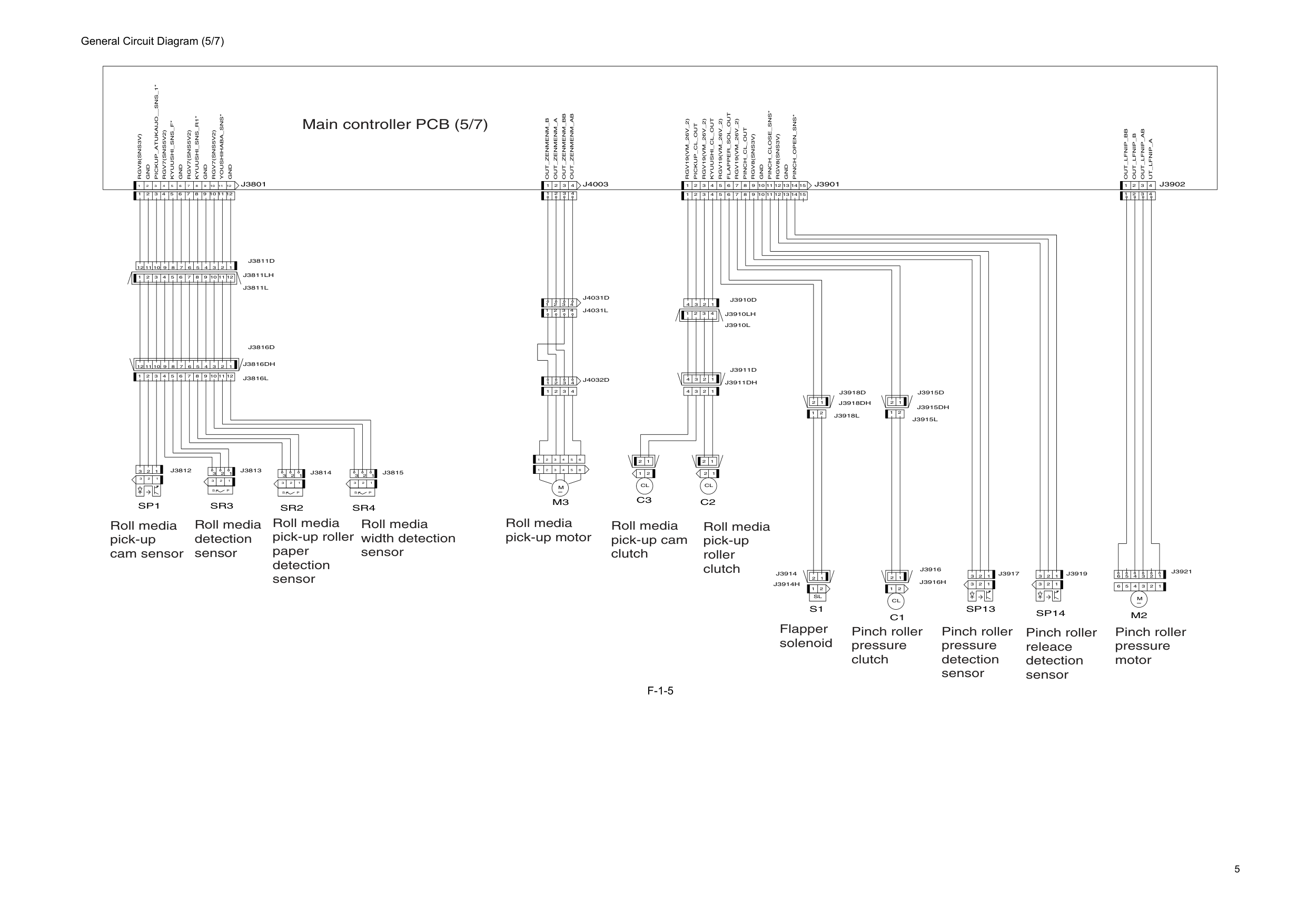
5 General Circuit Diagram (5/7)
F-1-5
2 1 2 3 4 5 6 1 2 3 4 5 6M
1 2 1Cl
2 1Cl
C2
C3
M3
Rgv8(Sns3V)
Gnd
1 2 3P
1 1 1 2 3 4 5 6 7 8 9 10 11 12Rgv19(Vm_26V_2)
Rgv19(Vm_26V_2)
Rgv19(Vm_26V_2)
Rgv7(Sns5V2)
2 1Cl
M
2 3S
2 1Sl
1 2 3 2 3P
S
2 3P
S
1 2 3Sr3
Sp1
Sr4
M2
Pickup_Atukaijo__Sns_1*
Kyuushi_Sns_F*
Youshihaba_Sns*
Gnd
Out_Lfnip_B
Out_Lfnip_Ab
Ut_Lfnip_A
J3902
Rgv7(Sns5V2)
Gnd
Out_Lfnip_Bb
Pickup_Cl_Out
Kyuushi_Cl_Out
Flapper_Sol_Out
Pinch_Cl_Out
Rgv8(Sns3V)
Gnd
S1
Sr2
Rgv8(Sns3V)
Rgv19(Vm_26V_2)
1Gnd
Kyuushi_Sns_R1*
Rgv7(Sns5V2)
Gnd
J3801
J3901
Pinch_Open_Sns*
Pinch_Close_Sns*
J4003
C1
Sp14
Sp13
Out_Zenmenm_B
Out_Zenmenm_A
Out_Zenmenm_Ab
Out_Zenmenm_Bb
2 1J3916H
J3915Dh
1 2 3J3919
1 2 3J3917
1 2J3916
12 11 10 9 8 2 3 4 5 6 1 7J3816D
12 11 10 9 8 2 3 4 5 6 1 7J3811L
1 2 3 4J3910L
1 2 3 4 1 2 3 4J3911D
J3911Dh
2 3 4 1J4031L
2 3 4 1 2 3 4 1J4032D
2 3 4 1J4031D
J3910Lh
1 2 3 4J3910D
J3816Dh
J3811Lh
J3914H
1 2J3914
15 14 13 12 11 10 9 8 2 3 4 5 6 1 7 15 14 13 12 11 10 9 8 2 3 4 5 6 1 7 12 11 10 9 8 2 3 4 5 6 1 7J3811D
2 3 4 1 2 3 4 1 12 11 10 9 8 2 3 4 5 6 1 7 2 3 1J3815
2 3 1J3814
2 3 1J3813
3 4 5 6 1 2 3 4 5 6 1 2J3921
1 2J3918L
J3918Dh
1 2J3918D
1 2J3915L
1 2J3915D
1 2 3J3812
2 3 4 1 2 3 4 1 12 11 10 9 8 2 3 4 5 6 1 7J3816L
Main controller PCB (5/7) Roll media pick-up cam sensor Roll media pick-up motor Roll media pick-up cam clutch Roll media pick-up roller clutch Flapper solenoid Pinch roller pressure clutch Pinch roller releace detection sensor Pinch roller pressure detection sensor Pinch roller pressure motor Roll media detection sensor Roll media pick-up roller paper detection sensor Roll media width detection sensor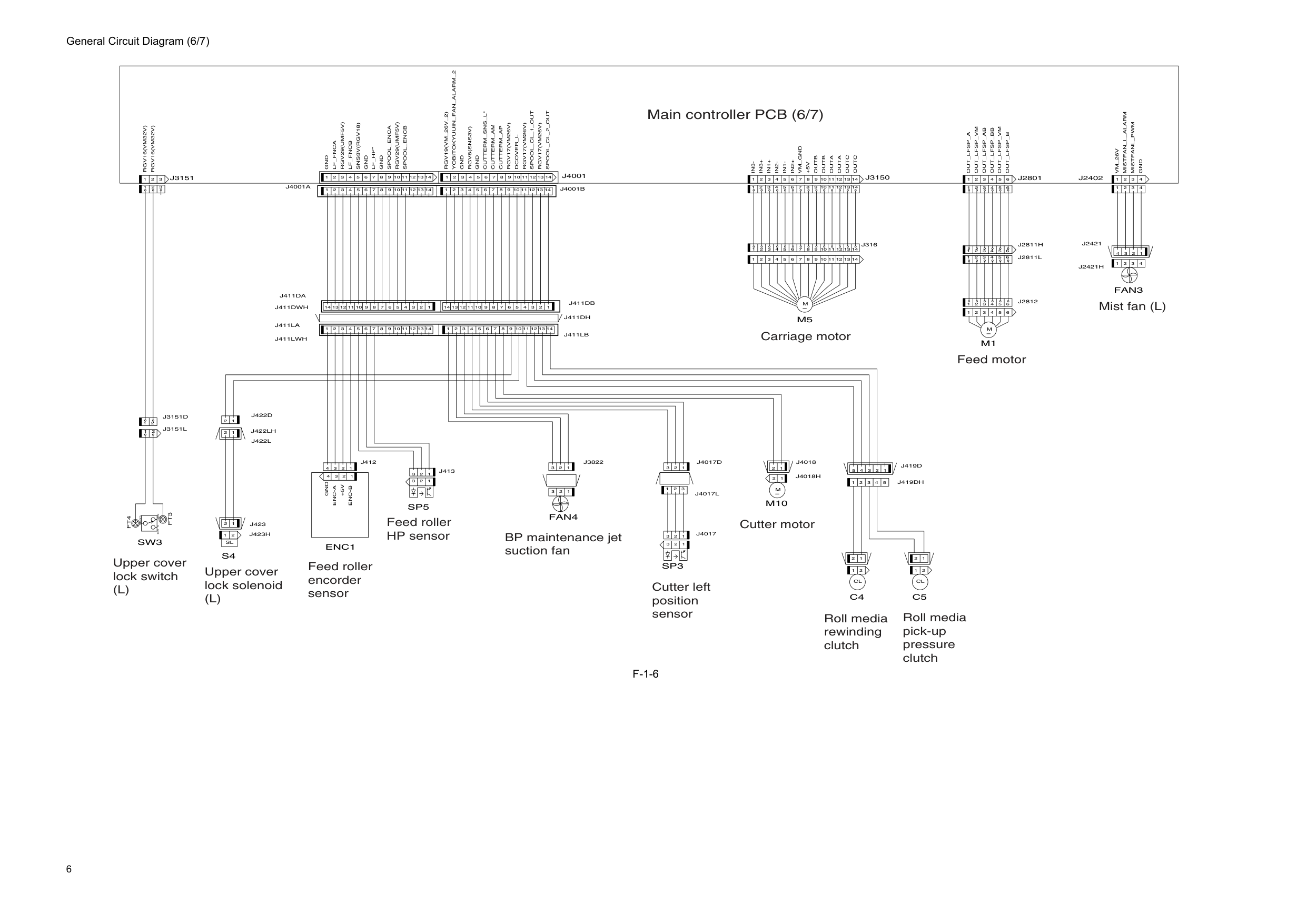
6 General Circuit Diagram (6/7)
F-1-6
2 3 4 5 1 2 1 2 1 1 2 3 4 5 6M
M1
1 2 3 4 4 3 2 1 4 3 2 1 3 1 2 1 2 3 2M
1M10
14 13 12 14 13 1 2 3 4 5 6 7 8 9 10Rgv17(Vm26V)
1 2 3 4 5 6 7 8 9 11Cutterm_Sns_L*
Cutterm_Am
Cutterm_Ap
Rgv17(Vm26V)
Rgv17(Vm26V)
Spool_Cl_1_Out
Spool_Cl_2_Out
Gnd
Rgv19(Vm_26V_2)
Gnd
Out_Lfsp_Vm
5 6Out_Lfsp_Ab
Out_Lfsp_Bb
Out_Lfsp_B
J2801
1 2 3 4 5 6 7 8 9 10 11 12 13 14 1 2 3 4 5 6 7 8 9 10 11 12 13 14M
In3+
In1+
In2-
In1-
In2+
Vm_Gnd
+5V
Outb
Outa
Outa
Outc
2 1Cl
2 1Cl
C4
Gnd
Sns3V(Rgv18)
Lf_Hp*
1 2 3 1 2 3 4+5V
Enc-A
Enc-B
Gnd
1 2 3Rgv16(Vm32V)
Nc
Com
2 3 1No
Rgv16(Vm32V)
2 1Sl
J3151
C5
Enc1
S4
Sp5
Sw3
M5
J3150
Vm_26V
Spool_Encb
Out_Lfsp_Vm
Outc
Outb
Spool_Enca
Gnd
Rgv29(Umf5V)
Rgv29(Umf5V)
In3-
Gnd
Out_Lfsp_A
11 12 10Lf_Fnca
Lf_Fncb
Rgv8(Sns3V)
J4001
Yobitokyuuin_Fan_Alarm_2
Dcover_L
J2402
Fan3
Gnd
Mistfan_L_Alarm
Mistfanl_Pwm
Sp3
Fan4
3 4 5 6 1 2J2811L
2 3 4 5 6 1J2811H
3 4 5 6 1 2J2812
1 2 3J4017
1 2 3J4017L
1 2 3J4017D
J4018H
1 2J4018
J423H
1 2 3 4 5J419D
J419Dh
1 2 3 4J2421
J2421H
1 2 3 4 14 13 12 11 10 9 8 2 3 4 5 6 1 7J4001B
14 13 12 11 10 9 8 2 3 4 5 6 1 7J4001A
2 3 1 1 2J422D
14 13 12 11 10 9 8 2 3 4 5 6 1 7J411Da
1 2J423
2 1J3151D
14 13 12 11 10 9 8 2 3 4 5 6 1 7J411Lb
J411Dh
14 13 12 11 10 9 8 2 3 4 5 6 1 7J411Db
J411Lwh
14 13 12 11 10 9 8 2 3 4 5 6 1 7J411La
J411Dwh
1 2J422L
J422Lh
3 4 5 6 1 2 1 2 3J413
1 2 3 4J412
2 1J3151L
14 13 12 11 8 1 2 3 4 5 6 7 9 10J316
14 13 12 11 8 1 2 3 4 5 6 7 9 10Ft4
Ft3
1 2 3J3822
Main controller PCB (6/7) Upper cover lock switch(L)
Upper cover lock solenoid(L)
Feed roller encorder sensor Feed roller HP sensor BP maintenance jet suction fan Cutter left position sensor Cutter motor Roll media rewinding clutch Roll media pick-up pressure clutch Carriage motor Feed motor Mist fan (L)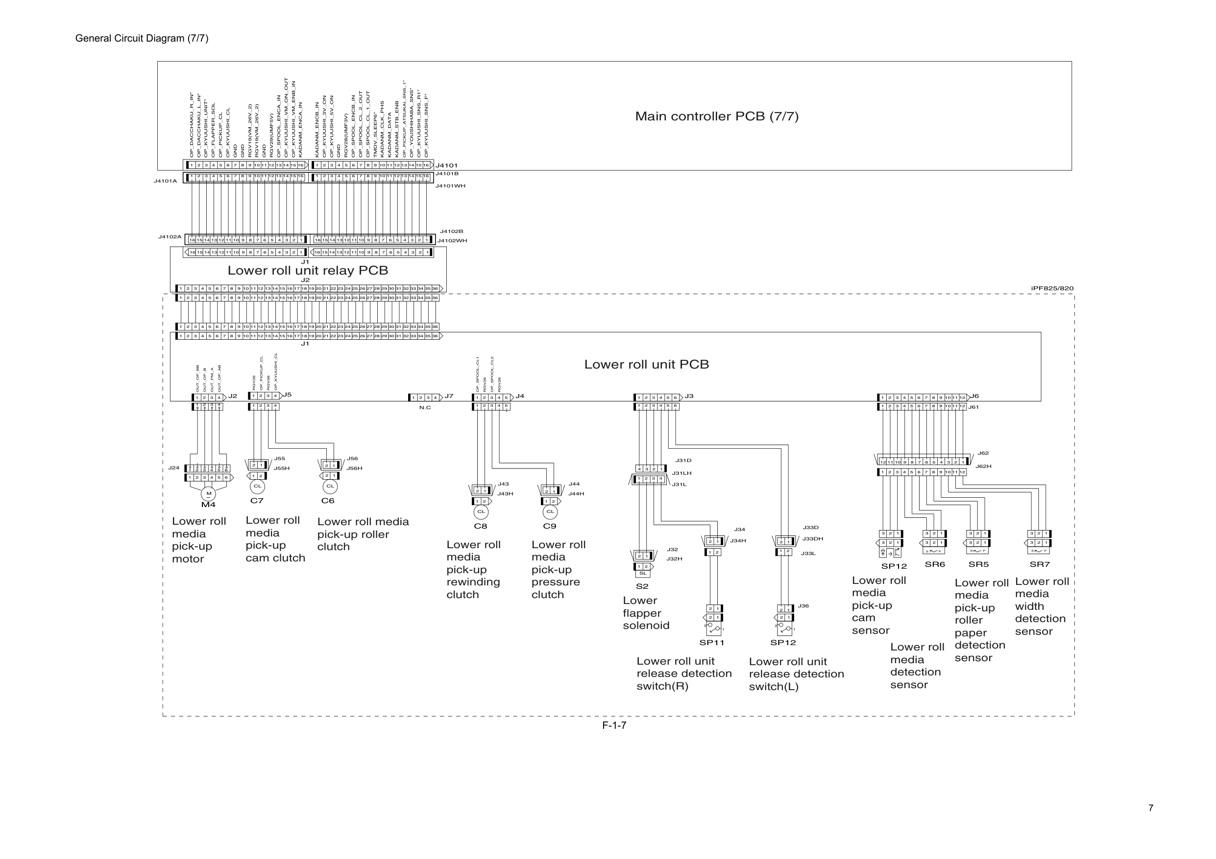
7 General Circuit Diagram (7/7)
F-1-7
iPF825/820Rgv26
Rgv26
1 2 3 4 1 2 3 4 5C7
2 3 4 5 6M
M4
2 1Cl
2 1Cl
C6
1 2 2 1S
P
1 2 3 4 6 5 4 3 2 1 2 1Cl
2 1Cl
C8
C9
1 2 1 2 1 2 3 4 1 2 3 4 5 6 7 8 9 10 11 12 13 14 15 16 17 18 19 20 21 22 23 24 25 26 27 28 29 30 31 32 33 34 35 36J1
1 2 3 4 5 6 7 8 9 10 11 12 1 2 3 1 2 3 1 2 3 1 2 3 1 2 3Rgv19(Vm_26V_2)
1 2 3P
S
1 2 3S
1 2 3 1 2 1 2 2 1Sl
S2
1 2 3 4 5 6 7 8 9 10 11 12 36 1 2 3 4 5 6 7 8 9 10 11 12 13 14 15 16 17 18 19 20 21 22 23 24 25 26 27 28 29 30 31 32 33 34 35 36 1 2 3 4 5 6 7 8 9 10 11 12 13 14 15 16 17 18 19 20 21 22 23 24 25 26 27 28 29 30 31 32 33 34 35 1 2 3 4 5 6 7 8 9 10 11 12 13 14 15 16 17 18 19 20 21 22 23 24 25 26 27 28 29 30 31 32 33 34 35 36 1 2 3 4 5 6 7 8 9 10 11 12 13 14 15 16 16 15 14 13 12 11 10 9 8 7 6 5 4 3 2 1 1 2 3 4 5 6 7 8 9 10 11 12 13 14 15 16 16 15 14 13 12 11 10 9 8 7 6 5 4 3 2 1J4101
J2
J1
Sp12
Sr6
Sr7
Sp12
Op_Dacchaku_R_In*
Op_Dacchaku_L_In*
Op_Kyuushi_Unit*
Op_Flapper_Sol
Op_Pickup_Cl
Op_Kyuushi_Cl
Gnd
Rgv19(Vm_26V_2)
Gnd
Rgv29(Umf5V)
Op_Spool_Enca_In
Op_Kyuushi_Vm_On_Out
Op_Kyuushi_Vm_Enb_In
Kadanm_Enca_In
Op_Kyuushi_3V_On
Op_Kyuushi_5V_On
Gnd
Rgv28(Umf3V)
Op_Spool_Encb_In
Op_Spool_Cl_2_Out
Op_Spool_Cl_1_Out
Tmdv_Sleep6*
Kadanm_Clk_Phs
Kadanm_Data
Kadanm_Stb_Enb
Op_Kyuushi_Sns_R1*
Op_Kyuushi_Sns_F*
Op_Youshihaba_Sns*
Op_Pickup_Atsukai_Sns_1*
Sr5
Kadanm_Encb_In
Sp11
J5
J3
J6
Gnd
Out_Op_Bb
Out_Op_B
P
J2
J4
J7
Rgv26
Op_Spool_Cl2
Op_Spool_Cl1
Rgv26
Op_Pickup_Cl
Op_Kyuushi_Cl
1Out_Pm_A
Out_Op_Ab
N.C
1 2J33L
2 3 4 1 1 2 3 4 5 3 4 5 6 1 2J24
1 2J33D
J33Dh
J34H
1 2J34
1 2J36
J31Lh
J62H
12 11 10 9 8 2 3 4 5 6 1 7J62
1 2 3 4J31D
J32H
1 2J32
J43H
1 2 3 4J31L
1 2 3 4 5 6 12 11 10 9 8 2 3 4 5 6 1 7J61
J44H
1 2J44
1 2J43
J4102Wh
16 15 14 13 12 11 10 9 8 2 3 4 5 6 1 7J4102B
J4101Wh
16 15 14 13 12 11 10 9 8 2 3 4 5 6 1 7J4101B
16 15 14 13 12 11 10 9 8 2 3 4 5 6 1 7J4102A
16 15 14 13 12 11 10 9 8 2 3 4 5 6 1 7J4101A
J56H
1 2J56
1 2 3 4J55H
1 2J55
Main controller PCB (7/7) Lower roll media pick-up motor Lower roll media pick-up cam clutch Lower roll media pick-up roller clutch Lower roll media pick-up rewinding clutch Lower roll unit PCB Lower roll unit relay PCB Lower roll media pick-up pressure clutch Lower roll media pick-up cam sensor Lower roll media pick-up roller paper detection sensor Lower roll media width detection sensor Lower roll media detection sensor Lower flapper solenoid Lower roll unit release detection switch(R) Lower roll unit release detection switch(L)
Feb 27 2017