Ask AI
— answers from the official manualAnswers from the official manual.
Common questions
Common Questions
10 totalWhat is the Honeywell e7 thermostat and what are its main features?
The Honeywell e7 is a digital thermostat designed for hotel guestrooms, assisted living facilities, and student housing that provides Direct Digital Control of Fan Coil Units (FCU) and PTAC systems. It comes standard with five relays, an on-board PIR motion detector, Zigbee and Bluetooth RF transceiver, integrates with Amazon Alexa voice control, and provides real-time data to INNcontrol 3 for energy management and diagnostics. (Page 5)
How do I set up the Room ID during initial thermostat installation?
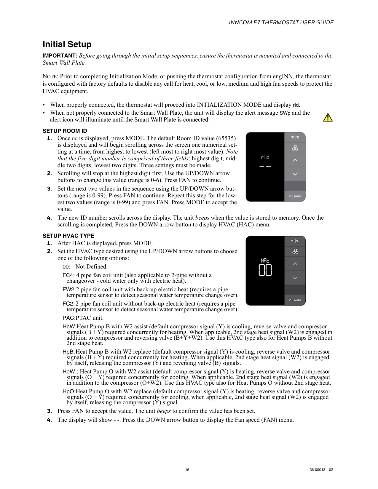
During Initialization Mode, press MODE when 'rId' is displayed. The default Room ID (65535) will scroll across the screen. Use UP/DOWN arrow buttons to set three values: the highest digit (range 0-6), then two middle digits (range 0-99), and finally the lowest two digits (range 0-99), pressing FAN between each field. Press MODE to accept the complete value and proceed to HVAC setup. (Page 15)
What HVAC types are supported by the e7 thermostat?
The e7 supports multiple HVAC types including: FC4 (4-pipe fan coil), FW2 (2-pipe with electric heat backup), FC2 (2-pipe without electric heat), PAC (PTAC units), HbW (Heat Pump B with W2 assist), HpB (Heat Pump B with W2 replace), HoW (Heat Pump O with W2 assist), and HpO (Heat Pump O with W2 replace). Each type is selected during Initialization Mode using UP/DOWN arrow buttons. (Page 15)
How do I adjust the temperature set point in normal operation?
Use the UP/DOWN arrow keys to set your desired room temperature. The set point low limit is 65°F and the high limit is 80°F (adjustable). The thermostat defaults to 72°F when a guest first enters the room, and the display reverts to showing the set point after 10 seconds if you view other information. (Page 20)
How do I change between Fahrenheit and Celsius temperature display?
Press the °F|°C button to toggle between Fahrenheit and Centigrade display modes. In Fahrenheit, temperatures are displayed in 1-degree increments with °F shown next to the value. In Centigrade, temperatures are displayed in 0.5-degree increments with °C shown next to the value. (Page 20)
What are the available fan speed options and how do I select them?
Press the FAN button to cycle through available fan speeds. Options include: Auto Mode (fan speed automatically selected based on temperature difference), and Low, Medium, and High fan speeds (indicated by 1 to 3 vertical dots). After reaching the highest speed, pressing FAN again returns you to the beginning of the cycle. Auto mode allows the thermostat to automatically control fan speed to achieve the set temperature. (Page 20)
Full Manual
26 pages

Installation And Operations Guide
36-00013-02 INNCOM e7 Thermostat User Guide https://pages1.honeywell.com/e7_Install_Instructions.html
36-00013—02 Important Safety Information and Installation Precautions Read all instructions Failure to follow all instructions may result in equipment damage or a hazardous condition. Read all instructions carefully before installing equipment. Local codes and practices Always install equipment in accordance with the National Electric Code and in a manner acceptable to the local authority having jurisdiction. Electrostatic sensitivity This product and its components may be susceptible to electrostatic discharge (ESD). Use appropriate ESD grounding techniques while handling the product. When possible, always handle the product by its non-electrical components. High voltage safety test Experienced electricians, at first contact, always assume that hazardous voltages may exist in any wiring system. A safety check using a known, reliable voltage measurement or detection device should be made immediately before starting work and when work resumes. Lightning and high-voltage danger Most electrical injuries involving low-voltage wiring result from sudden, unexpected high voltages on normally low- voltage wiring. Low-voltage wiring can carry hazardous high voltages under unsafe conditions. Never install or connect wiring or equipment during electrical storms. Improperly protected wiring can carry a fatal lightning surge for many miles. All outdoor wiring must be equipped with properly grounded and listed signal circuit protectors, which must be installed in compliance with local, applicable codes. Never install wiring or equipment while standing in water. Wiring and equipment separations All wiring and controllers must be installed to minimize the possibility of accidental contact with other potentially hazardous and disruptive power and lighting wiring. Never place 24VAC or communications wiring near other bare power wires, lightning rods, antennas, transformers, or steam or hot water pipes. Never place wire in any conduit, box, channel, duct or other enclosure containing power or lighting circuits of any type. Always provide adequate separation of communications wiring and other electrical wiring according to code. Keep wiring and controllers at least six feet from large inductive loads (power distribution panels, lighting ballasts, motors, etc.). Failure to follow these guidelines can introduce electrical interference and cause the system to operate erratically. Warning This equipment has been tested and found to comply with the limits for a class A digital device, pursuant to part 15 of the FCC rules. These limits are designed to provide reasonable protection against harmful interference when the equipment is operated in a commercial environment. This equipment generates, uses, and can radiate radio frequency energy and, if not installed and used in accordance with the instruction manual, may cause harmful interference to radio communications. Operation of this equipment in a residential area is likely to cause harmful interference, in which case the user will be required to correct the interference at his own expense. By using this Honeywell literature, you agree that Honeywell will have no liability for any damages arising out of your use, or modification to, the literature. You will defend and indemnify Honeywell, its affiliates and subsidiaries, from and against any liability, cost, or damages, including attorneys’ fees, arising out of, or resulting from, any modification to the literature by you. The material in this document is for information purposes only. The content and the product it describes are subject to change without notice. Honeywell makes no representations or warranties with respect to this document. In no event shall Honeywell be liable for technical or editorial omissions or mistakes in this document, nor shall it be liable for any damages, direct or incidental, arising out of or related to the use of this document. No part of this document may be reproduced in any form or by any means without prior written permission from Honeywell. Copyright © 2017 by Honeywell International, Inc. All Rights Reserved. Honeywell | 277 West Main Street | Niantic, CT 06357 | Phone: 1.860-739-4468 | www.INNCOM.com !
Inncom E7 Thermostat User Guide
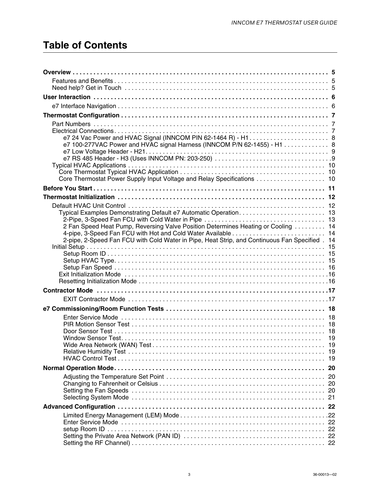
3 36-00013—02 Table of Contents Overview . . . . . . . . . . . . . . . . . . . . . . . . . . . . . . . . . . . . . . . . . . . . . . . . . . . . . . . . . . . . . . . . . . . . . . . . . . 5 Features and Benefits . . . . . . . . . . . . . . . . . . . . . . . . . . . . . . . . . . . . . . . . . . . . . . . . . . . . . . . . . . . . . . 5 Need help? Get in Touch . . . . . . . . . . . . . . . . . . . . . . . . . . . . . . . . . . . . . . . . . . . . . . . . . . . . . . . . . . . 5 User Interaction . . . . . . . . . . . . . . . . . . . . . . . . . . . . . . . . . . . . . . . . . . . . . . . . . . . . . . . . . . . . . . . . . . . . 6 e7 Interface Navigation . . . . . . . . . . . . . . . . . . . . . . . . . . . . . . . . . . . . . . . . . . . . . . . . . . . . . . . . . . . . . 6 Thermostat Configuration . . . . . . . . . . . . . . . . . . . . . . . . . . . . . . . . . . . . . . . . . . . . . . . . . . . . . . . . . . . . 7 Part Numbers . . . . . . . . . . . . . . . . . . . . . . . . . . . . . . . . . . . . . . . . . . . . . . . . . . . . . . . . . . . . . . . . . . . . 7 Electrical Connections. . . . . . . . . . . . . . . . . . . . . . . . . . . . . . . . . . . . . . . . . . . . . . . . . . . . . . . . . . . . . . 7 e7 24 Vac Power and HVAC Signal (INNCOM PIN 62-1464 R) - H1 . . . . . . . . . . . . . . . . . . . . . . . 8 e7 100-277VAC Power and HVAC signal Harness (INNCOM P/N 62-1455) - H1 . . . . . . . . . . . . . 8 e7 Low Voltage Header - H21. . . . . . . . . . . . . . . . . . . . . . . . . . . . . . . . . . . . . . . . . . . . . . . . . . . . . 9 e7 RS 485 Header - H3 (Uses INNCOM PN: 203-250) . . . . . . . . . . . . . . . . . . . . . . . . . . . . . . . . . .9 Typical HVAC Applications . . . . . . . . . . . . . . . . . . . . . . . . . . . . . . . . . . . . . . . . . . . . . . . . . . . . . . . . . 10 Core Thermostat Typical HVAC Application . . . . . . . . . . . . . . . . . . . . . . . . . . . . . . . . . . . . . . . . . . 10 Core Thermostat Power Supply Input Voltage and Relay Specifications . . . . . . . . . . . . . . . . . . . . 10 Before You Start . . . . . . . . . . . . . . . . . . . . . . . . . . . . . . . . . . . . . . . . . . . . . . . . . . . . . . . . . . . . . . . . . . . 11 Thermostat Initialization . . . . . . . . . . . . . . . . . . . . . . . . . . . . . . . . . . . . . . . . . . . . . . . . . . . . . . . . . . . . 12 Default HVAC Unit Control . . . . . . . . . . . . . . . . . . . . . . . . . . . . . . . . . . . . . . . . . . . . . . . . . . . . . . . . . 12 Typical Examples Demonstrating Default e7 Automatic Operation. . . . . . . . . . . . . . . . . . . . . . . . . 13 2-Pipe, 3-Speed Fan FCU with Cold Water in Pipe . . . . . . . . . . . . . . . . . . . . . . . . . . . . . . . . . . . 13 2 Fan Speed Heat Pump, Reversing Valve Position Determines Heating or Cooling . . . . . . . . . 14 4-pipe, 3-Speed Fan FCU with Hot and Cold Water Available . . . . . . . . . . . . . . . . . . . . . . . . . . . 14 2-pipe, 2-Speed Fan FCU with Cold Water in Pipe, Heat Strip, and Continuous Fan Specified . 14 Initial Setup . . . . . . . . . . . . . . . . . . . . . . . . . . . . . . . . . . . . . . . . . . . . . . . . . . . . . . . . . . . . . . . . . . . . . 15 Setup Room ID . . . . . . . . . . . . . . . . . . . . . . . . . . . . . . . . . . . . . . . . . . . . . . . . . . . . . . . . . . . . . . . 15 Setup HVAC Type. . . . . . . . . . . . . . . . . . . . . . . . . . . . . . . . . . . . . . . . . . . . . . . . . . . . . . . . . . . . . 15 Setup Fan Speed . . . . . . . . . . . . . . . . . . . . . . . . . . . . . . . . . . . . . . . . . . . . . . . . . . . . . . . . . . . . . 16 Exit Initialization Mode . . . . . . . . . . . . . . . . . . . . . . . . . . . . . . . . . . . . . . . . . . . . . . . . . . . . . . . . . . .16 Resetting Initialization Mode . . . . . . . . . . . . . . . . . . . . . . . . . . . . . . . . . . . . . . . . . . . . . . . . . . . . . . .16 Contractor Mode . . . . . . . . . . . . . . . . . . . . . . . . . . . . . . . . . . . . . . . . . . . . . . . . . . . . . . . . . . . . . . . . . . .17 EXIT Contractor Mode . . . . . . . . . . . . . . . . . . . . . . . . . . . . . . . . . . . . . . . . . . . . . . . . . . . . . . . . . .17 e7 Commissioning/Room Function Tests . . . . . . . . . . . . . . . . . . . . . . . . . . . . . . . . . . . . . . . . . . . . . . 18 Enter Service Mode . . . . . . . . . . . . . . . . . . . . . . . . . . . . . . . . . . . . . . . . . . . . . . . . . . . . . . . . . . . 18 PIR Motion Sensor Test . . . . . . . . . . . . . . . . . . . . . . . . . . . . . . . . . . . . . . . . . . . . . . . . . . . . . . . . 18 Door Sensor Test . . . . . . . . . . . . . . . . . . . . . . . . . . . . . . . . . . . . . . . . . . . . . . . . . . . . . . . . . . . . . 18 Window Sensor Test. . . . . . . . . . . . . . . . . . . . . . . . . . . . . . . . . . . . . . . . . . . . . . . . . . . . . . . . . . 19 Wide Area Network (WAN) Test . . . . . . . . . . . . . . . . . . . . . . . . . . . . . . . . . . . . . . . . . . . . . . . . . . 19 Relative Humidity Test . . . . . . . . . . . . . . . . . . . . . . . . . . . . . . . . . . . . . . . . . . . . . . . . . . . . . . . . . 19 HVAC Control Test . . . . . . . . . . . . . . . . . . . . . . . . . . . . . . . . . . . . . . . . . . . . . . . . . . . . . . . . . . . . 19 Normal Operation Mode. . . . . . . . . . . . . . . . . . . . . . . . . . . . . . . . . . . . . . . . . . . . . . . . . . . . . . . . . . . . . 20 Adjusting the Temperature Set Point . . . . . . . . . . . . . . . . . . . . . . . . . . . . . . . . . . . . . . . . . . . . . . 20 Changing to Fahrenheit or Celsius . . . . . . . . . . . . . . . . . . . . . . . . . . . . . . . . . . . . . . . . . . . . . . . . 20 Setting the Fan Speeds . . . . . . . . . . . . . . . . . . . . . . . . . . . . . . . . . . . . . . . . . . . . . . . . . . . . . . . . 20 Selecting System Mode . . . . . . . . . . . . . . . . . . . . . . . . . . . . . . . . . . . . . . . . . . . . . . . . . . . . . . . . 21 Advanced Configuration . . . . . . . . . . . . . . . . . . . . . . . . . . . . . . . . . . . . . . . . . . . . . . . . . . . . . . . . . . . . 22 Limited Energy Management (LEM) Mode . . . . . . . . . . . . . . . . . . . . . . . . . . . . . . . . . . . . . . . . . . .22 Enter Service Mode . . . . . . . . . . . . . . . . . . . . . . . . . . . . . . . . . . . . . . . . . . . . . . . . . . . . . . . . . . . 22 setup Room ID . . . . . . . . . . . . . . . . . . . . . . . . . . . . . . . . . . . . . . . . . . . . . . . . . . . . . . . . . . . . . . . 22 Setting the Private Area Network (PAN ID) . . . . . . . . . . . . . . . . . . . . . . . . . . . . . . . . . . . . . . . . . 22 Setting the RF Channel) . . . . . . . . . . . . . . . . . . . . . . . . . . . . . . . . . . . . . . . . . . . . . . . . . . . . . . . . 22
Inncom E7 Thermostat User Guide
36-00013—02 4 Teaching a Device Address . . . . . . . . . . . . . . . . . . . . . . . . . . . . . . . . . . . . . . . . . . . . . . . . . . . . . 23 Teaching a Device I/O Map . . . . . . . . . . . . . . . . . . . . . . . . . . . . . . . . . . . . . . . . . . . . . . . . . . . . . 23 Binding a Remote Device. . . . . . . . . . . . . . . . . . . . . . . . . . . . . . . . . . . . . . . . . . . . . . . . . . . . . . . 23 Ping a Device . . . . . . . . . . . . . . . . . . . . . . . . . . . . . . . . . . . . . . . . . . . . . . . . . . . . . . . . . . . . . . . . 24 Reset the e7 Thermostat . . . . . . . . . . . . . . . . . . . . . . . . . . . . . . . . . . . . . . . . . . . . . . . . . . . . . . . 24 Setting the e7 Thermostat Address . . . . . . . . . . . . . . . . . . . . . . . . . . . . . . . . . . . . . . . . . . . . . . . 24 Reading the e7 Software Version. . . . . . . . . . . . . . . . . . . . . . . . . . . . . . . . . . . . . . . . . . . . . . . . . 24 Door Open Alert . . . . . . . . . . . . . . . . . . . . . . . . . . . . . . . . . . . . . . . . . . . . . . . . . . . . . . . . . . . . . . 25 Bluetooth/Low Battery/Equipment Alerts . . . . . . . . . . . . . . . . . . . . . . . . . . . . . . . . . . . . . . . . . . . . . 25 INNtool/engINN Support . . . . . . . . . . . . . . . . . . . . . . . . . . . . . . . . . . . . . . . . . . . . . . . . . . . . . . . . . . . . 26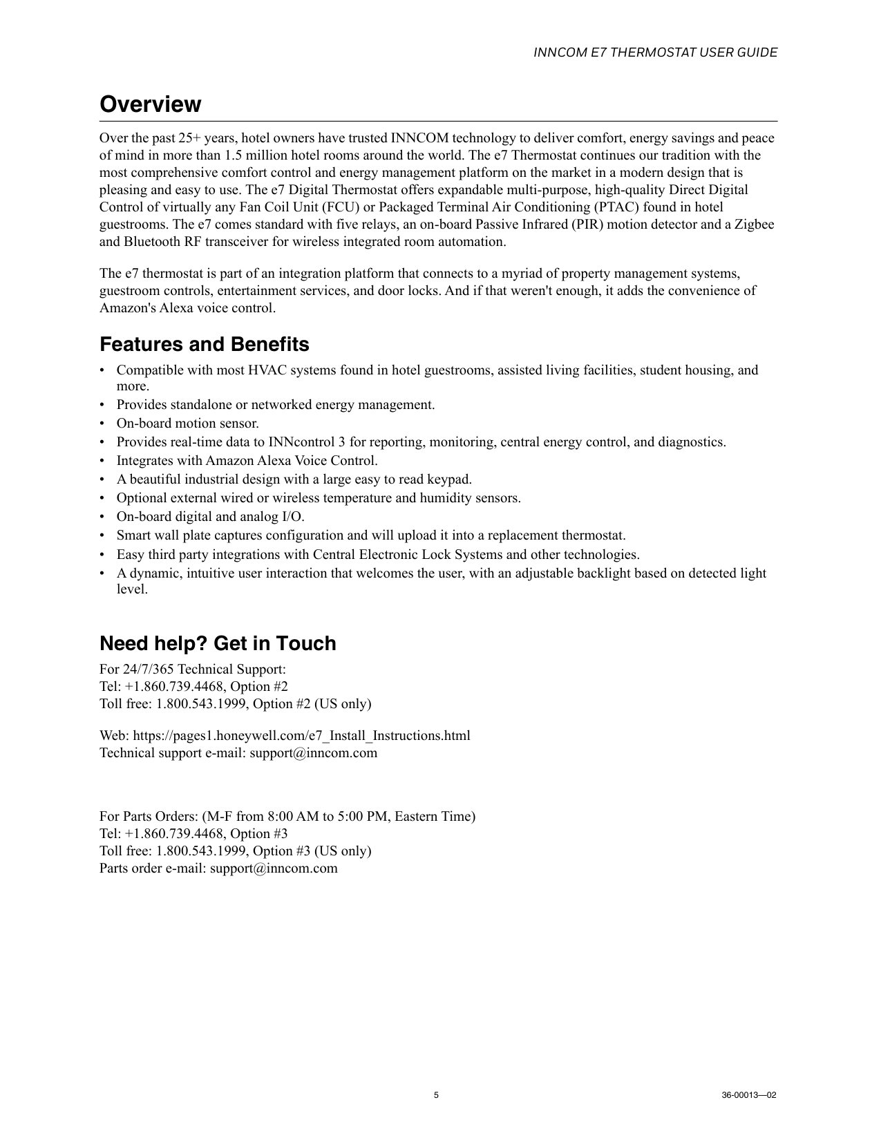
Inncom E7 Thermostat User Guide
5 36-00013—02 Overview Over the past 25+ years, hotel owners have trusted INNCOM technology to deliver comfort, energy savings and peace of mind in more than 1.5 million hotel rooms around the world. The e7 Thermostat continues our tradition with the most comprehensive comfort control and energy management platform on the market in a modern design that is pleasing and easy to use. The e7 Digital Thermostat offers expandable multi-purpose, high-quality Direct Digital Control of virtually any Fan Coil Unit (FCU) or Packaged Terminal Air Conditioning (PTAC) found in hotel guestrooms. The e7 comes standard with five relays, an on-board Passive Infrared (PIR) motion detector and a Zigbee and Bluetooth RF transceiver for wireless integrated room automation. The e7 thermostat is part of an integration platform that connects to a myriad of property management systems, guestroom controls, entertainment services, and door locks. And if that weren't enough, it adds the convenience of Amazon's Alexa voice control. Features and Benefits • Compatible with most HVAC systems found in hotel guestrooms, assisted living facilities, student housing, and more. • Provides standalone or networked energy management. • On-board motion sensor. • Provides real-time data to INNcontrol 3 for reporting, monitoring, central energy control, and diagnostics. • Integrates with Amazon Alexa Voice Control. • A beautiful industrial design with a large easy to read keypad. • Optional external wired or wireless temperature and humidity sensors. • On-board digital and analog I/O. • Smart wall plate captures configuration and will upload it into a replacement thermostat. • Easy third party integrations with Central Electronic Lock Systems and other technologies. • A dynamic, intuitive user interaction that welcomes the user, with an adjustable backlight based on detected light level. Need help? Get in Touch For 24/7/365 Technical Support: Tel: +1.860.739.4468, Option #2 Toll free: 1.800.543.1999, Option #2 (US only) Web: https://pages1.honeywell.com/e7_Install_Instructions.html Technical support e-mail: support@inncom.com For Parts Orders: (M-F from 8:00 AM to 5:00 PM, Eastern Time) Tel: +1.860.739.4468, Option #3 Toll free: 1.800.543.1999, Option #3 (US only) Parts order e-mail: support@inncom.com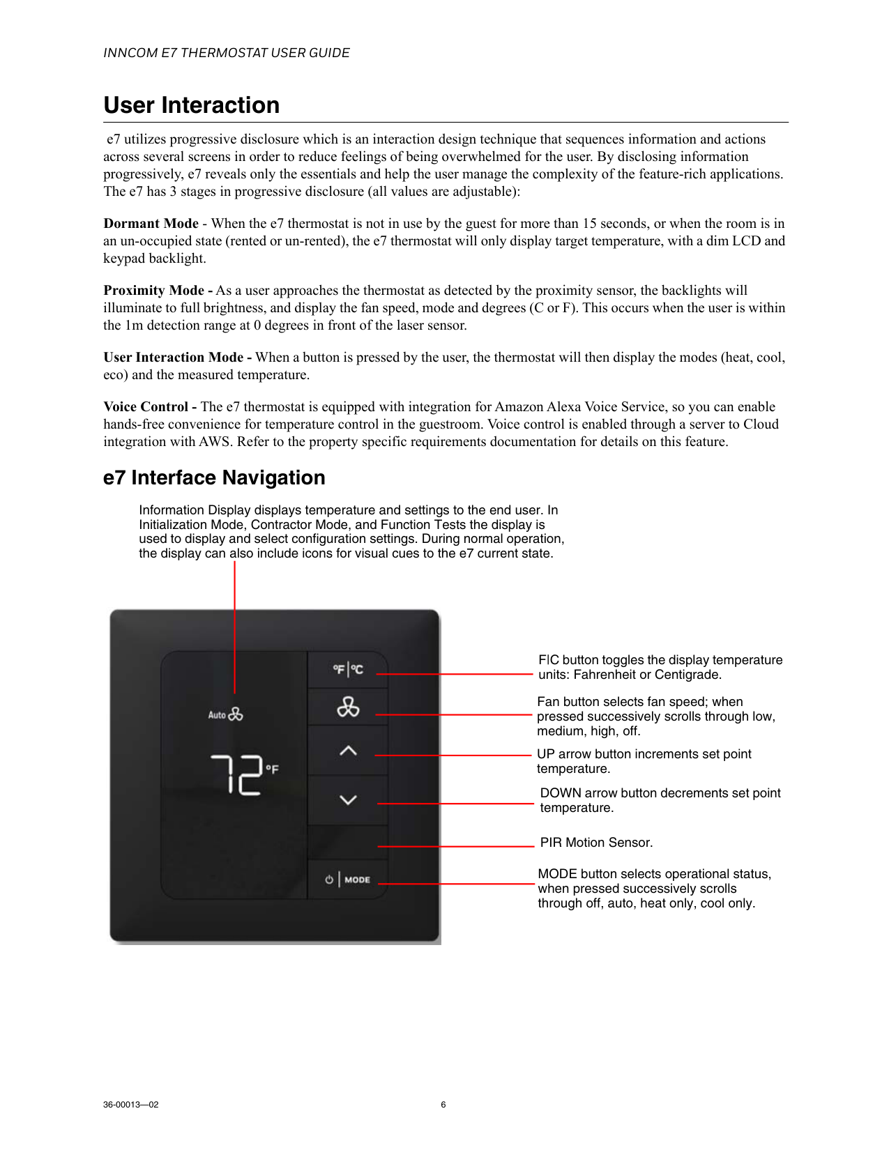
Inncom E7 Thermostat User Guide
36-00013—02 6 User Interaction e7 utilizes progressive disclosure which is an interaction design technique that sequences information and actions across several screens in order to reduce feelings of being overwhelmed for the user. By disclosing information progressively, e7 reveals only the essentials and help the user manage the complexity of the feature-rich applications. The e7 has 3 stages in progressive disclosure (all values are adjustable): Dormant Mode - When the e7 thermostat is not in use by the guest for more than 15 seconds, or when the room is in an un-occupied state (rented or un-rented), the e7 thermostat will only display target temperature, with a dim LCD and keypad backlight. Proximity Mode - As a user approaches the thermostat as detected by the proximity sensor, the backlights will illuminate to full brightness, and display the fan speed, mode and degrees (C or F). This occurs when the user is within the 1m detection range at 0 degrees in front of the laser sensor. User Interaction Mode - When a button is pressed by the user, the thermostat will then display the modes (heat, cool, eco) and the measured temperature. Voice Control - The e7 thermostat is equipped with integration for Amazon Alexa Voice Service, so you can enable hands-free convenience for temperature control in the guestroom. Voice control is enabled through a server to Cloud integration with AWS. Refer to the property specific requirements documentation for details on this feature. e7 Interface Navigation F|C button toggles the display temperature units: Fahrenheit or Centigrade. Fan button selects fan speed; when pressed successively scrolls through low, medium, high, off. UP arrow button increments set point temperature. DOWN arrow button decrements set point temperature. PIR Motion Sensor. MODE button selects operational status, when pressed successively scrolls through off, auto, heat only, cool only. Information Display displays temperature and settings to the end user. In Initialization Mode, Contractor Mode, and Function Tests the display is used to display and select configuration settings. During normal operation, the display can also include icons for visual cues to the e7 current state.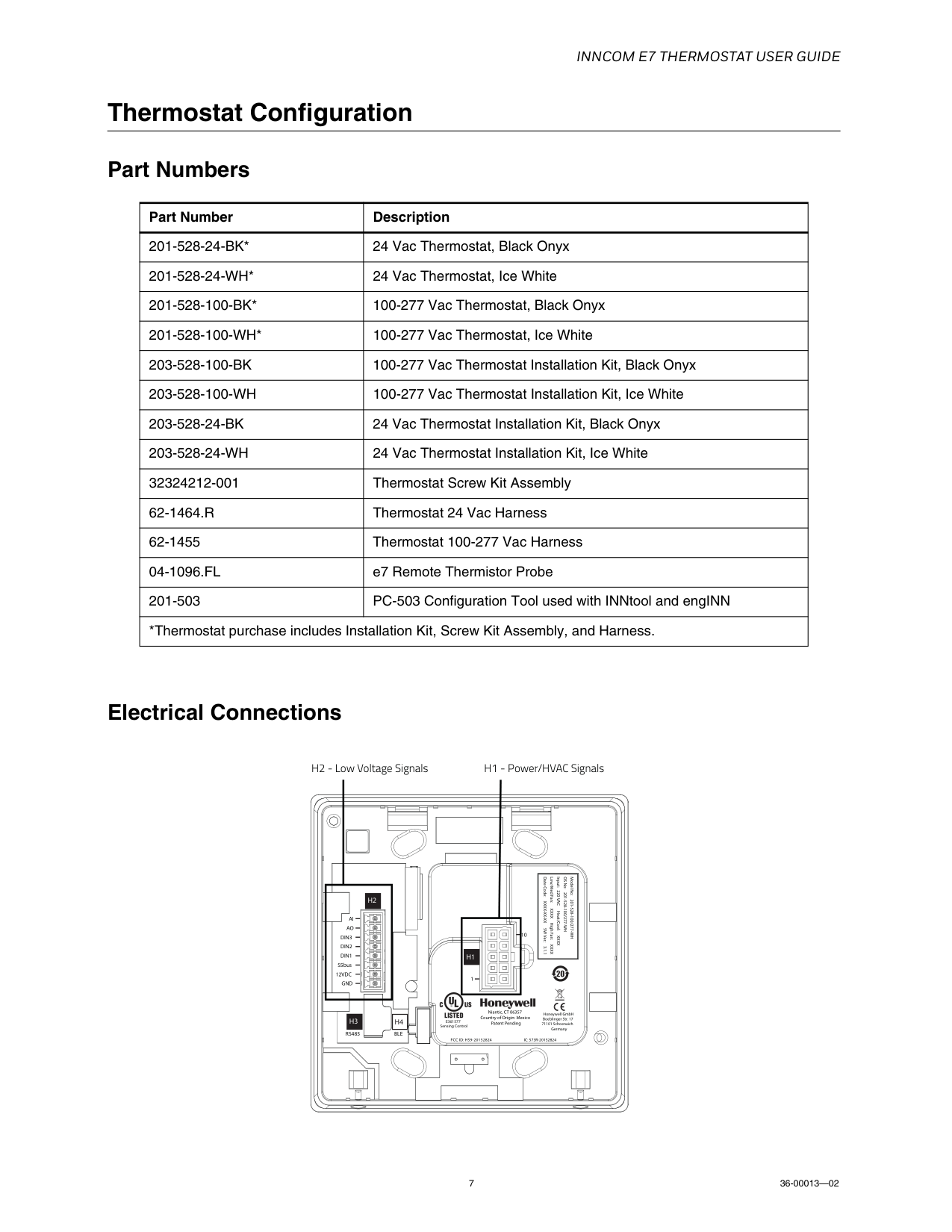
Inncom E7 Thermostat User Guide
7 36-00013—02 Thermostat Configuration Part Numbers Electrical Connections Part Number Description201-528-24-Bk*
24 Vac Thermostat, Black Onyx201-528-24-Wh*
24 Vac Thermostat, Ice White201-528-100-Bk*
100-277 Vac Thermostat, Black Onyx201-528-100-Wh*
100-277 Vac Thermostat, Ice White203-528-100-Bk
100-277 Vac Thermostat Installation Kit, Black Onyx203-528-100-Wh
100-277 Vac Thermostat Installation Kit, Ice White203-528-24-Bk
24 Vac Thermostat Installation Kit, Black Onyx203-528-24-Wh
24 Vac Thermostat Installation Kit, Ice White 32324212-001 Thermostat Screw Kit Assembly62-1464.R
Thermostat 24 Vac Harness 62-1455 Thermostat 100-277 Vac Harness04-1096.Fl
e7 Remote Thermistor Probe 201-503 PC-503 Configuration Tool used with INNtool and engINN *Thermostat purchase includes Installation Kit, Screw Kit Assembly, and Harness.Fcc Id: Hs9-20152824
Niantic, CT 06357 Country of Origin: Mexico Patent PendingAi
1 10Ao
Din3
Din2
Din1
S5bus12Vdc
Gnd
Ic: 573R-20152824
Ble
H4
Rs485
Model No: 201-528-100/277-WH OS No: 201-528-100/277-WH Input: 220 VAC Heat/Cool:Xxxx
Low/Med Fan: XXXX High Fan: XXXX Date Code: XXXX-XX-XX SW Ver.: 3.1.1H1
H3
H2
Honeywell GmbH Boeblinger Str. 17 71101 Schoenaich GermanyE361577
Sensing Control H2 - Low Voltage Signals H1 - Power/HVAC Signals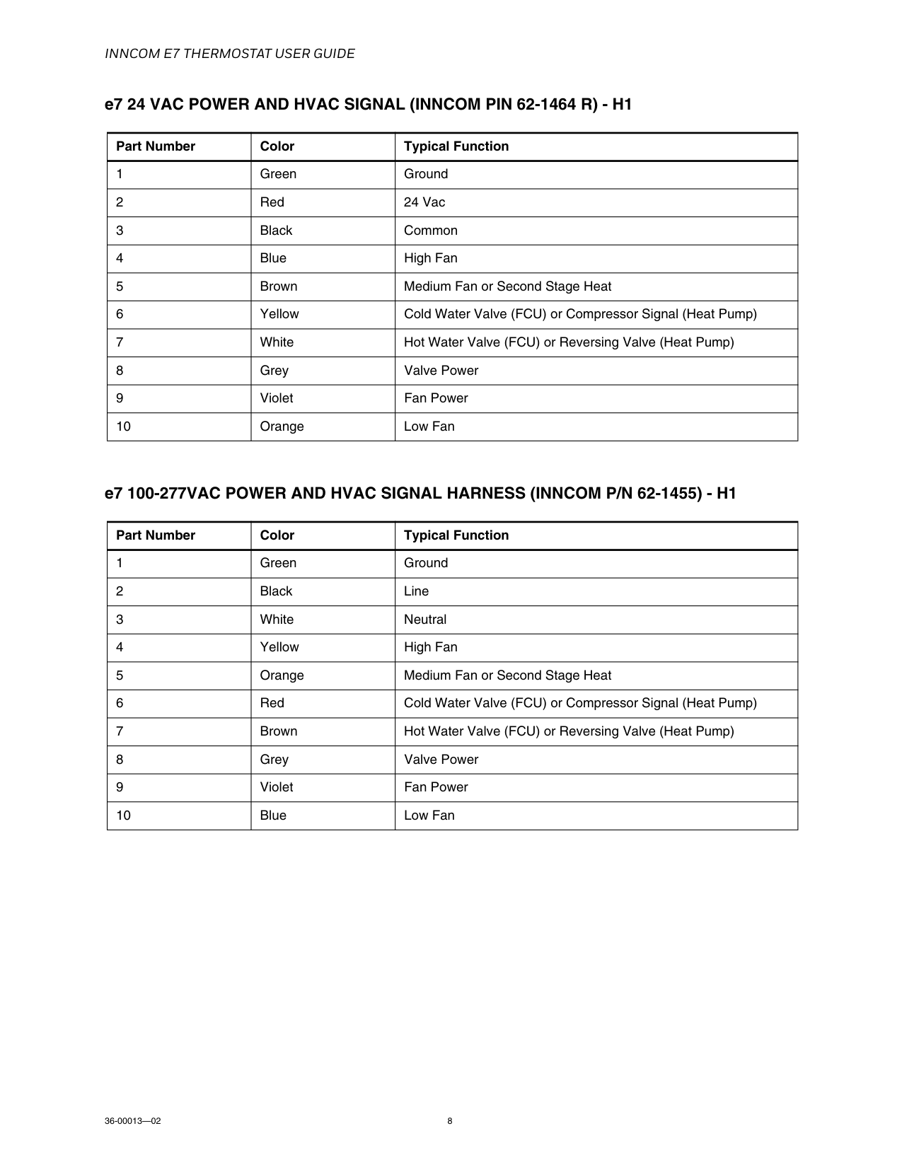
Inncom E7 Thermostat User Guide
36-00013—02 8 e7 24 VAC POWER AND HVAC SIGNAL (INNCOM PIN 62-1464 R) - H1 e7 100-277VAC POWER AND HVAC SIGNAL HARNESS (INNCOM P/N 62-1455) - H1 Part Number Color Typical Function 1 Green Ground 2 Red 24 Vac 3 Black Common 4 Blue High Fan 5 Brown Medium Fan or Second Stage Heat 6 Yellow Cold Water Valve (FCU) or Compressor Signal (Heat Pump) 7 White Hot Water Valve (FCU) or Reversing Valve (Heat Pump) 8 Grey Valve Power 9 Violet Fan Power 10 Orange Low Fan Part Number Color Typical Function 1 Green Ground 2 Black Line 3 White Neutral 4 Yellow High Fan 5 Orange Medium Fan or Second Stage Heat 6 Red Cold Water Valve (FCU) or Compressor Signal (Heat Pump) 7 Brown Hot Water Valve (FCU) or Reversing Valve (Heat Pump) 8 Grey Valve Power 9 Violet Fan Power 10 Blue Low Fan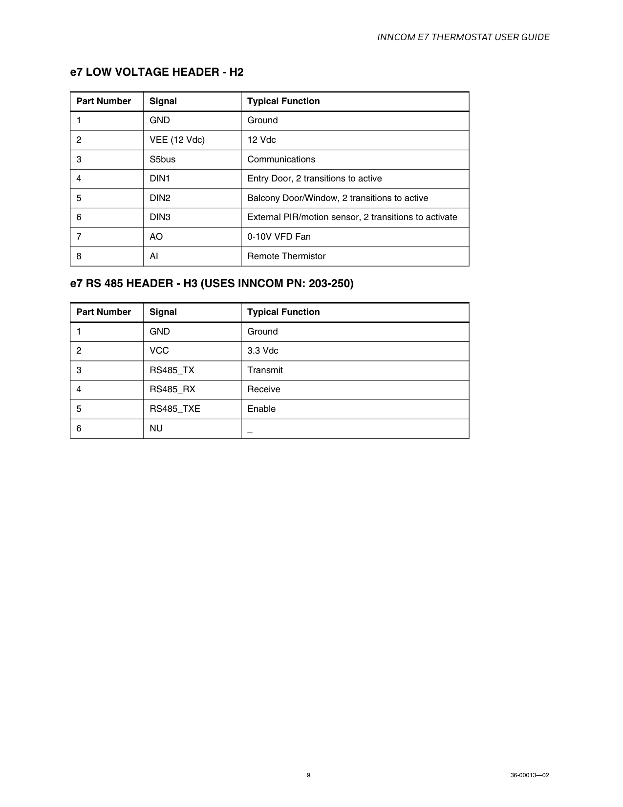
Inncom E7 Thermostat User Guide
9 36-00013—02 e7 LOW VOLTAGE HEADER - H2 e7 RS 485 HEADER - H3 (USES INNCOM PN: 203-250) Part Number Signal Typical Function 1Gnd
Ground 2 VEE (12 Vdc) 12 Vdc 3 S5bus Communications 4Din1
Entry Door, 2 transitions to active 5Din2
Balcony Door/Window, 2 transitions to active 6Din3
External PIR/motion sensor, 2 transitions to activate 7Ao
0-10V VFD Fan 8Ai
Remote Thermistor Part Number Signal Typical Function 1Gnd
Ground 2Vcc
3.3 Vdc 3Rs485_Tx
Transmit 4Rs485_Rx
Receive 5Rs485_Txe
Enable 6Nu
_
Inncom E7 Thermostat User Guide
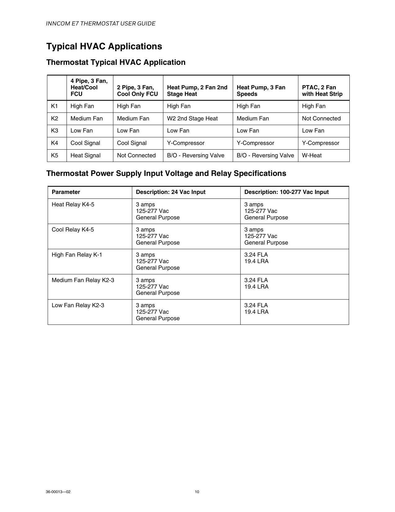
36-00013—02 10 Typical HVAC Applications Thermostat Typical HVAC Application Thermostat Power Supply Input Voltage and Relay Specifications4 Pipe, 3 Fan, Heat/Cool
Fcu
2 Pipe, 3 Fan, Cool Only FCU Heat Pump, 2 Fan 2nd Stage Heat Heat Pump, 3 Fan Speeds PTAC, 2 Fan with Heat StripK1
High Fan High Fan High Fan High Fan High FanK2
Medium Fan Medium Fan W2 2nd Stage Heat Medium Fan Not ConnectedK3
Low Fan Low Fan Low Fan Low Fan Low FanK4
Cool Signal Cool Signal Y-Compressor Y-Compressor Y-CompressorK5
Heat Signal Not Connected B/O - Reversing Valve B/O - Reversing Valve W-Heat Parameter Description: 24 Vac Input Description: 100-277 Vac Input Heat Relay K4-5 3 amps 125-277 Vac General Purpose 3 amps 125-277 Vac General Purpose Cool Relay K4-5 3 amps 125-277 Vac General Purpose 3 amps 125-277 Vac General Purpose High Fan Relay K-1 3 amps 125-277 Vac General Purpose3.24 Fla
19.4 Lra
Medium Fan Relay K2-3 3 amps 125-277 Vac General Purpose3.24 Fla
19.4 Lra
Low Fan Relay K2-3 3 amps 125-277 Vac General Purpose3.24 Fla
19.4 Lra
Inncom E7 Thermostat User Guide
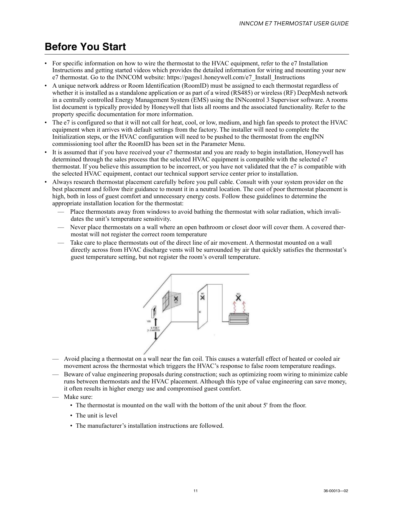
11 36-00013—02 Before You Start • For specific information on how to wire the thermostat to the HVAC equipment, refer to the e7 Installation Instructions and getting started videos which provides the detailed information for wiring and mounting your new e7 thermostat. Go to the INNCOM website: https://pages1.honeywell.com/e7_Install_Instructions • A unique network address or Room Identification (RoomID) must be assigned to each thermostat regardless of whether it is installed as a standalone application or as part of a wired (RS485) or wireless (RF) DeepMesh network in a centrally controlled Energy Management System (EMS) using the INNcontrol 3 Supervisor software. A rooms list document is typically provided by Honeywell that lists all rooms and the associated functionality. Refer to the property specific documentation for more information. • The e7 is configured so that it will not call for heat, cool, or low, medium, and high fan speeds to protect the HVAC equipment when it arrives with default settings from the factory. The installer will need to complete the Initialization steps, or the HVAC configuration will need to be pushed to the thermostat from the engINN commissioning tool after the RoomID has been set in the Parameter Menu. • It is assumed that if you have received your e7 thermostat and you are ready to begin installation, Honeywell has determined through the sales process that the selected HVAC equipment is compatible with the selected e7 thermostat. If you believe this assumption to be incorrect, or you have not validated that the e7 is compatible with the selected HVAC equipment, contact our technical support service center prior to installation. • Always research thermostat placement carefully before you pull cable. Consult with your system provider on the best placement and follow their guidance to mount it in a neutral location. The cost of poor thermostat placement is high, both in loss of guest comfort and unnecessary energy costs. Follow these guidelines to determine the appropriate installation location for the thermostat: — Place thermostats away from windows to avoid bathing the thermostat with solar radiation, which invali- dates the unit’s temperature sensitivity. — Never place thermostats on a wall where an open bathroom or closet door will cover them. A covered ther- mostat will not register the correct room temperature — Take care to place thermostats out of the direct line of air movement. A thermostat mounted on a wall directly across from HVAC discharge vents will be surrounded by air that quickly satisfies the thermostat’s guest temperature setting, but not register the room’s overall temperature. — Avoid placing a thermostat on a wall near the fan coil. This causes a waterfall effect of heated or cooled air movement across the thermostat which triggers the HVAC’s response to false room temperature readings. — Beware of value engineering proposals during construction; such as optimizing room wiring to minimize cable runs between thermostats and the HVAC placement. Although this type of value engineering can save money, it often results in higher energy use and compromised guest comfort. — Make sure: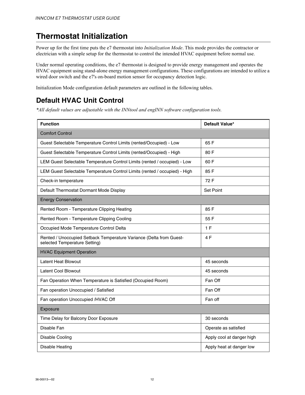
Inncom E7 Thermostat User Guide
36-00013—02 12 Thermostat Initialization Power up for the first time puts the e7 thermostat into Initialization Mode. This mode provides the contractor or electrician with a simple setup for the thermostat to control the intended HVAC equipment before normal use. Under normal operating conditions, the e7 thermostat is designed to provide energy management and operates the HVAC equipment using stand-alone energy management configurations. These configurations are intended to utilize a wired door switch and the e7's on-board motion sensor for occupancy detection logic. Initialization Mode configuration default parameters are outlined in the following tables. Default HVAC Unit Control *All default values are adjustable with the INNtool and engINN software configuration tools. Function Default Value* Comfort Control Guest Selectable Temperature Control Limits (rented/Occupied) - Low65 F
Guest Selectable Temperature Control Limits (rented/Occupied) - High80 F
LEM Guest Selectable Temperature Control Limits (rented / occupied) - Low60 F
LEM Guest Selectable Temperature Control Limits (rented / occupied) - High85 F
Check-in temperature72 F
Default Thermostat Dormant Mode Display Set Point Energy Conservation Rented Room - Temperature Clipping Heating85 F
Rented Room - Temperature Clipping Cooling55 F
Occupied Mode Temperature Control Delta1 F
Rented / Unoccupied Setback Temperature Variance (Delta from Guest- selected Temperature Setting)4 F
HVAC Equipment Operation Latent Heat Blowout 45 seconds Latent Cool Blowout 45 seconds Fan Operation When Temperature is Satisfied (Occupied Room) Fan Off Fan operation Unoccupied / Satisfied Fan Off Fan operation Unoccupied /HVAC Off Fan off Exposure Time Delay for Balcony Door Exposure 30 seconds Disable Fan Operate as satisfied Disable Cooling Apply cool at danger high Disable Heating Apply heat at danger low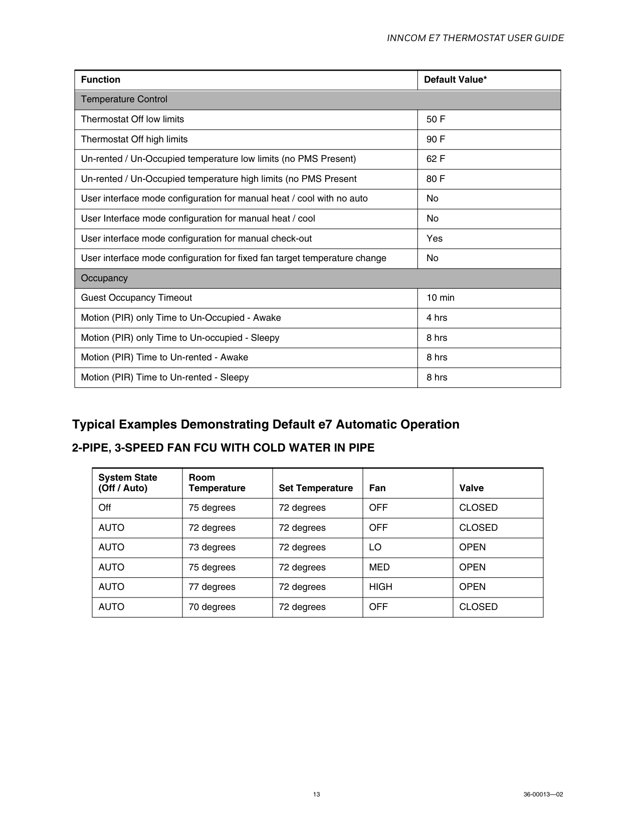
Inncom E7 Thermostat User Guide
13 36-00013—02 Typical Examples Demonstrating Default e7 Automatic Operation2-Pipe, 3-Speed Fan Fcu With Cold Water In Pipe
Temperature Control Thermostat Off low limits50 F
Thermostat Off high limits90 F
Un-rented / Un-Occupied temperature low limits (no PMS Present)62 F
Un-rented / Un-Occupied temperature high limits (no PMS Present80 F
User interface mode configuration for manual heat / cool with no auto No User Interface mode configuration for manual heat / cool No User interface mode configuration for manual check-out Yes User interface mode configuration for fixed fan target temperature change No Occupancy Guest Occupancy Timeout 10 min Motion (PIR) only Time to Un-Occupied - Awake 4 hrs Motion (PIR) only Time to Un-occupied - Sleepy 8 hrs Motion (PIR) Time to Un-rented - Awake 8 hrs Motion (PIR) Time to Un-rented - Sleepy 8 hrs System State (Off / Auto) Room Temperature Set Temperature Fan Valve Off 75 degrees 72 degreesOff
Closed
Auto
72 degrees 72 degreesOff
Closed
Auto
73 degrees 72 degreesLo
Open
Auto
75 degrees 72 degreesMed
Open
Auto
77 degrees 72 degreesHigh
Open
Auto
70 degrees 72 degreesOff
Closed
Function Default Value*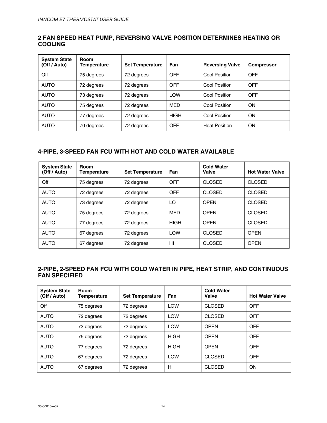
Inncom E7 Thermostat User Guide
36-00013—02 142 Fan Speed Heat Pump, Reversing Valve Position Determines Heating Or
Cooling
4-Pipe, 3-Speed Fan Fcu With Hot And Cold Water Available
2-Pipe, 2-Speed Fan Fcu With Cold Water In Pipe, Heat Strip, And Continuous
Fan Specified
System State (Off / Auto) Room Temperature Set Temperature Fan Reversing Valve Compressor Off 75 degrees 72 degreesOff
Cool PositionOff
Auto
72 degrees 72 degreesOff
Cool PositionOff
Auto
73 degrees 72 degreesLow
Cool PositionOff
Auto
75 degrees 72 degreesMed
Cool PositionOn
Auto
77 degrees 72 degreesHigh
Cool PositionOn
Auto
70 degrees 72 degreesOff
Heat PositionOn
System State (Off / Auto) Room Temperature Set Temperature Fan Cold Water Valve Hot Water Valve Off 75 degrees 72 degreesOff
Closed
Closed
Auto
72 degrees 72 degreesOff
Closed
Closed
Auto
73 degrees 72 degreesLo
Open
Closed
Auto
75 degrees 72 degreesMed
Open
Closed
Auto
77 degrees 72 degreesHigh
Open
Closed
Auto
67 degrees 72 degreesLow
Closed
Open
Auto
67 degrees 72 degreesHi
Closed
Open
System State (Off / Auto) Room Temperature Set Temperature Fan Cold Water Valve Hot Water Valve Off 75 degrees 72 degreesLow
Closed
Off
Auto
72 degrees 72 degreesLow
Closed
Off
Auto
73 degrees 72 degreesLow
Open
Off
Auto
75 degrees 72 degreesHigh
Open
Off
Auto
77 degrees 72 degreesHigh
Open
Off
Auto
67 degrees 72 degreesLow
Closed
Off
Auto
67 degrees 72 degreesHi
Closed
On
Inncom E7 Thermostat User Guide
15 36-00013—02 Initial Setup IMPORTANT: Before going through the initial setup sequences, ensure the thermostat is mounted and connected to the Smart Wall Plate. NOTE: Prior to completing Initialization Mode, or pushing the thermostat configuration from engINN, the thermostat is configured with factory defaults to disable any call for heat, cool, or low, medium and high fan speeds to protect the HVAC equipment. • When properly connected, the thermostat will proceed into INTIALIZATION MODE and display rId. • When not properly connected to the Smart Wall Plate, the unit will display the alert message SWp and the alert icon will illuminate until the Smart Wall Plate is connected.Setup Room Id
Setup Hvac Type
Inncom E7 Thermostat User Guide
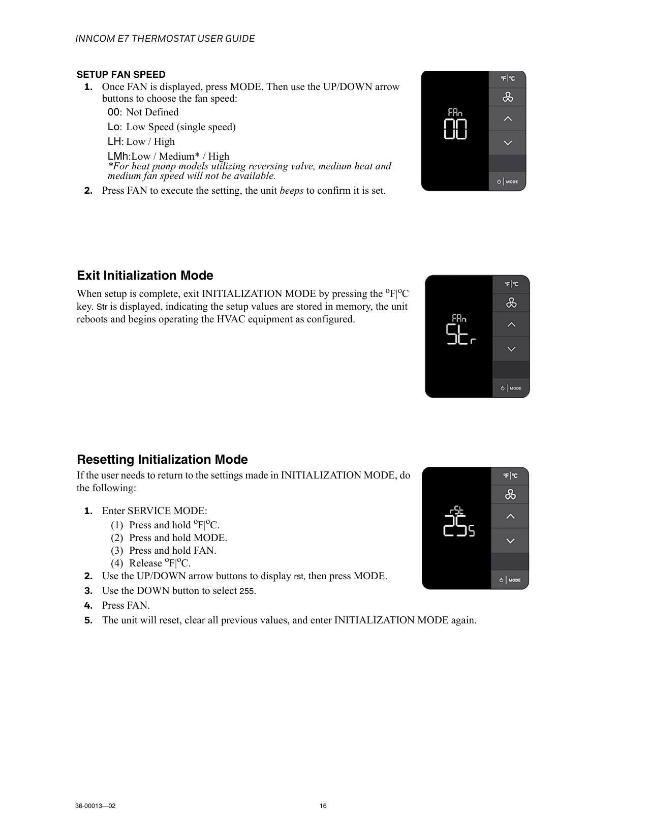
36-00013—02 16Setup Fan Speed
Inncom E7 Thermostat User Guide
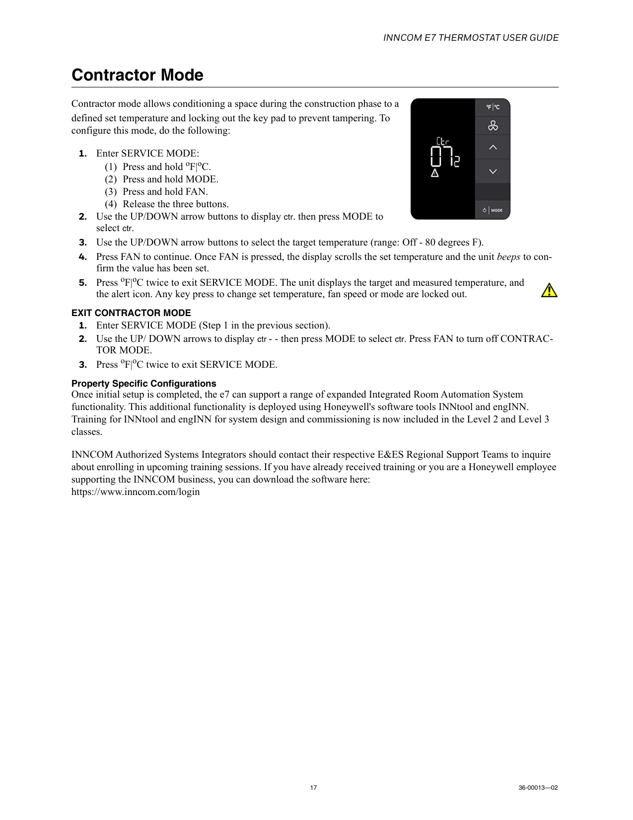
17 36-00013—02 Contractor Mode Contractor mode allows conditioning a space during the construction phase to a defined set temperature and locking out the key pad to prevent tampering. To configure this mode, do the following:Exit Contractor Mode
Tor Mode.
Inncom E7 Thermostat User Guide
36-00013—02 18 e7 Commissioning/Room Function Tests The e7 Thermostat is an energy management solution typically deployed in one of the following scenarios: Digital Thermostat with EMS - A programmable DDC thermostat designed for in-room energy management that typically requires a wired or wireless door switch monitor and a motion sensor for non-networked in-room energy management. Digital Thermostat with Centrally Controlled EMS - A programmable DDC thermostat designed for in-room energy management that typically requires a wired or wireless door switch monitor and motion sensor. The thermostat is wired or wireless networked to a server which monitors the system through the use of INNCOM's INNControl 3 Supervisor software. Digital Thermostat with Centrally Controlled EMS + Complex Applications - In addition to the above Centrally Controlled EMS application, the e7 can be augmented with a full range of guest amenities, lighting control, drapery control, Central Electronic Lock Interfaces (CELS), and other third party integrations. IMPORTANT: It is strongly recommended the following tests are conducted during commissioning the e7 to ensure proper operation and connectivity to the system is achieved.Enter Service Mode
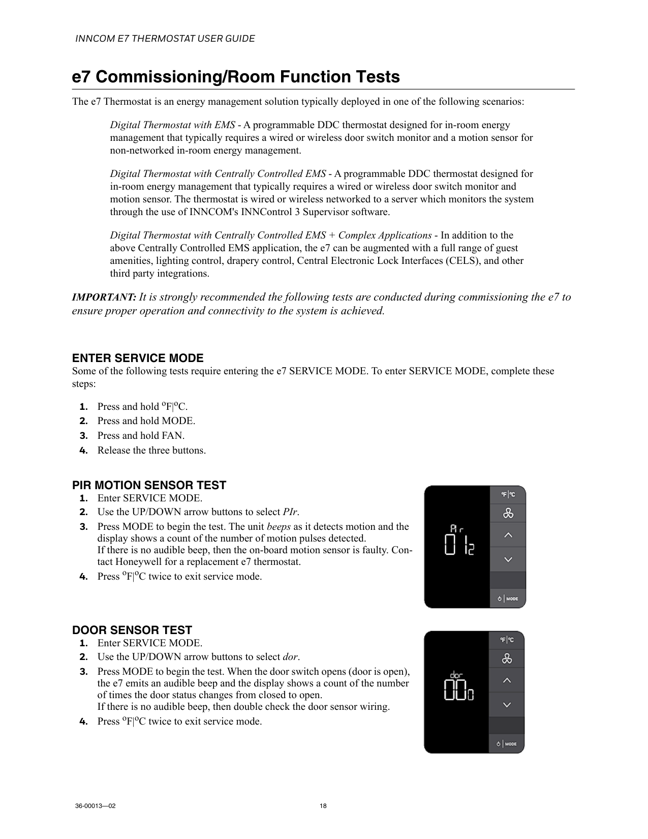
Some of the following tests require entering the e7 SERVICE MODE. To enter SERVICE MODE, complete these steps:Pir Motion Sensor Test
Door Sensor Test
Inncom E7 Thermostat User Guide
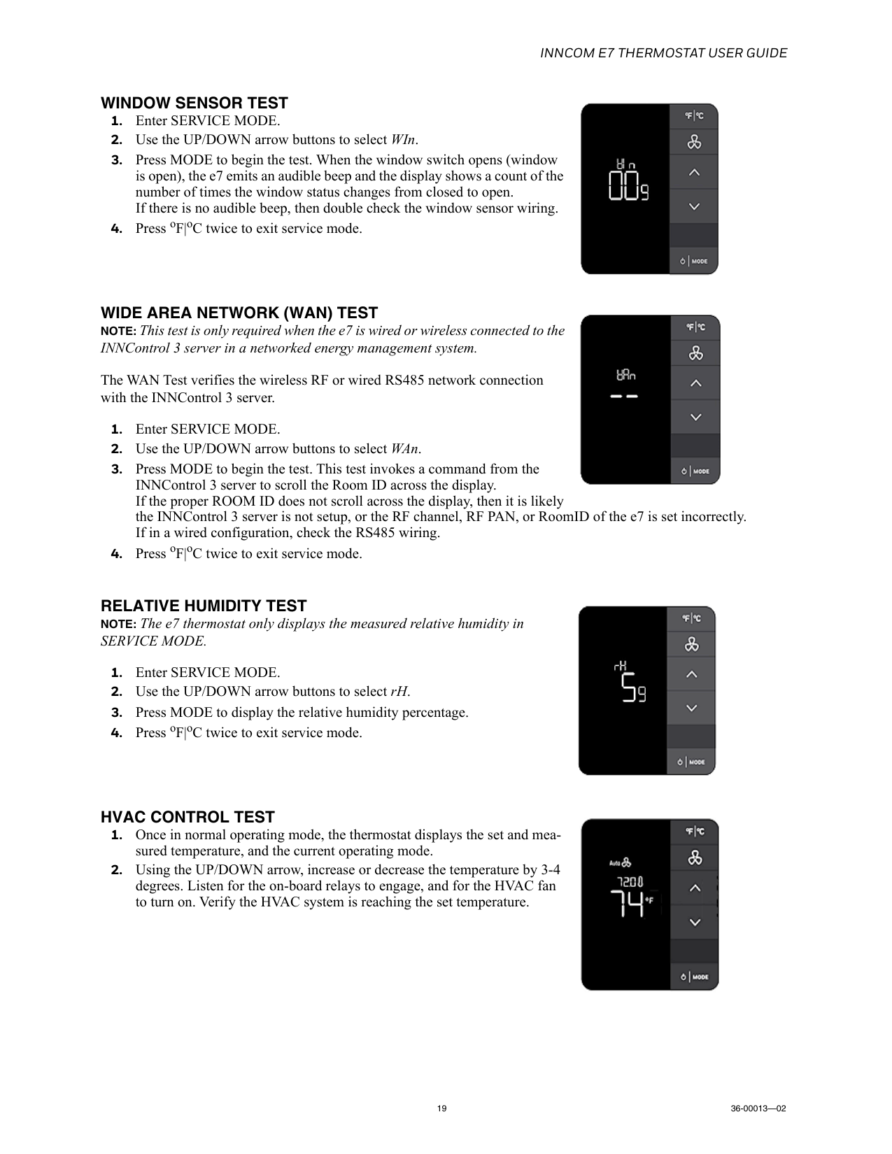
19 36-00013—02Window Sensor Test
Wide Area Network (Wan) Test
NOTE: This test is only required when the e7 is wired or wireless connected to the INNControl 3 server in a networked energy management system. The WAN Test verifies the wireless RF or wired RS485 network connection with the INNControl 3 server.Relative Humidity Test
NOTE: The e7 thermostat only displays the measured relative humidity inService Mode.
Hvac Control Test
Inncom E7 Thermostat User Guide
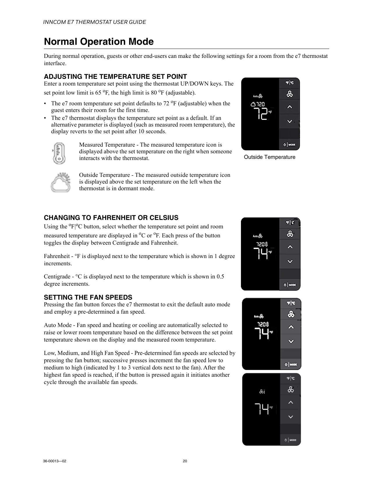
36-00013—02 20 Normal Operation Mode During normal operation, guests or other end-users can make the following settings for a room from the e7 thermostat interface.Adjusting The Temperature Set Point
Enter a room temperature set point using the thermostat UP/DOWN keys. The set point low limit is 65 oF, the high limit is 80 oF (adjustable). • The e7 room temperature set point defaults to 72 oF (adjustable) when the guest enters their room for the first time. • The e7 thermostat displays the temperature set point as a default. If an alternative parameter is displayed (such as measured room temperature), the display reverts to the set point after 10 seconds.Changing To Fahrenheit Or Celsius
Using the oF|oC button, select whether the temperature set point and room measured temperature are displayed in oC or oF. Each press of the button toggles the display between Centigrade and Fahrenheit. Fahrenheit - °F is displayed next to the temperature which is shown in 1 degree increments. Centigrade - °C is displayed next to the temperature which is shown in 0.5 degree increments.Setting The Fan Speeds
Pressing the fan button forces the e7 thermostat to exit the default auto mode and employ a pre-determined a fan speed. Auto Mode - Fan speed and heating or cooling are automatically selected to raise or lower room temperature based on the difference between the set point temperature shown on the display and the measured room temperature. Low, Medium, and High Fan Speed - Pre-determined fan speeds are selected by pressing the fan button; successive presses increment the fan speed low to medium to high (indicated by 1 to 3 vertical dots next to the fan). After the highest fan speed is reached, if the button is pressed again it initiates another cycle through the available fan speeds. Measured Temperature - The measured temperature icon is displayed above the set temperature on the right when someone interacts with the thermostat. Outside Temperature - The measured outside temperature icon is displayed above the set temperature on the left when the thermostat is in dormant mode. Outside Temperature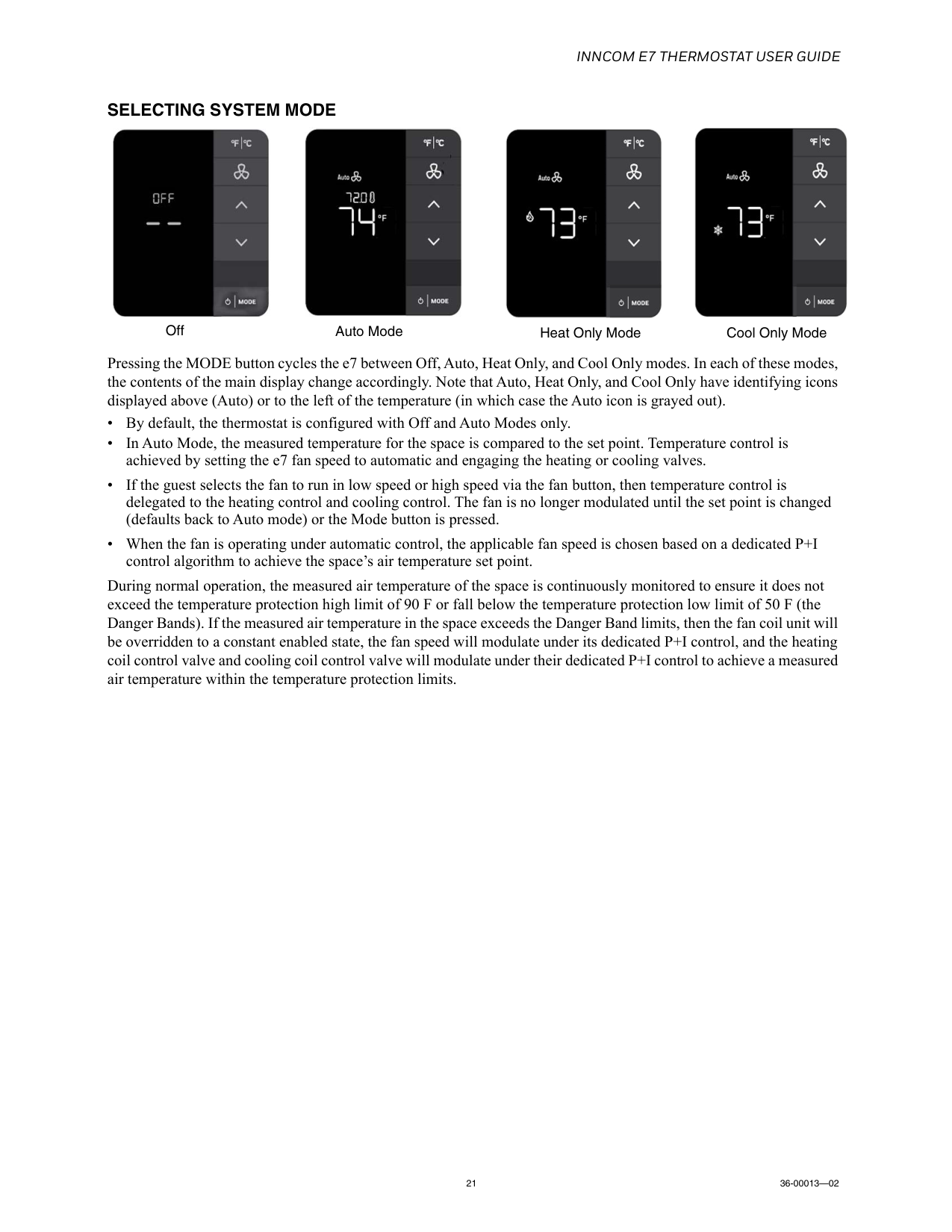
Inncom E7 Thermostat User Guide
21 36-00013—02Selecting System Mode
Pressing the MODE button cycles the e7 between Off, Auto, Heat Only, and Cool Only modes. In each of these modes, the contents of the main display change accordingly. Note that Auto, Heat Only, and Cool Only have identifying icons displayed above (Auto) or to the left of the temperature (in which case the Auto icon is grayed out). • By default, the thermostat is configured with Off and Auto Modes only. • In Auto Mode, the measured temperature for the space is compared to the set point. Temperature control is achieved by setting the e7 fan speed to automatic and engaging the heating or cooling valves. • If the guest selects the fan to run in low speed or high speed via the fan button, then temperature control is delegated to the heating control and cooling control. The fan is no longer modulated until the set point is changed (defaults back to Auto mode) or the Mode button is pressed. • When the fan is operating under automatic control, the applicable fan speed is chosen based on a dedicated P+I control algorithm to achieve the space’s air temperature set point. During normal operation, the measured air temperature of the space is continuously monitored to ensure it does not exceed the temperature protection high limit of 90 F or fall below the temperature protection low limit of 50 F (the Danger Bands). If the measured air temperature in the space exceeds the Danger Band limits, then the fan coil unit will be overridden to a constant enabled state, the fan speed will modulate under its dedicated P+I control, and the heating coil control valve and cooling coil control valve will modulate under their dedicated P+I control to achieve a measured air temperature within the temperature protection limits. Off Auto Mode Heat Only Mode Cool Only Mode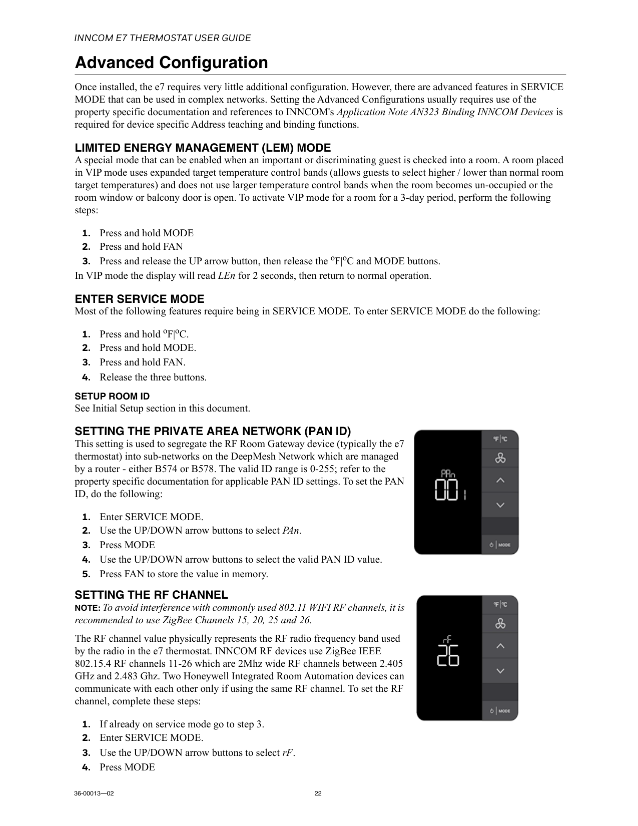
Inncom E7 Thermostat User Guide
36-00013—02 22 Advanced Configuration Once installed, the e7 requires very little additional configuration. However, there are advanced features in SERVICE MODE that can be used in complex networks. Setting the Advanced Configurations usually requires use of the property specific documentation and references to INNCOM's Application Note AN323 Binding INNCOM Devices is required for device specific Address teaching and binding functions.Limited Energy Management (Lem) Mode
A special mode that can be enabled when an important or discriminating guest is checked into a room. A room placed in VIP mode uses expanded target temperature control bands (allows guests to select higher / lower than normal room target temperatures) and does not use larger temperature control bands when the room becomes un-occupied or the room window or balcony door is open. To activate VIP mode for a room for a 3-day period, perform the following steps:Enter Service Mode
Most of the following features require being in SERVICE MODE. To enter SERVICE MODE do the following:Setup Room Id
See Initial Setup section in this document.Setting The Private Area Network (Pan Id)
This setting is used to segregate the RF Room Gateway device (typically the e7 thermostat) into sub-networks on the DeepMesh Network which are managed by a router - either B574 or B578. The valid ID range is 0-255; refer to the property specific documentation for applicable PAN ID settings. To set the PAN ID, do the following:Setting The Rf Channel
NOTE: To avoid interference with commonly used 802.11 WIFI RF channels, it is recommended to use ZigBee Channels 15, 20, 25 and 26. The RF channel value physically represents the RF radio frequency band used by the radio in the e7 thermostat. INNCOM RF devices use ZigBee IEEE 802.15.4 RF channels 11-26 which are 2Mhz wide RF channels between 2.405 GHz and 2.483 Ghz. Two Honeywell Integrated Room Automation devices can communicate with each other only if using the same RF channel. To set the RF channel, complete these steps: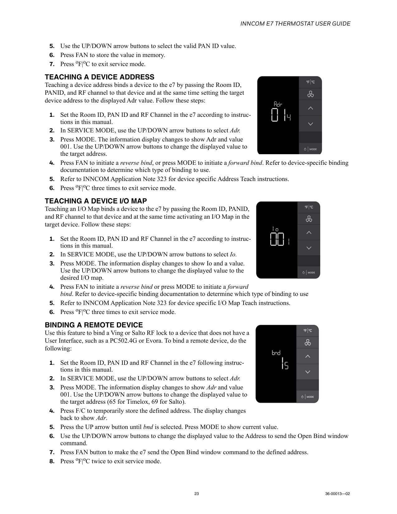
Inncom E7 Thermostat User Guide
23 36-00013—02Teaching A Device Address
Teaching a device address binds a device to the e7 by passing the Room ID, PANID, and RF channel to that device and at the same time setting the target device address to the displayed Adr value. Follow these steps:Teaching A Device I/O Map
Teaching an I/O Map binds a device to the e7 by passing the Room ID, PANID, and RF channel to that device and at the same time activating an I/O Map in the target device. Follow these steps:Binding A Remote Device
Use this feature to bind a Ving or Salto RF lock to a device that does not have a User Interface, such as a PC502.4G or Evora. To bind a remote device, do the following: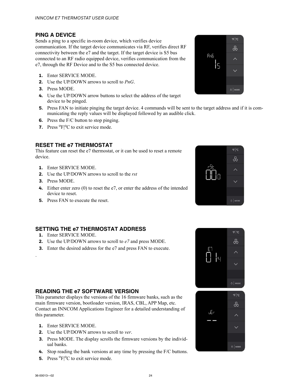
Inncom E7 Thermostat User Guide
36-00013—02 24Ping A Device
Sends a ping to a specific in-room device, which verifies device communication. If the target device communicates via RF, verifies direct RF connectivity between the e7 and the target. If the target device is S5 bus connected to an RF radio equipped device, verifies communication from the e7, through the RF Device and to the S5 bus connected device.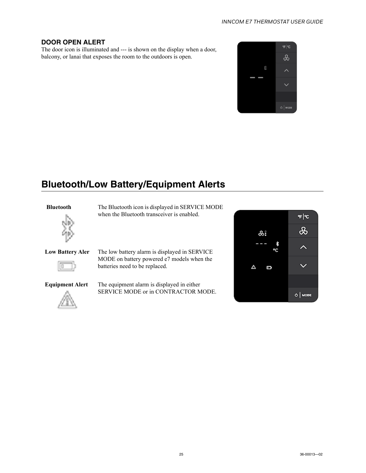
Inncom E7 Thermostat User Guide
25 36-00013—02Door Open Alert
The door icon is illuminated and --- is shown on the display when a door, balcony, or lanai that exposes the room to the outdoors is open. Bluetooth/Low Battery/Equipment Alerts Bluetooth The Bluetooth icon is displayed in SERVICE MODE when the Bluetooth transceiver is enabled.Low Battery Aler The low battery alarm is displayed in SERVICE MODE on battery powered e7 models when the batteries need to be replaced. Equipment Alert The equipment alarm is displayed in either SERVICE MODE or in CONTRACTOR MODE.