Ask AI
— answers from the official manualAnswers from the official manual.
Common questions
Common Questions
9 totalWhat is the difference between the VisionPRO and Prestige thermostat options?
The Prestige thermostat features an intuitive touchscreen interface with optional delta T fault detection for discharge and return air sensors, providing more advanced diagnostics. The VisionPRO is also a very good option with similar capabilities. Both work with the Equipment Interface Module (EIM) and can accept economizer fault detection inputs to meet code requirements. The Prestige offers a color screen for enhanced user experience.
How do I set up the Honeywell thermostat with an economizer?
For the Prestige thermostat, go to settings and set ISU 2220: A/L-A Terminal Setup to Economizer. For the VisionPRO thermostat, set ISU 222 to Economizer. Both thermostats work with the Equipment Interface Module (EIM) to control the W7220 Jade economizer controller and coordinate damper positioning for energy savings.
What are the basic installation steps for an RTU retrofit with this thermostat?
The installation workflow includes: (1) Replace the thermostat with VisionPRO or Prestige and install the EIM in a protected location, (2) Install a CO2 sensor in the space or return air duct, (3) Replace the economizer with a W7220 Jade controller, (4) Replace economizer sensors with new communicating sensors, (5) Replace the damper actuator with a Sylk actuator, (6) Install the VFD in a convenient RTU location, and (7) Install four relays for fan control.
How do I program the VFD for two-speed fan operation?
For the SmartVFD HVAC (HVFDSDxxxxxx), set the low speed fan at parameter P1.8 or P3.3.1 during setup, and configure high speed at P3.3.12. For Compact or HVAC2 models, set low speed at P3.1 and high speed at P3.5. When the thermostat calls for ventilation or first stage cooling, the fan runs at minimum frequency (lower speed), and for heating or second stage cooling, it runs at preset frequency 1 (higher speed).
What is Demand Control Ventilation (DCV) and how does it work with the thermostat?
Demand Control Ventilation uses CO2 sensors to measure occupancy levels and automatically adjust ventilation rates accordingly. The CO2 sensor is wired to the Jade W7220 economizer, which modulates the outdoor air damper to maintain the space below a set CO2 ppm level (default 1100 ppm). This allows buildings to reduce ventilation during partial occupancy periods, saving significant energy while meeting ASHRAE 62.1 code requirements.
How do I configure VENTMIN and VENTMAX settings in the Jade economizer for a two-speed fan?
In the Setpoints menu of the Jade economizer, set DCV to the required ppm (default 1100 ppm), then configure VENTMIN and VENTMAX with separate settings for low speed (VENTMIN L, VENTMAX L) and high speed (VENTMIN H, VENTMAX H) fans. The best method is to measure actual outdoor airflow and adjust damper positions until you achieve the correct minimum and maximum cfm, then enter the corresponding damper position voltages (2-10 Vdc) into the economizer.
Full Manual
24 pages
Application Guide
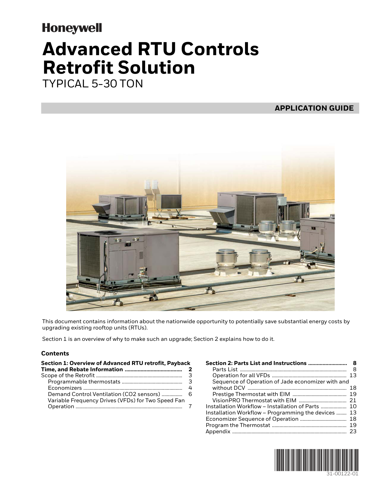
31-00122-01 Advanced RTU Controls Retrofit SolutionTypical 5-30 Ton
This document contains information about the nationwide opportunity to potentially save substantial energy costs by upgrading existing rooftop units (RTUs). Section 1 is an overview of why to make such an upgrade; Section 2 explains how to do it. Contents Section 1: Overview of Advanced RTU retrofit, Payback Time, and Rebate Information ........................................ 2 Scope of the Retrofit ................................................................... 3 Programmable thermostats ............................................... 3 Economizers ............................................................................. 4 Demand Control Ventilation (CO2 sensors) ................ 6 Variable Frequency Drives (VFDs) for Two Speed Fan Operation ................................................................................... 7 Section 2: Parts List and Instructions ........................... 8 Parts List ................................................................................... 8 Operation for all VFDs .......................................................... 13 Sequence of Operation of Jade economizer with and without DCV ............................................................................. 18 Prestige Thermostat with EIM .......................................... 19 VisionPRO Thermostat with EIM ..................................... 21 Installation Workflow – Installation of Parts .................... 10 Installation Workflow – Programming the devices ........ 13 Economizer Sequence of Operation .................................... 18 Program the Thermostat .......................................................... 19 Appendix ......................................................................................... 23
Advanced Rtu Controls Retrofit Solution
31-00122—01 2Section 1: Overview Of Advanced Rtu Retrofit,
Payback Time, And Rebate Information
An overview of the potential substantial and immediate cost and energy savings for the building owner, including some payback time estimates and rebate information. What is the Opportunity? Rooftop units (RTUs) are used extensively in smaller one- and two-story commercial and institutional buildings such as schools, restaurants, motels, retail stores, and small office buildings all across the country. Rooftop Units serve over 60% of the commercial floor space in North America. There are an estimated 12 million RTUs currently installed and running on commercial buildings in 2016a. The average age of these units is 10-14 yearsb, and due to lack of appropriate service, many suffer from operational problems including sensors that are out of calibration, refrigeration circuits improperly under and overcharged for a variety of reasons, economizer ventilation cycles that have ceased to function properly, and air flow systems improperly sized delivering substandard air flow. RTUs that are less than 15 years old, five tons or more, and have been well maintained, with a life-expectancy of at least 5 more years, are often good candidates for controls retrofits. With controls upgrades and RTU maintenance, building owners might achieve significant energy savings. Individual energy savings and payback results may vary depending on various factors, such as geographic location, choice and cost of equipment installed, cost of energy, existing age and condition of equipment, and as further described in the applicable estimator tools. In addition, it is the responsibility of the servicing mechanical contractor to make the final evaluation for retrofitting existing RTUs for the energy savings opportunities described in this document. 4 Things that Can Substantially Increase RTU Efficiency After any required basic maintenance on an RTU (duct sealing, replacing broken or worn belts, etc), there are a number of improvements that can be made to substantially increase RTU efficiency. These include:What Is The Cost For An Rtu Energy Controls Retrofit?
The parts cost for controls replacement and additions can be $500-2000 per RTU depending on the size of the unit and the changes implemented. This cost includes sensors, an economizer, a damper actuator, a VFD, a thermostat, and other needed parts. Rebates often exist which can help defray or sometimes completely pay for hardware depending on your utility company or state run program.What Is The Payback Time?
This depends on what controls are installed and the size of the RTU (the larger the RTU, the quicker should be the payback). Often, payback will occur anywhere from 6 months to two yearsc, depending on which controls are installed and what rebates are available. Substantial energy savings are possible, and there are case studies which support significant savings with a number of different approaches to RTU controls retrofits, involving installation of new economizers, VFDs, and CO2 sensors may result in such savings. For a few examples, see http://www.advancedrtu.org/case-studies--guidance.htmlWhat Are The Rebates?
There are many rebates offered in cities, states, and provinces across the USA and Canada. Some rebates are tied to specific parts installation (economizer, VFDs, thermostat), and others are tied to an entire retrofit solution. a EIA2003 b http://mn.gov/commerce-stat/pdfs/card-seventhwave-rtu.pdf http://wcec.ucdavis.edu/wp-content/uploads/2013/12/MTLC-Preliminary-Report.pdf c Economizer Savings Estimator Tool: https://customer.honeywell.com/en-US/support/commercial/se/Pages/default.aspx VFD Savings Estimator Tool: https://customer.honeywell.com/en-US/support/commercial/se/Pages/default.aspx
Advanced Rtu Controls Retrofit Solution
3 31-00122—01 A good resource for finding local rebates in the US is dsireusa.org. Within minutes, you can identify your state rebates and download the forms necessary to apply for them.Where Does The Energy Savings Come From In A Control Retrofit?
Compressors and fans consume most of the electrical energy in an RTU. And the supply fan by itself can often be half or more of the total annual operating cost of an RTU due to the amount of energy used by a typical supply fan. By reducing the equipment run times, optimizing economization, and slowing down the fan speed, significant energy (and energy dollars) can be saved while still maintaining comfort in the space. In addition, you will be helping to reduce the energy consumption of buildings and thus reducing the environmental impact of commercial buildings which consume roughly 18% of the total energy usage in North America, with HVAC accounting for roughly 39% of commercial building energy usage (U.S. Department of Energy (DOE), 2008 Buildings Energy Data Book). A single school district or commercial complex with hundreds of RTU units can yield considerable and immediate energy and cost savings with a properly performed RTU retrofit. For owners that can’t afford an RTU replacement, a controls retrofit should provide an immediate savings on energy bills and potentially delay the cost of a new RTU for 5 or more years (results will vary). The energy cost savings can help fund a new RTU unit at a later date.Good Candidates For Retrofit?
Some RTUs are better candidates than others for an advanced RTU retrofit. Retrofits of RTUs with single speed fans which have existing Honeywell economizer controls mounted are normally good candidates. Other RTUs with non-Honeywell economizers may also be valid candidates, but in those cases, you should check for proprietary communication protocols which may make a retrofit more challenging.Scope Of The Retrofit
Programmable thermostats It is already well known that significant energy savings are possible by setting back the setpoint and shutting off the fan during unoccupied periods. RTUs operating on small to mid-size commercial buildings are often controlled by simple thermostats. By replacing a non-programmable thermostat with a programmable thermostat, and by setting setbacks of at least 5-8 degrees (both heating and cooling) during unoccupied periods, energy savings of up to 15% are possiblea, depending on the amount of weekly unoccupied time, climate zone, and cost of electricity and gas in the area. Shutting down a fan during the unoccupied period (a significant and normally unneeded cost) can raise this energy savings to over 30%b.Savings
Honeywell provides for free an Economizer Savings Estimator tool that uses the latest ASHRAE standards and takes into account local climate conditions, and will provide information on estimated savings for any combination of the following:Rebates
Rebates exist for replacing non-programmable with programmable thermostats. Check your utility or state for available local rebates on programmable thermostats. a See the Economizer Savings Estimator tool: https://customer.honeywell.com/en-US/support/commercial/se/Pages/default.aspx b See the Economizer Savings Estimator tool: https://customer.honeywell.com/en-US/support/commercial/se/Pages/default.aspx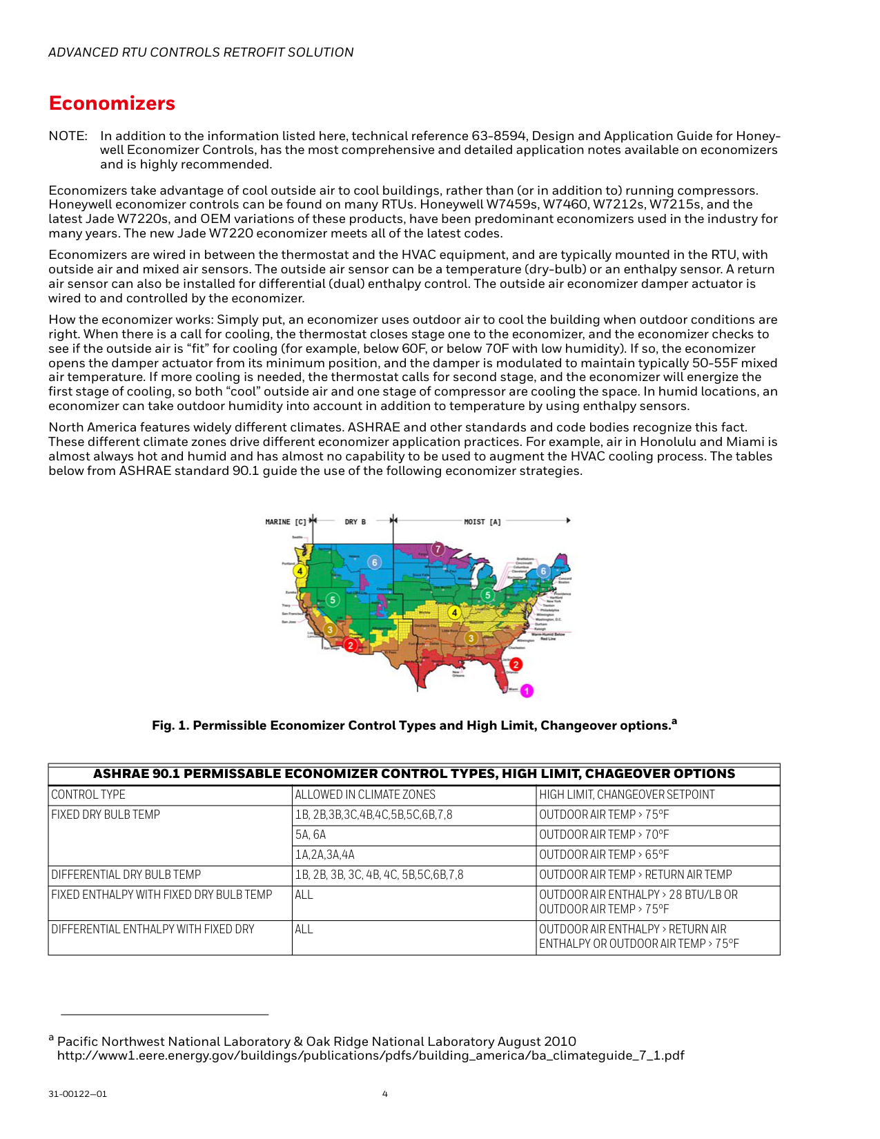
Advanced Rtu Controls Retrofit Solution
31-00122—01 4 EconomizersNote:
In addition to the information listed here, technical reference 63-8594, Design and Application Guide for Honey- well Economizer Controls, has the most comprehensive and detailed application notes available on economizers and is highly recommended. Economizers take advantage of cool outside air to cool buildings, rather than (or in addition to) running compressors. Honeywell economizer controls can be found on many RTUs. Honeywell W7459s, W7460, W7212s, W7215s, and the latest Jade W7220s, and OEM variations of these products, have been predominant economizers used in the industry for many years. The new Jade W7220 economizer meets all of the latest codes. Economizers are wired in between the thermostat and the HVAC equipment, and are typically mounted in the RTU, with outside air and mixed air sensors. The outside air sensor can be a temperature (dry-bulb) or an enthalpy sensor. A return air sensor can also be installed for differential (dual) enthalpy control. The outside air economizer damper actuator is wired to and controlled by the economizer. How the economizer works: Simply put, an economizer uses outdoor air to cool the building when outdoor conditions are right. When there is a call for cooling, the thermostat closes stage one to the economizer, and the economizer checks to see if the outside air is “fit” for cooling (for example, below 60F, or below 70F with low humidity). If so, the economizer opens the damper actuator from its minimum position, and the damper is modulated to maintain typically 50-55F mixed air temperature. If more cooling is needed, the thermostat calls for second stage, and the economizer will energize the first stage of cooling, so both “cool” outside air and one stage of compressor are cooling the space. In humid locations, an economizer can take outdoor humidity into account in addition to temperature by using enthalpy sensors. North America features widely different climates. ASHRAE and other standards and code bodies recognize this fact. These different climate zones drive different economizer application practices. For example, air in Honolulu and Miami is almost always hot and humid and has almost no capability to be used to augment the HVAC cooling process. The tables below from ASHRAE standard 90.1 guide the use of the following economizer strategies. Fig. 1. Permissible Economizer Control Types and High Limit, Changeover options.a a Pacific Northwest National Laboratory & Oak Ridge National Laboratory August 2010 http://www1.eere.energy.gov/buildings/publications/pdfs/building_america/ba_climateguide_7_1.pdfAshrae 90.1 Permissable Economizer Control Types, High Limit, Chageover Options
Control Type
Allowed In Climate Zones
High Limit, Changeover Setpoint
Fixed Dry Bulb Temp
1B, 2B,3B,3C,4B,4C,5B,5C,6B,7,8
Outdoor Air Temp > 75°F
5A, 6A
Outdoor Air Temp > 70°F
1A,2A,3A,4A
Outdoor Air Temp > 65°F
Differential Dry Bulb Temp
1B, 2B, 3B, 3C, 4B, 4C, 5B,5C,6B,7,8
Outdoor Air Temp > Return Air Temp
Fixed Enthalpy With Fixed Dry Bulb Temp
All
Outdoor Air Enthalpy > 28 Btu/Lb Or
Outdoor Air Temp > 75°F
Differential Enthalpy With Fixed Dry
All
Outdoor Air Enthalpy > Return Air
Enthalpy Or Outdoor Air Temp > 75°F

Advanced Rtu Controls Retrofit Solution
5 31-00122—01 Strategy: Differential Enthalpy with Fixed Dry Bulb Temperature Limit This technique can be used in all climate zones and offers good energy savings.a How does it work? If there is a call for cooling and outdoor air enthalpy is less than return air enthalpy and the outdoor air temperature is below high limit (see Fig. 1 above), outdoor air will be used to attempt to cool your customer’s building. Strategy: Fixed Enthalpy with fixed dry bulb temperature This technique can be used in all climate zones. HVAC professionals like this method as it’s relatively simple to deploy and only requires one enthalpy sensor. How does it work? If there is a call for cooling and the outdoor air enthalpy is less than the outdoor air enthalpy set point (changeover setpoint) and the outdoor air temperature is below high limit (see Fig. 1 above), outdoor air will be used to attempt to cool your customer’s building. Strategy: Differential (Dry bulb) Temperature This technique is suggested to be used in zones 1B, 2B, 3B, 3C, 4B, 4C, 5A, 5B, 5C, 6A, 6B, 7, and 8 as shown on the map. This method is restricted to the fewest number of zones. How does it work? If there is a call for cooling and outdoor air temperature is less than the return air temperature, outdoor air will be used to attempt to cool your customer’s building. Strategy: Fixed Dry bulb Temperature This technique is suggested to be used in zones 1A, 2A, 3A, 4A, 5A, 6A, 1B, 2B, 3B, 3C, 4B, 4C, 5B, 5C, 6B, 7, and 8. See map. This method is probably the simplest strategy to deploy and understand. This technique was widely used before humidity sensing technology became cost effective. Because the temperature setting must be set conservatively to avoid economizing with humid air, it will not save as much energy as the single or dual enthalpy strategies in humid zones. How does it work? If there is a call for cooling and outdoor air temperature is below the high limit changeover set point (see Fig. 1 above), outdoor air will be used to attempt to cool your customer’s building.Rebates
Economizer rebates are available from $5 to $50/ton. Check with your local utilities and state programs for available rebates.Savings
Honeywell provides for free an Economizer Savings Estimator tool that uses the latest ASHRAE standards and takes into account local climate conditions, and will provide estimated savings information for any combination of the following:
Advanced Rtu Controls Retrofit Solution
31-00122—01 6 Demand Control Ventilation (CO2 sensors) What is the Opportunity? Many buildings are still ventilated at ventilation rates assuming maximum occupancy. But almost all buildings never maintain maximum occupancy during all occupied times. In fact, many buildings maintain occupancy at just a small fraction of maximum occupancy for long periods of occupied time. This means that we can be spending huge amounts of energy to condition large amounts of outside air that is not needed. So can we reduce the ventilation rate during partial occupancy periods? Yes, and this is supported and promoted by ASHRAE 62.1. A typical payback depends on the type of building and other factors. What Do Codes Say? ASHRAE standard 62.1 (adopted by IECC and IMC codes, which are in turn adopted in many state and local codes) calls for certain ventilation rates based on:— Plus —
Rebates
Rebates do exist for CO2 installation. Check your local, state, and utility programs.Savings
Honeywell provides access to some really helpful free tools that allow you to understand how an economizer works, and how much energy savings are possible using programmable thermostats, economizers, and CO2 sensors for demand control ventilation. A free tool is provided by Honeywell to estimate these savings, and is based on the latest ASHRAE and CEC Title 24 guidelines. Free On-line Energy Savings Estimator: https://customer.honeywell.com/en-US/support/commercial/se/ese/Pages/default.aspx This tool allows you to include Demand Controlled Ventilation DCV (or not) in your economizer savings estimation. Results will vary based on design maximum occupancy (people/1000 ft2) and how much the levels of occupancy drop below the maximum design during the day. The tool allows you to enter actual occupancy as a percent of maximum design occupancy for each hour of the weekday and weekend. For some types of buildings, where actual occupancy can drop well below the design maximum occupancy for long periods of time, savings may be great and payback quick. Depending on the climate zone, type of building, occupancy levels, etc, payback for economizers or economizers with DCV (CO2 sensors) can typically provide payback within one or two yearsa. We encourage you to use the Energy Savings Estimator software to enter your own specific conditions and calculate your own savings estimate. a See the Economizer Savings Estimator tool: https://customer.honeywell.com/en-US/support/commercial/se/Pages/default.aspx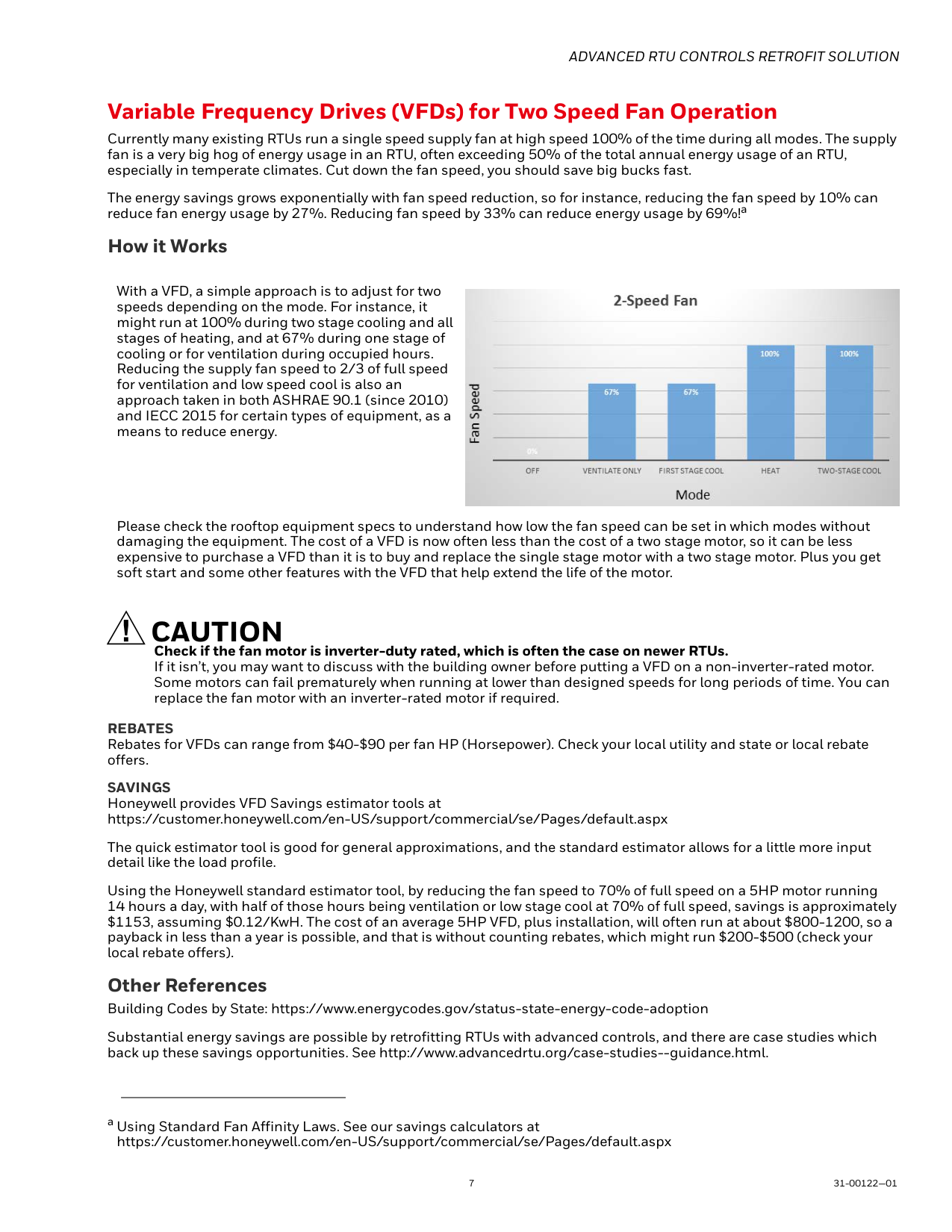
Advanced Rtu Controls Retrofit Solution
7 31-00122—01 Variable Frequency Drives (VFDs) for Two Speed Fan Operation Currently many existing RTUs run a single speed supply fan at high speed 100% of the time during all modes. The supply fan is a very big hog of energy usage in an RTU, often exceeding 50% of the total annual energy usage of an RTU, especially in temperate climates. Cut down the fan speed, you should save big bucks fast. The energy savings grows exponentially with fan speed reduction, so for instance, reducing the fan speed by 10% can reduce fan energy usage by 27%. Reducing fan speed by 33% can reduce energy usage by 69%!a How it WorksCaution
Check if the fan motor is inverter-duty rated, which is often the case on newer RTUs. If it isn’t, you may want to discuss with the building owner before putting a VFD on a non-inverter-rated motor. Some motors can fail prematurely when running at lower than designed speeds for long periods of time. You can replace the fan motor with an inverter-rated motor if required.Rebates
Rebates for VFDs can range from $40-$90 per fan HP (Horsepower). Check your local utility and state or local rebate offers.Savings
Honeywell provides VFD Savings estimator tools at https://customer.honeywell.com/en-US/support/commercial/se/Pages/default.aspx The quick estimator tool is good for general approximations, and the standard estimator allows for a little more input detail like the load profile. Using the Honeywell standard estimator tool, by reducing the fan speed to 70% of full speed on a 5HP motor running 14 hours a day, with half of those hours being ventilation or low stage cool at 70% of full speed, savings is approximately $1153, assuming $0.12/KwH. The cost of an average 5HP VFD, plus installation, will often run at about $800-1200, so a payback in less than a year is possible, and that is without counting rebates, which might run $200-$500 (check your local rebate offers). Other References Building Codes by State: https://www.energycodes.gov/status-state-energy-code-adoption Substantial energy savings are possible by retrofitting RTUs with advanced controls, and there are case studies which back up these savings opportunities. See http://www.advancedrtu.org/case-studies--guidance.html. a Using Standard Fan Affinity Laws. See our savings calculators at https://customer.honeywell.com/en-US/support/commercial/se/Pages/default.aspx With a VFD, a simple approach is to adjust for two speeds depending on the mode. For instance, it might run at 100% during two stage cooling and all stages of heating, and at 67% during one stage of cooling or for ventilation during occupied hours. Reducing the supply fan speed to 2/3 of full speed for ventilation and low speed cool is also an approach taken in both ASHRAE 90.1 (since 2010) and IECC 2015 for certain types of equipment, as a means to reduce energy. Please check the rooftop equipment specs to understand how low the fan speed can be set in which modes without damaging the equipment. The cost of a VFD is now often less than the cost of a two stage motor, so it can be less expensive to purchase a VFD than it is to buy and replace the single stage motor with a two stage motor. Plus you get soft start and some other features with the VFD that help extend the life of the motor.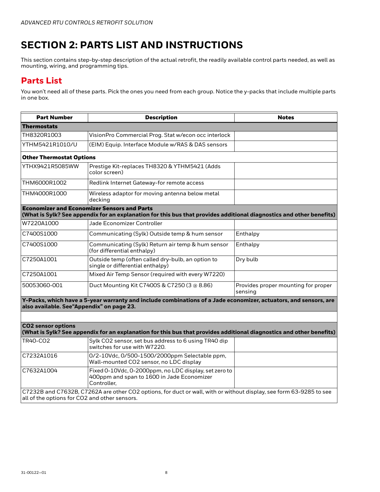
Advanced Rtu Controls Retrofit Solution
31-00122—01 8Section 2: Parts List And Instructions
This section contains step-by-step description of the actual retrofit, the readily available control parts needed, as well as mounting, wiring, and programming tips. Parts List You won’t need all of these parts. Pick the ones you need from each group. Notice the y-packs that include multiple parts in one box. Part Number Description Notes ThermostatsTh8320R1003
VisionPro Commercial Prog. Stat w/econ occ interlockYthm5421R1010/U
(EIM) Equip. Interface Module w/RAS & DAS sensors Other Thermostat OptionsYthx9421R5085Ww
Prestige Kit-replaces TH8320 & YTHM5421 (Adds color screen)Thm6000R1002
Redlink Internet Gateway-for remote accessThm4000R1000
Wireless adaptor for moving antenna below metal decking Economizer and Economizer Sensors and Parts (What is Sylk? See appendix for an explanation for this bus that provides additional diagnostics and other benefits)W7220A1000
Jade Economizer ControllerC7400S1000
Communicating (Sylk) Outside temp & hum sensor EnthalpyC7400S1000
Communicating (Sylk) Return air temp & hum sensor (for differential enthalpy) EnthalpyC7250A1001
Outside temp (often called dry-bulb, an option to single or differential enthalpy) Dry bulbC7250A1001
Mixed Air Temp Sensor (required with every W7220) 50053060-001 Duct Mounting Kit C7400S & C7250 (3 @ 8.86) Provides proper mounting for proper sensing Y-Packs, which have a 5-year warranty and include combinations of a Jade economizer, actuators, and sensors, are also available. See“Appendix” on page 23. CO2 sensor options (What is Sylk? See appendix for an explanation for this bus that provides additional diagnostics and other benefits)Tr40-Co2
Sylk CO2 sensor, set bus address to 6 using TR40 dip switches for use with W7220.C7232A1016
0/2-10Vdc, 0/500-1500/2000ppm Selectable ppm, Wall-mounted CO2 sensor, no LDC displayC7632A1004
Fixed 0-10Vdc, 0-2000ppm, no LDC display, set zero to 400ppm and span to 1600 in Jade Economizer Controller, C7232B and C7632B, C7262A are other CO2 options, for duct or wall, with or without display, see form 63-9285 to see all of the options for CO2 and other sensors.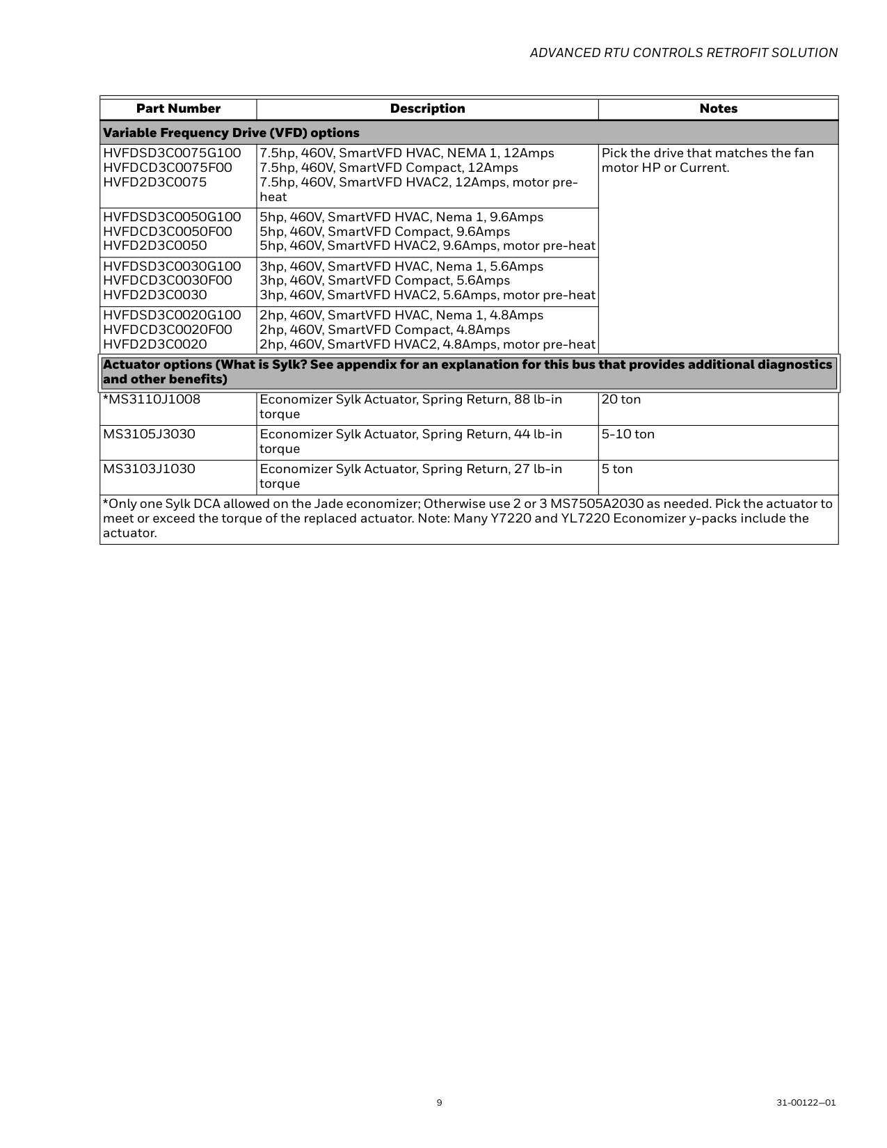
Advanced Rtu Controls Retrofit Solution
9 31-00122—01 Variable Frequency Drive (VFD) optionsHvfdsd3C0075G100
Hvfdcd3C0075F00
Hvfd2D3C0075
7.5hp, 460V, SmartVFD HVAC, NEMA 1, 12Amps 7.5hp, 460V, SmartVFD Compact, 12Amps 7.5hp, 460V, SmartVFD HVAC2, 12Amps, motor pre- heat Pick the drive that matches the fan motor HP or Current.Hvfdsd3C0050G100
Hvfdcd3C0050F00
Hvfd2D3C0050
5hp, 460V, SmartVFD HVAC, Nema 1, 9.6Amps 5hp, 460V, SmartVFD Compact, 9.6Amps 5hp, 460V, SmartVFD HVAC2, 9.6Amps, motor pre-heatHvfdsd3C0030G100
Hvfdcd3C0030F00
Hvfd2D3C0030
3hp, 460V, SmartVFD HVAC, Nema 1, 5.6Amps 3hp, 460V, SmartVFD Compact, 5.6Amps 3hp, 460V, SmartVFD HVAC2, 5.6Amps, motor pre-heatHvfdsd3C0020G100
Hvfdcd3C0020F00
Hvfd2D3C0020
2hp, 460V, SmartVFD HVAC, Nema 1, 4.8Amps 2hp, 460V, SmartVFD Compact, 4.8Amps 2hp, 460V, SmartVFD HVAC2, 4.8Amps, motor pre-heat Actuator options (What is Sylk? See appendix for an explanation for this bus that provides additional diagnostics and other benefits)*Ms3110J1008
Economizer Sylk Actuator, Spring Return, 88 lb-in torque 20 tonMs3105J3030
Economizer Sylk Actuator, Spring Return, 44 lb-in torque 5-10 tonMs3103J1030
Economizer Sylk Actuator, Spring Return, 27 lb-in torque 5 ton *Only one Sylk DCA allowed on the Jade economizer; Otherwise use 2 or 3 MS7505A2030 as needed. Pick the actuator to meet or exceed the torque of the replaced actuator. Note: Many Y7220 and YL7220 Economizer y-packs include the actuator. Part Number Description Notes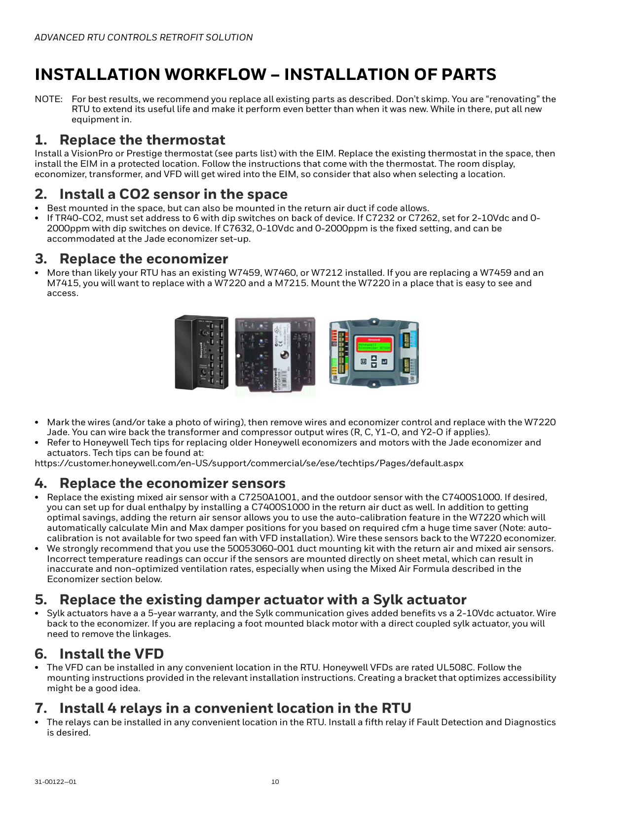
Advanced Rtu Controls Retrofit Solution
31-00122—01 10Installation Workflow – Installation Of Parts
Note:
For best results, we recommend you replace all existing parts as described. Don’t skimp. You are “renovating” the RTU to extend its useful life and make it perform even better than when it was new. While in there, put all new equipment in.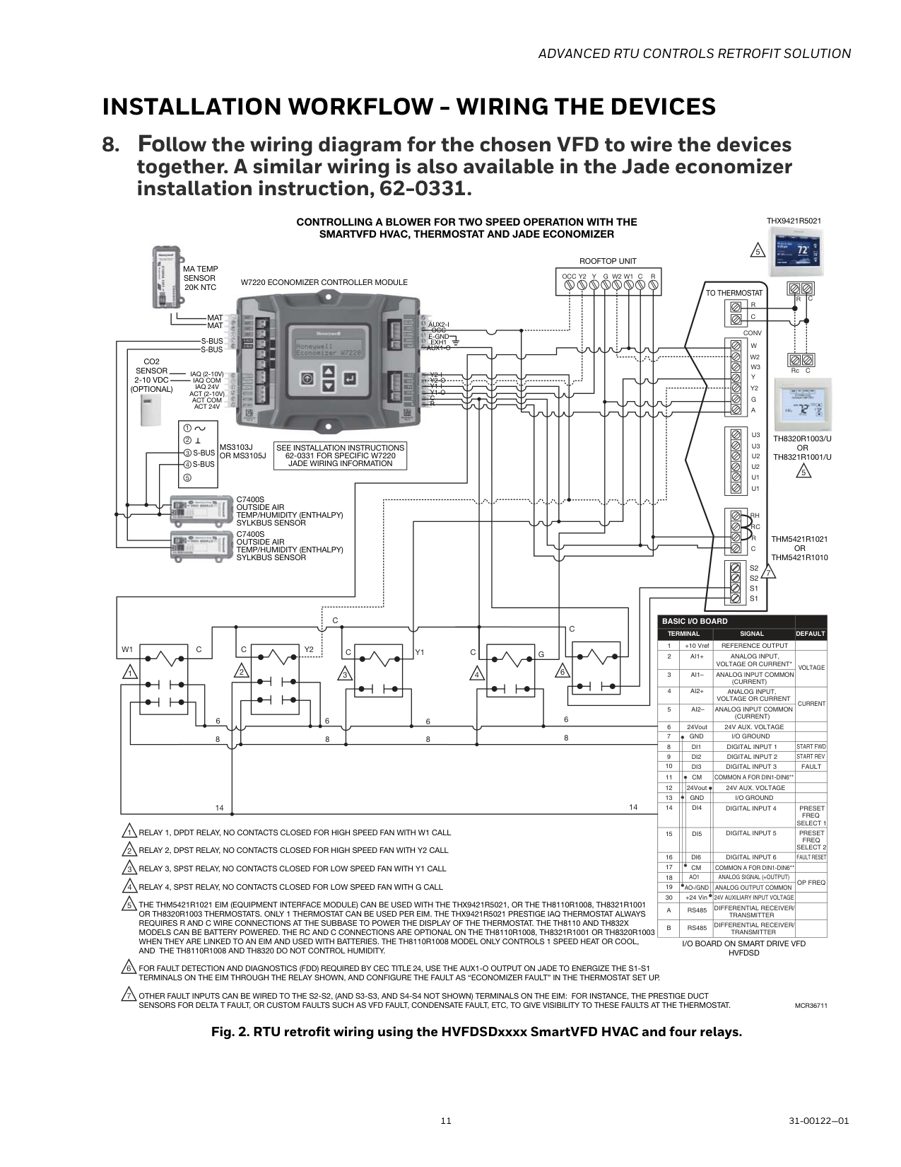
Advanced Rtu Controls Retrofit Solution
11 31-00122—01Installation Workflow - Wiring The Devices
G
C
Y2
Y1
W1
C
C
C
C
6 6 8 6 8 14 8 6 8Y
W1
G W2
C
R
R
C
Conv
W
W2
W3
Y
Y2
G
A
U3
U3
U2
U2
U1
U1
Rh
Rc
R
C
C
R
Y2
Occ
C
RcMcr36711
Controlling A Blower For Two Speed Operation With The
Smartvfd Hvac, Thermostat And Jade Economizer
5 5 1 2 3 4Relay 1, Dpdt Relay, No Contacts Closed For High Speed Fan With W1 Call
Relay 2, Dpst Relay, No Contacts Closed For High Speed Fan With Y2 Call
Relay 3, Spst Relay, No Contacts Closed For Low Speed Fan With Y1 Call
Relay 4, Spst Relay, No Contacts Closed For Low Speed Fan With G Call
THE THM5421R1021 EIM (EQUIPMENT INTERFACE MODULE) CAN BE USED WITH THE THX9421R5021, OR THE TH8110R1008, TH8321R1001 OR TH8320R1003 THERMOSTATS. ONLY 1 THERMOSTAT CAN BE USED PER EIM. THE THX9421R5021 PRESTIGE IAQ THERMOSTAT ALWAYS REQUIRES R AND C WIRE CONNECTIONS AT THE SUBBASE TO POWER THE DISPLAY OF THE THERMOSTAT. THE TH8110 AND TH832X MODELS CAN BE BATTERY POWERED. THE RC AND C CONNECTIONS ARE OPTIONAL ON THE TH8110R1008, TH8321R1001 OR TH8320R1003 WHEN THEY ARE LINKED TO AN EIM AND USED WITH BATTERIES. THE TH8110R1008 MODEL ONLY CONTROLS 1 SPEED HEAT OR COOL,And The Th8110R1008 And Th8320 Do Not Control Humidity.
FOR FAULT DETECTION AND DIAGNOSTICS (FDD) REQUIRED BY CEC TITLE 24, USE THE AUX1-O OUTPUT ON JADE TO ENERGIZE THE S1-S1 TERMINALS ON THE EIM THROUGH THE RELAY SHOWN, AND CONFIGURE THE FAULT AS “ECONOMIZER FAULT” IN THE THERMOSTAT SET UP. OTHER FAULT INPUTS CAN BE WIRED TO THE S2-S2, (AND S3-S3, AND S4-S4 NOT SHOWN) TERMINALS ON THE EIM: FOR INSTANCE, THE PRESTIGE DUCT SENSORS FOR DELTA T FAULT, OR CUSTOM FAULTS SUCH AS VFD FAULT, CONDENSATE FAULT, ETC, TO GIVE VISIBILITY TO THESE FAULTS AT THE THERMOSTAT. 1 2 3 4 5
I/O Board On Smart Drive Vfd
Hvfdsd
Thx9421R5021
W7220 Economizer Controller Module
Thm5421R1021
Or
Thm5421R1010
Rooftop Unit
To Thermostat
Ma Temp
Sensor
20K Ntc
Mat
Mat
S-Bus
S-Bus
Co2
Sensor
2-10 Vdc
(Optional)
Iaq (2-10V)
Iaq Com
Iaq 24V
Act (2-10V)
Act Com
Act 24V
S-Bus
S-Bus
Ms3103J
Or Ms3105J
See Installation Instructions
62-0331 For Specific W7220
Jade Wiring Information
C7400S
Outside Air
Temp/Humidity (Enthalpy)
Sylkbus Sensor
C7400S
Outside Air
Temp/Humidity (Enthalpy)
Sylkbus Sensor
14Aux2-I
Occ
E-Gnd
Exh1
Aux1-O
Y2-I
Y2-O
Y1-I
Y1-O
C
R
1 +10 Vref REFERENCE OUTPUT 2Ai1+
Analog Input,
Voltage Or Current* Voltage
3Ai1– Analog Input Common
(Current)
4Ai2+
Analog Input,
Voltage Or Current
Current
5Ai2– Analog Input Common
(Current)
6 24Vout 24V AUX. VOLTAGE 7Gnd
I/O Ground
8Di1
Digital Input 1 Start Fwd
9Di2
Digital Input 2 Start Rev
10Di3
Digital Input 3
Fault
11Cm
Common A For Din1-Din6**
12 24Vout 24V AUX. VOLTAGE 13Gnd
I/O Ground
14Di4
Digital Input 4 Preset
Freq
Select 1
15Di5
Digital Input 5 Preset
Freq
Select 2
16Di6
Digital Input 6
Fault Reset
17Cm Common A For Din1-Din6**
18Ao1 Analog Signal (+Output)
Op Freq
19Ao-/Gnd Analog Output Common
30 +24 Vin 24V AUXILIARY INPUT VOLTAGEA
Rs485
Differential Receiver/
Transmitter
B
Rs485
Differential Receiver/
Transmitter
Basic I/O Board
Terminal
Signal
Default
6C
Th8320R1003/U
Or
Th8321R1001/U
6 7 7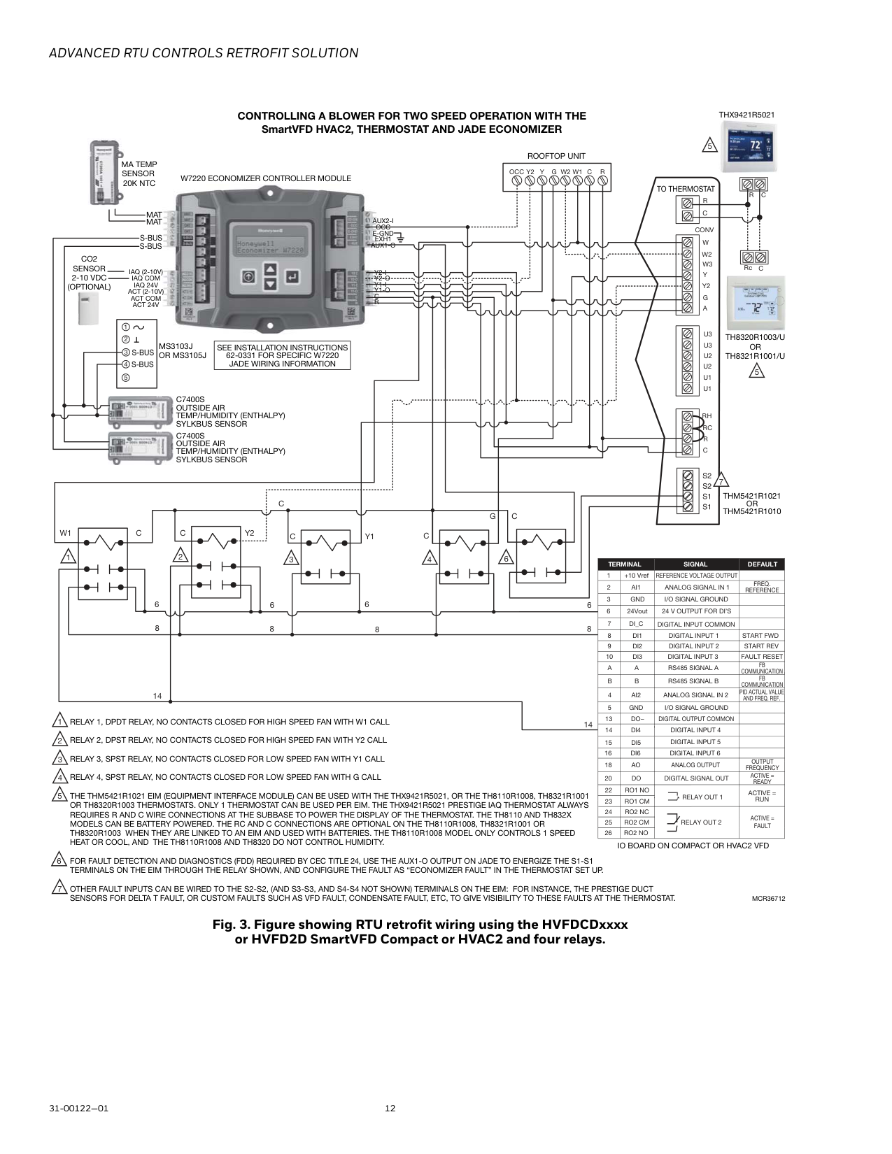
Advanced Rtu Controls Retrofit Solution
31-00122—01 12 Fig. 3. Figure showing RTU retrofit wiring using the HVFDCDxxxx or HVFD2D SmartVFD Compact or HVAC2 and four relays. 1G
C
Y2
Y1
W1
C
C
C
C
6 6 8 6 8 14 8 6 8Y
W1
G W2
C
R
R
C
Conv
W
W2
W3
Y
Y2
G
A
U3
U3
U2
U2
U1
U1
Rh
Rc
R
C
C
R
Y2
Occ
1C
RcMcr36712
Controlling A Blower For Two Speed Operation With The
SmartVFD HVAC2, THERMOSTAT AND JADE ECONOMIZERTh8320R1003/U
Or
Th8321R1001/U
5 5 1 2 3 4Relay 1, Dpdt Relay, No Contacts Closed For High Speed Fan With W1 Call
Relay 2, Dpst Relay, No Contacts Closed For High Speed Fan With Y2 Call
Relay 3, Spst Relay, No Contacts Closed For Low Speed Fan With Y1 Call
Relay 4, Spst Relay, No Contacts Closed For Low Speed Fan With G Call
THE THM5421R1021 EIM (EQUIPMENT INTERFACE MODULE) CAN BE USED WITH THE THX9421R5021, OR THE TH8110R1008, TH8321R1001 OR TH8320R1003 THERMOSTATS. ONLY 1 THERMOSTAT CAN BE USED PER EIM. THE THX9421R5021 PRESTIGE IAQ THERMOSTAT ALWAYS REQUIRES R AND C WIRE CONNECTIONS AT THE SUBBASE TO POWER THE DISPLAY OF THE THERMOSTAT. THE TH8110 AND TH832X MODELS CAN BE BATTERY POWERED. THE RC AND C CONNECTIONS ARE OPTIONAL ON THE TH8110R1008, TH8321R1001 OR TH8320R1003 WHEN THEY ARE LINKED TO AN EIM AND USED WITH BATTERIES. THE TH8110R1008 MODEL ONLY CONTROLS 1 SPEEDHeat Or Cool, And The Th8110R1008 And Th8320 Do Not Control Humidity.
FOR FAULT DETECTION AND DIAGNOSTICS (FDD) REQUIRED BY CEC TITLE 24, USE THE AUX1-O OUTPUT ON JADE TO ENERGIZE THE S1-S1 TERMINALS ON THE EIM THROUGH THE RELAY SHOWN, AND CONFIGURE THE FAULT AS “ECONOMIZER FAULT” IN THE THERMOSTAT SET UP. OTHER FAULT INPUTS CAN BE WIRED TO THE S2-S2, (AND S3-S3, AND S4-S4 NOT SHOWN) TERMINALS ON THE EIM: FOR INSTANCE, THE PRESTIGE DUCT SENSORS FOR DELTA T FAULT, OR CUSTOM FAULTS SUCH AS VFD FAULT, CONDENSATE FAULT, ETC, TO GIVE VISIBILITY TO THESE FAULTS AT THE THERMOSTAT. 1 2 3 4 5Io Board On Compact Or Hvac2 Vfd
Thx9421R5021
W7220 Economizer Controller Module
Thm5421R1021
Or
Thm5421R1010
Rooftop Unit
To Thermostat
Ma Temp
Sensor
20K Ntc
Mat
Mat
S-Bus
S-Bus
Co2
Sensor
2-10 Vdc
(Optional)
Iaq (2-10V)
Iaq Com
Iaq 24V
Act (2-10V)
Act Com
Act 24V
S-Bus
S-Bus
Ms3103J
Or Ms3105J
See Installation Instructions
62-0331 For Specific W7220
Jade Wiring Information
C7400S
Outside Air
Temp/Humidity (Enthalpy)
Sylkbus Sensor
C7400S
Outside Air
Temp/Humidity (Enthalpy)
Sylkbus Sensor
14Aux2-I
Occ
E-Gnd
Exh1
Aux1-O
Y2-I
Y2-O
Y1-I
Y1-O
C
R
1 +10 Vref REFERENCE VOLTAGE OUTPUT 2Ai1
Analog Signal In 1
Freq.
Reference
3 4Ai2
Analog Signal In 2
5Gnd I/O Signal Ground
Digital Input Common
6 24Vout 24 V OUTPUT FOR DI’S 7Gnd
I/O Signal Ground
8Di1
Digital Input 1 Start Fwd
9Di2
Digital Input 2 Start Rev
10Di3
Digital Input 3
Fault Reset
20Do Digital Signal Out
13Do−
Digital Output Common
22Ro1 No
15Di5
Digital Input 5
16Di6
Digital Input 6
Active =
Ready
18Ao Analog Output
A
Rs485 Signal A
B
Rs485 Signal B
Terminal
Signal
Default
Di_C
A
B
Fb
Communication
Fb
Communication
14Di4
Digital Input 4
Output
Frequency
Relay Out 1
Active =
Run
23Ro1 Cm
24Ro2 Nc
25Ro2 Cm
26Ro2 No
Relay Out 2
Active =
Fault
Pid Actual Value
And Freq. Ref.
6C
6 7 7
Advanced Rtu Controls Retrofit Solution
13 31-00122—01Installation Workflow – Programming The Devices
Note:
If digital input 4 is being used by an auto bypass, then wire the relays 1 and 2 to digital input 5 (terminal 15) instead of digital input 4 (14). Also configure P3.3.13, preset frequency 2 instead of P3.3.12, preset frequency 1.If Using The Smartvfd Compact Model Hvfdcd, Or
Hvac2 Model Hvfd2D
a. Program the SmartVFD as per user manual 62-0312 (Compact) or 31-00108 (HVAC2). b. Set low speed fan during VFD setup at parameter P3.1 c. Configure the VFD to drive the fan at high speed by setting parameter P3.5 Operation for all VFDsCommon Question:
How do you program VENTMIN and VENTMAX in a Jade economizer in a 2-speed fan application with a CO2 sensor?Note:
If there is no CO2 sensor, but you still plan to set this up for a 2-speed fan, the menu will only show MIN POS L and MIN POS H, so you would still need to follow these procedures, but only for two airflows, not 4 airflows.Important
Follow these steps in order, because some of the menu items in Jade will remain hidden unless certain parameters are set first.P1.8
Minimum frequency 0.00P1.9
Hz Varies 101 Minimum allowed frequency reference.P3.3.1
Minimum frequency 0.00P3.3.2
Hz 20.00 101 Minimum allowed frequency reference.P3.3.12
Preset frequency 1P3.3.1
P3.3.2
Hz 10.00 105 Select with digital input: Preset frequency selection 0(P3.5.1.16)
P3.1
Min frequency 0.00P3.2
Hz 0.00 101P3.5
Preset speed 1 0.00P3.2
Hz 10.00 105 Activated by digital inputs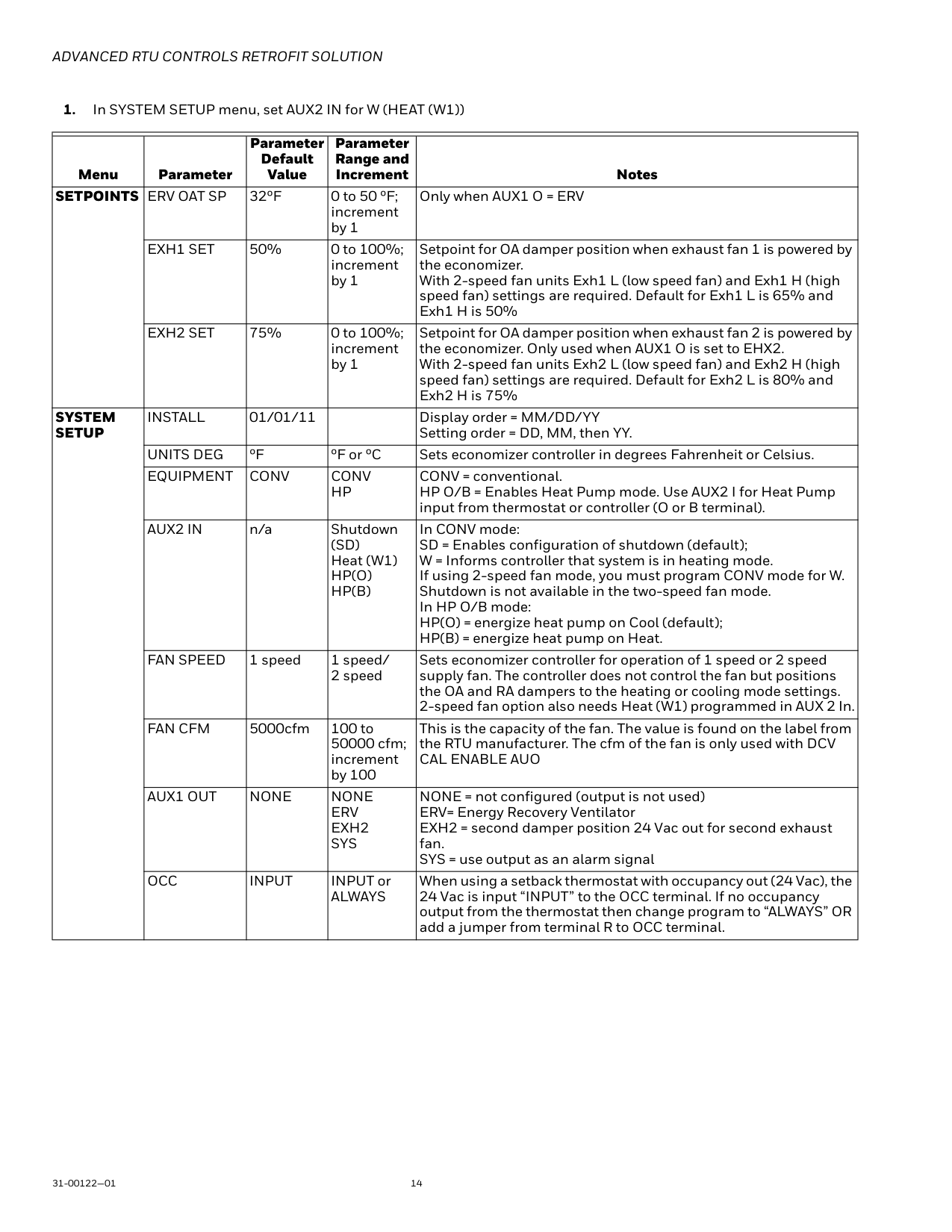
Advanced Rtu Controls Retrofit Solution
31-00122—01 14Setpoints Erv Oat Sp
32ºF 0 to 50 ºF; increment by 1 Only when AUX1 O = ERVExh1 Set
50% 0 to 100%; increment by 1 Setpoint for OA damper position when exhaust fan 1 is powered by the economizer. With 2-speed fan units Exh1 L (low speed fan) and Exh1 H (high speed fan) settings are required. Default for Exh1 L is 65% and Exh1 H is 50%Exh2 Set
75% 0 to 100%; increment by 1 Setpoint for OA damper position when exhaust fan 2 is powered by the economizer. Only used when AUX1 O is set to EHX2. With 2-speed fan units Exh2 L (low speed fan) and Exh2 H (high speed fan) settings are required. Default for Exh2 L is 80% and Exh2 H is 75%System
Setup
Install
01/01/11 Display order = MM/DD/YY Setting order = DD, MM, then YY.Units Deg
ºF ºF or ºC Sets economizer controller in degrees Fahrenheit or Celsius.Equipment
Conv
Conv
Hp
CONV = conventional. HP O/B = Enables Heat Pump mode. Use AUX2 I for Heat Pump input from thermostat or controller (O or B terminal).Aux2 In
n/a Shutdown(Sd)
Heat (W1)Hp(O)
Hp(B)
In CONV mode: SD = Enables configuration of shutdown (default); W = Informs controller that system is in heating mode. If using 2-speed fan mode, you must program CONV mode for W. Shutdown is not available in the two-speed fan mode. In HP O/B mode: HP(O) = energize heat pump on Cool (default); HP(B) = energize heat pump on Heat.Fan Speed
1 speed 1 speed/ 2 speed Sets economizer controller for operation of 1 speed or 2 speed supply fan. The controller does not control the fan but positions the OA and RA dampers to the heating or cooling mode settings. 2-speed fan option also needs Heat (W1) programmed in AUX 2 In.Fan Cfm
5000cfm 100 to 50000 cfm; increment by 100 This is the capacity of the fan. The value is found on the label from the RTU manufacturer. The cfm of the fan is only used with DCVCal Enable Auo
Aux1 Out
None
None
Erv
Exh2
Sys
NONE = not configured (output is not used) ERV= Energy Recovery Ventilator EXH2 = second damper position 24 Vac out for second exhaust fan. SYS = use output as an alarm signalOcc
Input
INPUT orAlways
When using a setback thermostat with occupancy out (24 Vac), the 24 Vac is input “INPUT” to the OCC terminal. If no occupancy output from the thermostat then change program to “ALWAYS” OR add a jumper from terminal R to OCC terminal.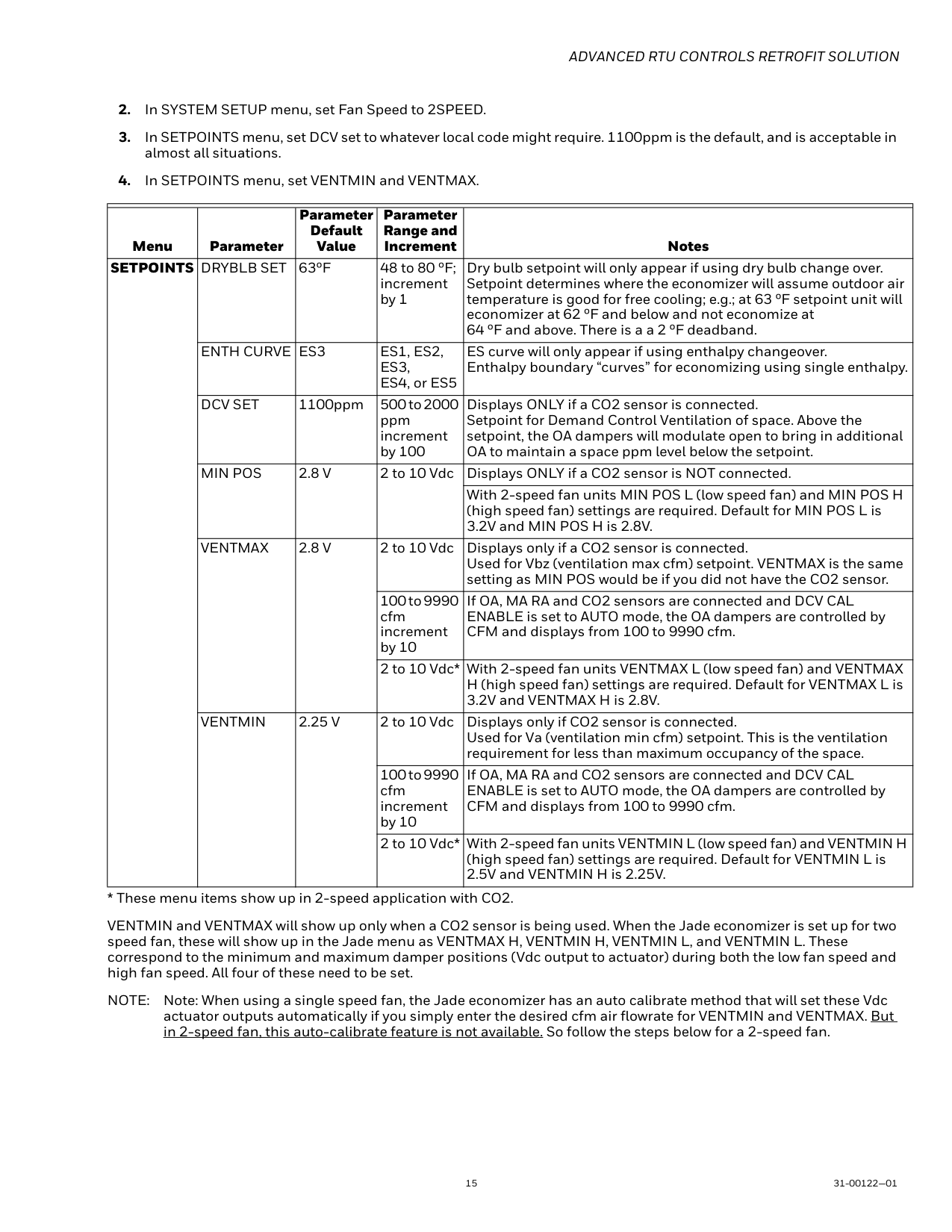
Advanced Rtu Controls Retrofit Solution
15 31-00122—01Note:
Note: When using a single speed fan, the Jade economizer has an auto calibrate method that will set these Vdc actuator outputs automatically if you simply enter the desired cfm air flowrate for VENTMIN and VENTMAX. But in 2-speed fan, this auto-calibrate feature is not available. So follow the steps below for a 2-speed fan. Menu Parameter Parameter Default Value Parameter Range and Increment NotesSetpoints Dryblb Set
63ºF 48 to 80 ºF; increment by 1 Dry bulb setpoint will only appear if using dry bulb change over. Setpoint determines where the economizer will assume outdoor air temperature is good for free cooling; e.g.; at 63 ºF setpoint unit will economizer at 62 ºF and below and not economize at 64 ºF and above. There is a a 2 ºF deadband.Enth Curve Es3
Es1, Es2,
Es3,
ES4, or ES5 ES curve will only appear if using enthalpy changeover. Enthalpy boundary “curves” for economizing using single enthalpy.Dcv Set
1100ppm 500 to 2000 ppm increment by 100 Displays ONLY if a CO2 sensor is connected. Setpoint for Demand Control Ventilation of space. Above the setpoint, the OA dampers will modulate open to bring in additional OA to maintain a space ppm level below the setpoint.Min Pos
2.8 V
2 to 10 Vdc Displays ONLY if a CO2 sensor is NOT connected. With 2-speed fan units MIN POS L (low speed fan) and MIN POS H (high speed fan) settings are required. Default for MIN POS L is 3.2V and MIN POS H is 2.8V.Ventmax
2.8 V
2 to 10 Vdc Displays only if a CO2 sensor is connected. Used for Vbz (ventilation max cfm) setpoint. VENTMAX is the same setting as MIN POS would be if you did not have the CO2 sensor. 100 to 9990 cfm increment by 10 If OA, MA RA and CO2 sensors are connected and DCV CAL ENABLE is set to AUTO mode, the OA dampers are controlled by CFM and displays from 100 to 9990 cfm. 2 to 10 Vdc* With 2-speed fan units VENTMAX L (low speed fan) and VENTMAX H (high speed fan) settings are required. Default for VENTMAX L is 3.2V and VENTMAX H is 2.8V.Ventmin
2.25 V
2 to 10 Vdc Displays only if CO2 sensor is connected. Used for Va (ventilation min cfm) setpoint. This is the ventilation requirement for less than maximum occupancy of the space. 100 to 9990 cfm increment by 10 If OA, MA RA and CO2 sensors are connected and DCV CAL ENABLE is set to AUTO mode, the OA dampers are controlled by CFM and displays from 100 to 9990 cfm. 2 to 10 Vdc* With 2-speed fan units VENTMIN L (low speed fan) and VENTMIN H (high speed fan) settings are required. Default for VENTMIN L is 2.5V and VENTMIN H is 2.25V.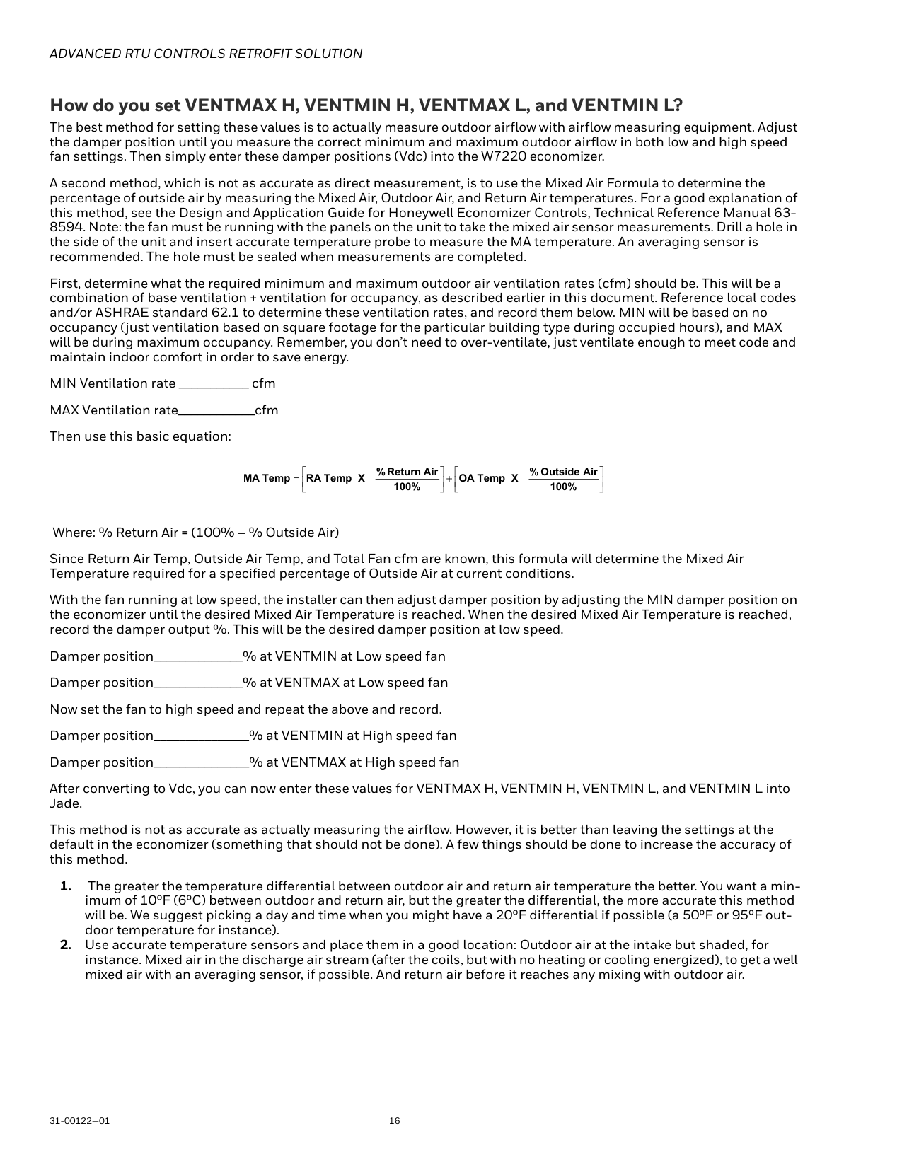
Advanced Rtu Controls Retrofit Solution
31-00122—01 16 How do you set VENTMAX H, VENTMIN H, VENTMAX L, and VENTMIN L? The best method for setting these values is to actually measure outdoor airflow with airflow measuring equipment. Adjust the damper position until you measure the correct minimum and maximum outdoor airflow in both low and high speed fan settings. Then simply enter these damper positions (Vdc) into the W7220 economizer. A second method, which is not as accurate as direct measurement, is to use the Mixed Air Formula to determine the percentage of outside air by measuring the Mixed Air, Outdoor Air, and Return Air temperatures. For a good explanation of this method, see the Design and Application Guide for Honeywell Economizer Controls, Technical Reference Manual 63-%
X
Temp
Oa
100% Air Return%
X
Temp
Ra
TempMa
Advanced Rtu Controls Retrofit Solution
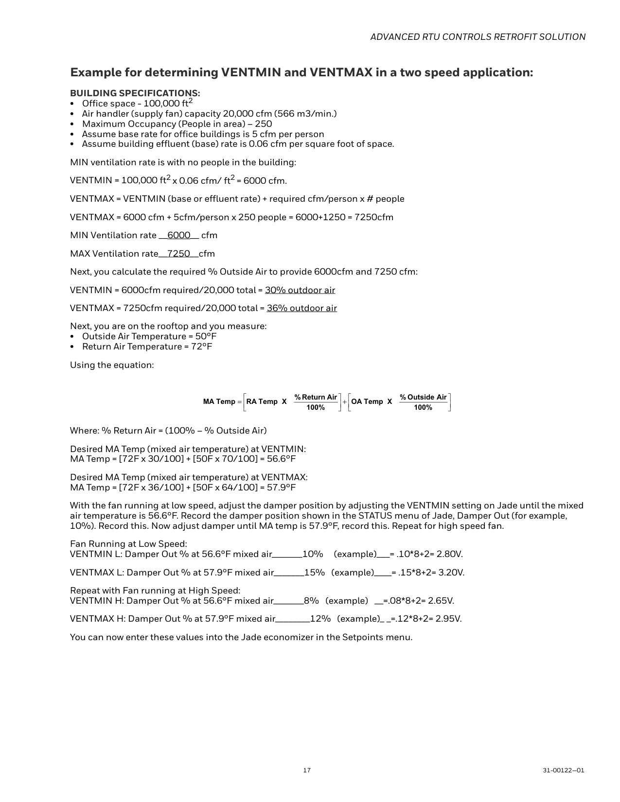
17 31-00122—01 Example for determining VENTMIN and VENTMAX in a two speed application:Building Specifications:
• Office space - 100,000 ft2 • Air handler (supply fan) capacity 20,000 cfm (566 m3/min.) • Maximum Occupancy (People in area) – 250 • Assume base rate for office buildings is 5 cfm per person • Assume building effluent (base) rate is 0.06 cfm per square foot of space. MIN ventilation rate is with no people in the building: VENTMIN = 100,000 ft2 x 0.06 cfm/ ft2 = 6000 cfm. VENTMAX = VENTMIN (base or effluent rate) + required cfm/person x # people VENTMAX = 6000 cfm + 5cfm/person x 250 people = 6000+1250 = 7250cfm MIN Ventilation rate __6000__ cfm MAX Ventilation rate__7250__cfm Next, you calculate the required % Outside Air to provide 6000cfm and 7250 cfm: VENTMIN = 6000cfm required/20,000 total = 30% outdoor air VENTMAX = 7250cfm required/20,000 total = 36% outdoor air Next, you are on the rooftop and you measure: • Outside Air Temperature = 50°F • Return Air Temperature = 72°F Using the equation: Where: % Return Air = (100% – % Outside Air) Desired MA Temp (mixed air temperature) at VENTMIN: MA Temp = [72F x 30/100] + [50F x 70/100] = 56.6°F Desired MA Temp (mixed air temperature) at VENTMAX: MA Temp = [72F x 36/100] + [50F x 64/100] = 57.9°F With the fan running at low speed, adjust the damper position by adjusting the VENTMIN setting on Jade until the mixed air temperature is 56.6°F. Record the damper position shown in the STATUS menu of Jade, Damper Out (for example, 10%). Record this. Now adjust damper until MA temp is 57.9°F, record this. Repeat for high speed fan. Fan Running at Low Speed: VENTMIN L: Damper Out % at 56.6°F mixed air_______10% (example)___= .10*8+2= 2.80V. VENTMAX L: Damper Out % at 57.9°F mixed air_______15% (example)____= .15*8+2= 3.20V. Repeat with Fan running at High Speed: VENTMIN H: Damper Out % at 56.6°F mixed air_______8% (example) __=.08*8+2= 2.65V. VENTMAX H: Damper Out % at 57.9°F mixed air________12% (example)_ _=.12*8+2= 2.95V. You can now enter these values into the Jade economizer in the Setpoints menu. + = 100% Air Outside%
X
Temp
Oa
100% Air Return%
X
Temp
Ra
TempMa
Advanced Rtu Controls Retrofit Solution
31-00122—01 18Economizer Sequence Of Operation
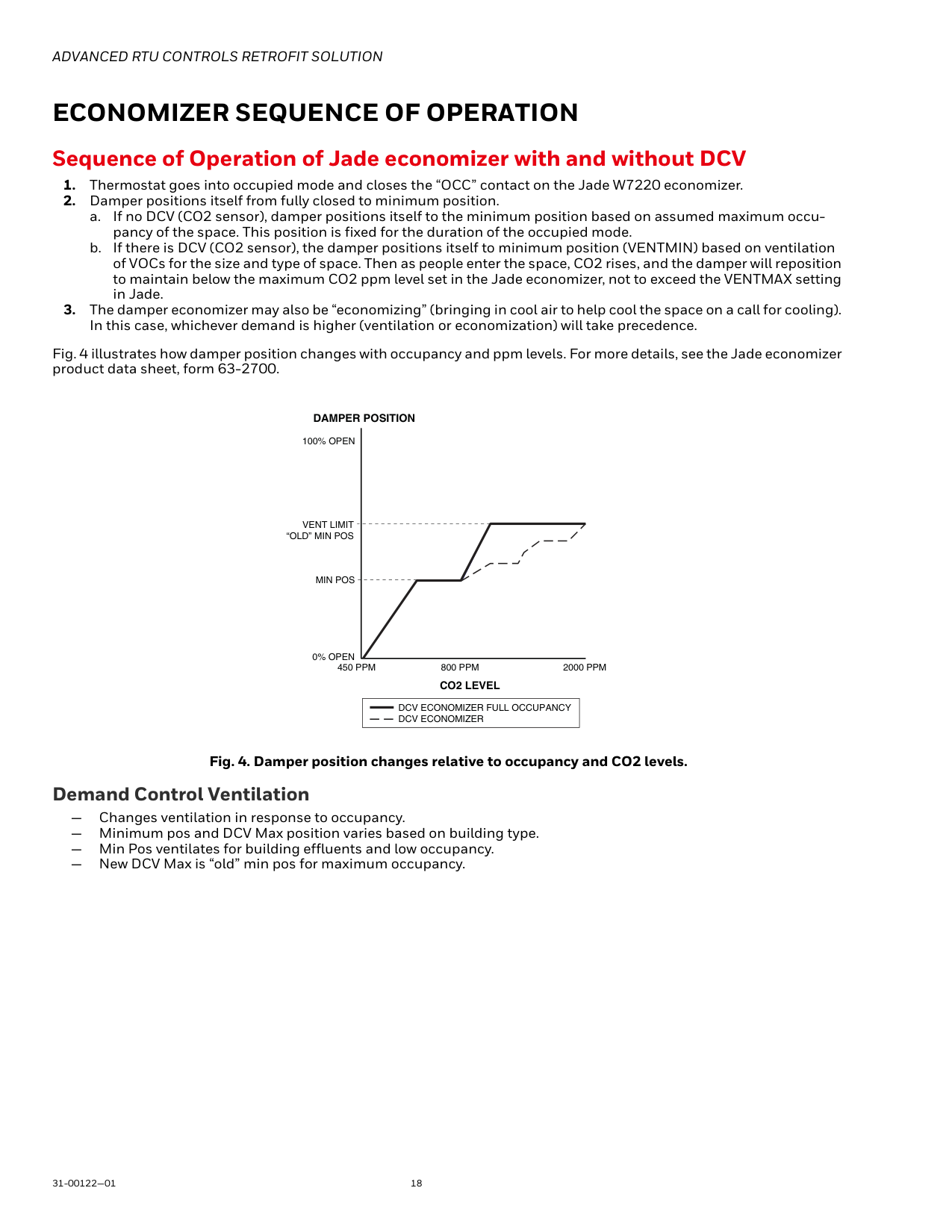
Sequence of Operation of Jade economizer with and without DCVDamper Position
Co2 Level
100% Open
Vent Limit
“Old” Min Pos
Min Pos
0% Open
450 Ppm
800 Ppm
2000 Ppm
Dcv Economizer Full Occupancy
Dcv Economizer

Advanced Rtu Controls Retrofit Solution
19 31-00122—01Program The Thermostat
Follow the instructions in the thermostat installation manual to program the thermostat. Prestige Thermostat with EIM The best option is the Prestige thermostat with equipment interface module (EIM). This provides an intuitive touch- screen interface and optional delta T fault detection. Fig. 5. Prestige thermostat with EIM and discharge air and return air sensors for diagnostics. Prestige Setup for Economizer OutputPrestige Setup for Fault Detection and Diagnostics The Prestige thermostat allows you to create a custom fault name and instructions. This helps to meet CEC Title 24 2016 and IECC 2015 requirements for fault detection and diagnostics.
Advanced Rtu Controls Retrofit Solution
31-00122—01 20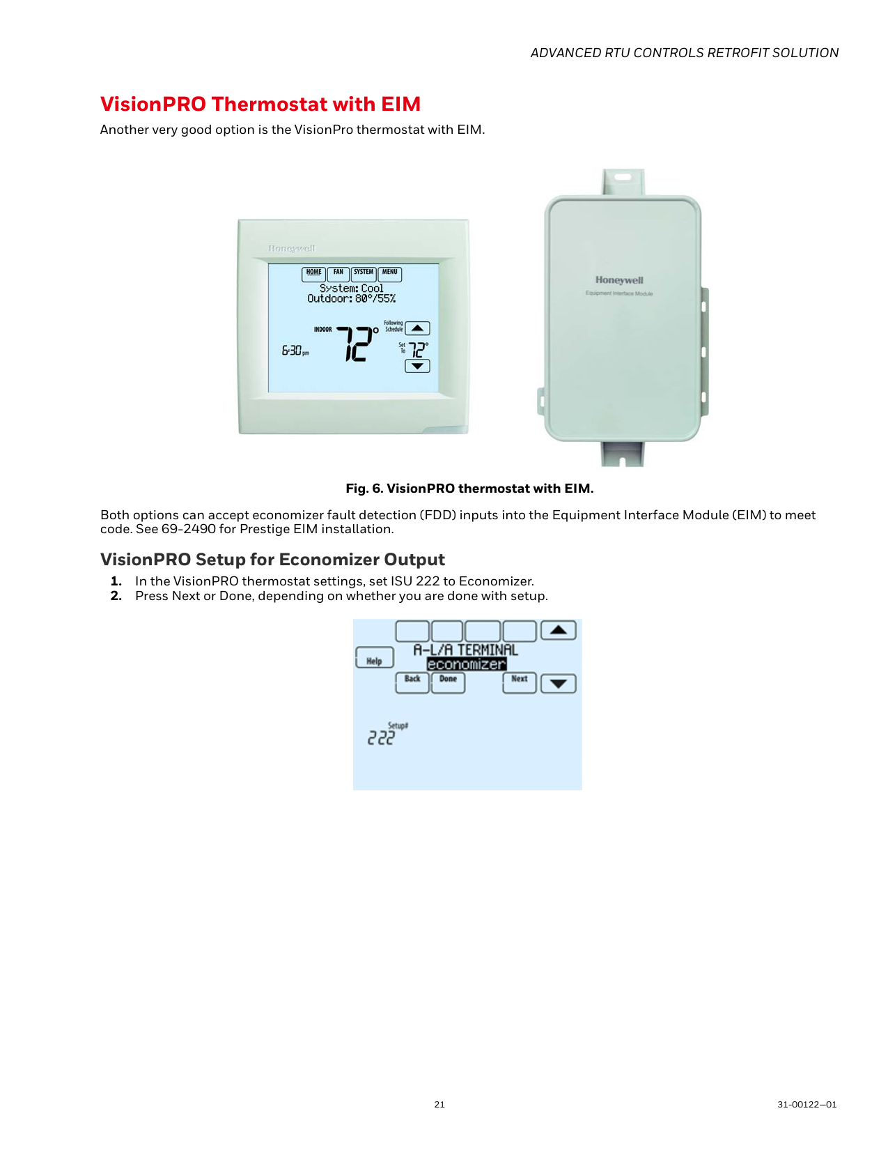
Advanced Rtu Controls Retrofit Solution
21 31-00122—01 VisionPRO Thermostat with EIM Another very good option is the VisionPro thermostat with EIM. Fig. 6. VisionPRO thermostat with EIM. Both options can accept economizer fault detection (FDD) inputs into the Equipment Interface Module (EIM) to meet code. See 69-2490 for Prestige EIM installation. VisionPRO Setup for Economizer Output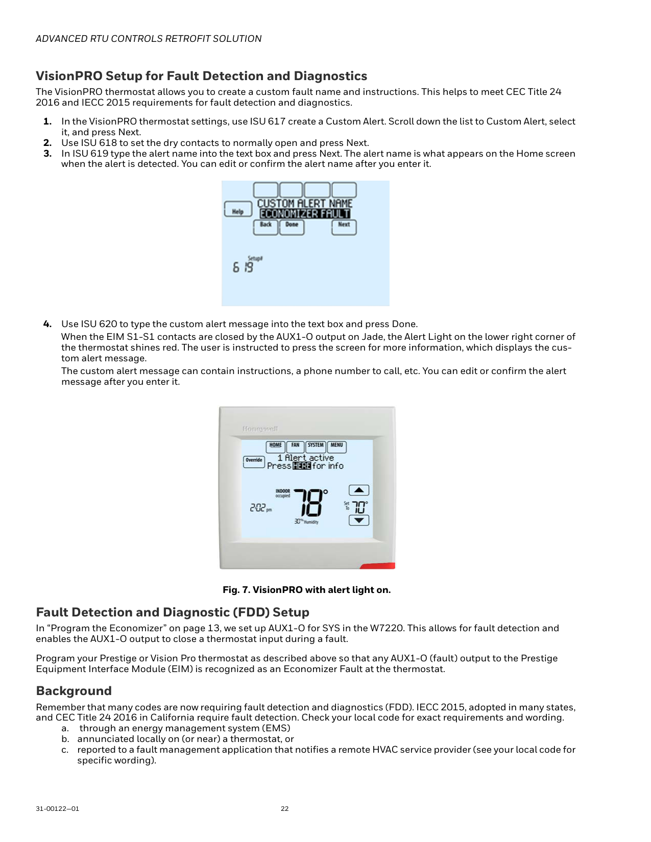
Advanced Rtu Controls Retrofit Solution
31-00122—01 22 VisionPRO Setup for Fault Detection and Diagnostics The VisionPRO thermostat allows you to create a custom fault name and instructions. This helps to meet CEC Title 24 2016 and IECC 2015 requirements for fault detection and diagnostics.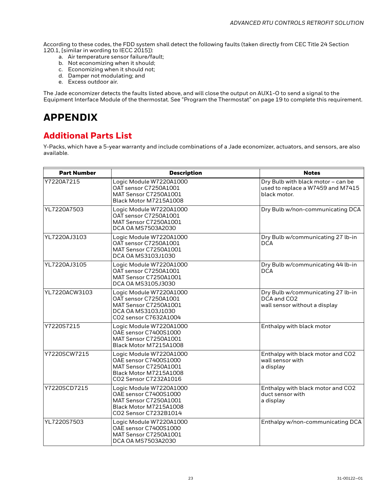
Advanced Rtu Controls Retrofit Solution
23 31-00122—01 According to these codes, the FDD system shall detect the following faults (taken directly from CEC Title 24 Section 120.1, [similar in wording to IECC 2015]): a. Air temperature sensor failure/fault; b. Not economizing when it should; c. Economizing when it should not; d. Damper not modulating; and e. Excess outdoor air. The Jade economizer detects the faults listed above, and will close the output on AUX1-O to send a signal to the Equipment Interface Module of the thermostat. See “Program the Thermostat” on page 19 to complete this requirement.Appendix
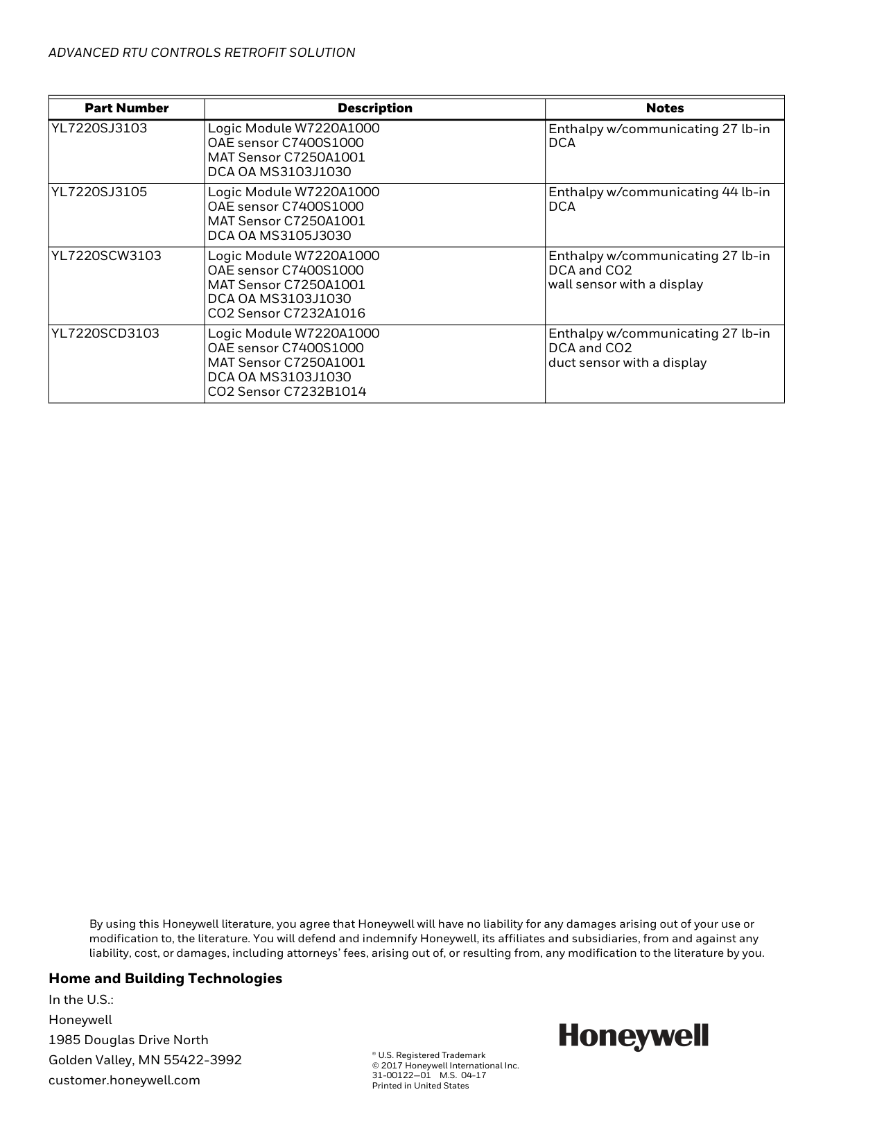
Additional Parts List Y-Packs, which have a 5-year warranty and include combinations of a Jade economizer, actuators, and sensors, are also available. Part Number Description NotesY7220A7215
Logic Module W7220A1000 OAT sensor C7250A1001 MAT Sensor C7250A1001 Black Motor M7215A1008 Dry Bulb with black motor – can be used to replace a W7459 and M7415 black motor.Yl7220A7503
Logic Module W7220A1000 OAT sensor C7250A1001 MAT Sensor C7250A1001Dca Oa Ms7503A2030
Dry Bulb w/non-communicating DCAYl7220Aj3103
Logic Module W7220A1000 OAT sensor C7250A1001 MAT Sensor C7250A1001Dca Oa Ms3103J1030
Dry Bulb w/communicating 27 lb-inDca
Yl7220Aj3105
Logic Module W7220A1000 OAT sensor C7250A1001 MAT Sensor C7250A1001Dca Oa Ms3105J3030
Dry Bulb w/communicating 44 lb-inDca
Yl7220Acw3103
Logic Module W7220A1000 OAT sensor C7250A1001 MAT Sensor C7250A1001Dca Oa Ms3103J1030
CO2 sensor C7632A1004 Dry Bulb w/communicating 27 lb-in DCA and CO2 wall sensor without a displayY7220S7215
Logic Module W7220A1000 OAE sensor C7400S1000 MAT Sensor C7250A1001 Black Motor M7215A1008 Enthalpy with black motorY7220Scw7215
Logic Module W7220A1000 OAE sensor C7400S1000 MAT Sensor C7250A1001 Black Motor M7215A1008 CO2 Sensor C7232A1016 Enthalpy with black motor and CO2 wall sensor with a displayY7220Scd7215
Logic Module W7220A1000 OAE sensor C7400S1000 MAT Sensor C7250A1001 Black Motor M7215A1008 CO2 Sensor C7232B1014 Enthalpy with black motor and CO2 duct sensor with a displayYl7220S7503
Logic Module W7220A1000 OAE sensor C7400S1000 MAT Sensor C7250A1001Dca Oa Ms7503A2030
Enthalpy w/non-communicating DCA