Ask AI
— answers from the official manualAnswers from the official manual.
Common questions
Common Questions
10 totalHow do I troubleshoot if my HP TouchPad stops functioning?
To troubleshoot a non-functioning TouchPad on your HP notebook, disconnect the system board cable from the TouchPad button board ZIF connector (1) and the TouchPad cable from the system board ZIF connector (2), then reconnect them to ensure they are properly seated. Also check if there is any debris or obstruction preventing proper contact between connectors. If issues persist, consulting with an authorized service provider may be necessary. (Page 47)
What do I need to replace the WLAN module in my HP notebook?
To replace the WLAN module in your HP notebook, ensure you remove the optical drive, bottom cover, battery, disconnect the two antenna cables from the module (1), and then use a Phillips M2.0 x 3.0 screw (2) to secure it properly. Follow proper electrostatic discharge procedures during replacement. It may be advisable to consult an authorized service provider for assistance due to potential warranty voiding risks if not done correctly. (Page 44)
How do I reset the BIOS settings on my HP 250 G7 Notebook PC?
To restore factory settings in Computer Setup, press F10 during start-up to enter BIOS setup and navigate to the 'Restore Defaults' option. Follow any screen prompts to confirm a full reset of all BIOS settings back to defaults. Refer to Chapter 7, 'Computer Setup (BIOS), TPM, and HP Sure Start,' for detailed instructions on entering Computer Setup mode. (Page 70)
How do I add a second hard drive to my notebook?
Your HP 250 G7 Notebook PC does not support adding an additional internal hard drive as it is designed with specific storage configurations that are fixed and customer non-upgradeable as stated in the Product Specifications. Consider using external storage options or replacing your existing SSD/HDD in accordance with authorized service provider guidelines. (Page 81-82)
What should I do if my notebook battery is not charging properly?
To resolve issues with a non-charging battery, ensure the AC adapter is securely connected to both the laptop and power outlet, and that there is no damage to either component. Check that the battery indicator light shows an amber color when charging occurs; if lights display other colors or do not illuminate, try disconnecting from power source for several minutes before reconnecting again to reset charger communication. Consult further steps in Chapter 5 ‘Removal and Replacement Procedures’ regarding battery replacement if issues continue. (Page 34-35)
How can I prevent static electricity damage when handling my notebook?
To protect your laptop from static electrical discharge, always be properly grounded before touching sensitive internal components like those found in Authorized Service Provider only parts sections of the guide. Use anti-static wrist straps and mats approved for grounding workstations to minimize risk during disassembly procedures described starting on page 25.
Full Manual
108 pages


Maintenance and Service Guide
HP 250 G7 Notebook PC
© Copyright 2018 HP Development Company, L.P.
AMD is a trademark of Advanced Micro Devices, Inc. Bluetooth is a trademark owned by its proprietor and used by HP Inc. under license. Intel, Celeron, Core, and Pentium are trademarks of Intel Corporation in the U.S. and other countries. Microsoft and Windows are trademarks of the Microsoft group of companies.
The information contained herein is subject to change without notice. The only warranties for HP products and services are set forth in the express warranty statements accompanying such products and services. Nothing herein should be construed as constituting an additional warranty. HP shall not be liable for technical or editorial errors or omissions contained herein.
First Edition: December 2018 Document Part Number: L47791-001
######### Product notice
This user guide describes features that are common to most models. Some features may not be available on your computer.
Not all features are available in all editions or versions of Windows. Systems may require upgraded and/or separately purchased hardware, drivers, software or BIOS update to take full advantage of Windows functionality. Windows 10 is automatically updated, which is always enabled. ISP fees may apply and additional requirements may apply over time for updates. See http://www.microsoft.com.
To access the latest user guides, go to http://www.hp.com/support, and follow the instructions to find your product. Then select User Guides.
######### Software terms
By installing, copying, downloading, or otherwise using any software product preinstalled on this computer, you agree to be bound by the terms of the HP End User License Agreement (EULA). If you do not accept these license terms, your sole remedy is to return the entire unused product (hardware and software) within 14 days for a full refund subject to the refund policy of your seller.
For any further information or to request a full refund of the price of the computer, please contact your seller.
#### Important Notice about Customer Self-Repair Parts
CAUTION: Your computer includes Customer Self-Repair parts and parts that should only be accessed by an authorized service provider. See Chapter 5, "Removal and replacement procedures for Customer Self-Repair parts," for details. Accessing parts described in Chapter 6, "Removal and replacement procedures for Authorized Service Provider only parts," can damage the computer or void your warranty.
iii
####### iv Important Notice about Customer Self-Repair Parts
#### Safety warning notice
WARNING! To reduce the possibility of heat-related injuries or of overheating the device, do not place the device directly on your lap or obstruct the device air vents. Use the device only on a hard, flat surface. Do not allow another hard surface, such as an adjoining optional printer, or a soft surface, such as pillows or rugs or clothing, to block airflow. Also, do not allow the AC adapter to contact the skin or a soft surface, such as pillows or rugs or clothing, during operation. The device and the AC adapter comply with the user-accessible surface temperature limits defined by the International Standard for Safety of Information Technology Equipment (IEC 60950-1).
v
####### vi Safety warning notice
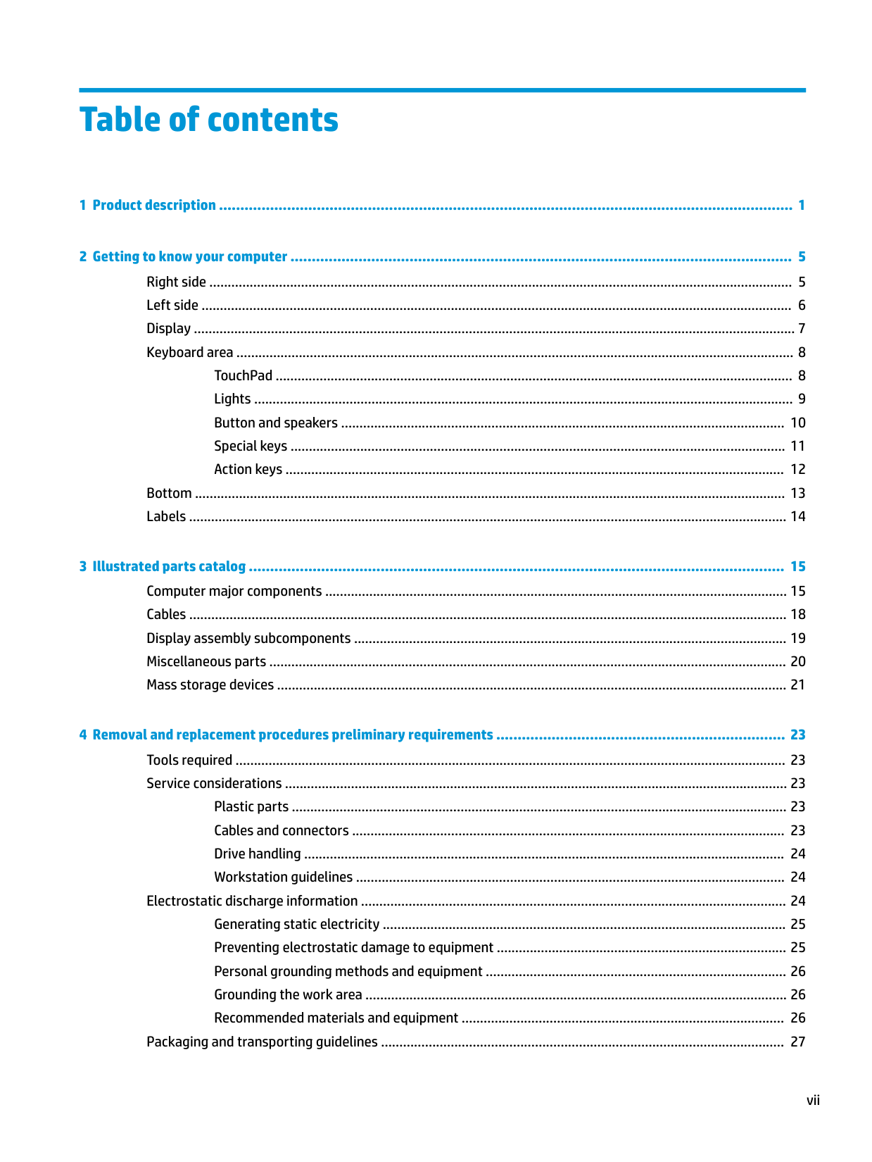
Table of contents
TouchPad ............................................................................................................................................. 8 Lights ................................................................................................................................................... 9 Button and speakers ......................................................................................................................... 10 Special keys ....................................................................................................................................... 11 Action keys ........................................................................................................................................ 12
Bottom ................................................................................................................................................................. 13 Labels ................................................................................................................................................................... 14

Plastic parts ....................................................................................................................................... 23 Cables and connectors ...................................................................................................................... 23 Drive handling ................................................................................................................................... 24 Workstation guidelines ..................................................................................................................... 24
Electrostatic discharge information .................................................................................................................... 24 Generating static electricity .............................................................................................................. 25 Preventing electrostatic damage to equipment ............................................................................... 25 Personal grounding methods and equipment .................................................................................. 26 Grounding the work area ................................................................................................................... 26 Recommended materials and equipment ........................................................................................ 26
Packaging and transporting guidelines .............................................................................................................. 27
vii
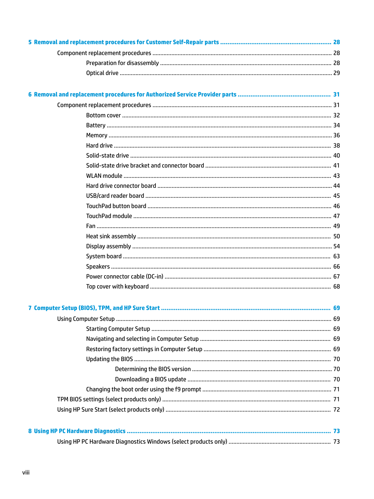
###### 5 Removal and replacement procedures for Customer Self-Repair parts ............................................................. 28Component replacement procedures .................................................................................................................. 28
Preparation for disassembly ............................................................................................................. 28 Optical drive ....................................................................................................................................... 29
###### 6 Removal and replacement procedures for Authorized Service Provider parts ................................................... 31Component replacement procedures .................................................................................................................. 31
Bottom cover ..................................................................................................................................... 32 Battery ............................................................................................................................................... 34 Memory .............................................................................................................................................. 36 Hard drive .......................................................................................................................................... 38 Solid-state drive ................................................................................................................................ 40 Solid-state drive bracket and connector board ................................................................................ 41 WLAN module .................................................................................................................................... 43 Hard drive connector board ............................................................................................................... 44 USB/card reader board ...................................................................................................................... 45 TouchPad button board ..................................................................................................................... 46 TouchPad module .............................................................................................................................. 47 Fan ..................................................................................................................................................... 49 Heat sink assembly ........................................................................................................................... 50 Display assembly ............................................................................................................................... 54 System board .................................................................................................................................... 63 Speakers ............................................................................................................................................ 66 Power connector cable (DC-in) .......................................................................................................... 67 Top cover with keyboard ................................................................................................................... 68
###### 7 Computer Setup (BIOS), TPM, and HP Sure Start ............................................................................................. 69Using Computer Setup ......................................................................................................................................... 69
Starting Computer Setup .................................................................................................................. 69 Navigating and selecting in Computer Setup ................................................................................... 69 Restoring factory settings in Computer Setup ................................................................................. 69 Updating the BIOS ............................................................................................................................. 70
Determining the BIOS version ......................................................................................... 70 Downloading a BIOS update ........................................................................................... 70
Changing the boot order using the f9 prompt .................................................................................. 71 TPM BIOS settings (select products only) ........................................................................................................... 71 Using HP Sure Start (select products only) ......................................................................................................... 72

###### 8 Using HP PC Hardware Diagnostics ................................................................................................................ 73Using HP PC Hardware Diagnostics Windows (select products only) ................................................................. 73
viii
Downloading HP PC Hardware Diagnostics Windows ....................................................................... 73 Downloading the latest HP PC Hardware Diagnostics Windows version ....................... 74 Downloading HP Hardware Diagnostics Windows by product name or number (select products only) ..................................................................................................... 74
Installing HP PC Hardware Diagnostics Windows ............................................................................. 74
Using HP PC Hardware Diagnostics UEFI ............................................................................................................. 74 Starting HP PC Hardware Diagnostics UEFI ....................................................................................... 75 Downloading HP PC Hardware Diagnostics UEFI to a USB flash drive .............................................. 75
Downloading the latest HP PC Hardware Diagnostics UEFI version .............................. 75 Downloading HP PC Hardware Diagnostics UEFI by product name or number (select products only) ..................................................................................................... 75
Using Remote HP PC Hardware Diagnostics UEFI settings (select products only) ............................................. 76
Downloading Remote HP PC Hardware Diagnostics UEFI ................................................................. 76 Downloading the latest Remote HP PC Hardware Diagnostics UEFI version ................. 76 Downloading Remote HP PC Hardware Diagnostics UEFI by product name or number ............................................................................................................................ 76
Customizing Remote HP PC Hardware Diagnostics UEFI settings .................................................... 76
Using Windows tools ......................................................................................................................... 78 Using the HP Cloud Recovery Download Tool to create recovery media (select products only) ..... 78
Restoring and recovery ........................................................................................................................................ 79 Restoring, resetting, and refreshing using Windows tools .............................................................. 79 Recovering using HP Recovery media ............................................................................................... 79 Changing the computer boot order ................................................................................................... 79

ix
Using HP Sure Start (select models only) ............................................................................................................ 93
Index ............................................................................................................................................................. 95
x
1 Product description
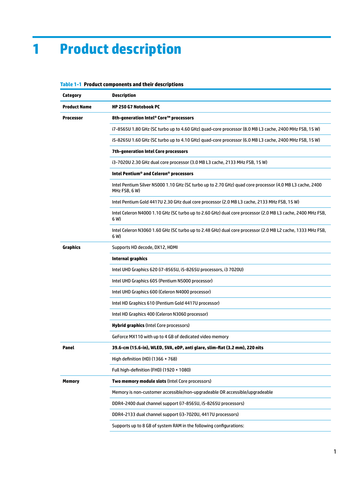
Table 1-1 Product components and their descriptions Category Description Product Name HP 250 G7 Notebook PC Processor 8th-generation Intel® Core™ processors
i7-8565U 1.80 GHz (SC turbo up to 4.60 GHz) quad-core processor (8.0 MB L3 cache, 2400 MHz FSB, 15 W) i5-8265U 1.60 GHz (SC turbo up to 4.10 GHz) quad-core processor (6.0 MB L3 cache, 2400 MHz FSB, 15 W) 7th-generation Intel Core processors
i3-7020U 2.30 GHz dual core processor (3.0 MB L3 cache, 2133 MHz FSB, 15 W) Intel Pentium® and Celeron® processors
Intel Pentium Silver N5000 1.10 GHz (SC turbo up to 2.70 GHz) quad core processor (4.0 MB L3 cache, 2400 MHz FSB, 6 W)
Intel Pentium Gold 4417U 2.30 GHz dual core processor (2.0 MB L3 cache, 2133 MHz FSB, 15 W) Intel Celeron N4000 1.10 GHz (SC turbo up to 2.60 GHz) dual core processor (2.0 MB L3 cache, 2400 MHz FSB, 6 W) Intel Celeron N3060 1.60 GHz (SC turbo up to 2.48 GHz) dual core processor (2.0 MB L2 cache, 1333 MHz FSB, 6 W)
Graphics Supports HD decode, DX12, HDMI Internal graphics Intel UHD Graphics 620 (i7-8565U, i5-8265U processors, i3 7020U) Intel UHD Graphics 605 (Pentium N5000 processor) Intel UHD Graphics 600 (Celeron N4000 processor) Intel HD Graphics 610 (Pentium Gold 4417U processor) Intel HD Graphics 400 (Celeron N3060 processor) Hybrid graphics (Intel Core processors) GeForce MX110 with up to 4 GB of dedicated video memory

Panel 39.6-cm (15.6-in), WLED, SVA, eDP, anti glare, slim-flat (3.2 mm), 220 nits High definition (HD) (1366 × 768) Full high-definition (FHD) (1920 × 1080)
Memory Two memory module slots (Intel Core processors) Memory is non-customer accessible/non-upgradeable OR accessible/upgradeable DDR4-2400 dual channel support (i7-8565U, i5-8265U processors) DDR4-2133 dual channel support (i3-7020U, 4417U processors) Supports up to 8 GB of system RAM in the following configurations:
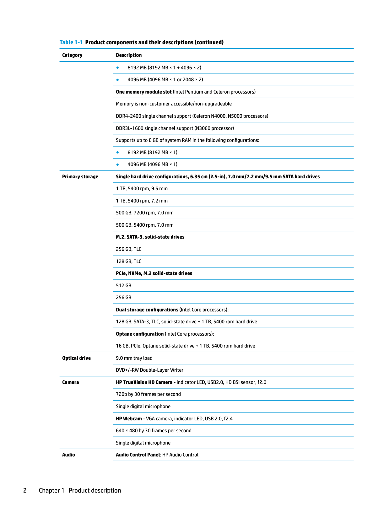
Primary storage Single hard drive configurations, 6.35 cm (2.5-in), 7.0 mm/7.2 mm/9.5 mm SATA hard drives 1 TB, 5400 rpm, 9.5 mm 1 TB, 5400 rpm, 7.2 mm 500 GB, 7200 rpm, 7.0 mm 500 GB, 5400 rpm, 7.0 mm M.2, SATA-3, solid-state drives
256 GB, TLC 128 GB, TLC PCIe, NVMe, M.2 solid-state drives
512 GB 256 GB Dual storage configurations (Intel Core processors):
128 GB, SATA-3, TLC, solid-state drive + 1 TB, 5400 rpm hard drive Optane configuration (Intel Core processors): 16 GB, PCIe, Optane solid-state drive + 1 TB, 5400 rpm hard drive
Optical drive 9.0 mm tray load
DVD+/-RW Double-Layer Writer
Camera HP TrueVision HD Camera - indicator LED, USB2.0, HD BSI sensor, f2.0 720p by 30 frames per second Single digital microphone HP Webcam - VGA camera, indicator LED, USB 2.0, f2.4 640 × 480 by 30 frames per second Single digital microphone
######### Audio Audio Control Panel: HP Audio Control
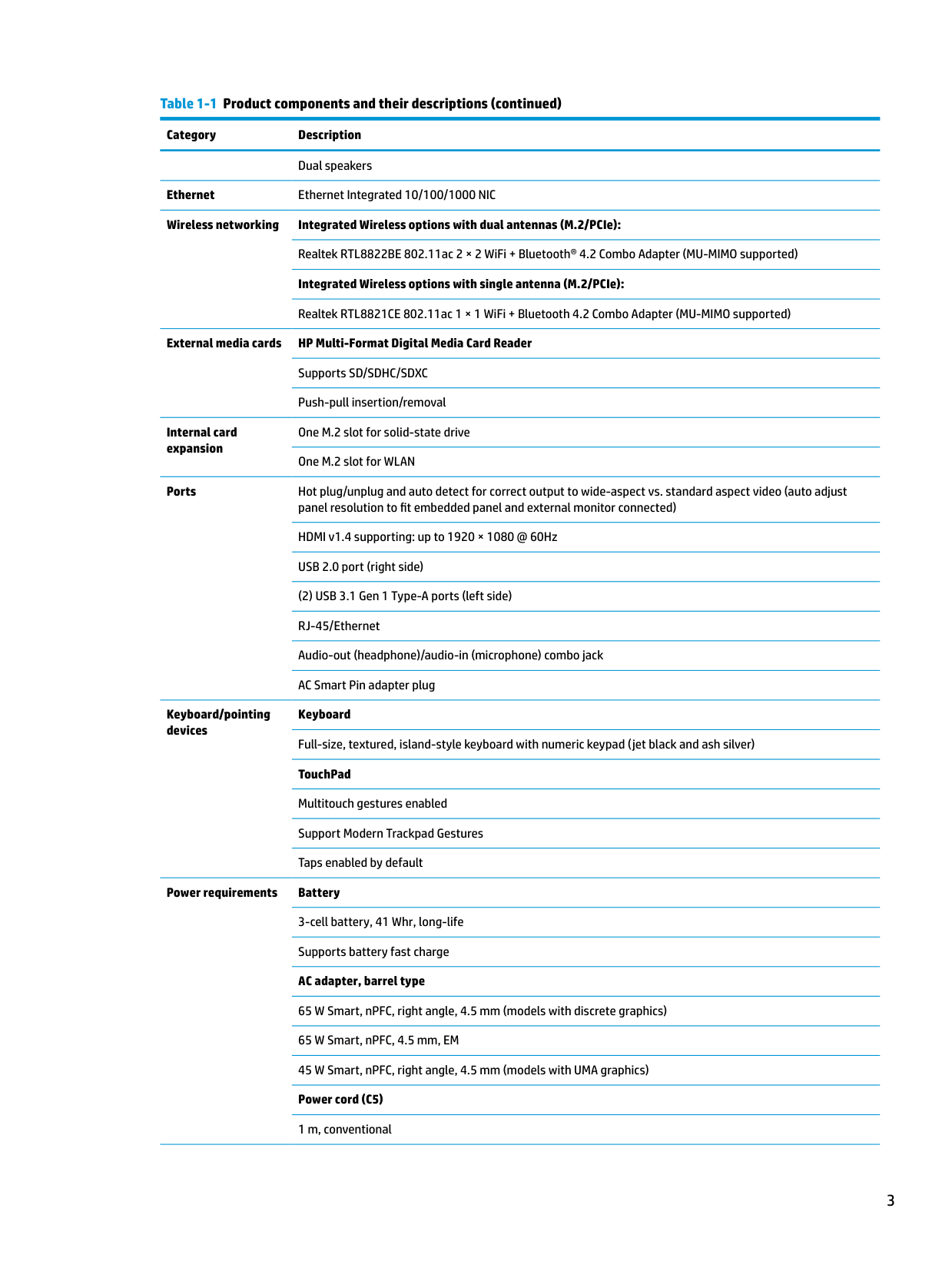
Dual speakers Ethernet Ethernet Integrated 10/100/1000 NIC Wireless networking Integrated Wireless options with dual antennas (M.2/PCIe):
Realtek RTL8822BE 802.11ac 2 × 2 WiFi + Bluetooth® 4.2 Combo Adapter (MU-MIMO supported) Integrated Wireless options with single antenna (M.2/PCIe): Realtek RTL8821CE 802.11ac 1 × 1 WiFi + Bluetooth 4.2 Combo Adapter (MU-MIMO supported)
External media cards HP Multi-Format Digital Media Card Reader Supports SD/SDHC/SDXC Push-pull insertion/removal
Internal card expansion
One M.2 slot for solid-state drive One M.2 slot for WLAN
Ports Hot plug/unplug and auto detect for correct output to wide-aspect vs. standard aspect video (auto adjust panel resolution to fit embedded panel and external monitor connected) HDMI v1.4 supporting: up to 1920 × 1080 @ 60Hz USB 2.0 port (right side)
(2) USB 3.1 Gen 1 Type-A ports (left side) RJ-45/Ethernet Audio-out (headphone)/audio-in (microphone) combo jack AC Smart Pin adapter plug
Keyboard/pointing devices
Keyboard Full-size, textured, island-style keyboard with numeric keypad (jet black and ash silver) TouchPad Multitouch gestures enabled Support Modern Trackpad Gestures Taps enabled by default
Power requirements Battery 3-cell battery, 41 Whr, long-life Supports battery fast charge AC adapter, barrel type 65 W Smart, nPFC, right angle, 4.5 mm (models with discrete graphics) 65 W Smart, nPFC, 4.5 mm, EM 45 W Smart, nPFC, right angle, 4.5 mm (models with UMA graphics) Power cord (C5) 1 m, conventional
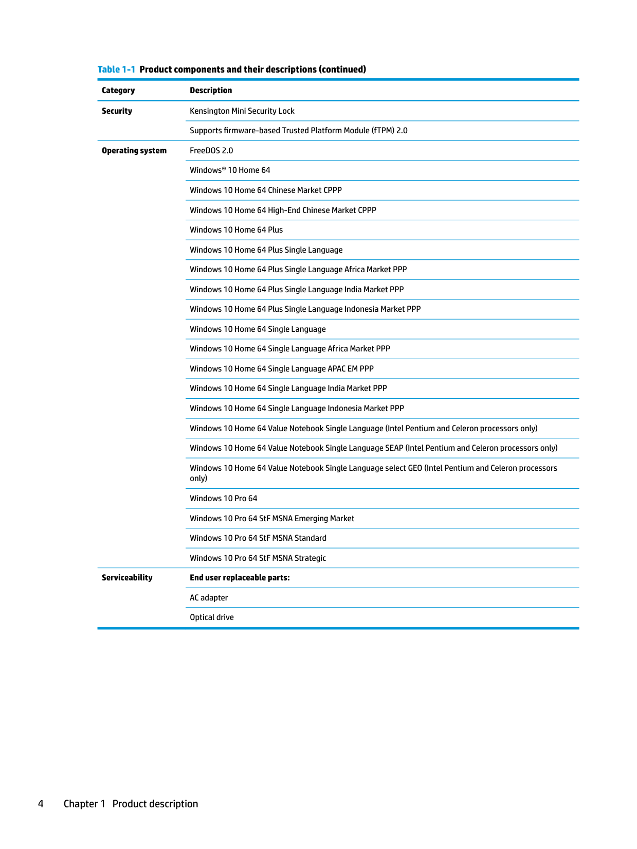
Security Kensington Mini Security Lock
Supports firmware-based Trusted Platform Module (fTPM) 2.0
Operating system FreeDOS 2.0 Windows® 10 Home 64 Windows 10 Home 64 Chinese Market CPPP Windows 10 Home 64 High-End Chinese Market CPPP Windows 10 Home 64 Plus Windows 10 Home 64 Plus Single Language Windows 10 Home 64 Plus Single Language Africa Market PPP Windows 10 Home 64 Plus Single Language India Market PPP Windows 10 Home 64 Plus Single Language Indonesia Market PPP Windows 10 Home 64 Single Language Windows 10 Home 64 Single Language Africa Market PPP Windows 10 Home 64 Single Language APAC EM PPP Windows 10 Home 64 Single Language India Market PPP Windows 10 Home 64 Single Language Indonesia Market PPP Windows 10 Home 64 Value Notebook Single Language (Intel Pentium and Celeron processors only) Windows 10 Home 64 Value Notebook Single Language SEAP (Intel Pentium and Celeron processors only) Windows 10 Home 64 Value Notebook Single Language select GEO (Intel Pentium and Celeron processors only) Windows 10 Pro 64 Windows 10 Pro 64 StF MSNA Emerging Market Windows 10 Pro 64 StF MSNA Standard Windows 10 Pro 64 StF MSNA Strategic
Serviceability End user replaceable parts: AC adapter Optical drive
2 Getting to know your computer
Your computer features top-rated components. This chapter provides details about your components, where they are located, and how they work.
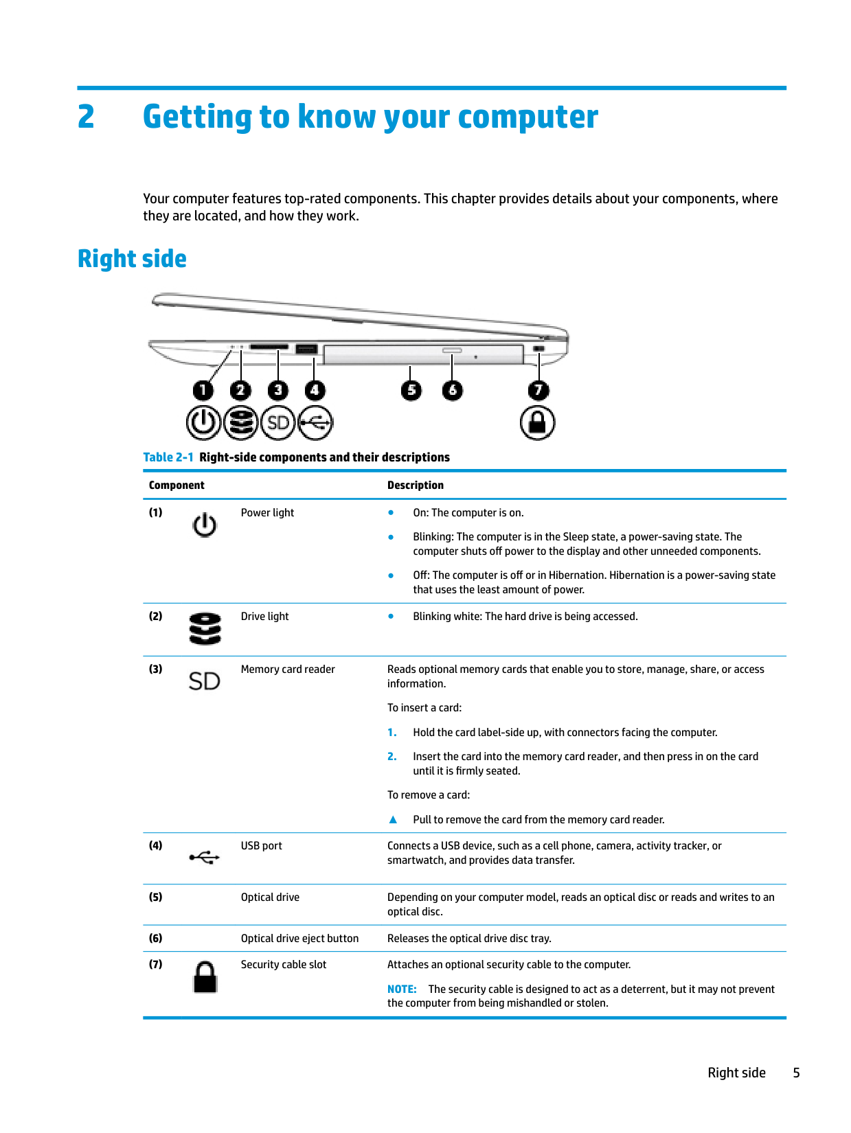
Right side

######## Table 2-1 Right-side components and their descriptions Component Description


To remove a card:
▲ Pull to remove the card from the memory card reader.


NOTE: The security cable is designed to act as a deterrent, but it may not prevent the computer from being mishandled or stolen.
Right side 5
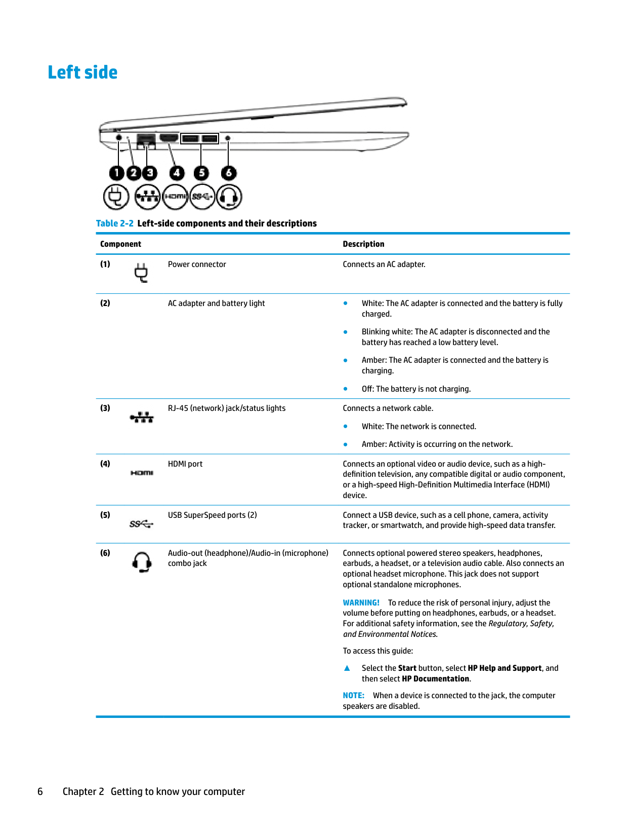
Left side

######## Table 2-2 Left-side components and their descriptions

######### Component Description


Connects optional powered stereo speakers, headphones, earbuds, a headset, or a television audio cable. Also connects an optional headset microphone. This jack does not support optional standalone microphones.

WARNING! To reduce the risk of personal injury, adjust the volume before putting on headphones, earbuds, or a headset. For additional safety information, see the Regulatory, Safety, and Environmental Notices.
To access this guide:
▲ Select the Start button, select HP Help and Support, and
then select HP Documentation.
NOTE: When a device is connected to the jack, the computer speakers are disabled.
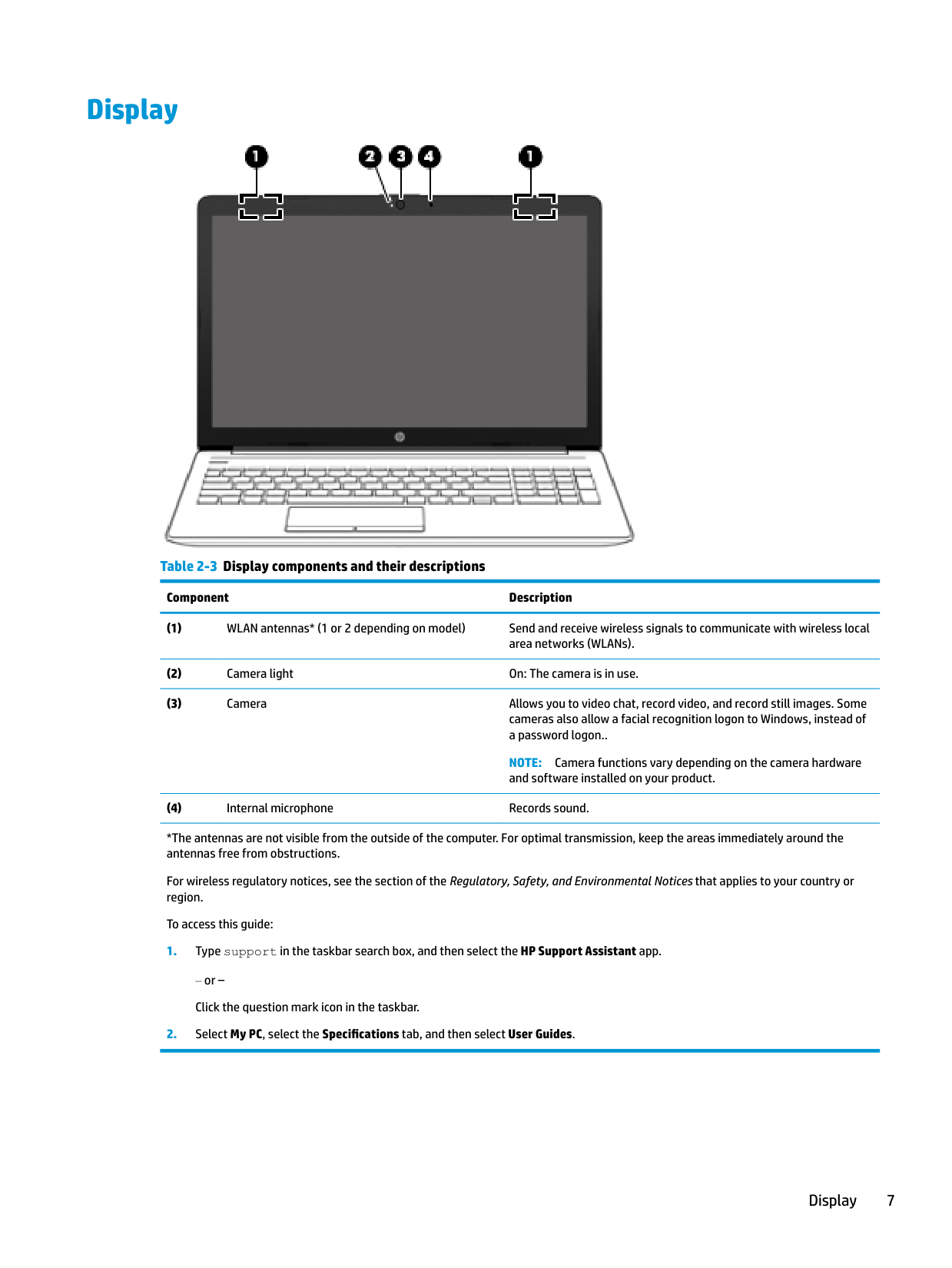
Display

######## Table 2-3 Display components and their descriptions
######### Component Description
NOTE: Camera functions vary depending on the camera hardware and software installed on your product.
*The antennas are not visible from the outside of the computer. For optimal transmission, keep the areas immediately around the antennas free from obstructions.
For wireless regulatory notices, see the section of the Regulatory, Safety, and Environmental Notices that applies to your country or region.
To access this guide:
‒ or – Click the question mark icon in the taskbar.
Display 7
Keyboard area
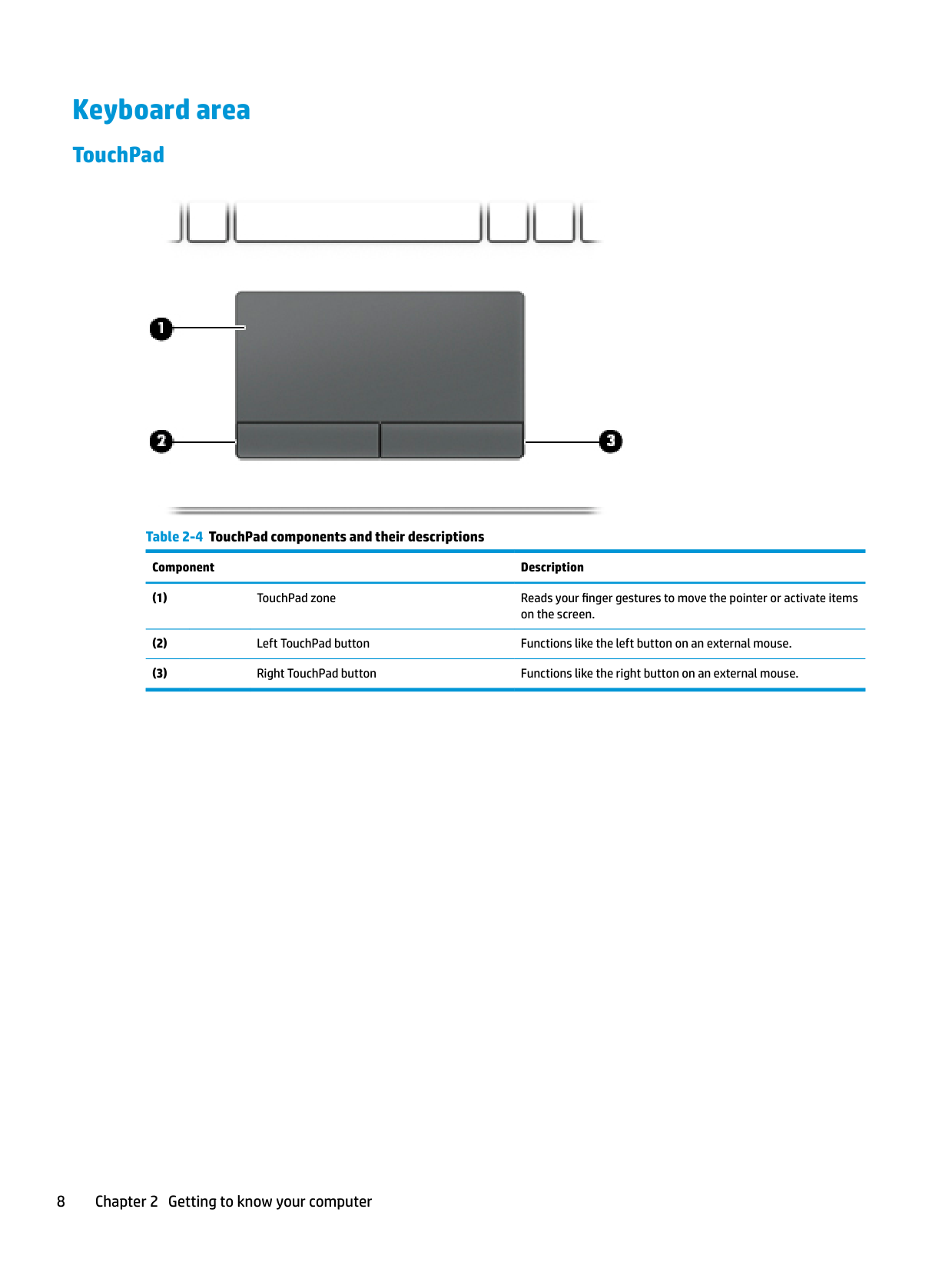
#### TouchPad

######## Table 2-4 TouchPad components and their descriptions
######### Component Description
#### Lights

######## Table 2-5 Lights and their descriptions
######### Component Description

● Off: Computer sound is on.
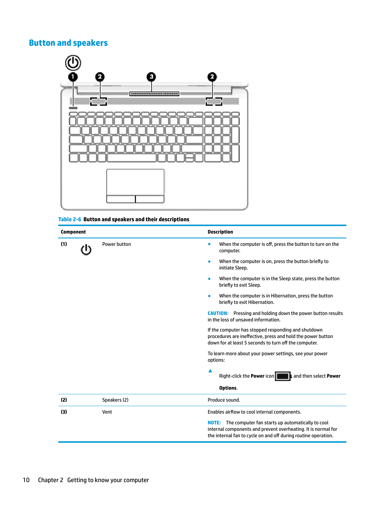
#### Button and speakers

######## Table 2-6 Button and speakers and their descriptions
######### Component Description

CAUTION: Pressing and holding down the power button results in the loss of unsaved information. If the computer has stopped responding and shutdown procedures are ineffective, press and hold the power button down for at least 5 seconds to turn off the computer. To learn more about your power settings, see your power options:
▲
Right-click the Power icon , and then select Power Options.

NOTE: The computer fan starts up automatically to cool internal components and prevent overheating. It is normal for the internal fan to cycle on and off during routine operation.
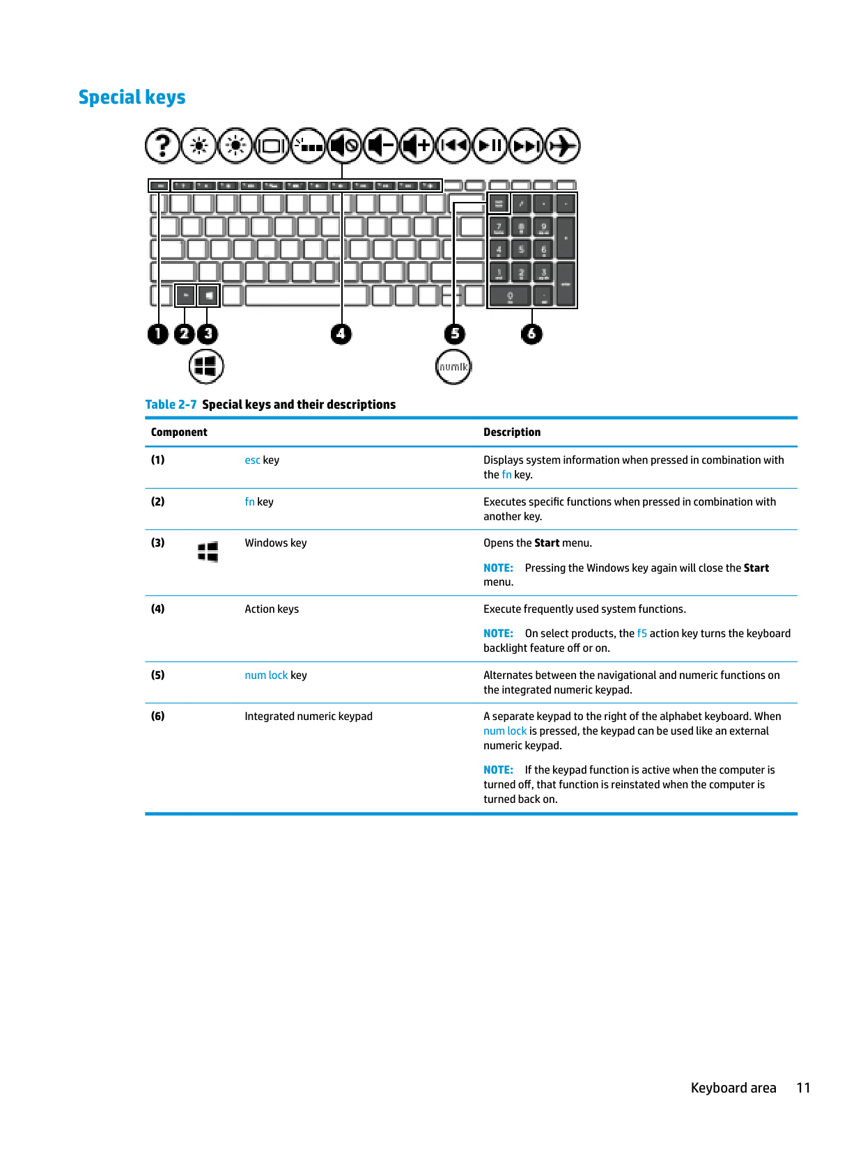
#### Special keys

######## Table 2-7 Special keys and their descriptions
######### Component Description

NOTE: Pressing the Windows key again will close the Start menu.
NOTE: On select products, the f5 action key turns the keyboard backlight feature off or on.
NOTE: If the keypad function is active when the computer is turned off, that function is reinstated when the computer is turned back on.
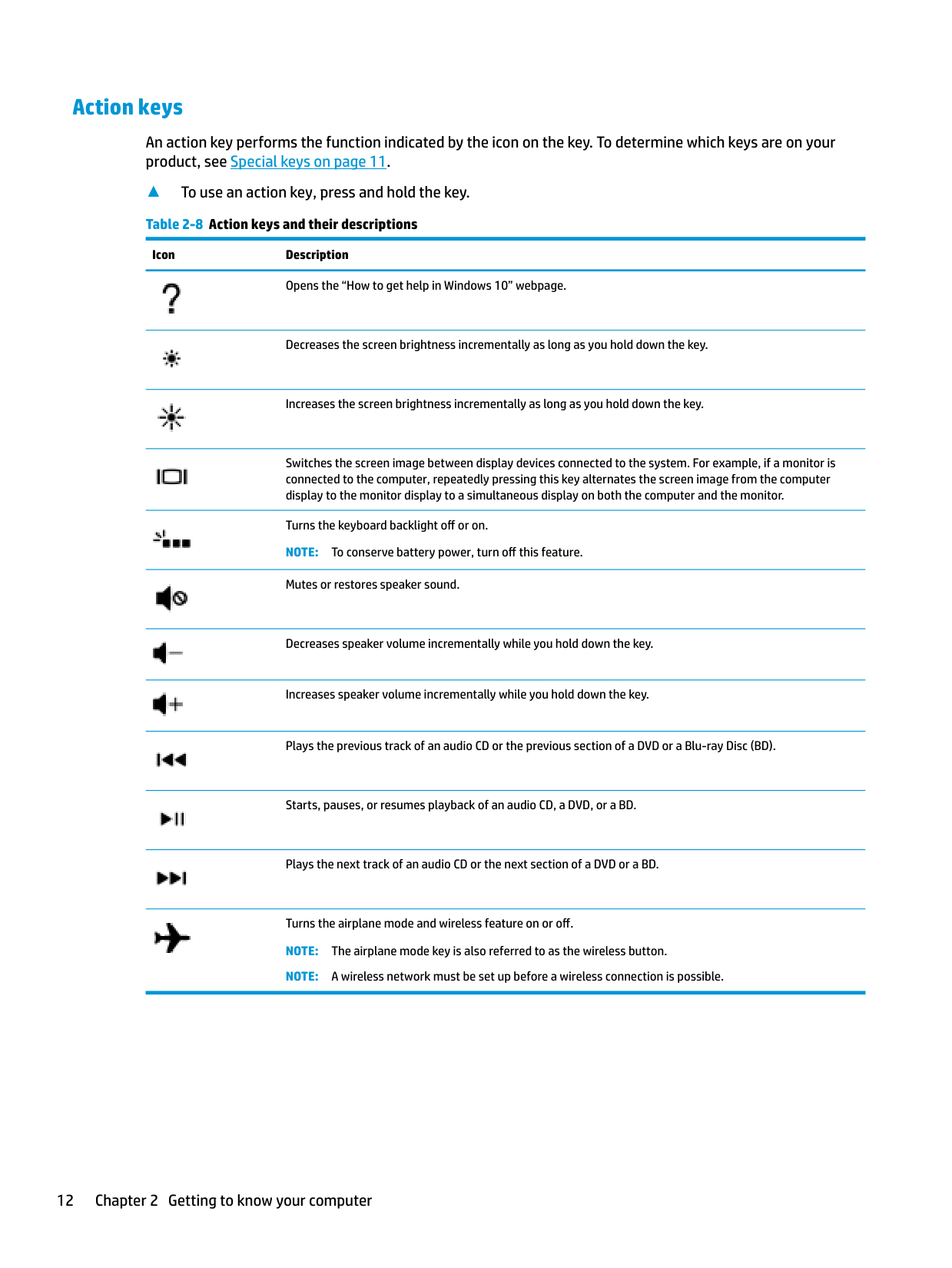
#### Action keys
An action key performs the function indicated by the icon on the key. To determine which keys are on your product, see Special keys on page 11.
▲ To use an action key, press and hold the key. Table 2-8 Action keys and their descriptions
Icon Description

Opens the “How to get help in Windows 10” webpage.


Decreases the screen brightness incrementally as long as you hold down the key.
Increases the screen brightness incrementally as long as you hold down the key.


Switches the screen image between display devices connected to the system. For example, if a monitor is connected to the computer, repeatedly pressing this key alternates the screen image from the computer display to the monitor display to a simultaneous display on both the computer and the monitor.
Turns the keyboard backlight off or on. NOTE: To conserve battery power, turn off this feature. Mutes or restores speaker sound.
Decreases speaker volume incrementally while you hold down the key.
Increases speaker volume incrementally while you hold down the key.
Plays the previous track of an audio CD or the previous section of a DVD or a Blu-ray Disc (BD).
Starts, pauses, or resumes playback of an audio CD, a DVD, or a BD.
Plays the next track of an audio CD or the next section of a DVD or a BD.
Turns the airplane mode and wireless feature on or off. NOTE: The airplane mode key is also referred to as the wireless button. NOTE: A wireless network must be set up before a wireless connection is possible.
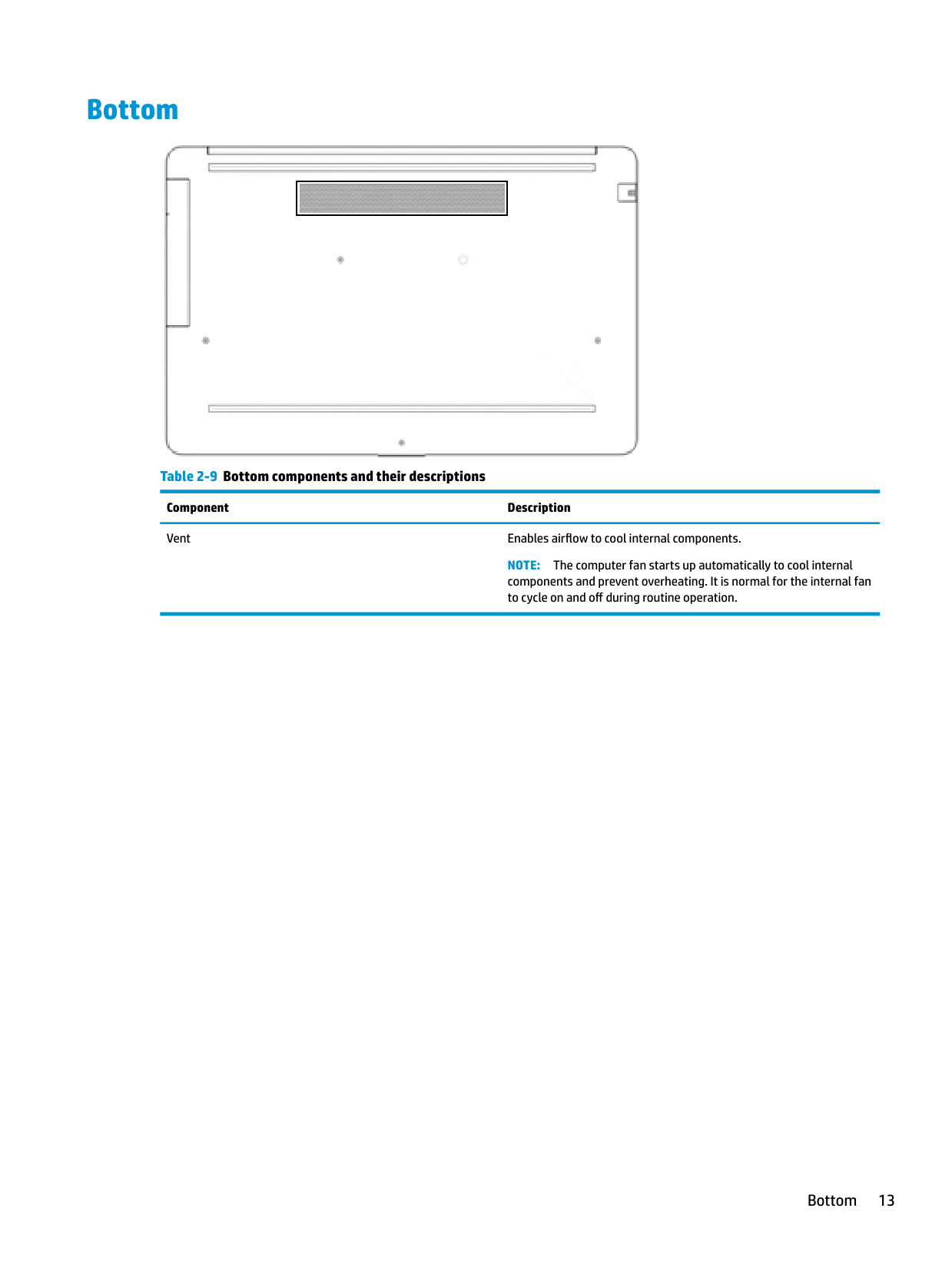
Bottom

Table 2-9 Bottom components and their descriptions Component Description Vent Enables airflow to cool internal components.
NOTE: The computer fan starts up automatically to cool internal components and prevent overheating. It is normal for the internal fan to cycle on and off during routine operation.
Bottom 13
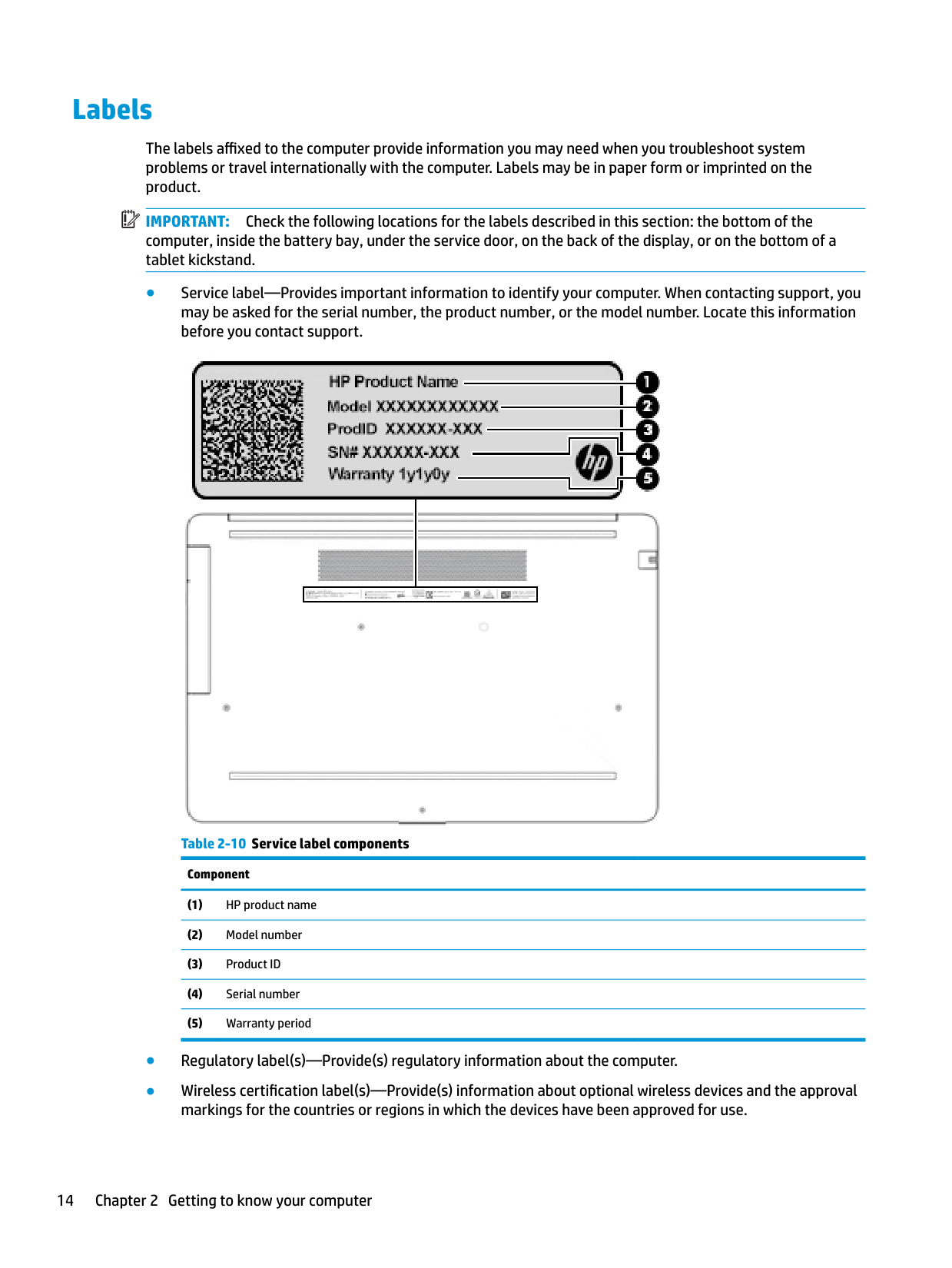
Labels
The labels affixed to the computer provide information you may need when you troubleshoot system problems or travel internationally with the computer. Labels may be in paper form or imprinted on the product.
| | |---|
IMPORTANT: Check the following locations for the labels described in this section: the bottom of the computer, inside the battery bay, under the service door, on the back of the display, or on the bottom of a tablet kickstand.
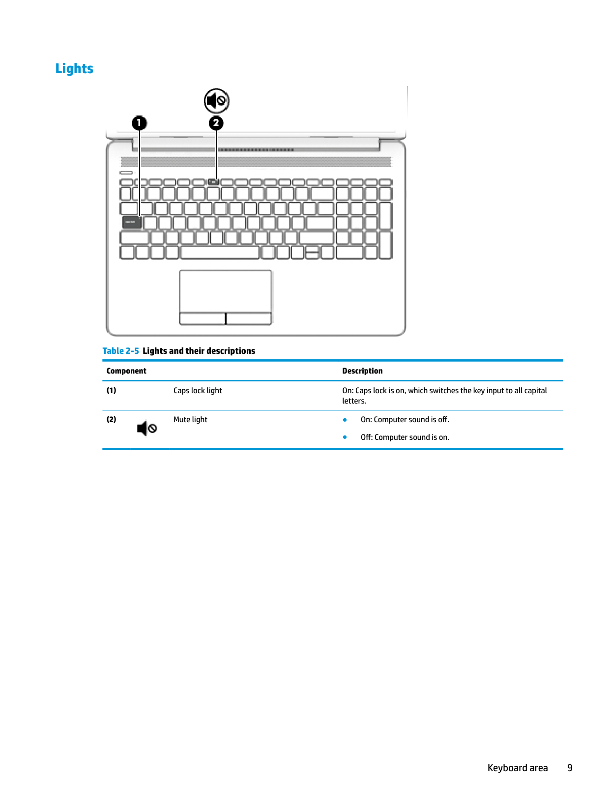

Table 2-10 Service label components
Component
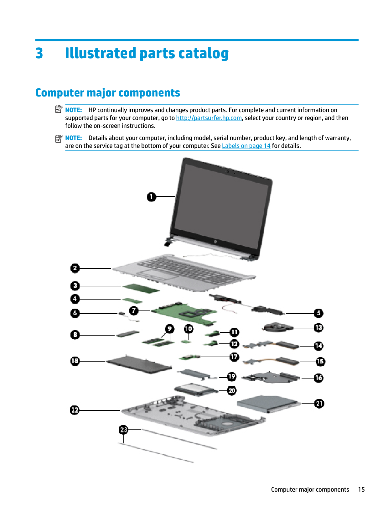
3 Illustrated parts catalog
Computer major components
| | |---|
NOTE: HP continually improves and changes product parts. For complete and current information on supported parts for your computer, go to http://partsurfer.hp.com, select your country or region, and then follow the on-screen instructions.
| | |---|
NOTE: Details about your computer, including model, serial number, product key, and length of warranty, are on the service tag at the bottom of your computer. See Labels on page 14 for details.

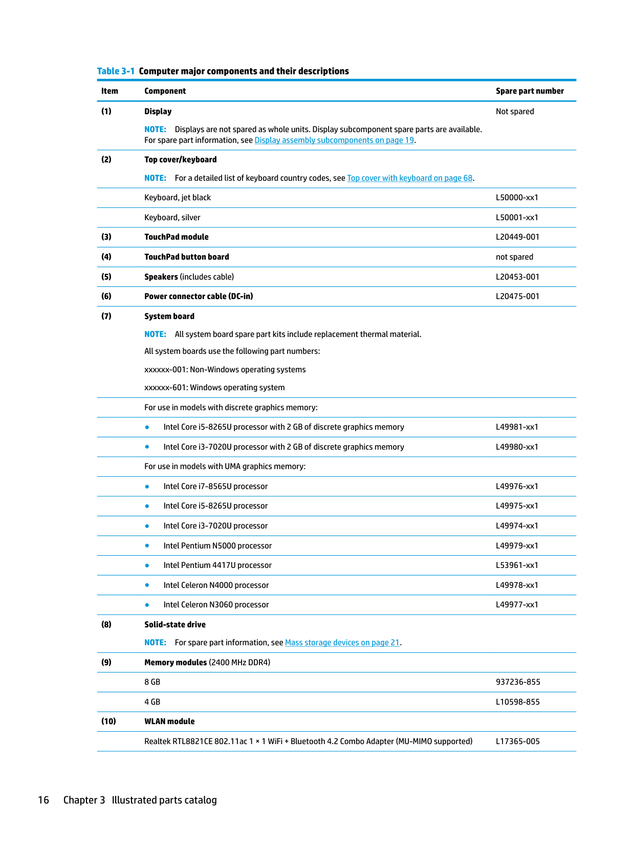
######## Table 3-1 Computer major components and their descriptions
Item Component Spare part number
NOTE: Displays are not spared as whole units. Display subcomponent spare parts are available. For spare part information, see Display assembly subcomponents on page 19.
Not spared
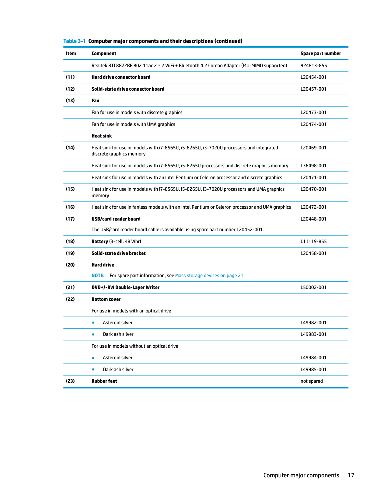
######## Table 3-1 Computer major components and their descriptions (continued)
######### Item Component Spare part number
Realtek RTL8822BE 802.11ac 2 × 2 WiFi + Bluetooth 4.2 Combo Adapter (MU-MIMO supported) 924813-855
L20469-001
Heat sink for use in models with i7-8565U, i5-8265U processors and discrete graphics memory L36498-001 Heat sink for use in models with an Intel Pentium or Celeron processor and discrete graphics L20471-001
L20470-001
L20448-001
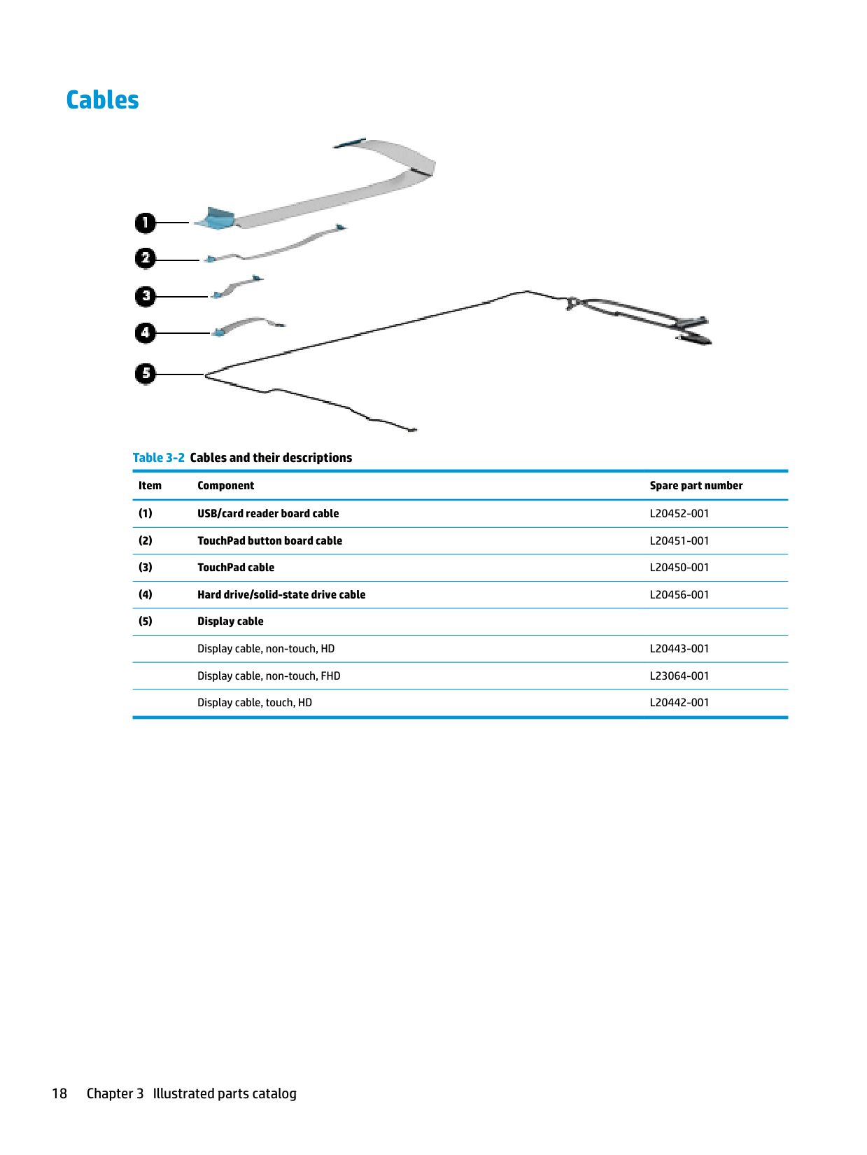
Cables

######## Table 3-2 Cables and their descriptions
Item Component Spare part number
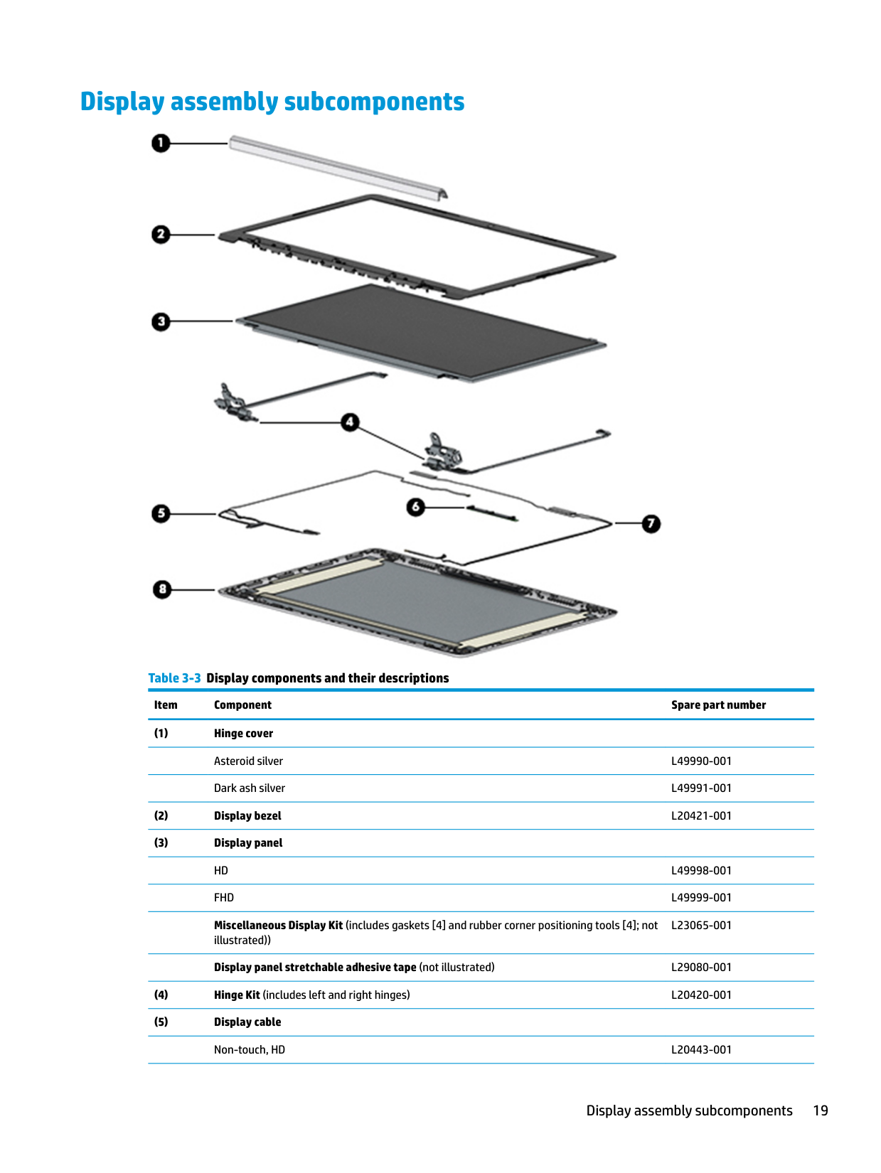
Display assembly subcomponents

######## Table 3-3 Display components and their descriptions
######### Item Component Spare part number
Miscellaneous Display Kit (includes gaskets [4] and rubber corner positioning tools [4]; not illustrated))
L23065-001
Display panel stretchable adhesive tape (not illustrated) L29080-001
Display assembly subcomponents 19
######## Table 3-3 Display components and their descriptions (continued)
######### Item Component Spare part number
Non-touch, FHD L23064-001 Touch, HD L20442-001
Miscellaneous parts
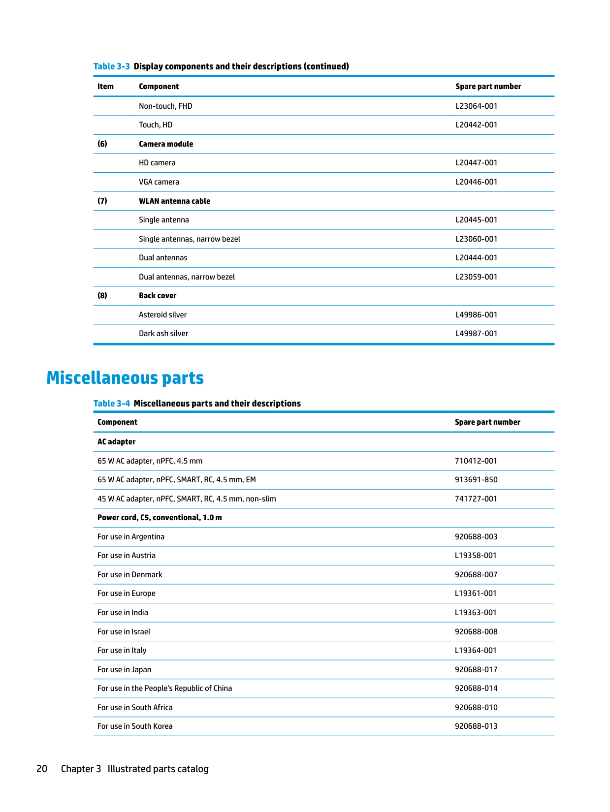
######## Table 3-4 Miscellaneous parts and their descriptions Component Spare part number AC adapter
65 W AC adapter, nPFC, 4.5 mm 710412-001 65 W AC adapter, nPFC, SMART, RC, 4.5 mm, EM 913691-850 45 W AC adapter, nPFC, SMART, RC, 4.5 mm, non-slim 741727-001 Power cord, C5, conventional, 1.0 m
For use in Argentina 920688-003 For use in Austria L19358-001 For use in Denmark 920688-007 For use in Europe L19361-001 For use in India L19363-001 For use in Israel 920688-008 For use in Italy L19364-001 For use in Japan 920688-017 For use in the People’s Republic of China 920688-014 For use in South Africa 920688-010 For use in South Korea 920688-013
######## Table 3-4 Miscellaneous parts and their descriptions (continued)
######### Component Spare part number
For use in Switzerland L19370-001 For use in Taiwan 920688-015 For use in Thailand 920688-012 For use in the United Kingdom L19373-001 Power adapter (for use in Japan) 226768-001 Screw Kit L20476-001
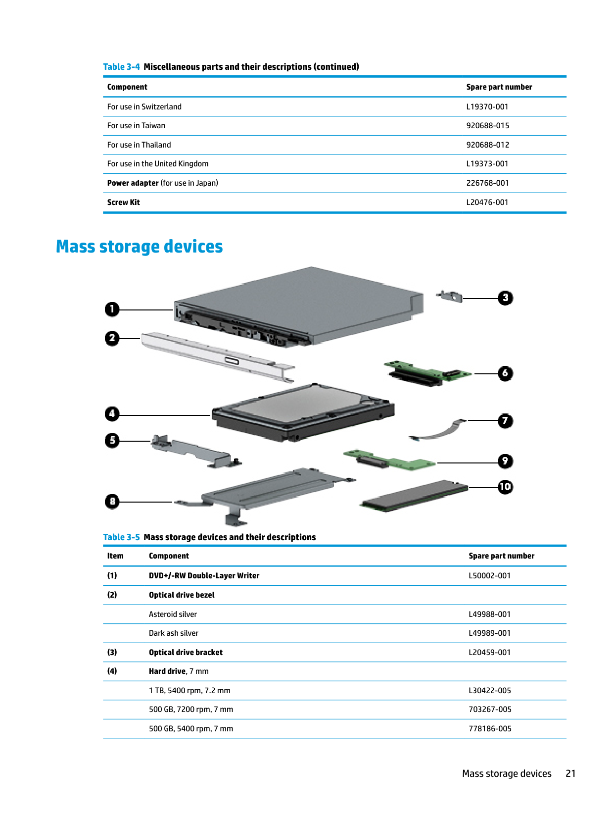
Mass storage devices

######## Table 3-5 Mass storage devices and their descriptions
Item Component Spare part number
Mass storage devices 21
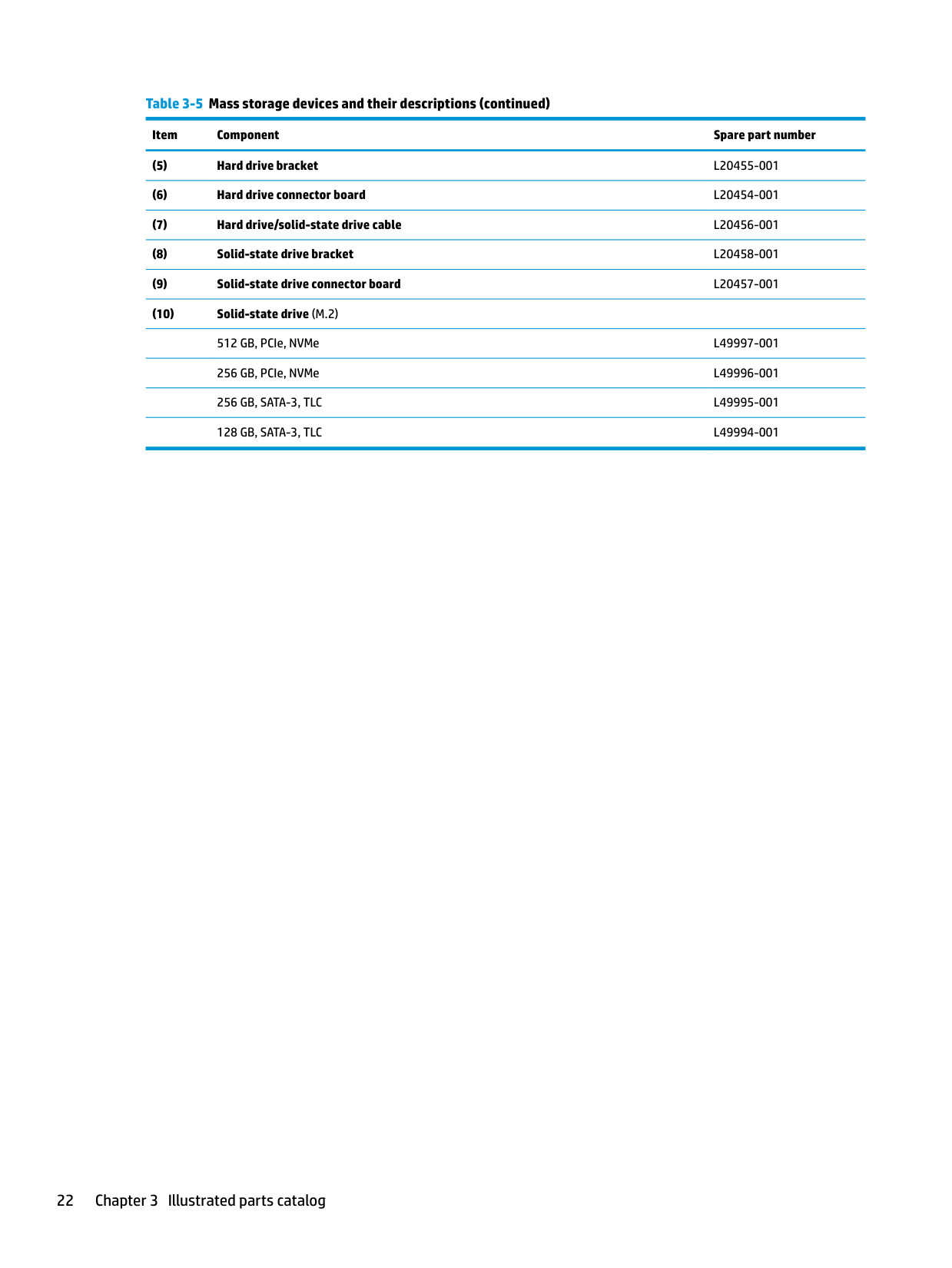
######## Table 3-5 Mass storage devices and their descriptions (continued)
Item Component Spare part number
4 Removal and replacement procedures preliminary requirements
Tools required
You will need the following tools to complete the removal and replacement procedures:
Service considerations
The following sections include some of the considerations that you must keep in mind during disassembly and assembly procedures.
| | |---|
NOTE: As you remove each subassembly from the computer, place the subassembly (and all accompanying screws) away from the work area to prevent damage.
#### Plastic parts
CAUTION: Using excessive force during disassembly and reassembly can damage plastic parts.
#### Cables and connectors
CAUTION: When servicing the computer, be sure that cables are placed in their proper locations during the reassembly process. Improper cable placement can damage the computer.
Cables must be handled with extreme care to avoid damage. Apply only the tension required to unseat or seat the cables during removal and insertion. Handle cables by the connector whenever possible. In all cases, avoid bending, twisting, or tearing cables. Be sure that cables are routed in such a way that they cannot be caught or snagged by parts being removed or replaced. Handle flex cables with extreme care; these cables tear easily.
Tools required 23
Drive handling CAUTION: Drives are fragile components that must be handled with care. To prevent damage to the computer, damage to a drive, or loss of information, observe these precautions: Before removing or inserting a hard drive, shut down the computer. If you are unsure whether the computer is off or in Hibernation, turn the computer on, and then shut it down through the operating system. Before handling a drive, be sure that you are discharged of static electricity. While handling a drive, avoid touching the connector. Before removing an optical drive, be sure that a disc is not in the drive and be sure that the optical drive tray is closed. Handle drives on surfaces covered with at least one inch of shock-proof foam. Avoid dropping drives from any height onto any surface. After removing a hard drive or an optical drive, place it in a static-proof bag. Avoid exposing an internal hard drive to products that have magnetic fields, such as monitors or speakers. Avoid exposing a drive to temperature extremes or liquids. If a drive must be mailed, place the drive in a bubble pack mailer or other suitable form of protective packaging and label the package “FRAGILE.”
#### Workstation guidelines
Follow these grounding workstation guidelines:
Electrostatic discharge information
A sudden discharge of static electricity from your finger or other conductor can destroy static-sensitive devices or microcircuitry. Often the spark is neither felt nor heard, but damage occurs. An electronic device exposed to electrostatic discharge (ESD) may not appear to be affected at all and can work perfectly throughout a normal cycle. The device may function normally for a while, but it has been degraded in the internal layers, reducing its life expectancy.
Networks built into many integrated circuits provide some protection, but in many cases, the discharge contains enough power to alter device parameters or melt silicon junctions.
| | |---|
IMPORTANT: To prevent damage to the device when you are removing or installing internal components, observe these precautions: Keep components in their electrostatic-safe containers until you are ready to install them. Before touching an electronic component, discharge static electricity by using the guidelines described in this section. Avoid touching pins, leads, and circuitry. Handle electronic components as little as possible. If you remove a component, place it in an electrostatic-safe container.
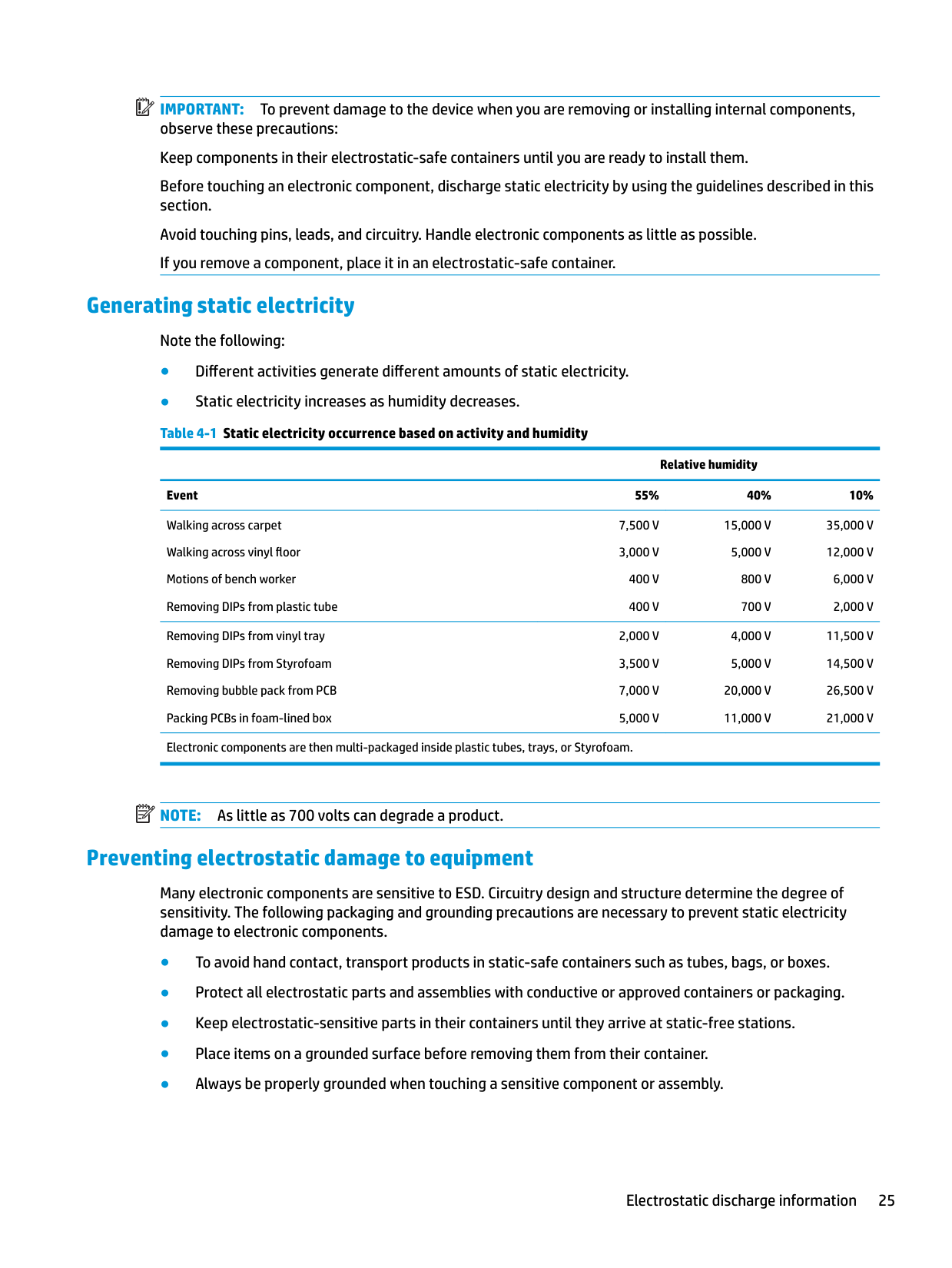
#### Generating static electricity
Note the following:
Relative humidity Event 55% 40% 10% Walking across carpet Walking across vinyl floor Motions of bench worker Removing DIPs from plastic tube
7,500 V 3,000 V
15,000 V
35,000 V 12,000 V
5,000 V 800 V 700 V
400 V 400 V
6,000 V 2,000 V
Removing DIPs from vinyl tray Removing DIPs from Styrofoam Removing bubble pack from PCB Packing PCBs in foam-lined box
Electronic components are then multi-packaged inside plastic tubes, trays, or Styrofoam.
20,000 V 11,000 V
11,500 V 14,500 V 26,500 V 21,000 V
| | |---|
NOTE: As little as 700 volts can degrade a product.
#### Preventing electrostatic damage to equipment
Many electronic components are sensitive to ESD. Circuitry design and structure determine the degree of sensitivity. The following packaging and grounding precautions are necessary to prevent static electricity damage to electronic components.
Electrostatic discharge information 25
#### Personal grounding methods and equipment
Use the following equipment to prevent static electricity damage to electronic components:
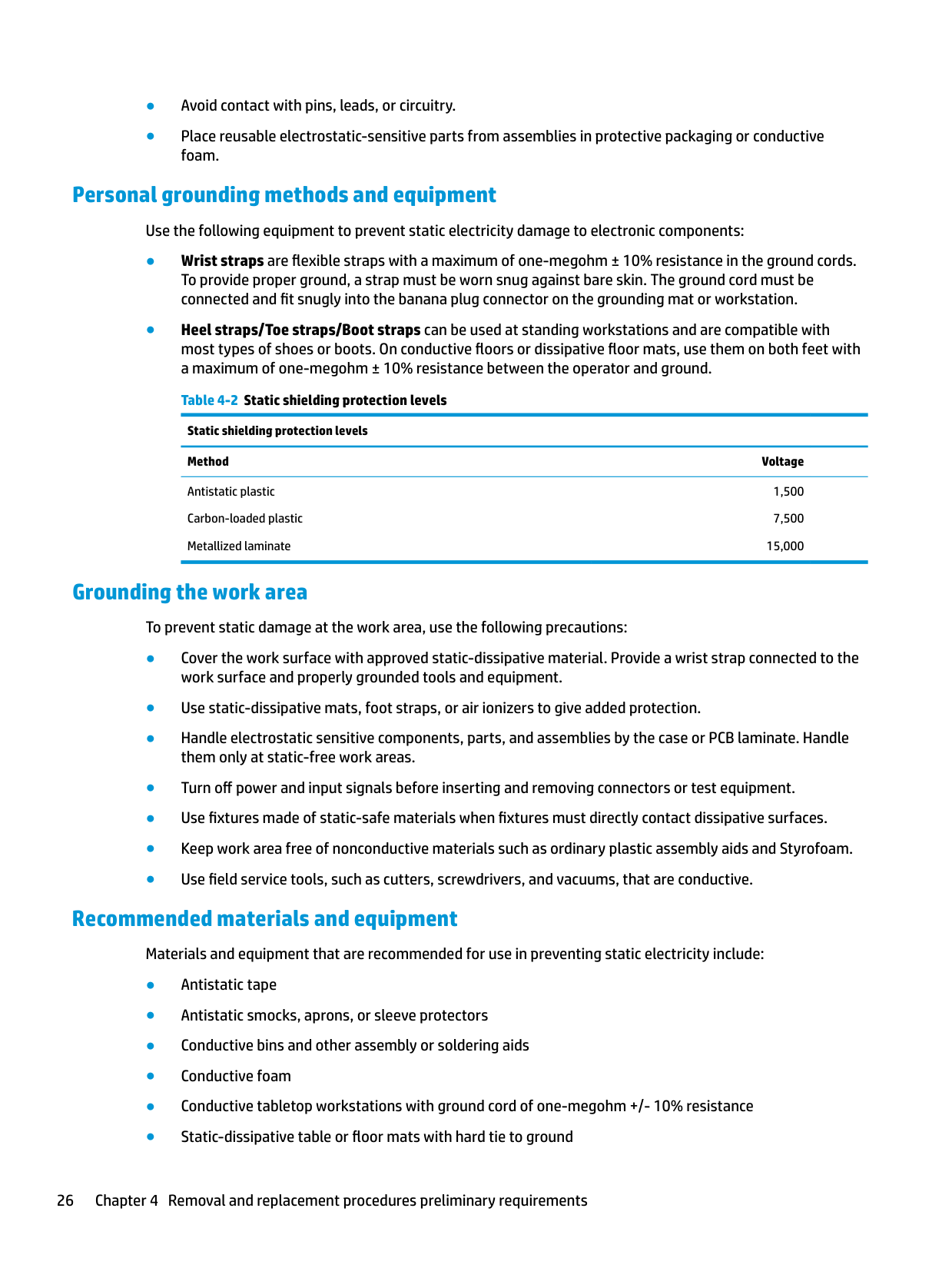
Static shielding protection levels Method Voltage
Antistatic plastic Carbon-loaded plastic Metallized laminate
1,500 7,500
15,000
#### Grounding the work area
To prevent static damage at the work area, use the following precautions:
#### Recommended materials and equipment
Materials and equipment that are recommended for use in preventing static electricity include:
Packaging and transporting guidelines
Follow these grounding guidelines when packaging and transporting equipment:
Packaging and transporting guidelines 27
5 Removal and replacement procedures for Customer Self-Repair parts
| | |---|
This chapter provides removal and replacement procedures for Customer Self-Repair parts. NOTE: The Customer Self-Repair program is not available in all locations. Installing a part not supported by the Customer Self-Repair program may void your warranty. Check your warranty to determine if Customer Self-Repair is supported in your location.
Component replacement procedures
| | |---|
NOTE: Details about your computer, including model, serial number, product key, and length of warranty, are on the service tag at the bottom of your computer. See Labels on page 14 for details.
| | |---|
NOTE: HP continually improves and changes product parts. For complete and current information on supported parts for your computer, go to http://partsurfer.hp.com, select your country or region, and then follow the on-screen instructions.
#### Preparation for disassembly
See Removal and replacement procedures preliminary requirements on page 23 for initial safety procedures.
#### Optical drive
######## Table 5-1 Spare part description and number
######### Description Spare part number
DVD+/-RW Double-Layer Writer L50002-001 Optical drive bracket L20459-001 Optical drive bezel - asteroid silver L49988-001 Optical drive bezel - dark ash silver L49989-001
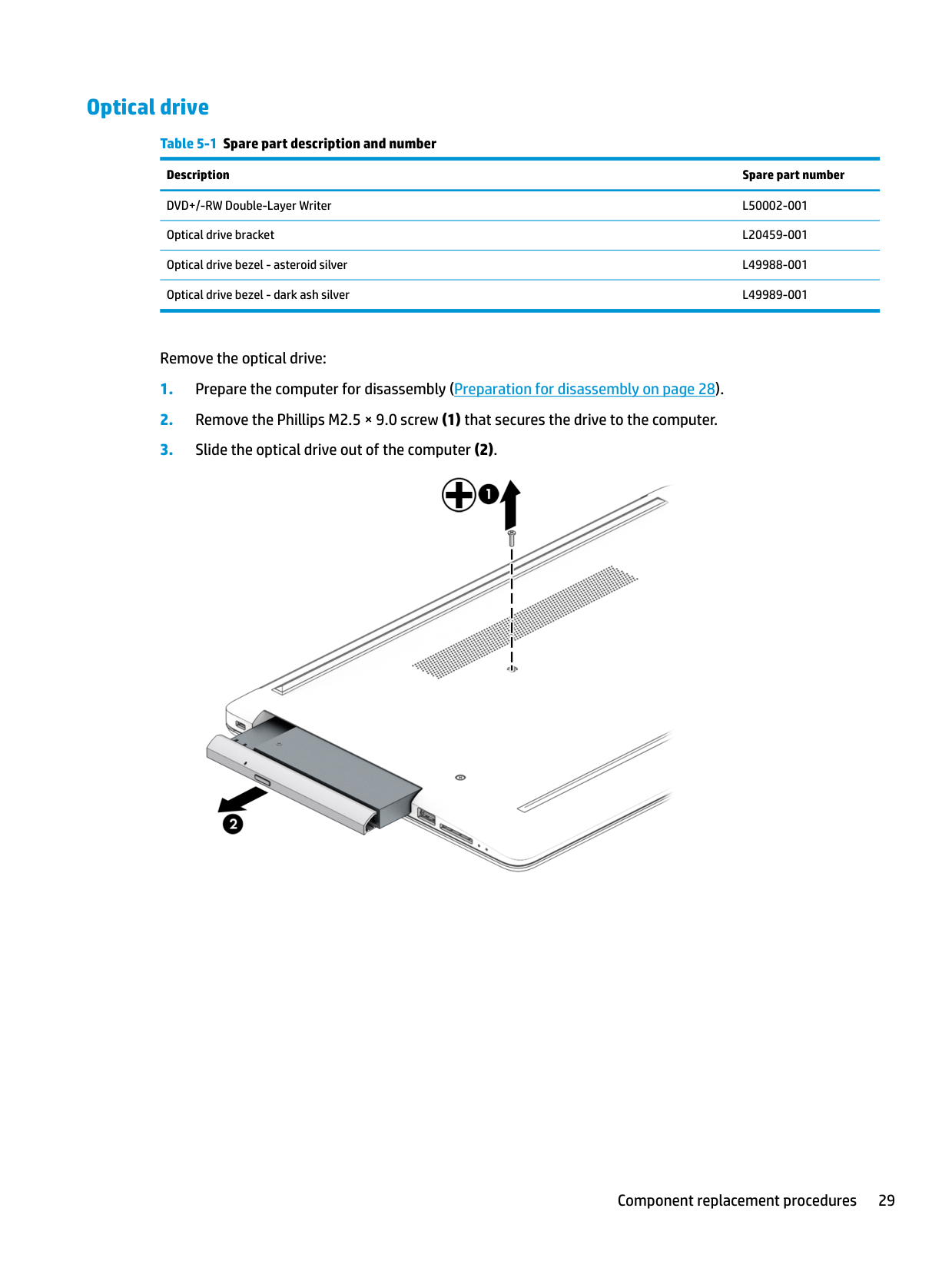
Remove the optical drive:


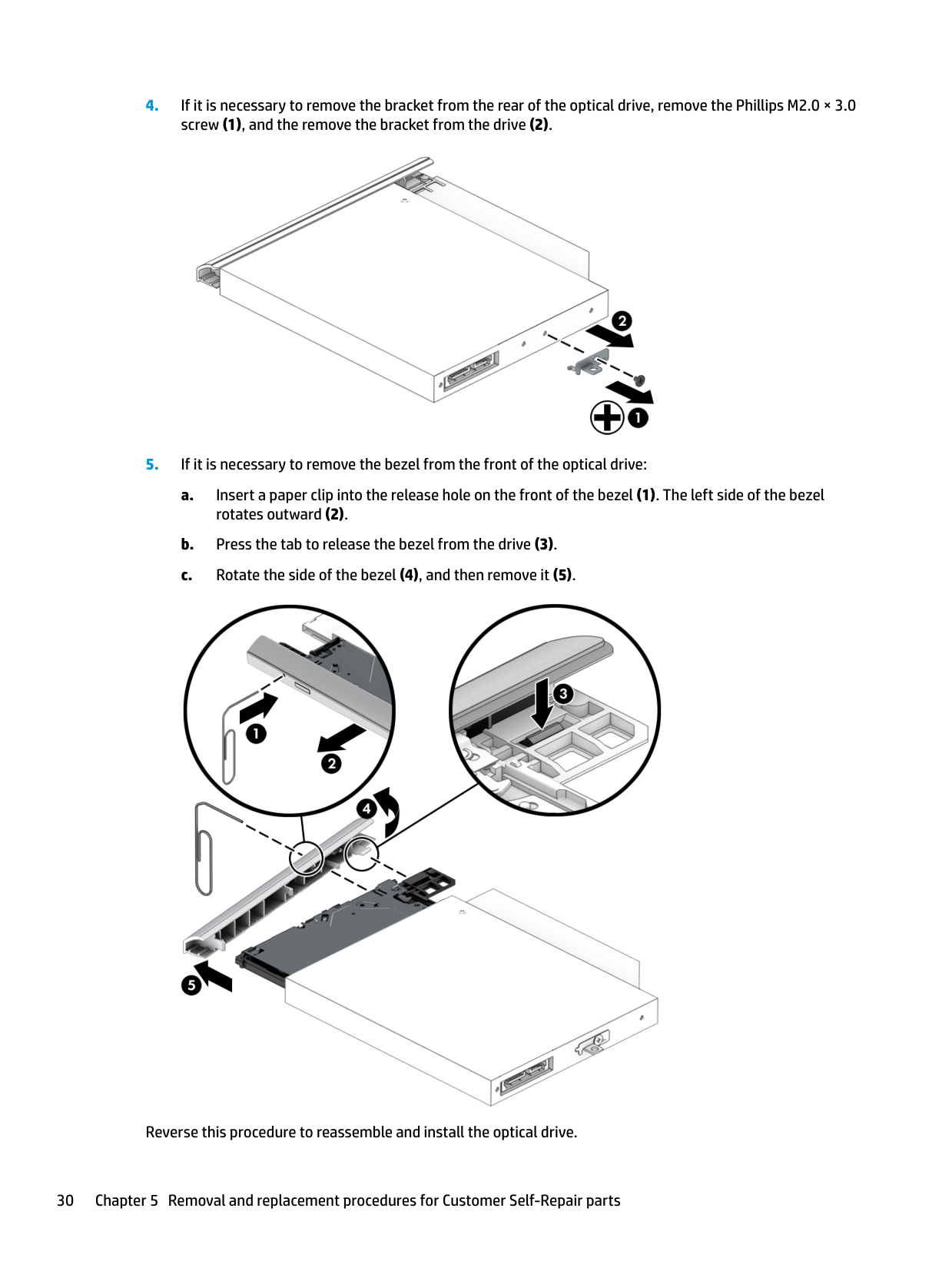
Reverse this procedure to reassemble and install the optical drive.
6 Removal and replacement procedures for Authorized Service Provider parts
This chapter provides removal and replacement procedures for Authorized Service Provider only parts. CAUTION: Components described in this chapter should only be accessed by an authorized service provider. Accessing these parts can damage the computer or void the warranty.
Component replacement procedures
| | |---|
NOTE: Details about your computer, including model, serial number, product key, and length of warranty, are on the service tag at the bottom of your computer. See Labels on page 14 for details.
| | |---|
NOTE: HP continually improves and changes product parts. For complete and current information on supported parts for your computer, go to http://partsurfer.hp.com, select your country or region, and then follow the on-screen instructions.
There are as many as 46 screws that must be removed, replaced, and/or loosened when servicing Authorized Service Provider only parts. Make special note of each screw size and location during removal and replacement.
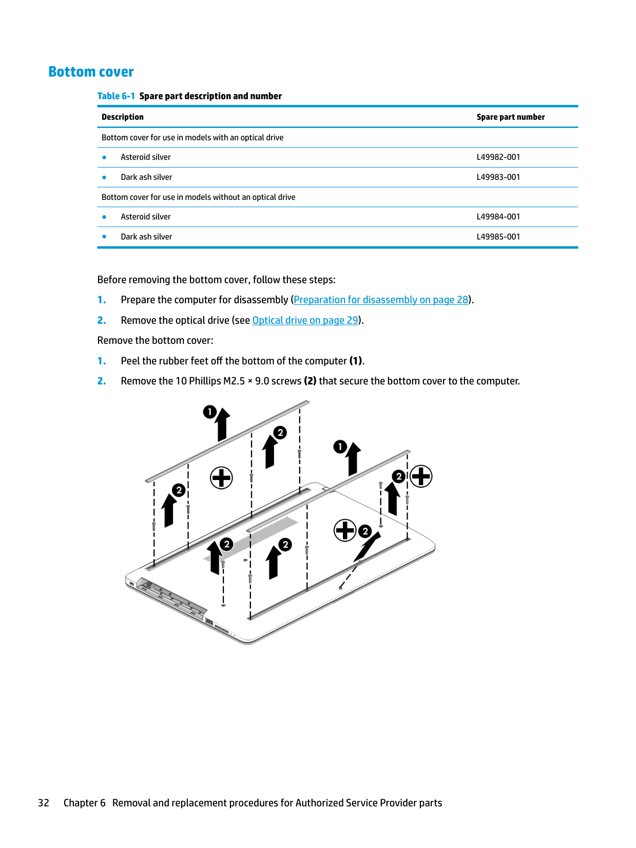
#### Bottom cover
Table 6-1 Spare part description and number Description Spare part number Bottom cover for use in models with an optical drive
Before removing the bottom cover, follow these steps:


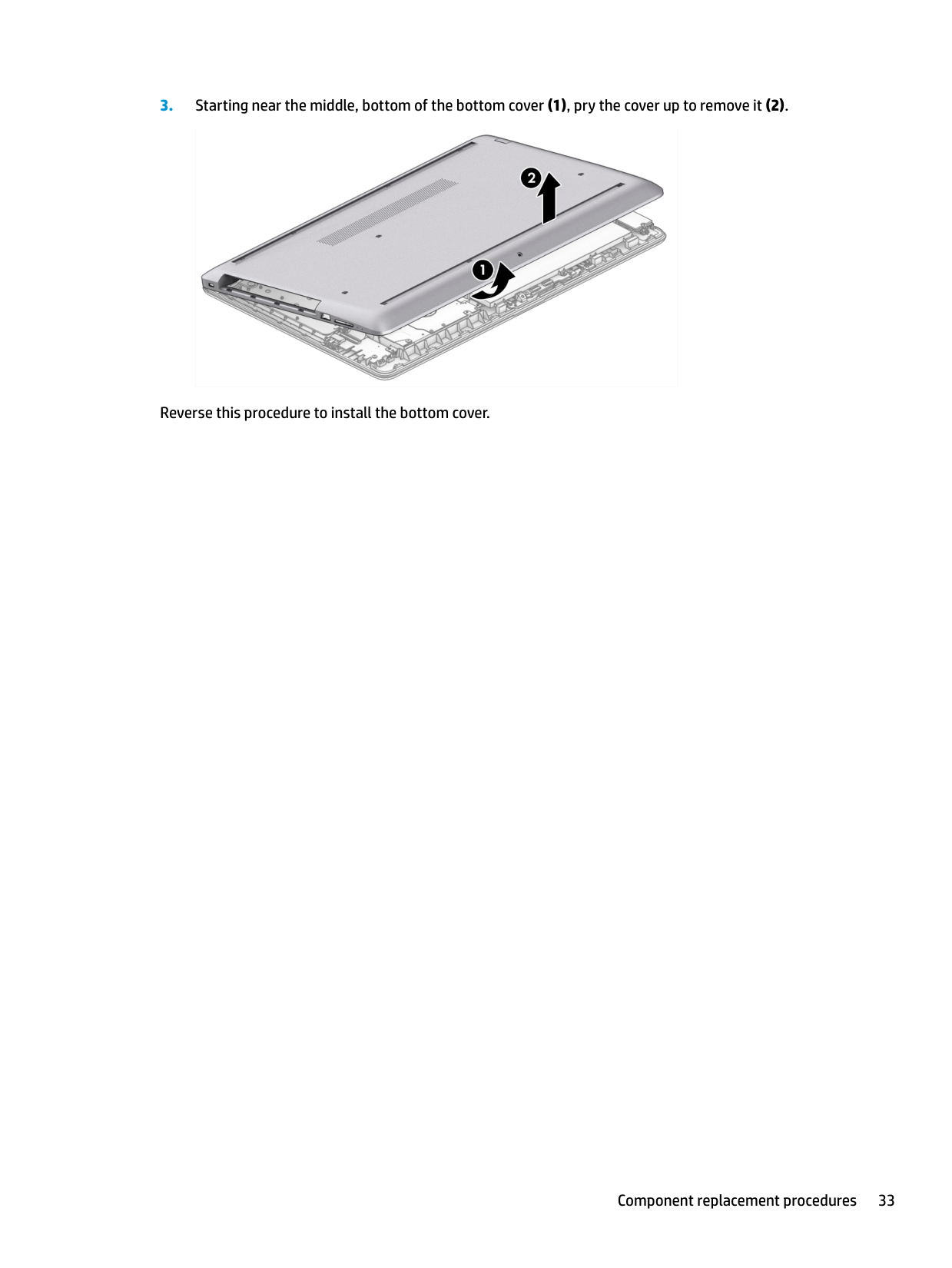
Reverse this procedure to install the bottom cover.
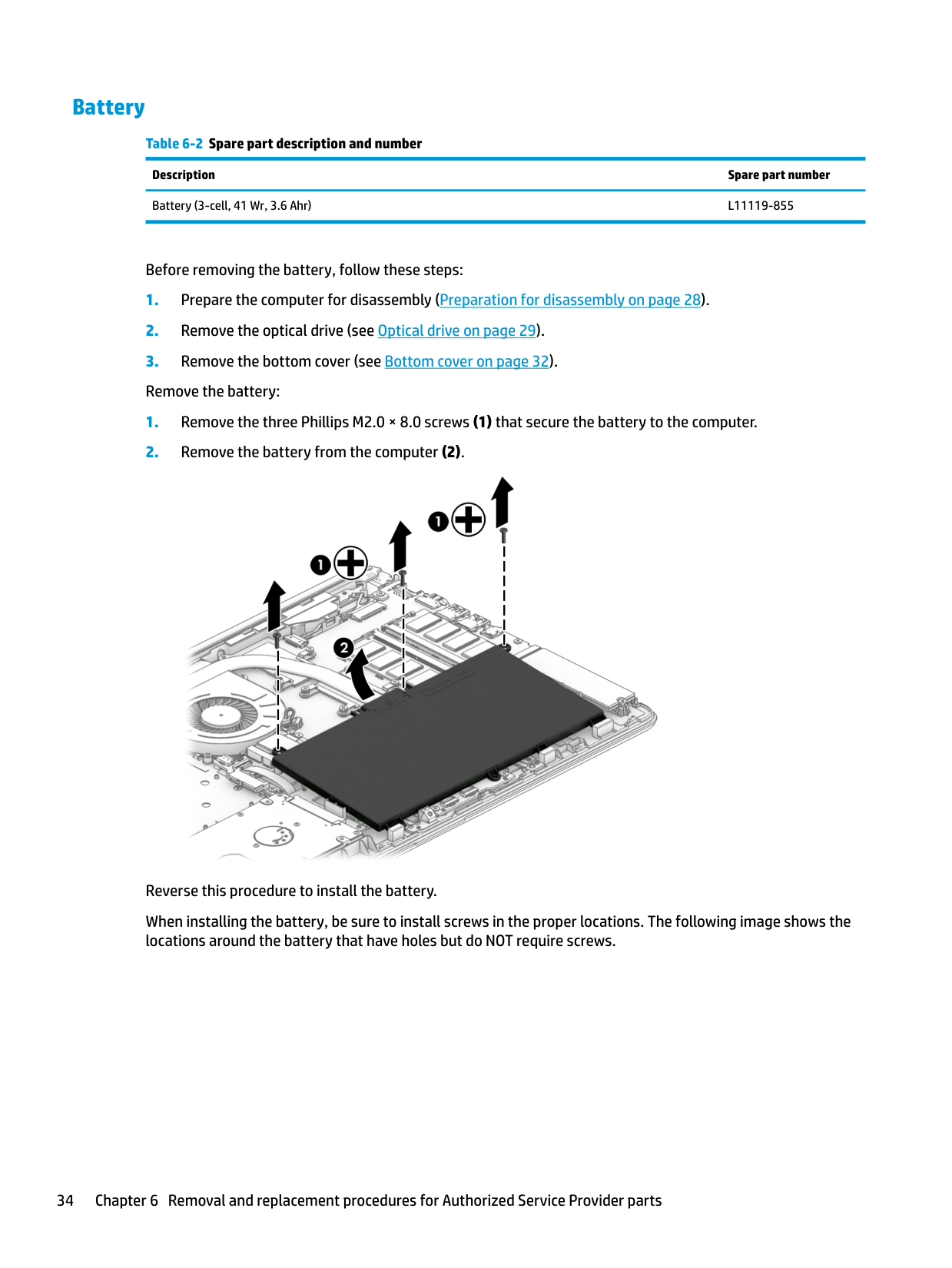
#### Battery
Table 6-2 Spare part description and number Description Spare part number Battery (3-cell, 41 Wr, 3.6 Ahr) L11119-855
Before removing the battery, follow these steps:

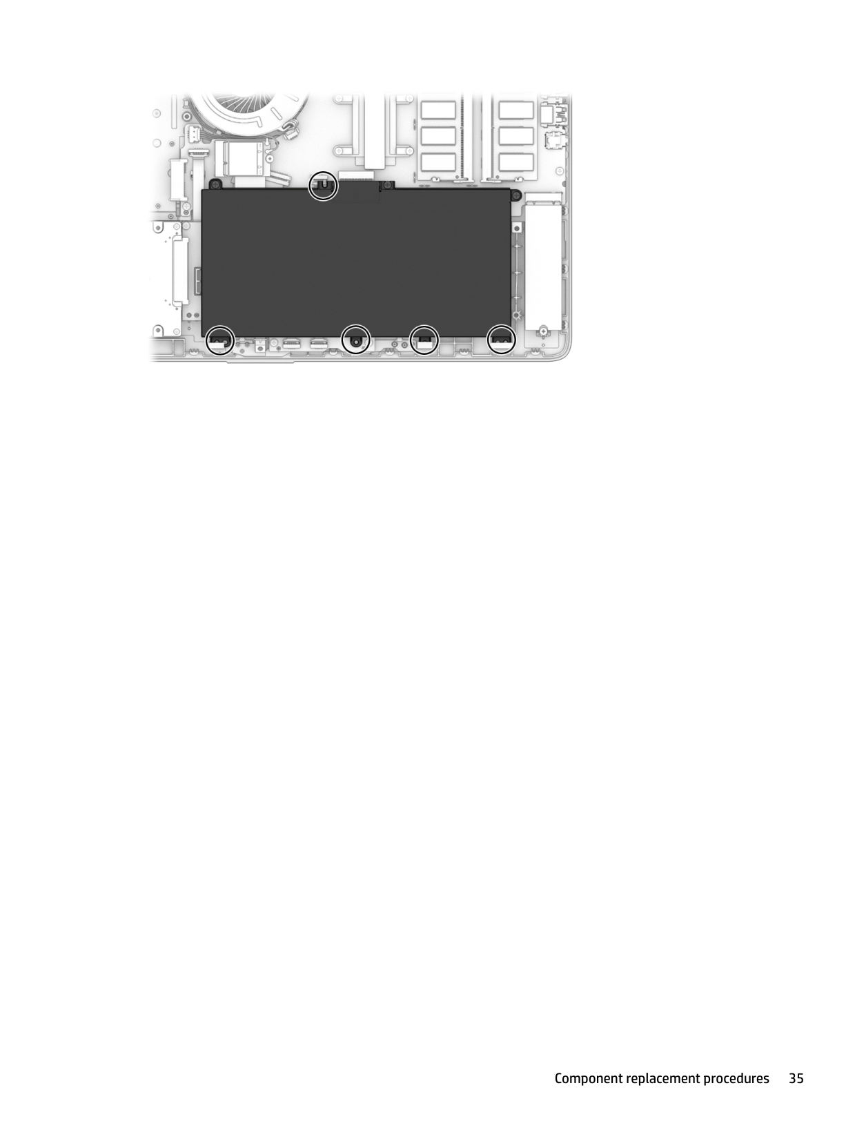
Reverse this procedure to install the battery. When installing the battery, be sure to install screws in the proper locations. The following image shows the locations around the battery that have holes but do NOT require screws.

#### Memory
######## Table 6-3 Spare part description and number
######### Description Spare part number
Memory module, 8 GB 937236-855 Memory module, 4 GB L10598-855
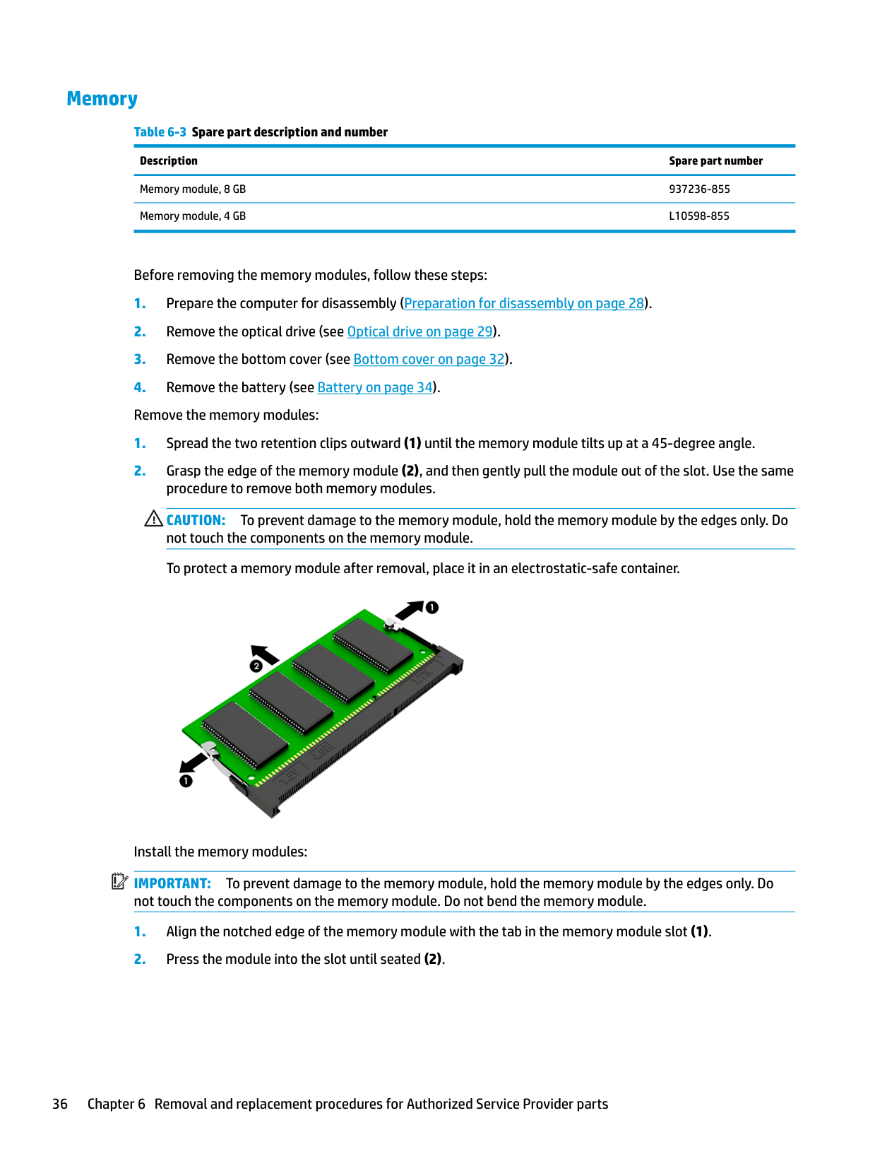
Before removing the memory modules, follow these steps:
CAUTION: To prevent damage to the memory module, hold the memory module by the edges only. Do not touch the components on the memory module. To protect a memory module after removal, place it in an electrostatic-safe container.

| | |---|
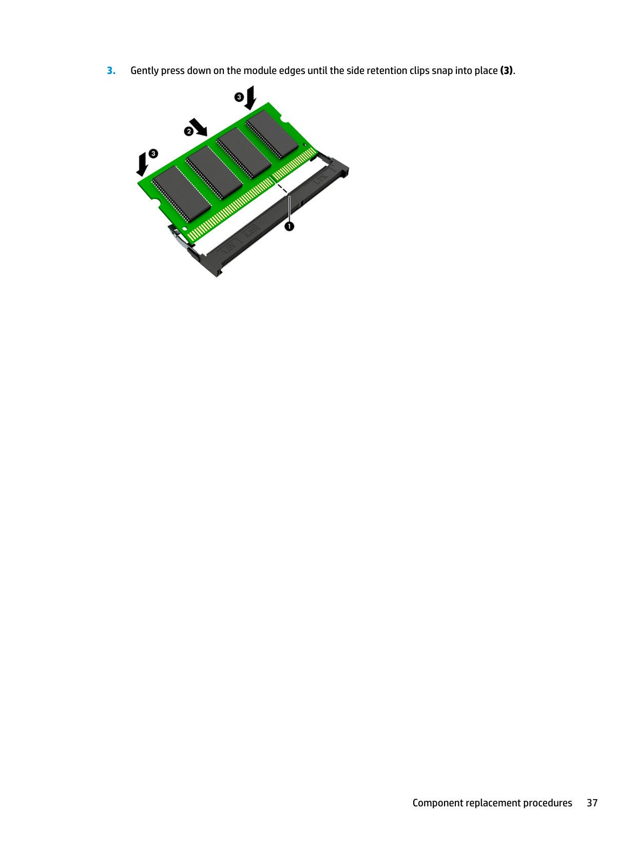
Install the memory modules: IMPORTANT: To prevent damage to the memory module, hold the memory module by the edges only. Do not touch the components on the memory module. Do not bend the memory module.
####### 3. Gently press down on the module edges until the side retention clips snap into place (3).

#### Hard drive
######## Table 6-4 Spare part description and number
######### Description Spare part number
Hard drive, 1 TB, 5400 rpm, 7.2 mm L30422-005 Hard drive, 500 GB, 7200 rpm, 7 mm 703267-005 Hard drive, 500 GB, 5400 rpm, 7 mm 778186-005 Hard drive bracket L20455-001
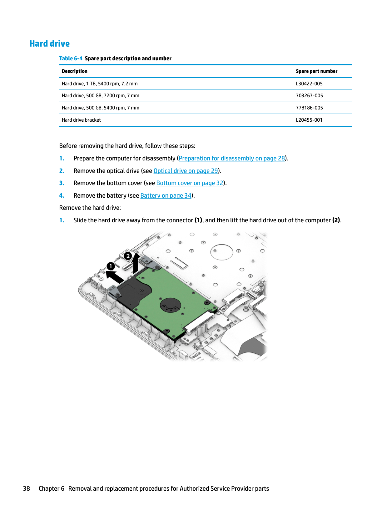
Before removing the hard drive, follow these steps:


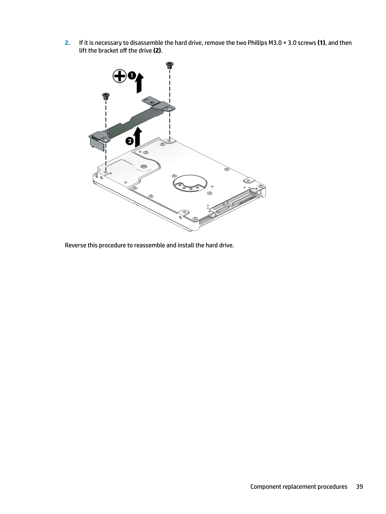
Reverse this procedure to reassemble and install the hard drive.
#### Solid-state drive
######## Table 6-5 Spare part description and number
######### Description Spare part number
512 GB, PCIe, NVMe L49997-001 256 GB, PCIe, NVMe L49996-001 256 GB, SATA-3, TLC L49995-001 128 GB, SATA-3, TLC L49994-001
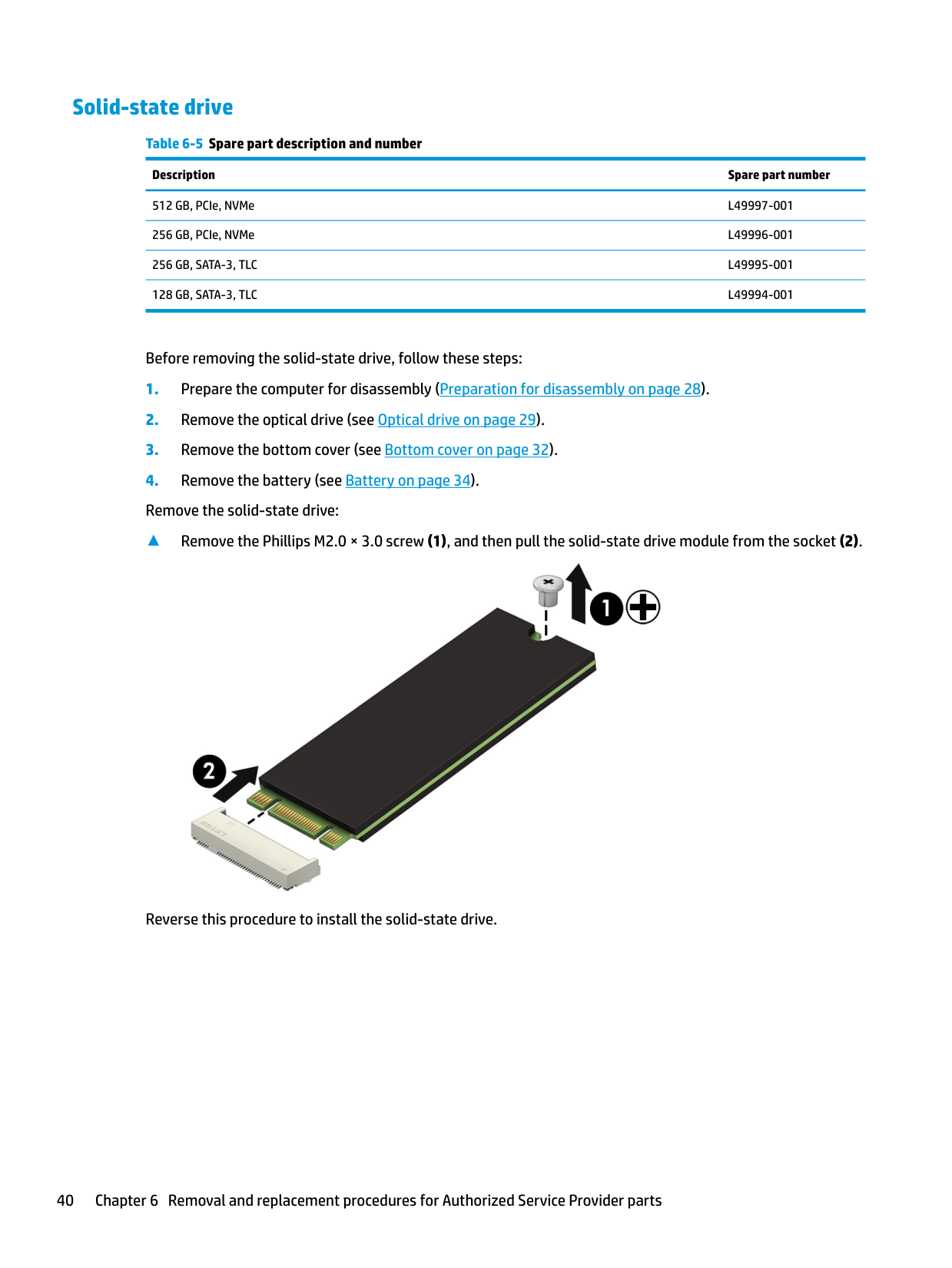
Before removing the solid-state drive, follow these steps:
▲ Remove the Phillips M2.0 × 3.0 screw (1), and then pull the solid-state drive module from the socket (2).

Reverse this procedure to install the solid-state drive.
#### Solid-state drive bracket and connector board
######## Table 6-6 Spare part description and number
######### Description Spare part number
Solid-state drive bracket L20458-001 Solid-state drive connector board L22542-001 Solid-state drive cable L20456-001
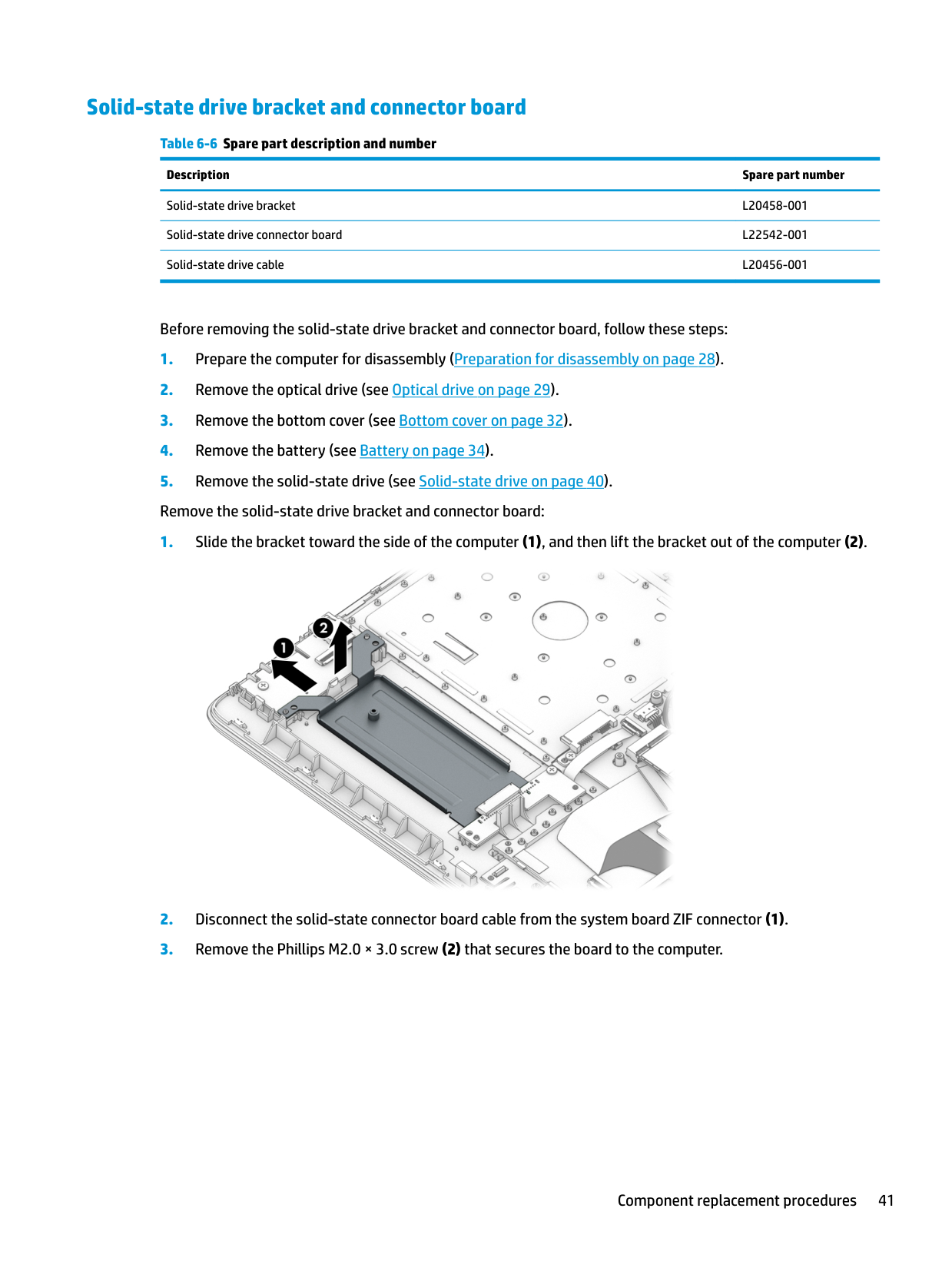
Before removing the solid-state drive bracket and connector board, follow these steps:


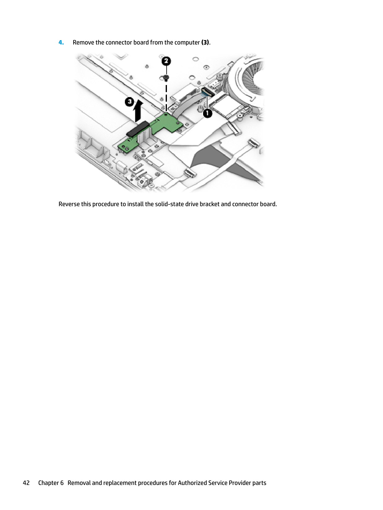
Reverse this procedure to install the solid-state drive bracket and connector board.
#### WLAN module
######## Table 6-7 Spare part description and number
######### Description Spare part number
Realtek RTL8822BE 802.11ac 2 × 2 WiFi + Bluetooth 4.2 Combo Adapter (MU-MIMO supported) 924813-855 Realtek RTL8821CE 802.11ac 1 × 1 WiFi + Bluetooth 4.2 Combo Adapter (MU-MIMO supported) L17365-005
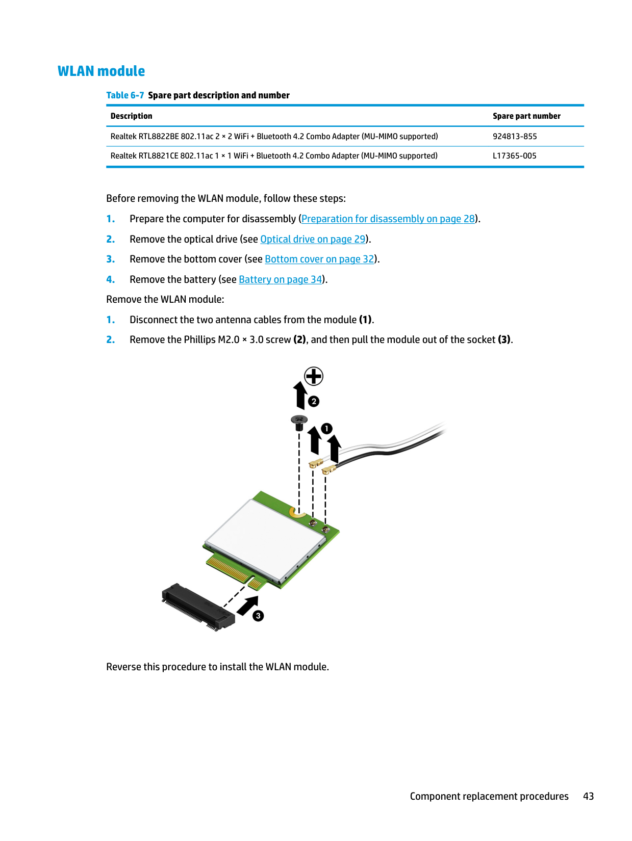
Before removing the WLAN module, follow these steps:

Reverse this procedure to install the WLAN module.
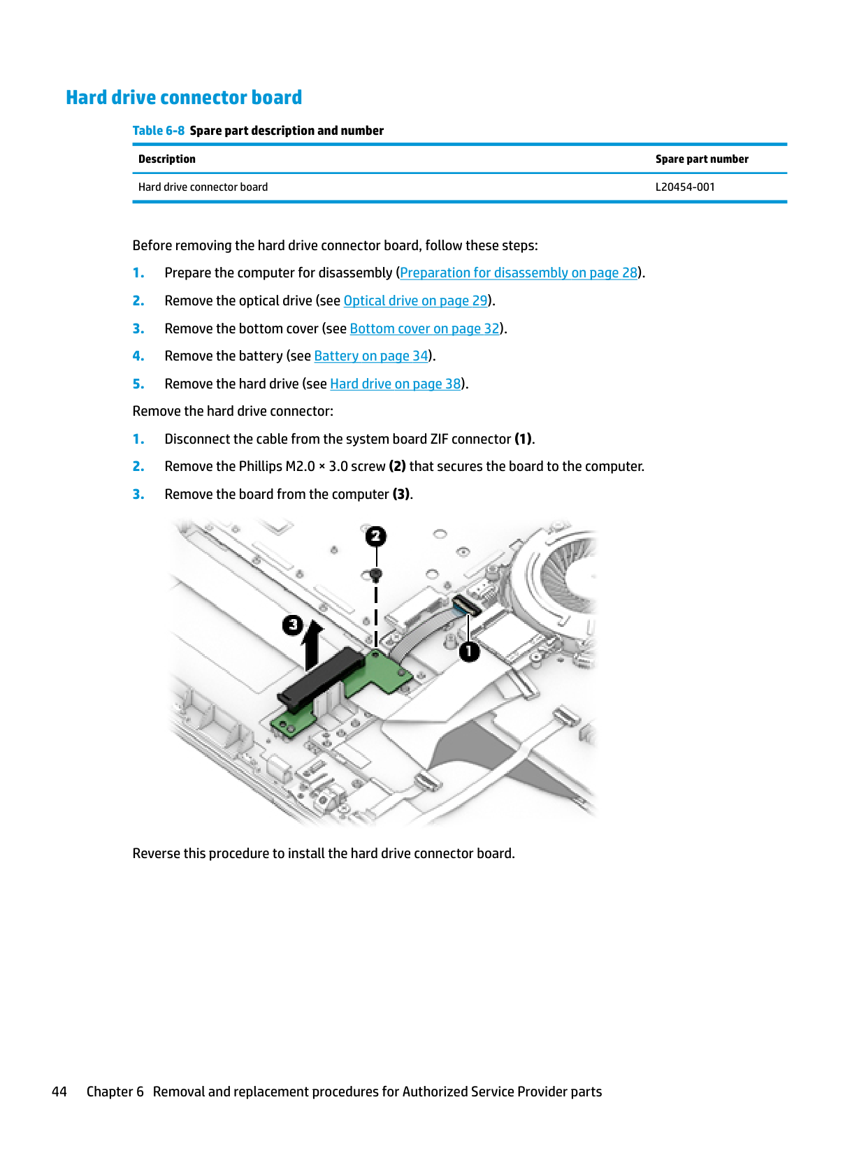
#### Hard drive connector board
Table 6-8 Spare part description and number Description Spare part number Hard drive connector board L20454-001
Before removing the hard drive connector board, follow these steps:

Reverse this procedure to install the hard drive connector board.
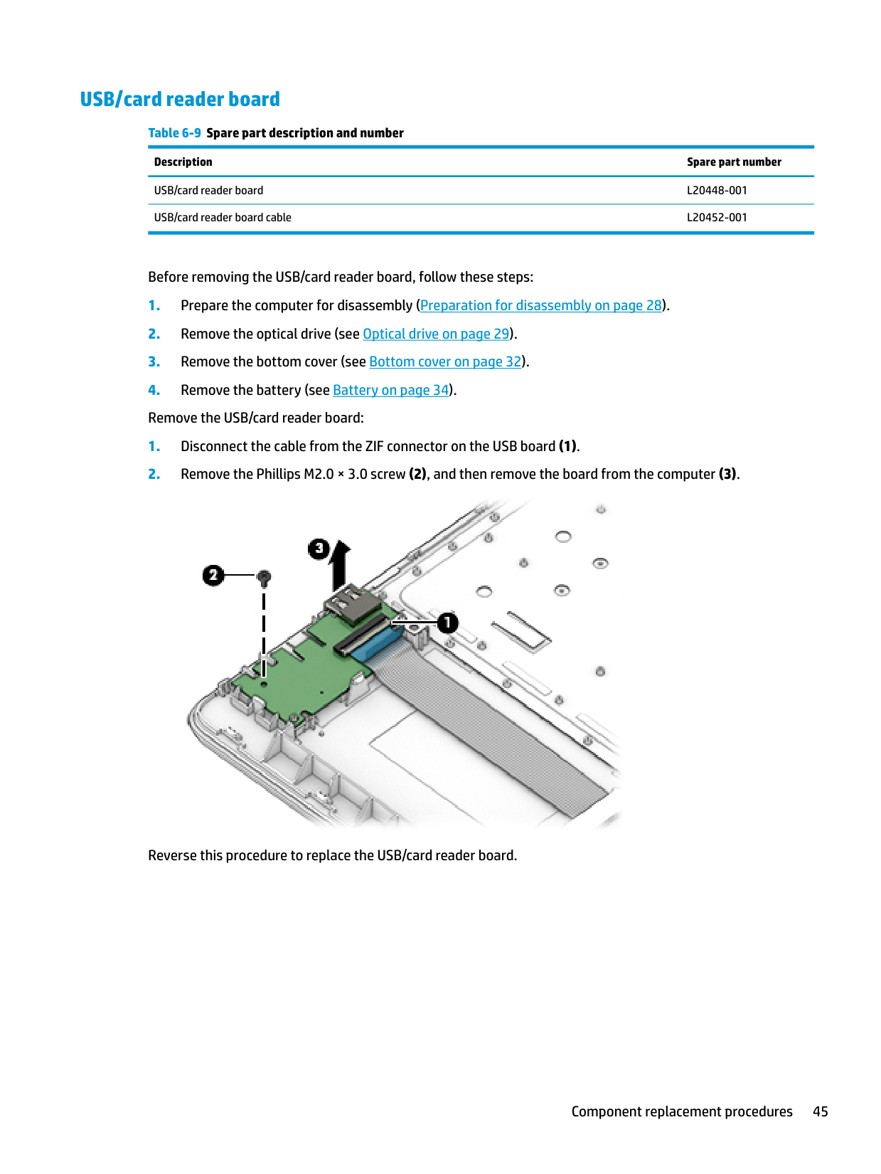
#### USB/card reader board
######## Table 6-9 Spare part description and number
######### Description Spare part number
USB/card reader board L20448-001 USB/card reader board cable L20452-001
Before removing the USB/card reader board, follow these steps:

Reverse this procedure to replace the USB/card reader board.
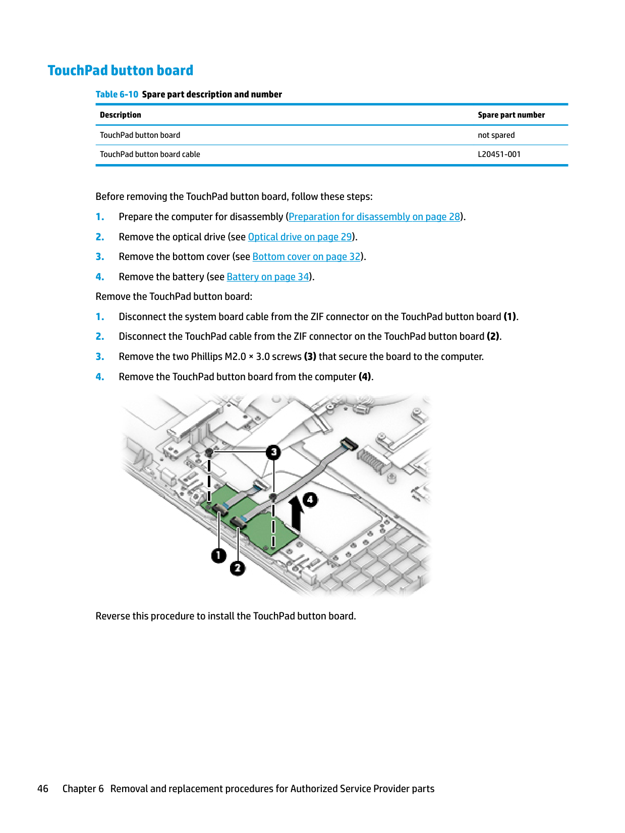
#### TouchPad button board
Table 6-10 Spare part description and number Description Spare part number TouchPad button board not spared TouchPad button board cable L20451-001
Before removing the TouchPad button board, follow these steps:

Reverse this procedure to install the TouchPad button board.
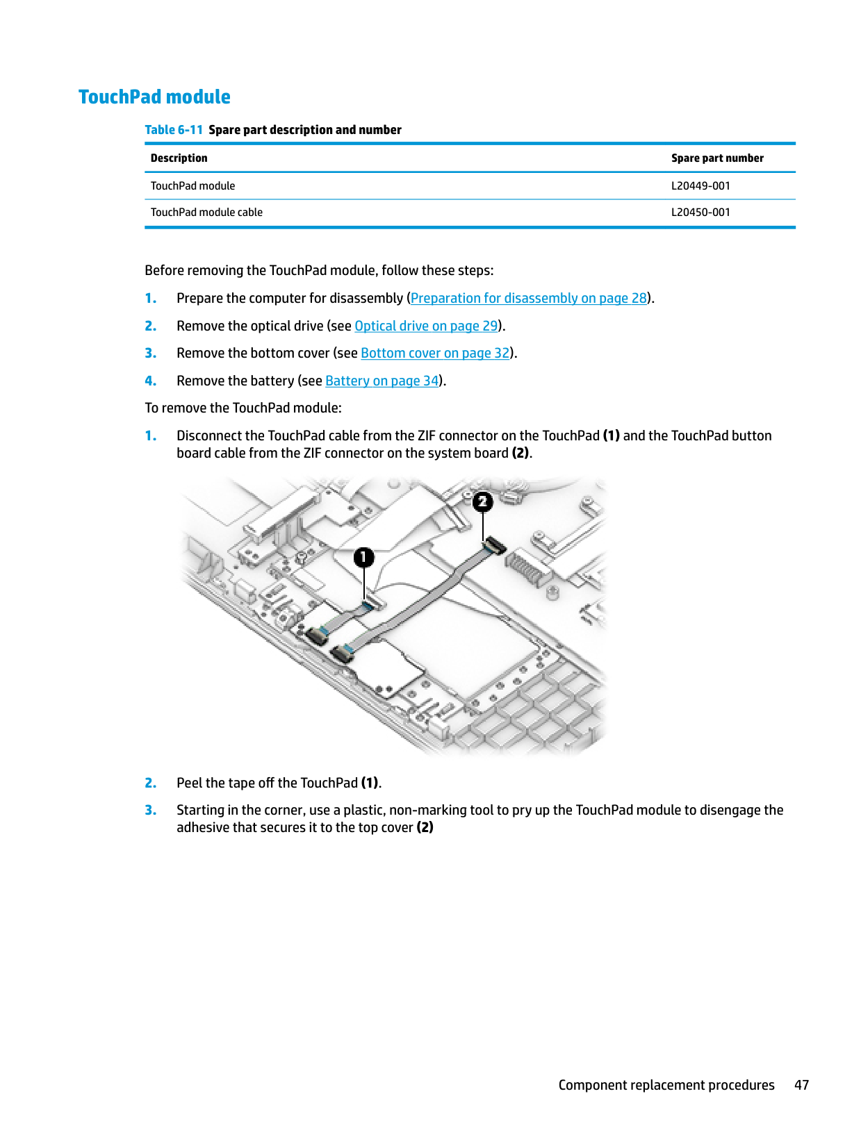
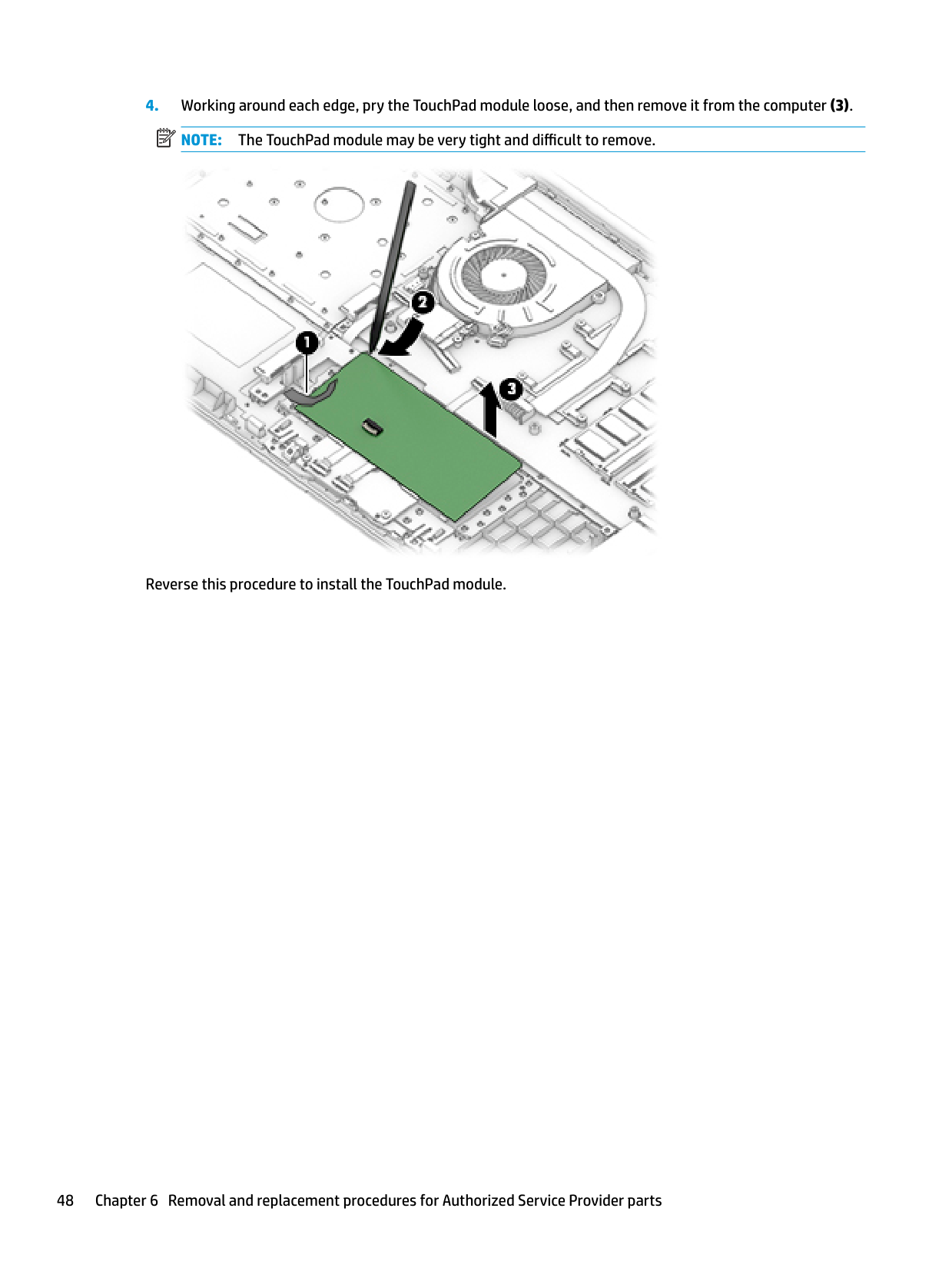
#### TouchPad module
######## Table 6-11 Spare part description and number
######### Description Spare part number
TouchPad module L20449-001 TouchPad module cable L20450-001
Before removing the TouchPad module, follow these steps:

| | |---|

Reverse this procedure to install the TouchPad module.
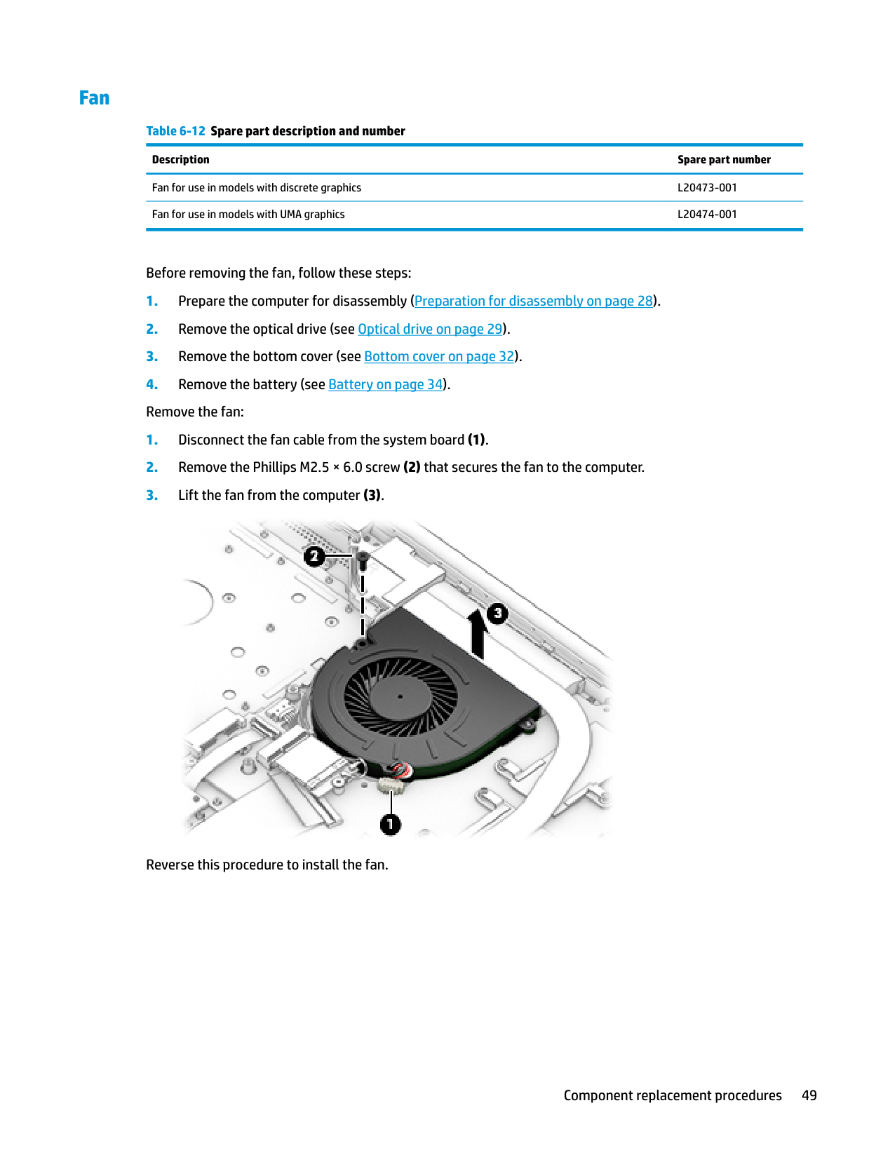
#### Fan
######## Table 6-12 Spare part description and number
######### Description Spare part number
Fan for use in models with discrete graphics L20473-001 Fan for use in models with UMA graphics L20474-001
Before removing the fan, follow these steps:

Reverse this procedure to install the fan.
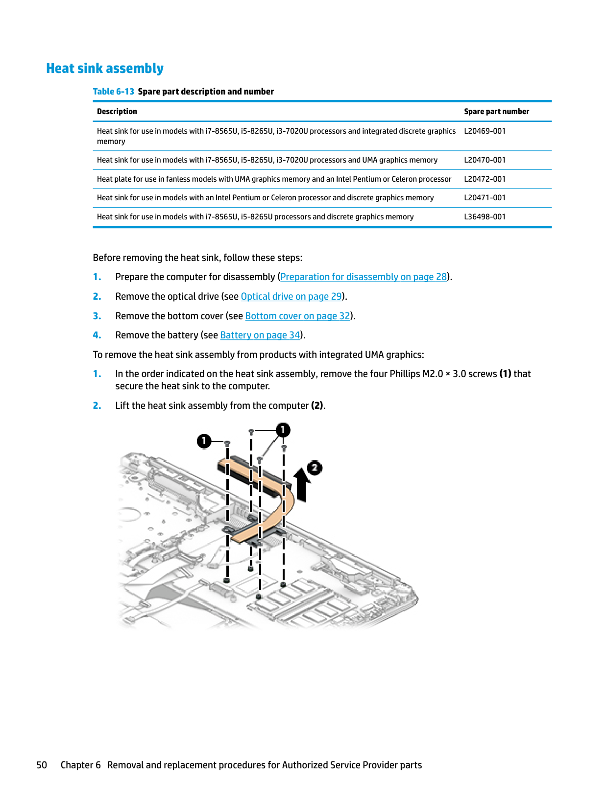
#### Heat sink assembly
######## Table 6-13 Spare part description and number
######### Description Spare part number
Heat sink for use in models with i7-8565U, i5-8265U, i3-7020U processors and integrated discrete graphics memory
L20469-001
Heat sink for use in models with i7-8565U, i5-8265U, i3-7020U processors and UMA graphics memory L20470-001 Heat plate for use in fanless models with UMA graphics memory and an Intel Pentium or Celeron processor L20472-001 Heat sink for use in models with an Intel Pentium or Celeron processor and discrete graphics memory L20471-001 Heat sink for use in models with i7-8565U, i5-8265U processors and discrete graphics memory L36498-001
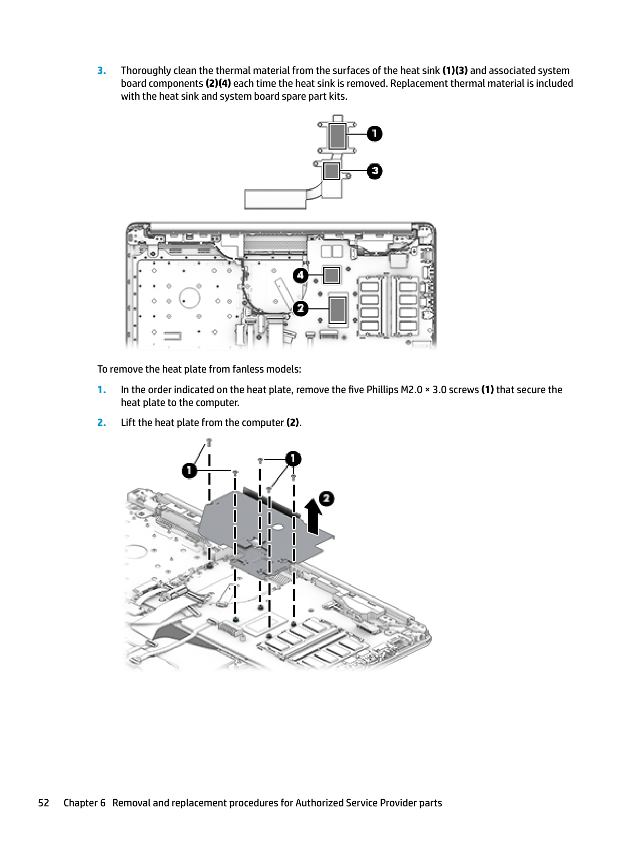
Before removing the heat sink, follow these steps:


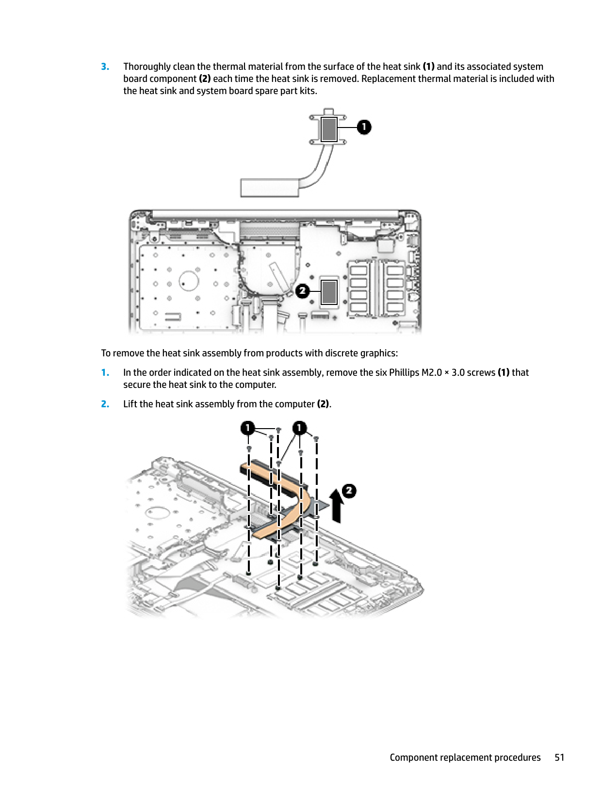
To remove the heat sink assembly from products with discrete graphics:


To remove the heat plate from fanless models:
heat plate to the computer.


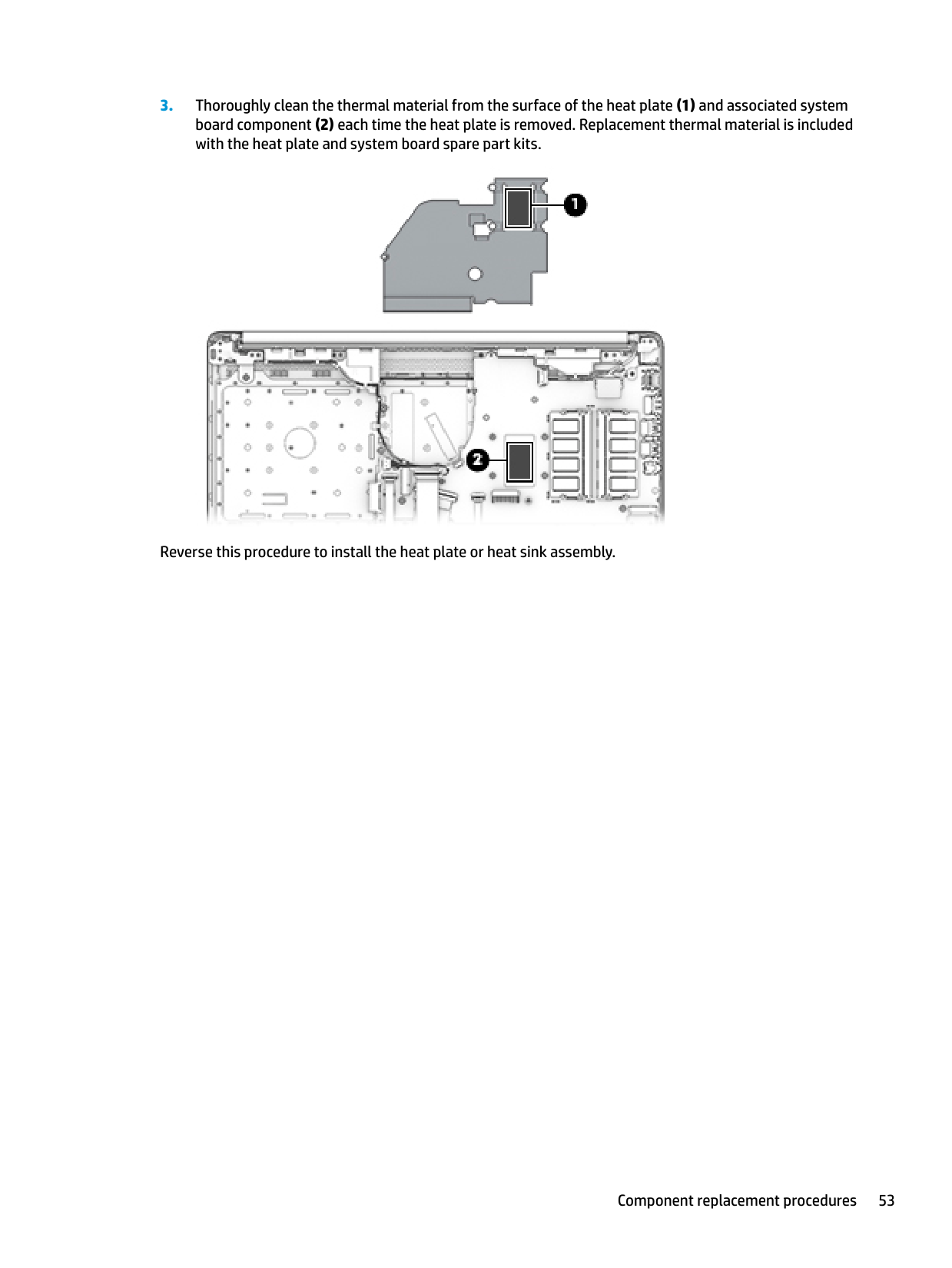
Reverse this procedure to install the heat plate or heat sink assembly.
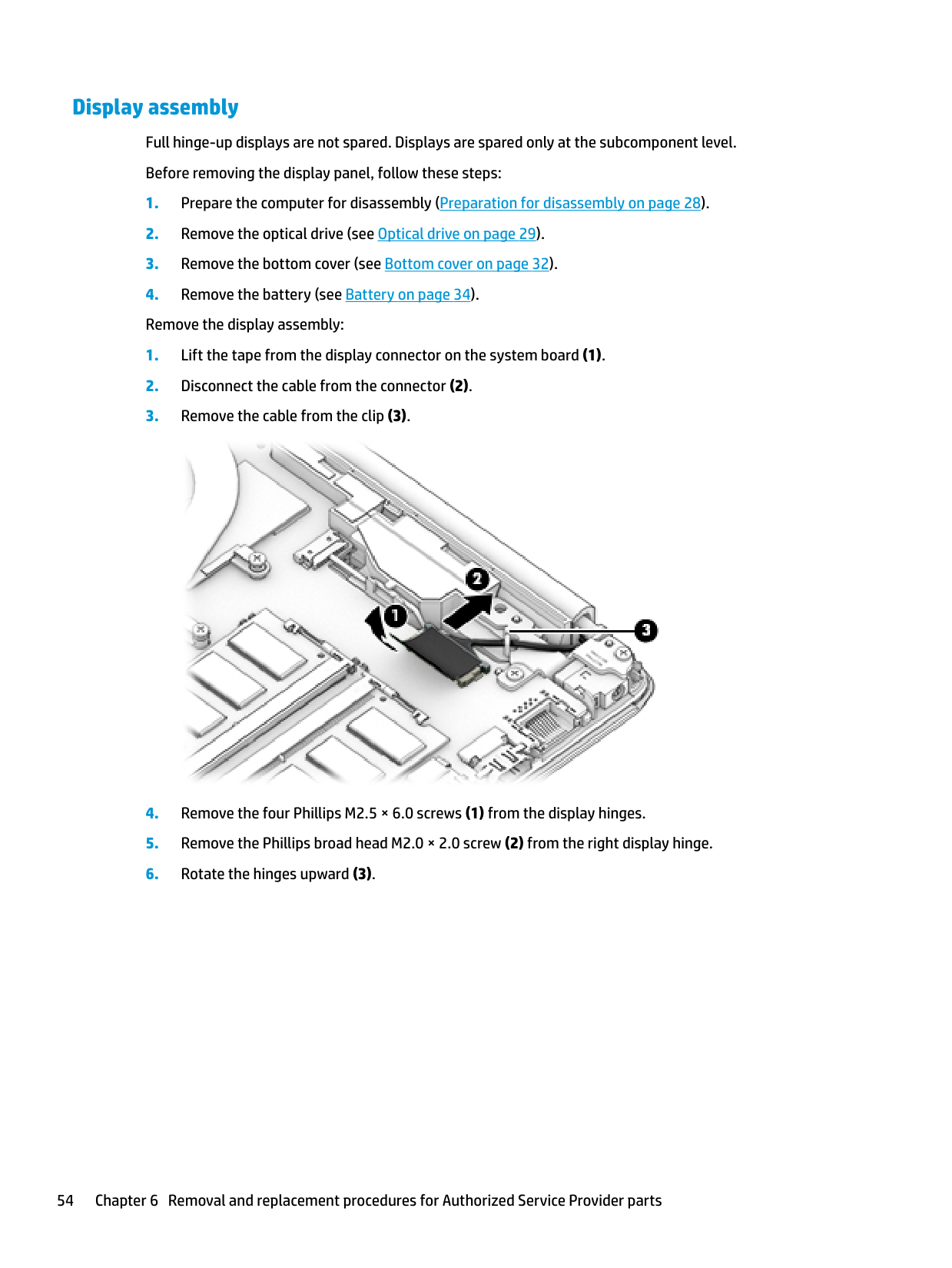
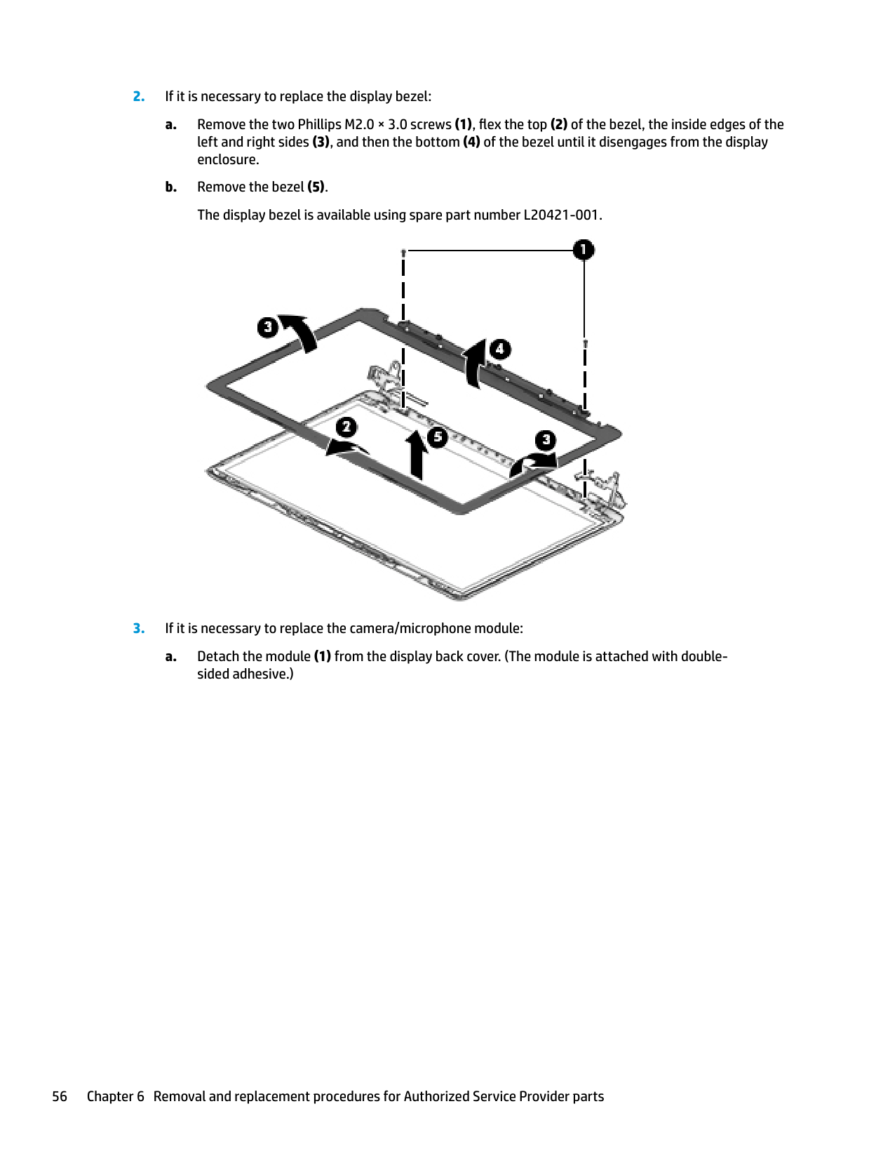
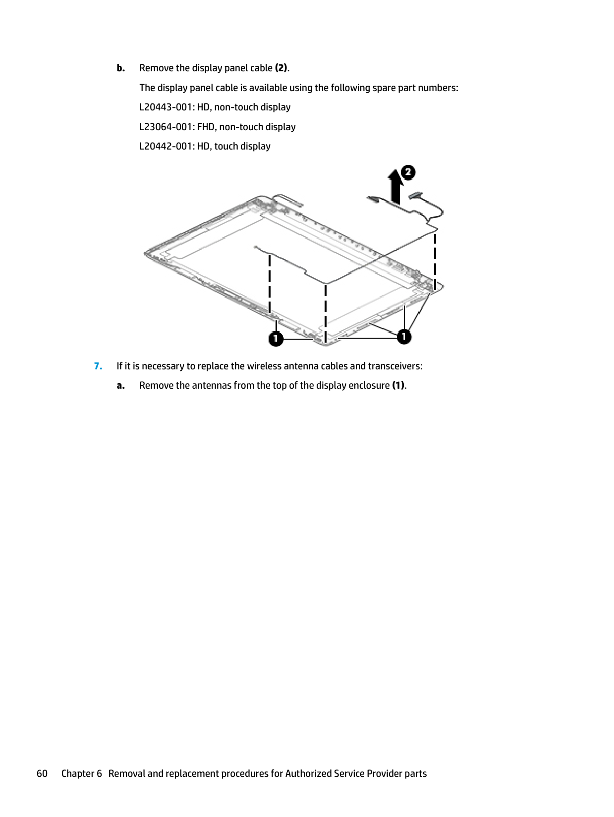
Display assembly Full hinge-up displays are not spared. Displays are spared only at the subcomponent level. Before removing the display panel, follow these steps:


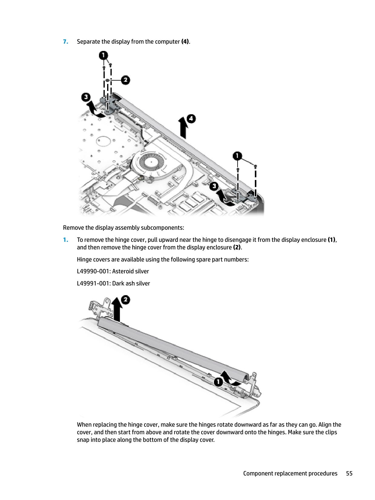
Remove the display assembly subcomponents:

When replacing the hinge cover, make sure the hinges rotate downward as far as they can go. Align the cover, and then start from above and rotate the cover downward onto the hinges. Make sure the clips snap into place along the bottom of the display cover.

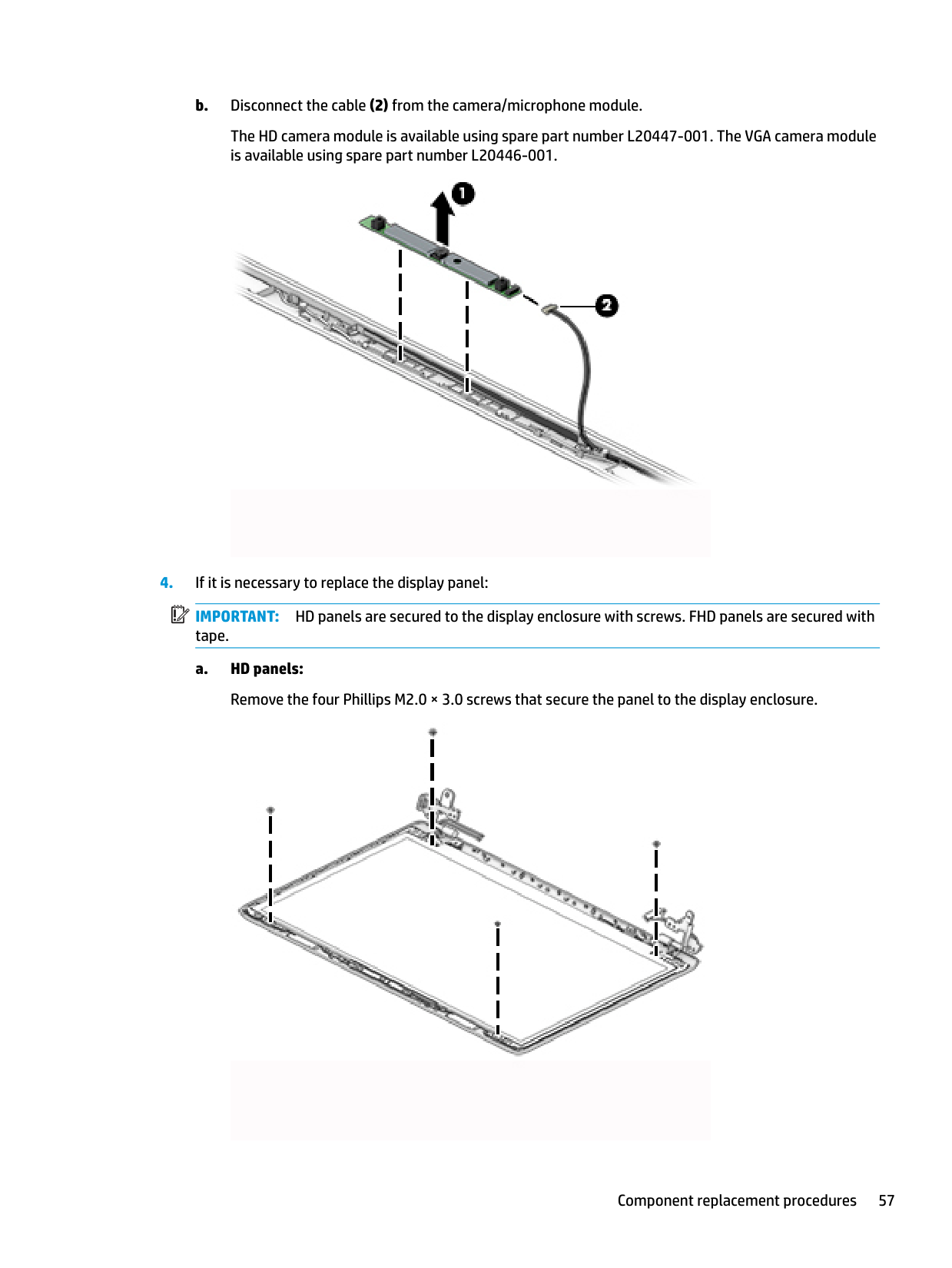
The HD camera module is available using spare part number L20447-001. The VGA camera module is available using spare part number L20446-001.

| | |---|
IMPORTANT: HD panels are secured to the display enclosure with screws. FHD panels are secured with tape.

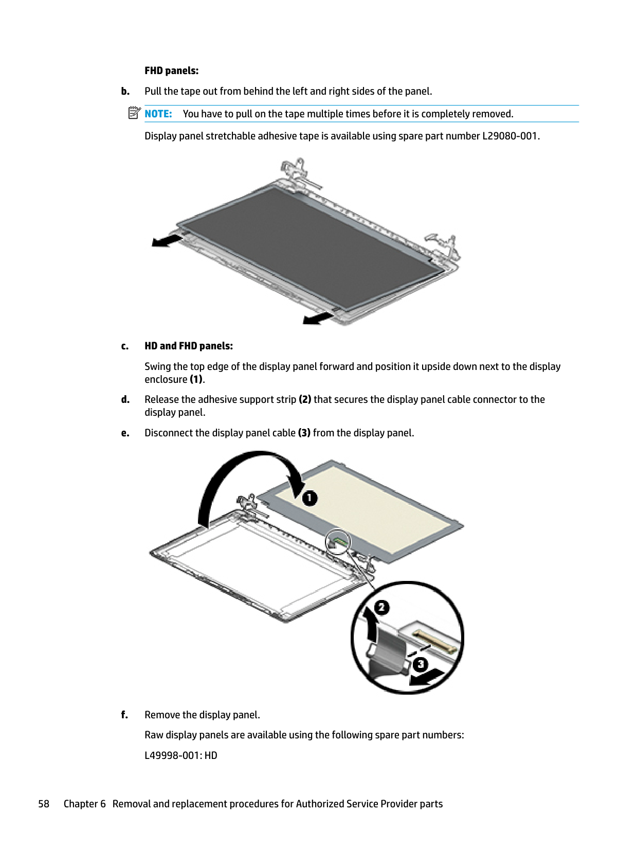
###### FHD panels:

Swing the top edge of the display panel forward and position it upside down next to the display enclosure (1).

| | |---|


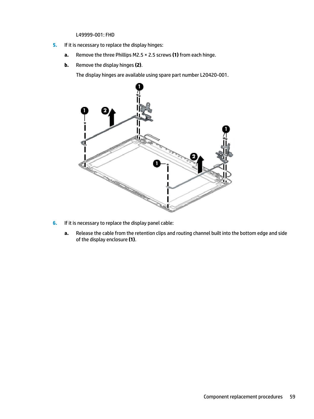
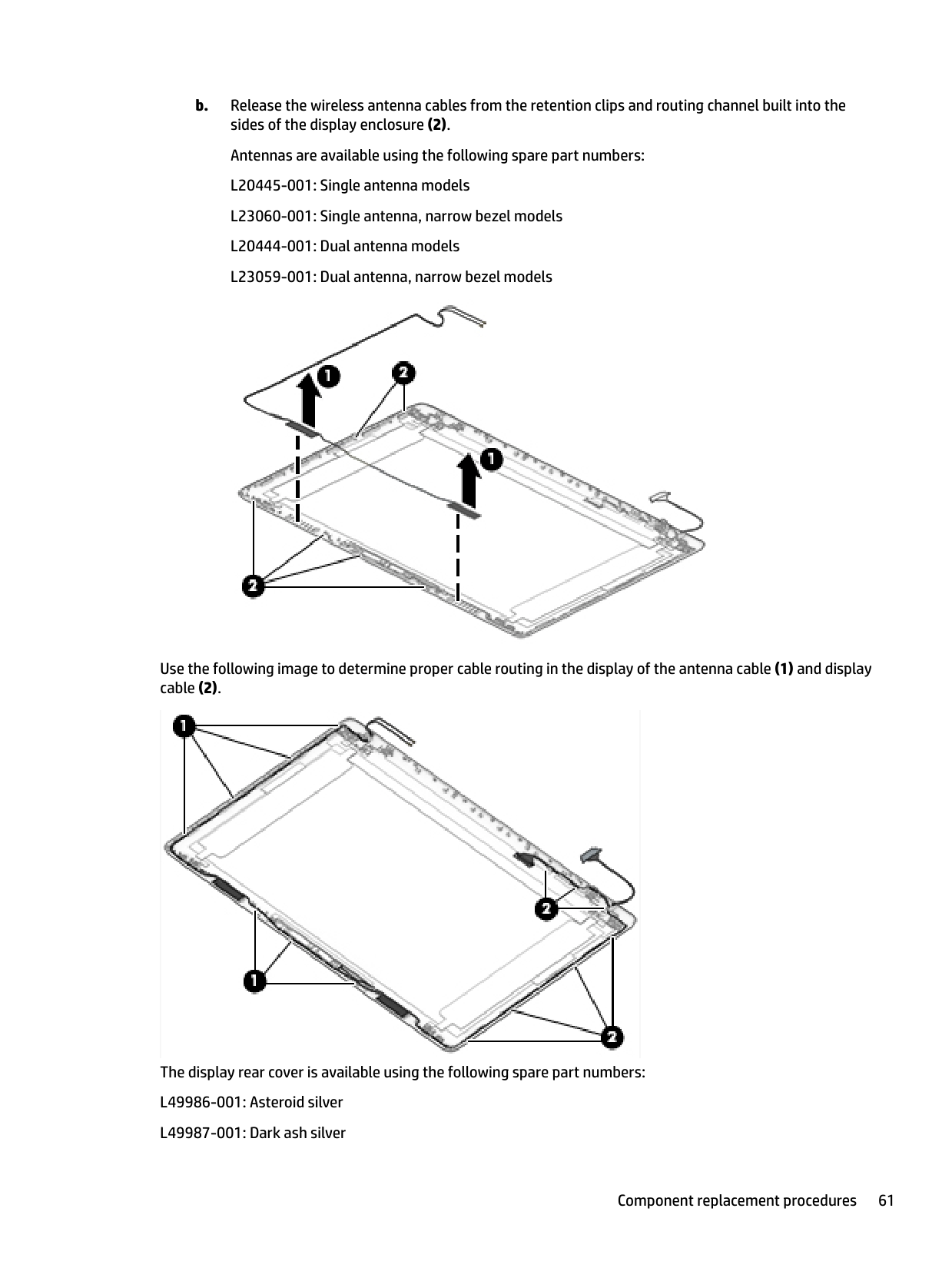
b. Release the wireless antenna cables from the retention clips and routing channel built into the sides of the display enclosure (2). Antennas are available using the following spare part numbers: L20445-001: Single antenna models L23060-001: Single antenna, narrow bezel models L20444-001: Dual antenna models L23059-001: Dual antenna, narrow bezel models

Use the following image to determine proper cable routing in the display of the antenna cable (1) and display cable (2).

The display rear cover is available using the following spare part numbers:
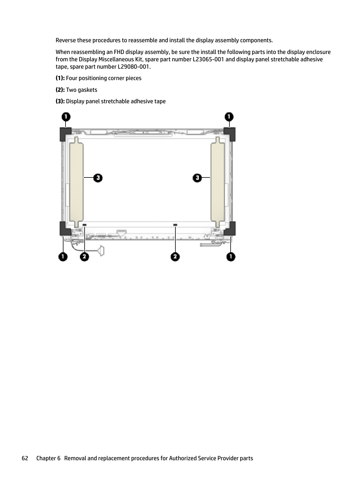
Reverse these procedures to reassemble and install the display assembly components. When reassembling an FHD display assembly, be sure the install the following parts into the display enclosure from the Display Miscellaneous Kit, spare part number L23065-001 and display panel stretchable adhesive tape, spare part number L29080-001.

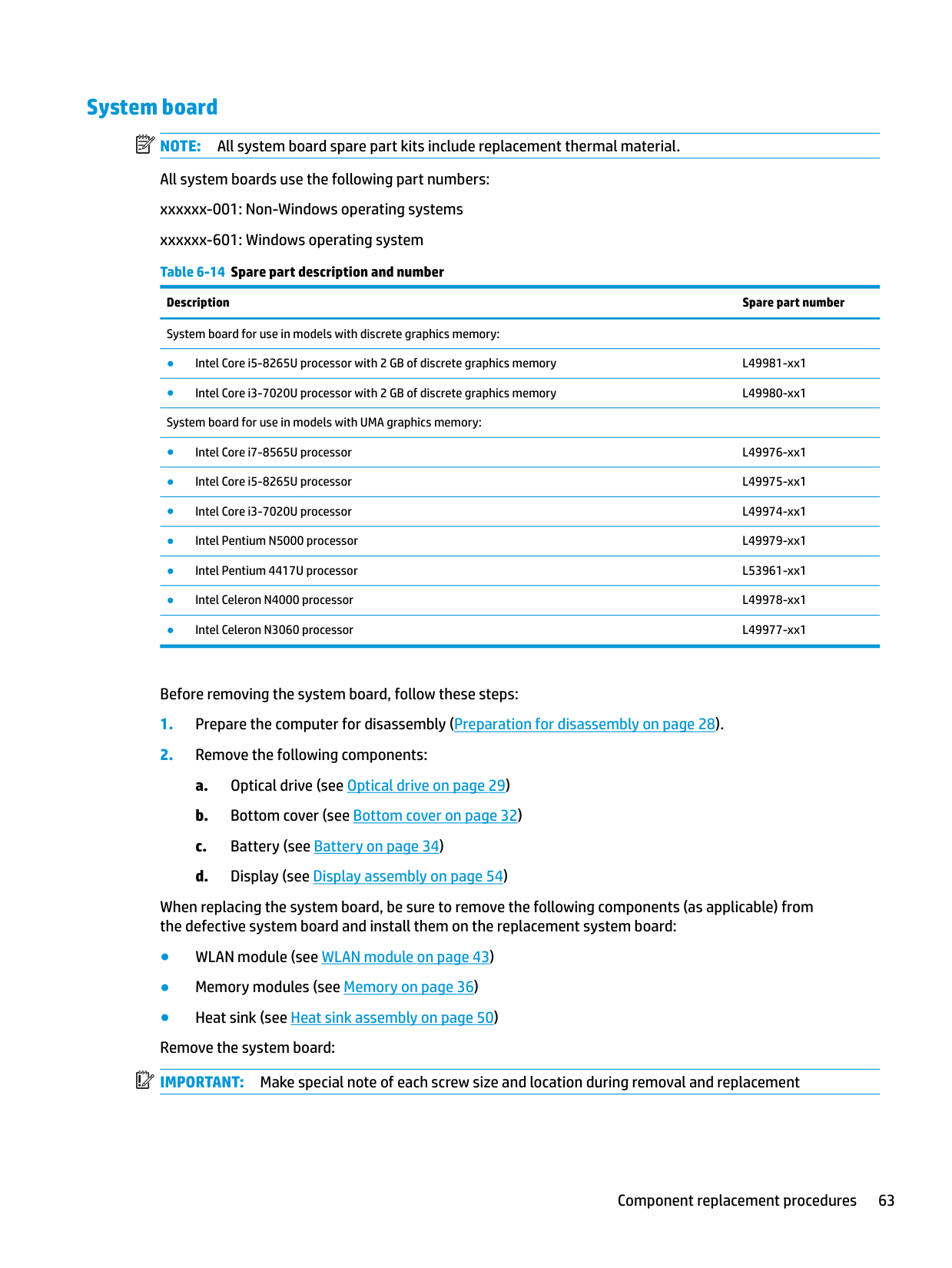
System board NOTE: All system board spare part kits include replacement thermal material. All system boards use the following part numbers: xxxxxx-001: Non-Windows operating systems xxxxxx-601: Windows operating system Table 6-14 Spare part description and number
| | |---|
Description Spare part number System board for use in models with discrete graphics memory:
Before removing the system board, follow these steps:
When replacing the system board, be sure to remove the following components (as applicable) from the defective system board and install them on the replacement system board:
| | |---|
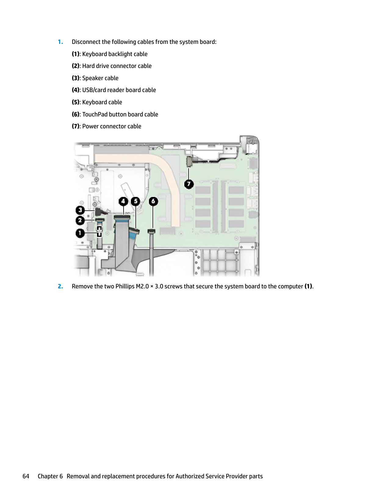
####### 1. Disconnect the following cables from the system board:

####### 2. Remove the two Phillips M2.0 × 3.0 screws that secure the system board to the computer (1).

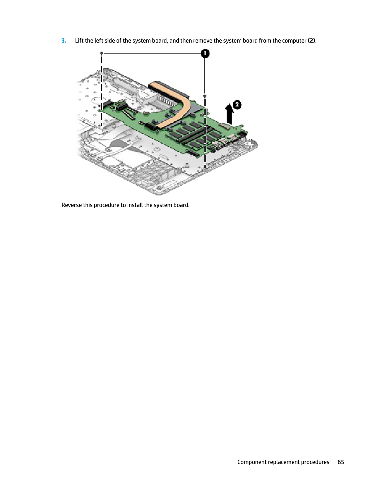
Reverse this procedure to install the system board.
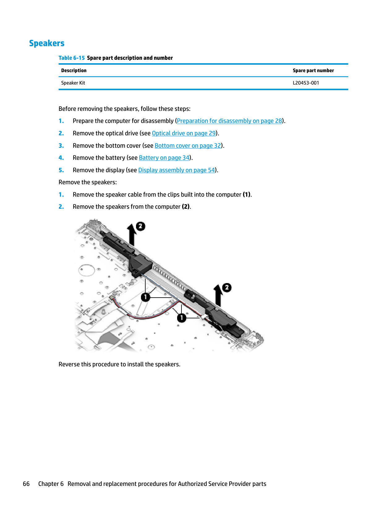
#### Speakers
Table 6-15 Spare part description and number Description Spare part number Speaker Kit L20453-001
Before removing the speakers, follow these steps:

Reverse this procedure to install the speakers.
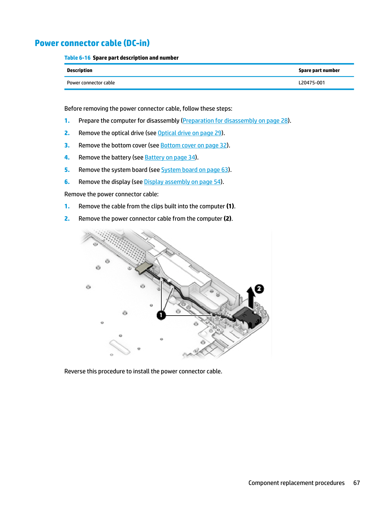
#### Power connector cable (DC-in)
Table 6-16 Spare part description and number Description Spare part number Power connector cable L20475-001
Before removing the power connector cable, follow these steps:

Reverse this procedure to install the power connector cable.
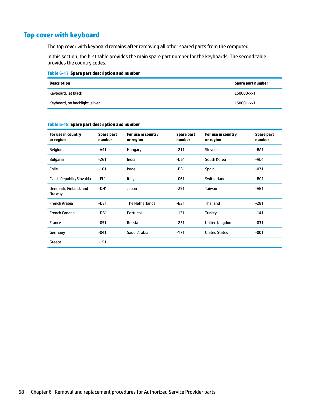
Top cover with keyboard The top cover with keyboard remains after removing all other spared parts from the computer. In this section, the first table provides the main spare part number for the keyboards. The second table provides the country codes.
For use in country or region
Spare part number
For use in country or region
Spare part number
For use in country or region
Spare part number
Belgium -A41 Hungary -211 Slovenia -BA1 Bulgaria -261 India -D61 South Korea -AD1 Chile -161 Israel -BB1 Spain -071 Czech Republic/Slovakia -FL1 Italy -061 Switzerland -BG1 Denmark, Finland, and Norway
-DH1 Japan -291 Taiwan -AB1
French Arabia -DE1 The Netherlands -B31 Thailand -281 French Canada -DB1 Portugal -131 Turkey -141 France -051 Russia -251 United Kingdom -031 Germany -041 Saudi Arabia -171 United States -001 Greece -151
7 Computer Setup (BIOS), TPM, and HP Sure Start
Using Computer Setup
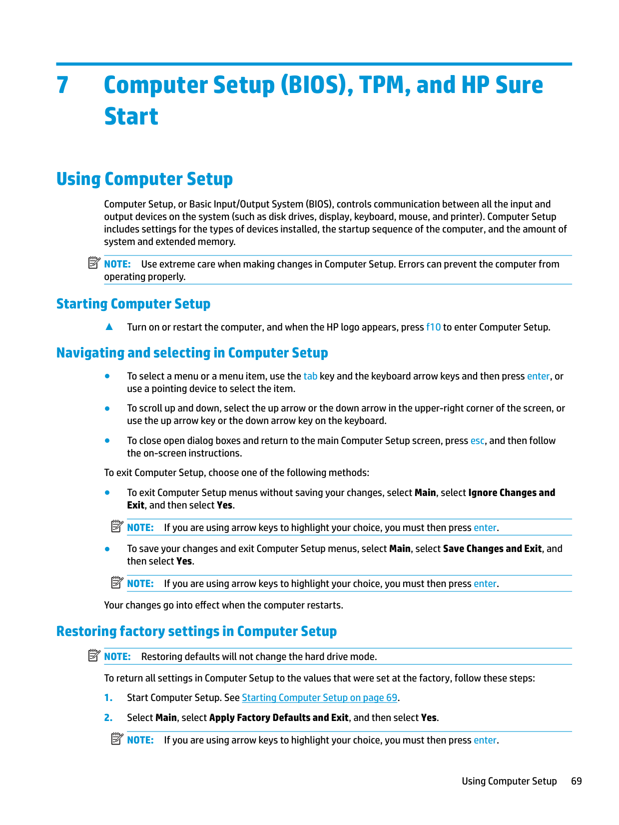
Computer Setup, or Basic Input/Output System (BIOS), controls communication between all the input and output devices on the system (such as disk drives, display, keyboard, mouse, and printer). Computer Setup includes settings for the types of devices installed, the startup sequence of the computer, and the amount of system and extended memory.
| | |---|
NOTE: Use extreme care when making changes in Computer Setup. Errors can prevent the computer from operating properly.
#### Starting Computer Setup
▲ Turn on or restart the computer, and when the HP logo appears, press f10 to enter Computer Setup.
#### Navigating and selecting in Computer Setup
To exit Computer Setup, choose one of the following methods:
| | |---|
| | |---|
Your changes go into effect when the computer restarts.
Restoring factory settings in Computer Setup NOTE: Restoring defaults will not change the hard drive mode. To return all settings in Computer Setup to the values that were set at the factory, follow these steps:
| | |---|
| | |---|
Using Computer Setup 69
| | |---|
NOTE: On select products, the selections may display Restore Defaults instead of Apply Factory Defaults and Exit.
| | |---|
Your changes go into effect when the computer restarts. NOTE: Your password settings and security settings are not changed when you restore the factory settings.
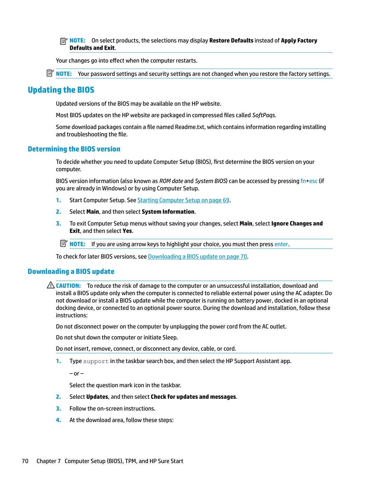
Updating the BIOS Updated versions of the BIOS may be available on the HP website. Most BIOS updates on the HP website are packaged in compressed files called SoftPaqs. Some download packages contain a file named Readme.txt, which contains information regarding installing and troubleshooting the file.
##### Determining the BIOS version
To decide whether you need to update Computer Setup (BIOS), first determine the BIOS version on your computer.
BIOS version information (also known as ROM date and System BIOS) can be accessed by pressing fn+esc (if you are already in Windows) or by using Computer Setup.
| | |---|
To check for later BIOS versions, see Downloading a BIOS update on page 70. Downloading a BIOS update
CAUTION: To reduce the risk of damage to the computer or an unsuccessful installation, download and install a BIOS update only when the computer is connected to reliable external power using the AC adapter. Do not download or install a BIOS update while the computer is running on battery power, docked in an optional docking device, or connected to an optional power source. During the download and installation, follow these instructions:
Do not disconnect power on the computer by unplugging the power cord from the AC outlet. Do not shut down the computer or initiate Sleep. Do not insert, remove, connect, or disconnect any device, cable, or cord.
– or – Select the question mark icon in the taskbar.
Make a note of the path to the location on your hard drive where the BIOS update is downloaded. You will need to access this path when you are ready to install the update.
| | |---|
NOTE: If you connect your computer to a network, consult the network administrator before installing any software updates, especially system BIOS updates.
BIOS installation procedures vary. Follow any instructions that are displayed on the screen after the download is complete. If no instructions are displayed, follow these steps:
| | |---|
NOTE: After a message on the screen reports a successful installation, you can delete the downloaded file from your hard drive.
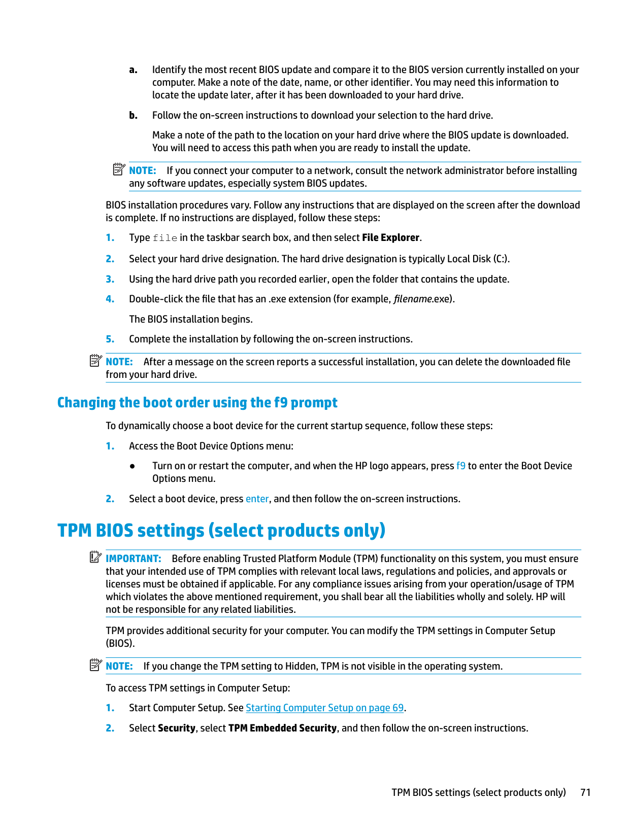
#### Changing the boot order using the f9 prompt
To dynamically choose a boot device for the current startup sequence, follow these steps:
● Turn on or restart the computer, and when the HP logo appears, press f9 to enter the Boot Device Options menu.
TPM BIOS settings (select products only)
| | |---|
IMPORTANT: Before enabling Trusted Platform Module (TPM) functionality on this system, you must ensure that your intended use of TPM complies with relevant local laws, regulations and policies, and approvals or licenses must be obtained if applicable. For any compliance issues arising from your operation/usage of TPM which violates the above mentioned requirement, you shall bear all the liabilities wholly and solely. HP will not be responsible for any related liabilities.
TPM provides additional security for your computer. You can modify the TPM settings in Computer Setup (BIOS).
| | |---|
NOTE: If you change the TPM setting to Hidden, TPM is not visible in the operating system. To access TPM settings in Computer Setup:
TPM BIOS settings (select products only) 71
Using HP Sure Start (select products only)
Select computer models are configured with HP Sure Start, a technology that monitors the computer's BIOS for attacks or corruption. If the BIOS becomes corrupted or is attacked, HP Sure Start automatically restores the BIOS to its previously safe state, without user intervention.
HP Sure Start is configured and already enabled so that most users can use the HP Sure Start default configuration. The default configuration can be customized by advanced users.
To access the latest documentation on HP Sure Start, go to http://www.hp.com/support. Select Find your product, and then follow the on-screen instructions.
8 Using HP PC Hardware Diagnostics
Using HP PC Hardware Diagnostics Windows (select products only)
HP PC Hardware Diagnostics Windows is a Windows-based utility that allows you to run diagnostic tests to determine whether the computer hardware is functioning properly. The tool runs within the Windows operating system in order to diagnose hardware failures.
If HP PC Hardware Diagnostics Windows is not installed on your computer, first you must download and install it. To download HP PC Hardware Diagnostics Windows, see Downloading HP PC Hardware Diagnostics Windows on page 73.
After HP PC Hardware Diagnostics Windows is installed, follow these steps to access it from HP Help and Support or HP Support Assistant.
– or – To access HP PC Hardware Diagnostics Windows from HP Support Assistant:
– or – Select the question mark icon in the taskbar.
| | |---|
When HP PC Hardware Diagnostics Windows detects a failure that requires hardware replacement, a 24-digit Failure ID code is generated. The screen displays one of the following options:
#### Downloading HP PC Hardware Diagnostics Windows
● The HP PC Hardware Diagnostics Windows download instructions are provided in English only. ● You must use a Windows computer to download this tool because only .exe files are provided.
Using HP PC Hardware Diagnostics Windows (select products only) 73
##### Downloading the latest HP PC Hardware Diagnostics Windows version
To download HP PC Hardware Diagnostics Windows, follow these steps:
The tool is downloaded to the selected location.
##### Downloading HP Hardware Diagnostics Windows by product name or number (select products only)
| | |---|
NOTE: For some products, it may be necessary to download the software to a USB flash drive by using the product name or number. To download HP PC Hardware Diagnostics Windows by product name or number, follow these steps:
The tool is downloaded to the selected location.
#### Installing HP PC Hardware Diagnostics Windows
To install HP PC Hardware Diagnostics Windows, follow these steps:
▲ Navigate to the folder on your computer or the USB flash drive where the .exe file was downloaded,
double-click the .exe file, and then follow the on-screen instructions.
Using HP PC Hardware Diagnostics UEFI
| | |---|
NOTE: For Windows 10 S computers, you must use a Windows computer and a USB flash drive to download and create the HP UEFI support environment because only .exe files are provided. For more information, see Downloading HP PC Hardware Diagnostics UEFI to a USB flash drive on page 75.
HP PC Hardware Diagnostics UEFI (Unified Extensible Firmware Interface) allows you to run diagnostic tests to determine whether the computer hardware is functioning properly. The tool runs outside the operating system so that it can isolate hardware failures from issues that are caused by the operating system or other software components.
If your PC will not boot into Windows, you can use HP PC Hardware Diagnostics UEFI to diagnose hardware issues.
When HP PC Hardware Diagnostics Windows detects a failure that requires hardware replacement, a 24-digit Failure ID code is generated. For assistance in solving the problem:
▲ Select Get Support, and then use a mobile device to scan the QR code that displays on the next screen. The HP Customer Support - Service Center page displays, with your Failure ID and product number automatically filled in. Follow the on-screen instructions.
– or – Contact support, and provide the Failure ID code.
| | |---|
NOTE: To start diagnostics on a convertible computer, your computer must be in notebook mode, and you must use the attached keyboard.
| | |---|
NOTE: If you need to stop a diagnostic test, press esc.
#### Starting HP PC Hardware Diagnostics UEFI
To start HP PC Hardware Diagnostics UEFI, follow these steps:
| | |---|
#### Downloading HP PC Hardware Diagnostics UEFI to a USB flash drive
Downloading HP PC Hardware Diagnostics UEFI to a USB flash drive can be useful in the following situations:
| | |---|
NOTE: The HP PC Hardware Diagnostics UEFI download instructions are provided in English only, and you must use a Windows computer to download and create the HP UEFI support environment because only .exe files are provided.
##### Downloading the latest HP PC Hardware Diagnostics UEFI version
To download the latest HP PC Hardware Diagnostics UEFI version to a USB flash drive:
##### Downloading HP PC Hardware Diagnostics UEFI by product name or number (select products only)
| | |---|
NOTE: For some products, it may be necessary to download the software to a USB flash drive by using the product name or number. To download HP PC Hardware Diagnostics UEFI by product name or number (select products only) to a USB flash drive:
Using HP PC Hardware Diagnostics UEFI 75
Using Remote HP PC Hardware Diagnostics UEFI settings (select products only)
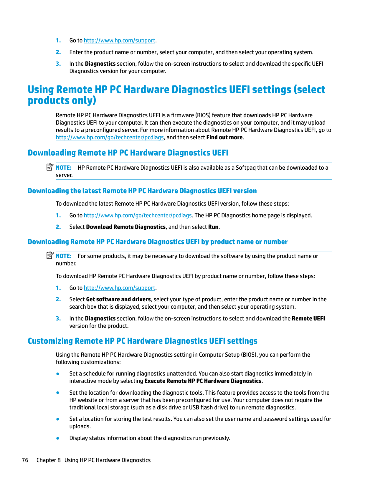
Remote HP PC Hardware Diagnostics UEFI is a firmware (BIOS) feature that downloads HP PC Hardware Diagnostics UEFI to your computer. It can then execute the diagnostics on your computer, and it may upload results to a preconfigured server. For more information about Remote HP PC Hardware Diagnostics UEFI, go to http://www.hp.com/go/techcenter/pcdiags, and then select Find out more.
#### Downloading Remote HP PC Hardware Diagnostics UEFI
| | |---|
NOTE: HP Remote PC Hardware Diagnostics UEFI is also available as a Softpaq that can be downloaded to a server.
##### Downloading the latest Remote HP PC Hardware Diagnostics UEFI version
To download the latest Remote HP PC Hardware Diagnostics UEFI version, follow these steps:
Downloading Remote HP PC Hardware Diagnostics UEFI by product name or number NOTE: For some products, it may be necessary to download the software by using the product name or number. To download HP Remote PC Hardware Diagnostics UEFI by product name or number, follow these steps:
| | |---|
#### Customizing Remote HP PC Hardware Diagnostics UEFI settings
Using the Remote HP PC Hardware Diagnostics setting in Computer Setup (BIOS), you can perform the following customizations:
To customize Remote HP PC Hardware Diagnostics UEFI settings, follow these steps:
Using Remote HP PC Hardware Diagnostics UEFI settings (select products only) 77
9 Backing up, restoring, and recovering
This chapter provides information about the following processes, which are standard procedure for most products:
| | |---|
IMPORTANT: If you will be performing recovery procedures on a tablet, the tablet battery must be at least 70% charged before you start the recovery process.
IMPORTANT: For a tablet with a detachable keyboard, connect the tablet to the keyboard base before beginning any recovery process.
Backing up information and creating recovery media
Using Windows tools IMPORTANT: Windows is the only option that allows you to back up your personal information. Schedule regular backups to avoid information loss. You can use Windows tools to back up personal information and create system restore points and recovery media. NOTE: If computer storage is 32 GB or less, Microsoft System Restore is disabled by default. For more information and steps, see the Get Help app.
| | |---|
| | |---|
| |
|---|
#### Using the HP Cloud Recovery Download Tool to create recovery media (select products only)
You can use the HP Cloud Recovery Download Tool to create HP Recovery media on a bootable USB flash drive, as follows:
78 Chapter 9 Backing up, restoring, and recovering
| | |---|
NOTE: If you cannot create recovery media yourself, contact support to obtain recovery discs. Go to http://www.hp.com/support, select your country or region, and then follow the on-screen instructions.
Restoring and recovery
#### Restoring, resetting, and refreshing using Windows tools
Windows offers several options for restoring, resetting, and refreshing the computer. For details, see Using Windows tools on page 78.
#### Recovering using HP Recovery media
HP Recovery media is used to recover the original operating system and software programs that were installed at the factory. On select products, it can be created on a bootable USB flash drive using the HP Cloud Recovery Download Tool. For details, see Using the HP Cloud Recovery Download Tool to create recovery media (select products only) on page 78.
| | |---|
NOTE: If you cannot create recovery media yourself, contact support to obtain recovery discs. Go to http://www.hp.com/support, select your country or region, and then follow the on-screen instructions.
To recover your system:
▲ Insert the HP Recovery media, and then restart the computer.
#### Changing the computer boot order
If your computer does not restart using the HP Recovery media, you can change the computer boot order. This is the order of devices listed in BIOS where the computer looks for startup information. You can change the selection to an optical drive or a USB flash drive, depending on the location of your HP Recovery media.
| | |---|
To change the boot order: IMPORTANT: For a tablet with a detachable keyboard, connect the tablet to the keyboard base before beginning these steps.
▲ Turn on or restart the computer or tablet, quickly press esc, and then press f9 for boot options. For tablets without keyboards:
▲ Turn on or restart the tablet, quickly hold down the volume up button, and then select f9.
or – Turn on or restart the tablet, quickly hold down the volume down button, and then select f9.
Restoring and recovery 79
10 Specifications
Computer specifications
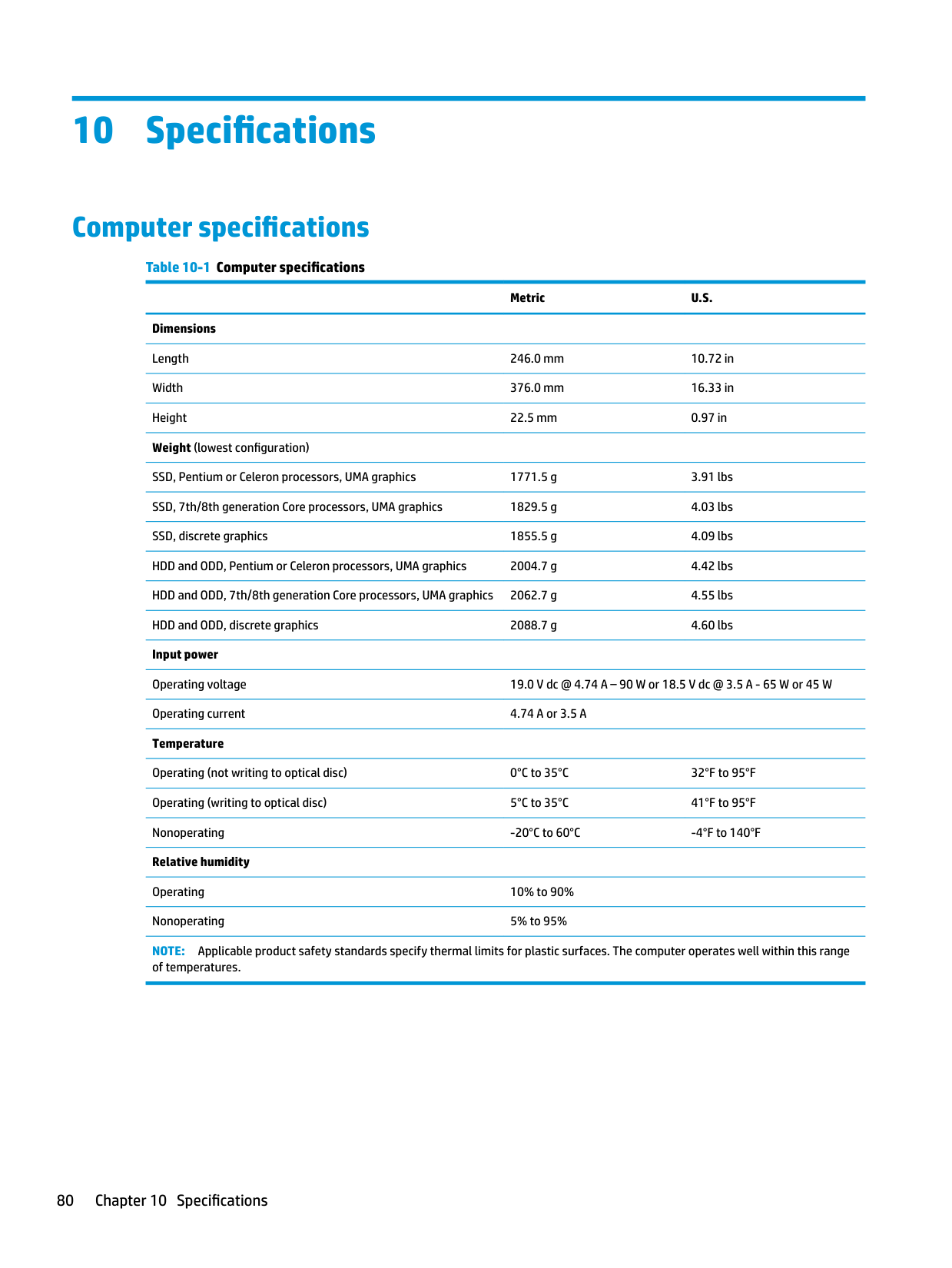
######## Table 10-1 Computer specifications
Metric U.S. Dimensions
Length 246.0 mm 10.72 in Width 376.0 mm 16.33 in Height 22.5 mm 0.97 in
Weight (lowest configuration)
SSD, Pentium or Celeron processors, UMA graphics 1771.5 g 3.91 lbs SSD, 7th/8th generation Core processors, UMA graphics 1829.5 g 4.03 lbs SSD, discrete graphics 1855.5 g 4.09 lbs HDD and ODD, Pentium or Celeron processors, UMA graphics 2004.7 g 4.42 lbs HDD and ODD, 7th/8th generation Core processors, UMA graphics 2062.7 g 4.55 lbs HDD and ODD, discrete graphics 2088.7 g 4.60 lbs Input power
Operating voltage 19.0 V dc @ 4.74 A – 90 W or 18.5 V dc @ 3.5 A - 65 W or 45 W Operating current 4.74 A or 3.5 A Temperature
Operating (not writing to optical disc) 0°C to 35°C 32°F to 95°F Operating (writing to optical disc) 5°C to 35°C 41°F to 95°F Nonoperating -20°C to 60°C -4°F to 140°F
Relative humidity Operating 10% to 90% Nonoperating 5% to 95% NOTE: Applicable product safety standards specify thermal limits for plastic surfaces. The computer operates well within this range of temperatures.
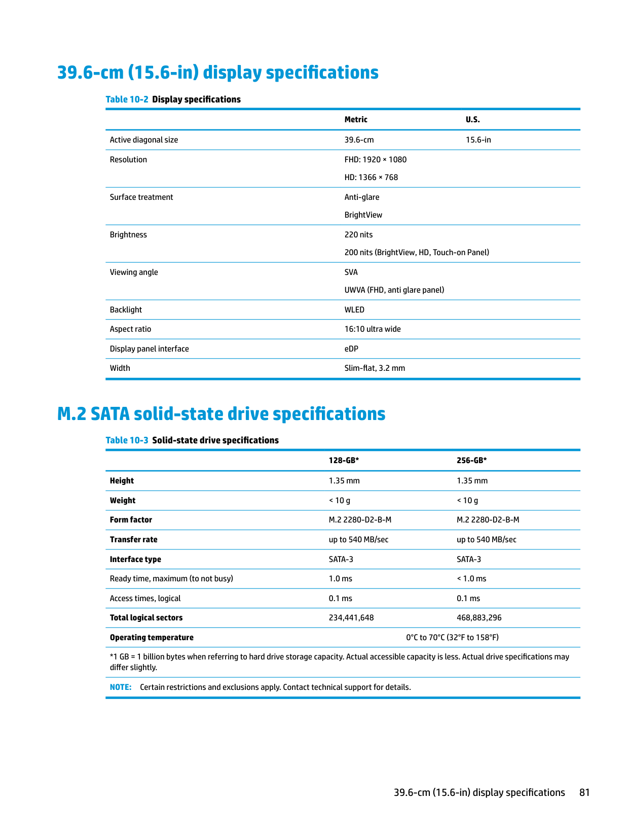
39.6-cm (15.6-in) display specifications
######## Table 10-2 Display specifications
Metric U.S. Active diagonal size 39.6-cm 15.6-in Resolution FHD: 1920 × 1080
HD: 1366 × 768 Surface treatment Anti-glare
BrightView Brightness 220 nits
200 nits (BrightView, HD, Touch-on Panel) Viewing angle SVA
UWVA (FHD, anti glare panel) Backlight WLED Aspect ratio 16:10 ultra wide Display panel interface eDP Width Slim-flat, 3.2 mm
M.2 SATA solid-state drive specifications
######## Table 10-3 Solid-state drive specifications
128-GB* 256-GB* Height 1.35 mm 1.35 mm Weight < 10 g < 10 g Form factor M.2 2280-D2-B-M M.2 2280-D2-B-M Transfer rate up to 540 MB/sec up to 540 MB/sec Interface type SATA-3 SATA-3 Ready time, maximum (to not busy) 1.0 ms < 1.0 ms Access times, logical 0.1 ms 0.1 ms Total logical sectors 234,441,648 468,883,296 Operating temperature 0°C to 70°C (32°F to 158°F)
*1 GB = 1 billion bytes when referring to hard drive storage capacity. Actual accessible capacity is less. Actual drive specifications may differ slightly.
NOTE: Certain restrictions and exclusions apply. Contact technical support for details.
39.6-cm (15.6-in) display specifications 81
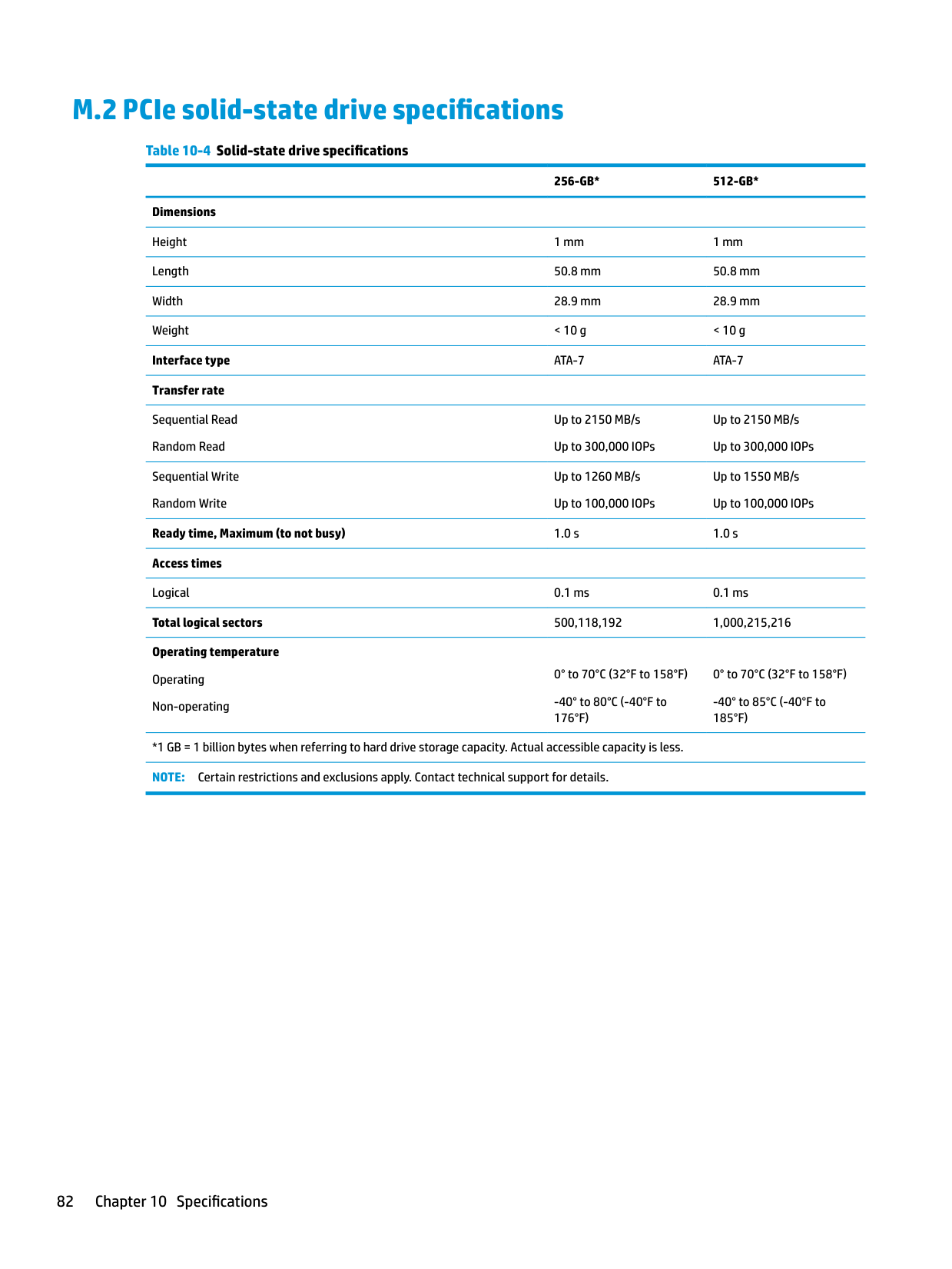
M.2 PCIe solid-state drive specifications
######## Table 10-4 Solid-state drive specifications
######### 256-GB* 512-GB*
Dimensions Height 1 mm 1 mm Length 50.8 mm 50.8 mm Width 28.9 mm 28.9 mm Weight < 10 g < 10 g Interface type ATA-7 ATA-7 Transfer rate
Sequential Read Random Read
Up to 2150 MB/s Up to 300,000 IOPs
Up to 2150 MB/s Up to 300,000 IOPs
Sequential Write Random Write
Up to 1260 MB/s Up to 100,000 IOPs
Up to 1550 MB/s Up to 100,000 IOPs
Ready time, Maximum (to not busy) 1.0 s 1.0 s Access times Logical 0.1 ms 0.1 ms Total logical sectors 500,118,192 1,000,215,216 Operating temperature Operating Non-operating
0° to 70°C (32°F to 158°F)
0° to 70°C (32°F to 158°F)
-40° to 80°C (-40°F to 176°F)
-40° to 85°C (-40°F to 185°F)
*1 GB = 1 billion bytes when referring to hard drive storage capacity. Actual accessible capacity is less. NOTE: Certain restrictions and exclusions apply. Contact technical support for details.
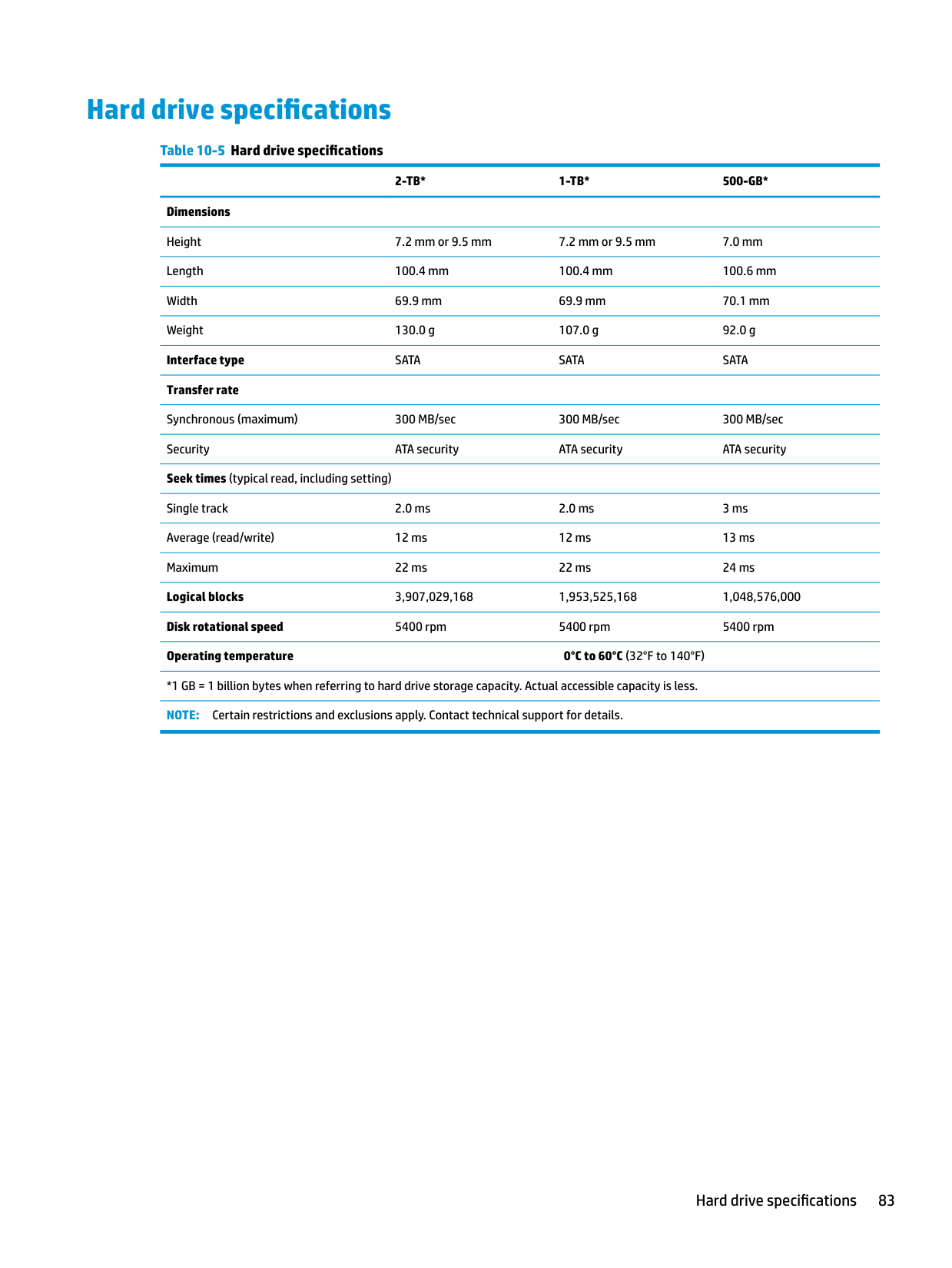
Hard drive specifications
######## Table 10-5 Hard drive specifications
######### 2-TB* 1-TB* 500-GB*
Dimensions Height 7.2 mm or 9.5 mm 7.2 mm or 9.5 mm 7.0 mm Length 100.4 mm 100.4 mm 100.6 mm Width 69.9 mm 69.9 mm 70.1 mm Weight 130.0 g 107.0 g 92.0 g Interface type SATA SATA SATA Transfer rate Synchronous (maximum) 300 MB/sec 300 MB/sec 300 MB/sec Security ATA security ATA security ATA security Seek times (typical read, including setting) Single track 2.0 ms 2.0 ms 3 ms Average (read/write) 12 ms 12 ms 13 ms Maximum 22 ms 22 ms 24 ms Logical blocks 3,907,029,168 1,953,525,168 1,048,576,000 Disk rotational speed 5400 rpm 5400 rpm 5400 rpm Operating temperature 0°C to 60°C (32°F to 140°F)
*1 GB = 1 billion bytes when referring to hard drive storage capacity. Actual accessible capacity is less. NOTE: Certain restrictions and exclusions apply. Contact technical support for details.
Hard drive specifications 83
11 Power cord set requirements
The wide-range input feature of the computer permits it to operate from any line voltage from 100 to 120 V ac, or from 220 to 240 V ac.
The 3-conductor power cord set included with the computer meets the requirements for use in the country or region where the equipment is purchased.
Power cord sets for use in other countries or regions must meet the requirements of the country and region where the computer is used.
Requirements for all countries
The following requirements are applicable to all countries and regions:
Requirements for specific countries and regions
######## Table 11-1 Power cord requirements for specific countries and regions
######### Country/region Accredited agency Applicable note number
Argentina IRAM 1 Australia SAA 1 Austria OVE 1 Belgium CEBEC 1 Brazil ABNT 1 Canada CSA 2 Chile IMQ 1 Denmark DEMKO 1 Finland FIMKO 1 France UTE 1 Germany VDE 1 India BIS 1 Israel SII 1 Italy IMQ 1 Japan JIS 3 The Netherlands KEMA 1 New Zealand SANZ 1 Norway NEMKO 1 The People's Republic of China CCC 4 Saudi Arabia SASO 7 Singapore PSB 1 South Africa SABS 1 South Korea KTL 5 Sweden SEMKO 1 Switzerland SEV 1 Taiwan BSMI 6 Thailand TISI 1 The United Kingdom ASTA 1 The United States UL 2 1. The flexible cord must be Type HO5VV-F, 3-conductor, 0.75 mm² conductor size. Power cord set fittings (appliance coupler and
wall plug) must bear the certification mark of the agency responsible for evaluation in the country or region where it will be used.
Requirements for specific countries and regions 85
######## Table 11-1 Power cord requirements for specific countries and regions (continued)
######### Country/region Accredited agency Applicable note number
12 Statement of memory volatility
The purpose of this chapter is to provide general information regarding nonvolatile memory in HP Business computers. This chapter also provides general instructions for restoring nonvolatile memory that can contain personal data after the system has been powered off and the hard drive has been removed.
HP Business computer products that use Intel®-based or AMD®-based system boards contain volatile DDR memory. The amount of nonvolatile memory present in the system depends upon the system configuration. Intel-based and AMD-based system boards contain nonvolatile memory subcomponents as originally shipped from HP, assuming that no subsequent modifications have been made to the system and assuming that no applications, features, or functionality have been added to or installed on the system.
Following system shutdown and removal of all power sources from an HP Business computer system, personal data can remain on volatile system memory (DIMMs) for a finite period of time and will also remain in nonvolatile memory. Use the steps below to remove personal data from the computer, including the nonvolatile memory found in Intel-based and AMD-based system boards.
| | |---|
NOTE: If your tablet has a keyboard base, connect to the keyboard base before beginning steps in this chapter.
###### Current BIOS steps

| | |---|
| | |---|
| | |---|
| | |---|
● Clear the drive contents by using a third party utility designed to erase data from an SSD.
| | |---|
IMPORTANT: If you clear data using Secure Erase, it cannot be recovered.
– or –
| | |---|
| | |---|
● Clear the contents of the drive using the following Disk Sanitizer commands steps: IMPORTANT: If you clear data using Disk Sanitizer, it cannot be recovered. NOTE: The amount of time it takes for Disk Sanitizer to run can take several hours. Plug the computer into an AC outlet before starting.
Nonvolatile memory usage
######## Table 12-1 Nonvolatile memory usage
Nonvolatile Memory Type Amount (Size)
Does this memory store customer data?
Does this memory retain data when power is removed?
What is the purpose of this memory?
How is data input into this memory?
How is this memory write-protected?
HP Sure Start flash (select models only)
8 MBytes No Yes Provides protected backup of critical System BIOS code, EC firmware, and critical computer configuration data for select platforms that support HP Sure Start.
For more information, see Using HP Sure Start (select models only) on page 93.
Real Time Clock (RTC) battery backed-up CMOS configuration memory
Controller (NIC) EEPROM
256 Bytes No Yes Stores system date and time and noncritical data.
64 KBytes (not customer accessible)
No Yes Stores NIC configuration and NIC firmware.
DIMM Serial Presence Detect (SPD) configuration data
256 Bytes per memory module, 128 Bytes programmable (not customer accessible)
No Yes Stores memory module information.
System BIOS 9 MBytes Yes Yes Stores system BIOS code and computer configuration data.
Data cannot be written to this device via the host processor. The content is managed solely by the HP Sure Start Embedded Controller.
This memory is protected by the HP Sure Start Embedded Controller.
RTC battery backed-up CMOS is programmed using the Computer Setup (BIOS), or changing the Microsoft® Windows date & time.
NIC EEPROM is programmed using a utility from the NIC vendor that can be run from DOS.
DIMM SPD is programmed by the memory vendor.
This memory is not writeprotected.
A utility is required to write data to this memory and is available from the NIC vendor. Writing data to this ROM in an inappropriate manner will render the NIC nonfunctional.
Data cannot be written to this memory when the module is installed in a computer. The specific write-protection method varies by memory vendor.
System BIOS code is programmed at the factory. Code is updated when the system BIOS is updated. Configuration data and settings are input using the Computer Setup (BIOS) or a custom utility.
NOTE: Writing data to this ROM in an inappropriate manner can render the computer nonfunctional.
A utility is required for writing data to this memory and is available on the HP website; go to http://www.hp.com/
######## Table 12-1 Nonvolatile memory usage (continued)
Nonvolatile Memory Type Amount (Size)
Does this memory store customer data?
Does this memory retain data when power is removed?
What is the purpose of this memory?
How is data input into this memory?
How is this memory write-protected?
support. Select Find your product, and then follow the on-screen instructions.
Intel Management Engine Firmware (present only in select Elite or Z models. For more information, go to http://www.hp.com/ support. Select Find your product, and then follow the onscreen instructions.)
1.5 MBytes or 7 MBytes
Yes Yes Stores Management Engine Code, Settings, Provisioning Data and iAMT third-party data store.
Management Engine Code is programmed at the factory. Code is updated via Intel secure firmware update utility. Unique Provisioning Data can be entered at the factory or by an administrator using the Management Engine (MEBx) setup utility. The third party data store contents can be populated by a remote management console or local applications that have been registered by an administrator to have access to the space.
Bluetooth flash (select products only)
2 Mbit No Yes Stores Bluetooth configuration and firmware.
Bluetooth flash is programmed at the factory. Tools for writing data to this memory are not publicly available but can be obtained from the silicon vendor.
802.11 WLAN EEPROM
4 Kbit to 8 Kbit No Yes Stores configuration and calibration data.
802.11 WLAN EEPROM is programmed at the factory. Tools for writing data to this memory are not made public.
Webcam (select products only)
64 Kbit No Yes Stores webcam configuration and firmware.
Webcam memory is programmed using a utility from the device manufacturer that can be run from Windows.
Fingerprint reader (select products only)
512 KByte flash Yes Yes Stores
fingerprint templates.
Fingerprint reader memory is programmed by user enrollment in HP ProtectTools Security Manager.
The Intel chipset is configured to enforce hardware protection to block all direct read/write access to this area. An Intel utility is required for updating the firmware. Only firmware updates digitally signed by Intel can be applied using this utility.
A utility is required for writing data to this memory and is made available through newer versions of the driver whenever the flash requires an upgrade.
A utility is required for writing data to this memory and is typically not made available to the public unless a firmware upgrade is necessary to address a unique issue.
A utility is required for writing data to this memory and is typically not made available to the public unless a firmware upgrade is necessary to address a unique issue.
Only a digitally signed application can make the call to write to the flash.
Nonvolatile memory usage 91
Questions and answers
IMPORTANT: Restore defaults does not securely erase any data on your hard drive. See question and answer 6 for steps to securely erase data. Restore defaults does not reset the Custom Secure Boot keys. See question and answer 7 for information about resetting the keys.
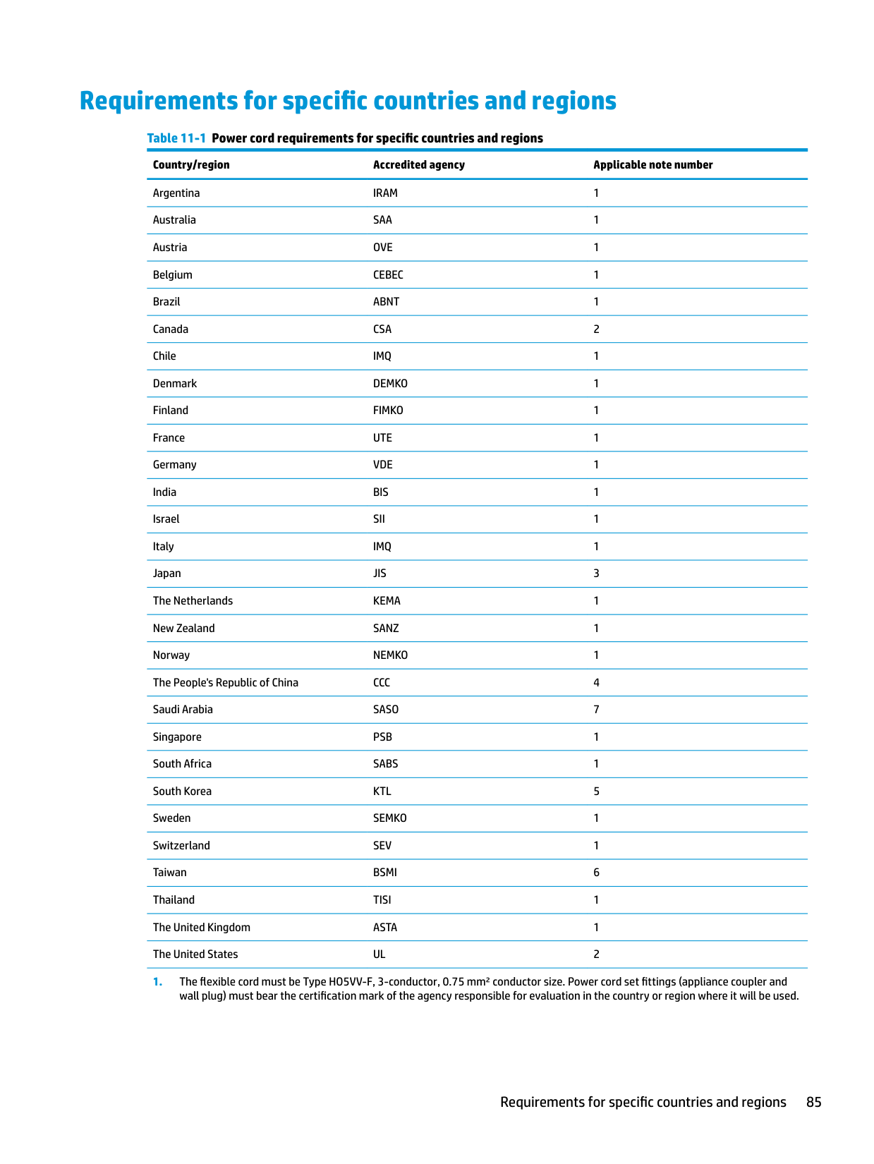
The Unified Extensible Firmware Interface (UEFI) BIOS is an industry-standard software interface between the platform firmware and an operating system (OS). It is a replacement for the older BIOS architecture, but supports much of the legacy BIOS functionality.
Like the legacy BIOS, the UEFI BIOS provides an interface to display the system information and configuration settings and to change the configuration of your computer before an OS is loaded. BIOS provides a secure run-time environment that supports a Graphic User Interface (GUI). In this environment, you can use either a pointing device (Touchscreen, TouchPad, pointing stick, or USB mouse) or the keyboard to navigate and make menu and configuration selections. The UEFI BIOS also contains basic system diagnostics.
The UEFI BIOS provides functionality beyond that of the legacy BIOS. In addition, the UEFI BIOS works to initialize the computer’s hardware before loading and executing the OS; the run-time environment allows the loading and execution of software programs from storage devices to provide more functionality, such as advanced hardware diagnostics (with the ability to display more detailed system information) and advanced firmware management and recovery software.
HP has provided options in Computer Setup (BIOS) to allow you to run in legacy BIOS, if required by the operating system. Examples of this requirement would be if you upgrade or downgrade the OS.
The DIMM SPD memory contains information about the memory module, such as size, serial number, data width, speed/timing, voltage, and thermal information. This information is written by the module manufacturer and stored on an EEPROM. This EEPROM cannot be written to when the memory module is installed in a computer. Third-party tools do exist that can write to the EEPROM when the memory module is not installed in a computer. Various third-party tools are available to read SPD memory.
This message relates to clearing the Real Time Clock (RTC) CMOS memory that contains computer configuration data.
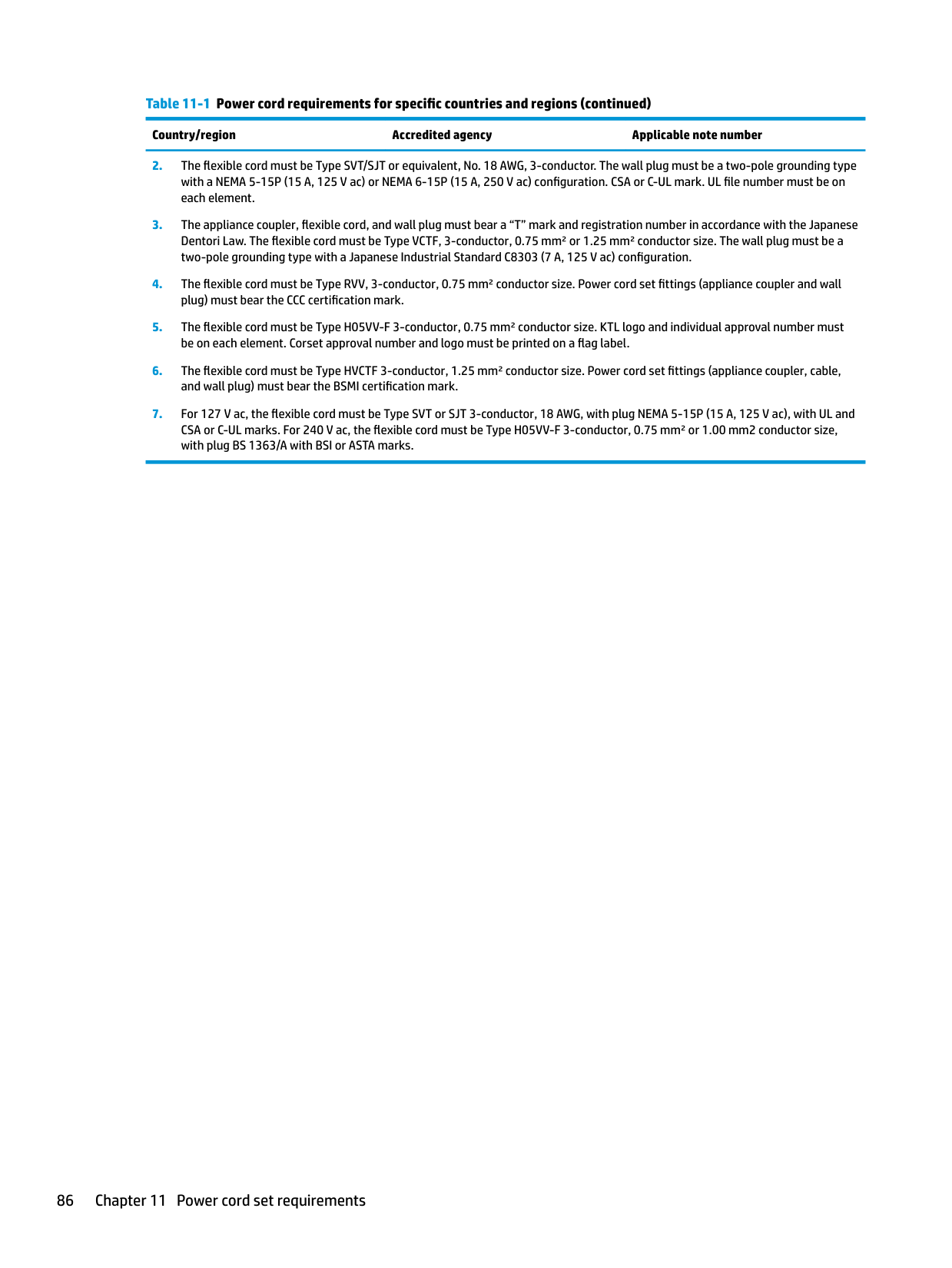
| | |---|
| | |---|
IMPORTANT: Resetting will result in the loss of information.
These steps will not reset Custom Secure Boot Keys. See question and answer 7 for information about resetting the keys.
###### 7. How can the Custom Secure Boot Keys be reset?
Secure Boot is a feature to ensure that only authenticated code can start on a platform. If you enabled Secure Boot and created Custom Secure Boot Keys, simply disabling Secure Boot will not clear the keys. You must also select to clear the Custom Secure Boot Keys. Use the same Secure Boot access procedure you used to create the Custom Secure Boot Keys, but make the selection to clear or delete all Secure Boot Keys.
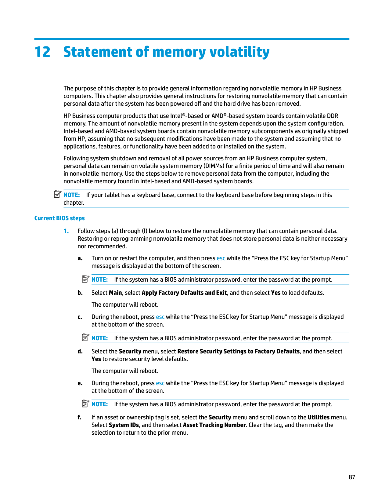
Using HP Sure Start (select models only)
Select computer models are configured with HP Sure Start, a technology that continuously monitors your computer's BIOS for attacks or corruption. If the BIOS becomes corrupted or is attacked, HP Sure Start restores the BIOS to its previously safe state, without user intervention. Those select computer models ship with HP Sure Start configured and enabled. HP Sure Start is configured and already enabled so that most users can use the HP Sure Start default configuration. The default configuration can be customized by advanced users.
To access the latest documentation on HP Sure Start, go to http://www.hp.com/support. Select Find your product, and then follow the on-screen instructions.
Using HP Sure Start (select models only) 93
13 Recycling
When a non-rechargeable or rechargeable battery has reached the end of its useful life, do not dispose of the battery in general household waste. Follow the local laws and regulations in your area for battery disposal.
HP encourages customers to recycle used electronic hardware, HP original print cartridges, and rechargeable batteries. For more information about recycling programs, see the HP Web site at http://www.hp.com/recycle.
94 Chapter 13 Recycling
Index
identifying 6 AC adapter, spare part numbers 20 action keys
airplane mode 12 help 12 identifying 11, 12 keyboard backlight 12 mute 12 next track 12 pause 12 play 12 screen brightness 12 speaker volume 12 switch screen image 12 using 12
airplane mode key 12 antenna
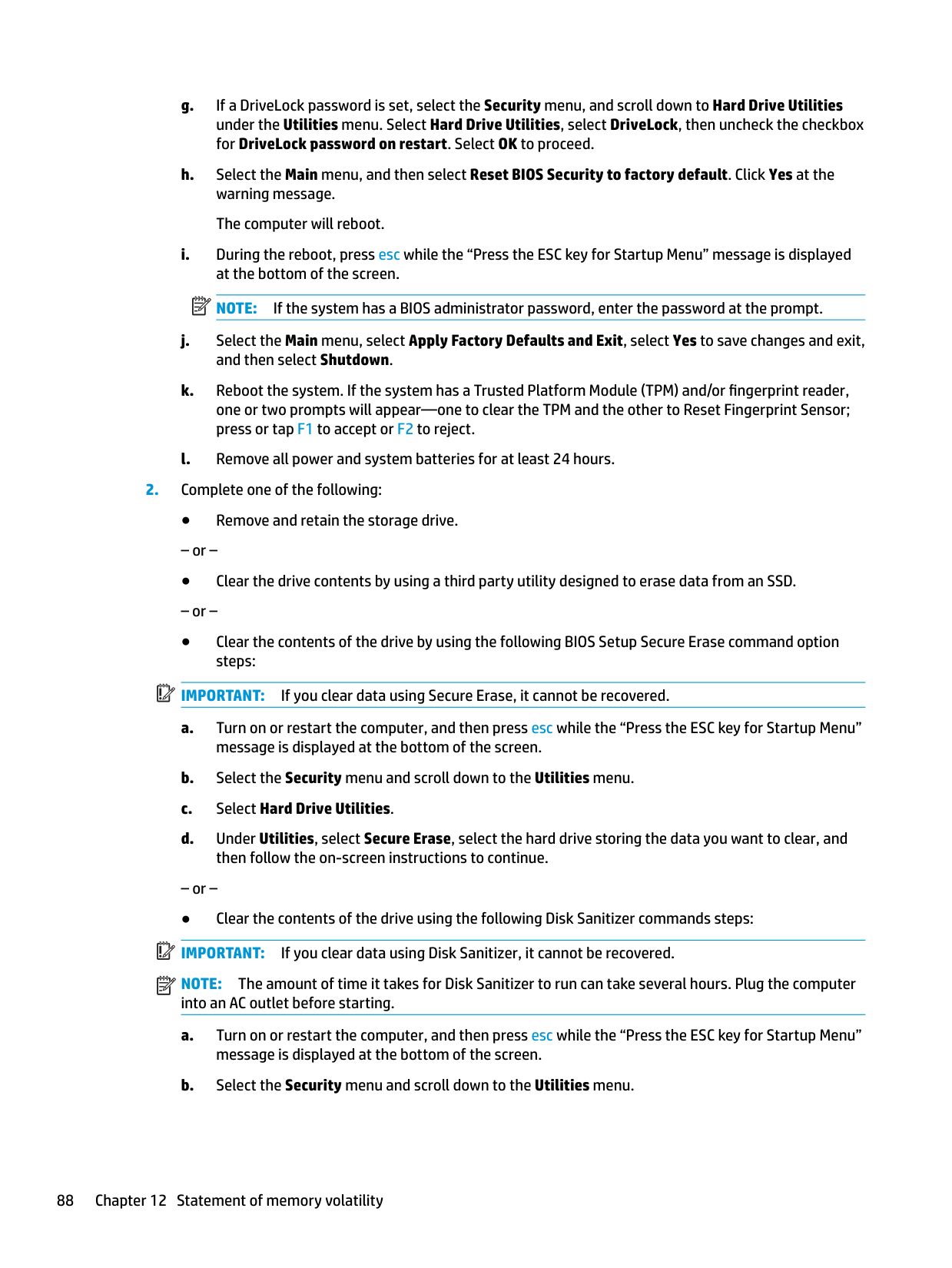
removal 60 audio
adjusting volume 12
audio-out (headphone)/audio-in (microphone) combo jack, identifying 6
spare part number 20 backup, creating 78 backups 78 battery
removal 34 spare part number 17, 34
BIOS determining version 70 downloading an update 70 updating 70 Bluetooth label 14 boot order
changing using the f9 prompt 71
boot order, changing 79 bottom components 13
bottom cover removal 32 spare part number 17, 32
buttons left TouchPad 8 optical drive eject 5 power 10 right TouchPad 8
C camera
identifying 7 product description 2

camera light, identifying 7 camera module
spare part number 20 camera/microphone module
spare part numbers 57 caps lock light, identifying 9 cautions
electrostatic discharge 24 chipset, product description 1 components
bottom 13 display 7 keyboard area 8 left side 6 right side 5
computer major components 15 Computer Setup
navigating and selecting 69 restoring factory settings 69 starting 69
computer setup 69 computer specifications 80 connector, power 6
D Display assembly
spare part numbers 16
display assembly removal 54 subcomponents 19
display assembly components removal 54 spare part numbers 54
display bezel removal 56 spare part numbers 19, 56
display cable, spare part number 19 display components 7 display panel
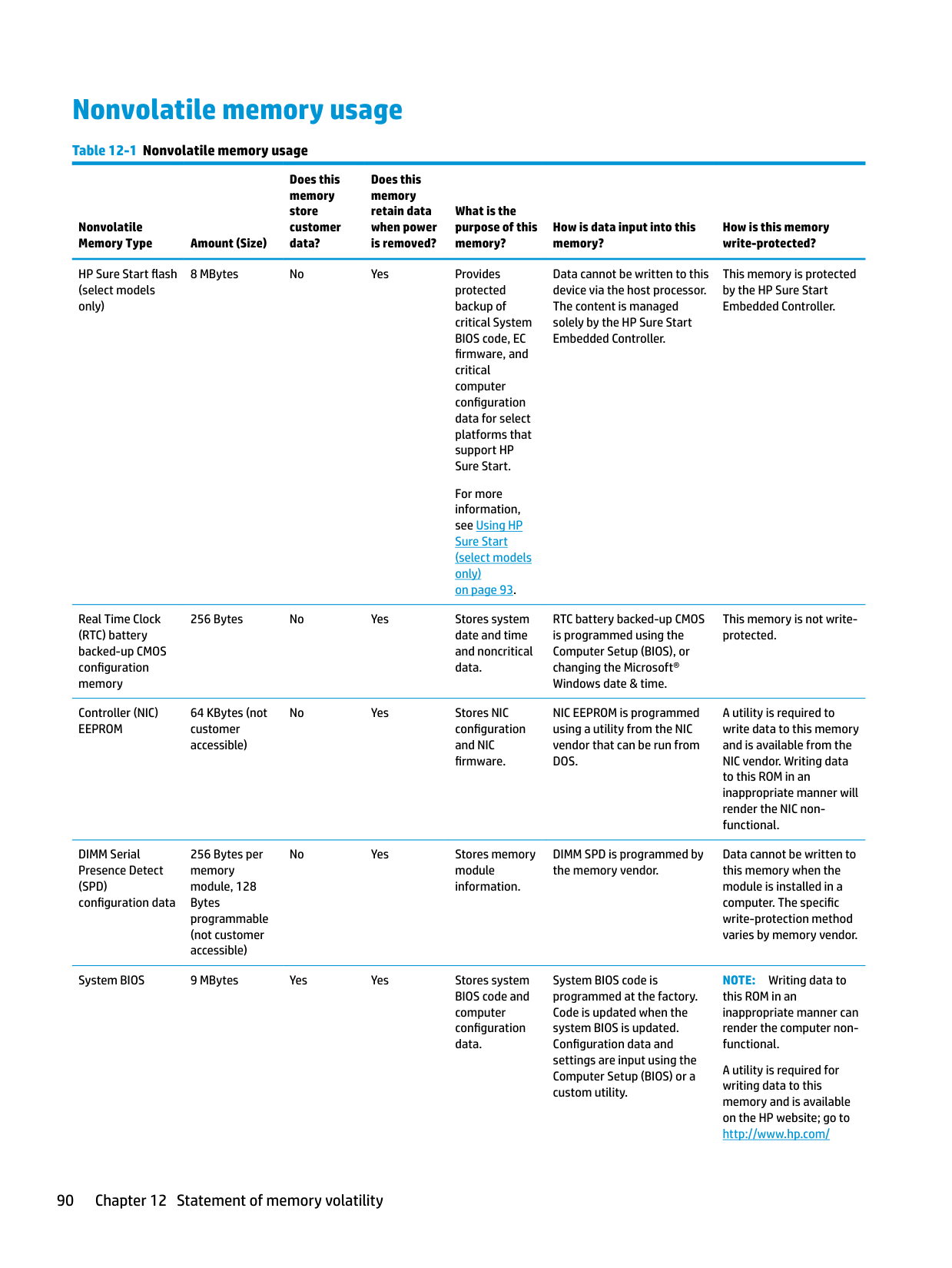
product description 1 removal 57
display panel cable removal 59 spare part numbers 60
display specifications 81 drive light, identifying 5 DVD+/-RW Double-Layer Writer
spare part number 17, 21, 29
preventing damage 25 esc key, identifying 11 ethernet
product description 3
removal 49 spare part number 17, 49
fn key, identifying 11
12 grounding methods 26 guidelines
packaging 27 transporting 27 workstation 24
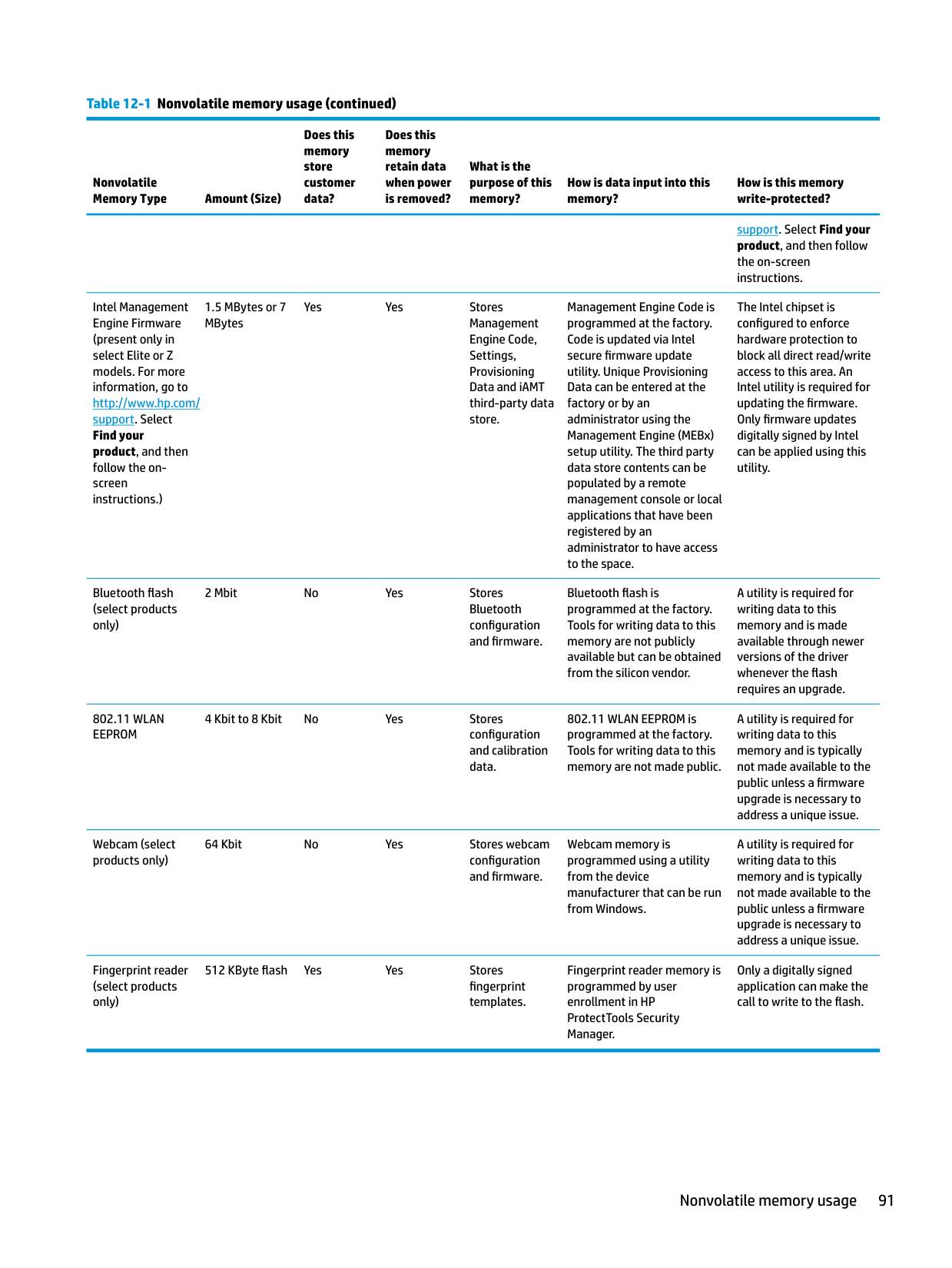
product description 2 removal 38
spare part number 17, 21 spare part numbers 38 specifications 83
hard drive bracket spare part number 22
hard drive connector board removal 44 spare part number 17, 22, 44
hard drive/solid-state drive cable
spare part number 22 HDMI port
identifying 6 heat sink
spare part numbers 17
heat sink assembly removal 50 spare part numbers 50
hinge removal 59 spare part number 59
hinge cover
spare part number 19 Hinge Kit
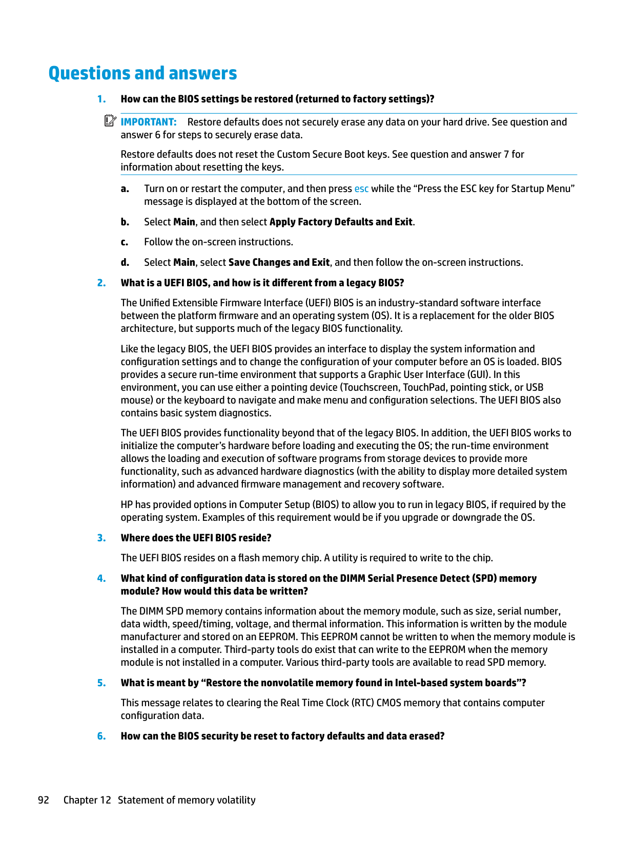
spare part number 19
HP PC Hardware Diagnostics UEFI downloading 75 starting 75 using 74
HP PC Hardware Diagnostics Windows downloading 73 installing 74 using 73
HP Recovery Manager
correcting boot problems 79 HP Recovery media
recovery 79 HP Sure Start 93
identifying 11 internal microphones, identifying 7
audio-out (headphone)/audio-in
(microphone) 6 network 6 RJ-45 (network) 6
product description 3 removal 68 spare part number 68 spare part numbers 16
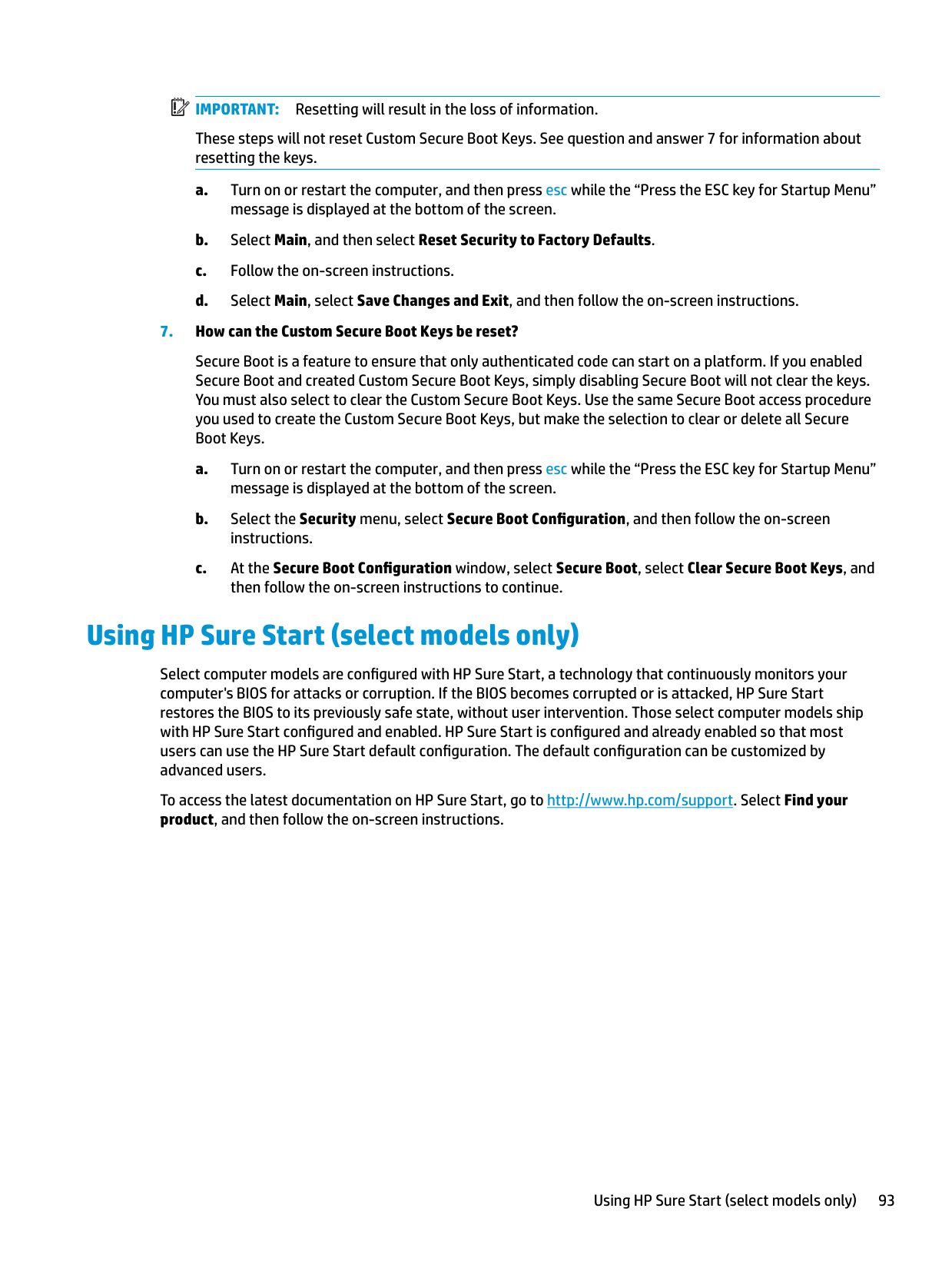
keyboard backlight action key 12 keypad, integrated numeric 11 keys
action 11 airplane mode 12 esc 11 fn 11 num lock 11 Windows 11
Bluetooth 14 regulatory 14 serial number 14 service 14 wireless certification 14 WLAN 14
left side components 6 lights
AC adapter and battery 6 camera 7 caps lock 9 drive 5 mute 9 power 5 RJ-45 (network) status 6
specifications 82
memory nonvolatile 87 product description 1 removal 36 spare part number 16 spare part numbers 36 volatile 87
MicroSD memory card reader,
identifying 5 model name 1 mute light, identifying 9 mute volume action key 12
description 4
optical drive product description 2 removal 29 spare part numbers 29
optical drive eject button, identifying 5 optical drive, identifying 5
spare part numbers 19 pause action key 12 play action key 12 pointing device, product
description 3
ports HDMI 6 product description 3 USB 5 USB SuperSpeed 6
power button, identifying 10 power connector
identifying 6
power connector cable removal 67 spare part numbers 67
power cord requirements for all countries 84 requirements for specific countries and regions 85
set requirements 84 power lights, identifying 5 power requirements, product
description 3 processor 1 product description
camera 2 chipset 1 display panel 1 ethernet 3
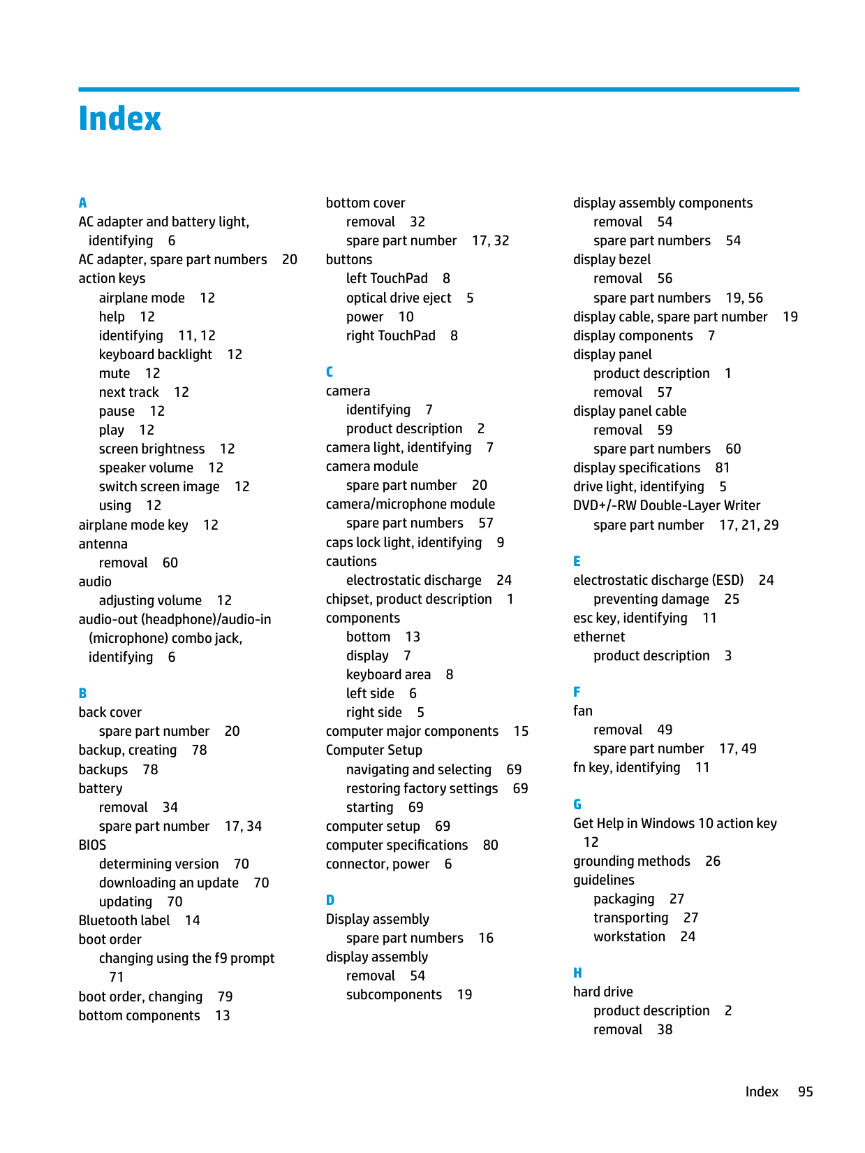
external media cards 3 hard drive 2 keyboard 3 memory 1 operating system 4 optical drive 2 pointing device 3 ports 3 power requirements 3 processor 1 product name 1 security 4 serviceability 4 wireless networking 3
product name 1 product name and number,
computer 14
discs 79 HP Recovery partition 79 media 79 USB flash drive 79
recovery media creating using HP Cloud Recovery Download Tool 78 creating using Windows tools 78
regulatory information regulatory label 14 wireless certification labels 14
Remote HP PC Hardware Diagnostics
UEFI settings customizing 76 using 76
removal/replacement procedures 28, 31 removing personal data from volatile
system memory 87 restoring 78 right side components 5 RJ-45 (network) jack, identifying 6 RJ-45 (network) status lights,
identifying 6
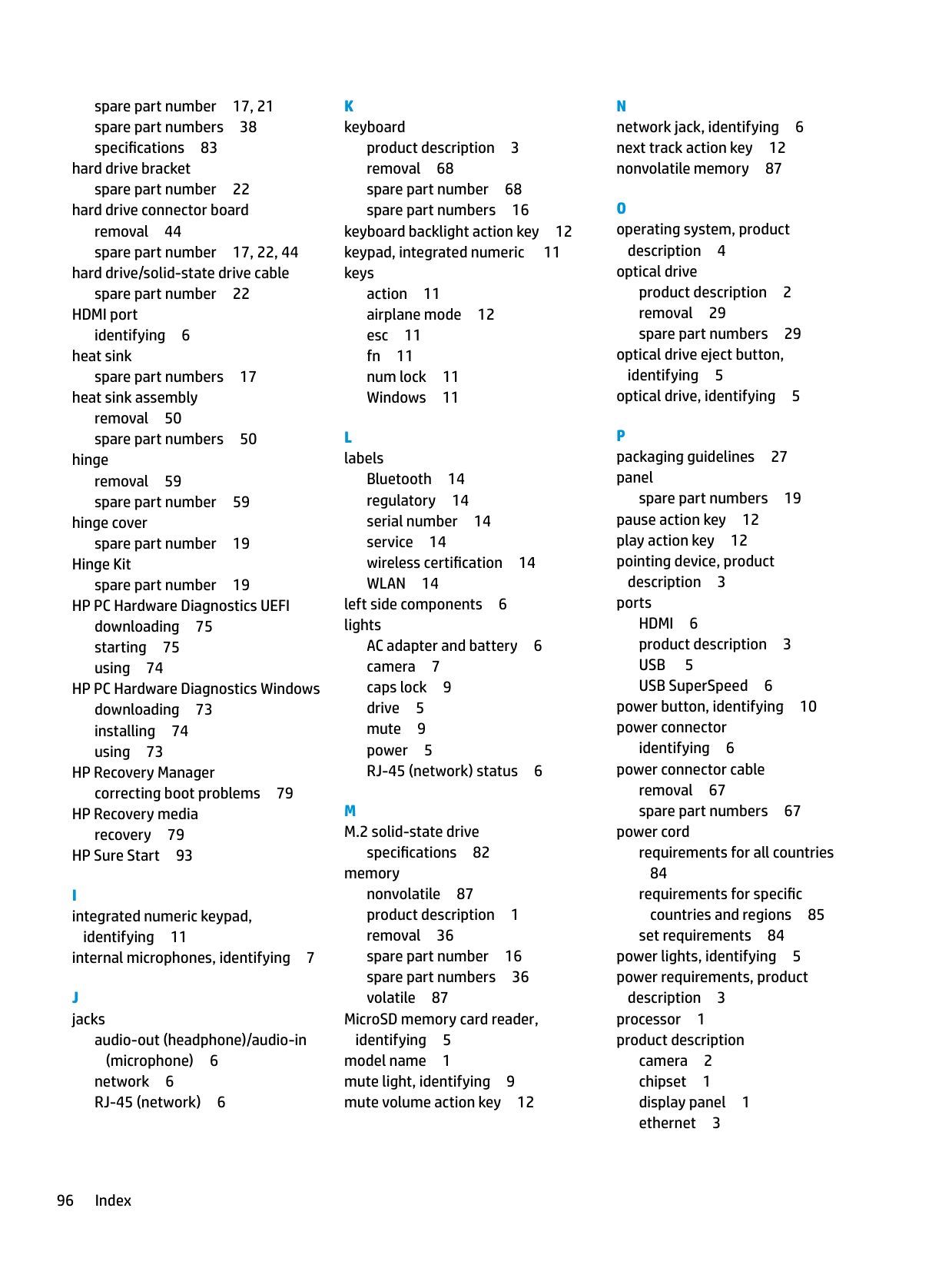
serial number, computer 14 service labels, locating 14 serviceability, product description 4 setup utility
navigating and selecting 69 restoring factory settings 69
slots memory card reader 5 security cable 5
solid-state drive removal 40 spare part number 16, 22 spare part numbers 40 specifications 81
solid-state drive bracket and
connector board removal 41 spare part numbers 41
solid-state drive cable spare part number 22 solid-state drive connector board
spare part number 17 speaker volume action keys 12 speakers
identifying 10 removal 66 spare part number 16 spare part numbers 66
special keys, using 11 specifications
computer 80 display 81 hard drive 83 M.2 solid-state drive 82 solid-state drive 81
static electricity 25 Sure Start
using 72 switch screen image action key 12 system board
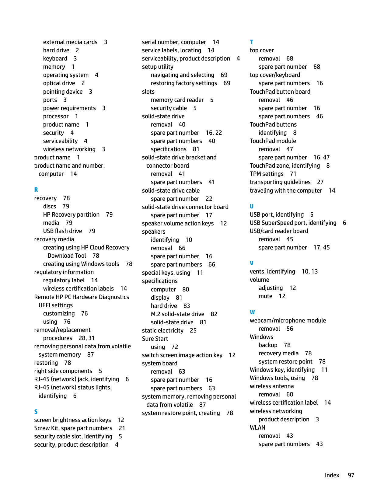
removal 63 spare part number 16 spare part numbers 63
system memory, removing personal data from volatile 87 system restore point, creating 78
removal 68 spare part number 68
top cover/keyboard spare part numbers 16
TouchPad button board removal 46 spare part number 16 spare part numbers 46
TouchPad buttons
identifying 8 TouchPad module
removal 47
TouchPad zone, identifying 8 TPM settings 71 transporting guidelines 27 traveling with the computer 14
U USB port, identifying 5 USB SuperSpeed port, identifying 6 USB/card reader board
removal 45

adjusting 12 mute 12
removal 56
Windows backup 78 recovery media 78 system restore point 78
Windows key, identifying 11 Windows tools, using 78 wireless antenna
removal 60 wireless certification label 14 wireless networking
product description 3
WLAN removal 43 spare part numbers 43
WLAN antenna
removal 60 WLAN antennas, identifying 7 WLAN cable
spare part number 20 WLAN device 14 WLAN label 14 WLAN module
spare part number 16 workstation guidelines 24