
Ask AI
— answers from the official manualAnswers from the official manual.
Common questions
Common Questions
15 totalWhat should I do if my power light does not turn on?
If pressing the Power button fails to turn on the computer, try unplugging and then replugging in the AC adapter. If the issue persists or the LED does not blink amber indicating connection activity, contact technical support as there may be a hardware malfunction.
How do I replace the hard drive?
First release the battery latches to remove it from the bay. Then unlock and lift off the bottom door panel. The hard drive slots are visible inside where the old unit must be carefully unplugged before removing the new replacement part with an exact fit. (Page 96, illustrated in Chapter 3)
How do I replace the battery?
To access and remove the old battery, open the two spring-loaded latches on either side of the bay and release the battery out from within. Slot in a new or spare rechargeable Li-Ion cell model matching the original specifications for proper fit and charging cycles.
How do I safely dispose of my old battery?
Remove the battery from its compartment by releasing and lifting open its retention latches. Dispose through a local electronics recycler as these components contain hazardous materials regulated under local environmental laws.
Why is my laptop overheating?
If you notice excessive warmth, especially around vents and fans are not operating effectively, it may be due to dust accumulation inside. Perform a cleaning check on internal air passages or schedule a maintenance session if unsure of DIY procedures.
What does the amber hard drive light indicate on the HP EliteBook 8460p?
An amber hard drive light indicates that HP 3D DriveGuard has temporarily parked the hard drive. A blinking turquoise hard drive light indicates that the hard drive or optical drive is actively being accessed. (Page 21)
Show 9 more questions
What is the maximum amount of RAM supported by the HP EliteBook 8460p?
How do I force shut down the HP EliteBook 8460p if it stops responding?
What does the amber battery light mean on the HP EliteBook 8460p?
Is it safe to place the HP EliteBook 8460p on my lap while using it?
How do I perform a system recovery on Windows 7 using the HP EliteBook 8460p?
What hard drive sizes are available for the HP EliteBook 8460p?
What do the different power light states mean on the HP EliteBook 8460p?
What wireless modules are compatible with the HP EliteBook 8460p?
Which end-user replaceable parts can I replace myself on the HP EliteBook 8460p?
Full Manual
160 pages
HP EliteBook 8460p Notebook PC HP ProBook 6460b Notebook PC Maintenance and Service Guide
© Copyright 2011 Hewlett-Packard Development Company, L.P. Bluetooth is a trademark owned by its proprietor and used by Hewlett-Packard Company under license. Intel and Core are trademarks or registered trademarks of Intel Corporation in the United States and other countries. Microsoft, Windows, and Windows Vista are either trademarks or registered trademarks of Microsoft Corporation in the United States and/or other countries. SD Logo is a trademark of its proprietor. The information contained herein is subject to change without notice. The only warranties for HP products and services are set forth in the express warranty statements accompanying such products and services. Nothing herein should be construed as constituting an additional warranty. HP shall not be liable for technical or editorial errors or omissions contained herein. First Edition: March 2011 Document Part Number: 644152-001

Safety warning notice
Warning!
To reduce the possibility of heat-related injuries or of overheating the computer, do not place the computer directly on your lap or obstruct the computer air vents. Use the computer only on a hard, flat surface. Do not allow another hard surface, such as an adjoining optional printer, or a soft surface, such as pillows or rugs or clothing, to block airflow. Also, do not allow the AC adapter to contact the skin or a soft surface, such as pillows or rugs or clothing, during operation. The computer and the AC adapter comply with the user-accessible surface temperature limits defined by the International Standard for Safety of Information Technology Equipment (IEC 60950). iii
iv Safety warning notice
Table of contents 1 Product description ........................................................................................................... 1 2 External component identification ................................................................................... 10 Display ................................................................................................................................. 10 Top ...................................................................................................................................... 13 TouchPad ............................................................................................................... 13 Lights ..................................................................................................................... 14 Buttons and fingerprint reader ................................................................................... 16 Keys ...................................................................................................................... 18 Front ..................................................................................................................................... 20 Left ....................................................................................................................................... 21 Rear ..................................................................................................................................... 22 Right ..................................................................................................................................... 23 Bottom .................................................................................................................................. 25 3 Illustrated parts catalog .................................................................................................. 27 Service tag ............................................................................................................................ 27 Computer major components ................................................................................................... 28 Display components ............................................................................................................... 36 Cable Kit .............................................................................................................................. 38 Plastics Kit ............................................................................................................................. 39 Mass storage devices ............................................................................................................. 40 Miscellaneous parts ................................................................................................................ 41 Sequential part number listing .................................................................................................. 42 4 Removal and replacement procedures ............................................................................ 54 Preliminary replacement requirements ....................................................................................... 54 Tools required ......................................................................................................... 54 Service considerations ............................................................................................. 54 Plastic parts ............................................................................................. 54 Cables and connectors ............................................................................. 55 v
Drive handling ......................................................................................... 55 Grounding guidelines .............................................................................................. 56 Electrostatic discharge damage .................................................................. 56 Packaging and transporting guidelines ........................................ 57 Workstation guidelines .............................................................. 57 Equipment guidelines ................................................................. 58 Component replacement procedures ........................................................................................ 59 Service tag ............................................................................................................. 59 Computer feet ......................................................................................................... 60 Battery ................................................................................................................... 61 SIM ....................................................................................................................... 62 Display assembly components (panel, bezel, webcam, microphone) .............................. 63 Bottom door ........................................................................................................... 68 Smart card reader ................................................................................................... 69 Optical drive .......................................................................................................... 70 Upgrade bay .......................................................................................................... 72 Hard drive ............................................................................................................. 74 RTC battery ............................................................................................................ 76 Memory modules .................................................................................................... 77 WWAN module ..................................................................................................... 79 WLAN module ........................................................................................................ 81 Bluetooth module .................................................................................................... 86 Modem module ....................................................................................................... 87 Fan ....................................................................................................................... 88 Heat sink ................................................................................................................ 89 Processor ............................................................................................................... 92 Keyboard ............................................................................................................... 93 Bottom cover .......................................................................................................... 96 Fingerprint reader board ........................................................................................ 100 Lid switch ............................................................................................................. 102 Speaker assembly ................................................................................................. 104 RJ-11 connector cable ............................................................................................ 106 Display assembly components (cable, antennas, hinges, enclosure) ............................. 108 System board ....................................................................................................... 115 ExpressCard assembly ........................................................................................... 118 5 Computer Setup (BIOS) and System Diagnostics ............................................................ 120 Using Computer Setup .......................................................................................................... 120 Starting Computer Setup ........................................................................................ 120 Navigating and selecting in Computer Setup ............................................................ 120 Restoring factory settings in Computer Setup ............................................................. 121 vi
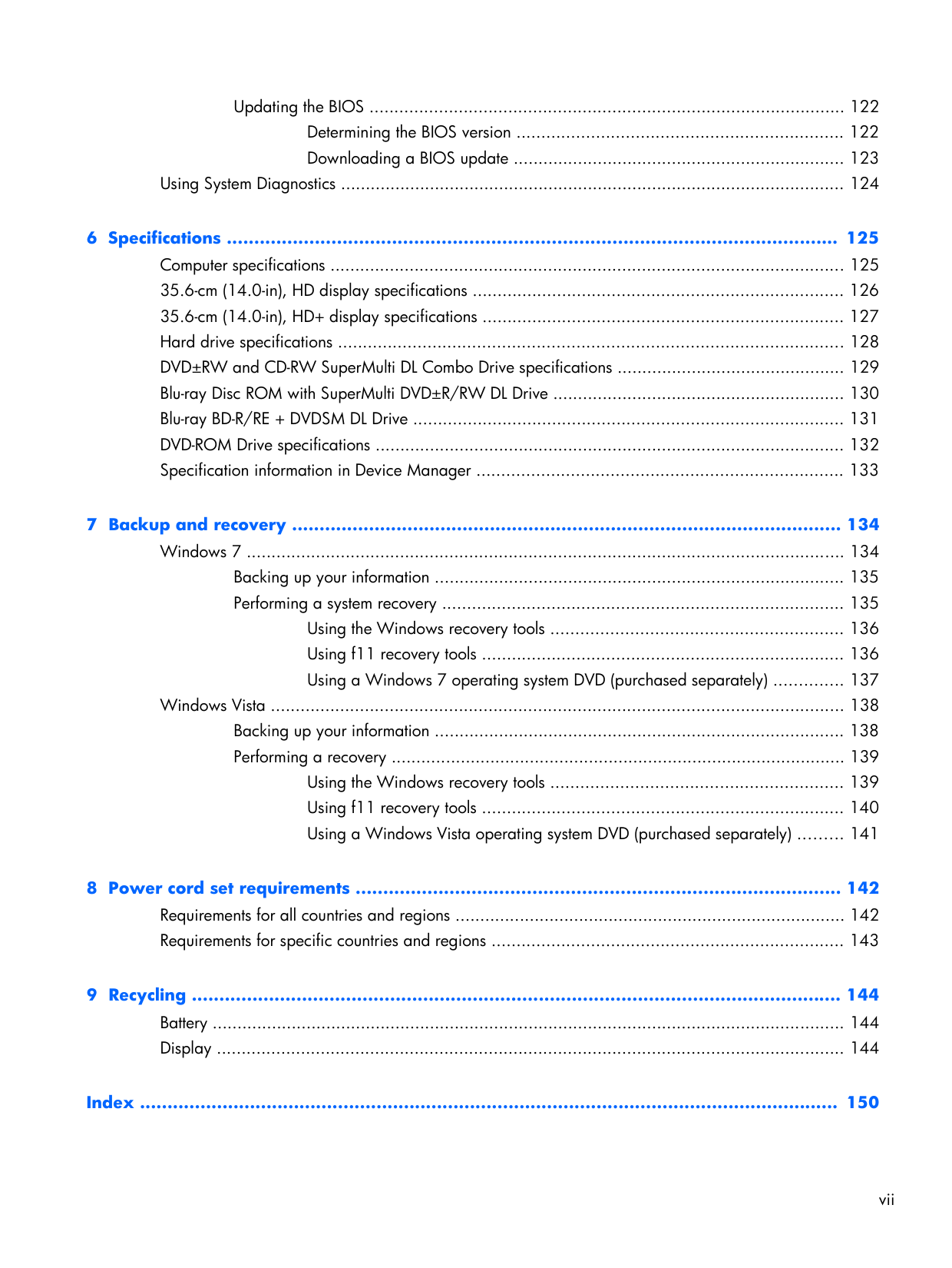
Updating the BIOS ................................................................................................ 122 Determining the BIOS version .................................................................. 122 Downloading a BIOS update ................................................................... 123 Using System Diagnostics ...................................................................................................... 124 6 Specifications ............................................................................................................... 125 Computer specifications ........................................................................................................ 125 35.6-cm (14.0-in), HD display specifications ........................................................................... 126 35.6-cm (14.0-in), HD+ display specifications ......................................................................... 127 Hard drive specifications ...................................................................................................... 128 DVD±RW and CD-RW SuperMulti DL Combo Drive specifications .............................................. 129 Blu-ray Disc ROM with SuperMulti DVD±R/RW DL Drive ........................................................... 130 Blu-ray BD-R/RE + DVDSM DL Drive ....................................................................................... 131 DVD-ROM Drive specifications ............................................................................................... 132 Specification information in Device Manager .......................................................................... 133 7 Backup and recovery .................................................................................................... 134 Windows 7 ......................................................................................................................... 134 Backing up your information ................................................................................... 135 Performing a system recovery ................................................................................. 135 Using the Windows recovery tools ........................................................... 136 Using f11 recovery tools ......................................................................... 136 Using a Windows 7 operating system DVD (purchased separately) .............. 137 Windows Vista .................................................................................................................... 138 Backing up your information ................................................................................... 138 Performing a recovery ............................................................................................ 139 Using the Windows recovery tools ........................................................... 139 Using f11 recovery tools ......................................................................... 140 Using a Windows Vista operating system DVD (purchased separately) ......... 141 8 Power cord set requirements ........................................................................................ 142 Requirements for all countries and regions ............................................................................... 142 Requirements for specific countries and regions ....................................................................... 143 9 Recycling ...................................................................................................................... 144 Battery ................................................................................................................................ 144 Display ............................................................................................................................... 144 Index ............................................................................................................................... 150 vii
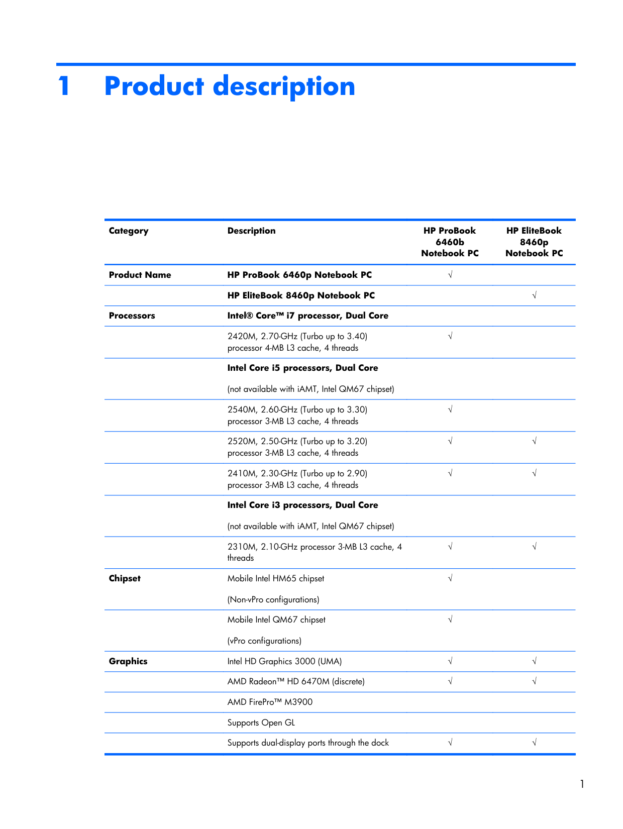
1 Product description Category Description HP ProBook 6460b Notebook PC HP EliteBook 8460p Notebook PC Product Name HP ProBook 6460p Notebook PC √
HP EliteBook 8460p Notebook PC
√ Processors Intel® Core™ i7 processor, Dual Core
2420M, 2.70-GHz (Turbo up to 3.40) processor 4-MB L3 cache, 4 threads √
Intel Core i5 processors, Dual Core (not available with iAMT, Intel QM67 chipset)
2540M, 2.60-GHz (Turbo up to 3.30) processor 3-MB L3 cache, 4 threads √
2520M, 2.50-GHz (Turbo up to 3.20) processor 3-MB L3 cache, 4 threads √ √
2410M, 2.30-GHz (Turbo up to 2.90) processor 3-MB L3 cache, 4 threads √ √
Intel Core i3 processors, Dual Core (not available with iAMT, Intel QM67 chipset)
2310M, 2.10-GHz processor 3-MB L3 cache, 4 threads √ √ Chipset Mobile Intel HM65 chipset (Non-vPro configurations) √
Mobile Intel QM67 chipset (vPro configurations) √
Graphics Intel HD Graphics 3000 (UMA) √ √
AMD Radeon™ HD 6470M (discrete) √ √
AMD FirePro™ M3900
Supports Open GL
Supports dual-display ports through the dock √ √ 1
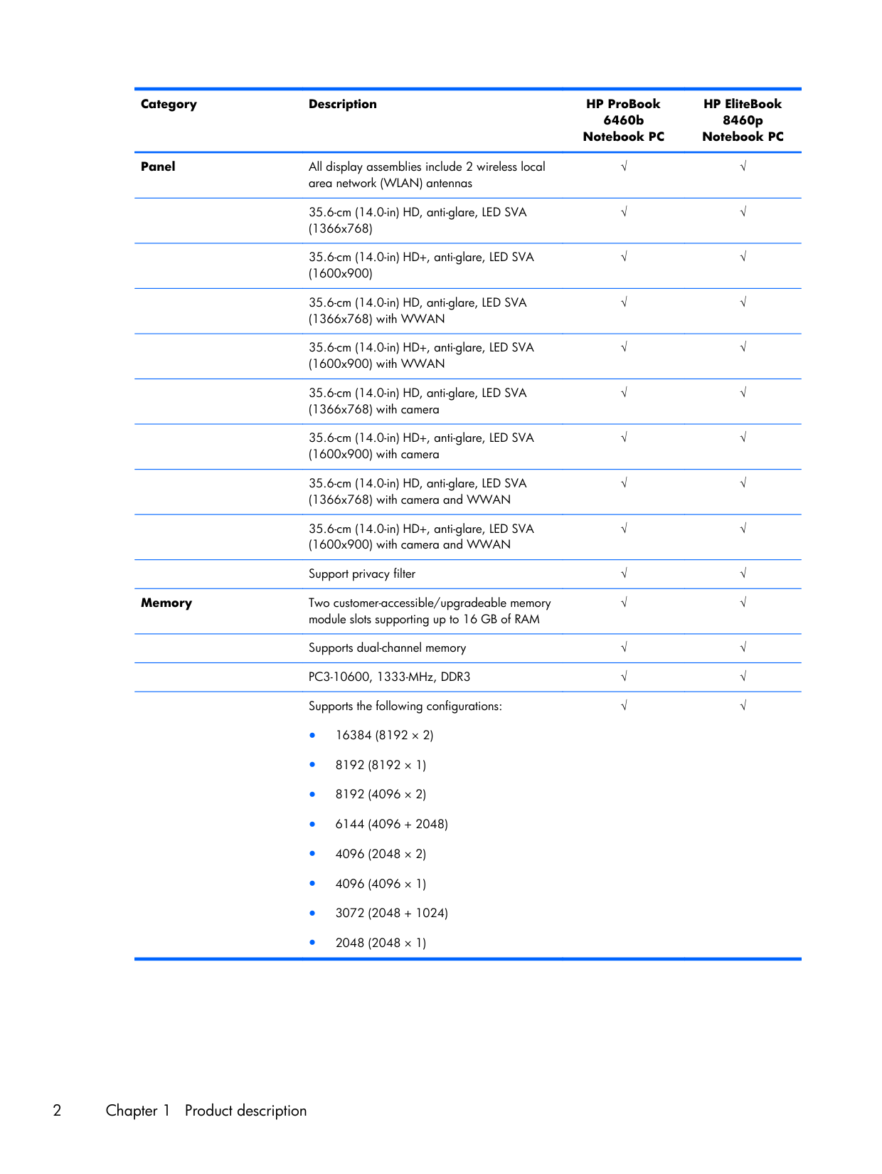
Category Description HP ProBook 6460b Notebook PC HP EliteBook 8460p Notebook PC Panel All display assemblies include 2 wireless local area network (WLAN) antennas √ √
35.6-cm (14.0-in) HD, anti-glare, LED SVA (1366x768) √ √
35.6-cm (14.0-in) HD+, anti-glare, LED SVA (1600x900) √ √
35.6-cm (14.0-in) HD, anti-glare, LED SVA (1366x768) with WWAN √ √
35.6-cm (14.0-in) HD+, anti-glare, LED SVA (1600x900) with WWAN √ √
35.6-cm (14.0-in) HD, anti-glare, LED SVA (1366x768) with camera √ √
35.6-cm (14.0-in) HD+, anti-glare, LED SVA (1600x900) with camera √ √
35.6-cm (14.0-in) HD, anti-glare, LED SVA (1366x768) with camera and WWAN √ √
35.6-cm (14.0-in) HD+, anti-glare, LED SVA (1600x900) with camera and WWAN √ √
Support privacy filter √ √ Memory Two customer-accessible/upgradeable memory module slots supporting up to 16 GB of RAM √ √
Supports dual-channel memory √ √
PC3-10600, 1333-MHz, DDR3 √ √
Supports the following configurations: ● 16384 (8192 × 2) ● 8192 (8192 × 1) ● 8192 (4096 × 2) ● 6144 (4096 + 2048) ● 4096 (2048 × 2) ● 4096 (4096 × 1) ● 3072 (2048 + 1024) ● 2048 (2048 × 1) √ √ 2 Chapter 1 Product description
Category Description HP ProBook 6460b Notebook PC HP EliteBook 8460p Notebook PC
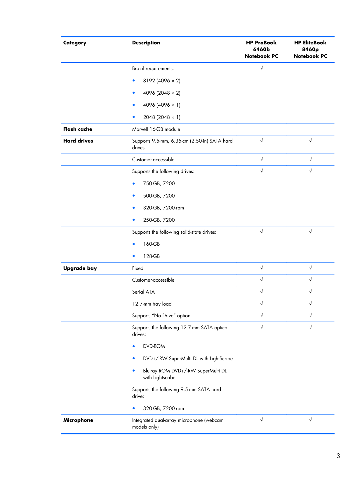
Brazil requirements: ● 8192 (4096 × 2) ● 4096 (2048 × 2) ● 4096 (4096 × 1) ● 2048 (2048 × 1) √
Flash cache Marvell 16-GB module
Hard drives Supports 9.5-mm, 6.35-cm (2.50-in) SATA hard drives √ √
Customer-accessible √ √
Supports the following drives: ●
750-Gb, 7200
●500-Gb, 7200
● 320-GB, 7200-rpm ●250-Gb, 7200
√ √Supports the following solid-state drives: ●
160-Gb
●128-Gb
√ √ Upgrade bay Fixed √ √Customer-accessible √ √
Serial ATA √ √
12.7-mm tray load √ √
Supports “No Drive” option √ √
Supports the following 12.7-mm SATA optical drives: ●
Dvd-Rom
● DVD+/-RW SuperMulti DL with LightScribe ● Blu-ray ROM DVD+/-RW SuperMulti DL with Lightscribe Supports the following 9.5-mm SATA hard drive: ● 320-GB, 7200-rpm √ √ Microphone Integrated dual-array microphone (webcam models only) √ √ 3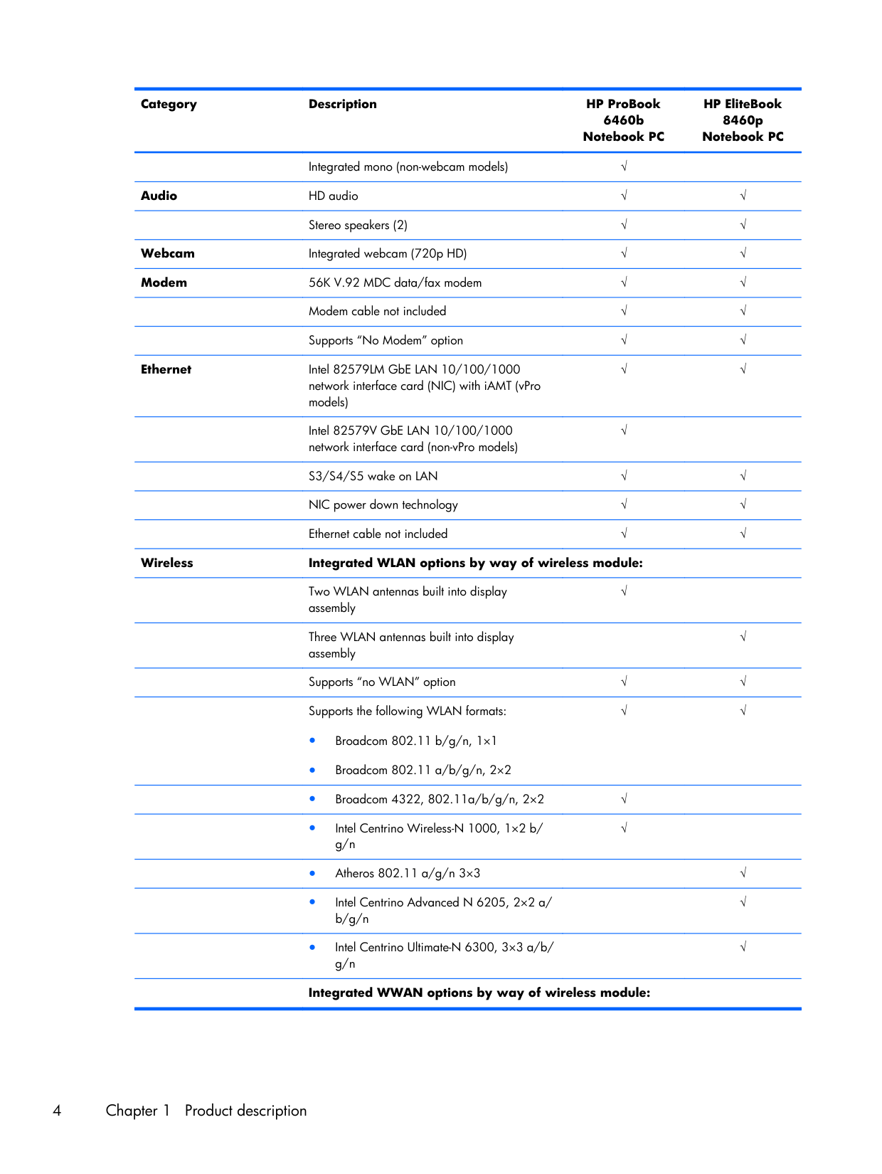
Category Description HP ProBook 6460b Notebook PC HP EliteBook 8460p Notebook PC
Integrated mono (non-webcam models) √
Audio HD audio √ √
Stereo speakers (2) √ √ Webcam Integrated webcam (720p HD) √ √ Modem 56K V.92 MDC data/fax modem √ √
Modem cable not included √ √
Supports “No Modem” option √ √ Ethernet Intel 82579LM GbE LAN 10/100/1000 network interface card (NIC) with iAMT (vPro models) √ √
Intel 82579V GbE LAN 10/100/1000 network interface card (non-vPro models) √
S3/S4/S5 wake on LAN √ √
NIC power down technology √ √
Ethernet cable not included √ √ Wireless Integrated WLAN options by way of wireless module:
Two WLAN antennas built into display assembly √
Three WLAN antennas built into display assembly
√
Supports “no WLAN” option √ √
Supports the following WLAN formats: ● Broadcom 802.11 b/g/n, 1×1 ● Broadcom 802.11 a/b/g/n, 2×2 √ √
● Broadcom 4322, 802.11a/b/g/n, 2×2 √
● Intel Centrino Wireless-N 1000, 1×2 b/ g/n √
● Atheros 802.11 a/g/n 3×3
√
● Intel Centrino Advanced N 6205, 2×2 a/ b/g/n
√
● Intel Centrino Ultimate-N 6300, 3×3 a/b/ g/n
√
Integrated WWAN options by way of wireless module: 4 Chapter 1 Product description
Category Description HP ProBook 6460b Notebook PC HP EliteBook 8460p Notebook PC
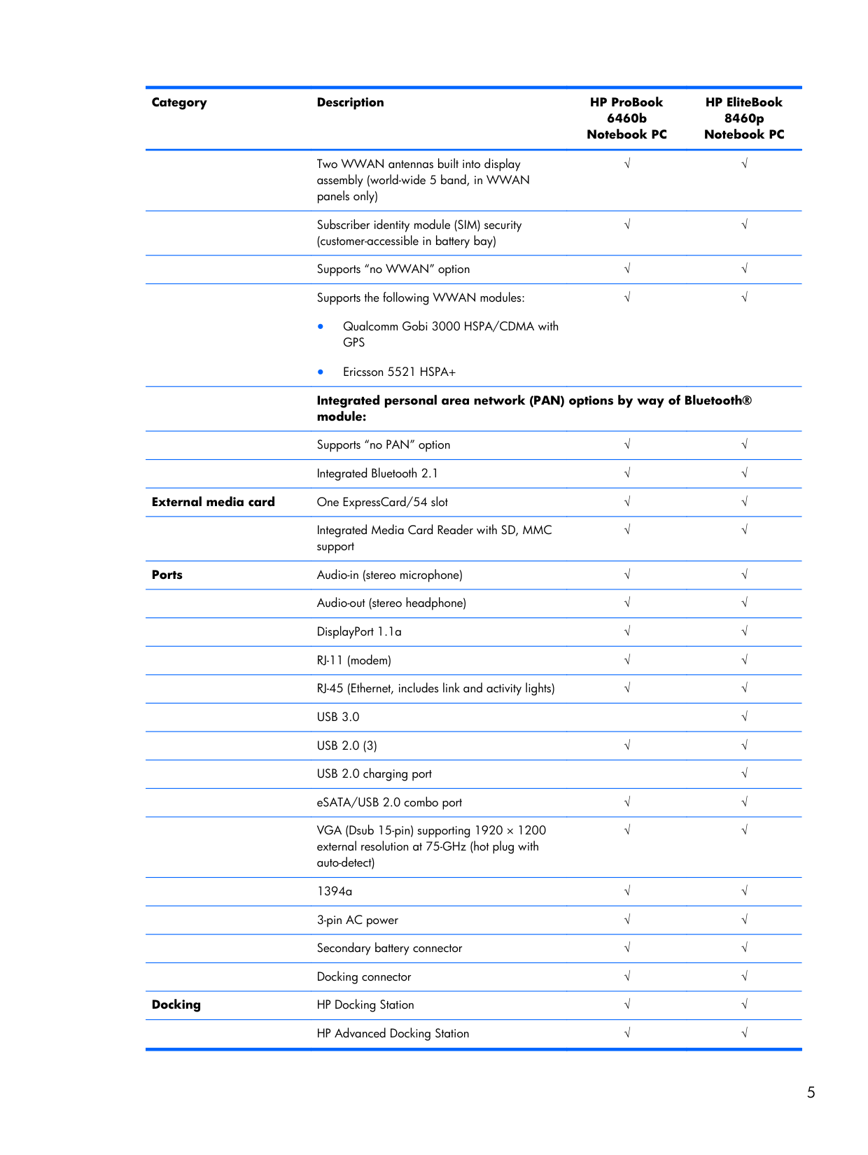
Two WWAN antennas built into display assembly (world-wide 5 band, in WWAN panels only) √ √
Subscriber identity module (SIM) security (customer-accessible in battery bay) √ √
Supports “no WWAN” option √ √
Supports the following WWAN modules: ● Qualcomm Gobi 3000 HSPA/CDMA with
Gps
● Ericsson 5521 HSPA+ √ √Integrated personal area network (PAN) options by way of Bluetooth® module:
Supports “no PAN” option √ √
Integrated Bluetooth 2.1 √ √ External media card One ExpressCard/54 slot √ √
Integrated Media Card Reader with SD, MMC support √ √ Ports Audio-in (stereo microphone) √ √
Audio-out (stereo headphone) √ √
DisplayPort 1.1a √ √
RJ-11 (modem) √ √
RJ-45 (Ethernet, includes link and activity lights) √ √
Usb 3.0
√
Usb 2.0 (3)
√ √USB 2.0 charging port
√
eSATA/USB 2.0 combo port √ √
VGA (Dsub 15-pin) supporting 1920 × 1200 external resolution at 75-GHz (hot plug with auto-detect) √ √
1394a √ √
3-pin AC power √ √
Secondary battery connector √ √
Docking connector √ √ Docking HP Docking Station √ √
HP Advanced Docking Station √ √ 5
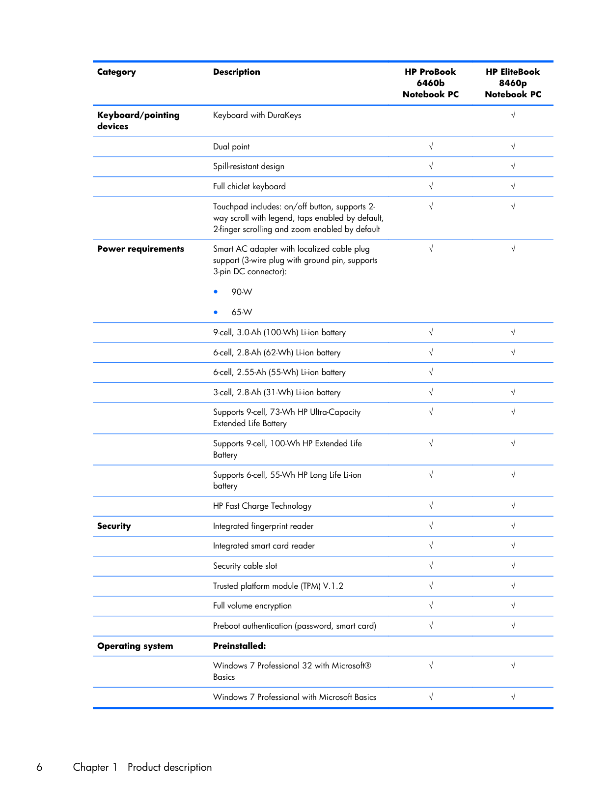
Category Description HP ProBook 6460b Notebook PC HP EliteBook 8460p Notebook PC Keyboard/pointing devices Keyboard with DuraKeys
√
Dual point √ √
Spill-resistant design √ √
Full chiclet keyboard √ √
Touchpad includes: on/off button, supports 2- way scroll with legend, taps enabled by default, 2-finger scrolling and zoom enabled by default √ √ Power requirements Smart AC adapter with localized cable plug support (3-wire plug with ground pin, supports 3-pin DC connector): ●
90-W
●65-W
√ √9-cell, 3.0-Ah (100-Wh) Li-ion battery √ √
6-cell, 2.8-Ah (62-Wh) Li-ion battery √ √
6-cell, 2.55-Ah (55-Wh) Li-ion battery √
3-cell, 2.8-Ah (31-Wh) Li-ion battery √ √
Supports 9-cell, 73-Wh HP Ultra-Capacity Extended Life Battery √ √
Supports 9-cell, 100-Wh HP Extended Life Battery √ √
Supports 6-cell, 55-Wh HP Long Life Li-ion battery √ √
HP Fast Charge Technology √ √ Security Integrated fingerprint reader √ √
Integrated smart card reader √ √
Security cable slot √ √
Trusted platform module (TPM) V.1.2 √ √
Full volume encryption √ √
Preboot authentication (password, smart card) √ √ Operating system Preinstalled:
Windows 7 Professional 32 with Microsoft® Basics √ √
Windows 7 Professional with Microsoft Basics √ √ 6 Chapter 1 Product description
Category Description HP ProBook 6460b Notebook PC HP EliteBook 8460p Notebook PC
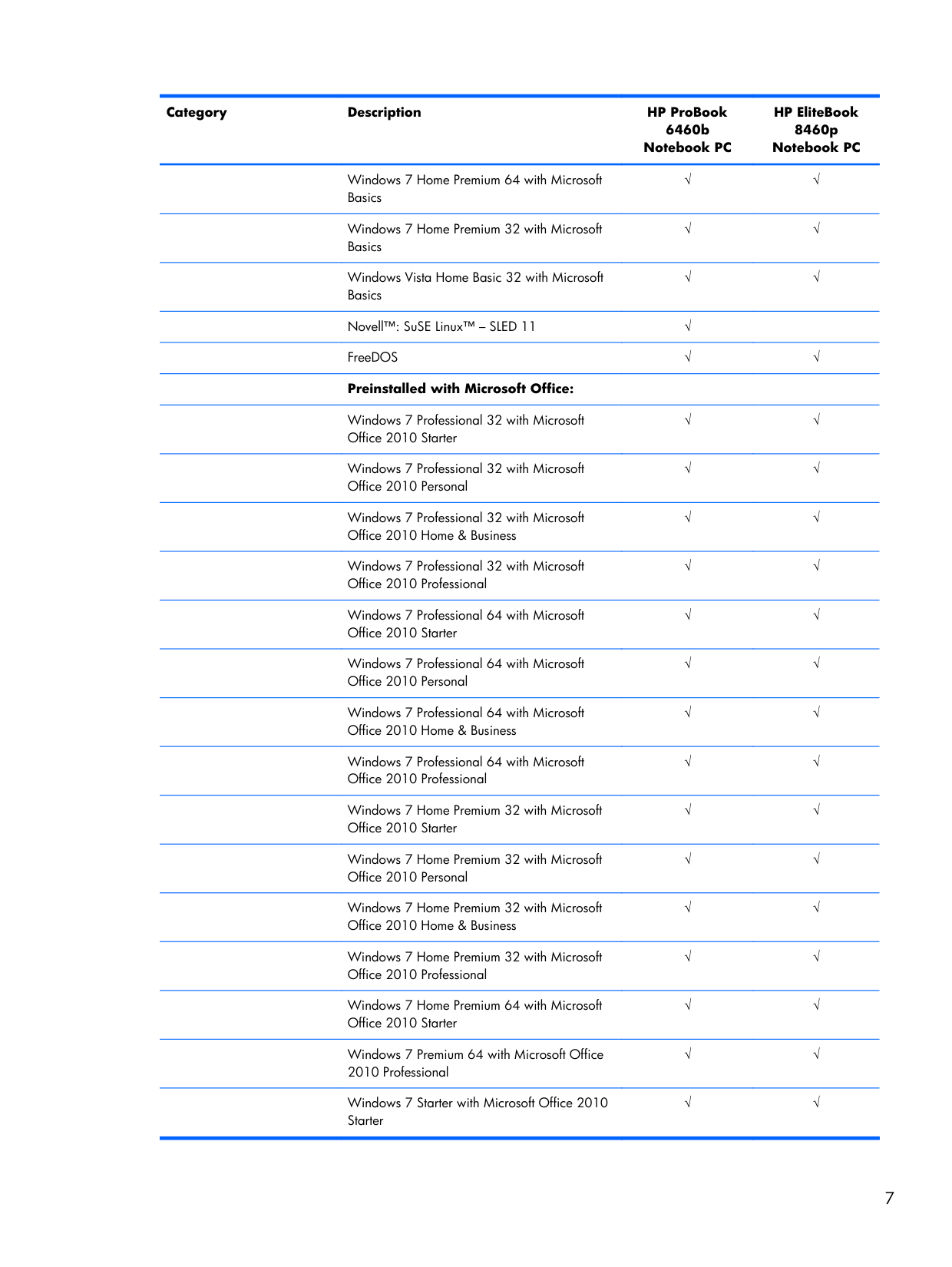
Windows 7 Home Premium 64 with Microsoft Basics √ √
Windows 7 Home Premium 32 with Microsoft Basics √ √
Windows Vista Home Basic 32 with Microsoft Basics √ √
Novell™: SuSE Linux™ – SLED 11 √
FreeDOS √ √
Preinstalled with Microsoft Office:
Windows 7 Professional 32 with Microsoft Office 2010 Starter √ √
Windows 7 Professional 32 with Microsoft Office 2010 Personal √ √
Windows 7 Professional 32 with Microsoft Office 2010 Home & Business √ √
Windows 7 Professional 32 with Microsoft Office 2010 Professional √ √
Windows 7 Professional 64 with Microsoft Office 2010 Starter √ √
Windows 7 Professional 64 with Microsoft Office 2010 Personal √ √
Windows 7 Professional 64 with Microsoft Office 2010 Home & Business √ √
Windows 7 Professional 64 with Microsoft Office 2010 Professional √ √
Windows 7 Home Premium 32 with Microsoft Office 2010 Starter √ √
Windows 7 Home Premium 32 with Microsoft Office 2010 Personal √ √
Windows 7 Home Premium 32 with Microsoft Office 2010 Home & Business √ √
Windows 7 Home Premium 32 with Microsoft Office 2010 Professional √ √
Windows 7 Home Premium 64 with Microsoft Office 2010 Starter √ √
Windows 7 Premium 64 with Microsoft Office 2010 Professional √ √
Windows 7 Starter with Microsoft Office 2010 Starter √ √ 7
Category Description HP ProBook 6460b Notebook PC HP EliteBook 8460p Notebook PC
Windows 7 Home Basic 32 with Microsoft Office 2010 Starter √ √
Windows Vista Basic 32 with Microsoft Office 2010 Starter √ √
Windows Vista Basic 32 with Microsoft Office 2010 Personal √ √
Windows Vista Basic 32 with Microsoft Office 2010 Home & Business √ √
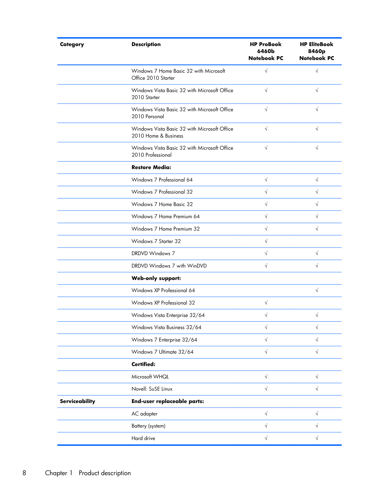
Windows Vista Basic 32 with Microsoft Office 2010 Professional √ √ Restore Media:
Windows 7 Professional 64 √ √
Windows 7 Professional 32 √ √
Windows 7 Home Basic 32 √ √
Windows 7 Home Premium 64 √ √
Windows 7 Home Premium 32 √ √
Windows 7 Starter 32 √
DRDVD Windows 7 √ √
DRDVD Windows 7 with WinDVD √ √
Web-only support:
Windows XP Professional 64
√
Windows XP Professional 32 √
Windows Vista Enterprise 32/64 √ √
Windows Vista Business 32/64 √ √
Windows 7 Enterprise 32/64 √ √
Windows 7 Ultimate 32/64 √ √
Certified:
Microsoft WHQL √ √
Novell: SuSE Linux √ √ Serviceability End-user replaceable parts:
AC adapter √ √
Battery (system) √ √
Hard drive √ √ 8 Chapter 1 Product description
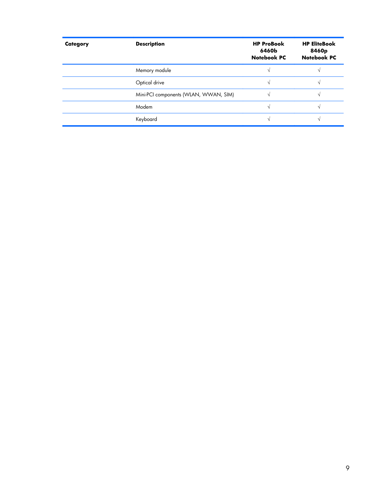
Category Description HP ProBook 6460b Notebook PC HP EliteBook 8460p Notebook PC
Memory module √ √
Optical drive √ √
Mini-PCI components (WLAN, WWAN, SIM) √ √
Modem √ √
Keyboard √ √ 9
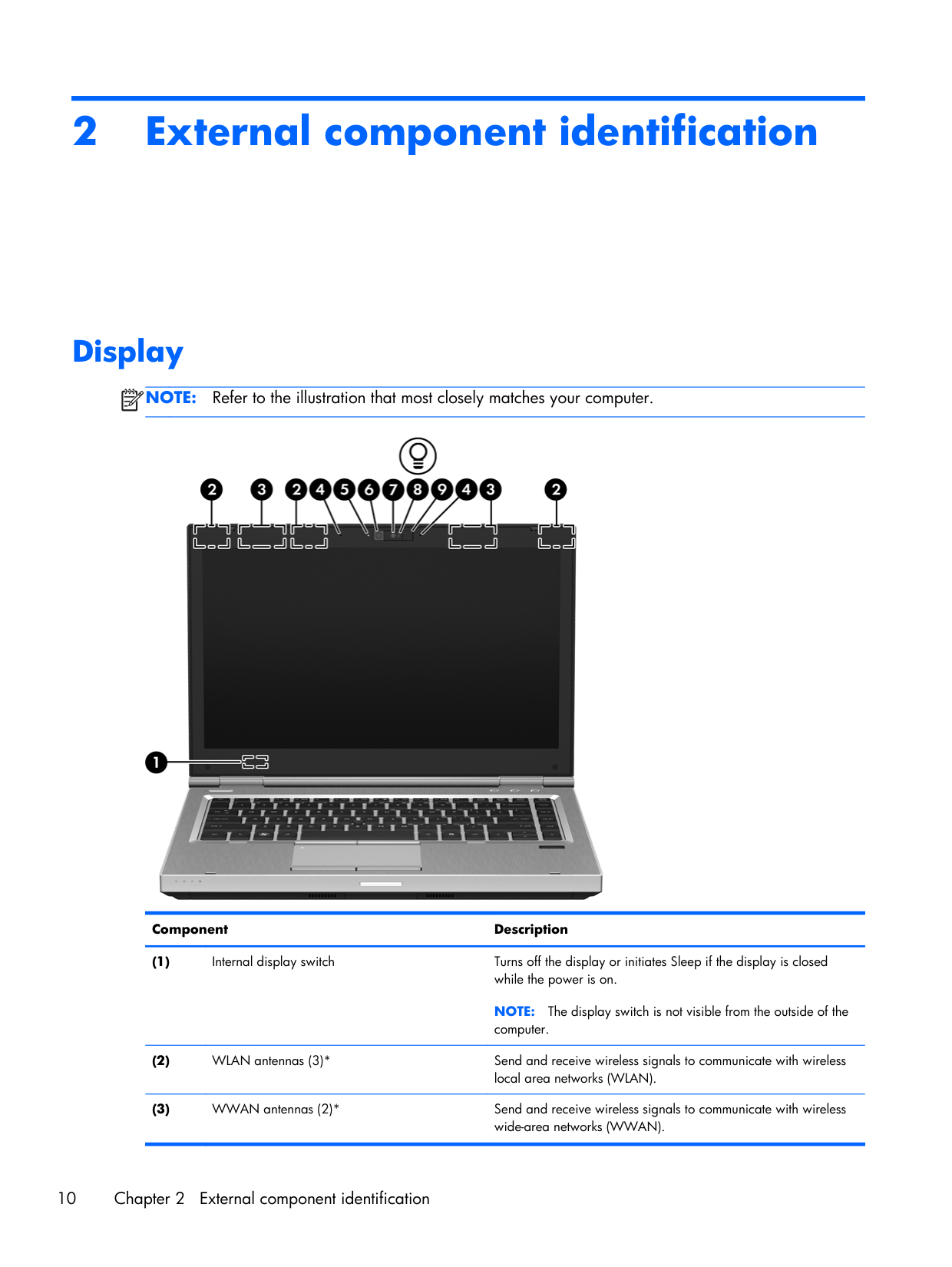
2 External component identification Display
Note:
Refer to the illustration that most closely matches your computer. Component Description (1) Internal display switch Turns off the display or initiates Sleep if the display is closed while the power is on.Note:
The display switch is not visible from the outside of the computer. (2) WLAN antennas (3)* Send and receive wireless signals to communicate with wireless local area networks (WLAN). (3) WWAN antennas (2)* Send and receive wireless signals to communicate with wireless wide-area networks (WWAN). 10 Chapter 2 External component identification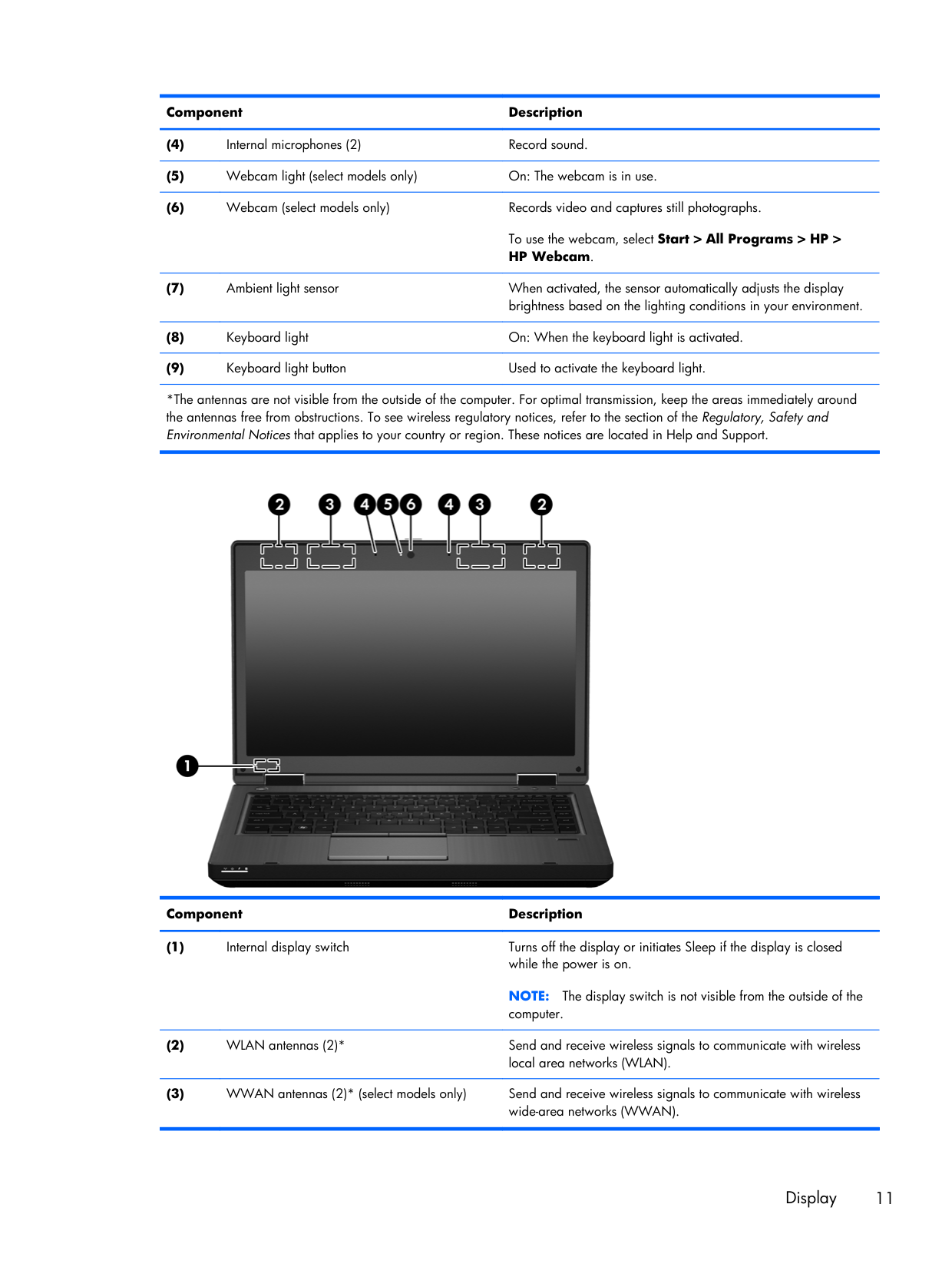
Component Description (4) Internal microphones (2) Record sound. (5) Webcam light (select models only) On: The webcam is in use. (6) Webcam (select models only) Records video and captures still photographs. To use the webcam, select Start > All Programs > HP > HP Webcam. (7) Ambient light sensor When activated, the sensor automatically adjusts the display brightness based on the lighting conditions in your environment. (8) Keyboard light On: When the keyboard light is activated. (9) Keyboard light button Used to activate the keyboard light. *The antennas are not visible from the outside of the computer. For optimal transmission, keep the areas immediately around the antennas free from obstructions. To see wireless regulatory notices, refer to the section of the Regulatory, Safety and Environmental Notices that applies to your country or region. These notices are located in Help and Support. Component Description (1) Internal display switch Turns off the display or initiates Sleep if the display is closed while the power is on.
Note:
The display switch is not visible from the outside of the computer. (2) WLAN antennas (2)* Send and receive wireless signals to communicate with wireless local area networks (WLAN). (3) WWAN antennas (2)* (select models only) Send and receive wireless signals to communicate with wireless wide-area networks (WWAN). Display 11
Component Description (4) Internal microphone(s) (1 or 2 depending on model) Record sound. (5) Webcam light (select models only) On: The webcam is in use. (6) Webcam (select models only) Records video and captures still photographs. To use the webcam, select Start > All Programs > HP > HP Webcam. *The antennas are not visible from the outside of the computer. For optimal transmission, keep the areas immediately around the antennas free from obstructions. To see wireless regulatory notices, refer to the section of the Regulatory, Safety and Environmental Notices that applies to your country or region. These notices are located in Help and Support. 12 Chapter 2 External component identification
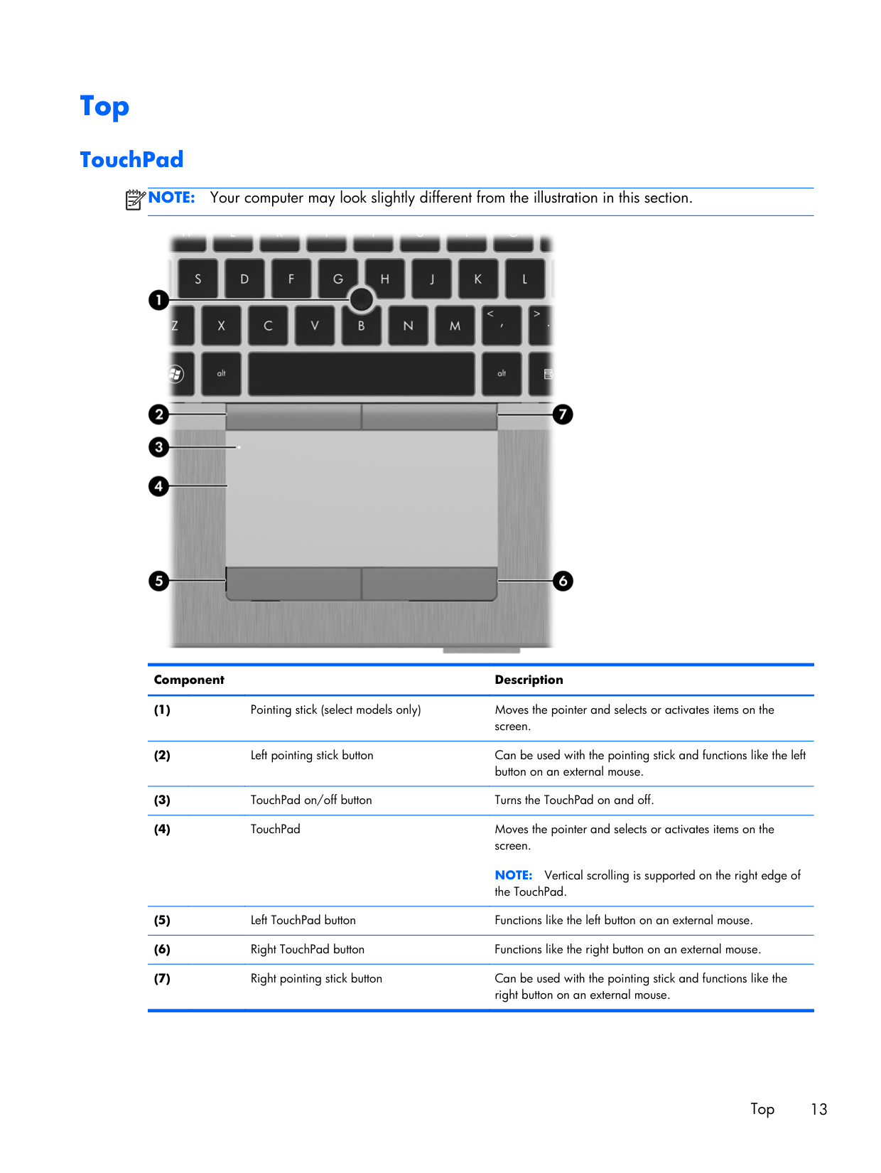
Top TouchPad
Note:
Your computer may look slightly different from the illustration in this section. Component Description (1)Pointing stick (select models only) Moves the pointer and selects or activates items on the screen. (2)
Left pointing stick button Can be used with the pointing stick and functions like the left button on an external mouse. (3)
TouchPad on/off button Turns the TouchPad on and off. (4)
TouchPad Moves the pointer and selects or activates items on the screen.
Note:
Vertical scrolling is supported on the right edge of the TouchPad. (5)Left TouchPad button Functions like the left button on an external mouse. (6)
Right TouchPad button Functions like the right button on an external mouse. (7)
Right pointing stick button Can be used with the pointing stick and functions like the right button on an external mouse. Top 13
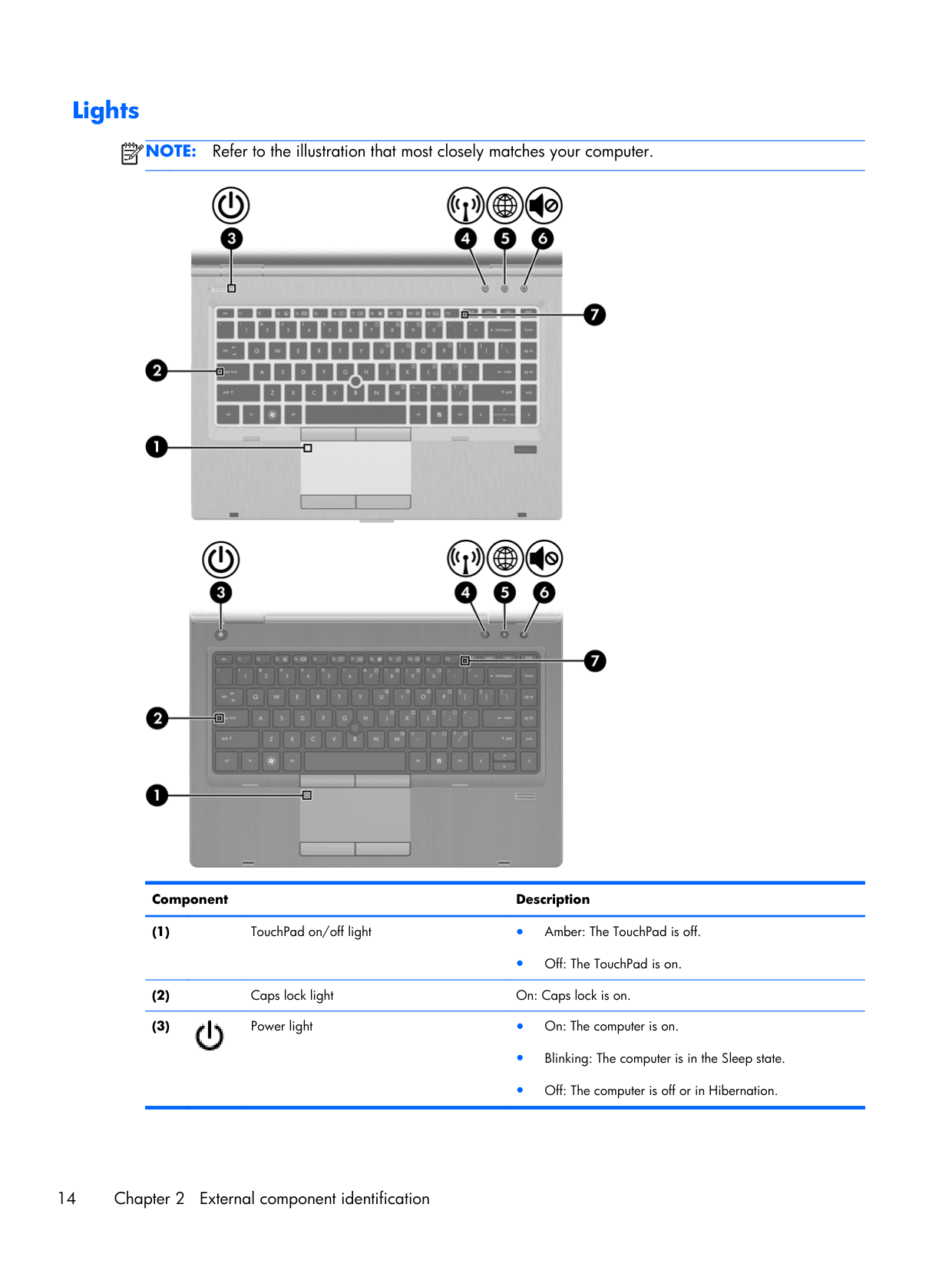
Lights
Note:
Refer to the illustration that most closely matches your computer. Component Description (1)TouchPad on/off light ● Amber: The TouchPad is off. ● Off: The TouchPad is on. (2)
Caps lock light On: Caps lock is on. (3) Power light ● On: The computer is on. ● Blinking: The computer is in the Sleep state. ● Off: The computer is off or in Hibernation. 14 Chapter 2 External component identification
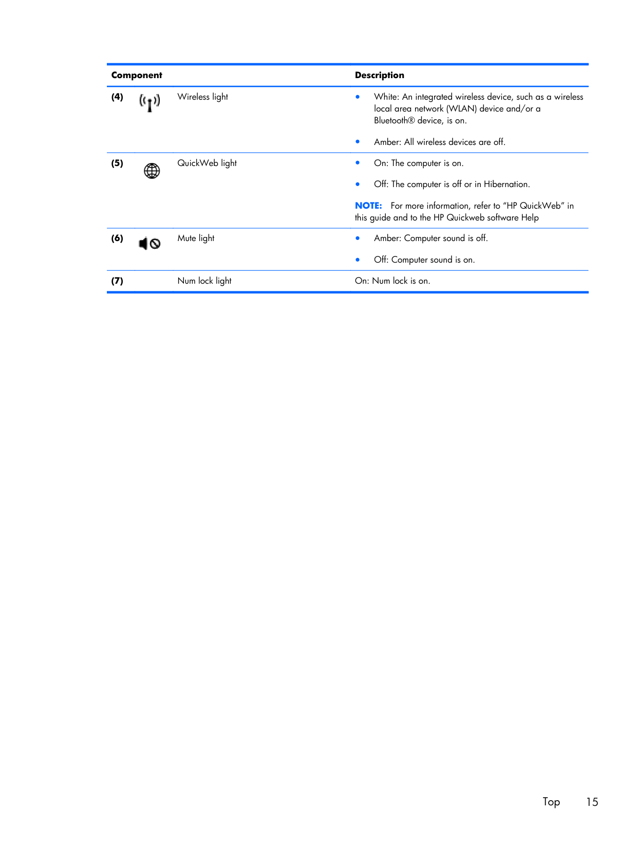
Component Description (4) Wireless light ● White: An integrated wireless device, such as a wireless local area network (WLAN) device and/or a Bluetooth® device, is on. ● Amber: All wireless devices are off. (5) QuickWeb light ● On: The computer is on. ● Off: The computer is off or in Hibernation.
Note:
For more information, refer to “HP QuickWeb” in this guide and to the HP Quickweb software Help (6) Mute light ● Amber: Computer sound is off. ● Off: Computer sound is on. (7)Num lock light On: Num lock is on. Top 15
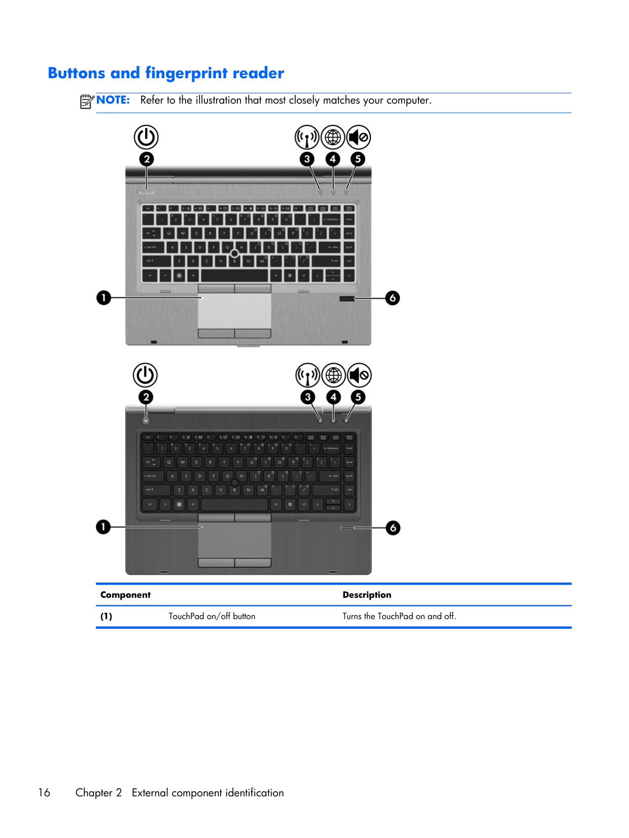
Buttons and fingerprint reader
Note:
Refer to the illustration that most closely matches your computer. Component Description (1)TouchPad on/off button Turns the TouchPad on and off. 16 Chapter 2 External component identification
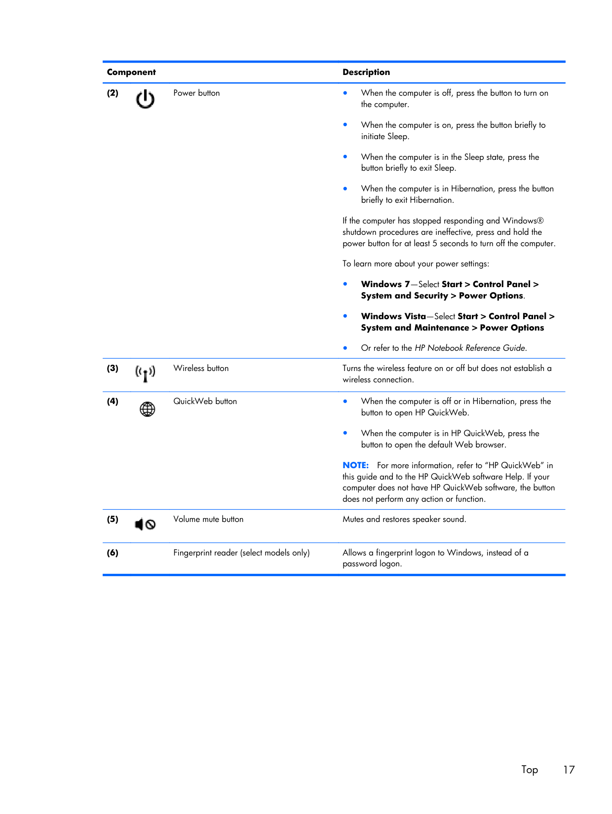
Component Description (2) Power button ● When the computer is off, press the button to turn on the computer. ● When the computer is on, press the button briefly to initiate Sleep. ● When the computer is in the Sleep state, press the button briefly to exit Sleep. ● When the computer is in Hibernation, press the button briefly to exit Hibernation. If the computer has stopped responding and Windows® shutdown procedures are ineffective, press and hold the power button for at least 5 seconds to turn off the computer. To learn more about your power settings: ● Windows 7—Select Start > Control Panel > System and Security > Power Options. ● Windows Vista—Select Start > Control Panel > System and Maintenance > Power Options ● Or refer to the HP Notebook Reference Guide. (3) Wireless button Turns the wireless feature on or off but does not establish a wireless connection. (4) QuickWeb button ● When the computer is off or in Hibernation, press the button to open HP QuickWeb. ● When the computer is in HP QuickWeb, press the button to open the default Web browser.
Note:
For more information, refer to “HP QuickWeb” in this guide and to the HP QuickWeb software Help. If your computer does not have HP QuickWeb software, the button does not perform any action or function. (5) Volume mute button Mutes and restores speaker sound. (6)Fingerprint reader (select models only) Allows a fingerprint logon to Windows, instead of a password logon. Top 17
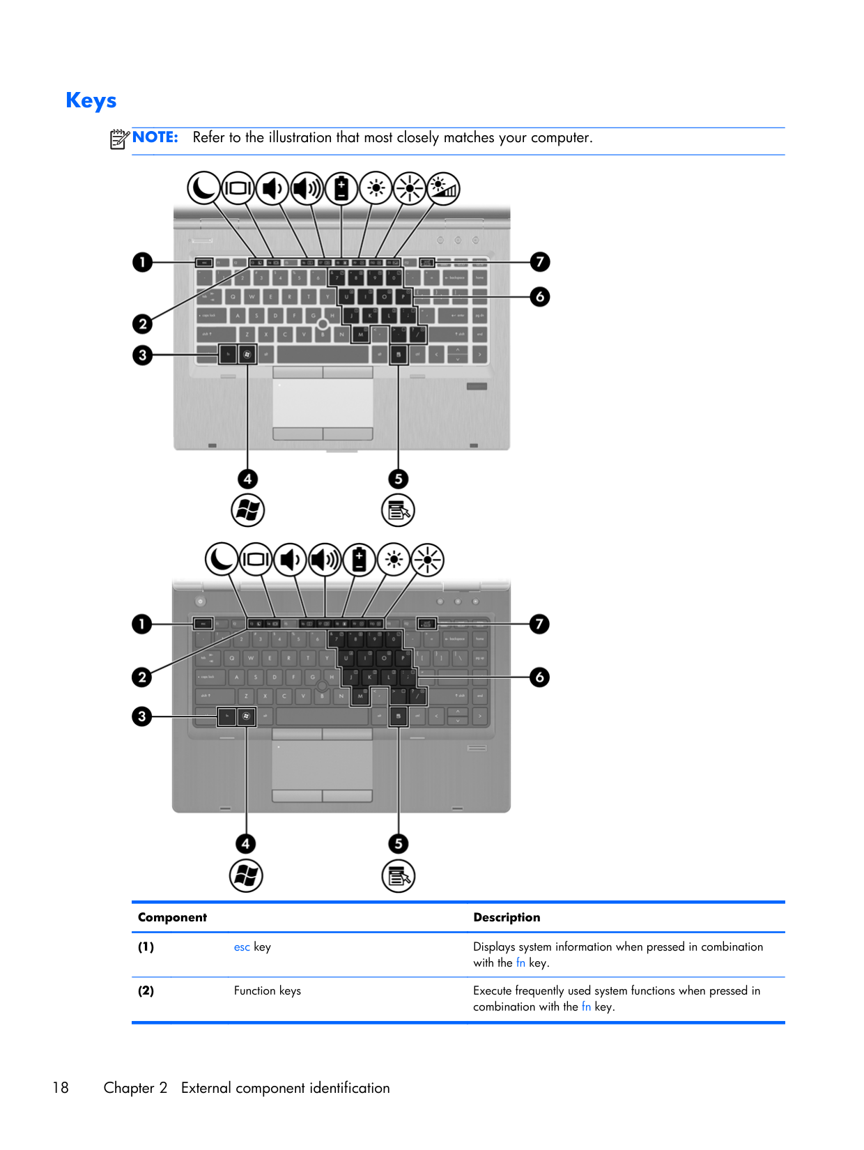
Keys
Note:
Refer to the illustration that most closely matches your computer. Component Description (1)esc key Displays system information when pressed in combination with the fn key. (2)
Function keys Execute frequently used system functions when pressed in combination with the fn key. 18 Chapter 2 External component identification
Component Description (3)
fn key Executes frequently used system functions when pressed in combination with a function key, the num lk key, or the esc key. (4) Start key Displays the Start menu. (5) Menu key Displays the active program’s shortcut menu (same as right- click menu). (6)
Embedded numeric keypad keys Can be used like the keys on an external numeric keypad when pressed in combination with the fn and num lk keys. (7)
num lk key Enables/disables the embedded numeric keypad when pressed in combination with the fn key. Top 19
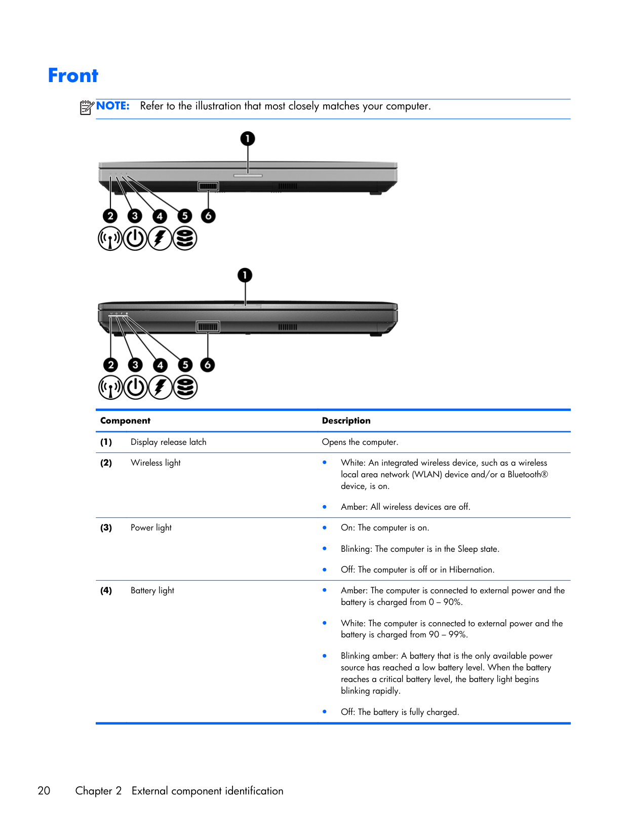
Front
Note:
Refer to the illustration that most closely matches your computer. Component Description (1) Display release latch Opens the computer. (2) Wireless light ● White: An integrated wireless device, such as a wireless local area network (WLAN) device and/or a Bluetooth® device, is on. ● Amber: All wireless devices are off. (3) Power light ● On: The computer is on. ● Blinking: The computer is in the Sleep state. ● Off: The computer is off or in Hibernation. (4) Battery light ● Amber: The computer is connected to external power and the battery is charged from 0 – 90%. ● White: The computer is connected to external power and the battery is charged from 90 – 99%. ● Blinking amber: A battery that is the only available power source has reached a low battery level. When the battery reaches a critical battery level, the battery light begins blinking rapidly. ● Off: The battery is fully charged. 20 Chapter 2 External component identification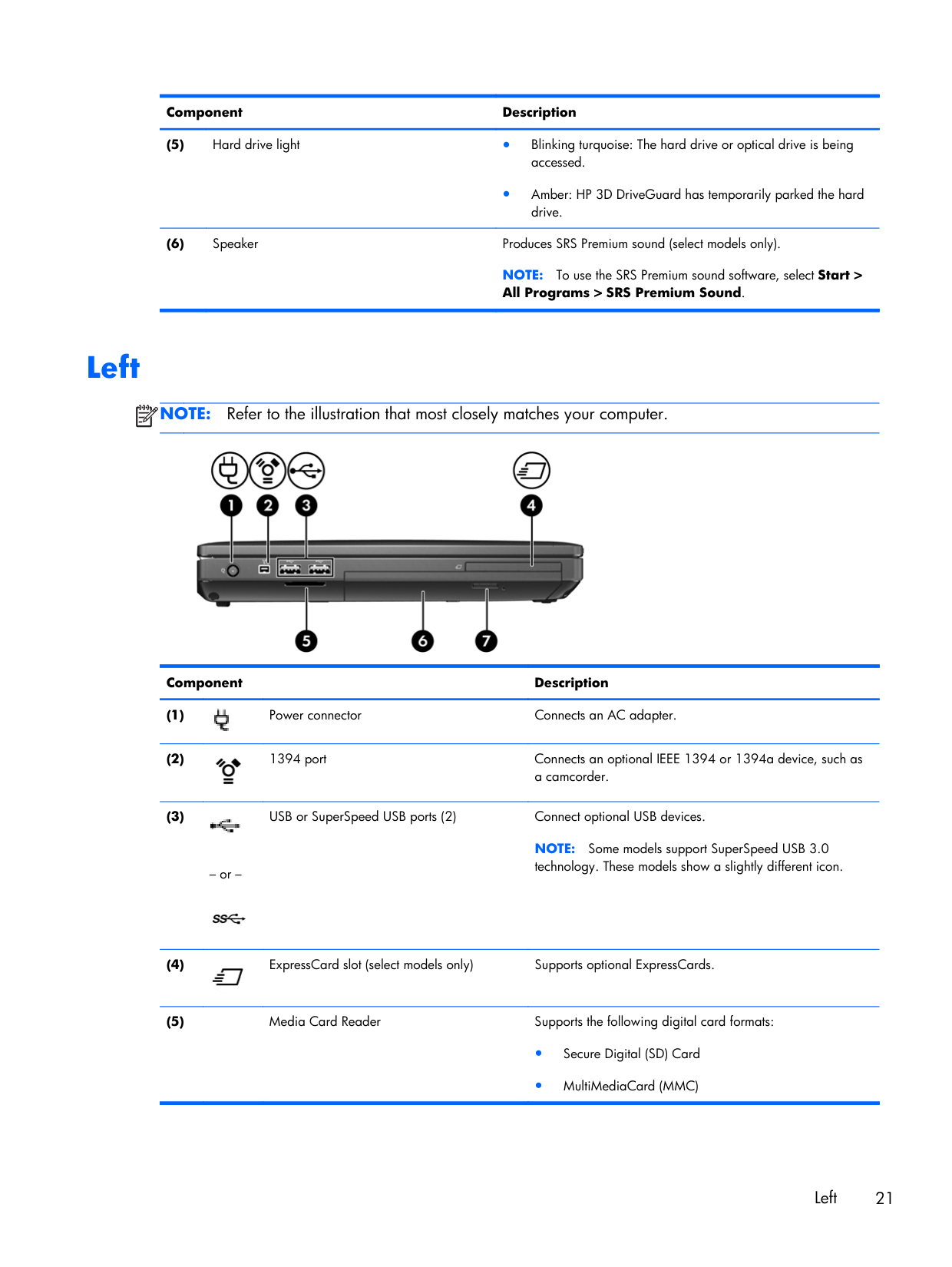
Component Description (5) Hard drive light ● Blinking turquoise: The hard drive or optical drive is being accessed. ● Amber: HP 3D DriveGuard has temporarily parked the hard drive. (6) Speaker Produces SRS Premium sound (select models only).
Note:
To use the SRS Premium sound software, select Start > All Programs > SRS Premium Sound. LeftNote:
Refer to the illustration that most closely matches your computer. Component Description (1) Power connector Connects an AC adapter. (2) 1394 port Connects an optional IEEE 1394 or 1394a device, such as a camcorder. (3) – or – USB or SuperSpeed USB ports (2) Connect optional USB devices.Note:
Some models support SuperSpeed USB 3.0 technology. These models show a slightly different icon. (4) ExpressCard slot (select models only) Supports optional ExpressCards. (5)Media Card Reader Supports the following digital card formats: ● Secure Digital (SD) Card ● MultiMediaCard (MMC) Left 21
Component Description (6)
Optical drive Reads and writes (select models only) to an optical disc. (7)
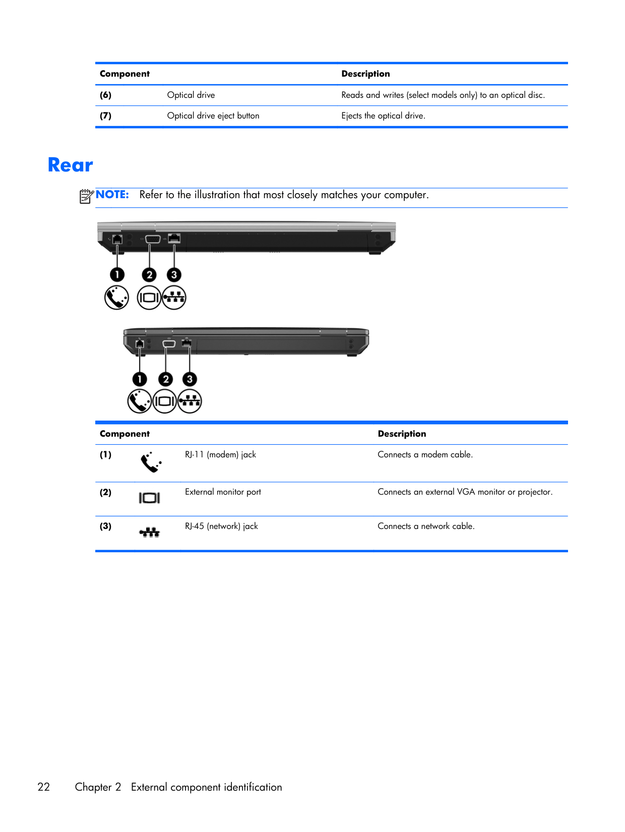
Optical drive eject button Ejects the optical drive. Rear
Note:
Refer to the illustration that most closely matches your computer. Component Description (1) RJ-11 (modem) jack Connects a modem cable. (2) External monitor port Connects an external VGA monitor or projector. (3) RJ-45 (network) jack Connects a network cable. 22 Chapter 2 External component identification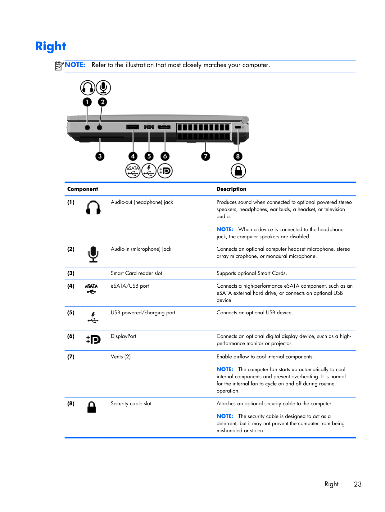
Right
Note:
Refer to the illustration that most closely matches your computer. Component Description (1) Audio-out (headphone) jack Produces sound when connected to optional powered stereo speakers, headphones, ear buds, a headset, or television audio.Note:
When a device is connected to the headphone jack, the computer speakers are disabled. (2) Audio-in (microphone) jack Connects an optional computer headset microphone, stereo array microphone, or monaural microphone. (3)Smart Card reader slot Supports optional Smart Cards. (4) eSATA/USB port Connects a high-performance eSATA component, such as an eSATA external hard drive, or connects an optional USB device. (5) USB powered/charging port Connects an optional USB device. (6) DisplayPort Connects an optional digital display device, such as a high- performance monitor or projector. (7)
Vents (2) Enable airflow to cool internal components.
Note:
The computer fan starts up automatically to cool internal components and prevent overheating. It is normal for the internal fan to cycle on and off during routine operation. (8) Security cable slot Attaches an optional security cable to the computer.Note:
The security cable is designed to act as a deterrent, but it may not prevent the computer from being mishandled or stolen. Right 23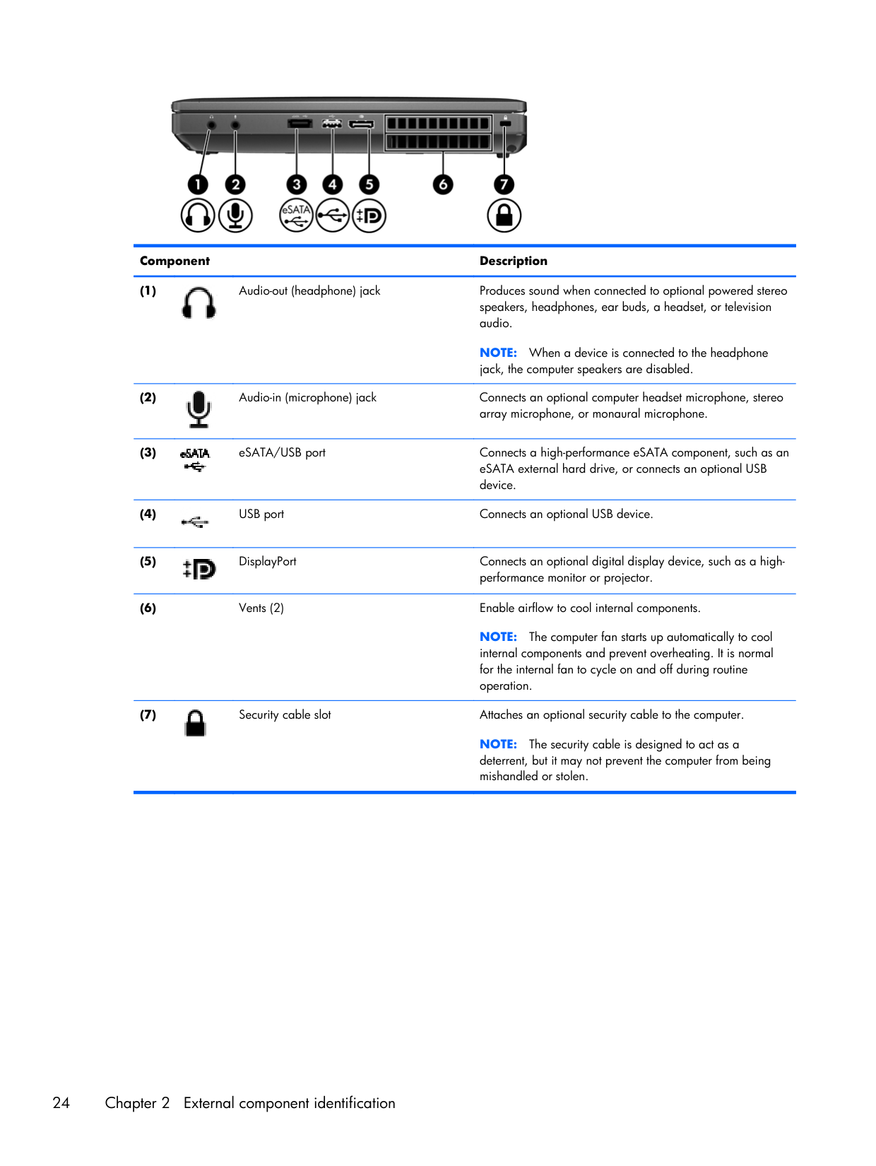
Component Description (1) Audio-out (headphone) jack Produces sound when connected to optional powered stereo speakers, headphones, ear buds, a headset, or television audio.
Note:
When a device is connected to the headphone jack, the computer speakers are disabled. (2) Audio-in (microphone) jack Connects an optional computer headset microphone, stereo array microphone, or monaural microphone. (3) eSATA/USB port Connects a high-performance eSATA component, such as an eSATA external hard drive, or connects an optional USB device. (4) USB port Connects an optional USB device. (5) DisplayPort Connects an optional digital display device, such as a high- performance monitor or projector. (6)Vents (2) Enable airflow to cool internal components.
Note:
The computer fan starts up automatically to cool internal components and prevent overheating. It is normal for the internal fan to cycle on and off during routine operation. (7) Security cable slot Attaches an optional security cable to the computer.Note:
The security cable is designed to act as a deterrent, but it may not prevent the computer from being mishandled or stolen. 24 Chapter 2 External component identification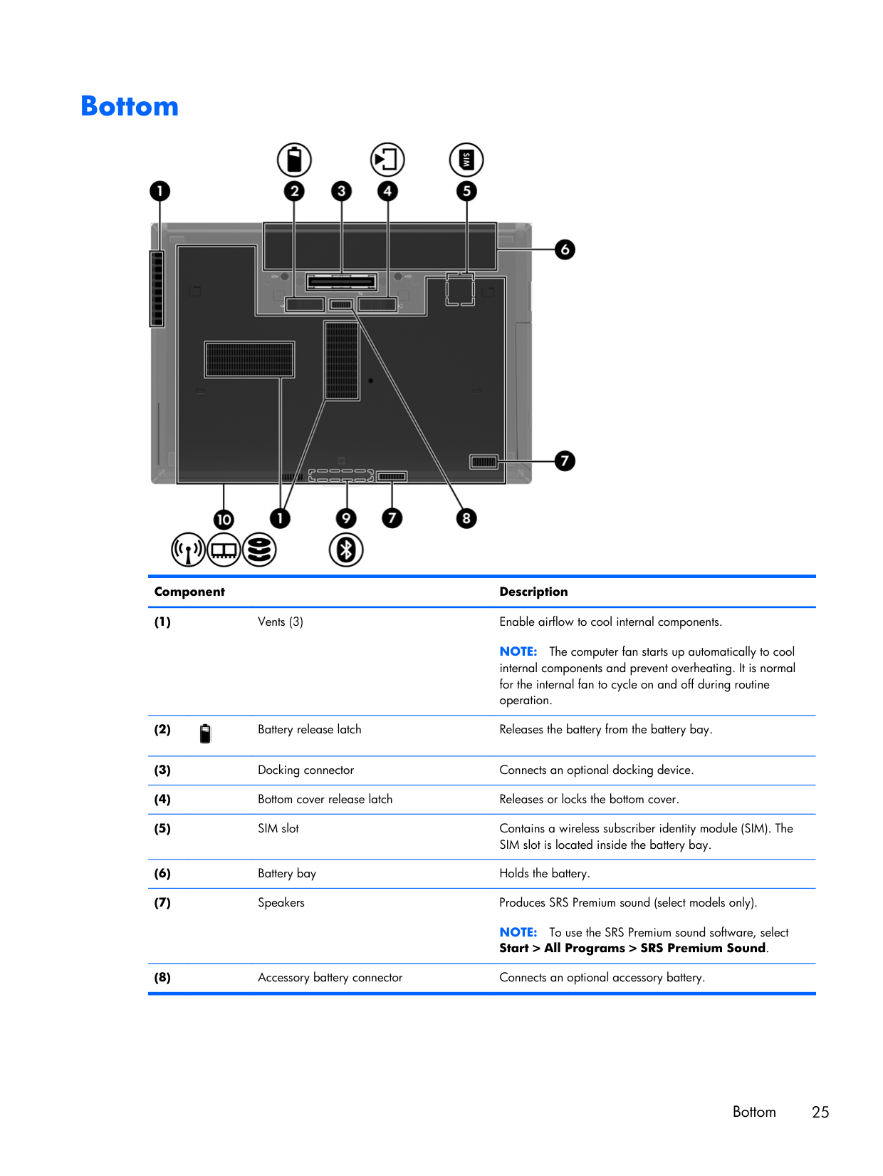
Bottom Component Description (1)
Vents (3) Enable airflow to cool internal components.
Note:
The computer fan starts up automatically to cool internal components and prevent overheating. It is normal for the internal fan to cycle on and off during routine operation. (2) Battery release latch Releases the battery from the battery bay. (3)Docking connector Connects an optional docking device. (4)
Bottom cover release latch Releases or locks the bottom cover. (5)
SIM slot Contains a wireless subscriber identity module (SIM). The SIM slot is located inside the battery bay. (6)
Battery bay Holds the battery. (7)
Speakers Produces SRS Premium sound (select models only).
Note:
To use the SRS Premium sound software, select Start > All Programs > SRS Premium Sound. (8)Accessory battery connector Connects an optional accessory battery. Bottom 25
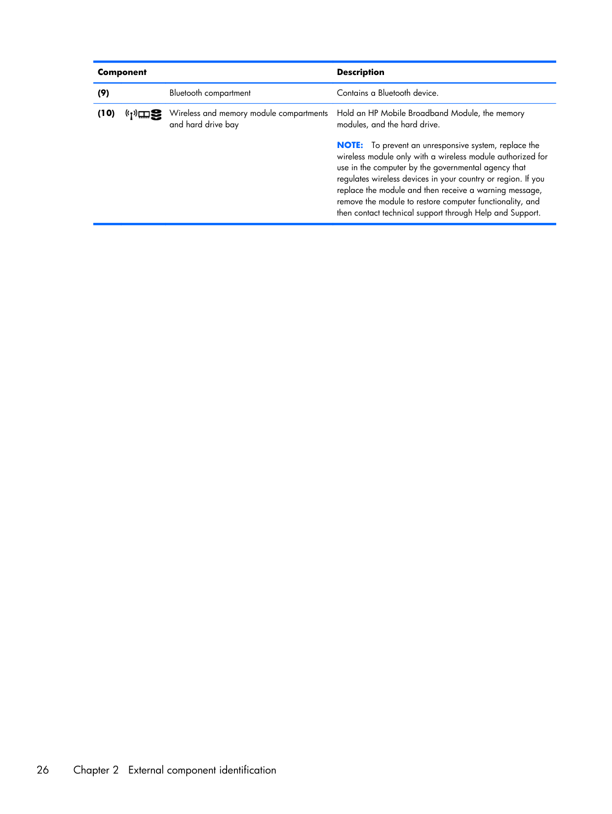
Component Description (9)
Bluetooth compartment Contains a Bluetooth device. (10) Wireless and memory module compartments and hard drive bay Hold an HP Mobile Broadband Module, the memory modules, and the hard drive.
Note:
To prevent an unresponsive system, replace the wireless module only with a wireless module authorized for use in the computer by the governmental agency that regulates wireless devices in your country or region. If you replace the module and then receive a warning message, remove the module to restore computer functionality, and then contact technical support through Help and Support. 26 Chapter 2 External component identification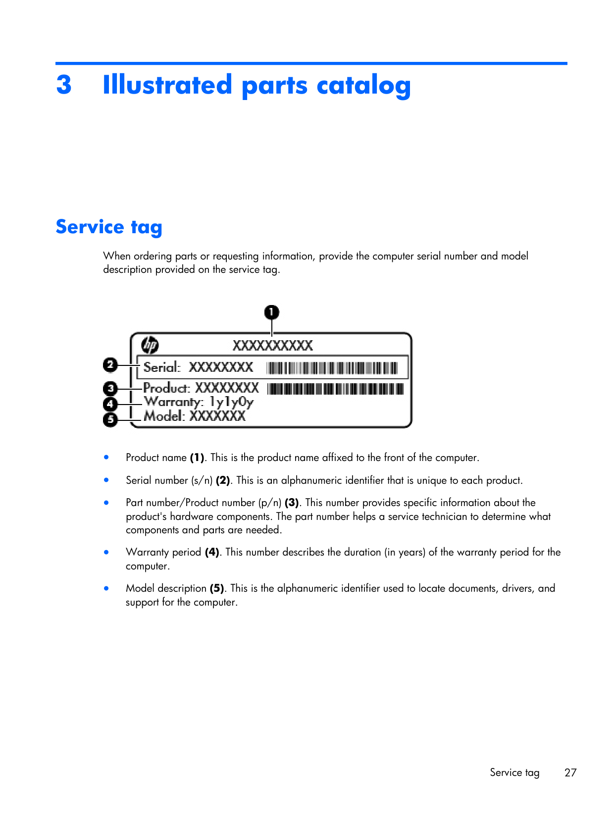
3 Illustrated parts catalog Service tag When ordering parts or requesting information, provide the computer serial number and model description provided on the service tag. ● Product name (1). This is the product name affixed to the front of the computer. ● Serial number (s/n) (2). This is an alphanumeric identifier that is unique to each product. ● Part number/Product number (p/n) (3). This number provides specific information about the product's hardware components. The part number helps a service technician to determine what components and parts are needed. ● Warranty period (4). This number describes the duration (in years) of the warranty period for the computer. ● Model description (5). This is the alphanumeric identifier used to locate documents, drivers, and support for the computer. Service tag 27
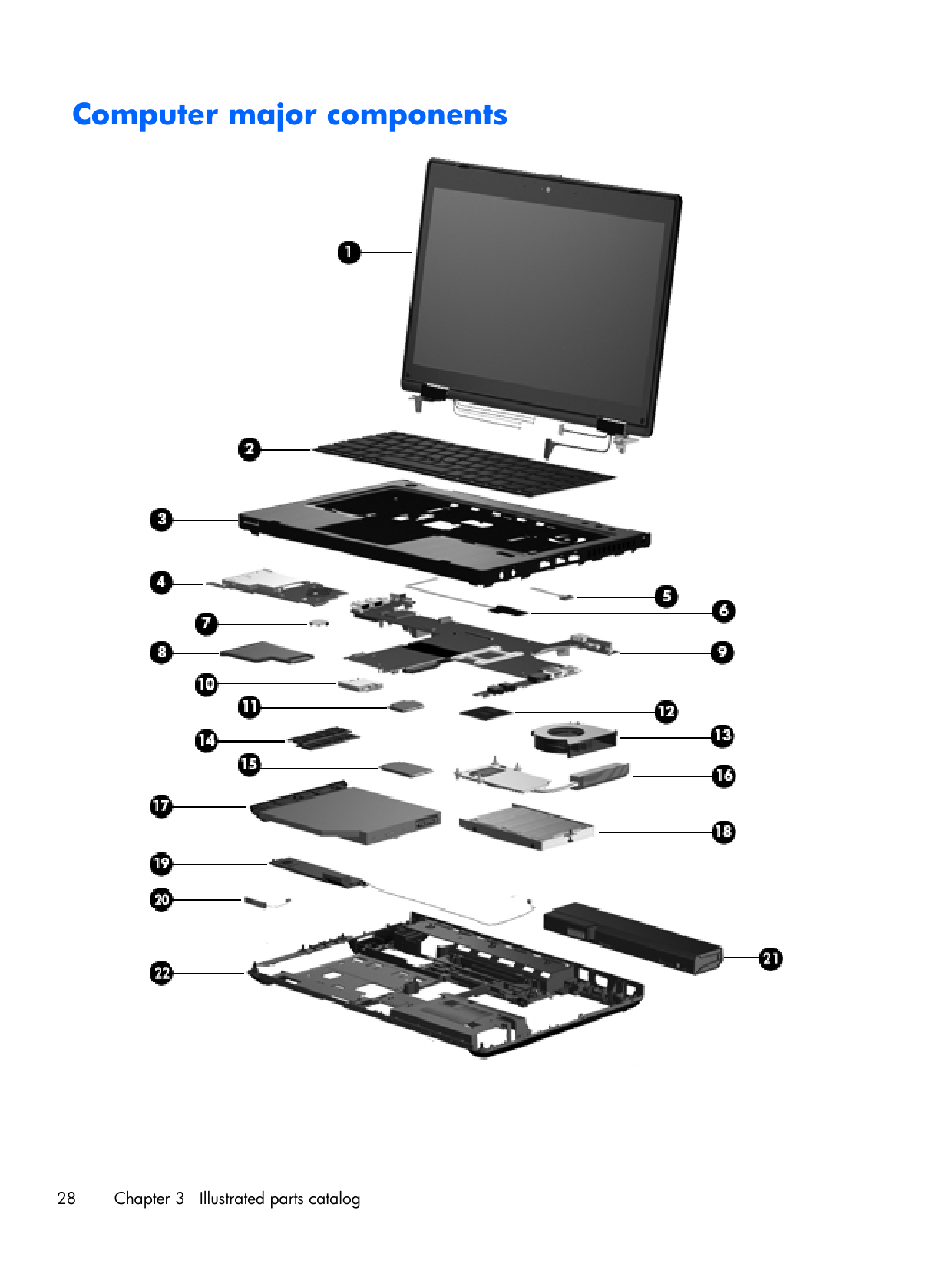
Computer major components 28 Chapter 3 Illustrated parts catalog
Item Description Spare part number (1) Display panel
Note:
For a list of display panel spare parts, see Display components on page 36. not spared (2) Keyboard (includes cable)Note:
For a detailed list of available keyboards, see Sequential part number listing on page 42.For use in model 6460b without a pointing stick 641834-xxx
For use in model 6460b with a pointing stick 641835-xxx
For use in model 8460p 642760-xxx (3) Top cover (includes TouchPad button and bracket)
For use in model 6460b:
● Includes a 2-button touchpad and fingerprint reader 642741-001
● Includes a 2-button touchpad without fingerprint reader 642742-001
● Includes a 4-button touchpad and fingerprint reader 642743-001
● Includes a 4-button touchpad without fingerprint reader 642746-001
For use in model 8460p:
● Includes 4-button touchpad and fingerprint reader 642744-001
● Includes 4-button touchpad without fingerprint reader 642747-001
● Includes 4-button touchpad and fingerprint reader 642745-001
● Includes 4-button touchpad without fingerprint reader 642748-001 (4) Smart card reader 642769-001 (5) Lid switch board (includes cable) 642765-001 (6) Fingerprint reader board (includes cable) 642764-001 (7) RTC battery 651948-001 (8) ExpressCard assembly 642763-001 (9) System board (includes replacement thermal material and VGA support bracket)
For use in computers with UMA graphics in all countries and regions except Russia and China:
● For use in computers with WLAN, no WWAN, no vPro (4M) 642755-001
● For use in computers with WLAN, with WWAN, no vPro (4M) 642756-001
● For use in computers with vPro (8M), WLAN, no WWAN 642757-001
● For use in computers with vPro (8M), WLAN, and with WWAN 642758-001
● For use in computers with vPro (8M), WLAN, no WWAN, and USB 3.0 ports 647180-001
● For use in computers with vPro (8M), WLAN, WWAN, and USB 3.0 ports 642759-001 Computer major components 29
Item Description Spare part number
For use in computers with discrete graphics in all countries and regions except Russia and China:
● For use in computers with WLAN, no WWAN, no vPro (4M) 642750-001
● For use in computers with WLAN, with WWAN, no vPro (4M) 642751-001
● For use in computers with vPro (8M), WLAN, no WWAN, and 512-MB graphics 642752-001
● For use in computers with vPro (8M), WLAN, with WWAN, and 512-MB graphics 642753-001
● For use in computers with vPro (8M), WLAN, with WWAN, and 1-GB graphics 642754-001
For use in computers with UMA graphics in only Russia and China:
● For use in computers with WLAN, no WWAN, no vPro (4M) 646320-001
● For use in computers with WLAN, with WWAN, no vPro (4M) 646321-001
● For use in computers with WLAN, with WWAN, no vPro (4M) 646322-001
● For use in computers with vPro (8M), WLAN, and WWAN 646323-001
● For use in computers with vPro (8M), WLAN, with WWAN, and USB 3.0 ports 646324-001
For use in computers with discrete graphics in only Russia and China:
● For use in computers with WLAN, no WWAN, no vPro (4M) 646315-001
● For use in computers with WLAN, with WWAN, no vPro (4M) 646316-001
● For use in computers with vPro (8M), WLAN, no WWAN, and 512-MB graphics 646317-001
● For use in computers with vPro (8M), WLAN, with WWAN, and 512-MB graphics 646318-001
● For use in computers with vPro (8M), WLAN, with WWAN, and 1-GB graphics 646319-001 (10) Modem module
Note:
The modem module spare part kit does not include a modem module cable. The modem module cable is included in the Cable Kit, spare part number 641830-001. See Cable Kit on page 38 for more Cable Kit spare part number information. 628824-001 (11) WLAN moduleIntel Wi-Fi Link 6300, 802.11a/b/g/n for use in Andorra, Antigua and Barbuda, Argentina, Aruba, Australia, Austria, Azerbaijan, Bahamas, Bahrain, Barbados, Belgium, Bermuda, Bolivia, Bosnia and Herzegovina, Brazil, Brunei, Bulgaria, Canada, Cayman Islands, Chile, the People's Republic of China, Colombia, Costa Rica, Croatia, Cyprus, Czech Republic, Denmark, Dominican Republic, Ecuador, Egypt, El Salvador, Estonia, Finland, France, French Guiana, Georgia, Germany, Ghana, Greece, Guadeloupe, Guam, Guatemala, Haiti, Honduras, Hong Kong, Hungary, Iceland, India, Indonesia, Ireland, Israel, Italy, Ivory Coast, Jamaica, Japan, Jordan, Kenya, South Korea, Kuwait, Kyrgyzstan, Latvia, Lebanon, Martinique, US Virgin Islands, Puerto Rico, Nether Antilles, Liechtenstein, Lithuania, Luxembourg, Malawi, Malaysia, Malta, Mauritius, Mexico, Monaco, Montenegro, Morocco, the Netherlands, New Zealand, Nicaragua, Nigeria, Norway, Oman, Pakistan, Panama, Paraguay, Peru, Philippines, Poland, Portugal, Qatar, Romania, San Marino, Saudi Arabia, Senegal, Singapore, Slovakia, Slovenia, South Africa, Spain, Sri Lanka, Sweden, Switzerland, Taiwan, Tanzania, Thailand, Trinidad and Tobago, Turkey, the United Arab Emirates, the United Kingdom, the United States, Uruguay, Venezuela, and Vietnam 572511-001 30 Chapter 3 Illustrated parts catalog
Item Description Spare part number
Broadcom 43224AGN 802.11a/b/g/draft-n WiFi Adapter for use in Antigua and Barbuda, Aruba, the Bahamas, Barbados, Belize, Canada, Guam, Guinea, Haiti, Jamaica, the Nether Antilles, Puerto Rico, St. Kitts and Nevis, St. Lucia, St. Vincent and the Grenadines, Suriname, the US Virgin Islands, and the United States 582564-001
Broadcom 43224AGN 802.11a/b/g/draft-n WiFi Adapter for use in Albania, Algeria, Andorra, Angola, Argentina, Armenia, Australia, Austria, Azerbaijan, Bahrain, Belarus, Belgium, Benin, Bermuda, Bhutan, Bolivia, Bosnia and Herzegovina, Botswana, Brazil, the British Virgin Islands, Brunei, Bulgaria, Burkina Faso, Burundi, Cambodia, Cameroon, Cape Verde, the Cayman Islands, Central African Republic, Chad, Chile, People's Republic of China, Colombia, Comoros, Congo, Costa Rica, Croatia, Cyprus, the Czech Republic, Denmark, Djibouti, Dominica, the Dominican Republic, East Timor, Ecuador, Egypt, El Salvador, Equitorial Guinea, Eritrea, Estonia, Ethiopia, Fiji Finland, France, French Guiana, Gabon, Gambia, Georgia, Germany, Ghana, Gibraltar, Greece, Grenada, Guadeloupe, Guatemala, Guinea, Guinea-Bissa, Honduras, Hong Kong, Hungary, Iceland, India, Ireland, Italy, Ivory Coast, Japan, Jordan, Kazakhstan, Kenya, Kiribati, Kuwait, Kyrgyzstan, Laos, Latvia, Lebanon, Lesotho, Liberia, Liechtenstein, Lithuania, Luxembourg, Macedonia, Madagascar, Malawi, Malaysia Maldives, Mali, Malta, Marshall Islands, Martinique, Mauritania, Mauritius, Mexico, Micronesia, Monaco, Mongolia, Montenegro, Morocco, Mozambique, Namibia, Nauru, Nepal, Netherlands, New Zealand, Nicaragua, Niger, Nigeria, Norway, Oman, Palau, Panama, Papua New Guinea, Paraguay, Peru, Philippines, Poland, Portugal, Qatar, Republic of Moldova, Romania, Rwanda, Samoa, San Marino, Sao Tome and Principe, Saudi Arabia, Senegal, Serbia and Montenegro, Seychelles, Sierra Leone, Singapore, Slovakia, Slovenia, Solomon Islands, Somalia, South Africa, South Korea, Spain, Sri Lanka, Swaziland, Sweden, Switzerland, Taiwan, Tajikistan, Tanzania, Thailand, Togo, Tonga, Trinidad and Tobago, Tunisia, Turkey, Turkmenistan, Tuvalu, Uganda, United Arab Emirates, United Kingdom, Uruguay, Uzbekistan, Vanuatu, Venezuela, Vietnam, Yemen, Zaire, Zambia, and Zimbabwe 582564-002
Broadcom 4313AGN 802.11a/b/g/draft-n WiFi Adapter for use in Afghanistan, Albania, Algeria, Andorra, Angola, Antigua and Barbuda, Argentina, Armenia, Aruba, Australia, Austria, Azerbaijan, Bahamas, Bahrain, Bangladesh, Barbados, Belarus, Belgium, Belize, Benin, Bermuda, Bhutan, Bolivia, Bosnia and Herzegovina, Botswana, Brazil, the British Virgin Islands, Brunei, Bulgaria, Burkina Faso, Burundi, Cambodia, Cameroon, Canada, Cape Verde, the Cayman Islands, Central African Republic, Chad, People's Republic of China, Colombia, Comoros, Congo, Costa Rica, Croatia, Cyprus, the Czech Republic, Denmark, Djibouti, Dominica, the Dominican Republic, East Timor, Ecuador, Egypt, El Salvador, Equitorial Guinea, Eritrea, Estonia, Ethiopia, Fiji, Finland, France, French Guiana, Gabon, Gambia, Georgia, Germany, Ghana, Gibraltar, Greece, Grenada, Guadeloupe, Guam, Guatemala, Guinea, Guinea-Bissa, Guyana, Haiti, Honduras, Hong Kong, Hungary, Iceland, India, Iraq, Ireland, Israel, Italy, Ivory Coast, Jamaica, Japan, Jordan, Kazakhstan, Kenya, Kiribati, Kuwait, Kyrgyzstan, Laos, Latvia, Lebanon, Lesotho, Liberia, Martinique, Liechtenstein, Lithuania, Luxembourg, Macedonia, Madagascar, Malawi, Malaysia, Maldives, Mali, Malta, Marshall Islands, Mauritania, Mauritius, Mexico, Micronesia, Monaco, Mongolia, Montenegro, Morocco, Mozambique, Namibia, Nauru, Nepal, the Nether Antilles, the Netherlands, New Zealand, Nicaragua, Niger, Nigeria, Norway, Oman, Pakistan, Palau, Panama, Papua New Guinea, Paraguay, Puerto Rico, Peru, Philippines, Poland, Portugal, Qatar, Republic of Moldova, Romania, Russia, Rwanda, Samoa, San Marino, Sao Tome and Principe, Saudi Arabia, Senegal, Serbia and Montenegro, Seychelles, Sierra Leone, Singapore, Slovakia, Slovenia, Solomon Islands, Somalia, South Africa, South Korea, Spain, Sri Lanka, St. Kitts and Nevis, St. Lucia, St. Vincent and the Grenadines, Suriname, Swaziland, Sweden, Switzerland, Syria, Taiwan, Tajikistan, Tanzania, Thailand, Togo, Tonga, Trinidad and Tobago, Tunisia, Turkey, Turkmenistan, Tuvalu, Uganda, Ukraine, the United Arab Emirates, the United Kingdom, Uruguay, the United States, the US Virgin Islands, Uzbekistan, Vanuatu, Venezuela, Vietnam, Yemen, Zaire, Zambia, and Zimbabwe 593836-001 Computer major components 31
Item Description Spare part number
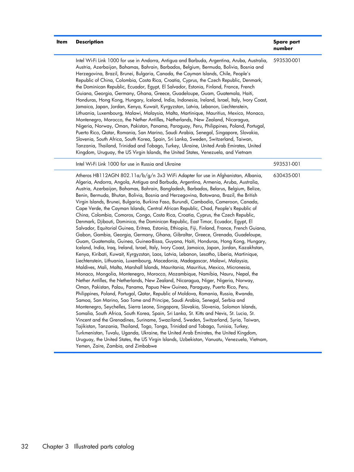
Intel Wi-Fi Link 1000 for use in Andorra, Antigua and Barbuda, Argentina, Aruba, Australia, Austria, Azerbaijan, Bahamas, Bahrain, Barbados, Belgium, Bermuda, Bolivia, Bosnia and Herzegovina, Brazil, Brunei, Bulgaria, Canada, the Cayman Islands, Chile, People's Republic of China, Colombia, Costa Rica, Croatia, Cyprus, the Czech Republic, Denmark, the Dominican Republic, Ecuador, Egypt, El Salvador, Estonia, Finland, France, French Guiana, Georgia, Germany, Ghana, Greece, Guadeloupe, Guam, Guatemala, Haiti, Honduras, Hong Kong, Hungary, Iceland, India, Indonesia, Ireland, Israel, Italy, Ivory Coast, Jamaica, Japan, Jordan, Kenya, Kuwait, Kyrgyzstan, Latvia, Lebanon, Liechtenstein, Lithuania, Luxembourg, Malawi, Malaysia, Malta, Martinique, Mauritius, Mexico, Monaco, Montenegro, Morocco, the Nether Antilles, Netherlands, New Zealand, Nicaragua, Nigeria, Norway, Oman, Pakistan, Panama, Paraguay, Peru, Philippines, Poland, Portugal, Puerto Rico, Qatar, Romania, San Marino, Saudi Arabia, Senegal, Singapore, Slovakia, Slovenia, South Africa, South Korea, Spain, Sri Lanka, Sweden, Switzerland, Taiwan, Tanzania, Thailand, Trinidad and Tobago, Turkey, Ukraine, United Arab Emirates, United Kingdom, Uruguay, the US Virgin Islands, the United States, Venezuela, and Vietnam 593530-001
Intel Wi-Fi Link 1000 for use in Russia and Ukraine 593531-001
Atheros HB112AGN 802.11a/b/g/n 3x3 WiFi Adapter for use in Afghanistan, Albania, Algeria, Andorra, Angola, Antigua and Barbuda, Argentina, Armenia, Aruba, Australia, Austria, Azerbaijan, Bahamas, Bahrain, Bangladesh, Barbados, Belarus, Belgium, Belize, Benin, Bermuda, Bhutan, Bolivia, Bosnia and Herzegovina, Botswana, Brazil, the British Virgin Islands, Brunei, Bulgaria, Burkina Faso, Burundi, Cambodia, Cameroon, Canada, Cape Verde, the Cayman Islands, Central African Republic, Chad, People's Republic of China, Colombia, Comoros, Congo, Costa Rica, Croatia, Cyprus, the Czech Republic, Denmark, Djibouti, Dominica, the Dominican Republic, East Timor, Ecuador, Egypt, El Salvador, Equitorial Guinea, Eritrea, Estonia, Ethiopia, Fiji, Finland, France, French Guiana, Gabon, Gambia, Georgia, Germany, Ghana, Gibraltar, Greece, Grenada, Guadeloupe, Guam, Guatemala, Guinea, Guinea-Bissa, Guyana, Haiti, Honduras, Hong Kong, Hungary, Iceland, India, Iraq, Ireland, Israel, Italy, Ivory Coast, Jamaica, Japan, Jordan, Kazakhstan, Kenya, Kiribati, Kuwait, Kyrgyzstan, Laos, Latvia, Lebanon, Lesotho, Liberia, Martinique, Liechtenstein, Lithuania, Luxembourg, Macedonia, Madagascar, Malawi, Malaysia, Maldives, Mali, Malta, Marshall Islands, Mauritania, Mauritius, Mexico, Micronesia, Monaco, Mongolia, Montenegro, Morocco, Mozambique, Namibia, Nauru, Nepal, the Nether Antilles, the Netherlands, New Zealand, Nicaragua, Niger, Nigeria, Norway, Oman, Pakistan, Palau, Panama, Papua New Guinea, Paraguay, Puerto Rico, Peru, Philippines, Poland, Portugal, Qatar, Republic of Moldova, Romania, Russia, Rwanda, Samoa, San Marino, Sao Tome and Principe, Saudi Arabia, Senegal, Serbia and Montenegro, Seychelles, Sierra Leone, Singapore, Slovakia, Slovenia, Solomon Islands, Somalia, South Africa, South Korea, Spain, Sri Lanka, St. Kitts and Nevis, St. Lucia, St. Vincent and the Grenadines, Suriname, Swaziland, Sweden, Switzerland, Syria, Taiwan, Tajikistan, Tanzania, Thailand, Togo, Tonga, Trinidad and Tobago, Tunisia, Turkey, Turkmenistan, Tuvalu, Uganda, Ukraine, the United Arab Emirates, the United Kingdom, Uruguay, the United States, the US Virgin Islands, Uzbekistan, Vanuatu, Venezuela, Vietnam, Yemen, Zaire, Zambia, and Zimbabwe 630435-001 32 Chapter 3 Illustrated parts catalog
Item Description Spare part number
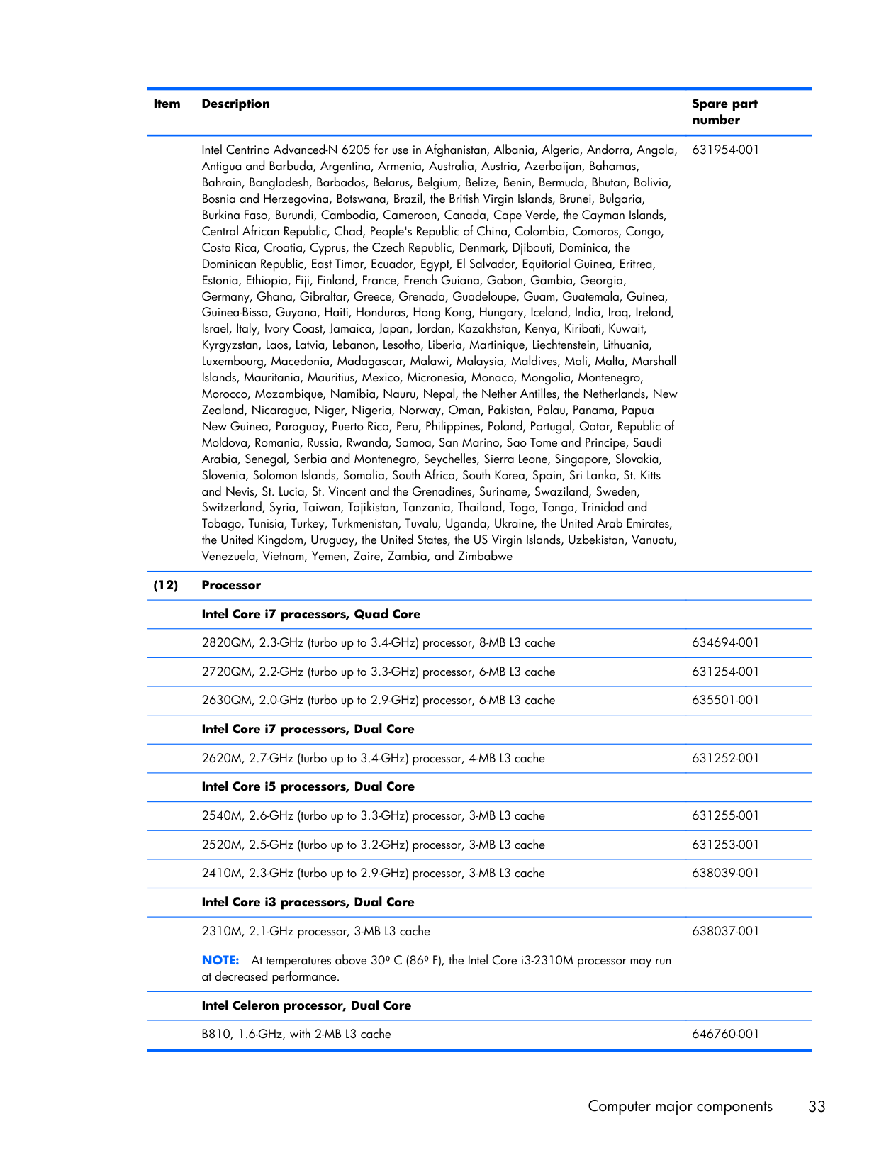
Intel Centrino Advanced-N 6205 for use in Afghanistan, Albania, Algeria, Andorra, Angola, Antigua and Barbuda, Argentina, Armenia, Australia, Austria, Azerbaijan, Bahamas, Bahrain, Bangladesh, Barbados, Belarus, Belgium, Belize, Benin, Bermuda, Bhutan, Bolivia, Bosnia and Herzegovina, Botswana, Brazil, the British Virgin Islands, Brunei, Bulgaria, Burkina Faso, Burundi, Cambodia, Cameroon, Canada, Cape Verde, the Cayman Islands, Central African Republic, Chad, People's Republic of China, Colombia, Comoros, Congo, Costa Rica, Croatia, Cyprus, the Czech Republic, Denmark, Djibouti, Dominica, the Dominican Republic, East Timor, Ecuador, Egypt, El Salvador, Equitorial Guinea, Eritrea, Estonia, Ethiopia, Fiji, Finland, France, French Guiana, Gabon, Gambia, Georgia, Germany, Ghana, Gibraltar, Greece, Grenada, Guadeloupe, Guam, Guatemala, Guinea, Guinea-Bissa, Guyana, Haiti, Honduras, Hong Kong, Hungary, Iceland, India, Iraq, Ireland, Israel, Italy, Ivory Coast, Jamaica, Japan, Jordan, Kazakhstan, Kenya, Kiribati, Kuwait, Kyrgyzstan, Laos, Latvia, Lebanon, Lesotho, Liberia, Martinique, Liechtenstein, Lithuania, Luxembourg, Macedonia, Madagascar, Malawi, Malaysia, Maldives, Mali, Malta, Marshall Islands, Mauritania, Mauritius, Mexico, Micronesia, Monaco, Mongolia, Montenegro, Morocco, Mozambique, Namibia, Nauru, Nepal, the Nether Antilles, the Netherlands, New Zealand, Nicaragua, Niger, Nigeria, Norway, Oman, Pakistan, Palau, Panama, Papua New Guinea, Paraguay, Puerto Rico, Peru, Philippines, Poland, Portugal, Qatar, Republic of Moldova, Romania, Russia, Rwanda, Samoa, San Marino, Sao Tome and Principe, Saudi Arabia, Senegal, Serbia and Montenegro, Seychelles, Sierra Leone, Singapore, Slovakia, Slovenia, Solomon Islands, Somalia, South Africa, South Korea, Spain, Sri Lanka, St. Kitts and Nevis, St. Lucia, St. Vincent and the Grenadines, Suriname, Swaziland, Sweden, Switzerland, Syria, Taiwan, Tajikistan, Tanzania, Thailand, Togo, Tonga, Trinidad and Tobago, Tunisia, Turkey, Turkmenistan, Tuvalu, Uganda, Ukraine, the United Arab Emirates, the United Kingdom, Uruguay, the United States, the US Virgin Islands, Uzbekistan, Vanuatu, Venezuela, Vietnam, Yemen, Zaire, Zambia, and Zimbabwe 631954-001 (12) Processor
Intel Core i7 processors, Quad Core
2820QM, 2.3-GHz (turbo up to 3.4-GHz) processor, 8-MB L3 cache 634694-001
2720QM, 2.2-GHz (turbo up to 3.3-GHz) processor, 6-MB L3 cache 631254-001
2630QM, 2.0-GHz (turbo up to 2.9-GHz) processor, 6-MB L3 cache 635501-001
Intel Core i7 processors, Dual Core
2620M, 2.7-GHz (turbo up to 3.4-GHz) processor, 4-MB L3 cache 631252-001
Intel Core i5 processors, Dual Core
2540M, 2.6-GHz (turbo up to 3.3-GHz) processor, 3-MB L3 cache 631255-001
2520M, 2.5-GHz (turbo up to 3.2-GHz) processor, 3-MB L3 cache 631253-001
2410M, 2.3-GHz (turbo up to 2.9-GHz) processor, 3-MB L3 cache 638039-001
Intel Core i3 processors, Dual Core
2310M, 2.1-GHz processor, 3-MB L3 cache
Note:
At temperatures above 30⁰ C (86⁰ F), the Intel Core i3-2310M processor may run at decreased performance. 638037-001Intel Celeron processor, Dual Core
B810, 1.6-GHz, with 2-MB L3 cache 646760-001 Computer major components 33
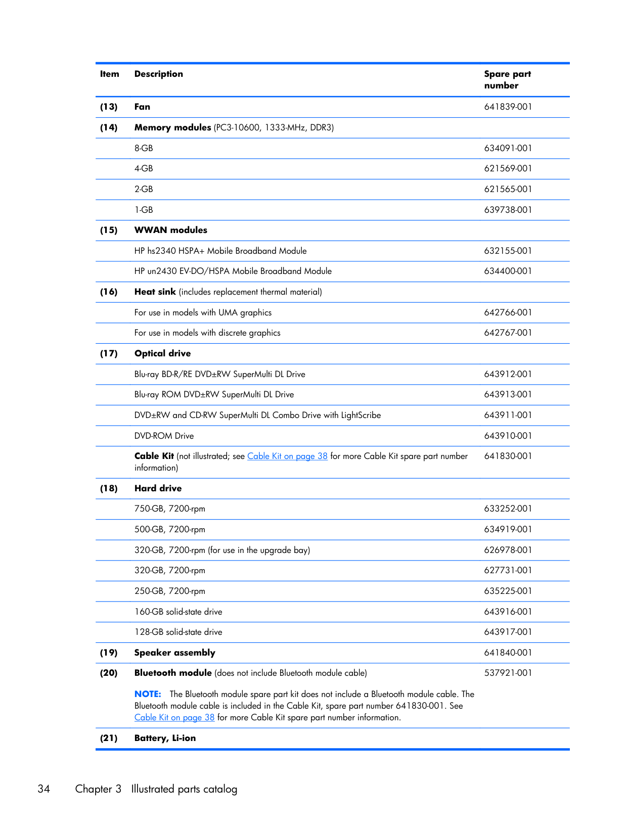
Item Description Spare part number (13) Fan 641839-001 (14) Memory modules (PC3-10600, 1333-MHz, DDR3)
8-Gb
634091-0014-Gb
621569-0012-Gb
621565-0011-Gb
639738-001 (15) WWAN modulesHP hs2340 HSPA+ Mobile Broadband Module 632155-001
HP un2430 EV-DO/HSPA Mobile Broadband Module 634400-001 (16) Heat sink (includes replacement thermal material)
For use in models with UMA graphics 642766-001
For use in models with discrete graphics 642767-001 (17) Optical drive
Blu-ray BD-R/RE DVD±RW SuperMulti DL Drive 643912-001
Blu-ray ROM DVD±RW SuperMulti DL Drive 643913-001
DVD±RW and CD-RW SuperMulti DL Combo Drive with LightScribe 643911-001
DVD-ROM Drive 643910-001
Cable Kit (not illustrated; see Cable Kit on page 38 for more Cable Kit spare part number information) 641830-001 (18) Hard drive
750-GB, 7200-rpm 633252-001
500-GB, 7200-rpm 634919-001
320-GB, 7200-rpm (for use in the upgrade bay) 626978-001
320-GB, 7200-rpm 627731-001
250-GB, 7200-rpm 635225-001
160-GB solid-state drive 643916-001
128-GB solid-state drive 643917-001 (19) Speaker assembly 641840-001 (20) Bluetooth module (does not include Bluetooth module cable)
Note:
The Bluetooth module spare part kit does not include a Bluetooth module cable. The Bluetooth module cable is included in the Cable Kit, spare part number 641830-001. See Cable Kit on page 38 for more Cable Kit spare part number information. 537921-001 (21) Battery, Li-ion34 Chapter 3 Illustrated parts catalog
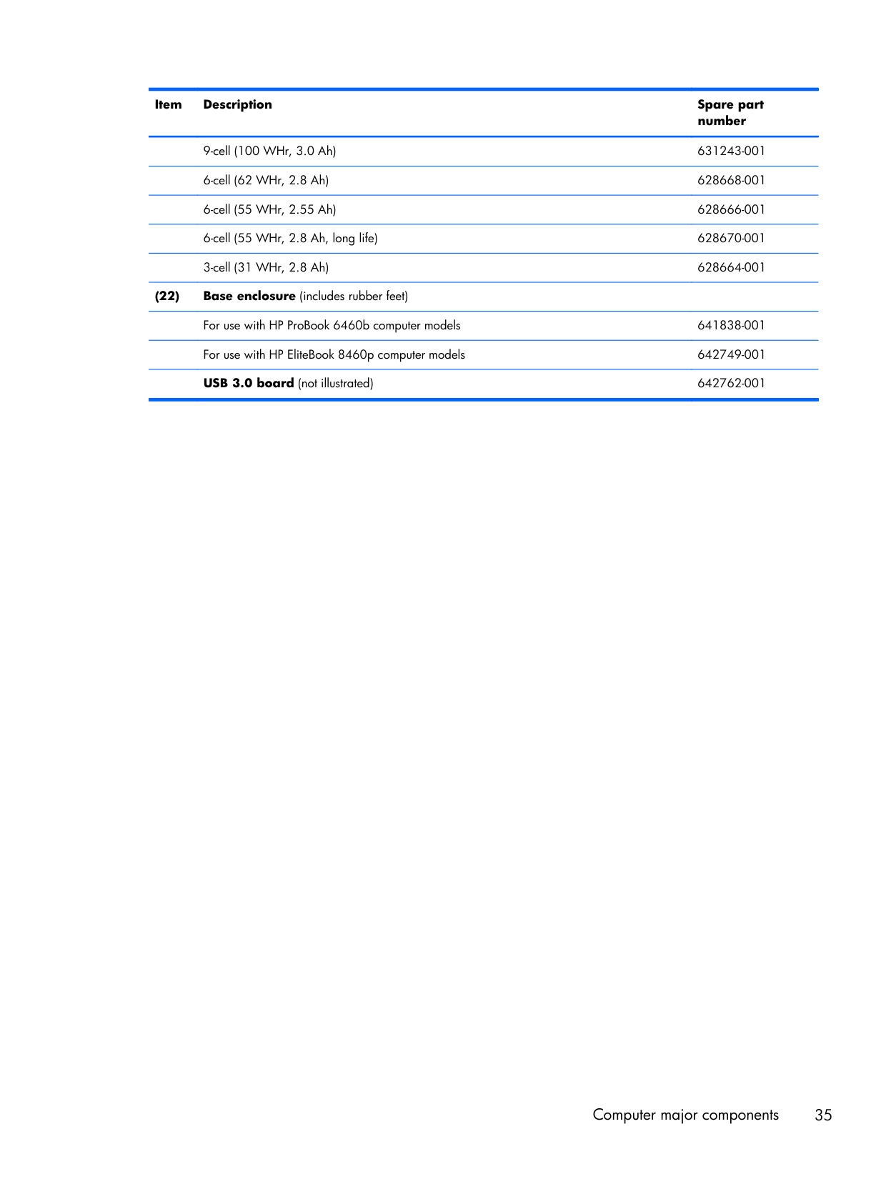
Item Description Spare part number
9-cell (100 WHr, 3.0 Ah) 631243-001
6-cell (62 WHr, 2.8 Ah) 628668-001
6-cell (55 WHr, 2.55 Ah) 628666-001
6-cell (55 WHr, 2.8 Ah, long life) 628670-001
3-cell (31 WHr, 2.8 Ah) 628664-001 (22) Base enclosure (includes rubber feet)
For use with HP ProBook 6460b computer models 641838-001
For use with HP EliteBook 8460p computer models 642749-001
USB 3.0 board (not illustrated) 642762-001 Computer major components 35
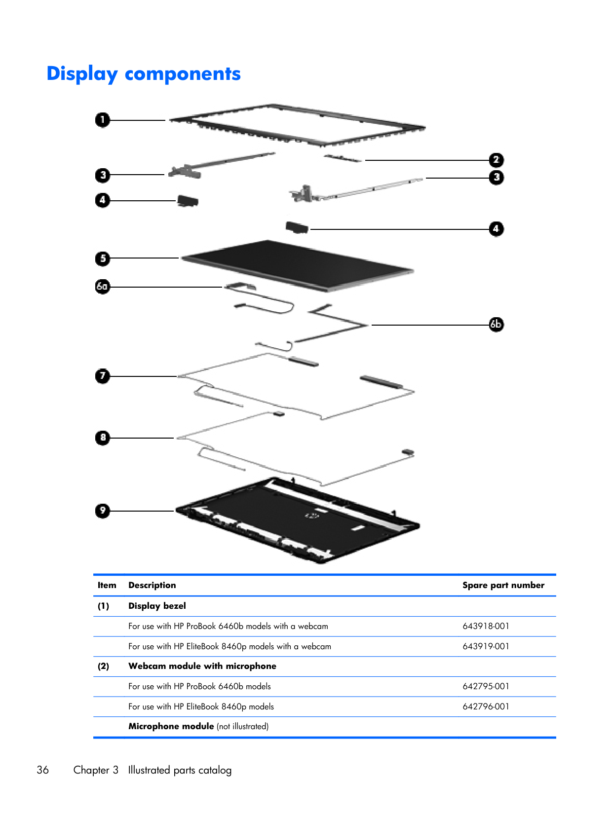
Display components Item Description Spare part number (1) Display bezel
For use with HP ProBook 6460b models with a webcam 643918-001
For use with HP EliteBook 8460p models with a webcam 643919-001 (2) Webcam module with microphone
For use with HP ProBook 6460b models 642795-001
For use with HP EliteBook 8460p models 642796-001
Microphone module (not illustrated)
36 Chapter 3 Illustrated parts catalog
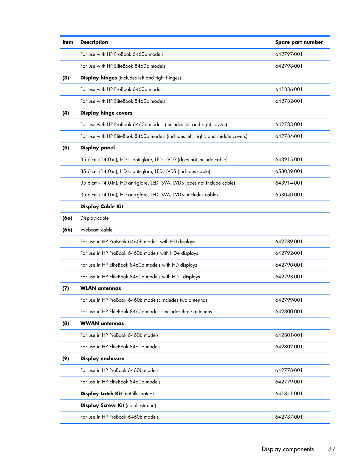
Item Description Spare part number
For use with HP ProBook 6460b models 642797-001
For use with HP EliteBook 8460p models 642798-001 (3) Display hinges (includes left and right hinges)
For use with HP ProBook 6460b models 641836-001
For use with HP EliteBook 8460p models 642782-001 (4) Display hinge covers
For use with HP ProBook 6460b models (includes left and right covers) 642783-001
For use with HP EliteBook 8460p models (includes left, right, and middle covers) 642784-001 (5) Display panel
35.6-cm (14.0-in), HD+, anti-glare, LED, LVDS (does not include cable) 643915-001
35.6-cm (14.0-in), HD+, anti-glare, LED, LVDS (includes cable) 653039-001
35.6-cm (14.0-in), HD anti-glare, LED, SVA, LVDS (does not include cable) 643914-001
35.6-cm (14.0-in), HD anti-glare, LED, SVA, LVDS (includes cable) 653040-001
Display Cable Kit
(6a) Display cable
(6b) Webcam cable
For use in HP ProBook 6460b models with HD displays 642789-001
For use in HP ProBook 6460b models with HD+ displays 642792-001
For use in HP EliteBook 8460p models with HD displays 642790-001
For use in HP EliteBook 8460p models with HD+ displays 642793-001 (7) WLAN antennas
For use in HP ProBook 6460b models; includes two antennas 642799-001
For use in HP EliteBook 8460p models; includes three antennas 642800-001 (8) WWAN antennas
For use in HP ProBook 6460b models 642801-001
For use in HP EliteBook 8460p models 642802-001 (9) Display enclosure
For use in HP ProBook 6460b models 642778-001
For use in HP EliteBook 8460p models 642779-001
Display Latch Kit (not illustrated) 641841-001
Display Screw Kit (not illustrated)
For use in HP ProBook 6460b models 642787-001 Display components 37
Item Description Spare part number
For use in HP EliteBook 8460p models 642788-001
Display Rubber Kit (not illustrated)
For use in HP ProBook 6460b models 642785-001
For use in HP EliteBook 8460p models 642786-001 Cable Kit Item Description Spare part number
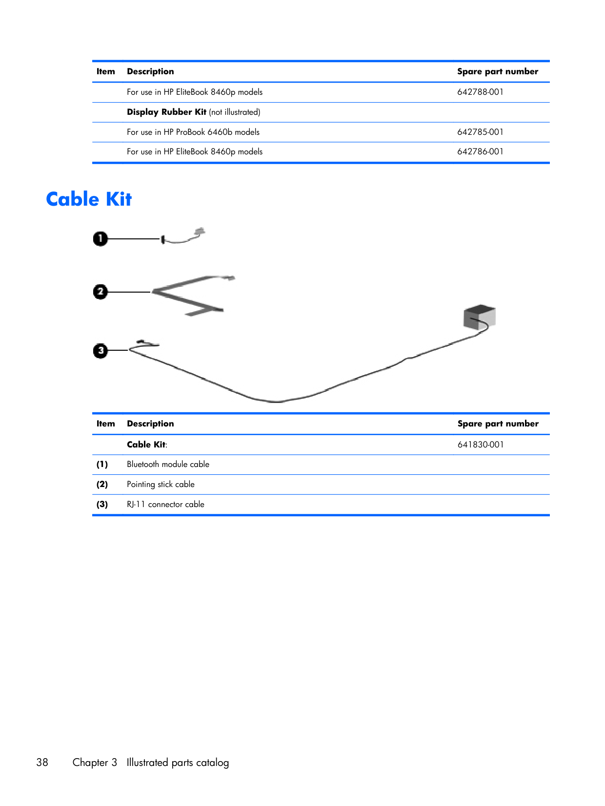
Cable Kit: 641830-001 (1) Bluetooth module cable (2) Pointing stick cable (3) RJ-11 connector cable 38 Chapter 3 Illustrated parts catalog
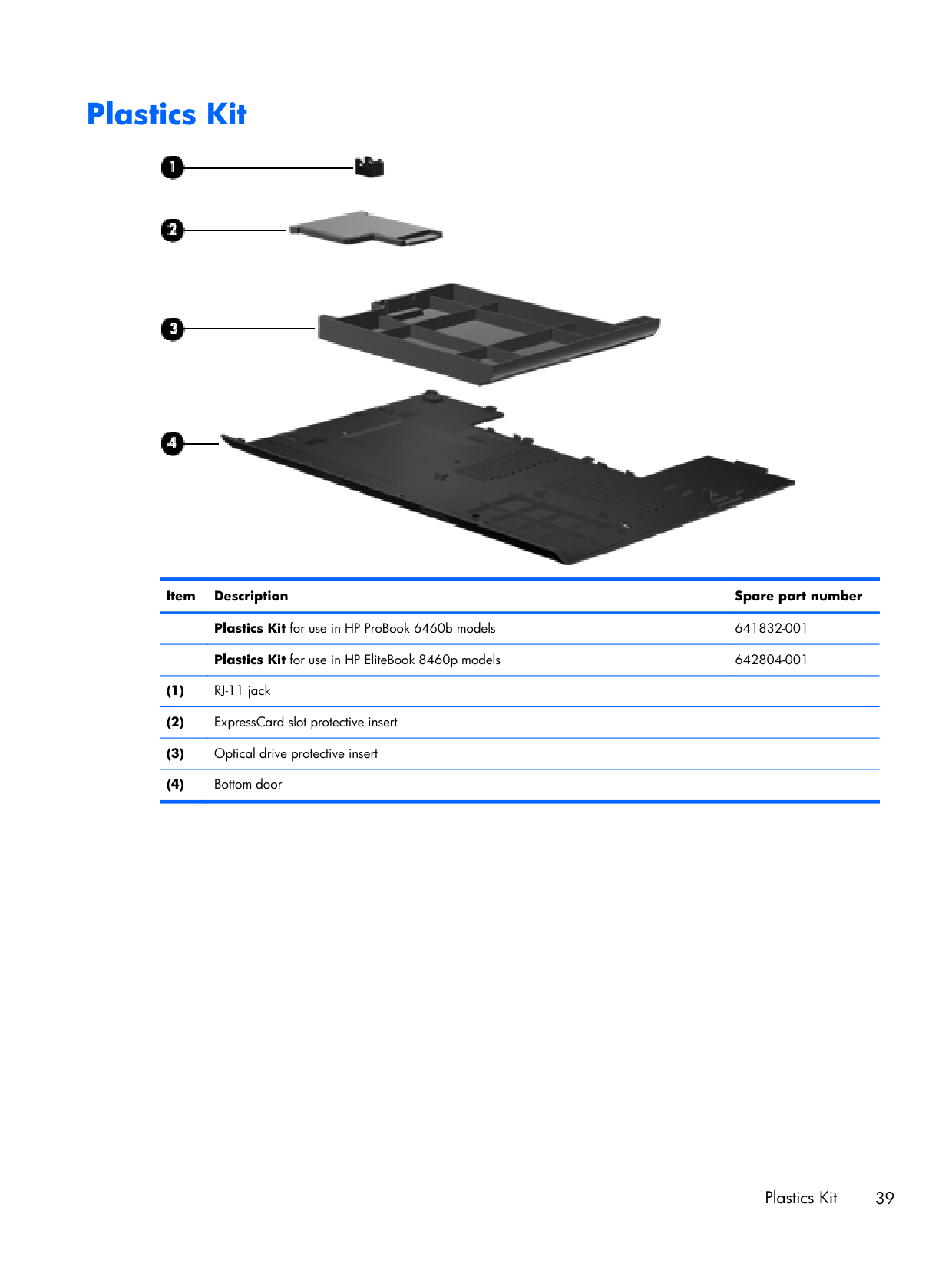
Plastics Kit Item Description Spare part number
Plastics Kit for use in HP ProBook 6460b models 641832-001
Plastics Kit for use in HP EliteBook 8460p models 642804-001 (1) RJ-11 jack (2) ExpressCard slot protective insert (3) Optical drive protective insert (4) Bottom door Plastics Kit 39
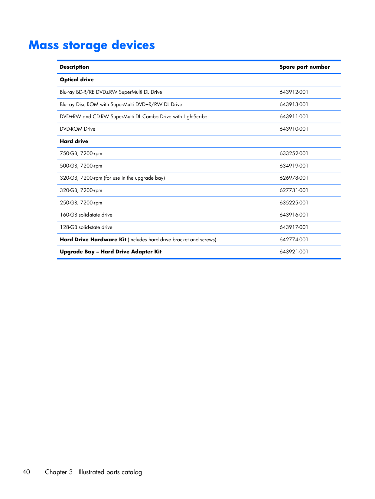
Mass storage devices Description Spare part number Optical drive Blu-ray BD-R/RE DVD±RW SuperMulti DL Drive 643912-001 Blu-ray Disc ROM with SuperMulti DVD±R/RW DL Drive 643913-001 DVD±RW and CD-RW SuperMulti DL Combo Drive with LightScribe 643911-001 DVD-ROM Drive 643910-001 Hard drive 750-GB, 7200-rpm 633252-001 500-GB, 7200-rpm 634919-001 320-GB, 7200-rpm (for use in the upgrade bay) 626978-001 320-GB, 7200-rpm 627731-001 250-GB, 7200-rpm 635225-001 160-GB solid-state drive 643916-001 128-GB solid-state drive 643917-001 Hard Drive Hardware Kit (includes hard drive bracket and screws) 642774-001 Upgrade Bay – Hard Drive Adapter Kit 643921-001 40 Chapter 3 Illustrated parts catalog
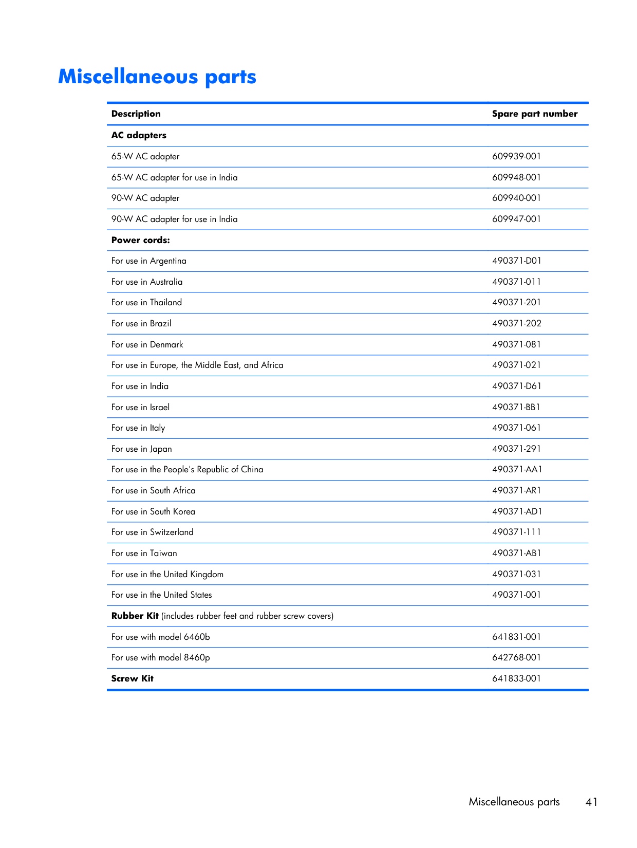
Miscellaneous parts Description Spare part number AC adapters 65-W AC adapter 609939-001 65-W AC adapter for use in India 609948-001 90-W AC adapter 609940-001 90-W AC adapter for use in India 609947-001 Power cords: For use in Argentina
490371-D01
For use in Australia 490371-011 For use in Thailand 490371-201 For use in Brazil 490371-202 For use in Denmark 490371-081 For use in Europe, the Middle East, and Africa 490371-021 For use in India490371-D61
For use in Israel490371-Bb1
For use in Italy 490371-061 For use in Japan 490371-291 For use in the People's Republic of China490371-Aa1
For use in South Africa490371-Ar1
For use in South Korea490371-Ad1
For use in Switzerland 490371-111 For use in Taiwan490371-Ab1
For use in the United Kingdom 490371-031 For use in the United States 490371-001 Rubber Kit (includes rubber feet and rubber screw covers)For use with model 6460b 641831-001 For use with model 8460p 642768-001 Screw Kit 641833-001 Miscellaneous parts 41
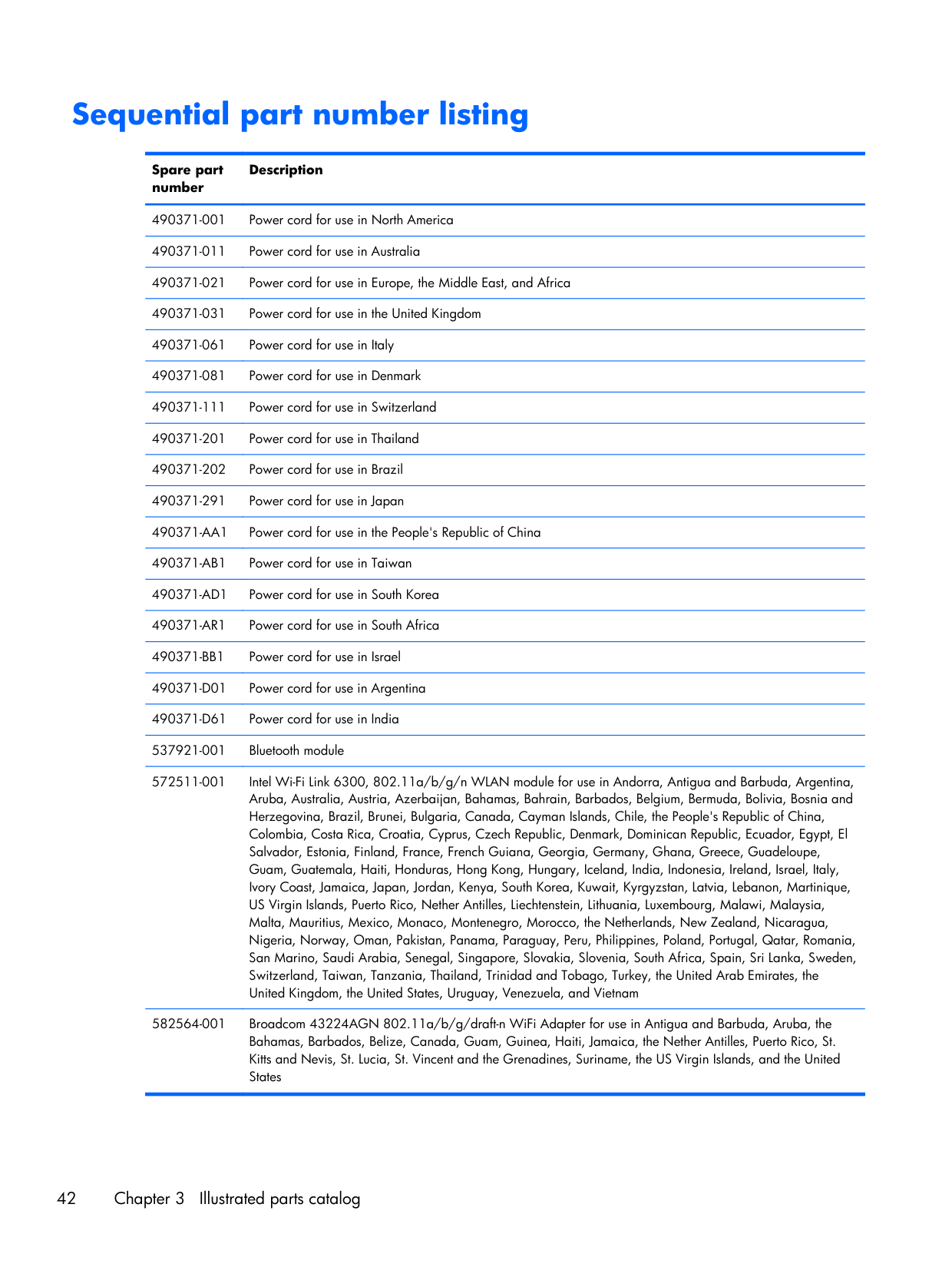
Sequential part number listing Spare part number Description 490371-001 Power cord for use in North America 490371-011 Power cord for use in Australia 490371-021 Power cord for use in Europe, the Middle East, and Africa 490371-031 Power cord for use in the United Kingdom 490371-061 Power cord for use in Italy 490371-081 Power cord for use in Denmark 490371-111 Power cord for use in Switzerland 490371-201 Power cord for use in Thailand 490371-202 Power cord for use in Brazil 490371-291 Power cord for use in Japan
490371-Aa1
Power cord for use in the People's Republic of China490371-Ab1
Power cord for use in Taiwan490371-Ad1
Power cord for use in South Korea490371-Ar1
Power cord for use in South Africa490371-Bb1
Power cord for use in Israel490371-D01
Power cord for use in Argentina490371-D61
Power cord for use in India 537921-001 Bluetooth module 572511-001 Intel Wi-Fi Link 6300, 802.11a/b/g/n WLAN module for use in Andorra, Antigua and Barbuda, Argentina, Aruba, Australia, Austria, Azerbaijan, Bahamas, Bahrain, Barbados, Belgium, Bermuda, Bolivia, Bosnia and Herzegovina, Brazil, Brunei, Bulgaria, Canada, Cayman Islands, Chile, the People's Republic of China, Colombia, Costa Rica, Croatia, Cyprus, Czech Republic, Denmark, Dominican Republic, Ecuador, Egypt, El Salvador, Estonia, Finland, France, French Guiana, Georgia, Germany, Ghana, Greece, Guadeloupe, Guam, Guatemala, Haiti, Honduras, Hong Kong, Hungary, Iceland, India, Indonesia, Ireland, Israel, Italy, Ivory Coast, Jamaica, Japan, Jordan, Kenya, South Korea, Kuwait, Kyrgyzstan, Latvia, Lebanon, Martinique, US Virgin Islands, Puerto Rico, Nether Antilles, Liechtenstein, Lithuania, Luxembourg, Malawi, Malaysia, Malta, Mauritius, Mexico, Monaco, Montenegro, Morocco, the Netherlands, New Zealand, Nicaragua, Nigeria, Norway, Oman, Pakistan, Panama, Paraguay, Peru, Philippines, Poland, Portugal, Qatar, Romania, San Marino, Saudi Arabia, Senegal, Singapore, Slovakia, Slovenia, South Africa, Spain, Sri Lanka, Sweden, Switzerland, Taiwan, Tanzania, Thailand, Trinidad and Tobago, Turkey, the United Arab Emirates, the United Kingdom, the United States, Uruguay, Venezuela, and Vietnam 582564-001 Broadcom 43224AGN 802.11a/b/g/draft-n WiFi Adapter for use in Antigua and Barbuda, Aruba, the Bahamas, Barbados, Belize, Canada, Guam, Guinea, Haiti, Jamaica, the Nether Antilles, Puerto Rico, St. Kitts and Nevis, St. Lucia, St. Vincent and the Grenadines, Suriname, the US Virgin Islands, and the United States 42 Chapter 3 Illustrated parts catalog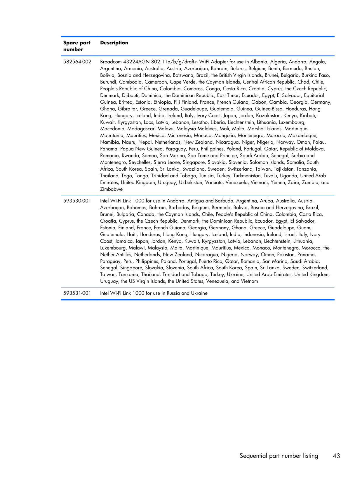
Spare part number Description 582564-002 Broadcom 43224AGN 802.11a/b/g/draft-n WiFi Adapter for use in Albania, Algeria, Andorra, Angola, Argentina, Armenia, Australia, Austria, Azerbaijan, Bahrain, Belarus, Belgium, Benin, Bermuda, Bhutan, Bolivia, Bosnia and Herzegovina, Botswana, Brazil, the British Virgin Islands, Brunei, Bulgaria, Burkina Faso, Burundi, Cambodia, Cameroon, Cape Verde, the Cayman Islands, Central African Republic, Chad, Chile, People's Republic of China, Colombia, Comoros, Congo, Costa Rica, Croatia, Cyprus, the Czech Republic, Denmark, Djibouti, Dominica, the Dominican Republic, East Timor, Ecuador, Egypt, El Salvador, Equitorial Guinea, Eritrea, Estonia, Ethiopia, Fiji Finland, France, French Guiana, Gabon, Gambia, Georgia, Germany, Ghana, Gibraltar, Greece, Grenada, Guadeloupe, Guatemala, Guinea, Guinea-Bissa, Honduras, Hong Kong, Hungary, Iceland, India, Ireland, Italy, Ivory Coast, Japan, Jordan, Kazakhstan, Kenya, Kiribati, Kuwait, Kyrgyzstan, Laos, Latvia, Lebanon, Lesotho, Liberia, Liechtenstein, Lithuania, Luxembourg, Macedonia, Madagascar, Malawi, Malaysia Maldives, Mali, Malta, Marshall Islands, Martinique, Mauritania, Mauritius, Mexico, Micronesia, Monaco, Mongolia, Montenegro, Morocco, Mozambique, Namibia, Nauru, Nepal, Netherlands, New Zealand, Nicaragua, Niger, Nigeria, Norway, Oman, Palau, Panama, Papua New Guinea, Paraguay, Peru, Philippines, Poland, Portugal, Qatar, Republic of Moldova, Romania, Rwanda, Samoa, San Marino, Sao Tome and Principe, Saudi Arabia, Senegal, Serbia and Montenegro, Seychelles, Sierra Leone, Singapore, Slovakia, Slovenia, Solomon Islands, Somalia, South Africa, South Korea, Spain, Sri Lanka, Swaziland, Sweden, Switzerland, Taiwan, Tajikistan, Tanzania, Thailand, Togo, Tonga, Trinidad and Tobago, Tunisia, Turkey, Turkmenistan, Tuvalu, Uganda, United Arab Emirates, United Kingdom, Uruguay, Uzbekistan, Vanuatu, Venezuela, Vietnam, Yemen, Zaire, Zambia, and Zimbabwe 593530-001 Intel Wi-Fi Link 1000 for use in Andorra, Antigua and Barbuda, Argentina, Aruba, Australia, Austria, Azerbaijan, Bahamas, Bahrain, Barbados, Belgium, Bermuda, Bolivia, Bosnia and Herzegovina, Brazil, Brunei, Bulgaria, Canada, the Cayman Islands, Chile, People's Republic of China, Colombia, Costa Rica, Croatia, Cyprus, the Czech Republic, Denmark, the Dominican Republic, Ecuador, Egypt, El Salvador, Estonia, Finland, France, French Guiana, Georgia, Germany, Ghana, Greece, Guadeloupe, Guam, Guatemala, Haiti, Honduras, Hong Kong, Hungary, Iceland, India, Indonesia, Ireland, Israel, Italy, Ivory Coast, Jamaica, Japan, Jordan, Kenya, Kuwait, Kyrgyzstan, Latvia, Lebanon, Liechtenstein, Lithuania, Luxembourg, Malawi, Malaysia, Malta, Martinique, Mauritius, Mexico, Monaco, Montenegro, Morocco, the Nether Antilles, Netherlands, New Zealand, Nicaragua, Nigeria, Norway, Oman, Pakistan, Panama, Paraguay, Peru, Philippines, Poland, Portugal, Puerto Rico, Qatar, Romania, San Marino, Saudi Arabia, Senegal, Singapore, Slovakia, Slovenia, South Africa, South Korea, Spain, Sri Lanka, Sweden, Switzerland, Taiwan, Tanzania, Thailand, Trinidad and Tobago, Turkey, Ukraine, United Arab Emirates, United Kingdom, Uruguay, the US Virgin Islands, the United States, Venezuela, and Vietnam 593531-001 Intel Wi-Fi Link 1000 for use in Russia and Ukraine Sequential part number listing 43
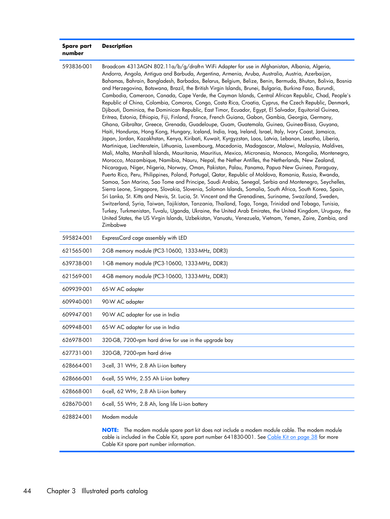
Spare part number Description 593836-001 Broadcom 4313AGN 802.11a/b/g/draft-n WiFi Adapter for use in Afghanistan, Albania, Algeria, Andorra, Angola, Antigua and Barbuda, Argentina, Armenia, Aruba, Australia, Austria, Azerbaijan, Bahamas, Bahrain, Bangladesh, Barbados, Belarus, Belgium, Belize, Benin, Bermuda, Bhutan, Bolivia, Bosnia and Herzegovina, Botswana, Brazil, the British Virgin Islands, Brunei, Bulgaria, Burkina Faso, Burundi, Cambodia, Cameroon, Canada, Cape Verde, the Cayman Islands, Central African Republic, Chad, People's Republic of China, Colombia, Comoros, Congo, Costa Rica, Croatia, Cyprus, the Czech Republic, Denmark, Djibouti, Dominica, the Dominican Republic, East Timor, Ecuador, Egypt, El Salvador, Equitorial Guinea, Eritrea, Estonia, Ethiopia, Fiji, Finland, France, French Guiana, Gabon, Gambia, Georgia, Germany, Ghana, Gibraltar, Greece, Grenada, Guadeloupe, Guam, Guatemala, Guinea, Guinea-Bissa, Guyana, Haiti, Honduras, Hong Kong, Hungary, Iceland, India, Iraq, Ireland, Israel, Italy, Ivory Coast, Jamaica, Japan, Jordan, Kazakhstan, Kenya, Kiribati, Kuwait, Kyrgyzstan, Laos, Latvia, Lebanon, Lesotho, Liberia, Martinique, Liechtenstein, Lithuania, Luxembourg, Macedonia, Madagascar, Malawi, Malaysia, Maldives, Mali, Malta, Marshall Islands, Mauritania, Mauritius, Mexico, Micronesia, Monaco, Mongolia, Montenegro, Morocco, Mozambique, Namibia, Nauru, Nepal, the Nether Antilles, the Netherlands, New Zealand, Nicaragua, Niger, Nigeria, Norway, Oman, Pakistan, Palau, Panama, Papua New Guinea, Paraguay, Puerto Rico, Peru, Philippines, Poland, Portugal, Qatar, Republic of Moldova, Romania, Russia, Rwanda, Samoa, San Marino, Sao Tome and Principe, Saudi Arabia, Senegal, Serbia and Montenegro, Seychelles, Sierra Leone, Singapore, Slovakia, Slovenia, Solomon Islands, Somalia, South Africa, South Korea, Spain, Sri Lanka, St. Kitts and Nevis, St. Lucia, St. Vincent and the Grenadines, Suriname, Swaziland, Sweden, Switzerland, Syria, Taiwan, Tajikistan, Tanzania, Thailand, Togo, Tonga, Trinidad and Tobago, Tunisia, Turkey, Turkmenistan, Tuvalu, Uganda, Ukraine, the United Arab Emirates, the United Kingdom, Uruguay, the United States, the US Virgin Islands, Uzbekistan, Vanuatu, Venezuela, Vietnam, Yemen, Zaire, Zambia, and Zimbabwe 595824-001 ExpressCard cage assembly with LED 621565-001 2-GB memory module (PC3-10600, 1333-MHz, DDR3) 639738-001 1-GB memory module (PC3-10600, 1333-MHz, DDR3) 621569-001 4-GB memory module (PC3-10600, 1333-MHz, DDR3) 609939-001 65-W AC adapter 609940-001 90-W AC adapter 609947-001 90-W AC adapter for use in India 609948-001 65-W AC adapter for use in India 626978-001 320-GB, 7200-rpm hard drive for use in the upgrade bay 627731-001 320-GB, 7200-rpm hard drive 628664-001 3-cell, 31 WHr, 2.8 Ah Li-ion battery 628666-001 6-cell, 55 WHr, 2.55 Ah Li-ion battery 628668-001 6-cell, 62 WHr, 2.8 Ah Li-ion battery 628670-001 6-cell, 55 WHr, 2.8 Ah, long life Li-ion battery 628824-001 Modem module
Note:
The modem module spare part kit does not include a modem module cable. The modem module cable is included in the Cable Kit, spare part number 641830-001. See Cable Kit on page 38 for more Cable Kit spare part number information. 44 Chapter 3 Illustrated parts catalog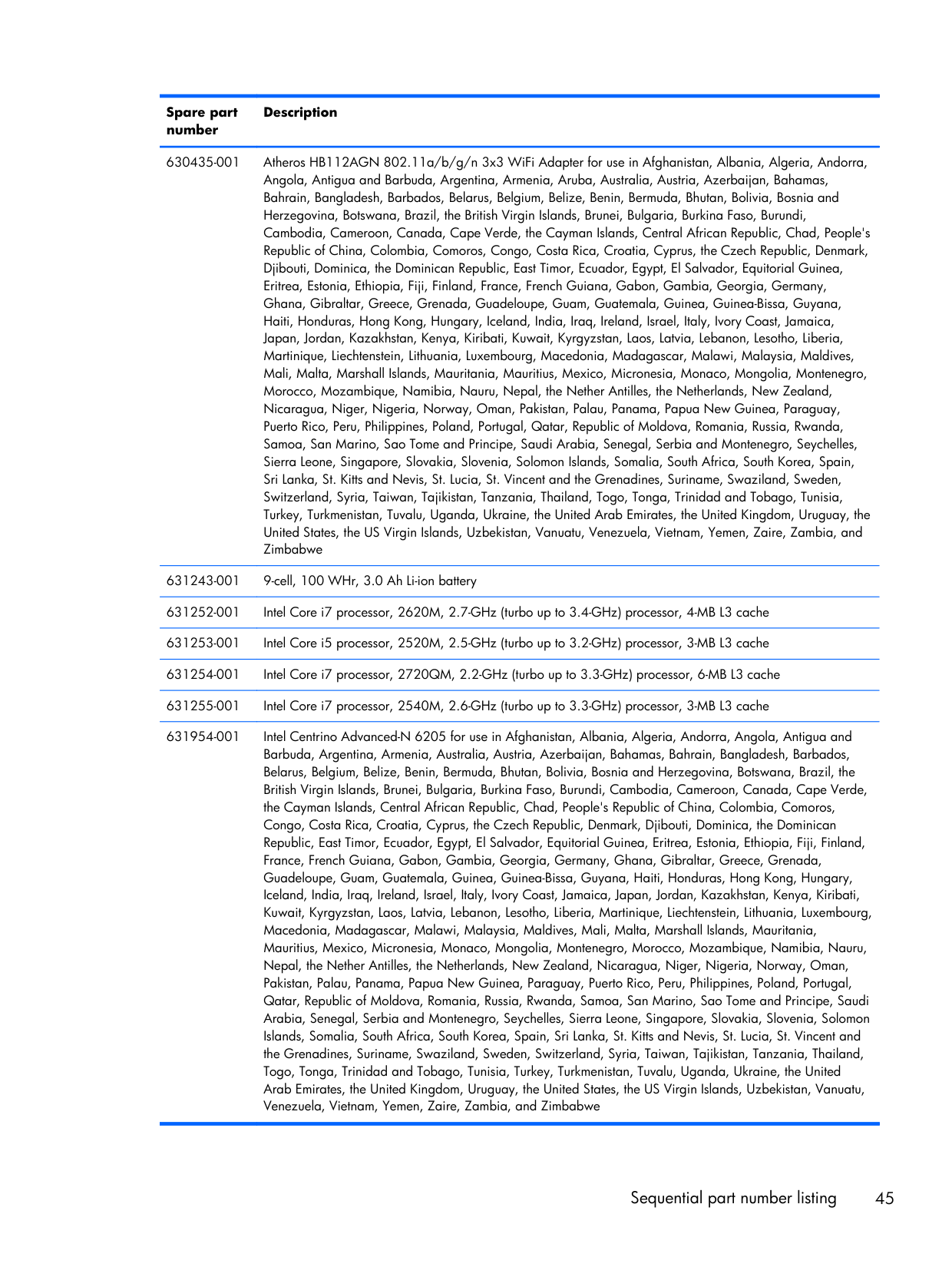
Spare part number Description 630435-001 Atheros HB112AGN 802.11a/b/g/n 3x3 WiFi Adapter for use in Afghanistan, Albania, Algeria, Andorra, Angola, Antigua and Barbuda, Argentina, Armenia, Aruba, Australia, Austria, Azerbaijan, Bahamas, Bahrain, Bangladesh, Barbados, Belarus, Belgium, Belize, Benin, Bermuda, Bhutan, Bolivia, Bosnia and Herzegovina, Botswana, Brazil, the British Virgin Islands, Brunei, Bulgaria, Burkina Faso, Burundi, Cambodia, Cameroon, Canada, Cape Verde, the Cayman Islands, Central African Republic, Chad, People's Republic of China, Colombia, Comoros, Congo, Costa Rica, Croatia, Cyprus, the Czech Republic, Denmark, Djibouti, Dominica, the Dominican Republic, East Timor, Ecuador, Egypt, El Salvador, Equitorial Guinea, Eritrea, Estonia, Ethiopia, Fiji, Finland, France, French Guiana, Gabon, Gambia, Georgia, Germany, Ghana, Gibraltar, Greece, Grenada, Guadeloupe, Guam, Guatemala, Guinea, Guinea-Bissa, Guyana, Haiti, Honduras, Hong Kong, Hungary, Iceland, India, Iraq, Ireland, Israel, Italy, Ivory Coast, Jamaica, Japan, Jordan, Kazakhstan, Kenya, Kiribati, Kuwait, Kyrgyzstan, Laos, Latvia, Lebanon, Lesotho, Liberia, Martinique, Liechtenstein, Lithuania, Luxembourg, Macedonia, Madagascar, Malawi, Malaysia, Maldives, Mali, Malta, Marshall Islands, Mauritania, Mauritius, Mexico, Micronesia, Monaco, Mongolia, Montenegro, Morocco, Mozambique, Namibia, Nauru, Nepal, the Nether Antilles, the Netherlands, New Zealand, Nicaragua, Niger, Nigeria, Norway, Oman, Pakistan, Palau, Panama, Papua New Guinea, Paraguay, Puerto Rico, Peru, Philippines, Poland, Portugal, Qatar, Republic of Moldova, Romania, Russia, Rwanda, Samoa, San Marino, Sao Tome and Principe, Saudi Arabia, Senegal, Serbia and Montenegro, Seychelles, Sierra Leone, Singapore, Slovakia, Slovenia, Solomon Islands, Somalia, South Africa, South Korea, Spain, Sri Lanka, St. Kitts and Nevis, St. Lucia, St. Vincent and the Grenadines, Suriname, Swaziland, Sweden, Switzerland, Syria, Taiwan, Tajikistan, Tanzania, Thailand, Togo, Tonga, Trinidad and Tobago, Tunisia, Turkey, Turkmenistan, Tuvalu, Uganda, Ukraine, the United Arab Emirates, the United Kingdom, Uruguay, the United States, the US Virgin Islands, Uzbekistan, Vanuatu, Venezuela, Vietnam, Yemen, Zaire, Zambia, and Zimbabwe 631243-001 9-cell, 100 WHr, 3.0 Ah Li-ion battery 631252-001 Intel Core i7 processor, 2620M, 2.7-GHz (turbo up to 3.4-GHz) processor, 4-MB L3 cache 631253-001 Intel Core i5 processor, 2520M, 2.5-GHz (turbo up to 3.2-GHz) processor, 3-MB L3 cache 631254-001 Intel Core i7 processor, 2720QM, 2.2-GHz (turbo up to 3.3-GHz) processor, 6-MB L3 cache 631255-001 Intel Core i7 processor, 2540M, 2.6-GHz (turbo up to 3.3-GHz) processor, 3-MB L3 cache 631954-001 Intel Centrino Advanced-N 6205 for use in Afghanistan, Albania, Algeria, Andorra, Angola, Antigua and Barbuda, Argentina, Armenia, Australia, Austria, Azerbaijan, Bahamas, Bahrain, Bangladesh, Barbados, Belarus, Belgium, Belize, Benin, Bermuda, Bhutan, Bolivia, Bosnia and Herzegovina, Botswana, Brazil, the British Virgin Islands, Brunei, Bulgaria, Burkina Faso, Burundi, Cambodia, Cameroon, Canada, Cape Verde, the Cayman Islands, Central African Republic, Chad, People's Republic of China, Colombia, Comoros, Congo, Costa Rica, Croatia, Cyprus, the Czech Republic, Denmark, Djibouti, Dominica, the Dominican Republic, East Timor, Ecuador, Egypt, El Salvador, Equitorial Guinea, Eritrea, Estonia, Ethiopia, Fiji, Finland, France, French Guiana, Gabon, Gambia, Georgia, Germany, Ghana, Gibraltar, Greece, Grenada, Guadeloupe, Guam, Guatemala, Guinea, Guinea-Bissa, Guyana, Haiti, Honduras, Hong Kong, Hungary, Iceland, India, Iraq, Ireland, Israel, Italy, Ivory Coast, Jamaica, Japan, Jordan, Kazakhstan, Kenya, Kiribati, Kuwait, Kyrgyzstan, Laos, Latvia, Lebanon, Lesotho, Liberia, Martinique, Liechtenstein, Lithuania, Luxembourg, Macedonia, Madagascar, Malawi, Malaysia, Maldives, Mali, Malta, Marshall Islands, Mauritania, Mauritius, Mexico, Micronesia, Monaco, Mongolia, Montenegro, Morocco, Mozambique, Namibia, Nauru, Nepal, the Nether Antilles, the Netherlands, New Zealand, Nicaragua, Niger, Nigeria, Norway, Oman, Pakistan, Palau, Panama, Papua New Guinea, Paraguay, Puerto Rico, Peru, Philippines, Poland, Portugal, Qatar, Republic of Moldova, Romania, Russia, Rwanda, Samoa, San Marino, Sao Tome and Principe, Saudi Arabia, Senegal, Serbia and Montenegro, Seychelles, Sierra Leone, Singapore, Slovakia, Slovenia, Solomon Islands, Somalia, South Africa, South Korea, Spain, Sri Lanka, St. Kitts and Nevis, St. Lucia, St. Vincent and the Grenadines, Suriname, Swaziland, Sweden, Switzerland, Syria, Taiwan, Tajikistan, Tanzania, Thailand, Togo, Tonga, Trinidad and Tobago, Tunisia, Turkey, Turkmenistan, Tuvalu, Uganda, Ukraine, the United Arab Emirates, the United Kingdom, Uruguay, the United States, the US Virgin Islands, Uzbekistan, Vanuatu, Venezuela, Vietnam, Yemen, Zaire, Zambia, and Zimbabwe Sequential part number listing 45
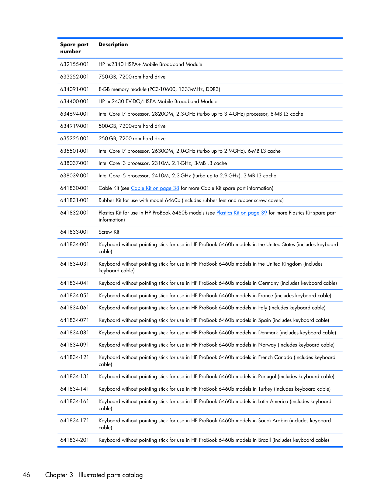
Spare part number Description 632155-001 HP hs2340 HSPA+ Mobile Broadband Module 633252-001 750-GB, 7200-rpm hard drive 634091-001 8-GB memory module (PC3-10600, 1333-MHz, DDR3) 634400-001 HP un2430 EV-DO/HSPA Mobile Broadband Module 634694-001 Intel Core i7 processor, 2820QM, 2.3-GHz (turbo up to 3.4-GHz) processor, 8-MB L3 cache 634919-001 500-GB, 7200-rpm hard drive 635225-001 250-GB, 7200-rpm hard drive 635501-001 Intel Core i7 processor, 2630QM, 2.0-GHz (turbo up to 2.9-GHz), 6-MB L3 cache 638037-001 Intel Core i3 processor, 2310M, 2.1-GHz, 3-MB L3 cache 638039-001 Intel Core i5 processor, 2410M, 2.3-GHz (turbo up to 2.9-GHz), 3-MB L3 cache 641830-001 Cable Kit (see Cable Kit on page 38 for more Cable Kit spare part information) 641831-001 Rubber Kit for use with model 6460b (includes rubber feet and rubber screw covers) 641832-001 Plastics Kit for use in HP ProBook 6460b models (see Plastics Kit on page 39 for more Plastics Kit spare part information) 641833-001 Screw Kit 641834-001 Keyboard without pointing stick for use in HP ProBook 6460b models in the United States (includes keyboard cable) 641834-031 Keyboard without pointing stick for use in HP ProBook 6460b models in the United Kingdom (includes keyboard cable) 641834-041 Keyboard without pointing stick for use in HP ProBook 6460b models in Germany (includes keyboard cable) 641834-051 Keyboard without pointing stick for use in HP ProBook 6460b models in France (includes keyboard cable) 641834-061 Keyboard without pointing stick for use in HP ProBook 6460b models in Italy (includes keyboard cable) 641834-071 Keyboard without pointing stick for use in HP ProBook 6460b models in Spain (includes keyboard cable) 641834-081 Keyboard without pointing stick for use in HP ProBook 6460b models in Denmark (includes keyboard cable) 641834-091 Keyboard without pointing stick for use in HP ProBook 6460b models in Norway (includes keyboard cable) 641834-121 Keyboard without pointing stick for use in HP ProBook 6460b models in French Canada (includes keyboard cable) 641834-131 Keyboard without pointing stick for use in HP ProBook 6460b models in Portugal (includes keyboard cable) 641834-141 Keyboard without pointing stick for use in HP ProBook 6460b models in Turkey (includes keyboard cable) 641834-161 Keyboard without pointing stick for use in HP ProBook 6460b models in Latin America (includes keyboard cable) 641834-171 Keyboard without pointing stick for use in HP ProBook 6460b models in Saudi Arabia (includes keyboard cable) 641834-201 Keyboard without pointing stick for use in HP ProBook 6460b models in Brazil (includes keyboard cable) 46 Chapter 3 Illustrated parts catalog

Spare part number Description 641834-211 Keyboard without pointing stick for use in HP ProBook 6460b models in Hungary (includes keyboard cable) 641834-251 Keyboard without pointing stick for use in HP ProBook 6460b models in Russia (includes keyboard cable) 641834-261 Keyboard without pointing stick for use in HP ProBook 6460b models in Bulgaria (includes keyboard cable) 641834-281 Keyboard without pointing stick for use in HP ProBook 6460b models in Thailand (includes keyboard cable) 641834-291 Keyboard without pointing stick for use in HP ProBook 6460b models in Japan (includes keyboard cable)
641834-A41
Keyboard without pointing stick for use in HP ProBook 6460b models in Belgium (includes keyboard cable)641834-A81
Keyboard without pointing stick for use in HP ProBook 6460b models in the Czech Republic (includes keyboard cable)641834-Ab1
Keyboard without pointing stick for use in HP ProBook 6460b models in Taiwan (includes keyboard cable)641834-Ad1
Keyboard without pointing stick for use in HP ProBook 6460b models in South Korea (includes keyboard cable)641834-B31
Keyboard without pointing stick for use in HP ProBook 6460b models in the Netherlands and Europe (includes keyboard cable)641834-B71
Keyboard without pointing stick for use in HP ProBook 6460b models in Sweden (includes keyboard cable)641834-Ba1
Keyboard without pointing stick for use in HP ProBook 6460b models in Slovenia (includes keyboard cable)641834-Bb1
Keyboard without pointing stick for use in HP ProBook 6460b models in Israel (includes keyboard cable)641834-Bg1
Keyboard without pointing stick for use in HP ProBook 6460b models in Switzerland (includes keyboard cable)641834-Dd1
Keyboard without pointing stick for use in HP ProBook 6460b models in Iceland (includes keyboard cable)641834-Dj1
Keyboard without pointing stick for use in HP ProBook 6460b models in Greece (includes keyboard cable)641834-Dw1
Keyboard without pointing stick for use in HP ProBook 6460b models in the French Arabic region (includes keyboard cable) 641835-001 Keyboard with pointing stick for use in HP ProBook 6460b models in the United States (includes keyboard and pointing stick cables) 641835-031 Keyboard with pointing stick for use in HP ProBook 6460b models in the United Kingdom (includes keyboard and pointing stick cables) 641835-041 Keyboard with pointing stick for use in HP ProBook 6460b models in Germany (includes keyboard and pointing stick cables) 641835-051 Keyboard with pointing stick for use in HP ProBook 6460b models in France (includes keyboard and pointing stick cables) 641835-061 Keyboard with pointing stick for use in HP ProBook 6460b models in Italy (includes keyboard and pointing stick cables) 641835-071 Keyboard with pointing stick for use in HP ProBook 6460b models in Spain (includes keyboard and pointing stick cables) 641835-081 Keyboard with pointing stick for use in HP ProBook 6460b models in Denmark (includes keyboard and pointing stick cables) Sequential part number listing 47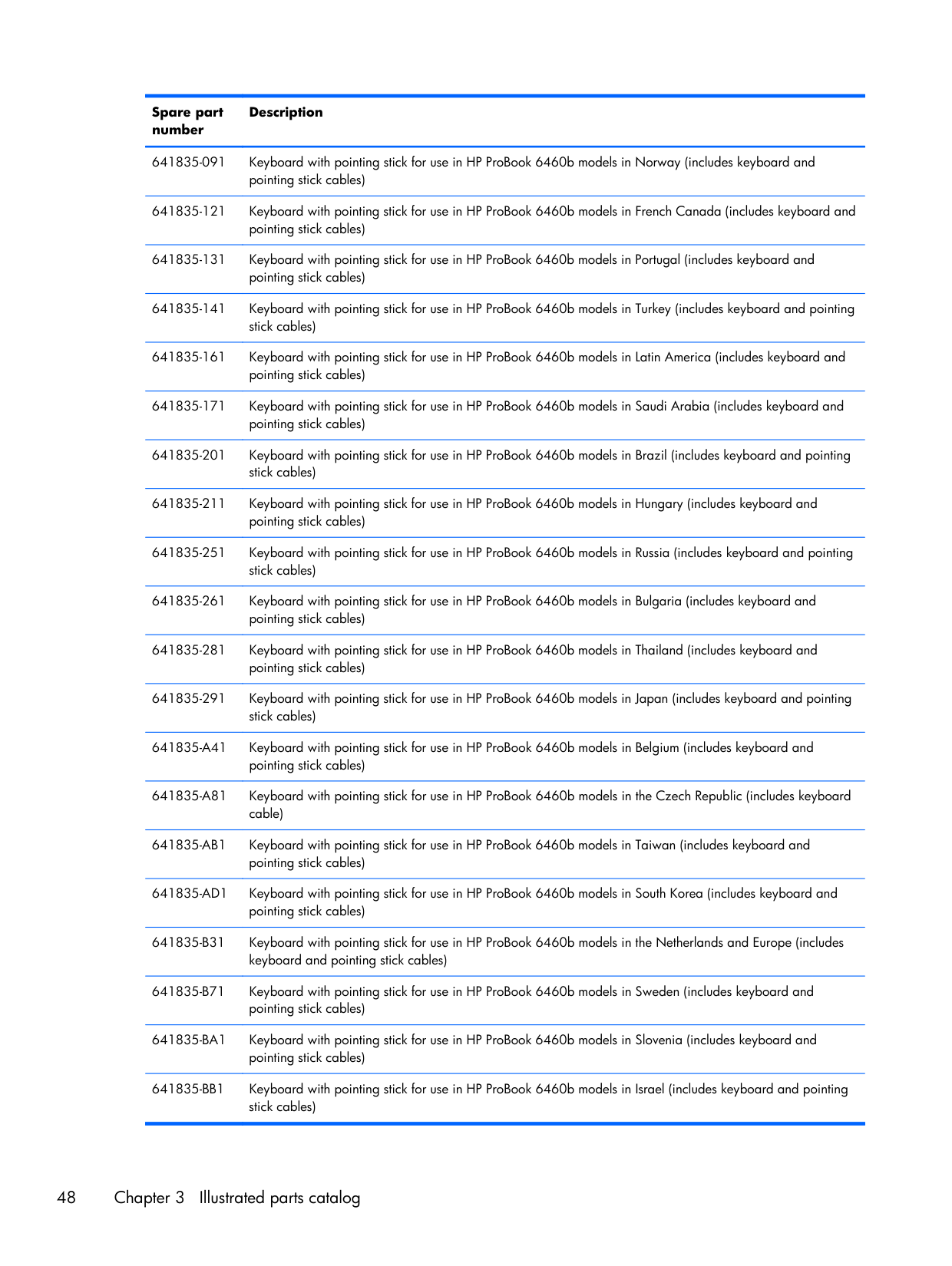
Spare part number Description 641835-091 Keyboard with pointing stick for use in HP ProBook 6460b models in Norway (includes keyboard and pointing stick cables) 641835-121 Keyboard with pointing stick for use in HP ProBook 6460b models in French Canada (includes keyboard and pointing stick cables) 641835-131 Keyboard with pointing stick for use in HP ProBook 6460b models in Portugal (includes keyboard and pointing stick cables) 641835-141 Keyboard with pointing stick for use in HP ProBook 6460b models in Turkey (includes keyboard and pointing stick cables) 641835-161 Keyboard with pointing stick for use in HP ProBook 6460b models in Latin America (includes keyboard and pointing stick cables) 641835-171 Keyboard with pointing stick for use in HP ProBook 6460b models in Saudi Arabia (includes keyboard and pointing stick cables) 641835-201 Keyboard with pointing stick for use in HP ProBook 6460b models in Brazil (includes keyboard and pointing stick cables) 641835-211 Keyboard with pointing stick for use in HP ProBook 6460b models in Hungary (includes keyboard and pointing stick cables) 641835-251 Keyboard with pointing stick for use in HP ProBook 6460b models in Russia (includes keyboard and pointing stick cables) 641835-261 Keyboard with pointing stick for use in HP ProBook 6460b models in Bulgaria (includes keyboard and pointing stick cables) 641835-281 Keyboard with pointing stick for use in HP ProBook 6460b models in Thailand (includes keyboard and pointing stick cables) 641835-291 Keyboard with pointing stick for use in HP ProBook 6460b models in Japan (includes keyboard and pointing stick cables)
641835-A41
Keyboard with pointing stick for use in HP ProBook 6460b models in Belgium (includes keyboard and pointing stick cables)641835-A81
Keyboard with pointing stick for use in HP ProBook 6460b models in the Czech Republic (includes keyboard cable)641835-Ab1
Keyboard with pointing stick for use in HP ProBook 6460b models in Taiwan (includes keyboard and pointing stick cables)641835-Ad1
Keyboard with pointing stick for use in HP ProBook 6460b models in South Korea (includes keyboard and pointing stick cables)641835-B31
Keyboard with pointing stick for use in HP ProBook 6460b models in the Netherlands and Europe (includes keyboard and pointing stick cables)641835-B71
Keyboard with pointing stick for use in HP ProBook 6460b models in Sweden (includes keyboard and pointing stick cables)641835-Ba1
Keyboard with pointing stick for use in HP ProBook 6460b models in Slovenia (includes keyboard and pointing stick cables)641835-Bb1
Keyboard with pointing stick for use in HP ProBook 6460b models in Israel (includes keyboard and pointing stick cables) 48 Chapter 3 Illustrated parts catalog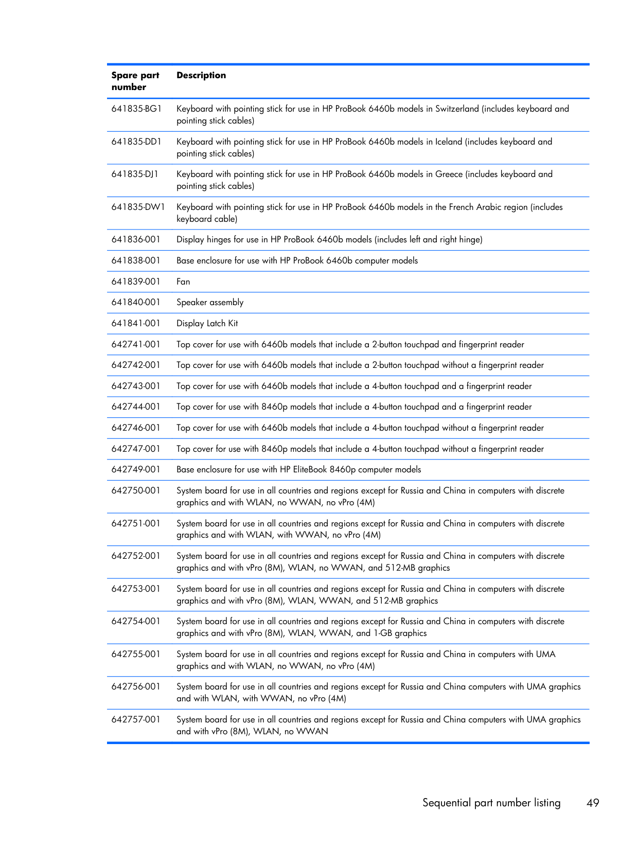
Spare part number Description
641835-Bg1
Keyboard with pointing stick for use in HP ProBook 6460b models in Switzerland (includes keyboard and pointing stick cables)641835-Dd1
Keyboard with pointing stick for use in HP ProBook 6460b models in Iceland (includes keyboard and pointing stick cables)641835-Dj1
Keyboard with pointing stick for use in HP ProBook 6460b models in Greece (includes keyboard and pointing stick cables)641835-Dw1
Keyboard with pointing stick for use in HP ProBook 6460b models in the French Arabic region (includes keyboard cable) 641836-001 Display hinges for use in HP ProBook 6460b models (includes left and right hinge) 641838-001 Base enclosure for use with HP ProBook 6460b computer models 641839-001 Fan 641840-001 Speaker assembly 641841-001 Display Latch Kit 642741-001 Top cover for use with 6460b models that include a 2-button touchpad and fingerprint reader 642742-001 Top cover for use with 6460b models that include a 2-button touchpad without a fingerprint reader 642743-001 Top cover for use with 6460b models that include a 4-button touchpad and a fingerprint reader 642744-001 Top cover for use with 8460p models that include a 4-button touchpad and a fingerprint reader 642746-001 Top cover for use with 6460b models that include a 4-button touchpad without a fingerprint reader 642747-001 Top cover for use with 8460p models that include a 4-button touchpad without a fingerprint reader 642749-001 Base enclosure for use with HP EliteBook 8460p computer models 642750-001 System board for use in all countries and regions except for Russia and China in computers with discrete graphics and with WLAN, no WWAN, no vPro (4M) 642751-001 System board for use in all countries and regions except for Russia and China in computers with discrete graphics and with WLAN, with WWAN, no vPro (4M) 642752-001 System board for use in all countries and regions except for Russia and China in computers with discrete graphics and with vPro (8M), WLAN, no WWAN, and 512-MB graphics 642753-001 System board for use in all countries and regions except for Russia and China in computers with discrete graphics and with vPro (8M), WLAN, WWAN, and 512-MB graphics 642754-001 System board for use in all countries and regions except for Russia and China in computers with discrete graphics and with vPro (8M), WLAN, WWAN, and 1-GB graphics 642755-001 System board for use in all countries and regions except for Russia and China in computers with UMA graphics and with WLAN, no WWAN, no vPro (4M) 642756-001 System board for use in all countries and regions except for Russia and China computers with UMA graphics and with WLAN, with WWAN, no vPro (4M) 642757-001 System board for use in all countries and regions except for Russia and China computers with UMA graphics and with vPro (8M), WLAN, no WWAN Sequential part number listing 49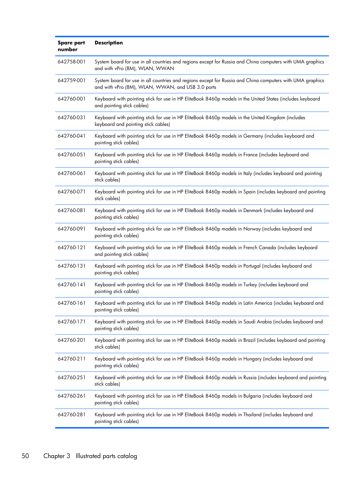
Spare part number Description 642758-001 System board for use in all countries and regions except for Russia and China computers with UMA graphics and with vPro (8M), WLAN, WWAN 642759-001 System board for use in all countries and regions except for Russia and China computers with UMA graphics and with vPro (8M), WLAN, WWAN, and USB 3.0 ports 642760-001 Keyboard with pointing stick for use in HP EliteBook 8460p models in the United States (includes keyboard and pointing stick cables) 642760-031 Keyboard with pointing stick for use in HP EliteBook 8460p models in the United Kingdom (includes keyboard and pointing stick cables) 642760-041 Keyboard with pointing stick for use in HP EliteBook 8460p models in Germany (includes keyboard and pointing stick cables) 642760-051 Keyboard with pointing stick for use in HP EliteBook 8460p models in France (includes keyboard and pointing stick cables) 642760-061 Keyboard with pointing stick for use in HP EliteBook 8460p models in Italy (includes keyboard and pointing stick cables) 642760-071 Keyboard with pointing stick for use in HP EliteBook 8460p models in Spain (includes keyboard and pointing stick cables) 642760-081 Keyboard with pointing stick for use in HP EliteBook 8460p models in Denmark (includes keyboard and pointing stick cables) 642760-091 Keyboard with pointing stick for use in HP EliteBook 8460p models in Norway (includes keyboard and pointing stick cables) 642760-121 Keyboard with pointing stick for use in HP EliteBook 8460p models in French Canada (includes keyboard and pointing stick cables) 642760-131 Keyboard with pointing stick for use in HP EliteBook 8460p models in Portugal (includes keyboard and pointing stick cables) 642760-141 Keyboard with pointing stick for use in HP EliteBook 8460p models in Turkey (includes keyboard and pointing stick cables) 642760-161 Keyboard with pointing stick for use in HP EliteBook 8460p models in Latin America (includes keyboard and pointing stick cables) 642760-171 Keyboard with pointing stick for use in HP EliteBook 8460p models in Saudi Arabia (includes keyboard and pointing stick cables) 642760-201 Keyboard with pointing stick for use in HP EliteBook 8460p models in Brazil (includes keyboard and pointing stick cables) 642760-211 Keyboard with pointing stick for use in HP EliteBook 8460p models in Hungary (includes keyboard and pointing stick cables) 642760-251 Keyboard with pointing stick for use in HP EliteBook 8460p models in Russia (includes keyboard and pointing stick cables) 642760-261 Keyboard with pointing stick for use in HP EliteBook 8460p models in Bulgaria (includes keyboard and pointing stick cables) 642760-281 Keyboard with pointing stick for use in HP EliteBook 8460p models in Thailand (includes keyboard and pointing stick cables) 50 Chapter 3 Illustrated parts catalog
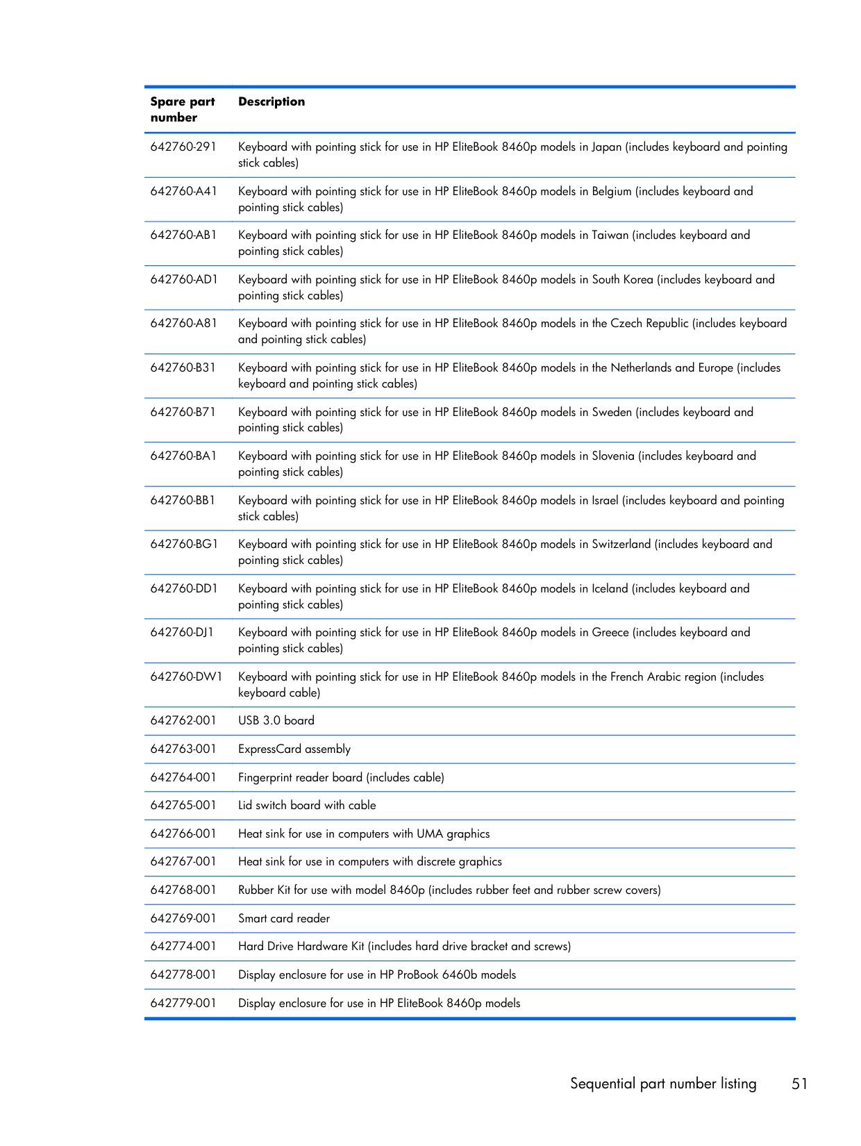
Spare part number Description 642760-291 Keyboard with pointing stick for use in HP EliteBook 8460p models in Japan (includes keyboard and pointing stick cables)
642760-A41
Keyboard with pointing stick for use in HP EliteBook 8460p models in Belgium (includes keyboard and pointing stick cables)642760-Ab1
Keyboard with pointing stick for use in HP EliteBook 8460p models in Taiwan (includes keyboard and pointing stick cables)642760-Ad1
Keyboard with pointing stick for use in HP EliteBook 8460p models in South Korea (includes keyboard and pointing stick cables)642760-A81
Keyboard with pointing stick for use in HP EliteBook 8460p models in the Czech Republic (includes keyboard and pointing stick cables)642760-B31
Keyboard with pointing stick for use in HP EliteBook 8460p models in the Netherlands and Europe (includes keyboard and pointing stick cables)642760-B71
Keyboard with pointing stick for use in HP EliteBook 8460p models in Sweden (includes keyboard and pointing stick cables)642760-Ba1
Keyboard with pointing stick for use in HP EliteBook 8460p models in Slovenia (includes keyboard and pointing stick cables)642760-Bb1
Keyboard with pointing stick for use in HP EliteBook 8460p models in Israel (includes keyboard and pointing stick cables)642760-Bg1
Keyboard with pointing stick for use in HP EliteBook 8460p models in Switzerland (includes keyboard and pointing stick cables)642760-Dd1
Keyboard with pointing stick for use in HP EliteBook 8460p models in Iceland (includes keyboard and pointing stick cables)642760-Dj1
Keyboard with pointing stick for use in HP EliteBook 8460p models in Greece (includes keyboard and pointing stick cables)642760-Dw1
Keyboard with pointing stick for use in HP EliteBook 8460p models in the French Arabic region (includes keyboard cable) 642762-001 USB 3.0 board 642763-001 ExpressCard assembly 642764-001 Fingerprint reader board (includes cable) 642765-001 Lid switch board with cable 642766-001 Heat sink for use in computers with UMA graphics 642767-001 Heat sink for use in computers with discrete graphics 642768-001 Rubber Kit for use with model 8460p (includes rubber feet and rubber screw covers) 642769-001 Smart card reader 642774-001 Hard Drive Hardware Kit (includes hard drive bracket and screws) 642778-001 Display enclosure for use in HP ProBook 6460b models 642779-001 Display enclosure for use in HP EliteBook 8460p models Sequential part number listing 51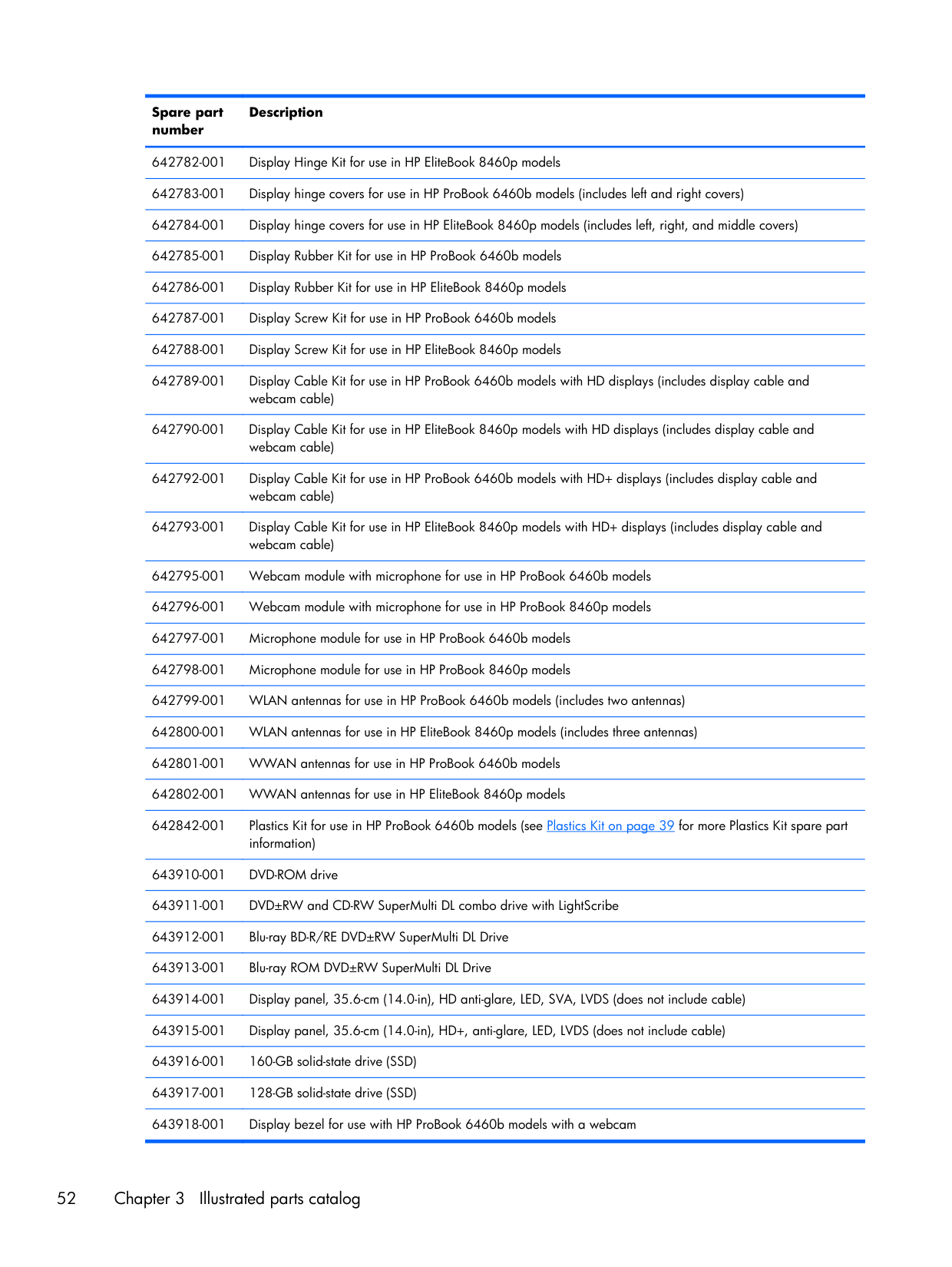
Spare part number Description 642782-001 Display Hinge Kit for use in HP EliteBook 8460p models 642783-001 Display hinge covers for use in HP ProBook 6460b models (includes left and right covers) 642784-001 Display hinge covers for use in HP EliteBook 8460p models (includes left, right, and middle covers) 642785-001 Display Rubber Kit for use in HP ProBook 6460b models 642786-001 Display Rubber Kit for use in HP EliteBook 8460p models 642787-001 Display Screw Kit for use in HP ProBook 6460b models 642788-001 Display Screw Kit for use in HP EliteBook 8460p models 642789-001 Display Cable Kit for use in HP ProBook 6460b models with HD displays (includes display cable and webcam cable) 642790-001 Display Cable Kit for use in HP EliteBook 8460p models with HD displays (includes display cable and webcam cable) 642792-001 Display Cable Kit for use in HP ProBook 6460b models with HD+ displays (includes display cable and webcam cable) 642793-001 Display Cable Kit for use in HP EliteBook 8460p models with HD+ displays (includes display cable and webcam cable) 642795-001 Webcam module with microphone for use in HP ProBook 6460b models 642796-001 Webcam module with microphone for use in HP ProBook 8460p models 642797-001 Microphone module for use in HP ProBook 6460b models 642798-001 Microphone module for use in HP ProBook 8460p models 642799-001 WLAN antennas for use in HP ProBook 6460b models (includes two antennas) 642800-001 WLAN antennas for use in HP EliteBook 8460p models (includes three antennas) 642801-001 WWAN antennas for use in HP ProBook 6460b models 642802-001 WWAN antennas for use in HP EliteBook 8460p models 642842-001 Plastics Kit for use in HP ProBook 6460b models (see Plastics Kit on page 39 for more Plastics Kit spare part information) 643910-001 DVD-ROM drive 643911-001 DVD±RW and CD-RW SuperMulti DL combo drive with LightScribe 643912-001 Blu-ray BD-R/RE DVD±RW SuperMulti DL Drive 643913-001 Blu-ray ROM DVD±RW SuperMulti DL Drive 643914-001 Display panel, 35.6-cm (14.0-in), HD anti-glare, LED, SVA, LVDS (does not include cable) 643915-001 Display panel, 35.6-cm (14.0-in), HD+, anti-glare, LED, LVDS (does not include cable) 643916-001 160-GB solid-state drive (SSD) 643917-001 128-GB solid-state drive (SSD) 643918-001 Display bezel for use with HP ProBook 6460b models with a webcam 52 Chapter 3 Illustrated parts catalog
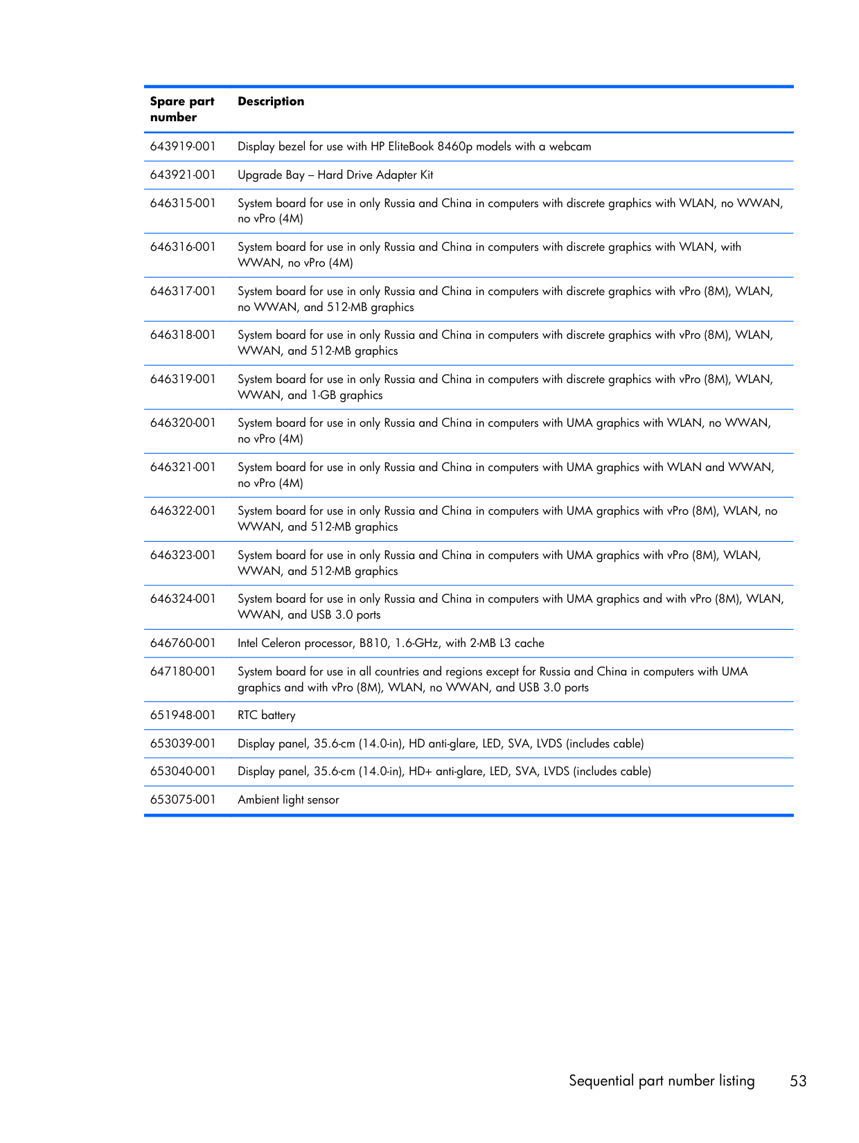
Spare part number Description 643919-001 Display bezel for use with HP EliteBook 8460p models with a webcam 643921-001 Upgrade Bay – Hard Drive Adapter Kit 646315-001 System board for use in only Russia and China in computers with discrete graphics with WLAN, no WWAN, no vPro (4M) 646316-001 System board for use in only Russia and China in computers with discrete graphics with WLAN, with WWAN, no vPro (4M) 646317-001 System board for use in only Russia and China in computers with discrete graphics with vPro (8M), WLAN, no WWAN, and 512-MB graphics 646318-001 System board for use in only Russia and China in computers with discrete graphics with vPro (8M), WLAN, WWAN, and 512-MB graphics 646319-001 System board for use in only Russia and China in computers with discrete graphics with vPro (8M), WLAN, WWAN, and 1-GB graphics 646320-001 System board for use in only Russia and China in computers with UMA graphics with WLAN, no WWAN, no vPro (4M) 646321-001 System board for use in only Russia and China in computers with UMA graphics with WLAN and WWAN, no vPro (4M) 646322-001 System board for use in only Russia and China in computers with UMA graphics with vPro (8M), WLAN, no WWAN, and 512-MB graphics 646323-001 System board for use in only Russia and China in computers with UMA graphics with vPro (8M), WLAN, WWAN, and 512-MB graphics 646324-001 System board for use in only Russia and China in computers with UMA graphics and with vPro (8M), WLAN, WWAN, and USB 3.0 ports 646760-001 Intel Celeron processor, B810, 1.6-GHz, with 2-MB L3 cache 647180-001 System board for use in all countries and regions except for Russia and China in computers with UMA graphics and with vPro (8M), WLAN, no WWAN, and USB 3.0 ports 651948-001 RTC battery 653039-001 Display panel, 35.6-cm (14.0-in), HD anti-glare, LED, SVA, LVDS (includes cable) 653040-001 Display panel, 35.6-cm (14.0-in), HD+ anti-glare, LED, SVA, LVDS (includes cable) 653075-001 Ambient light sensor Sequential part number listing 53
4 Removal and replacement procedures Preliminary replacement requirements Tools required You will need the following tools to complete the removal and replacement procedures: ● Flat-bladed screwdriver ● Phillips P0 and P1 screwdrivers ● Torx T8 screwdriver Service considerations The following sections include some of the considerations that you must keep in mind during disassembly and assembly procedures.
Note:
As you remove each subassembly from the computer, place the subassembly (and all accompanying screws) away from the work area to prevent damage. Plastic partsCaution:
Using excessive force during disassembly and reassembly can damage plastic parts. Use care when handling the plastic parts. Apply pressure only at the points designated in the maintenance instructions. 54 Chapter 4 Removal and replacement procedures
Cables and connectors
Caution:
When servicing the computer, be sure that cables are placed in their proper locations during the reassembly process. Improper cable placement can damage the computer. Cables must be handled with extreme care to avoid damage. Apply only the tension required to unseat or seat the cables during removal and insertion. Handle cables by the connector whenever possible. In all cases, avoid bending, twisting, or tearing cables. Be sure that cables are routed in such a way that they cannot be caught or snagged by parts being removed or replaced. Handle flex cables with extreme care; these cables tear easily. Drive handlingCaution:
Drives are fragile components that must be handled with care. To prevent damage to the computer, damage to a drive, or loss of information, observe these precautions: Before removing or inserting a hard drive, shut down the computer. If you are unsure whether the computer is off or in Hibernation, turn the computer on, and then shut it down through the operating system. Before handling a drive, be sure that you are discharged of static electricity. While handling a drive, avoid touching the connector. Before removing a diskette drive or optical drive, be sure that a diskette or disc is not in the drive and be sure that the optical drive tray is closed. Handle drives on surfaces covered with at least one inch of shock-proof foam. Avoid dropping drives from any height onto any surface. After removing a hard drive, an optical drive, or a diskette drive, place it in a static-proof bag. Avoid exposing a hard drive to products that have magnetic fields, such as monitors or speakers. Avoid exposing a drive to temperature extremes or liquids. If a drive must be mailed, place the drive in a bubble pack mailer or other suitable form of protective packaging and label the package “FRAGILE.” Preliminary replacement requirements 55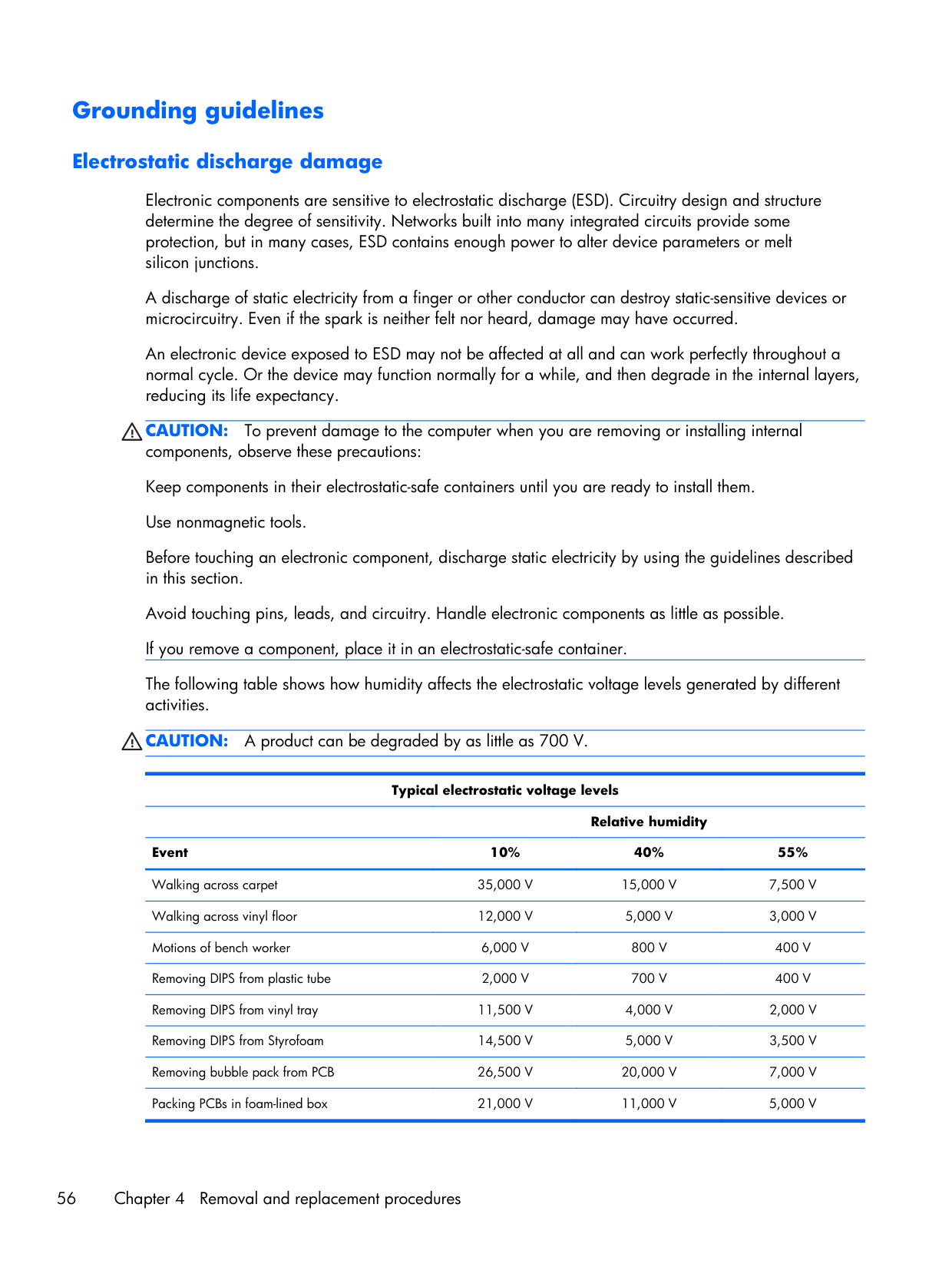
Grounding guidelines Electrostatic discharge damage Electronic components are sensitive to electrostatic discharge (ESD). Circuitry design and structure determine the degree of sensitivity. Networks built into many integrated circuits provide some protection, but in many cases, ESD contains enough power to alter device parameters or melt silicon junctions. A discharge of static electricity from a finger or other conductor can destroy static-sensitive devices or microcircuitry. Even if the spark is neither felt nor heard, damage may have occurred. An electronic device exposed to ESD may not be affected at all and can work perfectly throughout a normal cycle. Or the device may function normally for a while, and then degrade in the internal layers, reducing its life expectancy.
Caution:
To prevent damage to the computer when you are removing or installing internal components, observe these precautions: Keep components in their electrostatic-safe containers until you are ready to install them. Use nonmagnetic tools. Before touching an electronic component, discharge static electricity by using the guidelines described in this section. Avoid touching pins, leads, and circuitry. Handle electronic components as little as possible. If you remove a component, place it in an electrostatic-safe container. The following table shows how humidity affects the electrostatic voltage levels generated by different activities.Caution:
A product can be degraded by as little as 700 V. Typical electrostatic voltage levelsRelative humidity Event 10% 40% 55% Walking across carpet
35,000 V
15,000 V
7,500 V
Walking across vinyl floor12,000 V
5,000 V
3,000 V
Motions of bench worker6,000 V
800 V
400 V
Removing DIPS from plastic tube2,000 V
700 V
400 V
Removing DIPS from vinyl tray11,500 V
4,000 V
2,000 V
Removing DIPS from Styrofoam14,500 V
5,000 V
3,500 V
Removing bubble pack from PCB26,500 V
20,000 V
7,000 V
Packing PCBs in foam-lined box21,000 V
11,000 V
5,000 V
56 Chapter 4 Removal and replacement procedures
Packaging and transporting guidelines Follow these grounding guidelines when packaging and transporting equipment: ● To avoid hand contact, transport products in static-safe tubes, bags, or boxes. ● Protect ESD-sensitive parts and assemblies with conductive or approved containers or packaging. ● Keep ESD-sensitive parts in their containers until the parts arrive at static-free workstations. ● Place items on a grounded surface before removing items from their containers. ● Always be properly grounded when touching a component or assembly. ● Store reusable ESD-sensitive parts from assemblies in protective packaging or nonconductive foam. ● Use transporters and conveyors made of antistatic belts and roller bushings. Be sure that mechanized equipment used for moving materials is wired to ground and that proper materials are selected to avoid static charging. When grounding is not possible, use an ionizer to dissipate electric charges. Workstation guidelines Follow these grounding workstation guidelines: ● Cover the workstation with approved static-shielding material. ● Use a wrist strap connected to a properly grounded work surface and use properly grounded tools and equipment. ● Use conductive field service tools, such as cutters, screwdrivers, and vacuums. ● When fixtures must directly contact dissipative surfaces, use fixtures made only of static-safe materials. ● Keep the work area free of nonconductive materials, such as ordinary plastic assembly aids and Styrofoam. ● Handle ESD-sensitive components, parts, and assemblies by the case or PCM laminate. Handle these items only at static-free workstations. ● Avoid contact with pins, leads, or circuitry. ● Turn off power and input signals before inserting or removing connectors or test equipment. Preliminary replacement requirements 57
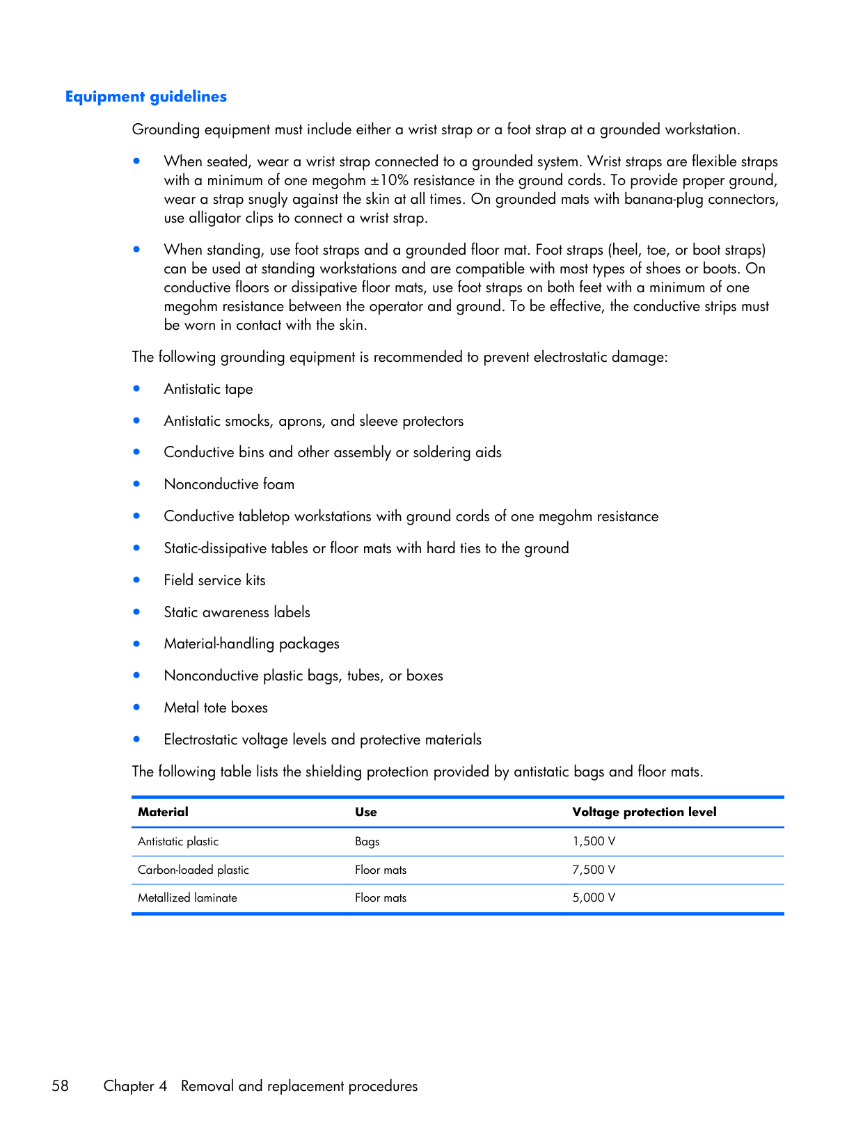
Equipment guidelines Grounding equipment must include either a wrist strap or a foot strap at a grounded workstation. ● When seated, wear a wrist strap connected to a grounded system. Wrist straps are flexible straps with a minimum of one megohm ±10% resistance in the ground cords. To provide proper ground, wear a strap snugly against the skin at all times. On grounded mats with banana-plug connectors, use alligator clips to connect a wrist strap. ● When standing, use foot straps and a grounded floor mat. Foot straps (heel, toe, or boot straps) can be used at standing workstations and are compatible with most types of shoes or boots. On conductive floors or dissipative floor mats, use foot straps on both feet with a minimum of one megohm resistance between the operator and ground. To be effective, the conductive strips must be worn in contact with the skin. The following grounding equipment is recommended to prevent electrostatic damage: ● Antistatic tape ● Antistatic smocks, aprons, and sleeve protectors ● Conductive bins and other assembly or soldering aids ● Nonconductive foam ● Conductive tabletop workstations with ground cords of one megohm resistance ● Static-dissipative tables or floor mats with hard ties to the ground ● Field service kits ● Static awareness labels ● Material-handling packages ● Nonconductive plastic bags, tubes, or boxes ● Metal tote boxes ● Electrostatic voltage levels and protective materials The following table lists the shielding protection provided by antistatic bags and floor mats. Material Use Voltage protection level Antistatic plastic Bags
1,500 V
Carbon-loaded plastic Floor mats7,500 V
Metallized laminate Floor mats5,000 V
58 Chapter 4 Removal and replacement procedures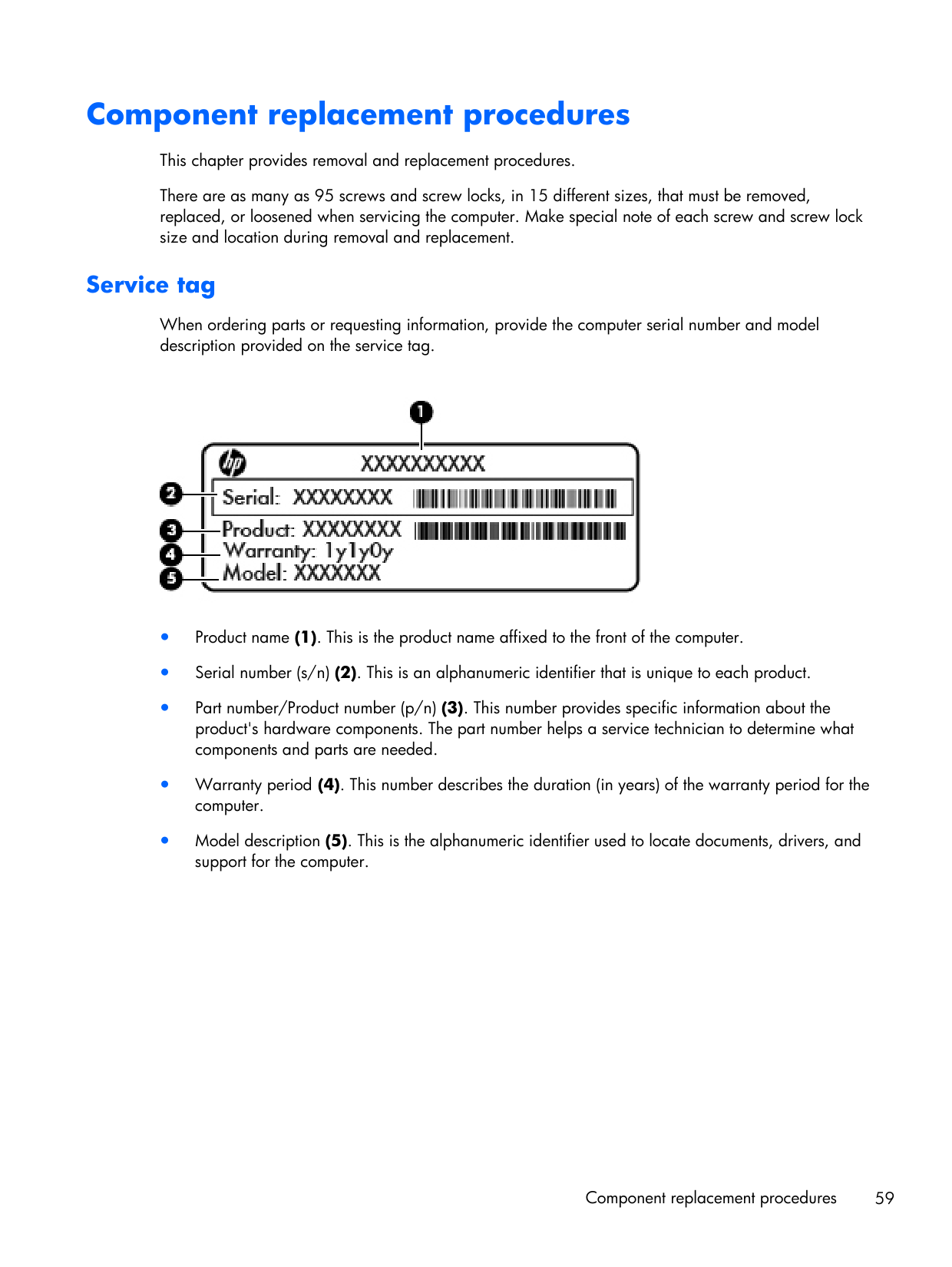
Component replacement procedures This chapter provides removal and replacement procedures. There are as many as 95 screws and screw locks, in 15 different sizes, that must be removed, replaced, or loosened when servicing the computer. Make special note of each screw and screw lock size and location during removal and replacement. Service tag When ordering parts or requesting information, provide the computer serial number and model description provided on the service tag. ● Product name (1). This is the product name affixed to the front of the computer. ● Serial number (s/n) (2). This is an alphanumeric identifier that is unique to each product. ● Part number/Product number (p/n) (3). This number provides specific information about the product's hardware components. The part number helps a service technician to determine what components and parts are needed. ● Warranty period (4). This number describes the duration (in years) of the warranty period for the computer. ● Model description (5). This is the alphanumeric identifier used to locate documents, drivers, and support for the computer. Component replacement procedures 59
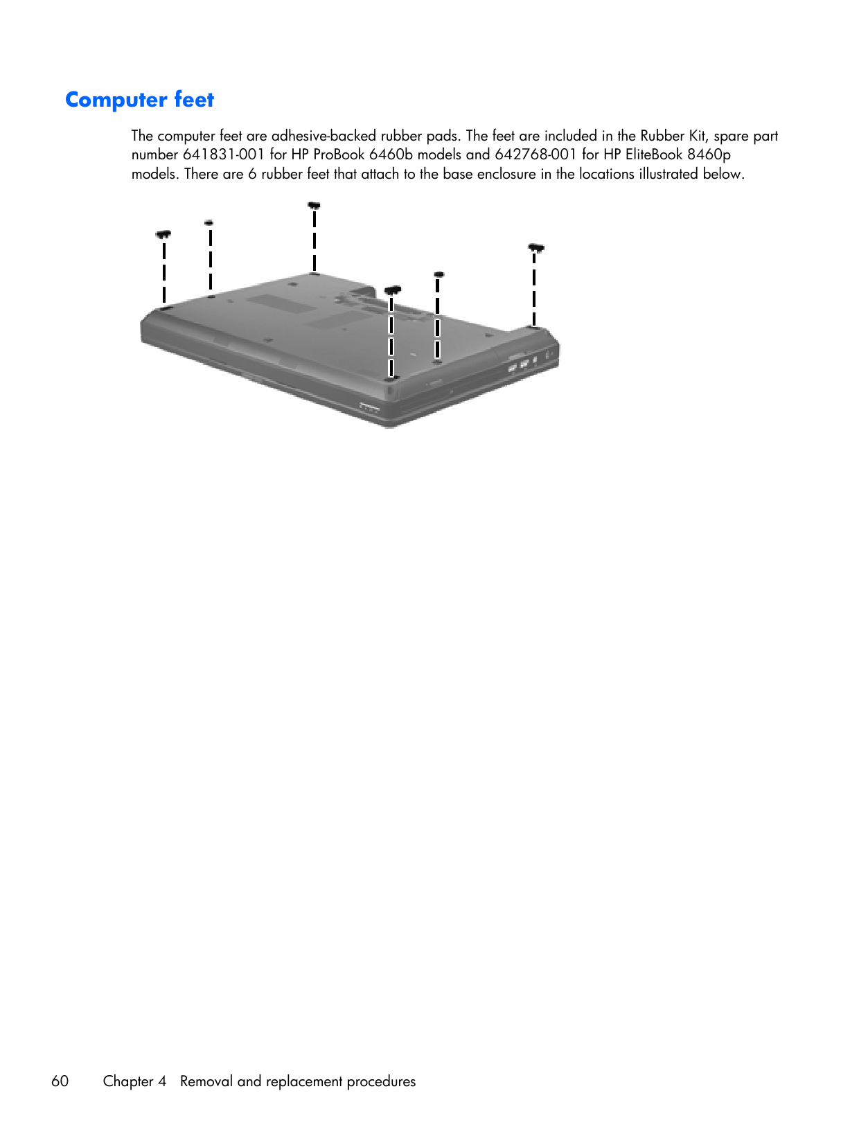
Computer feet The computer feet are adhesive-backed rubber pads. The feet are included in the Rubber Kit, spare part number 641831-001 for HP ProBook 6460b models and 642768-001 for HP EliteBook 8460p models. There are 6 rubber feet that attach to the base enclosure in the locations illustrated below. 60 Chapter 4 Removal and replacement procedures
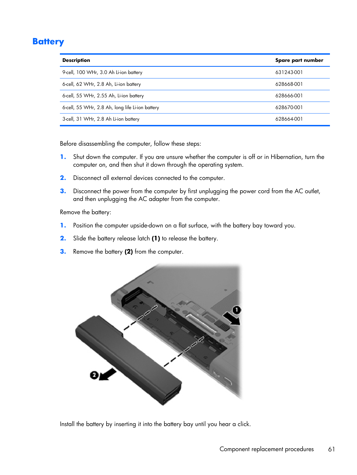
Battery Description Spare part number 9-cell, 100 WHr, 3.0 Ah Li-ion battery 631243-001 6-cell, 62 WHr, 2.8 Ah, Li-ion battery 628668-001 6-cell, 55 WHr, 2.55 Ah, Li-ion battery 628666-001 6-cell, 55 WHr, 2.8 Ah, long life Li-ion battery 628670-001 3-cell, 31 WHr, 2.8 Ah Li-ion battery 628664-001 Before disassembling the computer, follow these steps:
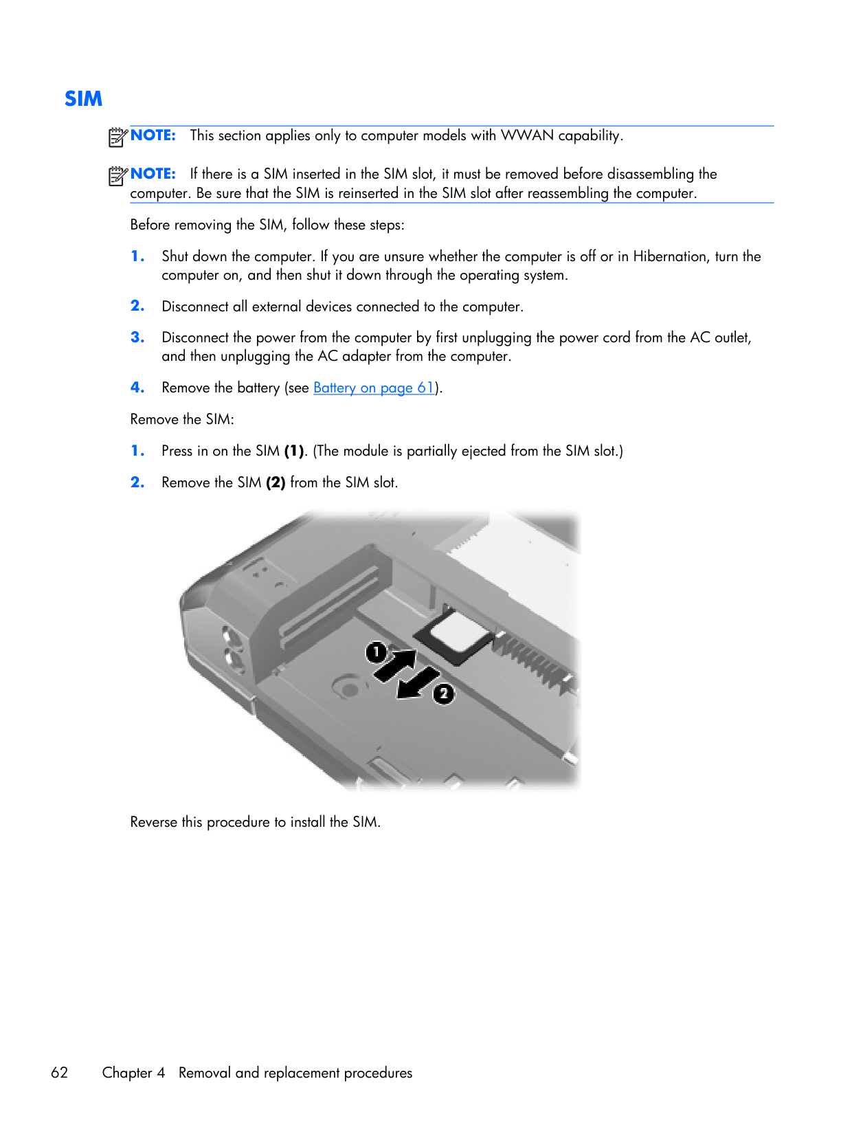
Sim
Note:
This section applies only to computer models with WWAN capability.Note:
If there is a SIM inserted in the SIM slot, it must be removed before disassembling the computer. Be sure that the SIM is reinserted in the SIM slot after reassembling the computer. Before removing the SIM, follow these steps:
Display assembly components (panel, bezel, webcam, microphone) All display assemblies include WLAN antenna transceivers and cables. WWAN models also include 2 WWAN antenna transceivers and cables.
Note:
Full hinge-up displays are not spared. This section describes removing components that do not require that you entirely remove the display assembly from the computer. You can remove the display bezel, webcam/microphone module, and display panel with the display assembly still attached to the computer. To remove the remaining display components, including the display brackets, antennas, cable, and enclosure, you must remove the entire display assembly from the computer.See Display assembly components (cable, antennas, hinges, enclosure) on page 108 for more information about removing the remaining components. Description Spare part number Display panels 35.6-cm (14.0-in), HD+, anti-glare, LED, LVDS (does not include cable) 643915-001 35.6-cm (14.0-in), HD+, anti-glare, LED, LVDS (includes cable) 653039-001 35.6-cm (14.0-in), HD anti-glare, LED, SVA, LVDS (does not include cable) 643914-001 35.6-cm (14.0-in), HD anti-glare, LED, SVA, LVDS (includes cable) 653040-001 Display bezelsFor use with HP ProBook 6460b models with a webcam 643918-001 For use with HP EliteBook 8460p models with a webcam 643919-001 Webcam module with microphone
For use in HP ProBook 6460b models 642795-001 For use in HP EliteBook 8460p models 642796-001 Microphone modules
For use in HP ProBook 6460b models 642797-001 For use in HP EliteBook 8460p models 642798-001 Display Screw Kit
For use in HP ProBook 6460b models 642787-001 For use in HP EliteBook 8460p models 642788-001 Display Rubber Kit
For use in HP ProBook 6460b models 642785-001 For use in HP EliteBook 8460p models 642786-001 Component replacement procedures 63
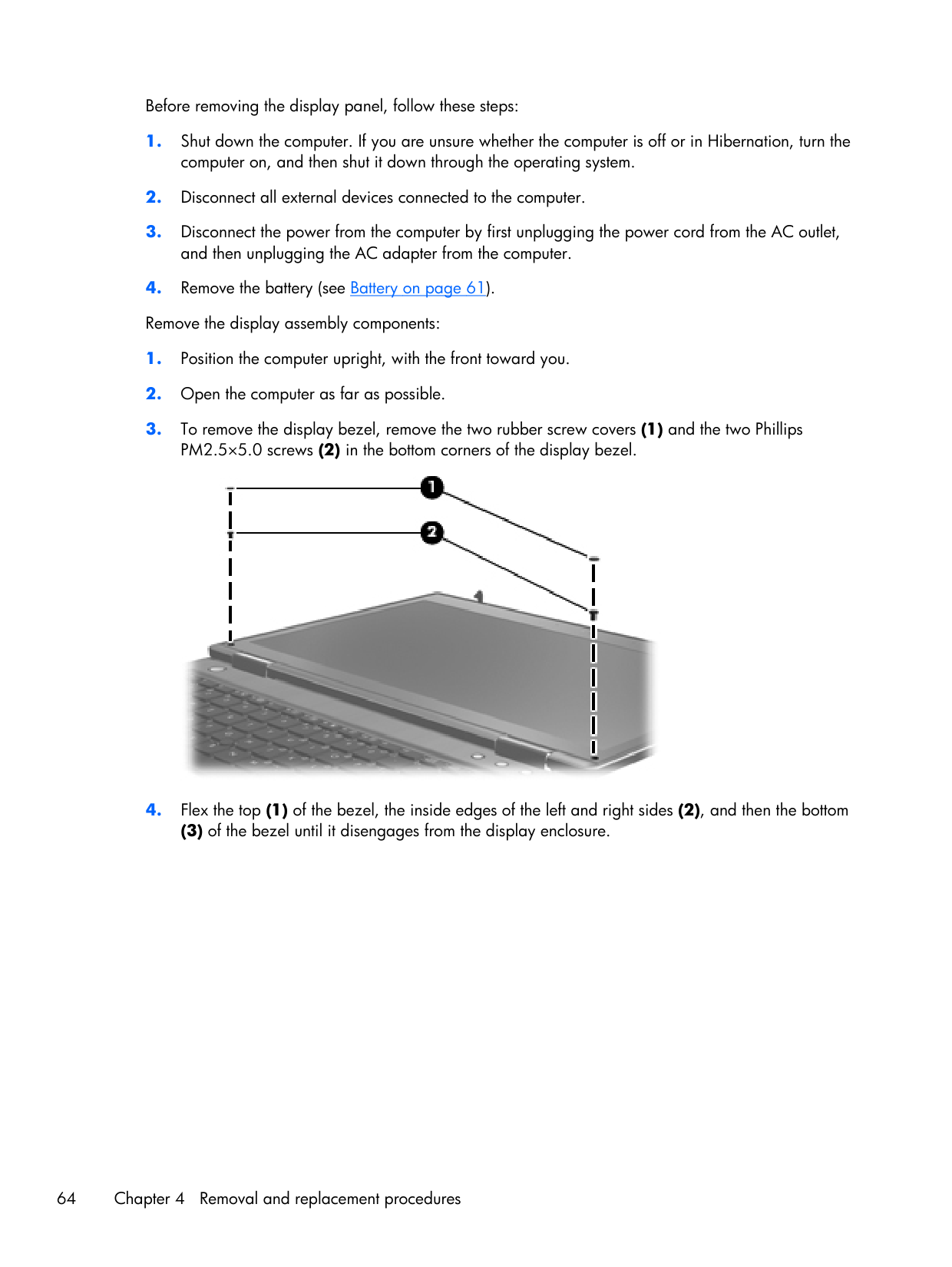
Before removing the display panel, follow these steps:
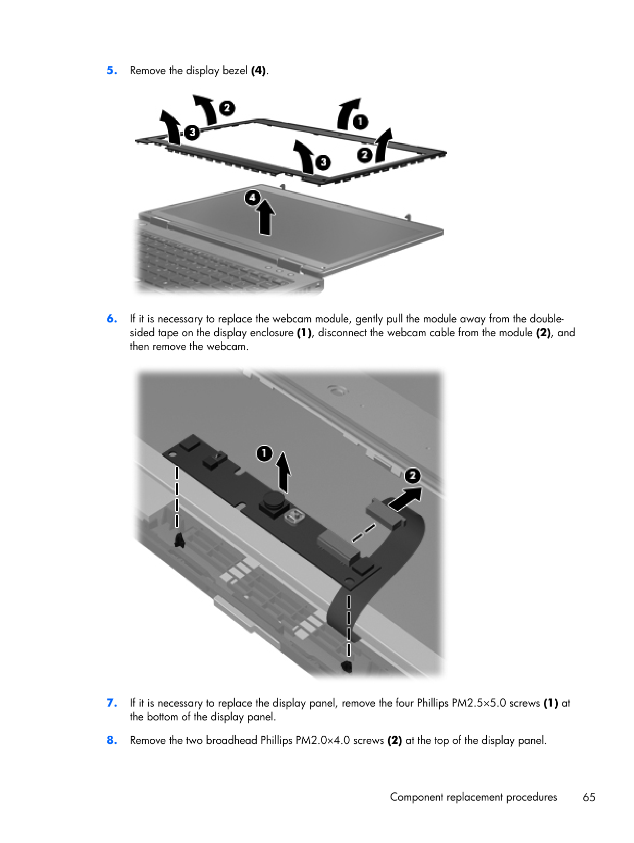
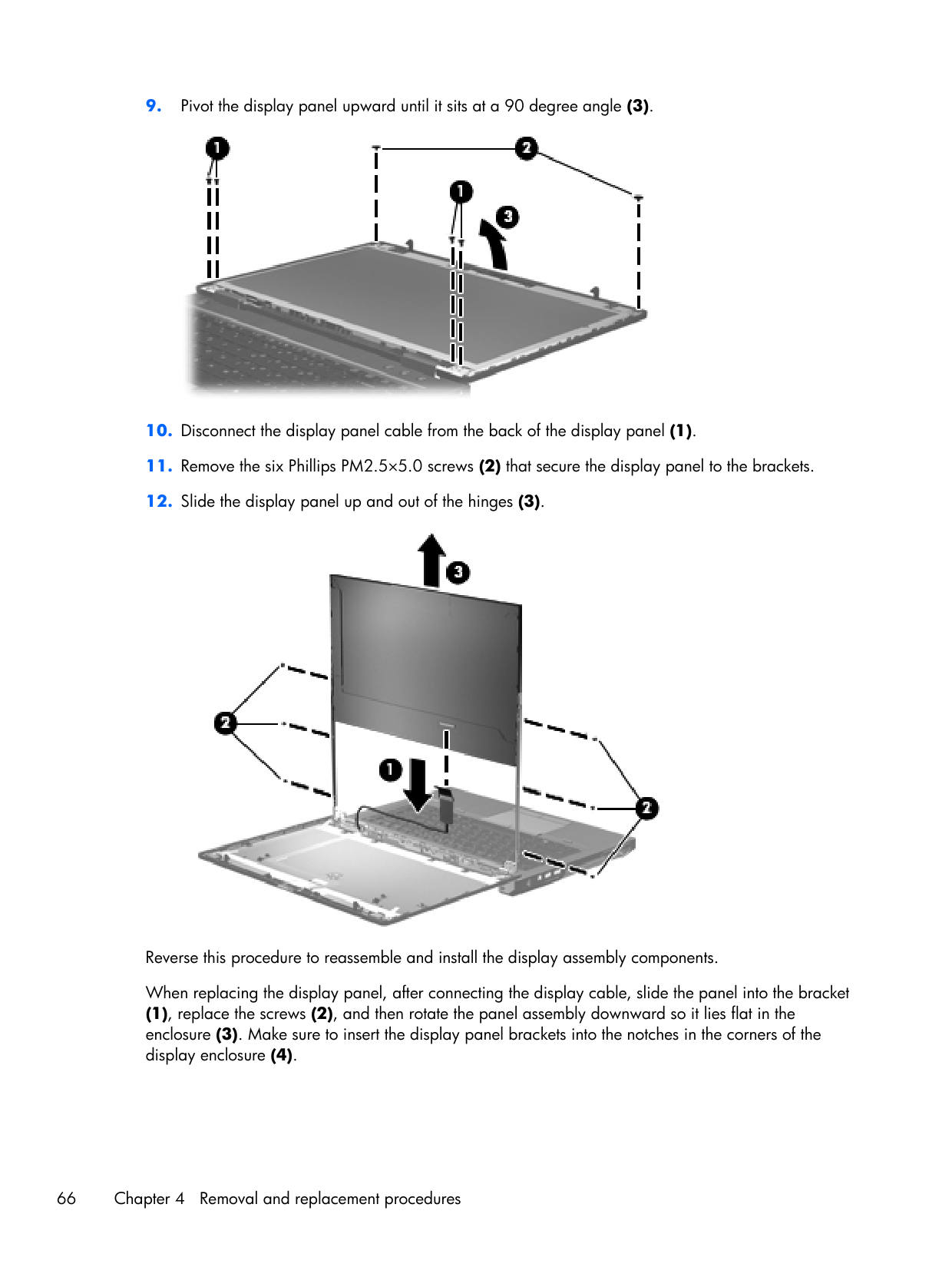
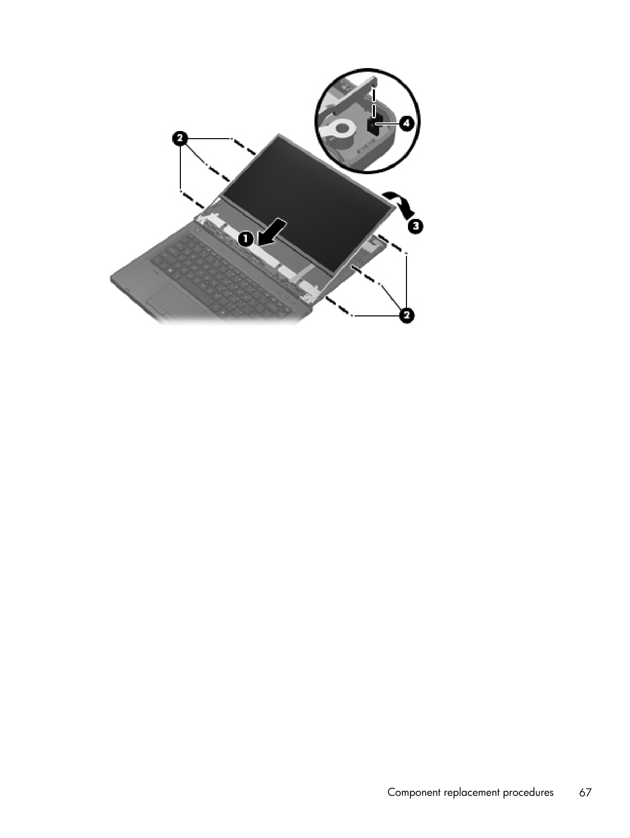
Component replacement procedures 67
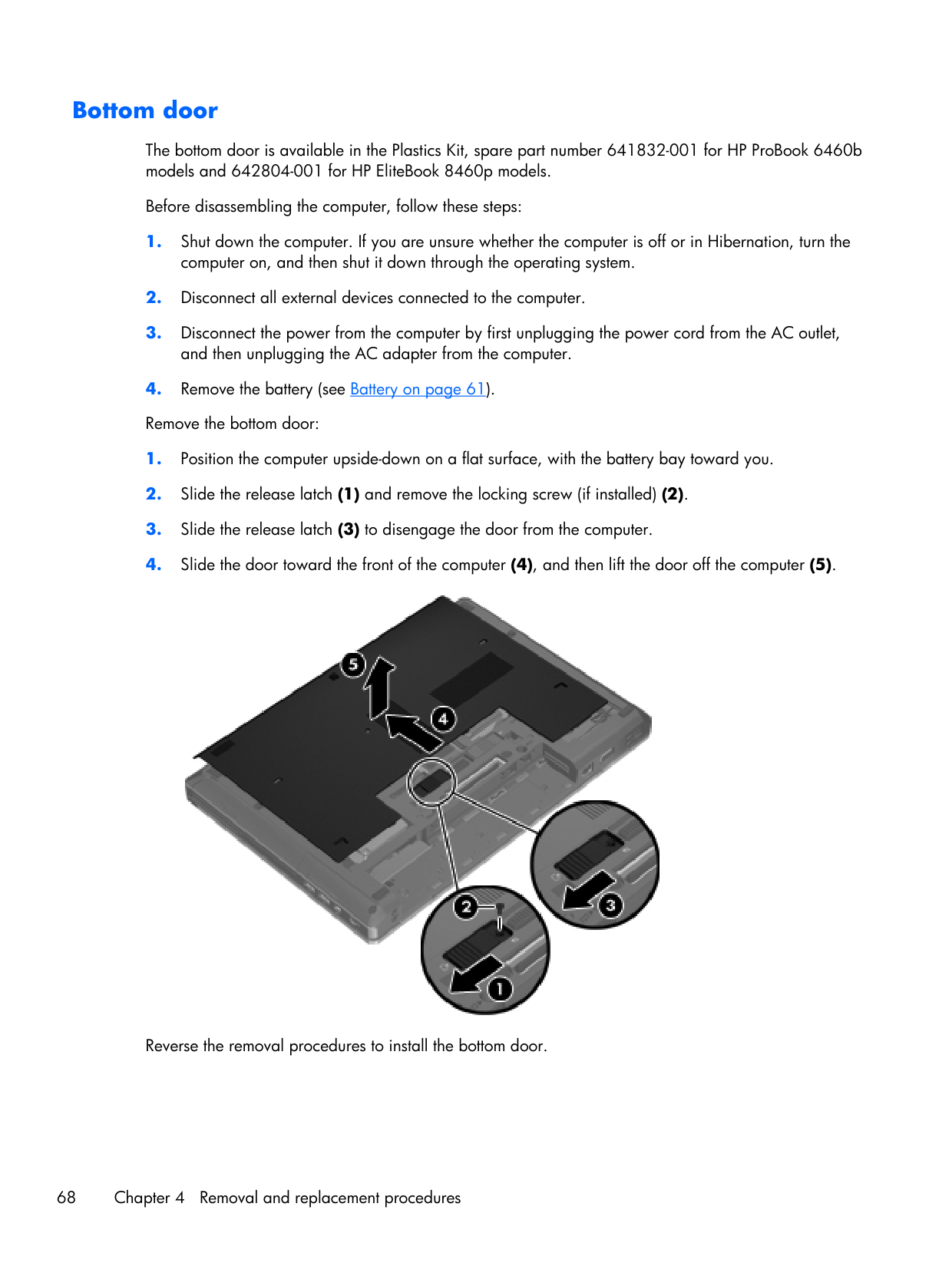
Bottom door The bottom door is available in the Plastics Kit, spare part number 641832-001 for HP ProBook 6460b models and 642804-001 for HP EliteBook 8460p models. Before disassembling the computer, follow these steps:
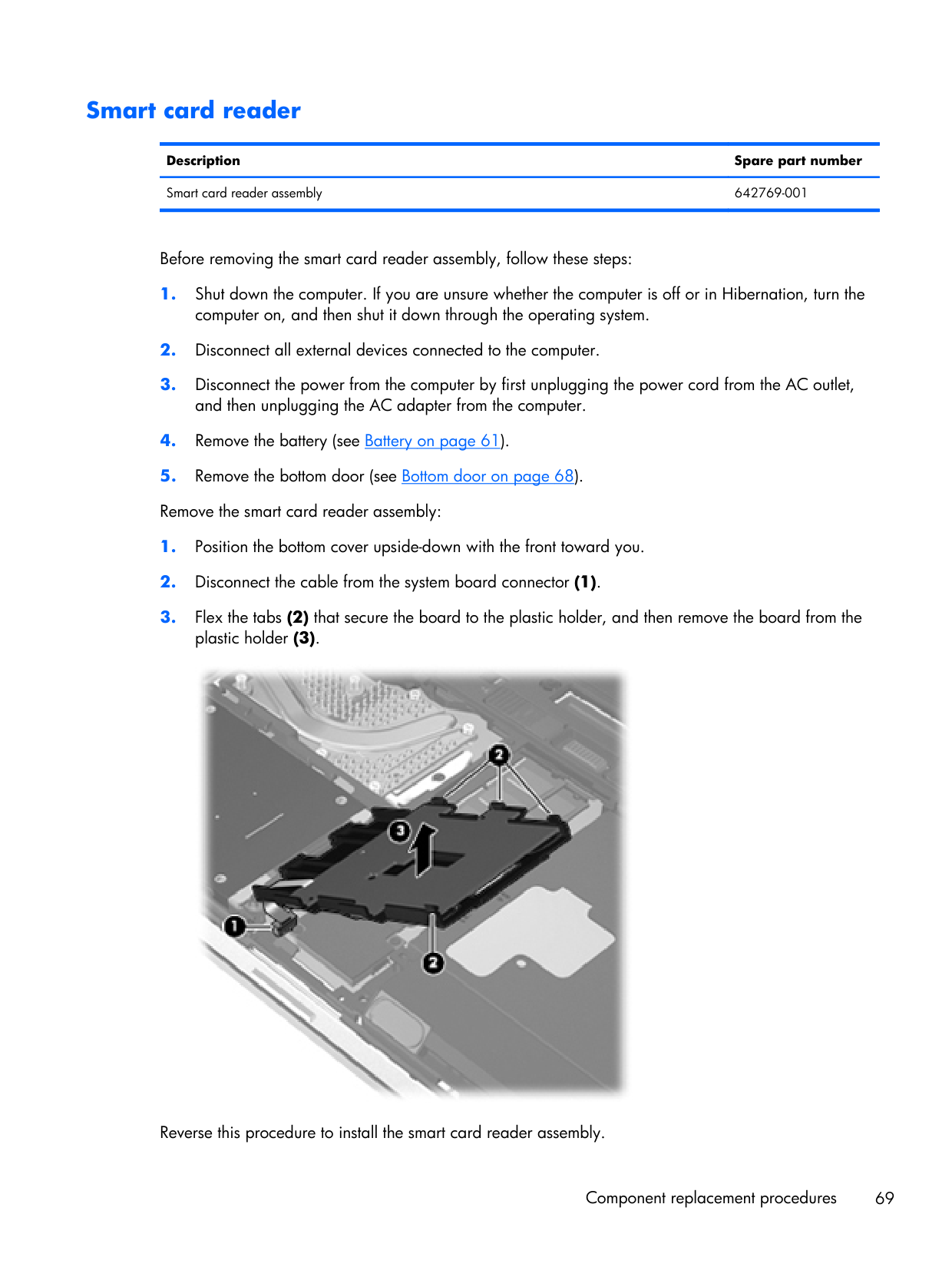
Smart card reader Description Spare part number Smart card reader assembly 642769-001 Before removing the smart card reader assembly, follow these steps:
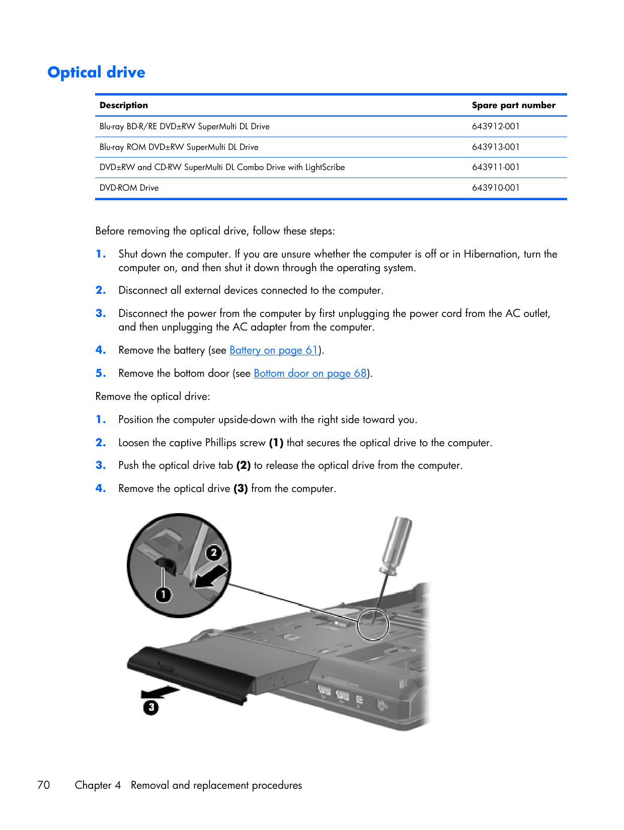
Optical drive Description Spare part number Blu-ray BD-R/RE DVD±RW SuperMulti DL Drive 643912-001 Blu-ray ROM DVD±RW SuperMulti DL Drive 643913-001 DVD±RW and CD-RW SuperMulti DL Combo Drive with LightScribe 643911-001 DVD-ROM Drive 643910-001 Before removing the optical drive, follow these steps:
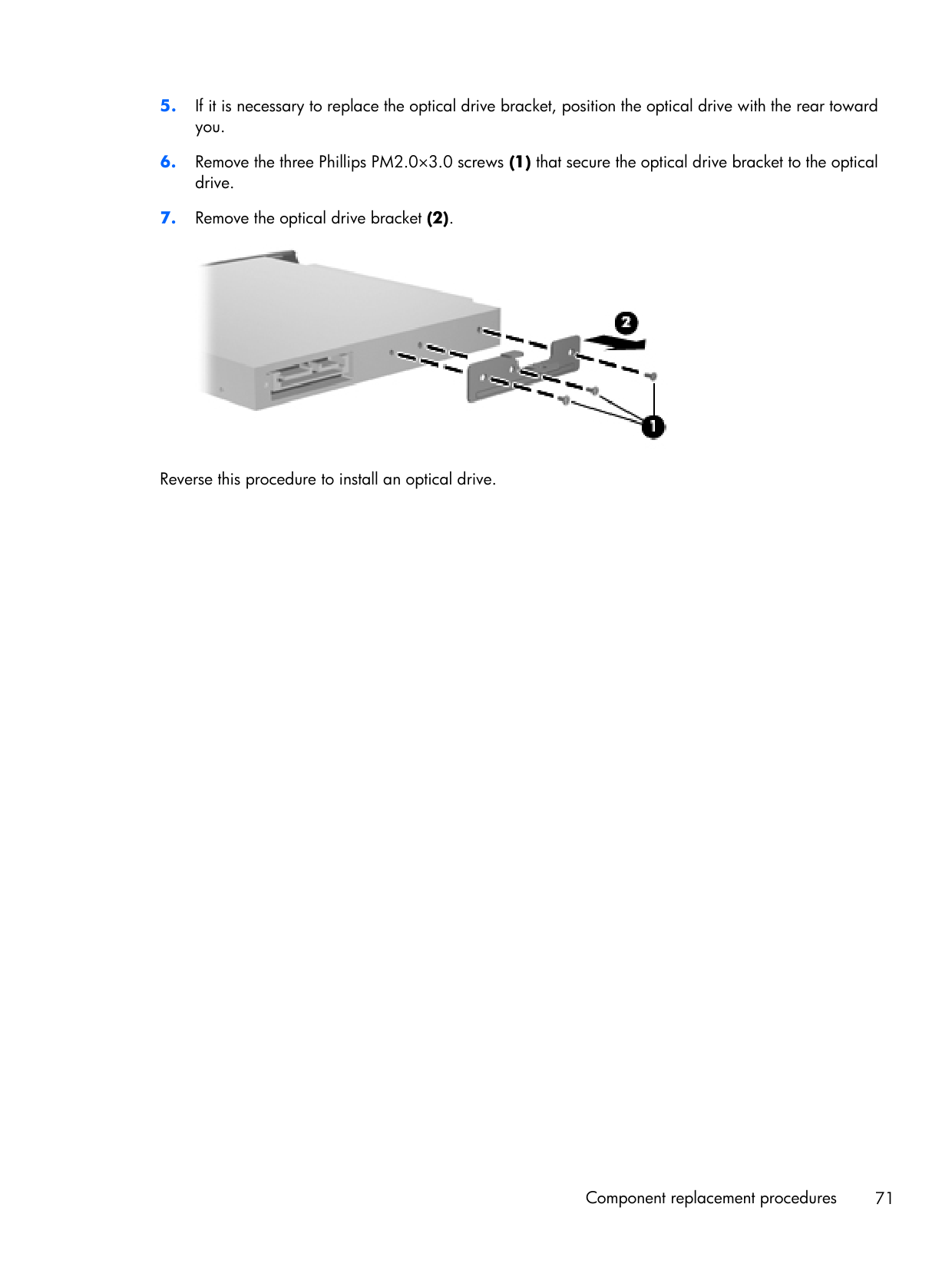
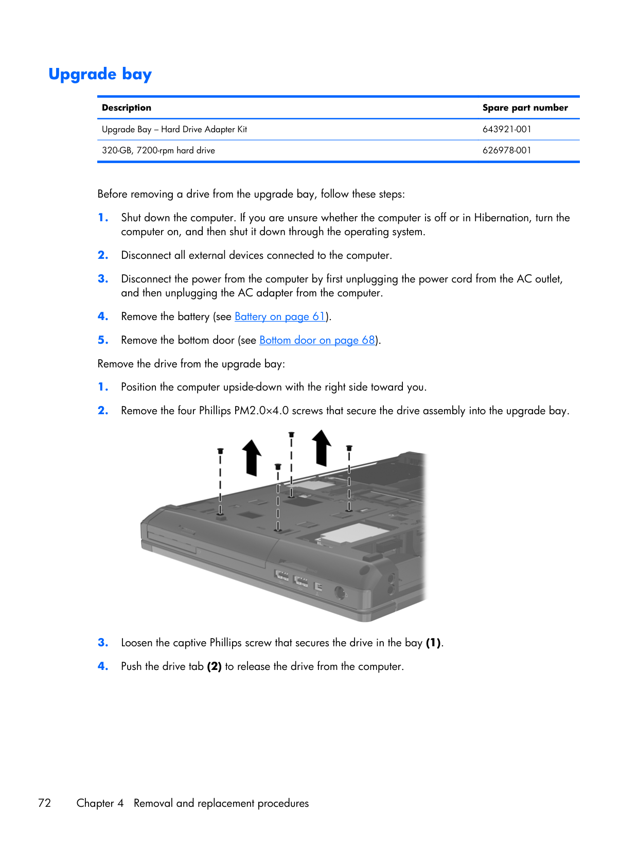
Upgrade bay Description Spare part number Upgrade Bay – Hard Drive Adapter Kit 643921-001 320-GB, 7200-rpm hard drive 626978-001 Before removing a drive from the upgrade bay, follow these steps:
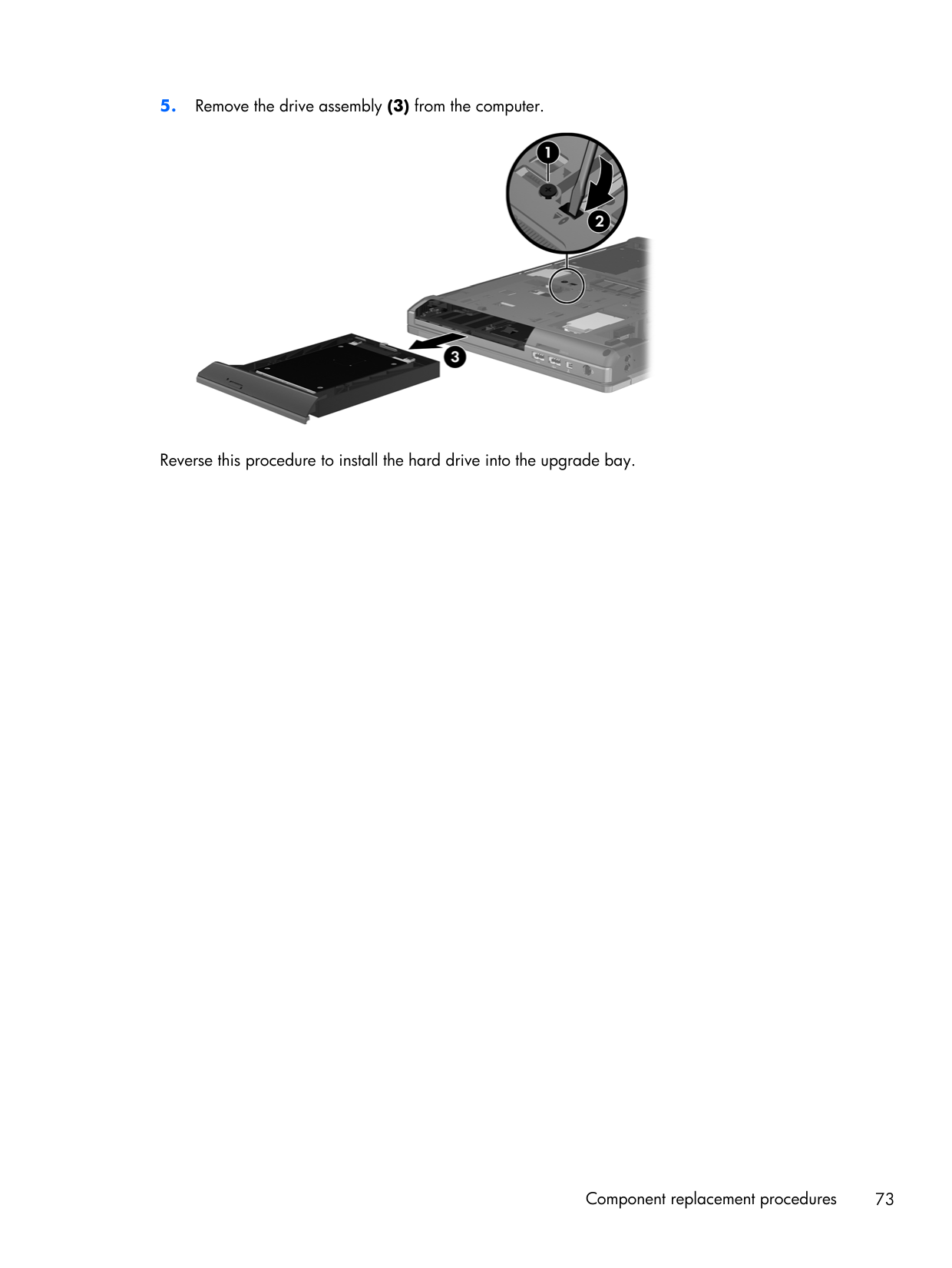
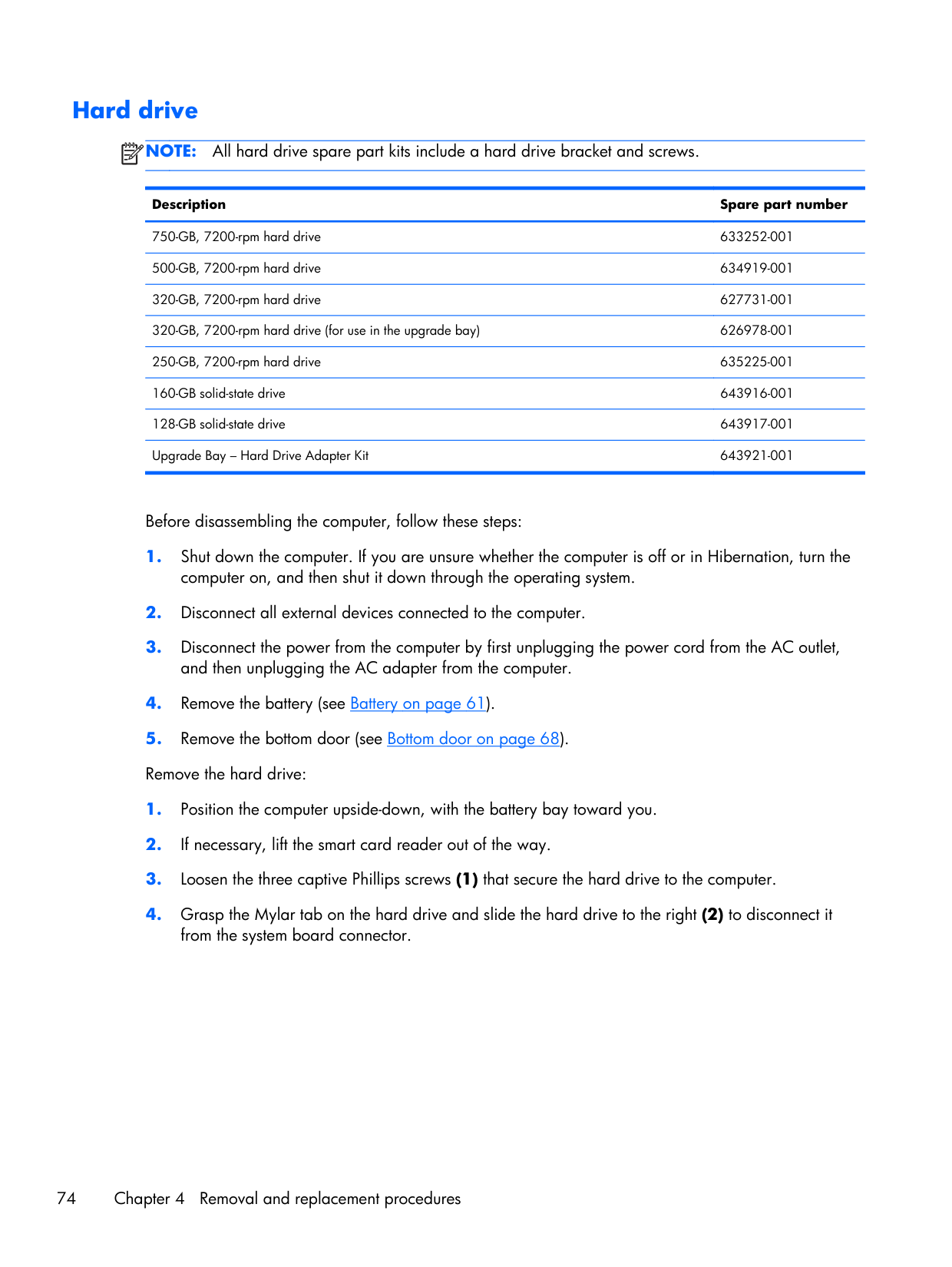
Hard drive
Note:
All hard drive spare part kits include a hard drive bracket and screws. Description Spare part number 750-GB, 7200-rpm hard drive 633252-001 500-GB, 7200-rpm hard drive 634919-001 320-GB, 7200-rpm hard drive 627731-001 320-GB, 7200-rpm hard drive (for use in the upgrade bay) 626978-001 250-GB, 7200-rpm hard drive 635225-001 160-GB solid-state drive 643916-001 128-GB solid-state drive 643917-001 Upgrade Bay – Hard Drive Adapter Kit 643921-001 Before disassembling the computer, follow these steps: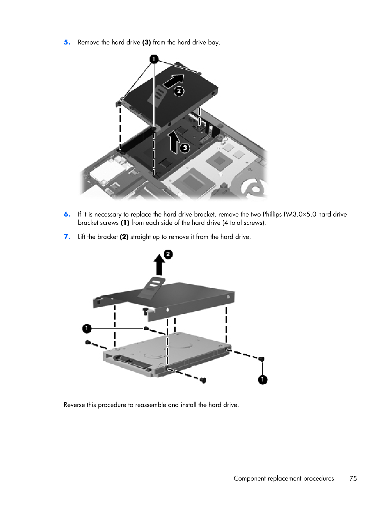
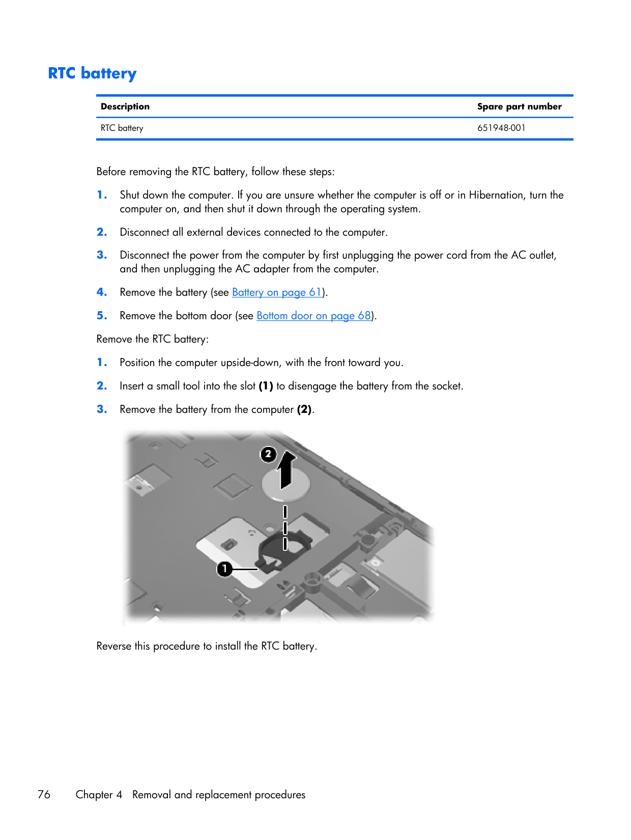
RTC battery Description Spare part number RTC battery 651948-001 Before removing the RTC battery, follow these steps:
Memory modules
Note:
Primary and expansion memory is installed in a stacked configuration in the bottom of the computer. Description Spare part number 1-GB (PC3-10600, 1333-MHz, DDR3) 639738-001 2-GB (PC3-10600, 1333-MHz, DDR3) 621565-001 4-GB (PC3-10600, 1333-MHz, DDR3) 621569-001 8-GB (PC3-10600, 1333-MHz, DDR3) 634091-001 Before removing the memory module, follow these steps: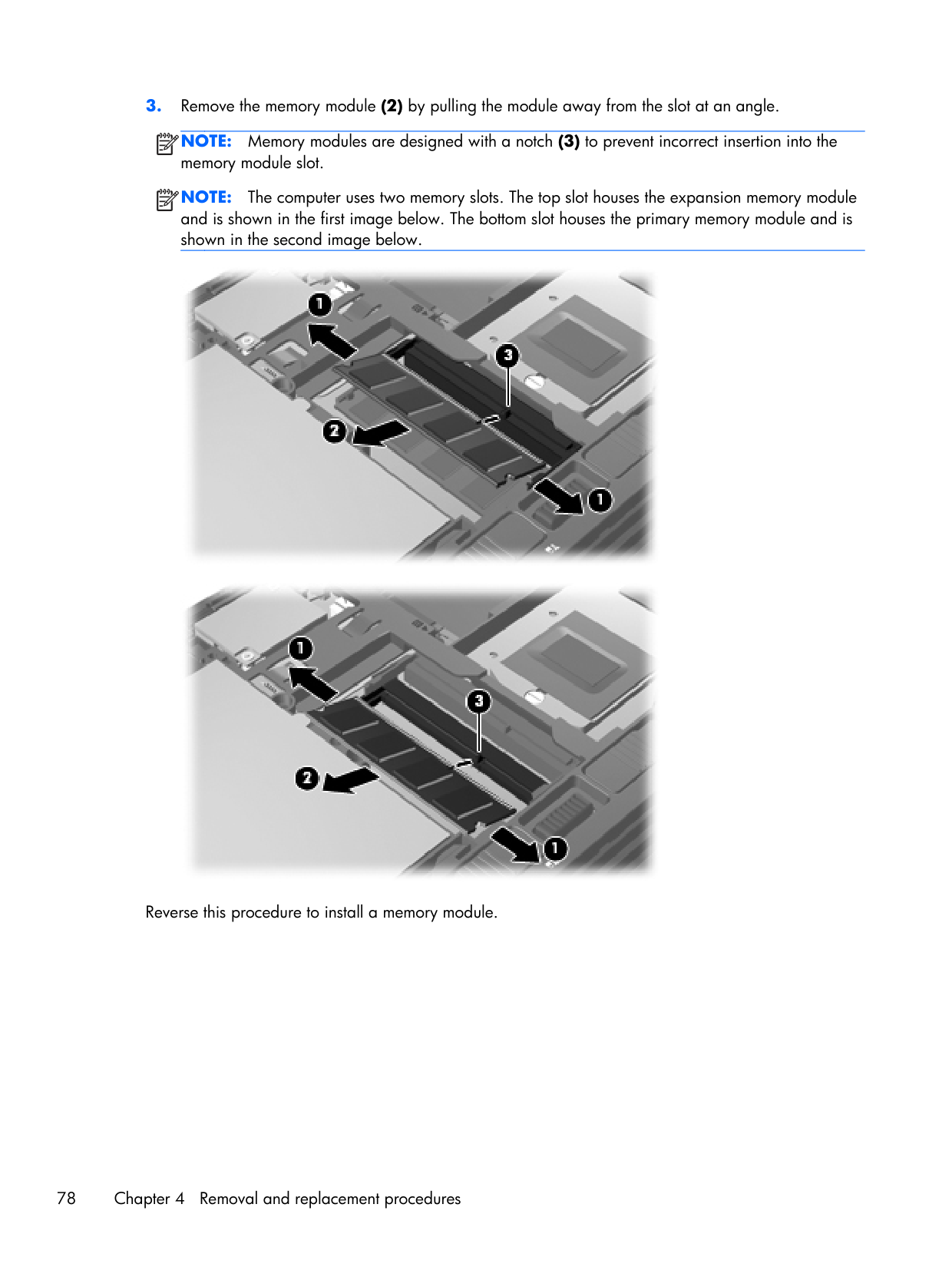
Note:
Memory modules are designed with a notch (3) to prevent incorrect insertion into the memory module slot.Note:
The computer uses two memory slots. The top slot houses the expansion memory module and is shown in the first image below. The bottom slot houses the primary memory module and is shown in the second image below. Reverse this procedure to install a memory module. 78 Chapter 4 Removal and replacement procedures
WWAN module
Caution:
The WWAN module and the WLAN module are not interchangeable. Description Spare part number HP hs2340 HSPA+ Mobile Broadband Module 632155-001 HP un2430 EV-DO/HSPA Mobile Broadband Module 634400-001 Before removing the WWAN module, follow these steps:Note:
The red WWAN antenna cable is connected to the WWAN module “Main” terminal. The blue WWAN antenna cable is connected to the WWAN module “Aux” terminal.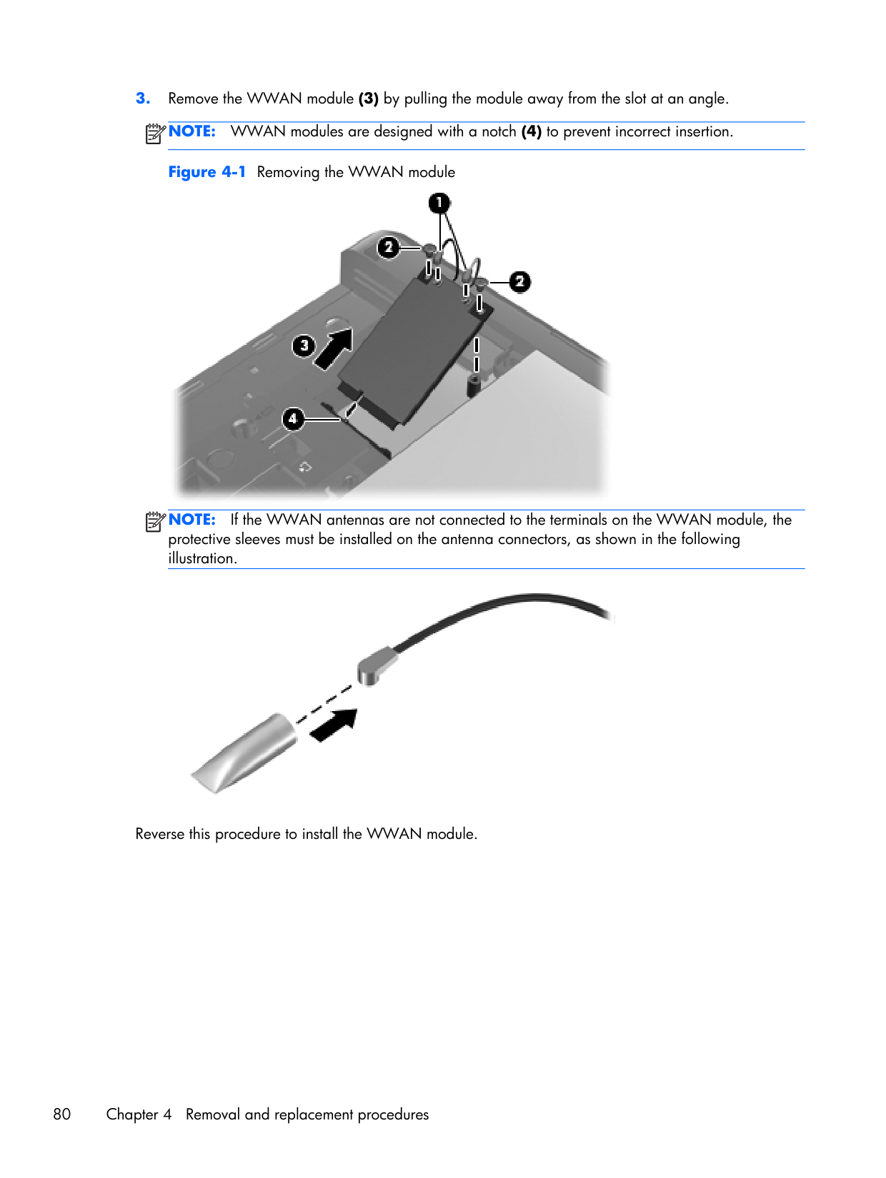
Note:
WWAN modules are designed with a notch (4) to prevent incorrect insertion. Figure 4-1 Removing the WWAN moduleNote:
If the WWAN antennas are not connected to the terminals on the WWAN module, the protective sleeves must be installed on the antenna connectors, as shown in the following illustration. Reverse this procedure to install the WWAN module. 80 Chapter 4 Removal and replacement procedures
WLAN module
Caution:
The WLAN module and the WWAN module are not interchangeable. Description Spare part number Intel Wi-Fi Link 6300, 802.11a/b/g/n WLAN module for use in Andorra, Antigua and Barbuda, Argentina, Aruba, Australia, Austria, Azerbaijan, Bahamas, Bahrain, Barbados, Belgium, Bermuda, Bolivia, Bosnia and Herzegovina, Brazil, Brunei, Bulgaria, Canada, Cayman Islands, Chile, the People's Republic of China, Colombia, Costa Rica, Croatia, Cyprus, Czech Republic, Denmark, Dominican Republic, Ecuador, Egypt, El Salvador, Estonia, Finland, France, French Guiana, Georgia, Germany, Ghana, Greece, Guadeloupe, Guam, Guatemala, Haiti, Honduras, Hong Kong, Hungary, Iceland, India, Indonesia, Ireland, Israel, Italy, Ivory Coast, Jamaica, Japan, Jordan, Kenya, South Korea, Kuwait, Kyrgyzstan, Latvia, Lebanon, Martinique, US Virgin Islands, Puerto Rico, Nether Antilles, Liechtenstein, Lithuania, Luxembourg, Malawi, Malaysia, Malta, Mauritius, Mexico, Monaco, Montenegro, Morocco, the Netherlands, New Zealand, Nicaragua, Nigeria, Norway, Oman, Pakistan, Panama, Paraguay, Peru, Philippines, Poland, Portugal, Qatar, Romania, San Marino, Saudi Arabia, Senegal, Singapore, Slovakia, Slovenia, South Africa, Spain, Sri Lanka, Sweden, Switzerland, Taiwan, Tanzania, Thailand, Trinidad and Tobago, Turkey, the United Arab Emirates, the United Kingdom, the United States, Uruguay, Venezuela, and Vietnam 572511-001 Broadcom 43224AGN 802.11a/b/g/draft-n WiFi Adapter for use in Antigua and Barbuda, Aruba, the Bahamas, Barbados, Belize, Canada, Guam, Guinea, Haiti, Jamaica, the Nether Antilles, Puerto Rico, St. Kitts and Nevis, St. Lucia, St. Vincent and the Grenadines, Suriname, the US Virgin Islands, and the United States 582564-001 Broadcom 43224AGN 802.11a/b/g/draft-n WiFi Adapter for use in Albania, Algeria, Andorra, Angola, Argentina, Armenia, Australia, Austria, Azerbaijan, Bahrain, Belarus, Belgium, Benin, Bermuda, Bhutan, Bolivia, Bosnia and Herzegovina, Botswana, Brazil, the British Virgin Islands, Brunei, Bulgaria, Burkina Faso, Burundi, Cambodia, Cameroon, Cape Verde, the Cayman Islands, Central African Republic, Chad, Chile, People's Republic of China, Colombia, Comoros, Congo, Costa Rica, Croatia, Cyprus, the Czech Republic, Denmark, Djibouti, Dominica, the Dominican Republic, East Timor, Ecuador, Egypt, El Salvador, Equitorial Guinea, Eritrea, Estonia, Ethiopia, Fiji Finland, France, French Guiana, Gabon, Gambia, Georgia, Germany, Ghana, Gibraltar, Greece, Grenada, Guadeloupe, Guatemala, Guinea, Guinea-Bissa, Honduras, Hong Kong, Hungary, Iceland, India, Ireland, Italy, Ivory Coast, Japan, Jordan, Kazakhstan, Kenya, Kiribati, Kuwait, Kyrgyzstan, Laos, Latvia, Lebanon, Lesotho, Liberia, Liechtenstein, Lithuania, Luxembourg, Macedonia, Madagascar, Malawi, Malaysia Maldives, Mali, Malta, Marshall Islands, Martinique, Mauritania, Mauritius, Mexico, Micronesia, Monaco, Mongolia, Montenegro, Morocco, Mozambique, Namibia, Nauru, Nepal, Netherlands, New Zealand, Nicaragua, Niger, Nigeria, Norway, Oman, Palau, Panama, Papua New Guinea, Paraguay, Peru, Philippines, Poland, Portugal, Qatar, Republic of Moldova, Romania, Rwanda, Samoa, San Marino, Sao Tome and Principe, Saudi Arabia, Senegal, Serbia and Montenegro, Seychelles, Sierra Leone, Singapore, Slovakia, Slovenia, Solomon Islands, Somalia, South Africa, South Korea, Spain, Sri Lanka, Swaziland, Sweden, Switzerland, Taiwan, Tajikistan, Tanzania, Thailand, Togo, Tonga, Trinidad and Tobago, Tunisia, Turkey, Turkmenistan, Tuvalu, Uganda, United Arab Emirates, United Kingdom, Uruguay, Uzbekistan, Vanuatu, Venezuela, Vietnam, Yemen, Zaire, Zambia, and Zimbabwe 582564-002 Component replacement procedures 81
Description Spare part number Broadcom 4313AGN 802.11a/b/g/draft-n WiFi Adapter for use in Afghanistan, Albania, Algeria, Andorra, Angola, Antigua and Barbuda, Argentina, Armenia, Aruba, Australia, Austria, Azerbaijan, Bahamas, Bahrain, Bangladesh, Barbados, Belarus, Belgium, Belize, Benin, Bermuda, Bhutan, Bolivia, Bosnia and Herzegovina, Botswana, Brazil, the British Virgin Islands, Brunei, Bulgaria, Burkina Faso, Burundi, Cambodia, Cameroon, Canada, Cape Verde, the Cayman Islands, Central African Republic, Chad, People's Republic of China, Colombia, Comoros, Congo, Costa Rica, Croatia, Cyprus, the Czech Republic, Denmark, Djibouti, Dominica, the Dominican Republic, East Timor, Ecuador, Egypt, El Salvador, Equitorial Guinea, Eritrea, Estonia, Ethiopia, Fiji, Finland, France, French Guiana, Gabon, Gambia, Georgia, Germany, Ghana, Gibraltar, Greece, Grenada, Guadeloupe, Guam, Guatemala, Guinea, Guinea-Bissa, Guyana, Haiti, Honduras, Hong Kong, Hungary, Iceland, India, Iraq, Ireland, Israel, Italy, Ivory Coast, Jamaica, Japan, Jordan, Kazakhstan, Kenya, Kiribati, Kuwait, Kyrgyzstan, Laos, Latvia, Lebanon, Lesotho, Liberia, Martinique, Liechtenstein, Lithuania, Luxembourg, Macedonia, Madagascar, Malawi, Malaysia, Maldives, Mali, Malta, Marshall Islands, Mauritania, Mauritius, Mexico, Micronesia, Monaco, Mongolia, Montenegro, Morocco, Mozambique, Namibia, Nauru, Nepal, the Nether Antilles, the Netherlands, New Zealand, Nicaragua, Niger, Nigeria, Norway, Oman, Pakistan, Palau, Panama, Papua New Guinea, Paraguay, Puerto Rico, Peru, Philippines, Poland, Portugal, Qatar, Republic of Moldova, Romania, Russia, Rwanda, Samoa, San Marino, Sao Tome and Principe, Saudi Arabia, Senegal, Serbia and Montenegro, Seychelles, Sierra Leone, Singapore, Slovakia, Slovenia, Solomon Islands, Somalia, South Africa, South Korea, Spain, Sri Lanka, St. Kitts and Nevis, St. Lucia, St. Vincent and the Grenadines, Suriname, Swaziland, Sweden, Switzerland, Syria, Taiwan, Tajikistan, Tanzania, Thailand, Togo, Tonga, Trinidad and Tobago, Tunisia, Turkey, Turkmenistan, Tuvalu, Uganda, Ukraine, the United Arab Emirates, the United Kingdom, Uruguay, the United States, the US Virgin Islands, Uzbekistan, Vanuatu, Venezuela, Vietnam, Yemen, Zaire, Zambia, and Zimbabwe 593836-001 Intel Wi-Fi Link 1000 for use in Andorra, Antigua and Barbuda, Argentina, Aruba, Australia, Austria, Azerbaijan, Bahamas, Bahrain, Barbados, Belgium, Bermuda, Bolivia, Bosnia and Herzegovina, Brazil, Brunei, Bulgaria, Canada, the Cayman Islands, Chile, People's Republic of China, Colombia, Costa Rica, Croatia, Cyprus, the Czech Republic, Denmark, the Dominican Republic, Ecuador, Egypt, El Salvador, Estonia, Finland, France, French Guiana, Georgia, Germany, Ghana, Greece, Guadeloupe, Guam, Guatemala, Haiti, Honduras, Hong Kong, Hungary, Iceland, India, Indonesia, Ireland, Israel, Italy, Ivory Coast, Jamaica, Japan, Jordan, Kenya, Kuwait, Kyrgyzstan, Latvia, Lebanon, Liechtenstein, Lithuania, Luxembourg, Malawi, Malaysia, Malta, Martinique, Mauritius, Mexico, Monaco, Montenegro, Morocco, the Nether Antilles, Netherlands, New Zealand, Nicaragua, Nigeria, Norway, Oman, Pakistan, Panama, Paraguay, Peru, Philippines, Poland, Portugal, Puerto Rico, Qatar, Romania, San Marino, Saudi Arabia, Senegal, Singapore, Slovakia, Slovenia, South Africa, South Korea, Spain, Sri Lanka, Sweden, Switzerland, Taiwan, Tanzania, Thailand, Trinidad and Tobago, Turkey, Ukraine, United Arab Emirates, United Kingdom, Uruguay, the US Virgin Islands, the United States, Venezuela, and Vietnam 593530-001 Intel Wi-Fi Link 1000 for use in Russia and Ukraine 593531-001 82 Chapter 4 Removal and replacement procedures
Description Spare part number Atheros HB112AGN 802.11a/b/g/n 3x3 WiFi Adapter for use in Afghanistan, Albania, Algeria, Andorra, Angola, Antigua and Barbuda, Argentina, Armenia, Aruba, Australia, Austria, Azerbaijan, Bahamas, Bahrain, Bangladesh, Barbados, Belarus, Belgium, Belize, Benin, Bermuda, Bhutan, Bolivia, Bosnia and Herzegovina, Botswana, Brazil, the British Virgin Islands, Brunei, Bulgaria, Burkina Faso, Burundi, Cambodia, Cameroon, Canada, Cape Verde, the Cayman Islands, Central African Republic, Chad, People's Republic of China, Colombia, Comoros, Congo, Costa Rica, Croatia, Cyprus, the Czech Republic, Denmark, Djibouti, Dominica, the Dominican Republic, East Timor, Ecuador, Egypt, El Salvador, Equitorial Guinea, Eritrea, Estonia, Ethiopia, Fiji, Finland, France, French Guiana, Gabon, Gambia, Georgia, Germany, Ghana, Gibraltar, Greece, Grenada, Guadeloupe, Guam, Guatemala, Guinea, Guinea-Bissa, Guyana, Haiti, Honduras, Hong Kong, Hungary, Iceland, India, Iraq, Ireland, Israel, Italy, Ivory Coast, Jamaica, Japan, Jordan, Kazakhstan, Kenya, Kiribati, Kuwait, Kyrgyzstan, Laos, Latvia, Lebanon, Lesotho, Liberia, Martinique, Liechtenstein, Lithuania, Luxembourg, Macedonia, Madagascar, Malawi, Malaysia, Maldives, Mali, Malta, Marshall Islands, Mauritania, Mauritius, Mexico, Micronesia, Monaco, Mongolia, Montenegro, Morocco, Mozambique, Namibia, Nauru, Nepal, the Nether Antilles, the Netherlands, New Zealand, Nicaragua, Niger, Nigeria, Norway, Oman, Pakistan, Palau, Panama, Papua New Guinea, Paraguay, Puerto Rico, Peru, Philippines, Poland, Portugal, Qatar, Republic of Moldova, Romania, Russia, Rwanda, Samoa, San Marino, Sao Tome and Principe, Saudi Arabia, Senegal, Serbia and Montenegro, Seychelles, Sierra Leone, Singapore, Slovakia, Slovenia, Solomon Islands, Somalia, South Africa, South Korea, Spain, Sri Lanka, St. Kitts and Nevis, St. Lucia, St. Vincent and the Grenadines, Suriname, Swaziland, Sweden, Switzerland, Syria, Taiwan, Tajikistan, Tanzania, Thailand, Togo, Tonga, Trinidad and Tobago, Tunisia, Turkey, Turkmenistan, Tuvalu, Uganda, Ukraine, the United Arab Emirates, the United Kingdom, Uruguay, the United States, the US Virgin Islands, Uzbekistan, Vanuatu, Venezuela, Vietnam, Yemen, Zaire, Zambia, and Zimbabwe 630435-001 Intel Centrino Advanced-N 6205 for use in Afghanistan, Albania, Algeria, Andorra, Angola, Antigua and Barbuda, Argentina, Armenia, Australia, Austria, Azerbaijan, Bahamas, Bahrain, Bangladesh, Barbados, Belarus, Belgium, Belize, Benin, Bermuda, Bhutan, Bolivia, Bosnia and Herzegovina, Botswana, Brazil, the British Virgin Islands, Brunei, Bulgaria, Burkina Faso, Burundi, Cambodia, Cameroon, Canada, Cape Verde, the Cayman Islands, Central African Republic, Chad, People's Republic of China, Colombia, Comoros, Congo, Costa Rica, Croatia, Cyprus, the Czech Republic, Denmark, Djibouti, Dominica, the Dominican Republic, East Timor, Ecuador, Egypt, El Salvador, Equitorial Guinea, Eritrea, Estonia, Ethiopia, Fiji, Finland, France, French Guiana, Gabon, Gambia, Georgia, Germany, Ghana, Gibraltar, Greece, Grenada, Guadeloupe, Guam, Guatemala, Guinea, Guinea-Bissa, Guyana, Haiti, Honduras, Hong Kong, Hungary, Iceland, India, Iraq, Ireland, Israel, Italy, Ivory Coast, Jamaica, Japan, Jordan, Kazakhstan, Kenya, Kiribati, Kuwait, Kyrgyzstan, Laos, Latvia, Lebanon, Lesotho, Liberia, Martinique, Liechtenstein, Lithuania, Luxembourg, Macedonia, Madagascar, Malawi, Malaysia, Maldives, Mali, Malta, Marshall Islands, Mauritania, Mauritius, Mexico, Micronesia, Monaco, Mongolia, Montenegro, Morocco, Mozambique, Namibia, Nauru, Nepal, the Nether Antilles, the Netherlands, New Zealand, Nicaragua, Niger, Nigeria, Norway, Oman, Pakistan, Palau, Panama, Papua New Guinea, Paraguay, Puerto Rico, Peru, Philippines, Poland, Portugal, Qatar, Republic of Moldova, Romania, Russia, Rwanda, Samoa, San Marino, Sao Tome and Principe, Saudi Arabia, Senegal, Serbia and Montenegro, Seychelles, Sierra Leone, Singapore, Slovakia, Slovenia, Solomon Islands, Somalia, South Africa, South Korea, Spain, Sri Lanka, St. Kitts and Nevis, St. Lucia, St. Vincent and the Grenadines, Suriname, Swaziland, Sweden, Switzerland, Syria, Taiwan, Tajikistan, Tanzania, Thailand, Togo, Tonga, Trinidad and Tobago, Tunisia, Turkey, Turkmenistan, Tuvalu, Uganda, Ukraine, the United Arab Emirates, the United Kingdom, Uruguay, the United States, the US Virgin Islands, Uzbekistan, Vanuatu, Venezuela, Vietnam, Yemen, Zaire, Zambia, and Zimbabwe 631954-001 Component replacement procedures 83
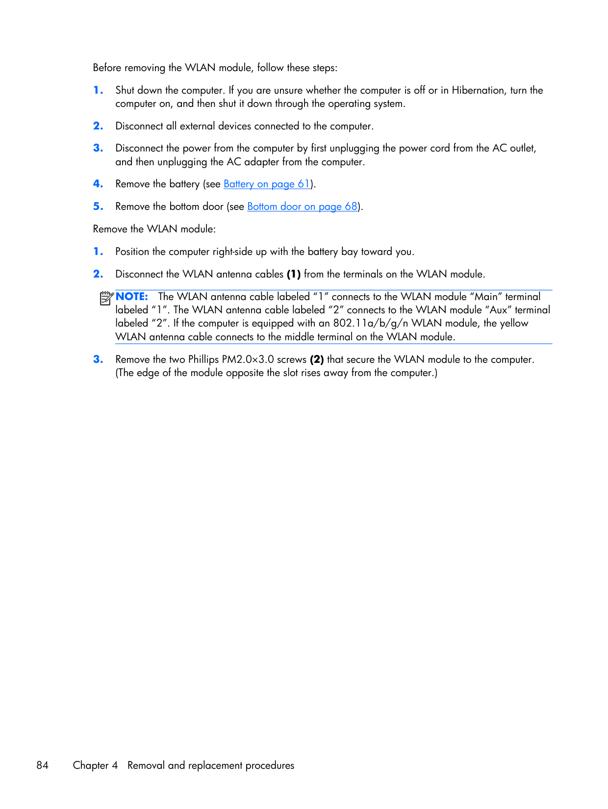
Before removing the WLAN module, follow these steps:
Note:
The WLAN antenna cable labeled “1” connects to the WLAN module “Main” terminal labeled “1”. The WLAN antenna cable labeled “2” connects to the WLAN module “Aux” terminal labeled “2”. If the computer is equipped with an 802.11a/b/g/n WLAN module, the yellow WLAN antenna cable connects to the middle terminal on the WLAN module.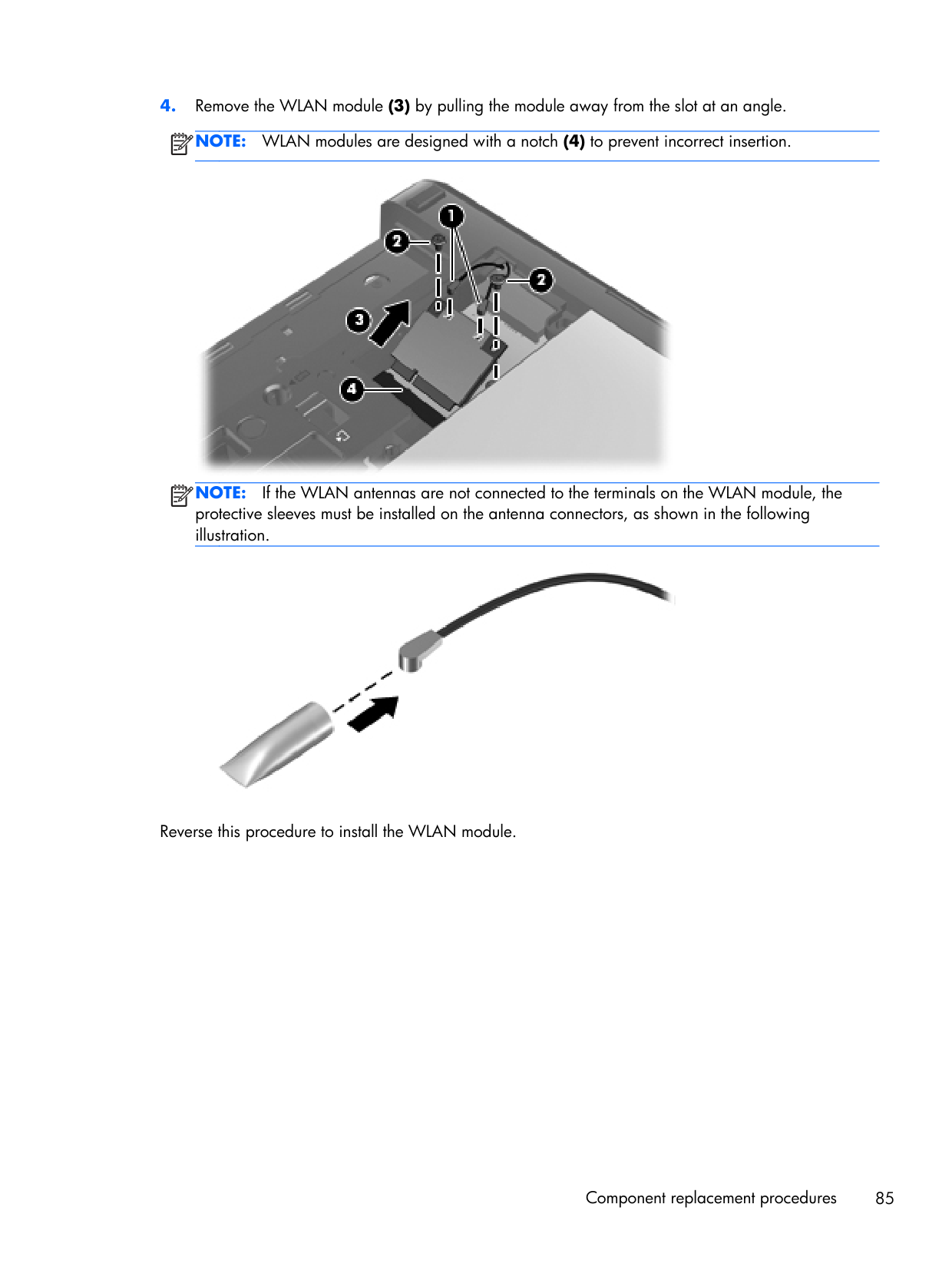
Note:
WLAN modules are designed with a notch (4) to prevent incorrect insertion.Note:
If the WLAN antennas are not connected to the terminals on the WLAN module, the protective sleeves must be installed on the antenna connectors, as shown in the following illustration. Reverse this procedure to install the WLAN module. Component replacement procedures 85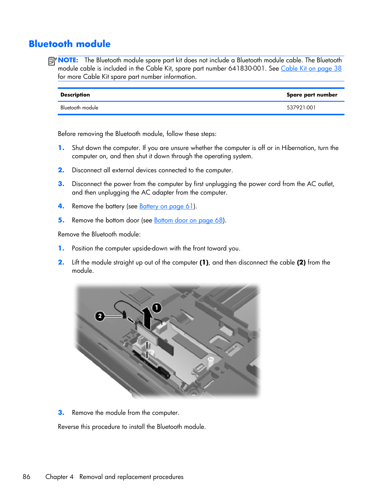
Bluetooth module
Note:
The Bluetooth module spare part kit does not include a Bluetooth module cable. The Bluetooth module cable is included in the Cable Kit, spare part number 641830-001. See Cable Kit on page 38 for more Cable Kit spare part number information. Description Spare part number Bluetooth module 537921-001 Before removing the Bluetooth module, follow these steps: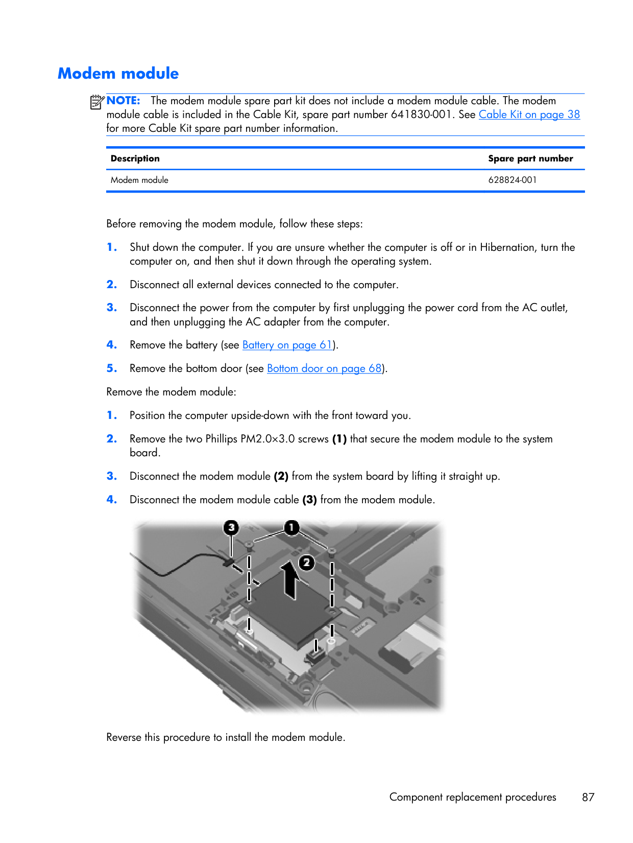
Modem module
Note:
The modem module spare part kit does not include a modem module cable. The modem module cable is included in the Cable Kit, spare part number 641830-001. See Cable Kit on page 38 for more Cable Kit spare part number information. Description Spare part number Modem module 628824-001 Before removing the modem module, follow these steps: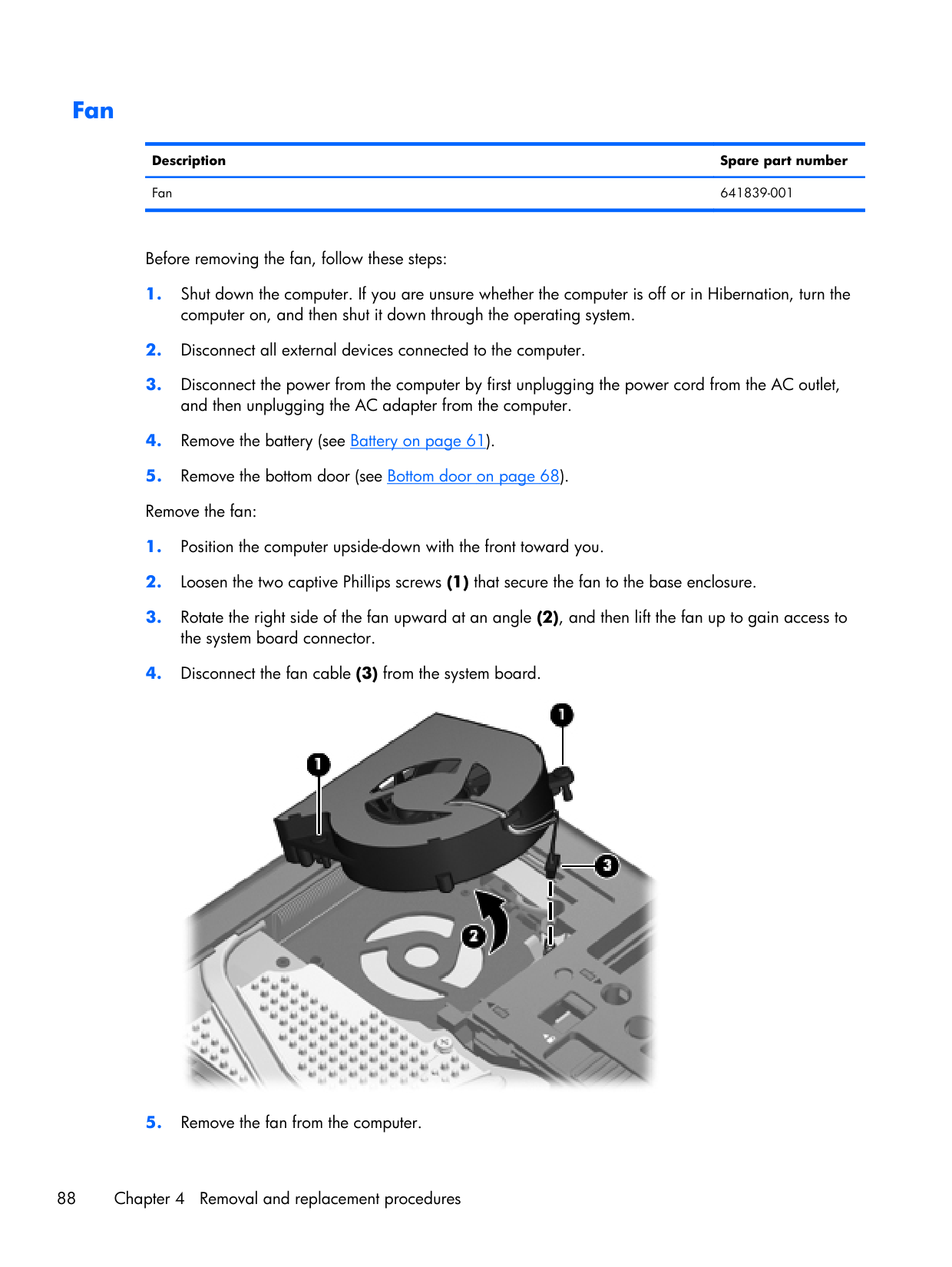
Fan Description Spare part number Fan 641839-001 Before removing the fan, follow these steps:
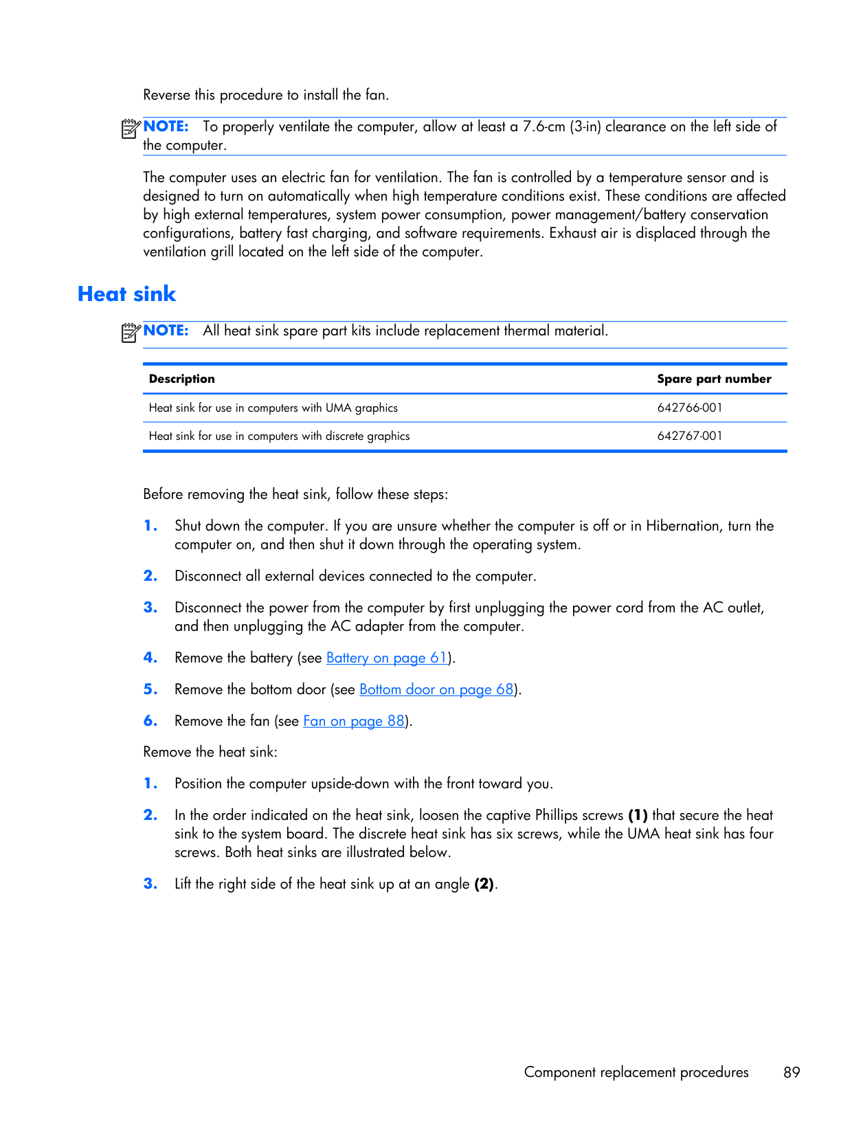
Reverse this procedure to install the fan.
Note:
To properly ventilate the computer, allow at least a 7.6-cm (3-in) clearance on the left side of the computer. The computer uses an electric fan for ventilation. The fan is controlled by a temperature sensor and is designed to turn on automatically when high temperature conditions exist. These conditions are affected by high external temperatures, system power consumption, power management/battery conservation configurations, battery fast charging, and software requirements. Exhaust air is displaced through the ventilation grill located on the left side of the computer. Heat sinkNote:
All heat sink spare part kits include replacement thermal material. Description Spare part number Heat sink for use in computers with UMA graphics 642766-001 Heat sink for use in computers with discrete graphics 642767-001 Before removing the heat sink, follow these steps: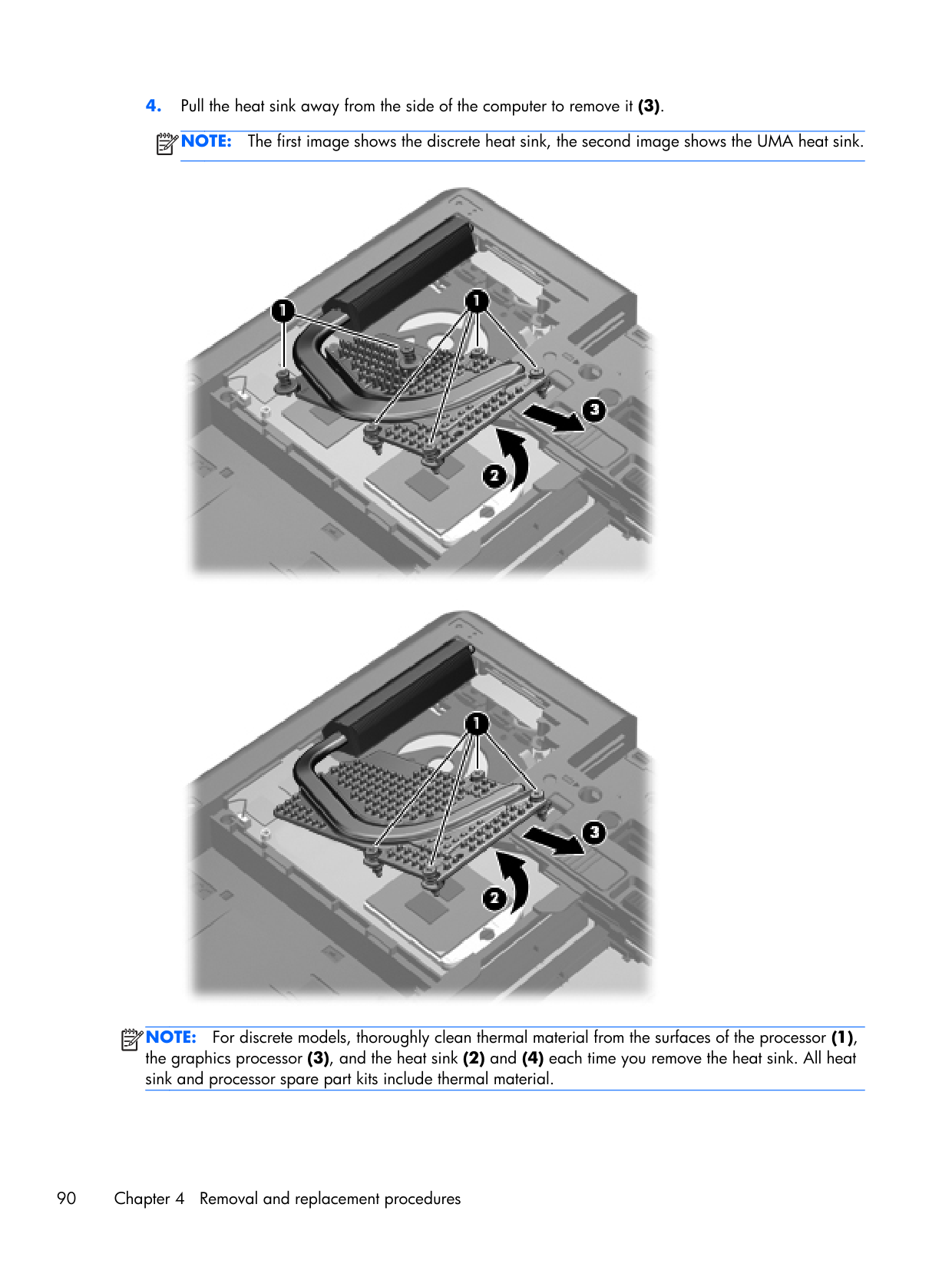
Note:
The first image shows the discrete heat sink, the second image shows the UMA heat sink.Note:
For discrete models, thoroughly clean thermal material from the surfaces of the processor (1), the graphics processor (3), and the heat sink (2) and (4) each time you remove the heat sink. All heat sink and processor spare part kits include thermal material. 90 Chapter 4 Removal and replacement procedures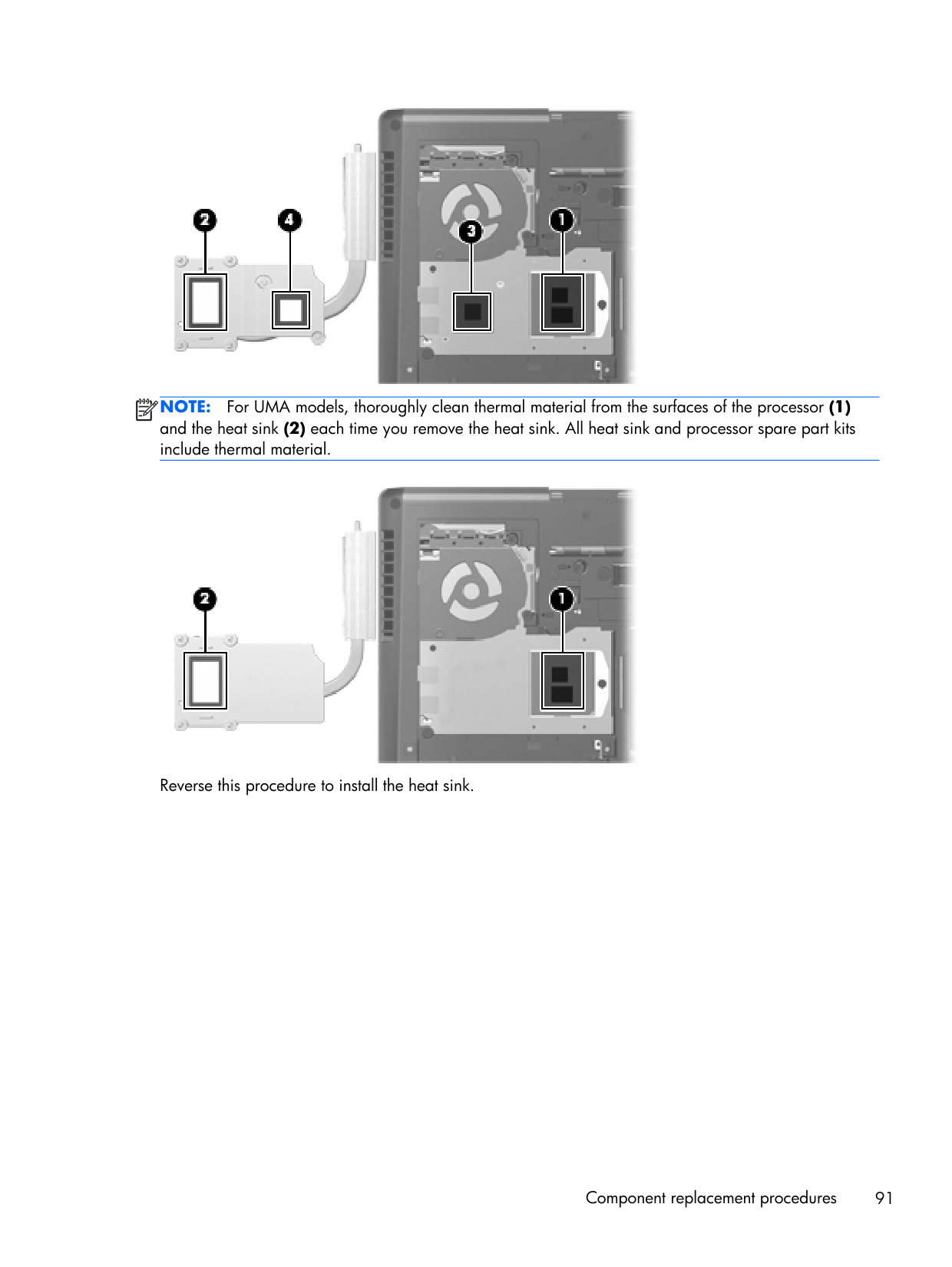
Note:
For UMA models, thoroughly clean thermal material from the surfaces of the processor (1) and the heat sink (2) each time you remove the heat sink. All heat sink and processor spare part kits include thermal material. Reverse this procedure to install the heat sink. Component replacement procedures 91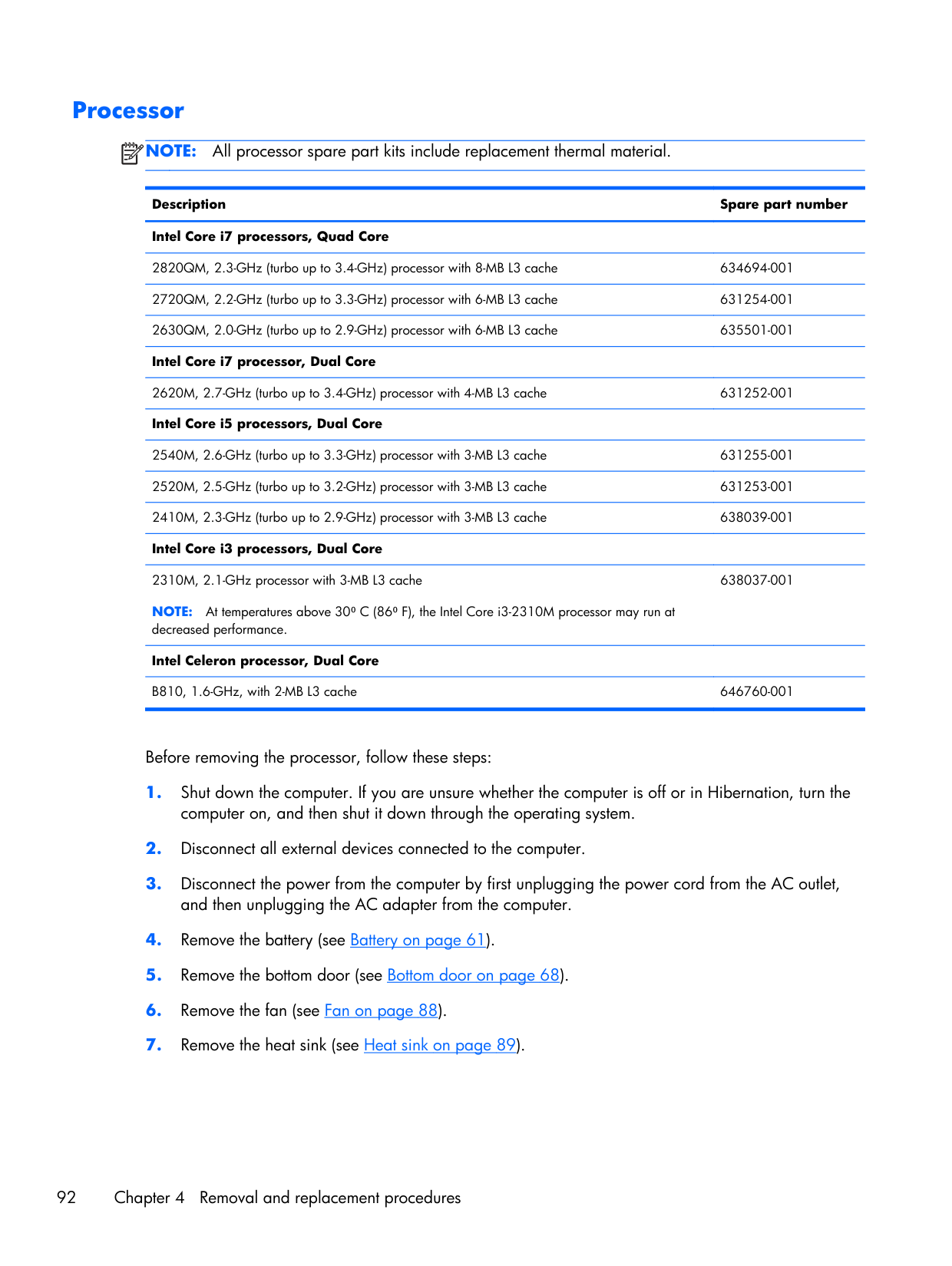
Processor
Note:
All processor spare part kits include replacement thermal material. Description Spare part number Intel Core i7 processors, Quad Core2820QM, 2.3-GHz (turbo up to 3.4-GHz) processor with 8-MB L3 cache 634694-001 2720QM, 2.2-GHz (turbo up to 3.3-GHz) processor with 6-MB L3 cache 631254-001 2630QM, 2.0-GHz (turbo up to 2.9-GHz) processor with 6-MB L3 cache 635501-001 Intel Core i7 processor, Dual Core
2620M, 2.7-GHz (turbo up to 3.4-GHz) processor with 4-MB L3 cache 631252-001 Intel Core i5 processors, Dual Core
2540M, 2.6-GHz (turbo up to 3.3-GHz) processor with 3-MB L3 cache 631255-001 2520M, 2.5-GHz (turbo up to 3.2-GHz) processor with 3-MB L3 cache 631253-001 2410M, 2.3-GHz (turbo up to 2.9-GHz) processor with 3-MB L3 cache 638039-001 Intel Core i3 processors, Dual Core
2310M, 2.1-GHz processor with 3-MB L3 cache
Note:
At temperatures above 30⁰ C (86⁰ F), the Intel Core i3-2310M processor may run at decreased performance. 638037-001 Intel Celeron processor, Dual CoreB810, 1.6-GHz, with 2-MB L3 cache 646760-001 Before removing the processor, follow these steps:
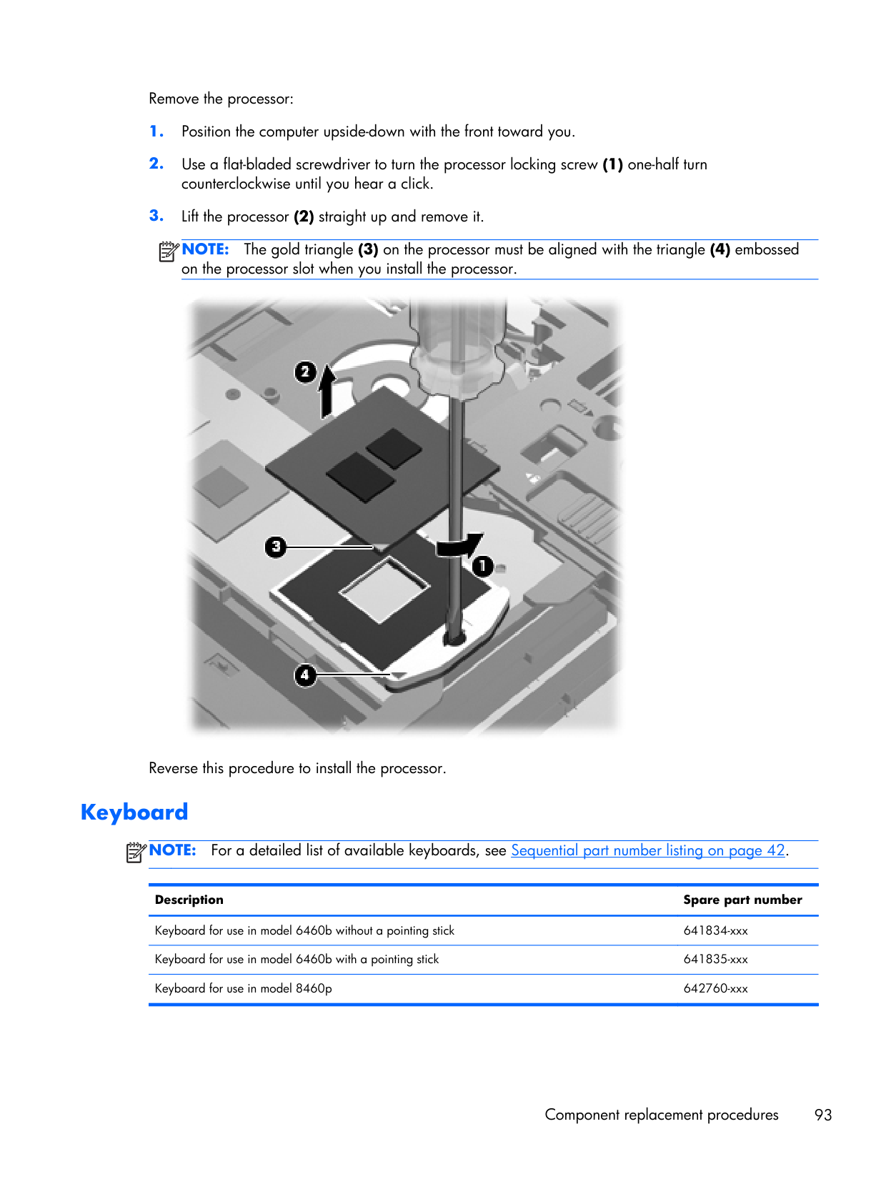
Remove the processor:
Note:
The gold triangle (3) on the processor must be aligned with the triangle (4) embossed on the processor slot when you install the processor. Reverse this procedure to install the processor. KeyboardNote:
For a detailed list of available keyboards, see Sequential part number listing on page 42. Description Spare part number Keyboard for use in model 6460b without a pointing stick 641834-xxx Keyboard for use in model 6460b with a pointing stick 641835-xxx Keyboard for use in model 8460p 642760-xxx Component replacement procedures 93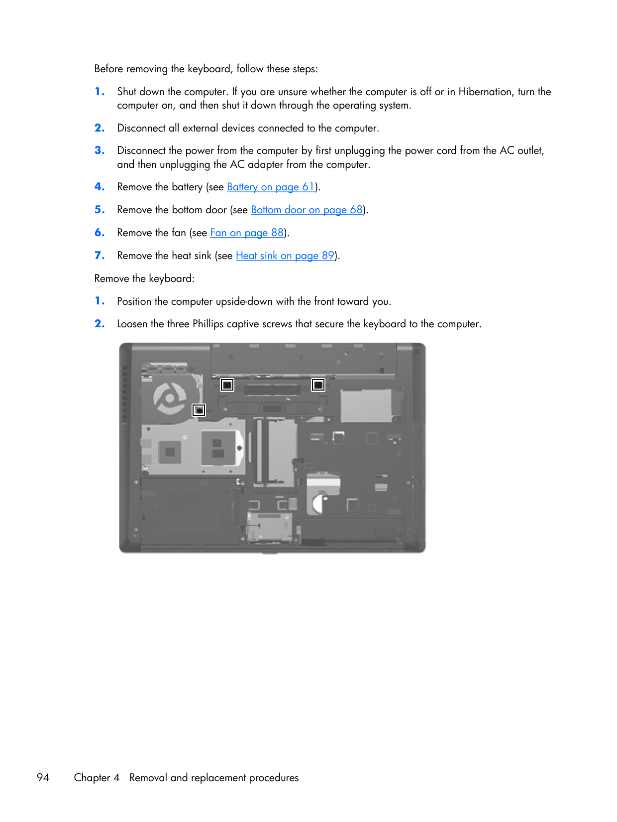
Before removing the keyboard, follow these steps:
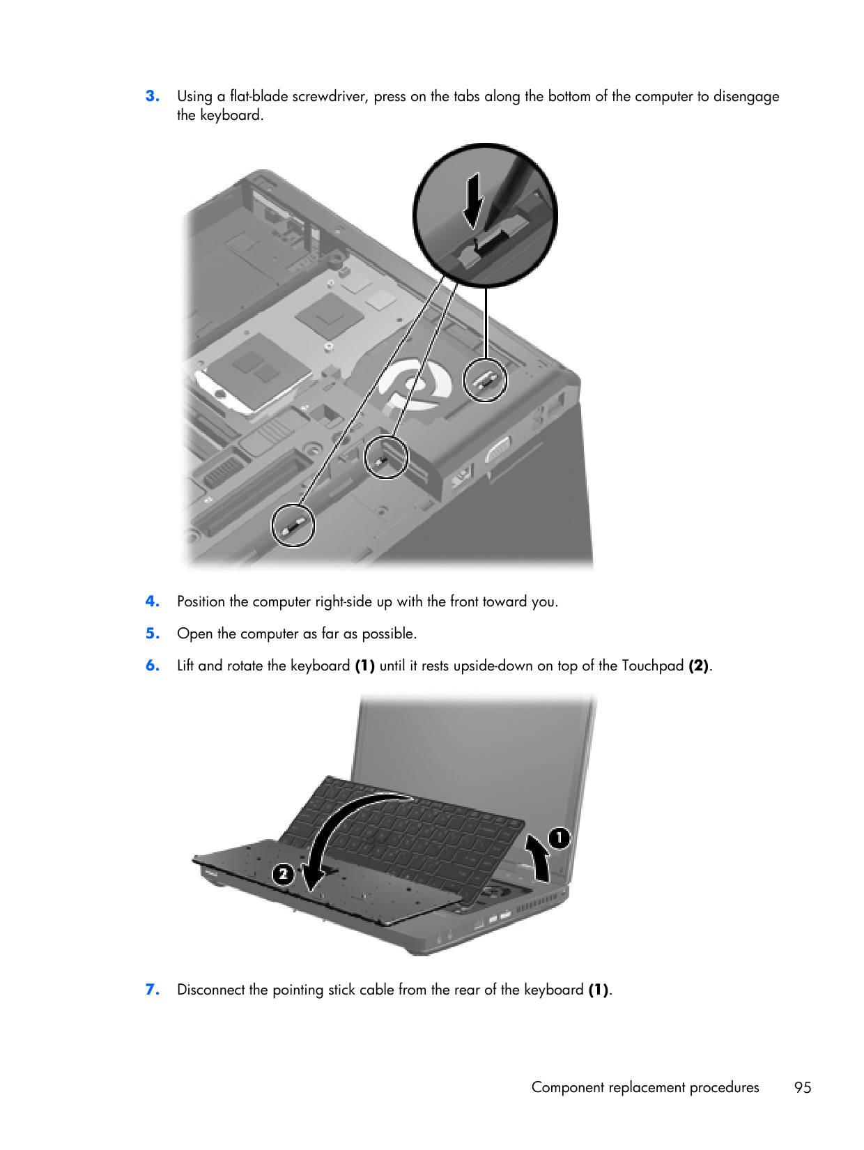
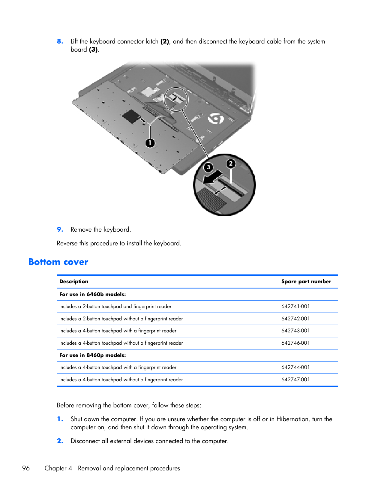
Includes a 2-button touchpad and fingerprint reader 642741-001 Includes a 2-button touchpad without a fingerprint reader 642742-001 Includes a 4-button touchpad with a fingerprint reader 642743-001 Includes a 4-button touchpad without a fingerprint reader 642746-001 For use in 8460p models:
Includes a 4-button touchpad with a fingerprint reader 642744-001 Includes a 4-button touchpad without a fingerprint reader 642747-001 Before removing the bottom cover, follow these steps:
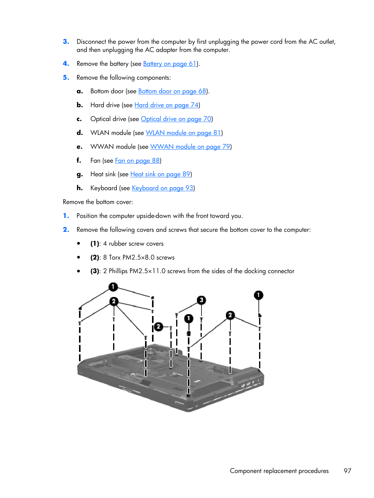
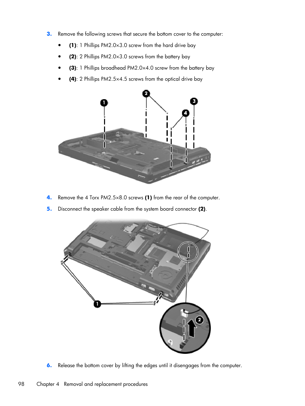
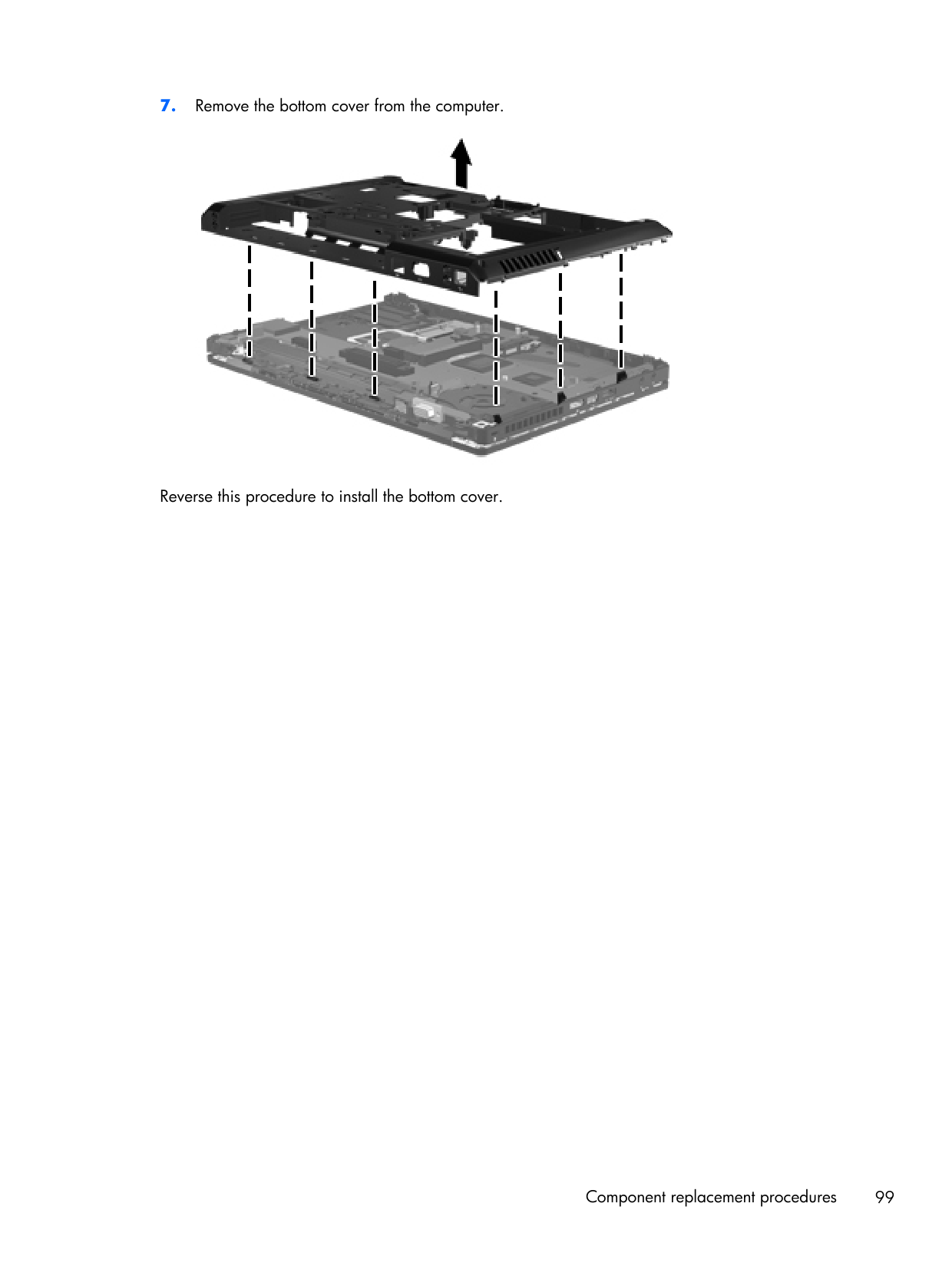
Fingerprint reader board Description Spare part number Fingerprint reader board (includes cable) 642764-001 Before removing the fingerprint reader board, follow these steps:
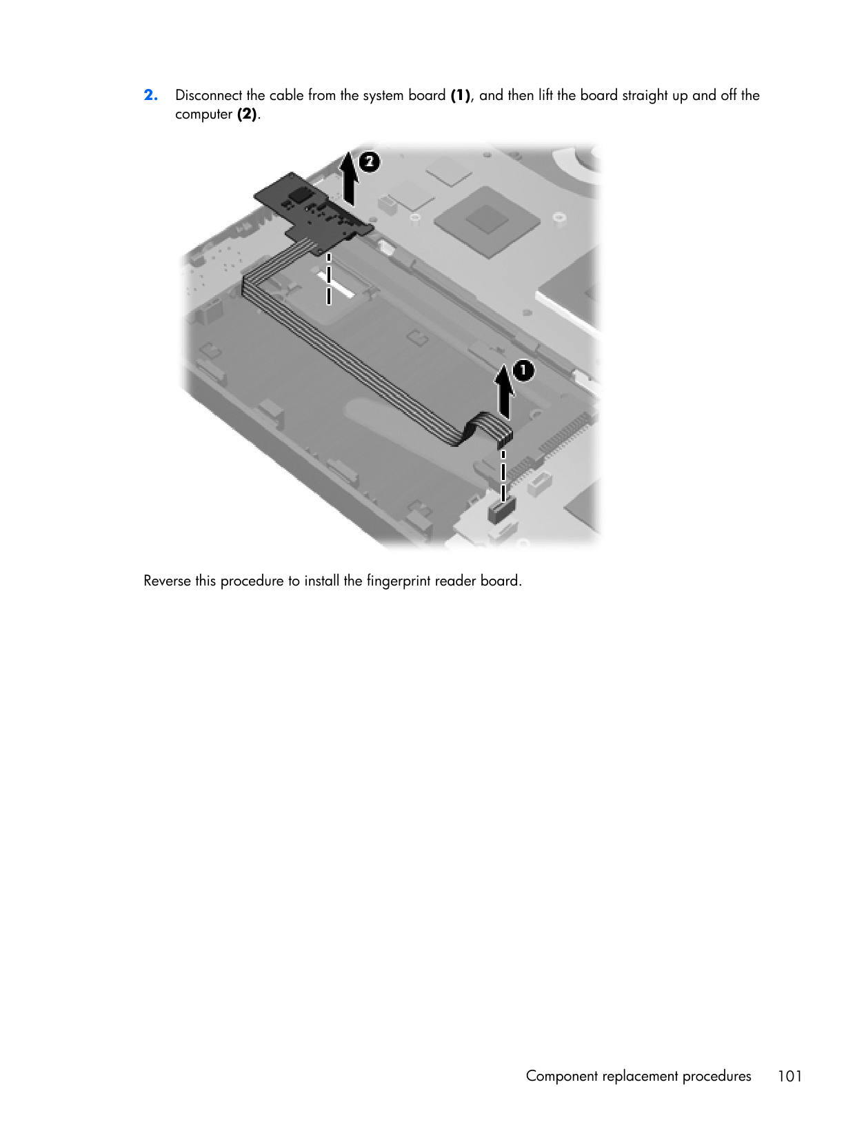
Lid switch Description Spare part number Lid switch board (includes cable) 642765-001 Before removing the lid switch, follow these steps:
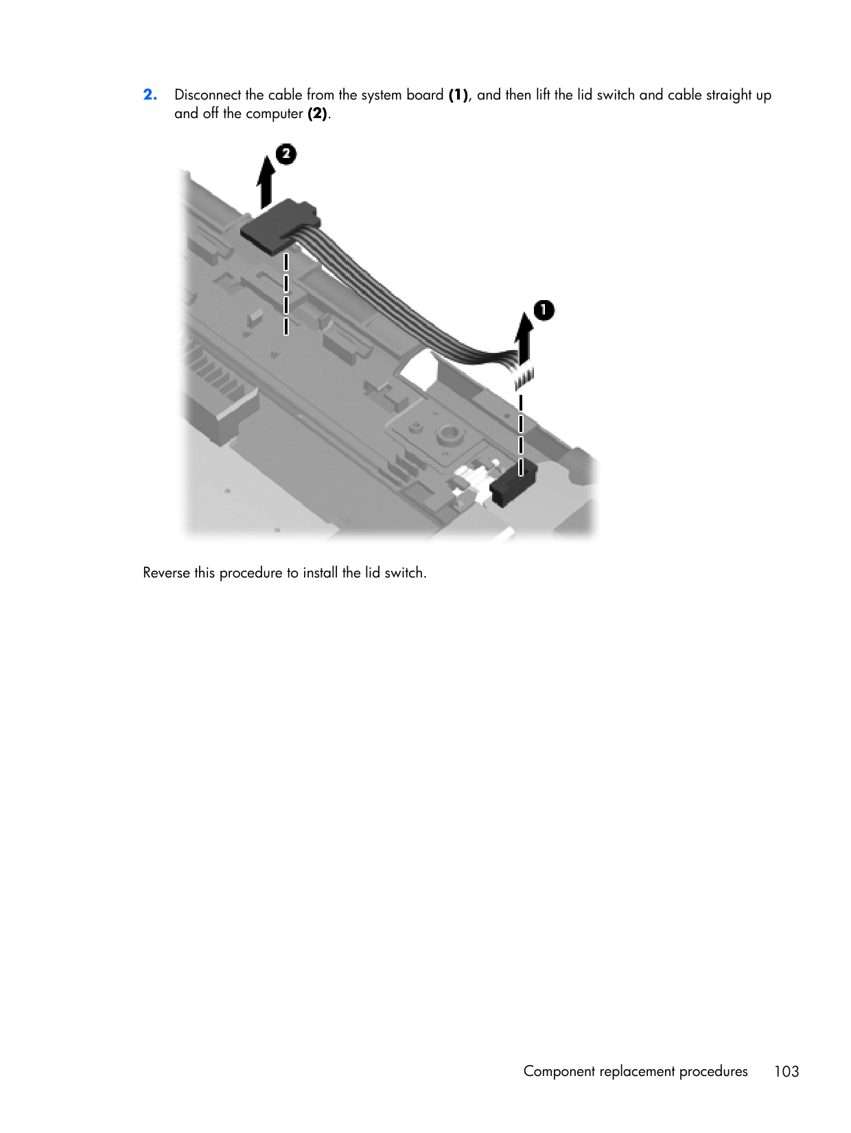
Speaker assembly Description Spare part number Speaker assembly 641840-001 Before removing the speaker assembly, follow these steps:
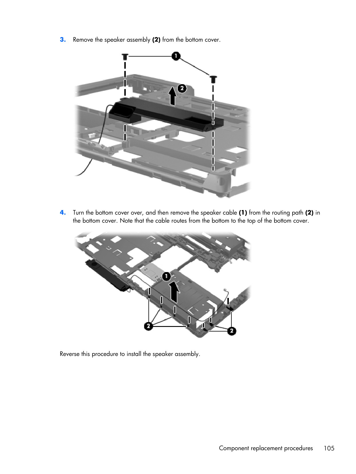
RJ-11 connector cable
Note:
The RJ-11 connector cable is included in the Cable Kit, spare part number 641830-001. Before removing the RJ-11 connector cable, follow these steps: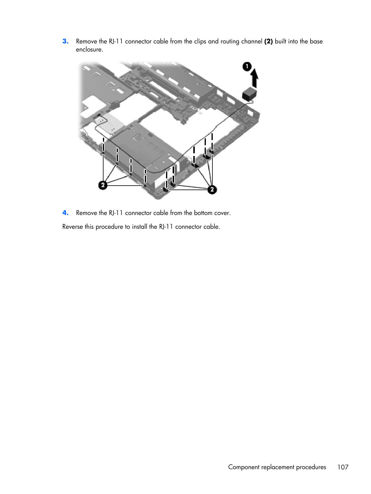
Display assembly components (cable, antennas, hinges, enclosure)
Note:
This section describes removing components that require you to completely remove the display panel. For more information about removing display components that do not require that you remove the assembly from the computer, see Display assembly components (panel, bezel, webcam, microphone) on page 63. All display assemblies include WLAN antenna transceivers and cables. WWAN models include 2 WWAN antenna transceivers and cables. For a list of display spare parts, see Display components on page 36. Before removing the display assembly, follow these steps: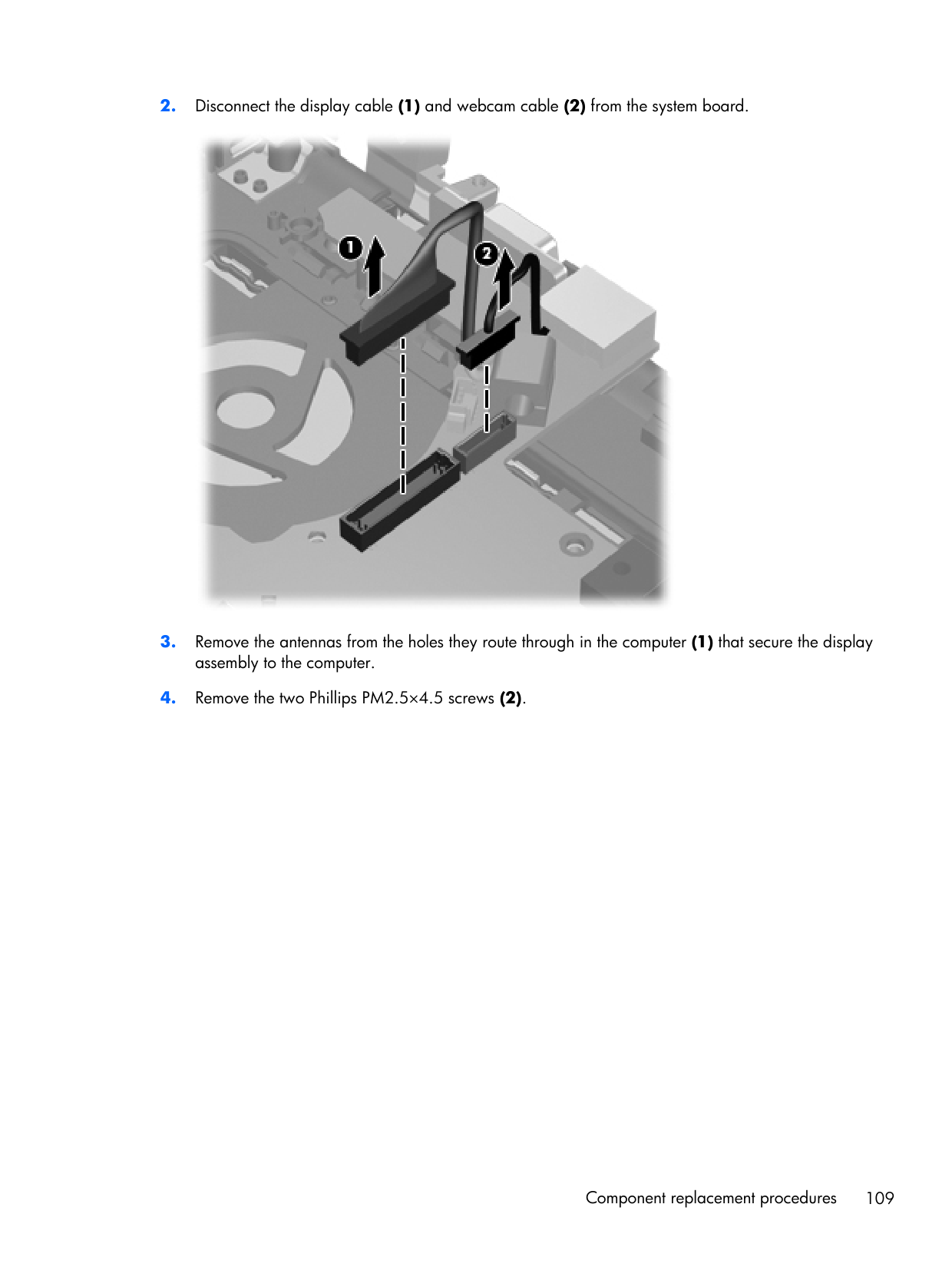
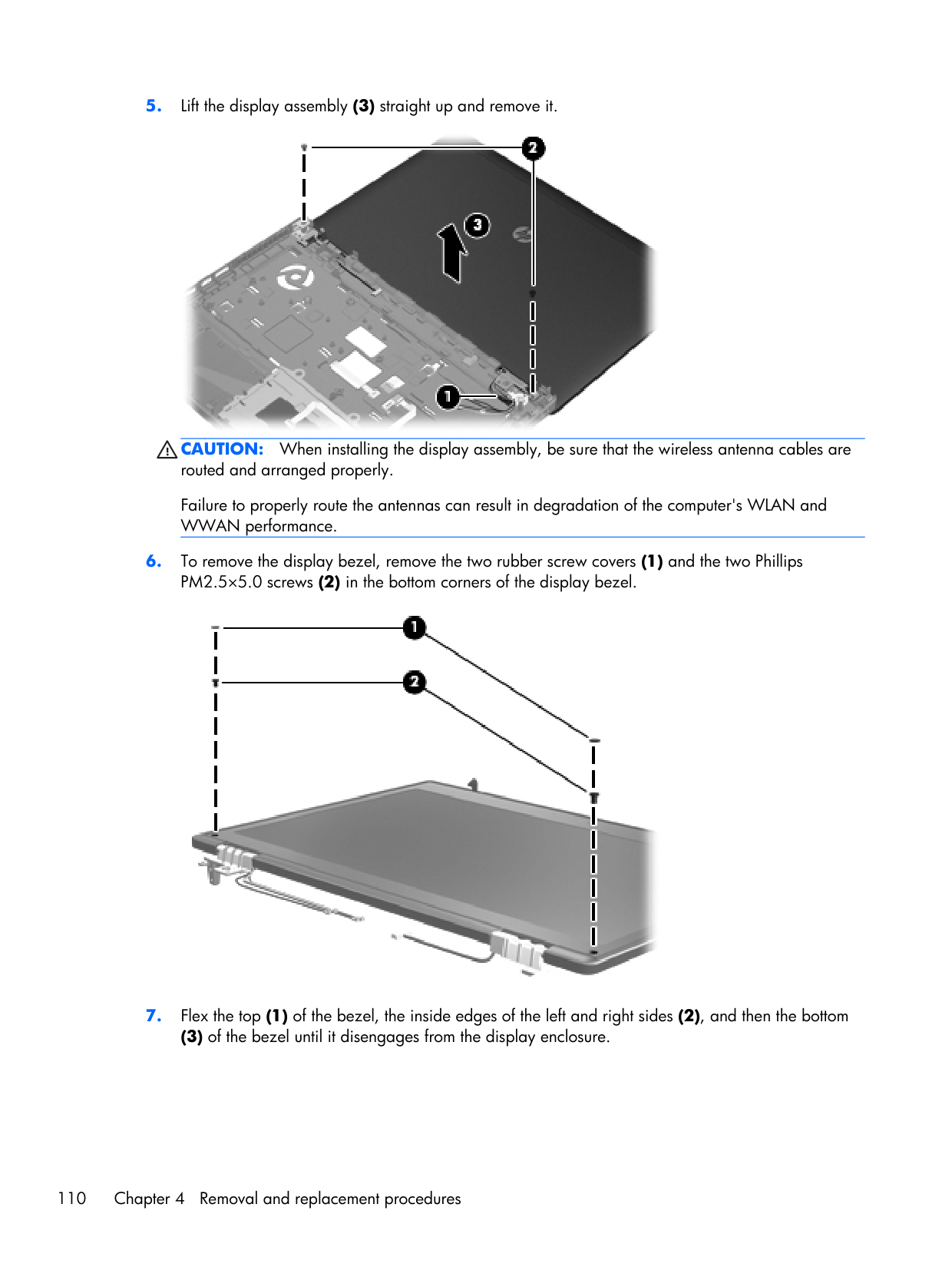
Caution:
When installing the display assembly, be sure that the wireless antenna cables are routed and arranged properly. Failure to properly route the antennas can result in degradation of the computer's WLAN and WWAN performance.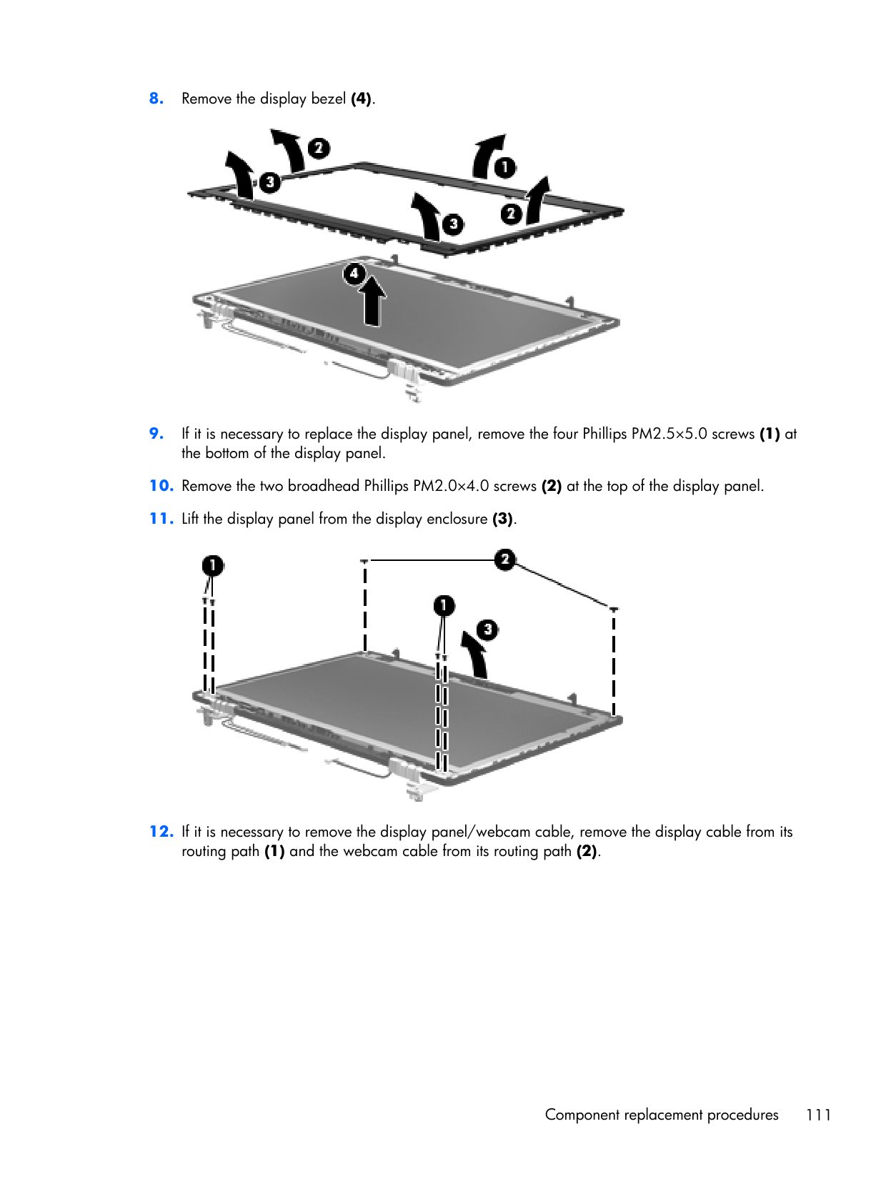
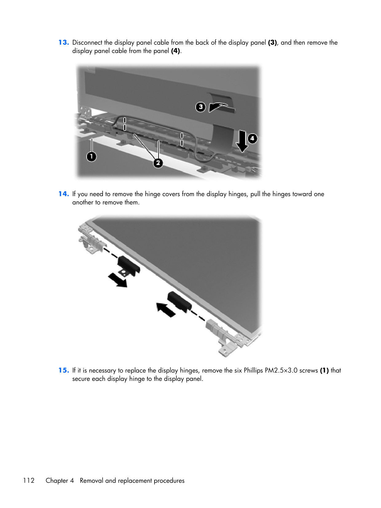
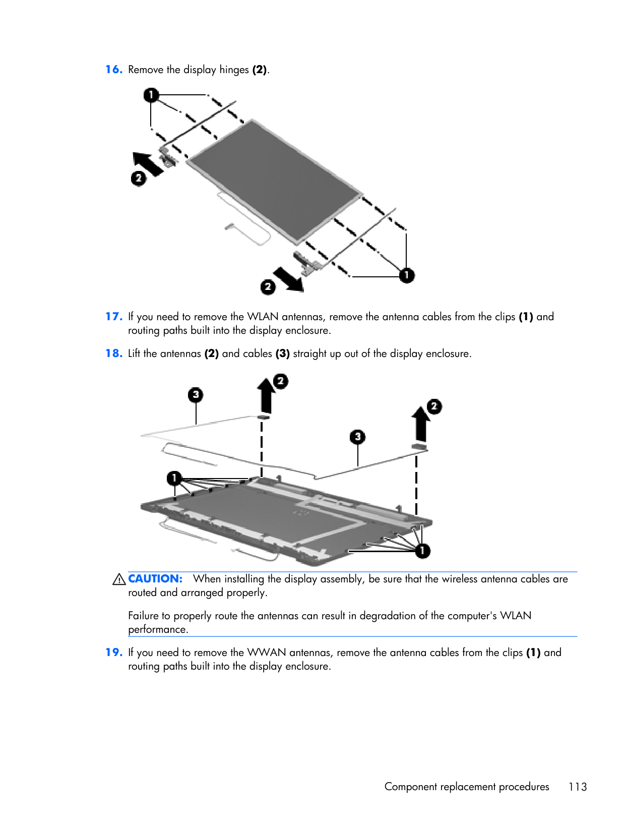
Caution:
When installing the display assembly, be sure that the wireless antenna cables are routed and arranged properly. Failure to properly route the antennas can result in degradation of the computer's WLAN performance.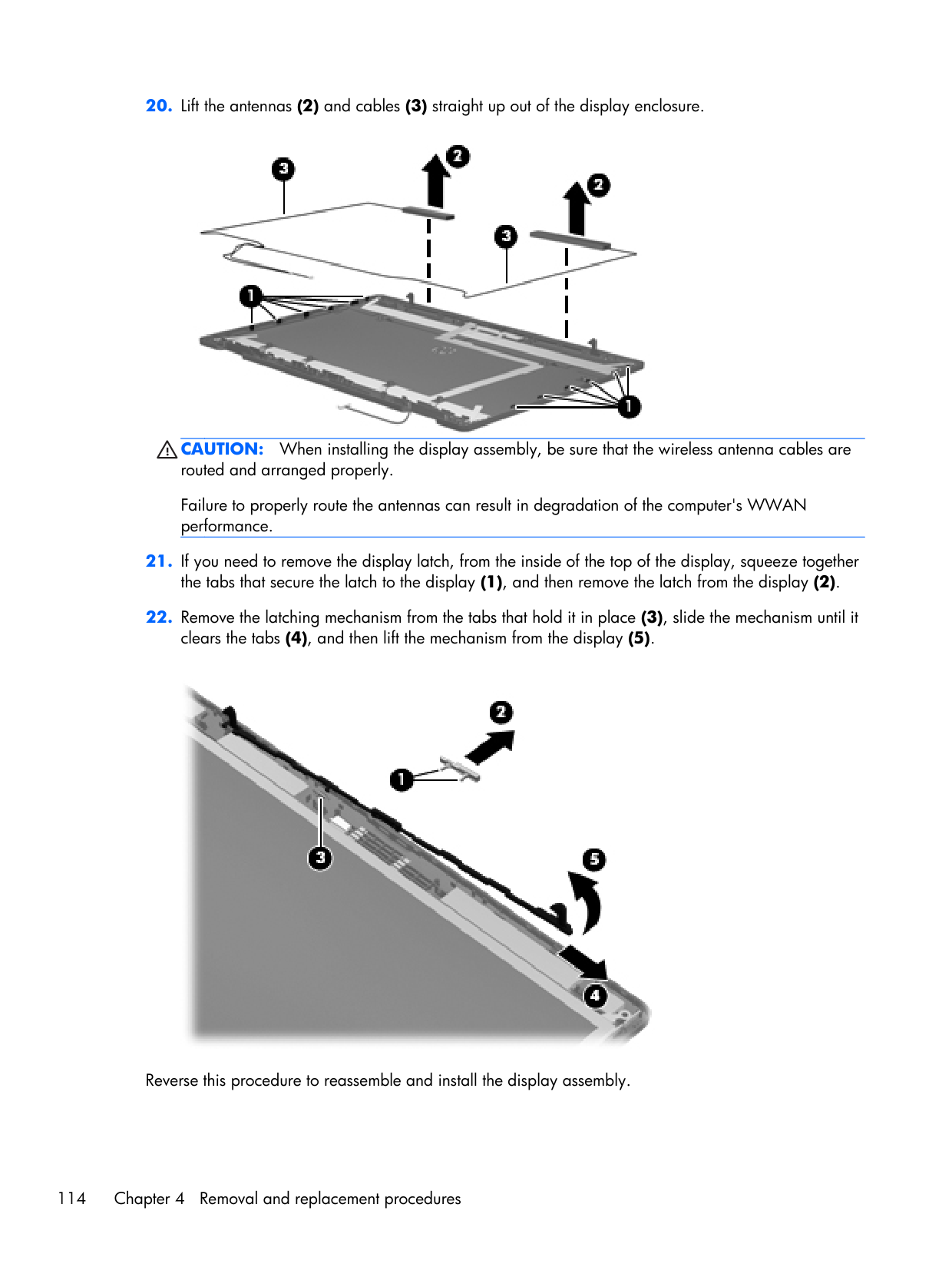
Caution:
When installing the display assembly, be sure that the wireless antenna cables are routed and arranged properly. Failure to properly route the antennas can result in degradation of the computer's WWAN performance.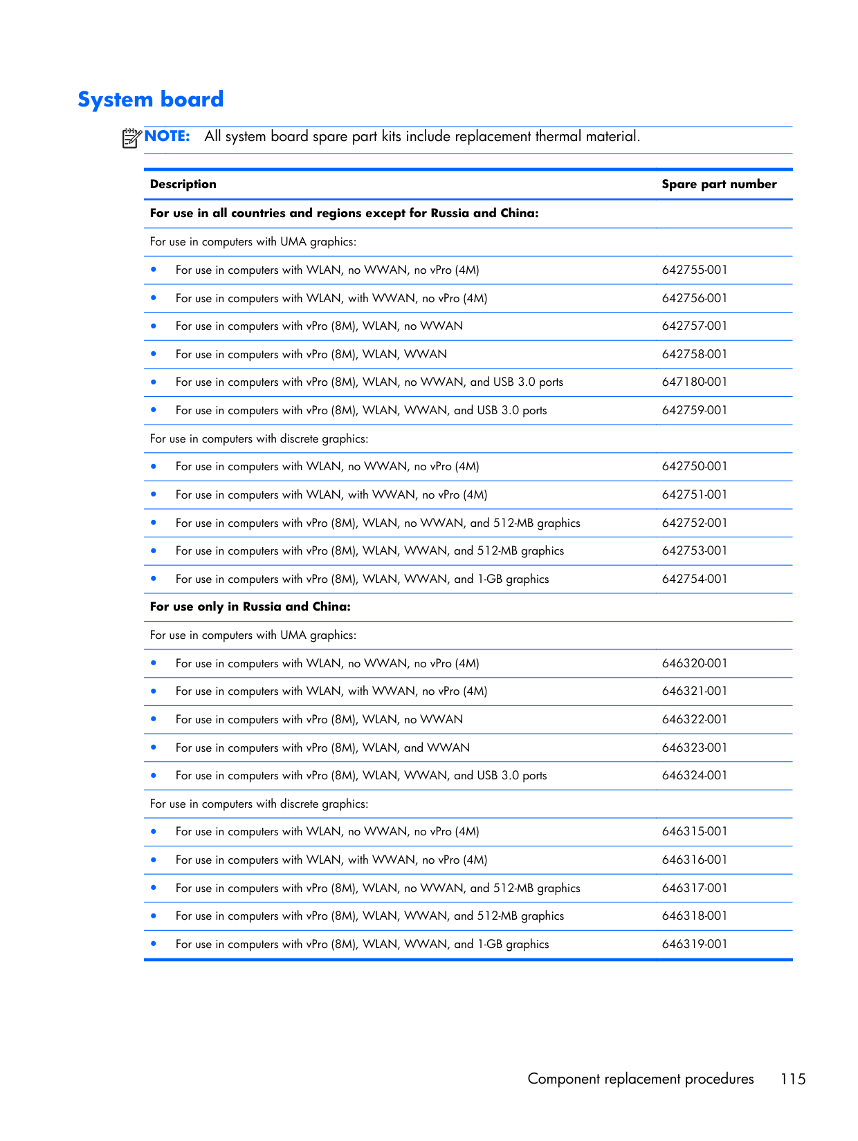
System board
Note:
All system board spare part kits include replacement thermal material. Description Spare part number For use in all countries and regions except for Russia and China:For use in computers with UMA graphics:
● For use in computers with WLAN, no WWAN, no vPro (4M) 642755-001 ● For use in computers with WLAN, with WWAN, no vPro (4M) 642756-001 ● For use in computers with vPro (8M), WLAN, no WWAN 642757-001 ● For use in computers with vPro (8M), WLAN, WWAN 642758-001 ● For use in computers with vPro (8M), WLAN, no WWAN, and USB 3.0 ports 647180-001 ● For use in computers with vPro (8M), WLAN, WWAN, and USB 3.0 ports 642759-001 For use in computers with discrete graphics:
● For use in computers with WLAN, no WWAN, no vPro (4M) 642750-001 ● For use in computers with WLAN, with WWAN, no vPro (4M) 642751-001 ● For use in computers with vPro (8M), WLAN, no WWAN, and 512-MB graphics 642752-001 ● For use in computers with vPro (8M), WLAN, WWAN, and 512-MB graphics 642753-001 ● For use in computers with vPro (8M), WLAN, WWAN, and 1-GB graphics 642754-001 For use only in Russia and China:
For use in computers with UMA graphics:
● For use in computers with WLAN, no WWAN, no vPro (4M) 646320-001 ● For use in computers with WLAN, with WWAN, no vPro (4M) 646321-001 ● For use in computers with vPro (8M), WLAN, no WWAN 646322-001 ● For use in computers with vPro (8M), WLAN, and WWAN 646323-001 ● For use in computers with vPro (8M), WLAN, WWAN, and USB 3.0 ports 646324-001 For use in computers with discrete graphics:
● For use in computers with WLAN, no WWAN, no vPro (4M) 646315-001 ● For use in computers with WLAN, with WWAN, no vPro (4M) 646316-001 ● For use in computers with vPro (8M), WLAN, no WWAN, and 512-MB graphics 646317-001 ● For use in computers with vPro (8M), WLAN, WWAN, and 512-MB graphics 646318-001 ● For use in computers with vPro (8M), WLAN, WWAN, and 1-GB graphics 646319-001 Component replacement procedures 115
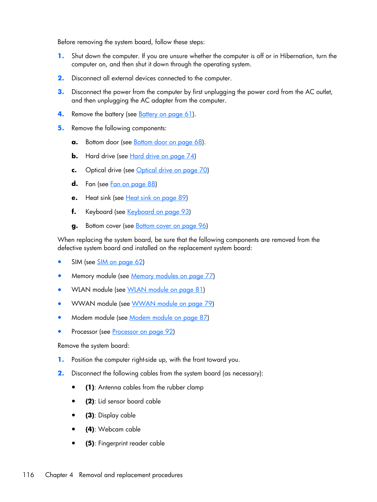
Before removing the system board, follow these steps:
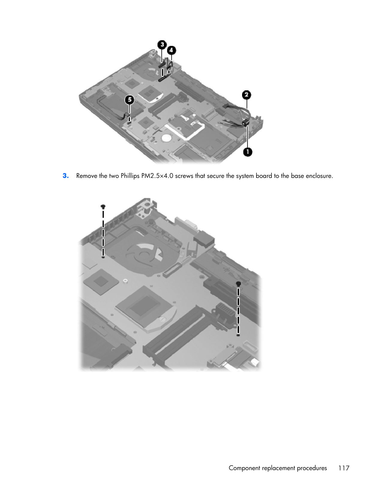
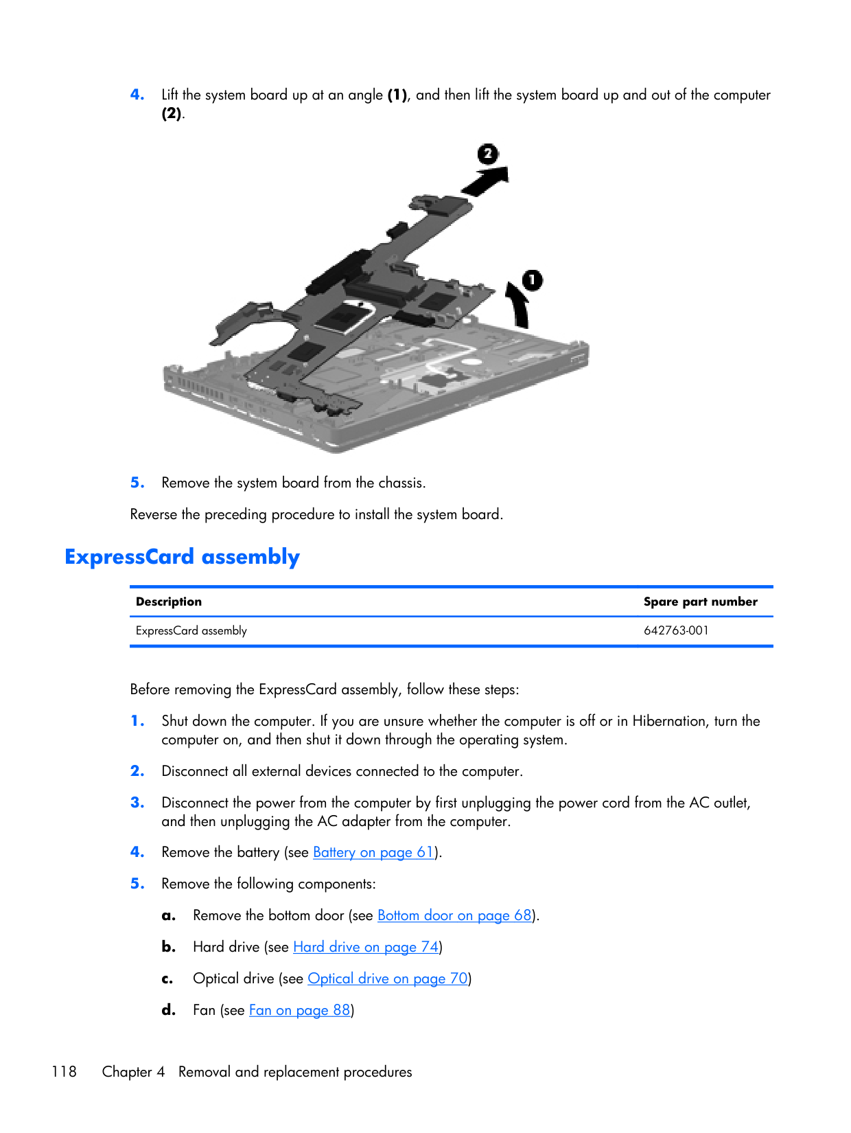
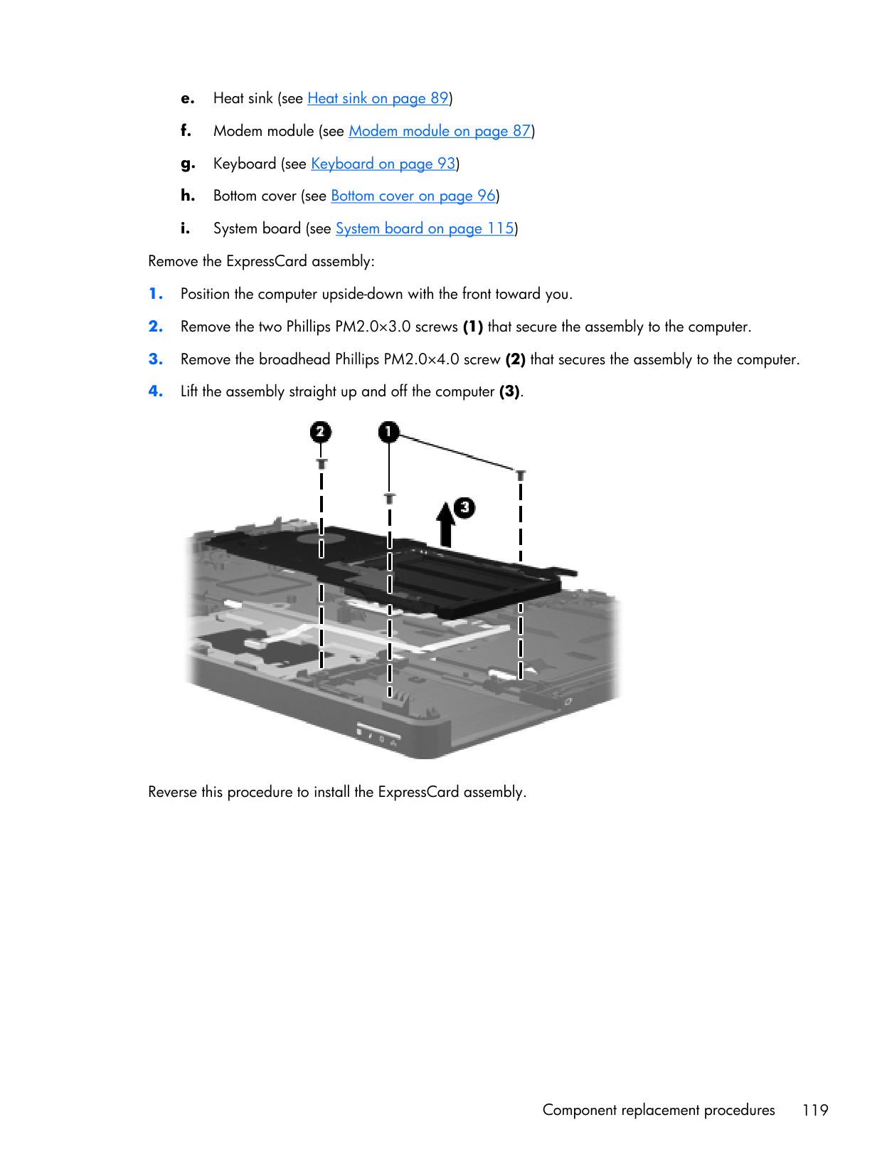
e. Heat sink (see Heat sink on page 89) f. Modem module (see Modem module on page 87) g. Keyboard (see Keyboard on page 93) h. Bottom cover (see Bottom cover on page 96) i. System board (see System board on page 115) Remove the ExpressCard assembly:
5 Computer Setup (BIOS) and System Diagnostics Using Computer Setup Computer Setup, or Basic Input/Output System (BIOS), controls communication between all the input and output devices on the system (such as disk drives, display, keyboard, mouse, and printer). Computer Setup includes settings for the types of devices installed, the startup sequence of the computer, and the amount of system and extended memory.
Note:
Use extreme care when making changes in Computer Setup. Errors can prevent the computer from operating properly. Starting Computer SetupNote:
An external keyboard or mouse connected to a USB port can be used with Computer Setup only if USB legacy support is enabled. To start Computer Setup, follow these steps:
Note:
You can use either a pointing device (TouchPad, pointing stick, or USB mouse) or the keyboard to navigate and make selections in Computer Setup.Note:
Restoring defaults will not change the hard drive mode. To return all settings in Computer Setup to the values that were set at the factory, follow these steps:Note:
Your password settings and security settings are not changed when you restore the factory settings. Using Computer Setup 121
Updating the BIOS Updated versions of the BIOS may be available on the HP Web site. Most BIOS updates on the HP Web site are packaged in compressed files called SoftPaqs. Some download packages contain a file named Readme.txt, which contains information regarding installing and troubleshooting the file. Determining the BIOS version To determine whether available BIOS updates contain later BIOS versions than those currently installed on the computer, you need to know the version of the system BIOS currently installed. BIOS version information (also known as ROM date and System BIOS) can be displayed by pressing fn +esc (if you are already in Windows) or by using Computer Setup.
Downloading a BIOS update
Caution:
To reduce the risk of damage to the computer or an unsuccessful installation, download and install a BIOS update only when the computer is connected to reliable external power using the AC adapter. Do not download or install a BIOS update while the computer is running on battery power, docked in an optional docking device, or connected to an optional power source. During the download and installation, follow these instructions: Do not disconnect power from the computer by unplugging the power cord from the AC outlet. Do not shut down the computer or initiate Sleep or Hibernation. Do not insert, remove, connect, or disconnect any device, cable, or cord.Note:
If you connect your computer to a network, consult the network administrator before installing any software updates, especially system BIOS updates. BIOS installation procedures vary. Follow any instructions that are displayed on the screen after the download is complete. If no instructions are displayed, follow these steps:Note:
After a message on the screen reports a successful installation, you can delete the downloaded file from your hard drive. Using Computer Setup 123
Using System Diagnostics System Diagnostics allows you to run diagnostic tests to determine if the computer hardware is functioning properly. The following diagnostic tests are available in System Diagnostics: ● Start-up test—This test analyzes the main computer components that are required to start the computer. ● Run-in test—This test repeats the start-up test and checks for intermittent problems that the start-up test does not detect. ● Hard disk test—This test analyzes the physical condition of the hard drive, and then checks all data in every sector of the hard drive. If the test detects a damaged sector, it attempts to move the data to a good sector. ● Memory test—This test analyzes the physical condition of the memory modules. If it reports an error, replace the memory modules immediately. ● Battery test—This test analyzes the condition of the battery. If the battery fails the test, contact HP Customer Support to report the issue and purchase a replacement battery. You can also view system information and error logs in the System Diagnostics window. To start System Diagnostics:
Note:
If you need to stop a diagnostics test while it is running, press esc. 124 Chapter 5 Computer Setup (BIOS) and System Diagnostics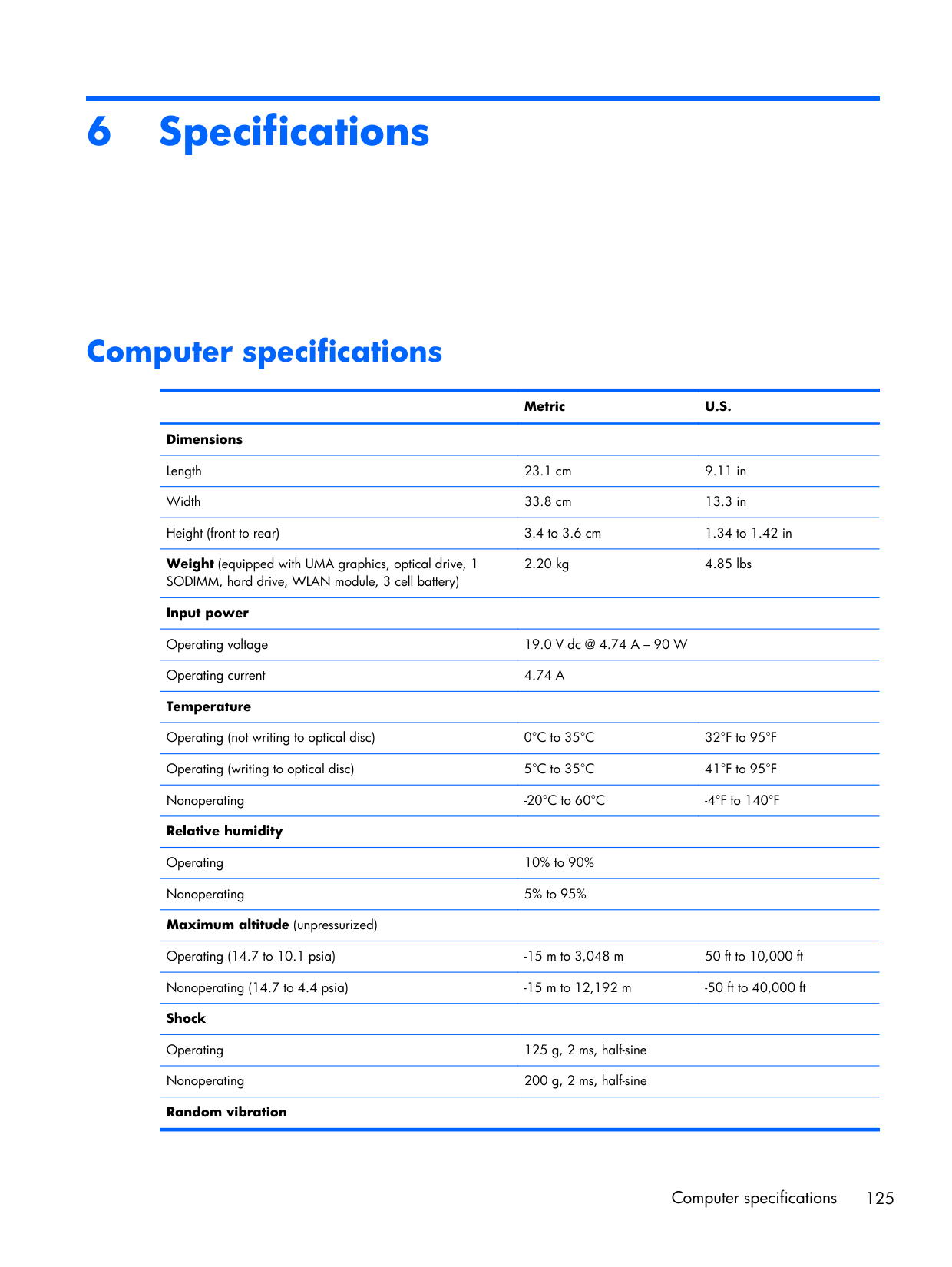
6 Specifications Computer specifications
Metric
U.S.
Dimensions Length 23.1 cm 9.11 in Width 33.8 cm 13.3 in Height (front to rear) 3.4 to 3.6 cm 1.34 to 1.42 in Weight (equipped with UMA graphics, optical drive, 1 SODIMM, hard drive, WLAN module, 3 cell battery) 2.20 kg 4.85 lbs Input power Operating voltage 19.0 V dc @ 4.74 A – 90 W Operating current4.74 A
Temperature Operating (not writing to optical disc) 0°C to 35°C 32°F to 95°F Operating (writing to optical disc) 5°C to 35°C 41°F to 95°F Nonoperating -20°C to 60°C -4°F to 140°F Relative humidity Operating 10% to 90% Nonoperating 5% to 95% Maximum altitude (unpressurized) Operating (14.7 to 10.1 psia) -15 m to 3,048 m 50 ft to 10,000 ft Nonoperating (14.7 to 4.4 psia) -15 m to 12,192 m -50 ft to 40,000 ft Shock Operating 125 g, 2 ms, half-sine Nonoperating 200 g, 2 ms, half-sine Random vibration Computer specifications 125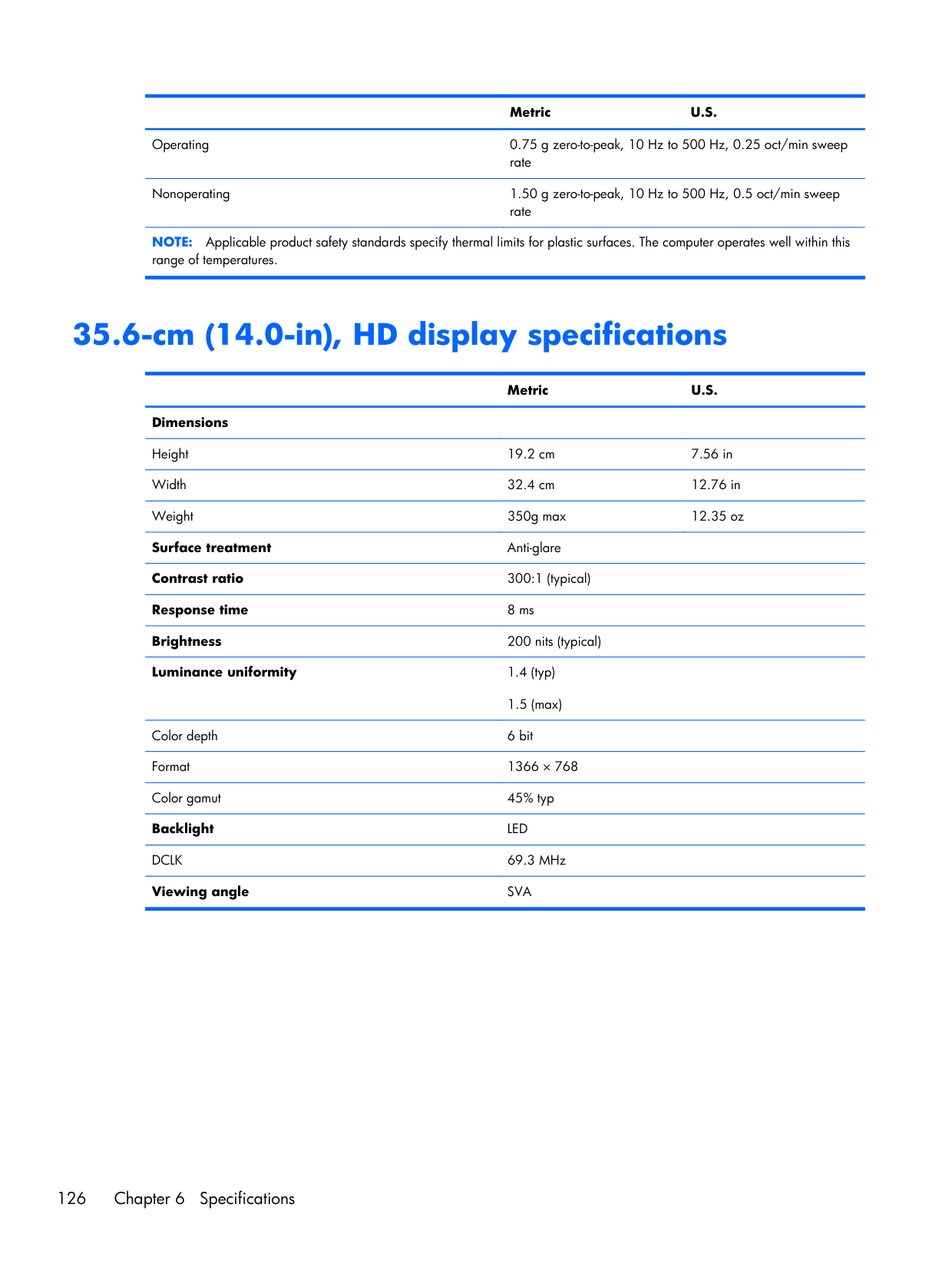
Metric
U.S.
Operating 0.75 g zero-to-peak, 10 Hz to 500 Hz, 0.25 oct/min sweep rate Nonoperating 1.50 g zero-to-peak, 10 Hz to 500 Hz, 0.5 oct/min sweep rateNote:
Applicable product safety standards specify thermal limits for plastic surfaces. The computer operates well within this range of temperatures. 35.6-cm (14.0-in), HD display specificationsMetric
U.S.
Dimensions Height 19.2 cm 7.56 in Width 32.4 cm 12.76 in Weight 350g max 12.35 oz Surface treatment Anti-glare Contrast ratio 300:1 (typical) Response time 8 ms Brightness 200 nits (typical) Luminance uniformity 1.4 (typ) 1.5 (max) Color depth 6 bit Format 1366 × 768 Color gamut 45% typ BacklightLed
Dclk
69.3 MHz Viewing angleSva
126 Chapter 6 Specifications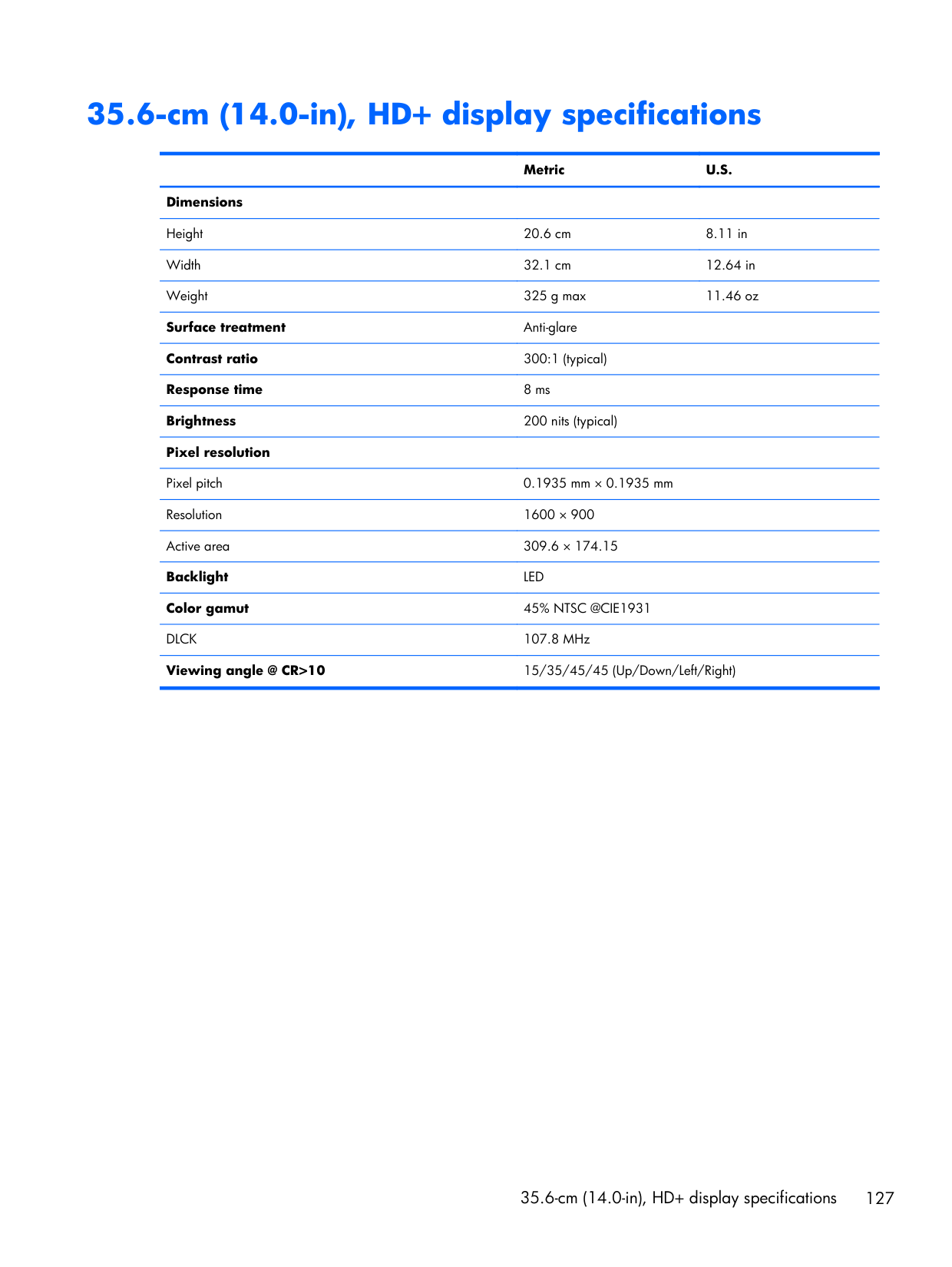
35.6-cm (14.0-in), HD+ display specifications
Metric
U.S.
Dimensions Height 20.6 cm 8.11 in Width 32.1 cm 12.64 in Weight 325 g max 11.46 oz Surface treatment Anti-glare Contrast ratio 300:1 (typical) Response time 8 ms Brightness 200 nits (typical) Pixel resolution Pixel pitch 0.1935 mm × 0.1935 mm Resolution 1600 × 900 Active area 309.6 × 174.15 BacklightLed
Color gamut45% Ntsc @Cie1931
Dlck
107.8 MHz Viewing angle @ CR>10 15/35/45/45 (Up/Down/Left/Right) 35.6-cm (14.0-in), HD+ display specifications 127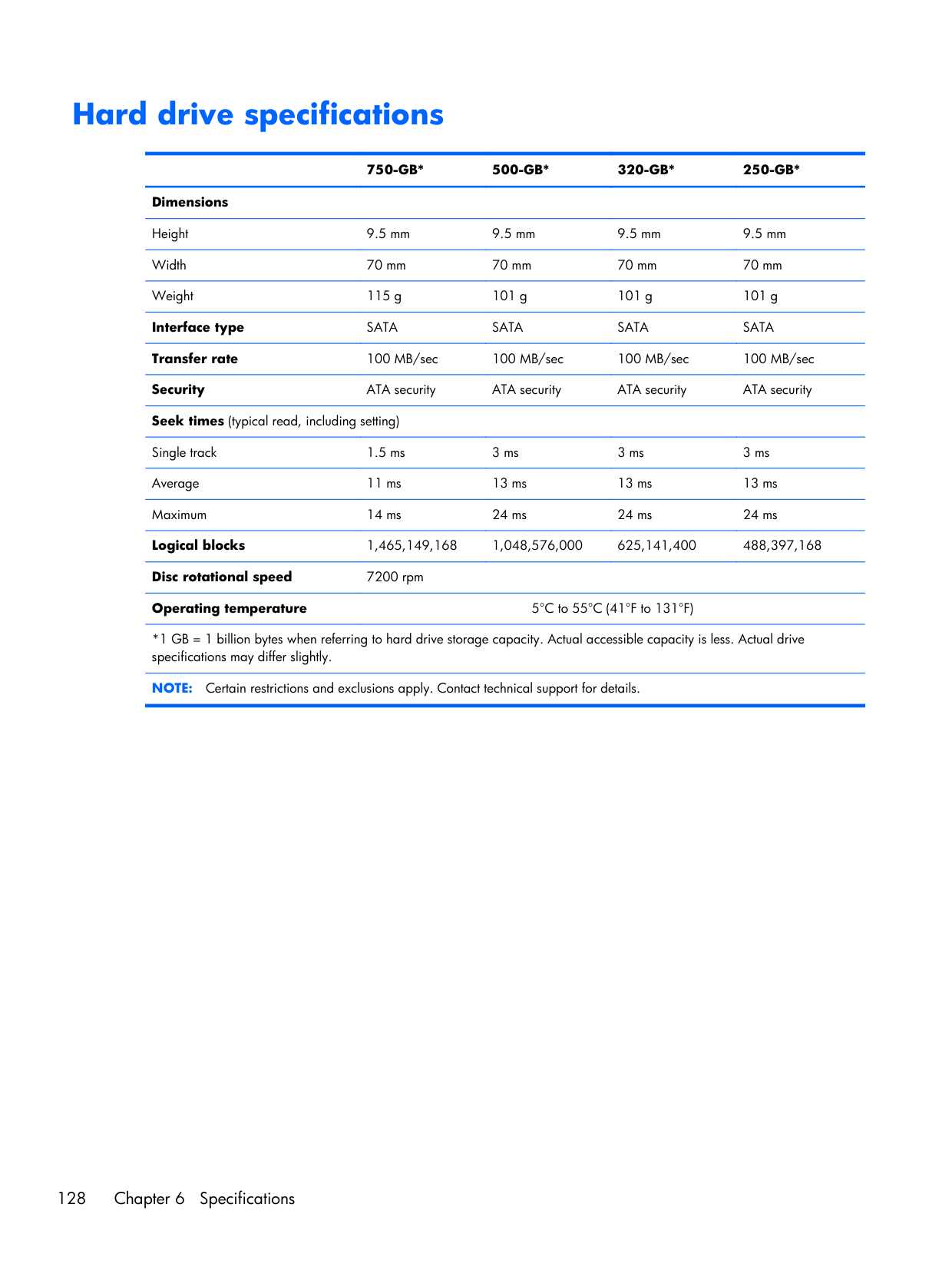
Hard drive specifications
750-Gb*
500-Gb*
320-Gb*
250-Gb*
Dimensions Height 9.5 mm 9.5 mm 9.5 mm 9.5 mm Width 70 mm 70 mm 70 mm 70 mm Weight 115 g 101 g 101 g 101 g Interface typeSata
Sata
Sata
Sata
Transfer rate 100 MB/sec 100 MB/sec 100 MB/sec 100 MB/sec Security ATA security ATA security ATA security ATA security Seek times (typical read, including setting) Single track 1.5 ms 3 ms 3 ms 3 ms Average 11 ms 13 ms 13 ms 13 ms Maximum 14 ms 24 ms 24 ms 24 ms Logical blocks 1,465,149,168 1,048,576,000 625,141,400 488,397,168 Disc rotational speed 7200 rpm Operating temperature 5°C to 55°C (41°F to 131°F) *1 GB = 1 billion bytes when referring to hard drive storage capacity. Actual accessible capacity is less. Actual drive specifications may differ slightly.Note:
Certain restrictions and exclusions apply. Contact technical support for details. 128 Chapter 6 Specifications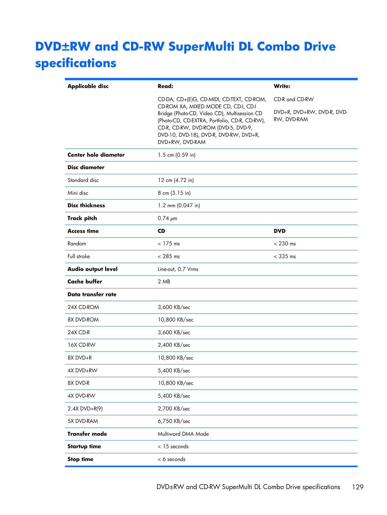
DVD±RW and CD-RW SuperMulti DL Combo Drive specifications Applicable disc Read:
Cd-Da, Cd+(E)G, Cd-Midi, Cd-Text, Cd-Rom,
Cd-Rom Xa, Mixed Mode Cd, Cd-I, Cd-I
Bridge (Photo-CD, Video CD), Multisession CD (Photo-CD, CD-EXTRA, Portfolio, CD-R, CD-RW),Cd-R, Cd-Rw, Dvd-Rom (Dvd-5, Dvd-9,
Dvd-10, Dvd-18), Dvd-R, Dvd-Rw, Dvd+R,
Dvd+Rw, Dvd-Ram
Write: CD-R and CD-RWDvd+R, Dvd+Rw, Dvd-R, Dvd-
Rw, Dvd-Ram
Center hole diameter 1.5 cm (0.59 in) Disc diameter Standard disc 12 cm (4.72 in) Mini disc 8 cm (3.15 in) Disc thickness 1.2 mm (0.047 in) Track pitch 0.74 μm Access timeCd
Dvd
Random < 175 ms < 230 ms Full stroke < 285 ms < 335 ms Audio output level Line-out, 0.7 Vrms Cache buffer2 Mb
Data transfer rate24X Cd-Rom
3,600 KB/sec8X Dvd-Rom
10,800 KB/sec24X Cd-R
3,600 KB/sec16X Cd-Rw
2,400 KB/sec8X Dvd+R
10,800 KB/sec4X Dvd+Rw
5,400 KB/sec8X Dvd-R
10,800 KB/sec4X Dvd-Rw
5,400 KB/sec2.4X Dvd+R(9)
2,700 KB/sec5X Dvd-Ram
6,750 KB/sec Transfer mode Multiword DMA Mode Startup time < 15 seconds Stop time < 6 seconds DVD±RW and CD-RW SuperMulti DL Combo Drive specifications 129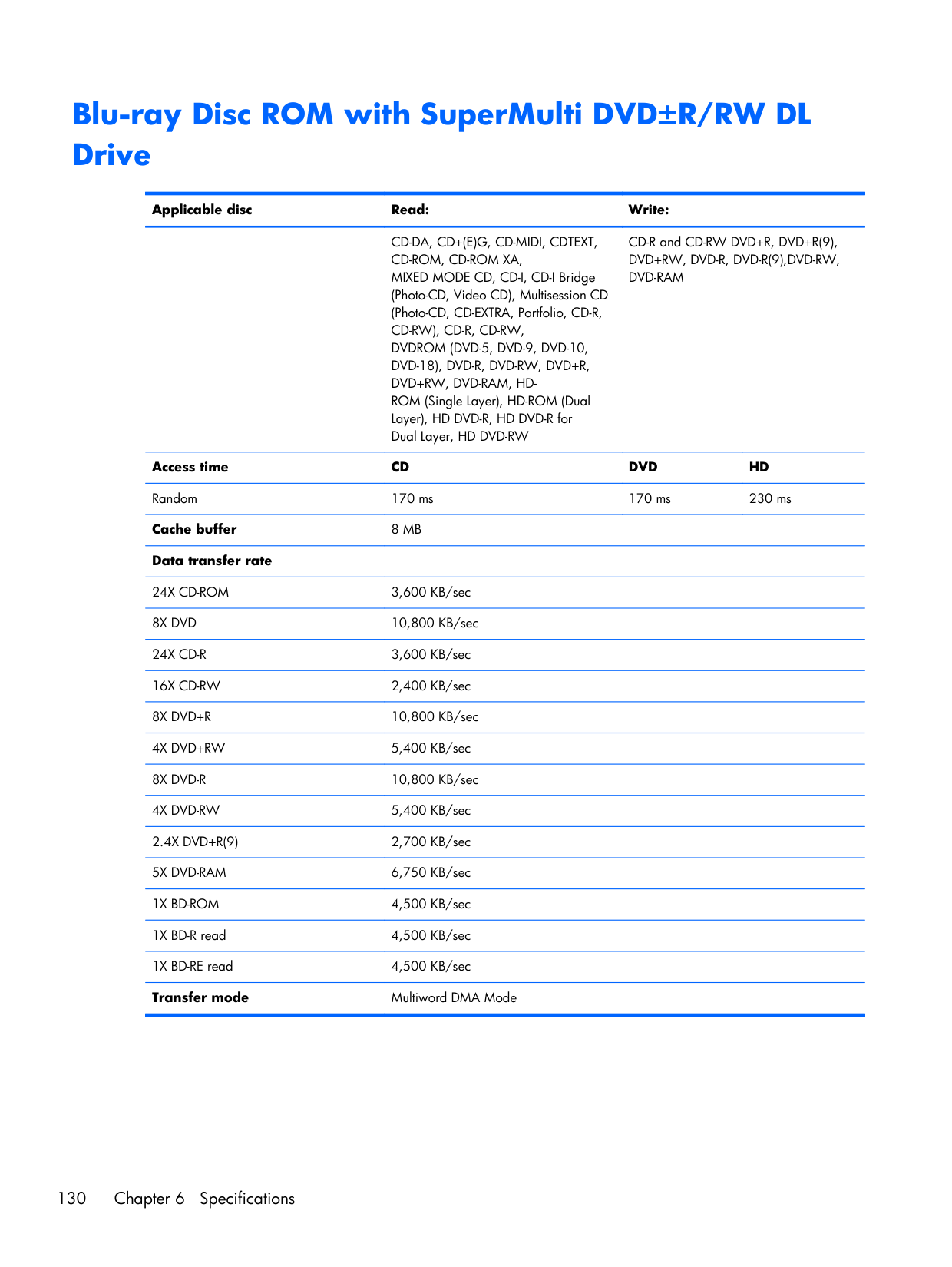
Blu-ray Disc ROM with SuperMulti DVD±R/RW DL Drive Applicable disc Read: Write:
Cd-Da, Cd+(E)G, Cd-Midi, Cdtext,
Cd-Rom, Cd-Rom Xa,
MIXED MODE CD, CD-I, CD-I Bridge (Photo-CD, Video CD), Multisession CD (Photo-CD, CD-EXTRA, Portfolio, CD-R,Cd-Rw), Cd-R, Cd-Rw,
Dvdrom (Dvd-5, Dvd-9, Dvd-10,
Dvd-18), Dvd-R, Dvd-Rw, Dvd+R,
Dvd+Rw, Dvd-Ram, Hd-
ROM (Single Layer), HD-ROM (Dual Layer), HD DVD-R, HD DVD-R for Dual Layer, HD DVD-RW CD-R and CD-RW DVD+R, DVD+R(9),Dvd+Rw, Dvd-R, Dvd-R(9),Dvd-Rw,
Dvd-Ram
Access timeCd
Dvd
Hd
Random 170 ms 170 ms 230 ms Cache buffer8 Mb
Data transfer rate24X Cd-Rom
3,600 KB/sec8X Dvd
10,800 KB/sec24X Cd-R
3,600 KB/sec16X Cd-Rw
2,400 KB/sec8X Dvd+R
10,800 KB/sec4X Dvd+Rw
5,400 KB/sec8X Dvd-R
10,800 KB/sec4X Dvd-Rw
5,400 KB/sec2.4X Dvd+R(9)
2,700 KB/sec5X Dvd-Ram
6,750 KB/sec1X Bd-Rom
4,500 KB/sec 1X BD-R read 4,500 KB/sec 1X BD-RE read 4,500 KB/sec Transfer mode Multiword DMA Mode 130 Chapter 6 Specifications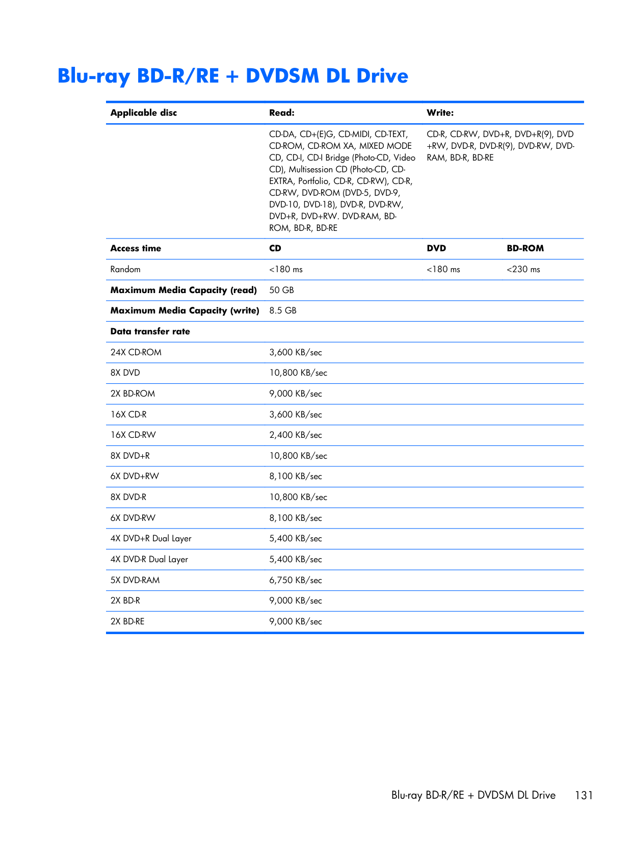
Blu-ray BD-R/RE + DVDSM DL Drive Applicable disc Read: Write:
Cd-Da, Cd+(E)G, Cd-Midi, Cd-Text,
Cd-Rom, Cd-Rom Xa, Mixed Mode
CD, CD-I, CD-I Bridge (Photo-CD, Video CD), Multisession CD (Photo-CD, CD- EXTRA, Portfolio, CD-R, CD-RW), CD-R,Cd-Rw, Dvd-Rom (Dvd-5, Dvd-9,
Dvd-10, Dvd-18), Dvd-R, Dvd-Rw,
Dvd+R, Dvd+Rw. Dvd-Ram, Bd-
Rom, Bd-R, Bd-Re
Cd-R, Cd-Rw, Dvd+R, Dvd+R(9), Dvd
+Rw, Dvd-R, Dvd-R(9), Dvd-Rw, Dvd-
Ram, Bd-R, Bd-Re
Access timeCd
Dvd
Bd-Rom
Random <180 ms <180 ms <230 ms Maximum Media Capacity (read)50 Gb
Maximum Media Capacity (write)8.5 Gb
Data transfer rate24X Cd-Rom
3,600 KB/sec8X Dvd
10,800 KB/sec2X Bd-Rom
9,000 KB/sec16X Cd-R
3,600 KB/sec16X Cd-Rw
2,400 KB/sec8X Dvd+R
10,800 KB/sec6X Dvd+Rw
8,100 KB/sec8X Dvd-R
10,800 KB/sec6X Dvd-Rw
8,100 KB/sec 4X DVD+R Dual Layer 5,400 KB/sec 4X DVD-R Dual Layer 5,400 KB/sec5X Dvd-Ram
6,750 KB/sec2X Bd-R
9,000 KB/sec2X Bd-Re
9,000 KB/sec Blu-ray BD-R/RE + DVDSM DL Drive 131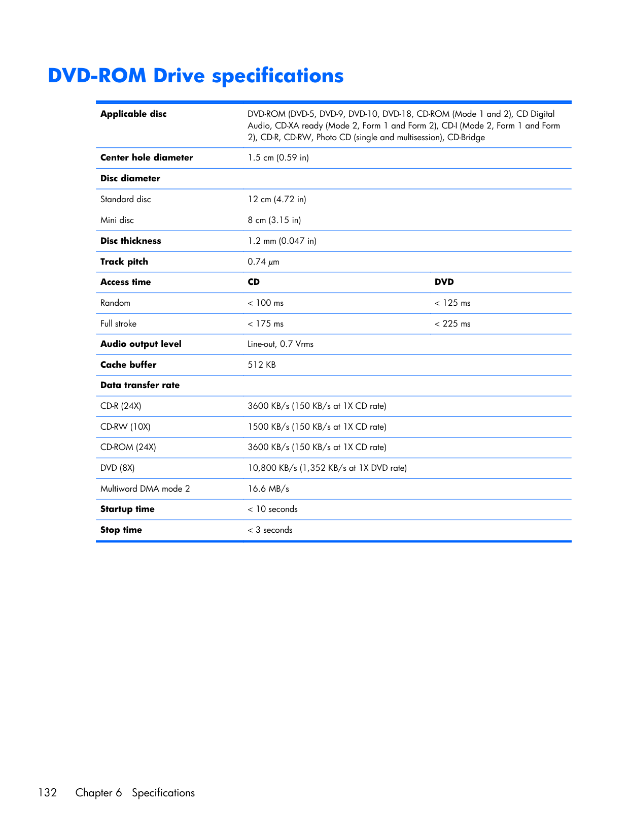
DVD-ROM Drive specifications Applicable disc DVD-ROM (DVD-5, DVD-9, DVD-10, DVD-18, CD-ROM (Mode 1 and 2), CD Digital Audio, CD-XA ready (Mode 2, Form 1 and Form 2), CD-I (Mode 2, Form 1 and Form 2), CD-R, CD-RW, Photo CD (single and multisession), CD-Bridge Center hole diameter 1.5 cm (0.59 in) Disc diameter
Standard disc Mini disc 12 cm (4.72 in) 8 cm (3.15 in) Disc thickness 1.2 mm (0.047 in) Track pitch 0.74 μm Access time
Cd
Dvd
Random < 100 ms < 125 ms Full stroke < 175 ms < 225 ms Audio output level Line-out, 0.7 Vrms Cache buffer512 Kb
Data transfer rateCd-R (24X)
3600 KB/s (150 KB/s at 1X CD rate)Cd-Rw (10X)
1500 KB/s (150 KB/s at 1X CD rate)Cd-Rom (24X)
3600 KB/s (150 KB/s at 1X CD rate)Dvd (8X)
10,800 KB/s (1,352 KB/s at 1X DVD rate) Multiword DMA mode 2 16.6 MB/s Startup time < 10 seconds Stop time < 3 seconds 132 Chapter 6 Specifications
Specification information in Device Manager Device Manager allows you to view and control the hardware attached to the computer, as well as provides hardware specification information. You can also add hardware or modify device configurations using Device Manager.
Note:
Windows 7 and Windows Vista include the User Account Control feature to improve the security of your computer. You may be prompted for your permission or password for tasks such as installing software, running utilities, or changing Windows settings. Refer to Windows Help and Support for more information. After you open Device Manager, drill-down to a device and double-click it to access its properties. To access Device Manager in Windows 7:
7 Backup and recovery Windows 7 ● Backing up your information ● Performing a system recovery To protect your information, use Windows Backup and Restore to back up individual files and folders, back up your entire hard drive (select models only), create system repair discs (select models only) by using the installed optical drive (select models only) or an optional external optical drive, or create system restore points. In case of system failure, you can use the backup files to restore the contents of your computer. Windows Backup and Restore provides the following options: ● Creating a system repair disc (select models only) by using the installed optical drive (select models only) or an optional external optical drive ● Backing up your information ● Creating a system image (select models only) ● Scheduling automatic backups (select models only) ● Creating system restore points ● Recovering individual files ● Restoring the computer to a previous state ● Recovering information using recovery tools
Note:
For detailed instructions, perform a search for these topics in Help and Support. In case of system instability, HP recommends that you print the recovery procedures and save them for later use.Note:
Windows includes the User Account Control feature to improve the security of your computer. You may be prompted for your permission or password for tasks such as installing software, running utilities, or changing Windows settings. Refer to Help and Support for more information. 134 Chapter 7 Backup and recovery
Backing up your information Recovery after a system failure is as good as your most recent backup. You should create system repair discs (select models only) by using the installed optical drive (select models only) or an optional external optical drive, and your initial backup immediately after software setup. As you add new software and data files, you should continue to back up your system on a regular basis to maintain a reasonably current backup. The system repair discs (select models only) are used to start up (boot) the computer and repair the operating system in case of system instability or failure. Your initial and subsequent backups allow you to restore your data and settings if a failure occurs. You can back up your information to an optional external hard drive, a network drive, or discs. Note the following when backing up: ● Store personal files in the Documents library, and back it up regularly. ● Back up templates that are stored in their associated programs. ● Save customized settings that appear in a window, toolbar, or menu bar by taking a screen shot of your settings. The screen shot can be a time-saver if you have to reset your preferences. ● When backing up to discs, use any of the following types of discs (purchased separately): CD-R, CD-RW, DVD+R, DVD+R DL, DVD-R, DVD-R DL, or DVD±RW. The discs you use will depend on the type of optical drive installed in your computer or the type of external optical drive you are using.
Note:
DVDs and DVDs with double-layer (DL) support store more information than CDs, so using them for backup reduces the number of recovery discs required. ● When backing up to discs, number each disc before inserting it into the optical drive of the computer. To create a backup using Backup and Restore:Note:
Be sure that the computer is connected to AC power before you start the backup process.Note:
The backup process may take over an hour, depending on file size and the speed of the computer.
Note:
If you are unable to boot (start up) your computer and you cannot use the system repair discs you previously created (select models only), you must purchase a Windows 7 operating system DVD to reboot the computer and repair the operating system. For additional information, refer to Using a Windows 7 operating system DVD (purchased separately) on page 137. Using the Windows recovery tools To recover information you previously backed up:Caution:
Using Startup Repair completely erases hard drive contents and reformats the hard drive. All files you have created and any software installed on the computer are permanently removed. When reformatting is complete, the recovery process restores the operating system, as well as the drivers, software, and utilities from the backup used for recovery.Note:
If the Windows partition and the HP Recovery partition are not listed, you must recover your operating system and programs using the Windows 7 operating system DVD and the Driver Recovery disc (both purchased separately). For additional information, refer to Using a Windows 7 operating system DVD (purchased separately) on page 137.Note:
For additional information on recovering information using the Windows tools, perform a search for these topics in Help and Support. Using f11 recovery toolsCaution:
Using f11 completely erases hard drive contents and reformats the hard drive. All files you have created and any software installed on the computer are permanently removed. The f11 recovery tool reinstalls the operating system and HP programs and drivers that were installed at the factory. Software not installed at the factory must be reinstalled. 136 Chapter 7 Backup and recovery
To recover the original hard drive image using f11:
Note:
If the HP Recovery partition is not listed, you must recover your operating system and programs using the Windows 7 operating system DVD and the Driver Recovery disc (both purchased separately). For additional information, refer to Using a Windows 7 operating system DVD (purchased separately) on page 137.Caution:
Using a Windows 7 operating system DVD completely erases hard drive contents and reformats the hard drive. All files you have created and any software installed on the computer are permanently removed. When reformatting is complete, the recovery process helps you restore the operating system, as well as drivers, software, and utilities. To initiate recovery using a Windows 7 operating system DVD:Note:
This process takes several minutes.
Windows Vista To protect your information, use the Backup and Restore Center to back up individual files and folders, back up your entire hard drive (select models only), or create system restore points. In case of system failure, you can use the backup files to restore the contents of your computer. The Backup and Restore Center provides the following options: ● Backing up individual files and folders ● Backing up the entire hard drive (select models only) ● Scheduling automatic backups (select models only) ● Creating system restore points ● Recovering individual files ● Restoring the computer to a previous state ● Recovering information using recovery tools
Note:
For detailed instructions, perform a search for these topics in Help and Support.Note:
In case of system instability, HP recommends that you print the recovery procedures and save them for later use.Note:
Windows® includes the User Account Control feature to improve the security of your computer. You may be prompted for your permission or password for tasks such as installing software, running utilities, or changing Windows settings. Refer to Help and Support for more information. Backing up your information Recovery after a system failure is as complete as your most current backup. You should create your initial backup immediately after software setup. As you add new software and data files, you should continue to back up your system on a regular basis to maintain a reasonably current backup. You can back up your information to an optional external hard drive, a network drive, or discs. Note the following when backing up: ● Store personal files in the Documents folder, and back it up regularly. ● Back up templates that are stored in their associated programs. ● Save customized settings that appear in a window, toolbar, or menu bar by taking a screen shot of your settings. The screen shot can be a time-saver if you have to reset your preferences. ● When backing up to discs, use any of the following types of discs (purchased separately): CD-R, CD-RW, DVD+R, DVD+R DL, DVD-R, DVD-R DL, or DVD±RW. The discs you use will depend on the type of optical drive installed in your computer. 138 Chapter 7 Backup and recovery
Note:
DVDs and DVDs with double-layer (DL) support store more information than CDs, so using them for backup reduces the number of recovery discs required. ● When backing up to discs, number each disc before inserting it into the optical drive of the computer. To create a backup using Backup and Restore Center:Note:
Be sure that the computer is connected to AC power before you start the backup process.Note:
The backup process may take over an hour, depending on file size and the speed of the computer.Note:
If you are unable to boot (start up) your computer, you must purchase a Windows Vista® operating system DVD to reboot the computer and repair the operating system. For additional information, refer to Using a Windows Vista operating system DVD (purchased separately) on page 141. Using the Windows recovery tools To recover information you previously backed up:
Caution:
Using Startup Repair completely erases hard drive contents and reformats the hard drive. All files you have created and any software installed on the computer are permanently removed. When reformatting is complete, the recovery process restores the operating system, as well as the drivers, software, and utilities from the backup used for recovery.Note:
If the Windows partition and the HP Recovery partition have been deleted, you must recover your operating system and programs using the Windows Vista operating system DVD and the Driver Recovery disc (both purchased separately). For additional information, refer to Using a Windows Vista operating system DVD (purchased separately) on page 141.Note:
For additional information on recovering information using the Windows tools, perform a search for these topics in Help and Support. Using f11 recovery toolsCaution:
Using f11 completely erases hard drive contents and reformats the hard drive. All files you have created and any software installed on the computer are permanently removed. The f11 recovery tool reinstalls the operating system and HP programs and drivers that were installed at the factory. Software not installed at the factory must be reinstalled. Personal files must be restored from a backup.Note:
If your computer includes a solid-state drive (SSD), you may not have a recovery partition. Recovery discs have been included for computers that do not have a partition. Use these discs to recover your operating system and software. To check for the presence of a recovery partition, select Start > Computer. If the partition is present, an HP Recovery drive is listed in the Hard Disk Drives section of the window. To recover the original hard drive image using f11, follow these steps:Note:
If the HP Recovery partition has been deleted, you must recover your operating system and programs using the Windows Vista operating system DVD and the Driver Recovery disc (both purchased separately). For additional information, refer to Using a Windows Vista operating system DVD (purchased separately) on page 141.
Caution:
Using a Windows Vista operating system DVD completely erases hard drive contents and reformats the hard drive. All files you have created and any software installed on the computer are permanently removed. When reformatting is complete, the recovery process helps you restore the operating system, as well as drivers, software, and utilities. To initiate recovery using a Windows Vista operating system DVD:Note:
This process takes several minutes.
8 Power cord set requirements The wide range input feature of the computer permits it to operate from any line voltage from 100 to 120 volts AC, or from 220 to 240 volts AC. The 3-conductor power cord set included with the computer meets the requirements for use in the country or region where the equipment is purchased. Power cord sets for use in other countries and regions must meet the requirements of the country or region where the computer is used. Requirements for all countries and regions The requirements listed below are applicable to all countries and regions: ● The length of the power cord set must be at least 1.5 m (5.0 ft) and no more than 2.0 m (6.5 ft). ● All power cord sets must be approved by an acceptable accredited agency responsible for evaluation in the country or region where the power cord set will be used. ● The power cord sets must have a minimum current capacity of 10 amps and a nominal voltage rating of 125 or 250 V AC, as required by the power system of each country or region. ● The appliance coupler must meet the mechanical configuration of an EN 60 320/IEC 320 Standard Sheet C13 connector for mating with the appliance inlet on the back of the computer. 142 Chapter 8 Power cord set requirements
Requirements for specific countries and regions Country/region Accredited agency Applicable note number Australia
Eansw
1 AustriaOve
1 BelgiumCebc
1 CanadaCsa
2 DenmarkDemko
1 FinlandFimko
1 FranceUte
1 GermanyVde
1 ItalyImq
1 JapanMeti
3 The NetherlandsKema
1 NorwayNemko
1 The People's Republic of ChinaCcc
5 South KoreaEk
4 SwedenSemko
1 SwitzerlandSev
1 TaiwanBsmi
4 The United KingdomBsi
1 The United StatesUl
2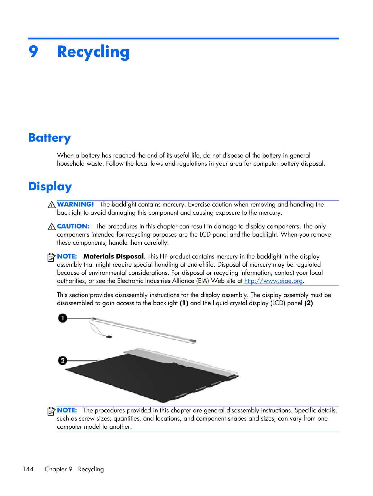
9 Recycling Battery When a battery has reached the end of its useful life, do not dispose of the battery in general household waste. Follow the local laws and regulations in your area for computer battery disposal. Display
Warning!
The backlight contains mercury. Exercise caution when removing and handling the backlight to avoid damaging this component and causing exposure to the mercury.Caution:
The procedures in this chapter can result in damage to display components. The only components intended for recycling purposes are the LCD panel and the backlight. When you remove these components, handle them carefully.Note:
Materials Disposal. This HP product contains mercury in the backlight in the display assembly that might require special handling at end-of-life. Disposal of mercury may be regulated because of environmental considerations. For disposal or recycling information, contact your local authorities, or see the Electronic Industries Alliance (EIA) Web site at http://www.eiae.org. This section provides disassembly instructions for the display assembly. The display assembly must be disassembled to gain access to the backlight (1) and the liquid crystal display (LCD) panel (2).Note:
The procedures provided in this chapter are general disassembly instructions. Specific details, such as screw sizes, quantities, and locations, and component shapes and sizes, can vary from one computer model to another. 144 Chapter 9 Recycling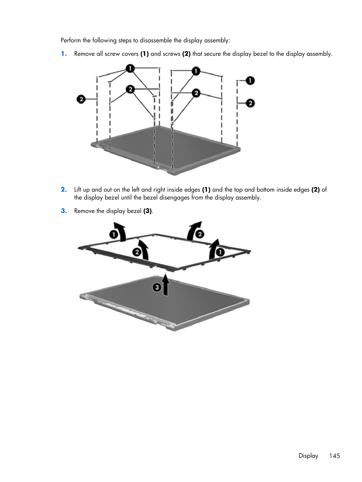
Perform the following steps to disassemble the display assembly:
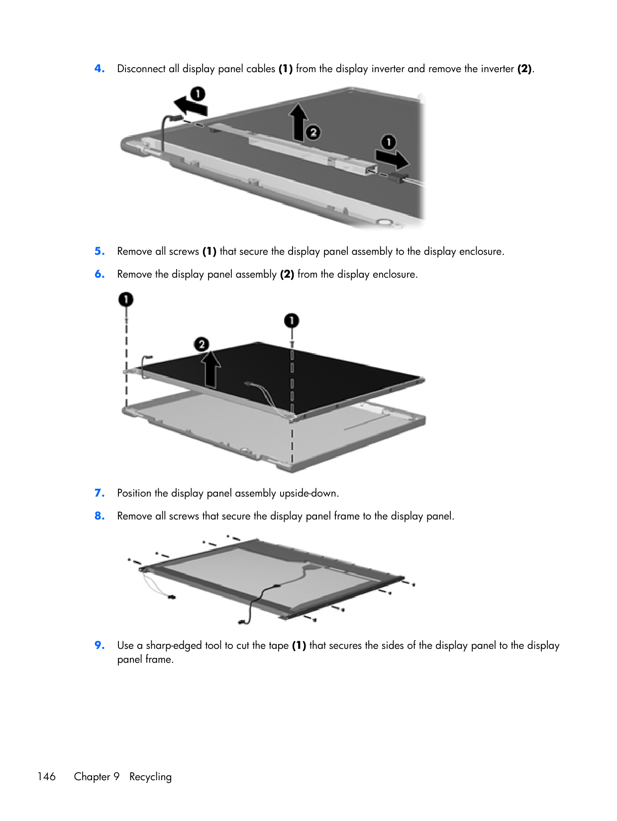
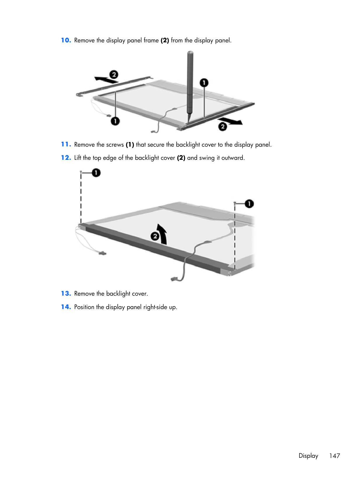
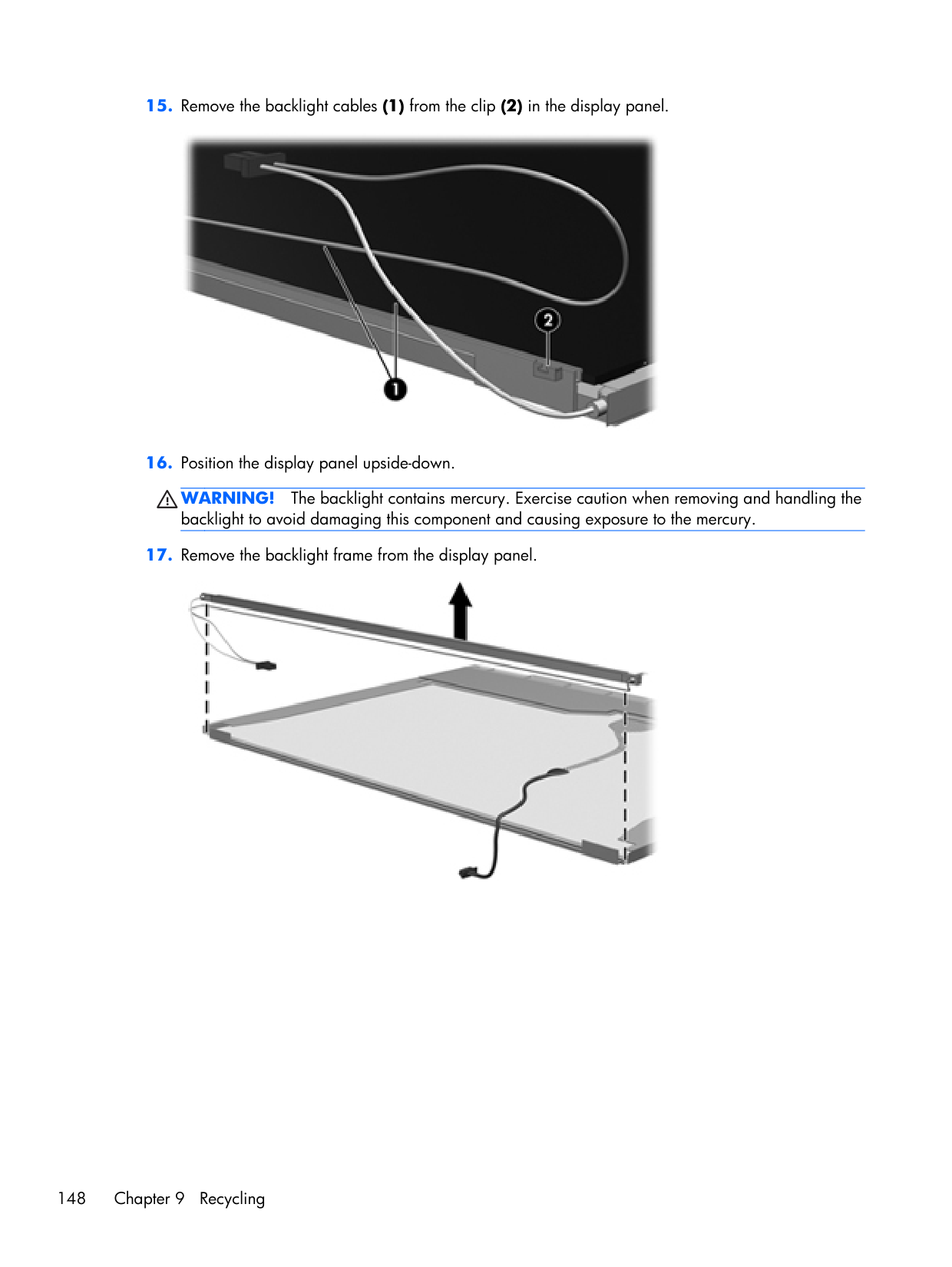
Warning!
The backlight contains mercury. Exercise caution when removing and handling the backlight to avoid damaging this component and causing exposure to the mercury.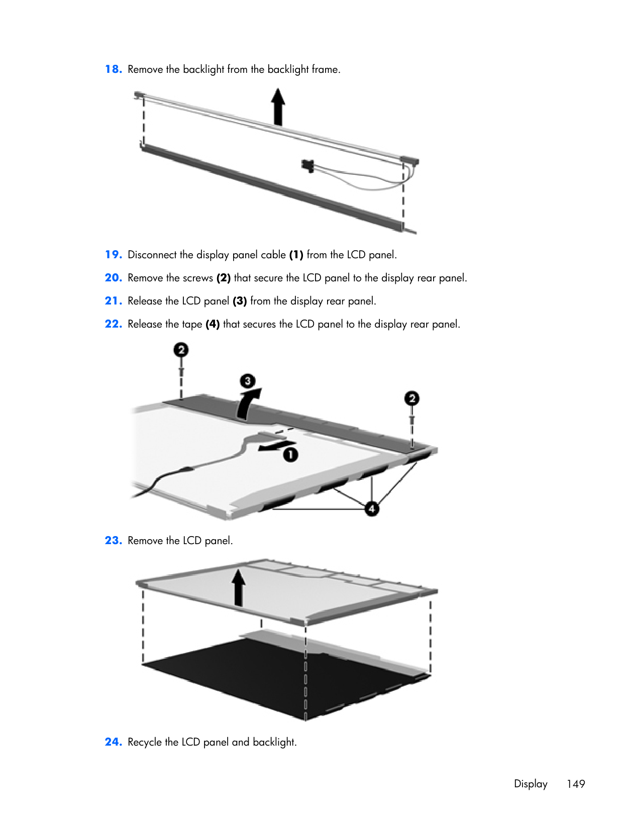
Index Symbols/Numerics 1394 port, identifying 21
A
AC adapter, spare part numbers 41, 44 accessory battery connector, identifying 25 ambient light sensor spare part number 53 ambient light sensor, identifying 11 antennas disconnecting 79, 84 audio, product description 4 audio-in (microphone) jack 23, 24 audio-out (headphone) jack 23, 24B
Backup and Restore 135 Backup and Restore Center 138, 139 base enclosure, spare part number 35, 49 battery removal 61 spare part number 34, 61 battery bay 25 battery light 20 battery release latch 25Bios
determining version 122 downloading an update 123 updating 122 Blu-ray BD-R/RE + DVDSM DL Drive, specifications 131 Blu-ray BD-R/RE DVD±RW SuperMulti DL Drive spare part number 34, 52, 70 Blu-ray Disc ROM with SuperMulti DVD±R/RW DL Drive spare part number 40 specifications 130 Blu-ray ROM DVD±RW SuperMulti DL Drive, spare part number 34, 40, 52, 70 Bluetooth cable, illustrated 38 Bluetooth compartment, identifying 26 Bluetooth module removal 86 spare part number 42 spare part numbers 34, 86 bottom cover removal 96 spare part number 96 Bottom cover release latch, identifying 25 bottom door illustrated 39 removal 68 spare part number 68 buttons left pointing stick button 13 left TouchPad 13 optical drive eject 22 power 17 QuickWeb 17 right pointing stick button 13 right TouchPad 13 TouchPad 16 TouchPad on/off 13 volume mute 17 wireless 17C
Cable Kit contents 38 spare part number 34, 38, 46 cables, service considerations 55 caps lock light, identifying 14 chipset, product description 1 components bottom 25 display 10 front 20 left side 21 rear 22 right side 23 top 13 computer feet locations 60 spare part number 60 Computer Setup navigating and selecting 120 restoring factory settings 121 computer specifications 125 connector, docking 25 connector, power 21 connectors, service considerations 55D
diskette drive precautions 55 display assembly removal 108 spare part numbers 108 display assembly components removal 63 spare part numbers 63 display bezel removal 64, 110 150 Index
spare part number 53 spare part numbers 36, 63 display component recycling 144 display components, spare part numbers 36 display enclosure, spare part number 51 spare part number 37 display hinge removal 112 spare part number 49 display hinge covers spare part number 37, 52 Display Hinge Kit spare part number 37, 52 Display Latch Kit spare part number 37, 49 display panel product description 2 removal 66 spare part number 37, 52, 63 display release latch 20 Display Rubber Kit, spare part number 38, 52, 63 Display Screw Kit, spare part number 37, 52, 63 display specifications 126, 127 DisplayPort, identifying 23, 24 docking connector, identifying 25 docking support, product description 5 drives preventing damage 55 DVD-ROM Drive precautions 55 removal 70 spare part number 34, 40, 52, 70 specifications 132 DVD±RW and CD-RW SuperMulti DL Combo Drive with LightScribe precautions 55 removal 70 spare part number 34, 40, 52, 70
E
electrostatic discharge 56 embedded numeric keypad, identifying 19 eSATA port, identifying 23, 24 esc key, identifying 18 Ethernet, product description 4 ExpressCard assembly removal 118 spare part number 29, 51, 118 ExpressCard slot 21 ExpressCard slot insert, illustrated illustrated 39 external media cards, product description 5 external monitor port 22F
f11 recovery 136, 140 fan removal 88 spare part number 34, 49, 88 feet locations 60 spare part number 60 fingerprint reader board removal 100 spare part number 29 spare part numbers 100 fingerprint reader board, spare part number 51 fingerprint reader, identifying 17 fn key, identifying 19 function keys identifying 18G
graphics, product description 1 grounding equipment and methods 58H
hard drive precautions 55 product description 3 removal 74 spare part number 44 spare part numbers 34, 40, 46, 74 specifications 128 hard drive bracket, removal 75 Hard Drive Hardware Kit, spare part number 40, 51 hard drive light 21 hard drive recovery 136, 140 heat sink removal 89 spare part number 34, 51, 89 hinge removal 112 spare part number 49 HP QuickWeb light 15I
integrated webcam light, identifying 11, 12 internal display switch 10, 11 internal microphones, identifying 11, 12J
jacks audio-in (microphone) 23, 24 audio-out (headphone) 23, 24 network 22 RJ-11 (modem) 22 RJ-45 (network) 22K
keyboard product description 6 removal 93 spare part numbers 29, 46, 47, 50, 93 keypad, embedded numeric 19 keys esc 18 fn 19 function 18 menu 19 num lk 19 start 19L
latch, battery release 25 latch, bottom cover release 25 legacy support, USB 120 lid switch removal 102 spare part number 29, 51 spare part numbers 102 light sensor, identifying 11 lights battery 20 caps lock 14 Index 151
hard drive 21 HP QuickWeb 15 mute 15 num lock 15 power 14, 20 webcam 11, 12 wireless 15, 20
M
mass storage devices, spare part numbers 40 Media Card Reader, identifying 21 memory module product description 2 removal 77 spare part numbers 34, 77 memory module compartment, identifying 26 menu key, identifying 19 microphone (audio-in) jack product description 3 microphone module spare part number 36, 52, 63 Mobile Broadband Module, identifying 26 model name 1 modem module product description 4 removal 87 spare part number 30, 44, 87 mute light, identifying 15N
network jack, identifying 22 num lk key, identifying 19 num lock light 15O
operating system, product description 6 optical drive precautions 55 product description 3 removal 70 spare part numbers 34, 40, 70 specifications 129, 130, 131, 132 optical drive eject button, identifying 22 optical drive protective insert illustrated 39 optical drive, identifying 22P
packing guidelines 57 plastic parts 54 Plastics Kit spare part number 52 Plastics Kit, spare part number 39, 46 pointing device, product description 6 pointing stick 13 pointing stick cable, illustrated 38 ports 1394 21 DisplayPort 23, 24 eSATA 23, 24 external monitor 22 product description 5Usb
21, 23, 24 power button, identifying 17 power connector, identifying 21 power cord set requirements 142 spare part numbers 41, 42 power light 14, 20 power requirements, product description 6 processor product description 1 removal 92 spare part numbers 33, 46, 53, 92 product description audio 4 chipset 1 display panel 2 docking support 5 Ethernet 4 external media cards 5 graphics 1 hard drives 3 keyboard 6 memory module 2 microphone 3 modem module 4 operating system 6 optical drives 3 pointing devices 6 ports 5 power requirements 6 processors 1 product name 1 security 6 serviceability 8 webcam 4 wireless 4 product name 1Q
QuickWeb button, identifying 17R
recovery partition 136, 140 removal/replacement preliminaries 54 procedures 59 restoring the hard drive 136, 140 RJ-11 (modem) jack, identifying 22 RJ-11 connector cable illustrated 38 removal 106 RJ-11 jack, illustrated 39 RJ-45 (network) jack, identifying 22 RTC battery removal 76 spare part number 29, 53, 76 Rubber Kit, spare part number 46S
Screw Kit, spare part number 41, 46 security cable slot, identifying 23, 24 security, product description 6 service considerations 54 service tag 27, 59 serviceability, product description 8 setup utility navigating and selecting 120 restoring factory settings 121 SIM slot, identifying 25 SIM, removal 62 slots ExpressCard 21 security cable 23, 24 152 Index
smart card reader spare part number 29, 51, 69 smart card reader assembly removal 69 spare part number 69 solid-state drive, spare part numbers 34, 40, 52, 74 speaker assembly removal 104 spare part number 34, 49, 104 speakers, identifying 21, 25 specifications Blu-ray BD-R/RE + DVDSM DL Drive 131 Blu-ray Disc ROM with SuperMulti DVD±R/RW DL Drive 130 computer 125 display 126, 127 DVD-ROM Drive 132 DVD±RW and CD-RW SuperMulti DL Combo Drive 129 hard drive 128 optical drive 129, 130, 131, 132 start key, identifying 19 static-shielding materials 58 system board removal 115 spare part number 29 spare part numbers 49, 53, 115 system repair disc 134 system restore points 134