
Ask AI
— answers from the official manualAnswers from the official manual.
Common questions
Common Questions
20 totalWhat should I do if my HP ProBook stops responding and normal shutdown procedures don't work?
Press and hold the Power button for at least 5 seconds to force shut down the computer.
What should I do if the power light doesn't turn on?
Ensure that the computer is connected to an AC source and that there isn’t any obstruction in the battery access that prevents proper connection or charging issues.
How do I properly reset the BIOS settings to factory defaults?
To restore factory settings, press F10 while booting to open Setup Utility. Navigate through the menus using arrow keys, go to ‘Restore Defaults,’ and follow on-screen instructions for setting confirmation.
What should I do if the computer stops responding and won't shut down normally?
Press and hold the power button for at least 5 seconds to turn off the computer. This forced shutdown method should only be used when the computer has stopped responding and Windows shutdown procedures are ineffective. (Page 19)
Is it safe to place the HP ProBook 4530s on my lap or on a soft surface like a pillow?
No, you should not place the computer directly on your lap or on soft surfaces such as pillows, rugs, or clothing. These surfaces can obstruct the computer's air vents and cause heat-related injuries or overheating. The computer should only be used on a hard, flat surface. (Page 3)
How much RAM can the HP ProBook 4530s support, and what memory types are compatible?
The HP ProBook 4530s supports up to 8 GB of RAM across two customer-accessible and upgradeable memory module slots. It uses PC3-10600, 1333-MHz, DDR3 memory and supports dual-channel memory configurations ranging from 1024 MB to 8192 MB. (Page 10)
Show 14 more questions
What does the amber light on the AC adapter indicate?
Which components can end users replace themselves on the HP ProBook 4530s?
How do I perform a system recovery on the HP ProBook 4530s running Windows 7?
What does the amber drive light on the front of the laptop mean?
Where is the SIM card slot located on the HP ProBook 4530s?
How do I access Computer Setup (BIOS) on the HP ProBook 4530s?
What wireless connectivity options are available on the HP ProBook 4530s?
How much RAM can my model handle and what are the supported configurations?
How do I access the computer setup menu?
Which hard drives are supported and what are their specifications?
Which WLAN formats and models does my HP ProBook support?
What happens if my computer goes into Hibernation?
How do I update or check my BIOS version?
What security measures can I take with my ProBook?
Full Manual
153 pages
HP ProBook 4530s Notebook PC HP ProBook 4730s Notebook PC
Maintenance and Service Guide
© Copyright 2011 Hewlett-Packard Development Company, L.P.
Bluetooth is a trademark owned by its proprietor and used by Hewlett-Packard Company under license. Intel and Core are trademarks or registered trademarks of Intel Corporation in the United States and other countries. Microsoft, Windows, and Windows Vista are either trademarks or registered trademarks of Microsoft Corporation in the United States and/or other countries. SD Logo is a trademark of its proprietor.
The information contained herein is subject to change without notice. The only warranties for HP products and services are set forth in the express warranty statements accompanying such products and services. Nothing herein should be construed as constituting an additional warranty. HP shall not be liable for technical or editorial errors or omissions contained herein.
Third Edition: October 2011 First Edition: March 2011 Document Part Number: 650281-003
#### Safety warning notice
WARNING! To reduce the possibility of heat-related injuries or of overheating the computer, do not place the computer directly on your lap or obstruct the computer air vents. Use the computer only on a hard, flat surface. Do not allow another hard surface, such as an adjoining optional printer, or a soft surface, such as pillows or rugs or clothing, to block airflow. Also, do not allow the AC adapter to contact the skin or a soft surface, such as pillows or rugs or clothing, during operation. The computer and the AC adapter comply with the user-accessible surface temperature limits defined by the International Standard for Safety of Information Technology Equipment (IEC 60950).
iii
####### iv Safety warning notice
Table of contents
TouchPad ............................................................................................................................ 9 Lights ................................................................................................................................. 10 Buttons and fingerprint reader (select models only) .......................................................... 11 Keys ................................................................................................................................... 13
Front ................................................................................................................................................... 14 Left ..................................................................................................................................................... 15 Right ................................................................................................................................................... 16 Bottom ................................................................................................................................................ 17
Tools required .................................................................................................................... 41 Service considerations ....................................................................................................... 41
Plastic parts ....................................................................................................... 41 Cables and connectors ..................................................................................... 42 Drive handling ................................................................................................... 42
v
Grounding guidelines ......................................................................................................... 43
Electrostatic discharge damage ........................................................................ 43 Packaging and transporting guidelines ............................................. 44 Workstation guidelines ..................................................................... 44 Equipment guidelines ....................................................................... 45
Component replacement procedures ................................................................................................. 46 Service tag ......................................................................................................................... 46 Battery ............................................................................................................................... 47 SIM .................................................................................................................................... 48 Bottom door ....................................................................................................................... 49 Optical drive ....................................................................................................................... 50 Hard drive .......................................................................................................................... 52 Memory modules ............................................................................................................... 54 WWAN module .................................................................................................................. 56 WLAN/Bluetooth combo card ............................................................................................ 58 Keyboard ........................................................................................................................... 63 Top cover ........................................................................................................................... 65 Card reader board ............................................................................................................. 70 Speaker assembly ............................................................................................................. 71 Quick Launch board ........................................................................................................... 73 Power button board ........................................................................................................... 74 Modem module .................................................................................................................. 76 Lid switch ........................................................................................................................... 78 USB board ......................................................................................................................... 80 Optical drive connector ...................................................................................................... 82 RJ-11 jack cable ................................................................................................................ 84 System board ..................................................................................................................... 85 Hard drive extension board (4730s models) ...................................................................... 89 RTC battery ....................................................................................................................... 91 Fan ..................................................................................................................................... 93 Heat sink ............................................................................................................................ 95 Processor ........................................................................................................................... 97 Power cable ..................................................................................................................... 100 Display assembly ............................................................................................................. 102
###### 5 Computer Setup (BIOS) and System Diagnostics ................................................................................... 112Using Computer Setup ..................................................................................................................... 112
Starting Computer Setup ................................................................................................. 112 Navigating and selecting in Computer Setup ................................................................... 112 Restoring factory settings in Computer Setup ................................................................. 113 Updating the BIOS ........................................................................................................... 114
vi
Determining the BIOS version ......................................................................... 114 Downloading a BIOS update ........................................................................... 114
Using System Diagnostics ................................................................................................................ 115
Backing up your information ............................................................................................ 126 Performing a system recovery ......................................................................................... 127
Using the Windows recovery tools .................................................................. 128 Using f11 recovery tools .................................................................................. 128 Using a Windows 7 operating system DVD (purchased separately) ............... 129
Windows Vista .................................................................................................................................. 130 Backing up your information ............................................................................................ 130 Performing a recovery ..................................................................................................... 131
Using the Windows recovery tools .................................................................. 131 Using f11 recovery tools .................................................................................. 132 Using a Windows Vista operating system DVD (purchased separately) ......... 132
###### Index ................................................................................................................................................................. 142
vii
####### viii
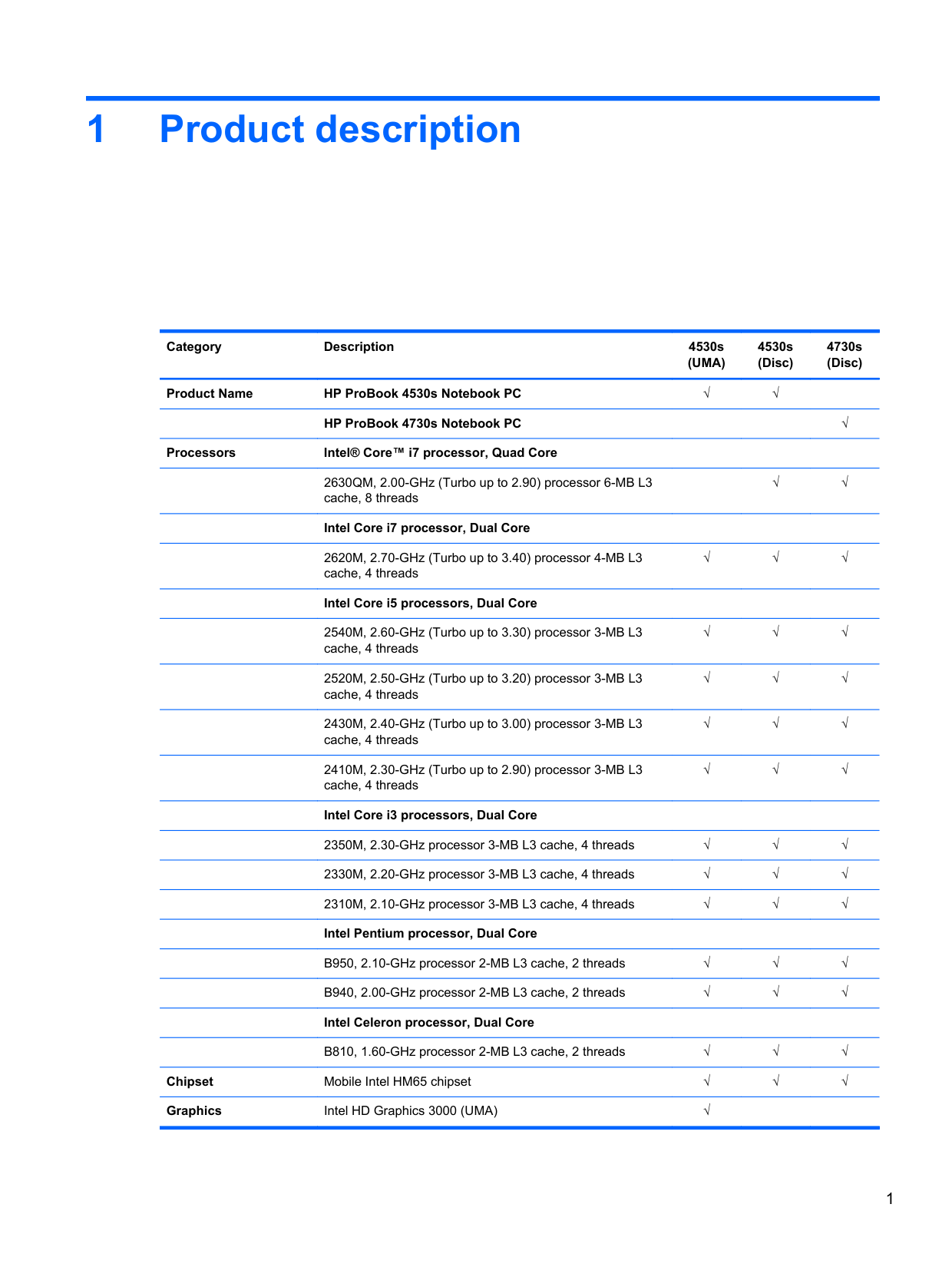
1 Product description
Category Description 4530s (UMA)
4530s (Disc)
4730s (Disc)
Product Name HP ProBook 4530s Notebook PC √√
HP ProBook 4730s Notebook PC √ Processors Intel® Core™ i7 processor, Quad Core
2670QM, 2.20-GHz (Turbo up to 3.10) processor 6-MB L3 cache, 8 threads
2630QM, 2.00-GHz (Turbo up to 2.90) processor 6-MB L3 cache, 8 threads
######## Intel Core i7 processor, Dual Core
2620M, 2.70-GHz (Turbo up to 3.40) processor 4-MB L3 cache, 4 threads
######## Intel Core i5 processors, Dual Core
2540M, 2.60-GHz (Turbo up to 3.30) processor 3-MB L3 cache, 4 threads
2520M, 2.50-GHz (Turbo up to 3.20) processor 3-MB L3 cache, 4 threads
2450M, 2.50-GHz (Turbo up to 3.10) processor 3-MB L3 cache, 4 threads
2430M, 2.40-GHz (Turbo up to 3.00) processor 3-MB L3 cache, 4 threads
2410M, 2.30-GHz (Turbo up to 2.90) processor 3-MB L3 cache, 4 threads
######## Intel Core i3 processors, Dual Core
√√
√√
√√√
√√√
√√√
√√√
√√√
√√√
2370M, 2.40-GHz processor 3-MB L3 cache, 4 threads √√√ 2350M, 2.30-GHz processor 3-MB L3 cache, 4 threads √√√ 2330M, 2.20-GHz processor 3-MB L3 cache, 4 threads √√√ 2310M, 2.10-GHz processor 3-MB L3 cache, 4 threads √√√ Intel Pentium processor, Dual Core
B950, 2.10-GHz processor 2-MB L3 cache, 2 threads √√√ B940, 2.00-GHz processor 2-MB L3 cache, 2 threads √√√
######## Intel Celeron processor, Dual Core
B840, 1.90-GHz processor 2-MB L3 cache, 2 threads √√√ B810, 1.60-GHz processor 2-MB L3 cache, 2 threads √√√
Chipset Mobile Intel HM65 chipset √√√ Graphics Intel HD Graphics 3000 (UMA) √
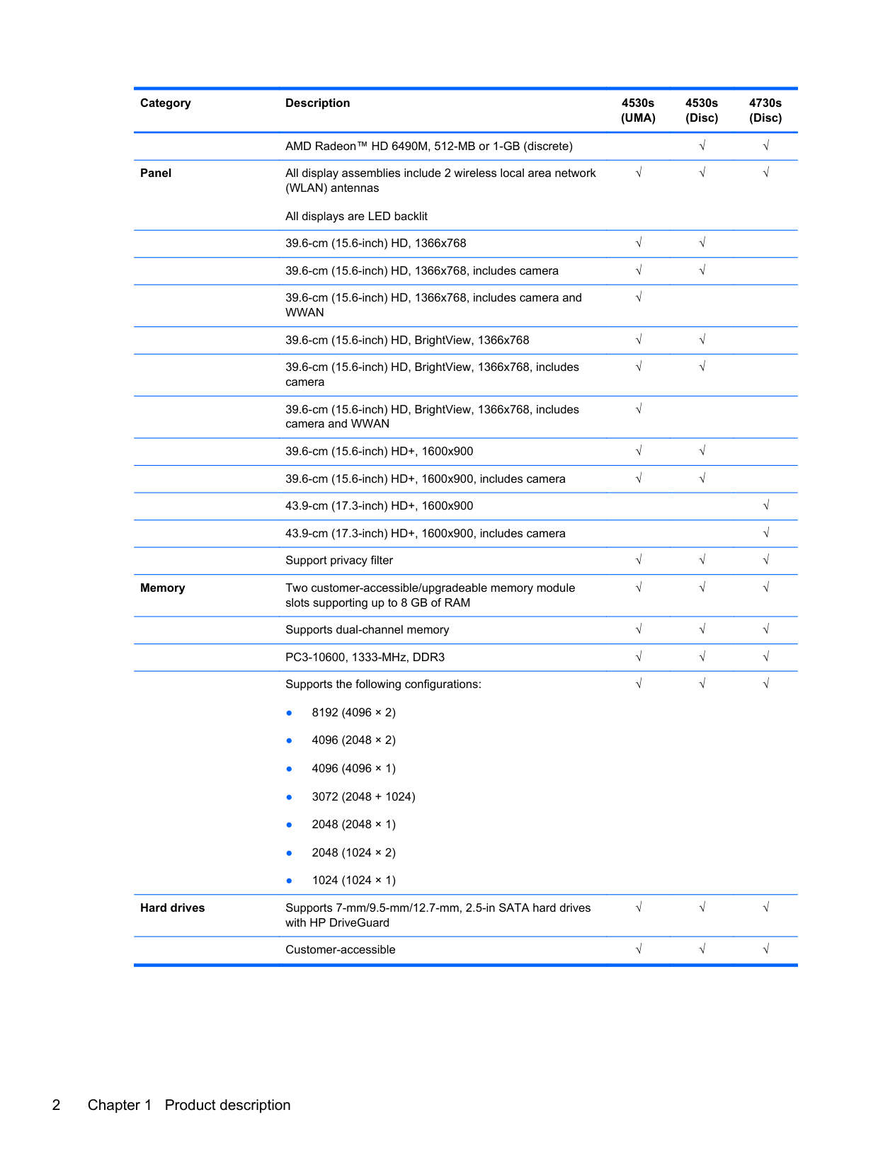
AMD Radeon™ HD 6490M, 512-MB or 1-GB (discrete) √√
Panel All display assemblies include 2 wireless local area network (WLAN) antennas All displays are LED backlit
√√√
39.6-cm (15.6-inch) HD, 1366x768 √√ 39.6-cm (15.6-inch) HD, 1366x768, includes camera √√ 39.6-cm (15.6-inch) HD, 1366x768, includes camera and WWAN
√
39.6-cm (15.6-inch) HD, BrightView, 1366x768 √√ 39.6-cm (15.6-inch) HD, BrightView, 1366x768, includes camera
√√
39.6-cm (15.6-inch) HD, BrightView, 1366x768, includes camera and WWAN
√
39.6-cm (15.6-inch) HD+, 1600x900 √√ 39.6-cm (15.6-inch) HD+, 1600x900, includes camera √√ 43.9-cm (17.3-inch) HD+, 1600x900 √ 43.9-cm (17.3-inch) HD+, 1600x900, includes camera √ Support privacy filter √√√
Memory Two customer-accessible/upgradeable memory module
slots supporting up to 8 GB of RAM
√√√
Supports dual-channel memory √√√
PC3-10600, 1333-MHz, DDR3 √√√ Supports the following configurations:
√√√

Hard drives Supports 7-mm/9.5-mm/12.7-mm, 2.5-in SATA hard drives
with HP DriveGuard
√√√
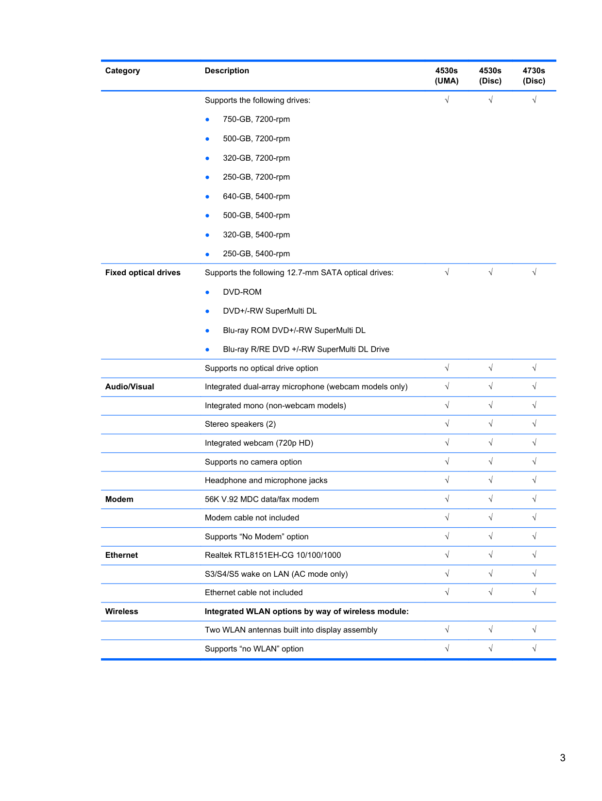
Customer-accessible √√√ Supports the following drives:
√√√
Fixed optical drives Supports the following 12.7-mm SATA optical drives:
√√√
Supports no optical drive option √√√ Audio/Visual Integrated dual-array microphone (webcam models only) √√√ Integrated mono (non-webcam models) √√√
Stereo speakers (2) √√√ Integrated webcam (720p HD) √√√ Supports no camera option √√√ Headphone and microphone jacks √√√
Modem 56K V.92 MDC data/fax modem √√√
Modem cable not included √√√ Supports “No Modem” option √√√
Ethernet Realtek RTL8151EH-CG 10/100/1000 √√√ S3/S4/S5 wake on LAN (AC mode only) √√√
Ethernet cable not included √√√ Wireless Integrated WLAN options by way of wireless module:
Two WLAN antennas built into display assembly √√√ Supports “no WLAN” option √√√
Supports the following WLAN formats:
######## Integrated WWAN options by way of wireless module:
Two WWAN antennas built into display assembly (worldwide 5 band, configured with panels on all units)
Subscriber identity module (SIM) security (customeraccessible in battery bay)
√√√
√
√
Supports “no WWAN” option √ Supports the following WWAN modules:
√
Integrated personal area network (PAN) options by way of Bluetooth® module: Bluetooth 3.0 only supported by combo card √√√
External media card One ExpressCard 34mm slot √√√ 6-in-1 Digital Media Reader Slot √√√ Ports Audio-in (stereo microphone) √√√ Audio-out (stereo headphone) √√√
Keyboard/pointing devices
RJ-11 (modem) √√√ RJ-45 (Ethernet, includes link and activity lights) √√√ USB 3.0 (1) √√√ USB 2.0 (3) √√√ VGA (Dsub 15-pin) supporting 1600 × 1200 external resolution at 75-GHz (hot plug/unplug with auto-detect)
√√√
HDMI √√√ Multi-pin AC port √√√
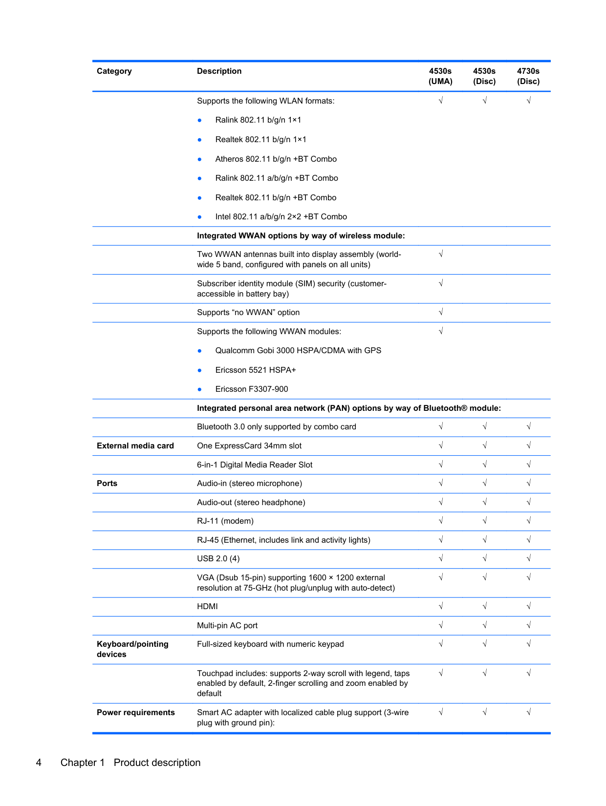
Full-sized keyboard with numeric keypad √√√
Touchpad includes: supports 2-way scroll with legend, taps enabled by default, 2-finger scrolling and zoom enabled by default
√√√
Power requirements Smart AC adapter with localized cable plug support (3-wire
plug with ground pin):
√√√
90-W √√ 65-W √ In-line cavity
Security Integrated fingerprint reader √√√
Intel AT support √√√ Support Kensington security lock √√√ Support no fingerprint reader option √√√
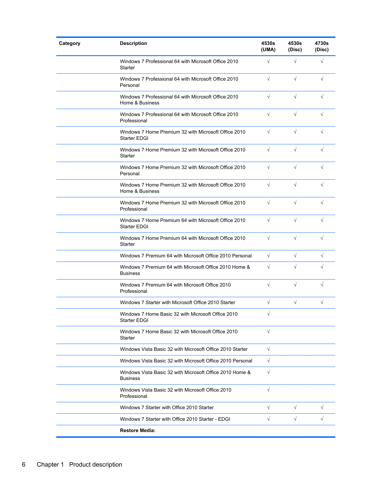
Operating system Preinstalled: Windows 7 Professional 32 with Microsoft® Basics √√√ Windows 7 Professional 64 with Microsoft Basics √√√ Windows 7 Home Premium 64 with Microsoft Basics √√√ Windows 7 Home Premium 32 with Microsoft Basics √√√ Windows Vista Home Basic 32 with Microsoft Basics √ Novell™: SuSE Linux™ – SLED 11 √√√ FreeDOS √√√ Preinstalled with Microsoft Office:
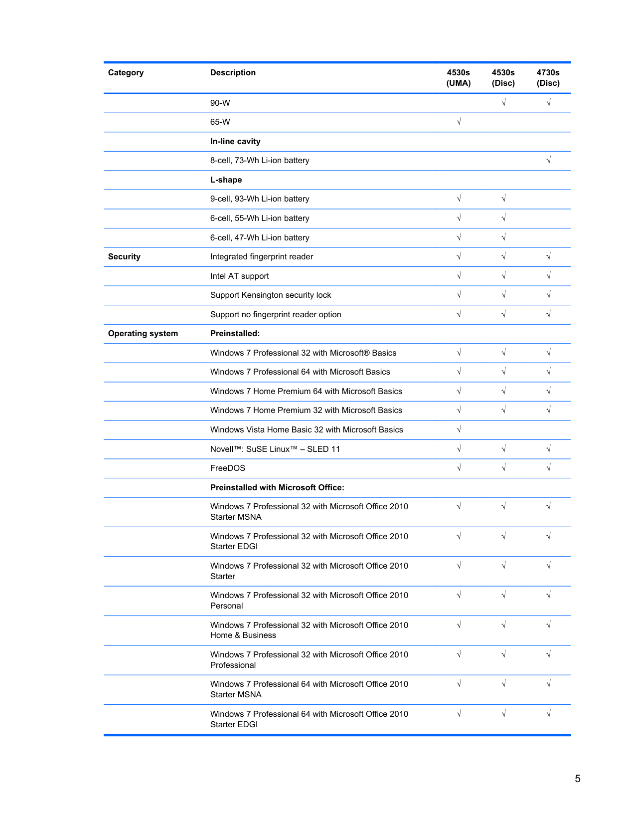
Windows 7 Professional 32 with Microsoft Office 2010 Starter MSNA
√√√
Windows 7 Professional 32 with Microsoft Office 2010 Starter EDGI
Windows 7 Professional 32 with Microsoft Office 2010 Starter
Windows 7 Professional 32 with Microsoft Office 2010 Personal
Windows 7 Professional 32 with Microsoft Office 2010 Home & Business
Windows 7 Professional 32 with Microsoft Office 2010 Professional
Windows 7 Professional 64 with Microsoft Office 2010 Starter MSNA
√√√
√√√
√√√
√√√
√√√
√√√
Windows 7 Professional 64 with Microsoft Office 2010 Starter EDGI
Windows 7 Professional 64 with Microsoft Office 2010 Starter
Windows 7 Professional 64 with Microsoft Office 2010 Personal
Windows 7 Professional 64 with Microsoft Office 2010 Home & Business
Windows 7 Professional 64 with Microsoft Office 2010 Professional
Windows 7 Home Premium 32 with Microsoft Office 2010 Starter EDGI
Windows 7 Home Premium 32 with Microsoft Office 2010 Starter
√√√
√√√
√√√
√√√
√√√
√√√
√√√
Windows 7 Home Premium 32 with Microsoft Office 2010 Personal
√√√
Windows 7 Home Premium 32 with Microsoft Office 2010 Home & Business
√√√
Windows 7 Home Premium 32 with Microsoft Office 2010 Professional
√√√
Windows 7 Home Premium 64 with Microsoft Office 2010 Starter EDGI
√√√
Windows 7 Home Premium 64 with Microsoft Office 2010 Starter
√√√
Windows 7 Premium 64 with Microsoft Office 2010 Personal √√√ Windows 7 Premium 64 with Microsoft Office 2010 Home & Business
√√√
Windows 7 Premium 64 with Microsoft Office 2010 Professional
√√√
Windows 7 Starter with Microsoft Office 2010 Starter √√√ Windows 7 Home Basic 32 with Microsoft Office 2010 Starter EDGI
√
Windows 7 Home Basic 32 with Microsoft Office 2010 Starter
√
Windows Vista Basic 32 with Microsoft Office 2010 Starter √ Windows Vista Basic 32 with Microsoft Office 2010 Personal √ Windows Vista Basic 32 with Microsoft Office 2010 Home & Business
√
Windows Vista Basic 32 with Microsoft Office 2010 Professional
√
Windows 7 Starter with Office 2010 Starter √√√ Windows 7 Starter with Office 2010 Starter - EDGI √√√
######## Restore Media:
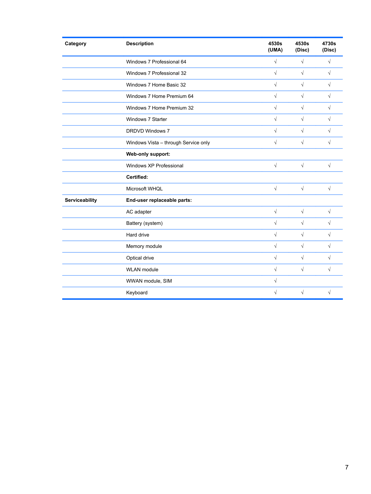
Windows 7 Professional 64 √√√ Windows 7 Professional 32 √√√ Windows 7 Home Basic 32 √√√ Windows 7 Home Premium 64 √√√ Windows 7 Home Premium 32 √√√
Windows 7 Starter √√√ DRDVD Windows 7 √√√ Windows Vista – through Service only √√√ Web-only support:
Windows XP Professional √√√ Certified:
Microsoft WHQL √√√ Serviceability End-user replaceable parts:
√√√ Battery (system) √√√
√√√ Memory module √√√
√√√
WLAN module √√√ WWAN module, SIM √ Keyboard √√√
2 External component identification
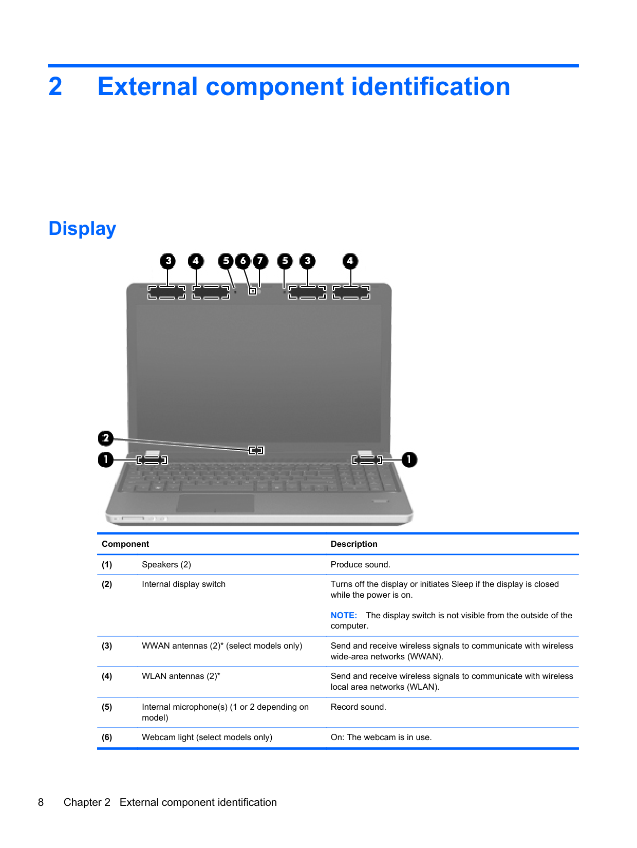
Display

######## Component Description
NOTE: The display switch is not visible from the outside of the computer.
Record sound.
######## To use the webcam, select Start > All Programs > ArcSoft TotalMedia Suite > WebCam Companion.
*The antennas are not visible from the outside of the computer. For optimal transmission, keep the areas immediately around the antennas free from obstructions. To see wireless regulatory notices, refer to the section of the Regulatory, Safety, and Environmental Notices that applies to your country or region. These notices are located in Help and Support.
Top
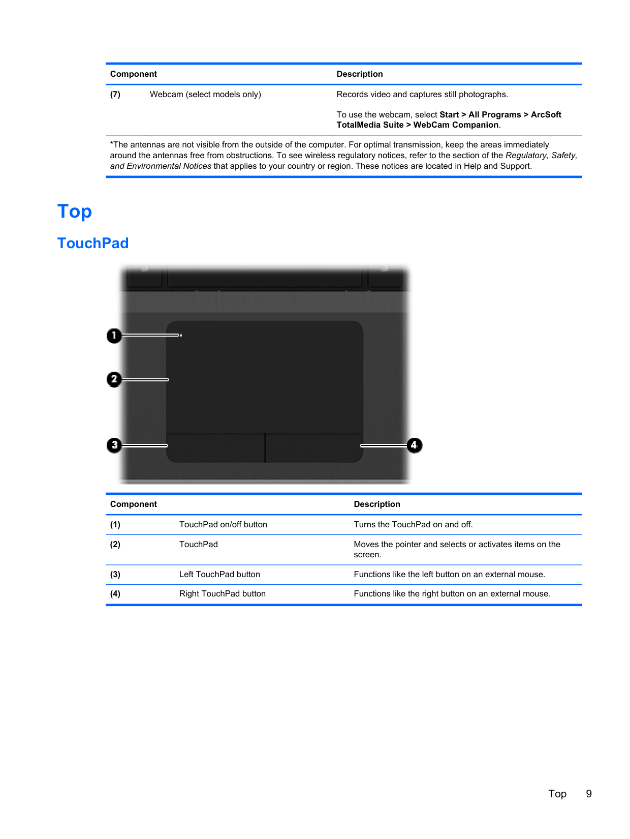
#### TouchPad

######## Component Description
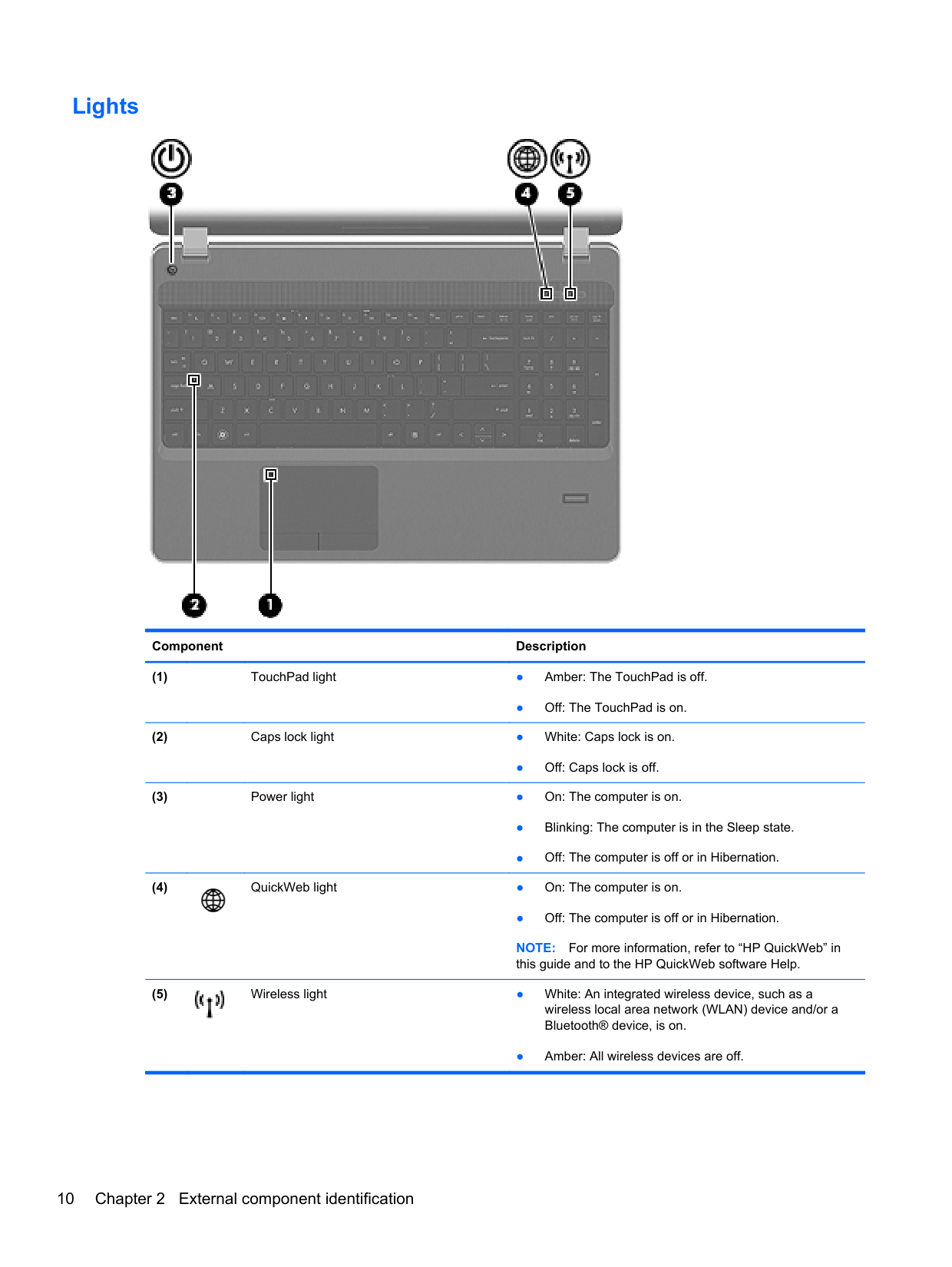
#### Lights

######## Component Description
● Off: The TouchPad is on.
● Off: Caps lock is off.

● Off: The computer is off or in Hibernation. NOTE: For more information, refer to “HP QuickWeb” in this guide and to the HP QuickWeb software Help.

● Amber: All wireless devices are off.
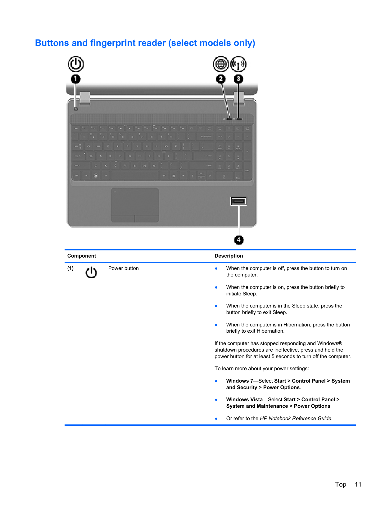
#### Buttons and fingerprint reader (select models only)

######## Component Description

If the computer has stopped responding and Windows® shutdown procedures are ineffective, press and hold the power button for at least 5 seconds to turn off the computer.
To learn more about your power settings:
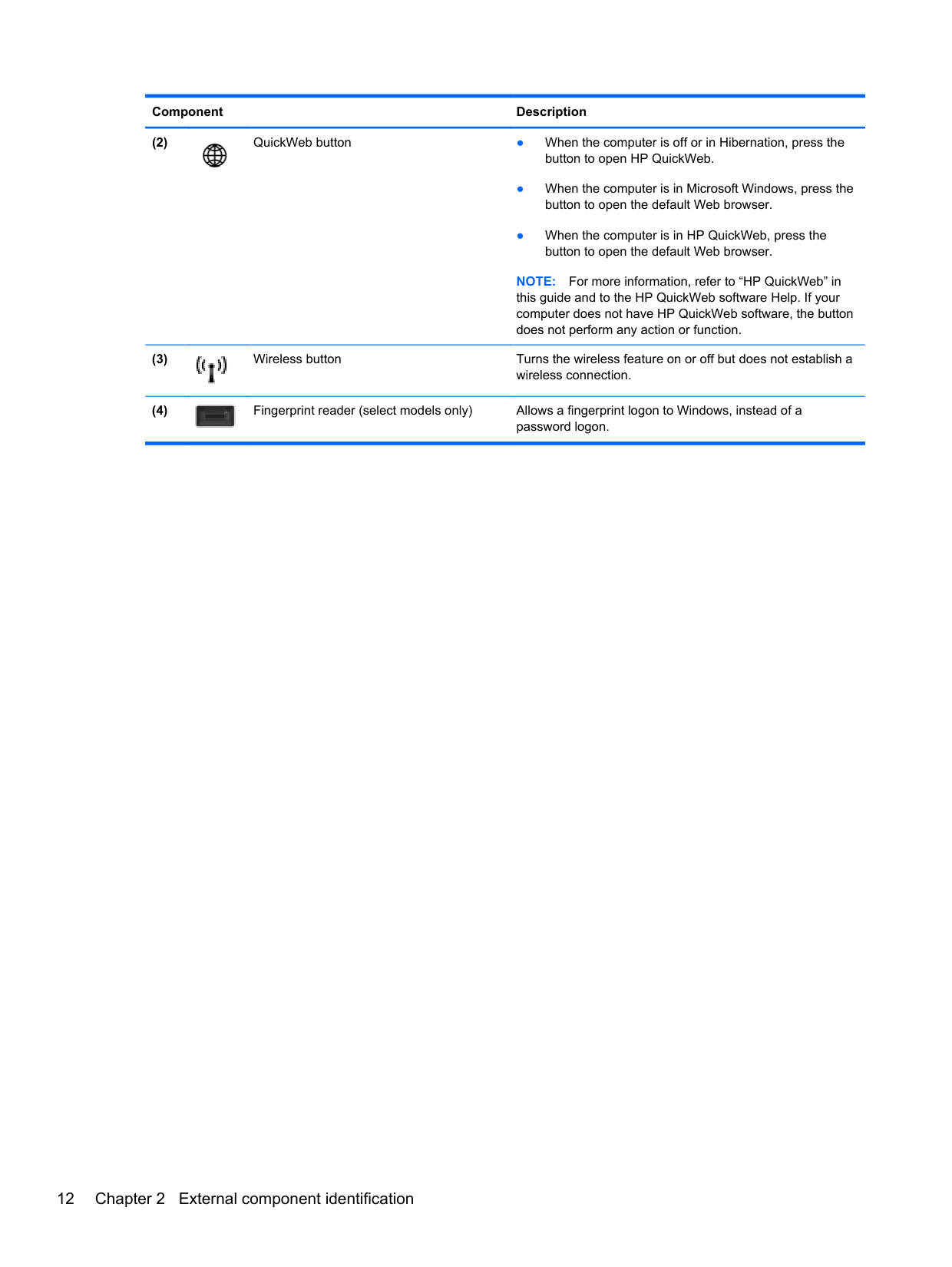
######## Component Description

NOTE: For more information, refer to “HP QuickWeb” in this guide and to the HP QuickWeb software Help. If your computer does not have HP QuickWeb software, the button does not perform any action or function.


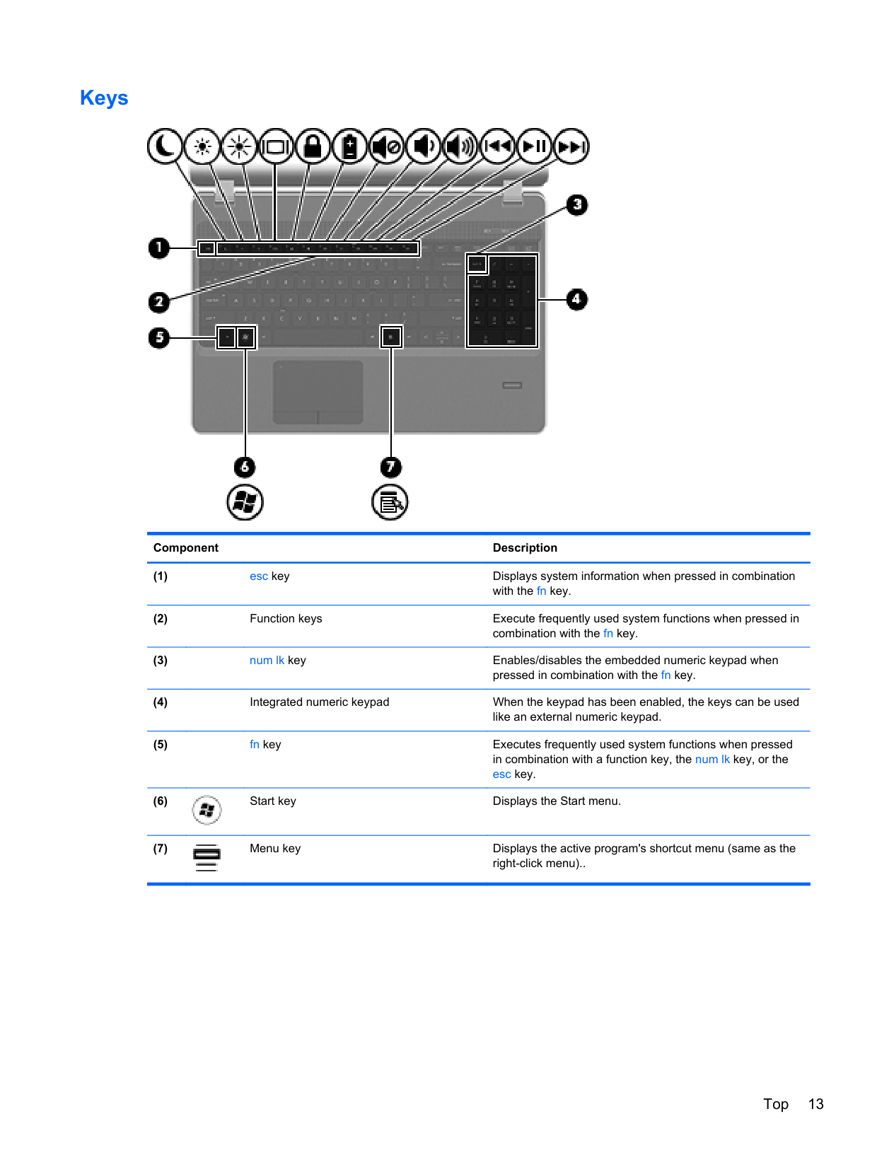
#### Keys

######## Component Description


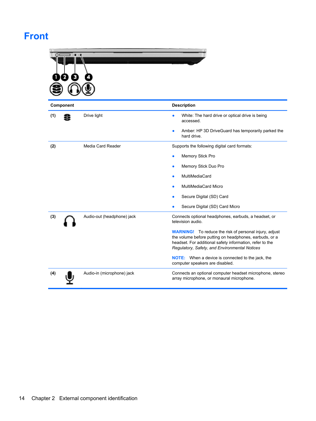
Front

######## Component Description

● Amber: HP 3D DriveGuard has temporarily parked the hard drive.

WARNING! To reduce the risk of personal injury, adjust the volume before putting on headphones, earbuds, or a headset. For additional safety information, refer to the Regulatory, Safety, and Environmental Notices
NOTE: When a device is connected to the jack, the computer speakers are disabled.

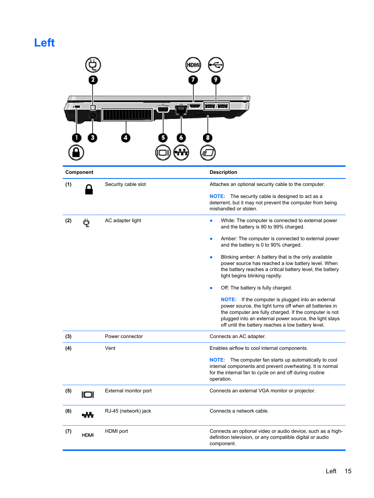
Left

######## Component Description

NOTE: The security cable is designed to act as a deterrent, but it may not prevent the computer from being mishandled or stolen.

NOTE: If the computer is plugged into an external power source, the light turns off when all batteries in the computer are fully charged. If the computer is not plugged into an external power source, the light stays off until the battery reaches a low battery level.
NOTE: The computer fan starts up automatically to cool internal components and prevent overheating. It is normal for the internal fan to cycle on and off during routine operation.


Left 15
######## Component Description


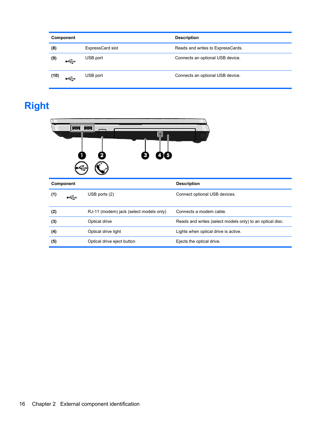
Right

######## Component Description

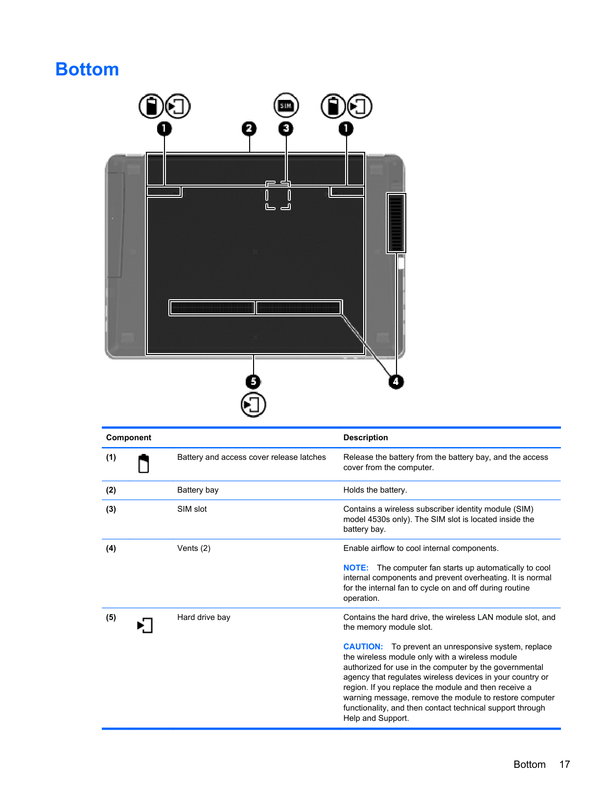
Bottom

######## Component Description

NOTE: The computer fan starts up automatically to cool internal components and prevent overheating. It is normal for the internal fan to cycle on and off during routine operation.

CAUTION: To prevent an unresponsive system, replace the wireless module only with a wireless module authorized for use in the computer by the governmental agency that regulates wireless devices in your country or region. If you replace the module and then receive a warning message, remove the module to restore computer functionality, and then contact technical support through Help and Support.
Bottom 17
3 Illustrated parts catalog
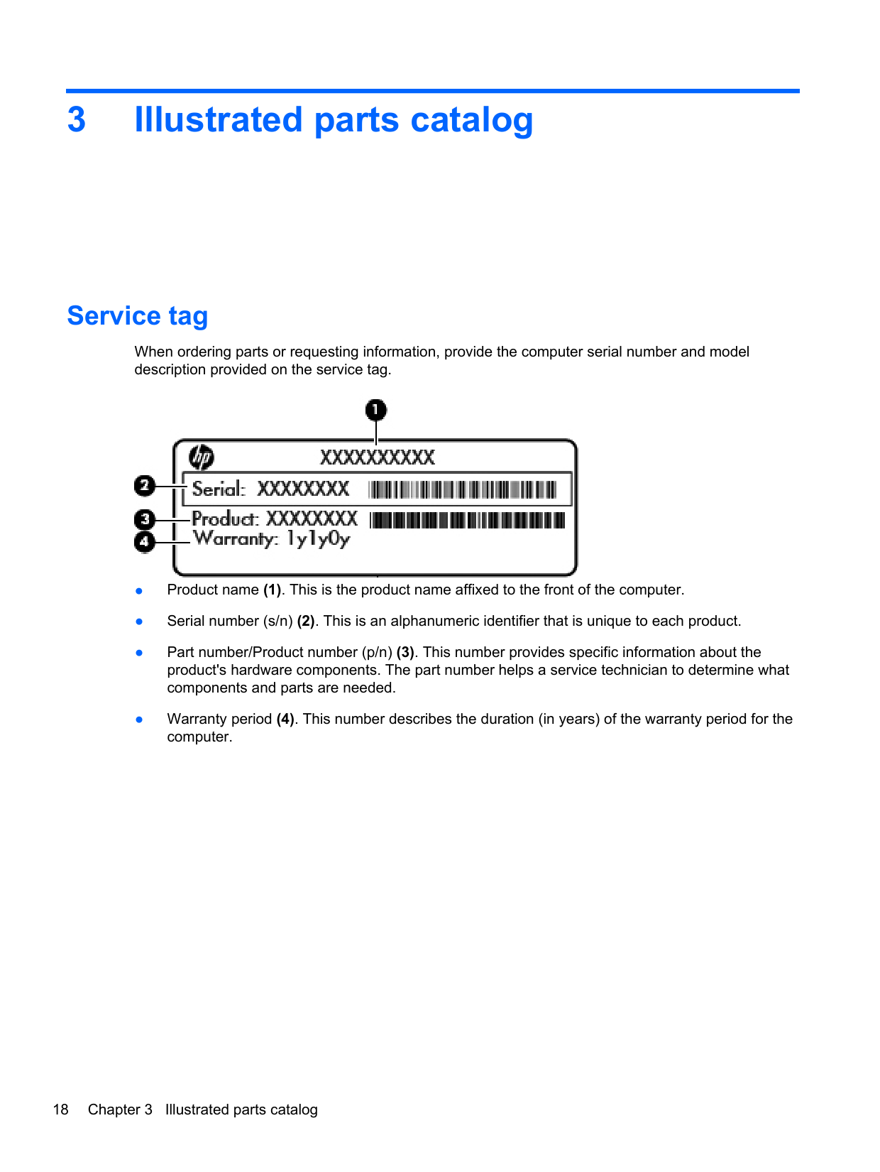
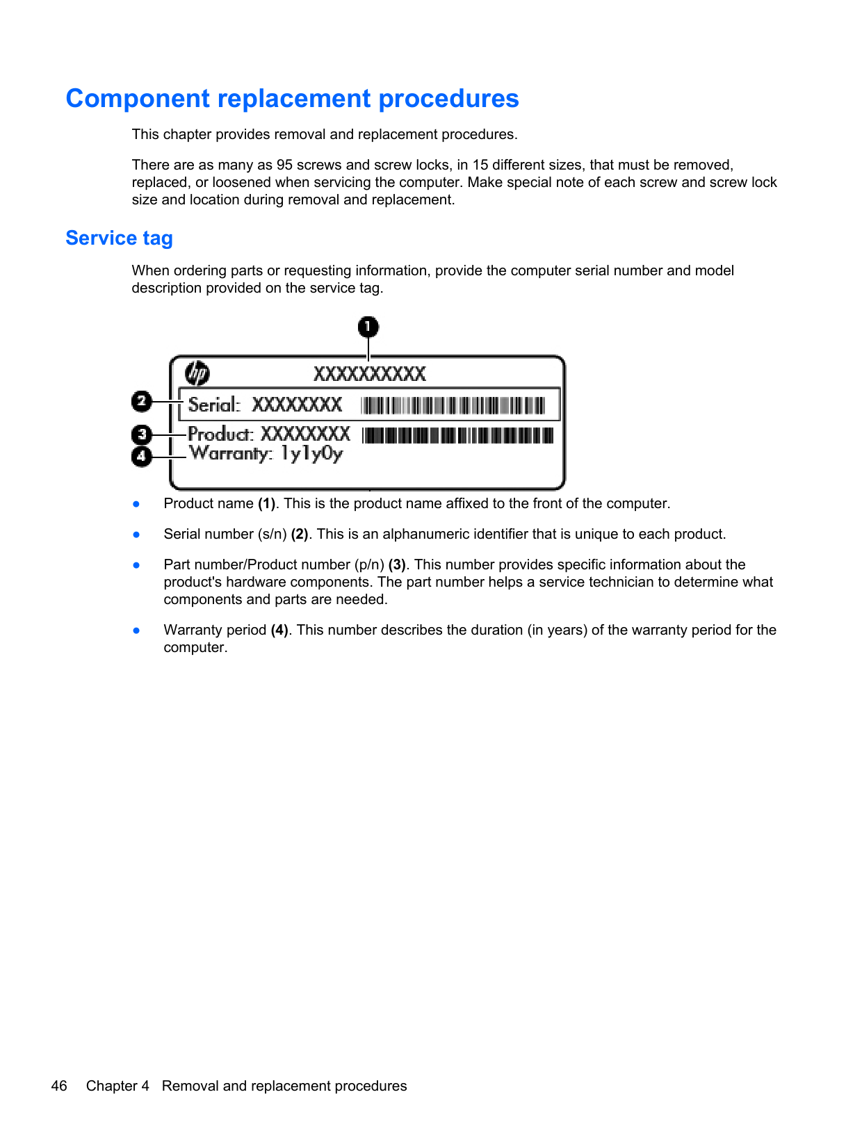
Service tag
When ordering parts or requesting information, provide the computer serial number and model description provided on the service tag.

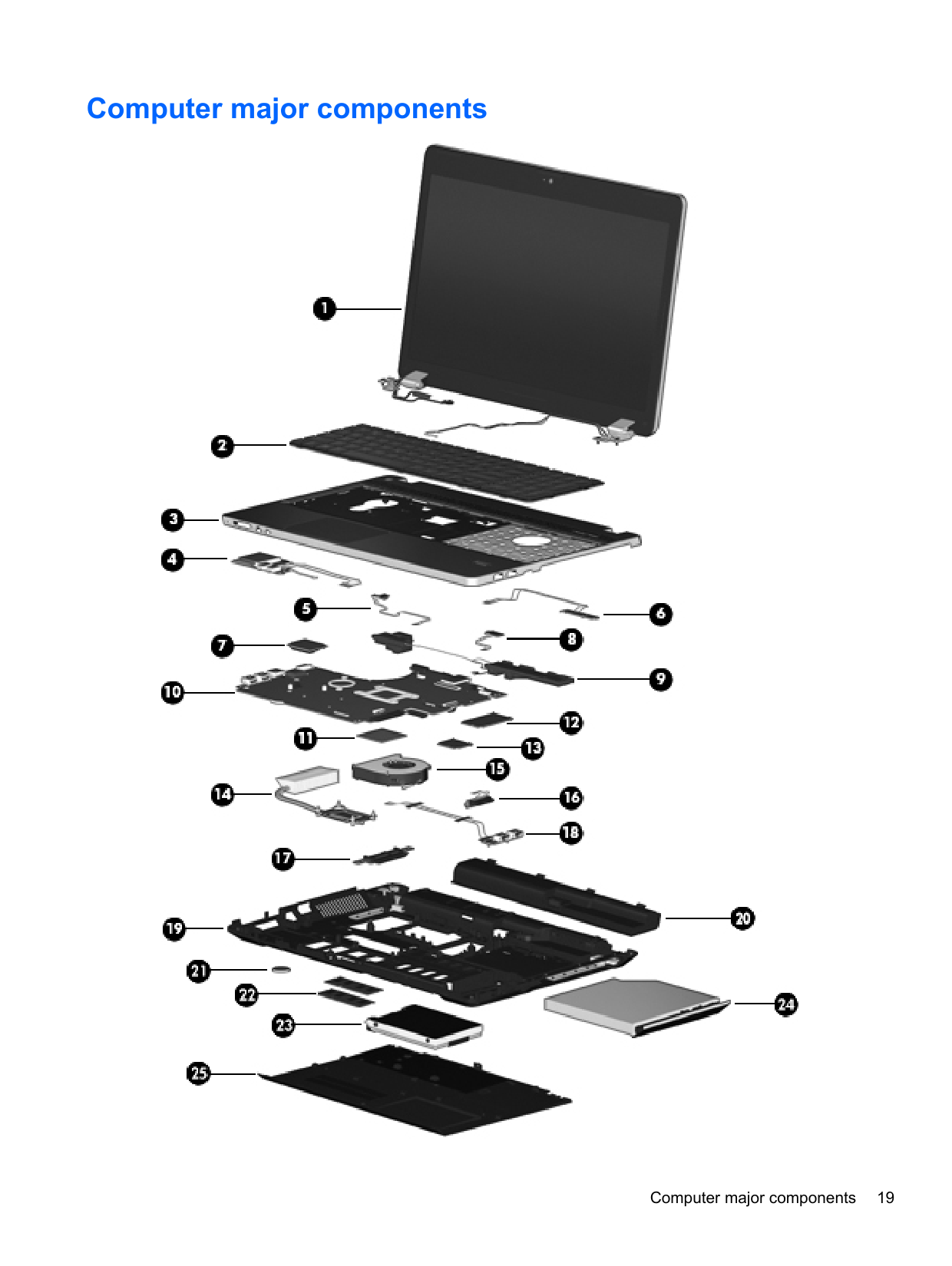
Computer major components

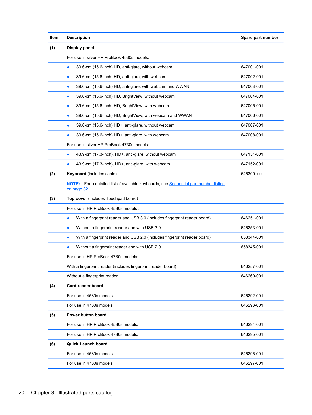
######### (1) Display panelFor use in silver HP ProBook 4530s models:
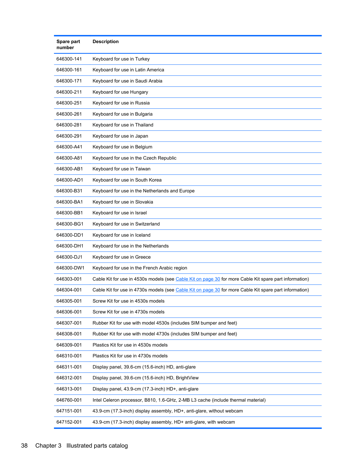
######### (2) Keyboard (includes cable)NOTE: For a detailed list of available keyboards, see Sequential part number listingon page 32.
646300-xxx
######### (3) Top cover (includes Touchpad board)For use in HP ProBook 4530s models :
667656-001
667657-001
For use in HP ProBook 4730s models:
667658-001
667659-001
######### (4) Card reader boardFor use in 4530s models 646292-001For use in 4730s models 646293-001
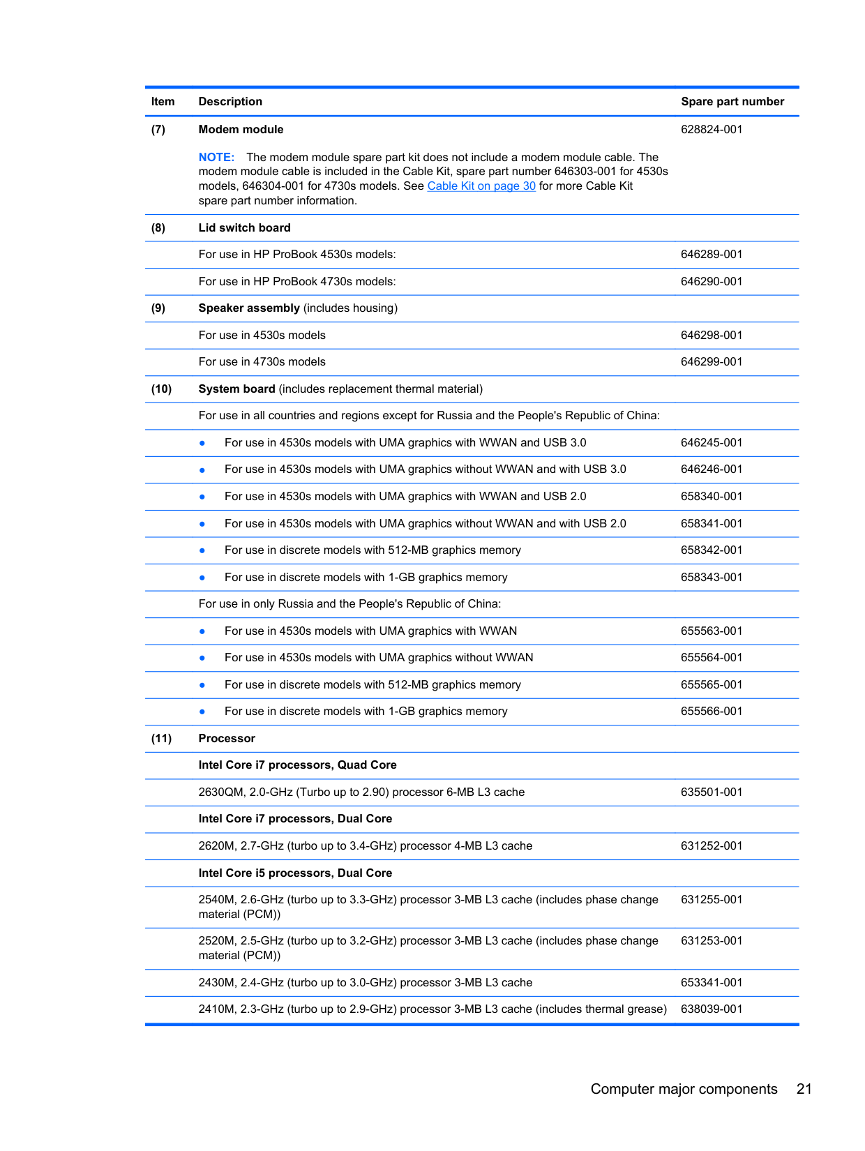
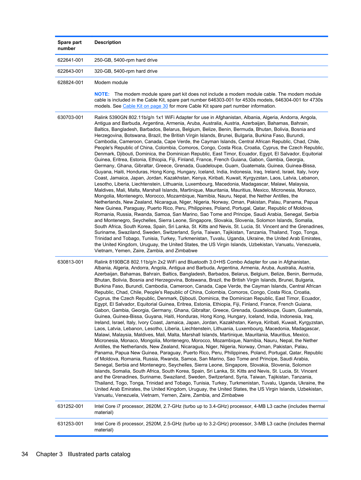
NOTE: The modem module spare part kit does not include a modem module cable. The modem module cable is included in the Cable Kit, spare part number 646303-001 for 4530s models, 646304-001 for 4730s models. See Cable Kit on page 30 for more Cable Kit spare part number information.
628824-001
2540M, 2.6-GHz (turbo up to 3.3-GHz) processor, 3-MB L3 cache (includes phase change material (PCM))
2520M, 2.5-GHz (turbo up to 3.2-GHz) processor, 3-MB L3 cache (includes phase change material (PCM))
631255-001
631253-001
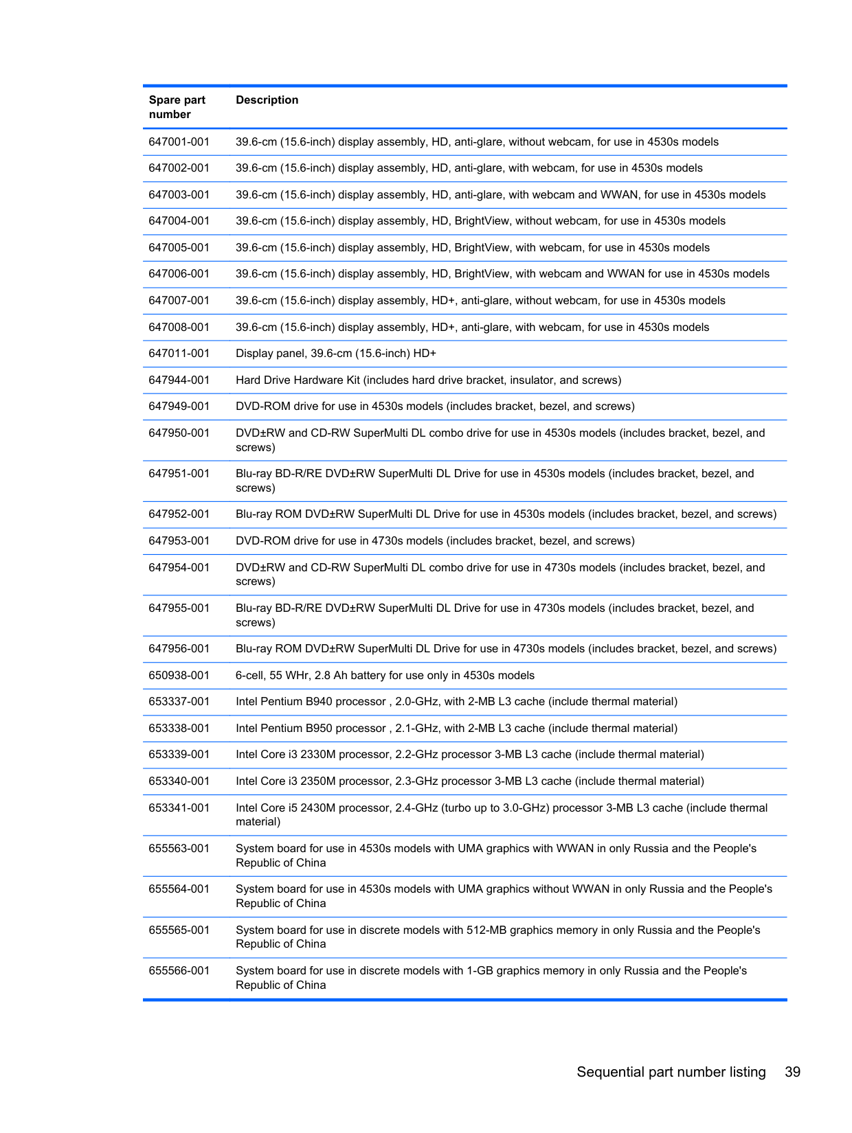
2430M, 2.4-GHz (turbo up to 3.0-GHz) processor, 3-MB L3 cache 653341-001
2410M, 2.3-GHz (turbo up to 2.9-GHz) processor, 3-MB L3 cache 638039-001 Intel Core i3 processors, Dual Core
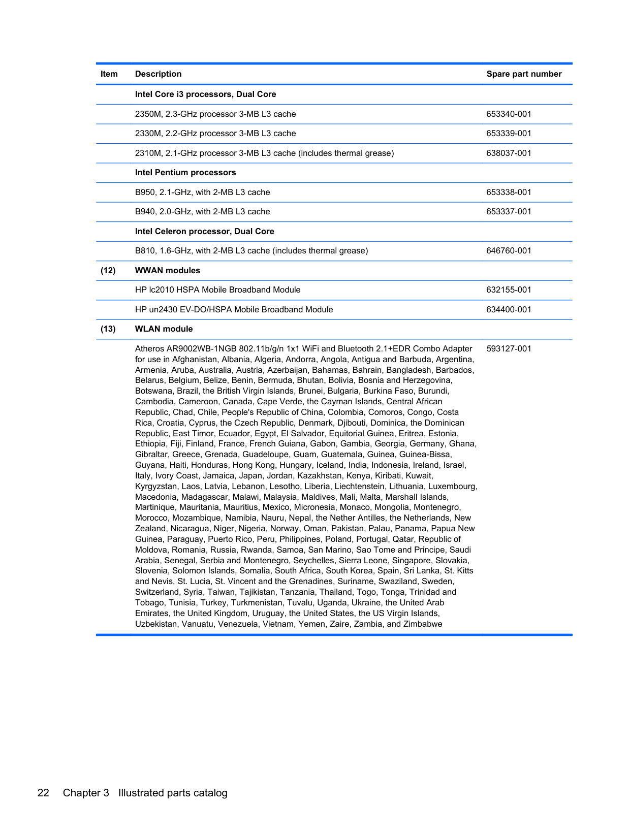
2350M, 2.3-GHz processor, 3-MB L3 cache 653340-001 2330M, 2.2-GHz processor, 3-MB L3 cache 653339-001 2310M, 2.1-GHz processor, 3-MB L3 cache 638037-001 Intel Pentium processors
B950, 2.1-GHz processor, 2-MB L3 cache 653338-001 B940, 2.0-GHz processor, 2-MB L3 cache 653337-001 Intel Celeron processor, Dual Core
B840, 1.9-GHz processor, 2-MB L3 cache 664663-001 B810, 1.6-GHz processor, 2-MB L3 cache 646760-001
Atheros AR9002WB-1NGB 802.11b/g/n 1x1 WiFi and Bluetooth 2.1+EDR Combo Adapter for use in Afghanistan, Albania, Algeria, Andorra, Angola, Antigua and Barbuda, Argentina, Armenia, Aruba, Australia, Austria, Azerbaijan, Bahamas, Bahrain, Bangladesh, Barbados, Belarus, Belgium, Belize, Benin, Bermuda, Bhutan, Bolivia, Bosnia and Herzegovina, Botswana, Brazil, the British Virgin Islands, Brunei, Bulgaria, Burkina Faso, Burundi, Cambodia, Cameroon, Canada, Cape Verde, the Cayman Islands, Central African Republic, Chad, Chile, People's Republic of China, Colombia, Comoros, Congo, Costa Rica, Croatia, Cyprus, the Czech Republic, Denmark, Djibouti, Dominica, the Dominican Republic, East Timor, Ecuador, Egypt, El Salvador, Equitorial Guinea, Eritrea, Estonia, Ethiopia, Fiji, Finland, France, French Guiana, Gabon, Gambia, Georgia, Germany, Ghana, Gibraltar, Greece, Grenada, Guadeloupe, Guam, Guatemala, Guinea, Guinea-Bissa, Guyana, Haiti, Honduras, Hong Kong, Hungary, Iceland, India, Indonesia, Ireland, Israel, Italy, Ivory Coast, Jamaica, Japan, Jordan, Kazakhstan, Kenya, Kiribati, Kuwait, Kyrgyzstan, Laos, Latvia, Lebanon, Lesotho, Liberia, Liechtenstein, Lithuania, Luxembourg, Macedonia, Madagascar, Malawi, Malaysia, Maldives, Mali, Malta, Marshall Islands, Martinique, Mauritania, Mauritius, Mexico, Micronesia, Monaco, Mongolia, Montenegro, Morocco, Mozambique, Namibia, Nauru, Nepal, the Nether Antilles, the Netherlands, New Zealand, Nicaragua, Niger, Nigeria, Norway, Oman, Pakistan, Palau, Panama, Papua New Guinea, Paraguay, Puerto Rico, Peru, Philippines, Poland, Portugal, Qatar, Republic of Moldova, Romania, Russia, Rwanda, Samoa, San Marino, Sao Tome and Principe, Saudi Arabia, Senegal, Serbia and Montenegro, Seychelles, Sierra Leone, Singapore, Slovakia, Slovenia, Solomon Islands, Somalia, South Africa, South Korea, Spain, Sri Lanka, St. Kitts and Nevis, St. Lucia, St. Vincent and the Grenadines, Suriname, Swaziland, Sweden, Switzerland, Syria, Taiwan, Tajikistan, Tanzania, Thailand, Togo, Tonga, Trinidad and Tobago, Tunisia, Turkey, Turkmenistan, Tuvalu, Uganda, Ukraine, the United Arab Emirates, the United Kingdom, Uruguay, the United States, the US Virgin Islands, Uzbekistan, Vanuatu, Venezuela, Vietnam, Yemen, Zaire, Zambia, and Zimbabwe
593127-001
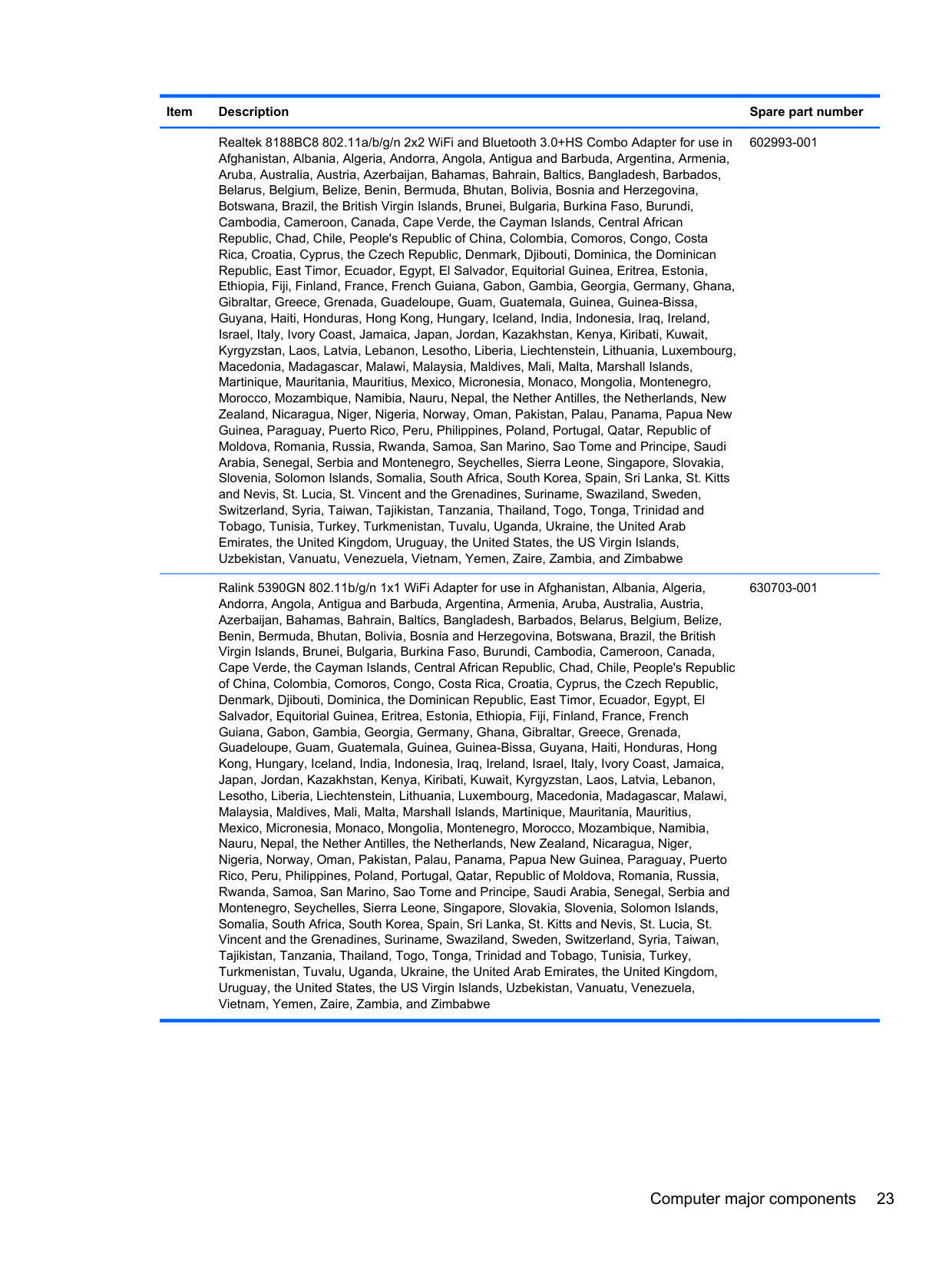
Realtek 8188BC8 802.11a/b/g/n 2x2 WiFi and Bluetooth 3.0+HS Combo Adapter for use in Afghanistan, Albania, Algeria, Andorra, Angola, Antigua and Barbuda, Argentina, Armenia, Aruba, Australia, Austria, Azerbaijan, Bahamas, Bahrain, Baltics, Bangladesh, Barbados, Belarus, Belgium, Belize, Benin, Bermuda, Bhutan, Bolivia, Bosnia and Herzegovina, Botswana, Brazil, the British Virgin Islands, Brunei, Bulgaria, Burkina Faso, Burundi, Cambodia, Cameroon, Canada, Cape Verde, the Cayman Islands, Central African Republic, Chad, Chile, People's Republic of China, Colombia, Comoros, Congo, Costa Rica, Croatia, Cyprus, the Czech Republic, Denmark, Djibouti, Dominica, the Dominican Republic, East Timor, Ecuador, Egypt, El Salvador, Equitorial Guinea, Eritrea, Estonia, Ethiopia, Fiji, Finland, France, French Guiana, Gabon, Gambia, Georgia, Germany, Ghana, Gibraltar, Greece, Grenada, Guadeloupe, Guam, Guatemala, Guinea, Guinea-Bissa, Guyana, Haiti, Honduras, Hong Kong, Hungary, Iceland, India, Indonesia, Iraq, Ireland, Israel, Italy, Ivory Coast, Jamaica, Japan, Jordan, Kazakhstan, Kenya, Kiribati, Kuwait, Kyrgyzstan, Laos, Latvia, Lebanon, Lesotho, Liberia, Liechtenstein, Lithuania, Luxembourg, Macedonia, Madagascar, Malawi, Malaysia, Maldives, Mali, Malta, Marshall Islands, Martinique, Mauritania, Mauritius, Mexico, Micronesia, Monaco, Mongolia, Montenegro, Morocco, Mozambique, Namibia, Nauru, Nepal, the Nether Antilles, the Netherlands, New Zealand, Nicaragua, Niger, Nigeria, Norway, Oman, Pakistan, Palau, Panama, Papua New Guinea, Paraguay, Puerto Rico, Peru, Philippines, Poland, Portugal, Qatar, Republic of Moldova, Romania, Russia, Rwanda, Samoa, San Marino, Sao Tome and Principe, Saudi Arabia, Senegal, Serbia and Montenegro, Seychelles, Sierra Leone, Singapore, Slovakia, Slovenia, Solomon Islands, Somalia, South Africa, South Korea, Spain, Sri Lanka, St. Kitts and Nevis, St. Lucia, St. Vincent and the Grenadines, Suriname, Swaziland, Sweden, Switzerland, Syria, Taiwan, Tajikistan, Tanzania, Thailand, Togo, Tonga, Trinidad and Tobago, Tunisia, Turkey, Turkmenistan, Tuvalu, Uganda, Ukraine, the United Arab Emirates, the United Kingdom, Uruguay, the United States, the US Virgin Islands, Uzbekistan, Vanuatu, Venezuela, Vietnam, Yemen, Zaire, Zambia, and Zimbabwe
602993-001
Ralink 5390GN 802.11b/g/n 1x1 WiFi Adapter for use in Afghanistan, Albania, Algeria, Andorra, Angola, Antigua and Barbuda, Argentina, Armenia, Aruba, Australia, Austria, Azerbaijan, Bahamas, Bahrain, Baltics, Bangladesh, Barbados, Belarus, Belgium, Belize, Benin, Bermuda, Bhutan, Bolivia, Bosnia and Herzegovina, Botswana, Brazil, the British Virgin Islands, Brunei, Bulgaria, Burkina Faso, Burundi, Cambodia, Cameroon, Canada, Cape Verde, the Cayman Islands, Central African Republic, Chad, Chile, People's Republic of China, Colombia, Comoros, Congo, Costa Rica, Croatia, Cyprus, the Czech Republic, Denmark, Djibouti, Dominica, the Dominican Republic, East Timor, Ecuador, Egypt, El Salvador, Equitorial Guinea, Eritrea, Estonia, Ethiopia, Fiji, Finland, France, French Guiana, Gabon, Gambia, Georgia, Germany, Ghana, Gibraltar, Greece, Grenada, Guadeloupe, Guam, Guatemala, Guinea, Guinea-Bissa, Guyana, Haiti, Honduras, Hong Kong, Hungary, Iceland, India, Indonesia, Iraq, Ireland, Israel, Italy, Ivory Coast, Jamaica, Japan, Jordan, Kazakhstan, Kenya, Kiribati, Kuwait, Kyrgyzstan, Laos, Latvia, Lebanon, Lesotho, Liberia, Liechtenstein, Lithuania, Luxembourg, Macedonia, Madagascar, Malawi, Malaysia, Maldives, Mali, Malta, Marshall Islands, Martinique, Mauritania, Mauritius, Mexico, Micronesia, Monaco, Mongolia, Montenegro, Morocco, Mozambique, Namibia, Nauru, Nepal, the Nether Antilles, the Netherlands, New Zealand, Nicaragua, Niger,
630703-001
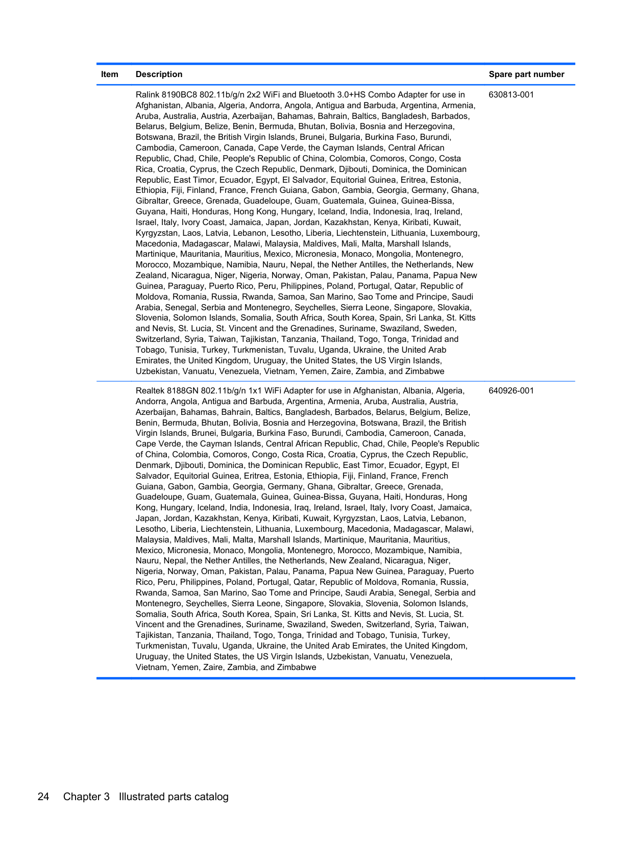
Ralink 8190BC8 802.11b/g/n 2x2 WiFi and Bluetooth 3.0+HS Combo Adapter for use in Afghanistan, Albania, Algeria, Andorra, Angola, Antigua and Barbuda, Argentina, Armenia, Aruba, Australia, Austria, Azerbaijan, Bahamas, Bahrain, Baltics, Bangladesh, Barbados, Belarus, Belgium, Belize, Benin, Bermuda, Bhutan, Bolivia, Bosnia and Herzegovina, Botswana, Brazil, the British Virgin Islands, Brunei, Bulgaria, Burkina Faso, Burundi, Cambodia, Cameroon, Canada, Cape Verde, the Cayman Islands, Central African Republic, Chad, Chile, People's Republic of China, Colombia, Comoros, Congo, Costa Rica, Croatia, Cyprus, the Czech Republic, Denmark, Djibouti, Dominica, the Dominican Republic, East Timor, Ecuador, Egypt, El Salvador, Equitorial Guinea, Eritrea, Estonia, Ethiopia, Fiji, Finland, France, French Guiana, Gabon, Gambia, Georgia, Germany, Ghana, Gibraltar, Greece, Grenada, Guadeloupe, Guam, Guatemala, Guinea, Guinea-Bissa, Guyana, Haiti, Honduras, Hong Kong, Hungary, Iceland, India, Indonesia, Iraq, Ireland, Israel, Italy, Ivory Coast, Jamaica, Japan, Jordan, Kazakhstan, Kenya, Kiribati, Kuwait, Kyrgyzstan, Laos, Latvia, Lebanon, Lesotho, Liberia, Liechtenstein, Lithuania, Luxembourg, Macedonia, Madagascar, Malawi, Malaysia, Maldives, Mali, Malta, Marshall Islands, Martinique, Mauritania, Mauritius, Mexico, Micronesia, Monaco, Mongolia, Montenegro, Morocco, Mozambique, Namibia, Nauru, Nepal, the Nether Antilles, the Netherlands, New Zealand, Nicaragua, Niger, Nigeria, Norway, Oman, Pakistan, Palau, Panama, Papua New Guinea, Paraguay, Puerto Rico, Peru, Philippines, Poland, Portugal, Qatar, Republic of Moldova, Romania, Russia, Rwanda, Samoa, San Marino, Sao Tome and Principe, Saudi Arabia, Senegal, Serbia and Montenegro, Seychelles, Sierra Leone, Singapore, Slovakia, Slovenia, Solomon Islands, Somalia, South Africa, South Korea, Spain, Sri Lanka, St. Kitts and Nevis, St. Lucia, St. Vincent and the Grenadines, Suriname, Swaziland, Sweden, Switzerland, Syria, Taiwan, Tajikistan, Tanzania, Thailand, Togo, Tonga, Trinidad and Tobago, Tunisia, Turkey, Turkmenistan, Tuvalu, Uganda, Ukraine, the United Arab Emirates, the United Kingdom, Uruguay, the United States, the US Virgin Islands, Uzbekistan, Vanuatu, Venezuela, Vietnam, Yemen, Zaire, Zambia, and Zimbabwe
630813-001
Realtek 8188GN 802.11b/g/n 1x1 WiFi Adapter for use in Afghanistan, Albania, Algeria, Andorra, Angola, Antigua and Barbuda, Argentina, Armenia, Aruba, Australia, Austria, Azerbaijan, Bahamas, Bahrain, Baltics, Bangladesh, Barbados, Belarus, Belgium, Belize, Benin, Bermuda, Bhutan, Bolivia, Bosnia and Herzegovina, Botswana, Brazil, the British Virgin Islands, Brunei, Bulgaria, Burkina Faso, Burundi, Cambodia, Cameroon, Canada, Cape Verde, the Cayman Islands, Central African Republic, Chad, Chile, People's Republic of China, Colombia, Comoros, Congo, Costa Rica, Croatia, Cyprus, the Czech Republic, Denmark, Djibouti, Dominica, the Dominican Republic, East Timor, Ecuador, Egypt, El Salvador, Equitorial Guinea, Eritrea, Estonia, Ethiopia, Fiji, Finland, France, French Guiana, Gabon, Gambia, Georgia, Germany, Ghana, Gibraltar, Greece, Grenada, Guadeloupe, Guam, Guatemala, Guinea, Guinea-Bissa, Guyana, Haiti, Honduras, Hong Kong, Hungary, Iceland, India, Indonesia, Iraq, Ireland, Israel, Italy, Ivory Coast, Jamaica, Japan, Jordan, Kazakhstan, Kenya, Kiribati, Kuwait, Kyrgyzstan, Laos, Latvia, Lebanon, Lesotho, Liberia, Liechtenstein, Lithuania, Luxembourg, Macedonia, Madagascar, Malawi, Malaysia, Maldives, Mali, Malta, Marshall Islands, Martinique, Mauritania, Mauritius, Mexico, Micronesia, Monaco, Mongolia, Montenegro, Morocco, Mozambique, Namibia, Nauru, Nepal, the Nether Antilles, the Netherlands, New Zealand, Nicaragua, Niger,
640926-001
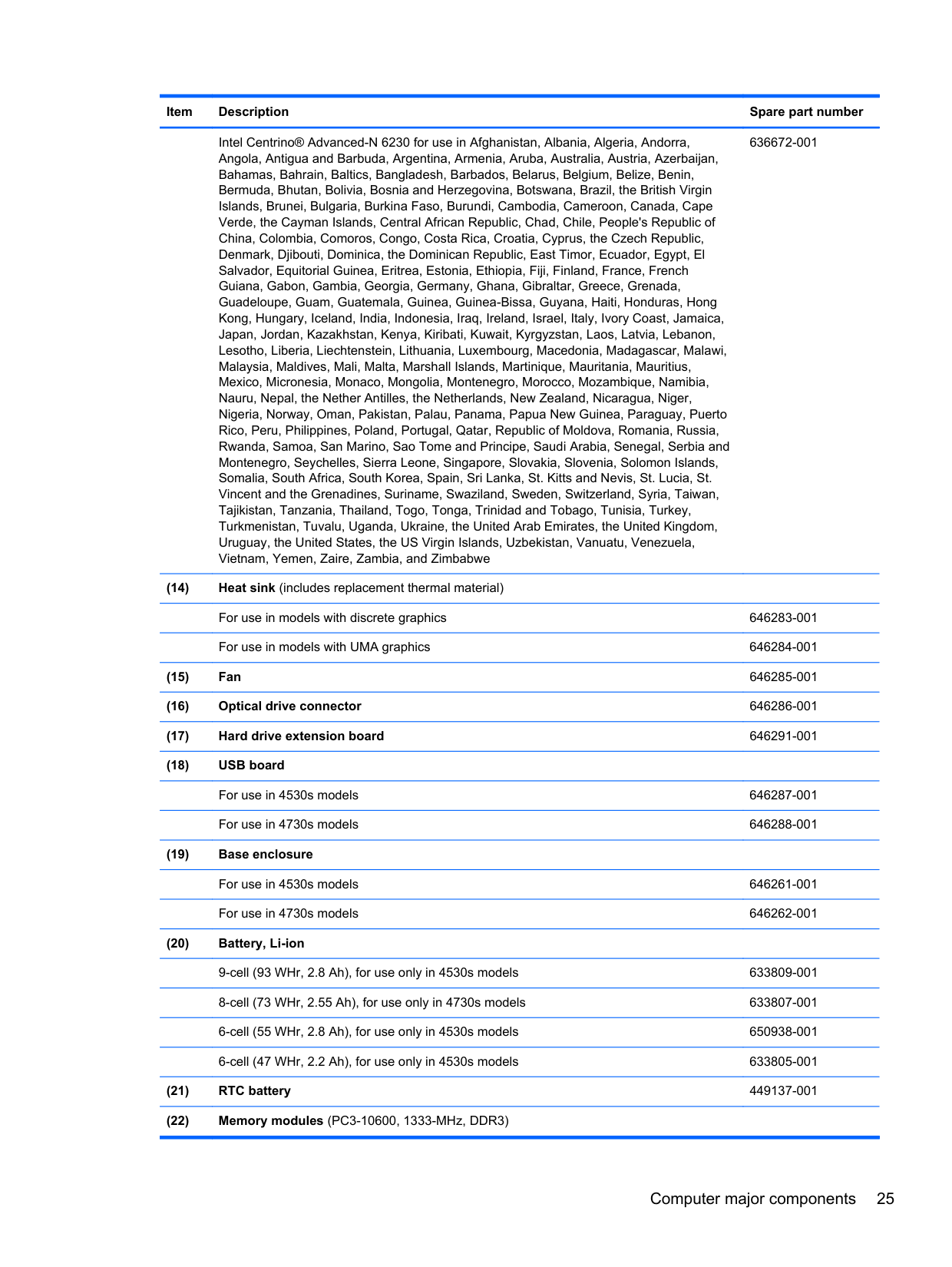
Intel Centrino® Advanced-N 6230 for use in Afghanistan, Albania, Algeria, Andorra, Angola, Antigua and Barbuda, Argentina, Armenia, Aruba, Australia, Austria, Azerbaijan, Bahamas, Bahrain, Baltics, Bangladesh, Barbados, Belarus, Belgium, Belize, Benin, Bermuda, Bhutan, Bolivia, Bosnia and Herzegovina, Botswana, Brazil, the British Virgin Islands, Brunei, Bulgaria, Burkina Faso, Burundi, Cambodia, Cameroon, Canada, Cape Verde, the Cayman Islands, Central African Republic, Chad, Chile, People's Republic of China, Colombia, Comoros, Congo, Costa Rica, Croatia, Cyprus, the Czech Republic, Denmark, Djibouti, Dominica, the Dominican Republic, East Timor, Ecuador, Egypt, El Salvador, Equitorial Guinea, Eritrea, Estonia, Ethiopia, Fiji, Finland, France, French Guiana, Gabon, Gambia, Georgia, Germany, Ghana, Gibraltar, Greece, Grenada, Guadeloupe, Guam, Guatemala, Guinea, Guinea-Bissa, Guyana, Haiti, Honduras, Hong Kong, Hungary, Iceland, India, Indonesia, Iraq, Ireland, Israel, Italy, Ivory Coast, Jamaica, Japan, Jordan, Kazakhstan, Kenya, Kiribati, Kuwait, Kyrgyzstan, Laos, Latvia, Lebanon, Lesotho, Liberia, Liechtenstein, Lithuania, Luxembourg, Macedonia, Madagascar, Malawi, Malaysia, Maldives, Mali, Malta, Marshall Islands, Martinique, Mauritania, Mauritius, Mexico, Micronesia, Monaco, Mongolia, Montenegro, Morocco, Mozambique, Namibia, Nauru, Nepal, the Nether Antilles, the Netherlands, New Zealand, Nicaragua, Niger, Nigeria, Norway, Oman, Pakistan, Palau, Panama, Papua New Guinea, Paraguay, Puerto Rico, Peru, Philippines, Poland, Portugal, Qatar, Republic of Moldova, Romania, Russia, Rwanda, Samoa, San Marino, Sao Tome and Principe, Saudi Arabia, Senegal, Serbia and Montenegro, Seychelles, Sierra Leone, Singapore, Slovakia, Slovenia, Solomon Islands, Somalia, South Africa, South Korea, Spain, Sri Lanka, St. Kitts and Nevis, St. Lucia, St. Vincent and the Grenadines, Suriname, Swaziland, Sweden, Switzerland, Syria, Taiwan, Tajikistan, Tanzania, Thailand, Togo, Tonga, Trinidad and Tobago, Tunisia, Turkey, Turkmenistan, Tuvalu, Uganda, Ukraine, the United Arab Emirates, the United Kingdom, Uruguay, the United States, the US Virgin Islands, Uzbekistan, Vanuatu, Venezuela, Vietnam, Yemen, Zaire, Zambia, and Zimbabwe
636672-001
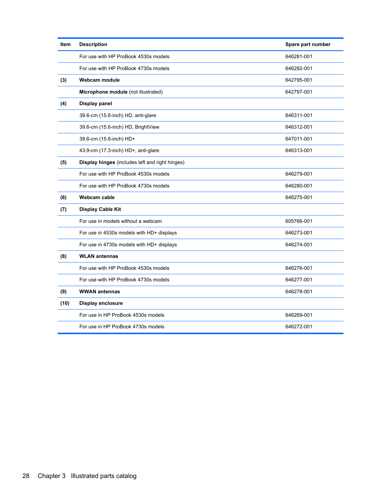
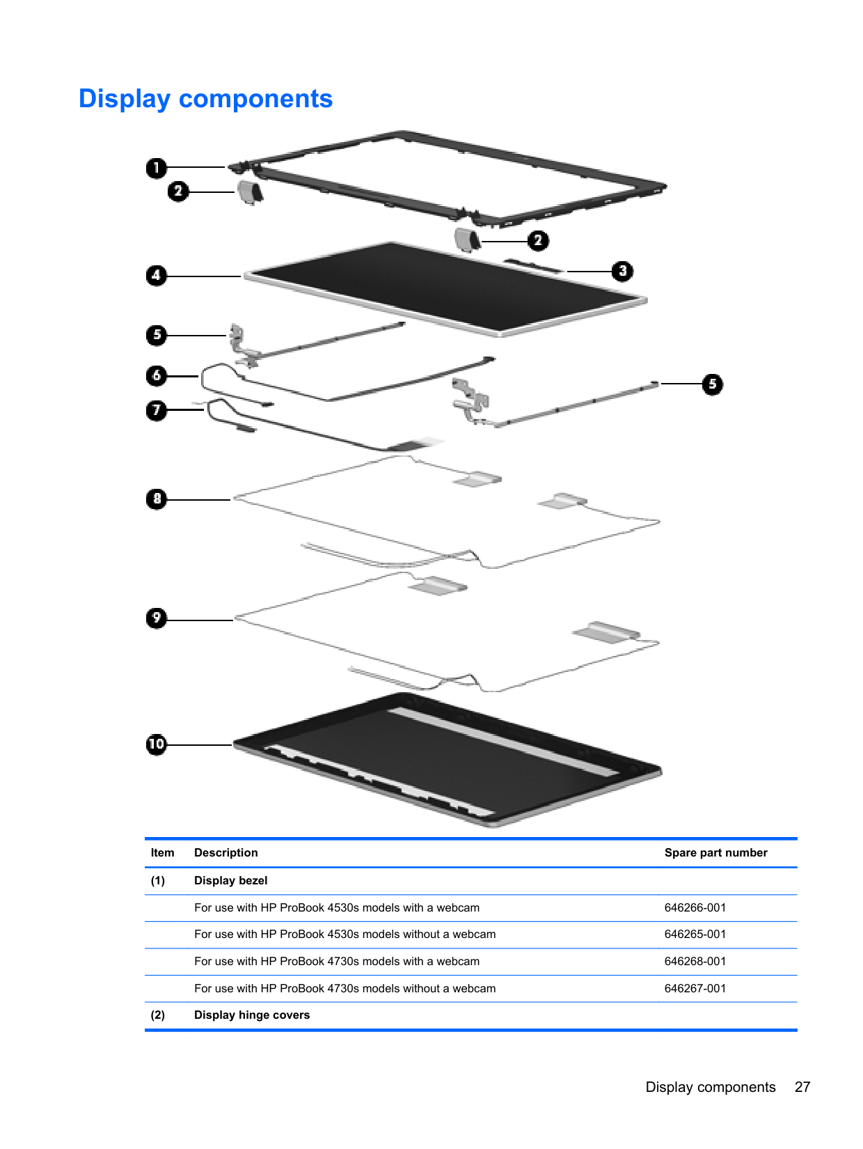
Display components

######## Item Description Spare part number
Display components 27
For use with HP ProBook 4530s models 646281-001 For use with HP ProBook 4730s models 646282-001
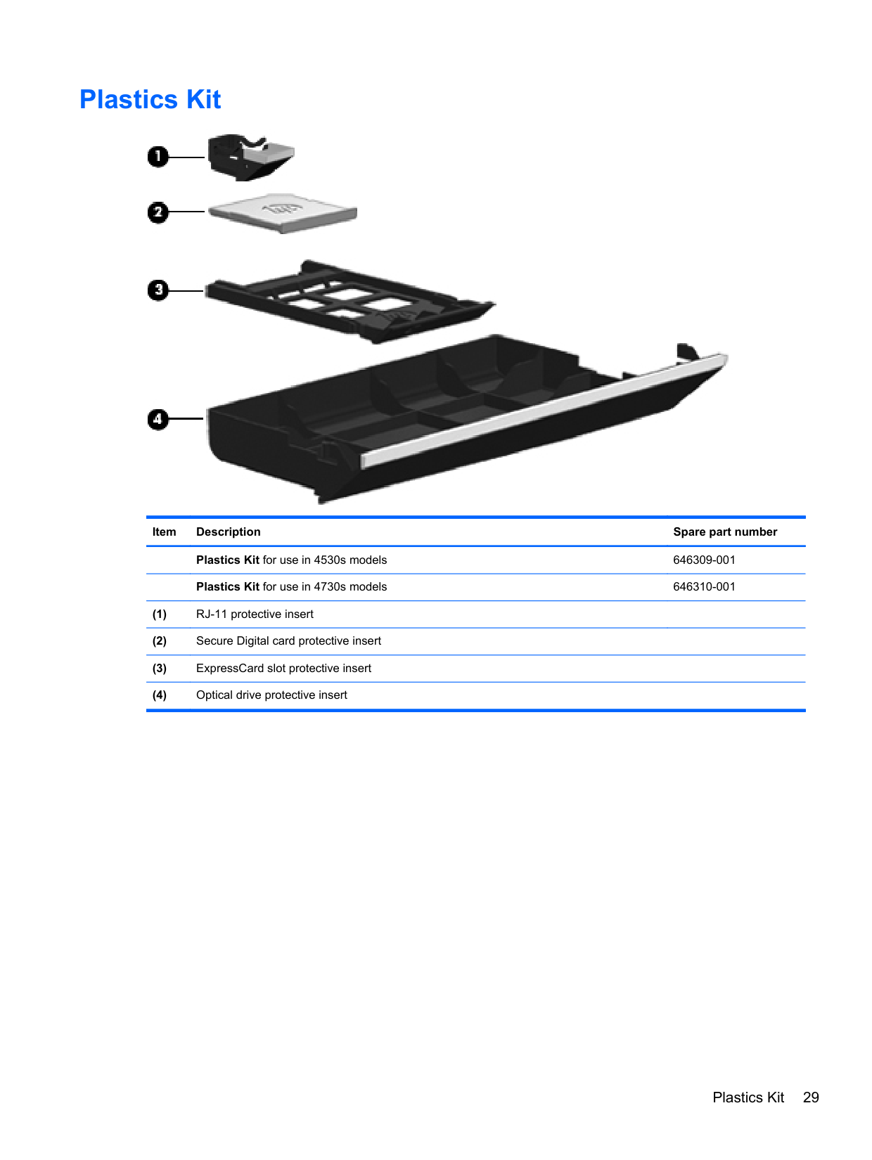
Plastics Kit

Item Description Spare part number Plastics Kit for use in 4530s models 646309-001 Plastics Kit for use in 4730s models 646310-001
Plastics Kit 29
Cable Kit

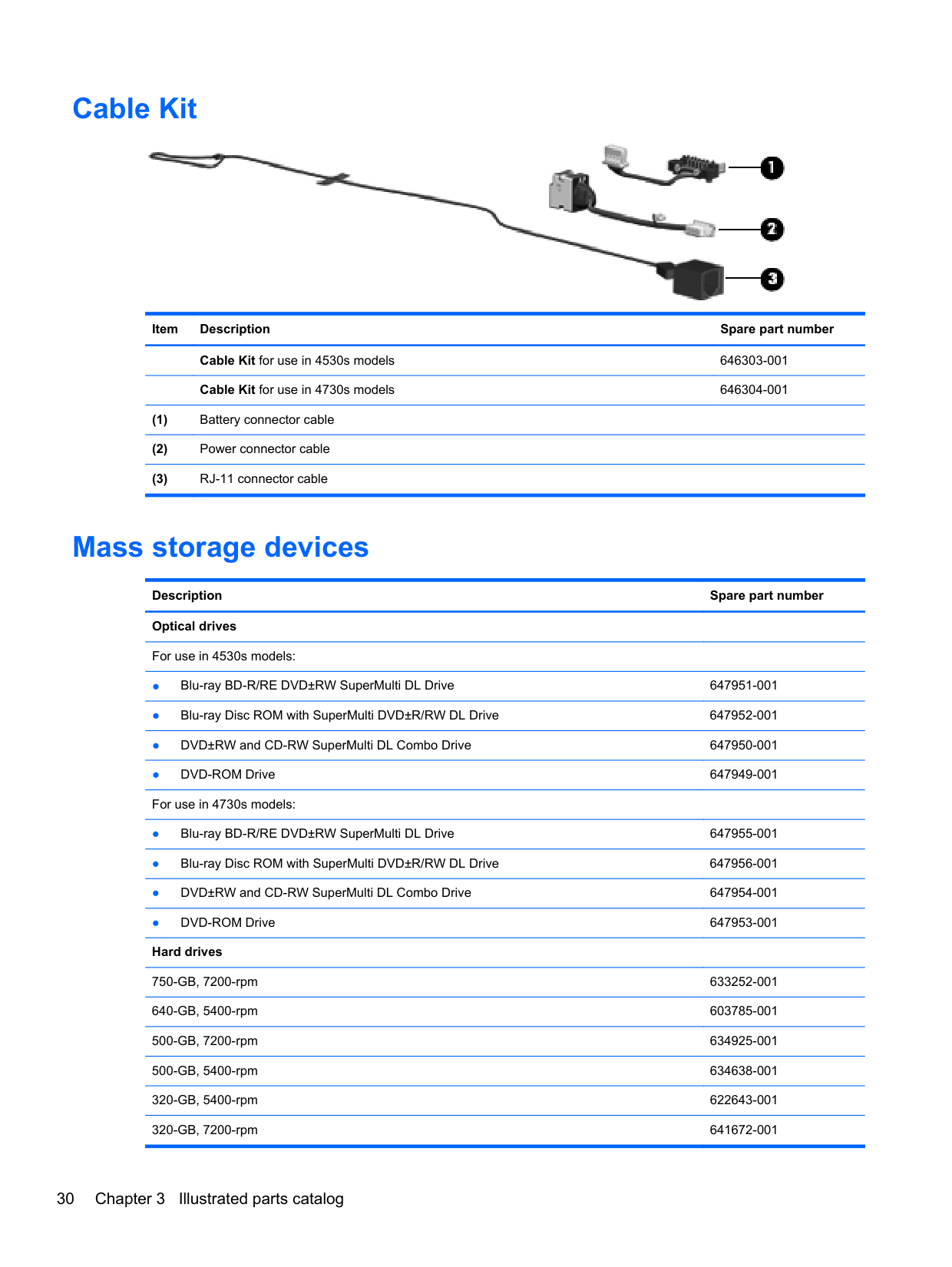
Item Description Spare part number Cable Kit for use in 4530s models 646303-001 Cable Kit for use in 4730s models 646304-001
Mass storage devices
Description Spare part number Optical drives For use in 4530s models:
250-GB, 7200-rpm 635225-001 250-GB, 5400-rpm 622641-001 Hard Drive Hardware Kit (includes hard drive bracket, insulator, and screws) 647944-001
Miscellaneous parts
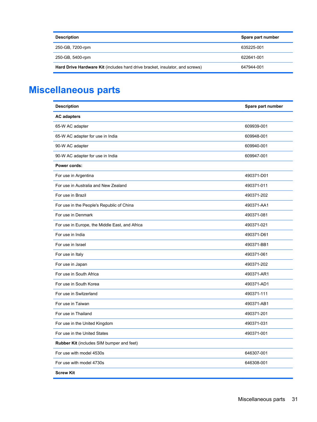
Description Spare part number AC adapters
65-W AC adapter 609939-001 65-W AC adapter for use in India 609948-001 90-W AC adapter 609940-001 90-W AC adapter for use in India 609947-001 Power cords:
For use in Argentina 490371-D01 For use in Australia and New Zealand 490371-011 For use in Brazil 490371-202 For use in the People's Republic of China 490371-AA1 For use in Denmark 490371-081 For use in Europe, the Middle East, and Africa 490371-021 For use in India 490371-D61 For use in Israel 490371-BB1 For use in Italy 490371-061 For use in Japan 490371-202 For use in South Africa 490371-AR1 For use in South Korea 490371-AD1 For use in Switzerland 490371-111 For use in Taiwan 490371-AB1 For use in Thailand 490371-201 For use in the United Kingdom 490371-031 For use in the United States 490371-001 Rubber Kit (includes SIM bumper and feet)
For use with model 4530s 646307-001 For use with model 4730s 646308-001 Screw Kit
Miscellaneous parts 31
For use with model 4530s 646305-001 For use with model 4730s 646306-001 Mouse, optical, 2-button 390632-001 Notebook combination lock 591699-001 HP keyed cable lock 626729-001 HP optical travel mouse 434594-001 HP basic carrying case 455084-001 Professional slim, top load case 592923-001 Nylon case 612757-001 Basic messenger bag 501505-001
Sequential part number listing
Spare part number
Description
390632-001 Mouse, optical, 2-button 434594-001 HP optical travel mouse 449137-001 RTC battery 455084-001 HP basic carrying case 490371-001 Power cord for use in North America 490371-011 Power cord for use in Australia and New Zealand 490371-021 Power cord for use in Europe, the Middle East, and Africa 490371-031 Power cord for use in the United Kingdom 490371-061 Power cord for use in Italy 490371-081 Power cord for use in Denmark 490371-111 Power cord for use in Switzerland 490371-201 Power cord for use in Thailand 490371-202 Power cord for use in Brazil 490371-291 Power cord for use in Japan
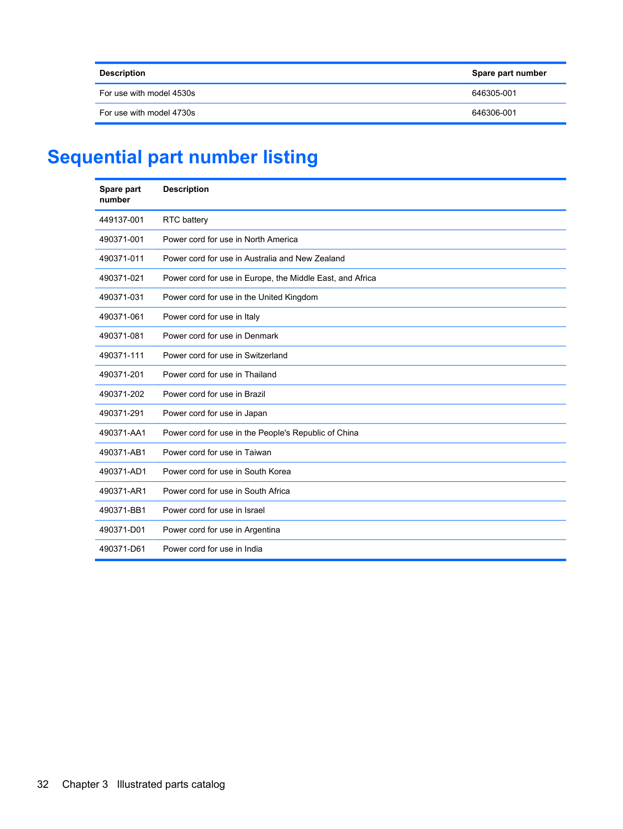
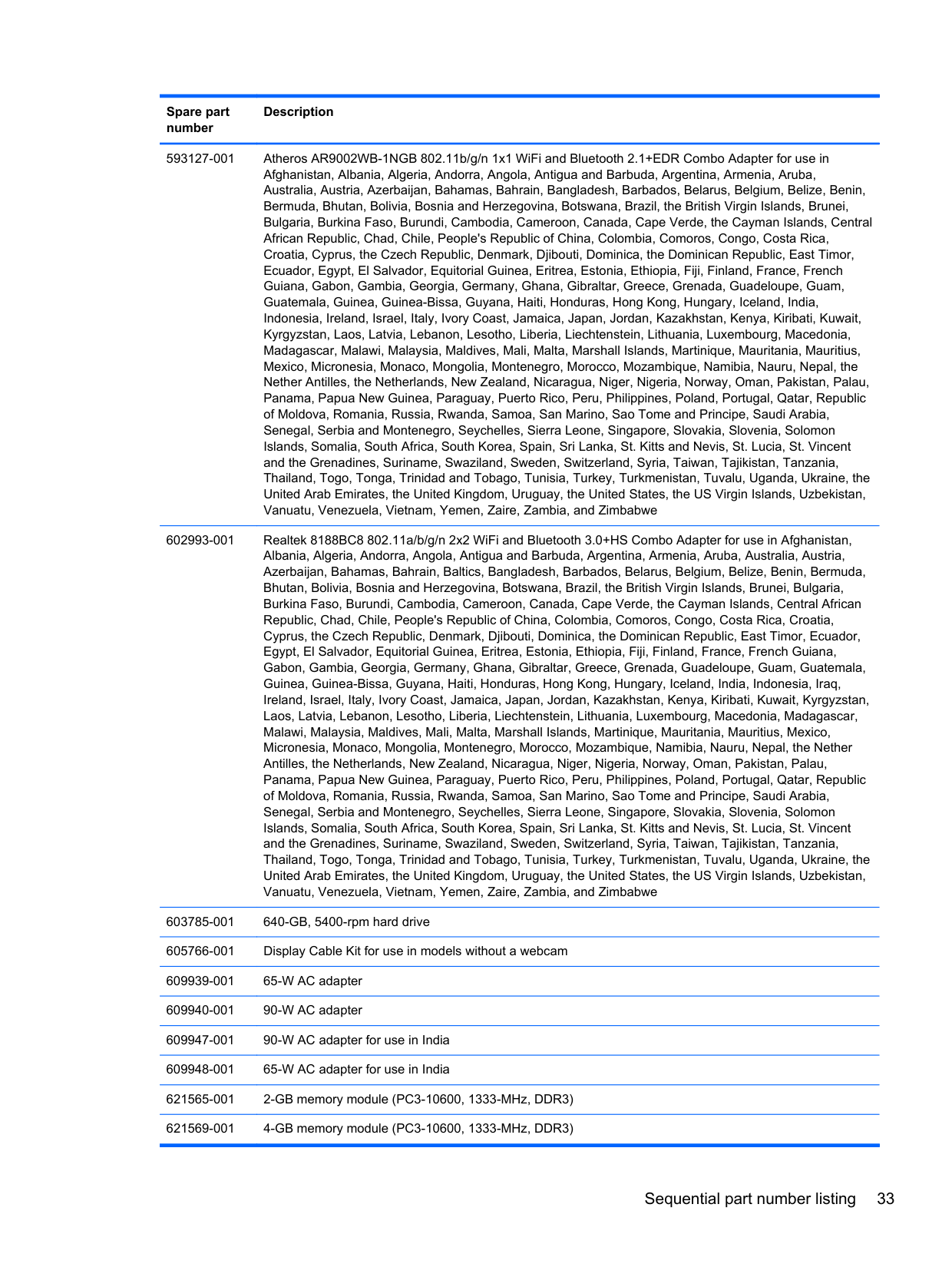
490371-D61 Power cord for use in India 501505-001 Basic messenger bag 593127-001 Atheros AR9002WB-1NGB 802.11b/g/n 1x1 WiFi and Bluetooth 2.1+EDR Combo Adapter for use in
Afghanistan, Albania, Algeria, Andorra, Angola, Antigua and Barbuda, Argentina, Armenia, Aruba, Australia, Austria, Azerbaijan, Bahamas, Bahrain, Bangladesh, Barbados, Belarus, Belgium, Belize, Benin, Bermuda, Bhutan, Bolivia, Bosnia and Herzegovina, Botswana, Brazil, the British Virgin Islands, Brunei, Bulgaria, Burkina Faso, Burundi, Cambodia, Cameroon, Canada, Cape Verde, the Cayman Islands, Central African Republic, Chad, Chile, People's Republic of China, Colombia, Comoros, Congo, Costa Rica, Croatia, Cyprus, the Czech Republic, Denmark, Djibouti, Dominica, the Dominican Republic, East Timor, Ecuador, Egypt, El Salvador, Equitorial Guinea, Eritrea, Estonia, Ethiopia, Fiji, Finland, France, French Guiana, Gabon, Gambia, Georgia, Germany, Ghana, Gibraltar, Greece, Grenada, Guadeloupe, Guam, Guatemala, Guinea, Guinea-Bissa, Guyana, Haiti, Honduras, Hong Kong, Hungary, Iceland, India, Indonesia, Ireland, Israel, Italy, Ivory Coast, Jamaica, Japan, Jordan, Kazakhstan, Kenya, Kiribati, Kuwait, Kyrgyzstan, Laos, Latvia, Lebanon, Lesotho, Liberia, Liechtenstein, Lithuania, Luxembourg, Macedonia, Madagascar, Malawi, Malaysia, Maldives, Mali, Malta, Marshall Islands, Martinique, Mauritania, Mauritius, Mexico, Micronesia, Monaco, Mongolia, Montenegro, Morocco, Mozambique, Namibia, Nauru, Nepal, the Nether Antilles, the Netherlands, New Zealand, Nicaragua, Niger, Nigeria, Norway, Oman, Pakistan, Palau, Panama, Papua New Guinea, Paraguay, Puerto Rico, Peru, Philippines, Poland, Portugal, Qatar, Republic of Moldova, Romania, Russia, Rwanda, Samoa, San Marino, Sao Tome and Principe, Saudi Arabia, Senegal, Serbia and Montenegro, Seychelles, Sierra Leone, Singapore, Slovakia, Slovenia, Solomon Islands, Somalia, South Africa, South Korea, Spain, Sri Lanka, St. Kitts and Nevis, St. Lucia, St. Vincent and the Grenadines, Suriname, Swaziland, Sweden, Switzerland, Syria, Taiwan, Tajikistan, Tanzania, Thailand, Togo, Tonga, Trinidad and Tobago, Tunisia, Turkey, Turkmenistan, Tuvalu, Uganda, Ukraine, the United Arab Emirates, the United Kingdom, Uruguay, the United States, the US Virgin Islands, Uzbekistan, Vanuatu, Venezuela, Vietnam, Yemen, Zaire, Zambia, and Zimbabwe
591699-001 Notebook combination lock 592923-001 Professional slim, top load case 602993-001 Realtek 8188BC8 802.11a/b/g/n 2x2 WiFi and Bluetooth 3.0+HS Combo Adapter for use in Afghanistan,
Albania, Algeria, Andorra, Angola, Antigua and Barbuda, Argentina, Armenia, Aruba, Australia, Austria, Azerbaijan, Bahamas, Bahrain, Baltics, Bangladesh, Barbados, Belarus, Belgium, Belize, Benin, Bermuda, Bhutan, Bolivia, Bosnia and Herzegovina, Botswana, Brazil, the British Virgin Islands, Brunei, Bulgaria, Burkina Faso, Burundi, Cambodia, Cameroon, Canada, Cape Verde, the Cayman Islands, Central African Republic, Chad, Chile, People's Republic of China, Colombia, Comoros, Congo, Costa Rica, Croatia, Cyprus, the Czech Republic, Denmark, Djibouti, Dominica, the Dominican Republic, East Timor, Ecuador, Egypt, El Salvador, Equitorial Guinea, Eritrea, Estonia, Ethiopia, Fiji, Finland, France, French Guiana, Gabon, Gambia, Georgia, Germany, Ghana, Gibraltar, Greece, Grenada, Guadeloupe, Guam, Guatemala, Guinea, Guinea-Bissa, Guyana, Haiti, Honduras, Hong Kong, Hungary, Iceland, India, Indonesia, Iraq, Ireland, Israel, Italy, Ivory Coast, Jamaica, Japan, Jordan, Kazakhstan, Kenya, Kiribati, Kuwait, Kyrgyzstan, Laos, Latvia, Lebanon, Lesotho, Liberia, Liechtenstein, Lithuania, Luxembourg, Macedonia, Madagascar, Malawi, Malaysia, Maldives, Mali, Malta, Marshall Islands, Martinique, Mauritania, Mauritius, Mexico, Micronesia, Monaco, Mongolia, Montenegro, Morocco, Mozambique, Namibia, Nauru, Nepal, the Nether Antilles, the Netherlands, New Zealand, Nicaragua, Niger, Nigeria, Norway, Oman, Pakistan, Palau, Panama, Papua New Guinea, Paraguay, Puerto Rico, Peru, Philippines, Poland, Portugal, Qatar, Republic of Moldova, Romania, Russia, Rwanda, Samoa, San Marino, Sao Tome and Principe, Saudi Arabia, Senegal, Serbia and Montenegro, Seychelles, Sierra Leone, Singapore, Slovakia, Slovenia, Solomon Islands, Somalia, South Africa, South Korea, Spain, Sri Lanka, St. Kitts and Nevis, St. Lucia, St. Vincent and the Grenadines, Suriname, Swaziland, Sweden, Switzerland, Syria, Taiwan, Tajikistan, Tanzania, Thailand, Togo, Tonga, Trinidad and Tobago, Tunisia, Turkey, Turkmenistan, Tuvalu, Uganda, Ukraine, the United Arab Emirates, the United Kingdom, Uruguay, the United States, the US Virgin Islands, Uzbekistan, Vanuatu, Venezuela, Vietnam, Yemen, Zaire, Zambia, and Zimbabwe
603785-001 640-GB, 5400-rpm hard drive 605766-001 Display Cable Kit for use in models without a webcam
NOTE: The modem module spare part kit does not include a modem module cable. The modem module cable is included in the Cable Kit, spare part number 646303-001 for 4530s models, 646304-001 for 4730s models. See Cable Kit on page 30 for more Cable Kit spare part number information.
630703-001 Ralink 5390GN 802.11b/g/n 1x1 WiFi Adapter for use in Afghanistan, Albania, Algeria, Andorra, Angola, Antigua and Barbuda, Argentina, Armenia, Aruba, Australia, Austria, Azerbaijan, Bahamas, Bahrain, Baltics, Bangladesh, Barbados, Belarus, Belgium, Belize, Benin, Bermuda, Bhutan, Bolivia, Bosnia and Herzegovina, Botswana, Brazil, the British Virgin Islands, Brunei, Bulgaria, Burkina Faso, Burundi, Cambodia, Cameroon, Canada, Cape Verde, the Cayman Islands, Central African Republic, Chad, Chile, People's Republic of China, Colombia, Comoros, Congo, Costa Rica, Croatia, Cyprus, the Czech Republic, Denmark, Djibouti, Dominica, the Dominican Republic, East Timor, Ecuador, Egypt, El Salvador, Equitorial Guinea, Eritrea, Estonia, Ethiopia, Fiji, Finland, France, French Guiana, Gabon, Gambia, Georgia, Germany, Ghana, Gibraltar, Greece, Grenada, Guadeloupe, Guam, Guatemala, Guinea, Guinea-Bissa, Guyana, Haiti, Honduras, Hong Kong, Hungary, Iceland, India, Indonesia, Iraq, Ireland, Israel, Italy, Ivory Coast, Jamaica, Japan, Jordan, Kazakhstan, Kenya, Kiribati, Kuwait, Kyrgyzstan, Laos, Latvia, Lebanon, Lesotho, Liberia, Liechtenstein, Lithuania, Luxembourg, Macedonia, Madagascar, Malawi, Malaysia, Maldives, Mali, Malta, Marshall Islands, Martinique, Mauritania, Mauritius, Mexico, Micronesia, Monaco, Mongolia, Montenegro, Morocco, Mozambique, Namibia, Nauru, Nepal, the Nether Antilles, the Netherlands, New Zealand, Nicaragua, Niger, Nigeria, Norway, Oman, Pakistan, Palau, Panama, Papua New Guinea, Paraguay, Puerto Rico, Peru, Philippines, Poland, Portugal, Qatar, Republic of Moldova, Romania, Russia, Rwanda, Samoa, San Marino, Sao Tome and Principe, Saudi Arabia, Senegal, Serbia and Montenegro, Seychelles, Sierra Leone, Singapore, Slovakia, Slovenia, Solomon Islands, Somalia, South Africa, South Korea, Spain, Sri Lanka, St. Kitts and Nevis, St. Lucia, St. Vincent and the Grenadines, Suriname, Swaziland, Sweden, Switzerland, Syria, Taiwan, Tajikistan, Tanzania, Thailand, Togo, Tonga, Trinidad and Tobago, Tunisia, Turkey, Turkmenistan, Tuvalu, Uganda, Ukraine, the United Arab Emirates, the United Kingdom, Uruguay, the United States, the US Virgin Islands, Uzbekistan, Vanuatu, Venezuela, Vietnam, Yemen, Zaire, Zambia, and Zimbabwe
630813-001 Ralink 8190BC8 802.11b/g/n 2x2 WiFi and Bluetooth 3.0+HS Combo Adapter for use in Afghanistan, Albania, Algeria, Andorra, Angola, Antigua and Barbuda, Argentina, Armenia, Aruba, Australia, Austria, Azerbaijan, Bahamas, Bahrain, Baltics, Bangladesh, Barbados, Belarus, Belgium, Belize, Benin, Bermuda, Bhutan, Bolivia, Bosnia and Herzegovina, Botswana, Brazil, the British Virgin Islands, Brunei, Bulgaria, Burkina Faso, Burundi, Cambodia, Cameroon, Canada, Cape Verde, the Cayman Islands, Central African Republic, Chad, Chile, People's Republic of China, Colombia, Comoros, Congo, Costa Rica, Croatia, Cyprus, the Czech Republic, Denmark, Djibouti, Dominica, the Dominican Republic, East Timor, Ecuador, Egypt, El Salvador, Equitorial Guinea, Eritrea, Estonia, Ethiopia, Fiji, Finland, France, French Guiana, Gabon, Gambia, Georgia, Germany, Ghana, Gibraltar, Greece, Grenada, Guadeloupe, Guam, Guatemala, Guinea, Guinea-Bissa, Guyana, Haiti, Honduras, Hong Kong, Hungary, Iceland, India, Indonesia, Iraq, Ireland, Israel, Italy, Ivory Coast, Jamaica, Japan, Jordan, Kazakhstan, Kenya, Kiribati, Kuwait, Kyrgyzstan, Laos, Latvia, Lebanon, Lesotho, Liberia, Liechtenstein, Lithuania, Luxembourg, Macedonia, Madagascar, Malawi, Malaysia, Maldives, Mali, Malta, Marshall Islands, Martinique, Mauritania, Mauritius, Mexico, Micronesia, Monaco, Mongolia, Montenegro, Morocco, Mozambique, Namibia, Nauru, Nepal, the Nether Antilles, the Netherlands, New Zealand, Nicaragua, Niger, Nigeria, Norway, Oman, Pakistan, Palau, Panama, Papua New Guinea, Paraguay, Puerto Rico, Peru, Philippines, Poland, Portugal, Qatar, Republic of Moldova, Romania, Russia, Rwanda, Samoa, San Marino, Sao Tome and Principe, Saudi Arabia, Senegal, Serbia and Montenegro, Seychelles, Sierra Leone, Singapore, Slovakia, Slovenia, Solomon Islands, Somalia, South Africa, South Korea, Spain, Sri Lanka, St. Kitts and Nevis, St. Lucia, St. Vincent and the Grenadines, Suriname, Swaziland, Sweden, Switzerland, Syria, Taiwan, Tajikistan, Tanzania, Thailand, Togo, Tonga, Trinidad and Tobago, Tunisia, Turkey, Turkmenistan, Tuvalu, Uganda, Ukraine, the United Arab Emirates, the United Kingdom, Uruguay, the United States, the US Virgin Islands, Uzbekistan, Vanuatu, Venezuela, Vietnam, Yemen, Zaire, Zambia, and Zimbabwe
636672-001 Intel Centrino Advanced-N 6230 for use in Afghanistan, Albania, Algeria, Andorra, Angola, Antigua and Barbuda, Argentina, Armenia, Aruba, Australia, Austria, Azerbaijan, Bahamas, Bahrain, Baltics, Bangladesh, Barbados, Belarus, Belgium, Belize, Benin, Bermuda, Bhutan, Bolivia, Bosnia and Herzegovina, Botswana, Brazil, the British Virgin Islands, Brunei, Bulgaria, Burkina Faso, Burundi, Cambodia, Cameroon, Canada, Cape Verde, the Cayman Islands, Central African Republic, Chad, Chile, People's Republic of China, Colombia, Comoros, Congo, Costa Rica, Croatia, Cyprus, the Czech Republic, Denmark, Djibouti, Dominica, the Dominican Republic, East Timor, Ecuador, Egypt, El Salvador, Equitorial Guinea, Eritrea, Estonia, Ethiopia, Fiji, Finland, France, French Guiana, Gabon, Gambia, Georgia, Germany, Ghana, Gibraltar, Greece, Grenada, Guadeloupe, Guam, Guatemala, Guinea, Guinea-Bissa, Guyana, Haiti, Honduras, Hong Kong, Hungary, Iceland, India, Indonesia, Iraq, Ireland, Israel, Italy, Ivory Coast, Jamaica, Japan, Jordan, Kazakhstan, Kenya, Kiribati, Kuwait, Kyrgyzstan, Laos, Latvia, Lebanon, Lesotho, Liberia, Liechtenstein, Lithuania, Luxembourg, Macedonia, Madagascar, Malawi, Malaysia, Maldives, Mali, Malta, Marshall Islands, Martinique, Mauritania, Mauritius, Mexico, Micronesia, Monaco, Mongolia, Montenegro, Morocco, Mozambique, Namibia, Nauru, Nepal, the Nether Antilles, the Netherlands, New Zealand, Nicaragua, Niger, Nigeria, Norway, Oman, Pakistan, Palau, Panama, Papua New Guinea, Paraguay, Puerto Rico, Peru, Philippines, Poland, Portugal, Qatar, Republic of Moldova, Romania, Russia, Rwanda, Samoa, San Marino, Sao Tome and Principe, Saudi Arabia, Senegal, Serbia and Montenegro, Seychelles, Sierra Leone, Singapore, Slovakia, Slovenia, Solomon Islands, Somalia, South Africa, South Korea, Spain, Sri Lanka, St. Kitts and Nevis, St. Lucia, St. Vincent and the Grenadines, Suriname, Swaziland, Sweden, Switzerland, Syria, Taiwan, Tajikistan, Tanzania, Thailand, Togo, Tonga, Trinidad and Tobago, Tunisia, Turkey, Turkmenistan, Tuvalu, Uganda, Ukraine, the United Arab Emirates, the United Kingdom, Uruguay, the United States, the US Virgin Islands, Uzbekistan, Vanuatu, Venezuela, Vietnam, Yemen, Zaire, Zambia, and Zimbabwe
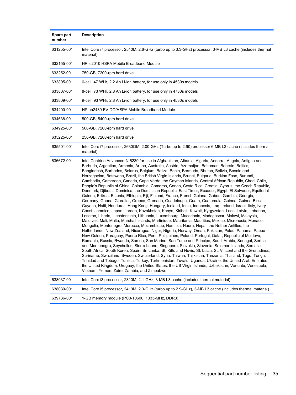
638037-001 Intel Core i3 processor, 2310M, 2.1-GHz, 3-MB L3 cache (includes thermal material) 638039-001 Intel Core i5 processor, 2410M, 2.3-GHz (turbo up to 2.9-GHz), 3-MB L3 cache (includes thermal material) 639736-001 1-GB memory module (PC3-10600, 1333-MHz, DDR3) 640926-001 Realtek 8188GN 802.11b/g/n 1x1 WiFi Adapter for use in Afghanistan, Albania, Algeria, Andorra, Angola,
Antigua and Barbuda, Argentina, Armenia, Aruba, Australia, Austria, Azerbaijan, Bahamas, Bahrain, Baltics, Bangladesh, Barbados, Belarus, Belgium, Belize, Benin, Bermuda, Bhutan, Bolivia, Bosnia and Herzegovina, Botswana, Brazil, the British Virgin Islands, Brunei, Bulgaria, Burkina Faso, Burundi, Cambodia, Cameroon, Canada, Cape Verde, the Cayman Islands, Central African Republic, Chad, Chile, People's Republic of China, Colombia, Comoros, Congo, Costa Rica, Croatia, Cyprus, the Czech Republic, Denmark, Djibouti, Dominica, the Dominican Republic, East Timor, Ecuador, Egypt, El Salvador, Equitorial Guinea, Eritrea, Estonia, Ethiopia, Fiji, Finland, France, French Guiana, Gabon, Gambia, Georgia, Germany, Ghana, Gibraltar, Greece, Grenada, Guadeloupe, Guam, Guatemala, Guinea, Guinea-Bissa, Guyana, Haiti, Honduras, Hong Kong, Hungary, Iceland, India, Indonesia, Iraq, Ireland, Israel, Italy, Ivory Coast, Jamaica, Japan, Jordan, Kazakhstan, Kenya, Kiribati, Kuwait, Kyrgyzstan, Laos, Latvia, Lebanon, Lesotho, Liberia, Liechtenstein, Lithuania, Luxembourg, Macedonia, Madagascar, Malawi, Malaysia, Maldives, Mali, Malta, Marshall Islands, Martinique, Mauritania, Mauritius, Mexico, Micronesia, Monaco, Mongolia, Montenegro, Morocco, Mozambique, Namibia, Nauru, Nepal, the Nether Antilles, the Netherlands, New Zealand, Nicaragua, Niger, Nigeria, Norway, Oman, Pakistan, Palau, Panama, Papua New Guinea, Paraguay, Puerto Rico, Peru, Philippines, Poland, Portugal, Qatar, Republic of Moldova, Romania, Russia, Rwanda, Samoa, San Marino, Sao Tome and Principe, Saudi Arabia, Senegal, Serbia and Montenegro, Seychelles, Sierra Leone, Singapore, Slovakia, Slovenia, Solomon Islands, Somalia, South Africa, South Korea, Spain, Sri Lanka, St. Kitts and Nevis, St. Lucia, St. Vincent and the Grenadines, Suriname, Swaziland, Sweden, Switzerland, Syria, Taiwan, Tajikistan, Tanzania, Thailand, Togo, Tonga, Trinidad and Tobago, Tunisia, Turkey, Turkmenistan, Tuvalu, Uganda, Ukraine, the United Arab Emirates, the United Kingdom, Uruguay, the United States, the US Virgin Islands, Uzbekistan, Vanuatu, Venezuela, Vietnam, Yemen, Zaire, Zambia, and Zimbabwe
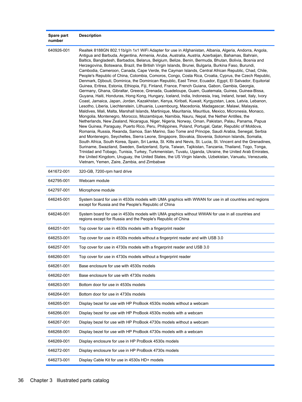
641672-001 320-GB, 7200-rpm hard drive 642795-001 Webcam module 642797-001 Microphone module 646245-001 System board for use in 4530s models with UMA graphics with WWAN 646246-001 System board for use in 4530s models with UMA graphics without WWAN
646251-001 Top cover for use in 4530s models with a fingerprint reader 646253-001 Top cover for use in 4530s models without a fingerprint reader and with USB 3.0 646257-001 Top cover for use in 4730s models with a fingerprint reader and USB 2.0
646300-DW1 Keyboard for use in the French Arabic region
4 Removal and replacement procedures
Preliminary replacement requirements
#### Tools required
You will need the following tools to complete the removal and replacement procedures:
#### Service considerations
The following sections include some of the considerations that you must keep in mind during disassembly and assembly procedures.
NOTE: As you remove each subassembly from the computer, place the subassembly (and all accompanying screws) away from the work area to prevent damage.
| | |---|
##### Plastic parts
CAUTION: Using excessive force during disassembly and reassembly can damage plastic parts. Use care when handling the plastic parts. Apply pressure only at the points designated in the maintenance instructions.
##### Cables and connectors
CAUTION: When servicing the computer, be sure that cables are placed in their proper locations during the reassembly process. Improper cable placement can damage the computer. Cables must be handled with extreme care to avoid damage. Apply only the tension required to unseat or seat the cables during removal and insertion. Handle cables by the connector whenever possible. In all cases, avoid bending, twisting, or tearing cables. Be sure that cables are routed in such a way that they cannot be caught or snagged by parts being removed or replaced. Handle flex cables with extreme care; these cables tear easily.
##### Drive handling
CAUTION: Drives are fragile components that must be handled with care. To prevent damage to the computer, damage to a drive, or loss of information, observe these precautions: Before removing or inserting a hard drive, shut down the computer. If you are unsure whether the computer is off or in Hibernation, turn the computer on, and then shut it down through the operating system. Before handling a drive, be sure that you are discharged of static electricity. While handling a drive, avoid touching the connector. Before removing a diskette drive or optical drive, be sure that a diskette or disc is not in the drive and be sure that the optical drive tray is closed. Handle drives on surfaces covered with at least one inch of shock-proof foam. Avoid dropping drives from any height onto any surface. After removing a hard drive, an optical drive, or a diskette drive, place it in a static-proof bag. Avoid exposing a hard drive to products that have magnetic fields, such as monitors or speakers. Avoid exposing a drive to temperature extremes or liquids. If a drive must be mailed, place the drive in a bubble pack mailer or other suitable form of protective packaging and label the package “FRAGILE.”
#### Grounding guidelines Electrostatic discharge damage
Electronic components are sensitive to electrostatic discharge (ESD). Circuitry design and structure determine the degree of sensitivity. Networks built into many integrated circuits provide some protection, but in many cases, ESD contains enough power to alter device parameters or melt silicon junctions.
A discharge of static electricity from a finger or other conductor can destroy static-sensitive devices or microcircuitry. Even if the spark is neither felt nor heard, damage may have occurred.
An electronic device exposed to ESD may not be affected at all and can work perfectly throughout a normal cycle. Or the device may function normally for a while, and then degrade in the internal layers, reducing its life expectancy.
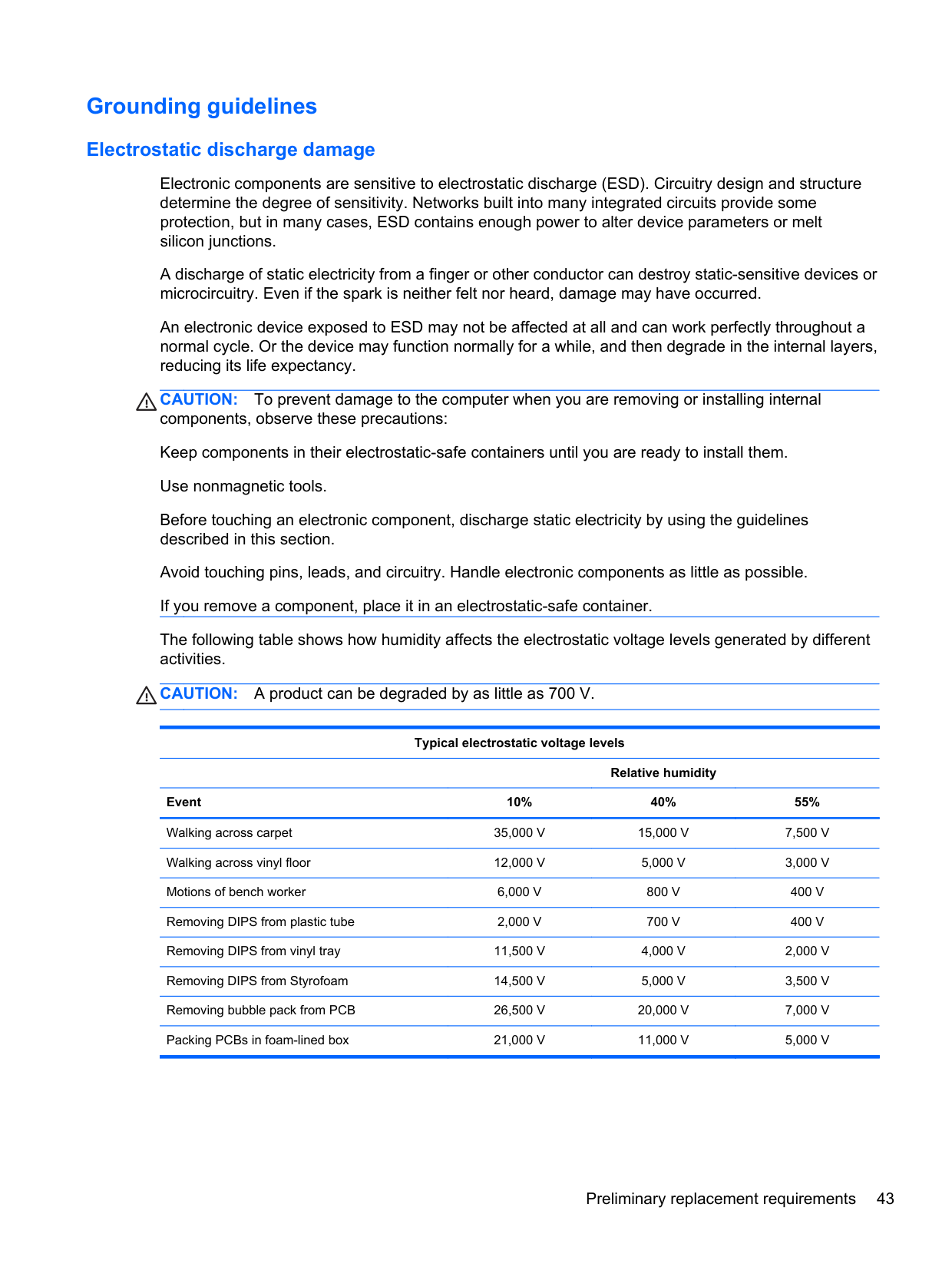
CAUTION: To prevent damage to the computer when you are removing or installing internal components, observe these precautions: Keep components in their electrostatic-safe containers until you are ready to install them. Use nonmagnetic tools. Before touching an electronic component, discharge static electricity by using the guidelines described in this section. Avoid touching pins, leads, and circuitry. Handle electronic components as little as possible. If you remove a component, place it in an electrostatic-safe container. The following table shows how humidity affects the electrostatic voltage levels generated by different activities.
CAUTION: A product can be degraded by as little as 700 V.
Typical electrostatic voltage levels
Relative humidity Event 10% 40% 55% Walking across carpet 35,000 V 15,000 V 7,500 V Walking across vinyl floor 12,000 V 5,000 V 3,000 V Motions of bench worker 6,000 V 800 V 400 V Removing DIPS from plastic tube 2,000 V 700 V 400 V Removing DIPS from vinyl tray 11,500 V 4,000 V 2,000 V Removing DIPS from Styrofoam 14,500 V 5,000 V 3,500 V Removing bubble pack from PCB 26,500 V 20,000 V 7,000 V Packing PCBs in foam-lined box 21,000 V 11,000 V 5,000 V
###### Packaging and transporting guidelines
Follow these grounding guidelines when packaging and transporting equipment:
###### Workstation guidelines
Follow these grounding workstation guidelines:
###### Equipment guidelines
Grounding equipment must include either a wrist strap or a foot strap at a grounded workstation.
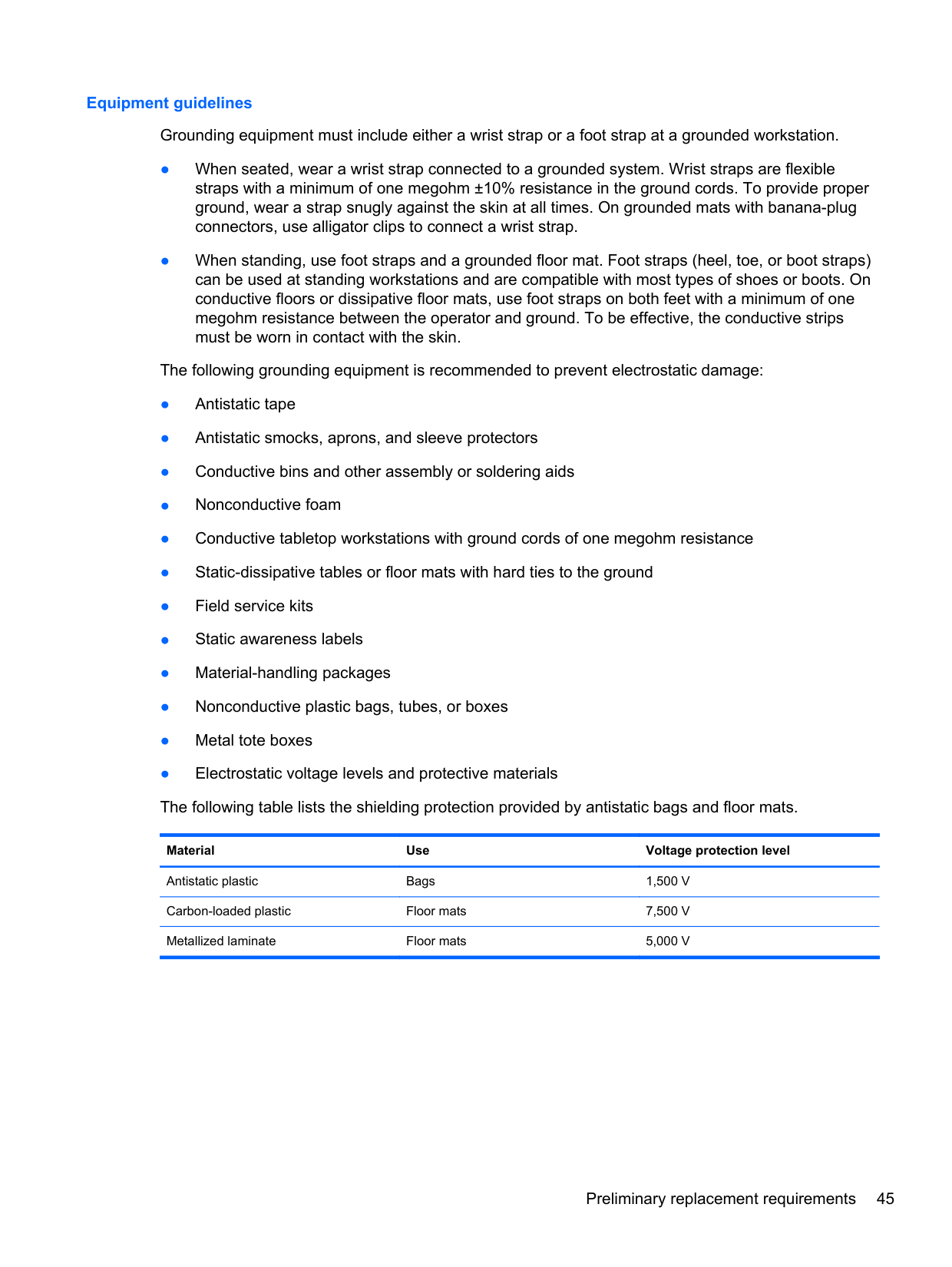
Material Use Voltage protection level
Antistatic plastic Bags 1,500 V Carbon-loaded plastic Floor mats 7,500 V Metallized laminate Floor mats 5,000 V
Component replacement procedures This chapter provides removal and replacement procedures. There are as many as 95 screws and screw locks, in 15 different sizes, that must be removed, replaced, or loosened when servicing the computer. Make special note of each screw and screw lock size and location during removal and replacement.
#### Service tag
When ordering parts or requesting information, provide the computer serial number and model description provided on the service tag.

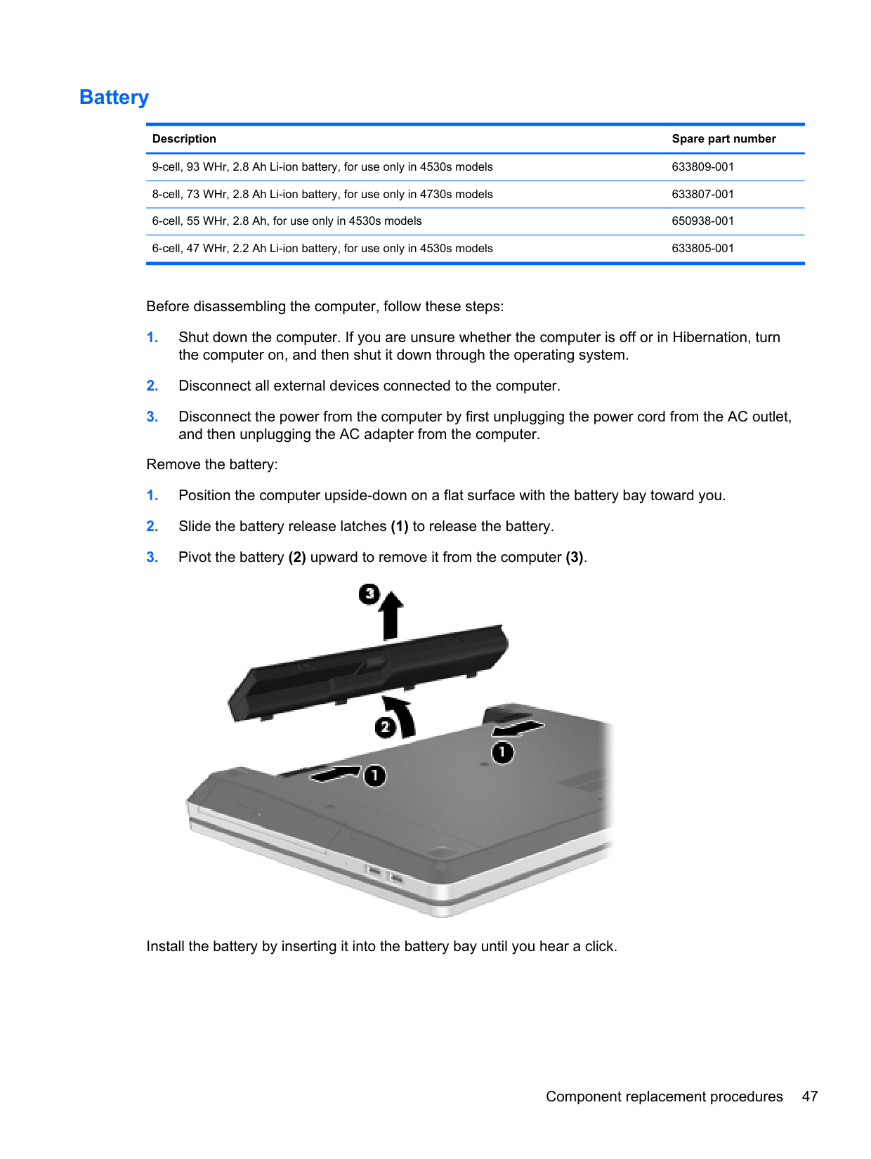
#### Battery
######## Description Spare part number
9-cell, 93 WHr, 2.8 Ah Li-ion battery, for use only in 4530s models 633809-001 8-cell, 73 WHr, 2.8 Ah Li-ion battery, for use only in 4730s models 633807-001 6-cell, 55 WHr, 2.8 Ah, for use only in 4530s models 650938-001 6-cell, 47 WHr, 2.2 Ah Li-ion battery, for use only in 4530s models 633805-001
Before disassembling the computer, follow these steps:
Remove the battery:

Install the battery by inserting it into the battery bay until you hear a click.
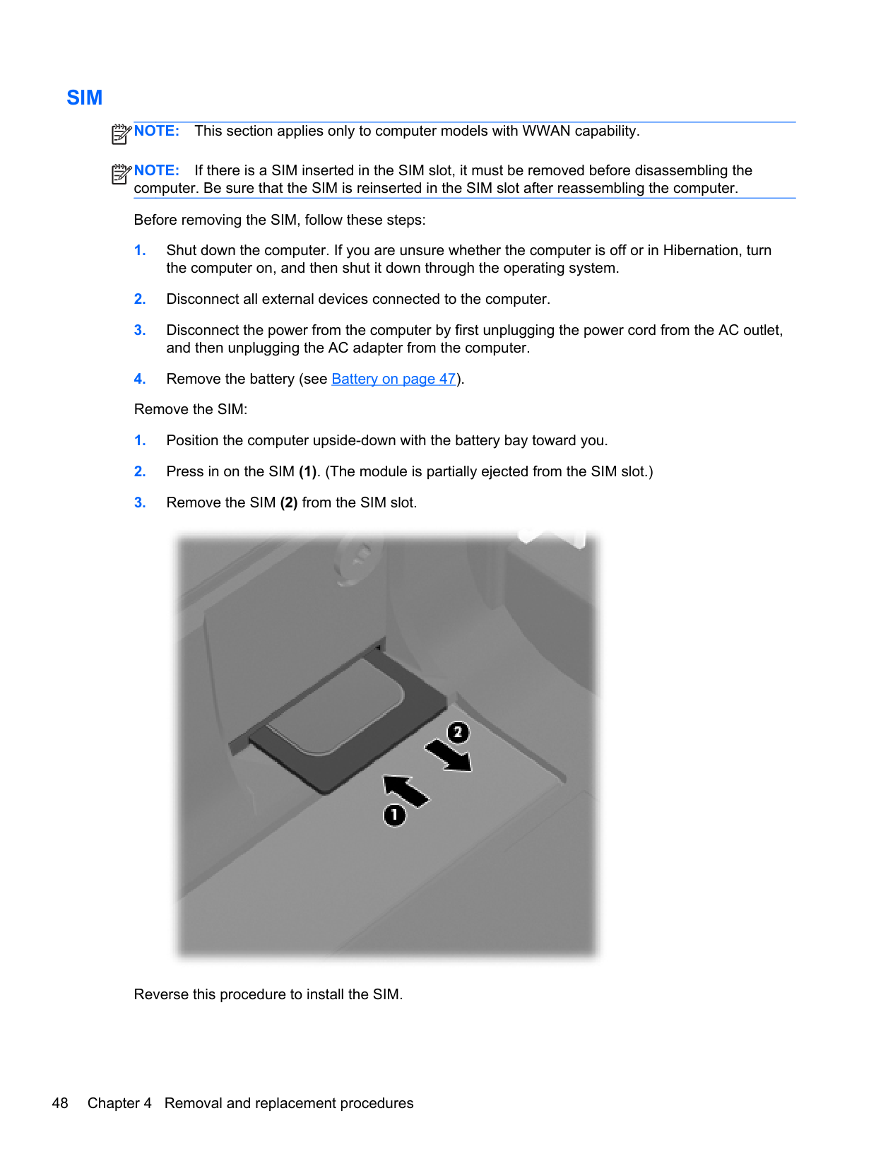
#### SIM
NOTE: This section applies only to computer models with WWAN capability. NOTE: If there is a SIM inserted in the SIM slot, it must be removed before disassembling the computer. Be sure that the SIM is reinserted in the SIM slot after reassembling the computer. Before removing the SIM, follow these steps:
| | |---|
| | |---|

Reverse this procedure to install the SIM.
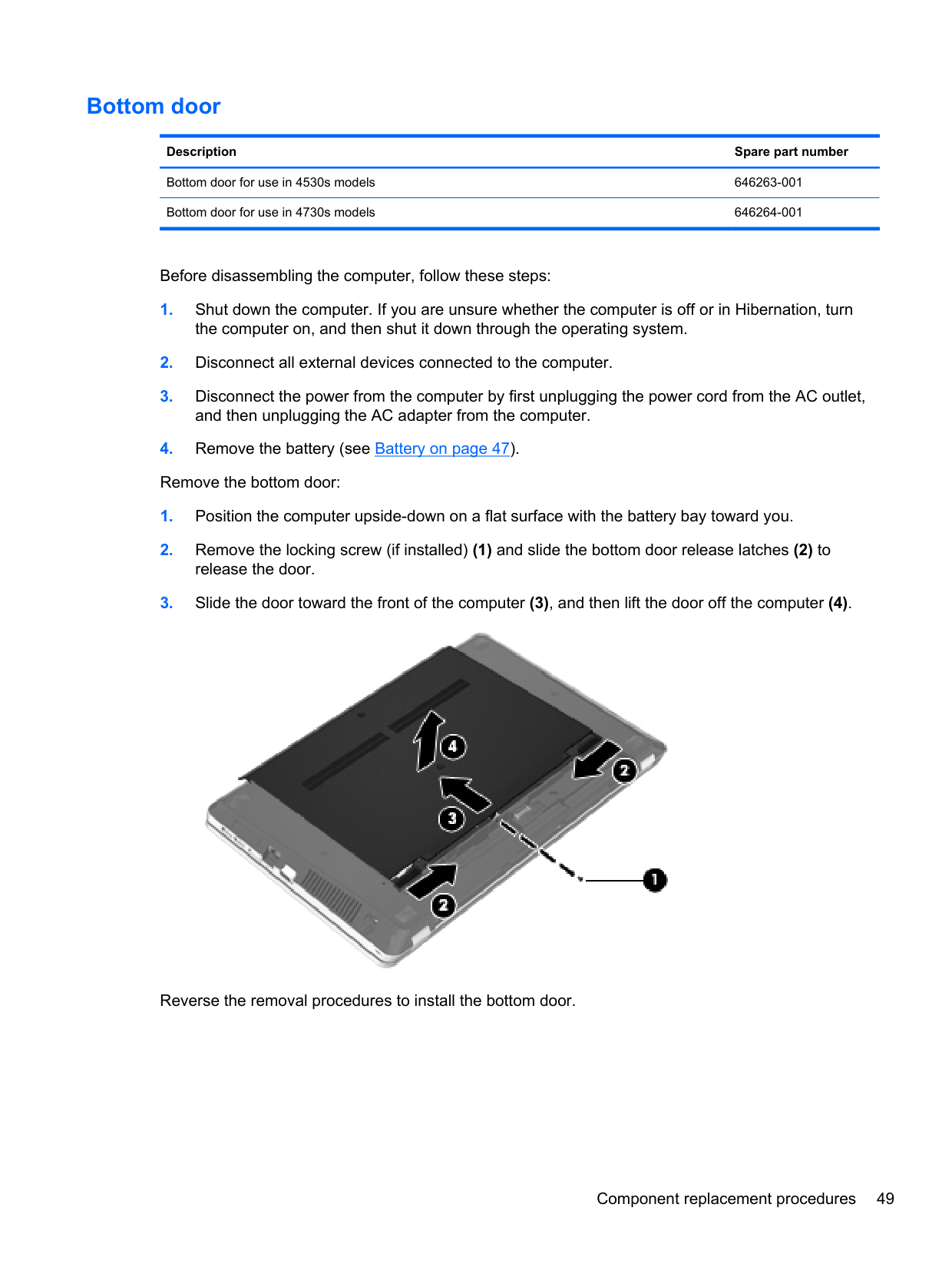
#### Bottom door
######## Description Spare part number
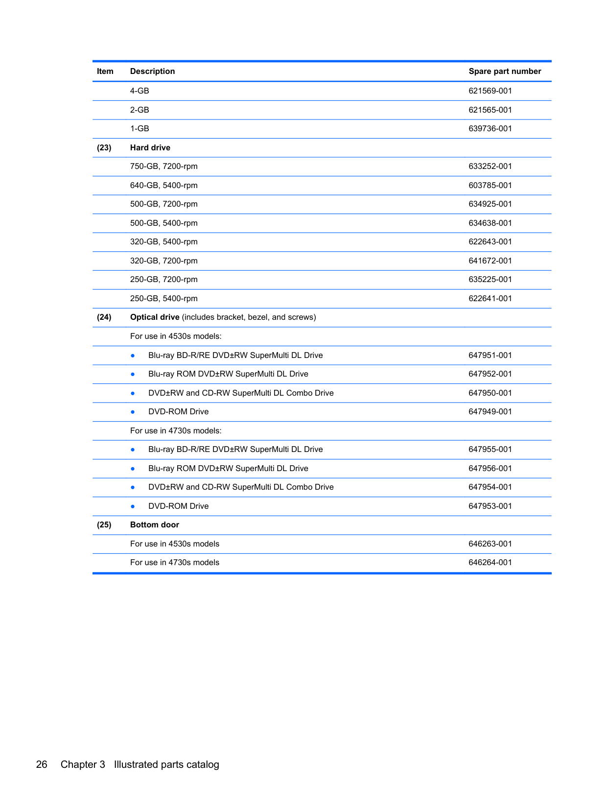
Bottom door for use in 4530s models 646263-001 Bottom door for use in 4730s models 646264-001
Before disassembling the computer, follow these steps:

Reverse the removal procedures to install the bottom door.
#### Optical drive
NOTE: All optical drive spare part kits include an optical drive bezel.
| | |---|
Description Spare part number For use in 4530s models:
Blu-ray BD-R/RE DVD±RW SuperMulti DL Drive 647951-001 Blu-ray ROM DVD±RW SuperMulti DL Drive 647952-001 DVD±RW and CD-RW SuperMulti DL Combo Drive 647950-001 DVD-ROM Drive 647949-001 For use in 4730s models:
Blu-ray BD-R/RE DVD±RW SuperMulti DL Drive 647955-001 Blu-ray ROM DVD±RW SuperMulti DL Drive 647956-001 DVD±RW and CD-RW SuperMulti DL Combo Drive 647954-001 DVD-ROM Drive 647953-001
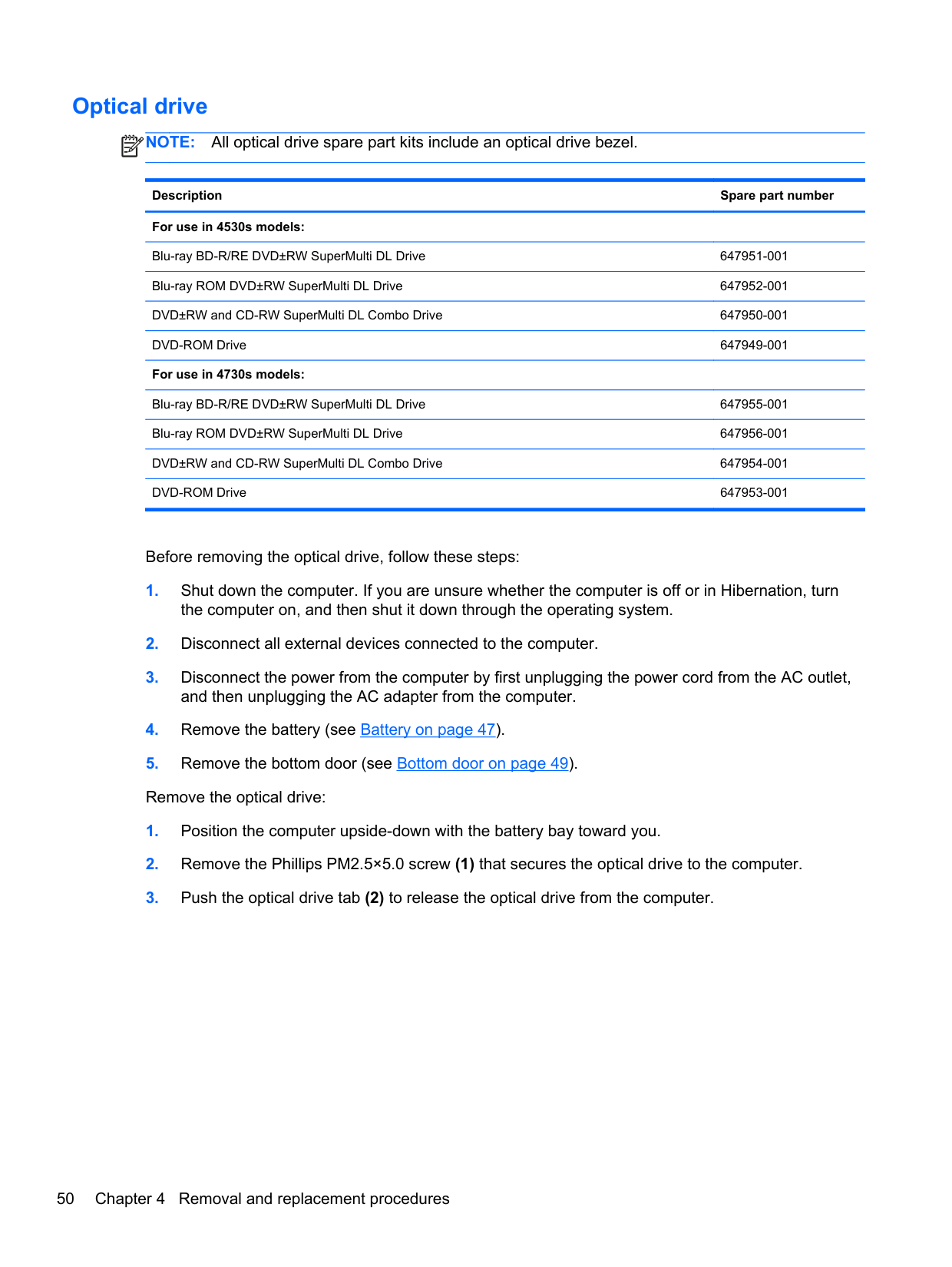
Before removing the optical drive, follow these steps:


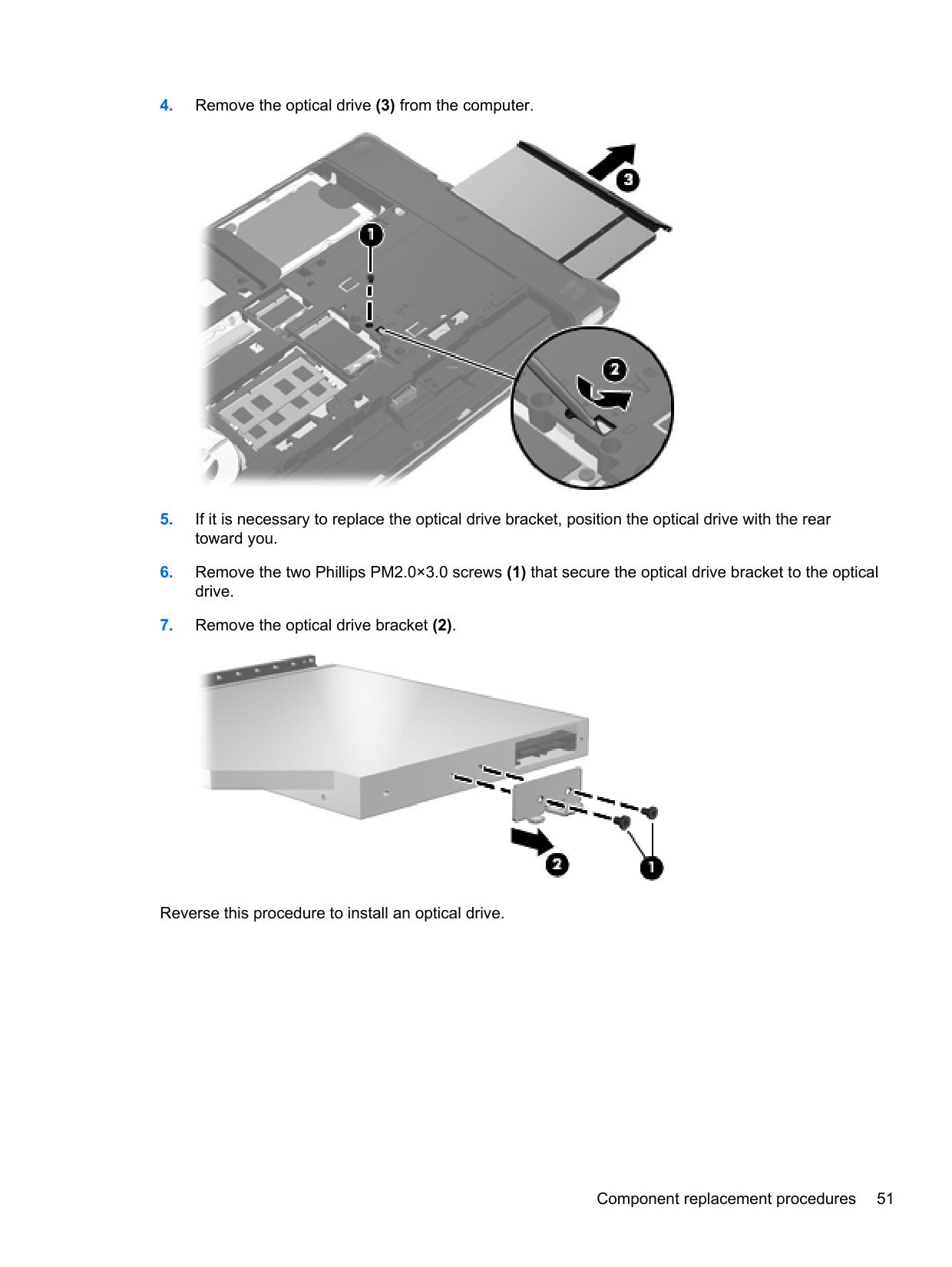
Reverse this procedure to install an optical drive.
#### Hard drive
NOTE: All hard drive spare part kits include a hard drive bracket and screws.
| | |---|
Description Spare part number
750-GB, 7200-rpm hard drive 633252-001 640-GB, 5400-rpm hard drive 603785-001 500-GB, 7200-rpm hard drive 634925-001 500-GB, 5400-rpm hard drive 634638-001 320-GB, 7200-rpm hard drive 641672-001 320-GB, 5400-rpm hard drive 622643-001 250-GB, 7200-rpm hard drive 635225-001 250-GB, 5400-rpm hard drive 622641-001 Hard Drive Hardware Kit (includes hard drive bracket, insulator, and screws) 647944-001
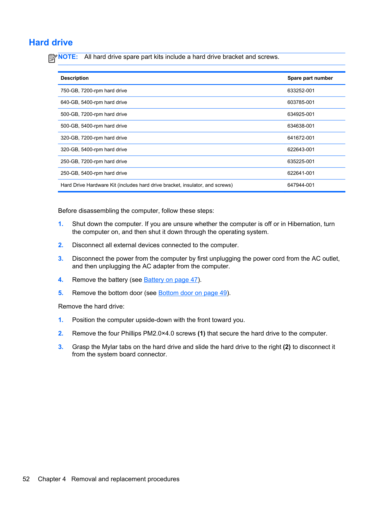
Before disassembling the computer, follow these steps:


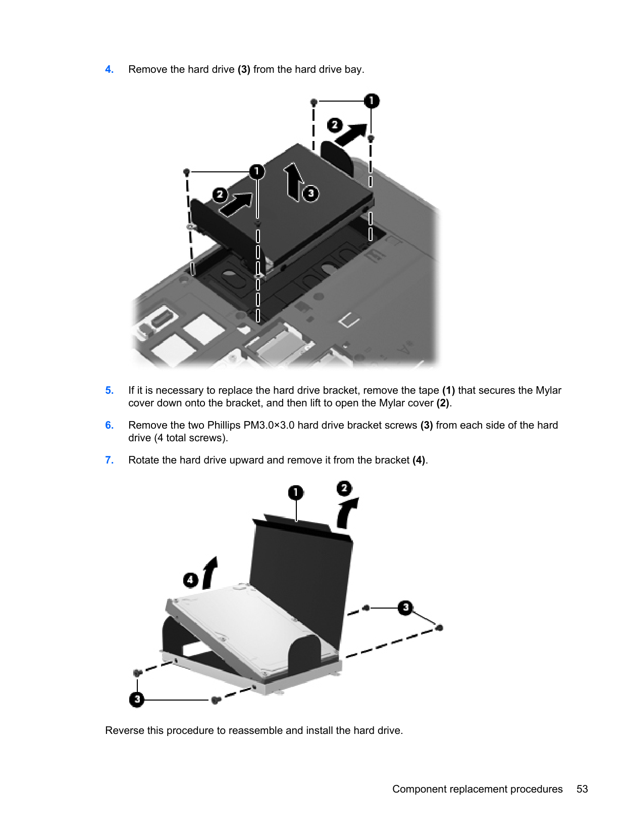
Reverse this procedure to reassemble and install the hard drive.
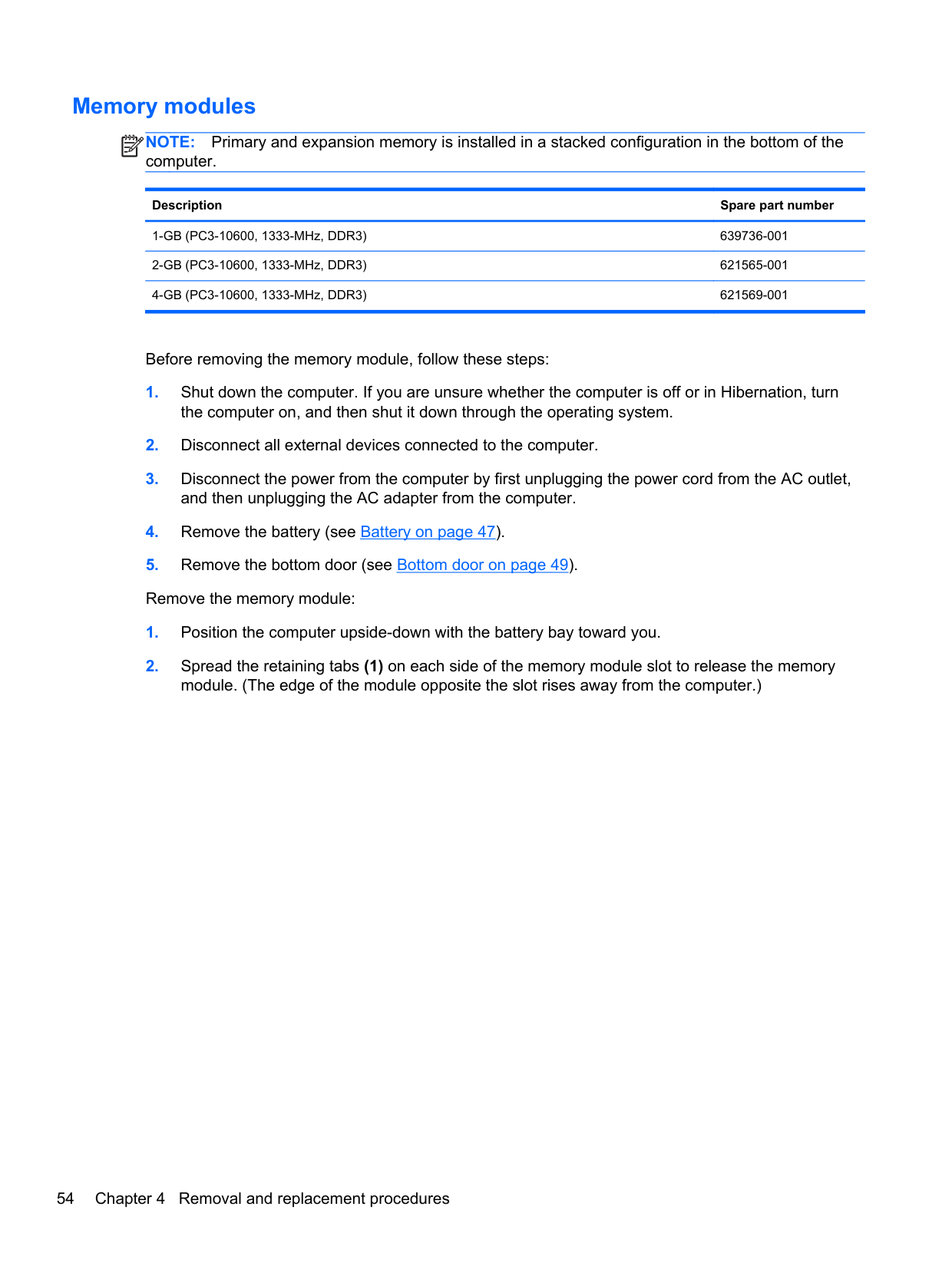
#### Memory modules
NOTE: Primary and expansion memory is installed in a stacked configuration in the bottom of the computer.
| | |---|
Description Spare part number
Update BIOS before adding memory modules Before adding new memory, make sure you update the computer to the latest BIOS.
CAUTION: Failure to update the computer to the latest BIOS prior to installing new memory may result in various system problems. To update BIOS:
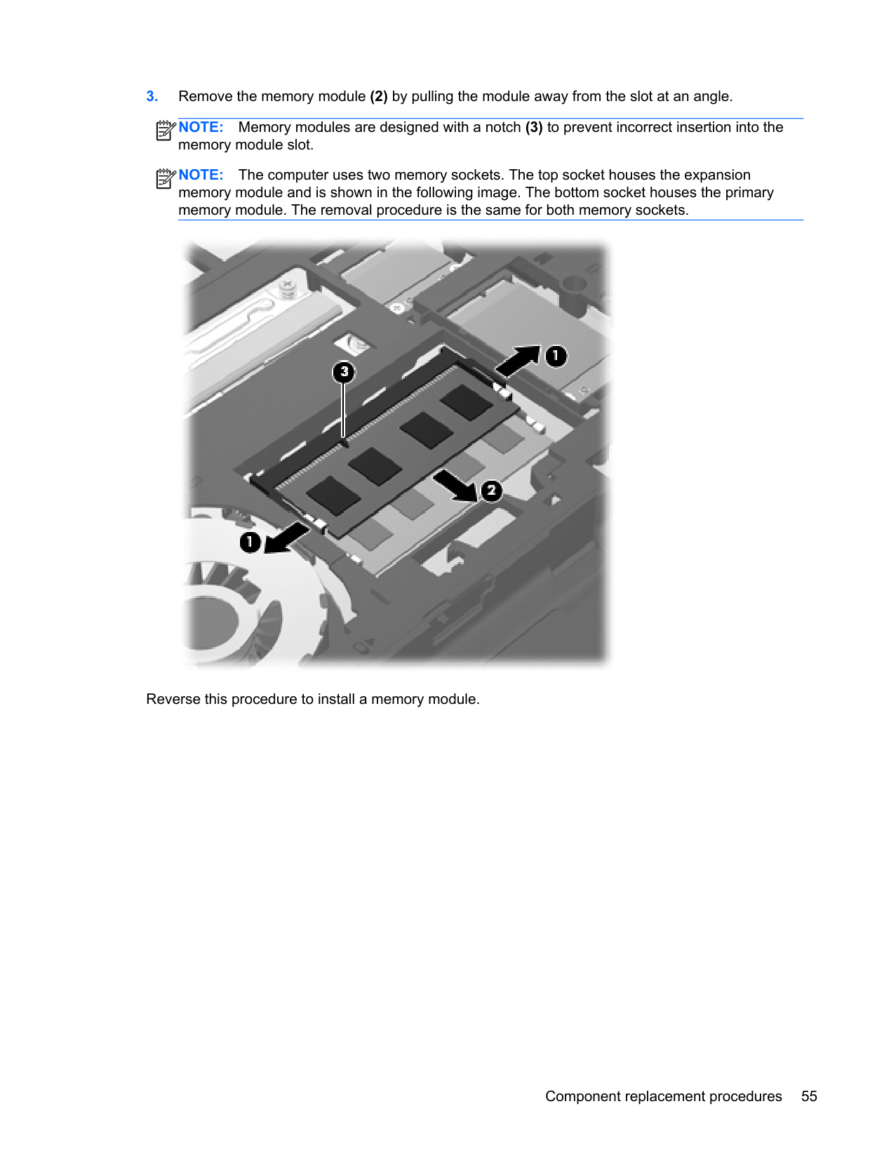
NOTE: Memory modules are designed with a notch (3) to prevent incorrect insertion into the memory module slot.
| | |---|
NOTE: The computer uses two memory sockets. The top socket houses the expansion memory module and is shown in the following image. The bottom socket houses the primary memory module. The removal procedure is the same for both memory sockets.
| | |---|

Reverse this procedure to install a memory module.
#### WWAN module
CAUTION: The WWAN module and the WLAN module are not interchangeable.
Description Spare part number
HP lc2010 HSPA Mobile Broadband Module 632155-001 HP un2430 EV-DO/HSPA Mobile Broadband Module 634400-001
Before removing the WWAN module, follow these steps:
| | |---|
NOTE: The red WWAN antenna cable is connected to the WWAN module “Main” terminal. The blue WWAN antenna cable is connected to the WWAN module “Aux” terminal.
| | |---|
Figure 4-1 Removing the WWAN module

NOTE: If the WWAN antennas are not connected to the terminals on the WWAN module, the protective sleeves must be installed on the antenna connectors, as shown in the following illustration.
| | |---|

Reverse this procedure to install the WWAN module.
#### WLAN/Bluetooth combo card
The computer uses a card that provides both WLAN and Bluetooth functionality.
CAUTION: The WLAN module and the WWAN module are not interchangeable.
Description Spare part number
Atheros AR9002WB-1NGB 802.11b/g/n 1x1 WiFi and Bluetooth 2.1+EDR Combo Adapter for use in Afghanistan, Albania, Algeria, Andorra, Angola, Antigua and Barbuda, Argentina, Armenia, Aruba, Australia, Austria, Azerbaijan, Bahamas, Bahrain, Bangladesh, Barbados, Belarus, Belgium, Belize, Benin, Bermuda, Bhutan, Bolivia, Bosnia and Herzegovina, Botswana, Brazil, the British Virgin Islands, Brunei, Bulgaria, Burkina Faso, Burundi, Cambodia, Cameroon, Canada, Cape Verde, the Cayman Islands, Central African Republic, Chad, Chile, People's Republic of China, Colombia, Comoros, Congo, Costa Rica, Croatia, Cyprus, the Czech Republic, Denmark, Djibouti, Dominica, the Dominican Republic, East Timor, Ecuador, Egypt, El Salvador, Equitorial Guinea, Eritrea, Estonia, Ethiopia, Fiji, Finland, France, French Guiana, Gabon, Gambia, Georgia, Germany, Ghana, Gibraltar, Greece, Grenada, Guadeloupe, Guam, Guatemala, Guinea, GuineaBissa, Guyana, Haiti, Honduras, Hong Kong, Hungary, Iceland, India, Indonesia, Ireland, Israel, Italy, Ivory Coast, Jamaica, Japan, Jordan, Kazakhstan, Kenya, Kiribati, Kuwait, Kyrgyzstan, Laos, Latvia, Lebanon, Lesotho, Liberia, Liechtenstein, Lithuania, Luxembourg, Macedonia, Madagascar, Malawi, Malaysia, Maldives, Mali, Malta, Marshall Islands, Martinique, Mauritania, Mauritius, Mexico, Micronesia, Monaco, Mongolia, Montenegro, Morocco, Mozambique, Namibia, Nauru, Nepal, the Nether Antilles, the Netherlands, New Zealand, Nicaragua, Niger, Nigeria, Norway, Oman, Pakistan, Palau, Panama, Papua New Guinea, Paraguay, Puerto Rico, Peru, Philippines, Poland, Portugal, Qatar, Republic of Moldova, Romania, Russia, Rwanda, Samoa,
593127-001
Realtek 8188BC8 802.11a/b/g/n 2x2 WiFi and Bluetooth 3.0+HS Combo Adapter for use in Afghanistan, Albania, Algeria, Andorra, Angola, Antigua and Barbuda, Argentina, Armenia, Aruba, Australia, Austria, Azerbaijan, Bahamas, Bahrain, Baltics, Bangladesh, Barbados, Belarus, Belgium, Belize, Benin, Bermuda, Bhutan, Bolivia, Bosnia and Herzegovina, Botswana, Brazil, the British Virgin Islands, Brunei, Bulgaria, Burkina Faso, Burundi, Cambodia, Cameroon, Canada, Cape Verde, the Cayman Islands, Central African Republic, Chad, Chile, People's Republic of China, Colombia, Comoros, Congo, Costa Rica, Croatia, Cyprus, the Czech Republic, Denmark, Djibouti, Dominica, the Dominican Republic, East Timor, Ecuador, Egypt, El Salvador, Equitorial Guinea, Eritrea, Estonia, Ethiopia, Fiji, Finland, France, French Guiana, Gabon, Gambia, Georgia, Germany, Ghana, Gibraltar, Greece, Grenada, Guadeloupe, Guam, Guatemala, Guinea, GuineaBissa, Guyana, Haiti, Honduras, Hong Kong, Hungary, Iceland, India, Indonesia, Iraq, Ireland, Israel, Italy, Ivory Coast, Jamaica, Japan, Jordan, Kazakhstan, Kenya, Kiribati, Kuwait, Kyrgyzstan, Laos, Latvia, Lebanon, Lesotho, Liberia, Liechtenstein, Lithuania, Luxembourg, Macedonia, Madagascar, Malawi, Malaysia, Maldives, Mali, Malta, Marshall Islands, Martinique, Mauritania, Mauritius, Mexico, Micronesia, Monaco, Mongolia, Montenegro, Morocco, Mozambique, Namibia, Nauru, Nepal, the Nether Antilles, the Netherlands, New Zealand, Nicaragua, Niger, Nigeria, Norway, Oman, Pakistan, Palau, Panama, Papua New Guinea, Paraguay, Puerto Rico, Peru, Philippines, Poland, Portugal, Qatar, Republic of Moldova, Romania, Russia, Rwanda, Samoa, San Marino, Sao Tome and Principe, Saudi Arabia, Senegal, Serbia and Montenegro, Seychelles, Sierra Leone, Singapore, Slovakia, Slovenia, Solomon Islands, Somalia, South Africa, South Korea, Spain, Sri Lanka, St. Kitts and Nevis, St. Lucia, St. Vincent and the Grenadines, Suriname, Swaziland, Sweden, Switzerland, Syria, Taiwan, Tajikistan, Tanzania, Thailand, Togo, Tonga, Trinidad and Tobago, Tunisia, Turkey, Turkmenistan, Tuvalu, Uganda, Ukraine, the United Arab Emirates, the United Kingdom, Uruguay, the United States, the US Virgin Islands, Uzbekistan, Vanuatu, Venezuela, Vietnam, Yemen, Zaire, Zambia, and Zimbabwe
602993-001
Ralink 5390GN 802.11b/g/n 1x1 WiFi Adapter for use in Afghanistan, Albania, Algeria, Andorra, Angola, Antigua and Barbuda, Argentina, Armenia, Aruba, Australia, Austria, Azerbaijan, Bahamas, Bahrain, Baltics, Bangladesh, Barbados, Belarus, Belgium, Belize, Benin, Bermuda, Bhutan, Bolivia, Bosnia and Herzegovina, Botswana, Brazil, the British Virgin Islands, Brunei, Bulgaria, Burkina Faso, Burundi, Cambodia, Cameroon, Canada, Cape Verde, the Cayman Islands, Central African Republic, Chad, Chile, People's Republic of China, Colombia, Comoros, Congo, Costa Rica, Croatia, Cyprus, the Czech Republic, Denmark, Djibouti, Dominica, the Dominican Republic, East Timor, Ecuador, Egypt, El Salvador, Equitorial Guinea, Eritrea, Estonia, Ethiopia, Fiji, Finland, France, French Guiana, Gabon, Gambia, Georgia, Germany, Ghana, Gibraltar, Greece, Grenada, Guadeloupe, Guam, Guatemala, Guinea, Guinea-Bissa, Guyana, Haiti, Honduras, Hong Kong, Hungary, Iceland, India, Indonesia, Iraq, Ireland, Israel, Italy, Ivory Coast, Jamaica, Japan, Jordan, Kazakhstan, Kenya, Kiribati, Kuwait, Kyrgyzstan, Laos, Latvia, Lebanon, Lesotho, Liberia, Liechtenstein, Lithuania, Luxembourg, Macedonia, Madagascar, Malawi, Malaysia, Maldives, Mali, Malta, Marshall Islands, Martinique, Mauritania, Mauritius, Mexico, Micronesia, Monaco, Mongolia, Montenegro, Morocco, Mozambique, Namibia, Nauru, Nepal, the Nether Antilles, the Netherlands, New Zealand, Nicaragua, Niger, Nigeria, Norway, Oman, Pakistan, Palau, Panama, Papua New Guinea, Paraguay, Puerto Rico, Peru, Philippines, Poland, Portugal, Qatar, Republic of Moldova, Romania, Russia, Rwanda, Samoa, San Marino, Sao Tome and Principe, Saudi Arabia, Senegal, Serbia and Montenegro, Seychelles, Sierra Leone, Singapore, Slovakia, Slovenia, Solomon Islands, Somalia, South Africa, South Korea, Spain, Sri Lanka, St. Kitts and Nevis, St. Lucia, St. Vincent and the Grenadines, Suriname, Swaziland, Sweden, Switzerland, Syria, Taiwan, Tajikistan, Tanzania, Thailand, Togo, Tonga, Trinidad and Tobago, Tunisia, Turkey, Turkmenistan, Tuvalu, Uganda, Ukraine, the United Arab Emirates, the United Kingdom, Uruguay, the United States, the US Virgin Islands, Uzbekistan, Vanuatu, Venezuela, Vietnam, Yemen, Zaire, Zambia, and Zimbabwe
630703-001
Ralink 8190BC8 802.11b/g/n 2x2 WiFi and Bluetooth 3.0+HS Combo Adapter for use in Afghanistan, Albania, Algeria, Andorra, Angola, Antigua and Barbuda, Argentina, Armenia, Aruba, Australia, Austria, Azerbaijan, Bahamas, Bahrain, Baltics, Bangladesh, Barbados, Belarus, Belgium, Belize, Benin, Bermuda, Bhutan, Bolivia, Bosnia and Herzegovina, Botswana, Brazil, the British Virgin Islands, Brunei, Bulgaria, Burkina Faso, Burundi, Cambodia, Cameroon, Canada, Cape Verde, the Cayman Islands, Central African Republic, Chad, Chile, People's Republic of China, Colombia, Comoros, Congo, Costa Rica, Croatia, Cyprus, the Czech Republic, Denmark, Djibouti, Dominica, the Dominican Republic, East Timor, Ecuador, Egypt, El Salvador, Equitorial Guinea, Eritrea, Estonia, Ethiopia, Fiji, Finland, France, French Guiana, Gabon, Gambia, Georgia, Germany, Ghana, Gibraltar, Greece, Grenada, Guadeloupe, Guam, Guatemala, Guinea, GuineaBissa, Guyana, Haiti, Honduras, Hong Kong, Hungary, Iceland, India, Indonesia, Iraq, Ireland, Israel, Italy, Ivory Coast, Jamaica, Japan, Jordan, Kazakhstan, Kenya, Kiribati, Kuwait, Kyrgyzstan, Laos, Latvia, Lebanon, Lesotho, Liberia, Liechtenstein, Lithuania, Luxembourg, Macedonia, Madagascar, Malawi, Malaysia, Maldives, Mali, Malta, Marshall Islands, Martinique, Mauritania, Mauritius, Mexico, Micronesia, Monaco, Mongolia, Montenegro, Morocco, Mozambique, Namibia, Nauru, Nepal, the Nether Antilles, the Netherlands, New Zealand, Nicaragua, Niger, Nigeria, Norway, Oman, Pakistan, Palau, Panama, Papua New Guinea, Paraguay, Puerto Rico, Peru, Philippines, Poland, Portugal, Qatar, Republic of Moldova, Romania, Russia, Rwanda, Samoa, San Marino, Sao Tome and Principe, Saudi Arabia, Senegal, Serbia and Montenegro, Seychelles, Sierra Leone, Singapore, Slovakia, Slovenia, Solomon Islands, Somalia, South Africa, South Korea, Spain, Sri Lanka, St. Kitts and Nevis, St. Lucia, St. Vincent and the Grenadines, Suriname, Swaziland, Sweden, Switzerland, Syria, Taiwan, Tajikistan, Tanzania, Thailand, Togo, Tonga, Trinidad and Tobago, Tunisia, Turkey, Turkmenistan, Tuvalu, Uganda, Ukraine, the United Arab Emirates, the United Kingdom, Uruguay, the United States, the US Virgin Islands, Uzbekistan, Vanuatu, Venezuela, Vietnam, Yemen, Zaire, Zambia, and Zimbabwe
630813-001
Realtek 8188GN 802.11b/g/n 1x1 WiFi Adapter for use in Afghanistan, Albania, Algeria, Andorra, Angola, Antigua and Barbuda, Argentina, Armenia, Aruba, Australia, Austria, Azerbaijan, Bahamas, Bahrain, Baltics, Bangladesh, Barbados, Belarus, Belgium, Belize, Benin, Bermuda, Bhutan, Bolivia, Bosnia and Herzegovina, Botswana, Brazil, the British Virgin Islands, Brunei, Bulgaria, Burkina Faso, Burundi, Cambodia, Cameroon, Canada, Cape Verde, the Cayman Islands, Central African Republic, Chad, Chile, People's Republic of China, Colombia, Comoros, Congo, Costa Rica, Croatia, Cyprus, the Czech Republic, Denmark, Djibouti, Dominica, the Dominican Republic, East Timor, Ecuador, Egypt, El Salvador, Equitorial Guinea, Eritrea, Estonia, Ethiopia, Fiji, Finland, France, French Guiana, Gabon, Gambia, Georgia, Germany, Ghana, Gibraltar, Greece, Grenada, Guadeloupe, Guam, Guatemala, Guinea, Guinea-Bissa, Guyana, Haiti, Honduras, Hong Kong, Hungary, Iceland, India, Indonesia, Iraq, Ireland, Israel, Italy, Ivory Coast, Jamaica, Japan, Jordan, Kazakhstan, Kenya, Kiribati, Kuwait, Kyrgyzstan, Laos, Latvia, Lebanon, Lesotho, Liberia, Liechtenstein, Lithuania, Luxembourg, Macedonia, Madagascar, Malawi, Malaysia, Maldives, Mali, Malta, Marshall Islands, Martinique, Mauritania, Mauritius, Mexico, Micronesia, Monaco, Mongolia, Montenegro, Morocco, Mozambique, Namibia, Nauru, Nepal, the Nether Antilles, the Netherlands, New Zealand, Nicaragua, Niger, Nigeria, Norway, Oman, Pakistan, Palau, Panama, Papua New Guinea, Paraguay, Puerto Rico, Peru, Philippines, Poland, Portugal, Qatar, Republic of Moldova, Romania, Russia, Rwanda, Samoa, San Marino,
640926-001
Intel Centrino Advanced-N 6230 for use in Afghanistan, Albania, Algeria, Andorra, Angola, Antigua and Barbuda, Argentina, Armenia, Aruba, Australia, Austria, Azerbaijan, Bahamas, Bahrain, Baltics, Bangladesh, Barbados, Belarus, Belgium, Belize, Benin, Bermuda, Bhutan, Bolivia, Bosnia and Herzegovina, Botswana, Brazil, the British Virgin Islands, Brunei, Bulgaria, Burkina Faso, Burundi, Cambodia, Cameroon, Canada, Cape Verde, the Cayman Islands, Central African Republic, Chad, Chile, People's Republic of China, Colombia, Comoros, Congo, Costa Rica, Croatia, Cyprus, the Czech Republic, Denmark, Djibouti, Dominica, the Dominican Republic, East Timor, Ecuador, Egypt, El Salvador, Equitorial Guinea, Eritrea, Estonia, Ethiopia, Fiji, Finland, France, French Guiana, Gabon, Gambia, Georgia, Germany, Ghana, Gibraltar, Greece, Grenada, Guadeloupe, Guam, Guatemala, Guinea, Guinea-Bissa, Guyana, Haiti, Honduras, Hong Kong, Hungary, Iceland, India, Indonesia, Iraq, Ireland, Israel, Italy, Ivory Coast, Jamaica, Japan, Jordan, Kazakhstan, Kenya, Kiribati, Kuwait, Kyrgyzstan, Laos, Latvia, Lebanon, Lesotho, Liberia, Liechtenstein, Lithuania, Luxembourg, Macedonia, Madagascar, Malawi, Malaysia, Maldives, Mali, Malta, Marshall Islands, Martinique, Mauritania, Mauritius, Mexico, Micronesia, Monaco, Mongolia, Montenegro, Morocco, Mozambique, Namibia, Nauru, Nepal, the Nether Antilles, the Netherlands, New Zealand, Nicaragua, Niger, Nigeria, Norway, Oman, Pakistan, Palau, Panama, Papua New Guinea, Paraguay, Puerto Rico, Peru, Philippines, Poland, Portugal, Qatar, Republic of Moldova, Romania, Russia, Rwanda, Samoa, San Marino, Sao Tome and Principe, Saudi Arabia, Senegal, Serbia and Montenegro, Seychelles, Sierra Leone, Singapore, Slovakia, Slovenia, Solomon Islands, Somalia, South Africa, South Korea, Spain, Sri Lanka, St. Kitts and Nevis, St. Lucia, St. Vincent and the Grenadines, Suriname, Swaziland, Sweden, Switzerland, Syria, Taiwan, Tajikistan, Tanzania, Thailand, Togo, Tonga, Trinidad and Tobago, Tunisia, Turkey, Turkmenistan, Tuvalu, Uganda, Ukraine, the United Arab Emirates, the United Kingdom, Uruguay, the United States, the US Virgin Islands, Uzbekistan, Vanuatu, Venezuela, Vietnam, Yemen, Zaire, Zambia, and Zimbabwe
636672-001
Before removing the WLAN module, follow these steps:
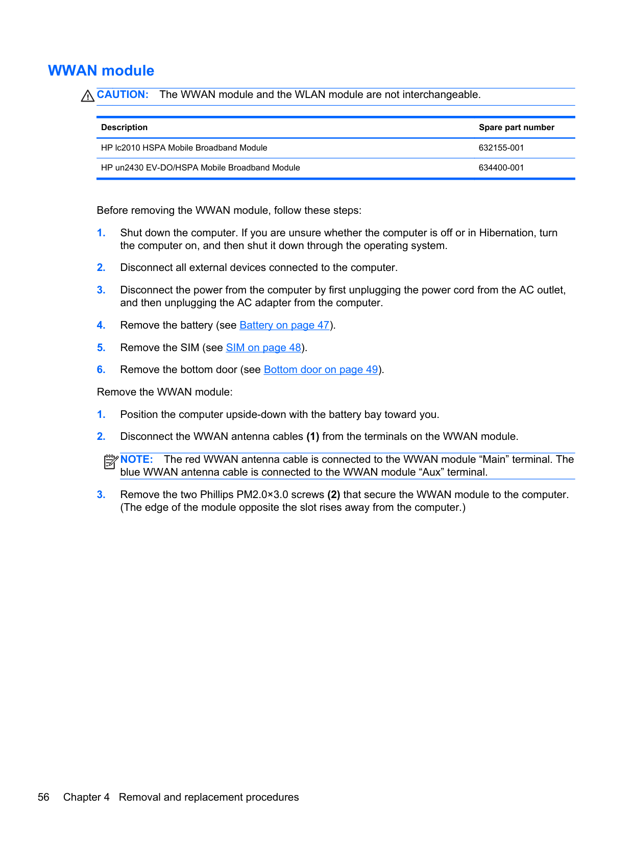
| | |---|
| | |---|
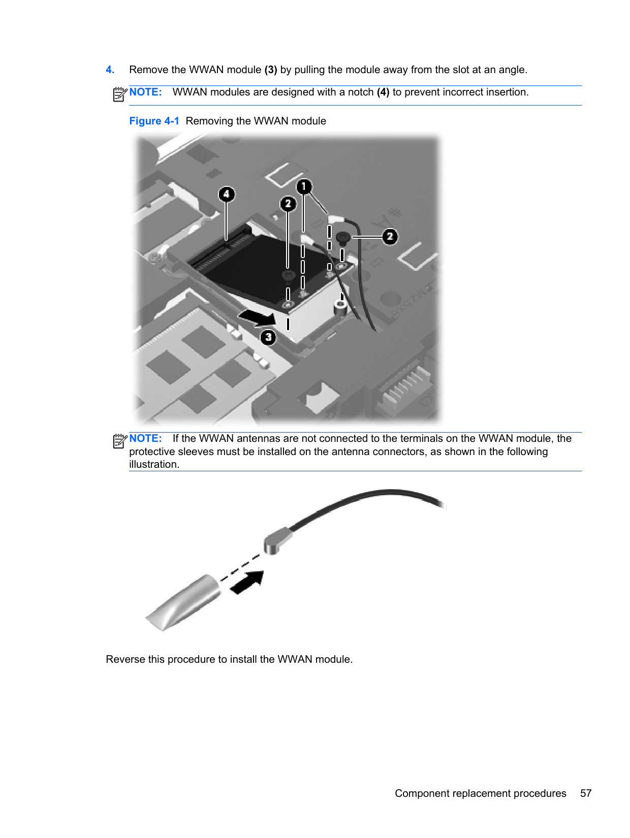

NOTE: If the WLAN antennas are not connected to the terminals on the WLAN module, the protective sleeves must be installed on the antenna connectors, as shown in the following illustration.
| | |---|

Reverse this procedure to install the WLAN module.
#### Keyboard
NOTE: For a detailed list of available keyboards, see Sequential part number listing on page 32.
| | |---|
Description Spare part number Keyboard 646300-xxx
Before removing the keyboard, follow these steps:


| | |---|


Reverse this procedure to install the keyboard.
#### Top cover
Description Spare part number Top cover for use in model 4530s:
With a fingerprint reader and USB 3.0 646251-001 Without a fingerprint reader and with USB 3.0 646253-001 With a fingerprint reader and USB 2.0 658344-001 Without a fingerprint reader and with USB 2.0 658345-001 With no USB logo for use in USB 2.0 or USB 3.0 computers with a fingerprint reader 667656-001 With no USB logo for use in USB 2.0 or USB 3.0 computers without a fingerprint reader 667657-001 Top cover for use in model 4730s:
With a fingerprint reader and USB 2.0 646257-001 Without a fingerprint reader and USB 2.0 646260-001 With no USB logo for use in USB 2.0 or USB 3.0 computers with a fingerprint reader 667658-001 With no USB logo for use in USB 2.0 or USB 3.0 computers without a fingerprint reader 667659-001
Before removing the top cover, follow these steps:
Remove the top cover:
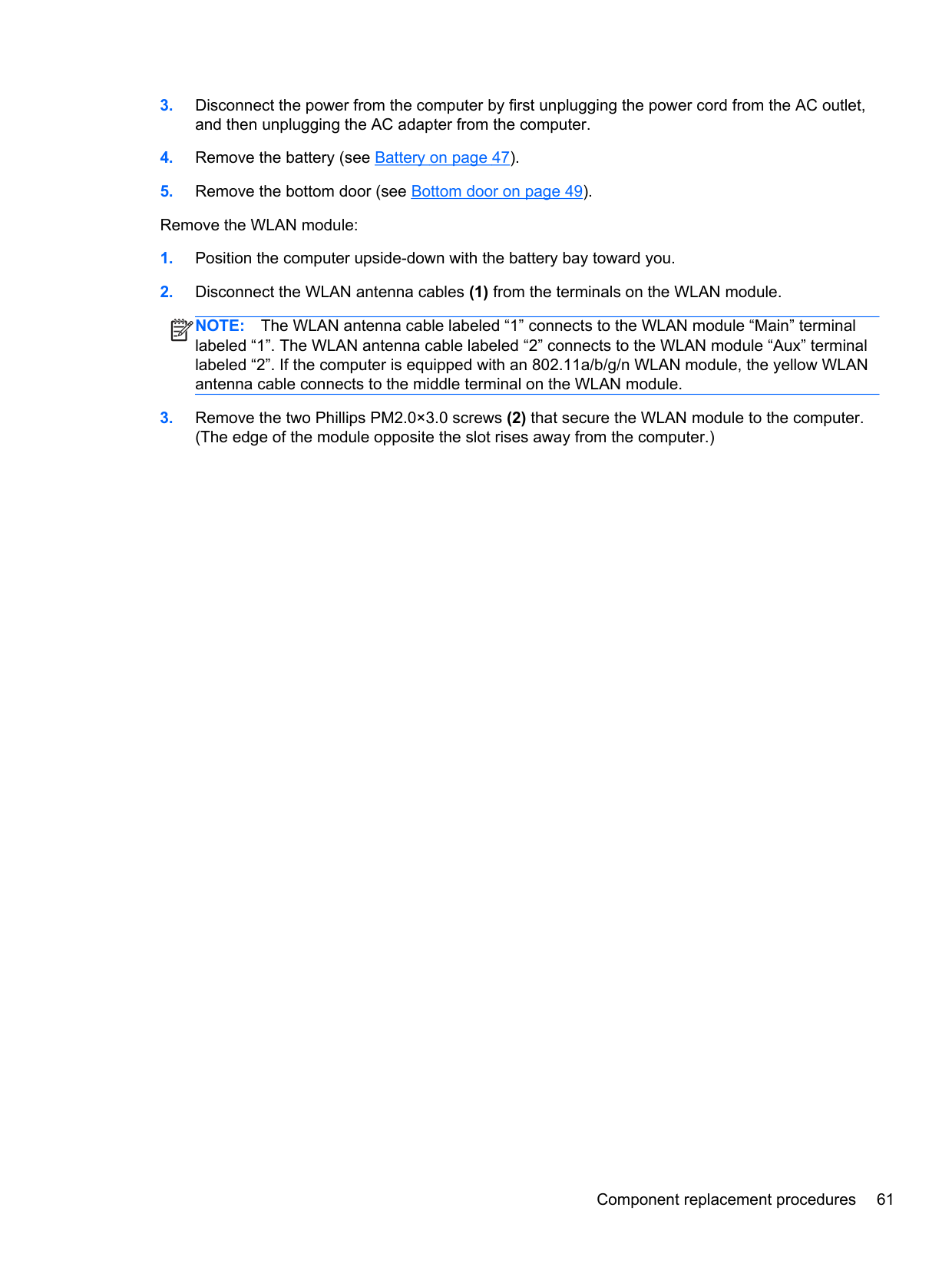
NOTE: The following image shows model 4530s. Model 4730s has 15 Torx screws on the bottom.
| | |---|

| | |---|
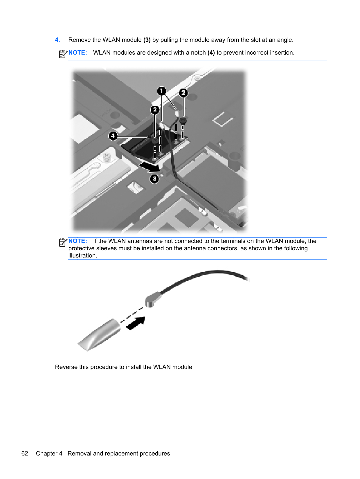

| | |---|
NOTE: The following image shows model 4530s. Model 4730s has 3 screws on the top side of the top cover.

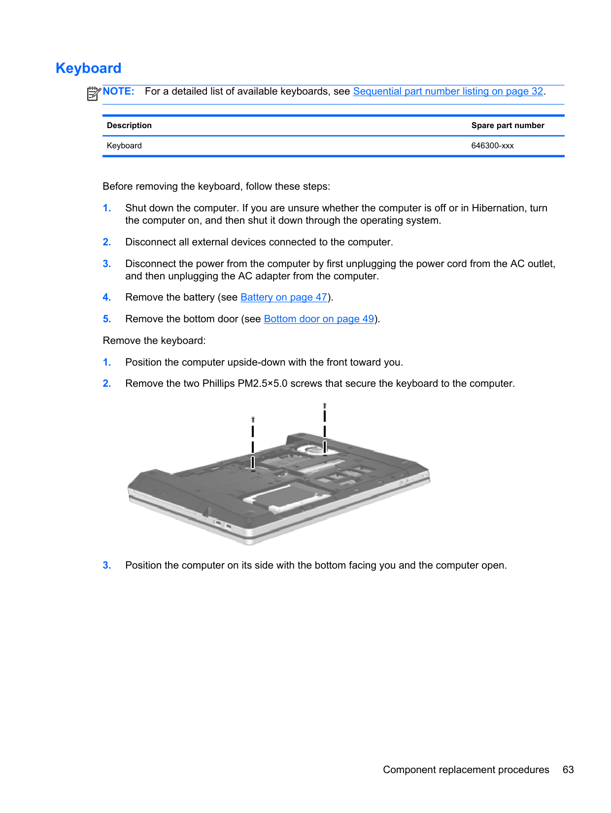


Reverse this procedure to install the top cover.
#### Card reader board
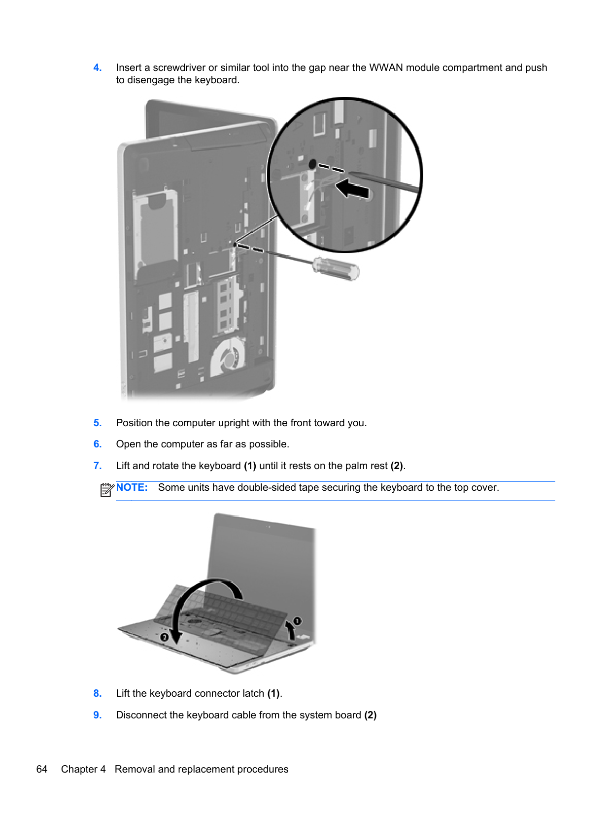
######## Description Spare part number
Card reader board for use in 4530s models 646292-001 Card reader board for use in 4730s models 646293-001
Before removing the card reader, follow these steps:
Remove the card reader:
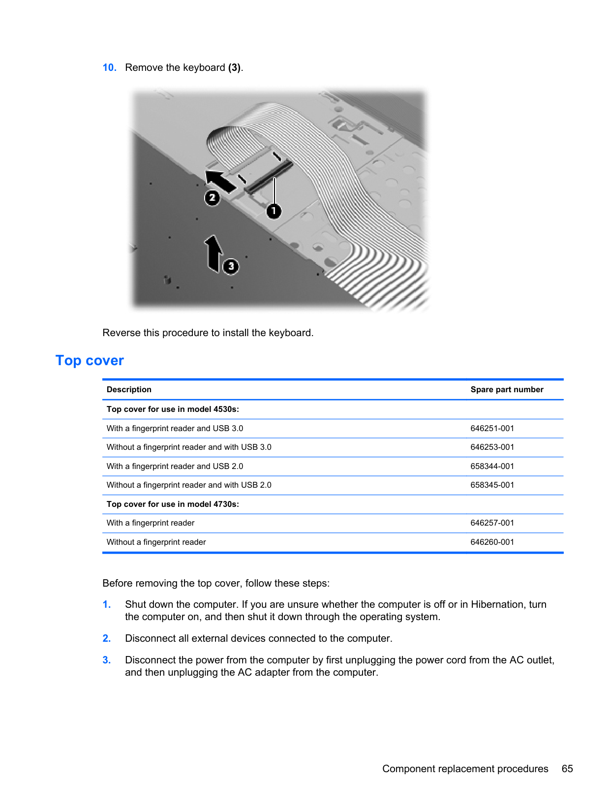
| | |---|

Reverse this procedure to install the card reader.
#### Speaker assembly
######## Description Spare part number
Speaker assembly for use in 4530s models (includes housing) 646298-001 Speaker assembly for use in 4730s models (includes housing) 646299-001
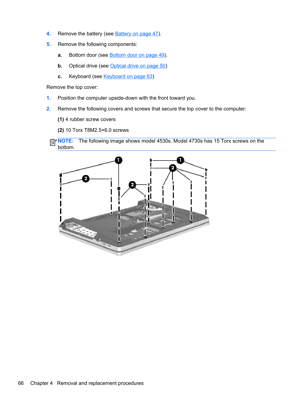
Before removing the speaker assembly, follow these steps:
Remove the speaker assembly:
NOTE: The following image shows model 4530s. Speaker appearance differs in model 4730s.
| |
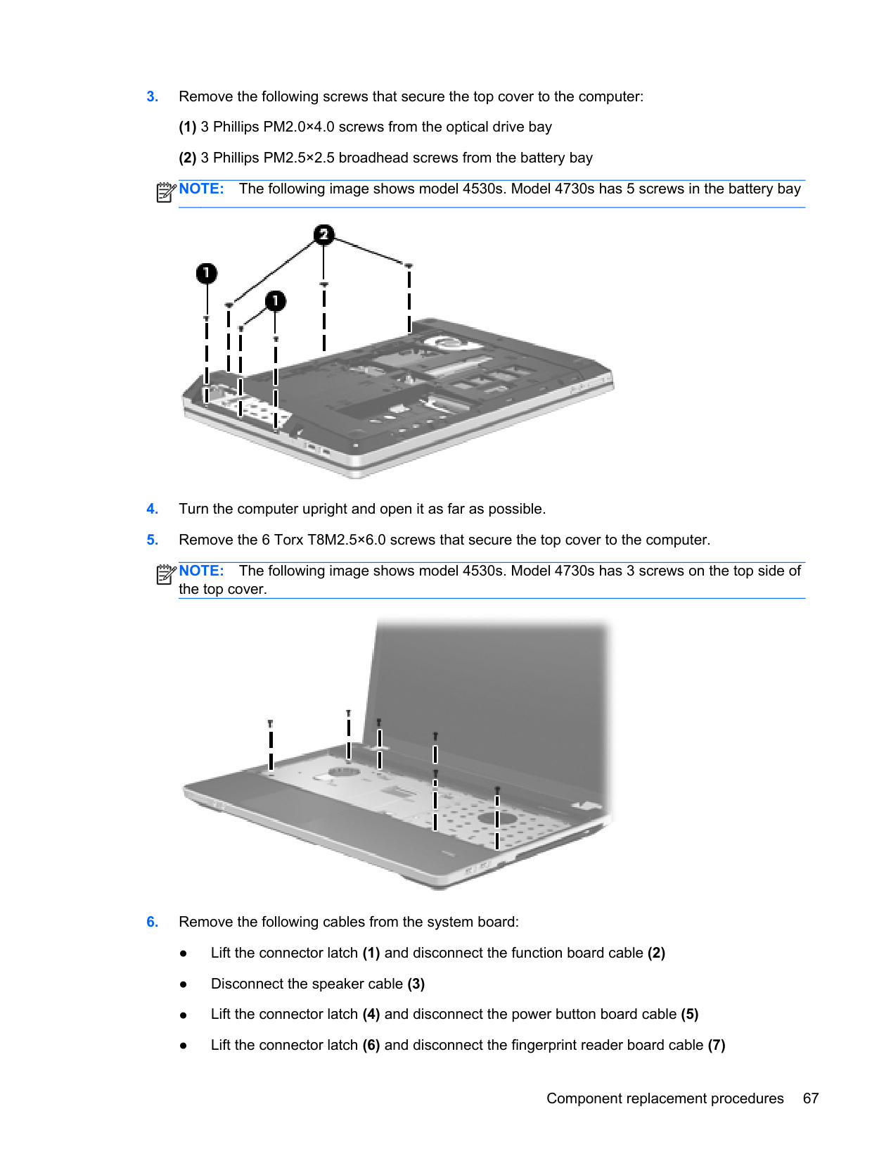
|---|
(1).

Reverse this procedure to install the speaker assembly.
#### Quick Launch board
######## Description Spare part number
Quick Launch board for use in 4530s models 646296-001 Quick Launch board for use in 4730s models 646297-001
Before removing the Quick Launch board, follow these steps:
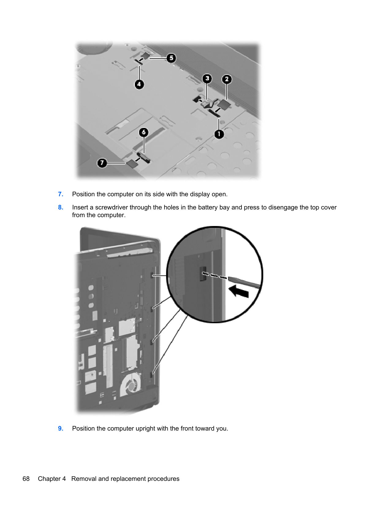
the computer on, and then shut it down through the operating system.
Remove the Quick Launch board:
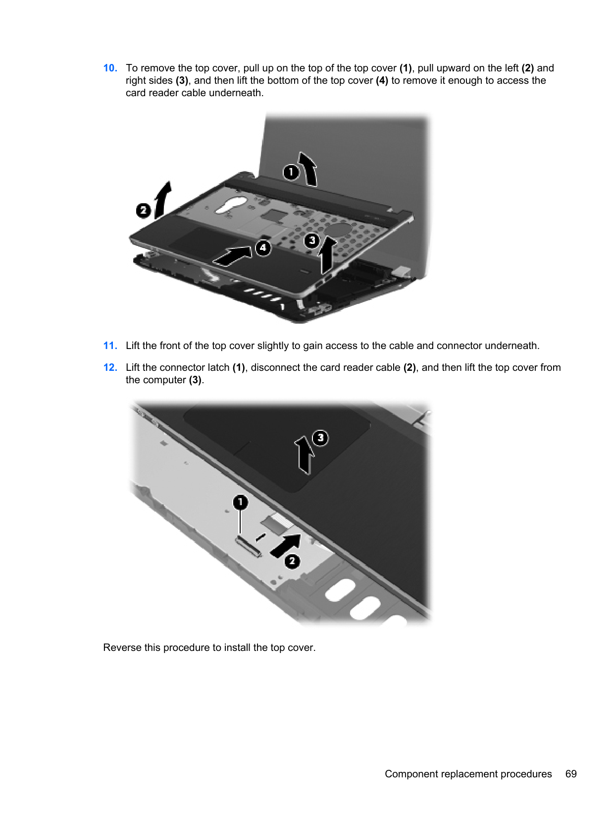

Reverse this procedure to install the Quick Launch board.
#### Power button board
######## Description Spare part number
Power button board for use in model 4530s 646294-001 Power button board for use in model 4730s 646295-001
Before removing the power button board, follow these steps:
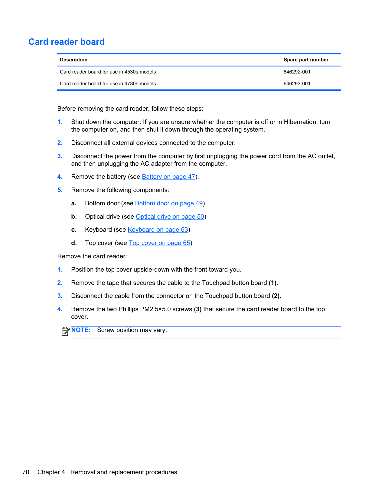
Remove the power button board:
NOTE: Model 4530s shown below. Power button board appearance differs in model 4730s.
| | |---|
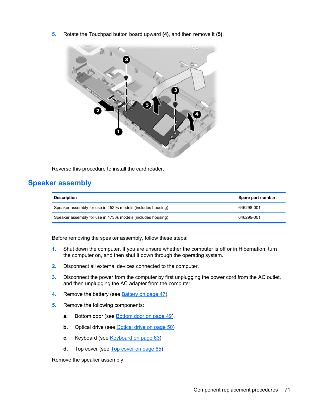

Reverse this procedure to install the power button board.
#### Modem module
NOTE: The modem module spare part kit does not include a modem module cable. The modem module cable is included in the Cable Kit, spare part number 646303-001 for 4530s models, 646304-001 for 4730s models. See Cable Kit on page 30 for more Cable Kit spare part number information.
| | |---|
Description Spare part number Modem module 628824-001
Before removing the modem module, follow these steps:
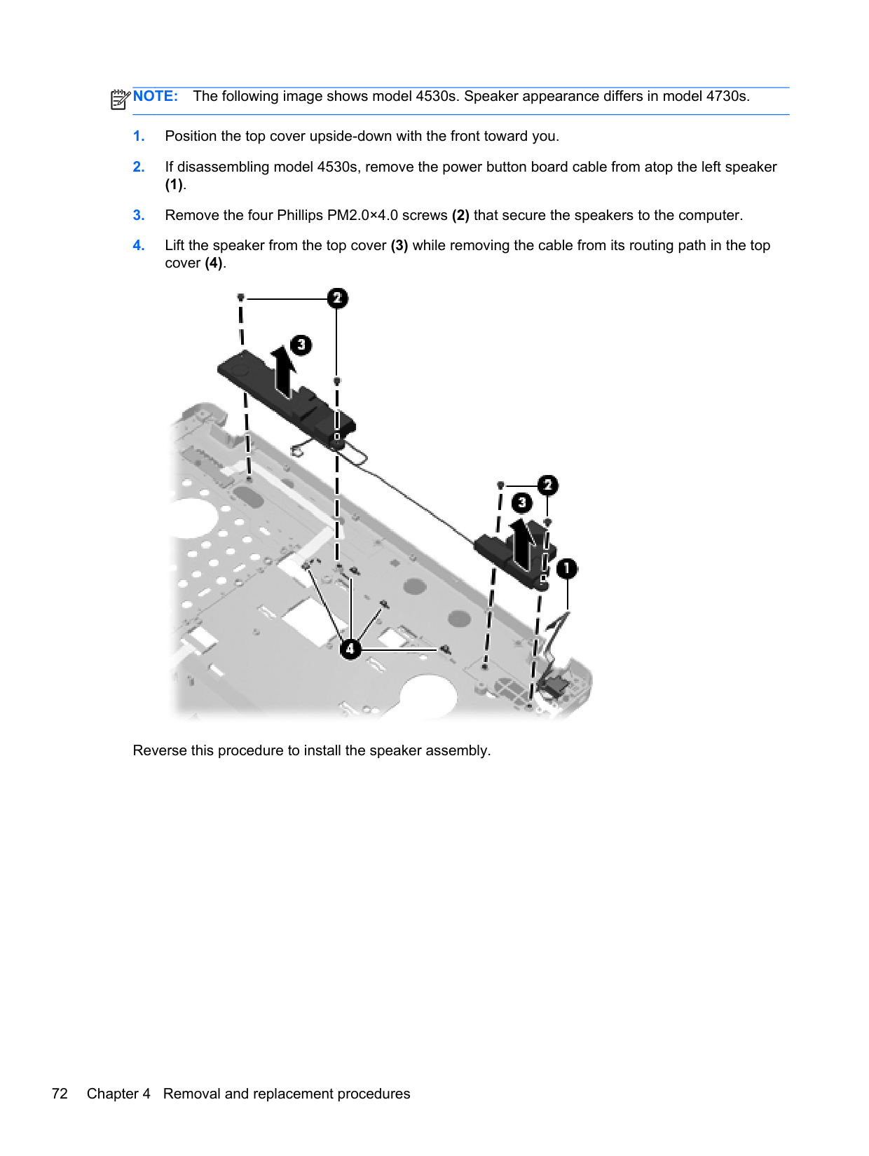
Remove the modem module:

Reverse this procedure to install the modem module.
#### Lid switch
######## Description Spare part number
Lid switch for use in 4530s models 646289-001 Lid switch for use in 4730s models 646290-001
Before removing the lid switch, follow these steps:
the computer on, and then shut it down through the operating system.
Remove the lid switch:
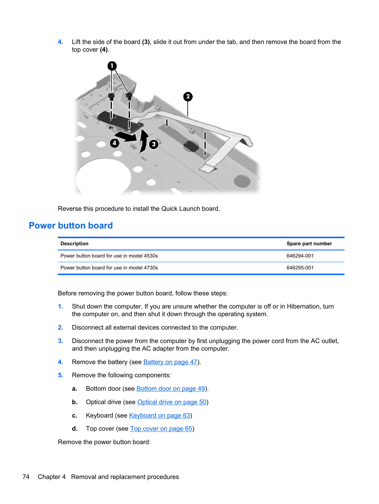

Reverse this procedure to install the lid switch.
#### USB board
######## Description Spare part number
USB board for use in 4530s models 646287-001 USB board for use in 4730s models 646288-001
Before removing the USB board, follow these steps:
the computer on, and then shut it down through the operating system.
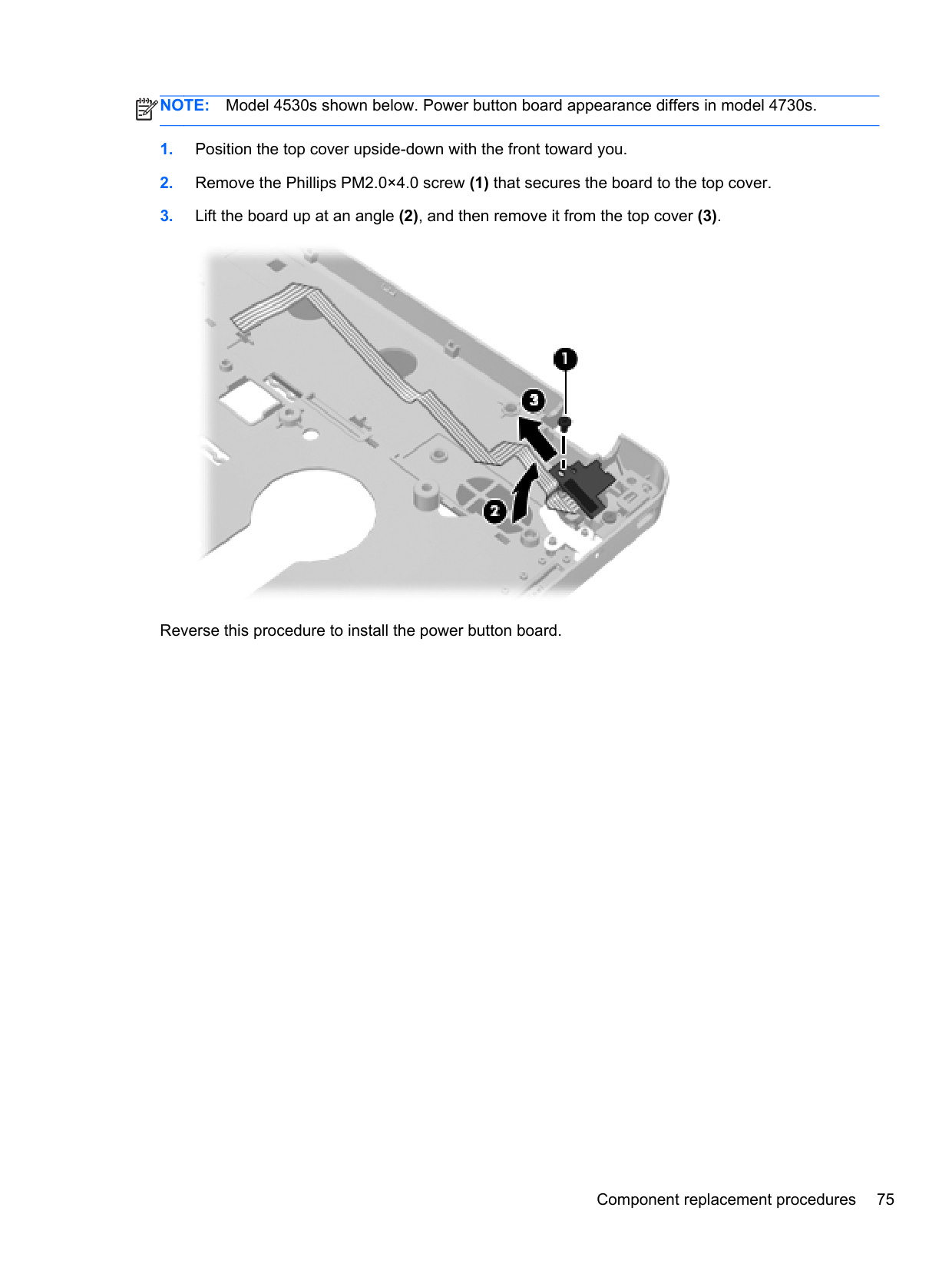
Remove the USB board:

Reverse this procedure to install the USB board.
#### Optical drive connector
Description Spare part number Optical drive connector 646286-001
Before removing the optical drive connector, follow these steps:
Remove the optical drive connector:
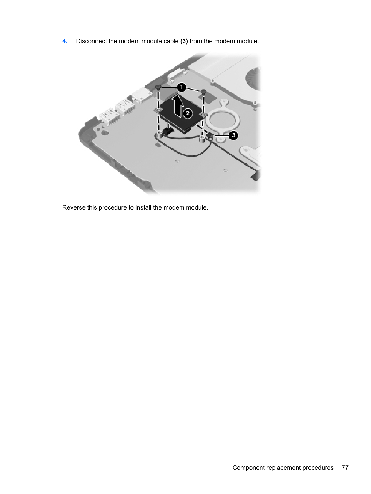

Reverse this procedure to install the optical drive connector.
RJ-11 jack cable NOTE: The RJ-11 jack cable is included in the Cable Kit, spare part number 646303-001 for 4530s models, 646304-001 for 4730s models. Before removing the RJ-11 jack cable, follow these steps:
| | |---|
the computer on, and then shut it down through the operating system.
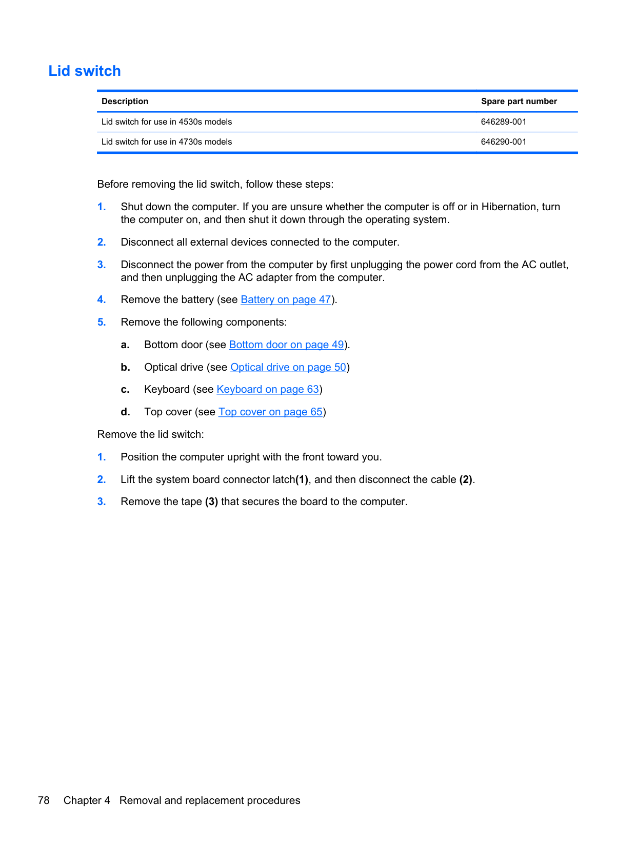
Remove the RJ-11 jack cable:
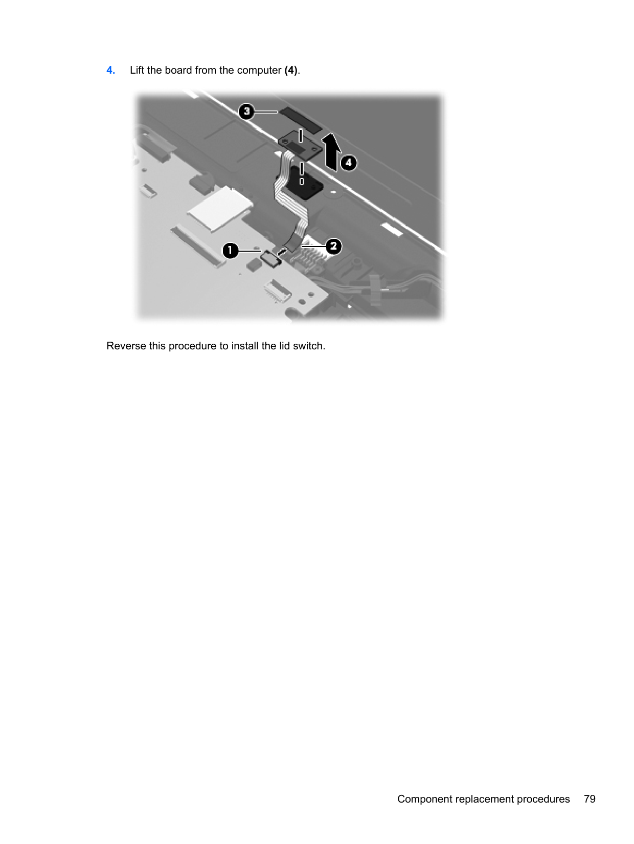

Reverse this procedure to install the RJ-11 jack cable.
#### System board
NOTE: All system board spare part kits include replacement thermal material.
| | |---|
Description Spare part number
For use in 4530s models with UMA graphics with WWAN and USB 3.0 646245-001 For use in 4530s models with UMA graphics without WWAN and with USB 3.0 646246-001
Before removing the system board, follow these steps:
When replacing the system board, be sure to remove the following components from the defective system board and install on the replacement system board:

If removing the system board from model 4530s, remove the two Phillips PM2.5×5.0 screws (1) that secure the system board to the base enclosure.


Reverse this procedure to install the system board.
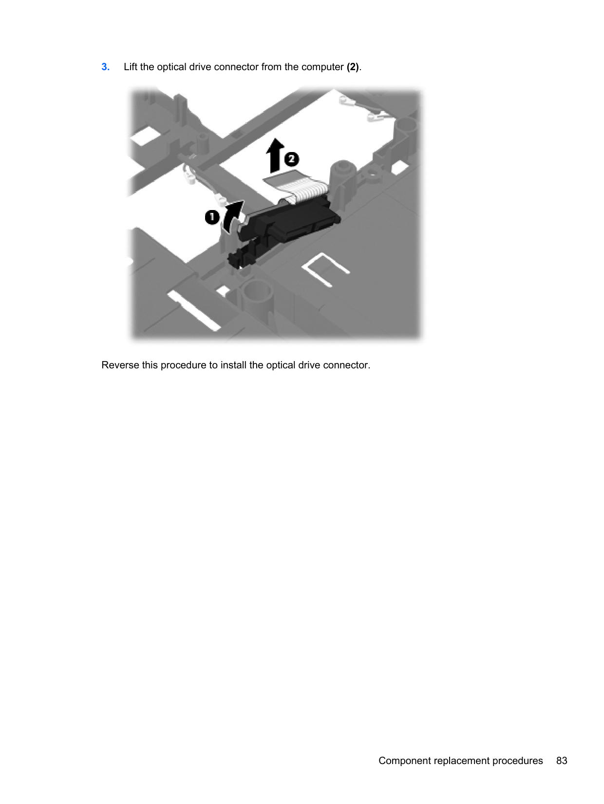
#### Hard drive extension board (4730s models)
Description Spare part number Hard drive extension board 646291-001
Before removing the hard drive extension board, follow these steps:
the computer on, and then shut it down through the operating system.
Remove the hard drive extension board:

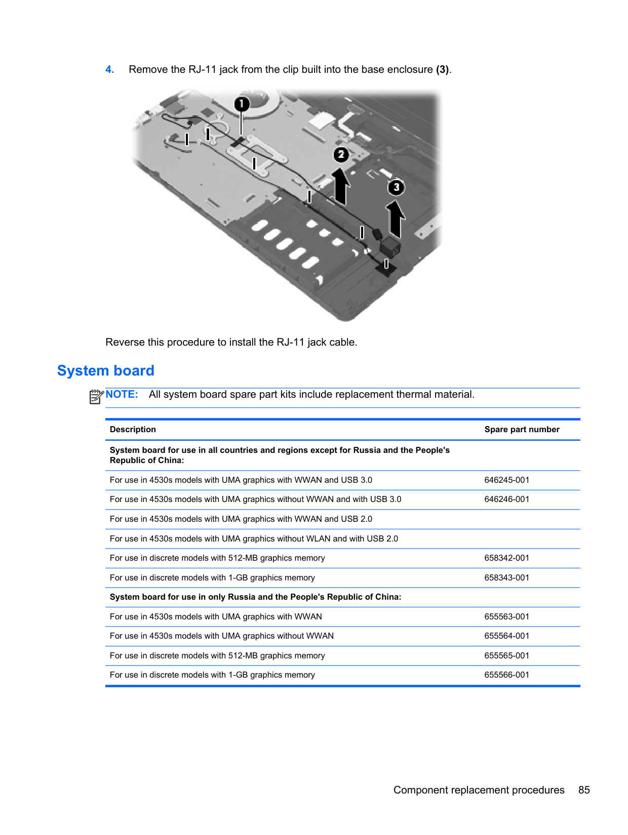
Reverse this procedure to install the hard drive extension board.
#### RTC battery
Description Spare part number RTC battery 449137-001
Before removing the RTC battery, follow these steps:
the computer on, and then shut it down through the operating system.
Remove the RTC battery:

Reverse this procedure to install the RTC battery.
#### Fan
Description Spare part number Fan 646285-001
Before removing the fan, follow these steps:
the computer on, and then shut it down through the operating system.
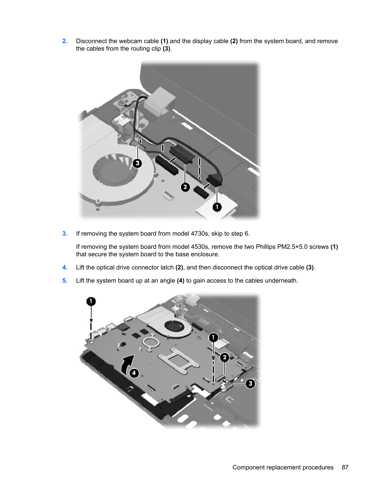
Remove the fan:

Reverse this procedure to install the fan. NOTE: To properly ventilate the computer, allow at least a 7.6-cm (3-in) clearance on the left side of the computer. The computer uses an electric fan for ventilation. The fan is controlled by a temperature sensor and is designed to turn on automatically when high temperature conditions exist. These conditions are affected by high external temperatures, system power consumption, power management/battery conservation configurations, battery fast charging, and software requirements. Exhaust air is displaced through the ventilation grill located on the left side of the computer.
| | |---|
#### Heat sink
All heat sink spare part kits include replacement thermal material.
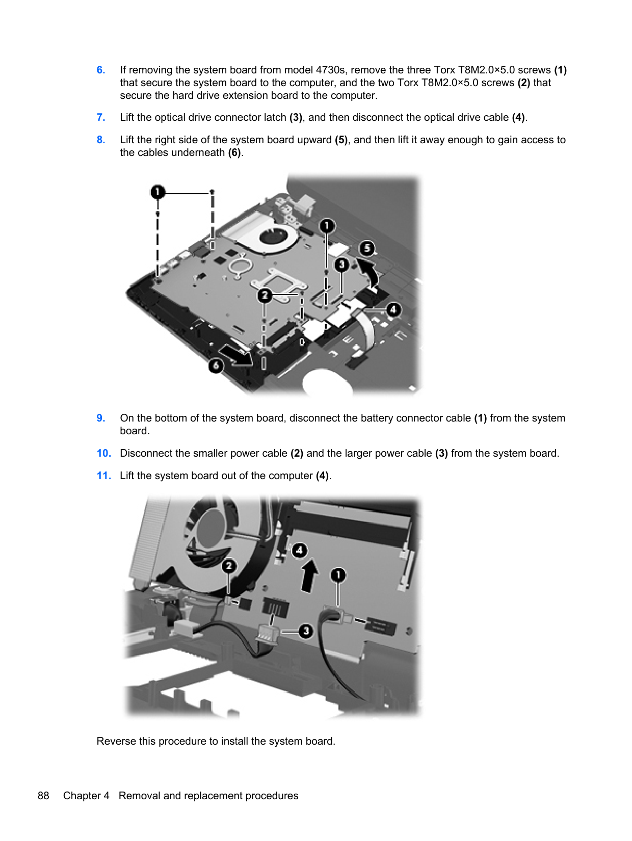
Description Spare part number
Heat sink for use in computers with UMA graphics 646283-001 Heat sink for use in computers with discrete graphics 646284-001
Before removing the heat sink, follow these steps:
Remove the heat sink:
(1) — (6) that secure the heat sink to the system board.

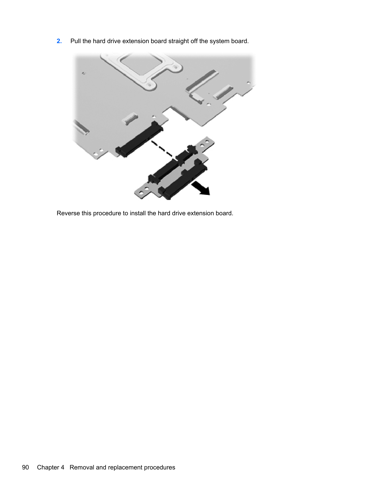
— (4) that secure the heat sink to the system board.

NOTE: For discrete models, thoroughly clean thermal material from the surfaces of the system board components (1)(3) and the heat sink (2)(4) each time you remove the heat sink. All heat sink and processor spare part kits include thermal material.
| | |---|

NOTE: For UMA models, thoroughly clean thermal material from the surface of the system board
| | |---|
(1) and heat sink (2) each time you remove the heat sink. All heat sink and processor spare part kits include thermal material.

Reverse this procedure to install the heat sink.
#### Processor
NOTE: All processor spare part kits include replacement thermal material.
| | |---|
Description Spare part number Intel Core i7 processor, Quad Core
2670QM, 2.2-GHz (turbo up to 3.1-GHz) processor with 6-MB L3 cache 665116-001 2630QM, 2.00-GHz (turbo up to 2.90) processor with 6-MB L3 cache 635501-001 Intel Core i7 processor, Dual Core
2620M, 2.7-GHz (turbo up to 3.4-GHz) processor with 4-MB L3 cache 631252-001 Intel Core i5 processors, Dual Core
2540M, 2.6-GHz (turbo up to 3.3-GHz) processor with 3-MB L3 cache 631255-001 2520M, 2.5-GHz (turbo up to 3.2-GHz) processor with 3-MB L3 cache 631253-001
######## Description Spare part number
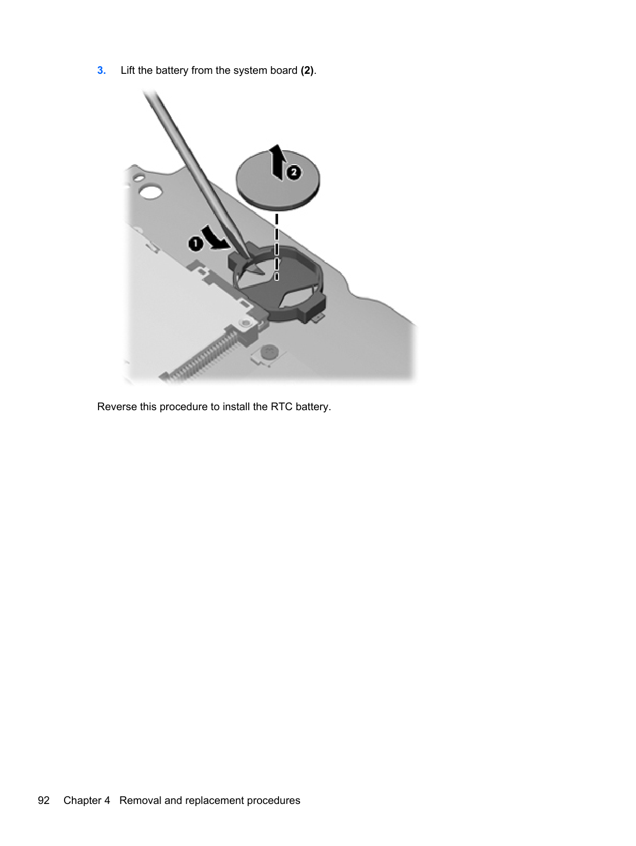
2430M, 2.4-GHz (turbo up to 3.0-GHz) processor with 3-MB L3 cache 653341-001 2410M, 2.3-GHz (turbo up to 2.9-GHz) processor with 3-MB L3 cache 638039-001 Intel Core i3 processors, Dual Core
2350M, 2.3-GHz processor with 3-MB L3 cache 653340-001 2330M, 2.2-GHz processor with 3-MB L3 cache 653339-001 2310M, 2.1-GHz processor with 3-MB L3 cache 638037-001 Intel Pentium processors
B950, 2.1-GHz processor with 2-MB L3 cache 653338-001 B940, 2.0-GHz processor with 2-MB L3 cache 653337-001 Intel Celeron processor, Dual Core
B840, 1.9-GHz processor with 2-MB L3 cache 664663-001 B810, 1.6-GHz processor with 2-MB L3 cache 646760-001
Before removing the processor, follow these steps:
the computer on, and then shut it down through the operating system.
Remove the processor:
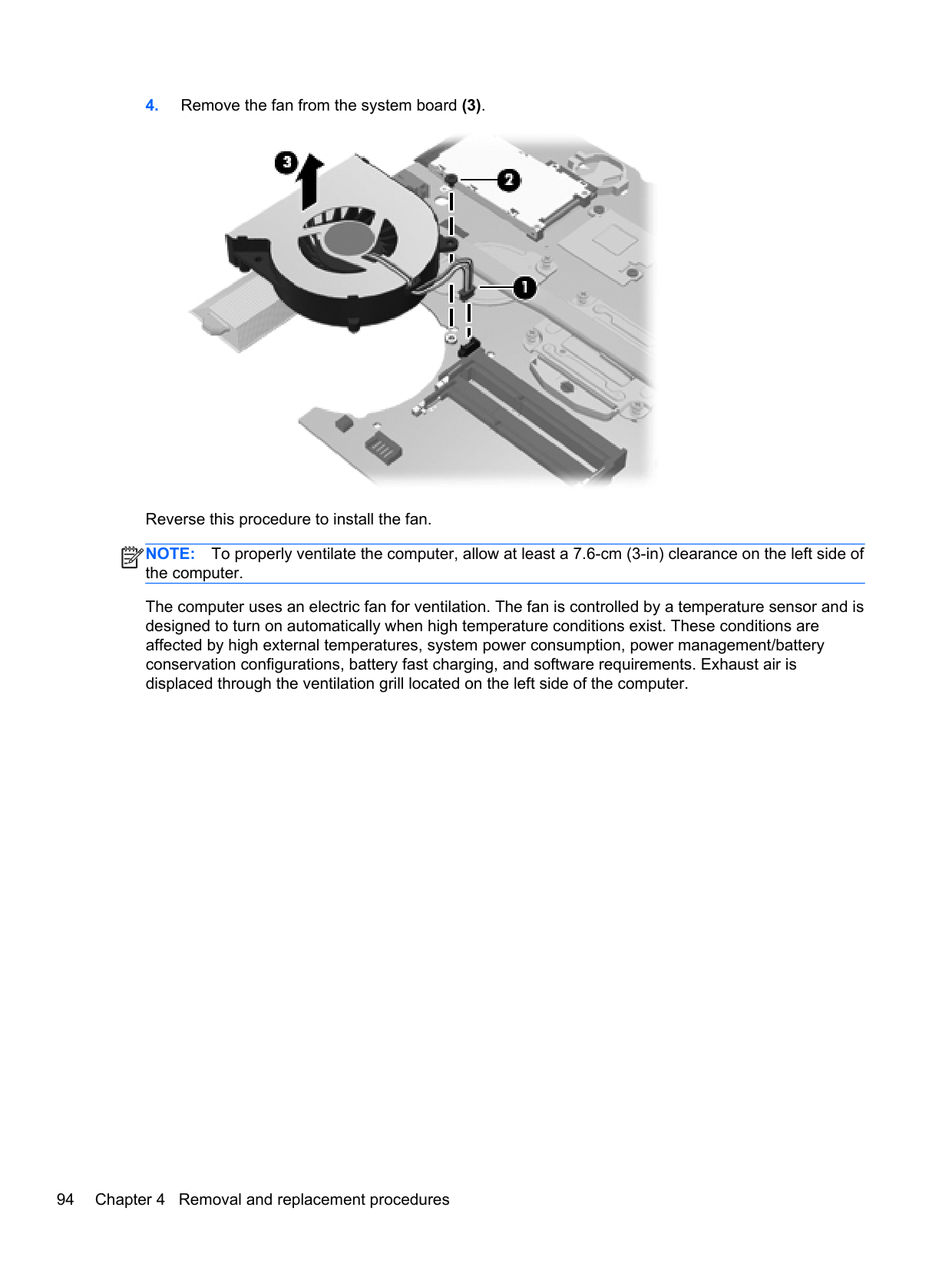
NOTE: The gold triangle (3) on the processor must be aligned with the triangle (4) embossed on the processor slot when you install the processor.
| | |---|

Reverse this procedure to install the processor.
#### Power cable
The power cable is included in the Cable Kit, spare part number 646303-001 for 4530s models, 646304-001 for 4730s models.
Before removing the power cable, follow these steps:
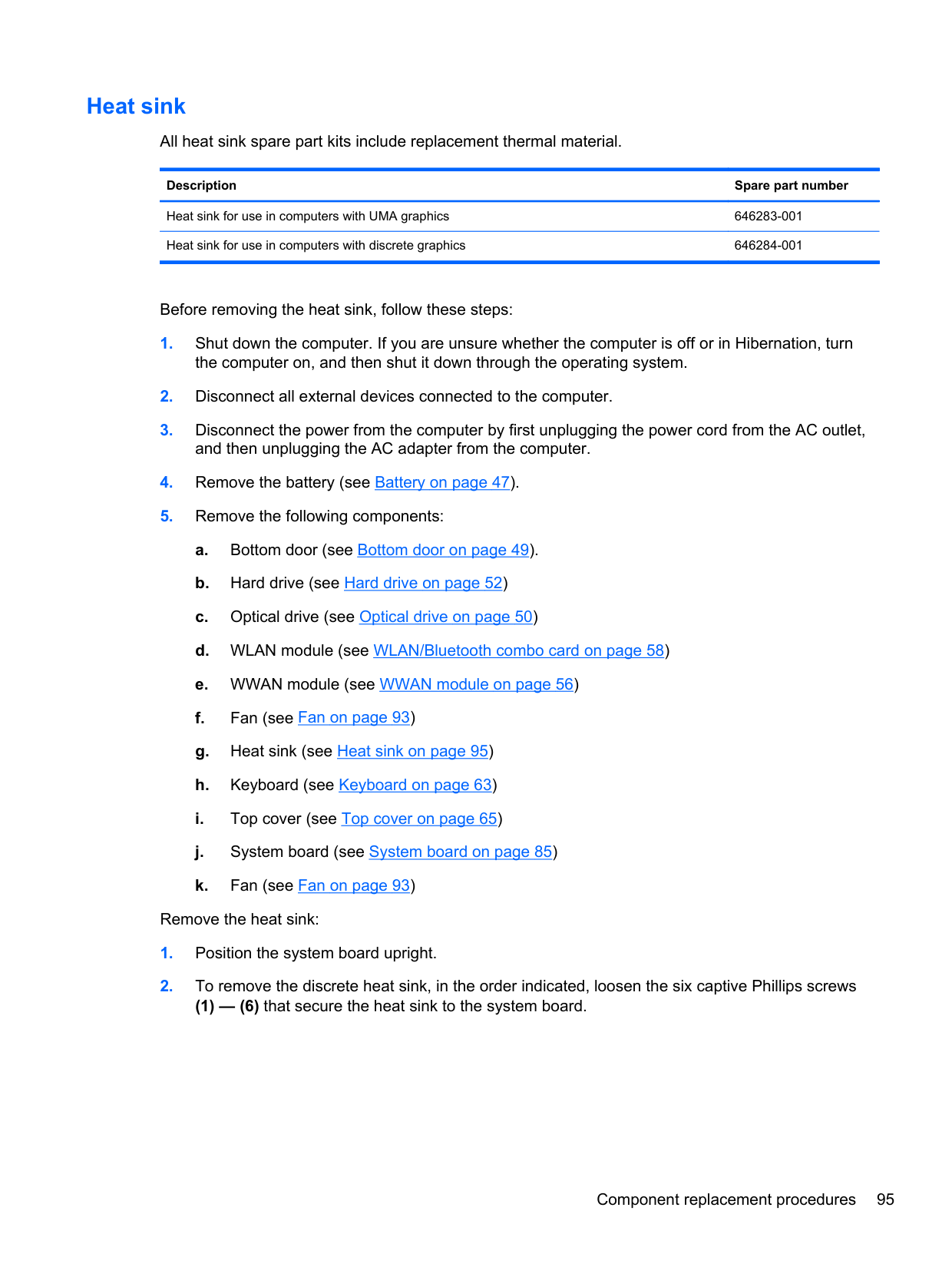
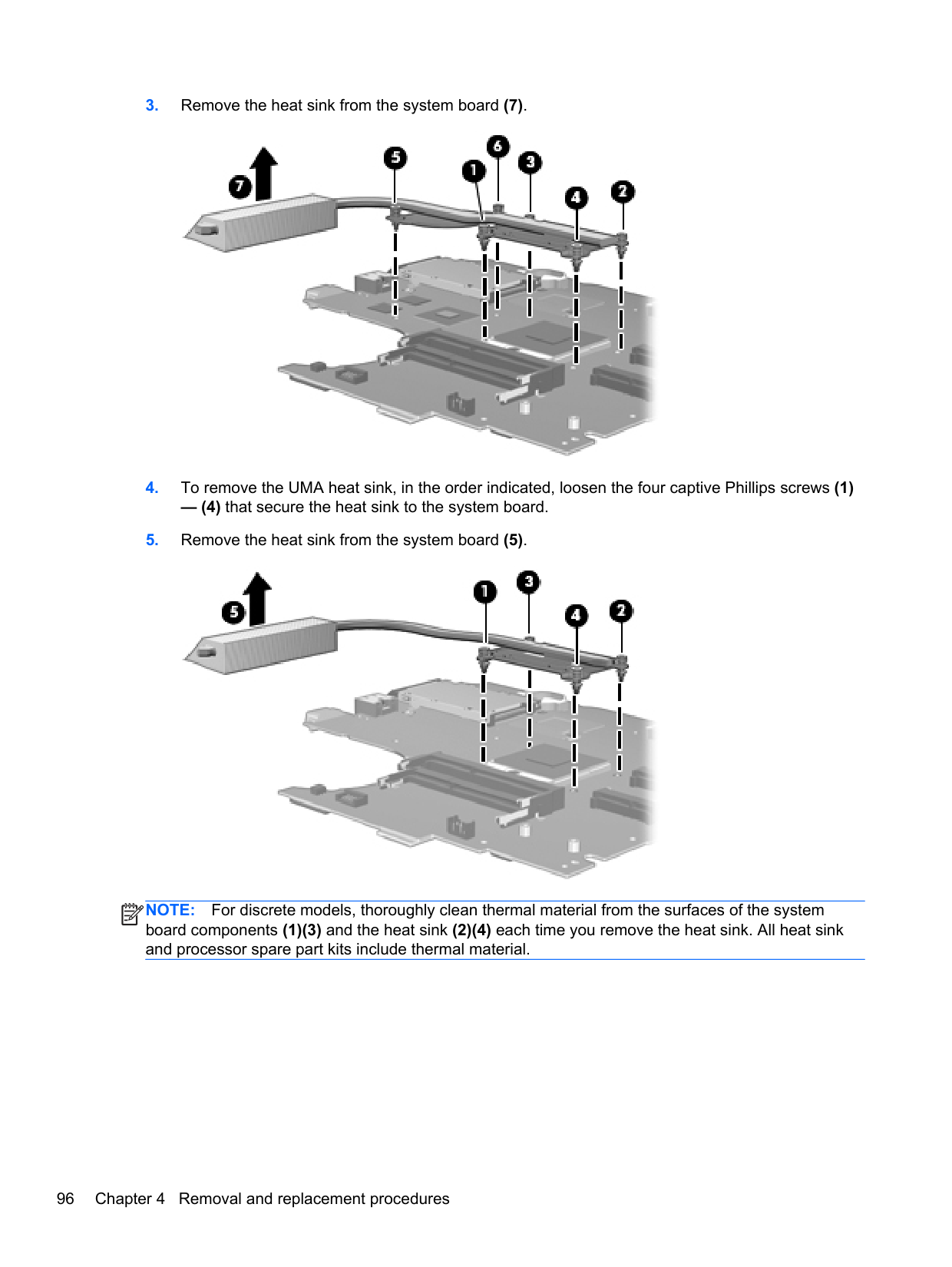
Remove the power cable:

Reverse this procedure to install the power cable.
#### Display assembly
All display assemblies include WLAN antenna transceivers and cables. WWAN models include 2 WWAN antenna transceivers and cables.
For a list of individual display spare parts, see Display components on page 27.
Description Spare part number For use in silver HP ProBook 4530s models:
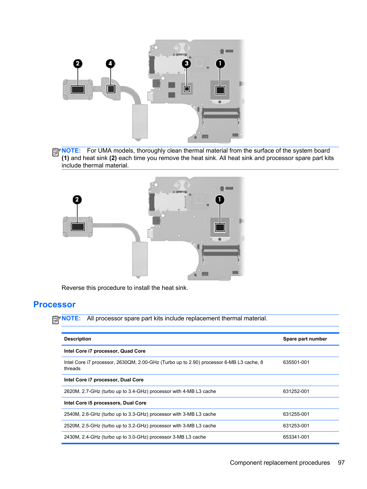
Before removing the display assembly, follow these steps:
Remove the display assembly:
####### 3. If necessary, disconnect the webcam cable (1) and display cable (2) from the system board, andthen remove the cables from the clip (3).

When installing the display assembly, be sure that the wireless antenna cables are routed and arranged properly.
Failure to properly route the antennas can result in degradation of the computer's WLAN and WWAN performance.
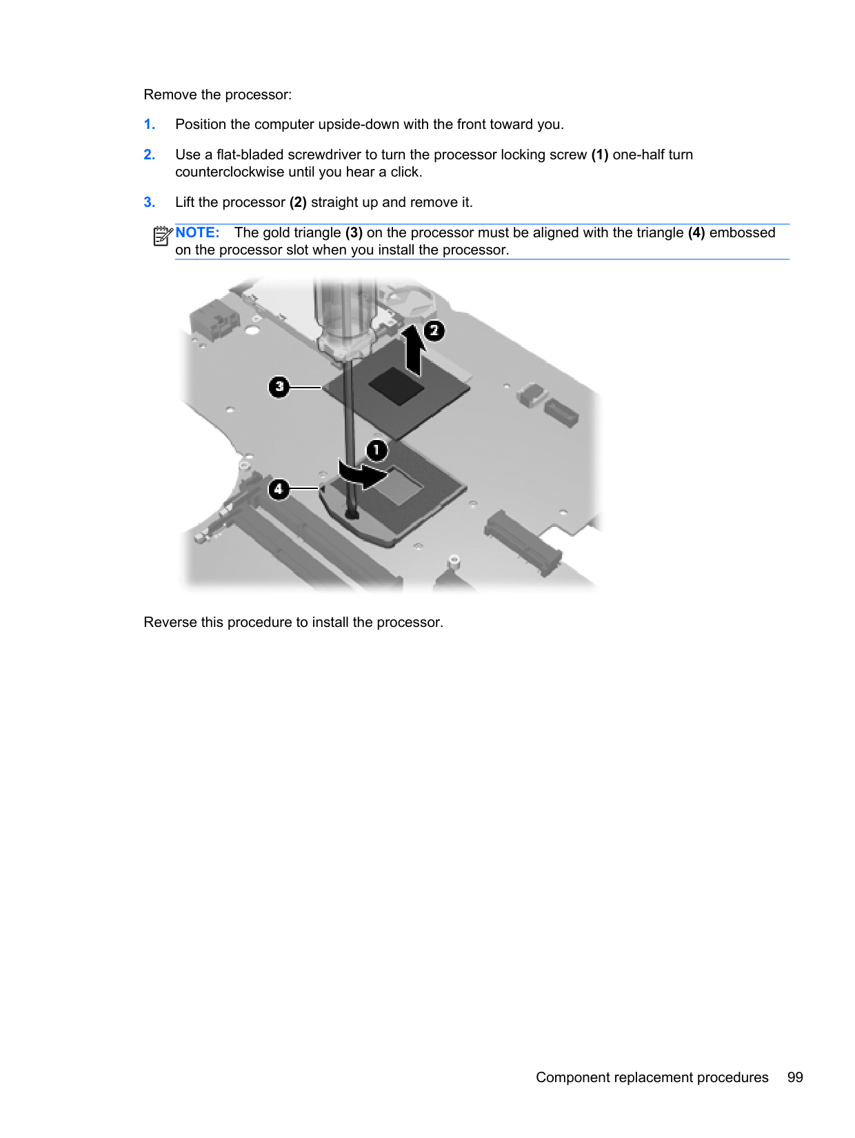

####### 5. If you need to remove the hinge covers from the display hinges, pull the hinges straight up andoff the display to remove them.
Display hinge covers are available using spare part number 646281-001 for 4530s models and 646282-001 for 4730s models.

####### 6. To replace the display bezel, remove the two rubber screw covers (1) and the two TorxT8M2.5×6.0 screws (2) in the bottom corners of the display bezel.
####### 7. Flex the top (3) of the bezel, the inside edges of the left and right sides (4), and then the bottom
(5) of the bezel until it disengages from the display enclosure. The bezel is available using the following spare part numbers:

####### 8. Remove the display bezel.
The microphone module is removed using the same procedure and is available using spare part number 642797-001.


####### 12. Disconnect the display panel cable from the back of the display panel by lifting the tape over theconnector (1), and then disconnecting the cable from the panel (2).
The display cable is available using spare part number 605766-001 for models without a webcam, 646273-001 for 4530s HD+ models, 646274-001 for 4730s models.

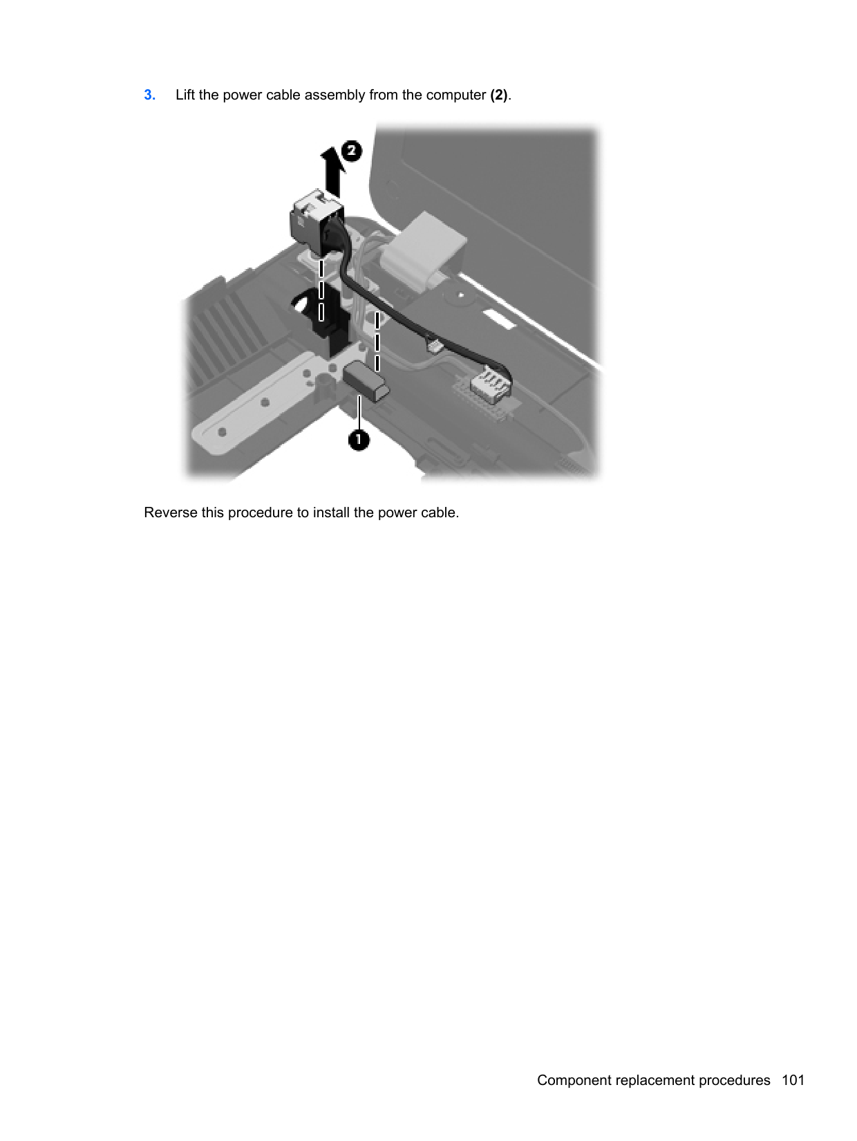
####### 13. If it is necessary to replace the display hinges, remove the four Phillips PM2.5×3.0 screws (1)that secure each display hinge to the display panel.
Display hinges are available using spare part number 646279-001 for 4530s models and 646280-001 for 4730s models.


CAUTION: When installing the display assembly, be sure that the wireless antenna cables are routed and arranged properly. Failure to properly route the antennas can result in degradation of the computer's wireless performance.
The display cable is available using spare part number 605766-001 for models without a webcam, 646273-001 for 4530s HD+ models, 646274-001 for 4730s models. The webcam cable is available using spare part number 646275-001.
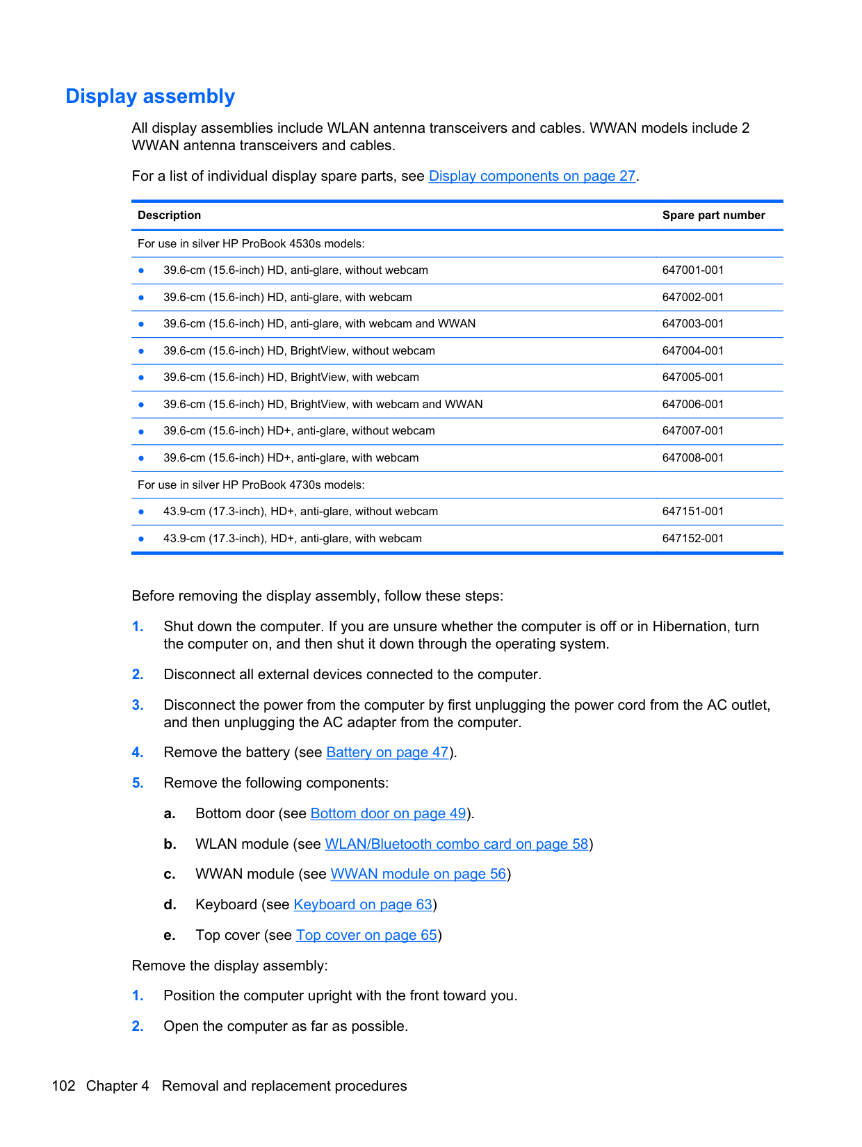

Reverse this procedure to reassemble and install the display assembly. Note the correct cable routing paths for the antenna cables. Make sure you properly route all cables when assembling the computer as shown in the following images. Cable routing path – top

###### Cable routing path – bottom

5 Computer Setup (BIOS) and SystemDiagnostics
Using Computer Setup
Computer Setup, or Basic Input/Output System (BIOS), controls communication between all the input and output devices on the system (such as disk drives, display, keyboard, mouse, and printer). Computer Setup includes settings for the types of devices installed, the startup sequence of the computer, and the amount of system and extended memory.
NOTE: Use extreme care when making changes in Computer Setup. Errors can prevent the computer from operating properly.
| | |---|
Starting Computer Setup NOTE: An external keyboard or mouse connected to a USB port can be used with Computer Setup only if USB legacy support is enabled. To start Computer Setup, follow these steps:
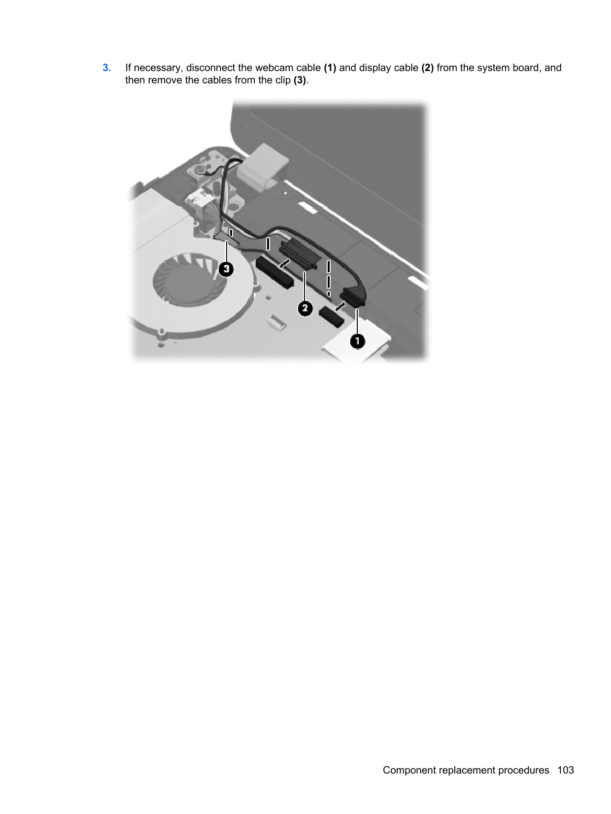
| | |---|
#### Navigating and selecting in Computer Setup
To navigate and select in Computer Setup, follow these steps:
| | |---|
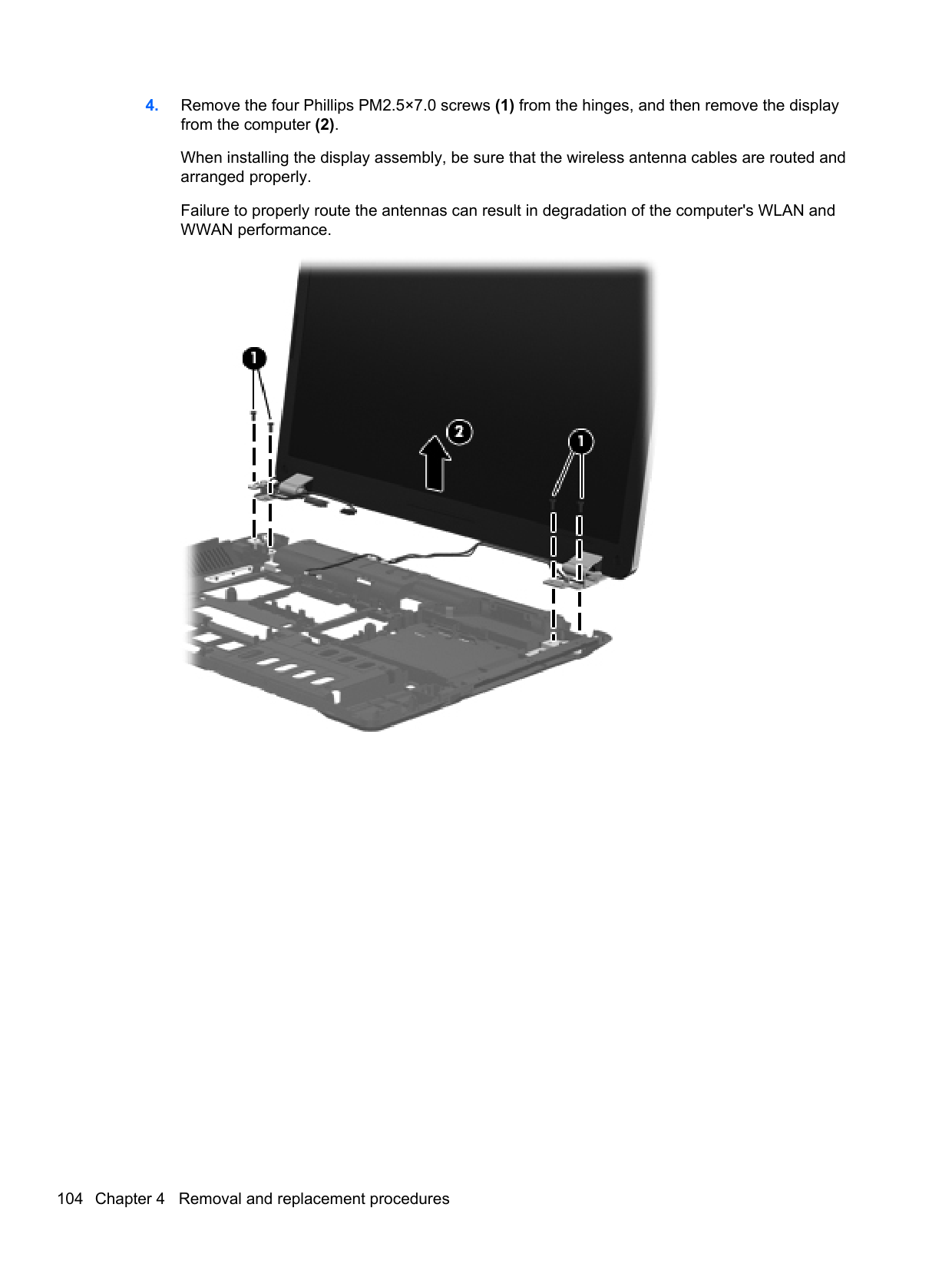
NOTE: You can use either a pointing device (TouchPad, pointing stick, or USB mouse) or the keyboard to navigate and make selections in Computer Setup.
To exit Computer Setup menus, choose one of the following methods:
Click the Exit icon in the lower-left corner of the screen, and then follow the on-screen instructions.
– or – Use the tab key and the arrow keys to select File > Ignore Changes and Exit, and then press enter.
Cclick the Save icon in the lower-left corner of the screen, and then follow the on-screen instructions.
– or – Use the tab key and the arrow keys to select File > Save Changes and Exit, and then press enter.
Your changes go into effect when the computer restarts.
#### Restoring factory settings in Computer Setup
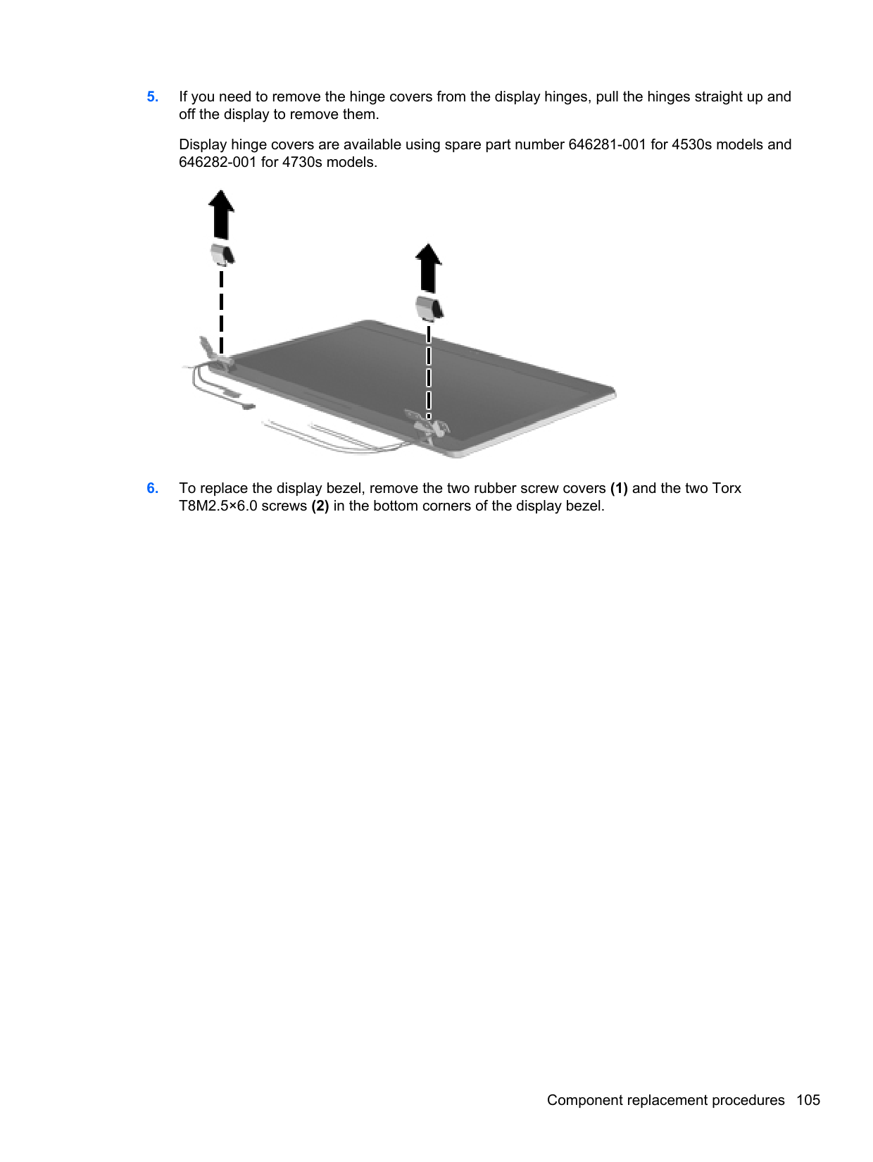
NOTE: Restoring defaults will not change the hard drive mode.
| | |---|
To return all settings in Computer Setup to the values that were set at the factory, follow these steps:
– or – Use the arrow keys to select File > Save Changes and Exit, and then press enter.
Your changes go into effect when the computer restarts. NOTE: Your password settings and security settings are not changed when you restore the factory settings.
| | |---|
Using Computer Setup 113
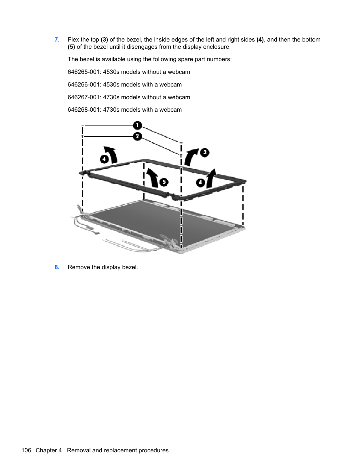
Updating the BIOS Updated versions of the BIOS may be available on the HP Web site. Most BIOS updates on the HP Web site are packaged in compressed files called SoftPaqs. Some download packages contain a file named Readme.txt, which contains information regarding installing and troubleshooting the file.
##### Determining the BIOS version
To determine whether available BIOS updates contain later BIOS versions than those currently installed on the computer, you need to know the version of the system BIOS currently installed.
BIOS version information (also known as ROM date and System BIOS) can be displayed by pressing fn+esc (if you are already in Windows) or by using Computer Setup.
– or – Use the tab key and the arrow keys to select File > Ignore Changes and Exit, and then press enter. Downloading a BIOS update
CAUTION: To reduce the risk of damage to the computer or an unsuccessful installation, download and install a BIOS update only when the computer is connected to reliable external power using the AC adapter. Do not download or install a BIOS update while the computer is running on battery power, docked in an optional docking device, or connected to an optional power source. During the download and installation, follow these instructions:
Do not disconnect power from the computer by unplugging the power cord from the AC outlet. Do not shut down the computer or initiate Sleep or Hibernation. Do not insert, remove, connect, or disconnect any device, cable, or cord.
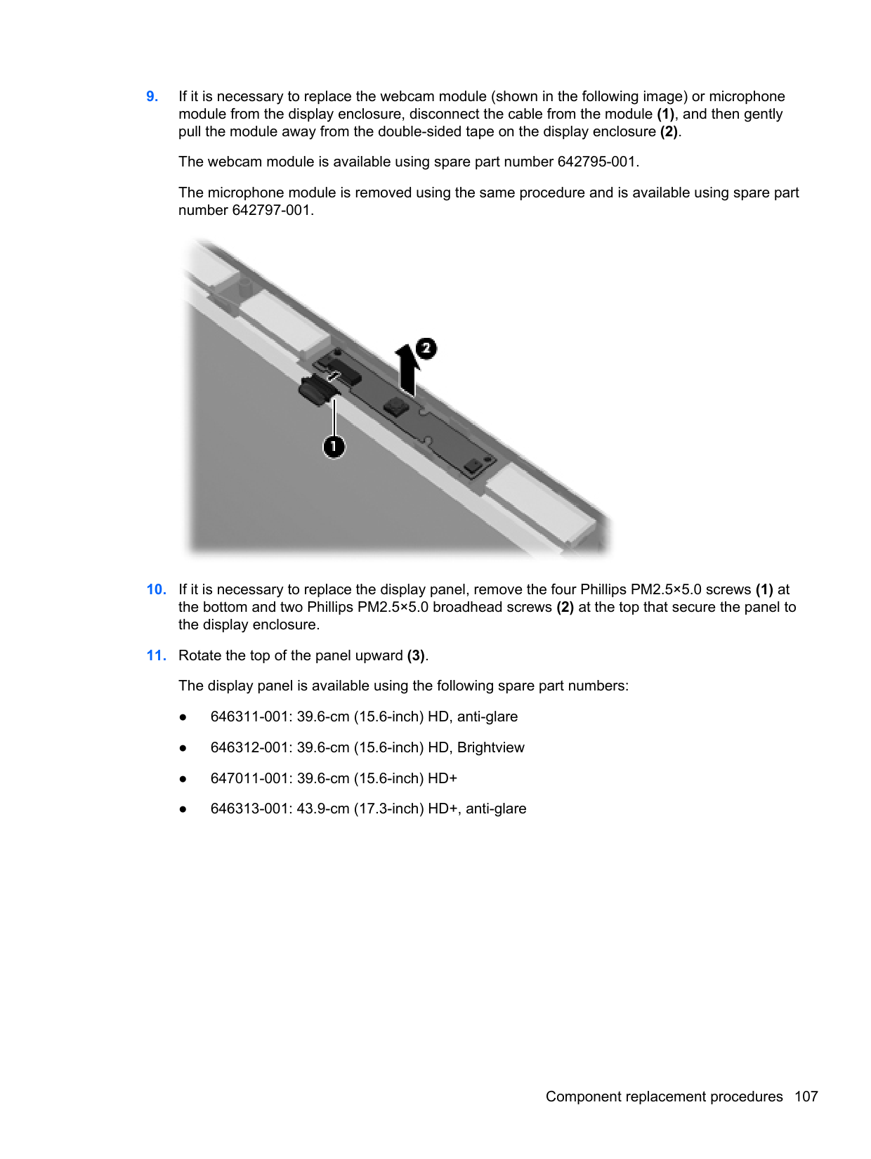
Make a note of the path to the location on your hard drive where the BIOS update is downloaded. You will need to access this path when you are ready to install the update.
NOTE: If you connect your computer to a network, consult the network administrator before installing any software updates, especially system BIOS updates.
| | |---|
BIOS installation procedures vary. Follow any instructions that are displayed on the screen after the download is complete. If no instructions are displayed, follow these steps:
NOTE: After a message on the screen reports a successful installation, you can delete the downloaded file from your hard drive.
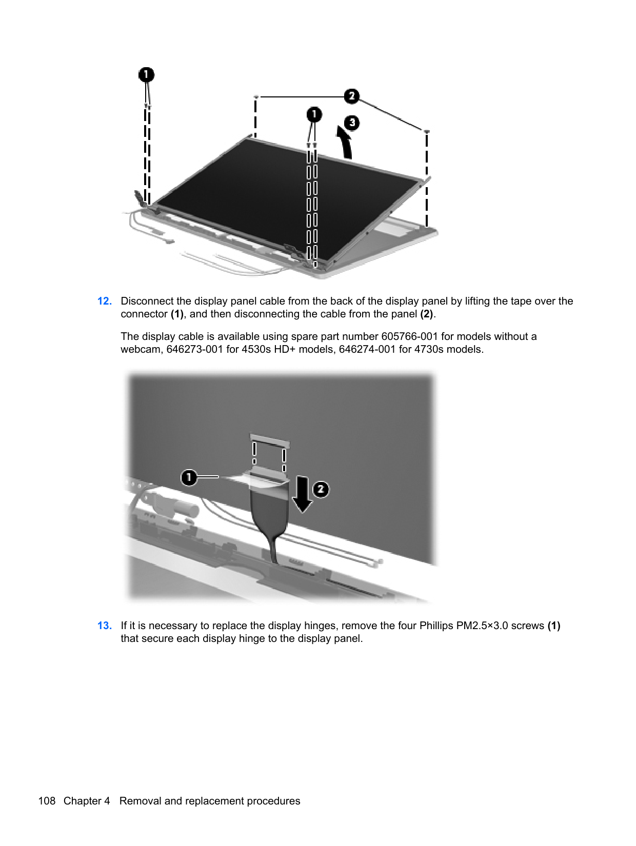
| | |---|
Using System Diagnostics
System Diagnostics allows you to run diagnostic tests to determine if the computer hardware is functioning properly. The following diagnostic tests are available in System Diagnostics:
You can also view system information and error logs in the System Diagnostics window. To start System Diagnostics:
| | |---|
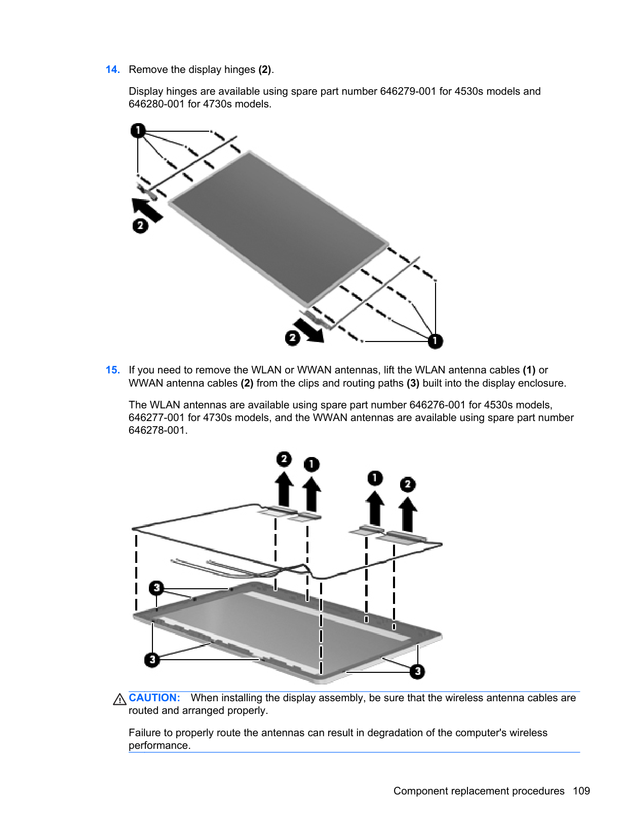
Using System Diagnostics 115
6 Specifications
Computer specifications
Metric U.S. Dimensions, 4530s models
Length 25.6 cm 10.1 in Width 37.5 cm 14.8 in Height (front to rear) 2.9 to 3.6 cm 1.1 to 1.4 in
Weight (equipped with optical drive, 1 DIMM, hard drive, optical drive, WLAN module, 6 cell battery)
Dimensions, 4730s models
Length 28.0 cm 11.0 in Width 41.4 cm 16.3 in Height (front to rear) 2.9 to 3.6 cm 1.1 to 1.4 in
Weight (equipped with optical drive, 1 DIMM, hard drive, optical drive, WLAN module, 6 cell battery)
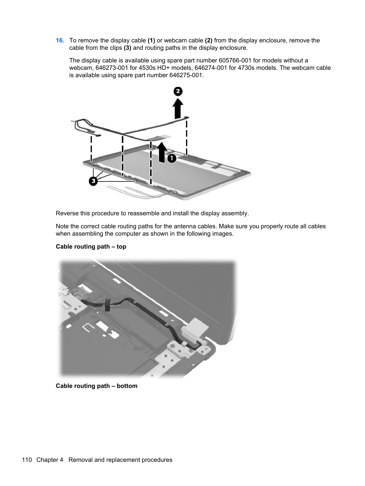
Input power Operating voltage 19.0 V dc @ 4.74 A – 90 W or 18.5 V dc @ 3.5 A - 65 W Operating current 4.74 A or 3.5 A Temperature
Operating (not writing to optical disc) 0°C to 35°C 32°F to 95°F Operating (writing to optical disc) 5°C to 35°C 41°F to 95°F Nonoperating -20°C to 60°C -4°F to 140°F
Relative humidity Operating 10% to 90% Nonoperating 5% to 95% Maximum altitude (unpressurized) Operating (14.7 to 10.1 psia) -15 m to 3,048 m 50 ft to 10,000 ft Nonoperating (14.7 to 4.4 psia) -15 m to 12,192 m -50 ft to 40,000 ft Shock
Operating 125 g, 2 ms, half-sine Nonoperating 200 g, 2 ms, half-sine Random vibration
Operating 0.75 g zero-to-peak, 10 Hz to 500 Hz, 0.25 oct/min sweep
rate Nonoperating 1.50 g zero-to-peak, 10 Hz to 500 Hz, 0.5 oct/min sweep rate NOTE: Applicable product safety standards specify thermal limits for plastic surfaces. The computer operates well within this range of temperatures.
39.6-cm (15.6-in), HD+ display specifications
Metric U.S. Active diagonal size 39.6-cm 15.6-in Resolution 1600x900 (HD+) Active area 344.16x193.59 PPI 118 Surface treatment Anti-glare Contrast ratio 300:1 (typical) – Anti-glare
500:1 – BrightView Response time 8 ms Brightness 200 nits (typical) Viewing angle WVA Backlight LED Luminance uniformity @ 13 points 1.4 (typ), 1.6 (max) Lifetime (1/2 luminance) 12,000 hours Color coordinate (white) (0.313, 0.329) Color tolerance (R, G, B) +/- 0.03 Color gamut 60% (typical)
39.6-cm (15.6-in), HD display specifications
Metric U.S. Active diagonal size 39.6-cm 15.6-in Resolution 1366x768 (HD) Active area 344.232x193.536
39.6-cm (15.6-in), HD+ display specifications 117
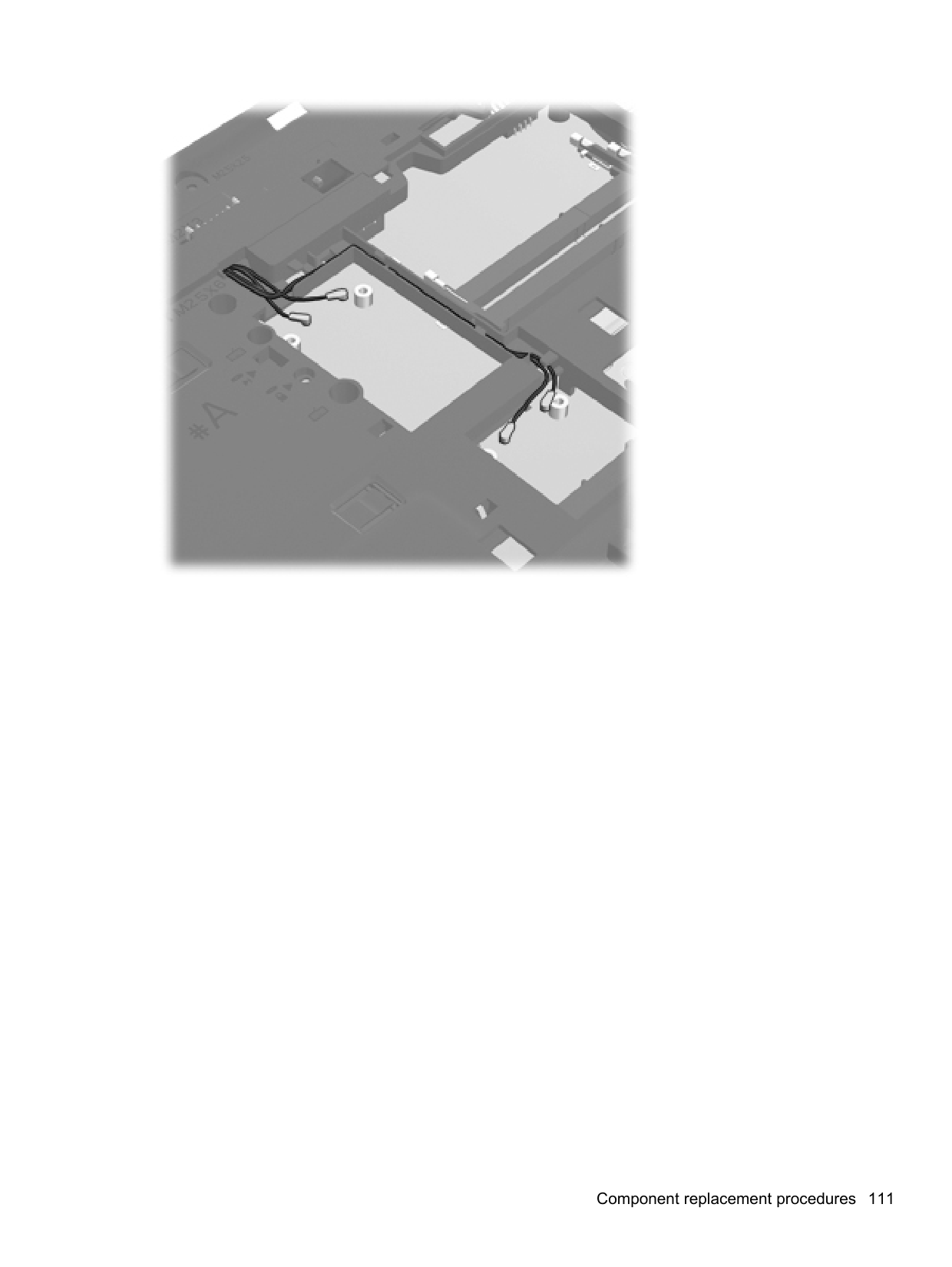
PPI 100 Surface treatment Anti-glare or BrightView Contrast ratio 300:1 (typical) – Anti-glare
500:1 – BrightView Response time 8 ms Brightness 200 nits (typical) Viewing angle SVA Backlight LED Luminance uniformity @ 13 points 1.4 (typ), 1.6 (max) Lifetime (1/2 luminance) 12,000 hours Color coordinate (white) (0.313, 0.329) Color tolerance (White) +/- 0.02 Color tolerance (R, G, B) +/- 0.03 Color gamut 60% (typical)
43.9-cm (17.3-in), HD+ display specifications
Metric U.S. Active diagonal size 43.9-cm 17.3-in Resolution 1600x900 (HD+) Active area 382.08x214.92 PPI 106 Surface treatment Anti-glare or BrightView Contrast ratio 300:1 (typical) – Anti-glare
500:1 – BrightView Response time 16 ms Brightness 200 nits (typical) Viewing angle SVA Backlight LED Luminance uniformity @ 13 points 1.4 (typ), 1.6 (max) Lifetime (1/2 luminance) 12,000 hours Color coordinate (white) (0.313, 0.329) Color tolerance (White) +/- 0.02 Color tolerance (W, R, G, B) +/- 0.03 Color gamut 60% NTSC @ CIE 1931
43.9-cm (17.3-in), HD+ display specifications 119
Hard drive specifications
######## 750-GB* 640-GB* 500-GB* 320-GB* 250-GB*
Dimensions Height 9.5 mm 9.5 mm 9.5 mm 9.5 mm 9.5 mm Width 70 mm 70 mm 70 mm 70 mm 70 mm Weight 115 g 101 g 101 g 101 g 101 g Interface type SATA SATA SATA SATA SATA Transfer rate 100 MB/sec 100 MB/sec 100 MB/sec 100 MB/sec 100 MB/sec Security ATA security ATA security ATA security ATA security ATA security Seek times (typical read, including setting) Single track 1.5 ms 2 ms 3 ms 3 ms 3 ms Average 11 ms 12 ms 13 ms 13 ms 13 ms Maximum 14 ms 22 ms 24 ms 24 ms 24 ms Logical blocks 1,465,149,168 1,250,263,728 1,048,576,000 625,141,400 488,397,168 Disc rotational speed 7200 rpm 7200 rpm or 5400 rpm Operating temperature 5°C to 55°C (41°F to 131°F)
*1 GB = 1 billion bytes when referring to hard drive storage capacity. Actual accessible capacity is less. Actual drive specifications may differ slightly.
NOTE: Certain restrictions and exclusions apply. Contact technical support for details.
Blu-ray BD-R/RE DVD±RW SuperMulti DL Drive specifications
######## Applicable disc Read: Write:
CD-DA, CD+(E)G, CD-MIDI, CD-TEXT, CD-ROM, CD-ROM XA, MIXED MODE CD, CD-I, CD-I Bridge (Photo-CD, Video CD), Multisession CD (PhotoCD, CD-EXTRA, Portfolio, CD-R, CDRW), CD-R, CD-RW, DVD-ROM (DVD-5, DVD-9, DVD-10, DVD-18), DVD-R, DVD-RW, DVD+R, DVD+RW. DVD-RAM, BD-ROM, BD-R, BD-RE
CD-R, CD-RW, DVD+R, DVD+R(9), DVD+RW, DVD-R, DVD-R(9), DVD-RW, DVD-RAM, BD-R, BD-RE
Access time CD DVD BD-ROM Random <180 ms <180 ms <230 ms Maximum Media Capacity (read) 50 GB Maximum Media Capacity (write) 8.5 GB Data transfer rate 24X CD-ROM 3,600 KB/sec 8X DVD 10,800 KB/sec 2X BD-ROM 9,000 KB/sec 16X CD-R 3,600 KB/sec 16X CD-RW 2,400 KB/sec 8X DVD+R 10,800 KB/sec 6X DVD+RW 8,100 KB/sec 8X DVD-R 10,800 KB/sec 6X DVD-RW 8,100 KB/sec 4X DVD+R Dual Layer 5,400 KB/sec
Blu-ray BD-R/RE DVD±RW SuperMulti DL Drive specifications 121
DVD±RW and CD-RW SuperMulti DL Combo Drive specifications
######## Applicable disc Read:
CD-DA, CD+(E)G, CD-MIDI, CD-TEXT, CDROM, CD-ROM XA, MIXED MODE CD, CD-I, CD-I Bridge (Photo-CD, Video CD), Multisession CD (Photo-CD, CD-EXTRA, Portfolio, CD-R, CD-RW), CD-R, CD-RW, DVDROM (DVD-5, DVD-9, DVD-10, DVD-18), DVDR, DVD-RW, DVD+R, DVD+RW, DVD-RAM
Write: CD-R and CD-RW DVD+R, DVD+RW, DVD-R, DVDRW, DVD-RAM
Center hole diameter 1.5 cm (0.59 in) Disc diameter Standard disc 12 cm (4.72 in) Mini disc 8 cm (3.15 in) Disc thickness 1.2 mm (0.047 in) Track pitch 0.74 µm Access time CD DVD Random < 175 ms < 230 ms Full stroke < 285 ms < 335 ms Audio output level Line-out, 0.7 Vrms Cache buffer 2 MB Data transfer rate 24X CD-ROM 3,600 KB/sec 8X DVD-ROM 10,800 KB/sec 24X CD-R 3,600 KB/sec 16X CD-RW 2,400 KB/sec 8X DVD+R 10,800 KB/sec 4X DVD+RW 5,400 KB/sec 8X DVD-R 10,800 KB/sec
Blu-ray Disc ROM with SuperMulti DVD±R/RW DL Drive
######## Applicable disc Read: Write:
CD-DA, CD+(E)G, CD-MIDI, CDTEXT, CD-ROM, CD-ROM XA, MIXED MODE CD, CD-I, CD-I Bridge (Photo-CD, Video CD), Multisession CD (Photo-CD, CD-EXTRA, Portfolio, CD-R, CD-RW), CD-R, CD-RW, DVDROM (DVD-5, DVD-9, DVD-10, DVD-18), DVD-R, DVD-RW, DVD+R, DVD+RW, DVD-RAM, HDROM (Single Layer), HD-ROM (Dual Layer), HD DVD-R, HD DVD-R for Dual Layer, HD DVD-RW
CD-R and CD-RW DVD+R, DVD+R(9), DVD+RW, DVD-R, DVD-R(9),DVD-RW, DVD-RAM
Access time CD DVD HD Random 170 ms 170 ms 230 ms Cache buffer 8 MB Data transfer rate 24X CD-ROM 3,600 KB/sec 8X DVD 10,800 KB/sec 24X CD-R 3,600 KB/sec 16X CD-RW 2,400 KB/sec 8X DVD+R 10,800 KB/sec 4X DVD+RW 5,400 KB/sec 8X DVD-R 10,800 KB/sec
Blu-ray Disc ROM with SuperMulti DVD±R/RW DL Drive 123
DVD-ROM Drive specifications
Applicable disc DVD-ROM (DVD-5, DVD-9, DVD-10, DVD-18, CD-ROM (Mode 1 and 2), CD Digital Audio, CD-XA ready (Mode 2, Form 1 and Form 2), CD-I (Mode 2, Form 1 and Form 2), CD-R, CD-RW, Photo CD (single and multisession), CD-Bridge
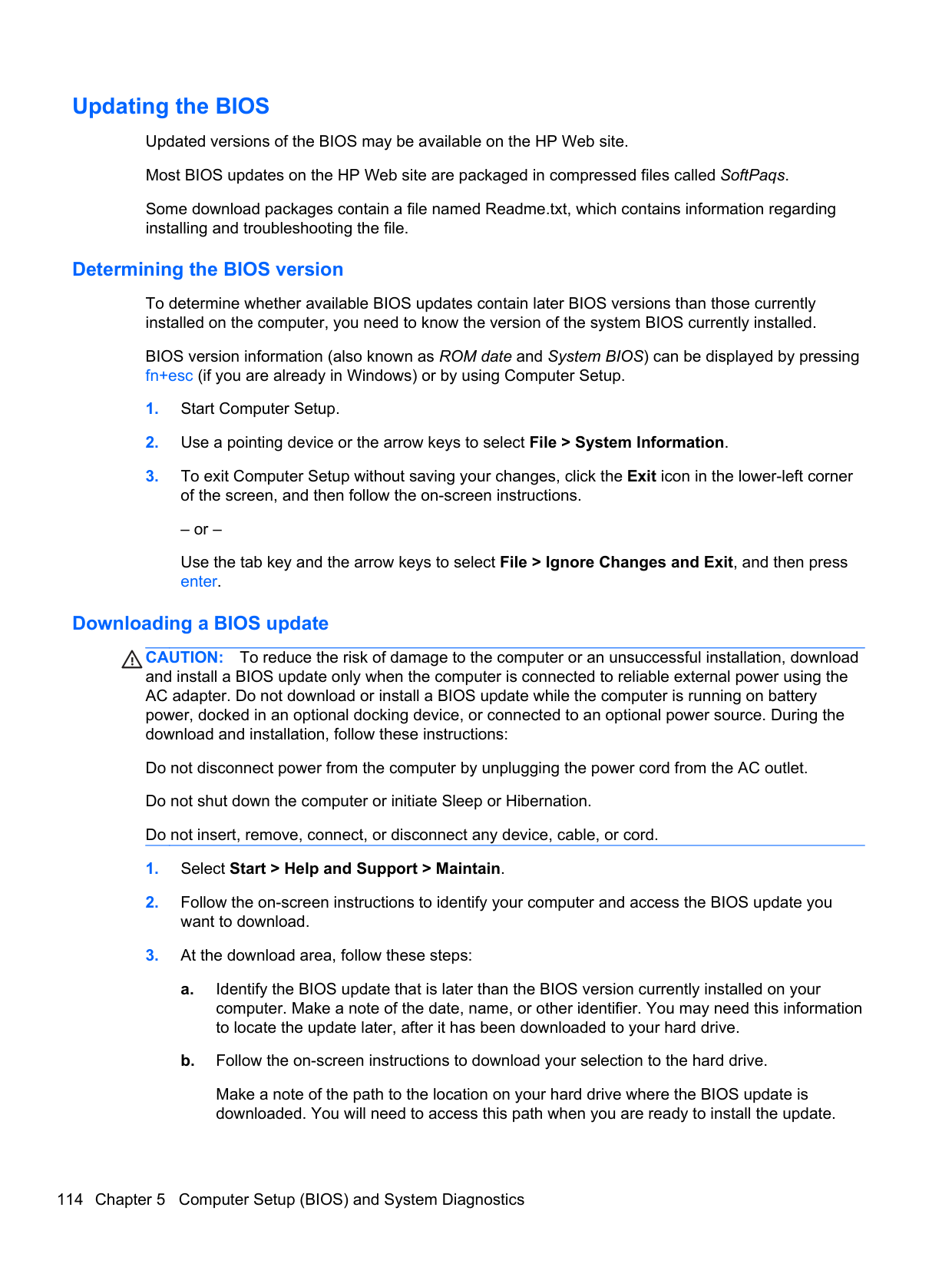
Center hole diameter 1.5 cm (0.59 in) Disc diameter Standard disc Mini disc
12 cm (4.72 in) 8 cm (3.15 in)
Disc thickness 1.2 mm (0.047 in) Track pitch 0.74 µm Access time CD DVD Random < 100 ms < 125 ms Full stroke < 175 ms < 225 ms Audio output level Line-out, 0.7 Vrms Cache buffer 512 KB Data transfer rate CD-R (24X) 3600 KB/s (150 KB/s at 1X CD rate) CD-RW (10X) 1500 KB/s (150 KB/s at 1X CD rate) CD-ROM (24X) 3600 KB/s (150 KB/s at 1X CD rate) DVD (8X) 10,800 KB/s (1,352 KB/s at 1X DVD rate) Multiword DMA mode 2 16.6 MB/s Startup time < 10 seconds Stop time < 3 seconds
Specification information in Device Manager
Device Manager allows you to view and control the hardware attached to the computer, as well as provides hardware specification information.
You can also add hardware or modify device configurations using Device Manager. NOTE: Windows 7 and Windows Vista include the User Account Control feature to improve the security of your computer. You may be prompted for your permission or password for tasks such as installing software, running utilities, or changing Windows settings. Refer to Windows Help and Support for more information. After you open Device Manager, drill-down to a device and double-click it to access its properties. To access Device Manager in Windows 7:
| | |---|
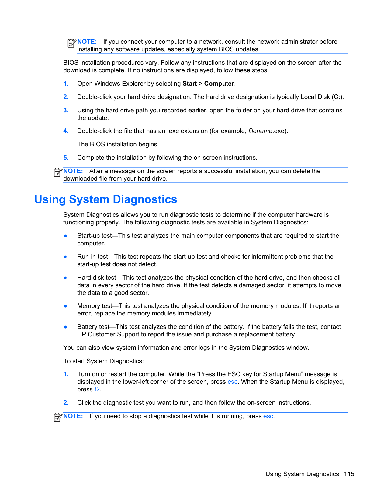
Specification information in Device Manager 125
7 Backup and recovery
Windows 7
To protect your information, use Windows Backup and Restore to back up individual files and folders, back up your entire hard drive (select models only), create system repair discs (select models only) by using the installed optical drive (select models only) or an optional external optical drive, or create system restore points. In case of system failure, you can use the backup files to restore the contents of your computer.
Windows Backup and Restore provides the following options:
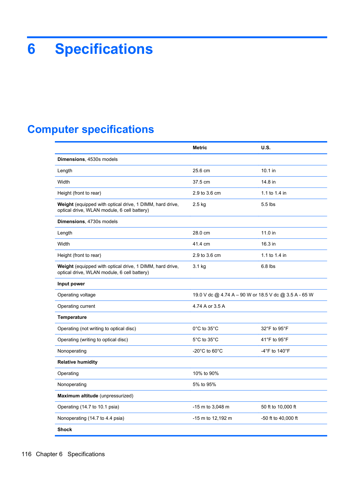
| | |---|
In case of system instability, HP recommends that you print the recovery procedures and save them for later use.
NOTE: Windows includes the User Account Control feature to improve the security of your
| | |---|
computer. You may be prompted for your permission or password for tasks such as installing software, running utilities, or changing Windows settings. Refer to Help and Support for more information.
#### Backing up your information
Recovery after a system failure is as good as your most recent backup. You should create system repair discs (select models only) by using the installed optical drive (select models only) or an optional external optical drive, and your initial backup immediately after software setup. As you add
new software and data files, you should continue to back up your system on a regular basis to maintain a reasonably current backup. The system repair discs (select models only) are used to start up (boot) the computer and repair the operating system in case of system instability or failure. Your initial and subsequent backups allow you to restore your data and settings if a failure occurs.
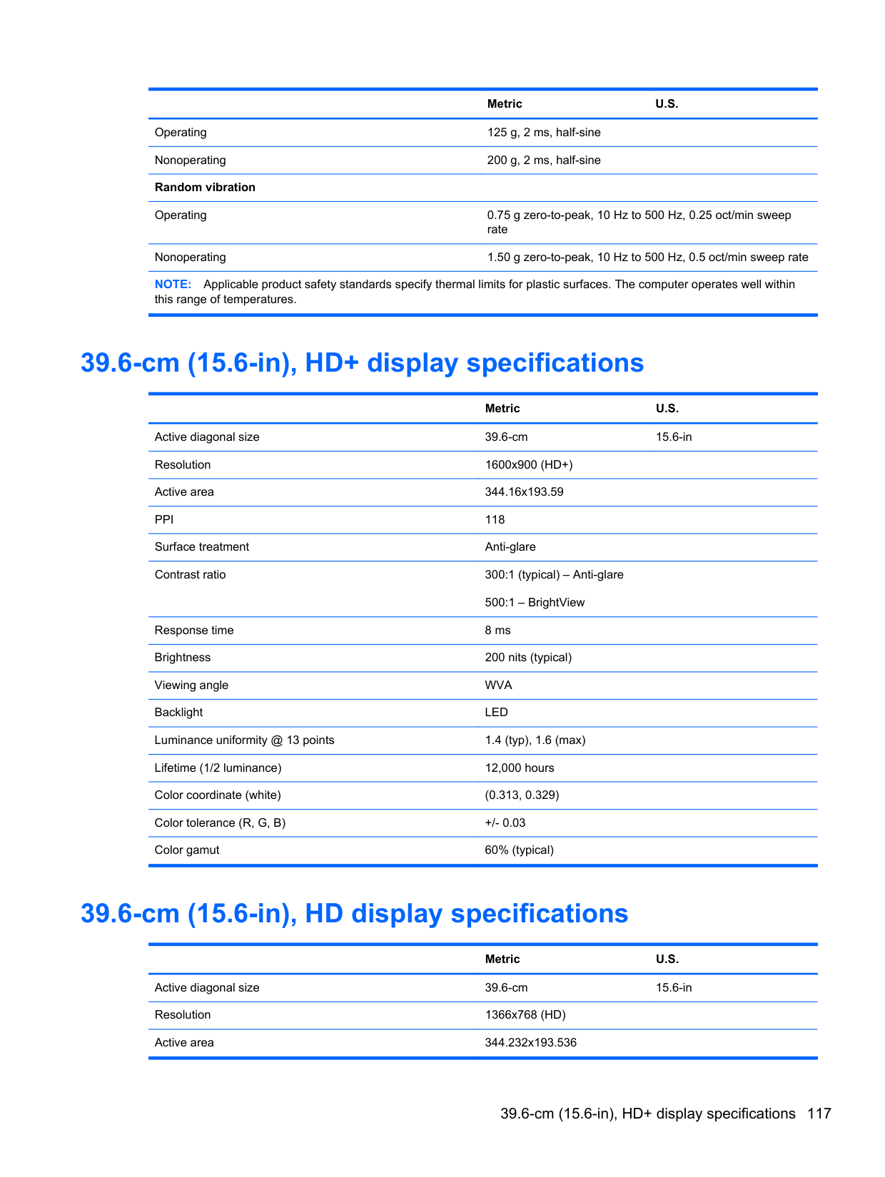
You can back up your information to an optional external hard drive, a network drive, or discs. Note the following when backing up:
| | |---|
NOTE: DVDs and DVDs with double-layer (DL) support store more information than CDs, so using them for backup reduces the number of recovery discs required.
To create a backup using Backup and Restore: NOTE: Be sure that the computer is connected to AC power before you start the backup process. NOTE: The backup process may take over an hour, depending on file size and the speed of the computer.
| | |---|
| |
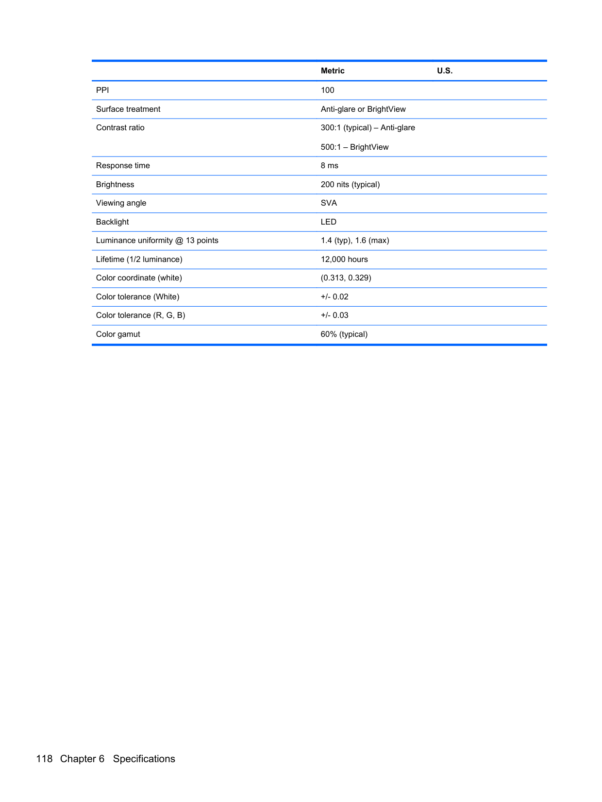
|---|
#### Performing a system recovery
In case of system failure or instability, the computer provides the following tools to recover your files: ● Windows recovery tools: You can use Windows Backup and Restore to recover information you
have previously backed up. You can also use Windows Startup Repair to fix problems that might prevent Windows from starting correctly.
● f11 recovery tools: You can use the f11 recovery tools to recover your original hard drive image. The image includes the Windows operating system and software programs installed at the factory.
NOTE: If you are unable to boot (start up) your computer and you cannot use the system repair discs you previously created (select models only), you must purchase a Windows 7 operating system DVD to reboot the computer and repair the operating system. For additional information, refer to Using a Windows 7 operating system DVD (purchased separately) on page 129.
| | |---|
##### Using the Windows recovery tools
To recover information you previously backed up:
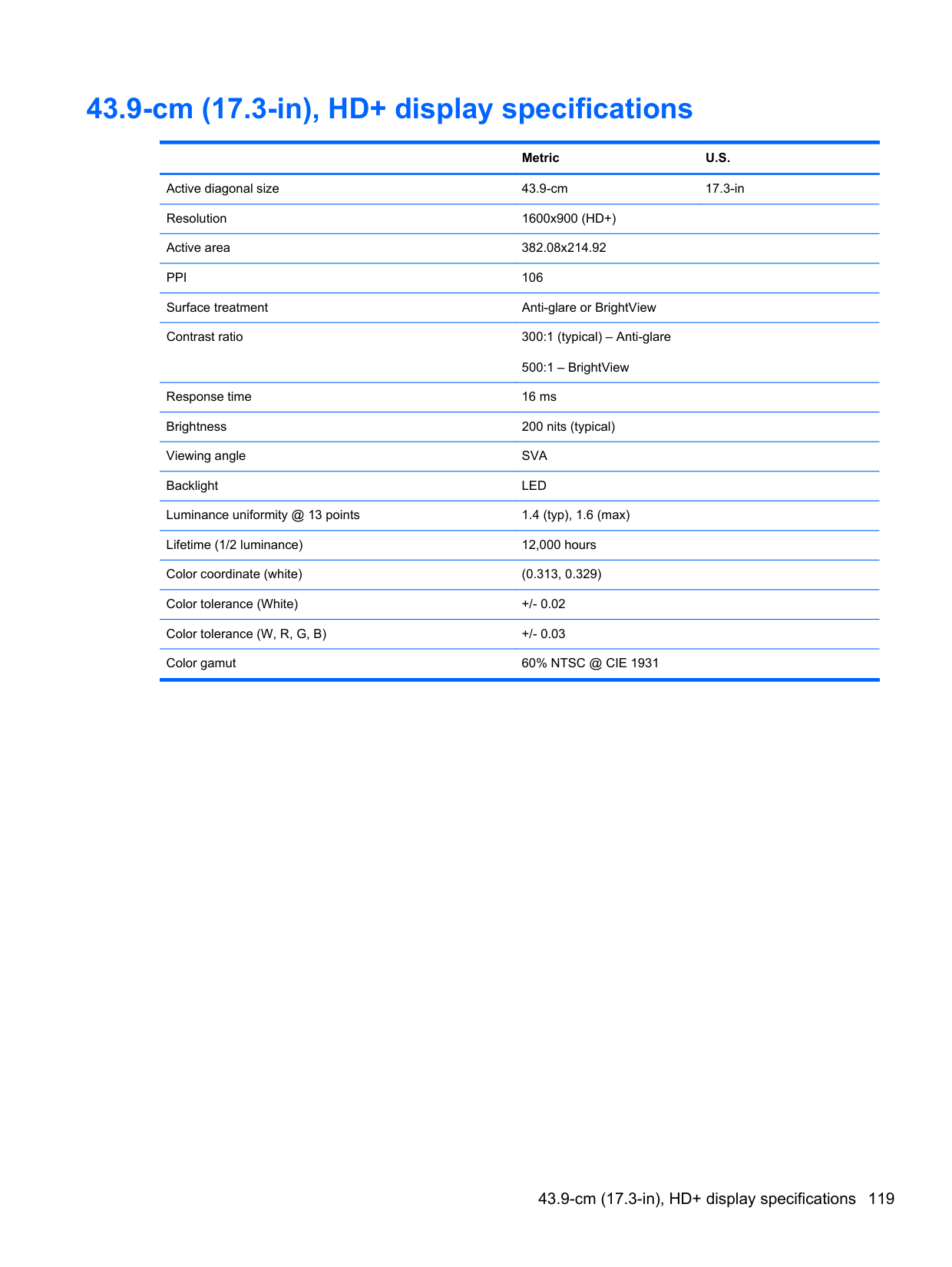
To recover your information using Startup Repair, follow these steps:
CAUTION: Using Startup Repair completely erases hard drive contents and reformats the hard drive. All files you have created and any software installed on the computer are permanently removed. When reformatting is complete, the recovery process restores the operating system, as well as the drivers, software, and utilities from the backup used for recovery.
To check for the HP Recovery partition, click Start, right-click Computer, click Manage, and then click Disk Management.
| | |---|
NOTE: If the Windows partition and the HP Recovery partition are not listed, you must recover
your operating system and programs using the Windows 7 operating system DVD and the Driver Recovery disc (both purchased separately). For additional information, refer to Using a Windows 7 operating system DVD (purchased separately) on page 129.
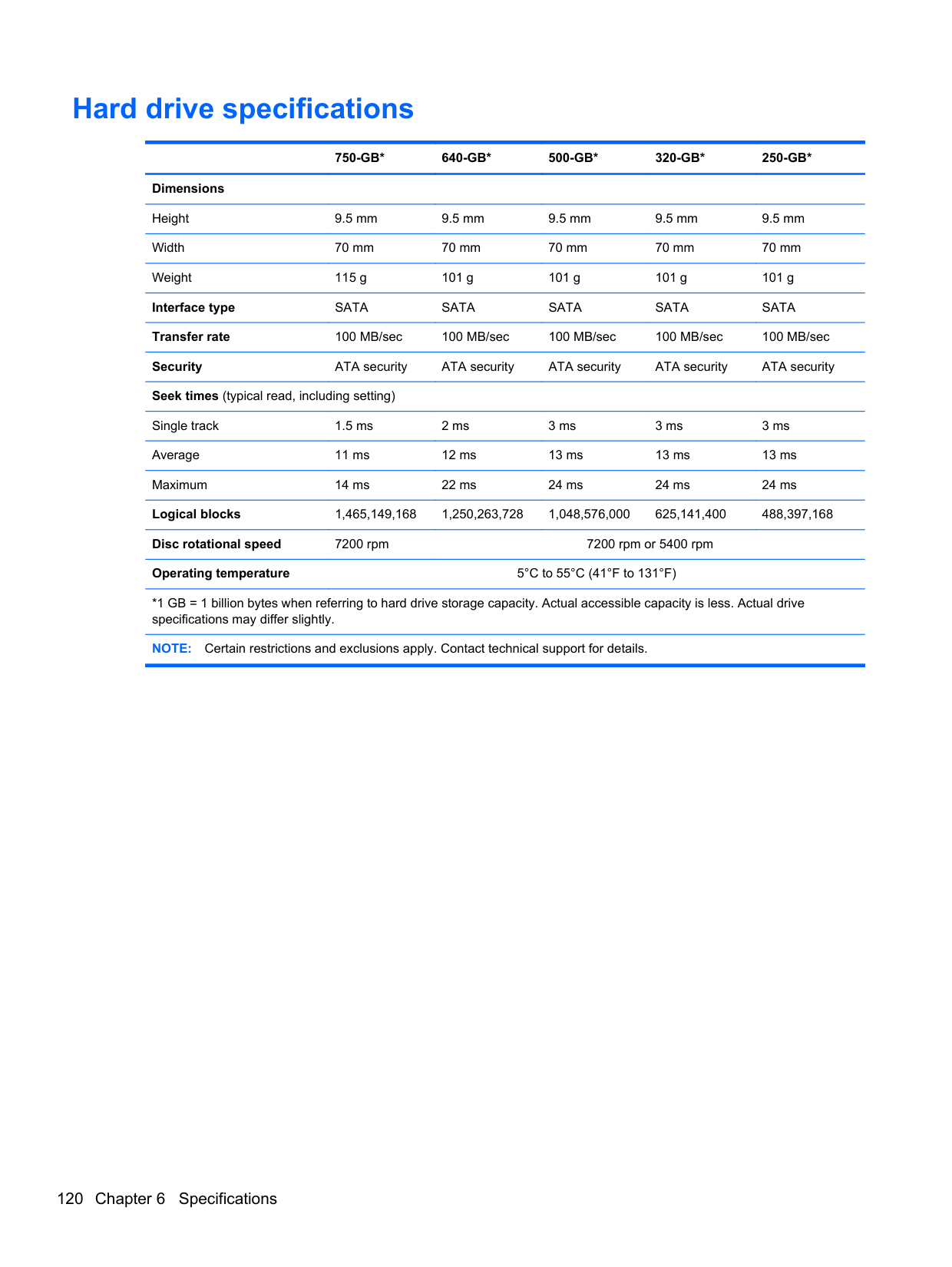
NOTE: For additional information on recovering information using the Windows tools, perform a search for these topics in Help and Support.
| | |---|
##### Using f11 recovery tools
CAUTION: Using f11 completely erases hard drive contents and reformats the hard drive. All files you have created and any software installed on the computer are permanently removed. The f11 recovery tool reinstalls the operating system and HP programs and drivers that were installed at the factory. Software not installed at the factory must be reinstalled.
To recover the original hard drive image using f11:
NOTE: If the HP Recovery partition is not listed, you must recover your operating system and programs using the Windows 7 operating system DVD and the Driver Recovery disc (both purchased separately). For additional information, refer to Using a Windows 7 operating system DVD (purchased separately) on page 129.
| | |---|
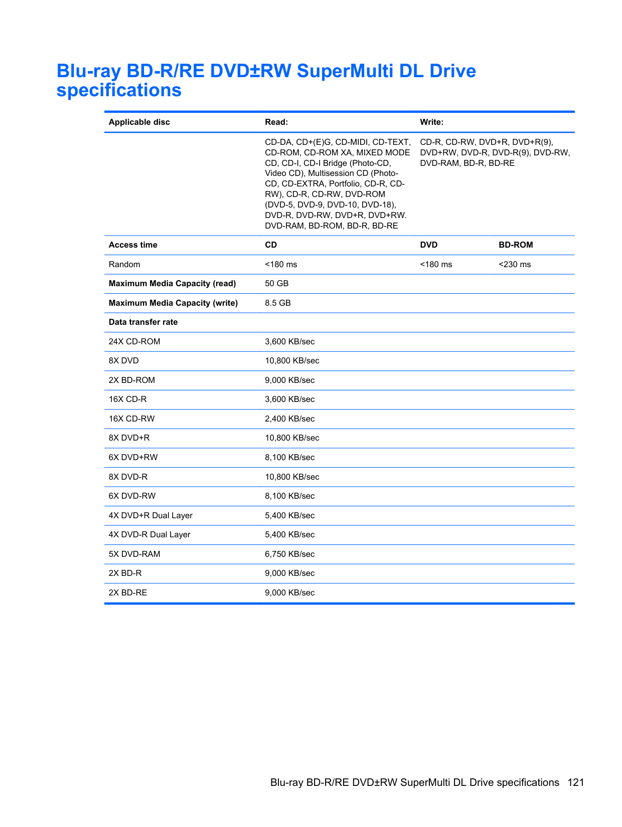
##### Using a Windows 7 operating system DVD (purchased separately)
To order a Windows 7 operating system DVD, go to http://www.hp.com/support, select your country or region, and follow the on-screen instructions. You can also order the DVD by calling technical support. For contact information, refer to the Worldwide Telephone Numbers booklet included with the computer.
CAUTION: Using a Windows 7 operating system DVD completely erases hard drive contents and
reformats the hard drive. All files you have created and any software installed on the computer are permanently removed. When reformatting is complete, the recovery process helps you restore the operating system, as well as drivers, software, and utilities.
To initiate recovery using a Windows 7 operating system DVD: NOTE: This process takes several minutes.
| | |---|
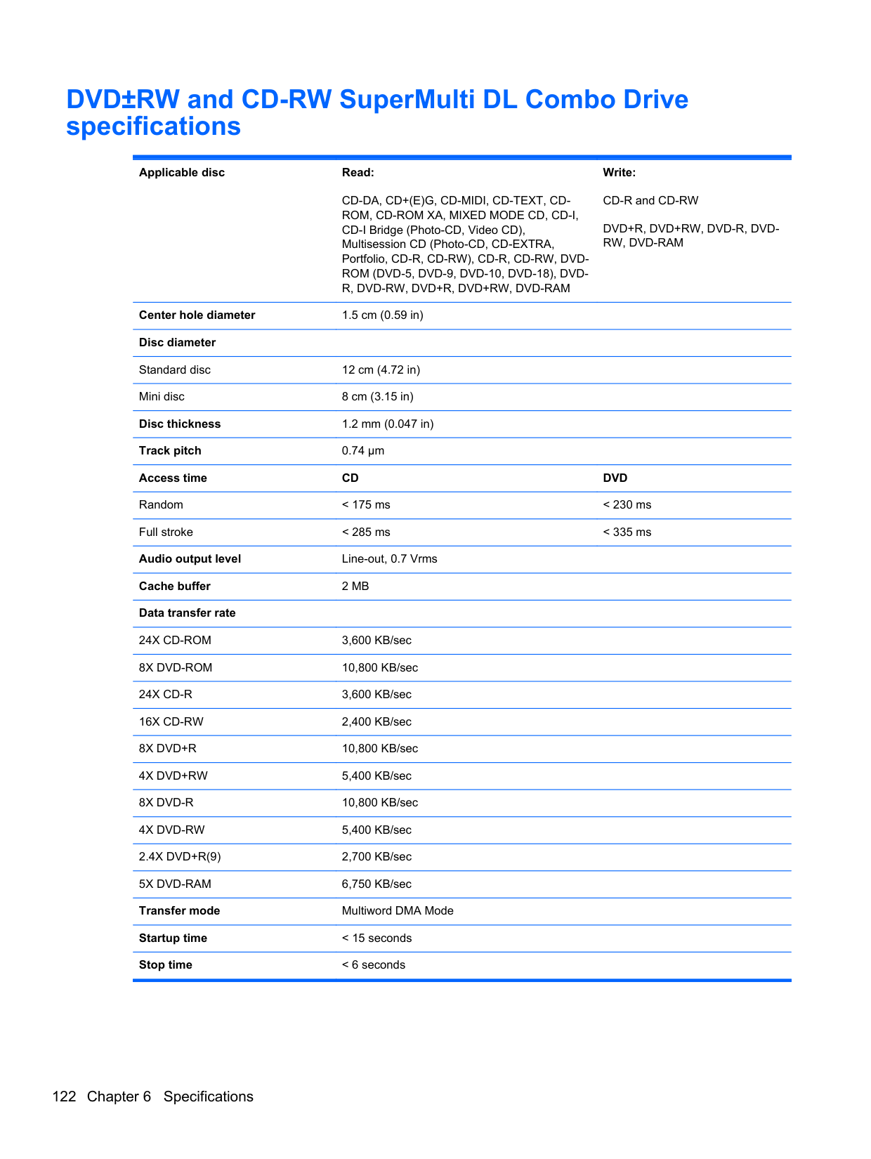
Windows Vista
To protect your information, use the Backup and Restore Center to back up individual files and folders, back up your entire hard drive (select models only), or create system restore points. In case of system failure, you can use the backup files to restore the contents of your computer.
The Backup and Restore Center provides the following options:
| | |---|
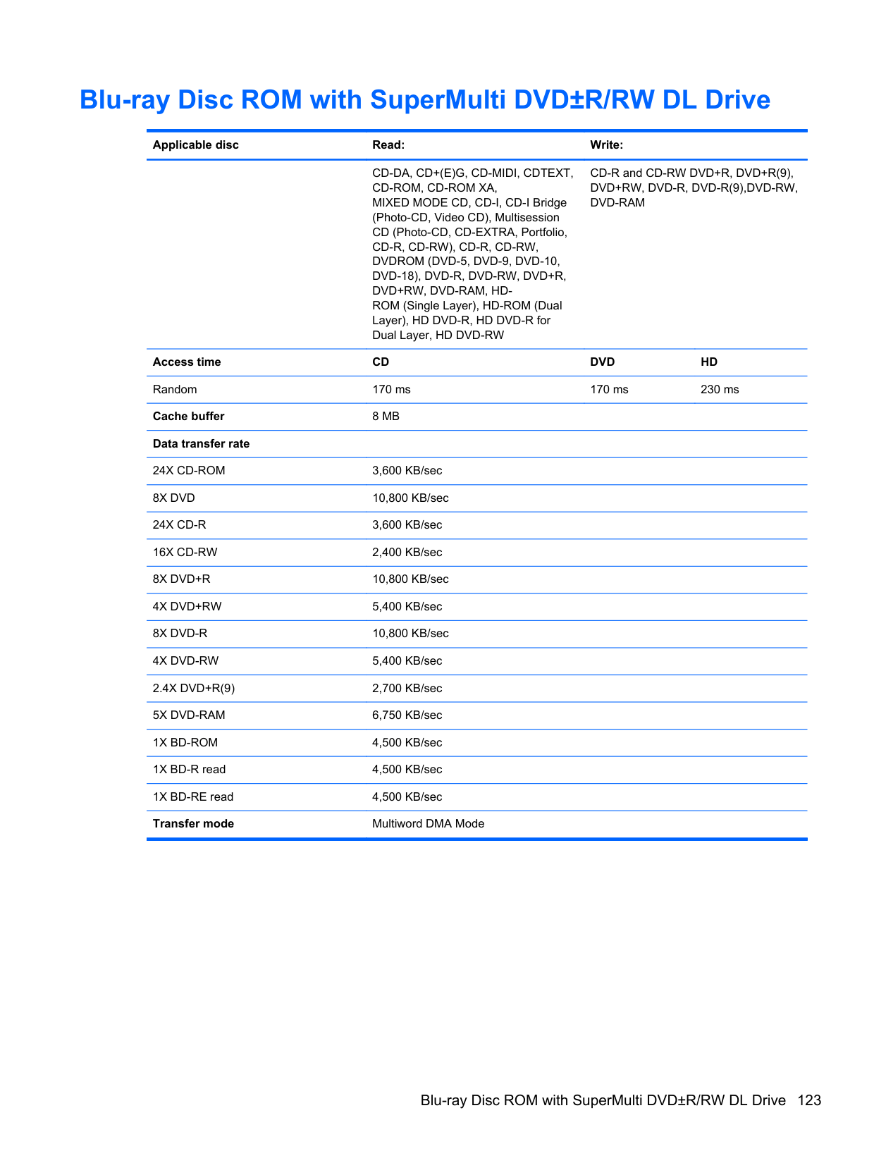
| | |---|
NOTE: In case of system instability, HP recommends that you print the recovery procedures and save them for later use.
NOTE: Windows® includes the User Account Control feature to improve the security of your
| | |---|
computer. You may be prompted for your permission or password for tasks such as installing software, running utilities, or changing Windows settings. Refer to Help and Support for more information.
#### Backing up your information
Recovery after a system failure is as complete as your most current backup. You should create your initial backup immediately after software setup. As you add new software and data files, you should continue to back up your system on a regular basis to maintain a reasonably current backup.
You can back up your information to an optional external hard drive, a network drive, or discs. Note the following when backing up:
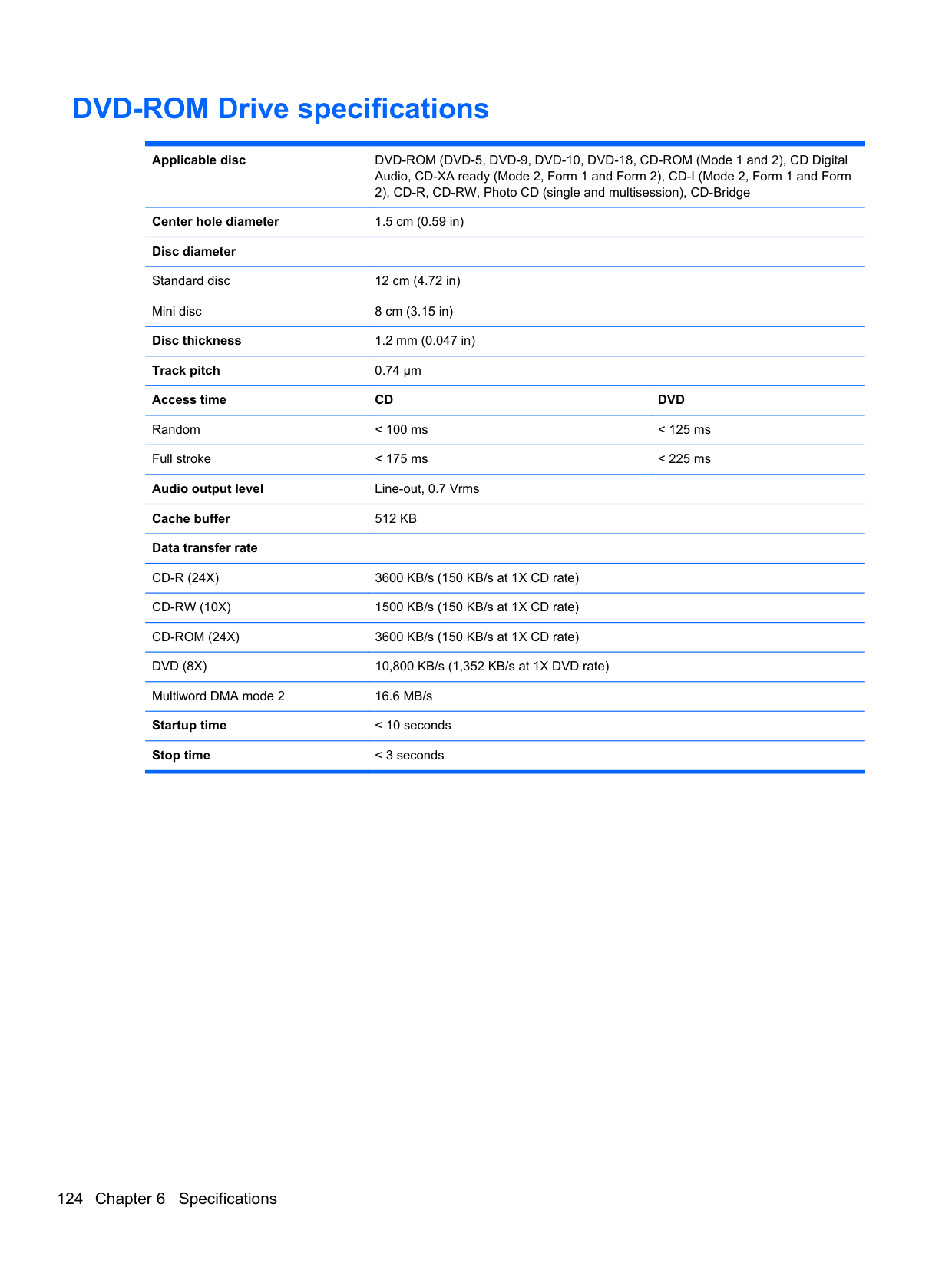
| | |---|
NOTE: DVDs and DVDs with double-layer (DL) support store more information than CDs, so using them for backup reduces the number of recovery discs required.
To create a backup using Backup and Restore Center: NOTE: Be sure that the computer is connected to AC power before you start the backup process. NOTE: The backup process may take over an hour, depending on file size and the speed of the computer.
| | |---|
| | |---|
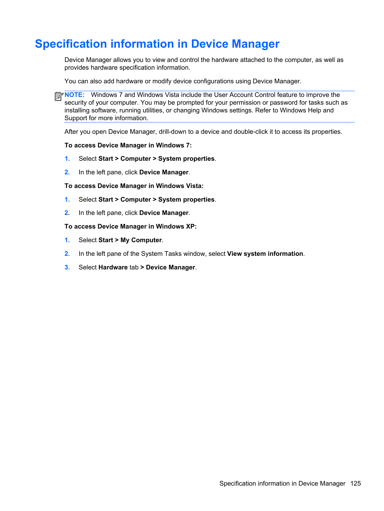
files.
#### Performing a recovery
In case of system failure or instability, the computer provides the following tools to recover your files:
NOTE: If you are unable to boot (start up) your computer, you must purchase a Windows Vista® operating system DVD to reboot the computer and repair the operating system. For additional information, refer to Using a Windows Vista operating system DVD (purchased separately) on page 132.
| | |---|
##### Using the Windows recovery tools
To recover information you previously backed up:
files. To recover your information using Startup Repair, follow these steps:
CAUTION: Using Startup Repair completely erases hard drive contents and reformats the hard drive. All files you have created and any software installed on the computer are permanently removed. When reformatting is complete, the recovery process restores the operating system, as well as the drivers, software, and utilities from the backup used for recovery.
| | |---|
NOTE: If the Windows partition and the HP Recovery partition have been deleted, you must recover your operating system and programs using the Windows Vista operating system DVD and the Driver Recovery disc (both purchased separately). For additional information, refer to
Using a Windows Vista operating system DVD (purchased separately) on page 132.
NOTE: For additional information on recovering information using the Windows tools, perform a search for these topics in Help and Support.
| | |---|
##### Using f11 recovery tools
CAUTION: Using f11 completely erases hard drive contents and reformats the hard drive. All files you have created and any software installed on the computer are permanently removed. The f11 recovery tool reinstalls the operating system and HP programs and drivers that were installed at the factory. Software not installed at the factory must be reinstalled. Personal files must be restored from a backup.
NOTE: If your computer includes a solid-state drive (SSD), you may not have a recovery partition. Recovery discs have been included for computers that do not have a partition. Use these discs to recover your operating system and software. To check for the presence of a recovery partition, select Start > Computer. If the partition is present, an HP Recovery drive is listed in the Hard Disk Drives section of the window. To recover the original hard drive image using f11, follow these steps:
| | |---|
| | |---|
NOTE: If the HP Recovery partition has been deleted, you must recover your operating system and programs using the Windows Vista operating system DVD and the Driver Recovery disc (both purchased separately). For additional information, refer to Using a Windows Vista operating system DVD (purchased separately) on page 132.
##### Using a Windows Vista operating system DVD (purchased separately)
To order a Windows Vista operating system DVD, go to http://www.hp.com/support, select your country or region, and follow the on-screen instructions. You can also order the DVD by calling technical support. For contact information, refer to the Worldwide Telephone Numbers booklet included with the computer.
CAUTION: Using a Windows Vista operating system DVD completely erases hard drive contents and reformats the hard drive. All files you have created and any software installed on the computer are permanently removed. When reformatting is complete, the recovery process helps you restore the operating system, as well as drivers, software, and utilities.
To initiate recovery using a Windows Vista operating system DVD:
NOTE: This process takes several minutes.
| | |---|
8 Power cord set requirements
The wide range input feature of the computer permits it to operate from any line voltage from 100 to 120 volts AC, or from 220 to 240 volts AC.
The 3-conductor power cord set included with the computer meets the requirements for use in the country or region where the equipment is purchased.
Power cord sets for use in other countries and regions must meet the requirements of the country or region where the computer is used.
Requirements for all countries and regions
The requirements listed below are applicable to all countries and regions:
134 Chapter 8 Power cord set requirements
Requirements for specific countries and regions
######## Country/region Accredited agency Applicable note number
Australia EANSW 1 Austria OVE 1 Belgium CEBC 1 Canada CSA 2 Denmark DEMKO 1 Finland FIMKO 1 France UTE 1 Germany VDE 1 Italy IMQ 1 Japan METI 3 The Netherlands KEMA 1 Norway NEMKO 1 The People's Republic of China CCC 5 South Korea EK 4 Sweden SEMKO 1 Switzerland SEV 1 Taiwan BSMI 4 The United Kingdom BSI 1 The United States UL 2
Requirements for specific countries and regions 135
9 Recycling
Battery
When a battery has reached the end of its useful life, do not dispose of the battery in general household waste. Follow the local laws and regulations in your area for computer battery disposal.
Display
WARNING! The backlight contains mercury. Exercise caution when removing and handling the backlight to avoid damaging this component and causing exposure to the mercury.
CAUTION: The procedures in this chapter can result in damage to display components. The only components intended for recycling purposes are the LCD panel and the backlight. When you remove these components, handle them carefully.
NOTE: Materials Disposal. This HP product contains mercury in the backlight in the display
| | |---|
assembly that might require special handling at end-of-life. Disposal of mercury may be regulated because of environmental considerations. For disposal or recycling information, contact your local authorities, or see the Electronic Industries Alliance (EIA) Web site at http://www.eiae.org.
This section provides disassembly instructions for the display assembly. The display assembly must be disassembled to gain access to the backlight (1) and the liquid crystal display (LCD) panel (2).

NOTE: The procedures provided in this chapter are general disassembly instructions. Specific details, such as screw sizes, quantities, and locations, and component shapes and sizes, can vary from one computer model to another.
| | |---|
Perform the following steps to disassemble the display assembly:


####### 15. Remove the backlight cables (1) from the clip (2) in the display panel.

####### 16. Position the display panel upside-down.
WARNING! The backlight contains mercury. Exercise caution when removing and handling the backlight to avoid damaging this component and causing exposure to the mercury.
####### 17. Remove the backlight frame from the display panel.


Index
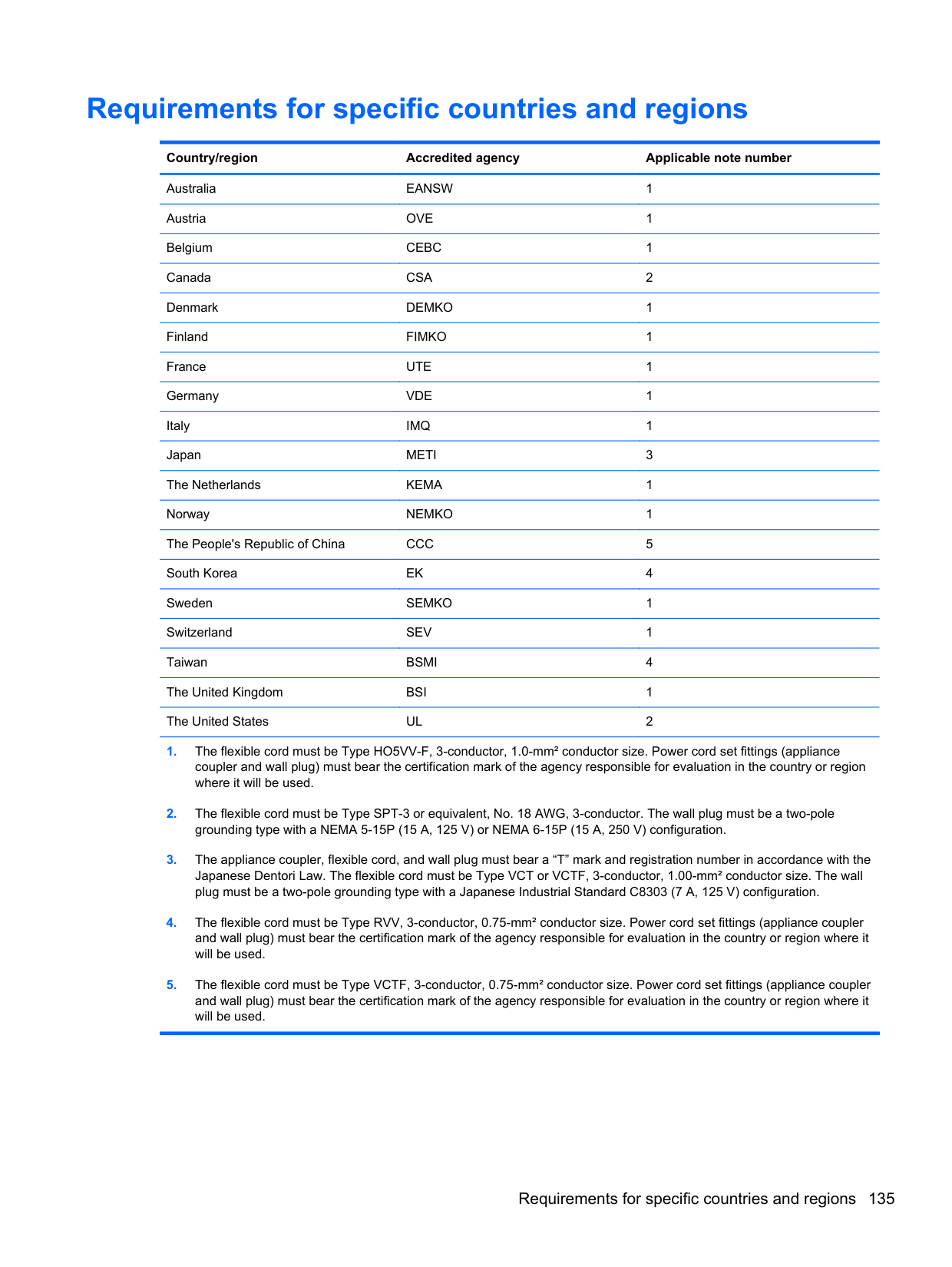
31, 33, 34 access cover release latches 17 antennas
disconnecting 56, 61 audio, product description 3 audio-in (microphone) jack 14 audio-out (headphone) jack 14
131 base enclosure, spare part number 25, 37
battery removal 47 spare part number 25, 47
battery bay 17 battery connector cable,
illustrated 30 battery release latches 17 BIOS
determining version 114 downloading an update 114 updating 114
Blu-ray BD-R/RE DVD±RW SuperMulti DL Drive 121
spare part number 26, 39, 40, 50 Blu-ray Disc ROM with SuperMulti
DVD±R/RW DL Drive spare part number 30 specifications 123
Blu-ray ROM DVD±RW SuperMulti DL Drive, spare part number 26, 30, 39, 40, 50
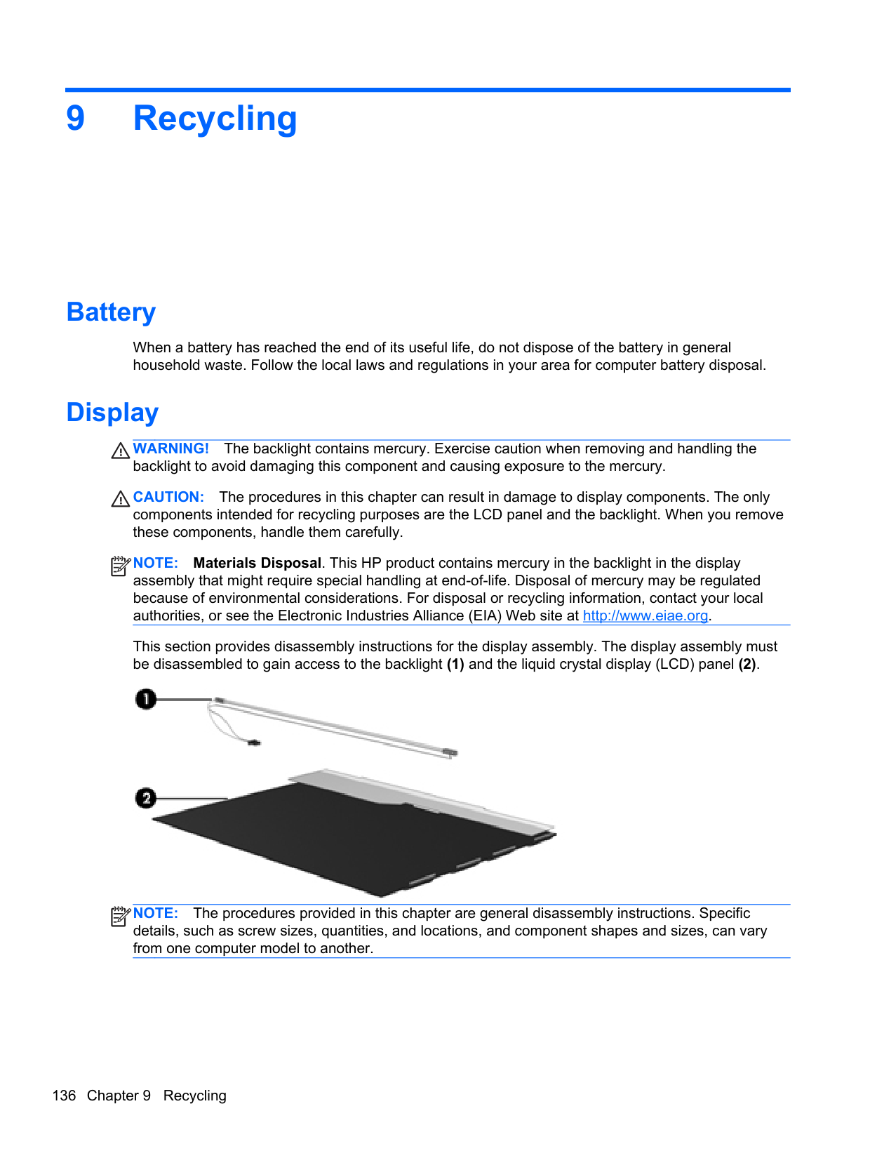
Bluetooth card spare part number 58
bottom door removal 49 spare part number 26, 37, 49
buttons left TouchPad 9 optical drive eject 16 power 11 QuickWeb 12 right TouchPad 9 TouchPad on/off 9 wireless 12
C Cable Kit
contents 30 spare part number 30, 39
cables, service considerations 42 caps lock light, identifying 10 card reader board
removal 70 spare part number 20, 37, 70
chipset, product description 2 components
bottom 17 display 8 front 14 left side 15 right side 16 top 9
Computer Setup
navigating and selecting 112 restoring factory settings 113
computer specifications 116 connectors, service
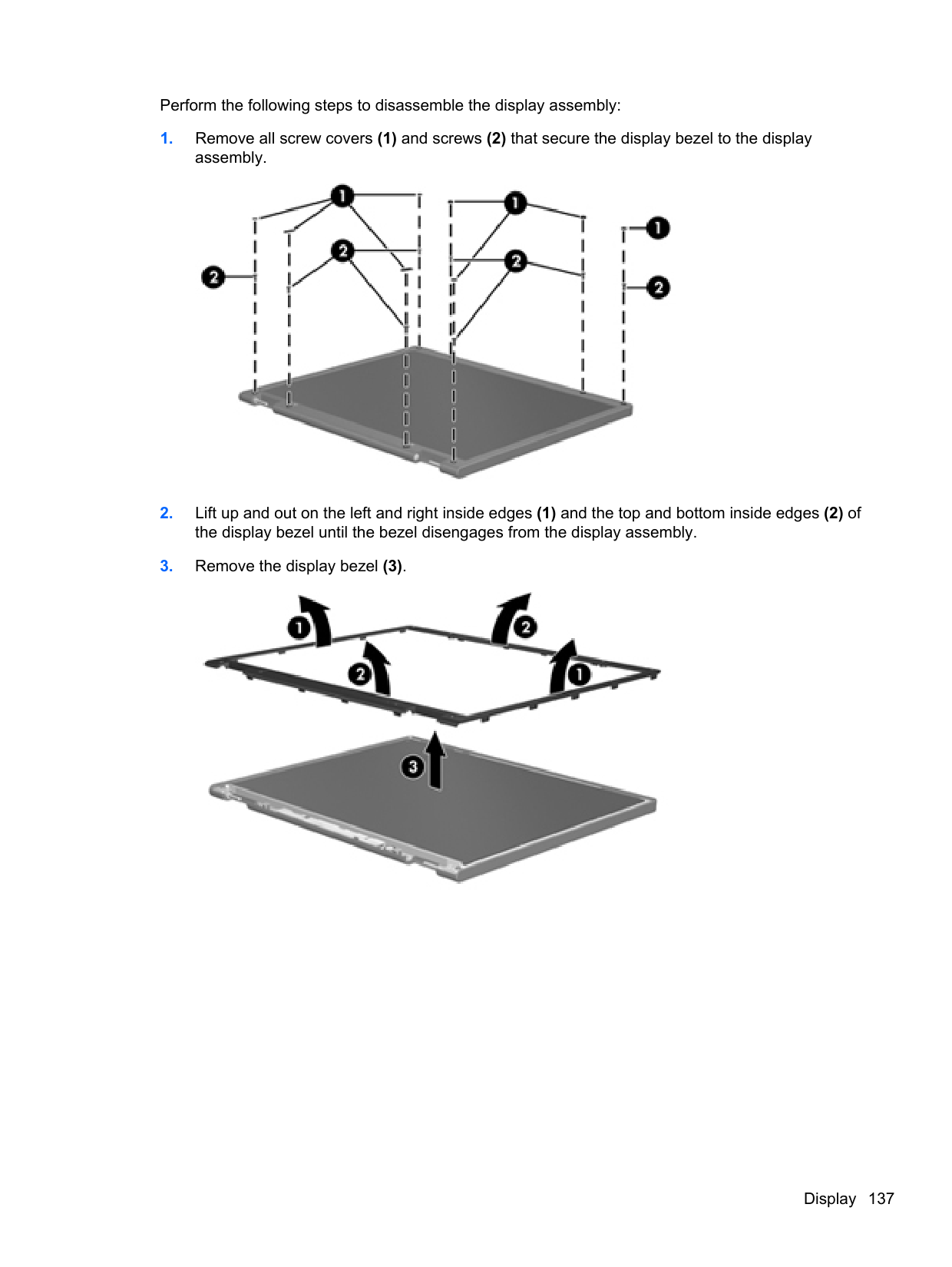
considerations 42
D diskette drive
precautions 42
display assembly removal 102 spare part numbers 102
display bezel removal 105 spare part numbers 27, 37 display component recycling 136 display components, spare part
numbers 27 display enclosure, spare part number 28, 37
display hinge removal 108 spare part number 37
display hinge cover
spare part numbers 27, 37 Display Hinge Kit
spare part number 28
display panel product description 2 removal 107 spare part number 28, 39
display specifications 117, 119 drive light 14 drives
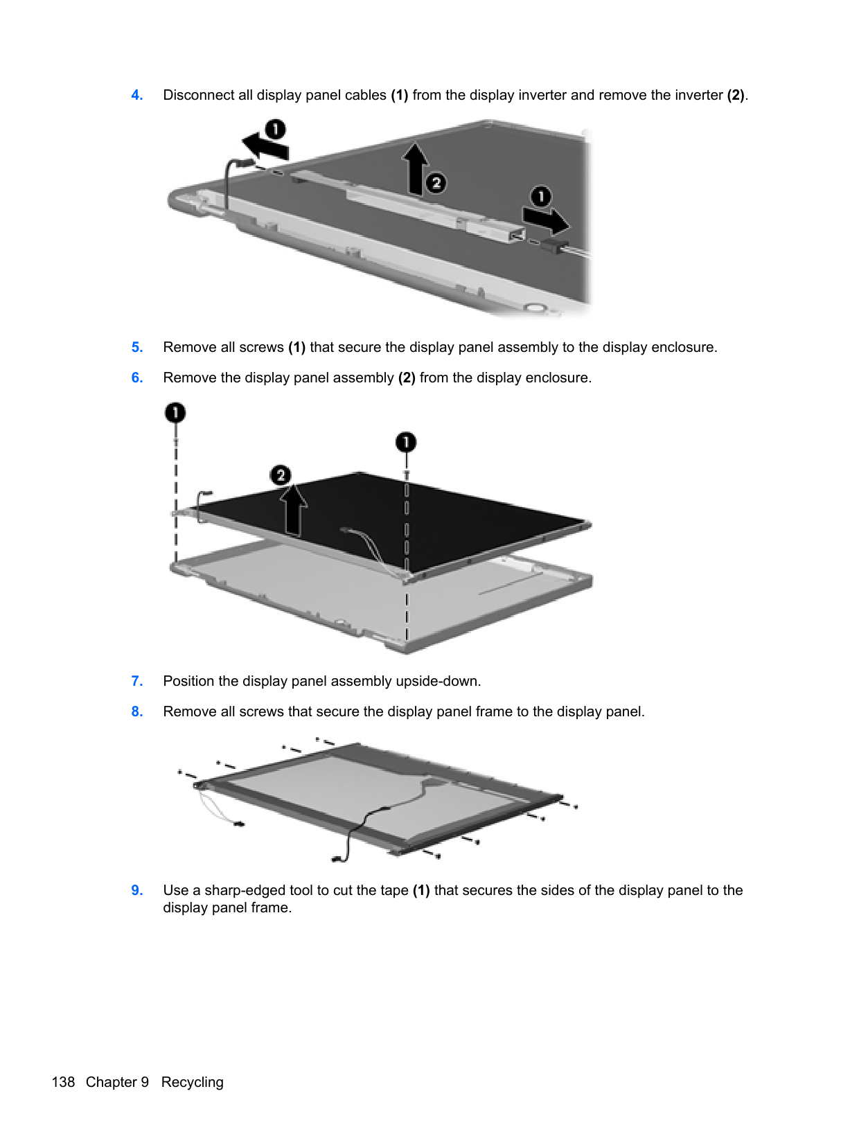
optical 16 preventing damage 42
DVD-ROM Drive precautions 42 removal 50 spare part number 26, 30, 39,
50 specifications 124 DVD±RW and CD-RW SuperMulti DL Combo Drive precautions 42
removal 50 spare part number 26, 30, 39,
50
illustrated 29 ExpressCard slot, identifying 16 external media cards, product
description 4 external monitor port 15
removal 93 spare part number 25, 37, 93
fingerprint reader, identifying 12 fn key, identifying 13 function keys
identifying 13
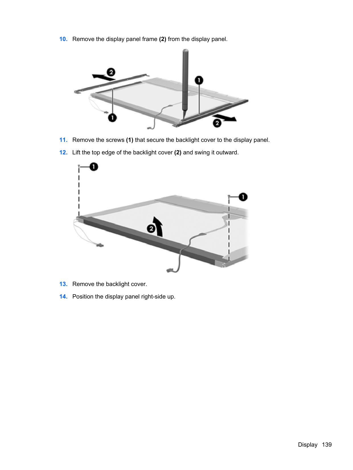
methods 45
precautions 42 product description 3 removal 52 spare part numbers 26, 30,
35, 36, 52
specifications 120 hard drive bay, identifying 17 hard drive bracket, removal 53 hard drive extension board
removal 89 spare part number 89
Hard Drive Hardware Kit, spare
part number 31, 39, 52 hard drive recovery 128, 132 HDMI port, identifying 15 heat sink
removal 95 spare part number 25, 95
hinge removal 108 spare part number 37
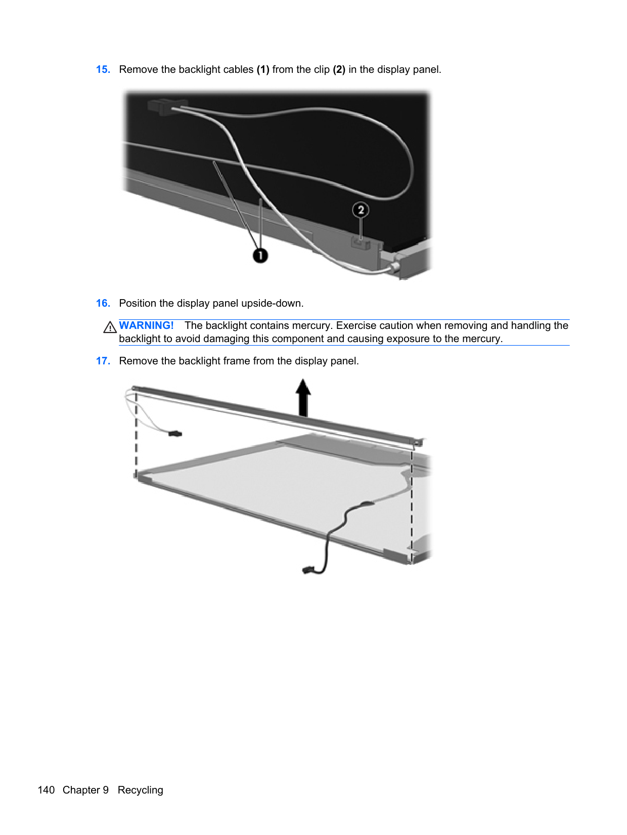
identifying 13 integrated webcam light,
identifying 8 internal display switch 8 internal microphones, identifying
8
audio-in (microphone) 14 audio-out (headphone) 14 network 15 RJ-11 (modem) 16 RJ-45 (network) 15
product description 4 removal 63 spare part numbers 20, 38, 63
keypad, integrated numeric 13 keys
esc 13 fn 13 function 13 menu 13 num lk 13 start 13
removal 78 spare part number 37, 78
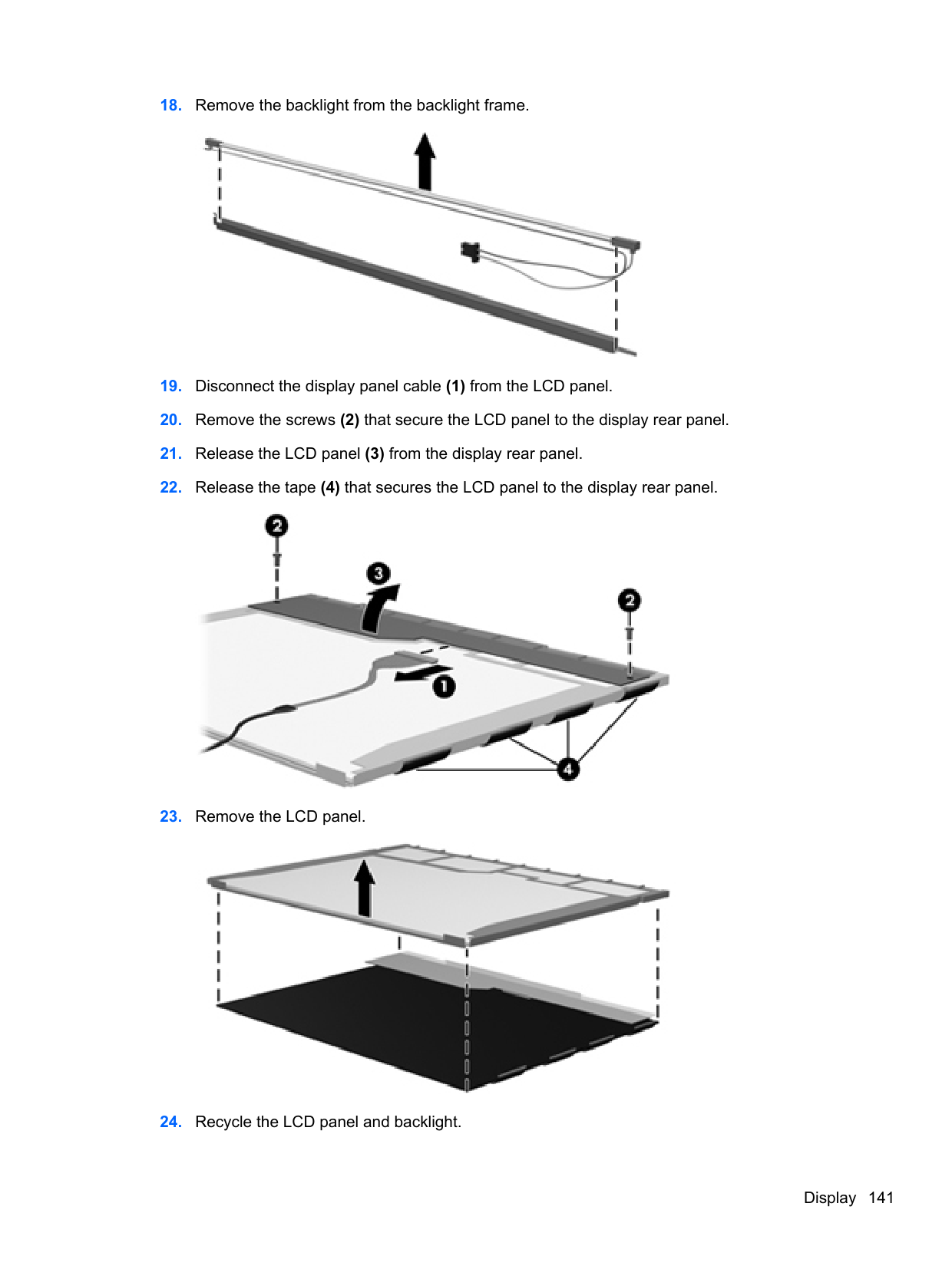
lid switch board spare part number 21
lights AC adapter 15 caps lock 10 drive 14 optical drive 16 power 10 QuickWeb 10 TouchPad 10
webcam 8 wireless 10
numbers 30 Media Card Reader 14 memory module
product description 2 removal 54 spare part numbers 25, 54
menu key, identifying 13 microphone (audio-in) jack
product description 3 microphone module
spare part number 36
model name 1 modem module
product description 3 removal 76 spare part number 21, 34, 76
description 5 optical drive 16 precautions 42 product description 3 removal 50 spare part numbers 26, 30, 50 specifications 121, 122, 123,
124
optical drive connector removal 82 spare part number 25, 37, 82
optical drive eject button 16 optical drive light 16 optical drive protective insert
illustrated 29
29, 39 pointing device, product description 4
ports external monitor 15 HDMI 15 product description 4 USB 16
power button board removal 74 spare part number 21, 38, 74
power button, identifying 11 power cable
removal 100 spare part number 100
power connector cable,
illustrated 30 power connector, identifying 15 power cord
set requirements 134 spare part numbers 31, 32
power light 10 power requirements, product
description 5
processor product description 1 removal 97 spare part numbers 21, 97
product description audio 3 chipset 2 display panel 2 Ethernet 3 external media cards 4 graphics 2 hard drives 3 keyboard 4 memory module 2 microphone 3 modem module 3 operating system 5 optical drives 3 pointing devices 4 ports 4 power requirements 5 processors 1 product name 1 security 5 serviceability 7 webcam 3 wireless 3 product name 1
removal 73 spare part number 21, 38, 73
QuickWeb button, identifying 12 QuickWeb light 10
access cover 17 battery 17
removal/replacement preliminaries 41 procedures 46
restoring the hard drive 128, 132 RJ-11 (modem) jack, identifying
16 RJ-11 connector cable illustrated 30 RJ-11 holder, illustrated
illustrated 29 RJ-11 jack cable
removal 84 RJ-45 (network) jack, identifying 15
RTC battery removal 91 spare part number 25, 32, 91
Rubber Kit, spare part number 39
39 Secure Digital card insert, illustrated
illustrated 29 security cable slot, identifying 15 security, product description 5 service considerations 41 service tag 18, 46 serviceability, product
description 7 setup utility
navigating and selecting 112 restoring factory settings 113
SIM slot, identifying 17 SIM, removal 48 slots
ExpressCard 16
security cable 15 SIM 17
speaker assembly removal 71 spare part number 21, 38, 71
speakers, identifying 8 specifications
Blu-ray BD-R/RE DVD±RW SuperMulti DL Drive 121
Blu-ray Disc ROM with SuperMulti DVD±R/RW DL Drive 123
computer 116 display 117, 119 DVD-ROM Drive 124 DVD±RW and CD-RW
SuperMulti DL Combo Drive 122
hard drive 120 optical drive 121, 122, 123,
124 start key, identifying 13 static-shielding materials 45 system board
removal 85 spare part numbers 21, 36,
85 system repair disc 126 system restore points 126
96, 97 tools required 41 top cover
removal 65 spare part number 20, 37, 65
TouchPad buttons 9 identifying 9
TouchPad light, identifying 10 TouchPad on/off button 9 transporting guidelines 44
removal 80 spare part number 25, 80
USB legacy support 112 USB port, identifying 16
USB ports, identifying 16
product description 3 spare part number 28, 36
webcam light, identifying 8 webcam, identifying 9 Windows 7 operating system
DVD 129 Windows Backup and Restore 126 Windows Vista operating system DVD 132 wireless antennas
disconnecting 56, 61 wireless antennas, identifying 8 wireless button, identifying 12 wireless light 10 wireless, product description 3 WLAN antennas
identifying 8 spare part number 28, 37
WLAN module spare part numbers 22, 33
WLAN/Bluetooth combo card removal 58 spare part number 58
workstation guidelines 44 WWAN antennas
identifying 8 spare part number 28, 37
WWAN module removal 56 spare part number 22, 35, 56