
Ask AI
— answers from the official manualAnswers from the official manual.
Common questions
Common Questions
20 totalWhat type of surge suppressor do I need to use with the treadmill?
You must use a single-outlet surge suppressor that is UL 1449 listed as a transient voltage surge suppressor (TVSS), with a UL suppressed voltage rating of 400 volts or less and a minimum surge dissipation of 450 joules. It must be electrically rated for 120 volts AC and 15 amps, and must have a monitoring light to indicate whether it is functioning properly. Failure to use a properly functioning surge suppressor could damage the control system, potentially causing the walking belt to change speed, accelerate, or stop unexpectedly. You can order a compatible surge suppressor by calling 1-866-699-3756 and requesting part number 146148.
How do I reset the circuit breaker if the treadmill loses power during use?
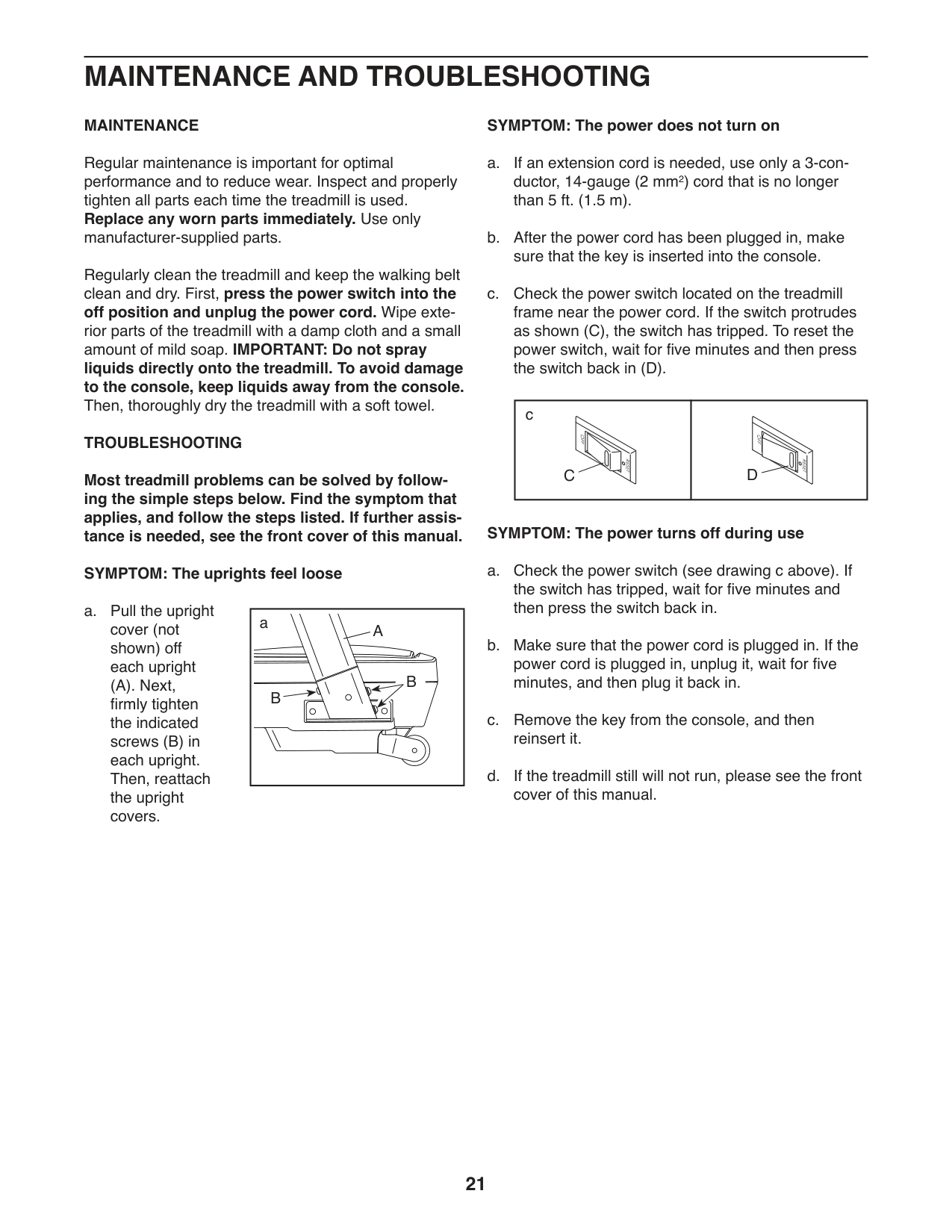
Check the reset/off circuit breaker located on the treadmill frame near the power cord. If the switch protrudes, the circuit breaker has tripped. To reset it, wait five minutes and then press the switch back in.
How do I stop the treadmill in an emergency?
In an emergency, pull the key from the console, which will cause the walking belt to slow to a stop. Before using the treadmill, you should attach the clip on the key to the waistband of your clothes so that the key is automatically pulled if you step too far back. Test the clip by carefully taking a few steps backward to ensure it works properly.
How do I adjust the walking belt if it shifts off-center?
First remove the key and unplug the power cord. If the walking belt has shifted to the left, use the hex key to turn the left rear roller bolt clockwise 1/2 of a turn. If it has shifted to the right, turn the left rear roller bolt counterclockwise 1/2 of a turn. Then plug in the power cord, insert the key, and run the treadmill for a few minutes, repeating the process until the walking belt is centered.
How do I know if the walking belt is properly tightened?
When the walking belt is correctly tightened, you should be able to lift each edge of the walking belt 2 to 3 inches off the walking platform. If the belt is overtightened, treadmill performance may decrease and the walking belt may become damaged. Use the hex key to turn both rear roller bolts counterclockwise 1/4 of a turn to loosen, or clockwise 1/4 of a turn to tighten, checking the tension after each adjustment.
Can I apply silicone spray or lubricant to the walking belt?
Never apply silicone spray or other substances to the walking belt or the walking platform. The treadmill features a pre-lubricated walking belt coated with high-performance lubricant, and applying additional substances will deteriorate the walking belt and cause excessive wear.
Show 14 more questions
How do I fold the treadmill for storage?
How do I change the incline of the treadmill?
What does the limited warranty cover for the Cadence G 40 Treadmill?
How do I change the incline of my Weslo Cadence G 40 treadmill?
Why does my treadmill's walking belt become off-center or slip when I walk on it?
How do I adjust the walking belt tension on my treadmill?
What are the steps if my Weslo Cadence G 40 treadmill won't turn on?
The treadmill stops or turns off suddenly during use; what do I check?
How do I safely fold my treadmill for storage?
What steps should I take to perform maintenance on my Weslo Cadence G 40 treadmill?
How do I start a workout program on the console?
How do I measure my heart rate during a workout on this model?
Where can I find assembly instructions for the Weslo Cadence G40 treadmill?
What is the maximum weight capacity of the Weslo Cadence G 40 Treadmill?
Full Manual
28 pages
User'S Manual
Model No. WLTL29606.0 Serial No.Caution
Read all precautions and instruc- tions in this manual before using this equipment. Save this manual for future reference. Visit our website at www.weslo.com new products, prizes, fitness tips, and much more!Questions?
As a manufacturer, we are com- mitted to providing complete customer satisfaction. If you have questions, or if parts are damaged or missing, PLEASEContact Our Customer
Service Department
Directly.
Call Toll-Free:
1-866-699-3756 Mon.–Fri., 6 a.m.–6 p.m. MSTOn The Web:
www.wesloservice.com Serial Number Decal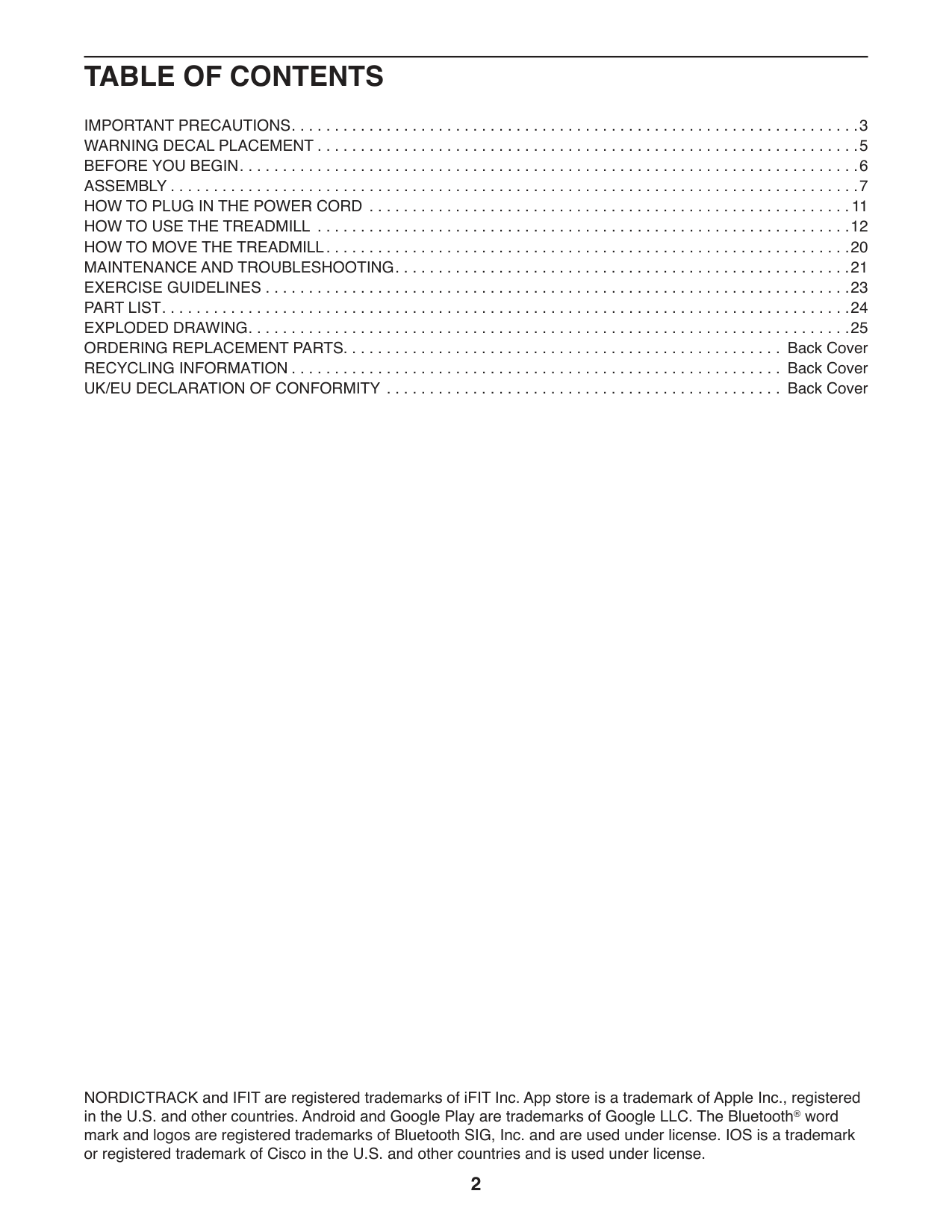
Table Of Contents
IMPORTANT PRECAUTIONS . . . . . . . . . . . . . . . . . . . . . . . . . . . . . . . . . . . . . . . . . . . . . . . . . . . . . . . . . . . . . . . . .3 BEFORE YOU BEGIN . . . . . . . . . . . . . . . . . . . . . . . . . . . . . . . . . . . . . . . . . . . . . . . . . . . . . . . . . . . . . . . . . . . . . . .5 ASSEMBLY . . . . . . . . . . . . . . . . . . . . . . . . . . . . . . . . . . . . . . . . . . . . . . . . . . . . . . . . . . . . . . . . . . . . . . . . . . . . . . .6 OPERATION AND ADJUSTMENT . . . . . . . . . . . . . . . . . . . . . . . . . . . . . . . . . . . . . . . . . . . . . . . . . . . . . . . . . . . .12 HOW TO FOLD AND MOVE THE TREADMILL . . . . . . . . . . . . . . . . . . . . . . . . . . . . . . . . . . . . . . . . . . . . . . . . . .17 MAINTENANCE AND TROUBLESHOOTING . . . . . . . . . . . . . . . . . . . . . . . . . . . . . . . . . . . . . . . . . . . . . . . . . . . .19 CONDITIONING GUIDELINES . . . . . . . . . . . . . . . . . . . . . . . . . . . . . . . . . . . . . . . . . . . . . . . . . . . . . . . . . . . . . . .21 PART LIST . . . . . . . . . . . . . . . . . . . . . . . . . . . . . . . . . . . . . . . . . . . . . . . . . . . . . . . . . . . . . . . . . . . . . . . . . . . . . . .23 EXPLODED DRAWING . . . . . . . . . . . . . . . . . . . . . . . . . . . . . . . . . . . . . . . . . . . . . . . . . . . . . . . . . . . . . . . . . . . . .24 ORDERING REPLACEMENT PARTS . . . . . . . . . . . . . . . . . . . . . . . . . . . . . . . . . . . . . . . . . . . . . . . . . .Back Cover LIMITED WARRANTY . . . . . . . . . . . . . . . . . . . . . . . . . . . . . . . . . . . . . . . . . . . . . . . . . . . . . . . . . . . . . . .Back Cover WESLO is a registered trademark of ICON IP, Inc. 2
3 WARNING: To reduce the risk of burns, fire, electric shock, or injury to persons, read the following important precautions and information before operating the treadmill.
Important Precautions
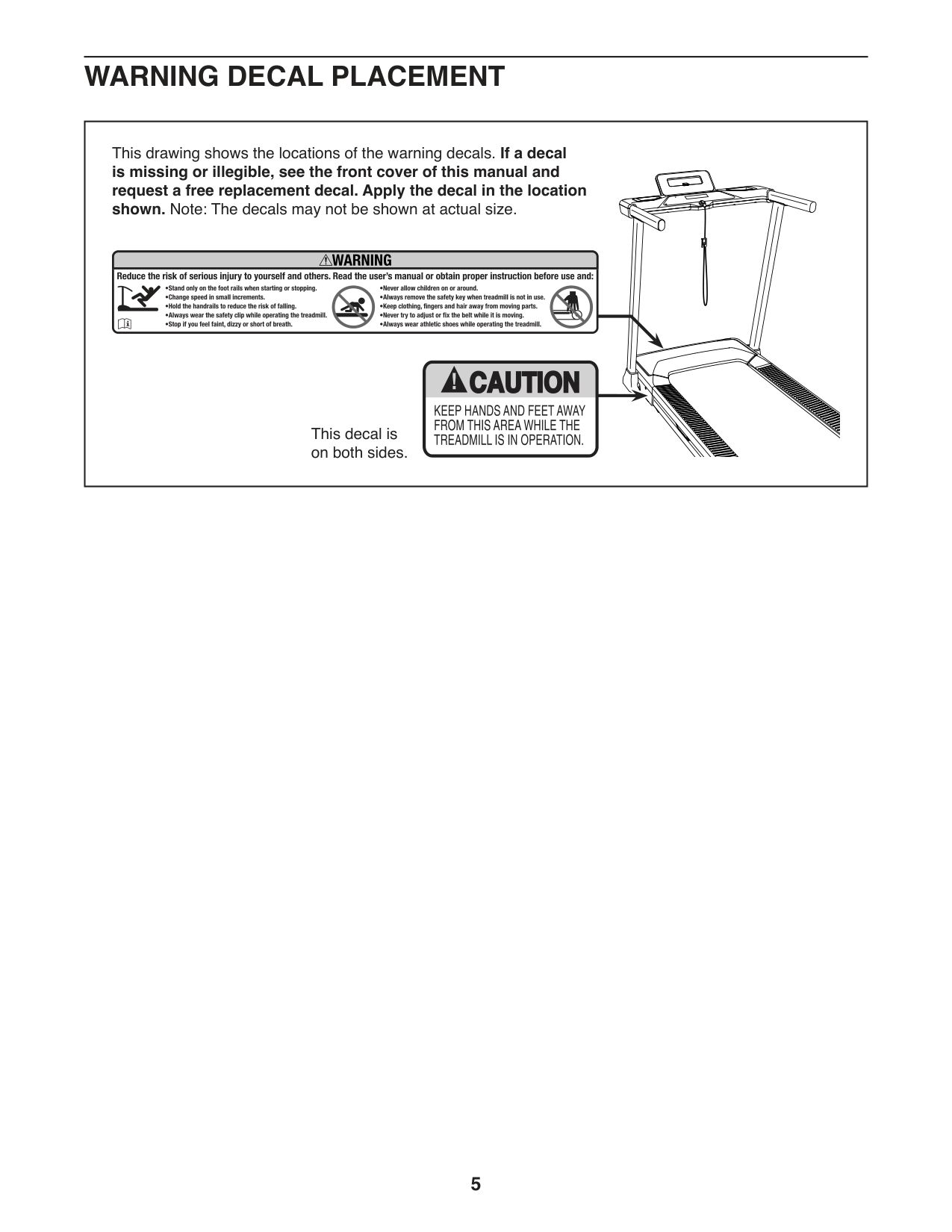
4 The decal shown here has been placed on the treadmill. If the decal is missing, or if it is not legible, call the toll-free telephone number on the front cover of this manual and order a free replacement decal. Apply the decal in the lo- cation shown. Note: The decal is not shown at actual size.
Save These Instructions
5 Thank you for selecting the new WESLO® CADENCE G-40 treadmill. The CADENCE G-40 treadmill combines advanced technology with innovative design to help you get the most from your exercise in the convenience of your home. And when you’re not exercising, the CA- DENCE G-40 treadmill can be folded up, requiring less than half the floor space of other treadmills. For your benefit, read this manual carefully before using the treadmill. If you have questions after read- ing this manual, please see the front cover of this man- ual. To help us assist you, note the product model number and serial number before contacting us. The model number of the treadmill is WLTL29606.0. The serial number can be found on a decal attached to the treadmill (see the front cover of this manual for the lo- cation). To avoid a registration fee for any service needed under warranty, you must register the treadmill at www.wesloservice.com/registration. Before reading further, please review the drawing below and familiarize yourself with the labeled parts.
Before You Begin
Handrail Storage Latch Console Key/Clip Reset/Off Circuit Breaker Power Cord Walking Belt Hood Wheel Foot Rail Rear Roller Adjustment Bolts Accessory Tray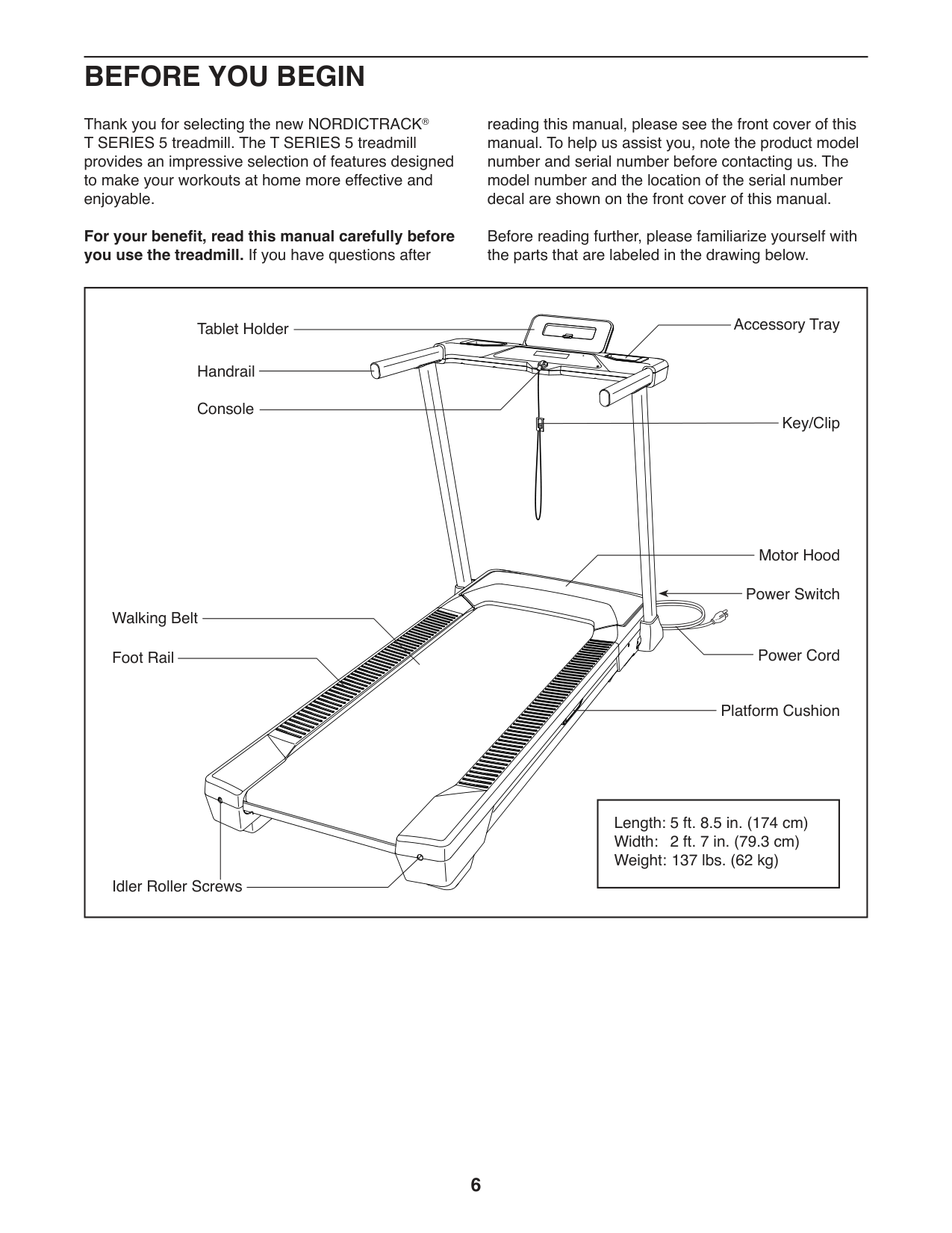
6
Assembly
To hire an authorized service technician to assemble the treadmill, call toll-free 1-800-445-2480. Assembly requires two persons. Set the treadmill in a cleared area and remove all packing materials; do not dispose of the packing materials until assembly is completed. Note: The underside of the treadmill walking belt is coated with high-performance lubricant. During shipping, a small amount of lubricant may be transferred to the top of the walking belt or the shipping carton. This does not affect treadmill performance. If there is lubricant on top of the walking belt, simply wipe off the lubricant with a soft cloth and a mild, non-abrasive cleaner. In addition to the included hex keys , assembly requires a phillips screwdriver , an adjustable wrench , and needlenose pliers . Use the drawings below to identify the hardware used during assembly. Note: If a part is not in the parts bag, check to see if it has been preattached to one of the parts to be assembled. Extra hardware may be in- cluded. To avoid damaging plastic parts, do not use power tools for assembly.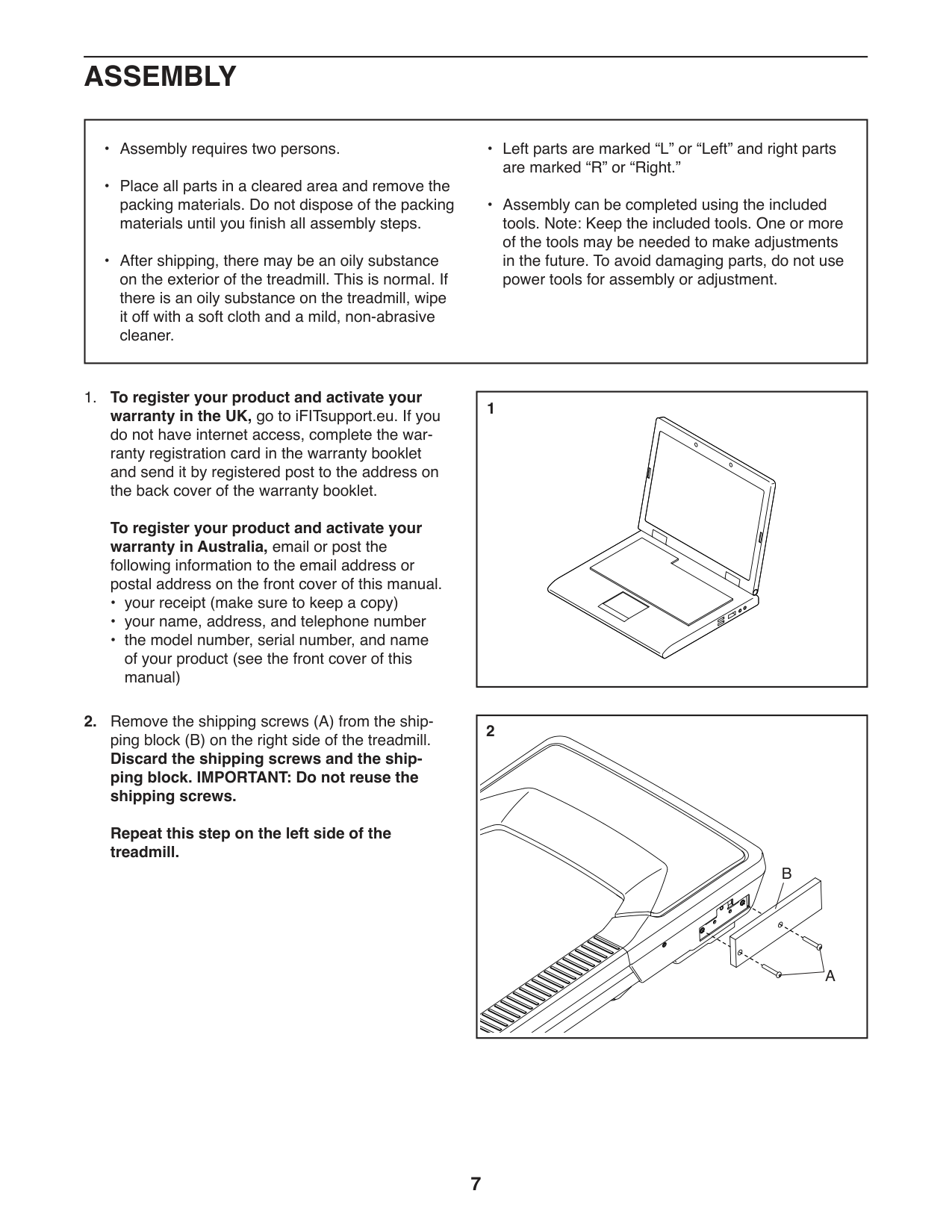
7
8
9
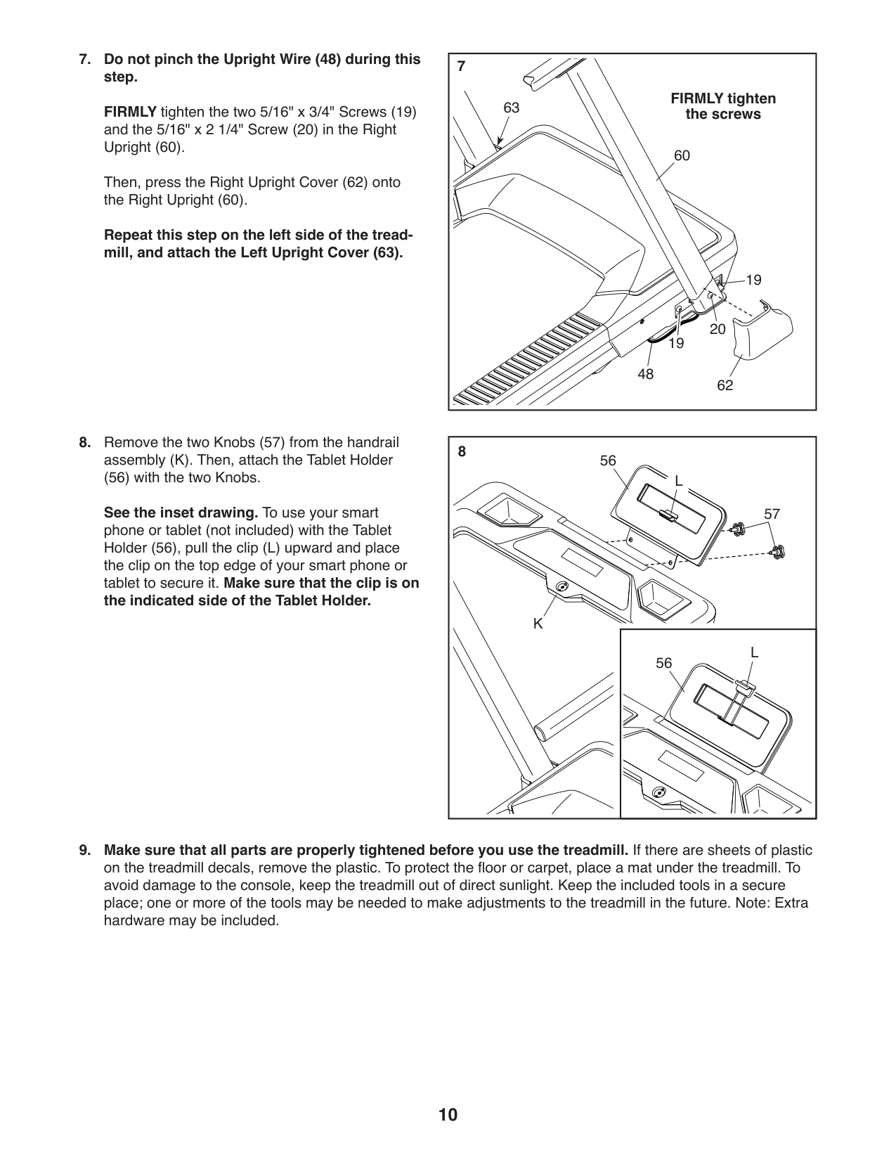
10.Set the Console (91) on the Uprights (53, 54). Make sure that no wires are pinched. Start four M8 x 15mm Bolts (8) with four M8 Star Washers (5) into the Uprights as shown. Do not tighten the M8 x 15mm Bolts yet. 10 8 8 5 5 91 54 53
Not Connected Properly, The Con-
Sole May Be Damaged When The
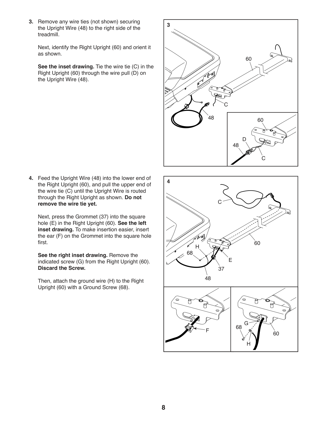
POWER IS TURNED ON. Insert the connectors and the excess wire downward into the Right Upright (54). 9 91 54 39 Console Wire 39 9a 10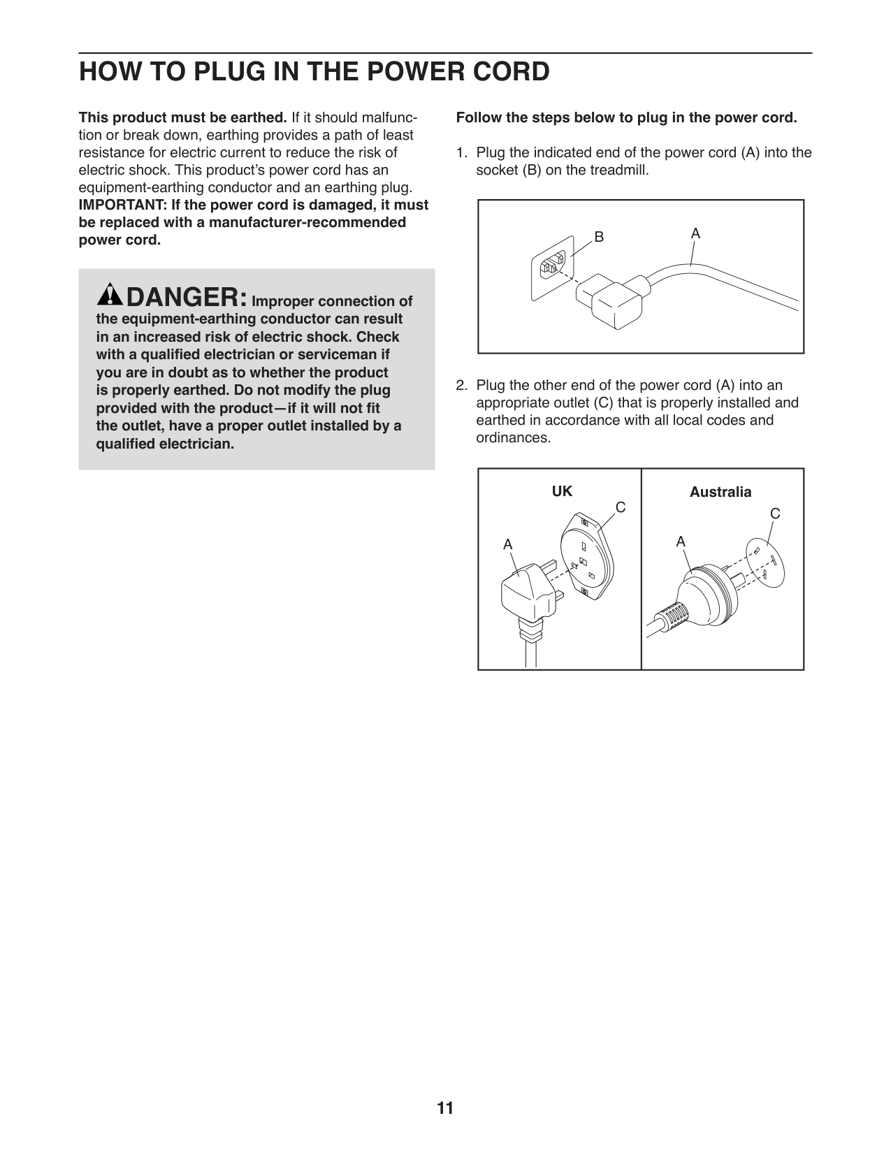
How To Fold The Treadmill For Stor-
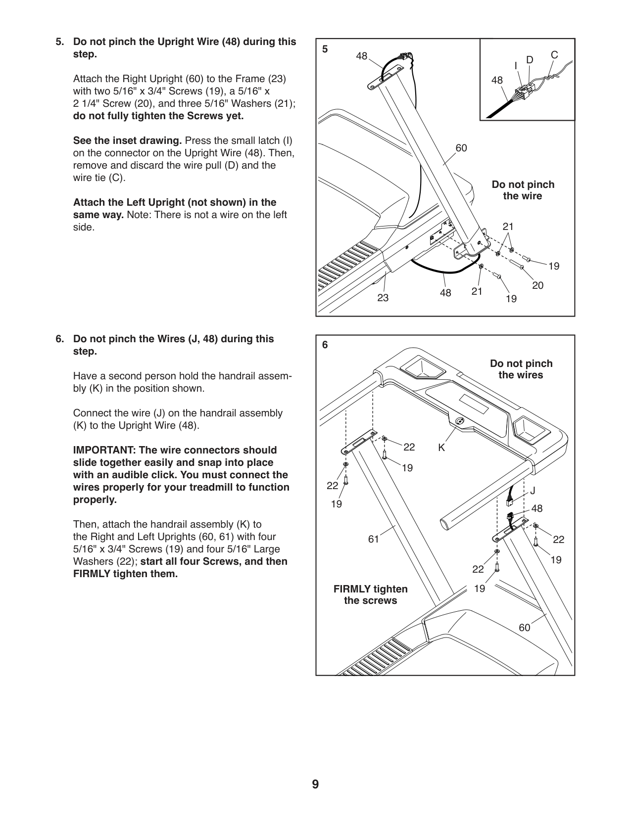
AGE on page 17). Attach an Incline Leg (95) to each side of the Frame (51) with an M8 x 52mm Bolt (82), two M8 Flat Washers (72), and an M8 Nut (46) as shown. Note: do not overtighten the Nuts. The Incline Leg should be able to rotate easily. Adjust the Incline Legs (95) to the desired in- cline (see page 16). 95 72 82 46 72 72 46 95 82 72 14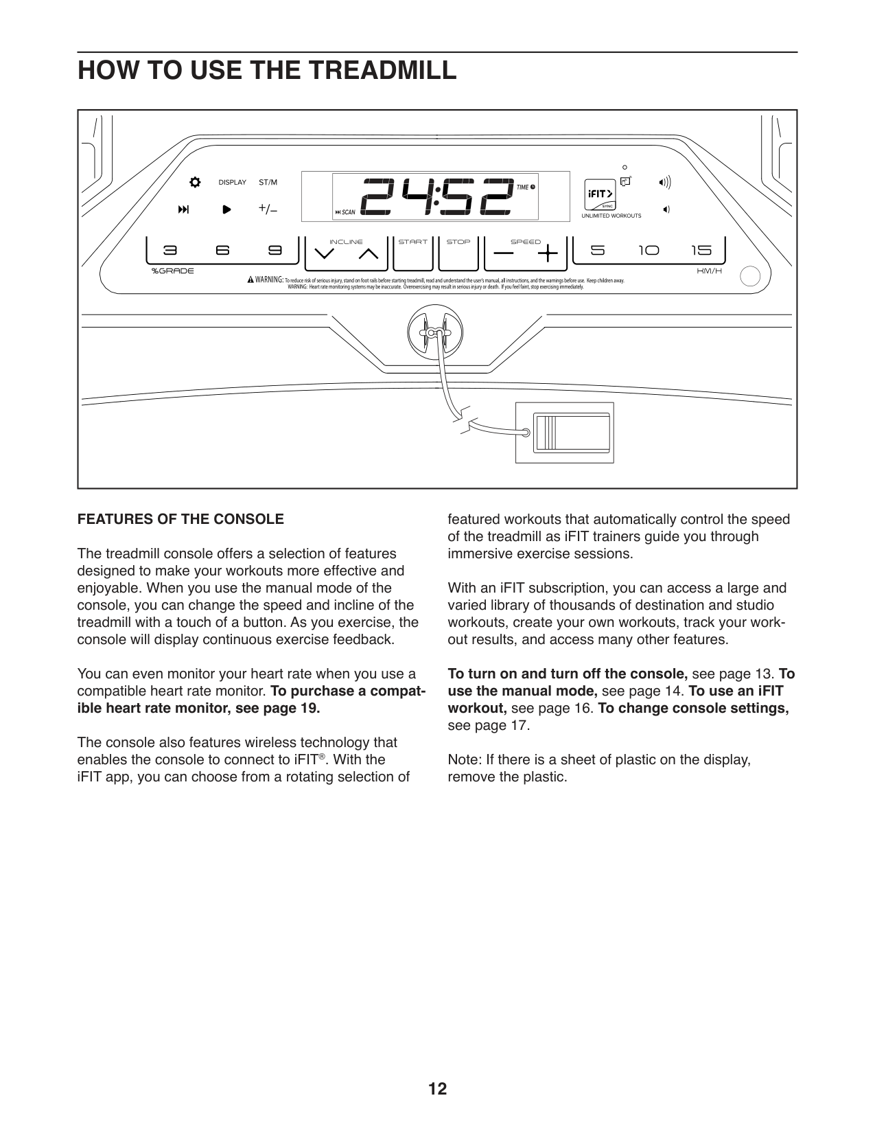
Operation And Adjustment
The Pre-Lubricated Walking Belt
Your treadmill features a walking belt coated with high- performance lubricant. IMPORTANT: Never apply sil- icone spray or other substances to the walking belt or the walking platform. Such substances will deteriorate the walking belt and cause excessive wear.How To Plug In The Power Cord
Your treadmill, like any other type of sophisticated electronic equipment, can be seriously damaged by sudden voltage changes in your home’s power. Voltage surges, spikes, and noise interference can result from weather conditions or from other appli- ances being turned on or off. To decrease the possi- bility of your treadmill being damaged, always use a surge suppressor with your treadmill (see drawing 1 at the right). To purchase a surge sup- pressor, see your local WESLO dealer or call the toll-free telephone number on the front cover of this manual and order part number 146148, or see your local electronics store. Use only a single-outlet surge suppressor that is UL 1449 listed as a transient voltage surge sup- pressor (TVSS). The surge suppressor must have a UL suppressed voltage rating of 400 volts or less and a minimum surge dissipation of 450 joules. The surge suppressor must be electrically rated for 120 volts AC and 15 amps. There must be a moni- toring light on the surge suppressor to indicate whether it is functioning properly. Failure to use a properly functioning surge suppressor could result in damage to the control system of the treadmill. If the control system is damaged, the walking belt may change speed, accelerate or stop unexpect- edly, which may result in a fall and serious injury. This product must be grounded. If it should malfunc- tion or break down, grounding provides a path of least resistance for electric current to reduce the risk of elec- tric shock. This product is equipped with a cord having an equipment-grounding conductor and a grounding plug. Plug the power cord into a surge suppressor, and plug the surge suppressor into an appropriate outlet that is properly installed and grounded in accordance with all local codes and ordinances. Important: The treadmill is not compatible with GFCI-equipped outlets. This product is for use on a nominal 120-volt circuit, and has a grounding plug that looks like the plug illus- trated in drawing 1 below. A temporary adapter that looks like the adapter illustrated in drawing 2 may be used to connect the surge suppressor to a 2-pole receptacle as shown in drawing 2 if a properly grounded outlet is not available. The temporary adapter should be used only until a properly grounded outlet (drawing 1) can be installed by a qualified electrician. The green-colored rigid ear, lug, or the like extending from the adapter must be connected to a permanent ground such as a properly grounded outlet box cover. Whenever the adapter is used it must be held in place by a metal screw. Some 2-pole receptacle outlet box covers are not grounded. Contact a qualified elec- trician to determine if the outlet box cover is grounded before using an adapter. DANGER: Improper connection of the equipment-grounding conductor can result in an increased risk of electric shock. Check with a qualified electrician or service- man if you are in doubt as to whether the product is properly grounded. Do not modify the plug provided with the product—if it will not fit the outlet, have a proper outlet installed by a qualified electrician. 1 2 Grounded Outlet Box Grounded Outlet Box Grounding Plug Surge Suppressor Surge Suppressor Grounding Pin Adapter Lug Metal Screw Grounded Outlet Grounding Pin 12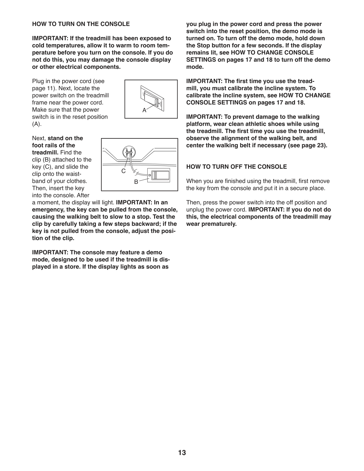
13
Features Of The Console
The treadmill console offers a selection of features designed to make your workouts more effective. When you select the manual mode of the console, you can change the speed of the treadmill with the touch of a button. As you exercise, the displays will provide continuous exercise feedback. You can even measure your heart rate using the built-in pulse sensor. The console also offers four speed programs. Each program automatically controls the speed of the tread- mill as it guides you through an effective workout. To prevent damage to the walking platform, always wear clean athletic shoes while using the treadmill. During the first few minutes that the treadmill is used, inspect the alignment of the walking belt, and center the walking belt if necessary (see page 20).How To Turn On The Power
Plug in the power cord (see page 12). Next, locate the reset/off circuit breaker on the treadmill frame near the power cord. Make sure that the circuit breaker is in the “reset” position. Next, stand on the foot rails of the treadmill. Find the clip attached to the key (see the drawing above), and slide the clip onto the waistband of your clothes. Then, insert the key into the console. After a moment, the dis- plays will light. Important: In an emergency situa- tion, the key can be pulled from the console, caus- ing the walking belt to slow to a stop. Test the clip by carefully taking a few steps backward; if the key is not pulled from the console, adjust the position of the clip.Console Diagram
Clip Key Reset Position Thumb Pulse Sensor Note: If there are sheets of clear plastic on the console, remove the plastic.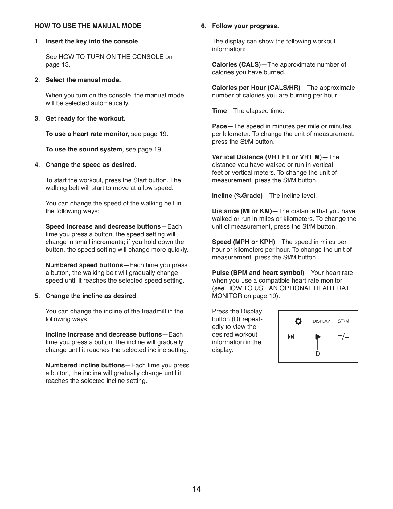
14
How To Use The Manual Mode
Insert the key into the console. See HOW TO TURN ON THE POWER on page 13. Select the manual mode. When the key is in- serted, the manual mode will be selected. If you have selected a speed program, rese- lect the manual mode by pressing the Program Select button repeatedly until only zeros appear in the displays. Start the walking belt. To start the walking belt, press the Start button, the speed + button, or one of the numbered speed buttons. If you press the Start button or the speed + button, the walking belt will begin to move at 1 mph. As you exercise, change the speed of the walking belt as desired by pressing the speed + and – but- tons. Each time you press a button, the speed set- ting will change by 0.1 mph; if you hold down a button, the speed setting will change in incre- ments of 0.5 mph. Note: After you press the but- tons, it may take a moment for the walking belt to reach the selected speed setting. If one of the numbered speed buttons is pressed, the walking belt will gradually change speed until it reaches the selected speed setting. To stop the walking belt, press the Stop button. The time will begin to flash in one of the displays. To restart the walking belt, press the Start button or the speed + button. Follow your progress with the track and the displays. The track—The track represents a distance of 1/4 mile. As you walk or run on the treadmill, the indicators around the track will appear in suc- cession until the entire track appears. The track will then disappear and the indicators will again begin to appear in succession. The center of the track will show the number of laps that you have completed. The lower left display—As you exer- cise, the lower left dis- play can show the elapsed time and the distance that you have walked or run. The lower right display—The lower right display can show the speed of the walking belt and the approximate number of calories that you have burned. The display also shows your heart rate when you use the pulse sensor (see step 5 on page 15). The upper display— The upper display can show the elapsed time, the distance that you have walked or run, the speed of the walking belt, or the approximate number of calories you have burned. Press the Display button repeatedly until the upper display shows the information that you are most interested in viewing. Note: While in- formation is shown in the upper display, the same information will not be shown in the lower displays. To reset the displays, press the Stop button, re- move the key, and then reinsert the key. Note: The console can display speed and dis- tance in either miles or kilometers. To see which unit of measurement is selected, first remove the key from the console. Next, hold down the Stop button, reinsert the key, wait until you hear a tone, and then release the Stop button. An “E” for English miles or an “M” for metric kilometers will appear in the upper display. Press the speed + button to change the unit of measurement if de- sired. When the desired unit of measurement is selected, remove the key and then reinsert it. 4 3 2 1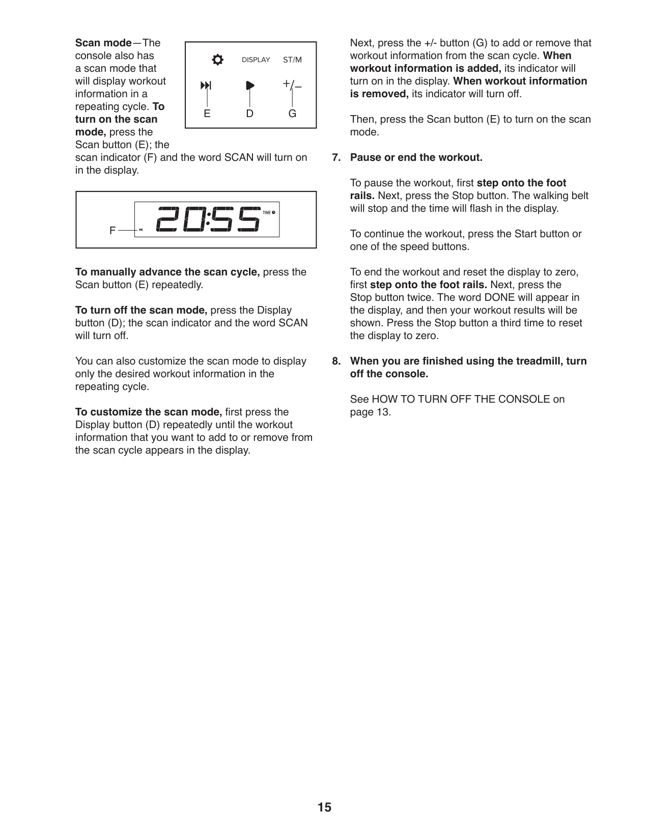
15 Measure your heart rate if desired. To measure your heart rate, stand on the foot rails and place your thumb on the pulse sensor (see the drawing on page 13). Do not press too hard, or the circulation in your thumb will be restricted and your pulse may not be detected. When your pulse is detected, the small heart sym- bol in the lower right display will flash, one or two dashes will appear, and then your heart rate will be shown. For the most accurate heart rate reading, hold your thumb on the pulse sensor for at least 15 seconds. If the displayed heart rate appears to be too high or too low, or if your heart rate is not displayed, lift your thumb for a few seconds, and then reposition your thumb on the pulse sensor. Remember to stand still while measuring your heart rate. When you are finished exercising, remove the key from the console. Step onto the foot rails, press the Stop button, and remove the key from the console. Keep the key in a secure place. Then, switch the on/off switch to the “off” position and unplug the power cord.
How To Use A Speed Program
Insert the key into the console. See HOW TO TURN ON THE POWER on page 13. Select one of the four speed programs. To select a speed pro- gram, press the Program Select button repeatedly; “P-1,” “P-2,” “P-3,” or “P-4” will ap- pear in the upper dis- play for a few seconds to show which program is selected. The maximum speed setting of the se- lected program will also flash in one of the dis- plays for a few seconds. Each program consists of 30 one-minute periods. One speed setting is programmed for each period. Note: The same speed setting may be pro- grammed for two or more consecutive periods. The profiles on the console show how the speed of the walking belt will change during the pro- grams. Press the Start button or the speed + button to start the program. When you press either button, the treadmill will automatically adjust to the speed setting that is programmed for the first period of the program. Hold the handrails and begin walking. When the first period ends, a series of tones will sound. If a different speed setting is programmed for the second period, the speed setting will flash in one of the displays to alert you, and then the speed of the walking belt will change. The pro- gram will continue until all 30 periods are com- pleted. The walking belt will then slow to a stop. If the speed setting is too high or too low during the program, you can manually override the setting by pressing the speed buttons. However, when the next period begins, the speed of the walk- ing belt will change if a different speed setting is programmed for the next period. To stop the program, press the Stop button. The time will begin to flash in one of the displays. To restart the program, press the Start button or the speed + button. The walking belt will begin to move at 1 mph. When the next period begins, the speed of the walking belt will change if a different speed setting is programmed for the next period. Follow your progress with the track and the displays. See step 4 on page 14. Measure your heart rate if desired. See step 5 on this page. When you are finished exercising, remove the key from the console. See step 6 on this page. 6 5 4 3 2 1 6 5
16
How To Change The Incline Of The Treadmill
To vary the intensity of your exercise, you can change the incline of the treadmill. There are three incline lev- els. Before changing the incline, remove the key and unplug the power cord. Next, fold the treadmill to the storage position (see page 17). To change the incline, first remove the incline pin from one of the incline legs. Adjust the incline leg to the de- sired position, and then fully reinsert the incline pin. Adjust the other incline leg in the same way. CAUTION: Before using the treadmill, make sure that both in- cline legs are at the same height and that both in- cline pins are fully inserted into the incline legs. After you have adjusted the incline legs, lower the treadmill (see page 18). Incline Legs Incline Pin Incline Pin
17
How To Fold And Move The Treadmill
How To Fold The Treadmill For Storage
Before folding the treadmill, unplug the power cord. CAUTION: You must be able to safely lift 45 lbs. (20 kg) to raise, lower, or move the treadmill.How To Move The Treadmill
Before moving the treadmill, convert the treadmill to the stor- age position as described above. Make sure that the catch is resting against the latch pin.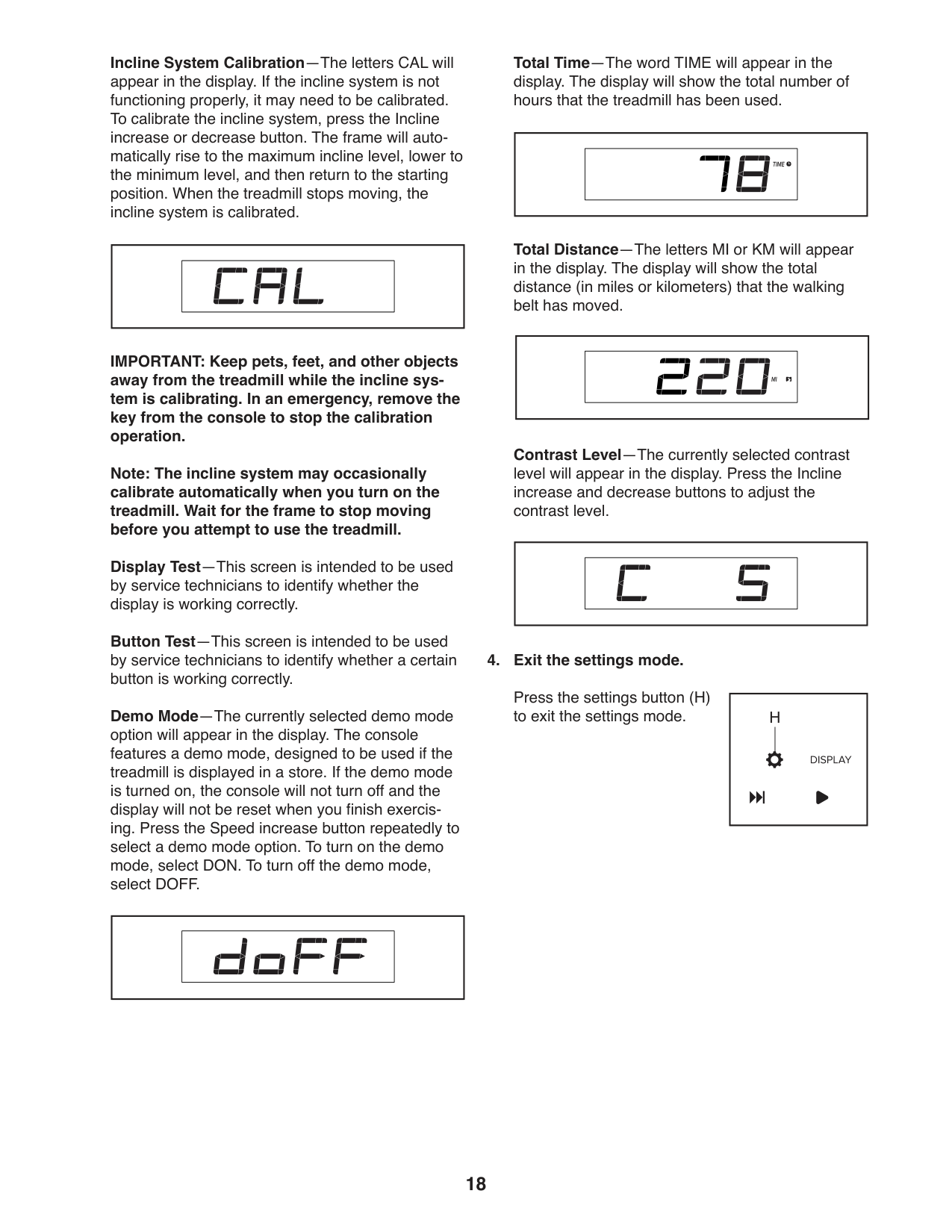
18
How To Lower The Treadmill For Use

19
Maintenance And Troubleshooting
Most treadmill problems can be solved by following the steps below. Find the symptom that applies, and follow the steps listed. If further assistance is needed, please see the front cover of this manual. PROBLEM: The power does not turn on SOLUTION: a. Make sure that the power cord is plugged into a surge suppressor, and that the surge suppressor is plugged into a properly grounded outlet (see page 12). Use only a single-outlet surge suppres- sor that meets all of the specifications described on page 12. Important: The treadmill is not com- patible with GFCI-equipped outlets. b. After the power cord has been plugged in, make sure that the key is inserted into the console. c. Check the reset/off circuit breaker located on the treadmill frame near the power cord. If the switch protrudes as shown, the circuit breaker has tripped. To reset the circuit breaker, wait for five minutes, and then press the switch back in. PROBLEM: The power turns off during use SOLUTION: a. Check the reset/off circuit breaker (see the drawing above). If the circuit breaker has tripped, wait for five minutes and then press the switch back in. b. Make sure that the power cord is plugged in. c. Remove the key from the console. Reinsert the key into the console. d. If the treadmill still will not run, please see the front cover of this manual. PROBLEM: The displays of the console do not function properly SOLUTION: a. Remove the key from the console and UNPLUG THE POWER CORD. Remove the three indicated Hood Screws (20) and two Foot Rail Screws (25). Then, carefully remove the Hood (65). Locate the Reed Switch (89) and the Magnet (62) on the left side of the Pulley (71). Turn the Pulley until the Magnet is aligned with the Reed Switch. Make sure that the gap between the Magnet and the Reed Switch is about 1/8". If necessary, loosen the Screw (3), move the Reed Switch slightly, and then retighten the Screw. Reattach the Hood (not shown), and run the treadmill for a few minutes to check for a correct speed reading. 25 20 65 a Tripped Reset c 62 3 89 Top View 1/8" 71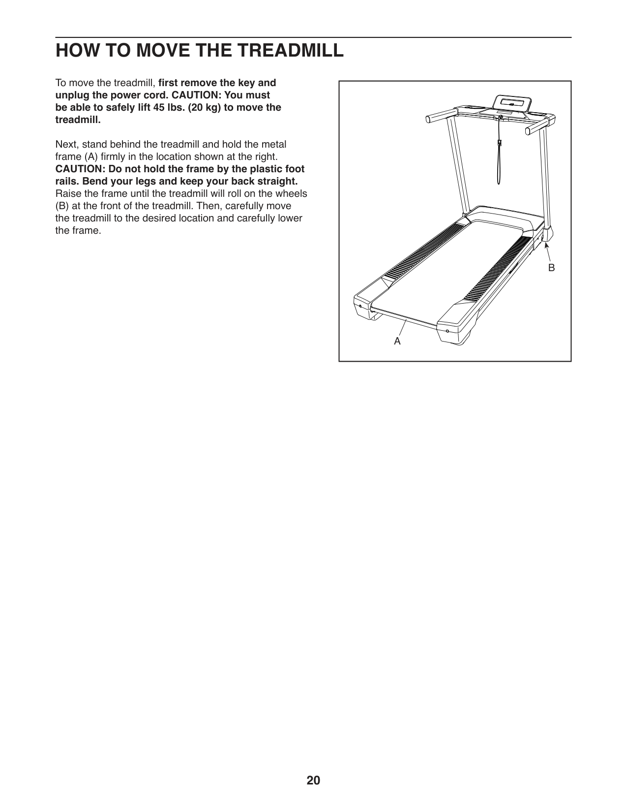
20 PROBLEM: The walking belt slows when walked on SOLUTION: a. Use only a single-outlet surge suppressor that meets all of the specifications described on page 12. b. If the walking belt is overtightened, treadmill perfor- mance may decrease and the walking belt may be- come damaged. Remove the key and UNPLUG THE POWER CORD. Using the hex key, turn both rear roller bolts counterclockwise, 1/4 of a turn. When the walking belt is properly tightened, you should be able to lift each edge of the walking belt 2 to 3 inches off the walking platform. Be careful to keep the walking belt centered. Then, plug in the power cord, insert the key, and run the treadmill for a few minutes. Repeat until the walking belt is properly tightened. c. If the walking belt still slows when walked on, see the front cover of this manual. PROBLEM: The walking belt is off-center or slips when walked on SOLUTION: a. If the walking belt has shifted to the left, first re- move the key and UNPLUG THE POWER CORD. Using the hex key, turn the left rear roller bolt clock- wise 1/2 of a turn. Be careful not to overtighten the walking belt. If the walking belt has shifted to the right, turn the left rear roller bolt counterclockwise 1/2 of a turn. Then, plug in the power cord, insert the key, and run the treadmill for a few minutes. Repeat until the walking belt is centered. b. If the walking belt slips when walked on, first re- move the key and UNPLUG THE POWER CORD. Using the hex key, turn both rear roller bolts clock- wise, 1/4 of a turn. When the walking belt is correctly tightened, you should be able to lift each edge of the walking belt 2 to 3 inches off the walking platform. Be careful to keep the walking belt centered. Then, plug in the power cord, insert the key, and carefully walk on the treadmill for a few minutes. Repeat until the walk- ing belt is properly tightened. b a b 2–3" Rear Roller Bolts
21
Conditioning Guidelines
The following guidelines will help you to plan your ex- ercise program. For more detailed exercise informa- tion, obtain a reputable book or consult your physician.Exercise Intensity
Whether your goal is to burn fat or to strengthen your cardiovascular system, the key to achieving the desired results is to exercise with the proper intensity. The proper intensity level can be found by using your heart rate as a guide. The chart below shows recom- mended heart rates for fat burning and aerobic exercise. To find the proper heart rate for you, first find your age near the bottom of the chart (ages are rounded off to the nearest ten years). Next, find the three numbers above your age. The three numbers define your “train- ing zone.” The lower two numbers are recommended heart rates for fat burning; the higher number is the recommended heart rate for aerobic exercise. To measure your heart rate during exercise, use the pulse sensor on the console. Fat Burning To burn fat effectively, you must exercise at a relatively low intensity level for a sustained period of time. During the first few minutes of exercise, your body uses easily accessible carbohydrate calories for en- ergy. Only after the first few minutes does your body begin to use stored fat calories for energy. If your goal is to burn fat, adjust the speed and incline of the tread- mill until your heart rate is near the lowest number in your training zone. For maximum fat burning, adjust the speed and incline of the treadmill until your heart rate is near the middle number in your training zone. Aerobic Exercise If your goal is to strengthen your cardiovascular sys- tem, your exercise must be “aerobic.” Aerobic exercise is activity that requires large amounts of oxygen for prolonged periods of time. This increases the demand on the heart to pump blood to the muscles, and on the lungs to oxygenate the blood. For aerobic exercise, adjust the speed and incline of the treadmill until your heart rate is near the highest number in your training zone.Workout Guidelines
Each workout should include the following three parts: A Warm-up—Start each workout with 5 to 10 minutes of stretching and light exercise. A proper warm-up in- creases your body temperature, heart rate and circula- tion in preparation for exercise. Training Zone Exercise—After warming up, increase the intensity of your exercise until your pulse is in your training zone for 20 to 60 minutes. (During the first few weeks of your exercise program, do not keep your pulse in your training zone for longer than 20 minutes.) Breathe regularly and deeply as you exercise—never hold your breath. A Cool-down—Finish each workout with 5 to 10 min- utes of stretching to cool down. This will increase the flexibility of your muscles and will help prevent post-ex- ercise problems.Exercise Frequency
To maintain or improve your condition, complete three workouts each week, with at least one day of rest be- tween workouts. After a few months, you may com- plete up to five workouts each week if desired. The key to success is to make exercise a regular and enjoyable part of your everyday life. WARNING: Before beginning this or any exercise program, consult your physi- cian. This is especially important for individu- als over the age of 35 or individuals with pre- existing health problems. The pulse sensor is not a medical device. Various factors, including your movement, may affect the accuracy of heart rate readings. The sensor is intended only as an exercise aid in determining heart rate trends in general.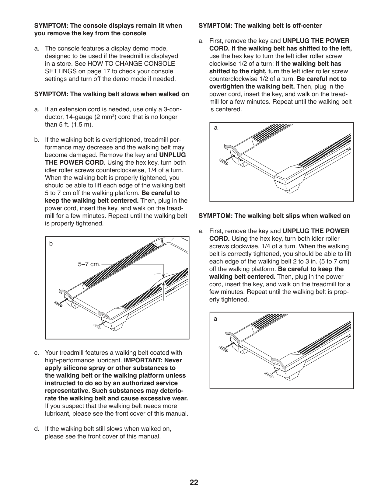
22
Suggested Stretches
The correct form for several basic stretches is shown at the right. Move slowly as you stretch—never bounce.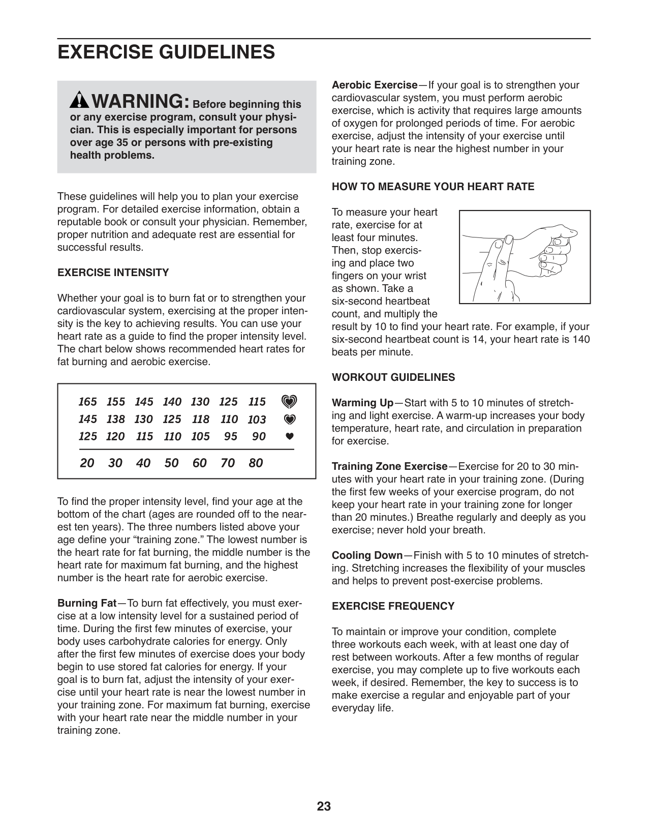
1 2 M10 x 110mm Bolt 2 4 M10 x 58mm Bolt 3 2 Wire Tie Screw/Reed Switch Screw 4 14 16mm Screw 5 6 M8 Star Washer 6 1 Warning Decal 7 2 M5 Star Washer 8 6 M8 x 15mm Bolt 9 2 M10 Star Washer 10 10 19mm Screw 11 2 Frame Spacer 12 1 Console Back 13 4 M6 x 58mm Bolt 14 2 M10 Flat Washer 15 1 Key/Clip 16 2 Nut 17 1 6 mm Hex Key 18 1 4 mm Hex Key 19 4 Roller Bracket Screw/ Front Platform Screw 20 3 Hood Screw 21 7 M4.2 x 13mm Screw 22 1 Left Handrail 23 1 Upright Grommet 24 1 Latch Pin Assembly 25 6 Foot Rail Screw 26 6 19mm Tek Screw 27 2 Walking Platform Bolt 28 4 Belt Guide Screw 29 2 Rear Roller Adj. Bolt 30 2 Motor Bolt 31 1 Motor Pivot Bolt 32 4 M6 Flat Washer 33 1 Right Handrail 34 2 Motor Tension Bolt 35 2 Wheel Bolt 36 2 Rear Roller Star Washer 37 1 Reset/Off Circuit Breaker 38 2 Motor Star Washer 39 1 Wire Harness 40 2 Incline Pin 41 4 Bellypan Screw 42 4 Electronics Star Washer 43 4 M6 Nut 44 6 Motor Tension Nut/Platform Nut 45 2 Wheel Housing 46 2 M8 Nut 47 3 Hood Clip 48 1 Latch Housing 49 1 Belly Pan Grommet 50 2 Isolator Fastener 51 1 Frame 52 1 Base 53 1 Left Upright 54 1 Right Upright 55 1 Rear Roller 56 1 Motor Belt 57 1 Electronics Bracket 58 2 18mm Screw 59 1 Motor Bracket 60 1 Left Rear Roller Bracket 61 1 Right Rear Roller Bracket 62 1 Magnet 63 6 Base Pad 64 1 Latch Catch 65 1 Hood 66 1 Belly Pan 67 1 Left Foot Rail 68 1 Right Foot Rail 69 4 Wheel Spacer 70 2 Wheel 71 1 Front Roller/Pulley 72 4 M8 Flat Washer 73 1 Access Door 74 2 Frame Endcap 75 4 Long Foot Rail Screw 76 1 Walking Belt 77 4 Handrail Endcap 78 2 Platform Cushion 79 1 Drive Motor 80 3 Wire Tie 81 3 8" Tie 82 2 M8 x 52mm Bolt 83 1 Reed Switch Clip 84 2 Controller Screw 85 2 16mm Screw 86 1 Walking Platform 87 1 Controller 88 1 Console Crossbar 89 1 Reed Switch 90 1 Power Cord 91 1 Console 92 1 Releasable Tie 93 2 Belt Guide 94 1 5 mm Hex Key 95 2 Incline Leg 96 2 U-nut 97 2 Front Roller Washer 98 1 Filter Wire 99 1 Power Cord Grommet 100 6 Cage Nut 101 1 Motor Pivot Nut # 1 10" Blue Wire, 2F # 1 4" Blue Wire, 2F # 1 4" Red Wire, M/F # 1 User’s Manual
These parts are not illustrated.
Specifications are subject to change without notice. PART LIST—Model No. WLTL29606.0R0207B
To locate the parts listed below, see the EXPLODED DRAWING on pages 24 to 27. Key No. Qty. Description Key No. Qty. Description 23
24 EXPLODED DRAWING A—Model No. WLTL29606.0
R0207B
93 17 86 51 76 67 28 62 89 3 83 93 6 96 96 31 25 25 25 25 25 75 75 56 25 71 68 28 18 44 95 40 82 46 72 72 95 40 46 82 72 72 27 29 21 74 61 19 55 36 42 21 29 74 60 36 19 42 27 44 19 19 78 50 78 64 10 10 50 41 41 41 41 10 94 97 97 101 44 44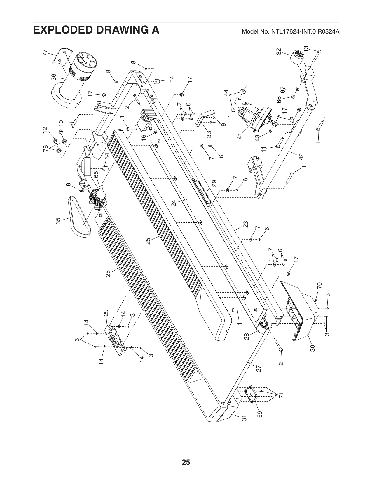
EXPLODED DRAWING B—Model No. WLTL29606.0
R0207B
34 38 44 79 34 30 59 38 90 65 47 47 47 57 21 21 42 42 21 84 87 98 81 66 49 37 99 20 20 20 92 25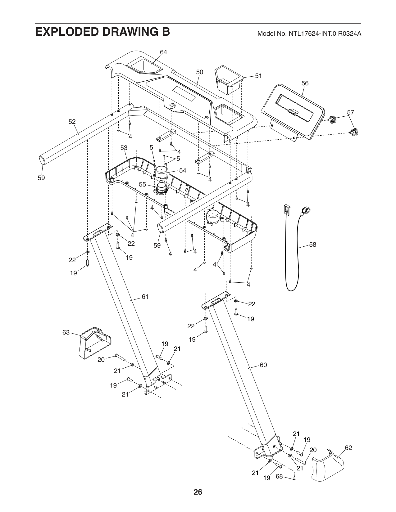
EXPLODED DRAWING C—Model No. WLTL29606.0
R0207B
80 4 3 54 11 53 14 1 9 1 11 14 9 58 48 39 85 26 63 10 63 26 26 63 33 77 22 88 77 24 70 35 16 63 26 69 69 43 45 32 43 13 5 8 5 8 5 77 10 10 10 77 63 26 10 10 10 10 35 16 70 69 69 63 26 45 32 43 43 32 13 85 7 7 8 5 100 100 8 100 39 2 2 23 52 26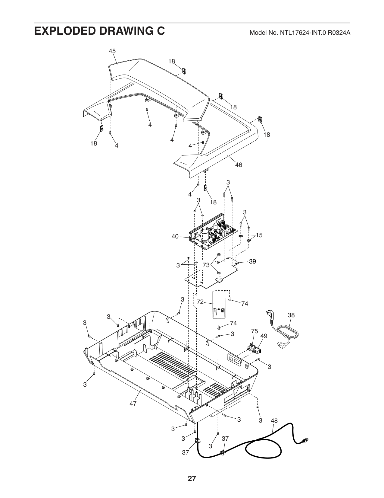
EXPLODED DRAWING D—Model No. WLTL29606.0
R0207B
15 91 73 4 12 4 4 4 4 4 4 4 4 4 27
Part No. 246825 R0207B Printed in China © 2007 ICON IP, Inc.